wind energy conversion system based on dfig with three
TRANSCRIPT

WIND ENERGY CONVERSION SYSTEM BASED ON DFIG WITHTHREE-PHASE SERIES GRID SIDE CONVERTER AND SINGLE DC-LINK
Ítalo A. Cavalcanti de Oliveira1, Cursino Brandao Jacobina2, Nady Rocha31Post-Graduate Program in Electrical Engineering (PPgEE) -Federal University of Campina Grande (UFCG), Campina Grande
– Paraíba, Brazil2Electrical Engineering Department (DEE) - Federal University of Campina Grande (UFCG), Campina Grande – Paraíba, Brazil
3Electrical Engineering Department (DEE) - Federal University of Paraíba (UFPB), João Pessoa – Paraíba, Brazile-mail: [email protected], [email protected], [email protected]
Abstract – In this paper, a wind energy conversionsystem based on doubly-fed induction generator with anadditional series grid side converter without transformeris proposed. Stator voltages may be compensated by seriesgrid side converter under distorted and unbalanced gridvoltage sags, thus avoiding over-current in the rotor, over-voltage in the dc-link, double-frequency oscillations in theelectromagnetic torque, and rotor over-speed. Moreover,the control strategy of the proposed system allows reactivepower to be injected during voltage sags. Simulationand experimental results are presented to evaluate theproposed system.
Keywords –Wind Energy Conversion System, DFIG,grid voltage disturbances, Additional Series Converter,transformerless.
NOMENCLATURE
DFIG Doubly-fed induction generator.DSOGI Dual second order generalized integrator.DSP Digital signal processor.DVR Dynamic voltage restorer.GSC Grid side converter.LVRT Low voltage ride-through.PI Proportional integral controller.PLL Phase-locked loop.PMSG Permanent magnet synchronous generator.rms Root mean square.RSC Rotor side converter.SGSC Series grid side converter.VOC Voltage-oriented control.WECS Wind energy conversion systems.Lp Inductor of the GSC filter.rp Resistance of the inductorLp.lp Inductance of the inductorLp.eg Grid voltage.vp Grid side converter’s voltage.vt Series grid side converter’s voltage.ig Grid current.ip Parallel current.xs Vector of the stator variables.xr Vector of the rotor variables.
Manuscript received 12/02/2020; first revision 03/12/2021; accepted forpublication 04/20/2021, by recommendation of Editor Demercilde SouzaOliveira Jr. http://dx.doi.org/10.18618/REP.2021.2.0067
vs Stator voltage.vr Rotor voltage.is Stator current.ir Rotor current.λs Stator flux.λr Rotor flux.rs Stator resistance.rr Rotor resistance.ls Stator inductance.lr Rotor inductance.lm Mutual inductance.ce Electromagnetic torque.cm Mechanical torque.J Moment of inertia.F Coefficient of friction.P Number of pole pairs.Pg Grid active power.Qg Grid reactive power.Ps Stator active power.Qs Stator reactive power.
I. INTRODUCTION
Wind energy is one of the most promising amongmany types of renewable energy sources, with increasingparticipation in the global electric matrix [1]–[3]. MostWECS are variable speed systems that use two main typesof generators [4]–[6]: PMSG and DFIG. Among variablespeed wind energy conversion systems, DFIG is the mostwidely used generator [6], [7] due to, in addition to othercharacteristics, advantages such as: controllable power factor,improvement of the system efficiency, durability, reducedmechanical stress, lower cost, reduced power converter rating(typically 30% of the generator rating), variable speed control,and four-quadrant active and reactive power control [5], [8]–[11].
However, since the stator windings of the DFIG are directlyconnected to the grid, these wind energy conversion systemsbased on DFIG are especially susceptible to grid voltagedisturbances. In past years, disconnection of wind energyconversion systems was a possible solution to protect the windsystem [12]–[14], however, with increasing wind power’sparticipation in the power grid, most grid codes require thatwind energy conversion systems must remain connected whena grid fault occurs [7], [11], [15]–[19]. According to thesegrid codes, the wind energy conversion systems must be ableto withstand voltage sags, i.e., the system must have LVRT
capability, and must act with reactive power compensation inorder to collaborate in the grid voltage recovery [7],[11],[15]–[26]. In addition, some grid codes require that wind energyconversion systems remain connected even in the event of 2%steady-state and 4% short term voltage imbalances [12], [27].
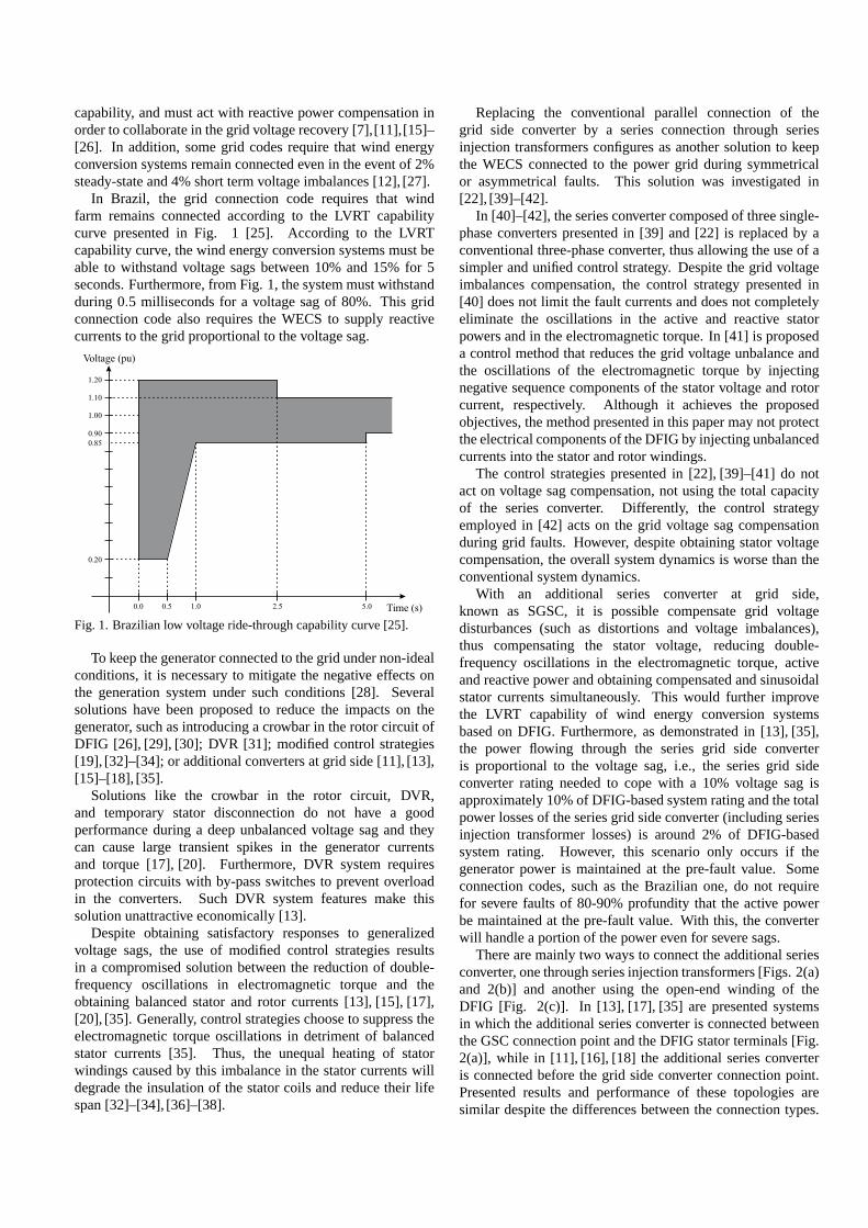
In Brazil, the grid connection code requires that windfarm remains connected according to the LVRT capabilitycurve presented in Fig. 1 [25]. According to the LVRTcapability curve, the wind energy conversion systems must beable to withstand voltage sags between 10% and 15% for 5seconds. Furthermore, from Fig. 1, the system must withstandduring 0.5 milliseconds for a voltage sag of 80%. This gridconnection code also requires the WECS to supply reactivecurrents to the grid proportional to the voltage sag.
0.85
0.20
0.90
1.00
Voltage (pu)
Time (s)0.0 0.5 1.0 5.02.5
1.10
1.20
Fig. 1. Brazilian low voltage ride-through capability curve [25].
To keep the generator connected to the grid under non-idealconditions, it is necessary to mitigate the negative effects onthe generation system under such conditions [28]. Severalsolutions have been proposed to reduce the impacts on thegenerator, such as introducing a crowbar in the rotor circuit ofDFIG [26], [29], [30]; DVR [31]; modified control strategies[19], [32]–[34]; or additional converters at grid side [11], [13],[15]–[18], [35].
Solutions like the crowbar in the rotor circuit, DVR,and temporary stator disconnection do not have a goodperformance during a deep unbalanced voltage sag and theycan cause large transient spikes in the generator currentsand torque [17], [20]. Furthermore, DVR system requiresprotection circuits with by-pass switches to prevent overloadin the converters. Such DVR system features make thissolution unattractive economically [13].
Despite obtaining satisfactory responses to generalizedvoltage sags, the use of modified control strategies resultsin a compromised solution between the reduction of double-frequency oscillations in electromagnetic torque and theobtaining balanced stator and rotor currents [13], [15], [17],[20], [35]. Generally, control strategies choose to suppress theelectromagnetic torque oscillations in detriment of balancedstator currents [35]. Thus, the unequal heating of statorwindings caused by this imbalance in the stator currents willdegrade the insulation of the stator coils and reduce their lifespan [32]–[34], [36]–[38].
Replacing the conventional parallel connection of thegrid side converter by a series connection through seriesinjection transformers configures as another solution to keepthe WECS connected to the power grid during symmetricalor asymmetrical faults. This solution was investigated in[22], [39]–[42].
In [40]–[42], the series converter composed of three single-phase converters presented in [39] and [22] is replaced by aconventional three-phase converter, thus allowing the useof asimpler and unified control strategy. Despite the grid voltageimbalances compensation, the control strategy presented in[40] does not limit the fault currents and does not completelyeliminate the oscillations in the active and reactive statorpowers and in the electromagnetic torque. In [41] is proposeda control method that reduces the grid voltage unbalance andthe oscillations of the electromagnetic torque by injectingnegative sequence components of the stator voltage and rotorcurrent, respectively. Although it achieves the proposedobjectives, the method presented in this paper may not protectthe electrical components of the DFIG by injecting unbalancedcurrents into the stator and rotor windings.
The control strategies presented in [22], [39]–[41] do notact on voltage sag compensation, not using the total capacityof the series converter. Differently, the control strategyemployed in [42] acts on the grid voltage sag compensationduring grid faults. However, despite obtaining stator voltagecompensation, the overall system dynamics is worse than theconventional system dynamics.
With an additional series converter at grid side,known as SGSC, it is possible compensate grid voltagedisturbances (such as distortions and voltage imbalances),thus compensating the stator voltage, reducing double-frequency oscillations in the electromagnetic torque, activeand reactive power and obtaining compensated and sinusoidalstator currents simultaneously. This would further improvethe LVRT capability of wind energy conversion systemsbased on DFIG. Furthermore, as demonstrated in [13], [35],the power flowing through the series grid side converteris proportional to the voltage sag, i.e., the series grid sideconverter rating needed to cope with a 10% voltage sag isapproximately 10% of DFIG-based system rating and the totalpower losses of the series grid side converter (including seriesinjection transformer losses) is around 2% of DFIG-basedsystem rating. However, this scenario only occurs if thegenerator power is maintained at the pre-fault value. Someconnection codes, such as the Brazilian one, do not requirefor severe faults of 80-90% profundity that the active powerbe maintained at the pre-fault value. With this, the converterwill handle a portion of the power even for severe sags.
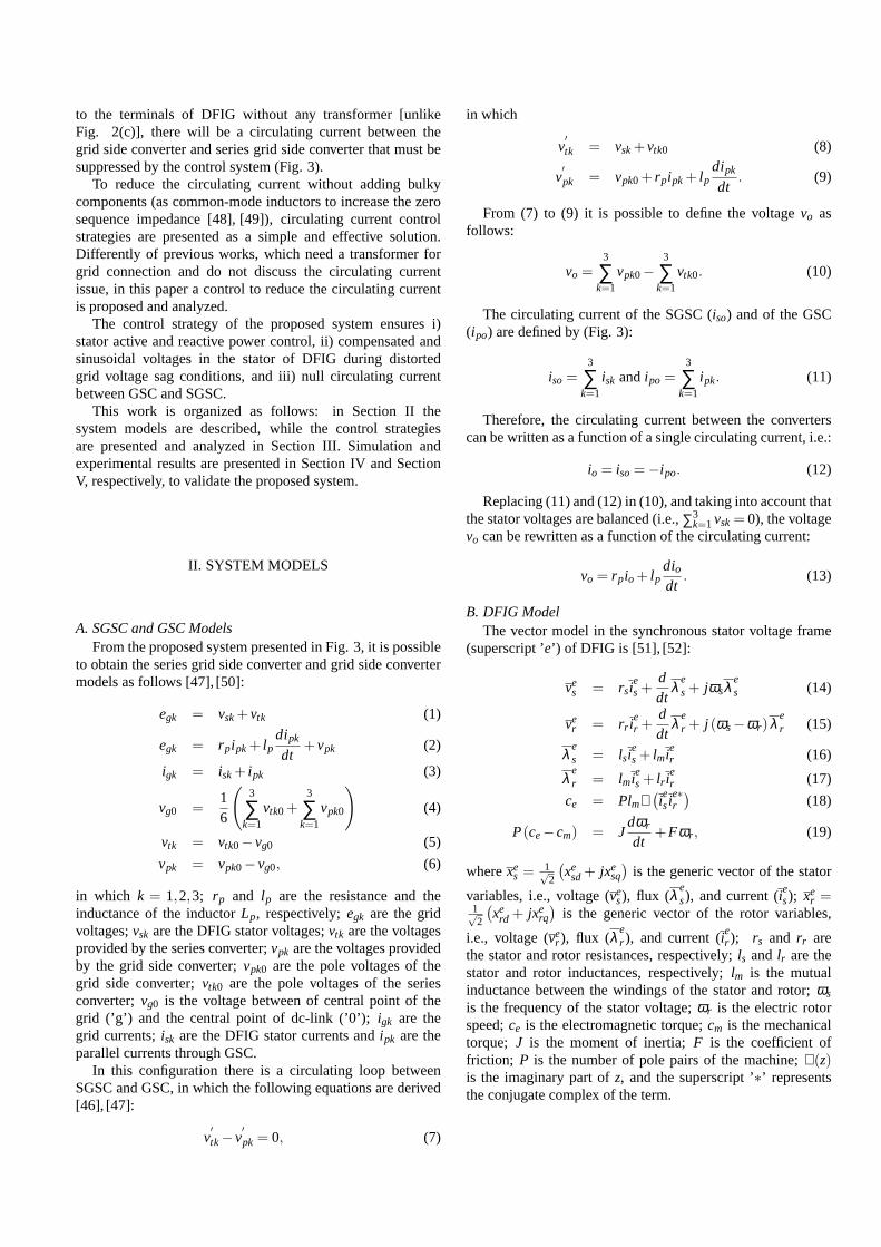
There are mainly two ways to connect the additional seriesconverter, one through series injection transformers [Figs. 2(a)and 2(b)] and another using the open-end winding of theDFIG [Fig. 2(c)]. In [13], [17], [35] are presented systemsin which the additional series converter is connected betweenthe GSC connection point and the DFIG stator terminals [Fig.2(a)], while in [11], [16], [18] the additional series converteris connected before the grid side converter connection point.Presented results and performance of these topologies aresimilar despite the differences between the connection types.

In [15], Flannery and Venkataramanan also present topologiesin which the additional series converter is connected in theDFIG stator open-end windings, as shown in Fig. 2(c).
GSC RSC
SGSC
DFIG
Series InjectionTransformers
Grid
Transformer
Gearbox
Turbine
(a)
GearboxGrid
Transformer
GSC RSC
SGSC
DFIG
Turbine
Series InjectionTransformers
(b)
GearboxGrid
Transformer
GSC RSC
SGSC
DFIG
Turbine
(c)
Fig. 2. Connection types for additional series grid side converter.(a) Connection between the grid side converter connection pointand stator terminals. (b) Connection before the grid side converterconnection point. (c) Connection with stator open-end windings.
In [18] is proposed a DFIG integration scheme with anadditional series converter at the stator DFIG terminals actingas a DVR to improve the LVRT capability. According to [18],the use of series converter could result in additional benefits,such as active series filtering, reactive power compensation,and electronic isolation. With compensation control proposedin [18], over-current and over-voltage in the rotor windingsare significantly reduced. However, in addition to using seriesinjection transformers (increasing the losses and complexity ofthe system), the proposed solution only acts on the reductionof the over-current and over-voltage due to the grid fault. Thus,oscillations in rotor speed are not eliminated while symmetricfault occurs and the dc-link voltage is not controlled duringthe faults studied in [18], presenting high oscillations duringan asymmetric fault.
In [43], [44], a system operating with two dc-link, onefor the back-to-back converter and another for the additionalseries converter operating with floating capacitors, wasproposed. However, the additional series converter in suchworks or only assists the system performances during severalgrid voltage disturbances or only reduces harmonic distortionsat DFIG stator terminals without grid voltage sag or swellcompensation.
In this paper, a wind energy conversion system basedon DFIG with series grid side converter is proposed, i.e.,a standard two-level voltage source inverter, fed Open-EndWinding DFIG with single dc-link voltage and without atransformer, as shown in Fig. 3. The proposed system withoutseries injection transformers has less complexity, lower cost,and reduced losses compared to the conventional system withadditional series converter [45]. Moreover, the proposedsystem also compensates the voltages in the stator terminalsof DFIG even during distorted and unbalanced grid voltageconditions, thus improving the LVRT. In addition to the seriesgrid side converter, the proposed system is composed of a gridside converter, which ensures a regulated dc-link voltage andmaintains a high grid power factor (through the grid currentcontrol), and a rotor side converter, which regulates the statoractive and reactive power through a voltage-oriented control.
Compared to the conventional system, the proposed systemdoes not require the use of any transformer (series injectiontransformer or a parallel transformer for connecting theGSC) and reduces the circulation current without using bulkycomponents, resulting in a system with lower cost and weightand with high LVRT capacity.
The proposed system in this work was previously analyzedin [46] for a static voltage sag condition and in [47] for seriesactive filter applications. In [46] and [47], the experimentalresults were obtained without DFIG and only validated theGSC and SGSC controls. In this work, simulation resultsfor a dynamic voltage sag condition (i.e., with inceptionand clearance of the voltage sag) with harmonic distortionsand imbalances are presented and analyzed. The work alsopresents more complete experimental results for a grid voltagesag, demonstrating the compensation capacity of the proposedsystem and validating the controls employed in all threeconverters. In addition, the control strategy proposed forSGSC in this work is able to deal with voltage imbalancesand harmonic distortions simultaneously, unlike the controlsproposed in [46] and [47]. The present work also bringsa detailed controller design to obtain the parameters of thecontrollers employed in the system.
L
ig1
ig2
p1
p2p3
+
-
0
-
r2
r1r2i
p ir1
ir3
GSC RSC
r3
Gearbox
t2t1
SGSC
t3
Turbine
io
io
io
p1i
p2ip3i
ig3
is1
is2
is3
is3 is1is2
eg1
eg2
eg3
vs3 vs2 vs1
GridDFIGRotor
DFIGStator
+
-
Lp
Lp
g
vc
2
vc
2
io
Fig. 3. Proposed DFIG system with additional series grid sideconverter without transformers.
Since the series grid side converter is connected directly
to the terminals of DFIG without any transformer [unlikeFig. 2(c)], there will be a circulating current between thegrid side converter and series grid side converter that mustbesuppressed by the control system (Fig. 3).
To reduce the circulating current without adding bulkycomponents (as common-mode inductors to increase the zerosequence impedance [48], [49]), circulating current controlstrategies are presented as a simple and effective solution.Differently of previous works, which need a transformer forgrid connection and do not discuss the circulating currentissue, in this paper a control to reduce the circulating currentis proposed and analyzed.
The control strategy of the proposed system ensures i)stator active and reactive power control, ii) compensated andsinusoidal voltages in the stator of DFIG during distortedgrid voltage sag conditions, and iii) null circulating currentbetween GSC and SGSC.
This work is organized as follows: in Section II thesystem models are described, while the control strategiesare presented and analyzed in Section III. Simulation andexperimental results are presented in Section IV and SectionV, respectively, to validate the proposed system.
II. SYSTEM MODELS
A. SGSC and GSC ModelsFrom the proposed system presented in Fig. 3, it is possible
to obtain the series grid side converter and grid side convertermodels as follows [47], [50]:
egk = vsk+vtk (1)
egk = rpipk+ lpdipk
dt+vpk (2)
igk = isk+ ipk (3)
vg0 =16
(
3
∑k=1
vtk0+3
∑k=1
vpk0
)
(4)
vtk = vtk0−vg0 (5)
vpk = vpk0−vg0, (6)
in which k = 1,2,3; rp and lp are the resistance and theinductance of the inductorLp, respectively;egk are the gridvoltages;vsk are the DFIG stator voltages;vtk are the voltagesprovided by the series converter;vpk are the voltages providedby the grid side converter;vpk0 are the pole voltages of thegrid side converter;vtk0 are the pole voltages of the seriesconverter;vg0 is the voltage between of central point of thegrid (’g’) and the central point of dc-link (’0’);igk are thegrid currents;isk are the DFIG stator currents andipk are theparallel currents through GSC.
In this configuration there is a circulating loop betweenSGSC and GSC, in which the following equations are derived[46], [47]:
v′tk−v
′pk = 0, (7)
in which
v′tk = vsk+vtk0 (8)
v′pk = vpk0+ rpipk+ lp
dipk
dt. (9)
From (7) to (9) it is possible to define the voltagevo asfollows:
vo =3
∑k=1
vpk0−3
∑k=1
vtk0. (10)
The circulating current of the SGSC (iso) and of the GSC(ipo) are defined by (Fig. 3):
iso=3
∑k=1
isk andipo =3
∑k=1
ipk. (11)
Therefore, the circulating current between the converterscan be written as a function of a single circulating current,i.e.:
io = iso=−ipo. (12)
Replacing (11) and (12) in (10), and taking into account thatthe stator voltages are balanced (i.e.,∑3
k=1vsk= 0), the voltagevo can be rewritten as a function of the circulating current:
vo = rpio+ lpdiodt
. (13)
B. DFIG ModelThe vector model in the synchronous stator voltage frame
(superscript ’e’) of DFIG is [51], [52]:
ves = rsi
es+
ddt
λ es+ jωsλ
es (14)
ver = rr i
er +
ddt
λ er + j (ωs−ωr)λ e
r (15)
λ es = lsi
es+ lmi
er (16)
λ er = lmi
es+ lr i
er (17)
ce = Plmℑ(
iesi
e∗r
)
(18)
P(ce−cm) = Jdωr
dt+Fωr , (19)
wherexes =
1√2
(
xesd+ jxe
sq
)
is the generic vector of the stator
variables, i.e., voltage (ves), flux (λ e
s), and current (ies); xe
r =1√2
(
xerd + jxe
rq
)
is the generic vector of the rotor variables,
i.e., voltage (ver ), flux (λ e
r ), and current (ier ); rs and rr are
the stator and rotor resistances, respectively;ls and lr are thestator and rotor inductances, respectively;lm is the mutualinductance between the windings of the stator and rotor;ωs
is the frequency of the stator voltage;ωr is the electric rotorspeed;ce is the electromagnetic torque;cm is the mechanicaltorque; J is the moment of inertia;F is the coefficient offriction; P is the number of pole pairs of the machine;ℑ(z)is the imaginary part ofz, and the superscript ’∗’ representsthe conjugate complex of the term.
vc*
vc
*irde
irde
vp12*
dq
123
*vrq*e irq
e
irqe
Pro
pose
d S
yste
m
PW
M
DSOGI-PLL
PW
M
Q s*
Q s
vrd*e
Circulating Current Control
RSC Control
Ps*
Ps
eg123
θs θr
vo*
io
io*
vs12*
vs12
vt12*
eghr12*
vcPI
igPR
vsPR
ioPR
qsPI
psPIirPI
irPI
Gvs
Vs*
θg12
g
egf12
eg12
*igqe
Qg*
*igdqs
Qg
qgPI
e jθ
igdqs
*vpdqs
dq
123
*igde
θg
GSC Control
SGSC Control
vr123*
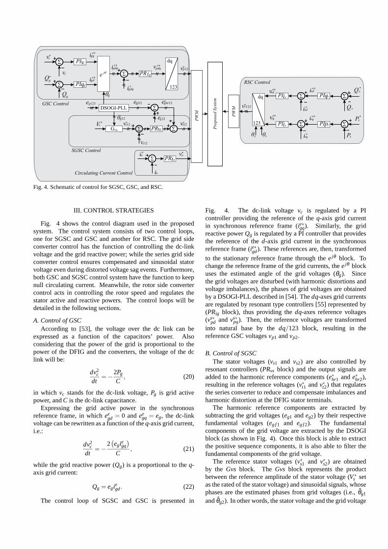
Fig. 4. Schematic of control for SGSC, GSC, and RSC.
III. CONTROL STRATEGIES
Fig. 4 shows the control diagram used in the proposedsystem. The control system consists of two control loops,one for SGSC and GSC and another for RSC. The grid sideconverter control has the function of controlling the dc-linkvoltage and the grid reactive power; while the series grid sideconverter control ensures compensated and sinusoidal statorvoltage even during distorted voltage sag events. Furthermore,both GSC and SGSC control system have the function to keepnull circulating current. Meanwhile, the rotor side convertercontrol acts in controlling the rotor speed and regulates thestator active and reactive powers. The control loops will bedetailed in the following sections.
A. Control of GSCAccording to [53], the voltage over the dc link can be
expressed as a function of the capacitors’ power. Alsoconsidering that the power of the grid is proportional to thepower of the DFIG and the converters, the voltage of the dclink will be:
dv2c
dt=−2Pg
C, (20)
in which vc stands for the dc-link voltage,Pg is grid activepower, andC is the dc-link capacitance.
Expressing the grid active power in the synchronousreference frame, in whichee
gd = 0 andeegq = eg, the dc-link
voltage can be rewritten as a function of theq-axis grid current,i.e.:
dv2c
dt=−
2(
egiegq
)
C, (21)
while the grid reactive power (Qg) is a proportional to theq-axis grid current:
Qg = egiegd. (22)
The control loop of SGSC and GSC is presented in
Fig. 4. The dc-link voltagevc is regulated by a PIcontroller providing the reference of theq-axis grid currentin synchronous reference frame (ie∗gq). Similarly, the gridreactive powerQg is regulated by a PI controller that providesthe reference of thed-axis grid current in the synchronousreference frame (ie∗gd). These references are, then, transformed
to the stationary reference frame through theejθ block. Tochange the reference frame of the grid currents, theejθ blockuses the estimated angle of the grid voltages (θg). Sincethe grid voltages are disturbed (with harmonic distortionsandvoltage imbalances), the phases of grid voltages are obtainedby a DSOGI-PLL described in [54]. Thedq-axes grid currentsare regulated by resonant type controllers [55] represented by(PRig block), thus providing thedq-axes reference voltages(vs∗
pd andvs∗pq). Then, the reference voltages are transformed
into natural base by thedq/123 block, resulting in thereference GSC voltagesvp1 andvp2.
B. Control of SGSCThe stator voltages (vs1 and vs2) are also controlled by
resonant controllers (PRvs block) and the output signals areadded to the harmonic reference components (e∗hr1 ande∗hr2),resulting in the reference voltages (v∗t1 andv∗t2) that regulatesthe series converter to reduce and compensate imbalances andharmonic distortion at the DFIG stator terminals.
The harmonic reference components are extracted bysubtracting the grid voltages (eg1 andeg2) by their respectivefundamental voltages (eg f1 and eg f2). The fundamentalcomponents of the grid voltage are extracted by the DSOGIblock (as shown in Fig. 4). Once this block is able to extractthe positive sequence components, it is also able to filter thefundamental components of the grid voltage.
The reference stator voltages (v∗s1 and v∗s2) are obtainedby the Gvs block. The Gvs block represents the productbetween the reference amplitude of the stator voltage (V∗
s setas the rated of the stator voltage) and sinusoidal signals, whosephases are the estimated phases from grid voltages (i.e.,θg1
andθg2). In other words, the stator voltage and the grid voltage

are synchronized. In this way, the series converter ensuresbalanced and sinusoidal voltages at the terminals of DFIG andeliminates critical problems that affect the DFIG during gridvoltage disturbances.
C. Control of Circulating CurrentThe last control mash is based on a resonant controller
(PRio block), which regulates the circulating currentio to zero,providing the reference circulating voltagev∗o. Therefore, thereference voltagesv∗t1, v∗t2, v∗p1, v∗p2, andv∗o are used to definethe switch states of SGSC and GSC.
D. Control of RSCAs mentioned before, traditional vector control can be
employed at the rotor side converter. Thus, in the rotor sideconverter control loop a VOC is employed, which performsstator active and reactive powers control [51], [52]. From theDFIG vector model in the synchronous stator voltage frame, inwhich ve
sd = 0 andvesq= vs, and neglecting resistive losses in
the stator windings, the active and reactive powers (Ps andQs,respectively) can be written as a function of the rotor currents,such that:
Ps = − lmls
vsierq (23)
Qs =lmls
vs
(
vs
lmωs− ierd
)
. (24)
The reactive power can be controlled byierd regardless ofierq, thus featuring a fully decoupled control of stator activeand reactive powers.
Then, makingQ∗s = 0 to ensure a high power factor, thed-
axis rotor reference current (ie∗rd) is determined by the outputof a PI controller (PIqs block) with reactive power error as theinput signal (see Fig. 4). On the other hand, theq-axis rotorreference current (ie∗rq) is obtained from another PI controller(PIps block) that regulates stator active power. Also, reactivepower can be injected into the power grid during voltage sagsusing the rotor side converter or grid side converter, thus actingin the power grid recovery.
The dq-axes rotor currents provide the reference rotorvoltagesve∗
rd and ve∗rq . Then, the reference voltagesv∗r1, v∗r2,
andv∗r3 are used to define the switch states of the rotor sideconverter, as shown in Fig. 4.
E. Controller DesignThe design of the controllers is performed using the gains
tuning techniques presented in [53]. In this section, thedesign of the circulating current loop controller (PRio) willbe presented, while the gains of the other controllers can besimilarly tuned.
From (13) it is possible to write the circulating current planton terms of the Laplace operators:
Io(s)Vo(s)
= Pio(s) =1lp
s+ rplp
. (25)
The block diagram of the circulating current control loopis shown in Fig 5, in which the resonant controller isapproximated by a PI controller for purposes of calculatingthe
proportional and integral gains, since the gains of a resonantcontroller can be adjusted similarly to a PI controller [56].
* Vo*Io
ioPR
IoioG (s)
Vo* 1
pr +slpIo
Fig. 5. Block diagram of the control loop ofio.
In Fig. 5, Kpio andKi io are the proportional and integralgains, respectively. Thus using the pole-zero cancellation, i.e.,Ki ioKpio
=rplp
, the transfer function of open-loop is:
Gio(s) =Kpio
lps
(
s+ Ki ioKpio
s+ rplp
)
=Kpio
lps, (26)
From (26), the transfer function of closed-loop is:
Cio(s) =1
τios+1. (27)
whereτio =lp
Kpiois the time constant of the transfer function of
the closed-loop system. The value ofτio is a design parameterthat must be chosen according to the desired response speedfor the closed-loop system [53]. Observe that:
Kpio =lp
τio(28)
Ki io =rp
τio. (29)
To calculate the control gains, the speed response wasτio =0.8 ms.
IV. PWM Strategies
In this section, the PWM strategies of the GSC and SGSCare presented. The PWM strategy of the RSC is presentedin [46], [47].
The reference pole voltages are determined by [47]:
v∗t10 = v∗t1+v∗x (30)
v∗t20 = v∗t2+v∗x (31)
v∗t30 = v∗t3−v∗o2+v∗x (32)
v∗p10 = v∗p1+v∗x (33)
v∗p20 = v∗p2+v∗x (34)
v∗p30 = v∗p3+v∗o2+v∗x. (35)
The auxiliary voltage can be chosen arbitrarily since themaximum and minimum values of the pole voltages arerespected. Thus:
v∗xmax =v∗c2−Vxmax (36)
v∗xmin = −v∗c2−Vxmin, (37)
where Vxmax = maxv∗t1,v∗t2,v
∗t3 −
v∗o2 ,v
∗p1,v
∗p2,v
∗p3 +
v∗o2 and

Vxmin = minv∗t1,v∗t2,v
∗t3 −
v∗o2 ,v
∗p1,v
∗p2,v
∗p3 +
v∗o2 . Then, the
auxiliary voltagev∗x can be writen by a factorµx with 0≤ µx ≤1, thus:
v∗x = µxv∗xmax+(1−µx)v∗xmin. (38)
The switch states are defined by comparing the polevoltages with a high frequency triangular carrier PWM.
V. SIMULATION RESULTS
Two sets of simulation results are obtained. One set foran unbalanced voltage sag (Figs. 6 to 8) and another for athree-phase voltage sag of 80% (Figs. 9 to 11). In Both setsa fundamental grid voltage of 220 V rms (phase voltage), a650 V dc-link voltage, a dc-link capacitance of 100µF, astator active power of−1.5 kW, a rotor speed of 365 rad/s,and an electromagnetic torque of−2.7 Nm were considered.The parameters of the DFIG utilized in the computationalsimulation are shown in Table I. Discrete controllers with asampling frequency of 10 kHz were used in the computationalsimulation and the values of the controllers gains are presentedin Table II.
A. Unbalanced Voltage SagFor the results with unbalanced voltage sag, a D-Type
voltage sag [57] with a characteristic voltage of 80% of therated voltage is applied att = 0.1 s and cleared after 0.5 s.During the sag event, the grid voltage also contains 5th and 7th
harmonic components with amplitude approximately 9.65%and 3.20% of the fundamental amplitude, respectively.
TABLE ISpecification of the DFIG parameters.
Parameters Values Parameters ValuesRated power 2 kW Rotor inductance 14.9 mH
Stator phase voltage 220 V Mutual inductance 599.2 mHStator resistance 3.0Ω Number of poles 2Rotor resistance 2.99Ω Moment of inertia 0.003 kg.m2
Stator inductance 14.9 mH Stator/rotor turns ratio 1
TABLE IISpecification of the controllers gains.
Controller Proportional Gain ( Kp) Integral Gain (Ki )PIvc 0.5 3PIqg 5×10⁻⁴ 0.3PRig 60 4×10³
PRvs 0.01 200PRio 10 625PIqs 1.4×10⁻³ 0.61PIps 1.4×10⁻³ 0.61PIir 642.82 6.52×10⁴
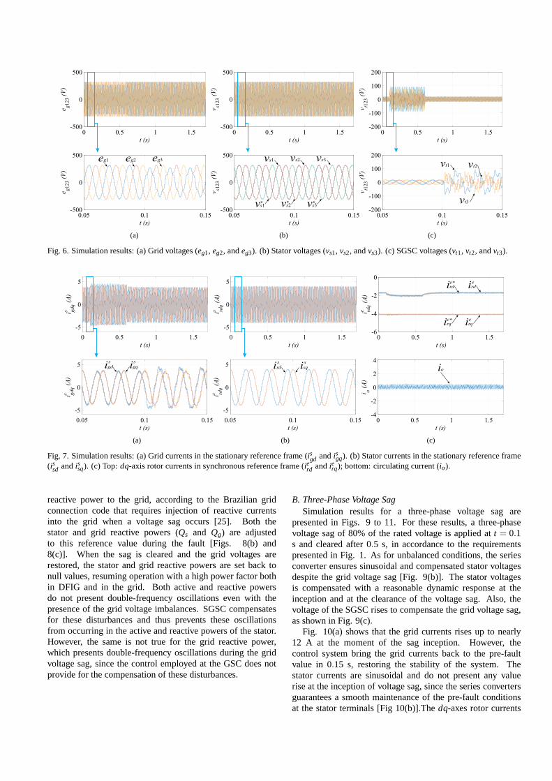
In Figs. 6 to 8 are shown simulation results for anunbalanced voltage sag. Dynamic responses and a detail ofthe grid voltage sag inception are presented in Fig. 6. Thegrid voltages are shown in Fig. 6(a), while the stator voltagesare presented in Fig. 6(b). Notice that the series converterensures sinusoidal and balanced stator voltages despite theunbalance and distortion of the grid voltage. The series voltage
of the SGSC rises at the inception of the voltage sag tocompensate the grid imbalances and distortions [Fig. 6(c)].The stator voltages is compensated with a reasonable dynamicresponse at the inception and at the clearance of the voltagesag. Moreover, it is possible to note that the 5th and 7th
harmonic components of the grid voltages are compensatedat stator voltages. Thus, the SGSC control ensures sinusoidaland balanced voltages at the DFIG stator terminals.
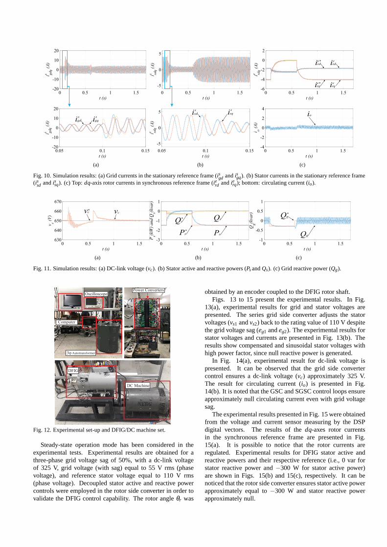
In Fig. 7(a) is possible to note that the grid currents aresinusoidal and balanced before the entry of the voltage sag.However, with the sag att = 0.1 s, the grid currents becomeunbalanced and distorted. The control carried out by the GSCdoes not provide for the compensation of these disturbancesinthe grid currents, such as reduction of harmonic content andnegative sequence components. Although the disturbancesremain present in the grid currents, the GSC maintains theamplitude of the currents under control and guarantees thestability of the system. The stator currents, on the other hand,are sinusoidal and balanced, as shown in Fig 7(b), since theseries converter maintains balanced and sinusoidal voltages atstator terminals. Thedq-axes rotor currents in the synchronousreference frame are presented in Fig. 7(c) (top). It can be notedthat the RSC control loop regulates the rotor currents to theirrespective reference value even during the voltage sag.
In Fig. 7(c) (bottom) is presented the result ofthe circulating current io. Notice that the controlassures a circulating current approximately null and withoutoscillations. Choosingµx = 0.5 the task of controlling thecirculating current is divided symmetrically between the GSCand the SGSC, similarly to the methodology used for dualinverters in [49], [58], [59], in which the task of reducingthe circulating current is carried out by the two inverters.Infact, whenµx = 0.0 or µx = 1.0, not only oscillations in thecirculating current appear as the control and general stabilityof the system are impaired, since the circulating voltage isnot more symmetrically compensated by the converters (GSCand SGSC). Therefore, in addition to the circulating currentcontrol loop is necessary to adjustµx = 0.5 to maintain thesystem stability and ensure null circulating current.
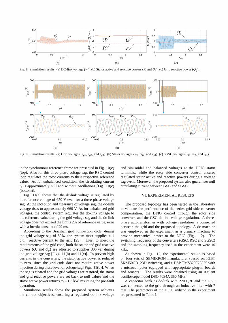
Fig. 8(a) shows the dc-link voltage is regulated by itsreference voltage of 650 V. At the inception of voltage sag,the dc-link voltage rises to approximately 652V. On the otherhand, at the clearance of voltage sag, the dc-link voltage dropsto approximately 648 V. Thus, the control system regulates thedc-link voltage to the reference value during the grid voltagesag and the dc-link voltage does not exceed the limits 2% ofreference value neither at the inception nor at the clearanceof voltage sag. It is worth mentioning here that the dc-linkinertia constant is approximately 29 ms, a typical value forWECS [60] and approximately 6% of the grid fault duration.However, double-frequency oscillations appears in the dc-link voltage during the grid sag due the voltage imbalances.Even though, these oscillations represents less than 1% of dc-link voltage and they do not impair the system stability andperformance.
Fig. 8(b) shows the result for active and reactive powerswith transient oscillations. The stator active power is settothe reference value of−1.5 kW even during voltage sag event.During the grid voltage sag, the system supplies 120 var of
0.05 0.1 0.15
t (s)
-500
0
500
e g123
(V)
0 0.5 1 1.5
t (s)
-500
0
500
e g123
(V)
eg3eg1 eg2
(a)
0.05 0.1 0.15
t (s)
-500
0
500
v s123
(V)
0 0.5 1 1.5
t (s)
-500
0
500
v s123
(V)
vs1 vs2 vs3
vs1 vs2 vs3* * *
(b)
0.05 0.1 0.15
t (s)
-200
-100
0
100
200
v t123
(V)
0 0.5 1 1.5
t (s)
-200
-100
0
100
200
v t123
(V)
vt1
vt3
vt2
(c)
Fig. 6. Simulation results: (a) Grid voltages (eg1, eg2, andeg3). (b) Stator voltages (vs1, vs2, andvs3). (c) SGSC voltages (vt1, vt2, andvt3).
0.05 0.1 0.15
t (s)
-5
0
5
i gdq
s(A
)
0 0.5 1 1.5
t (s)
-5
0
5
i gdq
s(A
)
sigd
sigq
(a)
0.05 0.1 0.15
t (s)
-5
0
5
i sdq
s(A
)
0 0.5 1 1.5
t (s)
-5
0
5
i sdq
s(A
)
sisd
sisq
(b)
0 0.5 1 1.5
t (s)
-6
-4
-2
0
i rdq
e(A
)
eirqirq*e
eirdird*e
0 0.5 1 1.5
t (s)
-4
-2
0
2
4i o
(A)
io
(c)
Fig. 7. Simulation results: (a) Grid currents in the stationary reference frame (isgd andisgq). (b) Stator currents in the stationary reference frame(issd andissq). (c) Top:dq-axis rotor currents in synchronous reference frame (ierd andierq); bottom: circulating current (io).
reactive power to the grid, according to the Brazilian gridconnection code that requires injection of reactive currentsinto the grid when a voltage sag occurs [25]. Both thestator and grid reactive powers (Qs and Qg) are adjustedto this reference value during the fault [Figs. 8(b) and8(c)]. When the sag is cleared and the grid voltages arerestored, the stator and grid reactive powers are set back tonull values, resuming operation with a high power factor bothin DFIG and in the grid. Both active and reactive powersdo not present double-frequency oscillations even with thepresence of the grid voltage imbalances. SGSC compensatesfor these disturbances and thus prevents these oscillationsfrom occurring in the active and reactive powers of the stator.However, the same is not true for the grid reactive power,which presents double-frequency oscillations during the gridvoltage sag, since the control employed at the GSC does notprovide for the compensation of these disturbances.
B. Three-Phase Voltage SagSimulation results for a three-phase voltage sag are
presented in Figs. 9 to 11. For these results, a three-phasevoltage sag of 80% of the rated voltage is applied att = 0.1s and cleared after 0.5 s, in accordance to the requirementspresented in Fig. 1. As for unbalanced conditions, the seriesconverter ensures sinusoidal and compensated stator voltagesdespite the grid voltage sag [Fig. 9(b)]. The stator voltagesis compensated with a reasonable dynamic response at theinception and at the clearance of the voltage sag. Also, thevoltage of the SGSC rises to compensate the grid voltage sag,as shown in Fig. 9(c).
Fig. 10(a) shows that the grid currents rises up to nearly12 A at the moment of the sag inception. However, thecontrol system bring the grid currents back to the pre-faultvalue in 0.15 s, restoring the stability of the system. Thestator currents are sinusoidal and do not present any valuerise at the inception of voltage sag, since the series convertersguarantees a smooth maintenance of the pre-fault conditionsat the stator terminals [Fig 10(b)].Thedq-axes rotor currents
0 0.5 1 1.5
t (s)
645
650
655v c
(V)
vc* vc
(a)
0 0.5 1 1.5
t (s)
-3
-2
-1
0
1
Ps(k
W)
an
d Q
s(kva
r)
Ps
Qs
Ps
Qs
*
*
(b)
0 0.5 1 1.5
t (s)
-1
-0.5
0
0.5
1
Qg(k
var)
Qg
Qg*
(c)
Fig. 8. Simulation results: (a) DC-link voltage (vc). (b) Stator active and reactive powers (PsandQs). (c) Grid reactive power (Qg).
0.05 0.1 0.15
t (s)
-500
0
500
e g123
(V)
0 0.5 1 1.5
t (s)
-500
0
500
e g123
(V)
eg3eg1 eg2
(a)
0.05 0.1 0.15
t (s)
-500
0
500
v s123
(V)
0 0.5 1 1.5
t (s)
-500
0
500
v s123
(V)
vs1 vs2 vs3
vs1 vs2 vs3* * *
(b)
0.05 0.1 0.15
t (s)
-500
0
500
v t123
(V)
0 0.5 1 1.5
t (s)
-500
0
500
v t123
(V)
vt1
vt2
vt3
(c)
Fig. 9. Simulation results: (a) Grid voltages (eg1, eg2, andeg3). (b) Stator voltages (vs1, vs2, andvs3). (c) SGSC voltages (vt1, vt2, andvt3).
in the synchronous reference frame are presented in Fig. 10(c)(top). Also for this three-phase voltage sag, the RSC controlloop regulates the rotor currents to their respective referencevalue. As for unbalanced condition, the circulating currentio is approximately null and without oscillations [Fig. 10(c)(bottom)].
Fig. 11(a) shows that the dc-link voltage is regulated byits reference voltage of 650 V even for a three-phase voltagesag. At the inception and clearance of voltage sag, the dc-linkvoltage rises to approximately 660 V. As for unbalanced gridvoltages, the control system regulates the dc–link voltagetothe reference value during the grid voltage sag and the dc-linkvoltage does not exceed the limits 2% of reference value, evenwith a inertia constant of 29 ms.
According to the Brazilian grid connection code, duringthe grid voltage sag of 80%, the system most supplies a 1p.u. reactive current to the grid [25]. Thus, to meet therequirements of the grid code, both the stator and grid reactivepowers (Qs andQg) are adjusted to supplies 300 var duringthe grid voltage sag [Figs. 11(b) and 11(c)]. To prevent highcurrents in the converters, the stator active power is reducedto zero, since the grid code does not require active powerinjection during these level of voltage sag [Figs. 11(b)]. Whenthe sag is cleared and the grid voltages are restored, the statorand grid reactive powers are set back to null values and thestator active power returns to−1.5 kW, resuming the pre-faultoperation.
Simulation results show the proposed system achievesthe control objectives, ensuring a regulated dc-link voltage
and sinusoidal and balanced voltages at the DFIG statorterminals, while the rotor side converter control ensuresregulated stator active and reactive powers during a voltagesag event. Moreover, the proposed system also guarantees nullcirculating current between GSC and SGSC.
VI. EXPERIMENTAL RESULTS
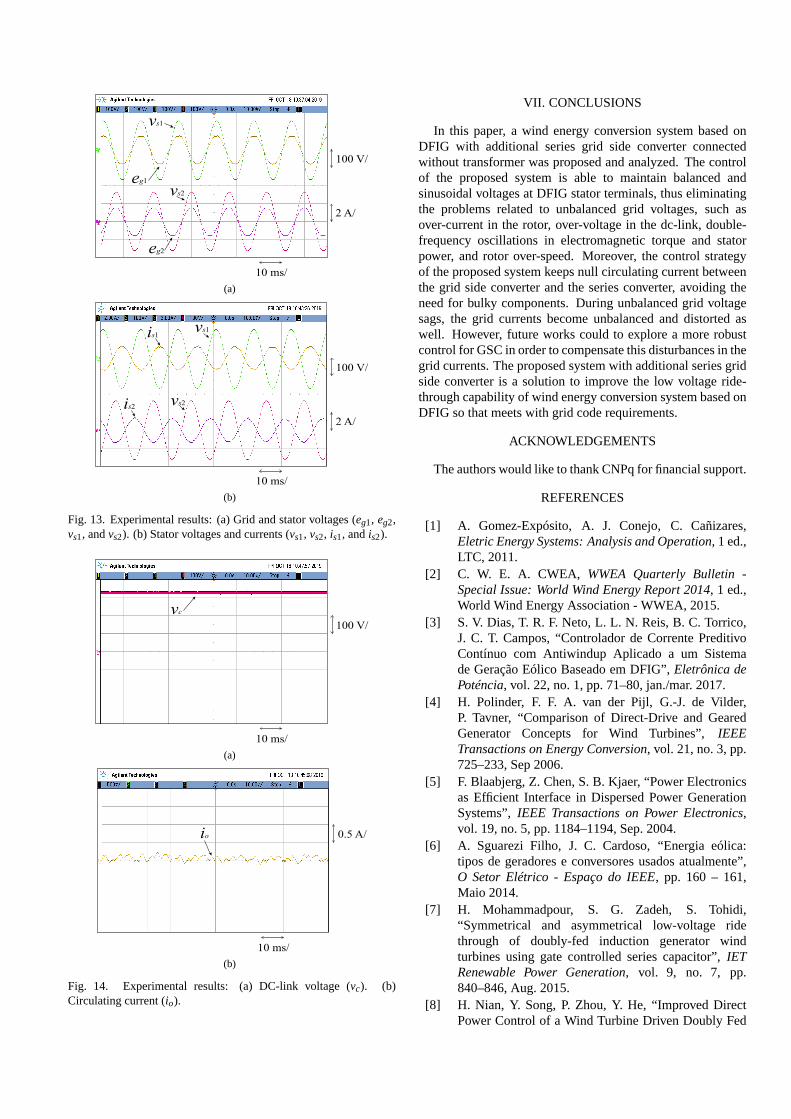
The proposed topology has been tested in the laboratoryto validate the performance of the series grid side convertercompensation, the DFIG control through the rotor sideconverter, and the GSC dc-link voltage regulation. A three-phase autotransformer with voltage regulation is connectedbetween the grid and the proposed topology. A dc machinewas employed in the experiment as a primary machine toprovide mechanical power to the DFIG (Fig. 12). Theswitching frequency of the converters (GSC, RSC and SGSC)and the sampling frequency used in the experiment were 10kHz.
As shown in Fig. 12, the experimental set-up is basedon four sets of SEMIKRON manufacturer (based on IGBTSKM50GB123D switches), and a DSP TMS320F28335 witha microcomputer equipped with appropriate plug-in boardsand sensors. The results were obtained using an Agilentoscilloscope model DSO 7034A 350 MHz.
A capacitor bank as dc-link with 2200µF and the GSCwas connected to the grid through an inductive filter with 7mH. The parameters of the DFIG utilized in the experimentare presented in Table I.
0.05 0.1 0.15
t (s)
-20
-10
0
10
20
i gdq
s(A
)
0 0.5 1 1.5
t (s)
-20
-10
0
10
20i g
dq
s(A
)
sigd
sigq
(a)
0.05 0.1 0.15
t (s)
-5
0
5
i sdq
s(A
)
0 0.5 1 1.5
t (s)
-5
0
5
i sdq
s(A
)
sisd
sisq
(b)
0 0.5 1 1.5
t (s)
-6
-4
-2
0
2
i rdq
e(A
)
eirdird*e
eirqirq*e
0 0.5 1 1.5
t (s)
-4
-2
0
2
4
i o(A
)
io
(c)
Fig. 10. Simulation results: (a) Grid currents in the stationary reference frame (isgd andisgq). (b) Stator currents in the stationary reference frame(issd andissq). (c) Top:dq-axis rotor currents in synchronous reference frame (ierd andierq); bottom: circulating current (io).
0 0.5 1 1.5
t (s)
630
640
650
660
670
v c(V
)
vc* vc
(a)
0 0.5 1 1.5
t (s)
-3
-2
-1
0
1
Ps(k
W)
an
d Q
s(kva
r)
Ps
Qs
Ps
Qs
*
*
(b)
0 0.5 1 1.5
t (s)
-1
-0.5
0
0.5
1
Qg(k
var)
Qg
Qg*
(c)
Fig. 11. Simulation results: (a) DC-link voltage (vc). (b) Stator active and reactive powers (PsandQs). (c) Grid reactive power (Qg).
Power Converters
DFIG
DC Machine
3φ Autotransformer
Oscilloscope
Computer
Fig. 12. Experimental set-up and DFIG/DC machine set.
Steady-state operation mode has been considered in theexperimental tests. Experimental results are obtained forathree-phase grid voltage sag of 50%, with a dc-link voltageof 325 V, grid voltage (with sag) equal to 55 V rms (phasevoltage), and reference stator voltage equal to 110 V rms(phase voltage). Decoupled stator active and reactive powercontrols were employed in the rotor side converter in order tovalidate the DFIG control capability. The rotor angleθr was
obtained by an encoder coupled to the DFIG rotor shaft.Figs. 13 to 15 present the experimental results. In Fig.
13(a), experimental results for grid and stator voltages arepresented. The series grid side converter adjusts the statorvoltages (vs1 andvs2) back to the rating value of 110 V despitethe grid voltage sag (eg1 andeg2). The experimental results forstator voltages and currents are presented in Fig. 13(b). Theresults show compensated and sinusoidal stator voltages withhigh power factor, since null reactive power is generated.
In Fig. 14(a), experimental result for dc-link voltage ispresented. It can be observed that the grid side convertercontrol ensures a dc-link voltage (vc) approximately 325 V.The result for circulating current (io) is presented in Fig.14(b). It is noted that the GSC and SGSC control loops ensureapproximately null circulating current even with grid voltagesag.
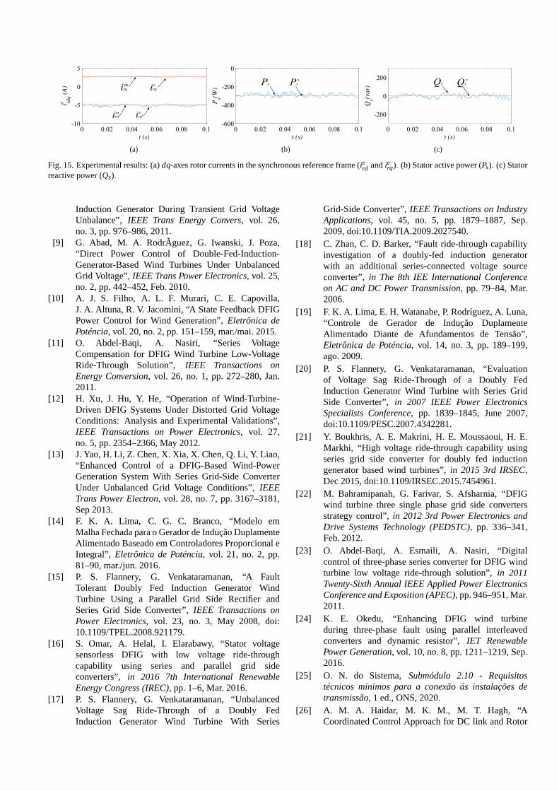
The experimental results presented in Fig. 15 were obtainedfrom the voltage and current sensor measuring by the DSPdigital vectors. The results of thedq-axes rotor currentsin the synchronous reference frame are presented in Fig.15(a). It is possible to notice that the rotor currents areregulated. Experimental results for DFIG stator active andreactive powers and their respective reference (i.e., 0 varforstator reactive power and−300 W for stator active power)are shown in Figs. 15(b) and 15(c), respectively. It can benoticed that the rotor side converter ensures stator activepowerapproximately equal to−300 W and stator reactive powerapproximately null.
eg1
vs1
eg2
vs2
100 V/
10 ms/
2 A/
(a)
vs1
vs2
is1
is2
100 V/
10 ms/
2 A/
(b)
Fig. 13. Experimental results: (a) Grid and stator voltages (eg1, eg2,vs1, andvs2). (b) Stator voltages and currents (vs1, vs2, is1, andis2).
vc
100 V/
10 ms/
(a)
io 0.5 A/
10 ms/
(b)
Fig. 14. Experimental results: (a) DC-link voltage (vc). (b)Circulating current (io).
VII. CONCLUSIONS
In this paper, a wind energy conversion system based onDFIG with additional series grid side converter connectedwithout transformer was proposed and analyzed. The controlof the proposed system is able to maintain balanced andsinusoidal voltages at DFIG stator terminals, thus eliminatingthe problems related to unbalanced grid voltages, such asover-current in the rotor, over-voltage in the dc-link, double-frequency oscillations in electromagnetic torque and statorpower, and rotor over-speed. Moreover, the control strategyof the proposed system keeps null circulating current betweenthe grid side converter and the series converter, avoiding theneed for bulky components. During unbalanced grid voltagesags, the grid currents become unbalanced and distorted aswell. However, future works could to explore a more robustcontrol for GSC in order to compensate this disturbances in thegrid currents. The proposed system with additional series gridside converter is a solution to improve the low voltage ride-through capability of wind energy conversion system based onDFIG so that meets with grid code requirements.
ACKNOWLEDGEMENTS
The authors would like to thank CNPq for financial support.
REFERENCES
[1] A. Gomez-Expósito, A. J. Conejo, C. Cañizares,Eletric Energy Systems: Analysis and Operation, 1 ed.,LTC, 2011.
[2] C. W. E. A. CWEA, WWEA Quarterly Bulletin -Special Issue: World Wind Energy Report 2014, 1 ed.,World Wind Energy Association - WWEA, 2015.
[3] S. V. Dias, T. R. F. Neto, L. L. N. Reis, B. C. Torrico,J. C. T. Campos, “Controlador de Corrente PreditivoContínuo com Antiwindup Aplicado a um Sistemade Geração Eólico Baseado em DFIG”,Eletrônica dePoténcia, vol. 22, no. 1, pp. 71–80, jan./mar. 2017.
[4] H. Polinder, F. F. A. van der Pijl, G.-J. de Vilder,P. Tavner, “Comparison of Direct-Drive and GearedGenerator Concepts for Wind Turbines”,IEEETransactions on Energy Conversion, vol. 21, no. 3, pp.725–233, Sep 2006.
[5] F. Blaabjerg, Z. Chen, S. B. Kjaer, “Power Electronicsas Efficient Interface in Dispersed Power GenerationSystems”,IEEE Transactions on Power Electronics,vol. 19, no. 5, pp. 1184–1194, Sep. 2004.
[6] A. Sguarezi Filho, J. C. Cardoso, “Energia eólica:tipos de geradores e conversores usados atualmente”,O Setor Elétrico - Espaço do IEEE, pp. 160 – 161,Maio 2014.
[7] H. Mohammadpour, S. G. Zadeh, S. Tohidi,“Symmetrical and asymmetrical low-voltage ridethrough of doubly-fed induction generator windturbines using gate controlled series capacitor”,IETRenewable Power Generation, vol. 9, no. 7, pp.840–846, Aug. 2015.
[8] H. Nian, Y. Song, P. Zhou, Y. He, “Improved DirectPower Control of a Wind Turbine Driven Doubly Fed
eirdeird*
eirqeirq*
(a)
Ps Ps*
(b)
Qs Qs*
(c)
Fig. 15. Experimental results: (a)dq-axes rotor currents in the synchronous reference frame (ierd andierq). (b) Stator active power (Ps). (c) Statorreactive power (Qs).
Induction Generator During Transient Grid VoltageUnbalance”, IEEE Trans Energy Convers, vol. 26,no. 3, pp. 976–986, 2011.
[9] G. Abad, M. A. RodrÃguez, G. Iwanski, J. Poza,“Direct Power Control of Double-Fed-Induction-Generator-Based Wind Turbines Under UnbalancedGrid Voltage”,IEEE Trans Power Electronics, vol. 25,no. 2, pp. 442–452, Feb. 2010.
[10] A. J. S. Filho, A. L. F. Murari, C. E. Capovilla,J. A. Altuna, R. V. Jacomini, “A State Feedback DFIGPower Control for Wind Generation”,Eletrônica dePoténcia, vol. 20, no. 2, pp. 151–159, mar./mai. 2015.
[11] O. Abdel-Baqi, A. Nasiri, “Series VoltageCompensation for DFIG Wind Turbine Low-VoltageRide-Through Solution”, IEEE Transactions onEnergy Conversion, vol. 26, no. 1, pp. 272–280, Jan.2011.
[12] H. Xu, J. Hu, Y. He, “Operation of Wind-Turbine-Driven DFIG Systems Under Distorted Grid VoltageConditions: Analysis and Experimental Validations”,IEEE Transactions on Power Electronics, vol. 27,no. 5, pp. 2354–2366, May 2012.
[13] J. Yao, H. Li, Z. Chen, X. Xia, X. Chen, Q. Li, Y. Liao,“Enhanced Control of a DFIG-Based Wind-PowerGeneration System With Series Grid-Side ConverterUnder Unbalanced Grid Voltage Conditions”,IEEETrans Power Electron, vol. 28, no. 7, pp. 3167–3181,Sep 2013.
[14] F. K. A. Lima, C. G. C. Branco, “Modelo emMalha Fechada para o Gerador de Indução DuplamenteAlimentado Baseado em Controladores Proporcional eIntegral”, Eletrônica de Poténcia, vol. 21, no. 2, pp.81–90, mar./jun. 2016.
[15] P. S. Flannery, G. Venkataramanan, “A FaultTolerant Doubly Fed Induction Generator WindTurbine Using a Parallel Grid Side Rectifier andSeries Grid Side Converter”,IEEE Transactions onPower Electronics, vol. 23, no. 3, May 2008, doi:10.1109/TPEL.2008.921179.
[16] S. Omar, A. Helal, I. Elarabawy, “Stator voltagesensorless DFIG with low voltage ride-throughcapability using series and parallel grid sideconverters”, in 2016 7th International RenewableEnergy Congress (IREC), pp. 1–6, Mar. 2016.
[17] P. S. Flannery, G. Venkataramanan, “UnbalancedVoltage Sag Ride-Through of a Doubly FedInduction Generator Wind Turbine With Series
Grid-Side Converter”,IEEE Transactions on IndustryApplications, vol. 45, no. 5, pp. 1879–1887, Sep.2009, doi:10.1109/TIA.2009.2027540.
[18] C. Zhan, C. D. Barker, “Fault ride-through capabilityinvestigation of a doubly-fed induction generatorwith an additional series-connected voltage sourceconverter”, in The 8th IEE International Conferenceon AC and DC Power Transmission, pp. 79–84, Mar.2006.
[19] F. K. A. Lima, E. H. Watanabe, P. Rodríguez, A. Luna,“Controle de Gerador de Indução DuplamenteAlimentado Diante de Afundamentos de Tensão”,Eletrônica de Poténcia, vol. 14, no. 3, pp. 189–199,ago. 2009.
[20] P. S. Flannery, G. Venkataramanan, “Evaluationof Voltage Sag Ride-Through of a Doubly FedInduction Generator Wind Turbine with Series GridSide Converter”, in 2007 IEEE Power ElectronicsSpecialists Conference, pp. 1839–1845, June 2007,doi:10.1109/PESC.2007.4342281.
[21] Y. Boukhris, A. E. Makrini, H. E. Moussaoui, H. E.Markhi, “High voltage ride-through capability usingseries grid side converter for doubly fed inductiongenerator based wind turbines”,in 2015 3rd IRSEC,Dec 2015, doi:10.1109/IRSEC.2015.7454961.
[22] M. Bahramipanah, G. Farivar, S. Afsharnia, “DFIGwind turbine three single phase grid side convertersstrategy control”,in 2012 3rd Power Electronics andDrive Systems Technology (PEDSTC), pp. 336–341,Feb. 2012.
[23] O. Abdel-Baqi, A. Esmaili, A. Nasiri, “Digitalcontrol of three-phase series converter for DFIG windturbine low voltage ride-through solution”,in 2011Twenty-Sixth Annual IEEE Applied Power ElectronicsConference and Exposition (APEC), pp. 946–951, Mar.2011.
[24] K. E. Okedu, “Enhancing DFIG wind turbineduring three-phase fault using parallel interleavedconverters and dynamic resistor”,IET RenewablePower Generation, vol. 10, no. 8, pp. 1211–1219, Sep.2016.
[25] O. N. do Sistema,Submódulo 2.10 - Requisitostécnicos mínimos para a conexão ás instalações detransmissão, 1 ed., ONS, 2020.
[26] A. M. A. Haidar, M. K. M., M. T. Hagh, “ACoordinated Control Approach for DC link and Rotor
Crowbars to Improve Fault Ride-Through of DFIG-Based Wind Turbine”,IEEE Trans Indus Appl, vol. 53,no. 4, pp. 4073–4086, Mar. 2017.
[27] P. Cheng, H. Nian, “Collaborative Control of DFIGSystem During Network Unbalance Using Reduced-Order Generalized Integrators”,IEEE Transactions onEnergy Conversion, vol. 30, no. 2, pp. 453 – 464, June2015.
[28] J.-I. Jang, Y.-S. Kim, D.-C. Lee, “Active and ReactivePower Control of DFIG for Wind Energy Conversionunder Unbalanced Grid Voltage”,in Power Electronicsand Motion Control Conference, 2006, vol. 3, pp. 1 – 5,Shanghai, China, Aug. 2006, iPEMC 2006. CES/IEEE5th International.
[29] S. Seman, J. Niiranen, S. Kanerva, A. Arkkio, J. Saitz,“Performance Study of a Doubly Fed Wind-powerInduction Generator under Network Disturbances”,IEEE Trans Energy Conversion, vol. 21, no. 4, pp. 883– 890, Dec. 2006.
[30] S. Seman, J. Niiranen, A. Arkkio, “Ride-ThroughAnalysis of Doubly Fed Induction Wind-PowerGenerator Under Unsymmetrical NetworkDisturbance”,IEEE Transactions on Power Systems,vol. 21, no. 4, pp. 1782 – 1789, Nov. 2006.
[31] A. O. Ibrahim, T. H. Nguyen, D. Lee, S. Kim, “AFault Ride-Through Technique of DFIG Wind TurbineSystems Using Dynamic Voltage Restorers”,IEEETransactions on Energy Conversion, vol. 26, no. 3, pp.871–882, Sep. 2011, doi:10.1109/TEC.2011.2158102.
[32] J. Hu, Y. He, “Modeling and enhanced control of DFIGunder unbalanced grid voltage conditions”,ELSEVIERElectric Power System Research, vol. 79, no. 2, pp.273–281, Feb. 2009.
[33] Í. A. C. de Oliveira, N. Rocha, E. R. C. da Silva,C. B. Jacobina, I. S. de Freitas, “A stationary statorreference frame control of DFIG under unbalancedvoltage conditions”, in 2015 IEEE 13th BrazilianPower Electronics Conference and 1st Southern PowerElectronics Conference (COBEP/SPEC), pp. 1–6, Nov2015, doi:10.1109/COBEP.2015.7420044.
[34] V. F. Mendes, H. Pereira, F. F. Matos, W. Hofmann,S. R. Silva, “Doubly-fed induction generator controlduring unbalanced grid conditions”,in PowerElectronics Conference and 1st Southern PowerElectronics Conference (COBEP/SPEC), Feb. 2016,2015 IEEE 13th Brazilian.
[35] Y. Liao, H. Li, J. Yao, K. Zhuang, “Operationand control of a grid-connected DFIG-based windturbine with series grid-side converter during networkunbalance”, ELSEVIER Electric Power SystemsResearch, vol. 81, no. 1, pp. 228 – 236, Sep 2011.
[36] A. Luna, K. Lima, F. Corcoles, E. Watanabe,P. Rodriguez, R. Teodorescu, “Control of DFIG-WT under unbalanced grid voltage conditions”,in 2009 IEEE Energy Conversion Congressand Exposition, pp. 370–377, Sep. 2009, doi:10.1109/ECCE.2009.5316125.
[37] H. Xu, J. Hu, Y. He, “Integrated Modeling andEnhanced Control of DFIG Under Unbalanced
and Distorted Grid Voltage Conditions”,IEEETransactions on Energy Conversion, vol. 27, no. 3, pp.725–736, Sep. 2012, doi:10.1109/TEC.2012.2199495.
[38] M. E. Zarei, B. Asaei, “Predictive direct torque controlof DFIG under unbalanced and distorted stator voltageconditions”,in 2013 12th International Conference onEnvironment and Electrical Engineering, pp. 507–512,May 2013, doi:10.1109/EEEIC.2013.6549568.
[39] N. N. Joshi, N. Mohan, “New Scheme to ConnectDFIG to Power Grid”,in IECON 2006 - 32nd AnnualConference on IEEE Industrial Electronics, pp. 4225–4230, Sep/Oct 2006.
[40] J. R. Massing, H. Pinheiro, “Design and control ofdoubly-fed induction generators with series grid-sideconverter”,in 2008 34th Annual Conference of IEEEIndustrial Electronics, pp. 139–145, Nov. 2008.
[41] V. P. Suppioni, A. P. Grilo, J. C. Teixeira,“Methodology for grid voltage unbalancecompensation appling a two-converter seriesDFIG topology”, in 2015 IEEE 15th InternationalConference on Environment and ElectricalEngineering (EEEIC), pp. 1736–1741, 2015, doi:10.1109/EEEIC.2015.7165434.
[42] B. Jahanbakhsh, D. Xu, “Improved low voltage ridethrough capability of doubly fed induction generatorusing series grid side converter”,in Proceedings ofThe 7th International Power Electronics and MotionControl Conference, pp. 2207–2211, Jun. 2012.
[43] Z. Din, J. Zhang, J. Zhao, Y. Jiang, “DoublyFed Induction Generator with Cascade Converterfor Improving Dynamic Performances”, in2018 IEEE Energy Conversion Congress andExposition (ECCE), pp. 2568–2575, Sep. 2018,doi:10.1109/ECCE.2018.8558069.
[44] I. A. C. de Oliveira, C. B. Jacobina, N. Rocha,P. L. S. Rodrigues, “Wind Energy ConversionSystem Based on DFIG with Three-Phase SeriesActive Filter Operating with Floating Capacitors”,in 2018 IEEE Energy Conversion Congress andExposition (ECCE), pp. 5500–5507, Sep. 2018, doi:10.1109/ECCE.2018.8558422.
[45] A. Javadi, H. F. Blanchette, K. Al-Haddad, “A noveltransformerless hybrid series active filter”,in IECON2012 - 38th Annual Conference on IEEE IndustrialElectronics Society, pp. 5312–5317, Oct. 2012.
[46] I. A. C. Oliveira, N. Rocha, E. R. C. Silva, L. M. S.Siqueira, E. C. Menezes, C. B. Jacobina, “Wind energyconversion system based on DFIG with series grid sideconverter without transformer”,in Energy ConversionCongress and Exposition (ECCE), 2017 IEEE, pp.3281–3288, Oct. 2017.
[47] I. A. C. de Oliveira, C. B. Jacobina, N. Rocha, P. L. S.Rodrigues, “Wind Energy Conversion System BasedOn DFIG With Three-Phase Series Active Filter AndSingle DC-Link”, in 2018 IEEE Energy ConversionCongress and Exposition (ECCE), pp. 4544–4551,Sep. 2018, doi:10.1109/ECCE.2018.8558028.
[48] J. Holtz, X. Qi, “Optimal Control of MediumVoltage Drives An Overview”,IEEE Transactions on
Industrial Electronics, vol. 60, no. 12, pp. 5472–5481,Dec. 2013.
[49] D. Wu, X. Wu, L. Su, X. Yuan, J. Xu, “A Dual Three-Level Inverter-Based Open-End Winding InductionMotor Drive With Averaged Zero-Sequence VoltageElimination and Neutral-Point Voltage Balance”,IEEETransactions on Industrial Electronics, vol. 63, no. 8,pp. 4783–4795, Aug. 2016.
[50] J. Yao, H. Li, Z. Chen, X. Xia, X. Chen, Q. Li, Y. Liao,“Enhanced Control of a DFIG-Based Wind-PowerGeneration System With Series Grid-Side ConverterUnder Unbalanced Grid Voltage Conditions”,IEEETrans Power Electron, vol. 28, no. 7, pp. 3167–3181,2013.
[51] H. Qi, Y. Wu, Y. Bi, “The main parameters designbased on three-phase voltage source PWM rectifierof voltage oriented control”,in 2014 InternationalConference on Information Science, Electronics andElectrical Engineering, vol. 1, pp. 10–13, April 2014,doi:10.1109/InfoSEEE.2014.6948057.
[52] M. K. Bourdoulis, A. T. Alexandridis, “Nonlinearstability analysis of DFIG wind generators in voltageoriented control operation”,in 2013 European ControlConference (ECC), pp. 484–489, July 2013, doi:10.23919/ECC.2013.6669692.
[53] O. Anaya-Lara, D. Campos-Gaona, E. L. Moreno-Goytia, G. P. Adam,Offshore wind energy generation: control, protection, and integration to electricalsystems, 1 ed., Wiley, 2014.
[54] P. Rodriguez, R. Teodorescu, I. Candela, A. V. Timbus,M. Liserre, F. Blaabjerg, “New Positive-sequenceVoltage Detector for Grid Synchronization of PowerConverters under Faulty Grid Conditions”,in PowerElectronics Specialists Conference (PESC), pp. 1 – 7,Jun. 2006, pESC ’06. 37th IEEE.
[55] C. B. Jacobina, M. B. R. Correa, R. F. Pinheiro,E. R. C. Silva, “Modeling and Control of UnbalancedThree-phase Systems containing PWM Converters”,inIndustry Applications Conference, 1999. Thirty-FourthIAS Annual Meeting, vol. 4, pp. 2173 – 2179, Phoenix,Az, USA, Oct. 1999, conference Record of the 1999IEEE.
[56] C. Zou, B. Liu, S. Duan, R. Li, “Stationary FrameEquivalent Model of Proportional-Integral Controllerin dq Synchronous Frame”,IEEE Trans PowerElectron, vol. 29, no. 9, pp. 4461–4465, Sep. 2014.
[57] M. H. J. Bollen, G. Olguin, M. Martins, “Voltage Dipsat the Terminals of Wind Power Installations”,NordicWind Power Conference, Mar 2004.
[58] H. Kubo, Y. Yamamoto, T. Kondo, K. Rajashekara,B. Zhu, “Zero-sequence current suppression for open-
end winding induction motor drive with resonantcontroller”, in IEEE Applied Power ElectronicsConference and Exposition, pp. 2788–2793, Mar.2016, aPEC 2016.
[59] J. Korhonen, J. Honkanen, T. J. Kärkkäinen,J. Nerg, P. Silventoinen, “Modulation and controlmethods to reduce zero sequence current in open-end winding motors”,in IEEE International ElectricMachines and Drives Conference, pp. 1–6, May 2017,iEMDC 2017.
[60] M. H. Rashid,Power Electronics Handbook: Devices,Circuits, and Applications., 1 ed., Butterworth-Heinemann, 2011.
BIOGRAPHIES
Ítalo A. Cavalcanti de Oliveira, born in Paulista,Pernambuco, Brazil, in 1989. He received the B.S. andM.S. degrees in electrical engineering from the FederalUniversity of Paraíba, João Pessoa, Brazil, in 2015 and 2017,respectively. He is currently working toward the Ph.D. degreein electrical engineering from Federal University of CampinaGrande, Campina Grande. His research interests includeenergy system optimization, power electronics, and renewableenergy, especially wind energy conversion systems.
Cursino Brandão Jacobina, born in Correntes, Brazil, in1955. He received the B.S. degree in electrical engineeringfrom the Federal University of Paraíba, Campina Grande,Brazil, in 1978, and the Diplôme d’Etudes Approfondies andthe Ph.D. degrees in electrical engineering from the InstitutNational Polytechnique de Toulouse, Toulouse, France, in1980 and 1983, respectively. From 1978 to March 2002, hewas with the Department of Electrical Engineering, FederalUniversity of Paraíba, João Pessoa, Brazil. Since April 2002,he has been with the Department of Electrical Engineering,Federal University of Campina Grande, Campina Grande,Brazil, where he is currently a Professor of ElectricalEngineering. His research interests include electrical drives,power electronics and energy systems.
Nady Rocha, born in São Gabriel, Bahia, Brazil, in1982. He received the B.S., M.S., and Ph.D. degrees inelectrical engineering from the Federal University of CampinaGrande, Campina Grande, Brazil, in 2006, 2008, and 2010,respectively. Since 2011, he has been with the Departmentof Electrical Engineering, Federal University of Paraíba,JoãoPessoa, where he is currently an Associate Professor ofElectrical Engineering. His research interests include powerelectronics, renewable energy sources and electrical drives.