williams production rmt company llc tr 41-35-597
TRANSCRIPT
)
)
.~, m~~~~ Im8 COLM)' Rd}2} ~' Rifl" CO 81650
Williams Production RMT Company LLC TR 41-35-597 Communications Site Limited Impact Review Permit Application
Submittal Item Tab 10- Erosion and Sediment Control PlanSection 4-502 C.4
Please find attached the fo llowing documents:
I.Construction Field Wide Stonnwater Management Plan- Trail Ridge Field- Garfield County, Colorado- Revised January 201 0, This plan and the attachments details all of the requirements set forth in ULUR section 4-502 C.4. Items 2-4 below detail additional items as required.
The Colorado Department of Public Health and Environment- Storm water Discharge Permit COR03Al16 with an effective date of 7/1/2007 is attached at the end of Appendix A.
Immediately following the permit is the site specific storm water management plan for the TR41-35-597.
This plan encompasses the entirety of the 4,08 acre natural gas well pad.
The planned disturbance for the communications faci lity is approx imately 1,500 squ are feet in size,
2, Section 4-502 C.4.J. Construction Schedule. The construction of the fac ility is anticipated to be completed in 1 month. The project is well within the boundaries of the existing natural gas well pad, so no revision of the storm water BMP's will be required.
3. Section 4-502 CA.k, Permanent Stabilization- The commu nications site will have a gravel base installed over the entirety of the 1,500 square feet site.
Page 1 of 2

4. Section 4-502 C.4.m. The estimated total cost of the temporary erosion and sediment control measures are $0.00 as these are already in place on the natural gas well pad. This communications site is within the pad location and will not have an effect on the BMP's that are currently in place.
Thank you for your assistance on this project.
Please contact me with any questions.
Sincerely
~~6l~~~ Philip B. Vaughan President PVCMI-Land Planning Division
Page 2 of 2
)
)
)
"
CONSTRUCTION FIELD WIDE STORMWATER MANAGEMENT PLAN
TRAIL RIDGE FIELD GARFIELD COUNTY, COLORADO
PREPARED FOR
WILLIAMS PRODUCTION RMT COMPANY PO BOX 370
PARACHUTE, COLORADO 81635
REVISED
JANUARY 2010
Environmental, Audit & Assessment, Inc.
225 NOJ1h 5"' Street, Suite # 8, Grand Junction, CO 81501 (970) 245-5897 www.eaa-co.com
PROJECT #EAA-08-SWMP-1S9
PREFACE
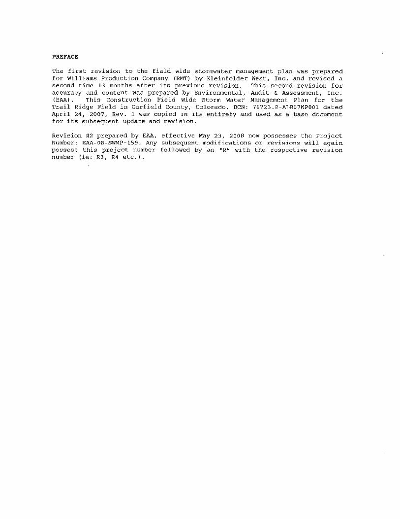
The first revision to the field wide stormwater management plan was prepared for Williams Production Company (RMT) by Kleinfelder West, Inc. and revised a second time 13 months after its previous revision. This second revision for accuracy and content was prepared by Environmental, Audit & Assessment, Inc. (EAA) . This Construction Field Wide Storm Water Management Plan for the Trail Ridge Field in Garfield County, Colorado, DCN: 76723.8-ALB07WPOOl dated April 24, 2007, Rev. 1 was copied in its entirety and used as a base document for its subsequent update and revision.
Revision #2 prepared by EAA, effective May 23, 2008 now possesses the Project Number: EAA-08-SWMP-159. Any subsequent modifications or revisions will again possess this project number followed by an "R n with the respective revision number (ie: R3, R4 etc.).
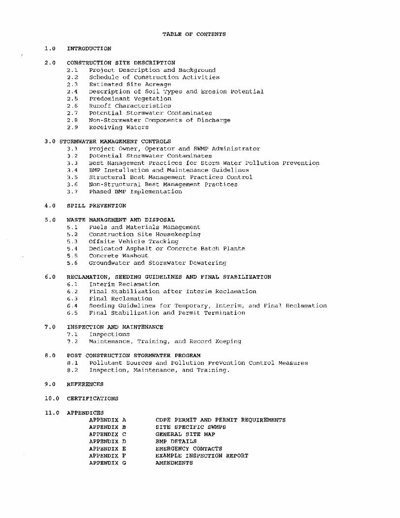
TABLE OF CONTENTS
1.0 INTRODUCTION
2.0 CONSTRUCTION SITE DESCRIPTION 2.1 project Description and Background 2.2 Schedule of construction Activities 2.3 Estimated Site Acreage 2.4 Description of Soil Types and Erosion Potential 2.5 predominant Vegetation 2.6 Runoff Characteristics 2.7 potential Stormwater Contaminates 2.8 Non-Stormwater Components of Discharge 2.9 Receiving Waters
3.0 STORMWATER MANAGEMENT CONTROLS 3.1 Project Owner, Operator and SWMP Administrator 3.2 potential Stormwater Contaminates 3.3 Best Management Practices for Storm Water Pollution prevention 3.4 BMP Installation and Maintenance Guidelines 3.5 structural Best Management Practices Control 3.6 Non-Structural Best Management Practices 3.7 Phased BMP Implementation
4.0 SPILL PREVENTION
5.0 WASTE MANAGEMENT AND DISPOSAL 5.1 Fuels and Materials Management 5.2 Construction site Housekeeping 5.3 Offsite Vehicle Tracking 5.4 Dedicated Asphalt or Concrete Batch Plants 5.5 concrete Washout 5.6 Groundwater and Stormwater Dewatering
6.0 RECLAMATION, SEEDING GUIDELINES AND FINAL STABILIZATION 6.1 Interim Reclamation 6.2 Final Stabilization after Interim Reclamation 6.3 Final Reclamation 6.4 Seeding Guidelines for Temporary, Interim, and Final Reclamation 6.5 Final Stabilization and Permit Termination
7.0 INSPECTION AND MAINTENANCE 7.1 Inspections 7.2 Maintenance, Training, and Record Keeping
B.O POST CONSTRUCTION STORMWATER PROGRAM 8.1 pollutant Sources and Pollution Prevention Control Measures 8.2 Inspection, Maintenance, and Training.
9.0 REFERENCES
10.0 CERTIFICATIONS
11. 0 APPENDICES APPENDIX A CDPE PERMIT AND PERMIT REQUIREMENTS APPENDIX B SITE SPECIFIC SWMPS APPENDIX C GENERAL SITE MAP APPENDIX D BMP DETAILS APPENDIX E EMERGENCY CONTACTS APPENDIX F EXAMPLE INSPECTION REPORT APPENDIX G AMENDMENTS
1.0 INTRODUCTION
This Field Wide Storm Water Management Plan (SWMP) and Site Specific SWMPs have been prepared for the Williams Production Company RMT (Williams) Trail Ridge Field in Garfield County, Colorado to identify the Best Management Practices (BMPs) which will be implemented to meet the terms and conditions of the Colorado Department of Public Health and Environment (CDPHE) permitting associated with General Construction Activity associated with oil and Gas development. The SWMP has been prepared in accordance with good engineering, hydrologic, and pollution control practices, and is designed to constitute compliance with Best Available Technology (BAT) and Best Conventional Technology (BCT), as mandated under the Federal Clean water Act and the Federal Water Pollution Control Act. The general permit was issued to Williams Production Company RMT for the Trail Ridge Field on May 16, 2006.
Permit requirements are attached in Appendix A and include the 'Colorado Discharge Permit System (CDPS) General Permit and the Storm Water Fact Sheet, Construction Permitting for oil and Gas Facilities. The CDPS Permit certification received by williams from the State of Colorado is also attached in Appendix A.
Development, implementation, and maintenance of the Field Wide SWMP and Site Specific Appendices will provide Williams with the framework for reducing soil erosion and minimizing pollutants in storm water during construction activities in the Trail Ridge Field. The Field Wide SWMP will achieve the following:
Permit requirements are attached in Appendix A and include the Colorado Discharge Permit System (CDPS) General Permit and the Storm Water Fact Sheet, Construction Permitting for Oil and Gas Facilities. The CDPS Permit Certification received by Williams from the State of Colorado is also attached in Appendix A.
Development, implementation, and maintenance of the Field Wide SWMP and Site Specific Appendices will provide Williams with the framework for reducing soil erosion and minimizing pollutants in storm water during construction activities in the Trail Ridge Field. The Field Wide SWMP will achieve the following:
• Describe the practices that may be implemented to control erosion and sediment transport.
• Describe the pollution control measures that may be used to prevent non-storm water contamination of State waters.
• Create an implementation schedule so that the practices described in this SWMP are effective.
• Describe the final stabilization methods to minimize erosion and prevent storm water impacts after well pad/site, road, pipeline, and related installations are complete.
• Best Management practices (BMPs) inspection report as required by individual construction projects.
installation the CDPHE,
Trail Ridge Field Wide SWMP Environmental, Audit & Assessment, Inc. Page 1 of 35
details, and BMPs
an example specific to
01/01/2010 Revision 3
• The approximate area of the site and area to undergo clearing and grading, runoff coefficient, existing vegetation, and percent ground cover.
• Location and description of potential pollution sources anticipated, non-storm water components of discharge, and the name of the receiving waters.
• Provide a site plan indicating current conditions and the locations of major BMP structures.
• The site map and accompanying figures will indicate construction site boundaries, areas of soil disturbance, cut and fill, areas for storage of materials, and surface waters.
This Field Wide SWMP also describes the means by which pollution control measures will be implemented. This SWMP as well as the Site Specific SWMPs, found in Appendix B, will be periodically updated as needed to address planned developments, new disturbances, and other changes needed to manage storm water and protect surface water quality. The updates may include:
• Revision of existing BMPs for erosion and sediment control.
• Revisions and updates to the site maps to indicate the locations of BMPs, soil disturbance areas, construction material and waste storage areas, etc.
• Deletion of BMPs and reduction in monitoring frequency for individual faci Ii ty locations where interim and long- term vegetation has been successfully established.
Maps for each individual site will be kept in a field binder for personnel use. The maps will reflect the BMPs as they currently exist on site.
Trail Ridge Field Wide SWMP Environmental, Audit & Assessment, Inc. Page 2 of 35
01/01/2010 Revision 3
2.0 CONSTRUCTION SITE DESCRIPTION
2 • 1 PROJECT DESCRIPTION AND BACKGROUND
The Trail Ridge Field is a grouping of natural gas leases and associated development that encompasses approximately 73,000 total acres in Townships 5 and 6 South and Ranges 97 and 98 West, see Appendix C for a general site map. The area is a combination of federal and private surface and mineral owners. Williams is the project operator and developer, and is actively conducting exploration and development of natural gas resources.
Currently, there are many actively producing wells and natural gas facilities within the Trail Ridge Field. Additional disturbance is expected during the next several years as more wells are drilled and new facilities are constructed.
2 • 2 SCHEDULE OF CONSTRUCTION ACTIVITIES
Natural gas exploration, development and production activities are currently underway within the Trail Ridge Field. Existing and future well pads as well as associated oil and gas exploration and production facilities are included in this SWMP. For new disturbances, BMPs will be installed prior to, during, and immediately following construction as practicable with consideration given to safety, access, and ground conditions (e. g. frozen ground) at the time of construction. Development of natural gas resources and construction of necessary improvement on these new sites will likely continue for three to five years. Recovery of natural gas from these constructed facilities will most likely continue for the next 30 years, or more.
New facilities and well pads will be constructed using conventional cut and fill earthmoving techniques and new access roads will connect the well pads to existing roads. The drilling reserve pit will be used during drilling to hold drilling fluids and cuttings. The reserve pits will be designed, constructed, and reclaimed according to Colorado oil and Gas Conservation Commission (COGCC) requirements.
Typical operational phases for a well pad include: access road and well pad construction, well drilling, well completion, well fracturing, construction of production facilities, and interim reclamation of the well pad into a long-term production configuration. After all wells have been constructed and all production facilities have been installed, the well pad will be graded to reduce cut and fill slopes and to minimize the overall size of the pad. The well pad will be re-vegetated after grading activities are complete. The well pad will remain in the long-term production configuration for 30 years or more, until well operation is no longer productive. After all wells have been plugged and abandoned and surface facilities removed, the well pad will be graded to restore approximate pre-disturbance contours and will be re-vegetated. site specific conditions are presented for each separate facility in the attached Site Specific SWMPs.
In areas that are disturbed by well pad construction, topsoil will be stripped and stockpiled near the site. Soil materials will be managed so that erosion and sediment transport are minimized. Nearby drainages will be protected by appropriate measures. Drill cuttings will be stockpiled on site and surrounded by an earthen berm to prevent runoff.
Trail Ridge Field wide SWMP Environmental, Audit & Assessment, Inc. Page 3 of 35
01/01/2010 Revision 3
The time necessary to complete drilling and completion activities is dependent on site conditions and can vary from well to well. If acceptable production is achieved, a well will be shut-in until gathering lines and production facilities are constructed. The drilling pad will be graded to reduce the pad surface to an area up to an estimated two acres and to reduce cut and fill slopes to approximately 2h:lv (horizontal:vertical). Access roads will remain in place for well operation and maintenance activities.
Non-productive wells on a well pad will be plugged according to COGCC rules; when all wells at the site are plugged, the pad area will be reclaimed to approximate pre-construction contours. Interim reclamation, final stabilization, and final reclamation will be conducted as described in section 6.0. Note that the proposed well pads generally contain multiple wells and it is considered unlikely that all wells on a given pad will be non-productive.
In additiop. to the well pads, other disturbances will occur as needed to construct access roads, gathering and sales pipelines, staging areas, natural gas treatment and compression facilities, and other areas needed for production of natural gas. This SWMP is intended to address all activities within the boundaries of the lease areas. This SWMP will be appended by Site Specific SWMPs that will be prepared as new construction activities are planned.
2.3 ESTIMATED SITE ACREAGE
Specific well pad dimensions vary depending on the planned drill rig, the number of wells to be drilled from each pad, and local conditions. Please see the Site Specific SWMP for the site acreage and disturbed acres for each site.
2 .4 DESCRIPTION OF SOIL TYPES AND EROSION POTENTIAL
There are a wide variety of soil types and slopes found in the Trail Ridge Field. The Natural Resources Conservation Service rates erosion potential on a scale of 0.02 (not highly erodable) to 0.69 (extremely erodable). Site specific soil types are presented in Site Specific SWMPs. Predominant soil types within the Trail Ridge Field include:
SOIL TYPES SLOPES (%) EROSION POTENTIAL RATING parachute-Irigul Rhone association 25-50 0.20
Parachute-Irigul complex 5-30 0.20 Happle-Rock outcrop 25-65 0.10
Utso-Rock outcrop complex 40-90 0.15 Northwater-Adel complex 5-50 0.20
Silas loam 1-12 0.20
2 • 5 PREDOMINANT VEGETATION
The Trail Ridge Field includes a variety of vegetative cover types. Prominent vegetation includes pinyon-juniper woodlands with understory grasses and sagebrush communities.
Trail Ridge Field Wide SWMP Environmental, Audit & Assessment, Inc. Page 4 of 35
01/01/2010 Revision 3
2 • 6 RUNOFF CHARACTERISTICS
Runoff characteristics are based on site topography, soil type, and soil/vegetative cover. Surface elevation in the Trail Ridge Field ranges from approximately 5,500 to 9,000 feet. Surface soils vary from sands, silts, and clays to exposed bedrock. Existing and future facilities are typically located on valley floors and hillsides. The estimated pre-construction runoff coefficient is expected to range from 0.1 to 0.3. The estimated postconstruction runoff coefficient is 0.3. Site specific runoff characteristics are presented in the Site Specific SWMPs.
2.7 POTENTIAL STORM WATER CONTAMINANTS
The primary potential storm water contaminant is sediment from grading, excavating, and stockpiling materials. Potential pollution sources during construction activities at the project site, other than sediment, include accidental releases of the following:
• Fuel and lubricants associated with construction equipment,
• Spillage of drilling fluids,
• Fluids used during fracturing,
• Flow back water,
• Produced water,
• Condensate,
• Storage of drilling and hazardous materials, and
• Garbage and sanitary waste
Storm water includes surface water runoff and drainage due to a storm event or due to snowmelt. All other discharges constitute non-storm water discharges.
2.8 NON-STORM WATER COMPONENTS OF DISCHARGE
Non-Storm water components of discharge will be addressed in the maps associated with the site Specific SWMPs.
BMPs including structural and non-structural BMPs will be pollutant loading in storm water releases associated with activities at the sites covered by this Field Wide SWMP.
2 • 9 RECEIVING WATERS
used to reduce the construction
There are numerous named and unnamed streams, creeks, and drainages within the Trail Ridge Field. Immediate receiving waters include Camp Gulch, Clear Creek and the West Fork of Parachute Creek, which ultimately flow into the Colorado River. Receiving waters for individual wells will be discussed in the Site Specific Storm Water Management Plans.
Trail Ridge Field Wide SWMP Environmental, Audit & Assessment, Inc, Page 5 of 3S
01/01/2010 Revision 3
In some locations, oil and gas operations come within close proximity to the waters of the State of Colorado. These drainages provide residents of western Colorado with public and private water supplies, groundwater supplies, flood control capacity, storm damage prevention, and habitat for wildlife and fisheries. Pro-active pollution prevention in the Trail Ridge Field is a priority for Williams and can be accomplished through implementation of BMPs at all construction sites.
Trail Ridge Field Wide SWMP Environmental, Audit & Assessment, Inc. Page 6 of 35
01/01/2010 Revision 3
3.0 STORMWATER MANAGEMENT CONTROLS
3 • 1 PROJECT OWNER, OPERATOR AND SWMP ADMINISTRATOR
The operator of the Trail Ridge Field is Williams Production RMT Company. The address is:
Williams Production RMT Co. 1515 Arapahoe street, Tower 3 - Suite 1000 Denver, Colorado 80202 Ph (303) 572-3900 Mr. Alan Harrison, Vice President
The SWMP Administrator for the Trail Ridge Field is Mr. Mike Gardner I Senior Environmental Specialist. Mr. Gardner works in the Parachute office and can be contacted by phone at:
Phone: Cell :
(970) 285-9377 ext. 2760 (970) 640-1855
Williams will be in charge of all aspects of the property and this pro] eet. Contractor (s) will perform the actual construction and drilling I but Williams will supervise all work and Williams will make all decisions.
Williams will be responsible for the following tasks related to the Trail Ridge SWMP:
• Implement the SWMPi
• Oversee maintenance practices identified as BMPs in the Field Wide and Site Specific SWMPi
• Oversee inspection and maintenance activitiesi
• Identify potential pollutant sources to be mitigated as practicable;
• Identify and correct deficiencies in the Field Wide and Site Specific SWMPi and
• Change the Site Specific SWMPs, as required, to correspond with changes in the phases of construction.
3.2 POTENTIAL STORM WATER CONTAMINANTS
As stated sediment pollution sediment,
in Section 2.7, the primary potential storm water contaminant is from grading, excavating, and stockpiling materials. Potential sources during construction activities at the project site, other than include accidental releases of the following:
• Fuel and lubricants associated with construction equipment,
• Spillage of drilling fluids,
• Fluids used during fracturing,
• Flow back water,
Trail Ridge Field Wide SWMP Environmental, Audit & Assessment, Inc. Page 7 of 35
01/01/2010 Revision 3
• Produced water,
• Condensate,
• Storage of drilling and hazardous materials, and
• Garbage and sanitary waste
3.3 BEST MANAGEMENT PRACTICES FOR STORM WATER POLLUTION PREVENTION
The BMPs to be employed during the construction of Williams proj ects which include, but are not limited to, natural gas well pads, natural gas pipelines, water transfer pipelines, compressor stations and access roads, and construction activities associated with oil and gas production and exploration are described in the following sections. construction project locations may employ a variety of BMPs and will be outlined within each attached Site Specific SWMP.
The obj ecti ve of erosion and sediment control is to minimize the release of sediments to storm water runoff. This can be accomplished through the use of structural and/or nonstructural controls. This section describes erosion and sediment controls which may be implemented at active construction sites to minimize possible sediment impacts to storm water runoff.
Storm water management controls will be accomplished through a combination of construction techniques, vegetation management, and structural features that may be temporary or permanent. BMPs can describe a wide variety of procedures, inspection schedules, prohibition of activities, and other management strategies to prevent contamination of storm water runoff. BMPs can also include practices that prevent contact between pollutants and runoff, and if contact is made, reduce levels or remove pollutants in runoff.
Developments on the property not currently or specifically addressed in the SWMP will be periodically checked for erosion and drainage problems. This is especially important for disturbed areas located within 100 feet of surface drainages or creeks. If problems are noted, they will be reported to the Site Manager and/or SWMP Coordinator. Problem areas may be addressed through surface grading, but will likely need to be addressed through installation of BMPs.
3 • 4 BMP INSTALLATION AND MAINTENANCE GUIDELINES
To provide installation specifications and maintenance suggestions, the Williams Storm water and 404 Handbook of Best Management Practices was utilized as referenced in Appendix D. This document is being used for guidance in BMP installation and maintenance and may be modified to provide practical and effecti ve BMPs depending on site conditions. For the purposes of consistency, specific BMPs addressed in the following sections are addressed according to the Williams Guidance document. Manufacturer suggested installation and maintenance guidelines and other sources as necessary will be used to supplement the attached BMP Guidance Documents. BMP Guidance documents from the colorado Department of Transportation and the united States Bureau of Land Management were also utilized in preparation and implementation of the Trail Ridge Field SWMP.
Trail Ridge Field wide SWMP Environmental, Audit & Assessment, Inc. Page 8 of 35
01/01/2010 Revision 3
3 • 5 STRUCTURAL BEST MANAGEMENT PRACTICES
Structural controls are constructed measures used to minimize erosion and sediment transport so that pollutant levels are reduced in storm water runoff. The main pollutant of concern for this project is erosion-borne sediment. The following section is a description of the structural controls, which may be implemented to minimize erosion and sediment transport. The Site Specific SWMP appendices indicate the specific structural BMPs utilized based on site conditions and characteristics. The installation details for the structural BMPs are attached.
3 • 5 • 1 STRUCTURAL BEST MANAGEMENT PRACTICES FOR EROSION CONTROL
The following BMPs will be utilized for erosion control:
EC-l, EC-2, EC-3 Land grading
Land grading involves reshaping the ground surface to planned grades as determined by an engineering survey, evaluation, and layout. Land grading provides more suitable topography for well pads and pipelines and helps control surface flow. Land grading of roads is applicable to sites with uneven or steep topography or easily erodable soils, because it stabilizes slopes and decreases runoff velocity. Road gravel is used to stabilize soft road sections, prevent erosion, limit dust from passing vehicles, and reduce the amount of mud that may develop during wet weather.
EC-4 Surface Roughening
Surface roughening is a temporary erosion control practice often used in conjunction with grading. Soil roughening involves increasing the relief of a bare soil surface with horizontal grooves, stair stepping, or tracking using construction equipment. Soil roughening reduces runoff velocity, increases infiltration, reduces erosion, traps sediment, and prepares the soil for seeding and planting by giving seed an opportunity to take hold and grow.
EC-5 Temporary Vegetation
Temporary vegetation involves the establishment of a temporary vegetative cover on disturbed areas by seeding with appropriate rapidly growing annual plants. Temporary vegetation reduces erosion and sedimentation by stabilizing disturbed areas that will not be brought to final grade for a period of more than 30 days.
EC-6 Permanent Vegetation
Permanent vegetation involves the establishment of perennial vegetative cover on disturbed areas by planting seed. Permanent vegetation reduces erosion, decreases sediment yield from disturbed areas, and permanently stabilizes disturbed areas in a manner that is economical, adaptable to site conditions, and allows selection of the most appropriate plant materials. Vegetation also improves wildlife habitat, and enhances natural beauty.
Trail Ridge Field Wide SWMP Environmental, Audit & Assessment, Inc. Page 9 of 35
01/01/2010 Revision 3
EC-7 Mulching
Mulching is a temporary erosion control practice in which materials such as grass, hay, wood chips, wood fibers, straw, or gravel are placed on exposed or recently planted soil surfaces. Mulching stabilizes soils by minimizing rainfall impact and reducing storm water runoff velocity. When used in combination with seeding or planting, mulching can aid plant growth by holding seeds, fertilizers, and topsoil in place, preventing birds from eating seeds, retaining moisture, and insulating plant roots against extreme temperatures.
EC-8 Wattles
Wattles consist of straw I flax, or other similar materials bound into a tight tubular roll. When wattles are placed at the toe and on the face of slopes, they intercept runoff I reduce its flow velocity I release the runoff as sheet flow I and proviqe removal of sediment from the runoff. By interrupting the length of a slope, wattles can also reduce erosion.
EC-9 Erosion Control Blanket
Erosion control blankets are porous fabrics and are manufactured by weaving or bonding fibers made from organic or synthetic materials. Erosion control blankets are installed on steep slopes or in channels to prevent erosion until final vegetation is established. Blankets can also be used as separators or to aid in plant growth by holding seeds, fertilizers, and topsoil in place.
EC-IO Low Water Crossings
A low water crossing is a temporary structure erected to provide a safe and stable way for construction vehicle traffic to cross waterways. The primary purpose of such a structure is to provide stream bank stabilization, reduce the risk of damaging the streambed or channel, and reduce the risk of sediment loading from construction traffic. A low water crossing may be a bridge, a culvert, or a ford surfaced with gravel, riprap, or concrete.
EC-ll Brush Matting
Brush matting consists of a mattress of brush laid on a slope and fastened down with stakes and wire. The brush mat protects the soil surface on slopes from erosive forces through the generation of a dense stand of woody vegetation.
EC-12 Terracing
Gradient terraces are made of either earthen embankments or ridge and channel systems that are properly spaced and constructed with an adequate grade. They reduce damage from erosion by collecting and redistributing surface runoff to stable outlets at slower speeds and by increasing the distance of overland runoff flow. They also surpass smooth slopes in holding moisture and help to minimize sediment loading of surface runoff.
EC-13 Preserve Existing Vegetation
Vegetation such as trees, vines, bushes, and grasses provide erosion control, storm water detention, biofiltration and aesthetic values to a site during and after construction.
Trail Ridge Field Wide SWMP Environmental, Audit & Assessment, Inc. Page 10 of 35
01/01/2010 Revision 3
EC-14 Vegetated Buffer
Vegetated buffers are areas of either natural or established vegetation that are maintained to protect the water quality of neighboring areas. Buffers reduce the velocity of storm water runoff, provide an area for the runoff to permeate the soil, contribute to ground water recharge, and act as filters to catch sediment. The reduction in velocity also helps to prevent soil erosion.
EC-1S Slope Drain
Slope drains are flexible conduits extending the length of a disturbed slope and serving as a temporary outlet for a diversion. Slope drains convey runoff without causing erosion on or at the bottom of the slope. This practice is a temporary measure used during grading operations until permanent drainage structures are installed and until slopes are permanently stabilized. They are typically-used for less than 2 years.
EC-16 Brush Layering
A brush layer is a horizontal row of live branch cuttings placed in soil with other similar rows, spaced a specific vertical distance apart. A brush layer helps to stabilize sloped areas by reinforcing the soil with un-rooted branch stems, trap debris on slopes, dries excessively wet sites, and redirects adverse slope seepage by acting as a horizontal drain.
EC-17 Gabions
Gabions are rectangular, rock-filled wire baskets that are pervious, semiflexible building blocks, which can be used to armor the bed and banks of channels or divert flow away from eroding sections of the channels.
EC-1B Level Spreader
A level spreader is a device used to prevent erosion and to improve infiltration by spreading concentrated storm water runoff evenly over the ground as shallow flow instead of through channels. This usually involves a depression in the soil surface that disperses flow onto a flatter area across a slight slope and then releases the flow onto level vegetated areas. This reduces flow speed and increases infiltration
EC-19 Retaining Wall
Retaining walls are structures that are used to stabilize and hold soil contained within a site boundary.
EC-20 Chemical Stabilization
Chemical stabilizers, also known as soil binders or soil palliatives, provide temporary soil stabilization. Materials made of vinyl, asphalt, or rubbers are sprayed onto the surface of exposed soils to hold the soil in place and protect against erosion from runoff and wind. Chemical stabilization techniques are easily applied, can be effective in difficult areas, and provide immediate protection.
Trail Ridge Field wide SWMP Environmental, Audit & Assessment, Inc. Page 11 of 35
01/01/2010 Revision 3
3 • 5 • 2 STRUCTURAL BEST MANAGEMENT PRACTICES FOR RUNOFF CONTROL
The following BMPs will be utilized for runoff control:
RC-l Roadside and Turnout Ditches
Roadside ditches are channels constructed parallel to roads. The ditches convey concentrated runoff of surface water from roads and surrounding areas to a stabilized outlet. Turnouts (wing ditches) are extensions of roadside ditches. Turnouts effectively remove run-off water from the roadside ditch into a well stabilized area before it reaches a waterway.
RC-2 Culvert Cross-Drain
CuI vert cross-drains are typically concrete, steel, aluminum, or plastic pipe used to move ditch water under the road or to direct stream flow under.the road or construction area.
RC-3 Culvert Outlet Protection
culvert outlet protection involves placing structurally lined aprons or other appropriate energy-dissipating devices, such as a plunge pool, at the outlets of pipes to reduce the velocity of storm water flows and thereby prevent scouring at storm water outlets, protect the outlet structure, and minimize potential for erosion downstream.
RC-4 Riprap
Riprap is a permanent, erosion-resistant layer made of stones used to stabilize areas subject to erosion and protect against scour of the soil caused by concentrated, high velocity flows. Riprap may be used on cut-and-fill slopes, on channel side slopes and or bottoms, at inlets and outlets to culverts or slope drains, or in roadside ditches.
RC-5 Check Dam
Check dams are small, temporary dams constructed across a swale or channel. Check dams can be constructed using gravel, rock, sandbags, logs, or straw bales and are used to slow the velocity of concentrated flow in a channel and thus reduce erosion. As a secondary function, check dams can also be used to catch sediment from the channel itself or from the contributing drainage area as storm water runoff flows through the structure.
RC- 6 Road Slope
Roads using sloping provide good drainage of water from the surface of the road into stabilized ditches or vegetation, and help keep the traveled way dry and passable during wet weather. The three most common types of roadway sloping are outs loped, ins loped, or crowned.
RC-7 Drainage Dip
Drainage dips intercept and remove surface water from the road and shoulders before the combination of water volume and velocity begins to erode the surface materials. Drainage dips are constructed diagonally across and as part of the road surface, and will pass slow traffic while dispersing surface water.
Trail Ridge Field Wide SWMP Environmental, Audit & Assessment, Inc. Page 12 of 35
01/01/2010 Revision 3
RC-8 Temporary Berm
A temporary berm is a ridge of compacted soil located at the top or base of a sloping disturbed area. The purpose of a temporary diversion berm is to control the velocity, divert onsite surface runoff to a sediment trapping device, and/or divert clean water away from disturbed areas.
RC-9 Culvert Inlet protection
Culvert inlet protection involves placing riprap, trash racks, and/or any other protection at the inlets of pipes. Riprap, or other energy-dissipating devices, will reduce the velocity of storm water flows and thereby prevent erosion and help protect the inlet structure. Trash racks may be constructed with logs, pipe, rebar, angle iron, railroad rail, H-Piles, and so on. The trash racks will trap debris, thus preventing the plugging of the culvert.
RC-IO Temporary Swale
A temporary swale is an excavated drainage way used to prevent runoff from entering disturbed areas by intercepting and diverting it to a stabilized outlet or to intercept sediment laden water and divert it to a sediment trapping device.
RC-l1 Temporary Diversion
A temporary diversion is an uncompacted berm of soil excavated from an adjoining swale. The purpose of a temporary diversion is to prevent off site storm water runoff from entering a disturbed area, to prevent sediment laden storm runoff from leaving the construction site or a disturbed area, to prevent flows from eroding slopes, and to direct sediment laden flows to a trapping device.
RC-12 Permanent Diversion
A permanent diversion is a drainage way of parabolic or trapezoidal cross section with a supporting ridge on the lower side that is constructed across the slope. The purpose of a diversion is to intercept and convey storm water runoff away from developing areas and to stable outlets at non-erosive velocities.
RC-13 water Bar
A water bar is a ridge, or ridge and channel, constructed diagonally across a sloping road or trail that is subject to erosion. water bars are normally used for drainage and erosion protection of closed, blocked, or infrequently used roads to limit the accumulation of erosive volumes of water by diverting surface runoff at pre-designed intervals.
3 • 5 • 3 STRUCTURAL BEST MANAGEMENT PRACTICES FOR SEDIMENT CONTROL
The following BMPs will be utilized for sediment control:
SC-l Straw Bale Barrier
A straw bale barrier is a series of entrenched and staked straw bales placed on a level contour to reduce runoff velocity, filter sediment, and protect against erosion. straw bales may be used at the toe of slopes, at outlets to culverts and ditches, along the perimeter of a site, along the banks of streams, or across swales or construction roads.
Trail Ridge Field Wide SWMP Environmental, Audit & Assessment, Inc. Page 13 of 35
01/01/2010 Revision 3
BC-2 Bil t Fence
Silt fences are used as temporary perimeter controls around sites where there will be soil disturbance due to construction activities. They consist of a length of filter fabric stretched between anchoring posts spaced at regular intervals along the site perimeter.
SC-3 Sediment Basin
A sediment basin is an earthen embankment used to retain sediment on the construction site and prevent sedimentation in off site water bodies. The structure allows a shallow pool to form in an excavated or natural depression where sediment from storm water runoff can settle. Basin dewatering is achieved through a single riser and drainage hole leading to a suitable outlet on the downstream side of the embankment. Wate~ is released at a substantially slower rate than would be possible without the control.
SC-4 Stabilized Construction Entrance
A stabilized construction entrance is a pad of gravel over filter cloth where construction traffic leaves a site. The purpose of a stabilized entrance to a site is to minimize the amount of tracked mud and dust that leaves a site.
SC-5 Brush Barrier
Brush barriers are perimeter sediment control structures used to prevent soil in storm water runoff from leaving a construction site. Brush barriers are constructed of material such as small tree branches, root mats, stone or other debris naturally available or left over from site clearing and grubbing. In some configurations, brush barriers are covered with a filter cloth to stabilize the structure and improve barrier efficiency.
SC-6 Sediment Trap
Sediment traps are small ponding areas that allow sediment to settle out of runoff water. They are usually installed in a drainage way or other point of discharge from a disturbed area. Temporary diversions may be used to direct runoff to the sediment trap. Sediment traps are formed by excavating below grade and/or by constructing an earthen embankment with a hard-lined spillway to slow the release of runoff.
SC-7 Filter Berm
A filter berm is a temporary ridge made up of loose gravel, stone or crushed rock that slows, filters, and diverts flow from an open traffic area and acts as an efficient form of sediment control.
BC-8 Rock Dam
A rock dam is a rock embankment used to retain sediment on the construction site and prevent sedimentation in off site water bodies. Basin dewatering is achieved gradually through the gravel of the rock dam.
Trail Ridge Field Wide SWMP Bnvironmental, Audit & Assessment, Inc. Page 14 of 35
01/01/2010 Revision 3
SC-9 Wind Fence
Wind fences are barriers of small, evenly spaced wooden slats or fabric erected to reduce wind velocity and to trap blowing sand.
3.6 NON- STRUCTURAL BEST MANAGEMENT PRACTICES
Non-structural controls include, in part, preservation of vegetated cover, construction scheduling, training of personnel, site inspections, and site management. Site management includes good housekeeping practices intended to reduce sediment and other pollutants exposed to storm water run off both during and after construction. Routing of pipelines, access roads, and sites should be designed as to avoid unnecessary crossings and fills of Waters of the United states and areas subj eet to erosion and sedimentation. However/such measures shall not impede safe entry for equipment and construction access. Nonstructural practices have been further specified in the following BMPs.
3 • 6 • 1 SCHEDULING OF ACTIVITIES
construction activities will be scheduled as follows:
NSl
Neither road grading nor pipeline installation will be initiated in heavy rains or periods of runoff. Perimeter BMP installation for the well pad construction will not be initiated during heavy rains. If BMP installation is necessary to protect already disturbed soils/ it will be completed as soon as possible.
NS2
Structural controls will be installed in increments, along the road shoulders as soon as practicable after road grading and/or pipe installation.
NS3
Pipeline installation will be completed in smaller increments to coordinate excavation/ installation/ and backfilling to limit the time that disturbed soils are exposed to the elements. Pipelines may be installed along access roads minimizing the width of the road and utilize the same structural BMPs used for the access road, Should the pipeline alignment fall outside the area of the access road/ separate BMPs may be required in the pipeline ROW,
3 . 6 • 2 DISTURBED AREA EXPOSURE CONTROL
controls for disturbed area exposure will be as follows:
NS4
The most effective management practice that will be used throughout the project will involve limiting the area of vegetation disturbance and time of soil exposure during structural BMP installation and construction activities.
Trail Ridge Field Wide SWMP Environmental, Audit & Assessment, Inc. Page 15 of 35
01/01/2010 Revision 3
NSS
During road grading, existing trees, shrubs, or vegetative ground cover will be removed or disturbed only where necessary. Grading outside of access roads and pipelines will be done only when necessary for the safe operation of equipment, to allow for equipment turn-around, and for fire protection. When possible, vegetation will be cut off near ground level leaving the root system intact or trimmed rather than disturbed to facilitate clearing and grading. Trees, shrubs, and ground cover outside the site construction area will not be disturbed, but when necessary, will have overhanging limbs removed by cutting.
NS6
cuts made in steepi contoured to blend drainage patterns to
NS7
rolling terrain during construction may be re-graded and into the adjoining landscape and to reestablish natural the extent possible.
Temporary stabilization of slopes may be used including mulch with a tackifier and hydro seeding. The mulch is typically certified weed free straw or hay, and may be applied by disking or hydro mulching, and may include a tackifier.
NS8
Erosion control blankets are used to prevent erosion, protect against rill formation and encourage vegetation growth along slopes and channels. Erosion control blankets can be composed of synthetic or organic materials and may be installed on slopes and erosion prone areas.
NS9
Grubbing, grading, or trenching for perimeter controls installed for site excavation will be completed efficiently to limit the amount of time that disturbed soil is exposed to wind, precipitation, and snow melt. Permanent or temporary controls such as silt fencing, brush barriers, Jersey barriers, or straw wattles may be used as perimeter controls for site installation. These controls may be placed on the down slope sides of the construction area at the toe of fill slopes.
NS10
Soil exposed during construction of the site (stripping, grading, etc.) will be maintained in a roughened condition by ripping or disking along land contours.
NSll
After permanent or temporary perimeter controls are installed, the site will be constructed. The final site will be level to help to reduce runoff velocities and ponding from precipitation and snowmelt.
Trail Ridge Field Wide SWMP Environmental, Audit & Assessment, Inc. Page 16 of 35
01/01/2010 Revision 3
NS12
Seeding of exposed disturbed soils may be used over pipeline ROWs f slopes adjacent to access roads, on slopes of sites, and/or stockpiles to provide temporary or permanent cover, decreased soil erosion, and to improve wildlife habi tat and site appearance. The appropriate seed mix and seeding application rate will be used and dictated by individual site conditions, see the BLM Specified Seed Mix and Application Rate Table (Section 6.4) requirements.
NS13
When an area is no longer needed for production, the land will be re-contoured as close as possible to its natural grade and seeded. This will provide an effective BMP to minimize erosion and runoff and will allow a reduction of inspection frequencies of these reclaimed areas.
3 • 6 • 3 TRAINING AND INSPECTION PROCEDURES
The following training and inspection procedures will be implemented:
NS14
Personnel involved in exploration and production activities, inspectors, and contractors involved in BMP maintenance/implementation will be familiar with the SWMP and the accompanying permit requirements. Additionally, Williams personnel who work in the Trail Ridge Field receive annual SWMP training.
NS15
Site inspections are conducted in accordance with permit requirements. Please refer to section 7.0 for a description of the inspection procedures.
3 . 6 • 4 GOOD HOUSEKEEPING PRACTICES
The following good housekeeping practices will be implemented:
NS16
Debris and waste materials such as well completion and drilling mud materials, drill pipe, and other equipment no longer needed for well installation may be removed.
NS17
When necessary, dust along the unpaved traffic
NS18
water sprinkling will be implemented for control of airborne construction ROWs, on unpaved haul roads, and other graded,
routes.
Regular disposal for garbage, rubbish, construction wastes, and sanitary waste will be maintained during operations.
Trail Ridge Field Wide SWMP Environmental, Audit & Assessment, Inc. Page 17 of 35
01/01/2010 Revision 3
NS19
If a measurable quantity of sediment is discharged from the site as a result of structural failure or lack of designed capacity of temporary erosion control measures, the sediment will be cleaned up as soon as practical and replaced or properly disposed of in a manner approved by the general permit.
3 • 6 • 5 ADDITIONAL BMP REFERENCES
The structural and non-structural BMPs listed above are intended to include all BMPs that may be used for gas gathering proj ects. However, there may be situations where a BMP is needed but not included above. Should the need arise for additional BMPs the SWMP will be updated to include the additional BMP description and design details
3 • 7 PHASED BMP IMPLEMENTATION
BMPs will be installed prior to, during, and immediately following construction as practicable with consideration given to safety, access, and ground conditions (e.g. frozen ground) at the time of construction.
New facilities and well pads will be constructed using conventional cut and fill earthmoving techniques and new access roads will connect the well pads to existing roads. The drilling reserve pit will be used during drilling to hold drilling fluids and cuttings. The reserve pits will be designed, constructed, and reclaimed according to Colorado Oil and Gas Conservation Commission (COGCC) requirements.
Typical operational phases for a well pad include: access road and well pad construction, well drilling, well completion, well fracturing, construction of production facilities, and interim reclamation of the well pad into a long-term production configuration.
Due to the nature of the topography found in the Trail Ridge Field, any number of BMP combinations may be used at any phase of the construction process. The most effective management practice that will be used throughout all construction phases of the project will involve limiting the area of vegetation disturbance and time of soil exposure during structural BMP installation and construction activities.
3 • 7 • 1 ACCESS ROAD CONSTRUCTION
structural controls will be installed in increments, along the road shoulders as soon as practicable after road grading and/or pipe installation. Culvert inlet and outlet protection as well as road side ditches and turnouts are used during access road construction.
3 • 7 • 2 WELL PAD CONSTRUCTION
A temporary berm is frequently placed around the well pad during well pad construction. Please note that perimeter BMP installation for the well pad construction will not be initiated during heavy rains. If BMP installation is necessary to protect already disturbed soils, it will be completed as soon as possible.
Trail Ridge Field Wide SWMP Environmental, Audit & Assessment, Inc. Page 18 of 35
01/01/2010 Revision 3
In areas that are disturbed by well pad construction, topsoil will be stripped and stockpiled near the site. Soil materials will be managed so that erosion and sediment transport are minimized. Nearby drainages will be protected by appropriate measures. Drill cuttings will be stockpiled on site and surrounded by an earthen berm to prevent runoff.
3.7.3 WELL DRILLING, COMPLETION, AND FRACTURING
During the drilling, completion, and fracturing phases of construction, a temporary berm and/or diversion ditch will be placed at the top of the slope to prevent stormwater from entering the construction area and a trench will be constructed at the toe of the slope to prevent sediment from migrating off site. Pad configuration may change depending on the number of wells to be drilled at each pad. Drilling, completion, fracturing, and installation of production facilities are conducted while the pad is in the drilling configuration.
3 • 7 .4 INTERIM RECLAMATION
After all wells have been constructed and all production facilities have been installed, the well pad will be graded to reduce cut and fill slopes and to minimize the overall size of the pad. The well pad will be re-vegetated after grading activities are complete. The well pad will remain in the long-term production configuration for 30 years or more, until well operation is no longer productive. After all wells have been plugged and abandoned and surface facilities removed, the well pad will be graded to restore approximate predisturbance contours and will be re-vegetated. Site specific conditions are presented for each facility in the Site Specific SWMPs, included in Appendix B.
The time necessary to complete drilling and completion activities is dependent on site conditions and can vary from well to well. If acceptable production is achieved, a well will be shut-in until gathering lines and production facilities are constructed. The drilling pad will be graded to reduce the pad surface to an area up to an estimated two acres and to reduce cut and fill slopes to approximately 2h:lv (horizontal:vertical). Access roads will remain in place for well operation and maintenance activities.
Non-productive wells on a well pad will be plugged according to COGCC rules; when all wells at the site are plugged, the pad area will be reclaimed to approximate pre-construction contours. Interim reclamation, final stabilization, and final reclamation will be conducted as described in Section 6.0. Note that the proposed well pads generally contain multiple wells and it is considered unlikely that all wells on a given pad will be non-productive.
Trail Ridge Field Wide SWMP Environmental, Audit & Assessment, Inc. Page 19 of 35
01/01/2010 Revision 3
4.0 SPILL PREVENTION
During drilling and workover operations Williams Production drilling contractors are responsible for Spill Prevention Control and countermeasures (SpeC) plans for each drilling location. Williams personnel are trained on the requirements of the spec plan and spill response during new hire training and then annually after employment. If a spill occurs during drilling activities, contractors are instructed to notify their Williams contact immediately. If the spill or leak can safely be stopped, employees/contractors will do so. The spill will be contained and resources for spill cleanup employed. Responsibility for agency notifications depends on whether the spill is by contractor or Williams personnel. Please see Appendix E for a list of emergency contacts.
Hazardous materials and petroleum products used in construction or stored at the site are limited to fuel and lubricants for construction equipment and vehicles, drilling mud, completion fluids, and production liquids such as produced water or condensate. Material Safety Data Sheets (MSDSs) for the materials will be maintained in a notebook at the site by the drilling contractor during drilling and workover operations. The following will be the methods for preventing storm water contamination from materials used on site:
• Fuel storage tanks stored containment such as soil lining, or steel mote.
on the project site shall berms, bermed visqueen, a
have secondary double walled
• Dry drilling materials will be stored on pallets and covered to avoid contact with precipitation, storm water, and wind. Dry and liquid drilling materials or equipment lubricants will be stored on pallets in secondary containment, such as soil berms or bermed visqueen, to capture accidental spills or leaks.
• Wastes generated from materials imported to the construction site will be removed and disposed in a timely fashion, including sanitary sewage facilities (typically portable) .
• Sanitary facilities will be located away from drainage areas, inlets, and areas of high traffic. Portable sanitary sewage facilities will be stabilized in windy areas to prevent discharge as a result of being blown or knocked over. Sanitary sewage waste will be properly disposed of by a licensed and approved sanitary/septic waste hauler.
• In case of a produced water or hydrocarbon product leak or spill, containment strategies will be implemented to control the release. Containment strategies will include, but are not limited to, utilization of spill kits, creation of diversion ditches and containment berms, and removal of free liquid by vacuum truck. Hydrocarbon contaminated soils and materials will be land farmed within bermed areas on site or will be properly stored in sealed containers or secondary containment to prevent contact wi th storm water until removed for proper disposal. The proposed BMPs implemented for erosion and sediment control will aid in the retention of spills or leaks. The use of secondary containment and inspections of equipment for leaks will also reduce the likelihood of spills or leaks.
Trail Ridge Field Wide SWMP Environmental, Audit & Assessment, Inc. Page 20 of 35
01/01/2010 Revision 3
• Incase of a dry drilling material spill or leak, the affected soil will be land farmed within bermed areas on site, if appropriate, or removed and temporarily stored in a sealed container to prevent contact with storm water until removed for proper disposal. If a spill occurs, prompt cleanup is required to minimize any commingling of waste materials with storm water runoff.
If a spill or release of a hazardous substance or oil occurs resulting in a discharge of a reportable quantity, the State of Colorado and the National Response Center will be notified. written reports, notifications, and updates to the SWMP will be completed as required.
Trail Ridge Field Wide SWMP Environmental, Audit & Assessment, Inc. Page 21 of 35
01/01/2010 Revision 3
5.0 WASTE MANAGEMENT AND DISPOSAL
Well pad construction and drilling will generate various other wastes during the course of construction. Other wastes may include the following:
• Trees and shrubs from clearing operations;
• Trash and debris from construction materials and workers;
• Drill cuttings;
• Drilling, completion, and production fluids; and
• Sanitary sewage.
Each of these wastes will be managed so as to not contribute to storm water pollution. Trees and shrubs may be piled along the toe of well pad fill slopes to provide additional sediment control. Construction trash and debris will be collected in containers and hauled off-site for disposal in suitable landfills. Sanitary waste will be containerized in portable toilets or other storage tanks with waste materials regularly pumped and transported off-site for disposal at approved facilities. All drilling fluids will be circulated within tanks or placed wi thin the reserve pit. A minimum of two feet of freeboard will be maintained at the reserve pit at all times to minimize the potential for overflowing. Prior to pit closure all non-exempt materials and liquids which have been placed in the pit may be hauled to the next well site to be drilled or will be allowed to dry before backfilling the pit. Alternatively, pit fluids may also be removed and disposed of at a certified disposal facility.
5 • 1 FUELS AND MATERIALS MANAGEMENT
5 • 1. 1 PETROLEUM PRODUCTS
Petroleum products that may be present at the construction/drilling sites include: gasoline, diesel fuel, lubricant oils l hydraulic oils, used oils, and solvents. Gasoline and diesel fuel will be stored in portable storage tanks with secondary containment. Lubricant, hydraulic, and miscellaneous oils and solvents will be stored in sealed containers of various sizes.
Pollutants from petroleum products used during construction and drilling activi ties adhere easily to soil particles and other surfaces. In case of a spill or leak, soils contaminated with petroleum products will be contained and land farmed on site in a bermed area or removed to a proper disposal site. Proposed soil erosion and sediment control practices will aid in retention of spills or leaks. Use of secondary containment and drip pans will reduce the likelihood of spills or leaks contacting the ground. Proposed maintenance and safe storage practices will reduce the chance of petroleum products contaminating the drilling site. Oily wastes such as crankcase oil, cans, rags, and paper containing oils will be placed in proper receptacles and disposed of or recycled. An additional source of petroleum contamination is leaks from equipment and vehicles. Routine regular inspections will be conducted to identify leaks and initiate corrective actions, if needed.
Trail Ridge Field Wide SWMP Environmental, Audit & Assessment, Inc. Page 22 of 35
01/01/2010 Revision 3
The following guidelines for storing petroleum products will be used:
• All product containers will be clearly labeled.
• Drums will be kept off the ground within secondary containment and stored under cover if needed.
• Fuel tanks will be stored within secondary containment.
• Lids of drummed materials will be securely fastened.
• Emergency spill response procedures will be available on-site. Persons trained in handling spills will be on call at all times.
• spill clean up and containment materials (absorbent, shovels, etc.) will be easily accessible. spills will be immediately cleaned up and contaminated materials will be properly stored on site until they can be disposed of in accordance with applicable regulations.
• Storage areas and containers will be regularly monitored for leaks and repaired or replaced as necessary. Workers will be reminded about proper storage and handling of materials during regular meetings.
• Shallow trenches may be installed around the drilling rig to provide secondary containment of potential spills below the rig.
5. 1. 2 OTHER CHEMICALS PRODUCTS MANAGEMENT
Additional materials will be used and stored on site for use in well drilling, construction, and completion. These materials will be stored appropriately and managed to minimize spills and leaks. Storage areas will be regularly inspected and any minor spills or leaks will be cleaned up immediately.
5 • 1 • 3 MATERIALS MANAGEMENT
The drilling contractor will maintain an equipment storage (lay down) or staging area for equipment and materials storage at each site. These areas will be maintained with good housekeeping and will be inspected on a regular basis for spills, leaks, and potential contamination. Excavations at the well pads not needed for completion and production operations will be filled in after release of the drilling rig from the location.
5.2 CONSTRUCTION SITE HOUSEKEEPING
Well pad housekeeping will consist of neat and orderly storage of materials and containerized fluids. wastes will be temporarily stored in sealed containers and regularly collected and disposed of at suitable, off-site facilities. If spills occur, prompt cleanup is required to minimize any commingling of waste materials with storm water runoff.
Routine maintenance will be limited to fueling and lubrication of equipment. Any waste product from maintenance will be containerized and transported off site for disposal or recycling. There will be no major equipment overhauls conducted on site. Equipment will be transported off site for major overhauls.
Trail Ridge Field Wide SWMP Environmental, Audit & Assessment, Inc. Page 23 of 35
01/01/2010 Revision 3
Temporary and permanent roads will be installed and may be stabilized to minimize the transport of sediment from the road surface by mobile equipment.
Cleanup of trash and discarded materials will be conducted on a regular schedule. Cleanup will consist of patrolling the well pads, access areas, and other work areas to pickup trash, scrap steel, other discarded materials, and any contaminated soil. These materials will be disposed of appropriately.
5 • 3 OFF SITE VEHICLE TRACKING
If necessary, access roads may be stabilized with base coarse or gravel to reduce erosion. Alternatively, tracking pads may be installed on site, at access road intersections, and at access points to asphalt public roadways to prevent tracking of mud and sediment. If necessary, street sweeping will be utilized to remove sediment deposits that have been tracked onto asphalt public roadways by vehicles used on this project (manual or hired service) .
Unimproved county roads exist in the Trail Ridge Field area and are used by entities other than personnel working in the Trail Ridge Field. Off site tracking of soil due to entities not assigned to the Williams Trail Ridge Field is not the responsibility of Williams.
5 • 4 DEDICATED ASPHALT OR CONCRETE BATCH PLANTS
There are no, nor will there be, dedicated asphalt or concrete batch plants used within the Trail Ridge Field.
5 • 5 CONCRETE WASH OUT
There are no concrete washout activities occurring in the Trail Ridge Field.
5.6 GROUNDWATER AND STORMWATER DEWATERING
There are no groundwater and/or stormwater dewatering activities occurring in the Trail Ridge Field.
Trail Ridge Field wide SWMP Environmental, Audit & Assessment, Inc. Page 24 of 35
01/01/2010 Revision 3
6.0 RECLAMATION, SEEDING GUIDELINES AND FINAL STABILIZATION
6 • 1 INTERIM RECLAMATION
When well pad construction, pipeline installation, access road preparation, and well installation are complete at a site, interim reclamation activities will be initiated on all disturbed areas affected by the construction, except areas reasonably needed for production operations or for subsequent drilling operations. A few sites in the Trail Ridge Field may be located on cropland; therefore, cropland guidelines and requirements may apply to these sites. Interim reclamation activities include:
• Debris and waste materials such as well completion and drilling mud materials I drill pipe, and other equipment no longer needed for well installation may be removed.
• Drilling fluids in cuttings and retention pits may be disposed of and the pits backfilled according to COGCC regulations; pits will be recontoured to avoid ponding of storm water.
• Compaction alleviation of disturbed areas no longer needed for well installation or production may be implemented according to COGCC regulations.
• unpaved access roads and pipelines may be stabilized with base coarse or gravel in such a way as to prevent ongoing erosion. Permanent erosion control structures may be installed at slopes or ditches.
• Waterbars will be installed on slopes of over 20% and composed of available rock and soil on the disturbed right-of-way. Waterbar spacing will be determined by the grade of the slope and construction will be across the slope at a grade of less than 5%.
• Rock check dams of varying size may be stacked in drainage channels that will be susceptible to erosion by crossing of existing drainage channels.
• The slope of the area, the natural landscape of the surrounding area and the proximity to channels that could carry sediments to any nearby drainage will be used to select the placement of permanent erosion control practices along the access roads and pipelines.
6.2 FINAL STABILIZATION AFTER INTERIM RECLAMATION
After interim reclamation, a site and access road will be considered finally stabilized when "all disturbed areas have been either built on, paved, or a uniform vegetative cover has been established with a density of at least 70 percent of pre-disturbance levels, or equivalent permanent, physical erosion reduction methods have been employed" (per the Storm Water Fact Sheet Construction at Oil and Gas Facilities, dated July 2007) .
6.3 FINAL RECLAMATION
Upon plug and abandonment of each well, final reclamation of a site may be completed in accordance with the current COGCC Final Reclamation regulations. The remaining pits and boreholes required for production may be backfilledi
Trail Ridge Field Wide SWMP Environmental, Audit & Assessment, Inc. Page 25 of 35
01/01/2010 Revision 3
debris and equipment will be removed. Access roads may be closed, graded, and re-contoured, and culverts removed. The site will be re-contoured to match the grade and contour of the surrounding land. Compaction alleviation methods will be applied per COGCC requirements, and the topsoil will be replaced over the site and prepared by disking or ripping.
6.4 SEEDING GUIDELINES FOR TEMPORARY, INTERIM, AND FINAL RECLAMATION
Seeding will be accomplished by drill seeding, hydro seeding with or without a tackifier, or hand broadcasting. Seeding methods include the following:
• Drill seeding may be accomplished with a range drill on the contour of the landscape. Straw mulch may be tacked into place by a disk wi th blades set nearly straight in areas of fine soils that have low surface rock.
• Hand broadcasting may be used in areas where drill seeding is not possible due to slope gradient or limited acceSSj the area may be hand broadcast and hand mulched with straw and/or vegetation cleared from the right-of-way.
• Alternatively to hand broadcasting, hydro seeding with or without a tackifier can be applied to areas for stabilization.
All disturbed areas will be reclaimed within the first growing season or prior to the first full growing season following disturbance.
NOTE: Seed mixes shall be those appropriate for the area as designated by regulatory agencies, Williams, or landowner specified. Site specific seed mixes are presented in the attached Site Specific SWMPs.
BLM SPECIFIED SEED MIXES & ApPLICATION RATES
SEED MIX SPECIES
Western wheatgrass (Rosanna) Indian riceqrass (Nezpar)
Native Seed Mix #2 Bluebunch wheatgrass (Whitmar) Thickspike wheatqrass (Critana) Green needlegrass (Lodorm) Globemallow Western wheatgrass (Rosanna) Bluebunch wheatgrass (Secar)
Native Seed Mix #3 Thickspike wheatqrass (Critana) Indian ricegrass (Nezpar) Fourwinq saltbush (Wvtana) Utah swetvetch Basin wildrye (Magnar) Western wheatgrass (Rosanna) Bluebunch wheatgrass (Secar)
Native Seed Mix #5 Thickspike wheatqrass (Critana) Fourwing saltbrush (Wytana) Utah sweetvetch Globemallow
* PLS LBS/Acre data not 1ncluded 1n APD COA
Trail Ridge Field Wide SWMP Environmental, Audit & Assessment, Inc. Page 26 of 35
PURE LIVE SEED POUNDS PER ACRE
2 1 2 2 1
0.5 2 2 2 1 1
* 2 3 1 2 1
* *
01/01/2010 Revision 3
6.5 FINAL STABILIZATION AND PERMIT TERMINATION
Once final stabilization requirements have been met at a site, inspections are no longer required. When all sites under a Field Permit are finally stabilized, coverage under the Storm water Construction permit can be terminated by sUbmitting an Inactivation Notice to the State of Colorado. Final stabilization measures are included in the BMPs described in Section 6.2 and 6.3 above.
Trail Ridge Field Wide SWMP Environmental, Audit & Assessment, Inc. Page 27 of 35
01/01/2010 Revision 3
7.0 INSPECTION AND MAINTENANCE
7 • 1 INSPECTIONS
Visual inspections of active sites will occur every 14 days during the non-snow cover seasons, and after major storm or snowmelt events that cause surface erosion. During inspections, observations will be made for evidence of I or potential for sediment entering drainage ways and to ensure that BMPs are functioning properly. Areas to be inspected, at a minimum, include:
• Construction site perimeter
• Disturbed areas
• Erosion and sediment control BMPs identified in section 3.0
• Locations where vehicles enter or exit the project location
• Areas used for materials storage that are exposed to precipitation
7 • 1. 1 ACTIVE AND INACTIVE SITES
Visual inspections of the active and inactive sites will be performed every 14-calendar days. Inspections will also be conducted as soon as possible, but no later than 72-hours after a precipitation or snowmelt event that may cause erosion. The amount of precipitation or snow melt that will require BMP inspections and possible maintenance will be determined by the observation of the construction sites and may vary depending on site conditions.
7 • 1 • 2 COMPLETED SITES
At completed sites, inspection frequencies may be reduced to at least once every month. According to Part I. C. 5.b of the CDPS General Permit Application and Storm water Management Plan Guidance for Storm Water Discharges Associated with Construction Activities, completed sites are defined as tlall construction activities are completed but final stabilization has not been achieved due to a vegetative cover that has been planted but has not become established. II
Stabilization requirements for well pads and lease roads are listed in the Storm water Fact Sheet Construction Permitting for oil and Gas Facilities in Appendix A.
7. 1. 3 WINTER CONDITIONS
Inspections are not required at sites with snow cover as defined by Part I.e.s.c of the CDPS General Permit Application and Storm Water Management Plan Guidance for Storm Water Discharges Associated with Construction Activities. Winter conditions are defined as IIwhere snow cover exists over the entire site for an extended period of time and melting conditions do not exist. II
7 • 1 • 4 INSPECTION PROCEDURES
The SWMP coordinator or qualified designee will conduct the inspections. Inspections will verify that the structural BMPs are in good condition and are minimizing erosion. The inspection will also verify that the procedures used to prevent storm water contamination from construction materials and petroleum products are effective.
Trail Ridge Field wide SWMP Environmental, Audit & Assessment, Inc. Page 28 of 35
01/01/2010 Revision 3
In addition to visual inspection to determine the effectiveness of BMPs, the attached Williams BMP guidance document will be referenced to verify that the correct maintenance procedures and schedules are being followed.
A Williams Storm Water Inspection Checklist including an updated site map will be completed during inspections. An example Inspection Checklist is provided.
7 .2 MAINTENANCE I TRAINING AND RECORD KEEPING
7 • 2 • 1 MAINTENANCE
Maintenance of erosion and sediment control BMPs will be conducted as soon as possible, and in most cases immediately to demonstrate that the BMPs are functioning properly. Maintenance procedures include, but are not limited to:
• Silt and sediment will be removed from implemented BMPs as necessary.
• Evidence of bank erosion, within the project area, will be stabilized with riprap or other appropriate control measures as listed in section 3.0. Silt fencing will be monitored for need of repair or removal.
7 • 2 • 2 EMPLOYEE TRAINING
Inspectors will be properly trained and/or have the proper experience to effectively conduct storm water management inspections. Inspectors will also be able to appropriately suggest modifications and verify the proper installation of BMPs.
Personnel working in the Field will be advised of the components and goals of the SWMP. They will be instructed to properly implement erosion and sediment controls, spill prevention, response, material handling, good housekeeping, and disposal and control of waste.
7 .2 .3 RECORD KEEPING
An Inspection Checklist form and updated site map will be completed during each site inspection. Completed inspection reports must be kept with the Site Specific SWMP for at least three years following site final stabilization. Copies of completed forms will be included in the attached Site Specific SWMPs of the Field Wide SWMP maintained at the Williams Production Field Office located at 1058 County Road 215, in Parachute, Colorado, during the construction phase of the project. The original BMP site maps are kept in electronic format in the Williams Office while the most recent EMP site maps are located in the inspectors I field notes. Following construction, the completed forms will be retained in the Williams office for a minimum of three years following final stabilization. If major construction activities or design modifications are made to the site plan that could impact storm water, the Site Specific SWMP will be amended as soon as practical. This amended Site Specific SWMP will have a description of the new activities that contribute to the increased pollutant loading and the planned source control activities.
Repairs and maintenance activities should be implemented as soon as practicable after the inspections. The Site Specific SWMPs must also be revised within 72-hours of the inspection, if necessary, to reflect changes to site alteration and maintenance activities.
Trail Ridge Field wide SWMP Environmental, Audit & Assessment, Inc. Page 29 of 35
01/01/2010 Revision 3
8.0 POST CONSTRUCTION STORMWATER PROGRAM
This Post Construction Stormwater Management Program shall reflect good faith efforts by the operator, Williams Production Company RMT (Williams), to select and employ Best Management Practices (BMPs) intended to serve the purposes of the Reclamation Regulations established by the Colorado Oil and Gas Conservation commission (COGCC) I pursuant to Rule 1004. BMPs shall be selected to address potential sources of discharges associated with the ongoing operation of production facilities during the post-construction and reclamation operation of the facilities I in meeting the requirements set forth in Rule 1002 f. (2) . pollutant sources that will be addressed by BMPS, if present t include:
• Transport of chemicals and materials t including loading and unloading operations;
• vehicle and equipment fueling;
• Outdoor storage activities, including those for chemical additives;
• Produced water and drilling fluids storage;
• Outdoor processing activities and machinery;
• Significant dust or particulate generating processes;
• Erosion and vehicle tracking from well pads, road surfaces t and pipelines;
• waste disposal practices;
• Leaks and spills; and
• Ground-disturbing maintenance activities.
Maps for each individual site will be kept in a field binder for personnel use. The maps will reflect the BMPs as they currently exist on site.
8.1 POLLUTANT SOURCES AND POLLUTION PREVENTION CONTROL MEASURES
The BMPs to be employed during post construction activities on Williams' proj ects are described in the following sections. Each project location may employ a variety of BMPs and will be outlined within the Site Specific SWMPs. BMPs will be installed prior to termination of the Colorado Department of public Health and Environment permit for oil and gas facilities.
8 • 1 • 1 TRANSPORT OF CHEMICALS AND MATERIALS
Once construction activities are completed at a site t there will be minimal materials handling occurring on location. Transportation of chemicals and materials will be limited to primarily oil/condensate and potentially methanol, corrosion inhibitor, etc. On loading and offloading activities will be performed as outlined in the Spill Prevention, Control and Countermeasure (SPCC) plan as well as protocol established by Williams.
Trail Ridge Field Wide SWMP Environmental, Audit & Assessment, Inc. Page 30 of 35
01/01/2010 Revision 3
8 . 1. 2 VEHICLE AND EQUIPMENT FUELING
There will be no vehicle and equipment fueling and/or maintenance activities occurring on sites under the Post Construction Management Program.
8. 1. 3 OUTDOOR STORAGE ACTIVITIES
Outdoor storage acti vi ties include those for chemical additives. Hazardous materials and petroleum products used or stored at the site will be limited to production liquids such as produced water or condensate, methanol, corrosion inhibitors, etc. All containers will be located wi thin secondary containment structures. Material Safety Data Sheets (MSDSs) for the materials will be maintained in a notebook at the Parachute field office. Any releases will be addressed as described in Section 4.0.
8 • 1. 4 PRODUCED WATER AND DRILLING FLUIDS STORAGE
As described in sections 8.1.1 and 8.1.3, minimal fluid storage will be kept on sites and all containers will be located in secondary containment structures.
8 • 1. 5 OUTDOOR PROCESSING ACTIVITIES AND MACHINERY
Outdoor processing activities will be limited the onloading and off loading of fluids as described in section 8.1.1 and 8.1.2.
8.1.6 SIGNIFICANT DUST OR PARTICULATE GENERATING PROCESSES
Operators shall employ practices for control of fugitive dust caused by their operations. Such practices shall include, but are not limited to, the use of speed restrictions, regular road maintenance, and restriction of ground disturbing activity during high-wind days. Additional management practices such as road surfacing, wind breaks and barriers, or automation of wells to reduce truck traffic may also be required if technologically feasible and economically reasonable to minimize fugitive dust emissions.
8 • 1. 7 EROSION AND VEHICLE TRACKING
Areas reasonably needed for production operations or for subsequent drilling operations shall be compacted, covered, paved, or otherwise stabilized and maintained in such a way as to minimize dust and erosion to the extent practicable. If necessary, access roads may be stabilized with base coarse or gravel to reduce erosion. Alternatively, tracking pads may be installed on site, at access road intersections, and at access points to asphalt public roadways to prevent tracking of mud and sediment.
In addition, if necessary, street sweeping will be utilized to remove sediment deposits that have been tracked onto asphalt public roadways by vehicles used on this project (manual or hired service) .
Unimproved county roads exist in the field and are used by entities other than personnel working in this specific field. Off site tracking of soil due to entities not assigned to the Williams operations is not the responsibility of Williams.
Trail Ridge Field Wide SWMP Environmental, Audit & Assessment, Inc. Page 31 of 35
01/01/2010 Revision 3
8 • 1. 8 WASTE DISPOSAL PRACTICES
Operation, production, and maintenance activities will generate various wastes during the course of project. These wastes may include the fallowing:
• Trash and debrisi
• Production fluidsj and
• Sanitary sewage.
Each of these wastes will be managed so as not to contribute to stormwater pollution. Trash and debris will be collected in containers and hauled off-site for disposal in suitable landfills. Sanitary waste will be containerized in portable toilets or other storage tanks with waste materials regularly pumped and transported off-site for disposal at approved facilities.
Cleanup of trash and discarded materials will be conducted on a regular schedule. Cleanup will consist of patrolling the well pads, access areas, and other work areas to pickup trash, scrap steel, other discarded materials, and any contaminated soil. These materials will be disposed of appropriately.
8. 1. 9 LEAKS AND SPILLS
Williams personnel are trained on the requirements of the Spill Prevention Control and Countermeasures (SPCC) plans and spill response during new hire training and then annually after employment. If a spill occurs during on site activities, contractors are instructed to notify their Williams contact immediately. If the spill or leak can safely be stopped, employees/contractors will do so. The spill will be contained and resources for spill cleanup employed. Responsibility for agency notifications depends on whether the spill is by contractor or Williams's personnel. Please see Appendix E for a list of emergency contacts. See section 5.0 for additional information on spill response procedures.
8.1.10 GROUND-DISTURBING MAINTENANCE ACTIVITIES
Any ground-disturbing maintenance activities will be kept to a minimum. Any maintenance activities resulting in the disturbance of more than one acre will be addressed in accordance with CDPHE regulations.
Routine maintenance will be limited minor equipment maintenance. Any waste product from maintenance will be containerized and transported off site for disposal or recycling. There will be no major equipment overhauls conducted on site. Equipment will be transported off site for major overhauls.
8 • 2 INSPECTIONS, MAINTENANCE AND TRAINING
The Post Construction stormwater program shall be supervised, documented and maintained by qualified personnel with training or prior work experience specific to stormwater management. williams' employees and contractors will be trained to make them aware of the BMPs implemented and maintained at the sites and procedures for reporting needed maintenance or repairs.
Once a site has reached final stabilization in accordance with CDPHE rules and regulations, the location will be included in the Post Construction Storm water
Trail Ridge Field Wide SWMP Environmental, Audit & Assessment, Inc. Page 32 of 35
01/01/2010 Revision 3
Program. Visual inspections of the sites will be completed on a 30 day frequency during the non-snow cover seasons, until final stabilization is achieved per COGCC Rule 1004. According to COGCC, "final reclamation of all disturbed areas shall be considered complete when all activities disturbing the ground have been completed, and all disturbed areas have been either built upon, compacted, covered, paved, or otherwise stabilized in such a way as to minimize erosion, or a uniform vegetative cover has been established that reflects predisturbance or reference area forbs, shrubs, and grasses with total percent plant cover of at least eighty percent (80%) of pre-disturbance or reference area levels, excluding noxious weeds, or equivalent permanent, physical erosion reduction methods have been employed."
Once final stabilization is achieved, all storm water inspections will be discontinued.
Trail Ridge Field Wide SWMP Environmental, Audit & Assessment, Inc. Page 33 of 35
01/01/2010 Revision 3
9.0 REFERENCES
colorado Department of Transportation, 2002. "Erosion Control and Storm water Quality Guide", 2002.
National Resources Conservation Service Web http://websoilsurvey.nrcs.usda.gov/, January 30, 2006.
Soil Survey URL:
Urban Drainage and Flood Control District Denver Colorado, October 2005. IIUrban Storm Drainage Criteria Manual, Volume 3-Best Management Practices" I october 2005.
United Stated Bureau of Land Management. IIGold Book Surface Operating Standards and Guidelines for oil and Gas Exploration and Development II , fourth edition, 2006
williams. storm Water and 404 Handbook of Best Management Practices (BMPs). January 2006
Trail Ridge Field Wide SWMP Environmental, Audit & Assessment, Inc. Page 34 of 35
01/01/2010 Revision 3
10.0 CERTIFICATIONS
I certify under penalty of law that this document and all attachments were prepared under my direction or supervision in accordance with a system designed to assure that qualified personnel properly gathered and evaluated the information submitted. Based on my inquiry of the person or persons who manages the system, or those persons directly responsible for the gathering the information, the information submitted is, to the best of my knowledge and belief t true, accurate, and complete. I am aware that there are significant penalties for submitting false information, including the possibility of fine and imprisonment for knowing violations.
Trail Ridge Field Wide SWMP Environmental, Audit & Assessment, Inc.
Signature:
printed Name:
Title:
Date:
page 35 of 3S 01/01/2010 Revision 3

APPENDIX A CDPE PERMIT AND PERMIT REQUIREMENTS
GENERAL CDPHE STORMWATER PERMIT CDPHE OIL & GAS FACT SHEET
FIELD WIDE CONSTRUCTION PERMIT

STATE OF COLORADO COLORADO DEPARTMENT OF PUBLIC HEALTH AND ENVIRONMENT Water Quality Control Division - Stormwater Program
STORMW ATER DISCHARGES ASSOCIATED WITH CONSTRUCTION ACTIVITY
GENERAL PERMIT APPLICATION INSTRUCTIONS and
STORMW ATER MANAGEMENT PLAN PREPARATION GUIDANCE
Rev;sed 712009
Contact infonn"tion
Telephone: (303) 692·3517 Colo .. ado Depa .. tm ent of Pnblic Health and Envi .. onment Wate .. Quality Control Division - Stormwate .. P .. og .. am WQCD·Pe .. mits·B2
Email: [email protected] Web P"ge: www.cdphe.state.co.usiwqil.e .. mitsUnit·
4300 Che .... y C .. eel< D .. ive South Denve .. , Colo .. ado 80246·1530
CONTENTS Applicability
Instmctions fo .. Complcting the Application Appendix A - P .. epa .. ing " Sto .. mwate .. Management Plan (SWMP)
APPLICABILITY
This application is for use by all entit ies engaged in construction ac tivities to obtain coverage under the general permit for Storm water Discharges Associated with Constl1lction Activities (the Stonnwater Construction Pennit). Const .. nction activity refers to ground surface disturbing activities, which include, but are not limited to, clearing, grading, excavation, demolition, installation of new or improved haul roads and access roads, staging areas, stockpiling of fill materials, and bOlTow areas. Construction does not include routine maintenance to maintain OIiginalline and grade, hydraulic capacity, or original purpose of the facility.
Stormwater Construction Penn it coverage is rcquired by State and Federal regulations for stonnwater discharged from any constl1lction ac tivity that disturbs at Icastl acre ofland (or is part of a larger common plan of development or sale that will disturb at least I acre). A "common plan of development 0" sale" is a site where multiple separate and distinct constl1lclion activities may be taking place at different times on di fferent schedules, but still under a single plan. This includes phased proj ects, proj ects with multiple filings or lots, and projects in a contiguous area that may be unrelated but st ill under the same contrac t. If the proj ect is part of a common plan of development or sale, the disturbed area of the entire plan must be used in detennining permit requirements, and all portions of the project must be covered .
NOTES:
Stonnwate .. Management Plan P .. epa .. ation Guidance - The guidance, available as Appendix A to this applica tion, has been revised and updatcd.
Additional Guidauce - Additional infonnation, including furthcr discussion on penni ttee and operator liability, is available in the Stonnwater Fact Shect - Construction, available from the Division's web s ite at www .cdphc.state.co.usiwqlPennitsUnit. If you have questions on completing this appli cation, you may contact the Di vision at [email protected] or (303) 692·351 7.
Instructions - Page I o f 5 Revised 7/07
)
)

Water Quality Control Division - Stormwater Program www.cdphe.s tate.co.us/wg/permitsunit
INSTRUCTIONS ) A) Submitting the Application
)
Application Due Date: At least ten days prior to the anticipated start of construction, the owner or operator of the construction act ivity must submit an application as provided by the Water Quality Control Division (Division). This form may be reproduced, and is also avai lable from the Division's web site (see previous page for address/contact information). Applications received by the Division are processed, and a permit certification and other relevant materials will be sent to the attention of the lega lly responsible person.
Permit Fcc: Do not send any payment with this application. You will be billed once you are covered under a permit. Current permit fees can be obta ined rrom the Division's web s ite at wWIV.cdphe.state.co. us/wq/Permit sUnit. Application Co mpleteness: The application must be completed accurately and in its enti rety or the applicat ion will be deemed incomplete-processing of the applicat ion will not begin until all required in rormation is received. One original copy of the completed application (no faxes or e-mails) must be submitted to the Division to initiate the application process (see page I above for address/contact in formation).
Do not include a copy of the Stormwater Management Plan, unless requested by the Division.
B) Who May Apply For and Maintain Permit Coverage
The Permit applicant must be a legal entity that meets the definition of the owner and/or operator of the construction site, in order for this application to legally cover the activities occurring at the s ite. The applicant must have day-to-day supervision and cont rol over activities at the site and implementation of the SWMP. Although it is acceptable for the applicant to meet this requirement through the actions of a contractor, as discussed in the examples below, the applicant remains liable for violations resulting from the act ions of their contractor and/or subcontractors. Examples of acceptable applicants include: • Owner or Developer - An owner or developer who is operating as the site manager or otherwise has
supervision and control over the site, either directly or tluough a contract with an enti ty such as those listed below.
• General Contractor or Subcontractor - A contractor with contractua l responsibility and operationa l control (including SWMP implementation) to address the impacts construction activities may have on stormwater quality.
• Other Designated Agents/Contractors - Other agents, such as a consultant acting as construction manager under contract with the owner or developer, with contractual responsibility and operational control (including SWMP implementation) to address the impacts construction act ivities may have on stormwater quality.
An entity conducting construction activit ies at a site may be held liable for operating without the necessary permit coverage if the site does not have a permit certification in place that is issued to an owner and/or operator. For example, if a si te (or portion of a si te) is sold or the contractor conducting construction activities changes, the s ite's permit certification may end up being held by a permittee (e.g., the previous owne r or contractor) who is no longer the current owner and/or operator. In this case, the existing permit certification will no longer cover the new operator's ac tivities, and a new certification must be issued, or the current certification transferred.
Utilities, Other Subcontractors, etc.: A separate permit certification is not needed for subcontracto rs, such as utility service line installers, where the permittee or their contractor is identified as having the opera tional control to address any impacts the subcontractor's ac tivities may have on stonnwater quality. Although separate permit coverage may not be needed in some cases, these entities are not exempt from the storm water regulations for all of their projects and may still be held liable if their activities result in the discharge of pollutants.
Leases: When dealing with leased land or facilities, the lessee sha ll be cons idered the "owner" for the purposes of storm water permitting if they are responsible for the activities occurring at the site.
lnstlUctions - Page 2 of 5 Revised 7/07
Water Quality Control Division Storm water Program www.cdphe.state.co.us/wg/perm itsu nit
C) Permitting for Developments with Multiple Owners and/or Operators
For situations where multiple entities meet the definition of owners and/or operators for different portions of a development (e.g., a single development with multiple lots owned and operated by separate entities), it is essential that the permittees, owners, and operators at the site correctly follow the guidance on who may apply for coverage under the Stormwater Construction Permit (see Part B, above).
When a portion of a permitted site is sold to a new owner, a permit certification must be in place that is held by an entity meeting the definition of owner and/or operator of that sold lot. This may be accomplished in one of the following ways: • Coverage Under the Existing Certification- Activities at the sold area may continue to be covered under an
existing permit certification for the project if the current permittee meets the definition of operator for the sold area. To meet the definition of operator, the current permittee must have contractual responsibility and operational control to address the impacts that construction activities at the sold area may have on stormwater runoff (including implementation of the SWMP for. the sold area). Therefore, a legally binding agreement must exist assigning this responsibility to the current permit holder on behalf of the new owner and/or operator for the sold area. It is not necessary to notify the Division in such case. However, documentation of the agreement must be available upon request, and the SWMP must be maintained to include all activities covered by the Stonnwater Construction Permit
• New Certification Issued - Reassignment - A new permit certification may be issued to the new owner and/or operator of the sold area. The existing permittee and the new owner and/or operator must complete the Reassignment Form (available from the Division's web page, see page I) to remove the sold area from the existing permit certification and cover it under a certification issued to the owner and/or operator of the sold area. Both entities must have SWMPs in place that accurately reflect their current covered areas and activities.
A more detailed explanation is available in the Stormwater Fact Sheet - Construction, available from the Division's ) web site (see page I).
D) Instructions for the Application Form
Item 1 - Contact Information: Provide the company name, address, phone number, email address for applicant, facility contact, and biling address/contact if needed. Indicate whether the applicant is the owner or a contractor.
Item 2 - Permitted Facility Information
• Name of the plan • Type of Ownership
Location of the Construction Site: Provide the following information(all items are required) • Street Address - Provide the address of the construction site. If an exact address is not available you
may use an approximate address, the nearest intersection or boundary streets including directional identifiers (e.g., "S. of Park St. between 51h Ave. and IOlh Ave.", or "W. side ofC.R. 21, 3.25 miles N. of Hwy 10") or other identifying information. A street name without an address, intersection, mile marker, or other identifying information describing the location of the project is not adequate. For linear projects, the route of the project should be described as best as possible with the location more accurately indicated by a map.
• City and Zip Code - If the project is located within the unincorporated portion of a county, write "unincorporated" in the space provided for the city name.
• County • LatitlldeiLongitllde - For the approximate center point of the property, to the nearest 15 seconds. The
latihlde and longitude must be provided as either degrees, minutes, and seconds, or in decimal degrees with tlu·ee decimal places. This information may be obtained from a variety of sources, including: o Surveyors or engineers for the project should have, or be able to calculate, this information.
Instructions - Page 3 of 5 Revised 7/07
)
)
Water Quality Control Division - Stormwater Program www.cdphe.state.co. us/wg/permitsunit
o EPA maintains a web-based siting tool as part of their Toxic Release Inventory program that uses interactive maps and aerial photography to help users get latitude and longitude. The siting tool can be accessed at www.cpa.gov/trilreportlsiting_tool/index.htm
o U.S. Geological Survey topographicalmap(s), available at area map stores. o Using a Global Positioning System (GPS) unit to obtain a direct reading.
Note: the latitude/lollg itude required above is 1I0t the directiol/al degrees, millutes, alld secollds provided 011 a site legal descriptioll to defille property bOlllldaries.
Legal Description or Map: One of these two items must be provided: • Legal Description of the entire site covered by the app lication. The description must include
subdivision(s), block(s), and lot(s) (providing the metes and bounds or just the township/sec tionlrange, is not adequate). This information should be available for subdivided properties from documents submitted to or maintained by the city or county, such as the subdivision plat or deed. If this information is not ava ilable, a map must be submitted. - or -
• Site Map that defines the boundaries of the s ite covered by the application . The level of detail that must be provided will depend on the nature of the project and must be adequate so that it can be determined during a field audit what construction activities are covered under the issued certification. For typica l developments within a specific surveyed property, a map that clearly shows the property boundaries should be obtainable. For projects located in areas with adjacent construction areas that will not be covered by the applicat ion (such as multi-lot developments with multiple owners/operators), this delail is essential. However, for projects such as road or utility projects, where providing this detail may not be feasible or necessary to distinguish the project from adjacent activities, a less detailed map showing the approximate area is adequate. Maps must have a minimum sca le of I :24000 (the sca le of a USGS 7.5 minute map). Maps must be folded to Sy, x 11 inches. Do not submit grading plans or other blueprints as the s ite map or the application will be rejected. This is not the same as the map required in the SWMP (see Appendix A).
Area of Construction Site: Provide both the total area of the construction site, and the area that will undergo disturbance, in acres. Note: aside from clearing, grading and excavation activities, disturbed areas also include areas receiving overburden (e.g., stockpiles), demolition areas, and areas with heavy equipment/vehicle traffic and storage that disturb existing vegeta tive cover (see construction activity description under the APPLICABILITY section on page 1).
If the project is part ofa larger COlli ilion plan of development or sale (see the definition unde r the APPLICABILITY section on page 1) , the disturbed area of the total plan must also be included.
Nature of Construction Activities: Check the appropriate box or boxes, or if the descriptions provided do not fit the project, provide a brief description that indicates the genera l nature of the construction activities for which permit coverage is being requested. A more detailed description of the project must be included in the Stonnwater Management Plan
Anticipated Construction Schedule: Provide the current estimated start and fLllal stabilization dates for the construct ion project as follows:
COlls/ructioll Start Date - This is the day you expect to begin ground disturbing activities, including grubbing, stockpilulg, excavating, demolition, and gradulg activities.
• Filial S/abiiiza /ioll Da/e - in terms of permit coverage, this is when the site is fmally stabilized. This means that all ground surface disturbing activities at the site have been co mpleted, and all disturbed areas have been either built on, paved, or a uniform vegetative cover has been established with an uldividua l plant density of at least 70 percent of pre-disturbance levels. Permit coverage mllst be maintained IIlltil the site is finally stabilized. Even if yo II are only doing one part of the project, the estimated final
Instructions - Page 4 of 5 Revised 7/07
Water Quatity Con trot Division - Stormwater Program www.cdphe.state.co .us/wg/perm itsunit
stabilization date must be fo,' thc overall project. If permit coverage is st ill required once your part is completed, the permit certification may be transferred or reassigned to a new responsible en tity(s).
Rcceiving Water(s): Identify the receiving water of the stonnwater from your site. Receiving waters are any waters of the State of Colorado. This includes all water courses, even if they are usually dry. If storm water from the construction site enters a ditch or storm sewer system, identify that system and indicate the ultimate receiving water for the ditch or storm sewer. Notc: a stormwater discharge permit does not allow a discharge into a ditch or storm sewer system without the approval of the owner/operator of that system.
REQUUREDSIGNATURES
Storlllwatcr Management Plan (SWMP) Certification: The certification of completion of a SWMP must be signed by the applicant or their authorized agent. Appendix A contains the requirements for the SWMP during the period of construction (as listed in the Storm water Construction Permit). Submittal of the SWMP with the application is not required; however, it must be developed and implemented, and kept at the construction site. The Division reserves the right to request the SWMP at any time.
Signaturc of Applicant: The applicant must be either the owner and/or operator of the construction site . Refer to Part B of the instructions for add it ional information. The application must be signed by the applica nt to be considered complete. In all cases, it shall be signed as follows: a) In the case of corporations, by a principal executive officer of at least the level of vice-president or his
or her duly authorized representative, if such representative is responsible fo r the overall operation of the facility from which the discharge described in the application originates.
b) In the case ofa partnership, by a general partner.
)
c) In the case ofa so le proprietorship, by the proprietor. d) In the case of a municipa l, state, or other public facility, by either a principal executive officer, ranking )
elected official, or other duly authorized employee if such representative is responsible for the overa ll operation of the facility from which the discharge described i.n the form originates.
This ccrtification includes an acknowledgment that the applicant understands that the perlllit coverage, and therefore the applicant's liability, will be for thc cntirety of the construction project describcd and applied for, until such tillle as the application is amended 01' the ccrtification is transferrcd, inactivated, or expired.
Instructions - Page 5 of 5 Revised 7/07
Water Quality Control Division - Stormwater Program www.cdphe.state.co.us/wq/permitsunit
APPENDIX A
SWMP GUIDANCE PREPARING A STORMWATER MANAGEMENT PLAN (SWMP)
Stormwate,' Construction General Permit
Contents
A. INTRODUCTION ..................................................................................................................................... page 2 B. GENERAL GUIDANCE ................................................................................................................................... 2
• BMPs ......................................................................................................................................................... 2 Special topic: Erosion Control BMPs, Sediment Control BMPs ................................................................... 3
• Implementation .......................................................................................................................................... 3 • Common Sense Approach ......................................................................................................................... 3 • SWMP Items, Fonnat ................................................................................................................................. 3 • Existing Controls ....................................................................................................................................... 3 • Control Implemented by Other Parties ....................................................................................................... 3 • SWMP Availability ................................................................................................................................... 4
C. STORMWATERMANAGEMENT PLAN REQUIRMENTS .................................................................... .4 C.I SWMP GENERAL REOUIREMENTS ...................................................................................................... 4 C.2 SWMP CONTENTS _ Narrative Site Description ...................................................................................... 5 C.3 SWMP CONTENTS - Site Map ................................................................................................................. 6
Special topic: Using Construction Plans, Plans Developed to Meet Local Stormwater Requirements, or Other Plans ........................................................................... 6
CA SWMP CONTENTS - Stonnwater Management Controls ......................................................................... 7 a. SWMP Administrator .......................................................................................................................... 7 b. Identification of Potential Pollutant Sources ........................................................................................ 8 c. Best Management Practices (BMPs) for Stonnwater Pollution Prevention ....................................... 10
i) Selecting and locating appropriate BMPs .................................................................................. 10 ii) Specific BMPs for Material Handling and Spill Prevention ...................................................... 10
Special topics: • BMP location ...................................................................................................................... II • Ensuring BMPs are under the Control ofthe Permittee ................................................. 11 • Protecting Waters of the United States .............................................................................. 11
iii) Documenting Selected BMPs in the SWMP (including phasing ofBMP implementation) ...... 12 Special topic: BMP description: Level of detail ................................................................. 12
iv) Non,Stonnwater Discharges ...................................................................................................... 12 • Concrete Washout water ..................................................................................................... 12 • Construction Dewatering water ........................................................................................... 12
v) Stonnwater Dewatering: ............................................................................................................ 13 d. Revising BMPs and the SWMP ......................................................................................................... 13
C.5 SWMP CONTENTS - Final Stabilization and Long,tenTI Stonnwater Management ............................... 14 Special topic: Inactivation of permit coverage ................................................................... 14 Special toptc: Use of Permanent Detention Ponds as BMPs during Construction .......... 15
C.6 SWMP CONTENTS - Inspection and Maintenance Procedures ............................................................... IS a. Inspection Schedules .......................................................................................................................... 15 b. Inspection Procedures ........................................................................................................................ 15 c. BMP MaintenancelReplacement and Failed BMPs .......................................................................... 16 d. Record Keeping and Documenting Inspections ................................................................................. 16
Appendix A ' Page 1 of 19 Revised 7/07
Water Quality Control Division - Stormwater Program www.cdphe.state.co.us/wq/permitsunit
D. ADDITIONAL SWMP AND BMP RESOURCES ....................................................................................... 17 0.1. RESOURCES - BMP Design and Implementation ................................................................................... 17
a. BMP Design Criteria Manuals: .......................................................................................................... 17 b. General BMP Selection and Design Guidance .................................................................................. 18 c. Special Applications .......................................................................................................................... 18
0.2. RESOURCES - Example Management Plans ........................................................................................... 19 0.3. RESOURCES - Training ........................................................................................................................... 19
A. INTRODUCTION
This guidance document is designed to help you develop a Stonnwater Management Plan (SWMP) for your construction project, as required for compliance with the COPS general permit for Stonnwater Discharges Associated with Construction Activities (the Stonnwater Construction Permit). It explains what each of the SWMP requirements means, and gives some options for you to consider in developing Best Management Practices (BMPs) that are best suited to your site during construction.
This guidance document primarily addresses the SWMP requirements in the Stonnwater Construction Pennit. Other requirements and limitations, such as records retention, reporting, inspections, etc., are detailed in the Stonnwater Construction Pennit itself. Also note that the SWMP and the Stormwater Construction Pennit only cover discharges of stonnwater.
Stormwater Management Plan (SWMP) Goal: To identify possible pollutant sources that may contribute pollutants to stonnwater, and identify Best Management Practices (BMPs) that, when implemented, will reduce or eliminate any possible water quality impacts. The SWMP must be completed and implemented at the time the project breaks ground, and revised as constlUction proceeds, to accurately reflect the conditions and practices at the site.
Constl'Uction activities use and prodnce many different lunds of pollutants which may impact water quality. The main pollutant of concern at constlUction sites is sediment. Grading activities remove grass, rocks, pavement and other protective ground covers, resulting in the exposure of underlying soil to the elements. The soil is then easily picked up by wind and/or washed away by rain or snowmelt. For example, sediment IUnoff rates from constlUction sites are typically 10 to 20 times greater than those from agricultural lands, and 1,000 to 2,000 times greater than those of forest lands. During a short period of time, const11lction activity can contribute more sediment to streams than would nonnally be deposited over several decades, causing physical and biological hann to our State's waters. The added sediment chokes the river channel and covers the areas where fish spawn and plants grow. Excess sediment can cause a number of other problems for waterbodies, such as increased difficulty in filtering drinking water, and clouding the waters which can kill plants growing in the river and suffocate fish. A number of pollutants, such as nullients, are absorbed onto sediment particles and also are a source of pollution associated with sediment discharged from constluction sites.
In addition, constlUction activities often require the use of toxic or
Uncontrolled storm water discharges from areas of urban development and construction activity negatively impact receiving waters by changing the physical, biological, and chemical composition of the water, resulting in an unhealthy environment for aquatic organisms, wildlife, and humans.
hazardous materials such as petroleum products, fertilizers, pesticides and herbicides, and building materials such as asphalt, sealants and concrete, which may pollute stonnwater. These materials can be hannful to humans, plants and aquatic life.
B. GENERAL GUIDANCE
BMPs: Best Management Practices (BMPs) encompass a wide range of erosion and sediment control practices, both st11lctural and non-st11lctural in nature, that are intended to reduce or eliminate any possible water quality impacts from stonnwater leaving a const11lction site. The individual BMPs appropriate for a particular const11lction site are largely dependant of the types of potential pollutant sources present, the nature of the const11lction activity, and specific-site conditions.
Appendix A - Page 2 of 19 Revised 7/07
Water Quality Control Division - Stormwater Program
NOIIS/I'lle/Ilm/ BMPs, such as preserving natural vegetation, l'reventive maintenance and spill response procedures, schedules of activities, prohibition of specific practices, education, and other management practices are mainly operational or managerial techniques.
S/I'llc/Ilm/ BMPs include treatment processes and practices ranging from diversion structures and silt fences, to retention ponds and inlet protection.
Most of the BMPs referenced here are widely used in the construction industty. They generally involve a simple and low cost approach, and can be very effective when properly installed and maintained.
The Stann water Consttuction Pennit requires the use of a selfdesigned SWMP. This plan is based on the use of BMPs. For construction sites, there are several types of BMPs: those that prevent erosion, those that prevent construction matetials from introducing pollutants to stollnwater, and those that remove
www.cdphe.state.co.us/wq/permitsunit
Best Management Practices to prevent the erosion and discharge of sediment typically include: 1. Erosion Control BMPs
Practices to prevent the erosion of soil. Examples: • minimizing the amount of disturbed soil
through phasing, temporary stabilization, or leaving existing vegetation
• diverting runoff around disturbed areas 2. Sediment Control BMPs
Pl'actices to remove sediment from runoff. Examples:
• retaining storm water in ponds or behind silt fence to settle out sediment
• filtering stonnwater through filter fabric on inlets
sediment and other pollutants before they can be discharged (see box, to right).
Implementation: The SWMP focus is primatily on controls used during ground surface disturbing activities. This focus means that many sediment control BMPs, such as silt fence and inlet protection, must be installed before disturbing activities begins, not after.
Common Sense Approach : Your SWMP is intended to be a usable document, not a paper exercise. Therefore, do not include practices that may sound good, but are unreasonable or not feasible for your site. Failure to implement your SWMP, even if the BMPs listed do not make sense, puts you in automatic violation of the Stonnwater Construction Pennit. For example, a blanket statement that runoff from all disturbed areas will be controlled by silt fences, even if the slope or channels are too steep/nalTow for this particular BMP, would be unreasonable.
On the other hand, if a particular BMP is listed in the SWMP, but then later turns out to be impractical or ineffective, the SWMP must be amended to reflect the changes/improvements made.
SWMP Items, Format: When prepating your plan, make sure to address each item included in this guidance. Ifit is not applicable to your site, briefly explain why. A simple "Not Applicable" is not enough. Failure to address each item is a violation of the Stollnwater Construction Pennit.
In addition, your SWMP should follow the same fonnat as the SWMP requirements listed in Section C, below. That is, even if you are using an existing document (such as plans and specs) that addresses the required SWMP items, you should include a cross-reference for each of the SWMP items that indicates where it can be found in yoU!' existing document. You must be able to provide all required components of the SWMP to a State, EPA, or local agency inspector at your site, so the location and fonnat of the infonnation must be clear to the site personnel in charge of SWMP implementation.
Existing Controls: Note that the SWMP should include any existing stonnwater controls at your site, not just new or proposed ones. It can also include any erosion, sediment or drainage controls which are required by other regulations, such as local erosion and sediment control ordinances, if you are also using them to meet the SWMP requirements.
Control Implemented by Other Parties: A pennittee wiIl often have to rely on controls implemented by other parties to ensure adequate management of stollnwater runoff. For example, if a pennit certification is obtained to cover a lot in a larger 'evelopment, the pennittee may need to rely on BMPs implemented by an entity in charge of the larger development, such as
street sweeping, inlet protection, or a water quality detention pond that treats runoff from several different lots. In such situations, the BMPs implemented by the other party must be fully addressed by the permittee's SWMP, and written
Appendix A - Page 3 of 19 Revised 7/07
Water Quality Control Division - Stormwater Program www.cdphe.state.co.us/wq/permitsunit
agreements must exist between the pennittee and the pal1y implementing the BMP(s) to ensure adequate operation and maintenance of those BMPs. Additional guidance is available in the Stonnwater Fact Sheet for Construction, available from the Division's web site at www.cdphe.state.co.us/wqlPermitsUnit.
SWMP Availability: A copy of the SWMP must be kept on site, readily available to the operator, and to Division or EPA personnel for review dudng inspections. City, county, and local agencies may also request the SWMP as part of a local oversight program. If an office location is not available at the site, the SWMP must be managed so that it is available at the site when construction activities are occl\l'ring (e.g., by keeping the SWMP in a superintendent's vehicle.)
C. STORMWATER MANAGEMENT PLAN REQUIRMENTS
In this section, the text in italics, and marked with the banner, is quoted directly from the Stonnwater Construction Pennit. The text in standard typeface is provided as . the preparation of your SWMP. The references (Part I.C, for example) conespond to the location of the item in the Stonnwater Construction Penn it, unless it specifically references a section in this document.
C.l SWMP GENERAL REQUIREMENTS
Part I.B Stonl11vater Management Plan (SWMP) - Gel/e/'(/I Re((lIiremel/ts
1. A SWMP shall be developedfor eachft/cility covered by this permit. The SWMP shall be prepared in accordance with good engineering, hydrologic and pollution control practices. (The SWMP need not be prepared by a registered engineer.)
2. The SWMP shall:
a) IdentifY all potential sources of pollution which may reasonably be expected to affect the quality of storm water discharges associated with construction activity ji'om the facility;
b) Describe the practices to be used to reduce the pollutants in stonmvater discharges associated with construction activity at the facility; and ensure the practices are selected and described in accordance with good engineering practices, inclllding the ills/allalioll, implementation and maintenance requirements,· and
c) Be properly prepared, and updated in accordance with Part I.D.5.c, to ensllre compliance with the terms and conditions of this permit.
3. Facilities nlllst implement the provisions of the SWMP as written and updated, fi'om commencement of constmction activity llnti/final stabilization is complete, as a condition of th is permit. The Division resel1'es the right to review the SWMP, and to require the permittee to develop and implement additionalmeasllres to prevent and control pollution as needed.
4. The SWMP may rejlect requirements for Spill Prevention Control and Countermeasure (SPCC) plans IInder section 311 of the CWA, or Best Management Practices (BMPs) Programs otherwise required by a separate CDPS permit, and may incOlporate any part of such plans into the SWMP by reference, provided that the relevall! sections of sllch plans are available as part of the SWMP consistent with Part I.D.5.b.
For any sites with permit coverage before June 30, 2007, the permittee's SMWP mllst meet the new SWMP requirements as summarized in Section II.! of the rationale. Any needed changes must be made by October 1, 2007.
The General Requirements section provides the broad expectations for the preparation, contents and implementation of a SWMP. The specific items that must be included in the SWMP are addressed in the SWMP Contents sections below.
Appendix A - Page 4 of 19 Revised 7107
Water Quality Control Division - Storm water Program www.cdphe.state.co.us/wq/perm itsunit
~.2 SWMP CONTENTS - Narrative Site Description I
Part I. C.l Stol"lll1vater Mallagemellt Plall (SWMP) - Contents: Site Description
The SWMP shall include the following items, at a minimum:
Site Description. The SWMP shall clearly describe the construction activity, to include:
a) The nature of the construction activity at the site. b) The proposed sequence for major activities. c) Estimates of the total area of the site, and the area and location expected to be disturbed by clearing, excavation,
grading, 01' olher constructioll activities. d) A summ(//)' of any existing data used in the development of the site constmction plans or SWMP that describe the
soil or existing potentialfor soil erosion. e) A description of the existing vegetation at the site and an estimate of the percent vegetative ground cover. j) The location and description of all potential pol/ution sources, including ground slllface disturbing activities
(see Part l.A.2.b), vehicle fueling, storage offertilizers or chemicals, etc. g) The location and description of any anticipated allowable sources ofnon-stomnvater discharge at the site, e.g.,
uncontaminated springs, landscape il'l'igaliolll'etllrnjlolV, construction dewatering, (lnd concrete washout. h) The name of the receiving IVater(s) and the size, type and location of any outfall(s). If the storm water discharge
is to a municipal separate storm selVer system, the name of that system, the locatioll of the s101"11I sewer discharge, and the ultimate receiving IVater(s).
This part requires a narrative description of the overall scope and physical charactedstics of the project, as follows:
1) Include a description of the consttuction activities at the site (e.g., type ofproject, a summ81Y of the grading activities, installation of utilities, paving, excavation, landscaping, etc) and the final disposition of the property.
b) Descdbe the sequence of events involved in the consttuction project, such as grading, excavation, etc. c) This information, which is also required in the application, is useful in detennining the extent of control measures needed. d) Data descdbing soils or erosion potential will typically not be needed. This infonnation only needs to be included if it was
used in development of the SWMP, such as for BMP design. e) It is necessary to include the percentage of existing vegetative ground cover in order to detennine, after consttuction, when
the site has been finally stabilized. See Part I.C.4 of the Stonnwater Consttuction Pennit (also Section C.S of this document), for final stabilization cdteria. Final stabilization of the site is necessary before coverage under the Stonnwater Consttuction Pennit can be telminated.
f) Descdbe all materials and activities at the site that may have an impact on stonnwater. These may include such things as: ground disturbing activities; equipment or vehicle washing; fertilizers, chemicals, or other matedals storage; vehicle maintenance or fueling; waste incineration, treatment, storage or disposal; haul roads; off-site vehicle tracking; loading/unloading areas, etc.
g) Will there be any discharge from the project site dudng consttuction that is not from stonnwater? If so, describe the source and how it will be handled.
h) The receiving water infonnation is also required in the pennit application. FOI' example, "tunoff from the east side of the site will go to a roadside ditch which discharges to Jimmy Smith Gulch; nmofffrom the west side of the site will go to an unnamed tributaIY to Westerly Creek."
Appendix A - Page 5 of 19 Revised 7/07
Water Quality Control Division - Stormwater Program
C.3 SWMP CONTENTS - Site Map
Part J.e.2 Storm water Mallagemellt Plall (SWMP) - COlltellts: Site Map
The SWMP shall include a legible site map(s), showing the entire site, identifj'ing: a) construction site boundaries; b) all areas oj grolllld sUi/ace disturbance; c) areas oj cut andfill; d) areas usedjorstorage ojbuilding materials, equipment, soil, or waste; e) locations oj dedicated asphalt or concrete batch plants; j) locations oj all structural BMPs; g) locatiolls ojlloll-structural BMPs as applicable; alld h) locatiolls oj sprillgs, streams, wetlallds alld other sill/ace waters.
www.cdphe.state.co.us/wq/permitsunit
A site map mu~t be developed for each constlUction project. The site map must show those items listed above. It does not need to be drawn to scale, but it should be legible and easy to read. Maps that are part of the constlUction plans, such as a grading plan, are a good base for developing the site map, if they are amended to include all required information as discussed below. Local municipalities may also have maps suitable as bases to begin mapping procedures. Ifno other suitable base maps are available, one must be developed. Regardless of the source of the base map, the site map needs to be of suitable scale to show the constlUction p0l1ion of the site and the features within it.
Using Construction Plans. Plans Developed to Meet Local Stormwater Requirements. or Other Plans: In many cases, some of the infonnation required for the SWMP will also be included in items such as construction plans, documents developed for a local stann water program, material management plans, etc. These materials may be used to meet the SWMP requirements, if they are amended andlor supplemented to include all required infonnation. If the SWMP will be incOlporated into the constlUction plan, all of the required narrative infonnation must also be included in the plans, or developed as a separate document. If a separate document is used for some of the infonnation not in the constlUction plans, or if the infonnation will be included in several locations, the pennittee must still be able to provide all required components of the SWMP to a State or EPA inspector. If this approach is used, it is highly recommended that an index be provided that references the location(s) of all infonnation required for the SWMP.
In addition to the items specifically mentioned in the pennit, above, it is useful to also indicate on the map the following: • Drainage basins for each outfall - Field inspection can usually accomplish this task with acceptable accuracy. Look for
high areas such as crests of hills, parking lots, roads, etc., which would fonn the division between drainages. Gullies and swales are indicators of stonnwater flow direction. Obviously, if lUnoff is observed during a stann, most uncertainties can be eliminated. The drainage areas shown should include the portions of the site where the activities described in I.C.I.f of the Stonnwater ConstlUction Pennit (see the pennit language in Section C.2, above) occur, as well as those portions (such as upslope areas) contributing stonnwater that mixes with lUnofffrom the constlUction area.
• Surface water bodies - Mark on the site map any surface water bodies, including dty water courses, lakes, streams, springs, wetlands, detention ponds, roadside or irrigation ditches, etc. These do not necessarily need to be within the constntction portion ofthe site, but may be adjacent to it orimpacted by stolmwater runoff. Also include any existing stann sewers.
• Existing and planned stlUctural stoflnwater pollution control measures - Show on the map the location of any stlUctural stann water pollution control measures, such as detention ponds, diversion ditches, covered material storage areas, fuel farm secondary containment structures, etc. Refer to the guidance on how to "Document Selected BMPs in the SWMP" in Section C.4, below.
• Areas where constntction activities take place - for those constlUction activities identified in Part I.C.I.a of the Stonnwater Construction Pennit (see the pennit language in Section C.2, above).
In addition, other features could be included to make the SWMP a more comprehensive and usable plan. For example, a later section ofthe SWMP includes requirements for material handling and spill prevention procedures, which could include a site
Appendix A - Page 6 of 19 Revised 7107
Water Quality Control Division - Stormwater Program www.cdphe.state.co.uslwqlpermitsunit
map showing where materials are stored. By including matelials handling, loading and storage areas on the site map, all information would be in one place on a single base map. Also, including such items as site entrance(s), vehicle parking areas lmd direction ofstonnwater flow on the site map adds to its overall utility
Refer to Section D of this guidance for sources of sample maps, such as the Douglas County Grading, Erosion, and Sediment Control (GESC) Manual and the ConstlUction Industry Compliance Assistance Center.
C.4 SWMP CONTENTS - Storm water Management Controls
Pari I.e.3 Siormwaler Managemenl Plan (SWMP) - Conlenls: Slorlllwlller Mw/{/gelllelli Conlrols
The SWMP nllisl inc/llde a descriplion ofllil slo/"lmvalermanagemenl conlrols Iltal will be implemenled as pari oflhe cOlls/rllction acNvity to cOlllro/ pol/utants ill slormwater discharges. The appropriateness Gnd priorities of stormwatel' managemenl conlrols in lite SWMP shall rej/ecllhe polenlial pollnlanl sOllrces idenlifled allhefacility.
The descripNoJ1 of stormll'ater management controls shall address the fallowing components, at a minimllm:
This is the key part of the SWMP - a nan'ative description of the appropriate stonnwater management controls for the pennitted site. As further addressed below, in many cases it may be necessary to supplement the nalTative description with technical drawings in order to accurately communicate the design standards for certain stlUctural BMPs.
Pari I.e.3 Slol"lll11'aler Management Plan (SWMP) - Conlenls: SWMP AdminislJ"lllor
a) SWMP Adminislrator - Tlte SWMP shall idenlw' a specific individllal(s), posilion or title wlto is responsible for developing, implemenling, mainlaining, and revising Ihe SWMP. The aclivities and responsibilities of the adminislralor shall address all aspects of the facility's SWMP.
a. SWMP Administrator: The SWMP Administrator can be an individual(s), position or title - this entity is responsible for developing, implementing, maintaining, and revising the SWMP. Remember that the SWMP Administrator is the contact for all SWMP-related issues and is the person responsible for its accuracy, completeness, and implementation. Therefore, the SWMP Administrator should be a person with authority to adequately manage and direct day-to-day stonnwater quality management activities at the site.
Appendix A - Page 7 of 19 Revised 7107
Water Quality Control Division - Stormwater Program www.cdphe.state.co.us/wq/permitsunit
Pari I.e.3 Storm waleI' Managemenl Plan (SWMPI- Conlenls: Idenlificalion ofPoleulirt! Polluftllli Sources
b) Idenlificalion 0/ Polenlial Polllllani SOllrces - All potenlial polllllani sources, inclllding malerials and aclivities, al a site musl be evaillaled/or Ihe potenliallo conlribllte polllllanis 10 slol'lI/waler discharges. The SWMP shall idelllifj, and describe those sources determined to have the potential to contribute pol/utants to stOrllllvater discharges, and Ihe sOllrces mllsl be conlrolled Ihrough BMP selection alld implemenlalioll, as reqllired ill paragraph (c), be/ow.
AI a millimllm, each o/Ihe/ollowillg sOllrces alld aclivilies shall be evaillaled/or Ihe potenliallo cOlltribllle polllllanis 10 slol'llllvaler discharges, and idenlified inlhe SWMP if/ound 10 have sllch polelliial:
1) all dislllrbed and slored soils; 2) vehicle Iracking 0/ sedimenls; 3) managemenl 0/ cOlllaminaled soils; 4) loadillg and 1I1110ading operations; 5) ollidoor slorage aclivilies (bllilding malerials, /erlilizers, chemicals, elc.); 6) vehicle and equipment maintenance (lndfueling; 7) significalll dusl or parliculale genera ling processes; 8) routine mahltenance activities involving!ertilizers, pesticides, detergents,fuels, so/vents, oils, etc.; 9) on-sile wasle managemenl practices (wasle piles, liquid wasles, dllmpslers, elc.); 10) cOllcrete Iruck/equipmenl washing, ineluding Ihe concrete Irllck chule and associaledfixlures and equipmenl; 11) dedicaled asphalt and concrele balch plan Is; 12) HOll-indllstrial waste sources sitch as lVorker trash and portable toilets; and 13) olher areas orprocedllres where pOlenlial spills call occur.
b. Identification of Potential Pollutant SOUl'ces: The first thing to do is evaluate all pollutant sources and activities at \ the site for the potential to contribute pollutants to stonnwater discharges. Part l.e.3.b of the Stonnwater ConstlUction Pennit (see permit language above) lists 13 pollutant sources that must be evaluated for the reasonable potential to contribute pollutants to lUnoff. During the evaluation, consider the following types of conditions that might affect the potential for a pollutant source to contribute pollutants to stonnwater:
• the frequency of the activity (i.e., does it occur every day, or just once a month; can it be scheduled to occur only during dry weather?);
• characteristics of the area where the activity takes place, e.g., area, surface type (pavement, gravel, vegetation, etc.), and physical characteristics such as site gradients and slope lengths;
• ability of primary and secondary containment (fuel tanks, dlUm storage, etc.) at product storage and loading/unloading facilities to prevent and contain spills and leaks;
• proximity of product storage and loading/unloading facilities to waterways or drainage facilities; • concentration and toxicity of materials which may to be found in the site's stonawater lUnoff • contamination of storage facilities/containment with stored materials (e.g., used oil dmms or tanks coated with spilled
oil)
Each pollutant source recognized through this process as having the potential to contribute pollutants to stonnwater, must be identified in the SWMP along with the specific stonnwater management control (BMPs) that will be implemented to adequately control the source. Note: the actual evaluation of the potential pollutant sources does NOT need to be included in the SWMP - just the resultant pollutant sources and their associated BMPs.
Appendix A - Page 8 of 19 Revised 7107
Water Quality Control Division - Stormwater Program www.cdphe.state.co.us/wq/permitsunit
Part I.G.3 Stol"llllvater Management Plan (SWMP)-
c) Best Management Practices (BMPs) for Sto/"lmvater Pollution Prevention - The SWMP shall identifY Gnd describe appropriate BMPs, including, but not limited to, those required by paragraphs 1 through 8 below, thatlvill be implemented at the facility to reduce the potential a/the sources identified in Part I. G.3.b to contribute pollutants to stornnvater discharges. The SWMP shall clearly describe the installation and implementation specifications lor each BMP identified in the SWMP to ensure proper implementation, operation and maintenance a/the BMP.
1) Structural Practices fiJr Erosion and Sediment Control. The SWMP shall clearly describe and locate all struc/ural practices implemented at the site to minimize erosion and sediment transport. Practices may include, but are not limited to: straw bales, watlles/sediment control logs, silt/ences, earth dikes, drainage swales, sediment traps, subswface drains, pipe slope drains, inlet proteetioll, olltlet protection, gabiol1s, and temporary 01' permanent sediment basins.
2) Non-Structural Practices for Erosion and Sediment Control. The SWMP shall clearly describe and locate, as applicable, all nOll-sirtlctural practices implemented at the site to minimize erosion and sediment transport. Description must include interim and permanent stabilization practices, and site-specific scheduling for implementation a/the practices. The SWMP should include practices to ensure that existing vegetation is preserved where possible. NOll-structural practices may inclltde, but (Ire no/limited to: temporal)' vegetation, permanent vegetation, mulching, geotextiles, sad stabilization, slope roughening, vegetative buffer strips, protection o/trees, Gnd preservation afmatllre vegetation.
3) Phased BMP Implementation. The SWMP shall clearly describe the relationship between the phases of construction, and the implementation and maintenance o/both structural alld nOJl-structural storm water management controls. The SWMP must identifY the storm water management controls to be implemented during the project phases, which can include, but are not Iimiled to, clearing and grubbing; road construction; utility and in./i"astructure installalion; vertical construction; final grading; and final stabilization.
4) Materials Handling aild Spill Prevention. The SWMP shall clearly describe and locate all practices implemented at the site to minimize impacts ./i"om procedures or signijicantmaterials (see definitions at Part I.E.) that could contribute pollutants to runoff. Such procedures or signijicantmaterials could include: exposed storage 0/ building materials; paints and solvents;/ertilizers OJ' chemicals; waste material; and equipment maintenance or jiteling procedures.
Areas 01' procedures where potential spills can occur must have spill prevention and response procedures identified in the SWMP.
5) Dedicated Concrete or Asphalt Batch Plants. The SWMP shall clearly describe and locate all practices implemented at the site to control stormwaterpollution./i"om dedicated concrete batch plants or dedicated asphalt batch plants covered by this certification.
6) Vehicle Tracking Control. The SWMP shall clearly describe and locate all practices implemented at the site to control potential sediment discharges./i"om vehicle tracking. Practices must be implementedfor all areas 0/ potential vehicle tracking, and can include: minimizing site access; street sweeping 01' scraping; tracking pads; graveled parking areas; requiring that vehicles stay on paved areas on-site; wash racks; contractor education; and/or sediment control BMPs, etc.
Appendix A - Page 9 of 19 Revised 7107
Water Quality Control Division - Stormwater Program www.cdphe.state.co.us/wq/permitsunit
Part I.e.3 Storm water Management Plan (SWMP)-
7) Waste Management and Disposal. Including Concrete Washout.
i) The SWMP shall clearly describe and locate the practices implemented at the site to control stOl"llllvater pollutionjrom all construction site wastes (liquid and solid), including concrete washout activities.
to The practices used for concrete 1Vashout IIllist enslIre that these activities do liD! result ill the contribution of polllltants associated 1Vith the washing activity to stormll'ater rllnoff.
iii) Part I.D.3.c of the permit allthorizes the conditional discharge of concrete wash alit water to the grollnd. The SWMP shall clearly describe and locate the practices to be IIsed that will ensure that no washollt water/rom concrete washout activities is discharged from the site as sur/ace runoff or to slilface waters.
8) Groundwater and SlormlVater Dewatering.
i) The SWMP shall clearly describe ancJ locate the practices implemented at the site to control stormwater pollutioll fi'om the de1Vatering of groundwater 01' storlmvatel'!rom excavations, wells, etc.
ii) Part I.D.3.d of the permit authorizes the conditional discharge of construction dewatering to the grollnd. For any construction dewatering of groundwater not authorized under a separate CDPS discharge permit, the SWMP shall clearly describe and locate the practices to be used that will ellsllre that no grollndwater /1'0111 cons/ruction dewatering is discharged/rom the site as sm/ace runoff or to Sill/ace waters.
c, Best Management Pl'actices (BMPs) for Stormwater Pollution Prevention
i) Selecting and locating appropriate BMPs: When selecting BMPs, consider first those that limit the source of the pollutant. It is much more efficient, from both a cost and environmental standpoint, to prevent the pollution in the first; place than to clean up polluted stonnwater. For example, mulching disturbed ground to reduce erosion, in most cases, " is easier and more effective than trying to capture and treat sediment-laden runoff before it reaches State waters.
ii) Specific BMPs for Material Handling and Spill Prevention: Where materials can impact stonnwater runoff, existing and planned practices that reduce the potential for pollution must be described. For example, materials should be stored and handled in covered areas to prevent contact with stonnwater, and chemicals should be stored within benns or other secondary containment devices to prevent leaks and spills from contacting stormwater runoff. In general, spill prevention and response procedures should include the following: • notification procedures to be used in the event of an accident. At the very least, the SWMP Administrator should
be notified. Depending on the nature of the spill and the material involved, the Colorado Department of Public Health and Environment (24-hour spill reporting line - 877-518-5608), downstream water users, or other agencies may also need to be notified;
• instructions for clean-up procedures, and identification of spill kit location(s); • provisions for absorbents to be made available for use in fuel areas, and for containers to be available for used
absorbents; and • procedures for properly washing out concrete huck chutes and other equipment in a manner and location so that
the materials and wash water can not discharge from the site, and never into a stonn drain system or stream.
Once source reduction BMPs have been evaluated, more costly options, such as mitigation of impacts or stonnwater treatment through detention storage, must be considered as necessaly. The selection ofBMPs is subject to the judgment of the individual pennittee, based on the conditions at the site. It is important to keep in
Appendix A - Page 10 of 19 Revised 7/07
Water Quality Controt Division - Storm water Program www.cdphe.state.co.uslwqlperm itsunit
) mind that BMPs included in the SWMP and implemented at the si te must be adequately designed to provide control for all potential pollutant sources associated with construction activity to prevent pollution or degradation or State waters. Therefore, in order to comply with your pen11it ten11S and conditions, appropliate practices must be implemented in keeping with the pollutant(s) involved and the risk potential at the facility. Redundant BMP use is highly recommended to eliminate reliance on anyone (or two) BMPs, and is often necessary to provide an adequate treatment train to remove pollutants in runoff.
In addit ion, the BMPs selected for use must be appropriately designed and implemented, following good engineering practices. It is best to base BMP design and implementation on professionally accepted references. Many wellaccepted references are avai lable that include guidance on proper BMP selection, design, and implementation. Some counties, cities, and local agencies have adopted criteria manuals for storm water BMPs. Section 0.1 of this guidance contains a discussion of additional resources for more in-depth information on stann water quality BMPs.
8MP location A pennittee mu st ensure that BMPs implemented to control stann water pollution are located prior to the stonnwater discharge to 'a receiving water or a ston11water collection system. To meet this condi tion, BMPs may be implemented at any location that allows for adequate treatment of storm water pollutants, as long as l!!! of the following criteria are met: • All BMPs arc located:
•
o prior to the st01'111water leaving the control of the permittee, i.e., where the permittee is capable of ensuring the BMPs' proper operation and maintenance (see below section on Ensuring BMPs);
o prior to discharge to a receiving water defined as Waters of the United States (see below section on Protecting Waters of the US); and
o prior to discharge into a municipal storm sewer or other ston11water collection system not owned by the pelmittee (unless specific permission is granted).
) . BMPs are implemented to control all pollutant sources covered by the pen11it certification (i.e., unmanaged pollutant sources are not located down s lope from the last BMP at a site). BMPs are implemented in accordance with the site's SWMP.
Although it is acceptable, and often advisable when used in conjunction with redundant BMPs, to locate slIuctural BMPs in areas of concentrated flow (e.g., check dams along drainage ditches, detention ponds, etc.), remember that removing sediment from ston11water is often not as efficient a practice as preventing erosion in the first place, and that once erosion starts, add itional sediment control BMPs will almost always be necessary to prevent the discharge of sediment from the site. The most efficient construction site BMPs are those that prevent erosion from occurring.
Ensnring 8MPs a,'e under the Control of the Permittee If a permittee will rely on contracts or agreements with other entities to manage BMPs (e.g., when BMPs will be located off of the permittee's property and implemented by a second party, such as a site developer) , the guidance found in Part 0.2.b of the Stormwater Fact Sheet- Construction (available from the Division's web s ite at www.cdphe.statc.co.us/wgIPennitsUnit) must be followed to ensure the BMPs are properly addressed in the SWMP and implemented in the field. A permittee may not rely on a BMP owned or operated by a second party if the pel111ittee does not have permission to use the BMP, and/or if they do not have any agreements in place to ensure its adequate operation and maintenance in accordance with the permittee's SWMP.
)'rotccting Wate,'s of the United States BMPs must not be located within waterways, including wetlands, that are defined as Waters of the United States, unless specifically authorized by and in compliance with a separate 404 pelmit (also refelTed to as Dredge and Fill permits) from the U.S. An11Y Corps of Engineers. Even when BMPs may be authorized in natural waterways, such BMPs are only intended to control pollutants originating from activities within the waterway, and additional BMPs are sti ll necessary to prevent sediment from the remainder of the site from entering that waterway. Note that even if a drainage has been modified by a private or municipal entity, it still may be considered Waters of the United States. It is the owner and/or operator's responsibility, through consultation with the Army Corps of Engineers, to confirm the existence of any Waters of the United States at their site. More infonnation on 404 pel11litting, including regional office contact info1'111ation, may be obtained from the Army Corps of Engineers regulatory programs' web page at
Appendix A - Page 11 of 19 Revised 7107
Water Quatity Control Division - Storm water Program www.cdphe.state.co.us/wq/permitsunit
http://www.usace.anny.mil/inet/functions/cw/cecwolregl. or by calling the Denver Regulatory Office at (303) 979-4120,
iii) Documenting Selected BMPs in the SWMP (including phasing of BMP implementation): The SWMP must describe the specific stonnwater management controls (BMPs) that will be implemented at the site to adequately control each identified pollutant source (see Section CA,b, above), Estimated dates for BMP implementation and maintenance are required, and any existing controls must also be discussed, The plan shall identify both structural and non-structural control measures that are necessmy for erosion and sediment control at the site, Thoroughly describe how the BMP used at the site will change with the different stages of construction activity at the site, and make sure that BMPs implemented for dedicated concrete or asphalt batch plants, if applicable, and vehicle tracking controls, are clearly documented,
BMP description: Level of detail BMP descriptions provided in the SWMP must contain adequate dctail to ensure proper implementation at the site, The following information must be addressed in the SWM?:
• What BMPs will be implemented? • When will the BM?s be implemented? Many BM?s will only be implemented during specific phases of the project.
For example, silt fence and detention ponds may be installed prior to grading, while inlet protection for a newly consttucted stonnwater collection system will need to be installed upon completion of the inlets,
• Where will the BMPs be implemented? The SWMP must clearly indicate the locations where BMPs will be implemented, For structural BMPs, this will usually require including the locations on the site map discussed in Section C.3 above,
• How will the BMPs be implemented? The installation and implementation specifications included in the SWMP must be sufficient to ensure proper implementation, including procedures for operation and maintenance of the BMP, For struct1ll'al BM?s, in most cases this must include a technical drawing, For example, if silt fence will be used at a site, in addition to the timing and location of installation, the SWMP must provide infonnation such as trenching depth, stake spacing, matedals, etc, BMP installation and implementation cliteda must follow good engineering practices, Although it is not necessalY to include design calculations in the SWMP, such as those used to detennine pond capacity or slope limitations for silt fence, this information may be useful to include to assist in proper revisions to the SWMP and site BM?s if and when neceSSaIy, as discussed below,
iv) Non-Stonnw.ter Discharges: Except for emergency fire fighting activities, landscape irrigation return flow, uncontaminated splings, construction dewatering and concrete wash out water, the Stann water Construction Pennit only covers discharges composed entirely of stonnwate!'.
Concrcte Washout water can NOT be discharged to surface waters or to storm sewer systems without separ.te penn it coverage, The discharge of Concrete Washout water to the ground, under specific conditions, may be allowed by the Stonnwater Construction Permit when appropriate BM?s are implemented, Additional infonnation on this subject is available in the Stollnwater Fact Sheet - Construction, available from the Division's web site at www.cdphe.state.co.us/wg/PennitsUnit .
Construction Dewatering water can NOT be discharged to surface waters or to storm sewer systems without separate penn it coverage, The discharge of Consttuction Dewatering water to the ground, under specific conditions, may be allowed by the Stormwater Construction Pennit when appropliate BMPs are implemented, Additional information on this subject is available in the Stonnwater Fact Sheet - Construction, available from the Division's web site at www.cdphe.state.co.us/wq/PennitsUnit.
Appendix A - Page 12 of 19 Revised 7/07
)
)
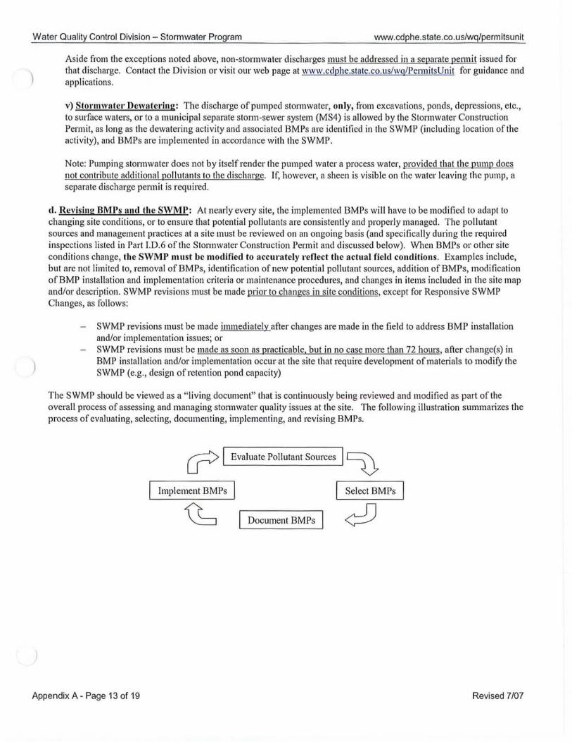
Water Quality Control Division - Storm water Program www.cdphe.state.co.us/wq/permitsunit
Aside from the exceptions noted above, non-storm water discharges must be addressed in a separate penn it issued for that discharge. Contact the Division or visit our web page at w\Vw.cdphe.s tate.co.us/\Vg/Permi tsUnit for guidance and applications.
v) Stol'lllwater Dewatering: The discharge of pumped stonnwatcl', only, from excavations, ponds, depressions, etc., to surface waters, or to a municipal separate storm-sewer system (MS4) is allowed by the Stonnwater Construction Permit, as long as the dewatering activity and associated BMPs are identified in the SWMP (including location of the activity), and BMPs are implemented in accordance with the SWMP.
Note: Pumping stonnwater does not by itself render the pumped water a process water, provided that the pump does not contribute additional pollutants to the discharge. If, however, a sheen is visible on the water leaving the pump, a separate discharge permit is required.
d. Revising BMPs and the SWMP: At nearly evelY site, the implemented BMPs will have to be modified to adapt to changing site conditions, or to ensure that potential pollutants are consistently and properly managed. The pollutant sources and management practices at a site must be reviewed on an ongoing basis (and specifically during the required inspections listed in Part 1.0.6 of the Stann water Construction Permit and d iscussed below). When BMPs or other site conditions change, the SWMP must be modified to accurately refl ect the actual field couditions. Examples include, but are not limited to, removal of BMPs, identification of new potential pollutant sources, addition of 8MPs, modification ofBMP installation and implementation criteria or maintenance procedures, and changes in items included in the site map and/or description. SWMP revisions must be made prior to changes in site conditions, except for Responsive SWMP Changes, as follows:
SWMP revisions must be made immediately after changes are made in the field to address 8MP installation and/or implementation issues; or SWMP revisions must be made as soon as practicable, but in no case more than 72 hours, after change(s) in 8MP installation and/or implementation occur at the site that require development of materials to modify the SWMP (e.g., design of retention pond capacity)
T he SWMP shou ld be viewed as a "living document" that is continuous ly being reviewed and modified as part ofthe overall process of assessing and managing stonnwater quality issues at the site. The following illustration summalizes the process of evaluating, selecting, document ing, implementing, and revising BMPs.
cr> Evaluate Pollutant Sources D Implement BMPs Select 8MPs
~ Document 8MPs ¢:O
Appendix A - Page 13 of 1 9 Revised 7/07
Water Quality Control Division - Stormwater Program www.cdphe.state.co.us/wq/permitsunit
C.S SWMP CONTENTS - Final Stabilization and Long-term Stormwate)' Management
Part j.C.4 StonllJI'ater Management Plan (SWMP) - Contents: Filial Stabiliwtioll al/(I LOllg-term StoNlllvater Mallagemellt
a) The SWMP shall clearly describe the practices used to achievejinal stabilization of all disturbed areas at the site, and any planned practices to control pollutants in storl1lwater discharges that will DeC",. after constructioll operations have been completed at the site.
b) Final stabilization practices for obtaining a vegetative cover should include, as appropriate: seed mix selection and application methods; soil preparation and amendments; soil stabilization practices (e.g., crimped straw, hydro mulch or rolled erosion control products); and appropriate sediment control BMPs as needed until final stabilization is achieved; etc.
c) Final stabilization is reached when all ground sill/ace disturbing activities at the site have been completed, and uniform vegetative cover has been established with an individual plant density of at least. 70 percent of predisturbance levels, OJ' equivalent permanent, physical erosion reductioJ11J1ethods have been employed.
The Division may, after consullatioll with the permittee and lIpon good calise, amend the final stabilization criteria in this section for specific operations.
Typically, the stormwater discharges associated with constmction activity are eliminated when the site is finally stabilized. As soon as practicable after constmction activities have been completed in a disturbed area, penn anent stabilization should be started to prevent further erosion of soil from that area. All disturbed areas (except those p0l1ions covered by pavement or a stmcture) must be finally stabilized once all constmction activities are completed in order to inactivate the pennit coverage. Sediment that collects within the site's drainage system and pennanent water quality or quantity controls is also considered un stabilized soil, and must be removed prior to the site being considered finally stabilized.
The SWMP must include a description of what measures will be taken to finally stabilize the site. The method of stabilization must be provided for all areas that will remain pervious (i.e., vegetated or landscaped instead of paved, built on, or otherwise stmcturally stabilized). Questions that may need to be addressed include: What type of cover will be used? What are the specific seed mixtures and application rates? Are additional BMPs needed to prevent erosion as the vegetation becomes established? Will the soil need to be amended? Will special methods be employed on any steep slopes or areas of concentrated flow?
Inactivation of permit coverage Coverage under the Stonnwater Constmction Pennit may be inactivated by the pennittee when the site has attained final stabilization, all temporary erosion and sediment control measures have been removed, and all components ofthe SWMP are complete.
Any planned stonnwater management controls to prevent or control pollution of stonnwater after constmction is completed must be addressed here. They typically include retention or detention ponds, infiltration measures, vegetative swales, and natural depressions.
New developments, buildings, etc., will often incorporate elements of pennanent stonnwater quality control into their design. The SWMP must be prepared consistent with these stmctural and nonstructural controls. Where possible, pennanent stonllwater quality controls can be consttucted at the initial stages of construction, or modified at the end of consttuction. This can increase the efficiency of the controls by using them during both the building and operational phases of the project. When a pennanent stmctural control is initially used as a construction BMP, the SWMP must contain the necessary infonnation discussed in the guidance for documenting BMPs, Section C.4 above.
Appendix A - Page 14 of 1 9 Revised 7107
Water Quality Control Division - Stormwater Program www.cdphe.state.co.us/wq/permitsunit
Use of Permanent Detention Ponds as BMPs during Construction Pennanent detention ponds are allowed to be used as a temporaty construction BMP, if: a) the pond is clearly designated as a construction BMP in the SWMP; b) detention pond inspection and maintenance are described as required in Part I.B.2, Part I.C.3, and Parts 1.0.6, 7, and 8 of the StonnwaterConsttuction Permit; and c) the pond is designed and implemented for use as a BMP during construction in accordance with good engineering, hydrologic and pollution control practices. In addition, stonnwater discharges from the pond must not cause or threaten to cause pollution or degradation of State waters. When a pennanent detention pond is used in this manner, redundant upgI'adient erosion and sediment control BMPs are still necessalY in almost all cases to comply with the pennit requirements to select and design BMPs to prevent pollution or degradation of State waters.
The design and implementation of the pond may differ from what will exist upon completion of the project when the BMP becomes a pennanent water quality feature. In this case, the description of the BMP included in the SWMP must address these differences. For example, if the outfall will be modified dUling construction to provide additional filtering or settling of sediment (which mayor may not be necessalY, depending on the existence of upstream BMPs, sediment loading to the pond, final outlet design, etc.), those modifications must be included in the SWMP. If additional temporalY stabilization of the pond (e.g., at points of concentrated flow into or through the pond, unstable slopes, etc.) is needed to prevent erosion and transport of sediment from the pond during consltuction, this must also be addressed.
Prior to inactivation of the pennit, the pond must be stabilized in accordance with the pennit requirements and sediment removed from the site's drainage system. Although not related to compliance with the construction storm water permit, the pond may need to be inspected and modified following construction in order to meet local pennanent BMP design criteria.
~.6 SWMP CONTENTS - Inspection and Maintenance Procedures
Part 1. C.5. Storm IVa tel' Management Plan (SWMP) - Contents: - Illspeefioll amI Maillfemlllee
Part J.D. 6 oj the permit illeludes requirements Jar site inspections. Part J.D. 7 oj the permit includes requiremellts Jar BMP maintenance. The SWMP shall clearly describe the illspection and maintellance procedures implemented at the site to mailltaill all erosion and sediment control practices and other protective practices idelllified ill the SWMP, in good and effective operating condition.
a. Inspection Schedules: The minimum inspection schedule described in Part I.C.6.a of the Stonnwater Consltuction Pennit requires that a thorough inspection of the stonnwater management system be pelfonned and documented at least every 14 days. and within 24 hours of any precipitation or snowmelt event that causes surface erosion (i.e., that results in stonnwater running across the gI·ound). If more frequent inspections are required to ensure that BMPs are properly maintained and operated, the inspection schedule must be modified to meet this need.
Exceptions to the minimum inspection schedule are also provided. Any use of an exception is temporaty, and does not eliminate the requirement to perfonn routine maintenance due to the effects of a stonn event or other conditions that may impact BMP perfonnance, including maintaining vehicle tracking controls and removing sediment from impervious areas.
Additionally, this part of the SWMP must also include maintenance procedures for the BMPs, as discussed below. You will need to set up a schedule appropliate to the activity and the BMP. Preventive maintenance should be coupled with periodic inspections.
b. Inspection Procedures: The inspection must include observation of: • the construction site perimeter and discharge points (including discharges into a stonn sewer system); • all disturbed areas; • areas used for mateliallwaste storage that are exposed to precipitation;
Appendix A - Page 15 of 19 Revised 7107
Water Quality Control Division - Stormwater Program www.cdphe.state.co.us/wq/permitsunit
• other areas detennined to have a significant potential for stonnwater pollution, such as demolition areas or concrete washout locations, or locations where vehicles enter or leave the site;
• erosion and sediment control measures identified in the SWMP; and • any other structural BMPs that may require maintenance, such as secondary containment around fuel tanks, or the
condition of spill response kits.
The inspection must detennine if there is evidence of, or the potential for, pollutants entering the drainage system. BMPs should be reviewed to detennine if they still meet the design and operational criteria in the SWMP, and if they continue to adequately control pollutants at the site. Any BMPs not operating in accordance with the SWMP must be addressed as soon as possible, immediately in most cases, to minimize the discharge of pollutants, and the SWMP must be updated as described in Section C.4.e, above. Inspections must be documented as discussed in the Record Keeping section, below.
c. 8MP MaintenancelRepIacement and Failed BMPs: The Stonnwater Construction Pennit requires that all erosion and sediment control practices and other protective measures identified in the SWMP be maintained in effective operating condition and in accordance with good engineering, hydrologic and pollution control practices. Therefore, site inspection procedures must address maintenance of BMPs that are found to no longer function as needed and designed, as well as preventive maintenance to proactively ensure continued operation (e.g., removing collected sediment outside the acceptable tolerances of the BMP).
A preventive maintenance program should prevent BMP breakdowns and failures by proactively maintaining or replacing BMPs and equipment. Site inspections should uncover any conditions, such as deteriorating silt fence or water collected in fuel tank secondaty containment, which could result in the discharge of pollutants to stonn sewers and surface waters. For example, sediment that has been collected by sediment controls, such as silt fence and inlet protection, should be removed on a regular basis, to prevent failure ofBMPs, and remove the potential of that sediment from being discharged from the site if the BMP did fail. Removed sediment must be moved to an appropriate location where it will not become an additional pollutant source, and should never be placed in ditches or streams. Maintenance activities to COiTect problems noted during inspections must be documented as discussed in the Record Keeping section, below.
The inspection process must also include procedures to ensure that, when needed, BMPs are replaced or new BMPs added to adequately manage the pollutant sources at the site. This procedure is part of the ongoing process of revising the BMPs and the SWMP as discussed Section C.4, above, and any changes to BMPs must be recorded in the SWMP. The SWMP must be modified as appropriate as soon as practicable after such inspections.
BMPs that have failed, or have the potential to fail without maintenance or modifications, must be addressed as soon as possible, immediately in most cases, to prevent the discharge of pollutants.
d. Record Keeping and Documenting Inspections: Keeping accurate and complete records serves several functions. First, keeping records of spills, leaks, inspections, etc. is a requirement of the Stonnwater Construction Pennit; therefore, enforcement action, including fines, could result if records are not adequate. Second, by keeping accurate and detailed records, you will have documentation of events which could prove invaluable should complications arise conceming the pennit, lawsuits, etc.
The permittee must document inspection results and maintain a record of the results for a period of 3 years following expiration or inactivation of penn it coverage. These records must be made available to the Division or EPA upon request. The following items must be documented as part of the site inspections:
i) The inspection date; ii) Name(s) and title(s) of personnel making the inspection;
iii) Location(s) of discharges of sediment or other pollutants from the site; iv) Location(s) ofBMPs that need to be maintained; v) Location(s) ofBMPs that failed to operate as designed or proved inadequate for a particular location;
vi) Location(s) where additional BMPs are needed that were not in place at the time of inspection; vii) Deviations from the minimum inspection schedule as provided in Section C.6.a above;
viii) Description of corrective action for items iii, iv, v, and vi, above, dates conective action(s) taken, and measures
Appendix A - Page 16 of 19 Revised 7107
Water Quality Control Division - Stormwater Program www.cdphe.state.co.us/wq/permitsunit
taken to prevent future violations, including requisite changes to the SWMP, as neceSSaIY; and ix) After adequate corrective action(s) has been taken, or where a report does not identify any incidents requiring
corrective action, the report shall contain a signed statement indicating the site is in compliance with the pennit to the best of the signer's knowledge and belief.
In addition to inspection records, the pennittee may opt to keep a log book for use in tracking other items related to the SWMP such as those listed below. Additional information such as dated photographs, field notebooks, drawings and maps, and the items below, etc. can also be included where approptiate.
• BMP operation and maintenance • stonnwater contamination • contacts with suppliers • notes on the need for and performance of preventive maintenance and other repairs • implementation of specific items in the SWMP • training events (given or attended) • events involving materials handling and storage • contacts with regulatOlY agencies and personnel • notes of employee activities, contact, notifications, etc.
Records of spills, leaks, or overflows that result in the discharge of pollutants must be documented and maintained. You may also want to record other spills that are responded to, even if they do not result in a discharge of pollutants. Infonnation that should be recorded for all occurrences includes the time and date, weather conditions, reasons for the spill, etc. Some spills may need to be reported to the Division immediately. Specifically, a release of any chemical, oil, petroleum product, sewage, etc., which may enter waters of the State of Colorado (which include surface water, ground water and dry gullies or storm sewers leading to sUlface water) must be reported. More guidance is available on the web at www.cdphe.state.co.uslhm/spillsandreleases.htm. The Division's toll-free 24-hour number for environmental hazards and chemical spills and releases is 1-877-518-5608.
D. ADDITIONAL SWMP AND BMP RESOURCES
There are a multitude of resources available to the construction industlY to assist in complying with the requirements of the Stonnwater Construction Pennit. The following suggested list of resources can provide valuable tools to assist you in developing and implementing your SWMP as effectively and efficiently as possible. However, the guidance found in the resources listed below in no way replaces the requirements of the Stormwater Construction Pennit, as desctibed in Sections A through C, above. Therefore, when using the following resources, especially in the case of example plans and maps, it is essential that you ensure that all of the requirements included in this guidance document and the Stormwater Construction Permit are being met.
Many of the resources below require access to the internet. If you are unable to obtain any resources you need due to a lack of access to the internet, please contact the Division at (303) 692-3517 and we can try to assist you in obtaining the infonnation you need.
D.l. RESOURCES - BMP Design and Implementation
a. BMP Design Criteria Manuals: Be sure to check with the local city or county to determine if they require that specifIc design criteria be met. The following are some highly respected criteria manuals that can be used in designing and implementing BMPs for your site.
Appendix A - Page 17 of 19 Revised 7/07
Water Quality Control Division - Stormwater Program www.cdphe.state.co.us/wq/permitsunit
o Urban Drainage and Flood Control District Urban Stonn Drainage Criteria Manual Volume 3 - Best Management Practices
o This criteria manual is commonly used by cities and counties in the Denver metropolitan area. The manual includes discussion of stormwater quality management and BMPs for many activities, including constl1lction, This manual is a highly respected across the country and a great resource for professionally accepted design criteria for constmction BMPs.
• Available free from the "download" section of the Urban Drainage and Flood Control District web page:
http://www.udfcd.org/
o Douglas County Grading, Erosion, and Sediment Control (GESC) Manual
o The criteria manual for compliance with Douglas County's GESC permitting program for stonnwater quality. Includes an excellent discussion of effective stormwater management strategies, design criteria, and several very useful sample site maps.
o Available for download free from the Douglas County Public Works web page: http://www.douglas.co.us/publ icworks/engineering/GESC.html
• Also available in print or CD-ROM from the Engineering Division office: Douglas County Public Works Department - Engineering Division 100 Third Street Castle Rock, CO 80 I 04 Phone: 303-660-7490
b. General 8MP Selection and Design Guidance
o Colorado Department of Transportation ) Erosion Control and Stonnwater Quality Guide
o Guidance on 8MP selection and design applicable specifically to highway development projects, but also useful as general guidance.
• Available online from CDOT's MS4 Program web page at:
http://www.dot.state.co.us/environmental/envWaterOuaI!wgms4 .asp
o EPA Menu of BMPs Constmction Site Storm Water Runoff Control
a EPA guidance for cities and counties who are required to develop programs to regulate construction activities in their jurisdiction. The BMP fact sheets provide a good discussion of various structural and nonstmctural 8MPs.
• A vailable online at: http ://c f pllb. epa.gov/npdes/stonnwater/menllofbmps/index.cfm
o International Stormwater Best Managemeut Practices (BMP) Database a Database of monitoring results showing effectiveness of stmctural and non-structural 8MPs. Currently,
the database and web site do not include much analysis of the data; this wiII be added in the future. Data contributions are being solicited on an ongoing basis.
o Available online at: http ://www . bmpdatabase .org
c. Special Applications
• BUI'll Areas:
U.S. Department of Agriculture, Forest Service, 2006. Bumed Area Emergency Response Treatments Catalog. 06251801-SDTDC.
Appendix A - Page 18 of 19 Revised 7107
Wate r Qua lity Control Divis ion - Stormwate r Progra m www.cdphe.state.co.us/wq/permitsunit
• Available online at: htlp: llwww.fs. fed.usleng/pubs/pdf/BAERCAT/lo reslTOContcnts.pdr
• Soil Bioengineering:
U.S. Deparlment of Agriculture, Forest Service, 2000. Soil Bioengineering An Alternali ve for Roadside Management. 0077 180 I- SDTDC.
• Available online al: htlp:llllap.coloslale.edu/Librarv/M ISC/USDA %200077%20 180 I %20SDTDC.pd f
Franli, Thomas G. 2006. Bioengineering for Hills lope, Sireambank and Lakeshore Erosion Conlrol. Universi ty of Nebraska-Lincoln Extension.
• Available onl ine al: htlp:llwww.ianrpubs.unl.edu/epublic/live/g I307!bui ld/g 1307.pdf
D.2. RESOURCES - Example Management Plans
• Constmction Industry Compliance Assistance Cente r - Stonnwat ... Pollution Prevention Plans a A websile with examples of actllal storm water plans prepared for a range o f constrilclion projecls located in
va rious slates. " The purpose of presenting these documents is to demons Irate various approaches to SWPPP development. Please note Ihat the ex amples presented here should not be excerpled or used as lemplales in the preparalion of a SWPPP, since each SWPPP musl be designed to handle Ihe specific needs of a parlicular conslruction site." (Note that Colorado's plan is refelTed to as a 'S WMP ' inslead of 'S WPPP' .) Not all of lhe example plans willmeel the requi rements of the Colorado General Permit. Therefore, it is essent iallhal this SWMP/SWPPP guidance document be used 10 ensure your compleled plan contains all of the required elements and is appropriate for your sile.
• Available online at : htlp :l/www.cicacenleLorg/swppp.html
1 .3. RESOURCES - Training
• Rocky MOllntain Education Center (Located al Red Rocks Community College, I.akewood) -Stann water Management and Erosion Control Course a One-day course, wilh an oplional addil ional half-day in the field, on the principles and practices of erosion
and sediment conlrol. Recommended for municipal erosion conlrol inspectors and those praclicing erosion conlrol in the fi eld. This course is required for the CDOT certified erosion conl rol supervisor cerlificati on. Course is given at Red Rocks CommunilY College in Lakewood. Course CET C #150.
Stormwater Compliance Inspector Course o Two-day course (including half-day in Ihe fi eld) on preparing for and conducting a comprehensive
COllstl1lction site inspection. Recommended for municipal erosion control inspectors, construction site managers, and those praclicing erosion conlrol in the fi eld. Prerequisile: Sionnwaler Management and Erosion Control Course (see above). Course is given al Red Rocks Communily College in Lakewood. Course CETC # 15 I.
• Conlacl the Rocky Mounlain Education Center at (800) 933 -8394 • Schedule of classes available online at: hllp:llwww.n.Cc.edu/nnec/cetc.h lml
• Keep it C lean Partnership (Boulder) Erosion Control Training and Cerlification
o The Keep it C lean Partnership provides a 10W-COSI, eight-hour erosion cont rol tra ining and recertificalion program available for bolh public and private inspectors and conlractors.
• Contact Ihe Keep it C lean Parlnership at 303-441 -1439 • h tlp:l !ben. boul deLco.us!basi nlk icp/lkicp conslrucl ion. him
Appendix A - Page 19 of 19 Re vised 7/07
STATE OF COLORADO COLORADO DEPARTMENT OF PUBLIC HEALTH AND ENVIRONMENT Water Quality Control Division - Stormwater Program
STORMWATER FACT SHEET -CONSTRUCTION at OIL and GAS FACILITIES
Contact information
Colorado Department of Pllblic Health and Environment 'Vater Qunlity Control Division - Stol'lUwatcl' Program WQCD-Pel'lIIi1s-B2
Telephone: Email: Web Page:
(303) 692-3517 [email protected] www.cdphc.stnte.co.lls/wq/Pcl.lIlitsUnit
4300 Chel'I'Y Cl'eel< Dl'ive SOllth Delll'el', Colol'ado 80246-1530
Contents A. Intl'oduction ............................ " ...................................... ... ....... ...... ............. .... ........... 1 B. \-Vhen do you need n PCI'Jllit? ............ ..... ....... ............................................................ 2
1. Definitions Regarding Finnl Stnbilization .......................................................... 2 2. Additional Final Stabilization Guidance for Oil and Gas Sites ...... .... ............ . 2
a. Stabilized Unpaved Surfaces .... ........................... ....... ... ... ........ .......... ..... .... 2 b. Agricultural Lalld ............................. ................. .......................................... 2 c. COGCC Interilll Stabilization ... ............................... ........ .... .... .... .. ... ......... 2
C. Is the site part of a largcr common plan of development? ..................................... 3 D. What if my construction site is on Federal 01' Indian Lands? ............................... 4 E. Obtnining Pel'lllit Covcrage .......... .. ............ ........... .... ... ... ... ..... .. ... .... ......... ............ ... 4 F. Obtaining IJermit Coverage: R-Fnctol' Waiver ...................... ........... ......... .. ... .. ..... .4 G. Pcrnlit Requircnlents ................................................... .............................................. 5
I. Stormw.ter Mllnngement I'lan (SWMP) ................................................. .... .. .. . 5 2. Site Inspection .. ......... .. .................. ...... ............ .................................... ........... ... .. 6
H. Field Permit Covel"llge and Master SWMPs .............................. ....... ...... ... .. ...... ...... 8 1. Size of Permitted Aren ........................................ .......... ......... .. .. .. .. ... ............. .. ... 8 2. Applying for Field Permit Covel'nge ............... ........ .......................................... 8 3. Master Stol'lllWRler Management Plan (S\VMP) ............................................. H
I. Obtaining FOI'IIiS and G uidance ............................................................................ 11
A. INTRODUCTION
• Lool< for this symbol for tips on saving time and money when involved in Illultiple oil and gas well sites!
On June 30, 2005, the State of Colorado stormwater regulation wenl into effect to require Colorado Discharge Permit System (CDPS) permits from the Waler Quality Control Division (the Division) for stormwater discharges from conslruction aclivities associated with small constntction activity for oil and gas sites (those that disturb between one and five acres). Pcrmitting for oil and gas construction sites that disturb five or more acres during the life of the project, or are part of a larger common plan of development, has been required since 1992. Although federal permit coverage for Ihese discharges was conditionally exempted from the Federal Clean Water Act by Ihe 2005 rederal Energy Bill, the Colorado Water Quality Control Commission has maintained the requirement within Colorado's regulations, and therefore permit coverage for these activities remains in effect in Colorado. These requirements are in addilion to the requirements of the Colorado Oil and Gas Conservation Conunission (COGCC).
Therefore, the State of Colorado cn .... ently requires stormwater discharge permit coverage for all construction activities that disturb one acre or greater (or that are part of a larger common plan of development, as discussed in Section 2, below), including construction of well pads, roads, pipeliues, pumpiug stations, etc.
This Fact Sheel provides specific guidance for compliance with the CDPS pennitting requiremenls for slormwater discharges from oil and gas related conslluction activities. This Fact Sheet is intended to augment Ihe general information relalive 10 all conshuction activities, available in the Stonnwater Fact Sheet for Constlllction and the pennit application and SWMP guidance document (see Seclionl, below, for how to oblain these documents.)
Page 1 of 11 Revised 7/07
)
Water Quality Control Division - Stormwater Program www.cdphe.state .co.us/wq/permitsunit
B. WHEN DO YOU NEED TO GET A STORM WATER CONSTRUCTION PERMIT?
lYou may need a permit to discharge stormwater from any construction activity that disturbs at least one acre ofland (or is part ofa larger common plan of development that will disturb at least one acre). The requirements Vaty slightly depending on if your project or plan of development will disturb less than five acres (Small Construction Site) or five acres or more (Large Construction Site). If permit coverage is required, it must be maintained until the site is finally stabilized.
)
I) Definitions Regarding Final Stabilization
"Finally Stabilized" means that all ground surface disturbing activities at the site have been completed, and all disturbed areas have been either built on, paved, or a uniform vegetative cover has been established with an individual plant density of at least 70 percent of pre-disturbance levels, or equivalent permanent, physica l erosion reduction methods have been employed. Re-seeding alone docs not qualify.
Oil and gas sites are considered finally stabilized once site preparation and interim reclamation are complete, and the above final stabilization criteria have been met, even though the site will be disturbed aga in in the future for final reclamation. However, future land d·isturbances that follow interim stabilization and result in disturbance of one acre or greater would require permit coverage at that time.
2) Additional Final Stabilization Guidance for Oil and Gas Sites
As discussed below, permit coverage may be inactivated for an oil and gas construction site even if stab ilized unpaved surfaces exist (see subsection a, below) and/or disturbed land that has been restored to cropland remains unvegetated (see subsection b, below), as long as construction activities have been completed and all other disturbed areas revegetated in accordance with the definition of "Finally Stabilized." It may be useful for some oil and gas construction operators to use the COGCC's definition of interi m stabilization in determining what areas at a site will require eventual revegetation to meet the Divis ion's final stabilization requirement, as discussed in subsection c, below.
a) Stabilized Unpaved Surfaces: Areas developed as stabilized unpaved surfaces as needed for operation of the facility after interim reclamation, also qualify as "tinally stabilized." The term "stabilized unpaved surfaces" includes dirt road surfaces and the p011ions of the well pad surfaces that cannot be revegetated due to operational necessity, but does not include slopes, ditches, and other areas where revegetation is necessary. Stabilized unpaved surfaces must be prepared in such a way as to minimize erosion, such as preventing rill erosion on pad surfaces or roads.
b) Agricultural Land: In most cases, when operational control ofa disturbed area that has not been finally stabilized is conveyed from the permittee to another entity, such as the surface landowner at a construction site, permit coverage must be reassigned to the new operator. This is not usually an issue for the oil and gas industlY since, in most cases, COGCC rules require stabili zation by the oil and gas industry prior to this reass iglUnent, unless the land will revel1 to cropland . Land di sturbances for agricultural activities, such as croplands, are exempt from stol'lnwater discharge permit requirements. As a result , when portions of an oil and gas site are restored to cropland in accordance with COGCC rules, and returned to control o f the fanner following interim reclamation, storm water permit coverage is no longer required for these areas, and it is not necessary for the oil and gas site operator to either stabilize or reassign permit coverage for the areas.
c) COGCC Interim Stabilization: Consistent with the guidance in this section, final stabilization at an oil and gas facility has been met when the site has met the site preparation requirements for interim reclamation in accordance with COGCC 1000 series rules, including restoration and revegetati o n of disturbed areas as required by COGCC Rule I 003.e, and: o all croplands have been restored and revegetated in accordance with COGCC Rule I 003.e.( I) and
returned to the surface owner for agriculture use. o all non-cropland areas requiring restoration and revegetation in accordance with COGCC Rule
I 003.e.(2) have established a uniform vegetative cover with an individual density of at least 70 percent of pre-disturbance levels.
Page 2 of 11 Revised 7107
Water Quality Control Division - Stormwater Program www.cdphe.state.co.us/wq/permitsunit
• areas reasonably needed for production operations that do not require restoration and revegetation in accordance with COGCC Rule I003.e. have been stabilized as unpaved surfaces. Stabilized unpaved surfaces must be prepared in such a way as to minimize erosion.
C) IS THE SITE PART OF A LARGER COMMON PLAN OF DEVELOPMENT?
A "common plan of development" is a site where multiple separate and distinct but related construction activities may be taking place at different times on different schedules. If the project is part of a common plan of development, the disturbed area of the entire plan must be used in determining permit requirements or the applicability of the waiver for small construction activities (see Section F, below).
For the oil and gas industry, a "common plan of development" is generally interpreted to mean development of several well pads andlor related infrastructure (i.e., roads, pipelines, pumping stations, etc.) in a contiguous area, either during the same time period or under a consistent plan for long-term development.
1) Well pads, pump stations, and other single site facilities: Consistent with EPA guidance, such facilities located in close proximity to each other (within 114 mile) are considered "contiguous," and therefore part of a common plan of development.
2) Pipelines and roads: Disturbed areas associated with feeder pipelines or roads that are constructed for the pUlpose of serving a well pad or other single site facility are considered, together with the well pad, to be part of a common plan of development. However, adjacent consltuction ofltunk lines or roads that are part of a regional network are not considered to be part of the common plan for that facility, and instead, are a separate cOllllnon plan of development that also requires pennit coverage if one or more acres are disturbed.
Examples for determining if a project is part of a Common Plan of Development I The following examples discuss common scenarios for detennining if a project is part of a common plan of development, and explain how the total disturbed area of the plan should be detennined. The total disturbed area in these examples is subsequently used to detennine if a stonnwater consltuction pennit is required (area is one acre or greater), and if the waiver discussed in Section F could apply (area is under five acres).
These examples are provided to help pennittees better understand how to calculate total disturbed area, not to address all possible scenarios when a site may be part of a larger common plan of development. Note that if separate contractors disturb different areas that are part of a common plan, the areas must still be added together.
Example 1) Well Pad Site Connecting to a Regional Road and Pipeline Network: Site A is a well pad under conshuction a short distance from a regional road and pipeline network that provides access to other well pads, which are over 114 mile away. An access road must be built off of the existing road and a feeder pipeline must be constructed from the existing hunk pipeline to the new well. The area disturbed for this example is calculated as follows: Total Disturbed Area = Well Pad Disturbance + Access Road Disturbance + Feeder Pipeline Disturbance
Example 2) Construction of New Road andlor Pipeline Network: Site B is construction of a road or pipeline that will be used to access more than one well pad. The construction of all sections of the road or pipeline is considered a common plan of development. However, construction of dedicated access roads or feeder pipelines that may connect to the primary road or pipeline network, but are used solely for the purpose of providing service to a single well pad or other single site facility, are not considered pa11 of the overall network's common plan of development. The dedicated road or pipeline in this case is considered part of the well pad construction, as discussed in Example 1. In addition, if, after a road or pipeline network has been completed and finally stabilized, an expansion to the network occurs that adds new roads or pipelines to access multiple new sites, the new construction may be considered a separate common plan of development since it is OCCUlTing after the first conshuction is completed. Total Disturbed Area = Regional Pipeline or Road Construction Disturbance
Page 3 of 11 Revised 7/07
Water Quality Control Division - Stormwater Program www.cdphe.state.co.us/wq/permitsunit
Exam Ie 3 Well Pad Site Located within 114 Mile of a Se arate Well Pad Site s: Site C is a well pad under construction; an access road and feeder pipeline will also be constructed, as with Site A. However, a separate well is also being constructed in the same area and will be unstabilized during the same period of time. A portion of the disturbed area of the access road, feeder pipeline, or pad of the second site will be within 114 mile of the access road, feeder pipeline, or pad for Site C. The area disturbed for this example is calculated as foll ows: Total Disturbed Area = Well Pad Disturbance + Access Road Disturbance + Feeder Pipeline Disturbance
+ Pad, Access Road, and Feeder Pipeline Disturbance for Sites within 114 Mile.
D) WHAT IF MY CONSTRUCTION SITE IS ON FEDERAL OR TRIBAL LANDS?
Federal Lands: All private oil and gas operat ions on federal lands, including BLM, Forest Service, etc., are regulated by the State of Color ado and must meet the State's stormwater permitting requirements discussed in this document. Although the EPA does regulate federal facilities in Colorado, private operat ions on federal lands are not considered federal facilities. Tribal Lands and Non-Tribal Member Activities on Fee Lands: Construction activities occurring on Tribal Lands in Colorado are not regulated by the State of Colorado and are therefore not subject to the permitting requirements discussed in this document. The federal EPA regulates activities on Tribal Lands. The State of Colorado does regulate non-tribal member activities on fee lands within the external boundmy of a reservation, and therefore Colorado's stormwater permitting requirements discussed in this fact sheet apply to those areas.
E) OBTAlNTNG PERMIT COVERAGE
)
F)
•
If the total area of ground disturbance, including disturbances from the entire conmlon plan of development, is greater than or equal to one acre, permit coverage is required (unless the waiver for small constmction activities disturbing less than five acres applies, as discussed in Section F, below) . The owner or operator must apply for coverage under the Stonnwater Construction Permit at least 10 days prior to the statt of constmction activities. An application and Stormwater Management Plan (SWMP) guidance document are available from the Division (see Section I, below). The SWMP must be complctcd prior to application.
The Stormwater Consttuction Permit certification must be inactivatcd once the site has been finally stabilized, in order to end permit coverage and billing. An inactivation form is supplied with the pert11it certification.
The Division strongly recommends that those involved in construction associated with oil and gas exploration and production consider applying for coverage nnder a Field Permit certification, as discussed ill Section H, below. This process eliminates the need for an operator to submit separate applications and inactivation forms for multiple si tes within a well field. This process, along with streamlining the SWMP and inspection procedures as discussed in Sections G and H, below, can considerably reduce the resources necessary for an operato r to comply with the stonnwater requirements and protect State surface waters.
OBTAINING PERMIT COVERAGE UNDER TI-JE R-FACTOR WAIVER (Less than five acres disturbance only)
A site may qualify for coverage under this wa iver only if less than five acres of land is disturbed at the site and the site is not part of a larger cOlllmon plan of development with greater than five acres disturbed, as discussed in Section C, above. Sites that are within an area covered under a Field Permit certification (see Section H) may still apply for an R-Factor waiver, if they are not otherwise part ofa common plan of development.
The R-Factor waiver allows a site owner or operator to apply for a waiver from State Stormwater Consttuction Permit requirements coverage when the R-Factor for a construction project, as calculated using the Sta te approved method, is less than five. The R-Factor is a way to measure erosion potential based on the duration of the project and time of year. An application with instructions for using the State-approved method is available fro m the Division. See Section I, below.
Page 4 of 11 Revised 7/07
Water Quality Control Division - Stormwater Program www.cdphe.state.co.us/wq/permitsunit
In general, the only projects that will qualify for the waiver are projects that are completely stabilized within a month or two of the start of construction. This means that projects relying on seeding for revegetation will usually ) not qualify for the waiver, because the vegetation must be established before the site is considered stabilized. For the oil and gas industry, this generally means that only projects for which all disturbed areas will be returned to cropland (see discussion under Section B) will qualify, since other disturbed areas typically rely on seeding for stabilization. In addition, the Division will not grant waivers for construction sites located in areas where snow cover exists at, or up-gradient of, the site for extended periods of time, if the construction site will potentially remain active and unstabilized during spring runoff.
This waiver does not relieve the operator or owner from the responsibility of managing the site to prevent pollution or degradation of State waters or Ii-OIn complying with the requirements of other agencies, such as meeting COGCC stonnwater quality requirements.
G) PERMIT REOUIREMENTS
The specific requirements that must be met are contained in detail within the permit and SWMP guidance document, and are further clarified specifically for the oil and gas industry within this guidance. Permittees must read all three documents. The two most significant requirements arc the development and implementation of a SWMP, and conducting and documenting the required self-inspections, as sununarized below.
1) Stormwater Management Plan (SWMP) The Stormwater Construction Permit requires dischargers to control and eliminate the sources of pollutants in stormwater through the development and implementation of a Stormwater Management Plan (SWMP). These requirements are fUIther described in the SWMP guidance document (included as an appendix to the application), which must be read prior to developing your plan.
The purpose of a SWMP is to identify possible pollutant sources that may contribute pollutants to stormwater, and identify Best Management Practices (BMPs) that, when implemented, will reduce or eliminate any possible water quality impacts. For construction activities the most conmlon pollutant sources is sediment. Other pollutant sources include fuels, fueling practices and chemicals/materials stored on site, etc. BMPs encompass a wide range of practices, both structural and non-structural in nature, and may include silt fence, sediment ponds, vehicle tracking controls, good housekeeping, inspection and maintenance schedules, training, etc .
• Because site conditions at different projects can sometimes be relatively consistent, an oil and gas company could significantly streamline the SWMP development process through the use of boilerplates andlor the development of a field-wide SWMP, as discussed in Section H.3, below.
a) SWMP Revisions: When BMPs or site conditions change, the SWMP must be modified to accurately reflect the actual field conditions. Examples include, but are not limited to, removal ofBMPs, identification of new potential pollutant sources, addition ofBMPs, modification ofBMP installation/implementation specifications or maintenance procedures, and changes in items included in the site map and/or description. SWMP revisions must be made prior to changes in site conditions, except for Responsive SWMP Changes, as follows:
SWMP revisions must be made inunediately after changes are made in the field to address BMP installation and/or implementation issues; or SWMP revisions must be made as soon as practicable, but in no case more than 72 hours, after change(s) in BMP installation and/or implementation occur at the site that require development of materials to modify the SWMP (e.g., design of retention pond capacity)
b) SWMP Location: The SWMP must be on site during active construction and site inspections to ensure accurate implementation and maintenance of BMPs, and required revisions. This can best be accomplished by having appropriate site staff, who are consistently at the project during constluction operations, keep a copy of the SWMP with them during active construction.
Page 5 of 11 Revised 7/07
)
Water Quality Control Division - Stormwater Program www.cdphe.state.co.us/wq/permitsunit
)
)
If a construction site is covered under a Field Permit cel1ification, as discussed in Section H, below, the Division will generally authorize a minor exception to the SWMP location requirement. For such sites, the permittee may request, in accordance with Part 1.E.2 of the permit, that the SWMP be retained at a central location in close proximity to the oil/gas field. All such requests must be made in writing to the Division, explain why the permit requirement can not be met, specify the alternate SWMP location(s), and include the associated permit certification number. If the Division does not respond to the written request within two weeks of receipt, the exception is approved. Permittees are advised to obta in delivery confirmation of receipt by the Division. An up-to-date copy of the SWMP must be available to a Division or EPA inspector at thc time of inspection. The intent of the SWMP must still be met-that the SWMP be available to those directly responsible for installing and maintaining the BMPs to ensure that activities in the field conform to the specifications in the SWMP.
2) Site Inspection
a) Required Schednles: Specific schedules for permittees to conduct inspections of their sites are prescribed in Part I.D.6 of the permit. The schedule differs based on conditions at the site.
A permit certification for an oil and gas construction activi ties operator wi ll often cover several separate sites that are being constructed on different schedules but under a conunon plan of development or a Field Permit certification (as discussed in Section H, below). Therefore, different inspection frequencies may apply to different p0l1ions of the permitted area, as discussed below.
1) Minimum Inspection Schedule (sec Part I.e.6.a. of the permit): The minimum inspection schedule applies those sites under ac tive construction, which includes the period from when the ground is initially disturbed to when construction activity is completed, and also includes the preparation of areas that will be revegetated for interim reclamat ion. During this period, a thorough inspection of the site stormwater management system must be conducted following the requirements in Part I.D.6.b of the permit, at least once every 14 calendar days. Also, post-storm event inspections must be conducted within 24 hours after the end of any precipitation or snowmelt event that causes surface erosion.
Preparing and seeding the site for reclamation as soon as practica l after construction is completed will help reduce the need of frequent inspections, and is a h.igilly effective BMP for reduci ng the potential for polluting runoff.
Exceptions to the minimum inspection schedule. Any use of an exception is temporalY, and does not eliminate the requirement to perform routine maintenance due to the effects of a storm event or other conditions that may impact BMP performance, including maintaining vehicle tracking controls and removing sediment from impervious areas . Inspections, as described above, are required at all other times.
i) Post-Storm Event Iuspections at Temporarily Idle Sites (sec Part I.e.6.a.1 of the permit) : Temporarily Idle Sites are those where there are no construction activities occurring following a storm event. At such sites, post-storm event inspections must be conducted prior to restal1ing construct ion activities at the site, but no later than 72 hours fo llowing the storm event, and the delay noted in the inspection report. Routine inspections sti ll must be conducted at least evelY 14 calendar days .
• ii) Completed Sites (see Part I.C.6.a.2 of the permit) : Once construction is completed and the site has been prepared for final stabilization (including completion of appropriate soil preparation, amendments and stabi lization practices), the site (or p0l1ion of a si te) is considered a Completed Site (for purposes of the stormwater permit). Note: only construction activities that result in a disturbance of the ground surface must be completed. Construction act ivi ties that can be conducted without disturbance of the ground surface, such as celtain well completion acti vities, would not prohibit a site from othelwise qualifying as a Completed Site. (Completed Sites still require permit coverage until fina l stabilization criteria have been mel.)
Page 6 of t 1 Revised 7/07
Water Quality Control Division - Storm water Program www.cdphe.state.co.us/wq/permitsunit
Completed Sites qualify for a reduced inspection schedule, as the potential for pollution is reduced if the site has been adequately prepared andlor seeded. However, because slopes and other disturbed areas are ') not vegetated, erosion in these areas still occurs which requires maintenance activities such as regrading and seeding of problem areas. As such, inspections must continue in order to address these situations. During the Completed Site period, a thorough inspection of the site stormwater management system is requi red at least once evelY month. The SWMP for the site must be amended to indicate those areas that will be inspected at this reduced frequency.
iii) Winter Conditions Inspections Exclusion (see Part I.C.S.c of the permit): Inspections are not required at sites where constl1lction activities are temporarily halted, snow cover exists over the entire site for an extended period, and melting conditions posing a risk of soil erosion do not exist. This temporOiY exclusion is applicable onlv durin g the period where melting conditions do not exist, and applies to the routine l4-day and monthly inspections, as well as the post-storm-event inspections. Note: it is typical that when snow cover exists, even at a Completed Site, significant potenti a l for eros ion and BMP fa ilure exists when melting does finally occur. Therefore, pelm ittees should prepare the site prior to snow cover to ensure it is as stabilized as possible, and be prepared to perform site mai ntenance when melt-off occurs, to alleviate any potential problems. Inspecti on records must document the following information when thi s exclusion is used: dates when snow cover occurred, date when constl1lction acti vities ceased, and date melting conditions began.
b) Performing Inspections: The inspection must cover the construction site perimeter, all disturbed areas, areas used for material/waste storage that are exposed to precipitation, discharge locations, and locations where vehicles enter and ex it the site. These areas must be inspected to determine if there is evidence of, or the potential for, pollutants leaving the construction site boundaries, enteri ng the stormwater dra inage system, or discharging to state waters. All BMPs must be evaluated to determine if they still meet the design and operational criteria in the SWMP and if they continue to adequately control pollutants at the site. Any BMPs not operating in accordance with the SWMP must be addressed as soon as possible, immediately in most cases, to minimize the discharge of pollutants, and the SWMP must be updated as described in Section G.l .a, above.
c) Documenting Inspections: The permittee must document inspection results, and maintain a record of the results for a period of 3 years following expiration or inactivation of pelmit coverage. These records must be made available to the Division or EPA upon request. The following items must be documented as pati of the site inspections:
i) The inspection date; ii) Name(s) and title(s) of persolUlel making the inspection; iii) Location(s) of discharges of sed iment or other pollutants from the site; iv) Location(s) of BMPs that need to be maintained; v) Location(s) ofBMPs that failed to operate as designed or proved inadequate fo r a particular
location; vi) Location(s) where additional BMPs are needed that were not in place at the time of inspection; vii) Deviations from the minimum inspection schedule as provided in Sections G.2.a. l .i-iii, above; vii) Description of corrective action for items iii , iv, v, and vi, above, date(s) corrective action(s)
taken, and measures taken to prevent future violations, including requisite changes to the SWMP, as necessary; and
viii) After adequate corrective action(s) has been taken, or where a report does not identi fy any incidents requiring corrective action, the report shall contain a signed statement indicating the site is in compliance with the permit to the best of the signer's knowledge and belief .
• To streamline this process, the inspection items could be included in a checklist. This is especially true during the Completed Site phase. However, the permittee must ensure that the staff performing the inspection is adequately trained to recognize potential pollutant sources, such as rill formation on slopes or inadequate materials management, and to assess the adequacy and proper maintenance of BMPs.
Page 7 of 11 Revised 7/07
Water Quality Control Division - Storm water Program www.cdphe.state.co.us/wq/permitsunit
H) SAVING TIME & MONEY WITH FIELD PERMIT COVERAGE AND MASTER SWMPS
• Due to the nature of oil and gas construction activities related to exploration activities, the Division allows for coverage to be obtained under the Stonnwater Construction Pennit for multiple conshuction activities in an oil and gas field (Field Permit Coverage), instead of obtaining permits for each separate site or conmlon plan of development. The Field Permit covers all construction activities disturbing over one acre, or that are part of a conunon plan of development exceeding one acre, within the applied-for fi eld, with the exception of any specific site that has obtained an R-Factor Waiver (see Section F). This option allows oil and gas companies to save considerable resources by not having to apply for permit coverage and inactivation on a site-by-basis, and can significantly streamline the SWMP development process. 1.11 addition, a permittee covered under a Field Permit cel1ification pays one permit fee for the area covered, instead of separate fees for each individual site.
)
1) Size of Penllitted Area A single permit certification may be allowed to cover all activities in an oil and gas field , although in some cases, additional certifications may be required in order to maintain a manageable area and amount of activity under a single permit certification. In general, the Division requires that the permitted area be discrete enough to allow for adequate administration by the permittee and enforcement by the Division. Although the Division has not developed specific criteria for a maximum area to be covered under one certification, it is our expectation that the individual sites covered under a single certification will be related (e.g., within the same oil and gas field or collection system) and will be of a manageable size, probably no larger than a USGS quadrangle, although the there is flexibility on this issue. Based on these criteria, permit coverage for an oil and gas field on Colorado's western slope will usually be adequately covered under a single permit certification. However, for larger well fields on the eastern plains, such as the Wattenberg oil and gas field, multiple permit cel1ifications will probably be needed unless an operator is only working in a specific area within the larger field.
2) Applying for Field Permit Coverage The same application is used to apply for Field Permit Coverage as is used for regular Stormwater Construction Permit coverage (Section E). However, the information provided on the application varies slightly to account for the non-typical covcrage being requested. All itellls on the application still must be filled out or the application will be returned unprocessed. Follow the instmctions below when completing the application.
• Location: In place of the street address, provide a general description of the proposed area to be permitted (e.g., Southeastern Fremont County), and indicate the nearest town to the proposed pennitted area. Provide all counties that the permit coverage will be located within. The latitude and longitude provided should be for the approximate center of the covered area.
• Map: A map must be provided. This map is in addition to the Site map(s) required in the SWMP. The map must indicate the boundaries of the proposed permitted area. All construction activities distlll'bing over one acre, or that are p811 of a conunon plan of development exceeding one acre, within the area indicated will be covered under the permit certification until finally stabi lized, with the exception of any specific site that has obtained an R-Factor Waiver (see Section F).
• Area of the construction site: Because the area will vary over time, a rough estimate of the total area and the area to be disturbed is acceptable.
• Anticipated construction schedule: Provide the date that activities will begin in the area to be covered, and indicate "ongoing" for the "Final Stabilization Date."
3) Master Storm water Management Plan (SWMP) The master SWMP must contain the same information required for typical pennit coverage and be prepared in accordance with the Division's SWMP guidance document. However, a permittee can considerably streamline the SWMP development process by developing a field-wide plan, i.e., a master SWMP, that summarizes information common to all of the sites. This information would be separate from the site-specific details, thereby eliminating the need to repeat this information in individual SWMPs. Templates (compliant with the permit), modified to reflect specific-site conditions, may be used to ensure that all permit items applicable to the specific sites are addressed.
Page 8 of 11 Revised 7/07
Water Quality Control Division - Stormwater Program www.cdphe.state.co.us/wq/permitsunit
Note: Permittees are allowed to use a master SWMP, without that by itself defining a site as a conunon plan of development. )
a) Master SWMP format: SWMP information must be developed and maintained for all construction activities that exceed one acre (or are patt of a common plan of development exceeding one acre) conducted within the permitted area. Instead of developing a complete separate plan for each individual site within a pennitted area, the permittee may wish to develop a single plan that addresses both the information conunon to the active projects, and the site-specific information (maps, etc.). As new activities begin, required information is added to the plan, and as areas are finally stabilized, the related information is removed. Documentation related to areas that have been finally stabi lized and removed from the active plan must be maintained for a period of at least tlu·ee years from the date that the associated site is finally stabilized.
A master SWMP format eliminates the need for operators to develop repetitive information in separate plans. A master SWMP could contain two sections, one containing all of the information specific to each site, and a second reference section containing information applicable to all sites (refer to the text box, below). The master SWMP can be administered as two separate documents to ease paper work, with the information conunon to the entire field contained in a document in the form of a field manual, containing BMP installation/implementation details and generic descriptions, as discussed below.
+ Possible Master SWMP Format
As discussed in Section H.3.a, above, a permittee may want to consider fonnatting a mastcr SWMP with two sections, one with specific infonnation for individual sites in a Site Specific section, and one with more generic infonnation applicable to the entire pennitted area in a Reference section. The following is an example of how the plan requirements could be divided between these sections and how templates could be used. For details on what must be included in each section, refer to the SWMP guidance in Appendix A of the pennit application.
SWMPlPermit Section of Discussion
Item SWMP
Site Description Site Specific or Much of the content here will be very similar for different projects, with only certain Reference specifics needed, such as the applicable schedule, location, receiving water, SWMP
(Pennit I.C.I) section administrator, etc. Items such as the description of the activity and the sequence of events will likely be similar for many sites, and therefore can be handled with template language developed for the Site Specific section, or even partially included in the Reference section. Using a template and associated language for this section may be extremely helpful in ensuring that all items are included in the site-specific information as required by the pennit.
Site Map Site Specific In the majority of cases, site-specific topography and drainage patterns will section require that individual site maps be developed for each site. However in some
(Pennit I.C.2) cases, such as when individualized BMPs are not needed because slopes and defined drainages are not present, a generic site map may be applicable. This would only occur when a well pad is located in a flat field and not adjacent to a drainage way. In this case, a generic site map could be used, since each site and associated BMPs are likely to be the same. This could significantly decrease the resources needed for sites with less complex stonnwater management needs.
Storm water SWMP The SWMP Administrator may differ for individual sites covered under a Field Permit Management Administrator: certification, and so should be identified in the Site Specific section. If the SWMP
Controls Site Specific or Administrator is the same for all sites covered under a Field Pennit certification, the Reference SWMP Administrator can be identified in the Reference section.
(Pennit I.C.3) section
Page 9 of 11 Revised 7/07
)
I
Water Quality Control Division - Stormwater Program www.cdphe.state.co.us/wq/permitsunit
Stormwater Management
Controls
(continued)
(Pennit J.C.3
)
Page 10 of 11
Pollutant Sources:
Site Specific section
BMP Identification: Site Specific
section
BMP Descrilltions:
Reference section
Potential pollutant sources will be different in type and location for specific sites within a Field Pennit certification. Template language may be useful here to ensure compliance with the minimum potential pollutant sources evaluation required by the pennit, as long as the resultant pollution sources reflect site-specific conditions.
The requirement to identify BMPs and other controls has two parts: identification of the controls for a specific site, and descriptions of those controls. Materials Handling and Spill Prevention can be handled in the Site Specific or Reference sections, andlor in SPCC Plans(s), as applicable.
Site-specific BMP Identification: The individual BMPs used at a site must be identified in the Site Specific section. However, in most cases, this could be accomplished by just listing the type of BMPs used and identifying where and when they will be used at the specific site. This can be done through a check list or filling out a table and then identifying the BMPs locations on the site map. In some cases, site specific infOlmation may still be needed, such as for a stream crossing where a generic BMP description may not suffice.
BMP Descriptions: This includes nalTative descriptions as well as technical drawings for structural BMPs. The description will also include maintenance requirements for that BMP, as required in Part J.D.6 and J.D.? of the pennit, discussed below. The descriptions can be included in the Reference section as a sort ofBMP manual, and do not need to be repeated for each specific site. This will also encourage consistent BMP implementation procedures across various sites, simplifying implementation, inspections, and training.
Materials Handling and Spill Prevention: All BMPs implemented to minimize impacts from procedures and significant materials handled at construction sites must be specifically addressed in the SWMP. The SWMP must identify all significant materials used or stored at sites covered under the pennit certification, and include applicable BMPs for those matelials. Specifically, the SWMP must identify procedures to prevent and manage spills. The materials present at separate locations must be identified either in the Site Specific section, or in a separate plan as discussed below.
In many cases, significant materials andlor BMPs to address those materials may be identified in a separate Spill Prevention Control and Countenneasures (SPCC) plan. Multiple versions of SPCC plans may be necessary for one pennit because of the uniqueness of individual drilling pads. Having multiple SPCC plans within one Field SWMP is acceptable. However, if material handling and spill prevention content is included in separate SPCC Plans, the pennittee must cross-reference the separate plans in the SWMP and indicate where they are located. The pennittee must be able to provide all required components of the SWMP to a State, EPA, or local agency inspector, as discussed in Section G.I.b of this fact sheet.
Revised 7/07
Water Quality Control Division - Stormwater Program www.cdphe.state.co.us/wq/permitsunit
Final BMP As with the BMP requirements, th is section could be split between the Site Specific Stabilization Identification: section and the Reierellce section, with a boilerplate used for the Site Specific section.
Site Specific (Penn it LCA) section Site Stabilization Description: The stabilization methods used for the different
portions of the site must be identified in the Site Specific section. For example, BMP identify areas to be stabilized as unpaved pad or road surfaces, cropland, or vegetated
Descriptions: with different seed mixes. The specifications on each stabilization method could then Reierellce be added to the Reierellce section . In some cases, si te-speci fic infonnati on may still
section be needed, such as for extremely steep slopes requiring a non-standard seedi ng method or seed mixture.
Stabilization Methods Description: This would include the details on how each stabilization method would be implemented, which will be heavily dependent on the more specific standards included in the COGCC niles. The descriptions can be included in the Reierellce section as part of the BMP manual discussed above, and do not need to be repeated for each specific site. Details such as compaction and surface standards for pad/road surfaces, seeding methodologies for different scenarios (e.g., drill seeding, hydro mulching, etc.), and specific seed mixtures for various vegetative cover requirements would be included here.
Inspection and Referellce In almost all cases, the description of the inspection and maintenance procedures will Maintenance section be the same for all sites, and so can be addressed in the Reierellce section. Different
(except for BMPs will have different maintenance requirements, but those requirements can be (Permit LC.5) uncommon included in the Reierellce section. In addition to the BMP maintenance discussion,
conditions) this section will also include a discussion of the inspection schedule, procedures, and documentation as discussed in Section G.2 of this fact sheet. In some cases, increasecl inspection schedules or alternative maintenance practi ces may be needed for difficult conditions or non-typical BMPs. In such a case, site-speci fic language must be added for that site.
J) OBTAINING FORMS AND GUIDANCE
The application, SWMP guidance, and other information may be obtained from the Division's web site at IVlVw.cdphe.state.co. us/wq/Pennit sUnit, or by calling (303) 692-3517. For other questions about the Stonnwater Program, please call (303) 692-3517.
Additional reference materials and construction BMP training classes are listed in the SWMP guidance document (included as an appendix to the permit applicalion) .
Page 11 of 11 Revised 7/07
I )
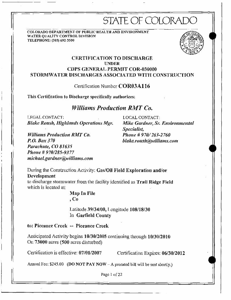
STATE OF COLORADO COLORADO DEPARTMENT OF PUBLIC HEALTH AND ENVIRONMENT WATER QUALITY CONTROL DIVISION TELEPHONE: (303) 692-3500
CERTIFICATION TO DISCHARGE UNDER
CDPS GENERAL PERMIT COR-030000 STORMWATER DISCHARGES ASSOCIATED WITH CONSTRUCTION
Certification Number COR03A116
This Certification to Discharge specifically authorizes:
Williams Production RMT Co. LEGAL CONTACT:
Blake Roush, Highlands Operations Mgr.
Williams Production RMT Co. P.O. Box 370 Parachute, CO 81635 Phone # 9701285-9377 [email protected]
LOCAL CONTACT: Mike Gardner, Sr. Envirollmelltal Specialist, Phone # 9701263-2760 blake.l'[email protected]
DUling the Construction Activity: GaslOil Field Exploration andlor Development to discharge stOlIDwater from the facility identified as Trail Ridge Field which is located at:
Map In File , Co
Latitude 39/34/00, Longitude 108/18/30 In Garfield County
to: Piceance Creek -- Piceance Creek
Anticipated Activity begins 1013012005 continuing through 10/30/2010 On 73000 acres (500 acres distmbed)
Celtification is effective: 0710112007 Certification Expires: 06/30/2012
Annual Fee: $245.00 (DO NOT PAY NOW - A prorated bill will be sent shortly.)
Page 1 of22

APPENDIX B SITE SPECIFIC SWMPS
)
)
SITE SPECIFIC STORMWATER MANAGEMENT PLANS TRAIL RIDGE FIELD
GARFIELD COUNTY, COLORADO
. PREPARED FOR
WILLIAMS PRODUCTION RMT COMPANY PO BOX 370
PARACHUTE, COLORADO 81635
REVI SED
JANUARY 2 01 0
~ Environmental, T Audit & Assessment, Inc.
225 North 51h Street, Suite # 8, Grand Junction, CO 8150 1 (970) 245-5897 www.eaa-co.com
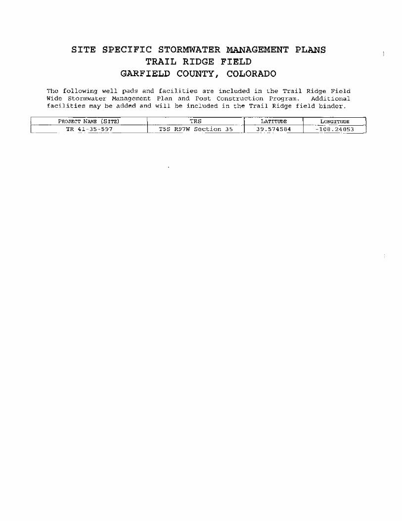
SITE SPECIFIC STORMWATER MANAGEMENT PLANS TRAIL RIDGE FIELD
GARFIELD COUNTY, COLORADO
The following well pads and facilities are included in the Trail Ridge Field Wide Stormwater Management Plan and Post Construction Program. Additional facilities may be added and will be included in the Trail Ridge field binder.
PROJECT NAME (SITE) TRS LATITUDE LONGITUDE
TR 41-35-597 T5S R97W Section 35 39.574584 -108.24053
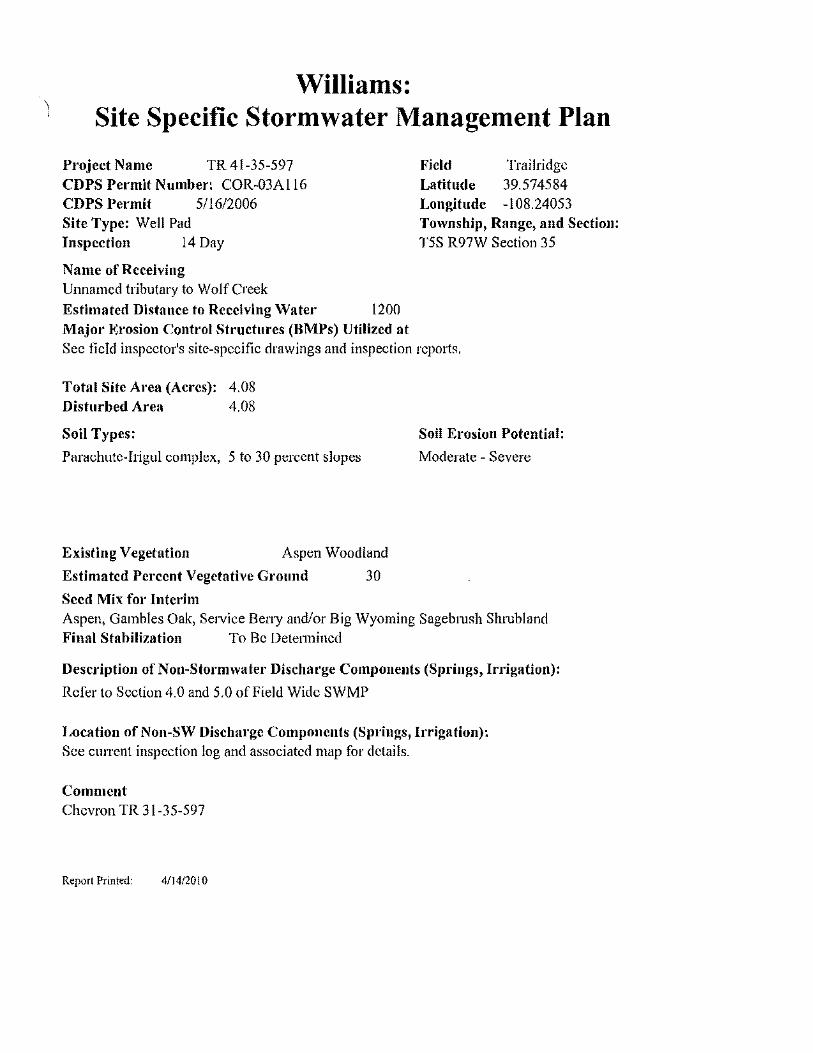
Williams: Site Specific Stormwater Management Plan
Project Name TR 41-35-597 CDPS Permit Number: COR-03AI16 CDPS Permit 511612006 Site Type: Well Pad Inspection 14 Day
Name of Receiving Unnamed tributary to WolfCreek Estimated Distance to Receiving Wate.· 1200 Major Erosion Control Structures (BMPs) Utilized at
Field Trailridge Latitude 39.574584 Longitude -108.24053 Township, Range, and Section: T5S R97W Section 35
See fiefd inspector's site-specific drawings and inspection reports.
Total Site Area (Acres): 4.08 Disturbed Area 4.08
Soil Types:
Parachute-Irigul complex, 5 to 30 percent slopes
Existing Vegetation Aspen Woodland
Estimated Percent Vegetative Ground 30
Seed Mix for Interim
Soil Erosion Potential:
Moderate - Severe
Aspen, Gambles Oak, Service Beny andlor Big Wyoming Sagebmsh Sluubland Final Stabilization To Be Detelmined
Description of Non-Stormwater Discharge Components (Springs, Irrigation):
Refer to Section 4.0 and 5.0 ofField Wide SWMP
Location of Non-SW Discharge Components (Springs, Irrigation): See current inspection log and associated map for details.
Comment Chevron TR 31-35-597
Report Printed: 4114/2010

Storm Water Inspection Map
TR 41-35-597
Legend
.-.~ Access Road
o Limit of Disturbance
Ins~ector Date A 1 " :-,< r~, ,-.~t·"
. nn, ,..>.~ A"'" ~-- Z7--).
N
W*E S
o 50 100 150 '<00 - - - 1 Feet

)
APPENDIX C GENERAL SITE MAP
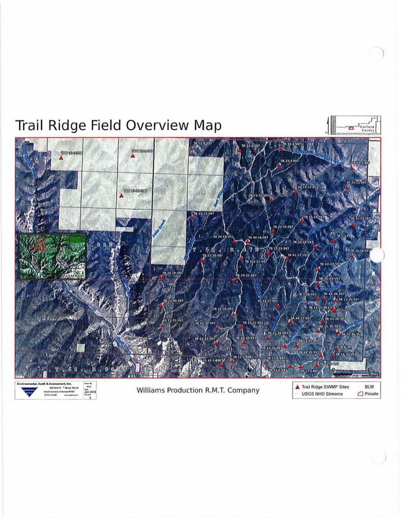
)
Trail Ridge Field Overview Map
)
Williams Production R.M.T. Company USGS NHD S I(8amS

APPENDIX D BMP DETAILS
.~I~,,~A ""I,.18IT1S.
Storm Water Manual of Best Management Practices (BMPs)
Revision 1 July 2010
)
)
AECOM Submitted to: Williams Production RMT Company Parachute, CO
Storm Water Manual of Best Management Practices (BMPs)
Prepared By Emily Nebel, P.E.
Reviewed By Thomas M. Kreutz, P.E.
Submitted by: AECOM Denver, CO 60154901-1 July 2010
Table of Contents
I Introduction ........................................................................................................... I 2 Detennination of BMP Applicability .................................................................... 2 3 BMP Selection ...................................................................................................... 3
Step I - Area of Constructi on ............................................................................... 3 Step 2 - Stage of Constructi on .............................................................................. 3 Step 3 - Type of contro l.. ...................................................................................... 3 Step 4 - BMP selection ......................................................................................... 4
4 BMP Implementation ............................................................................................ 5 5 lnspecti on and Maintenance ................................................................................. 6 6 References ............................................................................................................. 7
Figure I .................................................................................................................................. 9 Figure 2 ....................................................................... """".""" ......................................... 10 Figure 3 ............................................................................................................................... 11
1 Introduction
Rev: 1
The primary purpose of this Storm Water Manual of BMPs is to provide Williams' personnel, contractors, and subcontractors with information on the proper selection, design, installation, and management of Best Management Practices (BMPs) to manage oil and gas (O&G) related storm water and to meet federal and state Storm Water Management Plan (SWMP) requirements as well as Colorado Oil & Gas Conservation Commission (COGCC) postconstruction storm water requirements. The BMPs found in this manual are operating practices used to control erosion, runoff, and sedimentation associated with storm water runoff from areas disturbed by clearing, grading, and excavating activities related to site preparation, construction, and operation of oil and gas production facilities. The BMPs were derived from both common industry practices and from practical field experience.
Personnel responsible for storm water management, whether it be design, construction, maintenance, operation, or environmental compliance, should have a thorough knowledge of the applicable erosion and sediment control measures and the related specifications.
The main objectives of this manual are to:
I. Serve as an easy-to-use guide for selecting, designing, constructing, and maintaining BMPs.
2. Function as a reference for construction plans and specifications.
3. Ultimately lead to the avoidance of any net increase in off-site erosion and sedimentation of waters of the U.S. (see Section 2).
4. Provide a basis for field handbooks and training.
In the preparation of this document, emphasis was placed on the selection and practical application of BMPs, given a variety of basic physical circumstances. This document is provided as a tool to quickly evaluate which BMPs may be useful at a given construction or post-construction site, whether new or existing. This document anticipates that the user will be prudent and exercise good judgment in evaluating site conditions and deciding which BMP or combination of BMPs is to be used at a specific site. If the BMPs selected are not effective to prevent discharges of potentially undesirable quantities of sediment to a regulated water body, different or additional BMPs should be employed.
Date: July 2010 Page 1 Storm Water Manual of BM Ps
2 Determination of BMP Applicability
Rev: 1
There are several physical conditions that can determine whether BMPs are applicable and if so, which BMPs will be effective at a given construction site. Two primary factors are the proximity to waters of the U.S. (regulated water body) and the amount of vegetative cover between the construction site and the regulated water body. Other physical considerations include the slope of the terrain, rainfall, and soil erodibility.
A regulated water body is any body of water that is subject to the U.S. Environmental Protection Agency's (EPA's) jurisdiction under the Clean Water Act. EPA's jurisdiction extends over "waters of the U.S." as defined in 33 CFR 328.
The U.S. Army Corps of Engineers regulates the discharge of dredge and fill material into waters of the U.S. through a permit program under Section 404 of the Clean Water Act. The Corps jurisdiction over waters of the U.S. includes major rivers, streams, and creeks such as the Colorado River, Parachute Creek and Piceance Creek. Drainages and wetlands that are tributary or adjacent to waters of the U.S. such as Wheeler Gulch, Riley Gulch, Starkey Gulch, and Cottonwood Gulch are also typically considered by the Corps to be waters of the U.S. and within their jurisdiction.
Williams' O&G operations are primarily located north and east of Parachute, CO. Lower elevations at the site are categorized as deserts while higher elevations are categorized as xeric mountains. Common characteristics of deserts include slopes from 0 to 40%, shallow rocky or sandy soils with low erodibility, low vegetation cover, and low annual precipitation. Common characteristics of xeric mountains include slopes exceeding 10%, variable vegetation cover, shallow rocky soils with low to moderate erodibility, and low to moderate annual precipitation.
For consideration of BMPs, this manual will be useful in determining which BMPs would be effective for the given circumstances. The above identified minimum distances were determined using the assumed general physical characteristics for either deserts or xeric mountains. If local conditions in the immediate area do not meet those for deserts or xeric mountains the user should use good judgment in the determination of BMP applicability and selection.
Date: July 2010 Page 2 Storm Water Manual of BMPs
3 BMP Selection
Rev: 1
If it has been determined that BMPs are applicable to the construction or postconstruction site, the following steps should be followed in order to select the most appropriate BMP:
Step 1 - Area of Construction In what type of area is the BMP required? Choose one of the following:
• Access roads
• Well pads (including any aerial disturbance such as compressors, plants, etc.)
• Pipelines
Step 2 - Stage of Construction In what stage of construction will the BMP be installed? Choose one of the following:
• Pre-construction - Refers to all BMPs that could be implemented prior to commencement of construction on well pads, pipelines, and/or roads.
• Construction - Refers to all BMPs that could be implemented during/as part of the construction of well pads, pipelines, and/or roads.
• Interim (Temporary) Reclamation - Refers to all BMPs that could be implemented on completion of construction or during postconstruction/operation for temporary reclamation of well pads and/or roads.
• Final (Permanent) Reclamation - Refers to all BMPs that could be implemented on completion of construction, during postconstruction/operation OR on completion of any interim time period for permanent reclamation of well pads, pipelines, and/or roads.
Step 3 - Type of control What is the primary purpose of the BMP and what will the BMP control? Choose from one of the following three main types of storm water control measures:
• Erosion Control (EC) - any source control practice that protects the soil surface and/or strengthens the subsurface in order to prevent
Date: July 2010 Page 3 Storm Water Manual of BMPs
Rev: 1
soil particles from being detached by rain or wind, thus controlling raindrop, sheet, and/or rill erosion.
• Runoff Control (RC) - any practice that reduces or eliminates gully, channel, and stream erosion by minimizing, diverting, or conveying runoff.
• Sediment Control (SC) - any practice that traps the soil particles after they have been detached and moved by wind or water. Sediment control measures are usually passive systems that rely on filtering or settling the particles out of the water or wind that is transporting them prior to leaving the site boundary.
Step 4 - BMP selection Which BMP will be used? Once the area of construction, stage of construction, and type of control are determined (steps I through 3), use the BMP Matrix (Figures 1,2, and 3, below) to find suggested BMP alternatives. Each BMP is also numbered, which corresponds to a fact sheet. A fact sheet is a short document that gives all the information about a particular BMP. Typically, each fact sheet contains the following information:
• Description
• Applicability
• Limitations • Design Criteria
• Construction Specifications • Maintenance Considerations • Removal! Abandonment
• References
The applicability section in each fact sheet contains information on specific site characteristics (such as slope and drainage area) where that BMP may be used. Determination of which BMP or combination of BMPs to install should ultimately be decided after reviewing the BMP applicability section.
Date: July 2010 Page 4 Storm Water Manual of BMPs
4 BMP Implementation
Rev: 1
Once this manual has been used to choose specific BMPs, each control should be incorporated into a site-specific plan drawing. Each BMP has a number/identifier (i.e. SC-2 for Silt Fence) that may be used on plan drawings to represent that BMP at the desired location of installation. The BMP name is also acceptable on the plan drawings.
The design criteria section in each BMP fact sheet should be used to properly locate and size each control (some controls may not require a formal design). The construction requirements and installation figures should then be used in the field to properly install the control with the appropriate materials and methods of construction and at the location indicated on the site-specific plan drawings. It is important to note that minor deviations from the construction specifications are acceptable as long as performance oriented specifications are maintained. For example, the performance oriented specification for a wattle is that sediment is not observed on the down gradient side of the wattle.
Date: July 2010 Page 5 Storm Water Manual of 8M Ps
5 Inspection and Maintenance
Rev: 1
All BMPs must be properly inspected and maintained throughout the life of the entire operation according to the "Maintenance Considerations" section in each BMP fact sheet. In general, the maintenance program should provide for inspection of BMPs on a regular basis in accordance with the SWMP. Inspection of BMPs should also occur as soon as possible after major rainfall events, particularly at sensitive areas in proximity to a perennial drainage. The inspection should include repair or replacement of the BMPs, where needed, to ensure effective and efficient operation.
Date: July 2010 Page 6 Storm Water Manual of BMPs
6 References
Rev: 1
California Stonnwater Quality Association, Stormwater Best Management Practice (BMP) Handbook - Construction. January, 2003. <http://www.cabmphandbooks.com/Construction.asp>
City of Knoxville, Stonnwater Engineering, Knoxvilfe BMP Manual - Best Management Practices. July 2003. <http://www.ci.knoxville.tn.us/engineering>
Colorado Department of Transportation (COOT), Erosion Control and Stormwater Quality Guide. 2002. <http://www.coloradodot.info/programs/environmental/waterquality/documents/erosion-storm-quality>
Environmental Protection Agency (EPA), National Pollutant Discharge Elimination System (NPDES). Construction Site Storm Water Runoff Control. Washington, D.C., February, 2003. <http://cfpub.epa.gov/npdes/stormwater/menuofbmps/index.cfm>
Horizon Environmental Services, Inc, Guidance Document Reasonable and Prudent Practices for Stabilization (RAPPS) of Oil and Gas Construction Sites. Produced by Independent Petroleum Association of America (IPAA). April 2004. <http://www.dpcusa.org/enviro/rapps.html>
Keller, Gordon, and James Sherar, Low-Volume Roads Engineering, Best Management Practices Field Guide. United States Department of Agriculture (USDA), Forest Service, US Agency of International Development (US AID), 2005. <http://www.blm.gov/bmp/field%20guide.htm>
Maine Department of Conservation, Best Management Practices for Forestry: Protecting Maine's Water Quality. Maine Forest Service, Forest Policy and Management Division. Augusta, Maine. 2004. <http://www.state.me.us/doc/mfs/pubs/pdf/bmp _ manual/bmp _ manual.pdf>
New York State Department of Environmental Conservation, New York Guidelines for Urban Erosion and Sediment Control. New York. Fourth Edition, 1997.
United States Army Corps of Engineers (USACE), Engineering and Design -Handbook for the Preparation of Storm Water Pollution Prevention Plansfor Construction Activities. February 1997.
Date: July 2010 Page 7 Storm Water Manual of BMPs

Rev: 1
United States Department of Agriculture (USDA), Natural Resources Conservation Service (NRCS), Field Office Technical Guide. 2002. <www.nrcs.usda.gov/technical/efotg>
United States Department of the Interior, Bureau of Land Management (BLM), United States Department of Agriculture (USDA), Forest Service, Surface Operating Standards for Oil and Gas Exploration and Development "Gold Book". Fourth Edition, 2005.
Date: July 2010 Page 8 Storm Water Manual of BMPs
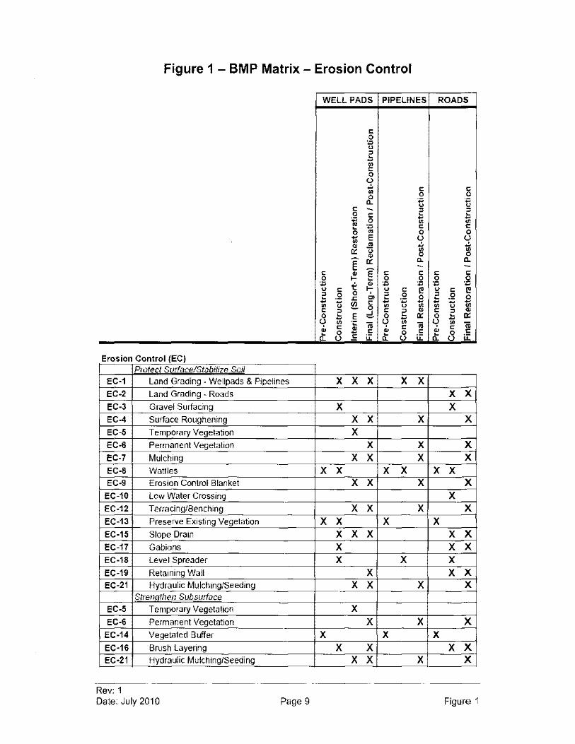
Figure 1 - BMP Matrix - Erosion Control
WELL PADS PIPELINES ROADS
c 0
n ::> ~ ~
til C 0 u .!. c C til 0 0 0 a- +:l ~ u
C - ::> ::> 0 c ~ ~
+:l 0 ~ ~ til '" .,
+:l C C ~
0 ., 0 0
~ E u U til ., .!. .!. OJ c:: <; til [g .. 0 - c:: a- a-E - -c ~ E c c c c
0 ~ 0 0 0 0 . ., t: .. . ., +:l +:l
. ., u c f;' u c I!! u c I!! ::> .2 0 ::> 0 ::> .2 ~ .c Cl ~ '':::; 0 ~ 0 ~ ~
~ c ~ ~ ~ ~ -til U 0 til U '" til U ID c ::> =. c ::> OJ c ::> 0 ~ E 0 ~ c:: 0 ~ c:: ~ ~ -U til .;:
'iii u til 'iii u til 'iii
" c OJ " C
" C ~ 0 - c
~ 0 c ~ 0 c
a- u c u:: a- u u:: a- u u::
Erosion Control (EC) Protect S!ltfacelStabilize Soil
EC-l Land Grading - Wellpads & Pipelines X X X X X EC-2 Land Grading - Roads X X EC-3 Gravel Surfacing X X EC-4 Surface Roughening X X X X EC-5 Temporary Vegetation X EC-6 Permanent Vegetation X X X EC-7 Mulching X X X X EC-8 Wattles X X X X X X EC-9 Erosion Control Blanket X X X X EC-l0 Low Water Crossing X EC-12 Terracing/Benching X X X X EC-13 Preserve Existing Vegetation X X X X EC-15 Slope Drain X X X X X EC-17 Gabions X X X EC-18 Level Spreader X X X EC-19 Retaining Wall X X X EC-21 Hydraulic Mulching/Seeding X X X X
SlrenaliJen Subsutface
EC-5 Temporary Vegetation X EC-6 Permanent Vegetation X X X
EC-14 Vegetated Buffer X X X EC-16 Brush Layering X X X X EC-21 Hydraulic Mulching/Seeding X X X X
Rev: 1 Date: July 2010 Page 9 Figure 1
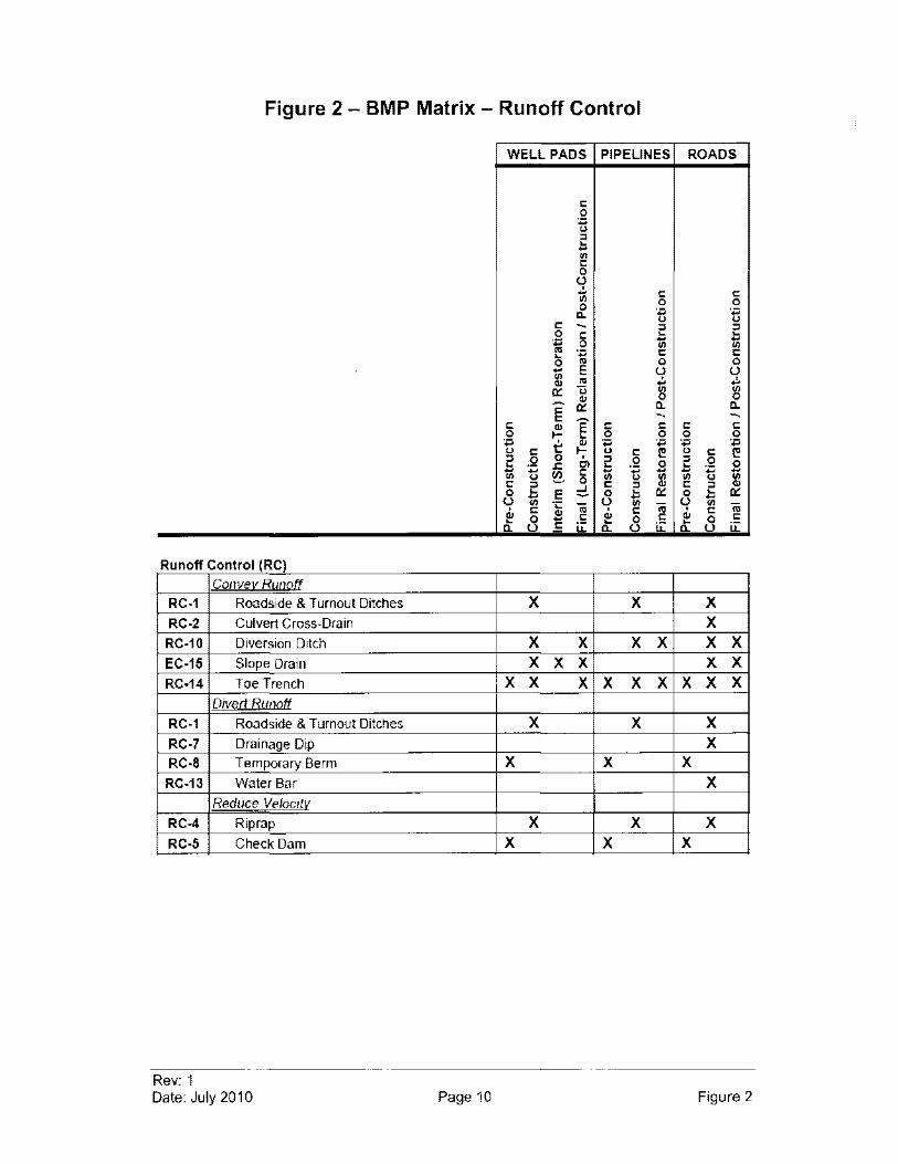
Figure 2 - BMP Matrix - Runoff Control
WELL PADS PIPELINES ROADS
I: 0 ., " " ~ ~ III I: 0
U .:. I: I: III 0 0 0 ., ., a. " u
I: - " " 0 I: ~ ~ ., ~ ~ 0 III III
'" . ., I: I: ~
0 .. 0 0 ~ E u u i!l .. .:. .:. a: u :g III
" 0 - a: a. a. E - -I: " E I: I: I: I:
0
~ ~ 0 0 0 0 ., "
. ., ., ., ., u I: f- u I: C! " I: C! " 0 0 .;, " 0 " 0 ~ . ., s: ~ . ., 0 ~ <:: 0 ~
~ I: t) ~ ~ ~ III U 0 U III III U ID I: " I: " '" I: " 0 ~ E :::!. 0 ~ a: 0 ~ a: ~ ~ -u '" .;: .. u '" .. u '" .. ~ I: " .. I: • I:
0 ~ I: 0 I: '" 0 I: I: u: ~ u: ~ u: a. u a. U a. U
Runoff Control (RC) CQJ1ve~ RUtlQft
RC·1 Roadside & Turnout Ditches X X X RC·2 Culvert Cross·Drain X RC·10 Diversion Ditch X X X X X X EC·15 Slope Drain X X X X X RC·14 Toe Trench X X X X X X X X X
OivS!.rt RU/loff
RC·1 Roadside & Turnout Ditches X X X RC·7 Drainage Dip X RC·8 Temporary Berm X X X RC·13 Water Bar X
Reduce Velocit~
RC·4 Riprap X X X RC·5 Check Dam X X X
Rev: 1 Date: July 2010 Page 10 Figure 2
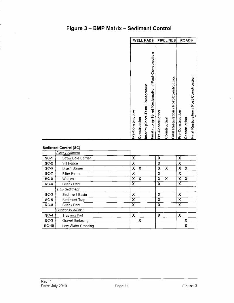
Figure 3 - BMP Matrix - Sediment Control
WELL PADS PIPELINES ROADS
" 0
~ " ~ -VI
" 0 (.) .!. " " '" 0 0 0 Do
., ., u u
" - " " 0 " ~ ~
~ - -0 '" fJ)
'''' " " 0 '" 0 0 - E (.) (.) i!l '" .!. t; a:: u ~ '" 0
E a:: Do Do - -" '" E " " " " 0 t ~ 0 0 0 0 .,
~ '''' ., '''' ., u C u C Cl u c Cl " 0 0 ,
" ,2 " 0 0 ~ .s: '" ~ 0 ~ -:;:; ~ " 1ii - --:;:; -VI U 0 u i!l VI u fJ)
c " ::!. c " " " '" 0 ~ E 0 ~ a:: 0 ~ a:: - - -(.) fJ) 'c 'jij (.) '" 'jij (.) fJ) 'jij
" " '" " " ,
" 0 - " 0 " '" 0 c ~
(.) c i.i: ~ (.) i.i: ~
(.) i.i: Do Do Do
Sediment Control (SC)
Filter Sediment
SC-1 Straw Bale Barrier X X X SC-2 Silt Fence X X X SC-5 Brush Barrier X X X X X X SC-7 Filter Berm X X X EC-8 Wattles X X X X X X RC-5 Check Dam X X X
True. Sediment SC-3 Sediment Basin X X X SC-6 Sediment Trap X X X RC-5 Check Dam X X X
Control Mud/Dust
SC-4 Tracking Pad X X X EC-3 Gravel Surfacing X X
EC-10 LolV Water Crossing X
Rev: 1 Date: July 2010 Page 11 Figure 3
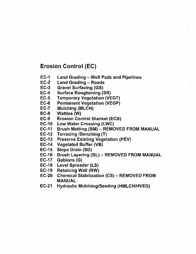
Erosion Control (EC)
EC-1 EC-2 EC-3 EC-4 EC-S EC-6 EC-7 EC-8 EC-9 EC-10 EC-11 EC-12 EC-13 EC-14 EC-1S EC-16 EC-17 EC-18 EC-19 EC-20
EC-21
Land Grading - Well Pads and Pipelines Land Grading - Roads Gravel Surfacing (GS) Surface Roughening (SR) Temporary Vegetation (VEGT) Permanent Vegetation (VEGP) Mulching (MLCH) Wattles (W) Erosion Control Blanket (ECB) Low Water Crossing (LWC) Brush Matting (BM) - REMOVED FROM MANUAL Terracing /Benching (T) Preserve Existing Vegetation (PEV) Vegetated Buffer (VB) Slope Drain (SO) Brush Layering (BL) - REMOVED FROM MANUAL Gabions (G) Level Spreader (LS) Retaining Wall (RW) Chemical Stabilization (CS) - REMOVED FROM MANUAL Hydraulic Mulching/Seeding (HMLCH/HVEG)
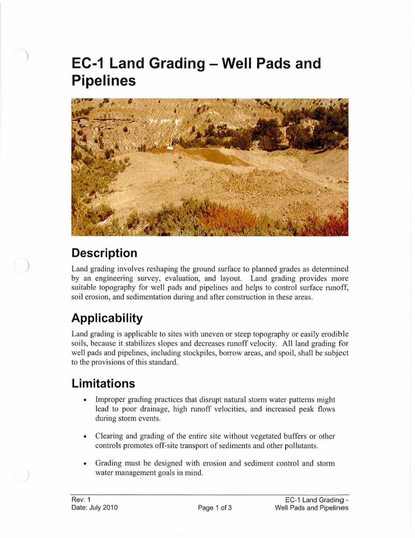
)
)
EC-1 Land Grading - Well Pads and Pipelines
Description Land grading involves reshaping the ground surface to planned grades as determined by an engineering survey, evaluation, and layout. Land grading provides more suitable topography for we ll pads and pipelines and helps to contro l surface runoff, so il erosion, and sedimentation during and after construction in these areas.
Applicability Land grading is applicable to sites with uneven or steep topography or eas ily erodible so il s, because it stabilizes slopes and decreases runoff velocity. All land grading for we ll pads and pipelines, including stockpiles, borrow areas, and spoil , shall be subject to the provisions of this standard .
Limitations • Improper grading practices that disrupt natural storm water patterns might
lead to poor drainage, high runoff veloc ities, and increased peak flows during storm events.
• Clearing and grading of the entire site without vegetated buffers or other controls promotes off-site transport of sediments and other pollutants.
• Grading must be des igned with erosion and sediment control and storm water management goals in mind.
Rev: 1 Date: July 2010 Page 1 of 3
EC-1 Land Grading -Well Pads and Pipelines
Design Criteria A construction plat is typically prepared for each well pad and pipeline to establish which areas of the site will be graded, and dictates where excess material will be disposed of (or where borrow materials will be obtained if needed). Berms, diversion ditches, terracing, and other storm water practices that require excavation and filling may also be incorporated into the construction plats.
Land grading should be based upon well pad and pipeline layouts that fit and utilize existing topography and desirable natural surroundings to avoid extreme grade modifications. Clearing and grading should only occur at those areas necessary for well pad activities and equipment traffic. Maintaining undisturbed temporary or permanent buffer zones in the grading operation provides a low-cost sediment control measure that will help reduce runoff and off-site sedimentation.
Construction Specifications I. All applicable erosion and sediment control practices and measures shall
be constructed prior to any land grading activities, if possible, and maintained in accordance with this BMP manual. Control practices should remain in place until all graded or disturbed areas, including slopes, are adequately stabilized.
2. Cut and fill slopes will be constructed in accordance with the grading plan. Ideally, both cut and fill slopes should be constructed with a 2: 1 or flatter slope to promote growth of vegetation.
3. Areas to be filled shall be cleared, grubbed, and stripped of topsoil to remove trees, vegetation, roots, or other objectionable material.
4. Except for nonstructural fills, fill material shall be free of brush, logs, stumps, roots, or other objectionable materials that would interfere with, or prevent, construction of satisfactory fills. Frozen material shall not be placed in the fill nor shall the fill material be placed on a frozen foundation.
5. All fills shall be compacted as required to reduce erosion, slippage, settlement, subsidence, or other related problems. Fill intended to support buildings, structures, and conduits, etc., shall be placed in appropriately sized layers and compacted as necessary.
6. Cut slopes occurring in ripable rock may be serrated if necessary to stabilize the slope. Overland flow shall be diverted from the top of any cut slopes and carried to a suitable outlet.
Rev: 1 Date: July 2010 Page 2 of 3
EC-1 Land Grading -Well Pads and Pipelines
7. Topsoil required for the establishment of vegetation (if available) shall be stockpiled in the amount necessary to complete finished grading of all exposed areas.
8. Areas that are to be topsoiled shall be scarified to a minimum depth of four inches, if necessary, prior to placement of topsoil.
9. Reverse slope benches (terraces) may be used on long slopes where slope lengths need to be shortened. Benches shall be designed according to EC-12 Terracing.
10. To ensure that surface runoff will not damage slopes or other graded areas, diversion ditches, slope drains, or other applicable runoff control will be used to safely direct surface runoff to storm drains, protected outlets, or to stable water courses, except where:
a. The face of the slope is or shall be stabilized and the face of all graded slopes shall be protected from surface runoff until they are stabilized.
b. The face of the slope shall not be subject to any concentrated flows of surface water such as from natural drainage ways, graded swales, downspouts, etc.
c. The face of the slope will be protected by special erosion control materials, gravel, riprap, surface roughening, or other stabilization method.
11. All graded areas shall be stabilized, either structurally or vegetatively, following finished grading.
Maintenance Considerations The frequency of inspections should be in accordance with the Storm Water Management Plan. If any erosion, washouts, or breaks occur, it should be repaired as soon as possible. Prompt maintenance of small-scale eroded areas is essential to prevent these areas from becoming significant gullies.
References Environmental Protection Agency (EPA), National Pollutant Discharge Elimination
System (NPDES). Construction Site Storm Water RunojJControl. Washington, D.C., February, 2003. <http://cfpub.epa.gov/npdes/stormwater/menuofbmpslindex.cfm>
New York State Department of Environmental Conservation, New York Guidelines for Urban Erosion and Sediment Control. New York. Fourth Edition, 1997.
Rev: 1 Date: July 2010 Page 3 of 3
EC-1 Land Grading -Well Pads and Pipelines
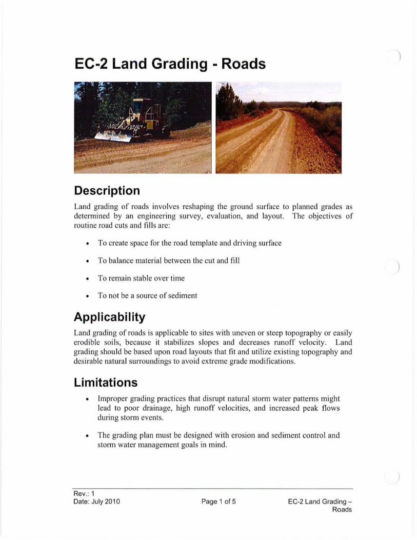
EC-2 Land Grading - Roads
Description Land grading of roads involves reshaping the ground surface to planned grades as determined by an engineering survey, evaluation, and layout. The objectives of routine road cuts and fills are:
• To create space for the road template and driving surface
• To balance material between the cut and fill
• To remain stable over time
• To not be a source of sediment
Applicability Land grading of roads is applicab le to sites with uneven or steep topography or easily erodible soi ls, because it stabi lizes slopes and decreases runoff ve locity. Land grading should be based upon road layouts that fit and utilize existing topography and desirable natural surroundings to avoid extreme grade modifications.
Limitations • Improper grading practices that disrupt natural stonn water patterns might
lead to poor drainage, high runoff velocities, and increased peak flows during storm events.
• The grading plan must be designed with erosion and sediment contro l and storm water management goals in mind.
Rev.: 1 Date: July 2010 Page 1 of 5 EC-2 Land Grading -
Roads
)
)
Design Criteria A construction plat is typically prepared for each road to establish the extent to which the road will be graded, and dictates where excess material will be disposed of (or where borrow materials will be obtained if needed). Berms, diversion ditches, culverts, terracing, and other storm water practices that require excavation and filling may also be incorporated into the construction plat.
Road Sloping Roads using sloping provide good drainage of water from the surface of the road into stabilized ditches or vegetation, and help keep the traveled way dry and passable during wet weather. The three most common types of roadway sloping are outsloped, insloped, or crowned as shown in Figure EC-2-1.
• Outs loped roads minimize the concentration of water and minimize road width by avoiding the need for an inside ditch, but may require roadway surface and fill slope stabilization. Outs loped roads with clay rich, slippery road surface materials will require rock surface stabilization (see EC-3 Road Gravel) or limited use during rainy periods to assure traffic safety. On road grades over 10 to 12 percent and on steep hill slope areas, outs loped roads are difficult to drain and can feel unsafe.
• Insloped roads are the best method to control surface water. However, ins loped roads also concentrate water and require a system of ditches and turnouts or cross-drains.
• Crowned roads are appropriate for higher standard, two lane roads on gentle grades. They also require a system of inside ditches and turnouts or cross-drains. It is difficult to create and maintain a crown on a narrow road, so generally ins loped or outs loped road drainage is more effective.
Slope Failures Landslides and failed road cuts and fills can be a major source of sediment, they can close the road or require major repairs, and they can greatly increase road maintenance costs. Slope failures, or landslides, typically occur where a slope is over-steep, where fill material is not compacted, or where cuts in natural soils encounter groundwater or zones of weak material. Good road location can often avoid landslide areas and reduce slope failures. When failures do occur, the slide area should be stabilized by removing the slide material, flattening the slope, adding drainage, or using structures, as discussed below. Designs are typically site specific and may require input from geotechnical engineers and engineering geologists. Failures that occur typically impact road operations and can be costly to repair. Failures near streams and channel crossings have an added risk of impact to water quality.
Rev.: 1 Date: July 2010 Page 2 of 5 EC-2 Land Grading -
Roads
Construction Specifications I. All applicable erosion and sediment control practices and measures shall
be constructed prior to any road grading activities, if possible, and maintained in accordance with this BMP manual. Control practices should remain in place until all graded or disturbed areas, including slopes, are adequately stabilized.
2. Areas to be filled shall be cleared, grubbed, and stripped of topsoil to remove trees, vegetation, roots, or other objectionable material.
3. Fill material shall be free of brush, logs, stumps, roots, or other objectionable materials that would interfere with, or prevent, construction of satisfactory fills. Frozen material shall not be placed in the fill nor shall the fill material be placed on a frozen foundation.
4. Cut and fill slopes will be constructed in accordance with the grading plan. Vertical cut slopes should not be used unless the cut is in rock or very well cemented soil. Ideally, both cut and fill slopes should be constructed with a 2: I or flatter slope to promote growth of vegetation.
5. All fills shall be compacted as required to reduce erosion, slippage, settlement, subsidence, or other related problems. Fill intended to support buildings, structures, and conduits, etc., shall be placed in appropriately sized layers and compacted as necessaty.
6. Topsoil required for the establishment of vegetation (if necessary) shall be stockpiled in the amount necessary to complete finished grading of all exposed areas.
7. Areas that are to be topsoiled shall be scarified to a minimum depth of four inches, if necessary, prior to placement of topsoil.
8. Reverse slope benches (terraces) may be used on long slopes where slope lengths need to be shortened. Benches shall be designed according to EC-12 Terracing.
9. To ensure that surface runoff will not damage slopes or other graded areas, diversion ditches, slope drains, or other applicable runoff control will be used to safely conduct surface runoff to storm drains, protected outlets, or to stable water courses, except where:
Rev.: 1
a. The face of the slope is or shall be stabilized and the face of all graded slopes shall be protected from surface runoff until they are stabilized.
Date: July 2010 Page 3 of 5 EC-2 Land Grading -Roads
b. The face of the slope shall not be subject to any concentrated flows of surface water such as from natural drainage ways, graded swales, downspouts, etc.
c. The face of the slope will be protected by special erosion control materials, gravel, riprap, surface roughening, or other stabilization method.
10. All graded areas shall be stabilized, either structurally or vegetatively, following finished grading. The following list are some common slope stabilization options appropriate for roads:
a. Vegetate the slope (EC-6 Permanent Vegetation)
b. Use an erosion control blanket (EC-9 Erosion Control Blanket)
c. Cover the slope with riprap (RC-4 Riprap)
d. Design and construct gab ions (EC-17 Gabions) or retaining walls (EC-19 Retaining Wall)
Maintenance Considerations The frequency of inspections should be in accordance with the Storm Water Management Plan. If any erosion, washouts or breaks occur, it should be repaired as soon as possible. Prompt maintenance of small-scale eroded areas is essential to prevent these areas from becoming significant gullies. Maintain road sloping and repair any problems as soon as possible.
References Environmental Protection Agency (EPA), National Pollutant Discharge Elimination
System (NPDES). Construction Site Storm Water Runoff Contro!' Washington, D.C., February, 2003. <http://cfpub.epa.gov/npdes/stormwater/menuofbmps/index.cfm>
Horizon Environmental Services, Inc, Guidance Document Reasonable and Prudent Practices for Stabilization (RAPPS) of Oil and Gas Construction Sites. Produced by Independent Petroleum Association of America (IPAA). April 2004. <http://www.dpcusa.org/enviro/rapps.html>
Keller, Gordon, and James Sherar, Low-Voilime Roads Engineering, Best Management Practices Field Guide. United States Department of Agriculture (USDA), Forest Service, US Agency of International Development (USAlD), 2005. <htlp:llwww.blm.gov/bmp/field%20guide.htm>
New York State Department of Environmental Conservation, New York Guidelines for Urban Erosion and Sediment Control. New York. Fourth Edition, 1997.
Rev.: 1 Date: July 2010 Page 4 of 5 EC-2 Land Grading -
Roads
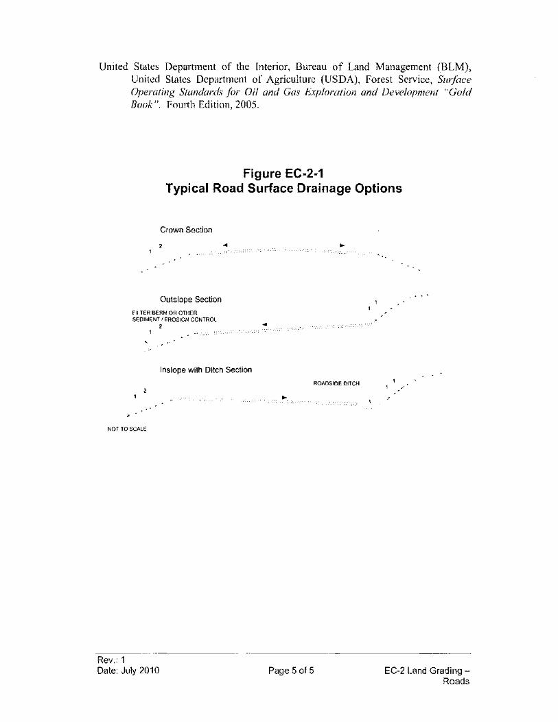
United States Department of the Interior, Bureau of Land Management (BLM), United States Department of Agriculture (USDA), Forest Service, Surface Operating Standards for Oil and Gas Exploration and Development "Gold Book ". Fourth Edition, 2005.
Figure EC-2-1 Typical Road Surface Drainage Options
Crown Section
2
Outslope Section
FILTER BERM OR OTHER SEDIMENT I EROSION CONTROL
2
,
..
Inslope with Ditch Section
2
NOT rOSCAlE
Rev.: 1 Date: July 2010
..
ROADSIDE DITCH
Page 5 of 5
...
EC-2 Land Grading -Roads
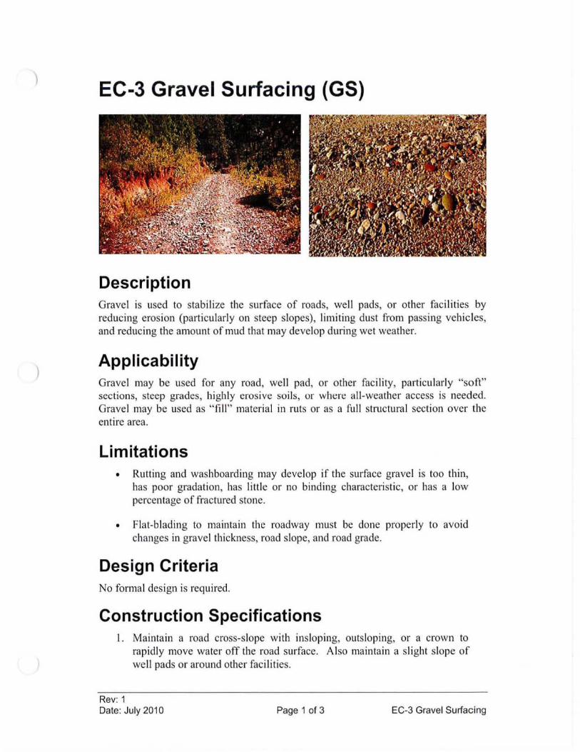
)
EC-3 Gravel Surfacing (GS)
Description Gravel is used to stab ili ze the surface of roads, we ll pads, or other fac ili ties by reducing erosion (particu larly on steep slopes), limiting dust from pass ing vehic les, and reducing the amount of mud that may develop during wet weather.
Applicability Grave l may be used for any road, we ll pad, or other fac ility, particularly "soft" sections, steep grades, high ly erosive soi ls, or wht:rt: all-weather access is needed. Gravel may be used as " fill " material in ruts or as a full structura l section over the entire area.
Limitations • Rutting and washboarding may develop if the surface gravel is too thin,
has poor gradation, has little or no binding characteristic , or has a low percentage of fractured stone.
• Flat-b lading to maintain the roadway must be done properly to avoid changes in gravel thickness, road slope, and road grade.
Design Criteria No formal design is required.
Construction Specifications I. Maintain a road cross-s lope with insloping, outsloping, or a crown to
rapidly move water off the road surface. Also maintain a slight slope of well pads or around other facilities.
Rev: 1 Date: July 2010 Page 1 of 3 EC-3 Grave l Surfacing
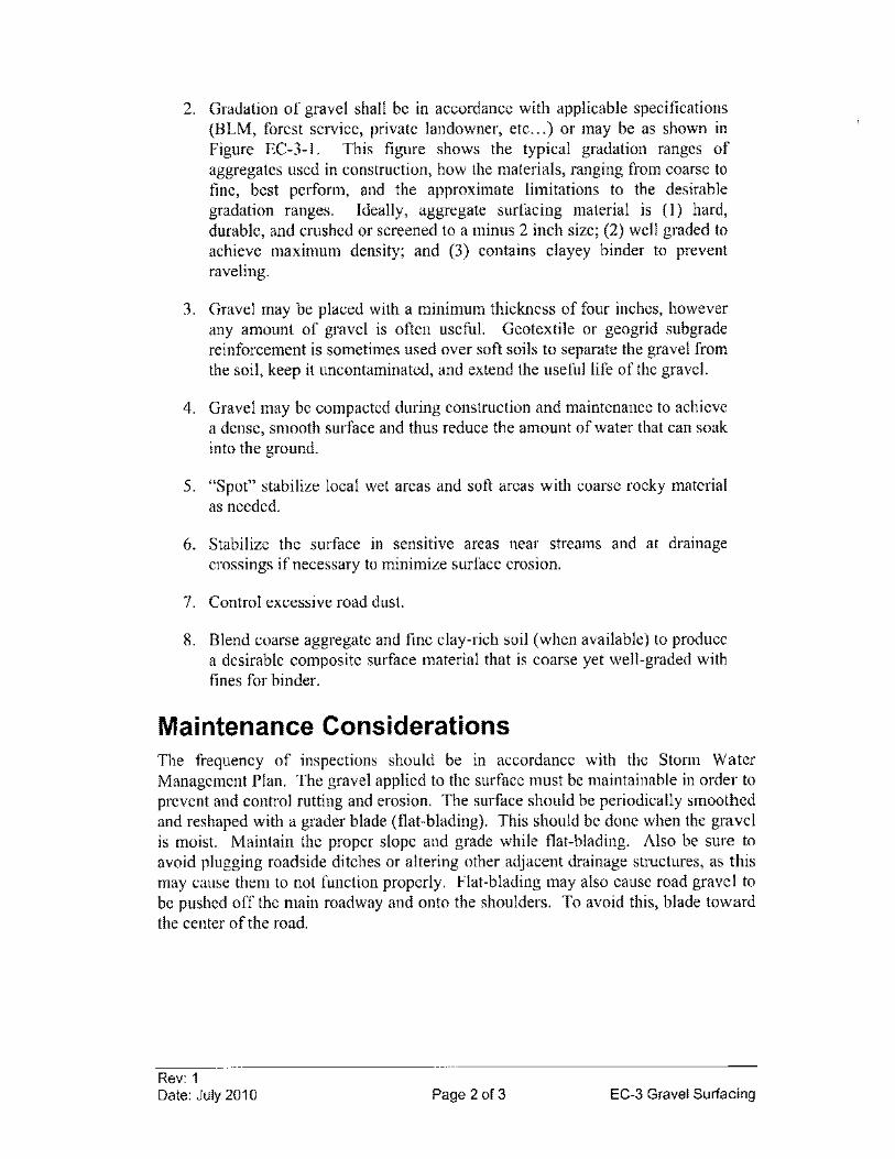
2. Gradation of gravel shall be in accordance with applicable specifications (BLM, forest service, private landowner, etc ... ) or may be as shown in Figure EC-3-1. This figure shows the typical gradation ranges of aggregates used in construction, how the materials, ranging from coarse to fine, best perform, and the approximate limitations to the desirable gradation ranges. Ideally, aggregate surfacing material is (I) hard, durable, and crushed or screened to a minus 2 inch size; (2) well graded to achieve maximum density; and (3) contains clayey binder to prevent raveling.
3. Gravel may be placed with a minimum thickness of four inches, however any amount of gravel is often useful. Geotextile or geogrid subgrade reinforcement is sometimes used over soft soils to separate the gravel from the soil, keep it uncontaminated, and extend the useful life of the gravel.
4. Gravel may be compacted during construction and maintenance to achieve a dense, smooth surface and thus reduce the amount of water that can soak into the ground.
5. "Spot" stabilize local wet areas and soft areas with coarse rocky material as needed.
6. Stabilize the surface in sensitive areas near streams and at drainage crossings if necessary to minimize surface erosion.
7. Control excessive road dust.
8. Blend coarse aggregate and fine clay-rich soil (when available) to produce a desirable composite surface material that is coarse yet well-graded with fines for binder.
Maintenance Considerations The frequency of inspections should be in accordance with the Stonn Water Management Plan. The gravel applied to the surface must be maintainable in order to prevent and control rutting and erosion. The surface should be periodically smoothed and reshaped with a grader blade (flat-blading). This should be done when the gravel is moist. Maintain the proper slope and grade while flat-blading. Also be sure to avoid plugging roadside ditches or altering other adjacent drainage structures, as this may cause them to not function properly. Flat-blading may also cause road gravel to be pushed off the main roadway and onto the shoulders. To avoid this, blade toward the center of the road.
Rev: 1 Date: July 2010 Page 2 of 3 EC-3 Gravel Surfacing
References Keller, Gordon, and James Sherar, Low- Volume Roads Engineering, Best
Management Practices Field Guide. United States Department of Agriculture (USDA), Forest Service, US Agency of International Development (USAID), 2005. http://www.blm.govlbmp/field%20guide.htm
Figure EC-3-1 Gradation and Performance of
Surfacing Materials
SIEVE ANALYSIS
Sfze of Oponlll9' In Inches Nom"', 01 Mesh· U.S. Slaooard
! ~ r-- f--- • 1- -
i
1=-\ -
j \ 1-o, I- I· ~-- fA ,
.. , . ...
~~ --
~ .~ ,(» . I.e ..
2
r. I~ :~ .. .
~"?Q'" ~--
~ k • 3
\ 1-- 1%: 1-' ~ I· (/.. 1<1 [IS) I
Vfm 1-- .. • .. r h r-f_ r"1
I-- I 10 .~ r.o "" - , I - 1
0•
-4
r ..' t\c ~ 0
I· I' D'. ~ ~. I 0 ~~< ~ .. - ...
3' ,. ~
... 1---" l--- .. 1
~ 1- I:-.I'~ ~~ ~. 1 I· I'" I'"
2. f-- 0 C(
~~ 0
10
.,. .. ,.-~~ ~- .........
0 ..... ""'- 1-- ---9 I. 1- _. _C I·. -- .. _ ...
I 1--:-
.... ,-
" ,,-, ., I "' , , I • _I II I 1 • fa s : I • ~
.. ~:; i : :J ;!!
• •
•
• o
.. PARTICLE SIZE IN MILLIMETERS
Fino Modlum
GRAVEL SAND
J\(HE: Gradation Ranges Showll Are Approximale.
Rev: 1 Date: July 2010 Page 3 of 3 EC-3 Gravel Surfacing
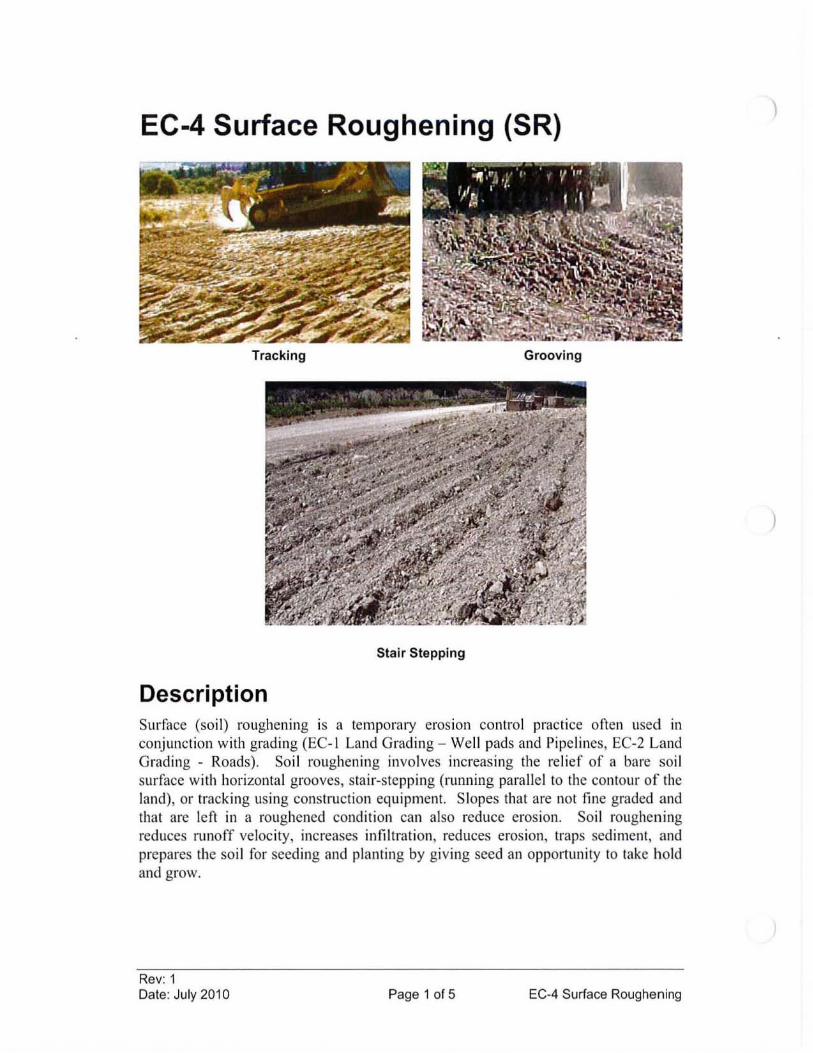
EC-4 Surface Roughening (SR)
Tracking Grooving
Stair Stepping
Description Surface (so il) roughening is a temporalY erosion control practice often used in conjunction with grading (EC- I Land Grading - Well pads and Pipelines, EC-2 Land Grading - Roads). Soil roughening involves increasing the relief of a bare soil surface with horizontal grooves, stair-stepping (running parallel to the contour of the land), or tracking using constlUction equipment. Slopes that are not fine graded and that are left in a roughened condition can also reduce erosion . Soil roughening reduces runoff veloc ity, increases infil tration, reduces erosion, traps sediment, and prepares the soi l for seeding and planting by giving seed an opportuni ty to take hold and grow.
Rev: 1 Date: July 2010 Page 1 of 5 EC-4 Surface Roughening
)
)
Applicability Soil roughening is most effective on areas on one acre or less, and works well for the following applications:
• To aid the establishment of vegetative cover from seed
• To reduce runoff velocity and increase infiltration
• To reduce erosion and provide for trapping of sediment
• Any slope, but particularly slopes greater than 3: 1
• Areas with highly erodible soils
• Soils that are frequently disturbed
Limitations • Soil roughening is not appropriate for rocky slopes.
• Soil compaction might occur when roughening with tracked machinery.
• Soil roughening is of limited effectiveness in anything more than a gentle or shallow depth rain.
• Ifroughening is washed away in a heavy storm, the surface will have to be re-roughened and new seed laid.
Design Criteria There are many different methods to achieve a roughened soil surface on a slope. No formal design is required. However, the selection of the appropriate method depends on the type of slope. Methods include tracking, grooving, and stair-stepping. Steepness, mowing requirements, and/or a cut or fill slope operation are all factors considered in choosing a roughening method.
Tracking Tracking (Figure EC-4-1) should be used primarily in sandy soils to avoid undue compaction of the soil surface. Tracking is generally not as effective as the other roughening methods described. (It has been used as a method to track down mulch.) Operate tracked machinery up and down the slope to leave horizontal depressions in the soil. Do not back-blade during the final grading operation.
Grooving Grooving (Figure EC-4-2) uses machinery to create a series of ridges and depressions that run across the slope on the contour. Groove using any appropriate implement
Rev: 1 Date: July 2010 Page 2 of 5 EC-4 Surface Roughening
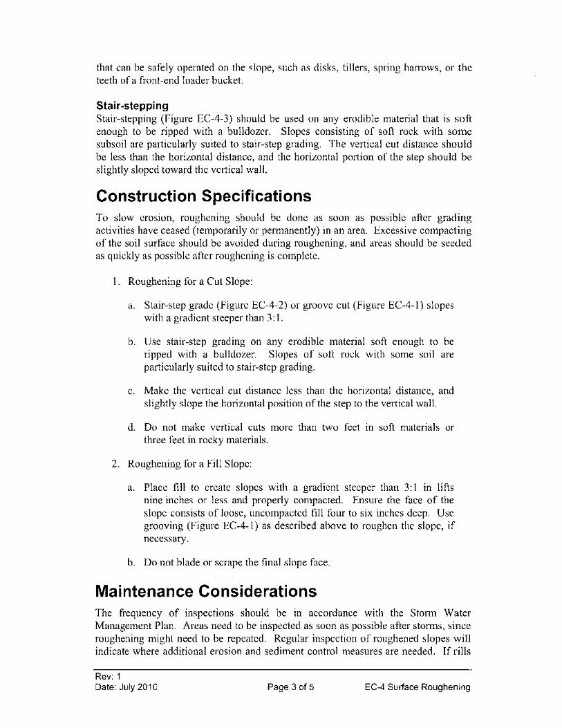
that can be safely operated on the slope, such as disks, tillers, spring harrows, or the teeth of a front -end loader bucket.
Stair-stepping Stair-stepping (Figure EC-4-3) should be used on any erodible material that is soft enough to be ripped with a bulldozer. Slopes consisting of soft rock with some subsoil are particularly suited to stair-step grading. The vertical cut distance should be less than the horizontal distance, and the horizontal portion of the step should be slightly sloped toward the vertical wall.
Construction Specifications To slow erosion, roughening should be done as soon as possible after grading activities have ceased (temporarily or permanently) in an area. Excessive compacting of the soil surface should be avoided during roughening, and areas should be seeded as quickly as possible after roughening is complete.
1. Roughening for a Cut Slope:
a. Stair-step grade (Figure EC-4-2) or groove cut (Figure EC-4-1) slopes with a gradient steeper than 3: 1.
b. Use stair-step grading on any erodible material soft enough to be ripped with a bulldozer. Slopes of soft rock with some soil are particularly suited to stair-step grading.
c. Make the vertical cut distance less than the horizontal distance, and slightly slope the horizontal position of the step to the vertical wall.
d. Do not make vertical cuts more than two feet in soft materials or three feet in rocky materials.
2. Roughening for a Fill Slope:
a. Place fill to create slopes with a gradient steeper than 3: 1 in lifts nine inches or less and properly compacted. Ensure the face of the slope consists of loose, uncompacted fill four to six inches deep. Use grooving (Figure EC-4-1) as described above to roughen the slope, if necessary.
b. Do not blade or scrape the final slope face.
Maintenance Considerations The frequency of inspections should be in accordance with the Storm Water Management Plan. Areas need to be inspected as soon as possible after storms, since roughening might need to be repeated. Regular inspection of roughened slopes will indicate where additional erosion and sediment control measures are needed. If rills
Rev: 1 Date: July 2010 Page 3 of 5 EC-4 Surface Roughening
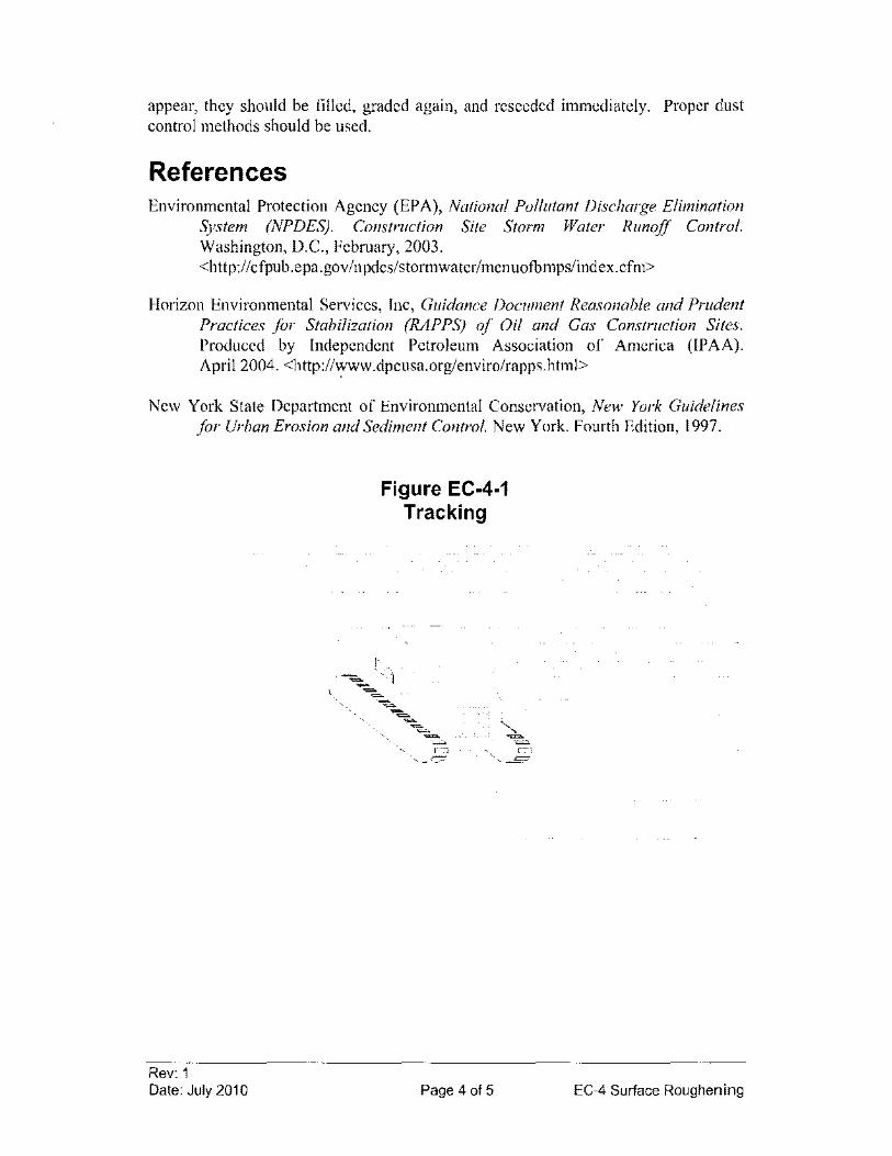
appear, they should be filled, graded again, and reseeded immediately. Proper dust control methods should be used.
References Environmental Protection Agency (EPA), National Pollutant Discharge Elimination
System (NPDES). Construction Site Storm Water Runoff Control. Washington, D.C., February, 2003. <http://cfpub.epa.gov/npdes/stormwater/menuofbmps/index.cfm>
Horizon Environmental Services, Inc, Guidance Document Reasonable and Prudent Practices for Stabilization (RAPPS) of Oil and Gas Construction Sites. Produced by Independent Petroleum Association of America (IPAA). April 2004. <http://www.dpcusa.org/enviro/rapps.html>
New York State Department of Environmental Conservation, New York Guidelines for Urban Erosion and Sediment Control. New York. Fourth Edition, 1997.
Rev: 1 Date: July 2010
Figure EC-4-1 Tracking
':;;:.. ~
',- '- --.l;;:
Page 4 of 5 EC-4 Surface Roughening
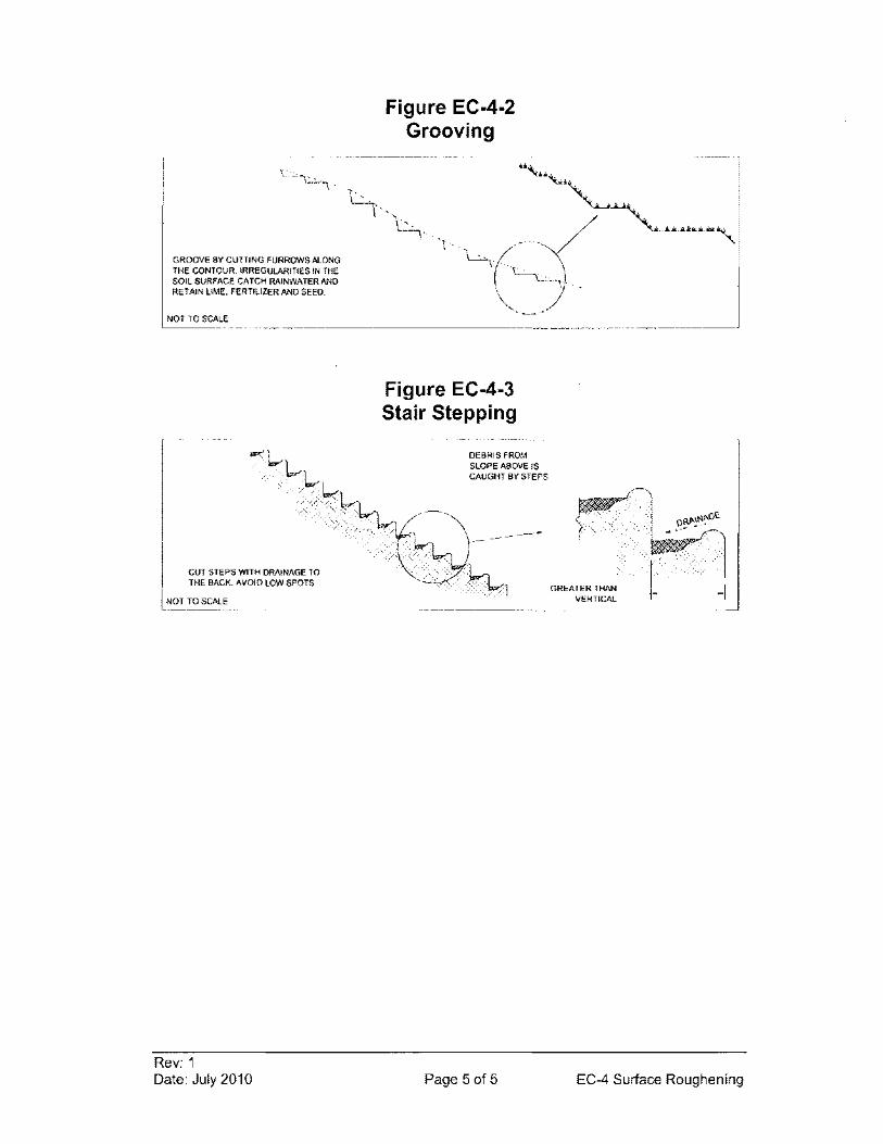
Figure EC-4-2 Grooving
,------------------------------------------------------,
GROOVE BY CUTTING FURROWS AlONG THE CONTOUR. IRREGULARITIeS IN THE SOIL SURFACE CATCH RAINWATER AND RETAIN LIME. FERTILIZER AND SEED.
NOT TO SCALE ... ~--.--~------------------
CUT STEPS WITH DRAINAGE TO THE BACK. AVOID LOW SPOTS
NOT TO SCAlE
Rev: 1 Date: July 2010
Figure EC-4-3 Stair Stepping
.-----~--------------,
DEBRIS FROM SLOPE ABOVE IS CAUGHT BY STEPS
Page 5 of 5
GREATER THAN VERTICAL -I
EC-4 Surface Roughening
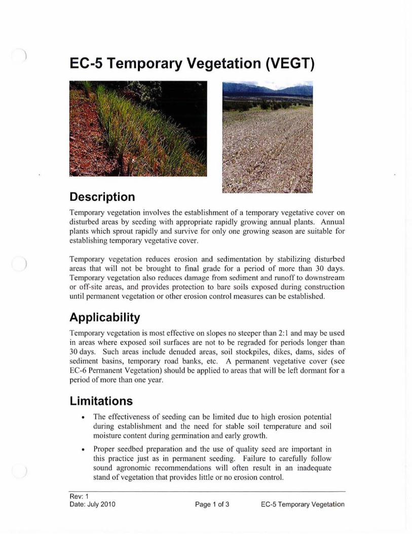
)
)
EC-5 Temporary Vegetation (VEGT)
Description Temporary vegeta ti on involves the establishment of a temporary vegetative cover on disturbed areas by seeding with appropriate rapidly growing annual plants. Annual plants which sprout rapidly and survive for only one growing season are suitable for establishing temporalY vegetative cover.
Temporary vegetation reduces erosion and sedimentation by stabilizing disturbed areas that will not be brought to final grade for a period of more than 30 days. Temporary vegetation also reduces damage from sediment and runoff to downstream or off-site areas, and provides protection to bare soi ls exposed during construction until permanent vegetation or other erosion control measures can be established.
Applicability Temporary vegetation is most effective on slopes no steeper than 2: I and may be used in areas where exposed soil surfaces are not to be regraded for periods longer than 30 days. Such areas include denuded areas, so il stockpiles, dikes, dams, sides of sediment basins, temporary road banks, etc. A permanent vegetative cover (see EC-6 Permanent Vegetation) should be app lied to areas that will be left d0n11ant for a period of more than one year.
Limitations • The effectiveness of seeding can be limited due to high erosion potential
during estab li shment and the need for stable soi l temperature and soil moisture content during germination and early growth.
• Proper seedbed preparation and the use of quality seed are important in thi s practice just as in permanent seeding. Failure to carefully follow sound agronomic recommendations wi ll often result in an inadequate stand of vegetation that provides little or no erosion control.
Rev: 1 Date: July 2010 Page 1 of 3 EC-5 Temporary Vegetation
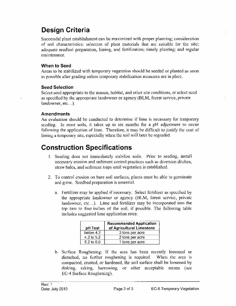
Design Criteria Successful plant establishment can be maximized with proper planning; consideration of soil characteristics; selection of plant materials that are suitable for the site; adequate seedbed preparation, liming, and fertilization; timely planting; and regular maintenance.
When to Seed Areas to be stabilized with temporary vegetation should be seeded or planted as soon as possible after grading unless temporary stabilization measures are in place.
Seed Selection Select seed appropriate to the season, habitat, and other site conditions, or select seed as specified by the appropriate landowner or agency (BLM, forest service, private landowner, etc ... ).
Amendments An evaluation should be conducted to determine if lime is necessary for temporary seeding. In most soils, it takes up to six months for a pH adjustment to occur following the application of lime. Therefore, it may be difficult to justify the cost of liming a temporary site, especially when the soil will later be regraded.
Construction Specifications 1. Seeding does not immediately stabilize soils. Prior to seeding, install
necessary erosion and sediment control practices such as diversion ditches, straw bales, and sediment traps until vegetation is established.
2. To control erosion on bare soil surfaces, plants must be able to germinate and grow. Seedbed preparation is essential.
Rev: 1
a. Fertilizer may be applied if necessary. Select fertilizer as specified by the appropriate landowner or agency (BLM, forest service, private landowner, etc ... ). Lime and fertilizer may be incorporated into the top two to four inches of the soil, if possible. The following table includes suggested lime application rates:
Recommended Application pH Test of AQricultural Limestone
below 4.2 3 tons per acre 4.2 to 5.2 2 tons per acre 5.2 to 6.0 1 tons per acre
b. Surface Roughening: If the area has been recently loosened or disturbed, no further roughening is required. When the area is compacted, crusted, or hardened, the soil surface shall be loosened by dis king, raking, harrowing, or other acceptable means (see EC-4 Surface Roughening).
Date: July 2010 Page 2 of 3 EC-5 Temporary Vegetation
3. The appropriate seed shall be evenly applied with a broadcast seeder, drill, cultipacker seeder or hydroseeder.
4. Temporary seedings mayor may not be mulched according to EC-7 Mulching.
Maintenance Considerations Inspect seeded areas in accordance with the Storm Water Management Plan. Areas which fail to establish vegetative cover adequate to prevent rill erosion will be reseeded as soon as such areas are identified.
References Keller, Gordon, and James Sherar, Low-Volume Roads Engineering, Best
Management Practices Field Guide. United States Department of Agriculture (USDA), Forest Service, US Agency of International Development (USAID), 2005. <http://www.blm.gov/bmp/field%20guide.htm>
United States Army Corps of Engineers (USACE), Engineering and Design -Handbookfor the Preparation of Storm Water Pollution Prevention Plans for Construction Activities. February 1997.
Rev: 1 Date: July 2010 Page 3 of 3 EC-5 Temporary Vegetation
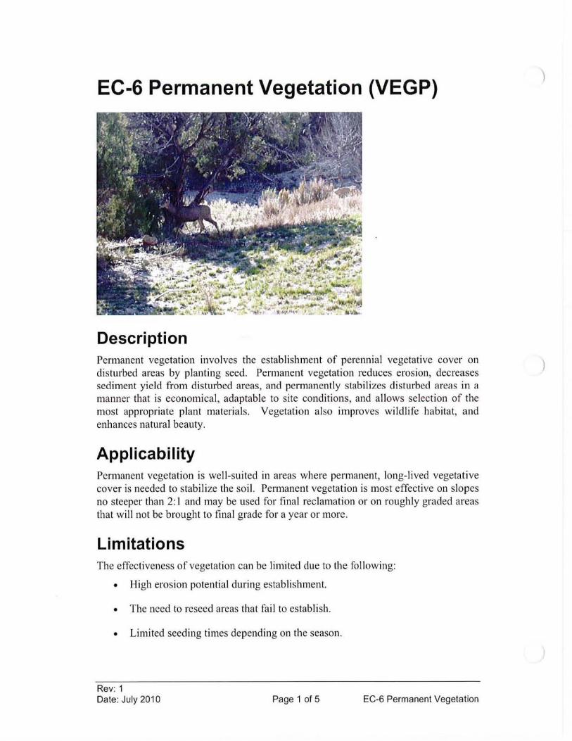
EC-6 Permanent Vegetation (VEGP)
Description Permanent vegetation involves the estab lishment of perennial vegetative cover on disturbed areas by planting seed. Permanent vegetation reduces eros ion, decreases sed iment yield from disturbed areas, and permanently stab ilizes disturbed areas in a maimer that is economica l, adaptable to site conditions, and allows se lection of the most appropriate plant materials. Vegetation also improves wildlife habitat, and enhances natural beauty.
Applicability Permanent vegetation is well-suited in areas where permanent, long- lived vegetative cover is needed to stabi li ze the soi l. Pel111anent vegetation is most effecti ve on slopes no steeper than 2 : I and may be used for final reclamation or on roughl y graded areas that will not be brought to final grade fo r a year or more.
Limitations The effectiveness of vegetation can be limited due to the following:
• High erosion potential during estab li shment.
• The need to reseed areas that fail to estab li sh.
• Limited seed ing times depending on the season.
Rev: 1 Date: July 2010 Page 1 of 5 EC-6 Permanent Vegetation
)
)
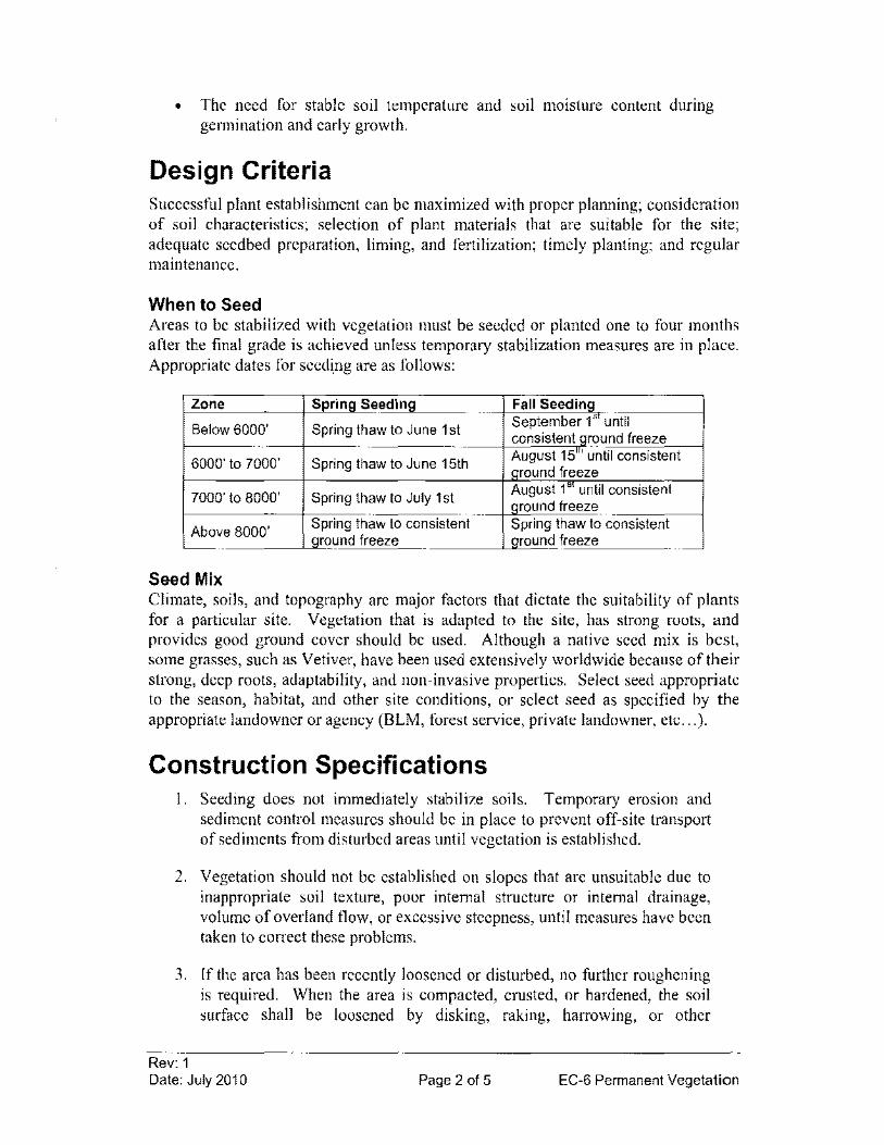
• The need for stable soil temperature and soil moisture content during gelmination and early growth.
Design Criteria Successful plant establishment can be maximized with proper planning; consideration of soil characteristics; selection of plant materials that are suitable for the site; adequate seedbed preparation, liming, and fertilization; timely planting; and regular maintenance.
When to Seed Areas to be stabilized with vegetation must be seeded or planted one to four months after the final grade is achieved unless temporary stabilization measures are in place. Appropriate dates for seeding are as follows:
Zone Spring Seeding Fall Seeding
Below 6000' Spring thaw to June 1 st September l' until consistent ground freeze
6000' to 7000' Spring thaw to June 15th August 15m until consistent Ground freeze
7000' to 8000' Spring thaw to July 1 st August l' until consistent ground freeze
Above 8000' Spring thaw to consistent Spring thaw to consistent ground freeze Qround freeze
Seed Mix Climate, soils, and topography are major factors that dictate the suitability of plants for a particular site. Vegetation that is adapted to the site, has strong roots, and provides good ground cover should be used. Although a native seed mix is best, some grasses, such as Vetiver, have been used extensively worldwide because of their strong, deep roots, adaptability, and non-invasive properties. Select seed appropriate to the season, habitat, and other site conditions, or select seed as specified by the appropriate landowner or agency (BLM, forest service, private landowner, etc ... ).
Construction Specifications 1. Seeding does not immediately stabilize soils. Temporary erosion and
sediment control measures should be in place to prevent off-site transport of sediments from disturbed areas until vegetation is established.
2. Vegetation should not be established on slopes that are unsuitable due to inappropriate soil texture, poor internal structure or internal drainage, volume of overland flow, or excessive steepness, until measures have been taken to correct these problems.
3. If the area has been recently loosened or disturbed, no further roughening is required. When the area is compacted, crusted, or hardened, the soil surface shall be loosened by disking, raking, harrowing, or other
Rev: 1 Date: July 2010 Page 2 of 5 EC-6 Permanent Vegetation
acceptable means to ensure good water infiltration and root penetration (see EC-4 Surface Roughening).
4. The soil on a disturbed site may need to be modified to provide an optimum environment for seed germination and seedling growth. To maintain a good stand of vegetation, the soil must meet certain minimum requirements as a growth medium. If any of the below criteria cannot be met then topsoil should be applied. The existing soil must have these characteristics:
a. Enough fine-grained material to maintain adequate moisture and nutrient supply.
b. Sufficient depth of soil to provide an adequate root zone. The depth to rock or impermeable layers such as hardpans shall be 12 inches or more, except on slopes steeper than 2: I where the addition of soil is not feasible.
c. A favorable pH range for plant growth. If the soil is so acidic that a pH range of 6.0-7.0 cannot be attained by addition of ph-modifying materials, then the soil is considered an unsuitable environment for plant roots and further soil modification would be required.
d. Freedom from toxic amounts of materials harmful to plant growth.
e. Freedom from excessive quantities of roots, branches, large stones, large clods of earth, or trash of any kind. Clods and stones may be left on slopes steeper than 3: I if they do not significantly impede good seed soil contact.
5. Add fertilizer and/or lime, if necessary. The addition of lime is equally as important as applying fertilizer. Lime will modify the pH and supply calcium and magnesium. Its effect on pH makes other nutrients more available to the plant. Select fertilizer as specified by the appropriate landowner or agency (BLM, forest service, private landowner, etc ... ).
6. Apply seed uniformly with a broadcast seeder, drill, culti-packer seeder, or hydro seeder on a firm, friable seedbed.
7. If necessary, apply mulch according to EC-7 Mulching. The mulch will hold moisture and modify temperature extremes, and prevent erosion while seedlings are growing.
Maintenance Considerations Inspect seeded areas in accordance with the Storm Water Management Plan. Areas which fail to establish vegetative cover adequate to prevent rill erosion will be reseeded as soon as such areas are identified.
Rev: 1 Date: July 2010 Page 3 of 5 EC-6 Permanent Vegetation
Newly seeded areas may be supplied with adequate moisture. Supply water if needed, especially late in the season, in abnormally hot or dry weather, or on adverse sites. Water application rates should be controlled to prevent excessive runoff. Inadequate amounts of water may be more harmful than no water.
Grasses should emerge within 4-28 days and legumes 5-28 days after seeding, with legumes following grasses. A successful stand should exhibit the following:
• Vigorous dark green or bluish green seedlings, not yellow
• Uniform density, with nurse plants, legumes, and grasses well intemlixed
• Green leaves-perennials should remain green throughout the summer, at least at the plant bases
Vegetation is considered established when a density of at least 70 percent of predisturbance levels has been reached. Seeded areas should be inspected for failure and any necessary repmrs and re-seedings should be made within the same season, if possible.
• If vegetative cover is inadequate to prevent rill erosIOn, over-seed and fertilize in accordance with soil test results.
• If timing is bad, Ryegrass or German Millet can be overseeded to thicken the stand until a suitable time for seeding perennials.
• If a stand has less than 40% cover, re-evaluate choice of plant materials and quantities of lime and fertilizer. The soil must be tested to determine if acidity or nutrient imbalances are responsible. Reestablish the stand following seedbed preparation and seeding recommendations.
In general, a stand of vegetation cannot be detem1ined to be fully established until it has been maintained for one full year after planting. Full plant establishment may require refertilization in the second growing season. Soil tests can be used to detem1ine if more fertilizer needs to be added. Do not fertilize cool season grasses in late May through July. Grass that looks yellow may be nitrogen deficient. Do not use nitrogen fertilizer if the stand contains more than 20 percent legumes.
References Environmental Protection Agency (EPA), National Pollutant Discharge Elimination
System (NPDES). Construction Site Storm Water RunojJControl. Washington, D.C., February, 2003. <http://cfpub.epa.gov/npdes/stom1water/menuofbmps/index.cfm>
Rev: 1 Date: July 2010 Page 4 of 5 EC-6 Permanent Vegetation
Horizon Environmental Services, Inc, Guidance Document Reasonable and Prudent Practices for Stabilization (RAPPS) of Oil and Gas Construction Sites. Produced by Independent Petroleum Association of America (lPAA). April 2004. <http://www.dpcusa.org/enviro/rapps.html>
Rev: 1 Date: July 2010 Page 5 of 5 EC-6 Permanent Vegetation
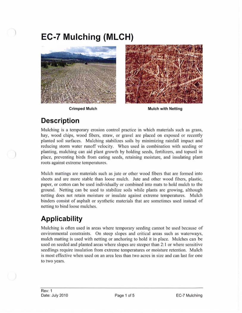
)
)
EC-7 Mulching (MLCH)
Crimped Mulch Mulch with Netting
Description Mulching is a temporary erosion control practice in which materi als such as grass, hay, wood chips, wood fibers, straw, or grave l are placed on exposed or recently planted soil surfaces. Mulching stabilizes soil s by minimizing rainfall impact and reducing storm water runoff ve locity. When used in combination with seeding or planting, mulching can aid plant growth by holding seeds, fertili zers, and topsoil in place, preventing birds from eating seeds, retaining moisture, and insulating plant roots aga inst extreme temperatures.
Mulch mattings are materials such as jute or other wood fibers that are formed into sheets and are more stable than loose mulch. Jute and other wood fibers, plastic, paper, or cotton can be used individually or combined into mats to hold mulch to the ground. Netting can be used to stabilize soils while plants are growing, although nett ing does not retain moisture or insulate aga inst extreme temperatures. Mulch binders consist of asphalt or synthetic materi als that are sometimes used instead of netting to bind loose mulches.
Applicability Mulching is often used in areas where temporary seeding cannot be used because of environmental constrai nts. On steep slopes and criti cal areas such as waterways, mulch matting is used with netting or anchoring to hold it in place. Mulches can be used on seeded and planted areas where slopes are steeper than 2; I or where sensitive seedlings requ ire insulation from ex treme temperatures or moisture retention. Mulch is most effecti ve when used on an area less than two acres in size and can last for one to two years.
Rev; 1 Date: July 2010 Page 1 of 5 EC-7 Mulching

Limitations • Mulching, matting, and netting might delay seed gennination because the
cover changes soil surface temperatures.
• The mulches themselves are subject to erosion and may be washed away in a large stonn.
• Maintenance is necessary to ensure that mulches provide effective erosion control.
Design Criteria No formal design is required.
Construction Specifications I. Site Preparation
a. Prior to mulching, install the necessary temporary or pennanent erosion control practices and drainage systems within or adjacent to the area to be mulched.
b. Slope, grade and smooth the site to fit needs of selected mulch products.
c. Remove all undesirable stones and other debris to meet the needs of the anticipated land use and maintenance required.
2. Mulching & Anchoring
Rev: 1
a. Select the appropriate mulch and application rate that will best meet the need and availability of material. When possible, organic mulches should be used for erosion control and plant material establishment. See Table EC-7-1 for suggested materials. Other materials include hydraulic mulch products with I DO-percent post-consumer paper content and yard trimming composts. Pea gravel or crushed granite can be used in unvegetated areas. All materials should be free of seed.
b. Apply mulch after soil amendments and planting is accomplished or simultaneously if hydro seeding is used. See Table EC-7-1 for installation guidelines.
c. Loose hay or straw may be anchored usmg one of the methods described in Table EC-7-2. Materials that are heavy enough to stay in place (for example, gravel or bark or wood chips on flat slopes) do not need anchoring. Mulches mayor may not require a binder, netting, or
Date: July 2010 Page 2 of 5 EC-7 Mulching
tacking. Effective use of netting and matting material requires firm, continuous contact between the materials and the soil.
Maintenance Considerations Mulched areas should be inspected in accordance with the Storm Water Management Plan to identify areas where mulch has loosened or been removed, especially after rainstorms. Such areas should be reseeded (if necessary) and the mulch cover replaced immediately. Mulch binders should be applied at rates recommended by the manufacturer. If washout, breakage, or erosion occurs, surfaces should be repaired, reseeded, and remulched, and new netting should be installed. Inspections should be continued until vegetation is firmly established.
Removal/Abandonment Anchor netting and any other artificial mulch material should be removed when protection is no longer needed and disposed of in a landfill.
References Environmental Protection Agency (EPA), National Pollutant Discharge Elimination
System (NPDES). Construction Site Storm Water Runoff Contra!' Washington, D.C., February, 2003. <http://cfpub.epa.gov/npdes/stormwater/menuofbmps/index.cfm>
Horizon Environmental Services, Inc, Guidance Document Reasonable and Prudent Practices for Stabilization (RAPPS) of Oil and Gas Construction Sites. Produced by Independent Petroleum Association of America (IPAA). April 2004. <http://www.dpcusa.org/enviro/rapps.html>
New York State Department of Environmental Conservation, New York Guidelines for Urban Erosion and Sediment Control. New York. Fourth Edition, 1997.
United States Department of Agriculture (USDA), Natural Resources Conservation Service (NRCS), Field Office Technical Guide. 2002. <www.nrcs.usda.gov/technical/efotg>
Rev: 1 Date: July 2010 Page 3 of 5 EC-7 Mulching
Table EC-7-1 Typical Mulching Materials and Application Rates
Rate per Material Acre Requirements Notes
Or!lanic Mulches
Straw 1 - 2 tons Dry, unchopped, Spread by hand or unweathered; avoid machine; must be tacked weeds. or tied down.
Wood fiber or Y, - 1 ton Use with hydroseeder; wood cellulose may be used to tack
straw. Do not use in hot, dry weather.
Wood chips 5 - 6 tons Air dry. Add fertilizer N, Apply with blower, chip 12 Ib/ton. handler, or by hand. Not
for fine turf areas.
Bark 35 yd' Air dry, shredded, or Apply with mulch blower, hammermilled, or chips chip handler, or by hand.
Do not use asphalt tack.
Nets and Mats
Jute net Cover area Heavy, uniform; woven Withstands water flow. of single jute yarn. Used with organic mulch.
Excelsior (wood Cover area fiber) mat
Fiberglass roving Y, - 1 ton Continuous fibers of Apply with compressed drawn glass bound air ejector. Tack with together with a non-toxic emulsified asphalt at a agent. rate of 25 - 35 gal./1 000
It.'
Rev: 1 Date: July 2010 Page 4 of 5 EC-7 Mulching
Anchoring Method or Material
1. Peg and Twine
2. Mulch netting
3. Wood cellulose fiber
4. Mulch anchoring tool
5. Chemical
Rev: 1 Date: July 2010
Table EC-7-2 Mulch Anchoring Guide
Kind of Mulch to be Anchored How to Apply Hay or straw After mulching, divide areas into blocks
approximately 1 sq. yd. in size. Drive 4-6 pegs per block to within 2" to 3" of soil surface. Secure mulch to surface by stretching twine between pegs in criss-cross pattern on each block. Secure twine around each peg with two or more tight turns. Drive pegs flush with soil. Driving stakes intoground tiqhtens twine.
Hay or straw Staple the light-weight paper, jute, wood fiber, or plastic nettings to soil surface according to manufacturer's recommendations. Should be biodegradable. Most products are not suitable for foot traffic.
Hay or straw Apply hydroseeder immediately after mulching. Use 500 Ibs. Wood fiber per acre. Some products contain an adhesive material, possiblyadvantaqeous.
Hay or straw Apply mulch and pull a mulch anchoring tool (blunt, straight discs, crimper, or tracked equipment) over mulch as near to the contour as possible. Mulch material should be "tucked" into soil surface about 3".
Hay or straw Apply Terra Tack AR 120 Ibs.lac. In 480 gal. of water (#156/ac.) or Aerospray 70 (60 gal/ac.) according to manufacturer's instructions. Avoid application during rain. A 24-hour curing period and a soil temperature higher than 45 deg. Fahrenheit are required.
Page 5 of 5 EC-7 Mulching
EC-8 Wattles (W)
Description A wattle (also called a fiber roll) consists of straw, flax , or other simi lar materials bound into a tight tubular roll. When wattles are placed at the toe and on the face of slopes, they intercept runoff, reduce its flow velocity, release the runoff as sheet flow, and provide removal of sediment from the runoff. By interrupting the length of a slope, fiber rolls can also reduce erosion.
Applicability Wattles may be suitable:
• Along the toe, top, face, and at grade breaks of exposed and erodible slopes to shorten slope length and spread runoff as sheet flow
• At the end of a downward slope where it transitions to a steeper slope
• A long the perimeter of a project
• As check dams in un lined ditches
• Down-slope of exposed soi l areas
• Around temporary stockpiles
Limitations • Watt les are not effect ive unless trenched.
• Difficult to move once saturated.
Rev: 1 Date: July 2010 Page 1 of 4 EC-8 Wattles
)
)

• If not properly staked and trenched in, wattles could be transported by high flows.
• Wattles have a very limited sediment capture zone.
• Wattles should not be used on slopes subject to creep, slumping, or landslide.
Design Criteria No formal design is required.
Construction Specifications Wattles should be either prefabricated rolls or rolled tubes of erosion control blanket. (If using an erosion control blanket roll the length of erosion control blanket into a tube of minimum 8 in. diameter and bind roll at each end and every 4 ft along length of roll with jute-type twine.)
Minor deviations from the following construction specifications are acceptable as long as performance oriented specifications are maintained. The perfonnance oriented specification for wattles is that sediment is not observed on the down gradient side of the wattle row. If sediment is observed on the down gradient side of the wattle, the wattle should be re-installed.
See Figure EC-8-1.
I. Locate wattles on level contours where possible. However, wattles may also be used off-contour to direct runoff to an outlet sediment control BMP (i.e. a sediment trap) or used as a check dam within a diversion ditch.
2. Suggested spacing of wattles for use on permanent slopes is as follows:
a. Slope inclination of 4: I (H:V) or flatter: Fiber rolls should be placed at a maximum interval of 20 ft.
b. Slope inclination between 4: I and 2: I (H:V): Fiber Rolls should be placed at a maximum interval of 15 ft. (a closer spacing is more effective).
c. Slope inclination 2: I (H:V) or greater: Fiber Rolls should be placed at a maximum interval of to ft. (a closer spacing is more effective).
3. Wattles may also be used on temporary slopes at a spacing determined in the field or as a single wattle placed at the toe of the slope or at the perimeter of a project.
Rev: 1 Date: July 2010 Page 2 of 4 EC-8 Wattles
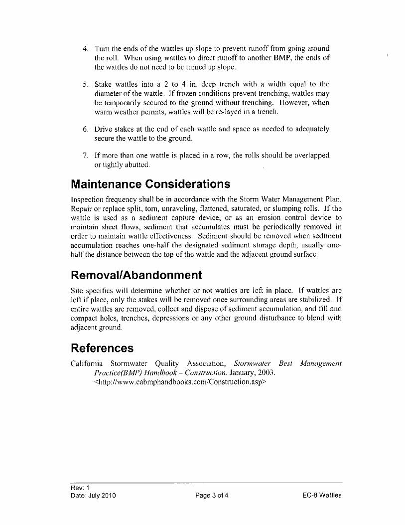
4. Tum the ends of the wattles up slope to prevent runoff from going around the roll. When using wattles to direct runoff to another BMP, the ends of the wattles do not need to be turned up slope.
5. Stake wattles into a 2 to 4 in. deep trench with a width equal to the diameter of the wattle. If frozen conditions prevent trenching, wattles may be temporarily secured to the ground without trenching. However, when warm weather permits, wattles will be re-layed in a trench.
6. Drive stakes at the end of each wattle and space as needed to adeqnately secure the wattle to the ground.
7. If more than one wattle is placed in a row, the rolls should be overlapped or tightly abutted.
Maintenance Considerations Inspection frequency shall be in accordance with the Storm Water Management Plan. Repair or replace split, tom, unraveling, flattened, saturated, or slumping rolls. If the wattle is used as a sediment capture device, or as an erosion control device to maintain sheet flows, sediment that accumulates must be periodically removed in order to maintain wattle effectiveness. Sediment should be removed when sediment accumulation reaches one-half the designated sediment storage depth, usually onehalf the distance between the top of the wattle and the adjacent ground surface.
Removal/Abandonment Site specifics will determine whether or not wattles are left in place. If wattles are left if place, only the stakes will be removed once surrounding areas are stabilized. If entire wattles are removed, collect and dispose of sediment accumulation, and fill and compact holes, trenches, depressions or any other ground disturbance to blend with adjacent ground.
References California Stormwater Quality Association, Storm water Best Management
Practice(BMP) Handbook - Construction. January, 2003. <http://www.cabmphandbooks.com/Construction.asp>
Rev: 1 Date: July 2010 Page 3 of 4 EC-8 Wattles
SlOPe
NOT TO SCALE
Rev: 1
Figure EC-8-1 Typical Wattle Installation
E~tend end of watue upslope to avoid lIow
around end
Wattle
Vertical spacing measured along the face of the slope varies.
.. 2'min. 4~ma~
Install wattle near slope where it transitions into steeper slope
Date: July 2010 Page 4 of4
Wattle S" min. ,
EC-8 Wattles
EC-9 Erosion Control Blanket (ECB)
Description Erosion control blankets are porous fabrics and are manufactured by weaving or bonding fibers made from organic or synthetic materials. Erosion control blankets are installed on steep slopes or in channels to prevent erosion until final vegetation is established. However, blankets can also be used as separators or to aid in plant growth by holding seeds, fertilizers , and topsoil in place.
Applicability Erosion control blankets may be used in the following applications:
• To control erosion on steep slopes and to promote the establishment of vegetation.
• To stabilize channels against erosion from concentrated flows.
• To protect exposed soils immediately and temporarily, such as when active piles of soil are left overnight.
• As a separator between riprap and soil to prevent soil from being eroded from beneath the riprap and to maintain the riprap's base.
• May be used on slopes as steep as I: I.
Rev: 1 Date: July 2010 Page 1 of 4 EC-9 Erosion Control Blanket
)
Limitations • Blankets used on slopes should be biodegradable, or photodegradable,
non-toxic to vegetation or germination of seed, and non-toxic or injurious to humans.
• Should not be used on slopes where vegetation is already established.
• Some blankets might promote increased runoff and might blow away if not firmly anchored.
• If the fabric is not properly selected, designed, or installed, the effectiveness may be reduced drastically.
Design Criteria There are many types of erosion control blankets available. Therefore, the selected fabric should match its purpose. Effective netting and matting require firm, continuous contact between the materials and the soil. If there is no contact, the material will not hold the soil, and erosion will occur underneath the material. Table EC-9-1 indicates some recommended criteria for the selection of erosion control blankets.
Construction Specifications 1. Smooth soil prior to installation and apply seed prior to fabric installation
for final stabilization of construction sites.
2. Select the appropriate fabric type based on the guidelines from Table EC-9-1 or based on field experience.
3. Installation of the blankets shall be in accordance with the manufacturer's recommendations and/or according to Figure EC-9-1.
4. Fabric needs to be adequately anchored so that it maintains continuous contact with exposed soil.
Maintenance Considerations Inspection frequency shall be in accordance with the Storm Water Management Plan. Inspections should be made to deternline if cracks, tears, or breaches have formed in the fabric; if so, it should be repaired or replaced immediately. Re-anchor loosened matting and replace missing matting and staples as required. It is necessary to maintain contact between the ground and the blanket at all times.
Rev: 1 Date: July 2010 Page 2 of 4 EC-9 Erosion Control Blanket
References Environmental Protection Agency (EPA), National Pollutant Discharge Elimination
System (NPDES). Construction Site Storm Water Runoff Control. Washington, D.C., February, 2003. <http://cfpub.epa.gov/npdes/stormwater/menuofbmpslindex.cfm>
Horizon Environmental Services, Inc, Guidance Document Reasonable and Prudent Practices for Stabilization (RAPPS) of Oil and Gas Construction Sites. Produced by Independent Petroleum Association of America (IPAA). April 2004. <http://www.dpcusa.org/enviro/rapps.html>
Keller, Gordon, and James Sherar, Low- Volume Roads Engineering. Best Management Practices Field Guide. United States Department of Agriculture (USDA), Forest Service, US Agency of International Development (USAID), 2005. <http://www.blm.gov/bmp/field%20guide.htm>
Rev: 1
Table EC-9-1 Suggested Blanket Types
Condition Blanket Type
Slopes 2: 1 or Steeper Straw Blanket Straw/coconut blanket Synthetic Blanket Wood Fiber Blanket (excelsior)
Erosive soil (sand) or slopes Straw Blanket Straw/coconut blanket
receiving sheet flow from Synthetic Blanket roadway surface runoff
Date: July 2010 Page 3 of 4 EC-9 Erosion Control Blanket
Figure EC-9-1 Erosion Control Blanket Installation
(i) Bury upslope end of blanket in trench 6" deep by 6" wide
Blanket fabric anchored In trench
(3) Use a 6" overlap wherever one roll of blanket ends and another begins.
Place blanket seam perbendicular to the direction 01 now. Do not JOin strips in the center of ditCh. Use check slots as reqUired.
Flow
.~~
NOT TO SCALE
Rev: 1 Date: July 2010
CD Use a 6" min. overlay wherever two widths of blanket are appliecl side by side. Adequately sacure blanket to ground using staples.
Blanket labne anchOred in trench
Check slots should be made periodically whoro condItions allow. Insert a lold 01 the blanket into a trench 6" wide by 6" deep and tamp firmly. lay the blanket smoothly or Ihe surface of Ihe SOil. Do nol stretch Ihe blanket, and do no! allow wrinkles. Install staples In
center In trench
Blanket labnc anchored in trench
Page 4 of 4
Blanket fabric anchored 'In trench
Place blanket parallel to the direction 01 fiow and anchor securely. Bring blanket to a level area before terminating the !nstallallon.
EC-9 Erosion Control Blanket
EC-10 Low Water Crossing (LWC)
Description A low water crossing is a temporary structure erected to provide a safe and stable way for construction vehicle traffic to cross waterways. The primary purpose of such a structure is to provide stream bank stabilization, reduce the risk of damaging the streambed or chatmel , and reduce the risk of sediment loading from construction traffic . A low water crossing may be a bridge, a culvert, or a ford surfaced with gravel, rip-rap, or concrete. However, only fords are discussed below.
Applicability Low water crossings may be used for the following applications:
• Wherever heavy construction equipment must be moved from one side of a stream channel to the other, or where lighter construction vehicles wi II cross the stream a number of times during the construction period.
• Fords can be designed as a broadcrested weir in order to pass larger flow.
• Fords can be "forgiving" and accommodate uncertainties in the design flow and thus are ideal for ephemeral and intemlittent drainages with unknown or variable flow characteristics.
• Fords are appropriate in steep areas subject to flash flooding , where normal flow is shallow or intermittent across a wide channel.
• Fords may be used for crossing seasonally dry streambeds (ephemeral or intermittent drainages) or streams with low flows during most periods of road use .
Rev: 1 Date: July 2010 Page 1 of 4 EC-10 Low Water Crossing
• Fords may be used in place of culverts when there is a high possibility of plugging by debris or vegetation.
Limitations • Low-water crossmgs that are not surfaced should not be used m wet
conditions.
• The approaches to fords often have high erosion potential. In addition, excavation of the streambed and approach to lay riprap or other stabilization material causes major stream disturbance. Mud and other debris are transported directly into the stream unless the crossing is used only during periods oflow flow.
• Ford-type structures may imply some periodic or occasional traffic delays during periods of high flow.
Design Criteria For all waters of the state, design of low water crossing shall be in accordance with the applicable 404 permit. However, low water crossings that do not require a 404 permit shall be designed as follows:
Site location Locate the crossing where there will be the least disturbance to the soils of the existing waterway banks. When possible, locate the crossing at a point receiving minimal surface runoff.
Crossing Alignment Where possible, the low water crossing shall be at right angles to the stream.
Road Approaches If possible, the centerline of both roadway approaches shall coincide with the crossing alignment centerline for a minimum distance of 50 feet from each bank of the waterway being crossed. If physical or right-of-way restraints preclude the 50 feet minimum, a shorter distance may be provided. All fill materials associated with the roadway approach shall be limited to a maximum height of two feet above the existing flood plain elevation.
Construction Specifications F or all waters of the state, construction of low water crossing shall be in accordance with the applicable 404 permit. However, low water crossings that do not require a 404 permit shall be constructed as follows:
See Figure Ee-IO-I.
Rev: 1 Date: July 2010 Page 2 014 EC-10 Low Water Crossing
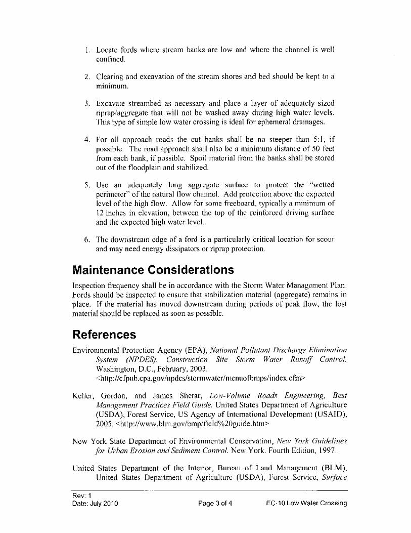
I. Locate fords where stream banks are low and where the channel is well confined.
2. Clearing and excavation of the stream shores and bed should be kept to a mInimum.
3. Excavate streambed as necessary and place a layer of adequately sized riprap/aggregate that will not be washed away during high water levels. This type of simple low water crossing is ideal for ephemeral drainages.
4. For all approach roads the cut banks shall be no steeper than 5:1, if possible. The road approach shall also be a minimum distance of 50 feet from each bank, if possible. Spoil material from the banks shall be stored out of the floodplain and stabilized.
5. Use an adequately long aggregate surface to protect the "wetted perimeter" of the natural flow channel. Add protection above the expected level of the high flow. Allow for some freeboard, typically a minimum of 12 inches in elevation, between the top of the reinforced driving surface and the expected high water level.
6. The downstream edge of a ford is a particularly critical location for scour and may need energy dissipators or riprap protection.
Maintenance Considerations Inspection frequency shall be in accordance with the Storm Water Management Plan. Fords should be inspected to ensure that stabilization material (aggregate) remains in place. If the material has moved downstream during periods of peak flow, the lost material should be replaced as soon as possible.
References Environmental Protection Agency (EPA), National Pollutant Discharge Elimination
System (NPDES). Construction Site Storm Water Runoff Control. Washington, D.C., February, 2003. <http://cfpub.epa.gov/npdes/stormwater/menuofbmps/index.cfm>
Keller, Gordon, and James Sherar, Low-Volume Roads Engineering, Best Management Practices Field Guide. United States Department of Agriculture (USDA), Forest Service, US Agency of International Development (USAID), 2005. <http://www.blm.gov/bmp/field%20guide.htm>
New York State Department of Environmental Conservation, New York Guidelines for Urban Erosion and Sediment Control. New York. Fourth Edition, 1997.
United States Department of the Interior, Bureau of Land Management (BLM), United States Department of Agriculture (USDA), Forest Service, Surface
Rev: 1 Date: July 2010 Page 3 of 4 EC-10 Low Water Crossing
Operating Standards for Oil and Gas Exploration and Development "Gold Book". Fourth Edition, 2005.
Figure EC-10-1 Typical Ford Installation
50' min. RO(ld Approach (if possible)
Traffic Flow
I
- Width of stream bed
50' min_ Road Approach (if possible)
MaKimum expected high water lavel
NOT TO SCALE Riprap I Aggregate
Rev: 1 Date: July 2010 Page 4 of 4 EC-10 Low Water Crossing
EC-11 Brush Matting (BM)
REMOVED FROM MANUAL
Rev: 1 Date: July 2010 Page 1 of 1 EC-11 Brush Matting
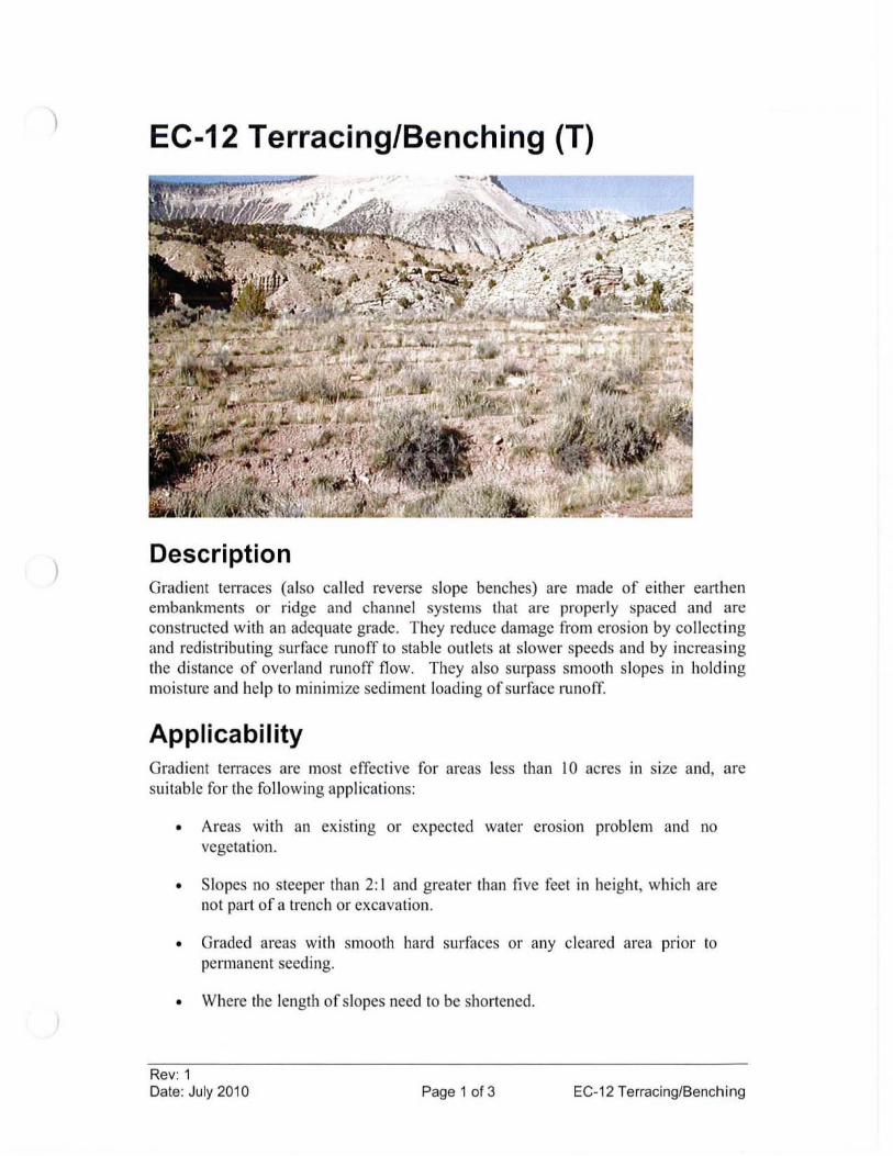
)
)
EC-12 Terracing/Benching (T)
Description Gradient telTaces (also ca lled reverse slope benches) are made of either earthen embankments or ridge and channel systems lhal are properl y spaced and are constructed with an adequate grade. They reduce damage from erosion by coll ecting and redistributing surface runoff to stable outlets at slower speeds and by increas ing the di stance of overland runoff flow. They also surpass smooth slopes in holding moisture and help to minimize sediment loading of surface runoff.
Applicability Gradient terraces are most effecti ve for areas less than 10 acres 111 size and, are suitable fo r the following applications:
• Areas with an ex isting or expected water eros ion problem and no vegetation.
• Slopes no steeper than 2: I and grea ter than fi ve feet in height, which are not part of a trench or excavation.
• Graded areas with smooth hard surfaces or any cleared area pnor to permanent seeding.
• Where the length of slopes need to be shortened.
Rev: 1 Date: July 2010 Page 1 of 3 EC-1 2 Terracing/Benching
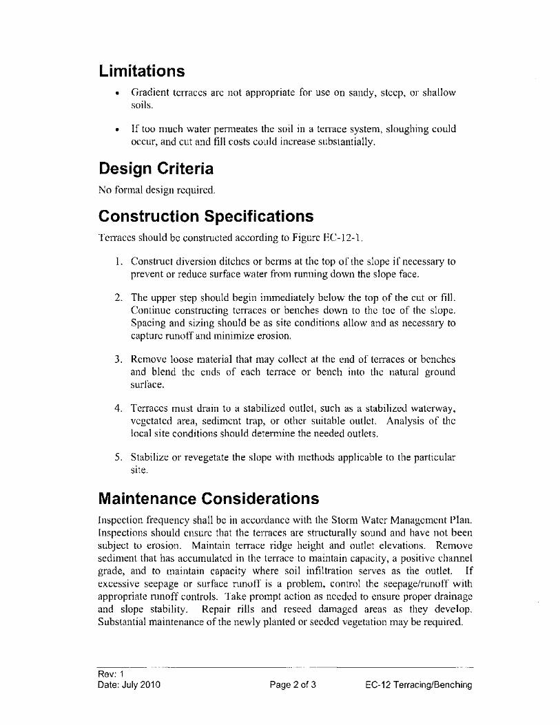
Limitations • Gradient terraces are not appropriate for use on sandy, steep, or shallow
soils.
• If too much water permeates the soil in a terrace system, sloughing could occur, and cut and fill costs could increase substantially.
Design Criteria No formal design required.
Construction Specifications Terraces should be constructed according to Figure EC-12-1.
I. Construct diversion ditches or berms at the top of the slope if necessary to prevent or reduce surface water from running down the slope face.
2. The upper step should begin immediately below the top of the cut or fill. Continue constructing terraces or benches down to the toe of the slope. Spacing and sizing should be as site conditions allow and as necessary to capture runoff and minimize erosion.
3. Remove loose material that may collect at the end of terraces or benches and blend the ends of each terrace or bench into the natural ground surface.
4. Terraces must drain to a stabilized outlet, such as a stabilized waterway, vegetated area, sediment trap, or other suitable outlet. Analysis of the local site conditions should determine the needed outlets.
5. Stabilize or revegetate the slope with methods applicable to the particular site.
Maintenance Considerations Inspection frequency shall be in accordance with the Storm Water Management Plan. Inspections should ensure that the terraces are structurally sound and have not been subject to erosion. Maintain terrace ridge height and outlet elevations. Remove sediment that has accumulated in the terrace to maintain capacity, a positive channel grade, and to maintain capacity where soil infiltration serves as the outlet. If excessive seepage or surface runoff is a problem, control the seepage/runoff with appropriate runoff controls. Take prompt action as needed to ensure proper drainage and slope stability. Repair rills and reseed damaged areas as they develop. Substantial maintenance of the newly planted or seeded vegetation may be required.
Rev: 1 Date: July 2010 Page 2 of 3 EC-12 Terracing/Benching
References
City of Knoxville, Stormwater Engineering, Knoxville BMP Manual - Best Management Practices. July 2003. http://www.ci.knoxville.tn.us/engineering
Environmental Protection Agency (EPA), National Pol/utant Discharge Elimination System (NPDES). Construction Site Storm Water Runoff Control. Washington, D.C., February, 2003. <http://cfpub.epa.gov/npdes/stonnwater/menuoibmps/index.cfm>
United States Department of Agriculture (USDA), Natural Resources Conservation Service (NRCS), Field Office Technical Guide. 2002. <www.nrcs.usda.gov/technical/efotg>
Diversion Ditch or berm
NOT TO SCALE
Rev: 1 Date: July 2010
Figure EC·12·1 Terracing/Benching
6ackslope
Normal slope line 2: 1 (H:V) or flatter
Ditch 10 catch loose material
1. Terraces shall slope between 2% and 3% to a stabilized outlet. 2. Flow length along a terrace Shall not exceed 800 feet, if possible.
Page 3 of 3 EC-12 Terracing/Benching
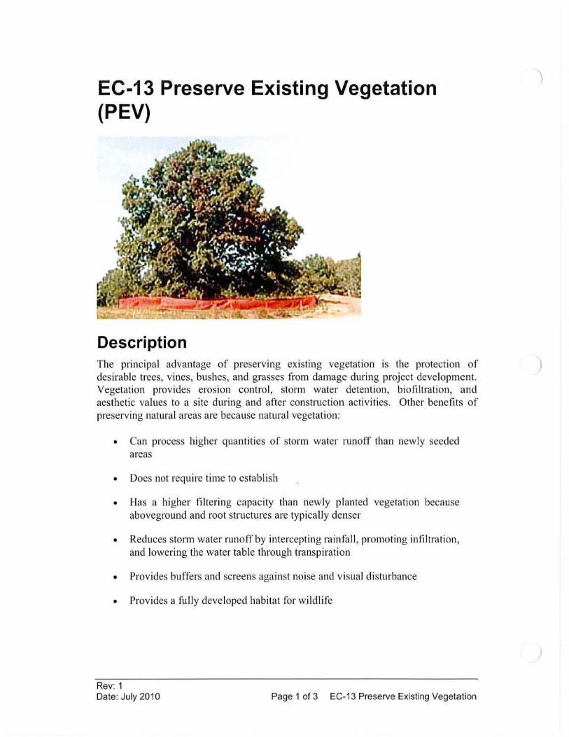
EC-13 Preserve Existing Vegetation (PEV)
Description The principal advantage of preserving existing vegetation is the protection of desirable trees, vines, bushes , and grasses from damage during project development. Vegetation provides erosion control, st0l111 water detention, biofiltration, and aesthetic values to a site during and after construction activities. Other benefits of preserving natural areas are because natural vegetation:
• Can process higher quantities of storm water runoff than newly seeded areas
• Does not require time to establish
• Has a higher filtering capacity than newly planted vegetation because aboveground and root structures are typically denser
• Reduces storm water runoff by intercepting rainfall , promoting infiltration, and lowering the water table through transpiration
• Provides buffers and screens against noise and visual disturbance
• Provides a fully developed habitat for wildlife
Rev: 1 Date: July 2010 Page 1 of 3 EC-13 Preserve Existing Vegetation
)
Applicability Preservation of existing vegetation is applicable to stream banks, steep slopes, and other areas where erosion controls would be difficult to establish, install, or maintain. Only land needed for drilling operations and vehicle traffic needs to be cleared.
Limitations • It requires planning to preserve and maintain the existing vegetation.
• Equipment must have enough room to maneuver; in some cases preserved vegetation might block equipment traffic and may constrict the area available for construction activities.
• Preconstruction drainage patterns should be maintained. Improper grading of a site might result in the alteration of hydrology and lead to die-off of preserved vegetation because their environmental requirements are no longer met.
Design Criteria Site Map A site map should be prepared with the locations of trees and boundaries of environmentally sensitive areas and buffer zones to be preserved. The location of roads, well pads and pipelines can be planned to avoid these areas. Preservation requires careful site management to minimize the impact of construction activities on existing vegetation. Large trees located near construction zones should be protected because damage during construction activities may result in reduced vigor or death after construction has ceased. The boundaries around contiguous natural areas should be extended and marked to protect the root zone from damage. Although direct contact by equipment is an obvious means of damage to trees and other vegetation, compaction, filling, or excavation of land too close to the vegetation also can cause severe damage.
Selection When selecting trees for preservation, the following factors should be considered:
• Tree vigor. Preserving healthy trees that will be less susceptible to damage, disease, and insects. Indicators of poor vigor include dead tips of branches, stunted leaf growth, sparse foliage, and pale foliage color. Hollow, rotten, split, cracked, or leaning trees also have less chance of survival.
• Tree age. Older trees are more aesthetically pleasing as long as they are healthy.
Rev: 1 Date: July 2010 Page 2 of 3 EC-13 Preserve Existing Vegetation
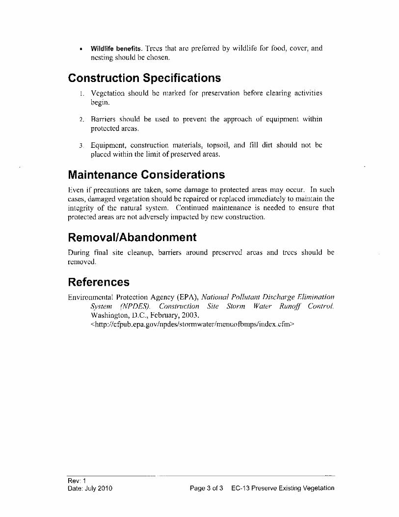
• Wildlife benefits. Trees that are preferred by wildlife for food, cover, and nesting should be chosen.
Construction Specifications I. Vegetation should be marked for preservation before clearing activities
begin.
2. Barriers should be used to prevent the approach of equipment within protected areas.
3. Equipment, construction materials, topsoil, and fill dirt should not be placed within the limit of preserved areas.
Maintenance Considerations Even if precautions are taken, some damage to protected areas may occur. In such cases, damaged vegetation should be repaired or replaced immediately to maintain the integrity of the natural system. Continued maintenance is needed to ensure that protected areas are not adversely impacted by new construction.
Removal/Abandonment During final site cleanup, barriers around preserved areas and trees should be removed.
References Environmental Protection Agency (EPA), National Pollutant Discharge Elimination
System (NPDES). Construction Site Storm Water Runoff Control. Washington, D.C., February, 2003. <http://cfpub.epa.gov/npdes/storrnwater/menuofbmps/index.cfm>
Rev: 1 Date: July 2010 Page 3 of 3 EC-13 Preserve Existing Vegetation
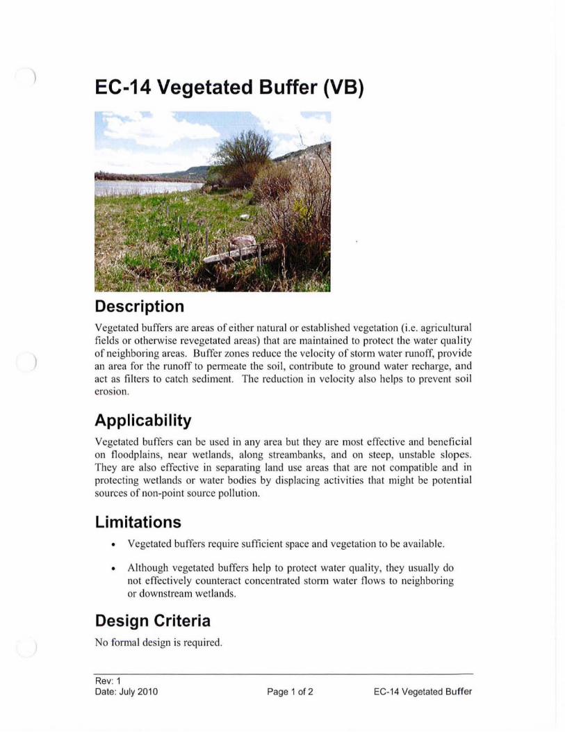
)
)
EC-14 Vegetated Buffer (VB)
Description Vegetated buffers are areas of either natural or established vegetation (i.e. agricultural fields or otherwise revegetated areas) that are maintained to protect the water quality of neighboring areas. Buffer zones reduce the velocity of storm water runoff, provide an area for the runoff to permeate the soi l, contribute to ground water recharge, and act as filters to catch sediment. The reduction in velocity also helps to prevent soi l eroSion.
Applicability Vegetated buffers can be used in any area but they are most effective and beneficial on floodplains, near wetlands, along streambanks, and on steep, unstable slopes. They are also effective in separating land use areas that are not compatible and in protecting wetlands or water bodies by displacing activit ies that might be potential sources of non-point source pollution.
Limitations • Vegetated buffers require sufficient space and vegetation to be avai lab le.
• Although vegetated buffers help to protect water quality, they usua ll y do not effectively cOllnteract concentrated storm water flows to neighboring or downstream wetlands.
Design Criteria No formal design is required.
Rev: 1 Date: July 2010 Page 1 of 2 EC-14 Vegetated Buffer
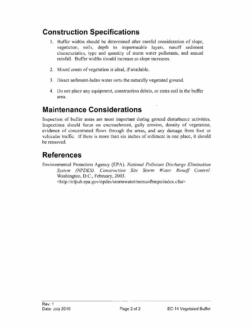
Construction Specifications I. Buffer widths should be determined after careful consideration of slope,
vegetation, soils, depth to impermeable layers, runoff sediment characteristics, type and quantity of storm water pollutants, and annual rainfall. Buffer widths should increase as slope increases.
2. Mixed zones of vegetation is ideal, if available.
3. Direct sediment-laden water onto the naturally vegetated ground.
4. Do not place any equipment, construction debris, or extra soil in the buffer area.
Maintenance Considerations Inspection of buffer areas are most important during ground disturbance activities. Inspections should focus on encroachment, gully erosion, density of vegetation, evidence of concentrated flows through the areas, and any damage from foot or vehicular traffic. If there is more than six inches of sediment in one place, it should be removed.
References Environmental Protection Agency (EPA), National Pollutant Discharge Elimination
System (NPDES). Construction Site Storm Water Runoff Control. Washington, D.C., February, 2003. <http://cfpub.epa.gov/npdes/stormwater/menuofbmps/index.cfm>
Rev: 1 Date: July 2010 Page 2 of 2 EC-14 Vegetated Buffer
)
)
EC-1S Slope Drain (SO)
Description A slope drain is a rigid or fl ex ible conduit ex tending the length of a disturbed slope. Slope drains convey runoff without causing erosion on or at the bottom of the slope. Slope drains may be fully enclosed or half pipes. This practi ce is typically used during grading operations and until permanent drainage structures (if used) are installed and until slopes are permanently stabilized.
Applicability Slope drains may be used on disturbed slopes at the outlet to a diversion ditch or sediment trap to convey water and reduce rill and gully erosion problems resulting from concentrated flows being discharged.
Limitations Phys ical obstructions substantia lly reduce the effectiveness of the drain. Other concerns are failures from overtopping because of inadequate pipe inlet capac ity, and reduced diversion channel capacity and ridge height.
Design Criteria No fo rmal des ign is requi red.
Construction Specifications See Figure EC-IS-I for installati on detai Is.
I. The slope drain shall have a slope of 3 percent or steeper.
Rev: 1 Date: July 20 10 Page 1 of 3 EC-1 5 Slope Drain
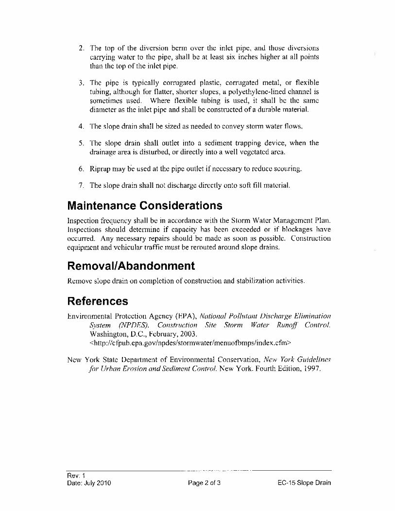
2. The top of the diversion berm over the inlet pipe, and those diversions carrying water to the pipe, shall be at least six inches higher at all points than the top ofthe inlet pipe.
3. The pipe is typically corrugated plastic, corrugated metal, or flexible tubing, although for flatter, shorter slopes, a polyethylene-lined channel is sometimes used. Where flexible tubing is used, it shall be the same diameter as the inlet pipe and shall be constructed of a durable material.
4. The slope drain shall be sized as needed to convey stonn water flows.
5. The slope drain shall outlet into a sediment trapping device, when the drainage area is disturbed, or directly into a well vegetated area.
6. Riprap may he used at the pipe outlet if necessary to reduce scouring.
7. The slope drain shall not discharge directly onto soft fill material.
Maintenance Considerations Inspection frequency shall be in accordance with the Storm Water Management Plan. Inspections should detennine if capacity has been exceeded or if blockages have occurred. Any necessary repairs should be made as soon as possible. Construction equipment and vehicular traffic must be rerouted around slope drains.
Removal/Abandonment Remove slope drain on completion of construction and stabilization activities.
References Environmental Protection Agency (EPA), National Pollutant Discharge Elimination
System (NPDES). Construction Site Storm Water Runoff Control. Washington, D.C., February, 2003. <http://cfpub.epa.gov/npdes/stormwater/menuofbmpslindex.cfm>
New York State Department of Environmental Conservation, New York Guidelines for Urban Erosion and Sediment Control. New York. Fourth Edition, 1997.
Rev: 1 Date: July 2010 Page 2 of 3 EC-15 Slope Drain
Anchor to fill slope as needed
Provide oullet protection (SEE NOTE)
, '-.\-1(-,-\ .
NOT TO SCALE
Rev: 1 Date: July 2010
Figure EC-15-1 Slope Drain Installation
Rigid or Rexable pipe
,
Earthen Berm (optional)
,
Well compacted stable fill slope
Diversion Ditch or Sediment Trap
Note: Direct outlet into a diversion ditch, a sediment control or a well vegetated area
Page 3 of 3 EC-15 Slope Drain

EC-16 Brush layering (Bl) REMOVED FROM MANUAL
Rev: 1 Date: July 2010 Page 1 of 1 EC-16 Brush Layering
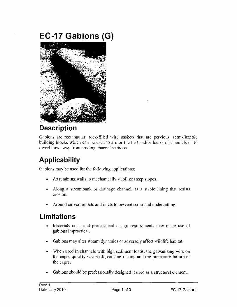
EC-17 Gabions (G)
Description Gabions are rectangular, rock-filled wire baskets that are pervious, semi-flexible building blocks which can be used to armor the bed and/or banks of channels or to divert flow away from eroding channel sections.
Applicability Gabions may be used for the following applications:
• As retaining walls to mechanically stabilize steep slopes.
• Along a streambank or drainage channel, as a stable lining that resists erosIOn.
• Around culvert outlets and inlets to prevent scour and undercutting.
Limitations • Materials costs and professional design requirements may make use of
gab ions impractical.
• Gabions may alter stream dynamics or adversely affect wildlife habitat.
• When used in channels with high sediment loads, the galvanizing wire on the cages quickly wears off, causing msting and the premature failure of the cages.
• Gabions should be professionally designed if used as a structural element.
Rev: 1 Date: July 2010 Page 1 of 3 EC-17 Gabions
Design Criteria Gabions should be designed and installed in accordance with manufacturer's standards and specifications and must be able to handle expected storm and flood conditions (see Figure EC-17-l for details).
Construction Specifications 1. Gabions shall be fabricated in such a manner that the sides, ends, and lid
can be assembled at the construction site into a rectangular basket of the specified sizes. Gabions shall be of single unit construction and shall be installed according manufacturer's recommendations. General specifications are listed below.
2. Clear and grade the area of trees, brush, vegetation and unsuitable soils. Compact sub grade firmly to prevent slumping or undercutting.
3. Place empty gabion baskets. Each row, tier, or layer of baskets should be reasonably straight and should conform to the specified line and grade. The empty gabion baskets should be fastened to the adjacent baskets along the top and vertical edges. Each layer (if using more than one layer) should be fastened to the underlying layer along the front, back and ends. Fastening should be performed in the same manner as provided for assembling the gabion units.
4. Unless otherwise indicated on the plans, the vertical joints between basket units of adjacent tiers or layers, along the length of the structure, should be staggered by at least one cell.
5. Before filling each gab ion with rock, all kinks and folds in the wire mesh should be removed and all baskets should be properly aligned. A standard fence stretcher, chain fall or steel rod may be used to stretch the wire baskets and hold alignment.
6. The gab ion cells should be carefully filled with aggregate.
7. The gab ion cells in any row or layer should be filled in stages so that local deformations may be avoided.
8. At no time should any cell be filled to a depth exceeding 12 inches more than any adjacent cell.
9. The layer of rock should completely fill the gab ion basket so that the lid will bear on the rock when it is secured. The lid should be joined to the sides, ends, and diaphragms in the same manner as specified for joining the vertical edges. The gabion basket lid should be secured so that no more than one inch gap remains at any connection.
Rev: 1 Date: July 2010 Page 2 of 3 EC-17 Gabions
Maintenance Considerations Inspection frequency shall be in accordance with the Storm Water Management Plan. Inspections shall check for signs of rusting, wear of baskets, undercutting, or instability. Repair damaged areas immediately to restore designed effectiveness and to prevent damage or erosion of the slope or streambank.
References City of Knoxville, Stormwater Engineering, Knoxville BMP Manual - Best
Management Practices. July 2003. <http://www.ci.knoxville.tn.us/engineering>
Horizon Environmental Services, Inc, Guidance Document Reasonable and Prudent Practices for· Stabilization (RAPPS) of Oil and Gas Construction Sites. Produced by Independent Petroleum Association of America (IPAA). April 2004. <http://www.dpcusa.org/enviro/rapps.html>
New York State Department of Environmental Conservation, New York Guidelines for Urban Erosion and Sediment Control. New York. Fourth Edition, 1997.
Rev: 1 Date: July 2010 Page 3 of 3 EC-17 Gabions
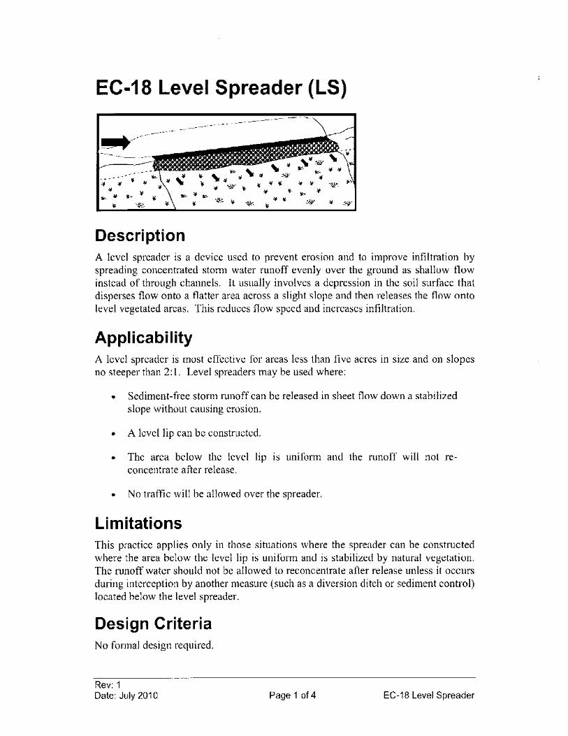
EC-18 Level Spreader (LS)
Description A level spreader is a device used to prevent erosion and to improve infiltration by spreading concentrated storm water runoff evenly over the ground as shallow flow instead of through channels. It usually involves a depression in the soil surface that disperses flow onto a flatter area across a slight slope and then releases the flow onto level vegetated areas. This reduces flow speed and increases infiltration.
Applicability A level spreader is most effective for areas less than five acres in size and on slopes no steeper than 2: 1. Level spreaders may be used where:
• Sediment-free storm runoff can be released in sheet flow down a stabilized slope without causing erosion.
• A level lip can be constructed.
• The area below the level lip IS uniform and the runoff will not reconcentrate after release.
• No traffic will be allowed over the spreader.
Limitations This practice applies only in those situations where the spreader can be constructed where the area below the level lip is uniform and is stabilized by natural vegetation. The runoff water should not be allowed to reconcentrate after release unless it occurs during interception by another measure (such as a diversion ditch or sediment control) located below the level spreader.
Design Criteria No formal design required.
Rev: 1 Date: July 2010 Page 1 of 4 EC-18 Level Spreader
Construction Specifications See Figure EC-18-1 for details.
I. If necessary, a transition section will be constructed from the diversion channel to the spreader to smoothly blend the different dimension and grades.
2. The level lip will be constructed to a uniform height over the length of the spreader.
3. For design flows less than 5 cfs, a vegetated level lip may be constructed with an erosion-resistant material, such as jute or excelsior blankets, to inhibit erosion and allow vegetation to become established.
4. For design flows higher than 5 cfs and permanent installations, a riprap covered level lip may be used.
5. The runoff discharge will be outleted onto a stabilized and generally smooth vegetated slope.
6. Seed and mulch any disturbed area.
7. Heavy equipment and traffic should not be allowed on the level spreader, as they can cause compaction of soil and disturbance of the slope grade.
Maintenance Considerations Inspection frequency shall be in accordance with the Storm Water Management Plan. The spreader should be regraded if ponding or erosion channels develop. Dense vegetation should be sustained and damaged areas reseeded when necessary.
Removal/Abandonment Level spreaders may be abandoned (left 111 place) or removed upon final site reclamation.
References City of Knoxville, Stormwater Engineering, Knoxville BMP Manual - Best
Management Practices. July 2003. http://www.ci.knoxville.tn.us/engineering
Environmental Protection Agency (EPA), National Pollutant Discharge Elimination System (NPDES). Construction Site Storm Water Runoff Control. Washington, D.C., February, 2003. <http://cfpub.epa.gov/npdes/stormwater/menuofbmps/index.cfm>
Rev: 1 Date: July 2010 Page 2 of 4 EC-18 Level Spreader
New York State Department of Environmental Conservation, New York Guidelines for Urban Erosion and Sediment Control. New York. Fourth Edition, 1997.
United States Army Corps of Engineers (USACE), Engineering and Design -Handbookfor the Preparation of Storm Water Pollution Prevention Plans for Construction Activities. February 1997.
Rev: 1 Date: July 2010 Page 3 of 4 EC-18 Level Spreader
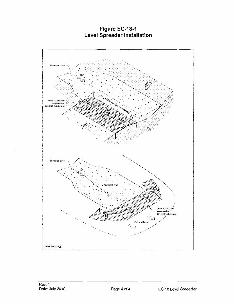
Figure EC-18-1 Level Spreader Installation
, .
• •
• Sedin:'ent Trap
.'
'.
)
NOT TO SCALE
Rev: 1 Date: July 2010 Page 4 of 4 EC-18 Level Spreader
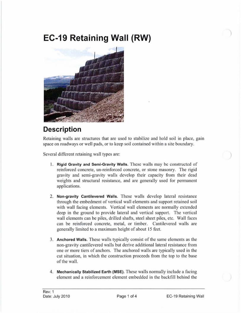
EC-19 Retaining Wall (RW)
Description Retaining walls are structures that are used to stabilize and hold soi l in place, gain space on roadways or well pads, or to keep so il contained within a site boundary.
Several different retaining wall types are:
I. Rigid Gravity and Semi-Gravity Walls. These wal ls may be constructcd of reinforced concrete, un-reinforced concrete, or stone masonry. The rigid gravi ty and semi-gravity walls deve lop their capacity from their dead weights and structural resistance, and are generally used for permanent applications.
2. Non-gravity Cantilevered Walls . These wa lls develop latera l resistance through the embedment of vertica l wa ll elements and support retained soi l with wall facing elements. Vertical wall elements are normally extended deep in the ground to provide latera l and vertica l support. The vertica l wall elements can be piles, drilled shafts, steel sheet piles, etc. Wall faces can be reinforced concrete, metal, or timber. Cantilevered wa lls are genera lly limited to a maximum height of about 15 feet.
3. Anchored Walls. These wa lls typically consist of the same elements as the non-gravity cantilevered wa lls but derive additional lateral resistance from one or more tiers of anchors. The anchored wa lls are typically used in the cut situation, in which the construction proceeds from the top to the base of the wa ll.
4. Mechanically Stabilized Earth (MSE). These walls normally include a facing element and a reinforcement element embedded in the backfill behind the
Rev: 1 Date: July 2010 Page 1 of 4 EC-19 Retaining Wall
)
facing. The facing element can be concrete or steel wire mesh. The reinforcement element can be either metallic (strip, grid, wire mesh) or polymeric (sheet, grid, or strip type). MSE walls are well suited when used to support fills and when substantial total and differential settlement are anticipated. These wall systems are normally used in a fill situation.
5. Geosynthetic retaining wall. These flexible retaining walls are constructed of geosynthetics, often a geotextile. A geosynthetic wall is constructed by placing successive layers of fill material, each on a geosynthetic layer with the geosynthetic folded over and covering the face of the wall. The weight of the next layer of fill material then holds the folded geosynthetic from the previous layer in place.
Applicability Retaining walls are often used near the toe of a cut or fill slope so that a flatter slope can be constructed to prevent or minimize slope erosion or failure. They can also be used to keep a toe of a slope from encroaching into a stream and thus prevent potential undercutting of the toe by flowing water. Retaining walls should be used when sites have very steep slopes or loose, highly erodible soils that cause other methods, such as vegetative stabilization or regrading, to be ineffective. The preconstruction drainage pattern should be maintained to the extent possible.
Limitations • To be effective, retaining walls must be designed to handle expected
loads. Non-engineered walls should not be used where traffic is expected near the top of the wall.
• They must be properly installed and maintained to avoid failure.
• Some types of retaining walls must be placed on a good foundation, such as bedrock or finn, in-place soil.
• Some MSE walls have height restrictions. Backfill must meet specific material property requirements.
Design Criteria Most retaining walls require a site-specific design. Wall heights, requirements for drainage, and suitable materials must be determined through on-site investigation. MSE walls are normally designed by the manufacturers. An engineered retaining structure is a designed structure that is supported by plans and specifications signed and sealed by a Professional Engineer. Non-engineered retaining structures may be designed by an engineer; however, if the design is not supported by the seal and signature, the retaining structure is not considered engineered.
Rev: 1 Date: July 2010 Page 2 of 4 EC-19 Retaining Wall
Construction Specifications Retaining walls shall be constructed in accordance with site specific designs and/or engineered designs. The following guidelines may be used for small, non-engineered designs.
Rock retaining wall guidelines
1. Excavate a footing trench at the location of the proposed wall.
2. Place the largest rocks in the footing trench with their longitudinal axis normal to the wall face. Arrange subsequent rock layers so that each rock above the foundation course has a firm seating on the underlying rocks.
3. Place fill material behind the rock wall. Backfill the footing trench with excavated material. If a roadway is located at the toe of the wall, provide roadside drainage ditch for water transport. If a roadway is not located at the toe of the retaining wall, slope the ground surface material away from the wall.
4. Revegetate the stabilized slope with a method applicable to the particular site.
Gabion retaining wall guidelines
I. Construct gab ions in accordance with EC-17 Gabions.
2. Place fill material behind the gab ion wall. If a roadway is located at the toe of the wall, provide roadside drainage ditch for water transport. If a roadway is not located at the toe of the retaining wall, slope the ground surface material away from the wall.
3. Revegetate the stabilized slope with a method applicable to the particular site.
Timber retaining wall guidelines
I. Prepare the site by rough grading the ground surface. Set the bottom course of timbers onto a rigid base foundation material, and secure with pinning or metal collars.
2. Place fill material behind the wall.
3. Place next layer of timbers and fasten it to the lower layer.
4. Place backfill and compact.
5. Proceed in a similar fashion to the desired height.
6. Revegetate the backfill behind the walls according to procedures applicable to the specific site.
Rev: 1 Date: July 2010 Page 3 of 4 EC-19 Retaining Wall
Maintenance Considerations Inspection frequency shall be in accordance with the Storm Water Management Plan. Inspections shall check for structural failure, erosion, damage, or other signs of deterioration. In stream bank installations, inspect for signs of undercutting and other instability. Make all repairs promptly, as needed.
References Environmental Protection Agency (EPA), National Pollutant Discharge Elimination
System (NPDES). Construction Site Storm Water Runoff Contra!' Washington, D.C., February, 2003. <http://cfpub.epa.gov/npdes/storrnwater/menuofbmpslindex.cfm>
Keller, Gordon, and James Sherar, Low-Volume Roads Engineering, Best Management Practices Field Guide. United States Department of Agriculture (USDA), Forest Service, US Agency of International Development (USAID), 2005. <http://www.blm.gov/bmp/field%20guide.htm>
New York State Department of Environmental Conservation, New York Guidelines for Urban Erosion and Sediment Control. New York. Fourth Edition, 1997.
Rev: 1 Date: July 2010 Page 4 of 4 EC-19 Retaining Wall
EC-20 Chemical Stabilization (CS)
REMOVED FROM MANUAL
Rev: 1 Date: July 2010 Page 1 of 1 EC-20 Chemical Stabilization
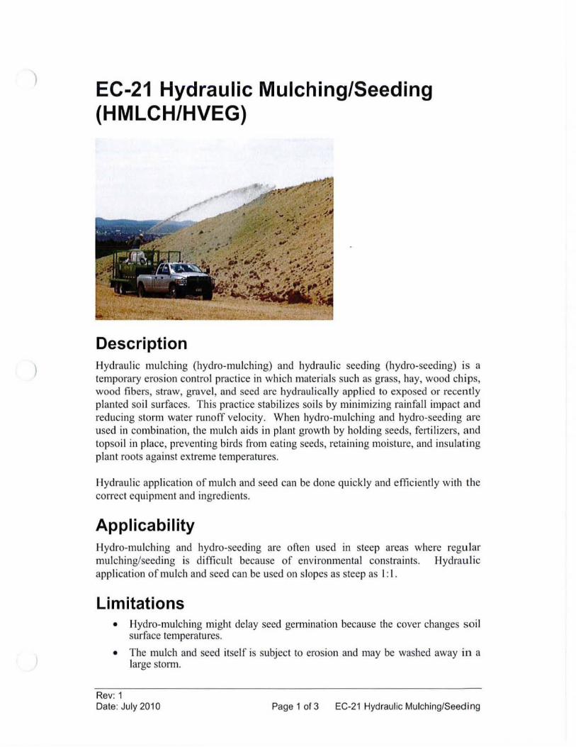
)
)
EC-21 Hydraulic Mulching/Seeding (HMLCH/HVEG)
Description Hydraulic mulching (hydro-mulching) and hydraulic seeding (hydro-seeding) is a temporary erosion control practice in which materials such as grass, hay, wood chips, wood fibers, straw, gravel, and seed arc hydraulically applied to exposed or recently planted soil surfaces. This practice stabilizes soils by minimizing rainfall impact and reducing storm water runoff velocity. When hydro-mulching and hydro-seeding are used in combination, the mulch aids in plant growth by holding seeds, fertilizers, and topsoil in place, preventing birds from eating seeds, retaining moisture, and insulating plant roots against extreme temperatures.
Hydraulic application of mulch and seed can be done quickly and effic iently with the correct equipment and ingredients.
Applicability Hydro-mulching and hydro-seeding are often used in steep areas where regular mulching/seeding is difficult because of environmental constraints. Hydraulic application of mulch and seed can be used on slopes as steep as I: I.
Limitations • Hydro-mulching might delay seed gennination because the cover changes soil
surface temperatures.
• The mulch and seed itself is subject to erosion and may be washed away in a large stonn.
Rev: 1 Date: July 2010 Page 1 of 3 EC-21 Hydraulic Mulching/Seeding
• Maintenance is necessary to ensure that hydro-mulch and hydro-seed provides effective erosion control.
• Hydraulic application of mulch and seed must be done when no rainfall is expected, preferably within a 24-hour time period.
Design Criteria No formal design is required.
Construction Specifications 1. Site preparation:
a. Prior to mulching/seeding, install the necessary temporary or permanent erosion control practices and drainage systenls within or adjacent to the area to be mulched/seeded.
b. Slope, grade, and smooth the site to fit needs of the selected products.
c. Remove all undesirable stones and other debris to meet the needs of the anticipated land use and maintenance required.
2. Hydraulic mulching/seeding:
a. For steep slopes an Erosion Control Mulch (ECM) consisting of a hydraulic matrix such as a Bonded Fiber Matrix (BFM) or Flexible Growth Medium (FGM) may be used. A BFM refers to a continuous layer of elongated wood fiber strands that are held together by a water-resistant bonding agent to form a water-absorbing crust.
b. The ECM shall be a hydraulically-applied, flexible erosion control blanket composed of long strand, thermally refined wood fibers, crimped, interlocking fibers, and performance enhancing additives. The ECM shall require no curing time period and upon application shall form an intimate bond with the soil surface to create a continuous, porous, absorbent and erosion resistant blanket that allows for rapid germination and accelerated plant growth.
3. Installation:
a. Strictly comply with manufacturer's installation instructions and recommendations. Use approved hydro-spraying machines with fan-type nozzle (50-degree tip) whenever possible to achieve best soil coverage. Apply ECM from opposing directions to soil surface to assure 95% soil surface coverage. Slope interruption devices or water diversion techniques are recommended when slope lengths exceed 100 ft (30m).
Maintenance Considerations The frequency of inspections should be in accordance with the Storm Water Management Plan. Areas should be identified where mulch and seed has loosened or been removed. Such areas should be reseeded (if necessary) and the cover replaced.
Rev: 1 Date: July 2010 Page 2 of 3 EC-21 Hydraulic Mulching/Seeding
If washout, breakage, or erosion occurs, surfaces should be repaired, reseeded, and remulched. Inspections should be continued until vegetation is firmly established.
References California Stormwater Quality Association, Stormwater Best Management Practice
(BMP) Handbook - Construction. January, 2003. <http://www.cabmphandbooks.comlConstruction.asp>
Environmental Protection Agency (EPA), National Pollutant Discharge Elimination System (NPDES). Construction Site Storm Water Runoff Control. Washington, D.C., February, 2003. <http://cfpub.epa.gov/npdes/stormwater/menuofbmps/con site.cfm>
Rev: 1 Date: July 2010 Page 3 of 3 EC-21 Hydraulic Mulching/Seeding
Runoff Control (RC)
RC·1 RC·2 RC·3
RC·4 RC·5 RC·6 RC·7 RC·8 RC·9
RC·10 RC·11
RC·12
RC·13 RC·14
Roadside (RSD) & Turnout (TO) Ditches Culvert Cross·Drain (CCD) Culvert Outlet Protection (COP) - COMBINED WITH RC·2 Riprap (RIP) Check Dam (CD) Road Slope - COMBINED WITH EC·2 Drainage Dip (DD) Temporary Berm (TB) Culvert Inlet Protection (CIP) - COMBINED WITH RC·2 Diversion Ditch (DD) Temporary Diversion (TD) - COMBINED WITH RC· 10 Permanent Diversion (PD) - COMBINED WITH Re· 10 Water Bar (WB) Toe Trench (TT)
)
)
RC-1 Roadside (RSD) and Turnout (TO) Ditches
Riprap Lined Channel Unlined Channel
TurnoutlWing Ditch Concrete Lined Channel
Description Roadside ditches are channels constructed parallel to roads. The ditches convey concentrated runoff of surface water from roads and surrounding areas to a stabilized outlet. Tumouts (wing ditches) are ex tensions of road-side ditches. Turnouts effective ly remove run-off water from the roadside ditch into well -stabilized areas before it reaches a watelway.
Applicability • Roadside ditches should be used for all roads built on a slope with either
an ins loped or a crowned design.
Rev: 1 Date: July 2010 Page 1 of 4
RC-1 Roadside a nd Turnout Ditches
• Ditch turnouts should be used as much as possible but their best use may be on slopes longer than 150 ft or greater than 5%, as conditions allow.
Limitations • If these structures are not installed correctly they may become a source of
erosIon.
• Road-side ditches do not necessarily filter sediment from runoff.
• Turnouts should be on gradual slopes only.
• Turnouts require vegetative cover or other filter at the discharge point.
• Turnouts only work well if small volumes of runoff drain into the turnout. Turnouts should only receive runoff from the road and ditch surface, not from large, uphill watersheds.
Design Criteria No formal design is required.
Construction Specifications See Figure RC-I-I for details.
Roadside Ditches
I. Roadside ditches should be constructed according to RC-IO Diversion Ditch with no projections of roots, stumps, rocks, or similar debris.
2. Excavate channel along roadside to a width and depth that can handle expected flows.
3. Slope channels so that water velocities do not cause excessive erosion, but no less than 0.5%.
4. If needed, vegetate or line channel with riprap to prevent erosion. Check dams may also be used periodically, if needed.
Turnouts
I. Turnouts should be constructed on undisturbed soil whenever possible.
2. Slope turnout gradually down from bottom of road-side ditch.
3. Angle turnout at approximately 30 degrees to the road-side ditch.
Rev: 1 Date: July 2010 Page 2 of 4
RC-1 Roadside and Turnout Ditches
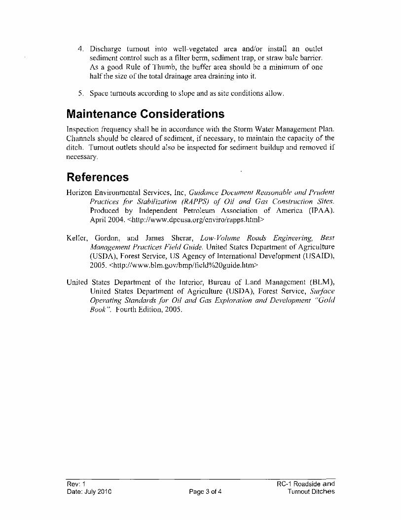
4. Discharge tumout into well-vegetated area and/or install an outlet sediment control such as a filter berm, sediment trap, or straw bale barrier. As a good Rule of Thumb, the buffer area should be a minimum of one half the size of the total drainage area draining into it.
5. Space tumouts according to slope and as site conditions allow.
Maintenance Considerations Inspection frequency shall be in accordance with the Storm Water Management Plan. Channels should be cleared of sediment, if necessary, to maintain the capacity of the ditch. Tumout outlets should also be inspected for sediment buildup and removed if necessary.
References Horizon Environmental Services, Inc, Guidance Document Reasonable and Prudent
Practices for Stabilization (RAPPS) of Oil and Gas Construction Sites. Produced by Independent Petroleum Association of America (IPAA). April 2004. <http://www.dpcusa.org/enviro/rapps.html>
Keller, Gordon, and James Sherar, Low- Volume Roads Engineering, Best Management Practices Field Guide. United States Department of Agriculture (USDA), Forest Service, US Agency of Intemational Development (USAID), 2005. <http://www.blm.gov/bmp/field%20guide.htm>
United States Department of the Interior, Bureau of Land Management (BLM), United States Department of Agricultnre (USDA), Forest Service, Surface Operating Standards for Oil and Gas Exploration and Development "Gold Book". Fourth Edition, 2005.
Rev: 1 Date: July 2010 Page 3 of 4
RC-1 Roadside and Turnout Ditches
NOT TO SCALE
Rev: 1 Date: July 2010
Figure RC-1-1 Roadside Ditch and Turnout Layout
Erosion or sediment control measure (ex: vegetated buffer)
• •
~30· (typ.)
~ , Drainage Ditch 0.5% min.
Space as site conditions allow
AC«Iss Road
Drainage Ditch 0.5% min ~
(ex: sediment trap)
Page 4 of 4
(ex: silt fence)
( ••
(ex: watlle)
RC-1 Roadside and Turnout Ditches
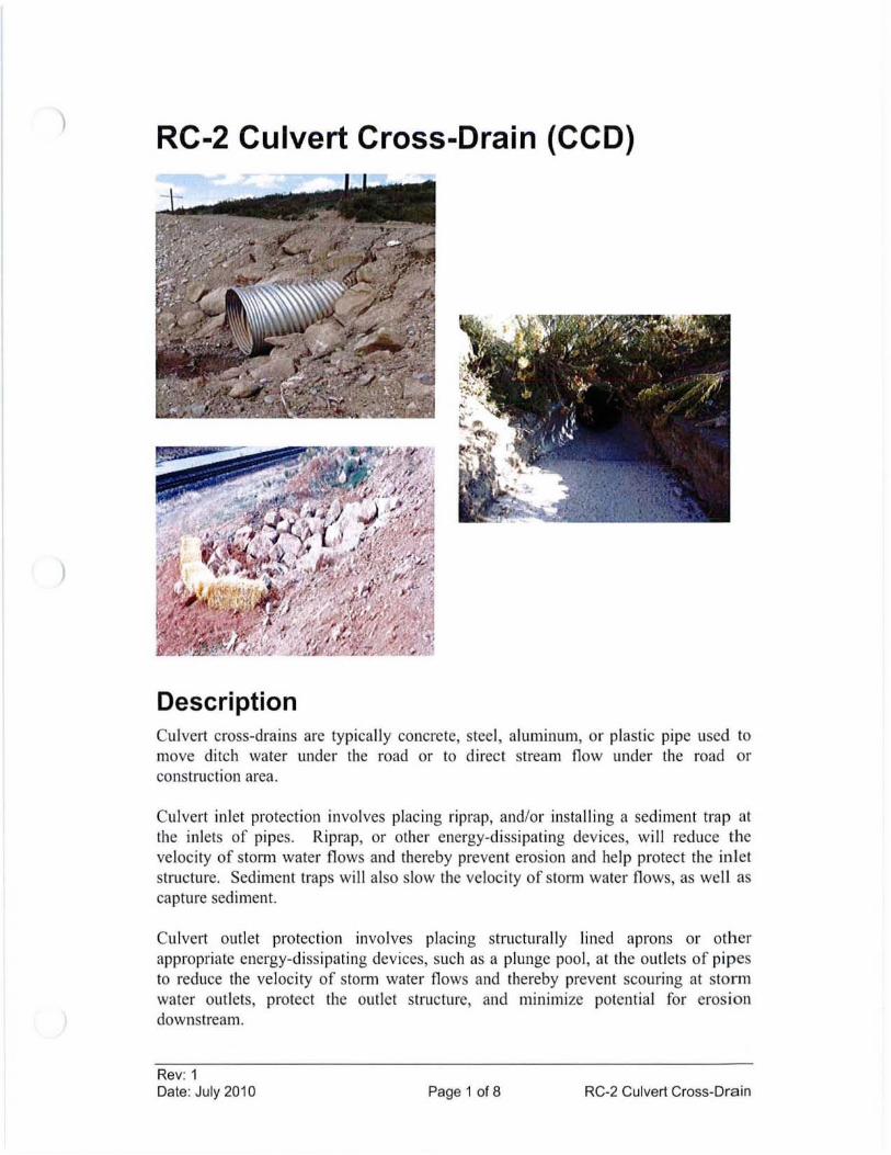
)
)
RC-2 Culvert Cross-Drain (CCD)
Description Culvert cross-drains are typically concrete, steel, aluminum, or plastic pipe used to move ditch water under the road or to direct stream flow under the road or construction area.
Culvert inlet protection involves placing riprap, andlor insta lling a sediment trap at the inlets of pipes. Riprap, or other energy-dissipating devices, will reduce the veloc ity of storm water flows and thereby preven t erosion and help protect the inlet structure. Sediment traps wi ll also slow the velocity of stom1 water flows, as we ll as capture sediment.
Culvert outlet protection involves placing structura ll y lined aprons or other appropriate energy-dissipating devices, such as a plunge pool , at the outlets of pipes to reduce the ve locity of storm water flows and thereby prevent scouring at storm water outlets, protect the outlet structure, and minimize potential for erosion downstream.
Rev: 1 Date: July 2010 Page 1 of 8 RC-2 Culvert Cross-Drain
Applicability Culvert cross-drains are ideal on road grades less than 15%. For grades over 15%, it is difficult to slow down the water or remove it from the road surface rapidly. On such steep grades, it is best to use frequently spaced cross-drain culverts, with armored ditches (see RCA Riprap). Culverts may be used in the following applications:
• As drainage crossing culverts in streams and gullies to allow normal drainage to flow under the traveled way.
• As ditch relief culverts to periodically relieve the inside ditch line flow by piping water to the opposite side of the road where the flow can be dispersed away from the roadway. Culverts placed in natural drainages may be utilized for ditch relief.
Riprap inlet protection should be used where velocities and energies at the inlets of culverts are sufficient to erode around the inlet structure. Riprap may also be used to help channel the storm water to the inlet of the culvert.
Culvert outlet protection applies where discharge velocities and energies at the outlets of culverts or channels are sufficient to erode the next downstream reach.
Limitations • If undersized, culverts are susceptible to plugging and require cleaning.
• Culverts will not filter sediment.
Design Criteria Capacity If possible, culverts should be designed for a minimum 25-year-frequency storm with an allowable head that does not overlap the roadway. Typically, if site conditions allow, a minimum culvert diameter of 18 inches is used to prevent failure from debris blockage. Ultimately, pipe size will be determined based upon site-specific conditions and site knowledge.
Depth The depth of culvert burial must be sufficient to ensure protection of the culvert barrel for the design life of the culvert. This requires anticipating the amount of material that may be lost due to road use and erosion.
Headwalls Headwalls are occasionally used on culvert pipes (see EC-19 Retaining Wall). The advantages of headwalls include: preventing large pipes from floating out of the ground when they plug; reducing the length of the pipe; increasing pipe capacity;
Rev: 1 Date: July 2010 Page 2 of 8 RC-2 Culvert Cross-Drain

helping to funnel debris through the pipe; retaining the backfill material; and reducing the chances of culvert failure if it is overtopped.
Construction Specifications Drainage crossing culverts
1. Make road crossings of natural drainages perpendicular to the drainage, where possible, to minimize pipe length and area of disturbance (Figure RC-2-1 ).
2. Use single large pipes versus multiple smaller diameter pipes to minimize plugging potential in most channels (unless roadway elevation is critical). In very broad channels, multiple pipes are desirable to maintain the natural flow spread across the channel. All culverts should be concrete, corrugated metal pipe (CMP) made of steel or aluminum, or properly bedded and backfilled corrugated plastic pipe.
3. Align culverts in the bottom and middle of the natural channel so that installation causes no change in the stream chatmel alignment or stream bottom elevation. Culverts should not cause damming or pooling or increase stream velocities significantly.
4. If necessary, install an overflow/drainage dip off the side of the culvert in drainage channels with a large fill that could be overtopped (see RC-7 Drainage Dip). Overflow dips may also be used, if necessary, on long sustained road grades where a plugged culvert could divert water down the road, plugging subsequent culverts and causing extensive off-site damage (Figure RC-2-1).
Ditch relief culverts
1. See Figure RC-2-2 for installation details.
2. Ditch relief culverts can provide better flow when skewed 0 to 30 degrees perpendicular to the road.
3. The culvert gradient should be at least 2% greater than the approach ditch gradient. This improves the flow hydraulics and reduces siltation and debris from plugging the culvert inlet.
4. If possible, discharge culvert at natural ground level (see Figure RC-2-3 -Type A), on firm, non-erosive soil or in rocky or brushy areas. If discharged on the fill slopes, armor outlets with riprap or other erosion control (see Figure RC-2-3 - Type B), or use slope drain (such as half pipe) structures (see Figure RC-2-3 - Type C and EC-15 Slope Drain).
5. Spacing of culverts is dependent on the road gradient, soil types, and runoff characteristics. Culverts shall be placed where necessary to route
Rev: 1 Date: July 2010 Page 3 of 8 RC-2 Culvert Cross-Drain
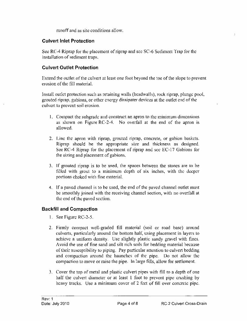
mnoff and as site conditions allow.
Culvert Inlet Protection
See RC-4 Riprap for the placement ofriprap and see SC-6 Sediment Trap for the installation of sediment traps.
Culvert Outlet Protection
Extend the outlet of the culvert at least one foot beyond the toe of the slope to prevent erosion of the fill material.
Install outlet protection such as retaining walls (headwalls), rock riprap, plunge pool, grouted riprap, gabions, or other energy dissipater devices at the outlet end of the culvert to prevent soil erosion.
1. Compact the subgrade and constmct an apron to the minimum dimensions as shown on Figure RC-2-4. No overfall at the end of the apron is allowed.
2. Line the apron with riprap, grouted riprap, concrete, or gabion baskets. Riprap should be the appropriate size and thickness as designed. See RC-4 Riprap for the placement of riprap and see EC-17 Gabions for the sizing and placement of gabions.
3. If grouted riprap is to be used, the spaces between the stones are to be filled with grout to a minimum depth of six inches, with the deeper portions choked with fine material.
4. If a paved channel is to be used, the end of the paved channel outlet must be smoothly joined with the receiving channel section, with no overfall at the end ofthe paved section.
Backfill and Compaction
1. See Figure RC-2-S.
2. Firmly compact well-graded fill material (soil or road base) around culverts, particularly around the bottom half, using placement in layers to achieve a uniform density. Use slightly plastic sandy gravel with fines. Avoid the use of fine sand and silt rich soils for bedding material because of their susceptibility to piping. Pay particular attention to culvert bedding and compaction around the haunches of the pipe. Do not allow the compaction to move or raise the pipe. In large fills, allow for settlement.
3. Cover the top of metal and plastic culvert pipes with fill to a depth of one half the culvert diameter or at least I foot to prevent pipe crushing by heavy trucks. Use a minimum cover of 2 feet of fill over concrete pipe.
Rev: 1 Date: July 2010 Page 4 of 8 RC-2 Culvert Cross-Drain
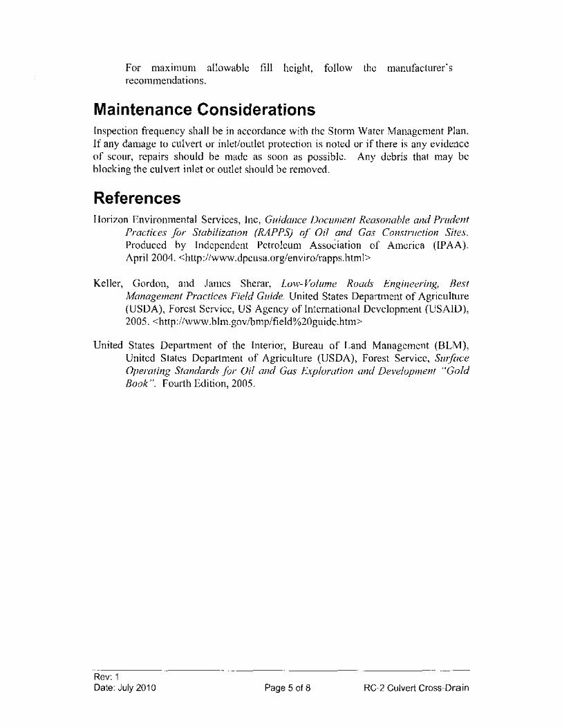
For maXlmum allowable fill height, follow the manufacturer's recommendations.
Maintenance Considerations Inspection frequency shall be in accordance with the Storm Water Management Plan. If any damage to culvert or inlet/outlet protection is noted or if there is any evidence of scour, repairs should be made as soon as possible. Any debris that may be blocking the culvert inlet or outlet should be removed.
References Horizon Environmental Services, Inc, Guidance Document Reasonable and Prudent
Practices for Stabilization (RAPPS) of Oil and Gas Construction Sites. Produced by Independent Petroleum AssoCiation of America (lPAA). April 2004. <http://www.dpcusa.org/enviro/rapps.html>
Keller, Gordon, and James Sherar, Low- Volume Roads Engineering, Best Management Practices Field Guide. United States Department of Agriculture (USDA), Forest Service, US Agency of International Development (USAID), 2005. <http://www.blm.govlbmp/field%20guide.htm>
United States Department of the Interior, Bureau of Land Management (BLM), United States Department of Agriculture (USDA), Forest Service, Surface Operating Standards for Oil and Gas Exploration and Development "Gold Book". Fourth Edition, 2005.
Rev: 1 Date: July 2010 Page 5 of 8 RC-2 Culvert Cross-Drain
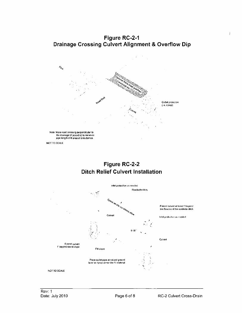
Figure RC-2-1 Drainage Crossing Culvert Alignment & Overflow Dip
Note: Make road crossing perpendicular 10 the drainage (if possible) to minimize pipe length and area of disturbance
NOT TO SCALE
Figure RC-2-2
/
Outlet protection (i.e. riprap)
Ditch Relief Culvert Installation
Extend culvert l' beyond loe of stope
NOT TO SCALE
Rev: 1 Date: July 2010
Inlel protection as needed
Roadside ditch
,
,
Fill slope
Place outlet pipe al natural ground level or riprap armor the fill material
0·30"
Page 6 of 8
,
.1-... I ,
Extend culvert atrells! " beyond the flowline of the roadside ditch
Inlel prolectton 85 needed
Culvert
RC-2 Culvert Cross-Drain
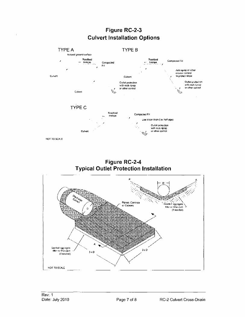
TYPE A
Figure RC-2-3 Culvert Installation Options
TYPE B Natural groun<l surface
,
Culvert
NOT TO SCALE
Graded aggregate filter or filler cloth
(il neodod)
NOT TO SCALE
Rev: 1 Date: July 2010
Roadbed - Insl?pe
Culvert
TYPEe
Culvert
Compacted Fill
Culvert
Outlet protection with rock riprap or other conlfol
Roadbed 1,:",~lope
!
Compacted Fill
Add riprap or other erosion control to protect slope
Outret protection with rock riprap or other control
Roadbed Instope
Compacted Fill
Figure RC-2-4
Use slope drain (Le. half pipe)
Outlet protection with rock riprap or other control
Typical Outlet Protection Installation
,,0
Page 7 of 8 RC-2 Culvert Cross-Drain
Figure RC-2-5 Culvert Backfill and Compaction
Roadbed
Base and Sidewall fill material should be compacted. Compact the fill a minil,lffi of each culvert
diameter on each side of the culvert
NOT TO SCALE
Rev: 1 Date: July 2010
Half diameter of culvert Of a\ least 1 ft. of cover for melal or
plastic culverts. Use 2 ft. cover for concrete pipe.
,
,
Culvert
Tamp backfill material at regular inlervals (lifts)
Level of nalural streambed (if applicable)
Gravel or soil culvert bed (no rock larger than 3")
Page 8 of 8 RC-2 Culvert Cross-Drain
RC-3 Culvert Outlet Protection (COP)
COMBINED WITH RC-2
Rev: 1 Date: July 2010 Page 1 of 1 RC-3 Culvert Outlet Protection
RC-4 Riprap (RIP)
Description Riprap is a permanent, eros ion-res istant layer made of native rocks/stones or crushed concrete. It is intended to stabi lize areas subject to erosion and protect against scour of the soil caused by concentrated, high velocity flows.
Applicability Riprap can be used for areas subject to erosion or weathering, particularly where conditions prohibit the establishment of vegetation or where flow velocities exceed 5 ft/sec. Riprap may be used in the following app lications:
• Cut-and-fi ll slopes
• Channel side slopes and/or bottoms
• Inlets and out lets to cu lverts or slope drains
• Roadside ditches
• Check dams
Limitations Riprap is limited by steepness of slope, because slopes greater than 1.5: I have potential riprap loss due to erosion and sliding. When working within flowing streams, measures should be taken to prevent excessive turbidity and erosion during construction. Bypassing base flows or temporarily blocking base flows are two possible methods.
Rev: 1 Date: July 20 10 Page 1 of 4 RC-4 Riprap
)
Design Criteria Quality Riprap must be durable so that freeze/thaw cycles do not decompose it in a short time. They should be angular and not subject to breaking down when exposed to water or weathering. Ideally, a well-graded mixture of rock sizes should be used instead of one uniform size.
Size The sizes of stones used for riprap protection are determined by purpose and specific site conditions:
I. Slope Stabilization. Riprap stone for slope stabilization not subject to flowing water should be sized for the proposed grade. The gradient of the slope to be stabilized should be less than the natural angle of repose of the stone selected. Angles of repose of riprap stones may be estimated from Figure RC-4-1. Riprap used for surface stabilization of slopes does not add significant resistance to sliding or slope failure and should not be considered a retaining wall. Slopes approaching 1.5: I may require special stability analysis. The inherent stability of the soil must be satisfactory before riprap is used for surface stabilization. Some slopes constructed in extremely rocky soils may not require additional riprap or other controls because the native soil itself is so rocky that it may already be considered riprap and is not likely to erode.
2. Outlet Protection. Riprap stone for outlet protection shall be determined based on site specific conditions and shall be large enough so that riprap is not washed away during periods of high runoff.
3. Streambank Protection. Riprap stone for streambank protection shall be determined based on site specific conditions and shall be large enough so that riprap is not washed away during periods of high runoff. The riprap should extend two feet below the channel bottom and be keyed into the bank both at the upstream end and downstream end of the proposed work or reach.
Filter material Filter material may be required between riprap and the underlying soil surface to prevent soil from moving through the riprap. Filter cloth material or a layer of sand and/or gravel is usually used for the filter.
Construction Specifications Minor deviations from the following construction specifications are acceptable as long as performance oriented specifications are maintained. The performance oriented specification for riprap is that erosion is not observed on the area with riprap application and that sediment is not observed to leave the ripraped area. If erosion or sediment is observed, the riprap should be re-designed and/or re-installed.
Rev: 1 Date: July 2010 Page 2 of 4 RC-4 Riprap
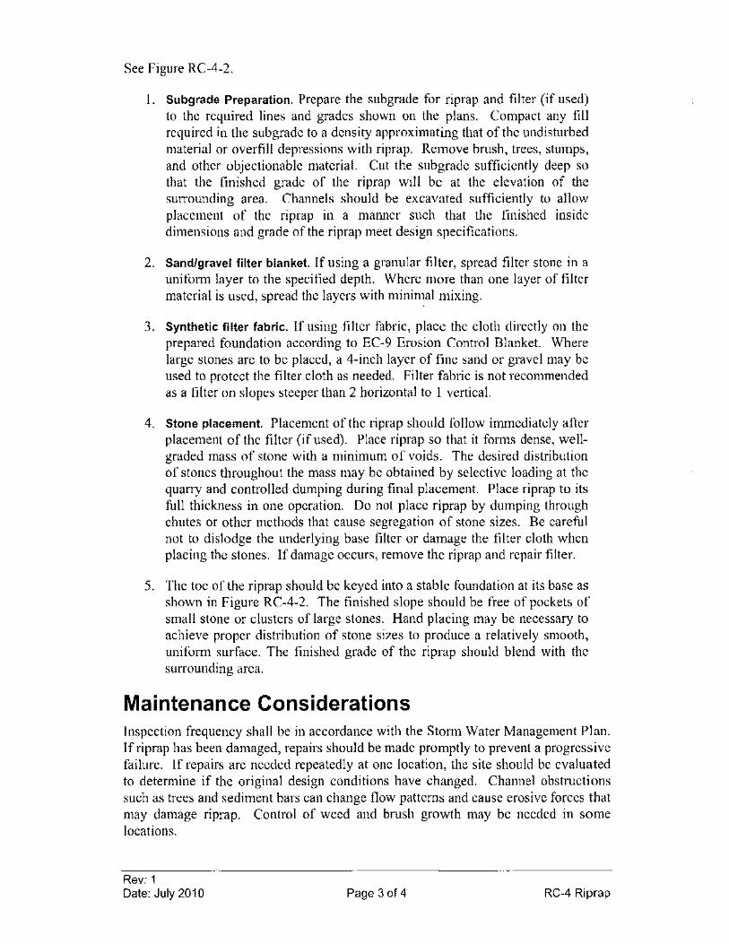
See Figure RC-4-2.
I. Subgrade Preparation. Prepare the sub grade for riprap and filter (if used) to the required lines and grades shown on the plans. Compact any fill required in the sub grade to a density approximating that of the undisturbed material or overfill depressions with riprap. Remove brush, trees, stumps, and other objectionable material. Cut the subgrade sufficiently deep so that the finished grade of the riprap will be at the elevation of the surrounding area. Channels should be excavated sufficiently to allow placement of the riprap in a manner such that the finished inside dimensions and grade of the riprap meet design specifications.
2. Sand/gravel filter blanket. If using a granular filter, spread filter stone in a uniform layer to the specified depth. Where more than one layer of filter material is used, spread the layers with minimal mixing.
3. Synthetic filter fabric. If using filter fabric, place the cloth directly on the prepared foundation according to EC-9 Erosion Control Blanket. Where large stones are to be placed, a 4-inch layer of fine sand or gravel may be used to protect the filter cloth as needed. Filter fabric is not recommended as a filter on slopes steeper than 2 horizontal to I vertical.
4. Stone placement. Placement of the riprap should follow immediately after placement of the filter (if used). Place riprap so that it forms dense, wellgraded mass of stone with a minimum of voids. The desired distribution of stones throughout the mass may be obtained by selective loading at the quarry and controlled dumping during final placement. Place riprap to its full thickness in one operation. Do not place riprap by dumping through chutes or other methods that cause segregation of stone sizes. Be careful not to dislodge the underlying base filter or damage the filter cloth when placing the stones. If damage occurs, remove the riprap and repair filter.
5. The toe of the riprap should be keyed into a stable foundation at its base as shown in Figure RC-4-2. The finished slope should be free of pockets of small stone or clusters of large stones. Hand placing may be necessary to achieve proper distribution of stone sizes to produce a relatively smooth, uniform surface. The finished grade of the riprap should blend with the surrounding area.
Maintenance Considerations Inspection frequency shall be in accordance with the Storm Water Management Plan. If riprap has been damaged, repairs should be made promptly to prevent a progressive failure. If repairs are needed repeatedly at one location, the site should be evaluated to determine if the original design conditions have changed. Channel obstructions such as trees and sediment bars can change flow patterns and cause erosive forces that may damage riprap. Control of weed and brush growth may be needed in some locations.
Rev: 1 Date: July 2010 Page 3 of 4 RC-4 Riprap
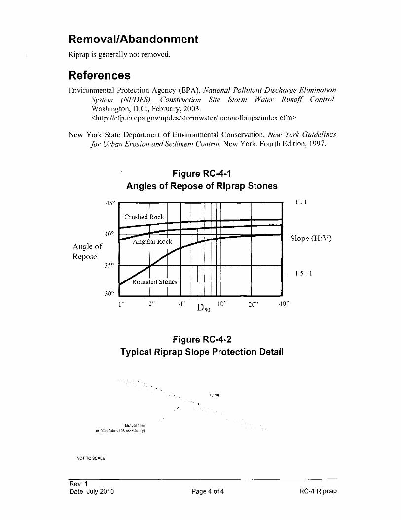
Removal/Abandonment Riprap is generally not removed.
References Environmental Protection Agency (EPA), National Pollutant Discharge Elimination
System (NPDES). Construction Site Storm Water Runoff Control. Washington, D.C., February, 2003. <http://cfpub.epa.gov/npdes/stormwater/menuofbmpslindex.cfm>
New York State Department of Environmental Conservation, New York Guidelines for Urban Erosion and Sediment Control. New York. Fourth Edition, 1997.
Angle of Repose
30°
Figure RC·4·1 Angles of Repose of Riprap Stones
I Cmshed Rock
I .... Angular Rock
// ....
~ded Stones
I I 1"' 4"
". ".
10'" D50
Figure RC·4·2
20'"
-
40'"
Typical Riprap Slope Protection Detail
Gravellilter or rllter fabric (as necessary)
NOT TO SCALE
Rev: 1 Date: July 2010
rlprap
. ,
Page 4 of 4
1 : 1
Slope (H:V)
1.5 : 1
RC-4 Riprap
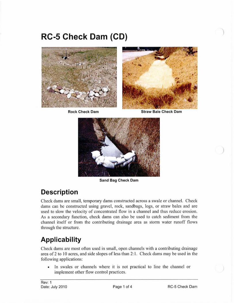
RC-5 Check Dam (CD)
Rock Check Dam Straw Bale Check Dam
Sand Bag Check Dam
Description Check dams are small, temporary dams constructed across a swale or channel. Check dams can be constructed using gravel, rock, sandbags, logs, or straw bales and are used to slow the velocity of concentrated flow in a channel and thus reduce erosion. As a secondary function, check dams can also be used to catch sediment from the channel itself or from the contributing drainage area as storm water runoff flows through the structure.
Applicability Check dams are most often used in small , open channels with a contributing drainage area of2 to 10 acres, and side slopes of less than 2: I. Check dams may be used in the following applications:
• In swales or channels where it is not practical to line the channel or implement other flow control practices.
Rev: 1 Date: July 2010 Page 1 of 4 RC-5 Check Dam
)
)
• Where temporary seeding has been recently implemented but has not had time to take root and fully develop.
Limitations • Check dams should not be used in live, flowing streams unless approved
by an appropriate regulatory agency.
• Leaves have been shown to be a significant problem by clogging check dams in the fall. Therefore, they might necessitate increased inspection and maintenance.
Design Criteria No formal design is required.
Construction Specifications 1. Dams should be installed with careful placement of the construction
material. Mere dumping of the dam material into a channel is not appropriate and will reduce overall effectiveness.
2. Check dams can be constructed from a number of different materials. Most commonly, they are made of rock, straw bales, or sandbags. When using rock or stone, the material diameter should be 2 to IS inches or sized appropriately for the site specific conditions.
3. The center of the dam should be at an elevation which is lower than the edges. This design creates a weir effect that helps to channel flows away from the banks and prevent further erosion.
4. Additional stability can be achieved by implanting the dam material into the sides and bottom of the channel.
S. Check dams may be used in a series and spaced as needed to reduce flow velocity and as site conditions allow.
6. When installing more than one check dam in a channel, outlet stabilization measures should be installed below the final dam in the series. Because this area is likely to be vulnerable to further erosion, riprap, geotextile lining, or some other stabilization measure is recommended.
7. Install straw bale check dams according to SC-l Straw Bale Barrier and Figures RC-S-l. Install rock check dams according to RC-S-2.
Rev: 1 Date: July 2010 Page 2 of 4 RC-5 Check Dam
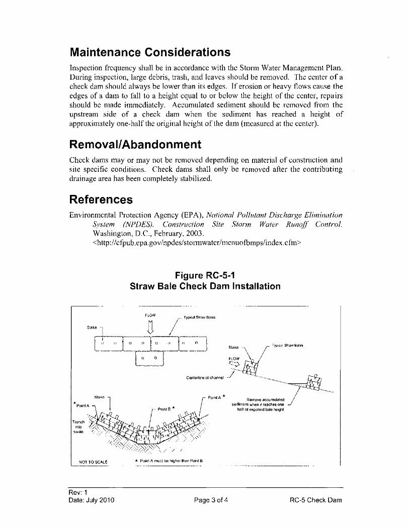
Maintenance Considerations Inspection frequency shall be in accordance with the Storm Water Management Plan. During inspection, large debris, trash, and leaves should be removed. The center of a check dam should always be lower than its edges. If erosion or heavy flows cause the edges of a dam to fall to a height equal to or below the height of the center, repairs should be made immediately. Accumulated sediment should be removed from the upstream side of a check dam when the sediment has reached a height of approximately one-half the original height of the dam (measured at the center).
Removal/Abandonment Check dams mayor may not be removed depending on material of construction and site specific conditions. Check dams shall only be removed after the contributing drainage area has been completely stabilized.
References Environmental Protection Agency (EPA), National Pollutant Discharge Elimination
System (NPDES). Construction Site Storm Water Runoff Control. Washington, D.C., February, 2003. <http://cfpub.epa.gov/npdes/stormwater/menuotbmpslindex.cfm>
Figure RC-S-1 Straw Bale Check Dam Installation
FLOW M ( Typical Straw Bales
Stake 1 <J
t'----.o ~o L: ° I ° o~ [0 ° I
Typical St'aw Balas
* Stak.e 1 PoinlA
NOT TO SCAlE
Rev: 1 Date: July 2010
Centerline of channel ~
* Point A must be higher than Point B
Page 3 of 4
Removo accumulated sediment when it reaches one
half of exposed bale height
RC-5 Check Dam
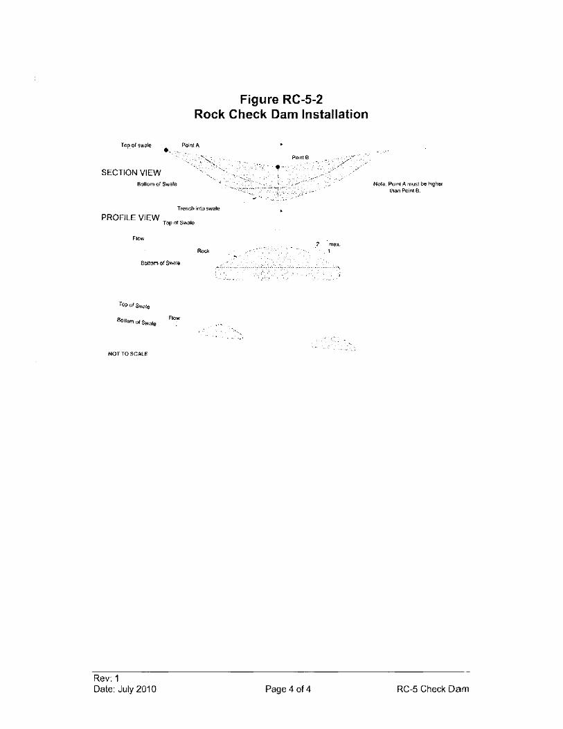
Figure RC-5-2 Rock Check Dam Installation
Top of swale Point A
PointB
SECTION VIEW Bottom of Swale
Trench into swa!e
PROFILE VIEW Top of Swale
Flow 2 ma)(.
Rock ,1
Bollom of Swale
Top of Swale
BOllom of Sware Flow
" - --NOT TO SCA.lE
Rev: 1 Date: July 2010 Page 4 of 4
Nole: Point A must be higher than Point R
RC-5 Check Dam
RC-6 Road Slope
COMBINED WITH EC-2
Rev: 1 Date: July 2010 Page 1 of 1 RC-6 Road Slope
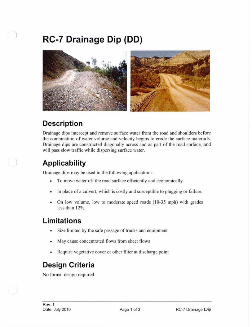
)
RC-7 Drainage Dip (DO)
Description Drainage dips intercept and remove surface water from the road and shoulders before the combination of water vo lume and veloc ity begins to erode the su rface material s. Drainage dips are constructed diagonally across and as part of the road surface, and wi ll pass slow traffic wh ile dispersing surface water.
Applicability Drainage dips may be used in the following applications:
• To move water off the road surface efficiently and economica lly.
• In place of a cu lvert, which is cost ly and susceptible to plugging or failure.
• On low vo lume, low to moderate speed roads ( 10-35 mph) with grades less than 12%.
Limitations • Size limited by the safe passage of trucks and equ ipment
• May cause concentrated flows from sheet flows
• Require vegetat ive cover or other filter at di scharge point
Design Criteria No formal design required .
Rev: 1 Date: July 2010 Page 1 of 3 RC-7 Drainage D ip
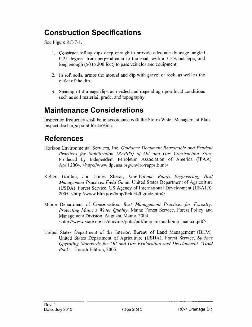
Construction Specifications See Figure RC-7-\.
I. Constmct rolling dips deep enough to provide adequate drainage, angled 0-25 degrees from perpendicular to the road, with a 3-5% outs lope, and long enough (50 to 200 feet) to pass vehicles and equipment.
2. In soft soils, armor the mound and dip with gravel or rock, as well as the outlet of the dip.
3. Spacing of drainage dips as needed and depending upon local conditions such as soil material, grade, and topography.
Maintenance Considerations Inspection frequency shall be in accordance with the Storm Water Management Plan. Inspect discharge point for erosion.
References Horizon Environmental Services, Inc, Guidance Document Reasonable and Prudent
Practices for Stabilization (RAPPS) of Oil and Gas Construction Sites. Produced by Independent Petroleum Association of America (IPAA). April 2004. <http://www.dpcusa.org/enviro/rapps.html>
Keller, Gordon, and James Sherar, Low-Volume Roads Engineering, Best Management Practices Field Guide. United States Department of Agriculture (USDA), Forest Service, US Agency of International Development (USAID), 2005. <http://www.blm.gov/bmp/field%20guide.htm>
Maine Department of Conservation, Best Management Practices for Forestry: Protecting Maine's Water Quality. Maine Forest Service, Forest Policy and Management Division. Augusta, Maine. 2004. <http://www.state.me.us/doc/mfs/pubs/pdf/bmp_ manual/bmp _ manual.pdf>
United States Department of the Interior, Bureau of Land Management (BLM), United States Department of Agriculture (USDA), Forest Service, Surface Operating Standards for Oil and Gas Exploration and Development "Gold Book". Fourth Edition, 2005.
Rev: 1 Dale: July 2010 Page 2 of 3 RC-7 Drainage Dip
"?/~ ROild Grade
Dip
NOT TO SCALE
Rev: 1 Date: July 2010
Figure RC-7-1 Typical Drainage Dip
............ , ........... .
SPACE AS
Page 3 of 3
25-
Re-7 Drainage Dip
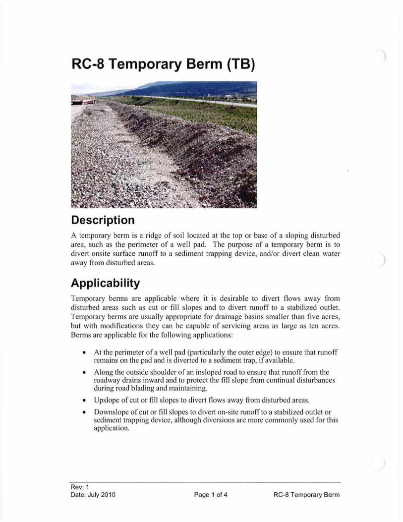
RC-8 Temporary Berm (TB)
Description A temporaty berm is a ridge of soil located at the top or base of a sloping disturbed area, such as the perimeter of a we ll pad. The purpose of a temporaty berm is to divert onsite surface runoff to a sediment trapping device, and/or divert clean water away from disturbed areas.
Applicability TemporalY benns are applicable where it is desirable to divert flows away from disturbed areas such as cut or fill slopes and to divert runoff to a stabilized outlet. TemporalY benns are usually appropriate for drainage basins smaller than five acres, but with modifications they can be capable of servicing areas as large as ten acres. Berms are app licable for the fo llowing applications:
• At the perimeter of a well pad (particularly the outer edge) to ensure that runoff remains on the pad and is diverted to a sediment trap, if ava ilab le.
• Along the outside shoulder of an insloped road to ensure that runofffrom the roadway drains inward and to protect the fill slope from continual disturbances during road blading and maintaining.
• Upslope of cut or fill slopes to divert flows away from disturbed areas.
• Downslope of cut or fill slopes to divert on-site runoff to a stabi li zed outlet or sediment trapping device, although diversions are more commonly used for this appl ication.
Rev: 1 Date: July 2010 Page 1 of 4 RC-8 Temporary Berm
)
)

Limitations • To alleviate erosion capability, benns must be directed into a stabilized
outlet or well-vegetated area or to sediment trapping devices, where erosion sediment can settle out of the runoff before being discharged to surface waters.
• If a berm crosses a vehicle roadway or entrance, its effectiveness may be reduced.
Design Criteria No formal design is required.
Construction Specifications 1. Prior to berm construction, remove all trees, brush, stumps and other
objects in the path of the benn and till the base of the benn before laying the fill.
2. Construct the benn according to Figure RC-8-1. All newly constructed well pad perimeter benns shall have a minimum height of 2 feet. Berm height may vary for other applications and depending on site specific conditions.
3. For points where vehicles will cross the benn, the slope should be no steeper than 3: I. This will prolong the life of the benn and mcrease effectiveness at the point of vehicle crossing.
4. All berms shall have positive drainage to an outlet, with the exception of well pad perimeter benns. Field location should be adjusted as needed to utilize a stabilized safe outlet.
5. Route the benn outlet into a well-vegetated area or install a sediment trapping or filter control at the outlet, such as straw bales.
6. If the expected life span of the temporary benn is greater than 15 days, it is recommended that the benn be compacted and seeded.
7. Stabilization shall be in accordance with EC-5 Temporary.
8. Where possible, benns should be constructed and fully stabilized prior to commencement of major land disturbance. This will maximize the effectiveness of the structure as an erosion and sediment control device.
Rev: 1 Date: July 2010 Page 2 of 4 RC-B Temporary Berm
Maintenance Considerations Inspection frequency shall be in accordance with the Storm Water Management Plan. Temporary berms should be inspected for evidence of erosion or deterioration. The berm should be maintained at the original height, and any decrease in height due to settling or erosion should be repaired as soon as possible.
Removal/Abandonment Temporary berms should remain in place and in good condition until the disturbed areas are permanently stabilized. There is no need to formally remove the berm on completion of stabilization.
References Environmental Protection Agency (EPA), National Pollutant Discharge Elimination
System (NPDES). Construction Site Storm Water Runoff Control. Washington, D.C., February, 2003. <http://cfpub.epa.gov/npdes/stormwater/menuofbmps/index.cfm>
New York State Department of Environmental Conservation, New York Guidelines for Urban Erosion and Sediment Control. New York. Fourth Edition, 1997.
Rev: 1 Date: July 2010 Page 3 of 4 RC-8 Temporary Berm
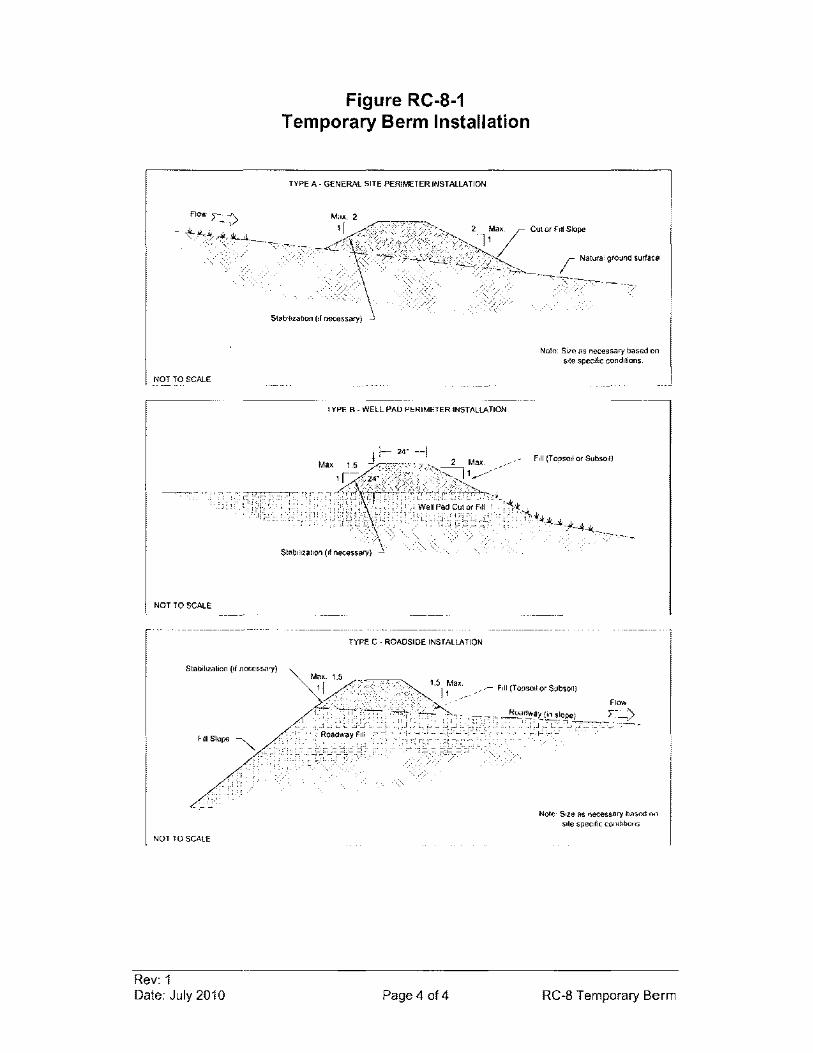
NOT TO SCALE
NOT TO SCALE
NOT TO SCALE
Rev: 1 Date: July 2010
Figure RC-8-1 Temporary Berm Installation
TYPE A - GENERAL SITE PERIMETER INSTAlLATION
TYPE B - WEll PAD PERIMETER INSTALLATION
Stabilization (II necessary) -
TYPE C • ROADSIDE INSTALLATION
Page 4 014
CuI or Fill Slope
Natural ground surface
Nole: Size as necessary based on $lie specific condilions.
Note: Size as necessary based on site specifiC condilions
RC-8 Temporary Berm

RC-9 Culvert Inlet Protection (CIP)
COMBINED WITH RC-2
Rev: 1 Date: July 2010 Page 1 of 1 RC-9 Culvert Inlet Protection
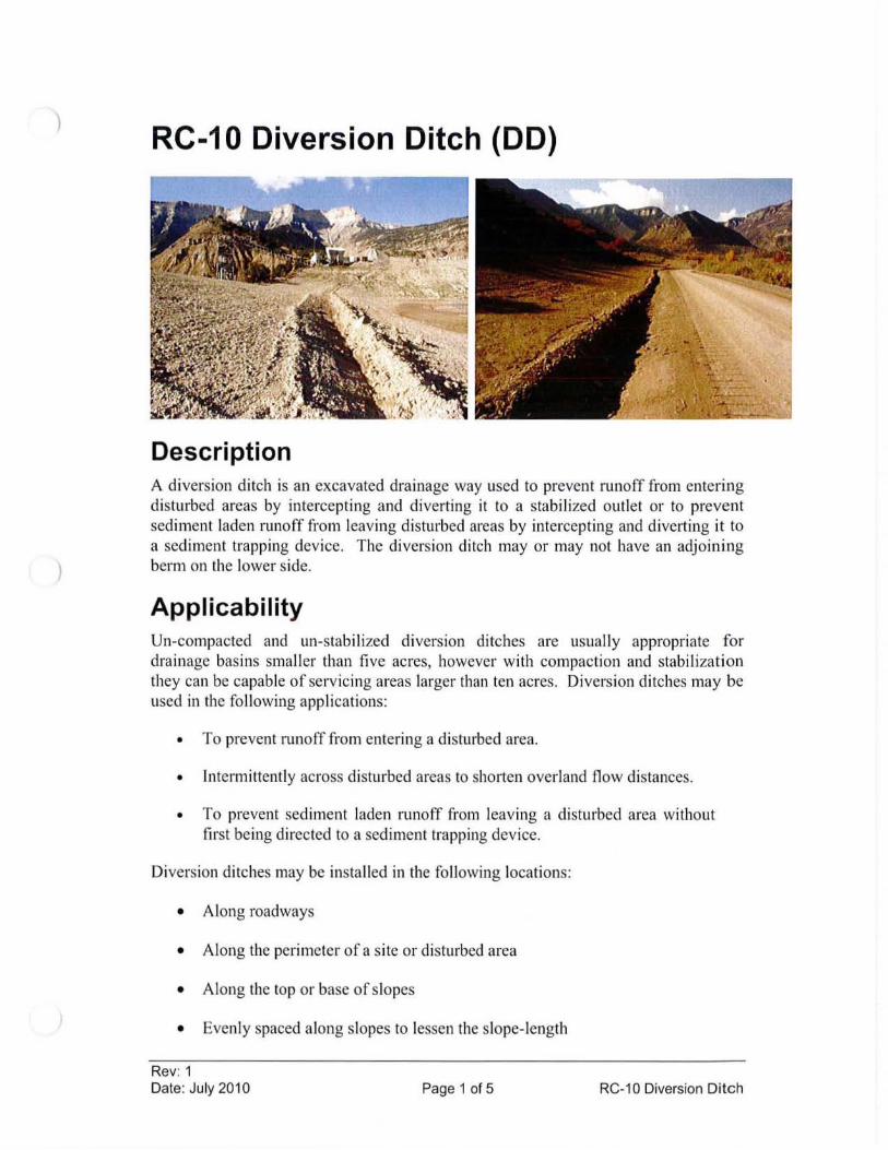
)
)
RC-10 Diversion Ditch (DO)
Description A diversion ditch is an excavated drainage way used to prevent runoff from entering disnu·bed areas by intercepting and diverting it to a stabilized outlet or to prevent sediment laden runoff from leaving disturbed areas by intercepting and diverting it to a sediment trapping device. The diversion ditch mayor may not have an adjoining berm on the lower side.
Applicability Un-compacted and un-stabilized diversion ditches are usually appropriate for drainage basins smaller than five acres, however with compaction and stabilization they can be capable of servicing areas larger than ten acres. Diversion ditches may be used in the following applications:
• To prevent runoff from entering a di sturbed area.
• Intermittently across disturbed areas to shorten overland flow distances.
• To prevent sediment laden runoff from leaving a disturbed area without first being directed to a sediment trapping device.
Diversion ditches may be installed in the following locations:
• Along roadways
• Along the perimeter of a site or disturbed area
• Along the top or base of slopes
• Evenly spaced along slopes to lessen the slope- length
Rev: 1 Date: July 2010 Page 1 of 5 RC-10 Diversion Ditch
Limitations • To alleviate erosion capability, diversion ditches must be directed to a
stabilized outlet (such as a well-vegetated area) or to a sediment trapping device where sediment can settle out of the runoff before being discharged to surface waters.
• If possible, diversion ditches should be designed to avoid crossing vehicle pathways.
• Diversion ditches should be used with caution on soils subject to slippage.
• The area around the diversion ditch that is disturbed by its construction may need to be stabilized so that it is not subject to similar erosion as the slope that the diversion ditch is built to protect.
Design Criteria A site specific design is only required for permanent diversion ditches with contributing drainage areas greater than 10 acres. The following design criteria shall only apply to permanent diversion ditches:
Location Location shall be determined by considering outlet conditions, topography, land use, soil type, length of slope, and the development layout.
Capacity Peak rates of runoff values used in determining the capacity requirements may be as outlined by TR-55, Urban Hydrology for Small Watersheds.
Velocity and Grade The permissible velocity for the specific soil type will determine the maximum grade. The maximum permissible velocity for sand and silt vegetated channels is 3 ft/sec, and 5 ft/sec for clay vegetated channels.
Construction Specifications
General
1. All trees, brush, stumps, obstructions, and other objectionable material shall be removed and disposed of so as not to interfere with the proper functioning of the diversion ditch.
2. The diversion ditch shall be free of bank projections or other irregularities which will impede normal flow.
3. All diversion ditches shall have uninterrupted positive grade to an outlet.
Rev: 1 Date: July 2010 Page 2 of 5 RC-10 Diversion Ditch
4. Diverted runoff from a disturbed area shall be conveyed to a sediment trapping device.
5. Diverted runoff from an undisturbed area shall outlet directly into an undisturbed, well vegetated and stabilized area at non-erosive velocity.
6. All earth removed and not needed for construction shall be placed so that it will not interfere with the functioning of the diversion ditch.
Temporary Diversion Ditches
See Figures RC- 10-1 and RC- 10-2 for details.
1. The appropriate size and design of temporary diversion ditches depends on the size of the contributing drainage area and other site specific conditions.
2. Fills may be compacted, if necessary to meet site specific needs, by earth moving equipment.
3. The diversion ditch may be stabilized with vegetation, riprap, or erosion control blanket if necessary to meet site specific needs.
Permanent Diversion Ditches
See Figure RC- 10-3 for details.
1. Permanent diversion ditches shall be parabolic, trapezoidal, or triangular shaped.
2. Fills shall be compacted as necessary to prevent unequal settlement.
3. The diversion ditch shall be stabilized with vegetation, riprap, or erosion control blanket as soon as possible following construction.
Maintenance Considerations Inspection frequency shall be in accordance with the Storm Water Management Plan. Diversion ditches should be cleared of accumulated sediment and reseeded if necessary. Repair as needed in order to maintain diversion ditch capacity.
Removal/Abandonment Drainage ditches mayor may not be removed. Drainage ditches collecting runoff from disturbed areas shall remain in place at least until the disturbed areas are permanently stabilized.
Rev: 1 Date: July 201 0 Page 3 of 5 RC-10 Diversion Ditch
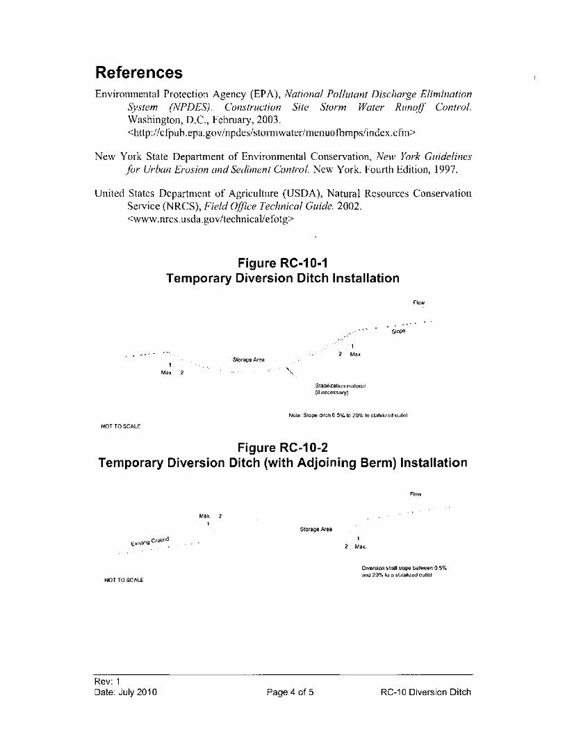
References Environmental Protection Agency (EPA), National Pollutant Discharge Elimination
System (NPDES). Construction Site Storm Water Runoff Control. Washington, D.C., February, 2003. <http://cfpub.epa.gov/npdes/stormwater/menuofbmps/index.cfm>
New York State Department of Environmental Conservation, New York Guidelines for Urban Erosion and Sediment Control. New York. Fourth Edition, 1997.
United States Department of Agriculture (USDA), Natural Resources Conservation Service (NRCS), Field Office Technical Guide. 2002. <www.nrcs.usda.govitechnicaliefotg>
. . ' .
NOT TO SCALE
Figure RC-10-1 Temporary Diversion Ditch Installation
1. Max, 2
Storage Area 2 Max .
Stabililation malerial (if necessary)
Flow
. ~ .. stope
Nole: Slope dItch 0.5% 10 20% 10 stabilized ouUel
Figure RC-10-2 Temporary Diversion Ditch (with Adjoining Berm) Installation
Max, 2 1
NOT rOSCAlE
Rev: 1 Date: July 2010
Storage Area
Page 4 of 5
Flow
2 Mal(
Oiversion shall slope between 0.5% and 20% to a stabilized outlet
RC-10 Diversion Ditch
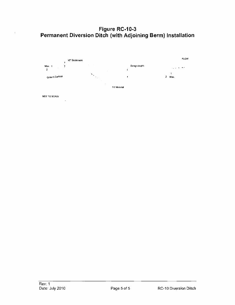
Figure RC-10-3 Permanent Diversion Ditch (with Adjoining Berm) Installation
Max_ 1
2
Ground Sunace
NOT TO SCALE
Rev: 1 Date: July 2010
10· SeiUemenl FLOW
Design Depth ...
2 Max
Fill Material
Page 5 of 5 RC-10 Diversion Ditch
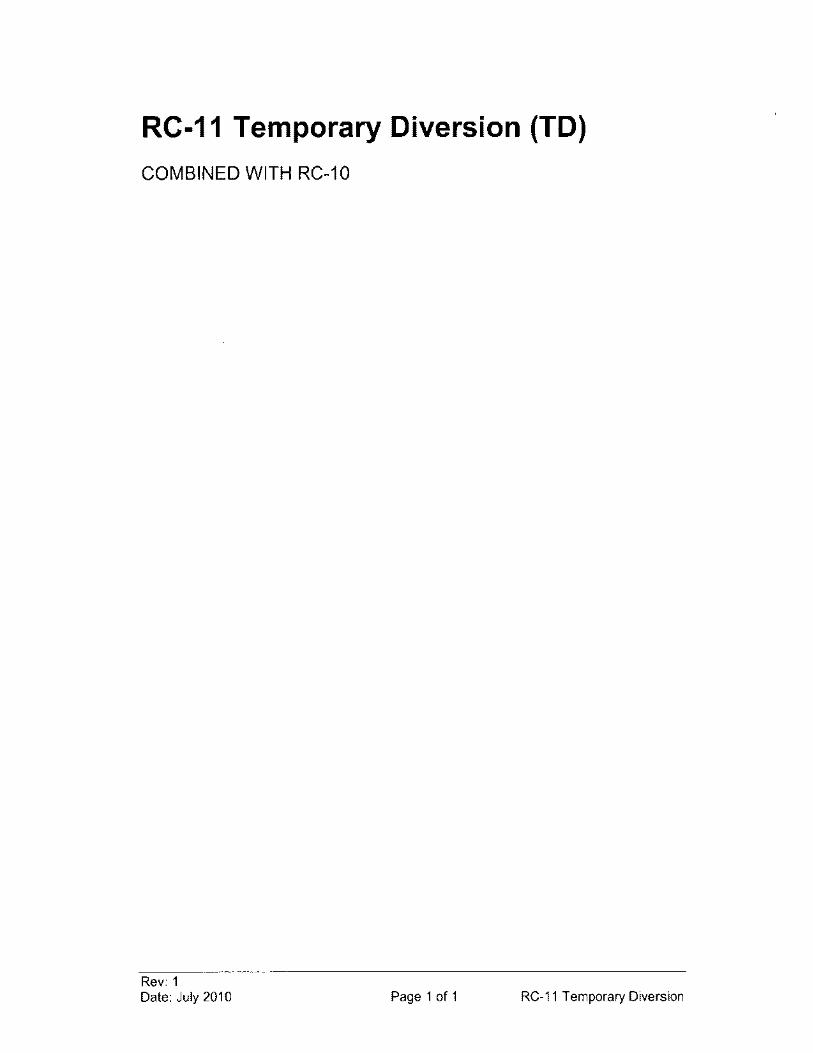
RC-11 Temporary Diversion (TO)
COMBINED WITH RC-10
Rev: 1 Date: July 2010 Page 1 of 1 RC-11 Temporary Diversion
RC-12 Permanent Diversion (PO) -
COMBINED WITH RC-10
Rev: 1 Date: July 2010 Page 1 of 1 RC-12 Permanent Diversion
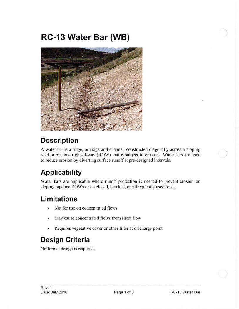
RC-13 Water Bar (WB)
Description A water bar is a ridge, or ridge and channel , constructed diagonally across a sloping road or pipeline right-of-way (ROW) that is subject to erosion. Water bars are used to reduce erosion by diverting surface runoff at pre-designed intervals.
Applicability Water bars are applicable where runoff protection is needed to prevent erosion on sloping pipeline ROWs or on closed, blocked, or infrequently used roads.
Limitations • Not for use on concentrated flows
• May cause concentrated flows from sheet flow
• Requires vegetative cover or other filter at discharge point
Design Criteria No formal design is required .
Rev: 1 Date: July 2010 Page 1 of 3 RC-13 Water Bar
)
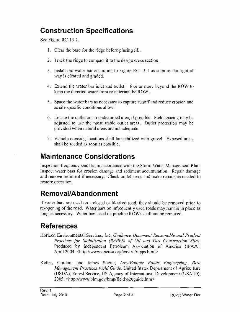
Construction Specifications See Figure RC-13-1.
I. Clear the base for the ridge before placing fill.
2. Track the ridge to compact it to the design cross section.
3. Install the water bar according to Figure RC-13-1 as soon as the right of way is cleared and graded.
4. Extend the water bar inlet and outlet I foot or more beyond the ROW to keep the diverted water from re-entering the ROW.
5. Space the water bars as necessary to capture runoff and reduce erosion and as site specific conditions allow.
6. Locate the outlet on an undisturbed area, if possible. Field spacing may be adjusted to use the most stable outlet areas. Outlet protection may be provided when natural areas are not adequate.
7. Vehicle crossing locations shall be stabilized with gravel. Exposed areas shall be seeded as soon as possible.
Maintenance Considerations Inspection frequency shall be in accordance with the Storm Water Management Plan. Inspect water bars for erosion damage and sediment accumulation. Repair damage and remove sediment if necessary. Check outlet areas and make repairs as needed to restore operation.
Removal/Abandonment If water bars are used on a closed or blocked road, they should be removed prior to re-opening of the road. Water bars on infrequently used roads may remain in place as long as necessary. Water bars used on pipeline ROWs shall not be removed.
References Horizon Environmental Services, Inc, Guidance Document Reasonable and Prudent
Practices for Stabilization (RAPPS) of Oil and Gas Construction Sites. Produced by Independent Petroleum Association of America (IPAA). April 2004. <http://www.dpcusa.org/enviro/rapps.html>
Keller, Gordon, and James Sherar, Low- Volume Roads Engineering, Best Management Practices Field Guide. United States Department of Agriculture (USDA), Forest Service, US Agency of International Development (USAID), 2005. <http://www.blm.gov/bmp/field%20guide.htm>
Rev: 1 Date: July 2010 Page 2 of 3 RC-13 Water Bar
Maine Department of Conservation, Best Management Practices for Forestry: Protecting Maine's Water Quality. Maine Forest Service, Forest Policy and Management Division. Augusta, Maine. 2004. <http://www.state.me.us/doc/mfs/pubs/pdf/bmp _ manuallbmp _manual. pdf>
New York State Department of Environmental Conservation, New York Guidelines for Urban Erosion and Sediment Control. New York. Fourth Edition, 1997.
OUTLET INTO STABILIZED AREA
(WELL VEGETATED
NOT TO SCALE
Rev: 1 Date: July 2010
Figure RC-13-1 Water Bar Installation
EDGE OF ROAD OR PIPELINE ROW.
GRAVEL
Page 3 of 3
EDGE OF ROAD OR PIPELINE R.OW
Noles' 1) Optional adjoining swale located on
upslope side of berm 2) Size as necessary based on site
specific conditions
RC-13 Water Bar
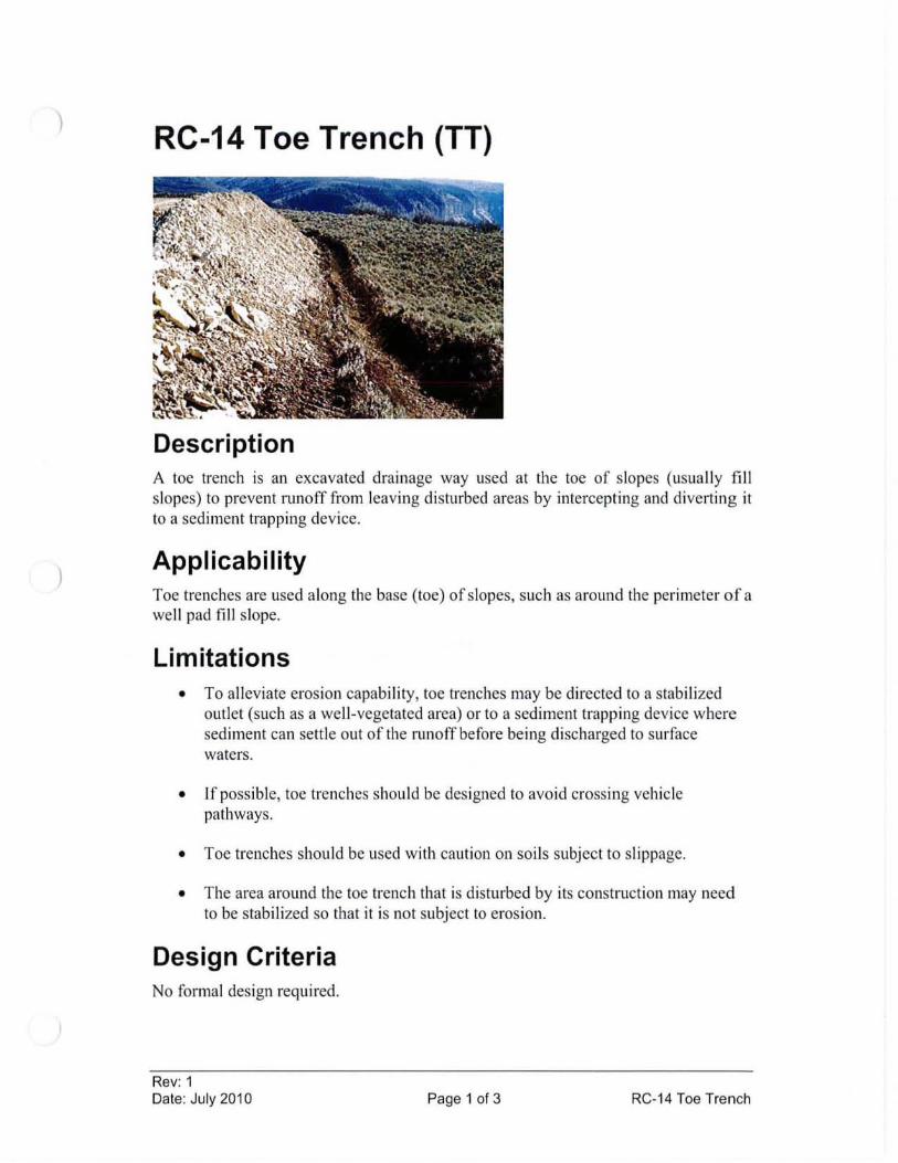
) RC-14 Toe Trench (TT)
Description A toe trench is an excavated drainage way used at the toe of slopes (usuall y fill slopes) to prevent runoff from leaving di sturbed areas by intercepting and di verting it to a sediment trapping device.
Applicability Toe trenches are used along the base (toe) of slopes, such as around the perimeter of a we ll pad fi ll slope.
Limitations • To alleviate erosion capabili ty, toe trenches may be directed to a stabilized
outl et (such as a we ll-vegetated area) or to a sediment trapping device where sediment can settle out of the runoff before being di scharged to surface waters.
• If possible, toe trenches should be designed to avo id crossing vehicle pathways.
• Toe trenches should be used with caution on soil s subject to slippage.
• The area around the toe trench that is disturbed by its construction may need to be stabilized so that it is not subject to erosion.
Design Criteria No formal des ign required.
Rev: 1 Date: July 2010 Page 1 of 3 RC-14 Toe Trench
Construction Specifications
See Figure RC-14-1 for details
1. All trees, brush, stumps, obstructions, and other objectionable material shall be removed and disposed of so as not to interfere with the proper functioning of the toe trench.
2. The toe trench shall be free of bank projections or other irregularities which will impede normal flow.
3. Toe trenches may have uninterrupted positive grade to an outlet.
4. All earth removed and not needed for construction shall be placed so that it will not interfere with the functioning of the toe trench.
5. The appropriate size and design of toe trenches depend on the size of the contributing sloped area and other site specific conditions.
6. Fills may be compacted, if necessary to meet site specific needs, by earth moving equipment.
7. The toe trench may be stabilized with vegetation, riprap, or erosion control blanket if necessary to meet site specific needs.
Maintenance Considerations Inspection frequency shall be in accordance with the Storm Water Management Plan. Toe trenches should be cleared of accumulated sediment and reseeded if necessary. Repair as needed in order to maintain toe trench capacity.
Removal/Abandonment Toe trenches mayor may not be removed. Toe trenches collecting runoff from disturbed areas shall remain in place at least until the disturbed areas are permanently stabilized.
References Environmental Protection Agency (EPA), National Pol/utant Discharge Elimination
System (NPDES). Construction Site Storm Water Runoff Control. Washington, D.C., February, 2003. <http://cfpub.epa.gov/npdes/stormwater/menuofbmps/index.cfm>
New York State Department of Environmental Conservation, New York Guidelines for Urban Erosion and Sediment Control. New York. Fourth Edition, 1997.
Rev: 1 Date: July 2010 Page 2 of 3 RC-14 Toe Trench
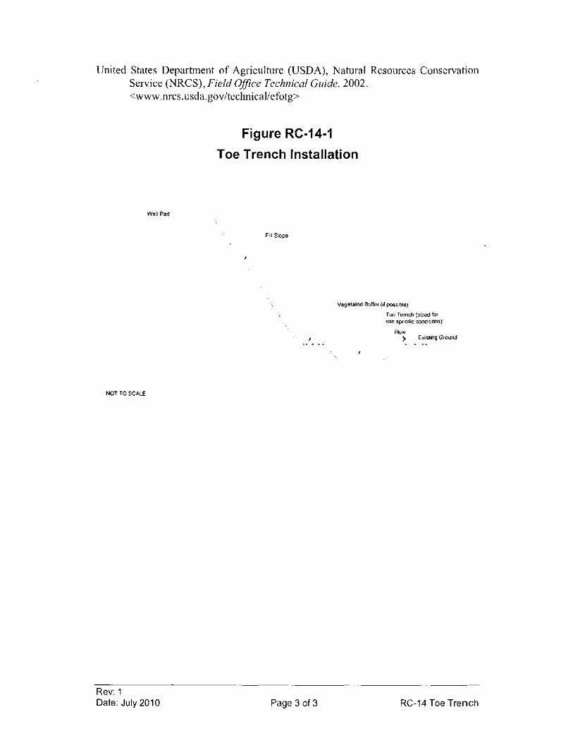
United States Department of Agriculture (USDA), Natural Resources Conservation Service (NRCS), Field Office Technical Guide. 2002. <www.nrcs.usda.gov/technical/efotg>
Well Pad
NOT TO SCALE
Rev: 1 Date: July 2010
Figure RC·14·1
Toe Trench Installation
Fill Slope
vegetated Bulfer (if possible)
Page 3 of 3
Toe Trench (sized for site specific conditions)
Flow > Existing Ground
RC-14 Toe Trench
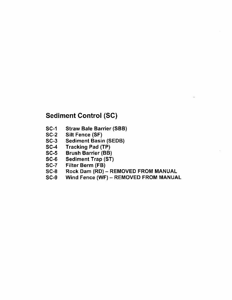
Sediment Control (SC)
SC-1 Straw Bale Barrier (SBB) SC-2 Silt Fence (SF) SC-3 Sediment Basin (SEDB) SC-4 Tracking Pad (TP) SC-5 Brush Barrier (BB) SC-6 Sediment Trap (ST) SC-7 Filter Berm (FB) SC-8 Rock Dam (RD) - REMOVED FROM MANUAL SC-9 Wind Fence (WF) - REMOVED FROM MANUAL
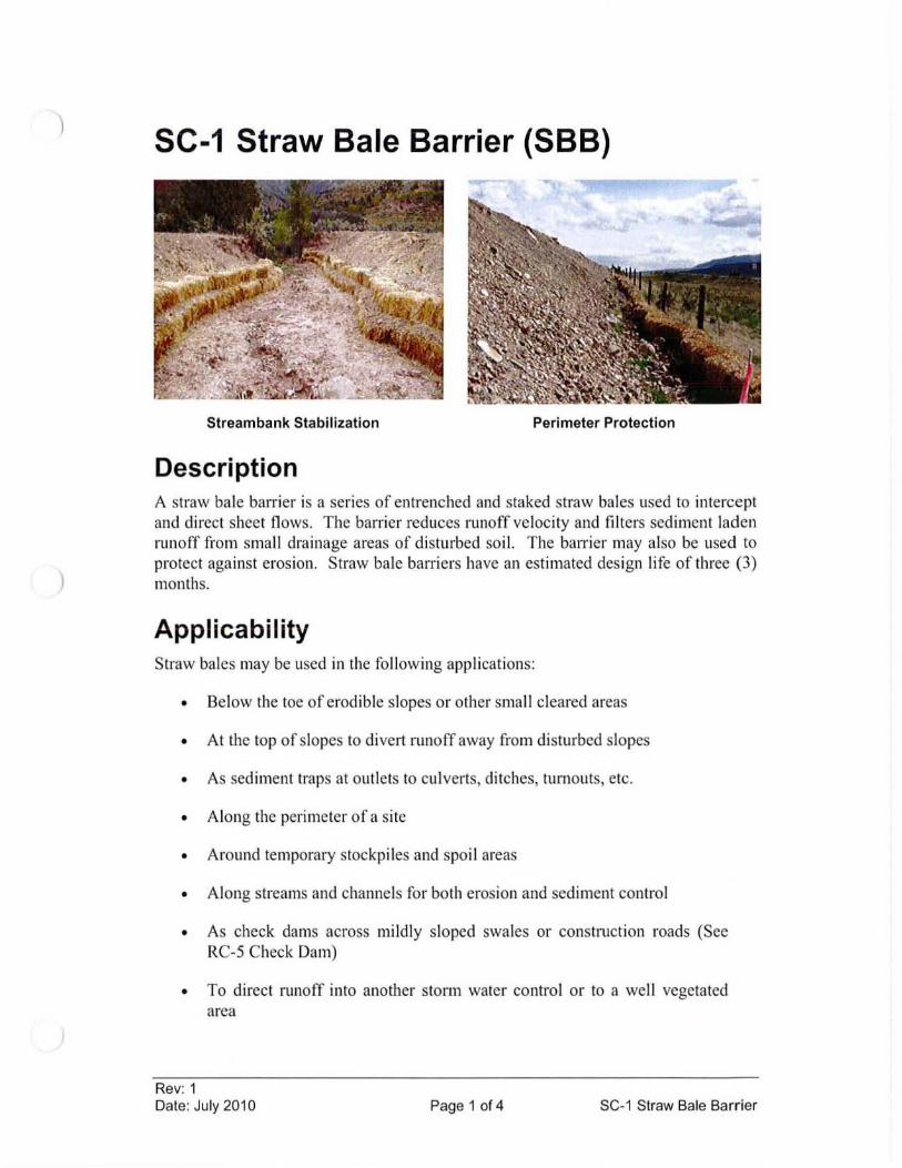
)
SC-1 Straw Bale Barrier (SBB)
Stream bank Stabilization Perimeter Protection
Description A straw bale batTier is a series of entrenched and staked straw bales used to intercept and direct sheet flows. The barrier reduces runoff velocity and filters sediment laden runoff from small drainage areas of disturbed so il. The barrier may also be used to protect against erosion. Straw bale barriers have an estimated design life of three (3) months.
Applicability Straw bales may be used in the following applications:
• Below the toe of erodible slopes or other small cleared areas
• At the top of slopes to divert runoff away from di sturbed slopes
• As sediment traps at outlets to cu lverts, ditches, turnouts, etc.
• Along the perimeter of a site
• Around temporary stockpiles and spoil areas
• Along streams and channels for both erosion and sediment control
• As check dams across mildly sloped swales or construction roads (See RC-5 Check Dam)
• To direct runoff into another storm water control or to a well vegetated area
Rev: 1 Date: Ju ly 2010 Page 1 of 4 SC-1 Straw Bale Barrier
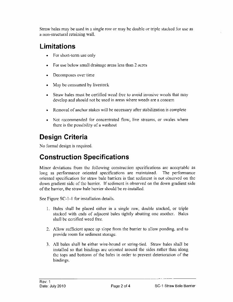
Straw bales may be used in a single row or may be double or triple stacked for use as a non-structural retaining wall.
Limitations • For short-tenn use only
• For use below small drainage areas less than 2 acres
• Decomposes over time
• May be consumed by livestock
• Straw bales must be certified weed free to avoid invasive weeds that may develop and should not be used in areas where weeds are a concern
• Removal of anchor stakes will be necessary after stabilization is complete
• Not recommended for concentrated flow, live streams, or swales where there is the possibility of a washout
Design Criteria No formal design is required.
Construction Specifications
Minor deviations from the following construction specifications are acceptable as long as perfonnance oriented specifications are maintained. The perfonnance oriented specification for straw bale barriers is that sediment is not observed on the down gradient side of the batTier. If sediment is observed on the down gradient side of the barrier, the straw bale barrier should be re-installed.
See Figure SC-l-l for installation details.
I. Bales shall be placed either in a single row, double stacked, or triple stacked with ends of adjacent bales tightly abutting one another. Bales shall be certified weed free.
2. Allow sufficient space up slope from the barrier to allow ponding, and to provide room for sediment storage.
3. All bales shall be either wire-bound or string-tied. Straw bales shall be installed so that bindings are oriented around the sides rather than along the tops and bottoms of the bales in order to prevent deterioration of the bindings.
Rev: 1 Date: July 2010 Page 2 of 4 SC-1 Straw Bale Barrier
4. A trench shall be excavated the width of a bale and the length of the proposed barrier to a minimum depth of 4 inches. If frozen conditions prevent trenching, straw bales may temporarily secured to the ground without trenching. However, when warm weather permits, bales will be re-Iayed in a trench. Stake the bales with wood stakes or standard "T" or "U" steel posts as necessary to fully secure the bale to the ground.
5. After the bales are staked and chinked (gaps filled by wedging), the excavated soil shall be backfilled against the barrier. Backfill soil shall conform to the ground level on the downhill side and may be built up against the uphill side of the barrier. If using double or triple stacked bales, the uphill side of the barrier may be backfilled up to Y, the height of the top of the highest bale.
Maintenance Considerations Inspection frequency shall be in accordance with the Storm Water Management Plan. Close attention should be paid to the repair of damaged or rotting bales, end runs and undercutting beneath bales. Necessary repairs to barriers or replacement of bales should be accomplished promptly. If a single row of bales is used, sediment deposits should be removed when the level of deposition reaches approximately one-half the height of the barrier. If a double or triple stack of bales is used, sediment should not be allowed to overtop the barrier.
Removal/Abandonment Straw bale barriers may be removed when they have served their usefulness or may remain in place (with only the stakes removed) and allowed to decompose over time. Straw bales should not be removed, however, until the upslope areas have been permanently stabilized. Any sediment deposits remaining in place after the straw bale barrier is no longer required should be dressed to conform to the existing grade, prepared and seeded.
References
Colorado Department of Transportation (COOT), Erosion Control and Stormwater Quality Guide. 2002. <http://www.coloradodot.info/programs/environmental/waterquality/documents/erosion-storrn-quality>
Horizon Environmental Services, Inc, Guidance Document Reasonable and Prudent Practices for Stabilization (RAPPS) of Oil and Gas Construction Sites. Produced by Independent Petroleum Association of America (IPAA). April 2004. <http://www.dpcusa.org/enviro/rapps.html>
New York State Department of Environmental Conservation, New York Guidelines for Urban Erosion and Sediment Control. New York. Fourth Edition, 1997.
Rev: 1 Date: July 2010 Page 3 of 4 SC-1 Straw Bale Barrier
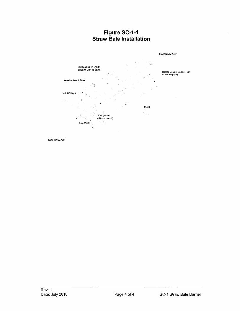
Figure SC-1-1 Straw Bale Installation
Bales must be tightly abutting with no gaps
Wood or Metal Stake
Bale Bindings
FLOW
4" (il ground "" . conditions permit)
Bale Width . !
NOTTO SCALE
Rev: 1 Date: July 2010 Page 4 of 4
Backfill Material (compact SO,1 10 prevent piping)
SC-1 Straw Bale Barrier
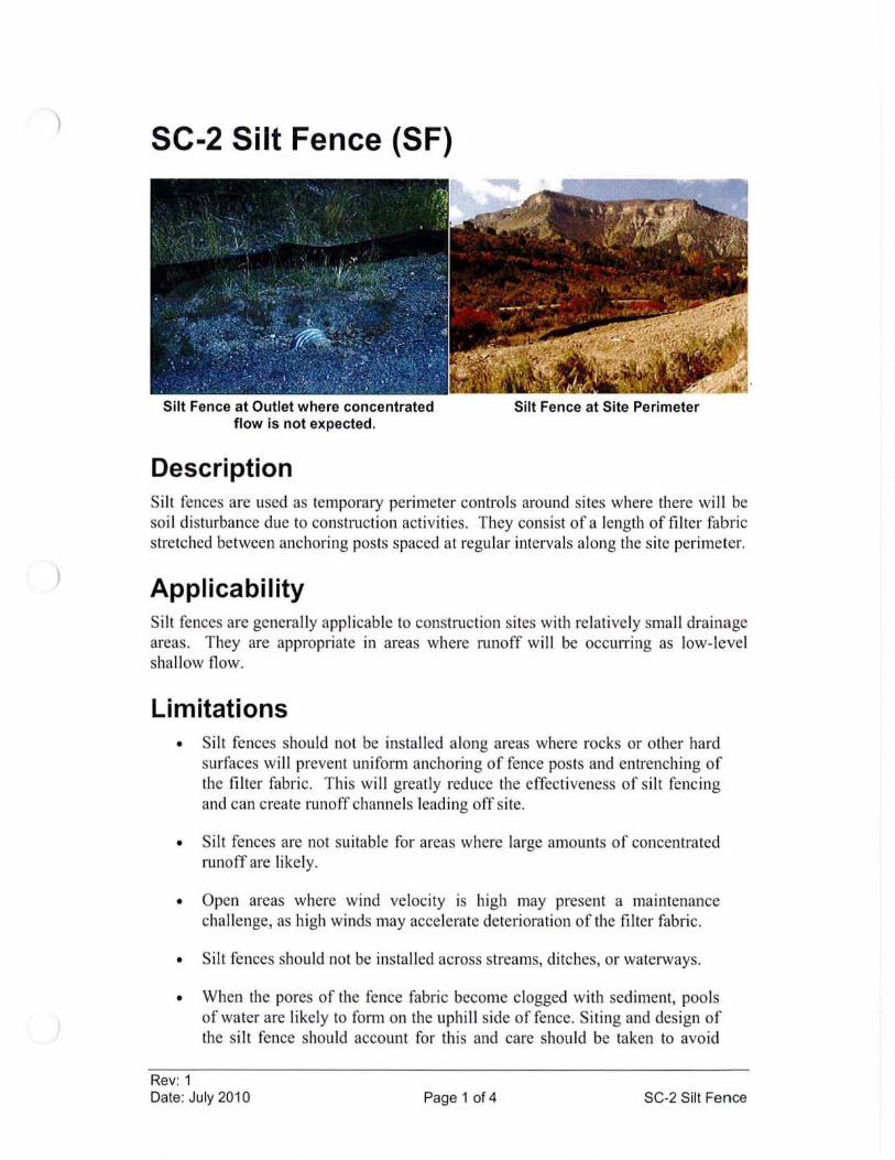
)
)
SC-2 Silt Fence (SF)
Silt Fence at Outlet where concentrated flow is not expected.
Description
Silt Fence at Site Perimeter
Si lt fences are used as temporaty perimeter controls around sites where there will be soi l disturbance due to construction activities. They consist of a length of filter fabric stretched between anchoring posts spaced at regular intervals along the site perimeter.
Applicability Silt fences are generally applicable to construction sites with relatively small drainage areas. They are appropriate in areas where runoff will be occllll'ing as low-level sha llow flow.
Limitations • Silt fences should not be installed along areas where rocks or other hard
surfaces wi ll prevent unifonn anchoring of fence posts and entrenching of the filter fabric. This wi ll greatly reduce the effectiveness of si lt fencing and can create runoff channels leading off site.
• Si lt fences are not suitable for areas where large amounts of concentrated runoff are likely.
• Open areas where wind velocity is high may present a maintenance challenge, as high winds may accelerate deterioration of the filter fabric.
• Silt fences should not be installed across streams, ditches, or watetways.
• When the pores of the fence fabric become clogged with sediment, pools of water are likely to form on the uphill side offence. Siting and design of the si lt fence should account for this and care should be taken to avoid
Rev: 1 Date: July 2010 Page 1 of 4 SC-2 Silt Fence
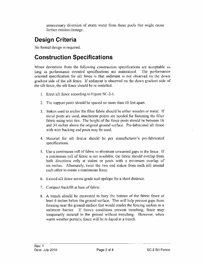
unnecessary diversion of storm water from these pools that might cause further erosion damage.
Design Criteria No formal design is required.
Construction Specifications
Minor deviations from the following construction specifications are acceptable as long as performance oriented specifications are maintained. The performance oriented specification for silt fence is that sediment is not observed on the down gradient side of the silt fence. If sediment is observed on the down gradient side of the silt fence, the silt fence should be re-installed.
\. Erect silt fence according to Figure SC-2-\'
2. The support posts should be spaced no more than 10 feet apart.
3. Stakes used to anchor the filter fabric should be either wooden or metal. If metal posts are used, attachment points are needed for fastening the filter fabric using wire ties. The height of the fence posts should be between 16 and 34 inches above the original ground surface. Pre-fabricated silt fence with wire backing and posts may be used.
4. Material for silt fences should be per manufacturer's pre-fabricated specifications.
5. Use a continuous roll of fabric to eliminate unwanted gaps in the fence. If a continuous roll of fabric is not available, the fabric should overlap from both directions only at stakes or posts with a minimum overlap of six inches. Alternately, twist the two end stakes from each roll around each other to create a continuous fence.
6. Extend silt fence across grade and upslope for a short distance.
7. Compact backfill at base offabric.
8. A trench should be excavated to bury the bottom of the fabric fence at least 6 inches below the ground surface. This will help prevent gaps from forming near the ground surface that would render the fencing useless as a sediment barrier. If frozen conditions prevent trenching, fence may temporarily secured to the ground without trenching. However, when warm weather permits, fence will be re-Iayed in a trench.
Rev: 1 Date: July 2010 Page 2 of 4 SC-2 Silt Fence
Maintenance Considerations Inspection frequency shall be in accordance with the Storm Water Management Plan. Inspections shall ensure that the fence is intact, attached to all stakes, and that there are no gaps at the fence-ground interface or tears along the length of the fence. If gaps or tears are found, they should be repaired or the fabric should be replaced immediately. Accumulated sediments should be removed from the fence base when the sediment reaches one-third to one-half the height of the fence. Sediment removal should occur more frequently if accumulated sediment is creating noticeable strain on the fabric and there is the possibility of the fence failing from a sudden storm event.
Removal/Abandonment Remove silt fences and all accumulated sediment after uphill drainage areas are stabilized by vegetation or other means.
References Colorado Department of Transportation (COOT), Erosion Control and Stormwater
Quality Guide. 2002. <http://www.coloradodot.info/programs/environmentallwaterquality/documents/erosion-storm-quality>
Environmental Protection Agency (EPA), National Pollutant Discharge Elimination System (NPDES). Construction Site Storm Water Runoff Control. Washington, D.C., February, 2003. <http://cfpub.epa.gov/npdes/stormwater/menuofbmpslindex.cfm>
Horizon Environmental Services, Inc, Guidance Document Reasonable and Prudent Practices for Stabilization (RAPPS) of Oil and Gas Construction Sites. Produced by Independent Petroleum Association of America (IPAA). April 2004. <http://www.dpcusa.org/enviro/rapps.html>
Keller, Gordon, and James Sherar, Low-Volume Roads Engineering, Best Management Practices Field Guide. United States Department of Agriculture (USDA), Forest Service, US Agency of International Development (USAID), 2005. <http://www.blm.gov/bmp/field%20guide.htm>
Rev: 1 Date: July 2010 Page 3 of 4 SC-2 Silt Fence
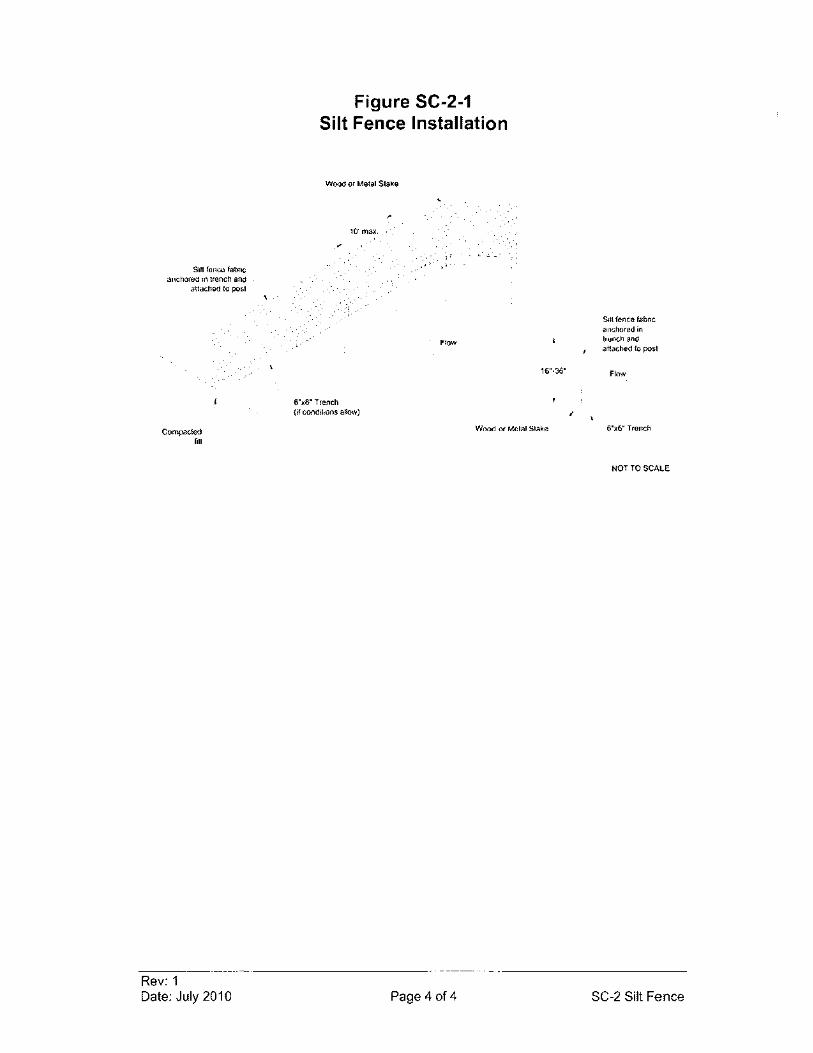
Silt fence fabric anchored in trench and
attached to post
Compacted fill
Rev: 1 Date: July 2010
Figure SC-2-1 Silt Fence Installation
Wood or Metal Stake
10' max ...
!'"Iow
16"·36"
6"x6" Trench (if conditions allow)
Wood or Metal Stake
Page 4 of 4
Silt fence fabric anchored in trench and atlached 10 post
Flow
6"x6" Trench
NOT TO SCALE
SC-2 Silt Fence
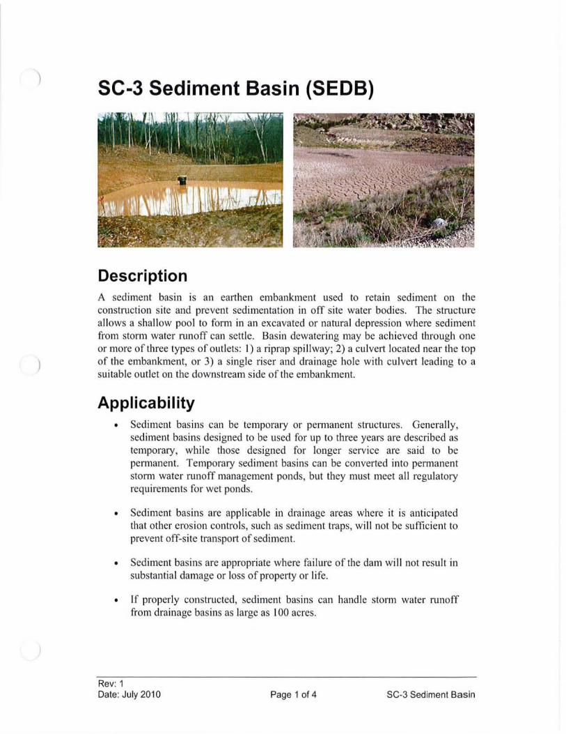
)
SC-3 Sediment Basin (SEDB)
Description A sediment basin is an earthen embankment used to retain sediment on the construction s ite and prevent sedimentation in off site water bodies. The structure allows a shallow pool to form in an excavated or natural depression where sediment from storm water runoff can settle. Basin dewatering may be achieved through one or more of three types of outlets: I) a riprap spi Ilway; 2) a culvert located near the top of the embankment, or 3) a single riser and drainage hole with cu lvert leading to a suitable outlet on the downstream side of the embankment.
Applicability • Sediment basins can be temporary or permanent structures. Genera lly,
sed iment basins designed to be used for up to three years are described as temporary, while those designed for longer service are said to be permanent. TemporalY sed iment basins can be converted into permanent storm water runoff management ponds, but they must meet all regulatory requirements for wet ponds.
• Sediment basins are applicable in drainage areas where it is anticipated that other erosion contro ls, such as sediment traps, wi ll not be sufficient to prevent off-site transport of sediment.
• Sediment basins are appropriate where fai lure of the dam wi ll not result in substantial damage or loss of property or life.
• If properly constructed, sediment basins can handle storm water runoff from drainage basins as large as 100 acres.
Rev: 1 Date: July 2010 Page 1 of 4 SC-3 Sediment Basin
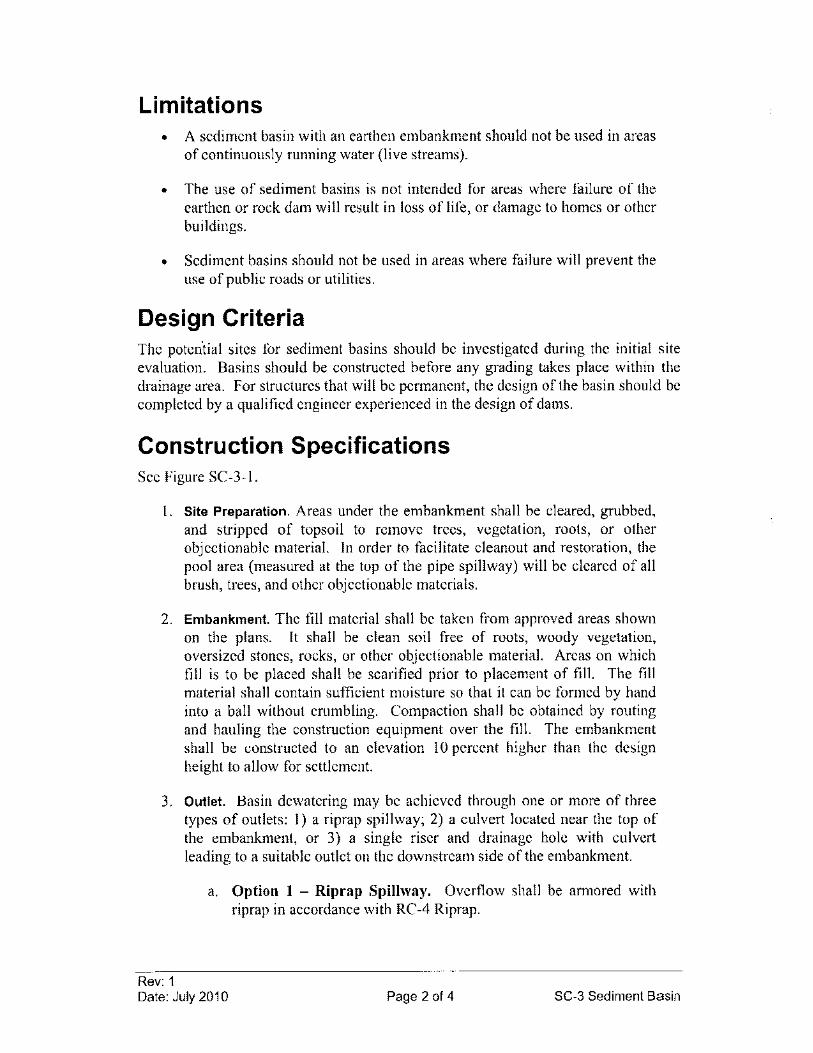
Limitations • A sediment basin with an earthen embankment should not be used in areas
of continuously running water (live streams).
• The use of sediment basins is not intended for areas where failure of the earthen or rock dam will result in loss oflife, or damage to homes or other buildings.
• Sediment basins should not be used in areas where failure will prevent the use of public roads or utilities.
Design Criteria The potential sites for sediment basins should be investigated during the initial site evaluation. Basins should be constructed before any grading takes place within the drainage area. For structures that will be permanent, the design of the basin should be completed by a qualified engineer experienced in the design of dams.
Construction Specifications See Figure SC-3-1.
1. Site Preparation. Areas under the embankment shall be cleared, grubbed, and stripped of topsoil to remove trees, vegetation, roots, or other objectionable material. In order to facilitate cleanout and restoration, the pool area (measured at the top of the pipe spillway) will be cleared of all brush, trees, and other objectionable materials.
2. Embankment. The fill material shall be taken from approved areas shown on the plans. It shall be clean soil free of roots, woody vegetation, oversized stones, rocks, or other objectionable material. Areas on which fill is to be placed shall be scarified prior to placement of fill. The fill material shall contain sufficient moisture so that it can be formed by hand into a ball without crumbling. Compaction shall be obtained by routing and hauling the construction equipment over the fill. The embankment shall be constructed to an elevation 10 percent higher than the design height to allow for settlement.
3. Outlet. Basin dewatering may be achieved through one or more of three types of outlets: 1) a riprap spillway; 2) a culvert located near the top of the embankment, or 3) a single riser and drainage hole with culvert leading to a suitable outlet on the downstream side of the embankment.
Rev: 1
a. Option 1 - Riprap Spillway. Overflow shall be armored with riprap in accordance with RC-4 Riprap.
Date: July 2010 Page 2 of 4 SC-3 Sediment Basin
b. Option 2 - Culvert. Locate one or more culverts near the top of the embankment in accordance with RC-2 Culvert Cross-Drain.
c. Option 3 - Culvet with Stand Pipe. If sediment basins are outfitted with a stand pipe (riser), the riser pipe should be located at the deepest point of the basin and extend no farther than I foot below the level of the earthen dam. A water-permeable cover (grate/screen) should be placed over the primary dewatering riser pipe to prevent trash and debris from entering and clogging the spillway. The riser shall be securely attached to the culvert (barrel) or barrel stub by welding the full circumference making a watertight structural connection. The barrel and riser shall be placed on a firm, smooth foundation of impervious soil.
4. Emergency Spillway. If outlet option 2 or 3 (as discussed above) is used, an emergency spillway (such as a riprap spillway) shall be installed.
5. Vegetative Treatment. Stabilize the embankment and emergency spillway in accordance with the appropriate vegetative standard and specification as soon as possible following construction.
Maintenance Considerations Inspection frequency shall be in accordance with the Storm Water Management Plan. Inspections should ensure proper drainage from the collection pool and determine the need for structural repairs. Erosion from the earthen embankment should be repaired as soon as possible. Sediment basins must be located in an area that is easily accessible to maintenance crews for removal of accumulated sediment. Sediment should be removed from the basin when its storage capacity has reached approximately 75 percent. Trash and debris from around dewatering devices should be removed promptly after rainfall events.
Removal/Abandonment When temporary structures have served their intended purpose and the contributing drainage area has been properly stabilized, the embankment and resulting sediment deposits are to be leveled or otherwise disposed of in accordance with the approved sediment control plan. Water contained within the storage areas shall be removed from the basin by pumping, cutting the top of the riser, or other appropriate method prior to removing or breaching the embankment. Sediment shall not be allowed to flush into a stream or drainage way.
References Environmental Protection Agency (EPA), National Pollutant Discharge Elimination
System (NPDES). Construction Site Storm Water Runoff Control. Washington, D.C., February, 2003. <http://cfpub.epa.gov/npdes/stormwater/menuofbmps/index.cfm>
Rev: 1 Date: July 2010 Page 3 of 4 SC-3 Sediment Basin
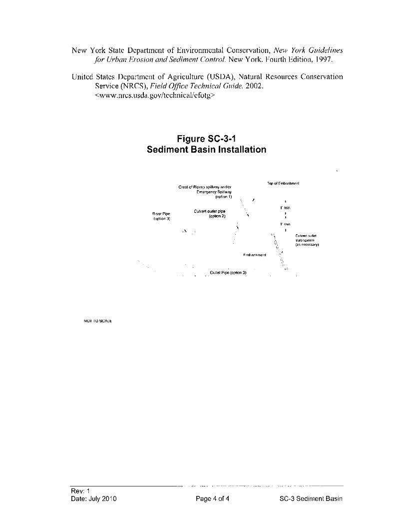
New York State Department of Environmental Conservation, New York Guidelines for Urban Erosion and Sediment Control. New York. Fourth Edition, 1997.
United States Department of Agriculture (USDA), Natural Resources Conservation Service (NRCS), Field Office Technical Guide. 2002. <www.nrcs.usda.gov/technicallefotg>
NOlTO SCALE
Rev: 1 Date: July 2010
Figure SC-3-1 Sediment Basin Installation
Riser Pipe (option 3)
Crest of Riprap spillway and/or Emergency Spillway
(option 1)
-_.-\.
Culvert outlet pipe (option 2)
,
Embankment
Outlet Pipe (option 3)
Page 4 of 4
Top of Embankment
l'min.
I'min
Culvert outlet stab,lizabon (as necessary)
SC-3 Sediment Basin
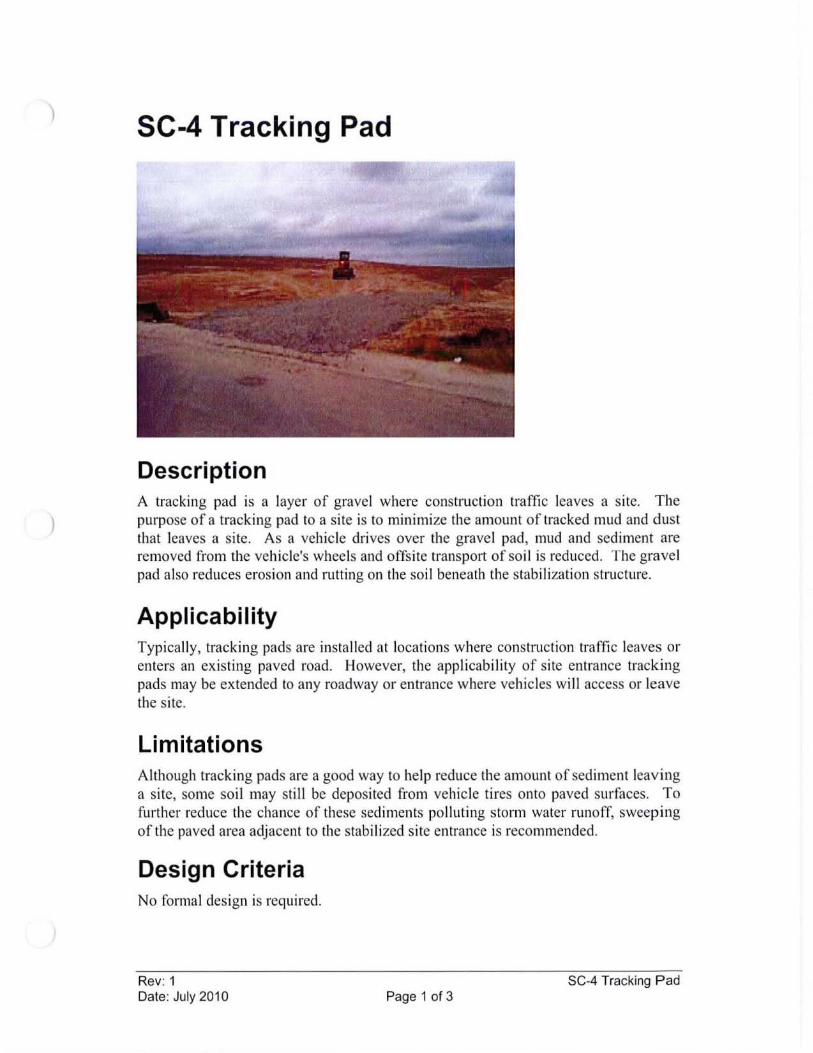
) SC-4 Tracking Pad
Description A tracking pad is a layer of gravel where construction traffic leaves a site. The purpose of a tracking pad to a site is to minimize the amount of tracked mud and dust that leaves a site. As a vehicle drives over the gravel pad, mud and sediment are removed from the veh icle's wheels and offsite transport of so il is reduced. The gravel pad also reduces erosion and rutting on the soil beneath the stabilization structure.
Applicability Typicall y, tracking pads are installed at locations where construction traffic leaves or enters an existing paved road. However, the applicability of site entrance tracking pads may be extended to any roadway or entrance where vehicles will access or leave the site.
Limitations Although tracking pads are a good way to help reduce the amount of sediment leaving a site, some soil may still be deposited from vehicle tires onto paved surfaces. To further reduce the chance of these sediments polluting storm water runoff, sweeping of the paved area adjacent to the stabilized site entrance is recommended.
Design Criteria No formal design is required.
Rev: 1 SC-4 Tracking Pad Date: July 2010 Page 1 of 3
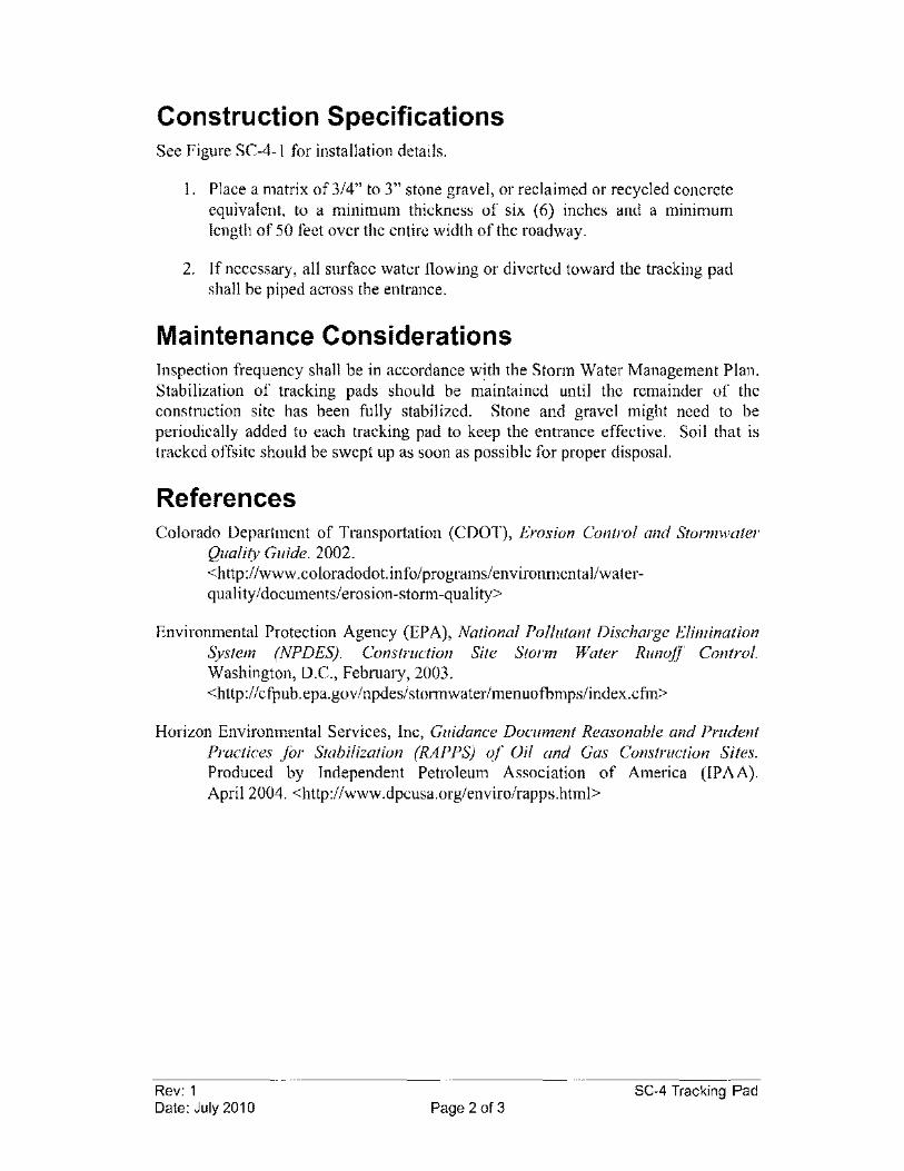
Construction Specifications See Figure SC-4-1 for installation details.
I. Place a matrix of 3/4" to 3" stone gravel, or reclaimed or recycled concrete equivalent, to a minimum thickness of six (6) inches and a minimum length of 50 feet over the entire width of the roadway.
2. If necessary, all surface water flowing or diverted toward the tracking pad shall be piped across the entrance.
Maintenance Considerations Inspection frequency shall be in accordance with the Storm Water Management Plan. Stabilization of tracking pads should be maintained until the remainder of the construction site has been fully stabilized. Stone and gravel might need to be periodically added to each tracking pad to keep the entrance effective. Soil that is tracked offsite should be swept up as soon as possible for proper disposal.
References Colorado Department of Transportation (CDOT), Erosion Control and Storm water
Quality Guide. 2002. <http://www.coloradodot.info/programs/environmentallwaterquality/documents/erosion-storm-quality>
Environmental Protection Agency (EPA), National Pollutant Discharge Elimination System (NPDES). Construction Site Storm Water Runoff Control. Washington, D.C., February, 2003. <http://cfpub.epa.gov/npdes/stormwater/menuofbmps/index.cfm>
Horizon Environmental Services, Inc, Guidance Document Reasonable and Prudent Practices for Stabilization (RAPPS) of Oil and Gas Construction Sites. Produced by Independent Petroleum Association of America (IPAA). April 2004. <htlp:llwww.dpcusa.org/enviro/rapps.html>
Rev: 1 SC-4 Tracking Pad Date: July 2010 Page 2 of 3
Existing Ground
Existing Ground
NOT TO SCALE
Rev: 1 Date: July 2010
Figure SC-4-1 Tracking Pad Installation
50'min.
314· - 3' grave!
" ,
Existing Pavement
Existing Pavement
314" - 3" gravel
10'
SC-4 Tracking Pad Page 3 of 3
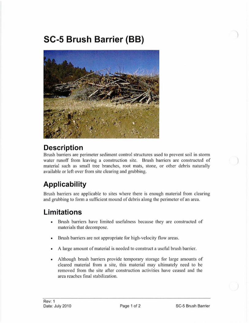
SC-5 Brush Barrier (BB)
Description Brush barriers are perimeter sediment control structures used to prevent soil in storm water runoff from leaving a construction site. Brush barriers are constructed of material such as small tree branches, root mats, stone, or other debris naturally available or left over from site clearing and grubbing.
Applicability Brush barriers are applicable to sites where there is enough material from clearing and grubbing to form a sufficient mound of debris along the perimeter of an area.
Limitations • Brush barriers have limited usefulness because they are constructed of
materials that decompose.
• Brush barriers are not appropriate for high-velocity flow areas.
• A large amount of material is needed to construct a useful brush barrier.
• Although brush barriers provide temporary storage for large amounts of cleared material from a site, thi s material may ultimately need to be removed from the site after construction activities have ceased and the area reaches final stabilization.
Rev: 1 Date: July 2010 Page 1 of 2 SC-5 Brush Barrier
)
)
Design Criteria No fonnal design is required.
Construction Specifications I. Place material cleared from the site across the slope or swale.
2. Cut up brush if necessary and compact to avoid large voids within the ban-ier.
3. The amount of available material will dictate the size of ban-ier to be constructed.
Maintenance Considerations Inspection frequency shall be in accordance with the Storm Water Management Plan. If channels fonn through void spaces in the ban-ier, the ban-ier should be reconstructed to eliminate the channels. Accumulated sediment should be removed from the uphill side of the barrier when sediment height reaches between 113 and 112 the height of the ban-ier.
Removal/Abandonment When the entire site has reached final stabilization, the brush ban-ier may need to be removed and disposed of properly, depending on the size of the ban-ier and the amount of material used.
References Environmental Protection Agency (EPA), National Pollutant Discharge Elimination
System (NPDES). Construction Site Storm Water Runoff Control. Washington, D.C., February, 2003. <http://cfpub.epa.gov/npdes/stonnwater/menuofbmps/index.cfm>
Horizon Environmental Services, Inc, Guidance Document Reasonable and Prudent Practices for Stabilization (RAPPS) of Oil and Gas Construction Sites. Produced by Independent Petroleum Association of America (lPAA). April 2004. <http://www.dpcusa.org/enviro/rapps.html>
Rev: 1 Date: July 2010 Page 2 of 2 SC-5 Brush Barrier
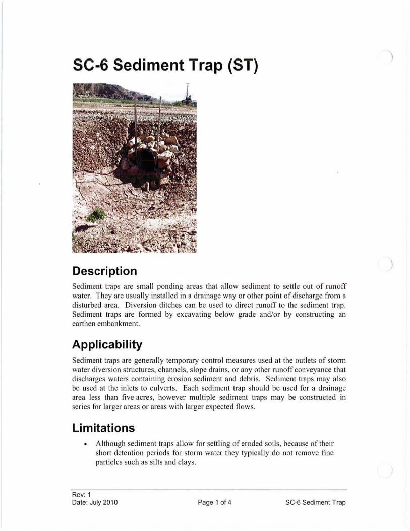
SC-6 Sediment Trap (ST)
Description Sediment traps are small ponding areas that allow sediment to settle out of runoff water. They are usually installed in a drainage way or other point of discharge from a disturbed area. Diversion ditches can be used to direct runoff to the sediment trap. Sediment traps are fOlllled by excavating below grade and/or by constructing an earthen embankment.
Applicabi lity Sediment traps are generally temporary control measures used at the outlets of storm water diversion structures, channels , slope drains , or any other runoff conveyance that discharges waters containing erosion sediment and debris. Sediment traps may also be used at the inlets to culverts. Each sediment trap should be used for a drainage area less than five acres, however multiple sediment traps may be constructed in series for larger areas or areas with larger expected flows.
Limitations • Although sediment traps allow for settling of eroded soils, because of their
short detention periods for storm water they typically do not remove fine particles such as silts and clays.
Rev: 1 Date: July 2010 Page 1 of 4 SC-6 Sediment Trap
)
)
• Water will remain in trap for extended periods.
• Never construct a sediment trap on a flowing stream or in wetlands.
Design Criteria Location Traps are typically located at points of discharge from disturbed areas. The location will be determined by the natural terrain, drainage pattem of the runoff, and the accessibility for maintenance. Sediment traps should not be located in areas where their failure due to storm water runoff excess can lead to further erosive damage of the landscape. Alternative diversion pathways may be designed to accommodate these potential overflows.
Storage Capacity A sediment trap should be designed to maximize surface area for infiltration and sediment settling. This will increase the effectiveness of the trap and decrease the likelihood of backup during and after periods of high runoff intensity. Half of the storage volume shall be in the form of wet storage or a permanent pool. The other half shall be in the form of dry storage. When possible, the wet storage volume should be contained within the excavated portion of the trap. The volume of each sediment trap should be based on site conditions and available space.
Construction Specifications See Figure SC-6-1 for installation details.
I. If possible, sediment traps, along with other perimeter controls, shall be installed before any land disturbance takes place in the drainage area.
2. Area under embankment shall be cleared, grubbed and stripped of any vegetation and root mat. The pool area shall be cleared.
3. The fill material for the embankment shall be free of roots and other woody vegetation as well as over-sized stones, rocks, organic material or other objectionable material. The embankment shall be compacted by traversing with equipment while it is being constructed.
4. The spillway shall be compacted or lined with coarse aggregate/riprap to provide for filtering/detention capability. The spillway may alternately be constructed with a small section of pipe or may consist of a level spreader, where the entire embankment is constructed at a uniform elevation.
5. If necessary, a geotextile may be placed at the stone-soil interface to act as a separator.
Rev: 1 Date: July 2010 Page 2 of 4 SC-6 Sediment Trap
Maintenance Considerations Inspection frequency shall be in accordance with the Storm Water Management Plan. The primary maintenance consideration for temporary sediment traps is the removal of accumulated sediment from the basin. Sediments should be removed when the basin reaches approximately 50 percent sediment capacity. A sediment trap should be inspected after each rainfall event to ensure that the trap is draining properly. Inspectors should also check the structure for damage from erosion. The depth of the spillway should be checked and maintained below the low point of the trap embankment.
Removal/Abandonment The structure mayor may not be removed w\1en the drainage area has been properly stabilized.
References Colorado Department of Transportation (COOT), Erosion Control and Stormwater
Quality Guide. 2002. <http://www.coloradodot.info/programs/environmental/water-qual i ty I documentsl erosion -storm-qual ity>
Environmental Protection Agency (EPA), National Pollutant Discharge Elimination System (NPDES). Construction Site Storm Water Runoff Control. Washington, D.C., February, 2003. <http://cfpub.epa.gov/npdes/stormwater/menuofbmps/index.cfm>
Horizon Environmental Services, Inc, Guidance Document Reasonable and Prudent Practices for Stabilization (RAPPS) of Oil and Gas Construction Sites. Produced by Independent Petroleum Association of America (IPAA). April 2004. <http://www.dpcusa.org/enviro/rapps.html>
Rev: 1 Date: July 2010 Page 3 of 4 SC-6 Sediment Trap
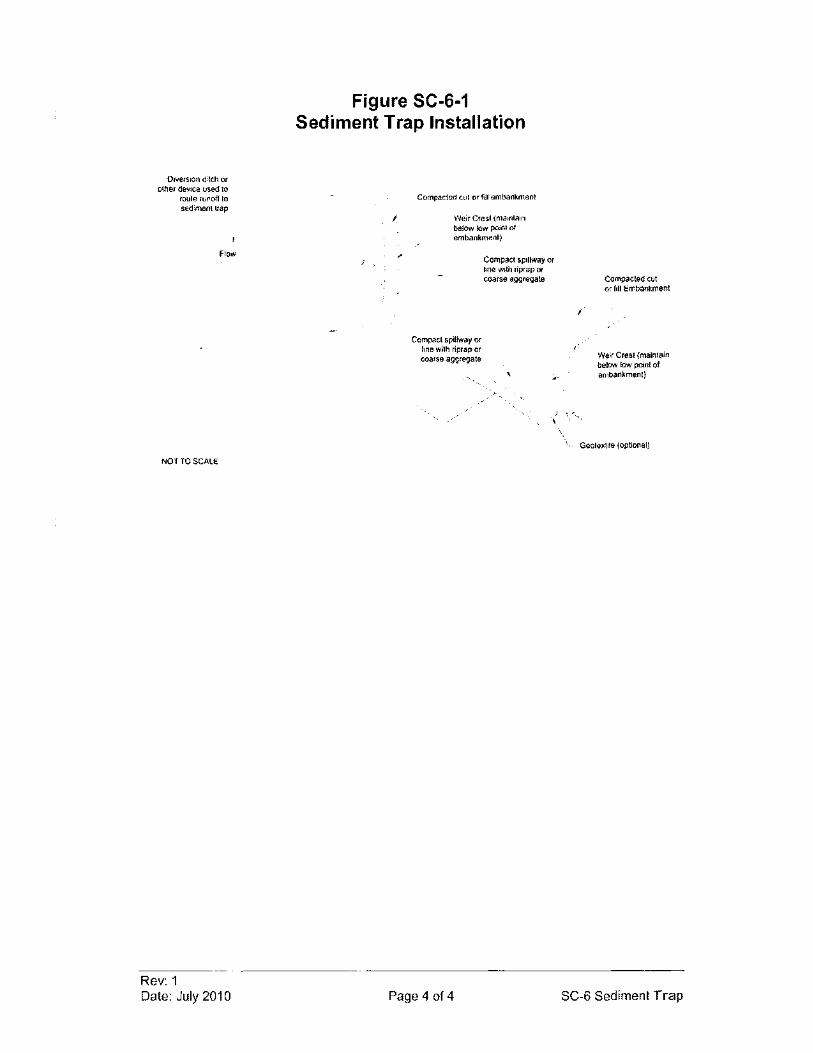
Diversion ditch or other device used to
route runoff to sediment trap
Flow
NOT TO SCALE
Rev: 1 Date: July 2010
Figure SC-6-1 Sediment Trap Installation
I
Compacted cut or filt embankment
Weir Crest (maintain below low point of embankment)
Compact spillway or line with riprap or coarse aggregate
Compact spillway or line with riprap ()( coarse aggregate
, \. \
I
Compacted cut or fill Embankment
Weir Crest (maintain below low point of embankment)
\. Geotexli1e (optional)
Page 4 of 4 SC-6 Sediment Trap
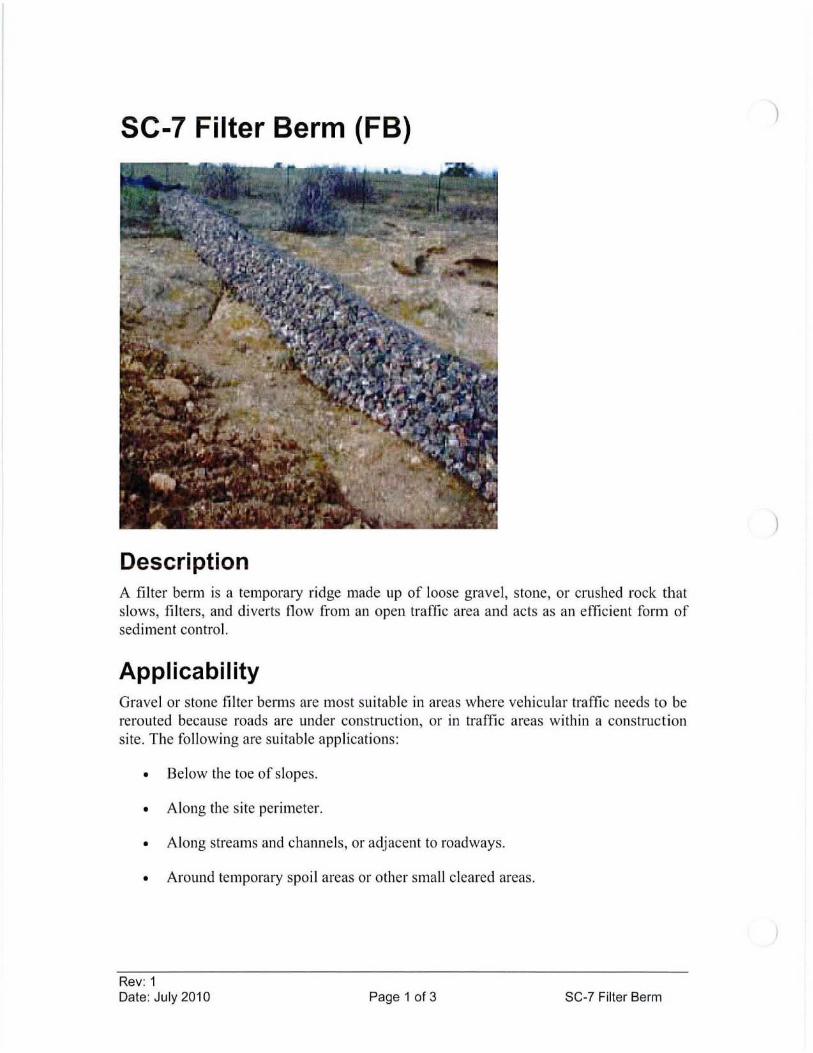
SC-7 Filter Berm (FB)
Description A filter berm is a temporary ridge made up of loose gravel , stone, or crushed rock that slows, filters , and diverts flow from an open traffic area and acts as an efficient form of sediment control.
Applicability Gravel or stone filter belms are most suitable in areas where vehicular traffic needs to be rerouted because roads are under construction, or in traffic areas within a construction site. The following are suitable applications:
• Below the toe of slopes.
• Along the site perimeter.
• Along streams and channels, or adjacent to roadways.
• Around temporary spoil areas or other small cleared areas.
Rev: 1 Date: July 2010 Page 1 of 3 SC-7 Filter Berm
)
)
Limitations • Intended to be used only in gently sloping areas.
• Filter benns do not last very long.
• Maintenance is required due to clogging from mud and soil on vehicle tires.
• Availability ofrock.
• May be difficult to remove after constlUction.
Design Criteria No formal design is required.
Construction Specifications 1. Place filter benn along a level contour. Use well-graded gravel or clUshed
rock of medium to large diameter with larger rocks on the bottom.
2. Size as necessary to filter lUnoff as and site conditions allow.
3. Cover with geotextiles fabric or wire screen if concentrated flows are expected to help keep benn in tack. If used, anchor fabric or wire by placing under the berm or use stakes.
4. Trenching is not required.
5. Berms should be spaced according to the steepness of the slope, with benns spaced closer together as the slope increases.
Maintenance Considerations Inspection frequency shall be in accordance with the Stonn Water Management Plan. Inspections shall ensure that sediment has not built up and that no damage has been done by vehicles. Regular inspection should indicate the frequency of sediment removal needed. Sediment that builds up should be removed and disposed of and the filter material and/or fabric should be replaced if necessary. It is important that repairs be perfonned as soon as possible to ensure that the berm is functioning properly.
Removall Abandon ment Remove filter berms after uphill drainage areas are stabilized. Rock may be left in place if it does not cause any landscaping problems. Remove all manmade materials (wire, fabric and/or stakes).
Rev: 1 Date: July 2010 Page 2 of 3 SC-7 Filter Berm
References Environmental Protection Agency (EPA), National Pollutant Discharge Elimination
System (NPDES). Construction Site Storm Water Runoff Control. Washington, D.C. , February, 2003. <http: //cfpub.epa.gov/npdes/stomlwater/menuofbmps/index.cfm>
Horizon Environmental Services, Inc , Guidance Document Reasonable and Prudent Practices Jar Stabilization (RAPPS) oj Oil and Gas Construction Sites. Produced by Independent Petroleum Association of America (IPAA). April 2004. http ://www.dpcusa.org/enviro/rapps .html
Rev: 1 Date: July 2010 Page 3 of 3 SC-7 Filter Berm
)
)

SC-8 Rock Dam (RD)
Removed from Manual
Rev: 1 Date: July 2010 Page 1 of 1 SC-8 Rock Dam
SC-9 Wind Fence (WF)
Removed from Manual
Rev: 1 Date: July 2010 Page 1 of 1 SC-9 Wind Fence

APPENDIX E EMERGENCY CONTACTS
Police Fire
NOTIFICATION OF OUTSIDE PARTIES
Williams Production RMT Company
PUBLIC SAFETY NOTIFICATION
GOVERNMENT AGENCY NOTIFICATIONS - VERBAL
National Response center Colorado Oil and Gas Conservation commission Colorado Department of Health Garfield County Health Department Water Quality Control
GOVERNMENT AGENCY NOTIFICATIONS - WRITTEN
911 911
(800)424-8802 (303) 894-2100 (303) 692-3596 (970) 625-5200 (970) 248-7150
Within 24 hours of the release, report spills that have the potential to reach or have reached state waters to;
colorado Department of Health (303) 692-3500 (303) 692-3596
Colorado Oil and Gas Conservation commission (303) 894-2100 Colorado Public Utilities (303) 894-2000 U.S. Department of Transportation (202) 366-4580 U.S. Department of Transportation (303) 231-5701
ENVIRONMENTAL CONSULTING AND REMEDIATION CONTRACTORS
williams Production RMT Company
CONTRACTOR PRIMARY CONTACT PHONE NUMBER
OFFICE CELL
Olsson Associates 826 21 JO Road Tim Dobransky (877) 264-0123 (970) 263-7822 Grand Junction, Colorado
Environmental, Audit & Assessment, Inc 225 N 5 th Street I Suite 8 Wes D/Aponti (970) 245-5897 (970) 250-9745 Grand Junction, colorado
HRL Compliance Solutions, Inc. 744 Hori zan Court I Suite 140 Herman Lucero (970) 243-3271 (970) 261-3571 Grand Junction, Colorado
Kirkpactrick Environmental Restoration services, Inc
Tom Kirkpatrick PO Box 27
(970) 309-9876 ( 970) 270-7687
Mesa, colorado
EXCAVATION, ROUSTABOUT AND GENERAL CONSTRUCTION CONTRACTORS
Williams Production RMT Company
CONTRACTOR PRIMARY CONTACT OFFICE
PHONE NUMBER
CELL
Accurate Construction & Excavation, Inc. PO Box 667 Randy VanConett (970) 858-6533 (970) 986-5723 Fruita, Colorado
C & J Field Services 100 Gillam Road Curt Dembowski (970) 675-5300 (970) 629-5161 Rangely, CO
High Plains Services, Inc. Marcus
2966 D Road Costopolous (970) 255-6697 (970) 201-0485
Grand Junction, CO
MB Construction 1058 county Road 215 Bob Prather (970) 574-8120 (970) 250-0385 Parachute, CO
Moody construction PO Box M Doug Moody (970) 878-4771 (970) 379-6351 Meeker, CO
Roustabout Specialties Inc 789 Valley Court Quentin Hoops (970) 241-9696 Grand Junction, Colorado
VACUUM SERVICE CONTRACTORS
Williams Production RMT Company
CONTRACTOR PRIMARY CONTACT PHONE NUMBER
OFFICE CELL
Old West oil Field Services 4550 Highway 6 &24 Trevor Taylor (970) 518-1121 ( 970) 261-8591 DeBe que , CO

APPENDIX F EXAMPLE INSPECTION REPORT
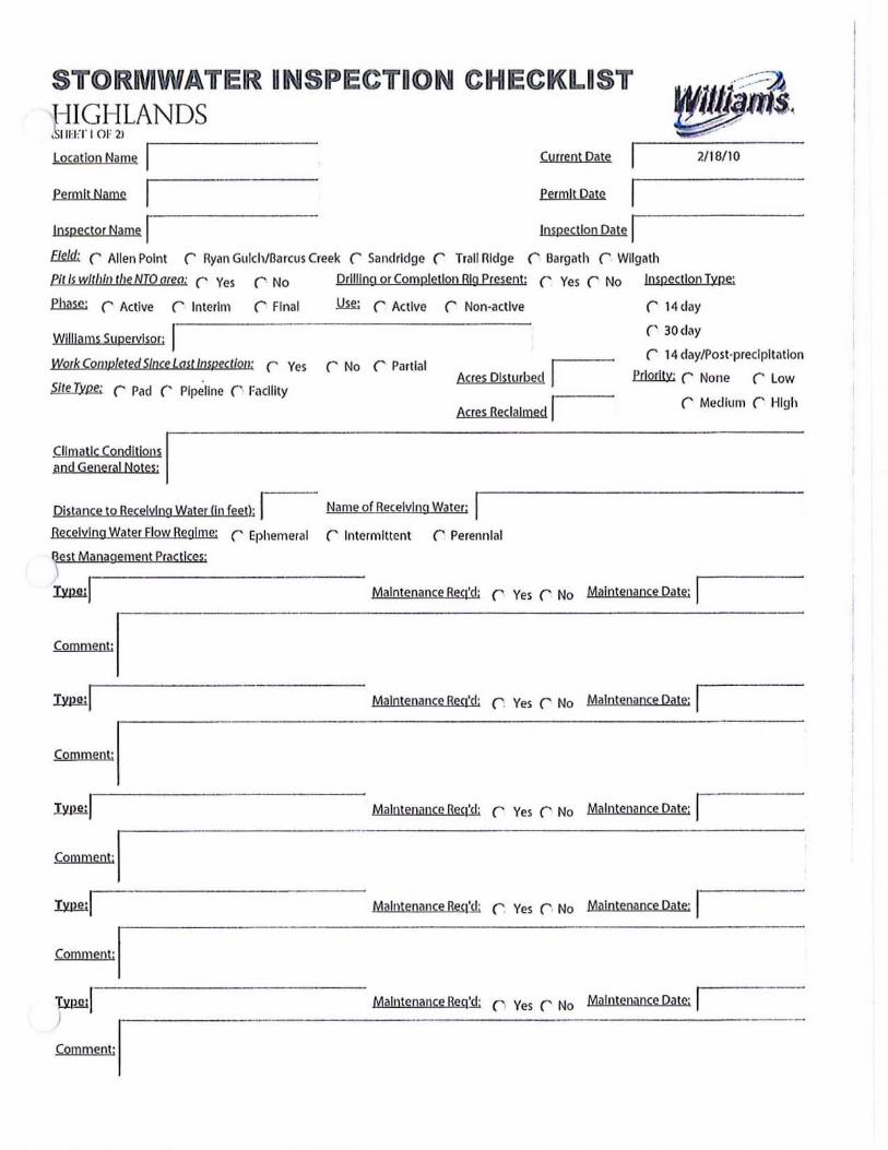
STOIRMWA'fIER ONSIPIECTOON CIHIECKn..nS'f
!jI~ottLANDS Location Name Ir---------- Current Date 2/16110
permit Name I permit Date
Inspector Name I Inspection Date I Ekk!;. (' Allen Point (' Ryan Gulch/Oarcus Creek (' Sandridge (' Trail Ridge (' Oargath (' Wllgath
Pltlsw/lh/Ilt/leNTOarea: (' Ves ('. No
fl= (' Active (' Interim (' Final
Williams Supervisor: I
Drilling or Completion Rig present:
llif; (' Active (' Non-active
(' Ves (' No Inspection Typ~
(' 14 day
(' 30 day
Work Comp/eledS/llce Lml inspect/oil: (' Ves (' No (' Partial Acres Disturbed I
(' 14 day/Post-precipitation
W2rJly; (' None (' Low
Climatic Conditlops I and General Notes;
Acres Reclaimed r,--- (' Medium (' High
Distance to Receiving Water Un (eet); I Name of Receiving water;
Recelylng Water Flow Regime: (' Ephemeral (' Intermittent (' Perennial
Gest Management Pract1ceS' , :uw:1
Comment:
:uw:1
Comment: I
Maintenance Req'd: ('. Ves (' No Maintenance Date: I
Maintenance Req'd: r . Yes r No Maintenance Date' 1
Tyneilr --------- - - ----- Maintenance Geq'd; rYes r No Maintenance Dille: I
CalUment: I :uw:1 Maintenance Req'e!: (" Yes ('I No Maintenance Date"
COlDment: I lYl!!!lI---------------- Maintenance Ileq:si; n Ves (' No Maintenance Date: I
~oIDOlent: I
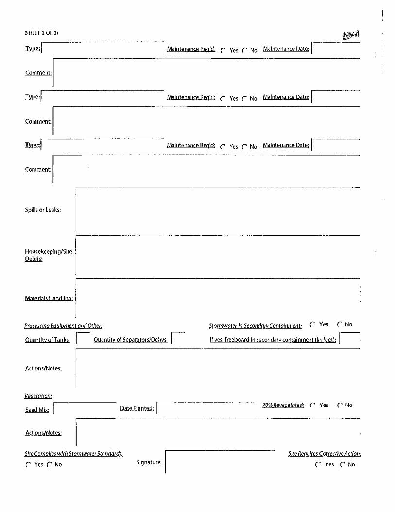
(SHllT 2 01' 21
~I Maintenance Req'd: r Ves (' No Maintenance Date: ,
Comment: I ~I----------------- Maintenance Req'd: r Ves r No Maintenance Date: r
Comment: I TYpo;rl---------------- Maintenance Req'rl; r Ves r No Maintenance Date: ,
Comment: I
Spills or Leaks:
Housekeeping/Site Debris:
Materials Handling:
Processlllg EQuipment and Other:
Quantity ofTanks: I Quantity of Separators/Dehys: I
Actions/Notes:
Vegetation:
Seed MiX:' r -------- Date Planted: ,
Actions/Notes:
Site Compiles with Storm water Standards:
r Ves r No Signature: I
Stormwqterln SecolldO(yCotlta/llmellt: r Ves r No
If yes. freeboard In secondary containment lin feet): ,---
70% Revegetated: r Ves r No
Site ReQuires Correclive Action:
r Ves r No
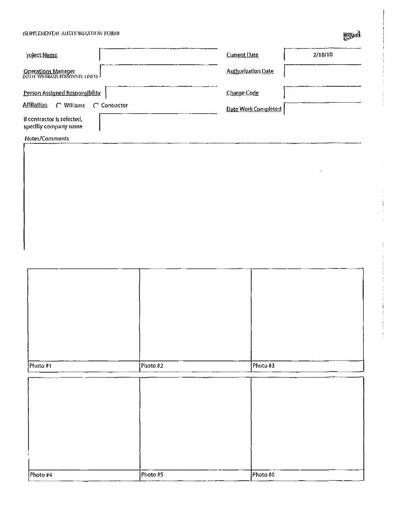
(SllI'I'LE~I[NTill ilUTIIOIU/J\TION FOI\~I)
'ralect Name
Operations Manager I (NOlf WJlIIlA~IS 1'[R.'iOX;.{El o>-:!.n
Person Assigned Responsibility
Affiliation (' Williams (' Contractor
If contractor Is selected, speclfiy company name
Notes/Comments
Photo 111
,
Photo 114
Current Date 2/18/10
Authorization Date
Charge Code
Date Work Completed I
Photo 112 Photo 113
Photo 115 Photo 1/6

APPENDIX G AMENDMENTS
AMENDMENT LOG
DATE OF AMENDMENT: AMENDMENT MADE TO: AMENDMENT MADE BY: