wet chemical deposition of transparent conducting coatings in glass tubes
TRANSCRIPT
Wet chemical deposition of transparent conducting coatings in glass tubes
J. Puetz*, F.N. Chalvet, M.A. Aegerter
Institut fur Neue Materialien, Coating Technology, D-66123 Saarbruecken, Germany¨
Abstract
A modified dip coating process was developed to deposit transparent conducting sol–gel SnO :Sb(ATO, antimony doped tin2
oxide) coatings inside tubes and cavities in optical quality. The necessity for this improvement arises from the fact that theconventional dip coating process applied to tubes results in coatings with poor and non-reproducible properties, showing largevariations in the thickness, an increased roughness and an island-like morphology. The main reason for this is found in a delayedand restricted solvent evaporation, due to an impediment of a laminar flow and a progressive saturation of the atmosphere insidethe tube. By means of an additional exhausting pipe, a forced laminar flow was, therefore, generated inside the tube, whichguarantees a fast evaporation and hydrolysis of the sol–gel films by a continuous renewal of the atmosphere. In this way, ATOcoatings with an excellent thickness uniformity and a low roughness ofR f1 nm could be deposited on borosilicate glass tubesa
of 300 mm length and inner diameters down to 11 mm. After a heat treatment at temperatures up to 5508C, single layer coatingsexhibit a high optical transmission(T)85%) and a resistance down to 10 kV over a length of 22 cm.
Keywords: Sol–gel process; Electrical properties and measurements; Optical coatings; Tin oxide
1. Introduction
Transparent conducting oxide(TCO) coatings com-bine the property of a high optical transmission withthat of a high electrical conductivity, which makes theman essential component in a large variety of applicationsw1,2x. Coating materials like ITO(tin doped indiumoxide, In O :Sn) and ATO (antimony doped tin oxide,2 3
SnO :Sb) can, for example, act as electrodes(e.g. in2
liquid crystal displays, solar cells)or give antistaticproperties to glasses or plastics(e.g. on cathode raytubes). In most cases physical or chemical vapourdeposition techniques(PVD, CVD) are used to depositsuch TCO coatingsw3x as they result in a low sheetresistance(typically 10 V ) and guarantee a highh
optical quality as it is required especially for displaysand solar cells. However, the corresponding techniquesare optimised to coat flat or weakly bent substrateswhereas complex surfaces like the inner surfaces oftubes and cavities are not accessible or accessible onlyafter extensive adaptations. Examples for such highlyspecific coating techniques for the inside coating are the
*Corresponding author. Tel.:q49-681-9300-349; fax:q49-681-9300-249.
E-mail address: [email protected](J. Puetz).
pulsed laser deposition(PLD), where a target is evapo-rated inside the tube by means of a laserw4x, ion beamsputteringw5x or plasma CVDw6x.It would, therefore, be of advantage to have a low
cost and flexible deposition technique at hand, as it isfound in the liquid film coatingw7x. The dip coatingtechnique, which is known for the high uniformity ofthe resulting coatings, has already been described todeposit lacquer systems on tubes with several sugges-tions for improvements and modificationsw8–10x. How-ever, sol–gel coatings have not been deposited so farinside tubes by dip coating, though this technique offersa convenient and low-cost alternative to obtain highquality coatings.
2. Experimental
2.1. Film preparation and characterization
Sol–gel ATO coatings were prepared by the dipcoating technique using an 0.2 M solution of SnCl in2
ethanol with a doping of 5 mol% SbCl and 0.4 M(23
equiv.) diacetone alcohol(4-hydroxy-4-methyl-2-pen-tanone). The obtained solution was stirred under refluxfor 1 h and filtered through a 0.2mm-PTFE filter. The
54 J. Puetz et al. / Thin Solid Films 442 (2003) 53–59
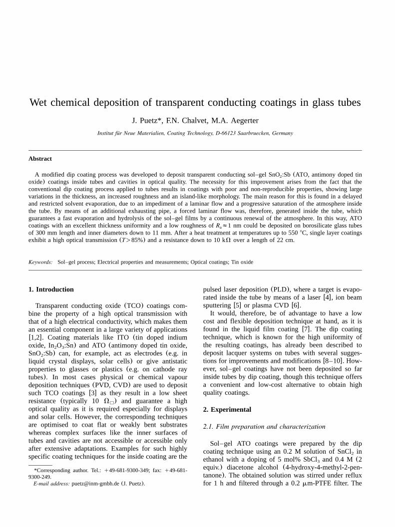
Fig. 1. Experimental set-up for the dip coating of tubes with an inter-nal exhausting pipe and a temperature controlled vessel.
coatings were deposited with a constant withdrawalspeed of 4 mmys on borosilicate glass tubes(Duran,Schott Rohrglas) with a length of 300 mm and outerdiameters of 14 mm(1.5 mm thickness) and 50 mm(1.8 mm thickness), respectively. During the depositionthe atmospheric conditions were kept constant at(21"1) 8C and(40"2)% RH. After a hydrolysis timeof 1 min, the as-deposited films were dried at 2508C(15 min) and subsequently heat treated with a heatingrate of 2.5 Kymin in a convection furnace in air at 5508C (15 min) to form the desired ATO coatings. Addi-tional coating experiments were carried out to investi-gate the evaporation behaviour of the deposited wetfilms on the tubes during dip coating by means of athermographical camera(Thermovision 400, Agema)using pure ethanol.For a characterization of the coatings, the tubes were
cut into pieces of 20 mm or 43 mm length, respectively.After rinsing with water and drying, the sheet resistanceR was then determined by the four-point techniqueh
using Au tips in a linear arrangement(34401 A, Hew-lett-Packard). For the same samples the coating thick-nessd was measured by surface profilometry(TencorP10) after preparation of a sharp edge by chemicaletching with HCl and Zn dust. Similarly, the averageroughnessR of the coatings was obtained from aa
measurement with the same device over a distance of0.5 mm. The film morphology was investigated byscanning electron microscopy(SEM) (15 keV, JSM6400F, Jeol) after deposition of a thin Au layer on topof the film.
2.2. Modified dip coating process
A modified dip coating apparatus was developed, asshown in Fig. 1, in order to obtain a forced laminarflow inside the tube. This was accomplished by anadditional exhausting glass pipe(5 mm outer�) thatwas placed in the solution vessel and introduced frombelow into the tube with the internal end rising 5 mmabove the solution. This arrangement brings almost norestrictions compared to the conventional process withregards to deposition speed and handling. The externalend of the exhausting pipe was connected to a diaphragmvacuum pump with an adjustable, constant flow of airof up to 210 lyh. The flow of air that is necessary toobtain homogeneous films depends on the withdrawalspeed, on the inner diameter of the tube and also on thecoating solution so that an optimisation is necessary. Forthe two tubes used in these experiments a constant flowof 50 lyh in the case of the 14 mm tubes and 210 lyhfor the 50 mm tubes was generated.For the formation of a constant laminar flow through
the tube, it is important that the lower end of the tuberemains in the solution in order to enclose the exhaustingpipe and force the air to go through the tube. It is,
therefore, necessary to modify the sequence of the dipcoating process compared to the coating of flat sub-strates, as on complete withdrawal the exhausting pipewould be bared and the internal flow would come to anend. Thus, the tube is not completely withdrawn but iskept in the solution just enough to seal the tube in thelower end. After a drying time of 1 min the substratetube is then removed from the solution and the adheringsolution is wiped off. The thus prepared films subse-quently were dried and heat treated as described before.
3. Results and discussion
3.1. Conventional dip coating process
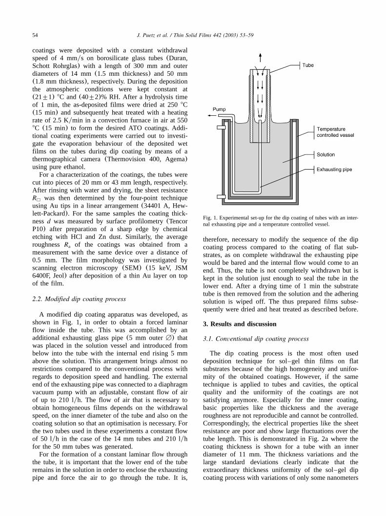
The dip coating process is the most often useddeposition technique for sol–gel thin films on flatsubstrates because of the high homogeneity and unifor-mity of the obtained coatings. However, if the sametechnique is applied to tubes and cavities, the opticalquality and the uniformity of the coatings are notsatisfying anymore. Especially for the inner coating,basic properties like the thickness and the averageroughness are not reproducible and cannot be controlled.Correspondingly, the electrical properties like the sheetresistance are poor and show large fluctuations over thetube length. This is demonstrated in Fig. 2a where thecoating thickness is shown for a tube with an innerdiameter of 11 mm. The thickness variations and thelarge standard deviations clearly indicate that theextraordinary thickness uniformity of the sol–gel dipcoating process with variations of only some nanometers
55J. Puetz et al. / Thin Solid Films 442 (2003) 53–59
Fig. 2. Thicknessd and average roughnessR of conventionally dip coated ATO coatings on tubes with an inner diameter of 11 mm.a
is not achieved for the tubes, neither inside nor outside.Nevertheless, the average thickness is comparable to thecoating thickness of(58"2) nm obtained on flat sub-strates with the same parameters. The surface roughness(Fig. 2b) is much higher than expected for sol–gel filmswhere values below 1 nm can be realized. Especiallythe inner coating exhibits an inhomogeneous distributionin the average roughnessR with values of approximate-a
ly 2 nm in the upper part, but up to(10"4) nm in thelower part of the tube. In contrast, the average roughnessof the outer coating is only 1–2 nm and shows lowerfluctuations. Similar results with regards to the thicknessand the roughness were obtained for tubes with a largerinner diameter, but the fluctuations are less distinct inthis case.The coating morphology, as investigated by SEM
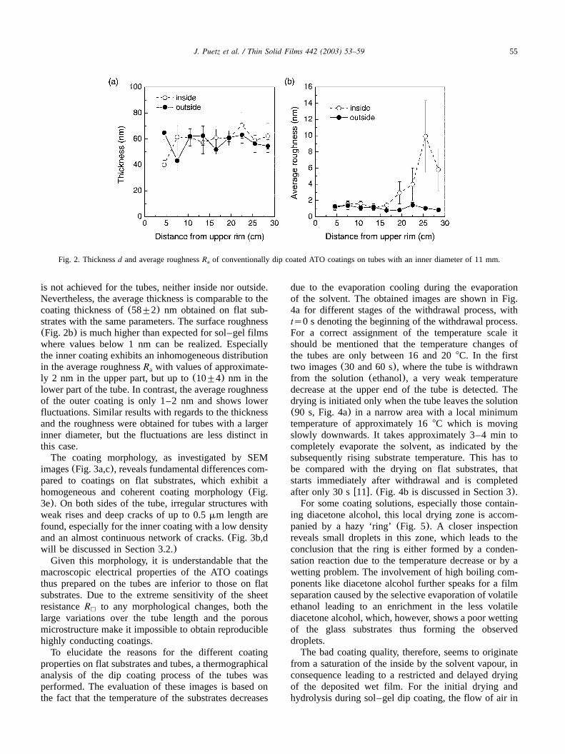
images(Fig. 3a,c), reveals fundamental differences com-pared to coatings on flat substrates, which exhibit ahomogeneous and coherent coating morphology(Fig.3e). On both sides of the tube, irregular structures withweak rises and deep cracks of up to 0.5mm length arefound, especially for the inner coating with a low densityand an almost continuous network of cracks.(Fig. 3b,dwill be discussed in Section 3.2.)Given this morphology, it is understandable that the
macroscopic electrical properties of the ATO coatingsthus prepared on the tubes are inferior to those on flatsubstrates. Due to the extreme sensitivity of the sheetresistanceR to any morphological changes, both theh
large variations over the tube length and the porousmicrostructure make it impossible to obtain reproduciblehighly conducting coatings.To elucidate the reasons for the different coating
properties on flat substrates and tubes, a thermographicalanalysis of the dip coating process of the tubes wasperformed. The evaluation of these images is based onthe fact that the temperature of the substrates decreases
due to the evaporation cooling during the evaporationof the solvent. The obtained images are shown in Fig.4a for different stages of the withdrawal process, withts0 s denoting the beginning of the withdrawal process.For a correct assignment of the temperature scale itshould be mentioned that the temperature changes ofthe tubes are only between 16 and 208C. In the firsttwo images(30 and 60 s), where the tube is withdrawnfrom the solution(ethanol), a very weak temperaturedecrease at the upper end of the tube is detected. Thedrying is initiated only when the tube leaves the solution(90 s, Fig. 4a) in a narrow area with a local minimumtemperature of approximately 168C which is movingslowly downwards. It takes approximately 3–4 min tocompletely evaporate the solvent, as indicated by thesubsequently rising substrate temperature. This has tobe compared with the drying on flat substrates, thatstarts immediately after withdrawal and is completedafter only 30 sw11x. (Fig. 4b is discussed in Section 3).For some coating solutions, especially those contain-
ing diacetone alcohol, this local drying zone is accom-panied by a hazy ‘ring’(Fig. 5). A closer inspectionreveals small droplets in this zone, which leads to theconclusion that the ring is either formed by a conden-sation reaction due to the temperature decrease or by awetting problem. The involvement of high boiling com-ponents like diacetone alcohol further speaks for a filmseparation caused by the selective evaporation of volatileethanol leading to an enrichment in the less volatilediacetone alcohol, which, however, shows a poor wettingof the glass substrates thus forming the observeddroplets.The bad coating quality, therefore, seems to originate
from a saturation of the inside by the solvent vapour, inconsequence leading to a restricted and delayed dryingof the deposited wet film. For the initial drying andhydrolysis during sol–gel dip coating, the flow of air in
56 J. Puetz et al. / Thin Solid Films 442 (2003) 53–59
Fig. 3. SEM images of ATO coatings deposited by conventional dip coating(left) and under forced flow conditions(right) on the outer(upper)and inner side(middle) of glass tubes(inner diameter 11 mm) and on flat substrates(lower).
the next surroundings of the wet film is extremelyimportant and decisively influences the properties of theresulting coating. As the solvent vapours are specificallyheavier than the ambient atmosphere, they start sinkingdownwards and thus generate a constant laminar flowover the film surface as it is illustrated in Fig. 6a forflat substrates. This increases the evaporation rate byreducing the partial pressure of solvent next to the
surface and keeps the concentration of water constantby permanently renewing the atmosphere. For a uniformthickness, this flow has to be laminar and thus shouldbe protected against external influences like draft andconvection.In the case of the tubes, however, this flow can only
form on the outside(Fig. 6b), whereas the inside of thetubes is closed at the bottom as long as the tube is in

57J. Puetz et al. / Thin Solid Films 442 (2003) 53–59
Fig. 5. Formation of a ring inside a tube during dip coating from asolution with a high boiling point component.
Fig. 4. Thermographical images of a borosilicate glass tube(inner diameter 11 mm) during (a) conventional dip coating and(b) under forcedflow conditions.ts0 s corresponds to the beginning withdrawal.
the solution. Formed solvent vapours hence accumulateat the bottom of the tube and a similar flow thus is notpossible. The upper part of the film, however, is almostunaffected if the withdrawal speed is not too low, as thevapours sink down in the tube and the internal volumeis permanently increased during withdrawal. But espe-cially in the lower part of the tube the evaporation iscompletely delayed as long as the tube is in the coatingsolution. Only when the tube leaves the solution a weakflow can form gradually. With decreasing inner diameterof the tubes these difficulties become more and moredecisive as the inner volume is decreasing and the dragforce is increasing, thus slowing down the flow rate.Another problem arising from the closed inner volumeis that the content of water is limited and thus therequired hydrolysis of the sol–gel materials is restricted.But it is not only the inner film that is affected by theseprocesses, as the substrate temperature changes inho-mogeneously as shown in the thermographical analysis(Fig. 4a), which also influences the drying of the wetfilm on the outer side.
3.2. Forced flow conditions
For an improvement of the coating quality, hence asaturation of the inner atmosphere with solvent has to
be avoided by forcing laminar flow conditions insidethe tube. This was achieved by the use of an additionalexhausting pipe that is advantageously introduced frombelow into the substrate tube(Fig. 1). In this way, acontinuous flow of air is generated that guarantees theremoval of the evaporated solvent while keeping theevaporation rate high, but that also maintains the supplyof water for hydrolysis of the sol–gel wet film. It turnedout that the resulting forced flow conditions are com-parable to the intrinsic laminar flows that form over theouter side of the tubes or over flat substrates.
58 J. Puetz et al. / Thin Solid Films 442 (2003) 53–59
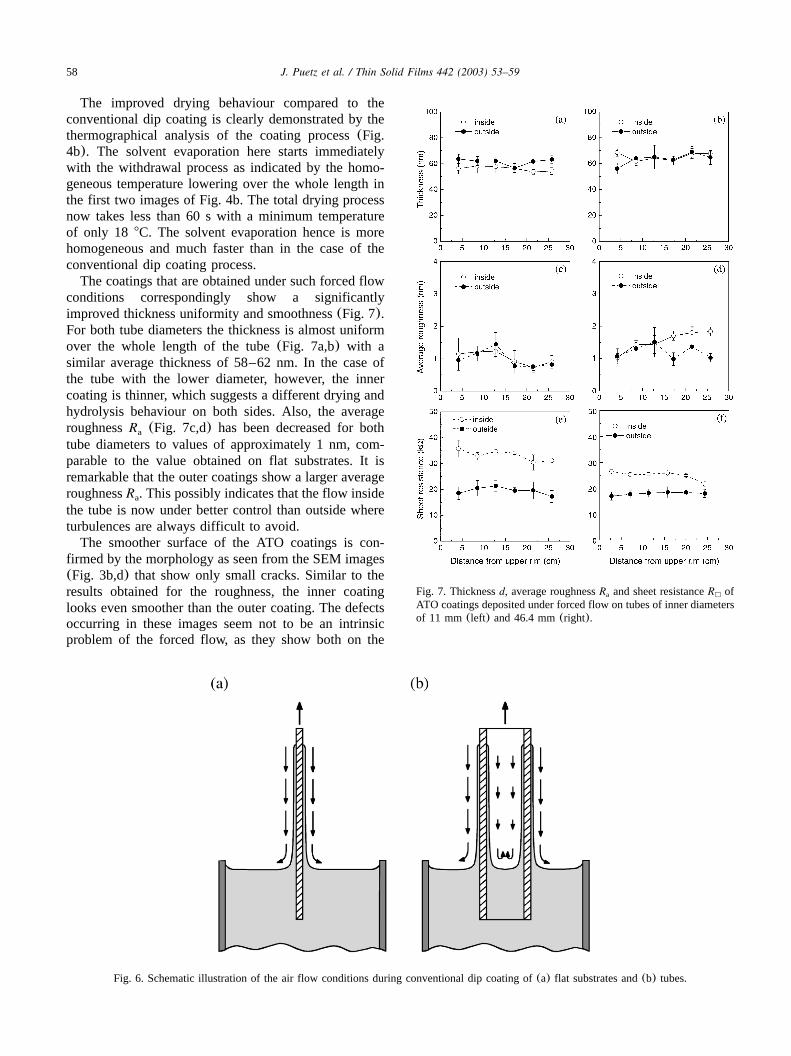
Fig. 7. Thicknessd, average roughnessR and sheet resistanceR ofa h
ATO coatings deposited under forced flow on tubes of inner diametersof 11 mm(left) and 46.4 mm(right).
Fig. 6. Schematic illustration of the air flow conditions during conventional dip coating of(a) flat substrates and(b) tubes.
The improved drying behaviour compared to theconventional dip coating is clearly demonstrated by thethermographical analysis of the coating process(Fig.4b). The solvent evaporation here starts immediatelywith the withdrawal process as indicated by the homo-geneous temperature lowering over the whole length inthe first two images of Fig. 4b. The total drying processnow takes less than 60 s with a minimum temperatureof only 18 8C. The solvent evaporation hence is morehomogeneous and much faster than in the case of theconventional dip coating process.The coatings that are obtained under such forced flow
conditions correspondingly show a significantlyimproved thickness uniformity and smoothness(Fig. 7).For both tube diameters the thickness is almost uniformover the whole length of the tube(Fig. 7a,b) with asimilar average thickness of 58–62 nm. In the case ofthe tube with the lower diameter, however, the innercoating is thinner, which suggests a different drying andhydrolysis behaviour on both sides. Also, the averageroughnessR (Fig. 7c,d) has been decreased for botha
tube diameters to values of approximately 1 nm, com-parable to the value obtained on flat substrates. It isremarkable that the outer coatings show a larger averageroughnessR . This possibly indicates that the flow insidea
the tube is now under better control than outside whereturbulences are always difficult to avoid.The smoother surface of the ATO coatings is con-
firmed by the morphology as seen from the SEM images(Fig. 3b,d) that show only small cracks. Similar to theresults obtained for the roughness, the inner coatinglooks even smoother than the outer coating. The defectsoccurring in these images seem not to be an intrinsicproblem of the forced flow, as they show both on the
59J. Puetz et al. / Thin Solid Films 442 (2003) 53–59
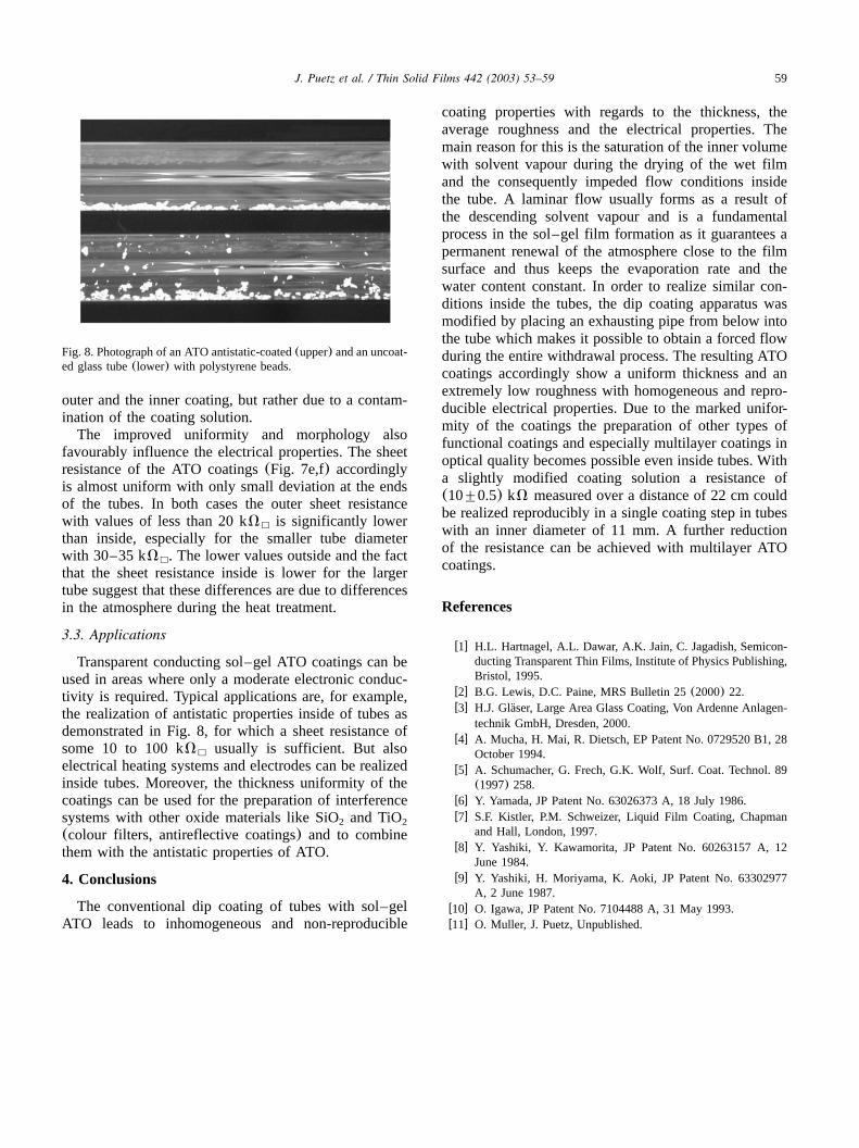
Fig. 8. Photograph of an ATO antistatic-coated(upper) and an uncoat-ed glass tube(lower) with polystyrene beads.
outer and the inner coating, but rather due to a contam-ination of the coating solution.The improved uniformity and morphology also
favourably influence the electrical properties. The sheetresistance of the ATO coatings(Fig. 7e,f) accordinglyis almost uniform with only small deviation at the endsof the tubes. In both cases the outer sheet resistancewith values of less than 20 kV is significantly lowerh
than inside, especially for the smaller tube diameterwith 30–35 kV . The lower values outside and the facth
that the sheet resistance inside is lower for the largertube suggest that these differences are due to differencesin the atmosphere during the heat treatment.
3.3. Applications
Transparent conducting sol–gel ATO coatings can beused in areas where only a moderate electronic conduc-tivity is required. Typical applications are, for example,the realization of antistatic properties inside of tubes asdemonstrated in Fig. 8, for which a sheet resistance ofsome 10 to 100 kV usually is sufficient. But alsoh
electrical heating systems and electrodes can be realizedinside tubes. Moreover, the thickness uniformity of thecoatings can be used for the preparation of interferencesystems with other oxide materials like SiO and TiO2 2
(colour filters, antireflective coatings) and to combinethem with the antistatic properties of ATO.
4. Conclusions
The conventional dip coating of tubes with sol–gelATO leads to inhomogeneous and non-reproducible
coating properties with regards to the thickness, theaverage roughness and the electrical properties. Themain reason for this is the saturation of the inner volumewith solvent vapour during the drying of the wet filmand the consequently impeded flow conditions insidethe tube. A laminar flow usually forms as a result ofthe descending solvent vapour and is a fundamentalprocess in the sol–gel film formation as it guarantees apermanent renewal of the atmosphere close to the filmsurface and thus keeps the evaporation rate and thewater content constant. In order to realize similar con-ditions inside the tubes, the dip coating apparatus wasmodified by placing an exhausting pipe from below intothe tube which makes it possible to obtain a forced flowduring the entire withdrawal process. The resulting ATOcoatings accordingly show a uniform thickness and anextremely low roughness with homogeneous and repro-ducible electrical properties. Due to the marked unifor-mity of the coatings the preparation of other types offunctional coatings and especially multilayer coatings inoptical quality becomes possible even inside tubes. Witha slightly modified coating solution a resistance of(10"0.5) kV measured over a distance of 22 cm couldbe realized reproducibly in a single coating step in tubeswith an inner diameter of 11 mm. A further reductionof the resistance can be achieved with multilayer ATOcoatings.
References
w1x H.L. Hartnagel, A.L. Dawar, A.K. Jain, C. Jagadish, Semicon-ducting Transparent Thin Films, Institute of Physics Publishing,Bristol, 1995.
w2x B.G. Lewis, D.C. Paine, MRS Bulletin 25(2000) 22.w3x H.J. Glaser, Large Area Glass Coating, Von Ardenne Anlagen-¨
technik GmbH, Dresden, 2000.w4x A. Mucha, H. Mai, R. Dietsch, EP Patent No. 0729520 B1, 28
October 1994.w5x A. Schumacher, G. Frech, G.K. Wolf, Surf. Coat. Technol. 89
(1997) 258.w6x Y. Yamada, JP Patent No. 63026373 A, 18 July 1986.w7x S.F. Kistler, P.M. Schweizer, Liquid Film Coating, Chapman
and Hall, London, 1997.w8x Y. Yashiki, Y. Kawamorita, JP Patent No. 60263157 A, 12
June 1984.w9x Y. Yashiki, H. Moriyama, K. Aoki, JP Patent No. 63302977
A, 2 June 1987.w10x O. Igawa, JP Patent No. 7104488 A, 31 May 1993.w11x O. Muller, J. Puetz, Unpublished.