wepsim - e-archivo
TRANSCRIPT
This is a postprint version of the following published document:
F. García-Carballeira, A. Calderón-Mateos, S. Alonso-Monsalve and J. Prieto-Cepeda, "WepSIM: An Online Interactive Educational Simulator Integrating Microdesign, Microprogramming, and Assembly Language Programming," in IEEE Transactions on Learning Technologies, vol. 13, no. 1, pp. 211-218, 1 Jan.-March 2020.
DOI: 10.1109/TLT.2019.2903714
©2020 IEEE. Personal use of this material is permitted. Permission from IEEE must be obtained for all other uses, in any current or future media, including reprinting/republishing this material for advertising or promotional purposes, creating new collective works, for resale or redistribution to servers or lists, or reuse of any copyrighted component of this work in other works.
Wepsim: an online interactive educational simulator integrating microdesign,microprogramming, and assembly language programming
Felix Garcıa-Carballeira∗, Alejandro Calderon-Mateos∗, Saul Alonso-Monsalve∗, Javier Prieto-Cepeda†
,Computer Science and Engineering Department. University Carlos III of Madrid.
Av. Universidad, 30. 28911 Leganes, Madrid, Spain.∗ {fgcarbal, acaldero, saualons}@inf.uc3m.es
† {javpriet}@pa.uc3m.es
Abstract—We have three primary goals in our educationalproject. First, we want to provide a robust vision of howhardware and software interplay, by integrating the designof an instruction set - through microprogramming - and usingthis instruction set for assembly programming. Second, wewant to offer a versatile tool where the previous tight visioncould be tested beyond handwritten exercises. This is calledWepSIM and provides an initial elemental processor with amicroprogrammed subset of the MIPS instruction set. Besides,WepSIM is flexible enough to be adapted to other instructionsets or hardware components (ARM, x86, etc.). Third, we wantto extend the activities of our University lab lectures (fixedhours in a fixed place) so that the students could learn usingtheir mobile device in near any location and any moment ofthe day.
This article introduces how WepSIM1 has improved theteaching of the Computer Structure course by empowering stu-dents with a more dynamic and autonomous learning process.In this work, we show the results obtained during the firstusage experience - three years - in the Computer Structurecourse of the Bachelor’s Degree in Computer Science andEngineering from the University Carlos III of Madrid.
1. Introduction
There are several interesting simulators used to teachComputer Structure courses. In general, each simulator isused to explain a specific topic of the subject so that studentscan learn each of the fundamental aspects of the course:assembly, cache, or CPU, separately. Those tools are specificto each aspect of the course; there are used using traditionalPCs during fixed lab hours (or event at home).
This diversity does not allow students to have a globalview of the system since they do not study the integrationof all the elements of the computer and their relationship.Besides, the most realistic simulators are also the most com-plex. For instance, in our experience, students use to havemany problems to understand how interruptions work. Theteaching of interruptions is essential for Computer Structure,
1. https://wepsim.github.io/, https://wepsim.github.io/wepsim/
critical for Operating systems courses, and it is also is a suit-able introduction to asynchronous behavior used elsewhere.It is tremendously difficult to get students to understandhow the hardware generates an interruption, how the CPUintercepts it, how the CPU searches for the associated han-dler, how the handler code is executed, and finally how theexecution returns to the line of code previously interrupted.There is a continuous interplay between the hardware, thefirmware (microcode for example), and the assembly code,which forces the usage of different simulators to explaineach part, and then to devote a tremendous effort to link allthese concepts. The cost of misunderstanding those ideascould lead to inherent issues [1] with a high impact on thestudents’ learning.
The most popular simulators for educational proposeswere created to perform a specific laboratory assignment,and they are available only for traditional PCs (laptops ordesktop computers). These conventional PCs usually includea user manual for help, but their goal is not to be a learningmaterial (based on use cases). Moreover, current studentsspend most of their time using mobile platforms - includingsmartphones, tablets, Chromebooks, etc. - and they demandinteractive and online learning tools - that may be used ona daily basis - rather than the current PC tools.
Given these challenges, our main goal is to provide amodular and straightforward educational and online simu-lator for Computer Structure courses that can be used byboth the students - to learn the topics mentioned aboveand improve their skills - and the professors - to teachin a better manner and make their work more accessible.The simulator may be used to teach microprogrammingand how a simple CPU works, how to use the firmware- through microcode - to create assembly programs, andhow the assembly code interacts with both the hardwareand the operating system at the same time. We want thissimulator to be intuitive and user-friendly, so students donot get lost in irrelevant details, but at the same time, to bevery similar to what happens in actual hardware and systemsoftware. We also want this simulator to be portable: to beused in smartphones, tablets, but also in desktop computers,and including as much training material as possible.
In this paper, we present WepSIM, an educational and
online simulator that we have designed and implemented toarchive the previously commented goals. WepSIM simulatesthe circuitry of an elementary processor interactively andallows the user to both define the microcode of the processorand to implement programs in assembly code using theinstruction set defined within the microcode. Its circuitry canbe modified or extended; it lets students see how circuitry,firmware, and assembly interplay, and it allows students totest paper exercises using both a mobile device or a desktopcomputer (and test variations of the tasks in an interactiveway).
We have also used WepSIM in two Teaching InnovationProjects of our University; in both of them, the studentshave demonstrated to work autonomously - without the per-manent supervision of the professors - and also to verify andvalidate the designing and resolution of complex problems.The results of providing WepSIM to be used in laboratoryclasses, and letting students test the exercises they solveby hand in WepSIM are outstanding: the majority of thestudents are more confident to face the final exam, andthey also improve their grades in both the assembly andmicroprogramming exercise in that final exam. What is moreastonishing is that we achieved those improvements evenwhen the ratio ’students per teacher’ was increased.
The rest of the document is organized as follows: Section2 describes the architecture and the hardware model of thesimulator. Section 3 introduces the elemental processor thatis simulated by using the WepSIM architecture (and thehardware model previously described). This section alsodescribes the microcode and the instruction format. Section4 describes the main aspects of the implementation processand Section 5 presents the evaluation of the simulator. Sec-tion 6 reviews the related work. Finally, Section 7 concludesthe paper and presents some future work.
2. The WepSIM Architecture and HardwareModel
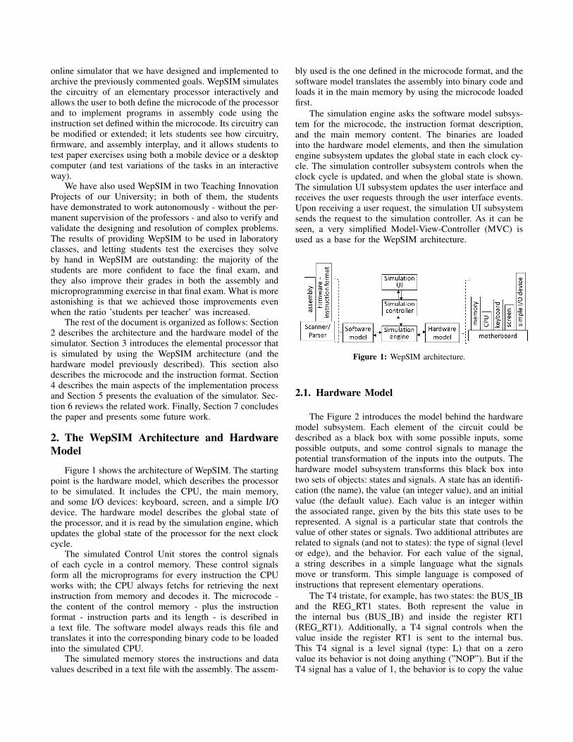
Figure 1 shows the architecture of WepSIM. The startingpoint is the hardware model, which describes the processorto be simulated. It includes the CPU, the main memory,and some I/O devices: keyboard, screen, and a simple I/Odevice. The hardware model describes the global state ofthe processor, and it is read by the simulation engine, whichupdates the global state of the processor for the next clockcycle.
The simulated Control Unit stores the control signalsof each cycle in a control memory. These control signalsform all the microprograms for every instruction the CPUworks with; the CPU always fetchs for retrieving the nextinstruction from memory and decodes it. The microcode -the content of the control memory - plus the instructionformat - instruction parts and its length - is described ina text file. The software model always reads this file andtranslates it into the corresponding binary code to be loadedinto the simulated CPU.
The simulated memory stores the instructions and datavalues described in a text file with the assembly. The assem-
bly used is the one defined in the microcode format, and thesoftware model translates the assembly into binary code andloads it in the main memory by using the microcode loadedfirst.
The simulation engine asks the software model subsys-tem for the microcode, the instruction format description,and the main memory content. The binaries are loadedinto the hardware model elements, and then the simulationengine subsystem updates the global state in each clock cy-cle. The simulation controller subsystem controls when theclock cycle is updated, and when the global state is shown.The simulation UI subsystem updates the user interface andreceives the user requests through the user interface events.Upon receiving a user request, the simulation UI subsystemsends the request to the simulation controller. As it can beseen, a very simplified Model-View-Controller (MVC) isused as a base for the WepSIM architecture.
Figure 1: WepSIM architecture.
2.1. Hardware Model
The Figure 2 introduces the model behind the hardwaremodel subsystem. Each element of the circuit could bedescribed as a black box with some possible inputs, somepossible outputs, and some control signals to manage thepotential transformation of the inputs into the outputs. Thehardware model subsystem transforms this black box intotwo sets of objects: states and signals. A state has an identifi-cation (the name), the value (an integer value), and an initialvalue (the default value). Each value is an integer withinthe associated range, given by the bits this state uses to berepresented. A signal is a particular state that controls thevalue of other states or signals. Two additional attributes arerelated to signals (and not to states): the type of signal (levelor edge), and the behavior. For each value of the signal,a string describes in a simple language what the signalsmove or transform. This simple language is composed ofinstructions that represent elementary operations.
The T4 tristate, for example, has two states: the BUS IBand the REG RT1 states. Both represent the value inthe internal bus (BUS IB) and inside the register RT1(REG RT1). Additionally, a T4 signal controls when thevalue inside the register RT1 is sent to the internal bus.This T4 signal is a level signal (type: L) that on a zerovalue its behavior is not doing anything (”NOP”). But if theT4 signal has a value of 1, the behavior is to copy the value
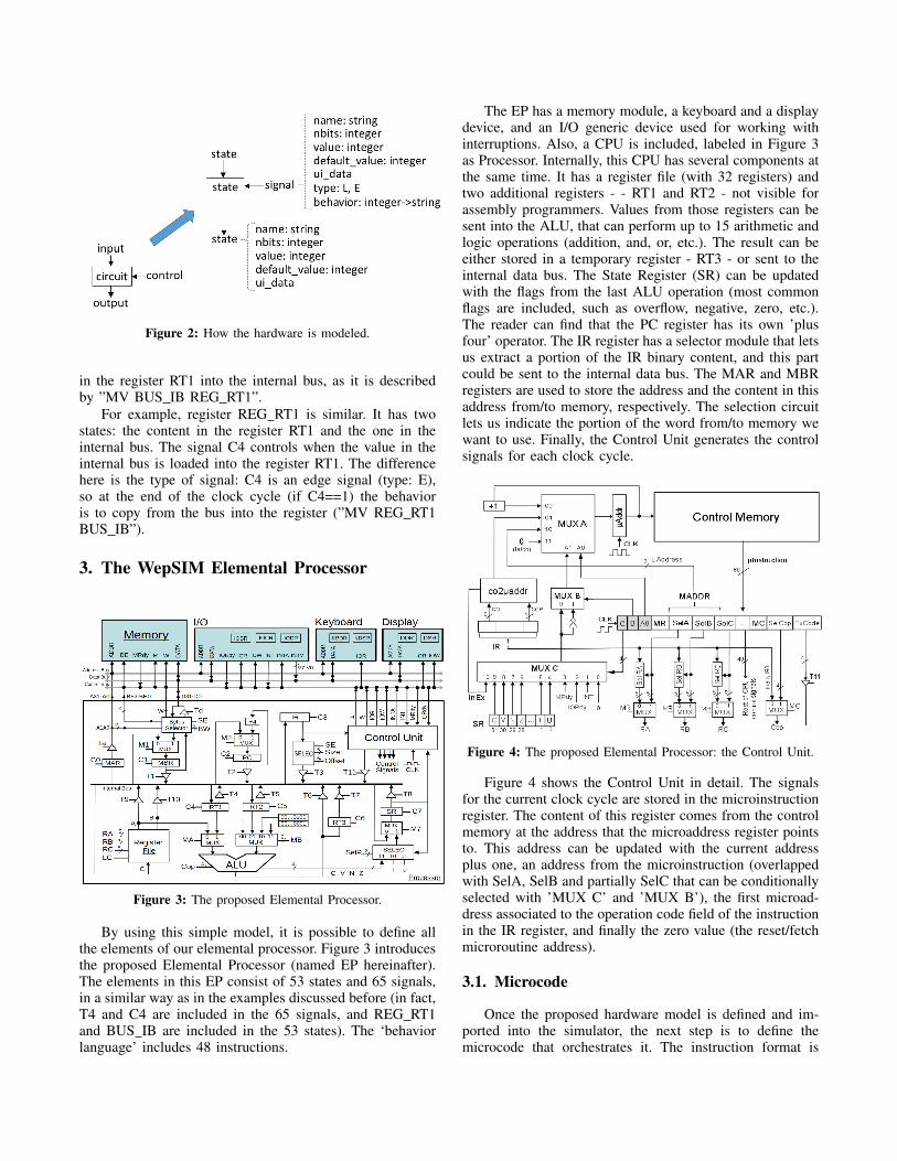
Figure 2: How the hardware is modeled.
in the register RT1 into the internal bus, as it is describedby ”MV BUS IB REG RT1”.
For example, register REG RT1 is similar. It has twostates: the content in the register RT1 and the one in theinternal bus. The signal C4 controls when the value in theinternal bus is loaded into the register RT1. The differencehere is the type of signal: C4 is an edge signal (type: E),so at the end of the clock cycle (if C4==1) the behavioris to copy from the bus into the register (”MV REG RT1BUS IB”).
3. The WepSIM Elemental Processor
Figure 3: The proposed Elemental Processor.
By using this simple model, it is possible to define allthe elements of our elemental processor. Figure 3 introducesthe proposed Elemental Processor (named EP hereinafter).The elements in this EP consist of 53 states and 65 signals,in a similar way as in the examples discussed before (in fact,T4 and C4 are included in the 65 signals, and REG RT1and BUS IB are included in the 53 states). The ‘behaviorlanguage’ includes 48 instructions.
The EP has a memory module, a keyboard and a displaydevice, and an I/O generic device used for working withinterruptions. Also, a CPU is included, labeled in Figure 3as Processor. Internally, this CPU has several components atthe same time. It has a register file (with 32 registers) andtwo additional registers - - RT1 and RT2 - not visible forassembly programmers. Values from those registers can besent into the ALU, that can perform up to 15 arithmetic andlogic operations (addition, and, or, etc.). The result can beeither stored in a temporary register - RT3 - or sent to theinternal data bus. The State Register (SR) can be updatedwith the flags from the last ALU operation (most commonflags are included, such as overflow, negative, zero, etc.).The reader can find that the PC register has its own ’plusfour’ operator. The IR register has a selector module that letsus extract a portion of the IR binary content, and this partcould be sent to the internal data bus. The MAR and MBRregisters are used to store the address and the content in thisaddress from/to memory, respectively. The selection circuitlets us indicate the portion of the word from/to memory wewant to use. Finally, the Control Unit generates the controlsignals for each clock cycle.
Figure 4: The proposed Elemental Processor: the Control Unit.
Figure 4 shows the Control Unit in detail. The signalsfor the current clock cycle are stored in the microinstructionregister. The content of this register comes from the controlmemory at the address that the microaddress register pointsto. This address can be updated with the current addressplus one, an address from the microinstruction (overlappedwith SelA, SelB and partially SelC that can be conditionallyselected with ’MUX C’ and ’MUX B’), the first microad-dress associated to the operation code field of the instructionin the IR register, and finally the zero value (the reset/fetchmicroroutine address).
3.1. Microcode
Once the proposed hardware model is defined and im-ported into the simulator, the next step is to define themicrocode that orchestrates it. The instruction format is
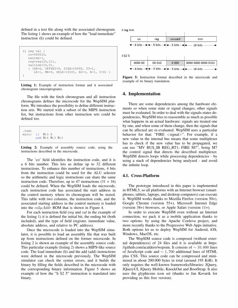
defined in a text file along with the associated chronogram.The listing 1 shows an example of how the ”load immediate”instruction (li) could be defined.
li reg val {co=000010,nwords=1,reg=reg(25,21),val=inm(15,0),{ (SE=0, OFFSET=0, SIZE=10000, T3=1,
LE=1, MR=0, SELE=10101, A0=1, B=1, C=0) }}
Listing 1: Example of instruction format and it associatedchronogram (microprogram).
The file with the fetch chronogram and all instructionchronograms defines the microcode for the WepSIM plat-form. We introduce the possibility to define different instruc-tion sets. We started with a subset of the MIPS instructionlist, but instructions from other instruction sets could bedefined too.
.textmain: li $t3 8
add $t6 $t3 $t3
Listing 2: Example of assembly source code, using theinstructions described in the microcode.
The ’co’ field identifies the instruction code, and it isa 6 bits number. This lets us define up to 32 differentinstructions. To enhance this number of instructions, 4 bitsfrom the instruction could be used for the ALU selectorso the arithmetic and logic instructions can share the sameinstruction code. Therefore, up to 47 instructions (31 + 16)could be defined. When the WepSIM loads the microcode,each instruction code has associated the start address inthe control memory where its chronogram will be stored.This table with two columns, the instruction code, and theassociated starting address in the control memory is loadedinto the co2µAddr ROM that is shown in Figure 4.
For each instruction field (reg and val in the example ofthe listing 1) it is defined the initial bit, the ending bit (bothincluded), and the type of field (register, immediate value,absolute address, and relative to PC address).
Once the microcode is loaded into the WepSIM simu-lator, it is possible to load an assembly file that was builtup from instructions defined on the former microcode. Inlisting 2 is shown an example of the assembly source code.This particular example (listing 2) shows a MIPS-like sourcecode. The load immediate (li) and the add (add) instructionswere defined in the microcode previously. The WepSIMsimulator can check the syntax errors, and it builds thebinary by filling the fields described in the microcode withthe corresponding binary information. Figure 5 shows anexample of how the ”li $2 5” instruction is translated intobinary.
Figure 5: Instruction format described in the microcode andexample of its binary translation.
4. Implementation
There are some dependencies among the hardware ele-ments so when some state or signal changes, other signalsmust be evaluated. In order to deal with the signals-states de-pendencies, WepSIM tries to reassemble as much as possiblewhat happens in an actual hardware: signals are treated oneby one, and when some of them change, then the signals thatcan be affected are re-evaluated. WepSIM uses a particularbehavior for that: ”FIRE <signal>”. For example, if anew value in the internal bus means that some multiplexerhas to check if the new value has to be propagated, wecan use ”MV BUS IB REG RT1; FIRE M7”, being M7the control signal that directs the described multiplexer.WepSIM detects loops while processing dependencies - byusing a stack of dependencies being analyzed - and avoidthe infinite loop.
4.1. Cross-Platform
The prototype introduced in this paper is implementedin HTML5, so all platforms with an Internet browser (smart-phones, tablets, laptops, and desktop computers) can executeit. WepSIM works thanks to Mozilla Firefox (version 50+),Google Chrome (version 55+), Microsoft Internet Edge(version 38+) browsers, or Apple Safari (version 11+).
In order to execute WepSIM even without an Internetconnection, we pack it as a mobile application thanks totwo options: by using the Apache Cordova project, andmore recently thanks to the Progressive Web Apps initiative.Both options let us to deploy WepSIM for Android, iOS,Windows, MacOS, etc.
The WepSIM source code is composed (without exter-nal dependences) of 24 files and it is available at https://github.com/acaldero/wepsim. It consists of ∼ 10, 000 linesof JavaScript code and ∼ 1, 700 additional lines of HTMLplus CSS. This source code can be compressed and mini-mized in about 200.000 bytes in total (around 195 KiB). Itonly requires the well-known frameworks/libraries: JQuery,JQueryUI, JQuery Mobile, KnockOut and BootStrap. It alsouses the glyphicons icon set (thanks to Jan Kovarik forproviding us this free version).
4.2. The ‘Test and Learn’ User Interface
The user interface has three views: simulation, micro-programming view, and assembler view. The three viewsare interconnected to allow students to microprogram aninstruction set (MIPS, ARM, Z80, etc.), then program anassembly application with the defined instruction set, andfinally execute the assembly application.
Each one of the 3 view provides as much feed-backas possible to students so they can test and learn. Forinstance, the circuit cables change its color when they areused, control signal change its color when they are activated,and so on. Moreover, each view has a help entry with theassociate explanation, there are 12 examples by default, andthere are 2 initial tutorials that quick cover how the userinterface is used.
Figure 6 shows an example of the assembly debuggerexecution, and Figure 7 shows the processor simulator whereby clicking on signal name open a popup where studentsaccess to the associated help, and the form to change thecurrent value of this signal.
Figure 6: Main view of the assembly debugger.
Figure 7: Help details of the ‘M2’ signal.
5. Evaluation
An important complement to perform exercises by handis to provide a way to make these activities to come inter-active, so students can make changes and study their effect.WepSIM can help to increase the curiosity of the students alltimes, but especially on the first exercises where WepSIMhelps to learn how an elemental processor works. Helping
on the initial exercises empower students to continue withthe exercises proposed in the literature in a better way.
A critical aspect of this first contact with exercises is tolet students make experiments at any moment, not only inthe hours of the day associated with the laboratory work.WepSIM mobility and portability are essential to providea better adjustment of the learning process of the students.And because WepSIM includes help material and examples,it can be used as a more autonomous learning tool thanthe existing ones (as far as authors know). The followingsubsection describes the evaluation of the first WepSIMexperience on that.
5.1. Grade Improvements
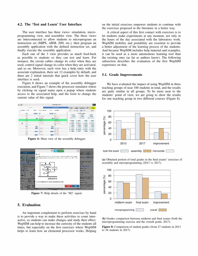
We have evaluated the impact of using WepSIM in threeteaching groups of near 100 students in total, and the resultsare quite similar in all groups. To be more near to thestudents’ point of view, we are going to show the resultsfor one teaching group in two different courses (Figure 8).
0
20
40
60
80
100
2013 2017 improvement
pe
rce
nta
ge
(%
)
took the exam assembly microcode
(a) Obtained portion of total grades in the final exams’ exercises ofassembly and microprogramming (2013 vs 2017).
0
20
40
60
80
100
midterm exam final exam improvement
pe
rce
nta
ge
(%
)
microprogramming overall
(b) Grades comparison between midterm and final exams (both themicroprogramming exercise and the overall grade, 2017).
Figure 8: Comparison of student grades (from 27 students in 2013to 38 students in 2017).
As it is shown in Figure 8a, in 2013/2014 the WepSIMteaching utility did not exist, and from 27 total students inthe final exam, only 18 performed the exercises of the exam.In 2017/2018 our proposed WepSIM utility was used (notonly as lab supporting tool but as a teaching assistant tooltoo). From 41 total students in the final exam, 38 performedthe exam’s exercises. By using WepSIM we were able toempower students to be more confident in its abilities, andthe percentage of student that performed the exam increasefrom 66% (18/27) up to 92% (38/41).
On the other hand, Figure 8b shows the grade com-parison between the midterm and the final exam, takinginto account both the microprogramming exercise and theoverall grade of the 2017/2018 course. As it can be seen,the same group of students greatly improved their gradefrom the midterm exam - without using WepSIM - to thefinal exam - after two months of using WepSIM. ThisFigure demonstrates that there is not only a significantimprovement among different courses, but also the samegroup of students is able to improve their grades after aWepSIM-based learning.
When the number of students per group increase (from27 up to 41) with the same amount of teachers, then the timeavailable per student decreased. Thanks to WepSIM, theresults show that we can improve the learning experience,and the grades of the students, even with high ’student perteacher’ ratio.
Only a teaching tool like WepSIM let teachers introducethe elemental concepts and behaviors, then the studentscould review and extend their abilities and knowledge, andfinally, the teachers could solve the students’ doubts (andperform some more advanced exercises). Not only morelearning tasks are transferred to the student, but also it isdone in a more fun and active way. WepSIM becomes notonly a lab tool, but also a learning tool where students couldtest different scenarios.
0
1
2
3
4
5
G1-spa G2-spa G3-eng
satisfa
ction
Q1 Q2 Q3 Q4
Figure 9: Poll average results from the students.
5.2. Survey Results
After the microprogramming laboratory based on theWepSIM simulator, we performed a simple survey to thestudents to know some of the learning results achieved with
our proposal. The questions of this poll were: (Q1) I agreeto participate in new teaching proposals. (Q2) I frequentlydo hand-made exercises. (Q3) It is better simulator-basedexercises rather than hand-made exercises. (Q4) The sim-ulator provides a better understanding of how a processorworks.
For each question, the student could rate from 0 up to5, where 0 means not to agree at all and 5 means totallyagree.
The Figure 9 shows the average results from three stu-dent groups of forty students each one. The results confirmthat we have accomplished our goal.
5.3. Platforms Where the Simulator Was Used
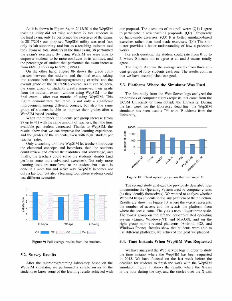
The first study from the Web Server logs analyzed theproportions of computer clients requests that came from theUC3M University or from outside the University. Duringthe last week for the laboratory dead-line, the WepSIMsimulator has been used a 7% with IP address from theUniversity,
1
10
100
1000
10000
Windows-
NT
Linux
MacO
S
Andro
id
iOS-iPad
iOS-iPhone
Windows-
Phone
nu
mb
er
of
use
rs
Figure 10: Client operating systems that use WepSIM.
The second study analyzed the previously described logsto determine the Operating System used by computer clients(as they identify themselves). We wanted to analyze whetherWepSIM helps students to use any platform of their election.Results are shown in Figure 10, where the y-axis representsthe number of access and the x-axis the platform fromwhere the access came. The y-axis uses a logarithmic scale.The x-axis group on the left the desktop-related operatingsystem (Linux, Windows-NT, and MacOS), and on theright group mobile-related platforms (Android, iOS, andWindows Phone). Results show that students were able touse different platforms, we achieved the goal we planned.
5.4. Time Instants When WepSIM Was Requested
We have analyzed the Web service logs in order to studythe time instants where the WepSIM has been requestedin 2013. We have focused on the last week before thedeadline for students to finish the work with the WepSIMsimulator. Figure 11 shows the results, where the X-axisis the hour during the day, and the circles over the X-axis
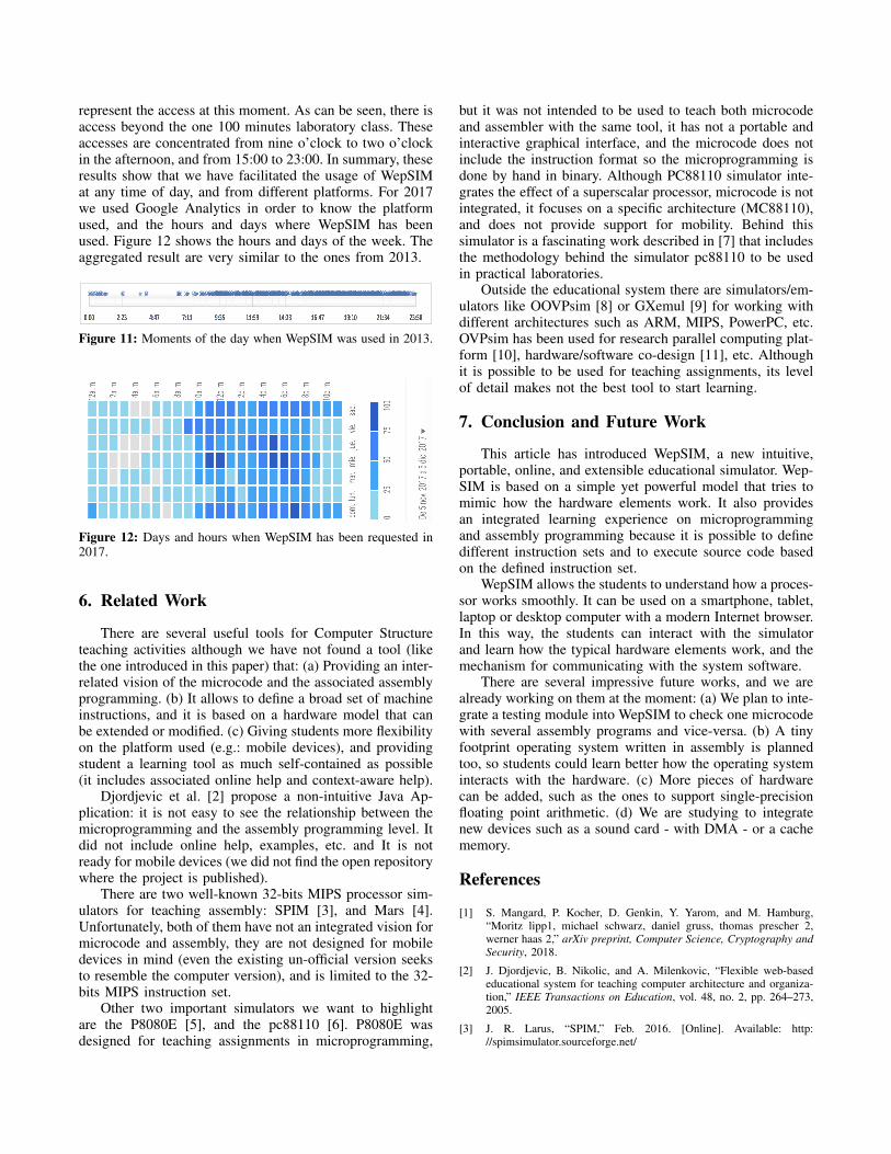
represent the access at this moment. As can be seen, there isaccess beyond the one 100 minutes laboratory class. Theseaccesses are concentrated from nine o’clock to two o’clockin the afternoon, and from 15:00 to 23:00. In summary, theseresults show that we have facilitated the usage of WepSIMat any time of day, and from different platforms. For 2017we used Google Analytics in order to know the platformused, and the hours and days where WepSIM has beenused. Figure 12 shows the hours and days of the week. Theaggregated result are very similar to the ones from 2013.
Figure 11: Moments of the day when WepSIM was used in 2013.
Figure 12: Days and hours when WepSIM has been requested in2017.
6. Related Work
There are several useful tools for Computer Structureteaching activities although we have not found a tool (likethe one introduced in this paper) that: (a) Providing an inter-related vision of the microcode and the associated assemblyprogramming. (b) It allows to define a broad set of machineinstructions, and it is based on a hardware model that canbe extended or modified. (c) Giving students more flexibilityon the platform used (e.g.: mobile devices), and providingstudent a learning tool as much self-contained as possible(it includes associated online help and context-aware help).
Djordjevic et al. [2] propose a non-intuitive Java Ap-plication: it is not easy to see the relationship between themicroprogramming and the assembly programming level. Itdid not include online help, examples, etc. and It is notready for mobile devices (we did not find the open repositorywhere the project is published).
There are two well-known 32-bits MIPS processor sim-ulators for teaching assembly: SPIM [3], and Mars [4].Unfortunately, both of them have not an integrated vision formicrocode and assembly, they are not designed for mobiledevices in mind (even the existing un-official version seeksto resemble the computer version), and is limited to the 32-bits MIPS instruction set.
Other two important simulators we want to highlightare the P8080E [5], and the pc88110 [6]. P8080E wasdesigned for teaching assignments in microprogramming,
but it was not intended to be used to teach both microcodeand assembler with the same tool, it has not a portable andinteractive graphical interface, and the microcode does notinclude the instruction format so the microprogramming isdone by hand in binary. Although PC88110 simulator inte-grates the effect of a superscalar processor, microcode is notintegrated, it focuses on a specific architecture (MC88110),and does not provide support for mobility. Behind thissimulator is a fascinating work described in [7] that includesthe methodology behind the simulator pc88110 to be usedin practical laboratories.
Outside the educational system there are simulators/em-ulators like OOVPsim [8] or GXemul [9] for working withdifferent architectures such as ARM, MIPS, PowerPC, etc.OVPsim has been used for research parallel computing plat-form [10], hardware/software co-design [11], etc. Althoughit is possible to be used for teaching assignments, its levelof detail makes not the best tool to start learning.
7. Conclusion and Future Work
This article has introduced WepSIM, a new intuitive,portable, online, and extensible educational simulator. Wep-SIM is based on a simple yet powerful model that tries tomimic how the hardware elements work. It also providesan integrated learning experience on microprogrammingand assembly programming because it is possible to definedifferent instruction sets and to execute source code basedon the defined instruction set.
WepSIM allows the students to understand how a proces-sor works smoothly. It can be used on a smartphone, tablet,laptop or desktop computer with a modern Internet browser.In this way, the students can interact with the simulatorand learn how the typical hardware elements work, and themechanism for communicating with the system software.
There are several impressive future works, and we arealready working on them at the moment: (a) We plan to inte-grate a testing module into WepSIM to check one microcodewith several assembly programs and vice-versa. (b) A tinyfootprint operating system written in assembly is plannedtoo, so students could learn better how the operating systeminteracts with the hardware. (c) More pieces of hardwarecan be added, such as the ones to support single-precisionfloating point arithmetic. (d) We are studying to integratenew devices such as a sound card - with DMA - or a cachememory.
References
[1] S. Mangard, P. Kocher, D. Genkin, Y. Yarom, and M. Hamburg,“Moritz lipp1, michael schwarz, daniel gruss, thomas prescher 2,werner haas 2,” arXiv preprint, Computer Science, Cryptography andSecurity, 2018.
[2] J. Djordjevic, B. Nikolic, and A. Milenkovic, “Flexible web-basededucational system for teaching computer architecture and organiza-tion,” IEEE Transactions on Education, vol. 48, no. 2, pp. 264–273,2005.
[3] J. R. Larus, “SPIM,” Feb. 2016. [Online]. Available: http://spimsimulator.sourceforge.net/
[4] P. Sanderson and K. Vollmar, “MARS,” Feb. 2016. [Online].Available: http://courses.missouristate.edu/kenvollmar/mars/
[5] DATSI.FI.UPM.ES, “P8080E,” Apr. 2016. [Online]. Available:http://www.datsi.fi.upm.es/docencia/Estructura/U Control/
[6] M. I. Garca, S. Rodrguez, A. Prez, and A. G. Dopico, “p88110:A graphical simulator for computer architecture and organizationcourses.” IEEE Trans. Education, vol. 52, no. 2, pp. 248–256, 2009.
[7] A. G. Dopico, S. R. de la Fuente, and F. J. R. Garca, “Automatizacionde practicas en entornos masificados,” in Actas de las IX Jornadasde Enseanza universitaria de la Informatica, ser. Jenui 2003. Spain:Thomson-Paraninfo, 2003, pp. 119–126.
[8] I. Software, “Open Virtual Platforms simulator,” Mar. 2016. [Online].Available: http://www.ovpworld.org/
[9] A. Gavare, “GXemul,” Mar. 2016. [Online]. Available: http://gxemul.sourceforge.net/
[10] C. Pinto, S. Raghav, A. Marongiu, M. Ruggiero, D. Atienza,and L. Benini, “Gpgpu-accelerated parallel and fast simulation ofthousand-core platforms.” in The 11th International Symposium onCluster, Cloud and Grid Computing. IEEE Computer Society, 2011,pp. 53–62.
[11] I. Nita, V. Lazarescu, and R. Constantinescu, “A new Hw/Sw co-design method for multiprocessor system on chip applications.” inProceedings of the 5th IEEE/ACM International Conference on Hard-ware/Software Codesign and system Synthesis. IEEE C.S., 2009, pp.1–4.
[12] J. Matak, “Assembly Emulator,” Feb. 2016. [Online].Available: https://play.google.com/store/apps/details?id=gr.ntua.ece.assembly.emulator
[13] F. G. Carballeira, J. C. Perez, J. D. G. Sanchez, and D. E. Singh,Problemas resueltos de estructura de computadores, segunda edicion.Ediciones Paraninfo, 2015, vol. 1, pp. 1–307.
[14] J. M. Perez Villadeamigo, S. R. de la Fuente, R. M. Cavanillas,and M. I. Garcıa Clemente, “The em88110: Emulating a superscalarprocessor,” SIGCSE Bull., vol. 29, no. 4, pp. 45–50, Dec. 1997.
[15] S. S. et al, “From NAND to Tetris,” Nov. 2016. [Online]. Available:http://www.nand2tetris.org/
[16] J. N. et al, “The Megaprocessor,” Nov. 2016. [Online]. Available:http://www.megaprocessor.com/