web interface and command line reference guide 6622-3201
TRANSCRIPT

MR-250, DR-250MR-200
3G Router ADSL Router GPRS Router
www.westermo.com
Web Interface andCommand LineReference Guide
6622-3201

2 6622-3201
Web Interface and Command Line Reference Guidewww.westermo.com
Legal informationThe contents of this document are provided “as is”. Except as required by applicable law, no war-ranties of any kind, either express or implied, including, but not limited to, the implied warranties of merchantability and fitness for a particular purpose, are made in relation to the accuracy and reli-ability or contents of this document. Westermo reserves the right to revise this document or with-draw it at any time without prior notice.
Under no circumstances shall Westermo be responsible for any loss of data or income or any spe-cial, incidental, and consequential or indirect damages howsoever caused.
More information about Westermo can be found at the following Internet address:
www.westermo.com

36622-3201
Web Interface and Command Line Reference Guide www.westermo.com
Typographical Conventions 1.
Throughout this manual certain typographical conventions are used as follows:
Text Type Meaning
Text like this is standard text.
Note: Text like this
indicates points that are of particular importance.
Text like this indicates commands entered by the user at the command line.
Text like this indicates responses from the unit to commands you enter at the com-mand line.
Configure > Save refers to the unit’s web-based menu system.
4 6622-3201
Web Interface and Command Line Reference Guidewww.westermo.com
Table of Contents
1. ...........................................Typographical Conventions ................................................... 3
2............................................Using the Web Interface ....................................................... 12
2.1 ..............................................Access Via a LAN Port ............................................................................. 12
2.2 ..............................................Access Via a Serial Port ............................................................................ 12
2.2.1 ................................... Installing the Driver File ........................................................................... 13
2.2.2 ...................................Creating A New Dial-Up Network Connection ................................ 17
2.2.3 ...................................Configuring the New DUN Connection .............................................. 20
2.2.4 ................................... Initiating a DUN Connection .................................................................. 22
3............................................Using the command line interface ...................................... 24
3.1 .............................................. The “AT” Command Interface ............................................................... 24
3.1.1 ...................................Command Prefix ........................................................................................ 24
3.1.2 ...................................The Escape Sequence ................................................................................ 25
3.1.3 ...................................Result Codes ............................................................................................... 25
3.1.4 ................................... “S” Registers ............................................................................................... 25
3.2 ..............................................Westermo Application Commands ....................................................... 26
3.2.1 ................................... The Reboot Command ............................................................................ 26
3.2.2 ...................................The Active Port .......................................................................................... 27
3.3 .............................................. Establishing a Remote Connection ........................................................ 27
4............................................Configuring your unit ............................................................ 28
4.1 .............................................. Logging In ..................................................................................................... 28
4.2 ..............................................Configuring and Testing W-WAN Models ............................................ 30
4.2.1 ................................... Signal Strength Indicators ......................................................................... 30
4.3 ..............................................The Configuration Pages .......................................................................... 31
4.4 ..............................................Configure > ADAPT > ADAPT n ........................................................... 32
4.5 ..............................................Configure > Analyser ................................................................................ 35
4.6 ..............................................Configure > ASY Ports > ASY Port n ................................................... 42
4.7 ..............................................Configure > TRANSIP ASY Ports ........................................................... 45
4.8 ..............................................Configure > Backup IP Addresses .......................................................... 47
4.9 ..............................................Configure > Basic ....................................................................................... 48
4.10 ............................................Configure > BGP ........................................................................................ 49
4.11 ............................................Configure > Certificates > Certificate request .................................. 59
4.12 ............................................Configure > Certificates > SCEP ........................................................... 61
4.13 ............................................Configure > Certificates > Utilities ....................................................... 63
4.14 ............................................Configure > Calling Numbers ................................................................. 65
4.15 ............................................Configure > Command Filters ................................................................ 66
4.16 ............................................Configure > Command Mappings .......................................................... 67
4.17 ............................................Configure > DHCP Servers > Ethernet Port n ................................. 68
4.18 ............................................Configure > DHCP Options > DHCP option n ................................ 71
4.19 ............................................Configure > DHCP Server > MAC –>IP Addresses ......................... 72
4.20 ............................................Configure > DNS Server selection > DNS server selection n ...... 73
4.21 ............................................Configure > DNS Server Update .......................................................... 75
4.22 ............................................Configure > DSL > ADSL ........................................................................ 78
4.23 ............................................Configure > DSL > ATM PVCs > PVC n ............................................. 80
4.24 ............................................Configure > Dynamic DNS ..................................................................... 82
4.25 ............................................Configure > Ethernet > ETH n .............................................................. 84
4.26 ............................................Configure > Ethernet > ETH n > QOS ............................................... 93
4.27 ............................................Configure > Ethernet > ETH n > VRRP Probing ............................... 95
4.28 ............................................Configure > Ethernet > MAC Filters .................................................... 97
56622-3201
Web Interface and Command Line Reference Guide www.westermo.com
4.29 ............................................Configure > Ethernet > VLANs .............................................................. 98
4.30 ............................................Configure > Event Handler ...................................................................100
4.31 ............................................Configure > Event Logcodes .................................................................105
4.31.1 .................................Configuring Events ...................................................................................105
4.31.2 .................................Configuring Reasons ................................................................................107
4.32 ............................................Configure > Firewall ................................................................................109
4.33 ............................................Configure > Firewall Options ...............................................................111
4.34 ............................................Configure > FTP Client ..........................................................................113
4.35 ............................................Configure > FTP Relay Agents > RELAY n ........................................114
4.36 ............................................Configure > General ...............................................................................117
4.37 ............................................Configure > IP Routes > RIP > RIP update options .......................125
4.38 ............................................Configure > IP Routes > RIP > RIP access list .................................126
4.39 ............................................Configure > IP Routes > Route n ........................................................127
4.40 ............................................Configure > IP Routes > RIP > Authentication keys > Key n .......131
4.41 ............................................Configure > IP Routes > Default Route n .........................................133
4.42 ............................................Configure > IPSec ....................................................................................133
4.43 ............................................Configure > IPSec > DPD .....................................................................134
4.44 ............................................Configure > IPSec > IKE > MODECFG > Static NAT Mappings .136
4.45 ............................................Configure > IPSec > IKE > IKE n .........................................................138
4.46 ............................................Configure > IPSec > IKE > Responder ...............................................141
4.47 ............................................Configure > IPSec > IKEv2 > IKEv2 n ................................................146
4.48 ............................................Configure > IPSec > IKEv2 > Responder ..........................................148
4.49 ............................................Configure > IPSec > IPSec Egroups > Egroup n ...............................150
4.50 ............................................Configure > IPSec > IPSec Eroutes > Eroute n ................................155
4.50.1 ................................. Setting up Eroutes for Multiple Users ................................................163
4.51 ............................................Configure > IPSec > Default Eroute ...................................................164
4.52 ............................................Configure > ISDN LAPB > LAPB n .....................................................165
4.53 ............................................Configure > ISDN LAPD > LAPD n ...................................................168
4.54 ............................................Configure > L2TP > L2TP n .................................................................171
4.55 ............................................Configure > OSPF ....................................................................................174
4.56 ............................................Configure > PPP .......................................................................................177
4.57 ............................................Configure > PPP > MLPPP .....................................................................178
4.58 ............................................Configure > PPP > External Modems > External Modem n .........181
4.59 ............................................Configure > PPP > Sub-Configs > Sub-Config n ..............................183
4.60 ............................................Configure > PPP > PPP n > Standard .................................................184
4.61 ............................................Configure > PPP > PPP n > Advanced ................................................192
4.62 ............................................Configure > PPP > PPP n > PPP/IP Over X25 .................................200
4.63 ............................................Configure > PPP > PPP n > QOS ........................................................202
4.64 ............................................Configure > PPTP ....................................................................................204
4.65 ............................................Configure > Protocol Bindings .............................................................206
4.65.1 .................................Binding TANS to ADAPT ........................................................................206
4.66 ............................................Configure > Protocol Switch ................................................................207
4.67 ............................................Configure > Protocol Switch > CUD Mappings ..............................215
4.68 ............................................Configure > Protocol Switch > NUA Mappings ...............................216
4.69 ............................................Configure > PSTN Modem ....................................................................217
4.70 ............................................Configure > Quality of Service ............................................................218
4.70.1 ................................. Introduction ...............................................................................................218
4.70.2 .................................Basic Operation ........................................................................................218
4.71 ............................................Configure > Quality of Service > DSCP Mappings ..........................220
4.72 ............................................Configure > Quality of Service > Q Profiles > Q Profile n ..........221
4.73 ............................................Configure > RADIUS client ...................................................................223
4.74 ............................................Configure > SMS Edit ..............................................................................226
4.75 ............................................Configure > SMTP ...................................................................................227
4.76 ............................................Configure > SNAIP > SNAIP n ............................................................229

6 6622-3201
Web Interface and Command Line Reference Guidewww.westermo.com
4.77 ............................................Configure >SNMP ....................................................................................235
4.78 ............................................Configure >SNMP Filters .......................................................................237
4.79 ............................................Configure >SNMP > Trap Servers > Trap Server n .........................238
4.80 ............................................Configure >SNMP > Users > User n .................................................240
4.81 ............................................Configure > STP .......................................................................................242
4.82 ............................................Configure > NTP .....................................................................................244
4.83 ............................................Configure > SNTP ...................................................................................246
4.84 ............................................Configure > SSH server .........................................................................248
4.84.1 .................................Complete SSH Configuration ...............................................................251
4.84.2 ................................. SSH Authentication with a public/private keypair. ............................252
4.85 ............................................Configure > SSL clients > SSL Client n ..............................................253
4.86 ............................................Configure > SSL server ..........................................................................254
4.87 ............................................Configure > Static Multicast Routes ...................................................255
4.88 ............................................Configure > Static NAT Mappings .......................................................256
4.89 ............................................Configure > SYNC Ports > SYNC n ..................................................258
4.90 ............................................Configure > Syslog Clients > Syslog n ................................................259
4.91 ............................................Configure > System Messages ..............................................................261
4.92 ............................................Configure > TACACS+ ...........................................................................262
4.93 ............................................Configure > TANS > TANS n ................................................................264
4.94 ............................................Configure > Time .....................................................................................267
4.95 ............................................Configure > Time Bands > Time Band n ............................................268
4.96 ............................................Configure > TPAD > TPAD Statistics ..................................................270
4.97 ............................................Configure > TPAD > TPAD n ...............................................................271
4.98 ............................................Configure > Tunnel (GRE) .....................................................................280
4.99 ............................................Configure > UDP Echo Client/Server > UDP Echo n ....................283
4.100 .........................................Configure > Users > User n .................................................................285
4.101 .........................................Configure > VXN client ..........................................................................288
4.102 .........................................Configure > W-WAN ..............................................................................291
4.102.1 ...............................Additional Configuration for wireless .................................................296
4.103 .........................................Configure > W-WAN module > Cell Monitor .................................297
4.104 .........................................Configure > X25 > NUI Mappings ......................................................299
4.105 .........................................Configure > X25 ......................................................................................300
4.106 .........................................Configure > X25 > Macros ...................................................................302
4.107 .........................................Configure > X25 > IP–>X25 Calls ......................................................303
4.108 .........................................Configure > X25 > NUA/NUI–>Interface ........................................306
4.109 .........................................Configure > X25 > PADs > PAD n .....................................................308
4.110 .........................................Configure > X25 > PADs > PAD n > Parameters ..........................313
4.110.1 ............................... PAD Recall Character .............................................................................313
4.110.2 ............................... Echo .............................................................................................................313
4.110.3 ...............................Data Forwarding Characters .................................................................313
4.110.4 ............................... Idle Timer Delay .......................................................................................314
4.110.5 ...............................Ancillary Device Control .......................................................................314
4.110.6 ............................... Suppression of PAD Service Signals ....................................................314
4.110.7 ...............................Action on Break (from DTE) ................................................................314
4.110.8 ...............................Discard Output ........................................................................................315
4.110.9 ............................... Padding after CR ......................................................................................315
4.110.10 ............................. Line Folding ...............................................................................................315
4.110.11 ............................. Port Speed .................................................................................................315
4.110.12 ............................. Flow Control of PAD (by DTE) ...........................................................315
4.110.13 ............................. LF Insertion (after CR) ...........................................................................316
4.110.14 ............................. LF Padding ..................................................................................................316
4.110.15 ............................. Editing .........................................................................................................316
4.110.16 .............................Character Delete Character .................................................................316
4.110.17 ............................. Line Delete Character ............................................................................316
76622-3201
Web Interface and Command Line Reference Guide www.westermo.com
4.110.18 ............................. Line Redisplay Character .......................................................................316
4.110.19 ............................. Editing PAD Service Signals ...................................................................317
4.110.20 ............................. Echo Mask ..................................................................................................317
4.110.21 ............................. Parity Treatment .......................................................................................317
4.110.22 ............................. Page Wait ...................................................................................................318
4.111 .........................................Configure > X25 > PVCs > PVC n .....................................................319
4.112 ......................................... Saving Configuration Settings. ...............................................................321
4.112.1 ...............................Config Files ................................................................................................321
4.112.2 ............................... SREGS.DAT ................................................................................................321
4.112.3 ............................... PWDS.DA0 ................................................................................................321
4.112.4 ............................... Factory Reset ............................................................................................322
4.112.5 ...............................Universal config.da0 using tags .............................................................322
5............................................ Statistics Pages .................................................................... 324
5.1 .............................................. Statistics > ATM PVCs > PVC n ...........................................................325
5.2 .............................................. Statistics > ADAPT > ADAPT n ...........................................................325
5.3 .............................................. Statistics > ADSL ......................................................................................326
5.4 .............................................. Statistics > ASY Ports .............................................................................326
5.5 .............................................. Statistics > DNS Update ........................................................................327
5.6 .............................................. Statistics > Ethernet > ETH n ..............................................................328
5.7 .............................................. Statistics > Ethernet > ETH n > QOS ...............................................329
5.8 .............................................. Statistics > Firewall ..................................................................................330
5.9 .............................................. Statistics > W-WAN Port ......................................................................330
5.10 ............................................ Statistics > IP .............................................................................................331
5.11 ............................................ Statistics > PPP > PPP n .........................................................................332
5.11.1 ................................. PPP n Stats .................................................................................................332
5.11.2 .................................Transaction Stats ......................................................................................333
5.12 ............................................ Statistics > PPP > PPP n > QOS ..........................................................333
5.13 ............................................ Statistics > SYNC Channels ..................................................................334
5.13.1 ................................. ISDN D Channel ......................................................................................334
5.13.2 ................................. ISDN B1 Channel .....................................................................................335
5.13.3 ................................. ISDN B2 Channel .....................................................................................335
5.13.4 ................................. Physical Port 0 ..........................................................................................336
5.14 ............................................ Statistics > TPAD > TPAD n ..................................................................336
5.14.1 .................................TPAD Stats ................................................................................................336
5.14.2 ................................. Layer 3 X25 Stats .....................................................................................338
5.14.3 ................................. Layer 2 LAPB Stats ..................................................................................338
5.14.4 ................................. Layer 1 B1 Sync Stats ..............................................................................339
5.14.5 ................................. Layer 2 LAPD Stats .................................................................................340
5.14.6 .................................D Channel Stats .......................................................................................340
5.14.7 ................................. Layer 1 D Sync Stats ...............................................................................341
5.15 ............................................ Statistics > X25 PADs > PAD n ..........................................................342
5.15.1 ................................. Layer 3 X25 Stats .....................................................................................342
5.15.2 ................................. Layer 2 LAPD Stats .................................................................................342
5.15.3 .................................D Channel Stats .......................................................................................343
5.15.4 ................................. Layer 1 D Sync Stats ...............................................................................343
6............................................ Status Pages ........................................................................ 344
6.1 .............................................. Status > Analyser Trace ...........................................................................344
6.2 .............................................. Status > PCAP traces .............................................................................344
6.3 .............................................. Status > DHCP Server ...........................................................................345
6.4 .............................................. Status > Ethernet > ETH n ...................................................................346
6.5 .............................................. Status > Ethernet > ETH n > QOS ....................................................347
6.6 .............................................. Status > Event log ....................................................................................347
8 6622-3201
Web Interface and Command Line Reference Guidewww.westermo.com
6.7 .............................................. Status > File Directory ...........................................................................347
6.8 .............................................. Status > Firmware Versions ...................................................................348
6.9 .............................................. Status > W-WAN Module ......................................................................348
6.10 ............................................ Status > W-WAN Module > Neighbour Cells ..................................352
6.11 ............................................ Status > W-WAN Module > Serving Cell ..........................................353
6.12 ............................................ Status > W-WAN Module > W-WAN Cell Information ................355
6.13 ............................................ Status > IGMP Groups ...........................................................................357
6.14 ............................................ Status > IPSec > IPSec Peers .................................................................357
6.15 ............................................ Status > IPSec > IKE SAs .......................................................................358
6.16 ............................................ Status > IPSec > IPSec SAs > Dynamic tunnels ...............................358
6.17 ............................................ Status > IPSec > IPSec SAs > Eroute n ..............................................359
6.18 ............................................ Status > ISDN BRI ...................................................................................360
6.19 ............................................ Status > Web Directory .........................................................................360
6.20 ............................................ Status > Web Server ...............................................................................360
6.21 ............................................ Status > X.25 Sessions ...........................................................................361
7............................................ The Filing System ............................................................... 362
7.1 .............................................. System Files ...............................................................................................362
7.2 .............................................. Filing System Commands .......................................................................362
7.2.1 ...................................COPY Copy File .......................................................................................362
7.2.2 ...................................DEL Delete File ........................................................................................362
7.2.3 ...................................DIR List File Directory ............................................................................363
7.2.4 ................................... FLOCK Lock Files ...................................................................................363
7.2.5 ................................... FUNLOCK Unlock Files ........................................................................363
7.2.6 ...................................MOVE Move File ......................................................................................363
7.2.7 ...................................REN Rename File .....................................................................................363
7.2.8 ................................... SCAN/SCANR Scan File System ..........................................................364
7.2.9 ................................... TYPE Display Text File ...........................................................................364
7.2.10 .................................XMODEM File Transfer ..........................................................................364
7.3 ..............................................USB Support .............................................................................................365
7.3.1 ................................... SD Memory Card Support ....................................................................365
7.3.2 ...................................Batch Control Commands .....................................................................365
7.3.3 ...................................USB Filing System Commands ..............................................................365
7.3.4 ...................................Using USB devices to upgrade firmware ............................................366
7.3.5 ...................................Using USB devices with .all files ...........................................................366
7.3.6 ...................................USB Security .............................................................................................366
7.3.7 ...................................Disable/Enable the USB ports ...............................................................367
8............................................ SQL Commands .................................................................. 369
9............................................Using V.120 ........................................................................... 372
9.1 .............................................. Initial Set Up ..............................................................................................372
9.2 .............................................. Initiating a V.120 Call ...............................................................................372
9.3 ..............................................Answering V.120 Calls .............................................................................373
10 .........................................Answering ISDN Calls ......................................................... 374
10.1 ............................................ Protocol Entities .......................................................................................374
10.2 ............................................Multiple Subscriber Numbers ...............................................................375
10.3 ............................................Multiple PPP Instances ............................................................................375
11 .........................................X.25 Packet Switching ........................................................ 376
11.1 ............................................ Introduction ...............................................................................................376
11.2 ............................................B-channel X.25 .........................................................................................376
96622-3201
Web Interface and Command Line Reference Guide www.westermo.com
11.3 ............................................D-channel X.25 .........................................................................................376
11.4 ............................................X.28 Commands ......................................................................................377
11.4.1 .................................CALL Make an X.25 Call .......................................................................377
11.4.2 .................................Aborting a CALL ......................................................................................379
11.4.3 .................................CLR Clear an X.25 Call .........................................................................381
11.4.4 ................................. ICLR Invitation To CLR ...........................................................................381
11.4.5 ................................. INT Send Interrupt Packet ....................................................................381
11.4.6 ................................. LOG Logoff and Disconnect .................................................................381
11.4.7 ................................. PAR? List Local X.3 Parameters ...........................................................381
11.4.8 ................................. PROF Load/Save PAD Profile ................................................................382
11.4.9 .................................RESET Send Reset Packet ......................................................................383
11.4.10 ...............................RPAR? Read Remote X.3 Parameters .................................................383
11.4.11 ...............................RSET Set Remote X.3 Parameters ......................................................383
11.4.12 ............................... SET Set Local X.3 Parameters ..............................................................383
12 .........................................PPP Over Ethernet ............................................................. 384
13 ......................................... IPSEC and VPNs .................................................................. 385
13.1 ............................................What is IPSec? ..........................................................................................385
13.2 ............................................Data Encryption Methods ......................................................................385
13.2.1 .................................DES (64-bit key) .......................................................................................385
13.2.2 .................................DES (192-bit key) .....................................................................................386
13.2.3 .................................AES (128-bit key) .....................................................................................386
13.3 ............................................What is a VPN? .........................................................................................386
13.4 ............................................The Benefits of IPSec ..............................................................................386
13.5 ............................................X.509 Certificates ....................................................................................387
14 .........................................The Event Log ...................................................................... 389
14.1 ............................................What is the Event Log? ..........................................................................389
14.2 ............................................The LOGCODES.TXT File ...................................................................390
14.2.1 ................................. Event Blocks .............................................................................................391
14.2.2 .................................Reason Blocks ...........................................................................................391
14.2.3 ................................. Editing the File ..........................................................................................391
15 ......................................... Firewall Scripts .................................................................... 392
15.1 ............................................ Introduction ...............................................................................................392
15.2 ............................................ Firewall Script Syntax ..............................................................................392
15.2.1 ................................. Labels ..........................................................................................................392
15.2.2 .................................Comments .................................................................................................392
15.2.3 ................................. Filter Rules .................................................................................................393
15.3 ............................................ Specifying IP Addresses and Ranges .....................................................397
15.4 ............................................Address/Port Translation ........................................................................398
15.5 ............................................ Filtering on Port Numbers ....................................................................398
15.6 ............................................ Filtering on TCP Flags .............................................................................400
15.7 ............................................ Filtering on ICMP Codes .......................................................................401
15.8 ............................................ Stateful Inspection ....................................................................................402
15.8.1 .................................Using [inspect-state] with Flags ............................................................403
15.8.2 .................................Using [inspect-state] with ICMP ..........................................................403
15.8.3 .................................Using [inspect-state] with the Out Of Service Option ..................404
15.8.4 .................................Using [inspect-state] with the Stat Option .......................................405
15.8.5 .................................Assigning DSCP Values ............................................................................405
15.9 ............................................The FWLOG.TXT File ...........................................................................406
15.9.1 ................................. Log File Examples .....................................................................................407
10 6622-3201
Web Interface and Command Line Reference Guidewww.westermo.com
15.10 ......................................... Further [inspect-state] Examples .........................................................408
15.11 .........................................Debugging a Firewall ...............................................................................410
16 .........................................Remote Management .......................................................... 411
16.1 ............................................Using V.120 .................................................................................................411
16.2 ............................................Using Telnet ...............................................................................................411
16.3 ............................................Using FTP ...................................................................................................411
16.3.1 ................................. FTP under Windows ...............................................................................412
16.3.2 ................................. FTP under DOS .......................................................................................412
16.4 ............................................Using X.25 .................................................................................................412
17 .........................................AT Commands ..................................................................... 413
17.1 ............................................D Dial .........................................................................................................413
17.1.1 .................................Dialling with a Specified Sub-Address .................................................413
17.1.2 .................................Dialling Stored Numbers .......................................................................413
17.1.3 .................................Combining ISDN and X.25 Calls .........................................................413
17.2 ............................................H Hang-up ................................................................................................413
17.3 ............................................Z Reset .....................................................................................................413
17.4 ............................................&C DCD Control ....................................................................................414
17.5 ............................................&F Load Factory Settings .......................................................................414
17.6 ............................................&R CTS Control ......................................................................................414
17.7 ............................................&V View Profiles .......................................................................................414
17.8 ............................................&W Write SREGS.DAT ..........................................................................415
17.9 ............................................&Y Set Default Profile .............................................................................415
17.10 .........................................&Z Store Phone Number ......................................................................415
17.11 ......................................... \AT Ignore Invalid AT Commands ........................................................416
17.12 ......................................... \LS Lock Speed .........................................................................................416
17.13 ......................................... \PORT Set Active Port ............................................................................416
17.14 ......................................... \smib Commands .....................................................................................417
17.14.1 ............................... System .........................................................................................................417
17.14.2 ............................... Interfaces ....................................................................................................418
17.14.3 ............................... IP ..................................................................................................................419
18 ......................................... “S” Registers ........................................................................ 421
18.1 ............................................ S0 V.120 Answer Enabled ........................................................................421
18.2 ............................................ S1 Ring count ............................................................................................421
18.3 ............................................ S2 Escape Character ...............................................................................422
18.4 ............................................ S12 Escape Delay .....................................................................................422
18.5 ............................................ S15 Data Forwarding Timer ..................................................................422
18.6 ............................................ S23 Parity ...................................................................................................422
18.7 ............................................ S31 ASY Interface Speed ........................................................................422
18.8 ............................................ S33 DTR Dialling ......................................................................................423
18.9 ............................................ S45 DTR Loss De-Bounce .....................................................................423
19 .........................................General System Commands .............................................. 424
19.1 ............................................CONFIG Show/Save Configuration .....................................................424
19.2 ............................................Config changes counter ..........................................................................424
19.3 ............................................REBOOT Reboot Unit ...........................................................................425
19.4 ............................................Reset router to factory defaults ..........................................................425
19.5 ............................................Disabling the reset button .....................................................................425
19.6 ............................................TEMPLOG Temperature monitoring ...................................................425
19.7 ............................................ADSL ...........................................................................................................426
19.8 ............................................ Ping and Traceroute .................................................................................426
116622-3201
Web Interface and Command Line Reference Guide www.westermo.com
20 .........................................TCPPERM and TCPDIAL ................................................... 427
20.1 ............................................TCPPERM ..................................................................................................427
20.2 ............................................TCPDIAL ...................................................................................................428
20.2.1 .................................Aborting TCPDIAL ..................................................................................428
21 ......................................... Serial Port Connections ...................................................... 429
21.1 ............................................MR-200, MR-250, DR-250 .......................................................................429
21.1.1 ................................. Port Pin-Outs ............................................................................................429
21.1.2 .................................X.21 25-Pin to 15-Pin Straight Through Cable – Internal Clock ..430
21.1.3 .................................X.21 25-Pin to 15-Pin Straight Through Cable – External Clock 431
21.1.4 .................................X.21 25-Pin to 15-Pin Crossover Cable – Internal Clock .............432
21.1.5 .................................X.21 25-Pin to 15-Pin Crossover Cable – External Clock ............433
21.2 ............................................RS-232 (V.24) Serial Cable Wiring .......................................................434
22 .........................................LOGCODES.TXT ................................................................ 439
23 .........................................Email Templates ................................................................... 453
23.1 ............................................Template Structure ..................................................................................453
23.1.1 .................................The Header Section ................................................................................453
23.1.2 .................................Other Fields ..............................................................................................453
23.1.3 .................................Body Section .............................................................................................454
24 .........................................Glossary ................................................................................ 456
12 6622-3201
Web Interface and Command Line Reference Guidewww.westermo.com
Using the Web Interface2
To access the built-in web pages using a web browser (e.g. Internet Explorer), there are two options.
Access Via a LAN Port 2.1
To access the unit through a LAN port you should assign your PC an IP address on the 192.168.0.0/ 24 network (for example use an IP address of 192.168.0.1 and a mask of 255.255.255.0).
Next, either connect an Ethernet crossover cable between the LAN ports on your router and PC, or ensure that both devices are connected to an Ethernet hub/switch on the same network. You should then be able to access the unit’s web, Telnet and FTP services on the IP address 192.168.0.99.
Note: All models are auto-sensing for 10/100 operation. All models are also auto MDI/MDX, i.e. will auto matically work with either a straight-through or cross-over cable.
Access Via a Serial Port 2.2
To access the web interface through one of the unit’s serial ports (using Windows dial-up network-ing) follow the steps below.
Note: To use Dial-up Networking you must have the TCP/IP > Dial-up adapter installed in the Network Con figuration for Windows. Check this by selecting Settings > Control Panel > Network > Configuration.

136622-3201
Web Interface and Command Line Reference Guide www.westermo.com
Installing the Driver File 2.2.1
You will need to install the “Westermo_Multi_Port.inf” driver file and create a Windows PPP Dial up Networking connection (DUN) for the unit as described below. It is assumed that you already have a basic knowledge of Windows networking concepts and terminology.
The precise procedure for installing the .inf driver file for the unit will vary slightly between differ-ent ver sions of Windows. The following description applies to Windows XP.
1. Start by selecting Start > Control Panel > Phone and Modem Options. You must be in Classic View. Select the Modems tab and you will see a dialog similar to the following:
2. Click on Add to install a new modem driver:
14 6622-3201
Web Interface and Command Line Reference Guidewww.westermo.com
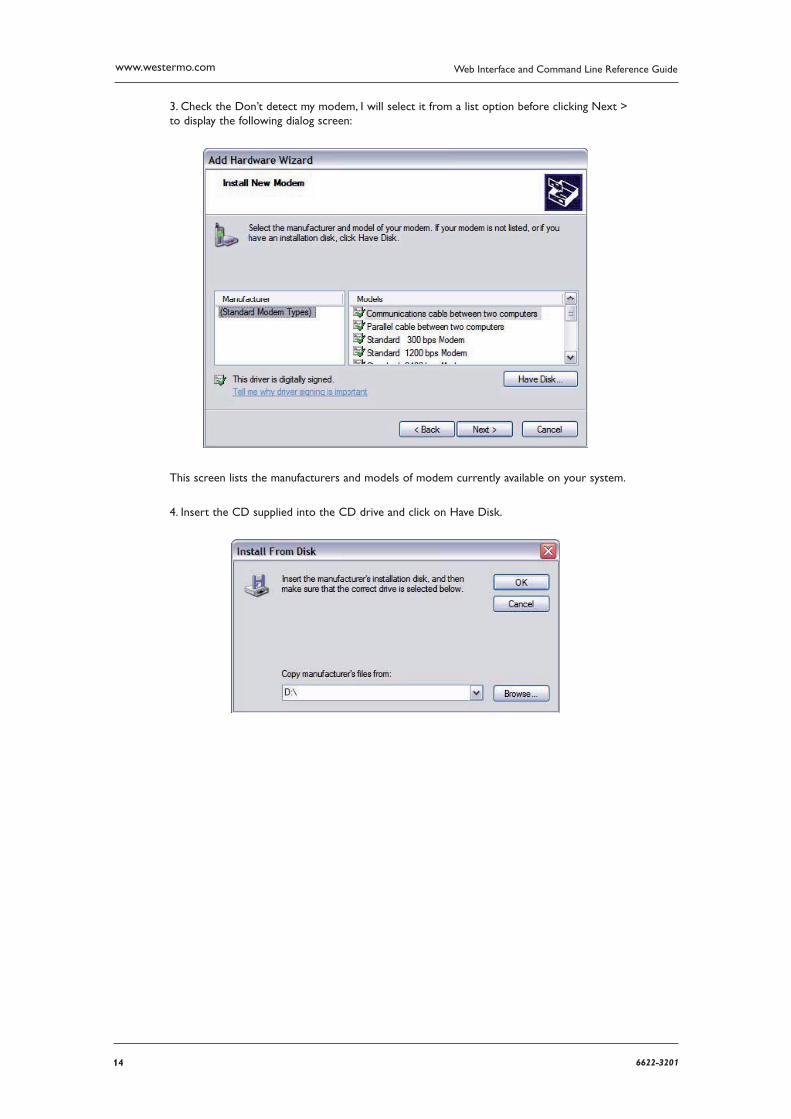
3. Check the Don’t detect my modem, I will select it from a list option before clicking Next > to display the following dialog screen:
This screen lists the manufacturers and models of modem currently available on your system.
4. Insert the CD supplied into the CD drive and click on Have Disk.
156622-3201
Web Interface and Command Line Reference Guide www.westermo.com
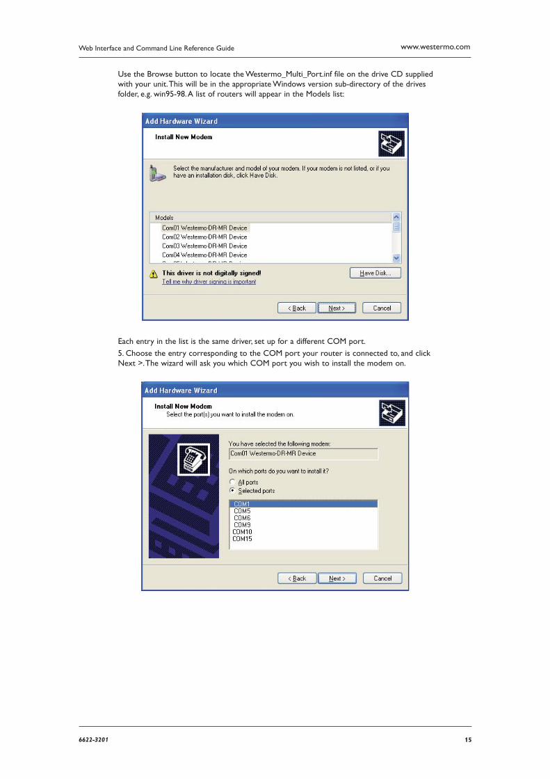
Use the Browse button to locate the Westermo_Multi_Port.inf file on the drive CD supplied with your unit. This will be in the appropriate Windows version sub-directory of the drives folder, e.g. win95-98. A list of routers will appear in the Models list:
Each entry in the list is the same driver, set up for a different COM port.
5. Choose the entry corresponding to the COM port your router is connected to, and click Next >. The wizard will ask you which COM port you wish to install the modem on.
16 6622-3201
Web Interface and Command Line Reference Guidewww.westermo.com
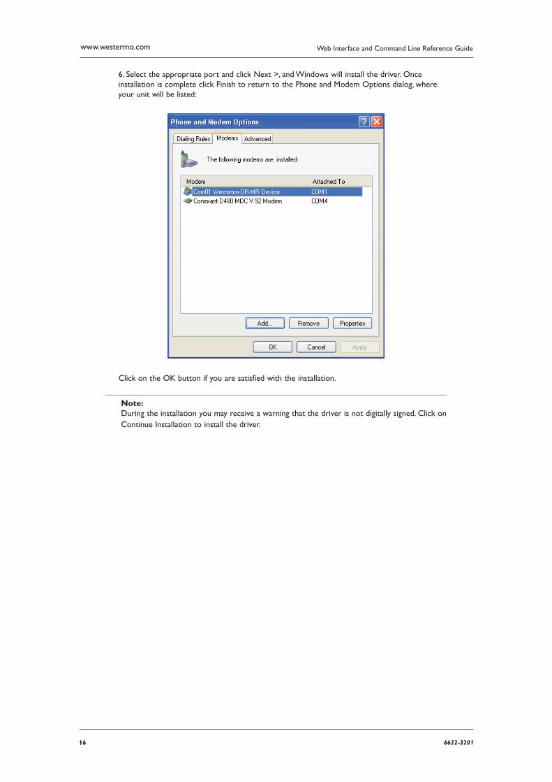
6. Select the appropriate port and click Next >, and Windows will install the driver. Once installa tion is complete click Finish to return to the Phone and Modem Options dialog, where your unit will be listed:
Click on the OK button if you are satisfied with the installation.
Note: During the installation you may receive a warning that the driver is not digitally signed. Click on Con tinue Installation to install the driver.
176622-3201
Web Interface and Command Line Reference Guide www.westermo.com
Creating A New Dial-Up Network Connection 2.2.2
You now need to create a new DUN connection through which you can access your unit.
If you are planning to connect the unit directly to your PC for configuration purposes, connect it to the appropriate COM port now using a suitable serial cable.
If you wish to configure a remote unit, make sure it is connected to a suitable ISDN line and make a note of the ISDN number.
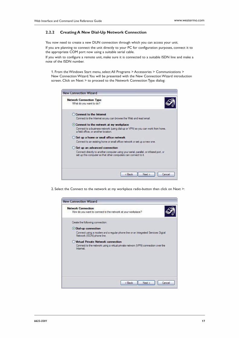
1. From the Windows Start menu, select All Programs > Accessories > Communications > New Connection Wizard. You will be presented with the New Connection Wizard introduction screen. Click on Next > to proceed to the Network Connection Type dialog:
2. Select the Connect to the network at my workplace radio-button then click on Next >:
18 6622-3201
Web Interface and Command Line Reference Guidewww.westermo.com
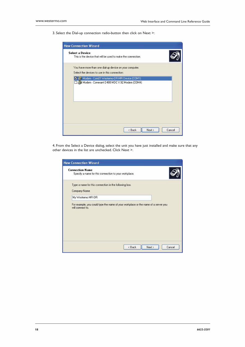
3. Select the Dial-up connection radio-button then click on Next >:
4. From the Select a Device dialog, select the unit you have just installed and make sure that any other devices in the list are unchecked. Click Next >.
196622-3201
Web Interface and Command Line Reference Guide www.westermo.com
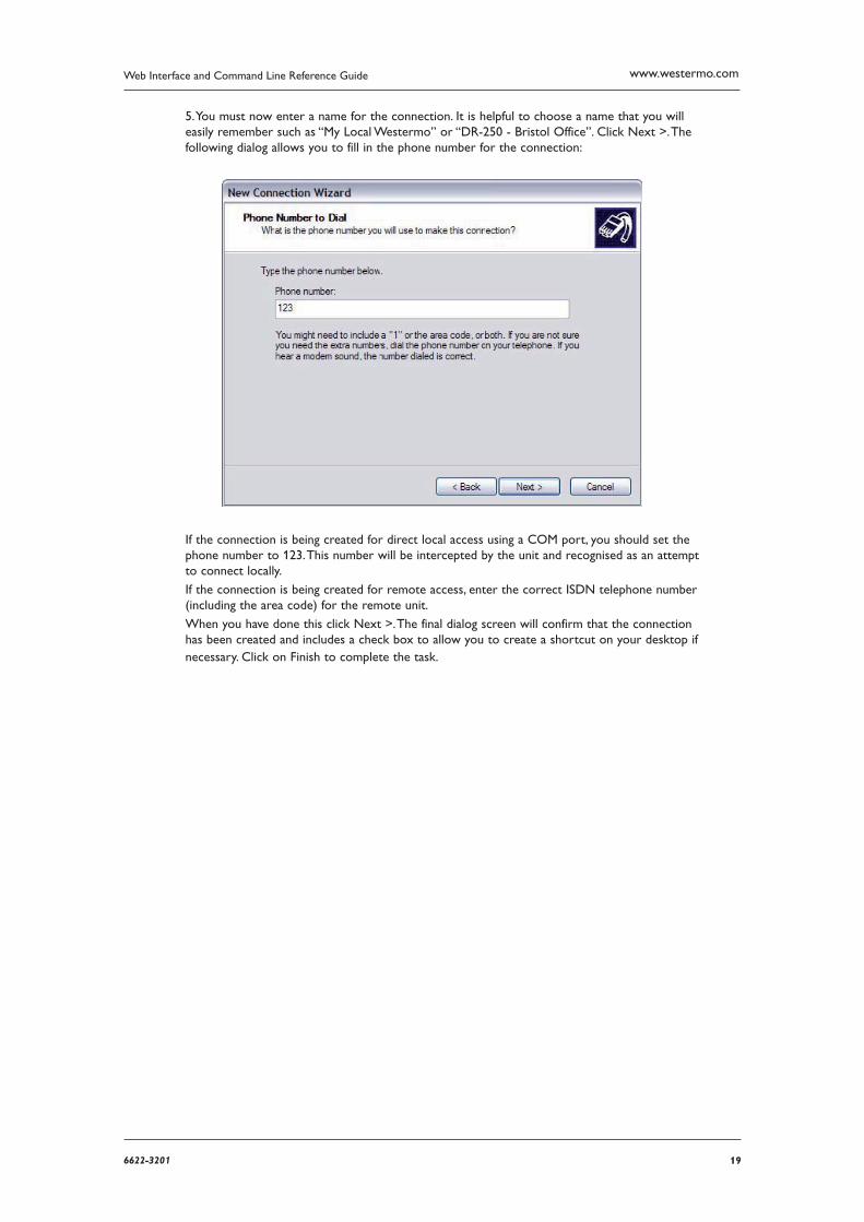
5. You must now enter a name for the connection. It is helpful to choose a name that you will easily remember such as “My Local Westermo” or “DR-250 - Bristol Office”. Click Next >. The fol lowing dialog allows you to fill in the phone number for the connection:
If the connection is being created for direct local access using a COM port, you should set the phone number to 123. This number will be intercepted by the unit and recognised as an attempt to connect locally.
If the connection is being created for remote access, enter the correct ISDN telephone number (including the area code) for the remote unit.
When you have done this click Next >. The final dialog screen will confirm that the connection has been created and includes a check box to allow you to create a shortcut on your desktop if necessary. Click on Finish to complete the task.
20 6622-3201
Web Interface and Command Line Reference Guidewww.westermo.com
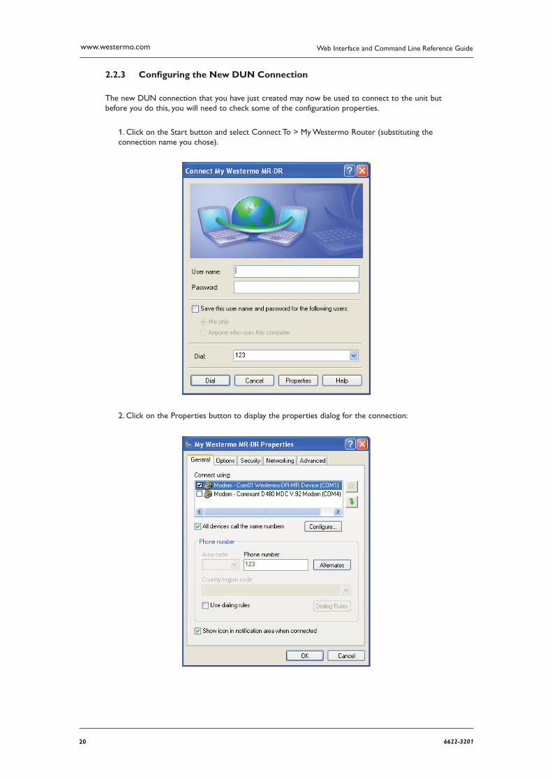
Confi guring the New DUN Connection 2.2.3
The new DUN connection that you have just created may now be used to connect to the unit but before you do this, you will need to check some of the configuration properties.
1. Click on the Start button and select Connect To > My Westermo Router (substituting the connec tion name you chose).
2. Click on the Properties button to display the properties dialog for the connection:
216622-3201
Web Interface and Command Line Reference Guide www.westermo.com
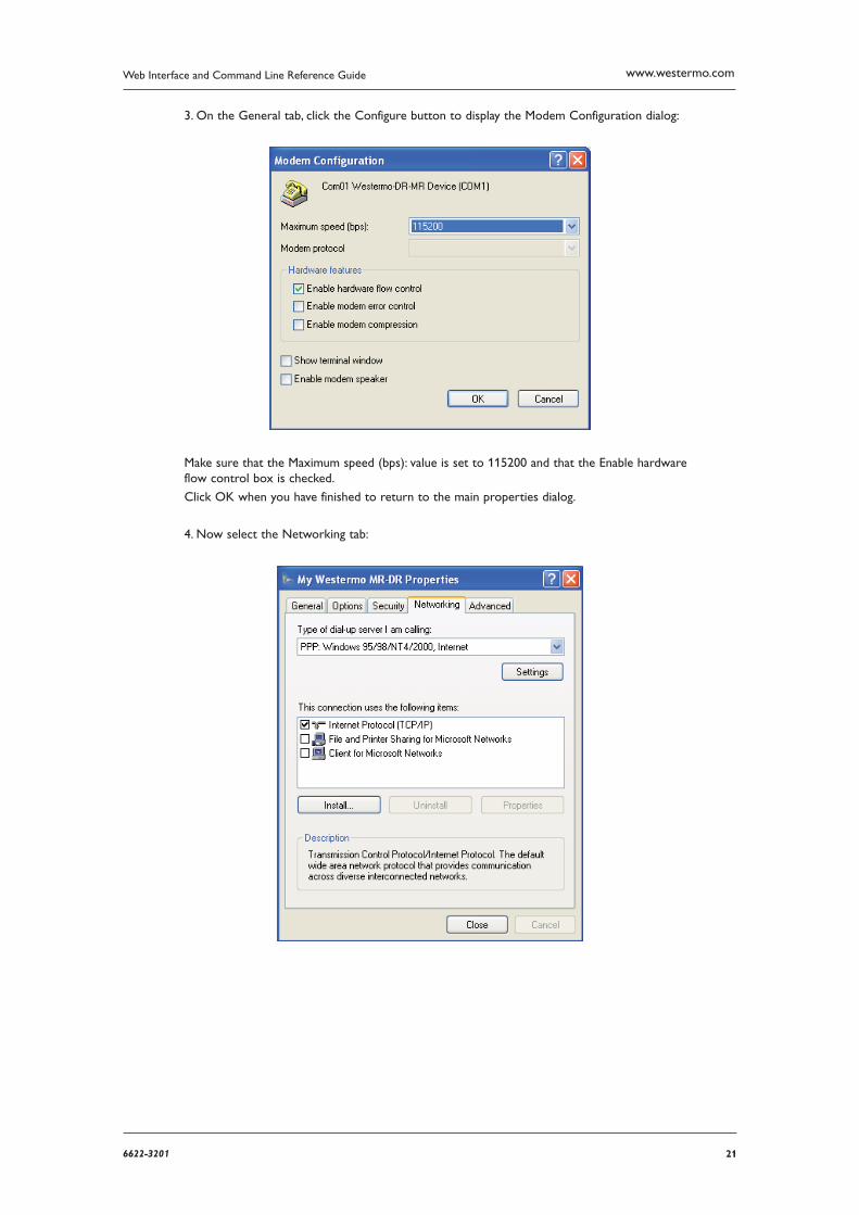
3. On the General tab, click the Configure button to display the Modem Configuration dia log:
Make sure that the Maximum speed (bps): value is set to 115200 and that the Enable hard ware flow control box is checked.
Click OK when you have finished to return to the main properties dialog.
4. Now select the Networking tab:
22 6622-3201
Web Interface and Command Line Reference Guidewww.westermo.com
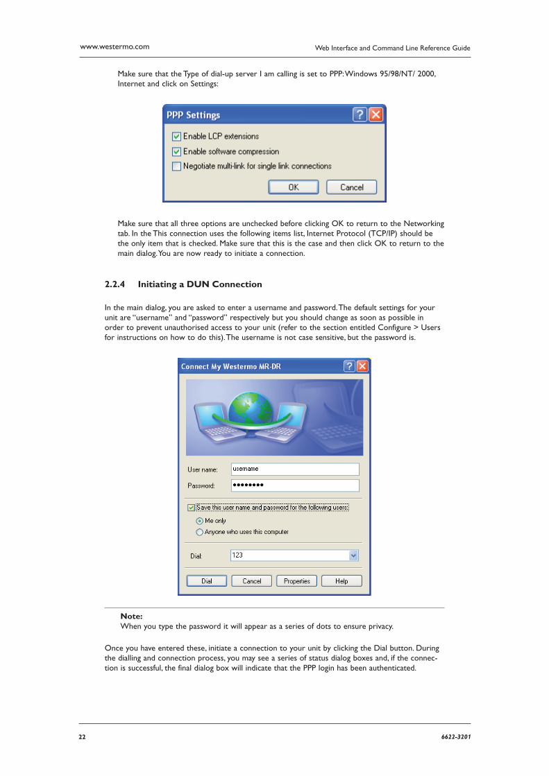
Make sure that the Type of dial-up server I am calling is set to PPP: Windows 95/98/NT/ 2000, Internet and click on Settings:
Make sure that all three options are unchecked before clicking OK to return to the Network ing tab. In the This connection uses the following items list, Internet Protocol (TCP/IP) should be the only item that is checked. Make sure that this is the case and then click OK to return to the main dialog. You are now ready to initiate a connection.
Initiating a DUN Connection 2.2.4
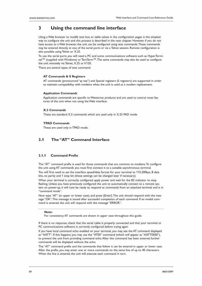
In the main dialog, you are asked to enter a username and password. The default settings for your unit are “username” and “password” respectively but you should change as soon as possible in order to prevent unauthorised access to your unit (refer to the section entitled Configure > Users for instructions on how to do this). The username is not case sensitive, but the password is.
Note: When you type the password it will appear as a series of dots to ensure privacy.
Once you have entered these, initiate a connection to your unit by clicking the Dial button. During the dialling and connection process, you may see a series of status dialog boxes and, if the connec-tion is successful, the final dialog box will indicate that the PPP login has been authenticated.

236622-3201
Web Interface and Command Line Reference Guide www.westermo.com
After a short delay, this dialog will minimise to a “linked computers” icon in the Windows taskbar:
You should now be ready to access the built-in web pages using your Web browser. The default “web address” for the unit is 1.2.3.4. By default, this is also mapped to the system IP hostname ss.2000r.
You will need a valid username and password to access the web interface. Once again, the default settings are username and password respectively. If these values do not allow access, you should contact your system administrator.
24 6622-3201
Web Interface and Command Line Reference Guidewww.westermo.com
Using the command line interface3
Using a Web browser to modify text box or table values in the configuration pages is the simplest way to configure the unit and this process is described in the next chapter. However, if you do not have access to a Web browser, the unit can be configured using text commands. These commands may be entered directly at one of the serial ports or via a Telnet session. Remote configuration is also possible using Telnet or X.25.
To use the serial ports you will need a PC and some communications software such as HyperTermi-nal™ (supplied with Windows) or TeraTerm™. The same commands may also be used to configure the unit remotely via Telnet, X.25 or V.120.
There are several types of text command:
AT Commands & S Registers
AT commands (pronounced “ay tee”) and Special registers (S registers) are supported in order to maintain compatibility with modems when the unit is used as a modem replacement.
Application Commands
Application commands are specific to Westermo products and are used to control most fea-tures of the unit when not using the Web interface.
X.3 Commands
These are standard X.3 commands which are used only in X.25 PAD mode
TPAD Commands
These are used only in TPAD mode.
The “AT” Command Interface 3.1
Command Prefi x 3.1.1
The “AT” command prefix is used for those commands that are common to modems. To configure the unit using AT commands you must first connect it to a suitable asynchronous terminal.
You will first need to set the interface speed/data format for your terminal to 115,200bps, 8 data bits, no parity and 1 stop bit (these settings can be changed later if necessary).
When your terminal is correctly configured, apply power and wait for the B2 indicator to stop flashing. Unless you have previously configured the unit to automatically connect to a remote sys-tem on power-up, it will now be ready to respond to commands from an attached terminal and is in “command mode”.
Now type “AT” (in upper or lower case), and press [Enter]. The unit should respond with the mes-sage “OK”. This message is issued after successful completion of each command. If an invalid com-mand is entered, the unit will respond with the message “ERROR”.
Note: For consistency AT commands are shown in upper case throughout this guide.
If there is no response, check that the serial cable is properly connected and that your terminal or PC communications software is correctly configured before trying again.
If you have local command echo enabled on your terminal, you may see the AT command displayed as “AATT”. If this happens you may use the “ATE0” command (which will appear as “AATTEE00”), to prevent the unit from providing command echo. After this command has been entered, further com mands will be displayed without the echo.
The “AT” command prefix and the commands that follow it can be entered in upper or lower case. After the prefix, you may enter one or more commands on the same line of up to 40 characters. When the line is entered, the unit will execute each command in turn.
256622-3201
Web Interface and Command Line Reference Guide www.westermo.com
The Escape Sequence 3.1.2
If you enter a command such as “ATD”, which results in the unit successfully establishing a connec-tion to a remote system, it will issue a “CONNECT” result code and switch from command mode to on-line mode. This means that it will no longer accept commands from the terminal. Instead, data will be passed transparently through the unit to the remote system. In the same way, data from the remote system will pass straight through to your terminal.
The unit will automatically return to command mode if the connection to the remote system is termi nated. To return to command mode manually, you must enter a special sequence of charac-ters called the “escape sequence”. This consists of three occurrences of the “escape character”, a pause (user configurable) and then “AT”. The default escape character is “+” so the default escape sequence is:
+++ {pause} AT
Entering this sequence when the unit is on-line will cause it to return to command mode but it will NOT disconnect from the remote system unless you specifically instruct it to do so (using “ATH” or another method of disconnecting). If you have not disconnected the call, the “ATO” command may be used to go back on-line.
Result Codes 3.1.3
Each time an AT command line is executed, the unit responds with a result code to indicate wheth-er the command was successful. If all commands entered on the line are valid, the “OK” result code will be issued. If any command on the line is invalid, the “ERROR” result code will be issued.
Result codes may take the form of an English word or phrase (verbose code) or an equivalent number (numeric code), depending on the setting of the “ATV” command. Verbose codes are used by default. The “ATV0” command can be used to select numeric codes if required. A full list of the Result codes is provided in the following table:
Numeric Code Verbose Code Meaning
0 OK Command line executed correctly
1 CONNECT ISDN connection established
2 RING Incoming ring signal detected
3 NO CARRIER X.25 service not available
4 ERROR Error in command line
6 NO DIALTONE ISDN service not available
7 BUSY B-channel(s) in use
8 NO ANSWER No response from remote
“S” Registers 3.1.4
“S” (Special) registers are registers in the unit that are used to store certain types of configuration infor mation. They are essentially a “legacy” feature included to provide compatibility with software that was originally designed to interact with modems. A full list of the registers is provided under the section heading “S registers”.
26 6622-3201
Web Interface and Command Line Reference Guidewww.westermo.com
Westermo Application Commands 3.2
The unit also supports numerous text-based “application” commands that are specific to Westermo products and do not require the “AT” prefix. Some of these are generic i.e. they are related to the general operation of the unit; others are application or protocol specific.
Application commands may be entered via any of the serial ports but if you are using ASY 0 or ASY 1 with auto-speed detection enabled (which is not possible on ports 2, 3, etc.), you must first lock the interface speed to the same as that of your terminal. To do this first ensure that the unit is responding to AT commands correctly and then enter the command:
AT\LS
The speed will remain locked until the unit goes on-line and then off-line again, the power is removed or the unit is reset. Once the port speed has been locked, “AT” commands will still work but you may also use the application commands.
Remember that if you subsequently re-enable auto-speed detection on the port it will disable the use of application commands until the “AT\LS” command has been re-entered or the port speed has been set to a specific speed using “S31”. For example, to set the port speed at 19,200bps enter the com mand:
ATS31=6
then change your terminal settings to match.
Note: Speed locking is not necessary when you use the text commands via a Telnet session.
Westermo application commands (referred to just as text commands throughout the remainder of this guide), can be entered in upper or lower case but unlike “AT” commands, only one command may be entered on a line. After each successful command, the “OK” result code will be issued. An invalid com mand will cause the “ERROR” result code to be issued.
The general syntax for an application commands is:
<cmd_name> <instance> <param_name> <value>
where:
<cmd_name> is the name of the command
<instance> is the instance number for the entity that you are configuring.
<param_name> is the name of the parameter that you wish to configure.
<value> is the new value for the specified parameter.
For example, to set the window size to 5 for X.25 PAD instance 1 you would enter:
pad 1 window 5
Even if there is only once instance of particular entity, you should only enter 0 for the instance number.
The Reboot Command 3.2.1
The reboot command is used to reboot the unit after altering the configuration. It has three modes of operation:
reboot - will reboot the unit after any FLASH write operations have been completed. Also, 1 second each is allowed for the following operations to be completed before reboot will take palce:
IPSec SA delete notifications have been created and sent •
TCP sockets have been closed •
PPP interfaces have been disconnected •
reboot <n> - will reboot the unit in <n> minutes where n is 1 to 65,535 reboot cancel - will cancel a timed reboot if entered before the time period has passed.
276622-3201
Web Interface and Command Line Reference Guide www.westermo.com
The Active Port 3.2.2
When entering “AT” or text commands it is important to understand that in most cases, the com-mand only affects the settings for the “active” port. This is usually the port to which you are physi-cally con nected but you may, if necessary, set the active port to another port of your choice using the “AT\PORT=N” command where “N” is 0-3.
Establishing a Remote Connection 3.3
Once you have finished configuring the unit, there are several ways of establishing a link to a remote system:
.
An outgoing V.120 call may be made using the “ATD” command •
You can initiate a DUN session to establish a dial-up PPP connection. •
An outgoing X.25 call may be made using the “ATD” command followed by the X.28 CALL • command.
An outgoing TPAD (Transaction PAD) call may be made by using the TPAD “a” (address) • command followed by the appropriate NUA (this is normally only carried out under soft-ware control).
Similarly, incoming calls will be handled according to which protocols have been bound to the ASY ports and whether or not answering is enabled for each protocol.
28 6622-3201
Web Interface and Command Line Reference Guidewww.westermo.com
Confi guring your unit4
This section describes the various configuration parameters for the unit and how to set or change them using the built-in web pages or the text commands. Configuration using the Web pages is achieved by entering the required values into text boxes or tables on the page, or by turning fea-tures on or off using checkboxes. The same results can be achieved entering the appropriate text commands via one of the serial ports.
Note: The WEB pages are arranged in two tiers. The initial WEB page displayed, is the basis setup page were many of the most often used features have been grouped together. For more advanced configuration option the “Full Menu” option can be selected. This will give the user access to all the advanced features detailed in section 4.4 onwards.
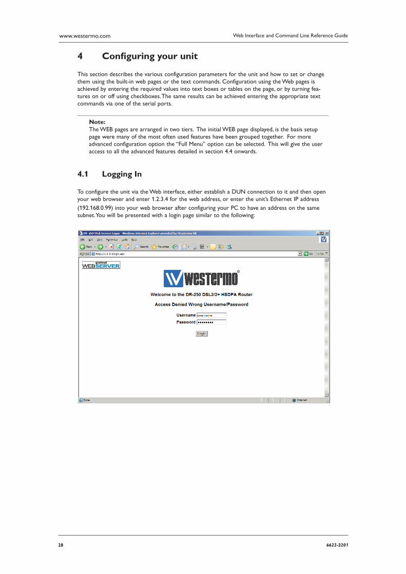
Logging In 4.1
To configure the unit via the Web interface, either establish a DUN connection to it and then open your web browser and enter 1.2.3.4 for the web address, or enter the unit’s Ethernet IP address
(192.168.0.99) into your web browser after configuring your PC to have an address on the same sub net. You will be presented with a login page similar to the following:
296622-3201
Web Interface and Command Line Reference Guide www.westermo.com
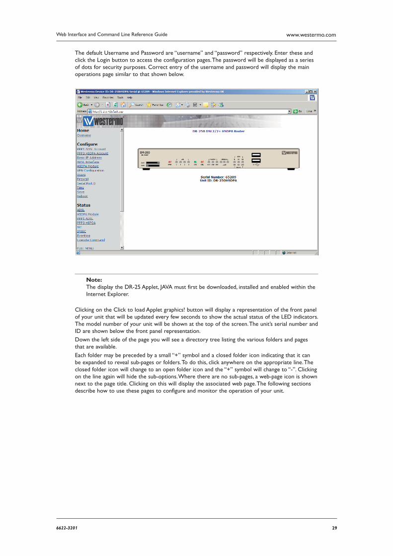
The default Username and Password are “username” and “password” respectively. Enter these and click the Login button to access the configuration pages. The password will be displayed as a series of dots for security purposes. Correct entry of the username and password will display the main oper ations page similar to that shown below.
Note:The display the DR-25 Applet, JAVA must first be downloaded, installed and enabled within the Internet Explorer.
Clicking on the Click to load Applet graphics! button will display a representation of the front panel of your unit that will be updated every few seconds to show the actual status of the LED indicators. The model number of your unit will be shown at the top of the screen. The unit’s serial number and ID are shown below the front panel representation.
Down the left side of the page you will see a directory tree listing the various folders and pages that are available.
Each folder may be preceded by a small “+” symbol and a closed folder icon indicating that it can be expanded to reveal sub-pages or folders. To do this, click anywhere on the appropriate line. The closed folder icon will change to an open folder icon and the “+” symbol will change to “-”. Clicking on the line again will hide the sub-options. Where there are no sub-pages, a web-page icon is shown next to the page title. Clicking on this will display the associated web page. The following sections describe how to use these pages to configure and monitor the operation of your unit.
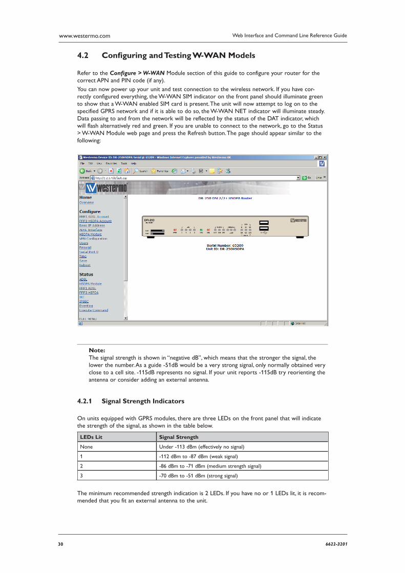
30 6622-3201
Web Interface and Command Line Reference Guidewww.westermo.com
Confi guring and Testing W-WAN Models 4.2
Refer to the Configure > W-WAN Module section of this guide to configure your router for the correct APN and PIN code (if any).
You can now power up your unit and test connection to the wireless network. If you have cor-rectly con figured everything, the W-WAN SIM indicator on the front panel should illuminate green to show that a W-WAN enabled SIM card is present. The unit will now attempt to log on to the specified GPRS network and if it is able to do so, the W-WAN NET indicator will illuminate steady. Data passing to and from the network will be reflected by the status of the DAT indicator, which will flash alternatively red and green. If you are unable to connect to the network, go to the Status > W-WAN Module web page and press the Refresh button. The page should appear similar to the following:
Note: The signal strength is shown in “negative dB”, which means that the stronger the signal, the lower the number. As a guide -51dB would be a very strong signal, only normally obtained very close to a cell site. -115dB represents no signal. If your unit reports -115dB try reorienting the antenna or consider adding an external antenna.
Signal Strength Indicators 4.2.1
On units equipped with GPRS modules, there are three LEDs on the front panel that will indicate the strength of the signal, as shown in the table below.
LEDs Lit Signal Strength
None Under -113 dBm (effectively no signal)
1 -112 dBm to -87 dBm (weak signal)
2 -86 dBm to -71 dBm (medium strength signal)
3 -70 dBm to -51 dBm (strong signal)
The minimum recommended strength indication is 2 LEDs. If you have no or 1 LEDs lit, it is recom-mended that you fit an external antenna to the unit.
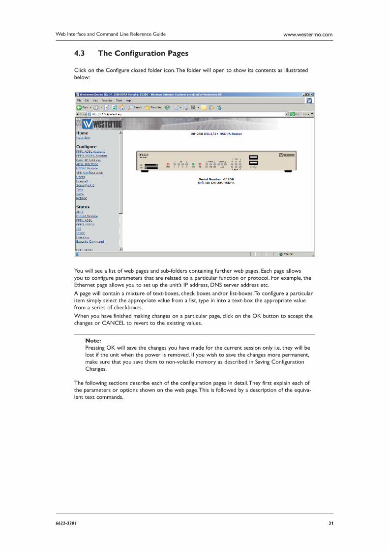
316622-3201
Web Interface and Command Line Reference Guide www.westermo.com
The Confi guration Pages 4.3
Click on the Configure closed folder icon. The folder will open to show its contents as illustrated below:
You will see a list of web pages and sub-folders containing further web pages. Each page allows you to configure parameters that are related to a particular function or protocol. For example, the Ethernet page allows you to set up the unit’s IP address, DNS server address etc.
A page will contain a mixture of text-boxes, check boxes and/or list-boxes. To configure a particular item simply select the appropriate value from a list, type in into a text-box the appropriate value from a series of checkboxes.
When you have finished making changes on a particular page, click on the OK button to accept the changes or CANCEL to revert to the existing values.
Note: Pressing OK will save the changes you have made for the current session only i.e. they will be lost if the unit when the power is removed. If you wish to save the changes more permanent, make sure that you save them to non-volatile memory as described in Saving Configuration Changes.
The following sections describe each of the configuration pages in detail. They first explain each of the parameters or options shown on the web page. This is followed by a description of the equiva-lent text commands.
32 6622-3201
Web Interface and Command Line Reference Guidewww.westermo.com
Confi gure > ADAPT > ADAPT n 4.4
The unit incorporates two “Adapt” (rate adaptation protocol) instances. Each instance allows you to select and configure the protocol to be used for providing rate adaptation over an ISDN B channel. The supported protocols are V.110, V.120 and X.75. Depending on which protocol is selected, there may be an associated LAPB instance (distinct from the two general purpose LAPB instances), as for exam ple, when V.120 is used in error corrected (Multi-frame) mode.
Using the Web Page(s)
V120 mode:
When the V mode parameter (see below), has been set to “V120”, the V120 mode parameter allows you to select “Unacknowledged”, “Multi-frame” or “Multi-frame/Fallback” mode for V.120 operation.
“Unacknowledged” mode is the simplest mode and does not provide error control.
“Multi-frame” mode provides error control but may only be used if the remote system also sup-ports this mode. In “Multi-frame/Fallback” mode, the unit will attempt to establish a multi-frame error controlled link
but will allow a connection in Unacknowledged mode if the remote unit does not support error control.
MSN:
This parameter provides the filter for the ISDN Multiple Subscriber Numbering facility. It is blank by default but when set to an appropriate value it will cause the unit to answer only incoming calls to telephone numbers where the trailing digits match that value (if answering is enabled). For exam ple setting MSN to 123 will prevent the unit from answering any calls to numbers that do not end in 123.
Sub-address:
This parameter provides the filter for the ISDN sub-address facility. It is blank by default but when set to an appropriate value with answering enabled, it will cause the unit to answer incoming calls only to ISDN numbers where the trailing digits of the sub address called match that value. For example, setting the Sub-address parameter to 123 will prevent the unit from answering any calls to numbers where the sub address does not end in 123.
CLI:
Calling Line Identification. The unit will only answer calls from numbers whose trailing digits match what is entered in this field. The line the unit is connected to must have CLI enabled by the tele coms provider, and the calling number cannot be withheld.
V mode:
This parameter allows you to specify which rate adaptation protocol to use and can be set to one of the following:
Option Description
V.120 Mode This allows one B-channel to carry multiple sub-rate channels in a suc-cession of statistically multiplexed (variable-length) frames. These frames support error detection and correction procedures if selected under V120 mode (above).
V.110 Mode V.110 is a fixed-frame based rate adaptation standard that subdivides the ISDN B-channel capacity so that it can carry one lower speed (sub-rate) data channel.
V110/V120 Detect This mode detects which protocol (V.110 or V.120) the remote host is using.
X75 Transparent This selects bit transparent X.75 mode of operation.
X75 T.70 NL This option generates T.70 NL telematic prefixes that are required by some ISDN terminal adapters.
336622-3201
Web Interface and Command Line Reference Guide www.westermo.com
V110 user rate:
This parameter allows you to specify the data rate to be used on ISDN when operating in V.110 mode.
V110 fixed rate:
This parameter can be set to Yes to prevent the V.110 protocol from changing the data rate.
Direct sync mode:
This parameter allows you to replace the standard V120 frame header with the 0xff character. The data received on the ASY port can then be considered to be written directly onto the sync ISDN line (apart from the 0xff header in each frame).
Socket mode:
This parameter allows you to connect using a TCP socket rather than an ISDN line.
IP address:
The IP address of the TCP socket the router is connecting to in Socket mode.
IP port:
The port number of the TCP socket the router is connecting to in Socket mode.
Listening IP port:
The port number the router is listening on in Socket mode.
LAPB Confi guration:
The following parameters are only used if a V.120 connection is established in Multi-frame mode:
N400 counter:
This is the standard LAPB/LAPD retry counter. The default value is 3 and it should not normally be necessary to change this.
RR timer (ms):
This is a standard LAPB/LAPD Receiver Ready timer. The default value is 10,000ms (10 seconds) and it should not normally be necessary to change this.
T1 timer (ms):
This is a standard LAPB/LAPD timer. The default value is 1000 milliseconds and under normal cir cumstances, it should not be necessary to change it.
T200 timer (ms):
This is a standard LAPB/LAPD re-transmit timer. The default value is 1000 milliseconds and under normal circumstances, it should not be necessary to change it.
34 6622-3201
Web Interface and Command Line Reference Guidewww.westermo.com
Using Text Commands
To configure rate adaptation parameters via the command line use the adaptcommand. To display current settings for “adapt 0” enter the command:
adapt 0 ?
To change the value of a parameter use the command in the format:
adapt <instance> <parameter> <value>
where <instance> is 0 or 1.
The parameters and values are:
Parameter Values Equivalent Web Parameter
cli number CLI
dial_retries number None - see below
dsync off, on Direct sync mode
fixed_rate off, on V110 fixed rate
ip_addr number IP address
ip_port number IP port
leased_line off, on None - see below
lip_port number Listening IP port
msn number MSN
msnv110 number MSN for V.110
multi 0,1,2 Mode: 0=unacknowledged, 1=multi-frame, 2=multi-frame/fallback
sockmode 0, 1 Socket mode: 0=Off 1=TCP
sub number Sub-address
user_rate 5,6,7,8,9,10,11 V110 User Rate: 5=38400, 6=19200, 7=9600, 8=4800, 9=2400, 10=1200, 11=600
vmode 0,1,2,3,4 V Mode: 0=V120 mode, 1=V110 mode, 2=V110/V120 detect, 3=X75 Transparent, 4=X75 T.70 NL
Dial Retries
If an ISDN connection is established, but rate adaption is not negotiated, this parameter will allow the unit to drop the connection and redial it.
Leased Line
This parameter will allow the unit to automatically attempt to maintain the connection once it has been established. A connection can be disconnected by the unit if it is instructed to do so, but if the connection is lost due to an error, it will continually redial. In other words, if the unit is not responsi ble for a disconnection, redialling will take place.
To change the values of the LAPB parameters for rate adaptation, use the lapb command. Note that LAPB 2 is used for “adapt 0” and LAPB 3 is used for “adapt 1”.
356622-3201
Web Interface and Command Line Reference Guide www.westermo.com
Confi gure > Analyser 4.5
Your unit can be configured to maintain a trace of activity taking place at the various ports and of the layer 2 and 3 protocols. Trace information is stored in a circular buffer in memory. When the buffer is full, the storage of new trace data starts at the beginning of the buffer again (overwriting the oldest data). This buffer appears in the file directory as a pseudo-file called “ANA.TXT”.
The following is a typical trace showing activity on the D-channel:
----- 4-5-2002 13:11:50.260 ------ L2 DCHAN SABME from NT to TE: COMMAND POLL SAPI=10, TEI=01, 42,03,7F,
--------- ----- 4-5-2002 13:11:50.260 ------ L2 DCHAN UA from TE to NT: RESPONSE FINAL SAPI=10, TEI=01, 42,03,73,
----- 4-5-2002 13:11:50.330 ------ L2 DCHAN I FRAME from NT to TE: COMMAND SAPI=10, TEI=01, NS=00, NR=00, 42,03,00,00,
X25 RESTART from DCE to DTE: LCG=0 LCN=0 PTI 10, 00, FB, 07 00 .. ---------
----- 4-5-2002 13:11:50.330 ------ L2 DCHAN I FRAME from TE to NT: COMMAND SAPI=10, TEI=01, NS=00, NR=01, 40,03,00,02,
X25 RESTART CONFIRMATION from DTE to DCE: LCG=0 LCN=0 PTI 10, 00, FF,
Both B and D-channel analysis can be enabled simultaneously if necessary and you can select which LAPB and LAPD sources you wish to include in the trace by checking the appropriate boxes.
Traffi c capture fi les for use with Ethereal / Wireshark
Depending on the source options chosen, the analyser trace will capture specific traffic into .cap files. These files can then be opened with Wireshark (formerly Ethereal). The 3 files are stored in the unit’s memory and will be retained during a warm reboot but cleared in the event of a power failure.
The .cap files and the traffic captures they contain are:
Capture file name Contents
anaeth.cap Ethernet traffic
anappp.cap PPP traffic
anaip.cap IP traffic
Using the Web Page(s)
The Configure > Analyser web page allows you to turn the analyser “On” or “Off” and to deter-mine what information is included in the trace using the following parameters:
Analyser:
This parameter is used to turn the protocol analyser “On” or “Off”.
36 6622-3201
Web Interface and Command Line Reference Guidewww.westermo.com
Protocol layers:
The check boxes shown under this heading are used to specify which protocol layers are includ-ed in the protocol analyser trace. You can choose to generate a trace of the physical layer (Layer 1), the Link Layer (Layer 2) protocol, the Network Layer (Layer 3) protocol or any combination, by checking or clearing the appropriate check-boxes. In addition, you may select XOT (X.25 over TCP/IP) tracing if this feature is included in your product.
IKE:
This checkbox is used to enable or disable the inclusion of IKE packets in the analyser trace when using IPSec.
SNAIP:
This checkbox is used to enable or disable the inclusion of SNAIP packets in the analyser trace.
ISDN sources:
The group of check boxes shown under this heading are used to select the ISDN channels (D, B1 and B2) that will be included in the trace. To include or exclude a specific LAPB or LAPD instance from the trace ensure that the appropriate checkbox is checked or cleared respectively.
ASY sources:
The group of checkboxes shown under this heading is used to select the ASY ports that will be included in the trace. To include a trace of commands issued to and responses from a particu-lar port, ensure that the appropriate box is checked. The list of available ports will include the physical ASY ports, internal “virtual ASY ports” (if present) and ports used by built-in GPRS/PSTN modems.
Raw sync sources:
The group of checkboxes shown under this heading are is to select the synchronous sources to be included in the trace. These include the ISDN channels D, B1 and B2 and any other syn-chronous ports/protocols that your unit may include (e.g. physical port 1, 2, etc.). This feature is especially useful for monitoring data transferred over ISDN when the higher layer protocol does not record data in the trace (e.g.V.120).
Max I-PAK size:
The text-box labelled Max I-PAK Size allows you to specify the maximum number of bytes from each X.25 Information Frame that will be included in the trace. Frames that are larger than this value are truncated. Bear in mind that the larger this value, the quicker the “ANA.TXT” pseudo-file (in which the trace output is stored), will become full so that the effective length of the trace is reduced. The default value of 128 should be suitable in most cases.
PPP sources:
The group of checkboxes shown under this heading may be used to select the PPP sources to be included in the trace.
IP sources:
The group of checkboxes shown under this heading may be used to select the IP sources to be included in the trace. These sources include IP packets transmitted over PPP and ETH instances.
Ethernet sources:
The group of checkboxes shown under this heading may be used to select the Ethernet port sources to be included in the trace.
IP Options:
The Trace Discarded Packets option will trace packets that have been discarded by any interface and will also record the reason for the discard, regardless of any other analyser trace configura-tion. Packets blocked by the firewall will also be logged to the trace.
376622-3201
Web Interface and Command Line Reference Guide www.westermo.com
ATM PVC sources:
The group of checkboxes shown under this heading may be used to select the ADSL ATM PVCs to include in the analyser trace.
IP filters:
This text box is used to prevent the tracing of packets to or from specific TCP or UDP ports. The format of this text box is a comma-separated list of port numbers. For example, you may wish to exclude tracing of HTTP traffic that would otherwise swamp the data of interest. This can be done by entering “80” in the IP Filters box. To filter in specific traffic enter a tilde (~) symbol before the list of filters, for example to capture telnet and ssh traffic enter ~22,23 in the Ports filter box.
At the bottom of the page, the OK and Cancel buttons may be used to save or cancel any changes respectively.
Using Text Commands
From the command line, the ana command can be used to configure the protocol analyser. To dis-play the current settings for the analyser enter the command:
ana <instance> ?
where <instance> is 0 (there is only one instance of the Analyser). To change the value of a parameter use the same command in the format:
ana 0 <parameter> <value>
The parameters and values are:
Parameter Values Equivalent Web Parameter
anon off, on Analyser
asyon 1-15 ASY source
discardson off, on IP Options - Trace discarded pack-ets
ikeon off, on IKE
ipfilt number list IP filters
l1on off, on Protocol layers - layer 1
l2on off, on Protocol layers - layer 2
l3on off, on Protocol layers - layer 3
lapbon 1-3 ISDN sources - LAPB
lapdon 1-7 ISDN sources - LAPD
maxdata number Max I-PAK size
syon 1-15 Raw sync sources
xoton off, Protocol layers - XOT
For example, to turn the analyser on, enter:
ana 0 anon on
To clear the existing contents of the analyser trace prior to starting a new trace session, use the following command:
ana 0 anaclr
38 6622-3201
Web Interface and Command Line Reference Guidewww.westermo.com
To include or exclude trace information from the various possible sources, use the appropriate command from the above table in conjunction with the required value from the following tables:
ASY sources:
Value ASY 3 ASY 2 ASY 1 ASY 0
0 OFF OFF OFF OFF
1 OFF OFF OFF ON
2 OFF OFF ON OFF
3 OFF OFF ON ON
4 OFF ON OFF OFF
5 OFF ON OFF ON
6 OFF ON ON OFF
7 OFF ON ON ON
8 ON OFF OFF OFF
9 ON OFF OFF ON
10 ON OFF ON OFF
11 ON OFF ON ON
12 ON ON OFF OFF
13 ON ON OFF ON
14 ON ON ON OFF
15 ON ON ON ON
Ethernet, IP or PPP sources:
These are a special case and cannot be configured from the command line using the ana command. Instead, these sources must be turned on or off from the command line by using the appropriate pppor eth commands. For example to turn IP tracing on for PPP instance 1 enter the following command:
ppp 1 ipanon on
For example to turn PPP tracing on for PPP instance 1 enter the following command:
ppp 1 pppanon on
To turn IP tracing on for Ethernet instance 0 enter the following command:
eth 0 ipanon on
This tracing can also be turned on or off in the web page entries for the Ethernet and PPP instanc-es.
LAPB sources:
Value LAPB 1 LAPB 0
0 OFF OFF
1 OFF ON
2 ON OFF
3 ON ON
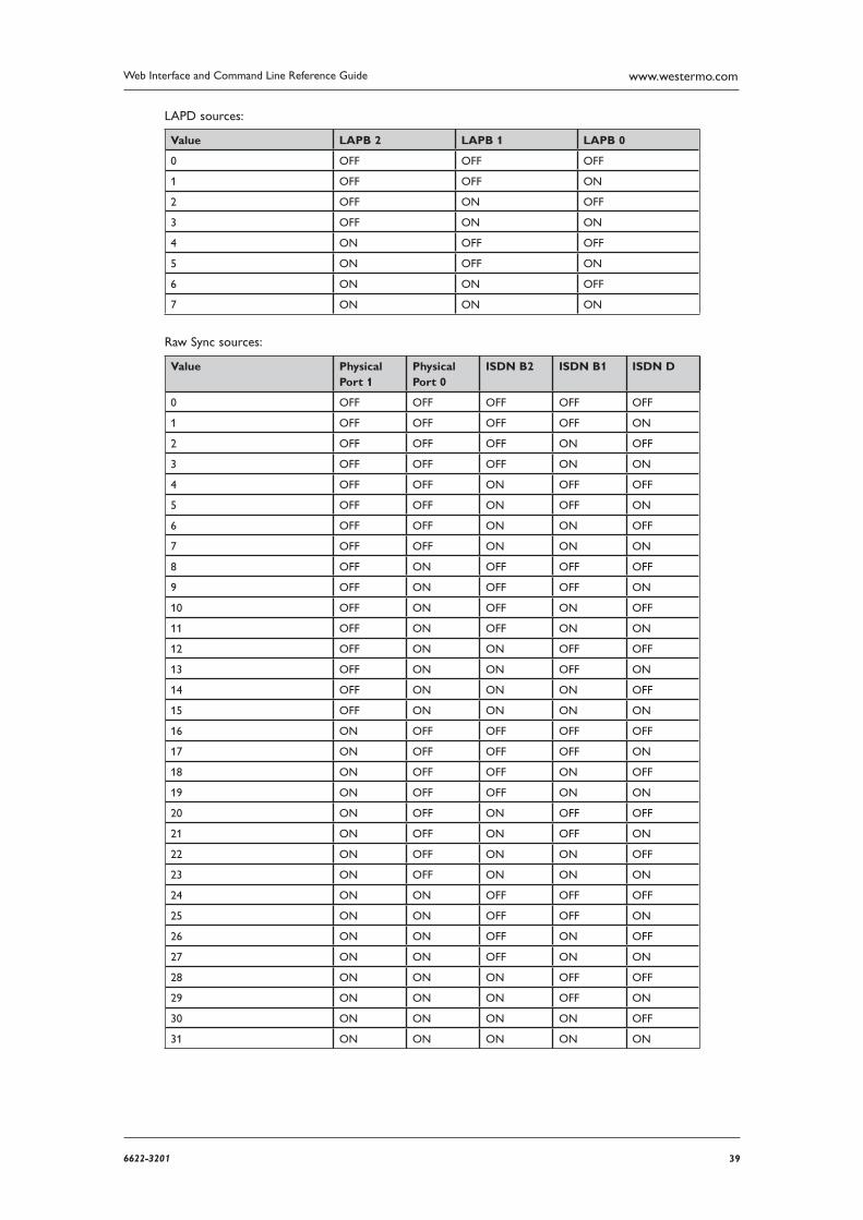
396622-3201
Web Interface and Command Line Reference Guide www.westermo.com
LAPD sources:
Value LAPB 2 LAPB 1 LAPB 0
0 OFF OFF OFF
1 OFF OFF ON
2 OFF ON OFF
3 OFF ON ON
4 ON OFF OFF
5 ON OFF ON
6 ON ON OFF
7 ON ON ON
Raw Sync sources:
Value Physical Port 1
Physical Port 0
ISDN B2 ISDN B1 ISDN D
0 OFF OFF OFF OFF OFF
1 OFF OFF OFF OFF ON
2 OFF OFF OFF ON OFF
3 OFF OFF OFF ON ON
4 OFF OFF ON OFF OFF
5 OFF OFF ON OFF ON
6 OFF OFF ON ON OFF
7 OFF OFF ON ON ON
8 OFF ON OFF OFF OFF
9 OFF ON OFF OFF ON
10 OFF ON OFF ON OFF
11 OFF ON OFF ON ON
12 OFF ON ON OFF OFF
13 OFF ON ON OFF ON
14 OFF ON ON ON OFF
15 OFF ON ON ON ON
16 ON OFF OFF OFF OFF
17 ON OFF OFF OFF ON
18 ON OFF OFF ON OFF
19 ON OFF OFF ON ON
20 ON OFF ON OFF OFF
21 ON OFF ON OFF ON
22 ON OFF ON ON OFF
23 ON OFF ON ON ON
24 ON ON OFF OFF OFF
25 ON ON OFF OFF ON
26 ON ON OFF ON OFF
27 ON ON OFF ON ON
28 ON ON ON OFF OFF
29 ON ON ON OFF ON
30 ON ON ON ON OFF
31 ON ON ON ON ON
40 6622-3201
Web Interface and Command Line Reference Guidewww.westermo.com
Secondary log fi les
A second analyser trace can be written to a USB flash drive plugged into the router or internal SD card. This is useful if the analyser is needed to be captured over an extended period of time and the normal ana.txt file would erase old events before having chance to view them. The secondary log file can be limited in size if required or allowed to fill the drive. Once the log file is full, old events will be pruned off the end of the file to allow for new entries at the top.
There are 2 options for this feature:
1. Take a snapshot of the analyser trace on a specific event and append this to the file on the s: or u: drive.
2. Continuous writing of the analyser trace to both files, i.e. the regular ana.txt and the file on the s: or u: drive.
Snapshot to log drive
A secondary log file will be created on the USB or drive and the analyser trace will be appended to this log file on a triggered event. As this is event triggered, there is an option in the logcodes editor (Con figure > Event Logcodes) Analyser snapshot to log drive which will need to be set to ON for the event on which the unit will send a copy of the analyser trace to selected drive.
There are no web page options.
The CLI commands are:
To specify the drive to log to:
ana 0 logdrive [s:|u:]
event 0 logdrive [s:|u:]
To specify the log file:
ana 0 logfile <name>
Where <name> is the name of the file on the log drive: For example, to log a trace to the file u:mylog.txt or s:mylog.txt
ana 0 logfile mylog.txt
To limit the maximum size of the log file:
ana 0 logsizek <n>
Where <n> is the maximum allowed size of the file in Kb, if 0 is used or this value is not set, the file size is unlimited. For example, to limit the log file to 1Gb
ana 0 logsizek 1048576
416622-3201
Web Interface and Command Line Reference Guide www.westermo.com
Continuous writing
A secondary log file will be created on the log drive and the analyser trace will continuously be appended to this log file in real time. Care should be taken when using this feature to ensure that the analyser trace is configured correctly and precisely, to only capture the data that is required. If the analyser is left to capture all traffic on a fast interface, trace data will be missed out from the file as the unit is unable to write the data fast enough. If this happens the following error will be seen in the log file ===== Missed Frames 34 =====
There are no web page options.
The CLI commands are:
To specify the log file:
ana 0 contfile <name>
Where <name> is the name of the file on the log drive:
For example, to log a trace to the file u:analog.txt or s:analog.txt
ana 0 contfile analog.txt
To limit the maximum size of the log file:
ana 0 logsizek <n>
Where <n> is the maximum allowed size of the file in Kb, if 0 is used or this value is not set, the file size is unlimited. For example, to limit the log file to 1Gb
ana 0 logsizek 1048576
Writing PCAP fi les to USB or SD cards
As with the standard analyser trace, the secondary trace may also be configured to capture in PCAP format for use with Wireshark.
To specify logging to PCAP files:
ana 0 <anatype> <n>
Where <anatype> can be anappps for PPP, anaeths for ethernet and anaips for IP. Where <n> defines the maximum number of separate log files to create using circular logging.
This is to be used in conjunction with the ana 0 logsizek <n> command to restrict the size of the log. eg: ana 0 logsizek 524288
The files written to the log drive will be named anapppx, anaethx or anaipx where x will be the number of the log file. eg: anappp1, anaeth1 or anaip1.
Disable / enable logging
The command logfat <0|1> will disable and enable secondary logging. This can be used to tem-porarily stop logging to the secondary log files, this does not affect logging to the standard analyser trace (ana.txt) which is held in internal memory. This command should be used before removing a USB flash drive to allow the log files to be closed and ensure data is not being written during removal of the flash drive.
For example, to disable USB logging
logfat 0
To re-enable USB logging
logfat 1
42 6622-3201
Web Interface and Command Line Reference Guidewww.westermo.com
Confi gure > ASY Ports > ASY Port n 4.6
Each ASY (serial) port can be independently configured for interface speed, parity, command echo, etc. These parameters can be set via the appropriate Configure > ASY Port web page or from the command line using AT commands and S registers.
Using the Web Page(s)
The Configure > ASY Ports folder icon opens to list a page for each of the asynchronous serial ports (usually ASY 0, 1, 2 & 3).
Note: On models fitted with GPRS one of the pages will be entitled GPRS port. Similarly, on models fitted with an analog modem, one of the pages will be entitled PSTN port.
Each page allows you to configure the following port parameters:
Description:
This parameter allows you to enter a name for this Ethernet instance, to make it easier to iden-tify.
Answer ring count (S0):
This parameter controls the answering of incoming V.120 calls. When set to zero, V.120 answer-ing is disabled, otherwise V.120 answering is enabled on this port. The actual value used for this parameter sets the number of rings the unit will wait before answering. This is equivalent to set-ting the value of the “S0” register for the relevant ASY port.
DCD:
The DCD parameter is used to configure the way in which the unit controls the DCD signal to the terminal.
Setting this parameter to “Auto” configures the unit so that it will only turn the DCD signal on when an ISDN connection has been established (this is equivalent to “AT&C1”).
Selecting “On” configures the unit so that the DCD signal is always on when the unit is pow-ered-up (this is equivalent to “AT&C0”).
Selecting “Off” configures the unit so that the DCD signal is normally on but goes off for the length of time specified by S10 after a call is disconnected (this is equivalent to “AT&C2”).
DTR control:
The DTR control parameter is used to configure the way in which the unit responds to the DTR sig nal from the terminal.
Setting this parameter to “None” configures the unit so that the DTR signal from the attached ter minal is ignored (this is equivalent to AT&D0).
Selecting to “Drop Call” configures the unit so that it will disconnect the current call and return to AT command mode when the DTR signal from the terminal goes from on to off (this is equivalent to “AT&D1”).
Selecting to “Drop Line & Call” configures the unit so that it will disconnect the current call, drop the line and return to AT command mode when the DTR signal from the terminal goes from On to Off (this is equivalent to “AT&D2”).
DTR de-bounce time (x20ms):
The value of this parameter determines the length of time (in multiples of 20ms), for which the DTR signal from the terminal must go off before the unit acts upon any options that are set to trigger on loss of DTR. Increasing or decreasing this value makes the unit less or more sensitive to “bounc ing” of the DTR signal respectively.
436622-3201
Web Interface and Command Line Reference Guide www.westermo.com
Echo:
This parameter can be used to turn command echo “On” or “Off” when using the text com-mand interface. Turn command echo off if your terminal provides local command echo itself.
Escape character:
This parameter determines which character is used in the escape sequence. The value of this parameter is the decimal ASCII code for the character, normally 43 (“+” symbol). Changing this parameter has the same effect as changing the “S2” register.
Escape delay (x20 ms):
This parameter defines the required minimum length of the pause (in multiples of 20ms), in the escape sequence between entering three escape characters and then entering “AT”.
Flow control:
The unit supports software flow control using XON/XOFF characters and hardware flow control using the RS232 RTS and CTS signals. Use this drop-down list to select “Software”, “Hardware” or a combination of “Both”. To disable flow control select the “None” option.
Interface speed:
This parameter allows you to select the interface speed from a drop down list. Select the required speed (from 300bps to 115,200bps), or for ASY 0 or ASY 1 only you may select the “Auto” option to allow automatic speed detection from the AT commands entered at the port.
Result codes:
This parameter is used to select “Numeric”, “Verbose” or no result codes (“None”) when using the text command interface.
Parity:
This parameter is used to set the ASY port parity to “None”, “Odd”, “Even”, “8Data Odd” or “8Data Even” as required.
Note: When the ASY port is not in 8-bit with parity mode (i.e. it is in either 8-bit no parity, or 7-bit with par ity), then the unit will continually check for parity when receiving AT commands, and adjust and match accordingly.
Disable Port:
This parameter will disable the ASY port from the software stack. The ASY port will not be able to send data and any data received will be discarded.
Forwarding Timeout(x10ms)
This parameter is the length of time the unit will wait for more data after receiving at least one byte of data through the serial port and before transmitting it onwards. This timer is reset each time more data is received. The unit will forward the data onwards when either the forwarding timer expires or the input buffer is full. This parameter applies to ADAPT, TCPDIAL, TCPPERM and PANS.
Power-up profile:
This parameter can be set to 0 or 1 to determine which of the two stored profiles is loaded when the unit is first powered up.
The two buttons at the bottom of the page are used to save/load the above settings to/from the “SREGS.DAT” file. You may create two stored profiles for each available ASY port containing the set tings detailed on this page, all of which are contained in “SREGS.DAT”.
Load Profile
Clicking this button loads the profile specified in the list box to the right.
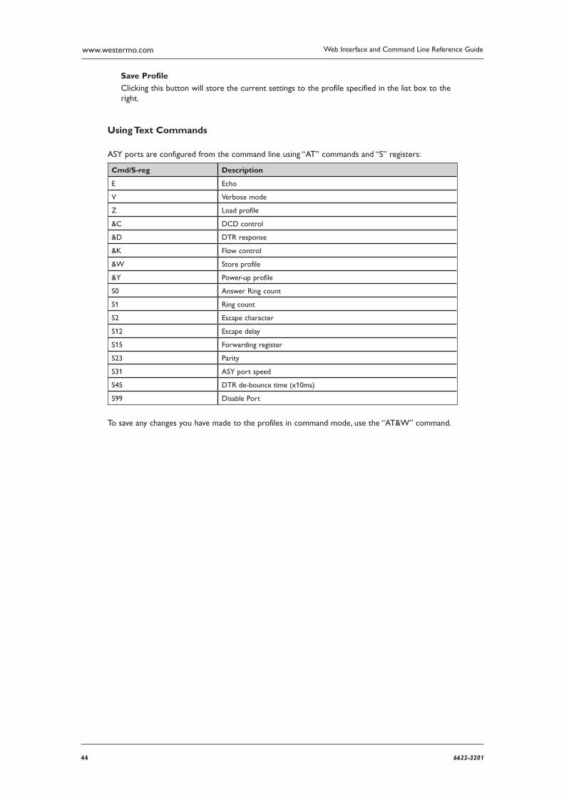
44 6622-3201
Web Interface and Command Line Reference Guidewww.westermo.com
Save Profile
Clicking this button will store the current settings to the profile specified in the list box to the right.
Using Text Commands
ASY ports are configured from the command line using “AT” commands and “S” registers:
Cmd/S-reg Description
E Echo
V Verbose mode
Z Load profile
&C DCD control
&D DTR response
&K Flow control
&W Store profile
&Y Power-up profile
S0 Answer Ring count
S1 Ring count
S2 Escape character
S12 Escape delay
S15 Forwarding register
S23 Parity
S31 ASY port speed
S45 DTR de-bounce time (x10ms)
S99 Disable Port
To save any changes you have made to the profiles in command mode, use the “AT&W” command.
456622-3201
Web Interface and Command Line Reference Guide www.westermo.com
Confi gure > TRANSIP ASY Ports 4.7
TransIP is a method of using virtual ASY ports for serial connections, in effect multiplying the number of concurrent serial connections to a unit.
Using the Web Page(s)
TransIP #:
The TransIP port number. Each TransIP is assigned a separate virtual ASY port.
ASY port:
The virtual ASY port number assigned to the TransIP instance.
TCP port:
The TCP port number to listen on.
TCP remote port:
TransIP can be configured to actively connect on a TCP socket (i.e. make outgoing socket con-nections). If this parameter is set it defines the TCP port number to use when TransIP is making TCP socket connections. When this parameter is set to zero, TransIP is listening only on the port defined in the TCP Port parameter.
Host:
The Hostname or IP address to which TransIP will make outward TCP connections.
Keep Alive(s):
This parameter defines the amount of time (in seconds) a connection will stay open without any traffic being passed.
Stay connected mode:
When this parameter is set to “On” the socket will not be cleared by the unit) at the end of a trans action, data call or data session (depending on what the TransIP ASY port was bound to and pro tocol it was implementing). For example, if the TransIP port is bound to TPAD and this parameter is “Off”, then the TransIP TCP socket will be cleared at the end of the TPAD transac-tion.
Command echo off:
Setting this parameter to “On” disables the command echo for the TransIP port. When set to “On”, all commands issued will be echoed back in the TransIP TCP socket.
Escape char:
This parameter defines which ASCII character is used as the Escape character, which by default is the “+” symbol. Entering this character three times followed by a delay of at least the period defined in the Escape time parameter, and then an AT command will cause the unit to switch from on-line mode to command mode. This is equivalent to the “S” Register S2.
Escape time:
This parameter defines the delay between sending the escape sequence and entering an AT com mand for the unit to switch from on-line mode to command mode. This is equivalent to the “S” Reg ister S12.
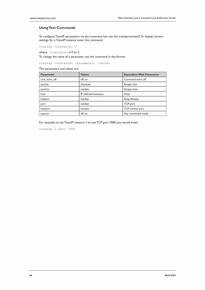
46 6622-3201
Web Interface and Command Line Reference Guidewww.westermo.com
Using Text Commands
To configure TransIP parameters via the command line use the transipcommand. To display current settings for a TransIP instance enter the command:
transip <instance> ?
where <instance> is 0 to 3.
To change the value of a parameter use the command in the format:
trnasip <instance> <parameter> <value>
The parameters and values are:
Parameter Values Equivalent Web Parameter
cmd_echo_off off, on Command echo off
escchar character Escape char
esctime number Escape time
host IP address/host name Host
keepact number Keep Alive(s)
port number TCP port
remport number TCP remote port
staycon off, on Stay connected mode
For example, to set TransIP instance 1 to use TCP port 7000 you would enter:
transip 1 port 7000
476622-3201
Web Interface and Command Line Reference Guide www.westermo.com
Confi gure > Backup IP Addresses 4.8
This page contains a table that is used to specify alternative addresses to use when the unit fails in an attempt to open a socket. These addresses are used only for socket connections that originate from the unit and are typically used to provide back-up for XOT connections, TANS (TPAD answer-ing) con nections or any application in which the unit is making outgoing socket connections.
When a back-up address is in use, the original IP address that failed to open is tested at intervals to check if it has become available again. Additionally, at the end of a session, the unit will remember when an IP address has failed and use the back-up IP address immediately for future connections. When the original IP address eventually becomes available again, the unit will automatically detect this and revert to using it.
Using the Web Page(s)
The web page contains a table with four columns headed:
IP Address:
In this column you should enter the original IP address to which the backup address relates.
Backup IP Address: This is the backup address to try when the unit fails to open a connection to IP Address.
Retry Time (s):
The is the length of time seconds that the unit will wait between checks to see if a connection can yet be made to IP Address.
Try Next:
In the case that a connection to the primary IP address has just failed, this parameter deter-mines whether a connection to the backup IP address should be attempted immediately or when the application next attempts to open a connection.
When set to “Yes” the socket will attempt to connect to the backup IP address immediately after the connection to the primary IP address failed and BEFORE reporting this failure to the calling application, e.g. TPAD. If the backup is successful this means the application will not expe-rience any kind of failure even though the unit has connected to the backup IP address.
When set to “No” the socket will report the failure to connect back to the calling applica-tion imme diately after the connection to the primary IP address has failed. The unit will not try to connect to the backup IP address at this stage. The next time the application attempts to connect to the same IP address, the unit will instead automatically connect to the backup IP address.
Chaining IP Addresses
It is possible to chain backup IP addresses by making multiple entries in the table.
For example the following table with 3 rows populated will cause the router to back-up from
192.168.0.1 to 192.168.0.2 and then to 192.168.0.3 and then to 192.168.0.4 (if necessary).
Note: The length of time that it takes for a connection to an IP address to fail is determined by the TCP socket connect timeout parameter on the Configure > General web page
48 6622-3201
Web Interface and Command Line Reference Guidewww.westermo.com
Confi gure > Basic 4.9
This page contains the parameters to configure Script Basic.
Using the Web Page(s)
User parameter n:
These parameters numbered 1 through 15 are string values that will be used as variables within
the running script, named string1 though string15. For example, configuring User parameter 1 as
test123 will replace all instances of string1 in the Basic script with test123.
Run Basic script:
This is the Basic script that will be run straight away. Only 1 script can be run from this param-eter but the running script can call other scripts if required. Click the “Go!” button to run the Basic script straight away. The “Kill Basic” button will stop the active script from running.
If a Basic script is required to run automatically when the router boots up, this should be done
using the Auto start macro parameter in Configure > General. Enter bas followed by the name
of the script. Eg: bas test.sb
Using Text Commands
To configure Script Basic parameters via the command line use the basic command.
To display current settings for basic 0 enter the command:
basic <instance> ?
where <instance> is 0.
To change the value of a parameter use the command in the format:
basic <instance> <parameter> <value>
The parameters and values are:
Parameter Values Equipment Web Parameter
string1 text User parameter 1
... text ...
string15 text User parameter 15
bas script name Run Basic Script & Go!
basic 0 kill none Kill basic button
496622-3201
Web Interface and Command Line Reference Guide www.westermo.com
Confi gure > BGP 4.10
This page contains the parameters to enable BGP, specify the configuration file and define the action that is taken on errors or when a new configuration file is loaded. The majority of BGP configu-ration is done from a text file called bgp.conf This text file can be created in a text editor then uploaded to the router. A basic example bgp.conf is shown below.
Using the Web Page(s)
Enable BGP:
This parameter enables and disables BGP routing. Options are No, Yes.
Configuration file:
A dropdown list of all the files stored on the router, select the BGP configuration file.
Restart BGP when new config file loaded:
If a new configuration file is selected, BGP can automatically restart and load in the new param-eters. Options are No, Yes.
Restart BGP after fatal error:
In the event of a fatal BGP error that stops the process from running, the BGP process will be restarted automatically. Options are No, Yes.
Debug level:
Enabling this option will output debug information via a CLI session. Options are OFF, LOW, MEDIUM, HIGH.
Using Text Commands
To configure BGP parameters via the command line use the bgp command.
To display current settings for BGP 0 enter the command:
bgp <instance> ?
where <instance> is 0.
To change the value of a parameter use the command in the format:
bgp <instance> <parameter> <value>
The parameters and values are:
Parameter Values Equipment Web Parameter
conffile filename Configuration file
debug 0,1,2,3 Debug level 0=Off 1=LOW 2=MEDIUM 3=HIGH
enable OFF,ON Enable BGP
fatal_rest OFF,ON Restart after fatal error
new_cfg_rest OFF,ON Restart BGP when new config file loaded
Use of the BGP.conf fi le.
The bgp.conf config file is divided into four main sections.
Macros
User-defined variables may be defined and used later, simplifying the configuration file.
50 6622-3201
Web Interface and Command Line Reference Guidewww.westermo.com
Global Confi guration
Global settings for bgp.
Neighbors and Groups
bgp establishes sessions with neighbors. The neighbor definition and properties are set in this sec-tion, as well as grouping neighbors for the ease of configuration.
Filter
Filter rules for incoming and outgoing UPDATES. .
Note: With the exception of macros, the sections should be grouped and appear in bgp.conf in the order shown above.
Macros
Macros can be defined that will later be expanded in context. Macro names must start with a let-ter, and may contain letters, digits and underscores. Macro names may not be reserved words (for example, AS, neighbor, or group). Macros are not expanded inside quotes.
For example:
peer1=”1.2.3.4”neighbor $peer1 { remote-as 65001}
Global Confi guration
There are quite a few settings that affect the operation of the BGP daemon globally.
AS as-number
Set the local autonomous system number to as-number. The AS numbers are assigned by local RIRs, such as: AfriNIC for Africa APNIC for Asia Pacific ARIN for North America and parts of the Caribbean LACNIC for Latin America and the Caribbean RIPE NCC for Europe, the Middle East, and parts of Asia
For example:
AS 65001 sets the local AS to 65001.
fib-update (yes|no)
If set to no, do not update the Forwarding Information Base, a.k.a. the kernel routing table. The default is yes.
516622-3201
Web Interface and Command Line Reference Guide www.westermo.com
holdtime seconds
Set the holdtime in seconds. The holdtime is reset to its initial value every time either a KEEPALIVE or an UPDATE message is received from the neighbor. If the holdtime expires the session is dropped. The default is 90 seconds. Neighboring systems negotiate the holdtime used when the connection is established in the OPEN messages. Each neighbor announces its config-ured holdtime; the smaller one is then agreed upon.
holdtime min seconds
The minimal accepted holdtime in seconds. This value must be greater than or equal to 3.
listen on address
Specify the local IP address bgp should listen on.
listen on 127.0.0.1
log updates
Log received and sent updates.
network address/prefix [set ...] network (inet|inet6) static [set ...] network (inet|inet6) con-nected [set ...] Announce the specified network as belonging to our AS. If set to connected, routes to directly attached networks will be announced. If set to static, all static routes will be announced.
network 192.168.7.0/24 It is possible to set default AS path attributes per network statement:
network 192.168.7.0/24 set localpref 220 See also the ATTRIBUTE SET section.
nexthop qualify via (bgp|default)
If set to bgp, bgp may use BGP routes to verify nexthops. If set to default, bgp may use the default route to verify nexthops. By default bgp will only use static routes or routes added by other routing daemons like ospf.
rde med compare (always|strict)
If set to always, the MED attributes will always be compared. The default is strict, where the MED is only compared between peers belonging to the same AS.
rde route-age (ignore|evaluate)
If set to evaluate, the best path selection will not only be based on the path attributes but also on the age of the route, giving preference to the older, typically more stable, route. In this case the decision process is no longer deterministic. The default is ignore.
route-collector (yes|no)
If set to yes, the route selection process is turned off. The default is no.
router-id address
Set the router ID to the given IP address, which must be local to the machine.
router-id 10.0.0.1 If not given, the BGP ID is determined as the biggest IP address assigned to the local machine.
Neighbors
BGP establishes TCP connections to other BGP speakers called neighbors. Each neighbor is specified by a neighbor section, which allows properties to be set specifically for that neighbor:
neighbor 10.0.0.2 {remote-as 65002descr ”a neighbor”} Multiple neighbors can be grouped together by a group section. Each neighbor section within the group section inherits all properties from its group:
52 6622-3201
Web Interface and Command Line Reference Guidewww.westermo.com
group ”peering AS65002” {remote-as 65002neighbor 10.0.0.2 { descr ”AS65002-p1”}neighbor 10.0.0.3 {descr ”AS65002-p2” } }
Instead of the neighbor’s IP address, an address/netmask pair may be given:
neighbor 10.0.0.0/8
In this case, the neighbor specification becomes a template, and if a neighbor connects from an IP address within the given network, the template is cloned, inheriting everything from the template but the remote address, which is replaced by the connecting neighbor’s address. With a template specification it is valid to omit remote-as; bgp will then accept any AS the neighbor presents in the OPEN message.
There are several neighbor properties:
announce (all|none|self|default-route)
If set to none, no UPDATE messages will be sent to the neighbor. If set to default-route, only the default route will be announced to the neighbor. If set to all, all generated UPDATE messag-es will be sent to the neighbor. This is usually used for transit AS’s and IBGP peers. The default value for EBGP peers is self, which limits the sent UPDATE messages to announcements of the local AS. The default for IBGP peers is all.
announce (IPv4|IPv6) (none|unicast)
For the given address family, control which subsequent address families (at the moment, only none, which disables the announcement of that address family, and unicast are supported) are announced during the capabilities negotiation. Only routes for that address family and subse-quent address family will be announced and processed.
demote group
Increase the carp(4) demotion counter on the given interface group, usually carp, when the session is not in state ESTABLISHED. The demotion counter will be increased as soon as bgp starts and decreased 60 seconds after the session went to state ESTABLISHED. For neigh-bors added at runtime, the demotion counter is only increased after the session has been ESTABLISHED at least once before dropping.
depend on interface
The neighbor session will be kept in state IDLE as long as interface reports no link. For carp(4) interfaces, no link means that the interface is currently backup. This is primarily intended to be used with carp(4) to reduce failover times.
The state of the network interfaces on the system can be viewed using the show interfaces command to bgpctl.
descr description
Add a description. The description is used when logging neighbor events, in status reports, for specifying neighbors, etc., but has no further meaning to bgp.
down
Do not start the session when bgp comes up but stay in IDLE.
dump (all|updates) (in|out) file [timeout]
Do a peer specific MRT dump. Peer specific dumps are limited to all and updates. See also the dump section in GLOBAL CONFIGURATION.
536622-3201
Web Interface and Command Line Reference Guide www.westermo.com
enforce neighbor-as (yes|no)
If set to yes, AS paths whose leftmost AS is not equal to the remote AS of the neighbor are rejected and a NOTIFICATION is sent back. The default value for IBGP peers is no otherwise the default is yes.
holdtime seconds
Set the holdtime in seconds. Inherited from the global configuration if not given.
holdtime min seconds
Set the minimal acceptable holdtime. Inherited from the global configuration if not given.
ipsec (ah|esp) (in|out) spi spi-number authspec [encspec]
Enable IPsec with static keying. There must be at least two ipsec statements per peer with man-ual keying, one per direction. authspec specifies the authentication algorithm and key. It can be
sha1 <key>md5 <key> encspec specifies the encryption algorithm and key. ah does not support encryption. With esp, encryption is optional. encspec can be
3des <key>3des-cbc <key>aes <key>aes-128-cbc <key>
Keys must be given in hexadecimal format.
ipsec (ah|esp) ike
Enable IPsec with dynamic keying. In this mode, bgp sets up the flows, and a key management daemon such as isakmp is responsible for managing the session keys. With isakmpd, it is suf-ficient to copy the peer’s public key, found in /etc/isakmpd/private/local.pub, to the local machine. It must be stored in a file named after the peer’s IP address and must be stored in /etc/ isakmpd/pubkeys/ipv4/. The local public key must be copied to the peer in the same way. As bgp manages the flows on its own, it is sufficient to restrict isakmpd to only take care of keying by specifying the flags -Ka. This can be done in rc.conf.local. After starting the isakmpd and bgp daemons on both sides, the session should be established.
local-address address
When bgp initiates the TCP connection to the neighbor system, it normally does not bind to a specific IP address. If a local address is given, bgp binds to this address first.
max-prefix number [restart number]
Terminate the session after number prefixes have been received (no such limit is imposed by default). If restart is specified, the session will be restarted after number minutes.
multihop hops
Neighbors not in the same AS as the local bgp normally have to be directly connected to the local machine. If this is not the case, the multihop statement defines the maximum hops the neighbor may be away.
passive
Do not attempt to actively open a TCP connection to the neighbor system.
remote-as as-number
Set the AS number of the remote system.
route-reflector [address]
Act as an RFC 2796 route-reflector for this neighbor. An optional cluster ID can be specified; otherwise the BGP ID will be used.
54 6622-3201
Web Interface and Command Line Reference Guidewww.westermo.com
set attribute ...
Set the AS path attributes to some default per neighbor or group block:
set localpref 300
See also the ATTRIBUTE SET section. Set parameters are applied to the received prefixes; the only exceptions are prepend-self, nexthop no-modify and nexthop self. These sets are rewritten into filter rules and can be viewed with ``bgp -nv’’.
softreconfig (in|out) (yes|no)
Turn soft reconfiguration on or off for the specified direction. If soft reconfiguration is turned on, filter changes will be applied on configuration reloads. If turned off, a BGP session needs to be cleared to apply the filter changes. Enabling softreconfig in will raise the memory require-ments of bgp because the unmodified AS path attributes need to be stored as well.
tcp md5sig password secret
tcp md5sig key secret Enable TCP MD5 signatures per RFC 2385. The shared secret can either be given as a password or hexadecimal key.
tcp md5sig password mekmidasdigoat tcp md5sig key deadbeef ttl-security (yes|no)
Enable or disable ttl-security. When enabled, outgoing packets are sent using a TTL of 255 and a check is made against an incoming packet’s TTL. For directly connected peers, incoming packets are required to have a TTL of 255, ensuring they have not been routed. For multihop peers, incoming packets are required to have a TTL of 256 minus multihop distance, ensuring they have not passed through more than the expected number of hops. The default is no.
Filter
BGP has the ability to allow and deny UPDATES based on prefix or AS path attributes. In addi-tion, UPDATES may also be modified by filter rules. For each UPDATE processed by the filter, the filter rules are evaluated in sequential order, from first to last. The last matching allow or deny rule decides what action is taken.
The following actions can be used in the filter:
allow The UPDATE is passed.
deny The UPDATE is blocked.
match Apply the filter attribute set without influencing the filter decision.
PARAMETERS
The rule parameters specify the UPDATES to which a rule applies. An UPDATE always comes from, or goes to, one neighbor. Most parameters are optional, but each can appear at most once per rule. If a parameter is specified, the rule only applies to packets with matching attributes.
as-type as-number
This rule applies only to UPDATES where the AS path matches. The as-number is matched against a part of the AS path specified by the as-type. as-type is one of the following operators:
AS (any part)
source-as (rightmost AS number)
transit-as (all but the rightmost AS number)
Multiple as-number entries for a given type or as-type as-number entries may also be specified, separated by commas or whitespace, if enclosed in curly brackets:
deny from any AS { 1, 2, 3 } deny from any { AS 1, source-as 2, transit-as 3 } deny from any { AS { 1, 2, 3 }, source-as 4, transit-as 5 }

556622-3201
Web Interface and Command Line Reference Guide www.westermo.com
community as-number:local
community name
This rule applies only to UPDATES where the community path attribute is present and matches. Communities are specified as as-number:local, where as-number is an AS number and local is a locally significant number between zero and 65535. Both as-number and local may be set to `*’ to do wildcard matching. Alternatively, well-known communities may be given by name instead and include NO_EXPORT, NO_ADVERTISE, NO_EXPORT_SUBCONFED, and NO_PEER. Both as number and local may be set to neighbor-as, which is expanded to the current neighbor remote AS number.
56 6622-3201
Web Interface and Command Line Reference Guidewww.westermo.com
(from|to) peer
This rule applies only to UPDATES coming from, or going to, this particular neighbor. This parameter must be specified. peer is one of the following:
any Any neighbor will be matched.
address Neighbors with this address will be matched.
group descr Neighbors in this group will be matched.
Multiple peer entries may also be specified, separated by commas or whitespace, if enclosed in curly brackets:
deny from { 128.251.16.1, 251.128.16.2, group hojo }
prefix address/len
This rule applies only to UPDATES for the specified prefix.
Multiple address/len entries may be specified, separated by commas or whitespace, if enclosed in
curly brackets:
deny from any prefix { 192.168.0.0/16, 10.0.0.0/8 }
Multiple lists can also be specified, which is useful for macro expansion:
good=”{ 192.168.0.0/16, 172.16.0.0/12, 10.0.0.0/8 }” bad=”{ 224.0.0.0/4, 240.0.0.0/4 }” ugly=”{ 127.0.0.1/8, 169.254.0.0/16 }” deny from any prefix { $good $bad $ugly }
prefixlen range
This rule applies only to UPDATES for prefixes where the prefixlen matches. Prefix length ranges are specified by using these operators:
= (equal)
!= (unequal)
< (less than)
<= (less than or equal)
> (greater than)
>= (greater than or equal)
- (range including boundaries)
>< (except range)
>< and - are binary operators (they take two arguments). For instance, to match all prefix lengths >= 8 and <= 12, and hence the CIDR netmasks 8, 9, 10, 11 and 12:
prefixlen 8-12 Or, to match all prefix lengths < 8 or > 12, and hence the CIDR netmasks 0-7 and 13-32:
prefixlen 8><12 prefixlen can be used together with prefix. This will match all prefixes in the 10.0.0.0/8 netblock with net masks longer than 16:
prefix 10.0.0.0/8 prefixlen > 16
quick
If an UPDATE matches a rule which has the quick option set, this rule is considered the last matching rule, and evaluation of subsequent rules is skipped.
set attribute ...
All matching rules can set the AS path attributes to some default. The set of every matching rule is applied, not only the last matching one. See also the following section.
ATTRIBUTE SET AS path attributes can be modified with set.set can be used on network state-ments, in neighbor or group blocks, and on filter rules. Attribute sets can be expressed as lists.
The following attributes can be modified:
community [delete] as-number:local
community [delete] name
Set or delete the COMMUNITIES AS path attribute. Communities are specified as
576622-3201
Web Interface and Command Line Reference Guide www.westermo.com
as number:local, where as-number is an AS number and local is a locally-significant number between zero and 65535. Alternately, well-known communities may be specified by name:
NO_EXPORT, NO_ADVERTISE, NO_EXPORT_SUBCONFED, or NO_PEER.
localpref number
Set the LOCAL_PREF AS path attribute. If number starts with a plus or minus sign, LOCAL_PREF will be adjusted by adding or subtracting number; otherwise it will be set to number.
med number
metric number
Set the MULTI_EXIT_DISC AS path attribute. If number starts with a plus or minus sign, MULTI_EXIT_DISC will be adjusted by adding or subtracting number; otherwise it will be set to number.
nexthop (address|blackhole|reject|self|no-modify)
Set the NEXTHOP AS path attribute to a different nexthop address or use blackhole or reject routes. If set to no-modify, the nexthop attribute is not modified. Unless set to self, the nexthop is left unmodified for IBGP sessions. self forces the nexthop to be set to the local interface address.
set nexthop 192.168.0.1 set nexthop blackhole set nexthop reject set nexthop no-modify set nexthop self
pftable table
Add the prefix in the update to the specified pf(4) table, regardless of whether or not the path was selected for routing. This option may be useful in building realtime blacklists.
prepend-neighbor number
Prepend the neighbor’s AS number times to the AS path.
prepend-self number
Prepend the local AS number times to the AS path.
rtlabel label
Add the prefix with the specified label to the kernel routing table.
weight number
The weight is used to tip prefixes with equally long AS paths in one or the other direction. A prefix is weighed at a very late stage in the decision process. If number starts with a plus or minus sign, the weight will be adjusted by adding or subtracting number; otherwise it will be set to number. Weight is a local non-transitive attribute and a bgp-specific extension.
Example bgp.conf
# sample bgp configuration file #macros peer1=”100.100.100.23” # global configuration AS 65001 router-id 100.100.100.20 holdtime 180 holdtime min 3 # fib-update no # route-collector no log updates network inet static network inet connected neighbor 100.100.100.23 {

58 6622-3201
Web Interface and Command Line Reference Guidewww.westermo.com
remote-as65003 descrupstream multihop2 passive announceall } neighbor 100.100.100.27 { remote-as65003 descr”site a” multihop2 passive announceall } neighbor 100.100.102.28 { remote-as65003 descr”site b” multihop2 passive announceall } # filter out prefixes longer than 24 or shorter than 8 bits #deny from any #allow from any prefixlen 8 - 24 # do not accept a default route #allow from any prefix 0.0.0.0/0 # filter bogus networks #deny from any prefix 10.0.0.0/8 prefixlen >= 8 #deny from any prefix 172.16.0.0/12 prefixlen >= 12 #deny from any prefix 192.168.0.0/16 prefixlen >= 16 #deny from any prefix 169.254.0.0/16 prefixlen >= 16 #deny from any prefix 192.0.2.0/24 prefixlen >= 24 #deny from any prefix 224.0.0.0/4 prefixlen >= 4 #deny from any prefix 240.0.0.0/4 prefixlen >= 4
596622-3201
Web Interface and Command Line Reference Guide www.westermo.com
Confi gure > Certifi cates > Certifi cate request 4.11
The unit can establish an IPSec tunnel to another unit using certificates. For more information on using certificates with your unit, please refer to the Application Note “How to configure an IPSEC VPN tunnel between two Westermo Routers using Certificates and SCEP”, which is available from the Westermo technical support.
This page contains fields that required when sending a certificate request to a Certificate Authority (CA). This information forms part of the certificate request, and thus part of the signed public key certificate.
Using the Web Page(s)
Challenge password:
Before you can create a certificate request you must first obtain a challenge password from the Certificate Authority Server. This password is generally obtained from the SCEP CA server by way of a WEB server, or a phone call to the CA Server Administrator. For the Microsoft® SCEP server, you browse to a web interface. If the server requires a challenge password, it will be dis-played on the page along with the CA certificate fingerprint.
This challenge password is usually only valid once and for a short period of time, in this case 60 minutes, meaning that a certificate request must be created after retrieving the challenge pass-word.
Country:
A two-character representation of the country the unit is in (e.g. UK for the United Kingdom).
Common name:
Enter a name for your unit. This field is important, as the common name will be used as the unit’s ID in IKE negotiations.
Locality:
The location of the unit (e.g. London).
Organisation:
An appropriate company name.
Organisational unit:
An appropriate organisational unit within the company (e.g. Development).
State:
State, County of Province the unit is located in.
Email address:
An appropriate email address.
Unstructured name:
This parameter is optional. You can enter some descriptive text if you wish.
Digest algorithm:
Choose either MD5 or SHA1. This is used when signing (encrypting) the certificate request.
60 6622-3201
Web Interface and Command Line Reference Guidewww.westermo.com
Using Text Commands
From the command line, the creq command can be used to enter the certificate request informa-tion. To display the current settings for certificate request enter the command:
creq <instance> ?
where <instance> is 0. To change the value of a parameter use the same command in the for-mat:
creq <instance> <parameter> <value>
where <instance> is 0.
The parameters and values are:
Parameter Values Equivalent Web Parameter
challenge_pwd text Challenge password
commonname text Common name
country text Country
digest text Digest algorithm
email text Email
locality text Locality
orgname text Organisation
org_unit text Organisational unit
state text State
unstructname text Unstructured name
For example, to set the country as UK, enter:
creq 0 country UK
To set the email address, enter:
creq 0 email [email protected]
616622-3201
Web Interface and Command Line Reference Guide www.westermo.com
Confi gure > Certifi cates > SCEP 4.12
This page contains information needed to both request CA certificates from the CA server, and to enrol the certificate requests using Simple Certificate Enrolment Protocol (SCEP).
Using the Web Page(s)
Host:
The IP address of the CA server.
Remote port:
The destination port. If this parameter is non-zero, the unit will use this value as the destination port rather than the default of 80 (HTTP).
Path:
The path on the server to the SCEP application. The path will be entered automatically if you choose either cgi-bin or Microsoft SCEP from the drop-down list.
Application:
This represents the SCEP application on the server.
CA Identifier:
CA identifier.
Private key filename:
The filename of the private key.
Certificate request filename:
The filename of the certificate request.
Certificate filename:
The filename for the public key certificate (must be prefixed with “cert”)
CA certificate filename:
The filename of the CA certificate.
CA encryption certificate filename:
The filename of the CA encryption certificate.
CA signature certificate filename:
The filename of the CA signature certificate.
CA certificate filename prefix:
Prefix used for all CA certificates.
There are also two buttons at the bottom of the page:
Enrol Certificate Request
Clicking this button will send the certificate request to the CA for signing.
Get CA certificate/s
Clicking this button will retrieve the CA certificates from the CA server.
62 6622-3201
Web Interface and Command Line Reference Guidewww.westermo.com
Using Text Commands
From the command line, the scep command can be used to retrieve CA certificates and enrol certif icate requests.
To display the current settings for SCEP enter the command:
scep <instance> ?
where <instance> is 0.
To change the value of a parameter use the same command in the format:
scep <instance> <parameter> <value>
where <instance> is 0. The parameters and values are:
Parameter Value Equivalent Web Parameter
app text Application
caencfile text CA encryption certificate filename
cafile text CA certificate filename
caident text CA Identifier
casigfile text CA signature certificate filename
certfile text Certificate filename
host text Host
keyfile text Private Key filename
path text Path
port number Remote port
reqfile text Certificate request filename
For example, to enter the path for Microsoft SCEP, enter:
scep 0 path certsrv/mscep/mscep.dll
To set the port to port 20, enter:
scep 0 port 20
636622-3201
Web Interface and Command Line Reference Guide www.westermo.com
Confi gure > Certifi cates > Utilities 4.13
This page contains information used to generate the private key needed before a certificate can be requested from the CA.
Using the Web Page(s)
New Key Size:
The size of the private key in bits. If this parameter is set to Off, the private key will not be gener ated. The key size can be anything between 384 bits and 2048 bits. The larger the key, the more secure the connection, but also the larger the key, the slower the connection.
Private key filename:
Enter a name for the private key (the filename must be prefixed with “priv” and have a “.pem” extension).
Save in SSHv1 format:
If this box is checked the private key will be generated in SSH version 1 format. If this box is cleared the private key will be generated in SSH version 2 format.
Note: IPSec requires SSH version 2 private keys.
Certificate request filename:
Enter a name for the certificate request (the filename must have a “.pem” extension)
The two buttons at the bottom of the page are used to generate the private key and the certifi-cate request.
Generate Private Key
Clicking this button will generate the private key.
Generate Certificate Request
Clicking this button will generate the certificate request. If the private key does not already exist, and the appropriate fields are completed, the key will be generated at the same time.
64 6622-3201
Web Interface and Command Line Reference Guidewww.westermo.com
Using Text Commands
From the command line the genkey command can be used to generate a private key. To generate a private key, enter the command
genkey <instance> <keysize> <filename> < -ssh1>
where: <instance> is 0
<keysize> is the size of the key in bits
<filename> is the name of the private key file
<-ssh1> is optional, and will generate the private key file in SSH version 1 format
For example, to generate a 1024 bit SSH version 2 key called privkey.pem, enter:
genkey 1024 privkey.pem
You will see the following output:
OK Starting 1024 bit key generation. Please wait. This may take some time... \Key generated, saving to FLASH file privkey.pemClosing filePrivate key file createdAll tasks completed
From the command line, the creqnew command can be used to generate a certificate request. If the private key does not already exist, and the appropriate parameters are entered, the key will be gen-erated at the same time.
To generate a certificate request, enter the command:
creq new <parameter><value> <parameter><value>
To generate a private key and a certificate request, enter the command:
creq new <parameter><value> <parameter><value> <parameter><value>
The parameters and values are:
Parameter Values Equivalent Web Parameter
-b number New Key Size
-k text Private key filename
-o text Certificate request filename
For example, to generate a certificate request file called “request.pem” from a private key called “priv001.pem”, enter:
creq new -kpriv001.pem -o request.pem
To generate a 512 bit private key called “private.pem”, and generate a certificate request called “cer-treq.pem” using that file, enter:
creq new -b512 -kprivate.pem -ocertreq.pem
Private key fi les - Splitting Certifi cates
For increased security there is the option of splitting the private key file between the Westermo flash and a USB memory stick. Once a private key has been split and stored in 2 parts, the USB memory stick must be present for any successful IKE negotiations that involve the private key. As the USB memory only contains a part of the private key, it cannot be used in another unit.
The command to split a private key is:
privsplit <certificate filename>
656622-3201
Web Interface and Command Line Reference Guide www.westermo.com
Confi gure > Calling Numbers 4.14
Note: This feature is for use by experienced personnel for network testing and fault diagnosis. It should not be required in normal use. To use this feature, your ISDN circuit must support the Calling Line Identi fication (CLI) facility. If CLI is available, incoming calls from specified numbers may be answered nor mally or alternatively, rejected with an optional reject code.
Using the Web Page(s)
The Configure > Calling Numbers page contains a table that allows you to enter a series of tele-phone numbers each of which has an associated Answer or Reject parameter, and in the case of num bers from which calls are to be rejected, a user defined reason code. For each number that you enter and set to “Reject”, the unit will reject incoming calls from that number using the reject reason code specified. The reason code is simply a numeric value that may be selected to suit your particular appli cation. If any one of the entries is set to “Answer” the unit will only answer incoming calls from that number and will reject calls from other numbers using a standard ISDN reject code.
Using Text Commands
To configure calling numbers from the command line use the rejlst command. To display an entry in the calling numbers list enter the command:
rejlst <entry> ?
where <entry> is 0-9.
For example, to display entry number 5 enter the command:
rejlst 5 ?
Up to three separate commands are needed to set up an entry. These take the form:
rejlst <entry> NUM <number>rejlst <entry> ANS <mode>rejlst <entry> CODE <code>
where: <entry> is the required entry number in the calling numbers table in each case.
<number> is the telephone number.
<mode> is either Off to reject calls from the corresponding number (the default), or On to accept
calls.
<code> is the reject reason code.
For example:
rejlst 0 NUM 1234567 rejlst 0 ANS OFF rejlst 0 CODE 42
66 6622-3201
Web Interface and Command Line Reference Guidewww.westermo.com
Confi gure > Command Filters 4.15
When this feature is enabled, commands will not reach the unit’s command interpreter unless they are defined in the Command Filters table. Terminal devices may send commands that the unit will not nec essarily understand but that require a basic “OK” response.
With Command Filtering turned on any command entered will be responded to with a modem like “OK” response unless the command is found in the Command Filters table. The command filter table uses wildcharacter matching so that command filters such as “cmd*” are permitted which would allow all “cmd 0 ....” commands to be executed. Note that the command mapping table is checked first and the command filter table is only checked if there was not a match in the com-mand mapping table.
Using the Web Page(s)
The Configure > Command Filters page contains a table that allows you to enter a series of com-mand filters.
Using Text Commands
To enable or disable command filtering, use the cmd command in the format:
cmd <port> cfilton <value>
where: <port> is the port number
<value> is 1 to enable command filtering, or 0 to disable command filtering
To configure command filters from the command line use the cfilter command. To display an entry in the command filter list enter the command:
cfilter <entry> ?
where <entry> is 0-9.
For example, to display entry number 5 enter the command:
cfilter 5 ?
To change the value of a parameter use the same command in the format:
cfilter <entry> cmd <value>
where:
<entry> is the required entry number in the command filters table
<value> is the command.
Note: If the command string contains blank characters you must enclose it with double quotes. When sub stituting a command, upper case characters are considered the same as the corresponding lower case characters.
676622-3201
Web Interface and Command Line Reference Guide www.westermo.com
Confi gure > Command Mappings 4.16
It is possible to specify a small number of command “aliases” on your unit. This allows you to specify substitute strings for text commands entered at the command line.
Using the Web Page(s)
The Configure > Command Mappings page contains a table that allows you to specify up to four ali ases for commands entered at the command prompt. Each table entry has the following fields:
Command to Map:
This column specifies the command that you want substituted.
Command Mapping:
This column specifies the corresponding replacement command.
Using Text Commands
From the command line, use the cmd command to configure or display the command mappings. To display the current command mappings enter the following commands:
cmd <n> cmdmapo ?cmd <n> cmdmapi ?
where <n> is the table entry number, i.e. 0 to 3. The cmdmapi parameter shows the command to be substituted, and the cmdmapo parameter shows the replacement command.
To change a command mapping use the following commands:
cmd <n> cmdmapo <string> cmd <n> cmdmapi <string>
Note: If either string contains blank characters you must enclose it with double quotes. When substi-tuting a command, upper case characters are considered the same as the corresponding lower case characters.
For example, to substitute the command “type ana.text” with “tana”, use the commands:
cmd 0 cmdmapo “type ana.txt” cmd 0 cmdmapi tana
After you have done this, typing “tana” at the command line will have the same effect as typing “type ana.txt”.
68 6622-3201
Web Interface and Command Line Reference Guidewww.westermo.com
Confi gure > DHCP Servers > Ethernet Port n 4.17
Westermo routers incorporate one or more Dynamic Host Configuration Protocol (DHCP) serv-ers, one for each Ethernet port. DHCP is a standard Internet protocol that allows a DHCP server to dynamically distribute IP addressing and configuration information to network clients.
The Configure > DHCP Servers folder contains one page for each for the DHCP Server instances. In addition, there is a separate page for mapping MAC addresses to fixed IP addresses.
Using the Web Page(s)
The Configure > DHCP Servers pages allow you to set up the parameters for the DHCP servers. The parameters are as follows.
Forward requests to this server (Act as relay agent):
Use this parameter if the DHCP server is on a different subnet. Entering an IP address will for-ward DHCP requests to the IP address specified. DHCP server must be within 4 hops.
Minimum assigned IP address:
This parameter specifies the lowest IP address that the DHCP server will assign to a client. Clearing this parameter will disable the DHCP server. This may be necessary if another device on the LAN provides a DHCP server.
IP address range:
This parameter is used to specify the number of different IP addresses that the DHCP server will assign. A value of 10 would assign 10 addresses starting with the address set for the Minimum assigned IP address parameter.
Minimum assigned IP address #2 & #3:
As above, but if using pools 2 & 3 this allows for breaks in the DHCP scope. eg DHCP pool 1
172.16.1.1 - 10, DHCP pool 2 172.16.1.21 - 99. Leaving 172.16.1.11 -20 free for static IP addresses.
1 - Mask:
This parameter specifies the subnet mask used on the network to which the unit is connected. For example, for a Class C network this would be 255.255.255.0.
3 - Gateway address:
A “gateway” is required in order to route data to IP addresses that are not on the local subnet. This parameter specifies the IP address of the gateway (which is usually the IP address of the router itself as configured by the IP address parameter on the Configure > Ethernet > ETH n page). Alternatively, you may set this to the address of another router on the LAN.
6 - DNS server address:
This parameter specifies the IP address of the primary DNS server to be used by clients on the LAN. This will usually be the IP address of the unit itself (as configured by the Configure > Ethernet > ETH n IP address parameter). Alternatively, you may set this to the address of an alternative DNS server.
6 - Secondary DNS server address:
This parameter specifies the IP address of a secondary DNS server (if available) to be used by clients on the LAN.
15 - Domain name:
This is the domain name which will be returned to clients. Altered DNS so that queries for names using that domain.
696622-3201
Web Interface and Command Line Reference Guide www.westermo.com
44 - NetBIOS name server address:
This is used to specify the primary WINS server.
44 - Secondary NetBIOS name server address:
This is used to specify the secondary WINS server.
51 - Lease time (mins):
This parameter specifies how long (in minutes), a DHCP client can use an assigned IP address before it must renew its configuration with the DHCP server.
150 - TFTP server address:
This parameter specifies the IP address of a TFTP server. Mainly used for boot images.
161 - FTP server address (for Wyse Terminals)
Custom optionfor use with Wyse Terminals
162 - FTP Root Dir (for Wyse Terminals)
Custom optionfor use with Wyse Terminals
Next server address:
This parameter specifies the IP address of a secondary configuration server. This server does not have to be on the same logical subnet as the client.
Server hostname:
This parameter specifies a host that the DHCP client can make contact with, in order to down-load a boot file.
Boot filename:
This parameter specifies the name of the boot file the client can download from the host speci-fied in the Server hostname parameter.
Response backoff delay(ms):
Configuring a backoff time will delay the DHCP_OFFER messages sent by this DHCP server. This will allow other DHCP servers on the network to respond first.
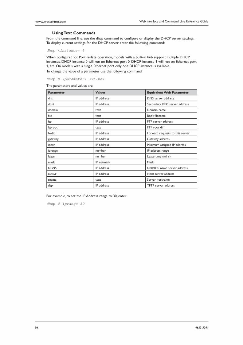
70 6622-3201
Web Interface and Command Line Reference Guidewww.westermo.com
Using Text Commands From the command line, use the dhcp command to configure or display the DHCP server settings. To display current settings for the DHCP server enter the following command:
dhcp <instance> ?
When configured for Port Isolate operation, models with a built-in hub support multiple DHCP instances. DHCP instance 0 will run on Ethernet port 0, DHCP instance 1 will run on Ethernet port 1, etc. On models with a single Ethernet port only one DHCP instance is available.
To change the value of a parameter use the following command:
dhcp 0 <parameter> <value>
The parameters and values are:
Parameter Values Equivalent Web Parameter
dns IP address DNS server address
dns2 IP address Secondary DNS server address
domain text Domain name
file text Boot filename
ftp IP address FTP server address
ftproot text FTP root dir
fwdip IP address Forward requests to this server
gateway IP address Gateway address
ipmin IP address Minimum assigned IP address
iprange number IP address range
lease number Lease time (mins)
mask IP netmask Mask
NBNS IP address NetBIOS name server address
nxtsvr IP address Next server address
sname text Server hostname
tftp IP address TFTP server address
For example, to set the IP Address range to 30, enter:
dhcp 0 iprange 30
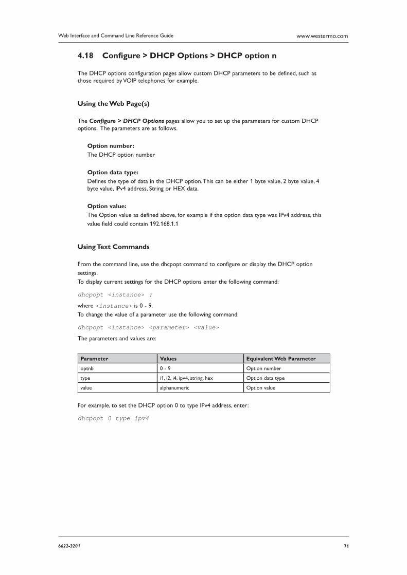
716622-3201
Web Interface and Command Line Reference Guide www.westermo.com
Confi gure > DHCP Options > DHCP option n 4.18
The DHCP options configuration pages allow custom DHCP parameters to be defined, such as those required by VOIP telephones for example.
Using the Web Page(s)
The Configure > DHCP Options pages allow you to set up the parameters for custom DHCP options. The parameters are as follows.
Option number:
The DHCP option number
Option data type:
Defines the type of data in the DHCP option. This can be either 1 byte value, 2 byte value, 4 byte value, IPv4 address, String or HEX data.
Option value:
The Option value as defined above, for example if the option data type was IPv4 address, this
value field could contain 192.168.1.1
Using Text Commands
From the command line, use the dhcpopt command to configure or display the DHCP option
settings.
To display current settings for the DHCP options enter the following command:
dhcpopt <instance> ?
where <instance> is 0 - 9.
To change the value of a parameter use the following command:
dhcpopt <instance> <parameter> <value>
The parameters and values are:
Parameter Values Equivalent Web Parameter
optnb 0 - 9 Option number
type i1, i2, i4, ipv4, string, hex Option data type
value alphanumeric Option value
For example, to set the DHCP option 0 to type IPv4 address, enter:
dhcpopt 0 type ipv4
72 6622-3201
Web Interface and Command Line Reference Guidewww.westermo.com
Confi gure > DHCP Server > MAC –>IP Addresses 4.19
This page allows you to configure a number of MAC to IP address mappings and should be used when it is necessary to supply a specific IP address to a particular Ethernet MAC address. This is particularly useful for mobile applications, e.g. GPRS, where a particular piece of mobile equipment is issued the same IP address no matter how long it has been since it was last connected to the network.
Using the Web Page(s)
To configure an entry in the table simply enter the MAC addresses of the devices that you want to allo cate a fixed IP addresses to in the left hand column and the required IP addresses in the right hand column. It is important to ensure that the IP addresses used DO NOT fall within the IP address ranges specified in the DHCP server page(s).
Using Text Commands
To configure NUI mappings from the command line use the mac2ip command.
To display a current mapping enter the command:
mac2ip <entry> ?
where <entry> is 0-9.Two separate commands are needed to set up a mapping. These take the form:
mac2ip <entry> mac <MAC> mac2ip <entry> ip <IP address>
where:
<entry> is the required entry number in the mapping table in each case
<MAC> is the MAC
<IP Address> is the IP address
736622-3201
Web Interface and Command Line Reference Guide www.westermo.com
Confi gure > DNS Server selection > DNS server selection n 4.20
The DNS server selection configuration pages allow the DNS server to be specified depending on the domain being queried. This is useful when an internal DNS server is to be used for internal DNS queries only and all other queries should use a public DNS server as defined in the PPP con-figuration.
Using the Web Page(s)
The web page includes the following parameters:
Hostname pattern:
The is the hostname or domain name that needs to match for queries to use the DNS server specified in the parameters below. This can refer to the FQDN of a host, a subdomain, a domain or any part thereof. Wildcards are supported. eg: host1.digi.com or *ilkley.digi.com or *.ilkley.digi.com
DNS server IP:
The IP address of the DNS server to use when performing queries on the hosts defined above.
Secondary DNS server IP:
The IP address of the DNS server to use when performing queries on the hosts defined above, used when the primary DNS server does not respond.
Interface: / Interface #:
The exit interface for DNS queries.
Source IP Interface: / Source IP Interface #:
If the DNS server is available via an IPSec tunnel, this parameter can be used to specify the source interface so the DNS query matches the Eroute subnet selectors.
74 6622-3201
Web Interface and Command Line Reference Guidewww.westermo.com
Using Text Commands
From the command line, use the dnssel command to configure or display DNS server selection
settings.
To display current settings enter the command:
dnssel <instance> ?
where <instance> is 0 - 14.
To change the value of a parameter use the command in the format:
dnssel <instance> <parameter> <value>
The parameters and values are:
Parameter Values Equivalent Web Parameter
pattern domain name Hostname pattern
svr IP address DNS server IP
secsvr IP address Secondary DNS server IP
ent <blank>, PPP, Eth Interface
add number Interface #
ipent <blank>, PPP, Eth Source IP
Interface
ipadd number Source IP Interface #
For example, to set the host pattern to “*.digi.com” you would enter the command:
dnssel 0 pattern *.digi.com
756622-3201
Web Interface and Command Line Reference Guide www.westermo.com
Confi gure > DNS Server Update 4.21
“Dynamic DNS” is supported in accordance with RFC2136 and RFC2485. This allows units to update specified DNS servers with their IP addresses when they first connect to the Internet and at regular intervals thereafter. The Configure > DNS Update page allows you to configure the dynam-ic DNS Update feature to operate as required.
Using the Web Page(s)
The web page includes the following parameters:
DNS server IP address:
This parameter is used to specify the IP address of the DNS Server that you wish to use. This server must support “DNS Update messages”. Dynamic DNS is generally offered as a subscrip-tion based service by ISPs but it may be appropriate for you to establish your own DNS Server if you have a large number of deployed units.
Zone to update:
When using Dynamic DNS it will be necessary for you to select or “purchase” a domain name, e.g. “mycompany.co.uk”. This parameter should be set match this domain name.
Name to update: This parameter specifies an identifier that is used in conjunction with the Zone to update parame ter to uniquely identify the unit e.g. “epos33”. The Name to update and the Zone to update together specify the full address of the unit e.g. “epos33.mycompany.co.uk”.
Update interval (s):
This parameter specifies the interval (in seconds), at which the unit will issue update messages to the DNS server.
Username:
This parameter is used to store the username that has been allocated to you by the Dynamic DNS service provider.
Password:
This parameter is used to store the password that has been allocated to you by the Dynamic DNS service provider.
Confirm password:
Enter the password again in this field to confirm it.
Password is Base64 encoded:
Some Dynamic DNS servers issue passwords that are Base64 encoded, e.g. Linux base servers. If this is the case turn this option on so that the unit correctly decodes the password before trans mission. Note that the password is not actually transmitted as part of the message but is used to create a “signature” that is appended to the message. If the password is issued to you as a hexa decimal string instead of text, you must prefix the parameter with 0x.
Interface:
This parameter defines which type of interface is configured for Internet connections (usually PPP). May also be set to use the default route if required.
Interface #:
This parameter defines which Interface instance is configured for Internet connections.
76 6622-3201
Web Interface and Command Line Reference Guidewww.westermo.com
Local time offset from GMT (hrs):
As part of the authentication process the DNS update message must include a time-stamp that is referenced to GMT. If you live in a non-GMT time zone ensure that you select the correct time offset.
Auto-detect time offset:
If no time offset is specified the unit can be configured automatically correct for time zone differ ences by setting this parameter to “Yes”.
Required time accuracy (s)
This parameter specifies the permitted variance between the unit’s time and that of the DNS server. If the variance exceeds this time then the DNS update will fail.
Time to live (s):
This parameter specifies how long a unit that resolved the address is allowed to cache that address for.
Always delete previous records:
When set to “Yes”, this parameter causes the DNS server to delete all records of previous addresses served to the unit.
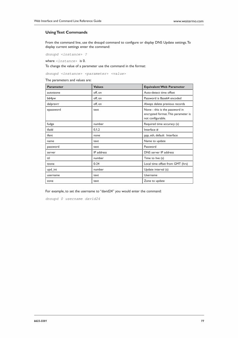
776622-3201
Web Interface and Command Line Reference Guide www.westermo.com
Using Text Commands
From the command line, use the dnsupd command to configure or display DNS Update settings. To display current settings enter the command:
dnsupd <instance> ?
where <instance> is 0.
To change the value of a parameter use the command in the format:
dnsupd <instance> <parameter> <value>
The parameters and values are:
Parameter Values Equivalent Web Parameter
autotzone off, on Auto-detect time offset
b64pw off, on Password is Base64 encoded
delprevrr off, on Always delete previous records
epassword text None - this is the password in encrypted format. This parameter is not configurable.
fudge number Required time accuracy (s)
ifadd 0,1,2 Interface #
ifent none ppp, eth, default Interface
name text Name to update
password text Password
server IP address DNS server IP address
ttl number Time to live (s)
tzone 0-24 Local time offset from GMT (hrs)
upd_int number Update interval (s)
username text Username
zone text Zone to update
For example, to set the username to “david24” you would enter the command:
dnsupd 0 username david24
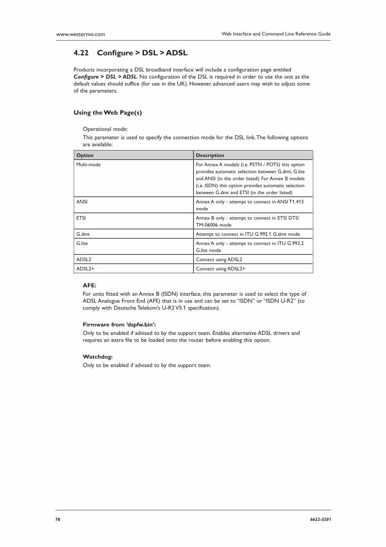
78 6622-3201
Web Interface and Command Line Reference Guidewww.westermo.com
Confi gure > DSL > ADSL 4.22
Products incorporating a DSL broadband interface will include a configuration page entitled Configure > DSL > ADSL. No configuration of the DSL is required in order to use the unit as the default values should suffice (for use in the UK). However, advanced users may wish to adjust some of the parameters.
Using the Web Page(s)
Operational mode:
This parameter is used to specify the connection mode for the DSL link. The following options are available:
Option Description
Multi-mode For Annex A models (i.e. PSTN / POTS) this option provides automatic selection between G.dmt, G.lite and ANSI (in the order listed). For Annex B models (i.e. ISDN) this option provides automatic selection between G.dmt and ETSI (in the order listed)
ANSI Annex A only - attempt to connect in ANSI T1.413 mode
ETSI Annex B only - attempt to connect in ETSI DTS/TM-06006 mode
G.dmt Attempt to connect in ITU G.992.1 G.dmt mode
G.lite Annex A only - attempt to connect in ITU G.992.2 G.lite mode
ADSL2 Connect using ADSL2
ADSL2+ Connect using ADSL2+
AFE:
For units fitted with an Annex B (ISDN) interface, this parameter is used to select the type of ADSL Analogue Front End (AFE) that is in use and can be set to “ISDN” or “ISDN U-R2” (to comply with Deutsche Telekom’s U-R2 V5.1 specification).
Firmware from ’dspfw.bin’:
Only to be enabled if advised to by the support team. Enables alternative ADSL drivers and requires an extra file to be loaded onto the router before enabling this option.
Watchdog:
Only to be enabled if advised to by the support team.
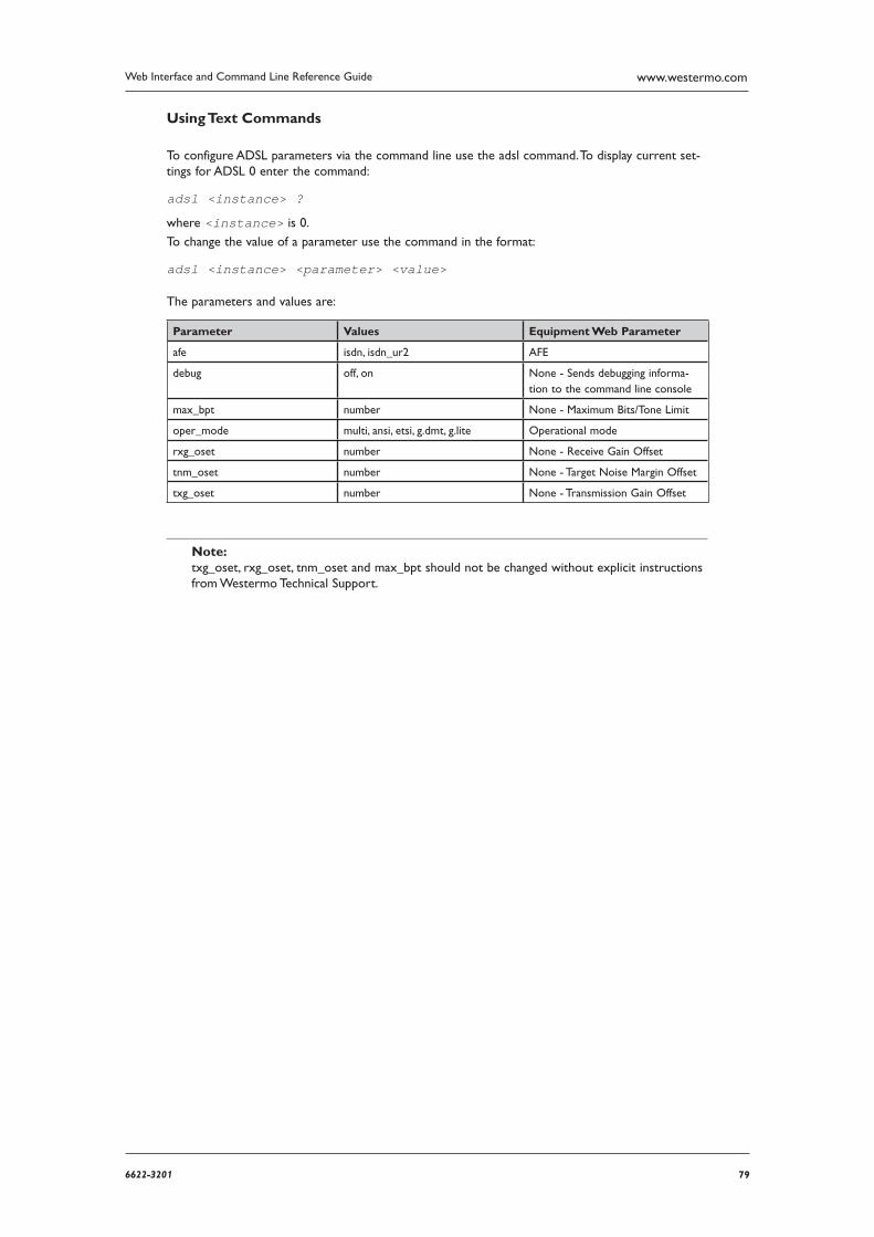
796622-3201
Web Interface and Command Line Reference Guide www.westermo.com
Using Text Commands
To configure ADSL parameters via the command line use the adsl command. To display current set-tings for ADSL 0 enter the command:
adsl <instance> ?
where <instance> is 0.
To change the value of a parameter use the command in the format:
adsl <instance> <parameter> <value>
The parameters and values are:
Parameter Values Equipment Web Parameter
afe isdn, isdn_ur2 AFE
debug off, on None - Sends debugging informa-tion to the command line console
max_bpt number None - Maximum Bits/Tone Limit
oper_mode multi, ansi, etsi, g.dmt, g.lite Operational mode
rxg_oset number None - Receive Gain Offset
tnm_oset number None - Target Noise Margin Offset
txg_oset number None - Transmission Gain Offset
Note: txg_oset, rxg_oset, tnm_oset and max_bpt should not be changed without explicit instructions from Westermo Technical Support.
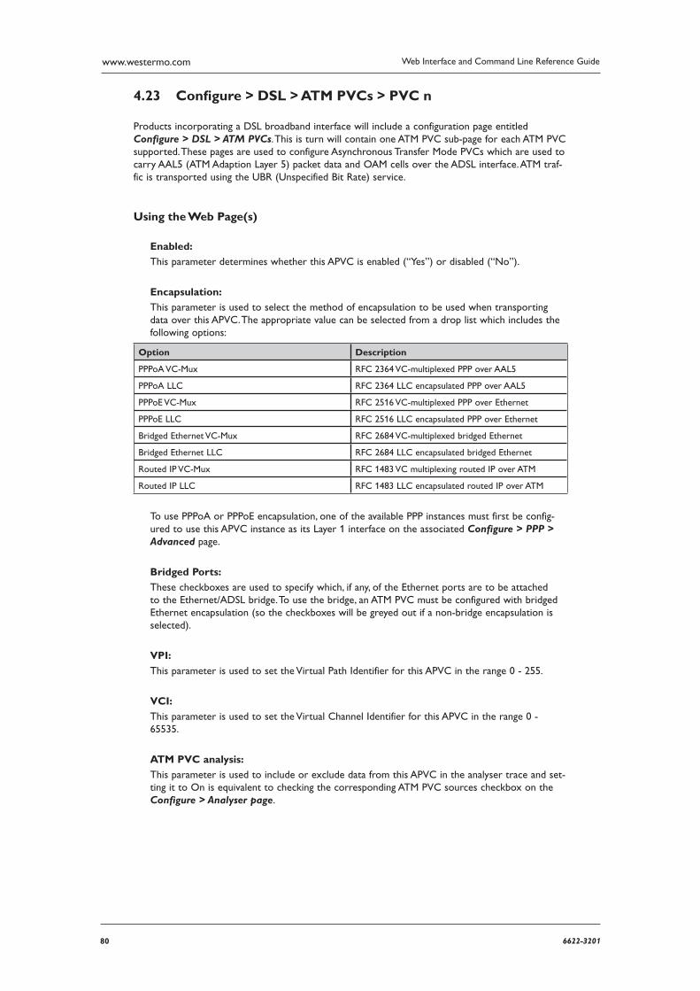
80 6622-3201
Web Interface and Command Line Reference Guidewww.westermo.com
Confi gure > DSL > ATM PVCs > PVC n 4.23
Products incorporating a DSL broadband interface will include a configuration page entitled Configure > DSL > ATM PVCs. This is turn will contain one ATM PVC sub-page for each ATM PVC supported. These pages are used to configure Asynchronous Transfer Mode PVCs which are used to carry AAL5 (ATM Adaption Layer 5) packet data and OAM cells over the ADSL interface. ATM traf-fic is transported using the UBR (Unspecified Bit Rate) service.
Using the Web Page(s)
Enabled:
This parameter determines whether this APVC is enabled (“Yes”) or disabled (“No”).
Encapsulation:
This parameter is used to select the method of encapsulation to be used when transporting data over this APVC. The appropriate value can be selected from a drop list which includes the follow ing options:
Option Description
PPPoA VC-Mux RFC 2364 VC-multiplexed PPP over AAL5
PPPoA LLC RFC 2364 LLC encapsulated PPP over AAL5
PPPoE VC-Mux RFC 2516 VC-multiplexed PPP over Ethernet
PPPoE LLC RFC 2516 LLC encapsulated PPP over Ethernet
Bridged Ethernet VC-Mux RFC 2684 VC-multiplexed bridged Ethernet
Bridged Ethernet LLC RFC 2684 LLC encapsulated bridged Ethernet
Routed IP VC-Mux RFC 1483 VC multiplexing routed IP over ATM
Routed IP LLC RFC 1483 LLC encapsulated routed IP over ATM
To use PPPoA or PPPoE encapsulation, one of the available PPP instances must first be config-ured to use this APVC instance as its Layer 1 interface on the associated Configure > PPP > Advanced page.
Bridged Ports:
These checkboxes are used to specify which, if any, of the Ethernet ports are to be attached to the Ethernet/ADSL bridge. To use the bridge, an ATM PVC must be configured with bridged Ethernet encapsulation (so the checkboxes will be greyed out if a non-bridge encapsulation is selected).
VPI:
This parameter is used to set the Virtual Path Identifier for this APVC in the range 0 - 255.
VCI:
This parameter is used to set the Virtual Channel Identifier for this APVC in the range 0 - 65535.
ATM PVC analysis:
This parameter is used to include or exclude data from this APVC in the analyser trace and set-ting it to On is equivalent to checking the corresponding ATM PVC sources checkbox on the Configure > Analyser page.
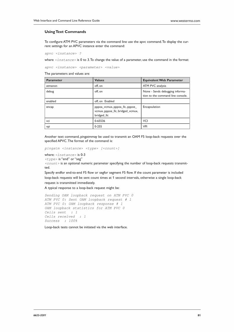
816622-3201
Web Interface and Command Line Reference Guide www.westermo.com
Using Text Commands
To configure ATM PVC parameters via the command line use the apvc command. To display the cur-rent settings for an APVC instance enter the command:
apvc <instance> ?
where <instance> is 0 to 3. To change the value of a parameter, use the command in the format:
apvc <instance> <parameter> <value>
The parameters and values are:
Parameter Values Equivalent Web Parameter
atmanon off, on ATM PVC analysis
debug off, on None - Sends debugging informa-tion to the command line console.
enabled off, on Enabled
encap pppoa_vcmux, pppoa_llc, pppoe_vcmux, pppoe_llc, bridged_vcmux, bridged_llc
Encapsulation
vci 0-65536 VCI
vpi 0-255 VPI
Another text command, pingatmmay be used to transmit an OAM F5 loop-back requests over the specified APVC. The format of the command is:
pingatm <instance> <type> [<count>]
where: <instance> is 0-3 <type> is “end” or “seg” <count> is an optional numeric parameter specifying the number of loop-back requests transmit-ted.
Specify endfor end-to-end F5 flow or segfor segment F5 flow. If the count parameter is included
loop-back requests will be sent count times at 1 second intervals, otherwise a single loop-back
request is transmitted immediately.
A typical response to a loop-back request might be:
Sending OAM loopback request on ATM PVC 0ATM PVC 0: Sent OAM loopback request # 1ATM PVC 0: OAM loopback response # 1OAM loopback statistics for ATM PVC 0Cells sent : 1 Cells received : 1 Success : 100%
Loop-back tests cannot be initiated via the web interface.
82 6622-3201
Web Interface and Command Line Reference Guidewww.westermo.com
Confi gure > Dynamic DNS 4.24
The Dynamic DNS client (DYNDNS), is used to update DNS hostnames with the current IP address of a particular interface. It operates in accordance with the specification supplied by dyndns.org (go to http://www.dyndns.org/developers/specs/). When the interface specified by the Interface and Inter face # parameters connects, the client checks the current IP address of that interface and if it differs from that obtained by the previous connection, www.dyndns.org is contacted and the hostnames spec ified in the Hostname parameters are updated with the new address.
Using the Web Page(s)
The web page includes the following parameters:
System:
This parameter is used to identify the Dynamic DNS system containing the hostnames to be updated and may be set to “Dynamic DNS”, “Static DNS” or “Custom DNS”.
Hostname n:
These are the hostnames to be updated.
Username:
Specifies the username to use when updating hostnames.
Password:
Specifies the password to use when updating hostnames.
Confirm password:
Enter the password again in this field to confirm it.
Interface:
Defines which interface, PPP, Ethernet or default, this DYNDNS instance is associated with (usu-ally PPP). If set to default, the client will keep track of and use the current default route.
Interface #:
Defines which Interface # this DYNDNS instance is associated with.
Wildcards:
When this parameter is “On”, it indicates that Dynamic DNS will match DNS requests of the form “*.hostname” where the “*” matches any text. For example if Hostname 1 was set to “user site.dyndns.org” and the Wildcard parameter was On, then “www.usersite.dyndns.org” would resolve to the interface address.
Supply IP address in update:
This parameter is set to “Yes” by default. When set to “No”, the interface address is not sup-plied as part of the Dynamic DNS update. In this case, DYNDNS attempts to determine the correct IP address by other means (e.g. IP source address). This mode would normally only be used if the router is “behind” a NAT box.
Note: Users should visit the www.dyndns.org web site for further information before attempting to config ure Dynamic DNS.
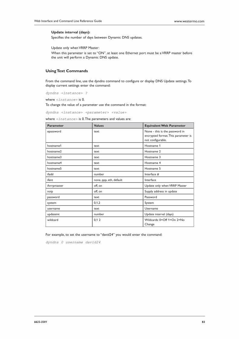
836622-3201
Web Interface and Command Line Reference Guide www.westermo.com
Update interval (days):
Specifies the number of days between Dynamic DNS updates.
Update only when VRRP Master:
When this parameter is set to “ON”, at least one Ethernet port must be a VRRP master before the unit will perform a Dynamic DNS update.
Using Text Commands
From the command line, use the dyndns command to configure or display DNS Update settings. To display current settings enter the command:
dyndns <instance> ?
where <instance> is 0.
To change the value of a parameter use the command in the format:
dyndns <instance> <parameter> <value>
where <instance> is 0. The parameters and values are:
Parameter Values Equivalent Web Parameter
epassword text None - this is the password in encrypted format. This parameter is not configurable.
hostname1 text Hostname 1
hostname2 text Hostname 2
hostname3 text Hostname 3
hostname4 text Hostname 4
hostname5 text Hostname 5
ifadd number Interface #
ifent none, ppp, eth, default Interface
ifvrrpmaster off, on Update only when VRRP Master
noip off, on Supply address in update
password text Password
system 0,1,2 System
username text Username
updateint number Update interval (days)
wildcard 0,1 2 Wildcards: 0=Off 1=On 2=No Change
For example, to set the username to “david24” you would enter the command:
dyndns 0 username david24
84 6622-3201
Web Interface and Command Line Reference Guidewww.westermo.com
Confi gure > Ethernet > ETH n 4.25
The Configure > Ethernet folder opens to list configuration pages for each of the available Ethernet instances on the unit. Each page allows you to configure parameters such as the IP address, mask, gateway, etc.
On units with only one Ethernet port, if more than one Ethernet instance exists these are treated as logical Ethernet ports. These instances can be used to assign more than one Ethernet IP address to a router.
On units with more than one physical Ethernet port, the Ethernet instances refer to the different physical Ethernet ports. These units can be configured for either “HUB” mode or “Port Isolate” mode.
In HUB mode all the Ethernet ports are linked together and behave like an Ethernet hub or switch. This means that the router will respond to all of its Ethernet IP addresses on all of its ports (as the hub/ switch behaviour links the ports together).
In Port Isolate mode the router will only respond to its Ethernet 0 IP address on physical port “LAN 0”, its Ethernet 1 IP address on physical port “LAN 1”, etc. The router will not respond to its Ethernet 1 address on port “LAN 0” unless routing has been configured appropriately.
When configured for HUB mode it is important that no more than one of the router’s ports is connected to another hub or switch on the same physical network otherwise an Ethernet loop can occur. The default behaviour is “HUB” rather than “Port Isolate”.
Note: VLAN tagging is not available when the router is configured for Port Isolate mode.
Using the Web Page(s)
Description:
This parameter allows you to enter a name for this Ethernet instance, to make it easier to iden-tify.
IP analysis:
This parameter is used to include or exclude IP data from this Ethernet port from the analyser trace and is equivalent to checking or un-checking the equivalent IP sources checkbox on the Configure > Analyser page.
Ethernet analysis:
This parameter is used to include or exclude IP data from this Ethernet port from the analyser trace and is equivalent to checking or un-checking the equivalent ETH boxes on the IP sources section of the Configure > Analyser page.
DHCP client:
This parameter is used to enable or disable the DHCP client for this Ethernet port.
IP address:
This parameter specifies the IP address of this Ethernet port on your LAN.
Multihome additional consecutive addresses:
This parameter defines how many additional (consecutive) addresses the ethernet driver will “own”. For example, if the IP address of the port was 10.3.20.40, and Multihome additional con-secutive addresses was set to 3, the IP addresses 10.3.20.41, 10.3.20.42 and 10.3.20.43 would also belong to the ethernet port.
Mask:
This parameter specifies the subnet mask of the IP subnet to which the unit is attached via this Ethernet port. Typically, this would be 255.255.255.0 for a Class C network.
Max Rx rate (kbps):
On models with multiple LAN ports, this parameter may be used to specify a maximum data
856622-3201
Web Interface and Command Line Reference Guide www.westermo.com
rate in kbps that the unit will receive on this port. This may be useful in applications where separate LAN ports are allocated to separate LANs and it is necessary to prioritise traffic from one LAN over another.
Max Tx rate (kbps):
On models with multiple LAN ports, this parameter may be used to specify a maximum data rate in kbps that the unit will transmit on this port. This may be useful in applications where separate LAN ports are allocated to separate LANs and it is necessary to prioritise traffic from one LAN over another.
Group:
On units with a built-in hub/switch, the Group parameter for each port is normally set to 0. This means that all ports “belong” to the same hub. If required however, the Group parameter may be used to isolate specific ports to create separate hubs. For example, if Ethernet 0 and Ethernet1 have their Group parameter set to 0 whilst Ethernet 2 and Ethernet 3 have their Group parameter set to 1, the unit will in effect be configured as two 2-port hubs instead of one 4-port hub. This means that traffic on physical ports “LAN 0” and “LAN 1” will not be vis-ible to traffic on physical ports “LAN 2” and “LAN 3” (and vice versa).
This parameter is not available on the web page when the unit is configured for VLAN opera-tion. (Changing it at the command line will have no effect when the unit is configured for VLAN operation.)
DNS server:
This parameter specifies the IP address of a DNS server to be used by the unit for resolving IP hostnames.
Gateway:
This parameter specifies the IP address of a gateway to be used by the unit. IP packets whose destination IP addresses are not on the LAN to which the unit is connected will be forwarded to this gateway.
Metric:
This parameter specifies the connected metric of an interface, changing this value will alter the metric of dynamic routes created automatically for this interface. The default metric of a con-nected interface is 1. By allowing the interface to have a higher value (lower priority), static routes can take preference to interface generated dynamic routes. For normal operation, leave this value unchanged.
NAT mode:
This parameter is used to select whether IP Network Address Translation (NAT) or Network Address and Port Translation (NAPT) are used at the Ethernet interface. When the parameter is set to Off, no address or port translation takes place.
NAT and NAPT can have many uses but they are generally used to allow a number of private IP hosts (PCs for example) to connect to the Internet through a single shared public IP address. This has two main advantages, it saves on IP address space (the ISP only need assign you one IP address), and it isolates the private IP hosts from the Internet (effectively providing a simple firewall because unsolicited traffic from the Internet cannot be routed directly to the private IP hosts.
To use NAT or NAPT correctly in the example of connecting private hosts to the Internet, NAT or NAPT should be enabled on the router’s interface with the public Internet IP address and should be disabled on the router’s interface with the private IP address.
NAT and NAPT Explanation
In order to explain the difference between NAT and NAPT the behaviour of these features in the above example is covered below:
NAT
When a private IP host sends a UDP or TCP packet to an Internet IP address, the router will change the source address of the packet from the private host IP to the router’s public IP address before forwarding the packet onto the Internet host. Additionally it will create an entry
86 6622-3201
Web Interface and Command Line Reference Guidewww.westermo.com
in a “NAT table” containing the private IP source address, the private IP port number, the public IP destina tion address and the destination port number. Conversely, when the router receives a reply packet back from the public host, it checks the source IP, source port number and destina-tion port number in the NAT table to determine which private host to forward the packet to. Before it forwards the packet back to the private host, it changes the destination IP address of the packet from its public IP address to the IP address of the private host.
NAPT
NAPT behaves like NAT but in addition to changing the source IP of the packet from the pri-vate host it can also change the source port number. This is required if more than one private host attempts to connect using the same local port number to the same Internet host on the same remote port number. If such a scenario were to occur with NAT the router would be unable to determine which private host to route the returning packets to and the connection would fail.
Note: NAT or NAPT should be used with great care as in most private IP routing scenarios it is not required and to enable it incorrectly WILL cause problems. NAT also uses another technique not detailed here to work with ICMP packets such as pings and other packet types.
Speed:
This parameter is used to select “10Base-T”, “100Base-T” or “Auto” mode. The currently select-ed mode will be shown in brackets after the parameter name.
Full duplex:
This parameter is used to turn on Full duplex mode so that data can be transmitted in both directions at the same time for this Ethernet instance. When set to “Off” the Ethernet instance will operate in half-duplex mode.
Firewall:
This parameter is used to enable or disable firewall operation for this Ethernet instance.
IGMP:
This parameter is used to enable or disable the Internet Group Management Protocol for this Ethernet instance.
IPSec:
This parameter is used to enable or disable IPSec security features for this Ethernet instance.
IPSec source IP from interface:
By default, the source IP address for an IPSec Eroute will be the IP address of the interface on which IPSec was enabled. By setting this parameter to either PPP or Ethernet, the source address used by IPSec will match that of the Ethernet or PPP interface specified by the IPSec source IP from interface # parameter below.
IPSec source IP from interface #:
See above.
GRE:
Note: From firmware version 4955 this web option and corresponding CLI commands have been removed. GRE tunnels should be configured from Configure > Tunnel (GRE)
This parameter enables Generic Routing Encapsulation (GRE) for this Ethernet instance. GRE is a simple tunnelling protocol. For further details refer to the GRE mode parameter on the Configure > IPSec > IPSec Eroutes > Eroute n page, and also RFC2784.
876622-3201
Web Interface and Command Line Reference Guide www.westermo.com
MAC address filtering:
When this parameter is enabled, a received frame will only be sent up the stack if the source MAC address or matching part thereof exists in the MAC filter table. It is possible to allow a range of addresses by specifying only the significant portion of the MAC address in the filter table to allow packets from other units.
MTU
This parameter is used to set the Maximum Transmit Unit for the specified interface. The default value is 0 meaning that the MTU will either be 1504 (for units using a Kendin Ethernet device) or 1500 (for non-Kendin devices). The non-zero, values must be greater than 128 and not more than the default value. Values must also be multiples of 4 and the unit will automatically adjust invalid values entered by the user. So, if the MTU is set to 1000, the largest IP packet that the unit will send is 1000 bytes.
QOS:
This parameter is used to turn QOS “On” or “Off” for this Ethernet port.
Remote access options:
The Remote access options parameter can be set to “No restrictions”, “Disable management”, “Disable return RST”, “Disable management & return RST”. When set to “No restrictions”, users on this interface can access the unit’s Telnet, FTP and web services for the purpose of managing the unit.
When set to “Disable management”, users on this interface are prevented from managing the unit via Telnet, FTP or the web interface.
Disable return RST - whenever a unit receives a TCP SYN packet for one of its own IP address-es with the destination port set to an unexpected value, i.e. a port that the unit would normally expect to receive TCP traffic on, it will reply with a TCP RST packet. This is normal behaviour.
However, the nature of internet traffic is such that whenever an internet connection is estab-lished, TCYP SYN packets are to be expected. As the router’s PPP inactivity timer is restarted each time the unit transmits data (but not when it receives data), the standard response of the unit to SYN packets i.e. transmitting an RST packet, will restart the inactivity timer and prevent the unit from disconnecting the link even when there is no “genuine” traffic. This effect can be prevented by using the appropriate commands and options within the firewall script. However, where you are not using a firewall, the same result can be achieved by selecting this option, i.e. when this option is selected the normal behaviour of the unit in responding to SYN packets with RST packets is disabled. The option will also prevent the unit from responding to unsolic-ited UDP packets with the normal ICMP destination unreachable responses.
The “Disable management & return RST” option prevents users from managing the unit via the Telnet, FTP and web interfaces and also disables the transmission of TCP RST packets as above.
RIP version:
RIP (Routing Information Protocol), is used by routers to determine the best route to any desti-nation. There are several different versions that can be enabled or disabled using this parameter. When RIP version is set to Off, RIP is disabled and no RIP packets transmitted out this inter-face. When RIP version is set to “V1” or “V2”, the unit will transmit RIP version 1 or 2 packets respectively (version 2 packets are sent to the “all routers” multicast address 224.0.0.9). When RIP Version is set to “V1 Compat”, the unit will transmit RIP version 2 packets to the subnet broadcast address. This allows “V1” capable routers to act upon these packets.
When RIP is enabled, RIP packets are transmitted when the Ethernet instance first becomes active, and at intervals specified by the RIP interval parameter on the Configure > General
page.
RIP destination IP address list:
RIP packets are normally sent out on a broadcast basis or to a multi-cast address. This parame-ter may be used to force RIP packets to be sent to a specified IP address. It is particularly useful if you need to route the packets via a VPN tunnel.
88 6622-3201
Web Interface and Command Line Reference Guidewww.westermo.com
RIP authentication method:
This parameter selects the authentication method for RIP packets. When set to “Off”, the inter-face will send and receive packets without any authentication. When set to “Access List”, the interface will send RIP packets without any authentication. When receiving packets, the interface will check the sender’s IP address against the list entered on the Configure > IP Routes > RIP > RIP access list, and if the IP address is present in the list, the packet will be allowed through.
When set to “Plain password (V1+V2)”, the interface will use the first valid key it finds (set on the Configure > IP Routes > RIP > Authentication Keys pages), and use the plaintext RIP authentication method before sending the packet out. If no valid key can be found, the interface will not send any RIP packets. When receiving a RIP packet, a valid plaintext key must be present in the packet before it will be accepted. This method can be used with both RIP v1 and RIP v2.
When set to “MD5 (V2 only)”, the interface will use the first valid key it finds (set on the Configure > IP Routes > RIP > Authentication Keys pages), and use the MD5 authentication algorithm before sending the packet out. If no valid key can be found, the interface will not send any RIP packets. Received RIP packets must be authenticated using the MD5 authentication algo-rithm before they will be accepted. This method can be used with RIP v2.
PING request interval (s):
If this parameter is set to a non-zero value the unit will generate a “ping” (ICMP echo request) to the address specified by the PING IP address parameter. Setting the value to 0 disables the ping facility. When used in conjunction with PING IP address and No PING response out of service delay, this parameter can be used to configure the router to use a back-up interface automatically should there be a problem with this interface.
PING IP address:
This parameter specifies the IP address or host name to which ICMP echo requests will be sent if the PING request interval is greater than 0.
Ping IP address #2:
This allows for more reliable problem detection before fail over occurs. If an IP address or host name is entered and the Ping IP switchover count has a value greater than 0, when a ping failure is detected on the primary IP address the 2nd IP address is checked. This is to ensure that if the main IP address becomes unavailable for any reason and stops responding to ICMP requests, the router will check another IP address before starting fail over procedures.
PING IP switchover count:
When set to more than 0, indicates the number pings that need to fail before the 2nd IP address is checked.
Only send PINGs when interface is in service:
If this parameter is set to “ON”, ICMP echo requests will only be sent from this interface when it is in service. The default setting is “OFF”, ICMP echo requests are sent when the interface is in service and out of service.
No PING response out of service delay (s):
This parameter is used to specify the length of time (in seconds), before a route will be desig-nated as being out of service if no response has been received after three PING attempts.
Out of service time (s):
This parameter is used to specify the length of time (in seconds) for which any routes using this Ethernet interface will be designated as being out of service after the above parameter has been effected.
Heartbeat request interval (s):
If this parameter is set to a non-zero value, the unit will transmit “heartbeat” packets at the interval specified. Heartbeat packets are UDP packets that contain status information about the unit that may be used to locate a remote unit’s current dynamic IP address.
896622-3201
Web Interface and Command Line Reference Guide www.westermo.com
Heartbeat IP address:
This parameter specifies the destination IP address for heartbeat packets.
Heartbeat selects interface from routing table:
When enabled, the UDP heartbeats will choose the best route from the routing table. If disa-bled the exit interface will be interface on which the heartbeat is configured.
Heartbeat includes IMSI:
When enabled, the heartbeat will include the IMSI of the wireless module.
Physical link down deact delay (s):
This parameter is used to specify the length of time (in seconds) that the router will wait after detecting that an Ethernet cable has been removed before routes that were using that interface are marked as out of service. If the parameter is set to 0, the feature is disabled i.e. routes using the port will not be marked as out of service if the cable is removed.
Enable Top Talker Monitoring:
If this parameter is set to “Yes”, Top Talker information is logged and displayed on the Statistics > Top Talkers page. Top Talkers displays average bandwidth usage for the interface over three time frames: current, previous minute, and previous 30 minutes.
VRRP group ID:
The VRRP parameters are used to configure the router to participate in a VRRP group. VRRP (Virtual Router Redundancy Protocol), allows multiple physical routers to appear as a single gateway for IP communications in order to provide back-up WAN communications in the event that the primary router in the group fails in some way. It works by allowing multiple routers to monitor data on the same IP address. One router is designated as the “owner” of the address and under normal circumstances it will route data as usual. However, the VRRP protocol allows the other routers in the VRRP group to monitor the “owner” and if, they detect that it is no longer operating, negotiate with each other to take over the role as owner. The protocol also facilitates the automatic re-prioritisation of the original owner when it returns to operation.
The VRRP group ID parameter is used to identify routers that are configured to operate within the same VRRP group. The default value is 0 which means that VRRP is disabled on this Ethernet port. The value may be set to a number from 1 to 255 to enable VRRP and include this Ethernet port in the specified VRRP group.
VRRP priority:
This parameter is used to set the priority level of this Ethernet interface within the VRRP group from 0 to 255. 255 is the highest priority and setting the priority to this value would designate this Ethernet port as the initial “owner” within the group. The value selected for the VRRP priority should reflect the values selected for other routers within the VRRP group, i.e. no two routers in the group should be initialised with the same value.
VLAN:
If this parameter is set to “On”, VLAN tagging is enabled on this interface according to the parameters set on the Configure > Ethernet > VLANs page. VLAN tagging will only apply if there is an entry for this interface on the Configure > Ethernet > VLANs page.
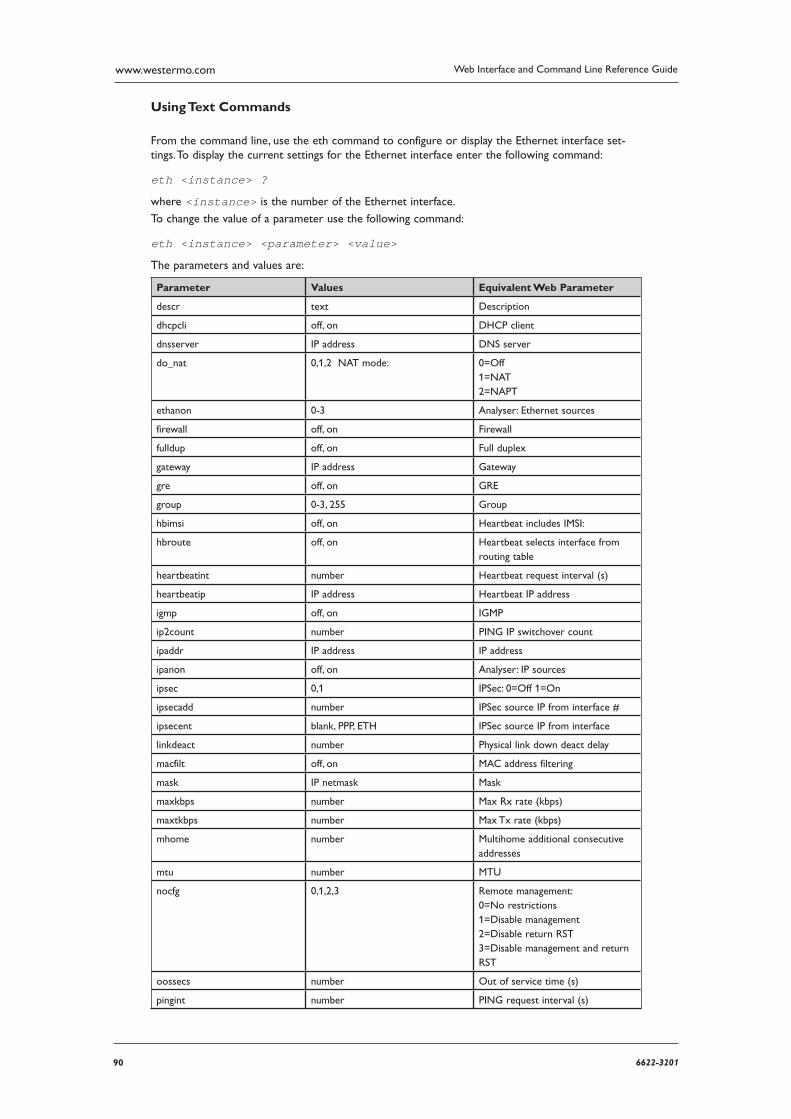
90 6622-3201
Web Interface and Command Line Reference Guidewww.westermo.com
Using Text Commands
From the command line, use the eth command to configure or display the Ethernet interface set-tings. To display the current settings for the Ethernet interface enter the following command:
eth <instance> ?
where <instance> is the number of the Ethernet interface.
To change the value of a parameter use the following command:
eth <instance> <parameter> <value>
The parameters and values are:
Parameter Values Equivalent Web Parameter
descr text Description
dhcpcli off, on DHCP client
dnsserver IP address DNS server
do_nat 0,1,2 NAT mode: 0=Off 1=NAT 2=NAPT
ethanon 0-3 Analyser: Ethernet sources
firewall off, on Firewall
fulldup off, on Full duplex
gateway IP address Gateway
gre off, on GRE
group 0-3, 255 Group
hbimsi off, on Heartbeat includes IMSI:
hbroute off, on Heartbeat selects interface from routing table
heartbeatint number Heartbeat request interval (s)
heartbeatip IP address Heartbeat IP address
igmp off, on IGMP
ip2count number PING IP switchover count
ipaddr IP address IP address
ipanon off, on Analyser: IP sources
ipsec 0,1 IPSec: 0=Off 1=On
ipsecadd number IPSec source IP from interface #
ipsecent blank, PPP, ETH IPSec source IP from interface
linkdeact number Physical link down deact delay
macfilt off, on MAC address filtering
mask IP netmask Mask
maxkbps number Max Rx rate (kbps)
maxtkbps number Max Tx rate (kbps)
mhome number Multihome additional consecutive addresses
mtu number MTU
nocfg 0,1,2,3 Remote management: 0=No restrictions 1=Disable management 2=Disable return RST 3=Disable management and return RST
oossecs number Out of service time (s)
pingint number PING request interval (s)
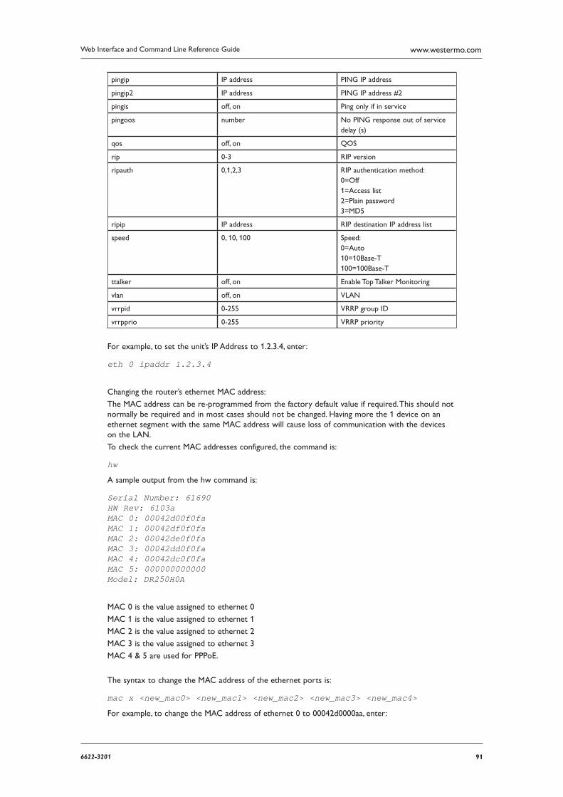
916622-3201
Web Interface and Command Line Reference Guide www.westermo.com
pingip IP address PING IP address
pingip2 IP address PING IP address #2
pingis off, on Ping only if in service
pingoos number No PING response out of service delay (s)
qos off, on QOS
rip 0-3 RIP version
ripauth 0,1,2,3 RIP authentication method: 0=Off 1=Access list 2=Plain password 3=MD5
ripip IP address RIP destination IP address list
speed 0, 10, 100 Speed: 0=Auto 10=10Base-T 100=100Base-T
ttalker off, on Enable Top Talker Monitoring
vlan off, on VLAN
vrrpid 0-255 VRRP group ID
vrrpprio 0-255 VRRP priority
For example, to set the unit’s IP Address to 1.2.3.4, enter:
eth 0 ipaddr 1.2.3.4
Changing the router’s ethernet MAC address:
The MAC address can be re-programmed from the factory default value if required. This should not normally be required and in most cases should not be changed. Having more the 1 device on an ethernet segment with the same MAC address will cause loss of communication with the devices on the LAN.
To check the current MAC addresses configured, the command is:
hw
A sample output from the hw command is:
Serial Number: 61690 HW Rev: 6103a MAC 0: 00042d00f0fa MAC 1: 00042df0f0fa MAC 2: 00042de0f0fa MAC 3: 00042dd0f0fa MAC 4: 00042dc0f0fa MAC 5: 000000000000 Model: DR250H0A
MAC 0 is the value assigned to ethernet 0
MAC 1 is the value assigned to ethernet 1
MAC 2 is the value assigned to ethernet 2
MAC 3 is the value assigned to ethernet 3
MAC 4 & 5 are used for PPPoE.
The syntax to change the MAC address of the ethernet ports is:
mac x <new_mac0> <new_mac1> <new_mac2> <new_mac3> <new_mac4>
For example, to change the MAC address of ethernet 0 to 00042d0000aa, enter:

92 6622-3201
Web Interface and Command Line Reference Guidewww.westermo.com
mac 0 00042d0000aa
A reboot is required after the command has been issued.
936622-3201
Web Interface and Command Line Reference Guide www.westermo.com
Confi gure > Ethernet > ETH n > QOS 4.26
In addition to the QOS parameter on the ETH N standard parameters pages (which are used to enable quality of service management for that ETH instance), each ETH instance has an associated QOS instance (ETH 0 maps to QOS 5, ETH 1 maps to QOS 6, etc.). These QOS instances include 10 QOS queues into which packets may be placed when using QOS. Each of these queues must be assigned a queue profile (from the twelve available profiles defined in the Configure > Quality of Service > Q Profile pages), and a priority value.
Using the Web Page(s)
Each ETH n > QOS page includes the Link speed parameter at the top followed by a list of queues with drop-down selection boxes that are used to assign a profile and a priority to each queue.
Link speed (Kbps):
This parameter should be set to the maximum data rate that this PPP link is capable of sus-taining. It is used when calculating whether or not the data rate from a queue may exceed its Minimum Kbps setting (as determined by the profile assigned to it) and send at a higher rate (up to the Max imum Kbps setting).
Queue priorities:
Below this heading is a list of the queues from 0 to 9 alongside each of which are drop down selec tion lists for assigning profile numbers (from 0 to 11) and queue priorities. The priority may be set to “Very High”, “High”, “Medium”, “Low” or “Very Low”.
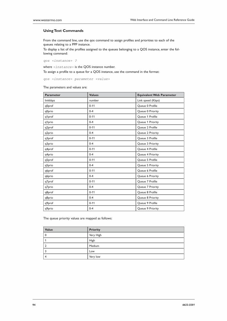
94 6622-3201
Web Interface and Command Line Reference Guidewww.westermo.com
Using Text Commands
From the command line, use the qos command to assign profiles and priorities to each of the queues relating to a PPP instance.
To display a list of the profiles assigned to the queues belonging to a QOS instance, enter the fol-lowing command:
qos <instance> ?
where <instance> is the QOS instance number.
To assign a profile to a queue for a QOS instance, use the command in the format:
qos <instance> parameter <value>
The parameters and values are:
Parameter Values Equivalent Web Parameter
linkkbps number Link speed (Kbps)
q0prof 0-11 Queue 0 Profile
q0prio 0-4 Queue 0 Priority
q1prof 0-11 Queue 1 Profile
q1prio 0-4 Queue 1 Priority
q2prof 0-11 Queue 2 Profile
q2prio 0-4 Queue 2 Priority
q3prof 0-11 Queue 3 Profile
q3prio 0-4 Queue 3 Priority
q4prof 0-11 Queue 4 Profile
q4prio 0-4 Queue 4 Priority
q5prof 0-11 Queue 5 Profile
q5prio 0-4 Queue 5 Priority
q6prof 0-11 Queue 6 Profile
q6prio 0-4 Queue 6 Priority
q7prof 0-11 Queue 7 Profile
q7prio 0-4 Queue 7 Priority
q8prof 0-11 Queue 8 Profile
q8prio 0-4 Queue 8 Priority
q9prof 0-11 Queue 9 Profile
q9prio 0-4 Queue 9 Priority
The queue priority values are mapped as follows:
Value Priority
0 Very High
1 High
2 Medium
3 Low
4 Very low
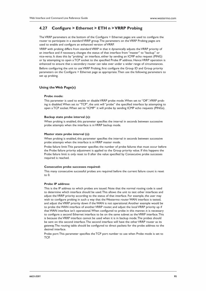
956622-3201
Web Interface and Command Line Reference Guide www.westermo.com
Confi gure > Ethernet > ETH n > VRRP Probing 4.27
The VRRP parameters at the bottom of the Configure > Ethernet pages are used to configure the router to participate in a standard VRRP group. The parameters on the VRRP Probing pages are used to enable and configure an enhanced version of VRRP.
VRRP with probing differs from standard VRRP in that it dynamically adjusts the VRRP priority of an interface and if necessary, changes the status of that interface from “master” to “backup” or vice-versa. It does this by “probing” an interface, either by sending an ICMP echo request (PING) or by attempting to open a TCP socket to the specified Probe IP address. Hence VRRP operation is enhanced to ensure that a secondary router can take over under a wider range of circumstances.
Before configuring the unit to use VRRP Probing, first configure the Group ID and Group priority parameters on the Configure > Ethernet page as appropriate. Then use the following parameters to set up probing.
Using the Web Page(s)
Probe mode:
This parameter is used to enable or disable VRRP probe mode. When set to “Off”, VRRP prob-ing is disabled. When set to “TCP”, the unit will “probe” the specified interface by attempting to open a TCP socket. When set to “ICMP” it will probe by sending ICMP echo requests (PINGs).
Backup state probe interval (s):
When probing is enabled, this parameter specifies the interval in seconds between successive probe attempts when the interface is in VRRP backup mode.
Master state probe interval (s):
When probing is enabled, this parameter specifies the interval in seconds between successive probe attempts when the interface is in VRRP master mode.
Probe failure limit: This parameter specifies the number of probe failures that must occur before the Probe failure priority adjustment is applied to the Group priority value. If this happens the Probe failure limit is only reset to 0 after the value specified by Consecutive probe successes required is reached.
Consecutive probe successes required:
This many consecutive successful probes are required before the current failure count is reset to 0.
Probe IP address:
This is the IP address to which probes are issued. Note that the normal routing code is used to determine which interface should be used. This allows the unit to test other interfaces and adjust the VRRP priority according to the status of that interface. For example, the user may wish to con figure probing in such a way that the Westermo router WAN interface is tested, and adjust the VRRP priority down if the WAN is not operational. Another example would be to probe the WAN interface of another VRRP router, and adjust the local VRRP priority up if that WAN interface isn’t opera tional. When configured to probe in this manner, it is necessary to configure a second Ethernet interface to be on the same subnet as the VRRP interface. This is because the VRRP interface cannot be used when it is in backup mode. The probes should be sent on this second interface. The second interface will have the other VRRP router as its gateway. The routing table should be configured to direct packets for the probe address to the desired interface.
Probe port: This parameter specifies the TCP port number to use when Probe mode is set to TCP.
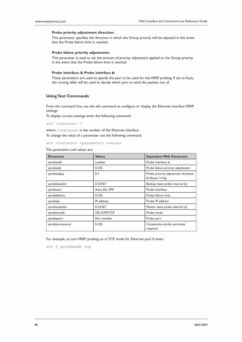
96 6622-3201
Web Interface and Command Line Reference Guidewww.westermo.com
Probe priority adjustment direction:
This parameter specifies the direction in which the Group priority will be adjusted in the event that the Probe failure limit is reached.
Probe failure priority adjustment:
This parameter is used to set the amount of priority adjustment applied to the Group priority in the event that the Probe failure limit is reached.
Probe interface: & Probe interface #:
These parameters are used to specify the port to be used for the VRRP probing. If set to Auto, the routing table will be used to decide which port to send the packets out of.
Using Text Commands
From the command line, use the eth command to configure or display the Ethernet interface VRRP settings.
To display current settings enter the following command:
eth <instance> ?
where <instance> is the number of the Ethernet interface.
To change the value of a parameter use the following command:
eth <instance> <parameter> <value>
The parameters and values are:
Parameter Values Equivalent Web Parameter
vprobeadd number Probe interface #
vprobeadj 0-255 Probe failure priority adjustment
vprobeadjup 0,1 Probe priority adjustment direction: 0=Down 1=Up
vprobebackint 0-32767 Backup state probe interval (s)
vprobeent Auto, Eth, PPP Probe interface
vprobefailcnt 0-255 Probe failure limit
vprobeip IP address Probe IP address
vprobemastint 0-32767 Master state probe interval (s)
vprobemode Off, ICMP, TCP Probe mode
vprobeport Port number Probe port
vprobesuccesscnt 0-255 Consecutive probe successes required
For example, to turn VRRP probing on in TCP mode for Ethernet port 0 enter:
eth 0 vprobemode tcp
976622-3201
Web Interface and Command Line Reference Guide www.westermo.com
Confi gure > Ethernet > MAC Filters 4.28
These pages contain the MAC addresses used for MAC address filtering on the Configure > Ether-net > n pages. When enabled either on the web page or using the eth <n> macfilt ON com mand from the command line, a received frame will only be sent up the stack if the source MAC address or matching part thereof exists in the MAC filter table. It is possible to allow a range of addresses by specifying only the significant portion of the MAC address in the table, e.g. macfilt 0 mac “00042d” to allow packets from units.
Using the Web Page(s)
#
The MAC filter number.
MAC:
The MAC address.
Using Text Commands
From the command line, use the macfiltcommand to configure or display the MAC filters. To display current settings enter the following command:
macfilt <instance> ?
where <instance> is the number of the MAC filter.
To change the value of a parameter use the following command:
macfilt <instance> <parameter> <value>
There is only one parameter:
Parameter Values Equivalent Web Parameter
mac MAC address MAC
98 6622-3201
Web Interface and Command Line Reference Guidewww.westermo.com
Confi gure > Ethernet > VLANs 4.29
VLANs (Virtual LANs) enable you to split a single physical LAN into separate Virtual LANs. This is use ful for security reasons, and will also help cut down on broadcast traffic on your LAN.
Using the Web Page(s)
The Configure > Ethernet > VLANs page contains a table that allows you to enter a series of VLAN IDs, Ethernet Instances, IP Addresses and Subnet Masks to base VLAN tagging on.
VLAN Id
The ID of the Virtual LAN. This parameter is used in the TCP header to identify the destination VLAN for the packet.
ETH Instance
The Ethernet port that will tag the outgoing packets. Only packets sent from this interface will have VLAN tagging applied.
IP Address
The destination IP address. If this field is filled in, only packets destined for this IP address will have VLAN tagging applied.
Mask
The destination IP subnet mask. If this field is filled in, only packets destined for this IP subnet mask will have VLAN tagging applied.
Src IP Address
The source IP address. If this field is filled in, only packets from this IP address will have VLAN tagging applied.
Src Mask
The source IP subnet mask. If this field is filled in, only packets from this IP subnet mask will have VLAN tagging applied.
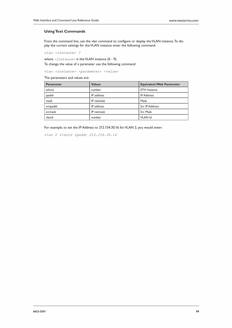
996622-3201
Web Interface and Command Line Reference Guide www.westermo.com
Using Text Commands
From the command line, use the vlan command to configure or display the VLAN instance. To dis-play the current settings for the VLAN instance enter the following command:
vlan <instance> ?
where <instance> is the VLAN instance (0 - 9).
To change the value of a parameter use the following command:
vlan <instance> <parameter> <value>
The parameters and values are:
Parameter Values Equivalent Web Parameter
ethctx number ETH Instance
ipaddr IP address IP Address
mask IP netmask Mask
srcipaddr IP address Src IP Address
srcmask IP netmask Src Mask
vlanid number VLAN Id
For example, to set the IP Address to 212.154.30.16 for VLAN 2, you would enter:
vlan 2 vlanid ipaddr 212.154.30.16
100 6622-3201
Web Interface and Command Line Reference Guidewww.westermo.com
Confi gure > Event Handler 4.30
The unit maintains a log of certain types of event in the “EVENTLOG.TXT” pseudo file. When an event of a specified level (or higher) occurs, it can be configured to automatically generate and send an email alert message, or on GPRS models an SMS alert message, to a pre-defined address. The Configure > Event Handler page is used to set-up the email or SMS related options for this fea-ture.
All events can be appended to a second log file stored on a USB flash disk, this is useful for captur-ing a very large log file over an extended period. The size of the secondary logfile is only limited by the size of the USB flash drive attached to the router.
Using the Web Page(s)
To use the email alert facility, you must first ensure that a valid Dial-out number, Username and Password have been specified on the Configure > PPP > PPP n > Standard page, and that the SMTP parameters have been set correctly on the Configure > SMTP page.
To use the automatic SMS alert message facility you must first ensure that a valid SMS Message Centre number has been specified on the Configure > GPRS page.
Then set the following parameters as required:
Event Filter Codes:
Enter the event codes you do not wish to be logged, separated by commas. For example, if you entered “30,68” then event codes 30 and 68 would never get logged.
Maximum event priority to log:
This specifies a maximum log level for events to be logged in the “EVENTLOG.TXT” pseudo file. For example, if this value is set to 6, only events with a log level of 6 or lower will be logged. The log levels for events are configured on the Configure>Event Logcodes page. Log level 1 is high, log level 9 is low.
Delay after powerup before sending traps/emails/sms (s):
This parameter will delay the sending of SNMP traps, email requests and SMS messages for a period of time after the unit powers up. This is useful in circumstances where the sending of those items would fail if sent too soon after the unit powers up because the underlying inter-face that would be used has not completed initialisation.
Emails today:
This read-only value maintains a count of how many email alert messages have been sent during the last 24-hour period.
Max emails/day:
The value in this field is the maximum number of email alert messages that the unit will gener-ate per day. This is intended to prevent messages being repeated frequently when you have set the event trigger level to a low value, i.e. a value that results in many events generating auto-mated email alert messages.
Email template:
This field contains the name of the template file that will be used to form the basis of any email alert messages generated by the event logger. The default template is a text file called “EVENT.EML” that is stored within the compressed .web file.
You may create alternative templates but you must use the “.EML” file extension and store the files in the normal file directory. If you create a new template with the name “EVENT.EML”, this will take precedence over the pre-defined “EVENT.EML” template.
Email trigger priority:
This is the lowest priority event code that will generate an email alert message. For example, if this value is set to 6, only events with a priority of 6 or higher will trigger an automated email
1016622-3201
Web Interface and Command Line Reference Guide www.westermo.com
alert mes sage. To disable email alarms set this value to 0.
Email To:
This parameter is used to specify the email address for the recipient of email alert messages gen erated by the event logger.
Email From:
This parameter is used to specify the email address for the unit. You will need to set up an email account with your Internet Service Provider.
Email Subject:
This field should contain a brief description of the email content.
SNMP traps today:
This read-only value maintains a count of how many SNMP trap messages have been sent during the current day.
Max SNMP traps/day:
The value in this field is the maximum number of SNMP trap messages that the unit can gener-ate per day. This is intended to prevent messages being repeated frequently when you have set SNMP trap trigger priority to a low value, i.e. a value that results in many traps occurring in one day.
SNMP trap trigger priority:
This is the lowest event priority code that will generate an SNMP trap message. For example, if this value is set to 6, only events with a priority of 6 or higher will trigger an automated SNMP trap message.
SYSLOG messages today:
This read-only value maintains a count of how many SYSLOG messages have been sent during the last 24-hour period.
Max SYSLOG messages/day:
The value in this field is the maximum number of SYSLOG (user informational) messages that the unit can generate per day. This is intended to prevent messages being repeated frequently when you have set SYSLOG trigger priority to a low value, i.e. a value that results in many SYSLOG events occurring in one day.
SYSLOG trigger priority:
This is the lowest event priority code that will generate SYSLOG message. For example, if this value is set to 6, only events with a priority of 6 or higher will trigger an automated SYSLOG message.
SMS Parameters:
Note: The following parameters apply only to models with GPRS capability.
SMS messages today:
This read-only value maintains a count of how many SMS messages have been sent during the last 24-hour period.
102 6622-3201
Web Interface and Command Line Reference Guidewww.westermo.com
Max SMS/day:
The value in this field is the maximum number of SMS messages that the unit will generate per day. This is intended to prevent messages being repeated frequently when you have set the event trigger level to a low value, i.e. a value that results in many events generating an automated SMS alarm.
SMS template:
This field contains the name of the template file that will be used to form the basis of any SMS alarm messages generated by the event logger. The default template is a text file called “EVENT.SMS” that is stored within the compressed .web file.
You may create alternative templates but you must use the “.SMS” file extension and store the files in the normal file directory. If you create a new template with the name “EVENT.SMS”, this will take precedence over the pre-defined “EVENT.SMS” template.
SMS trigger priority: / #2 / #3
This is the lowest priority event code that will generate an SMS alert message. For example, if this value is set to 6, only events with a priority of 6 or higher will trigger an automated SMS alert. To disable SMS alerts set this value to 0.
SMS destination: / #2 / #3
This is the destination phone number for SMS alert messages including the international dialling code but no “+” prefix or leading 0’s.
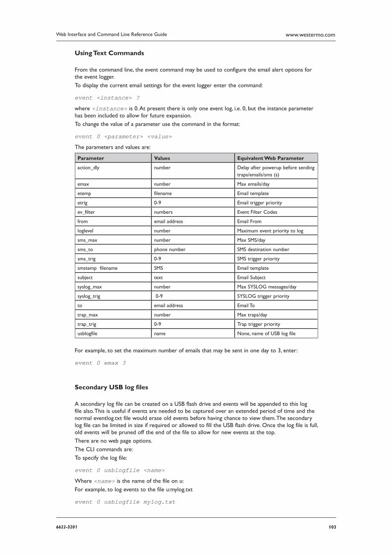
1036622-3201
Web Interface and Command Line Reference Guide www.westermo.com
Using Text Commands
From the command line, the event command may be used to configure the email alert options for the event logger.
To display the current email settings for the event logger enter the command:
event <instance> ?
where <instance> is 0. At present there is only one event log, i.e. 0, but the instance parameter has been included to allow for future expansion.
To change the value of a parameter use the command in the format:
event 0 <parameter> <value>
The parameters and values are:
Parameter Values Equivalent Web Parameter
action_dly number Delay after powerup before send ing traps/emails/sms (s)
emax number Max emails/day
etemp filename Email template
etrig 0-9 Email trigger priority
ev_filter numbers Event Filter Codes
from email address Email From
loglevel number Maximum event priority to log
sms_max number Max SMS/day
sms_to phone number SMS destination number
sms_trig 0-9 SMS trigger priority
smstemp filename SMS Email template
subject text Email Subject
syslog_max number Max SYSLOG messages/day
syslog_trig 0-9 SYSLOG trigger priority
to email address Email To
trap_max number Max traps/day
trap_trig 0-9 Trap trigger priority
usblogfile name None, name of USB log file
For example, to set the maximum number of emails that may be sent in one day to 3, enter:
event 0 emax 3
Secondary USB log fi les
A secondary log file can be created on a USB flash drive and events will be appended to this log file also. This is useful if events are needed to be captured over an extended period of time and the normal eventlog.txt file would erase old events before having chance to view them. The secondary log file can be limited in size if required or allowed to fill the USB flash drive. Once the log file is full, old events will be pruned off the end of the file to allow for new events at the top.
There are no web page options.
The CLI commands are:
To specify the log file:
event 0 usblogfile <name>
Where <name> is the name of the file on u:
For example, to log events to the file u:mylog.txt
event 0 usblogfile mylog.txt

104 6622-3201
Web Interface and Command Line Reference Guidewww.westermo.com
To limit the maximum size of the log file:
event 0 usblogsizek <n>
Where <n> is the maximum allowed size of the file in Kb, if 0 is used or this value is not set, the file size is unlimited. For example, to limit the log file to 1Gb
event 0 usblogsizek 1048576
The event logs stored on the USB drive can also be saved in XML format. The command used to enable this feature is:
event 0 usbxmllogs n
Where n is the number of logs to retain. When the XML event log reaches its maximum size as defined in the parameter usblogsizek, a new file is created, up to the maximum number defined. The files created will be named EVXML1.XML, EVXML2.XML etc...
1056622-3201
Web Interface and Command Line Reference Guide www.westermo.com
Confi gure > Event Logcodes 4.31
This page allows you to edit the logcodes used to describe events entered in the “EVENTLOG.TXT” pseudo file. If a change is made to the logcodes.txt file, the changes will be saved in the file logcodes.dif so when a firmware upgrade is performed the changes to the logcodes are retained.
Using the Web Page(s)
The web page shows the following information:
Event Code
The code used to describe the event in the “EVENTLOG.TXT” pseudo file.
Filter Priority
The priority of the event, used to determine whether the event will trigger emails, SMS mes-sages or SNMP traps.
Description
A description of the event.
Reasons
A list of reasons as to why the event occurred. Not every event has a list of reasons.
Confi guring Events 4.31.1
By clicking on an event, a new page is displayed showing the following parameters:
Priority:
The priority of the event, used to determine whether the event will trigger emails, SMS mes-sages or SNMP traps.
Analyser snapshot to log drive:
To be used in conjunction with the ana 0 logfile <name> command to send a copy of the ana-lyser trace to s: or u: on a specific event. See “Secondary log files”.
Attach Analyser:
Selecting “On” will attach a snapshot of the current Analyser trace to an email triggered by this event, no matter what reason triggered the event.
Analyser Action:
Choose from “Off”: the Analyser trace will continue as normal, “Freeze”: No more logging is per formed until the email is sent, or “Delete”: The trace is deleted once the email is sent.
Attach Eventlog:
Selecting “On” will attach a snapshot of the current Eventlog to an email triggered by this event, no matter what reason triggered the event.
Eventlog Action:
Choose from “Off”: the Eventlog will continue to be written as normal, or “Delete”: The Eventlog is deleted once the email is sent.
Syslog Priority:
This parameter will alter the default syslog priority of the event to that of the value selected.
106 6622-3201
Web Interface and Command Line Reference Guidewww.westermo.com
Syslog Facility:
This parameter will alter the default syslog facility of the event to that of the value selected.
Filter Event:
Selecting “On” will prevent this event from being written to the Event Log. This means the event will not trigger any automatic emails, SMS messages or SNMP traps.
Note: This parameter is NOT saved in the logcodes.txt file but in the config.dax file. This means that after changing this parameter, the change must be saved by clicking the Save link near the bot-tom of the web menu, NOT the Save All Event Code Changes button on the Configure > Event Logcodes page. On the command line the event number of filtered events is stored in comma separated list in the “event 0 ev_filter” parameter. This is edited on the web in the Event Filter Codes param-eter on the Configure > Event Handler page.
PPP Mask:
A bitmask (entered in decimal format) that determines which PPP instances the priority for the event will apply. For example, if you wish that only events on PPP0 and PPP3 have the priority set in the Priority parameter, enter 5 (1010 in decimal).
Log Level:
The priority of the event, used to determine whether the event will be logged. This is deter-mined by the value of the Maximum event priority to log parameter set in the Configure > Event Handler page.
Priority is Conditional on Entity#:
If this parameter is “On”, the event is conditional on which entity triggered the event (e.g. eth, ppp, etc.). Choose the entity from the Entity drop-down list.
Entity:
See above.
Priority is Conditional on instance#:
Used in conjunction with Priority is Conditional on Entity#. If this parameter is “On”, then the event is conditional not only upon which entity triggered the event, but on which instance of the entity, entered in the Instance # parameter. For example, if Priority is Conditional on Entity# is set to “eth”, this parameter is “On”, and Instance # is 1, only events of this type triggered by Eth 1 will be triggered.
Instance #:
See above.
1076622-3201
Web Interface and Command Line Reference Guide www.westermo.com
Confi guring Reasons 4.31.2
By clicking on a reason, a new page is displayed showing the following parameters:
Inherit priority from Event:
By selecting “On”, the priority of the reason will be the same as the Event that was triggered. If “Off” is selected, the reason takes the priority entered in the Priority parameter.
Priority:
The priority of the reason, if Inherit priority from Event is “Off”.
Attach Analyser:
Selecting “On” will attach a snapshot of the current Analyser trace to an email triggered by this event with this reason.
Analyser Action:
Choose from “Off”: the Analyser trace will continue as normal, “Freeze”: No more logging is per formed until the email is sent, or “Delete”: The trace is deleted once the email is sent.
Attach Eventlog:
Selecting “On” will attach a snapshot of the current Eventlog to an email triggered by this event with this reason.
Eventlog Action:
Choose from “Off”: the Eventlog will continue to be written as normal, or “Delete”: The Eventlog is deleted once the email is sent.
PPP Mask:
A bitmask (entered in decimal format) that determines which PPP instances the priority for the rea son will apply. For example, if you wish that only events on PPP0 and PPP3 have the priority set in the Priority parameter, enter 5 (1010 in decimal).
Log Level:
The priority of the reason, used to determine whether the event will be logged. This is deter-mined by the value of the Maximum event priority to log parameter set in the Configure > Event Handler page.
Priority is Conditional on Entity#:
If this parameter is “On”, the event is conditional on which entity triggered the event (e.g. eth, ppp, etc.). Choose the entity from the Entity drop-down list.
Entity:
See above.
Priority is Conditional on instance#:
Used in conjunction with Priority is Conditional on Entity#. If this parameter is “On”, then the event is conditional not only upon which entity triggered the event, but on which instance of the entity, entered in the Instance # parameter. For example, if Priority is Conditional on Entity# is set to eth, this parameter is “On”, and Instance # is 1, only reasons of this type triggered by Eth 1 will be triggered.
Instance #:
See above.

108 6622-3201
Web Interface and Command Line Reference Guidewww.westermo.com
Using Text Commands
There is no text command for editing Eventcodes. However, it is possible to edit the “LOGCODES.TXT” file, which holds all the logcode information. For details on this, refer to the section “The Event Log”.
1096622-3201
Web Interface and Command Line Reference Guide www.westermo.com
Confi gure > Firewall 4.32
All models in the MR and DR range incorporate a comprehensive firewall facility. A firewall is a security sys tem that is used to restrict the type of traffic that the router will transmit or receive, based on a combi nation of IP address, service type, protocol type, IP flags, etc. Firewalls are used to minimise the risk of unauthorised access to your local network resources by external users or to restrict the range of external resources to which local users have access. A more detailed descrip-tion of how firewalls oper ate on MR and DR routers is given in the “Firewall Scripts” section. If you intend to implement a firewall you should refer to that section first.
The rules governing the operation of the firewall are contained in a pseudo-file called “FW.TXT”. This file can be created either by using the controls on the Configure > Firewall web page, or by using a text editor on your PC and then loading the resulting file into the unit (using FTP or XMODEM).
Using the Web Page(s)
If you have not yet created a file called “FW.TXT” on the unit, the Configure > Firewall page will ini tially contain a blank script with a button labelled Insert to the right. If you have created the file it will be displayed in the top section of the screen with line numbers at the left and a series of but-tons at the right that allow you to delete, edit or insert lines.
At the bottom of the screen are three more buttons labelled Reset, Save and Restore.
To create a new rule directly on the web page click on the Insert button at the right of the screen. If there are already one or more lines in the file, there will be two Insert buttons, one next to the line (which inserts a new line above the current line) and one on the line below (which inserts a new line below the current line).
In either case a new text box will be created into which you can type the new rule. When you have finished typing the rule press the OK button to add it to the file or Cancel to abandon the changes. The unit will validate the rule and if it is valid it will add it to the file. If errors are detected it will display a warning message with an indication of the error and you may then choose to edit the line or delete it.
To edit an existing rule click on the Edit button to the right of the rule and then on OK or Cancel when you have completed the changes.
To delete an existing line click on the Delete button to the right of it.
When you have completed your editing session, click on the Save button at the bottom of the screen to copy it back to the “FW.TXT” pseudo-file. If you do not save the file any changes you have made will be lost when the power is removed or the unit is rebooted.
If you wish to cancel all changes you have made during an editing session and you have not yet saved them, you may click on the Restore button. This will copy the “FW.TXT” file to the screen.
The third button at the bottom of the screen labelled Reset Hit Counters allows you to zero the rule hit counters shown at the left of each rule.
Current Interface Firewall Status:
This section of the page provides a list of interfaces on which the firewall may be enabled and an indication of whether the firewall is currently “On” or “Off” for each interface. By clicking on the name of the interface you can jump to the appropriate configuration page to change the setting if necessary.
110 6622-3201
Web Interface and Command Line Reference Guidewww.westermo.com
Using Text Commands
If your firewall script is particularly complex, you may wish to create it on your PC using the text editor of your choice and then load it onto the unit when it is complete. To do this simply create the file and save it as “FW.TXT”. You may then load the file onto the unit using XMODEM as fol-lows:
1. Connect the router to your PC using ASY0 and apply power.
2. Load your terminal program and select the correct COM port.
3. Type “AT” and press Enter -the unit should respond with “OK”. If the command is not echoed turn echo on by entering “ATE1”.
4. Type “AT\LS” - the unit should respond with “OK”.
5. Type “XMODEM FW.TXT” and press Enter and the unit will wait for the file transfer to start.
6. Select the File transfer > XMODEM > Send option in your terminal software and when prompted for a filename select the “FW.TXT” file you created.
7. When the file transfer is complete the unit will display the “OK” message.
Refer to the section “FTP under Windows” for instructions on how to access the unit for the pur-pose of carrying out FTP file transfers.
Once the file “FW.TXT” has been successfully loaded onto the unit the router will automatically “com pile” it and generate a file called “FWSTAT.TXT”. If there are any errors in the “FW.TXT” file these will be identified in “FWSTAT.TXT”.
Saving and restoring the fw.txt
To revert the firewall to its saved rules in fw.txt
fw
To save the amended rules to the fw.txt file
fw save
To clear the firewall trace
fw logclr
Viewing fi rewall rule hits
To view the number of hits on the firewall from a command line, the command type fwstat.hitcan be used.
type fwstat.hit
H:102 1) pass break end
1116622-3201
Web Interface and Command Line Reference Guide www.westermo.com
Confi gure > Firewall Options 4.33
This page contains the timer parameters and other options that are used by the Firewall stateful inspection module. This module establishes temporary firewall rules that last for the duration of a sin gle connection only. Typically, the first packet of a TCP connection (a SYN packet), is used to cre-ate a stateful inspection rule that only allows subsequent packets for that TCP connection through the fire wall. The timers described below are used to set limits on how long such rules may persist.
Using the Web Page(s)
The web page includes the following parameters:
Timers
TCP opening (s):
This specifies the length of time following receipt of a TCP packet that causes a stateful inspec-tion rule to be created before a TCP connection must be established. If a TCP connection is not estab lished within this period, the associated stateful inspection rule will be removed.
TCP open (s):
This parameter specifies the length of time that an established TCP connection may remain idle before the stateful inspection rule created for it is removed. The timer is restarted each time a packet is processed by the associated stateful inspection rule.
TCP closing (s):
This parameter specifies the length of time that is allowed for a TCP socket to close once the first FIN packet has been received. If the timer elapses before the socket has completed closing the associated stateful inspection rule is removed.
TCP closed (s):
This parameter specifies the length of time that a stateful inspection rule will remain in place after a TCP connection has closed.
UDP (s):
This parameter specifies the length of time that a stateful inspection rule will remain in place fol lowing the receipt of a UDP packet. The timer is restarted each time packets matching the rule pass in each direction. As a consequence, rules based on UDP should only be used if it is antici pated that packets will travel in both directions.
ICMP (s):
Some ICPM packets, such as “ECHO” requests, will generate responses. This parameter speci-fies the length of time that a stateful inspection rule created in respect of an ICMP packet will remain in place before being removed if a response packet has not been received. Such a rule will also be removed immediately following the receipt of a response.
Other protocol (s):
If a stateful inspection rule is created from a packet type other that TCP, UDP or ICMP, this param eter specifies the length of time for which the rule will persist. The timer is restarted each time a packet is processed by the rule.
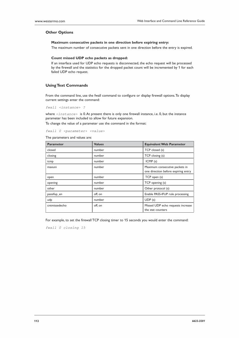
112 6622-3201
Web Interface and Command Line Reference Guidewww.westermo.com
Other Options
Maximum consecutive packets in one direction before expiring entry:
The maximum number of consecutive packets sent in one direction before the entry is expired.
Count missed UDP echo packets as dropped:
If an interface used for UDP echo requests is disconnected, the echo request will be processed by the firewall and the statistics for the dropped packet count will be incremented by 1 for each failed UDP echo request.
Using Text Commands
From the command line, use the fwall command to configure or display firewall options. To display current settings enter the command:
fwall <instance> ?
where <instance> is 0. At present there is only one firewall instance, i.e. 0, but the instance param eter has been included to allow for future expansion.
To change the value of a parameter use the command in the format:
fwall 0 <parameter> <value>
The parameters and values are:
Parameter Values Equivalent Web Parameter
closed number TCP closed (s)
closing number TCP closing (s)
icmp number ICMP (s)
maxuni number Maximum consecutive packets in one direction before expiring entry
open number TCP open (s)
opening number TCP opening (s)
other number Other protocol (s)
passifup_en off, on Enable PASS-IFUP rule process ing
udp number UDP (s)
cntmissedecho off, on Missed UDP echo requests increase the stat counters
For example, to set the firewall TCP closing timer to 15 seconds you would enter the command:
fwall 0 closing 15
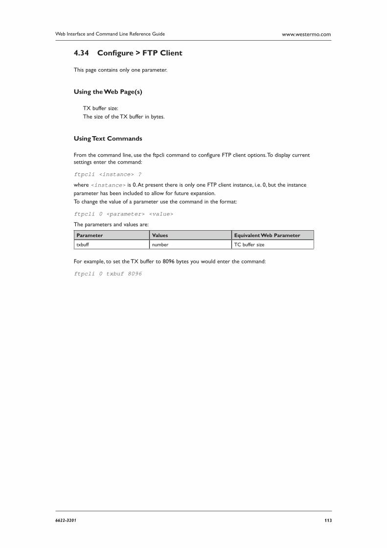
1136622-3201
Web Interface and Command Line Reference Guide www.westermo.com
Confi gure > FTP Client 4.34
This page contains only one parameter.
Using the Web Page(s)
TX buffer size:
The size of the TX buffer in bytes.
Using Text Commands
From the command line, use the ftpcli command to configure FTP client options. To display current settings enter the command:
ftpcli <instance> ?
where <instance> is 0. At present there is only one FTP client instance, i.e. 0, but the instance
parameter has been included to allow for future expansion.
To change the value of a parameter use the command in the format:
ftpcli 0 <parameter> <value>
The parameters and values are:
Parameter Values Equivalent Web Parameter
txbuff number TC buffer size
For example, to set the TX buffer to 8096 bytes you would enter the command:
ftpcli 0 txbuf 8096
114 6622-3201
Web Interface and Command Line Reference Guidewww.westermo.com
Confi gure > FTP Relay Agents > RELAY n 4.35
The FTP Relay agents allow any files transferred onto the unit by a specified user (using File Transfer Protocol), to be temporarily stored in memory and then relayed to a specified FTP host. This is use-ful when the unit is being used to collect data files from a locally attached device such as a webcam, which must then be relayed to a host system over a slower data connection such as GPRS. In effect, the unit acts as a temporary data buffer for the files.
The FTP Relay Agent can also be configured to email (as an attachment) any files that it was unable to transfer to the FTP Server. To facilitate this you should set the Email Template, To, From and Subject parameters as appropriate and also configure the SMTP Client (see Configure > SMTP).
Using the Web Page(s)
The web page includes the following parameters:
Local username:
This parameter should be set to match one of the usernames programmed in the Configure > Users page. This name is then used as the FTP login “username” when the local device needs to relay a file.
Server hostname:
This is the name of the FTP host to which files from the locally attached device are to be relayed.
Server username:
This is the username required for login to the specified FTP host.
Server password:
This is the password to be used for logging into the FTP host.
Server confirm password:
Enter the password again in this field to confirm it.
Remote directory:
This is the full name of the directory on the FTP host to which the file is to be saved.
File transfer mode:
This specifies either binary mode or ACSII mode for file transfers.
File transfer command:
This specifies either append or store (replace) mode for the file transfer.
Client timeout (s):
This parameter is specifies the length of time in seconds that the unit will maintain a connection to an FTP host after transferring a file.
Client retry count:
This parameter specifies the number of times the unit will try to connect to the specified FTP host.
Client retry interval (s):
This parameter specifies the interval in seconds between successive retries.
1156622-3201
Web Interface and Command Line Reference Guide www.westermo.com
Transfer failure mode:
If the unit cannot establish a connection to the specified FTP host after the number of retries spec ified above, it will either retain the file in memory or delete it depending upon the setting of this parameter. If the file is retained, manual intervention will be required to recover it at a later stage.
Note: The file will be lost if the power is removed from the unit.
Rename local file:
When this parameter is set to “Yes”, the unit will store uploaded files internally with a filename in the form “relnnnn” where nnnn is a sequential number. For each new file received the number is incremented. When the file is relayed to the FTP host the original filename is used.
When the parameter is set to “No”, the file is stored internally under its original filename.
This parameter should be used if you wish to upload a file with a file name longer than 12 charac ters including the extension and period (e.g. longer than an 8.3 style file name such as
autoexec.bat).
Email template:
This field contains the name of the template file that will be used to form the basis of any email messages generated by the FTP Relay Agent. This would normally be the standard “EVENT.EML” template provided with the unit but you may create alternative templates if necessary (see Email templates).
Email To:
This parameter is used to specify the email address for the recipient of email messages gener-ated by the FTP Relay Agent.
Email From:
This parameter is used to specify the email address for the unit. You will need to set up an email account with your Internet Service Provider.
Email Subject:
This field should contain a brief description of the email content.
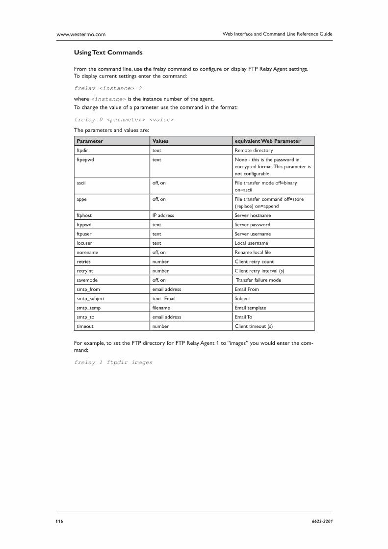
116 6622-3201
Web Interface and Command Line Reference Guidewww.westermo.com
Using Text Commands
From the command line, use the frelay command to configure or display FTP Relay Agent settings. To display current settings enter the command:
frelay <instance> ?
where <instance> is the instance number of the agent.
To change the value of a parameter use the command in the format:
frelay 0 <parameter> <value>
The parameters and values are:
Parameter Values equivalent Web Parameter
ftpdir text Remote directory
ftpepwd text None - this is the password in encrypted format. This parameter is not configurable.
ascii off, on File transfer mode off=binary on=ascii
appe off, on File transfer command off=store (replace) on=append
ftphost IP address Server hostname
ftppwd text Server password
ftpuser text Server username
locuser text Local username
norename off, on Rename local file
retries number Client retry count
retryint number Client retry interval (s)
savemode off, on Transfer failure mode
smtp_from email address Email From
smtp_subject text Email Subject
smtp_temp filename Email template
smtp_to email address Email To
timeout number Client timeout (s)
For example, to set the FTP directory for FTP Relay Agent 1 to “images” you would enter the com-mand:
frelay 1 ftpdir images
1176622-3201
Web Interface and Command Line Reference Guide www.westermo.com
Confi gure > General 4.36
This is used to set up a variety of features that relate to the basic operation of the unit.
Using the Web Page(s)
Power-up config:
This specifies which of the two config files “CONFIG.DA0” or “CONFIG.DA1”, is loaded when the unit is powered up or rebooted. This is equivalent to the config n powerup text command.
Serial number:
This read-only field displays the unit’s serial number.
Unit identity:
This is a string of up to 20 characters that can be used to identify the unit in email alert mes-sages generated by the event logger. It is also displayed as a prompt when logging on remotely. The character sequence “%s” may be used as part of the string. This is substituted by the unit’s serial number when the unit identity is displayed. For example, if the unit serial number is 005555, enter ing the string “MyRouter_%s>” would show the prompt “MyRouter_005555>” during a remote login.
Auto start macro:
This is a command that will be executed automatically when the unit is first powered up. This com mand will be issued to ASY 0. If it is necessary to issue a command to another ASY port then the command line interface must be used. For example, to issue a command to ASY port 3 you would use:
cmd 3 autocmd <command> where <command> is the command to be issued to ASY 3 on power-up.
System hostname:
This parameter can be used to allocate a synonym for the local IP address of the unit. For exam ple, the default local IP address is 1.2.3.4. The unit will respond to this address when you enter it into your Web browser. The default System hostname that maps to this address is “ss.2000r”.
Note: To work correctly with Windows 98 the System Hostname must include at least one full stop. To work correctly with Windows XP or 2000 the System Hostname must end in a letter (rather than a number).
Secondary hostname:
This allows a second hostname to be assigned to a unit. This is associated with the Secondary IP address.
Secondary IP address:
This can be used to assign an additional IP address to the router without assigning it to any partic ular interface. The router will respond directly to incoming traffic on this address, i.e. it will not attempt to onward route any IP packets for this address.
Remote command echo:
This parameter may be used to enable or disable command echo for remote access.
118 6622-3201
Web Interface and Command Line Reference Guidewww.westermo.com
Remote command timeout (s):
This specifies the maximum period of inactivity (in seconds), that may occur before a remote com mand session is terminated. The default value is 120 seconds.
When using the web interface, this timer can expire and uncomitted configuration details can be
lost. When you click OK, you will be presented with the log in page again. To work around this,
right click on “Operations” from the top of the menu to have the graphical display of the front panel open in a seperate window. The flashing LED’s in the display will stop the web session from timing out. Be sure to close both windows when configuration is complete. This right click feature can be used on any of the menu options to have it open in new window.
X25 remote command address:
This parameter is used to allow remote access to the unit via an X.25 channel. If the address spec ified, (up to 15 digits), matches the trailing digits of an incoming X.25 call, the calling user will be prompted to enter their username and password. Correct entry of these will allow the calling user to control the unit remotely. The range of functions they will be able to access will depend upon their user access level.
X25 call timeout (s):
This parameter is the time the unit will wait for an X.25 call to connect. This timer starts when the X.25 call request is sent.
X25 switch call timeout (s):
This parameter is the time the unit, operating as an X.25 switch, will wait for a switched X.25 call to connect. If the timer expires before a switched call has connected, then a CLR will be returned to the calling party.
GPRS LED mode:
On models fitted with GPRS, this parameter is used to select whether the dual-function status indi cators on the front panel reflect the status of the GPRS module or the ISDN connection and may be set to “GPRS” or “ISDN” respectively.
ASY LED mode:
This parameter determines what causes the ASY port LEDs to illuminate.
When set to “Connection”, the LED for an ASY port illuminates when the protocol bound to that port is connected.
When set to “DTR status”, the LED for an ASY port illuminates when the terminal connected to that port raises the DTR signal.
When set to “GPRS Signal Strength” the four LEDs that normally indicate activity on the ASY ports
ASY <port> name:
These parameters allow a name to be associated with each of the physical and logical ASY ports. Once you have allocated a name it will appear in the heading of the Config > ASY port page for that port. It will also be displayed when using the “AT\PORT” command.
W-WAN port name:
On models fitted with GPRS this parameter allows you assign a name to the port occupied by the GPRS module. Once you have allocated a name it will appear in the heading of the Config > ASY Ports > GPRS Port page. It will also be displayed when using the “AT\PORT” command.
PSTN port name:
On models fitted with an analog modem this parameter allows you assign a name to the port occu pied by the modem. Once you have allocated a name it will appear in the heading of the Config > ASY Ports > PSTN Port page. It will also be displayed when using the “AT\PORT” command.
1196622-3201
Web Interface and Command Line Reference Guide www.westermo.com
ASY <port> Telnet mode:
This parameter is used to select the Telnet mode when a remote entity is connected to an ASY port via TCP/IP (i.e. connected to TCP port 4000 to 4003 for ASY ports 0 - 3 respectively). When set to “Raw Mode” no byte stuffing is used. When set to “Telnet Mode” standard Telnet byte stuff ing is used. When set to “Telnet No Null Stuffing Mode”, Telnet byte stuffing without null stuffing is used.
W-WAN port Telnet mode:
On models fitted with GPRS, this parameter is used to select the Telnet mode when a remote entity is connected to the GPRS port via TCP/IP. The three available options are the same as those for ASY <port> Telnet mode described above.
PSTN port Telnet mode:
On models fitted with an analog modem, this parameter is used to select the Telnet mode when a remote entity is connected to the PSTN port via TCP/IP. The three available options are the same as those for ASY <port> Telnet mode described above.
Allow anonymous FTP login:
This parameter is used to allow or disallow anonymous FTP logins to the unit. Default is “Off” (dis allow anonymous logins).
TCP socket inactivity timer (s):
This specifies the maximum period of inactivity (in seconds) that may occur before an open TCP/ IP socket is closed. The default value is 300 seconds (5 minutes) and should not normally require altering.
TCP socket keep-alive (s):
This specifies the amount of time (in seconds) between sending “keep-alive” messages over open TCP connections. The purpose of these messages is to prevent a connection from closing even when no data is being transmitted or received. The default value of this parameter is zero, which disables keep-alive messages.
TCP socket connect timeout (s):
This parameter is used to specify the amount of time after which a TCP socket may remain idle before being closed. If the value is set to 0 the socket may remain open indefinitely.
SNMP enterprise number:
This parameter specifies the value of the Object Identifier component following “enterprises” to be used by SNMP managers when accessing the MIB on the unit. Object Identifiers of objects in the unit’s SNMP MIB have the prefix “{ enterprises n ir2140 }” where “n” is the SNMP enter-prise number.
SNMP enterprise name:
This specifies the name corresponding to the SNMP enterprise number above.
SNMP community string:
This specifies the required SNMP Community String to be used by SNMP managers in order to access the unit’s MIB.
SNMP trap destination address:
This is the IP address (or host name) of the destination for SNMP trap messages.
120 6622-3201
Web Interface and Command Line Reference Guidewww.westermo.com
GP sockets use IP from interface:
This parameter allows general-purpose TCP sockets to use a source IP address other than that of the interface on which the socket connection is created. The unit creates general-purpose sockets automatically when your application requires them, e.g. when TPAD calls are made over IP or XOT. Normally, the source address used by the socket will be that of the outgoing interface (usually PPP). However, for some applications such as when set ting up a VPN, it may be necessary to specify that the socket use a different source address such as that of the local Ethernet port. This parameter is used to specify from which interface the source address should be derived and may be set to “None” (default), “ETH” or “PPP”.
Note: Even when this parameter is not set to “None”, normally the IP address from the interface on which the socket is created will be used. The source address specified in this parameter will only be used if it will cause the traffic to match an Eroute and therefore be sent over IPSec or GRE.
GP sockets use IP from interface #:
This parameter is used in conjunction with the GP sockets use IP from interface parameter above to select which interface instance is used to derive a source address.
GRE checksums::
This parameter selects whether to add GRE checksums to GRE packets when the unit is terminat ing a GRE tunnel. “Off” disables checksums, “On” enables checksums.
Note: From firmware version 4955 this web option and corresponding CLI commands have been removed. GRE tunnels should be configured from Configure > Tunnel (GRE)
Additional FTP NAT port:
FTP control channels normally use TCP port 21 to carry the FTP commands. Consequently, when NAT is enabled the unit monitors the FTP commands on this port number and checks for the two FTP commands “PORT” and “PASV”. These commands contain information relating to IP addresses which may need modifying during the NAT process. Such modifications may result in different sized packets being generated that then require that the TCP sequence numbers be mod ified to allow for the changes.
This parameter may be used to specify an additional port number (other than 21), which the unit should monitor and is useful where FTP servers are known to be listening on non-standard control channels.
RIP interval (s):
If this parameter is set to a non-zero value then RIP (Routing Information Protocol) packets will be transmitted at the specified interval (in seconds). These packets contain the unit’s current routes
(e.g. any active PPP instance routes), static routes and the default route.
IP route out of service time (s):
This specifies the time in (seconds), for which an IP route is flagged as “out of service” when the route cannot be activated (i.e. the metric for the route is set to 16). This means the unit will subse quently attempt to route packets through other routes with matching net masks that are not out of service.
Alternative route delay (s):
This parameter is normally set to 0 and should not be changed without reference to Westermo Techni cal Support.
1216622-3201
Web Interface and Command Line Reference Guide www.westermo.com
Always-on route return-to-service delay (s):
An “always-on” route is either a route with the interface set to Ethernet or a route with the interface set to a PPP instance that has the AODI mode parameter set to On. If such a route goes out of service for some reason and then becomes available again some time later the unit will automati cally bring the route back up. This parameter is used to set the delay in seconds between the serv ice becoming available again and the unit starting to use it.
Route directed broadcasts:
When this parameter is “ON”, the unit will route private subnet broadcasts (e.g. 192.168.31.255) using the normal routing logic. When “OFF”, the unit will not route broadcasts.
Local port access level:
This parameter may be used to set the authority level for users entering commands via one of the ASY ports. This means that if you are intending to manage units remotely, you can restrict the access that local users have for reconfiguring them.
TRANSIP port access level:
This parameter may be used to set the authority level for users entering commands via one of the TRANSIP ports. This means that if you are intending to manage units remotely, you can restrict the access that local users have for reconfiguring them.
Local port access timeout:
This parameter defines the length of time to wait for a command on the ASY port before automati cally logging the user out. A value of zero means the user will never be logged out.
User task filename:
This specifies the name of a file containing a “user task” file. A user task is a software module that may be loaded into the unit to provide support for a new protocol or application.
PPP detect:
When this parameter is “On”, all ISDN answering protocols (V110, V120, X75, LAPB, etc.) can detect the presence of an inbound PPP connection and trigger a configured answering PPP to take over the ISDN call.
Pre login banner:
This parameter specifies a file that will be used as a banner placed before login information is requested when connecting to a command line session.
Post login banner:
This parameter specifies a file that will be used as a banner placed after login informa-tion is entered when connecting to a command line session. In addition, if a file is specified, “CONTINUE [Y/N]?” will be displayed after the login information is entered, and a response is required before access is granted to the unit.
Include CLI when dialling:
When this parameter is set to “On”, the CLI is included with the Calling Party element when the unit makes a call.
Auto-Confi gure Email Fields
This section is used to set up parameters for use in communicating with a configuration server via email. The following parameters may be set:
Template:
This is a read-only field showing the template to be used for auto-configuration request emails.
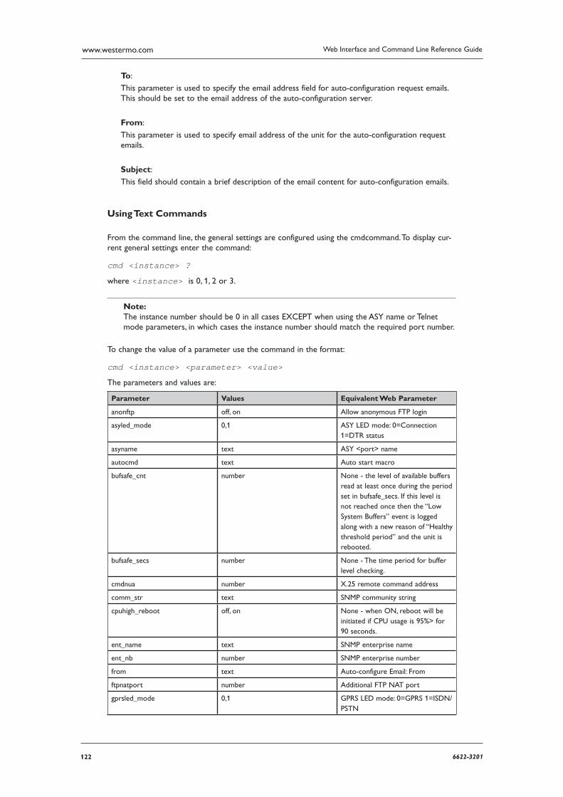
122 6622-3201
Web Interface and Command Line Reference Guidewww.westermo.com
To:
This parameter is used to specify the email address field for auto-configuration request emails. This should be set to the email address of the auto-configuration server.
From:
This parameter is used to specify email address of the unit for the auto-configuration request emails.
Subject:
This field should contain a brief description of the email content for auto-configuration emails.
Using Text Commands
From the command line, the general settings are configured using the cmdcommand. To display cur-rent general settings enter the command:
cmd <instance> ?
where <instance> is 0, 1, 2 or 3.
Note: The instance number should be 0 in all cases EXCEPT when using the ASY name or Telnet mode parameters, in which cases the instance number should match the required port number.
To change the value of a parameter use the command in the format:
cmd <instance> <parameter> <value>
The parameters and values are:
Parameter Values Equivalent Web Parameter
anonftp off, on Allow anonymous FTP login
asyled_mode 0,1 ASY LED mode: 0=Connection 1=DTR status
asyname text ASY <port> name
autocmd text Auto start macro
bufsafe_cnt number None - the level of available buff ers read at least once during the period set in bufsafe_secs. If this level is not reached once then the “Low System Buffers” event is logged along with a new reason of “Healthy threshold period” and the unit is rebooted.
bufsafe_secs number None - The time period for buffer level checking.
cmdnua number X.25 remote command address
comm_str text SNMP community string
cpuhigh_reboot off, on None - when ON, reboot will be ini tiated if CPU usage is 95%> for 90 seconds.
ent_name text SNMP enterprise name
ent_nb number SNMP enterprise number
from text Auto-configure Email: From
ftpnatport number Additional FTP NAT port
gprsled_mode 0,1 GPRS LED mode: 0=GPRS 1=ISDN/PSTN
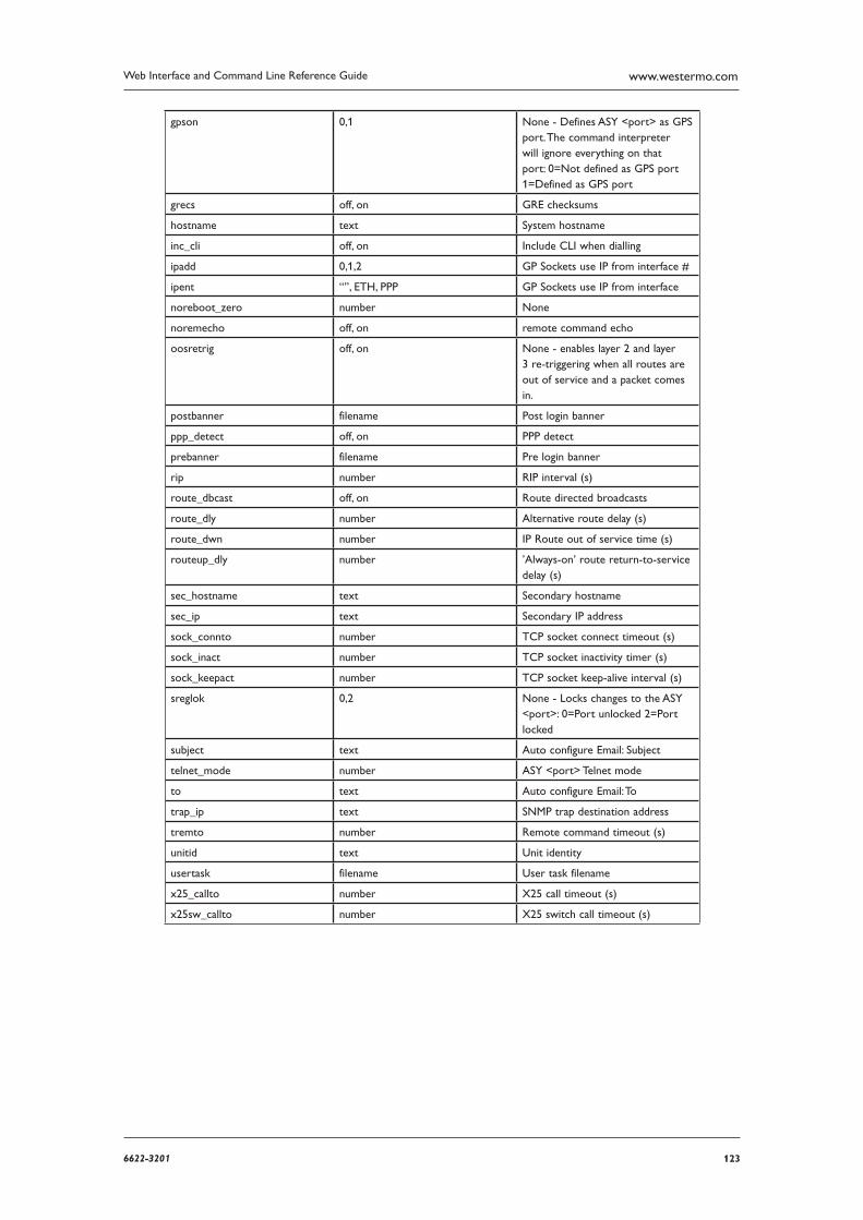
1236622-3201
Web Interface and Command Line Reference Guide www.westermo.com
gpson 0,1 None - Defines ASY <port> as GPS port. The command inter preter will ignore everything on that port: 0=Not defined as GPS port 1=Defined as GPS port
grecs off, on GRE checksums
hostname text System hostname
inc_cli off, on Include CLI when dialling
ipadd 0,1,2 GP Sockets use IP from interface #
ipent “”, ETH, PPP GP Sockets use IP from interface
noreboot_zero number None
noremecho off, on remote command echo
oosretrig off, on None - enables layer 2 and layer 3 re-triggering when all routes are out of service and a packet comes in.
postbanner filename Post login banner
ppp_detect off, on PPP detect
prebanner filename Pre login banner
rip number RIP interval (s)
route_dbcast off, on Route directed broadcasts
route_dly number Alternative route delay (s)
route_dwn number IP Route out of service time (s)
routeup_dly number ’Always-on’ route return-to-service delay (s)
sec_hostname text Secondary hostname
sec_ip text Secondary IP address
sock_connto number TCP socket connect timeout (s)
sock_inact number TCP socket inactivity timer (s)
sock_keepact number TCP socket keep-alive interval (s)
sreglok 0,2 None - Locks changes to the ASY <port>: 0=Port unlocked 2=Port locked
subject text Auto configure Email: Subject
telnet_mode number ASY <port> Telnet mode
to text Auto configure Email: To
trap_ip text SNMP trap destination address
tremto number Remote command timeout (s)
unitid text Unit identity
usertask filename User task filename
x25_callto number X25 call timeout (s)
x25sw_callto number X25 switch call timeout (s)
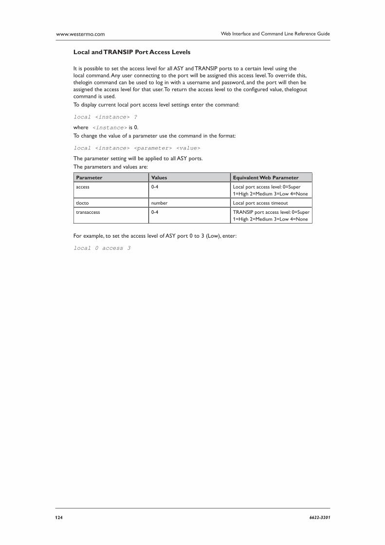
124 6622-3201
Web Interface and Command Line Reference Guidewww.westermo.com
Local and TRANSIP Port Access Levels
It is possible to set the access level for all ASY and TRANSIP ports to a certain level using the local command. Any user connecting to the port will be assigned this access level. To override this, thelogin command can be used to log in with a username and password, and the port will then be assigned the access level for that user. To return the access level to the configured value, thelogout command is used.
To display current local port access level settings enter the command:
local <instance> ?
where <instance> is 0.
To change the value of a parameter use the command in the format:
local <instance> <parameter> <value>
The parameter setting will be applied to all ASY ports.
The parameters and values are:
Parameter Values Equivalent Web Parameter
access 0-4 Local port access level: 0=Super 1=High 2=Medium 3=Low 4=None
tlocto number Local port access timeout
transaccess 0-4 TRANSIP port access level: 0=Super 1=High 2=Medium 3=Low 4=None
For example, to set the access level of ASY port 0 to 3 (Low), enter:
local 0 access 3
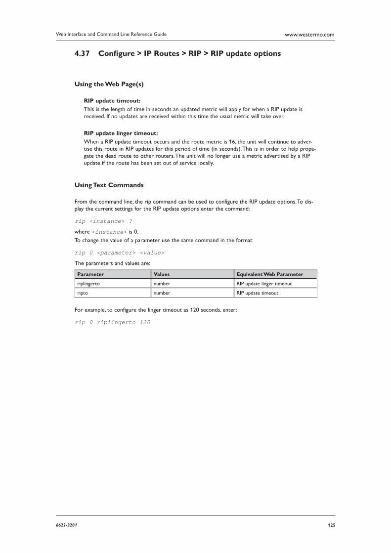
1256622-3201
Web Interface and Command Line Reference Guide www.westermo.com
Confi gure > IP Routes > RIP > RIP update options 4.37
Using the Web Page(s)
RIP update timeout:
This is the length of time in seconds an updated metric will apply for when a RIP update is received. If no updates are received within this time the usual metric will take over.
RIP update linger timeout:
When a RIP update timeout occurs and the route metric is 16, the unit will continue to adver-tise this route in RIP updates for this period of time (in seconds). This is in order to help propa-gate the dead route to other routers. The unit will no longer use a metric advertised by a RIP update if the route has been set out of service locally.
Using Text Commands
From the command line, the rip command can be used to configure the RIP update options. To dis-play the current settings for the RIP update options enter the command:
rip <instance> ?
where <instance> is 0.
To change the value of a parameter use the same command in the format:
rip 0 <parameter> <value>
The parameters and values are:
Parameter Values Equivalent Web Parameter
riplingerto number RIP update linger timeout
ripto number RIP update timeout
For example, to configure the linger timeout as 120 seconds, enter:
rip 0 riplingerto 120
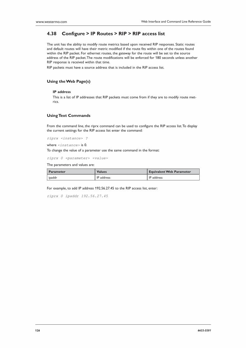
126 6622-3201
Web Interface and Command Line Reference Guidewww.westermo.com
Confi gure > IP Routes > RIP > RIP access list 4.38
The unit has the ability to modify route metrics based upon received RIP responses. Static routes and default routes will have their metric modified if the route fits within one of the routes found within the RIP packet. For ethernet routes, the gateway for the route will be set to the source address of the RIP packet. The route modifications will be enforced for 180 seconds unless another RIP response is received within that time.
RIP packets must have a source address that is included in the RIP access list.
Using the Web Page(s)
IP address
This is a list of IP addresses that RIP packets must come from if they are to modify route met-rics.
Using Text Commands
From the command line, the riprx command can be used to configure the RIP access list. To display the current settings for the RIP access list enter the command:
riprx <instance> ?
where <instance> is 0.
To change the value of a parameter use the same command in the format:
riprx 0 <parameter> <value>
The parameters and values are:
Parameter Values Equivalent Web Parameter
ipaddr IP address IP address
For example, to add IP address 192.56.27.45 to the RIP access list, enter:
riprx 0 ipaddr 192.56.27.45
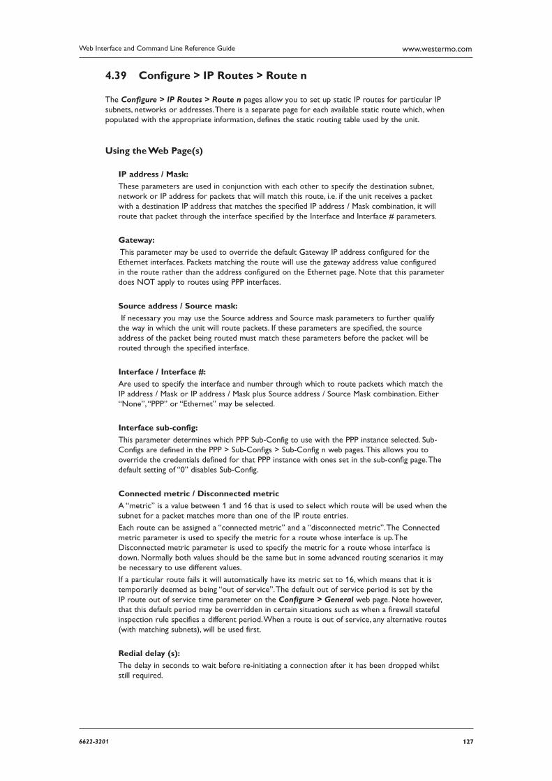
1276622-3201
Web Interface and Command Line Reference Guide www.westermo.com
Confi gure > IP Routes > Route n 4.39
The Configure > IP Routes > Route n pages allow you to set up static IP routes for particular IP sub nets, networks or addresses. There is a separate page for each available static route which, when pop ulated with the appropriate information, defines the static routing table used by the unit.
Using the Web Page(s)
IP address / Mask:
These parameters are used in conjunction with each other to specify the destination subnet, network or IP address for packets that will match this route, i.e. if the unit receives a packet with a destination IP address that matches the specified IP address / Mask combination, it will route that packet through the interface specified by the Interface and Interface # parameters.
Gateway:
This parameter may be used to override the default Gateway IP address configured for the Ethernet interfaces. Packets matching the route will use the gateway address value configured in the route rather than the address configured on the Ethernet page. Note that this parameter does NOT apply to routes using PPP interfaces.
Source address / Source mask:
If necessary you may use the Source address and Source mask parameters to further qualify the way in which the unit will route packets. If these parameters are specified, the source address of the packet being routed must match these parameters before the packet will be routed through the specified interface.
Interface / Interface #:
Are used to specify the interface and number through which to route packets which match the IP address / Mask or IP address / Mask plus Source address / Source Mask combination. Either “None”, “PPP” or “Ethernet” may be selected.
Interface sub-config:
This parameter determines which PPP Sub-Config to use with the PPP instance selected. Sub-Configs are defined in the PPP > Sub-Configs > Sub-Config n web pages. This allows you to override the credentials defined for that PPP instance with ones set in the sub-config page. The default setting of “0” disables Sub-Config.
Connected metric / Disconnected metric
A “metric” is a value between 1 and 16 that is used to select which route will be used when the subnet for a packet matches more than one of the IP route entries.
Each route can be assigned a “connected metric” and a “disconnected metric”. The Connected metric parameter is used to specify the metric for a route whose interface is up. The Disconnected metric parameter is used to specify the metric for a route whose interface is down. Normally both values should be the same but in some advanced routing scenarios it may be necessary to use different values.
If a particular route fails it will automatically have its metric set to 16, which means that it is temporarily deemed as being “out of service”. The default out of service period is set by the IP route out of service time parameter on the Configure > General web page. Note however, that this default period may be overridden in certain situations such as when a firewall stateful inspection rule specifies a different period. When a route is out of service, any alternative routes (with matching subnets), will be used first.
Redial delay (s):
The delay in seconds to wait before re-initiating a connection after it has been dropped whilst still required.
128 6622-3201
Web Interface and Command Line Reference Guidewww.westermo.com
Enqueue only one packet during interface connection period:
This parameter defines how many packets will be enqueued by the route during the time when waiting for an interface to connect. When turned “ON”, only one packet will be enqueued, when “Off”, two packets will be enqueued.
Initial Power-up delay (s):
This is the delay in seconds after the unit is powered up before packets matching this route will initiate a connection of the interface configured in the route. It is typically used on GPRS units that have ISDN backup to prevent unnecessary ISDN connections from being made whilst a GPRS connection is first being established.
Deactivate interface / Deactivate interface # /
2nd Deactivate interface / 2nd Deactivate interface #:
The interfaces specified by these two pairs of parameters will be deactivated when this route become available again after being out of service. This is typically used to deactivate backup interfaces when a primary interface becomes available again after being out of service.
Remove OOS on this interface when route deactivates /
Remove OOS on this interface #
When the interface that this route is configured to use is deactivated, the unit will clear the out of service status of any other routes using the interface specified by these parameters.
Remove OOS status for this period of time (s):
If a value is entered then the interface specified above will remain in service even if traffic cant be passed on this interface immediately. This is useful in situations where a PPP interface is activating and traffic should not try the next interface until this one has been allowed a certain amount of time to come up. When this timer expires, if the interface is unable to pass traffic, it will be marked OOS and the next interface will be tried.
Interface activation failure retry interval (s):
If an interface is requested to connect by this route (due to IP traffic being present), and it fails to connect, the route will be marked as out of service but the unit will continue to attempt to connect to the interface at the specified interval. If the interface does connect the unit will clear the out of service status for the route.
Deactivate interface after successful activation retry:
When set to “On”, this parameter is used (in conjunction with the above parameter), to deacti-vate an interface when once a successful activation attempt has been made.
Recovery group #:
This parameter may be used to assign the route to a “recovery group”. This means that if all of the routes in a particular recovery group go out of service, the out of service status is cleared for all routes in that group. If one route in a group comes back into service, all routes with a lower priority (metric) also have their out of service status cleared.
Consecutive activation failures before applying route down time:
Normally, if an interface is requested to connect by a route and fails to connect, the route met-ric is set to 16 for the period of time specified by the IP route out of service time parameter on the Configure > General page. Setting this parameter to a non-zero value prevents the route metric being set to 16 until the specified number of connection failures has been reached.
Use 2nd inactivity timeout when this route becomes available /
Change the inactivity timeout for this PPP #:
These parameters are used to select Inactivity timeout #2 on the specified PPP interface when this route comes back into service. This is useful when it is preferable to close down a backup route quickly when a primary route comes back into service.

1296622-3201
Web Interface and Command Line Reference Guide www.westermo.com
Current Routing Table
At the bottom of the page is a table showing the current dynamic and default IP routes. For each route its IP address, Mask, route Metric, Interface and Gateway are shown.
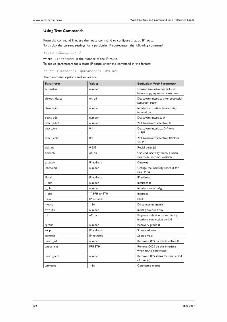
130 6622-3201
Web Interface and Command Line Reference Guidewww.westermo.com
Using Text Commands
From the command line, use the route command to configure a static IP route.
To display the current settings for a particular IP route, enter the following command:
route <instance> ?
where <instance> is the number of the IP route.
To set up parameters for a static IP route, enter the command in the format:
route <instance> <parameter> <value>
The parameter options and values are:
Parameter Values Equivalent Web Parameter
actooslim number Consecutive activation failures before applying route down time
chkoos_deact on, off Deactivate interface after success ful activation retry
chkoos_int number Interface activation failure retry interval (s)
deact_add number Deactivate interface #
deact_add2 number 2nd Deactivate interface #
deact_ent 0,1 Deactivate interface: 0=None 1=PPP
deact_ent2 0,1 2nd Deactivate interface: 0=None 1=PPP
dial_int 0-255 Redial delay (s)
doinact2 off, on Use 2nd inactivity timeout when this route becomes available
gateway IP address Gateway
inact2add number Change the inactivity timeout for this PPP #
IPaddr IP address IP address
ll_add number Interface #
ll_cfg number Interface sub-config
ll_ent “”, PPP, or ETH Interface
mask IP netmask Mask
metric 1-16 Disconnected metric
pwr_dly number Initial powerup delay
q1 off, on Enqueue only one packet during interface connection period
rgroup number Recovery group #
srcip IP address Source address
srcmask IP netmask Source mask
unoos_add number Remove OOS on this interface #
unoos_ent PPP, ETH Remove OOS on this interface when route deactivates
unoos_secs number Remove OOS status for this period of time (s)
upmetric 1-16 Connected metric
1316622-3201
Web Interface and Command Line Reference Guide www.westermo.com
Confi gure > IP Routes > RIP > Authentication keys > Key n 4.40
The RIP authentication keys are used with the “Plain password” and “MD5” RIP authentication meth ods used by the RIP authentication method parameter on the Configure > Ethernet > ETH n and Configure > PPP > PPP n > Standard pages.
Using the Web Page(s)
Key (Empty):
This is the RIP authentication key. Enter a string value up to 16 characters long. A current key will not be shown.
Confirm key:
Re-enter the RIP authentication key here that you entered above, in order to confirm the key is correct.
Key ID (0-255):
This is the ID for the key. The ID is inserted into the RIP packet when using RIP v2 MD5 authenti cation, and is used to look up the correct key for received packets. Valid range is 0 - 255.
Key start day:
This parameter defines the day of the month the key is valid from.
“Disable” means that this key should not be used.
“Now” indicates that the key will be valid up to the end date (defined by the Key end day, Key end month and Key end year parameters). A value of 1 - 31 is the day of the month the key is valid from, but this value must not exceed the number of days in the Key start month.
Key start month:
This parameter defines the month of the year the key is valid from. “None” means that this key should not be used. Otherwise, select the month of the year from the drop-down list.
Key start year:
This parameter defines the year the key is valid from. A year can be entered as either 2 (e.g. 06) or 4 (e.g. 2006) digits.
Key end day:
This parameter defines the day of the month the key expires.
“Disable” means that this key should not be used.
“Never” indicates that the key never expires (a valid start date defined by the Key start day, Key start month and Key start year parameters must be entered). A value of 1 - 31 is the day of the month the key expires, but this value must not exceed the number of days in the Key end month.
Key end month:
This parameter defines the month of the year the key expires. “None” means that this key should not be used. Otherwise, select the month of the year from the drop-down list.
Key end year:
This parameter defines the year the key expires. A year can be entered as either 2 (e.g. 06) or 4
(e.g. 2006) digits.
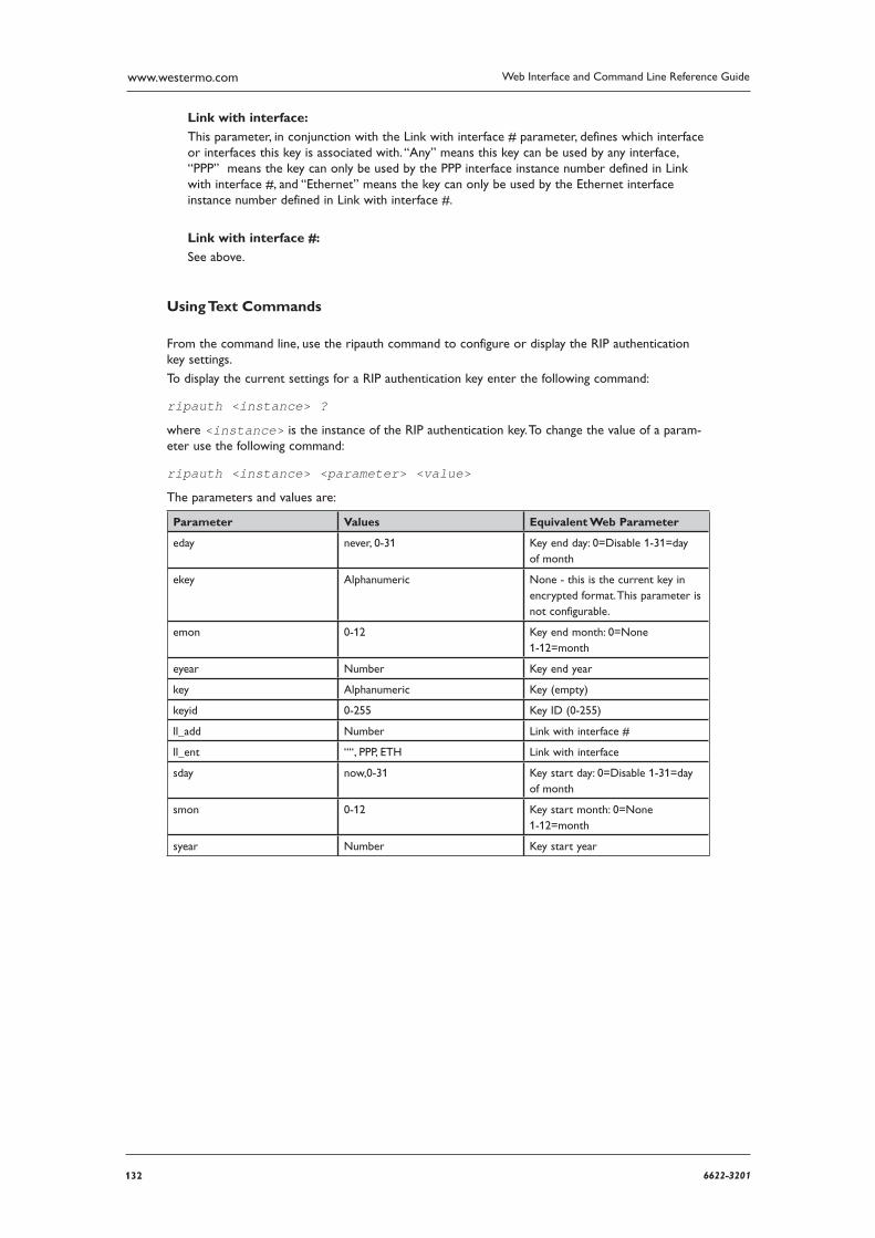
132 6622-3201
Web Interface and Command Line Reference Guidewww.westermo.com
Link with interface:
This parameter, in conjunction with the Link with interface # parameter, defines which interface or interfaces this key is associated with. “Any” means this key can be used by any interface, “PPP” means the key can only be used by the PPP interface instance number defined in Link with inter face #, and “Ethernet” means the key can only be used by the Ethernet interface instance number defined in Link with interface #.
Link with interface #:
See above.
Using Text Commands
From the command line, use the ripauth command to configure or display the RIP authentication key settings.
To display the current settings for a RIP authentication key enter the following command:
ripauth <instance> ?
where <instance> is the instance of the RIP authentication key. To change the value of a param-eter use the following command:
ripauth <instance> <parameter> <value>
The parameters and values are:
Parameter Values Equivalent Web Parameter
eday never, 0-31 Key end day: 0=Disable 1-31=day of month
ekey Alphanumeric None - this is the current key in encrypted format. This parameter is not configurable.
emon 0-12 Key end month: 0=None 1-12=month
eyear Number Key end year
key Alphanumeric Key (empty)
keyid 0-255 Key ID (0-255)
ll_add Number Link with interface #
ll_ent ““, PPP, ETH Link with interface
sday now,0-31 Key start day: 0=Disable 1-31=day of month
smon 0-12 Key start month: 0=None 1-12=month
syear Number Key start year
1336622-3201
Web Interface and Command Line Reference Guide www.westermo.com
Confi gure > IP Routes > Default Route n 4.41
The Configure > IP Routes > Default Route n pages allow you to set up default IP routes that will be used to route all non-local IP addresses not specified in a static IP route. The parameters are identical to those on the static route pages with the exception that there are no IP address or Mask parameters.
Confi gure > IPSec 4.42
IPSec (Internet Protocol Security) refers to a group of protocols and standards that may be used to protect data during transmission over the Internet (which is not inherently secure). Various levels of support for IPSec can be provided on your unit depending upon which model you have purchased. The web pages located under the heading Configure > IPSec are used to set the various param-eters and options that are available. You should note however that this is a complex area and you should have a good understanding of user authentication and data encryption techniques before you commence. For further information refer to “IPSec and VPNs” in this manual.
The first stage in establishing a secure link between two endpoints on an IP network is for those two points to securely exchange a little information about each other. This enables the endpoint respond ing to the request to decide whether it wishes to enter a secure dialogue with the endpoint requesting it. To achieve this, the two endpoints commonly identify themselves and verify the identi-ty of the other party. They must do this in a secure manner so that the process cannot be “listened in to” by any third party. The IKE protocol is used to perform this “checking” and if everything matches up it creates a Security Association (SA) between the two endpoints, normally one for data being sent TO the remote end and one for data being received FROM it.
Once this initial association exists the two devices can “talk” securely about and exchange informa-tion on what kind of security protocols they would like to use to establish a secure data link, i.e. what sort of encryption and/or authentication they can use and what sources/destinations they will accept. When this second stage is complete (and provided that both systems have agreed what they will do), IPSec will have set up its own Security Associations which it uses to test incoming and out-going data packets for eligibility and perform security operations on before passing them down or relaying them from the “tunnel”.
The Configure > IPSEC folder opens to list configuration pages for IKE 0 and IKE 1 with a sepa-rate page for IKE Responder. The IKE 0 instance can be used as an IKE “initiator” or as an IKE “responder” whereas IKE 1 can only be used as an initiator. The IKE 0 and IKE 1 pages are there-fore used to set up the IKE 0 and IKE 1 initiator parameters as required. The IKE Responder page is used to set up the responder parameters for IKE 0. There is also a DPD configuration page, which contains configuration information for Dead Peer Detection.
134 6622-3201
Web Interface and Command Line Reference Guidewww.westermo.com
Confi gure > IPSec > DPD 4.43
When an IPSec tunnel is not receiving packets, the unit will send an IKE DPD request at regular inter vals. If no response is received to the DPD request, more requests are sent at a shorter inter-val until either the maximum outstanding requests allowed is reached or a response is received. If no response is received to the configured maximum requests, the IPSec SAs are removed.
Note: IKE DPD requests require that an IKE SA is present. If one is not present, the DPD request will fail.
To help ensure that an IKE SA exists with a lifetime at least as great as the IPSec lifetime, the unit creates new IKE SAs whenever the desire IPSec SA lifetime exceeds the lifetime of an existing IKE SA, and attempts to negotiate a lifetime for the IKE SA that is 60 seconds longer than the desired life time of the IPSec SA.
Using the Web Page(s)
Request interval on healthy link:
This parameter defines the interval at which DPD requests on a link that is deemed to be healthy.
Request interval on suspect link:
This parameter defines the interval at which DPD requests on a link that is deemed to be sus-pect.
Tunnel inactivity timer (s):
This parameter defines the period of time for inactivity on a tunnel before it is deemed to be sus pect, i.e. if there is no activity on a healthy link for the time period defined in this parameter, the link is then deemed to be suspect.
Remove IPsec SAs after this many failed DPD requests:
This parameter defines the maximum number of DPD requests that will be sent without receiv-ing a response before the IPSec SAs are removed.
1356622-3201
Web Interface and Command Line Reference Guide www.westermo.com
Using Text Commands
From the command line, use the dpd command to configure or display DPD settings. To display cur-rent settings for DPD enter the command:
dpd <instance> ?
where <instance> is 0.
To change the value of a parameter use the command in the format:
dpd 0 <parameter> <value>
The parameters and values are:
Parameter Values Equivalent Web Parameter
failint number Request interval on suspect link
inact number Tunnel inactivity timer (s)
maxfail number Remove IPSec SAs after this many failed DPD requests
okint number request interval on healthy link
For example, to set the Tunnel inactivity timer to 2 minutes you would enter:
dpd 0 inact 120
136 6622-3201
Web Interface and Command Line Reference Guidewww.westermo.com
Confi gure > IPSec > IKE > MODECFG > Static NAT Map-4.44 pings
MODECFG is an extra stage built into IKE negotiations that fits between IKE phase 1 and IKE phase 2, and is used to perform operations such as extended authentication (XAUTH) and requesting an IP address from the host. This IP address becomes the source address to use when sending packets through the tunnel from the remote to the host. This mode of operation (receiving one IP address from the remote host) is called “client” mode. Another mode, called “network” mode, allows the unit to send packets with a range of source addresses through the tunnel.
If the unit receives packets from a local interface that need to be routed through the tunnel, it performs address translation so that the source address matches the assigned IP address before encrypting using the negotiated SA. Some state information is retained so that packets coming in the opposite direction with matching addresses/ports can have their destination address set to the source address of the original packet (in the same way as standard NAT).
If the remote end of the tunnel is to be able to access units connected to the local interface, the unit that has been assigned the virtual IP address needs to have some static NAT entries set up. When a packet is received through the tunnel, the unit will first look up existing NAT entries, fol-lowed by static NAT entries to see if the destination address/port should be modified, and forwards the packet to the new address. If a static NAT mapping is found, the unit creates a dynamic NAT entry that will be used for the duration of the connection. If no dynamic or stateful entry is found, the packet is directed to the local protocol handlers.
Using the Web Page(s)
Min Port #:
This parameter is used to specify the lowest port number to be redirected.
Max Port #:
This parameter is used to specify the highest port number to be redirected.
Map to IP address:
Enter an IP address to which packets containing the specified destination port number are to be redirected.
Map to port:
Enter an IP port number to which packets containing the specified destination port number are to be redirected. When set to “0” no port remapping occurs, and the original port number is used.
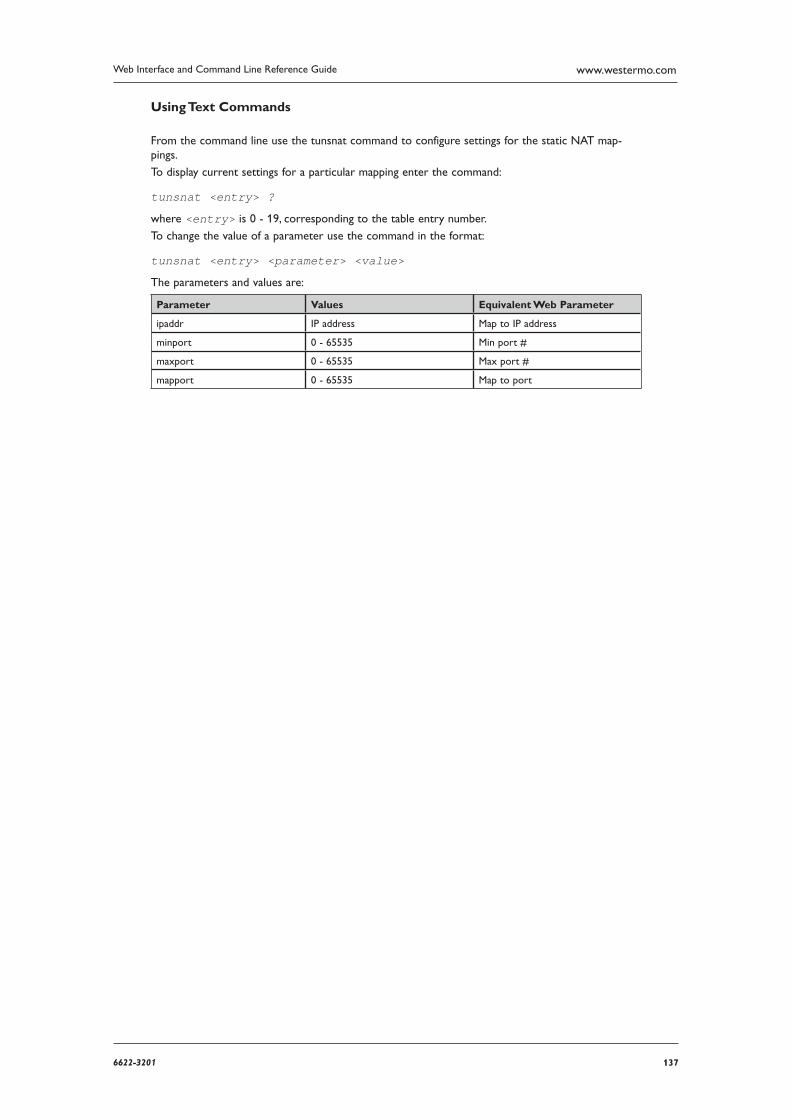
1376622-3201
Web Interface and Command Line Reference Guide www.westermo.com
Using Text Commands
From the command line use the tunsnat command to configure settings for the static NAT map-pings.
To display current settings for a particular mapping enter the command:
tunsnat <entry> ?
where <entry> is 0 - 19, corresponding to the table entry number.
To change the value of a parameter use the command in the format:
tunsnat <entry> <parameter> <value>
The parameters and values are:
Parameter Values Equivalent Web Parameter
ipaddr IP address Map to IP address
minport 0 - 65535 Min port #
maxport 0 - 65535 Max port #
mapport 0 - 65535 Map to port
138 6622-3201
Web Interface and Command Line Reference Guidewww.westermo.com
Confi gure > IPSec > IKE > IKE n 4.45
Using the Web Page(s)
Encryption algorithm:
This parameter selects the encryption algorithm to be used for IKE exchanges over the IP connec tion. You can select “AES”, “DES”, “3DES” or leave the option blank (in which case key exchanges will not be encrypted).
Encryption key bits (AES only):
When this parameter is set to “0”, IKE will use the maximum key length (256 bits) when acting as Initiator, and will accept any key length when acting as Responder. When this parameter is set to any other value, this parameter represents the minimum key length IKE will accept when act-ing as Responder. This parameter will only take effect if Encryption algorithm is set to “AES”.
Authentication algorithm:
This parameter selects the algorithm used to verify that the contents of data packets have not been changed in transit since they were sent. You may select none (i.e. blank), “MD5” or “SHA1”.
Duration (s):
This parameter determines how long (in seconds) the initial IKE Security Association will stay in force. When it expires any attempt to send packets to the remote system will result in IKE attempt ing to establish a new SA. Enter a value between 1 and 28800 seconds (8 hours).
Aggressive mode:
Historically, fixed IP addresses have been used in setting up IPSec tunnels. Today it is more com-mon, particularly with Internet ISPs, to dynamically allocate the user a temporary IP address as part of the process of connecting to the Internet. In this case, the source IP address of the party trying to initiate the tunnel is variable and cannot be pre-configured.
In Main mode (i.e. non-aggressive), the source IP address must be known i.e. this mode can only be used over the Internet if the ISP provides a fixed IP address to the user or you are using X.509 certificates.
Aggressive mode was developed to allow the host to identify a remote unit (initiator) from an ID string rather than from its IP address. This means that it can be used over the Internet via an ISP that dynamically allocates IP addresses. It also has two other noticeable differences from main mode. Firstly, it uses fewer messages to complete the phase 1 exchange (3 compared to 5) and so will execute a little more quickly, particularly on networks with large turn-around delays such as GPRS. Secondly, as more information is sent unencrypted during the exchange, it is potentially less secure than a normal mode exchange.
This parameter is used to select Main mode (“Off”) or Aggressive mode (“On”).
Note: Main mode can be used without knowing the remote unit’s IP address when using certificates. This is because the ID of the remote unit (its public key) can be retrieved from the certificate file.
Dead Peer Detection:
This parameter enables or disables Dead Peer Detection. For more details refer to the Configure > IPSec > DPD page.
IKE MODP group:
This parameter this allows you to set the key length used in the IKE Diffie-Hellman exchange to 768 bits (group 1) or 1024 bits (group 2). Normally this option is set to group 1 and this is suf-ficient for normal use. For particularly sensitive applications, you can improve security by select-ing group 2 to enable a 1024 bit key length. Note however that this will slow down the process of generating the phase 1 session keys (typically from 1-2 seconds for group 1), to 4-5 seconds.
1396622-3201
Web Interface and Command Line Reference Guide www.westermo.com
Minimum IPSec MODP group:
This parameter allows the user to set the minimum width of the numeric field used in the calcula tions for phase 2 of the security exchange. With “No PFS” (Perfect Forwarding Security) selected, the data transferred during phase 1 can be reused to generate the keys for the phase 2 SAs (hence speeding up connections). However, in doing this it is possible (though very unlikely), that if the phase 1 keys were compromised (i.e. dis covered by a third party), the phase 2 keys might be more easily compromised.
Enabling group 1 (768) or 2 (1024) or 3 (1536), IPSec MODP forces the key calculation for phase 2 to use new data that has no relationship to the phase 1 data and initiates a second Diffie-Hell man exchange. This provides an even greater level of security but of course can take longer to complete (see comments on group 1/group 2 calculation times under IKE MODP group).
RSA private key file:
This parameter specifies the name of a file for the X.509 certificate holding the unit’s private part of the public/private key pair used in certificate exchanges. See “X.509 Certificates” in the “IPSec and VPNs” section for further explanation.
Maximum re-transmits:
This parameter specifies the maximum number of times that IKE will re-transmit a negotiation frame as part of the exchange before failing.
Re-transmit interval (s):
This parameter specifies the amount of time in seconds that IKE will wait for a response from the remote system before retransmitting the negotiation frame.
Inactivity timeout (s):
This parameter specifies the period of time in seconds after which when no response to a negotia tion packet has been received from the remote IKE will give up.
Send INITIAL-CONTACT notifications:
This parameter specifies whether INITIAL-CONTACT notifications are sent.
NAT traversal enabled:
When set to “On”, this parameter enables support for NAT traversal within IKE/IPSec. When one end of an IPSec tunnel is behind a NAT box, some form of NAT traversal may be required before the IPSec tunnel can pass packets. Turning NAT traversal on enables the IKE protocol to discover whether or not one or both ends of a tunnel is behind a NAT box, and implements a standard NAT traversal protocol if NAT is being performed.
The version of NAT traversal supported is that described in the IETF draft “draft-ietf-ipsec-nat-t ike-03.txt”.
NAT traversal keep-alive interval (s)
This parameter may be used to set a timer (in seconds), such that the unit will send regular pack ets to a NAT device in order to prevent the NAT table from expiring.
SA removal mode:
This parameter determines how IPSec and IKE SAs are removed:
“Normal” operation will not delete the IKE SA when all the IPSec SAs that were created by it are removed, and will not remove IPSec SAs when the IKE SA that was used to create them is deleted.
“Remove IKE SA when last IPSec SA removed” will delete the IKE SA when all the IPsec SAs that it created to a particular peer are removed.
“Remove IPSec SAs when IKE SA removed” will delete all IPSec SAs that have been created by the IKE SA that has been removed.
“Both” will remove IPSec SAs when their IKE SA is deleted, and delete IKE SAs when their IPSec SAs are removed.
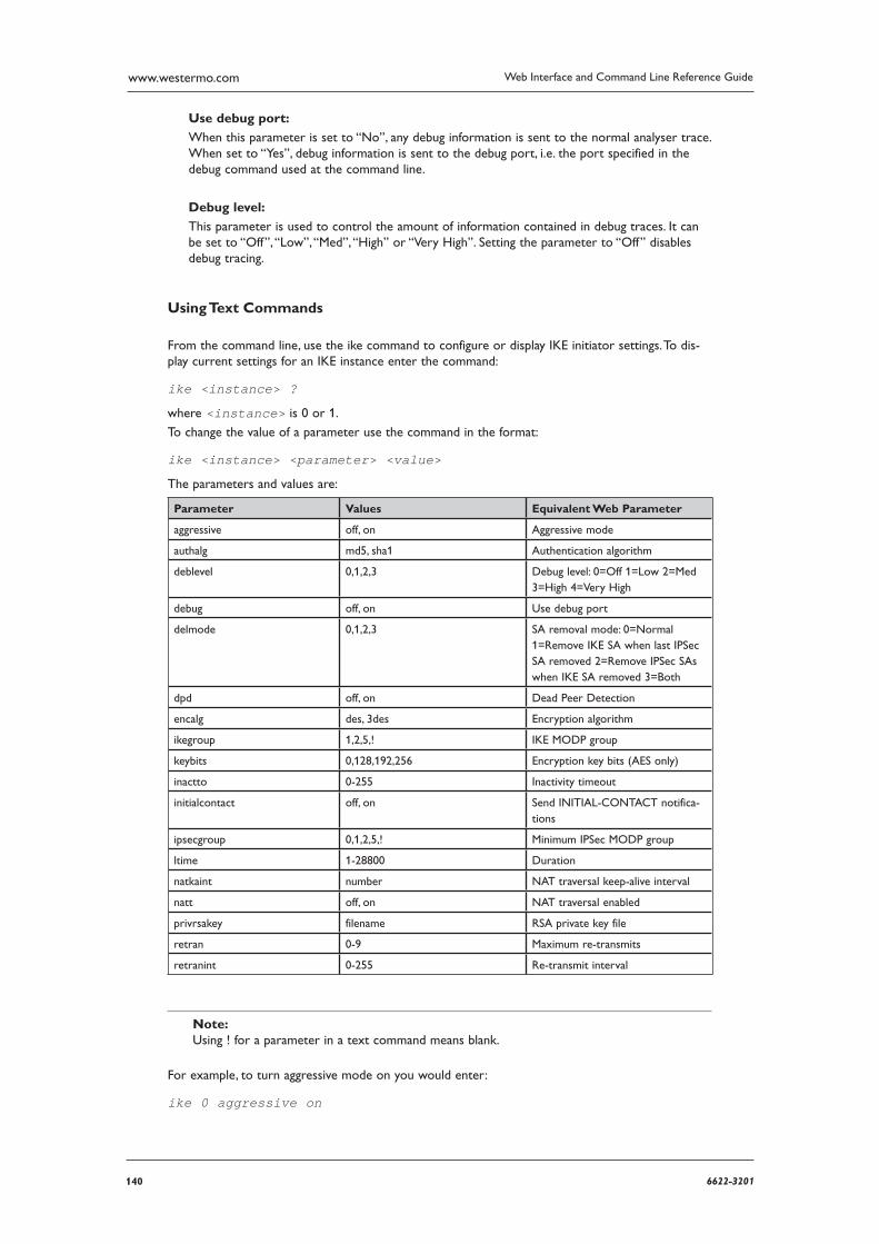
140 6622-3201
Web Interface and Command Line Reference Guidewww.westermo.com
Use debug port:
When this parameter is set to “No”, any debug information is sent to the normal analyser trace. When set to “Yes”, debug information is sent to the debug port, i.e. the port specified in the debug command used at the command line.
Debug level:
This parameter is used to control the amount of information contained in debug traces. It can be set to “Off”, “Low”, “Med”, “High” or “Very High”. Setting the parameter to “Off” disables debug tracing.
Using Text Commands
From the command line, use the ike command to configure or display IKE initiator settings. To dis-play current settings for an IKE instance enter the command:
ike <instance> ?
where <instance> is 0 or 1.
To change the value of a parameter use the command in the format:
ike <instance> <parameter> <value>
The parameters and values are:
Parameter Values Equivalent Web Parameter
aggressive off, on Aggressive mode
authalg md5, sha1 Authentication algorithm
deblevel 0,1,2,3 Debug level: 0=Off 1=Low 2=Med 3=High 4=Very High
debug off, on Use debug port
delmode 0,1,2,3 SA removal mode: 0=Normal 1=Remove IKE SA when last IPSec SA removed 2=Remove IPSec SAs when IKE SA removed 3=Both
dpd off, on Dead Peer Detection
encalg des, 3des Encryption algorithm
ikegroup 1,2,5,! IKE MODP group
keybits 0,128,192,256 Encryption key bits (AES only)
inactto 0-255 Inactivity timeout
initialcontact off, on Send INITIAL-CONTACT notifica-tions
ipsecgroup 0,1,2,5,! Minimum IPSec MODP group
ltime 1-28800 Duration
natkaint number NAT traversal keep-alive interval
natt off, on NAT traversal enabled
privrsakey filename RSA private key file
retran 0-9 Maximum re-transmits
retranint 0-255 Re-transmit interval
Note: Using ! for a parameter in a text command means blank.
For example, to turn aggressive mode on you would enter:
ike 0 aggressive on
1416622-3201
Web Interface and Command Line Reference Guide www.westermo.com
Confi gure > IPSec > IKE > Responder 4.46
Using the Web Page(s)
The Configure > IPSec > IKE Responder page lists the various parameters for IKE 0 when used in responder mode:
Act as initiator only:
Setting this parameter to “Yes” prevents the unit from responding to any remote IKE requests. When set to “No” the unit will both initiate an IPSec IKE exchange if required to do so and respond to any incoming IKE requests.
Acceptable encryption algorithms:
Enter in this parameter a comma separated list of acceptable encryption algorithms when responding to an IKE request. This can currently include “DES”, “3DES”, “AES” or any combina-tion of the three. If the remote peer requests the use of an algorithm that is not included in this list, the negotiation will fail.
Minimum Encryption key bits (AES only):
When this parameter is set to “0”, the IKE Responder will accept any key length. When this parameter is set to any other value, this parameter represents the minimum key length the IKE Responder will accept. This parameter will only take effect if Acceptable encryption algorithms includes AES.
Note: This parameter is exactly the same as the Encryption key bits (AES only) parameter on the Configure > IPSec > IKE > IKE 0 page. Changes to this parameter here will be reflected on the Configure > IPSec > IKE > IKE 0 page, and vice-versa.
Acceptable authentication algorithms:
Enter in this parameter a comma-separated list of acceptable authentication algorithms when responding to an IKE request. This can currently include “MD5”, “SHA1” or both. If the remote peer requests the use of an algorithm that is not included in this list, the negotiation will fail.
Minimum acceptable IPSec MODP group:
This parameter specifies the minimum DH group the unit will accept when acting as a respond-er.
Maximum acceptable IPSec MODP group:
This parameter specifies the maximum DH group the unit will accept when acting as a respond-er. This value may be decreased from the maximum value of 5 to ensure that negotiations times are not excessive.
Duration (s):
This parameter determines how long (in seconds) the initial IKE Security Association will stay in force. When it expires any attempt to send packets to the remote system will result in IKE attempting to establish a new SA. Enter a value between 1 and 28800 seconds (8 hours).
Inactivity timeout (s):
This parameter specifies the period of time in seconds after which when no response to a negotiation packet has been received from the remote IKE will give up.
Send INITIAL-CONTACT notifications:
This parameter enables or disables the sending of INITIAL-CONTACT notifications.
142 6622-3201
Web Interface and Command Line Reference Guidewww.westermo.com
Send RESPONDER-LIFETIME notifications:
Enables and disables the RESPONDER-LIFETIME notifications sent to the initiator. If an initiator requests an IKE lifetime that is greater than the responder, a notification will be sent and the initiator should reduce its lifetime value accordingly.
NAT traversal enabled:
When set to “On”, this parameter enables support for NAT traversal within IKE/IPSec. When one end of an IPSec tunnel is behind a NAT box, some form of NAT traversal may be required before the IPSec tunnel can pass packets. Turning NAT traversal on enables the IKE protocol to discover whether or not one or both ends of a tunnel is behind a NAT box, and implements a standard NAT traversal protocol if NAT is being performed.
The version of NAT traversal supported is that described in the IETF draft “draft-ietf-ipsec-nat-t ike-03.txt”.
NAT traversal keep-alive interval (s):
This parameter may be used to set a timer (in seconds), such that the unit will send regular packets to a NAT device in order to prevent the NAT table from expiring.
RSA private key file:
This parameter specifies the name of a file for the X.509 certificate holding the unit’s private part of the public/private key pair used in certificate exchanges. See “X.509 Certificates” in the “IPSec and VPNs” section for further explanation.
SA removal mode:
This parameter determines how IPSec and IKE SAs are removed:
“Normal” operation will not delete the IKE SA when all the IPSec SAs that were created by it are removed, and will not remove IPSec SAs when the IKE SA that was used to create them is deleted. “Remove IKE SA when last IPSec SA removed” will delete the IKE SA when all the IPsec SAs that it created to a particular peer are removed.
“Remove IPSec SAs when IKE SA removed” will delete all IPSec SAs that have been created by the IKE SA that has been removed.
“Both” will remove IPSec SAs when their IKE SA is deleted, and delete IKE SAs when their IPSec SAs are removed.
Use debug port:
When this parameter is set to “No”, any debug information is sent to the normal analyser trace where it may be filtered according to the analyser configuration. When set to “Yes”, debug infor-mation is also sent to the debug port i.e. the port specified in the debug command used at the command line.
Debug level:
This parameter is used to control the amount of information contained in debug traces. It can be set to “Off”, “Low”, “Med”, “High” or “Very High”. Setting the parameter to “Off” disables debug tracing.
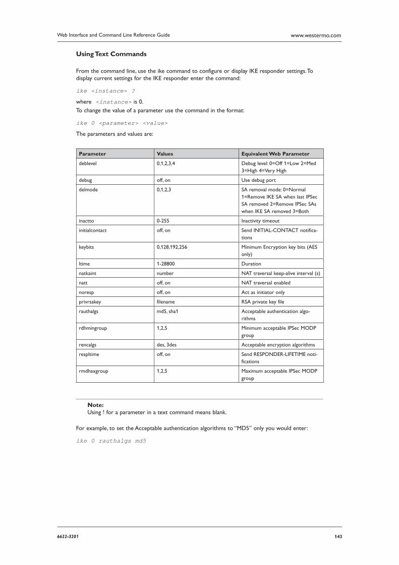
1436622-3201
Web Interface and Command Line Reference Guide www.westermo.com
Using Text Commands
From the command line, use the ike command to configure or display IKE responder settings. To display current settings for the IKE responder enter the command:
ike <instance> ?
where <instance> is 0.
To change the value of a parameter use the command in the format:
ike 0 <parameter> <value>
The parameters and values are:
Parameter Values Equivalent Web Parameter
deblevel 0,1,2,3,4 Debug level: 0=Off 1=Low 2=Med 3=High 4=Very High
debug off, on Use debug port
delmode 0,1,2,3 SA removal mode: 0=Normal 1=Remove IKE SA when last IPSec SA removed 2=Remove IPSec SAs when IKE SA removed 3=Both
inactto 0-255 Inactivity timeout
initialcontact off, on Send INITIAL-CONTACT notifica-tions
keybits 0,128,192,256 Minimum Encryption key bits (AES only)
ltime 1-28800 Duration
natkaint number NAT traversal keep-alive interval (s)
natt off, on NAT traversal enabled
noresp off, on Act as initiator only
privrsakey filename RSA private key file
rauthalgs md5, sha1 Acceptable authentication algo-rithms
rdhmingroup 1,2,5 Minimum acceptable IPSec MODP group
rencalgs des, 3des Acceptable encryption algorithms
respltime off, on Send RESPONDER-LIFETIME noti-fications
rmdhaxgroup 1,2,5 Maximum acceptable IPSec MODP group
Note: Using ! for a parameter in a text command means blank.
For example, to set the Acceptable authentication algorithms to “MD5” only you would enter:
ike 0 rauthalgs md5
144 6622-3201
Web Interface and Command Line Reference Guidewww.westermo.com
Confi gure > IPSec > IKEv2 > IKEv2 n When IKE Version 2 is supported, it is possible to specify whether the IKEv1 or IKEv2 protocol should be used to negotiate IKE SAs. By default, IKEv1 is used and units which have been upgraded from IKEv1 to IKEv2 will not require any changes to their configuration to continue working with IKEv1.
Using the Web Page(s)
Encryption algorithm:
This parameter selects the encryption algorithm to be used for IKE exchanges over the IP connec tion. You can select “DES”, “3DES”, “AES” or leave the option blank (in which case key exchanges will not be attempted).
Encryption key length (AES only):
When the Initiator encryption algorithm is set to “AES”, this parameter may be used to select the key length as 128 (default), 192 or 256 bits.
Authentication algorithm:
This parameter selects the algorithm used to verify that the contents of data packets have not been changed in transit since they were sent. You may select none (i.e. blank), “MD5” or “SHA-1”. If the parameter is left blank negotiations will not be attempted.
PRF algorithm:
This parameter selects the pseudo random function to negotiate and can be selected from “MD5” or “SHA1”.
MODP group:
This is the DH group number to negotiate. Larger values result in “stronger” keys but take longer to generate.
Duration (s):
This parameter determines how long (in seconds) the initial IKEv2 Security Association will stay in force. When it expires any attempt to send packets to the remote system will result in IKEv2 attempting to establish a new SA. Enter a value between 1 and 28800 seconds (8 hours).
Re-key time (s):
When the time left until expiry for this SA reaches the value specified by this parameter, the IKEv2 SA will be renegotiated, i.e. a new IKEv2 SA is negotiated and the old SA is removed. Any IPSec “child” SAs that were created are retained and become “children” of the new SA.
Maximum re-transmits:
This parameter specifies the maximum number of times that IKEv2 will retransmit a negotiation frame as part of the exchange before failing.
Re-transmit interval (s):
This parameter specifies the amount of time in seconds that IKEv2 will wait for a response from the remote system before retransmitting the negotiation frame.
Inactivity timeout (s):
This parameter specifies the period of time in seconds after which when no response to a negotia tion packet has been received from the remote IKEv2 will give up.
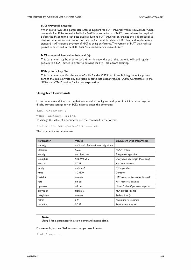
1456622-3201
Web Interface and Command Line Reference Guide www.westermo.com
NAT traversal enabled:
When set to “On”, this parameter enables support for NAT traversal within IKEv2/IPSec. When one end of an IPSec tunnel is behind a NAT box, some form of NAT traversal may be required before the IPSec tunnel can pass packets. Turning NAT traversal on enables the IKE protocol to discover whether or not one or both ends of a tunnel is behind a NAT box, and implements a standard NAT traversal protocol if NAT is being performed. The version of NAT traversal sup-ported is described in the IETF draft “draft-ietf-ipsec-nat-t-ike-03.txt”.
NAT traversal keep-alive interval (s):
This parameter may be used to set a timer (in seconds), such that the unit will send regular pack ets to a NAT device in order to prevent the NAT table from expiring.
RSA private key file:
This parameter specifies the name of a file for the X.509 certificate holding the unit’s private part of the public/private key pair used in certificate exchanges. See “X.509 Certificates” in the “IPSec and VPNs” section for further explanation.
Using Text Commands
From the command line, use the ike2 command to configure or display IKE2 initiator settings. To display current settings for an IKE2 instance enter the command:
ike2 <instance> ?
where <instance> is 0 or 1.
To change the value of a parameter use the command in the format:
ike2 <instance> <parameter> <value>
The parameters and values are:
Parameter Values Equivalent Web Parameter
iauthalg md5, sha1 Authentication algorithm
idhgroup 1,2,5,! MODP group
iencalg des, 3des, aes Encryption algorithm
ienkeybits 128, 192, 256 Encryption key length (AES only)
inactto 0-255 Inactivity timeout
Iprfalg md5, sha1 PRF algorithm
ltime 1-28800 Duration
natkaint number NAT traversal keep-alive interval
natt off, on NAT traversal enabled
openswan off, on None. Enable Openswan support.
privrsakey filename RSA private key file
rekeyltime number Re-key time (s)
retran 0-9 Maximum re-transmits
retranint 0-255 Re-transmit interval
Note: Using ! for a parameter in a text command means blank.
For example, to turn NAT traversal on you would enter:
ike2 0 natt on
146 6622-3201
Web Interface and Command Line Reference Guidewww.westermo.com
Confi gure > IPSec > IKEv2 > IKEv2 n 4.47
When IKE Version 2 is supported, it is possible to specify whether the IKEv1 or IKEv2 protocol should be used to negotiate IKE SAs. By default, IKEv1 is used and units which have been upgraded from IKEv1 to IKEv2 will not require any changes to their configuration to continue working with IKEv1.
Using the Web Page(s)
Encryption algorithm:
This parameter selects the encryption algorithm to be used for IKE exchanges over the IP connection. You can select “DES”, “3DES”, “AES” or leave the option blank (in which case key exchanges will not be attempted).
Encryption key length (AES only):
When the Initiator encryption algorithm is set to “AES”, this parameter may be used to select the key length as 128 (default), 192 or 256 bits.
Authentication algorithm:
This parameter selects the algorithm used to verify that the contents of data packets have not been changed in transit since they were sent. You may select none (i.e. blank), “MD5” or “SHA-1”. If the parameter is left blank negotiations will not be attempted.
PRF algorithm:
This parameter selects the pseudo random function to negotiate and can be selected from “MD5” or “SHA1”.
MODP group:
This is the DH group number to negotiate. Larger values result in “stronger” keys but take longer to generate.
Duration (s):
This parameter determines how long (in seconds) the initial IKEv2 Security Association will stay in force. When it expires any attempt to send packets to the remote system will result in IKEv2 attempting to establish a new SA. Enter a value between 1 and 28800 seconds (8 hours).
Re-key time (s):
When the time left until expiry for this SA reaches the value specified by this parameter, the IKEv2 SA will be renegotiated, i.e. a new IKEv2 SA is negotiated and the old SA is removed. Any IPSec “child” SAs that were created are retained and become “children” of the new SA.
Maximum re-transmits:
This parameter specifies the maximum number of times that IKEv2 will retransmit a negotiation frame as part of the exchange before failing.
Re-transmit interval (s):
This parameter specifies the amount of time in seconds that IKEv2 will wait for a response from the remote system before retransmitting the negotiation frame.
Inactivity timeout (s):
This parameter specifies the period of time in seconds after which when no response to a negotiation packet has been received from the remote IKEv2 will give up.
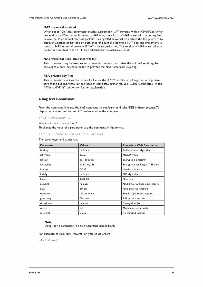
1476622-3201
Web Interface and Command Line Reference Guide www.westermo.com
NAT traversal enabled:
When set to “On”, this parameter enables support for NAT traversal within IKEv2/IPSec. When one end of an IPSec tunnel is behind a NAT box, some form of NAT traversal may be required before the IPSec tunnel can pass packets. Turning NAT traversal on enables the IKE protocol to discover whether or not one or both ends of a tunnel is behind a NAT box, and implements a standard NAT traversal protocol if NAT is being performed. The version of NAT traversal sup-ported is described in the IETF draft “draft-ietf-ipsec-nat-t-ike-03.txt”.
NAT traversal keep-alive interval (s):
This parameter may be used to set a timer (in seconds), such that the unit will send regular packets to a NAT device in order to prevent the NAT table from expiring.
RSA private key file:
This parameter specifies the name of a file for the X.509 certificate holding the unit’s private part of the public/private key pair used in certificate exchanges. See “X.509 Certificates” in the “IPSec and VPNs” section for further explanation.
Using Text Commands
From the command line, use the ike2 command to configure or display IKE2 initiator settings. To display current settings for an IKE2 instance enter the command:
ike2 <instance> ?
where <instance> is 0 or 1.
To change the value of a parameter use the command in the format:
ike2 <instance> <parameter> <value>
The parameters and values are:
Parameter Values Equivalent Web Parameter
iauthalg md5, sha1 Authentication algorithm
idhgroup 1,2,5,! MODP group
iencalg des, 3des, aes Encryption algorithm
ienkeybits 128, 192, 256 Encryption key length (AES only)
inactto 0-255 Inactivity timeout
Iprfalg md5, sha1 PRF algorithm
ltime 1-28800 Duration
natkaint number NAT traversal keep-alive interval
natt off, on NAT traversal enabled
openswan off, on None. Enable Openswan support.
privrsakey filename RSA private key file
rekeyltime number Re-key time (s)
retran 0-9 Maximum re-transmits
retranint 0-255 Re-transmit interval
Note: Using ! for a parameter in a text command means blank.
For example, to turn NAT traversal on you would enter:
ike2 0 natt on
148 6622-3201
Web Interface and Command Line Reference Guidewww.westermo.com
Confi gure > IPSec > IKEv2 > Responder 4.48
Using the Web Page(s)
The Configure > IPSec > IKEv2 > Responder page lists the various Responder parameters for IKEv2.0:
Act as initiator only:
Setting this parameter to “Yes” prevents the unit from responding to any remote IKEv2 requests. When set to “No” the unit will both initiate an IPSec IKE exchange if required to do so and respond to any incoming IKEv2 requests.
Acceptable encryption algorithms:
Enter in this parameter a comma separated list of acceptable encryption algorithms when responding to an IKEv2 request. This can currently include “DES”, “3DES”, “AES” or any combina tion. If the remote peer requests the use of an algorithm that is not included in this list, the negotia tion will fail.
Acceptable encryption key length (AES only):
When acting as a responder and negotiating AES encryption, this parameter may be used to spec ify the required key length as 128, 192 or 256 bits.
Acceptable authentication algorithms:
Enter in this parameter a comma separated list of authentication algorithms that the unit will allow remote peers to negotiate. This can currently include “MD5”, “SHA1” or both. If the remote peer requests the use of an algorithm that is not included in this list, the negotiation will fail.
Acceptable PRF algorithms:
Enter in this parameter a comma separated list of pseudo random function authentication algo-rithms that the unit will allow remote peers to negotiate. This can currently include “MD5”, “SHA1” or both. If the remote peer requests the use of an algorithm that is not included in this list, the negotiation will fail.
Minimum acceptable MODP group:
This parameter specifies the minimum DH group the unit will accept when acting as a respond-er.
Maximum acceptable MODP group:
This parameter specifies the maximum DH group the unit will accept when acting as a respond-er. This value may be decreased from the maximum value of 5 to ensure that negotiations times are not excessive.
Duration (s):
This parameter determines how long (in seconds) the initial IKE Security Association will stay in force. When it expires any attempt to send packets to the remote system will result in IKE attempt ing to establish a new SA. Enter a value between 1 and 28800 seconds (8 hours).
Inactivity timeout (s):
This parameter specifies the period of time in seconds after which when no response to a negotia tion packet has been received from the remote IKE will give up.
NAT traversal enabled:
When set to “On”, this parameter enables support for NAT traversal within IKE/IPSec. When one end of an IPSec tunnel is behind a NAT box, some form of NAT traversal may be required before the IPSec tunnel can pass packets. Turning NAT traversal on enables the IKE protocol to
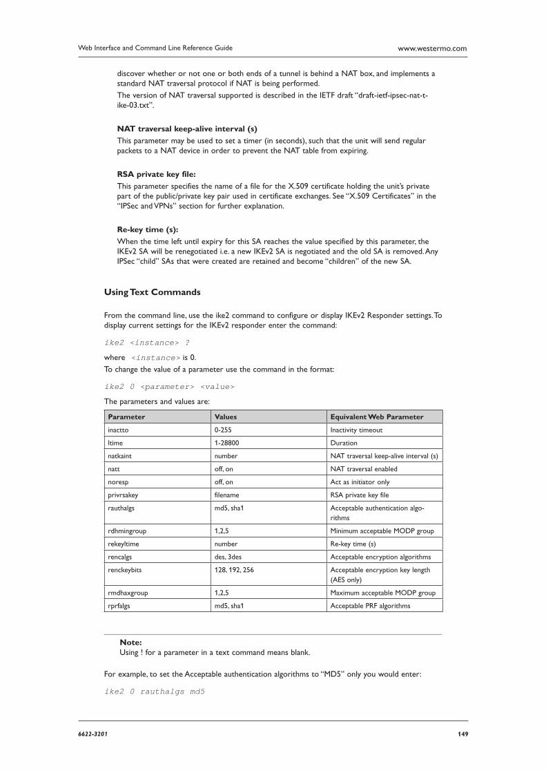
1496622-3201
Web Interface and Command Line Reference Guide www.westermo.com
discover whether or not one or both ends of a tunnel is behind a NAT box, and implements a standard NAT traversal protocol if NAT is being performed.
The version of NAT traversal supported is described in the IETF draft “draft-ietf-ipsec-nat-t-ike-03.txt”.
NAT traversal keep-alive interval (s)
This parameter may be used to set a timer (in seconds), such that the unit will send regular pack ets to a NAT device in order to prevent the NAT table from expiring.
RSA private key file:
This parameter specifies the name of a file for the X.509 certificate holding the unit’s private part of the public/private key pair used in certificate exchanges. See “X.509 Certificates” in the “IPSec and VPNs” section for further explanation.
Re-key time (s):
When the time left until expiry for this SA reaches the value specified by this parameter, the IKEv2 SA will be renegotiated i.e. a new IKEv2 SA is negotiated and the old SA is removed. Any IPSec “child” SAs that were created are retained and become “children” of the new SA.
Using Text Commands
From the command line, use the ike2 command to configure or display IKEv2 Responder settings. To display current settings for the IKEv2 responder enter the command:
ike2 <instance> ?
where <instance> is 0.
To change the value of a parameter use the command in the format:
ike2 0 <parameter> <value>
The parameters and values are:
Parameter Values Equivalent Web Parameter
inactto 0-255 Inactivity timeout
ltime 1-28800 Duration
natkaint number NAT traversal keep-alive interval (s)
natt off, on NAT traversal enabled
noresp off, on Act as initiator only
privrsakey filename RSA private key file
rauthalgs md5, sha1 Acceptable authentication algo-rithms
rdhmingroup 1,2,5 Minimum acceptable MODP group
rekeyltime number Re-key time (s)
rencalgs des, 3des Acceptable encryption algorithms
renckeybits 128, 192, 256 Acceptable encryption key length (AES only)
rmdhaxgroup 1,2,5 Maximum acceptable MODP group
rprfalgs md5, sha1 Acceptable PRF algorithms
Note: Using ! for a parameter in a text command means blank.
For example, to set the Acceptable authentication algorithms to “MD5” only you would enter:
ike2 0 rauthalgs md5
150 6622-3201
Web Interface and Command Line Reference Guidewww.westermo.com
Confi gure > IPSec > IPSec Egroups > Egroup n 4.49
This mode of operation can be used when the Westermo is terminating tunnels to a large number of remote devices e.g when being used as a VPN Concentrator. To keep the size of the configura-tion file in the Westermo box small and also to maintain ease of configuration, only the information that is used for all tunnels is stored on the Westermo box. All information that is site specific is stored in a MySQL database. This means the number of sites that can be configured is limited only by the SQL database size and performance. This will be literally millions of sites depending upon the operating system and hardware of the MySQL PC. The number of sites that can be connected to concurrently is much smaller and limited by the Westermo model.
Basic Concept
The unit with the Egroup/MySQL configuration will be the VPN Concentrator. The remote sites will normally not require an Egroup configuration as they will normally only need to connect to a single peer, the VPN Concentrator. The VPN Concentrator will normally need only a single Eroute configured. The local and remote subnet parameters need to be set up wide enough to encompass all the local and remote networks. The VPN Concentrator can act as an initiator and/or a responder. In situations where there are more remote sites than the unit can support concurrent sessions, it will normally be necessary for the Concentrator and the remote sites to be both an initiator and a responder. This is so that both the remote sites and the head-end can initiate the IPSEC session when required. Note that it is also important to configure the Eroutes to time out on inactivity to free up sessions for other sites. In the case of the VPN Concentrator acting as an initiator, when it receives a packet that matches the main Eroute, if no Security Associations already exist it will look up the required parameters in the database. The unit will then create a ”Dynamic Eroute” contain-ing all the settings from the base eroute and all the information retrieved from the database. At this point IKE will create the tunnel (IPSEC Security associations) as normal. The dynamic eroute will continue to exist until all the IPSEC Security Associates have been removed. At the point where the number of dynamic eroutes free is within 10% of the maximum supported in the platform (MR and DR model) the oldest Dynamic Eroutes (those that have not been used for the longest period of time) and their associated IPSEC Security Associations will be dropped until the number of dynamic eroutes free is above 10% of the total.
Logic fl ow - creation of IPSec SAs Concentrator acting as initiator.
The concentrator will normally act as an initiator when it receives an IP packet for routing with a source address matching the Eroute Local subnet address & mask and a destination address match-ing the Remote subnet address & mask. (Provided than an IPSEC SA does not already exist for this site.)
If an egroup is configured to use the matching eroute, the unit will use a MySQL query to obtain the site specific information in order to create the SA’s. The concentrator will create a SELECT query using the destination IP address of the packet and the mask configured in the egroup con-figuration to determine the remote subnet address. (This means that the remote subnet mask must be the same on all sites using the current egroup.) Once the site specific information has been retrieved, the unit creates a ’dynamic’ eroute which is based upon the base eroute configuration plus the site specific information from the MySQL database.The router can then use the completed eroute configuration and IKE will be used to create the IPsec SAs. For the pre-shared key, IKE will use the password returned from the MySQL database rather than doing a local look up in the user configuration. Once created, the SAs are linked with the dynamic eroute. Replacement SAs are cre-ated as the lifetimes start to get low and traffic is still flowing. When all SAs to this remote router are removed, the dynamic eroute will also be removed so that eroute can then be re-used to create tunnels to other remote sites. When processing outgoing packets, dynamic eroutes are searched before base eroutes. So, if a matching dynamic eroute is found, it is used, and the base eroute is only matched if no dynamic eroute exists. Once the dynamic eroute is removed, further outgoing packets will match the base eroute and the process is repeated.
1516622-3201
Web Interface and Command Line Reference Guide www.westermo.com
Concentrator acting as a responder to a session initiated from the remote site.
When a remote site needs to create an IPSEC SA with the concentrator it will send an IKE request to the concentrator. The concentrator needs to be able to confirm that the remote device is authorised to create an IPSec tunnel. The remote site will supply its ID to the host during the IKE negotiations. The concentrator will use this ID and look through the eroutes configured and dynam-ic eroutes to see if the supplied ID matches the configured Peer ID (peerid). If a match is found, the MYSQL database is queried to retrieve the information required to complete the negotiation (e.g. pre-shared key/ password). If no matching base eroute is found, the local user configuration is used to locate the password, and a normally configured eroute must also exist. Once the information is retrieved from the MySQL database, IKE negotiations continue and the created IPsec SAs will be associated with the dynamic eroute. As long as the dynamic eroute exists, it behaves just like a nor-mal eroute. i.e. SAs are replaced/removed as required.
If errors are received from the MySQL database, or not enough fields are returned, the dynamic eroutes are removed, and IKE negotiations in progress will be terminated. There are a limited number of dynamic eroutes. If the number of free dynamic eroutes is less than 10% of the total number of dynamic eroutes, the Westermo router will periodically remove the oldest dynamic eroutes. This is done to ensure that there will always be some free dynamic eroutes available for incoming connections from remote routers. It is possible to view the current dynamic tunnels that exist using the WEB server, browse to Status > IPSec > Dynamic Tunnels. The table will indicate the base eroute and the Remote Peer ID in the status display to help identify which remote sites are currently connected.
Preliminary Eroute confi guration:
The eroute configuration Configure > IPSec > Eroutes > Eroute n differs from a normal configu-ration in the following ways:
Peer IP/hostname: Because the peer IP address to each peer is unknown and is retrieved from the database, this field is left empty.
Bakpeerip (CLI only): Because the peer IP address to each peer is unknown and is retrieved from the database, this field is left empty.
Peer ID: When the host unit is acting as a responder during IKE negotiations, the router uses the ID supplied by the remote to decide whether or not the MySQL database should be inter-rogated. So that the unit can make this decision, the remote router must supply an ID that matches the peerid configured into the eroute. Wildcard matching is supported which means that the peerid may contain ’*’ and ’?’ characters. If only one eroute is configured, the peerid field may contain a ’*’, indicating that all remote IDs result in a MySQL look up.
Local subnet IP address / Local subnet mask: Configured as usual.
Remote subnet IP address / Remote subnet mask: These fields should be configured in such a way that packets to ALL remote sites fall within the configured subnet. e.g. if there are two sites with remote subnets 192.168.0.0/24, and 192.168.1.0/24 respectively, a valid configuration for the host would be 192.168.0.0/23 so that packets to both remote sites match.
All other fields should be configured as usual. It is possible to set up other Egroups linked with other eroutes. This would be done if there is a second group of remote sites that have a differ-ent set of local and remote subnets, or perhaps different encryption requirements. The only real requirement is that this second group uses peer IDs that do not match up with those in use by the first egroup.
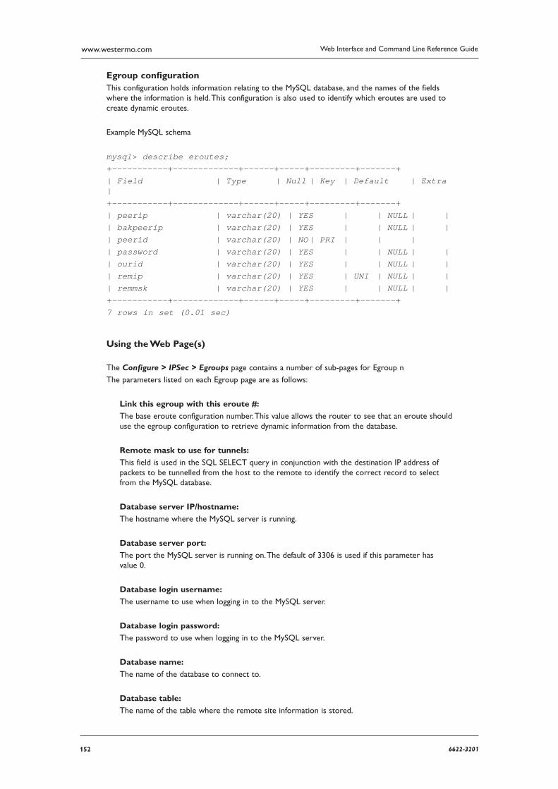
152 6622-3201
Web Interface and Command Line Reference Guidewww.westermo.com
Egroup confi guration This configuration holds information relating to the MySQL database, and the names of the fields where the information is held. This configuration is also used to identify which eroutes are used to create dynamic eroutes.
Example MySQL schema
mysql> describe eroutes; +-----------+-------------+------+-----+---------+-------+ | Field | Type | Null | Key | Default | Extra | +-----------+-------------+------+-----+---------+-------+ | peerip | varchar(20) | YES | | NULL | | | bakpeerip | varchar(20) | YES | | NULL | | | peerid | varchar(20) | NO | PRI | | | | password | varchar(20) | YES | | NULL | | | ourid | varchar(20) | YES | | NULL | | | remip | varchar(20) | YES | UNI | NULL | | | remmsk | varchar(20) | YES | | NULL | | +-----------+-------------+------+-----+---------+-------+ 7 rows in set (0.01 sec)
Using the Web Page(s)
The Configure > IPSec > Egroups page contains a number of sub-pages for Egroup n
The parameters listed on each Egroup page are as follows:
Link this egroup with this eroute #:
The base eroute configuration number. This value allows the router to see that an eroute should use the egroup configuration to retrieve dynamic information from the database.
Remote mask to use for tunnels:
This field is used in the SQL SELECT query in conjunction with the destination IP address of packets to be tunnelled from the host to the remote to identify the correct record to select from the MySQL database.
Database server IP/hostname:
The hostname where the MySQL server is running.
Database server port:
The port the MySQL server is running on. The default of 3306 is used if this parameter has value 0.
Database login username:
The username to use when logging in to the MySQL server.
Database login password:
The password to use when logging in to the MySQL server.
Database name:
The name of the database to connect to.
Database table:
The name of the table where the remote site information is stored.
1536622-3201
Web Interface and Command Line Reference Guide www.westermo.com
Remote subnet IP field name:
The name of the field in the table where the ’remip’ data is stored.
Remote subnet mask field name:
The name of the field in the table where the ’remmsk’ data is stored.
Peer IP field name:
The name of the field in the table where the ’peerip’ data is stored.
Backup Peer IP field name:
The name of the field in the table where the ’bakpeerip’ data is stored.
Peer ID field name:
The name of the field in the table where the ’peerid’ data is stored.
Our ID field name:
The name of the field in the table where the ’ourid’ data is stored.
Password field name:
The name of the field in the table where the password to use in IKE negotiations is stored.
Note The default MySQL field names match the matching eroute configuration parameter name. The default field name for the ’password’ field is ’password’.
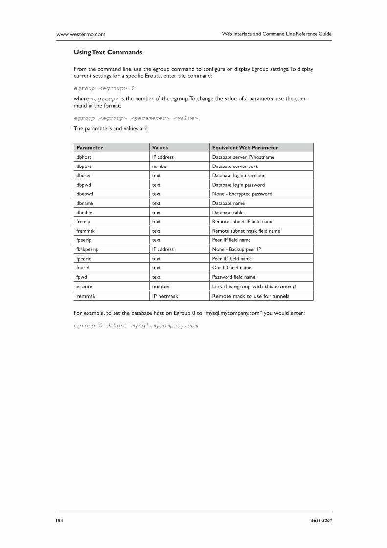
154 6622-3201
Web Interface and Command Line Reference Guidewww.westermo.com
Using Text Commands
From the command line, use the egroup command to configure or display Egroup settings. To display current settings for a specific Eroute, enter the command:
egroup <egroup> ?
where <egroup> is the number of the egroup. To change the value of a parameter use the com-mand in the format:
egroup <egroup> <parameter> <value>
The parameters and values are:
Parameter Values Equivalent Web Parameter
dbhost IP address Database server IP/hostname
dbport number Database server port
dbuser text Database login username
dbpwd text Database login password
dbepwd text None - Encrypted password
dbname text Database name
dbtable text Database table
fremip text Remote subnet IP field name
fremmsk text Remote subnet mask field name
fpeerip text Peer IP field name
fbakpeerip IP address None - Backup peer IP
fpeerid text Peer ID field name
fourid text Our ID field name
fpwd text Password field name
eroute number Link this egroup with this eroute #
remmsk IP netmask Remote mask to use for tunnels
For example, to set the database host on Egroup 0 to “mysql.mycompany.com” you would enter:
egroup 0 dbhost mysql.mycompany.com
1556622-3201
Web Interface and Command Line Reference Guide www.westermo.com
Confi gure > IPSec > IPSec Eroutes > Eroute n 4.50
Once the IKE parameters have been set-up, the next stage is to define the characteristics of the encrypted routes, or tunnels (“eroutes”). This includes items such as what source/destination addresses will be connected by the tunnel and what type of encryption/authentication procedures will be applied to the packets traversing it. For obvious reasons it is essential that parameters such as encryption and authentication are the same at each end of the tunnel. If they are not, then the two sys tems will not be able to agree on what set of rules or “policy” to adopt for the encrypted route and com munication cannot take place.
Using the Web Page(s)
The Configure > IPSec > Eroutes page contains a number of sub-pages for Eroutes 0-9, 10-19, etc.
Note: The number of Eroutes available depends on how many licenses you have purchased. Eroute licenses may be purchased in groups of 10 up to a maximum of 30).
The parameters listed on each Eroute page are as follows:
Description:
This parameter allows you to enter a name for this Eroute instance, to make it easier to identify.
Peer IP/hostname:
This is the IP address of the remote unit to which you wish to connect.
Backup peer IP:
This is the IP address of a backup peer. If the router cannot open a socket connection to the main peer this IP address will be used. Please note: The backup peer device must have an identi-cal eroute configuration to the primary peer.
Peer ID:
In Main mode (i.e. when Aggressive mode is “Off”) this must be the IP address of the peer. When Aggressive mode is “On”, this parameter is a string of up to 20 characters that is used in to identify the remote system and should contain the same text as the Our ID parameter in the corresponding remote unit’s Eroute configuration.
Our ID:
When Aggressive mode is “On”, this parameter is a string of up to 20 characters sent to the remote system to identify the initiator. The variable %s can be used in this field, this will send the unit serial number and may be prefixed with SN for example. When certificates are used this field should contain the “Altname” field in a valid certificate held on the unit.
XAUTH ID:
This is the Extended Authentication ID for use with MODECFG.
RSA private key file:
This field is used to override the private key filename configured in IKE. It is only used when certificates are being used for the authentication stage of the IKE negotiation.
Send our ID as FQDN:
When set to “Yes”, this parameter indicates to the remote peer that the ID is in Fully Qualified Domain Name format, e.g. “vpnclient1.anycompany.com”. When set to “No”, the ID is indicated as being of simple Key ID type e.g. “vpnclient1”. The default is “No” and it should only be neces-sary to select “Yes” where interoperability problems are encountered with other manufacturer’s VPN equipment.
156 6622-3201
Web Interface and Command Line Reference Guidewww.westermo.com
Interface to use for local subnet IP address / Interface # to use for local subnet IP address:
Together, these parameters allow the local subnet setting (Local subnet IP address/Local subnet mask) to take the value of the IP address of an interface. To configure, clear the Local subnet IP address and Local subnet mask parameters, and then configure the Interface to use for local subnet IP address as either “PPP” or “Ethernet” and Interface # to use for local subnet IP address interface instance (e.g. PPP 1).
Local subnet IP address:
This is the IP address of the local sub-net. This will usually be the IP address of the local router’s Ethernet interface or that of a specific device on the local sub-net (such as a PC running a client or host application).
Local subnet mask:
When connecting two sub-nets it will often be desirable to allow any device on one sub-net to connect to any other device on the remote sub-net. This mask sets the range of addresses that will be allowed to use the Eroute.
Local subnet IP address to negotiate (if different from above) /Local subnet mask to negotiate (if different from above):
If eroutes are allowed to negotiate local traffic selectors which differ from the normal ones, these two parameters will be the values used when negotiating the tunnels. The firewall can then be used to translate the source addresses of packets to a value that lies within the negoti-ated range. This is so that a packet can match more than one eroute, but will use a different source address (from the peers perspective) depending on which tunnel gets used.
Remote subnet IP address:
This is the IP address of the remote sub-net. It will usually be the IP address of the remote router’s Ethernet interface or that of a specific device on the remote sub-net (such as a PC run-ning a client or host application).
Remote subnet mask:
When connecting two sub-nets it will often be desirable to allow any device on one sub-net to connect to any other device on the remote sub-net. This mask sets the range of addresses that can be addressed on the remote sub-net via the Eroute.
Remote subnet ID:
When the unit is in server mode and negotiating IPsec from behind a NAT box, the Remote subnet IP address and Remote subnet mask parameters should be left blank, and this parameter should be configured to the ID sent by the remote Windows client (this is usually the computer name).
Local port / Remote port:
These parameters are used to match packets with a particular Eroute. For example, if Local port is 0 and Remote port is 80, only packets where the TCP or UDP remote port number is 80 will be matched by the Eroute. The value of 0 indicates that any port will match.
TX packets with these TOS values through this eroute:
Packets with matching TOS will not get tunnelled through any other eroute. Traffic selector matching etc still takes place. Packets with a TOS that don’t match any of those in the list get tunnelled as usual. Separate values with comma’s e.g. 2,4
First local port (IKEv2 only) / Last local port (IKEv2 only):
These parameters allow you to restrict which ports on the unit will be able to send and receive traffic on this Eroute.
1576622-3201
Web Interface and Command Line Reference Guide www.westermo.com
First remote port (IKEv2 only) / Last remote port (IKEv2 only):
These parameters allow you to restrict which ports on the client will be able to send and receive traffic on this Eroute.
Mode:
This parameter can be set to “Tunnel” or “Transport”. In normal use this will be set to “Tunnel”, i.e. both the data payload and the packet headers/routing information will be encrypted.
AH authentication algorithm:
This parameter selects the algorithm used to verify that the packet contents have not been
changed in transit since they were sent. You may select none (blank), “MD5” or “SHA1”.
Normally it is preferable to use ESP authentication and turn AH authentication off (as ESP
provides better protection) but for compatibility with some older systems it may necessary. There is little point in using AH and ESP Authentication together but this is also possible.
ESP authentication algorithm:
This parameter selects the algorithm used to verify that packet contents have not been changed. You may select none (blank), “MD5” or “SHA-1”.
ESP encryption algorithm:
This parameter specifies the cryptographic algorithm to be used when securing the packet pay-load. You may select none (blank), “DES”, “3-DES” or “RIJN” (AES).
ESP encrypt key length (bits):
This parameter is only used when ESP encryption algorithm is set to “AES”. The default value of 0 indicates that a key length of 128 bits is used. Other options are 192 and 256.
IPCOMP algorithm:
This parameter determines whether data compression is used. When set to “Off”, data is not compressed. When set to “DEFLATE”, data compression is applied to the data being carried. The effectiveness of data compression will vary with the type of data but a typical ratio achieved for a mix of data, for instance Web pages, spread sheets, databases, text files, GIFs, etc. would be between 2 and 3:1. This has the effect of increasing the connection throughput. If the data is tra-versing a network where charges are based on the amount of data passed (such as many GPRS networks), it may also offer significant cost savings. Note however that if the data is already compressed, such as .zip or .jpg files, then the system will detect that the data cannot be com-pressed further and send it un-compressed.
Note: Data compression is an optional feature that may not appear on your product unless you have pur chased it as a separate feature pack.
IPSec MODP group:
This parameter is used to specify the DH group to use when negotiating new IPSec SAs. When used, the IPSec SA keys cannot be predicted from any of the previous keys generated. It can be set to No PFS, 1, 2 or 3. Larger values result in “stronger” keys but they take longer to generate.
IP protocol:
This parameter acts as a filter. When set to “UDP” the unit will allow only UDP packets to cross the Eroute. When set to “TCP” only TCP packets will pass and when set to “Off”, all packet types may pass.
Duration (s):
This parameter specifies the length of time in seconds for which a phase 2 Eroute SA can remain valid. When this period has expired the unit will initiate a new phase 2 key exchange to re-validate the other end of the connection. A value of 0 means that the default time of 28800 seconds is used.
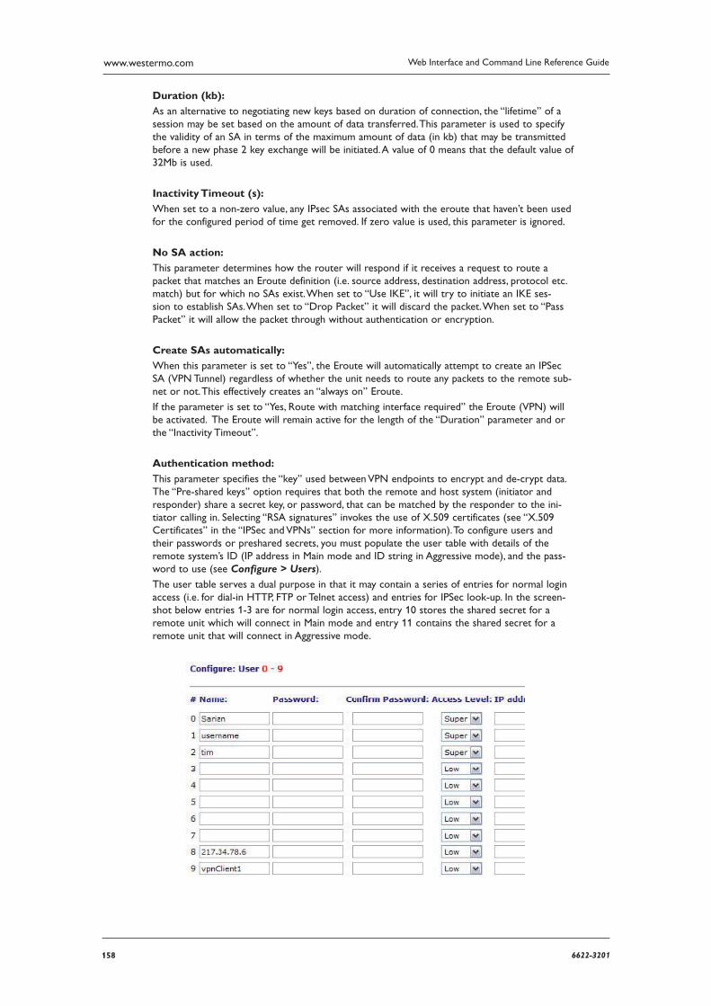
158 6622-3201
Web Interface and Command Line Reference Guidewww.westermo.com
Duration (kb):
As an alternative to negotiating new keys based on duration of connection, the “lifetime” of a session may be set based on the amount of data transferred. This parameter is used to specify the validity of an SA in terms of the maximum amount of data (in kb) that may be transmitted before a new phase 2 key exchange will be initiated. A value of 0 means that the default value of 32Mb is used.
Inactivity Timeout (s):
When set to a non-zero value, any IPsec SAs associated with the eroute that haven’t been used for the configured period of time get removed. If zero value is used, this parameter is ignored.
No SA action:
This parameter determines how the router will respond if it receives a request to route a packet that matches an Eroute definition (i.e. source address, destination address, protocol etc. match) but for which no SAs exist. When set to “Use IKE”, it will try to initiate an IKE ses-sion to establish SAs. When set to “Drop Packet” it will discard the packet. When set to “Pass Packet” it will allow the packet through without authentication or encryption.
Create SAs automatically:
When this parameter is set to “Yes”, the Eroute will automatically attempt to create an IPSec SA (VPN Tunnel) regardless of whether the unit needs to route any packets to the remote sub-net or not. This effectively creates an “always on” Eroute.
If the parameter is set to “Yes, Route with matching interface required” the Eroute (VPN) will be activated. The Eroute will remain active for the length of the “Duration” parameter and or the “Inactivity Timeout”.
Authentication method:
This parameter specifies the “key” used between VPN endpoints to encrypt and de-crypt data. The “Pre-shared keys” option requires that both the remote and host system (initiator and responder) share a secret key, or password, that can be matched by the responder to the ini-tiator calling in. Selecting “RSA signatures” invokes the use of X.509 certificates (see “X.509 Certificates” in the “IPSec and VPNs” section for more information). To configure users and their passwords or pre shared secrets, you must populate the user table with details of the remote system’s ID (IP address in Main mode and ID string in Aggressive mode), and the pass-word to use (see Configure > Users).
The user table serves a dual purpose in that it may contain a series of entries for normal login access (i.e. for dial-in HTTP, FTP or Telnet access) and entries for IPSec look-up. In the screen-shot below entries 1-3 are for normal login access, entry 10 stores the shared secret for a remote unit which will connect in Main mode and entry 11 contains the shared secret for a remote unit that will connect in Aggressive mode.
1596622-3201
Web Interface and Command Line Reference Guide www.westermo.com
It is important to understand that for an IPSec connection between any 2 units there is only one shared secret. This means that for one IPSec session only one entry is required in the user table of each router. For Aggressive mode the Name field should be the same as the Our ID parameter in the remote unit’s Eroute. (Or in the case of a Cisco™, it should be the host name of the remote Cisco™.) For Main mode operation the Name field should be set to the IP address of the remote unit. In both cases the Password field should contain the shared secret.
Note: The remote unit should also have this same secret in the Password field of its user table with the Name field set to the value of the Our ID parameter in the local unit.
This eroute is tunnelled within another eroute:
It is now possible to tunnel packets within a second (or more) tunnel. When this parameter is set to “On”, the unit will take outgoing packets going through this tunnel and once tunnelled, will recheck to see if the resultant packet also goes through a tunnel.
If the inner tunnel is an IPsec tunnel (i.e. needs IKE), you can get the inner IKE to use the cor-rect source address (matching the outer tunnel selectors) by setting the Use secondary IP address parameter to “Yes” and the inner IKE will use the IP address set in the Secondary IP address parameter on the Configure > General page.
GRE mode:
This parameter enables GRE (Generic Routing Encapsulation) for this Eroute instance. GRE is a simple tunnelling protocol that does not provide encryption or authentication. To use GRE it is not necessary to configure most of the parameters on this page. The following parameters only will need to be configured on this page:
Peer IP/hostname
Local subnet IP address
Remote subnet IP address
Remote subnet mask
GRE
Note: From firmware version 4955 this web option and corresponding CLI commands have been removed. GRE tunnels should be configured from Configure > Tunnel (GRE)
Additionally the GRE parameter will have to be enabled on the appropriate Interface, e.g. for PPP 1 on the Configure > PPP > PPP 1 > Standard page this would be achieved by setting the GRE parameter to “Yes”. For further details refer to RFC2784.
NAT traversal keep-alive interval (s):
This parameter may be used to set a timer (in seconds), such that the unit will send regular packets to a NAT device in order to prevent the NAT table from expiring.
Link Eroute with interface / Link Eroute with interface #:
These parameters can be configured to ensure that the Eroute only match packets using the specified interface. Where Eroutes are linked to Ethernet interfaces it might be necessary to use the “Group” or “Port Isolated” modes, in the Ethernet set up menu.
IKE config to use when initiator:
This parameter is used to specify whether the IKE 0 or IKE 1 config is used when the unit is being configured as an Initiator.
IKE version:
This parameter allows you to choose which version of IKE to use. The default value is “1”.
Check APN usage:
When this parameter is set to “Yes”, the Eroute can only use the APN specified in the Interface must use this APN parameter.
160 6622-3201
Web Interface and Command Line Reference Guidewww.westermo.com
Interface must use this APN:
This parameter allows you to choose between using the main APN or the backup APN, as defined in the Configure > GPRS Module page
Use Secondary IP address:
When this parameter is set to “ON”, tunnels set up from this eroute will use the IP address set in the Secondary IP address parameter on the Configure > General page as the source address for tunnelled packets. This gives the unit the ability to set two tunnels up to a single remote peer, and appear as though it is two separate units. Use in conjunction with This eroute is tun-nelled within another eroute.
Delete SAs when eroute goes out of service:
When this parameter is set to “Yes”, and the Eroute goes out of service, any SAs associated with the Eroute will be deleted.
Inhibit this eroute when these eroutes are not OOS:
This is a list of eroute numbers that will inhibit this eroute from being used as long as they are not OOS. If the eroute has been allowed to operate, and the eroute that inhibits it comes back into service, any SAs that may have existed are removed. As soon as an inhibiting eroute goes OOS, the unit will check to see if the inhibited eroute can now create SAs.
Inhibit unless this eroute is UP:
If this parameter is used, this eroute will only become active when the eroute specified is also active.
Delete SAs if not VRRP Master:
When this parameter is set to “Yes”, at least one Ethernet instance must be set as VRRP Master before the unit can create SAs. If the unit switches away from VRRP Master state, SAs will be deleted. When the unit switches back to VRRP Master state, SAs will be created automatically.
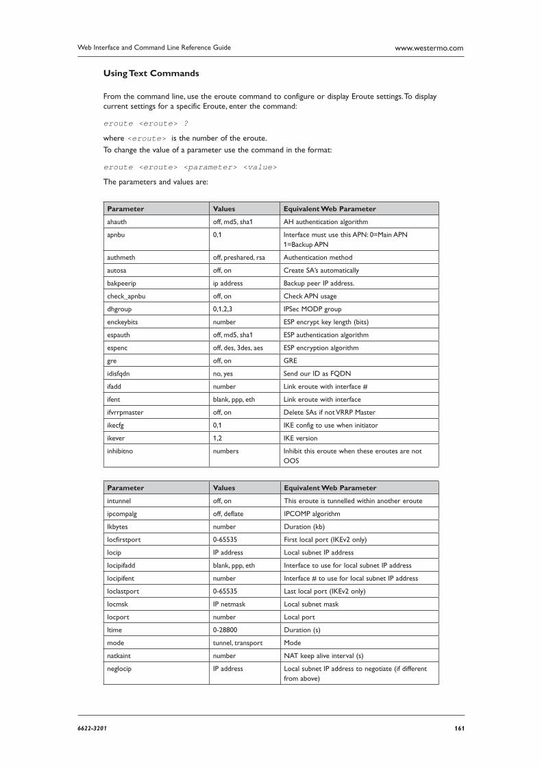
1616622-3201
Web Interface and Command Line Reference Guide www.westermo.com
Using Text Commands
From the command line, use the eroute command to configure or display Eroute settings. To display current settings for a specific Eroute, enter the command:
eroute <eroute> ?
where <eroute> is the number of the eroute.
To change the value of a parameter use the command in the format:
eroute <eroute> <parameter> <value>
The parameters and values are:
Parameter Values Equivalent Web Parameter
ahauth off, md5, sha1 AH authentication algorithm
apnbu 0,1 Interface must use this APN: 0=Main APN 1=Backup APN
authmeth off, preshared, rsa Authentication method
autosa off, on Create SA’s automatically
bakpeerip ip address Backup peer IP address.
check_apnbu off, on Check APN usage
dhgroup 0,1,2,3 IPSec MODP group
enckeybits number ESP encrypt key length (bits)
espauth off, md5, sha1 ESP authentication algorithm
espenc off, des, 3des, aes ESP encryption algorithm
gre off, on GRE
idisfqdn no, yes Send our ID as FQDN
ifadd number Link eroute with interface #
ifent blank, ppp, eth Link eroute with interface
ifvrrpmaster off, on Delete SAs if not VRRP Master
ikecfg 0,1 IKE config to use when initiator
ikever 1,2 IKE version
inhibitno numbers Inhibit this eroute when these eroutes are not OOS
Parameter Values Equivalent Web Parameter
intunnel off, on This eroute is tunnelled within another eroute
ipcompalg off, deflate IPCOMP algorithm
lkbytes number Duration (kb)
locfirstport 0-65535 First local port (IKEv2 only)
locip IP address Local subnet IP address
locipifadd blank, ppp, eth Interface to use for local subnet IP address
locipifent number Interface # to use for local subnet IP address
loclastport 0-65535 Last local port (IKEv2 only)
locmsk IP netmask Local subnet mask
locport number Local port
ltime 0-28800 Duration (s)
mode tunnel, transport Mode
natkaint number NAT keep alive interval (s)
neglocip IP address Local subnet IP address to negoti ate (if different from above)
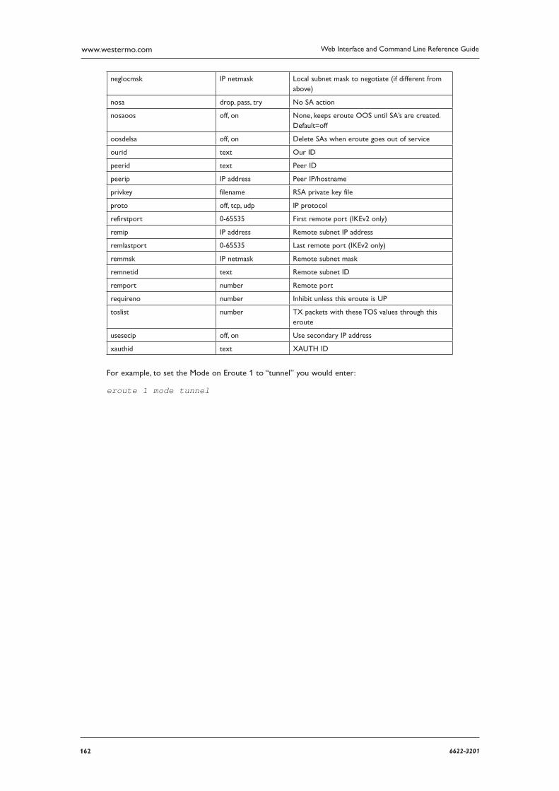
162 6622-3201
Web Interface and Command Line Reference Guidewww.westermo.com
neglocmsk IP netmask Local subnet mask to negotiate (if different from above)
nosa drop, pass, try No SA action
nosaoos off, on None, keeps eroute OOS until SA’s are created. Default=off
oosdelsa off, on Delete SAs when eroute goes out of service
ourid text Our ID
peerid text Peer ID
peerip IP address Peer IP/hostname
privkey filename RSA private key file
proto off, tcp, udp IP protocol
refirstport 0-65535 First remote port (IKEv2 only)
remip IP address Remote subnet IP address
remlastport 0-65535 Last remote port (IKEv2 only)
remmsk IP netmask Remote subnet mask
remnetid text Remote subnet ID
remport number Remote port
requireno number Inhibit unless this eroute is UP
toslist number TX packets with these TOS values through this eroute
usesecip off, on Use secondary IP address
xauthid text XAUTH ID
For example, to set the Mode on Eroute 1 to “tunnel” you would enter:
eroute 1 mode tunnel
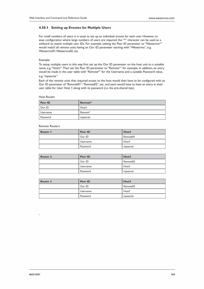
1636622-3201
Web Interface and Command Line Reference Guide www.westermo.com
Setting up Eroutes for Multiple Users 4.50.1
For small numbers of users it is usual to set up an individual eroute for each user. However, to ease configuration where large numbers of users are required, the “*” character can be used as a wildcard to match multiple user IDs. For example, setting the Peer ID parameter to “Westermo*” would match all remote units having an Our ID parameter starting with “Westermo”, e.g. Westermo01, Westermo02, etc.
Example:
To setup multiple users in this way, first set up the Our ID parameter on the host unit to a suitable name, e.g. “Host1”. Then set the Peer ID parameter to “Remote*” for example. In addition, an entry would be made in the user table with “Remote*” for the Username and a suitable Password value,
e.g. “mysecret”.
Each of the remote units that required access to the host would then have to be configured with an Our ID parameter of “Remote01”, “Remote02”, etc. and each would have to have an entry in their user table for User Host 1 along with its password (i.e. the pre-shared key).
Host Router
Peer ID Remote*
Our ID Host1
Username Remote*
Password mysecret
Remote Routers
Router 1 Peer ID Host1
Our ID Remote01
Username Host1
Password mysecret
Router 2 Peer ID Host1
Our ID Remote02
Username Host1
Password mysecret
Router 3 Peer ID Host1
Our ID Remote03
Username Host1
Password mysecret
,
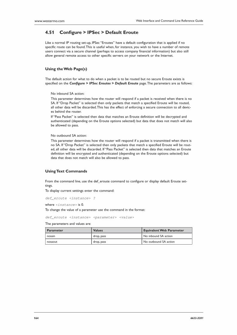
164 6622-3201
Web Interface and Command Line Reference Guidewww.westermo.com
Confi gure > IPSec > Default Eroute 4.51
Like a normal IP routing set-up, IPSec “Eroutes” have a default configuration that is applied if no spe cific route can be found. This is useful when, for instance, you wish to have a number of remote users connect via a secure channel (perhaps to access company financial information) but also still allow general remote access to other specific servers on your network or the Internet.
Using the Web Page(s)
The default action for what to do when a packet is to be routed but no secure Eroute exists is specified on the Configure > IPSec Eroutes > Default Eroute page. The parameters are as follows:
No inbound SA action:
This parameter determines how the router will respond if a packet is received when there is no SA. If “Drop Packet” is selected then only packets that match a specified Eroute will be routed, all other data will be discarded. This has the effect of enforcing a secure connection to all devic-es behind the router.
If “Pass Packet” is selected then data that matches an Eroute definition will be decrypted and authenticated (depending on the Eroute options selected) but data that does not match will also be allowed to pass.
No outbound SA action:
This parameter determines how the router will respond if a packet is transmitted when there is no SA. If “Drop Packet” is selected then only packets that match a specified Eroute will be rout-ed, all other data will be discarded. If “Pass Packet” is selected then data that matches an Eroute defini tion will be encrypted and authenticated (depending on the Eroute options selected) but data that does not match will also be allowed to pass.
Using Text Commands
From the command line, use the def_eroute command to configure or display default Eroute set-tings.
To display current settings enter the command:
def_eroute <instance> ?
where <instance> is 0.
To change the value of a parameter use the command in the format:
def_eroute <instance> <parameter> <value>
The parameters and values are:
Parameter Values Equivalent Web Parameter
nosain drop, pass No inbound SA action
nosaout drop, pass No outbound SA action
1656622-3201
Web Interface and Command Line Reference Guide www.westermo.com
Confi gure > ISDN LAPB > LAPB n 4.52
LAPB (Link Access Procedure Balanced) is a standard subset of the High-Level Data Link Control (HDLC) protocol. It is a bit-oriented, synchronous, link-layer protocol that provides data framing, flow control and error detection and correction. LAPB is the link layer used by X.25 applications.
Using the Web Page(s):
The Configure > ISDN LAPB folder expands to list separate pages for the LAPB 0 and LAPB 1 instances that allow you to set the following parameters.
Layer 1 interface:
This parameter determines which physical interface is to be used for carrying LAPB data. This can be set to either “ISDN” or “Port”. If “ISDN” is selected then LAPB data is carried over the ISDN BRI physical interface. By selecting “Port”, LAPB data can be routed to either ASY 0 or ASY 1 (operat ing in synchronous mode), as selected by the Sync Port parameter below.
To configure ASY 0 or ASY 1 for synchronous operation refer to the Configure > Sync Ports page.
Sync port:
This parameter is only relevant if the Layer 1 interface option above has been set to “Port” (as opposed to ISDN). It is used to select ASY0 or ASY1 as the layer 1 interface for LAPB data.
Answering:
If this parameter is set to “On”, the unit will answer incoming calls on the relevant LAPB ses-sion. To prevent the unit from answering incoming calls on this LAPB session set the option to “Off”.
DTE/DCE mode:
When this parameter is set to “DTE”, the unit will behave as Data Terminal Equipment with respect to the ISDN network. This is the default value and should not be changed for normal operation across the ISDN network. If your application involves using two units back-to-back, one of the units should have the DTE/DCE mode value set to “DCE” so that it acts as Data Communications Equipment.
MSN:
This parameter provides the filter for the ISDN Multiple Subscriber Numbering facility. It is blank by default but when set to an appropriate value with Answering “On” it will cause the unit to answer incoming calls only to ISDN numbers where the trailing digits match the MSN value. For example, setting the MSN parameter to 123 will prevent the unit from answering any calls to numbers that do not end in 123.
If Answering is “Off” this parameter is not used.
Sub-address:
This parameter provides the filter for the ISDN sub-addressing facility. It is blank by default but when set to an appropriate value, with Answering enabled it will cause the unit to answer incom ing ISDN calls only where the trailing digits of the sub address called match the Sub-address value. For example, setting the Sub-address to 123 will prevent the unit from answering any calls where the sub-address called does not end in 123.
If Answering is “Off” this parameter is not used.
CLI:
Calling Line Identification. The unit will only answer calls from numbers whose trailing digits match what is entered in this field. The line the unit is connected to must have CLI enabled by the tele coms provider, and the calling number cannot be withheld.
166 6622-3201
Web Interface and Command Line Reference Guidewww.westermo.com
RR timer (ms):
This is a standard LAPB/LAPD “Receiver Ready” timer. The default value is 10,000ms (10 sec-onds) and it should not normally be necessary to change this.
Inactivity timer (s):
This parameter may be used to specify the length of time (in seconds) before the link is discon-nected if there has been no activity. If this parameter is zero or not specified, then the inactiv-ity timer is disabled. It is useful to set this to a short period of time (say 120 seconds) when a LAPB instance is being used over ISDN for example with TPAD. Should the POS device fail to instruct TPAD to hang up then this timer can be used as a backup hang-up timer thus saving ISDN call charges.
When LAPB is being used on a synchronous port, this parameter should normally be set to 0.
Inactivity timer when X25 (s):
This parameter may be used to specify the length of time (in seconds) before the link is discon-nected if there has been no X.25 activity. If this parameter is zero or not specified, then the inactiv ity timer is disabled.
T1 timer:
This is a standard LAPB/LAPD timer. The default value is 1000 milliseconds (1 second) and under normal circumstances, it should not be necessary to change it.
T200 timer:
This is the standard LAPB/LAPD re-transmit timer. The default value is 1000 milliseconds (1 sec-ond) and under normal circumstances, it should not be necessary to change it.
N400 counter:
This is the standard LAPB/LAPD retry counter. The default value is 3 and it should not normally be necessary to change this.
Window size:
This parameter is used to set the X.25 window size. The value range is from 1 to 7 with the default being 7.
Restart when activate:
This parameter can be set to “No” or “Immediate”. When set to “Immediate”, the LAPB instance will send an X.25 restart packet immediately on receipt of an SABM (Set Asynchronous Balanced Mode) frame. If the parameter is set to “No”, then no X.25 restart is sent.
Keep Activated:
When this parameter is set to “Off”, the ISDN LAPB link will be disconnected if the user sends a DISC or when a PAD session is terminated (e.g. by the “log” command or because DTR goes off). By setting Keep activated to “On”, the link will not be disconnected under these circum-stances. Instead, when a DISC is received, the unit will response with a UA frame as usual but will immedi ately follow this with a SABM to re-establish the link. Similarly, the unit will not dis-connect the link after a log command or when DTR goes off.
Passive timer (ms):
This parameter sets the length of time (in milliseconds), that the LAPB instance will wait from an ISDN B-channel becoming active before attempting to establish a LAPB connection, i.e. the length of time for which the LAPB instance stays passive. The default is 0 as most ISDN net-works allow CPE devices to initiate a LAPB link. If your ISDN network does not permit CPE devices to initiate the LAPB link you should set this parameter to a value that allows the net-work sufficient time to establish the LAPB link.
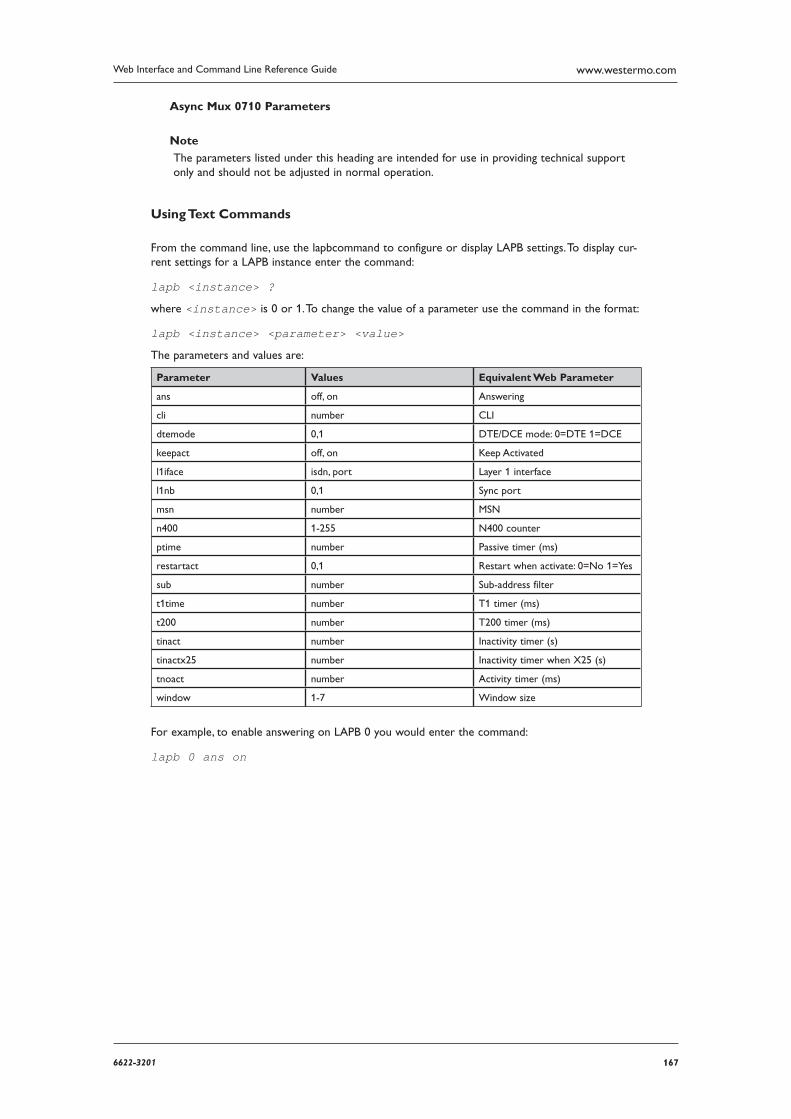
1676622-3201
Web Interface and Command Line Reference Guide www.westermo.com
Async Mux 0710 Parameters
Note
The parameters listed under this heading are intended for use in providing technical support only and should not be adjusted in normal operation.
Using Text Commands
From the command line, use the lapbcommand to configure or display LAPB settings. To display cur-rent settings for a LAPB instance enter the command:
lapb <instance> ?
where <instance> is 0 or 1. To change the value of a parameter use the command in the format:
lapb <instance> <parameter> <value>
The parameters and values are:
Parameter Values Equivalent Web Parameter
ans off, on Answering
cli number CLI
dtemode 0,1 DTE/DCE mode: 0=DTE 1=DCE
keepact off, on Keep Activated
l1iface isdn, port Layer 1 interface
l1nb 0,1 Sync port
msn number MSN
n400 1-255 N400 counter
ptime number Passive timer (ms)
restartact 0,1 Restart when activate: 0=No 1=Yes
sub number Sub-address filter
t1time number T1 timer (ms)
t200 number T200 timer (ms)
tinact number Inactivity timer (s)
tinactx25 number Inactivity timer when X25 (s)
tnoact number Activity timer (ms)
window 1-7 Window size
For example, to enable answering on LAPB 0 you would enter the command:
lapb 0 ans on
168 6622-3201
Web Interface and Command Line Reference Guidewww.westermo.com
Confi gure > ISDN LAPD > LAPD n 4.53
Link Access Protocol D (LAPD) is the protocol used for ISDN D-channel signalling and call set up.
Using the Web Page(s)
The Configure > ISDN LAPD folder expands to list separate pages for the LAPD0, LAPD1 and LAPD2 instances. LAPD2 is normally reserved for ISDN call control. LAPD0 and LAPD1 can be used as required for SAPI16 traffic, i.e. D-channel X.25. The configuration pages allow you to set the following parameters for each instance.
Enabled:
Setting this parameter to No will disable the LAPD instance. This may be necessary if you have an installation where two or more units are connected to the same ISDN “S” bus. In this case, only one of the units may be configured for D-channel X.25 on TEI1, SAPI16. On each of the other units you must disable any LAPD instance for which the TEI is set to 1 in order to pre-vent it from responding to X.25 traffic on that TEI that is actually destined for another unit.
DTE/DCE mode:
When the DTE/DCE mode parameter is set to DTE, the unit will behave as a DTE. This is the default value and should not be changed for normal operation across the ISDN network. If your application involves using two units back-to-back, one of the units should have the DTE mode value set to DCE.
Keep active:
When this parameter is set to “Yes”, the unit will try to reactivate a D-channel connection after dis connection by the network by transmitting SABME frames. If it is unable to reactivate the connec tion after retrying the number of times specified by the N400 counter, it will wait for 1 minute before repeating the retry sequence.
If this parameter is set to “No”, the unit will not attempt to reactivate a D-channel link follow-ing deactivation by the network.
Reactivate secs:
This parameter specifies the number of seconds a deactivation has to be present before the LAPD instance will try to reactivate itself.
N400 counter:
This is the standard LAPB/LAPD retry counter. The default value is 3 and it should not normally be necessary to change this.
RR timer (ms):
This is a standard LAPB/LAPD “Receiver Ready” timer. The default value is 10,000ms (10 sec-onds) and it should not normally be necessary to change this.
Deactivation:
This parameter can be set to “Active” or “Passive”. When set to “Passive”, the unit will not deacti vate a LAPD session when an X.25 PAD session is terminated using the log command. To enable automatic deactivation of a LAPD session the option should be set to “Active”.
T1 timer (ms):
This is the standard LAPB/LAPD timer. The default value is 1000 milliseconds (1 second) and it should not normally be necessary to change this.
T200 timer (ms):
This is the standard LAPB/LAPD re-transmit timer in milliseconds. The default value is 1000 milli seconds (1 second) and it should not normally be necessary to change this.
1696622-3201
Web Interface and Command Line Reference Guide www.westermo.com
TEI:
Each ISDN terminal device connected to your ISDN basic rate outlet must be assigned a unique Terminal Endpoint Identifier (TEI). In most cases, this is negotiated automatically. In some cases however, it may be necessary to assign a fixed TEI.
When TEI is set to 255, the TEI is negotiated with the ISDN network. To use a fixed TEI set the TEI parameter to the appropriate value as specified by your service provider.
Window size:
This specifies the transmit window size when using D-channel X.25. The default is 7.
Tx throughput (bps):
The Tx Throughput parameter is used in conjunction with the Rx Throughput parameter to limit the maximum data throughput on a LAPD link in bits per second. If this parameter is set to 0, the unit will transmit data across the LADP link as fast as possible whilst observing hardware or software flow control if enabled.
When set to a value greater than 0, the unit will limit the rate at which data is transmitted over the LAPD link Note that if multiple PAD or IP instances are sharing this LAPD instance, the maximum transmis sion rates of all instances will be limited.
Rx throughput (bps):
The Rx Throughput parameter is used in conjunction with the Tx Throughput parameter to limit the maximum data throughput on a LAPD link in bits per second. If this parameter is set to 0, the unit will transmit data across the LADP link as fast as possible whilst observing hardware or software flow control if enabled.
When set to a value greater than 0, the unit will limit the rate at which data can be received over the LAPD link when it detects that receive throughput exceeds the specified rate. Note that if multiple PAD or IP instances are sharing this LAPD instance, the maximum transmis sion rates of all instances will be limited.
D64S mode:
D64S mode is a mode in which ISDN B-channel(s) may be used without the need to use any D channel protocol. It is sometimes referred to as “nailed up” IDSN. To enable this mode for this LAPD instance, set the D64S mode parameter to On and ensure that the TEI parameter is set to
255. This means that for any application that uses ISDN (e.g. PPP) then it will use D64S mode.
Note: You may only use this mode if it is supported by your ISDN service provider.
First D64 B-channel:
When using D64S mode there is no dialling protocol to negotiate which B-channel to use. This must therefore be specified using this parameter. To use B1 set the parameter to 1, or select 2 to use B2 (if another channel is requested from an application then it will use the other unused B channel).
Using Text Commands
From the command line, use the lapd command to configure or display LAPD settings. To display current settings for a LAPD instance enter the command:
lapd <instance> ?
where <instance> is 0, 1 or 2. To change the value of a parameter use the command in the for-mat:
lapd <instance> <parameter> <value>
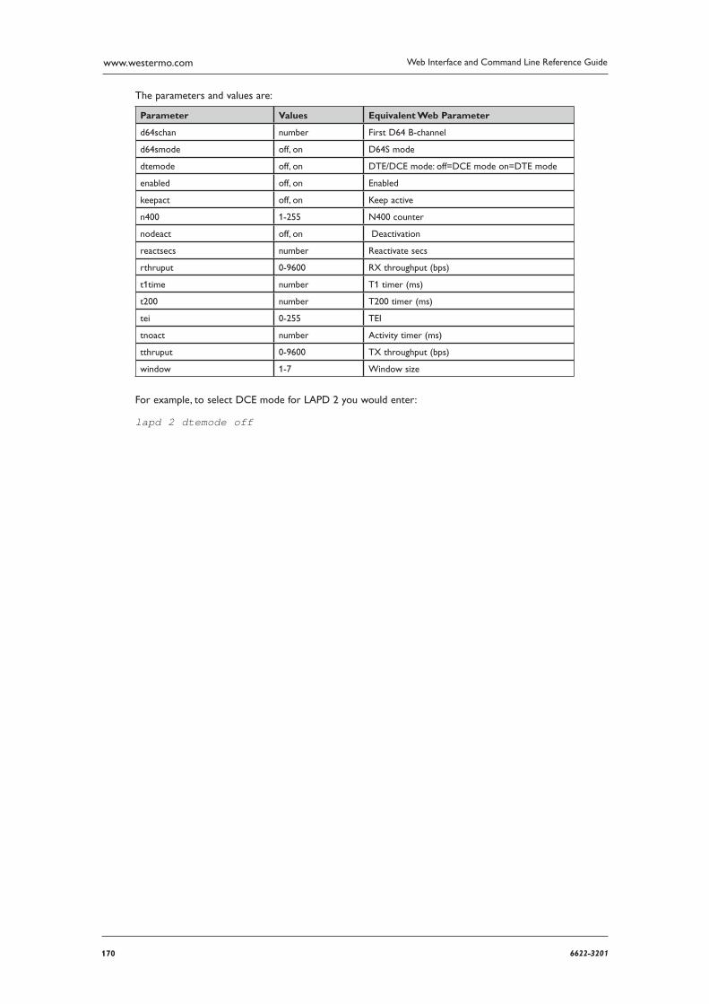
170 6622-3201
Web Interface and Command Line Reference Guidewww.westermo.com
The parameters and values are:
Parameter Values Equivalent Web Parameter
d64schan number First D64 B-channel
d64smode off, on D64S mode
dtemode off, on DTE/DCE mode: off=DCE mode on=DTE mode
enabled off, on Enabled
keepact off, on Keep active
n400 1-255 N400 counter
nodeact off, on Deactivation
reactsecs number Reactivate secs
rthruput 0-9600 RX throughput (bps)
t1time number T1 timer (ms)
t200 number T200 timer (ms)
tei 0-255 TEI
tnoact number Activity timer (ms)
tthruput 0-9600 TX throughput (bps)
window 1-7 Window size
For example, to select DCE mode for LAPD 2 you would enter:
lapd 2 dtemode off
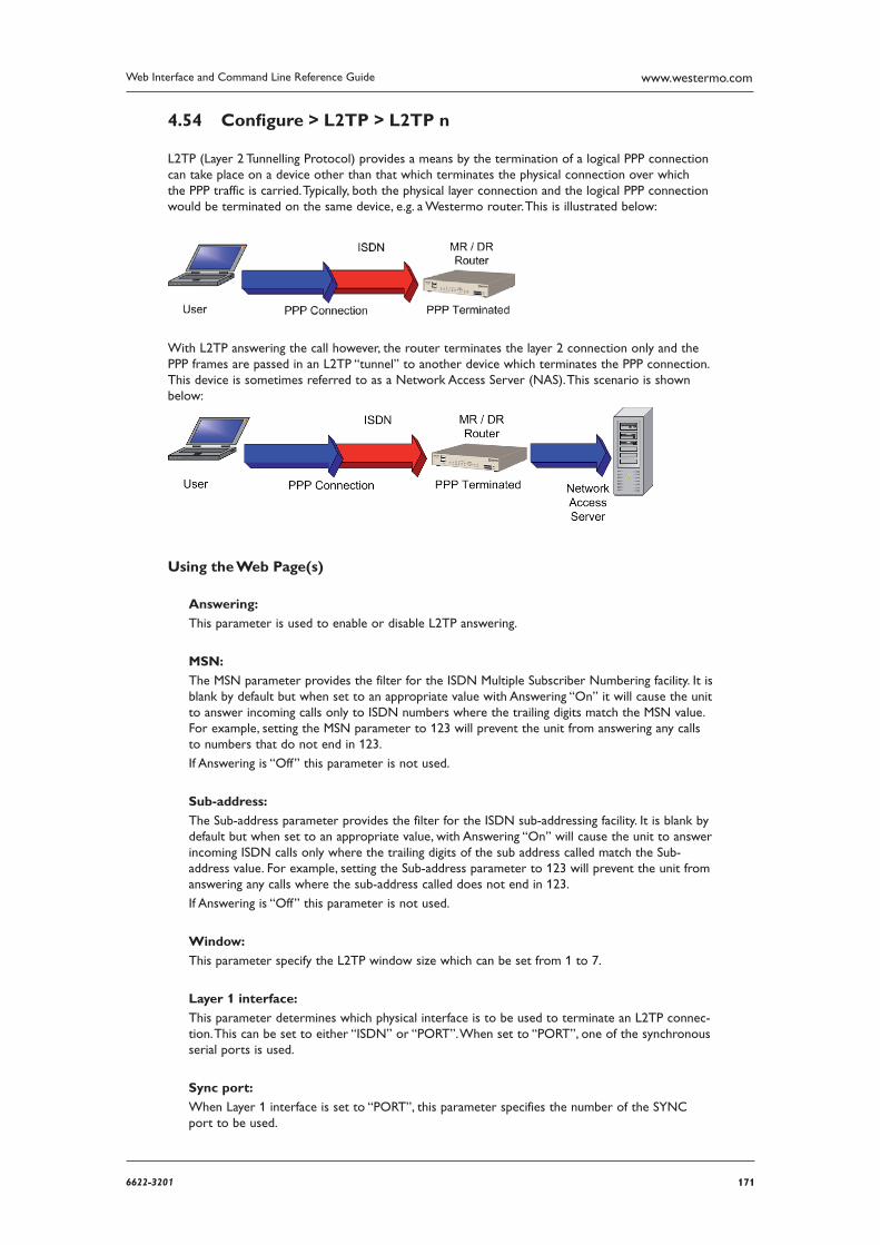
1716622-3201
Web Interface and Command Line Reference Guide www.westermo.com
Confi gure > L2TP > L2TP n 4.54
L2TP (Layer 2 Tunnelling Protocol) provides a means by the termination of a logical PPP connection can take place on a device other than that which terminates the physical connection over which the PPP traffic is carried. Typically, both the physical layer connection and the logical PPP connection would be terminated on the same device, e.g. a Westermo router. This is illustrated below:
With L2TP answering the call however, the router terminates the layer 2 connection only and the PPP frames are passed in an L2TP “tunnel” to another device which terminates the PPP connection. This device is sometimes referred to as a Network Access Server (NAS). This scenario is shown below:
Using the Web Page(s)
Answering:
This parameter is used to enable or disable L2TP answering.
MSN:
The MSN parameter provides the filter for the ISDN Multiple Subscriber Numbering facility. It is blank by default but when set to an appropriate value with Answering “On” it will cause the unit to answer incoming calls only to ISDN numbers where the trailing digits match the MSN value. For example, setting the MSN parameter to 123 will prevent the unit from answering any calls to numbers that do not end in 123.
If Answering is “Off” this parameter is not used.
Sub-address:
The Sub-address parameter provides the filter for the ISDN sub-addressing facility. It is blank by default but when set to an appropriate value, with Answering “On” will cause the unit to answer incoming ISDN calls only where the trailing digits of the sub address called match the Sub-address value. For example, setting the Sub-address parameter to 123 will prevent the unit from answering any calls where the sub-address called does not end in 123.
If Answering is “Off” this parameter is not used.
Window:
This parameter specify the L2TP window size which can be set from 1 to 7.
Layer 1 interface:
This parameter determines which physical interface is to be used to terminate an L2TP connec-tion. This can be set to either “ISDN” or “PORT”. When set to “PORT”, one of the synchronous serial ports is used.
Sync port:
When Layer 1 interface is set to “PORT”, this parameter specifies the number of the SYNC port to be used.
172 6622-3201
Web Interface and Command Line Reference Guidewww.westermo.com
Remote host:
This parameter is used to specify the IP address of the remote host, i.e. the device that will ter-minate the L2TP connection.
Backup Remote host:
It is possible to specify a backup remote L2TP host server with this parameter. When PPP attempts to connect using a L2TP connection and this field is used, then the PPP will not be informed of any failure until BOTH remote hosts are attempted. When a ’good’ server is found then that is the first one attempted for future connections.
UDP Interface:
This allows you to specify a lower interface to use for L2TP UDP sockets. This allows the unit to raise the desired interface should it be disconnected.
UDP Interface #:
This parameter determines the instance number of the UDP Interface selected above.
Source port:
Source port selection. When set to “normal” the default port number of 1701 is used. When set to “Variable” a random source port value will be used.
Listening mode:
When this parameter is “ON”, the unit will not actively try to establish an L2TP tunnel, it will only use L2TP if the remote host requests it. Leaving the parameter set to “OFF” means the unit will actively try to establish an L2TP connection with the remote host.
ServerMode:
Setting this parameter to “ON” enables the unit to act as an L2TP server.
Name:
This name is used in the establishment of L2TP tunnels to identify this router during the nego-tiation.
Secret:
This parameter is only used if the Authenticate parameter is set to “ON”, in which case it is used as part of the authentication process and both the router and the remote host must have this parameter set to the same value. Note that if authentication is OFF and the remote host requests authentication then this is the value used.
Authenticate:
Setting this parameter to “ON” enables authentication. Normally this is not necessary because most host systems require that IPSec be used over L2TP tunnels.
Always on tunnel:
When this parameter is “ON”, the tunnel is always enabled. When set to “OFF”, the tunnel will not activate automatically, but will wait until it is triggered by PPP.
Tunnel timeout if no call(s):
This parameter specifies a timeout in seconds after which the L2TP tunnel will be closed down after the last L2TP call on that tunnel.
Retransmit time(ms):
This parameter specifies the amount of time in milliseconds that the unit will wait before re-transmitting a Start Control Connection Request (SCCRQ) frame. The default value of 250ms should be changed to a higher value, for example 4000ms, if you are using L2TP over GPRS.
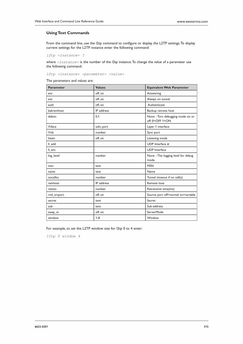
1736622-3201
Web Interface and Command Line Reference Guide www.westermo.com
Using Text Commands
From the command line, use the l2tp command to configure or display the L2TP settings. To display current settings for the L2TP instance enter the following command:
l2tp <instance> ?
where <instance> is the number of the l2tp instance. To change the value of a parameter use the following command:
l2tp <instance> <parameter> <value>
The parameters and values are:
Parameter Values Equivalent Web Parameter
ans off, on Answering
aot off, on Always on tunnel
auth off, on Authenticate
bakremhost IP address Backup remote host
debon 0,1 None - Turn debugging mode on or off: 0=OFF 1=ON
l1iface isdn, port Layer 1 interface
l1nb number Sync port
listen off, on Listening mode
ll_add UDP Interface #
ll_ent UDP Interface
log_level number None - The logging level for debug mode
msn text MSN
name text Name
nocallto number Tunnel timeout if no call(s)
remhost IP address Remote host
retxto number Retransmit time(ms)
rnd_srcport off, on Source port off=normal on=variable
secret text Secret
sub text Sub-address
swap_io off, on ServerMode
window 1-8 Window
For example, to set the L2TP window size for l2tp 0 to 4 enter:
l2tp 0 window 4
174 6622-3201
Web Interface and Command Line Reference Guidewww.westermo.com
Confi gure > OSPF 4.55
Open Shortest Path First (OSPF) is an Interior Gateway Protocol (IGP) developed for IP networks based on the shortest path first or link-state algorithm.
The unit uses link-state algorithms to send routing information to all nodes in a network by calcu-lating the shortest path to each node based on a topography of the network constructed by each node. Each unit sends that portion of the routing table (keeps track of routes to particular network destinations) that describes the state of its own links, and it also sends the complete routing struc-ture (topography).
The advantage of shortest path first algorithms is that they result in smaller more frequent updates eve rywhere. They converge quickly, thus preventing such problems as routing loops and Count-to-Infinity (when routers continuously increment the hop count to a particular network). This makes for a stable network.
Using the Web Page(s)
Enable OSPF:
Setting this parameter to “Yes” enabled OSPF on this unit. A valid configuration file must exist on the unit, and be specified in the Configuration file parameter.
ID:
The ID the unit is to use. This ID is in the same format as an IPv4 IP address. If the ID is not specified here, it MUST be specified in the OSPF section of the configuration file, otherwise the unit will be assigned the ID 0.0.0.0, which may cause problems. Each unit within an OSPF domain must have a unique ID.
Configuration file:
The file that holds the configuration data for OSPF. The file should have a “.conf” extension.
Default metric:
This parameter defines the cost for the interface. This value represents the cost for traffic to EXIT the unit. The default value for the metric is 10, and can be set to a value in the range 1 to 65535.
Default priority:
This parameter defines the priority of the unit. The default priority is 2, and can be set to a value in the range 0 to 255.
Default ’Hello’ interval (s):
This parameter defines the interval at which OSPF ‘Hello’ packets are sent out of the interface.
The ‘Hello’ packets are used to prove liveliness among the OSPF routers.
The default value for the ‘Hello’ interval is 10 seconds, and can be set to a value in the range 1 to 65535 seconds.
Note: This interval is included in a field in the ‘Hello’ packets, and must match the ‘Hello’ interval config ured into every OSPF router in the system. For this reason, the parameter should nor-mally be left at the default value (10 seconds).
Default router dead time (s):
This parameter defines the time a neighbour has been inactive before the unit will declare it inac tive. When a neighbour has been inactive for this time its state is set to DOWN. Neighbours that have been inactive for 24 hours are completely removed. The default value for the router dead time is 40 seconds, and can be set to a value in the range 2 to 2147483647 seconds.
1756622-3201
Web Interface and Command Line Reference Guide www.westermo.com
Default retransmit interval (s):
This parameter define the time the unit will wait for an acknowledgement of a Link State Advertise ment (LSA) update before resending the LSA update. The default value for the retrans-mit interval is 5 seconds, and can be set to a value in the range 5 to 3600 seconds.
Default transmit delay (s):
This parameter defines the time the unit will wait before sending an LSA update. The default value for the transmit delay is 1 second, and can be se to a value in the range 1 to 3600 sec-onds.
Adjacency timeout (s):
This parameter defines the maximum time allowed for adjacency to form. The default value for the adjacency timeout is 60 seconds, and can be set to a value in the range 1 to 2147483647 seconds.
Neighbour timeout (s):
This parameter defines the time that OSPF neighbours must be inactive for before they are removed. The default value for the neighbour timeout is 86400 seconds (24 hours), and can be set to a value in the range 1 to 2147483647 seconds.
Default SPF delay (s):
This parameter defines the time to wait before initiating the next SPF calculation once it has been decided that one is required. The default value for the SPF delay is 5 seconds, and can be set to a value in the range 1 to 10 seconds.
Default SPF hold time (s):
This parameter specifies the minimum time the calculated routing table is held for after com-pleting a Shortest Path First (SPF) calculation. The default value for the SPF hold time is 5 sec-onds, and can be set to a value in the range 1 to 5 seconds.
Ignore MTU indications:
All OSPF units must have the same Maximum Transmit Unit (MTU), and this MTU value is adver tised in the OSPF packets. When this parameter is set to “Yes”, the unit will ignore received pack ets that have an MTU that differs from that of the unit.
Advertise routes only:
When this parameter is set to “Yes”, the OSPF protocol will operate, but the unit will not use any learned routes. This is useful for debugging purposes, or in circumstances where the unit has spe cific routing requirements, and is only used to advertise routes to other OSPF routers in the domain.
Use Interface IPsec source IP:
When this parameter is set to “Yes”, OSPF will use the IP address of the interface specified by the IPSec source IP from interface # and IPSec source IP from interface parameters defined in the confguration page for the interface defined in each Configure > OSPF > OSPF External routes page. For example, if the Interface and Interface # parameters for OSPF External route 0 were set to PPP 0, and Use Interface IPsec source IP was enabled, OSPF packets will be sent from the IPSec interface defined on the Configure > PPP > PPP 0 > Advanced page. This parameter ena bles OSPF packets to be sent throught GRE/IPSec tunnels to remote peers.
Restart OSPF when new config file loaded:
When this parameter is set to “Yes”, OSPF will restart whenever a new configuration file is loaded onto the unit.
Restart OSPF after fatal error:
When this parameter is set to “Yes”, OSPF will restart after a delay of 5 seconds if there is a fatal error.
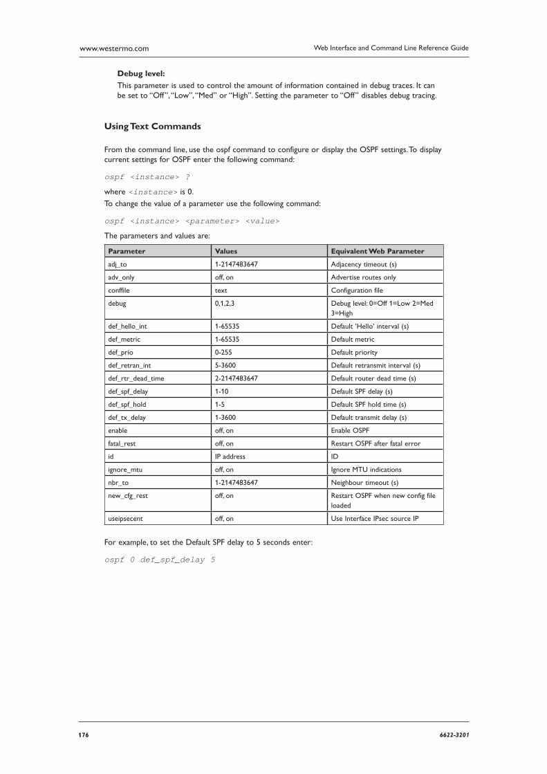
176 6622-3201
Web Interface and Command Line Reference Guidewww.westermo.com
Debug level:
This parameter is used to control the amount of information contained in debug traces. It can be set to “Off”, “Low”, “Med” or “High”. Setting the parameter to “Off” disables debug tracing.
Using Text Commands
From the command line, use the ospf command to configure or display the OSPF settings. To display current settings for OSPF enter the following command:
ospf <instance> ?
where <instance> is 0.
To change the value of a parameter use the following command:
ospf <instance> <parameter> <value>
The parameters and values are:
Parameter Values Equivalent Web Parameter
adj_to 1-2147483647 Adjacency timeout (s)
adv_only off, on Advertise routes only
conffile text Configuration file
debug 0,1,2,3 Debug level: 0=Off 1=Low 2=Med 3=High
def_hello_int 1-65535 Default ’Hello’ interval (s)
def_metric 1-65535 Default metric
def_prio 0-255 Default priority
def_retran_int 5-3600 Default retransmit interval (s)
def_rtr_dead_time 2-2147483647 Default router dead time (s)
def_spf_delay 1-10 Default SPF delay (s)
def_spf_hold 1-5 Default SPF hold time (s)
def_tx_delay 1-3600 Default transmit delay (s)
enable off, on Enable OSPF
fatal_rest off, on Restart OSPF after fatal error
id IP address ID
ignore_mtu off, on Ignore MTU indications
nbr_to 1-2147483647 Neighbour timeout (s)
new_cfg_rest off, on Restart OSPF when new config file loaded
useipsecent off, on Use Interface IPsec source IP
For example, to set the Default SPF delay to 5 seconds enter:
ospf 0 def_spf_delay 5
1776622-3201
Web Interface and Command Line Reference Guide www.westermo.com
Confi gure > PPP 4.56
Point-to-Point Protocol (PPP) is a standard tunnelling protocol for transporting data from point to multipoint networks (such as IP) across point-to-point links (such as a serial or ISDN connection). This is essential for dial-up Internet access.
As data is transferred across IP networks in synchronous format, your unit supports asynchro-nous to synchronous PPP conversion. This allows asynchronous terminals connected to the unit to communi cate with remote synchronous PPP devices. Normally this is carried out using a single ISDN B-channel so that data can be transferred at speeds up to 64kbps. This is known as ASYNC to SYNC PPP oper ation and is supported as standard by most terminal adaptors. To use ASYNC to SYNC PPP operation all that is necessary is to ensure that the PPP protocol is bound to the ASY port to which the terminal or PC is connected (see Configure > Protocol Bindings).
Note: In order to use ASYNC to SYNC PPP your terminal must also support the PPP protocol (Windows dial-up networking supports PPP).
In addition to ASYNC to SYNC operation (where the router only converts the PPP from one form to another) the router can initiate its own PPP sessions. This is used for example when:
The router is configured as a router to connect an Ethernet network to the Internet via ISDN or GPRS
The router is answering an incoming ISDN call with PPP either for remote management or remote access to the Ethernet network to which the router is connected
You access the router locally through the serial port for configuration purposes be setting up a Windows Dial-Up-Networking connection to the “phone number” 123
Note: With the exception of MLPPP the parameters in this section are only relevant when the router is gen erating the PPP, i.e. they are NOT relevant for Async to Sync PPP operation.
The unit also supports Multi-Link PPP (MLPPP). MLPPP uses both ISDN B-channels simultaneously (and two PPP instances), to provide data transfer speeds up to 128Kbps for applications such as email transmission and retrieval, high speed internet access (your ISP must also support MLPPP) or estab lishing a high speed point to point connection between two units.
Confi guring PPP
The Configure > PPP folder contains a number of sub-folders and sub-pages for configuring vari-ous aspects of PPP operation. These pages are described in the following sections.
178 6622-3201
Web Interface and Command Line Reference Guidewww.westermo.com
Confi gure > PPP > MLPPP 4.57
Using the Web Page(s)
Desired local ACCM:
For advanced users only - default value is 0x00000000.
Desired remote ACCM:
For advanced users only - default value is 0xffffffff.
Request remote CHAP authentication:
Set this parameter to “Yes” if it is required that the unit authenticate itself with the remote sys-tem using CHAP. If this parameter is set, the connection will fail if authentication is not success-ful. Gen erally, this parameter should be set to “No”.
Password:
This is the password used for authenticating with the remote system when multi-link PPP is used. This password is used for both B-channel PPP connections.
Confirm password:
If altering the password, the new password must also be entered here. The unit will check that both fields are identical before changing the parameter value.
Short sequence numbers:
MLPPP data packet sequence numbers are usually stored in 16 bits. This parameter may be set to “On” to select 12-bit sequence numbers if necessary.
Username:
This is the username for logging on to the remote system when multi-link PPP is used.
Connections
The parameters in this section are used to specify when the secondary ISDN B-channel should be activated.
1B->2B rate (bytes/s):
This is the transfer rate (in bytes/sec) that will trigger the unit to activate the secondary B-channel. If this parameter is set to 0 the secondary B-channel will not be used. The default is 2000 bytes/s.
1B->2B delay (s):
This is the time (in seconds) for which the 1B->2B rate must be sustained before the secondary B channel is activated. If this parameter is set to 0, the secondary B-channel will not be used. The default is 10 seconds.
2B->1B rate (bytes/s):
This is the transfer rate (in bytes/s) below which the data transfer rate must fall before the second ary B-channel will be deactivated. If this parameter is greater than the 1B->2B rate then the sec ondary B-channel connection will not be dropped until the connection is terminated. The default is 1000 bytes/s.
1796622-3201
Web Interface and Command Line Reference Guide www.westermo.com
2B->1B delay (s):
This is the time (in seconds) for which the transfer rate must fall below 2B->1B rate before the secondary B-channel will be deactivated. The default is 60 seconds.
Note: The following four parameters are only available if you have purchased the AODI software option. To use AODI you will also have to enable the Always on mode parameter on the Configure > General page.
D->1B up rate (bytes/s):
When Always on mode is “On”, this is the value (in bytes/s) above which the data transfer rate must remain for D->1B up delay (s) before the unit will activate a B-channel.
D->1B up delay (s):
When Always on mode is “On”, this is the time (in seconds) for which the data transfer rate must remain above the specified D->1B rate before the unit will activate a B-channel.
1B->D down rate (bytes/s):
When Always on mode is “On”, this is the value (in bytes/s) below which the data transfer rate must remain for 1B->1D down delay (s) before the unit will deactivate the B-channel.
1B->D down delay (s):
When Always on mode is “On”, this is the time (in seconds) for which the data transfer rate must remain below the specified 1B->D rate before the unit will activate a B-channel.
180 6622-3201
Web Interface and Command Line Reference Guidewww.westermo.com
Using Text Commands
From the command line use the mlppp command to set or display MLPPP parameter settings. To display current settings for MLPPP enter the following command:
mlppp <instance> ?
where <instance> is 0. To set the value for a parameter enter the command in the format:
mlppp <instance> <parameter> <value>
For example:
mlppp 0 username fred
The parameters and values are:
Parameter Values Equivalent Web Parameter
ddown_delay number 1B->D down delay (s)
ddown_rate number 1B->D down rate (bytes/s)
down_delay number 2B->1B delay (s)
down_rate number 2B-> 1B rate (bytes/s)
dup_delay number D->1B up delay (s)
dup_rate number D->1B up rate (bytes/s)
epassword text None - this is the password in encrypted format. This parameter is not configurable.
l_accm hex number Desired local ACCM
l_shortseq off, on Short sequence numbers
password text Password
r_accm hex number Desired remote ACCM
r_chap off, on Request remote CHAP authentica-tion
up_delay number 1B -> 2B delay (s)
up_rate number 1B -> 2B rate (bytes/s)
username text Username
1816622-3201
Web Interface and Command Line Reference Guide www.westermo.com
Confi gure > PPP > External Modems > External Modem n 4.58
Using the Web Page(s)
In circumstances where it is necessary to communicate with the router remotely via a normal ana-logue modem (perhaps because no ISDN line is available), this page may be used to set up the vari-ous parameters associated with controlling the modem.
ASY port:
This parameter is used to specify the ASY port to which the external modem is connected. The default value is 255, which means that no external modem is available. The other available options depend on the model and can be an ASY port number or a MUXn number.
The MUXn options are used to select those ports that are available for use in multiplexed mode with the built-in GPRS module.
W-WAN mode:
This option allows you to configure a second W-WAN PPP connection. In this case, the ASY port used would typically be a virtual port corresponding to a spare multiplex channel into the internal W-WAN module.
When W-WAN mode is “ON”, additional W-WAN specific parameters such as the APN are available. To view these parameters, first turn on W-WAN mode and click OK. Then reselect the external modem configuration page using the left hand menu tree. For details on the W-WAN options, refer to the Configure > W-WAN Module section.
Modem init string n:
Up to three initialisation strings may be defined which are issued in sequence to the modem each time a dial-out call is made.
Hang-up string:
This parameter is used to define the hang-up string to be used when call is to be terminated (usually ATH).
Post hang-up string:
This parameter is used to define a string which is sent to the modem immediately following a successful hang-up if necessary.
Listening init string:
The listening init string is sent at intervals specified by a listening init interval parameter. The command will be sent to the external modem so it can auto detect the baud rate of the unit. This saves on modem configuration.
Listening init interval (secs):
Specifies how often the above init string is sent out of the serial port.
Maximum RING count before answering incoming call:
The maximum number of rings the unit will allow before answering the call.
182 6622-3201
Web Interface and Command Line Reference Guidewww.westermo.com
Minimum RING count before answering incoming call:
The minimum number of rings the unit will allow before answering the call.
If this parameter is set to “0”, then the unit will always answer after the number of rings speci-fied in the Maximum RING count before answering incoming call parameter. If this parameter is set to any non-zero value, the unit will attempt to answer the call after the number of rings set in the Maximum RING count before answering incoming call parameter. If some other equip-ment (e.g. a telephone) answers the call first, answering count will be decremented by one, i.e. for the next call, the unit will attempt to answer after number of rings set in the Maximum RING count before answering incoming call parameter less one. This is repeated until either the unit answers the call, or until the answering count reaches the value set in this parameter. Once the unit answers a call, the answer count reverts to the values set in the Maximum RING count before answering incoming call parameter.
Using Text Commands
From the command line, use the modemcc command to configure or display the external modem settings.
To display current settings enter the following command:
modemcc <instance> ?
where <instance> is 0. At present there can only be one modemcc instance, i.e. 0, but the instance
parameter has been included to allow for future expansion.
To change the value of a parameter use the following command:
modemcc 0 <parameter> <value>
The parameters and values are:
Parameter Values Equivalent Web Parameter
ans_max number Maximum RING count before answering incoming call
ans_min number Minimum RING count before answering incoming call
asy_add 0-3, 255 ASY port
gprs off, on GPRS mode
hang_str string Hang-up string
init_str string Modem init string 1
init_str1 string Modem init string 2
init_str2 string Modem init string 3
linit_str string Listening init string
linit_int number Listening init interval (secs)
posthang_str string Post hang-up string
For example, to set the ASY port number to 1, enter:
modemcc 0 asy_add 1
1836622-3201
Web Interface and Command Line Reference Guide www.westermo.com
Confi gure > PPP > Sub-Confi gs > Sub-Confi g n 4.59
These pages must be used in conjunction with the Configure > IP Routes pages. Sub-configs can be used as an alternative to using an entire PPP instance if only a few parameter changes from an exist ing PPP instance are required. (This saves on memory usage in the unit).
If the normal route for a particular sub-net is down, the alternate route (with a higher metric) may spec ify that the same PPP instance is used but with a different sub-configuration. For example, the sub configuration may contain an alternative phone number.
Using the Web Page(s)
Name:
This parameter allows you to enter a name to easily identify the sub-config.
Username:
This is the username that should be used when authenticating with the remote system and is usu ally only required for outgoing PPP calls.
Password (Empty):
This is the username that should be used when authenticating with the remote system and is usu ally only required for outgoing PPP calls.
Confirm password:
If altering the password, the new password must also be entered here. The unit will check that both fields are identical before changing the parameter value.
Dialout number:
To allow the unit to automatically make outgoing PPP calls you must enter the ISDN number to dial in the Dialout number field. This might be the number of your Internet Service Provider (ISP) or another router for example.
Using Text Commands
From the command line, use the pppcfg command to configure or display the sub-config settings. To display current settings enter the following command:
sockopt <instance> ?
where <instance> is 1 - 50.
To change the value of a parameter use the following command:
pppcfg 0 <parameter> <value>
The parameters and values are:
Parameter Values Equivalent Web Parameter
epassword text None - this is the password in encrypted format. This parameter is not configurable.
name text Name
password text Password
phonenum number Dialout number
username text Username
For example, to set the dialout number to 123456, enter:
pppcfg 0 phonenum 123456
184 6622-3201
Web Interface and Command Line Reference Guidewww.westermo.com
Confi gure > PPP > PPP n > Standard 4.60
The following parameters are those that you are most likely to need to customise PPP for your appli cation. More advanced settings are covered in the next section.
Using the Web Page(s)
Name:
This parameter allows you to enter a name for this PP instance, to make it easier to identify it.
IP analysis:
This parameter is used to include or exclude IP data from this PPP instance from the analyser trace and is equivalent to checking or un-checking the equivalent IP sources checkbox on the Configure > Analyser page.
PPP analysis:
This parameter is used to include or exclude PPP data from this PPP instance from the analyser trace and is equivalent to checking or un-checking the equivalent IP sources checkbox on the Configure > Analyser page.
Answering:
If this parameter is set to “On”, the unit will answer incoming calls on the relevant PPP channel. To prevent the unit from answering incoming calls on this PPP channel set the option to “Off”. If PPP Answering is set to “Calling”, the unit requires the remote peer authenticate itself, but only if the remote peer has dialled in.
Metric:
This parameter specifies the connected metric of an interface. The default metric of a connected interface is 1. By allowing the interface to have a higher value (lower priority), static routes can take preference to interfaces. For normal operation, leave this value unchanged.
Calling number:
This parameter is used to restrict the range of numbers from which PPP will answer incom-ing calls, i.e. PPP will only answer a call if the trailing digits of the calling number match what is speci fied by this parameter. For example, if Calling Number was set to 3, incoming calls from 1234563 would be answered but calls from1234567 would not.
MSN:
If Answering is “Off” this parameter is not used. This parameter provides the filter for the ISDN Multiple Subscriber Numbering facility. It is blank by default but when set to an appropriate value with Answering set to “On”, it will cause the unit to answer incoming calls to only tel-ephone numbers where the trailing digits match the value selected. For example, setting MSN to 123 will prevent the unit from answering any calls to num bers that do not end in 123.
Sub-address: If Answering is “Off” this parameter is not used. This parameter provides the filter for the ISDN sub-address facility. It is blank by default but when set to an appropriate value with PPP Answering set to “On”, it will cause the unit to answer incom ing calls only to ISDN num-bers where the trailing digits match the Sub-address value. For exam ple, setting the Sub-address parameter to 123 will prevent the unit from answering any calls to numbers that do not end in 123.
CLI:
Calling Line Identification. The unit will only answer calls from numbers whose trailing digits match what is entered in this field. The line the unit is connected to must have CLI enabled by the tele coms provider, and the calling number cannot be withheld.
1856622-3201
Web Interface and Command Line Reference Guide www.westermo.com
Remote access options:
The Remote access options parameter can be set to “No restrictions”, “Disable management”, “Disable return RST” or “Disable management & return RST”. When set to “No restrictions”, users on this interface can access the unit’s Telnet, FTP and web services for the purpose of managing the unit.
When set to “Disable management”, users on this interface are prevented from managing the unit
via Telnet, FTP or the web interface. When set to “Disable return RST”, whenever the unit receives a TCP SYN packet for one of its own IP addresses with the destination port set to an unexpected value, i.e. a port that the unit would normally expect to receive TCP traffic on, it will reply with a TCP RST packet. This is normal behaviour.
However, the nature of internet traffic is such that whenever an internet connection is estab-lished, TCYP SYN packets are to be expected. As the router’s PPP inactivity timer is restarted each time the unit transmits data (but not when it receives data), the standard response of the unit to SYN packets, i.e. transmitting an RST packet, will restart the inactivity timer and prevent the unit from disconnecting the link even when there is no “genuine” traffic. This effect can be prevented by using the appropriate commands and options within the firewall script. However, on MR and DR series, or where you are not using a firewall, the same result can be achieved by selecting this option, i.e. when this option is selected the normal behaviour of the unit in responding to SYN packets with RST packets is disabled. The option will also prevent the unit from responding to unsolicited UDP packets with the normal ICMP destination unreachable responses.
The “Disable management & return RST” option prevents users from managing the unit via the Telnet, FTP and web interfaces and also disables the transmission of TCP RST packets as above.
Dial-out prefix:
When making outgoing PPP calls, the value specified by the Dial-out Prefix parameter is inserted at the started of the actual number being called. This is normally used to access an outside line. For example, when using AODI or BACP, the remote peer may provide a number to be used for raising an additional B-channel to increase bandwidth. However, such a number will not normally include the digits needed to connect to an outside line via a PABX.
Dial-out number:
To allow the unit to automatically make outgoing PPP calls you must enter the ISDN number to dial in the Dial-out Number field. This might be the number of your Internet Service Provider (ISP) or another router for example.
Dial-out number #2 #3 #4:
Optional extra dial-out numbers, if configured the dial-out numbers will be used in rotation.
Use GPRS/PSTN/external modem:
On models fitted with a GPRS module the PPP instance can be configured to use either GPRS, PSTN or an external modem (connected via one of the ASY ports) instead of ISDN.
Detach GPRS on link failure:
If this parameter is set to “Yes”’, a GPRS PPP connection will detach and reattach after a failed PPP connection disconnects. A PPP connection is deemed to have failed if the PPP was discon-nected due to a firewall request, or if the PPP PING response timer expires.
Detach GPRS between connection attempts:
When this parameter is set to “Yes” the GPRS module will always detach (and reattach) between PPP connections.
Username:
This is the username that should be used when authenticating with the remote system and is usu ally only required for outgoing PPP calls.
186 6622-3201
Web Interface and Command Line Reference Guidewww.westermo.com
Password (Empty):
This is the password that should be used when authenticating with the remote system and is usu ally only required for outgoing PPP calls.
Confirm password:
If altering the password, the new password must also be entered here. The unit will check that both fields are identical before changing the parameter value.
AODI NUA:
This parameter is used to specify the NUA (Network User Address) required to connect to your AODI (Always On Dynamic ISDN) access service provider and is only available if you have pur chase the AODI software option.
Always on mode:
This parameter is used to configure the PPP instance so that in the event that it is disconnected the unit will try to reconnect again after approximately 10 seconds. It should be set to “On” when using AODI or when using GPRS.
AODI delay (s):
This parameter specifies the length of time in seconds that the unit will wait after an “always-on” PPP connection has been terminated before trying to re-establish the link.
Power up AODI delay (s):
If this parameter is not set to “0”, this is the initial delay after power up before the PPP will acti-vate. After that, the usual always-on activation timers apply.
AODI delay when other PPPs inhibited by this one are connected (s): The value of this param-eter takes presedense over Power up AODI delay when some other PPP that is usually inhibited by this one is connected. This parameter would typically be used to reduce the connection retry rate when a lower priority PPP is connected.
Go out of service if first AODI connections fail:
Usually, always-on interfaces will not go out of service unless they have connected at least once. When this option is turned “On”, the interface will go out of service even if the first connection attempt fails.
DNS server:
This field should be used to enter the address of the DNS server that should be used to resolve IP addresses. If this field is left blank, PPP will attempt to negotiate this address during the network negotiation phase.
Multi-link:
This configures the PPP instance to operate in multi-link mode (MLPPP).
Inactivity timeout (s):
PPP will close the connection if the link is inactive for the length of time specified by this param-eter (in seconds).
Inactivity timeout #2 (s):
This parameter may be used to specify an alternative Inactivity timeout for use in conjunc-tion with the Use 2nd inactivity timeout when this route becomes available parameter on the Config ure > IP Route > Route n pages. This timeout will only be used until the PPP next deac-tivates. After that, the normal timeout value is used.
1876622-3201
Web Interface and Command Line Reference Guide www.westermo.com
Rx packet Inactivity timeout (s):
This parameter specifies the amount of time the unit will wait without receiving any PPP pack-ets before disconnecting. An inactivity timeout reset with each received PPP packet. The other inactiv ity timer is reset by outgoing packets. When Detach GPRS between connection attempts is set to “Yes”, the GPRS module will then detach and reattach.
Minimum link up-time (s):
If this parameter is set to a non-zero value, then PPP will not close the connection for the specified period (in seconds), even if the link is inactive.
Maximum link up-time (s):
This parameter specifies the maximum time that this PPP may remain connected during any one session. After this time, the PPP is deactivated.
Maximum negotiation time (s):
This parameter specifies the maximum time (in seconds) allowed for a PPP negotiation to complete. If negotiations have not completed within this time after initial connection, the PPP is disconnected.
Firewall:
The Firewall parameter is used to turn Firewall script processing “On” or “Off” for this inter-face.
IGMP:
This IGMP parameter is used to enable or disable the transmission and reception of IGMP pack-ets on this interface. IGMP is used to advertise members of multicast groups. If IGMP is enabled, and a member of a multicast group is discovered on this interface, multicast packets for this group received on other interfaces will be sent out this interface.
IPSec:
The IPSec parameter is used to enable or disable IPSec processing on this interface. If set to “On”, packets sent or received on this interface must pass through the IPSec code before being transmitted. IPSec may drop the packet, pass it unchanged, or encrypt and encapsulate within an IPSec packet.
GRE:
Note: From firmware version 4955 this web option and corresponding CLI commands have been removed. GRE tunnels should be configured from Configure > Tunnel (GRE)
This parameter enables GRE (Generic Routing Encapsulation) for this PPP instance. GRE is a simple tunnelling protocol. For further details refer to RFC2784 and also the Configure > IPSec > Eroutes section of this manual.
QOS:
This parameter is used to turn QOS “On” or “Off” for this PPP instance.
RIP version:
RIP (Routing Information Protocol), is used by routers to determine the best route to any destina tion. There are several different versions that can be enabled or disabled using this parameter. When RIP Version is set to “Off”, RIP is disable and no RIP packets transmitted out this interface. When RIP Version is set to V1 or V2, the unit will transmit RIP version 1 or 2 packets respectively (version 2 packets are sent to the “ALL ROUTERS” multicast address. (224.0.0.9). When RIP Ver sion is set to V1 Compat, the unit will transmit RIP version 2 packets to the subnet broadcast address. This allows V1 capable routers to act upon these packets.
When RIP is enabled, RIP packets are transmitted when the eth instance first becomes active, and at intervals specified by the RIP Interval parameter on the Configure > General page.
188 6622-3201
Web Interface and Command Line Reference Guidewww.westermo.com
RIP destination IP address list:
RIP packets are normally sent out on a broadcast basis or to a multi-cast address. This parame-ter may be used to force RIP packets to be sent to a specified IP address. It is particularly useful if you need to route the packets via a VPN tunnel.
RIP authentication method:
This parameter selects the authentication method for RIP packets.
When set to “Off”, the interface will send and receive packets without any authentication. When set to “Access List”, the interface will send RIP packets without any authentication. When receiving packets, the interface will check the sender’s IP address against the list entered on the
Configure > IP Routes > RIP > RIP access list, and if the IP address is present in the list, the packet will be allowed through. When set to “Plain password (V1+V2)”, the interface will use the first valid key it finds (set on the
Configure > IP Routes > RIP > Authentication Keys pages), and use the plaintext RIP authenti cation method before sending the packet out. If no valid key can be found, the interface will not send any RIP packets. When receiving a RIP packet, a valid plaintext key must be present in the packet before it will be accepted. This method can be used with both RIP v1 and RIP v2.
When set to “MD5 (V2 only)”, the interface will use the first valid key it finds (set on the Configure > IP Routes > RIP > Authentication Keys pages), and use the MD5 authentication algorithm before sending the packet out. If no valid key can be found, the interface will not send any RIP packets. Received RIP packets must be authenticated using the MD5 authentication algo-rithm before they will be accepted. This method can be used with RIP v2.
Only send RIP when interface is in service:
When set to ON, RIP packets will only be sent out of this interface if the interface is in service.
DEFLATE compression:
When this parameter is set to “Off”, DEFLATE compression is disabled on this PPP instance. When set to “On”, DEFLATE compression is enabled and data compression is applied to the data being carried. The effectiveness of data compression will vary with the type of data but a typical ratio achieved for a mix of data, for instance Web pages, spread sheets, databases, text files, GIFs, etc. would be between 2 and 3:1. This has the effect of increasing the connection through put. If the data is traversing a network where charges are based on the amount of data passed (such as many GPRS networks), it may also offer significant cost savings. Note however that if the data is already compressed, such as .zip or .jpg files, then the system will detect that the data can not be compressed further and send it un-compressed.
MPPE encryption:
When this parameter is set to “On”, the PPP instance will attempt to negotiate MPPE (Microsoft Point to Point Encryption) with the remote peer. It the remote is unable or unpre-pared to negotiate MPPE, negotiations will fail. When negotiated, the PPP will encrypt the PPP frames as per the MPPE standard.
MPPE key size:
This parameter indicates the desired encryption key length to use with MPPE. Valid values for the mppebits parameter are “Auto”, “40”, “56” and “128”. “Auto” indicates that the unit will accept whatever the remote suggests. For the other values, the remote must accept and request the key size specified, else the PPP negotiations will fail.
Note: With MPPE is that there is no pre-shared keys to set up or keys to set up at all. The encryption keys are determined by the PPP links themselves on start-up. Therefore, MPPE does not pro-vide authentication, and only encrypts the data sent on the PPP link.
Time band:
This parameter specifies the Time Band number to use for this PPP instance (see Configure > Time Bands > Time Band n).
1896622-3201
Web Interface and Command Line Reference Guide www.westermo.com
Log event up-time (mins):
The unit logs the amount of time that a PPP instance remains connected during each 24-hour period (continuously or otherwise). This parameter may be used to specify the length of time in minutes that the instance may remain connected before the unit generates an eventlog entry.
Max up-time/day (mins):
This parameter may be used to set the maximum amount of time in minutes that this PPP instance may remain connected during each 24-hour period. When set to 0 there is no maxi-mum time limit.
Local IP address:
This is the IP address of the unit. When making outgoing PPP connections, this field is generally left blank, and the remote end of the connection will supply the IP address. If receiving incoming calls, set this field to the desired IP address for the unit.
Remote IP address pool minimum:
PPP has a list of IP addresses to supply to incoming connections. This is the first address sup-plied to the incoming caller. The Request IPCP remote address option parameter on the rel-evant Configure > PPP > PPP n > Advanced page should also be set. This parameter may require alteration if the default value “10.10.10.0” does not suit the remote network configura-tion.
Remote IP address pool range:
This specifies the range of IP addresses that the PPP instance can provide to the remote unit. This will only be required if the Remote IP address pool minimum IP address is already in use. For example, if Remote IP pool minimum parameter is set to 10.10.10.1 and the Remote IP address Pool range is set to 9, this PPP instance would be authorised to assign IP address in the range of 10.10.10.1 to 10.10.10.10. In practice, 10.10.10.1 would always be assigned unless it is in use by another PPP instance.
Remote network address:
This specifies the unit’s IP network address. This is only used when the network address is not remotely assigned.
Remote network mask:
This specifies the IP netmask for the Remote network address parameter (see above). This can be used to create a dynamic route to the remote network whenever the PPP instance is active.
NAT mode:
This parameter is used to enable or disable IP Network Address Translation (NAT) or Network Address and Port Translation (NAPT). It may be set to “Off”, “NAT” or “NAPT” as required. For a more detail explanation refer to Configure > Ethernet > ETH n “NAT and NAPT Explanation”.
NAT source IP address: If specified, and NAT mode has been set to “NAT” or “NATP” for this interface, then the source address of packets being sent out this interface is changed to this address, rather than the inter face address.
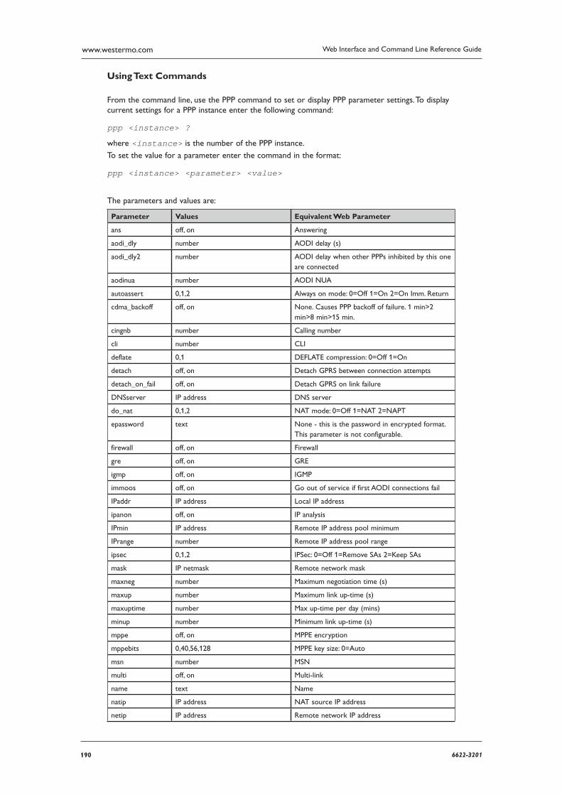
190 6622-3201
Web Interface and Command Line Reference Guidewww.westermo.com
Using Text Commands
From the command line, use the PPP command to set or display PPP parameter settings. To display current settings for a PPP instance enter the following command:
ppp <instance> ?
where <instance> is the number of the PPP instance.
To set the value for a parameter enter the command in the format:
ppp <instance> <parameter> <value>
The parameters and values are:
Parameter Values Equivalent Web Parameter
ans off, on Answering
aodi_dly number AODI delay (s)
aodi_dly2 number AODI delay when other PPPs inhibited by this one are connected
aodinua number AODI NUA
autoassert 0,1,2 Always on mode: 0=Off 1=On 2=On Imm. Return
cdma_backoff off, on None. Causes PPP backoff of fail ure. 1 min>2 min>8 min>15 min.
cingnb number Calling number
cli number CLI
deflate 0,1 DEFLATE compression: 0=Off 1=On
detach off, on Detach GPRS between connection attempts
detach_on_fail off, on Detach GPRS on link failure
DNSserver IP address DNS server
do_nat 0,1,2 NAT mode: 0=Off 1=NAT 2=NAPT
epassword text None - this is the password in encrypted format. This parameter is not configurable.
firewall off, on Firewall
gre off, on GRE
igmp off, on IGMP
immoos off, on Go out of service if first AODI con nections fail
IPaddr IP address Local IP address
ipanon off, on IP analysis
IPmin IP address Remote IP address pool minimum
IPrange number Remote IP address pool range
ipsec 0,1,2 IPSec: 0=Off 1=Remove SAs 2=Keep SAs
mask IP netmask Remote network mask
maxneg number Maximum negotiation time (s)
maxup number Maximum link up-time (s)
maxuptime number Max up-time per day (mins)
minup number Minimum link up-time (s)
mppe off, on MPPE encryption
mppebits 0,40,56,128 MPPE key size: 0=Auto
msn number MSN
multi off, on Multi-link
name text Name
natip IP address NAT source IP address
netip IP address Remote network IP address
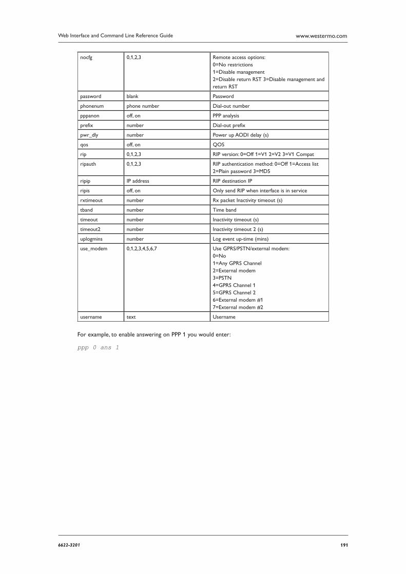
1916622-3201
Web Interface and Command Line Reference Guide www.westermo.com
nocfg 0,1,2,3 Remote access options: 0=No restrictions 1=Disable management 2=Disable return RST 3=Disable management and return RST
password blank Password
phonenum phone number Dial-out number
pppanon off, on PPP analysis
prefix number Dial-out prefix
pwr_dly number Power up AODI delay (s)
qos off, on QOS
rip 0,1,2,3 RIP version: 0=Off 1=V1 2=V2 3=V1 Compat
ripauth 0,1,2,3 RIP authentication method: 0=Off 1=Access list 2=Plain password 3=MD5
ripip IP address RIP destination IP
ripis off, on Only send RIP when interface is in service
rxtimeout number Rx packet Inactivity timeout (s)
tband number Time band
timeout number Inactivity timeout (s)
timeout2 number Inactivity timeout 2 (s)
uplogmins number Log event up-time (mins)
use_modem 0,1,2,3,4,5,6,7 Use GPRS/PSTN/external modem: 0=No 1=Any GPRS Channel 2=External modem 3=PSTN 4=GPRS Channel 1 5=GPRS Channel 2 6=External modem #1 7=External modem #2
username text Username
For example, to enable answering on PPP 1 you would enter:
ppp 0 ans 1
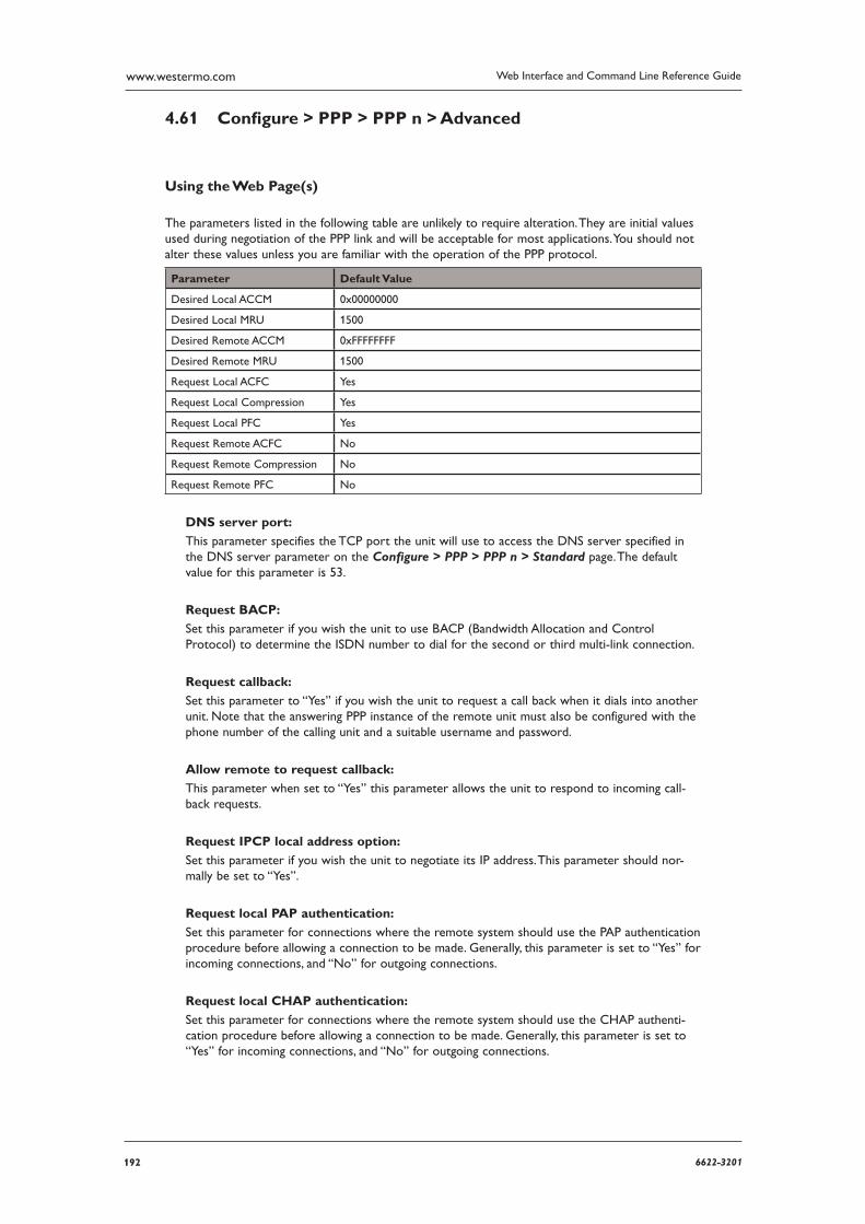
192 6622-3201
Web Interface and Command Line Reference Guidewww.westermo.com
Confi gure > PPP > PPP n > Advanced 4.61
Using the Web Page(s)
The parameters listed in the following table are unlikely to require alteration. They are initial values used during negotiation of the PPP link and will be acceptable for most applications. You should not alter these values unless you are familiar with the operation of the PPP protocol.
Parameter Default Value
Desired Local ACCM 0x00000000
Desired Local MRU 1500
Desired Remote ACCM 0xFFFFFFFF
Desired Remote MRU 1500
Request Local ACFC Yes
Request Local Compression Yes
Request Local PFC Yes
Request Remote ACFC No
Request Remote Compression No
Request Remote PFC No
DNS server port:
This parameter specifies the TCP port the unit will use to access the DNS server specified in the DNS server parameter on the Configure > PPP > PPP n > Standard page. The default value for this parameter is 53.
Request BACP:
Set this parameter if you wish the unit to use BACP (Bandwidth Allocation and Control Protocol) to determine the ISDN number to dial for the second or third multi-link connection.
Request callback:
Set this parameter to “Yes” if you wish the unit to request a call back when it dials into another unit. Note that the answering PPP instance of the remote unit must also be configured with the phone number of the calling unit and a suitable username and password.
Allow remote to request callback:
This parameter when set to “Yes” this parameter allows the unit to respond to incoming call-back requests.
Request IPCP local address option:
Set this parameter if you wish the unit to negotiate its IP address. This parameter should nor-mally be set to “Yes”.
Request local PAP authentication:
Set this parameter for connections where the remote system should use the PAP authentication procedure before allowing a connection to be made. Generally, this parameter is set to “Yes” for incoming connections, and “No” for outgoing connections.
Request local CHAP authentication:
Set this parameter for connections where the remote system should use the CHAP authenti-cation procedure before allowing a connection to be made. Generally, this parameter is set to “Yes” for incoming connections, and “No” for outgoing connections.
1936622-3201
Web Interface and Command Line Reference Guide www.westermo.com
Request local compression:
Setting this parameter to “Yes” causes the unit to request the use of VJ Header Compression, which compresses TCP/IP headers to about 3 bytes rather than the standard 40 bytes. It is gener ally only used to improve efficiency on slow speed links.
Request local PFC:
Setting this parameter to “Yes” causes the unit to request PFC (Protocol Field Compression), which compresses PPP protocol fields from 2 to 1 bytes.
Request remote ACFC:
Setting this parameter to “Yes” causes the unit to get the remote to request ACFC (Address Con trol Field Compression). When negotiated, the address/control fields are removed from the start of the PPP header.
Request IPCP remote address option:
Set this parameter if it is required that the remote system have an address supplied. An attempt to negotiate an IP address from the IP address pool will be made. Generally, this parameter is set to “Yes” for incoming connections, and “No” for outgoing connections.
Request remote PAP authentication:
Set this parameter if it is required that the unit authenticate itself with the remote system using PAP. If this parameter is set, the connection will fail if authentication is not successful. Generally, this parameter should be set to “No”.
Request remote CHAP authentication:
Set this parameter to “Yes” if it is required that the unit authenticate itself with the remote system using CHAP. If this parameter is set, the connection will fail if authentication is not suc-cessful. Generally, this parameter should be set to “Yes” for outgoing connections and “No” for incoming connections.
Request remote compression:
Setting this parameter to “Yes” causes the unit to get the remote to request the use of VJ com-pression.
Request remote PFC:
Setting this parameter to “Yes” causes the unit to get the remote to request Protocol Field Compression.
LCP echo request interval (s):
Setting this parameter to a non-zero value causes PPP to issue Link Control Protocol (LCP) Echo Request packets to the remote peer at the specified intervals. This would be used to keep a link active, for example when using GPRS.
Reset link after this many failed LCP echo requests:
When this parameter is set to a value greater than 0, the unit will terminate this PPP connec-tion after there has been no response to this many consecutive LCP echo requests. When set to 0 the unit will not terminate the PPP connection.
PING request interval (s):
If this parameter is set to a non-zero value the unit will automatically generate a “ping” (ICMP echo request) to the address specified by the PING IP address parameter at the interval speci-fied (auto ping). Setting the value to 0 disables the auto-ping facility. This parameter in conjunc-tion with PING IP address and No PING response out of service delay can be used to configure the unit to use a back-up interface automatically should there be a problem with this interface.
194 6622-3201
Web Interface and Command Line Reference Guidewww.westermo.com
No PING response request interval (s):
If this parameter is set to a non-zero value the unit will use this value as the interval to ping at when more than one ping request sent out the PPP interface is outstanding. This should be set to a shorter interval than the PING request interval so that the unit may more quickly react to a bro ken PPP link.
PING response timeout (s):
If this parameter is set to a non-zero value the unit will wait for the interval specified for a response from a PING request before applying the No PING response request interval. If this parameter is set to 0 (default), the time specified in the in PING Request interval is allowed before applying the No PING response request interval.
New connections to resume with previous PING interval: If this parameter is set to “Yes”, the unit will set the PING Request interval to the interval in use when the PPP last disconnected.
Only send PINGs when interface is in service:
If this parameter is set to “ON”, ICMP echo requests will only be sent from this interface when it is in service. The default setting is “OFF”, ICMP echo requests are sent when the interface is in service and out of service.
PING size (octets):
The parameter specifies the PING size when using interface autoping feature. The size indicates how large the ICMP packet should be excluding the size of the IP header.
PING IP address:
This parameter specifies the IP address or host name to which ICMP echo requests will be sent if the PING request interval is greater than 0.
Ping IP address #2:
This allows for more reliable problem detection before fail over occurs. If an IP address or host name is entered and the Ping IP switchover count has a value greater than 0, when a ping failure is detected on the primary IP address the 2nd IP address is checked. This is to ensure that if the main IP address becomes unavailable for any reason and stops responding to ICMP requests, the router will check another IP address before starting fail over procedures.
PING IP switchover count:
When set to more than 0, indicates the number pings that need to fail before the 2nd IP address is checked.
No PING response reset delay (s):
This parameter is primarily used where IP traffic is being carried over a GPRS network and the PPP instance has been configured for Always on mode. It specifies an amount of time after which if no response has been received to the auto-pings, the unit will terminate the PPP con-nection in an attempt to re-establish communications (because Always on mode has been selected the unit will automatically attempt to re-establish a PPP connection that has been ter-minated).
Use ETH0 for PING source IP:
Setting this parameter to “Yes” causes the unit to use the IP address of ETH0 (instead of the cur rent IP address of the PPP interface), as the source address for the auto PING packets.
Reset Ping interval after traffic:
When enabled, the time configured in the PING request interval (s): parameter will be reset if IP data is sent across the PPP link.
Settling time (*100ms):
On wireless links it is possible that initial packets sent to the PPP interface by TCP may be dropped by the network if they are sent too quickly after PPP negotiation has been completed. This parameter may be used to delay the notification to TCP that PPP has connected.
1956622-3201
Web Interface and Command Line Reference Guide www.westermo.com
Heartbeat interval (s):
If this parameter is set to a non-zero value, the unit will transmit “heartbeat” packets at the interval specified. Heartbeat packets are UDP packets that contain status information about the unit that may be used to locate a remote unit’s current dynamic IP address.
Heartbeat destination:
This parameter specifies the destination IP address for heartbeat packets.
Heartbeat source IP from interface: / Heartbeat source IP from interface #:
These 2 parameters allow the selection of the source interface for the UDP heartbeats. Selecting an ethernet source will allow the packets to follow the routing table, instead of being sent out of the PPP interface on which they are set.
Heartbeat selects interface from routing table:
When enabled, the UDP heartbeats will choose the best route from the routing table. If disa-bled the exit interface will be interface on which the heartbeat is configured.
Heartbeat includes IMSI:
When enabled, the heartbeat will include the IMSI of the wireless module.
Maximum unanswered TX packets before link reset:
If this parameter is set to a value greater than 0, the unit will terminate this PPP connection if the specified number of IP packets has been transmitted but none have been received AND the link has been active for at least the amount of time specified by Minimum time before link reset parameter.
Minimum time before link reset (s):
This parameter is used to set the minimum length of time in seconds before the PPP connec-tion can be terminated when the Maximum unanswered TX packets before link reset value has been exceeded.
Reboot after this many consecutive link resets:
If this parameter is set to a value greater than 0, the unit will reboot if the PPP link has been reset the specified number of times as a consequence of the Maximum unanswered TX packets before link reset value being exceeded.
Reboot after this many consecutive failed connections:
If this parameter is set to a value greater than 0, the unit will reboot if it fails to establish a connec tion over this PPP instance after the specified number of consecutive attempts.
Auto activation attempts allowed:
On GPRS units this parameter may be used to specify the maximum number of times a PPP instance that is configured to auto-activate (when the PPP Standard Always On mode is On), is allowed to do so before other PPP instances that were inhibited by this PPP instance will be allowed to connect.
Post-disconnect activation attempts allowed:
On GPRS units this parameter may be used to specify the maximum number of times a PPP instance that was connected and is then disconnected, is allowed to attempt to reconnect before other PPP instances that were inhibited by this PPP instance will be allowed to connect.
Inhibit auto-activation when these PPPs are active:
This is a comma separated list of PPP instances that can inhibit this PPP instance from activating. If any of the PPP instances in this list is connected, this instance cannot connect.
196 6622-3201
Web Interface and Command Line Reference Guidewww.westermo.com
Inhibit mode:
This parameter defines under what circumstances the PPP will be inhibited by the PPPs listed in
the Inhibit auto-activation when these PPPs are active parameter. The options are: Inhibit if other PPP active, Inhibit if other PPP is active and not OOS, Inhibit if
other PPP is not OOS, Inhibit if other PPP is connected and not OOS.
These inhibit modes can be used with the CLI based parameter trafficto. This parameter can be used to send traffic through an inhibited interface. The options are:
Option Value
0 Parameter is disabled, inhibit mode is unaffected
1 Traffic will activate this interface and be sent, the normal timeout value will deactivate this interface
2 or Higher As 1 but the value entered will be used as the timeout value to deac-tivate the interface overriding the default value
IPSec source IP from interface:
By default, the source IP address for an IPSec Eroute will be the IP address of the interface on which IPSec was enabled. By setting this parameter to either PPP or Ethernet, the source address used by IPSec will match that of the Ethernet or PPP interface specified by the IPSec source IP from interface # parameter below.
IPSec source IP from interface #:
See above.
Layer 1 interface:
This parameter determines which layer 1 interface is to be used. “Default” will send PPP frames over ISDN, “Port” will send PPP frames over the synchronous port, “ATM PVC” will send PPP frames over the ATM PVC (ADSL), “ETH” will send PPP frames over the Ethernet interface, “L2TP” will send PPP frames over Layer 2 Tunnelling Protocol, and “ASY” will send PPP frames over the asynchronous port.
Layer 1 interface #:
This parameter determines the instance number of the Layer 1 interface selected above.
Data limit warning level (kb):
On GPRS networks (where charging is based on the amount of data transferred as opposed to time spent on-line), this parameter may be used to specify a data limit after which the unit will cre ate an entry in the event log to indicate that this amount of data has been transferred. For exam ple, if your monthly tariff includes up to 5Mb of data before you are charged an “excess”, you might set the Data limit warning level to 4000. This would cause the unit to place a warn-ing entry in the event log once you had transferred 4Mb. This event could be used to trigger an email alert mes sage, SNMP trap or SMS alert message.
Data limit stop level (kb):
This parameter is used to set the maximum amount of data that may be transferred before the unit will “lock” the interface and prevent further transfer. As with the Data Limit Warning Level param eter it is used on networks where the tariff is based on the amount of data transferred to help pre vent excess charges being incurred.
Once the interface has been locked, it may be unlocked manually by clicking on the Clear Total Data Transferred button on the appropriate Statistics > PPP page or automatically at the start of the next billing period by setting the Data Limit Reset Day of Month appropriately.
Data limit reset day of month:
If you wish to automatically unlock a locked interface at the start of a new billing period, this param eter should be set to the appropriate day of the month (from 1 to 28). When this date is reached the unit will unlock the interface and data transfer may resume. If the parameter is set to 0, auto matic unlocking will not occur and manual unlocking will be necessary (by clicking on the Clear Total Data Transferred button on the appropriate Statistics > PPP page.
1976622-3201
Web Interface and Command Line Reference Guide www.westermo.com
Route broadcasts if this PPP issues an IP address for an Ethernet network:
When set to “Yes”, this parameter enables the routing of broadcasts to and from Ethernet inter faces. This will only occur if the PPP has issued an address which is part of the Ethernet interface network.
Local CHAP Login Confi guration Options
CHAP MD5:
Enabling this option will allow a remote unit to authenticate with the unit using the CHAP MD-5 algorithm.
MS-CHAP Algorithm:
Enabling this option will allow a remote unit to authenticate with the unit using the MS-CHAP algorithm.
MS-CHAPv2 Algorithm:
Enabling this option will allow a remote unit to authenticate with the unit using the MS-CHAPv2 algorithm.
Remote CHAP Login Confi guration Options
CHAP-MD5:
Enabling this option will allow the unit to authenticate with a remote unit using the CHAP MD-5 algorithm.
MS-CHAP Algorithm:
Enabling this option will allow the unit to authenticate with a remote unit using the MS-CHAP algorithm.
MS-CHAPv2 Algorithm:
Enabling this option will allow the unit to authenticate with a remote unit using the MS-CHAPv2 algorithm.
Enable Top Talker Monitoring:
If this parameter is set to “Yes”, Top Talker information is logged and displayed in the Statistics > Top Talkers page. Top Talkers displays average bandwidth usage for the interface over three time frames: current, previous minute, and previous 30 minutes.
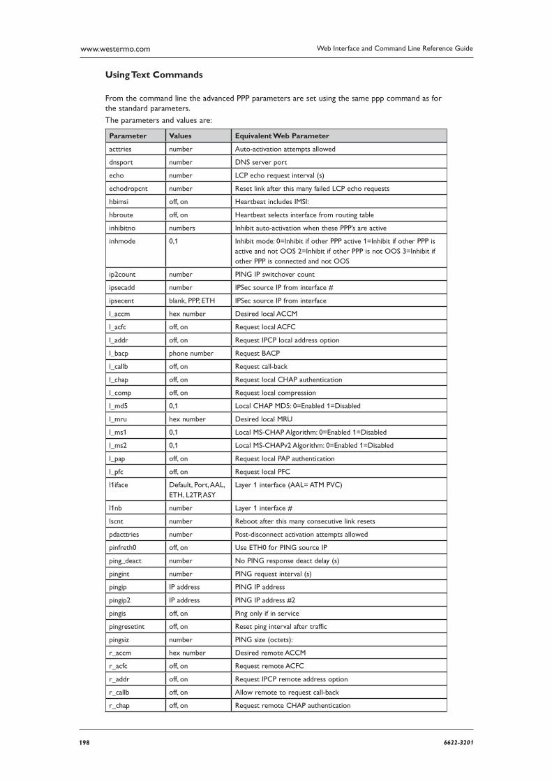
198 6622-3201
Web Interface and Command Line Reference Guidewww.westermo.com
Using Text Commands
From the command line the advanced PPP parameters are set using the same ppp command as for the standard parameters.
The parameters and values are:
Parameter Values Equivalent Web Parameter
acttries number Auto-activation attempts allowed
dnsport number DNS server port
echo number LCP echo request interval (s)
echodropcnt number Reset link after this many failed LCP echo requests
hbimsi off, on Heartbeat includes IMSI:
hbroute off, on Heartbeat selects interface from routing table
inhibitno numbers Inhibit auto-activation when these PPP’s are active
inhmode 0,1 Inhibit mode: 0=Inhibit if other PPP active 1=Inhibit if other PPP is active and not OOS 2=Inhibit if other PPP is not OOS 3=Inhibit if other PPP is connected and not OOS
ip2count number PING IP switchover count
ipsecadd number IPSec source IP from interface #
ipsecent blank, PPP, ETH IPSec source IP from interface
l_accm hex number Desired local ACCM
l_acfc off, on Request local ACFC
l_addr off, on Request IPCP local address option
l_bacp phone number Request BACP
l_callb off, on Request call-back
l_chap off, on Request local CHAP authentication
l_comp off, on Request local compression
l_md5 0,1 Local CHAP MD5: 0=Enabled 1=Disabled
l_mru hex number Desired local MRU
l_ms1 0,1 Local MS-CHAP Algorithm: 0=Enabled 1=Disabled
l_ms2 0,1 Local MS-CHAPv2 Algorithm: 0=Enabled 1=Disabled
l_pap off, on Request local PAP authentication
l_pfc off, on Request local PFC
l1iface Default, Port, AAL, ETH, L2TP, ASY
Layer 1 interface (AAL= ATM PVC)
l1nb number Layer 1 interface #
lscnt number Reboot after this many consecutive link resets
pdacttries number Post-disconnect activation attempts allowed
pinfreth0 off, on Use ETH0 for PING source IP
ping_deact number No PING response deact delay (s)
pingint number PING request interval (s)
pingip IP address PING IP address
pingip2 IP address PING IP address #2
pingis off, on Ping only if in service
pingresetint off, on Reset ping interval after traffic
pingsiz number PING size (octets):
r_accm hex number Desired remote ACCM
r_acfc off, on Request remote ACFC
r_addr off, on Request IPCP remote address option
r_callb off, on Allow remote to request call-back
r_chap off, on Request remote CHAP authentication
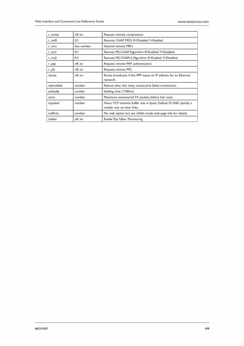
1996622-3201
Web Interface and Command Line Reference Guide www.westermo.com
r_comp off, on Request remote compression
r_md5 0,1 Remote CHAP MD5: 0=Disabled 1=Enabled
r_mru hex number Desired remote MRU
r_ms1 0,1 Remote MS-CHAP Algorithm: 0=Enabled 1=Disabled
r_ms2 0,1 Remote MS-CHAPv2 Algorithm: 0=Enabled 1=Disabled
r_pap off, on Request remote PAP authentication
r_pfc off, on Request remote PFC
rbcast off, on Route broadcasts if this PPP issues an IP address for an Ethernet network
rebootfails number Reboot after this many consecutive failed connections
settledly number Settling time (*100ms)
sscnt number Maximum unanswered TX packets before link reset
tcptxbuf number None, TCP transmit buffer size in bytes. Default 0=2560. Specify a smaller size on slow links.
trafficto number No web option but see inhibit mode web page info for details.
ttalker off, on Enable Top Talker Monitoring
200 6622-3201
Web Interface and Command Line Reference Guidewww.westermo.com
Confi gure > PPP > PPP n > PPP/IP Over X25 4.62
Westermo routers can optionally support transmission of TCP/IP packets encapsulated in X.25. This fea ture allows the ISDN D-channel to be used as an “always on” connection providing a permanent, low speed Internet Protocol pipe between two Local Area Networks.
Using the Web Page(s)
These parameters are used when configuring PPP or IP over X.25.
Calling NUA:
This specifies the calling X.25 address to be used when using PPP or IP over X.25.
Default packet size:
This specifies the default X.25 packet size to use.
IP over X25 mode:
When set to “On”, this causes the unit to route IP data over X.25. Otherwise, PPP over X.25 is used.
Layer 2 interface:
This parameter is used to select whether the PPP instance will use B or D-channel X.25. If “None” is specified, then PPP/IP over X.25 mode is disabled.
Layer 2 interface #:
This parameter specifies which LAPB or LAPD instance to use for the relevant PPP instance.
LCN:
The LCN (Logical Channel Number) parameter is the value of the first LCN that will be assigned for outgoing X.25 CALLs. The default is 1027.
LCN direction:
This parameter determines whether the LCN used for outgoing X.25 calls is incremented or decre mented from the starting value when multiple X.25 instances share one layer 2 (LAPB or LAPD), connection. The default is “Down” and LCNs are decremented, i.e. if the first CALL uses 1024, the next will use 1023, etc. Setting the parameter to “Up” will cause the LCN to be incre-mented from the start value.
Restart delay (ms):
When the Restarts parameter is set to “On” the value specified in the Restart delay dialog box determines the length of time in milliseconds that the unit will wait before issuing a Restart packet. The default value is 2000 giving a delay of 2 seconds.
Restarts:
It is normally possible to make X.28 CALLs immediately following the initial SABM-UA exchange. In some cases however, the X.25 network may require an X.25 RESTART before it will accept
X.25 CALLs. The correct mode to select depends upon the particular X.25 service to which you subscribe.
The default value is “On”. This means that the unit will issue X.25 RESTART packets. To prevent
the unit from issuing RESTART packets set this parameter to “Off”.
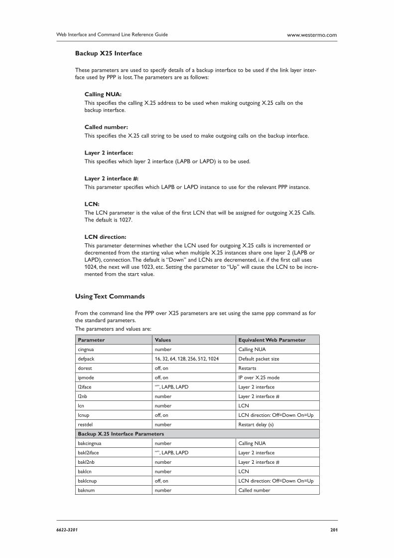
2016622-3201
Web Interface and Command Line Reference Guide www.westermo.com
Backup X25 Interface
These parameters are used to specify details of a backup interface to be used if the link layer inter-face used by PPP is lost. The parameters are as follows:
Calling NUA:
This specifies the calling X.25 address to be used when making outgoing X.25 calls on the backup interface.
Called number:
This specifies the X.25 call string to be used to make outgoing calls on the backup interface.
Layer 2 interface:
This specifies which layer 2 interface (LAPB or LAPD) is to be used.
Layer 2 interface #:
This parameter specifies which LAPB or LAPD instance to use for the relevant PPP instance.
LCN:
The LCN parameter is the value of the first LCN that will be assigned for outgoing X.25 Calls. The default is 1027.
LCN direction:
This parameter determines whether the LCN used for outgoing X.25 calls is incremented or decre mented from the starting value when multiple X.25 instances share one layer 2 (LAPB or LAPD), connection. The default is “Down” and LCNs are decremented, i.e. if the first call uses 1024, the next will use 1023, etc. Setting the parameter to “Up” will cause the LCN to be incre-mented from the start value.
Using Text Commands
From the command line the PPP over X25 parameters are set using the same ppp command as for the standard parameters.
The parameters and values are:
Parameter Values Equivalent Web Parameter
cingnua number Calling NUA
defpack 16, 32, 64, 128, 256, 512, 1024 Default packet size
dorest off, on Restarts
ipmode off, on IP over X.25 mode
l2iface “”, LAPB, LAPD Layer 2 interface
l2nb number Layer 2 interface #
lcn number LCN
lcnup off, on LCN direction: Off=Down On=Up
restdel number Restart delay (s)
Backup X.25 Interface Parameters
bakcingnua number Calling NUA
bakl2iface “”, LAPB, LAPD Layer 2 interface
bakl2nb number Layer 2 interface #
baklcn number LCN
baklcnup off, on LCN direction: Off=Down On=Up
baknum number Called number
202 6622-3201
Web Interface and Command Line Reference Guidewww.westermo.com
Confi gure > PPP > PPP n > QOS 4.63
In addition to the QOS parameter on the PPP N standard parameters pages (which are used to enable quality of service management for that PPP instance), each PPP instance has an associated QOS instance (PPP 0 maps to QOS 0, PPP 1 maps to QOS 1, etc.). These QOS instances include 10 QOS queues into which packets may be placed when using QOS. Each of these queues must be assigned a queue profile (from the twelve available profiles defined in the Configure > Quality of Service > Q Profile pages), and a priority value.
Using the Web Page(s)
Each PPP n > QOS page includes the Link speed parameter at the top followed by a list of queues with drop-down selection boxes that are used to assign a profile and a priority to each queue.
Link speed (Kbps):
This parameter should be set to the maximum data rate that this PPP link is capable of sustaining. It is used when calculating whether or not the data rate from a queue may exceed its Minimum Kbps setting (as determined by the profile assigned to it) and send at a higher rate (up to the Max imum Kbps setting).
Queue priorities:
Below this heading is a list of the queues from 0 to 9 alongside each of which are drop down selec-tion lists for assigning profile numbers (from 0 to 11) and queue priorities. The priority may be set to “Very High”, “High”, “Medium”, “Low” or “Very Low”.
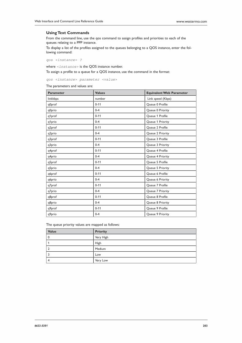
2036622-3201
Web Interface and Command Line Reference Guide www.westermo.com
Using Text Commands From the command line, use the qos command to assign profiles and priorities to each of the queues relating to a PPP instance.
To display a list of the profiles assigned to the queues belonging to a QOS instance, enter the fol-lowing command:
qos <instance> ?
where <instance> is the QOS instance number.
To assign a profile to a queue for a QOS instance, use the command in the format:
qos <instance> parameter <value>
The parameters and values are:
Parameter Values Equivalent Web Parameter
linkkbps number Link speed (Kbps)
q0prof 0-11 Queue 0 Profile
q0prio 0-4 Queue 0 Priority
q1prof 0-11 Queue 1 Profile
q1prio 0-4 Queue 1 Priority
q2prof 0-11 Queue 2 Profile
q2prio 0-4 Queue 2 Priority
q3prof 0-11 Queue 3 Profile
q3prio 0-4 Queue 3 Priority
q4prof 0-11 Queue 4 Profile
q4prio 0-4 Queue 4 Priority
q5prof 0-11 Queue 5 Profile
q5prio 0-4 Queue 5 Priority
q6prof 0-11 Queue 6 Profile
q6prio 0-4 Queue 6 Priority
q7prof 0-11 Queue 7 Profile
q7prio 0-4 Queue 7 Priority
q8prof 0-11 Queue 8 Profile
q8prio 0-4 Queue 8 Priority
q9prof 0-11 Queue 9 Profile
q9prio 0-4 Queue 9 Priority
The queue priority values are mapped as follows:
Value Priority
0 Very High
1 High
2 Medium
3 Low
4 Very Low
204 6622-3201
Web Interface and Command Line Reference Guidewww.westermo.com
Confi gure > PPTP 4.64
Point to point tunnelling protocol (PPTP) is a common way of creating a VPN tunnel to a Microsoft Win dows server.
PPTP works by sending a regular PPP session to the peer encapsulated by GRE (Generic Routing Encapsulation). A second session on TCP port 1723 is used to initiate and manage the GRE session. PPTP connections are authenticated with Microsoft MSCHAP-v2 or EAP-TLS. VPN traffic is pro-tected by MPPE encryption. PPTP does not work with GPRS/HSDPA mobile operators that assign a private IP address then NAT the traffic before it leaves their network. This is because the server tries to build a tunnel back to the router on port 1723 but fails when the traffic is blocked by the mobile operators firewall.
Using the Web Page(s)
Remote host:
This parameter is used to specify the IP address of the remote host, i.e. the device that will ter-minate the PPTP connection.
Tunnel Interface:
This allows you to specify an interface to use for PPTP sockets. This allows the unit to raise the desired interface should it be disconnected.
Tunnel Interface #:
This parameter determines the instance number of the interface selected above.
Listening mode:
If enabled, this parameter allows the Westermo router to act as a PPTP server and accept incoming VPN connections.
Server Mode:
This parameter is used to alter the type of call request sent to the remote device. The default is Off, which sends a call_in request. Changing this to On will send call_out requests.
SSL version:
This parameter will enable encryption of the control data using SSL.
Socket mode:
Special proprietary mode where PPP packets are sent via the PPTP control socket rather than in GRE packets.
Name:
This parameter allows you to enter a name for this PPP instance, to make it easier to identify it.
Debug:
This parameter is used to control the amount of information contained in debug traces.
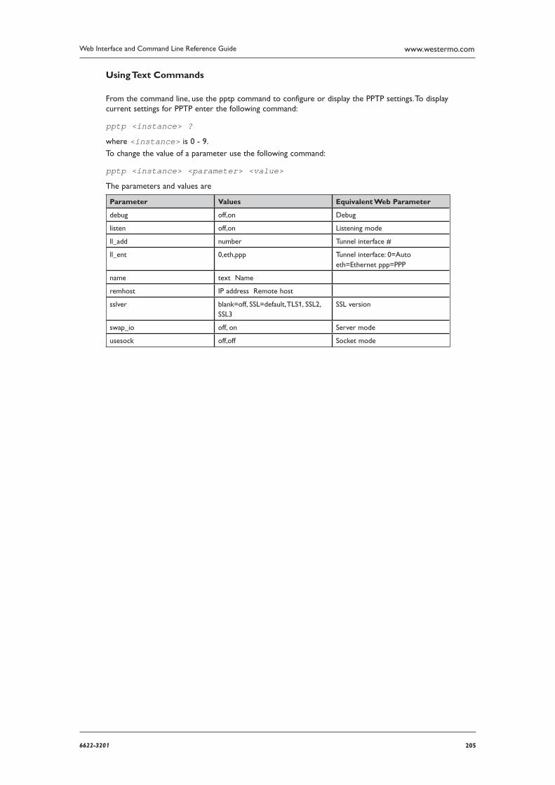
2056622-3201
Web Interface and Command Line Reference Guide www.westermo.com
Using Text Commands
From the command line, use the pptp command to configure or display the PPTP settings. To display current settings for PPTP enter the following command:
pptp <instance> ?
where <instance> is 0 - 9.
To change the value of a parameter use the following command:
pptp <instance> <parameter> <value>
The parameters and values are
Parameter Values Equivalent Web Parameter
debug off,on Debug
listen off,on Listening mode
ll_add number Tunnel interface #
ll_ent 0,eth,ppp Tunnel interface: 0=Auto eth=Ethernet ppp=PPP
name text Name
remhost IP address Remote host
sslver blank=off, SSL=default, TLS1, SSL2, SSL3
SSL version
swap_io off, on Server mode
usesock off,off Socket mode
206 6622-3201
Web Interface and Command Line Reference Guidewww.westermo.com
Confi gure > Protocol Bindings 4.65
The MR and DR series are soft configurable to allow different protocols to be used on different ports. The process of selecting which protocol will be used on which port is referred to as “bind-ing”.
Using the Web Page(s)
The Configure > Protocol Bindings page allows you to define which protocols will be used on each of the ASY ports.
For example, you may wish to use ASY 0 for an ISDN B-channel X.25 application. In this case, you would need to bind ASY0 to an X.25 PAD, say PAD0. You would then associate the PAD with a LAPB instance using the appropriate Configure > X.25 PAD page.
By default, if no specific protocol has been bound to an ASY port the unit will automatically associ-ate a PPP instance with that port, i.e. PPP is treated as the default protocol.
To change a binding or a add a new one, select the required protocol from the drop down list on the left and select the correct ASY port or REM from the list on the right. Once you have selected the appropriate values click the Add button. Each time you do this the new binding will appear in the list at the top of the page along with a Remove button. Clicking the Remove button will remove the binding and re-associate PPP with the appropriate port.
If you add a binding to an ASY port that already has a binding, the new binding will replace the old one.
The REM option listed with the ASY ports is the name for the Remote virtual ASY port. This port may be used to allow a remote X.25 or V.120 user to take control of the unit for management pur-poses.
Using Text Commands
From the command line, the bind command is used to configure protocol bindings. To display a list of current bindings enter the command:
bind ?
To bind protocols to ports via the command line, use the bind command in the format:
bind <protocol> <instance> <asy <number>¦rem>
For example, to assign the PAD 0 to ASY 1 you would enter:
bind pad 0 asy 1
To use the unit in V.120 mode you would use the bind command to bind a V.120 instance to the required serial port. For example:
bind v120 0 asy 0
Similarly, to access the internet using PPP via a terminal connected to ASY 2 you would enter the command:
bind ppp 1 asy 2
Binding TANS to ADAPT 4.65.1
Currently it is only possible to bind a TANS instance to an ADAPT instance using the bind com-mand. The format of the command is:
bind adapt <instance> tans <instance>
2076622-3201
Web Interface and Command Line Reference Guide www.westermo.com
Confi gure > Protocol Switch 4.66
The Protocol Switch software available on some models provides X.25 call switching between the var ious interfaces that may be available including:
Interface Description
Off/None Data will not be switched from / backed-up from this protocol
LAPD Data will be switched from / backed-up from LAPD using the X.25 service.
LAPD X As above but the actual LAPD instance used will be determined by the NUA.
LAPB 0 Data will be switched from / backed-up from LAPB 0.
LAPB 1 Data will be switched from / backed-up from LAPB 1.
LAPB 2 Data will be switched from / backed-up from LAPB 2.
LAPB 0 PVC Data will be switched from / backed-up from an X.25 PVC on LAPB 0.
LAPB 1 PVC Data will be switched from / backed-up from an X.25 PVC on LAPB 1.
LAPB 2 PVC Data will be switched from / backed-up from an X.25 PVC on LAPB 2.
XOT Data will be switched from / backed-up from an XOT (X.25 over TCP/IP) connection.
XOT PVC Data will be switched from / backed-up from an XOT PVC connection.
TCP stream Data will be switched from / backed-up from a TCP socket. The socket’s IP address will be deter mined from the IP stream port setting.
UDP stream This is similar to the TCP stream setting but instead of switching onto a TCP socket, data is switched onto a UDP socket. The effect is that a UDP frame will be sent for each packet of X.25 data being switched.
VXN Data will be backed-up from Datawire’s VXN protocol
SSL Data will be switched from / backed-up from SSL
When this optional feature is included, the unit may be configured to pass X.25 calls received via one of these interfaces to another interface. In addition, it is possible to specify a backup interface so that if an outgoing call on one interface fails, then the backup interface is automatically tried. The physical interfaces used by the LAPB instances are specified in the appropriate Configure > LAPB pages, and may either be ISDN or one of SYN 0 or SYN 1 operating in synchronous mode on a physical port.
The logic used in the switching software is outlined in the flowchart below. The following notes pro-vide a more in-depth explanation of the actions taken in each of the numbered boxes.
The unit will first look up the Called NUA/NUI in the Configure > X25 > NUA/NUI–>Interface mapping table to determine the IP address to use in the event that the call ends up being switched to a TCP or XOT interface. If a match is found on the Called NUA/NUI the unit assigns the match-ing IP address from the table to the call. If IP address mapping table does not contain an entry for the Called NUA/NUI and the call is eventually switched to a TCP or XOT channel then the default IP address (XOT remote IP address) is used.
The unit then determines from the source interface of the incoming call which interface type it should be switched to (from the Switch from parameters on the Configure > Protocol Switch page). For example, if the call arrived via a LAPB 0 interface and the Switch from LAPB 0 to param-eter was set to LAPD, then the outgoing interface would LAPD.
If the outgoing interface is LAPD the unit changes the Calling NUA field of the incoming call to the D-Channel NUA value (as defined on the Configure > Protocol Switch page). If the out going interface is NOT LAPD processing proceeds as at step 6.
The unit then searches the Protocol Switch NUA Mappings table to see if there are any matches for the Called or Calling NUA values on the specified interface. In cases where there is a match, the NUA In value is substituted by the NUA out value, i.e. the mapping is applied individually to both the Calling NUA and Called NUA for the packet.
The unit then checks the leading characters of the Calling NUA to see if there is a match with the Call Prefix parameter. If there is a match then the prefix digits are removed before the out going X.25 call is made. Otherwise the call is made anyway and the switching process is com plete for this call.
If after step 3, the unit has determined that the outgoing interface is not LAPD, it checks if the outgoing interface is LAPB. If it is, it then checks to see if the Called NUA field in the call packet matches the LAPB 0 NUA parameter and if it does, selects LAPB 0 as the outgoing interface. If the
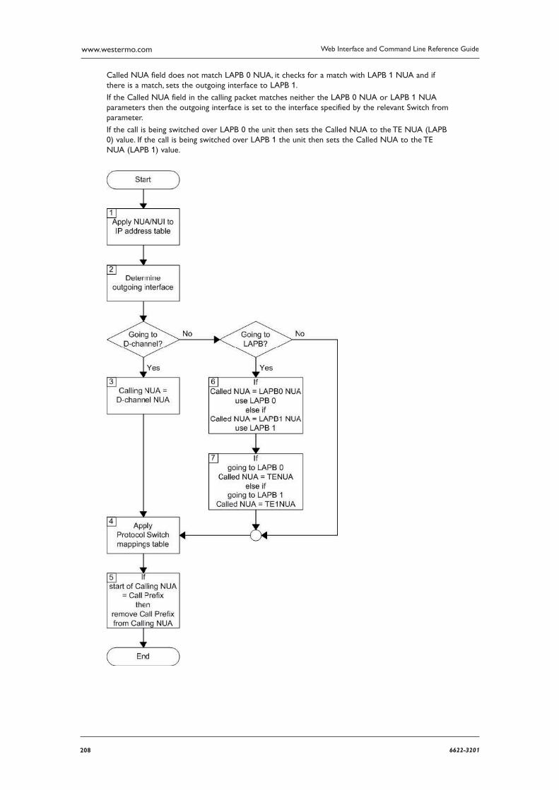
208 6622-3201
Web Interface and Command Line Reference Guidewww.westermo.com
Called NUA field does not match LAPB 0 NUA, it checks for a match with LAPB 1 NUA and if there is a match, sets the outgoing interface to LAPB 1.
If the Called NUA field in the calling packet matches neither the LAPB 0 NUA or LAPB 1 NUA parameters then the outgoing interface is set to the interface specified by the relevant Switch from parameter.
If the call is being switched over LAPB 0 the unit then sets the Called NUA to the TE NUA (LAPB 0) value. If the call is being switched over LAPB 1 the unit then sets the Called NUA to the TE NUA (LAPB 1) value.
2096622-3201
Web Interface and Command Line Reference Guide www.westermo.com
Using the Web Page(s)
The Configure > Protocol Switch page is used to configure the Protocol Switch using the follow-ing parameters:
Switch from XOT (TCP) to:
This parameter controls the switching of incoming X.25 calls received via XOT. Select the inter-face to which data should be switched from the drop down list, or select “Off” and the proto-col switch will not respond to any incoming XOT calls.
Switch from LAPD to:
This parameter controls the switching of incoming X.25 calls received via ISDN LAPD. Select the interface to which data should be switched from the drop down list, or select “Off” and the protocol switch will not respond to any incoming LAPD calls.
Switch from LAPB 0 to:
This parameter controls the switching of incoming X.25 calls received via LAPB 0. Select the inter face to which data should be switched from the drop down list, or select “Off” and the protocol switch will not respond to any incoming LAPB 0 calls.
Switch from LAPB 1 to:
This parameter controls the switching of incoming X.25 calls received via LAPB 1. Select the inter face to which data should be switched from the drop down list, or select “Off” and the protocol switch will not respond to any incoming LAPB 1 calls.
Switch from LAPB 2 to:
This parameter controls the switching of incoming X.25 calls received via LAPB 2. Select the inter face to which data should be switched from the drop down list, or select “Off” and the protocol switch will not respond to any incoming LAPB 2 calls.
Switch from LAPB 0 PVC to:
This parameter controls the switching of incoming X.25 calls received via an LAPB 0 PVC. Select the interface to which data should be switched from the drop down list, or select “Off” and the pro tocol switch will not respond to any incoming PVC calls on LAPB 0.
Switch from LAPB 1 PVC to:
This parameter controls the switching of incoming X.25 calls received via an LAPB 1 PVC. Select the interface to which data should be switched from the drop down list, or select “Off” and the pro tocol switch will not respond to any incoming PVC calls on LAPB 1.
Switch from LAPB 2 PVC to:
This parameter controls the switching of incoming X.25 calls received via an LAPB 2 PVC. Select the interface to which data should be switched from the drop down list, or select “Off” and the pro tocol switch will not respond to any incoming PVC calls on LAPB 2.
Switch from XOT PVC to:
This parameter controls the switching of incoming X.25 calls received via an XOT PVC. Select the interface to which data should be switched from the drop down list, or select “Off” and the protocol switch will not respond to any incoming XOT PVC calls.
Backup from XOT to:
If any of the Switch from parameters has been set to XOT, and XOT is unavailable, this parame-ter may be used to specify an alternative interface to switch the X.25 call to. Any of the other inter faces may be chosen, or “None”. If “None” is chosen, then no backup call will be attempted.
210 6622-3201
Web Interface and Command Line Reference Guidewww.westermo.com
Backup from LAPD to:
If any of the Switch from parameters has been set to LAPD, and LAPD is unavailable, this param-eter may be used to specify an alternative interface to switch the X.25 call to. Any of the other interfaces may be chosen, or “None”. If “None” is chosen, then no backup call will be attempted.
Backup from LAPB0 to:
If any of the Switch from parameters has been set to LAPB 0, and LAPB 0 is unavailable, this parameter may be used to specify an alternative interface to switch the X.25 call to. Any of the other interfaces may be chosen, or “None”. If “None” is chosen, then no backup call will be attempted.
Backup from LAPB1 to:
If any of the Switch from parameters has been set to LAPB 1, and LAPB 1 is unavailable, this parameter may be used to specify an alternative interface to switch the X.25 call to. Any of the other interfaces may be chosen, or “None”. If “None” is chosen, then no backup call will be attempted.
Backup from LAPB2 to:
If any of the Switch from parameters has been set to LAPB 2, and LAPB 2 is unavailable, this parameter may be used to specify an alternative interface to switch the X.25 call to. Any of the other interfaces may be chosen, or “None”. If “None” is chosen, then no backup call will be attempted.
Backup from VXN to:
If any of the Switch from parameters has been set to VXN, and VXN is unavailable, this parame-ter may be used to specify an alternative interface to switch the X.25 call to. Any of the other inter faces may be chosen, or “None”. If “None” is chosen, then no backup call will be attempted.
Call prefix:
This parameter specifies the call prefix to inserted in front of the NUA in calls being switched to LAPD. For example, if the called NUA in the call being received by the LAPB 0 interface is 56565 and the call prefix is 0242 then the call placed on the LAPD interface is to NUA 024256565. Also, for calls in the reverse direction, if the prefix in the calling NUA matches this parameter then it is removed from the calling NUA field.
LAPB LCN:
This is the value of the first LCN that will be assigned for outgoing X25 calls on LAPB.
LAPB LCN direction:
This parameter determines whether the LCN used for outgoing X.25 calls on LAPB is incre-mented or decremented from the starting value.
LAPB Max VCs:
This parameter sets the maximum number of Virtual Circuits (VCs) to be used on an LAPB inter face. When the maximum has been reached, then the backup call will take place immediate-ly (or the call will clear if there is no backup call). If this parameter is set to “0”, there is no limit.
B-channel #:
This parameter specifies an ISDN number to be used for calls being switched in the direction of LAPB 0 or LAPB 1.
LAPB ENQ char:
When this parameter is set to “On”, when an incoming call on LAPB is switched and the unit connects to it, the X.25 switch sends a data packet on the LAPB X.25 SVC containing the ENQ character.
2116622-3201
Web Interface and Command Line Reference Guide www.westermo.com
D-channel LCN:
This is the value of the first LCN that will be assigned for outgoing X25 calls on LAPD.
D-channel LCN direction:
This parameter determines whether the LCN used for outgoing X.25 calls on LAPD is incre-mented or decremented from the starting value.
LAPD Max VCs:
This parameter sets the maximum number of Virtual Circuits (VCs) to be used on an LAPD inter face. When the maximum has been reached, then the backup call will take place immediate-ly (or the call will clear if there is no backup call). If this parameter is set to “0”, there is no limit.
LAPD default packet size:
This is the default packet size for X.25 calls being switched onto LAPD. The default packet size is 128, other possible values are 256, 512 or 1024 bytes.
LAPD default window size:
This is the default window size for calls being switched onto LAPD. The default window size is 2, the valid range is 1 to 7.
LAPB0 default packet size:
This is the default packet size for calls being switched onto LAPB 0. The default packet size is 128, other possible values are 256, 512 or 1024 bytes.
LAPB0 default window size:
This is the default window size for calls being switched onto LAPB 0. The default window size is 2, the valid range is 1 to 7.
LAPB1 default packet size:
This is the default packet size for calls being switched onto LAPB 1. The default packet size is 128, other possible values are 256, 512 or 1024 bytes.
LAPB1 default window size:
This is the default window size for calls being switched onto LAPB 1. The default window size is 2, the valid range is 1 to 7.
LAPB2 default packet size:
This is the default packet size for calls being switched onto LAPB 2. The default packet size is 128, other possible values are 256, 512 or 1024 bytes.
LAPB2 default window size:
This is the default window size for calls being switched onto LAPB 2. The default window size is 2, the valid range is 1 to 7.
XOT remote IP address:
For calls being switched in the direction of XOT, this parameter specifies the destination IP address to be used for the outgoing XOT call. This is also used as the destination IP address in the IP/UDP stream modes.
XOT backup IP address:
If the Backup from XOT to parameter is set to “XOT”, this is the IP address that the XOT call will be switched to, in the event the original XOT IP address is unavailable.
212 6622-3201
Web Interface and Command Line Reference Guidewww.westermo.com
IP Stream port:
This parameter determines the IP port number used when IP stream or UDP stream are select-ed as the parameter for any of the Switch from or Backup from parameters.
Note: The XOT remote IP address and IP stream port parameters will be overridden by the values in the NUA/NUI to IP addresses table if the call matches any entry in that table.
IP length header:
When IP length header is “On”, a length indicator field is inserted at the start of each packet. When set to “8583 Ascii 4 byte”, the IP length header will conform to the ISO 8583 format.
XOT source IP address interface:
The default value for this parameter is “Auto”, which means that the source IP address of an out going XOT connection on an un-NATed GPRS link is the address of the PPP interface assigned to GPRS. This is because the XOT connection is initiated (automatically) within the router and so does not originate from the local subnet (LAN segment to which the unit is attached via the Ether net interface).
However, this means that if you are routing traffic from the local subnet across a VPN tunnel you would have to set up two Eroutes; one to match the local subnet address and one to match the XOT source address (i.e. the address of the PPP interface associated with to the GPRS net-work).
By setting this parameter to “Ethernet” the unit will use the IP address of the Ethernet port instead of that of the PPP interface so that you need only set up on Eroute.
XOT source IP address interface #:
This is the number of the interface selected by the XOT source IP address interface parameter.
Don’t switch facilities:
If this parameter is set to “Off”, the packet size and window size are only switched if they need to, i.e. they specify a value different from what is currently being negotiated. If this parameter is set to “On”, the facilities shall not be switched.
Don’t strip facilities:
When set to “On” this parameter stops the X.25 switch from stripping packet size and window size facilities as it switches an X.25 call. When set to “Off”, the X.25 switch will strip facilities if the requested facilities match the defined defaults for that interface.
Layer 2 Deactivation Clear Cause:
When one side of a switch call fails because layer 2 drops, the other side is usually cleared with a clear cause 9 “out of order”. This parameter allows you to set this code to any value.
X25 Version:
This parameter allows you to switch between X.25 version 88, and X.25 version 84, in which clear causes are always “0” when issued if the unit is the DTE.
Interpret no facilities on Call Accept as P7W2:
When this parameter is set to “On”, the X.25 switch will interpret any call accept packets that do not include the window size (’W’) or packet size (’P’) as if the call accept has ’P7W2’ (i.e. a packet size of 128 bytes and a windows size of 2).
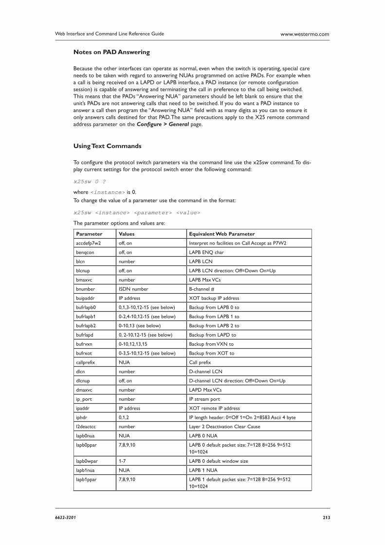
2136622-3201
Web Interface and Command Line Reference Guide www.westermo.com
Notes on PAD Answering
Because the other interfaces can operate as normal, even when the switch is operating, special care needs to be taken with regard to answering NUAs programmed on active PADs. For example when a call is being received on a LAPD or LAPB interface, a PAD instance (or remote configuration session) is capable of answering and terminating the call in preference to the call being switched. This means that the PADs “Answering NUA” parameters should be left blank to ensure that the unit’s PADs are not answering calls that need to be switched. If you do want a PAD instance to answer a call then program the “Answering NUA” field with as many digits as you can to ensure it only answers calls destined for that PAD. The same precautions apply to the X25 remote command address parameter on the Configure > General page.
Using Text Commands
To configure the protocol switch parameters via the command line use the x25sw command. To dis-play current settings for the protocol switch enter the following command:
x25sw 0 ?
where <instance> is 0.
To change the value of a parameter use the command in the format:
x25sw <instance> <parameter> <value>
The parameter options and values are:
Parameter Values Equivalent Web Parameter
accdefp7w2 off, on Interpret no facilities on Call Accept as P7W2
benqcon off, on LAPB ENQ char
blcn number LAPB LCN
blcnup off, on LAPB LCN direction: Off=Down On=Up
bmaxvc number LAPB Max VCs
bnumber ISDN number B-channel #
buipaddr IP address XOT backup IP address
bufrlapb0 0,1,3-10,12-15 (see below) Backup from LAPB 0 to
bufrlapb1 0-2,4-10,12-15 (see below) Backup from LAPB 1 to
bufrlapb2 0-10,13 (see below) Backup from LAPB 2 to
bufrlapd 0, 2-10,12-15 (see below) Backup from LAPD to
bufrvxn 0-10,12,13,15 Backup from VXN to
bufrxot 0-3,5-10,12-15 (see below) Backup from XOT to
callprefix NUA Call prefix
dlcn number D-channel LCN
dlcnup off, on D-channel LCN direction: Off=Down On=Up
dmaxvc number LAPD Max VCs
ip_port number IP stream port
ipaddr IP address XOT remote IP address
iphdr 0,1,2 IP length header: 0=Off 1=On 2=8583 Ascii 4 byte
l2deactcc number Layer 2 Deactivation Clear Cause
lapb0nua NUA LAPB 0 NUA
lapb0ppar 7,8,9,10 LAPB 0 default packet size: 7=128 8=256 9=512 10=1024
lapb0wpar 1-7 LAPB 0 default window size
lapb1nua NUA LAPB 1 NUA
lapb1ppar 7,8,9,10 LAPB 1 default packet size: 7=128 8=256 9=512 10=1024
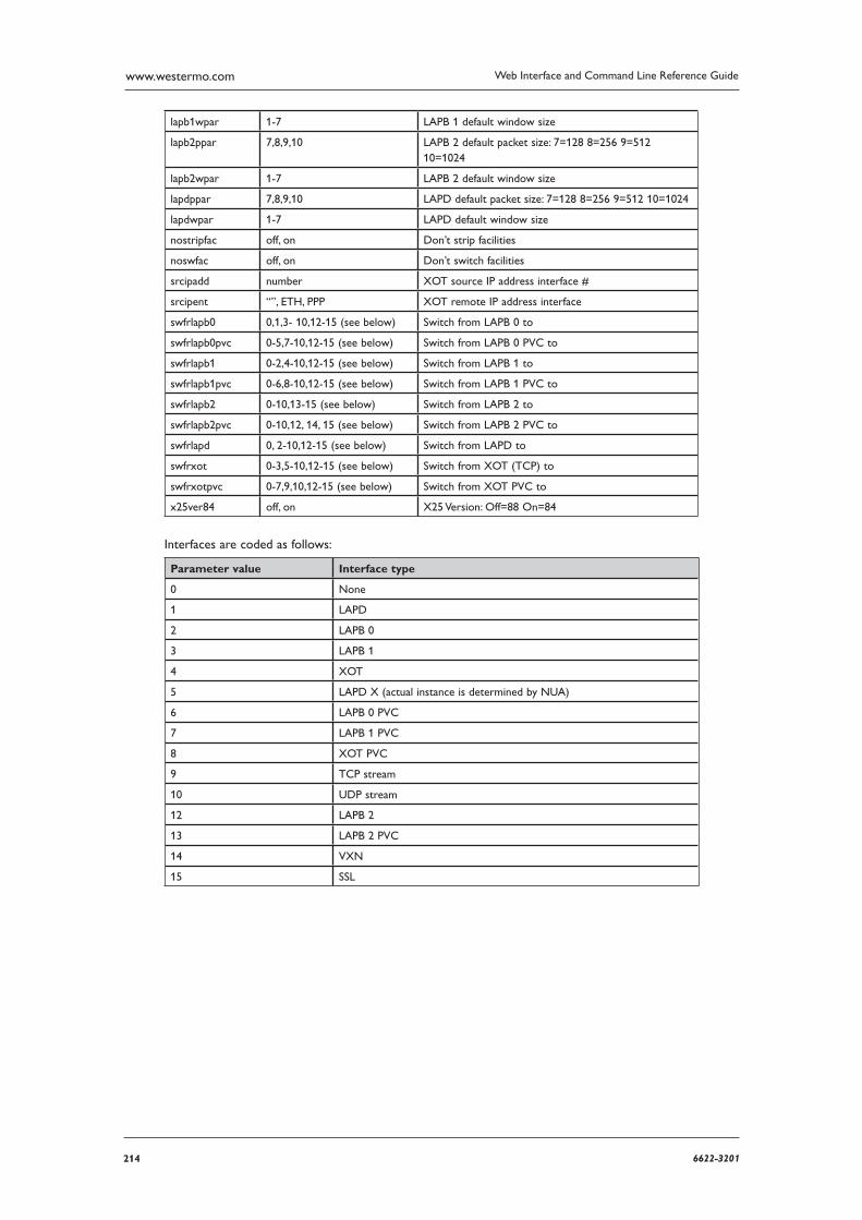
214 6622-3201
Web Interface and Command Line Reference Guidewww.westermo.com
lapb1wpar 1-7 LAPB 1 default window size
lapb2ppar 7,8,9,10 LAPB 2 default packet size: 7=128 8=256 9=512 10=1024
lapb2wpar 1-7 LAPB 2 default window size
lapdppar 7,8,9,10 LAPD default packet size: 7=128 8=256 9=512 10=1024
lapdwpar 1-7 LAPD default window size
nostripfac off, on Don’t strip facilities
noswfac off, on Don’t switch facilities
srcipadd number XOT source IP address interface #
srcipent “”, ETH, PPP XOT remote IP address interface
swfrlapb0 0,1,3- 10,12-15 (see below) Switch from LAPB 0 to
swfrlapb0pvc 0-5,7-10,12-15 (see below) Switch from LAPB 0 PVC to
swfrlapb1 0-2,4-10,12-15 (see below) Switch from LAPB 1 to
swfrlapb1pvc 0-6,8-10,12-15 (see below) Switch from LAPB 1 PVC to
swfrlapb2 0-10,13-15 (see below) Switch from LAPB 2 to
swfrlapb2pvc 0-10,12, 14, 15 (see below) Switch from LAPB 2 PVC to
swfrlapd 0, 2-10,12-15 (see below) Switch from LAPD to
swfrxot 0-3,5-10,12-15 (see below) Switch from XOT (TCP) to
swfrxotpvc 0-7,9,10,12-15 (see below) Switch from XOT PVC to
x25ver84 off, on X25 Version: Off=88 On=84
Interfaces are coded as follows:
Parameter value Interface type
0 None
1 LAPD
2 LAPB 0
3 LAPB 1
4 XOT
5 LAPD X (actual instance is determined by NUA)
6 LAPB 0 PVC
7 LAPB 1 PVC
8 XOT PVC
9 TCP stream
10 UDP stream
12 LAPB 2
13 LAPB 2 PVC
14 VXN
15 SSL
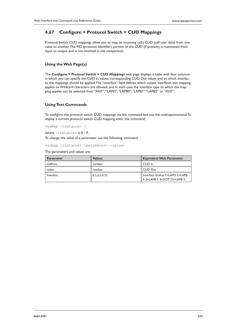
2156622-3201
Web Interface and Command Line Reference Guide www.westermo.com
Confi gure > Protocol Switch > CUD Mappings 4.67
Protocol Switch CUD mappings allow you to map an incoming call’s CUD (call user data) from one value to another. The PID (protocol identifier) portion of the CUD (if present) is maintained from input to output and is not involved in the comparison.
Using the Web Page(s)
The Configure > Protocol Switch > CUD Mappings web page displays a table with four columns in which you can specify the CUD In values, corresponding CUD Out values and to which interfac-es the mappings should be applied. The “interface” field defines which output interfaces this mapping applies to. Wildcard characters are allowed, and In each case the interface type to which the map-ping applies can be selected from “ANY”, “LAPD”, “LAPB0”, “LAPB1” “LAPB2” or “XOT”.
Using Text Commands
To configure the protocol switch CUD mappings via the command line use the cudmapcommand. To display a current protocol switch CUD mapping enter the command:
cudmap <instance> ?
where <instance> is 0 - 9.
To change the value of a parameter use the following command:
cudmap <instance> <parameter> <value>
The parameters and values are:
Parameter Values Equivalent Web Parameter
cudfrom number CUD In
cudto number CUD Out
Interface 0,1,2,3,4,12 Interface: 0=Any 1=LAPD 2=LAPB 0 3=LAPB 1 4=XOT 12=LAPB 2
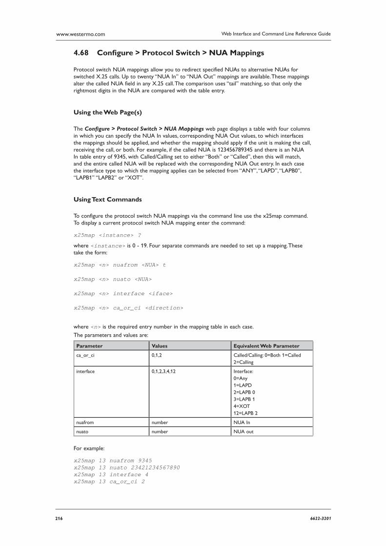
216 6622-3201
Web Interface and Command Line Reference Guidewww.westermo.com
Confi gure > Protocol Switch > NUA Mappings 4.68
Protocol switch NUA mappings allow you to redirect specified NUAs to alternative NUAs for switched X.25 calls. Up to twenty “NUA In” to “NUA Out” mappings are available. These mappings alter the called NUA field in any X.25 call. The comparison uses “tail” matching, so that only the rightmost digits in the NUA are compared with the table entry.
Using the Web Page(s)
The Configure > Protocol Switch > NUA Mappings web page displays a table with four columns in which you can specify the NUA In values, corresponding NUA Out values, to which interfaces the map pings should be applied, and whether the mapping should apply if the unit is making the call, receiving the call, or both. For example, if the called NUA is 123456789345 and there is an NUA In table entry of 9345, with Called/Calling set to either “Both” or “Called”, then this will match, and the entire called NUA will be replaced with the corresponding NUA Out entry. In each case the interface type to which the mapping applies can be selected from “ANY”, “LAPD”, “LAPB0”, “LAPB1” “LAPB2” or “XOT”.
Using Text Commands
To configure the protocol switch NUA mappings via the command line use the x25map command. To display a current protocol switch NUA mapping enter the command:
x25map <instance> ?
where <instance> is 0 - 19. Four separate commands are needed to set up a mapping. These take the form:
x25map <n> nuafrom <NUA> t
x25map <n> nuato <NUA>
x25map <n> interface <iface>
x25map <n> ca_or_ci <direction>
where <n> is the required entry number in the mapping table in each case.
The parameters and values are:
Parameter Values Equivalent Web Parameter
ca_or_ci 0,1,2 Called/Calling: 0=Both 1=Called 2=Calling
interface 0,1,2,3,4,12 Interface: 0=Any 1=LAPD 2=LAPB 0 3=LAPB 1 4=XOT 12=LAPB 2
nuafrom number NUA In
nuato number NUA out
For example:
x25map 13 nuafrom 9345 x25map 13 nuato 23421234567890 x25map 13 interface 4 x25map 13 ca_or_ci 2
2176622-3201
Web Interface and Command Line Reference Guide www.westermo.com
Confi gure > PSTN Modem 4.69
This page only appears on models which are fitted with an internal PSTN modem, e.g. MW3520 fitted with PSTN option. The Configure > PSTN Modem page provides access to the parameters that are used to configure internal PSTN modems. The parameters are identical to those for the Configure > PPP > External Modems > External Modemn pages except that there is no ASY port parameter. (The ASY port used by internal PSTN modems is predetermined).
Using the Web Page(s)
Refer to the Configure > PPP > External Modems > External Modemn section for a descrip-tion of the parameters used to set up an internal PSTN modem where this feature is available.
Using Text Commands
From the command line, use the modemcc command to configure or display the internal PSTN modem settings.
To display current settings for the internal modem enter the following command:
modemcc <instance> ?
where <instance> is 0 if your unit does NOT include a GPRS module, or 1 if it DOES include a W-WAN module.
To change the value of a parameter use the following command:
modemcc <instance> <parameter> <value>

218 6622-3201
Web Interface and Command Line Reference Guidewww.westermo.com
Confi gure > Quality of Service 4.70
Introduction 4.70.1
QOS (Quality of Service) provides the means to prioritise different types of IP traffic. It is generally used to ensure that low priority applications do not “hog” the available bandwidth to the detriment of those with a higher priority. For example, this might mean that EPOS transactions carried over XOT will be prioritised at a higher level than HTTP type traffic used for Internet access. Without some form of QOS all IP packets are treated as being equal so there is no discrimination between applications.
The IP packet Type of Service (TOS) field is used to indicate how a packet should be prioritised. Using the top 6 bits of the TOS field, a router that supports QOS will assign a DSCP (Differentiated Services Code Point) code to the packet. This may take place within the router when it receives the packet or another router closer to the packet source may have already assigned it. Based on the DSCP code, the router will assign the packet to a priority queue. There are currently four such queues for each PPP instance within the routers and each queue can be configured to behave in a particular way so that packets in that queue are prioritised for routing according to predefined rules.
There are two principle ways in which prioritisation may be effected:
A priority queue can be configured to allow packets to be routed at a specified data rate (pro viding that queues of higher priority are not already using the available bandwidth)
Weighted Random Early Dropping (WRED) of packets may be used as queues become busy in an attempt to get the TCP socket generating the packets to “back-off” its transmit timers, thus pre-venting the queue overflow (which would result in all subsequent packets being dropped)
QOS is a complex subject and can have a significant impact on the performance of your router. For detailed background information on QOS refer to RFC2474 (Definition of the Differentiated Services Field).
Basic Operation 4.70.2
In Westermo routers the classification of incoming IP packets for the purposes of QOS takes place within the firewall. The firewall allows the system administrator to assign a DSCP code to a packet with any combination of source/destination IP address/port and protocol. Details on how this is done are given in the section on Firewall scripts.
When the routing code within the unit receives an incoming packet, it directs it to the interface appli cable to that packet at the time (this is the case whether or not QOS is being applied). Just before the packet is sent to the interface, the QOS code intercepts the packet, and assigns it to one of the avail able priority queues (currently 10 per PPP instance), based on its DSCP value.
Each priority queue has a profile assigned to it. This profile specifies parameters such as the mini-mum transmit rate to attempt, maximum queue length, and WRED parameters.
The packet is then processed by the queue management code and either dropped, or placed in the queue for later transmission.
There are a number of configuration pages associated with QOS operation:
The Configure > Quality of Service folder contains pages for setting up the basic Quality of Service parameters including the DSCP mappings and the Q “profiles”
Each Configure > ETH and Configure > PPP instance page then contains a QOS sub-page which allows you to set up the specific QOS parameters to be used for those interfaces
2196622-3201
Web Interface and Command Line Reference Guide www.westermo.com
Confi gure > Quality of Service > DSCP Mappings Each Differentiated Services Code Point (DSCP) value must be mapped to a queue. These mappings are set-up using the DSCP Mappings configuration page.
Using the Web Page(s)
The Default parameter at the top of the page is used to set-up a default queue, which may be set to a value from Q0 to Q9. Below this is a list of valid DSCP codes, each of which may also be set to a value from Q0 to Q9 or Default.
When you change the Default DSCP queue setting, any DSCP codes that are set to Default will have their queue number changed.
Using Text Commands
From the command line, use the dscp command to configure or display the DSCP mappings. To dis-play a DSCP mapping enter the following command:
dscp <code> ?
where <code> is a valid DSCP code from 0 to 63, or 64 (see note below).
To change the value of a parameter use the following command:
dscp <code> q <value>
where <code> is a valid DSCP code and <value> is 0 to 9.
To set the default mapping value enter the command:
dscp 64 q <value>
where <value> is the default queue number required between 0 and 9.
Note: The dscp value of 64 is actually an invalid code and is only used to set up the default priority.
220 6622-3201
Web Interface and Command Line Reference Guidewww.westermo.com
Confi gure > Quality of Service > DSCP Mappings 4.71
Each Differentiated Services Code Point (DSCP) value must be mapped to a queue. These mappings are set-up using the DSCP Mappings configuration page.
Using the Web Page(s)
The Default parameter at the top of the page is used to set-up a default queue, which may be set to a value from Q0 to Q9. Below this is a list of valid DSCP codes, each of which may also be set to a value from Q0 to Q9 or Default.
When you change the Default DSCP queue setting, any DSCP codes that are set to Default will have their queue number changed.
Using Text Commands
From the command line, use the dscp command to configure or display the DSCP mappings. To dis-play a DSCP mapping enter the following command:
dscp <code> ?
where <code> is a valid DSCP code from 0 to 63, or 64 (see note below).
To change the value of a parameter use the following command:
dscp <code> q <value>
where <code> is a valid DSCP code and <value> is 0 to 9.
To set the default mapping value enter the command:
dscp 64 q <value>
where <value> is the default queue number required between 0 and 9.
Note: The dscp value of 64 is actually an invalid code and is only used to set up the default priority.
2216622-3201
Web Interface and Command Line Reference Guide www.westermo.com
Confi gure > Quality of Service > Q Profi les > Q Profi le n 4.72
You may define up to 12 distinct “queue profiles” that may then be assigned to the QOS queues as required. The queue profile determines how QOS queues with that profile assigned to them will behave.
Using the Web Page(s)
Each of the Queue Profile pages lists the following parameters:
Minimum Kbps:
This parameter is used to set the minimum data transfer rate in kilobits/sec that the unit will try to attain for this queue.
Maximum Kbps:
This parameter is used to set the maximum data transfer rate in kilobits/sec that the unit will try to attain for this queue. This means that if the unit determines that bandwidth is available to send more packets from a queue that has reached its Minimum Kbps setting, it will send more packets from that queue until the Maximum Kbps setting is reached.
Note that if you do not want this queue to provide more bandwidth than specified by the Minimum Kbps setting, this setting should be set to a value the same as or lower than the Minimum Kbps setting.
Maximum packet Q length:
This parameter specifies the maximum length of a queue (in terms of the number of packets in the queue). Any packets received that would cause the maximum length to be exceeded are dropped.
WRED minimum threshold:
This parameter specifies the minimum queue length threshold for using the WRED algorithm to drop packets. Once the queue length exceeds this value the WRED algorithm may cause packets to be dropped.
WRED maximum threshold:
This parameter specifies the maximum queue length threshold for using the WRED algorithm to drop packets. Once the queue length exceeds this value the WRED algorithm will cause all pack ets to be dropped.
WRED maximum drop probability (%)
This parameter is used to set the maximum % probability used by the WRED algorithm to deter mine whether or not a packet should be dropped when the queue length is approaching the WRED maximum threshold value.
Note: If the length of a queue is less than the WRED minimum threshold value, there is 0% chance that a packet will be dropped. When the queue length is between the WRED minimum and maximum values, the % chance of a packet being dropped increases linearly up to the WRED maximum drop probability %.
WRED Q length weight factor
This parameter specifies a weighting factor to be used in the WRED algorithm when calculating the weighted queue length. The weighted queue length is based upon the previous queue length and has a weighting factor that may be adjusted to provide different transmit characteristics. The actual formula used is:
new_length = (old_length × (1 – ½wfact)) + (cur_length × ½wfact)
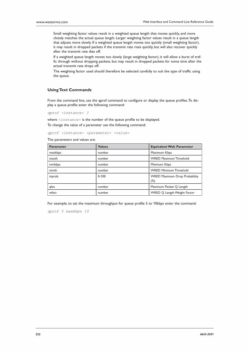
222 6622-3201
Web Interface and Command Line Reference Guidewww.westermo.com
Small weighting factor values result in a weighted queue length that moves quickly, and more closely matches the actual queue length. Larger weighting factor values result in a queue length that adjusts more slowly. If a weighted queue length moves too quickly (small weighting factor), it may result in dropped packets if the transmit rate rises quickly, but will also recover quickly after the transmit rate dies off.
If a weighted queue length moves too slowly (large weighting factor), it will allow a burst of traf-fic through without dropping packets, but may result in dropped packets for some time after the actual transmit rate drops off.
The weighting factor used should therefore be selected carefully to suit the type of traffic using the queue.
Using Text Commands
From the command line, use the qprof command to configure or display the queue profiles. To dis-play a queue profile enter the following command:
qprof <instance> ?
where <instance> is the number of the queue profile to be displayed.
To change the value of a parameter use the following command:
qprof <instance> <parameter> <value>
The parameters and values are:
Parameter Values Equivalent Web Parameter
maxkbps number Maximum Kbps
maxth number WRED Maximum Threshold
minkbps number Minimum Kbps
minth number WRED Minimum Threshold
mprob 0-100 WRED Maximum Drop Probability (%)
qlen number Maximum Packet Q Length
wfact number WRED Q Length Weight Factor
For example, to set the maximum throughput for queue profile 5 to 10kbps enter the command:
qprof 5 maxkbps 10
2236622-3201
Web Interface and Command Line Reference Guide www.westermo.com
Confi gure > RADIUS client 4.73
The RADIUS client may be used for authentication purposes at the start of remote command ses-sions, SSH sessions, FTP sessions and Web sessions. Depending on how the RADIUS client is config-ured, the unit may authenticate with one of two RADIUS servers, or may locally authenticate a user using the existing user tables configured on the unit.
When the unit has obtained the remote user username and password, the RADIUS client is used to pass this information (from the Username and Password attributes) to the specified RADIUS server for authorisation. The server should reply with either an ACCEPT or REJECT message.
The RADIUS client may be configured with up to two NAS’s (Network Access Servers). It may also have local authentication turned ON or OFF depending on system requirements.
When a user is authenticated, the configured RADIUS servers are contacted first. If a valid ACCEPT or REJECT message is received from the server, the user is allowed or denied access respectively. If no response is received from the first server, the second server is tried (if configured). If that server fails to respond, local authentication takes place unless this functionality is disabled. If both servers are unreachable, and local authorisation is disabled, all authentication attempts fail.
If a RADIUS server replies with a REPLY-MESSAGE attribute (18), this message will be displayed to the user after the login attempt and after any configured “post-banner”. The unit will then display a “Continue Y/N?” prompt to the user. If the user selects “N”, the remote session will be terminated. This applies to remote command sessions and SSH sessions only.
If the login attempt is successful and the server sends an IDLE-TIMEOUT attribute (28), the idle time specified will be assigned to the remote session. If no IDLE-TIMEOUT attribute is sent, the unit will apply the default idle timeout values to the session.
When the session starts and ends, the unit will send RADIUS accounting START/STOP messages to the configured server. Again, if no response is received from the primary accounting server, the sec-ondary server will be tried. No further action is taken if the second accounting server is unreach-able.
As a consequence of the fact that the unit has separate configurations for authorisation and accounting servers, it is possible to configure the unit to perform authorisation functions only, or accounting only, or both. An example of how this might be used could be to perform local authori-sations, but send accounting start/stop records to an accounting server.
Using the Web Page(s)
The Configure > RADIUS client > Client n page allows you to set the parameters for RADIUS client operation:
Primary authorisation NAS ID:
This is an identifier which is passed to the primary authorisation NAS and is used to identify the RADIUS client. The appropriate value will be supplied by the Primary authorisation NAS administrator.
Primary authorisation server IP address:
This is the IP address of the primary authorisation NAS.
Primary authorisation server password:
This password is supplied by the Primary authorisation NAS administrator and is used in conjunc tion with the Primary authorisation NAS ID to authenticate RADIUS packets.
Confirm primary authorisation server password:
This parameter is used to confirm the password value entered above.
Secondary authorisation NAS ID:
This is an identifier which is passed to the Secondary authorisation NAS and is used to identify the RADIUS client. The appropriate value will be supplied by the Secondary authorisation NAS administrator.
Secondary authorisation server IP address:
This is the IP address of the Secondary authorisation NAS server.
224 6622-3201
Web Interface and Command Line Reference Guidewww.westermo.com
Secondary authorisation server password:
This password is supplied by the Secondary authorisation NAS administrator and is used in con-junction with the Secondary authorisation NAS ID to authenticate RADIUS packets.
Confirm secondary authorisation server password:
This parameter is used to confirm the password value entered above.
Primary accounting NAS ID:
This is an identifier which is passed to the primary accounting NAS and is used to identify the RADIUS client. The appropriate value will be supplied by the Primary accounting NAS adminis-trator.
Primary accounting server IP address:
This is the IP address of the primary accounting NAS.
Primary accounting server password:
This password is supplied by the Primary accounting NAS administrator and is used in conjunc-tion with the Primary accounting NAS ID to authenticate RADIUS packets.
Confirm primary accounting server password:
This parameter is used to confirm the password value entered above.
Secondary accounting NAS ID:
This is an identifier which is passed to the Secondary accounting NAS and is used to identify the RADIUS client. The appropriate value will be supplied by the Secondary accounting NAS administrator.
Secondary accounting server IP address:
This password is supplied by the Secondary accounting NAS administrator and is used in conjunc tion with the Secondary accounting NAS ID to authenticate RADIUS packets.
Secondary accounting server password:
This password is supplied by the Secondary accounting NAS administrator and is used in conjunc tion with the Secondary accounting NAS ID to authenticate RADIUS packets.
Confirm secondary accounting server password:
This parameter is used to confirm the password value entered above.
Allow local authorisations:
Set this parameter to Yes to allow local authorisation if the RADIUS servers are unreachable or not configured. Select No to disable local authorisation.
The following parameters apply when communicating with any of the configured RADIUS servers:
Maximum re-transmits:
This parameter specifies the maximum number of times RADIUS data should be transmitted to the NAS before the negotiation is deemed to have failed.
Re-transmit interval (s):
This parameters specifies the interval between re-transmits in seconds.
Inactivity timeout (s):
If the negotiation procedure remains inactive for the length of time (in seconds) specified by this parameter it is deemed to have failed.
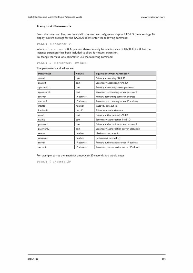
2256622-3201
Web Interface and Command Line Reference Guide www.westermo.com
Using Text Commands
From the command line, use the radcli command to configure or display RADIUS client settings. To display current settings for the RADIUS client enter the following command:
radcli <instance> ?
where <instance> is 0. At present there can only be one instance of RADIUS, i.e. 0, but the instance parameter has been included to allow for future expansion.
To change the value of a parameter use the following command:
radcli 0 <parameter> <value>
The parameters and values are:
Parameter Values Equivalent Web Parameter
anasid text Primary accounting NAS ID
anasid2 text Secondary accounting NAS ID
apassword text Primary accounting server password
apassword2 text Secondary accounting server password
aserver IP address Primary accounting server IP address
aserver2 IP address Secondary accounting server IP address
inactto number Inactivity timeout (s)
localauth on, off Allow local authorisations
nasid text Primary authorisation NAS ID
nasid2 text Secondary authorisation NAS ID
password text Primary authorisation server password
password2 text Secondary authorisation server password
retran number Maximum re-transmits
retranint number Re-transmit interval (s)
server IP address Primary authorisation server IP address
server2 IP address Secondary authorisation server IP address
For example, to set the inactivity timeout to 20 seconds you would enter:
radcli 0 inactto 20
226 6622-3201
Web Interface and Command Line Reference Guidewww.westermo.com
Confi gure > SMS Edit 4.74
Models with GPRS capability are capable of sending SMS alert messages. The SMS related param-eters on the Configure > Event Handler and Configure > W-WAN pages are used to configure the unit to send such alarms, but the Configure > SMS Edit page allows you to edit and send an SMS message manually.
Using the Web Page(s)
The Configure > SMS Edit page contains two text boxes and two buttons which operate as fol-lows:
To:
The To text box is used to enter the destination number for the SMS message.
Text:
Enter the message text that you want to send in the text box.
Send:
Click on the Send button to transmit the message.
Cancel:
Click on the Cancel button to clear the message
Using Text Commands
The sendsms command can be used to send an SMS message from the command line. The format of the command is as follows:
sendsms <phone number> “<message>”
where: <phone number> should be replaced with the phone number to send the message to including the international country code. (NB a + symbol should not be included.)
<message> should be replaced with the message to send which should be bounded by double quotation marks.
An example of sending a message to a UK phone number follows. The country code for the UK is 44, the NDC (National Destination Code) for the example message is 07974 and the number to dial for the example message is 123456.
sendsms 447974123456 “Test Message”
The possible responses to this command are as follows:
SMS send success
SMS send failure
SMS busy
2276622-3201
Web Interface and Command Line Reference Guide www.westermo.com
Confi gure > SMTP 4.75
The Simple Mail Transfer Protocol (SMTP) is widely used for the transmission of electronic mail. The unit incorporates a software module known as an SMTP Client which sends emails by establishing a connection to a remote computer that is running an SMTP server and then transmits emails using the SMTP protocol.
Using the Web Page(s)
The Configure > SMTP page allows you to set up the parameters for the SMTP client. This is used by the event logger when it has been configured to automatically generate email alert messages for events of a specified priority or higher.
Default reply address:
This address will be inserted into the email header if it is found that no reply address exists in the appropriate email template. If the email template contains an address in the Reply to: field it will override the Default reply address.
Use routing code to determine interface:
When this parameter is set to “Yes”, the routing code is used to determine the outbound inter-face, and that interface will determine the source IP address. When this parameter is “No”, the settings in the Interface and Interface # parameters determine the outbound interface and thus the source IP address.
Interface:
The Interface field is used to specify the type of interface to use. Either “PPP” or “Ethernet” may be selected.
Interface #:
The Interface # field is used to specify which instance of PPP to use for SMTP (normally PPP1).
Mail from address:
This parameter specifies the text to be inserted between the MAIL FROM braces command issued to the SMTP server. Most SMTP servers will accept an empty string, but some require that an address should be entered in this field. Consult your SMTP service provider for informa-tion on whether it is necessary to enter an address in this field.
Retry delay (s):
If the first attempt at sending an email fails then the unit will wait the specified amount of time (in seconds) before making another attempt. If this parameter is set to 0 then the unit will not make any further attempts to transmit the email.
Server address:
In order to allow the unit to send email messages, you will need to insert the address of your SMTP mail server for outgoing mail into the Server Address field, e.g. smtp.myisp.co.uk. You will also need to use the Configure > PPP pages to set the PPP dialout number to the correct number for your ISP.
Server port:
This is the TCP port number that the SMTP server listens on. It should not normally be neces-sary to change the default value of 25.
Attachment size limit (kb):
When sending an email message with an attachment, e.g. ANA.TXT, this parameter may be used to specify a maximum size for the attachment in kb. For example, setting the parameter to 250 would cause the unit to truncate each file attached to an email to 250kb before transmission. If the parameter is set to 0 the file size is not limited.
228 6622-3201
Web Interface and Command Line Reference Guidewww.westermo.com
SMTP AUTH Parameters
The following parameters are used to authenticate the unit against the SMTP server.
Username:
This is the password used to authenticate with the SMTP server, and is usually provided by your SMTP service provider.
Password:
This is the password used to authenticate with the SMTP server, and is usually provided by your SMTP service provider.
Confirm password:
This parameter is used to confirm the password value entered above.
Using Text Commands
From the command line, use the smtp command to configure or display SMTP settings. To display current settings for an SMTP instance enter the following command:
SMTP <instance> ?
where <instance> is 0. At present there can only be one instance of SMTP, i.e. 0, but the instance
parameter has been included to allow for future expansion.
To change the value of a parameter use the following command:
smtp 0 <parameter> <value>
The parameters and values are:
Parameter Values Equivalent Web Parameter
att_limit number Attachment size limit
epassword text None - this is the password in encrypted format. This param-eter is not configurable.
ll_add 0,1 Interface #
ll_ent PPP Interface
mail_from email address Mail From address
password text Password
port number Server port
reply_to email address Default reply address
retry_dly number Email retry delay
server text Server address
username text Username
userouting off, on Use routing code to determine interface
For example, to set the server address to smtp.myisp.net.uk, enter:
smtp 0 server smtp.myisp.net.uk
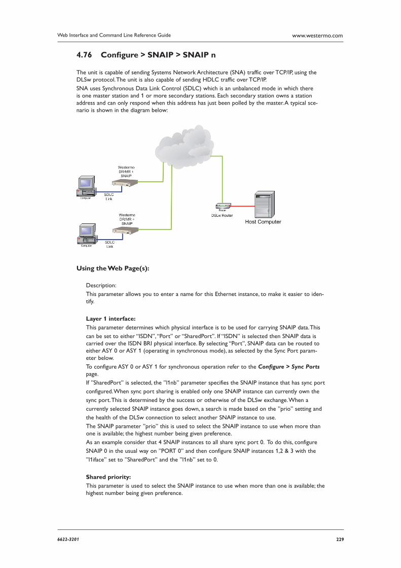
2296622-3201
Web Interface and Command Line Reference Guide www.westermo.com
Confi gure > SNAIP > SNAIP n 4.76
The unit is capable of sending Systems Network Architecture (SNA) traffic over TCP/IP, using the DLSw protocol. The unit is also capable of sending HDLC traffic over TCP/IP.
SNA uses Synchronous Data Link Control (SDLC) which is an unbalanced mode in which there is one master station and 1 or more secondary stations. Each secondary station owns a station address and can only respond when this address has just been polled by the master. A typical sce-nario is shown in the diagram below:
Using the Web Page(s):
Description:
This parameter allows you to enter a name for this Ethernet instance, to make it easier to iden-tify.
Layer 1 interface:
This parameter determines which physical interface is to be used for carrying SNAIP data. This
can be set to either “ISDN”, “Port” or “SharedPort”. If “ISDN” is selected then SNAIP data is carried over the ISDN BRI physical interface. By selecting “Port”, SNAIP data can be routed to either ASY 0 or ASY 1 (operating in synchronous mode), as selected by the Sync Port param-eter below.
To configure ASY 0 or ASY 1 for synchronous operation refer to the Configure > Sync Ports page.
If ”SharedPort” is selected, the ”l1nb” parameter specifies the SNAIP instance that has sync port
configured. When sync port sharing is enabled only one SNAIP instance can currently own the
sync port. This is determined by the success or otherwise of the DLSw exchange. When a
currently selected SNAIP instance goes down, a search is made based on the ”prio” setting and
the health of the DLSw connection to select another SNAIP instance to use.
The SNAIP parameter ”prio” this is used to select the SNAIP instance to use when more than one is available; the highest number being given preference.
As an example consider that 4 SNAIP instances to all share sync port 0. To do this, configure
SNAIP 0 in the usual way on ”PORT 0” and then configure SNAIP instances 1,2 & 3 with the
”l1iface” set to ”SharedPort” and the ”l1nb” set to 0.
Shared priority:
This parameter is used to select the SNAIP instance to use when more than one is available; the highest number being given preference.
230 6622-3201
Web Interface and Command Line Reference Guidewww.westermo.com
Sync port:
This parameter is only relevant if the Layer 1 Interface option above has been set to “Port” (as opposed to “ISDN”). It is used to select ASY0 or ASY1 as the layer 1 interface for SNAIP data.
Protocol:
This parameter sets the appropriate protocol for the interface. Choose “LAPB”, “SNA” for SDLC or “RAW” for raw mode in which all L2 frames are transmitted and received. You can also choose “RAW_NOHDR” for raw mode with no DLSw headers.
Answering:
If this parameter is set to “On”, the unit will answer incoming calls on the relevant LAPB ses-sion. To prevent the unit from answering incoming calls on this LAPB session set the option to “Off”. If Layer 1 interface is set to “Port” this parameter is not used.
MSN:
This parameter provides the filter for the ISDN Multiple Subscriber Numbering facility. It is blank by default but when set to an appropriate value with Answering “On” it will cause the unit to answer incoming calls only to ISDN numbers where the trailing digits match the MSN value. For example, setting the MSN parameter to 123 will prevent the unit from answering any calls to numbers that do not end in 123.
If Answering is “Off”, or Layer 1 interface is set to “Port”, this parameter is not used.
Sub-address:
This parameter provides the filter for the ISDN sub-addressing facility. It is blank by default but when set to an appropriate value, with Answering enabled, it will cause the unit to answer incoming ISDN calls only where the trailing digits of the sub address called match the Sub-address value. For example, setting the Sub-address to 123 will prevent the unit from answering any calls where the sub-address called does not end in 123.
If Answering is “Off”, or Layer 1 interface is set to “Port”, this parameter is not used.
Auto contact:
When set to “On” a TEST frame is not transmitted and the TEST response is not expected. Instead the unit assumes the station exists and proceed with the protocol as if the DLSw has received the TEST response.
DCD Toggle:
When this parameter is set to “On”, the DCD (Data Carrier Detect) output will turn off briefly each time the DLSw protocol enters the DISCONNECTED state. Thus any attached equipment that needs to will see signals changing state.
L1OOS:
This parameter causes the Sync port to be deaf and dumb (and have DCD low) while the connection with the WAN is down. This is so that some terminals don’t get too excited just because L2 is up and think everything else should be working (and go into a management error state).
SNA Parameters
Master:
Set this parameter to “On” if this unit is to be the Master in an unbalanced link, or “Off” for if the unit is to be a secondary station.
Polling Stations:
This parameter lists the station addresses on the data link as a comma-separated list of hex values (e.g. “c1,d1” for station addresses 0xc1 & 0xd1). This parameter is only applicable in SNA mode
2316622-3201
Web Interface and Command Line Reference Guide www.westermo.com
SAPs:
This parameter contains a list of SAP values which correspond to the station addresses.
DSAPs(blank=default):
This is the Destination SAP value, if left blank the SAP value above is used.
Polling Response(msec):
The poll time in msec (if the unit is the master in an unbalanced link).
Send Null XID:
When this parameter is set to “On” a null XID SSP message will be sent when the unit has just received or sent a REACH ACK SSP message.
XID Data:
This parameter is a hex string to define binary data and defines an XID SSP message that would be sent in response to a XIDFRAME SSP message being received.
Tx turn around time(msec):
This parameter specifies the time in milliseconds between receiving a frame from an outstation and transmission back to the same station. If this parameter is set to “0” this is disabled and the Westermo can respond immediately. The minimum non-zero value is 10ms.
DTE/DCE mode:
When this parameter is set to “DTE”, the unit will behave as Data Terminal Equipment with respect to the ISDN network. This is the default value and should not be changed for normal operation across the ISDN network. If your application involves using two units back-to-back, one of the units should have the DTE/DCE mode value set to “DCE” so that it acts as Data Communications Equipment.
RR timer (ms):
This is a standard LAPB/LAPD “Receiver Ready” timer. The default value is 10,000ms (10 sec-onds) and it should not normally be necessary to change this.
Inactivity timer (s):
This parameter may be used to specify the length of time (in seconds) before the link is discon-nected if there has been no activity. If this parameter is zero or not specified, then the inactivity timer is disabled. It is useful to set this to a short period of time (say 120 seconds) when an LAPB instance is being used over ISDN. This timer can be used as a backup hang-up timer thus saving ISDN call charges.
When LAPB is being used on a synchronous port, this parameter should normally be set to 0.
T1 timer (ms):
This is a standard LAPB timer. The default value is 1000 milliseconds (1 second) and under nor-mal circumstances, it should not be necessary to change it.
T200 timer (ms):
This is the standard LAPB re-transmit timer. The default value is 1000 milliseconds (1 second) and under normal circumstances, it should not be necessary to change it.
N400 counter:
This is the standard LAPB retry counter. The default value is 3 and it should not normally be necessary to change this.
Window size:
This parameter is used to set the X.25 window size. The value range is from 1 to 7 with the default being 7.
232 6622-3201
Web Interface and Command Line Reference Guidewww.westermo.com
SSP (WAN Iface) Parameters
VMAC:
Virtual MAC address. The host uses MAC addresses and SAP values as the addressing values to discriminate between circuits (in much the same way as an IP address & TCP port define an addressing point for a TCP socket). This is the MAC address that is reported as part of the DLSw protocol.
Peer VMAC:
The Virtual MAC address of the peer.
IP address:
The IP address of the peer DLSw unit.
Read port:
The read IP port. The TCP socket SNAIP listens on.
Write port:
The write IP port. This TCP socket will be opened by the unit if it needs to start the DLSw pro-tocol.
TCP socket inactivity timer (s):
This specifies the maximum period of inactivity (in seconds) that may occur before an open TCP/ IP socket is closed. The default value is 300 seconds (5 minutes) and should not normally require altering.
DLSw Role:
When this parameter is set to “Active”, and the unit is in SNA mode, then this DLSw switch will actively connect to the remote DLSw switch.
DLSw Ver:
This parameter controls the DLSw version to be used. Set to 0 (default) for version 1, set to 2 for version 2.
UDP Capable(ver 2):
This controls the UDP transmission of DLSw SSP packets. Reception is always enabled for ver-sion 2 support. If set to “OFF”, the state transitions occur just like DLSw version 1 but the unit will indicate it is version 2 capable.
Use 1 socket:
When this parameter is set to “On” then only one socket is used for both read and write data. This is useful if the unit is behind a NAT box and incoming connections are. This parameter can also be set to “Compatible”, in which mode both sockets are open to start with and then after a negotiation one of the sockets is dropped.
Include Mac Exclusivity Capability:
On or Off. Set this parameter to “On” in order to include the MAC exclusivity value in the capabilities exchange message.
Mac Exclusivity Value:
See above.
Source IP address interface:
By setting this parameter to either “PPP” or “ETH” (Ethernet), the source address used by SNAIP will match that of the Ethernet or PPP interface specified by the Source IP from interface # parameter below.
2336622-3201
Web Interface and Command Line Reference Guide www.westermo.com
Source IP address interface #:
See above.
DLSw Window:
This parameter is used to set the DLSw window size. The value range is from 10 to 100 with the default being 20.
Ignore Unsolicited Responses:
When this parameter is set to “On”, the unit will ignore unsolicited response frames.
Using Text Commands
From the command line, use the snaip command to display or configure SNAIP parameters. To dis-play the current settings for the SNAIP instance enter the following command:
snaip <instance> ?
where <instance> is the number of the SNAIP instance.
To change the value of a parameter use the following command:
snaip <instance> <parameter> <value>
The parameters and values are:
Parameter Value Equivalent Web Parameter
ans off, on Answering
autocontact off, on Auto contact
dcd_toggle off, on DCD Toggle
descr text Description
dlswwindow 10-100 DLSw Window
dsaps numbers DSAPs
dtemode 0,1 DTE/DCE mode: 0=DCE 1=DTE
inc_mac_exc off, on Include Mac Exclusivity Capability
ipaddr IP address IP address
iunsolresp off, on Ignore Unsolicited Responses
l1iface ISDN, Port, SharedPort Layer 1 interface
l1nb 0 Sync port
master off, on Master
msn number MSN
n400 number N400 counter
passive off, on DLSw Role: Off=Active On=Passive
peervmac MAC address Peer VMAC
pollresp number Polling Response(msec)
protocol LAPB, SNA, RAW, RAW_NOHDR Protocol
r_ipport number Read port
saps numbers SAPs
send_xid_null off, on Send Null XID
sock_inact number TCP socket inactivity timer (s)
srcipadd number Source IP address interface #
srcipent “”, PPP, ETH Source IP address interface
stations numbers Polling stations
sub IP address Sub-address
t1time number T1 timer (ms)
t200 number T200 timer (ms)
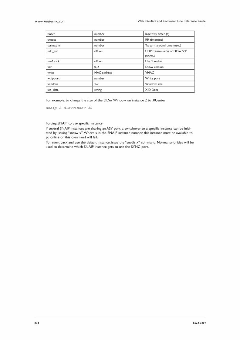
234 6622-3201
Web Interface and Command Line Reference Guidewww.westermo.com
tinact number Inactivity timer (s)
tnoact number RR timer(ms)
turntxtim number Tx turn around time(msec)
udp_cap off, on UDP transmission of DLSw SSP packets
use1sock off, on Use 1 socket
ver 0, 2 DLSw version
vmac MAC address VMAC
w_ipport number Write port
window 1-7 Window size
xid_data string XID Data
For example, to change the size of the DLSw Window on instance 2 to 30, enter:
snaip 2 dlswwindow 30
Forcing SNAIP to use specific instance
If several SNAIP instances are sharing an ASY port, a switchover to a specific instance can be initi-ated by issuing “snasw x”. Where x is the SNAIP instance number, this instance must be available to go online or this command will fail.
To revert back and use the default instance, issue the “snadis x” command. Normal priorities will be used to determine which SNAIP instance gets to use the SYNC port.
2356622-3201
Web Interface and Command Line Reference Guide www.westermo.com
Confi gure >SNMP 4.77
The unit supports Simple Network Management Protocol (SNMP) Versions 1, 2c & 3.
Creating SNMP MIB fi les
There are two Westermo MIBs.
One is generated on the unit after the firmware has been installed. This is done using the “mibprint” CLI command and the “MIBEXE” DOS tool which is available from the Technical Support team. This MIB changes with every firmware release as the firmware revision is embedded in the OIDs. This MIB provides access to most configuration and statistics.
The second is the “Westermo Monitor MIB” which is a standard MIB that gives access to various Westermo proprietary objects. The OIDs in this MIB do NOT change with each release although it is possible for new objects to be added to it. This MIB is available from the Technical Support team.
The standard MIBs supported are:
SNMP MIB (RFC3418)
Interfaces MIB (RFC2233)*
IP MIB (RFC2011)
IP Forwarding Table MIB (RFC2096)
TCP MIB (RFC2012)
UDP MIB (RFC2013)
VRRP MIB (RFC2787)
SNMP MPD MIB (RFC3412)
SNMP USM MIB (RFC3414)**
* The following groups/tables in RFC2233 are not supported:
ifXTable, ifStackTable, ifRcvAddressTable
** The following groups/tables in RFC3414 are not supported:
usmUserTable
Using the Web Page(s)
The Configure > SNMP page allows you to set up the global parameters for SNMP.
Enable SNMP v1:
Enables and disables SNMP Version 1.
Enable SNMP v2c:
Enables and disables SNMP Version 2c.
Enable SNMP v3:
Enables and disables SNMP Version 3.
Port:
Configures the UDP port number to use for the SNMP server, default is 161.
Engine ID:
Required for SNMPv3. A 24 character string, any trailing zero’s in this string making the value up to 24 characters can be omitted. A remote engine ID is required when an SNMP version 3 inform is configured. The remote engine ID is used to compute the security digest for authenti-cating and encrypting packets sent to a user on the remote host.
236 6622-3201
Web Interface and Command Line Reference Guidewww.westermo.com
MIB-II System Confi guration
Name:
The name or description of the router.
Contact:
The contact details of the person who administers the router.
Location:
The location of the router.
Trap Confi guration
Enable Enterprise Traps:
Enables and disables enterprise traps.
Enable Generic Traps:
Enables and disables generic traps.
Enable Authentication Failure Traps:
Enables and disables authentication failure traps.
Enable VRRP Traps:
Enables and disables VRRP traps.
Using Text Commands
From the command line, use the snmp command to configure or display SNMP settings. To display current settings for an SNMP instance enter the following command:
snmp <instance> ? where <instance> is 0. At present there can only be one instance of SNMP, i.e. 0, but the instance parameter has been included to allow for future expansion.
To change the value of a parameter use the following command:
snmp 0 <parameter> <value>
The parameters and values are:
Parameter Values Equivalent Web Parameter
authtraps 0,1 Enable Authentication Failure Traps
contact text Contact
engineid alpha-numeric Engine ID
enterprisetraps 0,1 Enable Enterprise Traps
generictraps 0,1 Enable Generic Traps
location text Location
name text Name
port number Port
v1enable 0,1 Enable SNMP v1
v2cenable 0,1 Enable SNMP v2c
v3enable 0,1 Enable SNMP v3
vrrptraps 0,1 Enable VRRP Traps
For example, to set the router location “Comms room - Leeds” enter:
snmp 0 location “Comms room - Leeds”
2376622-3201
Web Interface and Command Line Reference Guide www.westermo.com
Confi gure >SNMP Filters 4.78
Using the Web Page(s)
The Configure > SNMP Filters page allows you to block users access to a range of MIB items by using an Object ID prefix.
User
The user to apply restricted access to.
OID Prefix
The Object ID prefix for the range of objects in the MIB that the user is not allowed to view.
Using Text Commands
From the command line, use the snmpfilter command to configure or display SNMP Filter settings.
To display current settings for an SNMP instance enter the following command:
snmpfilter <instance> ?
where <instance> is 0-9.
To change the value of a parameter use the following command:
snmpfilter 0 <parameter> <value>
The parameters and values are:
Parameter Values Equivalent Web Parameter
user User
oid OID Prefix
For example, to set the filter on user 0 to HO-DaveJ enter:
snmpfilter 0 user HO-DaveJ
238 6622-3201
Web Interface and Command Line Reference Guidewww.westermo.com
Confi gure >SNMP > Trap Servers > Trap Server n 4.79
The Westermo router can send traps to servers running SNMP software on certain events. 2 trap servers can be configured.
Using the Web Page(s)
The Configure > SNMP > Trap Servers > Trap Server n page, is to configure the details of the trap servers that the unit will send traps to..
Trap Server IP Address:
The IP address of the server running the SNMP software.
Trap Server Port:
The UDP port number that the SNMP server is listening on. Default is 162.
SNMP Version:
This needs to be set to the same version that the servers SNMP software is running.
SNMP v1/v2c Trap Confi guration
Community:
The name of the SNMP community.
SNMP v3 Trap Confi guration
Trap Server Engine ID:
The SNMP server software Engine ID. This will be configured within the application.
Trap Server Security Name:
This needs to match a user from within Configure > SNMP > Users. This will be used to authenti cate the traps to the server.
Trap Server Security Level:
This security level is for the traps only and will over-ride the security level of the user config-ured above.
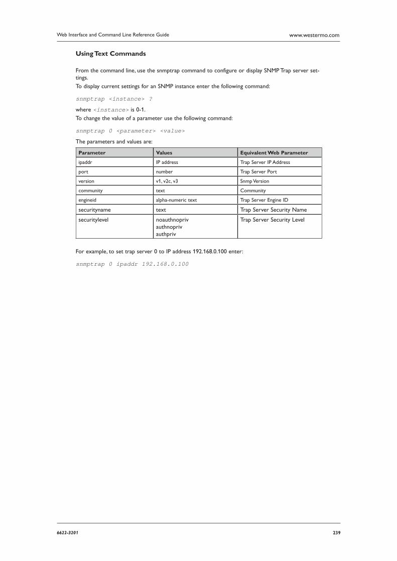
2396622-3201
Web Interface and Command Line Reference Guide www.westermo.com
Using Text Commands
From the command line, use the snmptrap command to configure or display SNMP Trap server set-tings.
To display current settings for an SNMP instance enter the following command:
snmptrap <instance> ?
where <instance> is 0-1.
To change the value of a parameter use the following command:
snmptrap 0 <parameter> <value>
The parameters and values are:
Parameter Values Equivalent Web Parameter
ipaddr IP address Trap Server IP Address
port number Trap Server Port
version v1, v2c, v3 Snmp Version
community text Community
engineid alpha-numeric text Trap Server Engine ID
securityname text Trap Server Security Name
securitylevel noauthnopriv authnopriv authpriv
Trap Server Security Level
For example, to set trap server 0 to IP address 192.168.0.100 enter:
snmptrap 0 ipaddr 192.168.0.100
240 6622-3201
Web Interface and Command Line Reference Guidewww.westermo.com
Confi gure >SNMP > Users > User n 4.80
Using the Web Page(s)
The Configure > SNMP > Users > User n page allows configuration of the user’s access level and whether authentication and privacy should be used when they connect to the unit.
SNMP v1/v2c User Confi guration
Community:
This specifies the comunity string for V1 & V2c SNMP packets.
SNMP v3 User Confi guration
Name:
The name of the SNMP user.
Authentication:
Specifies which authentication method should be used, none, MD5 or SHA1.
Authentication Password:
The users authentication password.
Privacy:
Specifies which privacy method should be used, none, DES or AES.
Privacy Password:
The users privacy password.
Access:
The access allowed on the unit, none, read only or read write.
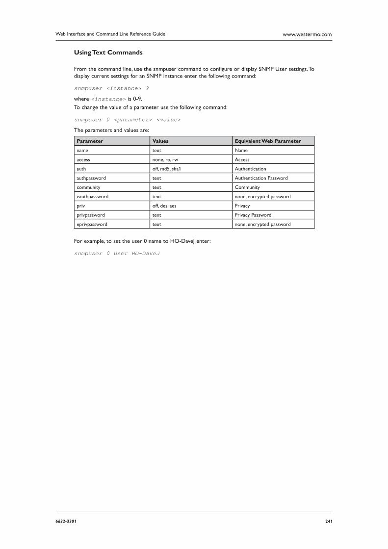
2416622-3201
Web Interface and Command Line Reference Guide www.westermo.com
Using Text Commands
From the command line, use the snmpuser command to configure or display SNMP User settings. To display current settings for an SNMP instance enter the following command:
snmpuser <instance> ?
where <instance> is 0-9.
To change the value of a parameter use the following command:
snmpuser 0 <parameter> <value>
The parameters and values are:
Parameter Values Equivalent Web Parameter
name text Name
access none, ro, rw Access
auth off, md5, sha1 Authentication
authpassword text Authentication Password
community text Community
eauthpassword text none, encrypted password
priv off, des, aes Privacy
privpassword text Privacy Password
eprivpassword text none, encrypted password
For example, to set the user 0 name to HO-DaveJ enter:
snmpuser 0 user HO-DaveJ
242 6622-3201
Web Interface and Command Line Reference Guidewww.westermo.com
Confi gure > STP 4.81
Rapid spanning tree protocol (RSTP) is a layer 2 protocol which ensures a loop free topology on a switched or bridged LAN whilst allowing redundant physical links between switches. When enabled, the router will use RSTP but this is backward compatible with STP.
The default priority of the router is 32768. This value is used if the priority parameter is left as zero. The granularity is 4096.
RSTP will not enable if the router is in “Port Isolate” mode. If an ethernet port has a hub group configured, RSTP will be disabled on that port.
Using the Web Page(s)
Enabled:
Enable or disable RSTP.
Priority:
Specifies the priority value, 0 is default.
Using Text Commands
From the command line, use the stp command to configure or display RSTP settings. To display cur-rent settings for an STP instance enter the following command:
stp <instance> ?
where <instance> is 0. At present there can only be one instance of RSTP, i.e. 0, but the instance parameter has been included to allow for future expansion.
To change the value of a parameter use the following command:
stp 0 <parameter> <value>
The parameters and values are:
Parameter Values Equivalent Web Parameter
enabled off, on Enabled
prio 0 - 65535 Priority
For example, to enable RSTP, enter:
stp 0 enable on
Port status
To view the status of RSTP/STP on a router’s ethernet ports, the following commands can be used.
stp show
Port 0, Designated, Forwarding ctrl2:0x6
Port 1, Backup, Discarding ctrl2:0x1
Port 2, Backup, Discarding ctrl2:0x1
Port 3, Disabled, Discarding ctrl2:0x1
2436622-3201
Web Interface and Command Line Reference Guide www.westermo.com
The port roles are:
Disabled: There is nothing physically connected to this ethernet port.
Root: A forwarding port that has been elected for the spanning-tree topology, towards the root bridge.
Designated: A forwarding port for every LAN segment, away from the root bridge.
Alternate: An alternate path to the root bridge. This path is different than using the root port.
Backup: A backup/redundant path to a segment where another bridge port already connects.
The STP port states are:
Disabled: The port is not functioning and cant send or receive data.
Listening: The port is sending and receiving BPDU’s and participates in the election process of the root bridge. Ethernet frames are discarded.
Learning: The port does not yet forward frames but it does learn source addresses from frames received and adds them to the MAC address table.
Forwarding: The port receiving and sending data, normal operation. STP still monitors incoming BPDU’s that would indicate it should return to the blocking state to prevent a loop.
Blocking: A port that would cause a switching loop, no user data is sent or received but it may go into forwarding mode if the other links in use were to fail and the spanning tree algorithm deter-mines the port may transition to the forwarding state. BPDU data is still received in blocking state.
The RSTP port states are:
Learning: The port does not yet forward frames but it does learn source addresses from frames received and adds them to the MAC address table. The port processes BPDU’s.
Forwarding: The port receiving and sending data, normal operation. STP still monitors incoming BPDU’s that would indicate it should return to the blocking state to prevent a loop.
Discarding: A port that would cause a switching loop, no user data is sent or received but it may go into forwarding mode if the other links in use were to fail and the spanning tree algorithm deter-mines the port may transition to the forwarding state. BPDU data is still received in blocking state.
244 6622-3201
Web Interface and Command Line Reference Guidewww.westermo.com
Confi gure > NTP 4.82
NTP is much more accurate than SNTP, with NTP an accuracy of 200 microseconds (1/5000 sec-ond) can be achieved. The NTP functionality is in accordance with RFC1305.
Up to 4 remote peers can be configured, all the peers are polled at intervals and the “best” peer is selected for using as the time source.
SNTP should be configured prior to using NTP. The router will calculate the accuracy of the NTP time servers over a period of time, once the drift compensation is calculated the NTP client will be used. The drift compensation value will be stored in NVRAM and written to the config.da0 file, if the router looses power or is rebooted it will not need to re-calculate the accuracy of the NTP servers again. The compensation value is constantly monitored to ensure it remains correct.
Using the Web Page(s)
The Configure > NTP page allows you to set up the parameters for the NTP client.
Operational Mode:
Specifies the mode, either SNTP or NTP. If SNTP is used the accuracy of around 1 second is achieved. If NTP is used 200 microsecond accuracy can be achieved.
Initial drift compensation:
If known, the drift compensation can be entered. Otherwise the router will calculate this value of a period of time. Once calculated, this field will have the drift value filled in.
NTP host:
This is the IP address or host name of the first NTP server you wish to use.
Broadcast mode:
When enabled, the NTP client will operate in a different manner. Rather than sending out an NTP client message and expecting a reply, the NTP module will send out a broadcast mode packet to the IP address configured in ’NTP host’ field. The broadcast interval will be deter-mined by the value of ’Minimum poll interval’.
Minimum poll interval:
The minimum polling interval between updates sent by the router. The value is actually the time in seconds represented as a power of 2. i.e. a value of ’4’ means that the minimum poll interval is 2^4 = 16 seconds.
Maximum poll interval:
The maximum polling interval between updates sent by the router. The value is actually the time in seconds represented as a power of 2. i.e. a value of ’4’ means that the minimum poll interval is 2^4 = 16 seconds.
2456622-3201
Web Interface and Command Line Reference Guide www.westermo.com
Using Text Commands
From the command line, use the ntp command to configure or display NTP settings. To display cur-rent settings for an NTP instance enter the following command:
ntp <instance> ?
where <instance> is 0. At present there can only be one instance of NTP, i.e. 0, but the instance
parameter has been included to allow for future expansion.
To change the value of a parameter use the following command:
ntp 0 <parameter> <value>
The parameters and values are:
Parameter Values Equivalent Web Parameter
enabled OFF, ON Operational mode OFF = SNTP ONLY ON = NTP enabled
driftppm number Initial drift compensation (ppm)
server IP address NTP host
bcast OFF, ON Broadcast mode
minpoll number Minimum poll interval
maxpoll number Maximum poll interval
server<n> IP address NTP host 2, 3 or 4
bcast<n> OFF, ON Broadcast mode 2, 3 or 4
minpoll<n> number Minimum poll interval 2, 3 or 4
maxpoll<n> number Maximum poll interval 2, 3 or 4
For example, to set the first server address to 172.16.20.10, enter:
ntp 0 server 172.16.20.10
246 6622-3201
Web Interface and Command Line Reference Guidewww.westermo.com
Confi gure > SNTP 4.83
The unit supports the Simple Network Time Protocol (SNTP). This protocol is used to synchronise the unit’s internal clock with the time and date information provided by a remote computer. The remote computer must be running an SNTP/NTP server in order to obtain this information.
Using the Web Page(s)
The Configure > SNTP page allows you to set up the parameters for the SNTP client. The SNTP client can be used to update the unit’s real time clock when it is configured to connect to the Internet (or a private IP network with an SNTP/NTP server).
Operational Mode:
Specifies the mode, either SNTP or NTP. If SNTP is used the accuracy of around 1 second is achieved. If NTP is used 200 microsecond accuracy can be achieved.
NTP host:
This is the IP address or host name of the NTP server you wish to use.
Interval (hrs):
This is the interval (in hours) at which the SNTP client will attempt to update the real time clock.
Randomised interval (s):
This parameter takes of the form [min,max] to define the SNTP interval between SNTP requests. A random time between min and max is selected after each SNTP update. e.g. 500,5000
Check on power-up:
Specifies whether the unit will attempt to connect to the NTP server every time the unit is booted.
Offset from GMT (hrs):
This parameter should be set to + or - the number of hours the unit’s time should be ahead or behind Greenwich Mean Time.
Daylight Savings Parameters
The following parameters are used to adjust the time value received from the SNTP server to take account of local daylight saving periods.
Daylight savings start month:
This is the month in which the daylight saving period starts.
Daylight savings start day:
This is the date in the month in which the daylight saving period starts.
Daylight savings start hour:
This is the hour on the day in which the daylight saving period starts.
Daylight savings stop month:
This is the month in which the daylight saving period ends.
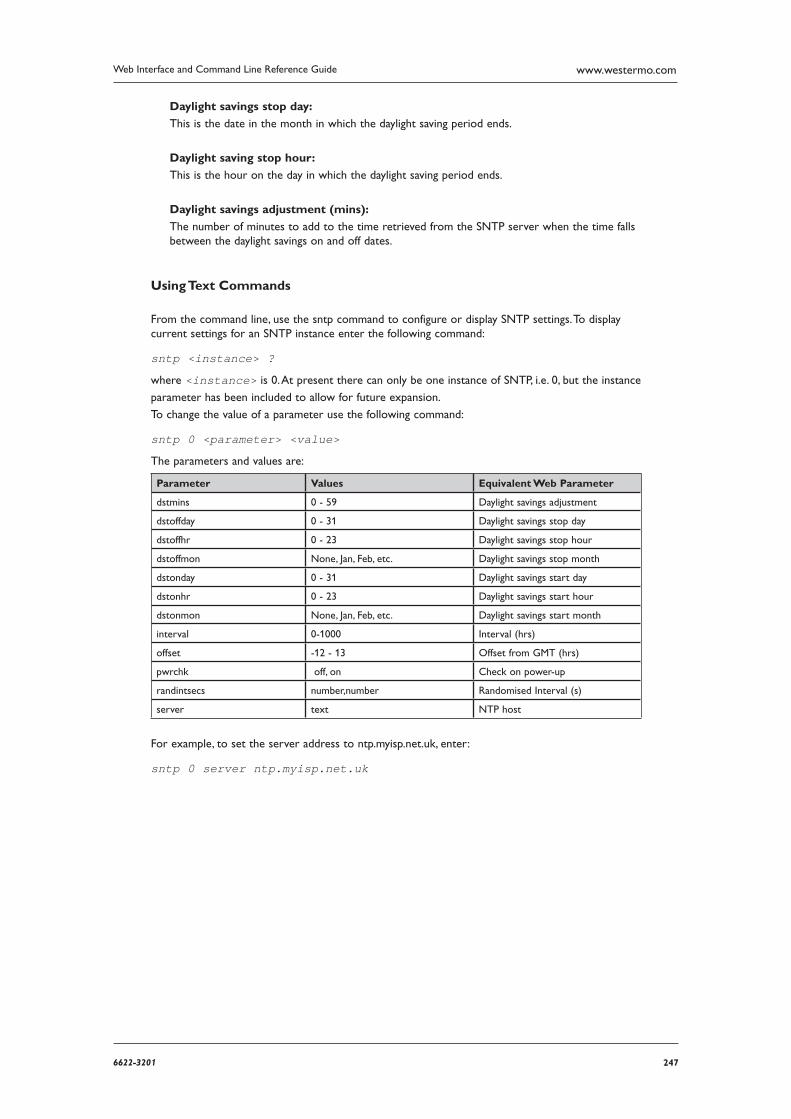
2476622-3201
Web Interface and Command Line Reference Guide www.westermo.com
Daylight savings stop day:
This is the date in the month in which the daylight saving period ends.
Daylight saving stop hour:
This is the hour on the day in which the daylight saving period ends.
Daylight savings adjustment (mins):
The number of minutes to add to the time retrieved from the SNTP server when the time falls between the daylight savings on and off dates.
Using Text Commands
From the command line, use the sntp command to configure or display SNTP settings. To display current settings for an SNTP instance enter the following command:
sntp <instance> ?
where <instance> is 0. At present there can only be one instance of SNTP, i.e. 0, but the instance
parameter has been included to allow for future expansion.
To change the value of a parameter use the following command:
sntp 0 <parameter> <value>
The parameters and values are:
Parameter Values Equivalent Web Parameter
dstmins 0 - 59 Daylight savings adjustment
dstoffday 0 - 31 Daylight savings stop day
dstoffhr 0 - 23 Daylight savings stop hour
dstoffmon None, Jan, Feb, etc. Daylight savings stop month
dstonday 0 - 31 Daylight savings start day
dstonhr 0 - 23 Daylight savings start hour
dstonmon None, Jan, Feb, etc. Daylight savings start month
interval 0-1000 Interval (hrs)
offset -12 - 13 Offset from GMT (hrs)
pwrchk off, on Check on power-up
randintsecs number,number Randomised Interval (s)
server text NTP host
For example, to set the server address to ntp.myisp.net.uk, enter:
sntp 0 server ntp.myisp.net.uk
248 6622-3201
Web Interface and Command Line Reference Guidewww.westermo.com
Confi gure > SSH server 4.84
The SSH (Secure Shell) server allows remote peers to access the unit over a secure TCP connec-tion using a suitable SSH client. The SSH server provides a Telnet-like interface and secure file trans-fer capability.
SSH uses a number of keys during a session. The host keys are used for authentication purposes. Keys unique to each SSH session are also generated, and are used for encryption/authentication purposes.
The unit supports SSH V1.5 and SSH V2. The host key file format differs for each version, but there would normally only be one host key for each version. For this reason, the unit allows the user to configure two host key files. These keys may be changed from time to time, specifically if it is sus-pected that the key has become compromised. Because the host keys need to be secure, it is highly recommended to store the files on the unit FLASH using filenames prefixed with “priv”, which makes it impossible to read the file using any of the normal methods (e.g. FTP). It is possible (using the genkey command) to create host keys in either format for use with SSH. Using this utility, it is not necessary to have the host key files present on any other storage device (thus providing an additional level of security). Refer to the section on Certificates for information on how to generate a private key file.
Unlike the Telnet server, it is possible to configure the number of SSH server sockets that listen for new SSH connections.
It is possible to configure which authentication methods are able to be used in an SSH session and the preferred selection order. The unit currently supports MD5, SHA1, MD5-96, and SHA1-96. If required, a public/private key pair can be used for authentication.
The unit currently only supports the 3DES and 3DES-CBC cipher methods.
DEFLATE compression is also supported. If this is enabled and negotiated, SSH packets are first compressed before being encrypted and delivered to the remote via the TCP socket.
Note: The SSH server supports the SCP file copy protocol but does NOT support filename wild cards. Addi tionally, there is no support at present for secure FTP or port forwarding.
Using the Web Page(s)
The Configure > SSH server page allows you to set the parameters for SSH server operation:
Server Port:
The TCP port number that the SSH server will use to listen for incoming connections.
Number of listening sockets:
This parameter specifies the number of sockets listening for new SSH connections on port 22 (the standard SSH port).
Version 1.5 enabled:
When set to “Yes”, this parameter allows the server to negotiate SSH V1.5. The unit must also have an SSH V1 key present and the filename entered into the SSH configuration.
Version 2.0 enabled:
When set to “Yes”, this parameter allows the server to negotiate SSH V2.0. The unit must also have an SSH V2 key present and the filename entered into the SSH configuration.
Host key #1 filename:
This is the filename of either an SSH V1 host key or an SSH V2 host key. It is highly recommend-ed that the filename be prefixed with “priv” to ensure that the key is not compromised. This key is generated on the Configure > Certificates > Utilities page.
2496622-3201
Web Interface and Command Line Reference Guide www.westermo.com
Host key #2 filename:
This is the filename of either an SSH V1 host key or an SSH V2 host key. It is highly recommend-ed that the filename be prefixed with “priv” to ensure that the key is not compromised. This key is generated on the Configure > Certificates > Utilities page
Note: The Host key filenames cannot be more than 12 characters in length. This includes the exten-sion and extension separator “.”.
Maximum login time (secs):
This parameter specifies the maximum length of time in seconds that a user is allowed to suc-cessfully complete the login procedure once the SSH socket has been opened. The socket is closed if the user has not completed a successful login within this period.
Maximum login attempts:
This is the maximum number of login attempts allowed before the SSH socket will be closed.
Compression level:
SSH uses the DEFLATE compression algorithm. This parameter is used to set the desired level of compression. Higher values may result in better compression but will require more CPU time within the router. If the value is set to 0, compression is disabled.
Port forwarding enabled:
When enabled and used with SSH client software (such as PuTTY) that has port forwarding functionality, different ports other than 23 can be forwarded to the router. For example, once the SSH tunnel is connected, http port 80 traffic can sent securely to the router.
V1 Options
Server key bits:
During the initialisation of an SSH session, the server sends its host key and a server key (which should be of a different size to the host key). The unit generates this key automatically but the length of the server key is determined by this parameter. If, when you set this value, it is too similar to the length of the host key, the unit will automatically adjust the selected value so that the key sizes are significantly different.
V2 Options
Actively start key exchange:
Some SSH clients wait for the server to initiate the key exchange process when a new SSH ses-sion is started unless they have data to send to the server, in which case they will initiate the key exchange themselves. If this parameter is set to “Yes”, the unit will automatically initiate a key exchange without waiting for the client.
Rekey Kbytes:
With SSH V2 it is possible to negotiate new encryption keys after they have been used to encrypt a specified amount of data. This parameter is used to specify the amount of data that passed over an encrypted link before a new set of keys must be negotiated. When the param-eter is set to 0 new keys are not negotiated.
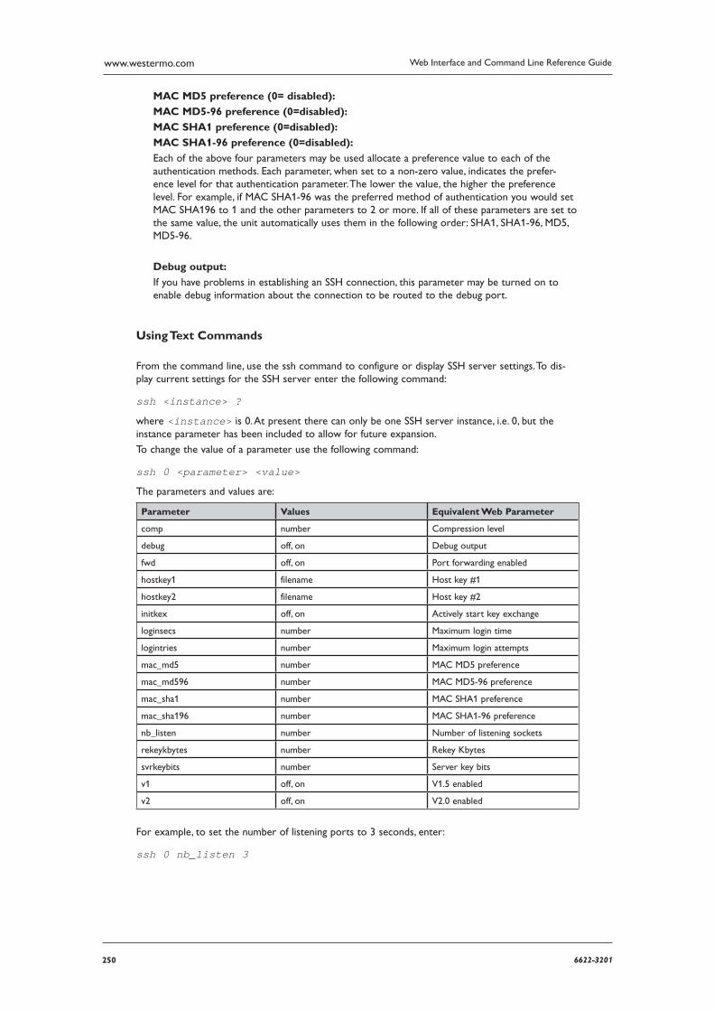
250 6622-3201
Web Interface and Command Line Reference Guidewww.westermo.com
MAC MD5 preference (0= disabled):
MAC MD5-96 preference (0=disabled):
MAC SHA1 preference (0=disabled):
MAC SHA1-96 preference (0=disabled):
Each of the above four parameters may be used allocate a preference value to each of the authentication methods. Each parameter, when set to a non-zero value, indicates the prefer-ence level for that authentication parameter. The lower the value, the higher the preference level. For example, if MAC SHA1-96 was the preferred method of authentication you would set MAC SHA1 96 to 1 and the other parameters to 2 or more. If all of these parameters are set to the same value, the unit automatically uses them in the following order: SHA1, SHA1-96, MD5, MD5-96.
Debug output:
If you have problems in establishing an SSH connection, this parameter may be turned on to enable debug information about the connection to be routed to the debug port.
Using Text Commands
From the command line, use the ssh command to configure or display SSH server settings. To dis-play current settings for the SSH server enter the following command:
ssh <instance> ?
where <instance> is 0. At present there can only be one SSH server instance, i.e. 0, but the instance parameter has been included to allow for future expansion.
To change the value of a parameter use the following command:
ssh 0 <parameter> <value>
The parameters and values are:
Parameter Values Equivalent Web Parameter
comp number Compression level
debug off, on Debug output
fwd off, on Port forwarding enabled
hostkey1 filename Host key #1
hostkey2 filename Host key #2
initkex off, on Actively start key exchange
loginsecs number Maximum login time
logintries number Maximum login attempts
mac_md5 number MAC MD5 preference
mac_md596 number MAC MD5-96 preference
mac_sha1 number MAC SHA1 preference
mac_sha196 number MAC SHA1-96 preference
nb_listen number Number of listening sockets
rekeykbytes number Rekey Kbytes
svrkeybits number Server key bits
v1 off, on V1.5 enabled
v2 off, on V2.0 enabled
For example, to set the number of listening ports to 3 seconds, enter:
ssh 0 nb_listen 3
2516622-3201
Web Interface and Command Line Reference Guide www.westermo.com
Complete SSH Confi guration 4.84.1
In order to completely configure SSH, you will need to generate an SSH version 1 key and an SSH version 2 key, and then configure the unit to use these keys as the host keys. The sections below show how to do this using both the Web interface and the Command Line Interface.
Note: SSH version 2 is more secure than SSH version 1. For that reason, Westermo recommends the use of SSH version 2 keys wherever possible. However, since some SSH clients may require version 1 keys, the unit supports both SSH version 1 and SSH version 2.
Note: The key filename cannot be more than 12 characters in length. This includes the extension and extension separator “.”.
Using the Web Interface
On the Configure > Certificates > Utilities page, select the size for the key file from the drop-down list. The larger the size of the key file, the more secure it will be.
Enter the name for the key file in the Private key filename field. The filename should be pre fixed with “priv” and have a “.pem” extension, e.g. “privssh1.pem”.
Check the Save in SSHv1 format checkbox in order to generate an SSH version 1 key. Click the Generate Private Key button in order to create the private key file. The key file will be stored in the unit’s flash memory.
Repeat steps 1 to 3 in order to generate the second key. However, ensure the Save in SSHv1 for-mat checkbox is cleared in order to generate an SSH version 2 key. Give the second key a different name than the first key. Remember to prefix the file name with “priv” and give it a “.pem” extension, e.g. “privssh2.pem”.
On the Configure > SSH server page, enter the filename of the key generated in step 3 in the Host key #1 filename field, and the filename of the key generated in step 4 in the Host key #2 filename field.
Save the configuration by first clicking the OK button at the bottom of the page, and then click ing the save to flash link.
Using the Command Line Interface
Generate the SSH V1 private key using the genkey command in the format: genkey <size> <filename> -ssh1, where: <size> is one of 384, 512, 768, 1024, 1536, or 2048, and <filename> is the name for the private key file. The filename should be prefixed with “priv” and have a “.pem” extension, e.g. “privssh1.pem”. For example, genkey 1024 privssh1.pem
Generate the SSH V2 private key using the genkey command. For example: genkey 1024 privssh2.pem
Set the first private key as the SSH Host key #1 using the ssh command in the format: ssh 0 hostkey1 <filename> where <filename> is the name of the private key file gen-erated in step 1. For example, ssh 0 hostkey1 privssh1.pem
Set the second private key as the SSH Host key #2 using the ssh command. For example: ssh 0 hostkey2 privssh2.pem Save the configuration: config 0 save

252 6622-3201
Web Interface and Command Line Reference Guidewww.westermo.com
SSH Authentication with a public/private keypair. 4.84.2
Once SSH access has been configured and confirmed to be working, RSA key pair authentication can be added and used to replace password authentication.
This process will involve the use of PuTTYgen to create public & private keys. Please see the Technical Notes section of our website for full details on how to perform this procedure.
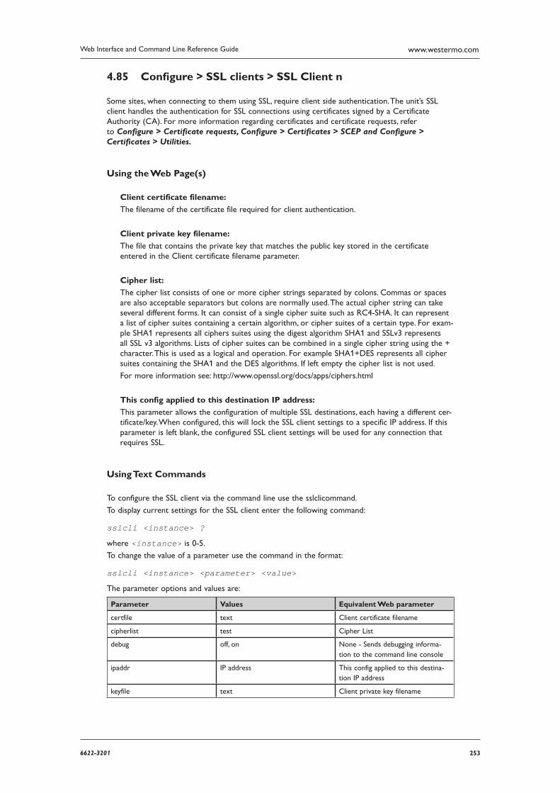
2536622-3201
Web Interface and Command Line Reference Guide www.westermo.com
Confi gure > SSL clients > SSL Client n 4.85
Some sites, when connecting to them using SSL, require client side authentication. The unit’s SSL client handles the authentication for SSL connections using certificates signed by a Certificate Authority (CA). For more information regarding certificates and certificate requests, refer to Configure > Certificate requests, Configure > Certificates > SCEP and Configure > Certificates > Utilities.
Using the Web Page(s)
Client certificate filename:
The filename of the certificate file required for client authentication.
Client private key filename:
The file that contains the private key that matches the public key stored in the certificate entered in the Client certificate filename parameter.
Cipher list:
The cipher list consists of one or more cipher strings separated by colons. Commas or spaces are also acceptable separators but colons are normally used. The actual cipher string can take several different forms. It can consist of a single cipher suite such as RC4-SHA. It can represent a list of cipher suites containing a certain algorithm, or cipher suites of a certain type. For exam-ple SHA1 represents all ciphers suites using the digest algorithm SHA1 and SSLv3 represents all SSL v3 algorithms. Lists of cipher suites can be combined in a single cipher string using the + character. This is used as a logical and operation. For example SHA1+DES represents all cipher suites containing the SHA1 and the DES algorithms. If left empty the cipher list is not used.
For more information see: http://www.openssl.org/docs/apps/ciphers.html
This config applied to this destination IP address:
This parameter allows the configuration of multiple SSL destinations, each having a different cer-tificate/key. When configured, this will lock the SSL client settings to a specific IP address. If this parameter is left blank, the configured SSL client settings will be used for any connection that requires SSL.
Using Text Commands
To configure the SSL client via the command line use the sslclicommand.
To display current settings for the SSL client enter the following command:
sslcli <instance> ?
where <instance> is 0-5.
To change the value of a parameter use the command in the format:
sslcli <instance> <parameter> <value>
The parameter options and values are:
Parameter Values Equivalent Web parameter
certfile text Client certificate filename
cipherlist test Cipher List
debug off, on None - Sends debugging informa-tion to the command line console
ipaddr IP address This config applied to this destina-tion IP address
keyfile text Client private key filename
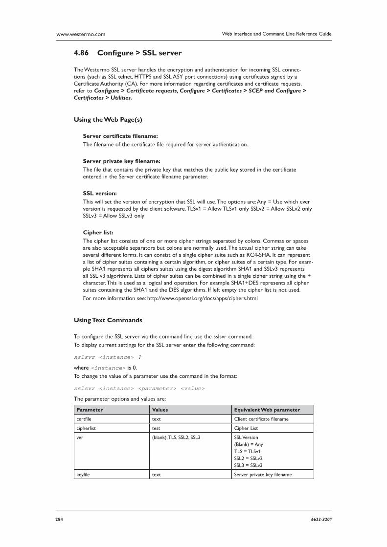
254 6622-3201
Web Interface and Command Line Reference Guidewww.westermo.com
Confi gure > SSL server 4.86
The Westermo SSL server handles the encryption and authentication for incoming SSL connec-tions (such as SSL telnet, HTTPS and SSL ASY port connections) using certificates signed by a Certificate Authority (CA). For more information regarding certificates and certificate requests, refer to Configure > Certificate requests, Configure > Certificates > SCEP and Configure > Certificates > Utilities.
Using the Web Page(s)
Server certificate filename:
The filename of the certificate file required for server authentication.
Server private key filename:
The file that contains the private key that matches the public key stored in the certificate entered in the Server certificate filename parameter.
SSL version:
This will set the version of encryption that SSL will use. The options are: Any = Use which ever version is requested by the client software. TLSv1 = Allow TLSv1 only SSLv2 = Allow SSLv2 only SSLv3 = Allow SSLv3 only
Cipher list:
The cipher list consists of one or more cipher strings separated by colons. Commas or spaces are also acceptable separators but colons are normally used. The actual cipher string can take several different forms. It can consist of a single cipher suite such as RC4-SHA. It can represent a list of cipher suites containing a certain algorithm, or cipher suites of a certain type. For exam-ple SHA1 represents all ciphers suites using the digest algorithm SHA1 and SSLv3 represents all SSL v3 algorithms. Lists of cipher suites can be combined in a single cipher string using the + character. This is used as a logical and operation. For example SHA1+DES represents all cipher suites containing the SHA1 and the DES algorithms. If left empty the cipher list is not used.
For more information see: http://www.openssl.org/docs/apps/ciphers.html
Using Text Commands
To configure the SSL server via the command line use the sslsvr command.
To display current settings for the SSL server enter the following command:
sslsvr <instance> ?
where <instance> is 0.
To change the value of a parameter use the command in the format:
sslsvr <instance> <parameter> <value>
The parameter options and values are:
Parameter Values Equivalent Web parameter
certfile text Client certificate filename
cipherlist test Cipher List
ver (blank), TLS, SSL2, SSL3 SSL Version (Blank) = Any TLS = TLSv1 SSL2 = SSLv2 SSL3 = SSLv3
keyfile text Server private key filename
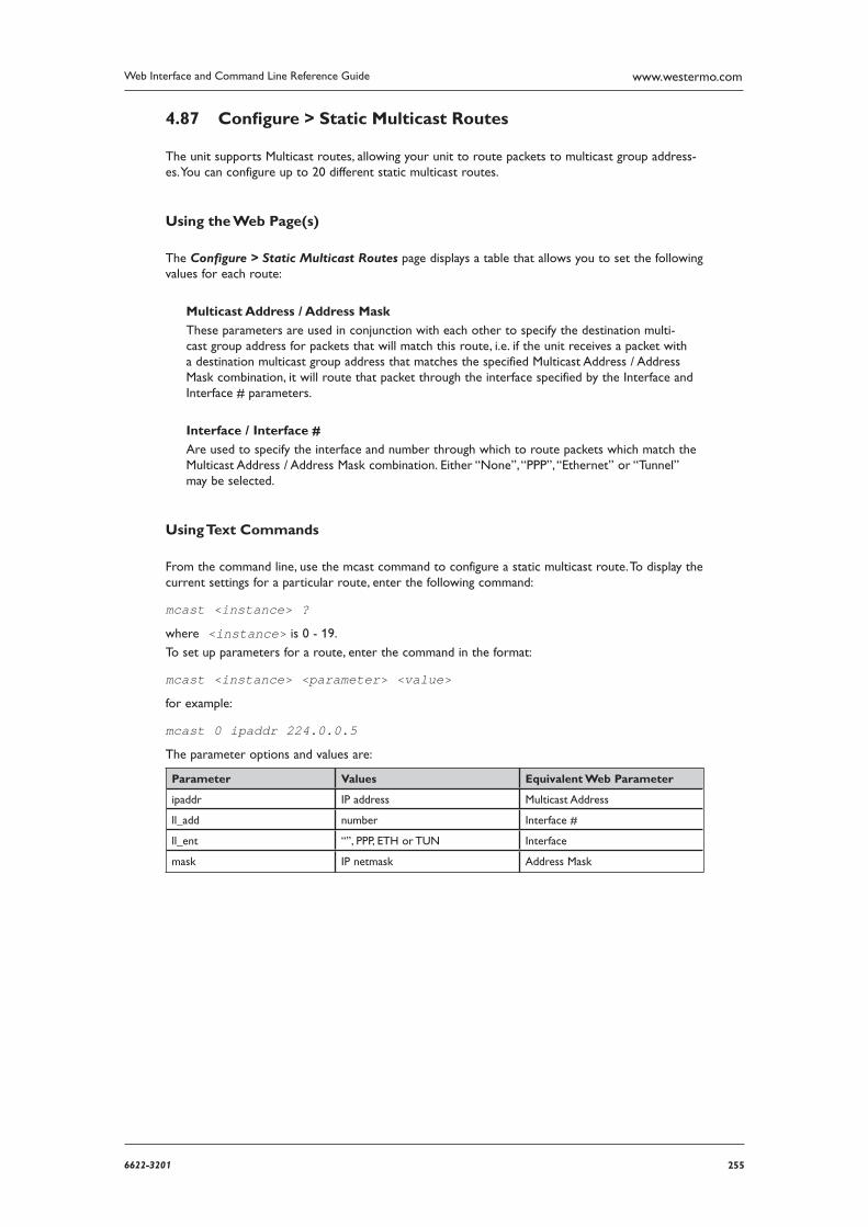
2556622-3201
Web Interface and Command Line Reference Guide www.westermo.com
Confi gure > Static Multicast Routes 4.87
The unit supports Multicast routes, allowing your unit to route packets to multicast group address-es. You can configure up to 20 different static multicast routes.
Using the Web Page(s)
The Configure > Static Multicast Routes page displays a table that allows you to set the following values for each route:
Multicast Address / Address Mask
These parameters are used in conjunction with each other to specify the destination multi-cast group address for packets that will match this route, i.e. if the unit receives a packet with a destination multicast group address that matches the specified Multicast Address / Address Mask combination, it will route that packet through the interface specified by the Interface and Interface # parameters.
Interface / Interface #
Are used to specify the interface and number through which to route packets which match the Multicast Address / Address Mask combination. Either “None”, “PPP”, “Ethernet” or “Tunnel” may be selected.
Using Text Commands
From the command line, use the mcast command to configure a static multicast route. To display the current settings for a particular route, enter the following command:
mcast <instance> ?
where <instance> is 0 - 19.
To set up parameters for a route, enter the command in the format:
mcast <instance> <parameter> <value>
for example:
mcast 0 ipaddr 224.0.0.5
The parameter options and values are:
Parameter Values Equivalent Web Parameter
ipaddr IP address Multicast Address
ll_add number Interface #
ll_ent “”, PPP, ETH or TUN Interface
mask IP netmask Address Mask
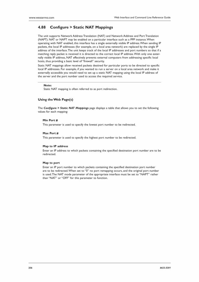
256 6622-3201
Web Interface and Command Line Reference Guidewww.westermo.com
Confi gure > Static NAT Mappings 4.88
The unit supports Network Address Translation (NAT) and Network Address and Port Translation (NAPT). NAT or NAPT may be enabled on a particular interface such as a PPP instance. When oper ating with NAT enabled, this interface has a single externally visible IP address. When sending IP packets, the local IP addresses (for example, on a local area network) are replaced by the single IP address of the interface. The unit keeps track of the local IP addresses and port numbers so that if a matching reply packet is received it is directed to the correct local IP address. With only one exter-nally visible IP address, NAT effectively prevents external computers from addressing specific local hosts, thus providing a basic level of “firewall” security.
Static NAT mappings allow received packets destined for particular ports to be directed to specific local IP addresses. For example, if you wanted to run a server on a local area network and make it externally accessible you would need to set up a static NAT mapping using the local IP address of the server and the port number used to access the required service.
Note: Static NAT mapping is often referred to as port redirection.
Using the Web Page(s)
The Configure > Static NAT Mappings page displays a table that allows you to set the following val ues for each mapping:
Min Port #
This parameter is used to specify the lowest port number to be redirected.
Max Port #
This parameter is used to specify the highest port number to be redirected.
Map to IP address
Enter an IP address to which packets containing the specified destination port number are to be redirected.
Map to port
Enter an IP port number to which packets containing the specified destination port number are to be redirected. When set to “0” no port remapping occurs, and the original port number is used. The NAT mode parameter of the appropriate interface must be set to “NAPT” rather than “NAT” or “OFF” for this parameter to function.
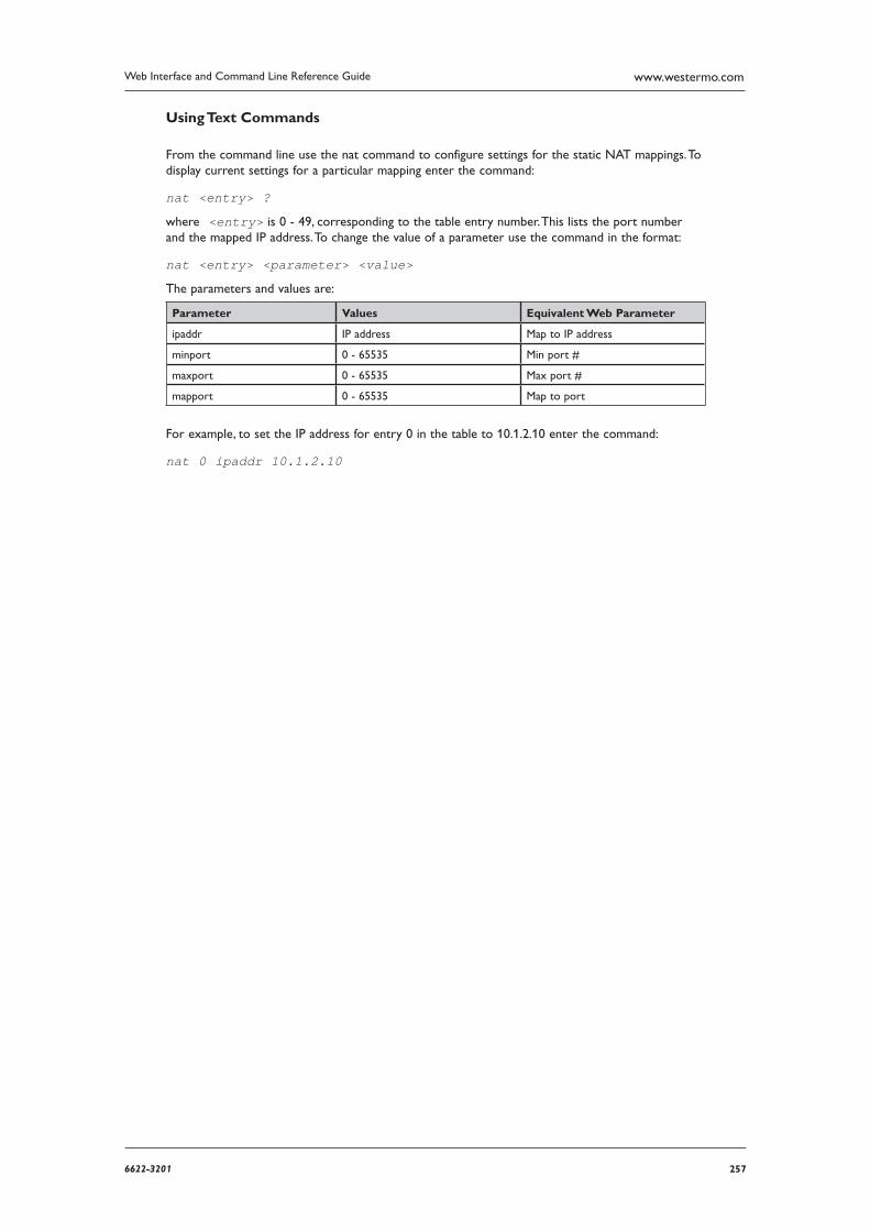
2576622-3201
Web Interface and Command Line Reference Guide www.westermo.com
Using Text Commands
From the command line use the nat command to configure settings for the static NAT mappings. To display current settings for a particular mapping enter the command:
nat <entry> ?
where <entry> is 0 - 49, corresponding to the table entry number. This lists the port number and the mapped IP address. To change the value of a parameter use the command in the format:
nat <entry> <parameter> <value>
The parameters and values are:
Parameter Values Equivalent Web Parameter
ipaddr IP address Map to IP address
minport 0 - 65535 Min port #
maxport 0 - 65535 Max port #
mapport 0 - 65535 Map to port
For example, to set the IP address for entry 0 in the table to 10.1.2.10 enter the command:
nat 0 ipaddr 10.1.2.10
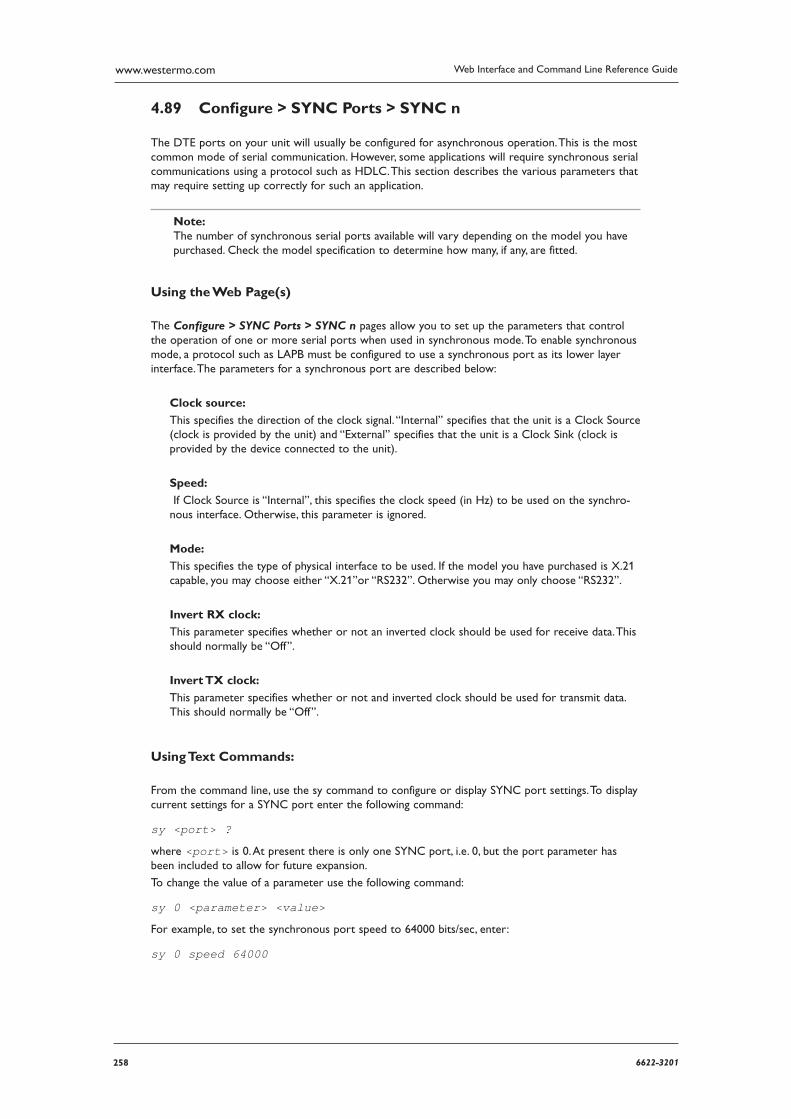
258 6622-3201
Web Interface and Command Line Reference Guidewww.westermo.com
Confi gure > SYNC Ports > SYNC n 4.89
The DTE ports on your unit will usually be configured for asynchronous operation. This is the most common mode of serial communication. However, some applications will require synchronous serial communications using a protocol such as HDLC. This section describes the various parameters that may require setting up correctly for such an application.
Note: The number of synchronous serial ports available will vary depending on the model you have pur chased. Check the model specification to determine how many, if any, are fitted.
Using the Web Page(s)
The Configure > SYNC Ports > SYNC n pages allow you to set up the parameters that control the operation of one or more serial ports when used in synchronous mode. To enable synchronous mode, a protocol such as LAPB must be configured to use a synchronous port as its lower layer interface. The parameters for a synchronous port are described below:
Clock source:
This specifies the direction of the clock signal. “Internal” specifies that the unit is a Clock Source (clock is provided by the unit) and “External” specifies that the unit is a Clock Sink (clock is pro vided by the device connected to the unit).
Speed:
If Clock Source is “Internal”, this specifies the clock speed (in Hz) to be used on the synchro-nous interface. Otherwise, this parameter is ignored.
Mode:
This specifies the type of physical interface to be used. If the model you have purchased is X.21 capable, you may choose either “X.21”or “RS232”. Otherwise you may only choose “RS232”.
Invert RX clock:
This parameter specifies whether or not an inverted clock should be used for receive data. This should normally be “Off”.
Invert TX clock:
This parameter specifies whether or not and inverted clock should be used for transmit data. This should normally be “Off”.
Using Text Commands:
From the command line, use the sy command to configure or display SYNC port settings. To display current settings for a SYNC port enter the following command:
sy <port> ?
where <port> is 0. At present there is only one SYNC port, i.e. 0, but the port parameter has been included to allow for future expansion.
To change the value of a parameter use the following command:
sy 0 <parameter> <value>
For example, to set the synchronous port speed to 64000 bits/sec, enter:
sy 0 speed 64000
2596622-3201
Web Interface and Command Line Reference Guide www.westermo.com
Confi gure > Syslog Clients > Syslog n 4.90
The router may be configured to deliver Syslog messages when events of a suitable priority occur, up to 5 syslog servers can be configured. Refer to the Configure > Event Handler page for more details.
Using the Web Page(s)
Remote syslog server:
This is the IP address of the unit that the Syslog messages will be sent to.
Port:
TCP or UDP port number to use. 0 = Default. Default values are TCP=1468, UDP = 514.
Operation mode:
The mode in which the Syslog client will operate. The options are UDP, TCP or RFC3195.
TCP timeout:
For use with TCP or RFC3195 only. This value specifies the amount to time in seconds that a TCP socket or RFC3195 BEEP channel is left connected in case another trap needs sending. The time out is reset after each event is logged over the connection. A timeout of 0 closes the con-nection after each trap is sent.
TCP source IP address interface: / TCP source IP address interface #:
These parameters allow the selection of the source interface for the packet generated. This will be required for routing if the Syslog server is via an IPSec tunnel.
Priority Selections:
This allows the selection of the level of alerts that will be sent to the syslog server.
Facility Selections:
This allows the selection of the type of alerts that will be sent to the syslog server.
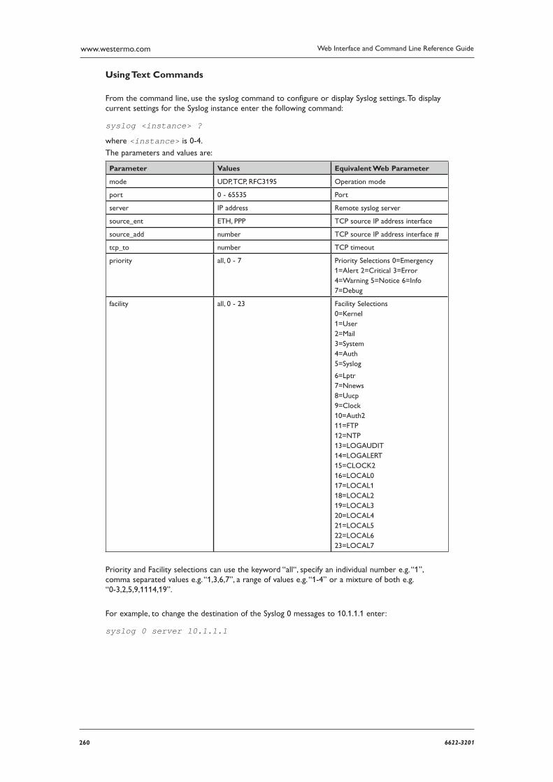
260 6622-3201
Web Interface and Command Line Reference Guidewww.westermo.com
Using Text Commands
From the command line, use the syslog command to configure or display Syslog settings. To display current settings for the Syslog instance enter the following command:
syslog <instance> ?
where <instance> is 0-4.
The parameters and values are:
Parameter Values Equivalent Web Parameter
mode UDP, TCP, RFC3195 Operation mode
port 0 - 65535 Port
server IP address Remote syslog server
source_ent ETH, PPP TCP source IP address interface
source_add number TCP source IP address interface #
tcp_to number TCP timeout
priority all, 0 - 7 Priority Selections 0=Emergency 1=Alert 2=Critical 3=Error 4=Warning 5=Notice 6=Info 7=Debug
facility all, 0 - 23 Facility Selections 0=Kernel 1=User 2=Mail 3=System 4=Auth 5=Syslog
6=Lptr 7=Nnews 8=Uucp 9=Clock 10=Auth2 11=FTP 12=NTP 13=LOGAUDIT 14=LOGALERT 15=CLOCK2 16=LOCAL0 17=LOCAL1 18=LOCAL2 19=LOCAL3 20=LOCAL4 21=LOCAL5 22=LOCAL6 23=LOCAL7
Priority and Facility selections can use the keyword “all“, specify an individual number e.g. “1”, comma separated values e.g. “1,3,6,7”, a range of values e.g. “1-4” or a mixture of both e.g. “0-3,2,5,9,11 14,19”.
For example, to change the destination of the Syslog 0 messages to 10.1.1.1 enter:
syslog 0 server 10.1.1.1
2616622-3201
Web Interface and Command Line Reference Guide www.westermo.com
Confi gure > System Messages 4.91
It is possible for the unit to deliver messages to other units using UDP. Currently, this only involves sending Backup IP addresses. If an IP address is configured in the System messages destination field, the unit will send IP address available and IP address unavailable messages to the IP address specified in this field. Units that receive the IP address available/unavailable messages will search their own backup IP address tables for the IP address indicated in the system message and tag that address as available/unavailable as applicable.
Using the Web Page(s)
System messages destination:
This is the IP address of the unit that the System Messages will be sent to.
Using Text Commands
From the command line, use the sarsys command to configure or display System Message settings.
To display current settings for the System Messages enter the following command:
sarsys <instance> ?
where <instance> is 0.
To change the destination of the Syslog messages enter:
sarsys 0 dest <IP address>
Where <ipaddress> is the address of the unit that the System Messages will be sent to.
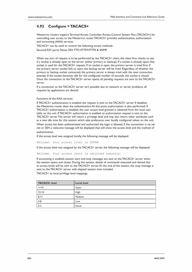
262 6622-3201
Web Interface and Command Line Reference Guidewww.westermo.com
Confi gure > TACACS+ 4.92
Westermo routers support Terminal Access Controller Access-Control System Plus (TACACS+) for controlling user access to the Westermo router. TACACS+ provides authentication, authorisation and accounting (AAA) services.
TACACS+ can be used to control the following access methods:
Secured ASY ports, Telnet, SSH, FTP, HTTP/HTTPS & SNMP.
When any sort of request is to be performed by the TACACS+ client, the client first checks to see if a socket is already open to the server (either primary or backup). If a socket is already open, that socket is used for the TACACS+ request. If no socket is open, the primary server is tried first. If the primary server socket fails to open, the backup server will be tried. Regardless of whether the primary or backup socket connected, the primary server is always tried with the next connection attempt. If the socket becomes idle for the configured number of seconds, the socket is closed. Once the connection to the TACACS+ server opens, all pending requests are sent to the TACACS+ server.
If a connection to the TACACS+ server isn’t possible due to network or server problems, all requests by applications are denied.
Functions of the AAA services
If TACACS+ authentication is enabled, the request is sent to the TACACS+ server. If disabled, the Westermo router does the authentication. At this point, authorisation is also performed. If TACACS+ authorisation is disabled, the user access level granted is obtained from the local user table on the unit. If TACACS+ authorisation is enabled, an authorisation request is sent to the TACACS+ server. The server will return a privilege level and may also return other attributes such as a new idle time for this session which take preference over locally configured values on the unit.
When access has been authenticated and authorised the login is allowed. If the connection is via tel-net or SSH, a welcome message will be displayed that will show the access level and the method of
authentication.
If the access level was assigned locally, the following message will be displayed:
Welcome. Your access level is SUPER
If the access level was assigned by the TACACS+ server, the following message will be displayed:
Welcome. Your access level is obtained remotely.
If accounting is enabled, session start and stop messages are sent to the TACACS+ server when the session opens and closes. During the session, details of commands executed and denied due to access levels will be sent to the TACACS+ server. At the end of the session, the stop message is sent to the TACACS+ server with elapsed session time included.
TACACS+ to local privilege level mappings:
TACACS+ level Local level
>=15 Super
12-14 High
8-11 Medium
4-8 Low
0-3 None
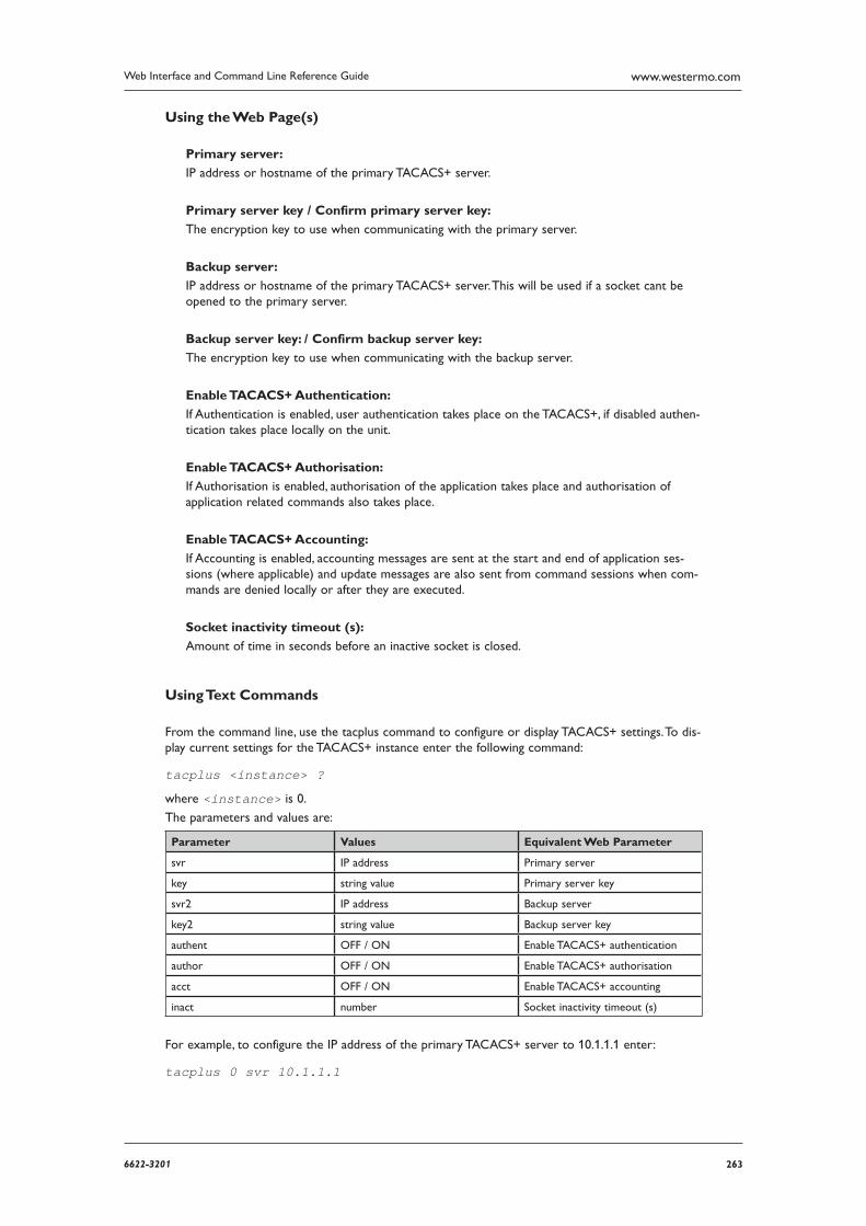
2636622-3201
Web Interface and Command Line Reference Guide www.westermo.com
Using the Web Page(s)
Primary server:
IP address or hostname of the primary TACACS+ server.
Primary server key / Confirm primary server key:
The encryption key to use when communicating with the primary server.
Backup server:
IP address or hostname of the primary TACACS+ server. This will be used if a socket cant be opened to the primary server.
Backup server key: / Confirm backup server key:
The encryption key to use when communicating with the backup server.
Enable TACACS+ Authentication:
If Authentication is enabled, user authentication takes place on the TACACS+, if disabled authen-tication takes place locally on the unit.
Enable TACACS+ Authorisation:
If Authorisation is enabled, authorisation of the application takes place and authorisation of application related commands also takes place.
Enable TACACS+ Accounting:
If Accounting is enabled, accounting messages are sent at the start and end of application ses-sions (where applicable) and update messages are also sent from command sessions when com-mands are denied locally or after they are executed.
Socket inactivity timeout (s):
Amount of time in seconds before an inactive socket is closed.
Using Text Commands
From the command line, use the tacplus command to configure or display TACACS+ settings. To dis-play current settings for the TACACS+ instance enter the following command:
tacplus <instance> ?
where <instance> is 0.
The parameters and values are:
Parameter Values Equivalent Web Parameter
svr IP address Primary server
key string value Primary server key
svr2 IP address Backup server
key2 string value Backup server key
authent OFF / ON Enable TACACS+ authentication
author OFF / ON Enable TACACS+ authorisation
acct OFF / ON Enable TACACS+ accounting
inact number Socket inactivity timeout (s)
For example, to configure the IP address of the primary TACACS+ server to 10.1.1.1 enter:
tacplus 0 svr 10.1.1.1
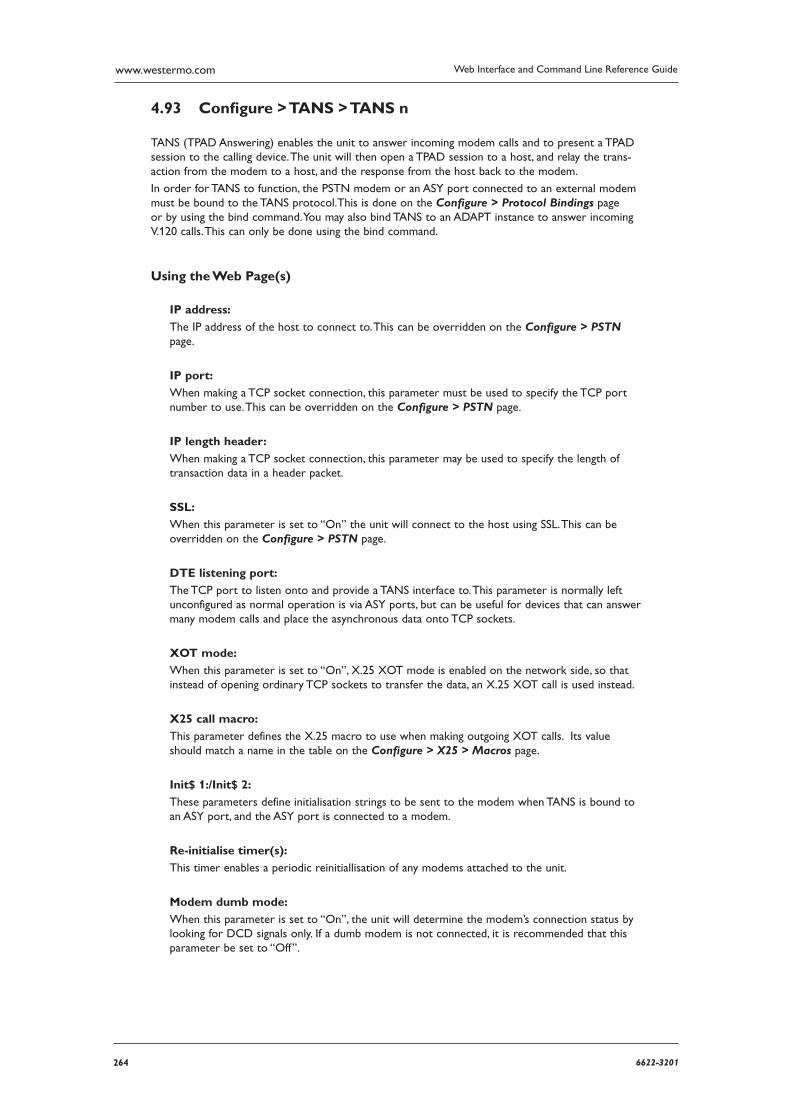
264 6622-3201
Web Interface and Command Line Reference Guidewww.westermo.com
Confi gure > TANS > TANS n 4.93
TANS (TPAD Answering) enables the unit to answer incoming modem calls and to present a TPAD session to the calling device. The unit will then open a TPAD session to a host, and relay the trans-action from the modem to a host, and the response from the host back to the modem.
In order for TANS to function, the PSTN modem or an ASY port connected to an external modem must be bound to the TANS protocol.This is done on the Configure > Protocol Bindings page or by using the bind command. You may also bind TANS to an ADAPT instance to answer incoming V.120 calls. This can only be done using the bind command.
Using the Web Page(s)
IP address:
The IP address of the host to connect to. This can be overridden on the Configure > PSTN page.
IP port:
When making a TCP socket connection, this parameter must be used to specify the TCP port number to use. This can be overridden on the Configure > PSTN page.
IP length header:
When making a TCP socket connection, this parameter may be used to specify the length of trans action data in a header packet.
SSL:
When this parameter is set to “On” the unit will connect to the host using SSL. This can be overrid den on the Configure > PSTN page.
DTE listening port:
The TCP port to listen onto and provide a TANS interface to. This parameter is normally left uncon figured as normal operation is via ASY ports, but can be useful for devices that can answer many modem calls and place the asynchronous data onto TCP sockets.
XOT mode:
When this parameter is set to “On”, X.25 XOT mode is enabled on the network side, so that instead of opening ordinary TCP sockets to transfer the data, an X.25 XOT call is used instead.
X25 call macro:
This parameter defines the X.25 macro to use when making outgoing XOT calls. Its value should match a name in the table on the Configure > X25 > Macros page.
Init$ 1:/Init$ 2:
These parameters define initialisation strings to be sent to the modem when TANS is bound to an ASY port, and the ASY port is connected to a modem.
Re-initialise timer(s):
This timer enables a periodic reinitiallisation of any modems attached to the unit.
Modem dumb mode:
When this parameter is set to “On”, the unit will determine the modem’s connection status by look ing for DCD signals only. If a dumb modem is not connected, it is recommended that this parame ter be set to “Off”.
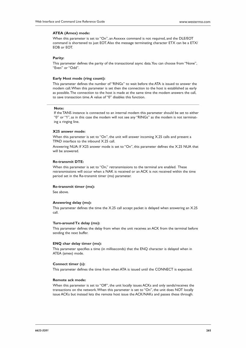
2656622-3201
Web Interface and Command Line Reference Guide www.westermo.com
ATEA (Amex) mode:
When this parameter is set to “On”, an Axxxxx command is not required, and the DLE/EOT com mand is shortened to just EOT. Also the message terminating character ETX can be a ETX/EOB or EOT.
Parity:
This parameter defines the parity of the transactional async data. You can choose from “None”, “Even” or “Odd”.
Early Host mode (ring count):
This parameter defines the number of “RINGs” to wait before the ATA is issued to answer the modem call. When this parameter is set then the connection to the host is established as early as possible. The connection to the host is made at the same time the modem answers the call, to save transaction time. A value of “0” disables this function.
Note: If the TANS instance is connected to an internal modem this parameter should be set to either “0” or “1”, as in this case the modem will not see any “RINGs” as the modem is not terminat-ing a ringing line.
X25 answer mode:
When this parameter is set to “On”, the unit will answer incoming X.25 calls and present a TPAD interface to the inbound X.25 call.
Answering NUA: If X25 answer mode is set to “On”, this parameter defines the X.25 NUA that will be answered.
Re-transmit DTE:
When this parameter is set to “On,” retransmissions to the terminal are enabled. These retrans missions will occur when a NAK is received or an ACK is not received within the time period set in the Re-transmit timer (ms) parameter.
Re-transmit timer (ms):
See above.
Answering delay (ms):
This parameter defines the time the X.25 call accept packet is delayed when answering an X.25 call.
Turn-around Tx delay (ms):
This parameter defines the delay from when the unit receives an ACK from the terminal before sending the next buffer.
ENQ char delay timer (ms):
This parameter specifies a time (in milliseconds) that the ENQ character is delayed when in ATEA (amex) mode.
Connect timer (s):
This parameter defines the time from when ATA is issued until the CONNECT is expected.
Remote ack mode:
When this parameter is set to “Off”, the unit locally issues ACKs and only sends/receives the trans actions on the network. When this parameter is set to “On”, the unit does NOT locally issue ACKs but instead lets the remote host issue the ACK/NAKs and passes these through.
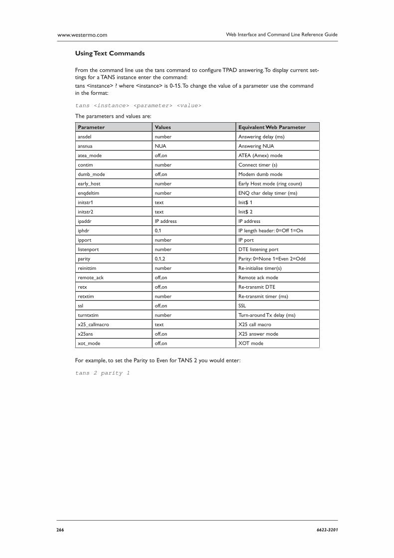
266 6622-3201
Web Interface and Command Line Reference Guidewww.westermo.com
Using Text Commands
From the command line use the tans command to configure TPAD answering. To display current set-tings for a TANS instance enter the command:
tans <instance> ? where <instance> is 0-15. To change the value of a parameter use the command in the format:
tans <instance> <parameter> <value>
The parameters and values are:
Parameter Values Equivalent Web Parameter
ansdel number Answering delay (ms)
ansnua NUA Answering NUA
atea_mode off,on ATEA (Amex) mode
contim number Connect timer (s)
dumb_mode off,on Modem dumb mode
early_host number Early Host mode (ring count)
enqdeltim number ENQ char delay timer (ms)
initstr1 text Init$ 1
initstr2 text Init$ 2
ipaddr IP address IP address
iphdr 0,1 IP length header: 0=Off 1=On
ipport number IP port
listenport number DTE listening port
parity 0,1,2 Parity: 0=None 1=Even 2=Odd
reinittim number Re-initialise timer(s)
remote_ack off,on Remote ack mode
retx off,on Re-transmit DTE
retxtim number Re-transmit timer (ms)
ssl off,on SSL
turntxtim number Turn-around Tx delay (ms)
x25_callmacro text X25 call macro
x25ans off,on X25 answer mode
xot_mode off,on XOT mode
For example, to set the Parity to Even for TANS 2 you would enter:
tans 2 parity 1
2676622-3201
Web Interface and Command Line Reference Guide www.westermo.com
Confi gure > Time 4.94
The unit incorporates a battery-backed real-time clock/calendar. This is used for time/date stamping of internal files and statistics. Normally, once the time and date has been set, the unit will keep the time accurate to +/- 5 seconds/day while power is applied. However you may also configure it to automati cally obtain the correct time at regular intervals using the SNTP option.
Using the Web Page(s)
This page allows you to set the date and time by filling in the appropriate dialog boxes.
Using Text Commands
To set the time and date from the command line use the time command.
To display the time/date as currently set on the unit, enter the command without a parameter:
Time
12:23:58, 10 Mar 2000
OK
To set the time/date, enter the command in the format:
time <hh> <mm> <ss> <dd> <mm> <yyyy>
The 24-hour clock system is used. For example:
time 22 16 00 12 03 2002
22:16:00, 12 Mar 2002
OK
will set the time/date to 10:16pm on 12th March 2002.
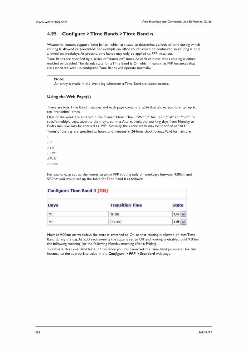
268 6622-3201
Web Interface and Command Line Reference Guidewww.westermo.com
Confi gure > Time Bands > Time Band n 4.95
Westermo routers support “time bands” which are used to determine periods of time during which routing is allowed or prevented. For example, an office router could be configured so routing is only allowed on weekdays. At present, time bands may only be applied to PPP instances.
Time Bands are specified by a series of “transition” times. At each of these times routing is either ena bled or disabled. The default state for a Time Band is On which means that PPP instances that are associated with un-configured Time Bands will operate normally.
Note: An entry is made in the event log whenever a Time Band transition occurs.
Using the Web Page(s)
There are four Time Band instances and each page contains a table that allows you to enter up to ten “transition” times.
Days of the week are entered in the format “Mon”, “Tue”, “Wed”, “Thu”, “Fri”, “Sat” and “Sun”. To spec ify multiple days, separate them by a comma. Alternatively, the working days from Monday to Friday inclusive may be entered as “MF”. Similarly, the entire week may be specified as “ALL”.
Times of the day are specified as hours and minutes in 24-hour clock format. Valid formats are:
H HH H:M H:MM HH:M HH:MM
For example, to set up the router to allow PPP routing only on weekdays between 9:00am and 5:30pm you would set up the table for Time Band 0 as follows:
Now, at 9:00am on weekdays the state is switched to On so that routing is allowed on that Time Band during the day. At 5:30 each evening the state is set to Off and routing is disabled until 9:00am the following morning (or the following Monday morning after a Friday).
To activate this Time Band for a PPP instance you must now set the Time band parameter for that instance to the appropriate value in the Configure > PPP > Standard web page.
2696622-3201
Web Interface and Command Line Reference Guide www.westermo.com
Using Text Commands
To setup time bands from the command line use the tbandcommand. To display current time band settings, enter the command in the format:
tband <instance> ?
where <instance> is 0 - 3. To set-up a transition you will need to enter three commands (one each to specify the days of the week,
the time and the transition state):
tband <instance> <days#> <days>
tband <instance> <time#> <time>
tband <instance> <state#> <on|off>
where:
<instance> is the Time Band instance number
<day#> is the day entry number
<time#> is the time entry number <state#> is the state entry number
<days> specifies the days on which the transition occurs
<time> specifies the time at which the transition occurs
<state> specifies the type of transition (on or off)
Valid days of the week are entered in the format “Mon”, “Tue”, “Wed”, “Thu”, “Fri”, “Sat” and “Sun”. To specify multiple days, separate them by a comma. Alternatively, the working days from Monday to Fri day inclusive may be entered as “MF”. Similarly, the entire week may be specified as “ALL”.
Times of the day are specified as hours and minutes in 24-hour clock format. Valid formats are:
H HH H:M H:MM HH:M HH:MM
For example, to set up the router to allow PPP routing only on weekdays between 9:00am and 5:30pm you would enter the following commands:
tband 0 days0 mf tband 0 time0 9 tband 0 state0 on tband 0 days1 mf tband 0 time1 5:30 tband 0 state1 off
270 6622-3201
Web Interface and Command Line Reference Guidewww.westermo.com
Confi gure > TPAD > TPAD Statistics 4.96
There are a number of statistics generated when TPAD transactions are received by the unit. This web page allows you to configure how those statistics are generated and used.
Using the Web Page(s)
Number of most recent transaction times to average:
This parameter specifies the number of most recent transaction times to average. This average value is maintained in a separate statistic shown on the Statistics > TPAD > TPAD n web pages.
Generate event after this many consecutive failures:
This parameter specifies the total number of consecutive failures before a system event is gener ated. Failures may be L3, L2, L1 or host response failures.
Generate event after average transaction time exceeds (ms):
This parameter specifies that a system event will be generated if the average transaction time for the last “n” events (“n” is set by Number of most recent transaction times to average) exceeds this time (in milliseconds).
2716622-3201
Web Interface and Command Line Reference Guide www.westermo.com
Confi gure > TPAD > TPAD n 4.97
TPAD is a simplified version of the X.25 PAD specification that is commonly used for carrying out credit-card clearance transactions. Westermo units support the use of TPAD over the ISDN B and D-chan nels and also over an IP interface such as GPRS via XOT or TCP. Automatic back-up between any two of these “layer 2 interfaces” is supported.
Using the Web Page(s)
The Configure > TPAD folder expands to list separate pages for each of the available TPAD instances. Each page is split into two sections. The first section includes general TPAD parameters (many of which are common to X.25 PADS). The second includes parameters relating to the backup interface.
B-channel ISDN #:
This parameter may be used to specify an ISDN number. This is used in cases where no ISDN number is provided with the ATD command when making an outgoing call.
Prefix #:
This parameter is used to specify a dialling code that the unit will place in front of the tel-ephone number that is issued by the terminal in the ATD command. For example, if the Prefix # was set to 0800 and the number specified by the terminal in the ATD command was 123456, the actual number dialled by the unit would be 0800123456.
Prefix removal #:
This parameter is used to specify a dialling prefix that is normally inserted by the terminal in the ATD command that is removed by the unit before dialling takes place. For example, if the Prefix removal # was set to 0800 and the terminal issued an ATD command containing 0800123456 then the actual number dialled by the unit would be 123456.
Note: Prefix # and Prefix removal # are usually used in conjunction with each other to substitute the dialling code issued by the terminal for an alternative code.
Suffix #:
The Suffix # parameter may be set to contain additional numbers that are dialled after the number specified by B-channel ISDN #. For example, if B-channel ISDN # was set to 123456 and Suffix # was set to 789, the actual number dialled would be 123456789.
NUA:
This parameter specifies the X.25 Network User Address to be used for outgoing X.25 calls if no NUA is specified in the call string.
NUI:
This specifies the X.25 Network User Identifier to be used for outgoing X.25 calls if no NUI is spec ified in the call string.
Call user data:
This specifies a text string that will be placed in the Call User Data field of an outgoing X.25 call request packet. Whether or not this information is required will depend on the X.25 host that you are connecting to. In most cases the information is not required.
272 6622-3201
Web Interface and Command Line Reference Guidewww.westermo.com
Forward mode time (ms):
If not framed with STX and ETX characters, can still have data formatted after this period.
Clearing time (direct mode) (ms):
This parameter defines the clearing time in milliseconds that an X.25 call will be left “open” after receiving a response from the host. Each response from the host resets this timer.
Terminal ID:
The Terminal ID parameter can be used to insert or replace a Terminal ID in the APACS 30 string.
Terminal ID translation:
If this parameter is set to “On”, any Terminal ID provided by a connected terminal will be replaced by the ID set in the Terminal ID field above.
APACS 50 terminal ID:
This parameter specifies the terminal ID for use with incoming APACS 50 polling calls.
Connect string:
This parameter specifies a string to be sent to the user’s terminal when an outgoing TPAD call has been connected, instead of the normal ENQ character. For example, this might be used to make a TPAD connection look like a PAD connection by specifying “CON COM” as the con-nect string.
Use connect string:
This parameter enables or disables use of the Connect string parameter.
Message numbering:
When this parameter is set to “On”, the unit will override the message numbering of the local equipment and substitute its own message numbering. This is useful when the locally connected equipment does not automatically increment the APACS 30 message number.
In same call:
If this parameter is set to “Off” only one transaction is allowed per call. When set to “Transaction”, and Message numbering is “On”, then multiple transactions are allowed per X.25 call, but not until a response has been received from the host. When multiple transactions are sent message numbers are incremented for each transaction. When set to “Clear”, multiple transactions per X.25 call are allowed irrespective of whether a response has been received from the host. Again, transaction numbers are incremented by the unit automatically.
Delimiter char:
This parameter specifies the character used to separate a main NUA from a backup NUA, and a main NUI from a backup NUI in an ATD command. The default value is the ASCII “!” character (decimal 33).
Poll chars:
This parameter is a string that specifies the set of characters to be treated as polling characters. The unit will respond to any of these characters using ACK. This parameter should normally be blank.
Merchant #:
This parameter can be used to insert a merchant number into the APACS 30 string when the locally connected equipment does not transmit a merchant number.
2736622-3201
Web Interface and Command Line Reference Guide www.westermo.com
Calling NUA:
This is the NUA that the unit will report to the X.25 network as its own NUA. Often the X.25 network will override this NUA.
Clear Delay (s):
This parameter defines the time period for which the socket closing or the X.25 call clearing is delayed by after the TPAD session has finished. For example, if this parameter is set to 10 then 10 seconds after the TPAD session is finished (NO CARRIER is seen on the ASY TPAD port) the net work call (X25 or TCP socket) is cleared.
Layer 2 deactivation timer (s):
Once a TPAD X.25 call has been cleared, the unit will keep a LAPB instance active for the length of time set by this parameter. This is to allow further TPAD transactions to take place without hav ing to make another ISDN call. The default value of 10 seconds should be acceptable for most applications.
If you select LAPD as the TPAD layer-2 interface, this value will automatically be set to 0 to dis-able layer-2 deactivation. You may still override the 0 setting by entering a new value but note that most network service providers prefer that LAPD connections are not repeatedly deacti-vated.
Default packet size:
This parameter specifies the default X.25 packet size to be used for TPAD transactions.
Layer 2 interface:
This parameter is used to select whether the TPAD instance will use ISDN B-channel X.25, D channel X.25, TCP, VXN or SSL as the transport protocol. For ISDN D-channel operation, ensure that the “LAPD” option is selected. For ISDN B-channel operation or operation through a synchro nous port, select “LAPB”.
Layer 2 interface #:
This parameter specifies which LAPB or LAPD instance to use for the relevant TPAD instance. Select “0” or “1” for LAPB or “0” or “1” for LAPD. When using LAPB with ISDN this param-eter may be set to “255”, which means use any free LAPB instance. This is useful when more than 2 POS terminals are connected to the router and the acquirer does not support multiple Switched Virtual Circuits (SVCs) on a single B-Channel.
Remote IP address:
When the unit is configured for XOT or TCP socket mode, this parameter is used to specify the IP address of the host to which the XOT call is made. Note that the layer 2 interface must be set to TCP.
IP mode:
This parameter is used to select XOT or IP socket mode when the Layer 2 interface has been set to TCP.
IP port (TCP socket mode):
When making a TCP socket connection (i.e. the Layer 2 interface has been set to TCP), this parameter must be used to specify the TCP port number to use.
IP length header:
When making a TCP socket connection (i.e. the Layer 2 interface has been set to TCP), setting this parameter to “On” will specify the length of transaction data in a header packet. When set to “8583 Ascii 4 byte”, the IP length header will conform to the ISO 8583 format.
274 6622-3201
Web Interface and Command Line Reference Guidewww.westermo.com
LCN:
The unit supports up to eight logical X.25/TPAD channels. In practice, the operational limit is deter mined by the particular service to which you subscribe (usually 4).
Each logical channel must be assigned a valid Logical Channel Number (LCN). The LCN parame-ter is the value of the first LCN that will be assigned for outgoing X.25 CALLs. The default is 1027.
For incoming calls, the unit accepts the LCN specified by the caller.
LCN direction:
This parameter determines whether the X.25 LCN used for outgoing TPAD calls is incremented or decremented from the starting value when multiple TPAD instances share one layer 2 (LAPB or LAPD), connection. The default is “DOWN” and LCNs are decremented, i.e. if the first CALL uses 1024, the next will use 1023, etc. Setting the parameter to “UP” will cause the LCN to be incre mented from the start value.
Direct Sync:
This parameter is used to turn direct synchronous mode on or off. When set to On, TPAD transac tions are transmitted without any “outer” protocol such as X.25, i.e. they are placed directly in a synchronous frame.
Response timeout (s):
This is the length of time in seconds that the unit will wait for a response to a TPAD transac-tion request before clearing the TPAD call.
Excessive transaction time (s):
Setting this parameter to a non-zero value causes the unit to generate an “Excessive Transaction Time” event (code 56) each time a TPAD transaction takes longer that the specified number of seconds. This could be used in conjunction with an appropriate Event Handler configuration to generate email alert messages or SNMP traps when TPAD transactions take longer than expect-ed. See “LOGCODES.TXT” for a complete list of events.
SLA Tran Time (ms):
When the total transaction time exceeds the value (in ms) set in this parameter, the NB SLA exceptions statistic on the Statistics > TPAD page is incremented. This statistic can be viewed on the CLI interface by entering the at\mibs=tpad.n.stats command, where n is the TPAD instance.
TID timeout (s):
This specifies the time in seconds before the Terminal ID is considered inactive.
Restart delay (ms):
When the Restarts parameter is set to “On”, the Restart delay value determines how long (in milli seconds) that the unit will wait before issuing a Restart packet. The default value is 2000 giv-ing a delay of 2 seconds.
Restarts:
The Restarts parameter is only used in D-channel X.25 mode, i.e. when the specified TPAD instance has been bound to a LAPD instance.
It is normally possible to make X.28 CALLs immediately following the initial SABM-UA exchange.
In some cases however, the X.25 network may require an X.25 RESTART before it will accept X.25 CALLs. The correct mode to select depends upon the particular X.25 service to which you subscribe.
The default value is “On”. This means that the unit will issue X.25 RESTART packets. To prevent
the unit from issuing RESTART packets set this parameter to “Off”.
2756622-3201
Web Interface and Command Line Reference Guide www.westermo.com
Include LRC:
The LRC (Longitudinal Redundancy Check) is a form of error checking that may be required by some TPAD terminals. When the Include LRC option is set to “Yes” the unit will check the LRC.
Include LRC line:
This parameter is normally set to “Off” so that any LCRs received from a TPAD terminal will be removed before the transaction data is transmitted to the remote host. In most cases this is acceptable before the network will provide error correction and so the LRC is redundant. In some circumstances however, you may find it necessary to change this parameter to “On” so that the unit transmits the LRC to the remote host along with the transaction data.
Force parity ASY:
When this parameter is set to “Yes”, the unit will always use Even parity when relaying data from a remote host to a locally connected TPAD terminal. To allow data to pass through with-out the parity being changed, set this option to “Off”.
Strip parity line:
Setting this parameter to “On” causes the unit to remove the parity bit from transmitted pack-ets.
Force parity line:
When this parameter is set to “Yes” the unit will always use EVEN parity when relaying data from the locally connected TPAD terminal to the remote host. To allow data to pass through without the parity being changed, set this option to “Off”.
ACK data:
This parameter causes the unit to acknowledge TPAD data packets from the terminal. This param eter should normally be set to the default value of “Yes”. Note that this parameter is only used if no Poll chars are defined.
DTE re-transmit:
Setting this parameter to “Yes” will cause the unit to retransmit the APACS 30 string if an error is detected.
Delete STX/ETX:
Setting this parameter to “Yes” will cause the unit to strip off the STX and ETX characters that nor mally surround the APACS 30 string.
No ENQ char:
Under the TPAD protocol the ENQ character is normally used to indicate that a call has con-nected and that the TPAD terminal may proceed with the transaction. Setting this parameter to “Off” will prevent the router from transmitting ENQ characters to the TPAD terminal if they are not required.
Relay ACKs:
Normally, ACK and NAK characters from the DTE are discarded by the unit, i.e. they are not relayed to the remote host. This parameter may be set to “On” if the remote host requires that ACK and NAK characters to be relayed by the unit.
EOT only:
A TPAD call is normally terminated with a DLE, EOT sequence. Some terminals only require the EOT character on its own. This can be configured by setting the EOT only parameter to “On”.
STX to SOH:
Setting this parameter to “On” will cause the unit to convert the leading STX character in a transac tion into an SOH character.
276 6622-3201
Web Interface and Command Line Reference Guidewww.westermo.com
Boot to direct mode:
Direct mode is a mode of operation whereby the unit automatically routes APACS 30 packets to their destination without the terminal having to perform any call control. If this parameter is set to “Yes”, then the next time the unit is rebooted it will operate in direct mode. For direct mode to work you must set up the appropriate addressing information (B channel, NUA or NUI). If this parameter is set to “No”, the unit will still try to use direct mode if it detects that it is required (due to the absence of call control information). This parameter can be used in certain cases where for some reason the unit cannot automatically determine whether or not to use direct mode. See also Disable direct mode below.
Disable direct mode: Setting this parameter to “Yes” will prevent the unit from automatically using Direct mode (see above) when it receives an APACS 30 packet without any call set-up.
Unable to authorise acquirer response:
This parameter only applies when the unit is operating in direct mode. In cases where the unit is unable to send the APACS 30 packet to the remote host, it replies to the terminal with an “unable to authorise” message. By default, this message contains a response code 05 which means declined. Entering a number for this parameter causes the unit to use that number in place of the default response code. A value of zero for this parameter prevents the unit from replying.
Transaction delay (ms):
Setting this parameter will cause the unit to pause for the specified number of milliseconds in between successfully connecting to the remote X.25 host and transmitting the APACS 30 string.
ENQ char delay (ms):
If this parameter is set to “0”, the unit will send ENQ characters to the locally attached TPAD termi nal when a call has been connected. This parameter may be used to set the delay in ms from when the router first connects the call to when it transmits the ENQ.
ACK char delay (ms):
This parameter defines the time period the unit will wait for an ACK character to be received after sending data to the terminal. If an ACK character is not received withing this time the data will be retransmitted. A value of “0” entered here will defaut to a delay of 1 second.
Data trigger:
This parameter can be used to generate a “Data Trigger” event (code 47) when the reply from the X.25 host contains the string specified in this parameter. It is possible to configure the unit to gen erate an email alert message when this event occurs. See “LOGCODES.TXT” for a com-plete list of events.
Dialling context:
This parameter is for advanced users only. It enables TPAD transactions to be carried out using the V.120 protocol. The parameter is used in conjunction with the Polling Answering Service (PANS), and identifies which PANS instance is to be used for an outgoing V.120 call. For this to work, the PANS instance must be bound to a V.120 instance.
Strip Trailing Spaces:
When this parameter is set to “On”, the TPAD instance will look at responses coming from the host and remove any trailing space characters from the end of the packet before relaying the data to the terminal. This may be necessary in the host system “pads out” responses with unnecessary spaces which then cause abnormal behaviour in the terminal.
Backup Parameters
Layer 2 deactivation timer (s):
This parameter is functionally equivalent to the Layer 2 deactivation timer parameter in the gen eral parameters section above but only applies to the backup service.
2776622-3201
Web Interface and Command Line Reference Guide www.westermo.com
Layer 2 interface:
The Layer 2 Interface parameter specifies whether the backup service uses “LAPB”, “LAPD” “TCP”, “SSL” or “None”.
Layer 2 interface #:
This parameter specifies which LAPB or LAPD instance to use for the backup interface. Select “0” or “1” for LAPB or “0”, “1” or “2” for LAPD.
LCN:
The LCN parameter is used to set the first LCN that will be used for the backup interface.
LCN direction:
This parameter determines whether the LCN used for the backup X.25 interface is increment-ed or decremented from the starting value when multiple X.25 instances share a single layer 2 connection.
NUA:
This parameter specifies the X.25 Network User Address to be used for outgoing X.25 calls if no NUA is specified in the call string.
NUI:
This specifies the X.25 Network User Identifier to be used for outgoing X.25 calls if no NUI is spec ified in the call string.
278 6622-3201
Web Interface and Command Line Reference Guidewww.westermo.com
Using Text Commands
From the command line, use the tpad command to configure or display TPAD settings. To display current settings for a TPAD instance enter the command:
tpad <instance> ?
To change the value of a parameter use the command in the format:
tpad <instance> <parameter> <value>
The parameters and values are:
Parameter Values Equivalent Web Parameter
uaarc number Unable to authorise acquirer response
ackdat off, on ACK data
bdir off, on Boot to direct mode
bnumber ISDN number B-channel ISDN #
cingnua text Calling NUA
clear_dirtime number Clearing time (direct mode) (ms)
clear_time number Clear Delay (s)
constr text Connect string
cud text Call user data
defpak number Default packet size
delimchar decimal ASCII Delimiter character
delstx off, on Delete STX/ETX
dialctx number Dialling context
disdir off, on Disable direct mode
domsgnb off, on Message numbering
dorest off, on Restarts
dotermid off, on Terminal ID translation
dsync off, on Direct sync
eot_only off, on EOT only
fpar off, on Force parity ASY
ftime number Forward mode time (s)
inclrc off, on Include LRC
ipaddr IP address Remote IP address
iphdr 0,1,2 IP length header: 0=Off 1=On 2=8583 Ascii 4 byte
ipmode 0,1 IP mode: 0=XOT 1=TCP socket mode
ipport number IP port (TCP socket mode)
l2iface lapb, lapd, tcp, ssl, vxn Layer 2 interface
l2nb 0-1 Layer 2 interface #
lcn number LCN
lcnup off, on LCN direction
lfpar off, on Force parity line
lrpar off, on Strip parity line
merchnum text Merchant #
no_enq off, on No ENQ char
nua text NUA
nui text NUI
pollchars text Poll characters
prefix number Prefix #
prefix_rem number Prefix removal #
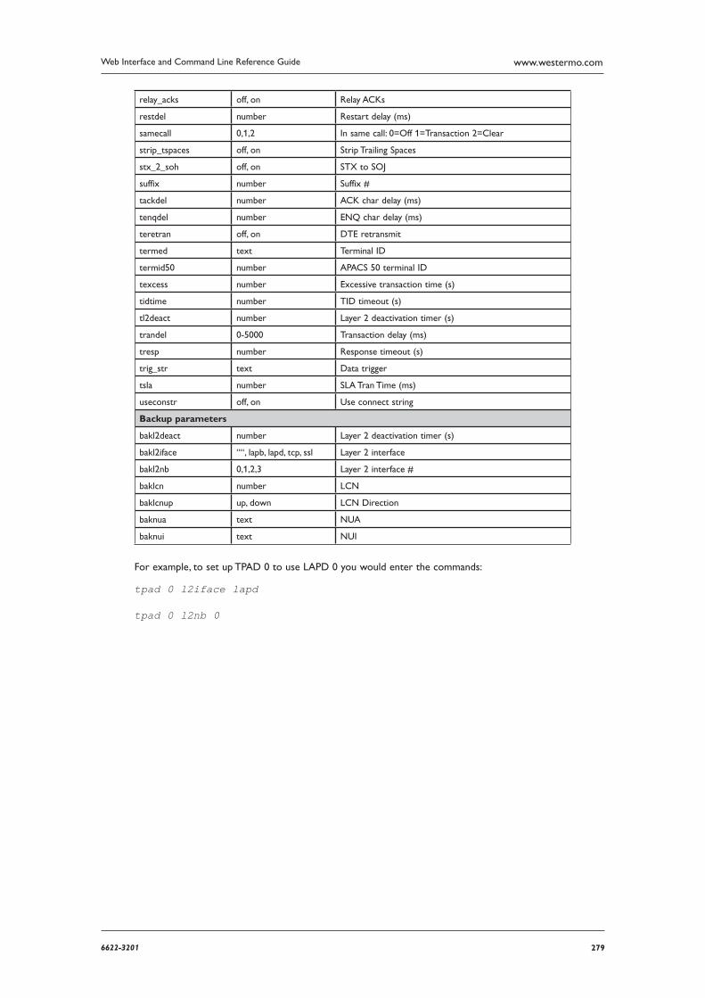
2796622-3201
Web Interface and Command Line Reference Guide www.westermo.com
relay_acks off, on Relay ACKs
restdel number Restart delay (ms)
samecall 0,1,2 In same call: 0=Off 1=Transaction 2=Clear
strip_tspaces off, on Strip Trailing Spaces
stx_2_soh off, on STX to SOJ
suffix number Suffix #
tackdel number ACK char delay (ms)
tenqdel number ENQ char delay (ms)
teretran off, on DTE retransmit
termed text Terminal ID
termid50 number APACS 50 terminal ID
texcess number Excessive transaction time (s)
tidtime number TID timeout (s)
tl2deact number Layer 2 deactivation timer (s)
trandel 0-5000 Transaction delay (ms)
tresp number Response timeout (s)
trig_str text Data trigger
tsla number SLA Tran Time (ms)
useconstr off, on Use connect string
Backup parameters
bakl2deact number Layer 2 deactivation timer (s)
bakl2iface ““, lapb, lapd, tcp, ssl Layer 2 interface
bakl2nb 0,1,2,3 Layer 2 interface #
baklcn number LCN
baklcnup up, down LCN Direction
baknua text NUA
baknui text NUI
For example, to set up TPAD 0 to use LAPD 0 you would enter the commands:
tpad 0 l2iface lapd
tpad 0 l2nb 0
280 6622-3201
Web Interface and Command Line Reference Guidewww.westermo.com
Confi gure > Tunnel (GRE) 4.98
When configured, a GRE tunnel will be created between 2 devices. Generic routing encapsulation (GRE) is a means of transporting IP packets from one device to another through an unencrypted point to-point IP tunnel. Multiple tunnels may be configured to multiple devices. The number of tun-nels supported is dependant on the model of router.
Using the Web Page(s)
The Configure > Tunnel (GRE) page contains a number of sub-pages for Tunnel 0, Tunnel 1 etc
Description:
This parameter allows you to enter a name for this GRE instance, to make it easier to identify it.
IP address:
This is the IP address of the virtual interface that will be used by the tunnel. Used in conjunc-tion with the mask parameter below. This parameter MUST be entered for the tunnel to work.
Mask:
Used with the IP address parameter to clarify the subnet in use on the virtual interface. This would normally be a 30 bit mask as this is a point-to-point link (255.255.255.252).
Interface to use for Tunnel Source IP address/
Interface # to use for Tunnel Source IP address:
These 2 parameters allow you to select the GRE tunnel source interace, so the tunnel end point can be a physical interface rather than a virtual IP address. This is for using GRE without IPSec. These parameters should not be used if the source address is used in the parameter below.
Tunnel Source IP Address:
A virtual host IP address for the local end of the tunnel, configured for routing purposes. This IP address has no other use and needs no mask as it is a host address. e.g. 1.1.1.1 Normally used in conjuction with IPSec. This parameter should not be used if the interface is selected as the source using the options above.
Tunnel Destination IP Address/Hostname:
This is the FQDN or IP address of the remote end of the tunnel. This could also be the virtual host IP address for the remote end of the tunnel, configured for routing purposes. e.g. 2.2.2.2
MTU:
Maximum Transmission Unit. The greatest amount of data that can be transferred in one physical packet. Default value is 1400.
Checksum:
This parameter selects whether to add GRE checksums to GRE packets when the unit is termi-nating a GRE tunnel. “Off” disables checksums, “On” enables checksums.
Keepalive Delay:
When configured to a non-zero value, keepalive packets will be sent to the remote end of the tunnel and the response is monitored to detect if the tunnel is up or down. If the tunnel is detected as down, the routing table metric will be altered. Value is configured in seconds. If set to zero then keepalives will not be used.
2816622-3201
Web Interface and Command Line Reference Guide www.westermo.com
Keepalive Retries:
The number of times that a keepalive packet will be sent (if no response is received from the remote end) before the tunnel is declared as being down.
Keepalives activate interfaces:
This specifies whether or not the GRE keepalive packets will activate the tunnel. If set to YES and the tunnel drops the GRE keepalive packet will try to raise the tunnel again. If set to NO and the tunnel has been marked as down due to the GRE keepalives not being received, the router will only raise the tunnel if a packet (other than a GRE keepalive) needs to be routed.
IP analysis:
When set to ON, the un-encapsulated IP traffic will be captured into the analyser trace.
Tunnel analysis:
When set to ON, the GRE encapsulated packets and keepalives will be captured to the analyser trace.
Firewall:
The Firewall parameter is used to turn Firewall script processing “On” or “Off” for this inter-face. If using the firewall for problem detection on a tunnel interface, the interface to put OOS will need to be specified, eg:
pass out break end on tun 0 from any to 100.100.100.29 port=4000 flags S!A inspect-state oos ppp 1 5
IGMP:
This IGMP parameter is used to enable or disable the transmission and reception of IGMP
packets on this interface. IGMP is used to advertise members of multicast groups. If IGMP is
enabled, and a member of a multicast group is discovered on this interface, multicast packets for
this group received on other interfaces will be sent out this interface.

282 6622-3201
Web Interface and Command Line Reference Guidewww.westermo.com
Using Text Commands
From the command line, use the tun command to configure or display a GRE tunnel instance. To display the current settings for a GRE tunnel instance, enter the command:
tun <instance> ?
where <instance> is 0 to 4.
To change the value of a parameter use the same command in the format:
tun 0 <parameter> <value>
The parameters and values are:
Parameter Values Equivalent Web Parameter
dest IP address Destination
firewall off, on Firewall
IPaddr IP address IP address
ipanon off, on IP analysis
kaactrq off, on Keepalives activate interfaces
kadelay number Keepalive Delay
karetries number Keepalive Retries
mask IP netmask Mask
mtu number MTU
source IP address Source
tunanon off, on Tunnel analysis
For example, to set instance 0 local tunnel interface IP address to 10.1.1.1
tun 0 ipaddr 10.1.1.1
For more information on using and configuring GRE tunnel interfaces, please see the application note in the support section on our website.
2836622-3201
Web Interface and Command Line Reference Guide www.westermo.com
Confi gure > UDP Echo Client/Server > UDP Echo n 4.99
When enabled, UDP Echo generates UDP packets that contain the unit serial number and ID, and transmits them to the specified IP address and port at the configured interval. When the unit receives a UDP packet at a local port configured for UDP echo, it will “echo” the packet back to the sender.There may be more than one UDP echo instance available on the unit. Instance 0 is used when specifying the local port to listen on.
Using the Web Page(s)
Destination IP address:
The IP address that UDP echo packets should be sent to. If this parameter is left blank, UDP Echo is disabled.
Destination port:
The destination port UDP echo packets should be sent to.
Local port:
The local port on the unit that should listen for UDP echo packets. If any UDP packets are sent to this port, the unit will send a copy back to the IP address and port they were sent from.
Echo request interval (s):
This parameter specifies the interval at which the unit will send UDP echo packets to the Destina tion IP address and Destination port specified above.
Use routing code to determine echo interface:
When this parameter is set to “No”, the interface used to send UDP echo packets will be specified in the Interface and Interface # parameters below. In this instance, the interface must already be connected for the packets to be sent. When set to “Yes”, the routing code is used to determine the best interface to send the UDP echo packets on. The interface will be connected if necessary before the packets are sent.
Only send when interface is in service:
When this parameter is set to “Yes”, and Use routing code to determine echo interface is set to “No”, UDP packets will not be sent if the Interface is out of service.
Exclude data from UDP packet:
When this parameter is set to “No”, UDP echo packets will contain the unit’s serial number and ID in textual form. When set to “Yes”, the packet will only contain a single byte of data of value 0. This keeps the size of the packets down, which is useful if the interface has high data charges (e.g. GPRS).
Interface:
This parameter specifies which interface the UDP echo packets should be sent from. If set to “None”, UDP echo packets will not be sent unless Use routing code to determine echo inter-face is set to “Yes”. Other options are “PPP” and “ETH”.
Interface #:
This parameter specifies which instance of the Interface defined above should be used to send UDP echo packets on.
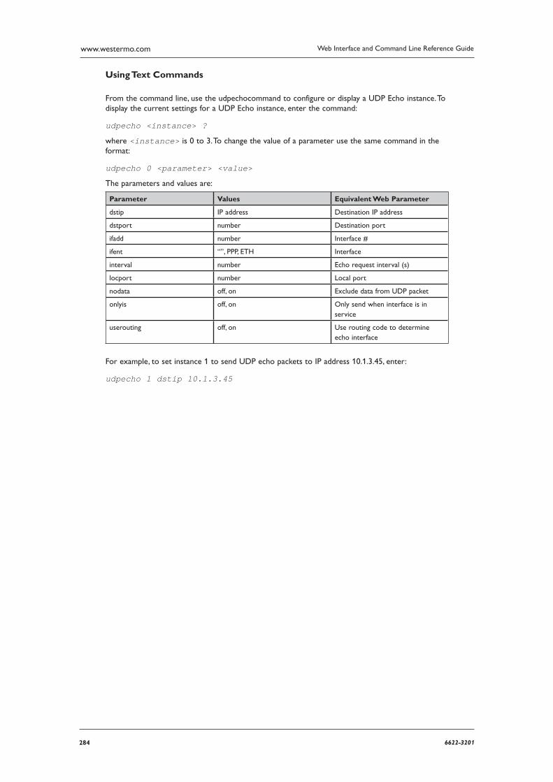
284 6622-3201
Web Interface and Command Line Reference Guidewww.westermo.com
Using Text Commands
From the command line, use the udpechocommand to configure or display a UDP Echo instance. To display the current settings for a UDP Echo instance, enter the command:
udpecho <instance> ?
where <instance> is 0 to 3. To change the value of a parameter use the same command in the format:
udpecho 0 <parameter> <value>
The parameters and values are:
Parameter Values Equivalent Web Parameter
dstip IP address Destination IP address
dstport number Destination port
ifadd number Interface #
ifent “”, PPP, ETH Interface
interval number Echo request interval (s)
locport number Local port
nodata off, on Exclude data from UDP packet
onlyis off, on Only send when interface is in service
userouting off, on Use routing code to determine echo interface
For example, to set instance 1 to send UDP echo packets to IP address 10.1.3.45, enter:
udpecho 1 dstip 10.1.3.45
2856622-3201
Web Interface and Command Line Reference Guide www.westermo.com
Confi gure > Users > User n 4.100
The unit allows you to define a number of authorised users. The number of users available depends upon the software build that your unit is running. Each user has a password and an access level that determines what facilities the user has access to.
Using the Web Page(s)
The Configure > Users > User n pages display options that allow you to set the following param-eters for each user:
Name:
Enter a username of up to 14 characters.
Password:
Enter a password for the user of up to 14 characters.
Confirm Password:
Re-enter the Password in this field to confirm it.
New Password:
When IKE is the initiator, the responder supplied HASH is checked using the normal password and if that fails, the new password. The initiator will remember which password was successful, and use that password to create the HASH if it becomes the responder of some new negotia-tion. If the IKE becomes responder and IKE negotiations fail after supplying the HASH, the other password will be used during the next negotiation.
Using this new password, it should be possible to configure new passwords into both ends of a tunnel, and not have too many failed negotiations. The process would be to add the new pass-word into the remote box, then update the site database with the new password. Once that has been done, the administrator would then be able to move the new password to the usual location and remove the ‘newpwd’ from the configuration. Should a negotiation take place dur-ing the period where the new password has been entered into the remote box, but not the database, there should be no more than one failed negotiation, and only if the remote box is the initiator.
Confirm New Password:
Re-enter the Password in this field to confirm it.
Access Level:
Select the access level for the User. “Super” allows full access to all facilities.
“High” allows users to change some settings such as the time & date and to reconfigure the general operation of the unit. However, a High level user cannot change User settings. “Medium” allows read-only access, i.e. the user will not be able to alter any of the configuration settings. “Low” allows the user access to commands whose access level is “Low” or “None”. “None” allows the user access to commands whose access level is “None”. User’s whose access level is “None” are not able to log in to the unit via the Web, FTP, SSH or TELNET.
286 6622-3201
Web Interface and Command Line Reference Guidewww.westermo.com
Remote Peer Address & Remote Subnet Address
In the event that multiple PPP instances are enabled for answering and that multiple remote routers can dial into the local router, static routes cannot always be used to ensure that packets which should be routed to the remote network are sent through the correct PPP interface. These parameters can be used in conjunction with the IP mask parameter to associate a net-work address with a user.
When a remote unit “dials in” and authenticates with the unit, the unit will then create a dynamic route (that will override any static routes) for the duration of the PPP session. The interface for the dynamic route will be the PPP interface that answered the call. The network address for the dynamic route will be taken from the entry in the user table that matches the username that the remote unit used during the PPP authentication.
Remote subnet mask
The remote subnet mask parameter is used in conjunction with the remote peer address parameter above to fully qualify the network address for the user.
Dialback number
This parameter is used to specify a telephone number for the user in the event that “dial-back” is required. If the username that the remote router uses during the PPP authentication matches an entry in the user table where a Dialback number is specified, this Dialback number will over-ride any Dialback number specified in the answering PPP interface.
Public Key file
This parameter contains the filename of the file containing the public key for that user. If the public key matches the client supplied public key, the user is allowed access.
DUN access enabled
Setting this parameter to “Yes” will allow the user to log in to the unit using PPP. Setting this parameter to “No” will disable PPP login for the user no matter what the user’s access level is.
Web page display mode
Select the default web view for a user. Basic will show a reduced set of configuration options, Advanced will show all configuration options. Setting this parameter to Auto will use the display mode pre-configured to the users access level, access levels Low & Medium show the basic parameters, access levels High & Super show all the configuration options. Default value is Auto
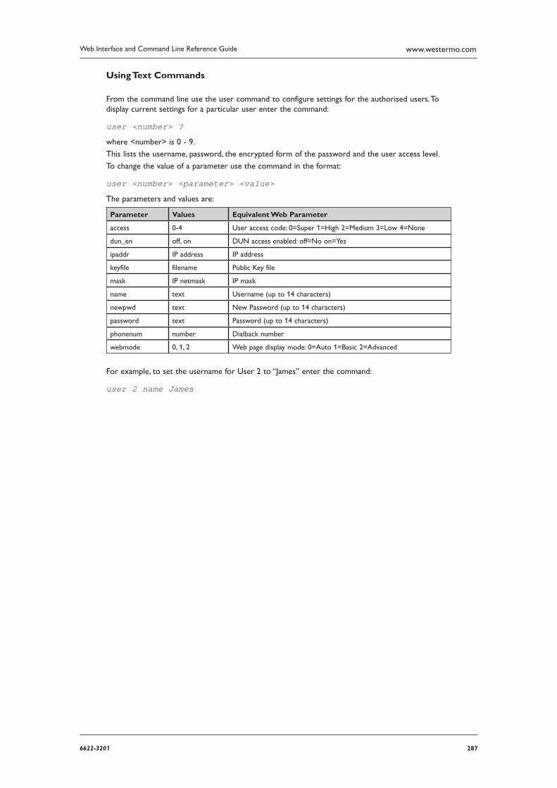
2876622-3201
Web Interface and Command Line Reference Guide www.westermo.com
Using Text Commands
From the command line use the user command to configure settings for the authorised users. To display current settings for a particular user enter the command:
user <number> ?
where <number> is 0 - 9.
This lists the username, password, the encrypted form of the password and the user access level.
To change the value of a parameter use the command in the format:
user <number> <parameter> <value>
The parameters and values are:
Parameter Values Equivalent Web Parameter
access 0-4 User access code: 0=Super 1=High 2=Medium 3=Low 4=None
dun_en off, on DUN access enabled: off=No on=Yes
ipaddr IP address IP address
keyfile filename Public Key file
mask IP netmask IP mask
name text Username (up to 14 characters)
newpwd text New Password (up to 14 characters)
password text Password (up to 14 characters)
phonenum number Dialback number
webmode 0, 1, 2 Web page display mode: 0=Auto 1=Basic 2=Advanced
For example, to set the username for User 2 to “James” enter the command:
user 2 name James
288 6622-3201
Web Interface and Command Line Reference Guidewww.westermo.com
Confi gure > VXN client 4.101
Datawire’s VXN® protocol acts as a replacement to X.25 and the Layer 2 protocol that X.25 is carried over. The Westermo unit still uses the X.25 entity to handle VXN sessions for the sake of convenience.
Using the Web Page(s)
Service name:
The name of the Datawire VXN server to use. This is supplied by Datawire.
Primary host name:
The primary hostname to connect to when locating the Datawire VXN servers. Supplied by Datawire.
Primary port:
TCP port to use in conjunction with the Primary hostname. Supplied by Datawire.
Secondary host name:
Secondary hostname to connect to when locating the Datawire VXN servers. Supplied by Datawire
.
Secondary port:
TCP port to use in conjunction with the Secondary hostname. Supplied by Datawire.
Merchant ID:
Currently a fixed string used by the unit when setting up security associations with the VXN server. In the future, the Merchant ID will be supplied by the service making the transaction request (e.g. TPAD), and may be extracted from the transaction itself.
Terminal ID:
Currently a fixed string. In the future, the Terminal ID will be supplied by the service making the transaction request.
OPNS server name:
The server name to use during OPNS negotiations. This parameter is supplied by Datawire, and is currently set to “OPNS Server”.
OPNS service name:
The service to be used during OPNS negotiations, which is different to the service used for trans actions. This parameter is supplied by Datawire, and will usually be “opns.dw”.
Keep socket open between transactions:
When this parameter is set to “No”, the TCP socket will be closed once all outstanding transac-tions are completed. When this parameter is set to “Yes”, the socket will be left open, however the server may close the socket if it is inactive for a long time.
Socket connection timeout (s):
This is the maximum time to wait for a connection to the VXN server to be established.
Transaction timeout (s):
This is the maximum time to wait for a transaction to be completed.

2896622-3201
Web Interface and Command Line Reference Guide www.westermo.com
Service discovery timeout (s):
This is the maximum time to wait (after the socket has opened) for a response when query-ing for services to access. The IP addresses and ports which of these services are stored within the unit. When the first transaction is performed, a table of all available IP addresses and ports providing access to the service name is populated by querying the primary and secondary hosts. Subse quent transactions use the same IP addresses/ports until a connection fails, at which time the failed entry is removed. When there are none left, the table will be repopulated when the next transaction takes place.
Retries:
The maximum number of times the unit should attempt to perform the transaction before the trans action is considered to have failed.
Key Synchronisation timeout (s):
Key synchronisation is normally only required once between the unit and the Datawire host. How ever, there may be times when the host loses synchronisation, which would result in an error response when the next transaction is received. This parameter defines the time that must elapse between transactions before the unit will perform another key synchronisation.
Perform initialisation with server at power up:
When this parameter is set to “No”, the primary and secondary hostnames are not resolved until the first transaction request is made. When this parameter is set to “Yes”, the unit will attempt to resolve the hostnames and populate the service addresses table when the unit first powers up.
Enable automatic online PUK negotiation (OPNS):
When the unit is powered up, it checks to see if a PUK (Power Up Key) exists in the Flash memory of the unit. If it does not find a PUK, it is not possible to use the VXN service to trans-port transac tion requests. If this parameter is set to “Yes”, and the required fields are configured, the unit will automatically attempt to negotiate a PUK with the OPNS server.
Enable debug output:
When this parameter is set to “Yes”, debug information about the VXN task is routed to the debug port
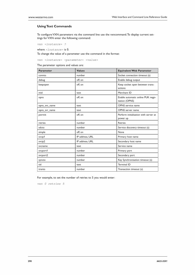
290 6622-3201
Web Interface and Command Line Reference Guidewww.westermo.com
Using Text Commands
To configure VXN parameters via the command line use the vxncommand. To display current set-tings for VXN enter the following command:
vxn <instance> ?
where <instance> is 0.
To change the value of a parameter use the command in the format:
vxn <instance> <parameter> <value>
The parameter options and values are:
Parameter Values Equivalent Web Parameter
connto number Socket connection timeout (s)
debug off, on Enable debug output
keepopen off, on Keep socket open between trans-actions
mid text Merchant ID
opns off, on Enable automatic online PUK nego-tiation (OPNS)
opns_svc_name text OPNS service name
opns_svr_name text OPNS server name
pwrinit off, on Perform initialisation with server at power up
retries number Retries
sdcto number Service discovery timeout (s)
simple off, on None
svcip1 IP address, URL Primary host name
svcip2 IP address, URL Secondary host name
svcname text Service name
svcport1 number Primary port
svcport2 number Secondary port
syncto number Key Synchronisation timeout (s)
tid text Terminal ID
tranto number Transaction timeout (s)
For example, to set the number of retries to 5 you would enter:
vxn 0 retries 5
2916622-3201
Web Interface and Command Line Reference Guide www.westermo.com
Confi gure > W-WAN 4.102
Wirelss WAN functionality is only available on models that are fitted with a wireless WAN module, such as CDMA, GPRS, 3G, HSDPA etc. This module is connected to one of the ASY ports (and USB controller on some models) and is controlled by the router using “AT” commands (in the same way as a modem). Any further references to W-WAN technologies such as CDMA, GPRS, 3G etc will be refered to as GPRS, GSM, 3G or simply ‘wireless’ networks.
W-WAN modules provide always-on wireless data connectively over the GSM network at speeds of up to 7.2Mbps. This means that the unit can be used in situations where no ISDN or xDSL service connection is available. In addition, wireless can be used to send or receive SMS alert messages (as an alternative to emails for issuing remote alert messages or for automating remote configuration of deployed units).
Before attempting to connect to a wireless service, you need to set several parameters specific to your mobile network operator. It will be useful to have the following information to hand:
Your assigned APN (Access Point Name)
PIN Number for your SIM card (if any)
Username and password
Note: Some SIMs require that a username and password are used in addition to the APN. These are not always pre-defined i.e. any “made-up” username or password will suffice. If you suspect that this is the case for your SIM then please enter a username and password into the username and password parameters for the W-WAN PPP instance.
Once your W-WAN unit is correctly configured you can check to see if it has obtained an IP address from the network by navigating to the Status > PPP > PPP x page (where x is either 1 or 3 depending on the model) and checking the IP address parameter. (It should contain an IP address other than 0.0.0.0 or 1.2.3.4).
Additionally you can check that the SIM is working correctly and also check the signal strength by navigating to the Status > W-WAN page.
Using the Web Page(s)
Note: If your unit has more than one SIM card slot, the following parameters will appear on the Configure > W-WAN > SIM n pages.
APN:
When using a W-WAN router, you must inform the mobile network which remote host you wish to connect to. You do this by specifying an Access Point Name (APN). Your network pro-vider or your system administrator will provide this information if you have a private APN.
Often this will look like an Internet address such as “isp.vodafone.ie”, but can also be a simple text string such as “orangeinternet” or “internet”. Be sure to enter this correctly otherwise you will be unable to make a connection to the network.
Static IP address:
You can specify an IP address associated with the APN.
Use back-up APN: This parameter is used to turn the Backup APN facility “On” or “Off”.
Back-up APN:
This parameter may be used to specify an alternative service APN for use in the event that the unit cannot connect using the primary APN specified by the APN parameter. The unit will only use this APN if the primary APN fails and the Use backup APN parameter is enabled.
292 6622-3201
Web Interface and Command Line Reference Guidewww.westermo.com
Backup static IP address:
This parameter may be used to specify an IP address associated with the Backup APN for use when the unit cannot connect using the primary Static IP address.
Retry APN time (mins):
If the Use backup APN parameter is enabled, this parameter is used to define how long the unit will use the backup APN before attempting to revert to the primary APN.
PIN:
Some SIM cards are locked with a Personal Identification Number (PIN) code to prevent misuse if they are lost or stolen. Your GSM operator should be able to tell you if your SIM has a PIN code as supplied.
If you enter a PIN code in this field, the unit will try to unlock the SIM before attempting to connect to the network.
Note: The PIN code is not shown for security reasons and it is essential that you enter this correctly as three incorrect attempts will usually block the SIM card from use. In this event, you will need to remove the SIM card from the unit and insert it into a mobile phone then enter the Personal Unblocking Key (PUK), which can be obtained from the network operator.
Confirm PIN:
Enter the PIN again in this field to confirm it.
PUK: / Confirm PUK:
If known, the SIM PUK code can be entered in these fields. If the router detects that a PUK is required due to a locked SIM, this number will be sent to the SIM. A SIM PIN must also be con-figured for the PUK parameter to take affect.
Initialisation string <n>:
These parameters (Initialisation string 1, Initialisation string 2, etc.) allow you to specify a number of command strings that are sent to the wireless module each time a wireless connec-tion is attempted. These can be used to set non-standard wireless operating modes. Each string is prefixed with the characters “AT” before being sent to the wireless module and they are sent to the wireless module in the order specified until an empty string is encountered. For example, Initialisation string 3 will not be sent unless Initialisation string 1 and Initialisation string 2 are both specified. Initialisation strings are not normally required for most applications as the unit will normally be pre-configured for correct operation with most networks.
Network preference/locking string:
This parameter can be used to specify the mobile network to try to connect to first or to lock to. Using the Preferred and Lock buttons in the webpage Status > W-WAN module will auto fill this parameter.
Hang-up string:
In a typical wireless application the connection to the network is “always on” and under normal circumstances it is not necessary to hang-up the wireless module. Under certain circumstances however, the router may use the “ATH” command to try and disconnect the wireless module from the network, e.g. if an incorrect APN has been specified and the module is unable to attach to the network correctly.
This parameter allows you to specify an alternative hang-up string that is sent to the wireless module when disconnecting a call. As with the Initialisation strings, it is not necessary to include the “AT” as this is inserted automatically by the router.
Post Hang-up string:
This parameter allows you to specify additional “AT” commands that is sent to the wireless module after it has been disconnected. As with the Initialisation strings, it is not necessary to include the “AT” as this is inserted automatically by the router.
2936622-3201
Web Interface and Command Line Reference Guide www.westermo.com
Intercall idle time (s):
This parameter allows is used to specify the length of time (in seconds) that the router will wait after hanging-up the wireless module before initiating another call attempt.
Link retries:
The router will normally make multiple attempts to connect to the wireless network in the event that the signal is lost. In some cases, this can result in a “lock-up” situation where the wireless network is unable to attach the wireless device due to the multiple attempts. The Link retries parameter specifies the number of attempts at connection that the unit should make before power cycling the internal wireless module. Power cycling the wireless module forces it to re-register and reattach to the network. The default setting of 10 is the recommended value. Setting this parameter to 0 will prevent the router from power cycling the wireless module if it cannot obtain an IP address.
Status retries:
The router will periodically collect status information from the internal wireless module. This information, which may be viewed on the Status > W-WAN web page, includes details of the signal strength and network attachment status. As a safeguard against problems communicating with the wireless module, the Status retries parameter may be used to specify the number of unsuccessful attempts to retrieve status information from the wireless module before power cycling it. The default setting of 30 is the recommended value. Setting this parameter to 0 will prevent the router from power cycling the wireless module if it cannot read the wireless status information.
Signal strength event interval (mins):
When configurered, the signal strength will be written to the eventlog every n minutes.
Minimum attach interval (secs):
The number of seconds between network attachment attempts, some networks require 60 sec-onds between attempts to attach to the wireless network.
Power cycle on loss of registration:
This parameter controls whether the unit will power cycle the wireless module after the net-work registration has been lost for 5 minutes. Setting this parameter to “Never” will never recy-cle the wireless module, setting to “GSM only” will power cycle the module after 5 minutes loss of GSM registration, and setting to “GPRS only” will power cycle the module after 5 minutes loss of GPRS, 3G or HSPA registration.
SMS message centre:
This is the number of the SMS message centre (sometimes referred to as the Service Centre Address), to be used to relay SMS messages or alarms. This number must include the interna-tional dialling code, e.g. 44 for the UK, but not the “+” prefix or leading 0’s, e.g. 44802000332. SMS alarms are generated when the SMS trigger priority is greater than 0 and an event of this priority or higher occurs. SMS messages may be edited and sent using the Configure > SMS
Edit page.
If no number is specified it is possible that the unit will operate using the default message centre for the GSM service to which you have subscribed.
SMS polling interval (mins):
This specifies the interval in minutes that the unit will wait in between checks for incoming SMS messages. Setting this interval to 0 turns off checking.
SMS command caller ID:
This parameter specifies a number that is compared with the trailing digits of the SMS sender’s phone number. If the numbers match, then the SMS text is treated as if it were a text command being entered via one of the serial ports. If the parameter is left blank, SMS messages are logged in the event log but are not treated as commands.
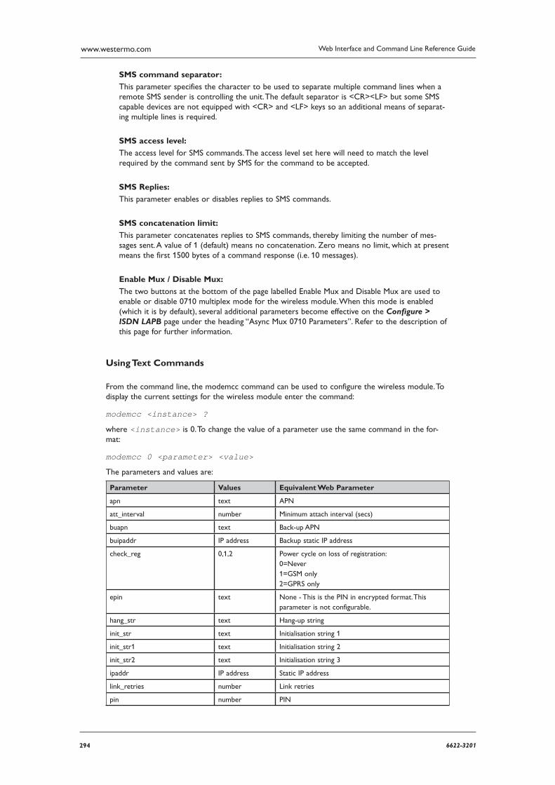
294 6622-3201
Web Interface and Command Line Reference Guidewww.westermo.com
SMS command separator:
This parameter specifies the character to be used to separate multiple command lines when a remote SMS sender is controlling the unit. The default separator is <CR><LF> but some SMS capable devices are not equipped with <CR> and <LF> keys so an additional means of separat-ing multiple lines is required.
SMS access level:
The access level for SMS commands. The access level set here will need to match the level required by the command sent by SMS for the command to be accepted.
SMS Replies:
This parameter enables or disables replies to SMS commands.
SMS concatenation limit:
This parameter concatenates replies to SMS commands, thereby limiting the number of mes-sages sent. A value of 1 (default) means no concatenation. Zero means no limit, which at present means the first 1500 bytes of a command response (i.e. 10 messages).
Enable Mux / Disable Mux:
The two buttons at the bottom of the page labelled Enable Mux and Disable Mux are used to enable or disable 0710 multiplex mode for the wireless module. When this mode is enabled (which it is by default), several additional parameters become effective on the Configure > ISDN LAPB page under the heading “Async Mux 0710 Parameters”. Refer to the description of this page for further information.
Using Text Commands
From the command line, the modemcc command can be used to configure the wireless module. To display the current settings for the wireless module enter the command:
modemcc <instance> ?
where <instance> is 0. To change the value of a parameter use the same command in the for-mat:
modemcc 0 <parameter> <value>
The parameters and values are:
Parameter Values Equivalent Web Parameter
apn text APN
att_interval number Minimum attach interval (secs)
buapn text Back-up APN
buipaddr IP address Backup static IP address
check_reg 0,1,2 Power cycle on loss of registration: 0=Never 1=GSM only 2=GPRS only
epin text None - This is the PIN in encrypted format. This parameter is not con figurable.
hang_str text Hang-up string
init_str text Initialisation string 1
init_str1 text Initialisation string 2
init_str2 text Initialisation string 3
ipaddr IP address Static IP address
link_retries number Link retries
pin number PIN
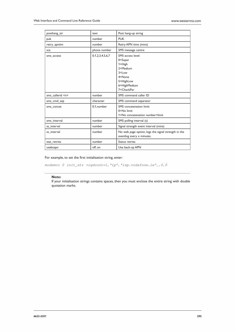
2956622-3201
Web Interface and Command Line Reference Guide www.westermo.com
posthang_str text Post hang-up string
puk number PUK
retry_apntim number Retry APN time (mins)
sca phone number SMS message centre
sms_access 0,1,2,3,4,5,6,7 SMS access level: 0=Super 1=High 2=Medium 3=Low 4=None 5=HighLow 6=HighMedium 7=CheckPar
sms_callerid <n> number SMS command caller ID
sms_cmd_sep character SMS command separator
sms_concat 0,1,number SMS concatenation limit: 0=No limit 1=No concatenation number=limit
sms_interval number SMS polling interval (s)
ss_interval number Signal strength event interval (mins)
ss_interval number No web page option, logs the sig nal strength in the eventlog every x minutes.
stat_retries number Status retries
usebuapn off, on Use back-up APN
For example, to set the first initialisation string, enter:
modemcc 0 init_str +cgdcont=1,“ip”,“isp.vodafone.ie”,,0,0
Note: If your initialisation strings contains spaces, then you must enclose the entire string with double quo tation marks.
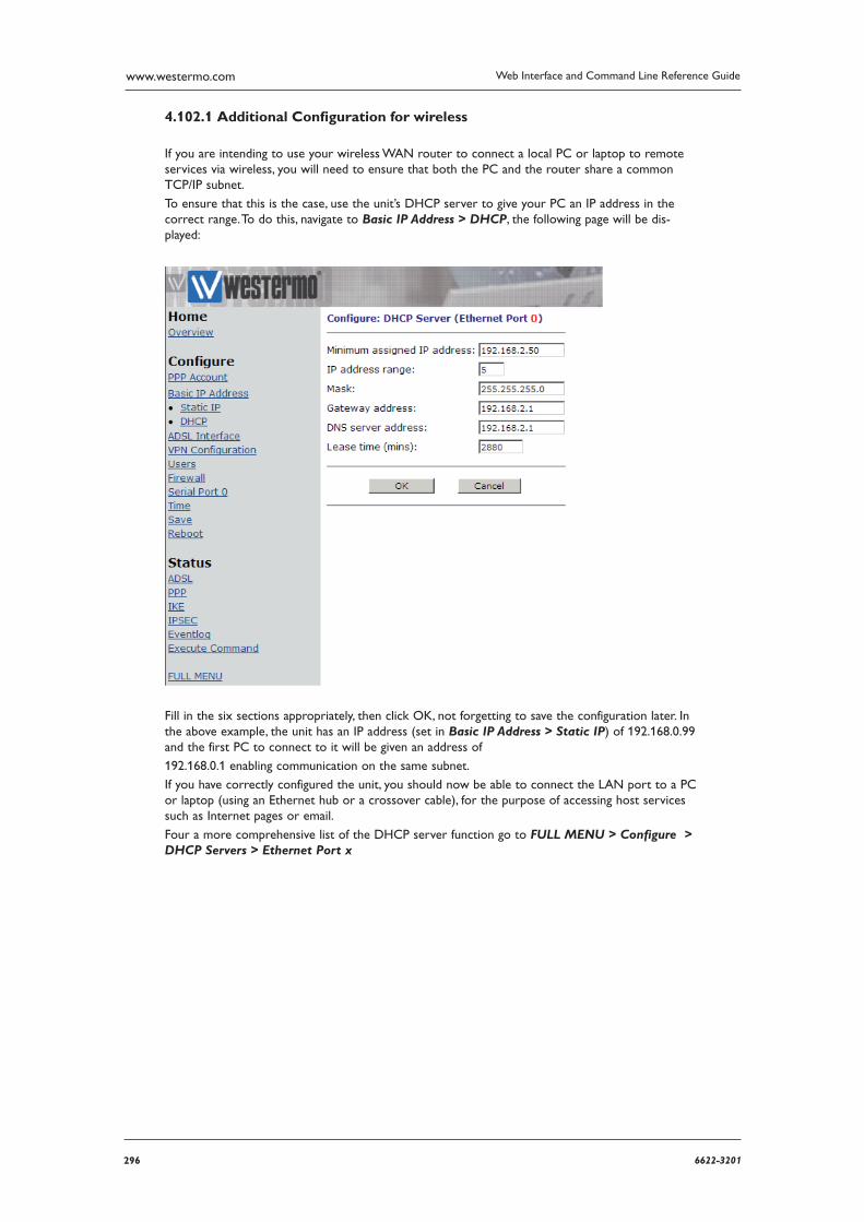
296 6622-3201
Web Interface and Command Line Reference Guidewww.westermo.com
Additional Confi guration for wireless 4.102.1
If you are intending to use your wireless WAN router to connect a local PC or laptop to remote services via wireless, you will need to ensure that both the PC and the router share a common TCP/IP subnet.
To ensure that this is the case, use the unit’s DHCP server to give your PC an IP address in the correct range. To do this, navigate to Basic IP Address > DHCP, the following page will be dis-played:
Fill in the six sections appropriately, then click OK, not forgetting to save the configuration later. In the above example, the unit has an IP address (set in Basic IP Address > Static IP) of 192.168.0.99 and the first PC to connect to it will be given an address of
192.168.0.1 enabling communication on the same subnet.
If you have correctly configured the unit, you should now be able to connect the LAN port to a PC or laptop (using an Ethernet hub or a crossover cable), for the purpose of accessing host services such as Internet pages or email.
Four a more comprehensive list of the DHCP server function go to FULL MENU > Configure > DHCP Servers > Ethernet Port x
2976622-3201
Web Interface and Command Line Reference Guide www.westermo.com
Confi gure > W-WAN module > Cell Monitor 4.103
The Cell Monitor retrieves information about the GSM network and displays the following:
The parameters of the GSM cell currently being used to provide the communications link (typ ically GPRS), known as the serving cell
The parameters of neighbouring GSM cells
GPRS specific parameters
Using the Web Page(s)
Monitor settings
This section contains parameters that determine what information is collected by the Cell Monitor, and how often.
Neighbour cells
If this parameter is selected, the Cell Monitor will retrieve information about the neighbouring cells.
Serving cell
If this parameter is selected, the Cell Monitor will retrieve information about the GSM cell cur-rently being used to provide the communications link.
GPRS information
If this parameter is selected, the Cell Monitor will retrieve GPRS specific cell information.
Monitoring interval (s):
When this parameter is set to a non zero value, this specifies the interval (in seconds) between information retrieval. A value of zero disables monitoring.
Email settings
The Cell Monitor may be configured to send an email at specified intervals. The parameters are as follows:
Email interval (mins):
This parameter specifies the interval (in minutes) between email transmissions.
Attach Event Log
If this parameter is selected, the unit’s event log will be sent with the email as an attachment.
Email To:
This parameter specifies a destination email address. Multiple email addresses may be specified by separating each address with a comma.
Email From:
This parameter specifies the identify of the sender of the email.
Email Subject:
This parameter specifies a subject to describe the contents of the email.
Email Template:
This parameter specifies the name of a file on the unit to be used as a template for the email.
298 6622-3201
Web Interface and Command Line Reference Guidewww.westermo.com
IP connection settings
The Cell Monitor may be configured to transmit the data it retrieves to a specified TCP/IP address/port. The parameters are as follows:
IP address:
This parameter specifies an IP address to which the unit will attempt to establish a TCP/IP con-nection. The TCP/IP port must be specified. Any retrieved data is then transmitted over this con-nection
.
TCP/IP port:
This parameter specifies the destination TCP/IP port number to be used for the connection. The recently retrieved Cell Monitor information may be viewed on the following web pages:
Status > W-WAN > Neighbour Cells
Status > W-WAN > Serving Cell
Status > W-WAN > W-WAN Cell Info
Using Text Commands
From the command line, the cellmon command can be used to configure the Cell Monitor. To dis-play the current settings for the Cell Monitor enter the command:
cellmon 0 ?
To change the value of a parameter use the same command in the format:
cellmon 0 <parameter> <value>
The parameters and values are:
Parameter Values Equivalent Web Parameter
att_elog off, on Attach event log
emailfrom text Email From
emailint number Email interval (mins)
emailto text Email To
etemplate filename Email Template
ipaddr IP address IP address
ipport number TCP/IP port
mon_int number Monitoring interval (s)
mong_on off, on GPRS information
moni_on off, on Serving cells
monp_on off, on Neighbour cells
subject text Email subject
For example, to disable monitoring of neighbour cells, enter:
cellmon 0 monp_on off
2996622-3201
Web Interface and Command Line Reference Guide www.westermo.com
Confi gure > X25 > NUI Mappings 4.104
When a TPAD call is taking place the attached terminal sometimes only specifies an “NUI” (Network User ID) to call. If the X.25 network requires an NUA instead of an NUI to determine the destination of a call then the NUI Mappings table can be used to convert an NUI to an NUA.
If a TPAD call specifies a call in which the NUI matches an entry the call actually placed on the net-work will contain the respective NUA and no NUI.
Using the Web Page(s)
The Configure > X25 > NUI Mappings web page displays a table with two columns in which you can specify up to 20 NUI values and their corresponding NUA values.
Using Text Commands
From the command line, use the nuimap command to configure or display an NUI mapping. To dis-play a current NUI mapping enter:
nuimap <instance> ?
where <instance> is 0 - 19. To change the value of a parameter us the following command:
nuimap <instance> <parameter> <value>
The parameters and values are:
Parameter Values Equivalent Web Parameter
nua text Map to NUA
nui text NUI
300 6622-3201
Web Interface and Command Line Reference Guidewww.westermo.com
Confi gure > X25 4.105
Using the Web Page(s)
Use addresses from call in accept for LAPD:
When this parameter is set to “On” then when X.25 is answering a call on the LAPD interface the called and calling addresses from the CALL packet are used in the X25 CALL CNF (call confirm packet) that the unit sends to answer the call.
Use addresses from call in accept for LAPB:
When this parameter is set to “On” then when X.25 is answering a call on the LAPB interface the called and calling addresses from the CALL packet are used in the X25 CALL CNF (call confirm packet) that the unit sends to answer the call.
Use addresses from call in accept for XOT:
When this parameter is set to “On” then when X.25 is answering a call on the XOT interface the called and calling addresses from the CALL packet are used in the X25 CALL CNF (call confirm packet) that the unit sends to answer the call.
Reset XOT PVC if Initiator:
When this parameter is set to “On” the unit is responsible for resetting the links when an XOT PVC comes up. This parameter should only be set to “Off” when it is known that the responder will reset the links.
Reset XOT PVC if Responder:
When this parameter is set to “On” the unit is responsible for resetting the links on XOT PVC links when it is the responder. The default for this parameter is “Off”.
Include length of header in IP length header:
For all X.25 calls which include an IP header length indication (i.e. IP Length Header is set to “On” a TPAD or PAD, etc.) this parameter specifies whether the length indicated includes or excludesthe length of the header itself. By default it is “Off”, in which the length of the header is NOT included in the value. For exam-ple, say we had one byte of data of value 67 to encode. Then “00 01 67” is the encoding if this param eter is set to “Off” as the length (00 01) is 1 because the length does not include the length of the header. When set to “On” the length of the IP header is included in the value, i.e. “00 03 67” is the encoding as the header bytes are included.
3016622-3201
Web Interface and Command Line Reference Guide www.westermo.com
Using Text Commands
From the command line, use the x25gen command to configure or display X.25 general settings. To display current settings for X.25 enter the following command:
x25gen <instance> ?
where <instance> is 0. At present there can only be one x.25 instance, i.e. 0, but the instance parameter has been included to allow for future expansion. To change the value of a parameter use the following command:
x25gen 0 <parameter> <value>
The parameters and values are:
Parameter Values Equivalent Web Parameter
en_incl_iphdr off, on Include length of header in IP length header
lapb_cnf_addr off, on Use addresses from call in accept for LAPB
lapd_cnf_addr off, on Use addresses from call in accept for LAPD
reset_xotpvc_ini off, on Reset XOT PVC if Initiator
reset_xotpvc_resp off, on Reset XOT PVC if Responder
xot_cnf_addr off, on Use addresses from call in accept for XOT
For example, to include the header length in the IP length header you would enter:
x25gen 0 en_incl_iphdr on

302 6622-3201
Web Interface and Command Line Reference Guidewww.westermo.com
Confi gure > X25 > Macros 4.106
This page allows you to define up to 64 X.25 CALL “macros” that can be used to initiate ISDN and/or X.25 layer 3 calls. These simple English-like names are mapped to full command strings. For example, the call string:
0800123456=789012Dtest data
could be given the name “X25test” and then executed simply by entering:
CALL X25test
Using the Web Page(s)
To create a macro, enter a name for the macro in the left column of the Configure > X25 > Macros table and in the right column enter the appropriate command string (excluding the ATD which is inserted automatically).
Using Text Commands
From the command line the macro command may be used to define CALL macros. To set up a new macro, two commands are required in the form:
macro <instance> name <name>
macro <instance> cmd <cmd>
The first command assigns the name <name> to macro instance <instance>where <instance>is 0 - 63. The second assigns the command string <cmd> to macro instance <instance>.
For example:
macro 5 name X25test
macro 5 cmd 0800123456=789012Dtest data
To display the current values for a particular macro use the macrocommand in the following format:
macro <instance> ? where <instance> is 0 - 63
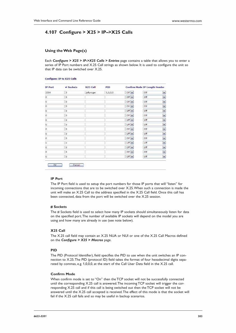
3036622-3201
Web Interface and Command Line Reference Guide www.westermo.com
Confi gure > X25 > IP–>X25 Calls 4.107
Using the Web Page(s)
Each Configure > X25 > IP->X25 Calls > Entries page contains a table that allows you to enter a series of IP Port numbers and X.25 Call strings as shown below. It is used to configure the unit so that IP data can be switched over X.25.
IP Port
The IP Port field is used to setup the port numbers for those IP ports that will “listen” for incoming connections that are to be switched over X.25. When such a connection is made the unit will make an X.25 Call to the address specified in the X.25 Call field. Once this call has been connected, data from the port will be switched over the X.25 session.
# Sockets
The # Sockets field is used to select how many IP sockets should simultaneously listen for data on the specified port. The number of available IP sockets will depend on the model you are using and how many are already in use (see note below).
X25 Call
The X.25 call field may contain an X.25 NUA or NUI or one of the X.25 Call Macros defined on the Configure > X25 > Macros page.
PID
The PID (Protocol Identifier), field specifies the PID to use when the unit switches an IP con-nection to X.25. The PID (protocol ID) field takes the format of four hexadecimal digits sepa-rated by com mas, e.g. 1,0,0,0, at the start of the Call User Data field in the X.25 call.
Confirm Mode
When confirm mode is set to “On” then the TCP socket will not be successfully connected until the corresponding X.25 call is answered. The incoming TCP socket will trigger the cor-responding X.25 call and if this call is being switched out then the TCP socket will not be answered until the X.25 call accepted is received. The effect of this mode is that the socket will fail if the X.25 call fails and so may be useful in backup scenarios.
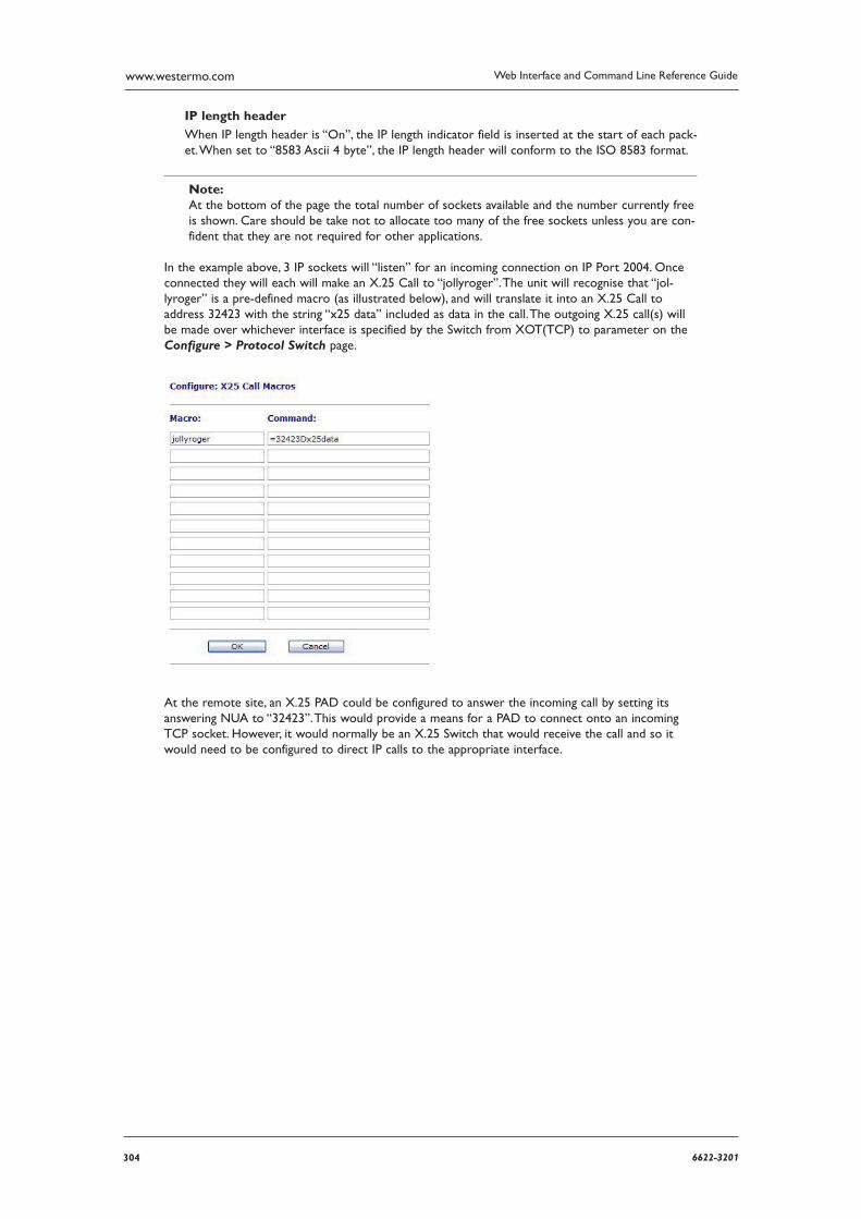
304 6622-3201
Web Interface and Command Line Reference Guidewww.westermo.com
IP length header
When IP length header is “On”, the IP length indicator field is inserted at the start of each pack-et. When set to “8583 Ascii 4 byte”, the IP length header will conform to the ISO 8583 format.
Note: At the bottom of the page the total number of sockets available and the number currently free is shown. Care should be take not to allocate too many of the free sockets unless you are con-fident that they are not required for other applications.
In the example above, 3 IP sockets will “listen” for an incoming connection on IP Port 2004. Once con nected they will each will make an X.25 Call to “jollyroger”. The unit will recognise that “jol-lyroger” is a pre-defined macro (as illustrated below), and will translate it into an X.25 Call to address 32423 with the string “x25 data” included as data in the call. The outgoing X.25 call(s) will be made over whichever interface is specified by the Switch from XOT(TCP) to parameter on the Configure > Protocol Switch page.
At the remote site, an X.25 PAD could be configured to answer the incoming call by setting its answer ing NUA to “32423”. This would provide a means for a PAD to connect onto an incoming TCP socket. However, it would normally be an X.25 Switch that would receive the call and so it would need to be configured to direct IP calls to the appropriate interface.
3056622-3201
Web Interface and Command Line Reference Guide www.westermo.com
Using Text Commands From the command line, use the ipx25 command to configure IP to X.25 calls. To display the current mappings enter the following command:
ipx25 <n> ?
where <n> is the table entry number, i.e. 0 - 255. To change the value of a parameter use the fol-lowing command:
ipx25 <n> <parameter> <value>
The parameters and values are:
Parameter Values Equivalent Web Parameter
cnf_mode 0.,1 Confirm Mode: 0=Off 1=On
ip_port number IP Port
iphdr 0,1,2 IP length header: 0=Off 1=On 2=8583 Ascii 4 byte
nb_listens number # Ports
pid hex numbers PID
x25call NUA, NUI or X.25 macro name X25 Call
For example, to set up table row 1 from the example you would enter the following series of com-mands:
ipx25 0 iphdr 0 ipx25 0 ip_port 2004 ipx25 0 nb_listens 3 ipx25 0 x25call jollyroger
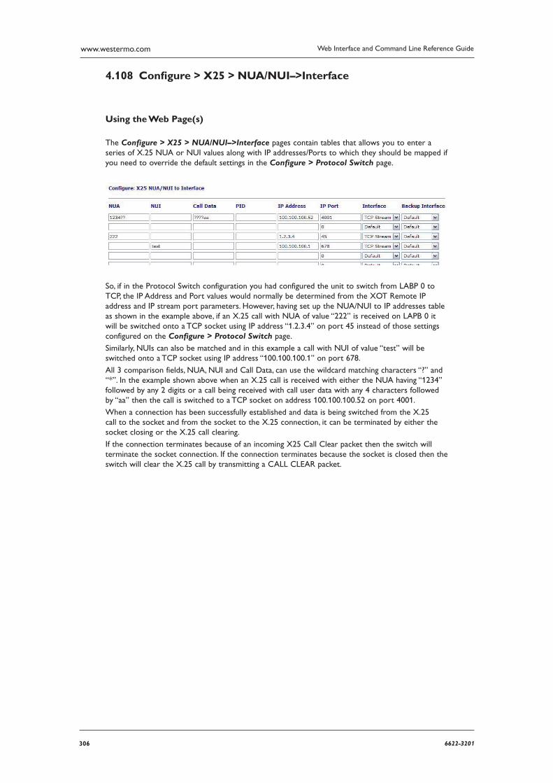
306 6622-3201
Web Interface and Command Line Reference Guidewww.westermo.com
Confi gure > X25 > NUA/NUI–>Interface 4.108
Using the Web Page(s)
The Configure > X25 > NUA/NUI–>Interface pages contain tables that allows you to enter a series of X.25 NUA or NUI values along with IP addresses/Ports to which they should be mapped if you need to override the default settings in the Configure > Protocol Switch page.
So, if in the Protocol Switch configuration you had configured the unit to switch from LABP 0 to TCP, the IP Address and Port values would normally be determined from the XOT Remote IP address and IP stream port parameters. However, having set up the NUA/NUI to IP addresses table as shown in the example above, if an X.25 call with NUA of value “222” is received on LAPB 0 it will be switched onto a TCP socket using IP address “1.2.3.4” on port 45 instead of those settings configured on the Configure > Protocol Switch page.
Similarly, NUIs can also be matched and in this example a call with NUI of value “test” will be switched onto a TCP socket using IP address “100.100.100.1” on port 678.
All 3 comparison fields, NUA, NUI and Call Data, can use the wildcard matching characters “?” and “*”. In the example shown above when an X.25 call is received with either the NUA having “1234” followed by any 2 digits or a call being received with call user data with any 4 characters followed by “aa” then the call is switched to a TCP socket on address 100.100.100.52 on port 4001.
When a connection has been successfully established and data is being switched from the X.25 call to the socket and from the socket to the X.25 connection, it can be terminated by either the socket clos ing or the X.25 call clearing.
If the connection terminates because of an incoming X25 Call Clear packet then the switch will termi nate the socket connection. If the connection terminates because the socket is closed then the switch will clear the X.25 call by transmitting a CALL CLEAR packet.
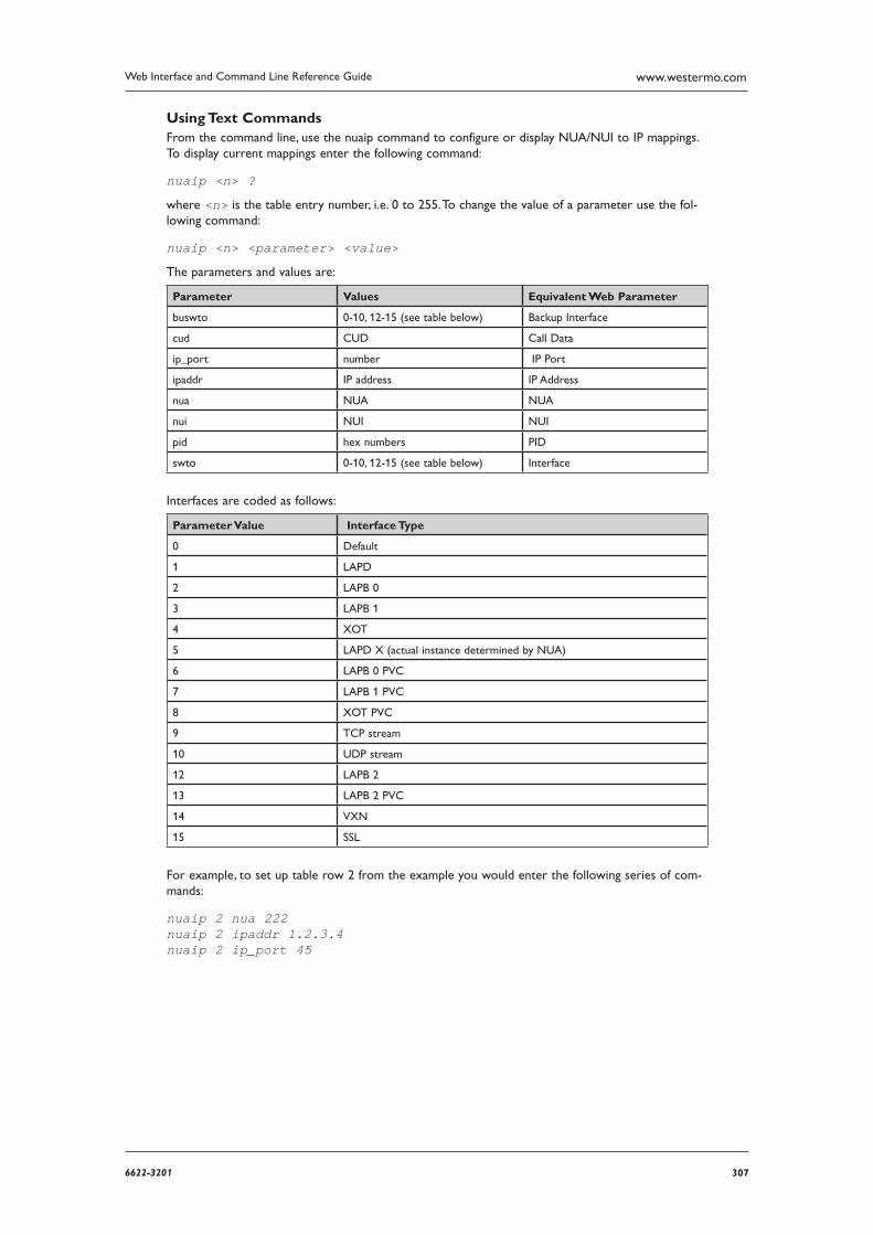
3076622-3201
Web Interface and Command Line Reference Guide www.westermo.com
Using Text Commands From the command line, use the nuaip command to configure or display NUA/NUI to IP mappings. To display current mappings enter the following command:
nuaip <n> ?
where <n> is the table entry number, i.e. 0 to 255. To change the value of a parameter use the fol-lowing command:
nuaip <n> <parameter> <value>
The parameters and values are:
Parameter Values Equivalent Web Parameter
buswto 0-10, 12-15 (see table below) Backup Interface
cud CUD Call Data
ip_port number IP Port
ipaddr IP address IP Address
nua NUA NUA
nui NUI NUI
pid hex numbers PID
swto 0-10, 12-15 (see table below) Interface
Interfaces are coded as follows:
Parameter Value Interface Type
0 Default
1 LAPD
2 LAPB 0
3 LAPB 1
4 XOT
5 LAPD X (actual instance determined by NUA)
6 LAPB 0 PVC
7 LAPB 1 PVC
8 XOT PVC
9 TCP stream
10 UDP stream
12 LAPB 2
13 LAPB 2 PVC
14 VXN
15 SSL
For example, to set up table row 2 from the example you would enter the following series of com-mands:
nuaip 2 nua 222 nuaip 2 ipaddr 1.2.3.4 nuaip 2 ip_port 45
308 6622-3201
Web Interface and Command Line Reference Guidewww.westermo.com
Confi gure > X25 > PADs > PAD n 4.109
There are two main elements to the configuration procedure for accessing X.25 networks:
General and service related parameters
PAD parameters (X.3)
Each X.25 PAD configuration page also includes a sub-page detailing the X.3 PAD parameters. Col-lectively this set of values is known as a PAD profile. Your unit contains four pre-defined standard PAD profiles numbered 50, 51, 90 and 91. You may also create up to four custom PAD profiles num-bered 1 to 4 for each PAD instance.
Using the Web Page(s)
Each PAD configuration page is split into two sections. The first section includes general PAD param eters; the second includes parameters relating to the backup interface. The parameters are as follows:
Answering NUA:
This is the NUA that the unit responds to for incoming X.25 calls.
Calling NUA:
This NUA will be used as the calling NUA when an outgoing X.25 call is made.
Answering CUG:
The PAD will only answer calls with this Call User Group (CUG) specified.
Auto macro:
This parameter specifies the name of an X.25 call macro that is used when an ATD command is received by the unit. The ATD command is ignored, and a PAD CALL command using the macro replaces it. The purpose of this feature is to allow non-PAD terminals to use an X.25 PAD net-work connection. X.25 call macros are set up in the Configure > X25 > Macros web page, or by using the macro text command.
Default packet size:
This parameter determines the default X.25 packet size. This may be set to “16”, “32”, “64”, “128”, “256”, “512” or “1024”, but the actual values permitted will normally be constrained by your service provider.
Layer 2 interface:
This parameter for each PAD is used to select whether it will be used for B or D-channel X.25 operation. For D-channel operation, ensure that the “LAPD” option is selected from the drop-down menu. For X.25 over an ISDN B-channel, select “LAPB”.
Layer 2 interface #:
The Layer 2 Interface Number is used to specify which Layer 2 instance will be used for this PAD (0 or 1 for LAPB, 0, 1 or 2 for LAPD).
Remote IP address (XOT only):
If the layer 2 interface is specified as “TCP” for an XOT call, then this field indicates the destina-tion host that will answer the XOT call.
IP Stream mode:
This parameter can be set to “Off”, “TCP”, or “UDP”. When set to “Off”, operation of the PAD is unaffected. When set to “TCP”, when the PAD makes a call, a TCP socket is opened and the PAD data is sent via the TCP socket. This is different to XOT operation because there are no X25 head ers or XOT headers as the PAD data is placed directly in the socket.
3096622-3201
Web Interface and Command Line Reference Guide www.westermo.com
IP Stream port:
When IP Stream mode is on this parameter defines the port number to use.
IP Length header:
When set to “On”, and in IP Stream mode, the length of a data sequence is inserted before the data. For the receive direction it is assumed the length of the data is in the data stream. When set to “8583 Ascii 4 byte”, the IP length header will conform to the ISO 8583 format.
Strip Trailing Spaces:
When this parameter is turned on any spaces received at the end of a sequence of data from the network will be removed before being relayed to the PAD port.
Leased line mode:
When this parameter is set to “On”, it causes the PAD to always attempt to be connected using the Auto macro setting as the call command.
LCN:
The unit supports up to eight logical X.25 channels. In practice, the operational limit is deter-mined by the particular service to which you subscribe (usually 4). Each logical channel must be assigned a valid Logical Channel Number (LCN). The LCN parame-ter is the value of the first LCN that will be assigned for outgoing X.25 CALLs. The default is 1027. For incoming calls, the unit accepts the LCN specified by the caller.
LCN direction:
This parameter determines whether the LCN used for outgoing X.25 calls is incremented or decre mented from the starting value when multiple X.25 instances share one layer 2 (LAPB or LAPD), connection. The default is “Down” and LCNs are decremented, i.e. if the first CALL uses 1024, the next will use 1023, etc. Setting the parameter to “Up” will cause the LCN to be incre-mented from the start value.
ENQ on connect:
When this parameter is set to “On” the PAD will send an ENQ character on the ASY link when an outgoing call has been answered.
NUI/NUA selection:
If both an NUI and an NUA are included in the call string, this parameter allows the unit to fil-ter one of these out of the X.25 call request. This can be extremely useful in backup scenarios. Consider the following example; the unit is configured to do online authorisations via the ISDN D channel and to fall back to B-channel (if the D-channel host did not respond for any reason). Using this parameter in conjunction with the backup equivalent, it is possible to configure the unit to use the supplied NUA to connect over D-channel and the supplied NUI to connect over B channel (for backup).
PAD profile #:
The PAD profile # allows you to select the PAD profile to use for this PAD instance. There are four pre-defined profiles numbered “50”, “51”, “90” and “91”. In addition to the pre-defined pro-files you can also create up to four user-defined profiles numbered “1”, “2”, “3” and “4”.
To assign a particular profile to the PAD select the appropriate number from the list.
PAD prompt:
This parameter allows you to redefine the standard “PAD>” prompt. To change the prompt enter a new string of up to 15 characters into the text box.
Restart delay (ms): When the Restarts parameter is “On” the Restart Delay value determines the length of time in mil liseconds that the unit will wait before issuing a Restart packet. The default value is 2000 giving a delay of 2 seconds.
310 6622-3201
Web Interface and Command Line Reference Guidewww.westermo.com
Restarts:
It is normally possible to make X.25 CALLs immediately following the initial SABM-UA exchange. In some cases however, the X.25 network may require an X.25 Restart before it will accept X.25 CALLs. The correct mode to select depends upon the particular X.25 service to which you subscribe.
The default value is “On”. This means that the unit WILL issue X.25 Restart packets. To prevent the unit from issuing Restart packets set this parameter to “Off”.
Inactivity timeout (s):
This parameter specifies the length of time in seconds after which the PAD will terminate an X.25 call if there has been no data transmission.
No Call L2 Timeout (s):
This parameter specifies the length of time in seconds after which the unit will disconnect a layer 2 link if there are no layer 3 calls in progress. For LAPB sessions this will also terminate the ISDN call.
PAD mode:
The PAD Mode parameter can be set to “Normal” or “Prompt Always On”. In Prompt Always On mode, the ASY port attached to the PAD behaves as if it were permanently connected at layer 2,
i.e. it always displays a “PAD>” prompt. AT commands may still be entered but the normal result codes are suppressed. To disable this mode set the parameter to “Normal”.
STX/ETX mode:
When this parameter is “On”, the PAD will ignore data that is not encapsulated between ASCII characters STX (Ctrl+B) and ETX (Ctrl+C). To disable this feature select the “Off” option.
Data trigger:
This parameter specifies a string, which if it appears in the received data causes a “Data Trigger” (47) event to be generated and recorded in the event log.
Inactivity Event Time(s):
This specifies the time in seconds in which if there is no activity on the PAD an event in the event log will be posted. This can be used to trigger email exceptions.
Backup Interface Parameters
Layer 2 interface:
This parameter specifies whether the backup service uses “LAPB”, “LAPD” or “None”.
Layer 2 interface #:
This parameter specifies which LAPB or LAPD instance to use for the backup interface. Select “0” or “1” for LAPB, or “0”, “1” or “2” for LAPD.
LCN:
The LCN parameter is used to set the first LCN that will be used for the backup interface.
LCN direction:
This parameter determines whether the LCN used for the backup X.25 interface is increment-ed or decremented from the starting value when multiple X.25 instances share a single layer 2 connection.
Backup IP address:
If the layer 2 interface is specified as “TCP” for an XOT call, then this field indicates the destina-tion host that will answer the XOT call if the host specified in the Remote IP address (XOT only) parameter is unavailable.
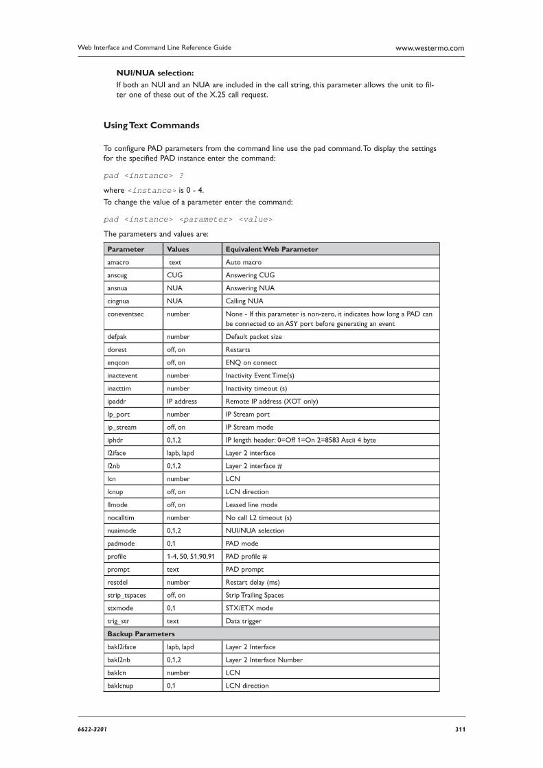
3116622-3201
Web Interface and Command Line Reference Guide www.westermo.com
NUI/NUA selection:
If both an NUI and an NUA are included in the call string, this parameter allows the unit to fil-ter one of these out of the X.25 call request.
Using Text Commands
To configure PAD parameters from the command line use the pad command. To display the settings for the specified PAD instance enter the command:
pad <instance> ?
where <instance> is 0 - 4.
To change the value of a parameter enter the command:
pad <instance> <parameter> <value>
The parameters and values are:
Parameter Values Equivalent Web Parameter
amacro text Auto macro
anscug CUG Answering CUG
ansnua NUA Answering NUA
cingnua NUA Calling NUA
coneventsec number None - If this parameter is non-zero, it indi cates how long a PAD can be connected to an ASY port before generating an event
defpak number Default packet size
dorest off, on Restarts
enqcon off, on ENQ on connect
inactevent number Inactivity Event Time(s)
inacttim number Inactivity timeout (s)
ipaddr IP address Remote IP address (XOT only)
Ip_port number IP Stream port
ip_stream off, on IP Stream mode
iphdr 0,1,2 IP length header: 0=Off 1=On 2=8583 Ascii 4 byte
l2iface lapb, lapd Layer 2 interface
l2nb 0,1,2 Layer 2 interface #
lcn number LCN
lcnup off, on LCN direction
llmode off, on Leased line mode
nocalltim number No call L2 timeout (s)
nuaimode 0,1,2 NUI/NUA selection
padmode 0,1 PAD mode
profile 1-4, 50, 51,90,91 PAD profile #
prompt text PAD prompt
restdel number Restart delay (ms)
strip_tspaces off, on Strip Trailing Spaces
stxmode 0,1 STX/ETX mode
trig_str text Data trigger
Backup Parameters
bakl2iface lapb, lapd Layer 2 Interface
bakl2nb 0,1,2 Layer 2 Interface Number
baklcn number LCN
baklcnup 0,1 LCN direction

312 6622-3201
Web Interface and Command Line Reference Guidewww.westermo.com
baknuaimode 0,1,2 NUA/NUI selection
buipaddr IP address Backup IP address
For example, to configure PAD 1 to use LAPD enter the command:
pad 1 l2iface lapd
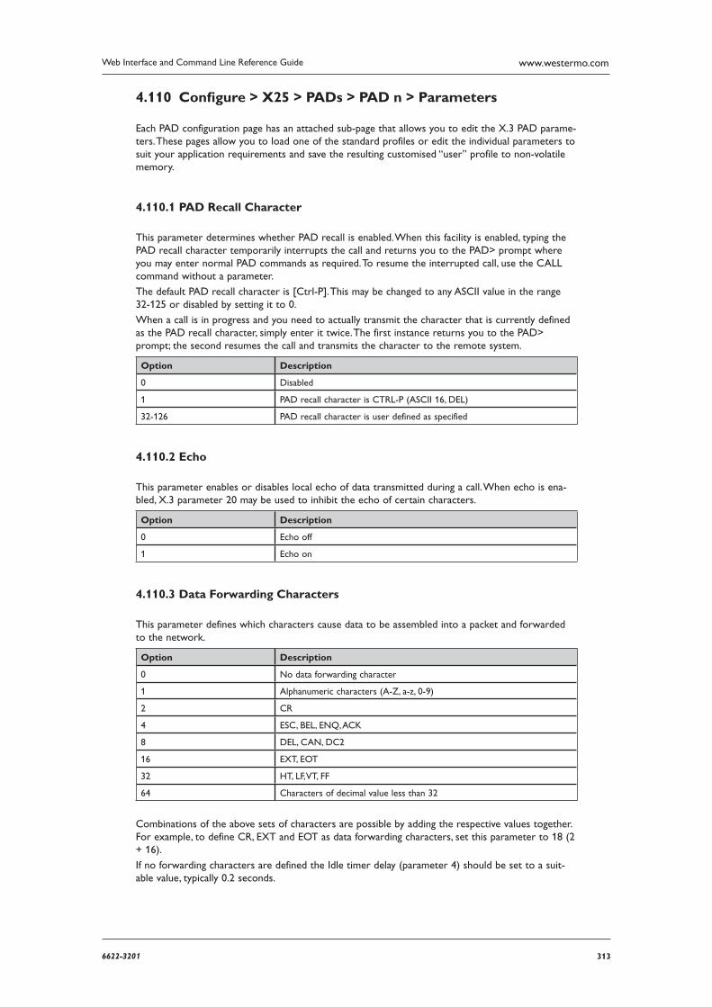
3136622-3201
Web Interface and Command Line Reference Guide www.westermo.com
Confi gure > X25 > PADs > PAD n > Parameters 4.110
Each PAD configuration page has an attached sub-page that allows you to edit the X.3 PAD parame-ters. These pages allow you to load one of the standard profiles or edit the individual parameters to suit your application requirements and save the resulting customised “user” profile to non-volatile memory.
PAD Recall Character 4.110.1
This parameter determines whether PAD recall is enabled. When this facility is enabled, typing the PAD recall character temporarily interrupts the call and returns you to the PAD> prompt where you may enter normal PAD commands as required. To resume the interrupted call, use the CALL com mand without a parameter.
The default PAD recall character is [Ctrl-P]. This may be changed to any ASCII value in the range 32-125 or disabled by setting it to 0.
When a call is in progress and you need to actually transmit the character that is currently defined as the PAD recall character, simply enter it twice. The first instance returns you to the PAD> prompt; the second resumes the call and transmits the character to the remote system.
Option Description
0 Disabled
1 PAD recall character is CTRL-P (ASCII 16, DEL)
32-126 PAD recall character is user defined as specified
Echo 4.110.2
This parameter enables or disables local echo of data transmitted during a call. When echo is ena-bled, X.3 parameter 20 may be used to inhibit the echo of certain characters.
Option Description
0 Echo off
1 Echo on
Data Forwarding Characters 4.110.3
This parameter defines which characters cause data to be assembled into a packet and forwarded to the network.
Option Description
0 No data forwarding character
1 Alphanumeric characters (A-Z, a-z, 0-9)
2 CR
4 ESC, BEL, ENQ, ACK
8 DEL, CAN, DC2
16 EXT, EOT
32 HT, LF, VT, FF
64 Characters of decimal value less than 32
Combinations of the above sets of characters are possible by adding the respective values together. For example, to define CR, EXT and EOT as data forwarding characters, set this parameter to 18 (2 + 16).
If no forwarding characters are defined the Idle timer delay (parameter 4) should be set to a suit-able value, typically 0.2 seconds.
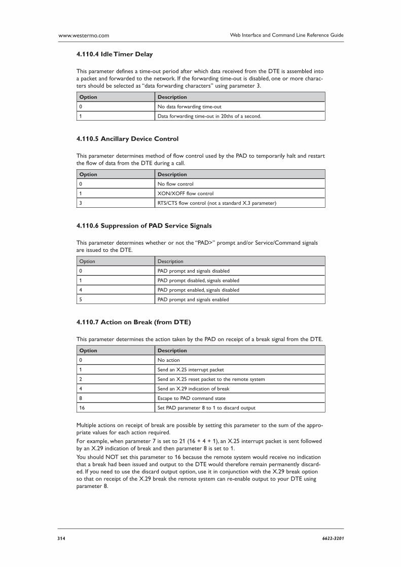
314 6622-3201
Web Interface and Command Line Reference Guidewww.westermo.com
Idle Timer Delay 4.110.4
This parameter defines a time-out period after which data received from the DTE is assembled into a packet and forwarded to the network. If the forwarding time-out is disabled, one or more charac-ters should be selected as “data forwarding characters” using parameter 3.
Option Description
0 No data forwarding time-out
1 Data forwarding time-out in 20ths of a second.
Ancillary Device Control 4.110.5
This parameter determines method of flow control used by the PAD to temporarily halt and restart the flow of data from the DTE during a call.
Option Description
0 No flow control
1 XON/XOFF flow control
3 RTS/CTS flow control (not a standard X.3 parameter)
Suppression of PAD Service Signals 4.110.6
This parameter determines whether or not the “PAD>” prompt and/or Service/Command signals are issued to the DTE.
Option Description
0 PAD prompt and signals disabled
1 PAD prompt disabled, signals enabled
4 PAD prompt enabled, signals disabled
5 PAD prompt and signals enabled
Action on Break (from DTE) 4.110.7
This parameter determines the action taken by the PAD on receipt of a break signal from the DTE.
Option Description
0 No action
1 Send an X.25 interrupt packet
2 Send an X.25 reset packet to the remote system
4 Send an X.29 indication of break
8 Escape to PAD command state
16 Set PAD parameter 8 to 1 to discard output
Multiple actions on receipt of break are possible by setting this parameter to the sum of the appro-priate values for each action required.
For example, when parameter 7 is set to 21 (16 + 4 + 1), an X.25 interrupt packet is sent followed by an X.29 indication of break and then parameter 8 is set to 1.
You should NOT set this parameter to 16 because the remote system would receive no indication that a break had been issued and output to the DTE would therefore remain permanently discard-ed. If you need to use the discard output option, use it in conjunction with the X.29 break option so that on receipt of the X.29 break the remote system can re-enable output to your DTE using parameter 8.
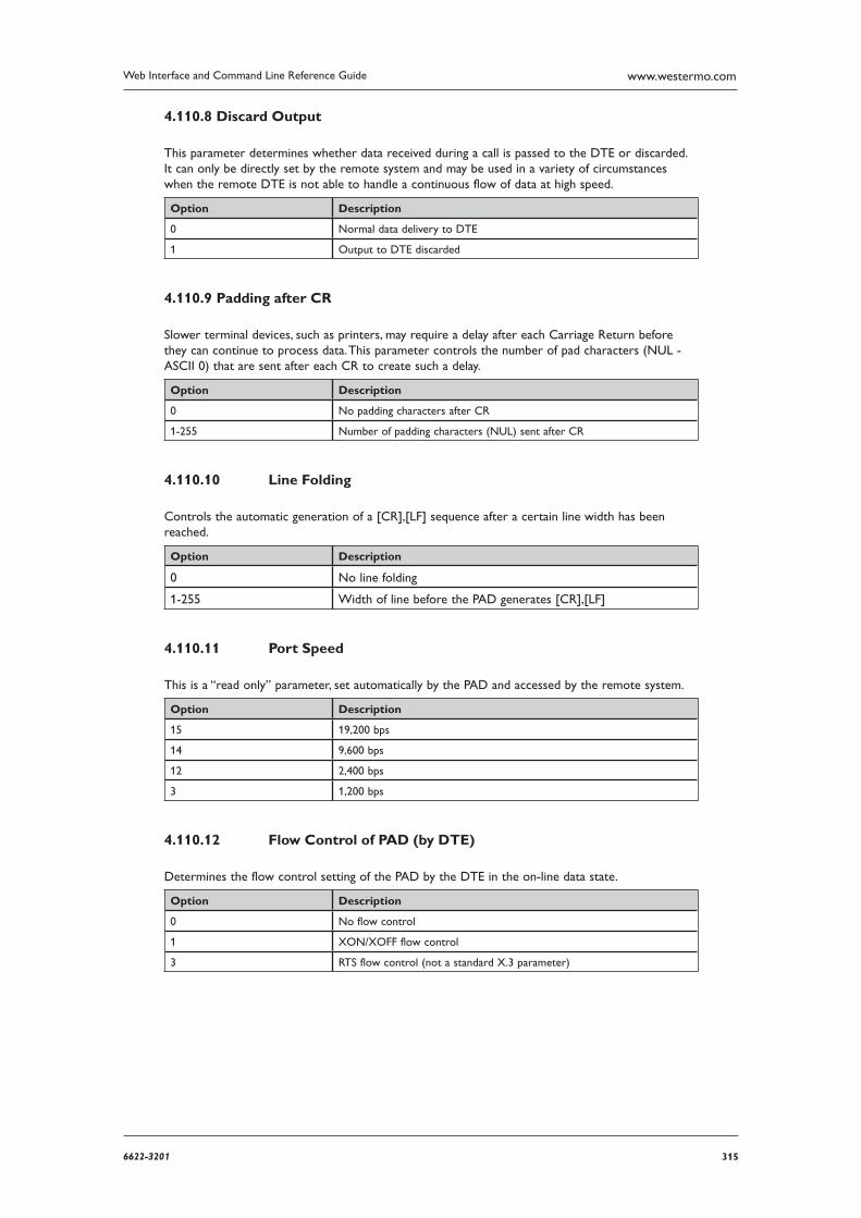
3156622-3201
Web Interface and Command Line Reference Guide www.westermo.com
Discard Output 4.110.8
This parameter determines whether data received during a call is passed to the DTE or discarded. It can only be directly set by the remote system and may be used in a variety of circumstances when the remote DTE is not able to handle a continuous flow of data at high speed.
Option Description
0 Normal data delivery to DTE
1 Output to DTE discarded
Padding after CR 4.110.9
Slower terminal devices, such as printers, may require a delay after each Carriage Return before they can continue to process data. This parameter controls the number of pad characters (NUL - ASCII 0) that are sent after each CR to create such a delay.
Option Description
0 No padding characters after CR
1-255 Number of padding characters (NUL) sent after CR
Line Folding 4.110.10
Controls the automatic generation of a [CR],[LF] sequence after a certain line width has been reached.
Option Description
0 No line folding
1-255 Width of line before the PAD generates [CR],[LF]
Port Speed 4.110.11
This is a “read only” parameter, set automatically by the PAD and accessed by the remote system.
Option Description
15 19,200 bps
14 9,600 bps
12 2,400 bps
3 1,200 bps
Flow Control of PAD (by DTE) 4.110.12
Determines the flow control setting of the PAD by the DTE in the on-line data state.
Option Description
0 No flow control
1 XON/XOFF flow control
3 RTS flow control (not a standard X.3 parameter)
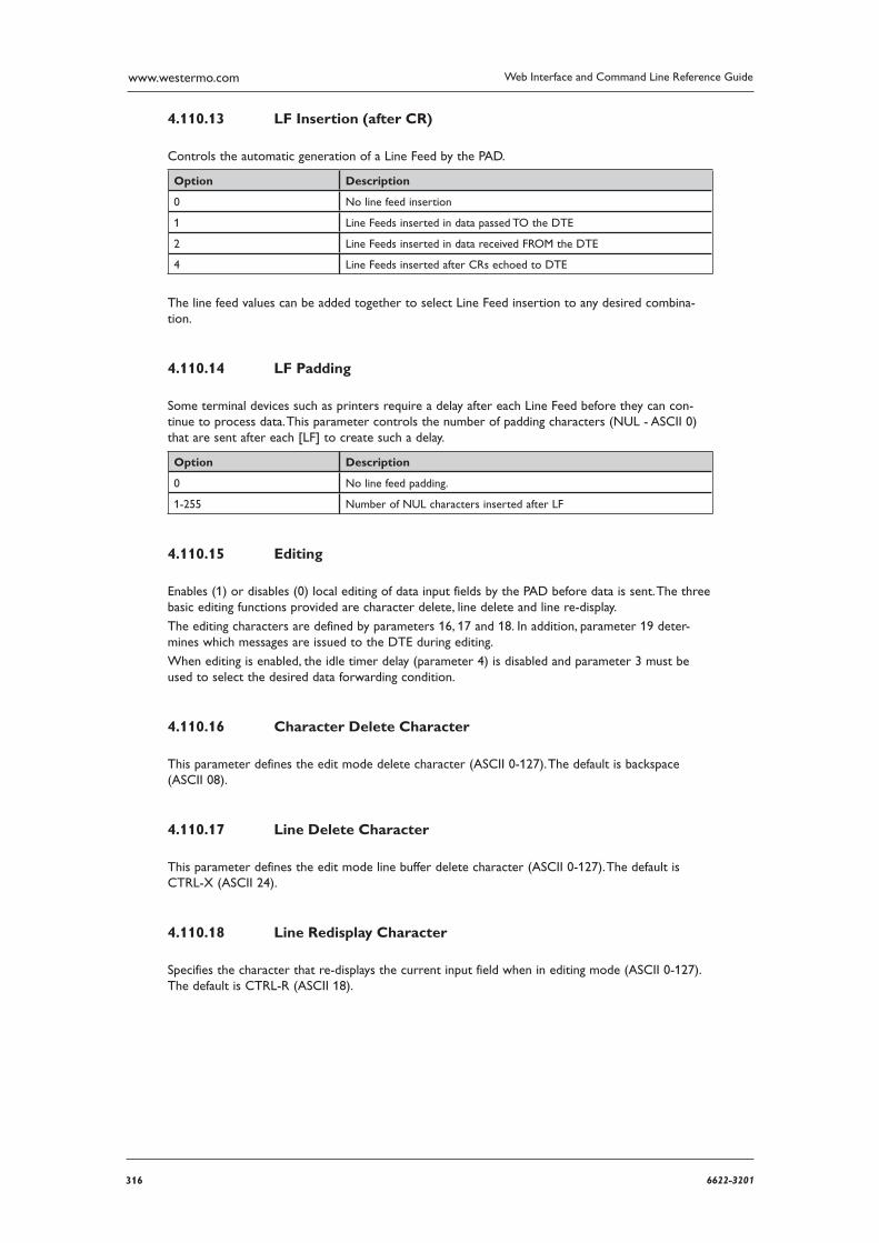
316 6622-3201
Web Interface and Command Line Reference Guidewww.westermo.com
LF Insertion (after CR) 4.110.13
Controls the automatic generation of a Line Feed by the PAD.
Option Description
0 No line feed insertion
1 Line Feeds inserted in data passed TO the DTE
2 Line Feeds inserted in data received FROM the DTE
4 Line Feeds inserted after CRs echoed to DTE
The line feed values can be added together to select Line Feed insertion to any desired combina-tion.
LF Padding 4.110.14
Some terminal devices such as printers require a delay after each Line Feed before they can con-tinue to process data. This parameter controls the number of padding characters (NUL - ASCII 0) that are sent after each [LF] to create such a delay.
Option Description
0 No line feed padding.
1-255 Number of NUL characters inserted after LF
Editing 4.110.15
Enables (1) or disables (0) local editing of data input fields by the PAD before data is sent. The three basic editing functions provided are character delete, line delete and line re-display.
The editing characters are defined by parameters 16, 17 and 18. In addition, parameter 19 deter-mines which messages are issued to the DTE during editing.
When editing is enabled, the idle timer delay (parameter 4) is disabled and parameter 3 must be used to select the desired data forwarding condition.
Character Delete Character 4.110.16
This parameter defines the edit mode delete character (ASCII 0-127). The default is backspace (ASCII 08).
Line Delete Character 4.110.17
This parameter defines the edit mode line buffer delete character (ASCII 0-127). The default is CTRL-X (ASCII 24).
Line Redisplay Character 4.110.18
Specifies the character that re-displays the current input field when in editing mode (ASCII 0-127). The default is CTRL-R (ASCII 18).
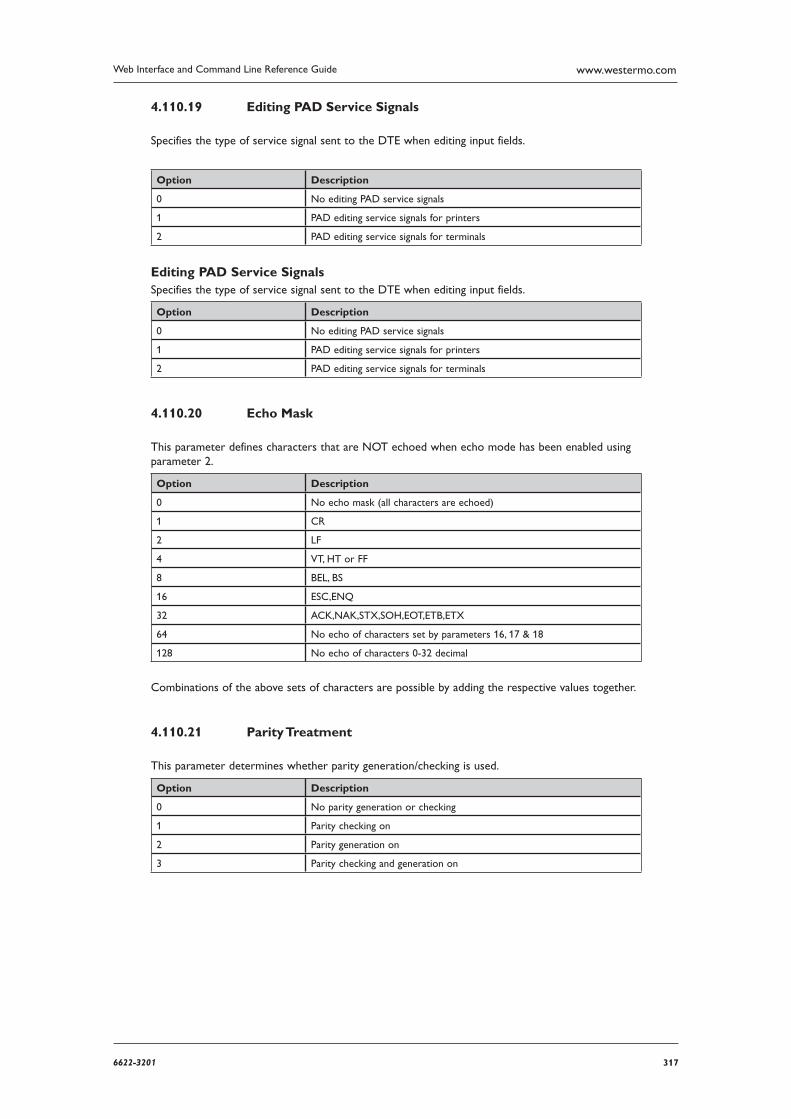
3176622-3201
Web Interface and Command Line Reference Guide www.westermo.com
Editing PAD Service Signals 4.110.19
Specifies the type of service signal sent to the DTE when editing input fields.
Option Description
0 No editing PAD service signals
1 PAD editing service signals for printers
2 PAD editing service signals for terminals
Editing PAD Service Signals Specifies the type of service signal sent to the DTE when editing input fields.
Option Description
0 No editing PAD service signals
1 PAD editing service signals for printers
2 PAD editing service signals for terminals
Echo Mask 4.110.20
This parameter defines characters that are NOT echoed when echo mode has been enabled using parameter 2.
Option Description
0 No echo mask (all characters are echoed)
1 CR
2 LF
4 VT, HT or FF
8 BEL, BS
16 ESC,ENQ
32 ACK,NAK,STX,SOH,EOT,ETB,ETX
64 No echo of characters set by parameters 16, 17 & 18
128 No echo of characters 0-32 decimal
Combinations of the above sets of characters are possible by adding the respective values together.
Parity Treatment 4.110.21
This parameter determines whether parity generation/checking is used.
Option Description
0 No parity generation or checking
1 Parity checking on
2 Parity generation on
3 Parity checking and generation on
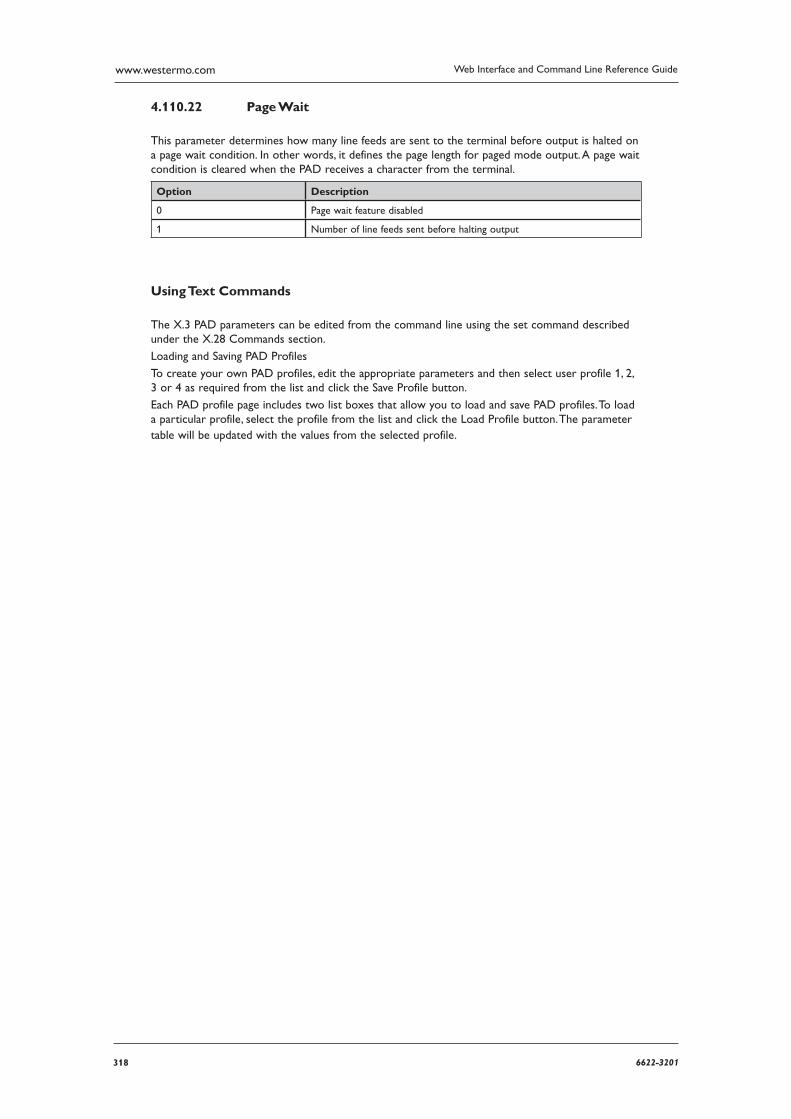
318 6622-3201
Web Interface and Command Line Reference Guidewww.westermo.com
Page Wait 4.110.22
This parameter determines how many line feeds are sent to the terminal before output is halted on a page wait condition. In other words, it defines the page length for paged mode output. A page wait con dition is cleared when the PAD receives a character from the terminal.
Option Description
0 Page wait feature disabled
1 Number of line feeds sent before halting output
Using Text Commands
The X.3 PAD parameters can be edited from the command line using the set command described under the X.28 Commands section.
Loading and Saving PAD Profiles
To create your own PAD profiles, edit the appropriate parameters and then select user profile 1, 2, 3 or 4 as required from the list and click the Save Profile button.
Each PAD profile page includes two list boxes that allow you to load and save PAD profiles. To load a particular profile, select the profile from the list and click the Load Profile button. The parameter table will be updated with the values from the selected profile.

3196622-3201
Web Interface and Command Line Reference Guide www.westermo.com
Confi gure > X25 > PVCs > PVC n 4.111
A Permanent Virtual Circuit (PVC) provides the X.25 equivalent of a leased line service. With a PVC there is no call setup or disconnect process; you can just start sending and receiving X.25 data on a specified LCN. For each X.25 service connection you may setup up multiple PVCs each of which uses a different LCN (or a mixture of PVCs and SVCs). Westermo routers support up to four PVCs numbered 0-3.
Using the Web Page(s)
Each of the Configure > X25 > PVCs pages allow you to define the parameters for one of the available X.25 PVCs. The parameters are as follows:
LCN:
This is the LCN value to be used for this PVC. In the case of an XOT PVC, this parameter defines the Responder LCN field in the PVC setup packet (though an LCN of 1 is always used in the XOT PVC connection). So for an XOT PVC this field should contain the remote connec-tions LCN.
Layer 2 interface:
This parameter defines the lower layer interface to be used for the PVC and can be set to “LAPB”, “LAPD” or “TCP” (for XOT mode).
Layer 2 interface #:
This parameter is used to specify which Layer 2 instance will be used for this PVC (“0” or “1” for LAPB, “0”, “1” or “2” for LAPD and “0” for TCP).
Remote IP address (XOT only):
This is the IP address to be used for outgoing XOT calls.
XOT source IP address interface:
This parameter specifies the source if the IP address for XOT calls. It can be set to “Auto”, “ETH” or “PPP”.
XOT source IP address interface #: If XOT source IP address interface is set to “ETH” or “PPP”, this parameter defines which Ether net or PPP interface to use for the source address.
Initiator interface (XOT only):
This parameter may be set to the “name” of the interface from which the PVC was initiated, e.g. Serial 1. The initiator and responder strings are used to identify the circuit when PVCs are being set up. They must match the names in the remote unit that terminates the XOT PVC connec-tion. If the unit terminating the PVC XOT connection is not another Westermo unit then you need to refer to the documentation or the configuration files of the other unit to determine the names of the interfaces.
Responder interface (XOT only):
This parameter may be set to the name of the interface to which a PVC initiator is connected, e.g. Serial 2.
Upper layer interface:
This parameter defines what type of upper layer interface is connected to this PVC and can be set to “PAD” (for an X.25 PAD), “TPAD” (for a TPAD instance) or “XSW” (for X.25 switching). Note that if set to “XSW” (for the X.25 switch) then the X.25 switch will need to also be con-figured regarding the interfaces to switch this PVC to/from. For example, if this is an incoming XOT PVC we are con figuring then the Switch from XOT PVC parameter needs to be set to the desired destination interface.
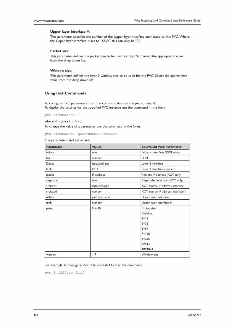
320 6622-3201
Web Interface and Command Line Reference Guidewww.westermo.com
Upper layer interface #:
This parameter specifies the number of the Upper layer interface connected to this PVC. Where the Upper layer interface is set to “XSW” this can only be “0”.
Packet size:
This parameter defines the packet size to be used for the PVC. Select the appropriate value from the drop down list.
Window size:
This parameter defines the layer 3 window size to be used for the PVC. Select the appropriate value from the drop down list.
Using Text Commands
To configure PVC parameters from the command line use the pvc command. To display the settings for the specified PVC instance use the command in the form
pvc <instance> ?
where <instance> is 0 - 3.
To change the value of a parameter use the command in the form:
pvc <instance> <parameter> <value>
The parameters and values are:
Parameter Values Equivalent Web Parameter
iniface text Initiator interface (XOT only)
lcn number LCN
l2iface lapb, lapd, tcp Layer 2 interface
l2nb 0,1,2 Layer 2 interface number
ipaddr IP address Remote IP address (XOT only)
respiface text Responder interface (XOT only)
srcipent auto, eth, ppp XOT source IP address interface
srcipadd number XOT source IP address interface #
uliface pad, tpad, xsw Upper layer interface
ulnb number Upper layer interface #
psize 0, 4-10 Packet size:
0=default
4=16
5=32
6=64
7=128
8=256
9=512
10=1024
window 1-7 Window size
For example, to configure PVC 1 to use LAPD enter the command:
pvc 1 l2iface lapd
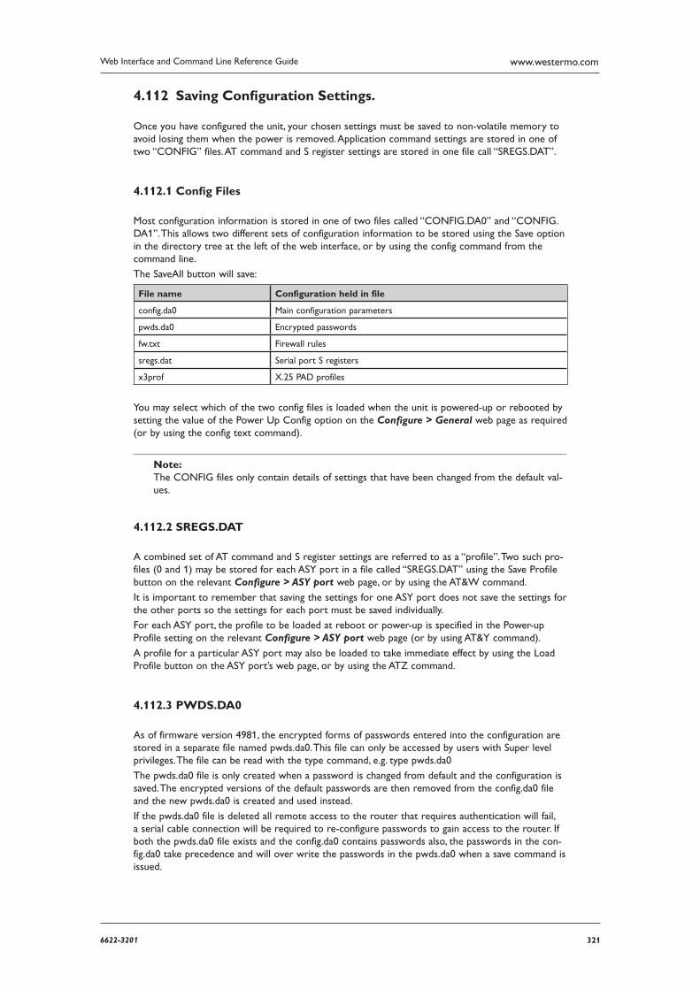
3216622-3201
Web Interface and Command Line Reference Guide www.westermo.com
Saving Confi guration Settings. 4.112
Once you have configured the unit, your chosen settings must be saved to non-volatile memory to avoid losing them when the power is removed. Application command settings are stored in one of two “CONFIG” files. AT command and S register settings are stored in one file call “SREGS.DAT”.
Confi g Files 4.112.1
Most configuration information is stored in one of two files called “CONFIG.DA0” and “CONFIG.DA1”. This allows two different sets of configuration information to be stored using the Save option in the directory tree at the left of the web interface, or by using the config command from the command line.
The SaveAll button will save:
File name Configuration held in file
config.da0 Main configuration parameters
pwds.da0 Encrypted passwords
fw.txt Firewall rules
sregs.dat Serial port S registers
x3prof X.25 PAD profiles
You may select which of the two config files is loaded when the unit is powered-up or rebooted by setting the value of the Power Up Config option on the Configure > General web page as required (or by using the config text command).
Note: The CONFIG files only contain details of settings that have been changed from the default val-ues.
SREGS.DAT 4.112.2
A combined set of AT command and S register settings are referred to as a “profile”. Two such pro-files (0 and 1) may be stored for each ASY port in a file called “SREGS.DAT” using the Save Profile button on the relevant Configure > ASY port web page, or by using the AT&W command.
It is important to remember that saving the settings for one ASY port does not save the settings for the other ports so the settings for each port must be saved individually.
For each ASY port, the profile to be loaded at reboot or power-up is specified in the Power-up Profile setting on the relevant Configure > ASY port web page (or by using AT&Y command).
A profile for a particular ASY port may also be loaded to take immediate effect by using the Load Profile button on the ASY port’s web page, or by using the ATZ command.
PWDS.DA0 4.112.3
As of firmware version 4981, the encrypted forms of passwords entered into the configuration are stored in a separate file named pwds.da0. This file can only be accessed by users with Super level privileges. The file can be read with the type command, e.g. type pwds.da0
The pwds.da0 file is only created when a password is changed from default and the configuration is saved. The encrypted versions of the default passwords are then removed from the config.da0 file and the new pwds.da0 is created and used instead.
If the pwds.da0 file is deleted all remote access to the router that requires authentication will fail, a serial cable connection will be required to re-configure passwords to gain access to the router. If both the pwds.da0 file exists and the config.da0 contains passwords also, the passwords in the con-fig.da0 take precedence and will over write the passwords in the pwds.da0 when a save command is issued.
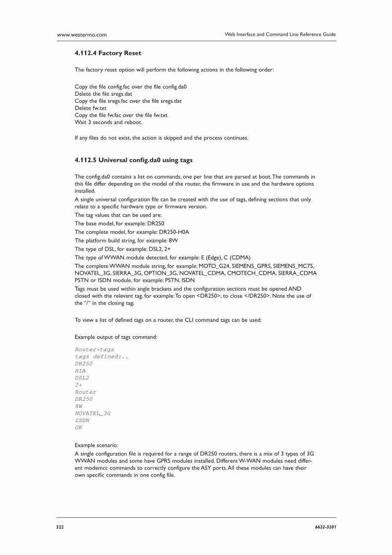
322 6622-3201
Web Interface and Command Line Reference Guidewww.westermo.com
Factory Reset 4.112.4
The factory reset option will perform the following actions in the following order:
Copy the file config.fac over the file config.da0 Delete the file sregs.dat Copy the file sregs.fac over the file sregs.dat Delete fw.txt Copy the file fw.fac over the file fw.txt Wait 3 seconds and reboot.
If any files do not exist, the action is skipped and the process continues.
Universal confi g.da0 using tags 4.112.5
The config.da0 contains a list on commands, one per line that are parsed at boot. The commands in this file differ depending on the model of the router, the firmware in use and the hardware options installed.
A single universal configuration file can be created with the use of tags, defining sections that only relate to a specific hardware type or firmware version.
The tag values that can be used are:
The base model, for example: DR250
The complete model, for example: DR250-H0A
The platform build string, for example: 8W
The type of DSL, for example: DSL2, 2+
The type of WWAN module detected, for example: E (Edge), C (CDMA)
The complete WWAN module string, for example: MOTO_G24, SIEMENS_GPRS, SIEMENS_MC75, NOVATEL_3G, SIERRA_3G, OPTION_3G, NOVATEL_CDMA, CMOTECH_CDMA, SIERRA_CDMA PSTN or ISDN module, for example: PSTN, ISDN
Tags must be used within angle brackets and the configuration sections must be opened AND closed with the relevant tag, for example: To open <DR250>, to close </DR250>. Note the use of the “/“ in the closing tag.
To view a list of defined tags on a router, the CLI command tags can be used:
Example output of tags command:
Router>tagstags defined:..DR250 HIA DSL2 2+ Router DR250 8W NOVATEL_3G ISDN OK
Example scenario:
A single configuration file is required for a range of DR250 routers, there is a mix of 3 types of 3G W WAN modules and some have GPRS modules installed. Different W-WAN modules need differ-ent modemcc commands to correctly configure the ASY ports. All these modules can have their own specific commands in one config file.

3236622-3201
Web Interface and Command Line Reference Guide www.westermo.com
Example configuration using tagged sections:
Comments are in red and prefixed with a # symbol. Comments may be used in configuration files to make them easier to read. The info_asy_add parameters are just for illustration purposes only and are not the actual ASY port numbers used.
<DR250-H0A>
#Start of DR250-H0A config
<NOVATEL_3G>
#Start of Novatel specific config
modemcc 0 asy_add 7modemcc 0 info_asy_add 8
#End of Novatel specific config
</NOVATEL_3G>
<OPTION_3G>
#Start of Option specific config
modemcc 0 asy_add 7modemcc 0 info_asy_add 9
#End of Option specific config
</OPTION_3G>
<SIERRA_3G>
#Start of Sierra specific config
modemcc 0 asy_add 7modemcc 0 info_asy_add 10
#End of Sierra specific config
</SIERRA_3G>
#End of DR250-H0A config
</DR250-H0A>
<DR250-E0A>
#Start of DR250-E0A config
modemcc 0 asy_add 7modemcc 0 info_asy_add 11
#End of DR250-E0A config
</DR250-E0A>
#Rest of generic config goes below here
modemcc 0 apn internet”
eth 0 ipaddr 192.168.0.99
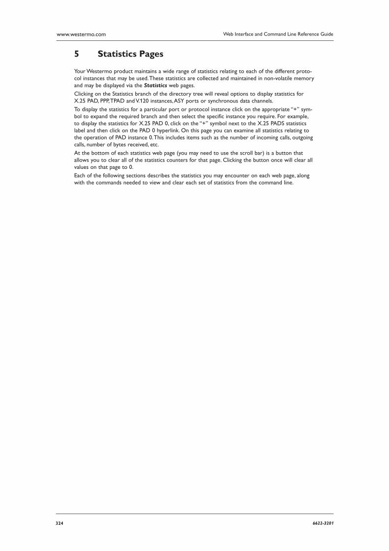
324 6622-3201
Web Interface and Command Line Reference Guidewww.westermo.com
Statistics Pages5
Your Westermo product maintains a wide range of statistics relating to each of the different proto-col instances that may be used. These statistics are collected and maintained in non-volatile memory and may be displayed via the Statistics web pages.
Clicking on the Statistics branch of the directory tree will reveal options to display statistics for X.25 PAD, PPP, TPAD and V.120 instances, ASY ports or synchronous data channels.
To display the statistics for a particular port or protocol instance click on the appropriate “+” sym-bol to expand the required branch and then select the specific instance you require. For example, to display the statistics for X.25 PAD 0, click on the “+” symbol next to the X.25 PADS statistics label and then click on the PAD 0 hyperlink. On this page you can examine all statistics relating to the operation of PAD instance 0. This includes items such as the number of incoming calls, outgoing calls, number of bytes received, etc.
At the bottom of each statistics web page (you may need to use the scroll bar) is a button that allows you to clear all of the statistics counters for that page. Clicking the button once will clear all values on that page to 0.
Each of the following sections describes the statistics you may encounter on each web page, along with the commands needed to view and clear each set of statistics from the command line.
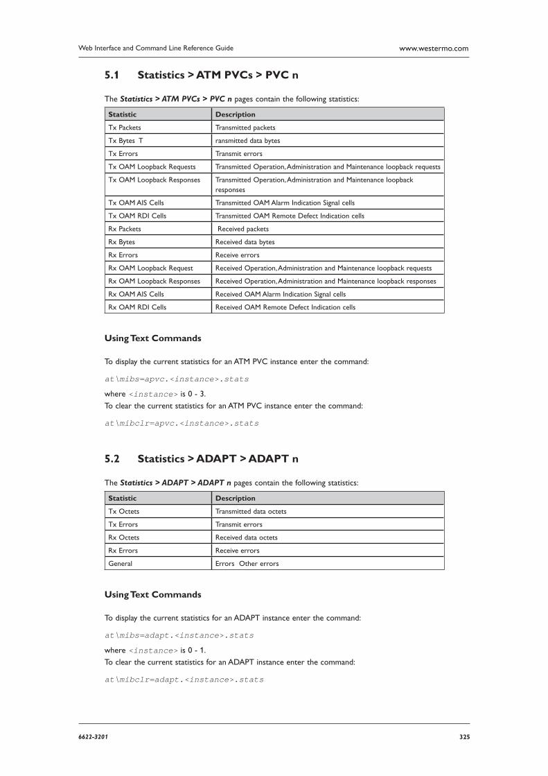
3256622-3201
Web Interface and Command Line Reference Guide www.westermo.com
Statistics > ATM PVCs > PVC n 5.1
The Statistics > ATM PVCs > PVC n pages contain the following statistics:
Statistic Description
Tx Packets Transmitted packets
Tx Bytes T ransmitted data bytes
Tx Errors Transmit errors
Tx OAM Loopback Requests Transmitted Operation, Administration and Maintenance loopback requests
Tx OAM Loopback Responses Transmitted Operation, Administration and Maintenance loopback responses
Tx OAM AIS Cells Transmitted OAM Alarm Indication Signal cells
Tx OAM RDI Cells Transmitted OAM Remote Defect Indication cells
Rx Packets Received packets
Rx Bytes Received data bytes
Rx Errors Receive errors
Rx OAM Loopback Request Received Operation, Administration and Maintenance loopback requests
Rx OAM Loopback Responses Received Operation, Administration and Maintenance loopback responses
Rx OAM AIS Cells Received OAM Alarm Indication Signal cells
Rx OAM RDI Cells Received OAM Remote Defect Indication cells
Using Text Commands
To display the current statistics for an ATM PVC instance enter the command:
at\mibs=apvc.<instance>.stats
where <instance> is 0 - 3.
To clear the current statistics for an ATM PVC instance enter the command:
at\mibclr=apvc.<instance>.stats
Statistics > ADAPT > ADAPT n 5.2
The Statistics > ADAPT > ADAPT n pages contain the following statistics:
Statistic Description
Tx Octets Transmitted data octets
Tx Errors Transmit errors
Rx Octets Received data octets
Rx Errors Receive errors
General Errors Other errors
Using Text Commands
To display the current statistics for an ADAPT instance enter the command:
at\mibs=adapt.<instance>.stats
where <instance> is 0 - 1.
To clear the current statistics for an ADAPT instance enter the command:
at\mibclr=adapt.<instance>.stats
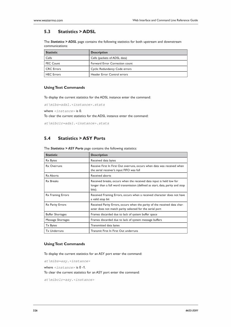
326 6622-3201
Web Interface and Command Line Reference Guidewww.westermo.com
Statistics > ADSL 5.3
The Statistics > ADSL page contains the following statistics for both upstream and downstream com munications:
Statistic Description
Cells Cells (packets of ADSL data)
FEC Count Forward Error Correction count
CRC Errors Cyclic Redundancy Code errors
HEC Errors Header Error Control errors
Using Text Commands
To display the current statistics for the ADSL instance enter the command:
at\mibs=adsl.<instance>.stats
where <instance> is 0.
To clear the current statistics for the ADSL instance enter the command:
at\mibclr=adsl.<instance>.stats
Statistics > ASY Ports 5.4
The Statistics > ASY Ports page contains the following statistics:
Statistic Description
Rx Bytes Received data bytes
Rx Overruns Receive First In First Out overruns, occurs when data was received when the serial receiver’s input FIFO was full
Rx Aborts Received aborts
Rx Breaks Received breaks, occurs when the received data input is held low for longer than a full word transmission (defined as start, data, parity and stop bits).
Rx Framing Errors Received Framing Errors, occurs when a received character does not have a valid stop bit
Rx Parity Errors Received Parity Errors, occurs when the parity of the received data char-acter does not match parity selected for the serial port
Buffer Shortages Frames discarded due to lack of system buffer space
Message Shortages Frames discarded due to lack of system message buffers
Tx Bytes Transmitted data bytes
Tx Underruns Transmit First In First Out underruns
Using Text Commands
To display the current statistics for an ASY port enter the command:
at\mibs=asy.<instance>
where <instance> is 0 -1.
To clear the current statistics for an ASY port enter the command:
at\mibclr=asy.<instance>
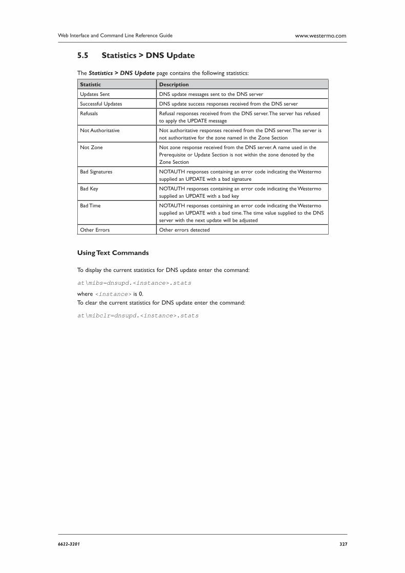
3276622-3201
Web Interface and Command Line Reference Guide www.westermo.com
Statistics > DNS Update 5.5
The Statistics > DNS Update page contains the following statistics:
Statistic Description
Updates Sent DNS update messages sent to the DNS server
Successful Updates DNS update success responses received from the DNS server
Refusals Refusal responses received from the DNS server. The server has refused to apply the UPDATE message
Not Authoritative Not authoritative responses received from the DNS server. The server is not authoritative for the zone named in the Zone Section
Not Zone Not zone response received from the DNS server. A name used in the Prerequi site or Update Section is not within the zone denoted by the Zone Section
Bad Signatures NOTAUTH responses containing an error code indicating the Westermo supplied an UPDATE with a bad signature
Bad Key NOTAUTH responses containing an error code indicating the Westermo supplied an UPDATE with a bad key
Bad Time NOTAUTH responses containing an error code indicating the Westermo supplied an UPDATE with a bad time. The time value supplied to the DNS server with the next update will be adjusted
Other Errors Other errors detected
Using Text Commands
To display the current statistics for DNS update enter the command:
at\mibs=dnsupd.<instance>.stats
where <instance> is 0.
To clear the current statistics for DNS update enter the command:
at\mibclr=dnsupd.<instance>.stats
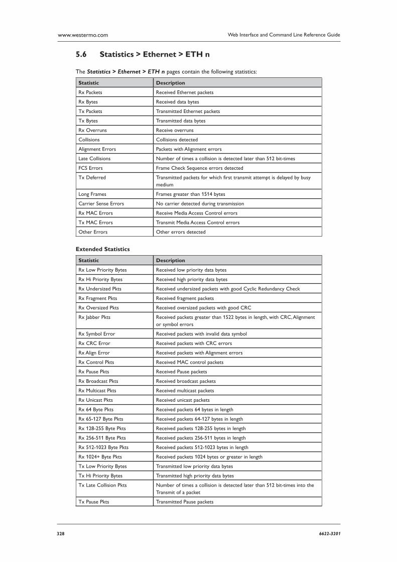
328 6622-3201
Web Interface and Command Line Reference Guidewww.westermo.com
Statistics > Ethernet > ETH n 5.6
The Statistics > Ethernet > ETH n pages contain the following statistics:
Statistic Description
Rx Packets Received Ethernet packets
Rx Bytes Received data bytes
Tx Packets Transmitted Ethernet packets
Tx Bytes Transmitted data bytes
Rx Overruns Receive overruns
Collisions Collisions detected
Alignment Errors Packets with Alignment errors
Late Collisions Number of times a collision is detected later than 512 bit-times
FCS Errors Frame Check Sequence errors detected
Tx Deferred Transmitted packets for which first transmit attempt is delayed by busy medium
Long Frames Frames greater than 1514 bytes
Carrier Sense Errors No carrier detected during transmission
Rx MAC Errors Receive Media Access Control errors
Tx MAC Errors Transmit Media Access Control errors
Other Errors Other errors detected
Extended Statistics
Statistic Description
Rx Low Priority Bytes Received low priority data bytes
Rx Hi Priority Bytes Received high priority data bytes
Rx Undersized Pkts Received undersized packets with good Cyclic Redundancy Check
Rx Fragment Pkts Received fragment packets
Rx Oversized Pkts Received oversized packets with good CRC
Rx Jabber Pkts Received packets greater than 1522 bytes in length, with CRC, Alignment or symbol errors
Rx Symbol Error Received packets with invalid data symbol
Rx CRC Error Received packets with CRC errors
Rx Align Error Received packets with Alignment errors
Rx Control Pkts Received MAC control packets
Rx Pause Pkts Received Pause packets
Rx Broadcast Pkts Received broadcast packets
Rx Multicast Pkts Received multicast packets
Rx Unicast Pkts Received unicast packets
Rx 64 Byte Pkts Received packets 64 bytes in length
Rx 65-127 Byte Pkts Received packets 64-127 bytes in length
Rx 128-255 Byte Pkts Received packets 128-255 bytes in length
Rx 256-511 Byte Pkts Received packets 256-511 bytes in length
Rx 512-1023 Byte Pkts Received packets 512-1023 bytes in length
Rx 1024+ Byte Pkts Received packets 1024 bytes or greater in length
Tx Low Priority Bytes Transmitted low priority data bytes
Tx Hi Priority Bytes Transmitted high priority data bytes
Tx Late Collision Pkts Number of times a collision is detected later than 512 bit-times into the Transmit of a packet
Tx Pause Pkts Transmitted Pause packets
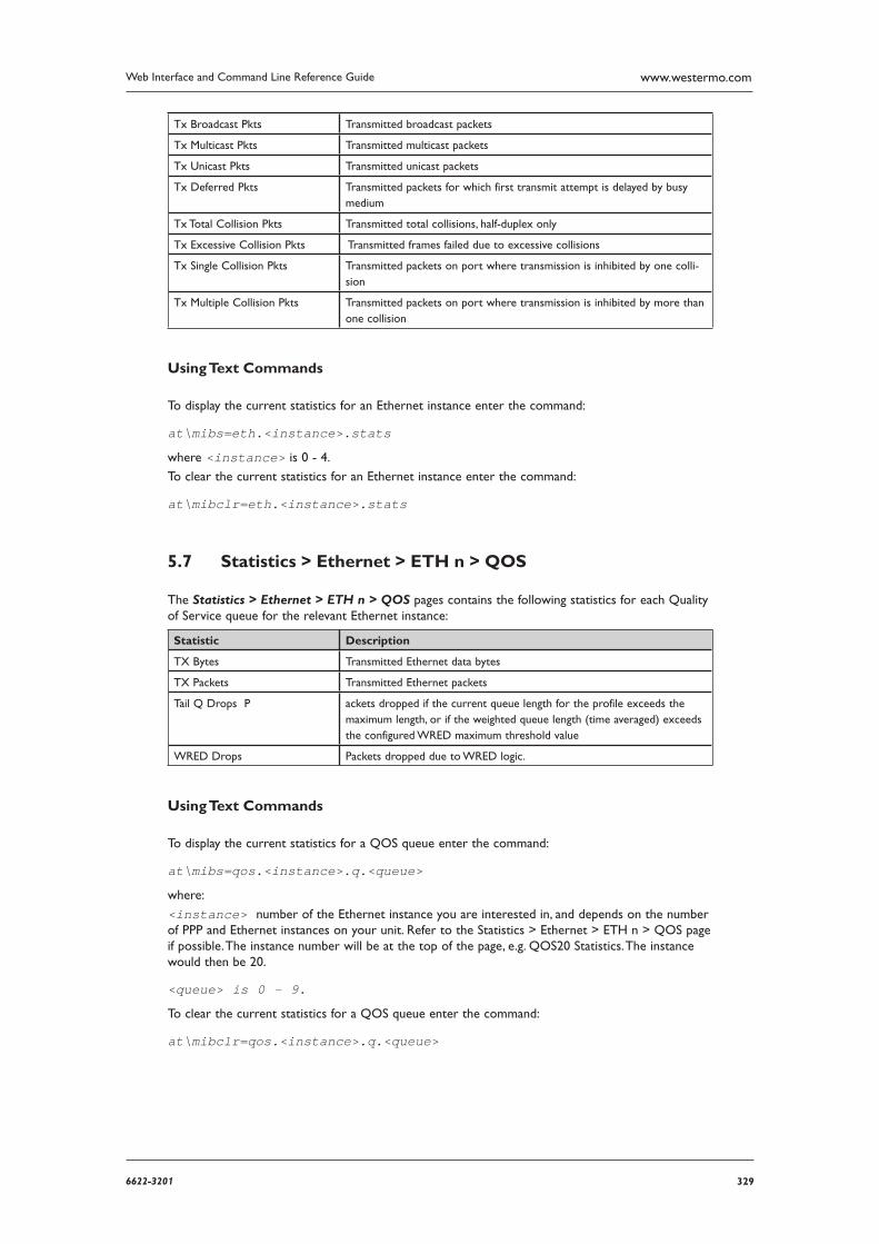
3296622-3201
Web Interface and Command Line Reference Guide www.westermo.com
Tx Broadcast Pkts Transmitted broadcast packets
Tx Multicast Pkts Transmitted multicast packets
Tx Unicast Pkts Transmitted unicast packets
Tx Deferred Pkts Transmitted packets for which first transmit attempt is delayed by busy medium
Tx Total Collision Pkts Transmitted total collisions, half-duplex only
Tx Excessive Collision Pkts Transmitted frames failed due to excessive collisions
Tx Single Collision Pkts Transmitted packets on port where transmission is inhibited by one colli-sion
Tx Multiple Collision Pkts Transmitted packets on port where transmission is inhibited by more than one collision
Using Text Commands
To display the current statistics for an Ethernet instance enter the command:
at\mibs=eth.<instance>.stats
where <instance> is 0 - 4.
To clear the current statistics for an Ethernet instance enter the command:
at\mibclr=eth.<instance>.stats
Statistics > Ethernet > ETH n > QOS 5.7
The Statistics > Ethernet > ETH n > QOS pages contains the following statistics for each Quality of Service queue for the relevant Ethernet instance:
Statistic Description
TX Bytes Transmitted Ethernet data bytes
TX Packets Transmitted Ethernet packets
Tail Q Drops P ackets dropped if the current queue length for the profile exceeds the maximum length, or if the weighted queue length (time averaged) exceeds the configured WRED maximum threshold value
WRED Drops Packets dropped due to WRED logic.
Using Text Commands
To display the current statistics for a QOS queue enter the command:
at\mibs=qos.<instance>.q.<queue>
where:
<instance> number of the Ethernet instance you are interested in, and depends on the number of PPP and Ethernet instances on your unit. Refer to the Statistics > Ethernet > ETH n > QOS page if possible. The instance number will be at the top of the page, e.g. QOS20 Statistics. The instance would then be 20.
<queue> is 0 - 9.
To clear the current statistics for a QOS queue enter the command:
at\mibclr=qos.<instance>.q.<queue>
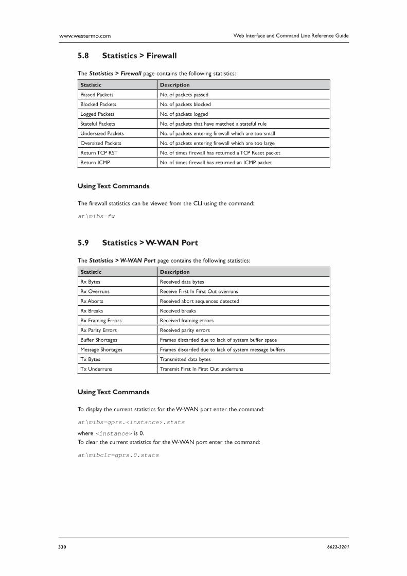
330 6622-3201
Web Interface and Command Line Reference Guidewww.westermo.com
Statistics > Firewall 5.8
The Statistics > Firewall page contains the following statistics:
Statistic Description
Passed Packets No. of packets passed
Blocked Packets No. of packets blocked
Logged Packets No. of packets logged
Stateful Packets No. of packets that have matched a stateful rule
Undersized Packets No. of packets entering firewall which are too small
Oversized Packets No. of packets entering firewall which are too large
Return TCP RST No. of times firewall has returned a TCP Reset packet
Return ICMP No. of times firewall has returned an ICMP packet
Using Text Commands
The firewall statistics can be viewed from the CLI using the command:
at\mibs=fw
Statistics > W-WAN Port 5.9
The Statistics > W-WAN Port page contains the following statistics:
Statistic Description
Rx Bytes Received data bytes
Rx Overruns Receive First In First Out overruns
Rx Aborts Received abort sequences detected
Rx Breaks Received breaks
Rx Framing Errors Received framing errors
Rx Parity Errors Received parity errors
Buffer Shortages Frames discarded due to lack of system buffer space
Message Shortages Frames discarded due to lack of system message buffers
Tx Bytes Transmitted data bytes
Tx Underruns Transmit First In First Out underruns
Using Text Commands
To display the current statistics for the W-WAN port enter the command:
at\mibs=gprs.<instance>.stats
where <instance> is 0.
To clear the current statistics for the W-WAN port enter the command:
at\mibclr=gprs.0.stats
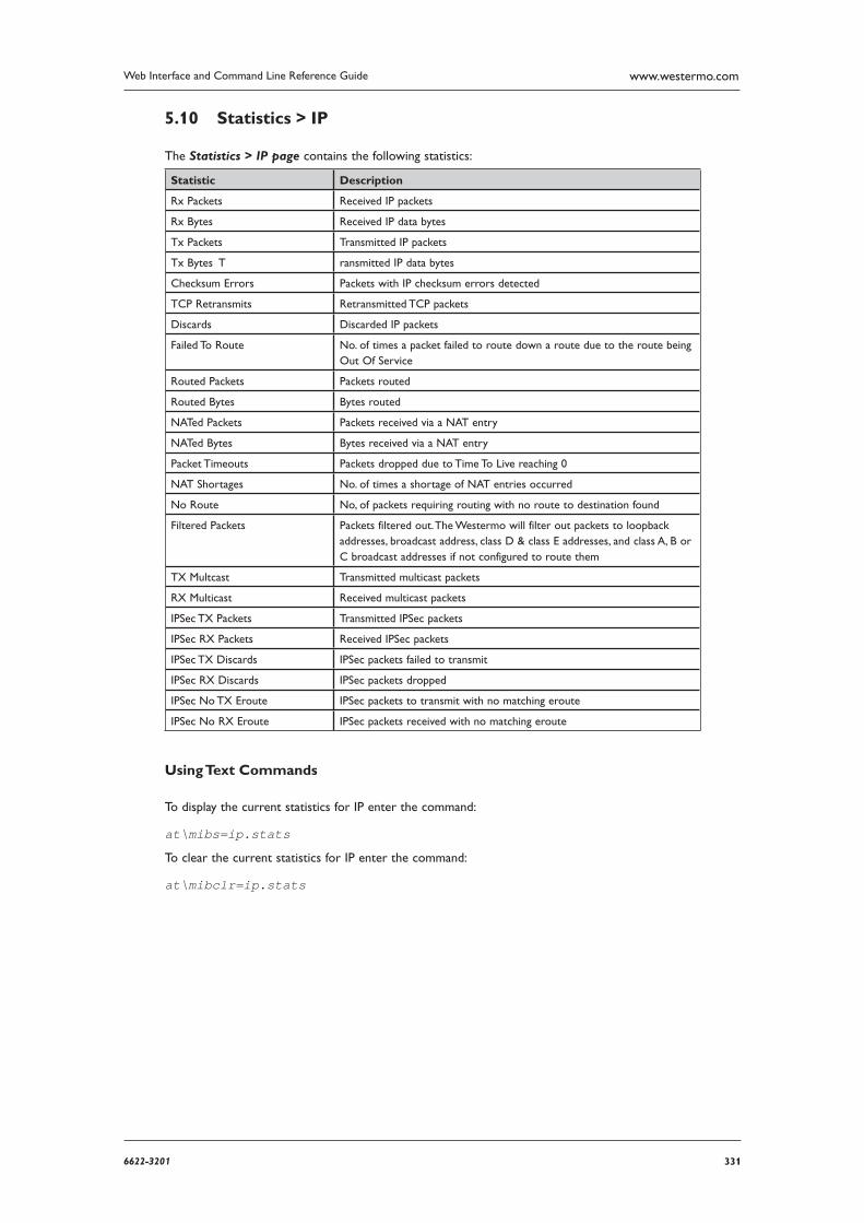
3316622-3201
Web Interface and Command Line Reference Guide www.westermo.com
Statistics > IP 5.10
The Statistics > IP page contains the following statistics:
Statistic Description
Rx Packets Received IP packets
Rx Bytes Received IP data bytes
Tx Packets Transmitted IP packets
Tx Bytes T ransmitted IP data bytes
Checksum Errors Packets with IP checksum errors detected
TCP Retransmits Retransmitted TCP packets
Discards Discarded IP packets
Failed To Route No. of times a packet failed to route down a route due to the route being Out Of Service
Routed Packets Packets routed
Routed Bytes Bytes routed
NATed Packets Packets received via a NAT entry
NATed Bytes Bytes received via a NAT entry
Packet Timeouts Packets dropped due to Time To Live reaching 0
NAT Shortages No. of times a shortage of NAT entries occurred
No Route No, of packets requiring routing with no route to destination found
Filtered Packets Packets filtered out. The Westermo will filter out packets to loopback addresses, broadcast address, class D & class E addresses, and class A, B or C broadcast addresses if not configured to route them
TX Multcast Transmitted multicast packets
RX Multicast Received multicast packets
IPSec TX Packets Transmitted IPSec packets
IPSec RX Packets Received IPSec packets
IPSec TX Discards IPSec packets failed to transmit
IPSec RX Discards IPSec packets dropped
IPSec No TX Eroute IPSec packets to transmit with no matching eroute
IPSec No RX Eroute IPSec packets received with no matching eroute
Using Text Commands
To display the current statistics for IP enter the command:
at\mibs=ip.stats
To clear the current statistics for IP enter the command:
at\mibclr=ip.stats

332 6622-3201
Web Interface and Command Line Reference Guidewww.westermo.com
Statistics > PPP > PPP n 5.11
The Statistics > PPP > PPP n pages contain the following two sets of statistics:
PPP n Stats 5.11.1
Statistic Description
Total Data Transferred Total data bytes transferred through the PPP instance, including the PPP head ers and all payload data
Total Up Time Today (mins) Time in minutes that this PPP instance has been connected for during the cur rent 24 hour period
TX octets Transmitted PPP data octets
TX LCP Packets ransmitted Link Control Protocol packets
TX PAP Packets Transmitted Password Authentication Protocol packets
TX IPCP Packets Transmitted IP Control Protocol packets
TX BACP Packets Transmitted Bandwidth Allocation and Control Protocol packets
TX BAP Packets Transmitted
TX Errors Transmit errors
RX octets Received PPP data octets
RX LCP Packets Received Link Control Protocol packets
RX PAP Packets Received Password Authentication Protocol packets
RX IPCP Packets Received IP Control Protocol packets
RX BACP Packets Received Bandwidth Allocation and Control Protocol packets
RX BAP Packets Received Bandwidth Allocation Protocol packets
RX Unknown Packets Received unrecognised packets
RX CRC Errors Received packets containing Cyclic Redundancy Code errors
RX Framing Errors Received packets containing framing errors
RX Errors Receive errors
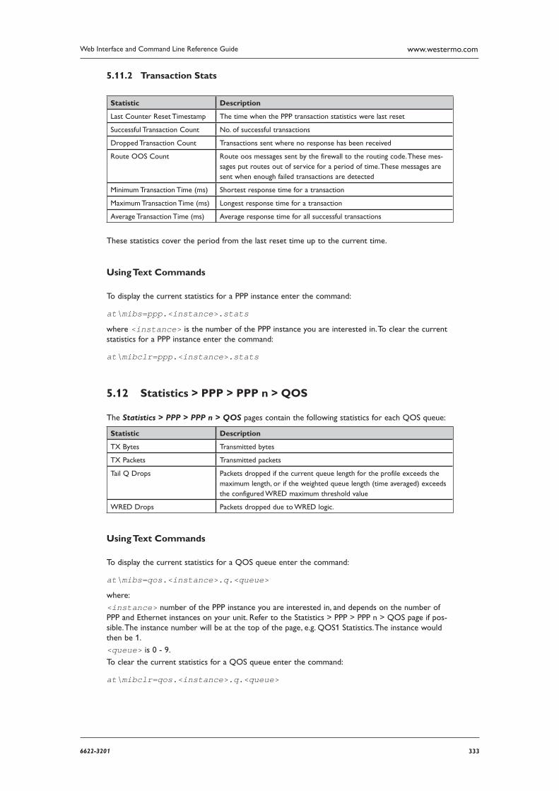
3336622-3201
Web Interface and Command Line Reference Guide www.westermo.com
Transaction Stats 5.11.2
Statistic Description
Last Counter Reset Timestamp The time when the PPP transaction statistics were last reset
Successful Transaction Count No. of successful transactions
Dropped Transaction Count Transactions sent where no response has been received
Route OOS Count Route oos messages sent by the firewall to the routing code. These mes-sages put routes out of service for a period of time. These messages are sent when enough failed transactions are detected
Minimum Transaction Time (ms) Shortest response time for a transaction
Maximum Transaction Time (ms) Longest response time for a transaction
Average Transaction Time (ms) Average response time for all successful transactions
These statistics cover the period from the last reset time up to the current time.
Using Text Commands
To display the current statistics for a PPP instance enter the command:
at\mibs=ppp.<instance>.stats
where <instance> is the number of the PPP instance you are interested in. To clear the current statistics for a PPP instance enter the command:
at\mibclr=ppp.<instance>.stats
Statistics > PPP > PPP n > QOS 5.12
The Statistics > PPP > PPP n > QOS pages contain the following statistics for each QOS queue:
Statistic Description
TX Bytes Transmitted bytes
TX Packets Transmitted packets
Tail Q Drops Packets dropped if the current queue length for the profile exceeds the maximum length, or if the weighted queue length (time averaged) exceeds the configured WRED maximum threshold value
WRED Drops Packets dropped due to WRED logic.
Using Text Commands
To display the current statistics for a QOS queue enter the command:
at\mibs=qos.<instance>.q.<queue>
where:
<instance> number of the PPP instance you are interested in, and depends on the number of PPP and Ethernet instances on your unit. Refer to the Statistics > PPP > PPP n > QOS page if pos-sible. The instance number will be at the top of the page, e.g. QOS1 Statistics. The instance would then be 1.
<queue> is 0 - 9.
To clear the current statistics for a QOS queue enter the command:
at\mibclr=qos.<instance>.q.<queue>
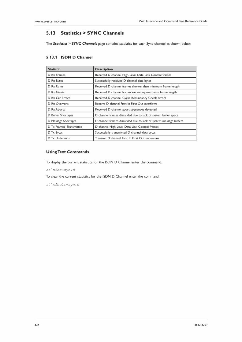
334 6622-3201
Web Interface and Command Line Reference Guidewww.westermo.com
Statistics > SYNC Channels 5.13
The Statistics > SYNC Channels page contains statistics for each Sync channel as shown below.
ISDN D Channel 5.13.1
Statistic Description
D Rx Frames Received D channel High-Level Data Link Control frames
D Rx Bytes Successfully received D channel data bytes
D Rx Runts Received D channel frames shorter than minimum frame length
D Rx Giants Received D channel frames exceeding maximum frame length
D Rx Crc Errors Received D channel Cyclic Redundancy Check errors
D Rx Overruns Receive D channel First In First Out overflows
D Rx Aborts Received D channel abort sequences detected
D Buffer Shortages D channel frames discarded due to lack of system buffer space
D Message Shortages D channel frames discarded due to lack of system message buffers
D Tx Frames Transmitted D channel High-Level Data Link Control frames
D Tx Bytes Successfully transmitted D channel data bytes
D Tx Underruns Transmit D channel First In First Out underruns
Using Text Commands
To display the current statistics for the ISDN D Channel enter the command:
at\mibs=syn.d
To clear the current statistics for the ISDN D Channel enter the command:
at\mibclr=syn.d
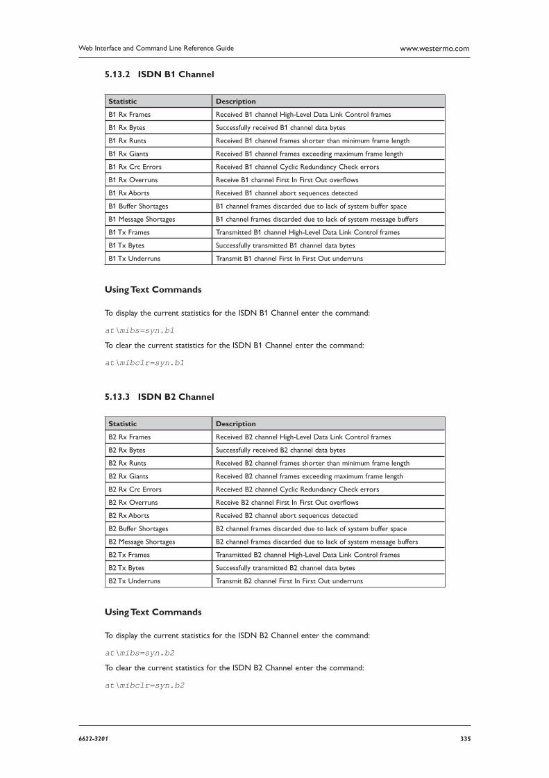
3356622-3201
Web Interface and Command Line Reference Guide www.westermo.com
ISDN B1 Channel 5.13.2
Statistic Description
B1 Rx Frames Received B1 channel High-Level Data Link Control frames
B1 Rx Bytes Successfully received B1 channel data bytes
B1 Rx Runts Received B1 channel frames shorter than minimum frame length
B1 Rx Giants Received B1 channel frames exceeding maximum frame length
B1 Rx Crc Errors Received B1 channel Cyclic Redundancy Check errors
B1 Rx Overruns Receive B1 channel First In First Out overflows
B1 Rx Aborts Received B1 channel abort sequences detected
B1 Buffer Shortages B1 channel frames discarded due to lack of system buffer space
B1 Message Shortages B1 channel frames discarded due to lack of system message buffers
B1 Tx Frames Transmitted B1 channel High-Level Data Link Control frames
B1 Tx Bytes Successfully transmitted B1 channel data bytes
B1 Tx Underruns Transmit B1 channel First In First Out underruns
Using Text Commands
To display the current statistics for the ISDN B1 Channel enter the command:
at\mibs=syn.b1
To clear the current statistics for the ISDN B1 Channel enter the command:
at\mibclr=syn.b1
ISDN B2 Channel 5.13.3
Statistic Description
B2 Rx Frames Received B2 channel High-Level Data Link Control frames
B2 Rx Bytes Successfully received B2 channel data bytes
B2 Rx Runts Received B2 channel frames shorter than minimum frame length
B2 Rx Giants Received B2 channel frames exceeding maximum frame length
B2 Rx Crc Errors Received B2 channel Cyclic Redundancy Check errors
B2 Rx Overruns Receive B2 channel First In First Out overflows
B2 Rx Aborts Received B2 channel abort sequences detected
B2 Buffer Shortages B2 channel frames discarded due to lack of system buffer space
B2 Message Shortages B2 channel frames discarded due to lack of system message buffers
B2 Tx Frames Transmitted B2 channel High-Level Data Link Control frames
B2 Tx Bytes Successfully transmitted B2 channel data bytes
B2 Tx Underruns Transmit B2 channel First In First Out underruns
Using Text Commands
To display the current statistics for the ISDN B2 Channel enter the command:
at\mibs=syn.b2
To clear the current statistics for the ISDN B2 Channel enter the command:
at\mibclr=syn.b2
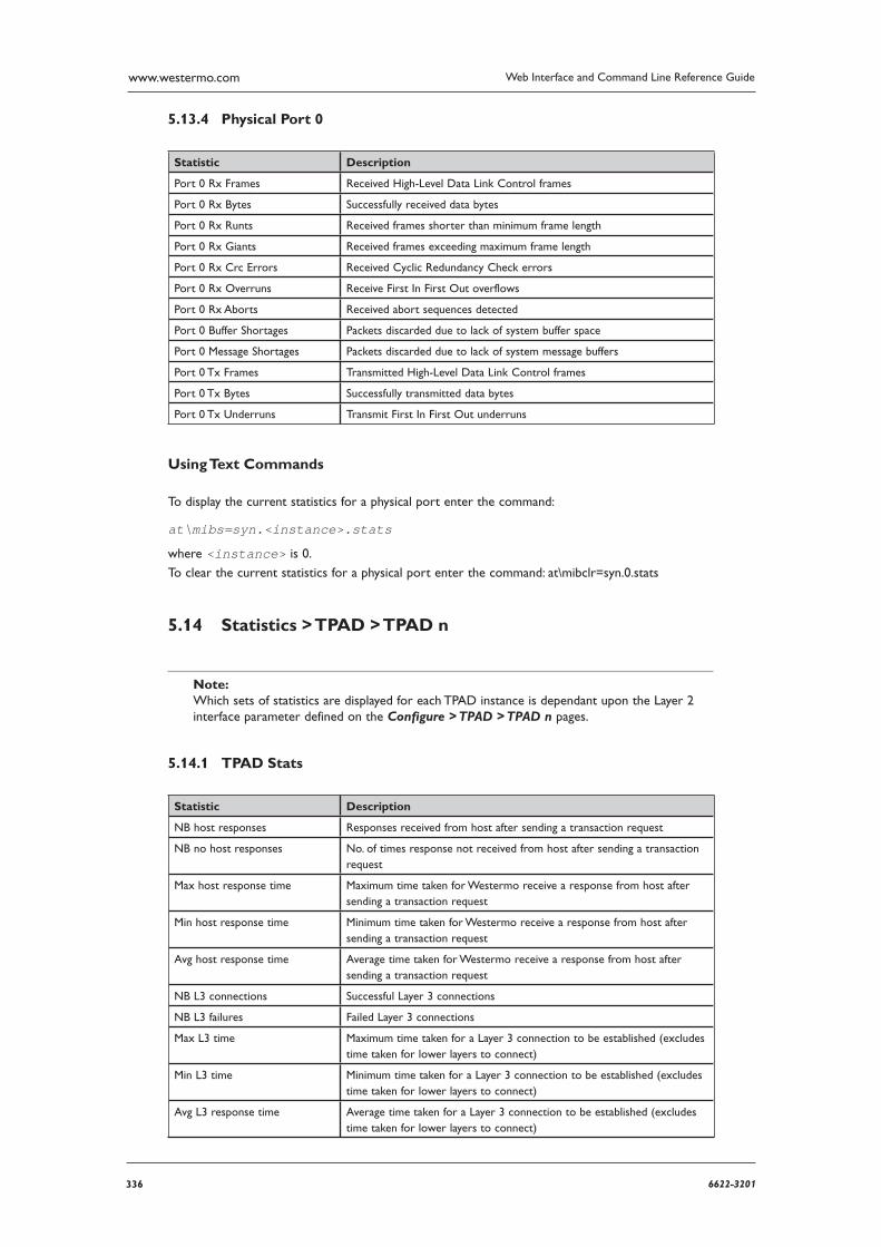
336 6622-3201
Web Interface and Command Line Reference Guidewww.westermo.com
Physical Port 0 5.13.4
Statistic Description
Port 0 Rx Frames Received High-Level Data Link Control frames
Port 0 Rx Bytes Successfully received data bytes
Port 0 Rx Runts Received frames shorter than minimum frame length
Port 0 Rx Giants Received frames exceeding maximum frame length
Port 0 Rx Crc Errors Received Cyclic Redundancy Check errors
Port 0 Rx Overruns Receive First In First Out overflows
Port 0 Rx Aborts Received abort sequences detected
Port 0 Buffer Shortages Packets discarded due to lack of system buffer space
Port 0 Message Shortages Packets discarded due to lack of system message buffers
Port 0 Tx Frames Transmitted High-Level Data Link Control frames
Port 0 Tx Bytes Successfully transmitted data bytes
Port 0 Tx Underruns Transmit First In First Out underruns
Using Text Commands
To display the current statistics for a physical port enter the command:
at\mibs=syn.<instance>.stats
where <instance> is 0.
To clear the current statistics for a physical port enter the command: at\mibclr=syn.0.stats
Statistics > TPAD > TPAD n 5.14
Note: Which sets of statistics are displayed for each TPAD instance is dependant upon the Layer 2 inter face parameter defined on the Configure > TPAD > TPAD n pages.
TPAD Stats 5.14.1
Statistic Description
NB host responses Responses received from host after sending a transaction request
NB no host responses No. of times response not received from host after sending a transaction request
Max host response time Maximum time taken for Westermo receive a response from host after sending a transaction request
Min host response time Minimum time taken for Westermo receive a response from host after sending a transaction request
Avg host response time Average time taken for Westermo receive a response from host after sending a transaction request
NB L3 connections Successful Layer 3 connections
NB L3 failures Failed Layer 3 connections
Max L3 time Maximum time taken for a Layer 3 connection to be established (excludes time taken for lower layers to connect)
Min L3 time Minimum time taken for a Layer 3 connection to be established (excludes time taken for lower layers to connect)
Avg L3 response time Average time taken for a Layer 3 connection to be established (excludes time taken for lower layers to connect)
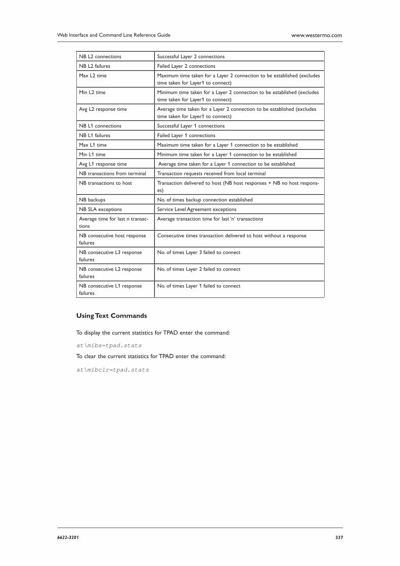
3376622-3201
Web Interface and Command Line Reference Guide www.westermo.com
NB L2 connections Successful Layer 2 connections
NB L2 failures Failed Layer 2 connections
Max L2 time Maximum time taken for a Layer 2 connection to be established (excludes time taken for Layer1 to connect)
Min L2 time Minimum time taken for a Layer 2 connection to be established (excludes time taken for Layer1 to connect)
Avg L2 response time Average time taken for a Layer 2 connection to be established (excludes time taken for Layer1 to connect)
NB L1 connections Successful Layer 1 connections
NB L1 failures Failed Layer 1 connections
Max L1 time Maximum time taken for a Layer 1 connection to be established
Min L1 time Minimum time taken for a Layer 1 connection to be established
Avg L1 response time Average time taken for a Layer 1 connection to be established
NB transactions from terminal Transaction requests received from local terminal
NB transactions to host Transaction delivered to host (NB host responses + NB no host respons-es)
NB backups No. of times backup connection established
NB SLA exceptions Service Level Agreement exceptions
Average time for last n transac-tions
Average transaction time for last ‘n’ transactions
NB consecutive host response fail ures
Consecutive times transaction delivered to host without a response
NB consecutive L3 response failures
No. of times Layer 3 failed to connect
NB consecutive L2 response failures
No. of times Layer 2 failed to connect
NB consecutive L1 response failures
No. of times Layer 1 failed to connect
Using Text Commands
To display the current statistics for TPAD enter the command:
at\mibs=tpad.stats
To clear the current statistics for TPAD enter the command:
at\mibclr=tpad.stats
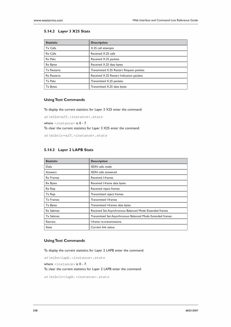
338 6622-3201
Web Interface and Command Line Reference Guidewww.westermo.com
Layer 3 X25 Stats 5.14.2
Statistic Description
Tx Calls X.25 call attempts
Rx Calls Received X.25 calls
Rx Paks Received X.25 packets
Rx Bytes Received X.25 data bytes
Tx Restarts Transmitted X.25 Restart Request packets
Rx Restarts Received X.25 Restart Indication packets
Tx Paks Transmitted X.25 packets
Tx Bytes Transmitted X.25 data bytes
Using Text Commands
To display the current statistics for Layer 3 X25 enter the command:
at\mibs=x25.<instance>.stats
where <instance> is 0 - 7.
To clear the current statistics for Layer 3 X25 enter the command:
at\mibclr=x25.<instance>.stats
Layer 2 LAPB Stats 5.14.3
Statistic Description
Dials ISDN calls made
Answers ISDN calls answered
Rx Frames Received I-frames
Rx Bytes Received I-frame data bytes
Rx Rejs Received reject frames
Tx Rejs Transmitted reject frames
Tx Frames Transmitted I-frames
Tx Bytes Transmitted I-frames data bytes
Rx Sabmes Received Set Asynchronous Balanced Mode Extended frames
Tx Sabmes Transmitted Set Asynchronous Balanced Mode Extended frames
Retrans I-frame re-transmissions
State Current link status
Using Text Commands
To display the current statistics for Layer 2 LAPB enter the command:
at\mibs=lapb.<instance>.stats
where <instance> is 0 - 7.
To clear the current statistics for Layer 2 LAPB enter the command:
at\mibclr=lapb.<instance>.stats
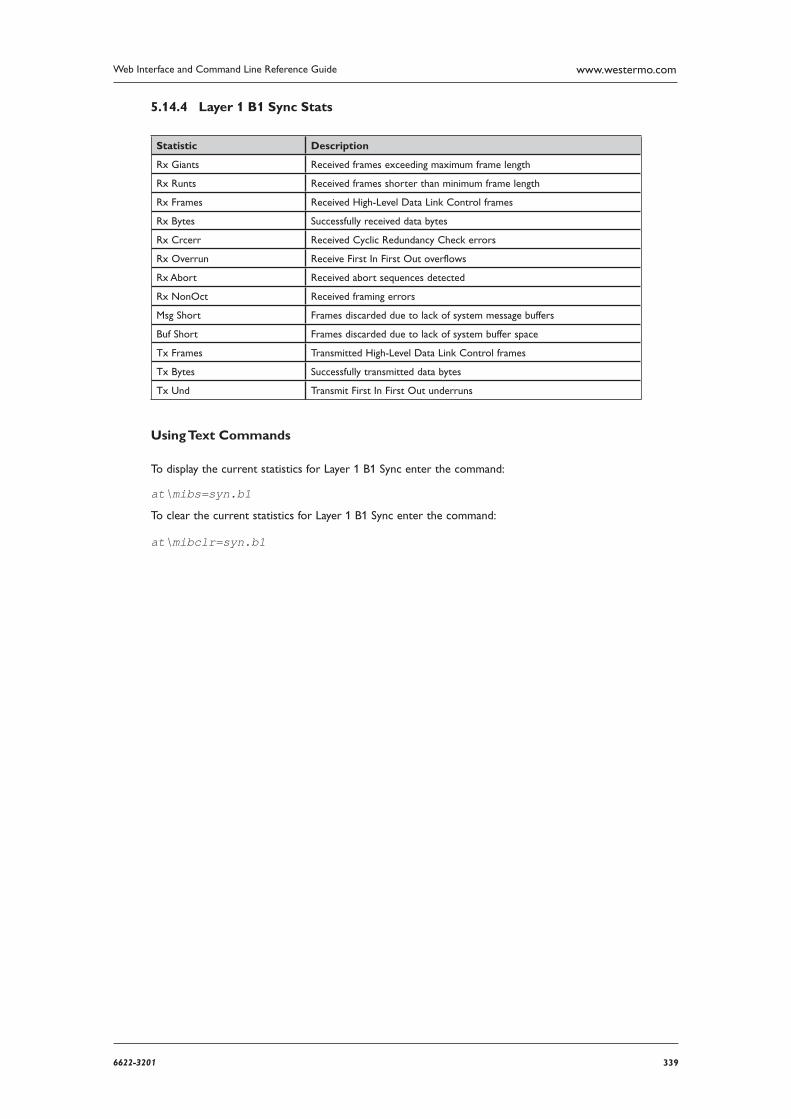
3396622-3201
Web Interface and Command Line Reference Guide www.westermo.com
Layer 1 B1 Sync Stats 5.14.4
Statistic Description
Rx Giants Received frames exceeding maximum frame length
Rx Runts Received frames shorter than minimum frame length
Rx Frames Received High-Level Data Link Control frames
Rx Bytes Successfully received data bytes
Rx Crcerr Received Cyclic Redundancy Check errors
Rx Overrun Receive First In First Out overflows
Rx Abort Received abort sequences detected
Rx NonOct Received framing errors
Msg Short Frames discarded due to lack of system message buffers
Buf Short Frames discarded due to lack of system buffer space
Tx Frames Transmitted High-Level Data Link Control frames
Tx Bytes Successfully transmitted data bytes
Tx Und Transmit First In First Out underruns
Using Text Commands
To display the current statistics for Layer 1 B1 Sync enter the command:
at\mibs=syn.b1
To clear the current statistics for Layer 1 B1 Sync enter the command:
at\mibclr=syn.b1
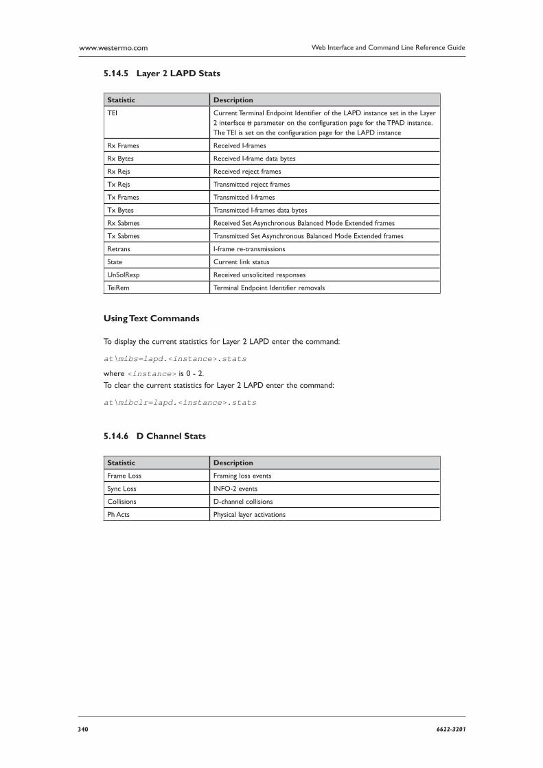
340 6622-3201
Web Interface and Command Line Reference Guidewww.westermo.com
Layer 2 LAPD Stats 5.14.5
Statistic Description
TEI Current Terminal Endpoint Identifier of the LAPD instance set in the Layer 2 interface # parameter on the configuration page for the TPAD instance. The TEI is set on the configuration page for the LAPD instance
Rx Frames Received I-frames
Rx Bytes Received I-frame data bytes
Rx Rejs Received reject frames
Tx Rejs Transmitted reject frames
Tx Frames Transmitted I-frames
Tx Bytes Transmitted I-frames data bytes
Rx Sabmes Received Set Asynchronous Balanced Mode Extended frames
Tx Sabmes Transmitted Set Asynchronous Balanced Mode Extended frames
Retrans I-frame re-transmissions
State Current link status
UnSolResp Received unsolicited responses
TeiRem Terminal Endpoint Identifier removals
Using Text Commands
To display the current statistics for Layer 2 LAPD enter the command:
at\mibs=lapd.<instance>.stats
where <instance> is 0 - 2.
To clear the current statistics for Layer 2 LAPD enter the command:
at\mibclr=lapd.<instance>.stats
D Channel Stats 5.14.6
Statistic Description
Frame Loss Framing loss events
Sync Loss INFO-2 events
Collisions D-channel collisions
Ph Acts Physical layer activations

3416622-3201
Web Interface and Command Line Reference Guide www.westermo.com
Layer 1 D Sync Stats 5.14.7
Statistic Description
Rx Giants Received frames exceeding maximum frame length
Rx Runts Received frames shorter than minimum frame length
Rx Frames Received High-Level Data Link Control frames
Rx Bytes Successfully received data bytes
Rx Crcerr Received Cyclic Redundancy Check errors
Rx Overrun Receive First In First Out overflows
Rx Abort Received abort sequences detected
Rx NonOct Received framing errors
Msg Short Frames discarded due to lack of system message buffers
Buf Short Frames discarded due to lack of system buffer space
Tx Frames Transmitted High-Level Data Link Control frames
Tx Bytes Successfully transmitted data bytes
Tx Und Transmit First In First Out underruns
Using Text Commands
To display the current statistics for Layer 1 D Sync enter the command:
at\mibs=syn.d
To clear the current statistics for Layer 1 D Sync enter the command:
at\mibclr=syn.d
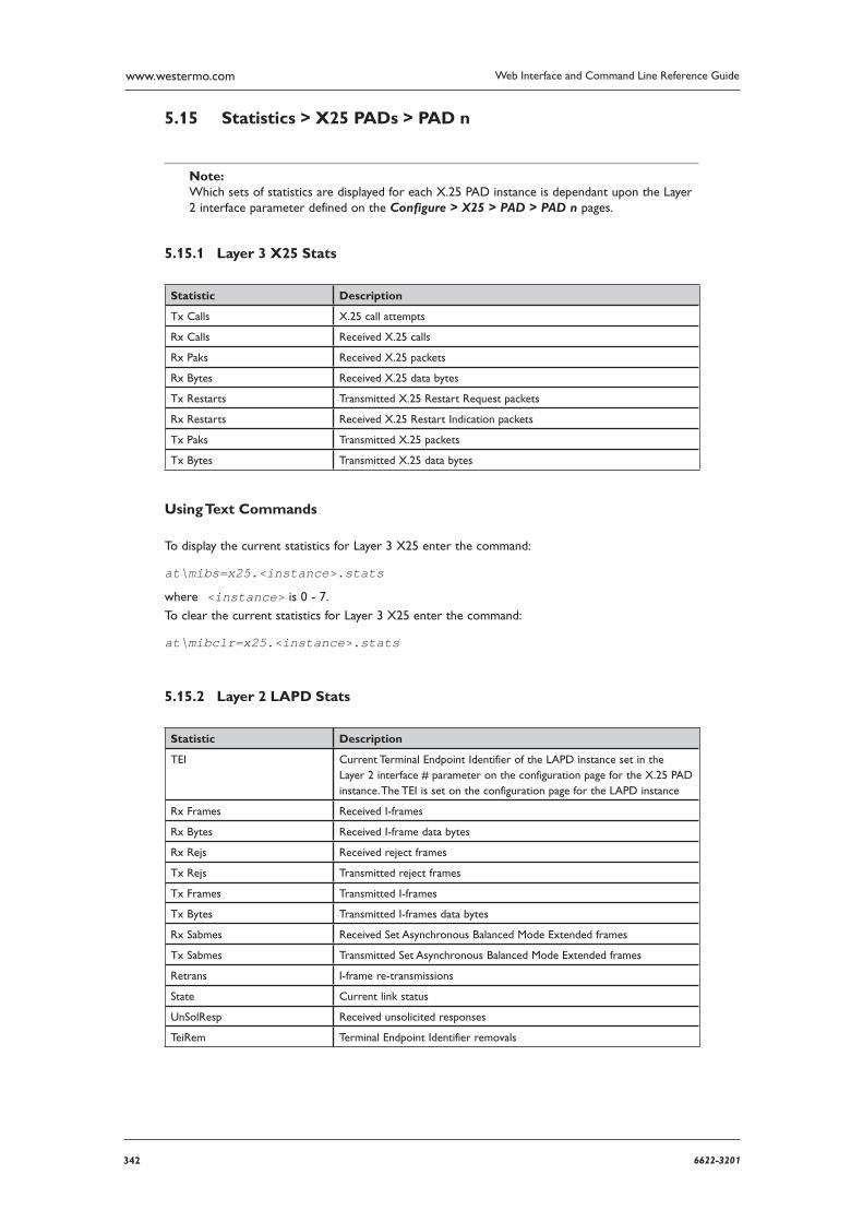
342 6622-3201
Web Interface and Command Line Reference Guidewww.westermo.com
Statistics > X25 PADs > PAD n 5.15
Note: Which sets of statistics are displayed for each X.25 PAD instance is dependant upon the Layer 2 inter face parameter defined on the Configure > X25 > PAD > PAD n pages.
Layer 3 X25 Stats 5.15.1
Statistic Description
Tx Calls X.25 call attempts
Rx Calls Received X.25 calls
Rx Paks Received X.25 packets
Rx Bytes Received X.25 data bytes
Tx Restarts Transmitted X.25 Restart Request packets
Rx Restarts Received X.25 Restart Indication packets
Tx Paks Transmitted X.25 packets
Tx Bytes Transmitted X.25 data bytes
Using Text Commands
To display the current statistics for Layer 3 X25 enter the command:
at\mibs=x25.<instance>.stats
where <instance> is 0 - 7.
To clear the current statistics for Layer 3 X25 enter the command:
at\mibclr=x25.<instance>.stats
Layer 2 LAPD Stats 5.15.2
Statistic Description
TEI Current Terminal Endpoint Identifier of the LAPD instance set in the Layer 2 interface # parameter on the configuration page for the X.25 PAD instance. The TEI is set on the configuration page for the LAPD instance
Rx Frames Received I-frames
Rx Bytes Received I-frame data bytes
Rx Rejs Received reject frames
Tx Rejs Transmitted reject frames
Tx Frames Transmitted I-frames
Tx Bytes Transmitted I-frames data bytes
Rx Sabmes Received Set Asynchronous Balanced Mode Extended frames
Tx Sabmes Transmitted Set Asynchronous Balanced Mode Extended frames
Retrans I-frame re-transmissions
State Current link status
UnSolResp Received unsolicited responses
TeiRem Terminal Endpoint Identifier removals
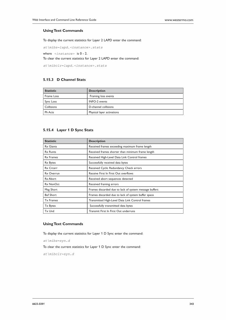
3436622-3201
Web Interface and Command Line Reference Guide www.westermo.com
Using Text Commands
To display the current statistics for Layer 2 LAPD enter the command:
at\mibs=lapd.<instance>.stats
where <instance> is 0 - 2.
To clear the current statistics for Layer 2 LAPD enter the command:
at\mibclr=lapd.<instance>.stats
D Channel Stats 5.15.3
Statistic Description
Frame Loss Framing loss events
Sync Loss INFO-2 events
Collisions D-channel collisions
Ph Acts Physical layer activations
Layer 1 D Sync Stats 5.15.4
Statistic Description
Rx Giants Received frames exceeding maximum frame length
Rx Runts Received frames shorter than minimum frame length
Rx Frames Received High-Level Data Link Control frames
Rx Bytes Successfully received data bytes
Rx Crcerr Received Cyclic Redundancy Check errors
Rx Overrun Receive First In First Out overflows
Rx Abort Received abort sequences detected
Rx NonOct Received framing errors
Msg Short Frames discarded due to lack of system message buffers
Buf Short Frames discarded due to lack of system buffer space
Tx Frames Transmitted High-Level Data Link Control frames
Tx Bytes Successfully transmitted data bytes
Tx Und Transmit First In First Out underruns
Using Text Commands
To display the current statistics for Layer 1 D Sync enter the command:
at\mibs=syn.d
To clear the current statistics for Layer 1 D Sync enter the command:
at\mibclr=syn.d
344 6622-3201
Web Interface and Command Line Reference Guidewww.westermo.com
Status Pages6
The next sub-heading on the directory tree is Status. Clicking on the “+” symbol at the left of the Status folder expands the sub-tree to list a number of pages which contain various status informa-tion about the unit.
Under the Status folder there are hyperlinks for pages that display the analyser trace, event log, file directory, etc. Click on the appropriate hyperlink to view the status screen for the item you require.
Status > Analyser Trace 6.1
If the protocol analyser has been enabled, the contents of the analyser log can be viewed on the Status > Analyser Trace page. The amount of detail provided in the log depends upon which ana-lyser options have been turned on. Use the scroll bar at the right of the screen to navigate up/down stored trace information. The most recent data will appear at the top of the screen.
Using Text Commands
To view the analyser trace from the command line, use the type command to list the “ANA.TXT” pseudo file:
type ana.txt
Status > PCAP traces 6.2
Three files are available to download, “anaip.cap”, “anaeth.cap” and “anappp.cap”. These files present IP/ETH/PPP frames captured in a format that can be viewed directly in Wireshark packet analyser.
3456622-3201
Web Interface and Command Line Reference Guide www.westermo.com
Status > DHCP Server 6.3
The Status > DHCP Server page displays a table of IP addresses leased by the DHCP server. Each table entry consists of the following:
IP address:
This is the IP address assigned to the client.
Hostname:
This is the IP Hostname of the client to which the IP address was assigned.
Lease time left (mins):
This is the time remaining in minutes before the client must renew its configuration with the DHCP server.
Using Text Commands
From the command line you may view the DHCP server status by using the dhcp command as fol-lows:
dhcp 0 status
For example:
dhcp 0 status
Entry: IP [10.1.2.13], hostname [Server], expiry 46 (mins)Entry: IP [10.1.2.11], hostname [Alan], expiry 50 (mins)Entry: IP [10.1.2.15], hostname [Colin], expiry 59 (mins)Entry: IP [10.1.2.91], hostname [Phil], expiry 37 (mins)Entry: IP [10.1.2.16], hostname [Reception], expiry 41 (mins) Entry: IP [10.1.2.10], hostname [X25], expiry 44 (mins)Entry: IP [10.1.2.17], hostname [Robin], expiry 49 (mins)Entry: IP [10.1.2.14], hostname [Alistair], expiry 59 (mins)OK
346 6622-3201
Web Interface and Command Line Reference Guidewww.westermo.com
Status > Ethernet > ETH n 6.4
The Status > Ethernet > ETH n pages show the settings of the various ethernet interfaces.
Activation Status:
The interface is active if it has an assigned IP address and has not been deactivated by a higher level tasks.
Connection Status:
The connection status of the interface.
Link:
The negotiated link settings.
MAC:
The MAC address of the interface.
IP Address:
The IP address of the interface.
Mask:
The mask of the interface.
DNS Server:
The IP address of the DNS server.
Gateway:
The IP address of the gateway.
DHCP Server:
The IP address of the DHCP server if DHCP client is enabled.
Lease Remaining (mins):
DHCP lease time remaining if using the DHCP client.
Using Text Commands
From the command line you may view the status of the Ethernet port by using the eth command with the status parameter:
eth <instance> status
where <instance> is the ethernet instance. For example:
eth 0 status Activation Status: Active Connection Status: Connected Link: 100Base-T Full-Duplex MAC: 00 04 2D 00 97 26 IP Address: 10.1.39.28 Mask: 255.255.0.0 DNS Server: 0.0.0.0 Gateway: 0.0.0.0
OK
3476622-3201
Web Interface and Command Line Reference Guide www.westermo.com
Status > Ethernet > ETH n > QOS 6.5
The Status > Ethernet > ETH n > QOS pages show the Quality of Service settings for the ether-net interfaces.
Priority Q
The QOS queue.
TX rate (kbps)
The transmission rate of the queue.
Limit
The link speed.
Weighted Q length
The weighted queue length using the WRED algorithm.
Q length
The number of packets in the queue.
Status > Event log 6.6
The Status > Event Log page allows you to display the contents of the “EVENTLOG.TXT” pseudo file with the most recent events listed at the top of the log. Each event log entry consists of the time and date of the event followed by a brief description. The information can be very useful in tracing and diagnosing fault conditions.
Using Text Commands
From the command line you may view the contents of the event log by using the type command to list the “EVENTLOG.TXT” pseudo file:
type eventlog.txt
Status > File Directory 6.7
The Status > File Directory page provides a list of files currently stored in the filing system. The listing includes the filename, size in bytes, read/write status and creation date/time.
Using Text Commands
From the command line the file directory may be listed using the dir command.
348 6622-3201
Web Interface and Command Line Reference Guidewww.westermo.com
Status > Firmware Versions 6.8
The Status > Firmware Versions page shows the model information and serial number for your unit and a list of the various firmware modules that are loaded along with the version number for each module.
Using Text Commands
From the command line the firmware versions can be listed using either ATI5or id?.
Status > W-WAN Module 6.9
The Status > W-WAN Module page displays information about the current status of the W-WAN module on those models that incorporate one. This includes:
SIM status:
This identifies whether or not a valid SIM card has been installed in the module. It may be one of the following:
READY - SIM is OK •
SIM PIN - PIN number required •
SIM PUK - SIM blocked (unblocking code required) •
ERROR - SIM is not installed or is faulty •
Signal strength:
This shows the W-WAN signal strength in dBm being received by the module. The range is -113dBm (min.) to -51dBm (max.)
Manufacturer:
This entry shows the manufacturer of the W-WAN module.
IMEI:
The International Mobile Equipment Identification number of the W-WAN module.
IMSI:
International Mobile Subscriber Identity of the W-WAN module. This can also be queried by using the text based command “modemcc 0 imsi ?”
ICCID:
Integrated Circuit Card IDentifier of the SIM card. This can also be queried by using the text based command “modemcc 0 iccid ?”
Firmware:
The version number of the firmware of the W-WAN module.
W-WAN Attachment Status:
This field displays the current status of the module with respect to the W-WAN service. It may be one of the following:
Not attached - the unit has not connected to a W-WAN service •
Attached - the unit has connected to a W-WAN service •
ERROR - unknown response from W-WAN module •
3496622-3201
Web Interface and Command Line Reference Guide www.westermo.com
W-WAN Registration:
This field indicates the status of the W-WAN module. It may be one of the following:
Not registered, not searching •
Registered, home network •
Not registered, searching •
Registration denied •
Registered, roaming •
Unknown •
ERROR •
GSM Registration:
This field indicates the status of the W-WAN module with respect to the GSM network. It may be one of the following:
Not registered, not searching •
Registered, home network •
Not registered, searching •
Registration denied •
Registered, roaming •
Unknown •
ERROR •
The registration status may sometimes be followed by additional information about the Location Area Code (LAC) and the Cell Identifier (CI), for example:
Registered, home network lac:22 ci:76E
Network:
This entry shows the name of the GSM network to which the W-WAN module is currently connected or ERROR if no network is available. The format of this field is:
<mode>,<format>,<operator> where:
<mode> is 0 for automatic, 1 for manually selected
<format> is 0 for long alphanumeric or 2 for numeric
<operator> is the operator name (if alphanumeric format) or operator code (MCC followed by Mobile network code)
For example:
0,0,“vodafone UK”
Connection Status:
This field displays error codes relating to the last unsuccessful call.
Note: The following parameters are only applicable to the MR-250.
Service Provider Name:
This field displays the name of the GSM service provider.
350 6622-3201
Web Interface and Command Line Reference Guidewww.westermo.com
Radio Access Technology:
This field displays the preferred and current Radio Access Technology (RAT) being employed by the modem. The format of this field is:
<mode>, <domain>, <state> where: <mode> indicates the preferred RAT, and can be one of the following: Automatic
GSM •
. WCDMA •
<domain> indicates the preferred service domain within the RAT, and can be one of the fol-lowing:
CS - Circuit switched only
PS - Packet switched only •
CS+PS - Circuit switched and packet switched •
<state> indicates the current mode and domain, and can be one of the following:
WCDMA CS •
WCDMA PS •
WCDMA CS+PS •
GSM CS •
GSM PS •
GSM CS+PS •
WCDMA,CS+PS,WCDMA CS+PS •
Network Technology:
The current network technology in use. This can be one of the following:
GSM •
GPRS •
EDGE •
UMTS •
HSDPA •
Cell Information:
This field displays the current Cell Identifier and Location Area Code.
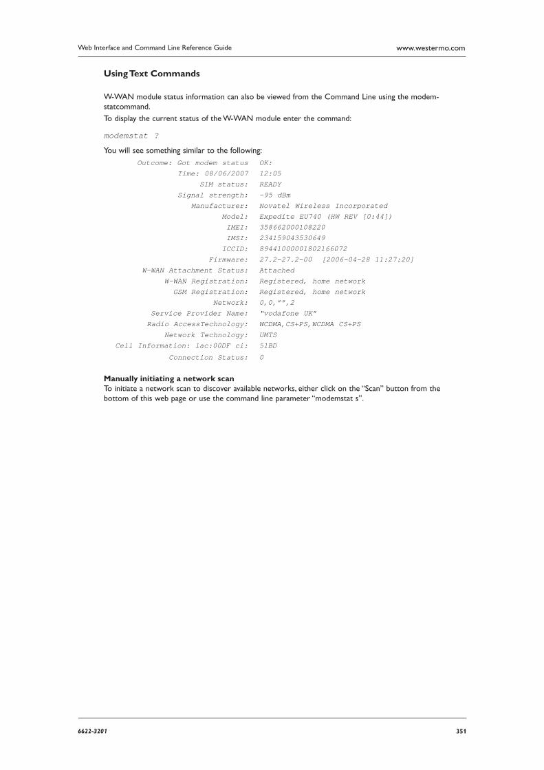
3516622-3201
Web Interface and Command Line Reference Guide www.westermo.com
Using Text Commands
W-WAN module status information can also be viewed from the Command Line using the modem-statcommand.
To display the current status of the W-WAN module enter the command:
modemstat ?
You will see something similar to the following:
Outcome: Got modem status OK: Time: 08/06/2007 12:05 SIM status: READY Signal strength: -95 dBm Manufacturer: Novatel Wireless Incorporated Model: Expedite EU740 (HW REV [0:44]) IMEI: 358662000108220 IMSI: 234159043530649 ICCID: 89441000001802166072 Firmware: 27.2-27.2-00 [2006-04-28 11:27:20] W-WAN Attachment Status: Attached W-WAN Registration: Registered, home network GSM Registration: Registered, home network Network: 0,0,””,2 Service Provider Name: “vodafone UK” Radio AccessTechnology: WCDMA,CS+PS,WCDMA CS+PS Network Technology: UMTS Cell Information: lac:00DF ci: 51BD
Connection Status: 0
Manually initiating a network scan To initiate a network scan to discover available networks, either click on the “Scan” button from the bottom of this web page or use the command line parameter “modemstat s”.
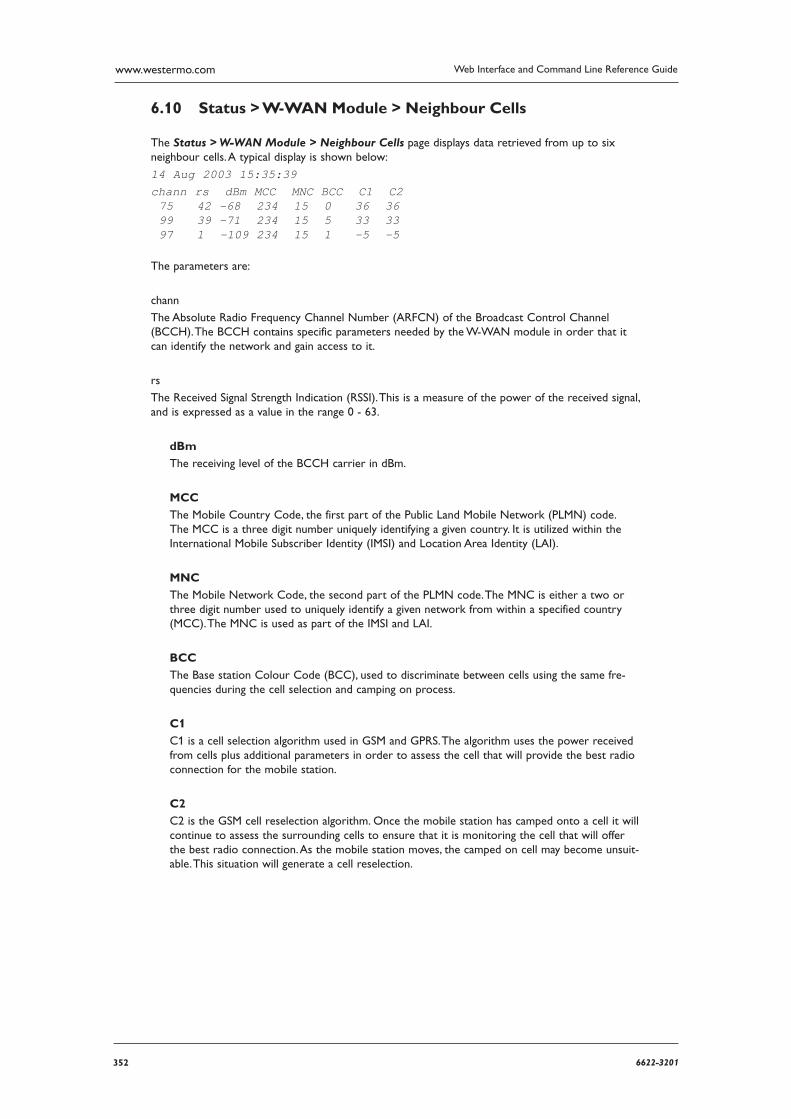
352 6622-3201
Web Interface and Command Line Reference Guidewww.westermo.com
Status > W-WAN Module > Neighbour Cells 6.10
The Status > W-WAN Module > Neighbour Cells page displays data retrieved from up to six neighbour cells. A typical display is shown below:
14 Aug 2003 15:35:39chann rs dBm MCC MNC BCC C1 C2 75 42 -68 234 15 0 36 36 99 39 -71 234 15 5 33 33 97 1 -109 234 15 1 -5 -5
The parameters are:
chann
The Absolute Radio Frequency Channel Number (ARFCN) of the Broadcast Control Channel (BCCH). The BCCH contains specific parameters needed by the W-WAN module in order that it can identify the network and gain access to it.
rs
The Received Signal Strength Indication (RSSI). This is a measure of the power of the received signal, and is expressed as a value in the range 0 - 63.
dBm
The receiving level of the BCCH carrier in dBm.
MCC
The Mobile Country Code, the first part of the Public Land Mobile Network (PLMN) code. The MCC is a three digit number uniquely identifying a given country. It is utilized within the International Mobile Subscriber Identity (IMSI) and Location Area Identity (LAI).
MNC
The Mobile Network Code, the second part of the PLMN code. The MNC is either a two or three digit number used to uniquely identify a given network from within a specified country (MCC). The MNC is used as part of the IMSI and LAI.
BCC
The Base station Colour Code (BCC), used to discriminate between cells using the same fre-quencies during the cell selection and camping on process.
C1
C1 is a cell selection algorithm used in GSM and GPRS. The algorithm uses the power received from cells plus additional parameters in order to assess the cell that will provide the best radio connection for the mobile station.
C2
C2 is the GSM cell reselection algorithm. Once the mobile station has camped onto a cell it will continue to assess the surrounding cells to ensure that it is monitoring the cell that will offer the best radio connection. As the mobile station moves, the camped on cell may become unsuit-able. This situation will generate a cell reselection.
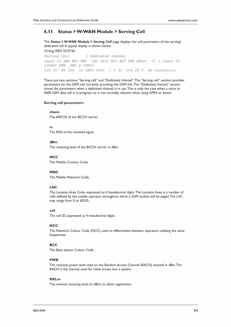
3536622-3201
Web Interface and Command Line Reference Guide www.westermo.com
Status > W-WAN Module > Serving Cell 6.11
The Status > W-WAN Module > Serving Cell page displays the cell parameters of the serving/ dedicated cell. A typical display is shown below:
14 Aug 2003 10:27:56
Serving Cell I Dedicated channel chann rs dBm MCC MNC LAC cell NCC BCC PWR RXLev C1 I chann TS timAdv PWR dBm Q ChMod105 30 -80 234 10 0BFD 3563 1 2 33 -104 24 I No connection
There are two sections, “Serving cell” and “Dedicated channel”. The “Serving cell” section provides parameters for the GSM cell currently providing the GSM link. The “Dedicated channel” section shows the parameters when a dedicated channel is in use. This is only the case when a voice or 9600 GSM data call is in progress, so is not normally relevant when using GPRS or better.
Serving cell parameters:
chann
The ARFCN of the BCCH carrier.
rs
The RSSI of the received signal.
dBm
The receiving level of the BCCH carrier in dBm.
MCC
The Mobile Country Code.
MNC
The Mobile Network Code.
LAC
The Location Area Code, expressed as 4 hexadecimal digits. The Location Area is a number of cells defined by the mobile operator, throughout which a GSM mobile will be paged. The LAC may range from 0 to 65535.
cell
The cell ID, expressed as 4 hexadecimal digits.
NCC
The Network Colour Code (NCC), used to differentiate between operators utilizing the same frequencies.
BCC
The Base station Colour Code.
PWR
The maximal power level used on the Random Access Channel (RACH) channel in dBm. The RACH is the channel used for initial access into a system.
RXLev
The minimal receiving level (in dBm) to allow registration
354 6622-3201
Web Interface and Command Line Reference Guidewww.westermo.com
C1
The cell selection criterion.
Dedicated channel parameters:
chann
The ARFCN of the Traffic Channel (TCH) carrier. The TCH is the bi-directional channel used for speech or circuit switched data. A value of “h” indicates frequency hopping.
TS
Timeslot number.
timAdv
The timing advance in bits.
PWR
Current power level.
DBm
The receiving level of the traffic channel carrier in dBm.
Q
The receiving quality (0-7).
ChMod
The channel mode (S_HR = half rate, S_FR = full rate, S_EFR =enhanced full rate).
Additional Text Additional text is provided to indicate the state of W-WAN module.
No Connection
The W-WAN module is camping on a cell and registered to the network. The service state is “idle”,
i.e. there is no dedicated channel in use or connection established. This is normally the state seen when using W-WAN.
Limited Service
The W-WAN module is camping on a cell but not registered to the network. Only emergency calls are allowed. This state typically occurs when there is no SIM inserted, or a required PIN has not been provided. Other reasons for this state are:
Neither home PLMN nor any other allowed PLMN found. •
Registration request was not answered or was denied by the network (see the Network • Registration parameter on the Status > W-WAN Module web page).
Authentication failed. •
Cell Reselection
The W-WAN module has not yet lost coverage but is searching for a better cell, since the cell reselection criterion has been fulfilled.
Searching
The W-WAN module is searching, but could not yet find a suitable cell. You might see this state immediately after power-up or after loss of coverage.
3556622-3201
Web Interface and Command Line Reference Guide www.westermo.com
Status > W-WAN Module > W-WAN Cell Information 6.12
The Status > W-WAN Module > W-WAN Cell Information page shows the W-WAN specific cell information. A typical display is shown below.
Note: This information is only available when a W-WAN context is active.
21 Aug 2003 16:34:21W-WAN Monitor BCCH G PBCCH PAT MCC MNC NOM TA RAC # Cell # 0000 1 -4 234 10 2 00 5F
The parameters are:
BCCH
The ARFCN of the BCCH carrier.
G
Displays GPRS/EDGE status: 0 GPRS/EDGE not available in currently used cell 1 GPRS available in currently used cell 2 GPRS attached 3 EDGE available in currently used cell
4 EDGE attached -GPRS not supported
Note: During a voice call or CSD connection GPRS services are not available, and consequently 0 or - is displayed.
PBCCH
The ARFCN of the PBCCH (Packet Broadcast Control Channel) if present, else “-”. If frequency hopping is used, this is indicated by “H”. In a W-WAN network, the PBCCH is used to broadcast packet data specific Packet System Information (PSI). If the PBCCH has not been allocated, this information is broadcast on the BCCH.
PAT
The Priority Access Threshold. A value of “0”, “1” or “2” means packet access is not allowed in the cell, a value of “3” means packet access is allowed for priority level 1, and a value of “4” means packet access is allowed for priority level 1 to 2.
MCC
The Mobile Country Code.
MNC
The Mobile Network Code.
NOM
Network Operation Mode (1 -3). The NOM, is responsible for the capabilities of a W-WAN network, while the class indicates the mobile phone capabilities. On NOM 1 networks, mobile phones with the right capabilities can have simultaneous circuit- and packet-switched connec-tions. On NOM 2 networks, mobile phones can remain attached to the W-WAN networks when in a voice call but they can’t transmit data at the same time. On NOM 3 networks, mobile phones can either establish a packet-switched data connection or a circuit-switched voice one but they need to disconnect from one to establish another.

356 6622-3201
Web Interface and Command Line Reference Guidewww.westermo.com
TA
Timing advance value.
RAC
The Routing Area Code, an 8 bit value which identifies a routing area within a location area. Expressed as a hexadecimal value.
3576622-3201
Web Interface and Command Line Reference Guide www.westermo.com
Status > IGMP Groups 6.13
The Status > IGMP Groups lists statistics relating to the Internet Group Management Protocol (IGMP). This protocol is used for the management of IP multicast group membership. The statistics are described in the following table:
Abbreviation Description
Free Groups Number of available multicast group entries
Min Free Groups Lowest value of Free Groups since power up
RX Total Total number of IGMP packets received
RX Reports Number of host membership report packets received
RX Queries Number of host membership query packets received
TX General Queries Number of general group membership query packets transmitted
TX Group Queries Number of group specific membership query packets transmitted
Too Short Number of IGMP packets received with an incorrect length
Bad Checksum Number of IGMP packets received with an incorrect checksum
RX Bad Queries Number of bad query packets received
RX Bad Reports Number of bad report packets received
Status > IPSec > IPSec Peers 6.14
The Status > IPSec > IPSec Peers page shows details for each IPSec peer.
Peer IP
The IP address of the remote unit.
Peer ID
The ID of the remote unit.
DPD
This field displays DPD status and the time until the next DPD request.
NATT local port
The local NATT port.
NATT remote port
The remote NATT port.
358 6622-3201
Web Interface and Command Line Reference Guidewww.westermo.com
Status > IPSec > IKE SAs 6.15
The Status > IPSec > IKE SAs page shows IKE V1 and IKE V2 SAs.
Peer ID
The ID of the remote unit.
Peer IP
The IP address of the remote unit.
Our IP
The IP address of the interface on the Westermo the eroute is on.
Session ID
The ID for this SA.
Time Left
The time remaining for the IKE Security Association to stay in force.
Status > IPSec > IPSec SAs > Dynamic tunnels 6.16
This page shows the status of IPSec SA’s for dynamic tunnels when using Egroups on a VPN responder. The page has the same datails as Status > IPSec > IPSec SAs > Eroute n but only details of dynamic tunnels are shown.
Using Text Commands
From the command line the sastat dyn command can be used to display Dynamic IPSec SA informa-tion. The format of the command is:
sastat dyn <First Eroute> <Last Eroute>
where <First Eroute> and <Last Eroute> are optional. sastat peer <peer-wildcard> sastat peer <peer-IP> <peer-wildcard> allows you to view a selection of sites, eg: sastat peer uk-north-*
<peer-IP> allows you to view a specific peer IP address.
3596622-3201
Web Interface and Command Line Reference Guide www.westermo.com
Status > IPSec > IPSec SAs > Eroute n 6.17
The Status > IPSec > IPSec SAs > Eroute n pages shows inbound and outbound IPSec V1 and V2 SAs. Selecting the Status > IPSec SAs folder will show a list of all Eroutes.
SPI
The Security Parameters Index (SPI) is a pointer that references the session key and algorithm used to protect the data being transported.
Eroute
The eroute number.
Peer IP
The IP address of the remote peer.
Rem. IP
The remote subnet IP address.
Rem. Mask
The remote subnet mask.
Loc. IP
The local subnet IP address.
Loc. Mask
The local subnet mask.
AH
The AH authentication algorithm in use, if any.
ESP Auth
The ESP authentication algorithm in use, if any.
ESP Enc
The ESP encryption algorithm in use, if any, and the key length in bits.
IPCOMP
The data compression in use (if any) and the compression ratio.
KBytes Delivered
The total amount of data that has been transferred (in both directions) over this eroute.
KBytes Left
The amount of data left to be transferred over the eroute before the data Duration limit is reached. The data Duration is negotiated between the Westermo and the remote unit, and so may not match the value of the Duration (kb) parameter configured on the Configure > IPSec > IPSec Eroutes > Eroute n page.
Time Left
The time left before the time Duration limit is reached. The time Duration is negotiated between the Westermo and the remote unit, and so may not match the value of the Duration (s) parameter configured on the Configure > IPSec > IPSec Eroutes > Eroute n page.
Interface
The interface on the Westermo this eroute is on.
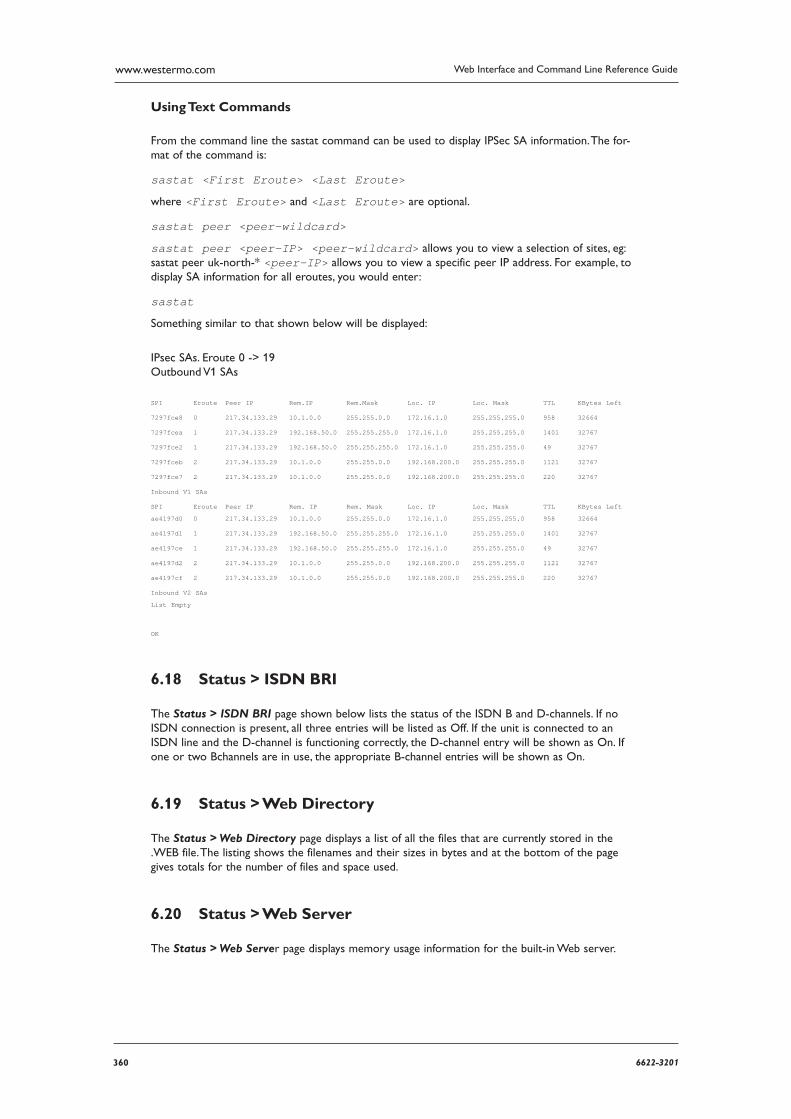
360 6622-3201
Web Interface and Command Line Reference Guidewww.westermo.com
Using Text Commands
From the command line the sastat command can be used to display IPSec SA information. The for-mat of the command is:
sastat <First Eroute> <Last Eroute>
where <First Eroute> and <Last Eroute> are optional.
sastat peer <peer-wildcard>
sastat peer <peer-IP> <peer-wildcard> allows you to view a selection of sites, eg: sastat peer uk-north-* <peer-IP> allows you to view a specific peer IP address. For example, to display SA information for all eroutes, you would enter:
sastat
Something similar to that shown below will be displayed:
IPsec SAs. Eroute 0 -> 19 Outbound V1 SAs
SPI Eroute Peer IP Rem.IP Rem.Mask Loc. IP Loc. Mask TTL KBytes Left
7297fce8 0 217.34.133.29 10.1.0.0 255.255.0.0 172.16.1.0 255.255.255.0 958 32664
7297fcea 1 217.34.133.29 192.168.50.0 255.255.255.0 172.16.1.0 255.255.255.0 1401 32767
7297fce2 1 217.34.133.29 192.168.50.0 255.255.255.0 172.16.1.0 255.255.255.0 49 32767
7297fceb 2 217.34.133.29 10.1.0.0 255.255.0.0 192.168.200.0 255.255.255.0 1121 32767
7297fce7 2 217.34.133.29 10.1.0.0 255.255.0.0 192.168.200.0 255.255.255.0 220 32767
Inbound V1 SAs
SPI Eroute Peer IP Rem. IP Rem. Mask Loc. IP Loc. Mask TTL KBytes Left
ae4197d0 0 217.34.133.29 10.1.0.0 255.255.0.0 172.16.1.0 255.255.255.0 958 32664
ae4197d1 1 217.34.133.29 192.168.50.0 255.255.255.0 172.16.1.0 255.255.255.0 1401 32767
ae4197ce 1 217.34.133.29 192.168.50.0 255.255.255.0 172.16.1.0 255.255.255.0 49 32767
ae4197d2 2 217.34.133.29 10.1.0.0 255.255.0.0 192.168.200.0 255.255.255.0 1121 32767
ae4197cf 2 217.34.133.29 10.1.0.0 255.255.0.0 192.168.200.0 255.255.255.0 220 32767
Inbound V2 SAs
List Empty
OK
Status > ISDN BRI 6.18
The Status > ISDN BRI page shown below lists the status of the ISDN B and D-channels. If no ISDN connection is present, all three entries will be listed as Off. If the unit is connected to an ISDN line and the D-channel is functioning correctly, the D-channel entry will be shown as On. If one or two B channels are in use, the appropriate B-channel entries will be shown as On.
Status > Web Directory 6.19
The Status > Web Directory page displays a list of all the files that are currently stored in the .WEB file. The listing shows the filenames and their sizes in bytes and at the bottom of the page gives totals for the number of files and space used.
Status > Web Server 6.20
The Status > Web Server page displays memory usage information for the built-in Web server.
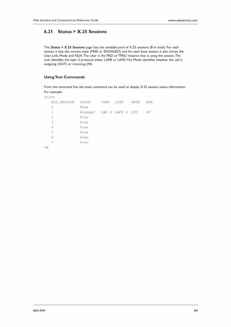
3616622-3201
Web Interface and Command Line Reference Guide www.westermo.com
Status > X.25 Sessions 6.21
The Status > X.25 Sessions page lists the available pool of X.25 sessions (8 in total). For each session it lists the current state (FREE or ENGAGED) and for each busy session it also shows the User, Link, Mode and NUA. The User is the PAD or TPAD instance that is using the session. The Link identifies the layer 2 protocol, either LAPB or LAPD. The Mode identifies whether the call is outgoing (OUT) or incoming (IN).
Using Text Commands
From the command line the statx command can be used to display X.25 session status information.
For example:
statx X25_SESSION STATE USER LINK MODE NUA 0 Free 1 Engaged PAD 0 LAPB 0 OUT 45 2 Free 3 Free 4 Free 5 Free 6 Free 7 Free OK
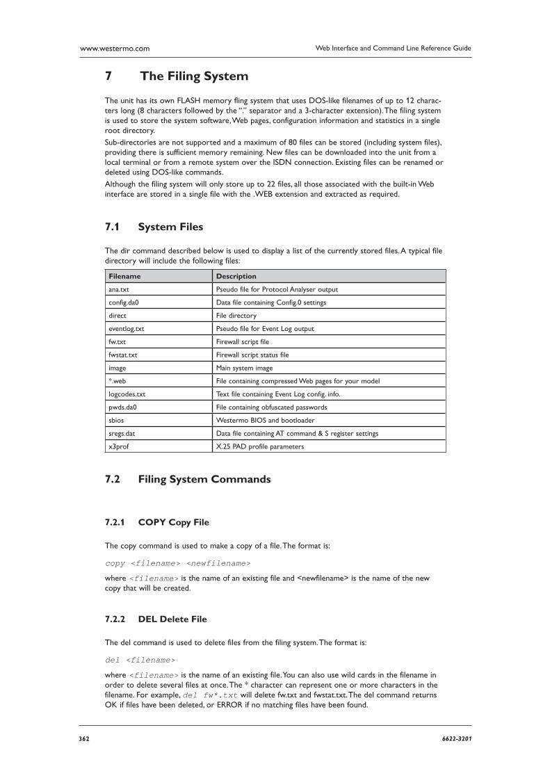
362 6622-3201
Web Interface and Command Line Reference Guidewww.westermo.com
The Filing System7
The unit has its own FLASH memory fling system that uses DOS-like filenames of up to 12 charac-ters long (8 characters followed by the “.” separator and a 3-character extension). The filing system is used to store the system software, Web pages, configuration information and statistics in a single root directory.
Sub-directories are not supported and a maximum of 80 files can be stored (including system files), providing there is sufficient memory remaining. New files can be downloaded into the unit from a local terminal or from a remote system over the ISDN connection. Existing files can be renamed or deleted using DOS-like commands.
Although the filing system will only store up to 22 files, all those associated with the built-in Web interface are stored in a single file with the .WEB extension and extracted as required.
System Files 7.1
The dir command described below is used to display a list of the currently stored files. A typical file directory will include the following files:
Filename Description
ana.txt Pseudo file for Protocol Analyser output
config.da0 Data file containing Config.0 settings
direct File directory
eventlog.txt Pseudo file for Event Log output
fw.txt Firewall script file
fwstat.txt Firewall script status file
image Main system image
*.web File containing compressed Web pages for your model
logcodes.txt Text file containing Event Log config. info.
pwds.da0 File containing obfuscated passwords
sbios Westermo BIOS and bootloader
sregs.dat Data file containing AT command & S register settings
x3prof X.25 PAD profile parameters
Filing System Commands 7.2
COPY Copy File 7.2.1
The copy command is used to make a copy of a file. The format is:
copy <filename> <newfilename>
where <filename> is the name of an existing file and <newfilename> is the name of the new copy that will be created.
DEL Delete File 7.2.2
The del command is used to delete files from the filing system. The format is:
del <filename>
where <filename> is the name of an existing file. You can also use wild cards in the filename in order to delete several files at once. The * character can represent one or more characters in the filename. For example, del fw*.txt will delete fw.txt and fwstat.txt. The del command returns OK if files have been deleted, or ERROR if no matching files have been found.
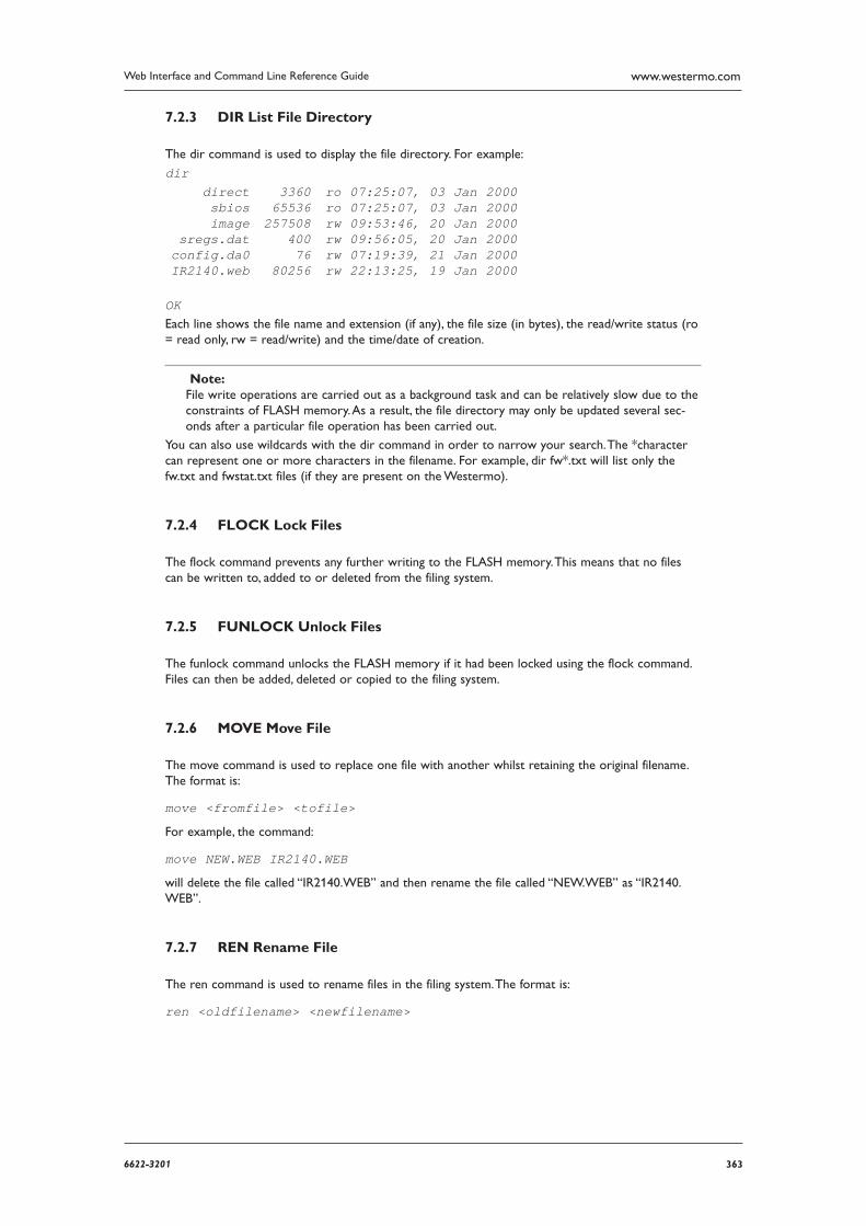
3636622-3201
Web Interface and Command Line Reference Guide www.westermo.com
DIR List File Directory7.2.3
The dir command is used to display the file directory. For example:
dir direct 3360 ro 07:25:07, 03 Jan 2000 sbios 65536 ro 07:25:07, 03 Jan 2000 image 257508 rw 09:53:46, 20 Jan 2000 sregs.dat 400 rw 09:56:05, 20 Jan 2000 config.da0 76 rw 07:19:39, 21 Jan 2000 IR2140.web 80256 rw 22:13:25, 19 Jan 2000
OK Each line shows the file name and extension (if any), the file size (in bytes), the read/write status (ro = read only, rw = read/write) and the time/date of creation.
Note: File write operations are carried out as a background task and can be relatively slow due to the con straints of FLASH memory. As a result, the file directory may only be updated several sec-onds after a particular file operation has been carried out.
You can also use wildcards with the dir command in order to narrow your search. The *character can represent one or more characters in the filename. For example, dir fw*.txt will list only the fw.txt and fwstat.txt files (if they are present on the Westermo).
FLOCK Lock Files 7.2.4
The flock command prevents any further writing to the FLASH memory. This means that no files can be written to, added to or deleted from the filing system.
FUNLOCK Unlock Files 7.2.5
The funlock command unlocks the FLASH memory if it had been locked using the flock command. Files can then be added, deleted or copied to the filing system.
MOVE Move File 7.2.6
The move command is used to replace one file with another whilst retaining the original filename. The format is:
move <fromfile> <tofile>
For example, the command:
move NEW.WEB IR2140.WEB
will delete the file called “IR2140.WEB” and then rename the file called “NEW.WEB” as “IR2140.WEB”.
REN Rename File 7.2.7
The ren command is used to rename files in the filing system. The format is:
ren <oldfilename> <newfilename>
364 6622-3201
Web Interface and Command Line Reference Guidewww.westermo.com
SCAN/SCANR Scan File System 7.2.8
The scan command performs a diagnostic check on the file system and reports any errors that are found. For example:
scan
direct ok sbios ok sregs.dat ok config.da0 ok IR2140.web ok image ok, data ok
OK
The scanning process may take several seconds so you should not enter any other commands until the results are listed.
The scanr command works in a similar fashion, except that it will return ERROR if any file is in error.
TYPE Display Text File 7.2.9
The type command is used to display the contents of a text file. The format is:
type <filename>
For example:
type config.da0
bind PAD 0 ASY 0 pad 0 l2iface LAPBcmd 0 username westermo cmd 0 epassword Oz57X0kdcmd 0 hostname ss.2000r OK
XMODEM File Transfer 7.2.10
The xmodem command is used to initiate an XMODEM file upload from the port at which the command is entered. The format is:
xmodem <filename>
where <filename> is the name under which the file will be saved when the upload is complete.
After entering the xmodem command the unit will wait for your terminal program to start trans-mitting the file. When the upload is complete and the file has been saved, the unit will respond with the OK result code.
A remote XMODEM upload can also be initiated by establishing a Telnet session over ISDN, and then issuing the xmodem command from the remote terminal.
3656622-3201
Web Interface and Command Line Reference Guide www.westermo.com
USB Support 7.3
Some Westermo units come equipped with USB ports that you can use to connect Mass Storage Devices (MSDs) such as external hard drives or flash-memory pen drives. All the files on the USB device will be listed under the USB Directory Listing heading on the Status > File Directory page.
Note: The USB storage device must be formatted using the FAT16 file system.
When the USB storage device is first inserted into the unit, the operating system looks for a file named “autoexec.bat”, and if found, executes it. Other batch files can be executed by pressing the reset button one or more times. The batch file to be executed must be called “pb<n>.bat”, where <n> is the number of times the reset button is to be pressed in order to execute the file.
SD Memory Card Support 7.3.1
Some Westermo routers are available with internal SD memory card, the drive letter assigned to this card is “s:”. To access the SD memory using an FTP client, the subdirectory assigned is “sdmmc”. The SD card can be used in the same way as USB MSDs. The SD card is internal and not removable.
Batch Control Commands 7.3.2
Any batch file can contain one of the following two control lines: ERROR_EXIT or ERROR_RUN. If ERROR_EXIT is specified in a batch file, any commands run after that point in the file will cause the termination of the batch file if that command causes an error (for example, attempting to delete a file that does not exist). ERROR_RUN can be used to return the operation to default, which is to continue the execution of the batch file commands.
USB Filing System Commands 7.3.3
The USB storage device will respond to any of the standard filing system commands. For all filing system commands, the USB storage device is regarded as drive u:.
Note: The unit does not support sub-directories. Any sub-directories on the USB device will appear with a size of 0 bytes on the Status > File Directory page.
Example 1:
To display the contents of the USB storage device, you would enter the command:
dir u:
SERIALS.TXT 1843 EVENTL~1.TXT 1449 USB.TXT 4278 MASSR1~1.TXT 1255
OK
If the USB storage device is empty, you will get the following message:
No files
If no USB device is present, the following message is displayed:
No USB flash directory
366 6622-3201
Web Interface and Command Line Reference Guidewww.westermo.com
Example 2: To copy a file called “image” from the main flash memory onto the USB device, you would enter the command:
copy image u:image
To copy a file called “Logcodes.TXT” from the USB device to the main flash memory, you would enter the command:
copy u:Logcodes.TXT Logcodes.TXT or on firmware version 4912 or later just typing “copy u:logcodes” will have the same effect, i.e. no need to specify the destination.
Using USB devices to upgrade fi rmware 7.3.4
Functionality available from firmware version 4891 onwards.
The firmware of a Westermo can be upgraded using the USB storage device. To do this procedure, using the information given above, a simple batch file called pb2.bat should created and the relevant files placed into the root directory of the USB storage device. Then, when the USB device is insert-ed into the Westermo and the reset button is pressed twice, the upgrade is performed.
ERROR_EXIT del *.web copy u:sbios1 sbios1 copy u:logcodes.txt logcodes.txt copy u:image image copy u:image4.c3 image4.c3 copy u:Y4890wVS.web Y4890wVS.web move sbios1 sbios scanr flashleds
When the LEDs on the Westermo start flashing, the upgrade is complete and the Westermo must be rebooted for the new firmware to be activated.
Using USB devices with .all fi les 7.3.5
Functionality available from firmware version 4910 onwards.
A .all file is a special file that contains all of the firmware and configuration files in a single file that has the file extension .all and is an exact copy of the Westermo router in its current state. This .all file can then be applied to another Westermo router, as long as it is the same model.
To extract a .all file use the Westermo Flash Writer software.
Copy the .all file to a USB storage device and insert the device into the Westermo router. Issue the command “dir u:” to confirm the Westermo can access the USB device. To copy the .all file onto the Westermo router, from the command line enter “copy u:MR-200.all t.all” (replacing mr4110.all with the correct .all file name and the t.all destination name can be anything). Please note that the source file (MR-200.all in this example) must adhere to the 8.3 filename convention (due to limits of the FAT file system) or the process will fail.
USB Security 7.3.6
In order to prevent unauthorised access to a Westermo unit using a USB storage device (e.g. insert-ing a USB storage device with an autoexec.bat file designed to copy usernames and passwords, etc.) theusbcon command can be used to define an access key. If the .bat file does not contain the matching key, it will not be allowed to execute. The put parameter of the uflash command is used to encode the key onto the file.
3676622-3201
Web Interface and Command Line Reference Guide www.westermo.com
Note: When using the uflash command, the filename should not be prefixed with u:, as the uflash command can only act on files stored on a USB storage device.
For example, to create a key you would enter the command:
usbcon 0 flashkey
In order to encode this key onto a file called “autoexec.bat” on the USB storage device, you would enter the command:
uflash autoexec.bat put
In order to remove a key from a file, you would use the clr parameter of the uflash command, thus:
uflash autoexec.bat clr
Note: You must be logged onto the unit with Master access level or higher in order to use the uflash command.
By default, an autoexec.bat file will be executed if found when a USB drive is inserted. Other batch files can also be executed. This behaviour can be controlled if required by issuing the command:
usbcon 0 batfile <off|on>
Disable/Enable the USB ports 7.3.7
If required, the external USB ports can be disabled to prevent any unauthorised copying of files to or from the router and prevent unauthorised use of flash drives or serial devices connected to the USB ports. This is also done with the usbcon command. The parameters used with the usbcon com-mand are dislist to disable or enalist to explicitly enable a list of USB drivers. The driver list can be comma separated to specify more than one driver if required.
The format of the disable command is:
usbcon 0 usb-x-p<.p>.<DRIVER>
Where x=1 for the bottom USB port and 2 for the top port.
Where p=<port #> (if connected to a USB hub the port numbers can increase).
Where DRIVER = “MSD” for Mass Storage Device. “SERIAL” for serial devices, or “HUB” for hub devices.
To disable a Flash Stick on the top port only...
usbcon 0 dislist usb-2-2.MSD
Wild cards are also possible so to disable flash devices entirely. For example:
usbcon 0 dislist usb-*.MSD
This will match on ALL MSD devices even if in another HUB.
To disable both external USB ports on a DR64x0 the following commands can be used...
usbcon 0 dislist “usb-1-2*,usb-2-2*”
or
usbcon 0 dislist “usb-?-2*”
Note that the final -2 is important in both cases as otherwise the command would disable the internal USB devices which could include connections to the wireless module or other components.
To disable Serial devices from using either external USB port on a DR64x0, or on a port connected to a hub on either these ports...
usbcon 0 dislist “usb-1-2*.SERIAL,usb-2-2*.SERIAL”
or
usbcon 0 dislist usb-?-2*.SERIAL

368 6622-3201
Web Interface and Command Line Reference Guidewww.westermo.com
The enalist takes the same format but when matches it causes the device to be specifically enabled. If a device matches the enable list as well as the disable list the enable list will take preference.
When a device matches a list an event is written to the event log of the form...
“USB device usb-1-2.4.MSD disabled”
or
“USB device usb-1-2.4.MSD enabled”
in the case the device matches the enalist.
3696622-3201
Web Interface and Command Line Reference Guide www.westermo.com
SQL Commands8
These events can be used to debug the correct matching string to match on when trying to config-ure these parameters. If both lists are left blank, all drivers are enabled and no extra events will appear in the event log.
When IPSec Egroups are used with a SQL database for dynamic Eroute configuration, there are CLI commands that will help with configuration and troubleshooting on the Westermo router.
Local Database commands As well as using an external SQL database, the Westermo can cache the SQL table entries it learns from the SQL server in RAM so if the SQL server goes offline for any reason, the database entries are still available to renew existing IPSec SA’s.
To configure the caching options the command used is sql 0 <parameter> <value>
The following parameters are available to configure the caching of database entries:
dbsrvmem <n>
This parameter is used to specify the amount of memory (RAM) the MySQL server cache should use. Where <n> is specified in multiples of 1k. e.g. 10Mb = 10240
To calculate the amount of memory to specify in this parameter:
Look at the size of the database file (.csv) that will be loaded into the Westermo memory. 1.
Double this value and add 100Kb, for example, if the csv file is 200Kb, this would make a value 2. of 500Kb for the memory allocation. Use the command sql 0 dbsrvmem 500
Load the database file into memory and check the memory allocated and free using the smem 3. command. This will show the memory allocated and left available. Increase the memory in the dbsrvmem command if required.
dbfile <name>
This is the name of the csv file that the Westermo will use to store the table definitions (1st line) and data records. This file is stored in flash and is used to populate the database stored in RAM on power up or when a new file matching this name has just been stored. The dbfile can be populated with records or the be empty except for the definitions line. The dbfile stored in RAM will be popu-lated from both the dbfile stored in flash and (if configured) via caching items learnt from the main SQL server. The dbfile in flash can then be updated from the dbfile in RAM and saved.
dbname <name>
This is the name of the backup database incase the main database goes offline. This name needs to match the database name in use on the SQL server.
learn <off|on>
When enabled, the Westermo will cache entries learnt via the main SQL database in a file stored in RAM. This can be used as a backup in the event of the main SQL database going offline. To use learning mode, at least one column in the csv dbfile must be marked as a unique key, with the U prefix.
For example, remip is marked as the unique key:
peerip[IP],bakpeerid[IP],peerid[K20],password[20],ourid[20],remip[UKIP],remmsk[IP]
intrude <off|on>
If a connection to the SQL server fails, setting intrude to ON will allow the Westermo to seam-lessly use the local database to perform the lookup.
Learning mode - Saving entries When learning mode is used, the dynamic backup database is stored in RAM. This database will be lost if the Westermo router is power cycled. The database in RAM can be saved to flash to over-write the dbfile with the one in RAM that includes the learnt entries or it can be saved to a new file.
To save the dbfile to flash from RAM, use the following command.
370 6622-3201
Web Interface and Command Line Reference Guidewww.westermo.com
sqlsave 0 <filename>
Where <filename> is the name of the destination file. For example, to save the learnt database entries to a file called backup.csv
sqlsave 0 backup.csv
If there are no learnt entries, this command will not create a file. To view the number to learnt entries, use the command sql 0 ? and refer to the section headed Learning info.
Learning info.items learned:0 matched retrievals:0 OK
Confi gure a Westermo to use a backup database Once the Westermo has been configured to run a SQL csv database locally, this backup csv data-base can be used in the event of the main SQL database going offline. The configuration parameters required are:
Configure the IP address of the SQL server to use.
egroup 0 dbhost “192.168.0.50”
Configure the IP address of the SQL server that will have a backup database. If a socket connection fails to this IP address, the Westermo will use the backup IP address.
ipbu 0 IPaddr “192.168.0.50”
Configure the backup database IP address. eg. the loopback address of the Westermo router or an alternative SQL server, this eaxmple shows the loopback IP address of the Westermo router.
ipbu 0 BUIPaddr “127.0.0.1”
Set the amount of time in seconds that the connection to the main SQL server will be retried.
ipbu 0 retrysec 30
Set the Westermo to use the backup IP address if the main database is unavailable.
ipbu 0 donext ON
For example, to configure and use a local backup database when the main SQL database at
192.168.0.50 is offline, the configuration may look similar to this:
egroup 0 dbhost “192.168.0.50”
sql 0 dbsrvmem 200sql 0 dbfile “sardb.csv”sql 0 dbname “sarvpns”sql 0 learn ONsql 0 intrude ON
sqlsave 0 backup.csv
ipbu 0 IPaddr “192.168.0.50”ipbu 0 BUIPaddr “127.0.0.1”ipbu 0 retrysec 30ipbu 0 donext ON
Memory info
smem
Displays the amount of memory allocated, in use and available for use by the MySQL server on the Westermo.
Transact SQL commands To query a SQL database manually using transact SQL statements, the following commands can be used.

3716622-3201
Web Interface and Command Line Reference Guide www.westermo.com
To connect to the SQL server and database:
sqlcon <host> <user> <pwd> <database>
For example:
sqlcon 192.168.0.50 sqluser sqlpass eroute-db
To issue transact SQL statements:
sqldo <”cmd”>
For example:
sqldo “select * from site where subnet=’10.110.100.0’ limit 3”
To limit the sqldo command to only act on specified fields, the following command can be used:
sqlfields “<field1> <field2> <field3>”
For example:
sqlfields “remmsk password peerip”
After issuing the sqlfields command, all further sqldo commands will apply to these fields only. When finished, to close the SQL server connection correctly:
sqlclose
If the database being queried is held locally on the Westermo, these commands can be preceded with the SQL debug command to give extra feedback on any commands issued.
To enable the SQL communications debug:
sql 0 debug 1
To enable the SQL local server file handling debug:
sql 0 debug 2
To enable both the SQL communications and file handling debug:
sql 0 debug 3
To disable the SQL debug:
sql 0 debug 0
372 6622-3201
Web Interface and Command Line Reference Guidewww.westermo.com
Using V.1209
V.120 is a protocol designed to provide high-speed point-to-point communication over ISDN. It pro-vides rate adaptation and can optionally provide error control. Both the calling and called units must be configured to use V.120 before data can be transferred. Similarly, if one unit is configured to use the error control facility, the other must be configured in the same way.
Initial Set Up 9.1
Before using V.120 you must first bind one of the two available V.120 instances to the required ASY port using the Configure > Protocol Bindings page or by using the bind command from the com-mand line, for example:
bind v120 0 asy 0
You should also select the appropriate method of flow control for the ASY port using the Configure > ASY ports page or by using the AT&K command from the command line. Other ASY port options such as command echo, result code format, etc. should also be configured as necessary.
Initiating a V.120 Call 9.2
Once the initial configuration is complete, V.120 calls may be initiated using the appropriate ATD com mand. For example:
atd01234567890
A successful connection will be indicated by a CONNECT result code being issued to the ASY port and the unit will switch into on-line mode. In this mode, all data from the terminal attached to the bound ASY port will be passed transparently through the unit across the ISDN network to the remote system. Similarly, all data from the remote system will be passed directly to the terminal attached to the bound ASY port.
If a V.120 call fails the unit will issue the NO ANSWER or NO CARRIER result code to the ASY port and remain in command mode.
The ATD command may also be used to route a call to an ISDN sub-address by following the tele-phone number with the letter S and the required sub-address value.
For example:
atd01234567890s003
In this case, the remote system will only answer the call if it has been configured to accept incoming calls on the specified sub-address.

3736622-3201
Web Interface and Command Line Reference Guide www.westermo.com
Answering V.120 Calls 9.3
V.120 answering can be enabled from the command interface by setting register S0 for the appropri-ate ASY port to a non-zero value. For example:
ats0=1
You should ensure that you have set S0 for the correct ASY port by either entering it directly on that port or by using the AT\PORT command to select the correct port first.
The actual value used for the parameter sets the number of rings the unit will wait before answer-ing.
Finally, you must ensure that there are no conflicts with other protocols configured to answer on other ASY ports. This can be done by disabling answering for the other ports/protocols or by using the MSN and/or Sub-address parameters to selectively answer calls to different telephone numbers using dif ferent protocols.
For example, if you have subscribed to the ISDN MSN facility, you may have been allocated say four telephone numbers ending in 4, 5, 6 and 7. You could then set the MSN parameter for the appropri-ate
V.120 instance to 4 to configure V.120 to answer only incoming calls to the MSN number ending in 4.
You should check that if PPP answering is enabled you have NOT selected the same MSN and Sub-address values for PPP. If they are the same, V.120 will answer the call ONLY if S0 is set to 1. Other-wise, PPP will take priority and answer the call.
374 6622-3201
Web Interface and Command Line Reference Guidewww.westermo.com
Answering ISDN Calls10
Westermo routers are capable of answering incoming B-channel ISDN calls with 3 main protocols. Usually several instances of these protocols exist. This section explains how answering priorities work for the different protocols.
Protocol Entities 10.1
The following protocol instances are capable of answering an incoming ISDN call:
Adapt Adapt instances provide rate adaptation protocols such as V.120 or V.110.
LAPB LAPB instances allow the unit to answer incoming X.25 calls over ISDN. They can optionally con nect the caller to a synchronous serial port, an asynchronous serial port bound to a PAD, or switch the call to another interface.
PPP IP data tunnelled over PPP instances allow remote access to the unit’s IP-based management fea tures and also facilitate onward IP routing through any of the unit’s IP enabled interfaces. The unit will automatically answer an incoming ISDN call if any of the following statements are true (subject to the entity MSN, Calling Number and Sub-address parameters being set to their default values):
An Adapt instance is bound to an asynchronous serial port (ASY) and the answer ring • count (S0) for that serial port is set to 1 A LAPB instance has its answering parameter set to On • A PPP instance has its answering parameter set to On •
If more than one of these protocols are configured to auto answer then the priority is as follows:
Adapt instances (normally V.120) will take priority over LAPB, which will take priority over PPP.
If an Adapt instance is bound to an asynchronous serial port (ASY port) but the answer ring count (ATS0) is not set to 1 for that same serial port then Adapt entity will not answer automatically. If any other protocol entities (e.g. LAPB, PPP or another Adapt instance) are configured to answer then one of these protocol entities will answer the call. If no other protocol entities are configured to answer then a repeating RING message will be sent out of the serial port and the RS232 ring indicator control will be activated. If a terminal attached to the serial port sends ATA followed by carriage return then the ISDN call will be answered by the Adapt entity and any incoming data will be channelled out of the serial port and vice-versa.
3756622-3201
Web Interface and Command Line Reference Guide www.westermo.com
Multiple Subscriber Numbers 10.2
An MSN (multiple subscriber number) is an alternative number provided by the telephone service pro vider which when dialled will also route through to your ISDN line. It is possible to purchase several MSNs for an ISDN line. This means that in effect one ISDN line can have several ISDN num-bers.
Every entity in the router which is capable of answering an ISDN call (Adapt, LABP and PPP) has an MSN parameter.
A protocol entity’s MSN parameter can be used to:
cause a protocol instance not to answer an incoming ISDN call (if the trailing digits of the • ISDN number called do not match the entry in this field).
increase the answering priority of an instance (if more than one protocol instance is config-• ured to answer and the trailing digits of the ISDN number called match the value of the MSN parameter for a particular protocol instance).
Example
Consider the following:
an Adapt instance is bound to a serial port and ATS0 for that serial port is set to 1 •
PPP instance 0 has answering turned On •
the ISDN line to which the router is connected has two numbers: the main number is 123456 • and the MSN number is 123789
Normally, because ADAPT has a higher answering priority than PPP, the Adapt instance will answer when either of the numbers are called. However if the ISDN number dialled is 123456 and 456 is entered into the MSN parameter of PPP then PPP will answer instead. This will also have the effect of preventing PPP from answering if any other ISDN number (e.g. 123457) has been called.
This means that whenever 123456 is called the PPP instance will answer and that whenever 123789 is called the V120 instance will answer.
It is possible to connect multiple ISDN devices to the same ISDN line. MSNs can then be used to allow the different ISDN devices to be dialled individually (i.e. dial the main ISDN number and get through to ISDN device one, dial the first MSN and get through to ISDN device number two, dial the second MSN and get through to ISDN device number three, etc.).
Multiple PPP Instances 10.3
It is also possible to configure multiple instances of a particular entity to answer. For example, PPP instance, 0, 1 and 4 could be configured to answer. In this case provided that none of the PPP instances are busy, the PPP instance with the highest number will answer first. MSNs can also be used to ensure that a chosen PPP instance answers the call.
Multiple protocol entity answering instance rules:
ADAPT
The lowest free Adapt instance with auto-answering enabled will answer first.
PPP
The lowest free PPP instance with answering on will answer first.
LAPB
The lowest free LAPB instance with answering on will answer first.
376 6622-3201
Web Interface and Command Line Reference Guidewww.westermo.com
X.25 Packet Switching11
Introduction 11.1
X.25 is a data communications protocol that is used throughout the world for wide area network-ing across Packet Switched Data Networks (PSDNs). The X.25 standard defines the way in which terminal equipment establishes, maintains and clears Switched Virtual Circuits (SVCs), across X.25 networks to other devices operating in packet mode on these networks.
The protocols used in X.25 operate at the lower three layers of the ISO model. At the lowest level the Physical layer defines the electrical and physical interfaces between the DTE and DCE. Layer 2 is the Data Link Layer that defines the unit of data transfer as a “frame” and includes the error con-trol and flow control mechanisms. Layer 3 is the Network layer. This defines the data and control packet struc ture and the procedures used to access services that are available on PSDNs.
A further standard, X.31 defines the procedures used to access X.25 networks via the ISDN B and D-channels.
Westermo ISDN products include support for allowing connected terminals to access X.25 over ISDN B channels, the ISDN D-channel or over TCP. They can also be configured so that if there is a network failure it will automatically switch to using an alternative service. The Packet Assembler/Disassembler (PAD) interface conforms to the X.3, X.28 and X.29 standards.
Up to six PAD instances (from an available pool of 8), can be created and dynamically assigned to the asynchronous serial ports or the REM pseudo-port.
Each application that uses the unit to access an X.25 network will have its own particular configura-tion requirements. For example, you may need to program your Network User Address (NUA) and specify which Logical Channel Numbers (LCNs) should be used on your X.25 service. This informa-tion will be available from your X.25 service provider. You will also need to decide whether your application will use B or D-channel X.25.
Once you have this information, the PAD configuration pages can be used to set up the appropriate parameters.
B-channel X.25 11.2
The unit can transfer data to/from X.25 networks over either of the ISDN B-channels.
Once the unit has been configured appropriately, the ISDN call to the X.25 network can be made using an ATD command or by executing a pre-defined macro. The format of the ATD com-mand allows you to combine the ISDN call and the subsequent X.25 call in a single command. Alternatively, the X.25 call may be made separately from the PAD> prompt once the ISDN connec-tion to the X.25 network has been established.
D-channel X.25 11.3
The unit can transfer data to/from X.25 networks over the ISDN D-channel if your ISDN service pro vider supports this facility. The speed at which data can be transferred varies depending on the service provider but is generally 9600bps or less.
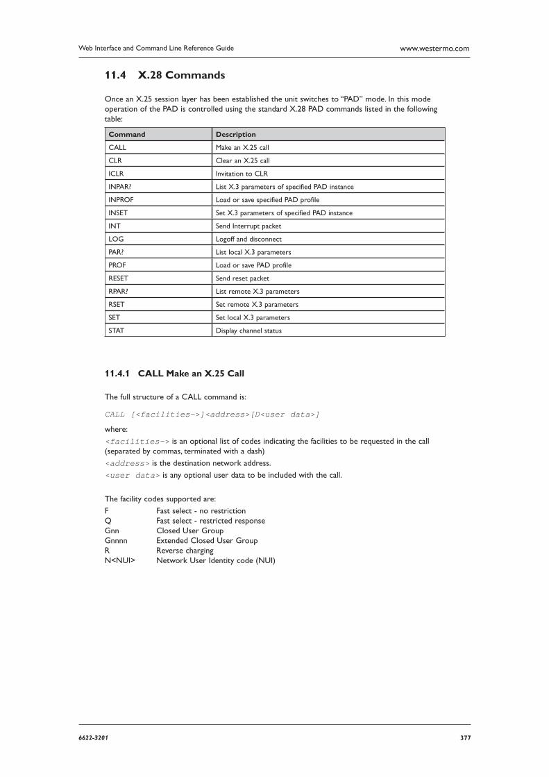
3776622-3201
Web Interface and Command Line Reference Guide www.westermo.com
X.28 Commands 11.4
Once an X.25 session layer has been established the unit switches to “PAD” mode. In this mode oper ation of the PAD is controlled using the standard X.28 PAD commands listed in the following table:
Command Description
CALL Make an X.25 call
CLR Clear an X.25 call
ICLR Invitation to CLR
INPAR? List X.3 parameters of specified PAD instance
INPROF Load or save specified PAD profile
INSET Set X.3 parameters of specified PAD instance
INT Send Interrupt packet
LOG Logoff and disconnect
PAR? List local X.3 parameters
PROF Load or save PAD profile
RESET Send reset packet
RPAR? List remote X.3 parameters
RSET Set remote X.3 parameters
SET Set local X.3 parameters
STAT Display channel status
CALL Make an X.25 Call 11.4.1
The full structure of a CALL command is:
CALL [<facilities->]<address>[D<user data>]
where:
<facilities-> is an optional list of codes indicating the facilities to be requested in the call (separated by commas, terminated with a dash)
<address> is the destination network address.
<user data> is any optional user data to be included with the call.
The facility codes supported are:
F Fast select - no restriction Q Fast select - restricted response Gnn Closed User Group Gnnnn Extended Closed User Group R Reverse charging N<NUI> Network User Identity code (NUI)
378 6622-3201
Web Interface and Command Line Reference Guidewww.westermo.com
Example
CALL R,G12,NMYNUI-56512120DHello
places a call to address 56512120 using reverse charging and specifying Closed User Group 12. The string “MYNUI” is your Network User Identity and the string “Hello” appears in the user data field of the call packet.
Note: The particular facilities that are available will vary between X.25 service providers.
If a CALL command is issued without the address parameter, it is assumed that you wish to go back on-line to a previously established call (having used the PAD recall facility to temporarily return to the PAD> prompt).
Fast select (ISDN B-channel only)
When the standard Fast select facility is requested using the “F” facility code, the call packet gen erated by the CALL command is extended to allow the inclusion of up to 124 bytes of user data. For example:
CALL F-1234567890DThis DATA sent with call packet would cause an X.25 CALL packet to be sent using the Fast select facility including the mes-sage “This DATA sent with call packet” (the Carriage Return used to enter the command is not transmit ted). Without the inclusion of the Fast select facility code, only the first 12 characters would be sent.
When a Fast select CALL has been made the PAD accepts an extended format response from the called address. This response, consisting of up to 124 bytes of user data, may be appended to the returning call accepted or call clear packet. When one of these packets is received, the user data is extracted and passed from the PAD to the terminal immediately prior to the “CLR DTE . . .” mes sage in the case of a call clear packet or “CON COM” message in case of a call accepted packet.
When a restricted response Fast select call has been made using the Q facility code, the call packet indicates that a full connection is not required so that any response to the user data in the CALL packet should be returned in a call clear packet.
When the PAD receives an incoming call specifying Fast select, the call is indicated to the termi-nal in the normal way. For example:
IC 1234567890 FAC: Q,W:2 COM would indicate that an incoming call had been received requesting Restricted response fast select and a window size of 2. The user (or system) then has 15 seconds in which to pass up to 124 bytes of data to the PAD to be included in the clear indication packet that is sent in response to the call.
The PAD does NOT differentiate between standard and restricted response Fast select on incom ing calls and, consequently, will always respond with a clear indication.
Network User Identity (NUI)
The N facility code allows you to include your Network User Identity in the call packet. For security reasons the PAD echoes each character as an asterisk (*) during the entry of an NUI. Some X.25 services use the NUI field to pass both a username and password for validation.
For example, if your Username is MACDONALD and your password is ASDF, a typical CALL com mand would have the format:
CALL NMACDONA;ASDF-56512120 where the “;” is used to separate the username from the password.
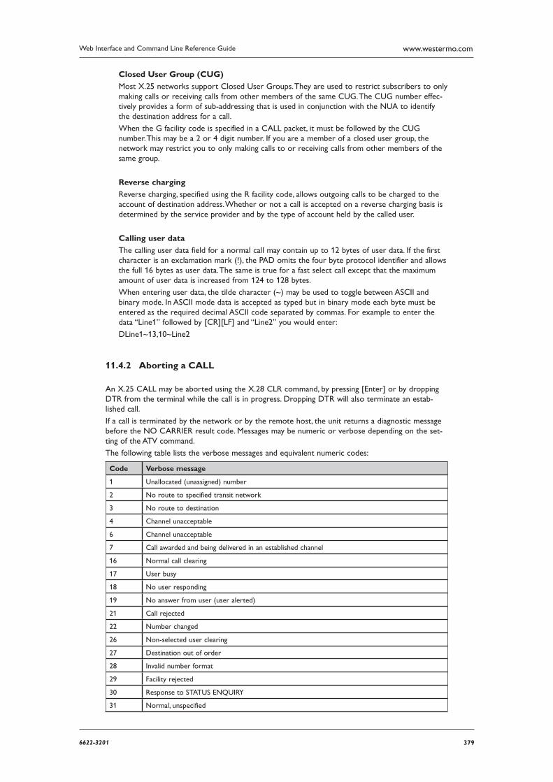
3796622-3201
Web Interface and Command Line Reference Guide www.westermo.com
Closed User Group (CUG)
Most X.25 networks support Closed User Groups. They are used to restrict subscribers to only making calls or receiving calls from other members of the same CUG. The CUG number effec-tively provides a form of sub-addressing that is used in conjunction with the NUA to identify the destina tion address for a call.
When the G facility code is specified in a CALL packet, it must be followed by the CUG number. This may be a 2 or 4 digit number. If you are a member of a closed user group, the network may restrict you to only making calls to or receiving calls from other members of the same group.
Reverse charging
Reverse charging, specified using the R facility code, allows outgoing calls to be charged to the account of destination address. Whether or not a call is accepted on a reverse charging basis is determined by the service provider and by the type of account held by the called user.
Calling user data
The calling user data field for a normal call may contain up to 12 bytes of user data. If the first char acter is an exclamation mark (!), the PAD omits the four byte protocol identifier and allows the full 16 bytes as user data. The same is true for a fast select call except that the maximum amount of user data is increased from 124 to 128 bytes.
When entering user data, the tilde character (~) may be used to toggle between ASCII and binary mode. In ASCII mode data is accepted as typed but in binary mode each byte must be entered as the required decimal ASCII code separated by commas. For example to enter the data “Line1” fol lowed by [CR][LF] and “Line2” you would enter:
DLine1~13,10~Line2
Aborting a CALL 11.4.2
An X.25 CALL may be aborted using the X.28 CLR command, by pressing [Enter] or by dropping DTR from the terminal while the call is in progress. Dropping DTR will also terminate an estab-lished call.
If a call is terminated by the network or by the remote host, the unit returns a diagnostic message before the NO CARRIER result code. Messages may be numeric or verbose depending on the set-ting of the ATV command.
The following table lists the verbose messages and equivalent numeric codes:
Code Verbose message
1 Unallocated (unassigned) number
2 No route to specified transit network
3 No route to destination
4 Channel unacceptable
6 Channel unacceptable
7 Call awarded and being delivered in an established channel
16 Normal call clearing
17 User busy
18 No user responding
19 No answer from user (user alerted)
21 Call rejected
22 Number changed
26 Non-selected user clearing
27 Destination out of order
28 Invalid number format
29 Facility rejected
30 Response to STATUS ENQUIRY
31 Normal, unspecified

380 6622-3201
Web Interface and Command Line Reference Guidewww.westermo.com
34 No circuit/channel available
38 Network out of order
41 Temporary failure
42 Switching equipment congestion
43 Access information discarded
44 Requested circuit/channel not available
47 Resources unavailable, unspecified
49 Quality of service unavailable
50 Requested facility not subscribed
57 Bearer capability not authorized
58 Bearer capability not presently available
63 Service or option not available, unspecified
65 Bearer capability not implemented
66 Channel type not implemented
69 Requested facility not implemented
70 Only restricted digital information bearer
79 Service or option not implemented, unspecified
81 Invalid call reference value
82 Identified channel does not exist
83 A suspended call exists, but this call identity does not
84 Call identity in use
85 No call suspended
86 Call having the requested call identity has been cleared
88 Incompatible destination
90 Destination address missing or incomplete
91 Invalid transit network selection
95 Invalid message, unspecified
96 Mandatory information element is missing
97 Message type non-existent or not implemented
98 Message not compatible with call state or message type non existent or not implemented
99 Information element non-existent or not implemented
100 Invalid information element contents
101 Message not compatible with call state
102 Recovery on timer expired
111 Protocol error, unspecified
127 Interworking, unspecified
128 General level 2 call control failure (probable network failure)
Note: Some verbose messages may be abbreviated by the unit.
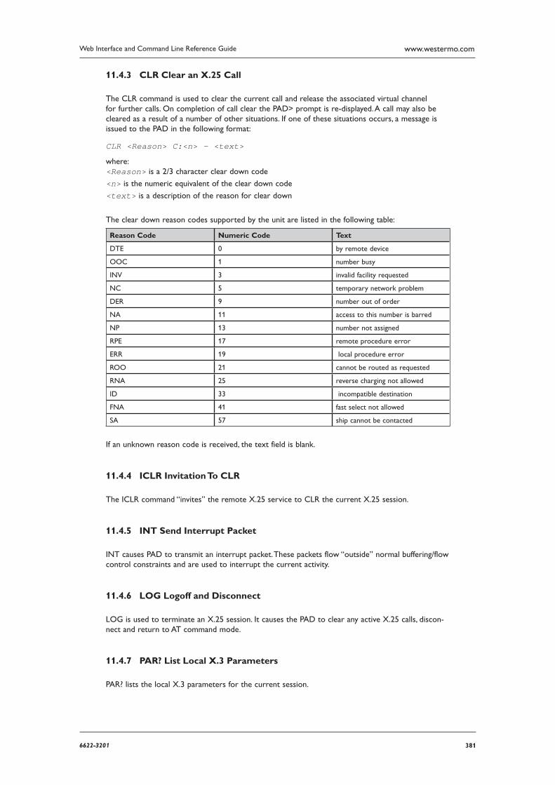
3816622-3201
Web Interface and Command Line Reference Guide www.westermo.com
CLR Clear an X.25 Call 11.4.3
The CLR command is used to clear the current call and release the associated virtual channel for fur ther calls. On completion of call clear the PAD> prompt is re-displayed. A call may also be cleared as a result of a number of other situations. If one of these situations occurs, a message is issued to the PAD in the following format:
CLR <Reason> C:<n> - <text>
where: <Reason> is a 2/3 character clear down code
<n> is the numeric equivalent of the clear down code
<text> is a description of the reason for clear down
The clear down reason codes supported by the unit are listed in the following table:
Reason Code Numeric Code Text
DTE 0 by remote device
OOC 1 number busy
INV 3 invalid facility requested
NC 5 temporary network problem
DER 9 number out of order
NA 11 access to this number is barred
NP 13 number not assigned
RPE 17 remote procedure error
ERR 19 local procedure error
ROO 21 cannot be routed as requested
RNA 25 reverse charging not allowed
ID 33 incompatible destination
FNA 41 fast select not allowed
SA 57 ship cannot be contacted
If an unknown reason code is received, the text field is blank.
ICLR Invitation To CLR 11.4.4
The ICLR command “invites” the remote X.25 service to CLR the current X.25 session.
INT Send Interrupt Packet 11.4.5
INT causes PAD to transmit an interrupt packet. These packets flow “outside” normal buffering/flow control constraints and are used to interrupt the current activity.
LOG Logoff and Disconnect 11.4.6
LOG is used to terminate an X.25 session. It causes the PAD to clear any active X.25 calls, discon-nect and return to AT command mode.
PAR? List Local X.3 Parameters 11.4.7
PAR? lists the local X.3 parameters for the current session.
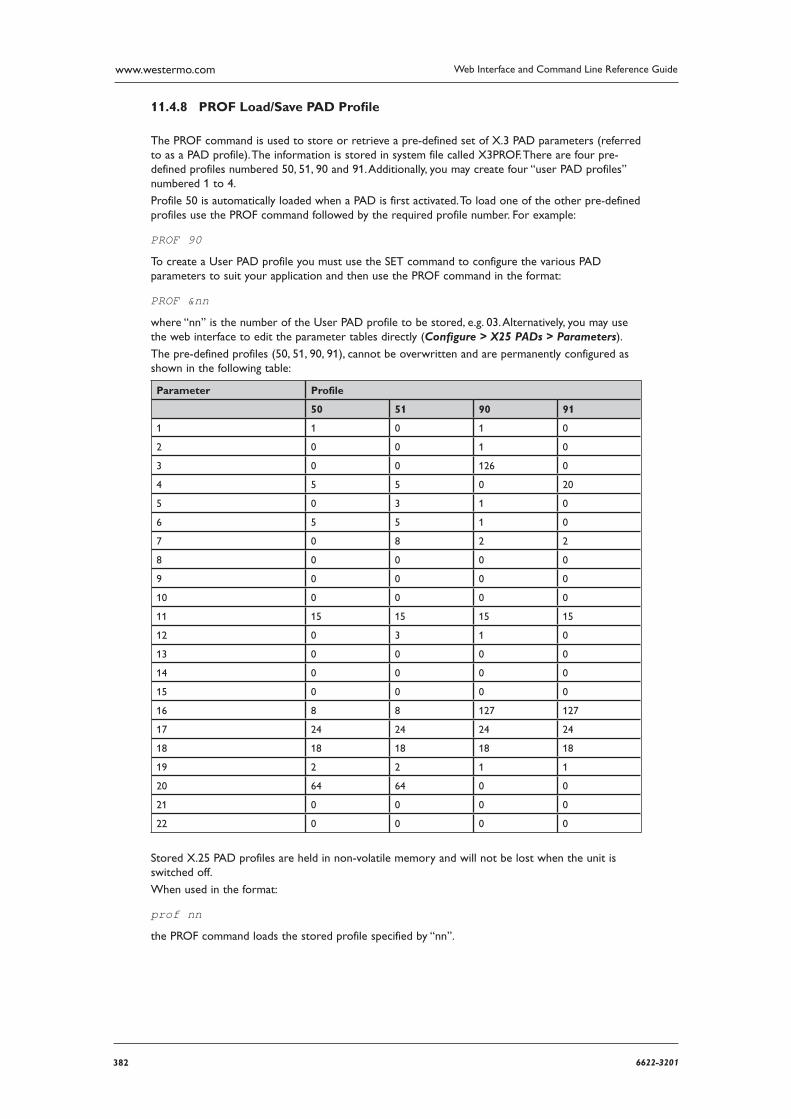
382 6622-3201
Web Interface and Command Line Reference Guidewww.westermo.com
PROF Load/Save PAD Profi le 11.4.8
The PROF command is used to store or retrieve a pre-defined set of X.3 PAD parameters (referred to as a PAD profile). The information is stored in system file called X3PROF. There are four pre-defined profiles numbered 50, 51, 90 and 91. Additionally, you may create four “user PAD profiles” numbered 1 to 4.
Profile 50 is automatically loaded when a PAD is first activated. To load one of the other pre-defined profiles use the PROF command followed by the required profile number. For example:
PROF 90
To create a User PAD profile you must use the SET command to configure the various PAD parame ters to suit your application and then use the PROF command in the format:
PROF &nn
where “nn” is the number of the User PAD profile to be stored, e.g. 03. Alternatively, you may use the web interface to edit the parameter tables directly (Configure > X25 PADs > Parameters).
The pre-defined profiles (50, 51, 90, 91), cannot be overwritten and are permanently configured as shown in the following table:
Parameter Profile
50 51 90 91
1 1 0 1 0
2 0 0 1 0
3 0 0 126 0
4 5 5 0 20
5 0 3 1 0
6 5 5 1 0
7 0 8 2 2
8 0 0 0 0
9 0 0 0 0
10 0 0 0 0
11 15 15 15 15
12 0 3 1 0
13 0 0 0 0
14 0 0 0 0
15 0 0 0 0
16 8 8 127 127
17 24 24 24 24
18 18 18 18 18
19 2 2 1 1
20 64 64 0 0
21 0 0 0 0
22 0 0 0 0
Stored X.25 PAD profiles are held in non-volatile memory and will not be lost when the unit is switched off.
When used in the format:
prof nn
the PROF command loads the stored profile specified by “nn”.
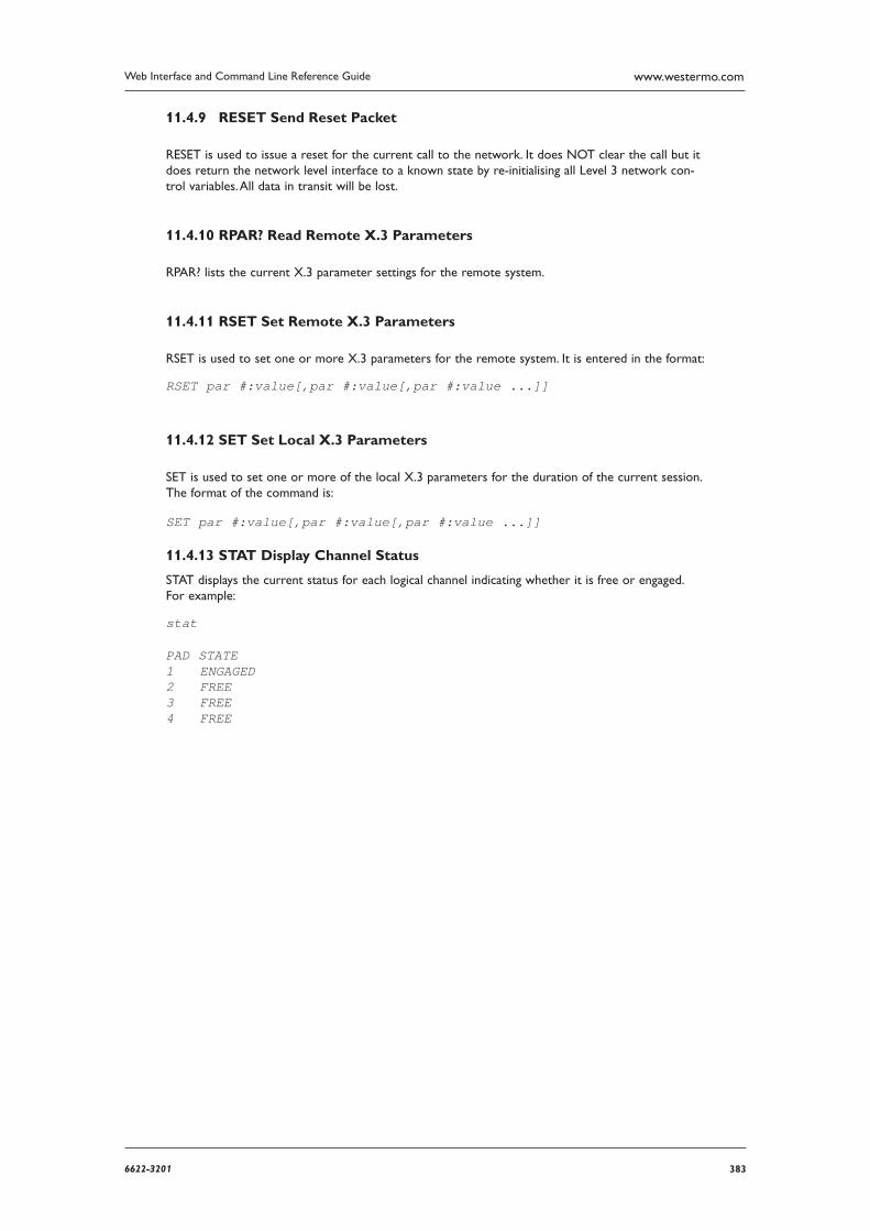
3836622-3201
Web Interface and Command Line Reference Guide www.westermo.com
RESET Send Reset Packet 11.4.9
RESET is used to issue a reset for the current call to the network. It does NOT clear the call but it does return the network level interface to a known state by re-initialising all Level 3 network con-trol varia bles. All data in transit will be lost.
RPAR? Read Remote X.3 Parameters 11.4.10
RPAR? lists the current X.3 parameter settings for the remote system.
RSET Set Remote X.3 Parameters 11.4.11
RSET is used to set one or more X.3 parameters for the remote system. It is entered in the format:
RSET par #:value[,par #:value[,par #:value ...]]
SET Set Local X.3 Parameters 11.4.12
SET is used to set one or more of the local X.3 parameters for the duration of the current session. The format of the command is:
SET par #:value[,par #:value[,par #:value ...]]
11.4.13 STAT Display Channel Status
STAT displays the current status for each logical channel indicating whether it is free or engaged. For example:
stat
PAD STATE 1 ENGAGED 2 FREE 3 FREE 4 FREE
384 6622-3201
Web Interface and Command Line Reference Guidewww.westermo.com
PPP Over Ethernet12
PPP over Ethernet (PPPoE) is a means of establishing a PPP connection over the top of an Ethernet connection. The implementation provided is compliant with RFC 2516, “A Method for Transmitting PPP Over Ethernet”. A typical application would be to allow non-PPPoE enabled devices to access Internet services where the connection to the Internet is provided by an ADSL bridge device.
An alternative implementation of PPPoE is where the DSL circuit is directly connected to the Westermo router and the encapsulation method is altered to PPPoE. This is explained at in the sec-tion PPPoE using DSL.
PPPoE using an DSL bridge
This implementation uses a DSL bridge on the LAN. The Westermo connects to the ISP via the DSL bridge.
Using the Web Page(s)
There is no dedicated web page for configuring the unit to use PPPoE; rather there are a number of parameters that appear on other web pages that must be used in conjunction with each other to establish a PPPoE connection over the appropriate Ethernet interface.
In particular, the following configuration pages and parameters are important.
On the appropriate Configure > PPP pages, you should configure the following parameters on the following pages:
Configure > PPP > PPP n > Standard
As a minimum requirement the Username and Password parameters should be initialised. If neces-sary, you may set the AODI Enabled parameter to “Yes” to configure the unit so that it will attempt to renegotiate the PPP link should it go down for any reason.
Configure > PPP > PPP n > Advanced
The advanced PPP options on this page should be initialised as required by your ISP. The Layer 1 Interface and Layer 1 Interface # fields define the physical Ethernet interface over which the PPPoE session will operate. In most cases this is ETH 0. The fact that you have selected “Ethernet” as the physical interface for operation with PPP automatically enables PPPoE mode. If another Ethernet
instance is used, this will need to be specified in the field Layer 1 interface # to ensure the correct MAC address is used, this is in the format 000 or blank for port 0, 100 for port 1, 200 for port 2 etc. In addition:
Desired Local MRU and Desired Remote MRU should be set to “1492”.
Request Local ACFC and Request Remote ACFC should be set to “No”.
Request Local PFC and Request Remote PFC should be set to “No”.
Desired Local ACCM and Desired Remote ACCM should be set to “0xffffffff”.
Using Text Commands
There are no specific PPPoE commands available to the user via the text command interface. The appropriate ppp commands should be used to set the required options.
PPPoE using DSL
This implementation is physically connected like a normal DSL service and the Westermo has a direct connection to the DSL circuit.
Using the Web Page(s)
Confi gure > DSL > ATM PVCs > PVC 0 The encapsulation will need to match that used by the ISP. This will either be “PPPoE LLC” or “PPPoE VC-Mux”. Confi gure > PPP > PPP n > Standard The Username and Password parameters should be configured. If necessary, you may set the AODI Enabled parameter to “Yes” to configure the unit so that it will attempt to renegotiate the PPP link should it go down for any reason.
3856622-3201
Web Interface and Command Line Reference Guide www.westermo.com
IPSEC and VPNs13
What is IPSec? 13.1
One inherent problem with the TCP protocol used to carry data over the vast majority of LANs and the Internet is that it provides virtually no security features. This lack of security, and recent publicity about “hackers” and “viruses”, prevent many people from even considering using the Internet for any sensi tive business application. IPSec provides a remedy for these weaknesses adding a comprehensive security “layer” to protect data carried over IP links.
IPSec (Internet Protocol Security) is a framework for a series of IETF standards designed to authenti cate users and data, and to secure data by encrypting it during transit. The protocols defined within IPSec include:
IKE – Internet Key Exchange protocol •
ISAKMP – Internet Security Association and Key Management Protocol •
AH – Authentication Header protocol •
ESP – Encapsulating Security Payload protocol •
HMAC – Hash Message Authentication Code •
MD5 – Message Digest 5 •
SHA-1 – Security Hash Algorithm •
and the cryptographic (encryption) techniques include: • DES – Data Encryption Standard
3DES – Triple DES •
AES – Advanced Encryption Standard (also known as Rijndael) •
Two key protocols within the framework are AH and ESP. AH is used to authenticate users, and ESP applies cryptographic protection. The combination of these techniques is designed to ensure the integ rity and confidentiality of the data transmission. Put simply, IPSec is about ensuring that:
only authorised users can access a service and •
that no one else can see what data passes between one point and another. •
There are two modes of operation for IPSec, transport mode and tunnel mode.
In transport mode, only the payload (i.e. the data content), of the message is encrypted. In tunnel mode, the payload and the header and routing information are all encrypted thereby by providing a higher degree of protection.
Data Encryption Methods 13.2
There are several different algorithms available for use in securing data whilst in transit over IP links. Each encryption technique has its own strengths and weaknesses and this is really, a personal selec-tion made with regard to the sensitivity of the data you are trying to protect. Some general state-ments may be made about the relative merits but users should satisfy themselves as to suitability for any par ticular purpose.
DES (64-bit key) 13.2.1
This well-known and established protocol has historically been used extensively in the banking and financial world. It is relatively “processor intensive”, i.e. to run efficiently at high data rates a power-ful processor is required. It is generally considered very difficult for casual hackers to attack but may be susceptible to determined attack by well-equipped and knowledgeable parties.
386 6622-3201
Web Interface and Command Line Reference Guidewww.westermo.com
DES (192-bit key) 13.2.2
Again, this is a well-established and accepted protocol but as it involves encrypting the data three times using DES with a different key each time, it has a very high processor overhead. This also renders it almost impossible for casual hackers to attack and very difficult to break in any meaning-ful time frame, even for well-equipped and knowledgeable parties.
AES (128-bit key) 13.2.3
Also known as Rijndael encryption, AES is the new “de-facto” standard adopted by many USA and European organisations for sensitive applications. It has a relatively low processor overhead com-pared to DES and it is therefore possible to encrypt at higher data rates. As with 3-DES, it is almost impossible for casual hackers to attack and is very difficult to break in any meaningful time frame, even for well-equipped and knowledgeable parties.
To put these into perspective, common encryption programs that are considered “secure” (such as PGP) and on-line credit authorisation services (such as Web-based credit card ordering) generally use 128-bit encryption.
Note: Data rates are the maximum that could be achieved but may be lower if other applications are run ning at the same time or small IP packet sizes are used.
What is a VPN? 13.3
VPNs (Virtual Private Networks) are networks that use the IPSec protocols to provide one or more secure routes or “tunnels” between endpoints. Users are issued either a shared “secret” key or “public/ private” key pair that is associated with their identity. When a message is sent from one user to another, it is automatically “signed” with the user’s key. The receiver uses the secret key or the sender’s public key to decrypt the message. These keys are used during IKE exchanges along with other information to create session keys that only apply for the lifetime of that IKE exchange.
The Benefi ts of IPSec 13.4
IPSec is typically used to attain confidentiality, integrity, and authentication in the transport of data across inherently insecure channels. When properly configured, it provides a highly secure virtual channel across cheap, globally available networks such as the Internet, or creates a “network within a network” for applications such as passing confidential information between two users across a private network.
3876622-3201
Web Interface and Command Line Reference Guide www.westermo.com
X.509 Certifi cates 13.5
In the previous section, security between two points was achieved by using a “pre-shared secret” or password. Certificates provide this sort of mechanism but without the need to manually enter or dis tribute secret keys. This is a complex area but put simply a user’s certificate acts a little like a passport providing proof that the user is who they say they are and enclosing details of how to use that certificate to decrypt data encoded with it. Passports however can be forged so there also needs to be proof that the passport has been properly issued and hasn’t been changed since it was. On a paper passport this is achieved by covering the photograph with a coating that shows if it has been tampered with, embed ding the user’s name in code in a long string of numbers, etc. In the same way, for a Security Certificate to be genuine it has to be protected from alteration as well. Like a passport, you also have to trust that the issuer is authorised and competent to create the certificate.
Certificates use something called a “Public/Private Key Pair”. This a complex area but the principle is that you can create an encryption key made up from two parts, one private (known only to the user), the other public (known to everyone). Messages encrypted with someone’s public key can only be recovered by the person with the Public AND Private key but as encrypting the message to someone in the first place only requires that you know their public key, anyone who knows that can send them an encrypted message, so you can send a secure message to someone knowing only their publicly available key. You can also prove who you are by including in the message your “identity” whereupon they can look up the certified public key for that identity and send a message back that only you can understand. The important principles are that a) your private key cannot be determined from your pub lic key and b) you both need to be able to look up the others certified ID. Once you’ve established two way secure link you can use it to establish some rules for further communication.
Before this gets any more complicated we’ll assume that Westermo are a competent authority to issue certificates and given that they exist and are valid, see how they are used.
Generally, the issuing and management of certificates will be provided as a managed service by Westermo or its partners, but some general information is provided here for system administrators.
Certificates are held in non-volatile files on the unit. Any private files are named privxxxx.xxx and can not be copied, moved, renamed, uploaded or typed. This is to protect the contents. They can be over written by another file, or deleted.
Two file formats for certificates are supported:
PEM – Privacy Enhanced MIME •
DER – Distinguished Encoding Rules •
Certificate and key files should be in one of these two formats, and should have an extension of “.pem” or “.der” respectively.
Note: The equivalent filename extension for .PEM files in Microsoft Windows is “.CER”. By renaming “.PEM” certificate files to “.CER”, it is possible to view their makeup under Windows.
The unit maintains two lists of certificate files. The first is a list of “Certificate Authorities” or CAs. Files in this list are used to validate public certificates sent by remote users. Public certificates must be signed by one of the certificates in the CA list before the unit can validate them. Certificates with the filename CA*.PEM and CA*.DER are loaded into this list at start-up time. In the absence of any CA certificates, a public certificate cannot be validated.
The second list is a list of public certificates that the unit can use to obtain public keys for decrypt-ing signatures sent during IKE exchanges. Certificates with a filename CERT*.PEM and CERT*.DER are loaded into this list when the unit is powered on or rebooted. Certificates in this list will be used in cases where the remote unit does not send a certificate during IKE exchanges. If the list does not contain a valid certificate communication with the remote unit cannot take place.
Both the host and remote units must have a copy of a file called CASAR.PEM. This file is required to validate the certificates of the remote units.
In addition, the host unit should have copies of the files CERT02.PEM (which allows it to send this cer tificate to remote units) and PRIVRSA.PEM. Note that before it can send this certificate, the “Responder ID” parameter in the Configure > IPSEC > IKE page must be set to “[email protected]”.
388 6622-3201
Web Interface and Command Line Reference Guidewww.westermo.com
The remote unit must have copies of CERT01.PEM and PRIVRSA.PEM. In addition, any Eroutes that are going to use certificates for authentication should be configured as follows:
Our ID
Should be set to “[email protected]”. This is the same as the subject “Altname” in certifi-cate CERT01.PEM which makes it possible for the router to locate the correct certificate to send to the host.
Authentication Method
Should be set to RSA Signatures. This indicates to IKE that RSA signatures (certificates) are to be used for authentication.
When IKE receives a signature from a remote unit, it needs to be able to retrieve the correct public key so that it can decrypt the signature, and confirm that the signature is correct. The certificate must either be on the FLASH file system, or be provided by the remote unit as part of the IKE negotiation. The ID provided by the remote unit is used to find the correct certificate to use. If the correct certificate is found, the code then checks that it has been signed by one of the certificate authority certificates (CA*.PEM) that exist on the unit. The code first checks the local certificates, and then the certificate provided by the remote (if any). IKE will send a certifi-cate during negotiations if it is able to find one that has subject “AltName” that matches the ID being used. If not able to locate the certificate, then the remote must have local access to the file so that the public key can be retrieved.
A typical set-up may be that the host unit has a copy of all certificates. This means that the remote units only require the private key, and the certificate authority certificate. This eases administration as any changes to certificates need only be made on the host. Because they do not have a copy of their certificate, remote units rely on the host having a copy of the cer-tificate. An alternative is that the remote units all have a copy of the certificate, as well as the private key and certificate authority certificate, and the host only has its own certificate. This scenario requires that the remote unit send its certificate during negotiations. It can validate the certificate because it has the certificate authority certificate.
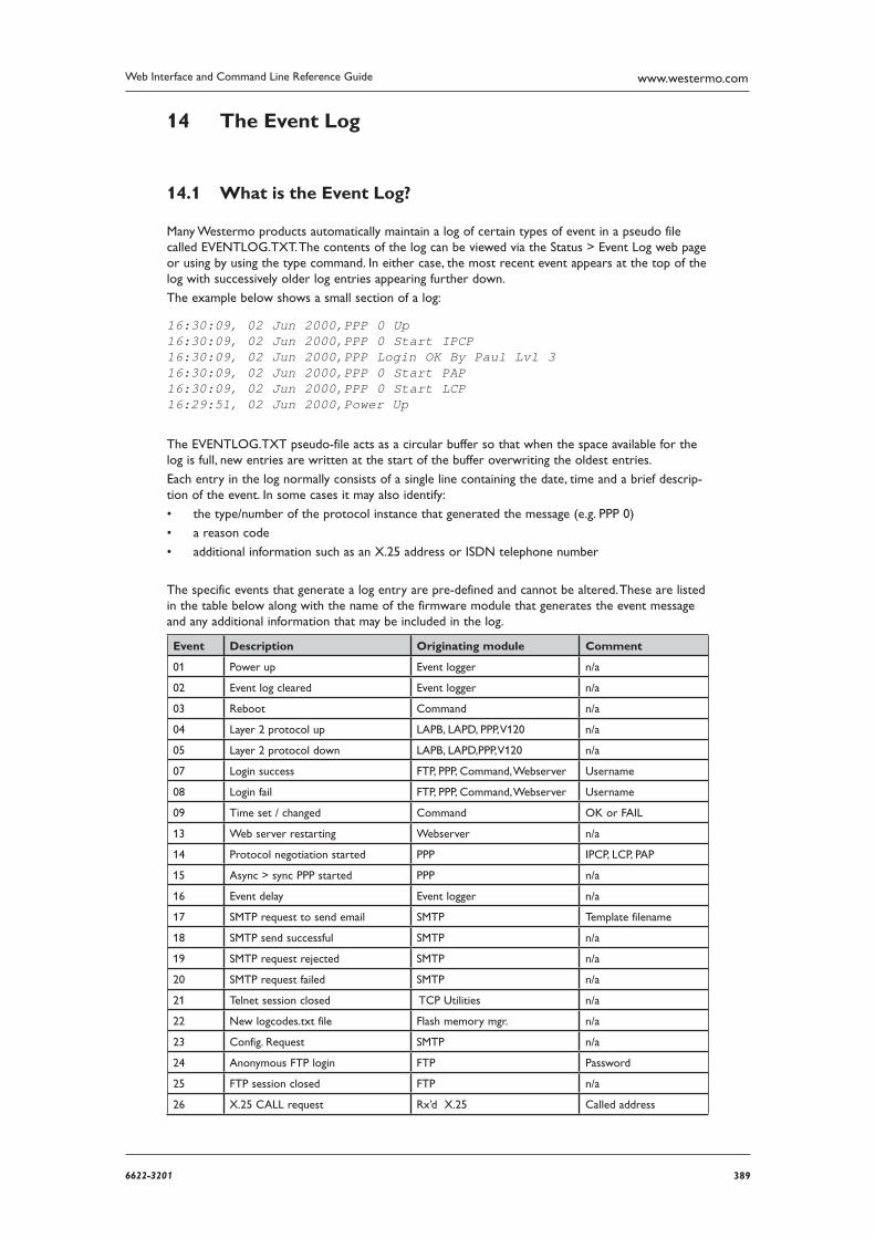
3896622-3201
Web Interface and Command Line Reference Guide www.westermo.com
The Event Log14
What is the Event Log? 14.1
Many Westermo products automatically maintain a log of certain types of event in a pseudo file called EVENTLOG.TXT. The contents of the log can be viewed via the Status > Event Log web page or using by using the type command. In either case, the most recent event appears at the top of the log with successively older log entries appearing further down.
The example below shows a small section of a log:
16:30:09, 02 Jun 2000,PPP 0 Up16:30:09, 02 Jun 2000,PPP 0 Start IPCP16:30:09, 02 Jun 2000,PPP Login OK By Paul Lvl 316:30:09, 02 Jun 2000,PPP 0 Start PAP16:30:09, 02 Jun 2000,PPP 0 Start LCP16:29:51, 02 Jun 2000,Power Up
The EVENTLOG.TXT pseudo-file acts as a circular buffer so that when the space available for the log is full, new entries are written at the start of the buffer overwriting the oldest entries.
Each entry in the log normally consists of a single line containing the date, time and a brief descrip-tion of the event. In some cases it may also identify:
the type/number of the protocol instance that generated the message (e.g. PPP 0) •
a reason code •
additional information such as an X.25 address or ISDN telephone number •
The specific events that generate a log entry are pre-defined and cannot be altered. These are listed in the table below along with the name of the firmware module that generates the event message and any additional information that may be included in the log.
Event Description Originating module Comment
01 Power up Event logger n/a
02 Event log cleared Event logger n/a
03 Reboot Command n/a
04 Layer 2 protocol up LAPB, LAPD, PPP, V120 n/a
05 Layer 2 protocol down LAPB, LAPD,PPP, V120 n/a
07 Login success FTP, PPP, Command, Webserver Username
08 Login fail FTP, PPP, Command, Webserver Username
09 Time set / changed Command OK or FAIL
13 Web server restarting Webserver n/a
14 Protocol negotiation started PPP IPCP, LCP, PAP
15 Async > sync PPP started PPP n/a
16 Event delay Event logger n/a
17 SMTP request to send email SMTP Template filename
18 SMTP send successful SMTP n/a
19 SMTP request rejected SMTP n/a
20 SMTP request failed SMTP n/a
21 Telnet session closed TCP Utilities n/a
22 New logcodes.txt file Flash memory mgr. n/a
23 Config. Request SMTP n/a
24 Anonymous FTP login FTP Password
25 FTP session closed FTP n/a
26 X.25 CALL request Rx’d X.25 Called address
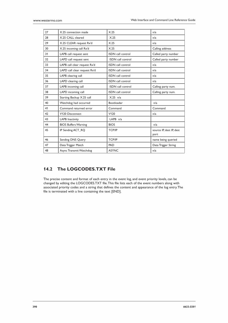
390 6622-3201
Web Interface and Command Line Reference Guidewww.westermo.com
27 X.25 connection made X.25 n/a
28 X.25 CALL cleared X.25 n/a
29 X.25 CLEAR request Rx’d X.25 n/a
30 X.25 incoming call Rx’d X.25 Calling address
31 LAPB call request sent ISDN call control Called party number
32 LAPD call request sent ISDN call control Called party number
33 LAPB call clear request Rx’d ISDN call control n/a
34 LAPD call clear request Rx’d ISDN call control n/a
35 LAPB clearing call ISDN call control n/a
36 LAPD clearing call ISDN call control n/a
37 LAPB incoming call ISDN call control Calling party num.
38 LAPD incoming call ISDN call control Calling party num.
39 Starting Backup X.25 call X.25 n/a
40 Watchdog had occurred Bootloader n/a
41 Command returned error Command Command
42 V120 Disconnect V120 n/a
43 LAPB Inactivity LAPB n/a
44 BIOS Buffers Warning BIOS n/a
45 IP Sending ACT_RQ TCP/IP source IP, dest IP, dest port
46 Sending DNS Query TCP/IP name being queried
47 Data Trigger Match PAD Data Trigger String
48 Async Transmit Watchdog ASYNC n/a
The LOGCODES.TXT File 14.2
The precise content and format of each entry in the event log, and event priority levels, can be changed by editing the LOGCODES.TXT file. This file lists each of the event numbers along with associated priority codes and a string that defines the content and appearance of the log entry. The file is termi nated with a line containing the text [END].
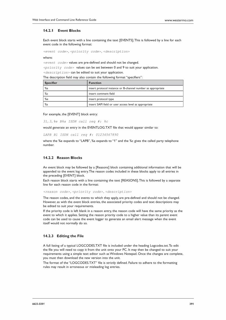
3916622-3201
Web Interface and Command Line Reference Guide www.westermo.com
Event Blocks 14.2.1
Each event block starts with a line containing the text [EVENTS]. This is followed by a line for each event code in the following format:
<event code>,<priority code>,<description>
where:
<event code> values are pre-defined and should not be changed.
<priority code> values can be set between 0 and 9 to suit your application.
<description> can be edited to suit your application.
The description field may also contain the following format “specifiers”:
Specifier Function
%a insert protocol instance or B-channel number as appropriate
%c insert comment field
%e insert protocol type
%s insert SAPI field or user access level as appropriate
For example, the [EVENT] block entry:
31,3,%e B%a ISDN call req #: %c
would generate an entry in the EVENTLOG.TXT file that would appear similar to:
LAPB B1 ISDN call req #: 01234567890
where the %e expands to “LAPB”, %a expands to “1” and the %c gives the called party telephone number.
Reason Blocks 14.2.2
An event block may be followed by a [Reasons] block containing additional information that will be appended to the event log entry. The reason codes included in these blocks apply to all entries in the preceding [EVENT] block.
Each reason block starts with a line containing the text [REASONS]. This is followed by a separate line for each reason code in the format:
<reason code>,<priority code>,<description>
The reason codes, and the events to which they apply, are pre-defined and should not be changed. However, as with the event block entries, the associated priority codes and text descriptions may be edited to suit your requirements.
If the priority code is left blank in a reason entry, the reason code will have the same priority as the event to which it applies. Setting the reason priority code to a higher value than its parent event code can be used to cause the event logger to generate an email alert message when the event itself would not normally do so.
Editing the File 14.2.3
A full listing of a typical LOGCODES.TXT file is included under the heading Logcodes.txt. To edit the file you will need to copy it from the unit onto your PC. It may then be changed to suit your requirements using a simple text editor such as Windows Notepad. Once the changes are complete, you must then download the new version into the unit.
The format of the “LOGCODES.TXT” file is strictly defined. Failure to adhere to the formatting rules may result in erroneous or misleading log entries.
392 6622-3201
Web Interface and Command Line Reference Guidewww.westermo.com
Firewall Scripts15
Introduction 15.1
A “firewall” is a protection system designed to prevent access to your local area network by unauthor ised “external” parties, i.e. other users of the internet or another wide area network. It may also limit the degree of access local users have to external network resources. A firewall does not provide a complete security solution; it provides only one element of a fully secure system. Consideration should also be given to the use of user authentication and data encryption. Refer to the IPSec section for fur ther information.
In simple terms, a firewall is a packet filtering system that allows or prevents the transmission of data (in either direction) based on a set of rules. These rules can allow filtering based on the follow-ing criteria:
source and destination IP addresses •
source and destination IP port or port ranges •
type of protocol in use •
direction of the data (in or out) •
interface type •
the eroute the packet is on •
if an interface is OOS (out of service) •
ICMP message type •
TCP flags (SYN, ACK, URG, RESET, PUSH, FIN) •
TOS field •
status of a link and/or data packets on UDP/TCP and ICMP protocols •
In addition to providing comprehensive filtering facilities, Westermo routers also allow you to spec-ify rules relating to the logging of information for audit/debugging purposes. This information can be logged to a pseudo-file on the unit called FWLOG.TXT, the EVENTLOG.TXT pseudo-file or to a syslog server. It can also be used to generate SNMP traps.
Firewall Script Syntax 15.2
A firewall must be individually configured to match the needs of authorised users and their applica-tions. On Westermo routers the rules governing firewall behaviour are defined in a script file called FW.TXT. Each line in this file consists of a label definition, a comment or a filter rule.
Labels 15.2.1
A label definition is a string of up to 12 characters followed by a colon. Labels can only include letters, digits and the underscore character and are used in conjunction with the break option to cause the processing of the script to jump to a new location.
Comments 15.2.2
Any line starting with the hash character (“#”) is deemed to be a comment and ignored.
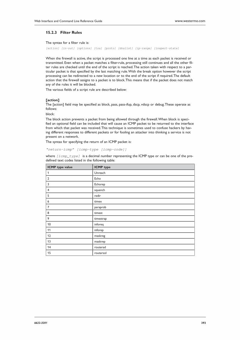
3936622-3201
Web Interface and Command Line Reference Guide www.westermo.com
Filter Rules 15.2.3
The syntax for a filter rule is:
[action] [in-out] [options] [tos] [proto] [dnslist] [ip-range] [inspect-state]
When the firewall is active, the script is processed one line at a time as each packet is received or transmitted. Even when a packet matches a filter-rule, processing still continues and all the other fil-ter rules are checked until the end of the script is reached. The action taken with respect to a par-ticular packet is that specified by the last matching rule. With the break option however the script processing can be redirected to a new location or to the end of the script if required. The default action that the firewall assigns to a packet is to block. This means that if the packet does not match any of the rules it will be blocked.
The various fields of a script rule are described below:
[action] The [action] field may be specified as block, pass, pass-ifup, dscp, vdscp or debug. These operate as follows:
block:
The block action prevents a packet from being allowed through the firewall. When block is speci-fied an optional field can be included that will cause an ICMP packet to be returned to the interface from which that packet was received. This technique is sometimes used to confuse hackers by hav-ing different responses to different packets or for fooling an attacker into thinking a service is not present on a network.
The syntax for specifying the return of an ICMP packet is:
“return-icmp” [icmp-type [icmp-code]]
where [icmp_type] is a decimal number representing the ICMP type or can be one of the pre-defined text codes listed in the following table:
ICMP type value ICMP type
1 Unreach
2 Echo
3 Echorep
4 squench
5 redir
6 timex
7 paraprob
8 timest
9 timestrap
10 inforeq
11 inforep
12 maskreg
13 maskrep
14 routerad
15 routersol
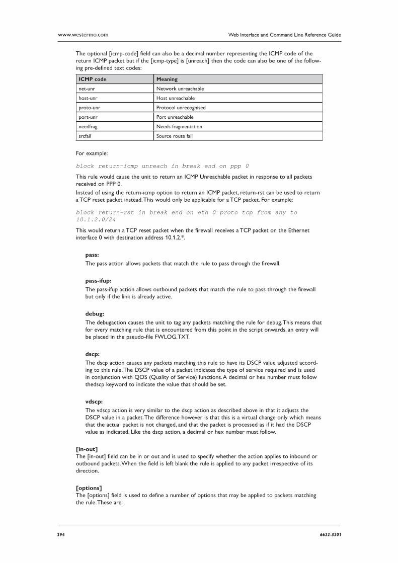
394 6622-3201
Web Interface and Command Line Reference Guidewww.westermo.com
The optional [icmp-code] field can also be a decimal number representing the ICMP code of the return ICMP packet but if the [icmp-type] is [unreach] then the code can also be one of the follow-ing pre-defined text codes:
ICMP code Meaning
net-unr Network unreachable
host-unr Host unreachable
proto-unr Protocol unrecognised
port-unr Port unreachable
needfrag Needs fragmentation
srcfail Source route fail
For example:
block return-icmp unreach in break end on ppp 0
This rule would cause the unit to return an ICMP Unreachable packet in response to all packets received on PPP 0.
Instead of using the return-icmp option to return an ICMP packet, return-rst can be used to return a TCP reset packet instead. This would only be applicable for a TCP packet. For example:
block return-rst in break end on eth 0 proto tcp from any to 10.1.2.0/24
This would return a TCP reset packet when the firewall receives a TCP packet on the Ethernet interface 0 with destination address 10.1.2.*.
pass:
The pass action allows packets that match the rule to pass through the firewall.
pass-ifup:
The pass-ifup action allows outbound packets that match the rule to pass through the firewall but only if the link is already active.
debug:
The debugaction causes the unit to tag any packets matching the rule for debug. This means that for every matching rule that is encountered from this point in the script onwards, an entry will be placed in the pseudo-file FWLOG.TXT.
dscp:
The dscp action causes any packets matching this rule to have its DSCP value adjusted accord-ing to this rule. The DSCP value of a packet indicates the type of service required and is used in conjunction with QOS (Quality of Service) functions. A decimal or hex number must follow thedscp keyword to indicate the value that should be set.
vdscp:
The vdscp action is very similar to the dscp action as described above in that it adjusts the DSCP value in a packet. The difference however is that this is a virtual change only which means that the actual packet is not changed, and that the packet is processed as if it had the DSCP value as indi cated. Like the dscp action, a decimal or hex number must follow.
[in-out] The [in-out] field can be in or out and is used to specify whether the action applies to inbound or outbound packets. When the field is left blank the rule is applied to any packet irrespective of its direction.
[options] The [options] field is used to define a number of options that may be applied to packets matching the rule. These are:
3956622-3201
Web Interface and Command Line Reference Guide www.westermo.com
log:
When the log option is specified, the unit will place an entry in the FWLOG.TXT file each time it processes a packet that matches the rule. This log will normally detail the rule that was matched along with a summary of the packet contents. If the log option is followed by the body sub-option, the complete IP packet is entered into the log file so that when the log file is dis-played, a more detailed decode of the IP packet is shown.
The log field may also be followed by a further sub-option that specifies a different type of log out
put. This may either be snmp, syslog or event. If snmp is specified an SNMP trap (containing similar information to the normal log entry), is gener ated when a packet matches the rule. If syslog is specified, a syslog message is sent to the configured syslog manager IP address. This message will contain the same information as that entered into the log file, but in a different format. If the body option has been specified, some of the IP packet information is also included. Note that the size of the syslog message is limited to the maximum of 1024 bytes. The syslog message is sent with default priority value of 14, which expands out to facility of USER, and pri-ority INFO.
If event is specified the log output will be copied to the EVENTLOG.TXT pseudo-file as well as the FWLOG.TXT file. The event log entry will contain the line number and hit count for the rule that caused the packet to be logged.
Example:
Say your local network is on subnet 192.168.*.* and you want to block any packets received on PPP 0 that were “pretending” to be on the local network and log the receipt of any such packets to the FWLOG.TXT file and to a syslog server. The filter rule would be constructed as follows:
block in log syslog break end on ppp 0 from 192.168.0.0/16 to any
break:
When the break option is specified it must be followed by a user-defined label name or the pre-defined end keyword. When followed by a label, the rule processor will “jump” to that label to con tinue processing. When followed by the end keyword rule processing will be terminated and the packet will be treated according to the last matching rule.
Example:
break ppp_label on ppp 0# insert rule processing here for packets that are not on ppp 0break end ppp_label:# insert rule processing here for packets that are on ppp 0
on:
The on option is used to specify the interface to which the rule applies and must be followed by a valid interface name. For example, if you were only interested in applying a particular rule to pack ets being transmitted or received by PPP 0, you would include on ppp 0 in the rule. Valid inter face-names are either eth n, tun n or ppp n, where n is the instance number.
oneroute:
The oneroute option is used to specify that a rule will only match packets associated with the specified eroute. For example, including the option oneroute 2 would cause the rule to only match on packets transmitted or received over Eroute 2. The oneroute option can be followed with the keyword any, which will match if the packet is on any eroute.
routeto:
When the routeto option is specified and the firewall is processing a received packet, if the rule is the last matching rule, then the packet is tagged as being required to be routed to the speci-fied interface.
For example:
pass in break end routeto eth 1 from 10.1.0.0/16 to 1.2.3.4 port=telnet would ensure that all packets from 10.1.*.* to 1.2.3.4 on the telnet port are all routed to ETH 1
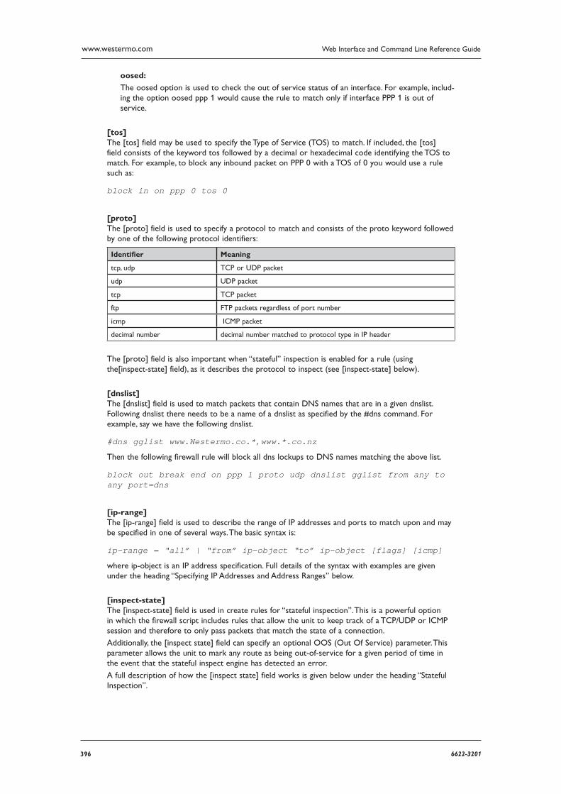
396 6622-3201
Web Interface and Command Line Reference Guidewww.westermo.com
oosed:
The oosed option is used to check the out of service status of an interface. For example, includ-ing the option oosed ppp 1 would cause the rule to match only if interface PPP 1 is out of service.
[tos] The [tos] field may be used to specify the Type of Service (TOS) to match. If included, the [tos] field consists of the keyword tos followed by a decimal or hexadecimal code identifying the TOS to match. For example, to block any inbound packet on PPP 0 with a TOS of 0 you would use a rule such as:
block in on ppp 0 tos 0
[proto] The [proto] field is used to specify a protocol to match and consists of the proto keyword followed by one of the following protocol identifiers:
Identifier Meaning
tcp, udp TCP or UDP packet
udp UDP packet
tcp TCP packet
ftp FTP packets regardless of port number
icmp ICMP packet
decimal number decimal number matched to protocol type in IP header
The [proto] field is also important when “stateful” inspection is enabled for a rule (using the[inspect-state] field), as it describes the protocol to inspect (see [inspect-state] below).
[dnslist] The [dnslist] field is used to match packets that contain DNS names that are in a given dnslist. Following dnslist there needs to be a name of a dnslist as specified by the #dns command. For example, say we have the following dnslist.
#dns gglist www.Westermo.co.*,www.*.co.nz
Then the following firewall rule will block all dns lockups to DNS names matching the above list.
block out break end on ppp 1 proto udp dnslist gglist from any to any port=dns
[ip-range] The [ip-range] field is used to describe the range of IP addresses and ports to match upon and may be specified in one of several ways. The basic syntax is:
ip-range = “all” | “from” ip-object “to” ip-object [flags] [icmp]
where ip-object is an IP address specification. Full details of the syntax with examples are given under the heading “Specifying IP Addresses and Address Ranges” below.
[inspect-state] The [inspect-state] field is used in create rules for “stateful inspection”. This is a powerful option in which the firewall script includes rules that allow the unit to keep track of a TCP/UDP or ICMP ses sion and therefore to only pass packets that match the state of a connection.
Additionally, the [inspect state] field can specify an optional OOS (Out Of Service) parameter. This parameter allows the unit to mark any route as being out-of-service for a given period of time in the event that the stateful inspect engine has detected an error.
A full description of how the [inspect state] field works is given below under the heading “Stateful Inspection”.
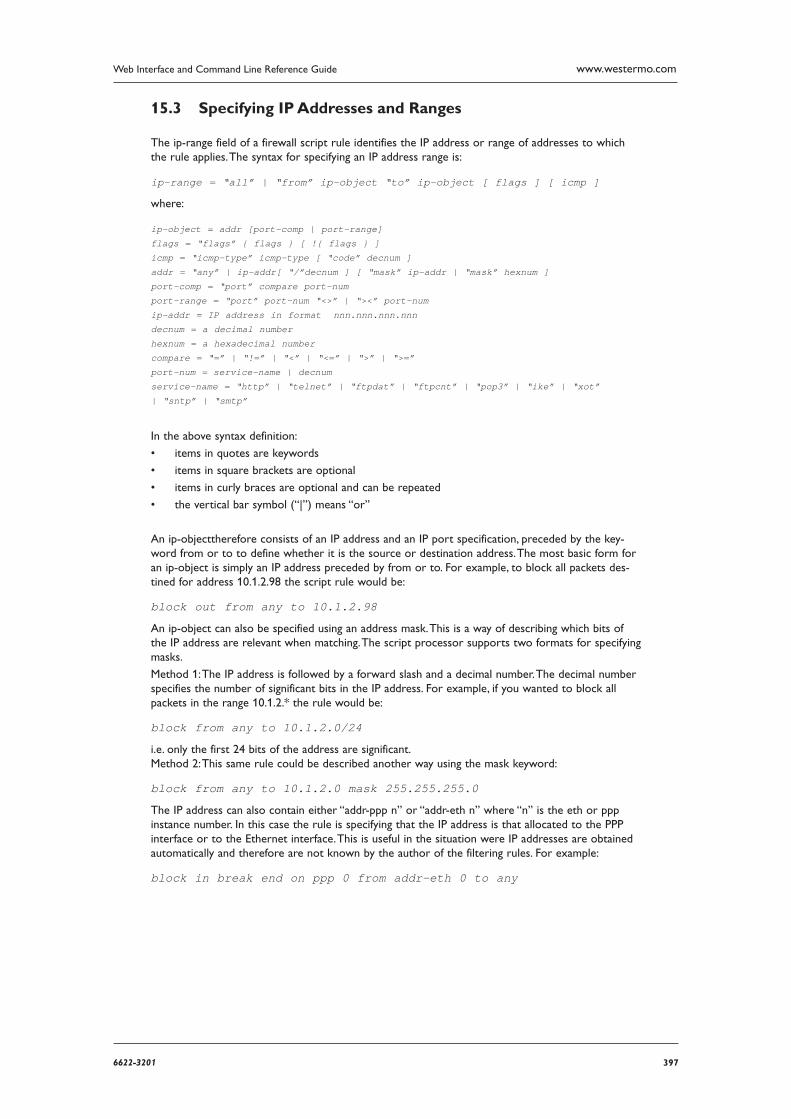
3976622-3201
Web Interface and Command Line Reference Guide www.westermo.com
Specifying IP Addresses and Ranges 15.3
The ip-range field of a firewall script rule identifies the IP address or range of addresses to which the rule applies. The syntax for specifying an IP address range is:
ip-range = “all” | “from” ip-object “to” ip-object [ flags ] [ icmp ]
where:
ip-object = addr [port-comp | port-range]
flags = “flags” { flags } [ !{ flags } ]
icmp = “icmp-type” icmp-type [ “code” decnum ]
addr = “any” | ip-addr[ “/”decnum ] [ “mask” ip-addr | “mask” hexnum ]
port-comp = “port” compare port-num
port-range = “port” port-num “<>” | “><” port-num
ip-addr = IP address in format nnn.nnn.nnn.nnn
decnum = a decimal number
hexnum = a hexadecimal number
compare = “=” | “!=” | “<” | “<=” | “>” | “>=”
port-num = service-name | decnum
service-name = “http” | “telnet” | “ftpdat” | “ftpcnt” | “pop3” | “ike” | “xot”
| “sntp” | “smtp”
In the above syntax definition:
items in quotes are keywords •
items in square brackets are optional •
items in curly braces are optional and can be repeated •
the vertical bar symbol (“|”) means “or” •
An ip-objecttherefore consists of an IP address and an IP port specification, preceded by the key-word from or to to define whether it is the source or destination address. The most basic form for an ip-object is simply an IP address preceded by from or to. For example, to block all packets des-tined for address 10.1.2.98 the script rule would be:
block out from any to 10.1.2.98
An ip-object can also be specified using an address mask. This is a way of describing which bits of the IP address are relevant when matching. The script processor supports two formats for specifying masks.
Method 1: The IP address is followed by a forward slash and a decimal number. The decimal number specifies the number of significant bits in the IP address. For example, if you wanted to block all pack ets in the range 10.1.2.* the rule would be:
block from any to 10.1.2.0/24
i.e. only the first 24 bits of the address are significant. Method 2: This same rule could be described another way using the mask keyword:
block from any to 10.1.2.0 mask 255.255.255.0
The IP address can also contain either “addr-ppp n” or “addr-eth n” where “n” is the eth or ppp instance number. In this case the rule is specifying that the IP address is that allocated to the PPP interface or to the Ethernet interface. This is useful in the situation were IP addresses are obtained automatically and therefore are not known by the author of the filtering rules. For example:
block in break end on ppp 0 from addr-eth 0 to any
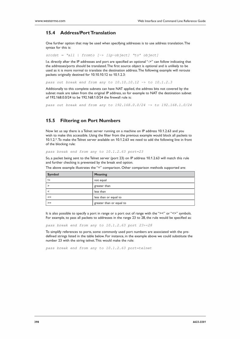
398 6622-3201
Web Interface and Command Line Reference Guidewww.westermo.com
Address/Port Translation 15.4
One further option that may be used when specifying addresses is to use address translation. The syn tax for this is:
srcdst = “all | fromto [-> [ip-object] “to” object]
I.e. directly after the IP addresses and port are specified an optional “->” can follow indicating that the addresses/ports should be translated. The first source object is optional and is unlikely to be used as it is more normal to translate the destination address. The following example will reroute packets orig inally destined for 10.10.10.12 to 10.1.2.3:
pass out break end from any to 10.10.10.12 -> to 10.1.2.3
Additionally to this complete subnets can have NAT applied, the address bits not covered by the sub net mask are taken from the original IP address, so for example to NAT the destination subnet of 192.168.0.0/24 to be 192.168.1.0/24 the firewall rule is:
pass out break end from any to 192.168.0.0/24 -> to 192.168.1.0/24
Filtering on Port Numbers 15.5
Now let us say there is a Telnet server running on a machine on IP address 10.1.2.63 and you wish to make this accessible. Using the filter from the previous example would block all packets to 10.1.2.*. To make the Telnet server available on 10.1.2.63 we need to add the following line in front of the blocking rule:
pass break end from any to 10.1.2.63 port=23
So, a packet being sent to the Telnet server (port 23) on IP address 10.1.2.63 will match this rule and further checking is prevented by the break end option.
The above example illustrates the “=” comparison. Other comparison methods supported are:
Symbol Meaning
!= not equal
> greater than
< less than
<= less than or equal to
>= greater than or equal to
It is also possible to specify a port in range or a port out of range with the “><” or “<>” symbols. For example, to pass all packets to addresses in the range 23 to 28, the rule would be specified as:
pass break end from any to 10.1.2.63 port 23><28
To simplify references to ports, some commonly used port numbers are associated with the pre-defined strings listed in the table below. For instance, in the example above we could substitute the number 23 with the string telnet. This would make the rule:
pass break end from any to 10.1.2.63 port=telnet

3996622-3201
Web Interface and Command Line Reference Guide www.westermo.com
The other port keywords that are defined are:
Keyword Std. Port Service
ftpdat 20 File Transfer Protocol data port
ftpcnt 21 File Transfer Protocol control port
telnet 23 Telnet server port
smtp 25 SMTP server port
http 80 Web server port
pop3 110 Mail server port
sntp 123 NTP server port
ike 500 Source/destination port for IKE key
xot 1998 Destination port for XOT packets
Note: The above service keywords are pre-defined based on “standard” port numbers. It is possible that these may have been defined differently on your system in which case you should use the port num bers explicitly (not the defined names).
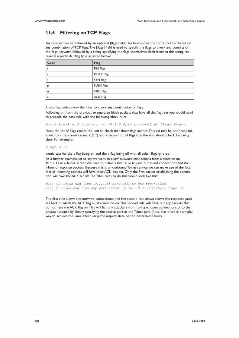
400 6622-3201
Web Interface and Command Line Reference Guidewww.westermo.com
Filtering on TCP Flags 15.6
An ip-objectcan be followed by an optional [flags]field. This field allows the script to filter based on any combination of TCP flags. The [flags] field is used to specify the flags to check and consists of the flags keyword followed by a string specifying the flags themselves. Each letter in this string rep-resents a particular flag type as listed below:
Code Flag
f FIN Flag
r RESET Flag
s SYN Flag
p PUSH Flag
u URG Flag
a ACK Flag
These flag codes allow the filter to check any combination of flags.
Following on from the previous example, to block packets that have all the flags set you would need to precede the pass rule with the following block rule:
block break end from any to 10.1.2.0/24 port=telnet flags frspua
Here, the list of flags causes the unit to check that those flags are set. This list may be optionally fol-lowed by an exclamation mark (“!”) and a second list of flags that the unit should check for being clear. For example:
flags s !a
would test for the s flag being on and the a flag being off with all other flags ignored.
As a further example, let us say we want to allow outward connections from a machine on 10.1.2.33 to a Telnet server. We have to define a filter rule to pass outbound connections and the inbound response packets. Because this is an outbound Telnet service we can make use of the fact that all incoming packets will have their ACK bits set. Only the first packet establishing the connec-tion will have the ACK bit off. The filter rules to do this would look like this:
pass out break end from 10.1.2.33 port>1023 to any port=telnetpass in break end from any port=telnet to 10.1.2.33 port>1023 flags !a
The first rule allows the outward connections, and the second rule above allows the response pack-ets back in which the ACK flag must always be on. This second rule will filter out any packets that do not have the ACK flag on. This will bar any attackers from trying to open connections onto the private net work by simply specifying the source port as the Telnet port (note that there is a simpler way to achieve the same effect using the inspect state option described below).

4016622-3201
Web Interface and Command Line Reference Guide www.westermo.com
Filtering on ICMP Codes 15.7
An ip-object can be followed by an optional [icmp] field. This allows the script to filter packets based on ICMP codes. ICMP packets are normally used to debug and diagnose a network and can be extremely useful. However they form part of a low-level protocol and are frequently exploited by hack ers for attacking networks. For this reason most network administrators will want to restrict the use of ICMP packets.
The syntax for including ICMP filtering is:
icmp = “icmp-type” icmp-type [“code” decnum]
The icmp-type can be one of the pre-defined strings listed in the following table or the equivalent decimal numeric value:
ICMP Type ICMP Value
Unreach 3
Echo 8
Echorep 0
Squench 4
Redir 5
Timex 11
Paramprob 12
Timest 13
Timestrep 14
Inforeq 15
Inforep 16
Maskreq 17
Maskrep 18
Routerad 9
Routersol 10
The following two rules are therefore equivalent:
pass in break end on ppp 0 proto icmp from any to 10.1.2.0/24 icmp-type 0
pass in break end on ppp 0 proto icmp from any to 10.1.2.0/24 icmp-type echorep
Both of these rules allow echo replies to come in from interface ppp 0 if they are addressed to our example local network address (10.1.2.*).
In addition to having a type, ICMP packets also include an ICMP code field. The filter syntax allows for the specification of an optional code field after the ICMP type. When specified the code field must also match. The ICMP code field is specified with a decimal number.
For example, suppose we wish to allow only echo replies and ICMP unreachable type ICMP packets from interface PPP 0. Then the rules would look something like this:
pass in break end on ppp 0 proto icmp from any to 10.1.2.0/24 icmp-type echorep code 0
pass in break end on ppp 0 proto icmp from any to 10.1.2.0/24 icmp-type unreach code 0 block in break end on ppp 0 proto icmp
The first two rules in this set allow in the ICMP packets that we are willing to permit and the third rule denies all other ICMP packets in from this interface. Now if we ever expect to see echo replies in onppp 0 we should allow echo requests out on that interface too. To do that we would have the rule:
pass out break end on ppp 0 proto icmp icmp-type echo
402 6622-3201
Web Interface and Command Line Reference Guidewww.westermo.com
Stateful Inspection 15.8
The Westermo routing code stack contains a sophisticated scripted “Stateful Firewall” and “Route Inspec tion” engine. Stateful inspection is a powerful tool that allows the unit to keep track of a TCP/UDP or ICMP session and match packets based on the state of the connection on which they are being car ried. In addition to providing sophisticated Firewall functionality the SF/RI engine also pro-vides a number of facilities for tracking the “health” of routes, marking “dead” routes as being Out Of Service (OOS) and creating rules for the automatic status checking of routes previously marked as OOS (for use in multi-level backup/restore scenarios).
The firewall may be used to place interface into an OOS state and also control how the interfaces return to service. When an interface goes OOS, all routes configured to use that interface will have their route metric set to 16 (the maximum value), meaning that some other route with a lower metric will be selected.
When a firewall stateful inspection rule expires, a decision is made as to whether the traffic being allowed to pass by this rule completed successfully or not. For example, if the stateful rule moni-tors SYN and FIN packets in both directions for a TCP socket then that rule will expire successfully. How ever, if SYNs are seen to pass in one direction but no SYNs pass in the other direction, the stateful rule will expire and the unit will tag this as a failure.
The following conditions tag a stateful rule as a failure:
packets have only passed in one direction •
10 packets have passed in one direction with no return packets (for TCP the packets must also • be re-transmits)
All of these features depend upon the stateful inspection capabilities of the Firewall engine which are explained below.
The [inspect] field takes the following format:
inspect = [“inspect-state” {“oos” {interface-name¦logical-name} secs {t=secs} {c=count} {d=count}} {r=“ping”¦“tcp”{,secs{secs}}} {rd=x} {dt=secs}{stat}]
The field can be used on its own or with an optional oos (Out Of Service) parameter.
To understand this better let us look at a simple example in which we want to set up a filter to allow all machines on a local network with addresses in the range 10.1.2.*, to access the Internet on port 80. We will need one rule to filter the outgoing packets and another to filter the responses:
pass out break end on ppp 0 from 10.1.2.0/24 to any port=80
pass in break end on ppp 0 from any port=80 to 10.1.2.0/24
In this example, the first rule allows outgoing http requests on PPP 0 from any address matching the mask 10.1.2.* providing that the requests are on port 80 (the normal port address for HTTP requests).
The second rule allows http response packets to be received on PPP 0 providing they are on port 80 and they are addressed to an IP address matching the mask 10.1.2.*.
However, rule 2 creates a potential security “hole”. The problem with filtering based on the source port is that you can trust the source port only as much as you trust the source machine. For instance an attacker could perform a port scan and provided the source port was set to 80 in each packet, it would get through this filter. Alternatively, on an already compromised system, a “Trojan horse” might be set up listening on port 80.
A more secure firewall can be defined using the “inspect-state” option. The stateful inspection sys-tem intelligently creates and manages dynamic filter rules based on the type of connection and the source/ destination IP addresses. Applying this to the above example, we can redesign the script to make it both simpler and more effective as described below.
As a consequence of the fact that only the first packet in a TCP handshake will have the SYN flag set, we can use a rule that checks the SYN flag:
pass out break end on ppp 0 from 10.1.2.0/24 to any port=80 flags s inspect-stateblock in break end on ppp 0
The first rule matches only the first outgoing packet because it checks the status of the s (SYN) flag and will only pass the packet if the SYN flag is set. At first glance however, it appears that the second rule blocks all inbound packets on PPP 0. Whilst this may be inherently more secure, it
4036622-3201
Web Interface and Command Line Reference Guide www.westermo.com
would also mean that users on the network would not be able to receive responses to their HTTP requests and would therefore be of little use!
The reason that this is not a problem is that the stateful inspection system creates temporary filter rules based on the outbound traffic. The first of these temporary rules allows the first response packet to pass because it also will have the SYN flag set. However, once the connection is estab-lished, a second temporary rule is created that passes inbound or outbound packets if the IP address and port number match those of the initial rule but does not check the SYN flag. It does however monitor the FIN flag so that the system can tell when the connection has been terminated. Once an outbound packet with the FIN flag has been detected along with a FIN/ACK response, the temporary rule ceases to exist and further packets on that IP address/port are blocked.
In the above example, if a local user on address 10.1.2.34 issues an http request to a host on 100.12.2.9, the outward packet would match and be passed. At the same time a temporary fil-ter rule is automatically created by the firewall that will pass inbound packets from IP address 100.12.2.9 that are addressed to 10.2.1.34 port x (where x is the source port used in the original request from 10.1.2.34).
This use of dynamic filters is more secure because both the source and destination IP addresses/ports are checked. In addition, the firewall will automatically check that the correct flags are being used for each stage of the communication.
The potential for a security breach has now been virtually eliminated because even if a hacker could time his attack perfectly he would still have to forge a response packet using the correct source address and port (which was randomly created by the sender of the HTTP request) and also has to target the specific IP address that opened the connection.
Another advantage of “inspect-state” rules is that they are scalable, i.e. many machines can use the rule simultaneously. In our above example for instance many machines on the local network could all browse the Internet and the inspection engine would be dynamically creating precise inward fil-ters as they are required and closing them when they are finished with.
The inspect-state option can be used on TCP, UDP protocols and some ICMP packets. The ICMP types that can be used with the “inspect-state” option are “echo”, “timest”, “inforeq” and “maskreq”.
Using [inspect-state] with Flags 15.8.1
As can be seen above, the inspect-state option can be used with flags. To illustrate this we will refer back to the earlier example of filtering using flags. It is possible to simplify the script by using thein-spect-state option. The original script was:
pass out break end from 10.1.2.33 port>1023 to any port=telnetpass in break end from any port=telnet to 10.1.2.33 port>1023 flags a/a
Using the inspect state option this can be replaced with a single filter rule:
pass out break end from 10.1.2.33 port>1023 to any port=telnet flags s/sa inspect-state
No rule is needed for the return packets because a temporary filter will be created that will only allow inbound packets to pass if they match sessions set up by this stateful inspection rule.
A further point to note about the new rule is that the “flags s/sa” specification ensures that it only matches the first packet in a connection. This is because the first packet in a TCP connection has the SYN flag on and the ACK flag off and so we only match on that combination. The stateful inspection engine will take care of matching the rest of the packets for this connection.
Using [inspect-state] with ICMP 15.8.2
The [inspect-state] option can be also used with ICMP codes. To allow the use of echo request and to allow echo replies you would have just the one rule:
pass out break end on ppp 0 proto icmp icmp-type echo inspect-state
The advantage of using inspect-state, other than just needing one rule, is that it leads to a more secure firewall. For instance with the inspect-state option the echo replies are not allowed in all the time; they will only be allowed in once an echo request has been sent out on that interface. The moment that a valid echo reply comes back (or there is a timeout), echo replies will again be blocked. Furthermore, the full IP address is checked; the IP source and destination must exactly
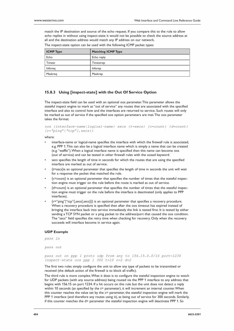
404 6622-3201
Web Interface and Command Line Reference Guidewww.westermo.com
match the IP destination and source of the echo request. If you compare this to the rule to allow echo replies in with out using inspect-state it would not be possible to check the source address at all and the desti nation address would match any IP address on our network.
The inspect-state option can be used with the following ICMP packet types:
ICMP Type Matching ICMP Type
Echo Echo reply
Timest Timestrep
Inforeq Inforep
Maskreq Maskrep
Using [inspect-state] with the Out Of Service Option 15.8.3
The inspect-state field can be used with an optional oos parameter. This parameter allows the stateful inspect engine to mark as “out of service” any routes that are associated with the specified interface and also to control how and the interfaces are returned to service. Such routes will only be marked as out of service if the specified oos option parameters are met. The oos parameter takes the format:
oos {interface-name¦logical-name} secs {t=secs} {c=count} {d=count} {r=“ping”|“tcp”{,secs}}
where:
interface-name or logical-name specifies the interface with which the firewall rule is associ ated, • e.g. PPP 1. This can also be a logical interface name which is simply a name that can be cre ated (e.g. “waffle”). When a logical interface name is specified then this name can become oos (out of service) and can be tested in other firewall rules with the oosed keyword.
secs specifies the length of time in seconds for which the routes that are using the specified • inter face are marked as out of service.
{t=secs}is an optional parameter that specifies the length of time in seconds the unit will wait • for a response the packet that matched the rule.
{c=count} is an optional parameter that specifies the number of times that the stateful inspec-• tion engine must trigger on the rule before the route is marked as out of service.
{d=count} is an optional parameter that specifies the number of times that the stateful inspec-• tion engine must trigger on the rule before the interface is deactivated (only applies to PPP interfaces).
{r=“ping”|“tcp”{,secs{,secs}}} is an optional parameter that specifies a recovery proce dure. • When a recovery procedure is specified then after the oos timeout has expired instead of bringing the interface back into service immediately the link is tested first. It is tested by either sending a TCP SYN packet or a ping packet to the address/port that caused the oos condition. The “secs” field specifies the retry time when checking for recovery. Only when the recovery suc ceeds will interface become in service again.
UDP Example
pass in
pass out
pass out on ppp 1 proto udp from any to 156.15.0.0/16 port=1234 inspect-state oos ppp 1 300 t=10 c=2 d=2
The first two rules simply configure the unit to allow any type of packets to be transmitted or received (the default action of the firewall is to block all traffic).
The third rule is more complex. What it does is to configure the stateful inspection engine to watch for UDP packets (with any source address) being routed via the PPP 1 interface to any address that begins with 156.15 on port 1234. If a hit occurs on this rule but the unit does not detect a reply within 10 seconds (as specified by the t= parameter), it will increment an internal counter. When this counter reaches the value set by the c= parameter, the stateful inspection engine will mark the PPP 1 interface (and therefore any routes using it), as being out of service for 300 seconds. Similarly, if this counter matches the d= parameter the stateful inspection engine will deactivate PPP 1. So
4056622-3201
Web Interface and Command Line Reference Guide www.westermo.com
in the above exam ple, the stateful inspection engine will mark any routes that use PPP 1 as out of service AND deactivate PPP 1 if no reply is detected within 10 seconds for two packets in a row.
Routes will come back into service when either the specified timeout expires or if there are no other routes with a higher metric in service.
PPP interfaces will be re-activated when either the routes using them are back in service and there is a packet to route and the AODI mode parameter is set to “On”.
TCP Example
pass out log break end on ppp 3 proto tcp from any to 192.168.0.1 flags S!Ainspect-state oos 30 t=10 c=2 d=2
pass in
pass out
This rule will specifically trace attempts to open a TCP connection on PPP 3 to the 192.168.0.1 IP address and if it fails within 10 seconds twice in a row, will cause the PPP 3 interface to be flagged as out of service (i.e. its metric will be set to 16), for 30 seconds. The optional d=2 entry will also cause the PPP link to be deactivated. Deactivating the link can be useful in scenarios where renego-tiating the PPP connection is likely to resolve the problem. Again, if a matching route with a higher metric has been defined it will be used whilst PPP 3 routes are out of service thus providing a pow-erful route backup mechanism.
Using [inspect-state] with the Stat Option 15.8.4
The inspect-state option can be used with the stat option. The stat option will cause this fire wall rule to record statistics associated with this firewall rule. Transaction times, counts and errors are recorded under the PPP statistics with this option.
Assigning DSCP Values 15.8.5
When using QOS, packet priorities will be determined by the DSCP values in their TOS fields. These priorities may have already been assigned but if necessary, the router can be configured to assign them by inserting the appropriate rules in the firewall. This is done by using the dscp command.
For example:
dscp 46 in on eth 0 from 100.100.100.25 to 1.2.3.4 port=4000
would set the DSCP value to 46 for almost any type of packet received on ETH 0 from IP address
100.100.100.25 addressed to 1.2.3.4 on port 4000. This allows you to set the DSCP value for almost any type of packet.
As a further example:
dscp 46 in on eth 0 proto smtp from any to any
would cause outgoing mail traffic to the same top priority queue (46 is by default a very high prior-ity code in the DSCP mappings).
406 6622-3201
Web Interface and Command Line Reference Guidewww.westermo.com
The FWLOG.TXT File 15.9
When the log option is specified within a firewall script rule, an entry is created in the FWLOG.TXT pseudo-file each time an IP packet matches the rule. Each log entry will in turn contain the fol-lowing information:
Parameter Description
Timestamp The time when the log entry is created.
Short Description Usually “FW LOG” but could be “FW DEBUG” for packets that hit rules with the “debug” action set.
Dir Either “IN” or “OUT”. Indicates the direction the packet is travelling.
Line The line number of the rule that cause the packet to be logged.
Hits The number of matches for the rule that caused this packet to be logged.
Iface The Interface the packet was to be transmitted/received on.
Source IP The source IP address in the IP packet.
Dest. IP The destination IP address in the IP packet.
ID The value of the ID field in the IP packet.
TTL The value of the TTL field in the IP packet.
PROTO The value of the protocol field in the IP packet. This will be expanded to text as well for the well-known protocols.
Src Port The value of the source port field in the TCP/UDP header.
Dst Port The value of the source port field in the TCP/UDP header.
Rule Text The rule that caused the packet to be logged is also entered into the log file.
In addition, port numbers will be expanded to text pre-defined port numbers.
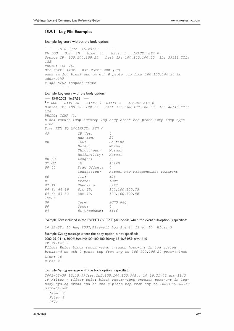
4076622-3201
Web Interface and Command Line Reference Guide www.westermo.com
Log File Examples 15.9.1
Example: log entry without the body option:
----- 15-8-2002 16:25:50 ----- FW LOG Dir: IN Line: 11 Hits: 1 IFACE: ETH 0Source IP: 100.100.100.25 Dest IP: 100.100.100.50 ID: 39311 TTL: 128 PROTO: TCP (6)Src Port: 4232 Dst Port: WEB (80)pass in log break end on eth 0 proto tcp from 100.100.100.25 to addr-eth0 flags S/SA inspect-state ------------
Example: Log entry with the body option:
----- 15-8-2002 16:27:56 ----- FW LOG Dir: IN Line: 7 Hits: 1 IFACE: ETH 0 Source IP: 100.100.100.25 Dest IP: 100.100.100.50 ID: 40140 TTL: 128 PROTO: ICMP (1)block return-icmp echorep log body break end proto icmp icmp-type echo From REM TO LOCIFACE: ETH 0 45 IP Ver: 4 Hdr Len: 20 00 TOS: Routine Delay: Normal Throughput: Normal Reliability: Normal 00 3C Length: 60 9C CC ID: 40140 00 00 Frag Offset: 0 Congestion: Normal May FragmentLast Fragment 80 TTL: 128 01 Proto: ICMP 0C E1 Checksum: 3297 64 64 64 19 Src IP: 100.100.100.25 64 64 64 32 Dst IP: 100.100.100.50 ICMP: 08 Type: ECHO REQ 00 Code: 0 04 5C Checksum: 1116
Example: Text included in the EVENTLOG.TXT pseudo-file when the event sub-option is specified:
16:26:32, 15 Aug 2002,Firewall Log Event: Line: 10, Hits: 3
Example: Syslog message where the body option is not specified:
2002-09-04 16:30:06User.Info100.100.100.50Aug 15 16:31:59 arm.1140 IP Filter - Filter Rule: block return-icmp unreach host-unr in log syslog breakend on eth 0 proto tcp from any to 100.100.100.50 port=telnetLine: 10 Hits: 4
Example: Syslog message with the body option is specified:
2002-08-30 16:19:59User.Info100.100.100.50Aug 10 16:21:56 arm.1140 IP Filter - Filter Rule: block return-icmp unreach port-unr in log-body syslog break end on eth 0 proto tcp from any to 100.100.100.50port=telnet Line: 9 Hits: 3 PKT:
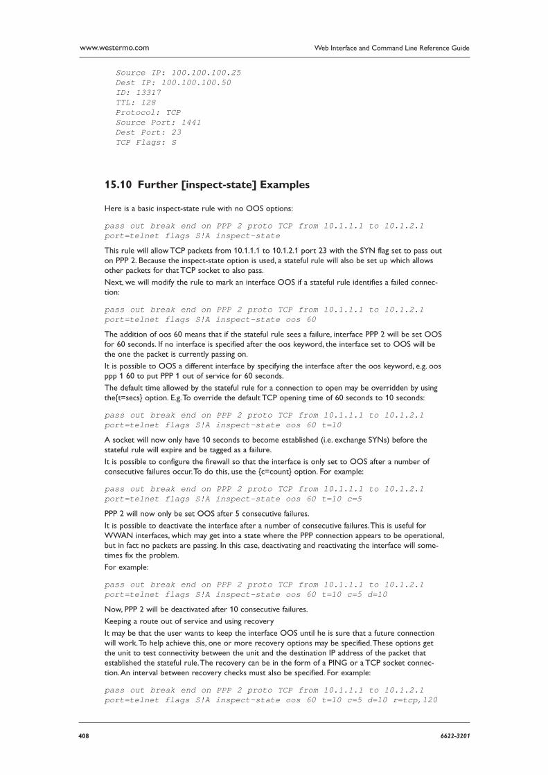
408 6622-3201
Web Interface and Command Line Reference Guidewww.westermo.com
Source IP: 100.100.100.25 Dest IP: 100.100.100.50 ID: 13317 TTL: 128 Protocol: TCP Source Port: 1441 Dest Port: 23 TCP Flags: S
Further [inspect-state] Examples 15.10
Here is a basic inspect-state rule with no OOS options:
pass out break end on PPP 2 proto TCP from 10.1.1.1 to 10.1.2.1 port=telnet flags S!A inspect-state
This rule will allow TCP packets from 10.1.1.1 to 10.1.2.1 port 23 with the SYN flag set to pass out on PPP 2. Because the inspect-state option is used, a stateful rule will also be set up which allows other packets for that TCP socket to also pass.
Next, we will modify the rule to mark an interface OOS if a stateful rule identifies a failed connec-tion:
pass out break end on PPP 2 proto TCP from 10.1.1.1 to 10.1.2.1 port=telnet flags S!A inspect-state oos 60
The addition of oos 60 means that if the stateful rule sees a failure, interface PPP 2 will be set OOS for 60 seconds. If no interface is specified after the oos keyword, the interface set to OOS will be the one the packet is currently passing on.
It is possible to OOS a different interface by specifying the interface after the oos keyword, e.g. oos ppp 1 60 to put PPP 1 out of service for 60 seconds.
The default time allowed by the stateful rule for a connection to open may be overridden by using the{t=secs} option. E.g. To override the default TCP opening time of 60 seconds to 10 seconds:
pass out break end on PPP 2 proto TCP from 10.1.1.1 to 10.1.2.1 port=telnet flags S!A inspect-state oos 60 t=10
A socket will now only have 10 seconds to become established (i.e. exchange SYNs) before the state ful rule will expire and be tagged as a failure.
It is possible to configure the firewall so that the interface is only set to OOS after a number of consec utive failures occur. To do this, use the {c=count} option. For example:
pass out break end on PPP 2 proto TCP from 10.1.1.1 to 10.1.2.1 port=telnet flags S!A inspect-state oos 60 t=10 c=5
PPP 2 will now only be set OOS after 5 consecutive failures.
It is possible to deactivate the interface after a number of consecutive failures. This is useful for W WAN interfaces, which may get into a state where the PPP connection appears to be operational, but in fact no packets are passing. In this case, deactivating and reactivating the interface will some-times fix the problem.
For example:
pass out break end on PPP 2 proto TCP from 10.1.1.1 to 10.1.2.1 port=telnet flags S!A inspect-state oos 60 t=10 c=5 d=10
Now, PPP 2 will be deactivated after 10 consecutive failures.
Keeping a route out of service and using recovery
It may be that the user wants to keep the interface OOS until he is sure that a future connection will work. To help achieve this, one or more recovery options may be specified. These options get the unit to test connectivity between the unit and the destination IP address of the packet that established the stateful rule. The recovery can be in the form of a PING or a TCP socket connec-tion. An interval between recovery checks must also be specified. For example:
pass out break end on PPP 2 proto TCP from 10.1.1.1 to 10.1.2.1 port=telnet flags S!A inspect-state oos 60 t=10 c=5 d=10 r=tcp,120
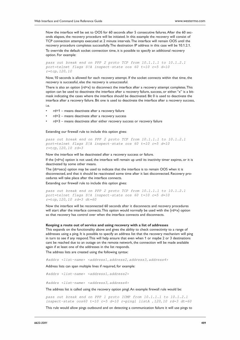
4096622-3201
Web Interface and Command Line Reference Guide www.westermo.com
Now the interface will be set to OOS for 60 seconds after 5 consecutive failures. After the 60 sec-onds elapses, the recovery procedure will be initiated. In this example the recovery will consist of TCP con nection attempts executed at 2 minute intervals. The interface will remain OOS until the recovery pro cedure completes successfully. The destination IP address in this case will be 10.1.2.1.
To override the default socket connection time, it is possible to specify an additional recovery option. For example:
pass out break end on PPP 2 proto TCP from 10.1.1.1 to 10.1.2.1 port=telnet flags S!A inspect-state oos 60 t=10 c=5 d=10 r=tcp,120,10
Now, 10 seconds is allowed for each recovery attempt. If the socket connects within that time, the recovery is successful, else the recovery is unsuccessful.
There is also an option {rd=x} to disconnect the interface after a recovery attempt completes. This option can be used to deactivate the interface after a recovery failure, success, or either. “x” is a bit-mask indicating the cases where the interface should be deactivated. Bit 0 is used to deactivate the interface after a recovery failure. Bit one is used to deactivate the interface after a recovery success,
i.e.
rd=1 – means deactivate after a recovery failure •
rd=2 – means deactivate after a recovery success •
rd=3 – means deactivate after either recovery success or recovery failure •
Extending our firewall rule to include this option gives:
pass out break end on PPP 2 proto TCP from 10.1.1.1 to 10.1.2.1 port=telnet flags S!A inspect-state oos 60 t=10 c=5 d=10 r=tcp,120,10 rd=3
Now the interface will be deactivated after a recovery success or failure.
If the {rd=x} option is not used, the interface will remain up until its inactivity timer expires, or it is deactivated by some other means.
The {dt=secs} option may be used to indicate that the interface is to remain OOS when it is discon nected, and that it should be reactivated some time after it last disconnected. Recovery pro-cedures will take place after the interface connects.
Extending our firewall rule to include this option gives:
pass out break end on PPP 2 proto TCP from 10.1.1.1 to 10.1.2.1 port=telnet flags S!A inspect-state oos 60 t=10 c=5 d=10 r=tcp,120,10 rd=3 dt=60
Now the interface will be reconnected 60 seconds after it disconnects and recovery procedures will start after the interface connects. This option would normally be used with the {rd=x} option so that recovery has control over when the interface connects and disconnects.
Keeping a route out of service and using recovery with a list of addresses This expands on the functionality above and gives the ability to check connectivity to a range of addresses using a ping. It is possible to specify an address list that the recovery mechanism will ping in turn to see if any respond. This will help ensure that even when 1 or maybe 2 or 3 destinations cant be reached due to an outage on the remote network, the connection will be made available again if at least one of the addresses in the list responds.
The address lists are created using the following syntax:
#addrs <list-name> <address1,address2,address3,address4>
Address lists can span multiple lines if required, for example:
#addrs <list-name> <address1,address2>
#addrs <list-name> <address3,address4>
The address list is called using the recovery option pingl. An example firewall rule would be:
pass out break end on PPP 1 proto ICMP from 10.1.1.1 to 10.1.2.1 inspect-state oos60 t=10 c=5 d=10 r=pingl listA ,120,10 rd=3 dt=60
This rule would allow pings outbound and on detecting a communication failure it will use pings to
410 6622-3201
Web Interface and Command Line Reference Guidewww.westermo.com
a address list named listA. The address list named listA could look like this:
#addrs listA 10.1.2.1,10.1.3.1,10.1.4.1,10.1.5.1
#addrs listA 10.1.6.1,10.2.1.1,10.2.2.1
This causes the recovery to ping the range of address shown in the list above.
Debugging a Firewall 15.11
During the creation and management of firewall scripts, firewall scripts may need debugging to ensure that packets are being processed correctly. To assist in this, a rule with the debug action may be used. If a rule with the debug action is encountered, an entry is made in the FWLOG.TXT pseu-do-file each time the packet in question matches a rule from that point on. This gives the adminis-trator the ability to follow a packet through a rule set, and can help determine what, if any, changes are required to the rule set. Rules that specify the debug action would typically be placed near the top of the rule set, so that all matching rules from that point on are entered into the log file.
Entries the FWLOG.TXT file created as the result of a debug rule may be identified by the short description “FW_DEBUG” at the top of the log entry.
An example rule set using a debug rule:
debug in on ppp 2 proto tcp from any to any port=http
pass in break end proto tcp from any to any port=http flags s/sa inspect statepass out break end proto udp
If placed at the top of the rule set, any packet received on interface PPP 2 to destination port 80 will generate a debug entry in the log file for each subsequent rule that it matches. In the example rule set above, a packet that matched the second rule would also match the first rule, and would therefore cre ate two log entries. The same packet would not match the third rule, and so no log entry would be made for this rule.
Because of the extra processor time required to add all of these additional log entries, debug rules should be removed (or commented out) once the rule set is operating as desired.
4116622-3201
Web Interface and Command Line Reference Guide www.westermo.com
Remote Management16
Westermo products equipped with ISDN BRIs can be accessed and controlled remotely via the ISDN net work by using:
a V.120 connection to access the text command interface •
PPP to access the Web Interface •
PPP to access the text command interface using Telnet •
the X.25 remote command channel •
Remote access via any one of these methods can be used to reconfigure the unit, upload/download files or upgrade the software, examine the event log or protocol analyser traces or to view statis-tics.
Using V.120 16.1
To establish a remote access session using V.120, initiate a V.120 call as normal using the ATD com-mand. Enter “%%%” within 5 seconds of the remote unit answering and you will be prompted to enter your username and password. Correct entry of these will allow access to the text com-mand interface. If the remote unit has been programmed with a Unit ID string on the Configure > General page, the Unit ID will appear as the command line prompt. Three login attempts are per-mitted before access is denied.
Using Telnet 16.2
If you have created a PPP DUN (Dial-up Networking) entry for the remote unit that you wish to access, any terminal program that supports Telnet may be used to establish a remote connection.
To initiate the connection, launch the DUN. If the remote unit is configured correctly with one of the PPP instances enabled for answering, it will connect and the linked computers icon will appear in the Windows system tray. You may then load your Telnet software.
To configure your Telnet software you must first specify that you require a TCP/IP connection and then enter the appropriate IP address or hostname (e.g. 1.2.3.4 or ss.2000r by default). After ensur-ing that your software is configured to connect to TCP port number 23 you may then initiate a new connection.
If the connection is successful you will see a connect confirmation message and you will be prompt-ed to enter your username and password. Correct entry of these will allow access to the text com-mand interface. If the remote unit has been programmed with a Unit ID string on the Configure > General page the Unit ID will appear as the command line prompt.
Three login attempts are permitted before access is denied.
Using FTP 16.3
Your unit incorporates an FTP server. FTP allows users to log on to remote hosts for the pur-pose of inspecting file directories, retrieving or uploading files, etc. For PC users, MS-DOS includes FTP sup port and there are a number of Windows-based specialist FTP client programs such as CuteFTP™ and Ws_ftp™. Many browsers also incorporate FTP support.
To initiate remote access to a unit using FTP, first establish a PPP DUN connection to the unit and then run your FTP software.
Note: If your unit has a USB storage device attached, it will show up as a sub-folder named “usb”.
412 6622-3201
Web Interface and Command Line Reference Guidewww.westermo.com
FTP under Windows 16.3.1
Once the connection has been established, enter the Web address for the unit. By default this will be:
1.2.3.4 or ss.2000r
If you are using a browser, as opposed to a specific FTP program, you will need to precede the address with “ftp://”. For example:
ftp://ss.2000r
This will give you an anonymous FTP login to the remote unit and you should see a listing of the file directory (the format of this will depend on the FTP client software that you are using). With an anon ymous login you will be able to view and retrieve files, but NOT upload, rename or delete them.
For full file access, you will need to log in with your correct username and password. To do this, enter the address in the following format:
ftp://username:[email protected]
This will give you full access and will allow you to copy, delete, rename, view and transfer files.
When using a browser CUT, COPY, DELETE and PASTE may be used for manipulating files as if they were in a normal Windows directory. If you are using a specific FTP client program, these opera-tions may be carried out using menu options or buttons.
FTP under DOS 16.3.2
To use FTP under DOS, use Windows DUN to establish the connection and then run the MSDOS prompt program. At the DOS prompt type:
ftp SS.2000R
or
ftp 1.2.3.4
When the connection has been established you will be prompted to enter your username and pass-word. Following a valid login the ftp> prompt will be issued and you may proceed to use the vari-ousftpcommands as appropriate. To obtain a list of available commands enter “?” at the prompt.
Using X.25 16.4
Remote access to your unit may also be carried out over an X.25 connection. The remote unit must first have its X.25 Remote Command Sub-address parameter set to an appropriate value (see Con figure > General). If the unit then receives an incoming X.25 call where the trailing digits of the NUA match the specified sub-address, the calling user will receive the standard login prompt. On entry of a valid username and password, they will be given access to the command line as if they were con nected locally.
4136622-3201
Web Interface and Command Line Reference Guide www.westermo.com
AT Commands17
D Dial 17.1
The ATD command causes the unit to initiate an ISDN call. The format of the command depends on the mode of operation.
When using the unit to make data calls on one of the ISDN B-channels, enter the ATD command followed by the telephone number. For example, to dial 01234 567890 enter the command:
atd01234567890
Spaces in the number are ignored. If the call is successful the unit will issue the CONNECT result code and switch to on-line mode.
Dialling with a Specifi ed Sub-Address 17.1.1
The ATD command may also be used to route a call to an ISDN sub-address by following the tel-ephone with the letter S and the required sub-address. The sub-address may be up to 15 digits long. For example:
atd01234567890s003
Dialling Stored Numbers 17.1.2
To dial numbers that have previously been stored within the unit using the AT&Z command, insert the S= modifier within the dial string. For example, to dial stored number 3 use the command:
atds=3
Combining ISDN and X.25 Calls 17.1.3
A further option for the ATD command for X.25 applications is to combine the ISDN call and the subsequent X.25 CALL in the same command. To do this, follow the telephone number with the “=” symbol and the X.25 call string. For example:
atd01234 567890=123456789
Pressing any key while the ATD command is being executed will abort the call attempt.
H Hang-up 17.2
The ATH command is used to terminate an ISDN call. If the unit is still on-line you must first switch back to command mode by entering the escape sequence, i.e. +++, wait 1 second and then enter an AT command or just AT<CR>.
After entering the ATH command the call will be disconnected and the NO CARRIER result will be issued.
Z Reset 17.3
The ATZ command is used to load one of the stored profiles for the active ASY port. The command is issued in the format ATZn where n is the number (0 or 1) of the ASY port profile you wish to load.
414 6622-3201
Web Interface and Command Line Reference Guidewww.westermo.com
&C DCD Control 17.4
The AT&C command is used to configure the way in which the unit controls the DCD signal to the terminal. There are three options:
&C0 DCD is always On
&C1 DCD is On only when an ISDN connection has been established (Layer 2 is UP)
&C2 DCD is always Off
&C3 DCD is normally On but pulses low for a time in 10 msec units determined by S register 10.
&F Load Factory Settings 17.5
The AT&F command is used to load a pre-defined default set of S-register and AT command settings (the default profile). These are: E1, V1, &C1, &K1, &D2, S0=0, S2=43 All other values are set to 0.
&R CTS Control 17.6
The AT&R command is used to configure the way in which the unit controls the CTS signal to the terminal. There are three options: &R0 CTS is always On &R1 CTS follows RTS. The delay between RTS changing and CTS changing is set in AT regis ter 56 in multiples of 10msec &R2 CTS is always Off
&V View Profi les 17.7
The AT&V command displays a list of the current AT command and S register values, and the set-tings for the two stored profiles. For example:
at&v CURRENT PROFILE: &c1 &d2 &k1 &s1 &r0 e1 q0 v1 &y0S0=0 S2=43 S12=50 S31=3 S45=5
STORED PROFILE 0: &c1 &d2 &k1 &s1 &r0 e1 q0 v1S0=0 S2=43 S12=50 S31=3 S45=5
STORED PROFILE 1: &c1 &d2 &k1 &s1 &r0 e1 q0 v1S0=0 S2=43 S12=50 S31=3 S45=5 OK
4156622-3201
Web Interface and Command Line Reference Guide www.westermo.com
&W Write SREGS.DAT 17.8
The AT&W command is used to save the current command and S registers settings (for the active port), to the file SREGS.DAT. The settings contained in this file can be reloaded at any time using the ATZ command.
The AT&W command may be immediately followed by a profile number, either 0 or 1, to store the settings in the specified profile, for example:
at&w1
would store the current settings as profile 1. If no profile number is specified, profile 0 is assumed. All S register values and the following command settings are written by AT&W:
e, &c, &d, &k
&Y Set Default Profi le 17.9
The AT&Y command is used to select the power-up profile (0 or 1). For example, to ensure that the unit boots up using stored profile 1, enter the command:
at&y1
&Z Store Phone Number 17.10
The AT&Z command is used to store “default” telephone numbers within the unit that may subse-quently dialled when DTR dialling is enabled or by using the S= modifier in the ATD dial command. One telephone number may be stored for each ASY port. For example, to store the phone number 0800 123456 as the default number to be associated with ASY 2, use the command:
at&z2=0800123456
If the number of the ASY port is not specified, the number will be stored against the port from which the command was entered, i.e. entering the command:
at&z=0800123456
from ASY 3 has the same effect as:
at&z3=0800123456
from any port. Once a number has been stored it may be dialled from the command line using the ATD command with the S= modifier:
atds=3
This means that any stored number can be dialled from any port. If DTR dialling has been enabled by setting S33=1 for the port, the number associated with that port will be dialled when the DTR signal for that port changes from Off to On, i.e. DTR dialling can only be used with the number associated with the port to which the terminal is connected.
416 6622-3201
Web Interface and Command Line Reference Guidewww.westermo.com
\AT Ignore Invalid AT Commands 17.11
This command is a work-around for use with terminals that generate large amounts of extraneous text. If not ignored, this text can cause many error messages to be generated by the router, and may result in a communications failure. To turn on this feature, type the following command:
at\at=1
To turn off the feature, type the following command:
at\at=0
When this feature is turned on, the ASY port ignores all commands except real AT commands. As with other ASY modes this can be saved by AT&W but is not included in the AT&V status display. To determine whether or not this mode is enabled type:
at\at ?
The unit will display 0 if the feature is Off, 1 if it is On.
\LS Lock Speed 17.12
The AT\LS command is used to lock the speed and data format of the port at which it is entered to the current settings so that the non-AT application commands may be used.
\PORT Set Active Port 17.13
Text commands which affect the settings associated with the serial ports normally operate on the port at which they are entered, i.e. entering the AT&K command from a terminal connected to ASY 1 will affect only the flow control settings for port 1.
The AT\PORT command is used to select a different “active” port from that at which the commands are entered. For example, if your terminal is connected to port 0 and you need to reconfigure the settings for port 2, you would first enter the command:
at\port=2
PORT 2
OK
Port 2 is now the active port and any AT commands or changes to S registers settings which affect the serial ports will now be applied to port 2 only. This includes:
Commands: Z, &D, &F, &K, &V, &Y, &W S registers: S31, S45
The AT\PORT? command will display the port to which you are connected and the active port for
command/S register settings. For example:
at\port?
PORT 2 ASY0 OK
Here, ASY2 is the active port and ASY0 is the port at which the command was entered. If the default port and the port to which you are connected are the same, only one entry will be listed.
To reset the default port to the one to which you are connected use the AT\PORT command with-out a parameter.
4176622-3201
Web Interface and Command Line Reference Guide www.westermo.com
\smib Commands 17.14
The at\smib command allows you to view a single standard MIB variable. To view the variable use theat\smib=<mib_name> command, where <mib_name> is the variable to be displayed. The vari-ables are sorted according to the hierarchy shown below.
DW?VPLE PLE
System 17.14.1
The System hierarchy consists of the following:
at\smib=mib-2.system.sysdescr
This variable shows the software version information (equivalent to what is shown on the Status > Firmware Versions page).
mib-2.system.sysdescr =Software Build Ver4891. Sep 22 2006 08:53:20 5W
at\smib=mib-2.system.sysobjectid
The authoritative identification of the network management subsystem. The Westermo does not sup port outputting OID variables. Instead, “oid” is output
at\smib=mib-2.system.sysuptime
The time the unit has been running in 10msec units (hundredths of a second).
mib-2.system.sysuptime = 1806718 The above example shows that the unit has been running for 5 hours, 1 minute and 7.18 sec-onds.
at\smib=mib-2.system.syscontact
A description of the contact person for the unit. For the Westermo, this is always a zero-length string.
at\smib=mib-2.system.sysname
The name of the unit (the name set in the Unit identity parameter on the Configure > General page).
mib-2.system.sysname = ss.2000r
at\smib=mib-2.system.syslocation
The physical location of the unit. For the Westermo, this is always a zero-length string.
at\smib=mib-2.system.sysservices
This variable displays a value that represents the set of services the unit provides. For each OSI layer the unit provides services for, 2(L-1) is added to the value, where L is the layer. The layers are shown below:
Layer Functionality
1 Physical
2 Data Link
3 Network
4 Transport
5 Session
6 Presentation
7 Application
For the Westermo, this value is always 7 (Physical layer (21-1) + Data Link layer (22-1) + Network layer (23-1)).
418 6622-3201
Web Interface and Command Line Reference Guidewww.westermo.com
Interfaces 17.14.2
The Interfaces hierarchy consists of the ifnumber variable and the iftable node:
at\smib=mib-2.interfaces.ifnumber
The total number of interfaces on the unit. This includes Ethernet, PPP and virtual interfaces (i.e. IPSec tunnels) and SYNC ports.
mib-2.interfaces.ifnumber = 52
at\smib=mib-2.interfaces.iftable The iftable node contains ifentry nodes for each interface. For each table entry, an index specifier must be appended to the end of each variable (e.g. for PPP0, 1 must be appended).
at\smib=mib-2.interfaces.iftable.ifentry
at\smib=mib-2.interfaces.iftable.ifentry.ifindex
The unique index number of the interface.
at\smib=mib-2.interfaces.iftable.ifentry.ifdescr
This variable displays information about the interface. This information is displayed in the format <interface type>-<instance>, where: <interface type> can be one of PPP, ETH, TUN (for IPSec tunnels), SNAIP (for SNAIP links) or SYNC, and <instance> is the instance. For example: mib-2.interfaces.iftable.ifentry.ifdescr.1 = PPP-0
at\smib=mib-2.interfaces.iftable.ifentry.iftype
The type of interface, as described by the physical/link protocol below the network layer in the pro tocol stack. Values can be one of the following:
PPP 23 ETH 6 IPSec Tunnel 131 SNAIP 17 SYNC port 118 For example:
mib-2.interfaces.iftable.ifentry.iftype.1 = 23
at\smib=mib-2.interfaces.iftable.ifentry.ifmtu
The size of the largest datagram (in octets) which can be sent on the interface. SNAIP and SYNC ports always return 0. IPSec tunnel interfaces will return the underlying interface if it can be located, otherwise 0 is returned. PPP interfaces will return the negotiated MTU if the link is con nected, otherwise 0 is returned.
For example:
mib-2.interfaces.iftable.ifentry.ifmtu.21 = 1504
at\smib=mib-2.interfaces.iftable.ifentry.ifspeed
This variable displays an estimate of the interface’s current bandwidth in bits per second. SNAIP and SYNC ports will always return 0. PPP ports will always return 64000. For example: mib-2.interfaces.iftable.ifentry.ifspeed.1 = 64000
at\smib=mib-2.interfaces.iftable.ifentry.ifphysaddress
The interface’s address at the protocol layer immediately below the network layer in the proto-col stack. For interfaces without such an address, a zero-length octet string is returned. For PPP, SNAIP and SYNC ports, a 0 length string is returned.
4196622-3201
Web Interface and Command Line Reference Guide www.westermo.com
t\smib=mib-2.interfaces.iftable.ifentry.ifadminstatus
The desired state of the interface. The testing state (3) indicates no operational packets can be passed.
at\smib=mib-2.interfaces.iftable.ifentry.ifoperstatus
The current operational state of the interface. The testing state (3) indicates no operational pack ets can be passed.
at\smib=mib-2.interfaces.iftable.ifentry.ifinoctets
The total number of octets received on this interface, including framing characters.
at\smib=mib-2.interfaces.iftable.ifentry.ifinucastpkts
The number of subnetwork-unicast packets delivered by this interface to a higher-layer protocol.
at\smib=mib-2.interfaces.iftable.ifentry.ifinnucastpkts
The number of non-unicast (i.e. broadcast or multicast) packets delivered by this interface to a higher-layer protocol.
at\smib=mib-2.interfaces.iftable.ifentry.ifinerrors
The number of inbound packets received by this interface that contained errors preventing them from being delivered to a higher-level protocol.
at\smib=mib-2.interfaces.iftable.ifentry.ifoutoctets
The total number of octets transmitted by this interface, including framing characters.
at\smib=mib-2.interfaces.iftable.ifentry.ifoutucastpkts
The total number of packets that higher-level protocols requested this interface to transmit to a subnetwork-unicast address, including those that were discarded or not sent.
at\smib=mib-2.interfaces.iftable.ifentry.ifoutnucastpkts
The total number of packets that higher-level protocols requested this interface to transmit to a non-unicast (i.e. broadcast or multicast) address, including those that were discarded or not sent.
at\smib=mib-2.interfaces.iftable.ifentry.ifouterrors
The number of outbound packets that this interface could not transmit because of errors.
IP 17.14.3
The IP node consists of the ipforwarding variable and the ipaddrtable and iproutetable nodes.
at\smib=mib-2.ip.ipforwarding
This variable indicates whether the unit is acting as an IP gateway in respect to the forwarding of datagrams received by, but not addressed to, the unit. IP gateways forward datagrams, IP hosts do not. For the Westermo, this value is always 1.
at\smib=mib-2.ip.ipaddrtable The ipaddrtable node contains ipaddrentry nodes for each IP address assigned to each interface of the unit. For each table entry, an index specifier must be appended to the end of each variable that specifies the interface (e.g. for PPP0, 1 must be appended).
at\smib=mib-2.ip.ipaddrtable.ipaddrentry
at\smib=mib-2.ip.ipaddrtable.ipaddrentry.ipadentaddr
The IP address to which this entry’s addressing information pertains.
420 6622-3201
Web Interface and Command Line Reference Guidewww.westermo.com
at\smib=mib-2.ip.ipaddrtable.ipaddrentry.ipadentifindex
The index identifier for the interface associated with this IP address.
at\smib=mib-2.ip.ipaddrtable.ipaddrentry.ipadentnetmask
The subnet mask associated with the IP address.
at\smib=mib-2.ip.ipaddrtable.ipaddrentry.ipadentbcastaddr
The value of the least-significant bit in the IP broadcast address used for sending datagrams on the IP address of this interface.
at\smib=mib-2.ip.iproutetable The iproutetable node contains iprouteentry nodes for each route defined on the unit.
at\smib=mib-2.ip.iproutetable.iprouteentry
at\smib=mib-2.ip.iproutetable.iprouteentry.iproutedest
The destination IP address for the route. An entry with a value of 0.0.0.0 is considered the default route. Multiple routes to a single destination can appear in the routing table, but access to such multiple entries is dependant on the table-access mechanisms defined by the network manage ment protocol in use.
at\smib=mib-2.ip.iproutetable.iprouteentry.iprouteifindex
The index value which uniquely identifies the local interface through which the next hop of the route should be reached.
at\smib=mib-2.ip.iproutetable.iprouteentry.iproutemetric1
The primary routing metric for the route.
at\smib=mib-2.ip.iproutetable.iprouteentry.iproutenexthop
The IP address of the next hop of the route.
at\smib=mib-2.ip.iproutetable.iprouteentry.iproutetype
The type of route. Valid values are:
1 Valid
2 Invalid
3 Direct
4 Indirect
at\smib=mib-2.ip.iproutetable.iprouteentry.iproutemask
The netmask for the route.

4216622-3201
Web Interface and Command Line Reference Guide www.westermo.com
“S” Registers18
In addition to the AT commands there are a number of Special (“S”) registers. These registers con-tain numeric values that may represent time intervals, ASCII characters or operational flags.
To display the contents of a particular “S” register, the ATS command is used in the form ATSn? where n is the number of the register whose contents are to be shown.
To store a new value into a register, use the S command in the form ATSN=X where N is the number of the register to be changed and X is the new value. For example, ATS31=4 would store the value 4 in S31.
The unit maintains one set of registers for each ASY port. By default, the S command operates ONLY on the S register set for the active port. To select an alternative default port, use the AT\PORT command first.
Each register can only be set to a limited range of values as shown in the table below:
Reg. Description Units Default Range
S0 V.120 Answer enable Rings 0 0-255
S1 Ring count Rings n/a n/a
S2 Escape character ASCII 43 0-255
S9 DCD on delay ms x 20 0 0-255
S10 Pulse time for DCD Low ms x 10 0 0-255
S12 Escape delay ms 50 0-255
S15 Data forwarding timer ms 2 0-255
S23 Parity N/A 0 0-2,5,6
S31 ASY interface speed refer to full description
n/a 0-11
S33 DTR dialling N/A 0 0,1
S45 DTR loss de-bounce 0.05 seconds (0.25s) 1-255
S0 V.120 Answer Enabled 18.1
Units: Rings Default: 0 Range: 0-255
S0 is used only in V.120 mode to enable or disable automatic answering of incoming ISDN calls. Auto answering is disabled when S0 is set to the default value of 0. Setting S0 to a non-zero value enables auto-answering.
The actual value stored determines the number of “rings” that the unit will wait before answering. For example, the command ATS0=2 enables auto-answering after two incoming rings have been detected.
With each ring the RING result code is issued and the value stored in S1 is incremented. When the value in S1 equals the value in S0 the call is answered.
S1 Ring count 18.2
Units: Rings Default: n/a Range: n/a
When ADAPT detects an incoming ISDN call on an ASY port, it will print “RING” to the ASY port at 2 second intervals. It also increments the S1 register, counting how many times “RING” is printed.
422 6622-3201
Web Interface and Command Line Reference Guidewww.westermo.com
S2 Escape Character 18.3
Units: ASCII Default: 43 Range: 0-255
The value stored in S2 defines which ASCII character is used as the Escape character, which by default is the “+” symbol. Entering this character three times followed by a delay of 1-2 seconds and then an AT command will cause the unit to switch from on-line mode to command mode.
S12 Escape Delay 18.4
Units: ms Default: 50 Range: 0-255
The value stored in S12 defines the delay between sending the escape sequence and entering an AT command for the unit to switch from on-line mode to command mode.
S15 Data Forwarding Timer 18.5
Units: 10ms Default: 0 Range: 0-255
S15 is used to set the data forwarding timer for the ASY port in multiples of 10ms. The default data forwarding time is 20ms and in normal use this there should be no need to change this. However, set ting S15 to 1 enables a special mode of operation in which data is forwarded as fast as possible for the data rate for which the port is configured (at 115000bps this will typically be 2-3ms).
Note that the default value of 0 is equivalent to setting the register to 2 in order to maintain com-patibility with older systems.
S23 Parity 18.6
Units: N/A Default: 0 Range: 0-2,5,6
The value stored in S23 determines whether the parity used for the ASY port is set to None (0), Odd (1), Even (2), 8Data Odd (5) or 8Data Even (6).
S31 ASY Interface Speed 18.7
Units: N/A Default: 0 Range: 0-11
Register S31 is used to set the speed and data format for the ASY port to which you are currently connected.
The default value for ASY 0 is 0, i.e. the port speed/data format is not set to a specific value, it is deter mined automatically from the AT commands that you enter.
The default value for ASY 1, 2 and 3 is 3, i.e. the ports will only accept AT commands at 115,200bps (8 data bits, no parity and 1 stop bit).
To set the speed of one of the ports to a to a particular value, the appropriate register should be set to the required value from the following table:
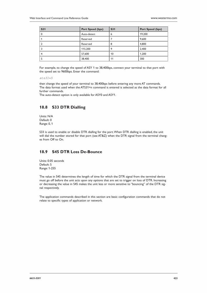
4236622-3201
Web Interface and Command Line Reference Guide www.westermo.com
S31 Port Speed (bps) S31 Port Speed (bps)
0 Auto-detect 6 19,200
1 Reserved 7 9,600
2 Reserved 8 4,800
3 115,200 9 2,400
4 57,600 10 1,200
5 38,400 11 300
For example, to change the speed of ASY 1 to 38,400bps, connect your terminal to that port with the speed set to 9600bps. Enter the command:
ats31=5
then change the speed of your terminal to 38,400bps before entering any more AT commands. The data format used when the ATS31=n command is entered is selected as the data format for all further commands. The auto-detect option is only available for ASY0 and ASY1.
S33 DTR Dialling 18.8
Units: N/A Default: 0 Range: 0, 1
S33 is used to enable or disable DTR dialling for the port. When DTR dialling is enabled, the unit will dial the number stored for that port (see AT&Z) when the DTR signal from the terminal chang-es from Off to On.
S45 DTR Loss De-Bounce 18.9
Units: 0.05 seconds Default: 5 Range: 1-255
The value in S45 determines the length of time for which the DTR signal from the terminal device must go off before the unit acts upon any options that are set to trigger on loss of DTR. Increasing or decreasing the value in S45 makes the unit less or more sensitive to “bouncing” of the DTR sig-nal respectively.
The application commands described in this section are basic configuration commands that do not relate to specific types of application or network.
424 6622-3201
Web Interface and Command Line Reference Guidewww.westermo.com
General System Commands19
CONFIG Show/Save Confi guration 19.1
The config command is used for the following purposes to show current or stored configuration settings, to save the current configuration or to specify which configuration is to be used when the unit is powered up or rebooted.
The format of the config command is:
config <0|1|c> <save|show|powerup>
Two separate configurations can be stored, numbered 0 and 1. The first parameter of the config command specifies to which configuration the command applies. The letter “c” denotes the current configuration settings, i.e. those currently in use.
The second parameter is one of the following keywords:
show displays the specified configuration (either 0, 1 or c for the current configuration) •
save saves the current settings as the specified configuration (either 0 or 1) •
powerup sets the specified configuration (either 0 or 1) to be used at power-up or reboot •
For example, to display the current configuration use the command:
config c show
The output will appear similar to the following example:
bind PAD 0 ASY 0 pad 0 l2iface LAPBcmd 0 username Westermo cmd 0 epassword Oz57X0kdcmd 0 hostname IR2140 OK
The config files only contain details of those settings that are different from the unit’s default set-tings. If you make a setting that is the same as the default setting, it will not appear in a stored con-figuration.
To save the current settings to configuration file 1, enter:
config 1 save
To use configuration 1 when the unit is powered up or rebooted, enter:
config 1 powerup
Confi g changes counter 19.2
The config changes command shows the number of changes to the current configuration since the unit has powered up and the initial configuration file run. Also shows the time when the config file was last saved.
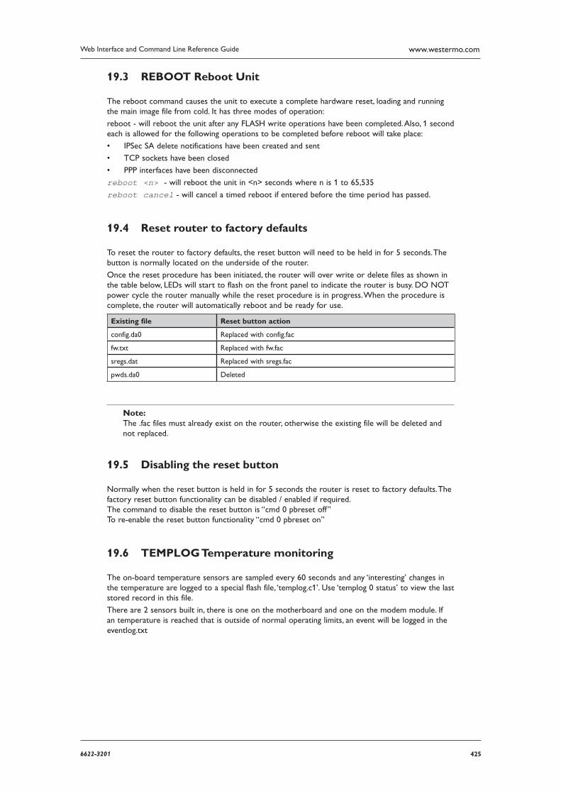
4256622-3201
Web Interface and Command Line Reference Guide www.westermo.com
REBOOT Reboot Unit 19.3
The reboot command causes the unit to execute a complete hardware reset, loading and running the main image file from cold. It has three modes of operation:
reboot - will reboot the unit after any FLASH write operations have been completed. Also, 1 second each is allowed for the following operations to be completed before reboot will take place:
IPSec SA delete notifications have been created and sent •
TCP sockets have been closed •
PPP interfaces have been disconnected •
reboot <n> - will reboot the unit in <n> seconds where n is 1 to 65,535
reboot cancel - will cancel a timed reboot if entered before the time period has passed.
Reset router to factory defaults 19.4
To reset the router to factory defaults, the reset button will need to be held in for 5 seconds. The button is normally located on the underside of the router.
Once the reset procedure has been initiated, the router will over write or delete files as shown in the table below, LEDs will start to flash on the front panel to indicate the router is busy. DO NOT power cycle the router manually while the reset procedure is in progress. When the procedure is complete, the router will automatically reboot and be ready for use.
Existing file Reset button action
config.da0 Replaced with config.fac
fw.txt Replaced with fw.fac
sregs.dat Replaced with sregs.fac
pwds.da0 Deleted
Note:The .fac files must already exist on the router, otherwise the existing file will be deleted and not replaced.
Disabling the reset button 19.5
Normally when the reset button is held in for 5 seconds the router is reset to factory defaults. The factory reset button functionality can be disabled / enabled if required. The command to disable the reset button is “cmd 0 pbreset off” To re-enable the reset button functionality “cmd 0 pbreset on”
TEMPLOG Temperature monitoring 19.6
The on-board temperature sensors are sampled every 60 seconds and any ‘interesting’ changes in the temperature are logged to a special flash file, ‘templog.c1’. Use ‘templog 0 status’ to view the last stored record in this file.
There are 2 sensors built in, there is one on the motherboard and one on the modem module. If an temperature is reached that is outside of normal operating limits, an event will be logged in the eventlog.txt
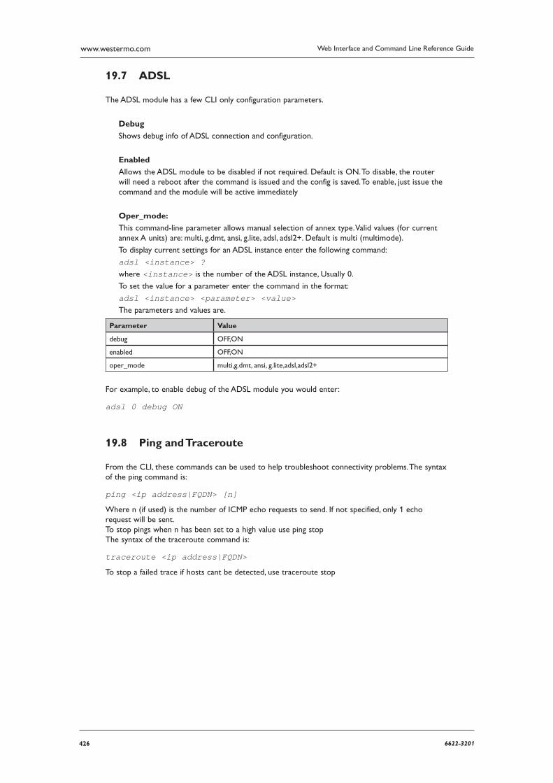
426 6622-3201
Web Interface and Command Line Reference Guidewww.westermo.com
ADSL 19.7
The ADSL module has a few CLI only configuration parameters.
Debug
Shows debug info of ADSL connection and configuration.
Enabled
Allows the ADSL module to be disabled if not required. Default is ON. To disable, the router will need a reboot after the command is issued and the config is saved. To enable, just issue the com mand and the module will be active immediately
Oper_mode:
This command-line parameter allows manual selection of annex type. Valid values (for current annex A units) are: multi, g.dmt, ansi, g.lite, adsl, adsl2+. Default is multi (multimode).
To display current settings for an ADSL instance enter the following command:
adsl <instance> ? where <instance> is the number of the ADSL instance, Usually 0.
To set the value for a parameter enter the command in the format:
adsl <instance> <parameter> <value> The parameters and values are.
Parameter Value
debug OFF,ON
enabled OFF,ON
oper_mode multi,g.dmt, ansi, g.lite,adsl,adsl2+
For example, to enable debug of the ADSL module you would enter:
adsl 0 debug ON
Ping and Traceroute 19.8
From the CLI, these commands can be used to help troubleshoot connectivity problems. The syntax of the ping command is:
ping <ip address|FQDN> [n]
Where n (if used) is the number of ICMP echo requests to send. If not specified, only 1 echo request will be sent. To stop pings when n has been set to a high value use ping stop The syntax of the traceroute command is:
traceroute <ip address|FQDN>
To stop a failed trace if hosts cant be detected, use traceroute stop
4276622-3201
Web Interface and Command Line Reference Guide www.westermo.com
TCPPERM and TCPDIAL20
This section describes the operation of the tcpperm and tcpdial commands which are available only as application commands and have no equivalent web pages.
TCPPERM 20.1
The tcpperm command is used to establish a permanent “serial to IP” connection between one of the ASY ports and a remote IP host. After the command has been executed, the unit will auto-matically open a socket connection to the remote peer whenever data is received from a terminal attached to the specified ASY port. When the socket is first opened and the connection has been established, the unit will issue a CONNECT message to the terminal and will subsequently relay data between the socket and the ASY port. The format of the CONNECT message can be modified using the standard AT commands (e.g. ATV, ATE, etc.) or using the Configure > ASY ports web page.
Note: The serial port should also be pre-configured to use the appropriate word format, speed and flow control.
While the serial-to-IP connection is established, if the attached serial device drops the DTR signal, then the socket connection will be terminated, much as with a standard modem or terminal adapter. Again this behaviour can be modified via the AT&D command or the serial port settings.
The format of the command is:
TCPPERM <[ASY 0-1]> <Dest Host> <Dest Port> [UDP] [nodeact] [-l<listening port>] [-i<inact_timeout>] [-f<fwd_time>] [-e<eth_ip>][-d(deact link)][-k<keepalive_time>] [-s<src_port>] [-ok] [-t<telnet_mode>] [-ho(host only)][-ssl] [-ao(always open)] [-m<mhome idx>]”
The parameters are detailed in the following table:
Parameter Description
ASY The number of the ASY port that the link will be made from/to
Dest Host The IP address (or name) of the remote peer
Dest Port The port number to use on the remote peer
UDP Open a UDP connection (the default is TCP)
-ao Open socket immediately, and reopen if and when the socket is closed
-e Use the address of ethernet port ’n’ for the socket connection rather than the default of the address of the interface over which the socket is opened (i.e ppp 1, ppp 2, etc.)
-d Deactivate link - if non-zero, when the socket is closed and there are no other sockets using the interface then the interface connection is dropped (switched connections only)
-f The forwarding time (x10ms) for packetising data from the serial port
-ho Host - indicates that the socket should only accept connections from the specified host.
-i The inactivity timeout (s) after which the socket will be closed
-k Keep alive packet timer (s)
-l Listening port - allows the user to set a new TCP port number to listen on rather than the default value of 4000+ASY port #
-m Multihome additional consecutive addresses index
-ok Open socket in ’quiet mode’, i.e. there is no ’OK’ response to the TCPPERM command.
-s Source port number
-ssl Use SSL mode
428 6622-3201
Web Interface and Command Line Reference Guidewww.westermo.com
-t Use Telnet mode. Opens socket in the corresponding Telnet mode (port 23 default), 0= raw, 1 Telnet Mode, 2 - Telnet Mode with null stuffing. If this is not specified then the mode specified for the associated ASY port in general setup is used. If the -t option is specified then the “ok” option is always used.
The command can also be made to execute automatically on power-up by using the “cmd n autoc-md ‘cmd’” macro command, i.e.
cmd 0 autocmd ’tcpperm asy 0 192.168.0.1 -f3 -s3000 -k10 -e1’
Considerations for use with VPN or GRE Tunnels When the socket used by TCPPERM is opened the default behaviour is to use the address of the inter face over which the socket is carried (ETHn or PPPn) as the source address of the socket. If the socket data is to be tunnelled then it may be necessary to use the -en modifier so that the source address of the socket matches the local subnet address specified in the appropriate Eroute. A similar effect can also be achieved by setting the parameter GP sockets use IP from interface: Ethernet n’ in the Web interface on the Configure > General page.
TCPDIAL 20.2
TCPDIAL operates in an identical manner to TCPPERM except that establishment of the socket con nection is not automatic and must be initiated by the tcpdial command. The simplest method of achieving this is to map a command using the Configure > Command Mappings table, i.e. Command to Map ATDT0800456789 maps to “tcpdial asy 1 217.36.133.29 -e0”. Now, whenever the attached ter minal device attempts to dial the number defined the unit will map it to an IP socket connection. In this way multiple dial commands can be directed to the same or different IP hosts with other simple com mand mappings.
Aborting TCPDIAL 20.2.1
The tcpdab command can be used to cancel a TCPDIAL connection before the connection has been made. It can also be used from a command session to disconnect an existing TCPDIAL connec tion on another ASY port.
The format of the command is:
tcpdab <instance> ?
where <instance> is the number of the ASY port.
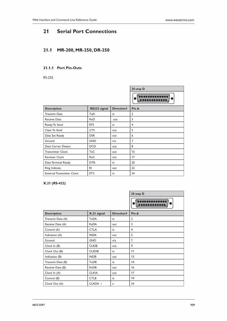
4296622-3201
Web Interface and Command Line Reference Guide www.westermo.com
Serial Port Connections21
MR-200, MR-250, DR-25021.1
Port Pin-Outs 21.1.1
RS-232
25-way D
13
25 14
1
Description RS232 signal Direction1 Pin #
Transmit Data TxD in 2
Receive Data RxD out 3
Ready To Send RTS in 4
Clear To Send CTS out 5
Data Set Ready DSR out 6
Ground GND n/a 7
Data Carrier Detect DCD out 8
Transmitter Clock TxC out 15
Receiver Clock RxC out 17
Data Terminal Ready DTR in 20
Ring Indicate RI out 22
External Transmitter Clock ETC in 24
X.21 (RS-422)
25-way D
13
25 14
1
Description X.21 signal Direction1 Pin #
Transmit Data (A) TxDA in 2
Receive Data (A) RxDA out 3
Control (A) CTLA in 4
Indication (A) INDA out 5
Ground GND n/a 7
Clock In (B) CLKIB out 9
Clock Out (B) CLKOB in 11
Indication (B) INDB out 13
Transmit Data (B) TxDB in 14
Receive Data (B) RxDB out 16
Clock In (A) CLKIA out 17
Control (B) CTLB in 19
Clock Out (A) CLKOA i n 24
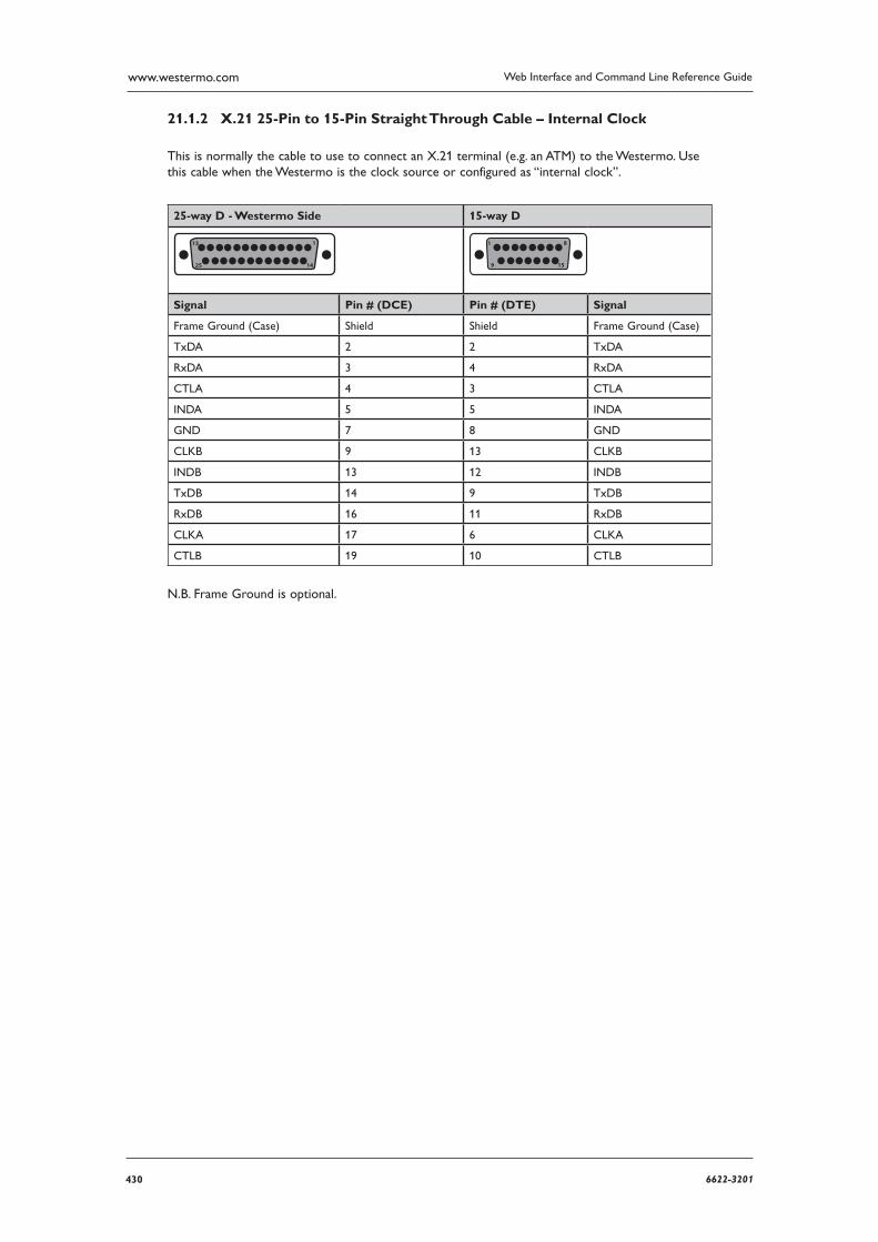
430 6622-3201
Web Interface and Command Line Reference Guidewww.westermo.com
X.21 25-Pin to 15-Pin Straight Through Cable – Internal Clock 21.1.2
This is normally the cable to use to connect an X.21 terminal (e.g. an ATM) to the Westermo. Use this cable when the Westermo is the clock source or configured as “internal clock”.
25-way D - Westermo Side 15-way D
13
25 14
1 1
9 15
8
Signal Pin # (DCE) Pin # (DTE) Signal
Frame Ground (Case) Shield Shield Frame Ground (Case)
TxDA 2 2 TxDA
RxDA 3 4 RxDA
CTLA 4 3 CTLA
INDA 5 5 INDA
GND 7 8 GND
CLKB 9 13 CLKB
INDB 13 12 INDB
TxDB 14 9 TxDB
RxDB 16 11 RxDB
CLKA 17 6 CLKA
CTLB 19 10 CTLB
N.B. Frame Ground is optional.
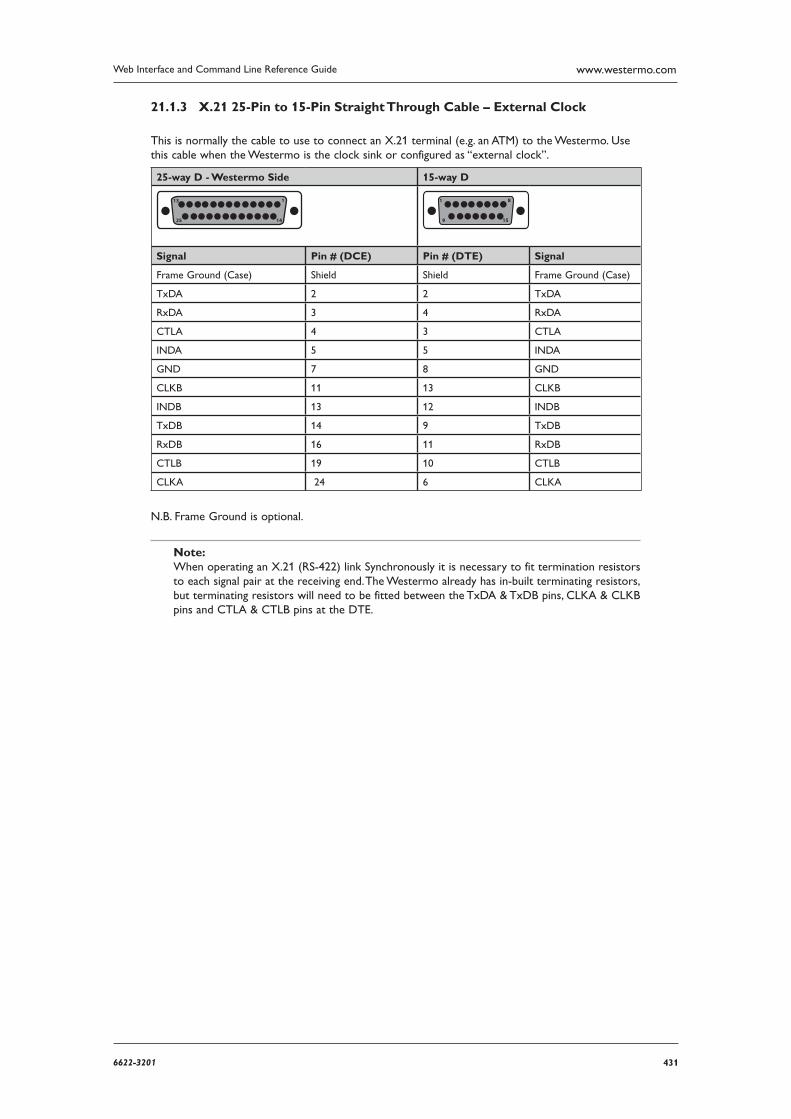
4316622-3201
Web Interface and Command Line Reference Guide www.westermo.com
X.21 25-Pin to 15-Pin Straight Through Cable – External Clock 21.1.3
This is normally the cable to use to connect an X.21 terminal (e.g. an ATM) to the Westermo. Use this cable when the Westermo is the clock sink or configured as “external clock”.
25-way D - Westermo Side 15-way D
13
25 14
1 1
9 15
8
Signal Pin # (DCE) Pin # (DTE) Signal
Frame Ground (Case) Shield Shield Frame Ground (Case)
TxDA 2 2 TxDA
RxDA 3 4 RxDA
CTLA 4 3 CTLA
INDA 5 5 INDA
GND 7 8 GND
CLKB 11 13 CLKB
INDB 13 12 INDB
TxDB 14 9 TxDB
RxDB 16 11 RxDB
CTLB 19 10 CTLB
CLKA 24 6 CLKA
N.B. Frame Ground is optional.
Note: When operating an X.21 (RS-422) link Synchronously it is necessary to fit termination resistors to each signal pair at the receiving end. The Westermo already has in-built terminating resistors, but terminating resistors will need to be fitted between the TxDA & TxDB pins, CLKA & CLKB pins and CTLA & CTLB pins at the DTE.
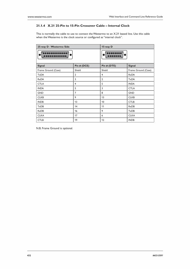
432 6622-3201
Web Interface and Command Line Reference Guidewww.westermo.com
X.21 25-Pin to 15-Pin Crossover Cable – Internal Clock 21.1.4
This is normally the cable to use to connect the Westermo to an X.21 leased line. Use this cable when the Westermo is the clock source or configured as “internal clock”.
25-way D - Westermo Side 15-way D
13
25 14
1 1
9 15
8
Signal Pin # (DCE) Pin # (DTE) Signal
Frame Ground (Case) Shield Shield Frame Ground (Case)
TxDA 2 4 RxDA
RxDA 3 2 TxDA
CTLA 4 5 INDA
INDA 5 3 CTLA
GND 7 8 GND
CLKB 9 13 CLKB
INDB 13 10 CTLB
TxDB 14 11 RxDB
RxDB 16 9 TxDB
CLKA 17 6 CLKA
CTLB 19 12 INDB
N.B. Frame Ground is optional.
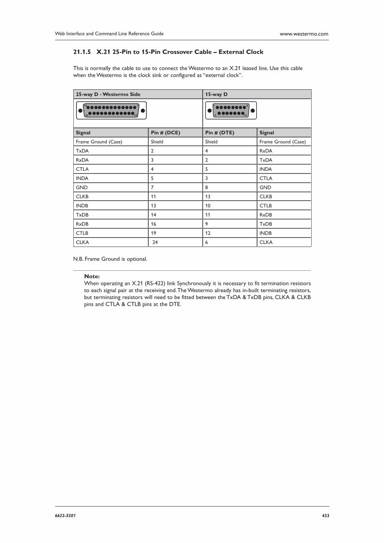
4336622-3201
Web Interface and Command Line Reference Guide www.westermo.com
X.21 25-Pin to 15-Pin Crossover Cable – External Clock 21.1.5
This is normally the cable to use to connect the Westermo to an X.21 leased line. Use this cable when the Westermo is the clock sink or configured as “external clock”.
25-way D - Westermo Side 15-way D
13
25 14
1 1
9 15
8
Signal Pin # (DCE) Pin # (DTE) Signal
Frame Ground (Case) Shield Shield Frame Ground (Case)
TxDA 2 4 RxDA
RxDA 3 2 TxDA
CTLA 4 5 INDA
INDA 5 3 CTLA
GND 7 8 GND
CLKB 11 13 CLKB
INDB 13 10 CTLB
TxDB 14 11 RxDB
RxDB 16 9 TxDB
CTLB 19 12 INDB
CLKA 24 6 CLKA
N.B. Frame Ground is optional.
Note: When operating an X.21 (RS-422) link Synchronously it is necessary to fit termination resistors to each signal pair at the receiving end. The Westermo already has in-built terminating resistors, but terminating resistors will need to be fitted between the TxDA & TxDB pins, CLKA & CLKB pins and CTLA & CTLB pins at the DTE.
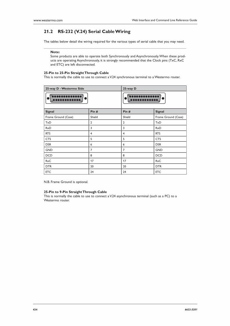
434 6622-3201
Web Interface and Command Line Reference Guidewww.westermo.com
RS-232 (V.24) Serial Cable Wiring 21.2
The tables below detail the wiring required for the various types of serial cable that you may need.
Note: Some products are able to operate both Synchronously and Asynchronously. When these prod-ucts are operating Asynchronously, it is strongly recommended that the Clock pins (TxC, RxC and ETC) are left disconnected.
25-Pin to 25-Pin Straight Through Cable This is normally the cable to use to connect a V.24 synchronous terminal to a Westermo router.
25-way D - Westermo Side 25-way D
13
25 14
1 13
25 14
1
Signal Pin # Pin # Signal
Frame Ground (Case) Shield Shield Frame Ground (Case)
TxD 2 2 TxD
RxD 3 3 RxD
RTS 4 4 RTS
CTS 5 5 CTS
DSR 6 6 DSR
GND 7 7 GND
DCD 8 8 DCD
RxC 17 17 RxC
DTR 20 20 DTR
ETC 24 24 ETC
N.B. Frame Ground is optional.
25-Pin to 9-Pin Straight Through Cable This is normally the cable to use to connect a V.24 asynchronous terminal (such as a PC) to a Westermo router.
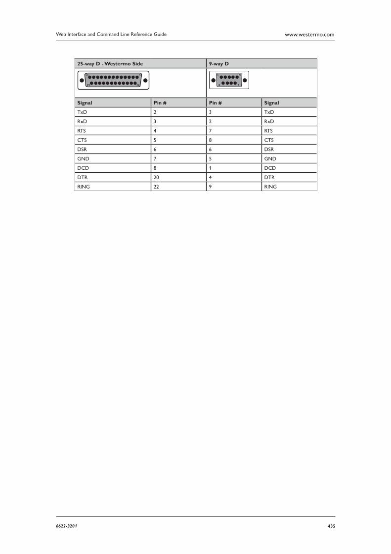
4356622-3201
Web Interface and Command Line Reference Guide www.westermo.com
25-way D - Westermo Side 9-way D
13
25 14
1 1
6 9
5
Signal Pin # Pin # Signal
TxD 2 3 TxD
RxD 3 2 RxD
RTS 4 7 RTS
CTS 5 8 CTS
DSR 6 6 DSR
GND 7 5 GND
DCD 8 1 DCD
DTR 20 4 DTR
RING 22 9 RING
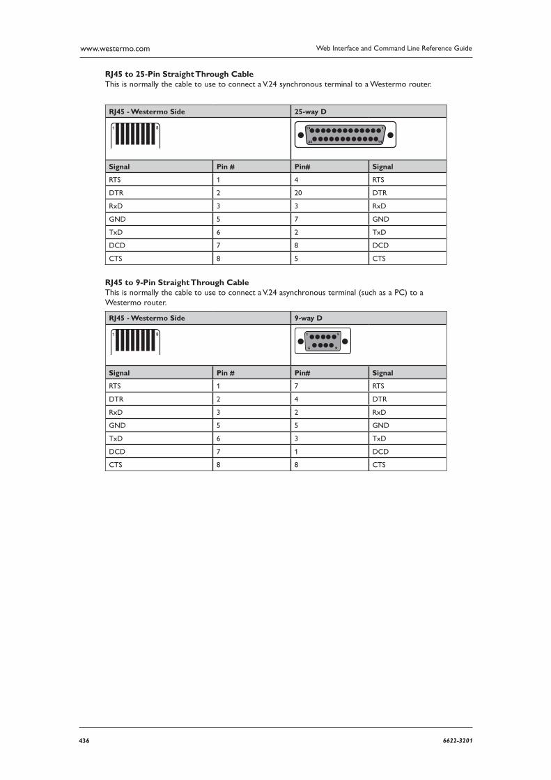
436 6622-3201
Web Interface and Command Line Reference Guidewww.westermo.com
RJ45 to 25-Pin Straight Through Cable This is normally the cable to use to connect a V.24 synchronous terminal to a Westermo router.
RJ45 - Westermo Side 25-way D
1 8 13
25 14
1
Signal Pin # Pin# Signal
RTS 1 4 RTS
DTR 2 20 DTR
RxD 3 3 RxD
GND 5 7 GND
TxD 6 2 TxD
DCD 7 8 DCD
CTS 8 5 CTS
RJ45 to 9-Pin Straight Through Cable This is normally the cable to use to connect a V.24 asynchronous terminal (such as a PC) to a Westermo router.
RJ45 - Westermo Side 9-way D
1 8 1
6 9
5
Signal Pin # Pin# Signal
RTS 1 7 RTS
DTR 2 4 DTR
RxD 3 2 RxD
GND 5 5 GND
TxD 6 3 TxD
DCD 7 1 DCD
CTS 8 8 CTS
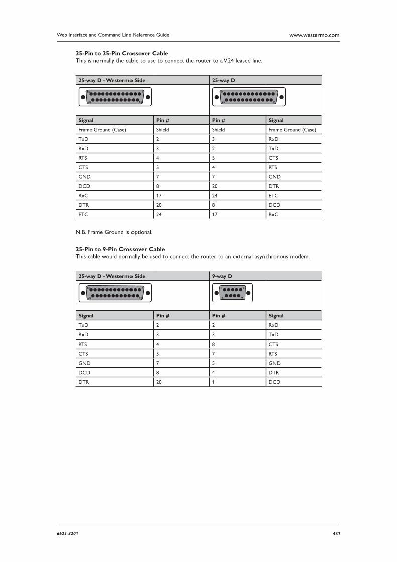
4376622-3201
Web Interface and Command Line Reference Guide www.westermo.com
25-Pin to 25-Pin Crossover Cable This is normally the cable to use to connect the router to a V.24 leased line.
25-way D - Westermo Side 25-way D
13
25 14
1 13
25 14
1
Signal Pin # Pin # Signal
Frame Ground (Case) Shield Shield Frame Ground (Case)
TxD 2 3 RxD
RxD 3 2 TxD
RTS 4 5 CTS
CTS 5 4 RTS
GND 7 7 GND
DCD 8 20 DTR
RxC 17 24 ETC
DTR 20 8 DCD
ETC 24 17 RxC
N.B. Frame Ground is optional.
25-Pin to 9-Pin Crossover Cable This cable would normally be used to connect the router to an external asynchronous modem.
25-way D - Westermo Side 9-way D
13
25 14
1 1
6 9
5
Signal Pin # Pin # Signal
TxD 2 2 RxD
RxD 3 3 TxD
RTS 4 8 CTS
CTS 5 7 RTS
GND 7 5 GND
DCD 8 4 DTR
DTR 20 1 DCD
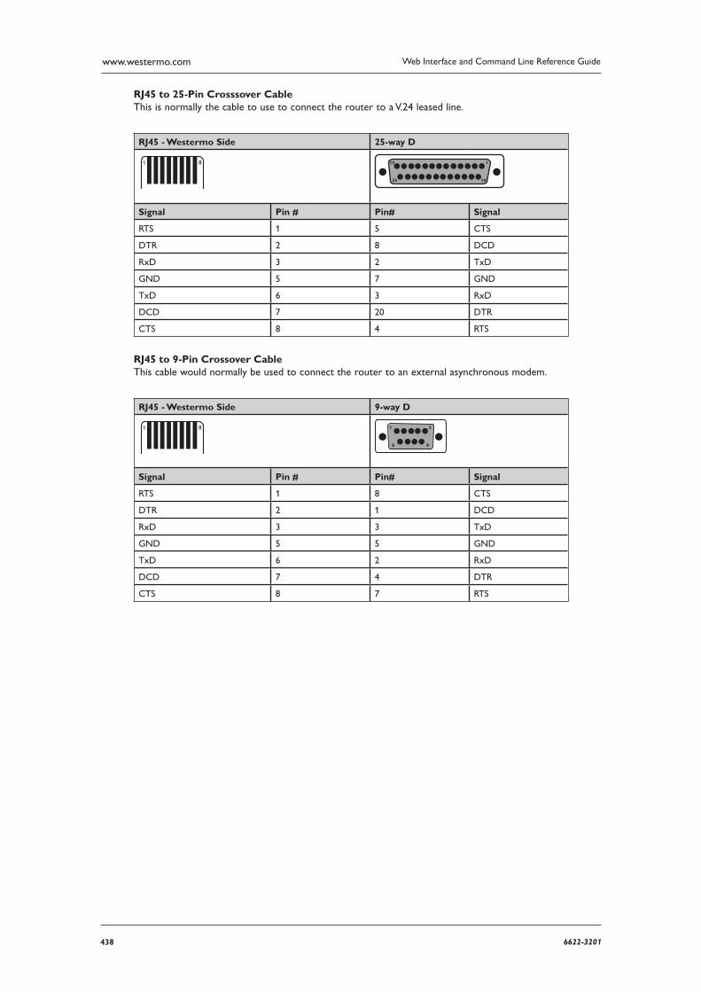
438 6622-3201
Web Interface and Command Line Reference Guidewww.westermo.com
RJ45 to 25-Pin Crosssover Cable This is normally the cable to use to connect the router to a V.24 leased line.
RJ45 - Westermo Side 25-way D
1 8 13
25 14
1
Signal Pin # Pin# Signal
RTS 1 5 CTS
DTR 2 8 DCD
RxD 3 2 TxD
GND 5 7 GND
TxD 6 3 RxD
DCD 7 20 DTR
CTS 8 4 RTS
RJ45 to 9-Pin Crossover Cable This cable would normally be used to connect the router to an external asynchronous modem.
RJ45 - Westermo Side 9-way D
1 8 1
6 9
5
Signal Pin # Pin# Signal
RTS 1 8 CTS
DTR 2 1 DCD
RxD 3 3 TxD
GND 5 5 GND
TxD 6 2 RxD
DCD 7 4 DTR
CTS 8 7 RTS
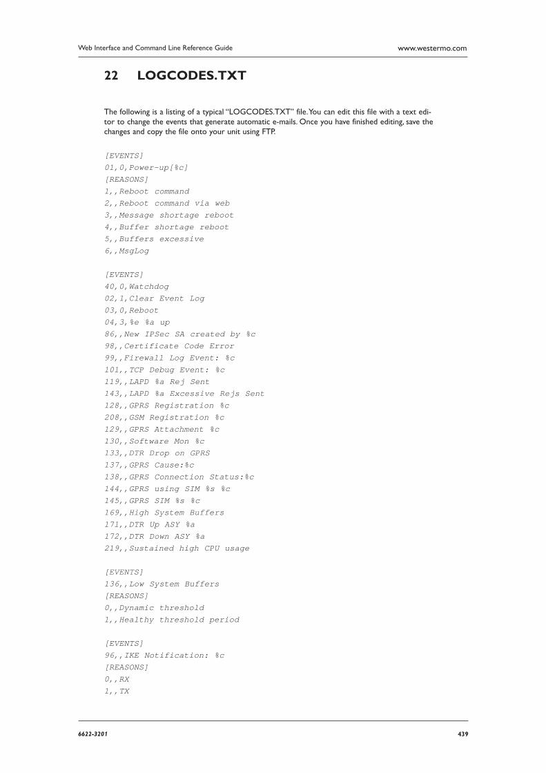
4396622-3201
Web Interface and Command Line Reference Guide www.westermo.com
LOGCODES.TXT22
The following is a listing of a typical “LOGCODES.TXT” file. You can edit this file with a text edi-tor to change the events that generate automatic e-mails. Once you have finished editing, save the changes and copy the file onto your unit using FTP.
[EVENTS]01,0,Power-up[%c][REASONS]1,,Reboot command2,,Reboot command via web3,,Message shortage reboot4,,Buffer shortage reboot5,,Buffers excessive6,,MsgLog
[EVENTS]40,0,Watchdog02,1,Clear Event Log03,0,Reboot04,3,%e %a up86,,New IPSec SA created by %c98,,Certificate Code Error99,,Firewall Log Event: %c101,,TCP Debug Event: %c119,,LAPD %a Rej Sent143,,LAPD %a Excessive Rejs Sent128,,GPRS Registration %c208,,GSM Registration %c129,,GPRS Attachment %c130,,Software Mon %c133,,DTR Drop on GPRS137,,GPRS Cause:%c138,,GPRS Connection Status:%c144,,GPRS using SIM %s %c145,,GPRS SIM %s %c169,,High System Buffers171,,DTR Up ASY %a172,,DTR Down ASY %a219,,Sustained high CPU usage
[EVENTS]136,,Low System Buffers[REASONS]0,,Dynamic threshold1,,Healthy threshold period
[EVENTS]96,,IKE Notification: %c[REASONS]0,,RX1,,TX
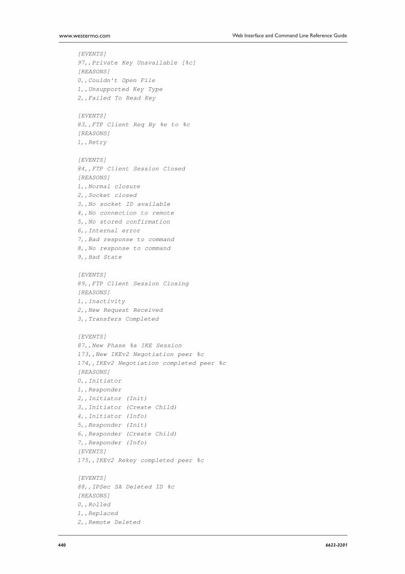
440 6622-3201
Web Interface and Command Line Reference Guidewww.westermo.com
[EVENTS]97,,Private Key Unavailable [%c][REASONS]0,,Couldn’t Open File1,,Unsupported Key Type2,,Failed To Read Key
[EVENTS]83,,FTP Client Req By %e to %c[REASONS]1,,Retry
[EVENTS]84,,FTP Client Session Closed[REASONS]1,,Normal closure2,,Socket closed3,,No socket ID available4,,No connection to remote5,,No stored confirmation6,,Internal error7,,Bad response to command8,,No response to command9,,Bad State
[EVENTS]89,,FTP Client Session Closing[REASONS]1,,Inactivity2,,New Request Received3,,Transfers Completed
[EVENTS]87,,New Phase %a IKE Session173,,New IKEv2 Negotiation peer %c174,,IKEv2 Negotiation completed peer %c[REASONS]0,,Initiator1,,Responder2,,Initiator (Init)3,,Initiator (Create Child)4,,Initiator (Info)5,,Responder (Init)6,,Responder (Create Child)7,,Responder (Info)[EVENTS]175,,IKEv2 Rekey completed peer %c
[EVENTS]88,,IPSec SA Deleted ID %c[REASONS]0,,Rolled1,,Replaced2,,Remote Deleted
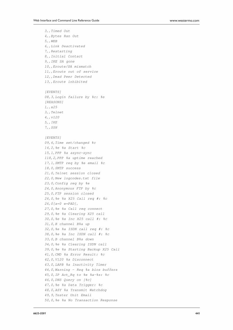
4416622-3201
Web Interface and Command Line Reference Guide www.westermo.com
3,,Timed Out4,,Bytes Ran Out5,,WEB6,,Link Deactivated7,,Restarting8,,Initial Contact9,,IKE SA gone10,,Eroute/SA mismatch11,,Eroute out of service12,,Dead Peer Detected13,,Eroute inhibited
[EVENTS]08,3,Login failure by %c: %e[REASONS]1,,x253,,Telnet4,,v1205,,IKE7,,SSH
[EVENTS]09,6,Time set/changed %c14,2,%e %a Start %c15,1,PPP %a async-sync118,2,PPP %a uptime reached17,1,SMTP req by %e email %c18,0,SMTP success21,0,Telnet session closed22,0,New logcodes.txt file23,0,Config req by %e24,0,Anonymous FTP by %c25,0,FTP session closed26,0,%e %a X25 Call req #: %c26,0[a=0 e=PAD],27,0,%e %a Call req connect29,0,%e %a Clearing X25 call30,0,%e %a Inc X25 call #: %c31,0,B channel B%a up32,0,%e %a ISDN call req #: %c38,0,%e %a Inc ISDN call #: %c33,0,B channel B%a down34,0,%e %a Clearing ISDN call39,0,%e %a Starting Backup X25 Call41,0,CMD %a Error Result: %c42,0,V120 %a Disconnect43,0,LAPB %a Inactivity Timer44,0,Warning - Req %a bios buffers45,0,IP Act_Rq to %e %a-%s: %c46,0,DNS Query on [%c]47,0,%e %a Data Trigger: %c48,0,ASY %a Transmit Watchdog49,9,Tester Unit Email50,0,%e %a No Transaction Response
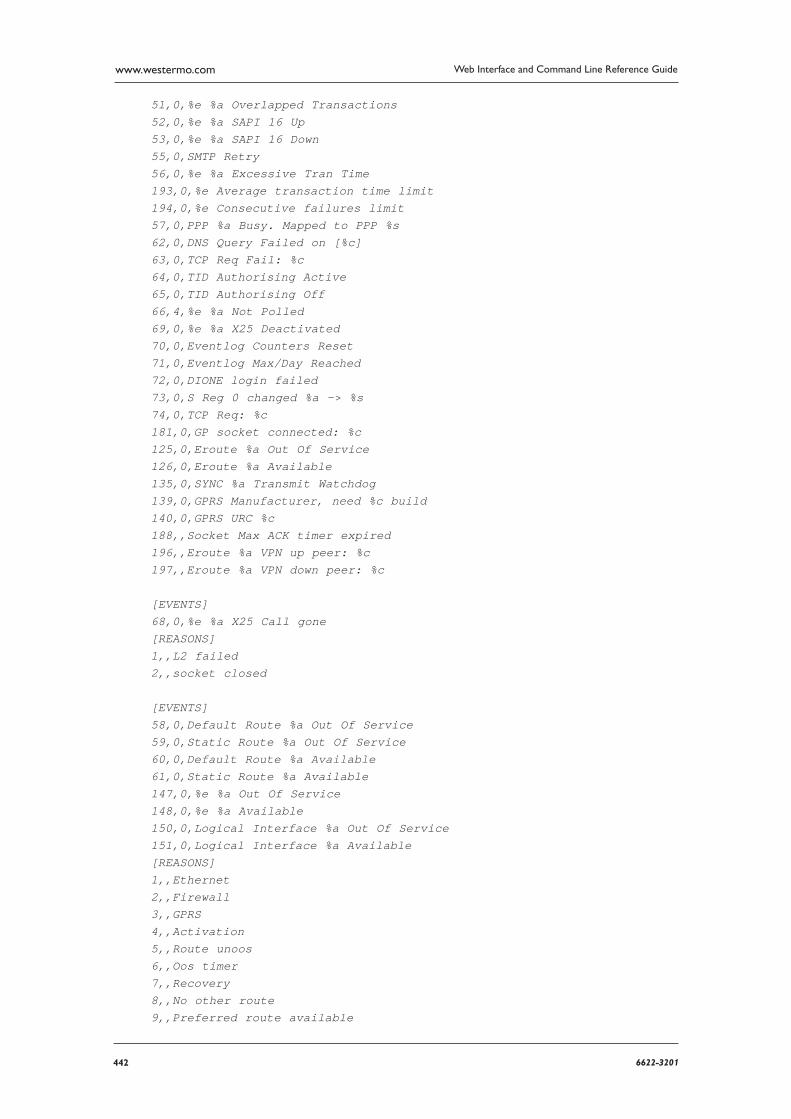
442 6622-3201
Web Interface and Command Line Reference Guidewww.westermo.com
51,0,%e %a Overlapped Transactions52,0,%e %a SAPI 16 Up53,0,%e %a SAPI 16 Down55,0,SMTP Retry56,0,%e %a Excessive Tran Time193,0,%e Average transaction time limit194,0,%e Consecutive failures limit57,0,PPP %a Busy. Mapped to PPP %s62,0,DNS Query Failed on [%c]63,0,TCP Req Fail: %c64,0,TID Authorising Active65,0,TID Authorising Off66,4,%e %a Not Polled69,0,%e %a X25 Deactivated70,0,Eventlog Counters Reset71,0,Eventlog Max/Day Reached72,0,DIONE login failed73,0,S Reg 0 changed %a -> %s74,0,TCP Req: %c181,0,GP socket connected: %c125,0,Eroute %a Out Of Service126,0,Eroute %a Available135,0,SYNC %a Transmit Watchdog139,0,GPRS Manufacturer, need %c build140,0,GPRS URC %c188,,Socket Max ACK timer expired196,,Eroute %a VPN up peer: %c197,,Eroute %a VPN down peer: %c
[EVENTS]68,0,%e %a X25 Call gone[REASONS]1,,L2 failed2,,socket closed
[EVENTS]58,0,Default Route %a Out Of Service59,0,Static Route %a Out Of Service60,0,Default Route %a Available61,0,Static Route %a Available147,0,%e %a Out Of Service148,0,%e %a Available150,0,Logical Interface %a Out Of Service151,0,Logical Interface %a Available[REASONS]1,,Ethernet2,,Firewall3,,GPRS4,,Activation5,,Route unoos6,,Oos timer7,,Recovery8,,No other route9,,Preferred route available

4436622-3201
Web Interface and Command Line Reference Guide www.westermo.com
10,,All routes oos
[EVENTS]149,0,%e %a Recovery Completed[REASONS]1,0,PING2,0,TCP
[EVENTS]75,7,%e alarm, machine %s, %c[REASONS]01,7, Failed02,7, Error detected03,7, Empty04,7, Critical05,7, Soap empty, FAIL06,7, Errors during cycle,FAIL07,7, Too short08,0, Error ignored09,7, No critical segment,FAIL10,7, Comms failure, FAIL11,7, Comms failure12,7, Crit tolerance exceeded13,7, Gen tolerance exceeded51,0, Failed52,0, Error detected53,0, Empty54,0, Critical55,0, Soap empty, FAIL56,0, Errors during cycle,FAIL57,0, Too short58,0, Error ignored59,0, No critical segment,FAIL60,0, Comms failure, FAIL61,0, Comms failure62,0, Crit tolerance exceeded63,0, Gen tolerance exceeded
[EVENTS]131,7,Dryer fault, D%s[REASONS]00,7, Unknown fault02,7, Exhaust high limit03,7, Fuse #204,7, Exhaust high temp05,7, Sail switch closed06,7, Sail switch open07,7, Burner high limit08,7, Burner purge09,7, Burner valve10,7, Burner ignition control11,7, Rotation12,7, Low voltage13,7, Model error

444 6622-3201
Web Interface and Command Line Reference Guidewww.westermo.com
14,7, Exhaust probe15,7, Axial probe16,7, Ignition17,7, Flame18,7, S.A.F.E. activated25,7, Drying and S.A.F.E. disabled
[EVENTS]176,7,Room O3 Level %c[REASONS]01,7, WARNING02,7, ALARM51,0, WARNING52,0, ALARM
[EVENTS]77,0,%e %a Connection Opened %c78,0,%e %a Connection Closed85,0,%e %a Orderly Shutdown81,0,V110 User Rate %c
[EVENTS]102,0,IP Backup On: %c[REASONS]0,,Local Conn. Failed1,,Rx Remote Indication
[EVENTS]103,0,IP Backup Off: %c[REASONS]0,,Local Conn. Succeeded1,,Chained Address2,,No RX Remote Indication3,,RX Remote Indication4,,Config Change
[EVENTS]67,0,TPAD %a TID change %c[REASONS]01,,Login02,,Ready03,,Abort04,,Conflict Removal
[EVENTS]05,0,%e %a down[REASONS]01,,Inactivity02,,Remote disconnect03,,LL disconnect04,,Upper layer req05,2,Negotiation failure06,6,Retransmit failure07,,DISC transmit

4456622-3201
Web Interface and Command Line Reference Guide www.westermo.com
08,5,TEI failure09,5,TEI lost10,,Lower deactivated11,,DISC receive12,,B Channel clr13,,Protocol failure14,,PPP PING Failure15,,PPP TX Link Failure16,,Call Req Timeout17,,LCP Echo Failure18,,Rebooting19,,Firewall Request20,,Timeband Off21,,Max up time22,,Max negotiation time23,,LL remote disconnect
[EVENTS]07,0,%e Login OK by %c lvl %s[REASONS]01,,X2503,,TELNET04,,V1207,,SSH
[EVENTS]10,0,Username %a change to ’%c’11,0,Password %a change12,0,Hostname change to ’%c’[REASONS]01,,WEB02,,CMD03,,SNMP
[EVENTS]13,4,WEB restart[REASONS]01,,BALLOC fail
[EVENTS]16,0,Event delay[REASONS]01,,Logger busy
[EVENTS]19,2,SMTP reject %e[REASONS]01,,SMTP busy02,,NULL template03,,Recd unexpected data04,,No Destination Address
[EVENTS]20,2,SMTP err %c

446 6622-3201
Web Interface and Command Line Reference Guidewww.westermo.com
[REASONS]01,,No connection02,,Socket err03,,Link err04,,Bad Response From Remote05,,No Recipient06,,Can’t Resolve Hostname07,,No Reply From Host08,,Unable To Bind To Socket09,,Template Unavailable10,,Can’t Open Template11,,Buffer Shortage12,,Error Sending Attachment
[EVENTS]28,0,%e %a X25 call cleared[REASONS]01,,Busy09,,Out of order17,,Rem proc err19,,Local proc err25,,Rev charg not acc33,,Incom dest41,,Fast select not sup57,,Ship absent03,,Inv facility req08,,Access barred11,,Access barred05,,Net congestion13,,Not obtainable21,,RPOA out of order128,,No response to Call129,,Restarted.130,,No buffers.131,,No LCNs
[EVENTS]36,0,%e %a ISDN Call Cleared[REASONS]01,,Unallocated03,,No route to dest16,,Normal clearing17,,User busy18,,No user19,,No answer21,,Call rejected34,,No cct38,,Net oor44,,Req cct not av50,,Fac not sup57,,Bearer not auth58,,Bearer not avail63,,Service not avail88,,Incomp dest
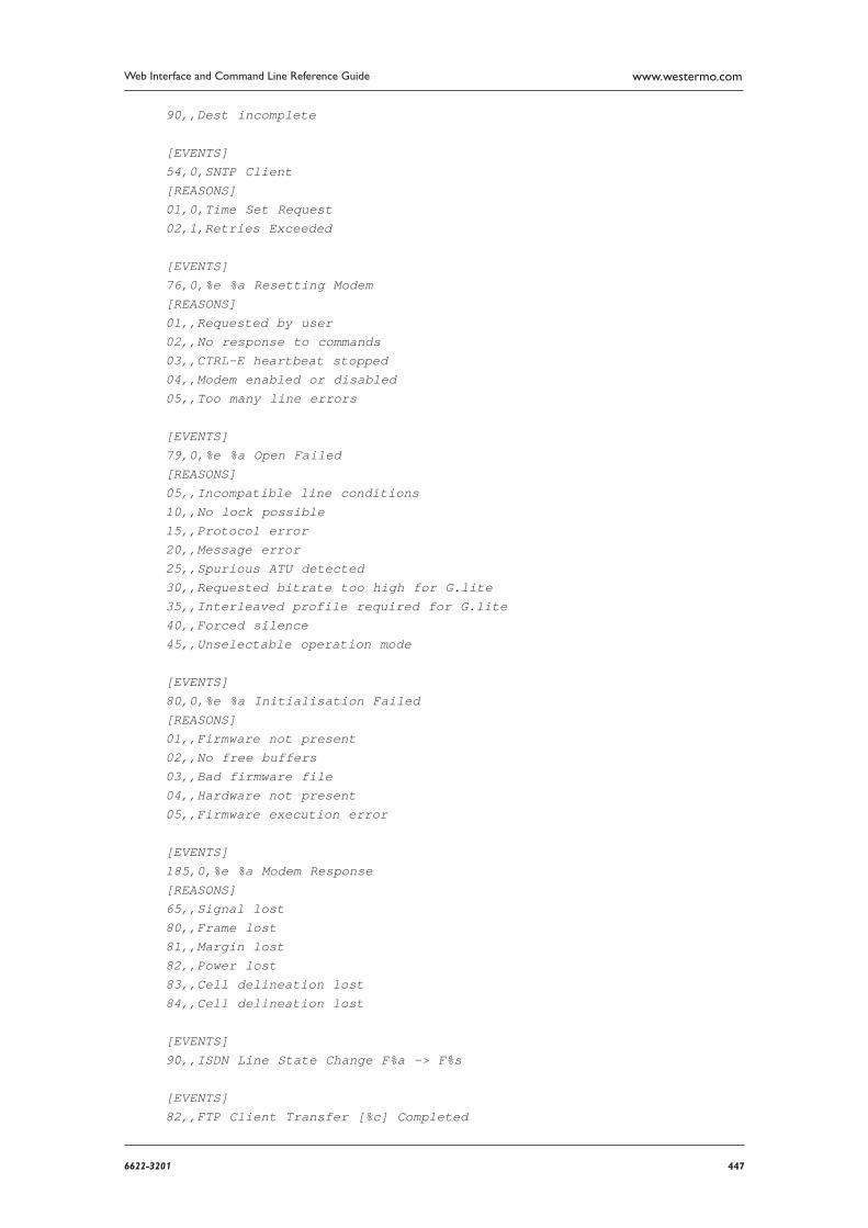
4476622-3201
Web Interface and Command Line Reference Guide www.westermo.com
90,,Dest incomplete
[EVENTS]54,0,SNTP Client[REASONS]01,0,Time Set Request02,1,Retries Exceeded
[EVENTS]76,0,%e %a Resetting Modem[REASONS]01,,Requested by user02,,No response to commands03,,CTRL-E heartbeat stopped04,,Modem enabled or disabled05,,Too many line errors
[EVENTS]79,0,%e %a Open Failed[REASONS]05,,Incompatible line conditions10,,No lock possible15,,Protocol error20,,Message error25,,Spurious ATU detected30,,Requested bitrate too high for G.lite35,,Interleaved profile required for G.lite40,,Forced silence45,,Unselectable operation mode
[EVENTS]80,0,%e %a Initialisation Failed[REASONS]01,,Firmware not present02,,No free buffers03,,Bad firmware file04,,Hardware not present05,,Firmware execution error
[EVENTS]185,0,%e %a Modem Response[REASONS]65,,Signal lost80,,Frame lost81,,Margin lost82,,Power lost83,,Cell delineation lost84,,Cell delineation lost
[EVENTS]90,,ISDN Line State Change F%a -> F%s
[EVENTS]82,,FTP Client Transfer [%c] Completed
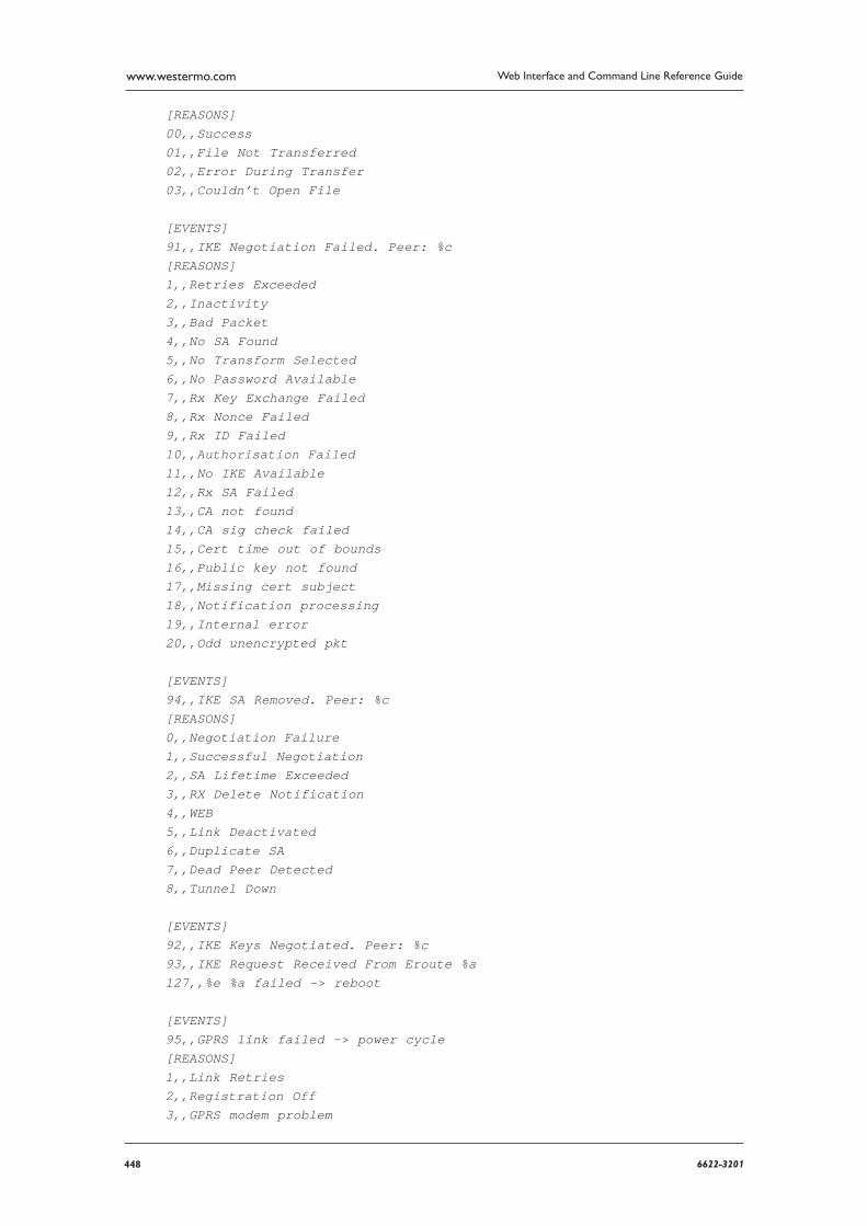
448 6622-3201
Web Interface and Command Line Reference Guidewww.westermo.com
[REASONS]00,,Success01,,File Not Transferred02,,Error During Transfer03,,Couldn’t Open File
[EVENTS]91,,IKE Negotiation Failed. Peer: %c[REASONS]1,,Retries Exceeded2,,Inactivity3,,Bad Packet4,,No SA Found5,,No Transform Selected6,,No Password Available7,,Rx Key Exchange Failed8,,Rx Nonce Failed9,,Rx ID Failed10,,Authorisation Failed11,,No IKE Available12,,Rx SA Failed13,,CA not found14,,CA sig check failed15,,Cert time out of bounds16,,Public key not found17,,Missing cert subject18,,Notification processing19,,Internal error20,,Odd unencrypted pkt
[EVENTS]94,,IKE SA Removed. Peer: %c[REASONS]0,,Negotiation Failure1,,Successful Negotiation2,,SA Lifetime Exceeded3,,RX Delete Notification4,,WEB5,,Link Deactivated6,,Duplicate SA7,,Dead Peer Detected8,,Tunnel Down
[EVENTS]92,,IKE Keys Negotiated. Peer: %c93,,IKE Request Received From Eroute %a127,,%e %a failed -> reboot
[EVENTS]95,,GPRS link failed -> power cycle[REASONS]1,,Link Retries2,,Registration Off3,,GPRS modem problem
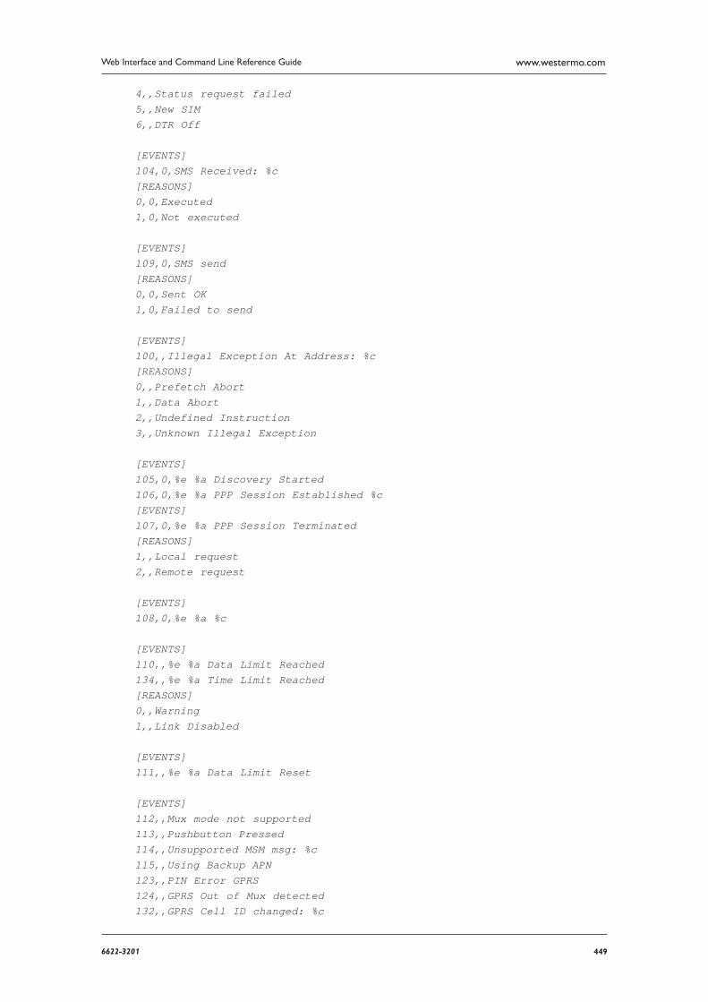
4496622-3201
Web Interface and Command Line Reference Guide www.westermo.com
4,,Status request failed5,,New SIM6,,DTR Off
[EVENTS]104,0,SMS Received: %c[REASONS]0,0,Executed1,0,Not executed
[EVENTS]109,0,SMS send[REASONS]0,0,Sent OK1,0,Failed to send
[EVENTS]100,,Illegal Exception At Address: %c[REASONS]0,,Prefetch Abort1,,Data Abort2,,Undefined Instruction3,,Unknown Illegal Exception
[EVENTS]105,0,%e %a Discovery Started106,0,%e %a PPP Session Established %c[EVENTS]107,0,%e %a PPP Session Terminated[REASONS]1,,Local request2,,Remote request
[EVENTS]108,0,%e %a %c
[EVENTS]110,,%e %a Data Limit Reached134,,%e %a Time Limit Reached[REASONS]0,,Warning1,,Link Disabled
[EVENTS]111,,%e %a Data Limit Reset
[EVENTS]112,,Mux mode not supported113,,Pushbutton Pressed114,,Unsupported MSM msg: %c115,,Using Backup APN123,,PIN Error GPRS124,,GPRS Out of Mux detected132,,GPRS Cell ID changed: %c
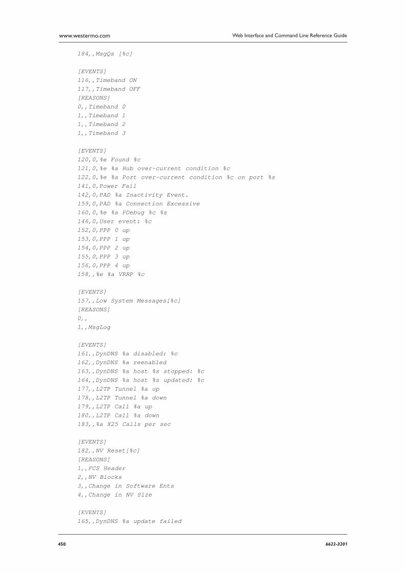
450 6622-3201
Web Interface and Command Line Reference Guidewww.westermo.com
184,,MsgQs [%c]
[EVENTS]116,,Timeband ON117,,Timeband OFF[REASONS]0,,Timeband 01,,Timeband 11,,Timeband 21,,Timeband 3
[EVENTS]120,0,%e Found %c121,0,%e %a Hub over-current condition %c122,0,%e %a Port over-current condition %c on port %s141,0,Power Fail142,0,PAD %a Inactivity Event.159,0,PAD %a Connection Excessive160,0,%e %a PDebug %c %s146,0,User event: %c152,0,PPP 0 up153,0,PPP 1 up154,0,PPP 2 up155,0,PPP 3 up156,0,PPP 4 up158,,%e %a VRRP %c
[EVENTS]157,,Low System Messages[%c][REASONS]0,,1,,MsgLog
[EVENTS]161,,DynDNS %a disabled: %c162,,DynDNS %a reenabled163,,DynDNS %a host %s stopped: %c164,,DynDNS %a host %s updated: %c177,,L2TP Tunnel %a up178,,L2TP Tunnel %a down179,,L2TP Call %a up180,,L2TP Call %a down183,,%a X25 Calls per sec
[EVENTS]182,,NV Reset[%c][REASONS]1,,FCS Header2,,NV Blocks3,,Change in Software Ents4,,Change in NV Size
[EVENTS]165,,DynDNS %a update failed

4516622-3201
Web Interface and Command Line Reference Guide www.westermo.com
[REASONS]1,,No connection2,,Socket didn’t close3,,Response too large
4,,No response[EVENTS]166,,Mobitex network contact %c167,,Mobitex IAS connection %c168,,Mobitex modem status
[REASONS]1,,DIE mode2,,LIVE mode4,,MANUAL mode10,,Reception buffer full11,,Reception buffer free12,,Transmission buffer full13,,Transmission buffer free16,,Returned cmd during DIE mode17,,Returned cmd during SPEECH mode18,,Returned cmd during MANUAL mode19,,MPAK returned22,,Login denied; duplicate MAN23,,Login denied; FLEXLIST full24,,Sender MAN invalid81,,Illegal MPAK type82,,Illegal MPAK state83,,Illegal MPAK flags84,,Illegal sendlist85,,Illegal MPAK length86,,Illegal MPAK addressee97,,TEMP_DEFAULT_LIST incorrect98,,MPAK returned on cmd99,,Power save mode101,,Mode change already activated160,,Tx buffer full (2)224,,Radio Tx failure240,,Tx queue full253,,Other error
[EVENTS]187,,VXN error: %c[REASONS]0,,OPNS1,,Transaction2,,SynchKey
[EVENTS]189,,USB device %a connected: %c190,,USB device %a disconnected191,,ASY %a assigned to %c192,,ASY %a unassigned195,,ADSL line: %c
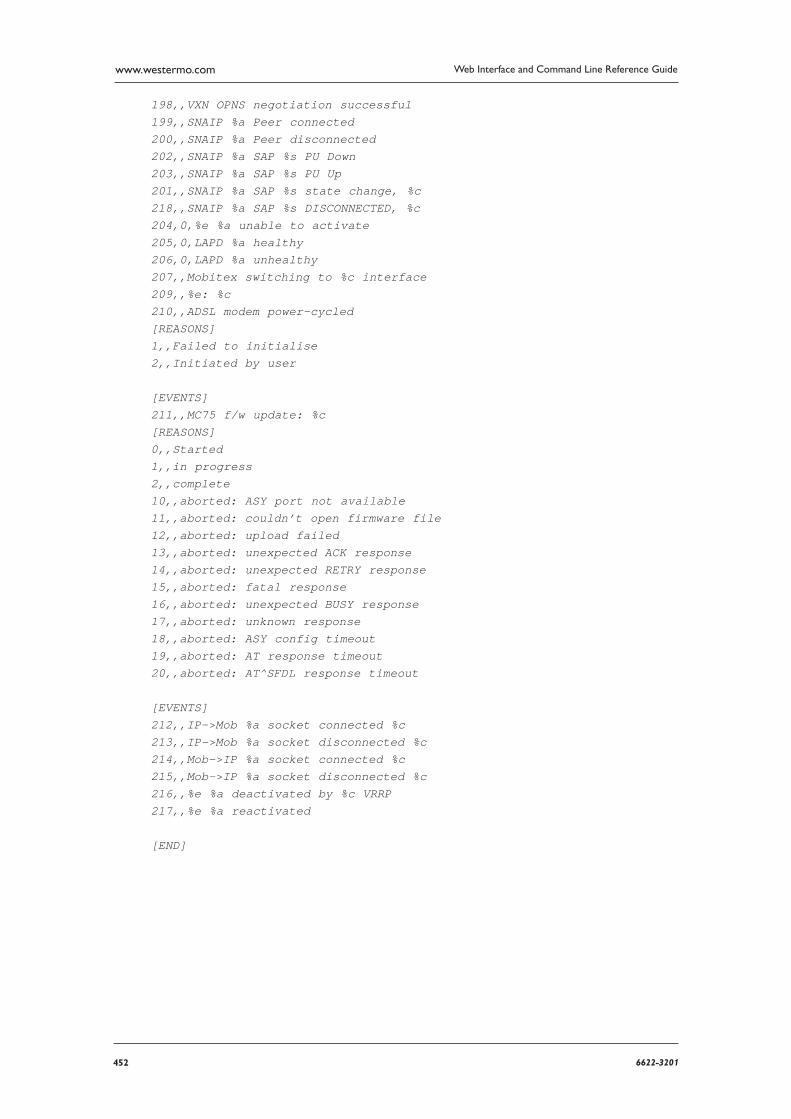
452 6622-3201
Web Interface and Command Line Reference Guidewww.westermo.com
198,,VXN OPNS negotiation successful199,,SNAIP %a Peer connected200,,SNAIP %a Peer disconnected202,,SNAIP %a SAP %s PU Down203,,SNAIP %a SAP %s PU Up201,,SNAIP %a SAP %s state change, %c218,,SNAIP %a SAP %s DISCONNECTED, %c204,0,%e %a unable to activate205,0,LAPD %a healthy206,0,LAPD %a unhealthy207,,Mobitex switching to %c interface209,,%e: %c210,,ADSL modem power-cycled[REASONS]1,,Failed to initialise2,,Initiated by user
[EVENTS]211,,MC75 f/w update: %c[REASONS]0,,Started1,,in progress2,,complete10,,aborted: ASY port not available11,,aborted: couldn’t open firmware file12,,aborted: upload failed13,,aborted: unexpected ACK response14,,aborted: unexpected RETRY response15,,aborted: fatal response16,,aborted: unexpected BUSY response17,,aborted: unknown response18,,aborted: ASY config timeout19,,aborted: AT response timeout20,,aborted: AT^SFDL response timeout
[EVENTS]212,,IP->Mob %a socket connected %c213,,IP->Mob %a socket disconnected %c214,,Mob->IP %a socket connected %c215,,Mob->IP %a socket disconnected %c216,,%e %a deactivated by %c VRRP217,,%e %a reactivated
[END]
4536622-3201
Web Interface and Command Line Reference Guide www.westermo.com
Email Templates23
One of the principal features provided by the event log function is the ability to configure the unit to automatically generate and send an email alert message each time an event of a specified priority, or higher, occurs. The format of the message is determined by the email template specified in the Email Template parameter (normally EVENT.EML) in the Configure > Event Handler web page.
If the standard EVENT.EML template supplied with the unit is not suitable, you may create your own template. An email template is simply a text file that defines the appearance and content of the email messages generated by the event logger.
Template Structure 23.1
An email template consists of a header section followed by a body section. One or more blank lines separate the two sections.
The Header Section 23.1.1
The header section MUST contain the following three fields:
To:
This field is used to specify at least one recipient’s email address. Multiple addresses may be included and must be separated by a space, comma or semicolon character. For example:
To: [email protected], [email protected]; abc.def.co.uk
From:
The From: field is normally used to supply the email address of the sending unit but alternatively you may enter a simple string. For example:
From: IR2140
Subject:
The Subject: field should contain a string describing the subject of the email message.
Other Fields 23.1.2
In addition to the mandatory fields described above, the header section of an email may also contain one or more optional fields. Many such fields are defined in the relevant RFCs but there are some fields that the unit handles a little differently as described below. The unit will insert other fields as necessary if it is required to send attachments with the email
Reply To:
If the unit discovers that this field is not present in the email template, the unit will insert this field into the header. The string used for this field is that configured by the smtp 0 reply_to text command (or the Default Reply Address parameter in the Configure > SMTP web page). This allows for different reply addresses, and allows a simple way of using the same (easily configura-ble) reply address for all emails.
Date:
If this field is present in the header, the unit will insert the current date and time into the head-er. The date and time are values local to the unit and do not contain any time zone information.
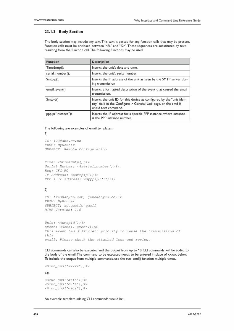
454 6622-3201
Web Interface and Command Line Reference Guidewww.westermo.com
Body Section 23.1.3
The body section may include any text. This text is parsed for any function calls that may be present. Function calls must be enclosed between “<%” and “%>”. These sequences are substituted by text resulting from the function call. The following functions may be used:
Function Description
TimeSmtp(); Inserts the unit’s date and time.
serial_number(); Inserts the unit’s serial number
Smtpip(); Inserts the IP address of the unit as seen by the SMTP server dur-ing trans mission
email_event() Inserts a formatted description of the event that caused the email transmis sion.
Smtpid() Inserts the unit ID for this device as configured by the “unit iden-tity” field in the Configure > General web page, or the cmd 0 unitid text command.
pppip(“instance”); Inserts the IP address for a specific PPP instance, where instance is the PPP instance number.
The following are examples of email templates.
1)
TO: [email protected]: MyRouterSUBJECT: Remote Configuration
Time: <%timeSmtp();%>Serial Number: <%serial_number();%>Req: CFG_RQIP Address: <%smtpip();%>PPP 1 IP address: <%pppip(“1”);%>
2)
TO: [email protected], [email protected]: MyRouterSUBJECT: automatic email MIME-Version: 1.0
Unit: <%smtpid();%>Event: <%email_event();%>This event had sufficient priority to cause the transmission of thisemail. Please check the attached logs and review.
CLI commands can also be executed and the output from up to 10 CLI commands will be added to the body of the email. The command to be executed needs to be entered in place of xxxxx below. To include the output from multiple commands, use the run_cmd() function multiple times.
<%run_cmd(“xxxxx”);%>
e.g.
<%run_cmd(“ati5”);%><%run_cmd(“bufs”);%><%run_cmd(“msgs”);%>
An example template adding CLI commands would be:
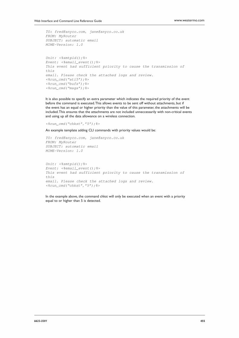
4556622-3201
Web Interface and Command Line Reference Guide www.westermo.com
TO: [email protected], [email protected]: MyRouterSUBJECT: automatic email MIME-Version: 1.0
Unit: <%smtpid();%>Event: <%email_event();%>This event had sufficient priority to cause the transmission of thisemail. Please check the attached logs and review.<%run_cmd(“ati5”);%><%run_cmd(“bufs”);%><%run_cmd(“msgs”);%>
It is also possible to specify an extra parameter which indicates the required priority of the event before the command is executed. This allows events to be sent off without attachments, but if the event has an equal or higher priority than the value of this parameter, the attachments will be included. This ensures that the attachments are not included unneccessarily with non-critical events and using up all the data allowance on a wireless connection.
<%run_cmd(“chkst”,”5”);%>
An example template adding CLI commands with priority values would be:
TO: [email protected], [email protected]: MyRouterSUBJECT: automatic email MIME-Version: 1.0
Unit: <%smtpid();%>Event: <%email_event();%>This event had sufficient priority to cause the transmission of thisemail. Please check the attached logs and review.<%run_cmd(“chkst”,”5”);%>
In the example above, the command chkst will only be executed when an event with a priority equal to or higher than 5 is detected.

456 6622-3201
Web Interface and Command Line Reference Guidewww.westermo.com
Glossary24
0 - 9
3DES Triple Data Encryption Standard
A
ACCM Asynchronous Communication Channel Multiplexer
ACFC Address Control Field Compression
ADSL Asymmetric Digital Subscriber Line
AES Advanced Encryption Standard
AFE Analogue Front End AH Authentication Header
AIS Alarm Indication Signal AODI Always On Dynamic ISDN
APACS Association of Payment Clearing Services, the UK payments association
APN Access Point Name
ATM Asynchronous Transfer Mode or Automatic Teller Machine
ARFCN Absolute Radio Frequency Channel Number
B
BACP Bandwidth Allocation and Control Protocol
BAP Bandwidth Allocation Protocol
BCC Base station Colour Code
BCCH Broadcast Control Channel
BGP Border Gateway Protocol
C
CA Certificate Authority
CHAP Challenge Handshake Authentication Protocol
CLI Calling Line Identification or Command Line Interface
CRC Cyclic Redundancy Code
CTS Clear To Send
CUD Call User Data
CUG Call User Group
D
DCE Data Communication Equipment
DER Distinguished Encoding Rules
DES Data Encryption Standard
DHCP Dynamic Host Configuration Protocol
DLSw Data-Link Switching DNS Domain Name Server
DPD Dead Peer Detection
DSCP Differentiated Services Code Point
DSL Digital Subscriber Line
DTE Data Terminal Equipment
DUN Dial-Up Networking

4576622-3201
Web Interface and Command Line Reference Guide www.westermo.com
E
EDGE Enhanced Data GSM Environment
ESP Encapsulating Security Payload protocol
F
FCS Frame Check Sequence
FEC Forward Error Correction
FIFO First In First Out
FQDN Fully Qualified Domain Name
FTP File Transfer Protocol
G
GPRS General Packet Radio System
GPS Global Positioning System
GRE Generic Routing Encapsulation
GSM Global System for Mobile Communications
H
HDLC High-Level Data Link Control
HEC Header Error Control HMAC Hash Message Authentication Code
HSDPA High Speed Downlink Packet Access
HSUPA High Speed Uplink Packet Access
I
ICMP Internet Control Message Protocol
IETF Internet Engineering Task Force
IGMP Internet Group Management Protocol
IGP Interior Gateway Protocol
IKE Internet Key Exchange
IMEI International Mobile Equipment Identification
IMSI International Mobile Subscriber Identity
IP Internet Protocol
IPCP Internet Protocol Control Protocol
IPSec Internet Protocol Security
ISAKMP Internet Security Association and Key Management Protocol
ISDN Integrated Services Digital Network
L
L2TP Layer 2 Tunnelling Protocol
LAC Location Area Code
LAI Location Area Identity
LAN Local Area Network
LAPB Link Access Procedure Balanced
LAPD Link Access Protocol D-channel
LCN Logical Channel Number
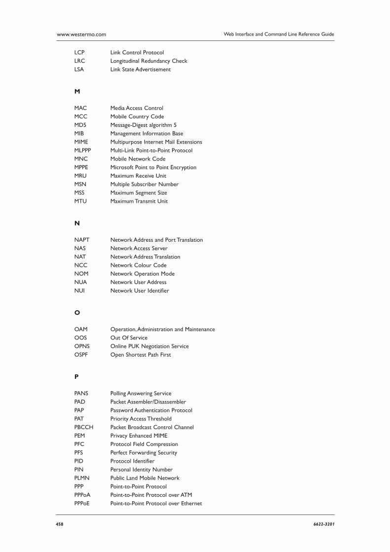
458 6622-3201
Web Interface and Command Line Reference Guidewww.westermo.com
LCP Link Control Protocol
LRC Longitudinal Redundancy Check
LSA Link State Advertisement
M
MAC Media Access Control
MCC Mobile Country Code
MD5 Message-Digest algorithm 5
MIB Management Information Base
MIME Multipurpose Internet Mail Extensions
MLPPP Multi-Link Point-to-Point Protocol
MNC Mobile Network Code
MPPE Microsoft Point to Point Encryption
MRU Maximum Receive Unit
MSN Multiple Subscriber Number
MSS Maximum Segment Size
MTU Maximum Transmit Unit
N
NAPT Network Address and Port Translation
NAS Network Access Server
NAT Network Address Translation
NCC Network Colour Code
NOM Network Operation Mode
NUA Network User Address
NUI Network User Identifier
O
OAM Operation, Administration and Maintenance
OOS Out Of Service
OPNS Online PUK Negotiation Service
OSPF Open Shortest Path First
P
PANS Polling Answering Service
PAD Packet Assembler/Disassembler
PAP Password Authentication Protocol
PAT Priority Access Threshold
PBCCH Packet Broadcast Control Channel
PEM Privacy Enhanced MIME
PFC Protocol Field Compression
PFS Perfect Forwarding Security
PID Protocol Identifier
PIN Personal Identity Number
PLMN Public Land Mobile Network
PPP Point-to-Point Protocol
PPPoA Point-to-Point Protocol over ATM
PPPoE Point-to-Point Protocol over Ethernet
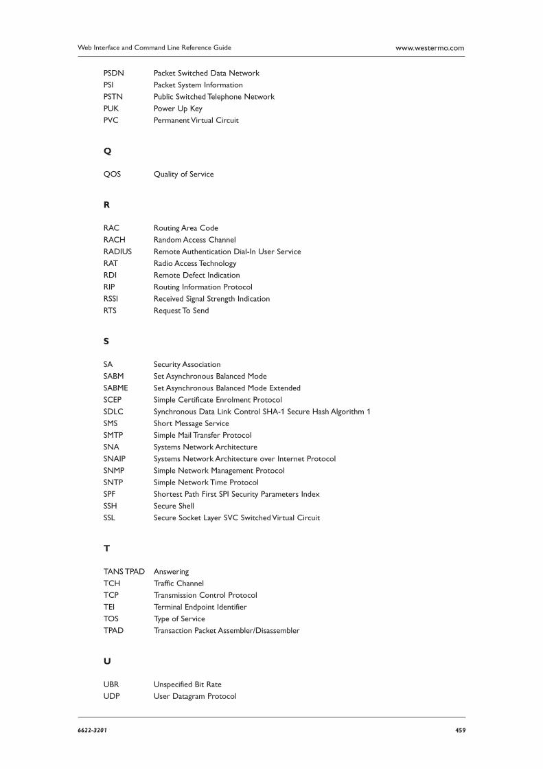
4596622-3201
Web Interface and Command Line Reference Guide www.westermo.com
PSDN Packet Switched Data Network
PSI Packet System Information
PSTN Public Switched Telephone Network
PUK Power Up Key
PVC Permanent Virtual Circuit
Q
QOS Quality of Service
R
RAC Routing Area Code
RACH Random Access Channel
RADIUS Remote Authentication Dial-In User Service
RAT Radio Access Technology
RDI Remote Defect Indication
RIP Routing Information Protocol
RSSI Received Signal Strength Indication
RTS Request To Send
S
SA Security Association
SABM Set Asynchronous Balanced Mode
SABME Set Asynchronous Balanced Mode Extended
SCEP Simple Certificate Enrolment Protocol
SDLC Synchronous Data Link Control SHA-1 Secure Hash Algorithm 1
SMS Short Message Service
SMTP Simple Mail Transfer Protocol
SNA Systems Network Architecture
SNAIP Systems Network Architecture over Internet Protocol
SNMP Simple Network Management Protocol
SNTP Simple Network Time Protocol
SPF Shortest Path First SPI Security Parameters Index
SSH Secure Shell
SSL Secure Socket Layer SVC Switched Virtual Circuit
T
TANS TPAD Answering
TCH Traffic Channel
TCP Transmission Control Protocol
TEI Terminal Endpoint Identifier
TOS Type of Service
TPAD Transaction Packet Assembler/Disassembler
U
UBR Unspecified Bit Rate
UDP User Datagram Protocol

460 6622-3201
Web Interface and Command Line Reference Guidewww.westermo.com
UMTS Universal Mobile Telecommunications System
USB Universal Serial Bus
V
VLAN Virtual Local Area Network
VPN Virtual Private Network
VRRP Virtual Router Redundancy Protocol
W
WAN Wide Area Network
WCDMA Wide-band Code-Division Multiple Access
WRED Weighted Random Early Dropping
W-WAN Wireless Wide Area Network
X
XOT X.25 Over TCP