command line interface (cli): hilcos rel. 10.34, 07/2021
TRANSCRIPT

Reference ManualCommand Line Interface (CLI) HiLCOS Rel. 10.34
RM CLI HiLCOS Release 10.34 07/2021
Technical support https://hirschmann-support.belden.com

The naming of copyrighted trademarks in this manual, even when not specially indicated, should not be taken to mean that these names may be considered as free in the sense of the trademark and tradename protection law and hence that they may be freely used by anyone.
© 2021 Hirschmann Automation and Control GmbH
Manuals and software are protected by copyright. All rights reserved. The copying, reproduction, translation, conversion into any electronic medium or machine scannable form is not permitted, either in whole or in part. An exception is the preparation of a backup copy of the software for your own use.
The performance features described here are binding only if they have been expressly agreed when the contract was made. This document was produced by Hirschmann Automation and Control GmbH according to the best of the company's knowledge. Hirschmann reserves the right to change the contents of this document without prior notice. Hirschmann can give no guarantee in respect of the correctness or accuracy of the information in this document.
Hirschmann can accept no responsibility for damages, resulting from the use of the network components or the associated operating software. In addition, we refer to the conditions of use specified in the license contract.
You can get the latest version of this manual on the Internet at the Hirschmann product site (www.doc.hirschmann.com).
Hirschmann Automation and Control GmbH Stuttgarter Str. 45-5172654 NeckartenzlingenGermany
Rel. 10.34 - 07/2021 2021-07-12
Contents
1 Introduction.............................................................................................24
1.2 Configuration with Telnet ......................................................................24
Open Telnet session...........................................................................24
Changing the console language.........................................................24
Close the Telnet session....................................................................24
Structure of the command-line interface............................................25
1.3 Commands for the console....................................................................25
Parameter overview for the ping command.......................................37
Parameter overview for the trace command......................................39
Overview of CAPWAP parameters with the show command.............41
Overview of IPv6-specific show commands.......................................43
Functions for editing commands........................................................47
Function keys for the command line..................................................48
1.4 Configuration with WEBconfig ..............................................................52
2 Setup........................................................................................................54
2.1 Name.....................................................................................................54
2.2 WAN......................................................................................................54
2.2.2 Dialup-Peers.............................................................................55
2.2.3 RoundRobin..............................................................................59
2.2.4 Layer.........................................................................................61
2.2.5 PPP...........................................................................................65
2.2.6 Incoming calling numbers.........................................................71
2.2.8 Scripts.......................................................................................72
RM CLI HiLCOS 3
Contents

2.2.9 Protect.......................................................................................74
2.2.10 Callback attempts....................................................................74
2.2.11 Router interface.......................................................................75
2.2.13 Manual dialing.........................................................................78
2.2.18 Backup-Delay-Seconds...........................................................79
2.2.19 DSL-Broadband-Peers............................................................79
2.2.20 IP-List......................................................................................84
2.2.21 PPTP peers.............................................................................88
2.2.22 RADIUS...................................................................................91
2.2.23 Polling table...........................................................................102
2.2.24 Backup peers........................................................................107
2.2.25 Action table...........................................................................108
2.2.26 MTU-List................................................................................115
2.2.30 Additional PPTP gateways....................................................116
2.2.31 PPTP source check...............................................................150
2.2.35 L2TP endpoints.....................................................................150
2.2.36 L2TP-Additional-Gateways...................................................155
2.2.37 L2TP-Peers...........................................................................178
2.2.38 L2TP source check...............................................................179
2.2.40 DS-Lite-Tunnel......................................................................180
2.2.50 EoGRE-Tunnel......................................................................182
2.2.51 GRE-Tunnel..........................................................................186
2.3 Charges...............................................................................................190
2.3.2 Days-per-Period......................................................................190
2.3.7 Time-Table...............................................................................191
2.3.8 DSL-Broadband-Minutes-Budget............................................192
2.3.9 Spare-DSL-Broadband-Minutes..............................................192
RM CLI HiLCOS 4
Contents

2.3.10 Router-DSL-Broadband-Budget............................................193
2.3.11 Reserve-DSL-Broadband-Budget.........................................193
2.3.12 Activate-Additional-Budget....................................................193
2.3.13 Dialup-Minutes-Budget..........................................................193
2.3.14 Spare-Dialup-Minutes...........................................................194
2.3.15 Dialup-Minutes-Active...........................................................194
2.3.16 Reset-Budgets......................................................................194
2.4 LAN......................................................................................................195
2.4.2 MAC-Address..........................................................................195
2.4.3 Heap-Reserve.........................................................................195
2.4.8 Trace-MAC..............................................................................195
2.4.9 Trace-Level.............................................................................196
2.4.10 IEEE802.1x...........................................................................196
2.4.11 Linkup-Report-Delay-ms.......................................................201
2.4.13.11.1 Interface bundling..........................................................201
2.7 TCP-IP.................................................................................................211
2.7.1 Operating................................................................................211
2.7.6 Access-List..............................................................................212
2.7.7 DNS-Default............................................................................213
2.7.8 DNS-Backup...........................................................................213
2.7.9 NBNS-Default..........................................................................214
2.7.10 NBNS-Backup.......................................................................214
2.7.11 ARP-Aging-Minutes...............................................................214
2.7.12 TCP-Aging-Minutes...............................................................215
2.7.13 TCP-Max.-Conn....................................................................215
2.7.16 ARP-Table.............................................................................216
2.7.17 Loopback-List........................................................................217
RM CLI HiLCOS 5
Contents
2.7.20 Non-Loc.-ARP-Replies..........................................................219
2.7.21 Alive-Test...............................................................................219
2.7.22 ICMP-on-ARP-Timeout.........................................................223
2.7.30 Network list............................................................................223
2.8 IP-Router.............................................................................................227
2.8.1 Operating................................................................................227
2.8.2 IP-Routing-Table.....................................................................228
2.8.5 Proxy-ARP..............................................................................231
2.8.6 Send-ICMP-Redirect...............................................................231
2.8.7 Routing-Method.......................................................................232
2.8.8 RIP..........................................................................................234
2.8.9 1-N-NAT..................................................................................254
2.8.10 Firewall..................................................................................264
2.8.11 Start-WAN-Pool.....................................................................298
2.8.12 End-WAN-Pool......................................................................298
2.8.13 Default-Time-List...................................................................299
2.8.14 Usage-Default-Timetable......................................................301
2.8.19 N-N-NAT................................................................................301
2.8.20 Load-Balancer.......................................................................303
2.8.21 VRRP....................................................................................311
2.8.22 WAN-Tag-Creation................................................................315
2.8.23 Tag-Table...............................................................................316
2.9 SNMP..................................................................................................319
2.9.1 Send-Traps..............................................................................320
2.9.2 IP-Traps...................................................................................320
2.9.3 Administrator...........................................................................322
2.9.4 Location...................................................................................322
RM CLI HiLCOS 6
Contents
2.9.5 Register-Monitor......................................................................322
2.9.6 Delete-Monitor.........................................................................323
2.9.7 Monitor-Table..........................................................................323
2.9.10 Password-Required-for-SNMP-Read-Access.......................326
2.9.11 Comment-1............................................................................326
2.9.12 Comment-2...........................................................................327
2.9.13 Comment-3...........................................................................327
2.9.14 Comment-4...........................................................................327
2.9.15 Read-Only-Community..........................................................328
2.9.16 Comment-5...........................................................................328
2.9.17 Comment-6...........................................................................328
2.9.17 Comment-7...........................................................................329
2.9.17 Comment-8...........................................................................329
2.9.20 Full host MIB.........................................................................329
2.9.21 Port........................................................................................330
2.9.22 Read-Only-Communities.......................................................330
2.9.23 Public-Comment-1................................................................331
2.9.24 Public-Comment-2................................................................331
2.9.25 Public-Comment-3................................................................332
2.9.26 Public-Comment-4................................................................332
2.10 DHCP................................................................................................333
2.10.6 Max.-Lease-Time-Minutes.....................................................333
2.10.7 Default-Lease-Time-Minutes.................................................333
2.10.8 DHCP-Table..........................................................................333
2.10.9 Hosts.....................................................................................336
2.10.10 Alias list...............................................................................338
2.10.18 Ports....................................................................................339
RM CLI HiLCOS 7
Contents
2.10.19 User-Class-Identifier...........................................................340
2.10.20 Network list..........................................................................341
2.10.21 Additional options................................................................350
2.10.22 Vendor-Class-Identifier........................................................352
2.11 Config.................................................................................................353
2.11.3 Password-Required-for-SNMP-Read-Access.......................353
2.11.4 Maximum connections...........................................................353
2.11.5 Config-Aging-Minutes............................................................354
2.11.6 Language...............................................................................354
2.11.7 Login-Error.............................................................................354
2.11.8 Lock-Minutes.........................................................................355
2.11.10 Display-Contrast..................................................................355
2.11.12 WLAN-Authentication-Pages-Only......................................356
2.11.15 Access table........................................................................356
2.11.16 Screen height......................................................................364
2.11.17 Prompt.................................................................................365
2.11.18 LED-Test..............................................................................365
2.11.20 Cron-Table...........................................................................366
2.11.21 Admins.................................................................................371
2.11.23 Telnet-Port...........................................................................374
2.11.25 SSH-Port.............................................................................375
2.11.26 SSH-Authentication-Methods..............................................375
2.11.27 Predef.-Admins....................................................................376
2.11.28 SSH.....................................................................................377
2.11.29 Telnet-SSL...........................................................................383
2.11.32 Reset-button........................................................................387
2.11.33 Outband-Aging-Minutes......................................................389
RM CLI HiLCOS 8
Contents

2.11.35 Monitor trace........................................................................389
2.11.39 License-Expiry-Email...........................................................390
2.11.40 Crash-Message...................................................................390
2.11.41 Admin-Gender.....................................................................390
2.11.42 Assert-Action.......................................................................391
2.11.43 Function keys......................................................................391
2.11.45 Configuration date...............................................................393
2.11.50 LL2M....................................................................................393
2.11.51 Sync.....................................................................................394
2.11.60 CPU-Load-Interval...............................................................405
2.11.65 Error aging minutes.............................................................405
2.11.73 Sort-menu............................................................................406
2.11.80 Authentication......................................................................406
2.11.81 Radius.................................................................................407
2.11.90 LED mode............................................................................413
2.11.91 LED off seconds..................................................................414
2.12 WLAN................................................................................................414
2.12.3 Heap-Reserve.......................................................................415
2.12.8 Access mode.........................................................................415
2.12.12 IAPP-Protocol......................................................................415
2.12.13 IAPP-Announce-Interval......................................................416
2.12.14 IAPP-Handover-Timeout.....................................................416
2.12.26 Inter-SSID-Traffic................................................................416
2.12.27 Supervise-Stations..............................................................417
2.12.29 RADIUS-Access-Check......................................................417
2.12.36 Country................................................................................425
2.12.38 ARP-Handling.....................................................................425
RM CLI HiLCOS 9
Contents
2.12.41 Mail-Address.......................................................................426
2.12.44 Allow-Illegal-Association-Without-Authentication................426
2.12.45 RADIUS-Accounting............................................................427
2.12.46 Indoor-Only-Operation........................................................433
2.12.47 Idle-Timeout........................................................................433
2.12.50 Signal averaging.................................................................434
2.12.51 Rate-Adaption.....................................................................435
2.12.60 IAPP-IP-Network.................................................................437
2.12.70 VLAN-Groupkey-Mapping...................................................437
2.12.80 Dual-Roaming.....................................................................438
2.12.85 PMK-Caching......................................................................439
2.12.86 Paket-Capture.....................................................................440
2.12.87 Band-Steering....................................................................442
2.12.88 Error-Monitoring..................................................................444
2.12.89 Access rules........................................................................447
2.12.100 Card-Reinit-Cycle..............................................................453
2.12.101 Noise-Calibration-Cycle....................................................453
2.12.103 Trace-MAC........................................................................453
2.12.105 Therm.-Recal.-Cycle.........................................................454
2.12.109 Noise-Offsets.....................................................................454
2.12.110 Trace-Level........................................................................456
2.12.111 Noise-Immunity..................................................................456
2.12.114 Aggregate retry limit..........................................................459
2.12.115 Omit-Global-Crypto-Sequence-Check...............................460
2.12.116 Trace-Packets...................................................................460
2.12.117 WPA-Handshake-Delay-ms...............................................460
2.12.118WPA-Handshake-Timeout-Override-ms.............................461
RM CLI HiLCOS 10
Contents

2.12.120 Rx-Aggregate-Flush-Timeout-ms......................................461
2.12.121 HT-Fairness......................................................................462
2.12.124 Trace-Mgmt-Packets.........................................................462
2.12.125 Trace-Data-Packets..........................................................463
2.12.130 DFS...................................................................................463
2.12.248 Wireless-IDS.....................................................................471
2.12.249 WLAN link status log.........................................................499
2.12.250 Roaming-Statistics-Timeout..............................................505
2.12.251 Prioritized-Channel-Scan..................................................505
2.14 Time...................................................................................................507
2.14.1 Fetch-Method........................................................................507
2.14.2 Current-Time.........................................................................507
2.14.7 UTC-in-Seconds....................................................................508
2.14.10 Timezone.............................................................................508
2.14.11 Daylight-saving-time............................................................509
2.14.12 DST-clock-changes.............................................................509
2.14.13 Get-Time.............................................................................511
2.14.15 Holidays..............................................................................511
2.14.16 Timeframe...........................................................................512
2.15 LCR....................................................................................................514
2.15.1 Router-Usage........................................................................514
2.15.4 Time-List................................................................................514
2.16 NetBIOS............................................................................................517
2.16.1 Operating..............................................................................517
2.16.2 Scope-ID...............................................................................518
2.16.4 Peers.....................................................................................518
2.16.5 Group list...............................................................................519
RM CLI HiLCOS 11
Contents
2.16.6 Host List................................................................................521
2.16.7 Server-List.............................................................................523
2.16.8 Watchdogs............................................................................526
2.16.9 Update...................................................................................526
2.16.10 WAN-Update-Minutes.........................................................527
2.16.11 Lease time...........................................................................527
2.16.12 Networks.............................................................................527
2.16.13 Browser-List........................................................................528
2.16.14 Support-Browsing................................................................531
2.17 DNS...................................................................................................531
2.17.1 Operating..............................................................................531
2.17.2 Domain..................................................................................532
2.17.3 DHCP-Usage........................................................................532
2.17.4 NetBIOS-Usage....................................................................532
2.17.5 DNS-List................................................................................533
2.17.6 Filter-List...............................................................................534
2.17.7 Lease time.............................................................................537
2.17.8 Dyn.-DNS-List.......................................................................537
2.17.9 DNS-Destinations..................................................................538
2.17.10 Service-Location-List...........................................................540
2.17.11 Dynamic-SRV-List...............................................................541
2.17.12 Resolve-Domain..................................................................542
2.17.13 Sub-Domains......................................................................542
2.17.14 Forwarder............................................................................543
2.17.15 Tag-Configuration................................................................544
2.18 Accounting.........................................................................................547
2.18.1 Operating..............................................................................547
RM CLI HiLCOS 12
Contents

2.18.2 Save-to-Flashrom..................................................................547
2.18.3 Sort-by...................................................................................547
2.18.4 Current user..........................................................................548
2.18.5 Accounting-List......................................................................549
2.18.6 Delete-Accounting-List..........................................................550
2.18.8 Time-Snapshot......................................................................551
2.18.9 Last snapshot........................................................................553
2.18.10 Discriminator.......................................................................554
2.19 VPN...................................................................................................555
2.19.3 Isakmp...................................................................................555
2.19.4 Proposals..............................................................................559
2.19.5 Certificates-and-Keys............................................................570
2.19.7 Layer.....................................................................................573
2.19.8 Operating..............................................................................575
2.19.9 VPN-Peers............................................................................576
2.19.10 AggrMode-Proposal-List-Default.........................................582
2.19.11 AggrMode-IKE-Group-Default.............................................583
2.19.12 Additional-Gateways...........................................................583
2.19.13 MainMode-Proposal-List-Default.........................................604
2.19.14 MainMode-IKE-Group-Default.............................................604
2.19.16 NAT-T-Operating.................................................................605
2.19.17 Simple-Cert-RAS-Operating................................................606
2.19.19 QuickMode-Proposal-List-Default.......................................606
2.19.20 QuickMode-PFS-Group-Default..........................................606
2.19.21 QuickMode-Shorthold-Time-Default....................................607
2.19.22 Allow-Remote-Network-Selection.......................................607
2.19.23 Establish-SAs-Collectively..................................................608
RM CLI HiLCOS 13
Contents

2.19.24 Max-Concurrent-Connections.............................................609
2.19.25 Flexibler-ID-Comparison.....................................................609
2.19.26 NAT-T-Port-for-Rekeying....................................................610
2.19.27 SSL encapsulation allowed.................................................610
2.19.30 Anti-Replay-Window-Size...................................................610
2.20 LAN-Bridge........................................................................................611
2.20.1 Protocol-Version....................................................................611
2.20.2 Bridge-Priority.......................................................................611
2.20.4 Encapsulation-Table..............................................................612
2.20.5 Max-Age................................................................................613
2.20.6 Hello-Time.............................................................................613
2.20.7 Forward-Delay.......................................................................614
2.20.8 Isolierter-Mode......................................................................614
2.20.10 Protocol-Table.....................................................................614
2.20.11 Port-Data.............................................................................620
2.20.12 Aging-Time..........................................................................623
2.20.13 Priority-Mapping..................................................................624
2.20.20 Spannning-Tree...................................................................625
2.20.30 IGMP-Snooping...................................................................630
2.20.40 DHCP-Snooping..................................................................639
2.20.41 DHCPv6-Snooping..............................................................643
2.20.42 RA-Snooping.......................................................................648
2.20.43 PPPoE snooping.................................................................650
2.20.248 L2-Firewall.........................................................................654
2.21 HTTP.................................................................................................665
2.21.1 Document root.......................................................................665
2.21.2 Page headers........................................................................666
RM CLI HiLCOS 14
Contents

2.21.3 Font-Family...........................................................................666
2.21.5 Page headers........................................................................667
2.21.6 Error-Page-Style...................................................................667
2.21.7 Port........................................................................................667
2.21.9 Max-Tunnel-Connections......................................................668
2.21.10 Tunnel-Idle-Timeout............................................................668
2.21.11 Session-Timeout..................................................................668
2.21.13 Standard-Design.................................................................668
2.21.14 Show-device-information.....................................................669
2.21.15 HTTP-Compression............................................................670
2.21.16 Keep-Server-Ports-Open....................................................670
2.21.20 Rollout-Wizard.....................................................................672
2.21.21 Max-HTTP-Job-Count.........................................................678
2.21.30 File-Server...........................................................................678
2.21.40 SSL......................................................................................679
2.22 SYSLOG............................................................................................684
2.22.1 Operating..............................................................................684
2.22.2 SYSLOG table.......................................................................684
2.22.3 Facility-Mapper......................................................................687
2.22.4 Port........................................................................................688
2.22.5 Messages-Table-Order..........................................................688
2.22.8 Log-CLI-Changes..................................................................689
2.22.9 Max-Message-Age................................................................689
2.22.10 Remove-Old-Messages......................................................690
2.22.11 Max-Age-Unit.......................................................................690
2.22.12 Critical prio..........................................................................690
2.23 Interfaces...........................................................................................691
RM CLI HiLCOS 15
Contents
2.23.4 DSL.......................................................................................691
2.23.7 Modem mobile.......................................................................693
2.23.20 WLAN..................................................................................695
2.23.21 LAN-interfaces....................................................................793
2.23.30 Ethernet-Ports.....................................................................794
2.23.40 Modem................................................................................798
2.23.41 Mobile..................................................................................802
2.24 Public-Spot-Module...........................................................................811
2.24.1 Authentication-Mode.............................................................811
2.24.2 User-Table.............................................................................812
2.24.3 Provider-Table.......................................................................814
2.24.5 Traffic-Limit-Bytes.................................................................820
2.24.6 Server-Subdir........................................................................820
2.24.7 Accounting cycle...................................................................821
2.24.8 Page table.............................................................................821
2.24.9 Roaming-Secret....................................................................823
2.24.12 Communication port............................................................823
2.24.14 Idle-Timeout........................................................................824
2.24.15 Port table.............................................................................824
2.24.16 Auto-Cleanup-User-Table....................................................825
2.24.17 Provide-Server-Database....................................................825
2.24.18 Disallow-Multiple-Login.......................................................825
2.24.19 Add-User-Wizard.................................................................826
2.24.20 VLAN-Table.........................................................................837
2.24.21 Login-Page-Type.................................................................838
2.24.22 Device-Hostname................................................................838
2.24.23 MAC-Address-Table............................................................839
RM CLI HiLCOS 16
Contents

2.24.24 MAC-Address-Check-Provider............................................840
2.24.25 MAC-Address-Check-Cache-Time......................................840
2.24.26 Station-Table-Limit..............................................................841
2.24.30 Free-Server.........................................................................841
2.24.31 Free networks.....................................................................841
2.24.32 Free-Hosts-Minimum-TTL...................................................843
2.24.33 Login-Text............................................................................844
2.24.34 WAN-Connection.................................................................844
2.24.35 Print-Logo-And-Headerboard..............................................845
2.24.36User-Must-Accept-GTC........................................................845
2.24.37 Print-Logout-Link.................................................................846
2.24.40 XML-Interface......................................................................846
2.24.41 Authentication-Modules.......................................................848
2.24.42 WISPr..................................................................................873
2.24.43 Advertisement.....................................................................876
2.24.44 Manage user wizard............................................................881
2.24.47 Check origin VLAN..............................................................883
2.24.48 Circuit-IDs...........................................................................884
2.24.50 Auto-Re-Login.....................................................................885
2.24.60 Login-Text............................................................................887
2.25 RADIUS.............................................................................................888
2.25.4 Auth.-Timeout........................................................................888
2.25.5 Auth.-Retry............................................................................889
2.25.9 Backup-Query-Strategy.........................................................889
2.25.10 Server..................................................................................889
2.25.20 RADSEC.............................................................................931
2.26 NTP....................................................................................................935
RM CLI HiLCOS 17
Contents
2.26.2 Server-Operating...................................................................935
2.26.3 BC-Mode...............................................................................936
2.26.4 BC-Interval............................................................................936
2.26.7 RQ-Interval............................................................................937
2.26.11 RQ-Address.........................................................................937
2.26.12 RQ-Tries..............................................................................939
2.27 Mail....................................................................................................939
2.27.1 SMTP-Server........................................................................939
2.27.2 Serverport.............................................................................940
2.27.3 POP3-Server.........................................................................940
2.27.4 POP3-Port.............................................................................940
2.27.5 User name.............................................................................941
2.27.6 Password..............................................................................941
2.27.7 E-Mail-Sender.......................................................................941
2.27.8 Send again (min)...................................................................942
2.27.9 Hold time (hrs).......................................................................942
2.27.10 Buffers.................................................................................942
2.27.11 Loopback-Addr....................................................................943
2.27.12 SMTP-use-TLS...................................................................943
2.27.13 SMTP-Authentication..........................................................944
2.30 IEEE802.1x........................................................................................945
2.30.3 Radius-Server.......................................................................945
2.30.4 Ports......................................................................................949
2.31 PPPoE-Server...................................................................................953
2.31.1 Operating..............................................................................954
2.31.2 Name list...............................................................................954
2.31.3 Service..................................................................................955
RM CLI HiLCOS 18
Contents

2.31.4 Session-Limit.........................................................................955
2.31.5 Ports......................................................................................956
2.31.6 AC-Name..............................................................................957
2.32 VLAN.................................................................................................957
2.32.1 Networks...............................................................................957
2.32.2 Port-Table..............................................................................959
2.32.4 Operating..............................................................................962
2.32.5 Tag-Value..............................................................................962
2.34 Printer................................................................................................962
2.34.1 Printer....................................................................................963
2.34.2 Access-List............................................................................965
2.35 ECHO-Server....................................................................................966
2.35.1 Operating..............................................................................966
2.35.2 Access table..........................................................................967
2.35.3 TCP-Timeout.........................................................................968
2.36 Performance-Monitoring....................................................................969
2.36.2 RttMonAdmin........................................................................969
2.36.3 RttMonEchoAdmin................................................................970
2.36.4 RttMonStatistics....................................................................972
2.37 WLAN-Management..........................................................................978
2.37.1 AP-Configuration...................................................................978
2.37.5 CAPWAP-Port.....................................................................1142
2.37.6 Autoaccept-AP....................................................................1143
2.37.7 Accept-AP...........................................................................1144
2.37.8 Provide-default-configuration..............................................1145
2.37.9 Disconnect-AP....................................................................1146
2.37.10 Notification........................................................................1146
RM CLI HiLCOS 19
Contents

2.37.19 Start-automatic-radio-field-optimization............................1149
2.37.21 Access rules......................................................................1150
2.37.27 Central-Firmware-Management........................................1155
2.37.29 Allow WAN connections....................................................1161
2.37.30 Sync-WTP-Password........................................................1162
2.37.31 Interval-for-status-table-cleanup.......................................1162
2.37.32 License count....................................................................1162
2.37.33 License limit......................................................................1163
2.37.34 WLC cluster.......................................................................1163
2.37.35 RADIUS-Server-Profiles....................................................1169
2.37.36 CAPWAP-Operating..........................................................1174
2.37.37 Preference.........................................................................1175
2.37.40 Client Steering...................................................................1175
2.38 LLDP................................................................................................1181
2.38.1 Message-TX-Interval...........................................................1182
2.38.2 Message-Tx-Hold-Multiplier................................................1182
2.38.3 Reinit-Delay.........................................................................1183
2.38.4 Tx-Delay..............................................................................1183
2.38.5 Notification-Interval.............................................................1184
2.38.6 Ports....................................................................................1184
2.38.7 Management-Addresses.....................................................1188
2.38.8 Protocol...............................................................................1189
2.38.9 Immediate-Delete................................................................1190
2.38.10 Operating..........................................................................1190
2.39 Certificates.......................................................................................1191
2.39.1 SCEP-Client........................................................................1191
2.39.2 SCEP-CA............................................................................1205
RM CLI HiLCOS 20
Contents
2.39.3 CRLs...................................................................................1246
2.40 GPS.................................................................................................1249
2.40.1 Operating............................................................................1249
2.51 HiDiscovery.....................................................................................1250
2.51.1 Server-Operating.................................................................1250
2.52 COM-Ports.......................................................................................1250
2.52.1 Devices...............................................................................1251
2.52.2 COM-Port-Server................................................................1251
2.52.3 WAN....................................................................................1263
2.52.4 Serial configuration.............................................................1264
2.53 Temperature-Monitor.......................................................................1265
2.53.1 Upper-Limit-Degrees...........................................................1265
2.53.2 Lower-Limit-Degrees...........................................................1266
2.54 TACACS..........................................................................................1266
2.54.2 Authorization.......................................................................1266
2.54.3 Accounting..........................................................................1267
2.54.6 Shared-Secret.....................................................................1267
2.54.7 Encryption...........................................................................1267
2.54.9 Server..................................................................................1268
2.54.10 Fallback to local users.......................................................1269
2.54.11 SNMP-GET-Requests-Authorisation.................................1270
2.54.11 SNMP-GET-Requests-Accounting....................................1270
2.54.13 Bypass-Tacacs-for-CRON/scripts/action-table.................1271
2.54.14 Include-value-into-authorisation-request...........................1272
2.59 WLAN-Management........................................................................1272
2.59.1 Static-WLC-Configuration...................................................1272
2.59.3 CAPWAP-Tuning.................................................................1274
RM CLI HiLCOS 21
Contents

2.59.4 AutoWDS............................................................................1277
2.59.5 CAPWAP-Port.....................................................................1281
2.59.120 Log-Entries......................................................................1281
2.60 Autoload..........................................................................................1282
2.60.1 Network...............................................................................1282
2.60.56 USB...................................................................................1287
2.63 Packet-Capture................................................................................1289
2.63.1 LCOSCap-Operating...........................................................1289
2.63.2 LCOSCap-Port....................................................................1289
2.63.11 RPCap-Operating..............................................................1290
2.63.12 RPCap-Port.......................................................................1290
2.70 IPv6.................................................................................................1291
2.70.1 Tunnel.................................................................................1291
2.70.2 Router-Advertisement.........................................................1304
2.70.3 DHCPv6..............................................................................1323
2.70.4 Network...............................................................................1347
2.70.5 Firewall................................................................................1353
2.70.6 LAN-Interfaces....................................................................1384
2.70.7 WAN-Interfaces...................................................................1390
2.70.10 Operating..........................................................................1396
2.70.11 Forwarding.........................................................................1396
2.70.12 Router...............................................................................1397
2.70.13 ICMPv6.............................................................................1399
2.70.14 RAS interface....................................................................1401
2.80 Relays..............................................................................................1405
2.80.1 Relay1.................................................................................1405
2.80.2 Relay2.................................................................................1405
RM CLI HiLCOS 22
Contents
3 Firmware..............................................................................................1407
3.1 Version table......................................................................................1407
3.1.1 Ifc...........................................................................................1407
3.1.2 Module..................................................................................1407
3.1.3 Version..................................................................................1407
3.1.4 Serial number........................................................................1407
3.2 Table Firmsafe...................................................................................1408
3.2.1 Position.................................................................................1408
3.2.2 Status....................................................................................1408
3.2.3 Version..................................................................................1408
3.2.4 Date.......................................................................................1408
3.2.5 Size.......................................................................................1409
3.2.6 Index......................................................................................1409
3.3 Firmsafe mode...................................................................................1409
3.4 Timeout-Firmsafe...............................................................................1410
3.7 Feature-Word.....................................................................................1411
4 Other....................................................................................................1412
4.1 Manual dialing...................................................................................1412
4.1.1 Connect.................................................................................1412
4.1.2 Disconnect............................................................................1412
4.2 System-Boot......................................................................................1412
4.5 Cold boot...........................................................................................1413
4.7 Flash restore......................................................................................1413
RM CLI HiLCOS 23
Contents
1 Introduction
1.2 Configuration with Telnet
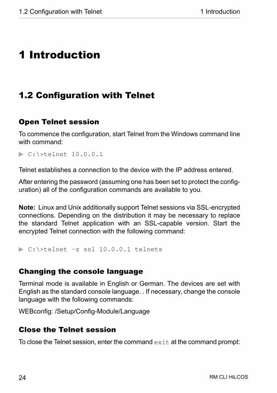
Open Telnet sessionTo commence the configuration, start Telnet from the Windows command linewith command:
D C:\>telnet 10.0.0.1
Telnet establishes a connection to the device with the IP address entered.
After entering the password (assuming one has been set to protect the config-uration) all of the configuration commands are available to you.
Note: Linux and Unix additionally support Telnet sessions via SSL-encryptedconnections. Depending on the distribution it may be necessary to replacethe standard Telnet application with an SSL-capable version. Start theencrypted Telnet connection with the following command:
D C:\>telnet -z ssl 10.0.0.1 telnets
Changing the console languageTerminal mode is available in English or German. The devices are set withEnglish as the standard console language. . If necessary, change the consolelanguage with the following commands:
WEBconfig: /Setup/Config-Module/Language
Close the Telnet sessionTo close the Telnet session, enter the command exit at the command prompt:
RM CLI HiLCOS 24
1.2 Configuration with Telnet 1 Introduction
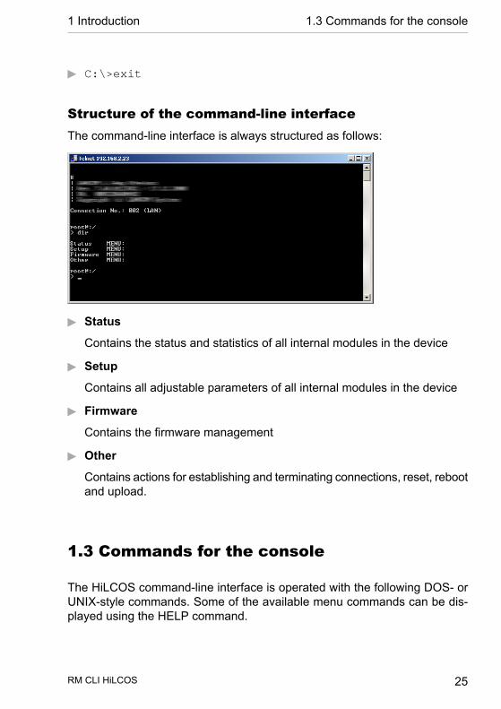
D C:\>exit
Structure of the command-line interfaceThe command-line interface is always structured as follows:
D Status
Contains the status and statistics of all internal modules in the device
D Setup
Contains all adjustable parameters of all internal modules in the device
D Firmware
Contains the firmware management
D Other
Contains actions for establishing and terminating connections, reset, rebootand upload.
1.3 Commands for the console
The HiLCOS command-line interface is operated with the following DOS- orUNIX-style commands. Some of the available menu commands can be dis-played using the HELP command.
RM CLI HiLCOS 25
1 Introduction 1.3 Commands for the console
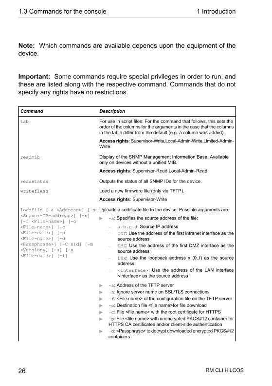
Note: Which commands are available depends upon the equipment of thedevice.
Important: Some commands require special privileges in order to run, andthese are listed along with the respective command. Commands that do notspecify any rights have no restrictions.
DescriptionCommand
For use in script files: For the command that follows, this sets theorder of the columns for the arguments in the case that the columnsin the table differ from the default (e.g. a column was added).
Access rights: Supervisor-Write,Local-Admin-Write,Limited-Admin-Write
tab
Display of the SNMP Management Information Base. Availableonly on devices without a unified MIB.
Access rights: Supervisor-Read,Local-Admin-Read
readmib
Outputs the status of all SNMP IDs for the device.readstatus
Load a new firmware file (only via TFTP).
Access rights: Supervisor-Write
writeflash
Uploads a certificate file to the device. Possible arguments are:loadfile [-a <Address>] [-s<Server-IP-address>] [-n]
D -a: Specifies the source address of the file:[-f <File-name>] [-o
– a.b.c.d: Source IP address<File-name>] [-c<File-name>] [-p – INT: Use the address of the first intranet interface as the
source address<File-name>] [-d<Passphrase>] [-C n|d] [-m – DMZ: Use the address of the first DMZ interface as the
source address<Version>] [-u] [-x<File-name>] [-i]
– LBx: Use the loopback address x (0..f) as the sourceaddress
– <Interface>: Use the address of the LAN interface<interface> as the source address
D -s: Address of the TFTP serverD -n: Ignore server name on SSL/TLS connectionsD -f: <File name> of the configuration file on the TFTP serverD -o: Destination file <file name>for file downloadD -c: File <file name> with the root certificate for HTTPSD -p: File <file name> with unencrypted PKCS#12 container for
HTTPS CA certificates and/or client-side authenticationD -d: <Passphrase> to decrypt downloaded encrypted PKCS#12
containers
RM CLI HiLCOS 26
1.3 Commands for the console 1 Introduction
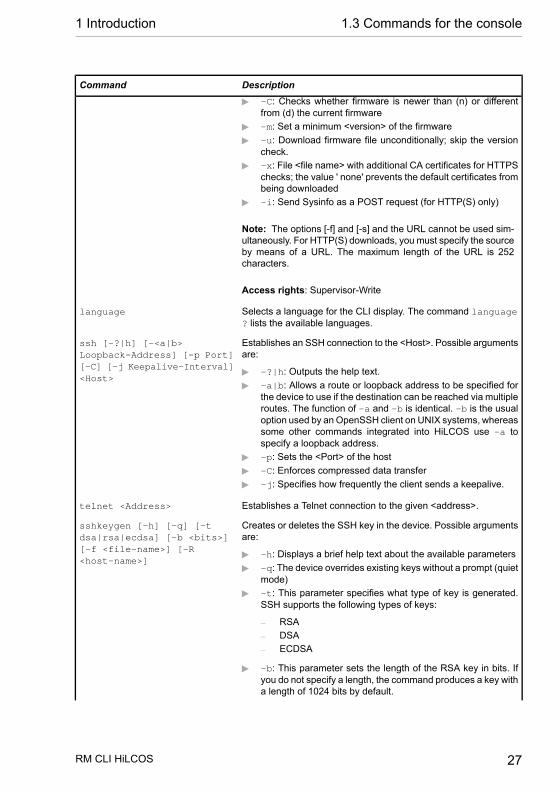
DescriptionCommand
D -C: Checks whether firmware is newer than (n) or differentfrom (d) the current firmware
D -m: Set a minimum <version> of the firmwareD -u: Download firmware file unconditionally; skip the version
check.D -x: File <file name> with additional CA certificates for HTTPS
checks; the value ' none' prevents the default certificates frombeing downloaded
D -i: Send Sysinfo as a POST request (for HTTP(S) only)
Note: The options [-f] and [-s] and the URL cannot be used sim-ultaneously. For HTTP(S) downloads, you must specify the sourceby means of a URL. The maximum length of the URL is 252characters.
Access rights: Supervisor-Write
Selects a language for the CLI display. The command language? lists the available languages.
language
Establishes an SSH connection to the <Host>. Possible argumentsare:
ssh [-?|h] [-<a|b>Loopback-Address] [-p Port][-C] [-j Keepalive-Interval]<Host>
D -?|h: Outputs the help text.D -a|b: Allows a route or loopback address to be specified for
the device to use if the destination can be reached via multipleroutes. The function of -a and -b is identical. -b is the usualoption used by an OpenSSH client on UNIX systems, whereassome other commands integrated into HiLCOS use -a tospecify a loopback address.
D -p: Sets the <Port> of the hostD -C: Enforces compressed data transferD -j: Specifies how frequently the client sends a keepalive.
Establishes a Telnet connection to the given <address>.telnet <Address>
Creates or deletes the SSH key in the device. Possible argumentsare:
sshkeygen [-h] [-q] [-tdsa|rsa|ecdsa] [-b <bits>][-f <file-name>] [-R<host-name>]
D -h: Displays a brief help text about the available parametersD -q: The device overrides existing keys without a prompt (quiet
mode)D -t: This parameter specifies what type of key is generated.
SSH supports the following types of keys:
– RSA– DSA– ECDSA
D -b: This parameter sets the length of the RSA key in bits. Ifyou do not specify a length, the command produces a key witha length of 1024 bits by default.
RM CLI HiLCOS 27
1 Introduction 1.3 Commands for the console
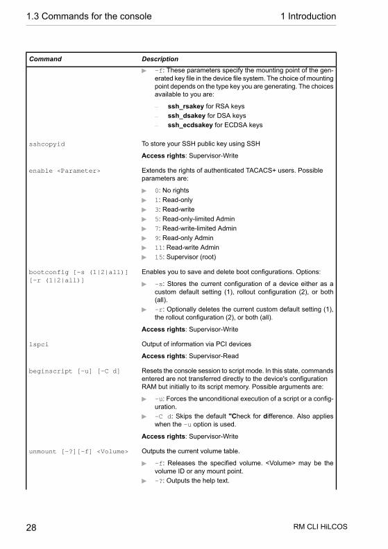
DescriptionCommand
D -f: These parameters specify the mounting point of the gen-erated key file in the device file system. The choice of mountingpoint depends on the type key you are generating. The choicesavailable to you are:
– ssh_rsakey for RSA keys– ssh_dsakey for DSA keys– ssh_ecdsakey for ECDSA keys
To store your SSH public key using SSH
Access rights: Supervisor-Write
sshcopyid
Extends the rights of authenticated TACACS+ users. Possibleparameters are:
enable <Parameter>
D 0: No rightsD 1: Read-onlyD 3: Read-writeD 5: Read-only-limited AdminD 7: Read-write-limited AdminD 9: Read-only AdminD 11: Read-write AdminD 15: Supervisor (root)
Enables you to save and delete boot configurations. Options:bootconfig [-s (1|2|all)][-r (1|2|all)]
D -s: Stores the current configuration of a device either as acustom default setting (1), rollout configuration (2), or both(all).
D -r: Optionally deletes the current custom default setting (1),the rollout configuration (2), or both (all).
Access rights: Supervisor-Write
Output of information via PCI devices
Access rights: Supervisor-Read
lspci
Resets the console session to script mode. In this state, commandsentered are not transferred directly to the device's configurationRAM but initially to its script memory. Possible arguments are:
beginscript [-u] [-C d]
D -u: Forces the unconditional execution of a script or a config-uration.
D -C d: Skips the default "Check for difference. Also applieswhen the -u option is used.
Access rights: Supervisor-Write
Outputs the current volume table.unmount [-?][-f] <Volume>
D -f: Releases the specified volume. <Volume> may be thevolume ID or any mount point.
D -?: Outputs the help text.
RM CLI HiLCOS 28
1.3 Commands for the console 1 Introduction
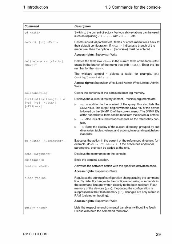
DescriptionCommand
Switch to the current directory. Various abbreviations can be used,such as replacing cd ../.. with cd ..., etc.
cd <Path>
Resets individual parameters, tables or entire menu trees back totheir default configuration. If <PATH> indicates a branch of themenu tree, then the option -r (recursive) must be entered.
Access rights: Supervisor-Write
default [-r] <Path>
Deletes the table row <Row> in the current table or the table refer-enced in the branch of the menu tree with <Path>. Enter the linenumber for the <Row>.
del|delete|rm [<Path>]<Row>|*
The wildcard symbol * deletes a table, for example, delConfig/Cron-Table *.
Access rights: Supervisor-Write,Local-Admin-Write,Limited-Admin-Write
Clears the contents of the persistent boot log memory.deletebootlog
Displays the current directory content. Possible arguments are:dir|list|ls|llong|l [-a][-r] [-s] [<Path>][<Filter>]
D -a: In addition to the content of the query, this also lists theSNMP IDs. The output begins with the SNMP ID of the devicefollowed by the SNMP ID of the current menu. The SNMP IDsof the subordinate items can be read from the individual entries.
D -r: Also lists all subdirectories as well as the tables they con-tain.
D -s: Sorts the display of the current directory; grouped by subdirectories, tables, values, and actions; in ascending alphabet-ical order.
Executes the action in the current or the referenced directory, forexample, do Other/Coldstart. If the action has additionalparameters, they can be added at the end.
do <Path> [<Parameter>]
Displays the commands on the console.echo <Argument>
Ends the terminal session.exit|quit|x
Activates the software option with the specified activation code.
Access rights: Supervisor-Write
feature <Code>
Regulates the storing of configuration changes using the commandline. By default, changes to the configuration using commands in
flash yes|no
the command line are written directly to the boot-resistant Flashmemory of the devices (yes). If updating the configuration issuppressed in the Flash memory (no), changes are only stored inRAM (deleted on booting).
Access rights: Supervisor-Write
Lists the respective environmental variables (without line feed).Please also note the command "printenv".
getenv <Name>
RM CLI HiLCOS 29
1 Introduction 1.3 Commands for the console

DescriptionCommand
Displays a list of recently executed commands. Command !# canbe used to directly call the list commands using their number (#):For example, !3 executes the third command in the list.
history
Starts iPerf on the device in order to perform a bandwidthmeasurement with an iPerf2 remote station. Possible argumentsare:
iperf [-s|-c <Host>] [-u][-p <Port>] [-B <Interface>][-c] [-b[<Bandw>/]<Bandw>[kKmM]] [-l
D Client/server<Length>] [-t <Time>] [-d][-r] [-L <Port>] [-h] – -u, --udp: Uses UDP instead of TCP.
– -p, --port <Port>: Connects with or expects datapackets on this port (default: 5001).
– -B, --bind <Interface>: Permits the connectiononly via the specified interface (IP address or interfacename).
D Server specific
– -s, --server: Starts iPerf in server mode and waitsfor an iPerf client to contact it.
D Client specific
– -c, --client <Host>: Starts iPerf in client mode andconnects with the iPerf server <Host> (IP address or DNSname).
– -b, --bandwidth [<Bandw>/]<Bandw>{kKmM}:Limit the [down]/up-stream bandwidth when analyzing aUDP connection. This Is specified as kilobytes (kK) ormegabytes (mM) per second (default: 1 Mbps).
– -l, --len <Length>: Sets the length of the UDP datapackets.
– -t, --time <Time>: Sets the duration of the connec-tion in seconds (default: 10 seconds).
– -d, --dualtest: The test is bidirectional: the iPerfserver and client send and receive at the same time.
– -r, --tradeoff: The test is sequential: the iPerf serverand client send and receive one after the other.
– -L, --listenport <Port>: Specifies the port wherethe device in bidirectional mode expects to receive datapackets from the remote iPerf server (default: 5001).
D Miscellaneous
– -h, --help: Outputs the help text.
Deletes the remaining unprocessed content of a script sessionSelect the script session using its name.
Access rights: Supervisor-Write
killscript <Name>
Only available on WLAN devices. It displays the results of theWLAN link test.
Access rights: Supervisor-Write
linktest
RM CLI HiLCOS 30
1.3 Commands for the console 1 Introduction

DescriptionCommandExecution right: WLAN link test
Searches for devices via LL2M in the LAN.
Access rights: Supervisor-Write
ll2mdetect
Sends one command per LL2M to a device in the LAN.
Access rights: Supervisor-Write
ll2mexec
Uploads a configuration file to the device via TFTP. You canoptionally enter the server address and the file name, or the entireURL.
Access rights: Supervisor-Write
loadconfig (-s <server IPaddress> -f<filename>)|<URL>
Uploads firmware to the device via TFTP. You can optionally enterthe server address and the file name, or the entire URL.
Access rights: Supervisor-Write
loadfirmware (-s <server IPaddress> -f<filename>)|<URL>
Uploads a configuration script to the device via TFTP. You canoptionally enter the server address and the file name, or the entireURL.
Access rights: Supervisor-Write
loadscript (-s <ServerIP-Address> -f<Filename>)|<URL>
Changes the password of the current user account. In order tochange the password without having to change the subsequent
setpass|passwd [-n <new><old>]
input request, use the option switch -n with the new and oldpassword.
Changes the password of the current user account.
In order to change the password without a subsequent input prompt,use the option switch -n while entering the new and old password.
setpass|passwd [-u<User>][-n <new> <old>]
In order to change the password of the local user account whenauthentication by TACACS+ is enabled, use the option switch -uwith the name of the corresponding user. If the local user does notexist or the user name is missing, the command aborts. The usermust also have supervisor rights, or authorization by TACACS mustbe enabled.
Sends an ICMP echo request to the IP address specified. For moreinformation about the command and the specifics of pinging IPv6
ping <IPv4 address|hostname>
ping -6 <IPv6address>%<scope>
addresses, see the section Parameter overview for the pingcommand on page 37.
Shows an overview of all environmental variables and their values.printenv
Shows the complete configuration in the format of the device syntax.
Access rights: Supervisor-Read
readconfig
Shows the complete configuration in the format of the device syntax.readconfig [-h] [-s<password>]
D -h: Adds a checksum to the configuration file.D -s <password>: Encrypts the configuration file with the use
of the specified password.
RM CLI HiLCOS 31
1 Introduction 1.3 Commands for the console

DescriptionCommandAccess rights: Supervisor-Read
The readscript command generates a text dump of all commandsand parameters required to configure the device in its current state.You can use the following option switches for this:
readscript [-n] [-d] [-i][-c] [-m]
D -n: The text output is only numerical without identifiers. Theoutput only contains the current status values of the configur-ation as well as the associated SNMP IDs.
D -d: The default values are included in the text output.D -i: The table designations are included in the text output.D -c: Includes any comments contained in the script file.D -m: The text is output to the screen in a compact but difficult
to read format (no indentations).
Access rights: Supervisor-Read
The readscript command generates a text dump of all commandsand parameters required to configure the device in its current state.You can use the following option switches for this:
readscript [-n] [-d] [-i][-c] [-m] [-h] [-s<password>]
D -n: The text output is only numerical without identifiers. Theoutput only contains the current status values of the configur-ation as well as the associated SNMP IDs.
D -d: The default values are included in the text output.D -i: The table designations are included in the text output.D -c: Includes any comments contained in the script file.D -m: The text is output to the screen in a compact but difficult
to read format (no indentations).D -h: Adds a checksum to the script file.D -s <password>: Encrypts the script file with the use of the
specified password.
Access rights: Supervisor-Read
The DHCPv6 client returns its IPv6 address and/or its prefix to theDHCPv6 server. It then submits a new request for an address or
release [-x]*|<Interface_1…Interface_n>
prefix to the DHCPv6 server. Depending on the provider, theserver assigns a new address to the client, or reassigns the previ-ous one. Whether the client receives a different address or prefixis determined solely by the server.
The option switch -x suppresses the confirmation message.
The * wildcard applies the command on all of the interfaces andprefix delegations. Alternatively, you can specify one or more spe-cific interfaces.
Release IPv6 address: Repeats the specified command every<Interval> seconds until the process is ended with new input.
repeat <Interval> <Command>
Deletes the files of the user-specific rollout wizard from the filesystem of the device. Possible files are:
rollout (-r|-remove)<RelatedFile>
D wizard: Deletes the wizardD template: Deletes the template
RM CLI HiLCOS 32
1.3 Commands for the console 1 Introduction

DescriptionCommand
D logo: Deletes the logoD all: Deletes the wizard, the template and the logo
Access rights: Supervisor-Write
Delays the processing of configuration commands by a particulartime or terminates them at a particular time.
sleep [-u] <Value><Suffix>
Applicable values for <SUFFIX> are s, m and h for seconds,minutes and hours. If no suffix is defined, the command uses milli-seconds. With option switch -u, the sleep command acceptstimes in format MM/DD/YYYY hh:mm:ss (English) or in formatTT.MM.JJJJ hh:mm:ss (German). Times will only be acceptedif the system time has been set.
Ends the PING commandstop
Sets a configuration parameter to a particular value. If theconfiguration parameter is a table value, a value must be specified
add|set [<Path>] <Value(s)>
for each column. Entering the * character leaves any existing tableentry unchanged.
Access rights: Supervisor-Write,Local-Admin-Write,Limited-Admin-Write
Lists all possible input values for a configuration parameter. If nospecific path is entered, the possible input values for allconfiguration parameters in the current directory are listed.
Access rights: Supervisor-Write,Local-Admin-Write,Limited-Admin-Write
add|set [<Path>] ?
Sets an environmental variable to the specified value.
Access rights: Supervisor-Write,Local-Admin-Write,Limited-Admin-Write
setenv <Name> <Value>
Displays selected internal data, such as the last boot processes(bootlog), firewall filter rules (filter), VPN rules (VPN) or
show <Options> <Filter>
memory utilization (mem, heap). With additional filter argumentsyou can further limit the output.
For an overview of all possible options, enter show ?. For inform-ation on displaying IPv6-specific data, read the section Overviewof IPv6-specific show commands on page 43.
Access rights: Supervisor-Read,Local-Admin-Read
Shows the system information (e.g., hardware release, softwareversion, MAC address, serial number, etc.).
sysinfo
Sends a test e-mail. A sender address and receiver address arenecessary; real name, subject line and message content areoptional.
Access rights: Supervisor-Write,Local-Admin-Write,Limited-Admin-Write
testmail <From> <To_1…To_n>[<Realname> <Subject><Body>]
RM CLI HiLCOS 33
1 Introduction 1.3 Commands for the console
DescriptionCommand
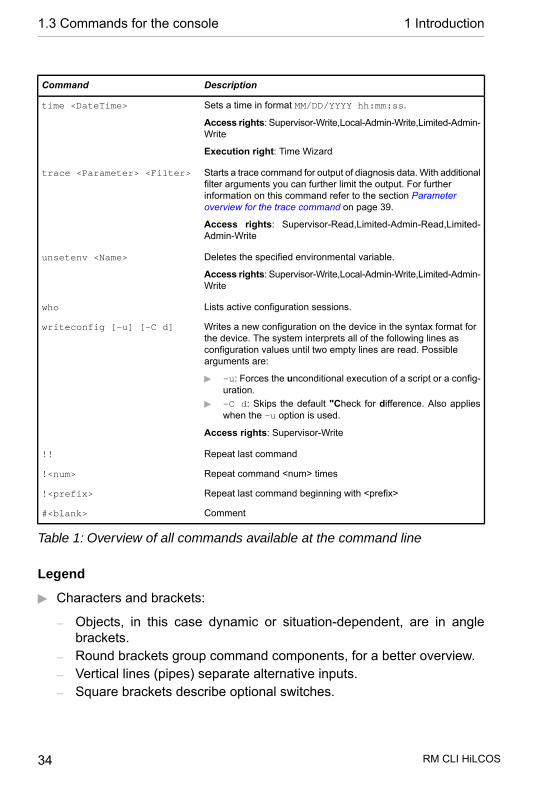
Sets a time in format MM/DD/YYYY hh:mm:ss.
Access rights: Supervisor-Write,Local-Admin-Write,Limited-Admin-Write
time <DateTime>
Execution right: Time Wizard
Starts a trace command for output of diagnosis data. With additionalfilter arguments you can further limit the output. For further
trace <Parameter> <Filter>
information on this command refer to the section Parameteroverview for the trace command on page 39.
Access rights: Supervisor-Read,Limited-Admin-Read,Limited-Admin-Write
Deletes the specified environmental variable.
Access rights: Supervisor-Write,Local-Admin-Write,Limited-Admin-Write
unsetenv <Name>
Lists active configuration sessions.who
Writes a new configuration on the device in the syntax format forthe device. The system interprets all of the following lines as
writeconfig [-u] [-C d]
configuration values until two empty lines are read. Possiblearguments are:
D -u: Forces the unconditional execution of a script or a config-uration.
D -C d: Skips the default "Check for difference. Also applieswhen the -u option is used.
Access rights: Supervisor-Write
Repeat last command!!
Repeat command <num> times!<num>
Repeat last command beginning with <prefix>!<prefix>
Comment#<blank>
Table 1: Overview of all commands available at the command line
Legend
D Characters and brackets:
– Objects, in this case dynamic or situation-dependent, are in anglebrackets.
– Round brackets group command components, for a better overview.– Vertical lines (pipes) separate alternative inputs.– Square brackets describe optional switches.
RM CLI HiLCOS 34
1.3 Commands for the console 1 Introduction

It follows that all command components that are not in square bracketsare necessary information.
D <Path>:
– Describes the path name for a menu or parameter, separated by "/" or"\".
– .. means: one level higher– . means: the current level
D <Value>:
– Describes a possible input value.– "" is a blank input value
D <Name>:
– Describes a character sequence of [0…9] [A…Z] [a…z] [ _ ].– The first character cannot be a digit.– There is no difference between small letters and capital letters.
D <Filter>:
– The output of some commands can be restricted by entering a filterexpression. Filtering does not occur line by line, but in blocks,depending on the command.
– A filter expression starts with the "@" symbol by itself and ends eitherat the end of the line or at a ";" (semicolon) to end the current command.
– A filter expression also consists of one or more search patterns, whichare separated by blank spaces and preceded either by no operator (ORpattern), a "+" operator (AND pattern) or a "-" operator (NOT pattern).
– For the execution of the command, an information block is output exactlywhen at least one of the "OR" patterns, all "AND" patterns or none ofthe "NOT" patterns matches. Capitalization is ignored.
– For a search pattern to contain characters for structuring in the filtersyntax (e.g., blank characters), then the entire search pattern can beenclosed in "". Alternatively, the symbol "\" can be placed before thespecial characters. If you want to search for a quotation mark (") or "\",another "\" symbol has to be placed in front of it.
Note: Entering the start of the word, if it is unique, is sufficient.
RM CLI HiLCOS 35
1 Introduction 1.3 Commands for the console

Explanations for addressing, syntax and command input
D All commands and directory/parameter names can be entered using theirshort-forms as long as they are unambiguous. For example, the commandsysinfo can be shortened to sys and cd Management to c ma. Theinput cd /s is not valid, however, since it corresponds to both cd /Setupand cd /Status.
D Directories can be addressed with the corresponding SNMP ID. Forexample, the command cd /2/8/10/2 has the same effect as cd/Setup/IP-router/Firewall/Rules.
D Multiple values in a table row can be changed with one command, forexample in the rules table of the IPv4 firewall:
– set WINS UDP sets the protocol of the WINS rule to UDP– set WINS UDP ANYHOST sets the protocol of the WINS rule to UDP
and the destination to ANY-HOST– set WINS * ANYHOST also sets the destination of the WINS rule to
ANYHOST; the asterisk means that the protocol remains unchanged
D The values in a table row can alternatively be addressed via the columnname or the position number in curly brackets. The command set ? inthe table shows the name, the possible input values and the positionnumber for each column. For example, in the rules table of the firewall,the destination has the number 4:
– set WINS {4} ANYHOST sets the destination of the WINS rule toANYHOST
– set WINS {destination} ANYHOST also sets the destination ofthe WINS rule to ANYHOST
– set WINS {dest} ANYHOST sets the destination of the WINS ruleto ANYHOST, because specifying dest here is sufficient to uniquelyidentify the column name.
D Names that contain spaces must be enclosed within quotation marks (““).
Command-specific help
D A command-specific help function is available for actions and commands(call the function with a question mark as the argument). For example,ping ? shows the options of the integrated ping command.
RM CLI HiLCOS 36
1.3 Commands for the console 1 Introduction
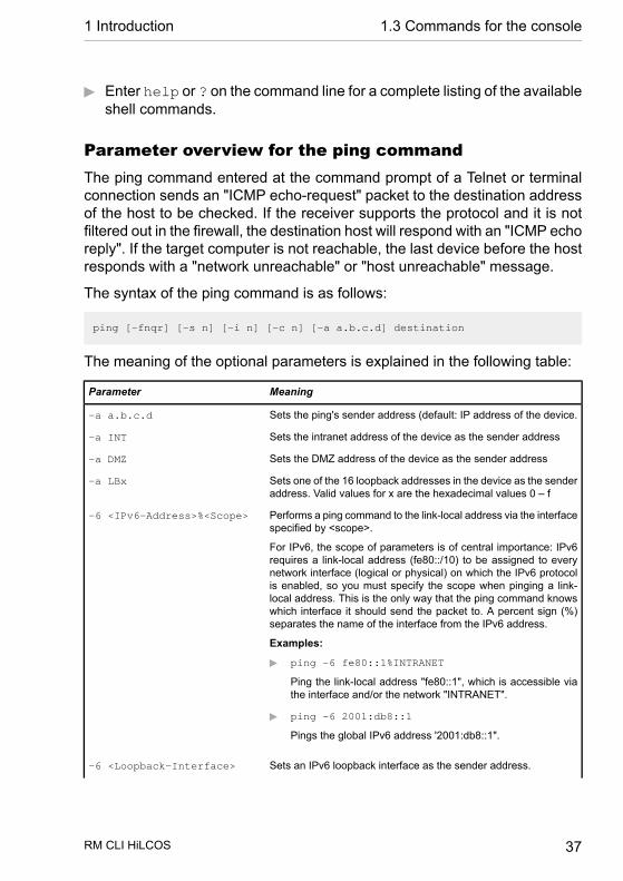
D Enter help or ? on the command line for a complete listing of the availableshell commands.
Parameter overview for the ping commandThe ping command entered at the command prompt of a Telnet or terminalconnection sends an "ICMP echo-request" packet to the destination addressof the host to be checked. If the receiver supports the protocol and it is notfiltered out in the firewall, the destination host will respond with an "ICMP echoreply". If the target computer is not reachable, the last device before the hostresponds with a "network unreachable" or "host unreachable" message.
The syntax of the ping command is as follows:
ping [-fnqr] [-s n] [-i n] [-c n] [-a a.b.c.d] destination
The meaning of the optional parameters is explained in the following table:
MeaningParameter
Sets the ping's sender address (default: IP address of the device.-a a.b.c.d
Sets the intranet address of the device as the sender address-a INT
Sets the DMZ address of the device as the sender address-a DMZ
Sets one of the 16 loopback addresses in the device as the senderaddress. Valid values for x are the hexadecimal values 0 – f
-a LBx
Performs a ping command to the link-local address via the interfacespecified by <scope>.
-6 <IPv6-Address>%<Scope>
For IPv6, the scope of parameters is of central importance: IPv6requires a link-local address (fe80::/10) to be assigned to everynetwork interface (logical or physical) on which the IPv6 protocolis enabled, so you must specify the scope when pinging a link-local address. This is the only way that the ping command knowswhich interface it should send the packet to. A percent sign (%)separates the name of the interface from the IPv6 address.
Examples:
D ping -6 fe80::1%INTRANET
Ping the link-local address "fe80::1", which is accessible viathe interface and/or the network "INTRANET".
D ping -6 2001:db8::1
Pings the global IPv6 address '2001:db8::1".
Sets an IPv6 loopback interface as the sender address.-6 <Loopback-Interface>
RM CLI HiLCOS 37
1 Introduction 1.3 Commands for the console
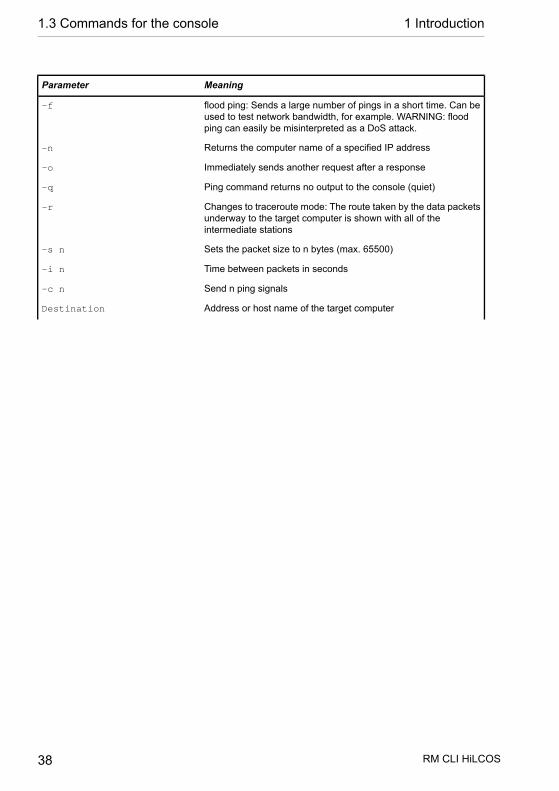
MeaningParameter
flood ping: Sends a large number of pings in a short time. Can beused to test network bandwidth, for example. WARNING: floodping can easily be misinterpreted as a DoS attack.
-f
Returns the computer name of a specified IP address-n
Immediately sends another request after a response-o
Ping command returns no output to the console (quiet)-q
Changes to traceroute mode: The route taken by the data packetsunderway to the target computer is shown with all of theintermediate stations
-r
Sets the packet size to n bytes (max. 65500)-s n
Time between packets in seconds-i n
Send n ping signals-c n
Address or host name of the target computerDestination
RM CLI HiLCOS 38
1.3 Commands for the console 1 Introduction

MeaningParameter
Entering "stop" or pressing the RETURN button terminates the pingcommand
stop /<RETURN>
Table 2: Overview of optional parameters for the ping command
Parameter overview for the trace command
Note: The traces available for a particular model can be displayed by enteringtrace without any arguments.
...causes the following message in the trace:This parameter ...
Connection status messagesStatus
Connection error messagesError
PPP protocol negotiationPPP
RM CLI HiLCOS 39
1 Introduction 1.3 Commands for the console

...causes the following message in the trace:This parameter ...
Least cost routerLCR
Script negotiationScript
Displays firewall eventsFirewall
IP routing information protocolRIP
Address resolution protocolARP
Internet control message protocolICMP
Events in the masquerading moduleIP masquerading
Dynamic host configuration protocolDHCP
NetBIOS managementNetBIOS
Domain name service protocolDNS
Displays the first 64 bytes of a packet in hexadecimalPacket dump
ATM packet layerATM cell
ATM errorATM error
E-mail processing by the internal mail clientSMTP client
E-mail processing by the internal mail clientMail client
Simple network time protocolSNTP
Timeserver traceNTP
Messages from the activity protocolConnact
Activities of the scheduler (cron table)Cron
RADIUS traceRADIUS
Information on the state of the serial interfaceSerial
Information on the state of the USB interfaceUSB
Information on load balancingLoad balancer
Information on the virtual router redundancy protocolVRRP
Information on the Ethernet interfacesEthernet
Information on virtual networksVLAN
Information on the Internet group management protocolIGMP
Information on activity in the wireless networksWLAN
RM CLI HiLCOS 40
1.3 Commands for the console 1 Introduction
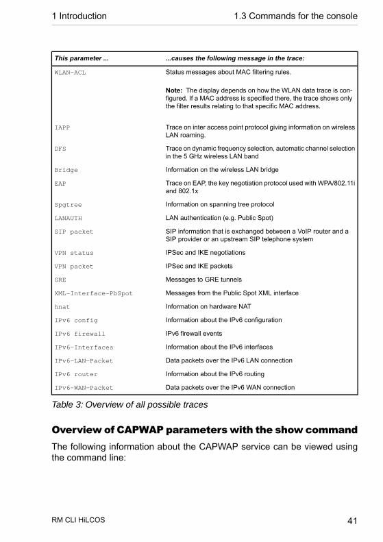
...causes the following message in the trace:This parameter ...
Status messages about MAC filtering rules.WLAN-ACL
Note: The display depends on how the WLAN data trace is con-figured. If a MAC address is specified there, the trace shows onlythe filter results relating to that specific MAC address.
Trace on inter access point protocol giving information on wirelessLAN roaming.
IAPP
Trace on dynamic frequency selection, automatic channel selectionin the 5 GHz wireless LAN band
DFS
Information on the wireless LAN bridgeBridge
Trace on EAP, the key negotiation protocol used with WPA/802.11iand 802.1x
EAP
Information on spanning tree protocolSpgtree
LAN authentication (e.g. Public Spot)LANAUTH
SIP information that is exchanged between a VoIP router and aSIP provider or an upstream SIP telephone system
SIP packet
IPSec and IKE negotiationsVPN status
IPSec and IKE packetsVPN packet
Messages to GRE tunnelsGRE
Messages from the Public Spot XML interfaceXML-Interface-PbSpot
Information on hardware NAThnat
Information about the IPv6 configurationIPv6 config
IPv6 firewall eventsIPv6 firewall
Information about the IPv6 interfacesIPv6-Interfaces
Data packets over the IPv6 LAN connectionIPv6-LAN-Packet
Information about the IPv6 routingIPv6 router
Data packets over the IPv6 WAN connectionIPv6-WAN-Packet
Table 3: Overview of all possible traces
Overview of CAPWAP parameterswith the show commandThe following information about the CAPWAP service can be viewed usingthe command line:
RM CLI HiLCOS 41
1 Introduction 1.3 Commands for the console

MeaningParameters
Shows the address tables of an individual or all WLC tunnels. Inthe case of an individual WLC tunnel, enter for the <IfcNum> thenumber of logical WLC tunnel interface, for example 10.
-addresses [<IfcNum>]
Shows the information for an individual or all availableassignment/tag groups.
-groups
Table 4: Overview of all CAPWAP parameters with the show command
You can supplement the command show capwap groupswith the paramet-ers listed below, which control the scope of the displayed information:
MeaningParameters
Shows the names configured in the setup menu and the device'sinternal names for all assignment/tag groups as well as the default
all
groups that were set up. The default group represents an internalgroup which contains all APs.
Shows all APs of the respective assignment/tag groups.<group1> <group2> <…>
Shows all APs of the respective location.-l <location>
Shows all APs of the respective country.-c <country>
Shows all APs of the respective city.-i <city>
Shows all APs of the respective street.-s <street>
Shows all APs of the respective building.-b <building>
Shows all APs of the respective floor.-f <floor>
Shows all APs of the respective room description.-r <room>
Shows all APs that have the specified device name.-d <device>
Shows all APs which have the specified antenna number.-a <antenna>
Shows all APs which have the specified firmware. To do this, enterthe version number for <firmware> followed by the build number,e.g., 9.00.0001.
-v <firmware>
Shows all APs with a firmware version lower than the one installedon the current device.
-x <firmware>
Shows all APs with a firmware version the same or lower than theone installed on the current device.
-y <firmware>
Shows all APs with a firmware version higher than the one installedon the current device.
-z <firmware>
Shows all APs with a firmware version the same or higher than theone installed on the current device.
-t <firmware>
RM CLI HiLCOS 42
1.3 Commands for the console 1 Introduction
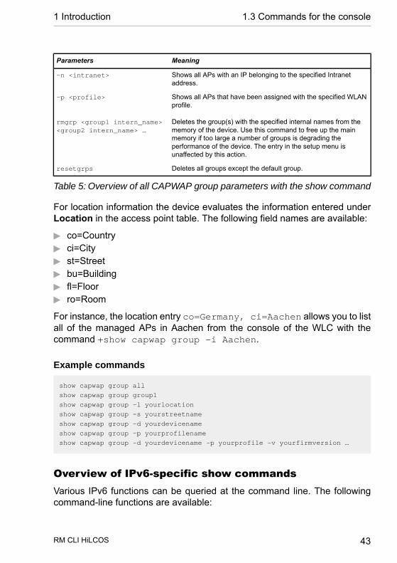
MeaningParameters
Shows all APs with an IP belonging to the specified Intranetaddress.
-n <intranet>
Shows all APs that have been assigned with the specified WLANprofile.
-p <profile>
Deletes the group(s) with the specified internal names from thememory of the device. Use this command to free up the main
rmgrp <group1 intern_name><group2 intern_name> …
memory if too large a number of groups is degrading theperformance of the device. The entry in the setup menu isunaffected by this action.
Deletes all groups except the default group.resetgrps
Table 5: Overview of all CAPWAP group parameters with the show command
For location information the device evaluates the information entered underLocation in the access point table. The following field names are available:
D co=CountryD ci=CityD st=StreetD bu=BuildingD fl=FloorD ro=Room
For instance, the location entry co=Germany, ci=Aachen allows you to listall of the managed APs in Aachen from the console of the WLC with thecommand +show capwap group -i Aachen.
Example commands
show capwap group all
show capwap group group1
show capwap group -l yourlocation
show capwap group -s yourstreetname
show capwap group -d yourdevicename
show capwap group -p yourprofilename
show capwap group -d yourdevicename -p yourprofile -v yourfirmversion …
Overview of IPv6-specific show commandsVarious IPv6 functions can be queried at the command line. The followingcommand-line functions are available:
RM CLI HiLCOS 43
1 Introduction 1.3 Commands for the console

D IPv6 addresses: show ipv6-addressesD IPv6 prefixes: show ipv6-prefixesD IPv6 interfaces: show ipv6-interfacesD IPv6 neighbor cache: show ipv6-neighbour-cacheD IPv6 DHCP server show dhcp6-serverD IPv6 DHCP client show dhcpv6-clientD IPv6 route: show ipv6-route
Additionally, IPv6 communications can be followed with the trace command.
IPv6 addressesThe command show ipv6-addresses shows a list of IPv6 addresses thatare currently being used. This is sorted by interface. Note that an interfacecan have multiple IPv6 addresses. One of these addresses is always the link-local address, which starts with fe80:.
The output is formatted as follows:
<Interface> :
<IPv6 address>, <status>, <attribute>, (<type>)
CommentOutput
The name of the interfaceInterface
The IPv6 addressIPv6 address
The status field can contain the following values:Status
D TENTATIVE
Duplicate Address Detection (DAD) is currently checking the address. Itis not yet available for unicast.
D PREFERRED
The address is valid
D DEPRECATED
The address is still valid, but it is being discontinued. The optimal statusfor communication is PREFERRED.
D INVALID
The address is invalid and cannot be used for communication. An addressgiven this status after its lifetime has expired.
Shows an attribute of the IPv6 address. Possible attributes are:Attribute
RM CLI HiLCOS 44
1.3 Commands for the console 1 Introduction

CommentOutput
D None
No special attributes
D (ANYCAST)
This is an anycast address
D (AUTO CONFIG)
The address was retrieved by auto-configuration
D (NO DAD PERFORMED)
No DAD is performed
The type of IP addressType
Table 6: Components of the command-line output show ipv6-addresses
IPv6 prefixesThe command show ipv6-prefixes displays all known prefixes. Theseare sorted according to the following criteria:Delegated prefixes
All prefixes that the router has obtained by delegation.
Advertised prefixesAll prefixes that the router announces in its router advertisements.
Deprecated prefixesAll prefixes that are being discontinued. These may still be functional, butthey will be deleted after a certain time.
IPv6-InterfacesThe command show ipv6-interfaces displays a list of IPv6 interfacesand their status.
The output is formatted as follows:
<Interface> : <Status>, <Forwarding>, <Firewall>
CommentOutput
The name of the interfaceInterface
RM CLI HiLCOS 45
1 Introduction 1.3 Commands for the console
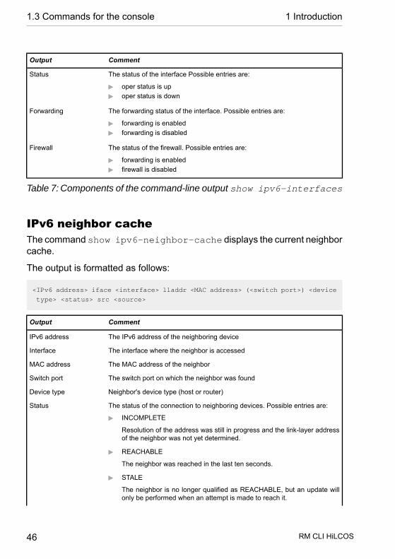
CommentOutput
The status of the interface Possible entries are:Status
D oper status is upD oper status is down
The forwarding status of the interface. Possible entries are:Forwarding
D forwarding is enabledD forwarding is disabled
The status of the firewall. Possible entries are:Firewall
D forwarding is enabledD firewall is disabled
Table 7: Components of the command-line output show ipv6-interfaces
IPv6 neighbor cacheThe command show ipv6-neighbor-cache displays the current neighborcache.
The output is formatted as follows:
<IPv6 address> iface <interface> lladdr <MAC address> (<switch port>) <device
type> <status> src <source>
CommentOutput
The IPv6 address of the neighboring deviceIPv6 address
The interface where the neighbor is accessedInterface
The MAC address of the neighborMAC address
The switch port on which the neighbor was foundSwitch port
Neighbor's device type (host or router)Device type
The status of the connection to neighboring devices. Possible entries are:Status
D INCOMPLETE
Resolution of the address was still in progress and the link-layer addressof the neighbor was not yet determined.
D REACHABLE
The neighbor was reached in the last ten seconds.
D STALE
The neighbor is no longer qualified as REACHABLE, but an update willonly be performed when an attempt is made to reach it.
RM CLI HiLCOS 46
1.3 Commands for the console 1 Introduction
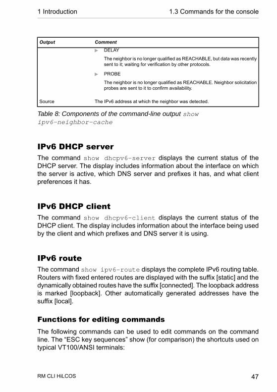
CommentOutput
D DELAY
The neighbor is no longer qualified as REACHABLE, but data was recentlysent to it; waiting for verification by other protocols.
D PROBE
The neighbor is no longer qualified as REACHABLE. Neighbor solicitationprobes are sent to it to confirm availability.
The IPv6 address at which the neighbor was detected.Source
Table 8: Components of the command-line output showipv6-neighbor-cache
IPv6 DHCP serverThe command show dhcpv6-server displays the current status of theDHCP server. The display includes information about the interface on whichthe server is active, which DNS server and prefixes it has, and what clientpreferences it has.
IPv6 DHCP clientThe command show dhcpv6-client displays the current status of theDHCP client. The display includes information about the interface being usedby the client and which prefixes and DNS server it is using.
IPv6 routeThe command show ipv6-route displays the complete IPv6 routing table.Routers with fixed entered routes are displayed with the suffix [static] and thedynamically obtained routes have the suffix [connected]. The loopback addressis marked [loopback]. Other automatically generated addresses have thesuffix [local].
Functions for editing commandsThe following commands can be used to edit commands on the commandline. The “ESC key sequences” show (for comparison) the shortcuts used ontypical VT100/ANSI terminals:
RM CLI HiLCOS 47
1 Introduction 1.3 Commands for the console

DescriptionEsc key sequencesFunction
In the list of commands last run, jumps one position up (inthe direction of older commands).
ESC [AUp arrow
In the list of commands last run, jumps one position down (inthe direction of newer commands).
ESC [BDown arrow
Moves the insert cursor one position to the right.Ctrl-F ESC [CRight arrow
Moves the insert cursor one position to the left.Ctrl-B ESC [DLeft arrow
Moves the insert cursor to the first character in the line.Ctrl-A ESC [A ESC [1˜ (Home or Pos1
Moves the insert cursor to the last character in the line.Ctrl-E ESC [F ESC OFESC [4˜
Close
Switches between input and overwrite modes.ESC [ ESC [2˜Ins
Deletes the character at the current position of the insertcursor or ends the Telnet session if the line is blank.
Ctrl-D ESC <BS> ESC [3˜Del
Deletes the next character to the left of the insert cursor.<BS><DEL>erase
Deletes all characters to the left of the insert cursor.Ctrl-Uerase-bol
Deletes all characters to the right of the insert cursor.Ctrl-Kerase-eol
Completes the input from the current position of the insertcursor for a command or path of the HiLCOS menu structure:
Tabulator
1. If there is only one possibility of completing the com-mand/path, this is accepted by the line.
2. If there is more than one possibility of completing thecommand/path, this is indicated by an audible soundwhen pressing the Tab key. Pressing the Tab key againdisplays a list of all possibilities to complete the entry.Then enter e.g. another letter, to allow unambiguouscompletion of the input.
3. If there is no possibility of completing the command/path,this is indicated by an audible sound when pressing theTab key. No further actions are run.
Function keys for the command lineWEBconfig: Setup / Config / Function keys
The function keys enable the user to save frequently used commandsequences and to call them easily from the command line. In the appropriatetable, commands are assigned to function keys F1 to F12 as they are enteredin the command line.
D Key
RM CLI HiLCOS 48
1.3 Commands for the console 1 Introduction

Name of function key.
Possible values:
– Selection from function keys F1 to F12.
Default:
– F1
D Figure
Description of the command/shortcut to be run on calling the function keyin the command line.
Possible values:
– All commands/shortcuts possible in the command line
Default:
– Blank
Special values:
– The caret symbol ^ is used to represent special control commands withASCII values below 32.
– ^A stands for Ctrl-A (ASCII 1)– ^Z stands for Ctrl-Z (ASCII 26)– ^[ stands for Escape (ASCII 27)– ^^ A double caret symbol stands for the caret symbol itself.
Note: If a caret symbol is entered in a dialog field or editor followed directlyby another character, the operating system may possibly interpret thissequence as another special character. By entering caret + A the Windowsoperating system outputs an Â. To enter the caret character itself, enter aspace in front of the subsequent characters. Sequence ^A is then formedfrom caret symbol + space + A.
Tab command when scriptingWhen working with scripts, the tab command enables the desired columnsfor the subsequent set command.
RM CLI HiLCOS 49
1 Introduction 1.3 Commands for the console

When you perform the configuration with a command line tool, you generallysupplement the set command with the values for the columns of the table.
For example, you set the values for the performance settings of a WLANinterface as follows:
> cd /Setup/Interfaces/WLAN/Performance
> set ?
Possible Entries for columns in Performance:
[1][Ifc] : WLAN-1 (1)
[5][QoS] : No (0), Yes (1)
[2][Tx-Bursting] : 5 Chars from: 1234567890
> set WLAN-1 Yes *
In this example the Performance table has three columns:
D Ifc, the desired interfaceD Enable or disable QoSD The desired value for TX bursting
With the command set WLAN-1 Yes * you enable the QoS function forWLAN-1, and you leave the value for TX bursting unchanged with the asterisk(*).
Working with the set command in this way is adequate for tables with onlya few columns. However, tables with many columns can pose a major chal-lenge. For example, the table under Setup > Interfaces >WLAN > Transmis-sion contains 22 entries:
> cd /Setup/Interfaces/WLAN/Transmission
> set ?
Possible Entries for columns in Transmission:
[1][Ifc] : WLAN-1 (1), WLAN-1-2 (16), WLAN-1-3 (17), WLAN-1-4
(18), WLAN-1-5 (19), WLAN-1-6 (20), WLAN-1-7 (21), WLAN-1-8 (22)
[2][Packet-Size] : 5 Chars from: 1234567890
[3][Min-Tx-Rate] : Auto (0), 1M (1), 2M (2), 5.5M (4), 11M (6), 6M
(8), 9M (9), 12M (10), 18M (11), 24M (12), 36M (13), 48M (14), 54M (15)
[9][Max-Tx-Rate] : Auto (0), 1M (1), 2M (2), 5.5M (4), 11M (6), 6M
(8), 9M (9), 12M (10), 18M (11), 24M (12), 36M (13), 48M (14), 54M (15)
[4][Basic-Rate] : 1M (1), 2M (2), 5.5M (4), 11M (6), 6M (8), 9M (9),
12M (10), 18M (11), 24M (12), 36M (13), 48M (14), 54M (15)
[19][EAPOL-Rate] : Like-Data (0), 1M (1), 2M (2), 5.5M (4), 11M (6),
RM CLI HiLCOS 50
1.3 Commands for the console 1 Introduction

6M (8), 9M (9), 12M (10), 18M (11), 24M (12), 36M (13), 48M (14), 54M (15),
HT-1-6.5M (28), HT-1-13M (29), HT-1-19.5M (30),
HT-1-26M (31), HT-1-39M (32), HT-1-52M (33), HT-1-58.5M (34), HT-1-65M (35),
HT-2-13M (36), HT-2-26M (37), HT-2-39M (38), HT-2-52M (39), HT-2-78M (40),
HT-2-104M (41), HT-2-117M (42), HT-2-130M (43)
[12][Hard-Retries] : 3 Chars from: 1234567890
[11][Soft-Retries] : 3 Chars from: 1234567890
[7][11b-Preamble] : Auto (0), Long (1)
[16][Min-HT-MCS] : Auto (0), MCS-0/8 (1), MCS-1/9 (2), MCS-2/10 (3),
MCS-3/11 (4), MCS-4/12 (5), MCS-5/13 (6), MCS-6/14 (7), MCS-7/15 (8)
[17][Max-HT-MCS] : Auto (0), MCS-0/8 (1), MCS-1/9 (2), MCS-2/10 (3),
MCS-3/11 (4), MCS-4/12 (5), MCS-5/13 (6), MCS-6/14 (7), MCS-7/15 (8)
[23][Use-STBC] : No (0), Yes (1)
[24][Use-LDPC] : No (0), Yes (1)
[13][Short-Guard-Interval] : Auto (0), No (1)
[18][Min-Spatial-Streams] : Auto (0), One (1), Two (2), Three (3)
[14][Max-Spatial-Streams] : Auto (0), One (1), Two (2), Three (3)
[15][Send-Aggregates] : No (0), Yes (1)
[22][Receive-Aggregates]: No (0), Yes (1)
[20][Max-Aggr.-Packet-Count] : 2 Chars from: 1234567890
[6][RTS-Threshold] : 5 Chars from: 1234567890
[10][Min-Frag-Len] : 5 Chars from: 1234567890
[21][ProbeRsp-Retries] : 3 Chars from: 1234567890
Use the following command to set the short guard interval in the transmissiontable for the WLAN-1-3 interface to No:
> set WLAN-1-3 * * * * * * * * * * * * No
Note: The asterisks for the values after the column for the short guard intervalare unnecessary in this example, as the columns will be ignored when settingthe new values.
As an alternative to this rather confusing and error-prone notation, you canuse the tab command as the first step to determine which columns arechanged with the subsequent set command:
> tab Ifc short guard-Interval
> set WLAN-1-3 No
The tab command also makes it possible to change the order of the columns.The following example for the WLAN-1-3 interface sets the value for the short
RM CLI HiLCOS 51
1 Introduction 1.3 Commands for the console
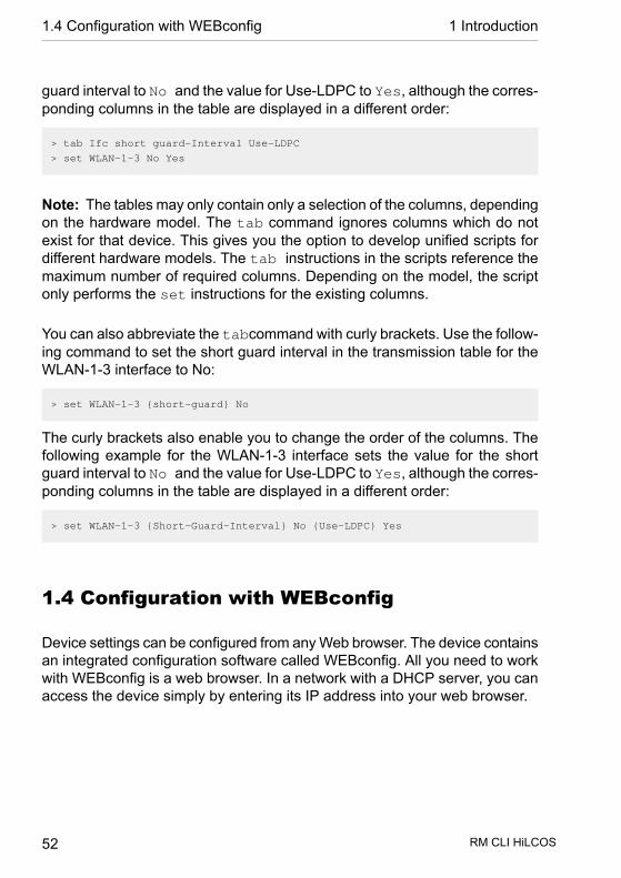
guard interval to No and the value for Use-LDPC to Yes, although the corres-ponding columns in the table are displayed in a different order:
> tab Ifc short guard-Interval Use-LDPC
> set WLAN-1-3 No Yes
Note: The tables may only contain only a selection of the columns, dependingon the hardware model. The tab command ignores columns which do notexist for that device. This gives you the option to develop unified scripts fordifferent hardware models. The tab instructions in the scripts reference themaximum number of required columns. Depending on the model, the scriptonly performs the set instructions for the existing columns.
You can also abbreviate the tabcommand with curly brackets. Use the follow-ing command to set the short guard interval in the transmission table for theWLAN-1-3 interface to No:
> set WLAN-1-3 {short-guard} No
The curly brackets also enable you to change the order of the columns. Thefollowing example for the WLAN-1-3 interface sets the value for the shortguard interval to No and the value for Use-LDPC to Yes, although the corres-ponding columns in the table are displayed in a different order:
> set WLAN-1-3 {Short-Guard-Interval} No {Use-LDPC} Yes
1.4 Configuration with WEBconfig
Device settings can be configured from any Web browser. The device containsan integrated configuration software called WEBconfig. All you need to workwith WEBconfig is a web browser. In a network with a DHCP server, you canaccess the device simply by entering its IP address into your web browser.
RM CLI HiLCOS 52
1.4 Configuration with WEBconfig 1 Introduction

Menu area “HiLCOS Menu Tree” provides the configuration parameters in thesame structure as they are used under Telnet.
RM CLI HiLCOS 53
1 Introduction 1.4 Configuration with WEBconfig

2 Setup
This menu allows you to adjust the settings for this device.
Telnet path: /Setup
2.1 Name
This field can be used to enter a name of your choice for this device.
Telnet path:Setup
Possible values:Max. 16 characters from[A-Z][a-z][0-9]@{|}~!$%&'()+-,/:;<=>?[\]^_.`
Default:empty
2.2 WAN
This menu contains the configuration of the Wide Area Network (WAN).
Telnet path:Setup
RM CLI HiLCOS 54
2.1 Name 2 Setup

2.2.2 Dialup-PeersHere you configure the remote sites that your device is to connect to andexchange data with.
Note: If two remote-site lists contain identical names for remote sites (e.g.DSL broadband remote sites and Dialup peers), the device automatically takesthe "fastest" interface when establishing the connection. The other interfaceis available for backup purposes. If the list does not specify DSL broadbandremote sites, access concentrators or services, then the device connects tothe first AC that responds to the request over the exchange. For an existingDSLoL interface, the same entries apply as for a DSL interface. This informa-tion is entered into the list of DSL broadband remote sites.
Telnet path:Setup > WAN
2.2.2.1 Remote siteEnter the name of the remote site here.
Telnet path:Setup > WAN > Dialup-Peers
Possible values:Select from the list of defined peers.Max. 16 characters from[A-Z][0-9]@{|}~!$%&'()+-,/:;<=>?[\]^_.
Default:empty
RM CLI HiLCOS 55
2 Setup 2.2 WAN

2.2.2.2 Dialup remoteA telephone number is only required if the remote is to be called. The fieldcan be left empty if calls are to be received only. Several numbers for thesame remote can be entered in the round-robin list.
Telnet path:Setup > WAN > Dialup-Peers
Possible values:Max. 31 characters from 0123456789S*#-EF:
Default:empty
2.2.2.3 B1-DTThe connection is terminated if it remains unused for the time set here.
Telnet path:Setup > WAN > Dialup-Peers
Possible values:0 … 9999
Default:0
2.2.2.4 B2-DTHold time for bundling: When channels are bundled, the second B channelwill be terminated if it is not used for the time entered here.
RM CLI HiLCOS 56
2.2 WAN 2 Setup

Telnet path:Setup > WAN > Dialup-Peers
Possible values:0 … 9999
Default:0
2.2.2.5 Layer nameFrom the layer list, select an entry that is to be used for this remote site.
The layer list already contains a number of entries with popular standard set-tings. For example, you should use the PPPHDLC entry to establish a PPPconnection to an Internet provider.
Telnet path:Setup > WAN > Dialup-Peers
Possible values:Select from the list of defined layersMax. 9 characters from[A-Z][0-9]@{|}~!$%&'()+-,/:;<=>?[\]^_.
Default:empty
2.2.2.6 CallbackWith callback activated, an incoming call from this remote site will not beanswered, but it will be called back instead.
RM CLI HiLCOS 57
2 Setup 2.2 WAN
This is useful if, for example, telephone fees are to be avoided at the remotesite.
Activate a check of the name if you want to be sure that the remote site isauthenticated before the callback.
Select the fast option if the callback is to follow within seconds. The remotesite must also support this method and the 'Expect callback' option must beactivated. Additionally, the remote site must be entered into the number list.
Note: The setting 'Name' offers the highest security if there is an entry in thenumbers list and in the PPP list. The setting 'Hirschmann' enables the fastestmethod of call-back between two devices from Hirschmann.
Note: For Windows remote sites, ensure that you select the setting 'Name'.
Telnet path:Setup > WAN > Dialup-Peers
Possible values:No
There is no return call.
AutoIf the remote site is found in the numbers list, this number is calledback. Initially the call is rejected and, as soon as the channel is freeagain, a return call is made (after approx. 8 seconds). If the remotesite is not found in the numbers list, the DEFAULT remote site is ini-tially taken and the return call is negotiated during the protocolnegotiation. The call is charged with one unit.
NameBefore a return call is made, the protocol is always negotiated evenif the remote site is found in the numbers list (e.g. for Windows com-puters that dial-in to the device). Small call charges are incurred forthis.
fast
RM CLI HiLCOS 58
2.2 WAN 2 Setup
If the remote site is found in the numbers list, the return call is madequickly, i.e. the device sends a special signal to the remote site andit calls back as soon as the channel is free again. The connection isestablished within about 2 seconds. If the remote site does not cancelthe call immediately after the signal, then two seconds later it revertsto the normal return call procedure (lasts about 8 seconds). Thisprocedure is available with DSS1 connections only.
LooserUse the "looser" option if a return call from the remote site is expected.This setting fulfills two jobs in one. Firstly it ensures that a connectionit established itself terminates if a call arrives from the remote sitethat was just called, and secondly this setting activates the functionthat reacts to the procedure for fast return calls. This means that touse fast return calls, the caller must be in 'Looser' mode and, at thecalled party, the return call must be set to 'Hirschmann'.
Default:No
2.2.3 RoundRobinIf a remote site can be reached at various call numbers. you can enter thesenumbers into this list.
Telnet path:Setup > WAN
2.2.3.1 Remote siteHere you select the name of a remote site from the list of remote sites.
Telnet path:Setup > WAN > RoundRobin
RM CLI HiLCOS 59
2 Setup 2.2 WAN
Possible values:Select from the list of defined peers.Max. 18 characters from#[A-Z][0-9]@{|}~!$%&'()+-,/:;<=>?[\]^_.
Default:empty
2.2.3.2 Round-RobinSpecify here the other call numbers for this peer. Separate the individual callnumbers with hyphens.
Telnet path:Setup > WAN > RoundRobin
Possible values:Max. 53 characters from 0123456789S*#-EF:
Default:empty
2.2.3.3 HeadSpecify here whether the next connection is to be established to the numberlast reached successfully, or always to the first number.
Telnet path:Setup > WAN > RoundRobin
Possible values:LastFirst
RM CLI HiLCOS 60
2.2 WAN 2 Setup

Default:Last
2.2.4 LayerHere you collect individual protocols into 'layers' that are to be used to transferdata to other routers.
Telnet path:Setup > WAN
2.2.4.1 Layer nameThis name is used for selecting the layer in the list of remote stations.
Telnet path:Setup > WAN > Layer
Possible values:Max. 9 characters from[A-Z][0-9]@{|}~!$%&'()+-,/:;<=>?[\]^_.
Default:empty
2.2.4.2 Encaps.Additional encapsulations can be set for data packets.
Telnet path:Setup > WAN > Layer
RM CLI HiLCOS 61
2 Setup 2.2 WAN
Possible values:TRANS
Transparent: No additional encapsulationETHER
Ethernet: Encapsulation as Ethernet frames.LLC-MUX
Multiplexing via ATM with LLC/SNAP encapsulation as per RFC 2684.Several protocols can be transmitted over the same VC (virtualchannel).
VC-MUXMultiplexing via ATM by establishing additional VCs as per RFC 2684.
Default:ETHER
2.2.4.3 Lay-3The following options are available for the network layer:
Telnet path:Setup > WAN > Layer
Possible values:PPP
The connection is established according to the PPP protocol (insynchronous mode, i.e. bit oriented). The configuration data are takenfrom the PPP table.
APPPAsyncPPP: Like 'PPP', but here the asynchronous mode is usedinstead. PPP works with characters.
SCPPPPPP with its own script. The script is specified in the script list.
SCAPPPAsyncPPP with its own script. The script is specified in the script list.
RM CLI HiLCOS 62
2.2 WAN 2 Setup
SCTRANSTransparent with its own script. The script is specified in the scriptlist.
DHCPAllocation of network parameters by DHCP.
TRANSTransparent: No additional header is inserted.
Default:PPP
2.2.4.4 Lay-2This field configures the upper sublayer of the data link layer.
Telnet path:Setup > WAN > Layer
Possible values:PPPoE
PPP over Ethernet: PPP information is encapsulated in Ethernetframes
TRANSTransparent: No additional header is inserted.
X.75LABPConnections are established with X.75 and LAPM (Link AccessProcedure Balanced).
Default:X.75LABP
RM CLI HiLCOS 63
2 Setup 2.2 WAN
2.2.4.5 L2-Opt.Here you can activate the compression of transmitted data . These optionsare only come into effect if they are supported by the interfaces used and bythe selected Layer 2 and Layer 3 protocols.
Telnet path:Setup > WAN > Layer
Possible values:Nonecompr.
Compression
Default:None
2.2.4.6 Lay-1This field is used to configure the lower section of the security layer (the datalink layer) for the WAN layer.
Telnet path:Setup > WAN > Layer
Possible values:ETH
Transparent Ethernet as per IEEE 802.3SERIAL
For connections by analog modem or cellular modem with ATinterface. The modem can be connected to the device via the serialport (outband).
Default:ETH
RM CLI HiLCOS 64
2.2 WAN 2 Setup
2.2.5 PPPIn order for the device to be able to establish PPP or PPTP connections, youmust enter the corresponding parameters (such as name and password) foreach remote site into this list.
Telnet path:Setup > WAN
2.2.5.1 Remote siteEnter the name of the remote site here. This name has to agree with the entryin the list of peers/remote sites. You can also select a name directly from thelist of peers / remote sites.
Telnet path:Setup > WAN > PPP
Possible values:Select from the list of defined peers.Max. 16 characters from[A-Z][0-9]@{|}~!$%&'()+-,/:;<=>?[\]^_.
Default:empty
Possible values:
Special values:DEFAULT
During PPP negotiations, a remote site dialing-in to the device logson with its name. The device can use the name to retrieve the permit-ted values for authentication from the PPP table. At the start of thenegotiation, the remote site occasionally cannot be identified by , IPaddress (PPTP dial-in ) or MAC address (PPPoE dial-in). It is thusnot possible to determine the permitted protocols in this first step. In
RM CLI HiLCOS 65
2 Setup 2.2 WAN
these cases, authentication is performed first with those protocolsenabled for the remote site with name DEFAULT. If the remote siteis authenticated successfully with these settings, the protocols permit-ted for the remote site can also be determined.
If authentication uses a protocol entered under DEFAULT, but whichis not permitted for the remote site, then authentication is repeatedwith the permitted protocols.
2.2.5.2 Authent.requestMethod for securing the PPP connection that the device expects from theremote site.
Telnet path:Setup > WAN > PPP
Possible values:MS-CHAPv2MS-CHAPCHAPPAP
2.2.5.3 PasswordPassword transferred from your device to the remote site (if required). A '*' inthe list indicates that an entry exists.
Telnet path:Setup > WAN > PPP
Possible values:Max. 32 characters from#[A-Z][a-z][0-9]@{|}~!$%&'()+-,/:;<=>?[\]^_. `
RM CLI HiLCOS 66
2.2 WAN 2 Setup
Default:empty
2.2.5.4 TimeTime between two tests of the connection with LCP (see also LCP). This timeis entered in multiples of 10 seconds (e.g. 2 for 20 seconds). The value is alsothe time between two tests of the connection as per CHAP. This time is enteredin minutes. For remote sites running the Windows operating system the timemust be set to 0.
Telnet path:Setup > WAN > PPP
Possible values:0 … 99
Default:0
2.2.5.5 TryNumber of retries for the test attempt. Multiple retries reduces the impact fromtemporary line faults. The connection is only terminated if all tries proveunsuccessful. The time between two retries is one tenth (1/10) of the timebetween two tests. This value is also the maximum number of "ConfigureRequests" that the device sends before assuming a line fault and tearing downthe connection itself.
Telnet path:Setup > WAN > PPP
Possible values:
RM CLI HiLCOS 67
2 Setup 2.2 WAN

0 … 99
Default:5
2.2.5.6 User nameName with which your device logs in to the remote site. If there is no entryhere, your device's device name is used.
Telnet path:Setup > WAN > PPP
Possible values:Max. 64 characters from#[A-Z][a-z][0-9]@{|}~!$%&'()+-,/:;<=>?[\]^_. `
Default:empty
2.2.5.7 ConfThis parameter affects the mode of operation of the PPP. The parameter isdefined in RFC 1661 and is not described in further detail here. If you areunable to establish PPP connections, this RFC in conjunction with the PPPstatistics of the router provides information on fault rectification. The defaultsettings are generally sufficient. This parameter can only be changed withLANconfig, SNMP or TFTP.
Telnet path:Setup > WAN > PPP
Possible values:
RM CLI HiLCOS 68
2.2 WAN 2 Setup

0 … 255
Default:10
2.2.5.8 FailThis parameter affects the mode of operation of the PPP. The parameter isdefined in RFC 1661 and is not described in further detail here. If you areunable to establish PPP connections, this RFC in conjunction with the PPPstatistics of the router provides information on fault rectification. The defaultsettings are generally sufficient. This parameter can only be changed withLANconfig, SNMP or TFTP.
Telnet path:Setup > WAN > PPP
Possible values:0 … 255
Default:5
2.2.5.9 TermThis parameter affects the mode of operation of the PPP. The parameter isdefined in RFC 1661 and is not described in further detail here. If you areunable to establish PPP connections, this RFC in conjunction with the PPPstatistics of the router provides information. The default settings are generallysufficient. This parameter can only be changed with LANconfig, SNMP orTFTP.
Telnet path:
RM CLI HiLCOS 69
2 Setup 2.2 WAN

Setup > WAN > PPP
Possible values:0 … 255
Default:2
2.2.5.10 RightsSpecifies the protocols that can be routed to this remote site.
Telnet path:Setup > WAN > PPP
Possible values:IPIP+NBTIPXIP+IPXIP+NBT+IPX
Default:IP
2.2.5.11 Authent-responseMethod for securing the PPP connection that the device offers when dialinginto a remote site.
Note: The device only uses the protocols enabled here—other negotiationswith the remote site are not possible.
RM CLI HiLCOS 70
2.2 WAN 2 Setup

Telnet path:Setup > WAN > PPP
Possible values:MS-CHAPv2MS-CHAPCHAPPAP
Default:MS-CHAPv2MS-CHAPCHAPPAP
2.2.6 Incoming calling numbersBased on the telephone numbers in this list, your device can identify whichremote site is making the incoming call.
Telnet path:Setup > WAN
2.2.6.1 Dialup remoteHere you enter the call number that is transmitted when you are called fromthe remote site. Generally this is the number of the remote site combined withthe corresponding local area code with the leading zero, e.g. 0221445566.For remote sites in other countries, you must add the corresponding countrycode with two leading zeros, e.g. 0049221445566.
Telnet path:Setup > WAN > Incoming calling numbers
RM CLI HiLCOS 71
2 Setup 2.2 WAN
Possible values:Max. 31 characters from 0123456789S*#-EF:
Default:empty
2.2.6.2 Remote siteEnter the name of the relevant remote site. Once a device has identified aremote site by means of its call number, the list of peers/remote sites issearched for an entry with that name and the associated settings are usedfor the connection.
Telnet path:Setup > WAN > Incoming calling numbers
Possible values:Select from the list of defined peers.Max. 16 characters from[A-Z][0-9]@{|}~!$%&'()+-,/:;<=>?[\]^_.
Default:empty
2.2.8 ScriptsIf a login script has to be processed when connecting to a remote site, enterthe script here.
Telnet path:Setup > WAN
RM CLI HiLCOS 72
2.2 WAN 2 Setup
2.2.8.1 Remote siteEnter the name of the remote site here. The remote site should already havebeen entered into the list of peers / remote sites. You can also select an entrydirectly from the list of peers / remote sites.
Telnet path:Setup > WAN > Scripts
Possible values:Select from the list of defined peers.Max. 18 characters from#[A-Z][0-9]@{|}~!$%&'()+-,/:;<=>?[\]^_.
Default:empty
2.2.8.2 ScriptSpecify here the login script for this peer. In order for this script to be used, alayer with the appropriate protocol for this peer must be set up in the list orpeers / remote sites.
Telnet path:Setup > WAN > Scripts
Possible values:Max. 58 characters from#[A-Z][a-z][0-9]@{|}~!$%&'()+-,/:;<=>?[\]^_. `
Default:empty
RM CLI HiLCOS 73
2 Setup 2.2 WAN

2.2.9 ProtectHere you set the conditions to be satisfied in order for the device to acceptincoming calls.
Telnet path:Setup > WAN
Possible values:None
The device answers any call.Number
The device will receive a call only if the caller's number is transmittedand if that number is in the number list.
ScreenedThe machine will only accept a call if the caller is in the number list,the caller's number is transmitted, and if the number has been checkedby the exchange.
Default:None
2.2.10 Callback attemptsSet the number of callback attempts for automatic callback connections.
Telnet path:Setup > WAN
Possible values:0 … 9
Default:3
RM CLI HiLCOS 74
2.2 WAN 2 Setup
2.2.11 Router interfaceEnter here further settings for each WAN interface used by the device, forexample the calling numbers to be used.
Telnet path:Setup > WAN
2.2.11.1 IfcWAN interface to which the settings in this entry apply.
Telnet path:Setup > WAN > Router-Interface
2.2.11.2 MSN/EAZSpecify here for this interface the call numbers for which the device shouldaccept incoming calls. As a rule these numbers are the call numbers of theinterface without an area code, or the internal call number behind a PBX, asappropriate. Multiple number can be entered by separating them with a semi-colon. The first call number is used for outgoing calls.
Note: If you specify any number outside of your number pool, the device willaccept no calls at all.
Note: If you do not enter a number here, the device will accept all calls.
Telnet path:Setup > WAN > Router-Interface
Possible values:
RM CLI HiLCOS 75
2 Setup 2.2 WAN

Max. 30 characters from #0123456789
Default:empty
2.2.11.3 CLIPActivate this option if a peer called by the device should not see your callnumber.
Note: This function must be supported by your network operator.
Telnet path:Setup > WAN > Router-Interface
Possible values:YesNo
Default:Yes
2.2.11.8 YC.Y connection: This setting determines what happens when channel bundlingis in operation and a request for a second connection arrives.
Note: Please note that channel bundling incurs costs for two connections.No further connections can be made over LANCAPI! Only use channelbundling when the full transfer speed is required and used.
RM CLI HiLCOS 76
2.2 WAN 2 Setup

Telnet path:Setup > WAN > Router-Interface
Possible values:Yes
The device interrupts channel bundling to establish the secondconnection to the other remote device. If the second channel becomesfree again, it is automatically used for channel bundling again (alwaysfor static bundling, when required for dynamic bundling).
NoThe device maintains the existing bundled connection; the secondconnection must wait.
Default:Yes
2.2.11.9 Accept-callsSpecify here whether the device answers calls to this interface or not.
Note: If you have specified a number for device configuration (Management/ Admin), all calls with this number will be accepted, whatever you select here.
Telnet path:Setup > WAN > Router-Interface
Possible values:allNone
Default:all
RM CLI HiLCOS 77
2 Setup 2.2 WAN
2.2.13 Manual dialingThis menu contains the settings for manual dialing.
Telnet path:Setup > WAN
2.2.13.1 EstablishEstablishes a connection to the remote site which is entered as a parameter.
Telnet path:Setup > WAN > Manual dialing
Possible arguments:<Remote>
Name of a remote site defined in the device.
2.2.13.2 DisconnectTerminates a connection to the remote site which is entered as a parameter.
Telnet path:Setup > WAN > Manual dialing
Possible arguments:<Remote>
Name of a remote site defined in the device.
RM CLI HiLCOS 78
2.2 WAN 2 Setup

2.2.18 Backup-Delay-SecondsWait time before establishing a backup connection in case a remote site shouldfail.
Telnet path:Setup > WAN
Possible values:0 … 9999 Seconds
Default:30
2.2.19 DSL-Broadband-PeersHere you configure the DSL broadband remote sites that your device is toconnect to and exchange data with.
Telnet path:Setup > WAN
2.2.19.1 Remote siteEnter the name of the remote site here.
Telnet path:Setup > WAN > DSL-Broadband-Peers
Possible values:Select from the list of defined peers.Max. 16 characters from[A-Z][0-9]@{|}~!$%&'()+-,/:;<=>?[\]^_.
RM CLI HiLCOS 79
2 Setup 2.2 WAN
Default:empty
2.2.19.3 AC-NameThe parameters for 'Access Concentrator' and 'Service' are used to explicitlyidentify the Internet provider. These parameters are communicated to you byyour Internet provider.
Telnet path:Setup > WAN > DSL-Broadband-Peers
Possible values:Max. 64 characters from[A-Z][a-z][0-9]@{|}~!$%&'()+-,/:;<=>?[\]^_.`
Default:empty
2.2.19.5 Layer nameSelect the communication layer to be used for this connection. How to config-ure this layer is described in the following section.
Telnet path:Setup > WAN > DSL-Broadband-Peers
Possible values:Max. 9 characters from[A-Z][0-9]@{|}~!$%&'()+-,/:;<=>?[\]^_.
Default:empty
RM CLI HiLCOS 80
2.2 WAN 2 Setup

2.2.19.9 AC-NameThe parameters for 'Access Concentrator' and 'Service' are used to explicitlyidentify the Internet provider. These parameters are communicated to you byyour Internet provider.
Telnet path:Setup > WAN > DSL-Broadband-Peers
Possible values:Max. 64 characters from[A-Z][a-z][0-9]@{|}~!$%&'()+-,/:;<=>?[\]^_.`
Default:empty
2.2.19.10 Service nameThe parameters for 'Access Concentrator' and 'Service' are used to explicitlyidentify the Internet provider. These parameters are communicated to you byyour Internet provider.
Telnet path:Setup > WAN > DSL-Broadband-Peers
Possible values:Max. 32 characters from[A-Z][a-z][0-9]@{|}~!$%&'()+-,/:;<=>?[\]^_.`
Default:empty
RM CLI HiLCOS 81
2 Setup 2.2 WAN

2.2.19.13 user-def.-MACEnter the MAC address of your choice is a user-defined address is required.
Telnet path:Setup > WAN > DSL-Broadband-Peers
Possible values:Max. 12 characters from [0-9][a-f]
Default:000000000000
2.2.19.14 DSL-Ifc(s)Enter the port number of the DSL port here. It is possible to make multipleentries. Separate the list entries either with commas (1,2,3,4) or divide it intoranges (1-4). Activate channel bundling in the relevant layer to bundle theDSL lines.
Telnet path:Setup > WAN > DSL-Broadband-Peers
Possible values:Max. 8 characters from -,01234
Default:0
2.2.19.15 MAC-TypeHere you select the MAC addresses which are to be used.
RM CLI HiLCOS 82
2.2 WAN 2 Setup
Telnet path:Setup > WAN > DSL-Broadband-Peers
Possible values:Global
If 'Global' is selected, the device MAC address is used for allconnections.
LocalIf 'Local' is selected, the device MAC addresses are used to formfurther virtual addresses for each WAN connection.
user-def.If a certain MAC address (user defined) is to be defined for the remotesite, this can be entered into this field.
Default:Local
2.2.19.16 VLAN-IDHere you enter the specific ID of the VLAN to identify it explicitly on the DSLconnection.
Telnet path:Setup > WAN > DSL-Broadband-Peers
Possible values:0 … 9999
Default:0
RM CLI HiLCOS 83
2 Setup 2.2 WAN

2.2.20 IP-ListIf certain remote sites do not automatically transmit the IP parameters neededfor a connection, then enter these values here.
Use this table to configure the extranet address of a VPN tunnel, for example.
Telnet path:Setup > WAN
2.2.20.1 Remote siteEnter the name for the remote station here.
When configuring a VPN tunnel, this entry corresponds to the appropriateservice under Setup > VPN > VPN-Peers or Setup > VPN > IKEv2 > Con-nections.
Telnet path:Setup > WAN > IP-List
Possible values:Select from the list of defined peers.Max. 16 characters from[A-Z][0-9]@{|}~!$%&'()+-,/:;<=>?[\]^_.
Default:empty
2.2.20.2 IP addressIf your Internet provider has supplied you with a fixed, publicly accessible IPaddress, you can enter this here. Otherwise leave this field empty. If you usea private address range in your local network and the device is to be assigned
RM CLI HiLCOS 84
2.2 WAN 2 Setup

with one of these addresses, do not enter the address here but under intranetIP address instead.
Telnet path:Setup > WAN > IP-List
Possible values:Valid IPv4 address, max. 15 characters from [0-9].
Default:0.0.0.0
2.2.20.3 IP-NetmaskSpecify here the netmask associated with the address above.
Telnet path:Setup > WAN > IP-List
Possible values:Valid IPv4 address, max. 15 characters from [0-9].
Default:0.0.0.0
2.2.20.4 GatewayEnter the address of the standard gateway here.
Telnet path:Setup > WAN > IP-List
Possible values:
RM CLI HiLCOS 85
2 Setup 2.2 WAN
Valid IPv4 address, max. 15 characters from [0-9].
Default:0.0.0.0
2.2.20.5 DNS-DefaultSpecify here the address of a name server to which DNS requests are to beforwarded. This field can be left empty if you have an Internet provider orother remote site that automatically assigns a name server to the device whenit logs in.
Telnet path:Setup > WAN > IP-List
Possible values:Valid IPv4 address, max. 15 characters from [0-9].
Default:0.0.0.0
2.2.20.6 DNS-BackupSpecify here a name server to be used in case the first DNS server fails.
Telnet path:Setup > WAN > IP-List
Possible values:Valid IPv4 address, max. 15 characters from [0-9].
Default:0.0.0.0
RM CLI HiLCOS 86
2.2 WAN 2 Setup
2.2.20.7 NBNS-DefaultSpecify here the address of a NetBIOS name server to which NBNS requestsare to be forwarded. This field can be left empty if you have an Internet provideror other remote site that automatically assigns a NetBIOS name server to thedevice when it logs in.
Telnet path:Setup > WAN > IP-List
Possible values:Valid IPv4 address, max. 15 characters from [0-9].
Default:0.0.0.0
2.2.20.8 NBNS-BackupIP address of the NetBIOS name server for the forwarding of NetBIOSrequests. Default: 0.0.0.0 The IP address of the device in this network iscommunicated as the NBNS server if the NetBIOS proxy is activated for thisnetwork. If the NetBIOS proxy is not active for this network, then the IP addressin the global TCP/IP settings is communicated as the NBNS server.
Telnet path:Setup > WAN > IP-List
Possible values:Valid IPv4 address, max. 15 characters from [0-9].
Default:0.0.0.0
RM CLI HiLCOS 87
2 Setup 2.2 WAN
2.2.20.9 Masq.-IP-Addr.Almost all Internet providers usually have the remote device assign adynamic IP address to your router when it establishes the connection. If yourInternet provider has assigned you static IP addresses, or if you wish tooperate masquerading for your VPN network, you assign it to the respectiveconnection here. If the masquerading IP address is not set, then the addressassigned when the connection was established is used for masquerading.
Note: You need to set a masquerading address for a VPN connection if youwish to mask a private network behind this address in the VPN network.
Note: This setting is also necessary if a private address (172.16.x.x) isassigned during PPP negotiation. Normal masquerading is thus impossibleas this type of address is filtered in the Internet.
Telnet path:Setup > WAN > IP-List
Possible values:Valid IPv4 address, max. 15 characters from [0-9].
Default:0.0.0.0
2.2.21 PPTP peersThis table displays and adds the PPTP remote sites.
Telnet path:Setup > WAN
RM CLI HiLCOS 88
2.2 WAN 2 Setup

2.2.21.1 Remote siteThis name from the list of DSL broadband peers.
Telnet path:Setup > WAN > PPTP-peers
Possible values:Select from the list of defined peers.Max. 16 characters from[A-Z][0-9]@{|}~!$%&'()+-,/:;<=>?[\]^_.
Default:empty
2.2.21.3 PortIP port used for running the PPTP protocol. According to the protocol standard,port '1,723' should always be specified.
Telnet path:Setup > WAN > PPTP-peers
Possible values:0 … 99999
Default:0
RM CLI HiLCOS 89
2 Setup 2.2 WAN
2.2.21.4 SH timeThis value specifies the number of seconds that pass before a connection tothis remote site is terminated if no data is being transferred.
Telnet path:Setup > WAN > PPTP-peers
Possible values:0 … 3600 Seconds
Default:0
Special values:9999
Connections are established immediately and without a time limit.
2.2.21.5 Rtg-TagRouting tag for this entry.
Telnet path:Setup > WAN > PPTP-peers
Possible values:0 … 65535
Default:0
RM CLI HiLCOS 90
2.2 WAN 2 Setup
2.2.21.6 IP addressSpecify the IP address of the PPTP remote station here.
Telnet path:Setup > WAN > PPTP-peers
Possible values:Max. 63 characters from[A-Z][a-z][0-9]@{|}~!$%&'()+-,/:;<=>?[\]^_.`
Default:empty
2.2.21.7 EncryptionHere you enter the key length.
Telnet path:Setup > WAN > PPTP-peers
Possible values:Off40-Bits56-Bits128-Bits
Default:Off
2.2.22 RADIUSThis menu contains the settings for the RADIUS server.
RM CLI HiLCOS 91
2 Setup 2.2 WAN
Telnet path:Setup > WAN
2.2.22.1 OperatingSwitches RADIUS authentication on/off.
Telnet path:Setup > WAN > RADIUS
Possible values:NoYesExclusive
Default:No
2.2.22.3 Auth.-PortThe TCP/UDP port over which the external RADIUS server can be reached.
Telnet path:Setup > WAN > RADIUS
Possible values:0 … 4294967295
Default:1812
RM CLI HiLCOS 92
2.2 WAN 2 Setup
2.2.22.4 KeySpecify here the key (shared secret) of your RADIUS server from which usersare managed centrally.
Telnet path:Setup > WAN > RADIUS
Possible values:
Default:0
2.2.22.5 PPP-OperationWhen PPP remote sites dial in, the internal user authentication data from thePPP list, or alternatively an external RADIUS server, can be used forauthentication.
Note: If you switch the PPP mode to 'Exclusive', the internal user authentic-ation data is ignored, otherwise these have priority.
Telnet path:Setup > WAN > RADIUS
Possible values:Yes
Enables the use of an external RADIUS server for authentication ofPPP remote sites. A matching entry in the PPP list takes priorityhowever.
NoNo external RADIUS server is used for authentication of PPP remotesites.
Exclusive
RM CLI HiLCOS 93
2 Setup 2.2 WAN
Enables the use of an external RADIUS server as the only possibilityfor authenticating PPP remote sites. The PPP list is ignored.
Default:No
2.2.22.6 CLIP operationWhen remote sites dial in, the internal call number list, or alternatively anexternal RADIUS server, can be used for authentication.
Note: The dial-in remote sites must be configured in the RADIUS server suchthat the name of the entry corresponds to the call number of the remote sitedialing in.
Telnet path:Setup > WAN > RADIUS
Possible values:Yes
Enables the use of an external RADIUS server for the authenticationof dial-in remote sites. A matching entry in the call number list takespriority however.
NoNo external RADIUS server is used for authentication of dial-in remotesites.
ExclusiveEnables the use of an external RADIUS server as the only possibilityfor authenticating dial-in remote sites. The call number list is ignored.
Default:No
RM CLI HiLCOS 94
2.2 WAN 2 Setup

2.2.22.7 CLIP passwordPassword for the log-in of dial-in remote sites to the external RADIUS server.
Note: The dial-in remote sites must be configured in the RADIUS server suchthat all the entries for all call numbers use the password configured here.
Telnet path:Setup > WAN > RADIUS
Possible values:Max. 31 characters from
Default:empty
2.2.22.8 Loopback-Addr.This is where you can configure an optional sender address to be used insteadof the one otherwise automatically selected for the destination address. If youhave configured loopback addresses, you can specify them here as sourceaddress.
Note: If the list of IP networks or loopback addresses contains an entry named'DMZ' then the associated IP address will be used.
Telnet path:Setup > WAN > RADIUS
Possible values:Name of the IP network whose address should be used, or any valid IPaddress
Special values:
RM CLI HiLCOS 95
2 Setup 2.2 WAN
INTfor the address of the first intranet
DMZfor the address of the first DMZ
LB0 to LBFfor the 16 loopback addresses
2.2.22.9 ProtocolRADIUS over UDP or RADSEC over TCP with TLS can be used as thetransmission protocol for authentication on an external server.
Telnet path:Setup > WAN > RADIUS
Possible values:RADIUSRADSEC
Default:RADIUS
2.2.22.10 Auth.-ProtocolsMethod for securing the PPP connection permitted by the external RADIUSserver. Do not set a method here if the remote site is an Internet provider thatyour device is to call.
Note: If all methods are selected, the next available method of authenticationis used if the previous one failed. If none of the methods are selected,authentication is not requested from the remote site.
RM CLI HiLCOS 96
2.2 WAN 2 Setup

Telnet path:Setup > WAN > RADIUS
Possible values:MS-CHAPv2MS-CHAPCHAPPAP
Default:MS-CHAPv2MS-CHAPCHAPPAP
2.2.22.11 Server host nameEnter the IP address (IPv4, IPv6) or the hostname of the RADIUS server tobe used to centrally manage the users.
Note: The RADIUS client automatically detects which address type is involved.
Telnet path:Setup > WAN > RADIUS
Possible values:Max. 64 characters from [A-Z][a-z][0-9].-:%
Default:empty
RM CLI HiLCOS 97
2 Setup 2.2 WAN
2.2.22.12 Attribute-ValuesWith this entry you configure the RADIUS attributes of the RADIUS server.
The attributes are specified in a semicolon-separated list of attribute numbersor names (according to RFC 2865, RFC 3162, RFC 4679, RFC 4818, RFC7268 ) and a co r respond ing va lue in the fo rm<Attribute_1>=<Value_1>,<Attribute_2>=<Value_2>.
Variables can also be used as values (such as %n for the device name).Example: NAS-Identifier=%n.
Telnet path:Setup > WAN > RADIUS
Possible values:Max. 128 characters from[A-Z][a-z][0-9]#@{|}~!$%&'()*+-,/:;<=>?[\]^_. `
Default:empty
2.2.22.20 L2TP-OperatingThis item determines whether RADIUS should be used to authenticate thetunnel endpoint.
Telnet path:Setup > WAN > RADIUS
Possible values:No
There is no RADIUS authentication.
Yes
RM CLI HiLCOS 98
2.2 WAN 2 Setup
RADIUS authentication occurs if, in the table 'L2TP Endpoints', thefield 'Auth-Peer' is set to 'Yes', but no password was entered.
ExclusiveRADIUS authentication always occurs if, in the table 'L2TP Endpoints',the field 'Auth-Peer' is set to 'Yes', irrespective of whether a passwordwas entered.
Default:No
2.2.22.21 L2TP-Server-HostnameIP address of the RADIUS server
Note: The internal RADIUS server of the device does not support tunnelauthentication. An external RADIUS server is required for this purpose.
Telnet path:Setup > WAN > RADIUS
Possible values:Max. 64 characters from [A-Z][a-z][0-9].-:%
2.2.22.22 L2TP-Auth.-PortThe UDP port of the RADIUS server.
Telnet path:Setup > WAN > RADIUS
Possible values:
RM CLI HiLCOS 99
2 Setup 2.2 WAN
0 … 65535
2.2.22.23 Loopback-AddressThe sender address used for RADIUS requests.
Telnet path:Setup > WAN > RADIUS
Possible values:Max. 16 characters from[A-Z][0-9]@{|}~!$%&'()+-,/:;<=>?[\]^_.
2.2.22.24 L2TP protocolThe protocol to be used.
Telnet path:Setup > WAN > RADIUS
Possible values:RADIUSRADSEC
Default:RADIUS
2.2.22.25 L2TP SecretThe shared secret between the device and the RADIUS server.
RM CLI HiLCOS 100
2.2 WAN 2 Setup

Telnet path:Setup > WAN > RADIUS
Possible values:Max. 64 characters from#[A-Z][a-z][0-9]@{|}~!$%&'()+-,/:;<=>?[\]^_. `
2.2.22.26 L2TP passwordThe password stored together with the host in the RADIUS server. Afterauthentication, the password for the tunnel is sent by the RADIUS server.
Telnet path:Setup > WAN > RADIUS
Possible values:Max. 64 characters from#[A-Z][a-z][0-9]@{|}~!$%&'()+-,/:;<=>?[\]^_. `
2.2.22.27 L2TP attribute valuesWith this entry you configure the RADIUS attributes for the tunnel end pointof the RADIUS server.
The attributes are specified in a semicolon-separated list of attribute numbersor names (according to RFC 2865, RFC 3162, RFC 4679, RFC 4818, RFC7268 ) and a co r respond ing va lue in the fo rm<Attribute_1>=<Value_1>,<Attribute_2>=<Value_2>.
Variables can also be used as values (such as %n for the device name).Example: NAS-Identifier=%n.
Telnet path:Setup > WAN > RADIUS
RM CLI HiLCOS 101
2 Setup 2.2 WAN

Possible values:Max. 128 characters from[A-Z][a-z][0-9]#@{|}~!$%&'()*+-,/:;<=>?[\]^_. `
Default:empty
2.2.23 Polling tableIn this table you can specify up to 4 IP addresses for non-PPP-based remotesites which are to be accessed for connection monitoring purposes.
Telnet path:Setup > WAN
2.2.23.1 Remote siteName of the remote site which is to be checked with this entry.
Telnet path:Setup > WAN > Polling-Table
Possible values:Select from the list of defined peers.Max. 16 characters from[A-Z][0-9]@{|}~!$%&'()+-,/:;<=>?[\]^_.
Default:empty
RM CLI HiLCOS 102
2.2 WAN 2 Setup
2.2.23.2 IP-address-1IP addresses for targeting with ICMP requests to check the remote site.
Telnet path:Setup > WAN > Polling-Table
Possible values:Valid IP address
Default:0.0.0.0
2.2.23.3 TimeEnter the ping interval here.
Note: If you enter 0 here and for the re-tries, the default values will be used.
Telnet path:Setup > WAN > Polling-Table
Possible values:0 … 4294967295 Seconds
Default:0
RM CLI HiLCOS 103
2 Setup 2.2 WAN
2.2.23.4 TryIf no reply to a ping is received then the remote site will be checked in shorterintervals. The device then tries to reach the remote site once a second. Thenumber of retries defines how many times these attempts are repeated.
Telnet path:Setup > WAN > Polling-Table
Possible values:0 … 255
Default:0
Special values:0
Uses the default value of 5 retries.
2.2.23.5 IP-address-2IP addresses for targeting with ICMP requests to check the remote site.
Telnet path:Setup > WAN > Polling-Table
Possible values:Valid IP address
Default:0.0.0.0
RM CLI HiLCOS 104
2.2 WAN 2 Setup

2.2.23.6 IP-address-3IP addresses for targeting with ICMP requests to check the remote site.
Telnet path:Setup > WAN > Polling-Table
Possible values:Valid IP address
Default:0.0.0.0
2.2.23.7 IP-address-4IP addresses for targeting with ICMP requests to check the remote site.
Telnet path:Setup > WAN > Polling-Table
Possible values:Valid IP address
Default:0.0.0.0
2.2.23.8 Loopback-Addr.Sender address sent with the ping; this is also the destination for theanswering ping.
RM CLI HiLCOS 105
2 Setup 2.2 WAN
Note: If the list of IP networks or loopback addresses contains an entry named'DMZ' then the associated IP address will be used.
Telnet path:Setup > WAN > Polling-Table
Possible values:Name of the IP network whose address should be used, or any valid IPaddress
Special values:INT
for the address of the first intranetDMZ
for the address of the first DMZLB0 to LBF
for the 16 loopback addresses
2.2.23.9 TypeThis setting influences the behavior of the polling.
Telnet path:Setup > WAN > Polling-Table
Possible values:Forced
The device polls in the given interval. This is the default behavior ofHiLCOS versions <8.00, which did not yet have this parameter.
AutoThe device only polls actively if it receives no data. ICMP packetsreceived are not considered to be data and are still ignored.
Default:
RM CLI HiLCOS 106
2.2 WAN 2 Setup
Forced
2.2.24 Backup peersThis table is used to specify a list of possible backup connections for eachremote site.
Telnet path:Setup > WAN
2.2.24.1 Remote siteHere you select the name of a remote site from the list of remote sites.
Telnet path:Setup > WAN > Backup-Peers
Possible values:Select from the list of backup peers.Max. 16 characters from[A-Z][0-9]@{|}~!$%&'()+-,/:;<=>?[\]^_.
Default:empty
2.2.24.2 Alternative peersSpecify here one or more remote sites for backup connections.
Telnet path:Setup > WAN > Backup-Peers
RM CLI HiLCOS 107
2 Setup 2.2 WAN
Possible values:Select from the list of backup peers.Max. 16 characters from[A-Z][0-9]@{|}~!$%&'()+-,/:;<=>?[\]^_.
Default:empty
2.2.24.3 HeadSpecify here whether the next connection is to be established to the numberlast reached successfully, or always to the first number.
Telnet path:Setup > WAN > Backup-Peers
Possible values:FirstLast
Default:Last
2.2.25 Action tableWith the action table you can define actions that are executed when the statusof a WAN connection changes.
Telnet path:Setup > WAN
RM CLI HiLCOS 108
2.2 WAN 2 Setup

2.2.25.1 IndexThe index gives the position of the entry in the table, and thus it must beunique. Entries in the action table are executed consecutively as soon asthere is a corresponding change in status of the WAN connection. The entryin the field 'Check for' can be used to skip lines depending on the result of theaction. The index sets the position of the entries in the table (in ascendingorder) and thus significantly influences the behavior of actions when the option'Check for' is used. The index can also be used to actuate an entry in theaction table via a cron job, for example to activate or deactivate an entry atcertain times.
Telnet path:Setup > WAN > Action-Table
Possible values:0 … 4294967295
Default:0
2.2.25.2 Host nameAction name. This name can be referenced in the fields 'Action' and 'Checkfor' with the place holder %h (host name).
Telnet path:Setup > WAN > Action-Table
Possible values:Max. 64 characters
Default:empty
RM CLI HiLCOS 109
2 Setup 2.2 WAN

2.2.25.3 Remote siteA change in status of this remote site triggers the action defined in this entry.
Telnet path:Setup > WAN > Action-Table
Possible values:Select from the list of defined peers.Max. 16 characters from[A-Z][0-9]@{|}~!$%&'()+-,/:;<=>?[\]^_.
Default:empty
2.2.25.4 Block timePrevents this action from being repeated within the period defined here.
Telnet path:Setup > WAN > Action-Table
Possible values:0 … 4294967295 Seconds
Default:0
2.2.25.5 ConditionThe action is triggered when the change in WAN-connection status set hereoccurs.
RM CLI HiLCOS 110
2.2 WAN 2 Setup
Telnet path:Setup > WAN > Action-Table
Possible values:Establish
The action is triggered when the connection has been establishedsuccessfully.
DisconnectThe action is triggered when the device itself terminates the connection(e.g.by manual disconnection or when the hold time expires).
CloseThe action is triggered on disconnection (whatever the reason forthis).
ErrorThis action is triggered on disconnects that were not initiated orexpected by the device.
Establish failureThis action is triggered when a connection establishment was startedbut not successfully concluded.
Default:Establish
2.2.25.6 Action0 switches off the monitoring of the time budget. Only one action can betriggered per entry. The result of the actions can be evaluated in the 'Checkfor' field.
Prefixes:
D exec: – This prefix initiates any command as it would be entered at theTelnet console. For example, the action “exec:do /o/m/d” terminates allcurrent connections.
RM CLI HiLCOS 111
2 Setup 2.2 WAN

D dnscheck: – This prefix initiates a DSN name resolution. For example, theaction “dnscheck:myserver.dyndns.org” requests the IP address of theindicated server.
D http: – This prefix initiates an HTTP-get request. A DynDNS update atdyndns.org is initiated with the following action: http://username:[email protected]/nic/update?system=dyndns&host-name=%h&myip=%a (the significance of the placeholders %h and %a aredescribed in the following.)
D https: – Like 'http:', except that the connection is encrypted.D gnudip: – This prefix initiates a request to the corresponding DynDNS
server via the GnuDIP protocol. For example, you can use the followingaction to use the GnuDIP protocol to execute a DynDNS update at aDynDNS provider: gnudip://gnudipsrv?method=tcp&user=myserv-er&domn=mydomain.org&pass=password&reqc=0&addr=%a
D repeat: – This prefix together with a time in seconds repeats all actionswith the condition "Establish" as soon as the connection has been estab-lished. For example, the action 'repeat 300' causes all of the establishactions to be repeated every 5 minutes.
D mailto: – This prefix causes an e-mail to be sent. For example, you canuse the following action to send an e-mail to the system administrator whena connection is terminated: mailto:[email protected]?subject=VPNconnection broken at %t?body=VPN connection to branch office 1 wasbroken.
Optional variables for the actions:
D %a – WAN IP address of the WAN connection relating to the action.D %H – Host name of the WAN connection relating to the action.D %h – Like %h, except the hostname is in small lettersD %c – Connection name of the WAN connection relating to the action.D %n – Device nameD %s – Device serial numberD %m – Device MAC address (as in Sysinfo)D %t – Time and date in the format YYYY-MM-DD hh:mm:ssD %e – Description of the error that was reported when connection establish-
ment failed.
Telnet path:Setup > WAN > Action-Table
RM CLI HiLCOS 112
2.2 WAN 2 Setup

Possible values:Max. 250 characters
Default:empty
2.2.25.7 Check forThe result of the action can be evaluated here to determine the number oflines to be skipped in the processing of the action table.
Prefixes/suffixes:
D contains= – This prefix checks if the result of the action contains the definedstring.
D isequal= – This prefix checks if the result of the action is exactly equal tothe defined string.
D ?skipiftrue= – This suffix skips the defined number of lines in the list ofactions if the result of the "contains" or "isequal" query is TRUE.
D ?skipiffalse= – This suffix skips the defined number of lines in the list ofactions if the result of the "contains" or "isequal" query is FALSE.
Optional variables for the actions:
D %a – WAN IP address of the WAN connection relating to the action.D %H – Host name of the WAN connection relating to the action.D %h – Like %h, except the hostname is in small lettersD %c – Connection name of the WAN connection relating to the action.D %n – Device nameD %s – Device serial numberD %m – Device MAC address (as in Sysinfo)D %t – Time and date in the format YYYY-MM-DD hh:mm:ssD %e – Description of the error that was reported when connection establish-
ment failed.
Telnet path:Setup > WAN > Action-Table
RM CLI HiLCOS 113
2 Setup 2.2 WAN
Possible values:Max. 50 characters
Default:empty
2.2.25.8 OperatingActivates or deactivates this entry.
Telnet path:Setup > WAN > Action-Table
Possible values:YesNo
Default:Yes
2.2.25.9 OwnerOwner of the action. The exec actions are executed with the rights of theowner. If the owner does not have the necessary rights (e.g. administratorswith write access) then the action will not be carried out.
Telnet path:Setup > WAN > Action-Table
Possible values:Select from the administrators defined in the deviceMax. 16 characters
RM CLI HiLCOS 114
2.2 WAN 2 Setup
Default:root
2.2.25.10 Routing-TagRouting tags are used to associate actions in the action table with a specificWAN connection. The device performs the action over the connection that ismarked with this routing tag.
Telnet path:Setup > WAN > Action-Table
Possible values:0 … 65535
Default:0
2.2.26 MTU-ListThis table allows you to set alternative MTU (Maximum Transfer Unit) valuesto those automatically negotiated by default.
Telnet path:Setup > WAN
2.2.26.1 Remote siteEnter the name of the remote site here. This name has to agree with the entryin the list of peers/remote sites. You can also select a name directly from thelist of peers / remote sites.
RM CLI HiLCOS 115
2 Setup 2.2 WAN
Telnet path:Setup > WAN > MTU-List
Possible values:Select from the list of defined peers.Max. 16 characters from[A-Z][0-9]@{|}~!$%&'()+-,/:;<=>?[\]^_.
Default:empty
2.2.26.2 MTUHere you can manually define a maximum MTU per connection in addition tothe automatic MTU settings. Enter the maximum IP packet length/size in bytes.Smaller values lead to greater fragmentation of the payload data.
Telnet path:Setup > WAN > MTU-List
Possible values:0 … 9999 Bytes
Default:0
2.2.30 Additional PPTP gatewaysHere you can define up to 32 additional gateways to ensure the availability ofPPTP peers. Each of the PPTP peers has the possibility of using up to 33gateways. The additional gateways can be defined in a supplementary list.
Telnet path:
RM CLI HiLCOS 116
2.2 WAN 2 Setup

Setup > WAN
2.2.30.1 Remote siteHere you select the PPTP remote site that this entry applies to.
Telnet path:Setup > WAN > Additional-PPTP-Gateways
Possible values:Select from the list of defined PPTP remote stations.Max. 16 characters from[A-Z][0-9]@{|}~!$%&'()+-,/:;<=>?[\]^_.
Default:empty
2.2.30.2 Begin withHere you select the order in which the entries are to be tried.
Telnet path:Setup > WAN > Additional-PPTP-Gateways
Possible values:Last used
Selects the entry for the connection which was successfully usedmost recently.
FirstSelects the first of the configured remote sites.
Random
RM CLI HiLCOS 117
2 Setup 2.2 WAN

Selects one of the configured remote sites at random. This settingprovides an effective measure for load balancing between thegateways at the headquarters.
Default:Last used
2.2.30.3 Gateway -1Enter the IP address of the additional gateway to be used for this PPTP remotestation.
Telnet path:Setup > WAN > Additional-PPTP-Gateways
Possible values:Valid IP address, max. 63 characters
Default:empty
2.2.30.4 Rtg-Tag-1Enter the routing tag for setting the route to the relevant remote gateway.
Telnet path:Setup > WAN > Additional-PPTP-Gateways
Possible values:0 … 65535
Default:0
RM CLI HiLCOS 118
2.2 WAN 2 Setup

Special values:0
The routing tag configured for this remote station in the PPTPconnection list is taken for the associated gateway.
2.2.30.5 Gateway -2Enter the IP address of the additional gateway to be used for this PPTP remotestation.
Telnet path:Setup > WAN > Additional-PPTP-Gateways
Possible values:Valid IP address, max. 63 characters
Default:empty
2.2.30.6 Rtg-Tag-2Enter the routing tag for setting the route to the relevant remote gateway.
Telnet path:Setup > WAN > Additional-PPTP-Gateways
Possible values:0 … 65535
Default:0
Special values:
RM CLI HiLCOS 119
2 Setup 2.2 WAN

0The routing tag configured for this remote station in the PPTPconnection list is taken for the associated gateway.
2.2.30.7 Gateway -3Enter the IP address of the additional gateway to be used for this PPTP remotestation.
Telnet path:Setup > WAN > Additional-PPTP-Gateways
Possible values:Valid IP address, max. 63 characters
Default:empty
2.2.30.8 Rtg-Tag-3Enter the routing tag for setting the route to the relevant remote gateway.
Telnet path:Setup > WAN > Additional-PPTP-Gateways
Possible values:0 … 65535
Default:0
Special values:0
RM CLI HiLCOS 120
2.2 WAN 2 Setup

The routing tag configured for this remote station in the PPTPconnection list is taken for the associated gateway.
2.2.30.9 Gateway -4Enter the IP address of the additional gateway to be used for this PPTP remotestation.
Telnet path:Setup > WAN > Additional-PPTP-Gateways
Possible values:Valid IP address, max. 63 characters
Default:empty
2.2.30.10 Rtg-Tag-4Enter the routing tag for setting the route to the relevant remote gateway.
Telnet path:Setup > WAN > Additional-PPTP-Gateways
Possible values:0 … 65535
Default:0
Special values:0
RM CLI HiLCOS 121
2 Setup 2.2 WAN

The routing tag configured for this remote station in the PPTPconnection list is taken for the associated gateway.
2.2.30.11 Gateway -5Enter the IP address of the additional gateway to be used for this PPTP remotestation.
Telnet path:Setup > WAN > Additional-PPTP-Gateways
Possible values:Valid IP address, max. 63 characters
Default:empty
2.2.30.12 Rtg-Tag-5Enter the routing tag for setting the route to the relevant remote gateway.
Telnet path:Setup > WAN > Additional-PPTP-Gateways
Possible values:0 … 65535
Default:0
Special values:0
RM CLI HiLCOS 122
2.2 WAN 2 Setup

The routing tag configured for this remote station in the PPTPconnection list is taken for the associated gateway.
2.2.30.13 Gateway -6Enter the IP address of the additional gateway to be used for this PPTP remotestation.
Telnet path:Setup > WAN > Additional-PPTP-Gateways
Possible values:Valid IP address, max. 63 characters
Default:empty
2.2.30.14 Rtg-Tag-6Enter the routing tag for setting the route to the relevant remote gateway.
Telnet path:Setup > WAN > Additional-PPTP-Gateways
Possible values:0 … 65535
Default:0
Special values:0
RM CLI HiLCOS 123
2 Setup 2.2 WAN

The routing tag configured for this remote station in the PPTPconnection list is taken for the associated gateway.
2.2.30.15 Gateway -7Enter the IP address of the additional gateway to be used for this PPTP remotestation.
Telnet path:Setup > WAN > Additional-PPTP-Gateways
Possible values:Valid IP address, max. 63 characters
Default:empty
2.2.30.16 Rtg-Tag-7Enter the routing tag for setting the route to the relevant remote gateway.
Telnet path:Setup > WAN > Additional-PPTP-Gateways
Possible values:0 … 65535
Default:0
Special values:0
RM CLI HiLCOS 124
2.2 WAN 2 Setup

The routing tag configured for this remote station in the PPTPconnection list is taken for the associated gateway.
2.2.30.17 Gateway -8Enter the IP address of the additional gateway to be used for this PPTP remotestation.
Telnet path:Setup > WAN > Additional-PPTP-Gateways
Possible values:Valid IP address, max. 63 characters
Default:empty
2.2.30.18 Rtg-Tag-8Enter the routing tag for setting the route to the relevant remote gateway.
Telnet path:Setup > WAN > Additional-PPTP-Gateways
Possible values:0 … 65535
Default:0
Special values:0
RM CLI HiLCOS 125
2 Setup 2.2 WAN

The routing tag configured for this remote station in the PPTPconnection list is taken for the associated gateway.
2.2.30.19 Gateway -9Enter the IP address of the additional gateway to be used for this PPTP remotestation.
Telnet path:Setup > WAN > Additional-PPTP-Gateways
Possible values:Valid IP address, max. 63 characters
Default:empty
2.2.30.20 Rtg-Tag-9Enter the routing tag for setting the route to the relevant remote gateway.
Telnet path:Setup > WAN > Additional-PPTP-Gateways
Possible values:0 … 65535
Default:0
Special values:0
RM CLI HiLCOS 126
2.2 WAN 2 Setup
The routing tag configured for this remote station in the PPTPconnection list is taken for the associated gateway.
2.2.30.21 Gateway -10Enter the IP address of the additional gateway to be used for this PPTP remotestation.
Telnet path:Setup > WAN > Additional-PPTP-Gateways
Possible values:Valid IP address, max. 63 characters
Default:empty
2.2.30.22 Rtg-Tag-10Enter the routing tag for setting the route to the relevant remote gateway.
Telnet path:Setup > WAN > Additional-PPTP-Gateways
Possible values:0 … 65535
Default:0
Special values:0
RM CLI HiLCOS 127
2 Setup 2.2 WAN

The routing tag configured for this remote station in the PPTPconnection list is taken for the associated gateway.
2.2.30.23 Gateway -11Enter the IP address of the additional gateway to be used for this PPTP remotestation.
Telnet path:Setup > WAN > Additional-PPTP-Gateways
Possible values:Valid IP address, max. 63 characters
Default:empty
2.2.30.24 Rtg-Tag-11Enter the routing tag for setting the route to the relevant remote gateway.
Telnet path:Setup > WAN > Additional-PPTP-Gateways
Possible values:0 … 65535
Default:0
Special values:0
RM CLI HiLCOS 128
2.2 WAN 2 Setup

The routing tag configured for this remote station in the PPTPconnection list is taken for the associated gateway.
2.2.30.25 Gateway -12Enter the IP address of the additional gateway to be used for this PPTP remotestation.
Telnet path:Setup > WAN > Additional-PPTP-Gateways
Possible values:Valid IP address, max. 63 characters
Default:empty
2.2.30.26 Rtg-Tag-12Enter the routing tag for setting the route to the relevant remote gateway.
Telnet path:Setup > WAN > Additional-PPTP-Gateways
Possible values:0 … 65535
Default:0
Special values:0
RM CLI HiLCOS 129
2 Setup 2.2 WAN

The routing tag configured for this remote station in the PPTPconnection list is taken for the associated gateway.
2.2.30.27 Gateway -13Enter the IP address of the additional gateway to be used for this PPTP remotestation.
Telnet path:Setup > WAN > Additional-PPTP-Gateways
Possible values:Valid IP address, max. 63 characters
Default:empty
2.2.30.28 Rtg-Tag-13Enter the routing tag for setting the route to the relevant remote gateway.
Telnet path:Setup > WAN > Additional-PPTP-Gateways
Possible values:0 … 65535
Default:0
Special values:0
RM CLI HiLCOS 130
2.2 WAN 2 Setup

The routing tag configured for this remote station in the PPTPconnection list is taken for the associated gateway.
2.2.30.29 Gateway -14Enter the IP address of the additional gateway to be used for this PPTP remotestation.
Telnet path:Setup > WAN > Additional-PPTP-Gateways
Possible values:Valid IP address, max. 63 characters
Default:empty
2.2.30.30 Rtg-Tag-14Enter the routing tag for setting the route to the relevant remote gateway.
Telnet path:Setup > WAN > Additional-PPTP-Gateways
Possible values:0 … 65535
Default:0
Special values:0
RM CLI HiLCOS 131
2 Setup 2.2 WAN
The routing tag configured for this remote station in the PPTPconnection list is taken for the associated gateway.
2.2.30.31 Gateway -15Enter the IP address of the additional gateway to be used for this PPTP remotestation.
Telnet path:Setup > WAN > Additional-PPTP-Gateways
Possible values:Valid IP address, max. 63 characters
Default:empty
2.2.30.32 Rtg-Tag-15Enter the routing tag for setting the route to the relevant remote gateway.
Telnet path:Setup > WAN > Additional-PPTP-Gateways
Possible values:0 … 65535
Default:0
Special values:0
RM CLI HiLCOS 132
2.2 WAN 2 Setup

The routing tag configured for this remote station in the PPTPconnection list is taken for the associated gateway.
2.2.30.33 Gateway -16Enter the IP address of the additional gateway to be used for this PPTP remotestation.
Telnet path:Setup > WAN > Additional-PPTP-Gateways
Possible values:Valid IP address, max. 63 characters
Default:empty
2.2.30.34 Rtg-Tag-16Enter the routing tag for setting the route to the relevant remote gateway.
Telnet path:Setup > WAN > Additional-PPTP-Gateways
Possible values:0 … 65535
Default:0
Special values:0
RM CLI HiLCOS 133
2 Setup 2.2 WAN

The routing tag configured for this remote station in the PPTPconnection list is taken for the associated gateway.
2.2.30.35 Gateway -17Enter the IP address of the additional gateway to be used for this PPTP remotestation.
Telnet path:Setup > WAN > Additional-PPTP-Gateways
Possible values:Valid IP address, max. 63 characters
Default:empty
2.2.30.36 Rtg-Tag-17Enter the routing tag for setting the route to the relevant remote gateway.
Telnet path:Setup > WAN > Additional-PPTP-Gateways
Possible values:0 … 65535
Default:0
Special values:0
RM CLI HiLCOS 134
2.2 WAN 2 Setup

The routing tag configured for this remote station in the PPTPconnection list is taken for the associated gateway.
2.2.30.37 Gateway -18Enter the IP address of the additional gateway to be used for this PPTP remotestation.
Telnet path:Setup > WAN > Additional-PPTP-Gateways
Possible values:Valid IP address, max. 63 characters
Default:empty
2.2.30.38 Rtg-Tag-18Enter the routing tag for setting the route to the relevant remote gateway.
Telnet path:Setup > WAN > Additional-PPTP-Gateways
Possible values:0 … 65535
Default:0
Special values:0
RM CLI HiLCOS 135
2 Setup 2.2 WAN

The routing tag configured for this remote station in the PPTPconnection list is taken for the associated gateway.
2.2.30.39 Gateway -19Enter the IP address of the additional gateway to be used for this PPTP remotestation.
Telnet path:Setup > WAN > Additional-PPTP-Gateways
Possible values:Valid IP address, max. 63 characters
Default:empty
2.2.30.40 Rtg-Tag-19Enter the routing tag for setting the route to the relevant remote gateway.
Telnet path:Setup > WAN > Additional-PPTP-Gateways
Possible values:0 … 65535
Default:0
Special values:0
RM CLI HiLCOS 136
2.2 WAN 2 Setup

The routing tag configured for this remote station in the PPTPconnection list is taken for the associated gateway.
2.2.30.41 Gateway -20Enter the IP address of the additional gateway to be used for this PPTP remotestation.
Telnet path:Setup > WAN > Additional-PPTP-Gateways
Possible values:Valid IP address, max. 63 characters
Default:empty
2.2.30.42 Rtg-Tag-20Enter the routing tag for setting the route to the relevant remote gateway.
Telnet path:Setup > WAN > Additional-PPTP-Gateways
Possible values:0 … 65535
Default:0
Special values:0
RM CLI HiLCOS 137
2 Setup 2.2 WAN

The routing tag configured for this remote station in the PPTPconnection list is taken for the associated gateway.
2.2.30.43 Gateway -21Enter the IP address of the additional gateway to be used for this PPTP remotestation.
Telnet path:Setup > WAN > Additional-PPTP-Gateways
Possible values:Valid IP address, max. 63 characters
Default:empty
2.2.30.44 Rtg-Tag-21Enter the routing tag for setting the route to the relevant remote gateway.
Telnet path:Setup > WAN > Additional-PPTP-Gateways
Possible values:0 … 65535
Default:0
Special values:0
RM CLI HiLCOS 138
2.2 WAN 2 Setup

The routing tag configured for this remote station in the PPTPconnection list is taken for the associated gateway.
2.2.30.45 Gateway -22Enter the IP address of the additional gateway to be used for this PPTP remotestation.
Telnet path:Setup > WAN > Additional-PPTP-Gateways
Possible values:Valid IP address, max. 63 characters
Default:empty
2.2.30.46 Rtg-Tag-22Enter the routing tag for setting the route to the relevant remote gateway.
Telnet path:Setup > WAN > Additional-PPTP-Gateways
Possible values:0 … 65535
Default:0
Special values:0
RM CLI HiLCOS 139
2 Setup 2.2 WAN

The routing tag configured for this remote station in the PPTPconnection list is taken for the associated gateway.
2.2.30.47 Gateway -23Enter the IP address of the additional gateway to be used for this PPTP remotestation.
Telnet path:Setup > WAN > Additional-PPTP-Gateways
Possible values:Valid IP address, max. 63 characters
Default:empty
2.2.30.48 Rtg-Tag-23Enter the routing tag for setting the route to the relevant remote gateway.
Telnet path:Setup > WAN > Additional-PPTP-Gateways
Possible values:0 … 65535
Default:0
Special values:0
RM CLI HiLCOS 140
2.2 WAN 2 Setup

The routing tag configured for this remote station in the PPTPconnection list is taken for the associated gateway.
2.2.30.49 Gateway -24Enter the IP address of the additional gateway to be used for this PPTP remotestation.
Telnet path:Setup > WAN > Additional-PPTP-Gateways
Possible values:Valid IP address, max. 63 characters
Default:empty
2.2.30.50 Rtg-Tag-24Enter the routing tag for setting the route to the relevant remote gateway.
Telnet path:Setup > WAN > Additional-PPTP-Gateways
Possible values:0 … 65535
Default:0
Special values:0
RM CLI HiLCOS 141
2 Setup 2.2 WAN

The routing tag configured for this remote station in the PPTPconnection list is taken for the associated gateway.
2.2.30.51 Gateway -25Enter the IP address of the additional gateway to be used for this PPTP remotestation.
Telnet path:Setup > WAN > Additional-PPTP-Gateways
Possible values:Valid IP address, max. 63 characters
Default:empty
2.2.30.52 Rtg-Tag-25Enter the routing tag for setting the route to the relevant remote gateway.
Telnet path:Setup > WAN > Additional-PPTP-Gateways
Possible values:0 … 65535
Default:0
Special values:0
RM CLI HiLCOS 142
2.2 WAN 2 Setup

The routing tag configured for this remote station in the PPTPconnection list is taken for the associated gateway.
2.2.30.53 Gateway -26Enter the IP address of the additional gateway to be used for this PPTP remotestation.
Telnet path:Setup > WAN > Additional-PPTP-Gateways
Possible values:Valid IP address, max. 63 characters
Default:empty
2.2.30.54 Rtg-Tag-26Enter the routing tag for setting the route to the relevant remote gateway.
Telnet path:Setup > WAN > Additional-PPTP-Gateways
Possible values:0 … 65535
Default:0
Special values:0
RM CLI HiLCOS 143
2 Setup 2.2 WAN

The routing tag configured for this remote station in the PPTPconnection list is taken for the associated gateway.
2.2.30.55 Gateway -27Enter the IP address of the additional gateway to be used for this PPTP remotestation.
Telnet path:Setup > WAN > Additional-PPTP-Gateways
Possible values:Valid IP address, max. 63 characters
Default:empty
2.2.30.56 Rtg-Tag-27Enter the routing tag for setting the route to the relevant remote gateway.
Telnet path:Setup > WAN > Additional-PPTP-Gateways
Possible values:0 … 65535
Default:0
Special values:0
RM CLI HiLCOS 144
2.2 WAN 2 Setup

The routing tag configured for this remote station in the PPTPconnection list is taken for the associated gateway.
2.2.30.57 Gateway -28Enter the IP address of the additional gateway to be used for this PPTP remotestation.
Telnet path:Setup > WAN > Additional-PPTP-Gateways
Possible values:Valid IP address, max. 63 characters
Default:empty
2.2.30.58 Rtg-Tag-28Enter the routing tag for setting the route to the relevant remote gateway.
Telnet path:Setup > WAN > Additional-PPTP-Gateways
Possible values:0 … 65535
Default:0
Special values:0
RM CLI HiLCOS 145
2 Setup 2.2 WAN

The routing tag configured for this remote station in the PPTPconnection list is taken for the associated gateway.
2.2.30.59 Gateway -29Enter the IP address of the additional gateway to be used for this PPTP remotestation.
Telnet path:Setup > WAN > Additional-PPTP-Gateways
Possible values:Valid IP address, max. 63 characters
Default:empty
2.2.30.60 Rtg-Tag-29Enter the routing tag for setting the route to the relevant remote gateway.
Telnet path:Setup > WAN > Additional-PPTP-Gateways
Possible values:0 … 65535
Default:0
Special values:0
RM CLI HiLCOS 146
2.2 WAN 2 Setup

The routing tag configured for this remote station in the PPTPconnection list is taken for the associated gateway.
2.2.30.61 Gateway -30Enter the IP address of the additional gateway to be used for this PPTP remotestation.
Telnet path:Setup > WAN > Additional-PPTP-Gateways
Possible values:Valid IP address, max. 63 characters
Default:empty
2.2.30.62 Rtg-Tag-30Enter the routing tag for setting the route to the relevant remote gateway.
Telnet path:Setup > WAN > Additional-PPTP-Gateways
Possible values:0 … 65535
Default:0
Special values:0
RM CLI HiLCOS 147
2 Setup 2.2 WAN

The routing tag configured for this remote station in the PPTPconnection list is taken for the associated gateway.
2.2.30.63 Gateway -31Enter the IP address of the additional gateway to be used for this PPTP remotestation.
Telnet path:Setup > WAN > Additional-PPTP-Gateways
Possible values:Valid IP address, max. 63 characters
Default:empty
2.2.30.64 Rtg-Tag-31Enter the routing tag for setting the route to the relevant remote gateway.
Telnet path:Setup > WAN > Additional-PPTP-Gateways
Possible values:0 … 65535
Default:0
Special values:0
RM CLI HiLCOS 148
2.2 WAN 2 Setup

The routing tag configured for this remote station in the PPTPconnection list is taken for the associated gateway.
2.2.30.65 Gateway -32Enter the IP address of the additional gateway to be used for this PPTP remotestation.
Telnet path:Setup > WAN > Additional-PPTP-Gateways
Possible values:Valid IP address, max. 63 characters
Default:empty
2.2.30.66 Rtg-Tag-32Enter the routing tag for setting the route to the relevant remote gateway.
Telnet path:Setup > WAN > Additional-PPTP-Gateways
Possible values:0 … 65535
Default:0
Special values:0
RM CLI HiLCOS 149
2 Setup 2.2 WAN

The routing tag configured for this remote station in the PPTPconnection list is taken for the associated gateway.
2.2.31 PPTP source checkWith this entry you specify the basis used by the PPTP (point-to-point tunnelingprotocol) to check incoming connections.
Telnet path:Setup > WAN
Possible values:Address
The PPTP checks the address only. This is the standard behavior ofolder versions of HiLCOS without this parameter.
Tag+addressThe PPTP checks the address and also the routing tag of interfaceto be used for the connection.
Default:Address
2.2.35 L2TP endpointsThe table contains the basic settings for the configuration of an L2TP tunnel.
Note: To authenticate RAS connections by RADIUS and without configuringa router, this table needs a default entry with the following values:
Identifier: DEFAULT
Poll: 20
Auth-peer: yes
Hide: no
RM CLI HiLCOS 150
2.2 WAN 2 Setup

All other values must remain empty. With 'Auth-Peer' set to 'No' in theDEFAULT entry, all hosts will be accepted unchecked and only the PPPsessions are authenticated.
Telnet path:Setup > WAN
2.2.35.1 IdentifierThe name of the tunnel endpoint. If an authenticated L2TP tunnel is to beestablished between two devices, the entries 'Identifier' and 'Hostname' needto cross match.
Telnet path:Setup > WAN > L2TP-Endpoints
Possible values:Max. 16 characters from[A-Z][0-9]@{|}~!$%&'()+-,/:;<=>?[\]^_.
2.2.35.2 IP addressThe IP address of the tunnel endpoint. An FQDN can be specified instead ofan IP address (IPv4 or IPv6).
Telnet path:Setup > WAN > L2TP-Endpoints
Possible values:Max. 64 characters from [A-Z][a-z][0-9].-:%
RM CLI HiLCOS 151
2 Setup 2.2 WAN
2.2.35.3 Rtg-TagThe tag assigned to the route to the tunnel endpoint is specified here.
Telnet path:Setup > WAN > L2TP-Endpoints
Possible values:0 … 65535
2.2.35.4 PortUDP port to be used.
Telnet path:Setup > WAN > L2TP-Endpoints
Possible values:0 … 65535
Default:1701
2.2.35.5 PollThe polling interval in seconds.
Telnet path:Setup > WAN > L2TP-Endpoints
Possible values:0 … 65535
RM CLI HiLCOS 152
2.2 WAN 2 Setup
Default:20
2.2.35.6 Host nameUser name for the authentication If an authenticated L2TP tunnel is to beestablished between two devices, the entries 'Identifier' and 'Hostname' needto cross match.
Telnet path:Setup > WAN > L2TP-Endpoints
Possible values:Max. 64 characters from#[A-Z][a-z][0-9]@{|}~!$%&'()+-,/:;<=>?[\]^_. `
2.2.35.7 PasswordThe password for the authentication This is also used to hide the tunnelnegotiations, if the function is activated.
Telnet path:Setup > WAN > L2TP-Endpoints
Possible values:Max. 32 characters from#[A-Z][a-z][0-9]@{|}~!$%&'()+-,/:;<=>?[\]^_. `
RM CLI HiLCOS 153
2 Setup 2.2 WAN

2.2.35.8 Auth-PeerSpecifies whether the remote station should be authenticated.
Telnet path:Setup > WAN > L2TP-Endpoints
Possible values:NoYes
Default:No
2.2.35.9 HideSpecifies whether tunnel negotiations should be hidden by using the specifiedpassword.
Telnet path:Setup > WAN > L2TP-Endpoints
Possible values:NoYes
Default:No
RM CLI HiLCOS 154
2.2 WAN 2 Setup

2.2.35.10 Source addressHere you can optionally specify a loopback address for the device to use asthe target address instead of the one that would normally be selected auto-matically.
Note: If the list of IP networks or source addresses contains an entry named'DMZ', then the associated IP address will be used.
Important: If the source address set here is a loopback address, this will beused unmasked even on masked remote clients.
Telnet path:Setup > WAN > L2TP-Endpoints
Possible values:Valid entry from the list of possible addresses.
Name of the IP networks whose addresses are to be used."INT" for the address of the first intranet"DMZ" for the address of the first DMZLB0 to LBF for the 16 loopback addressesAny valid IP address
empty
Default:
2.2.36 L2TP-Additional-GatewaysThis table allows you to specify up to 32 redundant gateways for each L2TPtunnel.
Telnet path:Setup > WAN
RM CLI HiLCOS 155
2 Setup 2.2 WAN

2.2.36.1 IdentifierThe name of the tunnel endpoint as also used in the table of L2TP endpoints.
Telnet path:Setup > WAN > L2TP-Additional-Gateways
Possible values:Max. 16 characters from[A-Z][0-9]@{|}~!$%&'()+-,/:;<=>?[\]^_.
2.2.36.2 Begin withThis setting specifies which redundant gateway is used first.
Telnet path:Setup > WAN > L2TP-Additional-Gateways
Possible values:Last used
This selects the last successfully used gateway.
FirstThis always selects the first gateway.
RandomA random gateway is selected at each attempt.
Default:Last used
RM CLI HiLCOS 156
2.2 WAN 2 Setup

2.2.36.3 Gateway -1The first alternative IP address (IPv4 or IPv6) or FQDN of the tunnel endpoint.
Telnet path:Setup > WAN > L2TP-Additional-Gateways
Possible values:Max. 64 characters from [A-Z][a-z][0-9].-:%
2.2.36.4 Rtg-Tag-1The routing tag of the route where Gateway-1 can be reached.
Telnet path:Setup > WAN > L2TP-Additional-Gateways
Possible values:0 … 65535
2.2.36.5 Gateway -2The first alternative IP address (IPv4 or IPv6) or FQDN of the tunnel endpoint.
Telnet path:Setup > WAN > L2TP-Additional-Gateways
Possible values:Max. 64 characters from [A-Z][a-z][0-9].-:%
RM CLI HiLCOS 157
2 Setup 2.2 WAN

2.2.36.6 Rtg-Tag-2The routing tag of the route where Gateway-2 can be reached.
Telnet path:Setup > WAN > L2TP-Additional-Gateways
Possible values:0 … 65535
2.2.36.7 Gateway -3The first alternative IP address (IPv4 or IPv6) or FQDN of the tunnel endpoint.
Telnet path:Setup > WAN > L2TP-Additional-Gateways
Possible values:Max. 64 characters from [A-Z][a-z][0-9].-:%
2.2.36.8 Rtg-Tag-3The routing tag of the route where Gateway-3 can be reached.
Telnet path:Setup > WAN > L2TP-Additional-Gateways
Possible values:0 … 65535
RM CLI HiLCOS 158
2.2 WAN 2 Setup
2.2.36.9 Gateway -4The first alternative IP address (IPv4 or IPv6) or FQDN of the tunnel endpoint.
Telnet path:Setup > WAN > L2TP-Additional-Gateways
Possible values:Max. 64 characters from [A-Z][a-z][0-9].-:%
2.2.36.10 Rtg-Tag-4The routing tag of the route where Gateway-4 can be reached.
Telnet path:Setup > WAN > L2TP-Additional-Gateways
Possible values:0 … 65535
2.2.36.11 Gateway -5The first alternative IP address (IPv4 or IPv6) or FQDN of the tunnel endpoint.
Telnet path:Setup > WAN > L2TP-Additional-Gateways
Possible values:Max. 64 characters from [A-Z][a-z][0-9].-:%
RM CLI HiLCOS 159
2 Setup 2.2 WAN
2.2.36.12 Rtg-Tag-5The routing tag of the route where Gateway-5 can be reached.
Telnet path:Setup > WAN > L2TP-Additional-Gateways
Possible values:0 … 65535
2.2.36.13 Gateway -6The first alternative IP address (IPv4 or IPv6) or FQDN of the tunnel endpoint.
Telnet path:Setup > WAN > L2TP-Additional-Gateways
Possible values:Max. 64 characters from [A-Z][a-z][0-9].-:%
2.2.36.14 Rtg-Tag-6The routing tag of the route where Gateway-6 can be reached.
Telnet path:Setup > WAN > L2TP-Additional-Gateways
Possible values:0 … 65535
RM CLI HiLCOS 160
2.2 WAN 2 Setup
2.2.36.15 Gateway -7The first alternative IP address (IPv4 or IPv6) or FQDN of the tunnel endpoint.
Telnet path:Setup > WAN > L2TP-Additional-Gateways
Possible values:Max. 64 characters from [A-Z][a-z][0-9].-:%
2.2.36.16 Rtg-Tag-7The routing tag of the route where Gateway-7 can be reached.
Telnet path:Setup > WAN > L2TP-Additional-Gateways
Possible values:0 … 65535
2.2.36.17 Gateway -8The first alternative IP address (IPv4 or IPv6) or FQDN of the tunnel endpoint.
Telnet path:Setup > WAN > L2TP-Additional-Gateways
Possible values:Max. 64 characters from [A-Z][a-z][0-9].-:%
RM CLI HiLCOS 161
2 Setup 2.2 WAN

2.2.36.18 Rtg-Tag-8The routing tag of the route where Gateway-8 can be reached.
Telnet path:Setup > WAN > L2TP-Additional-Gateways
Possible values:0 … 65535
2.2.36.19 Gateway -9The first alternative IP address (IPv4 or IPv6) or FQDN of the tunnel endpoint.
Telnet path:Setup > WAN > L2TP-Additional-Gateways
Possible values:Max. 64 characters from [A-Z][a-z][0-9].-:%
2.2.36.20 Rtg-Tag-9The routing tag of the route where Gateway-9 can be reached.
Telnet path:Setup > WAN > L2TP-Additional-Gateways
Possible values:0 … 65535
RM CLI HiLCOS 162
2.2 WAN 2 Setup

2.2.36.21 Gateway -10The first alternative IP address (IPv4 or IPv6) or FQDN of the tunnel endpoint.
Telnet path:Setup > WAN > L2TP-Additional-Gateways
Possible values:Max. 64 characters from [A-Z][a-z][0-9].-:%
2.2.36.22 Rtg-Tag-10The routing tag of the route where Gateway-10 can be reached.
Telnet path:Setup > WAN > L2TP-Additional-Gateways
Possible values:0 … 65535
2.2.36.23 Gateway -11The first alternative IP address (IPv4 or IPv6) or FQDN of the tunnel endpoint.
Telnet path:Setup > WAN > L2TP-Additional-Gateways
Possible values:Max. 64 characters from [A-Z][a-z][0-9].-:%
RM CLI HiLCOS 163
2 Setup 2.2 WAN

2.2.36.24 Rtg-Tag-11The routing tag of the route where Gateway-11 can be reached.
Telnet path:Setup > WAN > L2TP-Additional-Gateways
Possible values:0 … 65535
2.2.36.25 Gateway -12The first alternative IP address (IPv4 or IPv6) or FQDN of the tunnel endpoint.
Telnet path:Setup > WAN > L2TP-Additional-Gateways
Possible values:Max. 64 characters from [A-Z][a-z][0-9].-:%
2.2.36.26 Rtg-Tag-12The routing tag of the route where Gateway-12 can be reached.
Telnet path:Setup > WAN > L2TP-Additional-Gateways
Possible values:0 … 65535
RM CLI HiLCOS 164
2.2 WAN 2 Setup

2.2.36.27 Gateway -13The first alternative IP address (IPv4 or IPv6) or FQDN of the tunnel endpoint.
Telnet path:Setup > WAN > L2TP-Additional-Gateways
Possible values:Max. 64 characters from [A-Z][a-z][0-9].-:%
2.2.36.28 Rtg-Tag-13The routing tag of the route where Gateway-13 can be reached.
Telnet path:Setup > WAN > L2TP-Additional-Gateways
Possible values:0 … 65535
2.2.36.29 Gateway -14The first alternative IP address (IPv4 or IPv6) or FQDN of the tunnel endpoint.
Telnet path:Setup > WAN > L2TP-Additional-Gateways
Possible values:Max. 64 characters from [A-Z][a-z][0-9].-:%
RM CLI HiLCOS 165
2 Setup 2.2 WAN

2.2.36.30 Rtg-Tag-14The routing tag of the route where Gateway-14 can be reached.
Telnet path:Setup > WAN > L2TP-Additional-Gateways
Possible values:0 … 65535
2.2.36.31 Gateway -15The first alternative IP address (IPv4 or IPv6) or FQDN of the tunnel endpoint.
Telnet path:Setup > WAN > L2TP-Additional-Gateways
Possible values:Max. 64 characters from [A-Z][a-z][0-9].-:%
2.2.36.32 Rtg-Tag-15The routing tag of the route where Gateway-15 can be reached.
Telnet path:Setup > WAN > L2TP-Additional-Gateways
Possible values:0 … 65535
RM CLI HiLCOS 166
2.2 WAN 2 Setup

2.2.36.33 Gateway -16The first alternative IP address (IPv4 or IPv6) or FQDN of the tunnel endpoint.
Telnet path:Setup > WAN > L2TP-Additional-Gateways
Possible values:Max. 64 characters from [A-Z][a-z][0-9].-:%
2.2.36.34 Rtg-Tag-16The routing tag of the route where Gateway-16 can be reached.
Telnet path:Setup > WAN > L2TP-Additional-Gateways
Possible values:0 … 65535
2.2.36.35 Gateway -17The first alternative IP address (IPv4 or IPv6) or FQDN of the tunnel endpoint.
Telnet path:Setup > WAN > L2TP-Additional-Gateways
Possible values:Max. 64 characters from [A-Z][a-z][0-9].-:%
RM CLI HiLCOS 167
2 Setup 2.2 WAN

2.2.36.36 Rtg-Tag-17The routing tag of the route where Gateway-17 can be reached.
Telnet path:Setup > WAN > L2TP-Additional-Gateways
Possible values:0 … 65535
2.2.36.37 Gateway -18The first alternative IP address (IPv4 or IPv6) or FQDN of the tunnel endpoint.
Telnet path:Setup > WAN > L2TP-Additional-Gateways
Possible values:Max. 64 characters from [A-Z][a-z][0-9].-:%
2.2.36.38 Rtg-Tag-18The routing tag of the route where Gateway-18 can be reached.
Telnet path:Setup > WAN > L2TP-Additional-Gateways
Possible values:0 … 65535
RM CLI HiLCOS 168
2.2 WAN 2 Setup

2.2.36.39 Gateway -19The first alternative IP address (IPv4 or IPv6) or FQDN of the tunnel endpoint.
Telnet path:Setup > WAN > L2TP-Additional-Gateways
Possible values:Max. 64 characters from [A-Z][a-z][0-9].-:%
2.2.36.40 Rtg-Tag-19The routing tag of the route where Gateway-19 can be reached.
Telnet path:Setup > WAN > L2TP-Additional-Gateways
Possible values:0 … 65535
2.2.36.41 Gateway -20The first alternative IP address (IPv4 or IPv6) or FQDN of the tunnel endpoint.
Telnet path:Setup > WAN > L2TP-Additional-Gateways
Possible values:Max. 64 characters from [A-Z][a-z][0-9].-:%
RM CLI HiLCOS 169
2 Setup 2.2 WAN

2.2.36.42 Rtg-Tag-20The routing tag of the route where Gateway-20 can be reached.
Telnet path:Setup > WAN > L2TP-Additional-Gateways
Possible values:0 … 65535
2.2.36.43 Gateway -21The first alternative IP address (IPv4 or IPv6) or FQDN of the tunnel endpoint.
Telnet path:Setup > WAN > L2TP-Additional-Gateways
Possible values:Max. 64 characters from [A-Z][a-z][0-9].-:%
2.2.36.44 Rtg-Tag-21The routing tag of the route where Gateway-21 can be reached.
Telnet path:Setup > WAN > L2TP-Additional-Gateways
Possible values:0 … 65535
RM CLI HiLCOS 170
2.2 WAN 2 Setup

2.2.36.45 Gateway -22The first alternative IP address (IPv4 or IPv6) or FQDN of the tunnel endpoint.
Telnet path:Setup > WAN > L2TP-Additional-Gateways
Possible values:Max. 64 characters from [A-Z][a-z][0-9].-:%
2.2.36.46 Rtg-Tag-22The routing tag of the route where Gateway-22 can be reached.
Telnet path:Setup > WAN > L2TP-Additional-Gateways
Possible values:0 … 65535
2.2.36.47 Gateway -23The first alternative IP address (IPv4 or IPv6) or FQDN of the tunnel endpoint.
Telnet path:Setup > WAN > L2TP-Additional-Gateways
Possible values:Max. 64 characters from [A-Z][a-z][0-9].-:%
RM CLI HiLCOS 171
2 Setup 2.2 WAN

2.2.36.48 Rtg-Tag-23The routing tag of the route where Gateway-23 can be reached.
Telnet path:Setup > WAN > L2TP-Additional-Gateways
Possible values:0 … 65535
2.2.36.49 Gateway -24The first alternative IP address (IPv4 or IPv6) or FQDN of the tunnel endpoint.
Telnet path:Setup > WAN > L2TP-Additional-Gateways
Possible values:Max. 64 characters from [A-Z][a-z][0-9].-:%
2.2.36.50 Rtg-Tag-24The routing tag of the route where Gateway-24 can be reached.
Telnet path:Setup > WAN > L2TP-Additional-Gateways
Possible values:0 … 65535
RM CLI HiLCOS 172
2.2 WAN 2 Setup

2.2.36.51 Gateway -25The first alternative IP address (IPv4 or IPv6) or FQDN of the tunnel endpoint.
Telnet path:Setup > WAN > L2TP-Additional-Gateways
Possible values:Max. 64 characters from [A-Z][a-z][0-9].-:%
2.2.36.52 Rtg-Tag-25The routing tag of the route where Gateway-25 can be reached.
Telnet path:Setup > WAN > L2TP-Additional-Gateways
Possible values:0 … 65535
2.2.36.53 Gateway -26The first alternative IP address (IPv4 or IPv6) or FQDN of the tunnel endpoint.
Telnet path:Setup > WAN > L2TP-Additional-Gateways
Possible values:Max. 64 characters from [A-Z][a-z][0-9].-:%
RM CLI HiLCOS 173
2 Setup 2.2 WAN

2.2.36.54 Rtg-Tag-26The routing tag of the route where Gateway-26 can be reached.
Telnet path:Setup > WAN > L2TP-Additional-Gateways
Possible values:0 … 65535
2.2.36.55 Gateway -27The first alternative IP address (IPv4 or IPv6) or FQDN of the tunnel endpoint.
Telnet path:Setup > WAN > L2TP-Additional-Gateways
Possible values:Max. 64 characters from [A-Z][a-z][0-9].-:%
2.2.36.56 Rtg-Tag-27The routing tag of the route where Gateway-27 can be reached.
Telnet path:Setup > WAN > L2TP-Additional-Gateways
Possible values:0 … 65535
RM CLI HiLCOS 174
2.2 WAN 2 Setup

2.2.36.57 Gateway -28The first alternative IP address (IPv4 or IPv6) or FQDN of the tunnel endpoint.
Telnet path:Setup > WAN > L2TP-Additional-Gateways
Possible values:Max. 64 characters from [A-Z][a-z][0-9].-:%
2.2.36.58 Rtg-Tag-28The routing tag of the route where Gateway-28 can be reached.
Telnet path:Setup > WAN > L2TP-Additional-Gateways
Possible values:0 … 65535
2.2.36.59 Gateway -29The first alternative IP address (IPv4 or IPv6) or FQDN of the tunnel endpoint.
Telnet path:Setup > WAN > L2TP-Additional-Gateways
Possible values:Max. 64 characters from [A-Z][a-z][0-9].-:%
RM CLI HiLCOS 175
2 Setup 2.2 WAN

2.2.36.60 Rtg-Tag-29The routing tag of the route where Gateway-29 can be reached.
Telnet path:Setup > WAN > L2TP-Additional-Gateways
Possible values:0 … 65535
2.2.36.61 Gateway -30The first alternative IP address (IPv4 or IPv6) or FQDN of the tunnel endpoint.
Telnet path:Setup > WAN > L2TP-Additional-Gateways
Possible values:Max. 64 characters from [A-Z][a-z][0-9].-:%
2.2.36.62 Rtg-Tag-30The routing tag of the route where Gateway-30 can be reached.
Telnet path:Setup > WAN > L2TP-Additional-Gateways
Possible values:0 … 65535
RM CLI HiLCOS 176
2.2 WAN 2 Setup
2.2.36.63 Gateway -31The first alternative IP address (IPv4 or IPv6) or FQDN of the tunnel endpoint.
Telnet path:Setup > WAN > L2TP-Additional-Gateways
Possible values:Max. 64 characters from [A-Z][a-z][0-9].-:%
2.2.36.64 Rtg-Tag-31The routing tag of the route where Gateway-31 can be reached.
Telnet path:Setup > WAN > L2TP-Additional-Gateways
Possible values:0 … 65535
2.2.36.65 Gateway -32The first alternative IP address (IPv4 or IPv6) or FQDN of the tunnel endpoint.
Telnet path:Setup > WAN > L2TP-Additional-Gateways
Possible values:Max. 64 characters from [A-Z][a-z][0-9].-:%
RM CLI HiLCOS 177
2 Setup 2.2 WAN
2.2.36.66 Rtg-Tag-32The routing tag of the route where Gateway-32 can be reached.
Telnet path:Setup > WAN > L2TP-Additional-Gateways
Possible values:0 … 65535
2.2.37 L2TP-PeersIn this table, the tunnel endpoints are linked with the L2TP remote stationsthat are used in the routing table. An entry in this table is required for outgoingconnections if an incoming session should be assigned an idle timeout notequal to zero, or if the use of a particular tunnel is to be forced.
Telnet path:Setup > WAN
2.2.37.1 Remote siteName of the L2TP remote station.
Telnet path:Setup > WAN > L2TP-Peers
Possible values:Max. 16 characters from[A-Z][0-9]@{|}~!$%&'()+-,/:;<=>?[\]^_.
RM CLI HiLCOS 178
2.2 WAN 2 Setup

2.2.37.2 L2TP endpointName of the tunnel endpoint
Telnet path:Setup > WAN > L2TP-Peers
Possible values:Max. 16 characters from[A-Z][0-9]@{|}~!$%&'()+-,/:;<=>?[\]^_.
2.2.37.3 SH timeIdle timeout in seconds.
Telnet path:Setup > WAN > L2TP-Peers
Possible values:0 … 9999
2.2.38 L2TP source checkThe default setting checks the sender address of an incoming tunnel. Thetunnel is established if the address is part of the configured gateway for thetunnel or if no gateways have been configured at all. It is also possible tocheck the routing tag of incoming packets. Note that only routing tags notequal to zero will be checked.
Telnet path:Setup > WAN
Possible values:
RM CLI HiLCOS 179
2 Setup 2.2 WAN
AddressTag+address
Default:Address
2.2.40 DS-Lite-TunnelDual-Stack Lite, abbreviated DS-Lite, is used so that Internet providers cansupply their customers with access to IPv4 servers over an IPv6 connection.That is necessary, for example, if an Internet provider is forced to supply itscustomer with an IPv6 address due to the limited availability of IPv4 addresses.In contrast to the other three IPv6 tunnel methods "6in4", "6rd" and "6to4",DS-Lite is also used to transmit IPv4 packets on an IPv6 connection (IPv4viaIPv6 tunnel).
For this, the device packages the IPv4 packets in an IPv4-in-IPv6 tunnel andtransmits them unmasked to the provider, who then performs a NAT with oneof their own remaining IPv4 addresses.
To define a DS-Lite tunnel, all the device needs is the IPv6 address of thetunnel endpoint and the routing tag with which it can reach this address.
Telnet path:Setup > WAN
2.2.40.1 NameEnter the name for the tunnel.
Telnet path:Setup > WAN > DS-Lite-Tunnel
Possible values:
RM CLI HiLCOS 180
2.2 WAN 2 Setup

Max. 16 characters from[A-Z][a-z][0-9]@{|}~!$%&'()+-,/:;<=>?[\]^_.
Default:empty
2.2.40.2 Gateway addressThis entry defines the address of the DS-Lite gateway, the so-called AddressFamily Transition Router (AFTR). Enter a valid value from the followingselection:
D One IPv6 address (e.g. 2001:db8::1)D An FQDN (Fully Qualified Domain Name) that can be resolved by DNS,
e.g., aftr.example.comD The IPv6 unspecified address "::" determines that the device should retrieve
the address of the AFTRs via DHCPv6 (factory setting).D An empty field behaves the same as the entry "::".
Telnet path:Setup > WAN > DS-Lite-Tunnel
Possible values:Max. 64 characters from [A-Z][a-z][0-9].-:%
Default:empty
2.2.40.3 Rtg-TagEnter the routing tag where the device reaches the gateway.
Telnet path:
RM CLI HiLCOS 181
2 Setup 2.2 WAN

Setup > WAN > DS-Lite-Tunnel
Possible values:Max. 5 characters from [0-9]
Default:empty
2.2.50 EoGRE-TunnelThe current version of HiLCOS provides a number of "Ethernet over GRE"tunnels (EoGRE) to transmit Ethernet packets via GRE. You configure thevarious EoGRE tunnels here.
Telnet path:Setup > WAN
2.2.50.1 InterfaceName of the selected EoGRE tunnel.
Telnet path:Setup > WAN > EoGRE-Tunnel
2.2.50.2 OperatingActivates or deactivates the EoGRE tunnel. Deactivated EoGRE tunnels donot send or receive any data.
Telnet path:Setup > WAN > EoGRE-Tunnel
RM CLI HiLCOS 182
2.2 WAN 2 Setup
Possible values:YesNo
Default:No
2.2.50.3 IP addressAddress of the EoGRE tunnel endpoint (valid IPv4 or IPv6 address or FQDN).
Telnet path:Setup > WAN > EoGRE-Tunnel
Possible values:Max. 64 characters from[A-Z][0-9]@{|}~!$%&'()+-,/:;<=>?[\]^_.
Default:empty
2.2.50.4 Routing-TagRouting tag for the connection to the EoGRE tunnel endpoint.
Telnet path:Setup > WAN > EoGRE-Tunnel
Possible values:0 … 65535
Default:0
RM CLI HiLCOS 183
2 Setup 2.2 WAN

2.2.50.5 Key presentHere you specify whether the GRE header should contain a key for data-flowcontrol.
If you enable this feature, the device inserts the value set in the key field intothe GRE header for this EoGRE tunnel. The device only maps incoming datapackets to this EoGRE tunnel if their GRE header contains an identical keyvalue.
With this feature disabled, the GRE header of outgoing data packets does notcontain a key value. The device only maps incoming data packets to thisEoGRE tunnel if their GRE header similarly does not contain a key value.
Telnet path:Setup > WAN > EoGRE-Tunnel
Possible values:YesNo
Default:No
2.2.50.6 Key valueThe key that assures data-flow control in this EoGRE tunnel.
Telnet path:Setup > WAN > EoGRE-Tunnel
Possible values:0 … 4294967295
Default:0
RM CLI HiLCOS 184
2.2 WAN 2 Setup
2.2.50.7 ChecksumHere you specify whether the GRE header should contain a check sum.
With the check sum function enabled, the device calculates a checksum forthe transmitted data and attaches this to the GRE tunnel header. If the GREheader of incoming data contains a checksum, the device checks this againstthe transmitted data. The device discards any data received with an erroneousor missing check sum.
With the checksum function disabled, the device sends all tunnel data withouta checksum and it expected data packets without a checksum. Incoming datapackets with a checksum in the GRE header are discarded.
Telnet path:Setup > WAN > EoGRE-Tunnel
Possible values:YesNo
Default:No
2.2.50.8 SequencingHere you specify whether the GRE header contains information about thesequence of the data packets.
With this feature enabled, the device includes a counter in the GRE headerof outgoing data packets in order to communicate the sequence of the datapackets to the EoGRE tunnel endpoint. The device analyses the sequenceof incoming data packets and drops packets with an incorrect or missingpacket sequence.
Telnet path:Setup > WAN > EoGRE-Tunnel
RM CLI HiLCOS 185
2 Setup 2.2 WAN
Possible values:YesNo
Default:No
2.2.51 GRE-TunnelGRE is a tunneling protocol that encapsulates any layer-3 data packets(including IP, IPSec, ICMP, etc.) into virtual point-to-point network connections.You configure the various GRE tunnels here.
Telnet path:Setup > WAN
2.2.51.1 Remote siteThe name of the remote station for this GRE tunnel. Use this name in therouting table in order to send data through this GRE tunnel.
Telnet path:Setup > WAN > GRE-Tunnel
2.2.51.3 IP addressAddress of the GRE tunnel endpoint (valid IPv4 or IPv6 address or FQDN).
Telnet path:Setup > WAN > GRE-Tunnel
RM CLI HiLCOS 186
2.2 WAN 2 Setup
Possible values:Max. 64 characters from[A-Z][0-9]@{|}~!$%&'()+-,/:;<=>?[\]^_.
Default:empty
2.2.51.4 Routing-TagRouting tag for the connection to the GRE tunnel endpoint.
Telnet path:Setup > WAN > GRE-Tunnel
Possible values:0 … 65535
Default:0
2.2.51.5 Key presentHere you specify whether the GRE header should contain a key for data-flowcontrol.
If you enable this feature, the device inserts the value set in the key field intothe GRE header for this GRE tunnel. The device only maps incoming datapackets to this GRE tunnel if their GRE header contains an identical key value.
With this feature disabled, the GRE header of outgoing data packets does notcontain a key value. The device only maps incoming data packets to this GREtunnel if their GRE header similarly does not contain a key value.
Telnet path:
RM CLI HiLCOS 187
2 Setup 2.2 WAN
Setup > WAN > GRE-Tunnel
Possible values:YesNo
Default:No
2.2.51.6 Key valueThe key that assures data-flow control in this GRE tunnel.
Telnet path:Setup > WAN > GRE-Tunnel
Possible values:0 … 4294967295
Default:0
2.2.51.7 ChecksumHere you specify whether the GRE header should contain a check sum.
With the check sum function enabled, the device calculates a checksum forthe transmitted data and attaches this to the GRE tunnel header. If the GREheader of incoming data contains a checksum, the device checks this againstthe transmitted data. The device discards any data received with an erroneousor missing check sum.
RM CLI HiLCOS 188
2.2 WAN 2 Setup
With the checksum function disabled, the device sends all tunnel data withouta checksum and it expected data packets without a checksum. Incoming datapackets with a checksum in the GRE header are discarded.
Telnet path:Setup > WAN > GRE-Tunnel
Possible values:YesNo
Default:No
2.2.51.8 SequencingHere you specify whether the GRE header contains information about thesequence of the data packets.
With this feature enabled, the device includes a counter in the GRE headerof outgoing data packets in order to communicate the sequence of the datapackets to the GRE tunnel endpoint. The device analyses the sequence ofincoming data packets and drops packets with an incorrect or missing packetsequence.
Telnet path:Setup > WAN > GRE-Tunnel
Possible values:YesNo
Default:No
RM CLI HiLCOS 189
2 Setup 2.2 WAN

2.2.51.9 Source addressHere you can optionally specify a source address for the device to use as thetarget address instead of the one that would normally be selected automatic-ally.
Note: If the list of IP networks or loopback addresses contains an entry named'DMZ', then the associated IP address will be used.
Telnet path:Setup > WAN > GRE-Tunnel
Possible values:Valid entry from the list of possible addresses.
Name of the IP networks whose addresses are to be used."INT" for the address of the first intranet"DMZ" for the address of the first DMZLB0 to LBF for the 16 loopback addressesAny valid IP address
empty
Default:
2.3 Charges
This menu contains the settings for charge management.
SNMP ID: 2.3
Telnet path: /Setup
2.3.2 Days-per-PeriodSpecify a period in days that will serve as the basis for the controlling thecharges and time limits.
RM CLI HiLCOS 190
2.3 Charges 2 Setup

SNMP ID: 2.3.2
Telnet path: /Setup/Charges
Possible values:
D Max. 10 characters
Default: 1
2.3.7 Time-TableThis table displays an overview of configured budgets for your interfaces,sorted by budget minutes.
SNMP ID: 2.3.7
Telnet path: /Setup/Charges
2.3.7.1 lfc.The interface referred to by the entry.
SNMP ID: 2.3.7.1
Telnet path: /Setup/Charges/Time-Table
2.3.7.2 Budget-minutesDisplays the budgeted minutes used up for this interface.
SNMP ID: 2.3.7.2
Telnet path: /Setup/Charges/Time-Table
2.3.7.3 Spare-MinutesDisplays the remaining budgeted minutes for this interface.
SNMP ID: 2.3.7.3
Telnet path: /Setup/Charges/Time-Table
RM CLI HiLCOS 191
2 Setup 2.3 Charges
2.3.7.4 Minutes-activeDisplays the budgeted minutes of activity for data connections on this interface.
SNMP ID: 2.3.7.4
Telnet path: /Setup/Charges/Time-Table
2.3.7.5 Minutes-passiveDisplays the budgeted minutes that this interface was connected passively.
SNMP ID: 2.3.7.5
Telnet path: /Setup/Charges/Time-Table
2.3.8 DSL-Broadband-Minutes-BudgetSpecify here the maximum number of online minutes that can be consumedin the time period defined above. Once this limit is reached, the deviceestablishes no further connections.
SNMP ID: 2.3.8
Telnet path: /Setup/Charges
Possible values:
D Max. 10 characters
Default: 600
2.3.9 Spare-DSL-Broadband-MinutesDisplays the number of minutes remaining for DSL broadband connectionsin the current period.
SNMP ID: 2.3.9
Telnet path: /Setup/Charges
RM CLI HiLCOS 192
2.3 Charges 2 Setup
2.3.10 Router-DSL-Broadband-BudgetDisplays the number of minutes used by DSL broadband connections in thecurrent time period.
SNMP ID: 2.3.10
Telnet path: /Setup/Charges
2.3.11 Reserve-DSL-Broadband-BudgetSpecify here the number of additional online minutes that are permitted withinthe above time period if the reserve is activated.
SNMP ID: 2.3.11
Telnet path: /Setup/Charges
Possible values:
D Max. 10 characters
Default: 300
2.3.12 Activate-Additional-BudgetYou can manually reset units, time and volume budgets.
Enter the name of the WAN connection as the parameter. You can reset allvolume budgets with the parameter '*'. If you do not specify a parameter, youreset only the unit- and time counters.
Note: By resetting the current budget, you remove any charge limiter thatmay be in effect.
Telnet path:Setup > Charges
2.3.13 Dialup-Minutes-BudgetSpecify here the maximum number of online minutes that can be consumedin the time period defined above. Once this limit is reached, the deviceestablishes no further connections.
RM CLI HiLCOS 193
2 Setup 2.3 Charges
SNMP ID: 2.3.13
Telnet path: /Setup/Charges
Possible values:
D Max. 10 characters
Default: 210
2.3.14 Spare-Dialup-MinutesDisplays the number of minutes remaining for dial-in connections in the currentperiod.
SNMP ID: 2.3.14
Telnet path: /Setup/Charges
2.3.15 Dialup-Minutes-ActiveDisplays the number of minutes used by dial-in connections in the currenttime period.
SNMP ID: 2.3.15
Telnet path: /Setup/Charges
2.3.16 Reset-BudgetsSome providers allow you an additional data volume or time limit if your budgetis reached. This action can be used to increase the volume- or time budgetby an appropriate amount.
Specify the name of the WAN connection as well as the amount of the budgetin MB as additional parameters. If you do not specify a budget, you approvethe full amount of the budget specified for this WAN connection.
Note: By activating an additional budget, you remove any charge limiter thatmay be in effect.
Telnet path:Setup > Charges
RM CLI HiLCOS 194
2.3 Charges 2 Setup

2.4 LAN
This item contains the settings for the LAN.
SNMP ID: 2.4
Telnet path: /Setup/LAN
2.4.2 MAC-AddressThis is the hardware address of the network adapter in your device.
SNMP ID: 2.4.2
Telnet path: /Setup/LAN/MAC-Address
2.4.3 Heap-ReserveThe spare-heap value indicates how many blocks of the LAN heap arereserved for communication with the device over HTTP(S)/Telnet(S)/SSH.This heap is used to maintain the device's accessibility even in case of max-imum load (or if queue blocks get lost). If the number of blocks in the heapfalls below the specified value, received packets are dropped immediately(except for TCP packets sent directly to the device).
SNMP ID: 2.4.3
Telnet path: /Setup/LAN/Spare-Heap
Possible values:
D Max. 3 numeric characters in the range 0 – 999
Default: 10
2.4.8 Trace-MACUse this value to limit the Ethernet trace to those packets that have the spe-cified MAC address as their source or destination address.
SNMP ID: 2.4.8
Telnet path: /Setup/LAN/Trace-MAC
RM CLI HiLCOS 195
2 Setup 2.4 LAN
Possible values:
D 12 hexadecimal characters
Default: 000000000000
Special values: If set to 000000000000, the Ethernet trace outputs all packets.
2.4.9 Trace-LevelThe output of trace messages for the LAN-Data-Trace can be restricted tocontain certain content only.
SNMP ID: 2.4.9
Telnet path: /Setup/LAN/Trace-Level
Possible values:
D Numerical characters from 0 to 255
Default: 255
Special values:
D 0: Reports that a packet has been received/sentD 1: additionally the physical parameters of the packet (data rate, signal
strength...)D 2: Adds the MAC headerD 3: Adds the Layer-3 header (e.g. IP/IPX)D 4: Adds the Layer-4 header (TCP, UDP...)D 5: additionally the TCP/UDP payloadD 255: Output is not limited
2.4.10 IEEE802.1xThis menu contains the settings for the integrated 802.1x supplicant. Thedevice requires these settings, for example, if it is connected to an Ethernetswitch with activated 802.1x authentication.
SNMP ID: 2.4.10
Telnet path: /Setup/LAN/IEEE802.1x
RM CLI HiLCOS 196
2.4 LAN 2 Setup

2.4.10.1 Supplicant-Ifc-SetupThis table controls the function of the integrated 802.1x supplicant for theavailable LAN interfaces.
SNMP ID: 2.4.10.1
Telnet path: /Setup/LAN/IEEE802.1x/Supplicant-Ifc-Setup
2.4.10.1.1 IfcHere you select the LAN interface that the settings for the 802.1x supplicantapply to.
SNMP ID: 2.4.10.1.1
Telnet path: /Setup/LAN/IEEE802.1x/Supplicant-Ifc-Setup/Ifc
Possible values:
D Choose from the LAN interfaces available in the device, e.g. LAN-1 orLAN-2.
Default: LAN-1
2.4.10.1.2 MethodHere you select the method to be used by the 802.1x supplicant for authentic-ation.
SNMP ID: 2.4.10.1.2
Telnet path: /Setup/LAN/IEEE802.1x/Supplicant-Ifc-Setup/Method
Possible values:
D NoneD MD5D TLSD TTLS/PAPD TTLS/CHAPD TTLS/MSCHAPD TTLS/MSCHAPv2D TTLS/MD5
RM CLI HiLCOS 197
2 Setup 2.4 LAN
D PEAP/MSCHAPv2D PEAP/GTC
Default: None
Special values: The value "None" disables the 802.1x supplicant for therespective interface.
2.4.10.1.3 CredentialsDepending on the EAP/802.1X method, enter the credentials necessary tologin. TLS requires nothing to be entered here. The authentication is carriedout with the EAP/TLS certificate stored in the file system. For all other methods,enter the user name and password in the format 'user:password'.
SNMP ID: 2.4.10.1.3
Telnet path: /Setup/LAN/IEEE802.1x/Supplicant-Ifc-Setup/Credentials
Possible values:
D Max. 64 alphanumerical characters
Default: Blank
2.4.10.2 Authenticator-Ifc-SetupThis menu contains the settings for the RADIUS authentication of clients,which connect to the device via the LAN interfaces.
Telnet path:Setup > LAN > IEEE802.1x
2.4.10.2.1 IfcName of the LAN interface.
Telnet path:Setup > LAN > IEEE802.1x > Authenticator-Ifc-Setup
RM CLI HiLCOS 198
2.4 LAN 2 Setup

2.4.10.2.2 OperatingThis parameter specifies whether RADIUS authentication of clients is requiredon the selected LAN interface.
Telnet path:Setup > LAN > IEEE802.1x > Authenticator-Ifc-Setup
Possible values:NoYes
Default:No
2.4.10.2.3 ModeThis item sets whether one or more clients may login at this interface via IEEE802.1X.
Telnet path:Setup > LAN > IEEE802.1x > Authenticator-Ifc-Setup
Possible values:Single host
Just one client may login to this interface.Multiple host
Multiple clients may login to this interface. Just one client needs tosuccessfully login to the interface. The device automaticallyauthenticates all other clients at this interface. However, if theconnection to the authenticated device is closed, all of the other clientsare no longer able to use the connection.
Multiple authMultiple clients can login to this interface; each client must authenticateitself.
RM CLI HiLCOS 199
2 Setup 2.4 LAN

Default:Single host
2.4.10.2.4 RADIUS serverThis parameter specifies the RADIUS server to be used by the device toauthenticate the LAN clients.
Telnet path:Setup > LAN > IEEE802.1x > Authenticator-Ifc-Setup
Possible values:Name from Setup > IEEE802.1x > RADIUS-ServerValid IPv4/v6 address or FQDN, max. 16 characters from#[A-Z][a-z][0-9]@{|}~!$%&'()+-,/:;<=>?[\]^_. `
2.4.10.2.5 MAC-Auth.-BypassIn order for a device that does not support IEEE 802.1X to authenticate at thisinterface, selecting this option takes the MAC address of the device to be theuser name and password.
Important: The MAC address is easy to fake and does not protect againstmalicious attacks.
Telnet path:Setup > LAN > IEEE802.1x > Authenticator-Ifc-Setup
Possible values:No
MAC address authentication is not possible.Yes
RM CLI HiLCOS 200
2.4 LAN 2 Setup
MAC address authentication is possible.
Default:No
2.4.11 Linkup-Report-Delay-msThis setting specifies the time (in milliseconds) after which the LAN modulesignals to the device that a link is 'up' and data transfer can begin.
Telnet path:Setup > LAN > Linkup-Report-Delay-ms
Possible values:0 to 4294967295
Default:50
2.4.13.11.1 Interface bundlingThis table contains the settings for bundling the physical and logical interfaces.
By bundling interfaces, it is possible to transmit data packets on two pairedinterfaces. To do this, the device duplicates outgoing data packets andtransmits them on each of the two interfaces simultaneously. When receivingpackets, the device accepts the first incoming packets; duplicates are detectedand discarded by the device.
Using interface bundling makes it possible to reduce packet failure rates andlatency times for data transmissions, although this does reduce the maximumbandwidth of the corresponding interface.
Telnet path:Setup > LAN
RM CLI HiLCOS 201
2 Setup 2.4 LAN

2.4.13.1 InterfacesThis menu contains the settings for interface bundling.
Telnet path:Setup > LAN > Interface-Bundling
2.4.13.1.1 InterfaceThis parameter indicates shows the logical cluster interface used for bundlingthe selected logical and physical interfaces of the devices.
Telnet path:Setup > LAN > Interface-bundling > Interfaces
Possible values:PRP-1PRP-2
2.4.13.1.2 OperatingUsing this parameter, you enable or disable interface bundling.
With bundling enabled, the device groups the selected device interfacestogether into one common logical bundled interface. In the disabled state theinterfaces A and B that are selected in the corresponding table can still beused as individual interfaces.
Telnet path:Setup > LAN > Interface-bundling > Interfaces
Possible values:YesNo
RM CLI HiLCOS 202
2.4 LAN 2 Setup
Default:No
2.4.13.1.3 ProtocolSet the protocol that is used for interface bundling using these parameters.
Telnet path:Setup > LAN > Interface-bundling > Interfaces
Possible values:PRP
Sets the Parallel Redundancy Protocol (PRP).
2.4.13.1.4 MAC addressUsing this parameter you can set an alternative MAC address for use by thecorresponding bundle interface.
Telnet path:Setup > LAN > Interface-bundling > Interfaces
Possible values:Max. 12 characters from [a-f][0-9]
Special values:empty
If you leave this field empty, the device uses the system-wide MACaddress.
Default:Depends on the MAC address of your device
RM CLI HiLCOS 203
2 Setup 2.4 LAN

2.4.13.1.5 Interface-AUsing this parameter you select the 1st physical or logical link that this devicebundles.
Telnet path:Setup > LAN > Interface-bundling > Interfaces
Possible values:Select from the available interfaces.
Default:WLAN-1
2.4.13.1.6 Interface-BUsing this parameter you select the 2nd physical or logical link that this devicebundles.
Telnet path:Setup > LAN > Interface-bundling > Interfaces
Possible values:Select from the available interfaces.
Default:WLAN-2
2.4.13.11 InterfacesThis menu contains the settings for PRP as the bundling protocol.
Telnet path:
RM CLI HiLCOS 204
2.4 LAN 2 Setup

Setup > LAN > Interface-bundling > PRP > Interfaces
2.4.13.11.1 InterfacesThis table contains the interfaces with all PRP-relevant settings.
Telnet path:Setup > LAN > Interface-bundling > PRP > Interfaces
2.4.13.11.1.1 InterfaceThe parallel redundancy protocol (PRP) makes redundant transmissions ontwo (bundled) interfaces. To use this, you select two interfaces which thedevice internally combines into one interface. The device duplicates outgoingpackets so that the packets are transmitted on each of the two interfaces. Onthe receiving side, the device recognizes the duplicates and discards them.This leads to a reduced packet error rate and to lower latency on the bundledinterface in comparison to transmission on a single interface.
You enter the name for this interface here.
Telnet path:Setup > LAN > Interface-bundling > PRP > Interfaces
Possible values:Max. 18 characters from[A-Z][0-9]@{|}~!$%&'()+-,/:;<=>?[\]^_.
2.4.13.11.1.2 Duplicate-acceptSwitches the forwarding of packet duplicates on or off.
RM CLI HiLCOS 205
2 Setup 2.4 LAN

Telnet path:Setup > LAN > Interface-bundling > PRP > Interfaces
Possible values:
Special values:YesNo
2.4.13.11.1.3 Transparent modeSwitches the transparent operation mode on/off. If the transparent operationmode is enabled, the recipient of the PRP packets forwards the packets witha redundancy control trailer.
Telnet path:Setup > LAN > Interface-bundling > PRP > Interfaces
Possible values:YesNo
Default:No
2.4.13.11.1.4 Life check intervalSpecifies how often the device sends control packets.
Telnet path:Setup > LAN > Interface-bundling > PRP > Interfaces
Possible values:100 … 60000 Milliseconds
RM CLI HiLCOS 206
2.4 LAN 2 Setup
Default:2000
2.4.13.11.1.5 Node forget timeEnters the time until the device deletes a node from its node table or proxynode table.
Telnet path:Setup > LAN > Interface-bundling > PRP > Interfaces
Possible values:1000 … 3600000 Milliseconds
Default:60000
2.4.13.11.1.6 Entry forget timeSpecifies as of when the device deletes the entry from the duplicate-detectionbuffer.
Telnet path:Setup > LAN > Interface-bundling > PRP > Interfaces
Possible values:10 … 60000 Milliseconds
Default:400
RM CLI HiLCOS 207
2 Setup 2.4 LAN

2.4.13.11.1.7 Node reboot intervalSpecifies the time that a PRP device passively monitors a link until the devicesends packets over the link.
Telnet path:Setup > LAN > Interface-bundling > PRP > Interfaces
Possible values:0 … 60000 Milliseconds
Default:500
2.4.11.1.8 Dup elimination buffer sizeLimits the number of entries in the duplicate-detection memory.
Telnet path:Setup > LAN > Interface-bundling > PRP > Interfaces
Possible values:16 … 65536 Entries/Nodes
Default:8192
2.4.13.11.1.9 Send supervision framesSpecifies the settings for sending supervision packets.
Telnet path:LAN > Interface-bundling > PRP > Interfaces
RM CLI HiLCOS 208
2.4 LAN 2 Setup

Possible values:0
None1
Own MAC only2
All-nodes
Default:2
2.4.13.11.1.10 Node nameThe node name is the identifier for the node. You can specify any name.
Telnet path:Setup > LAN > Interface-bundling > PRP > Interfaces
Possible values:Max. 32 characters from[A-Z][0-9]@{|}~!$%&'()+-,/:;<=>?[\]^_.
2.4.13.11.1.11 Evaluate-Sup.-FramesSwitches the monitoring of control packets on or off.
Telnet path:Setup > LAN > Interface-bundling > PRP > Interfaces
Possible values:YesNo
RM CLI HiLCOS 209
2 Setup 2.4 LAN

Default:Yes
2.4.13.11.1.248 Reordering-buffer-onEnable or disable the PRP micro-reordering buffer here.
Telnet path:Setup > LAN > Interface-bundling > PRP > Interfaces
Possible values:No
PRP micro-reordering buffer offYes
PRP micro-reordering buffer on
Default:No
2.4.13.11.1.249 Reordering-buffer-max-delaySpecify the maximum delay time for PRP frames here.
Telnet path:Setup > LAN > Interface-bundling > PRP > Interfaces
Possible values:Max. 10 characters from [0-9]
Default:50
RM CLI HiLCOS 210
2.4 LAN 2 Setup

2.4.13.11.1.250 Force-PRP-transmissionHere you enable or disable the function to force the transmission to containthe Redundancy Control Trailer (RCT) on both interfaces.
Telnet path:Setup > LAN > Interface-Bundling > PRP > Interfaces
Possible values:No
Function to force the transmission to contain the Redundancy ControlTrailer (RCT) on both interfaces disabled
YesFunction to force the transmission to contain the Redundancy ControlTrailer (RCT) on both interfaces enabled
Default:No
2.7 TCP-IP
This menu contains the TCP/IP settings.
SNMP ID: 2.7
Telnet path: /Setup
2.7.1 OperatingActivates or deactivates the TCP-IP module.
SNMP ID: 2.7.1
Telnet path: /Setup/TCP-IP
Possible values:
D Yes
RM CLI HiLCOS 211
2 Setup 2.7 TCP-IP

D No
Default: Yes
2.7.6 Access-ListThe access list contains those stations that are to be granted access to thedevice's configuration. If the table contains no entries, all stations can accessthe device.
SNMP ID: 2.7.6
Telnet path: /Setup/TCP-IP
2.7.6.1 IP-AddressIP address of the station that is to be granted access to the device's configur-ation.
SNMP ID: 2.7.6.1
Telnet path: /Setup/TCP-IP/Access-List
Possible values:
D Valid IP address
2.7.6.2 IP-NetmaskIP netmask of the station that is to be given access to the device's configura-tion.
SNMP ID: 2.7.6.2
Telnet path: /Setup/TCP-IP/Access-List
Possible values:
D Valid IP address
2.7.6.3 Rtg-TagRouting tag for selecting a specified route.
RM CLI HiLCOS 212
2.7 TCP-IP 2 Setup

SNMP ID: 2.7.6.3
Telnet path: /Setup/TCP-IP/Access-List
Possible values: Max. 5 characters
2.7.6.4 CommentThis parameter allows you to enter a comment on the entry.
Telnet path:Setup > TCP-IP > Access-List
Possible values:Max. 63 characters from[A-Z][a-z][0-9]#@{|}~!$%&'()*+-,/:;<=>?[\]^_. `
Default:empty
2.7.7 DNS-DefaultSpecify here the address of a name server to which DNS requests are to beforwarded. This field can be left empty if you have an Internet provider orother remote site that automatically assigns a name server to the device whenit logs in.
SNMP ID: 2.7.7
Telnet path: /Setup/TCP-IP
Possible values:
D Valid IP address
Default: 0.0.0.0
2.7.8 DNS-BackupSpecify here a name server to be used in case the first DNS server fails.
SNMP ID: 2.7.8
Telnet path: /Setup/TCP-IP
RM CLI HiLCOS 213
2 Setup 2.7 TCP-IP

Possible values:
D Valid IP address
Default: 0.0.0.0
2.7.9 NBNS-DefaultSpecify here the address of a NetBIOS name server to which NBNS requestsare to be forwarded. This field can be left empty if you have an Internet provideror other remote site that automatically assigns a NetBIOS name server to thedevice when it logs in.
SNMP ID: 2.7.9
Telnet path: /Setup/TCP-IP
Possible values:
D Valid IP address
Default: 0.0.0.0
2.7.10 NBNS-BackupSpecify here a NetBIOS name server to be used in case the first NBNSserver fails.
SNMP ID: 2.7.10
Telnet path: /Setup/TCP-IP
Possible values:
D Valid IP address
Default: 0.0.0.0
2.7.11 ARP-Aging-MinutesHere you can specify the time in minutes after which the ARP table is updatedautomatically, i.e. any addresses that have not been contacted since the lastupdate are removed from the list.
SNMP ID: 2.7.11
Telnet path: /Setup/TCP-IP
RM CLI HiLCOS 214
2.7 TCP-IP 2 Setup
Possible values:
D 1 to 60 minutes
Default: 15 minutes
2.7.12 TCP-Aging-MinutesSpecify the time in minutes after which the TCP table is updated automatically,i.e. any addresses that have not been contacted since the last update areremoved from the list.
Telnet path:Setup > TCP-IP
Possible values:Max. 2 characters from [0-6]
1 … 60
Default:15
2.7.13 TCP-Max.-Conn.This entry places a limit on the maximum number of TCP connections.
Telnet path:Setup > TCP-IP
Possible values:Max. 3 characters from [0-9]
0 … 255
Special values:0
This value disables the limitation on the number of TCP connections.
Default:
RM CLI HiLCOS 215
2 Setup 2.7 TCP-IP

0
2.7.16 ARP-TableThe address resolution protocol (ARP) determines the MAC address for aparticular IP address and stores this information in the ARP table.
SNMP ID: 2.7.16
Telnet path: /Setup/TCP-IP
2.7.16.1 IP-AddressIP address for which a MAC address was determined.
SNMP ID: 2.7.16.1
Telnet path: /Setup/TCP-IP/ARP-Table
Possible values:
D Valid IP address
2.7.16.2 MAC-AddressMAC address matching the IP address in this entry.
SNMP ID: 2.7.16.2
Telnet path: /Setup/TCP-IP/ARP-Table
2.7.16.3 Last-accessThe time when this station last access the network.
SNMP ID: 2.7.16.3
Telnet path: /Setup/TCP-IP/ARP-Table
2.7.16.5 Ethernet-PortPhysical interface connecting the station to the device.
RM CLI HiLCOS 216
2.7 TCP-IP 2 Setup

SNMP ID: 2.7.16.5
Telnet path: /Setup/TCP-IP/ARP-Table
2.7.16.6 PeerRemote device over which the station can be reached.
SNMP ID: 2.7.16.6
Telnet path: /Setup/TCP-IP/ARP-Table
Possible values:
D Select from the list of defined peers.
2.7.16.7 VLAN-IDVLAN ID of network where the station is located.
SNMP ID: 2.7.16.7
Telnet path: /Setup/TCP-IP/ARP-Table
2.7.16.8 ConnectorLogical interface connecting the device.
SNMP ID: 2.7.16.8
Telnet path: /Setup/TCP-IP/ARP-Table/Connect
Possible values:
D A parameter from the list of logical interfaces.
2.7.17 Loopback-ListThis table is used to configure alternative addresses.
SNMP ID: 2.7.17
Telnet path: /Setup/TCP-IP
RM CLI HiLCOS 217
2 Setup 2.7 TCP-IP
2.7.17.1 Loopback-Addr.You can optionally configure up to 16 loopback addresses here. The deviceconsiders each of these addresses to be its own address and behaves as ifit has received the packet from the LAN. This applies in particular to maskedconnections. Answers to packets sent to a loopback address are not masked.
SNMP ID: 2.7.17.1
Telnet path: /Setup/TCP-IP/Loopback-List
Possible values:
D Name of the IP networks whose address should be usedD "INT" for the address of the first intranetD "DMZ" for the address of the first DMZD LB0 to LBF for the 16 loopback addressesD Any valid IP address
Default: 0.0.0.0
2.7.17.2 NameYou can enter a name with a max. 16 characters here
SNMP ID: 2.7.17.2
Telnet path: /Setup/TCP-IP/Loopback-List
Possible values:
D Max. 16 characters
Default: Blank
2.7.17.3 Rtg-tagHere you specify the routing tag that identifies routes to remote gateways thatare not configured with their own routing tag (i.e. the routing tag is 0).
SNMP ID: 2.7.17.3
Telnet path: /Setup/TCP-IP/Loopback-List
RM CLI HiLCOS 218
2.7 TCP-IP 2 Setup
Possible values:
D 0 to max. 65,535
Default: 0
2.7.20 Non-Loc.-ARP-RepliesWhen this option is activate the device will reply to ARP requests for its addresseven if the sender address is not located in its own local network.
SNMP ID: 2.7.20
Telnet path: /Setup/TCP-IP
2.7.21 Alive-TestThis menu contains the settings for the alive test. The alive test sends a pingto a destination address at configurable intervals. If the destination does notrespond, the device performs a reboot or other action according to definedcriteria.
To configure the alive test you have to define the target address, the actionto be performed, the combination of pings and retries, and the threshold fortriggering the defined action. The parameters required for this have the follow-ing default values:
D Fail-Limit: 10D Test-Interval: 10D Retry-Interval: 1D Retry-Count: 1
These settings cause the device to transmit a ping every 10 seconds (testinterval). If this ping is not answered, the device repeats the ping after 1 second(retry interval) and exactly one time (retry count). If this ping also goesunanswered, the device considers the series to have failed. If 10 series in arow fail (fail limit) then the device triggers the defined action, in this case after10 x 10 seconds = 100 seconds.
SNMP ID: 2.7.21
Telnet path: /Setup/TCP-IP
RM CLI HiLCOS 219
2 Setup 2.7 TCP-IP
Important: For defined actions that contain a configuration change the trigger interval (fail limit × test interval) should not be less than 5 seconds. Since consecutive triggers lead to consecutive configuration changes a 5 second interval is the minimum supported interval by the device.

2.7.21.1 Target-AddressThe target address to which the device sends a ping.
SNMP ID: 2.7.21.1
Telnet path: /Setup/TCP-IP/Alive-Test
Possible values:
D Valid IP address
2.7.21.2 Test-IntervalThe time interval in seconds, in which the device sends a ping to the targetaddress. If the ping is unanswered, the device optionally repeats a set numberof pings in the defined interval. With this configuration, the device forms a"series" of ping attempts. Only when all pings go unanswered is the completeseries evaluated as unsuccessful.
Note: The product of the error limit and test interval defines the overall durationuntil rebooting or executing the action.
SNMP ID: 2.7.21.2
Telnet path: /Setup/TCP-IP/Alive-Test
Possible values:
D 0 to 4294967295 seconds
Note: Select the test interval as a time which is greater than the productof the retry interval and retry count, so that the desired number of retriescan be performed within the test interval.
Default: 10
RM CLI HiLCOS 220
2.7 TCP-IP 2 Setup
2.7.21.3 Retry-CountIf a ping goes unanswered, this value defines the number of times that thedevice will repeat the ping to the target address.
SNMP ID: 2.7.21.3
Telnet path: /Setup/TCP-IP/Alive-Test
Possible values:
D 0 to 4294967295
Note: Set the retry count to a number such that the product of retry intervaland retry count is less than the test interval. This ensures that the desirednumber of retries can be performed within the test interval.
Default: 1
Special values: With a retry count of 0 the device sends no repeat pings.
2.7.21.4 Retry-IntervalIf a ping goes unanswered, this value defines the time interval before thedevice repeats the ping to the target address.
SNMP ID: 2.7.21.4
Telnet path: /Setup/TCP-IP/Alive-Test
Possible values:
D 0 to 4294967295
Note: Set the retry interval to a number such that the product of retryinterval and retry count is less than the test interval. This ensures that thedesired number of retries can be performed within the test interval.
Default: 1
Special values: With a retry interval of 0 the device sends no repeat pings.
RM CLI HiLCOS 221
2 Setup 2.7 TCP-IP
2.7.21.5 Fail-LimitThis parameter defines the number of consecutive failed test series beforethe device is rebooted or the configured action is executed.
Note: The product of the error limit and test interval defines the overall durationuntil rebooting or executing the action.
SNMP ID: 2.7.21.5
Telnet path: /Setup/TCP-IP/Alive-Test
Possible values:
D 0 to 4294967295
Default: 10
2.7.21.6 Boot-TypeThe device executes this action if the ping to the target address was unsuc-cessful.
SNMP ID: 2.7.21.6
Telnet path: /Setup/TCP-IP/Alive-Test
Possible values:D Warm boot: The device performs a warm boot.D Cold boot: The device performs a cold boot.D Action: The device performs a configurable action. Configure the action under /Setup/TCP-IP/Alive-Test (also see Action).
Default: Warm boot
2.7.21.7 ActionHere you enter the action executed by the device when the target address isunreachable. You can use the same actions as used in the cron table, i.e.executing CLI commands, HTTP requests, or sending messages.
RM CLI HiLCOS 222
2.7 TCP-IP 2 Setup
D Wlan-Mesh: The mesh auto connect feature will be triggered.
Note: The action set here will only be executed if the boot type is set to thevalue Action . The boot type is configured under/Setup/TCP-IP/Alive-test/Boot-type (also see Boot type ).
SNMP ID: 2.7.21.7
Telnet path: /Setup/TCP-IP/Alive-Test
Possible values:
D 251 characters
Default: Blank
2.7.22 ICMP-on-ARP-TimeoutWhen the device receives a packet that it should transmit to the LAN, it usesARP requests to determine the recipient. If a request goes unanswered, thedevice returns a "ICMP host unreachable" message to the sender of thepacket.
SNMP ID: 2.7.22
Telnet path: /Setup/TCP-IP
2.7.30 Network listThis table is used to define IP networks. These are referenced from othermodules (DHCP server, RIP, NetBIOS, etc.) via the network names.
SNMP ID: 2.7.30
Telnet path: /Setup/TCP-IP
2.7.30.1 Network nameEnter a unique name with max. 16 characters that the other modules (DHCPserver, RIP, NetBIOS, etc.) can use to reference the network.
SNMP ID: 2.7.30.1
Telnet path: /Setup/TCP-IP/Network-List
Possible values:
RM CLI HiLCOS 223
2 Setup 2.7 TCP-IP

D Max. 16 characters
Default: Blank
2.7.30.2 IP-AddressIf you use a private address range in your local network, then enter an availableaddress from this range here. IP masquerading conceals these addressesfrom remote networks, and these see only the Internet IP address of the cor-responding remote station.
SNMP ID: 2.7.30.2
Telnet path: /Setup/TCP-IP/Network-List
Possible values:
D Valid IP address
Default: 0.0.0.0
2.7.30.3 IP-NetmaskIf the intranet IP address you entered is an address from a private addressrange, then enter the associated netmask here.
SNMP ID: 2.7.30.3
Telnet path: /Setup/TCP-IP/Network-List
Possible values:
D Valid IP address
Default: 255.255.255.0
2.7.30.4 VLAN-IDA single physical interface can be used to connect multiple separate VLANs(which were separated by a switch previously). The router must be given itsown address and/or its own network in each of these VLANs. For this purpose,the interfaces and also a VLAN can be assigned to each network. If a packetis received on an interface with this VLAN ID, then the packet is assigned tothe respective network, i.e. the network is only accessible for packets that
RM CLI HiLCOS 224
2.7 TCP-IP 2 Setup

come from the same VLAN. Packets coming from this network will be markedwith this VLAN ID when being sent. A "0" stands for an untagged network (noVLAN). Please note: Changing the ID is very dangerous. It is very easy tolock yourself out of the device if you do not have access to the VLAN. Alsonote that this setting affects all of the traffic managed by this network. Thisincludes all packets that are routed through this network.
SNMP ID: 2.7.30.4
Telnet path: /Setup/TCP-IP/Network-List
Possible values:
D Max. 4,094
Default: 0
2.7.30.5 InterfaceHere you select the interface that is to be allocated to the network.
Note: The values for 'x' in the list vary per model.
Telnet path:Setup > TCP-IP > Network-List
Possible values:LAN-1LAN-xWLAN-x-xP2P-x-xBRG-x
Default:LAN-1
2.7.30.6 Source checkThis setting influences the address check by the firewall. "Loose" does notexpect a return route, so any source address is accepted when the device is
RM CLI HiLCOS 225
2 Setup 2.7 TCP-IP
contacted. Thus the device can be accessed directly, as before. 'Strict', onthe other hand, expects an explicit route if no IDS alerts are to be triggered.
SNMP ID: 2.7.30.6
Telnet path: /Setup/TCP-IP/Network-List
Possible values:
D LooseD Strict
Default: Loose
2.7.30.7 TypeUse this item to choose the type of the network (Intranet or DMZ) or disableit.
SNMP ID: 2.7.30.7
Telnet path: /Setup/TCP-IP/Network-List
Possible values:
D DeactivatedD IntranetD DMZ
Default: Intranet
2.7.30.8 Rtg-TagThe interface tag that you enter here is a value that uniquely identifies thenetwork. All packets received on this network are marked internally with thistag. The interface tag enables the routes which are valid for this network tobe separated even without explicit firewall rules. This tag also has an influenceon the routes propagated by IP and on the hosts and groups visible to theNetBIOS proxy.
SNMP ID: 2.7.30.8
Telnet path: /Setup/TCP-IP/Network-List
Possible values:
RM CLI HiLCOS 226
2.7 TCP-IP 2 Setup
D Maximum 65,535
Default: 0
2.7.30.9 CommentYou can enter a comment here.
SNMP ID: 2.7.30.9
Telnet path: /Setup/TCP-IP/Network-List
Possible values:
D Max. 64 characters
Default: Blank
2.8 IP-Router
This menu contains the settings for the IP router.
SNMP ID: 2.8
Telnet path: /Setup
2.8.1 OperatingSwitches the IP router on or off.
SNMP ID: 2.8.1
Telnet path: /Setup/IP-Router
Possible values:
D UpD Down
Default: Down
RM CLI HiLCOS 227
2 Setup 2.8 IP-Router
2.8.2 IP-Routing-TableIn this table you enter the remote sites which are to be used for accessingcertain networks or stations.
SNMP ID: 2.8.2
Telnet path: /Setup/IP-Router
2.8.2.1 IP-AddressThis is where you specify the destination address for this route. This can bean individual station that you wish to integrate into your network, or an entirenetwork that you wish to couple with your own network.
SNMP ID: 2.8.2.1
Telnet path: /Setup/IP-Router/IP-Routing-Table
Possible values:
D Valid IP address
Default: 0.0.0.0
2.8.2.2 IP-NetmaskSpecify here the netmask associated with the IP addresses entered. If youonly need to translate one single IP address, enter the netmask255.255.255.255.
SNMP ID: 2.8.2.2
Telnet path: /Setup/IP-Router/IP-Routing-Table
Possible values:
D Valid IP address
Default: 0.0.0.0
2.8.2.3 Peer-or-IPSelect the router that the packets for this route should be forwarded to.
RM CLI HiLCOS 228
2.8 IP-Router 2 Setup

Here you select the name of a remote site from the list of remote sites.
If this route is to lead to another station in the local network, simply enter thestation's IP address.
SNMP ID: 2.8.2.3
Telnet path: /Setup/IP-Router/IP-Routing-Table
2.8.2.4 DistanceEnter the number of hops to this router You do not normally need to set thisvalue as it is managed by the router automatically.
SNMP ID: 2.8.2.4
Telnet path: /Setup/IP-Router/IP-Routing-Table
Possible values:
D 0 to 16
Default: 0
2.8.2.5 MasqueradingYou can use IP masquerading to hide a hide a logical network behind a singleaddress (that of the router). If, for example, you have an Internet connection,you can us it to connect your entire network to the Internet.
Almost all Internet providers usually have the remote device assign adynamic IP address to your router when it establishes the connection. If yourInternet provider has assigned fixed IP addresses, you can assign them tothe relevant connection in the IP parameter list.
Select “on” to enable IP masquerading for all LAN interfaces. If you wish toassign fixed IP addresses to computers in the demilitarized zone (DMZ) andyet you still wish to activate IP masquerading for the computers on the otherLAN interfaces (intranet), then select “Intranet”.
If you want this entry to mask a VPN connection, select “on”.
Telnet path:Setup > IP-Router > IP-Routing-Table
RM CLI HiLCOS 229
2 Setup 2.8 IP-Router
Possible values:No
IP masking off
OnIntranet and DMZ masquerading
IntranetIntranet - Intranet masquerading only
Default:No
2.8.2.6 OperatingSpecify the switch status here. The route can be activated and either alwayspropagated via RIP or only propagated via RIP when the destination networkcan be reached.
SNMP ID: 2.8.2.6
Telnet path: /Setup/IP-Router/IP-Routing-Table
Possible values:
D Yes: The route is activated and will always be propagated by RIP (sticky).D Semi: The route can be activated and is propagated via RIP when the
destination network can be reached (conditional).D No: The route is off.
Default: Yes: The route is activated and will always be propagated by RIP(sticky)
2.8.2.7 CommentThis field is available for comments.
SNMP ID: 2.8.2.7
Telnet path: /Setup/IP-Router/IP-Routing-Table
Possible values:
RM CLI HiLCOS 230
2.8 IP-Router 2 Setup
D Max. 64 characters
2.8.2.8 Rtg-TagIf you specify a routing tag for this route, then the route will be used exclusivelyfor packets given the same tag by the firewall or arriving from a network withthe corresponding interface tag.
SNMP ID: 2.8.2.8
Telnet path: /Setup/IP-Router/IP-Routing-Table
Possible values:
D Maximum 65535
Default: 0
Note: It follows that the use of routing tags only makes sense in combinationwith corresponding, decorative rules in the firewall or tagged networks.
2.8.5 Proxy-ARPThis is where you can activate/deactivate the ARP mechanism . Use proxyARP to integrate remote computers into your local network as if they wereconnected locally.
SNMP ID: 2.8.5
Telnet path: /Setup/IP-Router
Possible values:
D UpD Down
Default: Down
2.8.6 Send-ICMP-RedirectThis is where you can chose if ICMP redirects should be sent.
SNMP ID: 2.8.6
RM CLI HiLCOS 231
2 Setup 2.8 IP-Router
Telnet path: /Setup/IP-Router
Possible values:
D UpD Down
Default: Operating
2.8.7 Routing-MethodThis menu contains the configuration of the routing methods used by your IProuter.
SNMP ID: 2.8.7
Telnet path: /Setup/IP-Router
2.8.7.1 Routing methodControls the analysis of ToS or DiffServ fields.
Telnet path:Setup > IP-Router > Routing-Method
Possible values:Normal
The TOS/DiffServ field is ignored.Type of service
The TOS/DiffServ field is regarded as a TOS field; the bits "low delay"and "high reliability" will be evaluated.
DiffServThe TOS/DiffServ field is regarded as a DiffServ field and evaluatedas follows.
D CSx (including CS0 = BE): Normal transmissionD AFxx: Secure transmissionD EF: Preferred transmission
Default:DiffServ
RM CLI HiLCOS 232
2.8 IP-Router 2 Setup

2.8.7.2 ICMP-Routing-MethodSpecify if the router should transmit secure ICMP packets.
SNMP ID: 2.8.7.2
Telnet path: /Setup/IP-Router
Possible values:
D normalD Secured
Default: normal
2.8.7.3 SYN/ACK-SpeedupSpecify if TCP SYN and ACK packets should be given preferential treatmentwhen forwarding.
SNMP ID: 2.8.7.3
Telnet path: /Setup/IP-Router/Routing-Method
Possible values:
D UpD Down
Default: Operating
2.8.7.4 L2-L3-TaggingSpecify what should happen with DiffServ layer 2 tags.
SNMP ID: 2.8.7.4
Telnet path: /Setup/IP-Router/Routing-Method
Possible values:
D IgnoreD Yes - Copy to layer 3D Auto - Copy automatically
RM CLI HiLCOS 233
2 Setup 2.8 IP-Router

Default: Ignore
2.8.7.5 L3-L2-TaggingSpecify if DiffServ layer 3 tags should be copied to layer 2.
SNMP ID: 2.8.7.5
Telnet path: /Setup/IP-Router
Possible values:
D UpD Down
Default: Down
2.8.7.6 Route-Internal-ServicesThis is where you select whether the internal services are to be directed viathe router.
SNMP ID: 2.8.7.6
Telnet path: /Setup/IP-Router/Routing-Method
Possible values:
D Yes: Packets for internal services are directed via the router.D No: Packets are returned straight to the sender.
Default: No
Note: You should treat the internal services VPN and PPTP specially sincerouting all packets without exception will result in performance loss. The deviceonly forwards the initial packets sent by these services to the router while theconnection is being established if you activate this option. Further packetsare forwarded to the next port.
2.8.8 RIPThis menu contains the RIP configuration for your IP router.
RM CLI HiLCOS 234
2.8 IP-Router 2 Setup

SNMP ID: 2.8.8
Telnet path: /Setup/IP-Router
2.8.8.2 R1-MaskThis setting is only required if you selected RIP-1 as RIP support. It affectshow network masks are formed for routes learned on the basis of RIP.
SNMP ID: 2.8.8.2
Telnet path: /Setup/IP-Router/RIP
Possible values:
D ClassD AddressD Class + address
Default: Class
2.8.8.4 WAN-SitesHere you configure the WAN-side RIP support separately for each remotesite.
SNMP ID: 2.8.8.4
Telnet path: /Setup/IP-Router/RIP
2.8.8.4.1 PeerName of the remote station from which WAN RIP packets are to be learned.
SNMP ID: 2.8.8.4.1
Telnet path: /Setup/IP-Router/RIP/WAN-Sites
Possible values:
D Select from the list of defined peers.
Default: Blank
Special values:Multiple remote sites can be configured in one entry by using* as a place holder. If for example multiple remote stations are to propagate
RM CLI HiLCOS 235
2 Setup 2.8 IP-Router

their networks via WAN RIP, while the networks for all other users and branchoffices are defined statically, the appropriate remote stations can be givennames with the prefix "RIP_". To configure all of the remote stations, the WANRIP table requires just a single entry for remote station "RIP_*".
2.8.8.4.2 RIP-TypThe RIP type details the RIP version with which the local routes are propag-ated.
SNMP ID: 2.8.8.4.2
Telnet path: /Setup/IP-Router/RIP/WAN-Sites
Possible values:
D OffD RIP-1D RIP-1 compatibleD RIP 2
Default: Off
2.8.8.4.3 RIP-AcceptThe column RIP accept lists whether RIP from the WAN is to be accepted.The RIP type must be set for this.
SNMP ID: 2.8.8.4.3
Telnet path: /Setup/IP-Router/RIP/WAN-Sites
Possible values:
D OnD Off
Default: Off
2.8.8.4.4 MasqueradeThe column Masquerade lists whether or not masquerading is performed onthe connection and how it is carried out. This entry makes it possible to startWAN RIP even in an empty routing table.
RM CLI HiLCOS 236
2.8 IP-Router 2 Setup
SNMP ID: 2.8.8.4.4
Telnet path: /Setup/IP-Router/RIP/WAN-Sites
Possible values:
D Auto: The masquerade type is taken from the routing table. If there is norouting entry for the remote site, then masquerading is not performed.
D On: All connections are masqueraded.D Intranet: IP masquerading is used for connections from the intranet, con-
nections from the DMZ pass through transparently.
Default: On
2.8.8.4.5 Dft-Rtg-TagThe column Default tag lists the valid "Default touting tag" for the WAN con-nection. All untagged routes are tagged with this tag when sent on the WAN.
SNMP ID: 2.8.8.4.5
Telnet path: /Setup/IP-Router/RIP/WAN-Sites
Possible values:
D Maximum 65,535
Default: 0
2.8.8.4.6 Rtg-Tag-ListThe column Routing tags list details a comma-separated list of the tags thatare accepted on the interface. If this list is empty, then all tags are accepted.If at least one tag is in the list, then only the tags in this list are accepted.When sending tagged routes on the WAN, only routes with valid tags arepropagated.
All learned routes from the WAN are treated internally as untagged routesand propagated on the LAN with the default tag (0). In the WAN, they arepropagated with the tag with which they were learned.
SNMP ID: 2.8.8.4.6
Telnet path: /Setup/IP-Router/RIP/WAN-Sites
Possible values:
RM CLI HiLCOS 237
2 Setup 2.8 IP-Router

D Comma-separated list with max. 33 characters
Default: Blank
2.8.8.4.7 Poisoned-ReversePoisoned reverse prevents the formation of routing loops. An update is sentback to the router that propagated the route to inform it that the network isunreachable at the associated interface.
However, this has a significant disadvantage over WAN connections: Thecentral location transmits a high number of routes which would then sufferfrom route poisoning, so leading to a heavy load on the available bandwidth.For this reason, poisoned reverse can be manually activated for everyLAN/WAN interface.
SNMP ID: 2.8.8.4.7
Telnet path: /Setup/IP-Router/RIP/WAN-Sites
Possible values:
D OnD Off
Default: Off
2.8.8.4.8 RFC2091Other than in the LAN, WAN bandwidth limitations may make regular updatesevery 30 seconds undesirable. For this reason, RFC 2091 requires that routesare transmitted to the WAN once only when the connection is established.After this, updates only are transmitted (triggered updates).
Because updates are explicitly requested here, broadcasts or multicasts arenot to be used for delivering RIP messages. Instead, the the subsidiary devicemust be statically configured with the IP address of the next available routerat the central location. Due to these requests, the central router knows whichsubsidiary routers it has received update requests from; it then sends anymessages on route changes directly to the subsidiary device.
SNMP ID: 2.8.8.4.8
Telnet path: /Setup/IP-Router/RIP/WAN-Sites
RM CLI HiLCOS 238
2.8 IP-Router 2 Setup
Possible values:
D OnD Off
Default: Off
Note: In a central gateway, the setting "RFC 2091" can always be off andthe "Gateway" entry always set to 0.0.0.0 because the central gateway alwaysconsiders the gateway as specified at the subsidiary.
2.8.8.4.9 GatewayIP address of the nearest available router in the context of RFC 2091.
SNMP ID: 2.8.8.4.9
Telnet path: /Setup/IP-Router/RIP/WAN-Sites
Possible values:
D Valid IP address
Default: 0.0.0.0
Special values: If 0.0.0.0 is entered, the gateway address is determined fromPPP negotiation.
Note: In a router at the central location, RFC 2091 can be switched off andthe gateway can remain on 0.0.0.0 because the central location alwaysobserves the requests from the subsidiaries.
Note: The device automatically reverts to standard RIP if the gateway indic-ated does not support RFC 2091.
Note: In a central gateway, the setting "RFC 2091" can always be off andthe "Gateway" entry always set to 0.0.0.0 because the central gateway alwaysconsiders the gateway as specified at the subsidiary.
RM CLI HiLCOS 239
2 Setup 2.8 IP-Router

2.8.8.4.10 Rx-FilterHere you define the filter to be used when receiving RIP packets.
SNMP ID: 2.8.8.4.10
Telnet path: /Setup/IP-Router/RIP/WAN-Sites
Possible values:
D Select from the list of defined RIP filters (max. 16 characters).
Default: Blank
2.8.8.4.11 Tx-FilterHere you define the filter to be used when sending RIP packets.
SNMP ID: 2.8.8.4.11
Telnet path: /Setup/IP-Router/RIP/WAN-Sites
Possible values:
D Select from the list of defined RIP filters (max. 16 characters).
Default: Blank
2.8.8.4.12 RIP-sendSpecify whether RIP is to be propagated on the WAN routes. The RIP typemust be set for this.
SNMP ID: 2.8.8.4.12
Telnet path: /Setup/IP-Router/RIP/WAN-Sites/RIP-send
Possible values:
D NoD Yes
Default: No/Off
2.8.8.4.13 Loopback addressEnter a loopback address here. Possible values are:
RM CLI HiLCOS 240
2.8 IP-Router 2 Setup
D The name of an ARF networkD Configured loopback addressD IPv4 address
Telnet path:Setup > IP-Router > RIP > WAN-Table
Possible values:Specify a valid IPv4 address here.
Default:empty
2.8.8.5 LAN-SitesThis table is used to adjust RIP settings and to select the network that theyapply to.
SNMP ID: 2.8.8.5
Telnet path: /Setup/IP-Router/RIP
2.8.8.5.1 Network-nameSelect here the name of the network to which the settings are to apply.
SNMP ID: 2.8.8.5.1
Telnet path: /Setup/IP-Router/RIP/LAN-Sites
Possible values:
D IntranetD DMZ
Default: Blank
2.8.8.5.2 RIP-TypeSpecify whether the router should support IP-RIP or not. IP-RIP can be usedto exchange routing information between individual stations automatically.
SNMP ID: 2.8.8.5.2
RM CLI HiLCOS 241
2 Setup 2.8 IP-Router

Telnet path: /Setup/IP-Router/RIP/LAN-Sites
Possible values:
D OffD RIP-1D RIP-1 compatibleD RIP-2
Default: Off
2.8.8.5.3 RIP-AcceptSpecify here whether routes from this network should be learned or not.
SNMP ID: 2.8.8.5.3
Telnet path: /Setup/IP-Router/RIP/LAN-Sites
Possible values:
D UpD Down
Default: Down
2.8.8.5.4 PropagateThis option defines whether the associated network is to be propagated toother networks.
SNMP ID: 2.8.8.5.4
Telnet path: /Setup/IP-Router/RIP/LAN-Sites
Possible values:
D UpD Down
Default: Down
2.8.8.5.5 Dft-Rtg-TagEnter a value here for the default routing tag that is valid for the selectedinterface. Routes that have the interface tag set will be propagated on this
RM CLI HiLCOS 242
2.8 IP-Router 2 Setup

interface with the default routing tag. Routes learned by the interface that havethis default routing tag set will be added to the RIP table with the interfacetag. In addition, unmarked routes (i.e. routes with tag '0') will not be propagatedon this interface unless the interface itself has the tag '0'.
SNMP ID: 2.8.8.5.5
Telnet path: /Setup/IP-Router/RIP/LAN-Sites
Possible values:
D 0 to 65535
Default: 0
2.8.8.5.6 Rtg-Tag-ListThis field contains a comma-separated list of routing tags that are acceptedby this interface. If this list is empty, then all routes are accepted irrespectiveof their routing tags. If the list contains at least one tag, then only the tags inthis list are accepted. Similarly, when marked routes are being sent, onlyroutes with permitted tags (i.e. those listed here) are forwarded. The routingtag list corresponds insofar to the WAN RIP list with the difference that anyrealization using standard routing is also taken into account. This means forexample that, in the case of an interface tag '1' and the standard routing tag'0', the tag '0' has to be included in the routing tag list because it is internallychanged to tag '1' when it is received. When transmitted, the internal tag '1'is converted into the external tag '0'. This measure is necessary in order fora virtualized router to be able to work together with other routers in the LANthat do not support tagged routes.
SNMP ID: 2.8.8.5.6
Telnet path: /Setup/IP-Router/RIP/LAN-Sites
Possible values:
D Max. 33 characters
Default: Blank
RM CLI HiLCOS 243
2 Setup 2.8 IP-Router

2.8.8.5.7 Poisoned-ReversePoisoned reverse prevents the formation of routing loops. An update is sentback to the router that propagated the route to inform it that the network isunreachable at the associated interface.
However, this has a significant disadvantage over WAN connections: Thecentral location transmits a high number of routes which would then sufferfrom route poisoning, so leading to a heavy load on the available bandwidth.For this reason, poisoned reverse can be manually activated for everyLAN/WAN interface.
SNMP ID: 2.8.8.5.7
Telnet path: /Setup/IP-Router/RIP/LAN-Sites
Possible values:
D UpD Down
Default: Down
2.8.8.5.10 Rx-FilterSpecify here the filter to be applied when receiving (RX) RIP packets.
Telnet path: /Setup/IP-router/RIP/LAN-Sites/Rx-Filter
Possible values:
D Max. 16 alphanumerical characters
Default: Blank
Note: You must first define the filter in the RIP filter list in order to use it here.
2.8.8.5.11 Tx-FilterSpecify here the filter to be applied when sending (TX) RIP packets.
Telnet path: /Setup/IP-router/RIP/LAN-Sites/Tx-Filter
Possible values:
RM CLI HiLCOS 244
2.8 IP-Router 2 Setup

D Max. 16 alphanumerical characters
Default: Blank
Note: You must first define the filter in the RIP filter list in order to use it here.
2.8.8.5.12 RIP-sendSpecify here whether routes should be propagated in this network. The RIPtype must also be set.
Telnet path: /Setup/IP router/RIP/LAN-Sites/RIP-Send
Possible values:
D NoD Yes
Default: No
2.8.8.6 ParameterThe Routing Information Protocol (RIP) regularly provides neighboring routerswith updates on the available networks and the associated metrics (hops).RIP uses various timers to control the exchange of routing information.
SNMP ID: 2.8.8.6
Telnet path: /Setup/IP-Router/RIP
2.8.8.6.1 UpdateThe time between two regular updates. A random value of +/-5 seconds isalways added to this value.
SNMP ID: 2.8.8.6.1
Telnet path: /Setup/IP-Router/RIP/Parameter
Possible values:
D 10 to 99 seconds
Default: 30 seconds
RM CLI HiLCOS 245
2 Setup 2.8 IP-Router
2.8.8.6.2 HolddownThe holddown interval defines how many update intervals pass before a routefrom router A which is no longer being propagated is replaced by an inferiorroute from router B.
The device will only accept a route from the same router that propagated theoriginal route until the holddown interval expires. Within this period, the deviceonly accepts a route from another router if it is better than the former route.
SNMP ID: 2.8.8.6.2
Telnet path: /Setup/IP-Router/RIP/Parameter
Possible values:
D 0 to 99 as multiples of the update interval
Default: 4
2.8.8.6.3 InvalidateThe invalidate interval defines the number of update intervals before a routeis marked as invalid (unavailable) when it stops being propagated by the routerthat originally reported it.
If the device learns of an equivalent or better route from another router withinthis time period, then this will be used instead.
SNMP ID: 2.8.8.6.3
Telnet path: /Setup/IP-Router/RIP/Parameter
Possible values:
D 0 to 99 as multiples of the update interval
Default: 6
2.8.8.6.4 FlushIf a route in a router is not updated before the flush interval expires, then theroute is deleted from the dynamic routing table.
SNMP ID: 2.8.8.6.4
Telnet path: /Setup/IP-Router/RIP/Parameter
RM CLI HiLCOS 246
2.8 IP-Router 2 Setup

Possible values:
D 0 to 99 as multiples of the update interval
Default: 10
2.8.8.6.5 Upd-DelayWith a triggered update, changes to the metrics are immediately reported tothe neighboring router. The system does not wait until the next regular update.An update delay stops faulty configurations from causing excessive updatemessages.
The update delay starts as soon as the routing table, or parts of it, arepropagated. As long as this delay is running, new routing information isaccepted and entered into the table but it is not reported any further. Therouter actively reports its current entries only after expiry of this delay.
The value set here sets the upper limit for the delay – the actual delay is arandom value between one second and the value set here.
SNMP ID: 2.8.8.6.5
Telnet path: /Setup/IP-Router/RIP/Parameter
Possible values:
D 1 to 99 seconds
Default: 5
2.8.8.6.6 Max-HopcountIn some scenarios it may be desirable to use a larger maximum hop countthan that intended by RIP (16). This value can be adapted with the parameterMax Hopcount.
SNMP ID: 2.8.8.6.6
Telnet path: /Setup/IP-Router/RIP/Parameter
Possible values:
D 16 to 99
Default: 16
RM CLI HiLCOS 247
2 Setup 2.8 IP-Router
2.8.8.6.7 Routes-per-FrameThe number of routes that can be propagated in a single packet.
SNMP ID: 2.8.8.6.7
Telnet path: /Setup/IP-Router/RIP/Parameter
Possible values:
D 1 to 90
Default: 25
2.8.8.6.8 Inter-Packet-DelayIf the number of devices on the network is so high that they no longer fit intoa single RIP packet, the sending router divides this into multiple RIP packets.In order for low-end routers on the network to be able to handle the successiveRIP packets, you configure a delay in milliseconds between the individual RIPpackets here.
Telnet path:Setup > IP-Router > RIP > Parameter
Possible values:Max. 3 characters from 0123456789
0 … 255 Milliseconds
Default:0
2.8.8.7 FilterRoutes learned from RIP can be filtered by their routing tag according to thesettings for LAN and WAN RIP. Routes can additionally be filtered by specifyingnetwork addresses (e.g. "Only learn routes in the network192.168.0.0/255.255.0.0"). First of all a central table is used to define the filtersthat can then be used by entries in the LAN and WAN RIP table.
RM CLI HiLCOS 248
2.8 IP-Router 2 Setup
Filters defined in the filter table can be referenced in the columns for RX filterand TX filter in the LAN RIP and WAN RIP tables. RX defines the networksfrom which routes can be learned or blocked, and TX defines the networks towhich propagation should be allowed or blocked.
SNMP ID: 2.8.8.7
Telnet path: /Setup/IP-Router/RIP
2.8.8.7.1 NameName of the filter.
SNMP ID: 2.8.8.7.1
Telnet path: /Setup/IP-Router/RIP/Filter
Possible values:
D 18 characters
Note: The hash symbol # can be used to combine multiple entries into asingle filter. Taken together, the entries LAN#1 and LAN#2 make up a filter"LAN" that can be called from the RIP table.
2.8.8.7.2 FilterComma-separated list of networks that are to be accepted (+) or rejected (-).
SNMP ID: 2.8.8.7.2
Telnet path: /Setup/IP-Router/RIP/Filter
Possible values:
D 64 characters from ,+-/0123456789.
Note: The plus-sign for accepted networks is optional.
Note: Filtering by routing tags is unaffected, i.e. if a tag for a route indicatesthat it is not to be learned or propagated, then this cannot be forced by meansof the filter table.
RM CLI HiLCOS 249
2 Setup 2.8 IP-Router

2.8.8.8 Best-RoutesIn large networks a destination network may be reachable via several gate-ways. If all these gateways propagate their routes using RIP the device willlearn several routes to the same destination. The preferred routes are storedin the "Best Routes" table. This table contains the following entries:
D IP addressD IP-NetmaskD Rtg-TagD GatewayD DistanceD TimeD Remote siteD PortD VLAN-IDD Network name
Telnet path: /Setup/IP-Router/RIP/Best-Routes
2.8.8.8.1 IP-AddressThe IP address of the network to which the route belongs.
Telnet path:Setup > IP-Router > RIP > Best-Routes
2.8.8.8.2 IP-NetmaskThe IP address of the network to which the route belongs.
Telnet path:Setup > IP-Router > RIP > Best-Routes
2.8.8.8.3 TimeThe time required to reach the network via this route.
Telnet path:Setup > IP-Router > RIP > Best-Routes
RM CLI HiLCOS 250
2.8 IP-Router 2 Setup
2.8.8.8.4 DistanceTh distance to the network to which the route belongs (i.e. the number ofintermediate hops).
Telnet path:Setup > IP-Router > RIP > Best-Routes
2.8.8.8.5 GatewayThe gateway via which the network can be reached to which the route belongs.
Telnet path:Setup > IP-Router > RIP > Best-Routes
2.8.8.8.6 Rtg-TagThe routing tag of the network to which the route belongs.
Telnet path:Setup > IP-Router > RIP > Best-Routes
2.8.8.8.8 PeerRemote device that can be reached over this route.
Telnet path:Setup > IP-Router > RIP > Best-Routes
2.8.8.8.10 VLAN-IDThe VLAN ID of the network to which the route belongs.
Telnet path:Setup > IP-Router > RIP > Best-Routes
2.8.8.8.11 Network nameThe name of the network to which the route belongs.
Telnet path:Setup > IP-Router > RIP > Best-Routes
RM CLI HiLCOS 251
2 Setup 2.8 IP-Router
2.8.8.8.12 PortThe (logical) LAN interface via which the route was learned.
Telnet path:Setup > IP-Router > RIP > Best-Routes
2.8.8.9 All routesIn large networks a destination network may be reachable via several gate-ways. If all these gateways propagate their routes using RIP the device willlearn several routes to the same destination. These routes are stored in the"All Routes" table. This table contains the following entries:
D IP addressD IP-NetmaskD Rtg-TagD GatewayD DistanceD TimeD Remote siteD PortD VLAN-IDD Network name
Telnet path: /Setup/IP-Router/RIP/All-Routes
2.8.8.9.1 IP-AddressThe IP address of the network to which the route belongs.
Telnet path:Setup > IP-Router > RIP > Best-Routes
2.8.8.9.2 IP-NetmaskThe IP address of the network to which the route belongs.
Telnet path:Setup > IP-Router > RIP > Best-Routes
RM CLI HiLCOS 252
2.8 IP-Router 2 Setup
2.8.8.9.3 TimeThe time required to reach the network via this route.
Telnet path:Setup > IP-Router > RIP > Best-Routes
2.8.8.9.4 DistanceTh distance to the network to which the route belongs (i.e. the number ofintermediate hops).
Telnet path:Setup > IP-Router > RIP > Best-Routes
2.8.8.9.5 GatewayThe gateway via which the network can be reached to which the route belongs.
Telnet path:Setup > IP-Router > RIP > Best-Routes
2.8.8.9.6 Rtg-TagThe routing tag of the network to which the route belongs.
Telnet path:Setup > IP-Router > RIP > Best-Routes
2.8.8.9.8 PeerRemote device that can be reached over this route.
Telnet path:Setup > IP-Router > RIP > Best-Routes
2.8.8.9.10 VLAN-IDThe VLAN ID of the network to which the route belongs.
Telnet path:Setup > IP-Router > RIP > Best-Routes
RM CLI HiLCOS 253
2 Setup 2.8 IP-Router

2.8.8.9.11 Network nameThe name of the network to which the route belongs.
Telnet path:Setup > IP-Router > RIP > Best-Routes
2.8.8.9.12 PortThe (logical) LAN interface via which the route was learned.
Telnet path:Setup > IP-Router > RIP > Best-Routes
2.8.9 1-N-NATThis menu contains the configuration of 1-N-NAT for your IP router.
SNMP ID: 2.8.9
Telnet path: /Setup/IP-Router
2.8.9.1 TCP-Aging-SecondsSpecify here how long an IPsec connection is inactive before the correspondingentry in the masquerading table is deleted.
SNMP ID: 2.8.9.1
Telnet path: /Setup/IP-Router/1-N-NAT
Possible values:
D 0 to 65,535
Default: 300 seconds
2.8.9.2 UDP-Aging-SecondsSpecify here how long an IPsec connection is inactive before the correspondingentry in the masquerading table is deleted.
SNMP ID: 2.8.9.2
RM CLI HiLCOS 254
2.8 IP-Router 2 Setup
Telnet path: /Setup/IP-Router/1-N-NAT
Possible values:
D 0 to 65,535
Default: 20 seconds
2.8.9.3 ICMP-Aging-SecondsSpecify here how long an IPSec connection is inactive before the correspond-ing entry in the masquerading table is deleted.
SNMP ID: 2.8.9.3
Telnet path: /Setup/IP-Router/1-N-NAT
Possible values:
D 0 to 65,535
Default: 10 seconds
2.8.9.4 Service-TableIf you wish to make certain services or stations accessible from outside ofyour network (e.g. a web server), enter these services and stations in thistable.
SNMP ID: 2.8.9.4
Telnet path: /Setup/IP-Router/1-N-NAT
2.8.9.4.1 D-port-fromSpecify the port of the desired service here.
SNMP ID: 2.8.9.4.1
Telnet path: /Setup/IP-Router/1-N-NAT/Service-Table
Possible values:
D Maximum 65,535
Default: 0
RM CLI HiLCOS 255
2 Setup 2.8 IP-Router

2.8.9.4.2 Intranet-AddressEnter the address of the computer in the intranet providing the service.
SNMP ID: 2.8.9.4.2
Telnet path: /Setup/IP-Router/1-N-NAT/Service-Table
Possible values:
D Valid IP address
Default: 0.0.0.0
2.8.9.4.3 D-Port-toSpecify the port of the desired service here.
SNMP ID: 2.8.9.4.3
Telnet path: /Setup/IP-Router/1-N-NAT/Service-Table
Possible values:
D Maximum 65,535
Default: 0
2.8.9.4.4 Map-PortPort used for forwarding the packet.
SNMP ID: 2.8.9.4.4
Telnet path: /Setup/IP-Router/1-N-NAT/Service-Table
Possible values:
D Maximum 65,535
Default: 0
2.8.9.4.5 ActiveYou can set this entry temporarily inactive without having to delete it.
SNMP ID: 2.8.9.4.5
RM CLI HiLCOS 256
2.8 IP-Router 2 Setup
Telnet path: /Setup/IP-Router/1-N-NAT/Service-Table
Possible values:
D UpD Down
Default: Operating
2.8.9.4.6 CommentThis field is available for comments.
SNMP ID: 2.8.9.4.6
Telnet path: /Setup/IP-Router/1-N-NAT/Service-Table
Possible values:
D Max. 64 characters
Default: /
2.8.9.4.7 PeerRemote site which is valid for this entry.
SNMP ID: 2.8.9.4.7
Telnet path: /Setup/IP-Router/1-N-NAT/Service-Table
Possible values:
D Select from the list of defined peers.
2.8.9.4.8 ProtocolHere you define which protocol the dataset applies to.
SNMP ID: 2.8.9.4.8
Telnet path: /Setup/IP-Router/1-N-NAT/Service-Table
Possible values:
D TCPD UDPD TCP+UDP
RM CLI HiLCOS 257
2 Setup 2.8 IP-Router

Default: TCP+UDP
2.8.9.4.9 WAN-AddressHere you define which WAN address the dataset applies to. Where more thanone static IP address is available, specifying this address enables a targetedport forwarding to be achieved for this address. If the address 0.0.0.0 is spe-cified, then the address assigned to the connection will continue to be used.
SNMP ID: 2.8.9.4.9
Telnet path: /Setup/IP-Router/1-N-NAT/Service-Table
Possible values:
D Valid IP address
Default: 0.0.0.0
2.8.9.5 Table-1-N-NATThe 1-N-NAT table shows the masked connections.
SNMP ID: 2.8.9.5
Telnet path: /Setup/IP-Router/1-N-NAT
2.8.9.5.1 Intranet-AddressShows the internal IP address of the station to which a masked connectionhas been stored.
SNMP ID: 2.8.9.5.1
Telnet path: /Setup/IP-Router/1-N-NAT/Table-1-N-NAT
Possible values:
D Valid IP address
2.8.9.5.2 S-PortSource port of the masked connection.
SNMP ID: 2.8.9.5.2
RM CLI HiLCOS 258
2.8 IP-Router 2 Setup
Telnet path: /Setup/IP-Router/1-N-NAT/Table-1-N-NAT
2.8.9.5.3 ProtocolProtocol (UDP/TCP) used by the masked connection.
SNMP ID: 2.8.9.5.3
Telnet path: /Setup/IP-Router/1-N-NAT/Table-1-N-NAT
2.8.9.5.4 TimeoutLease period for the masked connection in seconds (set under TCP aging,UDP aging or ICMP aging).
SNMP ID: 2.8.9.5.4
Telnet path: /Setup/IP-Router/1-N-NAT/Table-1-N-NAT
2.8.9.5.5 HandlerHandler required for masking, e.g. FTP
SNMP ID: 2.8.9.5.5
Telnet path: /Setup/IP-Router/1-N-NAT/Table-1-N-NAT
2.8.9.5.6 Remote-AddressRemote IP address that the masked connection was connected to.
SNMP ID: 2.8.9.5.6
Telnet path: /Setup/IP-Router/1-N-NAT/Table-1-N-NAT
Possible values:
D Valid IP address
2.8.9.6 FragmentsThis setting controls the firewall's behavior regarding fragmented IP packets.
SNMP ID: 2.8.9.6
Telnet path: /Setup/IP-Router/1-N-NAT
RM CLI HiLCOS 259
2 Setup 2.8 IP-Router
Possible values:
D Filter: Fragments are always dropped (filtered).D Route: The fragments are demasked. However, the fragments must be
received in their original order. In addition, this settings allows only theindividual fragments to be checked by the firewall, and not the entire IPpacket.
D Reassemble: The fragments are stored temporarily until the IP packet canbe reassembled in full. The fragments may be received in any order. Thefirewall also checks the reassembled IP packet.
Default: Reassemble
2.8.9.7 Fragment-Aging-SecondsIf an IP packet cannot be fully desmasked because fragments are missing,this time in seconds determines when the incomplete fragments are dropped.
SNMP ID: 2.8.9.7
Telnet path: /Setup/IP-Router/1-N-NAT
Possible values:
D 1 to 255
Default: 5
2.8.9.8 IPSec-Aging-SecondsSpecify here how long an IPSec connection is inactive before the correspond-ing entry in the masquerading table is deleted.
SNMP ID: 2.8.9.8
Telnet path: /Setup/IP-Router/1-N-NAT
Possible values:
D 0 to 65,535
Default: 2000
RM CLI HiLCOS 260
2.8 IP-Router 2 Setup

2.8.9.9 IPSec-TableThe IPSec table displays the masked IPSec connections, including some ofthe connection parameters.
SNMP ID: 2.8.9.9
Telnet path: /Setup/IP-Router/1-N-NAT
2.8.9.9.1 Remote-AddressAddress of the remote VPN gateway
SNMP ID: 2.8.9.9.1
Telnet path: /Setup/IP-Router/1-N-NAT/IPSec-Table
Possible values:
D Valid IP address
2.8.9.9.2 local-AddressAddress of the local VPN gateway (generally a VPN client in the local network)
SNMP ID: 2.8.9.9.2
Telnet path: /Setup/IP-Router/1-N-NAT/IPSec-Table
Possible values:
D Valid IP address
2.8.9.9.3 rc-hiThe most significant 32 bits of the IKE cookie of the remote VPN gateway
SNMP ID: 2.8.9.9.3
Telnet path: /Setup/IP-Router/1-N-NAT/IPSec-Table
2.8.9.9.4 rc-loThe least significant 32 bits of the IKE cookie of the remote VPN gateway
SNMP ID: 2.8.9.9.4
RM CLI HiLCOS 261
2 Setup 2.8 IP-Router

Telnet path: /Setup/IP-Router/1-N-NAT/IPSec-Table
2.8.9.9.5 lc-hiThe most significant 32 bits of the IKE cookie of the local VPN gateway
SNMP ID: 2.8.9.9.5
Telnet path: /Setup/IP-Router/1-N-NAT/IPSec-Table
2.8.9.9.6 lc-loThe least significant 32 bits of the IKE cookie of the local VPN gateway
SNMP ID: 2.8.9.9.6
Telnet path: /Setup/IP-Router/1-N-NAT/IPSec-Table
2.8.9.9.7 remote-SPISPI used by the remote VPN gateway
SNMP ID: 2.8.9.9.7
Telnet path: /Setup/IP-Router/1-N-NAT/IPSec-Table
2.8.9.9.8 local-SPISPI used by the local VPN gateway
SNMP ID: 2.8.9.9.8
Telnet path: /Setup/IP-Router/1-N-NAT/IPSec-Table
2.8.9.9.9 TimeoutTimeout in seconds until the entry is deleted. The value is divided into IPsecaging seconds. The default value is 2000 seconds
SNMP ID: 2.8.9.9.9
Telnet path: /Setup/IP-Router/1-N-NAT/IPSec-Table
2.8.9.9.10 FlagsFlags that describe the state of the connection:
RM CLI HiLCOS 262
2.8 IP-Router 2 Setup

0x01 Connection is inverse masqueraded
0x02 Connection waiting for SPI
0x04 Other connections waiting for SPI
0x08 Aggressive mode connection
0x10 NAT-Traversal-Connection
0x20 Session recovery
SNMP ID: 2.8.9.9.10
Telnet path: /Setup/IP-Router/1-N-NAT/IPSec-Table
2.8.9.9.11 COConnect timeout. Runs straight after the entry is created. If no SA is negotiatedwithin 30 seconds (i.e. no ESP packet is sent or received) the entry is deletedagain
SNMP ID: 2.8.9.9.11
Telnet path: /Setup/IP-Router/1-N-NAT/IPSec-Table
2.8.9.9.12 NLLocal notification timeout. This timer is started when an IKE notification isreceived from the local VPN gateway. The entry is deleted if no IKE or ESPpacket is received from the remote site within 30 seconds
SNMP ID: 2.8.9.9.12
Telnet path: /Setup/IP-Router/1-N-NAT/IPSec-Table
2.8.9.9.13 NRRemote notification timeout. Corresponds to the local notification timeout,except that in this case the notification was received from the remote VPNgateway.
SNMP ID: 2.8.9.9.13
Telnet path: /Setup/IP-Router/1-N-NAT/IPSec-Table
RM CLI HiLCOS 263
2 Setup 2.8 IP-Router

2.8.9.9.14 DPDPD timeout: This timer is started when a DPD packet is received from onesite. If no DPD packet is received from the other site within 30 seconds theentry is removed.
SNMP ID: 2.8.9.9.14
Telnet path: /Setup/IP-Router/1-N-NAT/IPSec-Table
2.8.9.10 ID-SpoofingNAT replaces the packet IDs in the outbound packets (ID spoofing). Thisenables fragmented packets to be transmitted and it stops information on theinternal network (packet IDs) from being leaked to the outside. If AH is beingused, this procedure should be avoided as the packet IDs are required by AH.For AH to function properly, ID spoofing can be deactivated here.
SNMP ID: 2.8.9.10
Telnet path: /Setup/IP-Router/1-N-NAT
Possible values:
D YesD No
Default: Yes
2.8.10 FirewallThis menu contains the firewall configuration.
SNMP ID: 2.8.10
Telnet path: /Setup/IP-Router
2.8.10.1 ObjectsElements/objects that are to be used in the firewall rules table are defined inthe objects table. Objects can be:
D Individual computers (MAC or IP address , hostname)
RM CLI HiLCOS 264
2.8 IP-Router 2 Setup

D Complete networksD ProtocolsD Services (ports or port areas, e.g. HTTP, Mail&News, FTP, ...)
SNMP ID: 2.8.10.1
Telnet path: /Setup/IP-Router/Firewall
2.8.10.1.1 NameSpecify here a unique name for this object.
SNMP ID: 2.8.10.1.1
Telnet path: /Setup/IP-Router/Firewall/Objects
Possible values:
D Max. 32 characters
Default: Blank
2.8.10.1.2 DescriptionSNMP ID: 2.8.10.1.2
Telnet path: /Setup/IP-Router/Firewall/Objects
Objects can be combined and hierarchically structured in any way. Forexample, objects for the TCP and UDP protocols can be defined first. Buildingupon this, objects can subsequently be created, for example, for FTP (= TCP+ ports 20 and 21), HTTP (= TCP + port 80) and DNS (= TCP, UDP + port53). These can in turn be combined into one object that contains all thedefinitions of the individual objects.
Possible values:
Stations and services can be defined in the objects table according to thefollowing rules.
Examples and commentsObject-IDDescription
%LLocal network
Name must be in DSL/PPTP or VPN remote site list%Hremote sites
%DHost name
00:A0:57:01:02:03%EMAC address
RM CLI HiLCOS 265
2 Setup 2.8 IP-Router
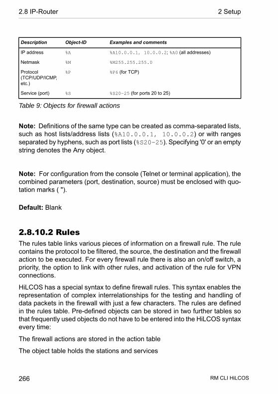
Examples and commentsObject-IDDescription
%A10.0.0.1, 10.0.0.2; %A0 (all addresses)%AIP address
%M255.255.255.0%MNetmask
%P6 (for TCP)%PProtocol(TCP/UDP/ICMP,etc.)
%S20-25 (for ports 20 to 25)%SService (port)
Table 9: Objects for firewall actions
Note: Definitions of the same type can be created as comma-separated lists,such as host lists/address lists (%A10.0.0.1, 10.0.0.2) or with rangesseparated by hyphens, such as port lists (%S20-25). Specifying '0' or an emptystring denotes the Any object.
Note: For configuration from the console (Telnet or terminal application), thecombined parameters (port, destination, source) must be enclosed with quo-tation marks ( ").
Default: Blank
2.8.10.2 RulesThe rules table links various pieces of information on a firewall rule. The rulecontains the protocol to be filtered, the source, the destination and the firewallaction to be executed. For every firewall rule there is also an on/off switch, apriority, the option to link with other rules, and activation of the rule for VPNconnections.
HiLCOS has a special syntax to define firewall rules. This syntax enables therepresentation of complex interrelationships for the testing and handling ofdata packets in the firewall with just a few characters. The rules are definedin the rules table. Pre-defined objects can be stored in two further tables sothat frequently used objects do not have to be entered into the HiLCOS syntaxevery time:
The firewall actions are stored in the action table
The object table holds the stations and services
RM CLI HiLCOS 266
2.8 IP-Router 2 Setup
The definition of firewall rules can contain entries in the object table for proto-cols, services, stations and the action table for firewall actions, and also directdefinitions in the appropriate HiLCOS syntax (e.g. %P6 for TCP).
SNMP ID: 2.8.10.2
Telnet path: /Setup/IP-Router/Firewall
Note: The objects from these tables can be used for rule definition, althoughthis is not compulsory. They merely simplify the use of frequently used objects.For direct input of level parameters in the HiLCOS syntax, the same rulesapply as specified in the following sections for protocols, source/destinationand firewall actions.
2.8.10.2.1 NameSpecify here a unique name for this firewall rule.
SNMP ID: 2.8.10.2.1
Telnet path: /Setup/IP-Router/Firewall/Rules
Possible values:
D Max. 32 characters
Default: Blank
2.8.10.2.2 ProtocolSpecification of the protocols for which this entry is to apply.
SNMP ID: 2.8.10.2.2
Telnet path: /Setup/IP-Router/Firewall/Rules
Possible values:
D Direct entry in HiLCOS syntax as described in the Objects table.D Link to an entry of the object table.
Default: Blank
RM CLI HiLCOS 267
2 Setup 2.8 IP-Router

2.8.10.2.3 SourceSpecification of the source stations for which this entry is to apply.
SNMP ID: 2.8.10.2.3
Telnet path: /Setup/IP-Router/Firewall/Rules
Possible values:
D Direct entry in HiLCOS syntax as described in the Objects table.D Link to an entry of the object table.
Default: Blank
2.8.10.2.4 DestinationSpecification of the destination stations for which this entry is to apply.
SNMP ID: 2.8.10.2.4
Telnet path: /Setup/IP-Router/Firewall/Rules
Possible values:
D Direct entry in HiLCOS syntax as described in the Objects table.D Link to an entry of the object table.
Default: Blank
2.8.10.2.7 ActionAction to be run if the firewall rule applies to a packet.
SNMP ID: 2.8.10.2.7
Telnet path: /Setup/IP-Router/Firewall/Rules
Possible values:
D Direct entry in HiLCOS syntax as described in the Actions table.D Link to an entry of the action table.
Default: Blank
RM CLI HiLCOS 268
2.8 IP-Router 2 Setup

2.8.10.2.8 LinkedLinks the rule to other rules.
SNMP ID: 2.8.10.2.8
Telnet path: /Setup/IP-Router/Firewall/Rules
Possible values:
D YesD No
Default: No
2.8.10.2.9 PriorityPriority of the rule.
SNMP ID: 2.8.10.2.9
Telnet path: /Setup/IP-Router/Firewall/Rules
Possible values:
D 0 to 255
Default: Blank
2.8.10.2.10 ActiveSwitches the rule on/off.
SNMP ID: 2.8.10.2.10
Telnet path: /Setup/IP-Router/Firewall/Rules
Possible values:
D YesD No
Default: Yes
2.8.10.2.11 VPN-RuleActivates the rule for creating VPN rules.
RM CLI HiLCOS 269
2 Setup 2.8 IP-Router

SNMP ID: 2.8.10.2.11
Telnet path: /Setup/IP-Router/Firewall/Rules
Possible values:
D YesD No
Default: No
2.8.10.2.12 StatefulWhen this option is enabled, a check is performed as to whether a connectionis being established correctly. Erroneous packets are dropped whilst theconnection is being established. If this option is disabled, all packets for whichthis rule applies are accepted.
Furthermore, this option is enabled for the automatic protocol recognition forFTP, IRC, PPTP necessary to be able to open a port in the firewall for eachdata connection.
The test for portscans/SYN flooding is also enabled/disabled with this option.This can exclude particular, heavily-frequented servers from the test, meaningthat limits for half-open connections (DOS) or port requests (IDS) do not haveto be set so high that they effectively become useless.
SNMP ID: 2.8.10.2.12
Telnet path: /Setup/IP-Router/Firewall/Rules
Possible values:
D YesD No
Default: Yes
2.8.10.2.13 CommentComment for this entry.
SNMP ID: 2.8.10.2.13
Telnet path: /Setup/IP-Router/Firewall/Rules
Possible values:
RM CLI HiLCOS 270
2.8 IP-Router 2 Setup

D Max. 64 characters
Default: Blank
2.8.10.2.14 Rtg-TagRouting tag for the rule.
SNMP ID: 2.8.10.2.14
Telnet path: /Setup/IP-Router/Firewall/Rules
Possible values:
D 0 to 65535
Default: 0
2.8.10.2.15 Source tagThe source tag (the expected interface- or routing tag) is used to identify theARF context from which a packet was received. This can be used to restrictfirewall rules to certain ARF contexts.
Telnet path:Setup > IP-Router > Firewall > Rules
Possible values:0 to 65535
Comment
D 65535: The firewall rule is applied if the expected interface- or routingtag is 0.
D 1…65534: The firewall rule is applied if the expected interface- orrouting tag is 1...65534.
D 0: Wildcard. The firewall rule is applied to all ARF contexts (theexpected interface- or routing tag is 0...65535).
Default:0
RM CLI HiLCOS 271
2 Setup 2.8 IP-Router
2.8.10.3 Filter-ListThe filter list is generated from the rules in the firewall. The filters it containsare static and can only be changed when firewall rules are added, edited ordeleted..
SNMP ID: 2.8.10.3
Telnet path: /Setup/IP-Router/Firewall
2.8.10.3.1 IndexIndex for this entry in the list.
SNMP ID: 2.8.10.3.1
Telnet path: /Setup/IP-Router/Firewall/Filter-List
2.8.10.3.2 ProtocolTCP protocol for data packets processed by this entry.
SNMP ID: 2.8.10.3.2
Telnet path: /Setup/IP-Router/Firewall/Filter-List
2.8.10.3.3 Src-AddressSource IP address for data packets processed by this entry.
SNMP ID: 2.8.10.3.3
Telnet path: /Setup/IP-Router/Firewall/Filter-List
Possible values:
D Valid IP address
2.8.10.3.4 Source netmaskSource IP netmask for data packets processed by this entry.
SNMP ID: 2.8.10.3.4
Telnet path: /Setup/IP-Router/Firewall/Filter-List
RM CLI HiLCOS 272
2.8 IP-Router 2 Setup
Possible values:
D Valid IP address
2.8.10.3.5 S-St.Start address of range of source IP addresses whose data packets are pro-cessed by this entry.
SNMP ID: 2.8.10.3.5
Telnet path: /Setup/IP-Router/Firewall/Filter-List
2.8.10.3.6 S-EndEnd address of the range of source IP addresses whose data packets areprocessed by this entry.
SNMP ID: 2.8.10.3.6
Telnet path: /Setup/IP-Router/Firewall/Filter-List
2.8.10.3.7 Dst-AddressDestination IP address for data packets processed by this entry.
SNMP ID: 2.8.10.3.7
Telnet path: /Setup/IP-Router/Firewall/Filter-List
Possible values:
D Valid IP address
2.8.10.3.8 Dst-netmaskDestination IP netmask for data packets processed by this entry.
SNMP ID: 2.8.10.3.8
Telnet path: /Setup/IP-Router/Firewall/Filter-List
Possible values:
D Valid IP address
RM CLI HiLCOS 273
2 Setup 2.8 IP-Router
2.8.10.3.9 D-St.Start address of range of destination IP addresses whose data packets areprocessed by this entry.
SNMP ID: 2.8.10.3.9
Telnet path: /Setup/IP-Router/Firewall/Filter-List
2.8.10.3.10 D-EndFinish address of range of destination IP addresses whose data packets areprocessed by this entry.
SNMP ID: 2.8.10.3.10
Telnet path: /Setup/IP-Router/Firewall/Filter-List
2.8.10.3.11 ActionAction performed for the data packets processed by this entry.
SNMP ID: 2.8.10.3.11
Telnet path: /Setup/IP-Router/Firewall/Filter-List
2.8.10.3.13 Source MACSource MAC address for data packets processed by this entry.
SNMP ID: 2.8.10.3.13
Telnet path: /Setup/IP-Router/Firewall/Filter-List
2.8.10.3.14 Dst-MACDestination MAC address for data packets processed by this entry.
SNMP ID: 2.8.10.3.14
Telnet path: /Setup/IP-Router/Firewall/Filter-List
2.8.10.3.15 LinkedIndicates whether further firewall rules are applied after this action.
RM CLI HiLCOS 274
2.8 IP-Router 2 Setup
SNMP ID: 2.8.10.3.15
Telnet path: /Setup/IP-Router/Firewall/Filter-List
2.8.10.3.16 PriorityPriority for this entry.
SNMP ID: 2.8.10.3.16
Telnet path: /Setup/IP-Router/Firewall/Filter-List
2.8.10.3.17 Rtg-tagThis routing tag is added to data packets processed by this entry.
SNMP ID: 2.8.10.3.17
Telnet path: /Setup/IP-Router/Firewall/Filter-List
2.8.10.3.18 Source tagThe source tag (the expected interface- or routing tag) is used to identify theARF context from which a packet was received.
Telnet path:Setup > IP-Router > Firewall > Filter-List
2.8.10.4 ActionsA firewall action comprises of a condition, a limit, a packet action and othermeasures.
As with the elements of the object table, firewall actions can be given a nameand be combined with each other in any way recursively. The maximumrecursion depth is limited to 16. They can also be entered into the actions fieldof the rules table directly.
SNMP ID: 2.8.10.4
Telnet path: /Setup/IP-Router/Firewall
RM CLI HiLCOS 275
2 Setup 2.8 IP-Router
2.8.10.4.1 NameSpecify a unique name for this action.
SNMP ID: 2.8.10.4.1
Telnet path: /Setup/IP-Router/Firewall/Actions
Possible values:
D Max. 32 characters
Default: Blank
2.8.10.4.2 DescriptionSNMP ID: 2.8.10.4.2
Telnet path: /Setup/IP-Router/Firewall/Actions
In the actions table, firewall actions are combined as any combination ofconditions, limits, packet actions and other measures.
Possible values:
A firewall action comprises of a condition, a limit, a packet action and othermeasures. In the actions table, firewall actions are made up of combinationsof any of the following elements.
Conditions
Object-IDDescriptionCondition
@cThe filter is active if there is no physical connection to the destination
of the packet
Connect filter
@dThe filter is active if the packet contains the specified Differentiated
Services Code Point (DSCP)
DiffServ filter
@iThe filter is active if the packet was received, or is to be sent, via the
default route
Internet-Filter
RM CLI HiLCOS 276
2.8 IP-Router 2 Setup

Object-IDDescriptionCondition
@vThe filter is active if the packet was received, or is to be sent, via a
VPN connection
VPN-Filter
Table 10: Conditions for firewall actions
Note: If no further action is specified for the “Connect" or “Internet” filter, acombination of these filters is implicitly adopted with the “Reject” action.
Limits
Each firewall action can be associated with a limit, which triggers the actionif it is exceeded. Action chains can be formed by combining multiple limits fora filter Limit objects are generally initiated with %L, followed by:
D Relation: connection-related (c) or global (g)D Type: Data rate (d), number of packets (p), or packet rate (b)D Limit valueD Other parameters (e.g., time and size)
The following limits are available:
Object-IDDescriptionLimit
%lcdAbsolute number of kilobytes over the connection, after which the
action is performed
Data (abs)
%lcds,
%lcdm,
%lcdh
Number of kilobytes per second, minute, hour over the connection,
after which the action is performed
Data (rel)
%lcpAbsolute number of packets over the connection, after which the action
is performed
Packet (abs)
%lcps,
%lcpm,
%lcph
Number of packets per second, minute, hour, or absolute over the
connection, after which the action is performed
Packet (rel)
%lgdAbsolute number of kilobytes sent to or received from the destination
computer, after which the action is performed
Global data (abs)
RM CLI HiLCOS 277
2 Setup 2.8 IP-Router
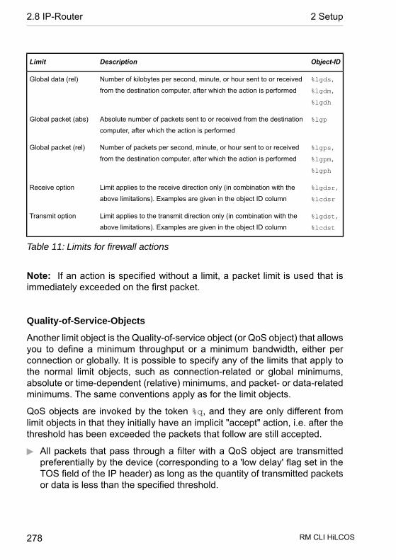
Object-IDDescriptionLimit
%lgds,
%lgdm,
%lgdh
Number of kilobytes per second, minute, or hour sent to or received
from the destination computer, after which the action is performed
Global data (rel)
%lgpAbsolute number of packets sent to or received from the destination
computer, after which the action is performed
Global packet (abs)
%lgps,
%lgpm,
%lgph
Number of packets per second, minute, or hour sent to or received
from the destination computer, after which the action is performed
Global packet (rel)
%lgdsr,
%lcdsr
Limit applies to the receive direction only (in combination with the
above limitations). Examples are given in the object ID column
Receive option
%lgdst,
%lcdst
Limit applies to the transmit direction only (in combination with the
above limitations). Examples are given in the object ID column
Transmit option
Table 11: Limits for firewall actions
Note: If an action is specified without a limit, a packet limit is used that isimmediately exceeded on the first packet.
Quality-of-Service-Objects
Another limit object is the Quality-of-service object (or QoS object) that allowsyou to define a minimum throughput or a minimum bandwidth, either perconnection or globally. It is possible to specify any of the limits that apply tothe normal limit objects, such as connection-related or global minimums,absolute or time-dependent (relative) minimums, and packet- or data-relatedminimums. The same conventions apply as for the limit objects.
QoS objects are invoked by the token %q, and they are only different fromlimit objects in that they initially have an implicit "accept" action, i.e. after thethreshold has been exceeded the packets that follow are still accepted.
D All packets that pass through a filter with a QoS object are transmittedpreferentially by the device (corresponding to a 'low delay' flag set in theTOS field of the IP header) as long as the quantity of transmitted packetsor data is less than the specified threshold.
RM CLI HiLCOS 278
2.8 IP-Router 2 Setup
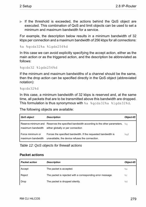
D If the threshold is exceeded, the actions behind the QoS object areexecuted. This combination of QoS and limit objects can be used to set aminimum and maximum bandwidth for a service.
For example, the description below results in a minimum bandwidth of 32kbps per connection and a maximum bandwidth of 256 kbps for all connections:
%a %qcds32%a %lgds256%d
In this case we can avoid explicitly specifying the accept action, either as themain action or as the triggered action, and the description be abbreviated asfollows:
%qcds32 %lgds256%d
If the minimum and maximum bandwidths of a channel should be the same,then the drop action can be specified directly in the QoS object (abbreviatednotation):
%qcds32%d
In this case, a minimum bandwidth of 32 kbps is reserved and, at the sametime, all packets that are to be transmitted above this bandwidth are dropped.This formulation is thus synonymous with %a %qcds32%a %lgds32%d.
The following objects are available:
Object-IDDescriptionQoS object
%qReserves the specified bandwidth according to the other parameters,
either globally or per connection
Reserve minimum and
maximum bandwidth
%qfForces the specified bandwidth. If the requested bandwidth is
unavailable, the device refuses the connection.
Force minimum or
maximum bandwidth
Table 12: QoS objects for firewall actions
Packet actions
Object-IDDescriptionPacket action
%aThe packet is accepted.Accept
%rThe packet is rejected with a corresponding error message.Reject
%dThe packet is dropped silently.Drop
RM CLI HiLCOS 279
2 Setup 2.8 IP-Router

Object-IDDescriptionPacket action
%xThe packet is passed another module for an external check. The %x
follows the identifier of the module performing the check. Possible
values:
External check
D %xc for the content filter, followed by a previously defined content-
filter profile, e.g. %xcCF-BASIC-PROFILE.
Table 13: Packet actions for firewall actions
Note: These packet actions can be combined with one another in any way.For nonsensical or ambiguous actions (such as Accept + Drop), the moresecure one is taken - “Drop" in this example.
Other measures
Apart from packet actions, the firewall can perform other actions once thelimits have been reached. For example, the firewall can send notificationsover various channels, or block ports or hosts for a certain period.
The following measures are available:
Object-IDDescriptionCountermeasures
%sProvides a detailed message via Syslog.Syslog
%mSends an e-mail to the administrator.E-mail
%nSends an SNMP trapSNMP
%pCloses the destination port of the packet for a configurable timeClose port
%hBlocks the sender address of the packet for a configurable timeDeny host
%tDisconnects the physical connection to the remote site over which the
packet was received or is to be sent.
Disconnect
%zResets the limit counter (see below) to 0 when the trigger threshold
is exceeded
Zero-limit
RM CLI HiLCOS 280
2.8 IP-Router 2 Setup

Object-IDDescriptionCountermeasures
%fForces the fragmentation of all packets not matching the rule.Fragmentation
Table 14: Other measures for firewall actions
Note: When the “Close port” action is run, an entry is made in a block listwith which all packets sent to the respective computer and port are dropped.For the “Close port” object, a block time in seconds, minutes or hours can bespecified. This is noted directly behind the object ID. This time is made up ofthe identifier for the time unit (h, m, s for hour, minute, second) as well as theactual time specification. For example, %pm10 blocks the port for 10 minutes."Minutes" is used as the unit if no time unit is specified. (%p10 is thereforeequivalent to %pm10)
Note: If the “Deny host” action is run, the sender of the packet is entered intoa block list. From this moment on, all packets received from the blockedcomputer are dropped. The "Deny host” object can also be given a block time,formed as described for the “Close port” option.
Note: The "fragmentation" action can be applied directionally (e.g. %ft512fragments transmitted packets and %fr512 fragments received packets to512 bytes) or, instead of hard fragmentation, it can reduce the PTMU only(%fp512 reduces the PMTU to 512 bytes). The PMTU reduction can also bedefined depending on direction (%fpt512, %fpr512). The "Fragmentation"action applies at all times, irrespective of whether a limit has been exceededor not.
Default: Blank
2.8.10.5 Connection listEstablished connections are entered into the connection list if the checkedpacket is accepted by the filter list. The connection list records the source anddestination, the protocol, and the port that a connection is currently allowedto use. The list also indicates how long the entry remains in the list and which
RM CLI HiLCOS 281
2 Setup 2.8 IP-Router

firewall rule generated the entry. This list is highly dynamic and always "onthe move".
SNMP ID: 2.8.10.5
Telnet path: /Setup/IP-Router/Firewall
2.8.10.5.1 Src-AddressIP address of the station that established a connection.
SNMP ID: 2.8.10.5.1
Telnet path: /Setup/IP-Router/Firewall/Connection-List
Possible values:
D Valid IP address
2.8.10.5.2 Dst-AddressDestination IP address to which a connection was established.
SNMP ID: 2.8.10.5.2
Telnet path: /Setup/IP-Router/Firewall/Connection-List
Possible values:
D Valid IP address
2.8.10.5.3 ProtocolProtocol allowed on this connection.
SNMP ID: 2.8.10.5.3
Telnet path: /Setup/IP-Router/Firewall/Connection-List
2.8.10.5.4 Source portSource port of the station that established a connection.
SNMP ID: 2.8.10.5.4
Telnet path: /Setup/IP-Router/Firewall/Connection-List
RM CLI HiLCOS 282
2.8 IP-Router 2 Setup
2.8.10.5.5 Dst-PortDestination port to which a connection was established.
SNMP ID: 2.8.10.5.5
Telnet path: /Setup/IP-Router/Firewall/Connection-List
2.8.10.5.6 TimeoutLease for this entry in the table.
SNMP ID: 2.8.10.5.6
Telnet path: /Setup/IP-Router/Firewall/Connection-List
2.8.10.5.7 FlagsThe flags are used to store information on the connection state and other(internal) information to a bit field.
The states can have the following values: New, establish, open, closing,closed, rejected (corresponding to the TCP flags: SYN, SYN ACK, ACK, FIN,FIN ACK and RST).
UDP connections know the states, open and closing (the latter only if the UDPconnection is linked by a stateful control channel. This is the case with H.323,for example).
Telnet path:/Setup/IP-Router/Firewall/Connection-List
Possible values:
D 00000001 TCP: SYN sentD 00000002 TCP: SYN/ACK receivedD 00000004 TCP: Wait for ACK from serverD 00000008 all: Connection openD 00000010 TCP: FIN receivedD 00000020 TCP: FIN sentD 00000040 TCP: RST sent or receivedD 00000080 TCP: Session being restoredD 00000100 FTP: Passive FTP connection being establishedD 00000400 H.323: Associated T.120 connection
RM CLI HiLCOS 283
2 Setup 2.8 IP-Router
D 00000800: Connection via loopback interfaceD 00001000: Check linked rulesD 00002000: Rule is linkedD 00010000: Destination is on "local route"D 00020000: Destination is on default routeD 00040000: Destination is on VPN routeD 00080000: No physical connection establishedD 00100000: Source is on default routeD 00200000: Source is on VPN routeD 00800000: No route to destinationD 01000000: Contains global action with condition
2.8.10.5.8 Filter ruleShows the filter rule that generated the entry.
SNMP ID: 2.8.10.5.8
Telnet path: /Setup/IP-Router/Firewall/Connection-List
2.8.10.5.9 Source routeSource route used to establish this connection.
SNMP ID: 2.8.10.5.9
Telnet path: /Setup/IP-Router/Firewall/Connection-List
2.8.10.5.10 Dest-RouteDestination route to which a connection was established.
SNMP ID: 2.8.10.5.10
Telnet path: /Setup/IP-Router/Firewall/Connection-List
2.8.10.5.11 Rtg-tagConnection routing tag.
SNMP ID: 2.8.10.5.11
Telnet path: /Setup/IP-Router/Firewall/Connection-List
RM CLI HiLCOS 284
2.8 IP-Router 2 Setup
2.8.10.6 Host block listThe port blocking list contains those stations that are blocked for a certaintime due to a firewall event. This list is dynamic and new entries can be addedcontinuously by corresponding firewall events; entries disappear automaticallyafter the blocking time expires.
SNMP ID: 2.8.10.6
Telnet path: /Setup/IP-Router/Firewall
2.8.10.6.1 Src-AddressSource IP address that is blocked by this entry.
SNMP ID: 2.8.10.6.1
Telnet path: /Setup/IP-Router/Firewall/Host-Block-List
Possible values:
D Valid IP address
2.8.10.6.2 TimeoutLease for this entry in the table.
SNMP ID: 2.8.10.6.2
Telnet path: /Setup/IP-Router/Firewall/Host-Block-List
2.8.10.6.3 Filter ruleShows the filter rule that generated the entry.
SNMP ID: 2.8.10.6.3
Telnet path: /Setup/IP-Router/Firewall/Host-Block-List
2.8.10.7 Port block listThe port blocking list contains those protocols and services that are blockedfor a certain time due to a firewall event. This list is dynamic and new entries
RM CLI HiLCOS 285
2 Setup 2.8 IP-Router

can be added continuously by corresponding firewall events; entries disappearautomatically after the blocking time expires.
SNMP ID: 2.8.10.7
Telnet path: /Setup/IP-Router/Firewall
2.8.10.7.1 Dst-AddressDestination IP address that is blocked by this entry.
SNMP ID: 2.8.10.7.1
Telnet path: /Setup/IP-Router/Firewall/Port-Block-List
Possible values:
D Valid IP address
2.8.10.7.2 ProtocolProtocol that is blocked by this entry.
SNMP ID: 2.8.10.7.2
Telnet path: /Setup/IP-Router/Firewall/Port-Block-List
2.8.10.7.3 Dst-PortDestination port blocked by this entry.
SNMP ID: 2.8.10.7.3
Telnet path: /Setup/IP-Router/Firewall/Port-Block-List
2.8.10.7.4 TimeoutLease for this entry in the table.
SNMP ID: 2.8.10.7.4
Telnet path: /Setup/IP-Router/Firewall/Port-Block-List
2.8.10.7.5 Filter ruleShows the filter rule that generated the entry.
RM CLI HiLCOS 286
2.8 IP-Router 2 Setup

SNMP ID: 2.8.10.7.5
Telnet path: /Setup/IP-Router/Firewall/Port-Block-List
2.8.10.8 Max.-Half-Open-Conns.Denial-of-Service attacks take advantage of inherent weaknesses in theTCP/IP protocol in combination with poor implementations. Attacks whichtarget these inherent weaknesses include SYN Flood and Smurf. Attackswhich target erroneous implementations include those operating with erro-neously fragmented packets (e.g. Teardrop) or with fake sender addresses(e.g. Land). Your device detects most of these attacks and reacts withappropriate countermeasures.
SNMP ID: 2.8.10.8
Telnet path: /Setup/IP-Router/Firewall
Possible values:
D 100 to 9999
Default: 100
2.8.10.9 DoS-ActionThis is where you can specify what action should be taken with packets thatactivate or exceed the trigger. You can transfer the packets, drop themuncommented or reject them using ICMP reject (i.e. the sender is informed).
SNMP ID: 2.8.10.9
Telnet path: /Setup/IP-Router/Firewall
Possible values:
D TransmitD DropD Reject
Default: Drop
RM CLI HiLCOS 287
2 Setup 2.8 IP-Router

2.8.10.10 Admin-EmailIf you wish to be notified of predefined events (DoS, IDS or when limits areexceeded) you must specify a valid e-mail address here.
SNMP ID: 2.8.10.10
Telnet path: /Setup/IP-Router/Firewall
Possible values:
D Max. 255 characters
Note: For e-mail messaging, you have to enter the necessary settings intothe main group "Log & Trace" in the subsection "SMTP".
2.8.10.11 OperatingYou can switch the entire firewall on or off here. The firewall inspects andcounts every single incoming and outgoing packet. Depending on the protocolin question, it temporarily opens the channels that are required by a localstation for processing a request. Furthermore individual networks, peers,services or protocols can be preferred, limited or blocked.
SNMP ID: 2.8.10.11
Telnet path: /Setup/IP-Router/Firewall
Possible values:
D UpD Down
Default: Operating
Note: Defined VPN rules continue to be observed even with the firewallswitched off.
RM CLI HiLCOS 288
2.8 IP-Router 2 Setup
2.8.10.12 Port-Scan-ThresholdIntrusion-Detection-System (IDS). Your device detects most unauthorizedintrusion attempts and can respond with countermeasures that can be con-figured here.
SNMP ID: 2.8.10.12
Telnet path: /Setup/IP-Router/Firewall
Possible values:
D 50 to 9999
Default: 50
2.8.10.13 IDS-ActionThis is where you can specify what action should be taken with packets thatactivate or exceed the trigger. You can transfer the packets, drop themuncommented or reject them using ICMP reject (i.e. the sender is informed).
SNMP ID: 2.8.10.13
Telnet path: /Setup/IP-Router/Firewall
Possible values:
D TransmitD DropD Reject
Default: Drop
2.8.10.14 Ping-BlockA controversial method of increasing security is to conceal the router by notresponding to ping and traceroute requests (ping blocking). This is controversialbecause the failure to answer can also betray the existence of a device. Ifthere truly is no device present, the previous router will respond to the relevantpackets with 'undeliverable' as it is unable to deliver them. However, if theprevious router no longer responds with a corresponding rejection, the packetis 'deliverable' and, regardless of the recipient's subsequent behavior, is most
RM CLI HiLCOS 289
2 Setup 2.8 IP-Router

certainly present. It is not possible to simulate the behavior of the previousrouter without keeping your device offline or switching it off (and thus makingit unreachable for the services you yourself request).
SNMP ID: 2.8.10.14
Telnet path: /Setup/IP-Router/Firewall
Possible values:
D OffD AlwaysD WAND Default route
Default: Off
2.8.10.15 Stealth-ModeA controversial method of increasing security is to conceal the router by notconforming to standards and rejecting TCP and UDP requests, but by ignoringthem (stealth mode) . This is controversial because the failure to answer canalso betray the existence of a device. If there truly is no device present, theprevious router will respond to the relevant packets with 'undeliverable' as itis unable to deliver them. However, if the previous router no longer respondswith a corresponding rejection, the packet is 'deliverable' and, regardless ofthe recipient's subsequent behavior, is most certainly present. It is not possibleto simulate the behavior of the previous router without keeping your deviceoffline or switching it off (and thus making it unreachable for the services youyourself request).
SNMP ID: 2.8.10.15
Telnet path: /Setup/IP-Router/Firewall
Possible values:
D OffD AlwaysD WAND Default route
Default: Off
RM CLI HiLCOS 290
2.8 IP-Router 2 Setup

2.8.10.16 Auth-PortHiding TCP or UDP ports will cause problems on masked connections whereso-called 'authenticate' or 'ident' queries, as used by some mail and newsservers to request additional information from users, are no longer rejectedcorrectly. These servers then time out, resulting in considerable delays in thedelivery of mail or news. In order to overcome this problem when stealth modeis switched on, stealth mode is deactivated temporarily for the port in question.The firewall recognizes that the internal station's wish to establish contact witha mail (SMTP, POP3, IMAP2) or news server (NNTP) and opens the port for20 seconds. You can use this option to suppress the temporary deactivationof stealth mode for the authentication port.
SNMP ID: 2.8.10.16
Telnet path: /Setup/IP-Router/Firewall
Possible values:
D UpD Down
Default: Down
2.8.10.17 Deny-Session-RecoverThe firewall opens appropriate channels for each session initiated and itsassociated connections (e.g. FTP with control and data connections) for acertain period. If there is no communication over the connection for a definedperiod of time (setting in the IP router masquerading), then the session isconsidered to be ended and the channels associated with the connectionsare closed. Selecting 'session recover' determines the behavior of the firewallwhen receiving packets which appear to belong to an earlier session. Thepackets are dropped or it is assumed that a session existed but that no com-munication took place for too long. In this case, an equivalent session can bereestablished. The latter behavior can in general be allowed or forbidden.Denial of a session can be restricted to the default route or to WAN sessions.
SNMP ID: 2.8.10.17
Telnet path: /Setup/IP-Router/Firewall
RM CLI HiLCOS 291
2 Setup 2.8 IP-Router

Possible values:
D Off - always permittedD Always - always forbiddenD WAN - forbidden over WAND Default-route - forbidden on default route
Default: Default-route - forbidden on default route
2.8.10.19 Open-Port-ListThe port blocking list contains protocols and services that a firewall event haspermitted for a certain time. This list is dynamic and new entries can be addedcontinuously by corresponding firewall events; entries disappear automaticallyafter the blocking time expires.
SNMP ID: 2.8.10.19
Telnet path: /Setup/IP-Router/Firewall
2.8.10.19.1 Src-AddressSource IP address that can be used by the open ports and protocols in thisentry.
SNMP ID: 2.8.10.19.1
Telnet path: /Setup/IP-Router/Firewall/Open-Port-List
Possible values:
D Valid IP address
2.8.10.19.2 Dst-AddressDestination IP address to which a connection may be established using theopen ports and protocols in this entry.
SNMP ID: 2.8.10.19.2
Telnet path: /Setup/IP-Router/Firewall/Open-Port-List
Possible values:
D Valid IP address
RM CLI HiLCOS 292
2.8 IP-Router 2 Setup

2.8.10.19.3 ProtocolProtocol opened by this entry.
SNMP ID: 2.8.10.19.3
Telnet path: /Setup/IP-Router/Firewall/Open-Port-List
2.8.10.19.5 Dst-PortDestination port opened by this entry.
SNMP ID: 2.8.10.19.5
Telnet path: /Setup/IP-Router/Firewall/Open-Port-List
2.8.10.19.6 TimeoutLease for this entry in the table.
SNMP ID: 2.8.10.19.6
Telnet path: /Setup/IP-Router/Firewall/Open-Port-List
2.8.10.19.8 Filter ruleShows the filter rule that generated the entry.
SNMP ID: 2.8.10.19.8
Telnet path: /Setup/IP-Router/Firewall/Open-Port-List
2.8.10.19.9 Source routeSource route used to establish this connection.
SNMP ID: 2.8.10.19.9
Telnet path: /Setup/IP-Router/Firewall/Open-Port-List
2.8.10.20 ApplicationsThis menu contains the configuration of individual firewall applications.
SNMP ID: 2.8.10.20
RM CLI HiLCOS 293
2 Setup 2.8 IP-Router

Telnet path: /Setup/IP-Router/Firewall
2.8.10.20.1 FTPThis menu contains the configuration of FTP for your firewall.
SNMP ID: 2.8.10.20.1
Telnet path: /Setup/IP-Router/Firewall/Applications
2.8.10.20.1.1 FTP-BlockWhen an FTP session is identified on any port, the countermeasures con-figured here are taken. 'FTP block' specifies whether and on what routes anytype of FTP should be given special treatment.
SNMP ID: 2.8.10.20.1.1
Telnet path: /Setup/IP-Router/Firewall/Applications/FTP
Possible values:
D OffD AlwaysD WAND Default route
Default: No
2.8.10.20.1.2 Active-FTP-BlockWhen an FTP session is identified on any port, the countermeasures con-figured here are taken. 'Block active FTP' specifies whether and on whatroutes active FTP should be given special treatment.
SNMP ID: 2.8.10.20.1.2
Telnet path: /Setup/IP-Router/Firewall/Applications/FTP
Possible values:
D NoD AlwaysD WAND Default route
RM CLI HiLCOS 294
2.8 IP-Router 2 Setup

Default: No
2.8.10.20.1.3 Min-PortWhen an FTP session is identified on any port, the countermeasures con-figured here are taken. 'Minimum port number' specifies the smallest permittedport for active FTP.
SNMP ID: 2.8.10.20.1.3
Telnet path: /Setup/IP-Router/Firewall/Applications/FTP
Possible values:
D 1024 to 9999
Default: 1024
2.8.10.20.1.4 Check-Host-IPWhen an FTP session is identified on any port, the countermeasures con-figured here are taken. 'Check host IP' specifies whether and on what routesthe address transmitted in the FTP command should be checked against thesource address of the FTP client. If it does not match, the countermeasuresconfigured below will be taken. This check will of course be skipped if a site-to-site transfer is to take place and is permitted es.
SNMP ID: 2.8.10.20.1.4
Telnet path: /Setup/IP-Router/Firewall/Applications/FTP
Possible values:
D NoD AlwaysD WAND Default route
Default: Default route
2.8.10.20.1.5 FXP-BlockWhen an FTP session is identified on any port, the countermeasures con-figured here are taken. 'FXP block' specifies whether site-to-site transfers(FXP) should be given special treatment.
RM CLI HiLCOS 295
2 Setup 2.8 IP-Router

SNMP ID: 2.8.10.20.1.5
Telnet path: /Setup/IP-Router/Firewall/Applications/FTP
Possible values:
D NoD AlwaysD WAND Default route
Default: Default route
2.8.10.20.2 IRCThis menu contains the configuration of IRC for your firewall.
SNMP ID: 2.8.10.20.2
Telnet path: /Setup/IP-Router/Firewall/Applications
2.8.10.20.2.1 IRC-BlockWhen an IRC session is identified on any port, the countermeasures configuredhere are taken. 'Block IRC' specifies whether and on what routes any type ofIRC should be given special treatment.
SNMP ID: 2.8.10.20.2.1
Telnet path: /Setup/IP-Router/Firewall/Applications/IRC
Possible values:
D NoD AlwaysD WAND Default route
Default: No
2.8.10.20.2.2 DDC-BlockWhen an IRC session is identified on any port, the countermeasures configuredhere are taken. 'Block DDC' specifies whether and on what routes Direct-Data-Connect (private chats and file transfers) should be given special treatment.
RM CLI HiLCOS 296
2.8 IP-Router 2 Setup

SNMP ID: 2.8.10.20.2.2
Telnet path: /Setup/IP-Router/Firewall/Applications/IRC
Possible values:
D NoD AlwaysD WAND Default route
Default: No
2.8.10.20.2.3 Min-PortWhen an IRC session is identified on any port, the countermeasures configuredhere are taken. 'Minimum port number' specifies the smallest permitted portfor DDC.
SNMP ID: 2.8.10.20.2.3
Telnet path: /Setup/IP-Router/Firewall/Applications/IRC
Possible values:
D 1024 to 9999
Default: 1024
2.8.10.20.2.4 Check-Host-IPWhen an IRC session is identified on any port, the countermeasures configuredhere are taken. 'Check-Host-IP' indicates whether and on what routes theaddress transmitted in the DDC command should be checked against thesource address of the IRC client.
SNMP ID: 2.8.10.20.2.4
Telnet path: /Setup/IP-Router/Firewall/Applications/IRC
Possible values:
D NoD AlwaysD WAND Default route
RM CLI HiLCOS 297
2 Setup 2.8 IP-Router

Default: Default route
2.8.10.20.10 Appl.-ActionWhen an IRC session is identified on any port, the countermeasures configuredhere are taken.
SNMP ID: 2.8.10.20.10
Telnet path: /Setup/IP-Router/Firewall/Applications
Possible values:
D TransmitD DropD Reject
Default: Reject
2.8.11 Start-WAN-PoolEnter a range of IP addresses that should be assigned to users dialing intothe device..
Each user is automatically assigned a free address from this range. As soonas a user disconnects from the device, the assigned address is freed up andis available for other users.
SNMP ID: 2.8.11
Telnet path: /Setup/IP-Router
Possible values:
D Valid IP address
Default: 0.0.0.0
2.8.12 End-WAN-PoolEnter a range of IP addresses that should be assigned to users dialing intothe device..
Each user is automatically assigned a free address from this range. As soonas a user disconnects from the device, the assigned address is freed up andis available for other users.
RM CLI HiLCOS 298
2.8 IP-Router 2 Setup
SNMP ID: 2.8.12
Telnet path: /Setup/IP-Router
Possible values:
D Valid IP address
Default: 0.0.0.0
2.8.13 Default-Time-ListTime-dependent control allows you to specify different destinations for thedefault route depending on the day of the week and time.
SNMP ID: 2.8.13
Telnet path: /Setup/IP-Router
2.8.13.1 IndexIndex for this entry in the list.
SNMP ID: 2.8.13.1
Telnet path: /Setup/IP-Router/Default-Time-List
2.8.13.2 DaysSpecify the days when this entry should be used.
SNMP ID: 2.8.13.2
Telnet path: /Setup/IP-Router/Default-Time-List
Possible values:
D MondayD TuesdayD WednesdayD ThursdayD FridayD SaturdayD Sunday
RM CLI HiLCOS 299
2 Setup 2.8 IP-Router

D Holiday
Default: No days are marked
2.8.13.3 StartUsed to specify the time period during which this entry should be used.
SNMP ID: 2.8.13.3
Telnet path: /Setup/IP-Router/Default-Time-List
Possible values:
D 12:00 AM to 11:59 PM (CET)
Default: 0
2.8.13.4 StopUsed to specify the time period during which this entry should be used.
SNMP ID: 2.8.13.4
Telnet path: /Setup/IP-Router/Default-Time-List
Possible values:
D 12:00 AM to 11:59 PM (CET)
Default: 0.999305556
2.8.13.5 PeerThe remote site specified here will become the default route after this entrybecomes valid when the defined time period is reached. Here you select thename of a remote site from the list of remote sites.
SNMP ID: 2.8.13.5
Telnet path: /Setup/IP-Router/Default-Time-List
Possible values:
D Select from the list of defined peers.
RM CLI HiLCOS 300
2.8 IP-Router 2 Setup
2.8.14 Usage-Default-TimetableActivates the time-dependent control of the default route. The default route isnormally used to establish the connection to an Internet provider. The timecontrol allows you to select various Internet providers depending on the time,for example to benefit from the most favorable provider at a certain time ofday.
SNMP ID: 2.8.14
Telnet path: /Setup/IP-Router
Possible values:
D UpD Down
Default: Down
Note: To make use of this mechanism, a default route must have been spe-cified in the routing table. The router specified in the default route is only usedduring those times that are not covered by the timed control table.
2.8.19 N-N-NATThe rules in the N:N-NAT table regulate the IP addresses to which sourceaddresses or entire IP networks are translated. These rules must be specifiedexplicitly for each remote site because translation takes place after routing.The remote site reaches the stations or networks at their translated IP addressas specified.
SNMP ID: 2.8.19
Telnet path: /Setup/IP-Router
2.8.19.1 Idx.Unique index for the entry
SNMP ID: 2.8.19.1
Telnet path: /Setup/IP-Router/N-N-NAT
RM CLI HiLCOS 301
2 Setup 2.8 IP-Router
Possible values:
D Max. 4 characters
Default: Blank
2.8.19.2 Src-AddressIP address of the computer or network that is to receive an alternative IPaddress.
SNMP ID: 2.8.19.2
Telnet path: /Setup/IP-Router/N-N-NAT
Possible values:
D Valid IP address
Default: 0.0.0.0
2.8.19.3 Src-MaskNetmask of the source range.
SNMP ID: 2.8.19.3
Telnet path: /Setup/IP-Router/N-N-NAT
Possible values:
D Valid IP address
Default: 0.0.0.0
2.8.19.4 Dst-StationName of the remote device that can be used to access the remote network.
SNMP ID: 2.8.19.4
Telnet path: /Setup/IP-Router/N-N-NAT
Possible values:
D Select from the list of defined peers.
RM CLI HiLCOS 302
2.8 IP-Router 2 Setup

Default: Blank
2.8.19.5 Mapped-NetworkIP addresses or address range to be used for translation.
SNMP ID: 2.8.19.5
Telnet path: /Setup/IP-Router/N-N-NAT
Possible values:
D Valid IP address
Default: 0.0.0.0
Note: For the new network address, the same netmask is taken as used bythe source address. The following applies with the assignment of source andmapping addresses:
D When translating individual addresses, source and mapping can beassigned in any way.
D When entire address ranges are translated, the computer-related part ofthe IP address is used directly and only the network-related part of themapping address is appended. When assigning 10.0.0.0/255.255.255.0to 192.168.1.0, the server in the LAN with the IP address 10.1.1.99 isnecessarily assigned with the mapping address 192.168.1.99.
Note: The address range for translation must be at least as large as thesource address range.
Note: Please note that the N:N mapping function is only effective when thefirewall is activated.
2.8.20 Load-BalancerThis menu contains the configuration of load balancing for your IP router.
SNMP ID: 2.8.20
RM CLI HiLCOS 303
2 Setup 2.8 IP-Router
Telnet path: /Setup/IP-Router
2.8.20.1 OperatingThis is where you can set parameters for load balancing. Load balancing canbe used if your provider does not offer true channel bundling. At least onevirtual connection must be specified in the load balancing table for this. Themaximum number of remote sites that can be bundled depends on how manyDSL ports are available for the type of device used.
SNMP ID: 2.8.20.1
Telnet path: /Setup/IP-Router/Load-Balancer
Possible values:
D UpD Down
Default: Down
2.8.20.2 Bundle-PeersIf your Internet provider offers true channel bundling, it is possible for multipleconnections to be combined with the help of load balancing.
SNMP ID: 2.8.20.2
Telnet path: /Setup/IP-Router/Load-Balancer
2.8.20.2.1 PeerUnique name for a virtual load-balancing remote site. This remote site canthen be used in the routing table.
SNMP ID: 2.8.20.2.1
Telnet path: /Setup/IP-Router/Load-Balancer/Bundle-Peers
Possible values:
D Select from the list of defined peers.
Default: Blank
RM CLI HiLCOS 304
2.8 IP-Router 2 Setup

2.8.20.2.2 Bundle-Peer-1Name of a previously configured remote site to which the others are to bebundled.
SNMP ID: 2.8.20.2.2
Telnet path: /Setup/IP-Router/Load-Balancer/Bundle-Peers
Possible values:
D Max. 16 characters
Default: Blank
2.8.20.2.3 Bundle-Peer-2Name of a previously configured remote site to which the others are to bebundled.
SNMP ID: 2.8.20.2.3
Telnet path: /Setup/IP-Router/Load-Balancer/Bundle-Peers
Possible values:
D Max. 16 characters
Default: Blank
2.8.20.2.4 Bundle-Peer-3Name of a previously configured remote site to which the others are to bebundled.
SNMP ID: 2.8.20.2.4
Telnet path: /Setup/IP-Router/Load-Balancer/Bundle-Peers
Possible values:
D Max. 16 characters
Default: Blank
RM CLI HiLCOS 305
2 Setup 2.8 IP-Router
2.8.20.2.5 Bundle-Peer-4Name of a previously configured remote site to which the others are to bebundled.
SNMP ID: 2.8.20.2.5
Telnet path: /Setup/IP-Router/Load-Balancer/Bundle-Peers
Possible values:
D Max. 16 characters
Default: Blank
2.8.20.2.10 Client bindingHere you enable or disable the client binding for each load balancer.
Telnet path:Setup > IP-Router > Load-Balancer > Bundle-Peers
Possible values:Yes
Client binding is enabled.No
Client binding is disabled.
Default:No
2.8.20.3 Client bindingIn this menu, you can configure the client binding.
The use of load balancing leads to problems for servers that use an IP addressto identify a logged-on user. If a user is logged in to a web site, for example,and the load balancer then takes a different Internet connection, then theserver interprets this as a connection attempt by a user who is not logged on.In the best case the user sees a new login dialog, but not the desired webpage.
RM CLI HiLCOS 306
2.8 IP-Router 2 Setup

One possible workaround would be to use a firewall rule (policy based routing)to direct the traffic to this server over a specific Internet connection. However,this would limit all of the traffic to that server to the bandwidth of a singleconnection. What's more, there is no way to establish a backup if the firstconnection should fail.
In contrast to this, client binding does not monitor the individual TCP/IP ses-sions but the client that opened an Internet connection in the initial session.It directs all subsequent sessions through this Internet connection, whichcorresponds in principle to the policy-based routing mentioned above. Howthis is done depends on the protocol, i.e. it transports only data of the sameprotocol type (e.g. HTTPS) over this Internet connection. If the client loadsadditional data via an HTTP connection, it probably does this with a differentconnection.
To prevent data from being bottle-necked into this one Internet connectionwhen it could easily be transferred via parallel connections, a timer ensuresthat the load balancer distributes additional sessions between the availableInternet connections for a specified period. After the timer expires, the clientbinding forces a new session over the original Internet connection and thetimer is restarted. The server thus continues to recognize the login status forthe user due to the current IP address.
Telnet path:Setup > IP-Router > Load-Balancer
2.8.20.3.1 ProtocolsIn this table, you specify the protocols and the associated ports for monitoringby the client binding.
Note: The table already contains the default entries
D HTTPSD HTTPD ANY
RM CLI HiLCOS 307
2 Setup 2.8 IP-Router
Telnet path:Status > IP-Router > Load-Balancer > Client-Binding
2.8.20.3.1.1 NameEnter a descriptive name for this entry.
Telnet path:Setup > IP-Router > Load-Balancer > Client-Binding > Protocols
Possible values:Max. 16 characters from [A-Z][a-z][0-9]
Default:empty
2.8.20.3.1.2 ProtocolSelect the IP protocol number.
Note: Learn more about IP protocol numbers in the online database of theIANA.
Telnet path:Setup > IP-Router > Load-Balancer > Client-Binding > Protocols
Possible values:Max. 3 characters from [0-255]
Special values:0
All protocols
RM CLI HiLCOS 308
2.8 IP-Router 2 Setup

Default:0
2.8.20.3.1.3 PortSelect the port.
Telnet path:Setup > IP-Router > Load-Balancer > Client-Binding > Protocols
Possible values:Max. 5 characters from [0-65535]
Special values:0
All ports
Default:0
2.8.20.3.1.4 OperatingHere you enable or disable the client binding for this entry.
Telnet path:Setup > IP-Router > Load-Balancer > Client-Binding > Protocols
Possible values:Yes
Enables the entryNo
Disables the entry
RM CLI HiLCOS 309
2 Setup 2.8 IP-Router
Default:Yes
2.8.20.3.2 Binding minutesSpecify the time in minutes for the binding entries to be valid for a client.
Telnet path:Status > IP-Router > Load-Balancer > Client-Binding
Possible values:Max. 3 characters from [0-999]
Special values:0
Default:30
2.8.20.3.3 Balance secondsTo prevent data from flowing through this main-session Internet connectionwhen it could easily be transferred via parallel connections, a timer ensuresthat the load balancer distributes additional sessions between the availableInternet connections for a specified period. After the timer expires, the clientbinding forces a new session over the original Internet connection and thetimer is restarted. The server thus continues to recognize the login status forthe user due to the current IP address.
Here you specify the time in seconds, following the start of the main session,during which the load balancer is free to distribute new sessions to otherInternet connections.
Telnet path:
RM CLI HiLCOS 310
2.8 IP-Router 2 Setup
Status > IP-Router > Load-Balancer > Client-Binding
Possible values:Max. 3 characters from [0-999]
Special values:0
The timer is deactivated. All sessions are bound to the existing Internetconnection.
Default:10
2.8.21 VRRPThis menu contains the configuration of VRRP for your IP router.
SNMP ID: 2.8.21
Telnet path: /Setup/IP-Router
2.8.21.1 OperatingVRRP – Virtual Router Redundancy Protocol – enables multiple physicalrouters to appear as a single "virtual" router. Of the existing physical routers,one is always the "master". The master is the only router that establishes adata connection to the Internet, for example, and transfers data. Only whenthe master fails, for example as a result of a power outage or if its Internetconnection is dropped, will the other routers become active. They will thennegotiate with the VRRP protocol to determine which router should assumethe role of master. The new master completely takes over the tasks that werecarried out by the previous master.
SNMP ID: 2.8.21.1
Telnet path: Setup/IP-Router/VRRP
Possible values:
D UpD Down
RM CLI HiLCOS 311
2 Setup 2.8 IP-Router

Default: Down
2.8.21.2 VRRP-ListIn the VRRP list you can define and configure virtual routers.
SNMP ID: 2.8.21.2
Telnet path: Setup/IP-Router/VRRP
2.8.21.2.1 Router-IDUnique ID for the virtual router.
SNMP ID: 2.8.21.2.1
Telnet path: /Setup/IP-Router/VRRP/VRRP-List
Possible values:
D 0 to 255
Default: 1
2.8.21.2.2 virt.-AddressIP address for the virtual router. All routers on which the virtual router is setup must assign this router the same IP address.
SNMP ID: 2.8.21.2.2
Telnet path: /Setup/IP-Router/VRRP/VRRP-List
Possible values:
D Valid IP address
Default: 0.0.0.0
2.8.21.2.3 PrioMain priority for the virtual router. Values between 0 and 255 are permitted.Priority is proportional to the value entered. The values 0 and 255 have specialmeanings. '0' turns the virtual router off. '255' is only accepted when the virtualrouter address is identical to the address of the interface that is connected to
RM CLI HiLCOS 312
2.8 IP-Router 2 Setup
the router. If this is not the case, the router will be reported by all other routersin their event logs.
SNMP ID: 2.8.21.2.3
Telnet path: /Setup/IP-Router/VRRP/VRRP-List
Possible values:
D 0 to 255
Default: 0
2.8.21.2.4 B-PrioBackup priority for the virtual router. Values between 0 and 255 are permitted.Priority is proportional to the value entered. The values 0 and 255 have specialmeanings. 0 disables the virtual router in the event of backup. Checks areconducted regularly in order to determine whether the standard connectioncan be reestablished. The interval is determined by the Reconnect-Delayparameter. '255' is only accepted when the virtual router address is identicalto the address of the interface that is connected to the router. If this is not thecase, the router will be reported by all other routers in their event logs. Whenthe backup connection cannot be established in backup mode, then the virtualrouter switches completely to the standby mode and attempts to reestablishthe standard or backup connection at regular intervals.
SNMP ID: 2.8.21.2.4
Telnet path: /Setup/IP-Router/VRRP/VRRP-List
Possible values:
D 0 to 255
Default: 0
2.8.21.2.5 PeerThe entry for the name of the remote site is optional. If a peer name is enteredhere it will be controlled by VRRP. If, for example, the peer loses its Internetconnection backup mode kicks in. If no peer is entered, VRRP can be usedto cover a hardware outage. The remote site can still also be assigned toother virtual routers.
RM CLI HiLCOS 313
2 Setup 2.8 IP-Router
SNMP ID: 2.8.21.2.5
Telnet path: /Setup/IP-Router/VRRP/VRRP-List
Possible values:
D Select from the list of defined peers.
Default: Blank
2.8.21.2.6 CommentThis is where you can insert a comment to describe the virtual router.
SNMP ID: 2.8.21.2.6
Telnet path: /Setup/IP-Router/VRRP/VRRP-List
Possible values:
D Max. 64 characters
Default: Blank
2.8.21.3 Reconnect-DelayThe router will no longer be propagated if the backup connection could notbe established. The reconnect delay specifies after how many minutes sucha router should in this case attempt to establish its main or backup connection.While the attempt is being made, the router will not be propagated.
SNMP ID: 2.8.21.3
Telnet path: Setup/IP-Router/VRRP
Possible values:
D 0 to 999 minutes
Default: 30 min.
2.8.21.4 Advert.-IntervalThe advertising interval shows how many seconds until a virtual router ispropagated again. All routers in virtual router system must be configured withthe same value.
RM CLI HiLCOS 314
2.8 IP-Router 2 Setup

SNMP ID: 2.8.21.4
Telnet path: Setup/IP-Router/VRRP
Possible values:
D 0 to 999 seconds
Default: 1 seconds
2.8.21.5 Internal-ServicesThe Internal services checkbox controls how the router should behave whenit is addressed via a virtual router address. In the default 'on' position, therouter reacts to DNS and NETBIOS services exactly as if it had beenaddressed via its actual address. This only occurs when the device itself isthe master of the virtual router. The 'off' setting results in RFC-compliantbehavior, i.e. relevant packets are rejected.
SNMP ID: 2.8.21.5
Telnet path: Setup/IP-Router/VRRP
Possible values:
D YesD Off
Default: Yes
2.8.22 WAN-Tag-CreationWAN tag creation defines the source for the assignment of interface tags.Besides assignment via the firewall or direct assignment via the tag table, theinterface tag can also be selected based on the effective routing table (staticrouting entries plus routes learned via RIP). The tag selected from this routingtable is is for the route that matches both the remote site and the associatednetwork. If the effective routing table contains more than one entry for a remotesite with the same network, the smallest tag is used.
SNMP ID: 2.8.22
Telnet path: /Setup/IP-Router
Possible values:
RM CLI HiLCOS 315
2 Setup 2.8 IP-Router

D Manual: With this setting, the interface tags are determined solely by anentry in the tag table. The routing table has no significance in the assign-ment of interfaces tags.
D Auto: With this setting, the interface tags are determined initially by anentry in the Tag table. If no matching entry is located there, the tag isdetermined based on the routing table.
Default: Manual:
Note: The interface tags determined via the tag table and on the basis of therouting table can be overwritten with an appropriate entry in the firewall.
2.8.23 Tag-TableThe tag table enables inbound data packets to be directly assigned with aninterface tag that depends on the remote site.
SNMP ID: 2.8.23
Telnet path: /Setup/IP-Router
2.8.23.1 PeerName of the remote site whose packets are to be given interface tags whenreceived.
SNMP ID: 2.8.23.1
Telnet path: /Setup/IP-Router/Tag-Table
Possible values:
D Select from the list of defined peers.
Default: Blank
Special values:Multiple remote sites can be configured in one entry by using* as a place holder. If, for example, several remote sites (RAS users) of acompany are to be tagged, all appropriate remote sites can be given a namewith the prefix “Company1_”. To configure all of the remote sites, just oneentry with remote site "Company1_*" can be included in the tag table.
RM CLI HiLCOS 316
2.8 IP-Router 2 Setup
2.8.23.2 Rtg-TagThis interface tag is assigned to the inbound packets of the remote site.
SNMP ID: 2.8.23.2
Telnet path: /Setup/IP-Router/Tag-Table
Possible values:
D 0 to 65535
Default: 0
2.8.23.3 Start-WAN-PoolThe start WAN pool represents the beginning of the address pool for theremote site or group of remote sites (when using placeholders to specifyremote site). When RAS users dial in, the remote site is assigned an addressfrom the address pool defined here.
SNMP ID: 2.8.23.3
Telnet path: /Setup/IP-Router/Tag-Table
Possible values:
D Valid IP address
Default: 0.0.0.0
2.8.23.4 End-WAN-PoolThe end WAN pool represents the end of the address pool for the remote siteor group of remote sites (when using placeholders to specify remote site).When RAS users dial in, the remote site is assigned an address from theaddress pool defined here.
SNMP ID: 2.8.23.4
Telnet path: /Setup/IP-Router/Tag-Table
Possible values:
D Valid IP address
RM CLI HiLCOS 317
2 Setup 2.8 IP-Router

Default: 0.0.0.0
Special values: If the pool is empty (start and end addresses are 0.0.0.0),the global pool is used.
2.8.23.5 DNS-DefaultUsing this entry you configure the address that the remote station is given asits DNS server.
If the specified value is 0.0.0.0, your device assigns the DNS server thatis configured in the setup menu under TCP-IP/DNS-Default. If 0.0.0.0 isalso entered there, your device assigns itself as the DNS server.
Telnet path:Setup > IP-Router > Tag-Table
Possible values:Valid IPv6 address
Default:0.0.0.0
2.8.23.6 DNS-BackupUsing this entry you configure the address that the remote station is assignedas an alternate DNS server.
If the specified value is 0.0.0.0, your device assigns the alternate DNSserver that is configured in the setup menu under TCP-IP/DNS-Backup.
Telnet path:Setup > IP-Router > Tag-Table
Possible values:Valid IPv6 address
Default:0.0.0.0
RM CLI HiLCOS 318
2.8 IP-Router 2 Setup
2.8.23.7 NBNS-DefaultUsing this entry you configure the address that the remote station is assignedas its NBNS server.
If the specified value is 0.0.0.0, your device assigns the NBNS server thatis configured in the setup menu under TCP-IP/NBNS-Default. If 0.0.0.0 isalso entered there, your device assigns itself as the NBNS server, if NetBIOSproxy is enabled.
Telnet path:Setup > IP-Router > Tag-Table
Possible values:Valid IPv6 address
Default:0.0.0.0
2.8.23.8 NBNS-BackupUsing this entry you configure the address that the remote station is assignedas an alternate NBNS server.
If the specified value is 0.0.0.0, your device assigns the alternate DNSserver that is configured in the setup menu under TCP-IP/NBNS-Backup.
Telnet path:Setup > IP-Router > Tag-Table
Possible values:Valid IPv6 address
Default:0.0.0.0
2.9 SNMP
This menu contains the configuration of SNMP.
RM CLI HiLCOS 319
2 Setup 2.9 SNMP

SNMP ID: 2.9
Telnet path: /Setup
2.9.1 Send-TrapsWhen serious errors occur, for example when an unauthorized attempt ismade to access the device, it can send an error message to one or moreSNMP managers automatically. Activate the option and, in the IP traps table,enter the IP addresses of those computers where the SNMP managers areinstalled.
SNMP ID: 2.9.1
Telnet path: /Setup/SNMP
Possible values:
D YesD No
Default: No
2.9.2 IP-TrapsYou can enter SNMP managers here.
SNMP ID: 2.9.2
Telnet path: /Setup/SNMP
2.9.2.1 Trap-IPEnter the IP address of the computer where an SNMP manager is installed.
SNMP ID: 2.9.2.1
Telnet path: /Setup/SNMP/IP-Traps
Possible values:
D Valid IP address
Default: Blank
RM CLI HiLCOSRelease 10.12 12/2018
320
2.9 SNMP 2 Setup
2.9.2.3 Loopback-Addr.This is where you can configure an optional sender address to be used insteadof the one otherwise automatically selected for the destination address.
SNMP ID: 2.9.2.3
Telnet path: /Setup/SNMP/IP-Traps
Possible values:
D Name of the IP networks whose address should be usedD "INT" for the address of the first intranetD "DMZ" for the address of the first DMZD LB0 to LBF for the 16 loopback addressesD Any valid IP address
Default: Blank
Note: If the list of IP networks or loopback addresses contains an entry named'DMZ', the associated IP address will be used.
2.9.2.4 VersionIndicates SNMP version that should be used for the traps sent to this receiver.
SNMP ID: 2.9.2.4
Telnet path: /Setup/SNMP/IP-Traps
Possible values:
D SNMPv1D SNMPv2
Default: SNMPv2
2.9.2.5 PortEnter the port of the computer where an SNMP manager is installed.
RM CLI HiLCOS 321
2 Setup 2.9 SNMP
Telnet path:Setup > SNMP > IP-Traps
Possible values:Max. 5 characters from 0123456789
0 … 65535
Default:empty
2.9.3 AdministratorName of the device administrator. For display purposes only.
SNMP ID: 2.9.3
Telnet path: /Setup/SNMP
Possible values:
D Max. 255 characters
Default: Blank
2.9.4 LocationLocation information for this device. For display purposes only.
SNMP ID: 2.9.4
Telnet path: /Setup/SNMP
Possible values:
D Max. 255 characters
Default: Blank
2.9.5 Register-MonitorThis action allows SNMP agents to log in to the device in order to subsequentlyreceive SNMP traps. The command is specified together with the IP address,the port and the MAC address of the SNMP agent. All three values can be
RM CLI HiLCOS 322
2.9 SNMP 2 Setup
replaced with the wildcard *, in which case the device ascertains the valuesfrom the packets received from the SNMP agent.
SNMP ID: 2.9.5
Telnet path: /Setup/SNMP
Possible values:
D <IP-Address|*>:<Port|*> <MAC-Address|*> <W>
Default: Blank
Special values: <W> at the end of the command is necessary if registrationis to be effected over a wireless LAN connection.
Note: A LANmonitor need not be explicitly logged in to the device. LANmon-itor automatically transmits the login information to the device when scanningfor new devices.
2.9.6 Delete-MonitorThis action allows registered SNMP agents to be removed from the monitorlist. The command is specified together with the IP address and the port ofthe SNMP agent. All three values can be replaced with the wildcard *, in whichcase the device ascertains the values from the packets received from theSNMP agent.
SNMP ID: 2.9.6
Telnet path: /Setup/SNMP
Possible values:
D <IP-Address|*>:<Port|*>
Default: Blank
2.9.7 Monitor-TableThe monitor table shows all SNMP agents registered with the device.
SNMP ID: 2.9.7
Telnet path: /Setup/SNMP
RM CLI HiLCOS 323
2 Setup 2.9 SNMP

2.9.7.1 IP-AddressIP address of the remote station from where an SNMP agent accesses thedevice.
SNMP ID: 2.9.7.1
Telnet path: /Setup/SNMP/Monitor-Table
Possible values:
D Valid IP address
2.9.7.2 PortPort used by the remote device to access the local device with an SNMPagent.
SNMP ID: 2.9.7.2
Telnet path: /Setup/SNMP/Monitor-Table
2.9.7.3 TimeoutTimeout in minutes until the remote device is removed from the monitor table.
SNMP ID: 2.9.7.3
Telnet path: /Setup/SNMP/Monitor-Table
2.9.7.4 MAC-AddressMAC address of the remote station from where an SNMP agent accesses thedevice.
SNMP ID: 2.9.7.4
Telnet path: /Setup/SNMP/Monitor-Table
2.9.7.5 PeerName of the remote station from where an SNMP agent accesses the device.
RM CLI HiLCOS 324
2.9 SNMP 2 Setup

SNMP ID: 2.9.7.5
Telnet path: /Setup/SNMP/Monitor-Table
Possible values:
D Select from the list of defined peers.
2.9.7.6 Loopback-Addr.Loopback address of the remote station from where an SNMP agent accessesthe device.
SNMP ID: 2.9.7.6
Telnet path: /Setup/SNMP/Monitor-Table
Possible values:
D Name of the IP networks whose address should be usedD "INT" for the address of the first intranetD "DMZ" for the address of the first DMZD LB0 to LBF for the 16 loopback addressesD Any valid IP address
2.9.7.7 VLAN-IDID of the VLAN used by the remote device to access the local device with anSNMP agent.
SNMP ID: 2.9.7.7
Telnet path: /Setup/SNMP/Monitor-Table
2.9.7.8 LAN-IfcLAN Ifc used by the remote device to access the local device with an SNMPagent.
SNMP ID: 2.9.7.8
Telnet path: /Setup/SNMP/Monitor-Table
RM CLI HiLCOS 325
2 Setup 2.9 SNMP
2.9.7.9 Ethernet-PortEthernet port used by the remote device to access the local device with anSNMP agent.
SNMP ID: 2.9.7.9
Telnet path: /Setup/SNMP/Monitor-Table
2.9.10 Password-Required-for-SNMP-Read-AccessThis setting specifies whether a password is required to read SNMP messageswith an SNMP agent (e.g. LANmonitor).
Telnet path:Setup > SNMP
Possible values:No
This setting allows information about the state of the device, currentconnections, reports, etc., to be read out publicly via SNMP ('public'ready-only community enabled).
YesThis setting only allows information about the state of the device,current connections, reports, etc., to be read out via SNMP after theuser authenticates at the device ('public' ready-only communitydisabled). Authorization can be conducted either with theadministrator-account access credentials or an access account createdfor the custom SNMP community.
Default:No
2.9.11 Comment-1Comment on this device. For display purposes only.
SNMP ID: 2.9.11
Telnet path: /Setup/SNMP
RM CLI HiLCOS 326
2.9 SNMP 2 Setup

Possible values:
D Max. 255 characters
Default: Blank
2.9.12 Comment-2Comment on this device. For display purposes only.
SNMP ID: 2.9.12
Telnet path: /Setup/SNMP
Possible values:
D Max. 255 characters
Default: Blank
2.9.13 Comment-3Comment on this device. For display purposes only.
SNMP ID: 2.9.13
Telnet path: /Setup/SNMP
Possible values:
D Max. 255 characters
Default: Blank
2.9.14 Comment-4Comment on this device. For display purposes only.
SNMP ID: 2.9.14
Telnet path: /Setup/SNMP
Possible values:
D Max. 255 characters
Default: Blank
RM CLI HiLCOS 327
2 Setup 2.9 SNMP
2.9.15 Read-Only-CommunityThis parameter specifies an individual SNMP community for read access.Either specify a master password or a username:password pair. Leave thefield blank if you do not wish to operate any other read-only community exceptfor 'public' (assuming the latter is enabled).
Note: Disabling the community 'public' has no effect on accessing with thecommunity created here. An individual SNMP read-only community alwayshas an alternative access key, which is not tied to an administrator account.
Telnet path:Setup > SNMP
Possible values:No direct dependency on other values. However,Read-Only-Communityunder Setup > SNMP > Read-Only Communities does add additionalread-only communities to the parameters defined here.Max. 31 characters from[A-Z][a-z][0-9]@{|}~!$%&'()+-,/:;<=>?[\]^_.`
Default:empty
2.9.16 Comment-5Comment on this device. For display purposes only.
SNMP ID: 2.9.16
Telnet path: /Setup/SNMP
Possible values:
D Max. 255 alphanumerical characters
Default: Blank
2.9.17 Comment-6Comment on this device. For display purposes only.
RM CLI HiLCOS 328
2.9 SNMP 2 Setup

SNMP ID: 2.9.17
Telnet path: /Setup/SNMP
Possible values:
D Max. 255 alphanumerical characters
Default: Blank
2.9.17 Comment-7Comment on this device. For display purposes only.
SNMP ID: 2.9.17
Telnet path: /Setup/SNMP
Possible values:
D Max. 255 alphanumerical characters
Default: Blank
2.9.17 Comment-8Comment on this device. For display purposes only.
SNMP ID: 2.9.17
Telnet path: /Setup/SNMP
Possible values:
D Max. 255 alphanumerical characters
Default: Blank
2.9.20 Full host MIBPlease select whether a full host MIB is used for the device.
SNMP ID: 2.9.20
Telnet path: /Setup/SNMP/Full-Host-MIB
Possible values:
D No
RM CLI HiLCOS 329
2 Setup 2.9 SNMP
D Yes
Default: No
2.9.21 PortUsing this parameter, you specifiy the port which external programs (such asLANmonitor) use to access the SNMP service.
Telnet path:Setup > SNMP
Possible values:0 … 65535
Default:161
2.9.22 Read-Only-CommunitiesIn this table, you define further write-protected communities for SNMP access.
Telnet path:Setup > SNMP
2.9.22.1 Read-Only-CommunityThis parameter specifies an additional individual SNMP community for readaccess. Either specify a master password or a username:password pair.
RM CLI HiLCOS 330
2.9 SNMP 2 Setup
Note: Disabling the community 'public' has no effect on accessing with thecommunity created here. An individual SNMP read-only community alwayshas an alternative access key, which is not tied to an administrator account.
Telnet path:Setup > SNMP > Read-Only-Communities
Possible values:No direct dependency on other values. However, this parameter doessupplement the Read-Only-Community under Setup > SNMP withadditional read-only communities.Max. 31 characters from[A-Z][a-z][0-9]@{|}~!$%&'()+-,/:;<=>?[\]^_.`
Default:empty
2.9.23 Public-Comment-1
Telnet path:Setup > SNMP
Possible values:Max. 255 characters from[A-Z][a-z][0-9]#@{|}~!$%&'()*+-,/:;<=>?[\]^_. `
Default:empty
2.9.24 Public-Comment-2
Telnet path:
RM CLI HiLCOS 331
2 Setup 2.9 SNMP
Setup > SNMP
Possible values:Max. 255 characters from[A-Z][a-z][0-9]#@{|}~!$%&'()*+-,/:;<=>?[\]^_. `
Default:empty
2.9.25 Public-Comment-3
Telnet path:Setup > SNMP
Possible values:Max. 255 characters from[A-Z][a-z][0-9]#@{|}~!$%&'()*+-,/:;<=>?[\]^_. `
Default:empty
2.9.26 Public-Comment-4
Telnet path:Setup > SNMP
Possible values:Max. 255 characters from[A-Z][a-z][0-9]#@{|}~!$%&'()*+-,/:;<=>?[\]^_. `
Default:empty
RM CLI HiLCOS 332
2.9 SNMP 2 Setup

2.10 DHCP
This menu contains the DHCP settings.
SNMP ID: 2.10
Telnet path: /Setup
2.10.6 Max.-Lease-Time-MinutesWhen a client requests an IP address from a DHCP server, it can also askfor a lease period for the address. This values governs the maximum lengthof lease that the client may request.
SNMP ID: 2.10.6
Telnet path: Setup/DHCP
Possible values:
D Max. 10 characters
Default: 6000
2.10.7 Default-Lease-Time-MinutesWhen a client requests an address without asking for a specific lease period,the address will be assigned the value set here as lease.
SNMP ID: 2.10.7
Telnet path: Setup/DHCP
Possible values:
D Max. 10 characters
Default: 500
2.10.8 DHCP-TableThe DHCP table provides an overview of the IP addresses used in the IPnetworks. The DHCP table is purely a status table where no parameters canbe configured.
RM CLI HiLCOS 333
2 Setup 2.10 DHCP

SNMP ID: 2.10.8
Telnet path: Setup/DHCP
2.10.8.1 IP-AddressIP address used by the client.
SNMP ID: 2.10.8.1
Telnet path: Setup/DHCP/DHCP-Table
Possible values:
D Valid IP address
2.10.8.2 MAC-AddressThe client's MAC address.
SNMP ID: 2.10.8.2
Telnet path: Setup/DHCP/DHCP-Table
2.10.8.3 TimeoutLease for the address assignment in minutes.
SNMP ID: 2.10.8.3
Telnet path: Setup/DHCP/DHCP-Table
2.10.8.4 HostnameName of the client, if it was possible to determine this.
SNMP ID: 2.10.8.4
Telnet path: Setup/DHCP/DHCP-Table
RM CLI HiLCOS 334
2.10 DHCP 2 Setup
2.10.8.5 TypeThe 'Type' field indicates how the address was assigned. This field may containthe following values:
New: The client made the request for the first time. The DHCP checks thatthe address to be assigned to the client is unique.
Unknown: When the server checked if the address was unique, it was foundthat the address had already been assigned to another client. Unfortunately,the DHCP server does not have any way of obtaining further information aboutthis client.
Stat: A client has informed the DHCP server that it has a fixed IP address.This address may not be used for any other clients in the network.
Dyn.: The DHCP server has assigned an address to the client.
SNMP ID: 2.10.8.5
Telnet path: Setup/DHCP/DHCP-Table
2.10.8.7 Ethernet-PortPhysical interface connecting the client to the device.
SNMP ID: 2.10.8.7
Telnet path: Setup/DHCP/DHCP-Table
2.10.8.8 VLAN-IDThe VLAN ID used by the client.
SNMP ID: 2.10.8.8
Telnet path: Setup/DHCP/DHCP-Table
2.10.8.9 Network nameName of the IP network where the client is located.
SNMP ID: 2.10.8.9
RM CLI HiLCOS 335
2 Setup 2.10 DHCP
Telnet path: Setup/DHCP/DHCP-Table
2.10.8.10 LAN-IfcThe LAN interface that this entry refers to.
SNMP ID: 2.10.8.10
Telnet path: /Setup/DHCP/DHCP-Table/LAN-Ifc
2.10.8.11 AssignmentThis column shows the time stamp (date and time in the format "dd.mm.yyyyhh:mm:ss") when the DHCP assignment for the specified IP address wasmade.
Telnet path:Setup > DHCP > DHCP-Table
2.10.9 HostsThe bootstrap protocol (BOOTP) can be used to communicate a certain IPaddress and other parameters to a workstation when it boots up. For this, theworkstation's MAC address is entered in the hosts table.
SNMP ID: 2.10.9
Telnet path: Setup/DHCP
2.10.9.1 MAC-AddressEnter the MAC address of the workstation to which an IP address is to beassigned.
SNMP ID: 2.10.9.1
Telnet path: Setup/DHCP/Hosts
Possible values:
D Valid MAC address
Default: 000000000000
RM CLI HiLCOS 336
2.10 DHCP 2 Setup
2.10.9.2 IP-AddressEnter the client IP address that is to be assigned to the client.
SNMP ID: 2.10.9.2
Telnet path: Setup/DHCP/Hosts
Possible values:
D Valid IP address
Default: 0.0.0.0
2.10.9.3 HostnameEnter the name that is to be used to identify the station. If the station does notcommunicate its name, the device will use the name entered here.
SNMP ID: 2.10.9.3
Telnet path: Setup/DHCP/Hosts
Possible values:
D Max. 30 characters
Default: Blank
2.10.9.4 Image aliasIf the client uses the BOOTP protocol, you can select a boot image that theclient should use to load its operating system from.
SNMP ID: 2.10.9.4
Telnet path: Setup/DHCP/Hosts
Possible values:
D Max. 16 characters
Default: Blank
RM CLI HiLCOS 337
2 Setup 2.10 DHCP
Note: You must enter the server providing the boot image and the name ofthe file on the server in the boot image table.
2.10.9.5 Network nameEnter the name of a configured IP network here. Only if a requesting client islocated in this IP network will it be assigned the relevant IP address definedfor the MAC address.
SNMP ID: 2.10.9.5
Telnet path: Setup/DHCP/Hosts
Possible values:
D Max. 16 characters
Default: Blank
Special values: Blank: The IP address will be assigned if the IP addressdefined in this field belongs to the range of addresses for the IP network wherethe requesting client is located.
Note: If the requesting client is located in an IP network for which there is nocorresponding entry in the hosts table, the client will be assigned an IP addressfrom the address pool of the appropriate IP network.
2.10.10 Alias listThe alias list defines the names for the boot images that are used to referencethe images in the hosts table.
SNMP ID: 2.10.10
Telnet path: Setup/DHCP
2.10.10.1 Image aliasEnter any name you wish for this boot image. This name is used when youassign a boot image to a particular client in the station list.
RM CLI HiLCOS 338
2.10 DHCP 2 Setup
SNMP ID: 2.10.10.1
Telnet path: Setup/DHCP/Alias-List
Possible values:
D Max. 16 characters
Default: Blank
2.10.10.2 Image fileEnter the name of the file on the server containing the boot image.
SNMP ID: 2.10.10.2
Telnet path: Setup/DHCP/Alias-List
Possible values:
D Max. 60 characters
Default: Blank
2.10.10.3 Image serverEnter the IP address of the server that provides the boot image.
SNMP ID: 2.10.10.3
Telnet path: Setup/DHCP/Alias-List
Possible values:
D Valid IP address
Default: 0.0.0.0
2.10.18 PortsThe port table is where the DHCP server is enabled for the appropriatelogical interface of the device.
SNMP ID: 2.10.18
Telnet path: Setup/DHCP
RM CLI HiLCOS 339
2 Setup 2.10 DHCP

2.10.18.2 PortSelect the logical interface for which the DHCP server should be enabled ordisabled.
SNMP ID: 2.10.18.2
Telnet path: Setup/DHCP/Ports
Possible values:
D Select from the list of logical devices in this device, e.g. LAN-1, WLAN-1,P2P-1-1 etc.
2.10.18.3 Enable DHCPEnables or disables the DHCP server for the selected logical interface.
SNMP ID: 2.10.18.3
Telnet path: Setup/DHCP/Ports
Possible values:
D YesD No
Default: Yes
2.10.19 User-Class-IdentifierThe DHCP client in the device can supplement the transmitted DHCP requestswith additional information to simplify the recognition of request within thenetwork. The vendor class ID (DHCP option 60) shows the type of device.The vendor class ID is always transmitted. The user class ID (DHCP option77) specifies a user-defined string. The user class ID is only transmitted whenthe user has configured a value.
SNMP ID: 2.10.19
Telnet path: Setup/DHCP
Possible values:
D Max. 63 characters
RM CLI HiLCOS 340
2.10 DHCP 2 Setup
Default: Blank
2.10.20 Network listDHCP settings for the IP networks are defined in this table. If multiple DHCPservers are active in a network, the stations "divide" themselves equallybetween them. However, the DNS server in devices can only properly resolvethe name of the station which was assigned the address information by theDHCP server. In order for the DNS server to be able to resolve the names ofother DHCP servers, these can be operated in a cluster. In this operatingmode, the DHCP server monitors all DHCP negotiations in the network. Itadditionally supplements its table with the stations which are registered at theother DHCP servers in the cluster.
A DHCP server's operation in the cluster can be activated or deactivated foreach individual ARF network with the associated DHCP settings.
SNMP ID: 2.10.20
Telnet path: Setup/DHCP/Network-list
2.10.20.1 Network nameThe name of the network which the DHCP server settings apply to.
SNMP ID: 2.10.20.1
Telnet path: Setup/DHCP/Network-list
Possible values:
D Max. 16 characters
Default: Blank
2.10.20.2 Start-Adress-PoolThe first IP address in the pool available to the clients. If no address is enteredhere the DHCP server takes the first available IP address from the network(as determined by network address and netmask).
SNMP ID: 2.10.20.2
Telnet path: Setup/DHCP/Network-list
RM CLI HiLCOS 341
2 Setup 2.10 DHCP

Possible values:
D Valid IP address
Default: 0.0.0.0
2.10.20.3 Ende-Adress-PoolThe last IP address in the pool available to the clients. If no address is enteredhere the DHCP server takes the last available IP address from the network(as determined by network address and netmask).
SNMP ID: 2.10.20.3
Telnet path: Setup/DHCP/Network-list
Possible values:
D Valid IP address
Default: 0.0.0.0
2.10.20.4 NetmaskCorresponding netmask for the address pool available to the clients. If noaddress is entered here the DHCP server uses the netmask from the corres-ponding network.
SNMP ID: 2.10.20.4
Telnet path: Setup/DHCP/Network-list
Possible values:
D Valid IP address
Default: 0.0.0.0
2.10.20.5 Broadcast addressAs a rule, broadcast packets in a local network have an address which resultsfrom the valid IP addresses and the netmask. In special cases (e.g. whenusing subnets for a selection of workstations) it may be necessary to use a
RM CLI HiLCOS 342
2.10 DHCP 2 Setup
different broadcast address. In this case the broadcast address is enteredinto the DHCP module.
SNMP ID: 2.10.20.5
Telnet path: Setup/DHCP/Network-list
Possible values:
D Valid IP address
Default: 0.0.0.0 (broadcast address is determined automatically).
Note: We recommend that only experienced network specialists change thepresetting for the broadcast address. Errors in the configuration can lead tothe establishment of undesired and costly connections.
2.10.20.6 Gateway addressAs standard, the DHCP server issues its own IP address as the gatewayaddress to computers making requests. If necessary, the IP address ofanother gateway can also be transmitted if a corresponding address is enteredhere.
SNMP ID: 2.10.20.6
Telnet path: Setup/DHCP/Network-list
Possible values:
D Valid IP address
Default: 0.0.0.0
2.10.20.7 DNS-DefaultIP address of the DNS name server that the requesting workstation shoulduse.
SNMP ID: 2.10.20.7
Telnet path: Setup/DHCP/Network-list
Possible values:
RM CLI HiLCOS 343
2 Setup 2.10 DHCP

D Valid IP address
Default: 0.0.0.0
Note: If no default or backup DNS server is defined, the device will assignthe requesting workstation its own IP address in the relevant ARF network as(primary) DNS server.
2.10.20.8 DNS-BackupIP address of the backup DNS name server. The workstation will use thisDNS server if the first DNS server fails
SNMP ID: 2.10.20.8
Telnet path: Setup/DHCP/Network-list
Possible values:
D Valid IP address
Default: 0.0.0.0
Note: If no default or backup DNS server is defined, the device will assignthe requesting workstation its own IP address in the relevant ARF network as(primary) DNS server.
2.10.20.9 NBNS-DefaultIP address of the NBNS name server that the requesting workstation shoulduse.
SNMP ID: 2.10.20.9
Telnet path: Setup/DHCP/Network-list
Possible values:
D Valid IP address
Default: 0.0.0.0
RM CLI HiLCOS 344
2.10 DHCP 2 Setup
2.10.20.10 NBNS-BackupIP address of the backup NBNS name server. The workstation will use thisNBNS server if the first NBNS name server fails
SNMP ID: 2.10.20.10
Telnet path: Setup/DHCP/Network-list
Possible values:
D Valid IP address
Default: 0.0.0.0
2.10.20.11 OperatingDHCP server operating mode in this network. Depending on the operatingmode, the DHCP server can enable/disable itself. The DHCP statistics showwhether the DHCP server is enabled.
SNMP ID: 2.10.20.11
Telnet path: Setup/DHCP/Network-list
Possible values:
D No: DHCP server is permanently switched off.D Yes: DHCP server is permanently switched on. When this value is entered
the server configuration (validity of the address pool) is checked. If theconfiguration is correct then the device starts operating as a DHCP serverin the network. Errors in the configuration (e.g. invalid pool limits) will causethe DHCP server to be deactivated. Only use this setting if you are certainthat no other DHCP server is active in the LAN.
D Automatic: With this setting, the device regularly searches the local networkfor other DHCP servers. The LAN-Rx/Tx LED flashes briefly when thissearch is in progress. If another DHCP server is discovered the deviceswitches its own DHCP server off. If the LANCOM is not configured withan IP address, then it switches into DHCP client mode and queries theLAN DHCP server for an IP address. This prevents unconfigured devicesintroduced to the network from assigning addresses unintentionally. If noother DHCP server is discovered the device switches its own DHCP server
RM CLI HiLCOS 345
2 Setup 2.10 DHCP
on. If another DHCP server is activated later, then the DHCP server in thedevice will be disabled.
D 'Relay requests': The DHCP server is active and receives requests fromDHCP clients in the LAN. The device does not respond to requests, butforwards them to a central DHCP server elsewhere in the network (DHCPrelay agent mode).
D 'Client-Mode': The DHCP server is disabled, the device behaves as aDHCP client and obtains its address from another DHCP server in theLAN. Only use this setting if you are certain that another DHCP server isin the LAN and actively assigning IP addresses.
Default: No
Note: Only use the setting "Yes" if you are certain that no other DHCP serveris active in the LAN. Only use the "client mode" setting if you are certain thatanother DHCP server is in the LAN and actively assigning IP addresses.
2.10.20.12 Broadcast-BitThis setting decides whether the broadcast bit from clients is to be checked.If the bit is not checked then all DHCP messages are sent as broadcasts.
SNMP ID: 2.10.20.12
Telnet path: Setup/DHCP/Network-list
Possible values:
D YesD No
Default: No
2.10.20.13 Master-ServerThis is where the IP address for the upstream DHCP server is entered whereDHCP requests are forwarded when the mode 'Relay requests' is selectedfor the network.
SNMP ID: 2.10.20.13
RM CLI HiLCOS 346
2.10 DHCP 2 Setup
Telnet path: Setup/DHCP/Network-list
Possible values:
D Valid IP address
Default: 0.0.0.0
2.10.20.14 CacheThis option allows the responses from the superordinate DHCP server to bestored in the device. Subsequent requests can then be answered by the deviceitself. This option is useful if the superordinate DHCP server can only bereached via a connection which incurs costs.
SNMP ID: 2.10.20.14
Telnet path: Setup/DHCP/Network-list
Possible values:
D YesD No
Default: No
2.10.20.15 AdaptionThis option allows the responses from the superordinate DHCP server to beadapted to the local network. When activated, the device adapts the responsesfrom the superordinate DHCP server by replacing the following entries withits own address (or local configured addresses):
- Gateway
- Network mask
- Broadcast address
- DNS server
- NBNS server
- Server ID
RM CLI HiLCOS 347
2 Setup 2.10 DHCP
This option is worthwhile if the superordinate DHCP server does not permitthe separate configuration for DHCP clients in another network.
SNMP ID: 2.10.20.15
Telnet path: Setup/DHCP/Network-list
Possible values:
D YesD No
Default: No
2.10.20.16 ClusterThis setting defines whether the DHCP server for this ARF network is to beoperated separately or in the cluster.
SNMP ID: 2.10.20.16
Telnet path: Setup/DHCP/Network-list
Possible values:
D Yes: With cluster mode activated, the DHCP server monitors all of theongoing DHCP negotiations in the network, and it additionally supplementsits table with the stations which are registered at the other DHCP serversin the cluster. These stations are flagged as "cache" in the DHCP table.
D No: The DHCP server manages information only for the stations connectedto it.
Default:
No
Note: If the lease time for the information supplied by DHCP expires, thestation requests a renewal from the DHCP server which supplied the originalinformation. If the original DHCP server does not respond, the station thenemits its rebinding request as a broadcast to all available DHCP servers.DHCP servers in a cluster ignore renew requests, which forces a rebinding.The resulting broadcast is used by all of the DHCP servers to update theirentries for the station. The only DHCP server to answer the rebind request isthe one with which the station was originally registered. If a station repeats
RM CLI HiLCOS 348
2.10 DHCP 2 Setup

its rebind request, the all DHCP servers in the cluster assume that the originalDHCP server is no longer active in the cluster, and they respond to the request.The responses received by the station will have the same IP address, but thegateway and DNS server addresses may differ. From these responses, thestation selects a new DHCP server to connect with, and it updates its gatewayand DNS server (and other relevant parameters) accordingly.
2.10.20.17 2nd-Master-ServerThis is where the IP address for an alternative DHCP server is entered whereDHCP requests are forwarded when the mode 'Relay requests' is selectedfor the network.
SNMP ID: 2.10.20.17
Telnet path: /Setup/DHCP/Network-list/2nd-Master-Server
Possible values:
D Valid IP address
Default: 0.0.0.0
2.10.20.18 3rd-Master-ServerThis is where the IP address for an alternative DHCP server is entered whereDHCP requests are forwarded when the mode 'Relay requests' is selectedfor the network.
SNMP ID: 2.10.20.18
Telnet path: /Setup/DHCP/Network-list/2nd-Master-Server
Possible values:
D Valid IP address
Default: 0.0.0.0
RM CLI HiLCOS 349
2 Setup 2.10 DHCP
2.10.20.19 4th-Master-ServerThis is where the IP address for an alternative DHCP server is entered whereDHCP requests are forwarded when the mode 'Relay requests' is selectedfor the network.
SNMP ID: 2.10.20.19
Telnet path: /Setup/DHCP/Network-list/2nd-Master-Server
Possible values:
D Valid IP address
Default: 0.0.0.0
2.10.21 Additional optionsDHCP options can be used to send additional configuration parameters to theclients. The vendor class ID (DHCP option 60) shows e.g. the type of device.This table allows additional options for DHCP operations to be defined.
SNMP ID: 2.10.21
Telnet path: Setup/DHCP
2.10.21.1 Option-NumberNumber of the option that should be sent to the DHCP client. The optionnumber describes the transmitted information. For example "17" (root path)is the path to a boot image that a PC without its own hard disk uses to obtainsits operating system via BOOTP.
SNMP ID: 2.10.21.1
Telnet path: Setup/DHCP/Additional-Options
Possible values: Max. 3 characters
Default: Blank
Note: You can find a list of all DHCP options in RFC 2132 – "DHCP Optionsand BOOTP Vendor Extensions" of the Internet Engineering Task Force(IETF).
RM CLI HiLCOS 350
2.10 DHCP 2 Setup

2.10.21.2 Network nameName of the IP network where this DHCP option is to be used.
SNMP ID: 2.10.21.2
Telnet path: Setup/DHCP/Additional-Options
Possible values:
D Select from the list of defined IP networks.
Default: Blank
Special values: Blank: If no network name is specified the DHCP optiondefined in this entry will be used in all IP networks.
2.10.21.3 Option valueThis field defines the contents of the DHCP option. IP addresses are normallyspecified using the conventional IPv4 notation, e.g. 123.123.123.100.Integer tapes are usually entered in decimal digits and string types as simpletext. Multiple values in a single field are separated with commas,e.g.123.123.123.100, 123.123.123.200.
Note: The maximum possible length value depends on the selected optionnumber. RFC 2132 lists the maximum length allowed for each option.
Telnet path:Setup > DHCP > Additional-Options
Possible values:Max. 251 characters from[A-Z][a-z][0-9]#@{|}~!$%&'()*+-,/:;<=>?[\]^_. `
Default:empty
RM CLI HiLCOS 351
2 Setup 2.10 DHCP
2.10.21.4 TypeEntry type.
SNMP ID: 2.10.21.4
Telnet path: Setup/DHCP/Additional-Options
This value depends on the respective option. For option "35" according toRFC 1232, e.g.the ARP cache time is defined as follows:
ARP cache timeout option
This option specifies the timeout in seconds for ARP cache entries.
The time is specified as a 32-bit unsigned integer.
The code for this option is 35, and its length is 4.
LenCode Time
t4t3t2t1435
This description tells you that this the type "32-bit integer" is used for thisoption.
Possible values:
D StringD Integer8D Integer16D Integer32D IP address
Default: String
Note: You can find out the type of the option either from the correspondingRFC or from the manufacturer's documentation of their DHCP options.
2.10.22 Vendor-Class-IdentifierThe vendor class ID (DHCP option 60) shows the type of device. The vendorclass ID is always transmitted.
RM CLI HiLCOS 352
2.10 DHCP 2 Setup
Telnet path:Setup > DHCP > Vendor-Class-Identifier
Possible values:Max. 63 characters
Default:Blank
2.11 Config
Contains the general configuration settings.
SNMP ID: 2.11
Telnet path: /Setup
2.11.3 Password-Required-for-SNMP-Read-AccessIf this option is activated and no password has been set, you will always berequested to set a password when you log in to the device.
SNMP ID: 2.11.3
Telnet path: Setup/Config
Possible values:
D YesD No
Default: No
2.11.4 Maximum connectionsThe maximum number of simultaneous configuration connections to thisdevice.
SNMP ID: 2.11.4
Telnet path: Setup/Config
RM CLI HiLCOS 353
2 Setup 2.11 Config
Possible values:
D Max. 10 characters
Default: 0
Special values: 0 switches the limit off.
2.11.5 Config-Aging-MinutesSpecify here the number of minutes after which an inactive TCP configurationconnection (e.g. via telnet) is automatically terminated.
SNMP ID: 2.11.5
Telnet path: Setup/Config
Possible values:
D Max. 10 characters
Default: 15
2.11.6 LanguageTerminal mode is available in English or German. Devices are set with Englishas the default console language.
SNMP ID: 2.11.6
Telnet path: Setup/Config
Possible values:
D DeutschD English
Default: English
Note: Keep in mind that the language of the commands should be the sameas the language of the console, otherwise the commands will be ignored.
2.11.7 Login-ErrorIn order to protect the configuration of your device against unauthorizedaccess, the device can lock itself after repeated incorrect attempts to log in.
RM CLI HiLCOS 354
2.11 Config 2 Setup
Use this setting to specify the number of incorrect login attempts are allowedbefore the device is locked.
SNMP ID: 2.11.7
Telnet path: Setup/Config
Possible values:
D Max. 10 characters
Default: 10
2.11.8 Lock-MinutesIn order to protect the configuration of your device against unauthorizedaccess, the device can lock itself after repeated incorrect attempts to log in.Enter the period for which the lock is to be active for. Access to the devicewill only be possible after this period expires.
SNMP ID: 2.11.8
Telnet path: Setup/Config
Possible values:
D Max. 10 characters
Default: 45
Special values: 0 switches the lock off.
2.11.10 Display-ContrastThis item allows you to set the contrast for the display of the device.
SNMP ID: 2.11.10
Telnet path: /Setup/Config/Display-Contrast
Possible values:
D K1 (low contrast) to K8 (high contrast).
Default: K4
RM CLI HiLCOS 355
2 Setup 2.11 Config

2.11.12 WLAN-Authentication-Pages-OnlyThis setting gives you the option of restricting device access via the PublicSpot interface to the Public Spot authentication pages only. All other configur-ation protocols are automatically blocked.
Note: Public Spot access to a Public Spot network's configuration (WEBconfig)should always be prohibited for security reasons. We strongly recommendthat you enable this setting for Public Spot scenarios!
Telnet path:Setup > Config
Possible values:No
Yes
Default:No
2.11.15 Access tableHere you can set the access rights separately for each network and configur-ation protocol. You can also set limitations on the access to certain stations.
SNMP ID: 2.11.15
Telnet path: Setup/Config
2.11.15.1 Ifc.The interface that this entry refers to.
SNMP ID: 2.11.15.1
Telnet path: /Setup/Config/Access-Table
RM CLI HiLCOS 356
2.11 Config 2 Setup

2.11.15.2 TelnetUse this option to set the access rights for configuring the device via theTELNET protocol. This protocol is required for text-based configuration of thedevice with the Telnet console, which is independent of the operating system.
Telnet path:Setup > Config > Access-Table
Possible values:VPN
Access is only possible via VPN.
Note: VPN-capable devices only.
YesAccess is generally possible.
Note: By default via all interfaces except WAN.
ReadAccess is read only.
NoAccess is not possible.
Note: Default setting for the WAN interface.
Default:YesNo
RM CLI HiLCOS 357
2 Setup 2.11 Config
2.11.15.3 TFTPUse this option to set the access rights for configuring the device via the TFTPprotocol (Trivial File Transfer Protocol). This protocol is required, for example,for configuration using the LANconfig application.
Telnet path:Setup > Config > Access-Table
Possible values:VPN
Access is only possible via VPN.
Note: VPN-capable devices only.
YesAccess is generally possible.
Note: By default via all interfaces except WAN.
ReadAccess is read only.
NoAccess is not possible.
Note: Default setting for the WAN interface.
Default:YesNo
RM CLI HiLCOS 358
2.11 Config 2 Setup

2.11.15.4 HTTPUse this option to set the access rights for configuring the device via the HTTPprotocol (Hypertext Transfer Protocol). This protocol is required for configuringthe device via the implemented web-based browser interface independent ofthe operating system.
Telnet path:Setup > Config > Access-Table
Possible values:VPN
Access is only possible via VPN.
Note: VPN-capable devices only.
YesAccess is generally possible.
Note: By default via all interfaces except WAN.
ReadAccess is read only.
NoAccess is not possible.
Note: Default setting for the WAN interface.
Default:YesNo
RM CLI HiLCOS 359
2 Setup 2.11 Config

2.11.15.5 SNMPUse this option to set the access rights for configuring the device via the SNMPprotocol (Simple Network Management Protocol). This protocol is required,for example, for configuring the device using the LANmonitor application.
Telnet path:Setup > Config > Access-Table
Possible values:VPN
Access is only possible via VPN.
Note: VPN-capable devices only.
YesAccess is generally possible.
Note: By default via all interfaces except WAN.
ReadAccess is read only.
NoAccess is not possible.
Note: Default setting for the WAN interface.
Default:YesNo
RM CLI HiLCOS 360
2.11 Config 2 Setup
2.11.15.6 HTTPSUse this option to set the access rights for configuring the device via theHTTPS protocol (Hypertext Transfer Protocol Secure or HTTP via SSL). Thisprotocol is required for configuring the device via the implemented web-browserinterface independent of the operating system.
Telnet path:Setup > Config > Access-Table
Possible values:VPN
Access is only possible via VPN.
Note: VPN-capable devices only.
YesAccess is generally possible.
Note: By default via all interfaces except WAN.
ReadAccess is read only.
NoAccess is not possible.
Note: Default setting for the WAN interface.
Default:YesNo
RM CLI HiLCOS 361
2 Setup 2.11 Config

2.11.15.7 Telnet-SSLUse this option to set the access rights for configuring the device via theTELNET protocol. This protocol is required for text-based configuration of thedevice with the Telnet console, which is independent of the operating system.
Telnet path:Setup > Config > Access-Table
Possible values:VPN
Access is only possible via VPN.
Note: VPN-capable devices only.
YesAccess is generally possible.
Note: By default via all interfaces except WAN.
ReadAccess is read only.
NoAccess is not possible.
Note: Default setting for the WAN interface.
Default:YesNo
RM CLI HiLCOS 362
2.11 Config 2 Setup

2.11.15.8 SSHUse this option to set the access rights for configuring the device via theTELNET/SSH protocol. This protocol is required for configuring the devicesecurely via the implemented Telnet console from text-based systems inde-pendent of the operating system.
Telnet path:Setup > Config > Access-Table
Possible values:VPN
Access is only possible via VPN.
Note: VPN-capable devices only.
YesAccess is generally possible.
Note: By default via all interfaces except WAN.
ReadAccess is read only.
NoAccess is not possible.
Note: Default setting for the WAN interface.
Default:YesNo
RM CLI HiLCOS 363
2 Setup 2.11 Config

2.11.15.10 Config SyncIndicates whether a config sync is possible (restricted) via this interface.
Telnet path:Setup > Config > Access-Table
Possible values:VPN
Access is only possible via VPN.
Note: VPN-capable devices only.
YesAccess is generally possible.
Note: By default via all interfaces except WAN.
ReadAccess is read only.
NoAccess is not possible.
Note: Default setting for the WAN interface.
Default:YesNo
2.11.16 Screen heightSpecifies the maximum height of the screen in lines. Entering 0 here causesthe device to determine optimum screen height automatically when you login.
RM CLI HiLCOS 364
2.11 Config 2 Setup
SNMP ID: 2.11.16
Telnet path: Setup/Config
Possible values:
D Max. 10 characters
Default: 24
Special values: 0
2.11.17 PromptThis value sets the prompt on the command line.
SNMP ID: 2.11.17
Telnet path: Setup/Config
Possible values:
D Max. 31 characters with the following variables:D %f: Starts a [Test] if you previously entered the command 'flash no' on the
command line. The command 'flash no' activates the test mode for theconfiguration changes outlined below. When test mode is enabled, thedevice saves the changes to the configuration in RAM only. As the device'sRAM is deleted during a reboot, all of the configuration changes made intest mode are lost. The [Test] display alerts the administrator about thispotential loss of changes to the configuration.
D %u: User nameD %n: Device nameD %p: Current pathD %t: Current timeD %o: Current operating time
Default: Blank
2.11.18 LED-TestActivates the test mode for the LEDs to test LED function in different colors.
SNMP ID: 2.11.18
Telnet path: Setup/Config
RM CLI HiLCOS 365
2 Setup 2.11 Config
Possible values:
D Off: Switches all LEDs offD Red Switches all LEDs on that emit red.D Green: Switches all LEDs on that emit green.D Orange Switches all LEDs on that emit orange.D No_Test: Normal LED operating mode.
Default: No_Test:
2.11.20 Cron-TableCRON jobs are used to carry out recurring tasks on a device automatically atcertain times. If the installation features a large number of active devices, allof which are subjected to the same CRON job at the same time (e.g. updatinga configuration by script), unpleasant side effects can result if, for example,all devices try to establish a VPN connection at once. To avoid these effects,the CRON jobs can be set with a random delay time between 0 and 59minutes.
SNMP ID: 2.11.20
Telnet path: Setup/Config
2.11.20.1 IndexIndex for this entry.
SNMP ID: 2.11.20.1
Telnet path: /Setup/Config/Cron-Table
2.11.20.2 MinuteThe value defines the point in time when a command is to be executed. Withno value entered, it is not included in the controlling. A comma-separated listof values can be entered, or alternatively a range of minimum and maximumvalues.
SNMP ID: 2.11.20.2
Telnet path: /Setup/Config/Cron-Table
RM CLI HiLCOS 366
2.11 Config 2 Setup
Possible values:
D Max. 50 characters
Default: Blank
2.11.20.3 HourThe value defines the point in time when a command is to be executed. Withno value entered, it is not included in the controlling. A comma-separated listof values can be entered, or alternatively a range of minimum and maximumvalues.
SNMP ID: 2.11.20.3
Telnet path: /Setup/Config/Cron-Table
Possible values:
D Max. 50 characters
Default: Blank
2.11.20.4 DayOfWeekThe value defines the point in time when a command is to be executed. Withno value entered, it is not included in the controlling. A comma-separated listof values can be entered, or alternatively a range of minimum and maximumvalues.
SNMP ID: 2.11.20.4
Telnet path: /Setup/Config/Cron-Table
Possible values:
D 0: SundayD 1: MondayD 2: TuesdayD 3: WednesdayD 4: ThursdayD 5: FridayD 6: Saturday
RM CLI HiLCOS 367
2 Setup 2.11 Config
Default: Blank
2.11.20.5 DayThe value defines the point in time when a command is to be executed. Withno value entered, it is not included in the controlling. A comma-separated listof values can be entered, or alternatively a range of minimum and maximumvalues.
SNMP ID: 2.11.20.5
Telnet path: /Setup/Config/Cron-Table
Possible values:
D Max. 50 characters
Default: Blank
2.11.20.6 MonthThe value defines the point in time when a command is to be executed. Withno value entered, it is not included in the controlling. A comma-separated listof values can be entered, or alternatively a range of minimum and maximumvalues.
SNMP ID: 2.11.20.6
Telnet path: /Setup/Config/Cron-Table
Possible values:
D 0: SundayD 1: MondayD 2: TuesdayD 3: WednesdayD 4: ThursdayD 5: FridayD 6: Saturday
Default: Blank
RM CLI HiLCOS 368
2.11 Config 2 Setup

2.11.20.7 CommandThe command to be executed or a comma-separated list of commands. Anycommand-line function can be executed.
SNMP ID: 2.11.20.7
Telnet path: /Setup/Config/Cron-Table
Possible values:
D Max. 100 characters
Default: Blank
2.11.20.8 BaseThe time base field determines whether time control is based on real time oron the device's operating time.
SNMP ID: 2.11.20.8
Telnet path: /Setup/Config/Cron-Table
Possible values:
D Real-Time: These rules evaluate all time/date information. Real-time basedrules can be executed provided that the device has a time from a relevantsource, e.g. via NTP.
D Operation-Time: These rules only evaluate the minutes and hours sincethe last time the device was started.
Default: Real time
2.11.20.9 OperatingActivates or deactivates the entry.
SNMP ID: 2.11.20.9
Telnet path: /Setup/Config/Cron-Table
Possible values:
D Yes
RM CLI HiLCOS 369
2 Setup 2.11 Config
D No
Default: Yes
2.11.20.10 OwnerAn administrator defined in the device can be designated as owner of theCRON job. If an owner is specified, then the CRON job commands will beexecuted with the rights of the owner.
SNMP ID: 2.11.20.10
Telnet path: /Setup/Config/Cron-Table
Possible values:
D Max. 16 characters
Default: Blank
2.11.20.11 VariationThis specifies the maximum delay, from 0 to 65536 minutes, for the start ofthe CRON job after the set start time. The actual delay time is determinedrandomly and lies between 0 and the time entered here.
SNMP ID: 2.11.20.11
Telnet path: /Setup/Config/Cron-Table
Possible values:
D 0 to 65535 seconds
Default: 0
Special values: When set to zero, the CRON job is executed at precisely thedefined time.
Note: Rules based on real-time can only be executed if the device has a timefrom a valid source, e.g. via NTP.
RM CLI HiLCOS 370
2.11 Config 2 Setup
2.11.20.12 CommentThis parameter is used to leave a comment about the entry in the CRON table.
Telnet path:Setup > Config > Cron-Table
Possible values:Max. 63 characters from[A-Z][a-z][0-9]#@{|}~!$%&'()*+-,/:;<=>?[\]^_. `
Default:empty
2.11.21 AdminsHere you can create additional administrator user accounts.
SNMP ID: 2.11.21
Telnet path: Setup/Config
2.11.21.1 AdministratorMultiple administrators can be set up in the configuration of the device, eachwith different access rights. Up to 16 different administrators can be set upfor a device.
SNMP ID: 2.11.21.1
Telnet path: Setup/Config/Admins
Possible values:
D Max. 16 characters
Default: Blank
Note: Besides these administrators set up in the configuration, there is alsothe "root" administrator with the main password for the device. This adminis-trator always has full rights and cannot be deleted or renamed. To log in as
RM CLI HiLCOS 371
2 Setup 2.11 Config

root administrator, enter the user name "root" in the login window or leave thisfield empty. As soon as a password is set for the "root" administrator in thedevice's configuration, WEBconfig will display the button Login that starts thelogin window. After entering the correct user name and password, the WEB-config main menu will appear. This menu only displays the options that areavailable to the administrator who is currently logged in. If more than oneadministrator is set up in the admin table, the main menu features an additionalbutton 'Change administrator' which allows other users to log in (with differentrights, if applicable).
2.11.21.2 PasswordPassword for this entry.
SNMP ID: 2.11.21.2
Telnet path: Setup/Config/Admins
Possible values:
D Max. 16 characters
Default: Blank
2.11.21.3 Function rightsEach administrator has "function rights" that determine personal access tocertain functions such as the Setup Wizards. You assign these function rightswhen you create a new administrator.
If you create a new administrator via Telnet, the following hexadecimal valuesare available to you. By entering one or more of these values with set you setthe function rights.
In WEBconfig you assign the function rights by selecting the appropriate checkboxes in the menu shown below.
Telnet path:Setup > Config > Admins
Possible values:
RM CLI HiLCOS 372
2.11 Config 2 Setup

D 0x00000001: The user can run the Basic Wizard.D 0x00000002: The user can run the Security Wizard.D 0x00000004: The user can run the Internet Wizard.D 0x00000008: The user can run the Wizard for selecting Internet pro-
viders.D 0x00000010: The user can run the RAS Wizard.D 0x00000020: The user can run the LAN-LAN link Wizard.D 0x00000040: The user can set the date and time (also applies for
Telnet and TFTP).D 0x00000080: The user can search for additional devices.D 0x00000100: The user can run the WLAN link test (also applies for
Telnet).D 0x00000200: The user can run the a/b Wizard.D 0x00000400: The user can run the WTP Assignment Wizard.D 0x00000800: The user can run the Public Spot Wizard.D 0x00001000: The user can run the WLAN Wizard.D 0x00002000: The user can run the Rollout Wizard.D 0x00004000: The user can run the Dynamic DNS Wizard.D 0x00008000: The user can run the VoIP Call Manager Wizard.D 0x00010000: The user can run the WLC Profile Wizard.D 0x00020000: The user can use the integrated Telnet or SSH client.D 0x00001000: The user can run the Public-Spot User management
Wizard.
Default:Blank
2.11.21.4 OperatingActivates or deactivates the function
SNMP ID: 2.11.21.4
Telnet path: Setup/Config/Admins
Possible values:
D YesD No
RM CLI HiLCOS 373
2 Setup 2.11 Config

Default: Yes
2.11.21.5 Access rightsAccess to the internal functions can be configured for each interface separately:
- LAN
- Wireless LAN (WLAN)
- WAN (e.g. , DSL or ADSL)
Access to the network configuration can be further restricted so that, forexample, configurations can only be edited from certain IP addresses orLANCAPI clients. Furthermore, the following internal functions can be switchedon/off separately:
- LANconfig (TFTP)
- WEBconfig (HTTP, HTTPS)
- SNMP
- Terminal/Telnet
For devices supporting VPN, it is also possible for internal functions thatoperate over WAN interfaces to be restricted to VPN connections only.
SNMP ID: 2.11.21.5
Telnet path: Setup/Config/Admins
Possible values:
D NoneD Admin-RO-LimitD Admin-RW-LimitD Admin-RoD Admin-RWD Supervisor
Default: Blank
2.11.23 Telnet-PortThis port is used for unencrypted configuration connections via Telnet.
RM CLI HiLCOS 374
2.11 Config 2 Setup

SNMP ID: 2.11.23
Telnet path: Setup/Config
Possible values:
D Max. 10 characters
Default: 23
2.11.25 SSH-PortThis port is used for configuration connections via SSH.
SNMP ID: 2.11.25
Telnet path: Setup/Config
Possible values:
D Max. 10 characters
Default: 22
2.11.26 SSH-Authentication-MethodsHere you specify the authentication method to be used for SSH.
SNMP ID: 2.11.26
Telnet path: Setup/Config
2.11.26.1 lfc.The authentication methods permitted for SSH access can be set separatelyfor LAN, WAN and WLAN.
SNMP ID: 2.11.26.1
Telnet path: /Setup/Config/SSH-Authentication-Methods
Possible values:
D LAND WAND WLAN
RM CLI HiLCOS 375
2 Setup 2.11 Config
2.11.26.2 MethodsThe SSH protocol generally allows two different authentication mechanisms:Username and password, using a public key, or interactively via the keyboard.
SNMP ID: 2.11.26.2
Telnet path: /Setup/Config/SSH-Authentication-Methods
Possible values:
D Public-Key: Only allows authentication with a digital certificate.D Keyboard-interactive: Only allows authentication via the keyboard.D Password: Only allows authentication with a password.D Password+Keyboard-Interactive: Allows authentication with password or
interactively via the keyboard.D Password+Public-Key: Allows authentication using password or using
digital certificate.D Keyboard-Interactive+Public Key: Only allows authentication via the key-
board or via digital certificate.D All: Allows authentication using any method.
Default: All
2.11.27 Predef.-AdminsHere you will find the predefined administrator account for the device. Thisadministrator account is used when no user name is defined when logging in.
SNMP ID: 2.11.27
Telnet path: /Setup/Config/Predef.-Admins
2.11.27.1 NameEnter the name of the predefined administrator account here.
SNMP ID: 2.11.27.1
Telnet path: Setup/Config/Predef.-Admins/Name
Possible Telnet values:
RM CLI HiLCOS 376
2.11 Config 2 Setup
D Maximum 16 characters
Default: Blank
2.11.28 SSHThis item manages the mechanisms used for SSH encryption. You can selectwhich algorithms are supported in both server and client mode.
Telnet path:Setup > Config
2.11.28.1 Cipher-AlgorithmsThe cipher algorithms are used for encrypting and decrypting data. Selectone or more of the available algorithms.
Telnet path:Setup > Config > SSH
Possible values:3des-cbc3des-ctrarcfourarcfour128arcfour256blowfish-cbcblowfish-ctraes128-cbcaes192-cbcaes256-cbcaes128-ctraes192-ctraes256-ctrchacha20-poly1305aes128-gcmaes256-gcm
Default:3des-cbc
RM CLI HiLCOS 377
2 Setup 2.11 Config

3des-ctrarcfourarcfour128arcfour256blowfish-cbcblowfish-ctraes128-cbcaes192-cbcaes256-cbcaes128-ctraes192-ctraes256-ctr
2.11.28.2 MAC algorithmsMAC algorithms are used to check the integrity of messages. Select one ormore of the available algorithms.
Telnet path:Setup > Config > SSH
Possible values:hmac-md5-96
hmac-md5
hmac-sha1-96
hmac-sha1
hmac-sha2-256-96
hmac-sha2-256
hmac-sha2-512-96
hmac-sha2-512
Default:hmac-md5-96,hmac-md5,hmac-sha1-96,hmac-sha1,hmac-sha2-256-96,hmac-sha2-256,hmac-sha2-512-96,hmac-sha2-512
RM CLI HiLCOS 378
2.11 Config 2 Setup
2.11.28.3 Key-exchange algorithmsThe MAC key exchange algorithms are used to negotiate the key algorithm.Select one or more of the available algorithms.
Telnet path:Setup > Config > SSH
Possible values:diffie-hellman-group1-sha1diffie-hellman-group14-sha1diffie-hellman-group-exchange-sha1diffie-hellman-group-exchange-sha256ecdh-sha2curve25519-sha256
Default:diffie-hellman-group1-sha1diffie-hellman-group14-sha1diffie-hellman-group-exchange-sha1diffie-hellman-group-exchange-sha256
2.11.28.4 Host key algorithmsThe host key algorithms are used to authenticate hosts. Select one or moreof the available algorithms.
Telnet path:Setup > Config > SSH
Possible values:ssh-rsassh-dssecdsa-sha2ssh-ed25519
RM CLI HiLCOS 379
2 Setup 2.11 Config

Default:ssh-rsassh-dss
2.11.28.5 Min-Hostkey-LengthThis parameter defines the minimum length of your host keys.
Telnet path:Setup > Config > SSH
Possible values:Max. 5 numbers
Default:512
2.11.28.6 Max-Hostkey-LengthThis parameter defines the maximum length of your host keys.
Telnet path:Setup > Config > SSH
Possible values:Max. 5 numbers
Default:8192
2.11.28.7 DH-GroupsThe Diffie-Hellman groups are used for the key exchange. Select one or moreof the available groups.
Telnet path:Setup > Config > SSH
Possible values:
RM CLI HiLCOS 380
2.11 Config 2 Setup
Group-1
Group-5
Group-14
Group-15
Group-16
Default:Group-1,Gruppe-5,Gruppe-14
2.11.28.8 CompressionWith this setting, you enable or disable compression of data packets for con-nections using SSH.
Telnet path:Setup > Config > SSH
Possible values:Yes
No
Default:Yes
2.11.28.9 Elliptic curvesThis is where you select the (NIST) curves used by the device for the ellipticcurve cryptography (ECC).
Note: All of the NIST curves given here are suitable for the ECDH keyagreement, whereas host keys are based on the curves nistp256 andnistp384.
Telnet path:
RM CLI HiLCOS 381
2 Setup 2.11 Config

Setup > Config > SSH
Possible values:nistp256nistp384nistp521
Default:nistp256nistp384nistp521
2.11.28.10 SFTP-ServerThis menu allows you to adjust the settings for the SFTP server.
Telnet path:Setup > Config > SSH
2.11.28.10.1 OperatingYou enable or disable the SFTP server with this setting.
Telnet path:Setup > Config > SSH > SFTP-Server
Possible values:Yes
No
Default:Yes
RM CLI HiLCOS 382
2.11 Config 2 Setup
2.11.28.11 Keepalive intervalUsing this parameter, you configure the SSH keepalives for server-side con-nections. The parameter defines the interval in which the internal HiLCOSSSH server sends keepalives to keep a connection open.
Telnet path:Setup > Config > SSH
Possible values:0 … 99999 Seconds
Special values:0
This value disables the function.
Default:60
2.11.29 Telnet-SSLThe parameters for Telnet-SSL connections are specified here.
Telnet path:Setup > Config
2.11.29.2 VersionsThis bitmask specifies which versions of the protocol are allowed.
Telnet path:Setup > Config > Telnet-SSL
Possible values:SSLv3
RM CLI HiLCOS 383
2 Setup 2.11 Config

TLSv1TLSv1.1TLSv1.2
Default:TLSv1
2.11.29.3 Key-exchange algorithmsThis bitmask specifies which key-exchange methods are available.
Telnet path:Setup > Config > Telnet-SSL
Possible values:RSADHEECDHE
Default:RSADHEECDHE
2.11.29.4 Crypro algorithmsThis bitmask specifies which cryptographic algorithms are allowed.
Telnet path:Setup > Config > Telnet-SSL
Possible values:RC4-40
RM CLI HiLCOS 384
2.11 Config 2 Setup

RC4-56RC4-128DES40DES3DESAES-128AES-256AESGCM-128AESGCM-256
Default:3DESAES-128AES-256AESGCM-128AESGCM-256
2.11.29.5 Hash algorithmsThis bit mask specifies which hash algorithms are allowed and implies whatHMAC algorithms used to protect of the integrity of the messages.
Telnet path:Setup > Config > Telnet-SSL
Possible values:MD5SHA1SHA2-256SHA2-384
Default:MD5SHA1SHA2-256SHA2-384
RM CLI HiLCOS 385
2 Setup 2.11 Config
2.11.29.6 Prefer PFSWhen setting the cipher suite, the device usually takes over the same settingas the requesting client. Certain client applications by default require a con-nection without perfect forward secrecy (PFS), even though both the deviceand the client are PFS-capable.
This option means that your device always prefers to connect with PFS,regardless of the default setting of the client.
Telnet path:Setup > Config > Telnet-SSL
Possible values:OnOff
Default:On
2.11.29.7 RenegotiationsThis setting gives you control over whether the client can trigger a renegotiationof SSL/TLS.
Telnet path:Setup > Config > Telnet-SSL
Possible values:Forbidden
The device disconnects from the remote station if this requests arenegotiation.
AllowedThe device permits renegotiations with the remote station.
Ignored
RM CLI HiLCOS 386
2.11 Config 2 Setup
The device ignores the request to renegotiate sent by the remotestation.
Default:Allowed
2.11.29.10 PORTThis port is used for encrypted configuration connections via telnet.
Telnet path:Setup > Config > Telnet-SSL
Possible values:0 … 65535
Default:992
2.11.32 Reset-buttonThe reset button offers two basic functions—boot (restart) and reset (to thefactory settings)—which are called by pressing the button for different lengthsof time.
Some devices simply cannot be installed under lock and key. There is con-sequently a risk that the configuration will be deleted by mistake if a co-worker presses the reset button too long. The behavior of the reset button iscontrolled with this setting.
SNMP ID: 2.11.32
Telnet path: Setup/Config
Possible values:
D Ignore: The button is ignored.
RM CLI HiLCOS 387
2 Setup 2.11 Config
D Boot only: With a suitable setting, the behavior of the reset button can becontrolled; the button is then ignored or a press of the button prompts arestart only, however long it is held down.
D Reset or boot (default setting): With this setting, the reset button fulfillsdifferent functions depending upon how long the key remains pressed:
– Less than 5 seconds: Boot (restart), whereby the user-defined config-uration is loaded from the configuration memory. If the user-definedconfiguration is empty, then the customer-specific standard settings(first memory space) are loaded instead. The loading of the customer-specific standard settings is visible when all LEDs on the device lightup briefly in red. Similarly, the factory settings are loaded if the firstmemory space is empty.
– Longer than 5 seconds until the first time that all device LEDs light up:Configuration reset (deletes the configuration memory) followed by arestart. In this case the customer-specific standard settings (first memoryspace) are loaded instead. The loading of the customer-specificstandard settings is visible when all LEDs on the device light up brieflyin red. The factory settings are loaded if the first memory space is empty.
– Longer than 15 seconds until the second time that all device LEDs lightup: Activating the rollout configuration and deleting the user-definedconfiguration After restarting, the rollout configuration is started frommemory space 2. The loading of the rollout configuration is visible whenall LEDs on the device light up twice briefly in red. The factory settingsare loaded if the second memory space is empty.
Note: Further information about the different boot configurations are to befound in the reference manual.
Default: reset or boot
Note: After a reset, the access point returns to managed mode, in which casethe configuration cannot be directly accessed via the WLAN interface!
Note: After resetting, the device starts completely unconfigured and all settingsare lost. If possible be sure to backup the current device configuration beforeresetting.
RM CLI HiLCOS 388
2.11 Config 2 Setup
Note: The settings 'Ignore' or 'Boot only' makes it impossible to reset theconfiguration to the factory settings or to load the rollout configuration with areset. If the password is lost for a device with this setting, there is no way toaccess the configuration! In this case the serial communications interface canbe used to upload a new firmware version to the device—this resets the deviceto its factory settings, which results in the deletion of the former configuration.Instructions on firmware uploads via the serial configuration interface areavailable in the HiLCOS reference manual.
2.11.33 Outband-Aging-MinutesSpecify here the number of minutes after which an inactive serial connection(e.g. via Hyper Terminal) is automatically terminated.
SNMP ID: 2.11.33
Telnet path: Setup/Config
Possible values:
D Max. 10 characters
Default: 1
2.11.35 Monitor traceThis menu contains the settings for monitor tracing.
SNMP ID: 2.11.35
Telnet path: Setup/Config
2.11.35.1 Tracemask1This parameter is for support purposes only.
SNMP ID: 2.11.35.1
Telnet path: /Setup/Config/Monitortrace
RM CLI HiLCOS 389
2 Setup 2.11 Config

2.11.35.2 Tracemask2This parameter is for support purposes only.
SNMP ID: 2.11.35.2
Telnet path: /Setup/Config/Monitortrace
2.11.39 License-Expiry-EmailThe license to use a product can be restricted to a set validity period. You willbe reminded of the license expiry date 30 days, one week and one day beforeit actually expires by an e-mail to the address configured here.
Telnet path:Setup/Config//License-Expiry-Email
Possible values:
D Valid e-mail address
Default: Blank
2.11.40 Crash-MessageHere you specify the message that appears in the bootlog when the devicecrashes.
SNMP ID: 2.11.40
Telnet path: /Setup/Config/Crash-Message
Possible values:
D Maximum 32 alphanumerical characters
Default: HiLCOS-Watchdog
2.11.41 Admin-GenderEnter the sex of the Admin.
SNMP ID: 2.11.41
Telnet path: /Setup/Config/Admin-Gender
Possible values:
RM CLI HiLCOS 390
2.11 Config 2 Setup

D UnknownD MaleD Female
Default: Unknown
2.11.42 Assert-ActionThis parameter affects the behavior of the device when it checks the firmwarecode.
SNMP ID: 2.11.42
Telnet path: /Setup/Config/Assert-Action
Possible values:
D log_onlyD reboot
Default: log_only
Note: The settings for this parameter are intended exclusively for developmentand support purposes. Do not alter the pre-set values for these parameters.An irregular configuration may cause the devices to behave unexpectedlyduring operations.
2.11.43 Function keysThe function keys enable the user to save frequently used commandsequences and to call them easily from the command line. In the appropriatetable, commands are assigned to function keys F1 to F12 as they are enteredin the command line.
SNMP ID: 2.11.43
Telnet path: Setup/Config
2.11.43.1 KeyName of function key.
SNMP ID: 2.11.43.1
RM CLI HiLCOS 391
2 Setup 2.11 Config
Telnet path: Setup\Config\Function-Keys
Possible values:
D Selection from function keys F1 to F12.
Default: F1
2.11.43.2 MappingDescription of the command/shortcut to be run on calling the function key inthe command line.
SNMP ID: 2.11.43.2
Telnet path: Setup\Config\Function-Keys
Possible values:
D All commands/shortcuts possible in the command line
Default: Blank
Special values: The caret symbol ^ is used to represent special controlcommands with ASCII values below 32.^a
^A stands for Ctrl-A (ASCII 1)
^Z stands for Ctrl-Z (ASCII 26)
^[ stands for Escape (ASCII 27)
^M stands for Return/Enter This character is useful if you enter a commandwith the function key and wish to send it immediately.
^^ A double caret symbol stands for the caret symbol itself.
Note: If a caret symbol is entered in a dialog field or editor followed directlyby another character, the operating system may possibly interpret thissequence as another special character. By entering caret + A the Windowsoperating system outputs an Â. To enter the caret character itself, enter aspace in front of the subsequent characters. Sequence ^A is then formed fromcaret symbol + space + A.
RM CLI HiLCOS 392
2.11 Config 2 Setup
2.11.45 Configuration dateThis parameter allows LANconfig to be used to set the date of a configuration.
Note: This value exists only in the SNMP chain.
Telnet path:Setup > Config > Config-Date
Possible values:Valid configuration date
2.11.50 LL2MThe menu contains the settings for LANCOM layer-2 management.
SNMP ID: 2.11.50
Telnet path: Setup/Config
2.11.50.1 EnabledEnables/disables the LL2M server. An LL2M client can contact an enabledLL2M server for the duration of the time limit following device boot/power-on.
SNMP ID: 2.11.50.1
Telnet path: /Setup/Config/LL2M
Possible values:
D YesD No
Default: Yes
2.11.50.2 Time-LimitDefines the period in seconds during which an enabled LL2M server can becontacted by an LL2M client after device boot/power-on. The LL2M server isdisabled automatically after expiry of the time limit.
RM CLI HiLCOS 393
2 Setup 2.11 Config
SNMP ID: 2.11.50.2
Telnet path: /Setup/Config/LL2M
Possible values:
D 0 to 4294967295
Default: 0
Special values: 0 disables the time limit. The LL2M server stays permanentlyenabled in this state.
2.11.51 SyncIn this directory, you configure the automatic configuration synchronization.
Telnet path:Setup > Config
2.11.51.1 OperatingActivates or deactivates the automatic configuration synchronization.
Telnet path:Setup > Config > Sync
Possible values:NoYes
Default:No
RM CLI HiLCOS 394
2.11 Config 2 Setup

2.11.51.2 New clusterHere you can configure the scope of a configuration synchronization.
Telnet path:Setup > Config > Sync
2.11.51.2.1 NameEnter an identifier for this entry.
Telnet path:Setup > Config > Sync > New Cluster
Possible values:Max. 254 characters from[A-Z][0-9]@{|}~!$%&'()+-,/:;<=>?[\]^_.
Default:Default
2.11.51.2.2 Cluster membersThis table lists devices that participate in the automatic configuration synchron-ization.
Telnet path:Setup > Config > Sync > New Cluster
RM CLI HiLCOS 395
2 Setup 2.11 Config

2.11.51.2.2.1 Idx.Index for this entry in the list.
Telnet path:Setup > Config > Sync > New Cluster > Group Members
Possible values:Max. 5 characters from 0123456789
Default:empty
2.11.51.2.2.2 AddressIP address of the corresponding device.
Telnet path:Setup > Config > Sync > New Cluster > Group Members
Possible values:Max. 63 characters from[A-Z][0-9]@{|}~!$%&'()+-,/:;<=>?[\]^_.
Possible arguments:IPv4 addressIPv6 address
Default:empty
RM CLI HiLCOS 396
2.11 Config 2 Setup

2.11.51.2.3 Menu nodesHere you configure which configuration items are to be contained in theautomatic configuration synchronization. This enables you to include or excludevalues, tables, and entire menus.
Telnet path:Setup > Config > Sync > New Cluster
2.11.51.2.3.1 Idx.Index for this entry in the list.
Telnet path:Setup > Config > Sync > New Cluster > Menu Nodes
Possible values:Max. 5 characters from 0123456789
Default:empty
2.11.51.2.3.2 IncludeSpecify here whether the specified menu node is included in or excluded fromthe automatic configuration synchronization.
Telnet path:Setup > Config > Sync > New Cluster > Menu Nodes
Possible values:IncludeExclude
RM CLI HiLCOS 397
2 Setup 2.11 Config
Default:Include
2.11.51.2.3.3 PathEnter the path to the menu node. This can be a value, a table, or a completemenu.
Telnet path:Setup > Config > Sync > New Cluster > Menu Nodes
Possible values:Max. 127 characters from[A-Z][a-z][0-9]@{|}~!$%&'()+-,/:;<=>?[\]^_.`
Default:/Setup
2.11.51.2.3.4 SNMP OIDShow the SNMP-ID of the specified menu node.
Note: The display is updated after you save the entry.
Telnet path:Setup > Config > Sync > New Cluster > Menu Nodes
Possible values:2
Default:2
RM CLI HiLCOS 398
2.11 Config 2 Setup
2.11.51.2.4 Ignored rowsIf you include a table into the automatic configuration synchronization, thisitem is used to determine which rows of this table are to be excluded from it.
Telnet path:Setup > Config > Sync > New Cluster
2.11.51.2.4.1 Idx.Index for this entry in the list.
Telnet path:Setup > Config > Sync > New Cluster > Ignored Rows
Possible values:Max. 5 characters from 0123456789
Default:empty
2.11.51.2.4.2 Row indexHere you specify the row number (index) to be excluded from the automaticconfiguration synchronization.
Telnet path:Setup > Config > Sync > New Cluster > Ignored Rows
Possible values:Max. 127 characters from[A-Z][a-z][0-9]#@{|}~!"$%&'()*+-,/:;<=>?[\]^_. `
Default:
RM CLI HiLCOS 399
2 Setup 2.11 Config
empty
2.11.51.2.4.3 PathSpecify the path to the node of the table that is contained in the automaticconfiguration synchronization.
Telnet path:Setup > Config > Sync > New Cluster > Ignored Rows
Possible values:Max. 127 characters from[A-Z][a-z][0-9]@{|}~!$%&'()+-,/:;<=>?[\]^_.`
Default:/Setup
2.11.51.2.4.4 SNMP OIDShow the SNMP-ID of the specified table node.
Note: The display is updated after you save the entry.
Telnet path:Setup > Config > Sync > New Cluster > Ignored Rows
Possible values:2
Default:2
RM CLI HiLCOS 400
2.11 Config 2 Setup

2.11.51.2.5 HomeStarts the automatic configuration synchronization for this entry.
Telnet path:Setup > Config > Sync > New Cluster
2.11.51.3 TLS connectionsIn this directory, you specify the address and port to be used by the device toaccept incoming configuration changes.
Telnet path:Setup > Config > Sync
2.11.51.3.1 PortSpecify the port to be used by the device to receive incoming configurationchanges.
Telnet path:Setup > Config > Sync > TLS-Connections
Possible values:Max. 5 characters from [0-9]
0 … 65535
Default:1941
RM CLI HiLCOS 401
2 Setup 2.11 Config
2.11.51.3.2 Loopback addressSpecify the loopback address to be used by the device to receive incomingconfiguration changes.
Telnet path:Setup > Config > Sync > TLS-Connections
Possible values:Max. 39 characters from [A-Z][a-z][0-9].-:%
Possible arguments:Name of the IP networks whose address should be used“INT” for the address of the first Intranet“DMZ” for the address of the first DMZLBO ... LBF for the 16 loopback addressesAny valid IPv4 or IPv6 address
Default:empty
2.11.51.4 Renew snapshotIn this directory you configure the snapshots.
Telnet path:Setup > Config > Sync > Renew-Snapshot
2.11.51.4.1 Modification limitEnter the modification limit here.
Telnet path:
RM CLI HiLCOS 402
2.11 Config 2 Setup

Setup > Config > Sync > Renew-Snapshot
Possible values:Max. 10 characters from 0123456789
Special values:0
This value disables the function.
Default:2048
2.11.51.4.2 Kept modificationsThis value specifies the number of kept modifications.
Telnet path:Setup > Config > Sync > Renew-Snapshot
Possible values:Max. 10 characters from 0123456789
0 … 4294967295 Powers of two
Special values:0
This value disables the function.
Default:256
2.11.51.4.3 Renew snapshotThis action renews the snapshot.
RM CLI HiLCOS 403
2 Setup 2.11 Config

Telnet path:Setup > Config > Sync > Renew-Snapshot
2.11.51.5 Local configurationIn this directory you specify the number of applied and detected modifications.
Telnet path:Setup > Config > Sync > Local Config
2.11.51.5.1 Detected modificationsSpecify the number of detected modifications.
Telnet path:Setup > Config > Sync > Local Config
Possible values:Max. 10 characters from 0123456789
2.11.51.5.2 Applied modificationsSpecify the number of applied modifications.
Telnet path:Setup > Config > Sync > Local Config
Possible values:Max. 10 characters from 0123456789
RM CLI HiLCOS 404
2.11 Config 2 Setup

2.11.60 CPU-Load-IntervalYou can select the time interval for averaging the CPU load. The CPU loaddisplayed in LANmonitor, in the status area, in the display (if fitted), or bySNMP tools is a value which is averaged over the time interval set here. Thestatus area under WEBconfig or CLI additionally display the CPU load valuesfor all four of the optional averaging periods.
Meaned values for CPU load are available in the following time intervals:
SNMP ID: 2.11.60
Telnet path: Setup/Config
Possible values:
T1s (arithmetic mean)
T5s (arithmetic mean)
T60s (moving average)
T300s (moving average)
Default: T60s
2.11.65 Error aging minutesHere you set the length of time in minutes after which the device deletes VPNerrors from the status table.
Note: To document sporadic errors, disable this option with the entry 0.
Telnet path:Setup > Config
Possible values:Max. 4 characters from 0123456789
Default:0
RM CLI HiLCOS 405
2 Setup 2.11 Config
Special values:0
Disables this option. Errors will remain in the status table.
2.11.73 Sort-menuUsing this parameter, you specify whether the device displays menu items inascending alphabetical order on the console by default. The setting corres-ponds to the option switch -s when listing menu or table contents.
Telnet path:Setup > Config
Possible values:NoYes
Default:No
2.11.80 AuthenticationVarious options are available to authenticate with the device and access themanagement interface.
D internal: The device manages the users internally in the table Setup >Config > Admins.
D Radius: A RADIUS server handles the management of the users.D Tacacs+: A TACACS+ server handles the management of the users.
Note: To manage the necessary data for the RADIUS server, go to Setup >Config > Radius > Server. To manage the necessary data for the TACACS+server, go to Setup > Tacacs+ > Server.
Note: Since the RADIUS protocol does not allow for a change of passwords,the users logged in via RADIUS cannot change their password in the device.
RM CLI HiLCOS 406
2.11 Config 2 Setup

Telnet path:Setup > Config
Possible values:Internal
Radius
TACACS+
Default:Internal
2.11.81 RadiusIf the user has to login to the management interface by authenticating via aRADIUS server, you enter the related server data and the user/administrationdata here.
Telnet path:Setup > Config
2.11.81.1 ServerThis table contains the settings for the RADIUS server.
Telnet path:Setup > Config > Radius
2.11.81.1.1 NameEnter a name for the RADIUS server.
Telnet path:Setup > Config > Radius > Server
Possible values:Max. 16 characters
Default:
RM CLI HiLCOS 407
2 Setup 2.11 Config

Blank
2.11.81.1.2 ServerEnter the IPv4 address of the RADIUS server here.
Telnet path:Setup > Config > Radius > Server
Possible values:Max. 64 characters
Default:Blank
2.11.81.1.3 PortSpecify here the port used by the RADIUS server to communicate with thedevice.
Telnet path:Setup > Config > Radius > Server
Possible values:Max. 5 characters
Default:1812
2.11.81.1.4 ProtocolSpecify here the protocol used by the RADIUS server to communicate withthe device.
Telnet path:Setup > Config > Radius > Server
Possible values:RADIUS
RADSEC
RM CLI HiLCOS 408
2.11 Config 2 Setup
Default:RADIUS
2.11.81.1.5 Loopback-AddressHere you can optionally specify a source address for the device to use as thetarget address instead of the one that would normally be selected automatic-ally.
Telnet path:Setup > Config > Radius > Server
Possible values:Name of the IP networks whose addresses are to be used by the device.
"INT" for the address of the first intranet.
"DMZ" for the address of the first DMZ.
Note: If the list of IP networks or loopback addresses contains an entrynamed "DMZ", then the associated IP address will be used.
LB0 – LBF for one of the 16 loopback addresses
Any valid IP address.
Default:Blank
2.11.81.1.6 SecretEnter the password for accessing the RADIUS server and repeat it in thesecond input field.
Telnet path:Setup > Config > Radius > Server
Possible values:Max. 64 characters
Default:
RM CLI HiLCOS 409
2 Setup 2.11 Config

Blank
2.11.81.1.7 BackupSpecify the name of the alternative RADIUS server to which the device for-wards requests when the first RADIUS server cannot be reached.
Note: The backup server requires an additional entry in the Server table.
Telnet path:Setup > Config > Radius > Server
Possible values:Max. 16 characters
Default:Blank
2.11.81.1.8 CategorySet the category for which the RADIUS server applies.
You can select No, one or both categories.
Telnet path:Setup > Config > Radius > Server
Possible values:Authentication
Accounting
Default:Authentication
2.11.81.1.9 Attribute-ValuesWith this entry you configure the RADIUS attributes of the RADIUS server.
The attributes are specified in a semicolon-separated list of attribute numbersor names (according to RFC 2865, RFC 3162, RFC 4679, RFC 4818, RFC
RM CLI HiLCOS 410
2.11 Config 2 Setup

7268 ) and a co r respond ing va lue in the fo rm<Attribute_1>=<Value_1>,<Attribute_2>=<Value_2>.
Variables can also be used as values (such as %n for the device name).Example: NAS-Identifier=%n.
Telnet path:Setup > Config > Radius > Server
Possible values:Max. 128 characters from[A-Z][a-z][0-9]#@{|}~!$%&'()*+-,/:;<=>?[\]^_. `
Default:empty
2.11.81.2 Access rights transferThe RADIUS server stores the user authorization. When a request arrives,the RADIUS server returns the access rights, privileges and the login data tothe device, which then logs in the user with the appropriate rights.
Normally access rights are set in the RADIUS management privilege level(attribute 136), so that the device only needs to map the returned value to itsinternal access rights (option mapped). The attribute can have the followingvalues, which are mapped by the device:
Access rightsAttribute
User, read-only1
User, write-only3
Admin, read-only, no trace rights5
Admin, read and write, no trace rights7
Admin, read-only9
Admin, read and write11
Supervisor15
RM CLI HiLCOS 411
2 Setup 2.11 Config
Note: The device maps all other values to 'no access'.
However, it may be that the RADIUS server additionally needs to transferprivileges, or that attribute 136 is already used for other purposes and/or forvendor-specific authorization attributes. If this is the case, you should selectVendor-Specific attributes. These attributes are specified as follows, basedon the vendor ID '2356':
D Privileges ID: 11D Function rights ID: 12
The values transferred for access rights are identical to those mentionedabove. If the RADIUS server should also transfer privileges, you achieve thisas follows:
1. Open the device console.2. Change to the directory Setup > Config > Admins.3. The command set ? shows you the current mapping of privileges to the
corresponding hexadecimal code (e.g. Device-Search (0x80)).4. In order to combine privileges, you add their hex values.5. You can use this decimal value as the Privileges ID to transfer the corres-
ponding privileges.6. You can use this decimal value as the Privileges ID to transfer the corres-
ponding privileges.
Telnet path:Setup > Config > Radius
Possible values:Vendor specificMappedShell privilege
Default:Vendor specific
RM CLI HiLCOS 412
2.11 Config 2 Setup

2.11.81.3 Account IPHere you specify whether the device should record the user's session. In thiscase it stores the session data including the start time, end time, user name,authentication mode and, if available, the port used.
Telnet path:Setup > Config > Radius
Possible values:No
Yes
Default:No
2.11.90 LED modeYou set the operating mode of the device LEDs here.
Notice: The "LED-Test" function is available despite the LEDs being disabled.
Telnet path:Setup > Config
Possible values:On
The LEDs are always enabled, also after rebooting the device.Off
The LEDs are all off. Even after restarting the device, the LEDs remainoff.
Timed off
RM CLI HiLCOS 413
2 Setup 2.11 Config
After a reboot, the LEDs are enabled for a certain period of time andare then turned off. This is useful for the LEDs to indicate critical errorsduring the restart process.
Default:On
2.11.91 LED off secondsYou specify the delay in seconds after which the LEDs are disabled followinga restart.
Note: If you change this value and save it within the previously set time, youshould restart the timer.
Telnet path:Setup > Config
Possible values:Max. 4 characters 0123456789
Default:300
2.12 WLAN
This menu contains the settings for wireless LAN networks
SNMP ID: 2.12
Telnet path: /Setup
RM CLI HiLCOS 414
2.12 WLAN 2 Setup

2.12.3 Heap-ReserveThe heap reserve specifies how many blocks in the LAN heap can be reservedfor direct communication (Telnet) with the device. If the number of blocks inthe heap falls below the specified value, received packets are droppedimmediately (except for TCP packets sent directly to the device).
SNMP ID: 2.12.3
Telnet path: /Setup/WLAN
Possible values:
D Max. 3 numbers
Default: 10
2.12.8 Access modeYou can limit the data traffic between the wireless LAN and its local networkby excluding certain stations from transferring data, or you can approve spe-cific stations only.
SNMP ID: 2.12.8
Telnet path: /Setup/WLAN
Possible values:
D Filter out data from listed stations, transfer all otherD transfer data from the listed stations, authenticate all other via RADIUS or
filter them out
Default: Filter out data from listed stations, transfer all other
2.12.12 IAPP-ProtocolAccess points use the Access Point Protocol (IAPP) to exchange informationabout their associated clients. This information is used in particular when clientsroam between different access points. The new access point informs theformer one of the handover, so that the former access point can delete theclient from its station table.
SNMP ID: 2.12.12
Telnet path: /Setup/WLAN
RM CLI HiLCOS 415
2 Setup 2.12 WLAN
Possible values:
D YesD No
Default: Yes
2.12.13 IAPP-Announce-IntervalThis is the interval (in seconds) with which the access points broadcast theirSSIDs.
SNMP ID: 2.12.13
Telnet path: /Setup/WLAN
Possible values:
D Max. 10 numbers
Default: 120
2.12.14 IAPP-Handover-TimeoutIf the handover is successful, the new access point informs the former accesspoint that a certain client is now associated with another access point. Thisinformation enables the former access point to delete the client from its stationtable. This stops packets being (unnecessarily) forwarded to the client. Forthis time space (in milliseconds) the new access point waits before contactingthe former access point again. After trying five times the new access pointstops these attempts.
SNMP ID: 2.12.14
Telnet path: /Setup/WLAN
Possible values:
D Max. 10 numbers
Default: 1000
2.12.26 Inter-SSID-TrafficDepending on the application, it may be required that the WLAN clients con-nected to an access point can—or expressly cannot—communicate with other
RM CLI HiLCOS 416
2.12 WLAN 2 Setup

clients. Communications between clients in different SSIDs can be allowedor stopped with this option. For models with multiple WLAN modules, thissetting applies globally to all WLANs and all modules.
SNMP ID: 2.12.26
Telnet path: /Setup/WLAN
Possible values:
D YesD No
Default: Yes
Note: Communications between clients in a logical WLAN is controlled sep-arately by the logical WLAN settings (Inter-Station-Traffic). If the Inter-SSID-Traffic is activated and the Inter-Station-Traffic deactivated, a client in onelogical WLAN can communicate with clients in another logical WLAN. Thisoption can be prevented with the VLAN settings or protocol filter.
2.12.27 Supervise-StationsIn particular for public WLAN access points (public spots), the charging ofusage fees requires the recognition of stations that are no longer active.Monitoring involves the access point regularly sending packets to logged-instations. If the stations do not answer these packets, then the charging systemsrecognizes the station as no longer active.
SNMP ID: 2.12.27
Telnet path: /Setup/WLAN
Possible values:
D OnD Off
Default: Off
2.12.29 RADIUS-Access-CheckThis menu contains the settings for the RADIUS access checking
RM CLI HiLCOS 417
2 Setup 2.12 WLAN

SNMP ID: 2.12.29
Telnet path: /Setup/WLAN
2.12.29.2 Auth.-PortPort for communication with the RADIUS server during authentication
Telnet path:/Setup/WLAN/RADIUS-Access-Check
Possible values:
D Valid port specification
Default: 1812
2.12.29.3 KeyPassword used to access the RADIUS server
Telnet path:/Setup/WLAN/RADIUS-Access-Check
Possible values:
D Max. 64 characters
Default: Blank
2.12.29.5 Backup-Auth.-PortPort for communication with the backup RADIUS server during authentication
Telnet path:/Setup/WLAN/RADIUS-Access-Check
Possible values:
D Valid port specification
Default: 1812
2.12.29.6 Backup-KeyPassword used to access the backup RADIUS server
Telnet path:/Setup/WLAN/RADIUS-Access-Check
RM CLI HiLCOS 418
2.12 WLAN 2 Setup
Possible values:
D Max. 64 characters
Default: Blank
2.12.29.7 Response-LifetimeThis value defines the lifetime for an entry stored on the device for a MACcheck that was rejected by the RADIUS server.
If a RADIUS server is used to check the MAC addresses of wireless clients,the device forwards all requests from wireless clients to the RADIUS server.If a MAC address is listed in the RADIUS server as blocked, then the rejectresponse from the RADIUS server is stored in the device for the time set here.If the device receives repeated requests from blocked MAC addresses, therequests are not forwarded to the RADIUS server.
Telnet path:/Setup/WLAN/RADIUS-Access-Check
Possible values:
D Max. 10 numeric characters ranging from 0 to 4294967295 (2^32-1)
Default: 15
Note: Recently cached MAC address entries can be viewed in the table'1.3.48 RADIUS-Cache '.
2.12.29.8 Password-SourceHere you specify whether the device uses the shared secret or the MACaddress as the password during authentication at the RADIUS server.
Telnet path:/Setup/WLAN/RADIUS-Access-Check
Possible values:
D SecretD MAC address
Default: Secret
RM CLI HiLCOS 419
2 Setup 2.12 WLAN
2.12.29.9 Recheck-CycleIf you select a value greater than zero, the device checks your MAC addressnot only at login but also during the connection in the specified cycle inseconds. If you specify zero, the MAC address is only checked at login. Cyc-lical rechecking enables the device to recognize, for example, a change inbandwidth limits for a MAC address. In this case the client remains logged onand the connection remains intact.
Telnet path:/Setup/WLAN/RADIUS-Access-Check
Possible values:
D Max. 10 numeric characters ranging from 0 – 4294967295 (2^32-1)
Default: 0
2.12.29.10 Provide-Server-DatabaseActivate this option if the MAC address list is provided by a RADIUS server.
Telnet path:/Setup/WLAN/RADIUS-Access-Check
Possible values:
D NoD Yes
Default: Yes
2.12.29.11 Loopback-AddressThis is where you can configure an optional sender address to be used insteadof the one otherwise automatically selected for the destination address.
If you have configured loopback addresses, you can specify them here assource address.
Telnet path:/Setup/WLAN/RADIUS-Access-Check
Possible values:
D Name of the IP networks whose address should be usedD "INT" for the address of the first intranet
RM CLI HiLCOS 420
2.12 WLAN 2 Setup
D "DMZ" for the address of the first DMZD LB0 to LBF for the 16 loopback addressesD Any valid IP address
Default: Blank
Note: If there is an interface named "DMZ", then its address is used.
2.12.29.12 Backup-Loopback-AddressThis is where you can configure an optional sender address to be used insteadof the one otherwise automatically selected for the destination address.
If you have configured loopback addresses, you can specify them here assource address.
Telnet path:/Setup/WLAN/RADIUS-Access-Check
Possible values:
D Name of the IP networks whose address should be usedD "INT" for the address of the first intranetD "DMZ" for the address of the first DMZD LBO ... LBF for the 16 loopback addressesD Any valid IP address
Default: Blank
2.12.29.13 ProtocolProtocol for communication between the RADIUS server and the clients.
SNMP ID: 2.12.29.13
Telnet path: /Setup/WLAN/RADIUS-Access-Check
Possible values:
D RADSECD RADIUS
Default: RADIUS
RM CLI HiLCOS 421
2 Setup 2.12 WLAN
2.12.29.14 Backup-ProtocolProtocol for communication between the backup RADIUS server and the cli-ents.
Telnet path:/Setup/WLAN/RADIUS-Access-Check/Backup-Protocol
Possible values:
D RADIUSD RADSEC
Default: RADIUS
2.12.29.15 Force-RecheckUsing this action you manually trigger an immediate RADIUS access check.You can enter optional parameters for the command in the input field. Thecommand expects one or more MAC addresses of registered clients as anargument. For these clients, the initial check of their MAC address using theRADIUS server will be repeated. Multiple MAC addresses can be separatedwith spaces.
Telnet path:Setup > WLAN > RADIUS-Access-Check
Possible values:MAC address(es) of registered clients using spaces as separators
2.12.29.16 Server host nameHere you enter the IP address (IPv4, IPv6) or hostname of the backupRADIUS server used by the RADIUS client to check the authorization of WLANclients by means of the MAC address (authentication).
Note: The RADIUS client automatically detects which address type is involved.
Note: To use the RADIUS functionality for WLAN clients, in LANconfig yougo to Wireless LAN > Stations and, for the Filter stations parameter, you
RM CLI HiLCOS 422
2.12 WLAN 2 Setup

select the option "Transfer data from the listed stations, authenticate all othersvia RADIUS or filter them out“. You also need to set the general values forretry and timeout in the RADIUS section.
Note: In the RADIUS server, you must enter the WLAN clients as follows:
D The user name is the MAC address in the format AABBCC-DDEEFF.D The password for all users is identical to the key (shared secret) for the
RADIUS server.
Telnet path:Setup > WLAN > RADIUS-Access-Check
Possible values:Max. 64 characters from [A-Z][a-z][0-9].-:%
Default:empty
2.12.29.17 Backup server hostnameHere you enter the IP address (IPv4, IPv6) or hostname of the backupRADIUS server used by the RADIUS client to check the authorization of WLANclients by means of the MAC address (authentication).
Note: The RADIUS client automatically detects which address type is involved.
Telnet path:Setup > WLAN > RADIUS-Access-Check
Possible values:Max. 64 characters from [A-Z][a-z][0-9].-:%
RM CLI HiLCOS 423
2 Setup 2.12 WLAN
Default:empty
2.12.29.18 Attribute-ValuesWith this entry you configure the RADIUS attributes of the RADIUS server.
The attributes are specified in a semicolon-separated list of attribute numbersor names (according to RFC 2865, RFC 3162, RFC 4679, RFC 4818, RFC7268 ) and a co r respond ing va lue in the fo rm<Attribute_1>=<Value_1>,<Attribute_2>=<Value_2>.
Variables can also be used as values (such as %n for the device name).Example: NAS-Identifier=%n.
Telnet path:Setup > WLAN > RADIUS-Access-Check
Possible values:Max. 128 characters from[A-Z][a-z][0-9]#@{|}~!$%&'()*+-,/:;<=>?[\]^_. `
Default:empty
2.12.29.19 Backup attribute valuesWith this entry you configure the RADIUS attributes of the RADIUS server.
The attributes are specified in a semicolon-separated list of attribute numbersor names (according to RFC 2865, RFC 3162, RFC 4679, RFC 4818, RFC7268 ) and a co r respond ing va lue in the fo rm<Attribute_1>=<Value_1>,<Attribute_2>=<Value_2>.
RM CLI HiLCOS 424
2.12 WLAN 2 Setup

Variables can also be used as values (such as %n for the device name).Example: NAS-Identifier=%n.
Telnet path:Setup > WLAN > RADIUS-Access-Check
Possible values:Max. 128 characters from[A-Z][a-z][0-9]#@{|}~!$%&'()*+-,/:;<=>?[\]^_. `
Default:empty
2.12.36 CountryThe device needs to be set with the country where it is operating in order forthe WLAN to use the parameters approved for the location.
Telnet path:Setup > WLAN
Possible values:Select from the list of countries
Note: If you select the value unknown, the device allows only thoseparameters that are approved worldwide!
Default:Europe
2.12.38 ARP-HandlingA station in the LAN attempting to establish a connection to a WLAN stationwhich is in power-save mode will often fail or only succeed after a considerabledelay. The reason is that the delivery of broadcasts (such as ARP requests)to stations in power-save mode cannot be guaranteed by the base station.
If you activate ARP handling, the base station responds to ARP requests onbehalf of the stations associated with it, thus providing greater reliability inthese cases.
RM CLI HiLCOS 425
2 Setup 2.12 WLAN
SNMP ID: 2.12.38
Telnet path: /Setup/WLAN
Possible values:
D OnD Off
Default: On
Note: As of HiLCOS version 8.00, this switch activates a similar treatmentfor IPv6 neighbor solicitations.
2.12.41 Mail-AddressInformation about events in the WLAN is sent to this e-mail address.
SNMP ID: 2.12.41
Telnet path: /Setup/WLAN
Possible values:
D Valid e-mail address
Default: Blank
Note: An SMTP account must be set up to make use of the e-mail function.
2.12.44 Allow-Illegal-Association-Without-AuthenticationThe ability of the device to associate with a WLAN without authentication isenabled or disabled with this parameter.
SNMP ID: 2.12.44
Telnet path: /Setup/WLAN
Possible values:
D YesD No
Default: No
RM CLI HiLCOS 426
2.12 WLAN 2 Setup

2.12.45 RADIUS-AccountingThe accounting function in the device can be used to check the budgets ofassociated wireless LAN clients, among other things. Wireless Internet ServiceProviders (WISPs) use this option as a part of their accounting procedure.Accounting periods generally switch at the end of the month. A suitable actionwill cause the accounting session to be restarted at this time. Existing WLANconnections remain intact. A cron job can be used to automate a restart.
SNMP ID: 2.12.45
Telnet path: /Setup/WLAN
2.12.45.8 Interim-Update-PeriodThis value sets the time interval in seconds after which the device sends aninterim update to the accounting server.
SNMP ID: 2.12.45.8
Telnet path: /Setup/WLAN/RADIUS-Accounting
Possible values:
D Max. 10 numeric characters in the range 0 – 4289999999
Default: 0
2.12.45.9 Excluded-VLANHere you enter the ID of the VLAN that the device is to exclude from RADIUSaccounting. The RADIUS server then receives no information about the trafficin that VLAN.
SNMP ID: 2.12.45.9
Telnet path: /Setup/WLAN/RADIUS-Accounting
Possible values:
D Max. 4 numeric characters in the range 0 – 9999D 0 deactivates this function.
Default: 0
RM CLI HiLCOS 427
2 Setup 2.12 WLAN

2.12.45.14 Restart-AccountingThis feature allows the device to end all running wireless LAN accountingsessions by sending an 'accounting stop' to the RADIUS server. This is helpful,for example, at the end of a billing period.
Telnet path:/Setup/WLAN/RADIUS-Accounting/Restart-Accounting
2.12.45.17 ServersThis table provides the option to specify alternative RADIUS accountingservers for logical WLAN interfaces. This means that you can use specialaccounting servers for selected WLAN interfaces instead of the globally spe-cified server.
Telnet path:Setup > WLAN > RADIUS-Accounting
2.12.45.17.1 NameName of the RADIUS server performing the accounting for WLAN clients. Thename entered here is used to reference that server from other tables.
Telnet path:Setup > WLAN > RADIUS-Accounting > Servers
Possible values:Max. 16 characters from[0-9][A-Z]@{|}~!$%&'()+-,/:;<=>?[\]^_.
Default:empty
RM CLI HiLCOS 428
2.12 WLAN 2 Setup
2.12.45.17.3 PortPort for communication with the RADIUS server during accounting
Telnet path:Setup > WLAN > RADIUS-Accounting > Servers
Possible values:0 … 65535
Default:0
2.12.45.17.4 Key valueEnter the key (shared secret) for access to the accounting server here. Ensurethat this key is consistent with that specified in the accounting server.
Telnet path:Setup > WLAN > RADIUS-Accounting > Servers
Possible values:Any valid shared secret, max. 64 characters from[A-Z][a-z][0-9]#@{|}~!$%&'()*+-,/:;<=>?[\]^_. `
Default:empty
2.12.45.17.5 Loopback-Addr.You have the option to enter a different address here (name or IP) to whichthe RADIUS accounting server sends its reply message. To do this, selectfrom:
RM CLI HiLCOS 429
2 Setup 2.12 WLAN

D Name of the IP network (ARF network), whose address should be used.D INT for the address of the first IntranetD DMZ for the address of the first DMZ
Note: If an interface with the name "DMZ" already exists, the device willselect that address instead.
D LB0…LBF for one of the 16 loopback addresses or its nameD Any IPv4 address
Note: If the source address set here is a loopback address, these will beused on the remote client. unmasked !
By default, the server sends its replies back to the IP address of your devicewithout having to enter it here. By entering an optional loopback address youchange the source address and route used by the device to connect to theserver. This can be useful, for example, when the server is available overdifferent paths and it should use a specific path for its reply message.
Telnet path:Setup > WLAN > RADIUS-Accounting > Servers
Possible values:Max. 16 characters from[A-Z][0-9]@{|}~!$%&'()+-,/:;<=>?[\]^_.
Default:empty
2.12.45.17.6 ProtocolUsing this item you specify the protocol that the accounting server uses.
Telnet path:Setup > WLAN > RADIUS-Accounting > Servers
RM CLI HiLCOS 430
2.12 WLAN 2 Setup
Possible values:RADIUSRADSEC
Default:RADIUS
2.12.45.17.7 BackupEnter the name of the RADIUS backup server used for the accounting ofWLAN clients if the actual accounting server is not available. This allows youto specify a backup chaining of multiple backup servers.
Telnet path:Setup > WLAN > RADIUS-Accounting > Servers
Possible values:Name from Setup > WLAN > RADIUS-Accounting > ServerMax. 16 characters from[A-Z][0-9]@{|}~!$%&'()+-,/:;<=>?[\]^_.
Default:empty
2.12.45.17.8 Host nameHere you enter the IPv4 or IPv6 address or the hostname of the RADIUSserver used by the RADIUS client for the accounting of WLAN clients.
Note: The RADIUS client automatically detects which address type is involved.
RM CLI HiLCOS 431
2 Setup 2.12 WLAN
Note: You also need to set the general values for retry and timeout in theRADIUS section.
Telnet path:Setup > WLAN > RADIUS-Accounting > Servers
Possible values:IPv4/IPv6 address or hostname, max. 64 characters from[A-Z][a-z][0-9].-:%
Default:empty
2.12.45.17.9 Attribute-ValuesWith this entry you configure the RADIUS attributes of the RADIUS server.
The attributes are specified in a semicolon-separated list of attribute numbersor names (according to RFC 2865, RFC 3162, RFC 4679, RFC 4818, RFC7268 ) and a co r respond ing va lue in the fo rm<Attribute_1>=<Value_1>,<Attribute_2>=<Value_2>.
Variables can also be used as values (such as %n for the device name).Example: NAS-Identifier=%n.
Telnet path:Setup > WLAN > RADIUS-Accounting > Servers
Possible values:Max. 128 characters from[A-Z][a-z][0-9]#@{|}~!$%&'()*+-,/:;<=>?[\]^_. `
Default:empty
RM CLI HiLCOS 432
2.12 WLAN 2 Setup

2.12.46 Indoor-Only-OperationIf indoor-only operation is activated, the 5-GHz-band channels are limited tothe 5.15 - 5.25 GHz spectrum (channels 36-48) in ETSI countries. Radardetection (DFS) is switched off and the mandatory interruption after 24 hoursis no longer in effect. This mode reduces the risk of interruption due to falseradar detections. In the 2.4-GHz band in France, the channels 8 to 13 arealso permitted, meaning that more channels are available.
SNMP ID: 2.12.46
Telnet path: /Setup/WLAN
Possible values:
D OnD Off
Default: Off
Note: Indoor operation may only be activated if the base station and all otherstations are operated within an enclosed space.
Note: Indoor operation may only be activated if the base station and all otherstations are operated within an enclosed space.
2.12.47 Idle-TimeoutThis is the time in seconds during which the access point cannot receive anypackets after a client is disconnected.
SNMP ID: 2.12.47
Telnet path: /Setup/WLAN/Idle-Timeout
Possible Telnet values:
D Max. 10 numerical characters
Default: 3600 seconds
RM CLI HiLCOS 433
2 Setup 2.12 WLAN

2.12.50 Signal averagingThis menu contains the settings for signal averaging.
SNMP ID: 2.12.50
Telnet path: /Setup/WLAN
Note: The settings for signal averaging are intended exclusively for develop-ment and support purposes. Do not alter the pre-set values for these paramet-ers. An irregular configuration may cause the devices to behave unexpectedlyduring operations.
2.12.50.1 MethodMethod for signal averaging.
SNMP ID: 2.12.50.1
Telnet path: /Setup/WLAN/Signal-Averaging
Possible values:
D StandardD Filtered
Default: Standard
Note: The settings for signal averaging are intended exclusively for develop-ment and support purposes. Do not alter the pre-set values for these paramet-ers. An irregular configuration may cause the devices to behave unexpectedlyduring operations.
2.12.50.2 Standard-ParametersThis menu contains the configuration of the default parameters for signalaveraging.
SNMP ID: 2.12.50.2
Telnet path: /Setup/WLAN/Signal-Averaging
RM CLI HiLCOS 434
2.12 WLAN 2 Setup
Note: The settings for signal averaging are intended exclusively for develop-ment and support purposes. Do not alter the pre-set values for these paramet-ers. An irregular configuration may cause the devices to behave unexpectedlyduring operations.
2.12.50.2.1 FactorFactor for the signal averaging.
Telnet path:/Setup/WLAN/Signal-Averaging/Standard-Parameters
Possible values:
D Max. 3 numerical characters
Default: 4
Note: The settings for signal averaging are intended exclusively for develop-ment and support purposes. Do not alter the pre-set values for these paramet-ers. An irregular configuration may cause the devices to behave unexpectedlyduring operations.
2.12.51 Rate-AdaptionThis menu contains the settings for the rate-adaption algorithm.
SNMP ID:2.12.51
Telnet path:Setup > WLAN
2.12.51.2 Initial rateThe initial rate determines the starting bit rate that the algorithm uses todetermine the optimal bit rate.
Telnet path:Setup > WLAN > Rate-Adaptation
RM CLI HiLCOS 435
2 Setup 2.12 WLAN

Possible values:Minimum
RSSI-dependent
Default:Minimum
2.12.51.3 Minstrel averaging factorThe averaging factor used for recalculating the net rates for each bit rateaccording to the Minstrel method.
Telnet path:Setup > WLAN > Rate-Adaptation
Possible values:0 to 99
Default:75
2.12.51.4 Standard averaging factorThe averaging factor used for recalculating the net rates for each bit rateaccording to the standard method.
Telnet path:Setup > WLAN > Rate-Adaptation
Possible values:0 to 99
Default:0
RM CLI HiLCOS 436
2.12 WLAN 2 Setup
2.12.51.5 MethodSets the method of rate adaptation.
Telnet path:Setup > WLAN > Raten-Adaptation > Method
Possible values:Standard
Minstrel
Default:Minstrel
2.12.60 IAPP-IP-NetworkHere you select the ARF network which is to be used as the IAPP-IP network.
SNMP ID: 2.12.60
Telnet path: /Setup/WLAN
Possible values:
D Select from the list of ARF networks defined in the deviceD Maximum 16 alphanumerical characters
Default: Blank
Special values:Blank: If no IAPP-IP network is defined, IAPP announcementsare transmitted on all of the defined ARF networks.
2.12.70 VLAN-Groupkey-MappingThis table contains the mapping of VLAN group keys to the logical WLANnetworks.
Telnet path:Setup > WLAN > VLAN-groupkey-mapping
RM CLI HiLCOS 437
2 Setup 2.12 WLAN
2.12.70.1 NetworkContains the name of a WLAN network registered in the device.
Telnet path:Setup > WLAN > VLAN-groupkey-mapping
2.12.70.2 VLAN-IdContains the VLAN ID assigned to the logical WLAN network.
Telnet path:Setup > WLAN > VLAN-groupkey-mapping
Possible values:1 to 4094
Default:1
2.12.70.3 Group key indexThe table contains the group key index.
Telnet path:Setup > WLAN > VLAN-groupkey-mapping
Possible values:1 to 3
2.12.80 Dual-RoamingHere is where you manage the roaming behavior of devices with multipleWLAN modules.
Telnet path:Setup > WLAN > Dual-Roaming
RM CLI HiLCOS 438
2.12 WLAN 2 Setup

2.12.80.1 GroupDetermines whether all WLAN modules participate in dual-roaming.
Telnet path:Setup > WLAN > Dual-Roaming
Possible values:Off
WLAN-1 + WLAN-2
Default:Off
2.12.80.2 Lockout-Period-msUsing this setting you specify the lockout period for time-staggered roamingof the WLAN modules in dual-radio clients.
If you enable dual roaming, your dual-radio device operates both WLANmodules in client mode. With dual roaming, this increases the probability thatat least one of the modules has a connection when changing between twocells. The lockout time describes the time (in milliseconds) within which aWLAN module does not perform any roaming operation or background scan-ning after the other WLAN module has successfully established a new con-nection.
Telnet path:Setup > WLAN > Dual-Roaming
Possible values:0 to 4294967295
Default:100
2.12.85 PMK-CachingManage PMK-caching here.
RM CLI HiLCOS 439
2 Setup 2.12 WLAN
Telnet path:Setup > WLAN > PMK-Caching
2.12.85.1 Default-LifetimeSpecifies the duration in seconds that the WLAN client stores the negotiatedPMK.
Note: Make sure that the time set here matches the session timeout in theaccept message that the access point or RADIUS server sends to the WLANclient. Once this time has expired, the access point or RADIUS server requiresa re-authentication.
Telnet path:Setup > WLAN > PMK-Caching
Possible values:0 to 4294967295
Default:0
Special values:0: The negotiated PMK expires immediately.
2.12.86 Paket-CaptureThis menu contains the settings for packet capturing.
Telnet path:Setup > WLAN
RM CLI HiLCOS 440
2.12 WLAN 2 Setup
2.12.86.1 WLAN-Capture-FormatUsing this setting you specify the format used by the packet capture functionto store the WLAN-specific information in the capture file.
The selection of the appropriate capture format depends on the transmissionstandard in your WLAN network and the scope of the information that youwould like to capture. The IEEE 802.11 standard with its numerous extensionshas grown over many years. However, the capture formats that were developedin parallel are not flexible enough to cater optimally for every extension (par-ticularly 802.11n). For this reason there is no universal capture format whichis equally suitable for all standards. However, there are recommendationsthat cover a wide spectrum of standards: Radiotap and PPI.
Telnet path:Setup > WLAN > Packet-Capture
Possible values:Radiotap
Uses the radiotap header. Radiotap is a widely accepted format onLinux and BSD WLAN drivers which enables the creation of compactcaptures due to its flexible structure. With radiotap you can record alarge amount of WLAN-specific information with a high compressionrate. This also applies to data packets from 802.11n compliantconnections. Limitations only arise when recording antenna-specificRSSI and signal strength as well as aggregations (A-MPDU). If youdo not require detailed WLAN-specific information for this, choosethe PPI format instead.
AVSUses the AVS header. The AVS header is a newer development ofthe PRISM header, and is used by HiLCOS as the standard headerup to version 8.60. However, since AVS is also unable to processinformation from 802.11n compliant connections, you should choosethe more powerful radiotap header.
PPIUses the Wireshark priority PPI header. Use this setting if you wantto analyze the capture file with Wireshark. PPI offers similar functionsas radiotap but can also bypass its limitations on the recording of
RM CLI HiLCOS 441
2 Setup 2.12 WLAN

information about 802.11n compliant connections. A disadvantage toradiotap is, however, the weaker compression and less detailedheader structure.
PRISMUses the classic PRISM header. Only use this setting if you want toanalyze the capture file with a program which does not support anyof the other formats. PRISM is not suitable for recording informationfrom 802.11n compliant connections. In the meantime this isconsidered obsolete and should no longer be used.
PlainDisables all headers. Use this setting if you are only interested in thepacket data itself.
Default:Radiotap
2.12.87 Band-SteeringThis is where you specify the 'WLAN band steering' settings of the WLAN cli-ents registered at the access point.
Telnet path:Setup > WLAN
2.12.87.1 EnabledThis option enables 'band steering' in the access point.
Telnet path:Setup > WLAN > Band-Steering
Possible values:Yes
No
Default:No
RM CLI HiLCOS 442
2.12 WLAN 2 Setup
2.12.87.3 Preferred-BandSet here the preferred frequency band to which the access point steers theWLAN client.
Telnet path:Setup > WLAN > Band-Steering
Possible values:5GHz
2.4GHz
Default:5GHz
2.12.87.4 Proberequest-Ageout-SecondsSet the time (in seconds) that the WLAN client connection should be storedin the access point. When this time expires, the access point deletes the entryfrom the table.
Note: This value should be set to a low value if you are using clients in theWLAN that frequently switch from dual-band to single-band mode.
Telnet path:Setup > WLAN > Band-Steering
Possible values:Max. 10 characters
From 0 to 9
Special values:0: The visible probe requests are deemed invalid immediately.
Default:120
RM CLI HiLCOS 443
2 Setup 2.12 WLAN

2.12.87.5 Initial block timeIf an access point with a 5-GHz DFS radio module is put into operation for thefirst time, and also following a restart, it cannot detect any dual-band capableWLAN clients during the DFS scan. As a result, the access point cannot directa WLAN client to a preferred 5-GHz band. Instead, the 2.4-GHz radio modulewould answer the client request and forward it to the 2.4-GHz band.
By setting an initial block time, the radio module that is configured to 2.4-GHzonly starts after the specified delay.
Note: Registration of a purely 2.4-GHz WLAN client also occurs after thisdelay time. If no 5-GHz WLAN clients are present in the network, the delaytime should be set to 0 seconds.
Telnet path:Setup > WLAN > Band-Steering
Possible values:Max. 10 characters from 0123456789
Special values:0
This value disables the delay.
Default:10
2.12.88 Error-MonitoringThis is where you determine the 'Error-Monitoring' settings. Using the errormonitoring the user may define, how many errors of dedicated error types areallowed during a give time range, before the chosen recovery action will betriggered. The recovery action will be executed in order to get the device backto a normal operation status.
Telnet path:Setup > WLAN
RM CLI HiLCOS 444
2.12 WLAN 2 Setup

2.12.88.1 ErrorsSelect the type or error, which should trigger the selected recovery action.
Telnet path:Setup > WLAN > Error-Monitoring
Possible values:Bus-Errors
NIC-Errors
AGC-Calibrate-Failures
Stuck-Interrupts
Default:AGC-Calibrate-Failures
Stuck-Interrupts
2.12.88.2 TimeSelect the time interval for the error monitoring. If the defined limit for an activeerror type is reached during this time, the selected recovery action will betriggered.
Telnet path:Setup > WLAN > Error-Monitoring
Possible values:0 to 4294967295 seconds
Default:60 seconds
2.12.88.3 Bus-Error-CountSelect the amount of bus errors, which should trigger the selected recoveryaction.
RM CLI HiLCOS 445
2 Setup 2.12 WLAN
Telnet path:Setup > WLAN > Error-Monitoring
Possible values:0 to 9
Default:5
2.12.88.4 Boot-TypeSelect the appropriate recovery action, which should be executed once thedefined limit for an active error type is reached.
Telnet path:Setup > WLAN > Error-Monitoring
Possible values:Warm-Boot
Cold-Boot
Default:Warm-Boot
2.12.88.5 NIC-Error-CountSelect the amount of nic errors, which should trigger the selected recoveryaction.
Telnet path:Setup > WLAN > Error-Monitoring
Possible values:0 to 9
Default:5
RM CLI HiLCOS 446
2.12 WLAN 2 Setup

2.12.88.6 AGC-Cal-Failure-CountSelect the amount of AGC calculation errors, which should trigger the selectedrecovery action.
Telnet path:Setup > WLAN > Error-Monitoring
Possible values:0 to 9
Default:5
2.12.88.7 Stuck-Interrupt-CountSelect the amount of stuck interrupts, which should trigger the selectedrecovery action.
Telnet path:Setup > WLAN > Error-Monitoring
Possible values:0 to 9
Default:5
2.12.89 Access rulesYou can limit the data traffic between the wireless LAN and its local networkby excluding certain stations from transferring data, or you can approve spe-cific stations only.
Telnet path:Setup > WLAN
RM CLI HiLCOS 447
2 Setup 2.12 WLAN
2.12.89.1 MAC address patternEnter the MAC address of a station.
Note: It is possible to use wildcards.
Telnet path:Setup > WLAN > Access rules
Possible values:Max. 20 characters from[A-Z][a-z][0-9]#@{|}~!$%&'()*+-,/:;<=>?[\]^_. `
Possible arguments:MAC address
MAC address of the WLAN client for this entry. The following entriesare possible:Individual MAC address
A MAC address in the format 00a057112233,00-a0-57-11-22-33 or 00:a0:57:11:22:33.
WildcardsThe wildcards '*' and '?' uses to specify MAC address ranges,e.g. 00a057*, 00-a0-57-11-??-?? or 00:a0:??:11:*.
Vendor IDThe device contains a list of the major manufacturer OUIs (organiza-tionally unique identifier). The MAC address range is valid if this entrymatches the first three bytes of the MAC address of the WLAN client.
Note: It is possible to use wildcards.
RM CLI HiLCOS 448
2.12 WLAN 2 Setup

2.12.89.2 NameYou can enter any name you wish for any station. This enables you to assignMAC addresses more easily to specific stations or users.
Telnet path:Setup > WLAN > Access rules
Possible values:Max. 32 characters from[A-Z][a-z][0-9]#@{|}~!$%&'()*+-,/:;<=>?[\]^_. `
2.12.89.3 CommentYou can enter any comment you wish for any station. This enables you toassign MAC addresses more easily to specific stations or users.
Telnet path:Setup > WLAN > Access rules
Possible values:Max. 30 characters from[A-Z][a-z][0-9]#@{|}~!$%&'()*+-,/:;<=>?[\]^_. `
2.12.89.4 WPA passphraseHere you may enter a separate passphrase for each entry that is used in a802.11i/WPA/AES-PSK-secured network. If no separate passphrase is spe-cified for this MAC address, the passphrases stored in the 802.11i/WEP areawill be used for each logical wireless LAN network.
RM CLI HiLCOS 449
2 Setup 2.12 WLAN

Important: The passphrases should consist of a random string at least 22characters long, corresponding to a cryptographic strength of 128 bits.
Note: This field has no significance for networks secured by WEP.
Telnet path:Setup > WLAN > Access rules
Possible values:Max. 63 characters from[A-Z][a-z][0-9]#@{|}~!$%&'()*+-,/:;<=>?[\]^_. `
2.12.89.5 Tx-LimitBandwidth restriction for registering WLAN clients. A client communicates itssetting to the AP when logging on. This then uses uses these two values toset the minimum bandwidth.
Note: The significance of the Rx and Tx values depends on the device'soperating mode. In this case, as an AP Rx stands for "Send data" and Txstands for "Receive data".
Telnet path:Setup > WLAN > Access rules
Possible values:Max. 9 characters from 0123456789
0 … 999999999
Default:0
Special values:
RM CLI HiLCOS 450
2.12 WLAN 2 Setup

0No limit
2.12.89.6 Rx-LimitBandwidth restriction for registering WLAN clients. A client communicates itssetting to the AP when logging on. This then uses uses these two values toset the minimum bandwidth.
Note: The significance of the Rx and Tx values depends on the device'soperating mode. In this case, as an AP Rx stands for "Send data" and Txstands for "Receive data".
Telnet path:Setup > WLAN > Access rules
Possible values:Max. 9 characters from 0123456789
0 … 999999999
Default:0
Special values:0
No limit
2.12.89.7 VLAN-IDThe device assigns this VLAN ID to packets received by the WLAN client andcontaining the MAC address entered here.
RM CLI HiLCOS 451
2 Setup 2.12 WLAN
Telnet path:Setup > WLAN > Access rules
Possible values:Max. 4 characters from 0123456789
0 … 4096
Default:0
Special values:0
No limit
2.12.89.9 SSID patternFor WLAN clients with the appropriate MAC addresses, this entry allows themto access this SSID or it restricts them to it.
Note: The use of wildcards makes it possible to allow access to multipleSSIDs.
Telnet path:Setup > WLAN > Access rules
Possible values:Max. 40 characters from[A-Z][a-z][0-9]#@{|}~!$%&'()*+-,/:;<=>?[\]^_. `
Special values:*
Placeholder for any number of characters?
Placeholder for exactly one character
RM CLI HiLCOS 452
2.12 WLAN 2 Setup
Default:empty
2.12.100 Card-Reinit-CycleIn this interval (in seconds) the internal WLAN cards in older access pointsare reinitialized in order to keep point-to-point connections active. This functionis handled by the "alive test" in newer models.
SNMP ID: 2.12.100
Telnet path: /Setup/WLAN
Possible values:
D Max. 10 numbers
Default: 0
Special values: 0: Deactivates this function.
2.12.101 Noise-Calibration-CycleWLAN cards fitted with the Atheros chipset measure noise levels on themedium in this interval (in seconds).
SNMP ID: 2.12.101
Telnet path: /Setup/WLAN
Possible values:
D Max. 10 numbers
Default: 0
Special values: 0: Deactivates this function.
2.12.103 Trace-MACThe output of trace messages for the WLAN-Data-Trace can be set for acertain client. The corresponding MAC address is entered here.
SNMP ID: 2.12.103
Telnet path: /Setup/WLAN
RM CLI HiLCOS 453
2 Setup 2.12 WLAN
Possible values:
D Max. 12 hexadecimal characters
Default: 000000000000
Special values: 000000000000: Deactivates this function and outputs tracemessages for all clients.
2.12.105 Therm.-Recal.-CycleIn this interval (in seconds) WLAN cards fitted with the Atheros chipset adjusttheir transmission power to compensate for thermal variations.
SNMP ID: 2.12.105
Telnet path: /Setup/WLAN
Possible values:
D Max. 10 numbers
Default: 20
Special values: 0: Deactivates this function.
Note: Please note that deactivating the thermal recalibration cycle for thesecards means that they cannot react to changes in temperature.
2.12.109 Noise-OffsetsThis table is used to define the correction factors which adjust the displayedsignal values.
SNMP ID: 2.12.109
Telnet path: /Setup/WLAN
2.12.109.1 BandThe noise-offset value is applied to the frequency band selected here.
SNMP ID: 2.12.109.1
Telnet path: /Setup/WLAN/Noise-Offsets
RM CLI HiLCOS 454
2.12 WLAN 2 Setup
Possible values:
D Choose from the frequency bands supported by the device, e.g. 2.4 GHzor 5 GHz.
Default: 2.4 GHz
2.12.109.2 ChannelThe noise-offset value is applied to the channel selected here.
SNMP ID: 2.12.109.2
Telnet path: /Setup/WLAN/Noise-Offsets
Possible values:
D Max. 5 numerical characters
Default: Blank
2.12.109.3 InterfaceThe noise-offset value is applied to the WLAN interface selected here.
SNMP ID: 2.12.109.3
Telnet path: /Setup/WLAN/Noise-Offsets
Possible values:
D Depend on the hardware capabilities, e.g. WLAN-1 or WLAN-2
Default: WLAN-1
2.12.109.4 ValueThis numeric value is added to the current noise value.
SNMP ID: 2.12.109.4
Telnet path: /Setup/WLAN/Noise-Offsets
Possible values:
D Max. 3 numeric characters in the range 0 – 127
RM CLI HiLCOS 455
2 Setup 2.12 WLAN
Default: 0
2.12.110 Trace-LevelThe output of trace messages for the WLAN data trace can be restricted tocontain certain content only. The messages are entered in the form of a bitmask for this.
SNMP ID: 2.12.110
Telnet path: /Setup/WLAN
Possible values:
D 0 to 255.D 0: Reports that a packet has been received/sentD 1: Adds the physical parameters for the packets (data rate, signal
strength...)D 2: Adds the MAC headerD 3: Adds the Layer-3 header (e.g. IP/IPX)D 4: Adds the Layer-4 header (TCP, UDP...)D 5: Adds the TCP/UDP payload
Default: 255
2.12.111 Noise-ImmunityThe settings for noise-immunity (Adaptive Noise Immunity - ANI) can beadjusted here.
SNMP ID: 2.12.111
Telnet path: /Setup/WLAN/Noise-Immunity
Note: Under most conditions the settings for noise immunity are controlledautomatically by the WLAN module driver according to the radio-field condi-tions. Do not alter the pre-set values for these parameters. An irregular con-figuration may cause the devices to behave unexpectedly during operations.
RM CLI HiLCOS 456
2.12 WLAN 2 Setup
2.12.111.1 Noise-ImmunityThis item sets the threshold value to be used for noise immunity.
Telnet path:/Setup/WLAN/Noise-Immunity/Noise-Immunity-Level
Possible values:
D Numerical characters from 0 to 255
Default: 255
Note: Under most conditions the settings for noise immunity are controlledautomatically by the WLAN module driver according to the radio-field condi-tions. Do not alter the pre-set values for these parameters. An irregular con-figuration may cause the devices to behave unexpectedly during operations.
2.12.111.2 OFDM-Weak-Signal-DetectionThis item sets the threshold value to be used for detecting weak OFDM signals.
Telnet path:/Setup/WLAN/Noise-Immunity/OFDM-Weak-Signal-Detection
Possible values:
D Numerical characters from 0 to 255
Default: 255
Note: Under most conditions the settings for noise immunity are controlledautomatically by the WLAN module driver according to the radio-field condi-tions. Do not alter the pre-set values for these parameters. An irregular con-figuration may cause the devices to behave unexpectedly during operations.
2.12.111.3 CCK-Weak-Signal-Detection-ThresholdThis item sets the threshold value to be used for detecting weak CCK signals.
Telnet path:/Setup/WLAN/Noise-Immunity/CCK-Weak-Signal-Detection-Threshold
RM CLI HiLCOS 457
2 Setup 2.12 WLAN

Possible values
D Numerical characters from 0 to 255
Default: 255
Note: Under most conditions the settings for noise immunity are controlledautomatically by the WLAN module driver according to the radio-field condi-tions. Do not alter the pre-set values for these parameters. An irregular con-figuration may cause the devices to behave unexpectedly during operations.
2.12.111.4 Fir-Step-LevelThis item sets the value to be used for the fir step.
Telnet path:/Setup/WLAN/Noise-Immunity/Fir-Step
Possible values:
D Numerical characters from 0 to 255
Default: 255
Note: Under most conditions the settings for noise immunity are controlledautomatically by the WLAN module driver according to the radio-field condi-tions. Do not alter the pre-set values for these parameters. An irregular con-figuration may cause the devices to behave unexpectedly during operations.
2.12.111.5 Spurious-Immunity-LevelThis item sets the threshold value to be used for spurious immunity.
Telnet path:/Setup/WLAN/Noise-Immunity/Spurious-Immunity-Level
Possible values
D Numerical characters from 0 to 255
Default: 255
RM CLI HiLCOS 458
2.12 WLAN 2 Setup

Note: Under most conditions the settings for noise immunity are controlledautomatically by the WLAN module driver according to the radio-field condi-tions. Do not alter the pre-set values for these parameters. An irregular con-figuration may cause the devices to behave unexpectedly during operations.
2.12.111.6 MRC-CCKWith this parameter, the Maximum Ratio Combining (MRC) for 802.11b rates(1 to 11 Mbit) on devices with an Osprey WLAN module (AR93xx) can beenabled (value != 0) or disabled (value = 0). The default value 255 meansthat the WLAN driver presetting is not overridden. In certain cases it may bereasonable to set this value to 0 in order to artificially "deafen" the receiver inthe device.
Telnet path:Setup > WLAN > Noise-Immunity
Possible values:0 to 255
Default:255
2.12.114 Aggregate retry limitThis parameter specifies how many times a set of packets to be sent by thehardware may be repeated until it is deferred while other packets waiting tobe sent are transmitted. Restricting the number of repeat attempts to a smallamount, e.g. in VoIP environments, limits the maximum delay for VoIP packets
SNMP ID: 2.12.114
Telnet path: /Setup/WLAN/Aggregate-Retry-Limit
Possible values:
D 0 to 255
Default: 255
RM CLI HiLCOS 459
2 Setup 2.12 WLAN

Note: The absolute value set under 'Hard-Retries' for transmission attemptsremains unaffected by the setting here.
2.12.115 Omit-Global-Crypto-Sequence-CheckThis is where you set the value for the crypto sequence check.
SNMP ID: 2.12.115
Telnet path: /Setup/WLAN
Possible values:
D AutoD YesD No
Default: Auto
Special values: Auto: HiLCOS contains a list of relevant devices. In the 'Auto'setting, the global sequence check is disabled. For other devices not includedin this list, the global sequence check has to be disabled manually.
2.12.116 Trace-PacketsSimilar to Trace MAC and Trace level, the output from WLAN DATA tracescan be restricted by the type of packet sent or received, e.g. management(authenticate, association, action, probe-request/response), control (e.g.powersave poll), EAPOL (802.1x negotiation, WPA key handshake).
SNMP ID: 2.12.116
Telnet path: /Setup/WLAN
Possible values:
D One or more values from Management, Control, Data, EAPOL, All
Default: All
2.12.117 WPA-Handshake-Delay-msThis setting sets the time (in milliseconds) that the device delays the WPAhandshake when roaming. A value of 0 means that there is no delay.
RM CLI HiLCOS 460
2.12 WLAN 2 Setup

Telnet path:Setup > WLAN
Possible values:0 to 4294967295
Default:0
2.12.118WPA-Handshake-Timeout-Override-msThis setting sets the time (in milliseconds) that the device overrides the WPAhandshake timeout when roaming. A value of 0means that there is no override.
Telnet path:Setup > WLAN > WPA-Handshake-Timeout-Override-ms
Possible values:0 to 4294967295
Default:0
2.12.120 Rx-Aggregate-Flush-Timeout-msUsing this setting you determine the time (in milliseconds) after which thedevice views parts of aggregates that were not received as "lost", and thesubsequent packets are no longer retained.
Telnet path:Setup > WLAN
Possible values:0 to 4294967295
Default:40
RM CLI HiLCOS 461
2 Setup 2.12 WLAN
2.12.121 HT-FairnessHT fairness is used for mixed operation with devices that do support 802.11nand those that do not, in order to ensure approximately equal access tobroadcast facilities for both types of clients. The devices uses a differentstrategy when selecting which packets are to be transmitted.
Telnet path:Setup > WLAN
Possible values:Yes
No
Default:Yes
2.12.124 Trace-Mgmt-PacketsWith this selection it is possible to set which type of management framesshould automatically appear in the WLAN-DATA trace
Telnet path:Setup > WLAN
Possible values:Association
(Re)association request/responseDisassociate
AuthenticationAuthenticationDeauthentication
ProbesProbe requestProbe response
Action
RM CLI HiLCOS 462
2.12 WLAN 2 Setup
BeaconOther
All other management frame types
Default:AssociationAuthenticationProbesActionOther
2.12.125 Trace-Data-PacketsWith this selection it is possible to set which type of data frames shouldautomatically appear in the WLAN-DATA trace
Telnet path:Setup > WLAN
Possible values:Normal
All normal data packetsNULL
All empty data packetsOther
All other data packets
2.12.130 DFSThis menu is used to configure the Dynamic Frequency Selection (DFS). DFSenables an access point to change channels if another system, such as suchas a weather radar, should become active on the current channel.
Telnet path:
RM CLI HiLCOS 463
2 Setup 2.12 WLAN
Setup > WLAN
2.12.130.1 Use-Full-ChannelsetWhen 5 GHz and DFS are operated and you are operating DFS according toEN 301893-1.3 or earlier, this parameter allows the use of channels 120, 124,128, which are otherwise blocked for weather radar. EN 301893 currentlydoes not support these channels; this parameter has no effect.
Important: Please not that activating this option constitutes a breach of ETSIregulations because no approval has been granted for HiLCOS.
Telnet path:Setup > WLAN > DFS
Possible values:No
The access point ignores channels 120, 124 and 128 when changingthe channel.
YesThe access point includes channels 120, 124 and 128 when changingthe channel.
Default:No
2.12.130.2 Radar-Load-ThresholdThis value indicates the percentage utilization of the WLAN module at whichthe access point reduces the accuracy of radar detection.
Telnet path:
RM CLI HiLCOS 464
2.12 WLAN 2 Setup

Setup > WLAN > DFS
Possible values:Max. 3 characters from 0123456789
0 … 100 Percent
Default:80
2.12.130.3 Direct-ChannelswitchingUse this parameter to determine how the device performs the channel avail-ability check (CAC) as required by DFS.
Telnet path:Setup > WLAN > DFS
Possible values:No
The device observes a randomly selected channel (country-specificchoice) for at least 60 seconds to see if it is free of radar beforebroadcasting on this channel. In order to be able to quickly changechannel if radar is detected during operations, the device determinesa minimum number of alternative channels that are expected to bevacant (also see 2.23.20.8.27 DFS-Rescan-Num-Channels on page750).
YesWithin a period of 60 seconds, the device gathers information aboutall of the channels by jumping between them at 500ms intervals. Ifthe device subsequently detects a radar during its operations, itimmediately switches to another channel.
Important: Note that this mode currently no longer complies with theapproval, so the switch is disabled by default.
RM CLI HiLCOS 465
2 Setup 2.12 WLAN
Default:No
2.12.130.4 DFS test modeYou enable or disable the DFS test mode with this setting. If it is enabled, thedevice only reports known radar bursts and does not switch radio channels– contrary to normal operation.
Important: This parameter is required exclusively for development tests andis not relevant for normal operations. Never change this default setting!
Telnet path:Setup > WLAN > DFS
Possible values:No
The DFS test mode is disabled.Yes
The DFS test mode is enabled.
Default:No
2.12.130.5 Ignore CRC errorsWith this parameter you specify whether the device ignores radar pulses thatare reported by the system at the same time as a CRC error.
Telnet path:Setup > WLAN > DFS
RM CLI HiLCOS 466
2.12 WLAN 2 Setup
Possible values:NoYes
Default:Yes
2.12.130.6 Trace ignored pulsesThis parameter specifies whether HiLCOS conducting the DFS pulse tracereports radar pulses that are reported by the WLAN hardware but are rejectedby the software as being invalid.
Telnet path:Setup > WLAN > DFS
Possible values:NoYes
Default:No
2.12.130.7 Go for highest bandwidthThis parameter specifies whether the device selects the channels that offerthe highest bandwidth, assuming that the eligible channels are stored as radar-free.
Telnet path:Setup > WLAN > DFS
Possible values:
RM CLI HiLCOS 467
2 Setup 2.12 WLAN

NoThe device will start operating immediately, although with a reducedchannel bandwidth (e.g. 20 instead of 40 MHz).
YesThe device initially performs a channel availability check to find groupsof channels that support operations at the full or at least with anincreased channel bandwidth.
Default:Yes
2.12.130.8 Prefer fast switchThis parameter is a placeholder and currently has no function.
Telnet path:Setup > WLAN > DFS
Possible values:NoYes
Default:Yes
2.12.130.9 Channel change delayHere you specify how long an access point, which has detected a radar, waitsuntil it changes to a different channel.
Telnet path:Setup > WLAN > DFS
RM CLI HiLCOS 468
2.12 WLAN 2 Setup

Possible values:Max. 3 characters from [0-9]
Default:0
Special values:0
The value 0 disables this function.
2.12.130.10 Radar-Pattern-ThresholdsIn this table, you specify the threshold values for radar detection.
Telnet path:Setup > WLAN > DFS
2.12.130.10.1 Pattern-ppsSelect one of the predefined radar patterns here to change the threshold valuefor the radar pattern recognition.
Telnet path:Setup > WLAN > DFS > Radar-Pattern-Thresholds
Possible values:Pattern-pps
EN301893-1.2-700ppsEN301893-1.2-1800ppsEN301893-1.2-330ppsEN301893-1.3-750ppsEN301893-1.3-200pps
RM CLI HiLCOS 469
2 Setup 2.12 WLAN
EN301893-1.3-300ppsEN301893-1.3-500ppsEN301893-1.3-800ppsEN301893-1.3-1000ppsEN301893-1.3-1200ppsEN301893-1.3-1500ppsEN301893-1.3-1600ppsEN301893-1.3-2000ppsEN301893-1.3-2300ppsEN301893-1.3-3000ppsEN301893-1.3-3500ppsEN301893-1.3-4000ppsEN302502-200ppsEN302502-300ppsEN302502-500ppsEN302502-750ppsEN302502-800ppsEN302502-1000ppsEN302502-1200ppsEN302502-1500ppsEN302502-1600ppsEN302502-2000ppsEN302502-2300ppsEN302502-3000ppsEN302502-3500ppsEN302502-4000ppsEN302502-4500pps
2.12.130.10.2 ThresholdThe value entered here describes the accuracy with which the correspondingradar pattern is detected.
RM CLI HiLCOS 470
2.12 WLAN 2 Setup
Important: Changing these default values may cause the device to operatein violation of the standard ETSI EN 301 893 version 1.3.
Telnet path:Setup > WLAN > DFS > Radar-Pattern-Thresholds
Possible values:0 … 4294967295
Default:depending on the selected radar pattern
2.12.248 Wireless-IDSThe Wireless Intrusion Detection System (Wireless IDS) provides APs withthe ability to detect potential intrusion attacks and provide warnings to thenetwork management software when the attack activities exceed the corres-ponding user-defined threshold value/interval.
Telnet path:> Setup > WLAN
2.12.248.9 IDS-OperationalEnable or disable Wireless IDS here.
Telnet path:Setup > WLAN > Wireless-IDS
Possible values:No
Wireless IDS disabled
RM CLI HiLCOS 471
2 Setup 2.12 WLAN
YesWireless IDS enabled
Default:No
2.12.248.10 Syslog-OperationalEnable or disable the creation of syslog entries via Wireless IDS here.
Telnet path:Setup > WLAN > Wireless-IDS
Possible values:No
Creation of syslog entries via Wireless IDS disabledYes
Creation of syslog entries via Wireless IDS enabled
Default:Yes
2.12.248.11 SNMPTraps-OperationalEnable or disable the sending of traps via Wireless IDS.
Telnet path:Setup > WLAN > Wireless-IDS
Possible values:No
Sending traps via Wireless IDS disabled
RM CLI HiLCOS 472
2.12 WLAN 2 Setup
YesSending traps via Wireless IDS enabled
Default:No
2.12.248.12 E-MailEnable or disable e-mail notifications via Wireless IDS here.
Telnet path:Setup > WLAN > Wireless-IDS
Possible values:No
E-mail notifications via Wireless IDS disabledYes
E-mail notifications via Wireless IDS enabled
Default:No
2.12.248.13 E-Mail-ReceiverSpecify the e-mail destination address here.
Telnet path:Setup > WLAN > Wireless-IDS
Possible values:Max. 63 characters from[A-Z][0-9][a-z]@{|}~!$%&'()+-,/:;<=>?[\]^_.
RM CLI HiLCOS 473
2 Setup 2.12 WLAN
2.12.248.14 E-Mail-Aggregate-IntervalHere you specify the period of time between the initial receipt of a WirelessIDS event and the e-mail being sent. This functions helps to prevent a floodof attacks causing an e-mail flood.
Telnet path:Setup > WLAN > Wireless-IDS
Possible values:Max. 4 characters from [0-9]
Special values:0
E-mail sending for each event
Default:10
2.12.248.43 Intruder-IdentificationEnable or disable Wireless IDS intruder identification here.
Telnet path:Setup > WLAN > Wireless-IDS
Possible values:No
Wireless IDS intruder identification is disabledYes
Wireless IDS intruder identification is enabled
Default:No
RM CLI HiLCOS 474
2.12 WLAN 2 Setup

2.12.248.44 Timeout-Intruder-ActivityHere you specify the time following an attack after which the status of theattacker is set to inactive.
Telnet path:Setup > WLAN > Wireless-IDS
Possible values:Max. 4 characters from [0-9]
Default:60
2.12.248.45 Store-Intruder-DHCP-RequestsEnable or disable the storage of intruder DHCP requests here.
Telnet path:Setup > WLAN > Wireless-IDS
Possible values:No
The storage of intruder DHCP requests is disabledYes
The storage of intruder DHCP requests is enabled
Default:No
RM CLI HiLCOS 475
2 Setup 2.12 WLAN
2.12.248.50 SignaturesHere you define the threshold values/intervals that provide the ability to helpdetect different kinds of potential intrusion attacks.
Telnet path:Setup > WLAN > Wireless-IDS
2.12.248.50.1 AssociateReqFloodAn attacker continually sends association frames to the AP. This overloadsthe AP's association table.
Telnet path:Setup > WLAN > Wireless-IDS > Signatures
2.12.248.50.1.1 CounterLimitSet the threshold value for associate request frames here.
Telnet path:Setup > WLAN > Wireless-IDS > Signatures > AssociateReqFlood
Possible values:Max. 4 characters from [0-9]
Default:250
RM CLI HiLCOS 476
2.12 WLAN 2 Setup

2.12.248.50.1.2 CounterIntervalHere you specify the period of time in which the associate request frames arecounted. If the device counts more associate request frames within the intervalthan are specified in the threshold value, then the program triggers an alarm.
Telnet path:Setup > WLAN > Wireless-IDS > Signatures > AssociateReqFlood
Possible values:Max. 4 characters from [0-9]
Special values:0
Switches the function off.
Default:10
2.12.248.50.2 ReassociateReqFloodAttacks using re-associate request frames
Telnet path:Setup > WLAN > Wireless-IDS > Signatures
2.12.248.50.2.1 CounterLimitSet the threshold value for re-associate request frames here.
Telnet path:Setup >WLAN >Wireless-IDS >Signatures >ReassociateReqFlood
RM CLI HiLCOS 477
2 Setup 2.12 WLAN
Possible values:Max. 4 characters from [0-9]
Default:250
2.12.248.50.2.2 CounterIntervalHere you specify the period of time in which the re-associate request framesare counted. If the device counts more re-associate request frames within theinterval than are specified in the threshold value, then the program triggersan alarm.
Telnet path:Setup >WLAN >Wireless-IDS >Signatures >ReassociateReqFlood
Possible values:Max. 4 characters from [0-9]
Special values:0
Switches the function off.
Default:10
2.12.248.50.3 AuthenticateReqFloodAn attacker continually sends authentication frames to the AP. This overloadsthe AP's authentication table.
Telnet path:Setup > WLAN > Wireless-IDS > Signatures
RM CLI HiLCOS 478
2.12 WLAN 2 Setup
2.12.248.50.3.1 CounterLimitSet the threshold value for authenticate request frames here.
Telnet path:Setup >WLAN >Wireless-IDS >Signatures >AuthenticateReqFlood
Possible values:Max. 4 characters from [0-9]
Default:250
2.12.248.50.3.2 CounterIntervalHere you specify the period of time in which the authenticate request framesare counted. If the device counts more authenticate request frames within theinterval than are specified in the threshold value, then the program triggersan alarm.
Telnet path:Setup >WLAN >Wireless-IDS >Signatures >AuthenticateReqFlood
Possible values:Max. 4 characters from [0-9]
Special values:0
Switches the function off.
Default:10
RM CLI HiLCOS 479
2 Setup 2.12 WLAN

2.12.248.50.4 EAPOLStartIf an AP receives an EAPOL-Start frame, it starts the identification processand allocates resources internally to the new client. An attacker can generatea lot of EAPOL-Start frames to exhaust the access point interval resource andoverload the RADIUS server.
Telnet path:Setup > WLAN > Wireless-IDS > Signatures
2.12.248.50.4.1 CounterLimitSet the threshold value for the EAPOL-Start frames here.
Telnet path:Setup > WLAN > Wireless-IDS > Signatures > EAPOLStart
Possible values:Max. 4 characters from [0-9]
Default:250
2.12.248.50.4.2 CounterIntervalSpecify the period of time in which the EAPOL-Start frames are counted here.If the device counts more EAPOL-Start frames within the interval than arespecified in the threshold value, then the program triggers an alarm.
Telnet path:Setup > WLAN > Wireless-IDS > Signatures > EAPOLStart
Possible values:
RM CLI HiLCOS 480
2.12 WLAN 2 Setup
Max. 4 characters from [0-9]
Special values:0
Switches the function off.
Default:10
2.12.248.50.5 ProbeBroadcastAn attacker continually sends probe requests to the network. Basically, proberequests are frames used by clients to ask: "Is there a WLAN here?" Proberesponses are sent by the APs to reply "Yes, there's a WLAN here with SSID".This is a mechanism for discovering WLAN services in WLAN networks. If theattacker sends sufficient probe requests, the AP will be overloaded with theseprobe requests and the wireless medium will be flooded with probe responses.
Telnet path:Setup > WLAN > Wireless-IDS > Signatures
2.12.248.50.5.1 CounterLimitSet the threshold value for the broadcast probe frames here.
Telnet path:Setup > WLAN > Wireless-IDS > Signatures > ProbeBroadcast
Possible values:Max. 4 characters from [0-9]
Default:500
RM CLI HiLCOS 481
2 Setup 2.12 WLAN
2.12.248.50.5.2 CounterIntervalSpecify the period of time in which the broadcast probe frames are countedhere. If the device counts more broadcast probe frames within the intervalthan are specified in the threshold value, then the program triggers an alarm.
Telnet path:Setup > WLAN > Wireless-IDS > Signatures > ProbeBroadcast
Possible values:Max. 4 characters from [0-9]
Special values:0
Switches the function off.
Default:10
2.12.248.50.6 DisassociateBroadcastAn attacker sends a spoof disassociation frame with broadcast destinationaddress to the network. Clients that receive the frame will be diassociatedand re-association to the AP is required. Management frames that includedisassociation are not protected and are sent in clear text. The describedattack is thus easy to carry out. Data communication between the AP and theclients is not possible until the clients reassociate.
Telnet path:Setup > WLAN > Wireless-IDS > Signatures
RM CLI HiLCOS 482
2.12 WLAN 2 Setup

2.12.248.50.6.1 CounterLimitSet the threshold value for broadcast disassociate frames here.
Telnet path:Setup > WLAN > Wireless-IDS > Signatures >DisassociateBroadcast
Possible values:Max. 4 characters from [0-9]
Default:2
2.12.248.50.6.2 CounterIntervalHere you specify the period of time in which the broadcast disassociate framesare counted. If the device counts more broadcast disassociate frames withinthe interval than are specified in the threshold value, then the program triggersan alarm.
Telnet path:Setup > WLAN > Wireless-IDS > Signatures >DisassociateBroadcast
Possible values:Max. 4 characters from [0-9]
Special values:0
Switches the function off.
Default:1
RM CLI HiLCOS 483
2 Setup 2.12 WLAN
2.12.248.50.7 DeauthenticateBroadcastAn attacker sends a spoof deauthentication frame with broadcast destinationaddress to the network. Clients that receive the frame will be deauthenticatedand re-authentication to the AP is required. Management frames that includedeauthentication are not protected and are sent in clear text. The describedattack is thus easy to carry out. Data communication between the AP and theclients is not possible until the clients reauthenticate.
Telnet path:Setup > WLAN > Wireless-IDS > Signatures
2.12.248.50.7.1 CounterLimitSet the threshold value for broadcast deauthenticate frames here.
Telnet path:Setup > WLAN > Wireless-IDS > Signatures >DeauthenticateBroadcast
Possible values:Max. 4 characters from [0-9]
Default:2
2.12.248.50.7.2 CounterIntervalHere you specify the period of time in which the broadcast deauthenticateframes are counted. If the device counts more broadcast deauthenticateframes within the interval than are specified in the threshold value, then theprogram triggers an alarm.
Telnet path:
RM CLI HiLCOS 484
2.12 WLAN 2 Setup
Setup > WLAN > Wireless-IDS > Signatures >DeauthenticateBroadcast
Possible values:Max. 4 characters from [0-9]
Special values:0
Switches the function off.
Default:1
2.12.248.50.8 DisassociateReqFloodAn attacker spoofs disassociation frames in order to log off a client from theAP. All clients affected then attempt to reassociate with the AP. No datacommunication is possible until the clients reassociate.
Telnet path:Setup > WLAN > Wireless-IDS > Signatures
2.12.248.50.8.1 CounterLimitSet the threshold value for dis-associate request frames here.
Telnet path:Setup > WLAN > Wireless-IDS > Signatures >DisassociateReqFlood
Possible values:Max. 4 characters from [0-9]
Default:
RM CLI HiLCOS 485
2 Setup 2.12 WLAN

250
2.12.248.50.8.2 CounterIntervalHere you specify the period of time in which the dis-associate request framesare counted. If the device counts more dis-associate request frames withinthe interval than are specified in the threshold value, then the program triggersan alarm.
Telnet path:Setup > WLAN > Wireless-IDS > Signatures >DisassociateReqFlood
Possible values:Max. 4 characters from [0-9]
Special values:0
Switches the function off.
Default:10
2.12.248.50.9 BlockAckOutOfWindowBlock-Ack DoS attack
An attacker spoofs the MAC address of the client and is able to conduct thefollowing attacks:
1. During the setup phase of a block-ACK session, the attacker sends anADDBA frame with a manipulated starting sequence number to the AP. Inthis way, the attacker causes the AP to discard legitimate frames.
2. The attacker sends manipulated A-MPDU frames, which overload of there-ordering buffer on the AP.
RM CLI HiLCOS 486
2.12 WLAN 2 Setup

Telnet path:Setup > WLAN > Wireless-IDS > Signatures
2.12.248.50.9.1 CounterLimitHere you set the threshold value on the out-of-window frames that are receivedduring a block-ack session.
Telnet path:Setup >WLAN >Wireless-IDS >Signatures >BlockAckOutOfWindow
Possible values:Max. 4 characters from [0-9]
Default:200
2.12.248.50.9.2 CounterIntervalHere you specify the time interval for counting the out-of-window frames. Ifthe device counts more out-of-window frames within the time interval than arespecified in the threshold value, then the program triggers an alarm.
Telnet path:Setup >WLAN >Wireless-IDS >Signatures >BlockAckOutOfWindow
Possible values:Max. 4 characters from [0-9]
Special values:0
Switches the function off.
Default:
RM CLI HiLCOS 487
2 Setup 2.12 WLAN
5
2.12.248.50.10 BlockAckAfterDelBABlock-Ack DoS attack
An attacker spoofs the MAC address of the client and is able to conduct thefollowing attacks: The attacker stops the block-ACK session with a fakeDELBA frame from the client to the AP, resulting in the loss of buffered frameson the AP. An attack with manipulated DELBA frames can also reducethroughput, because the client is forced to re-establish the block-ACK session.
Telnet path:Setup > WLAN > Wireless-IDS > Signatures
2.12.248.50.10.1 CounterLimitHere you set the threshold value for block-ACK-session frames that arriveafter receiving the DELBA frame.
Telnet path:Setup > WLAN > Wireless-IDS > Signatures > BlockAckAfterDelBA
Possible values:Max. 4 characters from [0-9]
Default:100
RM CLI HiLCOS 488
2.12 WLAN 2 Setup

2.12.248.50.10.2 CounterIntervalHere you specify the time interval for counting the Block-Ack-session frames.If the device counts more Block-Ack-session frames within the time intervalthan are specified in the threshold value, then the program triggers an alarm.
Telnet path:Setup > WLAN > Wireless-IDS > Signatures > BlockAckAfterDelBA
Possible values:Max. 4 characters from [0-9]
Special values:0
Switches the function off.
Default:5
2.12.248.50.11 NullDataFloodNull-data DoS attack
If a client is inactive for a long period, the AP is unable to decide whether theclient is switched off or merely outside of the radio cell. One consequencecould be for the AP to deauthenticate the client. To prevent accidental deau-thentication, the client sends null-data frames to the AP after a period ofinactivity in order to keep the session alive. The AP then acknowledges thereceipt of the null-data frame. An attacker can take advantage of this scenarioin the following way:
The attacker sends large numbers of null-data frames to the AP. Because theAP is forced to acknowledge the receipt of every individual null-data frame,the bandwidth on the radio channel is reduced to such an extent that legitimateclient requests are discarded.
Telnet path:
RM CLI HiLCOS 489
2 Setup 2.12 WLAN

Setup > WLAN > Wireless-IDS > Signatures
2.12.248.50.11.1 CounterLimitHere you set the threshold value for received null-data frames.
Telnet path:Setup > WLAN > Wireless-IDS > Signatures > NullDataFlood
Possible values:Max. 4 characters from [0-9]
Default:500
2.12.248.50.11.2 CounterIntervalHere you specify the time interval for counting the null-data frames. If thedevice counts more null-data frames within the time interval than are specifiedin the threshold value, then the program triggers an alarm.
Telnet path:Setup > WLAN > Wireless-IDS > Signatures > NullDataFlood
Possible values:Max. 4 characters from [0-9]
Special values:0
Switches the function off.
Default:5
RM CLI HiLCOS 490
2.12 WLAN 2 Setup
2.12.248.50.12 NullDataPSBufferOverflowNull-data PS attack
A client can use null-data frames to inform the AP that it is entering into thesleep mode. In this case, the AP buffers the packets that arrive for the clientin sleep mode, and it informs the client that packets are buffered at the AP byusing the TIM field of beacon frames. Upon receipt of beacon frames thathave the corresponding TIM bit set, the client uses a PS-poll frame to requestthe packets from the buffer of the AP. An attacker can take advantage of thisscenario in the following way:
The attacker spoofs the MAC address of the client and sends the AP a fakenotification about going into sleep mode. The AP now buffers the incomingpackets for the client and these packets will be dropped after a certain timeout.This continues as long as the client does not send a PS-poll frame. Becausein reality the client is not in the sleep mode at all, it will not send a PS-pollframe to request buffered packets from the AP. This leads to the loss of thepackets addressed to the client.
Telnet path:Setup > WLAN > Wireless-IDS > Signatures
2.12.248.50.12.1 CounterLimitHere you set the threshold value for the data frames that were deleted dueto a buffer overflow.
Telnet path:Setup > WLAN > Wireless-IDS > Signatures >NullDataPSBufferOverflow
Possible values:Max. 4 characters from [0-9]
Default:200
RM CLI HiLCOS 491
2 Setup 2.12 WLAN

2.12.248.50.12.2 CounterIntervalHere you specify the time interval for counting the deleted data frames. If thedevice counts more data frames within the time interval than are specified inthe threshold value, then the program triggers an alarm.
Telnet path:Setup > WLAN > Wireless-IDS > Signatures >NullDataPSBufferOverflow
Possible values:Max. 4 characters from [0-9]
Special values:0
Switches the function off.
Default:5
2.12.248.50.13 PSPollTIMIntervalPS-poll attack
The attacker spoofs the MAC address of the client in sleep mode and sendsfake PS-poll frames to the AP in order to request the buffered packets. Theattacker now retrieves the packets that were intended for the client.
Telnet path:Setup > WLAN > Wireless-IDS > Signatures
RM CLI HiLCOS 492
2.12 WLAN 2 Setup

2.12.248.50.13.1 CounterLimitHere you set the threshold value for the PS-poll frames that are received afterthe listen interval difference is exceeded.
Telnet path:Setup > WLAN > Wireless-IDS > Signatures > PSPollTIMInterval
Possible values:Max. 4 characters from [0-9]
Default:100
2.12.248.50.13.2 CounterIntervalHere you specify the time interval for counting the PS-poll frames. The programtriggers an alarm if, within this time interval, the device counts any additionalPS-poll frames arriving after the "PSPollTIMIntervalDiff" is exceeded and thatexceed the limit set for the "PSPollTIMIntervalDiffCounter".
Telnet path:Setup > WLAN > Wireless-IDS > Signatures > PSPollTIMInterval
Possible values:Max. 4 characters from [0-9]
Special values:0
Switches the function off.
Default:5
RM CLI HiLCOS 493
2 Setup 2.12 WLAN

2.12.248.50.13.3 Interval-DiffHere you specify when, at the earliest, the client is allowed to send a PS-pollframe to the AP before the specified TIM interval expires.
Telnet path:Setup > WLAN > Wireless-IDS > Signatures > PSPollTIMInterval
Possible values:Max. 4 characters from [0-9]
Default:5
2.12.248.50.14 SMPSMultiStreamThe use of multiple antennas on the same transmission channel enhancesdata throughput and improves the signal coverage. The operation of multipleantennas is energy intensive, so in times of low data throughput a clientswitches into static spatial multiplexing power save mode (SM power savemode) and just one antenna remains active. The client uses SM-power-save-action frames to inform the AP about a change into SM power save mode orthe end of the SM power save mode. An attacker can take advantage of thisscenario in the following way: The attacker spoofs the MAC address of a clientin static SM power save mode with just one active antenna and uses a fakeSM-power-save-action frame to inform the AP that it is ending its static SMpower save mode. The AP then communicates with the client via multiplespatial streams, which the client is not able to receive using only one activeantenna.
Telnet path:Setup > WLAN > Wireless-IDS > Signatures
RM CLI HiLCOS 494
2.12 WLAN 2 Setup

2.12.248.50.14.1 CounterLimitHere you specify the threshold value for the number of data frames the clienttransmits using multiple spatial streams after the client has switched into thestatic SM power save mode.
Telnet path:Setup > WLAN > Wireless-IDS > Signatures > SMPSMultiStream
Possible values:Max. 4 characters from [0-9]
Default:100
2.12.248.50.14.2 CounterIntervalHere you specify the time interval for counting the data frames the clienttransmits using multiple spatial streams. If the device counts more data frameswithin the time interval than are specified in the threshold value, then theprogram triggers an alarm.
Telnet path:Setup > WLAN > Wireless-IDS > Signatures > SMPSMultiStream
Possible values:Max. 4 characters from [0-9]
Special values:0
Switches the function off.
Default:5
RM CLI HiLCOS 495
2 Setup 2.12 WLAN

2.12.248.50.15 DeauthenticateReqFloodAn attacker continually sends spoof deauthentication frames from the AP toa client. Similarly, the client will be deauthenticated and data communicationwill be terminated until the client reassociates to the AP.
Telnet path:Setup > WLAN > Wireless-IDS > Signatures
2.12.248.50.15.1 CounterLimitSet the threshold value for deauthenticate frames here.
Telnet path:Setup > WLAN > Wireless-IDS > Signatures >DeauthenticateReqFlood
Possible values:Max. 4 characters from [0-9]
Default:250
2.12.248.50.15.2 CounterIntervalHere you specify the period of time in which the deauthenticate frames arecounted. If the device counts more deauthenticate frames within the intervalthan are specified in the threshold value, then the program triggers an alarm.
Telnet path:Setup > WLAN > Wireless-IDS > Signatures >DeauthenticateReqFlood
Possible values:
RM CLI HiLCOS 496
2.12 WLAN 2 Setup

Max. 4 characters from [0-9]
Special values:0
Switches the function off.
Default:10
2.12.248.50.18 SMPSSingleStreamThe use of multiple antennas on the same transmission channel enhancesdata throughput and improves the signal coverage. The operation of multipleantennas is energy intensive, so in times of low data throughput a clientswitches into static spatial multiplexing power save mode (SM power savemode) and just one antenna remains active. The client uses SM-power-save-action frames to inform the AP about a change into SM power save mode orthe end of the SM power save mode. An attacker can take advantage of thisscenario in the following way: The attacker spoofs the MAC address of a clientwith multiple active antennas and uses a fake SM-power-save-action frameto inform the AP that it is going into the static SM power save mode. The APthen communicates with the client over a single spatial stream, which signific-antly reduces the throughput.
Telnet path:Setup > WLAN > Wireless-IDS > Signatures
2.12.248.50.18.1 CounterLimitHere you specify the threshold value for the number of failed data frametransmissions from the AP using multiple spatial streams to the client afterthe client has disabled the static SM power save mode.
Telnet path:
RM CLI HiLCOS 497
2 Setup 2.12 WLAN
Setup > WLAN > Wireless-IDS > Signatures > SMPSSingleStream
Possible values:Max. 4 characters from [0-9]
Default:100
2.12.248.50.18.2 CounterIntervalHere you specify the time interval for counting the failed data frame transmis-sions from the AP using multiple spatial streams. If the device counts morefailed data frame transmissions within the time interval than are specified inthe threshold value, then the program triggers an alarm.
Telnet path:Setup > WLAN > Wireless-IDS > Signatures > SMPSSingleStream
Possible values:Max. 4 characters from [0-9]
Special values:0
Switches the function off.
Default:5
2.12.248.101 WIDS-White-List-TableBy entering certain stations into in a white list here, you exclude them fromthe intruder identification.
RM CLI HiLCOS 498
2.12 WLAN 2 Setup
Telnet path:Setup > WLAN > Wireless-IDS
2.12.248.101.1 Station-IdHere you specify the station ID as the index of the table.
Telnet path:Setup > WLAN > Wireless-IDS > WIDS-White-List-Table
Possible values:Max. 4 characters from [0-9]
2.12.248.101.2 Station-MACHere you specify the MAC address of the station that is to be excluded fromintruder identification.
Telnet path:Setup > WLAN > Wireless-IDS > WIDS-White-List-Table
Possible values:Max. 17 characters from [0-9] [a-f]
2.12.249 WLAN link status logUse this item to make the settings for the WLAN link status log. The WLANlink status log enables you to capture and monitor information about thequality of the WLAN links.
Telnet path:
RM CLI HiLCOS 499
2 Setup 2.12 WLAN

Setup > WLAN
2.12.249.10 ActiveYou activate or deactivate the WLAN link status log function here.
Telnet path:Setup > WLAN > WLAN-Link-Status-Log
Possible values:No
WLAN link status log function disabledYes
WLAN link status log function enabled
Default:No
2.12.249.11 SNMP-Traps-ActiveHere you enable or disable the transmission of SNMP traps by the WLAN linkstatus log.
Telnet path:Setup > WLAN > WLAN-Link-Status-Log
Possible values:No
SNMP trap transmission by the WLAN link status log disabled
YesSNMP trap transmission by the WLAN link status log enabled
RM CLI HiLCOS 500
2.12 WLAN 2 Setup

Default:No
2.12.249.12 Syslog-ActiveHere you enable or disable the creation of syslog entries by the WLAN linkstatus log.
Telnet path:Setup > WLAN > WLAN-Link-Status-Log
Possible values:No
Creation of syslog entries by the WLAN link status log is disabled
YesCreation of syslog entries by the WLAN link status log is enabled
Default:No
2.12.249.13 USB-Logging-ActiveThis is where you enable or disable the storage of information about the WLANlink status logs on the USB storage device ACA21 under the following filename: WirelessWlanLinkStatusLogReports.txt
Telnet path:Setup > WLAN > WLAN-Link-Status-Log
Possible values:No
RM CLI HiLCOS 501
2 Setup 2.12 WLAN

Disables storage on the USB storage device ACA21
YesEnables storage on the USB storage device ACA21
Default:No
2.12.249.14 Sampling-IntervalHere you set the time intervals at which information about the quality of WLANlinks is written to the WLAN link status log. The time interval is derived fromthe added values for hours, days, and months.
Telnet path:Setup > WLAN > WLAN-Link-Status-Log
2.12.249.14.1 MonthsSpecify the time interval in months here.
Telnet path:Setup > WLAN > WLAN-Link-Status-Log > Sampling-Interval
Possible values:Max. 1 characters from [0-9]
Default:1
RM CLI HiLCOS 502
2.12 WLAN 2 Setup

2.12.249.14.2 DaysSpecify the time interval in days here.
Telnet path:Setup > WLAN > WLAN-Link-Status-Log > Sampling-Interval
Possible values:Max. 3 characters from [0-9]
Default:0
2.12.249.14.3 HoursSpecify the time interval in hours here.
Telnet path:Setup > WLAN > WLAN-Link-Status-Log > Sampling-Interval
Possible values:Max. 3 characters from [0-9]
Default:10
2.12.249.15 Link-Age-Out-TimeHere you specify the time interval after which the monitoring of an inactiveWLAN link is stopped. The time interval is derived from the added values forhours, days, and months.
Telnet path:
RM CLI HiLCOS 503
2 Setup 2.12 WLAN
Setup > WLAN > WLAN-Link-Status-Log
2.12.249.15.1 MonthsSpecify the time interval in months here.
Telnet path:Setup > WLAN > WLAN-Link-Status-Log > Link-Age-Out-Time
Possible values:Max. 3 characters from [0-9]
Default:2
2.12.249.15.2 DaysSpecify the time interval in days here.
Telnet path:Setup > WLAN > WLAN-Link-Status-Log > Link-Age-Out-Time
Possible values:Max. 3 characters from [0-9]
Default:0
2.12.249.15.3 HoursSpecify the time interval in hours here.
RM CLI HiLCOS 504
2.12 WLAN 2 Setup

Telnet path:Setup > WLAN > WLAN-Link-Status-Log > Link-Age-Out-Time
Possible values:Max. 3 characters from [0-9]
Default:20
2.12.250 Roaming-Statistics-TimeoutHere you specify the timeout value for an entry in the roaming statistics table.If an entry is not updated within the timeout period, the entry is deleted.Rebooting the device also resets the entries.
Telnet path:Setup > WLAN
Possible values:Max. 10 characters from [0-9]
Special values:0
None of the entries in the roaming statistics table are deleted.
Default:86400
2.12.251 Prioritized-Channel-ScanThe prioritized channel scan function optimizes roaming by including previousroaming decisions. This is suitable for scenarios with recurring movementsof the clients within the WLAN. The prioritized channel scan function selects
RM CLI HiLCOS 505
2 Setup 2.12 WLAN
channels where potential roaming candidates are most likely to be found. Thisresults in accelerated roaming, reduced handover times, and less packet loss.
Telnet path:Setup > WLAN
2.12.251.1 Minimum-Roam-CountHere you specify the minimum roam count for the roaming entries. Only whenthe minimum roam count has been reached is the prioritized channel scanfunction enabled. The minimum roam count helps to prevent prematurechannel prioritization.
Telnet path:Setup > WLAN > Prioritized-Channel-Scan
Possible values:Max. 10 characters from [0-9]
Default:2
2.12.251.2 Normal-Scan-Cycle-PeriodHere you specify the number of scan cycles to perform before a regular,complete scan cycle takes place.
Telnet path:Setup > WLAN > Prioritized-Channel-Scan
Possible values:Max. 3 characters from [0-9]
RM CLI HiLCOS 506
2.12 WLAN 2 Setup
Special values:0
No regular, complete scan cycle is performed but exclusively prioritizedchannel scans instead.
1Regular, complete scan cycle is performed for all scan cycles.
Default:4
2.14 Time
This menu contains the configuration of the device time settings.
SNMP ID: 2.14
Telnet path: /Setup
2.14.1 Fetch-MethodSelect here if and how the device synchronizes its internal real-time clock.
Telnet path:Setup > Time
Possible values:None
NTP
Default:NTP
2.14.2 Current-TimeDisplay of current time.
SNMP ID: 2.14.2
RM CLI HiLCOS 507
2 Setup 2.14 Time

Telnet path: /Setup/Time
2.14.7 UTC-in-SecondsThis parameter is used by LANmonitor to read the time.
Telnet path:Setup > Time
2.14.10 TimezoneThis item sets the timezone for the location of your device. The time zone isthe difference between local time and Coordinated Universal Time (UTC) inhours. This is especially important for the Network Time Protocol (NTP)
SNMP ID: 2.14.10
Telnet path: /Setup/Time
Possible values:
D 0D +1D +2D +3D +4D +5D +6D +7D +8D +9D +10D +11D +12D +13D +14D -1D -2D -3D -4
RM CLI HiLCOS 508
2.14 Time 2 Setup
D -5D -6D -7D -8D -9D -10D -11D -12
Default: +1
2.14.11 Daylight-saving-timeThe time change between local standard time and daylight-saving time canbe set here manually or automatically. For automatic daylight saving timeadjustment, enter the appropriate time region for the location of your device.If your device is located outside the specified time regions, the use of automatictime adjustment requires you to select 'User defined' and for you to enter thefollowing values into the table for automatic time adjustment.
SNMP ID: 2.14.11
Telnet path: /Setup/Time
Possible values:
D YesD NoD Europe (EU)D RussiaD USAD Userdefined
Default: Europe (EU)
2.14.12 DST-clock-changesHere you configure the individual values for the automatic clock changebetween summer and winter time, assuming that the local daylight-savingtime settings have been selected as 'User defined'.
SNMP ID: 2.14.12
RM CLI HiLCOS 509
2 Setup 2.14 Time
Telnet path: /Setup/Time
2.14.12.1 EventDefines the beginning and end of daylight saving time
Telnet path: /Setup/Time/DST-Clock-Changes
2.14.12.2 IndexFirst or last day of month for switching to daylight-saving time (summertime).
Telnet path: /Setup/Time/DST-Clock-Changes
2.14.12.3 DayDefines on which recurring weekday of the month the time change is carriedout.
Telnet path: /Setup/Time/DST-Clock-Changes
2.14.12.4 MonthThe month in which the change is carried out.
Telnet path: /Setup/Time/DST-Clock-Changes
2.14.12.5 HourThe hour at which the change is carried out.
Telnet path: /Setup/Time/DST-Clock-Changes
2.14.12.6 MinuteThe minute at which the change is carried out.
Telnet path: /Setup/Time/DST-Clock-Changes
RM CLI HiLCOS 510
2.14 Time 2 Setup

2.14.12.7 Time-typeTime standard, such as UTC (Coordinated Universal Time).
Telnet path: /Setup/Time/DST-Clock-Changes
2.14.13 Get-TimeThis command causes the device to fetch the current time from the specifiedtime server.
SNMP ID: 2.14.13
Telnet path: /Setup/Time
2.14.15 HolidaysThis table contains the holidays that have been defined.
SNMP ID: 2.14.15
Telnet path: /Setup/Time/Holidays
2.14.15.1 IndexThis describes the position of the entry in the table.
SNMP ID: 2.14.15.1
Telnet path: /Setup/Time/Holidays/Index
Possible values:
D 0 to 9999
Default: Blank
2.14.15.2 DateIf you have created entries in the least-cost table or the timed control tablethat should apply on public holidays, enter the days here.
SNMP ID: 2.14.15.2
RM CLI HiLCOS 511
2 Setup 2.14 Time

Telnet path: /Setup/Time/Holidays/Date
Possible values:
D Valid date
Default: Blank
2.14.16 TimeframeTimeframes are used to define the periods when the content-filter profiles arevalid. One profile may contain several lines with different timeframes. Differentlines in a timeframe should complement one another, i.e. if you specifyWORKTIME you will should probably specify a timeframe called FREETIMEto cover the time outside of working hours.
SNMP ID: 2.14.16
Telnet path: /Setup/Time
2.14.16.1 NameEnter the name of the timeframe for referencing from the content-filter profile.
SNMP ID: 2.14.16.1
Telnet path: /Setup/Time/Timeframe
Possible values:
D Name of a timeframeD Maximum 31 characters
Default: Blank
2.14.16.2 StartHere you set the start time (time of day) when the selected profile becomesvalid.
SNMP ID: 2.14.16.2
Telnet path: /Setup/Time/Timeframe
Possible values:
RM CLI HiLCOS 512
2.14 Time 2 Setup
D Max. 5 charactersD Format HH:MM
Default: 00:00
2.14.16.3 StopHere you set the end time (time of day) when the selected profile becomesinvalid.
SNMP ID: 2.14.16.3
Telnet path: /Setup/Time/Timeframe
Possible values:
D Max. 5 charactersD Format HH:MM
Default: 23:59
2.14.16.4 WeekdaysHere you select the weekday on which the timeframe is to be valid.
SNMP ID: 2.14.16.4
Telnet path: /Setup/Time/Timeframe
Possible values:
D Monday
D Tuesday
D Wednesday
D Thursday
D Friday
D Saturday
D Sunday
D Public holiday
RM CLI HiLCOS 513
2 Setup 2.14 Time
Default: Activated for Monday, Tuesday, Wednesday, Thursday, Friday,Saturday, Sunday, Holiday
2.15 LCR
This menu contains the configuration of the least-cost router.
SNMP ID: 2.15
Telnet path: /Setup
2.15.1 Router-UsageA router is an intelligent network component; comparable with a post office,it uses the logical target address of a packet to determine which networkcomponent should transmit the packet next; it knows the overall topology ofthe network. If this option is activated, all connections made by the router arecontrolled by least-cost routing.
SNMP ID: 2.15.1
Telnet path: /Setup/LCR
Possible values:
D YesD No
Default: No
2.15.4 Time-ListIn this table you can define the Call-by-Call numbers to be used for telephonecalls depending on the time, day and area code.
SNMP ID: 2.15.4
Telnet path: /Setup/LCR
2.15.4.1 IndexIndex for this entry in the table.
RM CLI HiLCOS 514
2.15 LCR 2 Setup

SNMP ID: 2.15.4.1
Telnet path: /Setup/LCR/Time-List
Possible values:
D Max. 10 characters
Default: 0
2.15.4.2 PrefixEnter the prefix (e.g. area code) or the first few digits of a group of prefixesto which the entry will apply. If, for example, you enter 030 for Berlin, all callswith this prefix will be redirected as indicated here. Optionally you may wishto enter only 03 and then all calls to any place that begins with the prefix 03will be redirected accordingly.
SNMP ID: 2.15.4.2
Telnet path: /Setup/LCR/Time-List
Possible values:
D Max. 10 characters
Default: Blank
2.15.4.3 DaysThe days on which this entry should apply. You can create multiple entriesfor a given prefix, each applying to different periods or different days.
SNMP ID: 2.15.4.3
Telnet path: /Setup/LCR/Time-List
Possible values:
D MondayD TuesdayD WednesdayD ThursdayD Friday
RM CLI HiLCOS 515
2 Setup 2.15 LCR

D SaturdayD SundayD Public holiday
Default: Blank
2.15.4.4 StartThe start of the period during which this entry should apply.
SNMP ID: 2.15.4.4
Telnet path: /Setup/LCR/Time-List
Possible values:
D Max. 5 characters
Default: Blank
2.15.4.5 StopThe end of the period during which this entry should apply.
SNMP ID: 2.15.4.5
Telnet path: /Setup/LCR/Time-List
Possible values:
D Max. 5 characters
Default: Blank
2.15.4.6 Number listEnter here the prefix for the call-by-call provider to be used for calls matchingthis entry.
Multiple prefixes can be separated by semi-colons. If no connection can beestablished with the first prefix, the following prefixes will be tried in sequence.
Leave this field empty if calls that match this entry are not to be re-directed.
SNMP ID: 2.15.4.6
RM CLI HiLCOS 516
2.15 LCR 2 Setup

Telnet path: /Setup/LCR/Time-List
Possible values:
D Max. 29 characters
Default: Blank
2.15.4.7 FallbackAutomatic fallback: If no connection can be established on any of the suppliedcall-by-call numbers, the least-cost router will connect to your regular telephoneservice provider. Switch this option off if you do not want this to happen.
SNMP ID: 2.15.4.7
Telnet path: /Setup/LCR/Time-List
Possible values:
D YesD No
Default: No
2.16 NetBIOS
This menu contains the configuration of the NetBIOS.
SNMP ID: 2.16
Telnet path: /Setup
2.16.1 OperatingWhen this option is enabled, the device will also be able to forward NetBIOSpackets directly to specific stations in remote networks. Without this optionenabled, these packets often cause unnecessary connections, since theindividual computers of NetBIOS-based networks (e.g. Microsoft Windowsnetworks) continuously exchange status information.
SNMP ID: 2.16.1
RM CLI HiLCOS 517
2 Setup 2.16 NetBIOS
Telnet path: /Setup/NetBIOS
Possible values:
D YesD No
Default: No
2.16.2 Scope-IDThe device appends this string to the NetBIOS name for all TCP/IP connectionsusing NetBIOS.
SNMP ID: 2.16.2
Telnet path: /Setup/NetBIOS
Possible values:
D Max. 64 characters
Default: Blank
2.16.4 PeersEnter the name for the remote stations to which NetBIOS is to be transmittedover IP. These remote sites also have to be entered into the IP routing table.
SNMP ID: 2.16.4
Telnet path: /Setup/NetBIOS
2.16.4.1 NameEnter the name for the remote station here. This remote station must also bepresent in the routing table of the IP router.
SNMP ID: 2.16.4.1
Telnet path: /Setup/NetBIOS/Peers
Possible values:
D Max. 16 characters
Default: Blank
RM CLI HiLCOS 518
2.16 NetBIOS 2 Setup
2.16.4.3 TypeSpecify whether the remote station is a router or an individual workstationwith a dial-up remote-access connection.
SNMP ID: 2.16.4.3
Telnet path: /Setup/NetBIOS/Peers
Possible values:
D WorkstationD Router
Default: Router
2.16.5 Group listThis list displays all NetBIOS groups.
SNMP ID: 2.16.5
Telnet path: /Setup/NetBIOS
2.16.5.1 Group/DomainName of the workgroup communicated by NetBIOS.
SNMP ID: 2.16.5.1
Telnet path: /Setup/NetBIOS/Group-List
2.16.5.2 TypeNetBIOS defines a certain amount of server types, and these are displayedby hexadecimal numbers. The most important of these types are:
D Standard-Workstation 00
D Win PopUp service 03
D RAS-Server 06
D Domain master browser or PDC 1B
RM CLI HiLCOS 519
2 Setup 2.16 NetBIOS

D Master-Browser 1D
D NetDDE service 1F
D File or printer service 20
D RAS-Client 21
D Network monitor agent BE
D Network monitor utility BF
SNMP ID: 2.16.5.2
Telnet path: /Setup/NetBIOS/Group-List
2.16.5.3 IP-AddressThe station's IP address.
SNMP ID: 2.16.5.3
Telnet path: /Setup/NetBIOS/Group-List
Possible values:
D Valid IP address
2.16.5.4 PeerName of the remote device that can be used to access this NetBIOS group.
SNMP ID: 2.16.5.4
Telnet path: /Setup/NetBIOS/Group-List
Possible values:
D Select from the list of defined peers.
2.16.5.5 TimeoutPeriod of validity (lease) of this entry in minutes.
SNMP ID: 2.16.5.5
Telnet path: /Setup/NetBIOS/Group-List
RM CLI HiLCOS 520
2.16 NetBIOS 2 Setup

2.16.5.6 FlagsFlags as additional identifiers for the station or group.
SNMP ID: 2.16.5.6
Telnet path: /Setup/NetBIOS/Group-List
2.16.5.7 Network nameName of the IP network where the client is located.
SNMP ID: 2.16.5.7
Telnet path: /Setup/NetBIOS/Group-List
2.16.5.8 Rtg-TagRouting tag for this entry.
SNMP ID: 2.16.5.8
Telnet path: /Setup/NetBIOS/Group-List
2.16.6 Host ListThis list displays all NetBIOS hosts.
SNMP ID: 2.16.6
Telnet path: /Setup/NetBIOS
2.16.6.1 NameName of the station communicated by NetBIOS.
SNMP ID: 2.16.6.1
Telnet path: /Setup/NetBIOS/Host-List
RM CLI HiLCOS 521
2 Setup 2.16 NetBIOS
2.16.6.2 TypeNetBIOS defines a certain amount of server types, and these are displayedby hexadecimal numbers. The most important of these types are:
D Standard-Workstation 00
D Win PopUp service 03
D RAS-Server 06
D Domain master browser or PDC 1B
D Master-Browser 1D
D NetDDE service 1F
D File or printer service 20
D RAS-Client 21
D Network monitor agent BE
D Network monitor utility BF
SNMP ID: 2.16.6.2
Telnet path: /Setup/NetBIOS/Host-List
2.16.6.3 IP-AddressThe station's IP address.
SNMP ID: 2.16.6.3
Telnet path: /Setup/NetBIOS/Host-List
Possible values:
D Valid IP address
2.16.6.4 PeerName of the remote site that can be used to access this station.
SNMP ID: 2.16.6.4
RM CLI HiLCOS 522
2.16 NetBIOS 2 Setup

Telnet path: /Setup/NetBIOS/Host-List
Possible values:
D Select from the list of defined peers.
2.16.6.5 TimeoutPeriod of validity (lease) of this entry in minutes.
SNMP ID: 2.16.6.5
Telnet path: /Setup/NetBIOS/Host-List
2.16.6.6 FlagsFlags as additional identifiers for the station or group.
SNMP ID: 2.16.6.6
Telnet path: /Setup/NetBIOS/Host-List
2.16.6.7 Network nameName of the IP network where the client is located.
SNMP ID: 2.16.6.7
Telnet path: /Setup/NetBIOS/Host-List
2.16.6.8 Rtg-TagRouting tag for this entry.
SNMP ID: 2.16.6.8
Telnet path: /Setup/NetBIOS/Host-List
2.16.7 Server-ListThis list displays all NetBIOS servers.
SNMP ID: 2.16.7
RM CLI HiLCOS 523
2 Setup 2.16 NetBIOS

Telnet path: /Setup/NetBIOS
2.16.7.1 HostDisplays the host's NetBIOS name
SNMP ID: 2.16.7.1
Telnet path: /Setup/NetBIOS/Server-List
2.16.7.2 Group/DomainDisplays the workgroup/domain where the NetBIOS host is located.
SNMP ID: 2.16.7.2
Telnet path: /Setup/NetBIOS/Server-List
2.16.7.4 IP-AddressDisplays the IP address of the NetBIOS host.
SNMP ID: 2.16.7.4
Telnet path: /Setup/NetBIOS/Server-List
2.16.7.5 OS-Ver.Displays the NetBIOS host's operating system.
SNMP ID: 2.16.7.5
Telnet path: /Setup/NetBIOS/Server-List
2.16.7.6 SMB-Ver.Displays the SMB version of the NetBIOS host.
SNMP ID: 2.16.7.6
Telnet path: /Setup/NetBIOS/Server-List
RM CLI HiLCOS 524
2.16 NetBIOS 2 Setup

2.16.7.7 Server-TypeDisplays the NetBIOS host's server type.
SNMP ID: 2.16.7.7
Telnet path: /Setup/NetBIOS/Server-List
2.16.7.8 PeerRemote device over which the NetBIOS host can be reached.
SNMP ID: 2.16.7.8
Telnet path: /Setup/NetBIOS/Server-List
Possible values:
D Select from the list of defined peers.
2.16.7.9 TimeoutDisplays the time in minutes until the NetBIOS information is updated.
SNMP ID: 2.16.7.9
Telnet path: /Setup/NetBIOS/Server-List
2.16.7.10 FlagsDisplays the NetBIOS flags detected for the NetBIOS host.
SNMP ID: 2.16.7.10
Telnet path: /Setup/NetBIOS/Server-List
2.16.7.11 Network nameDisplays the IP network where the NetBIOS host is located.
SNMP ID: 2.16.7.11
Telnet path: /Setup/NetBIOS/Server-List
RM CLI HiLCOS 525
2 Setup 2.16 NetBIOS

2.16.7.12 Rtg-TagRouting tag for the connection to the NetBIOS host.
SNMP ID: 2.16.7.12
Telnet path: /Setup/NetBIOS/Server-List
2.16.8 WatchdogsSome stations send watchdog packets from time to time to check whetherother stations in the network can be reached. Watchdogs of this type cancause unnecessary connections to be established. Here you can specifywhether the device should intercept watchdogs of this type and answer themitself to prevent these connections from being established.
SNMP ID: 2.16.8
Telnet path: /Setup/NetBIOS
Possible values:
D SpoofD Route
Default: Spoof
2.16.9 UpdateThe device has to exchange routing information with other NetBIOS routersfrom time to time. To avoid unnecessary connections being established, selectwhen this should occur.
SNMP ID: 2.16.9
Telnet path: /Setup/NetBIOS
Possible values:
D pBackD TrigD Time
Default: pBack
RM CLI HiLCOS 526
2.16 NetBIOS 2 Setup
2.16.10 WAN-Update-MinutesIf you have specified that routing information should be exchanged at particularintervals, enter this interval here in minutes.
SNMP ID: 2.16.10
Telnet path: /Setup/NetBIOS
Possible values:
D Max. 10 characters
Default: 60
2.16.11 Lease timeThe maximum time in minutes for which NetBIOS names remain valid.
A host registers with the device with a NetBIOS name. When this periodexpires, then the host must re-register with its name.
SNMP ID: 2.16.11
Telnet path: /Setup/NetBIOS
Possible values:
D Max. 10 numerical characters
Default: 500
2.16.12 NetworksThis table is used to adjust NetBIOS settings and to select the network thatthey apply to.
SNMP ID: 2.16.12
Telnet path: /Setup/NetBIOS
2.16.12.1 Network nameSelect here the name of the network to which the settings are to apply.
SNMP ID: 2.16.12.1
RM CLI HiLCOS 527
2 Setup 2.16 NetBIOS

Telnet path: /Setup/NetBIOS/Networks
Possible values:
D Max. 16 characters
Default: Blank
2.16.12.2 OperatingSelect here whether or not the NetBIOS proxy is to be used for the selectednetwork.
SNMP ID: 2.16.12.2
Telnet path: /Setup/NetBIOS/Networks
Possible values:
D YesD No
Default: No
2.16.12.3 NT-DomainEnter the name of the workgroup used by the computers in your network. Ifseveral workgroups exist within your network, entering one name is sufficient.
SNMP ID: 2.16.12.3
Telnet path: /Setup/NetBIOS/Networks
Possible values:
D Max. 16 characters
Default: Blank
2.16.13 Browser-ListThis table shows you an overview of the master browsers known to the Net-BIOS proxy.
Telnet path:
RM CLI HiLCOS 528
2.16 NetBIOS 2 Setup

Setup > NetBIOS
2.16.13.1 BrowserThis entry shows the computer name (master browser).
Telnet path:Setup > NetBIOS > Browser-List
2.16.13.2 Group/DomainThis entry shows the workgroups/domains.
Telnet path:Setup > NetBIOS > Browser-List
2.16.13.4 IP-AddressThis entry shows the IP addresses.
Telnet path:Setup > NetBIOS > Browser-List
2.16.13.5 OS-Ver.This entry shows the OS version.
Telnet path:Setup > NetBIOS > Browser-List
2.16.13.7 Server-TypeThis entry shows the server type.
Telnet path:Setup > NetBIOS > Browser-List
RM CLI HiLCOS 529
2 Setup 2.16 NetBIOS
2.16.13.8 PeerThis entry shows the name of the remote station.
Telnet path:Setup > NetBIOS > Browser-List
2.16.13.9 TimeoutThis entry shows the number of timeouts.
Telnet path:Setup > NetBIOS > Browser-List
2.16.13.10 FlagsThis entry shows the flags.
Telnet path:Setup > NetBIOS > Browser-List
2.16.13.11 Network nameThis entry shows the network name.
Telnet path:Setup > NetBIOS > Browser-List
2.16.13.12 Rtg-TagThis entry shows the routing tag used.
Telnet path:Setup > NetBIOS > Browser-List
RM CLI HiLCOS 530
2.16 NetBIOS 2 Setup
2.16.14 Support-BrowsingWindows uses the browser service or search service to discover the networkenvironment. Since the browser service works with broadcasts, the networkenvironment in routed networks is incomplete if no domains are used. Supportof the search service closes this gap by propagating the master browser foreach local workgroup to the remote side, or by using broadcasts in the LANto propagate the master browsers located on the remote side. The list ofmaster browsers known to the NetBIOS proxy can be viewed under/Status/TCP-IP/NetBIOS/Browser-List. Support of the search service onlyneeds to be activated in workgroup networks. Domain networks operate withoutbroadcasts, and the master browser is always the domain controller.
Telnet path:/Setup/NetBIOS/Support-Browsing
Possible values:
D YesD No
Default: Yes
2.17 DNS
This menu contains the domain-name system (DNS) configuration.
SNMP ID: 2.17
Telnet path: /Setup
2.17.1 OperatingActivates or deactivates DNS.
SNMP ID: 2.17.1
Telnet path: /Setup/DNS/Operating
Possible values:
D YesD No
RM CLI HiLCOS 531
2 Setup 2.17 DNS

Default: Yes
2.17.2 DomainDevice's own domain.
SNMP ID: 2.17.2
Telnet path: /Setup/DNS
Possible values:
D Max. 64 characters
Default: Internal
2.17.3 DHCP-UsageThe DNS server can resolve the names of the stations that have requestedan IP address by DHCP.
Use this switch to activate this option.
SNMP ID: 2.17.3
Telnet path: /Setup/DNS
Possible values:
D YesD No
Default: Yes
2.17.4 NetBIOS-UsageThe DNS server can resolve the names of the clients that are known to theNetBIOS router.
Use this switch to activate this option.
SNMP ID: 2.17.4
Telnet path: /Setup/DNS
Possible values:
D Yes
RM CLI HiLCOS 532
2.17 DNS 2 Setup

D No
Default: Yes
2.17.5 DNS-ListEnter the station names and the associated IP addresses here.
SNMP ID: 2.17.5
Telnet path: /Setup/DNS
2.17.5.1 HostnameEnter the name of a station here.
For example, if you have a computer named myhost and your domain nameis myhome.internal, then you should enter the station name here asmyhost.myhome.intern.
SNMP ID: 2.17.5.1
Telnet path: /Setup/DNS/DNS-List
Possible values:
D Max. 64 characters
Default: Blank
2.17.5.2 IP-AddressEnter the IP address of the station.
If a client needs to resolve the name of a station, it sends a request with thatname to the DNS server. The server responds by communicating the IPaddress entered here.
SNMP ID: 2.17.5.2
Telnet path: /Setup/DNS/DNS-List
Possible values:
D Valid IP address
RM CLI HiLCOS 533
2 Setup 2.17 DNS
Default: 0.0.0.0
2.17.5.3 IPV6-AddressEnter the IPv6 address of the station.
If a client needs to resolve the name of a station, it sends a request with thatname to the DNS server. The server responds by communicating the IPv6address entered here.
SNMP ID: 2.17.5.3
Telnet path: /Setup/DNS/DNS-List
Possible values:
D Valid IPv6 address.
Default: Blank
2.17.5.4 Rtg-TagWhen resolving a station name, the device uses the routing tag to set the tagcontext for that station.
Telnet path:Setup > DNS > DNS-List
Possible values:0 to 65535
Default:0
2.17.6 Filter-ListUse the DNS filter to block access to certain stations or domains.
SNMP ID: 2.17.6
Telnet path: /Setup/DNS
RM CLI HiLCOS 534
2.17 DNS 2 Setup
2.17.6.1 Idx.Index for the filter entries.
SNMP ID: 2.17.6.1
Telnet path: /Setup/DNS/Filter-List
Possible values:
D Max. 4 characters
Default: Blank
2.17.6.2 DomainEnter the name of a station or a domain that you want to block. The characters'*' and '?' can be used as wildcards.
SNMP ID: 2.17.6.2
Telnet path: /Setup/DNS/Filter-List
Possible values:
D Max. 64 characters
Default: Blank
2.17.6.3 IP-AddressIf you want this access restriction to only apply to a specific workstation orsubnetwork, enter the IP address of the workstation or subnetwork here.
SNMP ID: 2.17.6.3
Telnet path: /Setup/DNS/Filter-List
Possible values:
D Valid IP address
Default: 0.0.0.0
RM CLI HiLCOS 535
2 Setup 2.17 DNS
2.17.6.4 NetmaskIf you have entered the address of a subnetwork for access restriction, youmust enter the associated subnet mask here.
SNMP ID: 2.17.6.4
Telnet path: /Setup/DNS/Filter-List
Possible values:
D Valid IP address
Default: 0.0.0.0
2.17.6.5 IPv6-PrefixUsing this setting you set the IPv6 addresses for which the device filters thedomain. If you want to apply the filter to all IPv6 addresses, select the prefix::/0.
Telnet path:Setup > DNS > Filter-List
Possible values:Valid IPv6 prefix
Default:
2.17.6.6 Rtg-TagThe routing tag determines which filters apply in each tag context.
Telnet path:Setup > DNS > Filter-List
Possible values:0 to 65535
Default:0
RM CLI HiLCOS 536
2.17 DNS 2 Setup

2.17.7 Lease timeSome computers store the names and addresses of clients that they havequeried from a DNS server in order to be able to access this information morequickly in the future.
Specify here how long this data may be stored before becoming invalid. Afterthis time the computer in question must issue a new request for the information.
SNMP ID: 2.17.7
Telnet path: /Setup/DNS
Possible values:
D Max. 10 characters
Default: 2000
2.17.8 Dyn.-DNS-ListThe Dyn DNS list records names that were registered via a register request.Windows does this when, for example, under Advanced TCP/IP Settings,"DNS", the network-connection options "Register this connection's addressesin DNS" and "Use this connection's DNS suffix in DNS registration" have beenactivated and the stations register in the domain.
SNMP ID: 2.17.8
Telnet path: /Setup/DNS
2.17.8.1 HostnameName of the station that registered via a register request.
SNMP ID: 2.17.8.1
Telnet path: /Setup/DNS/Dyn.-DNS-List
2.17.8.2 IP-AddressIP address of the station that registered via a register request.
SNMP ID: 2.17.8.2
RM CLI HiLCOS 537
2 Setup 2.17 DNS

Telnet path: /Setup/DNS/Dyn.-DNS-List
Possible values:
D Valid IP address
2.17.8.3 TimeoutLease period for this entry.
SNMP ID: 2.17.8.3
Telnet path: /Setup/DNS/Dyn.-DNS-List
2.17.8.4 IPV6-AddressDisplays the IPv6 address of the corresponding host (if available).
Telnet path:Setup > DNS > Dyn.-DNS-List
2.17.8.5 Network-nameDisplays the name of the network in which the host is located.
Telnet path:Setup > DNS > Dyn.-DNS-List
2.17.9 DNS-DestinationsRequests for certain domains can be explicitly forwarded to particular remotesites.
SNMP ID: 2.17.9
Telnet path: /Setup/DNS
RM CLI HiLCOS 538
2.17 DNS 2 Setup
2.17.9.1 Domain nameHere you can enter the domain and assign it a dedicated remote device or aDNS server in order to resolve the name of a certain domain from anotherDNS server.
SNMP ID: 2.17.9.1
Telnet path: /Setup/DNS/DNS-Destinations
Possible values:
D Max. 64 characters
Default: Blank
2.17.9.2 PeerSpecify the remote station for DNS forwarding.
SNMP ID: 2.17.9.2
Telnet path: /Setup/DNS/DNS-Destinations
Possible values:
D Max. 31 characters
Default: Blank
2.17.9.3 Rtg-TagThe routing tag makes it possible to specify multiple forwarding definitionsthat are independent of each other (especially general wildcard definitionswith "*"). Depending on the routing context of the requesting client, the routerconsiders only the forwarding entries that are identified accordingly and thegeneral entries marked with "0".
Telnet path:Setup > DNS > DNS-Destinations
Possible values:0 to 65535
RM CLI HiLCOS 539
2 Setup 2.17 DNS
Default:0
2.17.10 Service-Location-ListHere you configure if and to which station certain services are to be resolved.
SNMP ID: 2.17.10
Telnet path: /Setup/DNS
2.17.10.1 Service-NameSpecify here which service should be resolved by DNS, and how.
The service ID is the service that is to be resolved in accordance with RFC2782.
By way of illustration, the following example lists several entries used to resolveSIP services: (Service ID, station name, port)
D _sips._tcp.myhome.intern . 0
D _sip._tcp.myhome.intern myhost.myhome.intern 5060
D _sip._udp.myhome.intern [self] 5060
Telnet path: /Setup/DNS/Service-Location-List
Possible values:
D Max. 64 characters
Default: Blank
2.17.10.2 HostnameThe station name indicates which station provides the indicated service. Forexample, if you have a computer named myhost and your domain name ismyhome.internal, then you should enter the station name here asmyhost.myhome.intern. The station name '[self]' can be specified as the nameif it is the device itself. A period '.' can be entered if this service is blocked andtherefore should not be resolved. (In this case any definition in the followingport field will be ignored).
RM CLI HiLCOS 540
2.17 DNS 2 Setup
Telnet path: /Setup/DNS/Service-Location-List
Possible values:
D Max. 64 characters
Default: Blank
2.17.10.3 PortThe service port denotes the port number used for the defined service at thenamed client.
Telnet path: /Setup/DNS/Service-Location-List
Possible values:
D Max. 10 characters
Default: 0
2.17.10.4 Rtg-TagThe routing tag determines whether and how the device should resolve spe-cific service requests within the current tag context.
Telnet path:Setup > DNS > Service-Location-List
Possible values:0 to 65535
Default:0
2.17.11 Dynamic-SRV-ListThe dynamic SRV list stores service location records that the device usesitself. For example, the VoIP module enters itself here.
SNMP ID: 2.17.11
Telnet path: /Setup/DNS
RM CLI HiLCOS 541
2 Setup 2.17 DNS
2.17.11.1 Service-NameName of the service.
SNMP ID: 2.17.11.1
Telnet path: /Setup/DNS/Dynamic-SRV-List
2.17.11.2 HostnameName of the station providing this service.
SNMP ID: 2.17.11.2
Telnet path: /Setup/DNS/Dynamic-SRV-List
2.17.11.3 PortPort used to register this service.
SNMP ID: 2.17.11.3
Telnet path: /Setup/DNS/Dynamic-SRV-List
2.17.12 Resolve-DomainIf this option is active, the device answers queries about its own domain withits own IP address.
SNMP ID: 2.17.12
Telnet path: /Setup/DNS
Possible values:
D YesD No
Default: Yes
2.17.13 Sub-DomainsHere a separate domain can be configured for each logical network.
RM CLI HiLCOS 542
2.17 DNS 2 Setup
SNMP ID: 2.17.13
Telnet path: /Setup/DNS
2.17.13.1 Network nameIP network for which a dedicated domain is to be defined.
SNMP ID: 2.17.13.1
Telnet path: /Setup/DNS/Sub-Domains
Possible values:
D Select from the list of defined IP networks.
Default: Blank
2.17.13.2 Sub-DomainSub-domain that is to be used for the selected IP network.
SNMP ID: 2.17.13.2
Telnet path: /Setup/DNS/Sub-Domains
Possible values:
D Max. 64 characters
Default: Blank
2.17.14 ForwarderUsing this setting you specify whether your device forwards or rejects unre-cognized DNS requests.
To recognize an address, the device DNS server checks the tables in Setup >DNS
D DNS-ListD Dyn.-DNS-ListD Service location listD Dynamic SRV list
RM CLI HiLCOS 543
2 Setup 2.17 DNS
and requests the corresponding addresses from the DHCP server and fromthe NetBIOS proxy, if necessary and if you allow it.
Telnet path:Setup > DNS
Possible values:Yes
No
Default:Yes
2.17.15 Tag-ConfigurationYou manage the specific DNS settings for the individual tag contexts in thistable. If an entry for a tag context exists, then only the DNS settings in thistable apply for this context. However, if there is no entry in this table, then theglobal settings of the DNS server apply.
Telnet path:Setup > DNS
2.17.15.1 Rtg-tagUnique interface or routing tag, its settings will override the global settings ofthe DNS server.
Telnet path:Setup > DNS > Tag-Configuration
Possible values:Valid routing tag, 1 to 65534
Default:
2.17.15.2 ActiveEnables the DNS server of the device for the corresponding tag context.
Telnet path:
RM CLI HiLCOS 544
2.17 DNS 2 Setup

Setup > DNS > Tag-Configuration
Possible values:No
Yes
Default:Yes
2.17.15.3 ForwarderUsing this setting you specify whether your device forwards or rejects DNSrequests that are not recognized for the specified tag context.
To recognize an address, the device DNS server checks the tables in Setup >DNS
D DNS-ListD Dyn.-DNS-ListD Service location listD Dynamic SRV list
and requests the corresponding addresses from the DHCP server and fromthe NetBIOS proxy, if necessary and if you allow it.
Telnet path:Setup > DNS > Tag-Configuration
Possible values:No
Yes
Default:Yes
2.17.15.4 DHCP-usageFor the corresponding tag context, enables or disables the resolution of stationnames which have requested an IP address via DHCP.
Telnet path:
RM CLI HiLCOS 545
2 Setup 2.17 DNS
Setup > DNS > Tag-Configuration
Possible values:No
Yes
Default:Yes
2.17.15.5 NetBIOS usageFor the corresponding tag context, enables or disables the resolution of stationnames which are recognized by the NetBIOS router.
Telnet path:Setup > DNS > Tag-Configuration
Possible values:No
Yes
Default:Yes
2.17.15.6 Resolve-DomainFor the corresponding tag context, enables or disables the response of DNSrequests to its own domain with the IP address of the router.
Telnet path:Setup > DNS > Tag-Configuration
Possible values:No
Yes
Default:Yes
RM CLI HiLCOS 546
2.17 DNS 2 Setup
2.18 Accounting
This menu contains the configuration of the Accounting.
SNMP ID: 2.18
Telnet path: /Setup
2.18.1 OperatingTurn accounting on or off.
SNMP ID: 2.18.1
Telnet path: /Setup/Accounting
Possible values:
D YesD No
2.18.2 Save-to-FlashromTurn accounting data in flash memory on or off. Accounting data saved toflash will not be lost even in the event of a power outage.
SNMP ID: 2.18.2
Telnet path: /Setup/Accounting
Possible values:
D YesD No
2.18.3 Sort-bySelect here whether the data should be sorted in the accounting tableaccording to connection times or data volume.
SNMP ID: 2.18.3
Telnet path: /Setup/Accounting
RM CLI HiLCOS 547
2 Setup 2.18 Accounting

Possible values:
D TimeD Data
2.18.4 Current userDisplays an accounting list for all current users.
SNMP ID: 2.18.4
Telnet path: /Setup/Accounting
2.18.4.1 UsernameDisplays the username.
SNMP ID: 2.18.4.1
Telnet path: /Setup/Accounting/Current-User
2.18.4.3 PeerDisplays the name of the remote station.
SNMP ID: 2.18.4.3
Telnet path: /Setup/Accounting/Current-User
2.18.4.4 Conn.-TypeDisplays the connection type (e.g. DSL connection)
SNMP ID: 2.18.4.4
Telnet path: /Setup/Accounting/Current-User
2.18.4.5 Rx-KBytesThe number of bytes received.
SNMP ID: 2.18.4.5
RM CLI HiLCOS 548
2.18 Accounting 2 Setup

Telnet path: /Setup/Accounting/Current-User
2.18.4.6 Tx-KBytesThe number of bytes sent.
SNMP ID: 2.18.4.6
Telnet path: /Setup/Accounting/Current-User
2.18.4.8 Total-TimeShows the total time of the corresponding connection.
SNMP ID: 2.18.4.8
Telnet path: /Setup/Accounting/Current-User
2.18.4.9 ConnectionsDisplays the number of connections.
SNMP ID: 2.18.4.9
Telnet path: /Setup/Accounting/Current-User
2.18.5 Accounting-ListInformation on connections between clients in the local network and variousremote sites is saved in the accounting table with entries for the connectiontime and the transferred data volume. Using accounting snapshots, accountingdata can be regularly saved at specific times for later evaluation.
SNMP ID: 2.18.5
Telnet path: /Setup/Accounting
2.18.5.1 UsernameDisplays the username.
Telnet path:/Setup/Accounting/Accounting-List
RM CLI HiLCOS 549
2 Setup 2.18 Accounting
2.18.5.3 PeerDisplays the name of the remote station.
Telnet path:/Setup/Accounting/Accounting-List
2.18.5.4 Conn.-TypeDisplays the connection type (e.g. DSL connection)
Telnet path:/Setup/Accounting/Accounting-List
2.18.5.5 Rx-KBytesThe number of bytes received.
Telnet path:/Setup/Accounting/Accounting-List
2.18.5.6 Tx-KBytesThe number of bytes sent.
Telnet path:/Setup/Accounting/Accounting-List
2.18.5.8 Total-TimeShows the total time of the corresponding connection.
Telnet path:/Setup/Accounting/Accounting-List
2.18.5.9 ConnectionsDisplays the number of connections.
Telnet path:/Setup/Accounting/Accounting-List
2.18.6 Delete-Accounting-ListThis option allows you to delete the parameters.
RM CLI HiLCOS 550
2.18 Accounting 2 Setup

SNMP ID: 2.18.6
Telnet path: /Setup/Accounting
2.18.8 Time-SnapshotWhen configuring the snapshot, the interval is set at which the accountingdata are temporarily saved into a snapshot.
SNMP ID: 2.18.8
Telnet path: /Setup/Accounting
2.18.8.1 IndexDisplays the system's internal index.
Telnet path:/Setup/Accounting/Time-Snapshot
Default: 1
2.18.8.2 OperatingTurn intermediate storage of accounting data on or off.
Telnet path:/Setup/Accounting/Time-Snapshot
Possible values:
D YesD No
Default: No
2.18.8.3 TypeHere you can set the interval at which the snapshot will be generated.
Telnet path:/Setup/Accounting/Time-Snapshot
Possible values:
D DailyD Weekly
RM CLI HiLCOS 551
2 Setup 2.18 Accounting

D Monthly
Default: Monthly
2.18.8.4 DayThe day of the month on which caching is performed. Only relevant if theinterval is 'monthly'.
Telnet path:/Setup/Accounting/Time-Snapshot
Possible values:
D 0 to 31
Default: 1
2.18.8.5 DayOfWeekThe weekday on which caching is performed. Only relevant if the interval is'weekly'.
Telnet path:/Setup/Accounting/Time-Snapshot
Possible values:
D 0 to 7
Default: Unknown
2.18.8.6 HourThe hour of day at which caching will be performed.
Telnet path:/Setup/Accounting/Time-Snapshot
Possible values:
D 0 to 23
Default: 0
RM CLI HiLCOS 552
2.18 Accounting 2 Setup
2.18.8.7 MinuteThe minute in which caching will take place
Telnet path:/Setup/Accounting/Time-Snapshot
Possible values:
D 0 to 59
Default: 0
2.18.9 Last snapshotDisplays the last snapshot.
SNMP ID: 2.18.9
Telnet path: /Setup/Accounting
2.18.9.1 UsernameDisplays the username.
Telnet path:/Setup/Accounting/Last-Snapshot
2.18.9.3 PeerDisplays the name of the remote station.
Telnet path:/Setup/Accounting/Last-Snapshot
2.18.9.4 Conn.-TypeDisplays the connection type (e.g. DSL connection)
Telnet path:/Setup/Accounting/Last-Snapshot
2.18.9.5 Rx-KBytesThe number of bytes received.
RM CLI HiLCOS 553
2 Setup 2.18 Accounting

Telnet path:/Setup/Accounting/Last-Snapshot
2.18.9.6 Tx-KBytesThe number of bytes sent.
Telnet path:/Setup/Accounting/Last-Snapshot
2.18.9.8 Total-TimeShows the total time of the corresponding connection.
Telnet path:/Setup/Accounting/Last-Snapshot
2.18.9.9 ConnectionsDisplays the number of connections.
Telnet path:/Setup/Accounting/Last-Snapshot
2.18.10 DiscriminatorThis is where you can select the feature according to which accounting dataare to be gathered. MAC address: The data are collected according to theclient's MAC address. IP address: The data are collected according to theclient's IP address. --> see information
SNMP ID: 2.18.10
Telnet path: /Setup/Accounting
Possible values:
D MAC addressD IP address
Note: When varying IP addresses are in use, e.g. when using a DHCPserver, the option 'IP address' can lead to inaccurate accounting data. In thiscase, it may not be possible to accurately assign the data to users. Conversely,with this setting, data can be separated for clients that are behind another
RM CLI HiLCOS 554
2.18 Accounting 2 Setup
router and therefore appear in the accounting list with the same MAC addressas the router.
2.19 VPN
This menu contains the configuration of the Virtual Private Network (VPN).
Telnet path:Setup
2.19.3 IsakmpThis menu contains the configuration of the Isakmp.
Telnet path:Setup > VPN
2.19.3.4 TimerThis table contains values that affect the timing of IKE negotiations.
The values are passed to the IKE job with each full VPN configuration (settingup all VPN rules). Each time an IKE job is used it reads these values from itsconfiguration. This means that the expiry timeout will be used immediately forevery new negotiation (incl. rekeying of old connections). The retry limit isalso used immediately, even during the ongoing repeats of negotiation packets.
SNMP ID: 2.19.3.4
Telnet path: /Setup/VPN/Isakmp
2.19.3.4.1 Retr-LimThe retry limit specifies the maximum number of times that an IKE negotiationpacket will be repeated if there is no response to it. The default value is '5'.The time interval between repeats currently cannot be configured and is 5, 7,9, 11, 13... seconds. The overall time for IKE negotiation is also capped bythe expiry limit.
RM CLI HiLCOS 555
2 Setup 2.19 VPN
SNMP ID: 2.19.3.4.1
Telnet path: /Setup/VPN/Isakmp/Timer
Possible values:
D Maximum 5 characters
Default: 5
2.19.3.4.2 Retr-Tim
Note: These settings are included to maintain compatibility to earlier firmwareversions. Do not alter the pre-set values for these parameters. An irregularconfiguration may cause the devices to behave unexpectedly during opera-tions.
SNMP ID: 2.19.3.4.2
Telnet path: /Setup/VPN/Isakmp/Timer
2.19.3.4.3 Retr-Tim-Usec
Note: These settings are included to maintain compatibility to earlier firmwareversions. Do not alter the pre-set values for these parameters. An irregularconfiguration may cause the devices to behave unexpectedly during opera-tions.
SNMP ID: 2.19.3.4.3
Telnet path: /Setup/VPN/Isakmp/Timer
2.19.3.4.4 Retr-Tim-Max
Note: These settings are included to maintain compatibility to earlier firmwareversions. Do not alter the pre-set values for these parameters. An irregularconfiguration may cause the devices to behave unexpectedly during opera-tions.
SNMP ID: 2.19.3.4.4
RM CLI HiLCOS 556
2.19 VPN 2 Setup
Telnet path: /Setup/VPN/Isakmp/Timer
2.19.3.4.5 Exp-TimMaximum duration of the IKE negotiation phase in seconds.
SNMP ID: 2.19.3.4.5
Telnet path: /Setup/VPN/Isakmp/Timer
Possible values:
D 0 to 65535
Default: 30 seconds
Note: These settings are included to maintain compatibility to earlier firmwareversions. Do not alter the pre-set values for these parameters. An irregularconfiguration may cause the devices to behave unexpectedly during opera-tions.
2.19.3.4.6 Idx.The table contains only one line, so the index only has the value '1'.
SNMP ID: 2.19.3.4.6
Telnet path: /Setup/VPN/Isakmp/Timer
2.19.3.29 DH-GroupsThis menu contains the configuration for the precalculation of DH keys.
Telnet path:Setup > VPN > Isakmp
2.19.3.29.1PrecalculationThis option enables or disables the precalculation of DH keys.
Telnet path:Setup > VPN > Isakmp > DH-Groups
RM CLI HiLCOS 557
2 Setup 2.19 VPN

Possible values:Yes
No
Default:Yes
2.19.3.29.2 Group configThis table specifies the number of DH keys to calculate for each DH group.
Telnet path:Setup > VPN > Isakmp > DH-Groups
2.19.3.29.2.1 DH-GroupThis value displays the corresponding DH group.
Telnet path:Setup > VPN > Isakmp > DH-Groups > Group-config
Possible values:Selection from the list of predefined DH groups
2.19.3.29.2.2 Precalculation targetThis value specifies the number of DH keys to be calculated for this DH group.
Note: If you specify the value 0 here but you have enabled precalculation,the device will take the number from the policies stored in the SPD table(Security Policy Database) as a basis for calculation.
Telnet path:Setup > VPN > Isakmp > DH-Groups > Group-config
Possible values:0 to 999999999
Default:
RM CLI HiLCOS 558
2.19 VPN 2 Setup

0
2.19.4 ProposalsThis menu contains the configuration of the Proposals.
SNMP ID: 2.19.4
Telnet path: /Setup/VPN
2.19.4.9 IKE-Proposal-ListsHere you can display and add IKE proposal lists.
SNMP ID: 2.19.4.9
Telnet path: /Setup/VPN/Proposals
2.19.4.9.1 IKE-Proposal-ListsName for the combination of IKE proposals
Telnet path:/Setup/VPN/Proposals/IKE-Proposal-Lists
Possible values:
D Max. 64 characters
Default: Blank
2.19.4.9.2 IKE-Proposal-1Proposal to be used for this list.
Telnet path:/Setup/VPN/Proposals/IKE-Proposal-Lists
Possible values:
D Select from the defined IKE proposals
Default: Blank
2.19.4.9.3 IKE-Proposal-2Proposal to be used for this list.
RM CLI HiLCOS 559
2 Setup 2.19 VPN
Telnet path:/Setup/VPN/Proposals/IKE-Proposal-Lists
Possible values:
D Select from the defined IKE proposals
Default: Blank
2.19.4.9.4 IKE-Proposal-3Proposal to be used for this list.
Telnet path:/Setup/VPN/Proposals/IKE-Proposal-Lists
Possible values:
D Select from the defined IKE proposals
Default: Blank
2.19.4.9.5 IKE-Proposal-4Proposal to be used for this list.
Telnet path:/Setup/VPN/Proposals/IKE-Proposal-Lists
Possible values:
D Select from the defined IKE proposals
Default: Blank
2.19.4.9.6 IKE-Proposal-5Proposal to be used for this list.
Telnet path:/Setup/VPN/Proposals/IKE-Proposal-Lists
Possible values:
D Select from the defined IKE proposals
Default: Blank
2.19.4.9.7 IKE-Proposal-6Proposal to be used for this list.
RM CLI HiLCOS 560
2.19 VPN 2 Setup
Telnet path:/Setup/VPN/Proposals/IKE-Proposal-Lists
Possible values:
D Select from the defined IKE proposals
Default: Blank
2.19.4.9.8 IKE-Proposal-7Proposal to be used for this list.
Telnet path:/Setup/VPN/Proposals/IKE-Proposal-Lists
Possible values:
D Select from the defined IKE proposals
Default: Blank
2.19.4.9.9 IKE-Proposal-8Proposal to be used for this list.
Telnet path:/Setup/VPN/Proposals/IKE-Proposal-Lists
Possible values:
D Select from the defined IKE proposals
Default: Blank
2.19.4.10 IPSEC-Proposal-ListsHere you combine previously-defined proposals to form proposal lists.
SNMP ID: 2.19.4.10
Telnet path: /Setup/VPN/Proposals
2.19.4.10.1 IPSEC-Proposal-ListsName for the combination of IPSec proposals
Telnet path:/Setup/VPN/Proposals/IPSEC-Proposal-Lists
Possible values:
RM CLI HiLCOS 561
2 Setup 2.19 VPN

D Max. 64 characters
Default: Blank
2.19.4.10.2 IPSEC-Proposal-1Proposal to be used for this list.
Telnet path:/Setup/VPN/Proposals/IPSEC-Proposal-Lists
Possible values:
D Select from the defined IPSec proposals
Default: Blank
2.19.4.10.3 IPSEC-Proposal-2Proposal to be used for this list.
Telnet path:/Setup/VPN/Proposals/IPSEC-Proposal-Lists
Possible values:
D Select from the defined IPSec proposals
Default: Blank
2.19.4.10.4 IPSEC-Proposal-3Proposal to be used for this list.
Telnet path:/Setup/VPN/Proposals/IPSEC-Proposal-Lists
Possible values:
D Select from the defined IPSec proposals
Default: Blank
2.19.4.10.5 IPSEC-Proposal-4Proposal to be used for this list.
Telnet path:/Setup/VPN/Proposals/IPSEC-Proposal-Lists
Possible values:
RM CLI HiLCOS 562
2.19 VPN 2 Setup

D Select from the defined IPSec proposals
Default: Blank
2.19.4.10.6 IPSEC-Proposal-5Proposal to be used for this list.
Telnet path:/Setup/VPN/Proposals/IPSEC-Proposal-Lists
Possible values:
D Select from the defined IPSec proposals
Default: Blank
2.19.4.10.7 IPSEC-Proposal-6Proposal to be used for this list.
Telnet path:/Setup/VPN/Proposals/IPSEC-Proposal-Lists
Possible values:
D Select from the defined IPSec proposals
Default: Blank
2.19.4.10.8 IPSEC-Proposal-7Proposal to be used for this list.
Telnet path:/Setup/VPN/Proposals/IPSEC-Proposal-Lists
Possible values:
D Select from the defined IPSec proposals
Default: Blank
2.19.4.10.9 IPSEC-Proposal-8Proposal to be used for this list.
Telnet path:/Setup/VPN/Proposals/IPSEC-Proposal-Lists
Possible values:
RM CLI HiLCOS 563
2 Setup 2.19 VPN

D Select from the defined IPSec proposals
Default: Blank
2.19.4.11 IKEIn this table you can define the proposals for administration of the SA negoti-ation.
SNMP ID: 2.19.4.11
Telnet path: /Setup/VPN/Proposals
2.19.4.11.1 NameName for the combinations of IKE parameters that should be used as theproposal.
SNMP ID: 2.19.4.11.1
Telnet path: /Setup/VPN/Proposals/IKE
Possible values:
D Max. 64 characters
Default: Blank
Note: The Internet Key Exchange (IKE) is a protocol for authentication andkey exchange.
2.19.4.11.2 IKE-Crypt-AlgEncryption algorithm for this proposal
SNMP ID: 2.19.4.11.2
Telnet path: /Setup/VPN/Proposals/IKE
Possible values:
D AESD BlowfishD CAST128
RM CLI HiLCOS 564
2.19 VPN 2 Setup
D 3DESD DESD NULL
Default: AES-CBC
2.19.4.11.3 IKE-Crypt-KeylenKey length for this proposal
SNMP ID: 2.19.4.11.3
Telnet path: /Setup/VPN/Proposals/IKE
Possible values:
D 0 to 65535
Default: 128
2.19.4.11.4 IKE-Auth-AlgHash algorithm for the encryption. The available values depend on the deviceyou want to configure.
Telnet path:Setup > VPN > Proposals > IKE
Possible values:MD5SHA1SHA2-256SHA2-384SHA2-512
Default:MD5
2.19.4.11.5 IKE-Auth-ModeAuthentication method for this proposal
SNMP ID: 2.19.4.11.5
RM CLI HiLCOS 565
2 Setup 2.19 VPN
Telnet path: /Setup/VPN/Proposals/IKE
Possible values:
D Pre-shared key: Symmetrical PSK requires the key to be known at bothends of the connection.
D RSA-Signature: Asymmetrical method with private and public keys, knownfrom Rivest, Shamir Adleman.
Default: Preshared key
2.19.4.11.6 Lifetime-SecValidity of the connections negotiated with this proposal with respect to con-nection duration
SNMP ID: 2.19.4.11.6
Telnet path: /Setup/VPN/Proposals/IKE
Possible values:
D 0 to 65535
Default: 8000 seconds
Special values: 0: No limit on connection time
2.19.4.11.7 Lifetime-KBValidity of the connections negotiated with this proposal with respect totransmitted data volume.
SNMP ID: 2.19.4.11.7
Telnet path: /Setup/VPN/Proposals/IKE
Possible values:
D 0 to 65535
Default: 0 kBytes
Special values: 0: No limit on data volume
RM CLI HiLCOS 566
2.19 VPN 2 Setup

2.19.4.12 IPSECYou define the defaults for encryption, authentication or compression here.
SNMP ID: 2.19.4.12
Telnet path: /Setup/VPN/Proposals
2.19.4.12.1 NameName for the combinations of IPSec parameters that should be used as theproposal.
SNMP ID: 2.19.4.12.1
Telnet path: /Setup/VPN/Proposals/IPSEC
Possible values:
D Max. 64 characters
Default: Blank
Note: IPsec stands for “IP Security Protocol” and was originally the nameused by a working group of the IETF, the Internet Engineering Task Force.Over the years, this group has developed a framework for a secure IP protocolthat today is generally referred to as IPSec.
2.19.4.12.2 Encaps-ModeConnection mode selection
SNMP ID: 2.19.4.12.2
Telnet path: /Setup/VPN/Proposals/IPSEC
Possible values:
D Transport: In transport mode, the IP header of the original packet is leftunchanged and the ESP header, encrypted data and both trailers areinserted. The IP header contains the unchanged IP address. Transportmode can therefore only be used between two end points, for example forthe remote configuration of a router. It cannot be used for the connectivityof networks via the Internet – this would require a new IP header with the
RM CLI HiLCOS 567
2 Setup 2.19 VPN
public IP address of the recipient. In such cases, ESP can be used in tunnelmode.
D Tunnel: In tunnel mode, the entire packet including the original IP headeris encrypted and authenticated and the ESP header and trailers are addedat the entrance of the tunnel. A new IP header is added to this new packet,this time with the public IP address of the recipient at the end of the tunnel.
Default: Tunnel
2.19.4.12.3 ESP-Crypt-AlgEncryption algorithm for this proposal
SNMP ID: 2.19.4.12.3
Telnet path: /Setup/VPN/Proposals/IPSEC
Possible values:
D AESD BlowfishD CAST128D 3DESD DESD NULL
Default: AES-CBC
2.19.4.12.4 ESP-Crypt-KeylenKey length for this proposal
SNMP ID: 2.19.4.12.4
Telnet path: /Setup/VPN/Proposals/IPSEC
Possible values:
D 0 to 65535
Default: 128
2.19.4.12.5 ESP-Auth-AlgESP authentication method for this proposal
RM CLI HiLCOS 568
2.19 VPN 2 Setup
Telnet path:Setup > VPN > Proposals > IPSEC
Possible values:No authentication
HMAC-MD5
HMAC-SHA1
HMAC-SHA2-256
Default:No authentication
2.19.4.12.6 AH-Auth-AlgAH authentication method for this proposal
Telnet path:Setup > VPN > Proposals > IPSEC
Possible values:No authentication
HMAC-MD5
HMAC-SHA1
HMAC-SHA2-256
Default:No authentication
2.19.4.12.7 IPCOMP-AlgCompression method for this proposal
SNMP ID: 2.19.4.12.7
Telnet path: /Setup/VPN/Proposals/IPSEC
Possible values:
RM CLI HiLCOS 569
2 Setup 2.19 VPN

D No IPCOMPD DeflateD LZS
Default: No IPCOMP
2.19.4.12.8 Lifetime-SecValidity of the connections negotiated with this proposal with respect to con-nection duration
SNMP ID: 2.19.4.12.8
Telnet path: /Setup/VPN/Proposals/IPSEC
Possible values:
D 0 to 65535
Default: 8000 seconds
Special values: 0: No limit on connection time
2.19.4.12.9 Lifetime-KBValidity of the connections negotiated with this proposal with respect totransmitted data volume.
SNMP ID: 2.19.4.12.9
Telnet path: /Setup/VPN/Proposals/IPSEC
Possible values:
D 0 to 65535
Default: 0 kBytes
Special values: 0: No limit on data volume
2.19.5 Certificates-and-KeysThis menu contains the configuration of the certificates and keys.
SNMP ID: 2.19.5
Telnet path: /Setup/VPN
RM CLI HiLCOS 570
2.19 VPN 2 Setup
2.19.5.3 IKE-KeysEntered here are the shared key for preshared-key authentication and theidentities for preshared-key- and RSA signature authentication.
Telnet path: /Setup/VPN/Certificates-and-Keys
2.19.5.3.1 NameName for the combination of identities and keys
Telnet path: /Setup/VPN/Certificates-and-Keys/IKE-Keys
Possible values:
D Max. 64 characters
Default: Blank
2.19.5.3.2 Remote-IdentityRemote ID that the entered key is to be valid for.
Telnet path: /Setup/VPN/Certificates-and-Keys/IKE-Keys
Possible values:
D Max. 64 characters
Default: Blank
2.19.5.3.3 Shared-SecKey/secret that should apply to this combination.
Telnet path: /Setup/VPN/Certificates-and-Keys/IKE-Keys
Possible values:
D Max. 64 characters
Default: Blank
2.19.5.3.4 Shared-Sec-File[obsolete, not used: File with PSK]
RM CLI HiLCOS 571
2 Setup 2.19 VPN
Telnet path: /Setup/VPN/Certificates-and-Keys/IKE-Keys
2.19.5.3.5 Remote-ID-TypeType of remote ID that the entered key is to be valid for.
Telnet path: /Setup/VPN/Certificates-and-Keys/IKE-Keys
Possible values:
D No identityD IP addressD Domain name (FQDN)D E-mail address (FQUN)D ASN.1-Distinguished Name
Default: No identity
2.19.5.3.6 Local-ID-TypeType of local ID that the entered key is to be valid for.
Telnet path: /Setup/VPN/Certificates-and-Keys/IKE-Keys
Possible values:
D No identityD IP addressD Domain name (FQDN)D E-mail address (FQUN)D ASN.1-Distinguished Name
Default: No identity
2.19.5.3.7 Local-IdentityLocal ID that the entered key is to be valid for.
Telnet path: /Setup/VPN/Certificates-and-Keys/IKE-Keys
Possible values:
D Max. 64 characters
Default: Blank
RM CLI HiLCOS 572
2.19 VPN 2 Setup
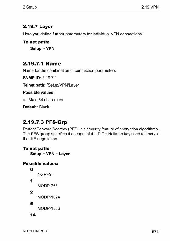
2.19.7 LayerHere you define further parameters for individual VPN connections.
Telnet path:Setup > VPN
2.19.7.1 NameName for the combination of connection parameters
SNMP ID: 2.19.7.1
Telnet path: /Setup/VPN/Layer
Possible values:
D Max. 64 characters
Default: Blank
2.19.7.3 PFS-GrpPerfect Forward Secrecy (PFS) is a security feature of encryption algorithms.The PFS group specifies the length of the Diffie-Hellman key used to encryptthe IKE negotiation.
Telnet path:Setup > VPN > Layer
Possible values:0
No PFS1
MODP-7682
MODP-10245
MODP-153614
RM CLI HiLCOS 573
2 Setup 2.19 VPN

MODP-204815
MODP-307216
MODP-4096
Default:2
2.19.7.4 IKE-GrpThe IKE group specifies the length of the Diffie-Hellman key used to encryptthe IKE negotiation.
Telnet path:Setup > VPN > Layer
Possible values:1
MODP-7682
MODP-10245
MODP-153614
MODP-204815
MODP-307216
MODP-4096
Default:2
RM CLI HiLCOS 574
2.19 VPN 2 Setup

2.19.7.5 IKE-Prop-ListIKE proposal list for this connection.
SNMP ID: 2.19.7.5
Telnet path: /Setup/VPN/Layer
Possible values:
D Select from the list of defined IKE proposal lists.
Default: Blank
2.19.7.6 IPSEC-Prop-ListIKE key for this connection.
SNMP ID: 2.19.7.6
Telnet path: /Setup/VPN/Layer
Possible values:
D Select from the list of defined IKE keys.
Default: Blank
2.19.7.7 IKE-KeyIPsec proposal list for this connection.
SNMP ID: 2.19.7.7
Telnet path: /Setup/VPN/Layer
Possible values:
D Select from the list of defined IPSec proposal lists.
Default: Blank
2.19.8 OperatingSwitches the VPN module on or off.
RM CLI HiLCOS 575
2 Setup 2.19 VPN

SNMP ID: 2.19.8
Telnet path: /Setup/VPN
Possible values:
D ActivatedD Deactivated
Default: Deactivated
2.19.9 VPN-PeersIn this table you define the VPN connections to be established by your device.
SNMP ID: 2.19.9
Telnet path: /Setup/VPN
2.19.9.1 PeerName of the VPN connection.
SNMP ID: 2.19.9.1
Telnet path: /Setup/VPN/VPN-Peers
Possible values:
D Select from the list of defined peers.
Default: Blank
2.19.9.2 Extranet addressIn HiLCOS versions before 9.10, this field contained the IPv4 address usedby the local stations to mask their own IP address in certain scenarios.
As of HiLCOS version 9.10, masquerading uses the entry under Setup >WAN > IP-List in the field Masq.-IP-Addr..
Telnet path:Setup > VPN > VPN-Peers
Possible values:
RM CLI HiLCOS 576
2.19 VPN 2 Setup
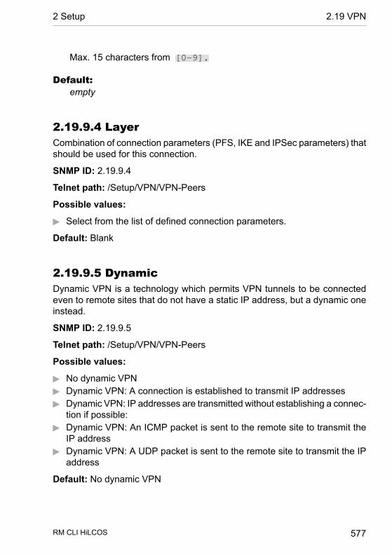
Max. 15 characters from [0-9].
Default:empty
2.19.9.4 LayerCombination of connection parameters (PFS, IKE and IPSec parameters) thatshould be used for this connection.
SNMP ID: 2.19.9.4
Telnet path: /Setup/VPN/VPN-Peers
Possible values:
D Select from the list of defined connection parameters.
Default: Blank
2.19.9.5 DynamicDynamic VPN is a technology which permits VPN tunnels to be connectedeven to remote sites that do not have a static IP address, but a dynamic oneinstead.
SNMP ID: 2.19.9.5
Telnet path: /Setup/VPN/VPN-Peers
Possible values:
D No dynamic VPND Dynamic VPN: A connection is established to transmit IP addressesD Dynamic VPN: IP addresses are transmitted without establishing a connec-
tion if possible:D Dynamic VPN: An ICMP packet is sent to the remote site to transmit the
IP addressD Dynamic VPN: A UDP packet is sent to the remote site to transmit the IP
address
Default: No dynamic VPN
RM CLI HiLCOS 577
2 Setup 2.19 VPN
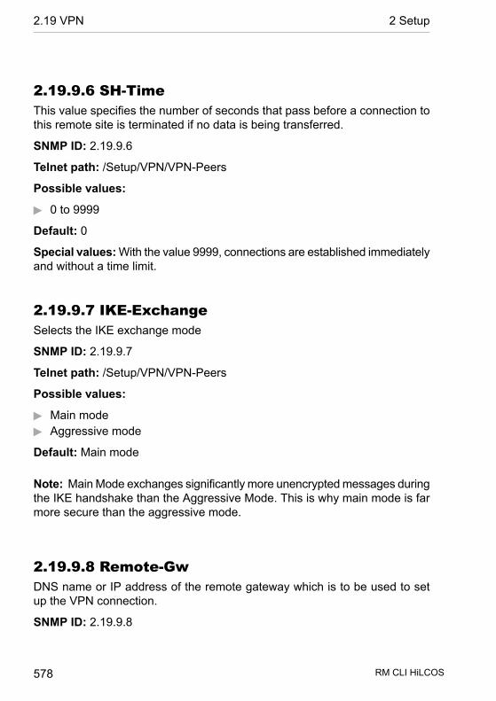
2.19.9.6 SH-TimeThis value specifies the number of seconds that pass before a connection tothis remote site is terminated if no data is being transferred.
SNMP ID: 2.19.9.6
Telnet path: /Setup/VPN/VPN-Peers
Possible values:
D 0 to 9999
Default: 0
Special values:With the value 9999, connections are established immediatelyand without a time limit.
2.19.9.7 IKE-ExchangeSelects the IKE exchange mode
SNMP ID: 2.19.9.7
Telnet path: /Setup/VPN/VPN-Peers
Possible values:
D Main modeD Aggressive mode
Default: Main mode
Note: Main Mode exchanges significantly more unencrypted messages duringthe IKE handshake than the Aggressive Mode. This is why main mode is farmore secure than the aggressive mode.
2.19.9.8 Remote-GwDNS name or IP address of the remote gateway which is to be used to setup the VPN connection.
SNMP ID: 2.19.9.8
RM CLI HiLCOS 578
2.19 VPN 2 Setup

Telnet path: /Setup/VPN/VPN-Peers
Possible values:
D Max. 64 characters
Default: Blank
2.19.9.9 Rule creationOn/off switch and type of rule creation
SNMP ID: 2.19.9.9
Telnet path: /Setup/VPN/VPN-Peers
Possible values:
D Off: No VPN rule is created for the remote site.D Automatic: Automatically created VPN rules connect the local IP networks
with the IP networks entered into the routing table for the remote site.D Manually: VPN rules are only created for the remote site for IP network
relationships specified "Manually" in the firewall configuration.
Default: Automatic
2.19.9.10 DPD-Inact-TimeoutDead peer detection is used when VPN clients dial in to a VPN gateway orwhen 2 VPN gateways are connected. This is designed to ensure that a peeris logged out if there is an interruption to the VPN connection, for examplewhen the Internet connection is interrupted briefly. If the line were not to bemonitored, then the VPN gateway would continue to list the client or the otherVPN gateway as logged-on. This would prevent the peer from dialing in againas, for example, the LANCOM Advanced VPN Client does not allow a simul-taneous dial-in using the same serial number.
With dead-peer detection, the gateway and peer regularly exchange "keepalive" packets. If no replies are received, the gateway will log out the peer sothat this ID can be registered anew once the VPN connection has been re-established. The DPD time for VPN clients is typically set to 60 seconds.
SNMP ID: 2.19.9.10
RM CLI HiLCOS 579
2 Setup 2.19 VPN

Telnet path: /Setup/VPN/VPN-Peers
Possible values:
D 0 to 9999 numerical characters
Default: 0
Note: Without line monitoring, a user with the same "identity" (user name)would be prevented from dialing in because the associated user would stillbe in the list for the logged-in peer.
2.19.9.11 IKE-CFGWhen configuring VPN dial-in connections, there is as an alternative to fixedIP addresses for the remote sites that dial in, in that a pool of IP addressescan be made available to them. To this end, the "IKE-CFG" mode is additionallyadded to the entries in the connection list.
SNMP ID: 2.19.9.11
Telnet path: /Setup/VPN/VPN-Peers
Possible values:
D Off: If the IKE-CFG mode is switched off, no IP addresses will be assignedfor the connection. Fixed IP addresses must be defined for both ends ofthe connection.
D Client: With this setting, the device functions as the client for this VPNconnection and requests an IP address from the remote site (server). Thedevice acts in a similar manner to a VPN client.
D Server: With this setting, the device functions as the server for this VPNconnection. The assignment of an IP address to the client can take placein two ways:
D If the remote site is entered in the routing table, the IP address definedhere will be assigned to the client.
D If the remote site is not entered in the routing table, an IP address whichis available from the IP pool will be taken for the dial-in connections.
Default: Off
RM CLI HiLCOS 580
2.19 VPN 2 Setup

Note: When set as server, the remote site must be configured as IKE-CFGclient, and thus has to request an IP address from the server. To dial in witha LANCOM Advanced VPN Client, the option "Use IKE Config Mode" has tobe activated in the connection profile.
2.19.9.12 XAUTHEnables the use of XAUTH for the VPN remote site selected.
SNMP ID: 2.19.9.12
Telnet path: /Setup/VPN/VPN-Peers
Possible values:
D Client: In the XAUTH client operating mode, the device starts the initialphase of IKE negotiation (Main mode or Aggressive mode) and then waitsfor the authentication request from the XAUTH server. The XAUTH clientresponds to this request with the user name and password from the PPPtable entry in which the PPP remote site corresponds to the VPN remotesite defined here. There must therefore be a PPP remote site of the samename for the VPN remote site. The user name defined in the PPP tablenormally differs from the remote site name.
D Server: In the XAUTH server operating mode, the device (after successfulnegotiation of the initial IKE negotiation) starts authentication with a requestto the XAUTH client, which then responds with its user name and password.The XAUTH server searches for the user name in the PPP table and, if amatch is found, it checks the password. The user name for this entry inthe PPP table is not used.
D Off: No XAUTH authentication is performed for the connection to this remotesite.
Default: Off
Note: If XAUTH authentication is enabled for a VPN remote site, the IKE-CFG option must be set to the same value.
RM CLI HiLCOS 581
2 Setup 2.19 VPN
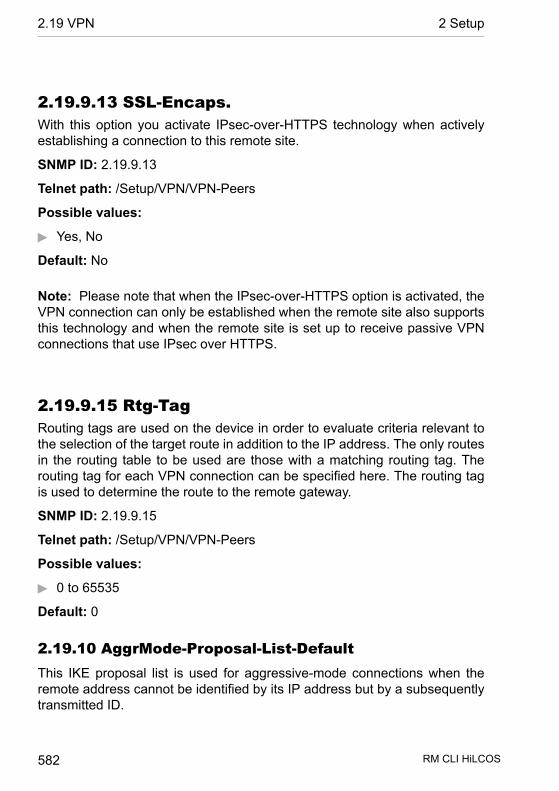
2.19.9.13 SSL-Encaps.With this option you activate IPsec-over-HTTPS technology when activelyestablishing a connection to this remote site.
SNMP ID: 2.19.9.13
Telnet path: /Setup/VPN/VPN-Peers
Possible values:
D Yes, No
Default: No
Note: Please note that when the IPsec-over-HTTPS option is activated, theVPN connection can only be established when the remote site also supportsthis technology and when the remote site is set up to receive passive VPNconnections that use IPsec over HTTPS.
2.19.9.15 Rtg-TagRouting tags are used on the device in order to evaluate criteria relevant tothe selection of the target route in addition to the IP address. The only routesin the routing table to be used are those with a matching routing tag. Therouting tag for each VPN connection can be specified here. The routing tagis used to determine the route to the remote gateway.
SNMP ID: 2.19.9.15
Telnet path: /Setup/VPN/VPN-Peers
Possible values:
D 0 to 65535
Default: 0
2.19.10 AggrMode-Proposal-List-DefaultThis IKE proposal list is used for aggressive-mode connections when theremote address cannot be identified by its IP address but by a subsequentlytransmitted ID.
RM CLI HiLCOS 582
2.19 VPN 2 Setup
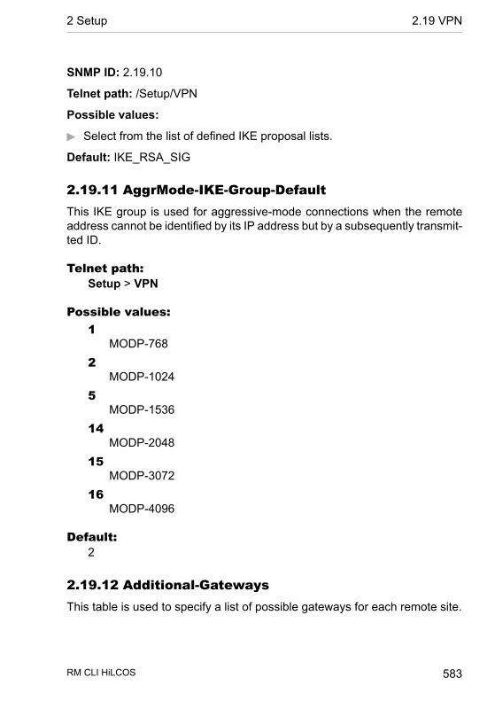
SNMP ID: 2.19.10
Telnet path: /Setup/VPN
Possible values:
D Select from the list of defined IKE proposal lists.
Default: IKE_RSA_SIG
2.19.11 AggrMode-IKE-Group-DefaultThis IKE group is used for aggressive-mode connections when the remoteaddress cannot be identified by its IP address but by a subsequently transmit-ted ID.
Telnet path:Setup > VPN
Possible values:1
MODP-7682
MODP-10245
MODP-153614
MODP-204815
MODP-307216
MODP-4096
Default:2
2.19.12 Additional-GatewaysThis table is used to specify a list of possible gateways for each remote site.
RM CLI HiLCOS 583
2 Setup 2.19 VPN
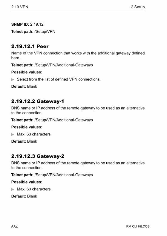
SNMP ID: 2.19.12
Telnet path: /Setup/VPN
2.19.12.1 PeerName of the VPN connection that works with the additional gateway definedhere.
Telnet path: /Setup/VPN/Additional-Gateways
Possible values:
D Select from the list of defined VPN connections.
Default: Blank
2.19.12.2 Gateway-1DNS name or IP address of the remote gateway to be used as an alternativeto the connection.
Telnet path: /Setup/VPN/Additional-Gateways
Possible values:
D Max. 63 characters
Default: Blank
2.19.12.3 Gateway-2DNS name or IP address of the remote gateway to be used as an alternativeto the connection.
Telnet path: /Setup/VPN/Additional-Gateways
Possible values:
D Max. 63 characters
Default: Blank
RM CLI HiLCOS 584
2.19 VPN 2 Setup

2.19.12.4 Gateway-3DNS name or IP address of the remote gateway to be used as an alternativeto the connection.
Telnet path: /Setup/VPN/Additional-Gateways
Possible values:
D Max. 63 characters
Default: Blank
2.19.12.5 Gateway-4DNS name or IP address of the remote gateway to be used as an alternativeto the connection.
Telnet path: /Setup/VPN/Additional-Gateways
Possible values:
D Max. 63 characters
Default: Blank
2.19.12.6 Gateway-5DNS name or IP address of the remote gateway to be used as an alternativeto the connection.
Telnet path: /Setup/VPN/Additional-Gateways
Possible values:
D Max. 63 characters
Default: Blank
2.19.12.7 Gateway-6DNS name or IP address of the remote gateway to be used as an alternativeto the connection.
RM CLI HiLCOS 585
2 Setup 2.19 VPN

Telnet path: /Setup/VPN/Additional-Gateways
Possible values:
D Max. 63 characters
Default: Blank
2.19.12.8 Gateway-7DNS name or IP address of the remote gateway to be used as an alternativeto the connection.
Telnet path: /Setup/VPN/Additional-Gateways
Possible values:
D Max. 63 characters
Default: Blank
2.19.12.9 Gateway-8DNS name or IP address of the remote gateway to be used as an alternativeto the connection.
Telnet path: /Setup/VPN/Additional-Gateways
Possible values:
D Max. 63 characters
Default: Blank
2.19.12.10 Begin-WithHere you select the first gateway that is to be used for establishing the VPNconnection.
Telnet path: /Setup/VPN/Additional-Gateways
Possible values:
D First: Start with the first entry in the list.D Random: Selects a random entry from the list.
RM CLI HiLCOS 586
2.19 VPN 2 Setup
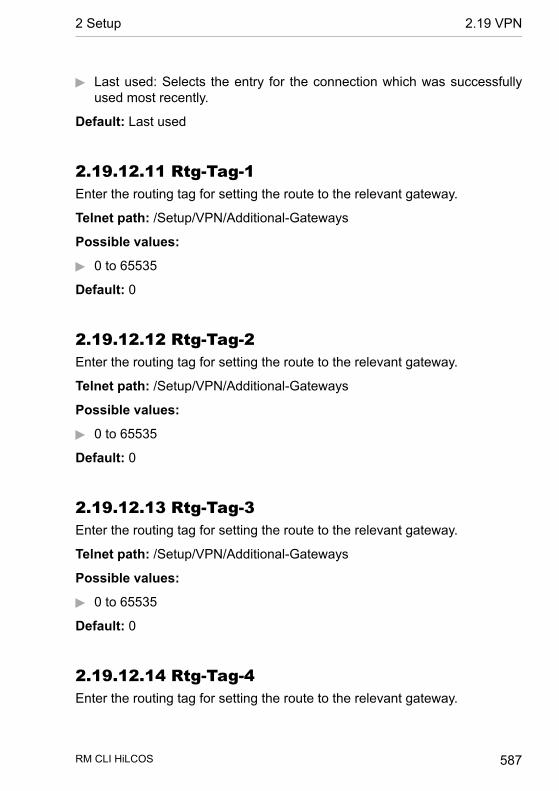
D Last used: Selects the entry for the connection which was successfullyused most recently.
Default: Last used
2.19.12.11 Rtg-Tag-1Enter the routing tag for setting the route to the relevant gateway.
Telnet path: /Setup/VPN/Additional-Gateways
Possible values:
D 0 to 65535
Default: 0
2.19.12.12 Rtg-Tag-2Enter the routing tag for setting the route to the relevant gateway.
Telnet path: /Setup/VPN/Additional-Gateways
Possible values:
D 0 to 65535
Default: 0
2.19.12.13 Rtg-Tag-3Enter the routing tag for setting the route to the relevant gateway.
Telnet path: /Setup/VPN/Additional-Gateways
Possible values:
D 0 to 65535
Default: 0
2.19.12.14 Rtg-Tag-4Enter the routing tag for setting the route to the relevant gateway.
RM CLI HiLCOS 587
2 Setup 2.19 VPN
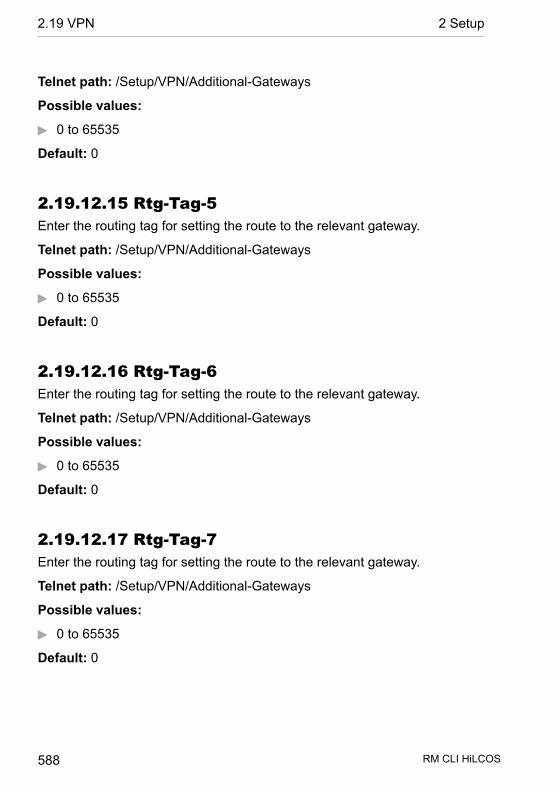
Telnet path: /Setup/VPN/Additional-Gateways
Possible values:
D 0 to 65535
Default: 0
2.19.12.15 Rtg-Tag-5Enter the routing tag for setting the route to the relevant gateway.
Telnet path: /Setup/VPN/Additional-Gateways
Possible values:
D 0 to 65535
Default: 0
2.19.12.16 Rtg-Tag-6Enter the routing tag for setting the route to the relevant gateway.
Telnet path: /Setup/VPN/Additional-Gateways
Possible values:
D 0 to 65535
Default: 0
2.19.12.17 Rtg-Tag-7Enter the routing tag for setting the route to the relevant gateway.
Telnet path: /Setup/VPN/Additional-Gateways
Possible values:
D 0 to 65535
Default: 0
RM CLI HiLCOS 588
2.19 VPN 2 Setup
2.19.12.18 Rtg-Tag-8Enter the routing tag for setting the route to the relevant gateway.
Telnet path: /Setup/VPN/Additional-Gateways
Possible values:
D 0 to 65535
Default: 0
2.19.12.19 Gateway-9DNS name or IP address of the remote gateway to be used as an alternativeto the connection.
Telnet path: /Setup/VPN/Additional-Gateways
Possible values:
D Max. 64 characters
Default: Blank
2.19.12.20 Gateway-10DNS name or IP address of the remote gateway to be used as an alternativeto the connection.
Telnet path: /Setup/VPN/Additional-Gateways
Possible values:
D Max. 63 characters
Default: Blank
2.19.12.21 Gateway-11DNS name or IP address of the remote gateway to be used as an alternativeto the connection.
Telnet path: /Setup/VPN/Additional-Gateways
RM CLI HiLCOS 589
2 Setup 2.19 VPN
Possible values:
D Max. 63 characters
Default: Blank
2.19.12.22 Gateway-12DNS name or IP address of the remote gateway to be used as an alternativeto the connection.
Telnet path: /Setup/VPN/Additional-Gateways
Possible values:
D Max. 63 characters
Default: Blank
2.19.12.23 Gateway-13DNS name or IP address of the remote gateway to be used as an alternativeto the connection.
Telnet path: /Setup/VPN/Additional-Gateways
Possible values:
D Max. 63 characters
Default: Blank
2.19.12.24 Gateway-14DNS name or IP address of the remote gateway to be used as an alternativeto the connection.
Telnet path: /Setup/VPN/Additional-Gateways
Possible values:
D Max. 63 characters
Default: Blank
RM CLI HiLCOS 590
2.19 VPN 2 Setup

2.19.12.25 Gateway-15DNS name or IP address of the remote gateway to be used as an alternativeto the connection.
Telnet path: /Setup/VPN/Additional-Gateways
Possible values:
D Max. 63 characters
Default: Blank
2.19.12.26 Gateway-16DNS name or IP address of the remote gateway to be used as an alternativeto the connection.
Telnet path: /Setup/VPN/Additional-Gateways
Possible values:
D Max. 63 characters
Default: Blank
2.19.12.27 Rtg-Tag-9Enter the routing tag for setting the route to the relevant gateway.
Telnet path: /Setup/VPN/Additional-Gateways
Possible values:
D 0 to 65535
Default: 0
2.19.12.28 Rtg-Tag-10Enter the routing tag for setting the route to the relevant gateway.
Telnet path: /Setup/VPN/Additional-Gateways
RM CLI HiLCOS 591
2 Setup 2.19 VPN

Possible values:
D 0 to 65535
Default: 0
2.19.12.29 Rtg-Tag-11Enter the routing tag for setting the route to the relevant gateway.
Telnet path: /Setup/VPN/Additional-Gateways
Possible values:
D 0 to 65535
Default: 0
2.19.12.30 Rtg-Tag-12Enter the routing tag for setting the route to the relevant gateway.
Telnet path: /Setup/VPN/Additional-Gateways
Possible values:
D 0 to 65535
Default: 0
2.19.12.31 Rtg-Tag-13Enter the routing tag for setting the route to the relevant gateway.
Telnet path: /Setup/VPN/Additional-Gateways
Possible values:
D 0 to 65535
Default: 0
2.19.12.32 Rtg-Tag-14Enter the routing tag for setting the route to the relevant gateway.
RM CLI HiLCOS 592
2.19 VPN 2 Setup
Telnet path: /Setup/VPN/Additional-Gateways
Possible values:
D 0 to 65535
Default: 0
2.19.12.33 Rtg-Tag-15Enter the routing tag for setting the route to the relevant gateway.
Telnet path: /Setup/VPN/Additional-Gateways
Possible values:
D 0 to 65535
Default: 0
2.19.12.34 Rtg-Tag-16Enter the routing tag for setting the route to the relevant gateway.
Telnet path: /Setup/VPN/Additional-Gateways
Possible values:
D 0 to 65535
Default: 0
2.19.12.35 Gateway-17DNS name or IP address of the remote gateway to be used as an alternativeto the connection.
Telnet path:/Setup/VPN/Certificates-and-Keys/Additional-Gateways/Gateway-17
Possible values:
D Max. 63 characters
Default: Blank
RM CLI HiLCOS 593
2 Setup 2.19 VPN
2.19.12.36 Rtg-Tag-17Enter the routing tag for setting the route to the relevant gateway.
Telnet path:/Setup/VPN/Certificates-and-Keys/Additional-Gateways/Rtg-Tag-17
Possible values:
D 0 to 65535
Default: 0
2.19.12.37 Gateway-18DNS name or IP address of the remote gateway to be used as an alternativeto the connection.
Telnet path:/Setup/VPN/Certificates-and-Keys/Additional-Gateways/Gateway-18
Possible values:
D Max. 63 characters
Default: Blank
2.19.12.38 Rtg-Tag-18Enter the routing tag for setting the route to the relevant gateway.
Telnet path:/Setup/VPN/Certificates-and-Keys/Additional-Gateways/Rtg-Tag-18
Possible values:
D 0 to 65535
Default: 0
RM CLI HiLCOS 594
2.19 VPN 2 Setup
2.19.12.39 Gateway-19DNS name or IP address of the remote gateway to be used as an alternativeto the connection.
Telnet path:/Setup/VPN/Certificates-and-Keys/Additional-Gateways/Gateway-19
Possible values:
D Max. 63 characters
Default: Blank
2.19.12.40 Rtg-Tag-19Enter the routing tag for setting the route to the relevant gateway.
Telnet path:/Setup/VPN/Certificates-and-Keys/Additional-Gateways/Rtg-Tag-19
Possible values:
D 0 to 65535
Default: 0
2.19.12.41 Gateway-20DNS name or IP address of the remote gateway to be used as an alternativeto the connection.
Telnet path:/Setup/VPN/Certificates-and-Keys/Additional-Gateways/Gateway-20
Possible values:
D Max. 63 characters
Default: Blank
RM CLI HiLCOS 595
2 Setup 2.19 VPN

2.19.12.42 Rtg-Tag-20Enter the routing tag for setting the route to the relevant gateway.
Telnet path:/Setup/VPN/Certificates-and-Keys/Additional-Gateways/Rtg-Tag-20
Possible values:
D 0 to 65535
Default: 0
2.19.12.43 Gateway-21DNS name or IP address of the remote gateway to be used as an alternativeto the connection.
Telnet path:/Setup/VPN/Certificates-and-Keys/Additional-Gateways/Gateway-21
Possible values:
D Max. 63 characters
Default: Blank
2.19.12.44 Rtg-Tag-21Enter the routing tag for setting the route to the relevant gateway.
Telnet path:/Setup/VPN/Certificates-and-Keys/Additional-Gateways/Rtg-Tag-21
Possible values:
D 0 to 65535
Default: 0
RM CLI HiLCOS 596
2.19 VPN 2 Setup

2.19.12.45 Gateway-22DNS name or IP address of the remote gateway to be used as an alternativeto the connection.
Telnet path:/Setup/VPN/Certificates-and-Keys/Additional-Gateways/Gateway-22
Possible values:
D Max. 63 characters
Default: Blank
2.19.12.46 Rtg-Tag-22Enter the routing tag for setting the route to the relevant gateway.
Telnet path:/Setup/VPN/Certificates-and-Keys/Additional-Gateways/Rtg-Tag-22
Possible values:
D 0 to 65535
Default: 0
2.19.12.47 Gateway-23DNS name or IP address of the remote gateway to be used as an alternativeto the connection.
Telnet path:/Setup/VPN/Certificates-and-Keys/Additional-Gateways/Gateway-23
Possible values:
D Max. 63 characters
Default: Blank
RM CLI HiLCOS 597
2 Setup 2.19 VPN
2.19.12.48 Rtg-Tag-23Enter the routing tag for setting the route to the relevant gateway.
Telnet path:/Setup/VPN/Certificates-and-Keys/Additional-Gateways/Rtg-Tag-23
Possible values:
D 0 to 65535
Default: 0
2.19.12.49 Gateway-24DNS name or IP address of the remote gateway to be used as an alternativeto the connection.
Telnet path:/Setup/VPN/Certificates-and-Keys/Additional-Gateways/Gateway-24
Possible values:
D Max. 63 characters
Default: Blank
2.19.12.50 Rtg-Tag-24Enter the routing tag for setting the route to the relevant gateway.
Telnet path:/Setup/VPN/Certificates-and-Keys/Additional-Gateways/Rtg-Tag-24
Possible values:
D 0 to 65535
Default: 0
RM CLI HiLCOS 598
2.19 VPN 2 Setup

2.19.12.51 Gateway-25DNS name or IP address of the remote gateway to be used as an alternativeto the connection.
Telnet path:/Setup/VPN/Certificates-and-Keys/Additional-Gateways/Gateway-25
Possible values:
D Max. 63 characters
Default: Blank
2.19.12.52 Rtg-Tag-25Enter the routing tag for setting the route to the relevant gateway.
Telnet path:/Setup/VPN/Certificates-and-Keys/Additional-Gateways/Rtg-Tag-25
Possible values:
D 0 to 65535
Default: 0
2.19.12.53 Gateway-26DNS name or IP address of the remote gateway to be used as an alternativeto the connection.
Telnet path:/Setup/VPN/Certificates-and-Keys/Additional-Gateways/Gateway-26
Possible values:
D Max. 63 characters
Default: Blank
RM CLI HiLCOS 599
2 Setup 2.19 VPN
2.19.12.54 Rtg-Tag-26Enter the routing tag for setting the route to the relevant gateway.
Telnet path:/Setup/VPN/Certificates-and-Keys/Additional-Gateways/Rtg-Tag-26
Possible values:
D 0 to 65535
Default: 0
2.19.12.55 Gateway-27DNS name or IP address of the remote gateway to be used as an alternativeto the connection.
Telnet path:/Setup/VPN/Certificates-and-Keys/Additional-Gateways/Gateway-27
Possible values:
D Max. 63 characters
Default: Blank
2.19.12.56 Rtg-Tag-27Enter the routing tag for setting the route to the relevant gateway.
Telnet path:/Setup/VPN/Certificates-and-Keys/Additional-Gateways/Rtg-Tag-27
Possible values:
D 0 to 65535
Default: 0
RM CLI HiLCOS 600
2.19 VPN 2 Setup
2.19.12.57 Gateway-28DNS name or IP address of the remote gateway to be used as an alternativeto the connection.
Telnet path:/Setup/VPN/Certificates-and-Keys/Additional-Gateways/Gateway-28
Possible values:
D Max. 63 characters
Default: Blank
2.19.12.58 Rtg-Tag-28Enter the routing tag for setting the route to the relevant gateway.
Telnet path:/Setup/VPN/Certificates-and-Keys/Additional-Gateways/Rtg-Tag-28
Possible values:
D 0 to 65535
Default: 0
2.19.12.59 Gateway-29DNS name or IP address of the remote gateway to be used as an alternativeto the connection.
Telnet path:/Setup/VPN/Certificates-and-Keys/Additional-Gateways/Gateway-29
Possible values:
D Max. 63 characters
Default: Blank
RM CLI HiLCOS 601
2 Setup 2.19 VPN
2.19.12.60 Rtg-Tag-29Enter the routing tag for setting the route to the relevant gateway.
Telnet path:/Setup/VPN/Certificates-and-Keys/Additional-Gateways/Rtg-Tag-29
Possible values:
D 0 to 65535
Default: 0
2.19.12.61 Gateway-30DNS name or IP address of the remote gateway to be used as an alternativeto the connection.
Telnet path:/Setup/VPN/Certificates-and-Keys/Additional-Gateways/Gateway-30
Possible values:
D Max. 63 characters
Default: Blank
2.19.12.62 Rtg-Tag-30Enter the routing tag for setting the route to the relevant gateway.
Telnet path:/Setup/VPN/Certificates-and-Keys/Additional-Gateways/Rtg-Tag-30
Possible values:
D 0 to 65535
Default: 0
RM CLI HiLCOS 602
2.19 VPN 2 Setup

2.19.12.63 Gateway-31DNS name or IP address of the remote gateway to be used as an alternativeto the connection.
Telnet path:/Setup/VPN/Certificates-and-Keys/Additional-Gateways/Gateway-31
Possible values:
D Max. 63 characters
Default: Blank
2.19.12.64 Rtg-Tag-31Enter the routing tag for setting the route to the relevant gateway.
Telnet path:/Setup/VPN/Certificates-and-Keys/Additional-Gateways/Rtg-Tag-31
Possible values:
D 0 to 65535
Default: 0
2.19.12.65 Gateway-32DNS name or IP address of the remote gateway to be used as an alternativeto the connection.
Telnet path:/Setup/VPN/Certificates-and-Keys/Additional-Gateways/Gateway-32
Possible values:
D Max. 63 characters
Default: Blank
RM CLI HiLCOS 603
2 Setup 2.19 VPN

2.19.12.66 Rtg-Tag-32Enter the routing tag for setting the route to the relevant gateway.
Telnet path:/Setup/VPN/Certificates-and-Keys/Additional-Gateways/Rtg-Tag-32
Possible values:
D 0 to 65535
Default: 0
2.19.13 MainMode-Proposal-List-DefaultThis IKE proposal list is used for main-mode connections when the remoteaddress cannot be identified by its IP address but by a subsequently transmit-ted ID.
SNMP ID: 2.19.13
Telnet path: /Setup/VPN
Possible values:
D Select from the list of defined IKE proposal lists.
Default: IKE_PRESH_KEY
2.19.14 MainMode-IKE-Group-DefaultThis IKE group is used for main-mode connections when the remote addresscannot be identified by its IP address but by a subsequently transmitted ID.
Telnet path:Setup > VPN
Possible values:1
MODP-7682
RM CLI HiLCOS 604
2.19 VPN 2 Setup

MODP-10245
MODP-153614
MODP-204815
MODP-307216
MODP-4096
Default:2
2.19.16 NAT-T-OperatingEnables the use of NAT-Traversal. NAT Traversal eliminates the problemsthat occur when establishing a VPN connection at the end points of the VPNtunnel.
SNMP ID: 2.19.16
Telnet path: /Setup/VPN
Possible values:
D OnD Off
Default: Off
Note: NAT-T can only be used with VPN connections that use ESP (Encap-sulating Security Payload) for authentication. Unlike AH (AuthenticationHeader), ESP does not consider the IP header of the data packets whendetermining the hash value for authentication. The hash value calculated bythe receiver is therefore also equivalent to the hash value entered in thepackets.
Note: If the device functions as a NAT router between the VPN end points,ensure that UDP ports 500 and 4500 are enabled in the firewall when you use
RM CLI HiLCOS 605
2 Setup 2.19 VPN
NAT-T! This port is activated automatically if you use the firewall assistant inLANconfig.
2.19.17 Simple-Cert-RAS-OperatingEnables simplified dial-in with certificates. The simplification is that a sharedconfiguration can be made for incoming connections, as long as the certificatesof the remote peers are signed by the issuer of the root certificate in the device.In this case a configuration has to be made for each remote peer. You findthe shared configuration necessary for this with the settings for default para-meters. Individual remote peers can only be excluded from this function byhaving their certificates revoked in a CRL (Certificate Revocation List).
SNMP ID: 2.19.17
Telnet path: /Setup/VPN
Possible values:
D OnD Off
Default: Off
2.19.19 QuickMode-Proposal-List-DefaultThis IPSec proposal list is used for simplified dial-in with certificates.
SNMP ID: 2.19.19
Telnet path: /Setup/VPN
Possible values:
D Select from the list of defined IPSec proposal lists.
Default: ESP_TN
2.19.20 QuickMode-PFS-Group-DefaultThis IPSec group is used for simplified dial-in with certificates.
RM CLI HiLCOS 606
2.19 VPN 2 Setup
Telnet path:Setup > VPN
Possible values:0
No PFS1
MODP-7682
MODP-10245
MODP-153614
MODP-204815
MODP-307216
MODP-4096
Default:2
2.19.21 QuickMode-Shorthold-Time-DefaultThis hold time is used for simplified dial-in with certificates.
SNMP ID: 2.19.21
Telnet path: /Setup/VPN
Possible values:
D 0 to 65535
Default: 0
2.19.22 Allow-Remote-Network-SelectionIf simplified dial-in with certificates is activated for the device at headquarters,then the remote routers can suggest a network to be used for the connection
RM CLI HiLCOS 607
2 Setup 2.19 VPN
during the IKE negotiation in phase 2. This network is entered, for example,when setting up the VPN connection on the remote router. The device atheadquarters accepts the suggested network when this option is activated.Moreover, the parameters used by the client during dial in must agree withthe default values in the VPN router.
SNMP ID: 2.19.22
Telnet path: /Setup/VPN
Possible values:
D OnD Off
Default: Off
Note: When configuring the dial-in remote sites, be sure to note that eachremote site requests a specific network so that no network address conflictsarise.
2.19.23 Establish-SAs-CollectivelySecurity Associations (SAs) are the basis for establishing a VPN tunnelbetween two networks. The establishment of Security Associations is normallyinitiated by an IP packet which is to be sent from a source network to a des-tination network.
The establishment of Security Associations is normally initiated by an IPpacket which is to be sent from a source network to a destination network.This allows the setup of network relationships to be precise controlledaccording to the application.
SNMP ID: 2.19.23
Telnet path: /Setup/VPN
Possible values:
D Separately: Only the SA which corresponds explicitly to a packet waitingfor transfer is to be established.
D Collectively: All SAs defined in the device will be established.
RM CLI HiLCOS 608
2.19 VPN 2 Setup
D Collectively with KeepAlive All of the defined SAs will be established forremote sites in the VPN connection list with a hold time set to '9999' (KeepAlive).
Default: Separately
2.19.24 Max-Concurrent-ConnectionsThis setting determines how many VPN connections the device can establish.
Telnet path: /Setup/VPN/Max-Concurrent-Connections
Possible values:
D The maximum value is limited by the relevant license.
Default: 0
Note: With a value of 0, the device may take fully advantage of the maximumnumber permitted by the license. Values above the license limits are ignored.
2.19.25 Flexibler-ID-ComparisonThis flexible method of identification comparison is activated or deactivatedin the VPN configuration.
SNMP ID: 2.19.25
Telnet path: /Setup/VPN
Possible values:
D Yes
D No
Default: No
Note: Flexible identity comparison is used when checking the (received)remote identity and also for selecting the certificate based on the local identity.
RM CLI HiLCOS 609
2 Setup 2.19 VPN

2.19.26 NAT-T-Port-for-RekeyingThis item sets whether the IKE packets are sent to port 500 (no) or the port4500 (yes) during rekeying.
Telnet path: /Setup/VPN/NAT-T-Port-For-Rekeying
Possible values:
D YesD No
Default: No
2.19.27 SSL encapsulation allowedActivate the 'SSL encaps' option in the general VPN settings to enable passiveconnection establishment to a VPN device from another VPN remote deviceusing IPsec-over-HTTPS technology (VPN device or LANCOM AdvancedVPN client).
SNMP ID: 2.19.27
Telnet path: /Setup/VPN
Possible values:
D Yes, No
Default: No
Note: The LANCOM Advanced VPN Client supports automatic fallback toIPsec over HTTPS. With this setting, the VPN client initially attempts toestablish a connection without using the additional SSL encapsulation. If theconnection cannot be made, the device then tries to connect with the additionalSSL encapsulation.
2.19.30 Anti-Replay-Window-SizeUsed for detecting replay attacks, this parameter defines the size of the window(i.e. number of packets) within which a VPN device considers the sequentialnumber of the received packets to be up-to-date. The VPN device dropspackets that have a sequence number older than or duplicated within thiswindow.
RM CLI HiLCOS 610
2.19 VPN 2 Setup
Telnet path:Telnet path:Setup > Vpn > myVPN
Possible values:Max. 5 numbers
Default:0
Special values:A value of 0 disables replay detection.
2.20 LAN-Bridge
This menu contains the settings for the LAN bridge.
SNMP ID: 2.20
Telnet path: /Setup
2.20.1 Protocol-VersionSelect the desired protocol here. Depending on the choice made here, thedevice uses either the classic protocol or the rapid protocol, as defined in theIEEE 802.1D-1998, chapter 8 and IEEE 802.1D-2004 chapter 17 respectively.
Telnet path:/Setup/LAN-Bridge/Protocol-Version
Possible values:
D ClassicD Rapid
Default: Classic
2.20.2 Bridge-PriorityThis value sets the priority of the bridge in the LAN. This value influenceswhich bridge the spanning tree protocol takes to be the root bridge. This is a16-bit value (0 .. 65535), where higher values mean lower priority. You should
RM CLI HiLCOS 611
2 Setup 2.20 LAN-Bridge
only change the default value if you prefer a certain bridge. The selectionprocess still works even if all the values are the same because, if the prioritiesare identical, the device uses the MAC address of the bridge to make thedecision.
Telnet path: /Setup/LAN-Bridge/Bridge-Priority
Possible values:
D Max. 5 numerical characters
Default: 32768
Note: Even though an entire 16-bit parameter is available for configuring thisparameter, special care should be taken where newer versions of the rapidor multiple spanning tree protocol are involved. The priority value should onlybe changed in increments of 4096, because the lower 12 bits are used forother purposes. This could mean that these values may be ignored by futurefirmware releases.
2.20.4 Encapsulation-TableThis table is used to add the encapsulation methods.
SNMP ID: 2.20.4
Telnet path: /Setup/LAN-Bridge
2.20.4.1 ProtocolA protocol is identified by its 16-bit protocol identifier carried in the EthernetII/SNAP type field (often referred to as the Ethertype). The protocol type iswritten as a hexadecimal number from 0001 to ffff. Even if the table is empty,some protocols are implicitly assumed to be listed in this table as type SNAP(such as IPX and AppleTalk). This can be overridden by explicitly setting theirprotocol to Ethernet II.
Telnet path: /Setup/LAN-Bridge/Encapsulation-Table
RM CLI HiLCOS 612
2.20 LAN-Bridge 2 Setup

2.20.4.2 EncapsulationHere you can specify whether or not data packets are to be given an Ethernetheader when being transmitted. Normally you should enter the option"Transparent". The "Ethernet" option should only be chosen if you wish tocombine a layer for use with the bridge.
Telnet path: /Setup/LAN-Bridge/Encapsulation-Table
Possible values:
D TransparentD Ethernet
Default: Transparent
2.20.5 Max-AgeThis value defines the time (in seconds) after which a bridge drops messagesreceived through Spanning Tree as 'outdated'. This defines how quickly thespanning-tree algorithm reacts to changes, for example due to failed bridges.This is a 16-bit value (0 .. 65535).
SNMP ID: 2.20.5
Telnet path: /Setup/LAN-Bridge/Max-Age
Possible values:
D Max. 5 numerical characters
Default: 20
2.20.6 Hello-TimeThis parameter specifies the time interval in seconds in which the deviceoperating as the root bridge sends information to the LAN.
SNMP ID: 2.20.6
Telnet path: /Setup/LAN-Bridge/Hello-Time
Possible values:
D Max. 5 numerical characters
RM CLI HiLCOS 613
2 Setup 2.20 LAN-Bridge
Default: 2
2.20.7 Forward-DelayThis value determines the time (in seconds) that passes before a port shouldchange from 'listening' to 'learning' or from 'learning' to 'forwarding'. However,now that rapid spanning tree offers a method of determining when a port canbe switched into the 'forwarding state' without a long wait, this setting in manycases no longer has any effect.
SNMP ID: 2.20.7
Telnet path: /Setup/LAN-Bridge/Forward-Delay
Possible values:
D Max. 5 numerical characters
Default: 6
2.20.8 Isolierter-ModeThis item allows connections to be switched on or off, such as those betweenlayer-2 forwarding and the LAN interfaces.
SNMP ID: 2.20.8
Telnet path: /Setup/LAN-Bridge
Possible values:
D Bridge or router (isolated mode)
Default: Bridge
Note: Please note that other functions relating to the connection (e.g. spanningtree, packet filters) continue to function, independent of whether the interfacesare switched on or off.
2.20.10 Protocol-TableYou can add the protocols to be used over the LAN bridge here.
SNMP ID: 2.20.10
RM CLI HiLCOS 614
2.20 LAN-Bridge 2 Setup
Telnet path: /Setup/LAN-Bridge
2.20.10.1 NameThis name should describe the rule. Note that this is also the content column(index column) of the table, i.e. the content of the table is a string.
Telnet path:/Setup/LAN-Bridge/Protocol-Table
Possible values:
D Max. 15 characters
Default: Blank
2.20.10.2 ProtocolThe identifier of the protocol is entered here. The identifier is a 4-digit hexa-decimal number that uniquely identifies each protocol. Common protocolsinclude 0800, 0806 for IP and ARP (Internet), E0E0, 8137 for IPX (NovellNetware), F0F0 for NetBEUI (Windows networks), or 809B, 80F3 for AppleTalk(Apple networks). If you set the protocol field to zero, this rule affects allpackets. Other protocols are referred to in the documentation.
Telnet path:/Setup/LAN-Bridge/Protocol-Table
Possible values:
D 4-digit hexadecimal number
Default: Blank
2.20.10.3 Sub-protocolEnter the sub-protocol here. Common sub-protocols within the IP protocol(0800) include 1 ICMP, 6 TCP, 17 UDP, 50 ESP (IPsec). This field specifiesthe ARP frame type (ARP request/reply, RARP request/reply) for ARP packets.If this value is unequal to 0, the rule will only match if either the packet is anIPv4 packet and the IP protocol (UDP, TCP, ICMP,...) matches the givenvalue, or if it is an ARP packet and the ARP type matches the given value. Ifthe protocol field is set, but the sub-protocol field is set to 0, then the ruleapplies to all packets of the specified protocol (e.g. for all IP packets for pro-
RM CLI HiLCOS 615
2 Setup 2.20 LAN-Bridge

tocol 0800). Note: Further information is to be found at www.iana.org underthe section "Protocol Number Assignment Services", documents "ProtocolNumbers" and "Port Numbers".
Telnet path:/Setup/LAN-Bridge/Protocol-Table
Possible values:
D Maximum 65,535
Default: 0
2.20.10.4 PortThis specifies the range of port numbers for the TCP or UDP protocols. Forexample, UDP port 500 corresponds to the IKE used by IPsec.
If this value is not equal to 0, then the rule only applies when an IPv4 TCP orUDP packet arrives or when the source of the target TCP/UDP port is withinthe range defined by these two values.
If '0' is entered as the end port, the rule applies only for the start port. The portnumbers of the receiving port and the target port are compared, and a ruleapplies if just one of these is within the defined range. If the protocol and thesub-protocol are set, but the port fields have the value 0, then the rule appliesto all packets of the specified sub-protocol (e.g. for all packets for protocol0800/6). Note: Further information is to be found at www.iana.org under thesection "Protocol Number Assignment Services", documents "Protocol Num-bers" and "Port Numbers".
Telnet path:/Setup/LAN-Bridge/Protocol-Table
Possible values:
D Maximum 65,535
Default: 0
2.20.10.5 Port-EndThis specifies the range of port numbers for the TCP or UDP protocols. Forexample, UDP port 500 corresponds to the IKE used by IPsec.
RM CLI HiLCOS 616
2.20 LAN-Bridge 2 Setup

If this value is not equal to 0, then the rule only applies when an IPv4 TCP orUDP packet arrives or when the source of the target TCP/UDP port is withinthe range defined by these two values.
If '0' is entered as the end port, the rule applies only for the start port. The portnumbers of the receiving port and the target port are compared, and a ruleapplies if just one of these is within the defined range. If the protocol and thesub-protocol are set, but the port fields have the value 0, then the rule appliesto all packets of the specified sub-protocol (e.g. for all packets for protocol0800/6). Note: Further information is to be found at www.iana.org under thesection "Protocol Number Assignment Services", documents "Protocol Num-bers" and "Port Numbers".
Telnet path:/Setup/LAN-Bridge/Protocol-Table
Possible values:
D Maximum 65,535
Default: 0
2.20.10.6 Ifc-ListThis list contains the LAN interfaces for which the rule applies. The syntax ofthe interface list is specified the in addenda/supplements/attachments.
The following pre-defined interface descriptors are used to specify the relevantinterfaces in a comma-separated expression:
D LAN-1,D WLAN-1, WLAN-1-2, WLAN-1-3, WLAN-1-4, WLAN-1-5, WLAN-1-6, WLAN-
1-7, WLAN-1-8, WLAN-2, WLAN-2-2, WLAN-2-3, WLAN-2-4, WLAN-2-5,WLAN-2-6, WLAN-2-7, WLAN-2-8,
D P2P-n-m ('n' refers to the interface of the wireless LAN network and 'm' isthe number of the P2P connection on this WLAN).
Numerically consecutive interface identifiers can be described by the followingabbreviations: P2P-4~P2P-10. If no interface is specified here, the selectedaction will never be executed.
Telnet path:/Setup/LAN-Bridge/Protocol-Table
Possible values:
RM CLI HiLCOS 617
2 Setup 2.20 LAN-Bridge

D All LAN interfacesD DMZ interfacesD Logical WLAN networks and the point-to-point bridges in the WLAN
Default: Blank
2.20.10.7 ActionThis field defines the action to be taken on a packet if it matches the rule. Apacket may be dropped, passed unchanged, or redirected to a different IPaddress. For redirection, the IP address that the packet is to be redirected tomust be specified in the following field. The redirect feature is only availablefor packets that support TCP, UDP, or ICMP echo requests. The device willmodify the destination MAC and IP address fields before forwarding thepacket, and will put an entry in the Connection Table to allow back translationof possible answers.
Telnet path:/Setup/LAN-Bridge/Protocol-Table
Possible values:
D TransmitD DropD Redirect
Default: Drop packets
2.20.10.8 Redirect-IP-AddressIf the rule is a redirect rule, this field must be used to specify which IP addressthe appropriate packets are to be redirected to.
Telnet path:/Setup/LAN-Bridge/Protocol-Table
Possible values:
D Valid IP address
Default: 0.0.0.0
RM CLI HiLCOS 618
2.20 LAN-Bridge 2 Setup

2.20.10.9 Dest-MAC-Addr.The physical address (MAC) of a destination station in the wireless LAN isentered here. Every network card has its own MAC address that is unique inthe world. The address is a 12-character hexadecimal number (e.g.00A057010203). This address can generally be found printed on the networkcard. If you enter no MAC address (or zero), this rule affects all packets.
Telnet path:/Setup/LAN-Bridge/Protocol-Table
Possible values:
D 12-digit hexadecimal number
Default: Blank
2.20.10.10 IP-NetworkIf the first field is set to a value unequal to 0.0.0.0, a packet will match thisrule only if it is an IPv4 packet and either the packet’s source or destinationaddress are contained in the IP network defined by these two values.
Telnet path:/Setup/LAN-Bridge/Protocol-Table
Possible values:
D Valid IP address
Default: 0.0.0.0
2.20.10.11 IP-NetmaskIf the first field is set to a value unequal to 0.0.0.0, a packet will match thisrule only if it is an IPv4 packet and either the packet’s source or destinationaddress are contained in the IP network defined by these two values.
Telnet path:/Setup/LAN-Bridge/Protocol-Table
Possible values:
D Valid IP address
Default: 0.0.0.0
RM CLI HiLCOS 619
2 Setup 2.20 LAN-Bridge
2.20.10.12 DHCP-Src-MACmeine Übersetzung: This setting decides whether matching of the rule shalldepend on a packet’s source MAC address, i.e. whether it is the MAC addressof a host that received its IP address via DHCP.
Aus anderer Quelle (Aurelia): DHCP tracking on a particular (W)LAN interfaceonly takes place when protocol filters for the interface have been defined withthe parameter "IP allocated by DHCP" set to Yes or No. Additionally, a networkcan be specified for a filter rule. However, if a rule has the parameter "IPallocated by DHCP" set to Yes, then a given network could be ignored.
Telnet path:/Setup/LAN-Bridge/Protocol-Table
Possible values:
D IrrelevantD NoD Yes
Default: Irrelevant
2.20.11 Port-DataThis table can be used to set further bridge parameters for each port.
SNMP ID: 2.20.11
Telnet path: /Setup/LAN-Bridge
2.20.11.2 PortSelects the port for which the spanning tree parameters are to be set.
SNMP ID: 2.20.11.2
Telnet path: /Setup/LAN-Bridge/Port-Data
Possible values:
D Select from the list of the device's logical interfaces, e.g. LAN-1, WLAN-1or P2P-1-1
RM CLI HiLCOS 620
2.20 LAN-Bridge 2 Setup

2.20.11.3 ActiveThis can be used to block a port completely, i.e. the port will always have the'disabled' status.
SNMP ID: 2.20.11.3
Telnet path: /Setup/LAN-Bridge/Port-Data
Possible values:
D UpD Down
Default: Activated
2.20.11.5 Bridge-GroupAssigns the logical interface to a bridge group to enable bridging from/to thislogical interface via the LAN bridge. If assigned to a common bridge group,several logical interfaces can be addressed at once and they appear to thedevice to be a single interface. This can then be used for Advanced Routingand Forwarding, for example.
SNMP ID: 2.20.11.5
Telnet path: /Setup/LAN-Bridge/Port-Data
Possible values:
D BRG-1 to BRG-8D None
Default: BRG - 1
Special values: If the interface is removed from all bridge groups by setting'none', then there is no communication between the LAN and WLAN via theLAN bridge (isolated mode). With this setting, LAN/WLAN data transfers overthis interface are only possible via the router.
Note: A requirement for data transfer from/to a logical interface via the LANbridge is the deactivation of the global "isolated mode" which applies to thewhole of the LAN bridge. Furthermore, the logical interface must be assigned
RM CLI HiLCOS 621
2 Setup 2.20 LAN-Bridge

to a bridge group. With the setting 'none', no transfers can be made via theLAN bridge.
2.20.11.6 DHCP-LimitNumber of clients which can be handled by DHCP. If the limit is exceeded,the oldest entry is dropped. This feature can be used in combination with theprotocol filer table to limit access to just one logical interface.
SNMP ID: 2.20.11.6
Telnet path: /Setup/LAN-Bridge/Port-Data
Possible values:
D 0 to 255
Default: 0
2.20.11.7 Point-To-Point-PortThis item corresponds to the "adminPointToPointMAC" setting as defined inIEEE 802.1D. By default, the "point-to-point" setting for the LAN interface isderived from the technology and the concurrent status:
An Ethernet port is assumed to be a P2P port if it is operating in full-duplexmode.
A token ring port is assumed to be a P2P port if it is operating in full-duplexmode.
A WLAN SSID is never considered to be a P2P port.
A WLAN P2P connection is always assumed to be a P2P port.
However, this automatic setting can be revised if this is unsuitable for therequired configuration. Interfaces in "point-to-point" mode have various spe-cialized capabilities, such as the accelerated port status change for workingwith the rapid spanning tree protocol.
SNMP ID: 2.20.11.7
Telnet path: /Setup/LAN-Bridge/Port-Data
RM CLI HiLCOS 622
2.20 LAN-Bridge 2 Setup
Possible values:
D AutomaticD YesD Off
Default: Automatic
2.20.11.9 Private modeYou have the option to enable or disable the private mode for each individualinterface.
Telnet path:Setup > LAN-Bridge > Port-Data
Possible values:No
The private mode is disabled.Yes
The private mode is enabled.
Default:No
2.20.12 Aging-TimeWhen a client requests an IP address from a DHCP server, it can also askfor a lease period for the address. This values governs the maximum lengthof lease that the client may request. When a client requests an address withoutasking for a specific lease period, the value set here will apply.
SNMP ID: 2.20.12
Telnet path: /Setup/LAN-Bridge
Possible values:
D 1 to 99,999 minutes
Default: Max. validity 6,000 min., default validity: 500 min.
RM CLI HiLCOS 623
2 Setup 2.20 LAN-Bridge

2.20.13 Priority-MappingThis table assigns a user priority to each IP packet due to be sent, based ona ToS/DSCP value as per 802.1D. An example of how user priority can beused concerns wireless LANs with activated QoS, where the packets areallocated to access categories (voice/video/best-effort/background).
Telnet path:/Setup/LAN-Bridge/Priority-Mapping
2.20.13.1 NameEnter a name for a combination of DSCP value and priority.
Telnet path:/Setup/LAN-Bridge/Priority-Mapping/Name
Possible values:
D Maximum 16 alphanumerical characters
Default: Blank
2.20.13.2 DSCP-ValueEnter the DSCP value that is used for this priority assignment.
Telnet path:/Setup/LAN-Bridge/Priority-Mapping/DSCP-Value
Possible values:
D Numerical characters from 0 to 255
Default: 0
2.20.13.3 PriorityEnter the priority that is used for this priority assignment.
Telnet path:/Setup/LAN-Bridge/Priority-Mapping/Priority
Possible values:
D Best-EffortD BackgroundD Two
RM CLI HiLCOS 624
2.20 LAN-Bridge 2 Setup

D Excellent-EffortD Controlled latencyD VideoD VoiceD Network-Control
Default: Best-Effort
2.20.20 Spannning-TreeThis menu contains the settings for the spanning tree.
SNMP ID: 2.20.20
Telnet path: /Setup/LAN-Bridge
2.20.20.1 OperatingHere you can switch the Spanning-Tree support on and off. When SpanningTree is turned off, the router does not send any Spanning Tree packets andpasses received packets along instead of processing them itself.
SNMP ID: 2.20.20.1
Telnet path: /Setup/LAN-Bridge/Spanning-Tree
Possible values:
D UpD Down
Default: Disabled
2.20.20.2 Bridge-PriorityThis value sets the priority of the bridge in the LAN. This can influence whichbridge should preferably be made root bridge by the spanning tree protocol.This is a 16-bit value (0 .. 65535), where higher values mean lower priority.The default value should only be changed if a certain bridge is to be preferred.The selection process still works even if all the values are the same because,if the priorities are identical, the bridge's MAC address is used to make thedecision. Even though an entire 16-bit parameter is available for configuring
RM CLI HiLCOS 625
2 Setup 2.20 LAN-Bridge
a parameter, special care should be taken where newer versions of the rapidor multiple spanning tree protocol are involved. The priority value should onlybe changed in increments of 4096, because the lower 12 bits are used forother purposes. This could mean that these values may be ignored by futurefirmware releases.
SNMP ID: 2.20.20.2
Telnet path: /Setup/LAN-Bridge/Spanning-Tree
Possible values:
D Maximum 65,535
Default: 32768
2.20.20.5 Max-AgeThis value defines the time (in seconds) after which a bridge drops messagesreceived through Spanning Tree as 'outdated'. This defines how quickly thespanning-tree algorithm reacts to changes, for example due to failed bridges.
SNMP ID: 2.20.20.5
Telnet path: /Setup/LAN-Bridge/Spanning-Tree
Possible values:
D Max. 65535 seconds
Default: 20 seconds
2.20.20.6 Hello timeThe Hello Time specifies the time interval (in seconds) for sending root-bridgeinformation to the LAN. Note that the non-root bridge can adopt values fromthe root bridge. This value might be ignored depending on the topology of thenetwork.
SNMP ID: 2.20.20.6
Telnet path: /Setup/LAN-Bridge/Spanning-Tree
Possible values:
D Max. 32768 seconds
RM CLI HiLCOS 626
2.20 LAN-Bridge 2 Setup

Default: 2 seconds
2.20.20.7 Forward-DelayThis value determines the time (in seconds) that passes before a port shouldchange from 'listening' to 'learning' or from 'learning' to 'forwarding'. However,now that rapid spanning tree offers a method of determining when a port canbe switched into the "forwarding state" without a long wait, this setting in manycases no longer has any effect. o not change this value without detailedknowledge of spanning tree, since it may increase the risk of temporary loopsin the network.
SNMP ID: 2.20.20.7
Telnet path: /Setup/LAN-Bridge/Spanning-Tree
Possible values:
D Max. 32768 seconds
Default: 6 seconds
2.20.20.11 Port-DataThis table can be used to set further spanning-tree parameters for each port.
SNMP ID: 2.20.20.11
Telnet path: /Setup/LAN-Bridge/Spanning-Tree
2.20.20.11.2 PortThe name of the LAN interface.
Telnet path:/Setup/LAN-Bridge/Spanning-Tree/Port-Data
2.20.20.11.4 PriorityThe priority of the port set as an 8-bit value. If more than one port is availableas a path to a LAN and the distance to both ports is the same, then this valuedecides which port is to be selected. If two ports have the same priority, thenthe port with the smaller number is selected.
RM CLI HiLCOS 627
2 Setup 2.20 LAN-Bridge

Telnet path:/Setup/LAN-Bridge/Spanning-Tree/Port-Data
Possible values:
D Maximum 255
Default: 128
Note: Rapid spanning tree uses only the upper 4 bits of this value, forexample, if a value is increased and decreased in 16 steps. Lower valuestake a higher priority.
2.20.20.11.6 Edge-PortA port can be labeled as an edge port
Telnet path:/Setup/LAN-Bridge/Spanning-Tree/Port-Data
Possible values:
D OnD Off
Default: No label
2.20.20.11.7 Path-Cost-OverrideSpecifies the influence of path cost.
Telnet path:/Setup/LAN-Bridge/Spanning-Tree/Port-Data
Possible values:
D Maximum 4,294,967,295
Default: 0
2.20.20.12 Protocol-VersionThis item selects the spanning-tree protocol version to be used. Setting thisswitch to ’Classic’ will engage the algorithm defined in IEEE 802.1D-1998chapter 8, while setting it to ’Rapid’ will engage the rapid spanning threescheme defined by IEEE 802.1D-2004 chapter 17.
RM CLI HiLCOS 628
2.20 LAN-Bridge 2 Setup

SNMP ID: 2.20.20.12
Telnet path: /Setup/LAN-Bridge/Spanning-Tree
Possible values:
D ClassicD Rapid
Default: Classic
Note: Note the upward compatibility of this protocol. Rapid spanning tree willautomatically fall back to classic spanning tree data elements and schemesif other bridges are detected that do not support rapid spanning tree.
2.20.20.13 Transmit-Hold-CountDetermines the number of BPDUs (Bridge Protocol Data Units) that may besent when using rapid spanning tree, before a second break is inserted. (Withclassic spanning tree, this value has no effect.)
SNMP ID: 2.20.20.13
Telnet path: /Setup/LAN-Bridge/Spanning-Tree
Possible values:
D Maximum 999
Default: 6
2.20.20.14 Path-Cost-ComputationThis item sets the protocol to be used for calculating the path cost. While therapid spanning tree method uses the full 32-bit value range, the classicalgorithm only works with a 16-bit value range. The rapid spanning treemethod is only useful if it is supported by all bridges in the network and it isconsistently configured.
SNMP ID: 2.20.20.14
Telnet path: /Setup/LAN-Bridge/Spanning-Tree
RM CLI HiLCOS 629
2 Setup 2.20 LAN-Bridge
Possible values:
D ClassicD Rapid
Default: Classic
2.20.30 IGMP-SnoopingTelnet path: /Setup/LAN-Bridge/IGMP-Snooping
WEBconfig English: Setup/LAN-Bridge/IGMP-Snooping
2.20.30.1 EnabledActivates or deactivates IGMP snooping in the device and all of the definedquerier instances. Without IGMP snooping the bridge functions like a simpleswitch and forwards all multicasts to all ports.
Note: If this function is deactivated, the bridge sends all IP multicast packetson all ports. With a change of the operating mode, the device completelyresets the IGMP snooping function, i.e. it deltes all dynamically learned values(memberships, router-port properties).
Telnet path:Setup > LAN-Bridge > IGMP-Snooping
Possible values:No
Yes
Auto
Default:No
2.20.30.2 Port-SettingsThis table defines the port-related settings for IGMP snooping.
RM CLI HiLCOS 630
2.20 LAN-Bridge 2 Setup

Telnet path: /Setup/LAN-Bridge/IGMP-Snooping
2.20.30.2.1 PortThe port for which the settings apply.
Telnet path: /Setup/LAN-Bridge/IGMP-Snooping/Port-Settings/Port
Possible values:
D Selects a port from the list of those available in the device.
2.20.30.2.2 Router-PortThis option defines the port's behavior.
Telnet path: /Setup/LAN-Bridge/IGMP-Snooping/Port-Settings/Router-Port
Possible values:
D Yes: This port will always work as a router port, irrespective of IGMPqueries or router messages received at this port.
D No: This port will never work as a router port, irrespective of IGMP queriesor router messages received at this port.
D Auto: This port will work as a router port if IGMP queries or router messagesare received. The port loses this status if no packets are received for theduration of "Robustness*Query-Interval+(Query-Response-Interval/2)".
Default: Auto
2.20.30.3 Unregistered-Data-Packet-HandlingThis setting defines the handling of multicast data packets with a destinationaddress outside the 224.0.0.x range and for which neither static membershipswere defined nor were dynamic memberships learned.
Telnet path: /Setup/LAN-Bridge/IGMP-Snooping
WEBconfig English: Setup/LAN-Bridge/IGMP-Snooping
Possible values:
D Router-Ports-only: Sends these packets to all router ports.D Flood: Sends these packets to all ports.
RM CLI HiLCOS 631
2 Setup 2.20 LAN-Bridge
D Discard: Discards these packets.
Default: Router-Ports-only
2.20.30.4 Simulated-QueriersThis table contains all of the simulated queriers defined in the device. Theseunits are employed if IGMP functions are required but there is no multicastrouter in the network. The querier can be limited to certain bridge groups orVLANs by defining multiple independent queriers to support the correspondingVLAN IDs.
Telnet path: /Setup/LAN-Bridge/IGMP-Snooping
WEBconfig English: Setup/LAN-Bridge/IGMP-Snooping
Name
Name of the querier instance
Possible values:
D 8 alphanumerical characters.
Default: Blank
Operating
Activates or deactivates the querier instance
Possible values:
D Yes
D No
Default: No
Bridge group
Limits the querier instance to a certain bridge group.
Possible values:
D Select from the list of available bridge groups.
Default: None
RM CLI HiLCOS 632
2.20 LAN-Bridge 2 Setup

Special values: If bridge group is set to "none", the IGMP queries will the sentvia all bridge groups.
VLAN-ID
Limits the querier instance to a certain VLAN.
Possible values:
D 0 to 4096.
Default: 0
Special values: If "0" is selected as VLAN, the IGMP queries are sent withouta VLAN tag. For this reason, this value only makes sense when VLAN isdeactivated in general.
2.20.30.4.1 NameName of the querier instance
Telnet path:/Setup/LAN-Bridge/IGMP-Snooping/Simulated-Queriers/Name
Possible values:
D 8 alphanumerical characters.
Default: Blank
2.20.30.4.2 OperatingActivates or deactivates the querier instance
Telnet path:/Setup/LAN-Bridge/IGMP-Snooping/Simulated-Queriers/Operating
Possible values:
D YesD No
Default: No
2.20.30.4.3 Bridge-GroupLimits the querier instance to a certain bridge group.
Telnet path:/Setup/LAN-Bridge/IGMP-Snooping/Simulated-Queriers/Bridge-Group
RM CLI HiLCOS 633
2 Setup 2.20 LAN-Bridge
Possible values:
D Select from the list of available bridge groups.D None
Special values: If bridge group is set to "none", the IGMP queries will thesent via all bridge groups.
Default: None
2.20.30.4.4 VLAN-IdLimits the querier instance to a certain VLAN.
Telnet path:/Setup/LAN-Bridge/IGMP-Snooping/Simulated-Queriers/VLAN-Id
Possible values:
D 0 to 4096
Special values: If "0" is selected as VLAN, the IGMP queries are sent withouta VLAN tag. For this reason, this value only makes sense when VLAN isdeactivated in general.
Default: 0
2.20.30.5 Query-IntervalInterval in seconds in which a multicast-capable router (or a simulated querier)sends IGMP queries to the multicast address 224.0.0.1, so prompting thestations to transmit return messages about multicast group memberships.These regular queries influence the time in which memberships age, expire,and are then deleted.
After the startup phase, the querier sends IGMP queries in this interval.
A querier returns to the querier status after a time equal to "Robustness*Query-Interval+(Query-Response-Interval/2)".
A port loses its router-port status after a time equal to "Robustness*Query-Interval+(Query-Response-Interval/2)".
Telnet path: /Setup/LAN-Bridge/IGMP-Snooping
WEBconfig English: Setup/LAN-Bridge/IGMP-Snooping
RM CLI HiLCOS 634
2.20 LAN-Bridge 2 Setup
Possible values:
D 10-figure number greater than 0
Default: 125
Note: The query interval must be greater than the query response interval.
2.20.30.6 Query-Response-IntervalInterval in seconds influencing the timing between IGMP queries and router-port aging and/or memberships.
Interval in seconds in which a multicast-capable router (or a simulated querier)expects to receive responses to its IGMP queries. These regular queriesinfluence the time in which memberships age, expire, and are then deleted.
Telnet path: /Setup/LAN-Bridge/IGMP-Snooping
WEBconfig English: Setup/LAN-Bridge/IGMP-Snooping
Possible values:
D 10-figure number greater than 0
Default: 10
Note: The query response interval must be less than the query interval.
2.20.30.7 RobustnessThis value defined the robustness of the IGMP protocol. This option toleratespacket losses of IGMP queries with respect to Join messages.
Telnet path: /Setup/LAN-Bridge/IGMP-Snooping
WEBconfig English: Setup/LAN-Bridge/IGMP-Snooping
Possible values:
D 10-figure number greater than 0
Default: 2
RM CLI HiLCOS 635
2 Setup 2.20 LAN-Bridge

2.20.30.8 Static-MembersThis table enables members to be defined manually, for example if they cannotor should not be learned automatically.
Telnet path: /Setup/LAN-Bridge/IGMP-Snooping
Address
The IP address of the manually defined multicast group.
Possible values:
D Valid IP multicast address
Default: Blank
VLAN-ID
The VLAN ID which is to support this static member. Each IP multicast addresscan have multiple entries with different VLAN IDs.
Possible values:
D 0 to 4096
Default: 0
Special values: If "0" is selected as VLAN, the IGMP queries are sent withouta VLAN tag. For this reason, this value only makes sense when VLAN isdeactivated in general.
Allow-Learning
This option activates the automatic learning of memberships in this multicastgroup. If automatic learning is deactivated, packets can only be sent via theports which have been manually defined for the multicast group.
Possible values:
D Yes
D No
Default: Yes
Static-Members
RM CLI HiLCOS 636
2.20 LAN-Bridge 2 Setup

These ports will always be the destination for packets with the correspondingIP multicast address, irrespective of any Join messages received.
Possible values:
D Comma-separated list of the desired ports, max. 215 alphanumericalcharacters
Default: Blank
2.20.30.8.1 AddressThe IP address of the manually defined multicast group.
Telnet path:/Setup/LAN-Bridge/IGMP-Snooping/Static-Members/Address
Possible values:
D Valid IP multicast address
Default: Blank
2.20.30.8.2 Static-MembersThese ports will always be the destination for packets with the correspondingIP multicast address, irrespective of any Join messages received.
Telnet path:/Setup/LAN-Bridge/IGMP-Snooping/Static-Members/Static-Members
Possible values:
D Comma-separated list of the desired ports, max. 215 alphanumericalcharacters
Default: Blank
2.20.30.8.3 VLAN-IdThe VLAN ID which is to support this static member. Each IP multicast addresscan have multiple entries with different VLAN IDs.
Telnet path:/Setup/LAN-Bridge/IGMP-Snooping/Static-Members/VLAN-Id
Possible values:
D 0 to 4096
RM CLI HiLCOS 637
2 Setup 2.20 LAN-Bridge
Special values: If "0" is selected as VLAN, the IGMP queries are sent withouta VLAN tag. For this reason, this value only makes sense when VLAN isdeactivated in general.
Default: 0
2.20.30.8.4 Allow-LearningThis option activates the automatic learning of memberships in this multicastgroup. If automatic learning is deactivated, packets can only be sent via theports which have been manually defined for the multicast group.
Telnet path:/Setup/LAN-Bridge/IGMP-Snooping/Static-Members/Allow-Learning
Possible values:
D YesD No
Default: Yes
2.20.30.9 Advertise-IntervalThe interval in seconds in which devices send packets advertising themselvesas multicast routers. This information makes it quicker for other IGMP-snooping devices to find which of their ports are to operate as router ports.When activating its ports, a switch (for example) can query for multicast routers,and the router can respond to this query with an advertisement of this type.Under some circumstances this method can be much quicker than thealternative IGMP queries.
Telnet path: /Setup/LAN-Bridge/IGMP-Snooping
WEBconfig English: Setup/LAN-Bridge/IGMP-Snooping
Possible values:
D 4 to 180 seconds
Default: 20
RM CLI HiLCOS 638
2.20 LAN-Bridge 2 Setup

2.20.40 DHCP-SnoopingHere you can configure DHCP snooping for each interface.
Telnet path:Setup > LAN-Bridge
2.20.40.1 PortIndicates the physical or logical interface to which this DHCP-snooping con-figuration applies.
Telnet path:Setup > LAN-Bridge > DHCP-Snooping
Possible values:LAN-x
All physical LAN interfacesWLAN-x
All physical WLAN interfacesWLAN-x-x
All logical WLAN interfacesP2P-x-x
All logical P2P interfacesWLC-TUNNEL-x
All virtual WLC tunnels
2.20.40.2 Add agent infoHere you decide whether the DHCP relay agent appends incoming DHCPpackets with the DHCP option "relay agent info" (option 82), or modifies anexisting entry, before forwarding the request to a DHCP server.
RM CLI HiLCOS 639
2 Setup 2.20 LAN-Bridge
This option allows the relay agent to deliver additional information to the DHCPserver about the interface used by the client to make the request.
The "relay agent info" is composed of values for theRemote ID and theCircuitID.
Notice: If these two fields are empty, the DHCP relay agent does not addany 'Relay Agent Info' to the data packets.
Telnet path:Setup > LAN-Bridge > DHCP-Snooping
Possible values:Yes
Adds "relay agent info" to the DHCP packets.No
This setting disables DHCP snooping for this interface.
Default:No
2.20.40.3 Treat-Existing-Agent-InfoHere you set how the DHCP relay agent handles the "relay agent info" inincoming DHCP packets.
Telnet path:Setup > LAN-Bridge > DHCP-Snooping
Possible values:Keep
In this setting, the DHCP relay agent forwards a DHCP packet andany existing "relay agent info" unchanged to the DHCP server.
Replace
RM CLI HiLCOS 640
2.20 LAN-Bridge 2 Setup
In this setting, the DHCP relay agent replaces any existing "relayagent info" with the values specified in the fields Remote ID andCircuit ID.
DropIn this setting, the DHCP relay agent deletes any DHCP packetcontaining "relay agent info".
Default:Keep
2.20.40.4 Remote IDThe remote ID is a sub-option of the "Relay agent info" option. It uniquelyidentifies the client making a DHCP request.
You can use the following variables:
D %%: Inserts a percent sign.D %c: Inserts the MAC address of the interface where the relay agent received
the DHCP request. If a WLAN-SSID is involved, then this is the correspond-ing BSSID.
D %i: Inserts the name of the interface where the relay agent received theDHCP request.
D %n: Inserts the name of the DHCP relay agent as specified under Setup >Name.
D %v: Inserts the VLAN ID of the DHCP request packet. This VLAN ID issourced either from the VLAN header of the DHCP packet or from theVLAN ID mapping for this interface.
D %p: Inserts the name of the Ethernet interface that received the DHCPpacket. This variable is useful for devices featuring an Ethernet switch orEthernet mapper, because they can map multiple physical interfaces to asingle logical interface. For other devices, %p and %i are identical.
D %s: Inserts the WLAN SSID if the DHCP packet originates from a WLANclient. For other clients, this variable contains an empty string.
D %e: Inserts the serial number of the relay agent, to be found for exampleunder Status > Hardware-Info > Serial number.
RM CLI HiLCOS 641
2 Setup 2.20 LAN-Bridge
Telnet path:Setup > LAN-Bridge > DHCP-Snooping
Possible values:Max. 30 characters[A-Z][a-z][0-9]#@{|}~!$%&'()*+-,/:;<=>?[\]^_.
Default:empty
2.20.40.5 Circuit IDThe circuit ID is a sub-option of the "Relay agent info" option. It uniquelyidentifies the interface used by the client to make a DHCP request.
You can use the following variables:
D %%: Inserts a percent sign.D %c: Inserts the MAC address of the interface where the relay agent received
the DHCP request. If a WLAN-SSID is involved, then this is the correspond-ing BSSID.
D %i: Inserts the name of the interface where the relay agent received theDHCP request.
D %n: Inserts the name of the DHCP relay agent as specified under Setup >Name.
D %v: Inserts the VLAN ID of the DHCP request packet. This VLAN ID issourced either from the VLAN header of the DHCP packet or from theVLAN ID mapping for this interface.
D %p: Inserts the name of the Ethernet interface that received the DHCPpacket. This variable is useful for devices featuring an Ethernet switch orEthernet mapper, because they can map multiple physical interfaces to asingle logical interface. For other devices, %p and %i are identical.
D %s: Inserts the WLAN SSID if the DHCP packet originates from a WLANclient. For other clients, this variable contains an empty string.
D %e: Inserts the serial number of the relay agent, to be found for exampleunder Status > Hardware-Info > Serial number.
RM CLI HiLCOS 642
2.20 LAN-Bridge 2 Setup

Telnet path:Setup > LAN-Bridge > DHCP-Snooping
Possible values:Max. 30 characters[A-Z][a-z][0-9]#@{|}~!$%&'()*+-,/:;<=>?[\]^_.
Default:empty
2.20.41 DHCPv6-SnoopingThis is where you can configure the lightweight DHCPv6 relay agent.
Telnet path:Setup > LAN-Bridge
2.20.41.1 PortIndicates the physical or logical interface to which this DHCPv6-snoopingconfiguration applies.
Telnet path:Setup > LAN-Bridge > DHCPv6-Snooping
Possible values:LAN-x
All physical LAN interfacesWLAN-x
All physical WLAN interfacesWLAN-x-x
All logical WLAN interfacesP2P-x-x
RM CLI HiLCOS 643
2 Setup 2.20 LAN-Bridge
All logical P2P interfacesWLC-TUNNEL-x
All virtual WLC tunnels
2.20.41.2 OrientationEnable or disable DHCPv6 snooping here.
Telnet path:Setup > LAN-Bridge > DHCPv6-Snooping
Possible values:Network-Facing
Disables DHCPv6 snooping for this interface. The LDRA does notforward any DHCPv6 requests to a DHCPv6 server.
Client-Facing:Enables DHCPv6 snooping for this interface.
Default:Network-Facing
2.20.41.3 TypeHere you set how the DHCP relay agent handles the "relay agent info" inincoming DHCP packets.
Telnet path:Setup > LAN-Bridge > DHCPv6-Snooping
Possible values:Trusted
RM CLI HiLCOS 644
2.20 LAN-Bridge 2 Setup
The LDRA forwards DHCP requests from clients and also DHCPresponses from DHCP servers.
UntrustedIf this interface is classified as untrusted, the LDRA discardsDHCPv6-server requests to this interface. This prevents unauthorizedclients from acting as "rogue DHCPv6 servers". Similarly, the LDRAdoes not forward DHCPv6 responses with the wrong interface ID tothe client.
Important: Interfaces that are facing clients should be set asuntrusted.
Default:Trusted
2.20.41.4 Remote IDAccording to RFC 4649, the remote ID uniquely identifies the client making aDHCPv6 request.
Note: This option is analogous to the DHCP option "Remote ID" of the relayagent in IPv4.
You can use the following variables:
D %%: Inserts a percent sign.D %c: Inserts the MAC address of the interface where the relay agent received
the DHCP request. If a WLAN-SSID is involved, then this is the correspond-ing BSSID.
D %i: Inserts the name of the interface where the relay agent received theDHCP request.
D %n: Inserts the name of the DHCP relay agent as specified under Setup >Name.
RM CLI HiLCOS 645
2 Setup 2.20 LAN-Bridge

D %v: Inserts the VLAN ID of the DHCP request packet. This VLAN ID issourced either from the VLAN header of the DHCP packet or from theVLAN ID mapping for this interface.
D %p: Inserts the name of the Ethernet interface that received the DHCPpacket. This variable is useful for devices featuring an Ethernet switch orEthernet mapper, because they can map multiple physical interfaces to asingle logical interface. For other devices, %p and %i are identical.
D %s: Inserts the WLAN SSID if the DHCP packet originates from a WLANclient. For other clients, this variable contains an empty string.
D %e: Inserts the serial number of the relay agent, to be found for exampleunder Status > Hardware-Info > Serial number.
Telnet path:Setup > LAN-Bridge > DHCPv6-Snooping
Possible values:Max. 30 characters[A-Z][a-z][0-9]#@{|}~!$%&'()*+-,/:;<=>?[\]^_.
Default:empty
2.20.41.5 Interface-IdThe interface ID uniquely identifies the interface used by a client to make aDHCPv6 request.
You can use the following variables:
D %%: Inserts a percent sign.D %c: Inserts the MAC address of the interface where the relay agent received
the DHCP request. If a WLAN-SSID is involved, then this is the correspond-ing BSSID.
D %i: Inserts the name of the interface where the relay agent received theDHCP request.
RM CLI HiLCOS 646
2.20 LAN-Bridge 2 Setup

D %n: Inserts the name of the DHCP relay agent as specified under Setup >Name.
D %v: Inserts the VLAN ID of the DHCP request packet. This VLAN ID issourced either from the VLAN header of the DHCP packet or from theVLAN ID mapping for this interface.
D %p: Inserts the name of the Ethernet interface that received the DHCPpacket. This variable is useful for devices featuring an Ethernet switch orEthernet mapper, because they can map multiple physical interfaces to asingle logical interface. For other devices, %p and %i are identical.
D %s: Inserts the WLAN SSID if the DHCP packet originates from a WLANclient. For other clients, this variable contains an empty string.
D %e: Inserts the serial number of the relay agent, to be found for exampleunder Status > Hardware-Info > Serial number.
Telnet path:Setup > LAN-Bridge > DHCPv6-Snooping
Possible values:Max. 30 characters[A-Z][a-z][0-9]#@{|}~!$%&'()*+-,/:;<=>?[\]^_.
Default:empty
2.20.41.6 Server addressYou can set the IPv6 address of a DHCPv6 server here.
Note: Leave this field blank if you want to receive responses from all DHCPv6servers on the network. Otherwise the LDRA reacts only to DHCPv6 responsesfrom the server you have specified. In this case, the LDRA discards responsesfrom other DHCPv6 servers.
Telnet path:Setup > LAN-Bridge > DHCPv6-Snooping
RM CLI HiLCOS 647
2 Setup 2.20 LAN-Bridge

Possible values:Max. 39 characters 0123456789ABCDEFabcdef:.
Default:empty
2.20.42 RA-SnoopingYou can configure the RA snooping here.
Telnet path:Setup > LAN-Bridge
2.20.42.1 PortIndicates the physical or logical interface to which this RA-snooping configur-ation applies.
Telnet path:Setup > LAN-Bridge > RA-Snooping
Possible values:LAN-x
All physical LAN interfacesWLAN-x
All physical WLAN interfacesWLAN-x-x
All logical WLAN interfacesP2P-x-x
All logical P2P interfacesWLC-TUNNEL-x
All virtual WLC tunnels
RM CLI HiLCOS 648
2.20 LAN-Bridge 2 Setup

2.20.42.3 OrientationSpecify the preferred interface type here.
Telnet path:Setup > LAN-Bridge > RA-Snooping
Possible values:Router
The device mediates all of the RAs arriving at this interface.Client
The device discards all of the RAs arriving at this interface.
Default:Router
2.20.42.4 Router-AddressIf you have selected the interface typeRouter, enter an optional router addresshere. If you specify a router address, the device will only mediate RAs fromthat router. With the interface type Client selected, the device ignores thisinput field.
Telnet path:Setup > LAN-Bridge > RA-Snooping
Possible values:Max. 39 characters 0123456789ABCDEFabcdef:.
Default:empty
RM CLI HiLCOS 649
2 Setup 2.20 LAN-Bridge

2.20.43 PPPoE snoopingHere you configure PPPoE snooping for each interface.
Telnet path:Setup > LAN-Bridge
2.20.43.1 PortIndicates the physical or logical interface to which this PPPoE-snooping con-figuration applies.
Telnet path:Setup > LAN-Bridge > PPPoE-Snooping
Possible values:LAN-x
All physical LAN interfacesWLAN-x
All physical WLAN interfacesWLAN-x-x
All logical WLAN interfacesP2P-x-x
All logical P2P interfacesWLC-TUNNEL-x
All virtual WLC tunnelsGRE-TUNNEL-x
All virtual GRE tunnels
RM CLI HiLCOS 650
2.20 LAN-Bridge 2 Setup

2.20.43.2 Add agent infoHere you decide whether the PPPoE intermediate agent gives incomingPPPoE packets a manufacturer-specific PPPoE tag with the vendor ID “3561”before forwarding the request to a PPPoE server.
This option allows the PPPoE intermediate agent to deliver additionalinformation to the PPPoE server about the interface used by the client to makethe request.
The PPPoE tag is composed of values for the Remote ID and the Circuit ID.
Note: If these two fields are empty, the PPPoE intermediate agent does notadd a PPPoE tag to the data packets.
Telnet path:Setup > LAN-Bridge > PPPoE-Snooping
Possible values:Yes
Adds “relay agent info” to the PPPoE packets.No
This setting disables PPPoE snooping for this interface.
Default:No
2.20.43.3 Remote IDThe remote ID is a sub-option of the PPPoE intermediate agent option. Ituniquely identifies the client making a PPPoE request.
You can use the following variables:
D %%: Inserts a percent sign.
RM CLI HiLCOS 651
2 Setup 2.20 LAN-Bridge

D %c: Inserts the MAC address of the interface where the PPPoE intermediateagent received the PPPoE request. If a WLAN-SSID is involved, then thisis the corresponding BSSID.
D %c: Inserts the name of the interface where the PPPoE intermediate agentreceived the PPPoE request.
D %n: Inserts the name of the PPPoE intermediate agent as specified underSetup > Name.
D %v: Inserts the VLAN ID of the PPPoE request packet. This VLAN ID issourced either from the VLAN header of the PPPoE data packet or fromthe VLAN ID mapping for this interface.
D %p: Inserts the name of the Ethernet interface that received the PPPoEdata packet. This variable is useful for devices featuring an Ethernet switchor Ethernet mapper, because they can map multiple physical interfaces toa single logical interface. For other devices, %p and %i are identical.
D %s: Inserts the WLAN SSID if the PPPoE packet originates from a WLANclient. For other clients, this variable contains an empty string.
D %e: Inserts the serial number of the PPPoE relay agent, to be found forexample under Status > Hardware-Info > Serial number.
Telnet path:Setup > LAN-Bridge > PPPoE-Snooping
Possible values:Max. 30 characters from[A-Z][a-z][0-9]#@{|}~!$%&'()*+-,/:;<=>?[\]^_.
Default:empty
2.20.43.4 Circuit IDThe circuit ID is a sub-option of the PPPoE intermediate agent info option. Ituniquely identifies the interface used by the client to make a PPPoE request.
You can use the following variables:
RM CLI HiLCOS 652
2.20 LAN-Bridge 2 Setup
D %%: Inserts a percent sign.D %c: Inserts the MAC address of the interface where the PPPoE intermediate
agent received the PPPoE request. If a WLAN-SSID is involved, then thisis the corresponding BSSID.
D %c: Inserts the name of the interface where the PPPoE intermediate agentreceived the PPPoE request.
D %n: Inserts the name of the PPPoE intermediate agent as specified underSetup > Name.
D %v: Inserts the VLAN ID of the PPPoE request packet. This VLAN ID issourced either from the VLAN header of the PPPoE data packet or fromthe VLAN ID mapping for this interface.
D %p: Inserts the name of the Ethernet interface that received the PPPoEdata packet. This variable is useful for devices featuring an Ethernet switchor Ethernet mapper, because they can map multiple physical interfaces toa single logical interface. For other devices, %p and %i are identical.
D %s: Inserts the WLAN SSID if the PPPoE packet originates from a WLANclient. For other clients, this variable contains an empty string.
D %e: Inserts the serial number of the PPPoE relay agent, to be found forexample under Status > Hardware-Info > Serial number.
Telnet path:Setup > LAN-Bridge > PPPoE-Snooping
Possible values:Max. 30 characters from[A-Z][a-z][0-9]#@{|}~!$%&'()*+-,/:;<=>?[\]^_.
Default:empty
2.20.43.5 Discard server packetsHere you decide whether the PPPoE intermediate agent retains or discardsany existing PPPoE tags.
RM CLI HiLCOS 653
2 Setup 2.20 LAN-Bridge
Telnet path:Setup > LAN-Bridge > PPPoE-Snooping
Possible values:Yes
The PPPoE intermediate Agent removes existing PPPoE tags andleaves both the “Circuit ID” and the “Remote ID” empty.
NoThe PPPoE intermediate agent takes over any existing PPPoE tags.
Default:No
2.20.248 L2-FirewallMake the settings for the L2 Firewall at this point.
Telnet path:> Setup > LAN-Bridge
2.20.248.1 ConfigMake the settings for the L2 Firewall configuration at this point.
Telnet path:> Setup > LAN-Bridge > L2-Firewall
2.20.248.1.1 Maximum-Number-Of-RulesSpecify the maximum number of L2 Firewall rules here.
RM CLI HiLCOS 654
2.20 LAN-Bridge 2 Setup

Telnet path:Setup > LAN-Bridge > L2-Firewall > Config
Possible values:10 characters [0-9]
Default:1000
2.20.248.1.10 Bridge-MappingHere is the table for bridge mapping.
Telnet path:Setup > LAN-Bridge > L2-Firewall > Config
2.20.248.1.10.1 Bridge-IndexSelect the bridge group here.
Telnet path:Setup > LAN-Bridge > L2-Firewall > Config > Bridge Mapping
Possible values:Selection from available bridge groups
2.20.248.1.10.2 EnableEnable or disable the bridge group here.
Telnet path:
RM CLI HiLCOS 655
2 Setup 2.20 LAN-Bridge

Setup > LAN-Bridge > L2-Firewall > Config > Bridge-Mapping
Possible values:No
Bridge group offYes
Bridge group on
Default:No
2.20.248.1.10.3 Filter-ManagementHere you activate the L2 Firewall filter for frames addressed to the manage-ment address of the device.
Telnet path:Setup > LAN-Bridge > L2-Firewall > Config > Bridge-Mapping
Possible values:No
Filter for management frames offYes
Filter for management frames on
Default:No
2.20.248.1.11 Rule-TableHere is the rule table.
Telnet path:
RM CLI HiLCOS 656
2.20 LAN-Bridge 2 Setup
Setup > LAN-Bridge > L2-Firewall > Config
2.20.248.1.11.1 Rule-IndexSpecify the rule index here.
Telnet path:Setup > LAN-Bridge > L2-Firewall > Config > Rule-Table
Possible values:Max. 4 characters [0-9]
Default:empty
2.20.248.1.11.2 Source-AddressSpecify the source address here.
Telnet path:Setup > LAN-Bridge > L2-Firewall > Config > Rule-Table
Possible values:IPv4 address, max. 19 characters [0-9]
Default:any
2.20.248.1.11.3 Source-PortSpecify the source port here.
RM CLI HiLCOS 657
2 Setup 2.20 LAN-Bridge
Telnet path:Setup > LAN-Bridge > L2-Firewall > Config > Rule-Table
Possible values:4 characters [0-9]
Default:0
2.20.248.1.11.4 Destination-AddressSpecify the destination IP address here.
Telnet path:Setup > LAN-Bridge > L2-Firewall > Config > Rule-Table
Possible values:IPv4 address, max. 19 characters [0-9]
Default:any
2.20.248.1.11.5 Destination-PortSpecify the destination port here.
Telnet path:Setup > LAN-Bridge > L2-Firewall > Config > Rule-Table
Possible values:4 characters [0-9]
Default:
RM CLI HiLCOS 658
2.20 LAN-Bridge 2 Setup
0
2.20.248.1.11.6 ProtocolHere you specify the protocol used by the firewall.
Telnet path:Setup > LAN-Bridge > L2-Firewall > Config > Rule-Table
Possible values:Any
ICMP, TCP and UDPICMPUDPTCP
Default:Any
2.20.248.1.11.7 Additional-ParametersNo current function.
Telnet path:Setup > LAN-Bridge > L2-Firewall > Config > Rule-Table
Possible values:Max. 50 characters [0-9] [A-Z] @{|}~!$%&'()+-,/:;<=>?[\]^_.
Default:empty
RM CLI HiLCOS 659
2 Setup 2.20 LAN-Bridge

2.20.248.1.11.8 ActionSpecify the frame handling here.
Telnet path:Setup > LAN-Bridge > L2-Firewall > Config > Rule-Table
Possible values:Accept
Accepted framesDrop
Discards frames silentReject
Discards frames loud
Default:Drop
2.20.248.1.11.9 LogEnable or disable the log here.
Telnet path:Setup > LAN-Bridge > L2-Firewall > Config > Rule-Table
Possible values:No
Log offYes
Log on
Default:No
RM CLI HiLCOS 660
2.20 LAN-Bridge 2 Setup

2.20.248.1.11.10 TrapEnable or disable traps here.
Telnet path:Setup > LAN-Bridge > L2-Firewall > Config > Rule-Table
Possible values:No
Traps offYes
Traps on
Default:No
2.20.248.1.11.11 StatusSpecify the status of the firewall rule here.
Telnet path:Setup > LAN-Bridge > L2-Firewall > Config > Rule-Table
Possible values:
Default:
RM CLI HiLCOS 661
2 Setup 2.20 LAN-Bridge
1 Active2 Not-in-service3 Not-ready4 Create-and-go5 Create-and-wait6 Destroy
2 Not-in-service
2.20.248.1.12 Rule-Mapping-TableHere is the rule mapping table.
Telnet path:Setup > LAN-Bridge > L2-Firewall > Config
2.20.248.1.12.1 Rule-IndexSpecify the rule index here.
Telnet path:Setup > LAN-Bridge > L2-Firewall > Config > Rule-Mapping-Table
Possible values:4 characters [0-9]
Default:empty
2.20.248.1.12.2 Associated-BridgeHere you specify to which bridge group the rule applies.
Telnet path:Setup > LAN-Bridge > L2-Firewall > Config > Rule-Mapping-Table
Possible values:Selection from available bridge groups
RM CLI HiLCOS 662
2.20 LAN-Bridge 2 Setup

2.20.248.1.12.3 PrioritySpecify the rule priority here.
Telnet path:Setup > LAN-Bridge > L2-Firewall > Config > Rule-Mapping-Table
Possible values:4 characters [0-9]
Default:0
2.20.248.1.12.4 DirectionSpecify the direction of a rule here.
Telnet path:Setup > LAN-Bridge > L2-Firewall > Config > Rule-Mapping-Table
Possible values:IngressEgressBoth
Default:Both
2.20.248.1.12.5 Interface-IndexHere you specify the interfaces to which the rule should apply.
Telnet path:
RM CLI HiLCOS 663
2 Setup 2.20 LAN-Bridge
Setup > LAN-Bridge > L2-Firewall > Config > Rule-Mapping-Table
Possible values:Selection from available interfaces
2.20.248.1.12.6 StatusSpecify the status of the firewall mapping rule here.
Telnet path:> Setup > LAN-Bridge > L2-Firewall > Config > Rule-Mapping-Table
Possible values:1
Firewall mapping rule on2
Firewall mapping rule off6
Delete firewall mapping rule
Default:12
2.20.248.2 ActionAt this point you can execute actions for the L2 Firewall.
Telnet path:> Setup > LAN-Bridge > L2-Firewall
RM CLI HiLCOS 664
2.20 LAN-Bridge 2 Setup
2.20.248.2.1 Reset-statisticsReset the L2 Firewall statistics with this command.
Telnet path:Setup > LAN-Bridge > L2-Firewall > Action
Possible arguments:none
2.20.248.2.2 Flush-TablesClose the connections previously opened in the L2 Firewall with this command.
Telnet path:Setup > LAN-Bridge > L2-Firewall > Action
Possible arguments:none
2.21 HTTP
This menu contains the HTTP settings.
SNMP ID: 2.21
Telnet path: /Setup
2.21.1 Document rootThis parameter defines the path to a directory where the help for WEBconfigis stored locally.
SNMP ID: 2.21.1
Telnet path: /Setup/HTTP/Document-Root
RM CLI HiLCOS 665
2 Setup 2.21 HTTP
Possible values:
D Maximum 99 alphanumerical characters
Default: Blank
Note: This parameter is for the future, local storage of WEBconfig help. Thisparameter has no function in current firmware versions.
2.21.2 Page headersUse this setting to choose whether the page headers of the HTTP pages forthe Public Spot should be displayed as text or as images.
SNMP ID: 2.21.2
Telnet path: /Setup/HTTP
Possible values:
D ImagesD Texts
Default: Images
Note: The settings for the page headers are intended exclusively for devel-opment and support purposes. Do not alter the pre-set values for theseparameters. An irregular configuration may cause the devices to behaveunexpectedly during operations.
2.21.3 Font-FamilyFont family for Web interface display.
SNMP ID: 2.21.3
Telnet path: /Setup/HTTP
Possible values:
D Max. 39 characters
Default:
RM CLI HiLCOS 666
2.21 HTTP 2 Setup

D Helvetica
D sans-serif
2.21.5 Page headersSelect here whether the Public Spot displays the page headers of the standardpages as text or graphics.
Telnet path:/Setup/HTTP/Page-Headers
Possible values:
D ImagesD Texts
Default: Images
2.21.6 Error-Page-StyleNormal error display or bluescreen
SNMP ID: 2.21.6
Telnet path: /Setup/HTTP
Possible values:
D StandardD Nifty
2.21.7 PortPort for the HTTP server connection
SNMP ID: 2.21.7
Telnet path: /Setup/HTTP
Possible values:
D Max. 5 characters
Default: 80
RM CLI HiLCOS 667
2 Setup 2.21 HTTP

2.21.9 Max-Tunnel-ConnectionsThe maximum number of simultaneously active HTTP tunnels
SNMP ID: 2.21.9
Telnet path: /Setup/HTTP
Possible values:
D Max. 255 tunnels
Default: 3
2.21.10 Tunnel-Idle-TimeoutLife-expectancy of an inactive tunnel. After expiry of this time period the tunnelcloses automatically unless data transfer is actively taking place.
SNMP ID: 2.21.10
Telnet path: /Setup/HTTP
Possible values:
D Max. 4294967295 seconds
Default: 300
2.21.11 Session-TimeoutPeriod of validity (lease) for the WEBconfig session without user activity, inseconds. When this period expires the password must be reentered.
SNMP ID: 2.21.11
Telnet path: /Setup/HTTP
Possible values:
D Max. 10 characters
Default: 600
2.21.13 Standard-DesignSelects the design that will be used by default to display WEBconfig.
RM CLI HiLCOS 668
2.21 HTTP 2 Setup

SNMP ID: 2.21.13
Telnet path: /Setup/HTTP
Possible values:
D Normal_designD Design_for_small_resolutionsD Design_for_high_contrast
Default: Normal_design
2.21.14 Show-device-informationThis table defines the system information that is displayed on the Systemdata/ Device status page in WEBconfig.
SNMP ID: 2.21.14
Telnet path: /Setup/HTTP
2.21.14.1 Device-informationSelection of device information to be displayed in WEBconfig.
Telnet path:Setup > HTTP > Show-device-information
Possible values:CPUMemoryUMTS/Modem-InterfaceEthernet portsP2P connectionsThroughput(Ethernet)RouterFirewallDHCPDNSVPNConnectionsTime
RM CLI HiLCOS 669
2 Setup 2.21 HTTP
IPv4 addressesIPv6 addressesIPv6 prefixesDHCPv6 clientDHCPv6 serverOperating-TimeDSLoL
2.21.14.2 PositionIndex for the sequence for the display of device information.
Telnet path:/Setup/HTTP/Show-device-information
Possible values:
D Max. 10 characters
Default: 0
2.21.15 HTTP-CompressionThe contents of WEBconfig are compressed in order to speed up the display.The compression can be deactivated for browsers that do not support it.
SNMP ID: 2.21.15
Telnet path: /Setup/HTTP
Possible values:
D ActivatedD DeactivatedD Only_for_WAN
Default: Activated
2.21.16 Keep-Server-Ports-OpenThis menu contains the parameters for restricting access to the web serverservices.
Telnet path:/Setup/HTTP/Keep-Server-Ports-Open
RM CLI HiLCOS 670
2.21 HTTP 2 Setup

2.21.16.1 Ifc.Here you select the access path to be set for accessing the web-server ser-vices.
Telnet path:/Setup/HTTP/Keep-Server-Ports-Open/Ifc.
Possible values:
D All access methods provided by the device (e.g. LAN, WAN, WLAN,depending on the model).
Default: Blank
2.21.16.2 Keep-Server-Ports-OpenYou can decide whether access to the device configuration via HTTP is to beenabled, disabled or limited to read-only. Irrespective of this, access to theweb server services can be regulated separately, e.g. to enable communicationvia CAPWAP, SSL-VPN or SCEP-CA via HTTP(S), even if HTTP(S) has beendisabled.
For each access method (LAN, WAN, WLAN, depending on the device), youset the access rights for the device's web server services at the HTTP serverport.
Telnet path:/Setup/HTTP/Keep-Server-Ports-Open/Keep-Server-Ports-Open
Possible values:
D Automatic: The HTTP server port is open, as long as a service is registered(e.g. CAPWAP). If no service is registered, the server port will be closed.
D Operating: The HTTP server port is always open, even if access to theconfiguration with HTTP is disabled. This can be used to restrict directaccess to the configuration. However, the automatic configuration of APsby a WLAN controller is still possible.
D Disabled: The HTTP server port is closed and no service can use the webserver. If access to the configuration via HTTP is enabled, then a messageis displayed expressing that the web server is not available.
Default: Automatic
RM CLI HiLCOS 671
2 Setup 2.21 HTTP

2.21.20 Rollout-WizardThis menu contains the settings for the Rollout Wizard.
SNMP ID: 2.21.20
Telnet path: /Setup/HTTP
2.21.20.1 EnabledSwitches the Rollout Wizard on or off. After being switched on the Wizardappears as an option on the WEBconfig start page.
Telnet path:Setup > HTTP > Rollout-Wizard
Possible values:No
Yes
Default:No
2.21.20.2 TitleThe name for the Rollout Wizard as displayed in the navigation tree in WEB-config under Setup Wizards.
Telnet path:Setup > HTTP > Rollout-Wizard
Possible values:Any string, max. 50 characters from
[0-9][A-Z][a-z] @{|}~!$%&'()+-,/:;<=>?[\]^_.#*`
Default:Rollout
RM CLI HiLCOS 672
2.21 HTTP 2 Setup
2.21.20.3 VariablesThis table defines the variables for the Rollout Wizard.
Telnet path: /Setup/HTTP/Rollout-Wizard
2.21.20.3.1 IndexIndex for the variable. The Rollout Wizard displays the variables in ascendingorder.
Telnet path:/Setup/HTTP/Rollout-Wizard/Variables
Possible values:
D 1 to 232 - 1
Default: 0
2.21.20.3.2 IdentityUnique identifier of variables that are referenced during the execution ofactions. Identifiers are not required for fields that are not used by users toenter their data (e.g. label).
Telnet path:/Setup/HTTP/Rollout-Wizard/Variables
Possible values:
D Max. 64 characters
Default: Blank
2.21.20.3.3 TitleName of the variable as displayed by the WEBconfig Rollout Wizard in .
Telnet path:/Setup/HTTP/Rollout-Wizard/Variables
Possible values:
D Max. 64 characters
Default: Blank
RM CLI HiLCOS 673
2 Setup 2.21 HTTP
2.21.20.3.4 TypeType of variable.
Telnet path:/Setup/HTTP/Rollout-Wizard/Variables
Possible values:
D Label: Text that is displayed to provide explanations of the other variables.Min.-Value and Max.-Value are of no further significance for these entries.
D Integer: Allows the entry of a positive integer number between 0 and 232- 1. By entering the Min.-Value and Max.-Value, the range of entries canbe limited. Also, a default value can be defined. This default value mustbe between the min. and max. values.
D String: Enables text to be entered. By entering the Min.-Value and Max.-Value, the length of the string can be limited. Also, a default value can bedefined. This default text must be shorter than the maximum length, other-wise it will be truncated.
D Password: splayed while being entered. Entering a password has to berepeated. The Rollout Wizard will execute no actions if the passwords donot agree.
D Checkmark: Simple option that can be switched on or off. Min.-Value andMax.-Value are of no further significance for these entries. Checkmarksare activated as standard if the default value is not empty.
Default: 0
2.21.20.3.5 Minimum valueMinimum value for the current variable (if type = integer) or minimum numberof characters (where type = String or Password).
Telnet path:/Setup/HTTP/Rollout-Wizard/Variables
Possible values:
D 0 to 232 - 1
Default: 0
RM CLI HiLCOS 674
2.21 HTTP 2 Setup
2.21.20.3.6 Maximum valueMaximum value for the current variable (if type = integer) or maximum numberof characters (where type = String or Password).
Telnet path:/Setup/HTTP/Rollout-Wizard/Variables
Possible values:
D 0 to 232 - 1
Default: 0
2.21.20.3.7 Default valueDefault value of the current variable.
Telnet path:/Setup/HTTP/Rollout-Wizard/Variables
Possible values:
D Max. 64 characters
Default: Blank
2.21.20.4 ActionsThis table defines the actions for the Rollout Wizard.
Telnet path: /Setup/HTTP/Rollout-Wizard
2.21.20.4.1 IndexIndex for the action. The Rollout Wizard executes the actions in ascendingorder.
Telnet path:/Setup/HTTP/Rollout-Wizard/Actions
Possible values:
D 1 to 232 - 1
Default: 0
RM CLI HiLCOS 675
2 Setup 2.21 HTTP

2.21.20.4.2 ActionAction to be executed by the Rollout Wizard after the user data have beenentered.
Telnet path:/Setup/HTTP/Rollout-Wizard/Actions
Possible values:
D Similar to Cron commands, actions are entered in the syntax [Protocol:]Argument. If no protocol is entered, 'exec.' is applied.
Default: Blank
Special values: exec: Executes any command just as it is used in Telnet toconfigure a device. The following example sets the name of the device to'MyDevice':
exec: set /setup/name MyDevice
mailto: Enables an e-mail to be sent upon entry of the address, subject andbody text, for example:
mailto:[email protected]?subject=Rollout?body=Device setup com-pleted
http and http: Enables a web site to be accessed, for example to carry out anaction there.
<http:|https:>//[user[:pass]@]hostname[:port]/...
Variables in the actions: When actions are executed, the values as definedwith the Rollout Wizard can be referenced. To this end, the variable's identifieris used for the action with a leading percent character. The identifier must beenclosed by curly brackets if other characters are included in the action. Thefollowing example sets the name of the device to the format 'Site (branch)', ifthe location of the device is being queried as a variable with the identifier'Location':
exec: set /setup/name %{Location}(Filiale)
For variables of the type Integer or String, the value as entered by the useris used. In the case of variables of the type Checkmark, '1' (switched on) or'0' (switched off) is used.
RM CLI HiLCOS 676
2.21 HTTP 2 Setup
Note: If the expression for the action contains spaces then the expressionmust be enclosed by quotation marks.
Note: To make use of the mail function, an SMTP account must be set up inthe device.
2.21.20.4.3 DescriptionComment on the action.
Telnet path:/Setup/HTTP/Rollout-Wizard/Actions
Possible values:
D Max. 251 characters
Default: Blank
2.21.20.5 Renumber variablesAs explained above, variables and actions are displayed or processed in theorder of their index. Occasionally, variables/actions with neighboring indexnumbers require a new entry to be entered between them. With this action,the indices can automatically be renumbered with a certain interval betweenthem.
When being executed, the arguments can be defined with the start value andincrement. This action renumbers the entries starting with the start value andcontinuing with the increment as chosen. If the start value and increment arenot defined, both are set automatically to 10. If no arguments are entered, theaction renumbers the indices with 10, 20, 30, etc.
Telnet path: /Setup/HTTP/Rollout-Wizard
2.21.20.6 Renumber actionsAs explained above, variables and actions are displayed or processed in theorder of their index. Occasionally, variables/actions with neighboring indexnumbers require a new entry to be entered between them. With this action,
RM CLI HiLCOS 677
2 Setup 2.21 HTTP
the indices can automatically be renumbered with a certain interval betweenthem.
When being executed, the arguments can be defined with the start value andincrement. This action renumbers the entries starting with the start value andcontinuing with the increment as chosen. If the start value and increment arenot defined, both are set automatically to 10. If no arguments are entered, theaction renumbers the indices with 10, 20, 30, etc.
Telnet path: /Setup/HTTP/Rollout-Wizard
2.21.20.7 Display connection statusThe first screen shows the status of the connection.
Telnet path: /Setup/HTTP/Rollout-Wizard
2.21.21 Max-HTTP-Job-CountUsing this setting you specify the maximum number of HTTPS jobs. An HTTPjob exists when HiLCOS is serving an HTTP connection from a client, forexample in the form of a request to WEBconfig. The setting therefore definesthe maximum number of concurrent HTTP connections.
Telnet path:Setup > HTTP
Possible values:5 to 512
Default:Depends on device
2.21.30 File-ServerThis menu contains the file-server settings for external USB data media.
SNMP ID: 2.21.30
Telnet path: /Setup/HTTP/File-Server
RM CLI HiLCOS 678
2.21 HTTP 2 Setup

2.21.30.1 Public-SubdirThis directory is the root directory on a USB medium. The device ignores allother files on the USB medium.
Telnet path:/Setup/HTTP/File-Server/Public-Subdir
Possible values:
D Maximum 64 alphanumerical characters
Default: public_html
2.21.30.2 EnabledThis parameter activates or deactivates the file server for USB media.
Telnet path:/Setup/HTTP/File-Server/Operating
Possible values:
D YesD No
Default: Yes
2.21.40 SSLThe parameters for HTTPS connections are specified here.
Telnet path:Setup > HTTP
2.21.40.3 VersionsThis bitmask specifies which versions of the protocol are allowed.
Telnet path:Setup > HTTP > SSL
RM CLI HiLCOS 679
2 Setup 2.21 HTTP
Possible values:SSLv3TLSv1TLSv1.1TLSv1.2
Default:SSLv3TLSv1
2.21.40.4 Key-exchange algorithmsThis bitmask specifies which key-exchange methods are available.
Telnet path:Setup > HTTP > SSL
Possible values:RSADHEECDHE
Default:RSADHEECDHE
2.21.40.5 Crypro algorithmsThis bitmask specifies which cryptographic algorithms are allowed.
Telnet path:Setup > HTTP > SSL
RM CLI HiLCOS 680
2.21 HTTP 2 Setup

Possible values:RC4-40RC4-56RC4-128DES40DES3DESAES-128AES-256AESGCM-128AESGCM-256
Default:3DESAES-128AES-256AESGCM-128AESGCM-256
2.21.40.6 Hash algorithmsThis bit mask specifies which hash algorithms are allowed and implies whatHMAC algorithms used to protect of the integrity of the messages.
Telnet path:Setup > HTTP > SSL
Possible values:MD5SHA1SHA2-256SHA2-384
Default:MD5SHA1
RM CLI HiLCOS 681
2 Setup 2.21 HTTP

SHA2-256SHA2-384
2.21.40.7 Prefer PFSWhen setting the cipher suite, the device usually takes over the same settingas the requesting client. Certain client applications by default require a con-nection without perfect forward secrecy (PFS), even though both the deviceand the client are PFS-capable.
This option means that your device always prefers to connect with PFS,regardless of the default setting of the client.
Telnet path:Setup > HTTP > SSL
Possible values:OnOff
Default:On
2.21.40.8 RenegotiationsThis setting gives you control over whether the client can trigger a renegotiationof SSL/TLS.
Telnet path:Setup > HTTP > SSL
Possible values:Forbidden
RM CLI HiLCOS 682
2.21 HTTP 2 Setup

The device disconnects from the remote station if this requests arenegotiation.
AllowedThe device permits renegotiations with the remote station.
IgnoredThe device ignores the request to renegotiate sent by the remotestation.
Default:Allowed
2.21.40.10 PortPort for the HTTPS server connection
Telnet path:Setup > HTTP > SSL
Possible values:0 … 65535
Default:443
2.21.40.11 Use-User-Provided-CertificateHere you select whether you want to use a user-provided certificate.
Telnet path:Setup > HTTP > SSL
Possible values:
RM CLI HiLCOS 683
2 Setup 2.21 HTTP
YesNo
Default:Yes
2.22 SYSLOG
This menu contains the SYSLOG settings.
SNMP ID: 2.22
Telnet path: /Setup
2.22.1 OperatingActivates the dispatch of information about system events to the configuredSYSLOG client.
SNMP ID: 2.22.1
Telnet path: /Setup/SYSLOG
Possible values:
D YesD No
Default: Yes
2.22.2 SYSLOG tableThis table defines the SYSLOG clients.
SNMP ID: 2.22.2
Telnet path: /Setup/SYSLOG
2.22.2.1 Idx.Position of the entry in the table.
RM CLI HiLCOS 684
2.22 SYSLOG 2 Setup

SNMP ID: 2.22.2.1
Telnet path: /Setup/SYSLOG/Server
Possible values:
D Max. 4 characters
Default: Blank
2.22.2.2 IP-Address<IP address of the SYSLOG client>
SNMP ID: 2.22.2.2
Telnet path: /Setup/SYSLOG/Server
Possible values:
D Valid IP address
Default: 0.0.0.0
2.22.2.3 SourceHere you select which source is entered in the SYSLOG messages.
Telnet path:Setup > SYSLOG > SYSLOG table
Possible values:NoneSystemLoginSystem timeConsole loginConnectionsAccountingAdministrationRouter
Default:
RM CLI HiLCOS 685
2 Setup 2.22 SYSLOG

None
2.22.2.4 LevelHere you select the source that is entered in the SYSLOG messages. Multipleentries can be selected.
Telnet path:Setup > SYSLOG > SYSLOG table
Possible values:NoneAlertErrorWarningInfoDebug
Default:None
2.22.2.6 Loopback-Addr.Sender address entered into the SYSLOG message. No answer is expectedto a SYSLOG message.
SNMP ID: 2.22.2.6
Telnet path: /Setup/SYSLOG/Server
Possible values:
D Name of the IP networks whose address should be usedD "INT" for the address of the first intranetD "DMZ" for the address of the first DMZD LB0 to LBF for the 16 loopback addressesD Any valid IP address
RM CLI HiLCOS 686
2.22 SYSLOG 2 Setup
Default: Blank
2.22.3 Facility-MapperThis table defines the allocation of SYSLOG sources to facilities.
SNMP ID: 2.22.3
Telnet path: /Setup/SYSLOG
2.22.3.1 SourceMapping sources to specific facilities.
SNMP ID: 2.22.3.1
Telnet path: Setup/SYSLOG/Facility-Mapper
Possible values:
D SystemD LoginsD System timeD Console loginD ConnectionsD AccountingD AdministrationD Router
2.22.3.2 FacilityThe mapping of sources to specific facilities.
Telnet path:Setup > SYSLOG > Facility-Mapper
Possible values:KERNUSERMAILDAEMON
RM CLI HiLCOS 687
2 Setup 2.22 SYSLOG

AUTHSYSLOGLPRNEWSUUCPCRONAUTHPRIVSYSTEM0SYSTEM1SYSTEM2SYSTEM3SYSTEM4LOCAL0LOCAL1LOCAL2LOCAL3LOCAL4LOCAL5LOCAL6LOCAL7
2.22.4 PortPort used for sending SYSLOG messages.
SNMP ID: 2.22.4
Telnet path: /Setup/SYSLOG
Possible values:
D Max. 10 characters
Default: 514
2.22.5 Messages-Table-OrderThis item determines the order in which the messages table is displayed.
SNMP ID: 2.22.5
Telnet path: /Setup/SYSLOG
Possible values:
RM CLI HiLCOS 688
2.22 SYSLOG 2 Setup

D Oldest on topD Newest on top
Default: newest-on-top
2.22.8 Log-CLI-ChangesThis parameter enables logging of the commands entered on the commandline. Enable this parameter to log an entry in the internal SYSLOG memorywhen a command is entered on the command line of the device.
Note: This protocol logs commands entered on the command line only.Configuration changes and actions made using LANconfig and WEBconfigare not logged.
SNMP ID: 2.22.8
Telnet path: /Setup/SYSLOG
Possible values:
D YesD No
Default: No
2.22.9 Max-Message-AgeThis parameter defines the maximum period for retaining SYSLOG messagesin the internal SYSLOG memory of the device in hours. After this period expiresthe device automatically deletes the obsolete SYSLOG messages if auto-delete is activated under Remove old messages.
Telnet path:Setup > SYSLOG
Possible values:1 to 99
Default:24
RM CLI HiLCOS 689
2 Setup 2.22 SYSLOG
2.22.10 Remove-Old-MessagesThis parameter enables deletion of the SYSLOG messages in the device afterthe period set for Maximum-message-age.
Telnet path:Setup > SYSLOG
Possible values:Yes
No
Default:No
2.22.11 Max-Age-UnitThis parameter determines whether the message age is specified in hours,days and months.
Note: In this case, a month is 30 days.
Telnet path:Setup > SYSLOG
Possible values:Hour
Day
Month
Default:Hour
2.22.12 Critical prioWith this setting you define the lowest syslog priority considered by the deviceto be 'critical'. As of this priority level, the device generates the correspondingalerts that you recieve, for example, in WEBconfig.
RM CLI HiLCOS 690
2.22 SYSLOG 2 Setup

Telnet path:Setup > SYSLOG
Possible values:EmergencyAlertCriticalErrorWarningNoticeInfoDebug
Default:Critical
2.23 Interfaces
This menu contains the settings for the interfaces.
SNMP ID: 2.23
Telnet path: /Setup
2.23.4 DSLThe settings for the DSL interface are located here.
SNMP ID: 2.23.4
Telnet path: /Setup/Interfaces
2.23.4.1 IfcSpecifies the interface that the settings refer to.
SNMP ID: 2.23.4.1
Telnet path: /Setup/Interfaces/S0/Ifc
RM CLI HiLCOS 691
2 Setup 2.23 Interfaces
Possible values:
D Choose from the DSL interfaces available in the device, e.g. DSL-1 orDSL-2.
Note: The selection options depend on the equipment of the device.
2.23.4.2 OperatingHere you can specify whether the interface is active or not.
SNMP ID: 2.23.4.2
Telnet path: /Setup/Interfaces/DSL/Operating
Possible values:
D NoD Yes
Default: No
2.23.4.16 Upstream-RateThis item allows you to set the gross upstream rate for this port. The data rateentered here (kbps) limits the outgoing data streams from the device.
Telnet path:/Setup/Interfaces/DSL/Upstream-Rate
Possible values:
D Max. 6 numerical characters
Default: Blank
Special values: 0: No limitation on the amount of data transferred
2.23.4.17 Ext.-OverheadThe external overhead results from the data that the modem attaches to eachpacket. For PPPoE connections, this is 4 bytes for the LLC header and 8 bytesfor the AAL 5 trailer. The modem cannot send "partial" ATM cells, so on
RM CLI HiLCOS 692
2.23 Interfaces 2 Setup

average half an ATM cell (= 24 bytes) must be allowed for additionally. Theresulting total overhead is thus 36 bytes per transmitted packet.
Telnet path:/Setup/Interfaces/DSL/Ext.-Overhead
Possible values:
D Max. 3 numerical characters
Default: Blank
2.23.4.18 Downstream-RateThe downstream rate is measured in kilobits and includes everything arrivingat the router over the WAN Ethernet. For example, on a T-DSL connectionwith guaranteed 768 kbit downstream, the upstream rate negotiated by themodem is 864 kbit. This still includes an overhead typical for this type ofconnection, which results from the modem using ATM as the transport protocol.If we adjust the 864 kbit to allow for the overhead that results from the structureof an ATM cell (48 bytes of payload for a cell length of 53 bytes), we arrive at864 * 48/53 = 792 kbit gross downstream rate, which is transferred from themodem to the router over Ethernet. If data rates negotiated by the modemare unknown, it is possible to multiply the guaranteed data rates by 56/55 toapproximate the gross data rates.
Telnet path:/Setup/Interfaces/DSL/Downstream-Rate
Possible values:
D Max. 6 numerical characters
Default: Blank
Special values: 0: No restriction on the received data traffic
2.23.7 Modem mobileThe settings for the mobile-telephony modem are located here.
SNMP ID: 2.23.7
Telnet path: /Setup/Interfaces
RM CLI HiLCOS 693
2 Setup 2.23 Interfaces
2.23.7.1 IfcHere you select the interface which you want to configure.
Telnet path:/Setup/Interfaces/Mobile/Ifc
Possible values:
D Modem
Note: The selection options depend on the equipment of the device.
2.23.7.2 OperatingSelect the operating mode for the interface.
Telnet path:Setup > Interfaces > Modem-Mobile
Possible values:No
Modem
Default:No
2.23.7.21 Data rateSelect the data rate in kilobytes per second used to transfer the data streams.
Telnet path:/Setup/Interfaces/Mobile/Datarate
Possible Telnet values:
D 19200D 38400D 57600D 115200
Default: 115200
RM CLI HiLCOS 694
2.23 Interfaces 2 Setup
2.23.7.22 ProfileHere you select the profile to be used for the UMTS interface.
Telnet path:/Setup/Interfaces/Mobile/Profile
Possible values:
D Maximum 16 alphanumerical characters
Default: Blank
2.23.20 WLANThis menu contains the settings for wireless LAN networks
SNMP ID: 2.23.20
Telnet path: /Setup/Interfaces
2.23.20.1 NetworkHere you can adjust further network settings for each logical wireless LANnetwork (MultiSSID) supported by your device.
SNMP ID: 2.23.20.1
Telnet path: /Setup/Interfaces/WLAN
2.23.20.1.1 IfcSelect from the logical WLAN interfaces.
Telnet path:/Setup/Interfaces/WLAN/Network
Possible values:
D Select from the available logical WLAN interfaces.
2.23.20.1.2 Network-NameDefine a unique SSID (the network name) for each of the logical wirelessLANs required. Only WLAN clients that have the same SSID can register withthis wireless network.
RM CLI HiLCOS 695
2 Setup 2.23 Interfaces
Telnet path:/Setup/Interfaces/WLAN/Network
Possible values:
D Max. 64 characters
Default: BLANK
2.23.20.1.4 Closed-NetworkYou can operate your wireless LAN either in public or private mode. A wirelessLAN in public mode can be contacted by any mobile station in the area. Yourwireless LAN is put into private mode by activating the closed network function.In this operation mode, mobile stations that do not know the network name(SSID) are excluded from taking part in the wireless LAN.
With the closed-network mode activated, WLAN clients that use an emptySSID or the SSID "ANY" are prevented from associating with your network.
The option Suppress SSID broadcast provides the following settings:
D No: The access point publishes the SSID of the cell. When a client sendsa probe request with an empty or incorrect SSID, the access point respondswith the SSID of the radio cell (public WLAN).
D Yes: The access point does not publish the SSID of the cell. When a clientsends a probe request with an empty SSID, the device similarly respondswith an empty SSID.
D Tightened: The access point does not publish the SSID of the cell. Whena client sends a probe request with a blank or incorrect SSID, the devicedoes not respond.
Note: Simply suppressing the SSID broadcast does not provide adequateprotection: When legitimate WLAN clients associate with the access point,this transmits the SSID in cleartext so that it is briefly visible to all clients inthe WLAN network.
Telnet path:Telnet path:Setup > Interfaces > WLAN > Network
Possible values:No
RM CLI HiLCOS 696
2.23 Interfaces 2 Setup

Yes
Tightened
Default:No
2.23.20.1.8 OperatingSwitches the logical WLAN on or off separately.
Telnet path:/Setup/Interfaces/WLAN/Network
Possible values:
D OnD Off
Default: On
2.23.20.1.9 MAC-FilterThe MAC addresses of the clients allowed to associate with an access pointare stored in the MAC filter list. The 'MAC filter' switch allows the use of theMAC filter list to be switched off for individual logical networks.
Telnet path:/Setup/Interfaces/WLAN/Network
Possible values:
D OnD Off
Default: On
Note: Use of the MAC filter list is required for logical networks in which theclients register via LEPS with an individual passphrase. The passphrase usedby LEPS is also entered into the MAC filter list. The MAC filter list is alwaysconsulted for registrations with an individual passphrase, even if this optionis deactivated.
RM CLI HiLCOS 697
2 Setup 2.23 Interfaces
2.23.20.1.10 Max-StationsHere you set the maximum number of clients that may associate with thisaccess point in this network. Additional clients wanting to associate will berejected.
Telnet path:/Setup/Interfaces/WLAN/Network
Possible values:
D 0 to 65535
Default: 0
Special values: 0 = Limitation switched off
2.23.20.1.11 Cl.-Brg.-SupportWhereas address adaptation allows only the MAC address of a single attacheddevice to be visible to the access point, client-bridge support provides trans-parency in that all MAC addresses of the LAN stations behind the client stationsare transferred to the access point.
Furthermore, the three MAC addresses usual in client mode are not used forthis operating mode (in this example for server, access point and client station),but rather four addresses as with point-to-point connections (the fourth is theMAC address of the station in the LAN of the client station). The fully transpar-ent connection of a LAN to the client station allows targeted transmission ofdata packets in the WLAN and hence functions such as TFTP downloads,initiated by a broadcast.
Note: Client-bridge mode can only be used between two OpenBAT devices.
Telnet path:Setup > Interfaces > WLAN > Network
Possible values:Yes
Activates client-bridge support for this logical WLAN.No
Deactivates client-bridge support for this logical WLAN.
RM CLI HiLCOS 698
2.23 Interfaces 2 Setup

ExclusiveOnly accepts clients that also support the client-bridge mode.
Default:No
2.23.20.1.12 RADIUS-AccountingDeactivates accounting via a RADIUS server for this network
Telnet path:/Setup/Interfaces/WLAN/Network
Possible values:
D OnD Off
Default: Off
2.23.20.1.13 Inter-Station-TrafficDepending on the application, it may be required that the WLAN clients con-nected to an access point can—or expressly cannot—communicate with otherclients. Individual settings can be made for every logical WLAN as to whetherclients in this SSID can exchange data with one another.
Telnet path:/Setup/Interfaces/WLAN/Network
Possible values:
D YesD No
Default: Yes
2.23.20.1.14 APSDActivates APSD power saving for this logical WLAN network.
Telnet path:/Setup/Interfaces/WLAN/Network
Possible values:
D OnD Off
RM CLI HiLCOS 699
2 Setup 2.23 Interfaces

Default: Off
Note: Please note that in order for the APSD function to work in a logicalWLAN, QoS must be activated on the device. APSD uses mechanisms inQoS to optimize power consumption for the application.
2.23.20.1.15 Aironet-ExtensionsActivates Aironet extensions for this logical wireless LAN.
Telnet path:/Setup/Interfaces/WLAN/Network/Aironet-Extensions
Possible values:
D YesD No
Default: Yes
2.23.20.1.16Min-Client-StrengthThis value sets the threshold value in percent for the minimum signal strengthfor clients when logging on. If the client's signal strength is below this value,the access point stops sending probe responses and discards the client'srequests.
A client with poor signal strength will not detect the access point and cannotassociate with it. This ensures that the client has an optimized list of availableaccess points, as those offering only a weak connection at the client's currentposition are not listed.
Telnet path:Telnet path:Setup > Interfaces > WLAN > Network
Possible values:0-100
Default:0
RM CLI HiLCOS 700
2.23 Interfaces 2 Setup
2.23.20.1.17 Include-UUIDHere you can determine whether the corresponding radio module shouldtransfer its UUID.
Telnet path:Setup > Interfaces > WLAN > Network
Possible values:Yes
No
Default:Yes
2.23.20.1.19 Transmit-only-UnicastsMulticast and broadcast transmissions within a WLAN cell cause a load onthe bandwidth of the cell, especially since the WLAN clients often do not knowhow to handle these transmissions. The access point already intercepts alarge part of the multicast and broadcast transmissions in the cell with ARPspoofing. With the restriction to unicast transmissions it filters out unnecessaryIPv4 broadcasts from the requests, such as Bonjour or NetBIOS.
The suppression of multicast and broadcast transmissions is also a require-ment from the HotSpot 2.0 specification.
Telnet path:Telnet path:Setup > Interfaces > WLAN > Network
Possible values:Yes
No
Default:No
RM CLI HiLCOS 701
2 Setup 2.23 Interfaces
2.23.20.1.20 Summaric-Tx-LimitWith this setting, you define the overall bandwidth that is available for trans-mission within this SSID.
Telnet path:Setup > Interfaces > WLAN
Possible values:0 … 4294967295 kbps
Special values:0
This value disables the limit.
Default:0
2.23.20.1.21 Summaric-Rx-LimitWith this setting, you define the overall bandwidth that is available for reception within this SSID.
Telnet path:Setup > Interfaces > WLAN
Possible values:0 … 4294967295 kbps
Special values:0
This value disables the limit.
Default:0
RM CLI HiLCOS 702
2.23 Interfaces 2 Setup

2.23.20.1.22 Accounting serverUsing this parameter, you define a RADIUS accounting server for the corres-ponding logical WLAN interface.
Telnet path:Setup > Interfaces > WLAN > Network
Possible values:Name from Setup > WLAN > RADIUS-Accounting > ServerMax. 16 characters from[A-Z][0-9]@{|}~!$%&'()+-,/:;<=>?[\]^_.
Default:empty
2.23.20.1.23 LBS-TrackingThis entry enables or disables the LBS tracking for this SSID.
Telnet path:Setup > Interfaces > WLAN > Network
Possible values:No
LBS tracking is disabled.Yes
LBS tracking is enabled.
RM CLI HiLCOS 703
2 Setup 2.23 Interfaces
Default:No
2.23.20.1.24 LBS-Tracking-ListWith this entry, you set the list name for the LBS tracking. When a client suc-cessfully associates with this SSID, the AP transfers the specified list name,the MAC address of the client, and its own MAC address to the LBS server.
Telnet path:Setup > Interfaces > WLAN > Network
Possible values:Name from Setup > WLAN > Network > LBS-TrackingMax. 16 characters from[A-Z][0-9]@{|}~!$%&'()+-,/:;<=>?[\]^_.
Default:empty
2.23.20.1.248 Cl.-Brg.-Roaming-SupportHere you enable or disable the Client Bridge Roaming Support for the APmode and the Client mode.
The Client Bridge Roaming Support improves the reliability and latency of theroaming process. It is useful in situations with many devices attached to theLAN of the Client and even more so, if most of the data traffic flows down-stream; meaning, the traffic flows from the APs, through the Client to theattached devices. Enabling this feature on APs directly allows the APs toexchange information about the devices attached to a roaming Client. Enablingthis feature on the Client allows freeing up the wireless link after roaming,which decreases roaming times. If this feature is enabled on the Client it willcheck on each roaming event if this improvement is possible or otherwise fallback on the default behavior.
Telnet path:Setup > Interfaces > WLAN > Network
Possible values:
RM CLI HiLCOS 704
2.23 Interfaces 2 Setup

NoClient Bridge Roaming Support disabled
YesClient Bridge Roaming Support enabled
Default:No
2.23.20.2 TransmissionHere you can adjust further transmission settings for each logical wirelessLAN network (MultiSSID) supported by your device.
Telnet path:Setup > Interfaces > WLAN
2.23.20.2.1 IfcOpens the settings for the logical WLAN networks.
Telnet path:/Setup/Interfaces/WLAN/Transmission
Possible values:
D Select from the available logical WLAN interfaces.
2.23.20.2.2 Packet sizeSmaller data packets cause fewer transmission errors than larger packets,although the proportion of header information in the traffic increases, leadingto a drop in the effective network load. Increase the factory value only if yourwireless network is largely free from interference and very few transmissionerrors occur. Reduce the value to reduce the occurrence of transmissionerrors.
Telnet path:/Setup/Interfaces/WLAN/Transmission
Possible values:
D 500 to 1600 (even values only)
RM CLI HiLCOS 705
2 Setup 2.23 Interfaces

Default: 1600
2.23.20.2.3 Min-Tx-RateNormally the access point negotiates the data transmission speeds continu-ously and dynamically with the connected WLAN clients. The access pointadjusts the transmission speeds to the reception conditions. As an alternative,you can set fixed values for the minimum transmission speed if you wish toprevent the dynamic speed adjustment.
Telnet path:/Setup/Interfaces/WLAN/Transmission
Possible values:
D AutomaticD Select from the available speeds
Default: Automatic
2.23.20.2.4 Basic-RateThe basic rate is the transmission rate with which the device sends all multicastand broadcast packets.
The basic rate set here should allow the slowest clients to connect to theWLAN even under poor reception conditions. A higher value should only beset here if all clients in this logical WLAN can be reached at this speed.
If you choose "Auto", the device automatically adapts to the transmission rateof the slowest WLAN client on your network.
Telnet path:Setup > Interfaces > WLAN > Transmission
Possible values:Auto
Select from the available speeds of 1 Mbps – 54Mbps
Default:2Mbps
RM CLI HiLCOS 706
2.23 Interfaces 2 Setup

2.23.20.2.6 RTS-ThresholdThe RTS threshold uses the RTS/CTS protocol to prevent the occurrence ofthe "hidden station“ phenomenon.
A collision between the very short RTS packets is improbable, although theuse of RTS/CTS leads to an increase in overhead. The use of this procedureis only worthwhile where long data packets are being used and the risk ofcollision is higher. The RTS threshold is used to define the minimum packetlength for the use of RTS/CTS. The best value can be found using trial anderror tests on location.
Telnet path:/Setup/Interfaces/WLAN/Transmission
Possible values:
D 512 to 2347
Default: 2347
2.23.20.2.7 11b-PreambleNormally, the clients in 802.11b mode negotiate the length of the preamblewith the access point. "Long preamble" should only be set when the clientsrequire this setting to be fixed.
Telnet path:/Setup/Interfaces/WLAN/Transmission
Possible values:
D OnD Off
Default: Off
2.23.20.2.9 Max-Tx-RateNormally the access point negotiates the data transmission speeds continu-ously and dynamically with the connected WLAN clients. The access pointadjusts the transmission speeds to the reception conditions. As an alternative,you can set fixed value for the maximum transmission speed if you wish toprevent the dynamic speed adjustment.
Telnet path:/Setup/Interfaces/WLAN/Transmission
RM CLI HiLCOS 707
2 Setup 2.23 Interfaces
Possible values:
D AutomaticD Select from the available speeds
Default: Automatic
2.23.20.2.10 Min.-Frag.-LenPacket fragment length below which fragments are dropped
Telnet path:/Setup/Interfaces/WLAN/Transmission
Possible values:
D 0 to 2347
Default: 16
2.23.20.2.11 Soft-RetriesIf the hardware was unable to send a packet, the number of soft retries defineshow often the system should attempt retransmission.
The total number of attempts is thus (soft retries + 1) * hard retries.
The advantage of using soft retries at the expense of hard retries is that therate-adaption algorithm immediately begins the next series of hard retries witha lower data rate.
Telnet path:/Setup/Interfaces/WLAN/Transmission
Possible values:
D 0 to 999
Default: 0
2.23.20.2.12 Hard-RetriesThis value defines the number of times that the hardware should attempt tosend packets before a Tx error message is issued. Smaller values mean thata packet which cannot be sent blocks the sender for less time.
Telnet path:/Setup/Interfaces/WLAN/Transmission
Possible values:
RM CLI HiLCOS 708
2.23 Interfaces 2 Setup
D 0 to 15
Default: 10
2.23.20.2.13 Short-Guard-IntervalThe default setting automatically optimizes the value for guard interval. If themomentary operating conditions allow, the interval will be set to the shortestpossible value.
You also have the option is deactivating this mechanism to prevent the short-guard interval from being used.
Put simply, the guard interval reduces the signal distortion caused by intersym-bol interference (ISI) when using signal multiplexing (OFDM).
Telnet path:/Setup/Interfaces/WLAN/Transmission/Short-Guard-Interval
Possible values:
D Activated
D Disabled
Default: Activated
2.23.20.2.14 Max.-Spatial-SteamsSpatial streams add a third dimension to the frequency-time matrix availableto radio communications: Space. An array of multiple antennas provides thereceiver with spatial information that enables the use of spatial multiplexing,a technique that increases transmission rates. This involves the paralleltransmission of multiple data streams over a single radio channel. Multipletransmitter and receiver antennas can be operated at the same time. Thisleads to a significant increase in the performance of the radio system.
The default setting allows settings for the spatial streams to be made automat-ically to make optimal use of the radio system.
You also have the option of limiting the spatial streams to one or two to reducethe load on the radio system.
Telnet path:/Setup/Interfaces/WLAN/Transmission/Max.-Spatial-Streams
Possible values:
RM CLI HiLCOS 709
2 Setup 2.23 Interfaces

D AutomaticD OneD Two
Default: Automatic
2.23.20.2.15 Send-AggregatesThe settings for frame aggregation are located here. Frame aggregation isan official standard and, according to the 802.11n standard, it is intended tobe vendor-independent. It is comparable to the long-existing burst mode.
With frame aggregation for WLAN, the frame is enlarged so that multipleEthernet packets fit into it. This method shortens the waiting time betweendata packets and increases throughput. The overhead is reduced to releasecapacity for transmitting data.
However, the increasing length of the frames increases the likelihood thatradio interference will make it necessary to retransmit packets. Furthermore,other stations must wait longer for a channel to become available, and theyhave to collect several data packets for transmission all at once. By default,frame aggregation is activated. This makes sense if you want to increase thethroughput for this station and others on this medium are not important. .
Telnet path:/Setup/Interfaces/WLAN/Transmission/Send-Aggregates
Possible values:
D YesD No
Default: Yes
2.23.20.2.16 Min.-HT-MCSMCS (Modulation Coding Scheme) automatically adapts transmission speeds.In the 802.11n standard it defines a number of variables that specify thenumber of spatial streams, the modulation and the data rate of each datastream, among others.
In the default setting the station automatically selects the best possible MCSfor each stream, based on the conditions of each channel. If interferencearises during operation and the channel conditions change, for example due
RM CLI HiLCOS 710
2.23 Interfaces 2 Setup

to movement of the transmitter or signal deterioration, the MCS is dynamicallyadjusted to suit the new conditions.
You also have the option of setting the MCS to a constant value. This mayfacilitate testing, or it may be useful in particularly dynamic environments toavoid unnecessary parameterizing where an optimal value simply cannot beexpected.
Telnet path:/Setup/Interfaces/WLAN/Transmission/Min.-HT-MCS
Possible values:
D AutomaticD MCS 0/8D MCS 1/9D MCS 2/10D MCS 3/11D MCS 4/12D MCS 5/13D MCS 6/14D MCS 7/15
Default: Automatic
2.23.20.2.17 Max.-HT-MCSMCS (Modulation Coding Scheme) automatically adapts transmission speeds.In the 802.11n standard it defines a number of variables that specify thenumber of spatial streams, the modulation and the data rate of each datastream, among others.
In the default setting the station automatically selects the best possible MCSfor each stream, based on the conditions of each channel. If interferencearises during operation and the channel conditions change, for example dueto movement of the transmitter or signal deterioration, the MCS is dynamicallyadjusted to suit the new conditions.
You also have the option of setting the MCS to a constant value. This mayfacilitate testing, or it may be useful in particularly dynamic environments toavoid unnecessary parameterizing where an optimal value simply cannot beexpected.
Telnet path:/Setup/Interfaces/WLAN/Transmission/Max.-HT-MCS
RM CLI HiLCOS 711
2 Setup 2.23 Interfaces

Possible values:
D AutomaticD MCS 0/8D MCS 1/9D MCS 2/10D MCS 3/11D MCS 4/12D MCS 5/13D MCS 6/14D MCS 7/15
Default: Automatic
2.23.20.2.18 Min.-Spatial-SteamsSpatial streams add a third dimension to the frequency-time matrix availableto radio communications: Space. An array of multiple antennas provides thereceiver with spatial information that enables the use of spatial multiplexing,a technique that increases transmission rates. This involves the paralleltransmission of multiple data streams over a single radio channel. Multipletransmitter and receiver antennas can be operated at the same time. Thisleads to a significant increase in the performance of the radio system.
The default setting allows settings for the spatial streams to be made automat-ically to make optimal use of the radio system.
You also have the option of limiting the spatial streams to one or two to reducethe load on the radio system.
Telnet path:/Setup/Interfaces/WLAN/Transmission/Min.-Spatial-Streams
Possible values:
D AutomaticD OneD Two
Default: Automatic
2.23.20.2.19 EAPOL-RateSet the data rate for EAPOL transmission here.
RM CLI HiLCOS 712
2.23 Interfaces 2 Setup
Telnet path:/Setup/Interfaces/WLAN/Transmission
Possible values:
D Like-Data
Select from the available speeds:
D 1MD 2MD 5.5MD 11MD 6MD 9MD 12MD 18MD 24MD 36MD 48MD 54MD T-12MD T-18MD T-24MD T-36MD T-48MD T-72MD T-96MD T-108M
Default: Like-Data
Special values: Like-Data transmits the EAPOL data at the same rate aspayload data.
2.23.20.2.20 Max.-Aggr.-Packet-CountThis parameter defines the maximum number of packets that may be packedinto an aggregate. Aggregation in IEEE 802.11n WLAN transmissions com-bines multiple data packets into one large packet, so reducing the overheadand speeding up the transmission.
RM CLI HiLCOS 713
2 Setup 2.23 Interfaces

Telnet path:/Setup/Interfaces/WLAN/Transmission/Max.-Aggr.-Packet-Number
Possible values:
D Max. 2 numerical characters
Default: 16
2.23.20.2.21 ProbeRsp-RetriesThis is the number of hard retries for probe responses, i.e. messages sentfrom an access point in answer to a probe request from a client.
Telnet path:/Setup/Interfaces/WLAN/Transmission
Possible values:
D 0 to 15
Default: 3
Note: Values larger than 15 are taken as 15.
2.23.20.2.22 Receive-AggregatesWith this setting you allow or prohibit the reception of aggregated (compiled)data packets (frames) on this interface.
Frame aggregation is used to combine several data packets (frames) into onelarge packet and transmit them together. This method serves to reduce thepacket overhead, and the data throughput increases.
Frame aggregation is not suitable when working with mobile receivers or time-critical data transmissions such as voice over IP.
Telnet path:Setup > Interfaces > WLAN > Transmission
Possible values:No
Yes
Default:Yes
RM CLI HiLCOS 714
2.23 Interfaces 2 Setup

2.23.20.2.23 Use-STBCHere you activate the use of STBC for data transfer per logical network (SSID).
Note: If the WLAN chipset does not support STBC, you cannot set this valueto Yes.
Telnet path:Setup > Interfaces > WLAN > Transmission
Possible values:Yes
No
Default:Yes (If the WLAN chipset supports STBC)
No (If the WLAN chipset does not support STBC)
2.23.20.2.24 Use-LDPCHere you activate the use of LDPC for data transfer per logical network (SSID).
Note: If the WLAN chipset does not support STBC, you cannot set this valueto Yes.
Telnet path:Setup > Interfaces > WLAN > Transmission
Possible values:Yes
No
Default:Yes (If the WLAN chipset supports STBC)
No (If the WLAN chipset does not support STBC)
RM CLI HiLCOS 715
2 Setup 2.23 Interfaces

2.23.20.2.25 Convert-to-UnicastThis parameter is used to specify which type of data packets sent in a WLANas a broadcast are automatically converted into unicast by the device.
Telnet path:Setup > Interfaces > WLAN > Transmission
Possible values:D NoneD DHCP: Response messages sent from the DHCP server as a broadcast
are converted into unicasts. This form of message delivery is morereliable because data packets sent as a broadcast have no specificaddressee, they do not use optimized transmission techniques suchas ARP spoofing or IGMP/MLD snooping, and they have a low datarate.
Default:DHCP
2.23.20.3 EncryptionHere you can adjust the encryption settings for each logical wireless LANnetwork (MultiSSID).
SNMP ID: 2.23.20.3
Telnet path: /Setup/Interfaces/WLAN
2.23.20.3.1 IfcOpens the WPA/WEP settings for the logical WLAN networks.
Telnet path:/Setup/Interfaces/WLAN/Encryption
Possible values:
D Select from the available logical WLAN interfaces.
2.23.20.3.2 EncryptionActivates the encryption for this logical WLAN.
RM CLI HiLCOS 716
2.23 Interfaces 2 Setup

Telnet path:/Setup/Interfaces/WLAN/Encryption
Possible values:
D OnD Off
Default: On
2.23.20.3.3 Default keySelects the WEP key to be used for encrypting packets sent by this logicalWLAN.
Telnet path:/Setup/Interfaces/WLAN/Encryption
Possible values:
D Key 1D Key 2D Key 3D Key 4
Default: Key 1
Note: Key 1 only applies for the current logical WLAN, keys 2 to 4 are validas group keys for all logical WLANs with the same physical interface.
2.23.20.3.4 MethodSelects the encryption method and, for WEP, the key length that is to be usedto encrypt data packets on the WLAN.
Telnet path:/Setup/Interfaces/WLAN/Encryption
Possible values:
D 802-11i-(WPA)-PSKD WEP-156 (128 bit)D WEP-128 (104 bit)D WEP-64 (40 bit)D 802-11i-(WPA)-802.1xD WEP-156 (128 bit)-802.1x
RM CLI HiLCOS 717
2 Setup 2.23 Interfaces
D WEP-128 (104 bit)-802.1xD WEP-64 (40 bit)-802.1x
Default: WEP-128 (104 bit)
Note: Please consider that not all wireless cards support all encryptionmethods.
2.23.20.3.5 AuthenticationThe encryption method can be selected when using WEP.
Telnet path:/Setup/Interfaces/WLAN/Encryption
Possible values:
D Open-System: For the Open System authentication procedure, all clientsare accepted. There is no authentication. The WLAN clients must alwaystransmit correctly encrypted data for this to be forwarded by the base sta-tion.
D Shared-Key: With the shared key authentication procedure, authenticationrequires that the WLAN client initially responds by returning a correctlyencrypted data packet. Only if this succeeds will the encrypted data fromthe client be accepted and forwarded. However, this method presents anattacker with a data packet in its encrypted and unencrypted form, soproviding the basis for an attack on the key itself.
Default: Open-System
Note: For reasons of security we recommend that you use the open systemauthentication procedure.
2.23.20.3.6 KeyYou can enter the key or passphrase as an ASCII character string. An optionfor WEP is to enter a hexadecimal number by adding a leading '0x'.
The following lengths result for the formats used:
Method, Length
WPA-PSK 8 to 63 ASCII characters
RM CLI HiLCOS 718
2.23 Interfaces 2 Setup
WEP152 (128 bit), 16 ASCII or 32 HEX characters
WEP128 (104 bit), 13 ASCII or 26 HEX characters
WEP64 (40 bit), 5 ASCII or 10 HEX characters
Telnet path:/Setup/Interfaces/WLAN/Encryption
Possible values:
D ASCII character string or hexadecimal number
Default: Blank
Note: When using 802.1x in AP mode, the name entered here refers to theRADIUS server.
Note: When using 802.1x in client mode and PEAP or TTLS as the clientEAP method, the credentials (user:password) are saved here.
2.23.20.3.9 WPA-VersionData in this logical WLAN will be encrypted with this WPA version.
Telnet path:/Setup/Interfaces/WLAN/Encryption
Possible values:
D WPA1D WPA2D WPA1/2
Default: WPA1/2
2.23.20.3.10 Client-EAP-MethodAccess points in WLAN client operating mode can authenticate themselvesto another access point using EAP/802.1X. To activate the EAP/802.1Xauthentication in client mode, the client EAP method is selected as theencryption method for the first logical WLAN network.
Please note that the selected client EAP method must match the settings ofthe access point that this access point is attempting to register with.
RM CLI HiLCOS 719
2 Setup 2.23 Interfaces
Telnet path:/Setup/Interfaces/WLAN/Encryption
Possible values:
D TLSD TTLS/PAPD TTLS/CHAPD TTLS/MSCHAPD TTLS/MSCHAPv2D TTLS/MD5D PEAP/MSCHAPv2
Default: TLS
Note: In addition to setting the client EAP method, also be sure to observethe corresponding setting for the WLAN client operation mode.
2.23.20.3.11 WPA-Rekeying-CycleDefines how often a WPA key handshake will be retried during an existingconnection (rekeying)
Telnet path:/Setup/Interfaces/WLAN/Encryption
Possible values:
D 0 to 4294967295 s
Default: 0
Special values: 0 = Rekeying deactivated
2.23.20.3.12 WPA1-Session-KeytypesHere you select the methods which are to be made available for generatingWPA session keys and group key. There is a choice of the Temporal KeyIntegrity Protocol (TKIP), the Advanced Encryption Standard (AES), or both.
Telnet path:/Setup/Interfaces/WLAN/Encryption
Possible values:
D TKIPD AES
RM CLI HiLCOS 720
2.23 Interfaces 2 Setup

D TKIP/AES
Default: TKIP
2.23.20.3.13 WPA2-Session-KeytypesHere you select the methods which are to be made available for generatingWPA session keys and group key. There is a choice of the Temporal KeyIntegrity Protocol (TKIP), the Advanced Encryption Standard (AES), or both.
Telnet path:/Setup/Interfaces/WLAN/Encryption
Possible values:
D TKIPD AESD TKIP/AES
Default: AES
2.23.20.3.14 Prot.-Mgmt-FramesBy default, the management information transmitted on a WLAN for establish-ing and operating data connections is unencrypted. Anybody within a WLANcell can receive this information, even those who are not associated with anaccess point. Although this does not entail any risk for encrypted data connec-tions, the injection of fake management information could severely disturb thecommunications within a WLAN cell.
The IEEE 802.11w standard encrypts this management information, meaningthat potential attackers can no longer interfere with the communications withoutthe corresponding key.
Here you can specify whether the corresponding WLAN interface supportsprotected management frames (PMF) as per IEEE 802.11w.
Telnet path:Setup > Interfaces > WLAN > Encryption
Possible values:No
The WLAN interface does not support PMF. The WLAN managementframes are not encrypted.
RM CLI HiLCOS 721
2 Setup 2.23 Interfaces

MandatoryThe WLAN interface supports PMF. The WLAN management framesare always encrypted. It is not possible to connect with WLAN clientsthat do not support PMF.
OptionalThe WLAN interface supports PMF. Depending on the WLAN client'sPMF support, the WLAN management frames are either encryptedor unencrypted.
Default:No
2.23.20.3.15 PMK-CachingEnables PMK caching in the WLAN client mode
Telnet path:Setup > Interfaces > WLAN > Encryption
Possible values:Yes
No
Default:No
2.23.20.3.16Pre-AuthenticationEnables pre-authentication support for the corresponding WLAN.
Note: In order to be able to use pre-authentication, PMK caching must beenabled.
Telnet path:Setup > Interfaces > WLAN > Encryption
Possible values:Yes
RM CLI HiLCOS 722
2.23 Interfaces 2 Setup

No
Default:No
2.23.20.3.19 WPA2 key managementYou configure the WPA2 key management with these options.
Important: Although it is possible to make multiple selections, this is advisableonly if you are sure that the clients attempting to login to the access point arecompatible. Unsuitable clients may refuse a connection if an option other thanStandard is enabled.
Telnet path:Setup > Interfaces > WLAN > Encryption
Possible values:Fast roaming
Enables fast roaming as per 802.11rSHA256
Enables key management according to the IEEE 802.11w standardwith keys based on SHA-256.
StandardEnables key management according to the IEEE 802.11i standardwithout Fast Roaming and with keys based on SHA-1. Depending onthe configuration, the WLAN clients in this case must use opportunistickey caching, PMK caching or pre-authentication.
Default:Standard
RM CLI HiLCOS 723
2 Setup 2.23 Interfaces
2.23.20.3.248 OKCTurn OKC on or off here.
Telnet path:Setup > Interfaces > WLAN > Encryption
Possible values:Yes
OKC onNo
OKC off
Default:No
2.23.20.4 Group-Encryption-KeysThis is where you can specify for each physical wireless LAN interface thoseWEP group keys 2 to 4, that are used there by the logical wireless LAN net-works in common.
SNMP ID: 2.23.20.4
Telnet path: /Setup/Interfaces/WLAN
Note: If 802.1x/EAP is activated, the group encryption keys are used by802.1x/EAP and are thus no longer available for WEP encryption.
2.23.20.4.1 IfcOpens the WEP group keys for the physical WLAN interface.
Telnet path:/Setup/Interfaces/WLAN/Group-Encryption-Keys
Possible values:
D Selection from the available physical WLAN interfaces.
RM CLI HiLCOS 724
2.23 Interfaces 2 Setup

2.23.20.4.3 Key-2WEP group key 2
Telnet path:/Setup/Interfaces/WLAN/Group-Encryption-Keys
Possible values:
D You can enter the key as an ASCII character string or as a hexadecimalnumber (with a leading '0x')
D The following lengths result for the formats used:D Method, LengthD WEP152 (128 bit), 16 ASCII or 32 HEX charactersD WEP128 (104 bit), 13 ASCII or 26 HEX charactersD WEP64 (40 bit), 5 ASCII or 10 HEX characters
Default: Blank
2.23.20.4.4 Key-3WEP group key 3
Telnet path:/Setup/Interfaces/WLAN/Group-Encryption-Keys
Possible values:
D You can enter the key as an ASCII character string or as a hexadecimalnumber (with a leading '0x')
D The following lengths result for the formats used:D Method, LengthD WEP152 (128 bit), 16 ASCII or 32 HEX charactersD WEP128 (104 bit), 13 ASCII or 26 HEX charactersD WEP64 (40 bit), 5 ASCII or 10 HEX characters
Default: Blank
2.23.20.4.5 Key-4WEP group key 4
Telnet path:/Setup/Interfaces/WLAN/Group-Encryption-Keys
Possible values:
RM CLI HiLCOS 725
2 Setup 2.23 Interfaces

D You can enter the key as an ASCII character string or as a hexadecimalnumber (with a leading '0x')
D The following lengths result for the formats used:D Method, LengthD WEP152 (128 bit), 16 ASCII or 32 HEX charactersD WEP128 (104 bit), 13 ASCII or 26 HEX charactersD WEP64 (40 bit), 5 ASCII or 10 HEX characters
Default: Blank
2.23.20.4.7 Keytype-2Select the key length to be used for the WEP group encryption key 2.
Telnet path:/Setup/Interfaces/WLAN/Group-Encryption-Keys
Possible values:
D WEP-156 (128 bit)D WEP-128 (104 bit)D WEP-64 (40 bit)
Default: WEP-64 (40 bit)
2.23.20.4.8 Keytype-3Select the key length to be used for the WEP group encryption key 3.
Telnet path:/Setup/Interfaces/WLAN/Group-Encryption-Keys
Possible values:
D WEP-156 (128 bit)D WEP-128 (104 bit)D WEP-64 (40 bit)
Default: WEP-64 (40 bit)
2.23.20.4.9 Keytype-4Select the key length to be used for the WEP group encryption key 4.
Telnet path:/Setup/Interfaces/WLAN/Group-Encryption-Keys
Possible values:
RM CLI HiLCOS 726
2.23 Interfaces 2 Setup

D WEP-156 (128 bit)D WEP-128 (104 bit)D WEP-64 (40 bit)
Default: WEP-64 (40 bit)
2.23.20.5 Interpoint-SettingsHere you can specify important parameters for the communication betweenand the behavior of base stations.
SNMP ID: 2.23.20.5
Telnet path: /Setup/Interfaces/WLAN
2.23.20.5.1 IfcOpens the settings for the physical WLAN interface.
Telnet path: /Setup/Interfaces/WLAN/Interpoint
Possible values:
D Selection from the available physical WLAN interfaces.
2.23.20.5.2 EnableThe behavior of an access point when exchanging data with other accesspoints is defined in the "Point-to-point operation mode".
Telnet path: /Setup/Interfaces/WLAN/Interpoint
Possible values:
D Off: The access point only communicates with mobile clientsD On: The access point can communicate with other access points and with
mobile clientsD Exclusive: The access point only communicates with other base stations
Default: Off
RM CLI HiLCOS 727
2 Setup 2.23 Interfaces

2.23.20.5.9 Isolated-ModeAllows or prohibits the transmission of packets between P2P links on the sameWLAN interface (compatibility setting for HiLCOS versions prior to version2.70)
Telnet path: /Setup/Interfaces/WLAN/Interpoint
Possible values:
D OnD Off
Default: Off
2.23.20.5.10 Channel selection schemeIn the 5-GHz band, the automatic search for vacant WLAN channels can leadto several simultaneous test transmissions from multiple access points, withthe result that they do not find each other. This stalemate situation can beavoided with the appropriate "Channel selection scheme".
Thus it is recommended for the 5GHz band that one central access pointshould be configured as 'Master' and all other point-to-point partners shouldbe configured as 'Slave'. In the 2.4GHz band, too, this setting simplifies theestablishment of point-to-point connections if the automatic channel searchis activated.
Telnet path: /Setup/Interfaces/WLAN/Interpoint
Possible values:
D Master: This access point makes the decisions when selecting a free WLANchannel.
D Slave: All other access points will keep searching until they find a transmit-ting Master.
Default: Master
Note: It is imperative that the channel selection scheme is configured correctlyif the point-to-point connections are to be encrypted with 802.11i/WPA.
RM CLI HiLCOS 728
2.23 Interfaces 2 Setup
2.23.20.5.11 Link-Loss-TimeoutTime in seconds after which a (DFS) slave considers the link to the master tobe lost if no beacons have been received.
Telnet path: /Setup/Interfaces/WLAN/Interpoint
Possible values:
D 0 to 4294967295 seconds
Default: 4
2.23.20.5.12 Key-Handshake-RoleSpecifies whether this party should act as authenticator or supplicant whenWPA is being used. In default mode, the authenticator is the master of a link,in auto mode the authenticator is the device with the lower MAC address
Telnet path: /Setup/Interfaces/WLAN/Interpoint
Possible values:
D DefaultD Auto
Default: Default
2.23.20.5.13 Local nameFor this physical WLAN interface, enter a name which is unique in the WLAN:This name can be used by other WLAN devices to connect this base stationover point-to-point.
You can leave this field empty if the device has only one WLAN interface andalready has a device name which is unique in the WLAN, or if the other basestations identify this interface by means of the WLAN adapter's MAC address.
Telnet path:Setup > Interfaces > WLAN > Interpoint-Settings
Possible values:Max. 24 characters from[A-Z][0-9]@{|}~!$%&'()+-,/:;<=>?[\]^_.
RM CLI HiLCOS 729
2 Setup 2.23 Interfaces
Default:empty
2.23.20.5.14 Remote-Status-ReportingThis parameter enables the device to inform its P2P partner whether the signalit is receiving has the required signal strength. This parameter is only relevantif you have defined signal thresholds a P2P link.
Telnet path:Setup > Interfaces > WLAN > Interpoint-Settings
Possible values:NoYes
Default:No
2.23.20.5.15 Network nameEnter a unique name for the network where this WLAN interface is located.
Telnet path:Setup > Interfaces > WLAN > Interpoint-Settings
Possible values:Max. 32 characters from[A-Z][0-9]@{|}~!$%&'()+-,/:;<=>?[\]^_.
Default:empty
RM CLI HiLCOS 730
2.23 Interfaces 2 Setup

2.23.20.5.248 C2C-IdentifierSpecify the name for the C2C identifier here. The purpose of the C2C identifierin the context of C2C coupling is to identify potential P2P partners.
Telnet path:Setup > Interfaces > WLAN > Interpoint-Settings
Possible values:Max. 24 characters from[A-Z][0-9][a-z]@{|}~!$%&'()+-,/:;<=>?[\]^_.
Default:C2C_DEFAULT
2.23.20.6 Client-SettingsIf you operate your device in client mode, you can make detailed settings onits behavior here.
SNMP ID: 2.23.20.6
Telnet path: /Setup/Interfaces/WLAN
2.23.20.6.1 IfcOpens the settings for the physical WLAN interface.
Telnet path:/Setup/Interfaces/WLAN/Client-Modes
Possible values:
D Selection from the available physical WLAN interfaces.
2.23.20.6.3 Connection-KeepaliveThis option ensures that the client station keeps the connection to the accesspoint alive even if the connected devices are not exchanging any data packets.If this option is disabled, the client station is automatically logged off thewireless network if no packets are transferred over the WLAN connectionwithin a specified time.
RM CLI HiLCOS 731
2 Setup 2.23 Interfaces
Telnet path:/Setup/Interfaces/WLAN/Client-Modes
Possible values:
D OnD Off
Default: On
2.23.20.6.4 Network-Types'Network types' specifies whether the station can only register with infrastruc-ture networks or with adhoc networks as well.
Telnet path:/Setup/Interfaces/WLAN/Client-Modes
Possible values:
D InfrastructureD Adhoc
Default: Infrastructure
2.23.20.6.5 Scan-BandsThis defines whether the client station scans just the 2.4 GHz, just the 5 GHz,or all of the available bands for access points.
Telnet path:/Setup/Interfaces/WLAN/Client-Modes
Possible values:
D 2.4/5 GHzD 2.4 GHzD 5 GHz
Default: 2.4/5 GHz
2.23.20.6.6 Preferred-BSSIf the client station is to log onto one particular access point only, the MACaddress of the WLAN card in this access point can be entered here.
Telnet path:/Setup/Interfaces/WLAN/Client-Modes
Possible values:
RM CLI HiLCOS 732
2.23 Interfaces 2 Setup

D Valid MAC address
Default: Blank
2.23.20.6.7 Address-AdaptionIn client mode, the client station normally replaces the MAC addresses in datapackets from the devices connected to it with its own MAC address. Theaccess point at the other end of the connection only ever “sees” the MACaddress of the client station, not the MAC address of the computer(s) connec-ted to it.
In some installations it may be desirable for the MAC address of a computerto be transmitted to the access point and not the MAC address of the clientstation. The option ‘Address adaptation’ prevents the MAC address from beingreplaced by the client station. Data packets are transferred with their originalMAC addresses.
Telnet path:/Setup/Interfaces/WLAN/Client-Modes
Possible values:
D OnD Off
Default: Off
Note: Address adaptation only works when just one computer is connectedto the client station.
2.23.20.6.12 Selection-PreferenceHere you select the access point selection criteria of the client.
Telnet path:/Setup/Interfaces/WLAN/Client-Modes
Possible values:
D Signal strength: The priority of the access point will be defined in following order:- The access point with the greatest signal strength will be selected.- If 2 or more access points have the same signal strength, then the access point with the lowest channel utilization will be selected.- If the above parameters match for 2 or more access points, then the access point with the lowest index will be selected.
RM CLI HiLCOS 733
2 Setup 2.23 Interfaces
D Profile: The priority of the access point will be defined in following order: - The access point with the lowest index will be selected.- If matched profile defined at same index, then the access point with the lowest channel utilization will be selected.- If the above parameters match for 2 or more access points, then the access point with the highest signal strength will be selected.
Default: Signal strength
2.23.20.6.13 Send-Deauth-uponThis parameter specifies the cases in which a device acting as a WLAN clientis able to explicitly log-off from the AP.
Telnet path:Setup > Interfaces > WLAN > Client-Modes
Possible values:Deactivation
Log-off on deactivation of the WLAN
Default:Deactivation
2.23.20.7 OperationalIn the operational settings you can set basic parameters for operating yourWLAN interface.
SNMP ID: 2.23.20.7
Telnet path: /Setup/Interfaces/WLAN
2.23.20.7.1 IfcOpens the settings for the physical WLAN interface.
Telnet path:/Setup/Interfaces/WLAN/Operational
Possible values:
D WLAN-1D WLAN-2
RM CLI HiLCOS 734
2.23 Interfaces 2 Setup
D Channel Utilization:
The priority of the access point will be defined based on the parameters "Modem Channel Utilization" and "Number of station connected to AP". User have the option to choose if number of station connected to AP should be used for AP selection. This option can be enabled/disabled using the CLI command “/setup/wlan/ Selection-Preference-AP-Station”. Based on Channel Utilization information the access point will be selected in the following order:- If the Selection-Preference-AP-Station parameter is enabled, the access point with the least stations connected to it will be selected.- If station count of 2 or more access points is the same.Selects the profile for the WLAN offering lowest AP Channel Utilization - If two or more Access point have same Channel Utilization and station count, then Access point offering the strongest signal will be selected.
2.23.20.7.2 OperatingSwitches the physical WLAN interface on or off separately.
Telnet path:/Setup/Interfaces/WLAN/Operational
Possible values:
D OnD Off
Default: On
2.23.20.7.3 Operation modeHirschmann devices can be operated in various operating modes:
Telnet path:Setup > Interfaces > WLAN > Operational
Possible values:Access point: As a base station (access point), the device makes thelink between WLAN clients and the cabled LAN.
Station: In station (client) mode, the device itself locates the connectionto another access point and attempts to register with a wireless network.In this case the device serves to connect a wired device to a base stationover a point-to-point link.
Managed-AP: As a managed access point, the device searches for acentral WLAN Controller from which it can obtain a configuration.
Probe: In 'Probe' mode, the spectral scan uses the radio module of theaccess point. The device cannot transmit or receive data in this mode.On startup of the spectral scan, the device automatically switches to'Probe' mode so that this setting need not be configured manually.
Default:Access points: Managed-AP
RM CLI HiLCOS 735
2 Setup 2.23 Interfaces
2.23.20.7.4 Link-LED-FunctionWhen setting up point-to-point connections or operating the device as a WLANclient, the best possible positioning of the antennas is facilitated if the signalstrength can be recognized at different positions. The WLAN link LED can beused for displaying the signal quality during the set-up phase. In the corres-ponding operating mode, the WLAN link LED blinks faster with better receptionquality.
Telnet path:/Setup/Interfaces/WLAN/Operational
Possible values:
D Number of connections: In this operation mode, the LED uses "inverseflashing" in order to display the number of WLAN clients that are loggedon to this access point as clients. There is a short pause after the numberof flashes for each client. Select this operation mode when you are operat-ing the device in access point mode.
D Client signal strength: In this operation mode, this LED displays the signalstrength of the access point with which the device has registered itself asa client. The faster the LED blinks, the better the signal. Select this opera-tion mode only if you are operating the device in client mode.
D P2P1 to P2P6 signal strength: In this operation mode, the LED displaysthe signal strength of respective P2P partner with which the device formsa P2P path. The faster the LED blinks, the better the signal.
Default: Number of connections
2.23.20.7.5 Broken-Link-DetectionWhen an access point is not connected to the cabled LAN, it is normally unableto fulfill its primary task, namely the authorization of WLAN clients for accessto the LAN. The broken-link detection function allows a device's WLAN to bedisabled if the connection to the LAN should fail. Clients associated with thataccess point are then able to login to a different one (even if it has a weakersignal).
Until HiLCOS version 7.80, broken-link detection always applied to LAN-1,even if the device was equipped with multiple LAN interfaces. Furthermore,deactivation affected all of the WLAN modules in the device. With HiLCOSversion 7.82, broken-link detection could be bound to a specific LAN interface.
RM CLI HiLCOS 736
2.23 Interfaces 2 Setup

This function allows the WLAN modules in a device to be disabled if theallocated LAN interface has no connection to the LAN.
Telnet path:/Setup/Interfaces/WLAN/Operational/Broken-Link-Detection
Possible values:
D No: Broken-link detection is disabled.D LAN-1 to LAN-n (depending on the LAN interfaces available in the device).
All of the WLAN modules in the device will be deactivated if the LANinterface set here should lose its connection to the cabled LAN.
Default:
D No
Note: The interface names LAN-1 to LAN-n represent the logical LAN inter-faces. To make use of this function, the physical Ethernet ports on the devicemust be set with the corresponding values LAN-1 to LAN-n.
Note: Broken-link detection can also be used for WLAN devices operatingin WLAN client mode. With broken-link detection activated, the WLAN modulesof a WLAN client are only activated when a connection exists between therelevant LAN interfaces and the cabled LAN.
2.23.20.7.248 AssignmentHere you specify the WLAN interface usage in the client operating mode.
Telnet path:Setup > Interfaces > WLAN > Operational
Possible values:WLAN
Standard connection (layer 2/layer 3) of the wired network.DSL-1
Use the N:N mapping function over the WLAN interface.
Default:WLAN
RM CLI HiLCOS 737
2 Setup 2.23 Interfaces
2.23.20.8 Radio-SettingsHere you can adjust settings that regulate the physical transmission andreception over your WLAN interface.
SNMP ID: 2.23.20.8
Telnet path: /Setup/Interfaces/WLAN
2.23.20.8.1 IfcOpens the settings for the physical WLAN interface.
Telnet path:/Setup/Interfaces/WLAN/Radio-Settings
Possible values:
D Selection from the available physical WLAN interfaces.
2.23.20.8.2 TX power reductionIn contrast to antenna gain, the entry in the field 'Tx power reduction' causesa static reduction in the power by the value entered, and ignores the otherparameters.
Telnet path:/Setup/Interfaces/WLAN/Radio-Settings
Possible values:
D 0 to 999 dB
Default: 0
Note: The transmission power reduction simply reduces the emitted power.The reception sensitivity (reception antenna gain) remains unaffected. Thisoption is useful, for example, where large distances have to be bridged byradio when using shorter cables. The reception antenna gain can be increasedwithout exceeding the legal limits on transmission power. This leads to animprovement in the maximum possible range and, in particular, the highestpossible data transfer rates.
RM CLI HiLCOS 738
2.23 Interfaces 2 Setup

2.23.20.8.3 5GHz-ModeUsing two neighboring, vacant channels for wireless transmissions canincrease the transfer speeds in Turbo Mode up to 108 Mbps.
Telnet path:/Setup/Interfaces/WLAN/Radio-Settings
Possible values:
D Normal (54 Mbps mode)D 108 Mbps (Turbo mode)
Default: Normal (802.11a) or 802.11a/n mixed (with 11n devices)
Note: This setting is only available for devices that support DFS2 or DFS3.
2.23.20.8.4 Maximum distanceThe run-time over large distances between transmitter and receiver give riseto increasing delays for the data packets. If a certain limit is exceeded, theresponses to transmitted packets no longer arrive within a given time limit.The entry for maximum distance increases the wait time for the responses.This distance is converted into a delay as required by the data packets forwireless communications.
Telnet path:/Setup/Interfaces/WLAN/Radio-Settings
Possible values:
D 0 to 65535 km
Default: 0
2.23.20.8.6 BandSelecting the frequency band determines whether the wireless LAN adapteroperates in the 2.4 GHz or 5 GHz band, which in turn determines the availableradio channels.
Telnet path:/Setup/Interfaces/WLAN/Radio-Settings
Possible values:
D 2.4 GHz
RM CLI HiLCOS 739
2 Setup 2.23 Interfaces

D 5 GHz
Default: 2.4 GHz
2.23.20.8.7 SubbandsIn the 5-GHz band, it is also possible to select a subband, which is linked tocertain radio channels and maximum transmission powers.
Telnet path:/Setup/Interfaces/WLAN/Radio-Settings
Possible values:
D Depends on the frequency band selected
Default: Band-1
2.23.20.8.8 Radio channelThe radio channel selects a portion of the conceivable frequency band fordata transfer.
Telnet path:/Setup/Interfaces/WLAN/Radio-Settings
Possible values:
D Depend on the selected frequency band and the selected country.
Default: 11
Note: In the 2.4-GHz band, two separate wireless networks must be at leastthree channels apart to avoid interference.
2.23.20.8.9 2.4GHz-ModeIn the 2.4 GHz band, there are two different wireless standards: The IEEE802.11b standard with a transmission speed of up to 11 Mbps and the IEEE802.11g standard offering up to 54 Mbps. If 2.4 GHz is selected as the oper-ating frequency, the transmission speed can be selected in addition.
The 802.11g/b compatibility mode offers the highest possible speeds and yetalso offers the 802.11b standard so that slower clients are not excluded. Inthis mode, the WLAN card in the access point principally works with the fasterstandard and falls back on the slower mode should a client of this type log
RM CLI HiLCOS 740
2.23 Interfaces 2 Setup
into the WLAN. In the '2Mbit compatible' mode, the access point supportsolder 802.11b cards with a maximum transmission speed of 2 Mbps.
Telnet path:/Setup/Interfaces/WLAN/Radio-Settings
Possible values:
D 802.11g/b mixedD 802.11g/b 2-Mbit compatibleD 802.11b (11 Mbit)D 802.11g (54 Mbit)D 802.11g (108 Mbit)
Default: 802.11b/g mixed or 802.11b/g/n mixed (with 11n devices)
Note: Please observe that clients supporting only the slower standards maynot be able to register with the WLAN if the speeds set here are higher.
2.23.20.8.10 AP-DensityThe more access points there are in a given area, the more the receptionareas of the antennae intersect. The setting 'Access point density' can beused to reduce the reception sensitivity of the antenna.
Telnet path:/Setup/Interfaces/WLAN/Radio-Settings
Possible values:
D LowD MediumD HighD MinicellD Microcell
Default: Low
2.23.20.8.12 Antenna gainThis item allows you to specify the antenna gain factor (in dBi) minus attenu-ation of the cable and (if applicable) lightning protection. Based on this, anddepending on the country where the system is operated and the frequencyband, the base station calculates the maximum permitted transmission power.
RM CLI HiLCOS 741
2 Setup 2.23 Interfaces

Transmission power can be reduced to a minimum of 0.5 dBm in the 2.4-GHzband and 6.5 dBm in the 5-GHz band. This limits the maximum value that canbe added to 17.5 dBi in the 2.4-GHz band and 11.5 dBi in the 5-GHz band.Please ensure that your combination of antenna, cable and lightning-protectioncomplies with the legal requirements of the country where the system isoperated.
The receiver's sensitivity is unaffected by this.
Example: AirLancer O-18a: Antenna gain: 18dBi, cable attenuation: 4dB -->Value to be entered = 18dBi - 4dB = 14dBi.
Telnet path:/Setup/Interfaces/WLAN/Radio-Settings
Possible values: Max. 4 characters
Default: 3
Note: The minimum of 6.5 dBm only applies to legacy abg radio moduleswith G-mode wireless LAN.
Note: The current transmission power is displayed by the device's webinterface or by telnet under 'Status->WLAN statistics->WLAN parameters->Transmission power' or with LANconfig under 'System information->WLANcard->Transmission power'.
2.23.20.8.13 Channel listThis field specifies the subset of channels to be used for automatic channelselection or in client mode.
Telnet path:/Setup/Interfaces/WLAN/Radio-Settings
Possible values:
D Comma-separated list of individual numbers or ranges.
Default: Blank
2.23.20.8.14 Background-ScanIn order to identify other access points within the device's local radio range,the device can record the beacons received (management frames) and store
RM CLI HiLCOS 742
2.23 Interfaces 2 Setup

them in the scan table. Since this recording occurs in the background inaddition to the access points' "normal" radio activity, it is called a "backgroundscan".
If a value is entered here, the device searches the frequencies in the activeband that are currently not in use in cycles within this interval in order to findavailable access points.
The background scan function is usually deployed for rogue AP detection forthe device in access point mode. This scan interval should correspond to thetime span within which rogue access points should be recognized, e.g. 1 hour.
Conversely, for the device in client mode, the background scan function isgenerally used for improved mobile WLAN client roaming. In order to achievefast roaming, the scan time is limited here, for example, to 260 seconds.
Telnet path:/Setup/Interfaces/WLAN/Radio-Settings
Possible values:
D 0 to 4294967295
Default: 0
Special values: 0: When the background scan time is '0' the backgroundscanning function is deactivated.
2.23.20.8.15 DFS Rescan HoursThis parameter sets the hours (0-24) at which the device deletes the DFSdatabase and performs a DFS rescan. The cron command options can beused to define the hour: For example, 1,6,13 to force a DFS rescan at 01:00h,06:00h or 13:00h, or 0-23/4 for a DFS scan between 0:00h and 23:00h every4 hours.
During the DFS rescan, the AP scans for as long as it takes to find the con-figured minimum number of free channels. You define the minimum numberof free channels via the parameter 2.23.20.8.27 DFS-Rescan-Num-Channelson page 750. The device does not perform a DFS rescan If there has not yetbeen a forced change of channel and if at least the minimum number of freechannels were found during the last DFS scan.
Note: The termination of a DFS scan requires that the device is set with thecorrect system time.
RM CLI HiLCOS 743
2 Setup 2.23 Interfaces

In some countries, the use of the DFS method for automatic channel selectionis a legal requirement. With the DFS method (Dynamic Frequency Selection)an AP automatically selects an unused frequency, for example, to avoidinterference from radar systems or to distribute WLAN devices as evenly aspossible over the entire frequency band. When booting, the device randomlyselects a channel from those available (based on the regional settings, forexample). The device then checks whether there is a radar signal or anotherWLAN already on this channel. This scan procedure is repeated until a suffi-cient number of channels has been found that are free of radar signals andwith the lowest possible number of other networks. The device then selectsone of the free channels and observes it for 60 seconds to be sure there areno radar signals. For this reason, data traffic may be interrupted for a periodof 60 seconds while the frequencies are scanned for a free channel.
By specifying certain times for the DFS rescan you reduce the chance of the60-second scan occurring at an inappropriate time.
Telnet path:Setup > Interfaces > WLAN > Radio-settings
Possible values:Comma separated list. Max. 19 characters from[A-Z][0-9]@{|}~!$%&'()+-,/:;<=>?[\]^_.
Special values:empty
The device only performs a DFS rescan when no further free channelis available. This is the case when the number of channels determinedduring the initial DFS scan falls below the minimum number of freechannels.
Default:empty
2.23.20.8.17 Antenna maskAntenna grouping can be configured in order to optimize the gain from spacialmultiplexing. By default the system automatically selects the optimum groupingsetting to match current conditions. You also have the possibility to set an
RM CLI HiLCOS 744
2.23 Interfaces 2 Setup

antenna group with a user-defined combination of antennas. The setting hasan affect on radiation and reception behavior of the radio system.
SNMP ID: 2.23.20.8.17
Telnet path: /Setup/Interfaces/WLAN/Radio-Settings/Antenna-Mask
Possible values:
D AutoD Antenna-1D Antenna-1+2D Antenna-1+3D Antenna-1+2+3
Default: Auto
2.23.20.8.18 Background-Scan-UnitUnit for the definition of the background scan interval
Telnet path:/Setup/Interfaces/WLAN/Radio-Settings
Possible values:
D MillisecondsD SecondsD MinutesD HoursD Days
Default: Seconds
2.23.20.8.19 Channel pairingThis value sets the channel pairs used by 11n devices in 40-MHz mode.
Telnet path:/Setup/Interfaces/WLAN/Radio-Settings/Channel-Pairing
Possible values:
D 11n-compliant: The device uses the channels as specified by 802.11n.Compared to the former proprietary channels used in Turbo Mode, the 40-MHz channels have shifted by 20 MHz.
RM CLI HiLCOS 745
2 Setup 2.23 Interfaces
D Legacy-turbo-friendly: Only useful in outdoor environments to avoid over-lapping with other 11a paths in turbo mode.
Default: 11n-compliant
2.23.20.8.20 Preferred DFS schemeIn order to operate the WLAN device in accordance with current ETSI radiostandards, select the corresponding standard here.
Note: When upgrading a HiLCOS version to a current radio standard, theprevious setting is retained.
Telnet path:Setup > Interfaces >WLAN >Radio settings >Preferred DFS scheme
Possible values:EN 301 893-V1.3EN 301 893-V1.5EN 301 893-V1.6EN 301 893-V1.7
Default:EN 301 893-V1.7
2.23.20.8.21 CAC-DurationDuration of the channel availability check. With this setting you specify howlong (in seconds) a WLAN module operating DFS carries out the initial checkof the channels before it selects a radio channel and starts with the datatransfer.
Note: The duration of the channel availability check is regulated by theappropriate standards (e.g. in Europe by the ETSI EN 301 893). Pleaseobserve the regulations valid for your country.
RM CLI HiLCOS 746
2.23 Interfaces 2 Setup

Telnet path:Setup > Interfaces > WLAN > Radio settings > CAC-Duration
Possible values:0 to 4294967295
Default:60
2.23.20.8.22 Force-40MHzOption forcing the device to use the 40-MHz bandwidth.
Telnet path:Setup > Interfaces > WLAN > Radio settings > Force-40MHz
Possible values:Yes
No
Default:No
2.23.20.8.23 Adaptive-Noise-ImmunityA wireless LAN can be subjected to interference from various sources. Devicessuch as microwave ovens or cordless phones interfere with data transmission,and even the network devices themselves can emit interference and hindercommunications. Each type of interference has its own characteristics.Adaptive Noise Immunity (ANI) enables the access point to use various errorconditions to determine the best way to compensate for the interference. Byautomatically increasing noise immunity, the size of the radio cell can bereduced to mitigate the impact of interference on the data transfer.
The current values and any previous actions are to be found under Status >WLAN > Noise-Immunity.
Telnet path:Setup > Interfaces > WLAN > Radio-settings
Possible values:
RM CLI HiLCOS 747
2 Setup 2.23 Interfaces

No
Yes
Default:Yes
2.23.20.8.24 Max.-Channel-BandwidthSpecify the maximum frequency range in which the physical WLAN interfaceis able to modulate the data to be transmitted onto the carrier signals (channelbandwidth).
In the setting Auto, the AP automatically adjusts the channel bandwidth tothe optimum. You have also the option to disable the automation and deliber-ately limit the bandwidth. The available values depend on the WLAN standardssupported by the device.
Telnet path:Setup > Interfaces > WLAN > Radio-settings
Possible values:Auto
The AP automatically adjusts the channel bandwidth to the optimum.The AP allows the use of the maximum available bandwidth, assumingthat the current operating conditions allow this. Otherwise, the APlimits channel bandwidth to 20MHz.
20MHzThe AP uses channels bundled at 20 MHz.
40MHzThe AP uses channels bundled at 40MHz.
80MHzThe AP uses channels bundled at 80MHz.
Default:Auto
RM CLI HiLCOS 748
2.23 Interfaces 2 Setup
2.23.20.8.25 Allow-PHY-RestartsWith this parameter, you specify whether the device allows PHY restarts inorder to receive processable information despite overlapping signals.
Telnet path:Setup > Interfaces > WLAN > Radio-settings
Possible values:No
This setting prohibits PHY restarts. The WLAN module discards theoverlapping data packets and requests retransmission.
YesThis setting allows PHY restarts. If two WLAN packets are receivedat the same time (overlap), the WLAN module processes the one withthe stronger signal.
Default:Yes
2.23.20.8.26 DFS-Rescan-Flush-Clear-ChannelsWith this parameter you specify whether, after a DFS rescan was completed,the physical WLAN interface deletes occupied channels or saves them forsubsequent DFS rescans.
Telnet path:Setup > Interfaces > WLAN > Radio-settings
Possible values:Yes
The physical WLAN interface deletes occupied channels aftercompleting a DFS rescan so that they are available again for a newDFS rescan.
No
RM CLI HiLCOS 749
2 Setup 2.23 Interfaces
The device saves occupied channels after completing a DFS rescanand so that the device immediately skips them during a new DFSrescan.
Default:No
2.23.20.8.27 DFS-Rescan-Num-ChannelsThis parameter specifies the minimum number of free channels that a DFSscan is required to find.
With the default value of 2 the AP continues to run a DFS scan until 2 freechannels are available. If the AP recognizes an active radar pattern duringsubsequent operations, at least one other free channel is available for the APto switch to directly.
Note: If a high number of channels is specified, the initial DFS scan has toexamine a large number of channels. Scanning takes 60 seconds per channel.In this context please observe the information given under 2.23.20.8.15 DFSRescan Hours on page 743 .
Telnet path:Setup > Interfaces > WLAN > Radio-settings
Possible values:0 … 4294967295
Special values:0
For value '0' the best available free channel is automatically selected. If no free channel is available, a DFS scan will be performed first.
Default:2
RM CLI HiLCOS 750
2.23 Interfaces 2 Setup
2.23.20.8.28 Preferred 2.4 schemeThis parameter sets the version of the EN 300 328 standard operated by thedevice in the 2.4-GHz band.
Note: Should you carry out a firmware update, the current version is retained.New devices and devices subject to a configuration reset operate version 1.8by default.
Telnet path:Setup > Interfaces > WLAN > Radio-settings
Possible values:EN300328-V1.7EN300328-V1.8
Default:EN300328-V1.8
2.23.20.8.248 Passive-Scan-DurationHere you specify the duration in ms of the passive scan to a suitable value inaccordance to the beacon interval of the APs.
This function allows you to adjust the duration of the passive scan to thebeacon interval of the APs.
Telnet path:Setup > Interfaces > WLAN > Radio-Settings
Possible values:Max. 10 characters from [0-9]
Default:400
RM CLI HiLCOS 751
2 Setup 2.23 Interfaces

2.23.20.9 PerformanceHere you can set the parameters that influence the performance of your WLANinterface.
SNMP ID: 2.23.20.9
Telnet path: /Setup/Interfaces/WLAN
2.23.20.9.1 IfcOpens the settings for the physical WLAN interface.
Telnet path:/Setup/Interfaces/WLAN/Performance
Possible values:
D Selection from the available physical WLAN interfaces.
2.23.20.9.2 Tx-BurstingEnables/prevents packet bursting for increasing throughput. Bursting leadsto less fairness on the medium.
Telnet path:/Setup/Interfaces/WLAN/Performance
Possible values:
D OnD Off
Default: Off
2.23.20.9.5 QoSWith the extension to the 802.11 standard, 802.11e, Quality of Service canbe provided for transfers via WLAN. Among others, 802.11e supports theprioritization of certain data-packet types. This extension is an important basisfor the use of voice applications in WLANs (Voice over WLAN, VoWLAN).The WiFi alliance certifies products that support Quality of Service accordingto 802.11e, and refer to WMM (WiFi Multimedia, formerly known as WME orWireless Multimedia Extension). WMM defines four categories (voice, video,best effort and background) which make up separate queues to be used forprioritization. The 802.11e standard sets priorities by referring to the VLAN
RM CLI HiLCOS 752
2.23 Interfaces 2 Setup
tags or, in the absence of these, by the DiffServ fields of IP packets. Delaytimes (jitter) are kept below 2 milliseconds, a magnitude which is inaudible tothe human ear. 802.11e controls access to the transfer medium with EDCF,the Enhanced Distributed Coordination Function.
Telnet path:/Setup/Interfaces/WLAN/Performance
Possible values:
D OnD Off
Default: Off
Note: Priorities can only be set if the WLAN client and the access point bothsupport 802.11e or WMM, and also if the applications are able to mark thedata packets with the corresponding priorities.
2.23.20.10 BeaconingRoaming settings are only relevant in the base-station operating mode. Thewireless LAN access point (WLAN AP) periodically transmits a radio signal(beacon) so that the clients can detect it or the logical wireless networks(SSIDs) that it provides.
SNMP ID: 2.23.20.10
Telnet path: /Setup/Interfaces/WLAN
2.23.20.10.1 IfcOpens the Expert settings for the physical WLAN interface.
Telnet path:/Setup/Interfaces/WLAN/Beaconing
Possible values:
D Selection from the available physical WLAN interfaces.
2.23.20.10.2 Beacon-PeriodThis value defines the time interval in Kµs between beacon transmission (1Kµs corresponds to 1024 microseconds and is a measurement unit of the
RM CLI HiLCOS 753
2 Setup 2.23 Interfaces
802.11 standard. 1 Kµs is also known as a Timer Unit (TU)). Smaller valuesresult in a shorter beacon timeout period for the client and enable quickerroaming in case of failure of an access point, but they also increase the WLANoverhead.
Telnet path:/Setup/Interfaces/WLAN/Beaconing
Possible values:
D 20 to 65535 TU
Default: 100
2.23.20.10.3 DTIM-PeriodThis value defines the number of beacons which are collected before multicastsare broadcast. Higher values enable longer client sleep intervals, but worsenthe latency times.
Telnet path:/Setup/Interfaces/WLAN/Beaconing
Possible values:
D 1 to 255
Default: 1
2.23.20.10.4 Beacon-OrderBeacon order refers to the order in which beacons are sent to the variousWLAN networks. For example, if three logical WLAN networks are active andthe beacon period is 100 Kµs, then the beacons will be sent to the threeWLANs every 100 Kµs. Depending on the beacon order, the beacons aretransmitted at times as follows
Telnet path:/Setup/Interfaces/WLAN/Beaconing
Possible values:
D Cyclic: In this mode the access point transmits the first beacon transmissionat 0 Kµs to WLAN-1, followed by WLAN-2 and WLAN-3. For the secondbeacon transmission (100 Kµs) WLAN-2 is the first recipient, followed byWLAN-3 and then WLAN-1. For the third beacon transmission (200 Kµs)the order is WLAN-3, WLAN-1, WLAN-2. After this the sequence startsagain.
RM CLI HiLCOS 754
2.23 Interfaces 2 Setup

D Staggered: In this mode, the beacons are not sent together at a particulartime, rather they are divided across the available beacon periods. Beginningat 0 Kµs, WLAN-1 only is sent; after 33.3 Kµs WLAN-2, after 66.6 KµsWLAN-3. At the start of a new beacon period, transmission starts againwith WLAN-1.
D Simple burst: In this mode the access point always transmits the beaconsfor the WLAN networks in the same order. The first beacon transmission(0 Kµs) is WLAN-1, WLAN-2 and WLAN-3; the second transmission is inthe same order, and so on.
Default: Cyclic
Note: Some older WLANs are unable to process the quick succession ofbeacons which occur with simple burst. Consequently these clients oftenrecognize the first beacons only and can only associate with this network.Staggered transmission of beacons produces better results but increases loadon the access point's processor. Cyclic transmission proves to be a goodcompromise as all networks are transmitted first in turn.
2.23.20.11 RoamingRoaming settings are only relevant in the client operating mode. They regulatethe way that the client switches between multiple base stations, where avail-able.
SNMP ID: 2.23.20.11
Telnet path: /Setup/Interfaces/WLAN
2.23.20.11.1 IfcOpens the Expert settings for the physical WLAN interface.
Telnet path:/Setup/Interfaces/WLAN/Roaming
Possible values:
D Selection from the available physical WLAN interfaces.
RM CLI HiLCOS 755
2 Setup 2.23 Interfaces
2.23.20.11.2 Beacon-Miss-ThresholdThe beacon loss threshold defines how many access-point beacons can bemissed before a registered client starts searching again.
Higher values will delay the recognition of an interrupted connection, so alonger time period will pass before the connection is re-established.
The lower the value set here, the sooner a potential interruption to the connec-tion will be recognized; the client can start searching for an alternative accesspoint sooner.
Telnet path:/Setup/Interfaces/WLAN/Roaming
Possible values:
D 0 to 99%
Default: 4
Note: Values which are too small may cause the client to detect lost connec-tions more often than necessary.
2.23.20.11.3 Roaming-ThresholdThis value is the percentage difference in signal strength between accesspoints above which the client will switch to the stronger access point.
Telnet path:/Setup/Interfaces/WLAN/Roaming
Possible values:
D 0 to 99%
Default: 15
Note: Other contexts require the value of signal strengths in dB. The followingconversion applies:
64dB - 100%
32dB - 50%
0dB - 0%
RM CLI HiLCOS 756
2.23 Interfaces 2 Setup
2.23.20.11.4 No-Roaming-ThresholdThis threshold refers to the field strength in percent. Field strengths exceedingthe value set here are considered to be so good that no switching to anotheraccess point will take place.
Telnet path:/Setup/Interfaces/WLAN/Roaming
Possible values:
D 0 to 99%
Default: 45
2.23.20.11.5 Force-Roaming-ThresholdThis threshold refers to the field strength in percent. Field strengths below thevalue set here are considered to be so poor that a switch to another accesspoint is required.
Telnet path:/Setup/Interfaces/WLAN/Roaming
Possible values:
D 0 to 99%
Default: 12
2.23.20.11.6 Soft-RoamingThis option enables a client to use scan information to roam to a strongeraccess point (soft roaming). Roaming due to connection loss (hard roaming)is unaffected by this. The roaming threshold values only take effect when softroaming is activated.
Telnet path:/Setup/Interfaces/WLAN/Roaming
Possible values:
D OnD Off
Default: On
RM CLI HiLCOS 757
2 Setup 2.23 Interfaces

2.23.20.11.7 Connect-ThresholdThis value defines field strength in percent defining the minimum that anaccess point has to show for a client to attempt to associate with it.
Telnet path:/Setup/Interfaces/WLAN/Roaming
Possible values:
D 0 to 99%
Default: 0
2.23.20.11.8 Connect-Hold-ThresholdThis threshold defines field strength in percent. A connection to an accesspoint with field strength below this value is considered as lost.
Telnet path:/Setup/Interfaces/WLAN/Roaming
Possible values:
D 0 to 99%
Default: 0
2.23.20.11.9 Min-Connect-Signal-LevelSimilar to the connection threshold, but specified as absolute signal strength
Telnet path:/Setup/Interfaces/WLAN/Roaming
Possible values:
D 0 to -128 dBm
Default: 0
2.23.20.11.10 Min-Connect-Hold-Signal-LevelSimilar to the connection hold threshold, but specified as absolute signalstrength
Telnet path:/Setup/Interfaces/WLAN/Roaming
Possible values:
RM CLI HiLCOS 758
2.23 Interfaces 2 Setup

D 0 to -128 dBm
Default: 0
2.23.20.11.11 Block timeIf your device is operating as a WLAN client in an environment with multipleWLAN access points all with the same SSID, you can define a time periodduring which the WLAN client will avoid associating with a particular accesspoint after receiving an "association-reject" from it.
Telnet path:/Setup/Interfaces/WLAN/Roaming
Possible values:
D 0 to 4294967295 secondsD Maximum 10 characters
Default:
D 0
2.23.20.11.248 Prioritized-Channel-ScanEnable or disable the prioritized channel scan function for the device here.The function is defined when the WLAN interface is configured as Station(Client mode).
The prioritized channel scan function optimizes roaming by including previousroaming decisions. This is suitable for scenarios with recurring movementsof the clients within the WLAN. The prioritized channel scan function selectschannels where potential roaming candidates are most likely to be found. Thisresults in accelerated roaming, reduced handover times, and less packet loss.
Telnet path:Setup > Interfaces > WLAN > Roaming
Possible values:No
Prioritized channel scan disabledYes
Prioritized channel scan enabled
RM CLI HiLCOS 759
2 Setup 2.23 Interfaces
Default:No
2.23.20.12 Interpoint-PeersHere you enter the wireless base stations that are to be networked via thepoint-to-point connection.
SNMP ID: 2.23.20.12
Telnet path: /Setup/Interfaces/WLAN
2.23.20.12.1 IfcOpens settings for the point-to-point peers.
Telnet path: Setup/Interfaces/WLAN/Interpoint-Peers
Possible values:
D Select from the available point-to-point connections.
2.23.20.12.2 Recognize byHere you select the characteristics to be used to identify the P2P peer.
Telnet path: Setup/Interfaces/WLAN/Interpoint-Peers
Possible values:
D MAC address: Select this option if the devices are to recognize P2P part-ners by their MAC address. In this case, fill-out the 'MAC address' with theWLAN MAC address of the physical WLAN interface of the P2P partner.
D Name: Select this option if the devices are to recognize P2P partners bytheir peer name. In this case, fill-out the 'Peer name' with the device nameof the P2P peer or, alternatively, the 'Peer name' defined in the physicalsettings.
D Serial-Autoconfig: Use this setting if the P2P peers are to exchange theirMAC addresses via a serial connection.
Default: MAC address
RM CLI HiLCOS 760
2.23 Interfaces 2 Setup
2.23.20.12.3 MAC addressMAC address of the P2P remote station.
Telnet path: Setup/Interfaces/WLAN/Interpoint-Peers
Possible values:
D Valid MAC address
Default: Blank
Note: If you work with detection by MAC address, enter the MAC address ofthe WLAN adapter here and not that of the device itself.
2.23.20.12.4 Peer-NameStation name of the P2P remote station
Telnet path:Setup > Interfaces > WLAN > Interpoint-Peers
Possible values:Max. 24 characters from[A-Z][0-9]@{|}~!$%&'()+-,/:;<=>?[\]^_.
Default:empty
2.23.20.12.5 OperatingActivates or deactivates this point-to-point channel.
Telnet path: Setup/Interfaces/WLAN/Interpoint-Peers
Possible values:
D OnD Off
Default: Off
RM CLI HiLCOS 761
2 Setup 2.23 Interfaces
2.23.20.12.6 Tx-LimitWith this setting you limit the bandwidth of the uplink (in kbps) for the con-figured point-to-point link. The value 0 disables the limit (unlimited bandwidth).
Telnet path:Setup > Interfaces > WLAN > Interpoint-Peers
Possible values:0 to 4294967295
Default:0
2.23.20.12.7 Rx-LimitWith this setting you limit the bandwidth of the downlink (in kbps) for the con-figured point-to-point link. The value 0 disables the limit (unlimited bandwidth).
Telnet path:Setup > Interfaces > WLAN > Interpoint-Peers
Possible values:0 to 4294967295
Default:0
2.23.20.12.8 Key valueSpecify the WPA2 passphrase for the P2P connection. Select the most com-plex key possible, with at least 8 and maximum 63 characters. The key requiresat least 32 characters to provide encryption of suitable strength.
Telnet path:Setup > Interfaces > WLAN > Interpoint-Peers
Possible values:
RM CLI HiLCOS 762
2.23 Interfaces 2 Setup
min. 8 characters; max. 63 characters from#[A-Z][a-z][0-9]@{|}~!$%&'()+-,/:;<=>?[\]^_. `
2.23.20.12.9 Connect-ThresholdA WLAN interface can manage point-to-point links to more than one remotestation, and each of these connections can have a different "nominal" signalstrength.
D The Connect-Threshold defines the beacon signal strength with whichthe remote site must be received in order to establish the point-to-pointlink.
D The Connect-Hold-Threshold defines the beacon signal strength withwhich the remote site must be received in order to keep the point-to-pointlink.
Both values represent the necessary signal-to-noise ratio (SNR) in percentage.The purpose of the two different values is to establish a hysteresis whichavoids connection state flatter. Fast connection state changes would otherwiselead to instability, for example, in the topology decisions of the spanning-treealgorithm.
Note: The Connect-Hold-Threshold must be lower than the Connect-Threshold. The value 0 disables the corresponding limits.
Telnet path:Setup > Interfaces > WLAN > Interpoint-Peers
Possible values:0 to 255
Default:0
2.23.20.12.10 Connect-Hold-ThresholdA WLAN interface can manage point-to-point links to more than one remotestation, and each of these connections can have a different "nominal" signalstrength.
RM CLI HiLCOS 763
2 Setup 2.23 Interfaces
D The Connect-Threshold defines the beacon signal strength with whichthe remote site must be received in order to establish the point-to-pointlink.
D The Connect-Hold-Threshold defines the beacon signal strength withwhich the remote site must be received in order to keep the point-to-pointlink.
Both values represent the necessary signal-to-noise ratio (SNR) in percentage.The purpose of the two different values is to establish a hysteresis whichavoids connection state flatter. Fast connection state changes would otherwiselead to instability, for example, in the topology decisions of the spanning-treealgorithm.
Note: The Connect-Hold-Threshold must be lower than the Connect-Threshold. The value 0 disables the corresponding limits.
Telnet path:Setup > Interfaces > WLAN > Interpoint-Peers
Possible values:0 to 255
Default:0
2.23.20.12.248 C2C-ModeSelect the operating mode for the C2C coupling here.
Telnet path:Setup > Interfaces > WLAN > Interpoint-Peers
Possible values:Automatic
The APs start searching for P2P partners automatically. P2P partnerswith same C2C identifier automatically establish a P2P link. If several
RM CLI HiLCOS 764
2.23 Interfaces 2 Setup
partners have same C2C identifier, the connection is established tothe closest partner.
Manual1) The APs start and stop the search for P2P partners via the CLI.This makes use of the C2C identifier stored in the configuration.
2) The APs start and stop the search for P2P partners via the serialC2C interface protocol. The commands are issued by a control unitthat also assigns the C2C identifiers to the APs.
Default:Automatic
2.23.20.13 Network-Alarm-LimitsThis table contains the settings for the network alarm limits for the device'slogical WLAN networks (SSIDs).
SNMP ID: 2.23.20.13
Telnet path: /Setup/Interfaces/WLAN
2.23.20.13.1 IfcSelect the logical WLAN network (SSID) for which you want to edit the networkalarm limits.
SNMP ID: 2.23.20.13.1
Telnet path: /Setup/Interfaces/WLAN/Network-Alarm-Limits
Possible values:
D Choose from the SSIDs available in the device, e.g. WLAN-1, WLAN-2,etc.
2.23.20.13.2 Phy-SignalThe negative threshold value for the signal level of the corresponding SSID.If the value falls below this threshold, an alert is issued. Setting this value to0 deactivates the check.
RM CLI HiLCOS 765
2 Setup 2.23 Interfaces
SNMP ID: 2.23.20.13.2
Telnet path: /Setup/Interfaces/WLAN/Network-Alarm-Limits
Possible values:
D 3 numerical characters
Default: 0
2.23.20.13.3 Total-RetriesThe threshold value for the total number of transmission retries for the corres-ponding SSID. Once the value is reached, an alert is issued. Setting this valueto 0 deactivates the check.
SNMP ID: 2.23.20.13.3
Telnet path: /Setup/Interfaces/WLAN/Network-Alarm-Limits
Possible values:
D 4 numeric characters to specify the repetitions in per mille
Default: 0 per mille
2.23.20.13.4 Tx-ErrorsThe total number of lost packets for the corresponding SSID. Once the valueis reached, an alert is issued. Setting this value to 0 deactivates the check.
SNMP ID: 2.23.20.13.4
Telnet path: /Setup/Interfaces/WLAN/Network-Alarm-Limits
Possible values:
D 4 numeric characters to specify the repetitions in per mille
Default: 0 per mille
2.23.20.14 Interpoint-Alarm-LimitsThis table contains the settings for the interpoint alarm limits for the device'sP2P connections (SSIDs).
SNMP ID: 2.23.20.14
RM CLI HiLCOS 766
2.23 Interfaces 2 Setup

Telnet path: /Setup/Interfaces/WLAN
2.23.20.14.1 IfcSelect the P2P connection here for which you wish to set the interpoint alarmlimits.
SNMP ID: 2.23.20.14.1
Telnet path: /Setup/Interfaces/WLAN/Interpoint-Alarm-Limits
Possible values:
D Choose from the P2P connections available in the device, e.g. P2P-1,P2P-2, etc.
2.23.20.14.2 Phy-SignalThe negative threshold value for the signal level of the corresponding P2Pconnection. If the value falls below this threshold, an alert is issued. Settingthis value to 0 deactivates the check.
SNMP ID: 2.23.20.14.2
Telnet path: /Setup/Interfaces/WLAN/Interpoint-Alarm-Limits
Possible values:
D 3 numerical characters
Default: 0
2.23.20.14.3 Total-RetriesThe threshold value for the total number of transmission retries for the corres-ponding P2P connection. Once the value is reached, an alert is issued. Settingthis value to 0 deactivates the check.
SNMP ID: 2.23.20.14.3
Telnet path: /Setup/Interfaces/WLAN/Interpoint-Alarm-Limits
Possible values:
D 4 numeric characters to specify the repetitions in per mille
Default: 0 per mille
RM CLI HiLCOS 767
2 Setup 2.23 Interfaces

2.23.20.14.4 Tx-ErrorsThe total number of lost packets for the corresponding P2P connection. Oncethe value is reached, an alert is issued. Setting this value to 0 deactivates thecheck.
SNMP ID: 2.23.20.14.4
Telnet path: /Setup/Interfaces/WLAN/Interpoint-Alarm-Limits
Possible values:
D 4 numeric characters to specify the repetitions in per mille
Default: 0 per mille
2.23.20.15 Probe-SettingsThis table contains the settings for the spectral scan.
Note: The device cannot transmit or receive data in this mode.
Telnet path:Setup > Interfaces > WLAN
2.23.20.15.1 IfcOpens the settings for the physical WLAN interface.
Telnet path:Setup > Interfaces > WLAN > Probe-Settings
Possible values:Selection from the available physical WLAN interfaces.
2.23.20.15.2 Radio bandsHere you can select which frequency bands should be analyzed by spectralscanning.
Telnet path:
RM CLI HiLCOS 768
2.23 Interfaces 2 Setup
Setup > Interfaces > WLAN > Probe-Settings
Possible values:2.4GHz
5GHz
2.4GHz/5GHz
Default:2.4GHz
2.23.20.15.3 Subbands-2.4GHzThis setting specifies which subbands of the 2.4GHz frequency are to beanalyzed.
Note: The spectral scan only takes this field into account when either '2.4GHz'or '2.4GHz/5GHz' is set in Radio bands.
Telnet path:Setup > Interfaces > WLAN > Probe-Settings
Possible values:Band-1
Band-2
Band-1+2
Default:Band-1
2.23.20.15.4 Channel list 2.4GHzSpecify in this field the channel list for the spectral scan in the 2.4GHz fre-quency band. Individual channels are separated with commas.
There is no need to change the default values of the spectral scan for itsoperation. The spectral scan examines the frequency bands in 20MHz-wideblocks at a time. Due to the 5MHz gaps between the individual 20MHz-widechannels in the 2.4GHz radio band, the channels specified result in a continu-
RM CLI HiLCOS 769
2 Setup 2.23 Interfaces

ous scan of the entire 2.4GHz radio band. In the 5GHz band, the channelbandwidth is also 20MHz, and the individual channels lie next to each otherwith no overlapping. When no channels are specified, all channels are scannedwhich results in a complete scan in the 5GHz band.
Telnet path:Setup > Interfaces > WLAN > Probe-Settings
Possible values:Max. 48 characters
from ABCDEFGHIJKLMNOPQRSTUVWXYZ@{|}~!$%&'()+-,/:;<=>?[\]^_.0123456789
Default:1,5,9,13
2.23.20.15.5 Subbands-5GHzThis setting specifies which subbands of the 5GHz frequency are to be ana-lyzed.
Note: The spectral scan only takes this field into account when either '5GHz'or '2.4GHz/5GHz' is set in Radio bands.
Telnet path:Setup > Interfaces > WLAN > Probe-Settings
Possible values:Band-1
Band-2
Band-1+2
Default:Band-1
RM CLI HiLCOS 770
2.23 Interfaces 2 Setup

2.23.20.15.6 Channel list 5GHzSpecify in this field the channel list for the spectral scan in the 5GHz frequencyband. Individual channels are separated with commas.
Telnet path:Setup > Interfaces > WLAN > Probe-Settings
Possible values:Max. 48 characters
from ABCDEFGHIJKLMNOPQRSTUVWXYZ@{|}~!$%&'()+-,/:;<=>?[\]^_.0123456789
Default:Blank
2.23.20.15.7 Channel-Dwell-TimeDetermine here the number of milliseconds the spectral scan dwells on achannel.
The web application can display up to 300 readings in the waterfall diagramusing the time slider. The readings from a maximum of 24 hours can becached. The default value is generally adequate. Only lower the value whenyou need a more accurate resolution, and when the performance of yourbrowser and PC is high enough to process the faster display of the readings.
Telnet path:Setup > Interfaces > WLAN > Probe-Settings
Possible values:Max. 10 characters
from 0 to 9
Default:250
RM CLI HiLCOS 771
2 Setup 2.23 Interfaces
2.23.20.19 Interpoint-transmissionThis table contains the transmission settings for the individual P2P links.
Telnet path:Setup > Interfaces > WLAN
2.23.20.19.1 IfcName of the logical P2P interface which you selected.
Telnet path:Setup > Interfaces > WLAN > Interpoint-Transmission
Possible values:Select from the available P2P links.
2.23.20.19.2 Packet sizeSelect the maximum size of data packets on a P2P link.
Smaller data packets cause fewer transmission errors than larger packets,although the proportion of header information in the traffic increases, leadingto a drop in the effective network load. Increase the factory value only if yourwireless network is largely free from interference and very few transmissionerrors occur. Reduce the value to reduce the occurrence of transmissionerrors.
Telnet path:Setup > Interfaces > WLAN > Interpoint-Transmission
Possible values:600 … 2347
RM CLI HiLCOS 772
2.23 Interfaces 2 Setup

Default:1600
2.23.20.19.3 Min-Tx-RateSpecify the minimum transmission rate in Mbps in the direction of transmission.
Normally the access point negotiates the data transmission speeds continu-ously and dynamically with the connected WLAN clients (Auto). The accesspoint adjusts the transmission speeds to the reception conditions. You alsohave the option of preventing dynamic speed adjustment by entering a fixedtransmission speed.
Telnet path:Setup > Interfaces > WLAN > Interpoint-Transmission
Possible values:Auto1M2M5.5M11M6M9M12M18M24M36M48M54M
Default:Auto
RM CLI HiLCOS 773
2 Setup 2.23 Interfaces

2.23.20.19.6 RTS-ThresholdUse this field to define the RTS threshold. If the size of the RTS packets fortransmission exceeds this value, the device uses the RTS/CTS protocol inorder to prevent the increased probability of collisions and the associated"hidden station" phenomena.
Since the RTS packets are generally very short and the use of RTS/CTSincreases the overhead, using this method only pays off if you are using longerdata packets where collisions are likely. The best value can be found usingtrial and error tests on location.
Important: The RTS/CTS threshold value also has to be set in the WLANclient, as far as the driver and/or operating system allow this.
Telnet path:Setup > Interfaces > WLAN > Interpoint-Transmission
Possible values:60 … 2347
Default:2347
2.23.20.19.7 11b-PreambleSpecify whether your device uses a long preamble in 802.11b mode.
Normally every WLAN client (in this case the P2P slave) independentlynegotiates the necessary length of the preamble for communication with thebase station (in this case the P2P master). However, in some rare cases it isnecessary to ignore this handshake process and use the long WLAN preamble,although this is less advantageous.
Only enable the long WLAN preamble if it precisely resolves your wirelessproblems.
RM CLI HiLCOS 774
2.23 Interfaces 2 Setup

Telnet path:Setup > Interfaces > WLAN > Interpoint-Transmission
Possible values:Auto
The P2P slave automatically negotiates the length of the preamble(short/long) required to communicate with the P2P-master.
LongThe P2P slave does not negotiate and always uses a long preamble.
Default:Auto
2.23.20.19.9 Max-Tx-RateSpecify the maximum transmission rate in Mbps in the direction of transmission.
Normally the access point negotiates the data transmission speeds continu-ously and dynamically with the connected WLAN clients (Auto). The accesspoint adjusts the transmission speeds to the reception conditions. You alsohave the option of preventing dynamic speed adjustment by entering a fixedtransmission speed.
Telnet path:Setup > Interfaces > WLAN > Interpoint-Transmission
Possible values:Auto1M2M5.5M11M6M9M12M18M
RM CLI HiLCOS 775
2 Setup 2.23 Interfaces
24M36M48M54M
Default:Auto
2.23.20.19.10 Min.-Frag.-LengthUsing this input field you define the minimum length of packet fragments,below which the device rejects data packet fragments.
Telnet path:Setup > Interfaces > WLAN > Interpoint-Transmission
Possible values:0 … 65535
Special values:0, 1
The device allows for packet fragments of any length.
Default:16
2.23.20.19.11 Soft-RetriesEnter the number of transmission attempts that the device tries if the hardwarecannot send a data packet. The total number of transmission attempts resultsfrom the calculation (Soft-Retries + 1) * Hard-Retries.
RM CLI HiLCOS 776
2.23 Interfaces 2 Setup
The advantage of using soft retries at the expense of hard retries is that therate-adaption algorithm immediately begins the next series of hard retries witha lower data rate.
Telnet path:Setup > Interfaces > WLAN > Interpoint-Transmission
Possible values:0 … 255
Default:10
2.23.20.19.12 Hard-RetriesEnter the number of transmission attempts that the device attempts beforethe hardware reports a Tx error. The smaller the value you choose, theshorter is the time that an unsendable packet will block the transmitter. If thehardware cannot send a data packet, you have the option to continue theattempts on the software side. For more information, see the parameter Soft-Retries.
Telnet path:Setup > Interfaces > WLAN > Interpoint-Transmission
Possible values:0 … 255
Default:10
2.23.20.19.13 Short guard intervalEnable or disable the short guard interval.
RM CLI HiLCOS 777
2 Setup 2.23 Interfaces
Put simply, the guard interval reduces the signal distortion caused by intersym-bol interference (ISI) when using signal multiplexing (OFDM). The optionreduces the transmission pause between two signals from 0.8 µs (default) to0.4 µs (short guard interval). This increases the effective time available fordata transmission and thus the data throughput. However, the wireless LANsystem becomes more liable to disruption that can be caused by interferencebetween two consecutive signals.
Telnet path:Setup > Interfaces > WLAN > Interpoint-Transmission
Possible values:Auto
The device activates the short guard interval in automatic mode,provided that the remote station supports this.
NoDisables the short guard interval.
Default:Auto
2.23.20.19.14 Max.-Spatial-SteamsSpecify the maximum number of allowed spatial streams.
Spatial streams add a third dimension to the frequency-time matrix availableto radio communications: Space. An array of multiple antennas provides thereceiver with spatial information that the device can use for spatial multiplexing,a technique that increases transmission rates. This allows parallel transmissionof multiple data streams over a single radio channel. Multiple transmitter andreceiver antennas can be operated at the same time. This leads to a significantincrease in the performance of the radio system.
With the factory setting, the device sets up the spatial streams automaticallyto make optimal use of the radio system. Alternatively you have the option oflimiting the spatial streams to one or two to reduce the load on the radio sys-tem.
RM CLI HiLCOS 778
2.23 Interfaces 2 Setup
Telnet path:Setup > Interfaces > WLAN > Interpoint-Transmission
Possible values:AutoOneTwoThree
Default:Auto
2.23.20.19.15 Send-AggregatesWith this setting you configure the transmission of aggregated data packets.Frame aggregation is an official standard and, according to the 802.11nstandard, it is intended to be vendor-independent. It is comparable to the long-existing burst mode.
For frame aggregation, the device combines multiple data packets (frames)to a larger packet—by increasing the length of the WLAN frame—and sendsthem together. The method shortens the waiting time between data packetsand also reduces the overhead, so increasing the data throughput.
However, with increased frame length, the probability increases that the devicemust resend the packets, for example, due to radio interference. Other stationsmust also wait for a free channel and collect their data packets until they havemultiple packets that they can send at one time.
Frame aggregation is enabled in the factory settings. This option makes senseif you want to increase the throughput for your device and others on thismedium are not important. Frame aggregation is not suitable when workingwith mobile receivers or real-time data transmissions such as voice over IP.
Telnet path:Setup > Interfaces > WLAN > Interpoint-Transmission
Possible values:
RM CLI HiLCOS 779
2 Setup 2.23 Interfaces

NoYes
Default:Yes
2.23.20.19.16 Min.-HT-MCSMCS (Modulation Coding Scheme) automatically adapts transmission speeds.In the 802.11n standard it defines a number of variables that specify thenumber of spatial streams, the modulation and the data rate of each datastream, among others.
In the factory settings the station automatically selects the best possible MCSfor each stream, based on the conditions of each channel. If interferencearises during operation and the channel conditions change, for example dueto movement of the transmitter or signal deterioration, the MCS is dynamicallyadjusted to suit the new conditions.
You also have the option of setting the MCS to a constant value. This mayfacilitate testing, or it may be useful in particularly dynamic environments toavoid unnecessary parameterizing where an optimal value simply cannot beexpected.
Telnet path:Setup > Interfaces > WLAN > Interpoint-Transmission
Possible values:AutoMCS-0/8MCS-1/9MCS-2/10MCS-3/11MCS-4/12MCS-5/13MCS-6/14MCS-7/15
RM CLI HiLCOS 780
2.23 Interfaces 2 Setup
Default:Auto
2.23.20.19.17 Max.-HT-MCSMCS (Modulation Coding Scheme) automatically adapts transmission speeds.In the 802.11n standard it defines a number of variables that specify thenumber of spatial streams, the modulation and the data rate of each datastream, among others.
In the factory settings the station automatically selects the best possible MCSfor each stream, based on the conditions of each channel. If interferencearises during operation and the channel conditions change, for example dueto movement of the transmitter or signal deterioration, the MCS is dynamicallyadjusted to suit the new conditions.
You also have the option of setting the MCS to a constant value. This mayfacilitate testing, or it may be useful in particularly dynamic environments toavoid unnecessary parameterizing where an optimal value simply cannot beexpected.
Telnet path:Setup > Interfaces > WLAN > Interpoint-Transmission
Possible values:AutoMCS-0/8MCS-1/9MCS-2/10MCS-3/11MCS-4/12MCS-5/13MCS-6/14MCS-7/15
Default:Auto
RM CLI HiLCOS 781
2 Setup 2.23 Interfaces
2.23.20.19.18 Min.-Spatial-SteamsSpecify the minimum number of allowed spatial streams.
Spatial streams add a third dimension to the frequency-time matrix availableto radio communications: Space. An array of multiple antennas provides thereceiver with spatial information that the device can use for spatial multiplexing,a technique that increases transmission rates. This allows parallel transmissionof multiple data streams over a single radio channel. Multiple transmitter andreceiver antennas can be operated at the same time. This leads to a significantincrease in the performance of the radio system.
With the factory setting, the device sets up the spatial streams automaticallyto make optimal use of the radio system. Alternatively you have the option oflimiting the spatial streams to one or two to reduce the load on the radio sys-tem.
Telnet path:Setup > Interfaces > WLAN > Interpoint-Transmission
Possible values:AutoOneTwoThree
Default:Auto
2.23.20.19.19 EAPOL-RateSet the data rate in Mbps for EAPOL transmission.
WLAN clients use EAP over LAN (EAPOL) to login to the access point byWPA and/or 802.1x. They encapsulate EAP packets in Ethernet frames toallow EAP communications on layer-2 connections.
RM CLI HiLCOS 782
2.23 Interfaces 2 Setup

Under certain circumstances it may be desirable to select a lower data ratefor the transfer of EAPOL packets than that available for the payload data.For example, in the case of mobile WLAN clients, high data rates can causethe loss of EAPOL packets, which in turn leads to considerable delays in clientassociation. This procedure can be stabilized by selecting specific data ratesfor EAPOL.
Telnet path:Setup > Interfaces > WLAN > Interpoint-Transmission
Possible values:Like-Data
In this setting, the device transmits the EAPOL data at the same rateas payload data.
1M2M5.5M11M6M9M12M18M24M36M48M54MHT-1-6.5MHT-1-13MHT-1-19.5MHT-1-26MHT-1-39MHT-1-52MHT-1-58.5MHT-1-65MHT-2-13MHT-2-26MHT-2-39MHT-2-52MHT-2-78M
RM CLI HiLCOS 783
2 Setup 2.23 Interfaces
HT-2-104MHT-2-117MHT-2-130M
Default:Like-Data
2.23.20.19.20 Max.-Aggr.-Packet-CountUsing this parameter, you define the maximum number of packets the devicemay combine into one aggregate. Aggregation in IEEE 802.11n WLANtransmissions combines multiple data packets into one large packet, soreducing the overhead and speeding up the transmission.
Telnet path:Setup > Interfaces > WLAN > Interpoint-Transmission
Possible values:0 … 11/16/24 (device dependent)
Special values:0
The device automatically uses the highest value allowed on thehardware side.
Default:0
2.23.20.19.22 Receive-AggregatesWith this setting you configure the reception of aggregated data packets.Frame aggregation is an official standard and, according to the 802.11nstandard, it is intended to be vendor-independent. It is comparable to the long-existing burst mode.
RM CLI HiLCOS 784
2.23 Interfaces 2 Setup
For frame aggregation, the device combines multiple data packets (frames)to a larger packet—by increasing the length of the WLAN frame—and sendsthem together. The method shortens the waiting time between data packetsand also reduces the overhead, so increasing the data throughput.
However, with increased frame length, the probability increases that the devicemust resend the packets, for example, due to radio interference. Other stationsmust also wait for a free channel and collect their data packets until they havemultiple packets that they can send at one time.
Frame aggregation is enabled in the factory settings. This option makes senseif you want to increase the throughput for your device and others on thismedium are not important. Frame aggregation is not suitable when workingwith mobile receivers or real-time data transmissions such as voice over IP.
Telnet path:Setup > Interfaces > WLAN > Interpoint-Transmission
Possible values:NoYes
Default:Yes
2.23.20.19.23 Use-STBCActivate the space time block coding (STBC) here.
STBC is a method for improving the reception conditions. The function addi-tionally varies the transmission of data packets over time to minimize time-related effects on the data. Due to the time offset of the packets the recipienthas an even better chance of receiving error-free data packets, regardless ofthe number of antennas.
Note: If the WLAN chipset does not support STBC, you cannot set thisparameter to Yes.
RM CLI HiLCOS 785
2 Setup 2.23 Interfaces
Telnet path:Setup > Interfaces > WLAN > Interpoint-Transmission
Possible values:NoYes
Default:Yes
2.23.20.19.24 Use-LDPCActivate the low density parity check here (LDPC).
LDPC is an error correction method. Before the sender transmits the datapackets, it expands the data stream with checksum bits depending on themodulation rate. These checksum bits allow the receiver to correct transmissionerrors. By default the 802.11n standard uses 'Convolution Coding' (CC) forerror correction, which is well-known from 802.11a and 802.11g; however,the 11n standard also provides for error correction according to the LDPCmethod (Low Density Parity Check).
In contrast to CC encoding, LDPC encoding uses larger packets to calculatechecksums and can also recognize more bit errors. The improved ratio ofpayload to checksum data enables LDPC encoding to provide a higher datarate.
Note: If the WLAN chipset does not support STBC, you cannot set this valueto Yes.
Telnet path:Setup > Interfaces > WLAN > Interpoint-Transmission
Possible values:NoYes
RM CLI HiLCOS 786
2.23 Interfaces 2 Setup

Default:Yes
2.23.20.20 Interpoint-EncryptionThis table contains the encryption settings of the physical WLAN interface forP2P links.
Telnet path:Setup > Interfaces > WLAN
2.23.20.20.1 IfcName of the physical WLAN interface
Telnet path:Setup > Interfaces > WLAN > Interpoint-Encryption
2.23.20.20.2 EncryptionEnables or disables the WPA/WEP encryption for P2P connections over therespective interface.
Telnet path:Setup > Interfaces > WLAN > Interpoint-Encryption
Possible values:NoYes
Default:
RM CLI HiLCOS 787
2 Setup 2.23 Interfaces
Yes
2.23.20.20.3 Default-KeyWEP keys with which the device encrypts the packets sent over this interface.
Telnet path:Setup > Interfaces > WLAN > Interpoint-Encryption
Possible values:0 … 9
Default:1
2.23.20.20.4 MethodSelects the encryption method or, for WEP, the key length which the deviceuses for the encryption of P2P data packets.
Important: Please note that not every client (or their hardware) supportsevery encryption method.
Telnet path:Setup > Interfaces > WLAN > Interpoint-Encryption
Possible values:802.11i-WPA-PSKWEP-128-BitWEP-104-BitWEP-40-Bit
Default:
RM CLI HiLCOS 788
2.23 Interfaces 2 Setup

802.11i-WPA-PSK
2.23.20.20.9 WPA-VersionWPA version that the device offers a client for WPA encryption.
Telnet path:Setup > Interfaces > WLAN > Interpoint-Encryption
Possible values:WPA1WPA2WPA1/2
Default:WPA1/2
2.23.20.20.11 WPA-Rekeying-CycleEnter at which intervals the device repeats the WPA key handshake.
For WPA1/2, authentication on a network is performed with a pre-shared key(PSK), which is part of a 128-bit individual key. The device (as authenticator)generates this key with a 48-bit initial vector (IV), which makes it difficult forattackers to calculate the WPA key. The repetition of the key that consists ofthe IV and WPA keys only occurs after 248 data packets, which no WLAN willreach within a foreseeable time.
To prevent the (theoretical) repetition of the real key, the WPA allows for anautomatic renegotiation of the key with the WLAN client (the supplicant) inregular intervals (rekeying). This prevents the repetition of the real key. Bysetting an individual cycle, you have the option of shortening the rekeyingintervals.
Telnet path:
RM CLI HiLCOS 789
2 Setup 2.23 Interfaces

Setup > Interfaces > WLAN > Interpoint-Encryption
Possible values:0 … 4294967295 Seconds
Special values:0
This value disables the preliminary negotiation of a new WPA key atthe device. Rekeying can still be triggered by the supplicant.
Default:0
2.23.20.20.12 WPA1-Session-KeytypesSelect the method or methods that the device offers the remote station forgenerating the WPA session or group key for WPA1. The device can providethe Temporal Key Integrity Protocol (TKIP) method, the Advanced EncryptionStandard (AES) method, or both.
Telnet path:Setup > Interfaces > WLAN > Interpoint-Encryption
Possible values:TKIPAESTKIP/AES
Default:TKIP
RM CLI HiLCOS 790
2.23 Interfaces 2 Setup
2.23.20.20.13 WPA2-Session-KeytypesSelect the method or methods that the device offers the remote station forgenerating the WPA session or group key for WPA2. The device can providethe Temporal Key Integrity Protocol (TKIP) method, the Advanced EncryptionStandard (AES) method, or both.
Telnet path:Setup > Interfaces > WLAN > Interpoint-Encryption
Possible values:TKIPAESTKIP/AES
Default:AES
2.23.20.20.14 Prot.-Mgmt-FramesBy default, the management information transmitted on a WLAN for establish-ing and operating data connections is unencrypted. Anybody within a WLANcell can receive this information, even those who are not associated with anaccess point. Although this does not entail any risk for encrypted data connec-tions, the injection of fake management information could severely disturb thecommunications within a WLAN cell.
The IEEE 802.11w standard encrypts this management information, meaningthat potential attackers can no longer interfere with the communications withoutthe corresponding key.
Here you can specify whether the corresponding WLAN interface supportsprotected management frames (PMF) as per IEEE 802.11w.
Telnet path:Setup > Interfaces > WLAN > Interpoint-Encryption
RM CLI HiLCOS 791
2 Setup 2.23 Interfaces

Possible values:No
The WLAN interface does not support PMF. The WLAN managementframes are not encrypted.
MandatoryThe WLAN interface supports PMF. The WLAN management framesare always encrypted. It is not possible to connect with WLAN clientsthat do not support PMF.
OptionalThe WLAN interface supports PMF. Depending on the WLAN client'sPMF support, the WLAN management frames are either encryptedor unencrypted.
Default:No
2.23.20.20.19 WPA2 key managementYou can configure the WPA2 key management with these options.
Important: Although it is possible to make multiple selections, this is advisableonly if you are sure that the clients attempting to login to the access point arecompatible. Unsuitable clients may refuse a connection if an option other thanStandard is enabled.
Telnet path:Setup > Interfaces > WLAN > Interpoint-Encryption
Possible values:SHA256
Enables key management according to the IEEE 802.11w standardwith keys based on SHA-256.
Standard
RM CLI HiLCOS 792
2.23 Interfaces 2 Setup
Enables key management according to the IEEE 802.11i standardwithout Fast Roaming and with keys based on SHA-1. Depending onthe configuration, the WLAN clients in this case must use opportunistickey caching, PMK caching or pre-authentication.
Default:Standard
2.23.21 LAN-interfacesThis menu contains the settings for the LAN interfaces.
SNMP ID: 2.23.21
Telnet path: /Setup/Interfaces/LAN-Interfaces
2.23.21.1 IfcThis is where you select the LAN interface to which the subsequent settingsare to apply.
SNMP ID: 2.23.21.1
Telnet path: /Setup/Interfaces/LAN-Interfaces/Ifc
Possible values:
D Select from the available LAN interfaces.
2.23.21.7 OperatingActivate or deactivate the corresponding LAN interface here.
SNMP ID: 2.23.21.7
Telnet path: /Setup/Interfaces/LAN-Interfaces
Possible values:
D YesD No
Default: Yes
RM CLI HiLCOS 793
2 Setup 2.23 Interfaces
2.23.21.8 Tx-LimitEnter the bandwidth limit (kbps) in the transmission direction. The value 0means there is no limit.
SNMP ID: 2.23.21.8
Telnet path: /Setup/Interfaces/LAN-Interfaces
Possible values:
D Maximum 10 numerical characters
Default: 0
Note: This setting is only available for devices with a WLAN module.
2.23.21.9 Rx-LimitEnter the bandwidth limit (kbps) in the receive direction. The value 0 meansthere is no limit.
SNMP ID: 2.23.21.9
Telnet path: /Setup/Interfaces/LAN-Interfaces
Possible values:
D Maximum 10 numerical characters
Default: 0
Note: This setting is only available for devices with a WLAN module.
2.23.30 Ethernet-PortsThe Ethernet interfaces on any publicly accessible device can potentially beused by unauthorized persons to gain physical access to a network. TheEthernet interfaces on the device can be disabled to prevent this.
SNMP ID: 2.23.30
Telnet path: /Setup/Interfaces
RM CLI HiLCOS 794
2.23 Interfaces 2 Setup

2.23.30.1 PortThe name of the selected port.
Telnet path:/Setup/Interfaces/Ethernet-Ports
2.23.30.2 ConnectorSelect the network connection you will use to connect to your local network.If you select Auto, the device will automatically detect the connection used.
Telnet path: /Setup/Interfaces/Ethernet-ports
Possible values:
D AutoD Auto-100D 10B-TD FD10B-TXD 100B-TXD FD100B-TXD FD1000B-TX
Default: Auto
2.23.30.3 PrivateModeOnce private mode is activated, this switch port is unable to exchange datadirectly with the other switch ports.
Telnet path:/Setup/Interfaces/Ethernet-Ports
Possible values:
D Yes
D No
Default: No
RM CLI HiLCOS 795
2 Setup 2.23 Interfaces
2.23.30.4 AssignmentHere you select how this interface is to be used.
Telnet path:/Setup/Interfaces/Ethernet-Ports
Possible values:
D LAN-1 to LAN-n: The interface is allocated to a logical LAN.D DSL-1 to DSL-n: The interface is allocated to a DSL interface.D Idle: The interface is not allocated to any particular task, but it remains
physically active.D Monitor: The port is a monitor port, i.e. everything received at the other
ports is output via this port. A packet sniffer such as Ethereal can be con-nected to this port, for example.
D Power down: The interface is deactivated.
Default: Depends on the particular interface or the hardware model.
2.23.30.5 MDI-ModeThis item is used to set the connection type of the switch port. The connectiontype is either selected automatically or it can be fixed as a crossed (MDIX) ornot crossed (MDI) connection.
Telnet path:/Setup/Interfaces/Ethernet-Ports
Possible values: Auto, MDI, MDIX
Default: Auto
2.23.30.6 Clock-RoleAn Ethernet port working in 1000BASE-Tx mode requires a continuous streamof data between both connected partners in order to stay synchronized. Thenature of this requires the two ends to have a synchronized clock to transmitdata. IEEE 802.3 introduced the concept of a master and a slave for this typeof connection. The master provides the clocking for data transmission in bothdirections while the slave synchronizes to this clock. The roles of clockingmaster and slave are shared out in the automatic negotiation phase. Thisaspect can normally be ignored since automatic negotiation works very well
RM CLI HiLCOS 796
2.23 Interfaces 2 Setup

in most cases. In some cases it may be necessary to influence master-slavenegotiation.
Telnet path:/Setup/Interfaces/Ethernet-Ports/Clock-Role
Possible values:
D Slave-Preferred: This is the recommended default setting for non-switchdevices. During the negotiation phase, the port will attempt to negotiatethe slave role. It will accept the role of master if necessary.
D Master-Preferred: During the negotiation phase, the port will attempt tonegotiate the master role. It will accept the role of slave if necessary.
D Slave: The port is forced to negotiate the slave role. A connection will notbe established if both connection partners are forced to negotiate the slaverole.
D Master: The port is forced to negotiate the master role. A connection willnot be established if both connection partners are forced to negotiate themaster role.
Default: Slave-Preferred
2.23.30.9 Flow controlUsing flow control, you can prevent the loss of data packets if a partner networkcannot process incoming data packets, for example due to a memory overflow.In this case, the receiver signals the sender to pause the data transmissionfor a certain period of time.
Telnet path:Setup > Interfaces > LAN-Interfaces
Possible values:Auto
If auto-negotiation is enabled, the flow control is performedautomatically according to the capabilities of the partner (symmetric,asymmetric).
Note: If auto-negotiation is disabled, no flow control takes place.
On
RM CLI HiLCOS 797
2 Setup 2.23 Interfaces
Enables symmetrical flow control when auto-negotiation is disabled.Off
Disables the flow control when auto-negotiation is enabled.
2.23.40 ModemMore commands and options used for an optional external modem connectedto the serial interface.
SNMP ID: 2.23.40
Telnet path: /Setup/Interfaces
2.23.40.1 Ring-CountNumber of rings before answering.
Telnet path:/Setup/Interfaces/Modem/Ring-Count
Possible values:
D Numerical characters from 0 to 99
Default: 1
2.23.40.2 Echo-off commandWhen the modem echo is enabled, the external modem sends back everycharacter it receives. The modem echo must be disabled in order for theexternal modem to function properly with the device described here. Thedevice uses this command to disable the modem echo.
Telnet path:/Setup/Interfaces/Modem/Echo-Off-Command
Possible values:
D Maximum 9 alphanumerical characters
Default: E0
RM CLI HiLCOS 798
2.23 Interfaces 2 Setup
2.23.40.3 ResetThe device uses this command to perform a hardware reset on the externallyconnected modem.
SNMP ID: 2.23.40.3
Telnet path: /Setup/Interfaces/Modem/Reset
Possible values:
D Maximum 9 alphanumerical characters
Default: &F
2.23.40.4 Init-CommandThe device uses this command to initialize the external modem.
The device sends this sequence to the external modem after this has had ahardware reset.
Telnet path:/Setup/Interfaces/Modem/Init-Command
Possible values:
D Maximum 63 alphanumerical characters
Default: L0X1M1S0=0
2.23.40.5 Dial commandThe device issues this command when the external modem is to dial a number.The device takes the telephone number from the list of remote stations andappends it to the string specified here.
Telnet path:/Setup/Interfaces/Modem/Dial-Command
Possible values:
D Maximum 31 alphanumerical characters
Default: DT
RM CLI HiLCOS 799
2 Setup 2.23 Interfaces
2.23.40.6 Request IDThe device uses this command to query the modem ID. The result is outputin the modem status.
Telnet path:/Setup/Interfaces/Modem/Request-ID
Possible values:
D Maximum 9 alphanumerical characters
Default: I6
2.23.40.7 Accept callsThe device uses this command to accept a call arriving at the external modem.
Telnet path:/Setup/Interfaces/Modem/Answer-Command
Possible values:
D Max. 9 alphanumerical characters
Default: A
2.23.40.8 Disconnect commandThe device uses this command to terminate calls made by the external modem(hang up).
Telnet path:/Setup/Interfaces/Modem/Disconnect-Command
Possible values:
D Max. 9 alphanumerical characters
Default: H
2.23.40.9 Escape sequenceThe device uses this command sequence to transmit individual commandsto the modem in the data phase.
Telnet path:/Setup/Interfaces/Modem/Escape-Sequence
RM CLI HiLCOS 800
2.23 Interfaces 2 Setup

Possible values:
D Max. 9 alphanumerical characters
Default: + + +
2.23.40.10 Escape prompt delay (ms)After the escape sequence, the device waits for the time set here beforeissuing the command to hang up.
Telnet path:/Setup/Interfaces/Modem/Escape-Prompt-Delay-(ms)
Possible values:
D Numerical values from 0 to 9999 milliseconds
Default: 1000
2.23.40.11 Init.-DialThe device sends the initialization sequence for dialing to the external modembefore outputting the dial command.
Telnet path:/Setup/Interfaces/Modem/Init.-Dial
Possible values:
D Maximum 63 alphanumerical characters
Default: Blank
2.23.40.12 Init.-AnswerThe device sends the initialization sequence for answering to the externalmodem before outputting the accept-call command.
Telnet path:/Setup/Interfaces/Modem/Init.-Answer
Possible values:
D Maximum 63 alphanumerical characters
Default: Blank
RM CLI HiLCOS 801
2 Setup 2.23 Interfaces

2.23.40.13 Cycletime AT poll (s)When disconnected, the device checks the presence and correct functioningof the external modem by sending the string "AT" to the modem. If the modemis connected properly and working, it responds with "OK". The cycle time forthe "AT-Poll" defines the time interval between checks.
Telnet path:/Setup/Interfaces/Modem/Cycletime-AT-Poll-(s)
Possible values:
D Numerical characters from 0 to 9 seconds
Default: 1 second
2.23.40.14 AT-Poll-CountIf the external modem does not respond to the number of AT polls from thedevice set here, then the device performs a hardware reset for the externalmodem.
Telnet path:/Setup/Interfaces/Modem/AT-Poll-Count
Possible values
D Numerical characters from 0 to 9
Default: 5
2.23.41 MobileThe settings for mobile telephony are located here.
SNMP ID: 2.23.41
Telnet path: /Setup/Interfaces/Mobile
2.23.41.1 ProfilesThis table contains the settings for the GPRS/UMTS profiles.
Telnet path:/Setup/Interfaces/Mobile/Profiles
RM CLI HiLCOS 802
2.23 Interfaces 2 Setup
2.23.41.1.1 ProfileSpecify here a unique name for this UMTS/GPRS profile. This profile can thenbe selected in the UMTS/GPRS WAN settings.
Telnet path:/Setup/Interfaces/Mobile/Profiles/Profile
Possible values:
D Maximum 16 alphanumerical characters
Default: Blank
2.23.41.1.2 PINEnter the 4-digit PIN of the mobile phone SIM card used at the UMTS/GPRSinterface. The device needs this information to operate the UMTS/GPRSinterface.
Telnet path:/Setup/Interfaces/Mobile/Profiles/PIN
Possible values:
D Max. 6 numerical characters
Default: Blank
Note: The SIM card logs every failed attempt with an incorrect PIN. Thenumber of failed attempts remains stored even when the device is temporarilydisconnected from the mains. After 3 failed attempts, the SIM card is lockedfrom further access attempts. If this occurs, you usually need the 8-digit PUKor SuperPIN to unlock it.
2.23.41.1.3 APNHere you enter the name of the access server for mobile data services knownas the APN (AP Name). This information is specific to your mobile telephonyservice provider, and you will find this information in the documentation foryour mobile telephony contract.
Telnet path:/Setup/Interfaces/Mobile/Profiles/APN
Possible values:
RM CLI HiLCOS 803
2 Setup 2.23 Interfaces
D Maximum 48 alphanumerical characters
Default: Blank
2.23.41.1.4 NetworkIf you have opted for manual mobile network selection, then the UMTS/GPRSinterface will login only to the mobile network specified here with its full name.
Telnet path:/Setup/Interfaces/Mobile/Profiles/Network
Possible values:
D Maximum 16 alphanumerical characters
Default: Blank
2.23.41.1.5 SelectIf you have opted for automatic mobile network selection, then theUMTS/GPRS interface will login to any available and valid mobile network. Ifyou select manual mobile network selection, then the UMTS/GPRS interfacewill only login to the specified mobile network.
Telnet path:/Setup/Interfaces/Mobile/Profiles/Select
Possible values:
D AutoD Manual
Default: Auto
Note: Manual selection of the mobile network is useful if the device is operatedin a fixed location and the UMTS/GPRS interface should be prevented fromlogging into other networks, which may offer strong signals, but which maybe undesirable or more expensive.
2.23.41.1.6 ModeSelect the mobile networking transmission mode here.
Telnet path:
RM CLI HiLCOS 804
2.23 Interfaces 2 Setup

Setup > Interfaces > Mobile > Profiles
Possible values:Auto
Automatic selection of transmission mode3G
UMTS operation only2G
GPRS operation only3G-2G
Combined UMTS-GPRS operation4G
LTE operation only4G-3G
Combined LTE-UMTS operation4G-2G
Combined LTE-GPRS operation
Default:Auto
2.23.41.1.7 QoS-downstream-data-rateThe transfer rates used by the UMTS connection should be entered here toensure that the Quality of Service (QoS) functions in the firewall work properly.
Telnet path:/Setup/Interfaces/Mobile/Profiles/QoS-Downstream-Datarate
Possible values:
D Max. 5 numerical characters
Default: 0
Special values: 0: The interface is unrestricted and QoS mechanisms do nottake effect.
RM CLI HiLCOS 805
2 Setup 2.23 Interfaces

2.23.41.1.8 QoS-upstream-data-rateThe transfer rates used by the UMTS connection should be entered here toensure that the Quality of Service (QoS) functions in the firewall work properly.
Telnet path:/Setup/Interfaces/Mobile/Profiles/QoS-Upstream-Datarate
Possible values:
D Max. 5 numerical characters
Default: 0
Special values: 0: The interface is unrestricted and QoS mechanisms do nottake effect.
2.23.41.1.9 PDP-TypeWith this setting you specify the type of PDP context for the mobile profile.The PDP context describes the support of the address spaces which thebackbone of the corresponding cellular network provider offers for connectionsfrom the cellular network to the Internet. This can be either IPv4 or IPv6 alone,or can include support for both address spaces (dual stack). Clients that wantto use the corresponding cellular network provider must support at least oneof the specified address spaces.
Telnet path:Setup > Interfaces > Mobile > Profiles
Possible values:IPv4
IPv6
IPv4v6
Default:IPv4
2.23.41.1.10 LTE-bandsIf unfavorable environmental conditions cause the device to constantly switchbetween two frequency bands, instabilities in the transmission may be theresult. This selection allows you to control which frequency bands the mobile
RM CLI HiLCOS 806
2.23 Interfaces 2 Setup

networking device can or should use. The following frequency bands areavailable:
D B1_2100: 2.1GHz band is enabled.D B3_1800: 1.8GHz band is enabled.D B7_2600: 2.6GHz band is enabled.D B8_900: 900MHz band is enabled.D B20_800: 800MHz band is enabled.D All: All frequency bands are enabled.
Note: This option applies only to the LTE standard frequency bands. All bandscan be used for UMTS and GPRS.
Telnet path:Setup > Interfaces > Mobile > Profiles
Possible values:All
B1_2100
B3_1800
B7_2600
B8_900
B20_800
Default:All
2.23.41.1.11 LTE-AttachHere you specify whether the LTE attach takes place directly or after a timedelay.
Telnet path:
RM CLI HiLCOS 807
2 Setup 2.23 Interfaces
Setup > Interfaces > Mobile > Profiles
Possible values:ImmediateDelayed
Default:Immediate
2.23.41.1.12 SIM-SlotThis parameter selects the SIM card slot that you want to link with the mobileprofile.
Telnet path:Setup > Interfaces > Mobile > Profiles
Possible values:0
Profile inactive1
SIM slot 12
SIM slot 2
Default:0
2.23.41.2 Scan networksThis command starts a scan for available networks. The networks discoveredare listed as a network list under the modem status.
Telnet path:/Setup/Interfaces/Mobile/Scan-Networks
RM CLI HiLCOS 808
2.23 Interfaces 2 Setup

2.23.41.3 Input-PUKIf PIN entry is locked after multiple entries of the wrong number (e.g. becausethe profile is incorrect), the SIM card must be activated again by entering thePUK. This command starts the the PUK entry procedure.
Telnet path:/Setup/Interfaces/Mobile/Input-PUK
2.23.41.6 History interval (sec)Logging interval in seconds for the values displayed for the modem statusunder History.
Telnet path: /Setup/Interfaces/Mobile/History-Interval(sec)
Possible values:
D 0 to 999999 seconds
Default: 0
Special values: '0' disables the logging of history values.
2.23.41.7 Syslog-enabledActivate this option if the history values for modem status (also see '2 .23.41.6History interval (sec)') are additionally to be logged by SYSLOG.
Telnet path:/Setup/Interfaces/Mobile/Syslog-enabled
Possible values:
D YesD No
Default: No
2.23.41.8 Enable-HSUPAHSUPA can be activated or deactivated here.
Telnet path:/Setup/Interfaces/Mobile/Enable-HSUPA
RM CLI HiLCOS 809
2 Setup 2.23 Interfaces

Possible values:
D YesD No
Default: Yes
2.23.41.9 Signal check interval (min)This value specifies the time in minutes after which the device may switchback a 3G connection (if available).
Telnet path:/Setup/Interfaces/Mobile/Signal-check-interval(min)
Possible values:
D 0 to 9999 minutes
Default: 0 minutes
Special values: '0' disables the fallback from 3G to 2G connections.
2.23.41.10 Threshold 3G-to-2G (dB)This value specifies the threshold for falling back from 3G to 2G connections.If the signal strength in 3G mode falls below this threshold, then the deviceswitches to a 2G connection (if available). Positive values are automaticallyconverted into negative values.
Telnet path:/Setup/Interfaces/Mobile/Threshold-3G-to-2G[dB]
Possible values:
D -51 to -111 or 51 to 111 dB
Default: -89 dB
Special values: '0' disables the fallback from 3G to 2G connections.
2.23.41.11 Check-while-connectedActivate this option if the device is also to be allowed to fallback to 2G connec-tions when WAN connections exist.
RM CLI HiLCOS 810
2.23 Interfaces 2 Setup
Telnet path:/Setup/Interfaces/Mobile/Check-while-connected
Possible values:
D YesD No
Default: Yes
Note: This setting only takes effect if the fallback from 3G to 2G connectionshas been configured.
2.23.41.12 PIN-changeThis action changes the PIN of the SIM card in your device. Syntax:
do pin-change <old_PIN><new_PIN> <new_PIN>
Telnet path:Setup > Interfaces > Mobile
Possible values:4 characters from [0-9]
2.24 Public-Spot-Module
This menu contains the settings for the Public Spot.
SNMP ID: 2.24
Telnet path: /Setup
2.24.1 Authentication-ModeYour device supports different types of authentication for network access witha Public Spot. To start with, you can specify whether a user needs to log inat all. The Public Spot stores the credentials in the user table. If you chooseto use a registration procedure, you have two options:
RM CLI HiLCOS 811
2 Setup 2.24 Public-Spot-Module
D Login is performed with either a username and password, or additionallywith the physical or MAC address. In this case, the administrator commu-nicates the access credentials to the users by means of a printout.
D The login is performed using the username and password, which the usergenerates themself. Access credentials can be automatically sent to usersthat login for first time either by e-mail or SMS (text message).
D The login is automatically performed via a RADIUS server after the userhas accepted the terms of use on the welcome page that the administratorset up. The access credentials remain hidden from the user, and the userdoes not need them. The creation of a user account on the RADIUS serveris only for the internal administration of the associated users.
Telnet path:Setup > Public-Spot-Module > Authentication-Mode
Possible values:None
User+password
MAC+user+password
E-Mail2SMS
Login-via-agreement
Default:None
2.24.2 User-TableUsers who are to be granted access to your network are created as entriesin the user table.
SNMP ID: 2.24.2
Telnet path: /Setup/Public-Spot-Module
2.24.2.1 NameEnter the user's name.
RM CLI HiLCOS 812
2.24 Public-Spot-Module 2 Setup
Telnet path:/Setup/Public-Spot-Module/User-Table/Name
Possible values:
D Max. 64 characters
2.24.2.2 PasswordEnter a password.
Telnet path:/Setup/Public-Spot-Module/User-Table/Password
Possible values:
D Max. 16 characters
2.24.2.3 MAC-AddressEnter the MAC address here.
Telnet path:/Setup/Public-Spot-Module/User-Table/MAC-Address
Possible values:
D Max. 12 characters
2.24.2.4 CommentYou can enter a comment here.
Telnet path:/Setup/Public-Spot-Module/User-Table/Comment
Possible values:
D Max. 80 characters
2.24.2.5 ProviderEnter the provider's name.
Telnet path:/Setup/Public-Spot-Module/User-Table/Provider
Possible values:
D Max. 16 characters
RM CLI HiLCOS 813
2 Setup 2.24 Public-Spot-Module

2.24.2.6 ExpiryEnter the validity period for this setting (date).
Telnet path:/Setup/Public-Spot-Module/User-Table/Expiry
Possible values:
D Max. 20 characters
2.24.3 Provider-TableWhen you configure a public spot, the user credentials for authentication andfor accounting can be forwarded to one or more RADIUS servers. These areconfigured in the provider list.
SNMP ID: 2.24.3
Telnet path: /Setup/Public-Spot-Module
Note: In addition to the dedicated parameters for the RADIUS providers, youmust enter the general RADIUS parameters, such as the retry and timeoutvalues, into the appropriate configuration areas.
2.24.3.1 NameName of the RADIUS server provider who supplies the authentication and/oraccounting.
Telnet path:/Setup/Public-Spot-Module/Provider-Table/Name
Possible values:
D Max. 16 alphanumerical characters
Default: Blank
2.24.3.3 Auth.-Server-PortEnter here the port used by the server that the Public Spot requests forauthenticating the access sessions with this provider.
RM CLI HiLCOS 814
2.24 Public-Spot-Module 2 Setup
Telnet path:/Setup/Public-Spot-Module/Provider-Table/Auth.-Server-Port
Possible values:
D Valid port name
Default: l0
2.24.3.4 Auth.-Server-SecretEnter here the key (shared secret) for access to the RADIUS server of theprovider. Ensure that this key is consistent with that in the RADIUS server.
SNMP ID: 2.24.3.4
Telnet path: /Setup/Public-Spot-Module/Provider-Table/Auth.-Server-Secret
Possible values:
D Max. 32 alphanumerical characters
Default: Blank
2.24.3.6 Acc.-Server-PortEnter here the port used by the server that the Public Spot uses for theaccounting of the access sessions with this provider.
SNMP ID: 2.24.3.6
Telnet path: /Setup/Public-Spot-Module/Provider-Table/Acc.-Server-Port
Possible values:
D Valid port name
Default: l0
2.24.3.7 Acc.-Server-KeyEnter here the key (shared secret) for access to the accounting server of theprovider. Ensure that this key is consistent with that in the accounting server.
SNMP ID: 2.24.3.7
Telnet path: /Setup/Public-Spot-Module/Provider-Table/Acc.-Server-Secret
RM CLI HiLCOS 815
2 Setup 2.24 Public-Spot-Module
Possible values:
D Max. 32 alphanumerical characters
Default: Blank
2.24.3.8 BackupFrom the provider table, select a different entry to be used as backup. If theserver at the primary provider is unavailable, the Public Spot contacts thebackup provider for authentication and/or accounting of access sessions.
SNMP ID: 2.24.3.8
Telnet path: Setup/Public-Spot-Module/Provider-Table/Backup
Possible values:
D Selection from the list of defined RADIUS providers (max. 16 characters).
Default: Blank
2.24.3.9 Auth.-Server-Loopback-Addr.Enter here the loopback address of the server that the Public Spot contactsfor authenticating the access sessions with this provider.
Telnet path:/Setup/Public-Spot-Module/Provider-Table/Auth.-Server-Loopback-Addr.
Possible values:
D Name of the IP networks whose address should be usedD "INT" for the address of the first intranetD "DMZ" for the address of the first DMZD LBO ... LBF for the 16 loopback addressesD Any valid IP address
Default: Blank
RM CLI HiLCOS 816
2.24 Public-Spot-Module 2 Setup
2.24.3.10 Acc.-Server-Loopback-Addr.Enter here the loopback address of the server that the Public Spot contactsfor accounting the access sessions with this provider.
Telnet path:/Setup/Public-Spot-Module/Provider-Table/Acc.-Server-Loopback-Addr.
Possible values:
Possible values:
D Name of the IP networks whose address should be usedD "INT" for the address of the first intranetD "DMZ" for the address of the first DMZD LBO ... LBF for the 16 loopback addressesD Any valid IP address
Default: Blank
2.24.3.11 Auth.-Server-ProtocolThis item selects the protocol that the Public Spot is to use for authenticatingaccess sessions with this provider.
Telnet path:/Setup/Public-Spot-Module/Provider-Table/Auth.-Server-Protocol
Possible values:
D RADIUSD RADSEC
Default: RADIUS
2.24.3.12 Acc.-Server-ProtocolThis item selects the protocol that the Public Spot is to use for the accountingof the access sessions with this provider.
Telnet path:/Setup/Public-Spot-Module/Provider-Table/Acc.-Server-Protocol
Possible values:
RM CLI HiLCOS 817
2 Setup 2.24 Public-Spot-Module
D RADIUSD RADSEC
Default: RADIUS
2.24.3.13 Auth.-Server-Host-NameEnter the IP address (IPv4, IPv6) or the hostname of the RADIUS server whichthe Public Spot contacts for authentication with this provider.
Note: The RADIUS client automatically detects which address type is involved.
Telnet path:Setup > Public-Spot-Module > Provider-Table
Possible values:Max. 64 characters from [A-Z][a-z][0-9].-:%
Default:empty
2.24.3.14 Acc.-Server-Host-NameEnter the IP address (IPv4, IPv6) or the hostname of the RADIUS server whichthe Public Spot contacts for accounting the access sessions with this provider.
Note: The RADIUS client automatically detects which address type is involved.
Telnet path:Setup > Public-Spot-Module > Provider-Table
Possible values:Max. 64 characters from [A-Z][a-z][0-9].-:%
RM CLI HiLCOS 818
2.24 Public-Spot-Module 2 Setup
Default:empty
2.24.3.15 Auth.-Attribute-ValuesWith this entry you configure the RADIUS attributes of the RADIUS server.
The attributes are specified in a semicolon-separated list of attribute numbersor names (according to RFC 2865, RFC 3162, RFC 4679, RFC 4818, RFC7268 ) and a co r respond ing va lue in the fo rm<Attribute_1>=<Value_1>,<Attribute_2>=<Value_2>.
Variables can also be used as values (such as %n for the device name).Example: NAS-Identifier=%n.
Telnet path:Setup > Public-Spot-Module > Provider-Table > Server
Possible values:Max. 128 characters from[A-Z][a-z][0-9]#@{|}~!$%&'()*+-,/:;<=>?[\]^_. `
Default:empty
2.24.3.16 Acc.-Attribute-ValuesWith this entry you configure the RADIUS attributes of the RADIUS server.
The attributes are specified in a semicolon-separated list of attribute numbersor names (according to RFC 2865, RFC 3162, RFC 4679, RFC 4818, RFC7268 ) and a co r respond ing va lue in the fo rm<Attribute_1>=<Value_1>,<Attribute_2>=<Value_2>.
RM CLI HiLCOS 819
2 Setup 2.24 Public-Spot-Module

Variables can also be used as values (such as %n for the device name).Example: NAS-Identifier=%n.
Telnet path:Setup > Public-Spot-Module > Provider-Table > Server
Possible values:Max. 128 characters from[A-Z][a-z][0-9]#@{|}~!$%&'()*+-,/:;<=>?[\]^_. `
Default:empty
2.24.5 Traffic-Limit-BytesEven before login and quite independent of the servers, networks and pagesmentioned earlier, traffic is generated by DHCP, DNS and ARP requests.These requests are allowed. However, they can be misused to tunnel otherdata.
To counter this, you can define a maximum transfer volume here. This affectsonly the data exchanged before login and not the data sent to or from the freeweb servers mentioned above. This remains unlimited at all times.
SNMP ID: 2.24.5
Telnet path: /Setup/Public-Spot-Module
Possible values:
D Max. 10 characters
Default: 0
2.24.6 Server-SubdirEnter the directory for the public page used by your Public Spot service. Thispage should provide information enabling the new user to contact you andregister.
SNMP ID: 2.24.6
Telnet path: /Setup/Public-Spot-Module/Server-Subdir
RM CLI HiLCOS 820
2.24 Public-Spot-Module 2 Setup

Possible values:
D Max. 127 characters
Default: Blank
2.24.7 Accounting cycleDefine the time in seconds for the accounting cycle.
SNMP ID: 2.24.7
Telnet path: /Setup/Public-Spot-Module
2.24.8 Page tableIn addition to freely available web servers, you can define customized pageswhich your customers can access without having to log on.
The page table allows you to link certain pre-defined events with certain pageson your servers, so that when these events occur the standard pages aredisplayed.
SNMP ID: 2.24.8
Telnet path: /Setup/Public-Spot-Module
2.24.8.1 PageName of the page that your customers can use without logging in.
SNMP ID: 2.24.8.1
Telnet path: /Setup/Public-Spot-Module/Page-Table/Page
2.24.8.2 URLURL of the page that your customers can use without logging in.
SNMP ID: 2.24.8.2
Telnet path: /Setup/Public-Spot-Module/Page-Table/URL
Possible values:
RM CLI HiLCOS 821
2 Setup 2.24 Public-Spot-Module

D Max. 100 characters
Default: By default, different HTML pages stored on the device file systemcan be displayed, depending on the page chosen by the user.
2.24.8.3 FallbackEnable or disable the fallback to the "on-board" page in case the Public Spotcannot display the user-defined URL.
SNMP ID: 2.24.8.3
Telnet path: /Setup/Public-Spot-Module/Page-Table/Fallback
Possible values:
D YesD No
Default: No
2.24.8.4 TypeSelect the type of the page.
SNMP ID: 2.24.8.4
Telnet path: /Setup/Public-Spot-Module/Page-Table/Type
Possible values:
D TemplateD Redirect
Default: Template
2.24.8.5 Loopback-Addr.Enter a loopback address.
SNMP ID: 2.24.8.5
Telnet path: /Setup/Public-Spot-Module/Page-Table/Loopback-Addr.
Possible values:
RM CLI HiLCOS 822
2.24 Public-Spot-Module 2 Setup
D Name of the IP networks whose address should be usedD "INT" for the address of the first intranetD "DMZ" for the address of the first DMZD LB0 to LBF for the 16 loopback addressesD Any valid IP address
Default: Blank
2.24.9 Roaming-SecretWhen moving into the signal coverage area of another base station (roaming),it is necessary to login again. If you are located in the overlap area betweentwo stations, you may even experience a regular change of connectionbetween the two base stations. The task of the roaming secret is to allowPublic Spot sessions to be passed between access points without the userhaving to login again.
SNMP ID: 2.24.9
Telnet path: /Setup/Public-Spot-Module/Roaming-Secret
Possible values:
D Max. 32 characters
Default: Blank
2.24.12 Communication portHere you set the port that the Public Spot uses to communicate with the clientsassociated with it.
SNMP ID: 2.24.12
Telnet path: /Setup/Public-Spot-Module/Communication-Port
Possible values:
D Any valid port descriptor, max. 5 characters
Default: Blank
RM CLI HiLCOS 823
2 Setup 2.24 Public-Spot-Module
2.24.14 Idle-TimeoutIf an idle timeout has been defined (either here or by RADIUS) the Public Spotterminates the connection if no data was received from the client within thespecified interval.
SNMP ID: 2.24.14
Telnet path: /Setup/Public-Spot-Module
Possible values:
D Max. 10 characters
Default: 0
2.24.15 Port tableThis table is used to activate or deactivate the authentication by Public Spotfor the ports on the device.
SNMP ID: 2.24.15
Telnet path: /Setup/Public-Spot-Module/Port-Table
2.24.15.2 PortSelect the port for which you want to activate or deactivate authentication bythe Public Spot.
SNMP ID: 2.24.15.2
Telnet path: /Setup/Public-Spot-Module/Port-Table/Port
Possible values:
D Choose from the device's ports, e.g. LAN-1
2.24.15.3 Authentication-NecessaryActivate or deactivate authentication by the Public Spot for the selected port.
SNMP ID: 2.24.15.3
Telnet path: /Setup/Public-Spot-Module/Port-Table/Authentication-Necessary
RM CLI HiLCOS 824
2.24 Public-Spot-Module 2 Setup
Possible values:
D YesD No
Default: No
2.24.16 Auto-Cleanup-User-TableThis item specifies whether the user list is automatically cleaned up. Sincethe size of the user table is limited, outdated user accounts should be deletedas soon as possible.
SNMP ID: 2.24.16
Telnet path: /Setup/Public-Spot-Module
Possible values:
D Yes
D No
Default: No
2.24.17 Provide-Server-DatabaseHere you can select whether the Public Spot provides the MAC address listvia RADIUS.
SNMP ID: 2.24.17
Telnet path: /Setup/Public-Spot-Module/Provide-Server-Database
Possible values:
D YesD No
Default: No
2.24.18 Disallow-Multiple-LoginAllows a single user account to login multiple times simultaneously.
SNMP ID: 2.24.18
RM CLI HiLCOS 825
2 Setup 2.24 Public-Spot-Module
Telnet path: /Setup/Public-Spot-Module
Possible values:
D No
D Yes
Default: No
Note: The multiple-login option must be deactivated if the RADIUS server isto monitor a time budget. The time budget can only be monitored if the useris running just one session at a time.
2.24.19 Add-User-WizardThis wizard in WEBconfig provides you with an easy way to create PublicSpot user accounts. The wizard automatically generates a username andpassword and then presents a page for printing out with all the necessarycredentials. This menu contains the settings for this wizard.
SNMP ID: 2.24.19
Telnet path: /Setup/Public-Spot-Module
2.24.19.2 Username-PatternThis item defines the format of the name of new user accounts.
SNMP ID: 2.24.19.2
Telnet path: Setup/Public-Spot-Module/Add-User-Wizard
Possible values:
D Max. 19 characters The string '%n' is a placeholder for a unique accountnumber that is automatically generated by the Public Spot.
Default: user%n
RM CLI HiLCOS 826
2.24 Public-Spot-Module 2 Setup

2.24.19.3 Password lengthDefine the length of the password generated for a new account by the PublicSpot Add-User wizard.
SNMP ID: 2.24.19.3
Telnet path: Setup/Public-Spot-Module/Add-User-Wizard
Possible values:
D 0 to 255
Default: 6
2.24.19.4 SSIDEnter the SSID that Public Spot Add-User wizard prints out on the form forthe user.
SNMP ID: 2.24.19.4
Telnet path: Setup/Public-Spot-Module/Add-User-Wizard
English description: SSID
Possible values:
D Max. 32 alphanumerical characters
Default: Blank
Note: If you leave this field blank, the Public Spot Add-User wizard fills outthe form with the SSID of the first logical WLAN with an activated Public Spot.
2.24.19.5 Default runtimeIn this table, you define the optional default runtimes as presented by thePublic Spot Add-User wizard. The wizard offers these options when you createa user account.
SNMP ID: 2.24.19.5
RM CLI HiLCOS 827
2 Setup 2.24 Public-Spot-Module
Telnet path: Setup/Public-Spot-Module/Add-User-Wizard
2.24.19.5.1 RuntimeSelect the runtime of a user account on the Public Spot.
SNMP ID: 2.24.19.5.1
Telnet path: /Setup/Public-Spot-Module/Default-Runtime
Possible values: Max. 5 characters
Default: Blank
2.24.19.5.2 UnitSelect the unit to be used for the runtime of a user account on the Public Spot.
SNMP ID: 2.24.19.5.2
Telnet path: /Setup/Public-Spot-Module/Default-Runtime
Possible values:
D Minute(s)
D Hour(s)
D Day(s)
Default: Hour(s)
2.24.19.6 Comment fieldsIn this table, you define the comment fields for the Public Spot Add-Userwizard.
SNMP ID: 2.24.19.6
Telnet path: Setup/Public-Spot-Module/Add-User-Wizard/Comment-Fields
RM CLI HiLCOS 828
2.24 Public-Spot-Module 2 Setup
2.24.19.6.1 Field nameThe Public Spot Add-User wizard can print out up to 5 comments on the form.This item is used to set the names of the comment fields that are displayedby the wizard when creating the user accounts.
Telnet path: /Setup/Public-Spot-Module/Add-User-Wizard/Comment-Fields/Field-Name
Possible values:
D Max. 31 characters
Default: Blank
Note: Activate the printout of the comments with the option 2.24.19.8 Print-Comments-On-Voucher.
2.24.19.7 Default-Starting-TimeHere you select the starting time at which the voucher's runtime begins. Byusing the option to commence the runtime at the first login, you can print outa supply of vouchers in advance. The user can still use the full runtime.
SNMP ID: 2.24.19.7
Telnet path: Setup/Public-Spot-Module/Add-User-Wizard/Default-Starting-Time
Specify the default starting time here.
Possible values:
D ImmediatelyD First login
Default: First login
2.24.19.8 Print comments on voucherThis item activates or deactivates the printout of the comment fields on thevoucher for a Public Spot user.
RM CLI HiLCOS 829
2 Setup 2.24 Public-Spot-Module
SNMP ID: 2.24.19.8
Telnet path: Setup/Public-Spot-Module/Add-User-Wizard/Print-Comments-on-Voucher
Possible values:
D YesD No
Default: No
2.24.19.9 Maximal-Voucher-Validity-PeriodThis value defines the maximum validity period of the voucher in days.
SNMP ID: 2.24.19.9
Telnet path:Setup/Public-Spot-Module/Add-User-Wizard/Maximal-Voucher-Validity-Period
Possible values:
D Max. 10 characters
Default: 365 days
Note: If you starting time for the voucher's runtime to 'first login' (2.24.19.7Default starting time), the runtime for the vouchers will begin at some time inthe future. The maximum validity period takes precedence over the runtimeof the individual voucher. If the user activates the voucher, the runtime couldpotentially have expired already or could expire during the intended runtime.
2.24.19.10Available-expiry-methodsUse this setting to determine which expiry methods are offered by the Public-Spot add-user wizard when creating new user accounts.
SNMP ID: 2.24.19.10
Telnet path: /Setup/Public-Spot-Module/Add-User-Wizard/Available-expiry-methods
RM CLI HiLCOS 830
2.24 Public-Spot-Module 2 Setup
Possible values:
D All methods: The wizard offers all of the available expiry methods.D Current time method: The expiry method offered by the wizard is based
on the current time. The runtime of a user account created with this methodbegins immediately when the user account is created.
D Login-time-method: The expiry method offered by the wizard is based onthe login time. The runtime of a user account created with this methodbegins when the user logs in to the Public Spot for the first time.
Default: All methods
Note: If you select the login-time method, the user account could feasiblyexpire before the user has logged in for the first time if this time is longer thanthe maximum voucher validity period (2.24.19.9 Maximum-Voucher-Validity-Period).
2.24.19.11 SSID-TableThis table contains the list of network names available for Public Spot users.
Telnet path:Setup > Public-Spot-Module > Add-User-Wizard > SSID-Table
2.24.19.11.1 Network nameEnter here the name of a logical WLAN (stored in the device) for which accessis to be provided to Public Spot users by means of billable vouchers.
Telnet path:Setup > Public-Spot-Module > Add-User-Wizard > SSID-Table
Possible values:Maximum 32 alphanumerical characters
from ABCDEFGHIJKLMNOPQRSTUVWXYZ@{|}~!$%&'()+-,/:;<=>?[\]^_.0123456789
DefaultBlank
RM CLI HiLCOS 831
2 Setup 2.24 Public-Spot-Module
2.24.19.11.2 DefaultSpecifies the name of the wireless LAN as the default value. The CreatePublic Spot Account Wizard will automatically suggest this value in the list ofavailable WLAN networks. You can optionally change this value in the Wizard'sinput mask.
Telnet path:Setup > Public-Spot-Module > Add-User-Wizard > SSID-Table
Possible values:No
Yes
DefaultNo
2.24.19.12 Case-sensitiveThis setting specifies whether the name of the newly created Public Spot useris handled case-sensitive.
Telnet path:Setup > Public-Spot-Module > Add-User-Wizard
Possible values:Yes
No
Default:Yes
2.24.19.13 Hide case-sensitive checkboxThis setting determines whether the option for the case-sensitive input of usernames is visible in the Public-Spot add-user wizard.
Telnet path:
RM CLI HiLCOS 832
2.24 Public-Spot-Module 2 Setup
Setup > Public-Spot-Module > Add-User-Wizard
Possible values:Yes
No
Default:Yes
2.24.19.14Max-Concurrent-Logins-TableWith this table you can set the number of devices that can simultaneouslyaccess each account; this is done by entering one or several values. Byentering different values (e.g. 1, 3, 4, 5) you can respond to the needs of dif-ferent users or user groups.
Telnet path:Setup > Public-Spot-Module > Add-User-Wizard > Max-Concurrent-Logins-Table
Possible values:Max. 5 numbers
Default:0, 3, 10
Special values:0 enables an unlimited number of logins for a single account.
2.24.19.14.1 ValueUsing this entry you define a default value for the selection menu Max-Con-current-Logins, which you can find in the setup wizard Create Public Spotaccount. The specified value describes the maximum number of deviceswhich can be logged in at the same time using a single user account. Thevalue 0 stands for "unlimited".
Telnet path:
RM CLI HiLCOS 833
2 Setup 2.24 Public-Spot-Module

Setup > Public-Spot-Module > Add-User-Wizard >Max-Concurrent-Logins-Table
Possible values:0 to 99999
Default:
2.24.19.15 Multi-LoginUsing this setting you specify whether multiple login, which you create withthe setup wizardCreate Public Spot account or via web API (without enteringvariables/values) is allowed by default. In the setup wizard, for example, theoption field Multiple-Logins is preselected by default.
Telnet path:Setup > Public-Spot-Module > Add-User-Wizard
Possible values:No
Yes
Default:No
2.24.19.16 Hide-Multi-Login-CheckboxUsing this setting you hide the option field Multi-Login in the setup wizardCreate Public Spot account.
Telnet path:Setup > Public-Spot-Module > Add-User-Wizard
Possible values:No
Yes
Default:No
RM CLI HiLCOS 834
2.24 Public-Spot-Module 2 Setup
2.24.19.17 Bandwidth profilesIn this table you manage individual bandwidth profiles. Using a bandwidthprofile you have the option to selectively restrict the bandwidth (uplink anddownlink) that is available to Public Spot users when their accounts are cre-ated.
Telnet path:Setup > Public-Spot-Module > Add-User-Wizard
2.24.19.17.1 Profile nameEnter the name for the bandwidth profile here.
Telnet path:Setup >Public-Spot-Module >Add-User-Wizard >Bandwidth-profiles
Possible values:String, max. 255 characters
Default:
2.24.19.17.2 TX-BandwidthEnter the maximum uplink bandwidth (in bps), which should be available toa Public Spot user. To limit the bandwidth, for example, to 1 Mbps, enter thevalue 1024.
Telnet path:Setup >Public-Spot-Module >Add-User-Wizard >Bandwidth-profiles
Possible values:0 to 4294967295
Default:0
RM CLI HiLCOS 835
2 Setup 2.24 Public-Spot-Module

2.24.19.17.3 RX-bandwidthEnter the maximum uplink bandwidth (in bps), which should be available toPublic Spot users. To limit the bandwidth, for example, to 1 Mbps, enter thevalue 1024.
Telnet path:Setup >Public-Spot-Module >Add-User-Wizard >Bandwidth-profiles
Possible values:0 to 4294967295
Default:0
2.24.19.18 Password input setThis setting specifies the character set used by the Create Public SpotAccount wizard to create passwords for new users.
Telnet path:Setup > Public-Spot-Module > Add-User-Wizard
Possible values:Character+digitsCharactersDigits
2.24.19.19 Hide CSV exportThis parameter determines whether or not to display the button for exportinginformation to a CSV file in the Wizard for creating new Public Spot accounts.
Telnet path:Setup > Public-Spot-Module > Add-User-Wizard
RM CLI HiLCOS 836
2.24 Public-Spot-Module 2 Setup
Possible values:NoYes
Default:No
2.24.19.20 Hide-User-Management-ButtonThis parameter gives you the option to hide the Manage user wizard buttonin the Setup Wizard.
Telnet path:Setup > Public-Spot-Module > Add-User-Wizard
Possible values:Yes
The Create Public Spot account Setup Wizard hides the Manageuser wizard button.
NoThe Setup Wizard displays the Manage user button.
Default:No
2.24.20 VLAN-TableBy default, all data is routed via the relevant interface. However if VLAN-IDtags are specified, the only data to be routed via the relevant interface is thattagged with the specified VLAN-ID. Only select VLAN-IDs here if you do notwant all data packets to be routed via the corresponding interface.
SNMP ID: 2.24.20
Telnet path: /Setup/Public-Spot-Module
RM CLI HiLCOS 837
2 Setup 2.24 Public-Spot-Module
2.24.20.1 VLAN-IDEnter the VLAN ID here.
Telnet path: /Setup/Public-Spot-Module/Add-User-Wizard/VLAN-Table/VLAN-ID
Possible values:
D 0 to 4096
Default: Blank
2.24.21 Login-Page-TypeHere you select the protocol to be used by the Public Spot to display the loginpages.
SNMP ID: 2.24.21
Telnet path: /Setup/Public-Spot-Module/Login-Page-Type
Possible values:
D HTTPD HTTPS
Default: HTTP
2.24.22 Device-HostnameCertificates are normally issues for DNS names, so the Public Spot mustspecify the certificate's DNS name as the destination and not an internal IPaddress. This name has to be resolved by the DNS server to provide thecorresponding IP address of the Public Spot.
SNMP ID: 2.24.22
Telnet path: /Setup/Public-Spot-Module
Possible values:
D Max. 31 characters
Default: Blank
RM CLI HiLCOS 838
2.24 Public-Spot-Module 2 Setup
2.24.23 MAC-Address-TableThis table contains the WLAN clients that can automatically authenticate tothe Public Spot using the MAC address.
Telnet path:Setup > Public-Spot
2.24.23.1 MAC-AddressMAC address of the WLAN client that can use automatic authentication.
Telnet path:Setup > Public-Spot > MAC-Address-Table
Possible values:Valid MAC address, 12 characters
Default:
2.24.23.2 User nameUser name of the WLAN client that can use automatic authentication. ThePublic Spot takes this name for the optional session accounting by means ofRADIUS server.
Telnet path:Setup > Public-Spot > MAC-Address-Table
Possible values:A name that is unique within this table; maximum 32 alphanumericcharacters
Default:
2.24.23.3 ProviderThe Public Spot takes this provider for the optional session accounting bymeans of RADIUS server.
Telnet path:
RM CLI HiLCOS 839
2 Setup 2.24 Public-Spot-Module
Setup > Public-Spot > MAC-Address-Table
Possible values:One of the RADIUS servers defined in the provider list.
Default:
2.24.24 MAC-Address-Check-ProviderThe Public Spot uses this provider to authenticate the MAC address by meansof RADIUS server.
Note: If no provider is selected, no authentication of the MAC address byRADIUS server takes place. In this case, only those WLAN clients listed inthe MAC address table can authenticate at the Public Spot without loggingon.
Telnet path:Setup > Public-Spot >
Possible values:One of the RADIUS servers defined in the provider list.
Default:
2.24.25 MAC-Address-Check-Cache-TimeIf a MAC address authentication is rejected by the RADIUS server, the PublicSpot saves this rejection for the lifetime defined here (in seconds). The PublicSpot responds directly to further requests for the same MAC address, withoutforwarding it to the RADIUS server first.
Telnet path:Setup > Public-Spot
Possible values:0 to 4294967295
Default:60
RM CLI HiLCOS 840
2.24 Public-Spot-Module 2 Setup

2.24.26 Station-Table-LimitYou can increase the maximum number of clients up to 65,536.
Telnet path:Setup > Public-Spot-Module > Station-Table-Limit
Possible values:16 to 65536
Default:8192
Note: While the device is operating, changes to the station table only comeinto immediate effect if the table has been extended. Restart the access pointin order to immediately reduce the size of the station table.
2.24.30 Free-ServerEnter the IP address of the public page used by your Public Spot service. Thispage should provide information enabling the new user to contact you andregister.
SNMP ID: 2.24.30
Telnet path: /Setup/Public-Spot-Module/Free-Server
Possible values:
D Max. 64 characters
Default: Blank
2.24.31 Free networksIn addition to freely available web servers, you can define other networkswhich your customers can access without having to log on. As of HiLCOSversion 8.80 you also have the option to enter the hostname using wildcards.
Telnet path:Setup > Public-Spot-Module > Free-Networks
RM CLI HiLCOS 841
2 Setup 2.24 Public-Spot-Module
2.24.31.1 Host-NameWith this input field in the Free networks table, you can define a server, net-work, or individual web pages, which customers may use without a login. Hereyou can enter either an IP-address or a host name, both of which allow theuse of wildcards. This allows you to enter values such as "203.000.113.*","google.??*" or "*.wikipedia.org". The table is dynamic and the display isadjusted according to the number of host names and IP addresses that youenter.
Telnet path:Setup > Public-Spot-Module > Free-Networks > Host-Name
Possible values:Max. 64 Characters, including letters, numbers, hyphens, periods (.), andwildcards (?, *).
Default:Blank
2.24.31.2 MaskEnter the associated netmask here. If you wish to authorize just a singleworkstation with the previously specified IP address, enter 255.255.255.255here. If you wish to authorize a whole IP network, enter the correspondingnetmask.
Telnet path:Setup > Public-Spot-Module > Free-Networks > Mask
Possible values:Max. 15 characters
Default:0.0.0.0
RM CLI HiLCOS 842
2.24 Public-Spot-Module 2 Setup
2.24.31.3 VLANsThis parameter optionally defines a list of VLAN IDs which control the approvedsite(s) that are available to the corresponding host name. Only users whohave the VLAN ID stored in the station table are able to access this hostwithout having to authenticate. Use this parameter, for example, in applicationscenarios where Public Spot networks/SSIDs are separated by VLAN andyou wish to set different access restrictions for different user groups.
Telnet path:Setup > Public-Spot-Module > Free-Networks > VLans
Possible values:
Default:empty
Comma-separated list, max. 16 characters from [0-9],
Special values:empty, 0
Access to the host entered here is possible from all VLANs.
2.24.32 Free-Hosts-Minimum-TTLThe configuration of the Public Spots can allow users to visit unlocked webpages, web servers or networks, free of charge and without requiring a login.The access point directs the visitors to the IP addresses corresponding to thehost name. The access point saves the host names and the correspondingIP addresses in the state tables Status > Public-Spot > Free-hosts andStatus > Public-Spot > Free-networks.
This value specifies the time in seconds for which the addresses in the statustable Free hosts are valid (TTL: "Time to live").
Telnet path:Setup > Public-Spot-Module > Free-Hosts-Minimum-TTL
Possible values:Max. 10 characters
RM CLI HiLCOS 843
2 Setup 2.24 Public-Spot-Module

Special values:0: The validity period is set by the duration in the DNS response (TTL).
Default:300
2.24.33 Login-TextThe setting allows you to specify a custom text that the device inserts into thebox on the login form of the Public Spot module's authentication page. Totype umlauts, you should use their HTML equivalents (such as ü forü), because the text is directly embedded in the Web page. You can also useHTML tags to structure and format the text. Example:
Herzlich Willkommen!<br/><i>Bitte füllen Sie das Formular aus.</i>)
Telnet path:Setup > Public-Spot-Module
Possible values:Any string, max. 254 characters from
[0-9][A-Z][a-z] @{|}~!$%&'()+-,/:;<=>?[\]^_.#*`
Default:
2.24.34 WAN-ConnectionWith this parameter you name the remote station that is monitored by thePublic Spot module for its connection status, in order to display an appropriatemessage to unauthenticated users in the case of a WAN-link failure. Potentialusers are informed about the lack of network availability beforehand.
If no remote site is named for monitoring, the Public Spot module disablesthe display of the connection error page. If the WAN connection fails, unau-thenticated will not see an error page and their browsers will timeout instead.
Users who are already authenticated will see an appropriate error messagefrom their browser.
RM CLI HiLCOS 844
2.24 Public-Spot-Module 2 Setup

Telnet path:Setup > Public-Spot-Module
Possible values:Valid name of a remote station, max. 16 characters
Default:
2.24.35 Print-Logo-And-HeaderboardIn the default settings, the device outputs a voucher with the header image"Hotspot" and the logo "Powered by Hirschmann". You have the option ofdisabling these graphics directly on the device without having to upload acustomized version of the voucher template without the graphics. If you disablethe graphics, a text-only voucher is issued.
Telnet path:Setup > Public-Spot-Module
Possible values:No
Yes
Default:Yes
2.24.36User-Must-Accept-GTCEnabling this parameter allows you to combine certain login modes with anacceptance of the terms and conditions. In this case, the Public Spot loginpage displays an additional option, which prompts the user to accept the termsof use before registering or logging in. Users who do not explicitly agree tothese terms and conditions are unable to login to the Public Spot.
The following login modes can be combined with an acceptance of the termsand conditions:
D User+passwordD MAC+user+passwordD E-mailD E-Mail2SMS
RM CLI HiLCOS 845
2 Setup 2.24 Public-Spot-Module
Note: Remember to upload a page with the terms and conditions onto thedevice before you require them to be confirmed.
Telnet path:Setup > Public-Spot-Module
Possible values:No
Yes
Default:No
2.24.37 Print-Logout-LinkThis parameter determines whether a voucher printout shows the URL forlogging out from the Public Spot.
Note: Iin order for the correct URL to appear on the voucher, the parameterDevice host name (SNMP ID 2.24.22) must contain the value logout.
Telnet path:Setup > Public-Spot-Module
Possible values:No
Yes
Default:Yes
2.24.40 XML-InterfaceConfigure the XML interface here.
Telnet path:Setup > Public-Spot-Module > XML-Interface
RM CLI HiLCOS 846
2.24 Public-Spot-Module 2 Setup

2.24.40.1 OperatingEnable the XML interface here.
Telnet path:Setup > Public-Spot-Module > XML-Interface
Possible values:Yes
No
Default:No
2.24.40.2Radius-AuthenticationThis item enables or disables authentication by a RADIUS server when usingthe XML interface of the Public Spot.
Note: The additional authentication by RADIUS server is only active if thePublic Spot's XML interface is enabled (see XML interface).
Telnet path:Setup > Public-Spot-Module > XML-Interface
Possible values:Yes: The Public Spot forwards the request to the internal RADIUS server,or a RADIUS re-direct transfers it via a realm to an external RADIUSserver.
No: No additional authentication necessary
Default:Yes
RM CLI HiLCOS 847
2 Setup 2.24 Public-Spot-Module

2.24.41 Authentication-ModulesIn this menu option you define individual parameters for using the networklogin, and you specify how and with what parameters the authentication isperformed and the login data is transmitted.
Telnet path:Setup > Public-Spot-Module > Authentication-Modules
2.24.41.1 e-mail-AuthenticationThis menu specifies the settings for authentication to the network and trans-mission of the credentials. The latter is done by e-mail.
Telnet path:Setup > Public-Spot-Module > Authentication-Modules
2.24.41.1.1 Limit-e-mails-per-HourEnter the maximum number of e-mails sent within one hour to Public-Spotusers with login data.
Telnet path:Setup > Public-Spot-Module > Authentication-Modules > e-mail-Authentication > Limit-e-mails-per-Hour
Possible values:Max. 5 numbers
Default:100
2.24.41.1.3 SubjectEnter the subject line of the e-mail that is sent.
The subject line may also contain the following control characters:
D \n: CRLF (carriage return, line feed)D \t: Tabulator
RM CLI HiLCOS 848
2.24 Public-Spot-Module 2 Setup

D \xy: ASCII code of the corresponding character
Note: You can use these control characters in the subject line, as well as inthe text content for e-mail or e-mail2SMS. If the e-mail2SMS provider requiresa variable which contains a backslash ("\"), you have to prefix this withanother "\". This prevents HiLCOS from modifying the "\".
Telnet path:Setup > Public-Spot-Module > Authentication-Modules > e-mail-Authentication > Subject
Possible values:Max. 250 characters
Default:Your Public Spot Account
2.24.41.1.4 BodyWith this parameter you can specify the contents of the e-mail, where"$PSpotPasswd" is the variable for the generated password.
The body text may also contain the following control characters:
D \n: CRLF (carriage return, line feed)D \t: TabulatorD \xy: ASCII code of the corresponding character
Note: You can use these control characters in the subject line, as well as inthe text content for e-mail or e-mail2SMS. If the e-mail2SMS provider requiresa variable which contains a backslash ("\"), you have to prefix this withanother "\". This prevents HiLCOS from modifying the "\".
Telnet path:Setup > Public-Spot-Module > Authentication-Modules > e-mail-Authentication > Body
Possible values:Max. 500 characters
RM CLI HiLCOS 849
2 Setup 2.24 Public-Spot-Module

Default:Your Public Spot login credentials: User name: <Your e-mail address>Password: $PSpotPasswd $PSpotLogoutLink
2.24.41.1.5 Max-Request-AttemptsWith this parameter you specify how many different credentials can berequested for a MAC address within one day.
Telnet path:Setup > Public-Spot-Module > Authentication-Modules > e-mail-Authentication > Max-Request-Attempts
Possible values:Max. 5 numbers
Default:3
2.24.41.1.6 Local-e-mail-AddressEnter the sender e-mail address for the e-mail that is sent.
Telnet path:Setup > Public-Spot-Module > Authentication-Modules > e-mail-Authentication > Local-e-mail-Address
Possible values:Valid e-mail address with a maximum of 150 characters.
Default:Blank
2.24.41.1.7 NameEnter the sender name for the e-mail that is sent.
Telnet path:Setup > Public-Spot-Module > Authentication-Modules > e-mail-Authentication > Real-Name
RM CLI HiLCOS 850
2.24 Public-Spot-Module 2 Setup

Possible values:Max. 150 characters
Default:Blank
2.24.41.1.8 Black-White-Domain-ListWith this parameter you specify whether the device uses the table Domain-List as a blacklist or whitelist. This definition sets which e-mail addresses ordomains may be entered by your Public Spot users in order to register.
Telnet path:Setup > Public-Spot-Module > Authentication-Modules > e-mail-Authentication
Possible values:D Blacklist: Registration is permitted on all e-mail domains except those
in this table.D Whitelist: Registration is possible only via the e-mail domains that are
present in this table.
Default:Blacklist
2.24.41.1.9 Domain-ListWith this list, you can specify whether you want e-mails from certain e-mailproviders to be generally accepted or rejected. Use the "Add" button to addindividual providers to the list. With the Black-White-Domain-List youdetermine whether you accept or reject a provider.
Important: Please note that a Public Spot operating with an empty whitelistwill black-list (reject) all domains.
Telnet path:Setup > Public-Spot-Module > Authentication-Modules > e-mail-Authentication
RM CLI HiLCOS 851
2 Setup 2.24 Public-Spot-Module

Possible values:Valid e-mail domains (such as @hotmail.com) with a maximum of 150characters.
Default:Blank
2.24.41.1.9.1 DomainUsing this entry you define the e-mail domains that you allow or prohibit inthe case of logins by your Public Spot users via e-mail. With the Black-White-Domain-List you determine whether you accept or reject a provider.
Important: Please note that a Public Spot operating with an empty whitelistwill black-list (reject) all domains.
Telnet path:Setup > Public-Spot-Module > Authentication-Modules >e-mail-Authentication > Domain-List
Possible values:Valid e-mail domains (such as @hotmail.com) with a maximum of 150characters.
Default:Blank
2.24.41.1.20 NameIn this table, you can manage the different language variants for the sender'sname used by the Public Spot module when sending login credentials via e-mail. If you do not specify any text for a language, the device automaticallyenters the internal default text.
Telnet path:Setup > Public-Spot-Module > Authentication-Modules >e-mail-Authentication
RM CLI HiLCOS 852
2.24 Public-Spot-Module 2 Setup

2.24.41.1.20.1 LanguageThis parameter shows the language variant for the individual sender name.
Telnet path:Setup > Public-Spot-Module > Authentication-Modules >e-mail-Authentication > Real-Name
2.24.41.1.20.2 ContentUse this parameter to set the sender name used for the selected language.
Telnet path:Setup > Public-Spot-Module > Authentication-Modules >e-mail-Authentication > Real-Name
Possible values:Any string, max. 251 characters from
[0-9][A-Z][a-z] @{|}~!$%&'()+-,/:;<=>?[\]^_.#*`
Default:
2.24.41.1.21 BodyIn this table, you can manage the different language variants for the messagetext used by the Public Spot module when sending login credentials via e-mail. If you do not specify any text for a language, the device automaticallyenters the internal default text.
Telnet path:Setup > Public-Spot-Module > Authentication-Modules >e-mail-Authentication
2.24.41.1.21.1 LanguageThis parameter shows the language variant for the individual message text.
Telnet path:Setup > Public-Spot-Module > Authentication-Modules >e-mail-Authentication > Body
RM CLI HiLCOS 853
2 Setup 2.24 Public-Spot-Module

2.24.41.1.21.2 ContentUse this parameter to set the message text used for the selected language.A range of variables and control characters are available. The variables areautomatically populated with values when the Public Spot module sends thee-mail to the user.
The following variables are available:
$PSpotPasswd
Placeholder for user-specific password for the Public Spot access.
$PSpotLogoutLink
Placeholder for the logout URL of the Public Spot in the form http://<IPaddress of the Public Spot>/authen/logout. This URL allowsusers to logout of the Public Spot if, after a successful login, the sessionwindow (which also contains this link) was blocked by the browser orclosed by the Public Spot user.
The following control characters are available:
\n
CRLF (carriage return, line feed)
\t
Tabulator
\<ASCII>
ASCII code of the corresponding character
Note: If the e-mail2SMS provider requires a variable which contains a back-slash ("\"), you have to prefix this with another "\". This prevents the transform-ation of the "\" by HiLCOS.
Telnet path:Setup > Public-Spot-Module > Authentication-Modules >e-mail-Authentication > Body
Possible values:
RM CLI HiLCOS 854
2.24 Public-Spot-Module 2 Setup

Any string, max. 251 characters from
[0-9][A-Z][a-z] @{|}~!$%&'()+-,/:;<=>?[\]^_.#*`
Default:
2.24.41.1.22 SubjectIn this table, you can manage the different language variants for the subjectline used by the Public Spot module when sending login credentials via e-mail. If you do not specify any text for a language, the device automaticallyenters the internal default text.
Telnet path:Setup > Public-Spot-Module > Authentication-Modules >e-mail-Authentication
2.24.41.1.22.1 LanguageThis parameter shows the language variant for the individual subject-line text.
Telnet path:Setup > Public-Spot-Module > Authentication-Modules >e-mail-Authentication > Subject
2.24.41.1.22.2 ContentUse this parameter to set the subject line used for the selected language. Thefollowing control characters are available.
\n
CRLF (carriage return, line feed)
\t
Tabulator
\<ASCII>
ASCII code of the corresponding character
RM CLI HiLCOS 855
2 Setup 2.24 Public-Spot-Module
Note: If the e-mail2SMS provider requires a variable which contains a back-slash ("\"), you have to prefix this with another "\". This prevents the transform-ation of the "\" by HiLCOS.
Telnet path:Setup > Public-Spot-Module > Authentication-Modules >e-mail-Authentication > Subject
Possible values:Any string, max. 251 characters from
[0-9][A-Z][a-z] @{|}~!$%&'()+-,/:;<=>?[\]^_.#*`
Default:
2.24.41.2 E-Mail2SMS-authenticationThis menu specifies the settings for authentication to the network and trans-mission of the credentials. The latter is done by SMS.
Telnet path:Setup > Public-Spot-Module > Authentication-Modules
2.24.41.2.1 Limit-e-mails-per-HourEnter the maximum number of e-mails sent within one hour to Public-Spotusers with login data.
Telnet path:Setup >Public-Spot-Module >Authentication-Modules > e-mail2Sms-Authentication > Limit-e-mails-per-Hour
Possible values:Max. 5 numbers
Default:100
RM CLI HiLCOS 856
2.24 Public-Spot-Module 2 Setup
2.24.41.2.3 SubjectEnter the subject line of the e-mail that is sent. Keep in mind any formattingspecifications for the SMS gateway.
The subject line may also contain the following control characters:
D \n: CRLF (carriage return, line feed)D \t: TabulatorD \xy: ASCII code of the corresponding character
Note: You can use these control characters in the subject line, as well as inthe text content for e-mail or e-mail2SMS. If the e-mail2SMS provider requiresa variable which contains a backslash ("\"), you have to prefix this withanother "\". This prevents HiLCOS from modifying the "\".
You can use the following variables provided that the your e-mail2SMS gate-ways allows or requires them:
D $PSpotUserMobileNr for the user's mobile phone numberD $PSpotPasswd for the user's password generated by the Public Spot
Note: The Public Spot transmits the user's mobile phone number set withthe variable $PSpotUserMobileNr without any leading zeros to the SMSgateway. If the SMS gateway expects a certain string for the country code(e.g. "00" or "+"), then enter this prefix in front of the variable.
Telnet path:Setup >Public-Spot-Module >Authentication-Modules > e-mail2SMS-Authentication > Subject
Possible values:Max. 250 characters
Default:Your Public Spot login credentials.
RM CLI HiLCOS 857
2 Setup 2.24 Public-Spot-Module
2.24.41.2.4 Max-Request-AttemptsWith this parameter you specify how many different credentials can berequested for a MAC address within one day.
Telnet path:Setup >Public-Spot-Module >Authentication-Modules > e-mail2SMS-Authentication > Max-Request-Attempts
Possible values:Max. 5 numbers
Default:3
2.24.41.2.5 Local-e-mail-AddressEnter the sender e-mail address for the e-mail that is sent.
Telnet path:Setup > Public-Spot-Module > Authentication-Modules > e-mail-Authentication > Local-e-mail-Address
Possible values:Max. 150 characters
Default:Blank
2.24.41.2.6 NameEnter the sender name of the SMS.
Telnet path:Setup >Public-Spot-Module >Authentication-Modules > e-mail2SMS-Authentication > Real-Name
Possible values:Max. 150 characters
RM CLI HiLCOS 858
2.24 Public-Spot-Module 2 Setup
Default:Blank
2.24.41.2.12 BodyThis parameter sets the contents of the sent e-mail. Keep in mind anyformatting specifications for the SMS gateway.
The body text may also contain the following control characters:
D \n: CRLF (carriage return, line feed)D \t: TabulatorD \xy: ASCII code of the corresponding character
Note: You can use these control characters in the subject line, as well as inthe text content for e-mail or e-mail2SMS. If the e-mail2SMS provider requiresa variable which contains a backslash ("\"), you have to prefix this withanother "\". This prevents HiLCOS from modifying the "\".
You can use the following variables provided that the your e-mail2SMS gate-ways allows or requires them:
D $PSpotUserMobileNr for the user's mobile phone numberD $PSpotPasswd for the user's password generated by the Public Spot
Note: The Public Spot transmits the user's mobile phone number set withthe variable $PSpotUserMobileNr without any leading zeros to the SMSgateway. If the SMS gateway expects a certain string for the country code(e.g. "00" or "+"), then enter this prefix in front of the variable.
Telnet path:Setup >Public-Spot-Module >Authentication-Modules > e-mail2SMS-Authentication > Body
Possible values:Max. 512 characters
Default:#Key#Route#From#
RM CLI HiLCOS 859
2 Setup 2.24 Public-Spot-Module

2.24.41.2.13 Gateway-E-Mail-AddressHere you enter the address of your e-mail2SMS gateway for sending thecredentials via SMS message. Keep in mind any formatting specifications forthe SMS gateway.
You can use the following variables provided that the your e-mail2SMS gate-ways allows or requires them:
D $PSpotUserMobileNr for the user's mobile phone number
Telnet path:Setup > Public-Spot-Module > Authentication-Modules > e-mail-Authentication > Gateway-e-mail-Address
Possible values:Valid e-mail address of the gateway with maximum 150 characters. .
Default:Blank
2.24.41.2.14 Allowed-Country-CodesIn this table you define the country codes that you allow in the case of a loginby a Public Spot user via SMS (text message). A user can only have his logindata sent to phone numbers with country codes that are included in this list.
Telnet path:Setup > Public-Spot-Module > Authentication-Modules >e-mail2SMS-Authentication
2.24.41.2.14.1 NameUsing this entry you assign a designation for the country code, for example,DE or Germany.
Telnet path:Setup > Public-Spot-Module > Authentication-Modules >e-mail2SMS-Authentication > Allowed-Country-Codes
Possible values:String, max. 150 characters
RM CLI HiLCOS 860
2.24 Public-Spot-Module 2 Setup
Default:
2.24.41.2.14.2 CodeUsing this entry you assign the country code for the country that you want toadd, for example, 0049 for Germany.
Telnet path:Setup > Public-Spot-Module > Authentication-Modules >e-mail2SMS-Authentication > Allowed-Country-Codes
Possible values:Any valid country code, max. 5 characters
Default:0
2.24.41.2.15 Send SMSThis parameter specifies how the device sends SMS text messages. Thechoices available to you vary according to the device type.
Important: SMS transmission is suitable for installations with a maximumthroughput of 10 SMS per minute.
Important: In order to successfully send access credentials as an e-mail,you must set up a valid SMTP account under Setup > Mail.
Telnet path:Setup > Public-Spot-Module > Authentication-Modules >e-mail2SMS-Authentication
Possible values:HTTP2SMS
The credentials are sent as an SMS text message via the 3G/4GWWAN module in another deviceWhen registering with the Public Spot via SMS, you have the optionof sending the access credentials via another device equipped witha 3G/4G WWAN module. To use this option, you must store the
RM CLI HiLCOS 861
2 Setup 2.24 Public-Spot-Module
address and the access data for the other device on the device thatprovides the Public Spot. In order to send the SMS, the Public Spotmodule logs on to the other device and uses a URL to initiate thetransmission of the text message via the 3G/4G WWAN module inthe other device.
Note: Make sure that the SMS module on the other device is con-figured correctly. In addition, we recommended that you create anadministrator without access rights (select None) and with just onefunction right, Send SMS.
SMS gatewayThe access credentials are sent as an e-mail to an externalE-Mail2SMS gateway, which then converts the e-mail to SMS.
Default:SMS gateway
2.24.41.2.16 HTTP usernameWith this parameter you specify the user name used by your device toauthenticate at another device.
Telnet path:Setup > Public-Spot-Module > Authentication-Modules >e-mail2SMS-Authentication
Possible values:Max. 16 characters from [0-9][A-Z][a-z]@{|}~!$%&'()+-,/:;<=>?[\]^_.#*`
Default:empty
RM CLI HiLCOS 862
2.24 Public-Spot-Module 2 Setup
2.24.41.2.17 HTTP passwordWith this parameter you specify the password for the user name used by yourdevice to authenticate at another device.
Telnet path:Setup > Public-Spot-Module > Authentication-Modules >e-mail2SMS-Authentication
Possible values:Max. 16 characters from [0-9][A-Z][a-z]@{|}~!$%&'()+-,/:;<=>?[\]^_.#*`
Default:empty
2.24.41.2.18 HTTP-Gateway-AddressThis parameter specifies the IP address of the other device that is to be usedfor sending SMS.
Telnet path:Setup > Public-Spot-Module > Authentication-Modules >e-mail2SMS-Authentication
Possible values:Valid IPv4/IPv6 address, max. 15 characters from [0-9][A-F][a-f]:./
Default:empty
2.24.41.2.23 NameIn this table, you can manage the different language variants for the sender'sname used by the Public Spot module when sending login credentials via e-
RM CLI HiLCOS 863
2 Setup 2.24 Public-Spot-Module

mail2SMS. If you do not specify any text for a language, the device automat-ically enters the internal default text.
Telnet path:Setup > Public-Spot-Module > Authentication-Modules >e-mail2SMS-Authentication
2.24.41.1.22.1 LanguageThis parameter shows the language variant for the individual sender name.
Telnet path:Setup > Public-Spot-Module > Authentication-Modules >e-mail2SMS-Authentication > Real-Name
2.24.41.2.23.2 ContentUse this parameter to set the sender name used for the selected language.
Telnet path:Setup > Public-Spot-Module > Authentication-Modules >e-mail2SMS-Authentication > Real-Name
Possible values:Any string, max. 251 characters from
[0-9][A-Z][a-z] @{|}~!$%&'()+-,/:;<=>?[\]^_.#*`
Default:
2.24.41.2.24 BodyIn this table, you can manage the different language variants for the messagetext used by the Public Spot module when sending login credentials via e-mail2SMS. If you do not specify any text for a language, the device automat-ically enters the internal default text.
Telnet path:Setup > Public-Spot-Module > Authentication-Modules >e-mail2SMS-Authentication
RM CLI HiLCOS 864
2.24 Public-Spot-Module 2 Setup

2.24.41.2.24.1 LanguageThis parameter shows the language variant for the individual message text.
Telnet path:Setup > Public-Spot-Module > Authentication-Modules >e-mail2SMS-Authentication > Body
2.24.41.2.24.2 ContentUse this parameter to set the message text used for the selected language.A range of variables and control characters are available. The variables areautomatically populated with values when the Public Spot module sends thee-mail to the SMS gateway.
The following variables are available:
$PSpotPasswd
Placeholder for user-specific password for the Public Spot access.
$PSpotLogoutLink
Placeholder for the logout URL of the Public Spot in the form http://<IPaddress of the Public Spot>/authen/logout. This URL allowsusers to logout of the Public Spot if, after a successful login, the sessionwindow (which also contains this link) was blocked by the browser orclosed by the Public Spot user.
The following control characters are available:
\n
CRLF (carriage return, line feed)
\t
Tabulator
\<ASCII>
ASCII code of the corresponding character
RM CLI HiLCOS 865
2 Setup 2.24 Public-Spot-Module

Note: If the e-mail2SMS provider requires a variable which contains a back-slash ("\"), you have to prefix this with another "\". This prevents the transform-ation of the "\" by HiLCOS.
Telnet path:Setup > Public-Spot-Module > Authentication-Modules >e-mail2SMS-Authentication > Body
Possible values:Any string, max. 251 characters from
[0-9][A-Z][a-z] @{|}~!$%&'()+-,/:;<=>?[\]^_.#*`
Default:
2.24.41.2.25 SubjectIn this table, you can manage the different language variants for the subjectline used by the Public Spot module when sending login credentials via e-mail2SMS. If you do not specify any text for a language, the device automat-ically enters the internal default text.
Telnet path:Setup > Public-Spot-Module > Authentication-Modules >e-mail2SMS-Authentication
2.24.41.2.25.1 LanguageThis parameter shows the language variant for the individual subject-line text.
Telnet path:Setup > Public-Spot-Module > Authentication-Modules >e-mail2SMS-Authentication > Subject
2.24.41.2.25.2 ContentUse this parameter to set the subject line used for the selected language. Thefollowing control characters are available.
\n
RM CLI HiLCOS 866
2.24 Public-Spot-Module 2 Setup

CRLF (carriage return, line feed)
\t
Tabulator
\<ASCII>
ASCII code of the corresponding character
Note: If the e-mail2SMS provider requires a variable which contains a back-slash ("\"), you have to prefix this with another "\". This prevents the transform-ation of the "\" by HiLCOS.
Telnet path:Setup > Public-Spot-Module > Authentication-Modules >e-mail2SMS-Authentication > Subject
Possible values:Any string, max. 251 characters from
[0-9][A-Z][a-z] @{|}~!$%&'()+-,/:;<=>?[\]^_.#*`
Default:
2.24.41.3 User-TemplateIn this menu you manage the default values which the Public Spot uses toautomatically create a user account if the login is made via e-mail, SMS (textmessage) or after confirming an agreement. The configurable parameterscorrespond closely to those of the setup wizardCreate Public Spot account.
Telnet path:Setup > Public-Spot-Module > Authentication-Modules
2.24.41.3.2 CommentUsing this entry you specify a comment or informational text which theRADIUS server adds to an automatically created user account.
Telnet path:
RM CLI HiLCOS 867
2 Setup 2.24 Public-Spot-Module

Setup > Public-Spot-Module > Authentication-Modules >User-Template
Possible values:String, max. 251 characters
Default:
2.24.41.3.3 Volume budgetWith this entry you specify the volume budget in MBytes assigned to automat-ically created users. The value 0 deactivates the function.
Telnet path:Setup > Public-Spot-Module > Authentication-Modules >User-Template
Possible values:Max. 4 characters from 0123456789
Default:0
Special values:0
switches off the monitoring of data volume.
2.24.41.3.4 Time-BudgetUsing this entry you define the time budget which automatically created usersare assigned. The value 0 deactivates the function.
Telnet path:Setup > Public-Spot-Module > Authentication-Modules >User-Template
Possible values:0 to 4294967295
Default:0
RM CLI HiLCOS 868
2.24 Public-Spot-Module 2 Setup

2.24.41.3.5 Rel.-ExpiryUsing this entry you define the relative expiry time of an automatically createduser account (in seconds). The Expiry-type that you chose must includerelative in order for this setting to work. The validity of the account termin-ates after the time period specified in this field from the time of the first suc-cessful login of the user.
Telnet path:Setup > Public-Spot-Module > Authentication-Modules >User-Template
Possible values:0 to 4294967295
Default:3600
2.24.41.3.6 Abs.-ExpiryUsing this entry you define the absolute expiry time of an automatically createduser account (in days). The Expiry-type that you chose must includeabsolute in order for this setting to work. The validity of the account termin-ates at the time specified in this field, calculated from the day of the creationof the account.
Telnet path:Setup > Public-Spot-Module > Authentication-Modules >User-Template
Possible values:0 to 4294967295
Default:365
2.24.41.3.7 Expiry-TypeUsing this entry you define how an automatically created Public Spot useraccount expires. You can specify whether the validity period of a user accountis absolute (e.g. expires on a set date) and/or relative (elapsed time since the
RM CLI HiLCOS 869
2 Setup 2.24 Public-Spot-Module
first successful login). If you select both values, the expiry time depends onwhich case occurs first.
Telnet path:Setup > Public-Spot-Module > Authentication-Modules >User-Template
Possible values:Absolute
Relative
Default:Absolute, relative
2.24.41.3.8 Max-Concurrent-LoginsUsing this entry you set the maximum number of devices which can concur-rently login to an automatically created account. The value 0 stands for"unlimited".
Important: In order for this setting to work, the parameter Multiple-Loginmust be enabled.
Telnet path:Setup > Public-Spot-Module > Authentication-Modules >User-Template
Possible values:0 to 4294967295
Default:1
2.24.41.3.9 Multiple-LoginThis entry allows you to generally allow or prohibit users with an automaticallycreated account to login to the Public Spot using the same credentials withmultiple devices at the same time. The number of devices that can be loggedon simultaneously is specified using the parameter Max-concurrent-logins.
Telnet path:
RM CLI HiLCOS 870
2.24 Public-Spot-Module 2 Setup
Setup > Public-Spot-Module > Authentication-Modules >User-Template
Possible values:Yes
No
Default:Yes
2.24.41.3.10 Tx-LimitWith this setting you limit the maximum transmission bandwidth (in kbps),which is available to the user. The value 0 disables the limit (unlimited band-width).
Telnet path:Setup > Public-Spot-Module > Authentication-Modules >User-Template
Possible values:0 to 4294967295
Default:0
2.24.41.3.11 Rx-LimitWith this setting you limit the maximum receiving bandwidth (in kbps), whichis available to the user. The value 0 disables the limit (unlimited bandwidth).
Telnet path:Setup > Public-Spot-Module > Authentication-Modules >User-Template
Possible values:0 to 4294967295
Default:0
RM CLI HiLCOS 871
2 Setup 2.24 Public-Spot-Module

2.24.41.4Login-via-agreementIn this menu, you specify the settings for automatic login and authenticationvia RADIUS.
Telnet path:Setup > Public-Spot-Module > Authentication-Modules
2.24.41.4.1Max-Request-per-HourThis entry indicates the maximum number of users per hour, which canautomatically create an account on the device. Decrease this value to reduceperformance degradation caused by an excessive number of users.
Telnet path:Setup > Public-Spot-Module > Authentication-Modules > Login-via-agreement
Possible values:0 to 65535
Default:100
2.24.41.4.2User-Accounts-per-DayThis entry displays the number of accounts that a user can create on one dayfor the designated login mode. If this value is reached and the user sessionhas expired, a user can not automatically register and get authenticated onthe Public Spot on the specified day.
Telnet path:Setup > Public-Spot-Module > Authentication-Modules > Login-via-agreement
Possible values:0 to 65535
Default:1
RM CLI HiLCOS 872
2.24 Public-Spot-Module 2 Setup

2.24.41.4.3Username-PrefixThis entry contains the prefix which is added to the automatically generatedPublic Spot username, when it is automatically generated by the device in thelogin mode "No Authentication" (automatic login and authentication).
Telnet path:Setup > Public-Spot-Module > Authentication-Modules > Login-via-agreement
Possible values:String, max. 10 characters
Default:free
2.24.42 WISPrThis menu contains the WISPr settings.
Telnet path:Setup > Public-Spot-Module
2.24.42.1 EnabledEnable or disable the WISPr function for your device.
Telnet path:Setup > Public-Spot-Module > WISPr
Possible values:No
Yes
Default:No
RM CLI HiLCOS 873
2 Setup 2.24 Public-Spot-Module

2.24.42.2 Location-IdUse this ID to assign a unique location number or ID for your device, fore x a m p l e , i n t h e f o r m a tisocc=<ISO_Country_Code>,cc=<E.164_Country_Code>,ac=<E.164_Area_Code>,network=<SSID/ZONE>
Telnet path:Setup > Public-Spot-Module > WISPr
Possible values:String, max. 255 characters, with the following restrictions:
Alphanumeric characters: [0-9][A-Z][a-z]
special characters: @{|}~!$%&'()+-,/:;<=>?[\]^_`.
Default:
2.24.42.3 Operator-NameEnter the name of the hotspot operator, e.g., providerX. This informationhelps the user to manually select an Internet service provider.
Telnet path:Setup > Public-Spot-Module > WISPr
Possible values:String, max. 255 characters, with the following restrictions:
Alphanumeric characters: [0-9][A-Z][a-z]
special characters: @{|}~!$%&'()+-,/:;<=>?[\]^_`.
Default:
2.24.42.4 Location-NameDescribe the location of your device, e.g., CafeX_Market3. This helps tobetter identify a user in your hotspot.
RM CLI HiLCOS 874
2.24 Public-Spot-Module 2 Setup

Telnet path:Setup > Public-Spot-Module > WISPr
Possible values:String, max. 255 characters, with the following restrictions:
Alphanumeric characters: [0-9][A-Z][a-z]
special characters: @{|}~!$%&'()+-,/:;<=>?[\]^_`.
Default:
2.24.42.5 Login-URLEnter the HTTPS address, that the WISPr client uses to transfer the credentialsto your Internet service provider.
Telnet path:Setup > Public-Spot-Module > WISPr
Possible values:HTTPS URL, max. 255 characters
Default:
2.24.42.6 Logout-URLEnter the HTTPS address that a WISPr client uses for logging off at yourInternet service provider.
Telnet path:Setup > Public-Spot-Module > WISPr
Possible values:HTTPS URL, max. 255 characters
Default:
RM CLI HiLCOS 875
2 Setup 2.24 Public-Spot-Module
2.24.42.7 Disconnect login URLEnter the HTTPS address to which the device forwards a WISPr client ifauthentication fails.
Telnet path:Setup > Public-Spot-Module > WISPr
Possible values:HTTPS URL, max. 255 characters
Default:
2.24.42.8 Max-Authen-FailureEnter the maximum number of failed attempts which the login page of yourInternet service provider allows.
Telnet path:Setup > Public-Spot-Module > WISPr
Possible values:0 to 65535
Default:5
2.24.43 AdvertisementThis menu gives you the option to enable or disable advertising pop-ups, andto edit these.
Telnet path:Setup > Public-Spot-Module
RM CLI HiLCOS 876
2.24 Public-Spot-Module 2 Setup

2.24.43.1 OperatingThis menu switches the advertisements on or off.
Telnet path:Setup > Public-Spot-Module > Advertisement
Possible values:NoYes
Default:No
2.24.43.2 IntervalThis item allows you to specify the interval after which the Public Spot redirectsa user to an advertisement URL.
Telnet path:Setup > Public-Spot-Module > Advertisement
Possible values:0 … 65535 Minutes
Default:10
Special values:0
Redirection takes place directly after signing on.
RM CLI HiLCOS 877
2 Setup 2.24 Public-Spot-Module
2.24.43.3 URLThis item is used to enter the advertisement URLs. If multiple URLs areentered, the Public Spot displays them in sequence after the specified interval.
Telnet path:Setup > Public-Spot-Module > Advertisement
Possible values:Max. 150 characters from#[A-Z][a-z][0-9]@{|}~!$%&'()+-,/:;<=>?[\]^_. `
Default:empty
2.24.43.3.1 ContentsThis parameter specifies the advertisement URL(s).
Telnet path:Setup > Public-Spot-Module > Advertisement > URL
Possible values:Max. 150 characters from#[A-Z][a-z][0-9]@{|}~!$%&'()+-,/:;<=>?[\]^_. `
Default:empty
2.24.43.4 User-Agent-White-ListThis item is used to add user agents which the Public Spot excludes fromadvertising.
RM CLI HiLCOS 878
2.24 Public-Spot-Module 2 Setup

Telnet path:Setup > Public-Spot-Module > Advertisement
Possible values:Max. 150 characters from#[A-Z][a-z][0-9]@{|}~!$%&'()+-,/:;<=>?[\]^_. `
Default:empty
2.24.43.4.1 User-AgentName of the user agent you included in the white list.
Telnet path:Setup >Public-Spot-Module >Advertisement >User-Agent-White-List
Possible values:Max. 150 characters from#[A-Z][a-z][0-9]@{|}~!$%&'()+-,/:;<=>?[\]^_. `
Default:empty
2.24.43.5 Process-WISPr-Redirect-URLIf the access-accept message from the RADIUS server contains the attribute'WISPr-Redirection-URL', the Public Spot client is redirected to this URL aftersuccessful authentication. This scenario behaves in the same way as if theRADIUS server were to return 'LCS-Advertisement-URL=any' and 'LCS-Advertisement-Interval=0'. There is no need to set the Operating switch. Theattribute 'WISPr-Redirection-URL' is sufficient. This configuration is useful if,
RM CLI HiLCOS 879
2 Setup 2.24 Public-Spot-Module

after authentication (e.g. by MAC authentication), a client is to be redirectedto a page just once.
Telnet path:Setup > Public-Spot-Module > Advertisement
Possible values:NoYes
Default:No
2.24.43.6 Free networksThis item is used to add networks which the Public Spot excludes fromadvertising.
Telnet path:Setup > Public-Spot-Module > Advertisement
2.24.43.6.1 Host nameEnter the IP address of the additional network or server, which your PublicSpot users are to be given advertisement-free access to.
Alternatively, you have the option of entering a domain name (with or withouta wildcard "*"). Wildcards can be used, for example, to allow advertisement-free access to all of the subdomains of a particular domain. The entry*.google.com allows the addresses mail.google.com, andmaps.google.com, etc.
Telnet path:Setup > Public-Spot-Module > Advertisement > Free-Networks
RM CLI HiLCOS 880
2.24 Public-Spot-Module 2 Setup

Possible values:Max. 64 characters from[A-Z][0-9][a-z]#@{|}~!$%&'()*+-,/:;<=>?[\]^_. `
Default:empty
2.24.43.6.2 MaskEnter the netmask of the additional network or server, which your Public Spotusers are to be given advertisement-free access to.
If you wish to authorize a domain or just a single workstation with the addressnamed earlier, set 255.255.255.255 as the netmask here. If you wish toauthorize a whole IP network, specify the corresponding netmask. If you donot set a netmask (value 0.0.0.0), the device ignores the table entry.
Telnet path:Setup > Public-Spot-Module > Advertisement > Free-Networks
Possible values:Max. 15 characters from [0-9].
Default:0.0.0.0
2.24.44 Manage user wizardIn this entry, you will find the advanced settings for the Public Spot ManageUsers wizard.
Telnet path:Setup > Public-Spot-Module
RM CLI HiLCOS 881
2 Setup 2.24 Public-Spot-Module

2.24.44.10 Show status informationThis entry gives you the option to hide status information in the Setup Wizard.
Telnet path:Setup > Public-Spot-Module > Manage-User-Wizard
Possible values:No
The Setup Wizard hides the following columns:Online-Time, Traffic,Status, MAC-Address, IP-Address.
YesThe Setup Wizard displays all status information.
2.24.44.11 show-all-users-admin-independentThis entry allows you to display only those user accounts in the Setup Wizardthat were created by the currently logged-in administrator.
Telnet path:Setup > Public-Spot-Module > Manage-User-Wizard
Possible values:Yes
The Setup Wizard displays all Public Spot accounts.No
The Setup Wizard only displays the Public Spot accounts created bythe currently logged-on administrator.
Default:Yes
RM CLI HiLCOS 882
2.24 Public-Spot-Module 2 Setup
2.24.47 Check origin VLANUse this parameter to specify whether the VLAN ID of the network where auser is authenticated is used by the XML interface to verify user requests.This is relevant, for example, in scenarios where several Public Spot SSIDsare separated by means of VLAN and a one-time authentication at one ofthese SSIDs should not automatically entitle the user to access the otherSSIDs.
Note: The parameter requires that you have also enabled the setup paramet-ers 2.24.40.1 (the XML interface itself) and 2.24.40.2 (authentication by theXML interface via an internal or an external RADIUS server) .
Telnet path:Setup > Public-Spot-Module
Possible values:No
The Public Spot does not take the VLAN ID into account whenverifying users. A one-time authentication entitles a user to accessall of the SSIDs managed by the Public Spot. As long as the useraccount is valid, authentication is automatic.
YesThe Public Spot takes the VLAN ID into account when verifying users.The Public Spot stores the VLAN ID to the column of the same namein the station table, assuming that the authentication by the RADIUSserver was successful. This VLAN ID is the value for SOURCE_VLANin the login request from the external gateway. If the Public Spot usermoves to a network with a different VLAN ID, the Public Spot updatestheir station-table entry to “unauthenticated” and prompts the user toauthenticate at the RADIUS server again. In this case, the userreceives the sign-in page to authenticate again.
Note: To learn more about the request and response types, as wellas the SOURCE_VLAN element, refer to the User Guide.
Default:
RM CLI HiLCOS 883
2 Setup 2.24 Public-Spot-Module

No
2.24.48 Circuit-IDsWhen a user authenticates at a Public Spot, the circuit ID configured in thistable is an additional identifier sent by the AP to the WLC along with the username and password.
When you create a new Public Spot account, the Public Spot setup wizardchecks to see whether this table contains an entry for the logged-in adminis-trator. If this is the case, the setup wizard inserts the circuit ID into the RADIUSuser table as the “called station”.
Telnet path:Setup > Public Spot
2.24.48.1 AdministratorContains the name of the administrator who is entitled to assign this circuitID.
Telnet path:Setup > Public-Spot > Circuit-IDs
Possible values:Max. 16 characters from[A-Z][a-z][0-9]@{|}~!$%&'()+-,/;<=>?[\]^_.`
Default:empty
RM CLI HiLCOS 884
2.24 Public-Spot-Module 2 Setup
2.24.48.2 Circuit IDContains the circuit ID sent by the AP to the WLC as an additional identifieralong with the user name and password when a user authenticates at aPublic Spot.
Telnet path:Setup > Public-Spot > Circuit-IDs
Possible values:Max. 64 characters from[A-Z][a-z][0-9]#@{|}~!$%&'()*+-,/:;<=>?[\]^_. `
Default:empty
2.24.50 Auto-Re-LoginMobile WLAN clients (e.g., smart phones and tablet PCs) automatically login to known WLAN networks (SSID) when they reenter the cell. In this case,many apps automatically and directly access web content using the webbrowser in order to request current data (such as e-mails, social networks,weather reports, etc.) In these cases, it is impractical to make the usermanually log in to the Public Spot again in the browser.
With automatic re-login, the user only has be identified on the Public Spot thefirst time that they are within the cell. After a temporary absence, the user canseamlessly use the Public Spot again.
The Public Spot records the manual login and logout as well as a re-login inthe SYSLOG. It stores the same login data for a re-login that a user hademployed for initial authentication.
Note: Please note that authentication only takes place using the MAC addresswhen auto-re-login is enabled.
In this menu you configure the parameters for automatic re-login.
Telnet path:
RM CLI HiLCOS 885
2 Setup 2.24 Public-Spot-Module
Setup > Public-Spot-Module
2.24.50.1 OperatingEnable or disable the automatic re-login with this action.
Note: The authentication is only performed on the MAC address of the WLANclient when re-login is enabled. Since it can lead to security problems, re-loginis disabled by default.
Telnet path:Setup > Public-Spot-Module > Auto-Re-Login
Possible values:Yes
No
Default:No
2.24.50.2 Station-Table-LimitYou can increase the maximum number of clients that are allowed to use there-login function to up to 65,536 participants.
Note: While the device is operating, the only changes to the station table thattake immediate effect are the additions to it. Restart the access point in orderto immediately reduce the size of the station table.
Telnet path:Setup > Public-Spot-Module > Auto-Re-Login
Possible values:16 to 65536
Default:
RM CLI HiLCOS 886
2.24 Public-Spot-Module 2 Setup
8192
2.24.50.3 Exist-TimeoutThis value indicates how long the Public Spot stores the credentials in thetable of a WLAN client for a re-login. After this period (in seconds) has expired,the Public Spot user must log in again using the login page of the Public Spotin the browser.
Note: If a Public Spot user has a time quota that is smaller than the timeoutinterval set here, this parameter has no effect. An automatic re-login does notoccur if the user has the status "unauthenticated".
Telnet path:Setup > Public-Spot-Module > Auto-Re-Login
Possible values:Max. 10 characters
Default:259200
2.24.60 Login-TextUse this table to manage the login texts.
The Public Spot module gives you the option to specify customized text, whichappears on the login page inside the box of the login form. This Login textcan be stored in multiple languages. The language displayed by the devicedepends on the language settings of the user's Web browser. If no customizedlogin text is specified for a language, then the device falls back to the Englishlogin text (if available).
Telnet path:Setup > Public-Spot-Module
2.24.60.1 LanguageThis parameter shows the language of the login text to be entered.
RM CLI HiLCOS 887
2 Setup 2.24 Public-Spot-Module
Telnet path:Setup > Public-Spot-Module > Login-Text
2.24.60.2 ContentsUse this parameter to set the login text used for the selected language. Totype umlauts, you should use their HTML equivalents (such as ü forü), because the text is directly embedded in the Web page. You can also useHTML tags to structure and format the text. Example:
Welcome!<br/><i>Please complete this form.</i>)
Telnet path:Setup > Public-Spot-Module > Login-Text
Possible values:Any string, max. 254 characters from
[0-9][A-Z][a-z] @{|}~!$%&'()+-,/:;<=>?[\]^_.#*`
Default:
2.25 RADIUS
This menu contains the settings for the RADIUS server.
SNMP ID: 2.25
Telnet path: /Setup
2.25.4 Auth.-TimeoutThis value specifies how many milliseconds should elapse before retryingRADIUS authentication.
SNMP ID: 2.25.4
Telnet path: /Setup/RADIUS
Possible values:
RM CLI HiLCOS 888
2.25 RADIUS 2 Setup

D Max. 10 characters
Default: 5000
2.25.5 Auth.-RetryThis value specifies how many authentication attempts are made in total beforea Reject is issued.
SNMP ID: 2.25.5
Telnet path: /Setup/RADIUS
Possible values:
D Max. 10 characters
Default: 3
2.25.9 Backup-Query-StrategyThis value specifies how the device should handle unanswered queries frommultiple RADIUS servers.
SNMP ID: 2.25.9
Telnet path: /Setup/RADIUS/Backup-Query-Strategy
Possible values:
D Block: The device first returns the maximum number of repeat queries tothe first server before forwarding them to the backup server.
D Cyclic: The device sends unanswered queries to the configured serversby turns.
Default: Block
2.25.10 ServerThis menu contains the settings for the RADIUS server.
SNMP ID: 2.25.10
Telnet path: /Setup/RADIUS
RM CLI HiLCOS 889
2 Setup 2.25 RADIUS
2.25.10.1 Authentication portSpecify here the port used by the authenticators to communicate with theRADIUS server in the access point.
SNMP ID: 2.25.10.1
Telnet path: /Setup/RADIUS/Server
Possible values:
D Max. 5 numbers
Default: 0
Special values: 0: Switches the RADIUS server off.
2.25.10.2 ClientsHere you enter the clients that are to communicate with the RADIUS server.
Telnet path:Setup > RADIUS > Server
2.25.10.2.1 IP-networkIP network (IP address range) of RADIUS clients for which the passworddefined in this entry applies.
SNMP ID: 2.25.10.2.1
Telnet path: /Setup/RADIUS/Server/Clients
Possible values:
D Valid IP address
Default: Blank
2.25.10.2.2 SecretPassword required by the client for access to the RADIUS server in the accesspoint.
SNMP ID: 2.25.10.2.2
RM CLI HiLCOS 890
2.25 RADIUS 2 Setup

Telnet path: /Setup/RADIUS/Server/Clients
Possible values:
D Max. 32 characters
Default: Blank
2.25.10.2.3 IP-NetmaskIP netmask of the RADIUS client
SNMP ID: 2.25.10.2.3
Telnet path: /Setup/RADIUS/Server/Clients
Possible values:
D Valid IP address
Default: Blank
2.25.10.2.4 ProtocolsProtocol for communication between the internal RADIUS server and the cli-ents.
SNMP ID: 2.25.10.2.4
Telnet path: /Setup/RADIUS/Server/Clients
Possible values:
D RADSECD RADIUSD all
Default: RADIUS
2.25.10.2.5 CommentComment on this entry.
Telnet path:
RM CLI HiLCOS 891
2 Setup 2.25 RADIUS

Setup > RADIUS > Server > Clients
Possible values:Max. 251 characters from[A-Z][a-z][0-9]@{|}~!$%&'()*+-,/:;<=>?[\]^_.`
Default:empty
2.25.10.3 Forward-ServersIf you wish to use RADIUS forwarding, you have to specify further settingshere.
SNMP ID: 2.25.10.3
Telnet path: /Setup/RADIUS/Server
2.25.10.3.1 RealmString with which the RADIUS server identifies the forwarding destination.
Telnet path:Setup > RADIUS > Server > Forward-Servers
Possible values:Max. 64 characters
Default:Blank
2.25.10.3.3 PortOpen port for communications with the forwarding server.
SNMP ID: 2.25.10.3.3
Telnet path: /Setup/RADIUS/Server/Forward-Servers
Possible values:
D Max. 10 characters
RM CLI HiLCOS 892
2.25 RADIUS 2 Setup

Default: 0
2.25.10.3.4 SecretPassword required for accessing the forwarding server.
SNMP ID: 2.25.10.3.4
Telnet path: /Setup/RADIUS/Server/Forward-Servers
Possible values:
D Max. 32 characters
Default: Blank
2.25.10.3.5 BackupAlternative routing server that the RADIUS server forwards requests to whenthe first routing server is not reachable.
Telnet path:Setup > RADIUS > Server > Forward-Servers
Possible values:Max. 64 characters
Default:Blank
2.25.10.3.6 Loopback-Addr.This is where you can configure an optional sender address to be used insteadof the one otherwise automatically selected for the destination address.
SNMP ID: 2.25.10.3.6
Telnet path: /Setup/RADIUS/Server/Forward-Servers
Possible values:
D Name of the IP networks whose address should be usedD "INT" for the address of the first intranetD "DMZ" for the address of the first DMZ
RM CLI HiLCOS 893
2 Setup 2.25 RADIUS
D LB0 to LBF for the 16 loopback addressesD Any valid IP address
Default: Blank
Note: If the list of IP networks or loopback addresses contains an entrynamed 'DMZ' then the associated IP address will be used.
2.25.10.3.7 ProtocolProtocol for communication between the internal RADIUS server and the for-warding server.
SNMP ID: 2.25.10.3.7
Telnet path: /Setup/RADIUS/Server/Forward-Servers
Possible values:
D RADSECD RADIUS
Default: RADIUS
2.25.10.3.9 Accnt.-PortEnter the port of the server to which the integrated RADIUS server forwardsdata packets for accounting.
Telnet path:Setup > RADIUS > Server > Forward-Servers
Possible values:0 to 65535
Default:0
2.25.10.3.10 Accnt.-SecretEnter the key (shared secret) for access to the accounting server here. Ensurethat this key is consistent with that in the accounting server.
RM CLI HiLCOS 894
2.25 RADIUS 2 Setup

Telnet path:Setup > RADIUS > Server > Forward-Servers
Possible values:Any key, max. 64 characters
Default:
2.25.10.3.11 Accnt.-Loopback-AddressOptionally enter a different address here (name or IP) to which the RADIUSforwarding accounting server sends its reply message.
By default, the server sends its replies back to the IP address of your devicewithout having to enter it here. By entering an optional loopback address youchange the source address and route used by the device to connect to theserver. This can be useful, for example, when the server is available overdifferent paths and it should use a specific path for its reply message.
Telnet path:Setup > RADIUS > Server > Forward-Servers
Possible values:D Name of the IP network (ARF network), whose address should be
used.
D INT for the address of the first Intranet
D DMZ for the address of the first DMZ
Note: If an interface with the name "DMZ" already exists, the devicewill select that address instead.
D LB0…LBF for one of the 16 loopback addresses or its name
D Any IPv4 address
Note: If the sender address set here is a loopback address, these willbe used unmasked on the remote client!
Default:
RM CLI HiLCOS 895
2 Setup 2.25 RADIUS

2.25.10.3.10 Accnt.-ProtocolUsing this item you specify the protocol that the forwarding accounting serveruses.
Telnet path:Setup > RADIUS > Server > Forward-Servers
Possible values:RADIUS
RADSEC
Default:RADIUS
2.25.10.3.13 Host nameHere you enter the IP address (IPv4, IPv6) or hostname of the RADIUSserver to which the RADIUS client forwards the requests from WLAN clients.
Note: The RADIUS client automatically detects which address type is involved.
Telnet path:Setup > RADIUS > Server > Forward-Servers
Possible values:Max. 64 characters from [A-Z][a-z][0-9].-:%
Default:empty
2.25.10.3.14 Host nameHere you enter the IP address (IPv4, IPv6) or hostname of the RADIUSserver to which the RADIUS client forwards the accounting data packets.
RM CLI HiLCOS 896
2.25 RADIUS 2 Setup

Note: The RADIUS client automatically detects which address type is involved.
Telnet path:Setup > RADIUS > Server > Forward-Servers
Possible values:Max. 64 characters from [A-Z][a-z][0-9].-:%
Default:empty
2.25.10.3.15 Attribute-ValuesWith this entry you configure the RADIUS attributes of the RADIUS server.
The attributes are specified in a semicolon-separated list of attribute numbersor names (according to RFC 2865, RFC 3162, RFC 4679, RFC 4818, RFC7268 ) and a co r respond ing va lue in the fo rm<Attribute_1>=<Value_1>,<Attribute_2>=<Value_2>.
Variables can also be used as values (such as %n for the device name).Example: NAS-Identifier=%n.
Telnet path:Setup > RADIUS > Server > Forward-Servers
Possible values:Max. 128 characters from[A-Z][a-z][0-9]#@{|}~!$%&'()*+-,/:;<=>?[\]^_. `
Default:empty
RM CLI HiLCOS 897
2 Setup 2.25 RADIUS
2.25.10.3.16 Accnt.-Attribute-ValuesWith this entry you configure the RADIUS attributes of the RADIUS server.
The attributes are specified in a semicolon-separated list of attribute numbersor names (according to RFC 2865, RFC 3162, RFC 4679, RFC 4818, RFC7268 ) and a co r respond ing va lue in the fo rm<Attribute_1>=<Value_1>,<Attribute_2>=<Value_2>.
Variables can also be used as values (such as %n for the device name).Example: NAS-Identifier=%n.
Telnet path:Setup > RADIUS > Server > Forward-Servers
Possible values:Max. 128 characters from[A-Z][a-z][0-9]#@{|}~!$%&'()*+-,/:;<=>?[\]^_. `
Default:empty
2.25.10.5 Default-RealmThis realm is used if the supplied username uses an unknown realm that isnot in the list of forwarding servers.
Telnet path:Setup > RADIUS > Server
Possible values:Max. 64 characters
Default:Blank
2.25.10.6 Empty-RealmThis realm is used when the specified username does not contain a realm.
RM CLI HiLCOS 898
2.25 RADIUS 2 Setup

Telnet path:Setup > RADIUS > Server
Possible values:Max. 64 characters
Default:Blank
2.25.10.7 User nameIn the following table, enter the data for the users that are to be authenticatedby this server.
SNMP ID: 2.25.10.7
Telnet path: /Setup/RADIUS/Server/Users
Multiple logins
Allows a single user account to login multiple times simultaneously.
Possible values: Yes, No
Default: Yes
Note: The multiple-login option must be deactivated if the RADIUS server isto monitor a time budget. The time budget can only be monitored if the useris running just one session at a time.
Expiry type
This option defines how the validity period is limited for a user account.
Possible values:
D Absolute: The validity of the user account terminates at a set time.D Relative: The validity of the user account terminates a certain period of
time after the first user login.
Default: Blank: The user account never expires, unless a predefined time orvolume budget expires.
RM CLI HiLCOS 899
2 Setup 2.25 RADIUS
Note: The two options can be combined. In this case the user account expireswhen one of the two limiting values has been reached.
Note: The device must have a valid time in order for the device to work withuser-account time budgets.
Abs.-Expiry
If "absolute" has been selected as the expiry type, the user account becomesinvalid at the time defined by this value.
Possible values: Valid time information (date and time). Max. 20 charactersfrom 0123456789/:.Pp
Default: Blank
Special values: 0 switches off the monitoring of the absolute expiry time.
Rel.-Expiry
If "relative" has been selected as the expiry type, the user account becomesinvalid after this time period has expired since the user logged in for the firsttime.
Possible values: Time span in seconds. Max. 10 characters from 0123456789
Default: 0
Special values: 0 switches off the monitoring of the relative expiry time.
Time budget
The maximum duration of access time for this user account. The user canuse this duration of access time until a relative or absolute expiry time (if set)is reached.
Possible values: Time span in seconds. Max. 10 characters from 0123456789
Default: 0
Special values: 0 switches off the monitoring of the time budget.
Volume budget
The maximum data volume for this user account. The user can use this datavolume until a relative or absolute expiry time (if set) is reached.
RM CLI HiLCOS 900
2.25 RADIUS 2 Setup

Possible values: Volume budget in Bytes. Max. 10 characters from 0123456789
Default: 0
Special values: 0 switches off the monitoring of data volume.
Comment
Comment on this entry.
Service type
The service type is a special attribute of the RADIUS protocol. The NAS(Network Access Server) sends this with the authentication request. Theresponse to this request is only positive if the requested service type agreeswith the user account service type.
Possible values:
D Framed: For checking WLAN MAC addresses via RADIUS or IEEE 802.1x.D Login: For Public Spot authentications.D Authorize only: For RADIUS authentication of dialup peers via PPP.D Any
Default: Any
Note: The number of entries permissible with the service type "any" or "login"is 64 or 256, depending on the model. This means that the table is not com-pletely filled with entries for Public Spot access accounts (using the servicetype "Any") and it enables the parallel use of logins via 802.1x.
2.25.10.7.1 User nameUser name.
SNMP ID: 2.25.10.7.1
Telnet path: /Setup/RADIUS/Server/Users
Possible values:
D Max. 48 characters
Default: Blank
RM CLI HiLCOS 901
2 Setup 2.25 RADIUS
2.25.10.7.2 PasswordUser password.
SNMP ID: 2.25.10.7.2
Telnet path: /Setup/RADIUS/Server/Users
Possible values:
D Max. 32 characters
Default: Blank
2.25.10.7.3 Limited-Auth-MethodsThis option allows you to place limitations on the authentication methodspermitted for the user.
SNMP ID: 2.25.10.7.3
Telnet path: /Setup/RADIUS/Server/Users
Possible values:
D Any combination of the following values:D PAPD CHAPD MSCHAPD MSCHAPv2D EAPD All
Default: All
2.25.10.7.4 VLAN-IdUsing this input field you assign the user an individual VLAN ID. Afterauthentication by the RADIUS server, the individual VLAN ID overwrites aglobal VLAN ID that a user would otherwise obtain from the interface. Thevalue 0 disables the assignment of an individual VLAN ID.
RM CLI HiLCOS 902
2.25 RADIUS 2 Setup

Note: For technical reasons, the assignment of a VLAN ID requires a newaddress assignment by the DHCP server. As long as a client is not yetassigned a new address after successful authentication, the client is still inthe previous (e.g., untagged) network. In order for clients to be transferred tothe new network as quickly as possible, it is necessary to set the lease timeof the DHCP server – in the setup menu Setup >DHCP – as short as possible.Possible values (in minutes) include, for example:
D Max.-Lease-Time-Minutes 2D Default-Lease-Time-Minutes 1
Take into account that a strong reduction in global lease time can flood yournetwork with DHCP messages, and when there is a larger number of users,it leads to an increased network load! Alternatively, you have the option ofusing a different DHCP server or allowing your users to manually request anew address by using their client. In the Windows command line this is done,for example, using the commands ipconfig /release and ipconfig/renew.
Note: By assigning a VLAN-ID, the user loses his connection after the initialDHCP lease expires. The connection only remains stable as of the secondlease, i.e. after successfully assigning the VLAN-ID.
Telnet path:Setup > RADIUS > Server > Users
Possible values:0 to 4094
Default:4
2.25.10.7.5 Calling-Station-Id-MaskThis mask restricts the validity of the entry to certain IDs. The ID is sent bythe calling station (WLAN client). During the authentication by 802.1X, theMAC address of the calling station is transmitted in ASCII format (uppercase
RM CLI HiLCOS 903
2 Setup 2.25 RADIUS

only). Each pair of characters is separated by a hyphen (e.g.00-10-A4-23-19-C0).
Telnet path:Setup > RADIUS > Server > Users
Possible values:Max. 64 characters[A-Z][a-z][0-9]#@{|}~!$%&'()*+-,/:;<=>?[\]^_. `
Special values:*
The wildcard * can be used to include whole groups of IDs to act asa mask.
Default:empty
2.25.10.7.6 Called-Station-Id-MaskThis mask restricts the validity of the entry to certain IDs. The ID is sent bythe called station (BSSID and SSID of the AP). During the authentication by802.1X, the MAC address (BSSID) of the called station is transmitted in ASCIIformat (uppercase only). Each pair of characters is separated by a hyphen;the SSID is appended after a separator, a colon (e.g.00-10-A4-23-19-C0:AP1).
Telnet path:Setup > RADIUS > Server > Users
Possible values:Max. 64 characters[A-Z][a-z][0-9]#@{|}~!$%&'()*+-,/:;<=>?[\]^_. `
Special values:*
RM CLI HiLCOS 904
2.25 RADIUS 2 Setup
The wildcard * can be used to include whole groups of IDs to act asa mask.
With the mask *:AP1*, for example, you define an entry that appliesto a client in the radio cell with the name AP1, irrespective of whichAP the client associates with. This allows the client to switch (roam)from one AP to the next while always using the same authenticationdata.
Default:empty
2.25.10.7.7 Tx-LimitLimitation of bandwidth for RADIUS clients.
Telnet path:/Setup/RADIUS/Server/Users/Tx-Limit
Possible values:
D 0 to 4294967295 (2^32-1)
Default: 0
2.25.10.7.8 Rx-LimitLimitation of bandwidth for RADIUS clients.
Telnet path:/Setup/RADIUS/Server/Users/Rx-Limit
Possible values:
D 0 to 4294967295 (2^32-1)
Default: 0
2.25.10.7.9 Multiple-LoginAllows or prohibits more than one parallel session with the same user ID. Ifparallel sessions are prohibited, the device rejects authentication requests fora user ID for which a session is already running in the active sessionaccounting table. This is a prerequisite to enforce time and volume budgets.
Telnet path:/Setup/RADIUS/Server/Users/Multiple-Login
RM CLI HiLCOS 905
2 Setup 2.25 RADIUS
Possible values:
D YesD No
Default: Yes
Note: The multiple-login option must be deactivated if the RADIUS server isto monitor a time budget. The time budget can only be monitored if the useris running just one session at a time.
2.25.10.7.10 Abs.-ExpiryIf "absolute" has been selected as the expiry type, the user account becomesinvalid at the time defined by this value.
SNMP ID: 2.25.10.7.10
Telnet path: /Setup/RADIUS/Server/Users/Abs.-Expiry
Possible values:
D Valid time information (date and time). Max. 20 characters from0123456789/:.
Default: 0
Special values: 0 switches off the monitoring of the absolute expiry time.
2.25.10.7.11 Time-BudgetThe maximum duration of access time for this user account. The user canuse this duration of access time until a relative or absolute expiry time (if set)is reached.
SNMP ID: 2.25.10.7.11
Telnet path: /Setup/RADIUS/Server/Users/Time-Budget
Possible values:
D Time span in seconds. Max. 10 characters from 0123456789
Default: 0
Special values: 0 switches off the monitoring of the time budget.
RM CLI HiLCOS 906
2.25 RADIUS 2 Setup
2.25.10.7.13 Expiry-TypeThis option defines how the validity period is limited for a user account.
Telnet path:/Setup/RADIUS/Server/Forward servers/Expiry-Type
Possible values:
D Absolute: The validity of the user account terminates at a set time.D Relative: The validity of the user account terminates a certain period of
time after the first user login.D None: The user account never expires, unless a predefined time or volume
budget expires.
Default: Absolute
Note: The two options can be combined. In this case the user account expireswhen one of the two limiting values has been reached.
Note: The device must have a valid time in order for the device to work withuser-account time budgets.
2.25.10.7.14 Rel.-ExpiryIf "relative" has been selected as the expiry type, the user account becomesinvalid after this time period has expired since the user logged in for the firsttime.
SNMP ID: 2.25.10.7.14
Telnet path: /Setup/RADIUS/Server/Users/Rel.-Expiry
Possible values:
D Time span in seconds. Max. 10 characters from 0123456789
Default: 0
Special values: 0 switches off the monitoring of the relative expiry time.
RM CLI HiLCOS 907
2 Setup 2.25 RADIUS
2.25.10.7.15 Comment
Comment on this entry.
SNMP ID: 2.25.10.7.15
Telnet path: HiLCOS Menu Tree/Setup/RADIUS/Server/Users/
Comment Possible values:
D Max. 64 characters
Default: Blank
2.25.10.7.16 Service-TypeThe service type is a special attribute of the RADIUS protocol. The NAS(Network Access Server) sends this with the authentication request. Theresponse to this request is only positive if the requested service type agreeswith the user account service type. For example, the service type for PublicSpot is 'Login' and for 802.1x 'Framed'.
SNMP ID: 2.25.10.7.16
Telnet path: /Setup/RADIUS/Server/Users/Service-Type
Possible values:
D AnyD Framed: For checking WLAN MAC addresses via RADIUS or IEEE 802.1x.D Login: For Public Spot authentications.D Authorize only: For RADIUS authentication of dialup peers via PPP.
Default: Any
Note: The number of entries permissible with the service type "any" or "login"is 64 or 256, depending on the model. This means that the table is not com-pletely filled with entries for Public Spot access accounts (using the servicetype "Any") and it enables the parallel use of logins via 802.1x.
RM CLI HiLCOS 908
2.25 RADIUS 2 Setup

2.25.10.7.17 Case-SensitiveThis setting specifies whether the RADIUS server handles the user namecase-sensitive.
Telnet path:Setup > RADIUS > Server > Users
Possible values:Yes
No
Default:Yes
2.25.10.7.18 WPA-PassphraseHere you can specify the WPA passphrase with which users can login to theWLAN.
Note: The RADIUS server stores this passphrase in the user table. Thisenables a device which is connected to the LAN to operate as a centralRADIUS server and use the benefits of LEPS (LANCOM Enhanced PassphraseSecurity).
Telnet path:Setup > RADIUS > Server > Users
Possible values:8 to 63 characters from the ASCII character set
Default:
2.25.10.7.19 Max-Concurrent-LoginsIf you have enabled multiple logins, this parameter specifies how many clientscan be concurrently logged in to this user account.
Telnet path:
RM CLI HiLCOS 909
2 Setup 2.25 RADIUS

Setup > RADIUS > Server > Users
Possible values:0 to 4294967295
Default:0
2.25.10.7.20 ActiveUsing this parameter, you specifically enable or disable individual RADIUSuser accounts. This makes it possible, for example, to disable individualaccounts temporarily without deleting the entire account.
Telnet path:Setup > RADIUS > Server > Users
Possible values:No
Yes
Default:Yes
2.25.10.7.21 Shell-Priv.-LevelThis field contains a vendor-specific RADIUS attribute to communicate theprivilege level of the user in a RADIUS-Accept.
Telnet path:Setup > RADIUS > Server > Users
Possible values:0 … 4294967295
Default:0
RM CLI HiLCOS 910
2.25 RADIUS 2 Setup

2.25.10.7.22 Volume budget MByteThis entry enables you to set the budget volume of the RADIUS user inmegabytes.
Telnet path:Setup > RADIUS > Server > Users
Possible values:Max. 10 characters from [0-9]
Default:0
Special values:0
The volume budget is deactivated.
2.25.10.10 EAPThis menu contains the EAP settings.
SNMP ID: 2.25.10.10
Telnet path: /Setup/RADIUS/Server
2.25.10.10.1 Tunnel-ServerThis realm refers to the entry in the table of the forwarding server that is tobe used for tunneled TTLS or PEAP requests.
SNMP ID: 2.25.10.10.1
Telnet path: /Setup/RADIUS/Server/EAP
Possible values:
D Max. 24 characters
Default: Blank
RM CLI HiLCOS 911
2 Setup 2.25 RADIUS

2.25.10.10.3 Reauth-PeriodWhen the internal RADIUS server responds to a client request with a CHAL-LENGE (negotiation of authentication method not yet completed), the RADIUSserver can inform the authenticator how long it should wait (in seconds) for aresponse from the client before issuing a new CHALLENGE.
SNMP ID: 2.25.10.10.3
Telnet path: /Setup/RADIUS/Server/EAP
Possible values:
D Max. 10 numbers
Default: 0
Special values: 0: No timeout is sent to the authenticator.
Note: The function is not supported by all authenticators.
2.25.10.10.4 Retransmit-TimeoutWhen the internal RADIUS server responds to a client request with an ACCEPT(negotiation of authentication method completed successfully), the RADIUSserver can inform the authenticator how long it should wait (in seconds) beforetriggering repeat authentication of the client.
SNMP ID: 2.25.10.10.4
Telnet path: /Setup/RADIUS/Server/EAP
Possible values:
D Max. 10 numbers
Default: 0
Special values: 0: No timeout is sent to the authenticator.
Note: The function is not supported by all authenticators.
RM CLI HiLCOS 912
2.25 RADIUS 2 Setup

2.25.10.10.5 TTLS-Default-Tunnel-MethodTwo authentication methods are negotiated when TTLS is used. A secureTLS tunnel is first negotiated using EAP. Then a second authenticationmethod is negotiated in this tunnel. In each of these negotiating processesthe server offers a method that the client can either accept (ACK) or reject(NAK). The the client rejects it, it sends the server a proposal for a methodthat it would like to use. If enabled in the server, the method proposed by theclient is will be used. Otherwise the server breaks off negotiation.
This parameter is used to determine the method that the server offers to clientsfor authentication in the TLS tunnel. The value specified here can help to avoidrejected proposals and thus speed up the process of negotiation.
SNMP ID: 2.25.10.10.5
Telnet path: /Setup/RADIUS/Server/EAP
Possible values:
D NoneD MD5D GTCD MSCHAPv2
Default: MD5
2.25.10.10.6 PEAP-Default-Tunnel-MethodTwo authentication methods are negotiated when PEAP is used. A secureTLS tunnel is first negotiated using EAP. Then a second authenticationmethod is negotiated in this tunnel. In each of these negotiating processesthe server offers a method that the client can either accept (ACK) or reject(NAK). The the client rejects it, it sends the server a proposal for a methodthat it would like to use. If enabled in the server, the method proposed by theclient is will be used. Otherwise the server breaks off negotiation.
This parameter is used to determine the method that the server offers to clientsfor authentication in the TLS tunnel. The value specified here can help to avoidrejected proposals and thus speed up the process of negotiation.
SNMP ID: 2.25.10.10.6
Telnet path: /Setup/RADIUS/Server/EAP
RM CLI HiLCOS 913
2 Setup 2.25 RADIUS
Possible values:
D NoneD MD5D GTCD MSCHAPv2
Default: MSCHAPv2
2.25.10.10.7 Default-MethodThis value specifies which method the RADIUS server should offer to the clientoutside of a possible TTLS/PEAP tunnel.
SNMP ID: 2.25.10.10.7
Telnet path: /Setup/RADIUS/Server/EAP
Possible values:
D NoneD MD5D GTCD MSCHAPv2D TLSD TTLSD PEAP
Default: MD5
2.25.10.10.8 Default-MTUDefine the Maximum Transmission Unit to be used by the device as the defaultfor EAP connections.
SNMP ID: 2.25.10.10.8
Telnet path: /Setup/RADIUS/Server/EAP/Default-MTU
Possible values:
D 100 to 1496 bytes
Default: 1036 bytes
RM CLI HiLCOS 914
2.25 RADIUS 2 Setup
2.25.10.10.9 Allow-MethodsHere you select the server and the method for the EAP authentication.
Telnet path:Setup > RADIUS > Server > EAP > Allow-Methods
2.25.10.10.9.1 MethodSelect the default EAP authentication method.
Telnet path:Setup > RADIUS > Server > EAP > Allow-Methods
Possible values:MD5
GTC
MSCHAPv2
TLS
TTLS
PEAP
Default:MD5
2.25.10.10.9.2 Allow EAP-TLSEnable the EAP-TLS method for authentication here.
Telnet path:Setup > RADIUS > Server > EAP > Allow-Methods
Possible values:On
Off
Internal only
RM CLI HiLCOS 915
2 Setup 2.25 RADIUS

Default:On
2.25.10.10.10MSCHAPv2-Backend-ServerThis setting lets you define an optional external RADIUS server to be usedby the internal RADIUS server operating EAP-MSCHAPv2 (as is usual forexample in a PEAP tunnel) to outsource the MS-CHAP v2 response check.This enable you to outsource the user database to an external RADIUSserver that does not support EAP.
Note: Note that the external RADIUS server must support at least MSCHAPv2because CHAP leaves the actual password on the server.
Telnet path:Setup > RADIUS > Server > EAP
Possible values:Valid DNS name or IP address of the server. Value range:
ABCDEFGHIJKLMNOPQRSTUVWXYZ@{|}~!$%&'()+-,/:;<=>?[\]^_.0123456789
Default:Blank
2.25.10.10.18 EAP-SIM802.11u networks make it possible for WLAN clients in the area of coverageto automatically log in to the provider's hotspot with the login data of the pro-vider's own SIM card.
In this directory you specify the SIM access credentials for automaticauthentication.
Telnet path:Setup > RADIUS > Server > EAP
RM CLI HiLCOS 916
2.25 RADIUS 2 Setup
2.25.10.10.18.1 Card-KeysUsing this table you configure the SIM cards for automatic authentication withEAP SIM.
Telnet path:Setup > RADIUS > Server > EAP > EAP-SIM
2.25.10.10.18.1.1 User nameEnter the user name for the EAP-SIM authentication here. With EAP-SIM, theusername consists of
D a leading 1,D the mobile country code (MCC),D the mobile network code (MNC),D the international mobile subscriber identity (IMSI) andD the @realm
. This results in the following syntax:
Syntax: 1<MCC><MNC><IMSI>@<Realm> Example:
Telnet path:Setup > RADIUS > Server > EAP > EAP-SIM > Card-Keys
Possible values:Max. 48 characters from[A-Z][a-z][0-9]@{|}~!$%&'()*+-,/:;<=>?[\]^_.# `
Default:empty
RM CLI HiLCOS 917
2 Setup 2.25 RADIUS

2.25.10.10.18.1.5 Calling-Station-Id-MaskThis mask restricts the validity of the entry to certain IDs. The ID is sent bythe calling station (WLAN client). During the authentication by 802.1X, theMAC address of the calling station is transmitted in ASCII format (uppercaseonly). Each pair of characters is separated by a hyphen (e.g.00-10-A4-23-19-C0).
Telnet path:Setup > RADIUS > Server > EAP > EAP-SIM > Card-Keys
Possible values:Max. 64 characters[A-Z][a-z][0-9]#@{|}~!$%&'()*+-,/:;<=>?[\]^_. `
Special values:*
The wildcard * can be used to include whole groups of IDs to act asa mask.
Default:empty
2.25.10.10.18.1.6 Called-Station-Id-MaskThis mask restricts the validity of the entry to certain IDs. The ID is sent bythe called station (BSSID and SSID of the AP). During the authentication by802.1X, the MAC address (BSSID) of the called station is transmitted in ASCIIformat (uppercase only). Each pair of characters is separated by a hyphen;the SSID is appended after a separator, a colon (e.g.00-10-A4-23-19-C0:AP1).
Telnet path:Setup > RADIUS > Server > EAP > EAP-SIM > Card-Keys
Possible values:
RM CLI HiLCOS 918
2.25 RADIUS 2 Setup

Max. 64 characters[A-Z][a-z][0-9]#@{|}~!$%&'()*+-,/:;<=>?[\]^_. `
Special values:*
The wildcard * can be used to include whole groups of IDs to act asa mask.
With the mask *:AP1*, for example, you define an entry that appliesto a client in the radio cell with the name AP1, irrespective of whichAP the client associates with. This allows the client to switch (roam)from one AP to the next while always using the same authenticationdata.
Default:empty
2.25.10.10.18.1.7 Rand1The authentication via GSM is based on a challenge-response mechanismwith random numbers and authentication keys. In this field you specify a 128-bit random number, which is sent to the client to create the two keys(authentication, encryption of payload data).
Telnet path:Setup > RADIUS > Server > EAP > EAP-SIM > Card-Keys
Possible values:Max. 32 characters from 0123456789abcdef
Default:00000000000000000000000000000000
RM CLI HiLCOS 919
2 Setup 2.25 RADIUS

2.25.10.10.18.1.8 SRES1This field contains the SRES key (Signed RESponse) which the client mustgenerate from the 128-bit random number in order to correctly authenticate.
Telnet path:Setup > RADIUS > Server > EAP > EAP-SIM > Card-Keys
Possible values:Max. 8 characters from 0123456789abcdef
Default:00000000
2.25.10.10.18.1.9 Kc1This field contains the Kc key (Ciphering Key) which the client must generatefrom the 128-bit random number in order to encrypt the payload data.
Telnet path:Setup > RADIUS > Server > EAP > EAP-SIM > Card-Keys
Possible values:Max. 16 characters from 0123456789abcdef
Default:0000000000000000
2.25.10.10.18.1.10 Rand2The authentication via GSM is based on a challenge-response mechanismwith random numbers and authentication keys. In this field you specify a 128-
RM CLI HiLCOS 920
2.25 RADIUS 2 Setup
bit random number, which is sent to the client to create the two keys(authentication, encryption of payload data).
Telnet path:Setup > RADIUS > Server > EAP > EAP-SIM > Card-Keys
Possible values:Max. 32 characters from 0123456789abcdef
Default:00000000000000000000000000000000
2.25.10.10.18.1.11 SRES2This field contains the SRES key (Signed RESponse) which the client mustgenerate from the 128-bit random number in order to correctly authenticate.
Telnet path:Setup > RADIUS > Server > EAP > EAP-SIM > Card-Keys
Possible values:Max. 8 characters from 0123456789abcdef
Default:00000000
2.25.10.10.18.1.12 Kc2This field contains the Kc key (Ciphering Key) which the client must generatefrom the 128-bit random number in order to encrypt the payload data.
Telnet path:Setup > RADIUS > Server > EAP > EAP-SIM > Card-Keys
RM CLI HiLCOS 921
2 Setup 2.25 RADIUS
Possible values:Max. 16 characters from 0123456789abcdef
Default:0000000000000000
2.25.10.10.18.1.13 Rand3The authentication via GSM is based on a challenge-response mechanismwith random numbers and authentication keys. In this field you specify a 128-bit random number, which is sent to the client to create the two keys(authentication, encryption of payload data).
Telnet path:Setup > RADIUS > Server > EAP > EAP-SIM > Card-Keys
Possible values:Max. 32 characters from 0123456789abcdef
Default:00000000000000000000000000000000
2.25.10.10.18.1.11 SRES3This field contains the SRES key (Signed RESponse) which the client mustgenerate from the 128-bit random number in order to correctly authenticate.
Telnet path:Setup > RADIUS > Server > EAP > EAP-SIM > Card-Keys
Possible values:Max. 8 characters from 0123456789abcdef
Default:
RM CLI HiLCOS 922
2.25 RADIUS 2 Setup
00000000
2.25.10.10.18.1.15 Kc3This field contains the Kc key (Ciphering Key) which the client must generatefrom the 128-bit random number in order to encrypt the payload data.
Telnet path:Setup > RADIUS > Server > EAP > EAP-SIM > Card-Keys
Possible values:Max. 16 characters from 0123456789abcdef
Default:0000000000000000
2.25.10.10.19 EAP-TLSThe parameters for EAP-TLS connections are specified here.
Telnet path:Setup > RADIUS > Server > EAP
2.25.10.10.19.3 Key-exchange algorithmsThis bitmask specifies which key-exchange methods are available.
Telnet path:Setup > RADIUS > Server > EAP > EAP-TLS
Possible values:
RM CLI HiLCOS 923
2 Setup 2.25 RADIUS

RSADHEECDHE
Default:RSADHEECDHE
2.25.10.10.19.4 Crypro algorithmsThis bitmask specifies which cryptographic algorithms are allowed.
Telnet path:Setup > RADIUS > Server > EAP > EAP-TLS
Possible values:RC4-40RC4-56RC4-128DES40DES3DESAES-128AES-256AESGCM-128AESGCM-256
Default:RC4-1283DESAES-128AES-256AESGCM-128AESGCM-256
RM CLI HiLCOS 924
2.25 RADIUS 2 Setup

2.25.10.10.19.5 Hash algorithmsThis bit mask specifies which hash algorithms are allowed and implies whatHMAC algorithms used to protect of the integrity of the messages.
Telnet path:Setup > RADIUS > Server > EAP > EAP-TLS
Possible values:MD5SHA1SHA2-256SHA2-384
Default:MD5SHA1SHA2-256SHA2-384
2.25.10.10.19.6 Prefer PFSWhen setting the cipher suite, the device usually takes over the same settingas the requesting client. Certain client applications by default require a con-nection without perfect forward secrecy (PFS), even though both the deviceand the client are PFS-capable.
This option means that your device always prefers to connect with PFS,regardless of the default setting of the client.
Telnet path:Setup > RADIUS > Server > EAP > EAP-TLS
Possible values:OnOff
RM CLI HiLCOS 925
2 Setup 2.25 RADIUS

Default:On
2.25.10.10.19.10 Check-UsernameTLS authenticates the client via certificate only. If this option is activated, theRADIUS server additionally checks if the username in the certificate is con-tained in the RADIUS user table.
Telnet path:Setup > RADIUS > Server > EAP > EAP-TLS
Possible values:YesNo
Default:No
2.25.10.11 Accounting-PortEnter the port used by the RADIUS server to receive accounting information.Port '1813' is normally used.
SNMP ID: 2.25.10.11
Telnet path: /Setup/RADIUS/Server
Possible values:
D Max. 4 numbers
Default: 0
Special values: 0: Switches the use of this function off.
RM CLI HiLCOS 926
2.25 RADIUS 2 Setup

2.25.10.12 Accounting-Interim-IntervalEnter the value that the RADIUS server should output as "Accounting interiminterval" after successful authentication. Provided the requesting device sup-ports this attribute, this value determines the intervals (in seconds) at whichan update of the accounting data is sent to the RADIUS server.
SNMP ID: 2.25.10.12
Telnet path: /Setup/RADIUS/Server
Possible values:
D Max. 4 numbers
Default: 0
Special values: 0: Switches the use of this function off.
2.25.10.13 RADSEC-PortEnter the (TCP) port used by the server to accept accounting or authenticationrequests encrypted using RADSEC. Port 2083 is normally used.
SNMP ID: 2.25.10.13
Telnet path: /Setup/RADIUS/Server
Possible values:
D Max. 5 numbers
Default: 0
Special values: 0: Deactivates RADSEC in the RADIUS server.
2.25.10.14 Auto-Cleanup-User-TableWith this feature enabled, the RADIUS server automatically deletes accountsfrom the Users table when the expiry date has passed.
Telnet path:/Setup/RADIUS/Server/Auto-Cleanup-User-Table
Possible values:
RM CLI HiLCOS 927
2 Setup 2.25 RADIUS

D YesD No
Default: No
2.25.10.15 Allow-Status-RequestsHere you specify whether to allow status requests.
SNMP ID: 2.25.10.15
Telnet path: /Setup/RADIUS-Server
Possible values:
D NoD Yes
Default: No
2.25.10.16 IPv6 clientsHere you specify the RADIUS access data for IPv6 clients.
Telnet path:Setup > RADIUS > Server
2.25.10.16.1 Address-Prefix-LengthThis value specifies the IPv6 network and the prefix length, e.g., "fd00::/64".The entry "fd00::/64", for example, permits access to the entire network, theentry "fd00::1/128" only permits exactly one client.
Telnet path:Setup > RADIUS > Server > IPv6-Clients
RM CLI HiLCOS 928
2.25 RADIUS 2 Setup
Possible values:Max. 43 characters from [A-F][a-f][0-9]:./
Default:empty
2.25.10.16.2 Address-Prefix-LengthThis value specifies the password required by the clients for access to theinternal server.
Telnet path:Setup > RADIUS > Server > IPv6-Clients
Possible values:Max. 43 characters from#[A-Z][a-z][0-9]@{|}~!$%&'()+-,/:;<=>?[\]^_. `
Default:empty
2.25.10.16.4 ProtocolsThis selection specifies the protocol for communication between the internalserver and the clients.
Telnet path:Setup > RADIUS > Server > IPv6-Clients
Possible values:RADIUSRADSECAll
RM CLI HiLCOS 929
2 Setup 2.25 RADIUS
Default:RADIUS
2.25.10.16.5 CommentComment on this entry.
Telnet path:Setup > RADIUS > Server > IPv6-Clients
Possible values:Max. 251 characters from[A-Z][a-z][0-9]@{|}~!$%&'()*+-,/:;<=>?[\]^_.`
Default:empty
2.25.10.17 Realm typesSpecify how the RADIUS server determines the realm of a RADIUS request.
Telnet path:Setup > RADIUS > Server
Possible values:Mail domain
[email protected]: company.com is the realm and is separatedfrom the name of the user by an @ character.
MS domaincompany\user: company is the realm and is separated from thename of the user by a backslash (“\”). This form of authentication isused for a Windows login, for example.
MS-CompAuth
RM CLI HiLCOS 930
2.25 RADIUS 2 Setup

host/user.company.com: If the user name starts with the stringhost/ and the rest of the name contains at least one dot/period, thedevice considers everything after the first dot to be the realm (in thiscase company.com).
Default:Mail domainMS domain
2.25.10.18 Auto-Cleanup-Accounting-TotalsThis entry gives you the option of deleting all of the access information on theRADIUS server.
Telnet path:Setup > RADIUS > Server
Possible values:No
Accouting information is not automatically deleted.Yes
Accounting information is deleted automatically.
Default:No
2.25.20 RADSECThe parameters for READSEC connections are specified here.
Telnet path:Setup > RADIUS
RM CLI HiLCOS 931
2 Setup 2.25 RADIUS
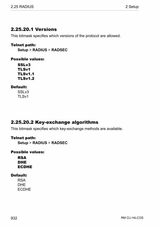
2.25.20.1 VersionsThis bitmask specifies which versions of the protocol are allowed.
Telnet path:Setup > RADIUS > RADSEC
Possible values:SSLv3TLSv1TLSv1.1TLSv1.2
Default:SSLv3TLSv1
2.25.20.2 Key-exchange algorithmsThis bitmask specifies which key-exchange methods are available.
Telnet path:Setup > RADIUS > RADSEC
Possible values:RSADHEECDHE
Default:RSADHEECDHE
RM CLI HiLCOS 932
2.25 RADIUS 2 Setup

2.25.20.3 Crypro algorithmsThis bitmask specifies which cryptographic algorithms are allowed.
Telnet path:Setup > RADIUS > RADSEC
Possible values:RC4-40RC4-56RC4-128DES40DES3DESAES-128AES-256AESGCM-128AESGCM-256
Default:RC4-1283DESAES-128AES-256AESGCM-128AESGCM-256
2.25.20.4 Hash algorithmsThis bit mask specifies which hash algorithms are allowed and implies whatHMAC algorithms used to protect of the integrity of the messages.
Telnet path:Setup > RADIUS > RADSEC
Possible values:
RM CLI HiLCOS 933
2 Setup 2.25 RADIUS

MD5SHA1SHA2-256SHA2-384
Default:MD5SHA1SHA2-256SHA2-384
2.25.20.5 Prefer PFSWhen setting the cipher suite, the device usually takes over the same settingas the requesting client. Certain client applications by default require a con-nection without perfect forward secrecy (PFS), even though both the deviceand the client are PFS-capable.
This option means that your device always prefers to connect with PFS,regardless of the default setting of the client.
Telnet path:Setup > RADIUS > RADSEC
Possible values:OnOff
Default:On
RM CLI HiLCOS 934
2.25 RADIUS 2 Setup

2.25.20.6 RenegotiationsThis setting gives you control over whether the client can trigger a renegotiationof SSL/TLS.
Telnet path:Setup > RADIUS > RADSEC
Possible values:Forbidden
The device disconnects from the remote station if this requests arenegotiation.
AllowedThe device permits renegotiations with the remote station.
IgnoredThe device ignores the request to renegotiate sent by the remotestation.
Default:Allowed
2.26 NTP
This menu contains the NTP settings.
SNMP ID: 2.26
Telnet path: /Setup
2.26.2 Server-OperatingHere you switch on the time server in your device for the local network. Otherdevices in the same network can then synchronize with the server via thenetwork time protocol (NTP).
SNMP ID: 2.26.2
Telnet path: /Setup/NTP
RM CLI HiLCOS 935
2 Setup 2.26 NTP

Possible values:
D YesD No
Default: No
2.26.3 BC-ModeIf the device should regularly operate as a time server and send the currenttime to all stations in the network, enable the “send mode” here.
Note: The send mode of the device only supports IPv4 addresses.
Telnet path:Setup > NTP
Possible values:No
The send mode is disabled.Yes
The send mode is enabled.
Default:No
2.26.4 BC-IntervalHere you set the time interval after which your device's time server sends thecurrent time to all devices or stations accessible via the local network.
SNMP ID: 2.26.4
Telnet path: /Setup/NTP
Possible values:
D Max. 10 characters
Default: 64
RM CLI HiLCOS 936
2.26 NTP 2 Setup

2.26.7 RQ-IntervalSpecify the time interval in seconds after which the internal clock of the deviceis re-synchronized with the specified time server (NTP).
SNMP ID: 2.26.7
Telnet path: /Setup/NTP
Possible values:
D Max. 10 characters
Default: 86400
Note: A connection may be established in order to access the time server.Please be aware that this may give rise to additional costs.
2.26.11 RQ-AddressHere you enter the time server that supplies the correct current time.
SNMP ID: 2.26.11
Telnet path: /Setup/NTP
2.26.11.1 RQ-AddressSpecify a time server (NTP) here for the device to synchronize with. The timeserver should be accessible via one of the available interfaces.
An address can be specified as a FQDN, IPv4 or IPv6 address. If the DNSname resolution returns an IPv6 address for the time server, the device willuse this IPv6 address preferentially.
Telnet path:Setup > NTP > RQ-Address
Possible values:Max. 31 characters from[A-Z][0-9]@{|}~!$%&'()+-,/:;<=>?[\]^_.
RM CLI HiLCOS 937
2 Setup 2.26 NTP
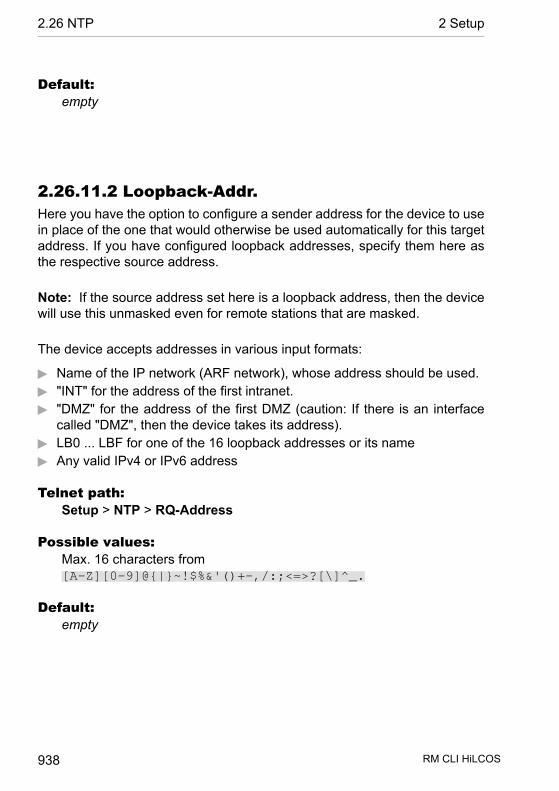
Default:empty
2.26.11.2 Loopback-Addr.Here you have the option to configure a sender address for the device to usein place of the one that would otherwise be used automatically for this targetaddress. If you have configured loopback addresses, specify them here asthe respective source address.
Note: If the source address set here is a loopback address, then the devicewill use this unmasked even for remote stations that are masked.
The device accepts addresses in various input formats:
D Name of the IP network (ARF network), whose address should be used.D "INT" for the address of the first intranet.D "DMZ" for the address of the first DMZ (caution: If there is an interface
called "DMZ", then the device takes its address).D LB0 ... LBF for one of the 16 loopback addresses or its nameD Any valid IPv4 or IPv6 address
Telnet path:Setup > NTP > RQ-Address
Possible values:Max. 16 characters from[A-Z][0-9]@{|}~!$%&'()+-,/:;<=>?[\]^_.
Default:empty
RM CLI HiLCOS 938
2.26 NTP 2 Setup
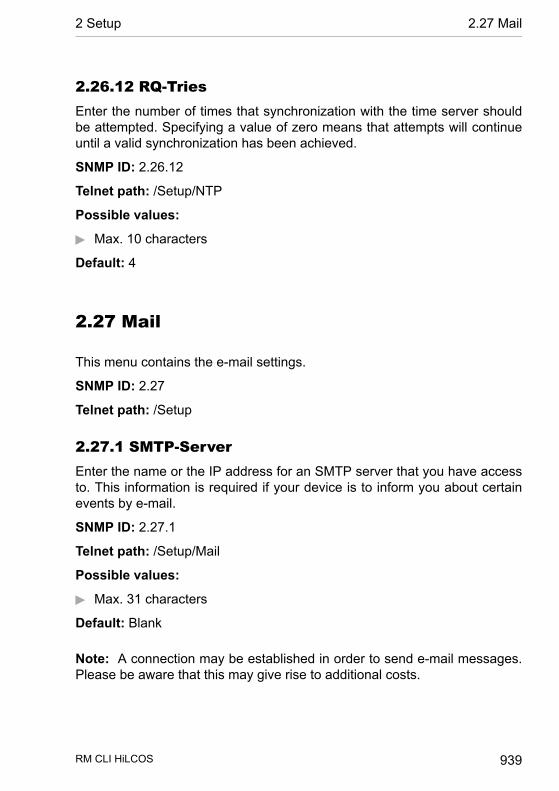
2.26.12 RQ-TriesEnter the number of times that synchronization with the time server shouldbe attempted. Specifying a value of zero means that attempts will continueuntil a valid synchronization has been achieved.
SNMP ID: 2.26.12
Telnet path: /Setup/NTP
Possible values:
D Max. 10 characters
Default: 4
2.27 Mail
This menu contains the e-mail settings.
SNMP ID: 2.27
Telnet path: /Setup
2.27.1 SMTP-ServerEnter the name or the IP address for an SMTP server that you have accessto. This information is required if your device is to inform you about certainevents by e-mail.
SNMP ID: 2.27.1
Telnet path: /Setup/Mail
Possible values:
D Max. 31 characters
Default: Blank
Note: A connection may be established in order to send e-mail messages.Please be aware that this may give rise to additional costs.
RM CLI HiLCOS 939
2 Setup 2.27 Mail

2.27.2 ServerportEnter the number of the SMTP port of the aforementioned server for unencryp-ted e-mail transmission. The default value is 587.
Telnet path:Setup > Mail
Possible values:Max. 10 characters
Default:587
2.27.3 POP3-ServerThe only difference between names of many POP3 servers and SMTP serversis the prefix. All you have to do is enter the same of your SMTP server andreplace 'SMTP' with 'POP' or "POP3".
SNMP ID: 2.27.3
Telnet path: /Setup/Mail
Possible values:
D Max. 31 characters
Default: Blank
2.27.4 POP3-PortEnter the number of the POP3 port of the aforementioned server for unencryp-ted mail. The default value is 110.
SNMP ID: 2.27.4
Telnet path: /Setup/Mail
Possible values:
D Max. 10 characters
Default: 110
RM CLI HiLCOS 940
2.27 Mail 2 Setup
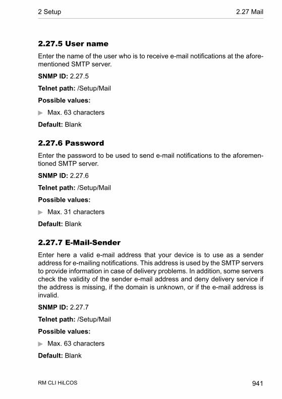
2.27.5 User nameEnter the name of the user who is to receive e-mail notifications at the afore-mentioned SMTP server.
SNMP ID: 2.27.5
Telnet path: /Setup/Mail
Possible values:
D Max. 63 characters
Default: Blank
2.27.6 PasswordEnter the password to be used to send e-mail notifications to the aforemen-tioned SMTP server.
SNMP ID: 2.27.6
Telnet path: /Setup/Mail
Possible values:
D Max. 31 characters
Default: Blank
2.27.7 E-Mail-SenderEnter here a valid e-mail address that your device is to use as a senderaddress for e-mailing notifications. This address is used by the SMTP serversto provide information in case of delivery problems. In addition, some serverscheck the validity of the sender e-mail address and deny delivery service ifthe address is missing, if the domain is unknown, or if the e-mail address isinvalid.
SNMP ID: 2.27.7
Telnet path: /Setup/Mail
Possible values:
D Max. 63 characters
Default: Blank
RM CLI HiLCOS 941
2 Setup 2.27 Mail

2.27.8 Send again (min)In case of connection problems with the SMTP server, mails will be bufferedhere and repeated tries will be made to send them. This also applies for mailswhich cannot be delivered due to incorrect settings such as incorrect SMTPparameters or unknown recipients. Set the time after which an attempt will bemade to re-submit buffered messages. Attempts are also made to re-submiteach time a new e-mail is received.
SNMP ID: 2.27.8
Telnet path: /Setup/Mail
Possible values:
D Max. 10 characters
Default: 30
2.27.9 Hold time (hrs)In case of connection problems with the SMTP server, mails will be bufferedhere and repeated tries will be made to send them. This also applies for mailswhich cannot be delivered due to incorrect settings such as incorrect SMTPparameters or unknown recipients. Set the maximum hold time for a message.Once this time has elapsed, all attempts to submit a certain message will bediscontinued.
SNMP ID: 2.27.9
Telnet path: /Setup/Mail
Possible values:
D Max. 10 characters
Default: 72
2.27.10 BuffersIn case of connection problems with the SMTP server, mails will be bufferedhere and repeated tries will be made to send them. This also applies for mailswhich cannot be delivered due to incorrect settings such as incorrect SMTPparameters or unknown recipients. Set the maximum number of buffered
RM CLI HiLCOS 942
2.27 Mail 2 Setup
messages. When this limit is exceeded, the oldest messages will be discardedto make room for incoming messages.
SNMP ID: 2.27.10
Telnet path: /Setup/Mail
Possible values:
D Max. 10 characters
Default: 100
2.27.11 Loopback-Addr.Here you can optionally configure a sender address to be used instead of theone used automatically for this destination address. If you have configuredloopback addresses, you can specify them here as sender address.
SNMP ID: 2.27.11
Telnet path: /Setup/Mail
Possible values:
D Name of the IP networks whose address should be usedD "INT" for the address of the first intranetD "DMZ" for the address of the first DMZD LB0 to LBF for the 16 loopback addressesD Any valid IP address
Default: Blank
Note: If there is an interface called "DMZ", its name will be taken in this case.
2.27.12 SMTP-use-TLSHere you determine if and how the device encrypts the connection. Theavailable values have the following meanings:
D No: No encryption. The device ignores any STARTTLS responses fromthe server.
D Yes: The device uses SMTPS, and is therefore encrypted right from con-nection establishment.
RM CLI HiLCOS 943
2 Setup 2.27 Mail

D Preferred: Connection establishment is not encrypted. If the SMTP serveroffers STARTTLS, the device starts encrypting. This setting is the defaultvalue.
D Required: Connection establishment is not encrypted. If the SMTP serverdoes not offer STARTTLS, the device does not transmits any data.
Telnet path:Setup > Mail
Possible values:No
Yes
Preferred
Required
Default:Preferred
2.27.13 SMTP-AuthenticationHere you specify if and how the device authenticates at the SMTP server.The device's behavior depends on the server settings: If the server does notrequire authentication, the login occurs in any case. Otherwise, the devicereacts according to the settings described below:
Telnet path:Setup > Mail
Possible values:None
Basically no authentication.Plain text preferred:
The authentication preferably occurs in cleartext (PLAIN, LOGIN), ifthe server requires authentication. If it does not accept cleartextauthentication, the device uses secure authentication.
Encrypted
RM CLI HiLCOS 944
2.27 Mail 2 Setup

The authentication is done without transmitting the password ascleartext (e.g., CRAM-MD5), if the server requires authentication.Cleartext authentication does not take place.
Preferred-EncryptedThe authentication is preferably encrypted (e.g., CRAM-MD5), if theserver requires authentication. If it does not accept secureauthentication, the device uses cleartext authentication.
Default:Preferred-Encrypted
2.30 IEEE802.1x
This menu contains the settings for the IEEE802.1x protocol.
SNMP ID: 2.30
Telnet path: /Setup
2.30.3 Radius-ServerAuthentication in all wireless LAN networks by a central RADIUS server (namedDEFAULT) can be managed here. You can also define RADIUS servers thatare dedicated to certain wireless LAN networks (instead of defining thepassphrase for the logical wireless LAN network). Furthermore, a backupserver can be specified for every RADIUS server.
SNMP ID: 2.30.3
Telnet path: /Setup/IEEE802.1x
2.30.3.1 NameThe name of the server.
SNMP ID: 2.30.3.1
Telnet path: /Setup/IEEE802.1x /RADIUS-Server
Possible values:
RM CLI HiLCOS 945
2 Setup 2.30 IEEE802.1x

D Max. 16 characters
Default: Blank
2.30.3.3 PortThe port the RADIUS server.
SNMP ID: 2.30.3.3
Telnet path: /Setup/IEEE802.1x /RADIUS-Server
Possible values:
D Max. 10 characters
Default: 0
2.30.3.4 SecretThe secret used by the RADIUS server.
SNMP ID: 2.30.3.4
Telnet path: /Setup/IEEE802.1x /RADIUS-Server
Possible values:
D Max. 32 characters
Default: Blank
2.30.3.5 BackupYou can enter the name of a backup server for the specified RADIUS server.The backup server will be connected only if the specified RADIUS server isunavailable. The name of the backup server can be selected from the sametable.
SNMP ID: 2.30.3.5
Telnet path: /Setup/IEEE802.1x /RADIUS-Server
Possible values:
D Max. 24 characters
RM CLI HiLCOS 946
2.30 IEEE802.1x 2 Setup
Default: Blank
2.30.3.6 Loopback-Addr.Here you can optionally configure a sender address to be used instead of theone used automatically for this destination address. If you have configuredloopback addresses, you can specify them here as sender address.
SNMP ID: 2.30.3.6
Telnet path: /Setup/IEEE802.1x /RADIUS-Server
Possible values:
D You can enter an address in various forms:D Name of the IP networks whose addresses are to be used.D "INT" for the address of the first intranet.D "DMZ" for the address of the first DMZ
Note: If there is an interface called "DMZ", its address will be taken in thiscase.
D LBO... LBF for the 16 loopback addresses.D Furthermore, any IP address can be entered in the form x.x.x.x.
Default: Blank
2.30.3.7 ProtocolProtocol for communication between the internal RADIUS server and the for-warding server.
SNMP ID: 2.30.3.7
Telnet path: /Setup/IEEE802.1x/RADIUS-Server/Protocol
Possible values:
D RADSECD RADIUS
Default: RADIUS
RM CLI HiLCOS 947
2 Setup 2.30 IEEE802.1x
2.30.3.8 Host nameEnter the IP address (IPv4, IPv6) or the hostname of the RADIUS server.
Note: The RADIUS client automatically detects which address type is involved.
Telnet path:Setup > IEEE802.1x > RADIUS-Server
Possible values:Max. 64 characters from [A-Z][a-z][0-9].-:%
Default:empty
Special values:DEFAULT
The name "DEFAULT" is reserved for all WLAN networks that useIEEE 802.1x for authentication and that do not have their own RADIUSserver. Every WLAN that uses authentication by IEEE 802.1x canuse its own RADIUS server after specifying appropriate values for'Key1/Passphrase'.
2.30.3.9 Attribute-ValuesWith this entry you configure the RADIUS attributes of the RADIUS server.
The attributes are specified in a semicolon-separated list of attribute numbersor names (according to RFC 2865, RFC 3162, RFC 4679, RFC 4818, RFC7268 ) and a co r respond ing va lue in the fo rm<Attribute_1>=<Value_1>,<Attribute_2>=<Value_2>.
Variables can also be used as values (such as %n for the device name).Example: NAS-Identifier=%n.
Telnet path:
RM CLI HiLCOS 948
2.30 IEEE802.1x 2 Setup
Setup > IEEE802.1x > RADIUS-Server
Possible values:Max. 128 characters from[A-Z][a-z][0-9]#@{|}~!$%&'()*+-,/:;<=>?[\]^_. `
Default:empty
2.30.4 PortsYou should specify the login settings separately for each local network.
SNMP ID: 2.30.4
Telnet path: /Setup/IEEE802.1x
2.30.4.2 PortThe interface that this entry refers to.
SNMP ID: 2.30.4.2
Telnet path: /Setup/IEEE802.1x /Ports
Possible values:
D All of the interfaces available in the device.
Default: Blank
2.30.4.4 Re-Auth-MaxThis parameter is a timer in the authentication state machine for IEEE 802.1x.
SNMP ID: 2.30.4.4
Telnet path: /Setup/IEEE802.1x /Ports
Possible values:
D Max. 10 characters
Default: 3
RM CLI HiLCOS 949
2 Setup 2.30 IEEE802.1x
Note: Changes to these parameters require expert knowledge of the IEEE802.1x standard. Only make changes here if your system configurationabsolutely requires them.
2.30.4.5 Max-ReqThis parameter is a timer in the authentication state machine for IEEE 802.1x.
SNMP ID: 2.30.4.5
Telnet path: /Setup/IEEE802.1x /Ports
Possible values:
D Max. 10 characters
Default: 3
Note: Changes to these parameters require expert knowledge of the IEEE802.1x standard. Only make changes here if your system configurationabsolutely requires them.
2.30.4.6 Tx-PeriodThis parameter is a timer in the authentication state machine for IEEE 802.1x.
SNMP ID: 2.30.4.6
Telnet path: /Setup/IEEE802.1x /Ports
Possible values:
D Max. 10 characters
Default: 30
Note: Changes to these parameters require expert knowledge of the IEEE802.1x standard. Only make changes here if your system configurationabsolutely requires them.
RM CLI HiLCOS 950
2.30 IEEE802.1x 2 Setup

2.30.4.7 Supp-TimeoutThis parameter is a timer in the authentication state machine for IEEE 802.1x.
SNMP ID: 2.30.4.7
Telnet path: /Setup/IEEE802.1x /Ports
Possible values:
D Max. 10 characters
Default: 30
Note: Changes to these parameters require expert knowledge of the IEEE802.1x standard. Only make changes here if your system configurationabsolutely requires them.
2.30.4.8 Server-TimeoutThis parameter is a timer in the authentication state machine for IEEE 802.1x.
SNMP ID: 2.30.4.8
Telnet path: /Setup/IEEE802.1x /Ports
Possible values:
D Max. 10 characters
Default: 30
Note: Changes to these parameters require expert knowledge of the IEEE802.1x standard. Only make changes here if your system configurationabsolutely requires them.
2.30.4.9 Quiet-PeriodThis parameter is a timer in the authentication state machine for IEEE 802.1x.
SNMP ID: 2.30.4.9
RM CLI HiLCOS 951
2 Setup 2.30 IEEE802.1x

Telnet path: /Setup/IEEE802.1x /Ports
Possible values:
D Max. 10 characters
Default: 60
Note: Changes to these parameters require expert knowledge of the IEEE802.1x standard. Only make changes here if your system configurationabsolutely requires them.
2.30.4.10 Re-AuthenticationHere you activate regular re-authentication. If a new authentication starts, theuser remains registered during the negotiation. A typical value as a re-authentication interval is 3,600 seconds.
SNMP ID: 2.30.4.10
Telnet path: /Setup/IEEE802.1x /Ports
Possible values:
D YesD No
Default: No
2.30.4.11 Re-Auth-IntervalA typical value as a re-authentication interval is 3,600 seconds.
SNMP ID: 2.30.4.11
Telnet path: /Setup/IEEE802.1x /Ports
Possible values:
D Max. 10 characters
Default: 3600
RM CLI HiLCOS 952
2.30 IEEE802.1x 2 Setup
2.30.4.12 Key-TransmissionHere you activate the regular generation and transmission of a dynamic WEPkey.
SNMP ID: 2.30.4.12
Telnet path: /Setup/IEEE802.1x /Ports
Possible values:
D YesD No
Default: No
2.30.4.13 Key-Tx-IntervalA typical value as a key-transmission interval is 900 seconds.
SNMP ID: 2.30.4.13
Telnet path: /Setup/IEEE802.1x /Ports
Possible values:
D Max. 10 characters
Default: 900
2.31 PPPoE-Server
This menu contains the settings for the PPPoE server.
Telnet path:Setup
RM CLI HiLCOS 953
2 Setup 2.31 PPPoE-Server
2.31.1 OperatingThis switch enables and disables the PPPoE server.
SNMP ID: 2.31.1
Telnet path: /Setup/PPPoE-Server
Possible values:
D YesD No
2.31.2 Name listIn the list of peers/ remote sites, define those clients that are permitted accessby the PPPoE server and define further properties and rights in the PPP listor the firewall.
SNMP ID: 2.31.2
Telnet path: /Setup/PPPoE-Server
2.31.2.1 PeerHere you can define a remote-station name for each client. The remote-sitename must be used by the client as the PPP user name.
SNMP ID: 2.31.2.1
Telnet path: /Setup/PPPoE-Server/Name-List
Possible values:
D Select from the list of defined peers.
Default: Blank
2.31.2.2 SH-TimeDefine the short-hold time for the PPPoE connection here.
SNMP ID: 2.31.2.2
Telnet path: /Setup/PPPoE-Server/Name-List
RM CLI HiLCOS 954
2.31 PPPoE-Server 2 Setup
Possible values:
D Max. 10 characters
Default: 0
2.31.2.3 MAC-AddressIf a MAC address is entered, then the PPP negotiation is terminated if theclient logs on from a different MAC address.
SNMP ID: 2.31.2.3
Telnet path: /Setup/PPPoE-Server/Name-List
Possible values:
D Max. 12 characters
Default: 000000000000
2.31.3 ServiceThe name of the service offered is entered under 'Service'. his enables aPPPoE client to select a certain PPPoE server that is entered for the client.
SNMP ID: 2.31.3
Telnet path: /Setup/PPPoE-Server
Possible values:
D Max. 32 characters
Default: Blank
2.31.4 Session-LimitThe 'Session limit' specifies how often a client can be logged on simultaneouslywith the same MAC address. Once the limit has been reached, the server nolonger responds to the client queries that are received. Default value is '1',maximum value '99'. A Session limit of '0' stands for an unlimited number ofsessions.
SNMP ID: 2.31.4
RM CLI HiLCOS 955
2 Setup 2.31 PPPoE-Server

Telnet path: /Setup/PPPoE-Server
Possible values:
D 0 to 99
Default: 1
Special values: 0 switches the session limit off.
2.31.5 PortsHere you can specify for individual ports whether the PPPoE server is active.
SNMP ID: 2.31.5
Telnet path: /Setup/PPPoE-Server
2.31.5.2 PortPort for which the PPPoE server is to be activated/deactivated.
SNMP ID: 2.31.5.2
Telnet path: /Setup/PPPoE-Server/Ports
Possible values:
D Selects a port from the list of those available in the device.
2.31.5.3 Enable PPPoEActivates or deactivates the PPPoE server for the selected port.
SNMP ID: 2.31.5.3
Telnet path: /Setup/PPPoE-Server/Ports
Possible values:
D YesD No
Default: Yes
RM CLI HiLCOS 956
2.31 PPPoE-Server 2 Setup
2.31.6 AC-NameThis input field provides the option to give the PPPoE server a name that isindependent of the device name (AC-Name = access concentrator name).
Telnet path:Setup > PPPoE-Server
Possible values:Max. 32 characters from[A-Z][a-z][0-9]#@{|}~!$%&'()*+-,/:;<=>?[\]^_. `
Special values:empty
If you leave this field blank, the PPPoE server uses the device nameas the server name.
Default:empty
2.32 VLAN
There are two important tasks when configuring the VLAN capabilities of thedevices:
D Defining virtual LANs and giving each one a name, a VLAN ID, and alloc-ating the interfaces
D For each interface, define how data packets with or without VLAN tags areto be handled
SNMP ID: 2.32
Telnet path: /Setup
2.32.1 NetworksThe network list contains the name of each VLAN, the VLAN ID and the ports.Simply click on an entry to edit it.
RM CLI HiLCOS 957
2 Setup 2.32 VLAN
SNMP ID: 2.32.1
Telnet path: /Setup/VLAN
2.32.1.1 NameThe name of the VLAN only serves as a description for the configuration. Thisname is not used anywhere else.
SNMP ID: 2.32.1.1
Telnet path: /Setup/VLAN/Networks
2.32.1.2 VLAN-IDThis number uniquely identifies the VLAN.
SNMP ID: 2.32.1.2
Telnet path: /Setup/VLAN/Networks
Possible values:
D 0 to 4096
Default: 0
2.32.1.4 PortsEnter here the device interfaces that belong to the VLAN. For a device witha LAN interface and a WLAN port, ports that to be entered could include "LAN-1" and "WLAN-1". Port ranges are defined by entering a tilde between theindividual ports: "P2P-1~P2P-4".
SNMP ID: 2.32.1.4
Telnet path: /Setup/VLAN/Networks
Possible values:
D Max. 251 characters
Default: Blank
RM CLI HiLCOS 958
2.32 VLAN 2 Setup
Note: The first SSID of the first wireless LAN module is WLAN-1, and furtherSSIDs are WLAN-1-2 to WLAN-1-8. If the device has two WLAN modules,the SSIDs are called WLAN-2 and WLAN-2-2 to WLAN-2-8.
2.32.1.5 LLDP-Tx-TLV-PPIDThis setting specifies to which ports, which are members of this VLAN, thedevice is to propagate the membership via LLDP.
Telnet path:Setup > VLAN > Networks
Possible values:Comma-separated list of interface names (analogous to the names in thecolumn Ports), max. 251 characters
Default:
2.32.1.6 LLDP-Tx-TLV-NameThis setting specifies to which ports, which are members of this VLAN, thedevice is to propagate the name of the VLAN via LLDP.
Telnet path:Setup > VLAN > Networks
Possible values:Comma-separated list of interface names (analogous to the names in thecolumn Ports), max. 251 characters
Default:
2.32.2 Port-TableThe port table is used to configure each of the device's ports that are used inthe VLAN. The table has an entry for each of the device's ports.
SNMP ID: 2.32.2
Telnet path: /Setup/VLAN
RM CLI HiLCOS 959
2 Setup 2.32 VLAN
2.32.2.1 PortThe name of the port; this cannot be edited.
SNMP ID: 2.32.2.1
Telnet path: /Setup/VLAN/Port-Table
2.32.2.4 Allow-All-VLANsThis option defines whether tagged data packets with any VLAN ID shouldbe accepted, even if the port is not a "member" of this VLAN.
SNMP ID: 2.32.2.4
Telnet path: /Setup/VLAN/Port-Table
Possible values:
D YesD No
Default: Yes
2.32.2.5 Port-VLAN-IdThis port ID has two functions:
D Untagged packets received at this port in 'Mixed' or 'Ingress-mixed' modeare assigned to this VLAN, as are all ingress packets received in 'Never'mode.
D In the 'Mixed' mode, this value determines whether outgoing packets receivea VLAN tag or not: Packets assigned to the VLAN defined for this portreceive no VLAN tag; all others are given a VLAN tag.
SNMP ID: 2.32.2.5
Telnet path: /Setup/VLAN/Port-Table
Possible values:
D Max. 4 characters
Default: 1
RM CLI HiLCOS 960
2.32 VLAN 2 Setup
2.32.2.6 Tagging modeControls the processing and assignment of VLAN tags at this port.
SNMP ID: 2.32.2.6
Telnet path: /Setup/VLAN/Port-Table
Possible values:
D Never: Outbound packets are not given a VLAN tag at this port. Incomingpackets are treated as though they have no VLAN tag. If incoming packetshave a VLAN tag, it is ignored and treated as though it were part of thepacket's payload. Incoming packets are always assigned to the VLANdefined for this port.
D Always: Outgoing packets at this port are always assigned with a VLANtag, irrespective of whether they belong to the VLAN defined for this portor not. Incoming packets must have a VLAN tag, otherwise they will bedropped.
D Mixed: Allows mixed operation of packets with and without VLAN tags atthe port. Packets without a VLAN tag are assigned to the VLAN definedfor this port. Outgoing packets are given a VLAN tag unless they belongto the VLAN defined for this port.
D Ingress mixed: Arriving (ingress) packets may or may not have a VLANtag; outbound (egress) packets are never given a VLAN tag.
Default: Ingress mixed
Tx-LLDP-TLV-Port-VLANEnables or disables the port as the LLDP-TLV port in this VLAN.
WEBconfig path:HiLCOS menu tree/Setup/VLAN/Port-Table/Tx-LLDP-TLV-Port-VLAN
Possible values:
D YesD No
Default: Yes
RM CLI HiLCOS 961
2 Setup 2.32 VLAN
2.32.4 OperatingYou should only activate the VLAN module if you are familiar with the effectsthis can have.
SNMP ID: 2.32.4
Telnet path: /Setup/VLAN
Possible values:
D Yes
D No
Default: No
Note: Faulty VLAN settings may cause access to the device's configurationto be blocked.
2.32.5 Tag-ValueWhen transmitting VLAN tagged networks via provider networks that useVLAN themselves, providers sometimes use special VLAN tagging IDs. Inorder for VLAN transmission to allow for this, the Ethernet2 type of the VLANtag can be set as a 16-bit hexadecimal value as 'tag value'. The default is'8100' (802.1p/q VLAN tagging) other typical values for VLAN tagging couldbe '9100' or '9901'.
SNMP ID: 2.32.5
Telnet path: /Setup/VLAN
Possible values:
D Max. 4 characters
Default: 8100
2.34 Printer
This menu contains settings for the printer.
RM CLI HiLCOS 962
2.34 Printer 2 Setup
SNMP ID: 2.34
Telnet path: /Setup
2.34.1 PrinterYou can adjust setting for the network printer here.
SNMP ID: 2.34.1
Telnet path: /Setup/Printer
2.34.1.1 PrinterPrinter name.
SNMP ID: 2.34.1.1
Telnet path: /Setup/Printer/Printer
Possible values:
D Max. 10 characters
Default: *
2.34.1.2 RawIp-PortThis port can be used to accept print jobs over RawIP.
SNMP ID: 2.34.1.2
Telnet path: /Setup/Printer/Printer
Possible values:
D Max. 10 characters
Default: 9100
2.34.1.3 LPD-PortThis port can be used to accept print jobs over LDP.
SNMP ID: 2.34.1.3
RM CLI HiLCOS 963
2 Setup 2.34 Printer

Telnet path: /Setup/Printer/Printer
Possible values:
D Max. 10 characters
Default: 515
2.34.1.4 OperatingActivates or deactivates this entry.
SNMP ID: 2.34.1.4
Telnet path: /Setup/Printer/Printer
Possible values:
D Yes: The print server is active.D No: The print server is not active.
Default: No
2.34.1.5 BidirectionalThis parameter enables or disables the bi-directional mode of the printer.
SNMP ID: 2.34.1.5
Telnet path: /Setup/Printer/Printer
Note: The bidirectional model of the printer is intended exclusively fordevelopment and support purposes. Do not alter the pre-set values for theseparameters. An irregular configuration may cause the devices to behaveunexpectedly during operations.
2.34.1.6 Reset-on-OpenIf this option is activated the device will send a reset command to the printerbefore opening a printer session.
SNMP ID: 2.34.1.6
RM CLI HiLCOS 964
2.34 Printer 2 Setup
Telnet path: /Setup/Printer/Printer
Possible values:
D YesD No
Default: No
Note: Activate this option if the connection to the printer does not work asexpected.
2.34.2 Access-ListHere you define the networks that have access to the printer.
SNMP ID: 2.34.2
Telnet path: /Setup/Printer
2.34.2.1 IP-AddressIP address of the network with clients requiring access to the printer.
SNMP ID: 2.34.2.1
Telnet path: Setup/Printer/Access-list
Possible values:
D Valid IP address
Default: 0.0.0.0
2.34.2.2 IP-NetmaskNetmask of the permitted networks.
SNMP ID: 2.34.2.2
Telnet path: Setup/Printer/Access-list
Possible values:
D Valid IP address
RM CLI HiLCOS 965
2 Setup 2.34 Printer
Default: 0.0.0.0
2.34.2.3 Rtg-TagIf you specify a routing tag for this access rule, the only packets that will beaccepted have received the same tag in the firewall or they are from a networkwith the corresponding interface tag. If the routing tag is 0, access attemptsfrom suitable IP addresses are accepted every time.
SNMP ID: 2.34.2.3
Telnet path: Setup/Printer/Access-list/Rtg-Tag
Possible values:
D Max. 5 characters
Default: Blank
Note: It follows that the use of routing tags only makes sense in combinationwith the appropriate accompanying rules in the firewall or tagged networks.
2.35 ECHO-Server
This menu contains the configuration of the ECHO server.
SNMP ID: 2.35
Telnet path: /Setup
2.35.1 OperatingThe echo server is used to monitor the line quality by measuring RTT and jitter.
SNMP ID: 2.35.1
Telnet path: /Setup/ECHO-Server
Possible values:
D Yes
RM CLI HiLCOS 966
2.35 ECHO-Server 2 Setup

D No
Default: No
2.35.2 Access tableThis table defines the access rights for using the ECHO server.
SNMP ID: 2.35.2
Telnet path: /Setup/ECHO-Server
2.35.2.1 IP-AddressIP address of remote device.
SNMP ID: 2.35.2.1
Telnet path: /Setup/ECHO-server/Access-table
Possible values:
D Valid IP address
2.35.2.2 NetmaskIP address of remote device.
SNMP ID: 2.35.2.2
Telnet path: /Setup/ECHO-server/Access-table
Possible values:
D Valid IP address
2.35.2.3 ProtocolProtocol used for measuring.
SNMP ID: 2.35.2.3
Telnet path: /Setup/ECHO-server/Access-table
Possible values:
RM CLI HiLCOS 967
2 Setup 2.35 ECHO-Server
D NoneD TCPD UDPD TCP+UDP
2.35.2.4 OperatingActivates or deactivates this entry in the table.
SNMP ID: 2.35.2.4
Telnet path: /Setup/ECHO-server/Access-table
Possible values:
D YesD No
Default: No
2.35.2.5 CommentComment on this entry.
SNMP ID: 2.35.2.5
Telnet path: /Setup/ECHO-server/Access-table
2.35.3 TCP-TimeoutIf a TCP session to an ECHO server is inactive for 10 (default) seconds, theserver disconnects. Normally TCP clears up "dormant" connections by itself,but this takes far longer.
SNMP ID: 2.35.3
Telnet path: /Setup/ECHO-Server
Possible values:
D Max. 10 characters
Default: 10
RM CLI HiLCOS 968
2.35 ECHO-Server 2 Setup

2.36 Performance-Monitoring
This menu contains the configuration of the performance monitoring.
SNMP ID: 2.36
Telnet path: /Setup
2.36.2 RttMonAdminThis table displays information about the type of measurements.
SNMP ID: 2.36.2
Telnet path: /Setup/Performance-Monitoring
2.36.2.1 IndexShared index for the measurement
SNMP ID: 2.36.2.1
Telnet path: /Setup/Performance-Monitoring/RttMonAdmin
2.36.2.4 TypeMeasurement type.
SNMP ID: 2.36.2.4
Telnet path: /Setup/Performance-Monitoring/RttMonAdmin
2.36.2.6 FrequencyTime in milliseconds until the measurement is repeated. Is the only parameterthat can be modified while the status is active. In this case only 0 is allowedin order to prevent further iterations.
SNMP ID: 2.36.2.6
Telnet path: /Setup/Performance-Monitoring/RttMonAdmin
RM CLI HiLCOS 969
2 Setup 2.36 Performance-Monitoring
2.36.2.7 TimeoutMeasurement timeout in milliseconds. The timeout value must be smaller thanthe time until measurement is repeated.
SNMP ID: 2.36.2.7
Telnet path: /Setup/Performance-Monitoring/RttMonAdmin
2.36.2.9 StatusMeasurement status
SNMP ID: 2.36.2.9
Telnet path: /Setup/Performance-Monitoring/RttMonAdmin
Possible values:
D Active: Measurement is in progress. This value can only be set if the Statusvalue is Not_In_Service. No measurement parameters can be modifiedwhile the Status is active.
D Not_In_Service: All parameters required have been set; no measurementis currently in progress.
D Not_Ready: Not all parameters required have been set.D Create: Create a table row. SNMP Set is used to create a table row by
setting the desired index to Create. When configuration is performed fromthe menu system the Status must also first be set to Create. When a newtable row is created, the appropriate rows in the other tables are createdautomatically.
D Destroy: Delete a table row. This is only possible when the status is notActive. The appropriate rows in the other tables are deleted automatically.
2.36.3 RttMonEchoAdminThis table displays information about the the measurements.
SNMP ID: 2.36.3
Telnet path: /Setup/Performance-Monitoring
RM CLI HiLCOS 970
2.36 Performance-Monitoring 2 Setup
2.36.3.1 ProtocolProtocol to be used
SNMP ID: 2.36.3.1
Telnet path: /Setup/Performance-Monitoring/RttMonEchoAdmin
2.36.3.2 Destination addressAddress of the responder
SNMP ID: 2.36.3.2
Telnet path: /Setup/Performance-Monitoring/RttMonEchoAdmin
Possible values:
D Valid IP address
2.36.3.3 Packet sizeLength of the measurement packets in bytes. Packets are padded out to theminimum length required by the measurement.
SNMP ID: 2.36.3.3
Telnet path: /Setup/Performance-Monitoring/RttMonEchoAdmin
2.36.3.5 Destination portDestination port. Currently ignored
SNMP ID: 2.36.3.5
Telnet path: /Setup/Performance-Monitoring/RttMonEchoAdmin
2.36.3.17 IntervalTime between two measurement packets in milliseconds
SNMP ID: 2.36.3.17
RM CLI HiLCOS 971
2 Setup 2.36 Performance-Monitoring

Telnet path: /Setup/Performance-Monitoring/RttMonEchoAdmin
2.36.3.18 Packet countNumber of measurement packets per measurement
SNMP ID: 2.36.3.18
Telnet path: /Setup/Performance-Monitoring/RttMonEchoAdmin
2.36.3.255 IndexShared index for the measurement
SNMP ID: 2.36.3.255
Telnet path: /Setup/Performance-Monitoring/RttMonEchoAdmin
2.36.4 RttMonStatisticsThis table displays performance monitoring statistics.
SNMP ID: 2.36.4
Telnet path: /Setup/Performance-Monitoring
2.36.4.2 CompletionsNumber of measurements performed.
SNMP ID: 2.36.4.2
Telnet path: /Setup/Performance-Monitoring/RttMonStatistics
2.36.4.4 RTT-CountTotal number of RTT values determined
SNMP ID: 2.36.4.4
Telnet path: /Setup/Performance-Monitoring/RttMonStatistics
RM CLI HiLCOS 972
2.36 Performance-Monitoring 2 Setup

2.36.4.5 RTT-SumSum of all RTT values determined
SNMP ID: 2.36.4.5
Telnet path: /Setup/Performance-Monitoring/RttMonStatistics
2.36.4.8 RTT-MinMinimum roundtrip time in uSec
SNMP ID: 2.36.4.8
Telnet path: /Setup/Performance-Monitoring/RttMonStatistics
2.36.4.9 RTT-MaxMaximum roundtrip time in uSec
SNMP ID: 2.36.4.9
Telnet path: /Setup/Performance-Monitoring/RttMonStatistics
2.36.4.10 Jitter-Min-Pos-SDMinimum positive jitter value from sender to responder in uSec
SNMP ID: 2.36.4.10
Telnet path: /Setup/Performance-Monitoring/RttMonStatistics
2.36.4.11 Jitter-Max-Pos-SDMaximum positive jitter value from sender to responder in uSec
SNMP ID: 2.36.4.11
Telnet path: /Setup/Performance-Monitoring/RttMonStatistics
RM CLI HiLCOS 973
2 Setup 2.36 Performance-Monitoring
2.36.4.12 Jitter-Count-Pos-SDNumber of positive jitter values determined from sender to responder
SNMP ID: 2.36.4.12
Telnet path: /Setup/Performance-Monitoring/RttMonStatistics
2.36.4.13 Jitter-Sum-Pos-SDSum of all positive jitter values from sender to responder in uSec
SNMP ID: 2.36.4.13
Telnet path: /Setup/Performance-Monitoring/RttMonStatistics
2.36.4.16 Jitter-Min-Pos-DSMinimum positive jitter value from responder to sender in uSec
SNMP ID: 2.36.4.16
Telnet path: /Setup/Performance-Monitoring/RttMonStatistics
2.36.4.17 Jitter-Max-Pos-DSMaximum positive jitter value from responder to sender in uSec
SNMP ID: 2.36.4.17
Telnet path: /Setup/Performance-Monitoring/RttMonStatistics
2.36.4.18 Jitter-Count-Pos-DSNumber of positive jitter values determined from responder to sender
SNMP ID: 2.36.4.18
Telnet path: /Setup/Performance-Monitoring/RttMonStatistics
RM CLI HiLCOS 974
2.36 Performance-Monitoring 2 Setup

2.36.4.19 Jitter-Sum-Pos-DSSum of all positive jitter values from responder to sender in uSec
SNMP ID: 2.36.4.19
Telnet path: /Setup/Performance-Monitoring/RttMonStatistics
2.36.4.22 Jitter-Min-Neg-SDMinimum negative jitter value from sender to responder in uSec, absolutevalue
SNMP ID: 2.36.4.22
Telnet path: /Setup/Performance-Monitoring/RttMonStatistics
2.36.4.23 Jitter-Max-Neg-SDMaximum negative jitter value from sender to responder in uSec, absolutevalue
SNMP ID: 2.36.4.23
Telnet path: /Setup/Performance-Monitoring/RttMonStatistics
2.36.4.24 Jitter-Count-Neg-SDNumber of negative jitter values determined from sender to responder
SNMP ID: 2.36.4.24
Telnet path: /Setup/Performance-Monitoring/RttMonStatistics
2.36.4.25 Jitter-Sum-Neg-SDSum of all negative jitter values from sender to responder in uSec, absolutevalue
SNMP ID: 2.36.4.25
Telnet path: /Setup/Performance-Monitoring/RttMonStatistics
RM CLI HiLCOS 975
2 Setup 2.36 Performance-Monitoring

2.36.4.28 Jitter-Min-Neg-DSMinimum negative jitter value from responder to sender in uSec, absolutevalue
SNMP ID: 2.36.4.28
Telnet path: /Setup/Performance-Monitoring/RttMonStatistics
2.36.4.29 Jitter-Max-Neg-DSMaximum negative jitter value from responder to sender in uSec, absolutevalue
SNMP ID: 2.36.4.29
Telnet path: /Setup/Performance-Monitoring/RttMonStatistics
2.36.4.30 Jitter-Count-Neg-DSNumber of negative jitter values determined from responder to sender
SNMP ID: 2.36.4.30
Telnet path: /Setup/Performance-Monitoring/RttMonStatistics
2.36.4.31 Jitter-Sum-Neg-DSSum of all negative jitter values from responder to sender in uSec, absolutevalue
SNMP ID: 2.36.4.31
Telnet path: /Setup/Performance-Monitoring/RttMonStatistics
2.36.4.34 Packet-Loss-SDNumber of packets lost from sender to responder
SNMP ID: 2.36.4.34
Telnet path: /Setup/Performance-Monitoring/RttMonStatistics
RM CLI HiLCOS 976
2.36 Performance-Monitoring 2 Setup

2.36.4.35 Packet-Loss-DSNumber of packets lost from responder to sender
SNMP ID: 2.36.4.35
Telnet path: /Setup/Performance-Monitoring/RttMonStatistics
2.36.4.62 Average-JitterAverage of all absolute jitter values
SNMP ID: 2.36.4.62
Telnet path: /Setup/Performance-Monitoring/RttMonStatistics
2.36.4.63 Average-Jitter-SDAverage of all absolute jitter values from sender to responder
SNMP ID: 2.36.4.63
Telnet path: /Setup/Performance-Monitoring/RttMonStatistics
2.36.4.64 Average-Jitter-DSAverage of all absolute jitter values from responder to sender
SNMP ID: 2.36.4.64
Telnet path: /Setup/Performance-Monitoring/RttMonStatistics
2.36.4.255 IndexShared index for the measurement
SNMP ID: 2.36.4.255
Telnet path: /Setup/Performance-Monitoring/RttMonStatistics
RM CLI HiLCOS 977
2 Setup 2.36 Performance-Monitoring

2.37 WLAN-Management
This menu is used to configure WLAN management for WLCs.
2.37.1 AP-ConfigurationThis menu contains the settings for the AP.
SNMP ID: 2.37.1
Telnet path: /Setup/WLAN-Management
Default: Blank
2.37.1.1 Network profilesHere you define the logical WLAN networks that can be activated and operatedon the associated APs.
SNMP ID: 2.37.1.1
Telnet path: /Setup/WLAN-Management/AP-Configuration
2.37.1.1.1 NameName of the logical WLAN network under which the settings are saved. Thisname is only used for internal administration of logical networks.
SNMP ID: 2.37.1.1.1
Telnet path: Setup/WLAN-Management/AP-Configuration/Networkprofiles
Possible values:
D Max. 31 ASCII characters
Default: Blank
2.37.1.1.2 Parent-NameA WLC is capable of managing a wide range of different APs at different loc-ations. However, WLAN profiles include settings that are not equally suitable
RM CLI HiLCOS 978
2.37 WLAN-Management 2 Setup

for every type of AP that can be managed. For rexample, there are differencesbetween the country settings and the device properties.
In order to avoid having to maintain multiple redundant WLAN profiles to caterfor different countries or device types, it is possible for the logical WLAN net-works to "inherit" properties from other entries.
SNMP ID: 2.37.1.1.2
Telnet path: Setup/WLAN-Management/AP-Configuration/Networkprofiles
Possible values:
D Max. 31 ASCII characters
Default: Blank
2.37.1.1.3 Local-ValuesSpecifies which logical wireless LAN parameters are taken over duringinheritance from the parent element. All non-inherited parameters can be setlocally for this profile.
SNMP ID: 2.37.1.1.3
Telnet path: Setup/WLAN-Management/AP-Configuration/Networkprofiles
Possible values:
D Bit field as HEX number. Set bits specify the columns to be inherited. Selectfrom the list of logical WLAN networks (GUI).
Default: All values are taken over from parent elements.
2.37.1.1.4 OperatingSwitches the logical WLAN on or off separately.
SNMP ID: 2.37.1.1.4
Telnet path: Setup/WLAN-Management/AP-Configuration/Networkprofiles
Possible values:
D OnD Off
Default: On
RM CLI HiLCOS 979
2 Setup 2.37 WLAN-Management
2.37.1.1.6 EncryptionSelects the encryption method and, for WEP, the key length that is to be usedto encrypt data packets on the WLAN.
SNMP ID: 2.37.1.1.6
Telnet path: Setup/WLAN-Management/AP-Configuration/Networkprofiles
Possible values:
D 802.11i-WPA-PSKD 802.11i-WPA-802.1xD WEP-104-BitD WEP-40-BitD WEP-104-Bit-802.1xD WEP-40-Bit-802.1xD None
Default: 802.11i-WPA-PSK (0)
Note: Please consider that not all wireless cards support all encryptionmethods.
2.37.1.1.7 WPA1-Session-KeytypesHere you select the methods which are to be made available for generatingWPA session keys and group key. There is a choice of the Temporal KeyIntegrity Protocol (TKIP), the Advanced Encryption Standard (AES), or both.
SNMP ID: 2.37.1.1.7
Telnet path: Setup/WLAN-Management/AP-Configuration/Networkprofiles
Possible values:
D TKIP/AESD AESD TKIP
Default: TKIP/AES
RM CLI HiLCOS 980
2.37 WLAN-Management 2 Setup

2.37.1.1.8 WPA-VersionData in this logical WLAN will be encrypted with this WPA version.
SNMP ID: 2.37.1.1.8
Telnet path: Setup/WLAN-Management/AP-Configuration/Networkprofiles
Possible values:
D WPA1/2D WPA1D WPA2
Default: WPA1/2 (0)
2.37.1.1.9 KeyYou can enter the key or passphrase as an ASCII character string. An optionfor WEP is to enter a hexadecimal number by adding a leading '0x'. The fol-lowing lengths result for the formats used: Method, length WPA-PSK 8-63ASCII characters WEP152 (128 bit) 16 ASCII or 32 HEX characters WEP128(bit 104) 13 ASCII or 26 HEX characters WEP64 (bit 40) 5 ASCII or 10 HEXcharacters
SNMP ID: 2.37.1.1.9
Telnet path: Setup/WLAN-Management/AP-Configuration/Networkprofiles
Possible values:
D ASCII character string or hexadecimal number
Default: Blank
2.37.1.1.10 BandSelecting the frequency band determines whether the wireless LAN adapteroperates in the 2.4 GHz or 5 GHz band, which in turn determines the availableradio channels.
SNMP ID: 2.37.1.1.10
Telnet path: Setup/WLAN-Management/AP-Configuration/Networkprofiles
Possible values:
RM CLI HiLCOS 981
2 Setup 2.37 WLAN-Management
D 2.4GHz/5GHzD 2.4GHzD 5GHz
Default: 2.4GHz/5GHz
2.37.1.1.11 Continuation-TimeThe time in minutes that a managed-mode AP continues to operate in itscurrent configuration.
The configuration is provided to the AP by the WLC and is optionally storedin flash memory (in an area that is not accessible to LANconfig or other tools).Should the connection to the WLC be interrupted, the AP will continue tooperate with the configuration stored in flash for the time period entered here.The AP can also continue to work with this flash configuration after a localpower outage.
If there is still no connection to the WLC after this time period has expiredthen the flash configuration is deleted and the access point goes out of oper-ation. As soon as the WLC can be reached again, the configuration is trans-mitted again from the WLC to the AP.
This option enables an AP to continue operating even if the connection to theWLC is temporarily interrupted. Furthermore this represents an effectivemeasure against theft as all security-related configuration parameters areautomatically deleted after this time has expired.
SNMP ID: 2.37.1.1.11
Telnet path: Setup/WLAN-Management/AP-Configuration/Networkprofiles
Possible values:
D 0 to 9999
Default: 0
Special values: 0: Switches the WLAN module off the moment that the con-nection to the Controller is lost. With this setting, the configuration providedby the WLC is not stored in flash memory but in RAM, meaning that a poweroutage causes the configuration to be lost immediately.
RM CLI HiLCOS 982
2.37 WLAN-Management 2 Setup
9999: Continues working indefinitely with the current configuration, even if theWLAN controller is permanently unavailable. The WLAN configuration in theflash memory is only deleted after a reset.
Note: All other WLAN network parameters correspond to those for thestandard configuration of APs.
Note: If the AP establishes a backup connection to a secondary WLC thenthe countdown to the expiry of standalone operation is halted. The AP and itsWLAN networks remain active as long as there is a connection to a WLANcontroller.
Note: Please note that the configuration in flash memory is deleted only afterexpiry of the time for standalone operation, and not when the power is lost!
2.37.1.1.12 Min-Tx-RateNormally the AP negotiates the data transmission speeds continuously anddynamically with the connected WLAN clients. The AP adjusts the transmissionspeeds to the reception conditions. As an alternative, you can set fixed valuesfor the minimum transmission speed if you wish to prevent the dynamic speedadjustment.
SNMP ID: 2.37.1.1.12
Telnet path: Setup/WLAN-Management/AP-Configuration/Networkprofiles
Possible values:
D AutoD 1MD 2MD 5.5MD 11MD 6MD 9MD 12MD 18M
RM CLI HiLCOS 983
2 Setup 2.37 WLAN-Management

D 24MD 36MD 48MD 54MD T-72MD T-96MD T-108M
Default: Auto
2.37.1.1.13 Max-Tx-RateNormally the AP negotiates the data transmission speeds continuously anddynamically with the connected WLAN clients. The AP adjusts the transmissionspeeds to the reception conditions. As an alternative, you can set fixed valuefor the maximum transmission speed if you wish to prevent the dynamic speedadjustment.
SNMP ID: 2.37.1.1.13
Telnet path: Setup/WLAN-Management/AP-Configuration/Networkprofiles
Possible values:
D AutoD 1MD 2MD 5.5MD 11MD 6MD 9MD 12MD 18MD 24MD 36MD 48MD 54MD T-72MD T-96MD T-108M
RM CLI HiLCOS 984
2.37 WLAN-Management 2 Setup
Default: Auto
2.37.1.1.14 Basic-RateThe defined broadcast rate should allow the slowest clients to connect to theWLAN even under poor reception conditions. A higher value should only beset here if all clients are able to connect "faster".
SNMP ID: 2.37.1.1.14
Telnet path: Setup/WLAN-Management/AP-Configuration/Networkprofiles
Possible values:
D 1MD 2MD 5.5MD 11MD 6MD 9MD 12MD 18MD 24MD 36MD 48MD 54MD T-72MD T-96MD T-108M
Default: 2M
2.37.1.1.15 11b-PreambelNormally, the clients in 802.11b mode negotiate the length of the preamblewith the AP. "Long preamble" should only be set when the clients require thissetting to be fixed.
SNMP ID: 2.37.1.1.15
Telnet path: Setup/WLAN-Management/AP-Configuration/Networkprofiles
RM CLI HiLCOS 985
2 Setup 2.37 WLAN-Management
Possible values:
D AutoD Long
Default: Auto
2.37.1.1.16 MAC-FilterThe MAC addresses of the clients allowed to associate with an AP are storedin the MAC filter list. The 'MAC filter' switch allows the use of the MAC filterlist to be switched off for individual logical networks.
SNMP ID: 2.37.1.1.16
Telnet path: Setup/WLAN-Management/AP-Configuration/Networkprofiles
Possible values:
D YesD No
Default: No
Note: Use of the MAC filter list is required for logical networks in which theclients register via LEPS with an individual passphrase. The passphrase usedby LEPS is also entered into the MAC filter list. The MAC filter list is alwaysconsulted for registrations with an individual passphrase, even if this optionis deactivated.
2.37.1.1.17 Cl.-Brg.-SupportWhereas address adjustment allows only the MAC address of a directly con-nected device to be visible to the AP, client-bridge support provides transpar-ency; all MAC addresses of the LAN stations behind the client stations aretransferred to the AP.
Furthermore, the three MAC addresses usual in client mode are not used forthis operating mode (in this example for server, AP and client station), butrather four addresses as with point-to-point connections (the fourth is the MACaddress of the station in the LAN of the client station). The fully transparentconnection of a LAN to the client station allows targeted transmission of data
RM CLI HiLCOS 986
2.37 WLAN-Management 2 Setup

packets in the WLAN and hence functions such as TFTP downloads, initiatedby a broadcast.
SNMP ID: 2.37.1.1.17
Telnet path: Setup/WLAN-Management/AP-Configuration/Networkprofiles
Possible values:
D Yes: Activates client-bridge support for this logical WLAN.D No: Deactivates client-bridge support for this logical WLAN.D Exclusive: Only accepts clients that also support the client-bridge mode.
Default: No
2.37.1.1.18 Maximum-StationsHere you set the maximum number of clients that may associate with this AP.Additional clients wanting to associate will be rejected.
SNMP ID: 2.37.1.1.18
Telnet path: Setup/WLAN-Management/AP-Configuration/Networkprofiles
Possible values:
D 0 to 65535
Default: 0
2.37.1.1.19 SSID broadcastYou can operate your wireless LAN either in public or private mode. A wirelessLAN in public mode can be contacted by any mobile station in the area. Yourwireless LAN is put into private mode by activating the closed network function.In this operation mode, mobile stations that do not know the network name(SSID) are excluded from taking part in the wireless LAN.
With the closed-network mode activated on the AP, WLAN clients that usean empty SSID or the SSID "ANY" are prevented from associating with yournetwork.
The option SSID broadcast provides the following settings:
RM CLI HiLCOS 987
2 Setup 2.37 WLAN-Management
D Yes: The AP publishes the SSID of the cell. When a client sends a proberequest with an empty or incorrect SSID, the AP responds with the SSIDof the radio cell (publicly visible WLAN).
D No: The AP does not publish the SSID of the cell. When a client sends aprobe request with an empty SSID, the AP similarly responds with an emptySSID.
D Tightened: The AP does not publish the SSID of the cell. When a clientsends a probe request with a blank or incorrect SSID, the AP does notrespond.
Note: Simply suppressing the SSID broadcast does not provide adequateprotection: When legitimate WLAN clients associate with the AP, this transmitsthe SSID in cleartext so that it is briefly visible to all clients in the WLAN net-work.
Note: The "closed network" function for the AP is to be found under Setup >Interfaces > WLAN > Network. Please note: If the WLC has the option SSIDbroadcast set to "No" (device does not broadcast the SSID), the AP sets itsclosed network option to "Yes", and vice versa. Only with the setting"Tightened" do both devices retain identical settings.
Telnet path:Telnet path:Setup > WLAN-Management > AP-Configuration > Net-workprofiles
Possible values:No
Yes
Tightened
Default:Yes
RM CLI HiLCOS 988
2.37 WLAN-Management 2 Setup
2.37.1.1.21 SSIDDefine a unique SSID (the network name) for each of the logical wirelessLANs required. Only WLAN clients that have the same SSID can register withthis wireless network.
SNMP ID: 2.37.1.1.21
Telnet path: Setup/WLAN-Management/AP-Configuration/Networkprofiles
Possible values:
D Max. 32 characters
Default: BLANK
2.37.1.1.22 Min.-HT-MCSA specific MCS number denotes a unique combination from the modulationof the individual carriers (BPSK, QPSK, 16QAM, 64QAM), coding rate (i.e.proportion of error correction bits in the raw data) and number of spatialstreams. 802.11n uses this term instead of the term "data rate" used in olderwireless LAN standards because data rate is no longer an unambiguousdescription.
Selecting the MCS therefore specifies the minimum and maximum modulationparameters to be used. Within these limits, the appropriate MCS is selectedwhen the connection is established depending on the current conditions andmay be adapted during the connection if required. This also defines themaximum attainable data throughput. You can find a list with the values forthe different MCS in the reference manual.
The first digit specifies the modulation parameters for one spatial stream, thesecond digit specifies the modulation parameters for two spatial streams.
SNMP ID: 2.37.1.1.22
Telnet path: Setup/WLAN-Management/AP-Configuration/Networkprofiles
Possible values:
D AutoD MCS-0/8D MCS-1/9D MCS-2/10
RM CLI HiLCOS 989
2 Setup 2.37 WLAN-Management
D MCS-3/11D MCS-4/12D MCS-5/13D MCS-6/14D MCS-7/15
Default: Auto
Note: In the default setting the station automatically selects the best possibleMCS for each stream, based on the conditions of each channel. If interferencearises during operation and the channel conditions change, for example dueto movement of the transmitter or signal deterioration, the MCS is dynamicallyadjusted to suit the new conditions.
2.37.1.1.23 Max.-HT-MCSA specific MCS number denotes a unique combination from the modulationof the individual carriers (BPSK, QPSK, 16QAM, 64QAM), coding rate (i.e.proportion of error correction bits in the raw data) and number of spatialstreams. 802.11n uses this term instead of the term "data rate" used in olderwireless LAN standards because data rate is no longer an unambiguousdescription.
Selecting the MCS therefore specifies the minimum and maximum modulationparameters to be used. Within these limits, the appropriate MCS is selectedwhen the connection is established depending on the current conditions andmay be adapted during the connection if required. This also defines themaximum attainable data throughput. You can find a list with the values forthe different MCS in the reference manual.
The first digit specifies the modulation parameters for one spatial stream, thesecond digit specifies the modulation parameters for two spatial streams.
SNMP ID: 2.37.1.1.23
Telnet path: Setup/WLAN-Management/AP-Configuration/Networkprofiles
Possible values:
D AutoD MCS-0/8D MCS-1/9
RM CLI HiLCOS 990
2.37 WLAN-Management 2 Setup

D MCS-2/10D MCS-3/11D MCS-4/12D MCS-5/13D MCS-6/14D MCS-7/15
Default: Auto
Note: In the default setting the station automatically selects the best possibleMCS for each stream, based on the conditions of each channel. If interferencearises during operation and the channel conditions change, for example dueto movement of the transmitter or signal deterioration, the MCS is dynamicallyadjusted to suit the new conditions.
2.37.1.1.24 Short-Guard-IntervalThis option is used to reduce the transmission pause between two signalsfrom 0.8 µs (default) to 0.4 µs (short guard interval). This increases theeffective time available for data transmission and thus the data throughput.However, the wireless LAN system becomes more liable to disruption thatcan be caused by interference between two consecutive signals.
The short guard interval is activated in automatic mode provided the operatingconditions allow this. Alternatively the short guard mode can be switched off.
SNMP ID: 2.37.1.1.24
Telnet path: Setup/WLAN-Management/AP-Configuration/Networkprofiles
Possible values:
D AutoD No
Default: Auto
2.37.1.1.25 Max.-Spatial-SteamsThe spatial multiplexing function allows several separate data streams to betransmitted over separate antennas in order to increase data throughput. The
RM CLI HiLCOS 991
2 Setup 2.37 WLAN-Management
use of this function is only recommended when the remote device can processthe data streams with corresponding antennas.
SNMP ID: 2.37.1.1.25
Telnet path: Setup/WLAN-Management/AP-Configuration/Networkprofiles
Possible values:
D AutoD OneD Two
Default: Auto
Special values:
D Auto: With the 'Auto' setting all spatial streams that are supported by thewireless LAN module in question are used.
2.37.1.1.26 Send-AggregatesFrame aggregation is used to combine several data packets (frames) into onelarge packet and transmit them together. This method serves to reduce thepacket overhead, and the data throughput increases.
Frame aggregation is not suitable when working with mobile receivers or time-critical data transmissions such as voice over IP.
SNMP ID: 2.37.1.1.26
Telnet path: Setup/WLAN-Management/AP-Configuration/Networkprofiles
Possible values:
D YesD No
Default: Yes
2.37.1.1.27 WPA2-Session-KeytypesHere you select the methods which are to be made available for generatingWPA session keys and group key. There is a choice of the Temporal KeyIntegrity Protocol (TKIP), the Advanced Encryption Standard (AES), or both.
SNMP ID: 2.37.1.1.27
RM CLI HiLCOS 992
2.37 WLAN-Management 2 Setup
Telnet path: Setup/WLAN-Management/AP-Configuration/Networkprofiles
Possible values:
D TKIP/AESD AESD TKIP
Default: TKIP/AES
2.37.1.1.28 RADIUS accounting activatedEnables or disables the RADIUS accounting on this logical WLAN network.
Note: The APs supporting the logical WLAN network as configured by theWLC must have a HiLCOS firmware version 8.00 or higher.
Telnet path:Setup > WLAN-Management > AP-Configuration > Networkprofiles
Possible values:YesNo
Default:No
2.37.1.1.30 VLAN-ModeThis item allows you to select the VLAN mode for this WLAN network (SSID).
SNMP ID: 2.37.1.1.30
Telnet path: Setup/WLAN-Management/AP-Configuration/Networkprofiles
Possible values:
D tagged: The AP marks the packets of this SSID with the ID configuredunder 2.37.1.1.34 VLAN ID.
D untagged: The AP forwards the packets of this SSID without any VLANID.
RM CLI HiLCOS 993
2 Setup 2.37 WLAN-Management
Default: untagged
Note: The AP only uses the VLAN settings for the logical WLAN if you activatethe VLAN module in the AP (in the physical WLAN parameters). The setting'untagged' for a specific WLAN allows you to operate in a wireless LAN withoutVLAN, even if VLAN is otherwise activated.
2.37.1.1.32 Connect-SSID-toHere you can select the logical interface used by the AP to transfer the payloaddata from this WLAN network (SSID).
SNMP ID: 2.37.1.1.32
Telnet path: Setup/WLAN-Management/AP-Configuration/Networkprofiles
Possible values:
D LAN: The AP forwards payload data from this WLAN network via the bridgeto its own local LAN interface. In this case, configure how the data packetsare to be further processed by using appropriate routes directly on the AP,for example through a separate Internet connection.
D WLC-Tunnel-1 to WLC-Tunnel-x (depending on model): The AP forwardsthe payload data from this WLAN network via one of the virtual interfacesto the WLC (WLC tunnel). In this case, configure how the data packets areto be further processed by using appropriate routes centrally on the WLC,for example through a shared Internet connection.
Default: LAN
Note: Forwarding payload data from multiple SSIDs to the WLC increasesthe CPU load and bandwidth demands of the central devices. Consider theperformance requirements of central WLAN management that uses layer-3tunneling.
Note: For each AP you can connect up to 7 SSIDs with a WLC tunnel. Foreach AP, the WLC connects the WLC tunnel and its associated SSID to anavailable bridge group. Since one of the eight available bridge groups isreserved for other purposes, 7 bridge groups remain for assigning the WC-tunnel.
RM CLI HiLCOS 994
2.37 WLAN-Management 2 Setup
2.37.1.1.33 Inter-Station-TrafficDepending on the application, it may be required that the WLAN clients con-nected to an access point can—or expressly cannot—communicate with otherclients. The setting that decides whether clients within an SSID can exchangedata with one another has to be set separately for each logical WLAN.
SNMP ID: 2.37.1.1.33
Telnet path: Setup/WLAN-Management/AP-Configuration/Networkprofiles
Possible values:
D YesD No
Default: Yes
2.37.1.1.34 VLAN-IdThis item allows you to set the VLAN ID for this logical WLAN network. Whenthe VLAN mode is set to 'tagged', the AP transmits the data from this WLANnetwork (SSID) with the VLAN ID set here.
SNMP ID: 2.37.1.1.34
Telnet path: Setup/WLAN-Management/AP-Configuration/Networkprofiles
Possible values:
D 2 to 4094
Default: 2
2.37.1.1.35 RADIUS profileHere you enter the name of the RADIUS profile containing the informationabout the RADIUS server used for the authentication of the user data and theaccounting of user activity.
SNMP ID: 2.37.1.1.35
Telnet path:/Setup/WLAN-Management/AP-Configuration/Networkprofiles
Possible values:
D Max. 16 characters
RM CLI HiLCOS 995
2 Setup 2.37 WLAN-Management
Default: Blank
2.37.1.1.36 Min-Client-StrengthThis entry determines the threshold, in percentage, for the minimum signalstrength for clients when logging on. If the client's signal strength is below thisvalue, the AP stops sending probe responses and discards the client'srequests.
A client with poor signal strength will not detect the AP and cannot associatewith it. This ensures that the client has an optimized list of available APs, sincethe list does not contain any APs that would offer a weak connection at theclient's current position.
Telnet path:Setup > WLAN-Management > AP-Configuration > Networkprofiles
Possible values:max. 3 characters from 0 to 9
Default:0
2.37.1.1.37 LDPC-activatedWith this setting you enable LDPC for the corresponding logical network.LDPC (Low Density Parity Check) is a method to correct errors during datatransmission. If you do not enable LDPC, your device uses the less effectiveConvolution Coding (CC) method which is defined for error correction in theIEEE 802.11n standard.
Note: APs in your network that do not support LDPC ignore this setting.
Telnet path:Setup > WLAN-Management > AP-Configuration > Networkprofiles
Possible values:No
Yes
RM CLI HiLCOS 996
2.37 WLAN-Management 2 Setup

Default:Yes
2.37.1.1.38 Min-Client-StrengthA WLAN installation at a location with a really large potential number of clients(e.g., a football stadium) has considerable throughput problems. In this typeof scenario, a possible cause is a large percentage of overhead due to remotestations with a weak connection. If one of these stations is registered (associ-ated), the access point can only send data to this station with a relatively lowphysical bit-rate – possibly with several repetitions per packet. Not only doesthis result in a weak connection for the user, it also places a load on themedium to the detriment of clients with stronger connections, which wouldotherwise make more effective use of the available bandwidth. It should benoted that unregistered remote stations can also negatively impact thethroughput of the cell when attempting to find a network. Probe requests(search packets) of such clients must be directly and specifically answeredby the AP after reception, e.g., they will be repeated until the client has con-firmed receipt or the maximum number of repetitions is reached. The effectis worsened by the fact that these response packets are WLAN managementpackets, which are usually transmitted at the lowest available fixed bit rate assupported by the AP.
Although there is no way that an AP can prevent clients from sending proberequests, it can ignore them or simply not respond to them if they fall belowa certain signal strength.
A configured Min-Client-Strength functions as follows:
D If a probe request with an appropriate SSID or a placeholder SSID isreceived, a response is only sent if it has at least the minimum signalstrength. If not, it is silently discarded.
D If an authentication or registration request is received, which is below theconfigured signal strength, it will be rejected. Please note that this situationis rare, since the probe requests of such clients usually go unansweredanyway, and a client can only have found this AP using a passive searchof its radio beacon.
This value is specified as a percentage. This specifies the ratio of the signaland noise levels (SNR). A percentage value of 100% means an SNR of 64 dB,smaller percentage values are correspondingly lower. The default value is 0,e.g., no clients are ignored.
RM CLI HiLCOS 997
2 Setup 2.37 WLAN-Management
Telnet path:Setup > WLAN-Management > AP-Configuration > Networkprofiles
Possible values:0 to 255
Default:0
2.37.1.1.39 IEEE802.11u-Network-ProfileUsing this parameter you specify the name of an 802.11u network profile,which is to be assigned to the logical wireless network.
Telnet path:Setup > WLAN-Management > AP-Configuration > Networkprofiles
Possible values:Name from the tableSetup >WLAN-Management >AP-Configuration >IEEE802.11u > Network-Profiles, max. 32 characters
Default:
2.37.1.1.40 OKCWith opportunistic key caching, the management of WLAN client keys is movedto a WLC or central switch, which manages all of the APs in the network.When a client authenticates at an AP, the downstream WLC, which acts asthe authenticator, performs the key management and returns the PMK to theAP for forwarding to the client. If the client moves to another cell, it uses thisPMK and the MAC address of the new AP to calculate a PMKID, and it sendsthis to the new AP in the expectation that OKC is enabled (i.e. "opportunistic").If the AP is unable to handle the PMKID, it negotiates a regular 802.1Xauthentication with the client.
An AP is even able to perform OKC if the WLC is temporarily unavailable. Inthis case it stores the PMK and sends it to the WLC, once available again.The WLC then sends the PMK to all of the AP in the network so that the clientcan continue to use OKC when moving between cells.
With this setting you enable OKC on the AP which is to be managed by theWLC.
RM CLI HiLCOS 998
2.37 WLAN-Management 2 Setup

Telnet path:Setup > WLAN-Management > AP-Configuration > Networkprofiles
Possible values:Yes
No
Default:Yes
2.37.1.1.41 WPA2 key managementYou configure the WPA2 key management with these options.
Important: Although it is possible to make multiple selections, this is advisableonly if you are sure that the clients attempting to login to the AP are compatible.Unsuitable clients may refuse a connection if an option other than Standardis enabled.
Telnet path:Setup > WLAN-Management > AP-Configuration > Networkprofiles
Possible values:Fast roaming
Enables fast roaming as per 802.11rSHA256
Enables key management according to the IEEE 802.11w standardwith keys based on SHA-256.
StandardEnables key management according to the IEEE 802.11i standardwithout Fast Roaming and with keys based on SHA-1. Depending onthe configuration, the WLAN clients in this case must use opportunistickey caching, PMK caching or pre-authentication.
Default:
RM CLI HiLCOS 999
2 Setup 2.37 WLAN-Management

Standard
2.37.1.1.42 APSDActivates APSD power saving for the corresponding logical WLAN network.
Note: Please note that in order for the APSD function to work in a logicalWLAN, QoS must be activated on the device. APSD uses mechanisms inQoS to optimize power consumption for the application.
Telnet path:Setup > WLAN-Management > AP-Configuration > Networkprofiles
Possible values:YesNo
Default:Yes
2.37.1.1.43 Prot.-Mgmt-FramesBy default, the management information transmitted on a WLAN for establish-ing and operating data connections is unencrypted. Anybody within a WLANcell can receive this information, even those who are not associated with anAP. Although this does not entail any risk for encrypted data connections, theinjection of fake management information could severely disturb the commu-nications within a WLAN cell.
The IEEE 802.11w standard encrypts this management information, meaningthat potential attackers can no longer interfere with the communications withoutthe corresponding key.
RM CLI HiLCOS 1000
2.37 WLAN-Management 2 Setup
Here you can specify whether the corresponding WLAN interface supportsprotected management frames (PMF) as per IEEE 802.11w.
Telnet path:Setup > WLAN-Management > AP-Configuration > Networkprofiles
Possible values:No
The WLAN interface does not support PMF. The WLAN managementframes are not encrypted.
MandatoryThe WLAN interface supports PMF. The WLAN management framesare always encrypted. It is not possible to connect with WLAN clientsthat do not support PMF.
OptionalThe WLAN interface supports PMF. Depending on the WLAN client'sPMF support, the WLAN management frames are either encryptedor unencrypted.
Default:No
2.37.1.1.44 Tx-LimitWith this setting, you define the overall bandwidth that is available for trans-mission within this SSID.
Telnet path:Setup > WLAN-Management > AP-Configuration > Networkprofiles
Possible values:0 … 4294967295 kbps
Special values:0
RM CLI HiLCOS 1001
2 Setup 2.37 WLAN-Management
This value disables the limit.
Default:0
2.37.1.1.45 Rx-LimitWith this setting, you define the overall bandwidth that is available for receptionwithin this SSID.
Telnet path:Setup > WLAN-Management > AP-Configuration > Networkprofiles
Possible values:0 … 4294967295 kbps
Special values:0
This value disables the limit.
Default:0
2.37.1.1.46 LBS-TrackingThis option specifies whether the LBS server is permitted to track the clientinformation.
Note: This option configures the tracking of all clients in an SSID. In thePublic Spot module you determine whether the LBS server is allowed to trackthe users who are logged on to the Public Spot.
Telnet path:
RM CLI HiLCOS 1002
2.37 WLAN-Management 2 Setup

Setup > WLAN-Management > AP-Configuration > Networkprofiles
Possible values:YesNo
Default:No
2.37.1.1.47 LBS tracking listWith this entry, you set the list name for the LBS tracking. When a client suc-cessfully associates with this SSID, the AP transfers the specified list name,the MAC address of the client, and its own MAC address to the LBS server.
Telnet path:Setup > WLAN-Management > AP-Configuration
Possible values:Name from Setup > WLAN-Management > AP-Configuration > LBS-TrackingMax. 16 characters from[A-Z][0-9]@{|}~!$%&'()+-,/:;<=>?[\]^_.
Default:empty
2.37.1.1.48 Cl.-Brg.-Roaming-SupportHere you enable or disable the Client Bridge Roaming Support for the APsmanaged by the WLC.
The Client Bridge Roaming Support improves the reliability and latency of theroaming process. It is useful in situations with many devices attached to the
RM CLI HiLCOS 1003
2 Setup 2.37 WLAN-Management
LAN of the Client and even more so, if most of the data traffic flows down-stream; meaning, the traffic flows from the APs, through the Client to theattached devices. Enabling this feature on APs directly allows the APs toexchange information about the devices attached to a roaming Client. Enablingthis feature on the Client allows freeing up the wireless link after roaming,which decreases roaming times. If this feature is enabled on the Client it willcheck on each roaming event if this improvement is possible or otherwise fallback on the default behavior.
Telnet path:Setup > WLAN-Management > AP-Configuration > Networkprofiles
Possible values:No
Client Bridge Roaming Support disabled
YesClient Bridge Roaming Support enabled
Default:No
2.37.1.2 Radio profilesHere you define the physical WLAN parameters which apply to all of thelogical WLAN networks that share a managed AP.
SNMP ID: 2.37.1.2
Telnet path: /Setup/WLAN-Management/AP-Configuration
2.37.1.2.1 NameUnique name for this combination of physical WLAN parameters.
SNMP ID: 2.37.1.2.1
Telnet path: /Setup/WLAN-Management/AP-Configuration/Radioprofiles
Possible values:
D Max. 31 ASCII characters
RM CLI HiLCOS 1004
2.37 WLAN-Management 2 Setup

Default: Blank
2.37.1.1.2 Parent-NameA WLC is capable of managing a wide range of different APs at different loc-ations. However, WLAN profiles include settings that are not equally suitablefor every type of AP that can be managed. For rexample, there are differencesbetween the country settings and the device properties.
In order to avoid having to maintain multiple redundant WLAN profiles to caterfor different countries or device types, it is possible for the physical WLANparameters to "inherit" properties from other entries.
SNMP ID: 2.37.1.2.2
Telnet path: /Setup/WLAN-Management/AP-Configuration/Radioprofiles
Possible values:
D Max. 31 ASCII characters
Default: Blank
2.37.1.2.3 Local-ValuesSpecifies which physical wireless LAN parameters are taken over duringinheritance from the parent element. All non-inherited parameters can be setlocally for this profile.
SNMP ID: 2.37.1.2.3
Telnet path: /Setup/WLAN-Management/AP-Configuration/Radioprofiles
Possible values:
D Bit field as HEX number. Set bits specify the columns to be inherited. Selectfrom the list of logical WLAN networks (GUI).
Default: All values are taken over from parent elements.
2.37.1.2.4 CountryThe device needs to be set with the country where it is operating in order forthe WLAN to use the parameters approved for the location.
SNMP ID: 2.37.1.2.4
RM CLI HiLCOS 1005
2 Setup 2.37 WLAN-Management

Telnet path: /Setup/WLAN-Management/AP-Configuration/Radioprofiles
Possible values:
D AlbaniaD ArgentinaD AustraliaD AustriaD BahrainD BangladeshD BelarusD BelgiumD Bosnia-HerzegovinaD BrazilD Brunei Dar es SalaamD BulgariaD CanadaD ChileD ChinaD ColombiaD Costa RicaD CroatiaD CyprusD Czech RepublicD DenmarkD EcuadorD EgalistanD EgyptD EstoniaD FinlandD FranceD GermanyD GhanaD GreeceD GuatemalaD HondurasD Hong-Kong
RM CLI HiLCOS 1006
2.37 WLAN-Management 2 Setup

D HungaryD IcelandD IndiaD IndonesiaD IrelandD IsraelD ItalyD JapanD JordanD South KoreaD KuwaitD LatviaD LebanonD LiechtensteinD LithuaniaD LuxembourgD MacaoD MacedoniaD MalaysiaD MaltaD MexicoD MoldaviaD MoroccoD NetherlandsD New ZealandD NicaraguaD NorwayD OmanD PakistanD PanamaD ParaguayD PeruD PhilippinesD PolandD Portugal
RM CLI HiLCOS 1007
2 Setup 2.37 WLAN-Management

D Puerto RicoD QatarD RomaniaD RussiaD Saudi ArabiaD SingaporeD SlovakiaD SloveniaD South AfricaD SpainD SwedenD SwitzerlandD TaiwanD TanzaniaD ThailandD TunisiaD TurkeyD UgandaD UkraineD United Arab EmiratesD Great BritainD United States FCCD UruguayD Venezuela
Default: Default
Special values: Default: Makes use of the encryption method defined in the'Options' area.
2.37.1.2.5 Channel listAs standard the APs can use all of the channels permitted in the country ofoperation. To restrict the selection to certain channels, these can be enteredhere as a comma-separated list. Ranges can also be defined (e.g. '7–9').
SNMP ID: 2.37.1.2.5
Telnet path: /Setup/WLAN-Management/AP-Configuration/Radioprofiles
RM CLI HiLCOS 1008
2.37 WLAN-Management 2 Setup

Possible values:
D Comma-separated list with max. 48 characters
Default: Blank
2.37.1.2.6 2.4-GHz modeHere you specify the radio standard(s) that the physical WLAN interfaceprovides to the WLAN clients in the 2.4-GHz frequency band. Depending onthe device type and selected frequency band, you have the option of operatingan AP in just one particular mode or one of the compatibility modes.
Important: Please observe that WLAN clients supporting only a slowerstandard may not be able to associate with the WLAN if the value for the modeis set too high. However, compatibility is always achieved at the expense ofperformance. It is therefore recommended to allow only those modes ofoperation that are absolutely necessary for the wireless LAN clients in use.
Telnet path:Setup > WLAN-Management > AP-Configuration > Radioprofiles
Possible values:11bg mixed
802.11g/b (mixed)11b-only
802.11b only (11Mbps)11g-only
802.11g only (54Mbps)108Mbps
802.11g++ (108Mbps mode / Turbo mode)11bgn mixed
802.11g/b/n11gn mixed
802.11g/nGreenfield
802.11n only (greenfield mode)
RM CLI HiLCOS 1009
2 Setup 2.37 WLAN-Management

AutoAutomatic. In the 2.4-GHz mode, automatic selection provides either11bgn-mixed or 11bg-mixed.
Default:Auto
2.37.1.2.7 5-GHz modeHere you specify the radio standard(s) that the physical WLAN interfaceprovides to the WLAN clients in the 5-GHz frequency band. Depending onthe device type and selected frequency band, you have the option of operatingan AP in just one particular mode or one of the compatibility modes.
Important: Please observe that WLAN clients supporting only a slowerstandard may not be able to associate with the WLAN if the value for the modeis set too high. However, compatibility is always achieved at the expense ofperformance. It is therefore recommended to allow only those modes ofoperation that are absolutely necessary for the wireless LAN clients in use.
Telnet path:Setup > WLAN-Management > AP-Configuration > Radioprofiles
Possible values:Normal
802.11 g (54Mbps mode)108Mbps
802.11g++ (108Mbps mode / Turbo mode)11an mixed
802.11a/n (mixed)Greenfield
802.11n only (greenfield mode)11anac mixed
802.11a/n/ac (mixed)
RM CLI HiLCOS 1010
2.37 WLAN-Management 2 Setup

11nac mixed802.11n/ac (mixed)
11ac-only802.11ac only
AutoAutomatic. In the 5-GHz mode, automatic selection provides either11anac-mixed, 11an-mixed, or Normal.
Default:Auto
2.37.1.2.8 SubbandsIn the 5-GHz band, it is also possible to select a subband, which is linked tocertain radio channels and maximum transmission powers.
SNMP ID: 2.37.1.2.8
Telnet path: /Setup/WLAN-Management/AP-Configuration/Radioprofiles
Possible values:
D Band-1D Band-2D Band-3D Band-1+2D Band-1+3D Band-2+3D Band-1+2+3
Default: Band-1+2+3 (0)
2.37.1.2.9 QoSWith the extension to the 802.11 standard, 802.11e, Quality of Service canbe provided for transfers via WLAN. Among others, 802.11e supports theprioritization of certain data-packet types. This extension is an important basisfor the use of voice applications in WLANs (Voice over WLAN, VoWLAN).The WiFi alliance certifies products that support Quality of Service accordingto 802.11e, and refer to WMM (WiFi Multimedia, formerly known as WME orWireless Multimedia Extension). WMM defines four categories (voice, video,
RM CLI HiLCOS 1011
2 Setup 2.37 WLAN-Management
best effort and background) which make up separate queues to be used forprioritization. The 802.11e standard sets priorities by referring to the VLANtags or, in the absence of these, by the DiffServ fields of IP packets. Delaytimes (jitter) are kept below 2 milliseconds, a magnitude which is inaudible tothe human ear. 802.11e controls access to the transfer medium with EDCF,the Enhanced Distributed Coordination Function.
SNMP ID: 2.37.1.2.9
Telnet path: /Setup/WLAN-Management/AP-Configuration/Radioprofiles
Possible values:
D YesD No
Default: No
Note: Priorities can only be set if the WLAN client and the AP both support802.11e or WMM, and also if the applications are able to mark the datapackets with the corresponding priorities.
2.37.1.2.10 DTIM-PeriodThis value defines the number of beacons which are collected before multicastsare broadcast. Higher values enable longer client sleep intervals, but worsenthe latency times.
SNMP ID: 2.37.1.2.10
Telnet path: /Setup/WLAN-Management/AP-Configuration/Radioprofiles
Possible values:
D 0 to 255
Default: 0
2.37.1.2.11 Background-ScanIn order to identify other APs within local radio range, the device can recordthe beacons received (management frames) and store them in the scan table.Since this recording occurs in the background in addition to the AP's "normal"radio activity, it is called a "background scan".
RM CLI HiLCOS 1012
2.37 WLAN-Management 2 Setup
If a value is entered here, the device searches the frequencies in the activeband that are currently not in use in cycles within this interval in order to findavailable APs.
The background scan function is usually deployed for rogue AP detection forthe device in AP mode. This scan interval should correspond to the time spanwithin which rogue APs should be recognized, e.g. 1 hour.
Conversely, for the device in client mode, the background scan function isgenerally used for improved mobile WLAN client roaming. In order to achievefast roaming, the scan time is limited here, for example, to 260 seconds.
SNMP ID: 2.37.1.2.11
Telnet path: /Setup/WLAN-Management/AP-Configuration/Radioprofiles
Possible values:
D 0 to 4294967296
Default: 0
Special values: 0: When the background scan time is '0' the backgroundscanning function is deactivated.
2.37.1.2.12 Antenna gainWhere the transmission power of an antennae exceeds the levels permittedin the country of operation, the power must be attenuated accordingly.
The field 'Antenna gain' is for the gain of the antenna minus the actual cableloss. This value for true antenna gain is dynamically used to calculate andemit the maximum permissible power with regards to other parameters suchas country, data rate and frequency band.
In contrast to this, the entry in the field 'Tx power reduction' causes a staticreduction in the power by the value entered, and ignores the other parameters..
SNMP ID: 2.37.1.2.12
Telnet path: /Setup/WLAN-Management/AP-Configuration/Radioprofiles
Possible values:
D Minus 128 to 127
RM CLI HiLCOS 1013
2 Setup 2.37 WLAN-Management

Default: 0
2.37.1.2.13 TX power reductionIn contrast to antenna gain, the entry in the field 'Tx power reduction' causesa static reduction in the power by the value entered, and ignores the otherparameters.
SNMP ID: 2.37.1.2.13
Telnet path: /Setup/WLAN-Management/AP-Configuration/Radioprofiles
Possible values:
D 0 to 255
Default: 0
Note: The transmission power reduction simply reduces the emitted power.The reception sensitivity (reception antenna gain) remains unaffected. Thisoption is useful, for example, where large distances have to be bridged byradio when using shorter cables. The reception antenna gain can be increasedwithout exceeding the legal limits on transmission power. This leads to animprovement in the maximum possible range and, in particular, the highestpossible data transfer rates.
2.37.1.2.16 Indoor-Only-OperationYou can specify whether indoor-operation only is to be allowed.
SNMP ID: 2.37.1.2.16
Telnet path: /Setup/WLAN-Management/AP-Configuration/WLAN-Module-2-Default/Indoor-Only-Operation
Possible values:
D YesD No
Default: No
RM CLI HiLCOS 1014
2.37 WLAN-Management 2 Setup

2.37.1.2.17 Activate-VLAN-Module-of-managed-APsUse this item to activate or deactivate the VLAN module in the managed APs.If VLAN is switched off, all VLAN settings in the logical network are ignored.
SNMP ID: 2.37.1.2.17
Telnet path: /Setup/WLAN-Management/AP-Configuration/Radioprofiles
Possible values:
D YesD No
Default: No
2.37.1.2.18 Mgmt-VLAN-ModeVLAN mode for the management network. VLAN is only used if the VLANmodule in the access point is enabled. The management network can beoperated untagged even if VLAN is activated.
SNMP ID: 2.37.1.2.18
Telnet path: /Setup/WLAN-Management/AP-Configuration/Radioprofiles
Possible values:
D untagged: The AP's management packets are not marked with a VLANID.
D tagged: The AP's management packets are marked with the VLAN ID thatis configured in this radio profile as the management VLAN ID.
Default: untagged
2.37.1.2.19 Mgmt-VLAN-IDVLAN ID for the management network. The management VLAN ID is usedfor tagging the management network which is used for communicationsbetween the WLC and the APs. VLAN is only used if the VLAN module in theaccess point is enabled. The management network can be operated withouttagging even if VLAN is enabled by selecting the corresponding setting forthe management VLAN mode. The VLAN ID '1' is reserved internally for this.
SNMP ID: 2.37.1.2.19
RM CLI HiLCOS 1015
2 Setup 2.37 WLAN-Management

Telnet path: /Setup/WLAN-Management/AP-Configuration/Radioprofiles
Possible values:
D 2 to 4094
Default: 2
2.37.1.2.20 Report-seen-clientsThis entry determines whether the AP should report clients detected in theWLAN network.
Telnet path:Setup > WLAN-Management > AP-Configuration > Radioprofiles
Possible values:Yes
No
Default:Yes
2.37.1.2.21 Client-SteeringThis entry determines whether the AP should enable band steering.
Telnet path:Setup > WLAN-Management > AP-Configuration > Radioprofiles
Possible values:Yes
No
Default:No
2.37.1.2.22 Preferred-BandThis entry determines the frequency band that the AP preferably should directthe WLAN client.
RM CLI HiLCOS 1016
2.37 WLAN-Management 2 Setup
Telnet path:Setup > WLAN-Management > AP-Configuration > Radioprofiles
Possible values:5GHz
2.4GHz
Default:5GHz
2.37.1.2.23 Proberequest-Ageout-SecondsThis entry determines the length of time in seconds that the AP should storea WLAN client's connection. When this time expires, the AP deletes the entryfrom the table.
Note:
This value should be set to a low value if you are using clients in the WLANthat frequently switch from dual-band to single-band mode.
Telnet path:Setup > WLAN-Management > AP-Configuration > Radioprofiles
Possible values:max. 10 characters from 0 to 9
Special values:0: The AP immediately considers seen probe requests as invalid.
Default:120
RM CLI HiLCOS 1017
2 Setup 2.37 WLAN-Management
2.37.1.3 Common profilesHere you define entire WLAN profiles that summarize all of the WLAN settingswhich can be used on the managed APs. This includes for example up to 16logical WLAN networks and a set of physical WLAN parameters.
SNMP ID: 2.37.1.3
Telnet path: /Setup/WLAN-Management/AP-Configuration
2.37.1.3.1 NameName of the profile under which the settings are saved.
SNMP ID: 2.37.1.3.1
Telnet path: /Setup/WLAN-Management/AP-Configuration/Commonprofiles
Possible values:
D Max. 31 ASCII characters
Default: Blank
2.37.1.3.2 NetworksList of the logical WLAN networks that are assigned via this profile.
SNMP ID: 2.37.1.3.2
Telnet path: /Setup/WLAN-Management/AP-Configuration/Commonprofiles
Possible values:
D Max. 251 ASCII characters, multiple values separated by commas.
Default: Blank
Note: From this list, APs use only the first eight entries that are compatiblewith their own hardware. This means that eight WLAN networks for purely2.4-GHz operations and eight for purely 5-GHz operations can be defined ina profile. Consequently, each AP—be it a model offering 2.4 GHz or 5 GHzsupport—can choose from a maximum of eight logical WLAN networks.
RM CLI HiLCOS 1018
2.37 WLAN-Management 2 Setup

2.37.1.3.3 AP parametersA set of physical parameters that the AP WLAN modules are supposed towork with.
SNMP ID: 2.37.1.3.3
Telnet path: /Setup/WLAN-Management/AP-Configuration/Commonprofiles
Possible values:
D Select from the list of physical WLAN parameters (GUI) or max. 31 ASCIIcharacters
Default: Blank
2.37.1.3.4 ControllerA list of WLCs that the APs should attempt to connect with. The AP startssearching for a WLC with a broadcast. Defining alternative WLCs is worthwhilewhen a broadcast cannot reach all WLCs (e.g.if the WLC is located in anothernetwork).
SNMP ID: 2.37.1.3.4
Telnet path: /Setup/WLAN-Management/AP-Configuration/Commonprofiles
Possible values:
D IP addresses, multiple values separated by commas. Maximum 159 char-acters, i.e. 9 to 10 entries depending on the length of the IP addresses.
Default: Blank
2.37.1.3.6 IEEE802.11u-GeneralUse this parameter to specify the name of the venue profile that is to applyfor the WLAN profile (i.e. the local common profile).
Telnet path:Setup > WLAN-Management > AP-Configuration > Commonprofiles
Possible values:Name from the tableSetup >WLAN-Management >AP-Configuration >IEEE802.11u > General, max. 32 characters
RM CLI HiLCOS 1019
2 Setup 2.37 WLAN-Management

Default:
2.37.1.3.7 Configuration delayThis parameter specifies the delay time before an AP executes a configurationupdate immediately after being rolled out by the WLC.
The delay time is primarily relevant for APs which are integrated into yourmanaged WLAN via a radio link (e.g. via AutoWDS). This reduces the prob-ability of undelivered configuration updates leading only to a partial configur-ation of your network, so making the other APs unreachable. The higher youset the delay time, the more likely it is that all unassociated APs will receivethe configuration update rolled out by the WLC.
A value of at least 1 second per (AutoWDS-) hop is recommended.
Telnet path:Setup > WLAN-Management > AP-Configuration > Commonprofiles
Possible values:0 … 4294967295 Seconds
Special values:0
This value disables the delayed configuration update.
Default:0
2.37.1.3.8 LED profilesThe device LED profile selected here applies to the WLAN profile.
Telnet path:Setup > WLAN-Management > AP-Configuration > Commonprofiles
Possible values:Max. 31 characters from [A-Z][a-z][0-9]
RM CLI HiLCOS 1020
2.37 WLAN-Management 2 Setup

Default:empty
2.37.1.3.9 LBS general profileThe LBS general profile selected here applies to the WLAN profile.
Telnet path:Setup > WLAN-Management > AP-Configuration > Commonprofiles
Possible values:Max. 31 characters from [A-Z][a-z][0-9]
Default:empty
2.37.1.3.10 Wireless ePaper profileEnter the Wireless ePaper profile that is configured on the device.
Telnet path:Setup > WLAN-Management > AP-Configuration > Commonprofiles
Possible values:Max. 31 characters from[A-Z][a-z][0-9]#@{|}~!$%&'()*+-,/:;<=>?[\]^_. `
Default:empty
RM CLI HiLCOS 1021
2 Setup 2.37 WLAN-Management

2.37.1.3.248 Wireless-IDSHere you specify the Wireless-IDS profile to the corresponding WLAN profile.
Telnet path:Setup >WLAN-Management >AP-Configuration >Commonprofiles
Possible values:Max. 32 characters from[A-Z][0-9]@{|}~!$%&'()+-,/:;<=>?[\]^_.
2.37.1.4 Access pointsHere you define the APs that are to be managed from this WLC. At the sametime you assign the WLAN profile to the AP.
SNMP ID: 2.37.1.4
Telnet path: /Setup/WLAN-Management/AP-Configuration
2.37.1.4.1 MAC-AddressMAC address of the AP.
SNMP ID: 2.37.1.4.1
Telnet path: /Setup/WLAN-Management/AP-Configuration/Accesspoints
Possible values:
D Valid MAC address
Default: Blank
Special values: FFFFFFFFFFFF: Defines the default configuration
2.37.1.4.2 NameName of the AP in managed mode.
Telnet path:Setup > WLAN-Management > AP-Configuration > Accesspoints
RM CLI HiLCOS 1022
2.37 WLAN-Management 2 Setup
Possible values:Max. 64 characters from[A-Z][a-z][0-9]#@{|}~!$%&'()*+-,/:;<=>?[\]^_. `
Default:empty
2.37.1.4.3 LocationLocation of the AP in managed mode.
SNMP ID: 2.37.1.4.3
Telnet path: /Setup/WLAN-Management/AP-Configuration/Accesspoints
Possible values:
D Max. 251 ASCII characters
Default: Blank
2.37.1.4.4 ProfileThis entry sets the WLAN profile that is to be used by this AP.
SNMP ID: 2.37.1.4.4
Telnet path: /Setup/WLAN-Management/AP-Configuration/Accesspoints
Possible values:
D Select from the list of defined WLAN profiles, max. 31 ASCII characters.
Default: Blank
2.37.1.4.6 Control-Connection-EncryptionEncryption for the communication over the control channel. Without encryptionthe control data is exchanged as cleartext. In both cases authentication is bycertificate.
SNMP ID: 2.37.1.4.6
Telnet path: /Setup/WLAN-Management/AP-Configuration/Accesspoints
Possible values:
RM CLI HiLCOS 1023
2 Setup 2.37 WLAN-Management
D defaultD DTLSD No
Default: Default
Special values: Default: Makes use of the encryption method defined in the'Options' area.
2.37.1.4.7 WLAN-Module-1Frequency of the first WLAN module. This parameter can also be used todeactivate the WLAN module.
SNMP ID: 2.37.1.4.7
Telnet path: /Setup/WLAN-Management/AP-Configuration/Accesspoints
Possible values:
D defaultD 2.4 GHzD 5 GHzD Off
Default: Default
Special values: Default: Makes use of the encryption method defined in the'Options' area.
2.37.1.4.8 WLAN-Module-2Frequency of the second WLAN module. This parameter can also be used todeactivate the WLAN module.
SNMP ID: 2.37.1.4.8
Telnet path: /Setup/WLAN-Management/AP-Configuration/Accesspoints
Possible values:
D defaultD 2.4 GHzD 5 GHzD Off
RM CLI HiLCOS 1024
2.37 WLAN-Management 2 Setup
Default: Default
Special values: Default: Makes use of the encryption method defined in the'Options' area.
2.37.1.4.9 Module-1-Channel-ListThe radio channel selects a portion of the conceivable frequency band fordata transfer.
SNMP ID: 2.37.1.4.9
Telnet path: /Setup/WLAN-Management/AP-Configuration/Accesspoints
Possible values:
D Comma-separated list with max. 48 characters
Default: Blank
Note: In the 2.4-GHz band, two separate wireless networks must be at leastthree channels apart to avoid interference.
2.37.1.4.10 Module-2-Channel-ListThe radio channel selects a portion of the conceivable frequency band fordata transfer.
SNMP ID: 2.37.1.4.10
Telnet path: /Setup/WLAN-Management/AP-Configuration/Accesspoints
Possible values:
D Comma-separated list with max. 48 characters
Default: Blank
Note: In the 2.4-GHz band, two separate wireless networks must be at leastthree channels apart to avoid interference.
2.37.1.4.11 OperatingActivates or deactivates this entry.
RM CLI HiLCOS 1025
2 Setup 2.37 WLAN-Management

SNMP ID: 2.37.1.4.11
Telnet path: /Setup/WLAN-Management/AP-Configuration/Accesspoints
Possible values:
D YesD No
Default: Yes
2.37.1.4.12 IP-AddressStatic IP address for the AP if DHCP cannot be /should not be used.
SNMP ID: 2.37.1.4.12
Telnet path: /Setup/WLAN-Management/AP-Configuration/Accesspoints
Possible values:
D Valid IP address
Default: Blank
2.37.1.4.13 NetmaskStatic netmask if DHCP cannot be /should not be used.
SNMP ID: 2.37.1.4.13
Telnet path: /Setup/WLAN-Management/AP-Configuration/Accesspoints
Possible values:
D Valid IP address
Default: Blank
Note: Cannot be configured with LANconfig
2.37.1.4.14 GatewayStatic IP address of the gateway if DHCP cannot be /should not be used.
SNMP ID: 2.37.1.4.14
RM CLI HiLCOS 1026
2.37 WLAN-Management 2 Setup

Telnet path: /Setup/WLAN-Management/AP-Configuration/Accesspoints
Possible values:
D Valid IP address
Default: Blank
Note: Cannot be configured with LANconfig
2.37.1.4.16 Antenna maskAPs with 802.11 support can use up to three antennas for transmitting andreceiving data. Depending on the application the use of the antennas can beset.
SNMP ID: 2.37.1.4.16
Telnet path: /Setup/WLAN-Management/AP-Configuration/Accesspoints
Possible values:
D 1+2+3: When using the device in AP mode to connect wireless LAN clientsit is generally recommended to use all three antennas in parallel in order
D to achieve good network coverage.D 1+3: Antenna ports 1 and 3 are used for 2 parallel data streams for example
in point to point connections with an appropriate dual slant antenna. Thethird antenna port is deactivated.
D 1: For applications with only one antenna (for example an outdoor applic-ation with just one antenna) the antenna is connected to port 1
D and ports 2 and 3 are deactivatedD Auto: Automatic antenna selection
Default: Auto
Special values: Auto: The ''Auto' setting means that all available antennasare used.
2.37.1.4.17 AP-IntranetThis references a line in the AP intranet table.
SNMP ID: 2.37.1.4.17
RM CLI HiLCOS 1027
2 Setup 2.37 WLAN-Management

Telnet path: /Setup/WLAN-Management/AP-Configuration/Accesspoints
Possible values:
D Max. 31 ASCII characters
Default: Blank
2.37.1.4.18 Manage-FirmwareThis allows the automatic firmware upload to be disabled for this AP. This isalso automatically disabled by the controller in the case of certain errors. Thereason for automatic deactivation is displayed in the column "Manage firmwareadditional information".
SNMP ID: 2.37.1.4.18
Telnet path: /Setup/WLAN-Management/AP-Configuration/Accesspoints
Possible values:
D YesD No
Default: Yes
Note: Cannot be configured with LANconfig
2.37.1.4.19 Manage-Firmware-Additional-InformationThis allows the automatic firmware upload to be disabled for this AP. This isalso automatically disabled by the controller in the case of certain errors. Thereason for automatic deactivation is displayed in the column "Manage firmwareadditional information".
SNMP ID: 2.37.1.4.19
Telnet path: /Setup/WLAN-Management/AP-Configuration/Accesspoints
Possible values:
D BlankD Disabled_due_to_error_during_updateD Disabled_by_manual_upload
RM CLI HiLCOS 1028
2.37 WLAN-Management 2 Setup

Default: Blank
Note: Cannot be configured with LANconfig
2.37.1.4.20 Module-1-Ant-GainThis item allows you to specify the antenna gain factor (in dBi) minus attenu-ation of the cable and (if applicable) lightning protection. Based on this, anddepending on the country where the system is operated and the frequencyband, the base station calculates the maximum permitted transmission power.
If the field is left blank, the default setting defined in the configuration profileof relevant WLAN profile will be used.
Transmission power can be reduced to a minimum of 0.5 dBm in the 2.4-GHzband or 6.5 dBm in the 5-GHz band. This limits the maximum value that canbe added to 17.5 dBi in the 2.4-GHz band and 11.5 dBi in the 5-GHz band.Please ensure that your combination of antenna, cable and lightning-protectioncomplies with the legal requirements of the country where the system isoperated.
The receiver's sensitivity is unaffected by this.
Example: AirLancer O-18a: Antenna gain: 18dBi, cable attenuation: 4dB -->Value to be entered = 18dBi - 4dB = 14dBi.
SNMP ID: 2.37.1.4.20
Telnet path: /Setup/WLAN-Management/AP-Configuration/Accesspoints/Mod-ule-1-Ant-Gain
Possible Telnet values:
D 0 to 999 dBi
Default: Blank
Note: The current transmission power is displayed by the device's webinterface or by telnet under 'Status->WLAN statistics->WLAN parameters->Transmission power' or with LANconfig under 'System information->WLANcard->Transmission power'.
RM CLI HiLCOS 1029
2 Setup 2.37 WLAN-Management
2.37.1.4.21 Module-2-Ant-GainThis item allows you to specify the antenna gain factor (in dBi) minus attenu-ation of the cable and (if applicable) lightning protection. Based on this, anddepending on the country where the system is operated and the frequencyband, the base station calculates the maximum permitted transmission power.
If the field is left blank, the default setting defined in the configuration profileof relevant WLAN profile will be used.
Transmission power can be reduced to a minimum of 0.5 dBm in the 2.4-GHzband or 6.5 dBm in the 5-GHz band. This limits the maximum value that canbe added to 17.5 dBi in the 2.4-GHz band and 11.5 dBi in the 5-GHz band.Please ensure that your combination of antenna, cable and lightning-protectioncomplies with the legal requirements of the country where the system isoperated.
The receiver's sensitivity is unaffected by this.
Example: AirLancer O-18a: Antenna gain: 18dBi, cable attenuation: 4dB -->Value to be entered = 18dBi - 4dB = 14dBi.
SNMP ID: 2.37.1.4.21
Telnet path: /Setup/WLAN-Management/AP-Configuration/Accesspoints/Mod-ule-2-Ant-Gain
Possible Telnet values:
D 0 to 999 dBi
Default: Blank
Note: The current transmission power is displayed by the device's webinterface or by telnet under 'Status->WLAN statistics->WLAN parameters->Transmission power' or with LANconfig under 'System information->WLANcard->Transmission power'.
2.37.1.4.22 Module-1-TX-Reduct.If you use an antenna with a high amplification factor, you can use this entryto attenuate the transmission power of your base station to the transmissionpower permitted in your country in the frequency band in question.
RM CLI HiLCOS 1030
2.37 WLAN-Management 2 Setup
If the field is left blank, the default setting defined in the configuration profileof relevant WLAN profile will be used.
Transmission power can be reduced to a minimum of 0.5 dBm in the 2.4-GHzband or 6.5 dBm in the 5-GHz band. This limits the maximum value that canbe added to 17.5 dBi in the 2.4-GHz band and 11.5 dBi in the 5-GHz band.Please ensure that your combination of antenna, cable and lightning-protectioncomplies with the legal requirements of the country where the system isoperated.
The receiver's sensitivity is unaffected by this.
SNMP ID: 2.37.1.4.22
Telnet path: /Setup/WLAN-Management/AP-Configuration/Accesspoints
Possible Telnet values:
D 0 to 999 dBi
Default: Blank
Note: The current transmission power is displayed by the device's webinterface or by telnet under 'Status->WLAN statistics->WLAN parameters->Transmission power' or with LANconfig under 'System information->WLANcard->Transmission power'.
2.37.1.4.23 Module-2-TX-Reduct.If you use an antenna with a high amplification factor, you can use this entryto attenuate the transmission power of your base station to the transmissionpower permitted in your country in the frequency band in question.
If the field is left blank, the default setting defined in the configuration profileof relevant WLAN profile will be used.
Transmission power can be reduced to a minimum of 0.5 dBm in the 2.4-GHzband or 6.5 dBm in the 5-GHz band. This limits the maximum value that canbe added to 17.5 dBi in the 2.4-GHz band and 11.5 dBi in the 5-GHz band.Please ensure that your combination of antenna, cable and lightning-protectioncomplies with the legal requirements of the country where the system isoperated.
The receiver's sensitivity is unaffected by this.
RM CLI HiLCOS 1031
2 Setup 2.37 WLAN-Management

SNMP ID: 2.37.1.4.23
Telnet path: /Setup/WLAN-Management/AP-Configuration/Accesspoints
Possible Telnet values:
D 0 to 999 dBi
Default: Blank
Note: The current transmission power is displayed by the device's webinterface or by telnet under 'Status->WLAN statistics->WLAN parameters->Transmission power' or with LANconfig under 'System information->WLANcard->Transmission power'.
2.37.1.4.24 GroupsUsing this parameter, you optionally assign the corresponding AP profile toone or more tag groups. If you edit an AP profile, this parameter may addition-ally contain those assignment groups assigned by the WLC to the correspond-ing AP during the IP-dependent auto-configuration.
Note: The tag groups are independent of the assignment groups, theassignment of which is specified in the same field. Assignment groups aregenerally assigned by the device, so this does not need to be done by theuser. Manually assigning an assignment group has no effect on the AP con-figuration. The only effects are on the filtering in the command show capwapgroup at the console
Important: The manual addition of assignment group for filtering purposesis not recommended. You should create separate tag groups instead.
Telnet path:Setup > WLAN-Management > AP-Configuration > Accesspoints
Possible values:
RM CLI HiLCOS 1032
2.37 WLAN-Management 2 Setup
Name from Setup >WLAN-Management >AP-Configuration >Config-Assignment-Groups. Multiple entries can be provided in a comma-sep-arated list.Name from Setup > WLAN-Management > AP-Configuration > Tag-Groups. Multiple entries can be provided in a comma-separated list.Max. 31 characters from[A-Z][0-9]@{|}~!$%&'()+-,/:;<=>?[\]^_.
Default:empty
2.37.1.4.25 Module-2-Max.-Channel-BandwidthEnter how and to what extent the AP specifies the channel bandwidth for the2nd physical WLAN interface.
By default, the physical WLAN interface automatically determines the frequencyrange used to modulate the data onto the carrier signals. 802.11a/b/g use48 carrier signals in one 20-MHz channel. The use of double the frequencyrange of 40 MHz means that 96 carrier signals can be used, resulting in adoubling of the data throughput.
802.11n can use 52 carrier signals in a 20-MHz channel for modulation, andeven up to 108 carrier signals in a 40-MHz channel. The use of the 40 MHzoption for 802.11n therefore means a performance gain of more than double.
Telnet path:Setup > WLAN-Management > AP-Configuration > Accesspoints
Possible values:Automatic
The AP automatically detects the maximum channel bandwidth.20MHz
The AP uses channels bundled at 20 MHz.40MHz
The AP uses channels bundled at 40MHz.
RM CLI HiLCOS 1033
2 Setup 2.37 WLAN-Management
80MHzThe AP uses channels bundled at 80MHz.
Default:Automatic
2.37.1.4.26 Module-1-Max.-Channel-BandwidthEnter how and to what extent the AP specifies the channel bandwidth for the1st physical WLAN interface.
By default, the physical WLAN interface automatically determines the frequencyrange used to modulate the data onto the carrier signals. 802.11a/b/g use48 carrier signals in one 20-MHz channel. The use of double the frequencyrange of 40 MHz means that 96 carrier signals can be used, resulting in adoubling of the data throughput.
802.11n can use 52 carrier signals in a 20-MHz channel for modulation, andeven up to 108 carrier signals in a 40-MHz channel. The use of the 40 MHzoption for 802.11n therefore means a performance gain of more than double.
Telnet path:Setup > WLAN-Management > AP-Configuration > Accesspoints
Possible values:Automatic
The AP automatically detects the maximum channel bandwidth.20MHz
The AP uses channels bundled at 20 MHz.40MHz
The AP uses channels bundled at 40MHz.80MHz
The AP uses channels bundled at 80MHz.
Default:Automatic
RM CLI HiLCOS 1034
2.37 WLAN-Management 2 Setup
2.37.1.4.27 Client steering profileClient-steering profiles control how the WLC decides which APs are to accepta client at the next login attempt.
Telnet path:Setup > WLAN-Management > AP-Configuration > Accesspoints
Possible values:Max. 31 characters from[A-Z][0-9]@{|}~!$%&'()+-,/:;<=>?[\]^_.
Default:empty
2.37.1.4.28 LBS device location profileWith this entry, you assign a profile created under Setup > WLAN-Manage-ment > AP-Configuration > LBS > Device-Location to the AP.
Telnet path:Setup > WLAN-Management > AP-Configuration > Accesspoints
Possible values:Max. 32 characters from[A-Z][0-9]{|}~!$%&'()+-,/:;<=>?[\]^_.
Default:empty
2.37.1.4.29 Wireless-ePaper-ChannelSelect a channel for the Wireless ePaper module from the drop down menu.
RM CLI HiLCOS 1035
2 Setup 2.37 WLAN-Management
Telnet path:Setup > WLAN-Management > AP-Configuration > Accesspoints
Possible values:2404MHz2410MHz2422MHz2425MHz2442MHz2450MHz2462MHz2470MHz2474MHz2477MHz2480MHzAuto
Default:Auto
2.37.1.4.30 iBeacon-ProfilesEnter the iBeacon profile that is configured on the device.
Telnet path:Setup > WLAN-Management > AP-Configuration > Accesspoints
Possible values:Max. 31 characters from[A-Z][a-z][0-9]#@{|}~!$%&'()*+-,/:;<=>?[\]^_. `
Default:empty
RM CLI HiLCOS 1036
2.37 WLAN-Management 2 Setup
2.37.1.4.31 iBeacon-ChannelSet the transmit channel for the iBeacon module.
Telnet path:Setup > WLAN-Management > AP-Configuration > Accesspoints
Possible values:2402MHz2426MHz2480MHz
Default:2402MHz2426MHz2480MHz
2.37.2.4.32 MinorSpecify here the unique minor ID of the iBeacon module.
Telnet path:Setup > WLAN-Management > AP-Configuration > Accesspoints
Possible values:Max. 5 characters from [0-9]
1 … 65535 Integer value
Default:0
RM CLI HiLCOS 1037
2 Setup 2.37 WLAN-Management
2.37.1.4.33 iBeacon-Transmit-PowerSet the transmission power of the iBeacon module here.
Telnet path:Setup > WLAN-Management > AP-Configuration > Accesspoints
Possible values:Low
The module sends with minimum power.Medium
The module sends with medium power.High
The module sends with maximum power.
Default:High
2.37.1.5 WLAN-Modul-1-DefaultThis setting allows you to configure the frequency band in which the APoperates the 1st physical WLAN interface.
Telnet path:Setup > WLAN-Management > AP-Configuration
Possible values:Auto
The AP independently selects the frequency band for the physicalWLAN interface. The AP prefers the 2.4GHz band, if available.
2.4GHzThe AP operates the physical WLAN interface in the 2.4Ghz band.
5GHzThe AP operates the physical WLAN interface in the 5Ghz band.
OffThe AP disables the physical WLAN interface.
RM CLI HiLCOS 1038
2.37 WLAN-Management 2 Setup

Default:Auto
2.37.1.6 WLAN-Modul-2-DefaultThis setting allows you to configure the frequency band in which the APoperates the 2nd physical WLAN interface.
Note: If a managed AP only has one physical WLAN interface, the AP ignoresthe settings for the 2nd physical WLAN interface.
Telnet path:Setup > WLAN-Management > AP-Configuration
Possible values:Auto
The AP independently selects the frequency band for the physicalWLAN interface. The AP prefers the 5GHz band, if available.
2.4GHzThe AP operates the physical WLAN interface in the 2.4Ghz band.
5GHzThe AP operates the physical WLAN interface in the 5Ghz band.
OffThe AP disables the physical WLAN interface.
Default:Auto
2.37.1.7 Control connection encryption defaultEncryption for the communication over the control channel. Without encryptionthe control data is exchanged as cleartext. In both cases authentication is bycertificate.
RM CLI HiLCOS 1039
2 Setup 2.37 WLAN-Management
SNMP ID: 2.37.1.7
Telnet path: /Setup/WLAN-Management/AP-Configuration
Possible values:
D DTLSD No
Default: DTLS (1)
2.37.1.8 Country defaultThe country in which the AP is to be operated. This information is used todefine country-specific settings such as the permitted channels, etc.
SNMP ID: 2.37.1.8
Telnet path: /Setup/WLAN-Management/AP-Configuration
Possible values:
D AlbaniaD ArgentinaD AustraliaD AustriaD BahrainD BangladeshD BelarusD BelgiumD Bosnia-HerzegovinaD BrazilD Brunei Dar es SalaamD BulgariaD CanadaD ChileD ChinaD ColombiaD Costa RicaD CroatiaD Cyprus
RM CLI HiLCOS 1040
2.37 WLAN-Management 2 Setup

D Czech RepublicD DenmarkD EcuadorD EgalistanD EgyptD EstoniaD FinlandD FranceD GermanyD GhanaD GreeceD GuatemalaD HondurasD Hong-KongD HungaryD IcelandD IndiaD IndonesiaD IrelandD IsraelD ItalyD JapanD JordanD South KoreaD KuwaitD LatviaD LebanonD LiechtensteinD LithuaniaD LuxembourgD MacaoD MacedoniaD MalaysiaD MaltaD Mexico
RM CLI HiLCOS 1041
2 Setup 2.37 WLAN-Management

D MoldaviaD MoroccoD NetherlandsD New ZealandD NicaraguaD NorwayD OmanD PakistanD PanamaD ParaguayD PeruD PhilippinesD PolandD PortugalD Puerto RicoD QatarD RomaniaD RussiaD Saudi ArabiaD SingaporeD SlovakiaD SloveniaD South AfricaD SpainD SwedenD SwitzerlandD TaiwanD TanzaniaD ThailandD TunisiaD TurkeyD UgandaD UkraineD United Arab EmiratesD Great Britain
RM CLI HiLCOS 1042
2.37 WLAN-Management 2 Setup
D United States FCCD UruguayD Venezuela
Default: Germany (276)
2.37.1.9 AP-IntranetsIf necessary, define IP parameter profiles here for use in the AP table if certainAPs have IP addresses that were not assigned by DHCP.
SNMP ID: 2.37.1.9
Telnet path: /Setup/WLAN-Management/AP-Configuration
2.37.1.9.1 NameName of the intranet where APs are operated. This name is only used forinternal administration of intra-networks.
Possible values:
D Max. 31 ASCII characters
Default: Blank
2.37.1.9.2 Parent-NameA WLC is capable of managing a wide range of different APs at different loc-ations. However, WLAN profiles include settings that are not equally suitablefor every type of AP that can be managed. For rexample, there are differencesbetween the country settings and the device properties.
In order to avoid having to maintain multiple redundant WLAN profiles, it ispossible for the intranets to "inherit" selected properties from other entries.
Possible values:
D Max. 31 ASCII characters
Default: Blank
RM CLI HiLCOS 1043
2 Setup 2.37 WLAN-Management

2.37.1.9.3 Local-ValuesSpecifies which intranet parameters are taken over during inheritance fromthe parent element. All non-inherited parameters can be set locally for thisprofile.
Possible values:
D Bit field as HEX number. Set bits specify the columns to be inherited. Selectfrom the list of intranets (GUI).
Default: 0
2.37.1.9.4 Domain nameDomain name used by the access point when resolving WLC addresses.
Possible values:
D Max. 63 ASCII characters
Default: Blank
2.37.1.9.5 NetmaskStatic netmask if DHCP cannot be /should not be used.
Possible values:
D Valid IP address
Default: Blank
2.37.1.9.6 GatewayStatic IP address of the gateway if DHCP cannot be /should not be used.
Possible values:
D Valid IP address
Default: Blank
RM CLI HiLCOS 1044
2.37 WLAN-Management 2 Setup
2.37.1.9.7 Primary-DNS-SrvStatic IP address of the first DNS server if DHCP cannot be /should not beused.
Possible values:
D Valid IP address
Default: Blank
2.37.1.9.8 Secondary-DNS-SrvStatic IP address of the second DNS server if DHCP cannot be /should notbe used.
Possible values:
D Valid IP address
Default: Blank
2.37.1.9.9 IPv4-Config-Pool-StartThe start of the IPv4 address range from which a new AP receives an IPaddress if the WLC can allocate an assignment group to the AP and you havenot defined a specific IP address for the AP in the AP table.
Telnet path:Setup > WLAN-Management > AP-Configuration > AP-Intranets
Possible values:0.0.0.0 … 255,255,255,255
Default:empty
RM CLI HiLCOS 1045
2 Setup 2.37 WLAN-Management

2.37.1.9.10 IPv4-Config-Pool-EndThe end of the IPv4 address range from which a new AP receives an IPaddress if the WLC can allocate an assignment group to the AP and you havenot defined a specific IP address for the AP in the AP table.
Telnet path:Setup > WLAN-Management > AP-Configuration > AP-Intranets
Possible values:0.0.0.0 … 255,255,255,255
Default:empty
2.37.1.10 Predef.-IntranetsThis table lists the predefined AP intranets.
SNMP ID: 2.37.1.10
Telnet path: /Setup/WLAN-Management/AP-Configuration/Predef.-Intranets
Note: The settings for the predefined intranets are used exclusively forinternal communications between the device and LANconfig. Do not alter thepre-set values for these parameters. An irregular configuration may cause thedevices to behave unexpectedly during operations.
2.37.1.10.1 NameThis is the name of the predefined AP intranet.
Telnet path:/Setup/WLAN-Management/AP-Configuration/WLAN-Module-2-Default/Name
Note: The settings for the predefined intranets are used exclusively forinternal communications between the device and LANconfig. Do not alter thepre-set values for these parameters. An irregular configuration may cause thedevices to behave unexpectedly during operations.
RM CLI HiLCOS 1046
2.37 WLAN-Management 2 Setup

2.37.1.12 DSCP-for-Control-PacketsThis item allows you to set the prioritization of control packets by DiffServ(Differentiated Services).
SNMP ID: 2.37.1.12
Telnet path: /Setup/WLAN-Management/AP-Configuration
Possible values:
D Best-EffortD Assured-Forwarding-11D Assured-Forwarding-12D Assured-Forwarding-13D Assured-Forwarding-21D Assured-Forwarding-22D Assured-Forwarding-23D Assured-Forwarding-31D Assured-Forwarding-32D Assured-Forwarding-33D Assured-Forwarding-41D Assured-Forwarding-42D Assured-Forwarding-43D Expedited-Forwarding
Default: Best-Effort
2.37.1.13 DSCP-for-Data-PacketsThis item allows you to set the prioritization of data packets by DiffServ (Dif-ferentiated Services).
SNMP ID: 2.37.1.13
Telnet path: /Setup/WLAN-Management/AP-Configuration
Possible values:
D Best-EffortD Assured-Forwarding-11
RM CLI HiLCOS 1047
2 Setup 2.37 WLAN-Management
D Assured-Forwarding-12D Assured-Forwarding-13D Assured-Forwarding-21D Assured-Forwarding-22D Assured-Forwarding-23D Assured-Forwarding-31D Assured-Forwarding-32D Assured-Forwarding-33D Assured-Forwarding-41D Assured-Forwarding-42D Assured-Forwarding-43D Expedited-Forwarding
Default: Best-Effort
2.37.1.14 Multicast-NetworksThis table contains the settings for the transmission of CAPWAP multicastpackets over the bridge interfaces.
When a WLC receives a broadcast or multicast packet from a networkbelonging to a certain SSID, then it has to forward this packet to all APs thatwork with that SSID. The WLC has two ways to reach all of these APs:
D The WLC copies the packet and sends it as a unicast to the relevant APs.The replication of packets increases the CPU load on the controller andthe necessary bandwidths, which negatively impacts performance especiallyof WAN connections.
D The WLC sends the packet as a multicast. In this case, a single packetonly has to be transmitted. However, multicast packets sent from a control-ler only reach those APs in its own broadcast domain. APs at the otherend of a routed WAN link cannot receive multicast packets from the con-troller.
Note: The forwarding of multicast packets depends on the devices oper-ated on the WAN route.
RM CLI HiLCOS 1048
2.37 WLAN-Management 2 Setup

The WLC regularly sends keep-alive multicast packets to the multicast group.If an AP responds to these packets, the controller is able to reach this AP withmulticast packets. For all other APs, the controller copies the multicast packetsit receives and sends them as a unicast to the appropriate APs.
If the transmission of CAPWAP multicast packets has been activated and avalid multicast IP address with port has been defined for the bridge interface,the device forwards the incoming broadcast and multicast packets as a mul-ticast to this address.
To ensure that the information about associated WLAN clients and their mul-ticast group memberships is kept up to date even when they switch betweenAPs, devices operating multicast simultaneously activate IGMP snooping forcontinuous updates to the information on multicast structure.
In applications featuring multiple WLCs, multicast packets can lead to loops.In order to avoid loops due to multicasts when using the bridge, the WLCapplies the following measures:
D The WLC ignores CAPWAP multicast packets. When working with a WLCdata tunnel, the controller sends these packets as unicast.
D The WLC does not forward packets that carry a CAPWAP multicast addressas the recipient.
D The WLC automatically enables IGMP snooping on all managed APs ifCAPWAP works with multicast.
2.37.1.14.1 Bridge-InterfaceThis item allows you to select a bridge interface for the multicast settings.
SNMP ID: 2.37.1.14.1
Telnet path: /Setup/WLAN-Management/AP-Configuration/Multicast-Networks
Possible values:
D Select one of the defined bridge interfaces
2.37.1.14.2 ActiveThis option activates or disables the use of CAPWAP multicast packets forthis bridge interface.
SNMP ID: 2.37.1.14.2
RM CLI HiLCOS 1049
2 Setup 2.37 WLAN-Management

Telnet path: /Setup/WLAN-Management/AP-Configuration/Multicast-Networks
Possible values:
D YesD No
Default: No
2.37.1.14.3 Multicast-AddressUse this item to select an IP address to which the device sends CAPWAPmulticast packets for the selected bridge interface.
SNMP ID: 2.37.1.14.3
Telnet path: /Setup/WLAN-Management/AP-Configuration/Multicast-Networks
Possible values:
D Maximum 15 characters to define a valid IP address
Default: 233.252.124.1 to 233.252.124.32 (IP addresses from the unassignedrange)
2.37.1.14.4 Multicast-PortThis item allows you to select a port for transmitting CAPWAP multicastpackets over the selected bridge interface.
SNMP ID: 2.37.1.14.4
Telnet path: /Setup/WLAN-Management/AP-Configuration/Multicast-Networks
Possible values:
D Maximum 5 numbers to define a valid port number
Default: 20000 to 20031
2.37.1.14.5 Loopback-Addr.This is where you can configure an optional sender address to be used insteadof the one otherwise automatically selected for the destination address.
If you have configured loopback addresses, you can specify them here assender address.
RM CLI HiLCOS 1050
2.37 WLAN-Management 2 Setup

SNMP ID: 2.37.1.14.5
Telnet path: /Setup/WLAN-Management/AP-Configuration/Multicast-Networks
Possible values:
D Name of the IP networks whose address should be usedD "INT" for the address of the first intranetD "DMZ" for the address of the first DMZD LB0 to LBF for the 16 loopback addressesD Any valid IP address
Default: 0.0.0.0
Note: If the list of IP networks or loopback addresses contains an entry named'DMZ' then the associated IP address will be used. Name of a loopbackaddress.
2.37.1.15 AutoWDS profilesThis table contains the parameters for the AutoWDS profiles which you assignto the individual APs by means of the WLAN profile in order to implementmeshed networks. AutoWDS profiles collect the settings and limits that formthe P2P topology and the AutoWDS base networks.
In simple network environments, the use of the preset AutoWDS profile“DEFAULT” is sufficient. If you use several different AutoWDS profiles, thefollowing conditions should be observed:
D APs with different AutoWDS profiles cannot be connected to one other,neither automatically nor manually.
D The maximum number of AutoWDS profiles corresponds to the maximumpossible number of WLAN profiles on the WLC.
D The entry for the AutoWDS profile “DEFAULT” cannot be deleted orrenamed.
D If two different AutoWDS profiles are used, then the rollout SSIDs mustalso be different. Similarly, the linking of an AutoWDS profile to a WLAN
RM CLI HiLCOS 1051
2 Setup 2.37 WLAN-Management
profile must be unique and unequivocal. If this is not the case, the WLCreports a profile error.
D Each AutoWDS profile uses its own SSID. This reduces the number ofSSIDs that are available for the profiles. If an SSID is used multiple times,the WLC reports a profile error.
D There is only one WLC-TUNNEL-AUTOWDS interface on the WLC. Theindividual rollout SSIDs therefore use the same interface on the WLC asthe endpoint. By default, communication between the WLAN clients isdisabled during the integration.
D When express integration is enabled, the rollout SSID for unconfiguredWLAN clients is initially unimportant. This means that during an expressintegration, an AP is able to retrieve its configuration from the WLC via anAP with a different AutoWDS profile; however, in this case it only receivesits AutoWDS profile and the manually configured topology entries and/orP2P links. The automatic generation of a P2P configuration does not takeplace if the AutoWDS profiles of the two APs do not match. If only oneAutoWDS profile is transferred in this case, the AP falls back to scan modeafter the usual time: however, it has by then been assigned its AutoWDSrollout SSID and it then integrates with the corresponding AutoWDS APs(according to its profile).
Telnet path:Setup > WLAN-Management > AP-Configuration
2.37.1.15.0 Link calibration
Telnet path:Setup >WLAN-Management >AP-Configuration >AutoWDS-Profiles
Possible values:OffCapacityRobustness
RM CLI HiLCOS 1052
2.37 WLAN-Management 2 Setup
2.37.1.15.1 NameName of the AutoWDS profile which you reference from other tables.
Note: The entry for the AutoWDS profile “DEFAULT” cannot be deleted orrenamed.
Telnet path:Setup >WLAN-Management >AP-Configuration >AutoWDS-Profiles
Possible values:Max. 15 characters from[A-Z][0-9]@{|}~!$%&'()+-,/:;<=>?[\]^_.
Default:empty
2.37.1.15.2 CommonprofileEnter the name of the WLAN profile which the AutoWDS base network isassigned to. All APs operating with this WLAN profile simultaneously deploythe corresponding AutoWDS base network.
Note: Different AutoWDS profiles may not refer to the same WLAN profile.
Telnet path:Setup >WLAN-Management >AP-Configuration >AutoWDS-Profiles
Possible values:Name from Setup > WLAN-Management > AP-Configuration > Com-monprofiles.Max. 31 characters from[A-Z][0-9]@{|}~!$%&'()+-,/:;<=>?[\]^_.
RM CLI HiLCOS 1053
2 Setup 2.37 WLAN-Management

Default:empty
2.37.1.15.3 SSIDEnter the name of the logical WLAN network (SSID) that a managed AP usesto deploy the AutoWDS base network. In client mode, unassociated APs usethe SSID entered here to receive a configuration from the WLC.
Note: This SSID is reserved exclusively for this AutoWDS profile. TheAutoWDS base network cannot be used by other WLAN clients such assmartphones, laptops, etc. These devices require their own SSID within yourWLAN infrastructure.
Telnet path:Setup >WLAN-Management >AP-Configuration >AutoWDS-Profiles
Possible values:Max. 31 characters from[A-Z][0-9]@{|}~!$%&'()+-,/:;<=>?[\]^_.
Default:AutoWDS-Rollout
2.37.1.15.4 KeyEnter the WPA2 passphrase for the AutoWDS base network supported by amanaged AP. Select the most complex key possible, with at least 8 andmaximum 63 characters. The key requires at least 32 characters to provideencryption of suitable strength.
Telnet path:Setup >WLAN-Management >AP-Configuration >AutoWDS-Profiles
RM CLI HiLCOS 1054
2.37 WLAN-Management 2 Setup

Possible values:min. 8 characters; max. 63 characters from[A-Z][a-z][0-9]#@{|}~!$%&'()*+-,/:;<=>?[\]^_. `
Default:empty
2.37.1.15.6 OperatingSpecify whether the AutoWDS is enabled or disabled for the selected profile.Inactive profiles are not transmitted by the WLC to an AP.
Telnet path:Setup >WLAN-Management >AP-Configuration >AutoWDS-Profiles
Possible values:NoYes
Default:No
2.37.1.15.7 Allow-Express-IntegrationHere you specify whether the APs of the corresponding WLAN profile permitthe express integration of unassociated APs via the AutoWDS base network.If you enable this setting, the affected master APs send an additional vendor-specific identifier in their beacons (assuming you have enabled 'SSID broad-cast' in the AutoWDS profile) and probe responses to signal the availabilityof this integration option to unassociated APs.
If you enable AutoWDS and prohibit express integration, the AutoWDS basenetwork allows only the preconfigured integration of unassociated or alreadyassociated APs in client mode.
RM CLI HiLCOS 1055
2 Setup 2.37 WLAN-Management

Telnet path:Setup >WLAN-Management >AP-Configuration >AutoWDS-Profiles
Possible values:No
The AutoWDS base network allows only the preconfigured integrationfor unassociated clients.
YesThe AutoWDS base network allows preconfigured integration as wellas express integration of unassociated APs.
Default:No
2.37.1.15.8 Topology-ManagementEnter which type of topology management the WLC uses for the respectiveAutoWDS profile.
Due to the assignment of the WLAN profile by the WLC, the slave APs simul-taneously receive information about the topology of the meshed network Thetopology results directly from the hierarchy of the P2P connections establishedbetween the APs. The two affected WLAN interfaces form a P2P pairing forthis: The physical WLAN interface of the unassociated AP becomes the P2Pslave; that of the selected anchor AP becomes the P2P master.
Normally, the WLC handles the automatic calculation of the topology, wherea slave AP generally connects with the closest master AP. Calculated in real-time, the topology is recorded by the WLC in the status tableAutoWDS-Auto-Topology (SNMP-ID 1.73.2.13). If you use semi-automatic or manual man-agement, you define the static P2P links in the setup table AutoWDS-Topo-logy. To achieve this, you specify the relationships between the individualmaster APs and slave APs in a similar manner to a normal P2P connection.
Note: The automatically generated topology entries are not boot-persistent.The table is emptied when the WLC is restarted.
RM CLI HiLCOS 1056
2.37 WLAN-Management 2 Setup

Note: For manual topology configuration, it is important for a configured P2Pmaster AP within the topology to be closer to the WLC than a correspondingP2P slave AP. This is because a brief interruption to the P2P connection willcause the slave AP to scan for the master AP.
Telnet path:Setup >WLAN-Management >AP-Configuration >AutoWDS-Profiles
Possible values:Automatic
The WLC automatically generates a P2P configuration. The deviceignores manually specified P2P links.
Semi automaticThe WLC only generates a P2P configuration if no manual P2Pconfiguration exists for the unassociated AP. Otherwise the WLCuses the manual configuration.
ManualThe WLC does not automatically generate a P2P configuration. Amanual P2P configuration is taken, if available. Otherwise, the WLCdoes not transmit a P2P configuration to the AP.
Default:Automatic
2.37.1.15.10 Slave-Tx-LimitOptionally, limit the maximum transmission bandwidth which applies to theP2P connections in the direction of transmission from slave AP to master AP.The setting only affects P2P connections which the WLC has generatedautomatically.
Telnet path:Setup >WLAN-Management >AP-Configuration >AutoWDS-Profiles
Possible values:
RM CLI HiLCOS 1057
2 Setup 2.37 WLAN-Management

0 … 4294967295 kbps
Special values:0
This value disables the bandwidth limit.
Default:0
2.37.1.15.11 Master-Tx-LimitOptionally, limit the maximum transmission bandwidth which applies to theP2P connections in the direction of transmission from master AP to slave AP.The setting only affects P2P connections which the WLC has generatedautomatically.
Telnet path:Setup >WLAN-Management >AP-Configuration >AutoWDS-Profiles
Possible values:0 … 4294967295 kbps
Special values:0
This value disables the bandwidth limit.
Default:0
2.37.1.15.12 Link-Loss-TimeoutSpecify the time after which the AP tags the connection to its P2P partner asinterrupted. The setting only affects P2P connections which the WLC has
RM CLI HiLCOS 1058
2.37 WLAN-Management 2 Setup

generated automatically. If the device has marked a P2P link as interrupted,its physical WLAN interface starts scanning the WLAN for the lost P2P partner.
Note: The link-loss timeout is independent of the other timeouts. In theinterests of stable connectivity of the overall AutoWDS base network, werecommend that you do not use a value less than the default value.
Telnet path:Setup >WLAN-Management >AP-Configuration >AutoWDS-Profiles
Possible values:0 … 4294967295 Seconds
Default:4
2.37.1.15.14 ContinuationSpecify the continuation time of the automatically generated P2P configuration.
The continuation time mentioned above refers to the lifetime of any P2P linkif the AP loses the CAPWAP connection to the WLC. If the AP detects a lossof the CAPWAP connection, it attempts to reconnect within the specifiedcontinuation time. Connections to P2P partners and associated WLAN clientsremain intact during these times. If the recovery fails and the continuationtime expires, the AP discards this part of the WLC configuration. If the stan-dalone continuation time is set to 0, the AP immediately discards this part ofthe configuration.
Next, the device uses the remaining configuration parts—the SSID of theAutoWDS base network, the related WPA2 passphrase, and the timeoutperiods for the preconfigured and express integrations—as a basis to countdown the preset time until the start of the automatic (re-)configuration for thepreconfigured integration.
Telnet path:Setup >WLAN-Management >AP-Configuration >AutoWDS-Profiles
RM CLI HiLCOS 1059
2 Setup 2.37 WLAN-Management
Possible values:0 … 9999 Minutes
Special values:0
The AP immediately switches off its physical WLAN interface(s) assoon as contact to the WLC is lost. The device immediately deletesits configuration parameters so that the WLC must re-transmit themwhen reestablishing the connecting.Select this setting to protect the configuration parameters that arerelevant for security from unauthorized access and misuse (e.g., incase the AP is stolen).
9999The configuration parameters are permanently stored in the device.The AP continues to operate regardless how long the contact to theWLC is lost.
Default:0
2.37.1.15.15 Time-till-Preconf-ScanSpecify the wait time after which the AP switches to client mode and scansfor an AutoWDS base network using the values in the preconfiguration (theSSID and passphrase that are stored in the AutoWDS profile), if all continuationtimes have expired. If the AP finds a matching SSID, the device attempts toauthenticate with the respective WPA2 passphrase in order to subsequentlyperform the reconfiguration process.
Parallel to this process, the configured wait time for the start of expressintegration .
Important: The process of preconfigured integration does not start if thesettings for the AutoWDS base network (SSID, passphrase) are incompleteor if the preconfiguration timer is set to 0.
RM CLI HiLCOS 1060
2.37 WLAN-Management 2 Setup
Telnet path:Setup >WLAN-Management >AP-Configuration >AutoWDS-Profiles
Possible values:0 … 4294967295 Seconds
Special values:0
This value disables preconfigured integration on the respective AP.
Default:60
2.37.1.15.16 Time-till-Express-ScanSpecify the wait time after which the AP switches to client mode and scansfor any AutoWDS base networks, if all continuation times and also the waittime for the start of the preconfigured integration have expired (if set). If theAP finds a suitable SSID, the device attempts to authenticate at the WLAN inorder to subsequently perform the reconfiguration process. The deviceauthenticates with an express pre-shared key, which is hard-coded in thefirmware.
Telnet path:Setup >WLAN-Management >AP-Configuration >AutoWDS-Profiles
Possible values:0 … 4294967295 Seconds
Special values:0
This value disables express integration on the corresponding AP.
Default:0
RM CLI HiLCOS 1061
2 Setup 2.37 WLAN-Management

2.37.1.15.17 Interface-PairingSpecify which type of interface pairings an anchor AP allows based on theAutoWDS profile assigned to it. The setting is mainly relevant for devices withmore than a physical WLAN interface.
The interface pairing influences the search by the AP for suitable anchor APsin client mode, taking the participating WLAN interfaces into account. Thisspecifies whether the unassociated AP has to connect to the equivalentphysical WLAN interface of the anchor AP to integrate, or whether it may pairwith other physical interfaces. The definition of the interface pairing makes itpossible to exclude invalid pairings, which may occur due to the assignmentof different frequency bands due to the WLC configuration.
For instance, the anchor APs of your AutoWDS base network might be oper-ating with the physical WLAN interfaces WLAN-1 set to the 2.4GHz band andWLAN-2 on the 5GHz band: If, for example, an unassociated AP is using aphysical WLAN interface to search on both frequency bands, the interfacepairing Strict prevents it from selecting WLAN-1 in the 5 GHz band in orderto connect with the WLAN-2 of the anchor AP. Although this connection wouldbe legitimate for the WLC configuration, the different radio settings wouldmake it impossible to establish the P2P connection. The unassociated APwould lose the connection and would have to start a reconfiguration process.
If, on the other hand, both physical WLAN interfaces transmit on the sameband, the interface pairing Mixed is also permissible, as the problematicconfiguration described above cannot occur.
Important: If possible, ensure that all APs on each physical WLAN interfaceconsistently use the same frequency band (2.4 GHz or 5 GHz) to exclude anypotential problems with the automatic topology configuration.
Telnet path:Setup >WLAN-Management >AP-Configuration >AutoWDS-Profiles
Possible values:Automatic
The WLC checks if a problematic configuration can occur. If noproblematic configuration occurs, it accepts the interface pairing via
RM CLI HiLCOS 1062
2.37 WLAN-Management 2 Setup
the anchor AP. Otherwise, the WLC rejects it and the unassociatedAP must connect again.
StrictAn unassociated AP may only connect its physical WLAN interfaceX to the equivalent WLAN interface of the anchor AP.
MixedAn unassociated AP may connect its physical WLAN interface X toany WLAN interface of the anchor AP.
Default:Automatic
2.37.1.15.19 BandSpecify the frequency band used by the APs for the AutoWDS base network.
Telnet path:Setup >WLAN-Management >AP-Configuration >AutoWDS-Profiles
Possible values:2.4GHz/5GHz
Both the 2.4-GHz and the 5-GHz bands are used for AutoWDS basenetwork.
2.4GHzOnly the 2.4-GHz band is used for the AutoWDS base network.
5GHzOnly the 5-GHz band is used for the AutoWDS base network.
Default:5GHz
RM CLI HiLCOS 1063
2 Setup 2.37 WLAN-Management
2.37.1.15.20 BandThis parameter specifies whether or not the APs broadcast the SSID of theAutoWDS base network in their beacons.
Telnet path:Setup >WLAN-Management >AP-Configuration >AutoWDS-Profiles
Possible values:Yes
The APs broadcast the SSID of the AutoWDS base network. Thenetwork is visible for other WLAN clients.
NoThe APs hide the SSID of the AutoWDS base network. The networkis invisible for other WLAN clients.
Default:No
2.37.1.16 AutoWDS-TopologyIn this table you specify the manual elements of the AutoWDS topology; or,more specifically, the P2P routes between the individual slave APs and masterAPs. The device only processes this table if you activated manual or semi-automatic topology management .
Telnet path:Setup > WLAN-Management > AP-Configuration
2.37.1.16.0 Link calibration
Telnet path:
RM CLI HiLCOS 1064
2.37 WLAN-Management 2 Setup
Setup>WLAN-Management>AP-Configuration>AutoWDS-Topology
Possible values:StandardOffCapacityRobustness
2.37.1.16.1 AutoWDS-TopologyName of the AutoWDS profile for which this manual P2P configuration applies.
Telnet path:Setup>WLAN-Management>AP-Configuration>AutoWDS-Topology
Possible values:Name from Setup > WLAN-Management > AP-Configuration >AutoWDS-ProfilesMax. 15 characters from[A-Z][0-9]@{|}~!$%&'()+-,/:;<=>?[\]^_.
Default:empty
2.37.1.16.2 PrioritySpecify the priority of a P2P connection from the perspective of a slave AP'sphysical WLAN interface.
Important: This setting is currently a placeholder as the evaluation of thepriorities has not been implemented yet. Please always enter the value 0 forthe priority.
RM CLI HiLCOS 1065
2 Setup 2.37 WLAN-Management

Telnet path:Setup>WLAN-Management>AP-Configuration>AutoWDS-Topology
Possible values:0 … 4294967295
Default:empty
2.37.1.16.3 Slave-AP-NameEnter the name of the AP which takes on the role of the slave.
Telnet path:Setup>WLAN-Management>AP-Configuration>AutoWDS-Topology
Possible values:Name from Setup > WLAN-Management > AP-Configuration >AutoWDS-Profile.Max. 31 characters from[A-Z][0-9]@{|}~!$%&'()+-,/:;<=>?[\]^_.
Default:empty
2.37.1.16.4 Slave-AP-WLAN-Ifc.Here you set the physical WLAN interface used by the slave AP for the P2Plink to the master AP.
Telnet path:Setup>WLAN-Management>AP-Configuration>AutoWDS-Topology
RM CLI HiLCOS 1066
2.37 WLAN-Management 2 Setup

Possible values:Selection from the available physical WLAN interfaces.
Default:WLAN-1
2.37.1.16.6 Master-AP-NameEnter the name of the AP which takes on the role of the master.
Telnet path:Setup>WLAN-Management>AP-Configuration>AutoWDS-Topology
Possible values:Name from Setup > WLAN-Management > AP-Configuration >AutoWDS-Profile.Max. 31 characters from[A-Z][0-9]@{|}~!$%&'()+-,/:;<=>?[\]^_.
Default:empty
2.37.1.16.7 Master-AP-WLAN-Ifc.Here you set the physical WLAN interface used by the master AP for the P2Plink to the slave AP.
Telnet path:Setup>WLAN-Management>AP-Configuration>AutoWDS-Topology
Possible values:Selection from the available physical WLAN interfaces.
RM CLI HiLCOS 1067
2 Setup 2.37 WLAN-Management
Default:WLAN-1
2.37.1.16.9 Key valueYou can also enter an individual WPA2 passphrase for the P2P connection.If you leave the field empty, the device automatically generates a passphrasewith a length of 32 characters.
Telnet path:Setup>WLAN-Management>AP-Configuration>AutoWDS-Topology
Possible values:min. 8 characters; max. 63 characters from[A-Z][a-z][0-9]#@{|}~!$%&'()*+-,/:;<=>?[\]^_. `
Default:empty
2.37.1.16.10 OperatingSpecify whether the P2P configuration is enabled or disabled for the selectedAuto-WDS profile.
Note: The WLC does not transmit disabled P2P configurations to the AP and,when evaluating the manual AutoWDS topology table in semi-automatic mode,it ignores disabled entries.
Telnet path:Setup>WLAN-Management>AP-Configuration>AutoWDS-Topology
Possible values:No
RM CLI HiLCOS 1068
2.37 WLAN-Management 2 Setup

Yes
Default:No
2.37.1.16.12 Slave-Tx-LimitOptionally, limit the maximum transmission bandwidth which applies to theP2P connections in the direction of transmission from slave AP to master AP.This setting only affects P2P connections that you created manually.
Telnet path:Setup>WLAN-Management>AP-Configuration>AutoWDS-Topology
Possible values:0 … 4294967295 kbps
Special values:0
This value disables the bandwidth limit.
Default:0
2.37.1.16.13 Master-Tx-LimitOptionally, limit the maximum transmission bandwidth which applies to theP2P connections in the direction of transmission from master AP to slave AP.This setting only affects P2P connections that you created manually.
Telnet path:Setup>WLAN-Management>AP-Configuration>AutoWDS-Topology
Possible values:
RM CLI HiLCOS 1069
2 Setup 2.37 WLAN-Management
0 … 4294967295 kbps
Special values:0
This value disables the bandwidth limit.
Default:0
2.37.1.16.14 Link-Loss-TimeoutSpecify the time after which the AP tags the connection to its P2P partner asinterrupted. This setting only affects P2P connections that you createdmanually. If the device has marked a P2P link as interrupted, its physicalWLAN interface starts scanning the WLAN for the lost P2P partner.
Note: The link-loss timeout is independent of the other timeouts. In theinterests of stable connectivity of the overall AutoWDS base network, werecommend that you set the timeout to 4 seconds as a minimum.
Telnet path:Setup>WLAN-Management>AP-Configuration>AutoWDS-Topology
Possible values:0 … 4294967295 Seconds
Special values:0
For this value, the WLC retrieves the specified value forLink-Loss-Timeout from Setup > WLAN-Management >AP-Configuration > AutoWDS-Profile.
Default:0
RM CLI HiLCOS 1070
2.37 WLAN-Management 2 Setup

2.37.1.16.16 ContinuationSpecify the continuation time of the manual P2P configuration.
The continuation time mentioned above refers to the lifetime of any P2P linkif the AP loses the CAPWAP connection to the WLC. If the AP detects a lossof the CAPWAP connection, it attempts to reconnect within the specifiedcontinuation time. Connections to P2P partners and associated WLAN clientsremain intact during these times. If the recovery fails and the continuationtime expires, the AP discards this part of the WLC configuration. If the stan-dalone continuation time is set to 0, the AP immediately discards this part ofthe configuration.
Next, the device uses the remaining configuration parts—the SSID of theAutoWDS base network, the related WPA2 passphrase, and the timeoutperiods for the preconfigured and express integrations—as a basis to countdown the preset time until the start of the automatic (re-)configuration for thepreconfigured integration.
Telnet path:Setup>WLAN-Management>AP-Configuration>AutoWDS-Topology
Possible values:0 … 9999 Minutes
Special values:0
The AP immediately switches off its physical WLAN interface(s) assoon as contact to the WLC is lost. The device immediately deletesits configuration parameters so that the WLC must re-transmit themwhen reestablishing the connecting.Select this setting to protect the configuration parameters that arerelevant for security from unauthorized access and misuse (e.g., incase the AP is stolen).
9999The configuration parameters are permanently stored in the device.The AP continues to operate regardless how long the contact to theWLC is lost.
Default:
RM CLI HiLCOS 1071
2 Setup 2.37 WLAN-Management
0
2.37.1.17 IEEE802.11uThe tables and parameters in this menu are used to make all settings forconnections according to IEEE 802.11u and Hotspot 2.0. Profiles are used toassign these settings to the APs that are connected to the WLC.
Telnet path:Setup > WLAN-Management > AP-Configuration
2.37.1.17.1 Network-ProfilesThe table Network profiles is the highest administrative level for 802.11uand Hotspot 2.0. Here you have the option of enabling or disabling functionsfor each of your created profiles, assigning downstream profile lists (such asthose for ANQP or HS20) to them, or modifying general settings.
Telnet path:Setup > WLAN-Management > AP-Configuration > IEEE802.11u
2.37.1.17.1.1 NameUse this parameter to give the 002.11u profile a name. You then assign alogical WLAN network to this profile in the table Setup > WLAN-Manage-ment > AP-Configuration > Networkprofiles under 802.11u-Profile.
Telnet path:Setup > WLAN-Management > AP-Configuration > IEEE802.11u >Networkprofiles
Possible values:String, max. 32 characters
Default:
2.37.1.17.1.2 OperatingEnable or disable support for connections according to IEEE 802.11u at theappropriate interface. If you enable support, the device sends the interworkingelement in beacons/probes for the interface or for the associated SSID,respectively. This element is used as an identifying feature for IEEE 802.11u-
RM CLI HiLCOS 1072
2.37 WLAN-Management 2 Setup

enabled connections: It includes, for example, the Internet bit, the ASRA bit,the HESSID, and the location group code and the location type code. Theseindividual elements use 802.11u-enabled devices as the first filtering criteriafor network detection.
Telnet path:Setup > WLAN-Management > AP-Configuration > IEEE802.11u >Networkprofiles
Possible values:Yes
No
Default:No
2.37.1.17.1.3 Hotspot2.0Enable or disable the support for Hotspot 2.0 according to the Wi-Fi Alliance®at the appropriate interface. Hotspot 2.0 extends the IEEE standard 802.11uwith additional network information, which stations can request using an ANQPrequest. These include, for example, the operator-friendly name, the connectioncapabilities, operating class and WAN metrics. Using this additional information,stations are in a position to make an even more selective choice of Wi-Finetwork.
Note: The prerequisite for this function is that support for connectionsaccording to IEEE 802.11u is enabled.
Telnet path:Setup > WLAN-Management > AP-Configuration > IEEE802.11u >Networkprofiles
Possible values:Yes
No
Default:No
RM CLI HiLCOS 1073
2 Setup 2.37 WLAN-Management
2.37.1.17.1.4 InternetSelect whether the Internet bit is set. Over the Internet-bit, all stations areexplicitly informed that the Wi-Fi network allows Internet access. Enable thissetting if services other than internal services are accessible via your device.
Telnet path:Setup > WLAN-Management > AP-Configuration > IEEE802.11u >Networkprofiles
Possible values:Yes
No
Default:No
2.37.1.17.1.5 Network-TypeSelect a network type from the available list which most closely describes theWi-Fi network behind the selected interface.
Telnet path:Setup > WLAN-Management > AP-Configuration > IEEE802.11u >Networkprofiles
Possible values:D Private: Describes networks which are blocked to unauthorized
users. Select this type, for example, for home networks or corporatenetworks where access is limited to employees.
D Private-GuestAcc: Similar to Private, but with guest access forunauthorized users. Select this type, for example, for corporate net-works where visitors may use the Wi-Fi network in addition toemployees.
D Public-Charge: Describes public networks that are accessible toeveryone and can be used for a fee. Information about fees may beavailable through other channels (e.g.: IEEE 802.21, HTTP/HTTPS orDNS forwarding). Select this type, for example, for hotspots in shopsor hotels that offer fee-based Internet access.
RM CLI HiLCOS 1074
2.37 WLAN-Management 2 Setup
D Public-Free: Describes public networks that are accessible toeveryone and for which no fee is payable. Select this type, for example,for hotspots in public, local and long-distance transport, or for com-munity networks where Wi-Fi access is an included service.
D Personal-Dev: In general, it describes networks that connect wirelessdevices. Select this type, for example, for digital cameras that areconnected to a printer via WLAN.
D Emergency: Describes networks that are intended for, and limited to,emergency services. Select this type, for example, for connected ESSor EBR systems.
D Experimental: Describes networks that are set up for testing pur-poses or are still in the setup stage.
D Wildcard: Placeholder for previously undefined network types.
Default:Private
2.37.1.17.1.6 AsraSelect whether the ASRA bit (Additional Step Required for Access) is set.Using the ASRA bit explicitly informs all stations that further authenticationsteps are needed to access the Wi-Fi network. Enable this setting if you have,for example, set up online registration, additional authentication, or a consentform for your terms of use on your web site.
Note: Please remember to specify a forwarding address in the Networkauthentication types table for the additional authentication and/or WISPr forthe Public Spot module if you set the ASRA bit.
Telnet path:Setup > WLAN-Management > AP-Configuration > IEEE802.11u >Networkprofiles
Possible values:Yes
No
Default:No
RM CLI HiLCOS 1075
2 Setup 2.37 WLAN-Management
2.37.1.17.1.7 HESSID-TypeSpecify the HESSID to be transmitted by the device to the APs for thehomogeneous ESS.
A homogeneous ESS is defined as a group of a specific number of APs, whichall belong to the same network. The MAC address of a connected AP (itsBSSID) or the MAC address of the WLC serves as a globally unique identifier(HESSID). The SSID can not be used as an identifier in this case, becausedifferent network service providers can have the same SSID assigned in ahotspot zone, e.g., by common names such as "HOTSPOT".
Telnet path:Setup > WLAN-Management > AP-Configuration > IEEE802.11u >Networkprofiles
Possible values:D Auto: The device uses its own MAC address to generate a common
HESSID for all of the APs with the relevant network profile.D User: Set an HESSID for all APs with the relevant network profile
manually.D None: The connected APs are not assigned an HESSID.
Default:Auto
2.37.1.17.1.8 HESSID-MACIf you selected the setting user for the HESSID-Type, enter the HESSID ofyour homogeneous ESS as a 6-octet MAC address. Set the HESSID to beeither the BSSID of any AP in your homogeneous ESS or the MAC addressof the WLC; enter it with capital letters and without separators, e.g.,008041AEFD7E for the MAC address 00:80:41:ae:fd:7e.
Note: If your AP is not present in multiple homogeneous ESS's, the HESSIDis identical for all interfaces
Telnet path:Setup > WLAN-Management > AP-Configuration > IEEE802.11u >Networkprofiles
RM CLI HiLCOS 1076
2.37 WLAN-Management 2 Setup
Possible values:MAC address in capital letters and without separators
Default:000000000000
2.37.1.17.1.10 ANQP-ProfileUse this parameter to specify a valid ANQP profile that you want to use forthe 802.11u profile.
Telnet path:Setup > WLAN-Management > AP-Configuration > IEEE802.11u >Networkprofiles
Possible values:Name from the tableSetup >WLAN-Management >AP-Configuration >IEEE802.11u > ANQP-Profiles, max. 32 characters
Default:
2.37.1.17.1.12 HS20-ProfileUse this parameter to specify a valid Hotspot-2.0 or HS20 profile that youwant to use for the 802.11u profile.
Telnet path:Setup > WLAN-Management > AP-Configuration > IEEE802.11u >Networkprofiles
Possible values:Name from the tableSetup >WLAN-Management >AP-Configuration >IEEE802.11u > Hotspot2.0-Profiles, max. 32 characters
Default:
2.37.1.17.2 ANQP-ProfileUsing this table you manage the profile lists for IEEE802.11u or ANQP.IEEE802.11u profiles offer you the ability to group certain ANQP elementsand to assign them to mutually independent logical WLAN interfaces in thetable Network-Profiles. These elements include, for example, information
RM CLI HiLCOS 1077
2 Setup 2.37 WLAN-Management

about your OIs, domains, roaming partners and their authentication methods.Some of the elements are located in other profile lists.
Telnet path:Setup > WLAN-Management > AP-Configuration > IEEE802.11u
2.37.1.17.2.1 NameAssign a name for the ANQP 2.0 profile here. You specify this name later inthe table Network-Profiles under ANQP profile.
Telnet path:Setup > WLAN-Management > AP-Configuration > IEEE802.11u >ANQP-Profile
Possible values:String, max. 32 characters
Default:
2.37.1.17.2.2 Include-in-Beacon-OUIOrganizationally Unique Identifier, abbreviated as OUI, simplified as OI. Asthe hotspot operator, you enter the OI of the roaming partner with whom youhave agreed a contract. If you are the hotspot operator as well as the serviceprovider, enter the OI of your roaming consortium or your own OI. A roamingconsortium consists of a group of service providers which have entered intomutual agreements regarding roaming. In order to get an OI, this type ofconsortium – as well as an individual service provider – must register withIEEE.
It is possible to specify up to 3 parallel OIs, in case you, as the operator, haveroaming agreements with several partners. Multiple OIs can be provided in acomma-separated list, such as 00105E,00017D,00501A.
Note: This device transmits the specified OI(s) in its beacons. If a deviceshould transmit more than 3 OIs, these can be configured under Additional-OUI. However, additional OIs are not transferred to a station until after theGAS request. They are not immediately visible to the stations!
Telnet path:
RM CLI HiLCOS 1078
2.37 WLAN-Management 2 Setup
Setup > WLAN-Management > AP-Configuration > IEEE802.11u >ANQP-Profile
Possible values:OI, max. 65 characters. Multiple OIs can be provided in acomma-separated list.
Default:
2.37.1.17.2.3 Additional-OUIEnter the OI(s) that the device also sends to a station after a GAS request.Multiple OIs can be provided in a comma-separated list, such as00105E,00017D,00501A.
Telnet path:Setup > WLAN-Management > AP-Configuration > IEEE802.11u >ANQP-Profile
Possible values:OI, max. 65 characters. Multiple OIs can be provided in acomma-separated list.
Default:
2.37.1.17.2.4 Domain-ListEnter one or more domains that are available to you as a hotspot operator.Multiple domain names are separated by a comma separated list, such asproviderX.org,provx-mobile.com,wifi.mnc410.provX.com. Forsubdomains it is sufficient to specify only the highest qualified domain name.If a user configured a home provider on his device, e.g., providerX.org, thisdomain is also assigned to access points with the domain name wi-fi.pro-viderX.org. When searching for suitable hotspots, a station always prefers ahotspot from its home provider in order to avoid possible roaming costs.
Telnet path:Setup > WLAN-Management > AP-Configuration > IEEE802.11u >ANQP-Profile
Possible values:OI, max. 65 characters. Multiple OIs can be provided in acomma-separated list.
RM CLI HiLCOS 1079
2 Setup 2.37 WLAN-Management
Default:
2.37.1.17.2.5 NAI-Realm-ListEnter a valid NAI realm profile in this field.
Telnet path:Setup > WLAN-Management > AP-Configuration > IEEE802.11u >ANQP-Profile
Possible values:Name from the tableSetup >WLAN-Management >AP-Configuration >IEEE802.11u > NAI-Realm-List, max. 65 characters Multiple names canbe provided in a comma-separated list.
Default:
2.37.1.17.2.6 Cellular-ListEnter a valid cellular network profile in this field.
Telnet path:Setup > WLAN-Management > AP-Configuration > IEEE802.11u >ANQP-Profile
Possible values:Name from the tableSetup >WLAN-Management >AP-Configuration >IEEE802.11u >Cellular-Network-Information-List, max. 65 characters.Multiple names can be provided in a comma-separated list.
Default:
2.37.1.17.2.7 Network-Auth-Type-ListEnter one or more valid authentication parameters in this field.
Telnet path:Setup > WLAN-Management > AP-Configuration > IEEE802.11u >ANQP-Profile
Possible values:
RM CLI HiLCOS 1080
2.37 WLAN-Management 2 Setup

Name from the tableSetup >WLAN-Management >AP-Configuration >IEEE802.11u > Network-Authentication-Type, max. 65 characters.Multiple names can be provided in a comma-separated list.
Default:
2.37.1.17.3 Hotspot2.0-ProfileUsing this table you manage the profile lists for the Hotspot 2.0. Hotspot -2.0profiles offer you the ability to group certain ANQP elements (from the Hotspot2.0 specification) and to assign them to mutually independent logical WLANinterfaces in the table Network-Profiles under HS20-Profile. These include,for example, the operator-friendly name, the connection capabilities, operatingclass and WAN metrics. Some of the elements are located in other profilelists.
Telnet path:Setup > WLAN-Management > AP-Configuration > IEEE802.11u
2.37.1.17.3.1 NameAssign a name for the Hotspot 2.0 profile here. You specify this name laterin the table Setup > WLAN-Management > AP-Configuration >IEEE802.11u > Network-Profiles under HS20-Profile.
Telnet path:Setup > WLAN-Management > AP-Configuration > IEEE802.11u >Hotspot2.0-Profiles
Possible values:String, max. 32 characters
Default:
2.37.1.17.3.2 Operator-NameEnter a valid profile for hotspot operators in this field.
Telnet path:Setup > WLAN-Management > AP-Configuration > IEEE802.11u >Hotspot2.0-Profiles
Possible values:
RM CLI HiLCOS 1081
2 Setup 2.37 WLAN-Management

Name from the tableSetup >WLAN-Management >AP-Configuration >IEEE802.11u > Operator-List, max. 65 characters
Default:
2.37.1.17.3.3 Connection-CapabilitiesEnter one or more valid entries for the connection capabilities into this field.Before joining a network, stations use the information stored in this list todetermine whether your hotspot even allows the required services (e.g.,Internet access, SSH, VPN). For this reason, the fewest possible entriesshould be entered with the status "unknown".
Telnet path:Setup > WLAN-Management > AP-Configuration > IEEE802.11u >Hotspot2.0-Profiles
Possible values:Name from the tableSetup >WLAN-Management >AP-Configuration >IEEE802.11u > Connection-Capability, max. 250 characters Multiplenames can be provided in a comma-separated list.
Default:
2.37.1.17.3.4 Operating-ClassEnter the code for the global operating class of the managed APs. The oper-ating class is used to inform a station about the frequency bands and channelsused by an AP. Example:
D 81: Operation at 2.4 GHz with channels 1-13D 116: Operation at 40 MHz with channels 36 and 44
Please refer to the IEEE standard 802.11-2012, Appendix E, Table E-4, forthe operating class that corresponds to an AP: Global operating classes,available at standards.ieee.org.
Telnet path:Setup > WLAN-Management > AP-Configuration > IEEE802.11u >Hotspot2.0-Profiles
Possible values:Operating class code, max. 32 characters
RM CLI HiLCOS 1082
2.37 WLAN-Management 2 Setup
Default:
2.37.1.17.4 Network-Authentication-TypeUsing this table, you manage addresses to which the device forwards stationsfor an additional authentication step after the station has been successfullyauthenticated by the hotspot operator or any of its roaming partners. Only oneforwarding entry is allowed for each authentication type.
You specify the name of the network authentication type profile later in thetable ANQP-profiles under Network-Auth-Type-List.
Telnet path:Setup > WLAN-Management > AP-Configuration > IEEE802.11u
2.37.1.17.4.1 NameAssign a name for the table entry, e.g., Accept Terms and Conditions.
Telnet path:Setup > WLAN-Management > AP-Configuration > IEEE802.11u >Network-Authentication-Type
Possible values:String, max. 32 characters
Default:
2.37.1.17.4.2 Network-Auth-TypeChoose the context from the list, which applies before forwarding.
Telnet path:Setup > WLAN-Management > AP-Configuration > IEEE802.11u >Network-Authentication-Type
Possible values:D Accept-Terms-Cond: An additional authentication step is set up that
requires the user to accept the terms of use.D Online-Enrollment: An additional authentication step is set up that
requires the user to register online first.
RM CLI HiLCOS 1083
2 Setup 2.37 WLAN-Management

D Http-Redirection: An additional authentication step is set up towhich the user is forwarded via HTTP.
D DNS-Redirection: An additional authentication step is set up towhich the user is forwarded via DNS.
Default:Accept-Terms-Cond
2.37.1.17.4.3 Redirect-URLEnter the address to which the device forwards stations for additionalauthentication.
Telnet path:Setup > WLAN-Management > AP-Configuration > IEEE802.11u >Network-Authentication-Type
Possible values:URL, max. 65 characters
Default:
2.37.1.17.5 Cellular-Network-Information-ListUsing this table, you manage the profile lists for the cellular networks. Withthese lists you have the ability to group certain ANQP elements. These includethe network and country codes of the hotspot operator and its roaming part-ners. Based on the information stored here, stations with SIM or USIM cardsuse this list to determine if the hotspot operator belongs to their cellular networkcompany or has a roaming agreement with their cellular network company.
In the setup menu you assign an ANQP profile to this list by using the tableANQP-Profiles.
Telnet path:Setup > WLAN-Management > AP-Configuration > IEEE802.11u
2.37.1.17.5.1 NameAssign a name for the cellular network profile, such as an abbreviation of thenetwork operator in combination with the cellular network standard used. Youspecify this name later in the table ANQP-Profiles under Cellular-List.
RM CLI HiLCOS 1084
2.37 WLAN-Management 2 Setup
Telnet path:Setup > WLAN-Management > AP-Configuration > IEEE802.11u >Cellular-Network-Information-List
Possible values:String, max. 32 characters
Default:
2.37.1.17.5.2 Country-CodeEnter the Mobile Country Code (MCC) of the hotspot operator or its roamingpartners, consisting of 2 or 3 characters, e.g., 262 for Germany.
Telnet path:Setup > WLAN-Management > AP-Configuration > IEEE802.11u >Cellular-Network-Information-List
Possible values:Valid MCC, max. 3 characters
Default:
2.37.1.17.5.3 Network-CodeEnter the Mobile Network Code (MNC) of the hotspot operator or its roamingpartners, consisting of 2 or 3 characters.
Telnet path:Setup > WLAN-Management > AP-Configuration > IEEE802.11u >Cellular-Network-Information-List
Possible values:Valid MNC, max. 32 characters
Default:
2.37.1.17.6 Venue-NameIn this table, enter general information about the location of an AP.
In the event of a manual search, additional details on the Venue informationhelp a user to select the correct hotspot. If more than one operator (e.g.,
RM CLI HiLCOS 1085
2 Setup 2.37 WLAN-Management

multiple cafés) in a single hotspot zone uses the same SSID, the user canclearly identify the appropriate location using the venue information.
Telnet path:Setup > WLAN-Management > AP-Configuration > IEEE802.11u
2.37.1.17.6.1 NameEnter a name for the list entry in the table. This name will be used to referencethe site information from other tables.
Telnet path:Setup > WLAN-Management > AP-Configuration > IEEE802.11u >Venue-Name
Possible values:String, max. 65 characters
Default:
2.37.1.17.6.2 LanguageSelect the language in which you store information about the location.
Telnet path:Setup > WLAN-Management > AP-Configuration > IEEE802.11u >Venue-Name
Possible values:None
English
Deutsch
Chinese
Spanish
French
Italian
Russian
Dutch
RM CLI HiLCOS 1086
2.37 WLAN-Management 2 Setup

Turkish
Portuguese
Polish
Czech
Arabian
Default:None
2.37.1.17.6.3 Venue-NameEnter a short description of the location of your device for the selected lan-guage.
Telnet path:Setup > WLAN-Management > AP-Configuration > IEEE802.11u >Venue-Name
Possible values:String, max. 65 characters
Default:
2.37.1.17.7 NAI-RealmsUsing this table you manage the profile lists for the NAI realms. With theselists you have the ability to group certain ANQP elements. These include therealms of the hotspot operator and its roaming partners, as well as the asso-ciated authentication methods and parameters. Stations use the informationstored in this list to determine whether they have the hotspot operator or oneof its roaming partners have valid credentials.
In the setup menu you assign an ANQP profile to this list by using the tableANQP-Profiles.
Telnet path:Setup > WLAN-Management > AP-Configuration > IEEE802.11u
RM CLI HiLCOS 1087
2 Setup 2.37 WLAN-Management

2.37.1.17.7.1 NameAssign a name for the NAI realm profile, such as the name of the serviceprovider or service to which the NAI realm belongs. You specify this namelater in the table Setup > WLAN-Management > AP-Configuration >IEEE802.11u > Network-Profiles under HS20-Profile.
Telnet path:Setup > WLAN-Management > AP-Configuration > IEEE802.11u >NAI-Realms
Possible values:String, max. 32 characters
Default:
2.37.1.17.7.2 NAI-RealmEnter the realm for the Wi-Fi network. The identification of the NAI realmconsists of the username and a domain, which can be extended using regularexpressions. The syntax for an NAI realm is defined in IETF RFC 2486 and,in the simplest case, is <username>@<realm>, [email protected], and therefore the corresponding realm isproviderX.org.
Telnet path:Setup > WLAN-Management > AP-Configuration > IEEE802.11u >NAI-Realms
Possible values:String, max. 32 characters
Default:
2.37.1.17.7.3 EAP-MethodSelect a language for the NAI realm from the list. EAP stands for the authen-tication profile (Extensible Authentication Protocol), followed by the corres-ponding authentication procedure
Telnet path:
RM CLI HiLCOS 1088
2.37 WLAN-Management 2 Setup

Setup > WLAN-Management > AP-Configuration > IEEE802.11u >NAI-Realms
Possible values:D None: Select this setting when the relevant NAI realm does not require
authentication.D EAP-TLS: Authentication using Transport Layer Security (TLS). Select
this setting when authentication via the relevant NAI realm is performedby a digital certificate installed by the user.
D EAP-SIM: Authentication via the Subscriber Identity Module (SIM).Select this setting when authentication via the relevant NAI realm isperformed by the GSM Subscriber Identity Module (SIM card) of thestation.
D EAP-TTLS: Authentication via Tunneled Transport Layer Security(TTLS). Select this setting when authentication via the relevant NAIreal is performed using a username and password. For security reas-ons, the connection is tunneled for this method.
D EAP-AKA: Authentication using Authentication and Key Agreement(AKA). Select this setting when authentication via the relevant NAIrealm is performed by the UMTS Subscriber Identity Module (USIMcard) of the station.
Default:None
2.37.1.17.7.4 Auth-Parameter-ListIn this field, enter the appropriate authentication parameters for the EAPmethod using a comma-separated list, e.g., for EAP-TTLSNonEAPAuth.MSCHAPV2,Credential.UserPass or for EAP-TLSCredentials.Certificate.
Telnet path:Setup > WLAN-Management > AP-Configuration > IEEE802.11u >NAI-Realms
Possible values:Name from the tableSetup >WLAN-Management >AP-Configuration >IEEE802.11u >Auth-Parameter, max. 65 characters Multiple names canbe provided in a comma-separated list.
RM CLI HiLCOS 1089
2 Setup 2.37 WLAN-Management
Default:
2.37.1.17.8 Operator-ListUsing this table you manage the cleartext name of the hotspot operator. Anentry in this table offers you the ability to send a user-friendly operator nameto the stations, which they can then display instead of the realms. However,whether they actually do that depends on their implementation.
Telnet path:Setup > WLAN-Management > AP-Configuration > IEEE802.11u
2.37.1.17.8.1 NameAssign a name for the entry, such as an index number or combination ofoperator-name and language.
Telnet path:Setup > WLAN-Management > AP-Configuration > IEEE802.11u >Operator-List
Possible values:String, max. 32 characters
Default:
2.37.1.17.8.2 LanguageSelect a language for the hotspot operator from the list.
Telnet path:Setup > WLAN-Management > AP-Configuration > IEEE802.11u >Operator-List
Possible values:None
English
Deutsch
Chinese
Spanish
RM CLI HiLCOS 1090
2.37 WLAN-Management 2 Setup

French
Italian
Russian
Dutch
Turkish
Portuguese
Polish
Czech
Arabian
Default:None
2.37.1.17.8.3 Operator-NameEnter the cleartext name of the hotspot operator.
Telnet path:Setup > WLAN-Management > AP-Configuration > IEEE802.11u >Operator-List
Possible values:String, max. 65 characters
Default:
2.37.1.17.9 GeneralThis table is used to manage the general settings for IEEE 802.11u/Hotspot2.0.
On a standalone AP, these settings are available as separate parameters.On a WLC these parameter are collected into tables, which are ultimatelyassigned to the managed APs by means of the WLAN profile (tableCommon-profiles).
Telnet path:Setup > WLAN-Management > AP-Configuration > IEEE802.11u
RM CLI HiLCOS 1091
2 Setup 2.37 WLAN-Management

2.37.1.17.9.1 NameAssign a name for the general-settings profile here. You specify this namelater in the table Setup > WLAN-Management > AP-Configuration > Com-monprofiles under Hotspot2.0-General.
Telnet path:Setup > WLAN-Management > AP-Configuration > IEEE802.11u >General
Possible values:String, max. 32 characters
Default:
2.37.1.17.9.2 Link-StatusUsing this entry, you specify the connectivity status of your device to theInternet.
Telnet path:Setup > WLAN-Management > AP-Configuration > IEEE802.11u >General
Possible values:D Auto: The device determines the status value for this parameter
automaticallyD Link-Up: The connection to the Internet is established.D Link-Down: The connection to the Internet is interrupted.D Link-Test: The connection to the Internet is being established or is
being checked.
Default:Auto
2.37.1.17.9.3 Downlink-SpeedUsing this entry, you enter the nominal value for the maximum receivingbandwidth (downlink) that is available to a client logged in to your hotspot.The bandwidth itself can be defined using the Public Spot module.
Telnet path:
RM CLI HiLCOS 1092
2.37 WLAN-Management 2 Setup
Setup > WLAN-Management > AP-Configuration > IEEE802.11u >General
Possible values:0 to 4294967295, in Kbit/s
Default:0
2.37.1.17.9.4 Uplink-SpeedUsing this entry you can enter the nominal value for the maximum transmissionbandwidth (uplink) that is available to a client logged in to your hotspot. Thebandwidth itself can be defined using the Public Spot module.
Telnet path:Setup > WLAN-Management > AP-Configuration > IEEE802.11u >General
Possible values:0 to 4294967295, in Kbit/s
Default:0
2.37.1.17.9.5 IPv4-Addr-TypeUsing this entry you inform an IEEE802.11u-capable station whether theaddress it receives after successful authentication on the operator's Hotspotis of type IPv4.
Telnet path:Setup > WLAN-Management > AP-Configuration > IEEE802.11u >General
Possible values:Not-Available
IPv4 address type is not available.
Public-Addr-AvailablePublic IPv4 address is available.
RM CLI HiLCOS 1093
2 Setup 2.37 WLAN-Management

Port-Restr-Addr-AvailPort-restricted IPv4 address is available.
Single-Nat-Priv-Addr-AvailPrivate, single NAT-masked IPv4 address is available.
Double-Nat-Priv-Addr-AvailPrivate, double NAT-masked IPv4 address is available.
Port-Restr-Single-Nat-Addr-AvailPort-restricted IPv4 address and single NAT-masked IPv4 addressis available.
Port-Restr-Double-Nat-Addr-AvailPort-restricted IPv4 address and double NAT-masked IPv4 addressis available.
Availability-not-knownThe availability of an IPv4 address type is unknown.
Default:Single-Nat-Priv-Addr-Avail
2.37.1.17.9.6 IPv6-Addr-TypeUsing this entry you inform an IEEE802.11u-capable station whether theaddress it receives after successful authentication on the operator's Hotspotis of type IPv6.
Telnet path:Setup > WLAN-Management > AP-Configuration > IEEE802.11u >General
Possible values:Not-Available
IPv6 address type is not available.
AvailableIPv6 address type is available.
Availability-not-knownThe availability of an IPv6 address type is unknown.
RM CLI HiLCOS 1094
2.37 WLAN-Management 2 Setup
Default:Not-Available
2.37.1.17.9.7 Venue-GroupThe venue group describes the environment where you set up the AP. Youdefine them globally for all languages. The possible values, which are set bythe venue group code, are specified in the 802.11u standard.
Telnet path:Setup > WLAN-Management > AP-Configuration > IEEE802.11u >General
Possible values:D Unspecified: UnspecifiedD Assembly: AssemblyD Business: BusinessD Educational: Educational:D Factory-and-Industrial: Factory and industryD Institutional: InstitutionalD Mercantile: CommerceD Residential: Halls of residenceD Storage: WarehouseD Utility-and-Miscellaneous: Utility and miscellaneousD Vehicular: VehicularD Outdoor: Outdoor
Default:Unspecified
2.37.1.17.9.8 Venue-TypeUsing the location type code (venue type), you have the option to specifydetails for the location group. These values are also specified by the standard.The possible type codes can be found in the following table.
Telnet path:Setup > WLAN-Management > AP-Configuration > IEEE802.11u >General
RM CLI HiLCOS 1095
2 Setup 2.37 WLAN-Management
Possible values:Code = Venue-Type-CodeVenue group
Unspecified
Assembly D 0 = unspecified assemblyD 1 = stageD 2 = stadiumD 3 = passenger terminal (e.g., airport, bus station, ferry terminal, train
station)D 4 = amphitheaterD 5 = amusement parkD 6 = place of worshipD 7 = convention centerD 8 = libraryD 9 = museumD 10 = restaurantD 11 = theaterD 12 = barD 13 = caféD 14 = zoo, aquariumD 15 = emergency control center
Business D 0 = unspecified businessD 1 = doctor's officeD 2 = bankD 3 = fire stationD 4 = police stationD 6 = post officeD 7 = officeD 8 = research facilityD 9 = law firm
Educational: D 0 = unspecified educationD 1 = primary schoolD 2 = secondary schoolD 3 = college
Factory and industry D 0 = unspecified factory and industryD 1 = factory
Institutional D 0 = unspecified institutionD 1 = hospitalD 2 = long-term care facility (e.g., nursing home, hospice)D 3 = rehabilitation clinicD 4 = organizational associationD 5 = prison
Commerce D 0 = unspecified commerce
RM CLI HiLCOS 1096
2.37 WLAN-Management 2 Setup
Code = Venue-Type-CodeVenue group
D 1 = retail storeD 2 = food storeD 3 = Automobile workshopD 4 = shopping centerD 5 = gas station
Halls of residence D 0 = unspecified residence hallD 1 = private residenceD 2 = hotel or motelD 3 = student housingD 4 = guesthouse
Warehouse D 0 = unspecified warehouse
Utility andmiscellaneous
D 0 = unspecified service and miscellaneous
Vehicular D 0 = unspecified vehicleD 1 = passenger or transport vehiclesD 2 = aircraftD 3 = busD 4 = ferryD 5 = ship or boatD 6 = trainD 7 = motorcycle
Outdoor D 0 = unspecified outdoorD 1 = Municipal WLAN networkD 2 = city parkD 3 = rest areaD 4 = traffic controlD 5 = bus stopD 6 = kiosk
Table 15: Overview of possible values for venue groups and types
Default:0
2.37.1.17.9.9 Venue-NameUse this field to specify one or more valid list entries from the table VenueName in order to identify the location of the device. The parameter considersall list entries that match the venue name specified here.
Telnet path:
RM CLI HiLCOS 1097
2 Setup 2.37 WLAN-Management

Setup > WLAN-Management > AP-Configuration > IEEE802.11u >General
Possible values:Name from the tableSetup >WLAN-Management >AP-Configuration >IEEE802.11u > Venue-Name, max. 32 characters. Multiple names canbe provided in a hash-sign-separated ('#') list.
Default:
2.37.1.17.10 Auth-ParameterThis table contains a set list of possible authentication parameters for the NAIrealms. You reference this list in the tableNAI-Realms as a comma-separatedlist in the input field Auth-Parameter.
CommentSub-ParameterParameter
Identifies the protocol that the realm requires forphase 2 authentication:
NonEAPAuth.
Password Authentication ProtocolPAP
Challenge Handshake Authentication Protocol, originalCHAP implementation, specified in RFC 1994
CHAP
Implementation of Microsoft CHAP V1, specified inRFC 2433
MSCHAP
Implementation of Microsoft CHAP V2, specified inRFC 2759
MSCHAPV2
Describes the type of authentication that the realmaccepts:
Credentials.
SIM cardSIM
USIM cardUSIM
NFC chipNFCSecure
Hardware tokenHWToken*
Software tokenSoftToken*
Digital certificateCertificate
Username and passwordUserPass
No credentials requiredNone
TunnelEAPCredentials.*
SIM cardSIM*
USIM cardUSIM*
RM CLI HiLCOS 1098
2.37 WLAN-Management 2 Setup
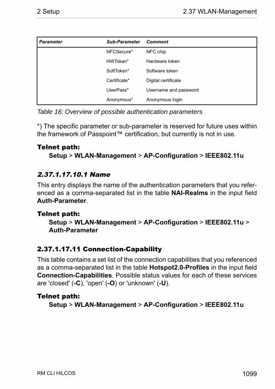
CommentSub-ParameterParameter
NFC chipNFCSecure*
Hardware tokenHWToken*
Software tokenSoftToken*
Digital certificateCertificate*
Username and passwordUserPass*
Anonymous loginAnonymous*
Table 16: Overview of possible authentication parameters
*) The specific parameter or sub-parameter is reserved for future uses withinthe framework of Passpoint™ certification, but currently is not in use.
Telnet path:Setup > WLAN-Management > AP-Configuration > IEEE802.11u
2.37.1.17.10.1 NameThis entry displays the name of the authentication parameters that you refer-enced as a comma-separated list in the table NAI-Realms in the input fieldAuth-Parameter.
Telnet path:Setup > WLAN-Management > AP-Configuration > IEEE802.11u >Auth-Parameter
2.37.1.17.11 Connection-CapabilityThis table contains a set list of the connection capabilities that you referencedas a comma-separated list in the table Hotspot2.0-Profiles in the input fieldConnection-Capabilities. Possible status values for each of these servicesare 'closed' (-C), 'open' (-O) or 'unknown' (-U).
Telnet path:Setup > WLAN-Management > AP-Configuration > IEEE802.11u
RM CLI HiLCOS 1099
2 Setup 2.37 WLAN-Management
2.37.1.17.11.1 NameThis entry displays the name of the connection capability that you referencedas a comma-separated list in the table Hotspot2.0-Profiles in the input fieldConnection-Capabilities.
Telnet path:Setup > WLAN-Management > AP-Configuration > IEEE802.11u >Connection-Capability
2.37.1.18 Config-Assignment-GroupsThis table contains the assignment groups. Based on these, the WLC auto-matically assigns the network configuration, a WLAN profile and a client-steering profile to the unassociated APs. For this purpose, you specify an IPaddress range for each individual assignment group. For example, in a centrallymanaged WLAN you can use IP address ranges to automatically assign alocation-specific configuration to unassociated APs (e.g., Branch A, BranchB, etc.).
Important: An AP is only ever allowed to receive one assignment group. Ifthe IP address ranges of the assignment groups should overlap, HiLCOSimmediately detects the configuration error and writes the messages to thecorresponding status table under Status > WLAN-Management > AP-Con-figuration.
Important: Please ensure that the AP table does not contain an AP profile(e.g., the default profile), which the WLC would assign to the unassociatedAPs. If an appropriate AP profile is available, this always takes higher prioritythan the assignment groups.
Telnet path:Setup > WLAN-Management > AP-Configuration
RM CLI HiLCOS 1100
2.37 WLAN-Management 2 Setup

2.37.1.18.1 NameName of the assignment group which you reference from other tables.
Telnet path:Setup > WLAN-Management > AP-Configuration >Config-Assignment-Groups
Possible values:Max. 31 characters from[A-Z][0-9]@{|}~!$%&'()+-,/:;<=>?[\]^_.
Default:empty
2.37.1.18.2 ProfileName of the WLAN profile that the WLC automatically assigns to an unasso-ciated AP via the assignment group.
Telnet path:Setup > WLAN-Management > AP-Configuration >Config-Assignment-Groups
Possible values:Name from Setup > WLAN-Management > AP-Configuration > Com-monprofiles.Max. 31 characters from[A-Z][0-9]@{|}~!$%&'()+-,/:;<=>?[\]^_.
Default:empty
RM CLI HiLCOS 1101
2 Setup 2.37 WLAN-Management

2.37.1.18.3 AP-IntranetName of the IP parameter profile that the WLC automatically assigns to anunassociated AP via the assignment group.
Telnet path:Setup > WLAN-Management > AP-Configuration >Config-Assignment-Groups
Possible values:Name from Setup > WLAN-Management > AP-Configuration > AP-IntranetsMax. 31 characters from[A-Z][0-9]@{|}~!$%&'()+-,/:;<=>?[\]^_.
Special values:DHCP
The AP retrieves its network configuration via DHCP.
Default:empty
2.37.1.18.4 IPv4-Reference-Pool-StartStart of the IPv4 address range for the corresponding assignment group. Anew AP must register at the WLC with an IP address from this range in orderto obtain the configuration for this group.
Telnet path:Setup > WLAN-Management > AP-Configuration >Config-Assignment-Groups
Possible values:0.0.0.0 … 255,255,255,255
Default:
RM CLI HiLCOS 1102
2.37 WLAN-Management 2 Setup
empty
2.37.1.18.5 IPv4-Reference-Pool-EndEnd of the IPv4 address range for the corresponding assignment group. Anew AP must register at the WLC with an IP address from this range in orderto obtain the configuration for this group.
Telnet path:Setup > WLAN-Management > AP-Configuration >Config-Assignment-Groups
Possible values:0.0.0.0 … 255,255,255,255
Default:empty
2.37.1.18.6 Client steering profileClient-steering profiles control how the WLC decides which APs are to accepta client at the next login attempt.
Telnet path:Setup > WLAN-Management > AP-Configuration >Config-Assignment-Groups
Possible values:Name from Setup > WLAN-Management > Client-Steering > ProfilesMax. 31 characters from[A-Z][0-9]@{|}~!$%&'()+-,/:;<=>?[\]^_.
Default:empty
RM CLI HiLCOS 1103
2 Setup 2.37 WLAN-Management
2.37.1.18.7 iBeacon-ProfilesEnter the iBeacon profile that is configured on the device.
Telnet path:Setup > WLAN-Management > AP-Configuration >Config-Assignment-Groups
Possible values:Max. 31 characters from[A-Z][a-z][0-9]#@{|}~!$%&'()*+-,/:;<=>?[\]^_. `
Default:empty
2.37.1.20 Tag groupsThis table contains the tag groups that the WLC automatically assigns to theAPs belonging to a WLAN profile. Among other things, tag groups allow actionsperformed on the WLC to be restricted to a selection of APs.
Telnet path:Setup > WLAN-Management > AP-Configuration
2.37.1.20.1 NameYou use this parameter to specify the name of the tag being created.
Telnet path:Setup > WLAN-Management > AP-Configuration > Tag-Groups
Possible values:
RM CLI HiLCOS 1104
2.37 WLAN-Management 2 Setup

Max. 31 characters from [A-Z][0-9]@{|}~!$%&'()+-,/:;<=>?[\]^_.
Default:empty
2.37.1.21 LED profilesThe LEDs on the device are configurable so that you can, for instance, operatean AP while drawing a minimum of attention to it. In order to perform thisconfiguration by WLC, you need to create the corresponding profile and assignthis to a WLAN profile.
Telnet path:Setup > WLAN-Management > AP-Configuration
2.37.1.21.1 NameGive a name to the device LED profile here.
Telnet path:Setup > WLAN-Management > AP-Configuration > LED-Profiles
Possible values:Max. 31 characters from [A-Z][a-z][0-9]
Default:empty
RM CLI HiLCOS 1105
2 Setup 2.37 WLAN-Management
2.37.1.21.4 LED modeSet the operating mode for the LEDs here.
Telnet path:Setup > WLAN-Management > AP-Configuration > LED-Profiles
Possible values:On
The LEDs are always enabled, also after rebooting the device.Off
The LEDs are all off. Even after restarting the device, the LEDs remainoff.
Timed offAfter a reboot, the LEDs are enabled for a certain period of time andare then turned off. This is useful for the LEDs to indicate critical errorsduring the restart process.
Default:On
2.37.1.21.5 LED off secondsIn the operating mode Timed off you can specify the delay in seconds afterwhich the LEDs are disabled following a restart. This is useful for the LEDsto indicate critical errors during the restart process.
Telnet path:Setup > WLAN-Management > AP-Configuration > LED-Profiles
Possible values:Max. 4 characters from [0-9]
Default:300
RM CLI HiLCOS 1106
2.37 WLAN-Management 2 Setup

2.37.1.22 LBSThis is where you configure the settings for the LANCOM location-basedservices (LBS).
Telnet path:Setup > WLAN-Management > AP-Configuration
2.37.1.22.1 GeneralIn this directory you configure the general settings for the LANCOM location-based services (LBS).
Telnet path:Setup > WLAN-Management > AP-Configuration > LBS
2.37.1.22.1.1 NameEnter a description of the device.
Telnet path:Setup > WLAN-Management > AP-Configuration > LBS > General
Possible values:Max. 251 characters from#[A-Z][a-z][0-9]@{|}~!$%&'()*+-,/:;<=>?[\]^_. `
Default:empty
RM CLI HiLCOS 1107
2 Setup 2.37 WLAN-Management

2.37.1.22.1.2 OperatingEnables or disables the location-based services.
Telnet path:Setup > WLAN-Management > AP-Configuration > LBS > General
Possible values:YesNo
Default:No
2.37.1.22.1.3 Use TLS connectionThis setting determines whether the connection to the LBS server is SSL/TLSsecured.
Note: Modifying this setting requires the LBS to be restarted.
Telnet path:Setup > WLAN-Management > AP-Configuration > LBS > General
Possible values:YesNo
2.37.1.22.1.4 LBS server addressEnter the address of the LBS server.
Telnet path:
RM CLI HiLCOS 1108
2.37 WLAN-Management 2 Setup
Setup > WLAN-Management > AP-Configuration > LBS > General
Possible values:Max. 64 characters from[A-Z][a-z][0-9]@{|}~!$%&'()+-,/:;<=>?[\]^_.`
Default:empty
2.37.1.22.1.5 LBS server portEnter the port used by the LBS server.
Telnet path:Setup > WLAN-Management > AP-Configuration > LBS > General
Possible values:Max. 4 characters from [0-9]
Default:9090
2.37.1.22.2 Device locationThis table is used to set the coordinates of the device location. The positionis defined in geographical coordinates (degrees, minutes, seconds, orientation).
Telnet path:Setup > WLAN-Management > AP-Configuration > LBS
RM CLI HiLCOS 1109
2 Setup 2.37 WLAN-Management
2.37.1.22.2.1 NameEnter a description of the device.
Telnet path:Setup > WLAN-Management > AP-Configuration > LBS >Device-Location
Possible values:Max. 251 characters from#[A-Z][a-z][0-9]@{|}~!$%&'()*+-,/:;<=>?[\]^_. `
Default:empty
2.37.1.22.2.2 FloorHere you enter the floor on which the device is located. This allows you todifferentiate between the top floor and bottom floor, for example.
Telnet path:Setup > WLAN-Management > AP-Configuration > LBS >Device-Location
Possible values:Max. 6 characters from [0-9]-
Default:0
RM CLI HiLCOS 1110
2.37 WLAN-Management 2 Setup
2.37.1.22.2.3 HeightHere you enter the height of the device installation. It is possible to specify anegative value so that you can differentiate between a location above andbelow sea level.
Telnet path:Setup > WLAN-Management > AP-Configuration > LBS >Device-Location
Possible values:Max. 6 characters from [0-9]-
Default:0
2.37.1.22.2.4 LatitudeThis value specifies the angle of the latitude in degrees.
Telnet path:Setup > WLAN-Management > AP-Configuration > LBS >Device-Location
Possible values:Max. 2 characters from [0-9]
0 … 90
Default:0
RM CLI HiLCOS 1111
2 Setup 2.37 WLAN-Management

2.37.1.22.2.5 Latitude minutesThis value specifies the minutes value of the latitude.
Telnet path:Setup > WLAN-Management > AP-Configuration > LBS >Device-Location
Possible values:Max. 2 characters from [0-9]
0 … 60
Default:0
2.37.1.22.2.6 Latitude secondsThis value specifies the seconds value of the latitude.
Telnet path:Setup > WLAN-Management > AP-Configuration > LBS >Device-Location
Possible values:Max. 2 characters from [0-9]
0 … 60
Default:0
2.37.1.22.2.7 Latitude hemisphereThis value specifies the orientation of the latitude. Possible values are:
RM CLI HiLCOS 1112
2.37 WLAN-Management 2 Setup
D N: Northerly latitudeD S: Southerly latitude
Telnet path:Setup > WLAN-Management > AP-Configuration > LBS >Device-Location
Possible values:NS
Default:N
2.37.1.22.2.8 LongitudeThis value specifies the angle of the longitude in degrees.
Telnet path:Setup > WLAN-Management > AP-Configuration > LBS >Device-Location
Possible values:Max. 2 characters from [0-9]
0 … 90
Default:0
2.37.1.22.2.9 Longitude minutesThis value specifies the minutes value of the longitude.
Telnet path:
RM CLI HiLCOS 1113
2 Setup 2.37 WLAN-Management

Setup > WLAN-Management > AP-Configuration > LBS >Device-Location
Possible values:Max. 2 characters from [0-9]
0 … 60
Default:0
2.37.1.22.2.10 Longitude secondsThis value specifies the seconds value of the longitude.
Telnet path:Setup > WLAN-Management > AP-Configuration > LBS >Device-Location
Possible values:Max. 2 characters from [0-9]
0 … 60
Default:0
2.37.1.22.2.8 Longitude hemisphereThis value specifies the orientation of the longitude. Possible values are:
D W: Western longitudeD E: Eastern longitude
Telnet path:
RM CLI HiLCOS 1114
2.37 WLAN-Management 2 Setup
Setup > WLAN-Management > AP-Configuration > LBS >Device-Location
Possible values:OW
Default:W
2.37.1.22.2.12 DescriptionEnter a description of the device.
Telnet path:Setup > WLAN-Management > AP-Configuration > LBS >Device-Location
Possible values:Max. 251 characters from#[A-Z][a-z][0-9]@{|}~!$%&'()*+-,/:;<=>?[\]^_. `
Default:empty
2.37.1.23 Wireless ePaper profile
Telnet path:Setup > WLAN-Management > AP-Configuration
RM CLI HiLCOS 1115
2 Setup 2.37 WLAN-Management

2.37.1.23.1 NameSpecify the name of the Wireless ePaper profile here.
Telnet path:Setup > WLAN-Management > AP-Configuration >Wireless-ePaper-Profile
Possible values:Max. 31 characters from[A-Z][a-z][0-9]#@{|}~!$%&'()*+-,/:;<=>?[\]^_. `
Default:DEFAULT
2.37.1.23.2 OperatingSpecify whether the selected Wireless ePaper profile is enabled or disabled.Inactive profiles are not transmitted by the WLC to an AP.
Telnet path:Setup > WLAN-Management > AP-Configuration >Wireless-ePaper-Profile
Possible values:No
The selected Wireless ePaper profile is not enabled.Yes
The selected Wireless ePaper profile is enabled.
Default:Yes
RM CLI HiLCOS 1116
2.37 WLAN-Management 2 Setup

2.37.1.23.3 PortEnter the port used for the Wireless ePaper module.
Telnet path:Setup > WLAN-Management > AP-Configuration >Wireless-ePaper-Profile
Possible values:Max. 5 characters from [0-9]
1 … 65535 Integer value
Default:7353
2.37.1.24 iBeacon-Profiles
Telnet path:Setup > WLAN-Management > AP-Configuration
2.37.1.24.1 NameSpecify the name of the iBeacon profile that should be supplied to the APs.
Telnet path:Setup > WLAN-Management > AP-Configuration > iBeacon-Profile
Possible values:Max. 31 characters from[A-Z][a-z][0-9]#@{|}~!$%&'()*+-,/:;<=>?[\]^_. `
Default:
RM CLI HiLCOS 1117
2 Setup 2.37 WLAN-Management
empty
2.37.1.24.2 OperatingSpecify whether the selected iBeacon profile is enabled or disabled. Inactiveprofiles are not transmitted by the WLC to an AP
Telnet path:Setup > WLAN-Management > AP-Configuration > iBeacon-Profile
Possible values:No
The selected iBeacon profile is not enabled.Yes
The selected iBeacon profile is enabled.
Default:No
2.37.1.24.3 MajorSpecify the unique major ID of the iBeacon profile that the WLC is to supplyto the APs.
Telnet path:Setup > WLAN-Management > AP-Configuration > iBeacon-Profile
Possible values:Max. 5 characters from [0-9]
Default:0
RM CLI HiLCOS 1118
2.37 WLAN-Management 2 Setup
2.37.1.24.4 UUIDSpecify the "universally unique identifier" (UUID) of the iBeacon module thatshould be transmitted to the APs.
Telnet path:Setup > WLAN-Management > AP-Configuration > iBeacon-Profile
Possible values:Max. 36 characters from [0-9][a-f][A-F]-
Default:00000000-0000-0000-0000-000000000000
2.37.1.248 Wireless-IDSAt this point you make the settings for the Wireless IDS.
Telnet path:Setup > WLAN-Management > AP-Configuration
2.37.1.248.1 NameHere you specify the name of the Wireless IDS profile.
Telnet path:Setup > WLAN-Management > AP-Configuration > Wireless-IDS
Possible values:Max. 31 characters from[A-Z][0-9]@{|}~!$%&'()+-,/:;<=>?[\]^_.
RM CLI HiLCOS 1119
2 Setup 2.37 WLAN-Management
2.37.1.248.2 OperatingActivates or deactivates Wireless IDS.
Telnet path:Setup > WLAN-Management > AP-Configuration > Wireless-IDS
Possible values:No
Wireless IDS deactivated
YesWireless IDS activated
Default:Yes
2.37.1.248.3 EAPOLStartCounterLimitSet the threshold value for the EAPOL-Start frames here.
Telnet path:Setup > WLAN-Management > AP-Configuration > Wireless-IDS
Possible values:Max. 4 characters from [0-9]
Default:250
RM CLI HiLCOS 1120
2.37 WLAN-Management 2 Setup

2.37.1.248.4 EAPOLStartCounterIntervalSpecify the period of time in which the EAPOL-Start frames are counted here.If the device counts more EAPOL-Start frames within the interval than arespecified in the threshold value, then the program triggers an alarm.
Telnet path:Setup > WLAN-Management > AP-Configuration > Wireless-IDS
Possible values:Max. 4 characters from [0-9]
Special values:0
Switches the function off.
Default:10
2.37.1.248.5 ProbeBroadCounterLimitSet the threshold value for the broadcast probe frames here.
Telnet path:Setup > WLAN-Management > AP-Configuration > Wireless-IDS
Possible values:Max. 4 characters from [0-9]
Default:500
RM CLI HiLCOS 1121
2 Setup 2.37 WLAN-Management
2.37.1.248.6 ProbeBroadCounterIntervalSpecify the period of time in which the broadcast probe frames are countedhere. If the device counts more broadcast probe frames within the intervalthan are specified in the threshold value, then the program triggers an alarm.
Telnet path:Setup > WLAN-Management > AP-Configuration > Wireless-IDS
Possible values:Max. 4 characters from [0-9]
Special values:0
Switches the function off.
Default:10
2.37.1.248.7 DeauthenticateBroadCounterLimitSet the threshold value for broadcast deauthenticate frames here.
Telnet path:Setup > WLAN-Management > AP-Configuration > Wireless-IDS
Possible values:Max. 4 characters from [0-9]
Default:2
RM CLI HiLCOS 1122
2.37 WLAN-Management 2 Setup

2.37.1.248.8 DeauthenticateBroadCounterIntervalHere you specify the period of time in which the broadcast deauthenticateframes are counted. If the device counts more broadcast deauthenticateframes within the interval than are specified in the threshold value, then theprogram triggers an alarm.
Telnet path:Setup > WLAN-Management > AP-Configuration > Wireless-IDS
Possible values:Max. 4 characters from [0-9]
Special values:0
Switches the function off.
Default:1
2.37.1.248.9 DeauthenticateCounterLimitSet the threshold value for deauthenticate frames here.
Telnet path:Setup > WLAN-Management > AP-Configuration > Wireless-IDS
Possible values:Max. 4 characters from [0-9]
Default:250
RM CLI HiLCOS 1123
2 Setup 2.37 WLAN-Management

2.37.1.248.10 DeauthenticateCounterIntervalHere you specify the period of time in which the deauthenticate frames arecounted. If the device counts more deauthenticate frames within the intervalthan are specified in the threshold value, then the program triggers an alarm.
Telnet path:Setup > WLAN-Management > AP-Configuration > Wireless-IDS
Possible values:Max. 4 characters from [0-9]
Special values:0
Switches the function off.
Default:10
2.37.1.248.11 AssociateReqCounterLimitSet the threshold value for associate request frames here.
Telnet path:Setup > WLAN-Management > AP-Configuration > Wireless-IDS
Possible values:Max. 4 characters from [0-9]
Default:250
RM CLI HiLCOS 1124
2.37 WLAN-Management 2 Setup

2.37.1.248.12 AssociateReqCounterIntervalHere you specify the period of time in which the associate request frames arecounted. If the device counts more associate request frames within the intervalthan are specified in the threshold value, then the program triggers an alarm.
Telnet path:Setup > WLAN-Management > AP-Configuration > Wireless-IDS
Possible values:Max. 4 characters from [0-9]
Special values:0
Switches the function off.
Default:10
2.37.1.248.13 ReAssociateReqCounterLimitSet the threshold value for re-associate request frames here.
Telnet path:Setup > WLAN-Management > AP-Configuration > Wireless-IDS
Possible values:Max. 4 characters from [0-9]
Default:250
RM CLI HiLCOS 1125
2 Setup 2.37 WLAN-Management

2.37.1.248.14 ReAssociateReqCounterIntervalHere you specify the period of time in which the re-associate request framesare counted. If the device counts more re-associate request frames within theinterval than are specified in the threshold value, then the program triggersan alarm.
Telnet path:Setup > WLAN-Management > AP-Configuration > Wireless-IDS
Possible values:Max. 4 characters from [0-9]
Special values:0
Switches the function off.
Default:10
2.37.1.248.15 AuthenticateCounterLimitSet the threshold value for authenticate request frames here.
Telnet path:Setup > WLAN-Management > AP-Configuration > Wireless-IDS
Possible values:Max. 4 characters from [0-9]
Default:250
RM CLI HiLCOS 1126
2.37 WLAN-Management 2 Setup
2.37.1.248.16 AuthenticateCounterIntervalHere you specify the period of time in which the authenticate request framesare counted. If the device counts more authenticate request frames within theinterval than are specified in the threshold value, then the program triggersan alarm.
Telnet path:Setup > WLAN-Management > AP-Configuration > Wireless-IDS
Possible values:Max. 4 characters from [0-9]
Special values:0
Switches the function off.
Default:10
2.37.1.248.17 DisAssociateCounterLimitSet the threshold value for dis-associate request frames here.
Telnet path:Setup > WLAN-Management > AP-Configuration > Wireless-IDS
Possible values:Max. 4 characters from [0-9]
Default:250
RM CLI HiLCOS 1127
2 Setup 2.37 WLAN-Management
2.37.1.248.18 DisAssociateCounterIntervalHere you specify the period of time in which the dis-associate request framesare counted. If the device counts more dis-associate request frames withinthe interval than are specified in the threshold value, then the program triggersan alarm.
Telnet path:Setup > WLAN-Management > AP-Configuration > Wireless-IDS
Possible values:Max. 4 characters from [0-9]
Special values:0
Switches the function off.
Default:10
2.37.1.248.19 IDS-OperationalEnable or disable Wireless IDS here.
Telnet path:Setup > WLAN-Management > AP-Configuration > Wireless-IDS
Possible values:No
Wireless IDS disabledYes
Wireless IDS enabled
Default:No
RM CLI HiLCOS 1128
2.37 WLAN-Management 2 Setup
2.37.1.248.20 SyslogOperationalEnable or disable the creation of syslog entries via Wireless IDS here.
Telnet path:Setup > WLAN-Management > AP-Configuration > Wireless-IDS
Possible values:No
Creation of syslog entries via Wireless IDS disabledYes
Creation of syslog entries via Wireless IDS enabled
Default:Yes
2.37.1.248.21 SNMPTraps-OperationalEnable or disable the sending of traps via Wireless IDS.
Telnet path:Setup > WLAN-Management > AP-Configuration > Wireless-IDS
Possible values:No
Sending traps via Wireless IDS disabledYes
Sending traps via Wireless IDS enabled
Default:No
RM CLI HiLCOS 1129
2 Setup 2.37 WLAN-Management

2.37.1.248.22 E-MailEnable or disable e-mail notifications via Wireless IDS here.
Telnet path:Setup > WLAN-Management > AP-Configuration > Wireless-IDS
Possible values:No
E-mail notifications via Wireless IDS disabledYes
E-mail notifications via Wireless IDS enabled
Default:No
2.37.1.248.23 E-Mail-ReceiverSpecify the e-mail destination address here.
Telnet path:Setup > WLAN-Management > AP-Configuration > Wireless-IDS
Possible values:Max. 63 characters from[A-Z][0-9][a-z]@{|}~!$%&'()+-,/:;<=>?[\]^_.
2.37.1.248.24 E-Mail-Aggregate-IntervalHere you specify the period of time between the initial receipt of a WirelessIDS event and the e-mail being sent. This functions helps to prevent a floodof attacks causing an e-mail flood.
RM CLI HiLCOS 1130
2.37 WLAN-Management 2 Setup

Telnet path:Setup > WLAN-Management > AP-Configuration > Wireless-IDS
Possible values:Max. 4 characters from [0-9]
Special values:0
E-mail sending for each event
Default:10
2.37.1.248.26 BlockAckOutOfWindowCounterLimitHere you set the threshold value on the out-of-window frames that are receivedduring a block-ack session.
Telnet path:Setup > WLAN-Management > AP-Configuration > Wireless-IDS
Possible values:Max. 4 characters from [0-9]
Default:200
2.37.1.248.27 BlockAckOutOfWindowCounterIntervalHere you specify the time interval for counting the out-of-window frames. Ifthe device counts more out-of-window frames within the time interval than arespecified in the threshold value, then the program triggers an alarm.
Telnet path:
RM CLI HiLCOS 1131
2 Setup 2.37 WLAN-Management

Setup > WLAN-Management > AP-Configuration > Wireless-IDS
Possible values:Max. 4 characters from [0-9]
Special values:0
Switches the function off.
Default:5
2.37.1.248.28 BlockAckAfterDelBACounterLimitHere you set the threshold value for block-ACK-session frames that arriveafter receiving the DELBA frame.
Telnet path:Setup > WLAN-Management > AP-Configuration > Wireless-IDS
Possible values:Max. 4 characters from [0-9]
Default:100
2.37.1.248.29 BlockAckAfterDelBACounterIntervalHere you specify the time interval for counting the Block-Ack-session frames.If the device counts more Block-Ack-session frames within the time intervalthan are specified in the threshold value, then the program triggers an alarm.
Telnet path:Setup > WLAN-Management > AP-Configuration > Wireless-IDS
RM CLI HiLCOS 1132
2.37 WLAN-Management 2 Setup

Possible values:Max. 4 characters from [0-9]
Special values:0
Switches the function off.
Default:5
2.37.1.248.31 NullDataFloodCounterLimitHere you set the threshold value for received null-data frames.
Telnet path:Setup > WLAN-Management > AP-Configuration > Wireless-IDS
Possible values:Max. 4 characters from [0-9]
Default:500
2.37.1.248.32 NullDataFloodCounterIntervalHere you specify the time interval for counting the null-data frames. If thedevice counts more null-data frames within the time interval than are specifiedin the threshold value, then the program triggers an alarm.
Telnet path:Setup > WLAN-Management > AP-Configuration > Wireless-IDS
Possible values:
RM CLI HiLCOS 1133
2 Setup 2.37 WLAN-Management
Max. 4 characters from [0-9]
Special values:0
Switches the function off.
Default:5
2.37.1.248.34 NullDataPSBufferOverflowCounterLimitHere you set the threshold value for the data frames that were deleted dueto a buffer overflow.
Telnet path:Setup > WLAN-Management > AP-Configuration > Wireless-IDS
Possible values:Max. 4 characters from [0-9]
Default:200
2.37.1.248.35 NullDataPSBufferOverflowCounterIntervalHere you specify the time interval for counting the deleted data frames. If thedevice counts more data frames within the time interval than are specified inthe threshold value, then the program triggers an alarm.
Telnet path:Setup > WLAN-Management > AP-Configuration > Wireless-IDS
Possible values:Max. 4 characters from [0-9]
RM CLI HiLCOS 1134
2.37 WLAN-Management 2 Setup
Special values:0
Switches the function off.
Default:5
2.37.1.248.37 PSPollTIMIntervalHere you specify when, at the earliest, the client is allowed to send a PS-pollframe to the AP before the specified TIM interval expires.
Telnet path:Setup > WLAN-Management > AP-Configuration > Wireless-IDS
Possible values:Max. 4 characters from [0-9]
Default:5
2.37.1.248.38 PSPollTIMIntervalCounterLimitHere you set the threshold value for the PS-poll frames that are received afterthe listen interval difference is exceeded.
Telnet path:Setup > WLAN-Management > AP-Configuration > Wireless-IDS
Possible values:Max. 4 characters from [0-9]
Default:
RM CLI HiLCOS 1135
2 Setup 2.37 WLAN-Management
100
2.37.1.248.39 PSPollTIMIntervalCounterIntervalHere you specify the time interval for counting the PS-poll frames. The programtriggers an alarm if, within this time interval, the device counts any additionalPS-poll frames arriving after the "PSPollTIMIntervalDiff" is exceeded and thatexceed the limit set for the "PSPollTIMIntervalDiffCounter".
Telnet path:Setup > WLAN-Management > AP-Configuration > Wireless-IDS
Possible values:Max. 4 characters from [0-9]
Special values:0
Switches the function off.
Default:5
2.37.1.248.41 SMPSMulStreamCounterLimitHere you specify the threshold value for the number of data frames the clienttransmits using multiple spatial streams after the client has switched into thestatic SM power save mode.
Telnet path:Setup > WLAN-Management > AP-Configuration > Wireless-IDS
Possible values:Max. 4 characters from [0-9]
RM CLI HiLCOS 1136
2.37 WLAN-Management 2 Setup

Default:100
2.37.1.248.42 SMPSMulStreamCounterIntervalHere you specify the time interval for counting the data frames the clienttransmits using multiple spatial streams. If the device counts more data frameswithin the time interval than are specified in the threshold value, then theprogram triggers an alarm.
Telnet path:Setup > WLAN-Management > AP-Configuration > Wireless-IDS
Possible values:Max. 4 characters from [0-9]
Special values:0
Switches the function off.
Default:5
2.37.1.248.43 SMPSSingleStreamCounterLimitHere you specify the threshold value for the number of failed data frametransmissions from the AP using multiple spatial streams to the client afterthe client has disabled the static SM power save mode.
Telnet path:Setup > WLAN-Management > AP-Configuration > Wireless-IDS
Possible values:
RM CLI HiLCOS 1137
2 Setup 2.37 WLAN-Management

Max. 4 characters from [0-9]
Default:100
2.37.1.248.44 SMPSSingleStreamCounterIntervalHere you specify the time interval for counting the failed data frame transmis-sions from the AP using multiple spatial streams. If the device counts morefailed data frame transmissions within the time interval than are specified inthe threshold value, then the program triggers an alarm.
Telnet path:Setup > WLAN-Management > AP-Configuration > Wireless-IDS
Possible values:Max. 4 characters from [0-9]
Special values:0
Switches the function off.
Default:5
2.37.1.248.45 DisAssociateBroadCounterLimitSet the threshold value for broadcast disassociate frames here.
Telnet path:Setup > WLAN-Management > AP-Configuration > Wireless-IDS
Possible values:Max. 4 characters from [0-9]
RM CLI HiLCOS 1138
2.37 WLAN-Management 2 Setup
Default:2
2.37.1.248.46 DisAssociateBroadCounterIntervalHere you specify the period of time in which the broadcast disassociate framesare counted. If the device counts more broadcast disassociate frames withinthe interval than are specified in the threshold value, then the program triggersan alarm.
Telnet path:Setup > WLAN-Management > AP-Configuration > Wireless-IDS
Possible values:Max. 4 characters from [0-9]
Special values:0
Switches the function off.
Default:1
2.37.1.248.52 Intruder-IdentificationEnable or disable Wireless IDS intruder identification here.
Telnet path:Setup > WLAN-Management > AP-Configuration > Wireless-IDS
Possible values:No
Wireless IDS intruder identification is disabled
RM CLI HiLCOS 1139
2 Setup 2.37 WLAN-Management

YesWireless IDS intruder identification is enabled
Default:No
2.37.1.248.53 Timeout-Intruder-ActivityHere you specify the time following an attack after which the status of theattacker is set to inactive.
Telnet path:Setup > WLAN-Management > AP-Configuration > Wireless-IDS
Possible values:Max. 4 characters from [0-9]
Default:60
2.37.1.248.54 White-List-IdHere you specify the White List ID for the white list of the Wireless IDS profile.This White List ID is used to group the stations that are to be excluded fromthe intruder identification into white lists for the corresponding Wireless IDSprofile.
Telnet path:Setup > WLAN-Management > AP-Configuration > Wireless-IDS
Possible values:Max. 4 characters from [0-9]
RM CLI HiLCOS 1140
2.37 WLAN-Management 2 Setup

2.37.1.248.55 Store-Intruder-DHCP-RequestsEnable or disable the storage of intruder DHCP requests here.
Telnet path:Setup > WLAN-Management > AP-Configuration > Wireless-IDS
Possible values:No
The storage of intruder DHCP requests is disabledYes
The storage of intruder DHCP requests is enabled
Default:No
2.37.1.249 WIDS-White-List-TableHere you configure the entries in the white lists for the corresponding WirelessIDS profile. These entries specify the stations for exclusion from the intruderidentification.
Telnet path:Setup > WLAN-Management > AP-Configuration
2.37.1.249.1 IndexSpecify the index for the entry here.
Telnet path:Setup > WLAN-Management > AP-Configuration >WIDS-White-List-Table
RM CLI HiLCOS 1141
2 Setup 2.37 WLAN-Management

Possible values:Max. 4 characters from [0-9]
2.37.1.249.2 White-List-IdEnter the White List ID that fits to the Wireless IDS profile here. You use theWhite List ID to assign those stations that are to be excluded from the intruderidentification to the white lists for the corresponding Wireless IDS profile.
Telnet path:Setup > WLAN-Management > AP-Configuration >WIDS-White-List-Table
Possible values:Max. 4 characters from [0-9]
2.37.1.249.3 Station-MACHere you specify the MAC address of the station that is to be excluded fromintruder identification.
Telnet path:Setup > WLAN-Management > AP-Configuration >WIDS-White-List-Table
Possible values:Max. 17 characters from [0-9] [a-f]
2.37.5 CAPWAP-PortPort number for the CAPWAP service
SNMP ID: 2.37.5
Telnet path: /Setup/WLAN-Management
RM CLI HiLCOS 1142
2.37 WLAN-Management 2 Setup

Possible values:
D 0 to 65535
Default: 1027
Note: Cannot be configured with LANconfig
2.37.6 Autoaccept-APEnables the WLC to provide all new APs with a configuration, even those notin possession of a valid certificate.
Enables the WLC to provide a certificate to all new APs without a valid certi-ficate. One of two conditions must be fulfilled for this:
- A configuration for the AP is entered into the AP table under its MAC address.
- The option 'Automatically provide APs with the default configuration' isenabled.
SNMP ID: 2.37.6
Telnet path: /Setup/WLAN-Management
Possible values:
D YesD No
Default: No
Note: Combining the settings for auto-accept and default configuration cancater for a variety of different situations for the setup and operation of APs:
Auto-Accept ON, Default-Configuration ON: Rollout phase: Use this combin-ation only if you can be sure that no APs can connect unintentionally with theLAN and thus be accepted into the WLAN infrastructure.
Auto-Accept ON, Default-Configuration OFF: Controlled rollout phase: Usethis combination if you have entered all of the approved APs into the AP tablealong with their MAC addresses, assuming that these are to be automaticallyaccepted into the WLAN infrastructure.
RM CLI HiLCOS 1143
2 Setup 2.37 WLAN-Management
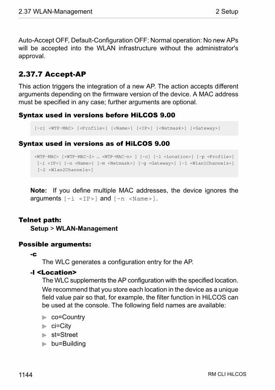
Auto-Accept OFF, Default-Configuration OFF: Normal operation: No new APswill be accepted into the WLAN infrastructure without the administrator'sapproval.
2.37.7 Accept-APThis action triggers the integration of a new AP. The action accepts differentarguments depending on the firmware version of the device. A MAC addressmust be specified in any case; further arguments are optional.
Syntax used in versions before HiLCOS 9.00
[-c] <WTP-MAC> [<Profile>] [<Name>] [<IP>] [<Netmask>] [<Gateway>]
Syntax used in versions as of HiLCOS 9.00
<WTP-MAC> [<WTP-MAC-2> … <WTP-MAC-n> ] [-c] [-l <Location>] [-p <Profile>]
[-i <IP>] [-n <Name>] [-m <Netmask>] [-g <Gateway>] [-1 <Wlan1Channels>]
[-2 <Wlan2Channels>]
Note: If you define multiple MAC addresses, the device ignores thearguments [-i <IP>] and [-n <Name>].
Telnet path:Setup > WLAN-Management
Possible arguments:-c
The WLC generates a configuration entry for the AP.-l <Location>
The WLC supplements the AP configuration with the specified location.We recommend that you store each location in the device as a uniquefield value pair so that, for example, the filter function in HiLCOS canbe used at the console. The following field names are available:
D co=CountryD ci=CityD st=StreetD bu=Building
RM CLI HiLCOS 1144
2.37 WLAN-Management 2 Setup
D fl=FloorD ro=Room
-p <Profile>The WLC supplements the AP configuration with the specified WLANprofile.
-i <IP>The WLC supplements the AP configuration with the specified IPv4address.
-n <Name>The WLC supplements the AP configuration with the specified deviceidentifier.
-m <Netmask>The WLC supplements the AP configuration with the specifiednetmask.
-g <Gateway>The WLC supplements the AP configuration with the specified gatewayaddress (IPv4).
-1 <Wlan1Channels>The WLC supplements the AP configuration with the first channel list.
-2 <Wlan2Channels>The WLC supplements the AP configuration with the second channellist.
2.37.8 Provide-default-configurationThis enables the WLC to assign a default configuration to every new AP (eventhose without a valid certificate), even if no explicit configuration has beenstored for it. In combination with auto-accept, the WLC can accept all managed-mode APs which are found in the WLAN infrastructure managed by it (up tothe maximum number of APs that can be managed by one WLC).
SNMP ID: 2.37.8
Telnet path: /Setup/WLAN-Management
Possible values:
D YesD No
RM CLI HiLCOS 1145
2 Setup 2.37 WLAN-Management

Default: No
Note: This option can also lead to the acceptance of unintended APs intothe WLAN infrastructure. For this reason this option should only be activatedduring the start-up phase when setting up a centrally managed WLAN infra-structure.
2.37.9 Disconnect-APDo command to disconnect APs. The MAC address must be specified as aparameter.
SNMP ID: 2.37.9
Telnet path: /Setup/WLAN-Management
Possible values:
D Syntax: do Disconnect-AP <WTP-MAC>
Default: Blank
2.37.10 NotificationThis menu contains the configuration of the notification system of the WLANmanagement.
SNMP ID: 2.37.10
Telnet path: /Setup/WLAN-Management
2.37.10.1 E-MailActivates notification by e-mail.
SNMP ID: 2.37.10.1
Telnet path: /Setup/WLAN-Management/Notification
Possible values:
D YesD No
RM CLI HiLCOS 1146
2.37 WLAN-Management 2 Setup

Default: No
2.37.10.2 SyslogActivates notification by SYSLOG.
SNMP ID: 2.37.10.2
Telnet path: /Setup/WLAN-Management/Notification
Possible values:
D YesD No
Default: No
2.37.10.3 E-Mail-ReceiverInformation about events in the WLC is sent to this e-mail address.
SNMP ID: 2.37.10.3
Telnet path: /Setup/WLAN-Management/Notification
Possible values:
D Valid e-mail address with up to 63 ASCII characters
Default: Blank
Note: An SMTP account must be set up to make use of e-mail messaging.
2.37.10.4 AdvancedHere you define the events that you wish to be informed of.
SNMP ID: 2.37.10.4
Telnet path: /Setup/WLAN-Management/Notification
RM CLI HiLCOS 1147
2 Setup 2.37 WLAN-Management
2.37.10.4.1 NameSelects the events that trigger notification.
SNMP ID: 2.37.10.4.1
Telnet path: /Setup/WLAN-Management/Notification/Advanced
Possible values:
D E-mailD Syslog
Default: Blank
Special values: Value is fixed
2.37.10.4.2 Active-RadiosActivates notification about active APs.
SNMP ID: 2.37.10.4.2
Telnet path: /Setup/WLAN-Management/Notification/Advanced
Possible values:
D YesD No
Default: No
2.37.10.4.3 Missing-APActivates notification about lost APs.
SNMP ID: 2.37.10.4.3
Telnet path: /Setup/WLAN-Management/Notification/Advanced
Possible values:
D YesD No
Default: No
RM CLI HiLCOS 1148
2.37 WLAN-Management 2 Setup

2.37.10.4.4 New-APActivates notification about new APs.
SNMP ID: 2.37.10.4.4
Telnet path: /Setup/WLAN-Management/Notification/Advanced
Possible values:
D YesD No
Default: No
2.37.10.5 Send-SNMP-Trap-for-Station-Table-EventHere you specify when you receive information about events relating to entriesin the station table.
Telnet path:/Setup/WLAN-Management/Notification/Send-SNMP-Trap-for-Station-Table-Event
Possible values:
D Add/remove_entryD All_events
Default: Add/remove_entry
2.37.19 Start-automatic-radio-field-optimizationLaunches RF optimization automatically. Optimization may be limited to oneAP by specifying its MAC address as a parameter.
SNMP ID: 2.37.19
Telnet path: /Setup/WLAN-Management
Possible values:
D Syntax: do Start-automatic-radio-field-optimization [<WTP-MAC>]
Default: Blank
RM CLI HiLCOS 1149
2 Setup 2.37 WLAN-Management

2.37.21 Access rulesYou can limit the data traffic between the wireless LAN and its local networkby excluding certain stations from transferring data, or you can approve spe-cific stations only.
Telnet path:Setup > WLAN-Management
2.37.21.1 MAC address patternEnter the MAC address of a station.
Note: It is possible to use wildcards.
Telnet path:Setup > WLAN-Management > Access rules
Possible values:Max. 20 characters from[A-Z][a-z][0-9]#@{|}~!$%&'()*+-,/:;<=>?[\]^_. `
Possible arguments:MAC address
MAC address of the WLAN client for this entry. The following entriesare possible:Individual MAC address
A MAC address in the format 00a057112233,00-a0-57-11-22-33 or 00:a0:57:11:22:33.
WildcardsThe wildcards '*' and '?' uses to specify MAC address ranges,e.g. 00a057*, 00-a0-57-11-??-?? or 00:a0:??:11:*.
Vendor ID
RM CLI HiLCOS 1150
2.37 WLAN-Management 2 Setup
The device contains a list of the major manufacturer OUIs (organiza-tionally unique identifier). The MAC address range is valid if this entrymatches the first three bytes of the MAC address of the WLAN client.
Note: It is possible to use wildcards.
2.37.21.2 NameYou can enter any name you wish for any station. This enables you to assignMAC addresses more easily to specific stations or users.
Telnet path:Setup > WLAN-Management > Access rules
Possible values:Max. 32 characters from[A-Z][a-z][0-9]#@{|}~!$%&'()*+-,/:;<=>?[\]^_. `
2.37.21.3 CommentYou can enter any comment you wish for any station. This enables you toassign MAC addresses more easily to specific stations or users.
Telnet path:Setup > WLAN-Management > Access rules
Possible values:Max. 30 characters from[A-Z][a-z][0-9]#@{|}~!$%&'()*+-,/:;<=>?[\]^_. `
RM CLI HiLCOS 1151
2 Setup 2.37 WLAN-Management
2.37.21.4 WPA passphraseHere you may enter a separate passphrase for each entry that is used in a802.11i/WPA/AES-PSK-secured network. If no separate passphrase is spe-cified for this MAC address, the passphrases stored in the 802.11i/WEP areawill be used for each logical wireless LAN network.
Important: The passphrases should consist of a random string at least 22characters long, corresponding to a cryptographic strength of 128 bits.
Note: This field has no significance for networks secured by WEP.
Telnet path:Setup > WLAN-Management > Access rules
Possible values:Max. 63 characters from[A-Z][a-z][0-9]#@{|}~!$%&'()*+-,/:;<=>?[\]^_. `
2.37.21.5 Tx-LimitBandwidth restriction for registering WLAN clients. A client communicates itssetting to the AP when logging on. This then uses uses these two values toset the minimum bandwidth.
Note: The significance of the Rx and Tx values depends on the device'soperating mode. In this case, as an AP Rx stands for "Send data" and Txstands for "Receive data".
Telnet path:Setup > WLAN-Management > Access rules
Possible values:
RM CLI HiLCOS 1152
2.37 WLAN-Management 2 Setup
Max. 9 characters from 0123456789
0 … 999999999
Default:0
Special values:0
No limit
2.37.21.6 Rx-LimitBandwidth restriction for registering WLAN clients. A client communicates itssetting to the AP when logging on. This then uses uses these two values toset the minimum bandwidth.
Note: The significance of the Rx and Tx values depends on the device'soperating mode. In this case, as an AP Rx stands for "Send data" and Txstands for "Receive data".
Telnet path:Setup > WLAN-Management > Access rules
Possible values:Max. 9 characters from 0123456789
0 … 999999999
Default:0
Special values:0
No limit
RM CLI HiLCOS 1153
2 Setup 2.37 WLAN-Management
2.37.21.7 VLAN-IDThe device assigns this VLAN ID to packets received by the WLAN client andcontaining the MAC address entered here.
Telnet path:Setup > WLAN-Management > Access rules
Possible values:Max. 4 characters from 0123456789
0 … 4096
Default:0
Special values:0
No limit
2.37.21.9 SSID patternFor WLAN clients with the appropriate MAC addresses, this entry allows themto access this SSID or it restricts them to it.
Note: The use of wildcards makes it possible to allow access to multipleSSIDs.
Telnet path:Setup > WLAN-Management > Access rules
Possible values:Max. 40 characters from[A-Z][a-z][0-9]#@{|}~!$%&'()*+-,/:;<=>?[\]^_. `
RM CLI HiLCOS 1154
2.37 WLAN-Management 2 Setup

Special values:*
Placeholder for any number of characters?
Placeholder for exactly one character
Default:empty
2.37.27 Central-Firmware-ManagementThis menu contains the configuration of central firmware management.
SNMP ID: 2.37.27
Telnet path: /Setup/WLAN-Management
2.37.27.11 Firmware-Depot-URLDirectory where the latest firmware files are stored
SNMP ID: 2.37.27.11
Telnet path: /Setup/WLAN-Management/Central-Firmware-Management
Possible values:
D URL in the form Server/Directory or http://Server/Directory
Default: Blank
2.37.27.12 Script-Depot-URLThe path to the directory with the script files.
SNMP ID: 2.37.27.12
Telnet path: /Setup/WLAN-Management/Central-Firmware-Management
Possible values:
D URL in the form Server/Directory or http://Server/Directory
Default: Blank
RM CLI HiLCOS 1155
2 Setup 2.37 WLAN-Management

2.37.27.13 Update-Firmware-and-Script-InformationLaunches an update process for the available firmware and script information
SNMP ID: 2.37.27.13
Telnet path: /Setup/WLAN-Management/Central-Firmware-Management
Possible values:
D Syntax: do Update-Firmware-and-Script-Information
Note: Do command
2.37.27.14 Maximum-Number-Of-Loaded-FirmwaresMaximum number of firmware versions in memory
SNMP ID: 2.37.27.14
Telnet path: /Setup/WLAN-Management/Central-Firmware-Management
Possible values:
D 1 to 10
Default: 5
2.37.27.15 Firmware-Version-ManagementTable with device type, MAC address and firmware version for the precisecontrol of the firmware files in use.
SNMP ID: 2.37.27.15
Telnet path: /Setup/WLAN-Management/Central-Firmware-Management
2.37.27.15.2 DeviceSelect here the type of device that the firmware version specified here is tobe used for.
SNMP ID: 2.37.27.15.2
RM CLI HiLCOS 1156
2.37 WLAN-Management 2 Setup

Telnet path: /Setup/WLAN-Management/Central-Firmware-Management/Firm-ware-Version-Management
Possible values:
D All, or a selection from the list of available devices.
Default: All devices
2.37.27.15.3 MAC-AddressSelect here the device (identified by its MAC address) that the firmware versionspecified here is to be used for.
SNMP ID: 2.37.27.15.3
Telnet path: /Setup/WLAN-Management/Central-Firmware-Management/Firm-ware-Version-Management
Possible values:
D Valid MAC address
Default: Blank
2.37.27.15.4 VersionFirmware version that is to be used for the devices or device types specifiedhere.
SNMP ID: 2.37.27.15.4
Telnet path: /Setup/WLAN-Management/Central-Firmware-Management/Firm-ware-Version-Management
Possible values:
D Firmware version in the form X.XX
Default: Blank
2.37.27.15.5 DateDate of the corresponding firmware version.
Telnet path:
RM CLI HiLCOS 1157
2 Setup 2.37 WLAN-Management
Setup > WLAN-Management > Central-Firmware-Management >Firmware-Version-Management
Possible values:Max. 8 characters from [0-9]
Default:Corresponds to the UPX header of the firmware (such as "01072014" forthe July 01, 2014)
2.37.27.16 Script managementTable with the name of the script file and a WLAN profile for allocating thescript to a WLAN profile.
Configuring a AP in the “Managed” mode is handled via WLAN profiles. Ascript can be used for setting those detailed parameters in managed devicesthat are not handled by the pre-defined parameters in a WLAN profile. Distri-bution is also handled by WLAN profiles to ensure that the APs with the sameWLC configuration also use the same script.
As only one script file can be defined per WLAN profile, versioning is notpossible here. However, when distributing a script to a AP, an MD5 checksumof the script file is saved. This checksum allows the WLC to determinewhether the script file has to be transmitted again in case a new or alteredscript has the same file name.
SNMP ID: 2.37.27.16
Telnet path: /Setup/WLAN-Management/Central-Firmware-Management
2.37.27.16.1 ProfileSelect here the WLAN profile that the script file specified here should be usedfor.
SNMP ID: 2.37.27.16.1
Telnet path: /Setup/WLAN-Management/Central-Firmware-Manage-ment/Script-Management
Possible values:
RM CLI HiLCOS 1158
2.37 WLAN-Management 2 Setup
D Select from the list of defined WLAN profiles, maximum 31 ASCII charac-ters.
Default: Blank
2.37.27.16.2 NameName of the script file to be used.
SNMP ID: 2.37.27.16.2
Telnet path: /Setup/WLAN-Management/Central-Firmware-Manage-ment/Script-Management
Possible values:
D File name in the form *.lcs, max. 63 ASCII characters
Default: Blank
2.37.27.18 Reboot-updated-APsReboot updated APs.
SNMP ID: 2.37.27.18
Telnet path: /Setup/WLAN-Management/Central-Firmware-Management
Possible values:
D Syntax: Do Reboot-updated-APs
Note: Do command
2.37.27.25 Firmware-Loopback-AddressThis is where you can configure an optional sender address to be used insteadof the one otherwise automatically selected for the destination address.
SNMP ID: 2.37.27.25
Telnet path: /Setup/WLAN-Management/Central-Firmware-Management
Possible values:
RM CLI HiLCOS 1159
2 Setup 2.37 WLAN-Management
D Name of a defined IP network.D 'INT' for the IP address in the first network with the setting 'Intranet'.D 'DMZ' for the IP address in the first network with the setting 'DMZ'.D Name of a loopback address.D Any other IP address.
Default: Blank
Note: If the list of IP networks or loopback addresses contains an entry named'DMZ' then the associated IP address will be used.
2.37.27.26 Script-Loopback-AddressThis is where you can configure an optional sender address to be used insteadof the one otherwise automatically selected for the destination address.
SNMP ID: 2.37.27.26
Telnet path: /Setup/WLAN-Management/Central-Firmware-Management
Possible values:
D Name of a defined IP network.D 'INT' for the IP address in the first network with the setting 'Intranet'.D 'DMZ' for the IP address in the first network with the setting 'DMZ'.D Name of a loopback address.D Any other IP address.
Default: Blank
Note: If the list of IP networks or loopback addresses contains an entry named'DMZ' then the associated IP address will be used.
2.37.27.38 Max. number of concurrent updatesHere you specify how many firmware updates the WLC may perform at thesame time.
Telnet path:
RM CLI HiLCOS 1160
2.37 WLAN-Management 2 Setup
Setup > WLAN-Management > Central-Firmware-Management
Possible values:1-3010
Default:10
2.37.29 Allow WAN connectionsThis item configures the way that the WLC handles requests from the WAN.For example, it is desirable to prevent CAPWAP requests from unknown WANpeers from accidentally assigning a default configuration with internal networksettings to these APs.
Telnet path:Setup > WLAN-Management
Possible values:Yes
When an AP sends a request from the WAN, the WLC includes it intothe AP management and, with the appropriate setting, it sends adefault configuration.
VPNWhen an AP sends a request from the WAN, the WLC includes it intothe AP management and, with the appropriate setting, it sends adefault configuration only if the WAN connection uses a VPN tunnel.
NoWhen an AP sends a request from the WAN, the WLC does notinclude it into the AP management.
Default:No
RM CLI HiLCOS 1161
2 Setup 2.37 WLAN-Management

2.37.30 Sync-WTP-PasswordActivating this function sets the main device password for the AP each timeit registers. This ensures that the password is synchronized with that of theWLC. If this function is deactivated, the main device password will only be setif the AP has no password when it registers. Once a password is set, it willnot be overwritten.
SNMP ID: 2.37.30
Telnet path: /Setup/WLAN-Management/Sync-WTP-Password
Possible values:
D YesD No
Default: Yes
2.37.31 Interval-for-status-table-cleanupThe WLC regularly cleans up the status tables for the background scans andfor the wireless clients. During this cleanup, the WLC removes all entries thatare older than the interval in minutes defined here.
Telnet path:/Setup/WLAN-Management/Interval-for-status-table-cleanup
Possible values:
D Max. 11 numerical characters
Default: 1440 minutes
2.37.32 License countThis value indicates the current number of licenses for the WLC that you canuse on this device.
SNMP ID: 2.37.32
Telnet path: /Setup/WLAN-Management/License-Count
Note: This value is for your information only. You cannot change it.
RM CLI HiLCOS 1162
2.37 WLAN-Management 2 Setup

2.37.33 License limitThis value indicates the maximum possible number of licenses for the WLCthat you can use on this device.
Telnet path:/Setup/WLAN-Management/License-limit
Note: This value is for your information only. You cannot change it.
2.37.34 WLC clusterThis menu contains the settings for the data connections and status connec-tions between multiple WLCs (WLC cluster).
Telnet path:Setup > WLAN-Management
2.37.34.2 WLC-Data-Tunnel-activeThis option activates or disables the use of data tunnels (L3 tunnels) betweenmultiple WLCs. This allows you to extend a transparent layer-2 network asan overlay network across the remote WLCs.
Important: Be sure never to bridge the corresponding WLC tunnels if theindividual WLCs are located in the same broadcast domain. Otherwise youwill create a switching loop that will overload your network.
Tip: In order to maximize data throughput and the network performance, youcan forward the AP data traffic directly into the LAN. In this case there is noneed for a layer-3 tunnel between the WLCs even when they are in differentlayer-2 networks.
RM CLI HiLCOS 1163
2 Setup 2.37 WLAN-Management

Telnet path:Setup > WLAN-Management > WLC-Cluster
Possible values:Yes
The WLC connects to remote WLCs via a layer-3 tunnel.No
The WLC does not connect to remote WLCs via a layer-3 tunnel.
Default:No
2.37.34.3 Static WLC listIn this table, you define the static IPv4 addresses of the remote WLCs whichyour WLC connects to. As an alternative, this table can also be used to bypassthe search of the local network as performed by the WLC Discovery table.
If you connect to a remote WLC at a static IPv4 address, your WLC initiallyestablishes a control tunnel to this remote site. If you have enabled the datatunnel option, your WLC automatically establishes a data tunnel to this remotesite.
Note: The WLCs can only interconnect if they have a certificate from thesame certificate hierarchy.
Telnet path:Setup > WLAN-Management > WLC-Cluster
RM CLI HiLCOS 1164
2.37 WLAN-Management 2 Setup

2.37.34.3.1 IP addressHere you specify the IPv4 address of the remote WLC to which your WLCestablishes a connection.
Telnet path:Setup > WLAN-Management > WLC-Cluster > Static-WLC-List
Possible values:0.0.0.0 … 255,255,255,255
Default:empty
2.37.34.3.2 Loopback-Addr.Here you can optionally specify another address (name or IP) used by yourdevice to identify itself to the remote WLC as the sender.
By default, your device sends its IP address from the corresponding ARFcontext, without you having to enter it here. By entering an optional loopbackaddress you change the source address and route that your device uses tocontact the remote site. This can be useful, for example, if your device isavailable over different paths and the remote site should use a specific pathfor its reply message.
Note: If the source address set here is a loopback address, these will beused on the remote client. unmasked !
Telnet path:Setup > WLAN-Management > WLC-Cluster > Static-WLC-List
Possible values:Max. 16 characters from[A-Z][0-9]@{|}~!$%&'()+-,/:;<=>?[\]^_.
RM CLI HiLCOS 1165
2 Setup 2.37 WLAN-Management
Special values:Name of the IP network (ARF network), whose addressshould be used.INT for the address of the first IntranetDMZ for the address of the first DMZ
Note: If the lists of IP networks or loopback addresses contains aninterface named 'DMZ', then the device selects the associated IPaddress instead!
LB0…LBF for one of the 16 loopback addresses or itsnameAny IPv4 address
Default:empty
2.37.34.3.3 PortSpecify the port used by your WLC to establish a data tunnel to the remoteWLC.
Telnet path:Setup > WLAN-Management > WLC-Cluster > Static-WLC-List
Possible values:0 … 65535
Special values:0
The device uses default port 1027.
Default:0
RM CLI HiLCOS 1166
2.37 WLAN-Management 2 Setup

2.37.34.4 WLC-DiscoveryThis table is used to enable or disable the automatic search for WLCs in thesame local network for each of your IPv4 networks.
Note: Enter the addresses of WLCs that are not on the local network (remoteWLCs) into the static WLC list (SNMP ID 2.37.34.3). The automatic searchdoes not find remote WLCs.
Telnet path:Setup > WLAN-Management > WLC-Cluster
2.37.34.4.1 NetworkSpecify the name of the IPv4 network, in which the WLC automaticallysearches for remote WLCs.
Telnet path:Setup > WLAN-Management > WLC-Cluster > WLC-Discovery
Possible values:Network name from Setup > TCP-IP > Network-listMax. 16 characters from[A-Z][0-9]@{|}~!$%&'()+-,/:;<=>?[\]^_.
Default:empty
2.37.34.4.2 OperatingUsing this option, you can enable or disable the automatic search for remoteWLCs in the selected network.
RM CLI HiLCOS 1167
2 Setup 2.37 WLAN-Management
The automatic search for remote WLCs is one way of establishing the connec-tion between several WLCs. If you disable this option, the WLC cannot auto-matically connect to another WLC over the corresponding network, even ifthe use of WLC tunnels in general has been enabled. An alternative is tospecify the remote sites in the static WLC list.
Telnet path:Setup > WLAN-Management > WLC-Cluster > WLC-Discovery
Possible values:YesNo
Default:No
2.37.34.4.3 PortSpecify the port used for the automatic search for remote WLCs.
Telnet path:Setup > WLAN-Management > WLC-Cluster > WLC-Discovery
Possible values:0 … 65535
Special values:0
The device uses default port 1027.
Default:0
RM CLI HiLCOS 1168
2.37 WLAN-Management 2 Setup
2.37.34.5 Trigger-WLC-rediscovery-on-WTPsWith this action, you command all of the managed APs to calculate the idealdistribution of the APs in the WLC cluster. The result of this calculation maycause the APs to be redistributed.
Telnet path:Setup > WLAN-Management > WLC-Cluster
Possible arguments:none
2.37.34.6 WLC-Tunnel-activeUsing this parameter, you can enable or disable the WLC tunnel used forWLC clustering. This indirectly switches the cluster functionality for the corres-ponding WLC on or off.
Telnet path:Setup > WLAN-Management > WLC-Cluster
Possible values:No
WLC cluster tunnels on the device are disabled.Yes
WLC cluster tunnels on the device are enabled.
Default:No
2.37.35 RADIUS-Server-ProfilesBy default, the WLC forwards requests for account and access administrationto the RADIUS server. In order for the APs to contact the RADIUS server dir-ectly, you define the necessary RADIUS profiles in this table. When setting
RM CLI HiLCOS 1169
2 Setup 2.37 WLAN-Management
up logical wireless networks (SSIDs), you have the option of choosing a sep-arate RADIUS profile for each SSID.
SNMP ID: 2.37.35
Telnet path: /Setup/WLAN-Management
2.37.35.1 NameName of the RADIUS profile. This name is used to reference the RADIUSprofile in the logical WLAN settings.
SNMP ID: 2.30.3.1
Telnet path: /Setup/WLAN-Management/RADIUS-Server-Profiles
Possible values:
D Max. 16 characters
Default: Blank
2.37.35.2 Account IPIP address of the RADIUS server that carries out the accounting of useractivities. In the default setting with the IP address of 0.0.0.0, the AP sendsRADIUS requests to the WLC.
SNMP ID: 2.37.35.2
Telnet path: /Setup/WLAN-Management/RADIUS-Server-Profiles
Possible values:
D Valid IP address
Default: 0.0.0.0
2.37.35.3 Account portPort of the RADIUS server that carries out the accounting of user activities.
SNMP ID: 2.37.35.3
Telnet path: /Setup/WLAN-Management/RADIUS-Server-Profiles
RM CLI HiLCOS 1170
2.37 WLAN-Management 2 Setup

Possible values:
D Max. 5 numbers
Default: 1813
2.37.35.4 Account secretPassword for the RADIUS server that carries out the accounting of useractivities.
SNMP ID: 2.37.35.4
Telnet path: /Setup/WLAN-Management/RADIUS-Server-Profiles
Possible values:
D Max. 32 characters
Default: Blank
2.37.35.5 Account loopbackHere, you can optionally configure a sender address for the RADIUS serverthat carries out the accounting of user activities. This is used instead of thesender address otherwise selected automatically for the destination address.If you have configured loopback addresses, you can specify them here assender address.
SNMP ID: 2.37.35.5
Telnet path: /Setup/WLAN-Management/RADIUS-Server-Profiles
Possible values:
D You can enter an address in various forms:D Name of the IP networks whose addresses are to be used.D "INT" for the address of the first intranet.D "DMZ" for the address of the first DMZ
Note: If there is an interface called "DMZ", its address will be taken in thiscase.
RM CLI HiLCOS 1171
2 Setup 2.37 WLAN-Management
D LBO... LBF for the 16 loopback addresses.D Furthermore, any IP address can be entered in the form x.x.x.x.
Default: Blank
2.37.35.6 Account-ProtocolProtocol for communication between the AP and the RADIUS server thatcarries out the accounting of user activities.
SNMP ID: 2.37.35.6
Telnet path: /Setup/WLAN-Management/RADIUS-Server-Profiles
Possible values:
D RADSECD RADIUS
Default: RADIUS
2.37.35.7 Access IPIP address of the RADIUS server that authenticates user data. In the defaultsetting with the IP address of 0.0.0.0, the AP sends RADIUS requests to theWLC.
SNMP ID: 2.37.35.7
Telnet path: /Setup/WLAN-Management/RADIUS-Server-Profiles
Possible values:
D Valid IP address
Default: 0.0.0.0
2.37.35.8 Access portPort of the RADIUS server that authenticates user data.
SNMP ID: 2.37.35.8
Telnet path: /Setup/WLAN-Management/RADIUS-Server-Profiles
RM CLI HiLCOS 1172
2.37 WLAN-Management 2 Setup

Possible values:
D Max. 5 numbers
Default: 1812
2.37.35.9 Access secretPassword for the RADIUS server that authenticates user data.
SNMP ID: 2.37.35.9
Telnet path: /Setup/WLAN-Management/RADIUS-Server-Profiles
Possible values:
D Max. 32 characters
Default: Blank
2.37.35.10 Access loopbackHere, you can optionally configure a sender address for the RADIUS serverthat authenticates user data. This is used instead of the sender address oth-erwise selected automatically for the destination address. If you have con-figured loopback addresses, you can specify them here as sender address.
SNMP ID: 2.37.35.10
Telnet path: /Setup/WLAN-Management/RADIUS-Server-Profiles
Possible values:
D You can enter an address in various forms:D Name of the IP networks whose addresses are to be used.D "INT" for the address of the first intranet.D "DMZ" for the address of the first DMZ
Note: If there is an interface called "DMZ", its address will be taken in thiscase.
D LBO... LBF for the 16 loopback addresses.D Furthermore, any IP address can be entered in the form x.x.x.x.
RM CLI HiLCOS 1173
2 Setup 2.37 WLAN-Management

Default: Blank
2.37.35.11 Access-ProtocolProtocol for communication between the WLC and the RADIUS server thatauthenticates the user data.
SNMP ID: 2.37.35.11
Telnet path: /Setup/WLAN-Management/RADIUS-Server-Profiles
Possible values:
D RADSECD RADIUS
Default: RADIUS
2.37.35.12 BackupName of the backup RADIUS profile. This name is used to reference thebackup RADIUS profile in the logical WLAN settings. The WLC uses the set-tings from the backup RADIUS profile when the primary RADIUS server forauthentication or accounting does not respond to queries.
SNMP ID: 2.30.3.12
Telnet path: /Setup/WLAN-Management/RADIUS-Server-Profiles
Possible values:
D Max. 16 characters
Default: Blank
2.37.36 CAPWAP-OperatingEnables or disabled the CAPWAP service on your device.
In order to operate multiple WLCs in a cluster, they must all have identicalconfigurations. This is not the case on one WLC by default, since it automat-ically generates certain configuration parts (such as certificates). By disabling
RM CLI HiLCOS 1174
2.37 WLAN-Management 2 Setup

CAPWAP on all devices except one, you have the option of setting one of thedevices in your WLC cluster as a master controller. The other WLCs can besynchronized with the master controller's configuration.
Telnet path:Setup > WLAN-Management
Possible values:NoYes
Default:Yes
2.37.37 PreferenceThis parameter specifies a preferred value used by an AP to set the priorityof a WLC within a WLC cluster. The AP evaluates the preference value thatyou have assigned to a WLC. The higher the number between 0 and 255, thehigher the AP prioritizes the WLC.
Telnet path:Setup > WLAN-Management
Possible values:0 … 255
Default:0
2.37.40 Client SteeringThis directory is used to configure the client steering by the WLC.
Telnet path:
RM CLI HiLCOS 1175
2 Setup 2.37 WLAN-Management

Setup > WLAN-Management
2.37.40.11 Trace-MacAn as aid to troubleshooting, only the MAC address you entered is shownwhen the trace is enabled (trace # wlc-steering).
Telnet path:Status > WLAN-Management > Client-Steering
Possible values:16 characters from 0123456789abcdef
Default:0000000000000000
2.37.40.17 Acquire-statistical-dataUsing this parameter, you enable or disable the recording of client-steeringstatistics. This statistical data is suitable for analysis by LANmonitor, forexample. Another option for viewing the statistics is available under Status >WLAN-Management > Client-Steering.
Note: Statistics capture increases the load on the WLC. Hirschmann doesnot recommend the permanent recording of statistics.
Telnet path:Status > WLAN-Management > Client-Steering
Possible values:Yes
Enables the recording of client-steering statistics.
RM CLI HiLCOS 1176
2.37 WLAN-Management 2 Setup

NoDisables the recording of client-steering statistics.
Default:No
2.37.40.19 ProfilesThis table is used to manage the profiles for the client steering. A client-steering profile specifies the conditions under which the WLC triggers a client-steering operation.
Telnet path:Status > WLAN-Management > Client-Steering
2.37.40.19.1 NameName of the client-steering profile.
Telnet path:Setup > WLAN-Management > Client-Steering > Profiles
Possible values:Max. 31 characters from[A-Z][0-9]@{|}~!$%&'()+-,/:;<=>?[\]^_.
Default:empty
RM CLI HiLCOS 1177
2 Setup 2.37 WLAN-Management
2.37.40.19.2 Tolerance levelThe calculated value for an AP may deviate from the maximum calculatedvalue by this percentage value in order for the AP to be allowed to accept theclient at the next login attempt.
Telnet path:Setup > WLAN-Management > Client-Steering > Profiles
Possible values:0 … 100 Percent
Default:0
2.37.40.19.4 Signal-Strength-WeightingSpecifies the percentage weighting of the signal-strength value used to calcu-late the final value.
Telnet path:Setup > WLAN-Management > Client-Steering > Profiles
Possible values:0 … 100 Percent
Default:100
2.37.40.19.5 Associated-Clients-WeightingSpecifies with how many percent the number of clients associated with an APis entered into the final value.
RM CLI HiLCOS 1178
2.37 WLAN-Management 2 Setup
Telnet path:Setup > WLAN-Management > Client-Steering > Profiles
Possible values:0 … 100 Percent
Default:100
2.37.40.19.6 Frequency-Band-WeightingSpecifies the percent weighting of the value for the frequency band used tocalculate the final value.
Telnet path:Setup > WLAN-Management > Client-Steering > Profiles
Possible values:0 … 100 Percent
Default:100
2.37.40.19.9 Preferred-BandSpecifies with how many percent the number of clients associated with an APis entered into the final value.
Telnet path:Setup > WLAN-Management > Client-Steering > Profiles
Possible values:2.4GHz
RM CLI HiLCOS 1179
2 Setup 2.37 WLAN-Management
The WLC steers the AP to the 2.4 GHz frequency band.5GHz
The WLC steers the AP to the 5 GHz frequency band.
Default:5GHz
2.37.40.19.10 Disassociation-ThresholdSpecifies the threshold value below which the connection to the client mustdrop before the AP disconnects from the client and initiates a new client-steering operation.
Telnet path:Setup > WLAN-Management > Client-Steering > Profiles
Possible values:0 … 100 Percent
Default:30
2.37.40.19.11 Time-to-DisassociationSpecifies the number of seconds in which no data is transferred between APand client before the AP disconnects the client.
Telnet path:Setup > WLAN-Management > Client-Steering > Profiles
Possible values:0 … 10 Seconds
RM CLI HiLCOS 1180
2.37 WLAN-Management 2 Setup

Default:1
2.37.40.20 Client-MAC-Statistic-FilterThis parameter specifies a list of MAC addresses, for which the WLC explicitlyrecords statistical data. The WLC writes statistics for the listed MAC addressesto the Event-Table under Status > WLAN-Management > Client-Steering.Multiple MAC addresses can be specified in a comma-separated list.
Note: The recording of statistical data is enabled elsewhere using the para-meter 2.37.40.17 Acquire-statistical-data on page 1176.
Telnet path:Status > WLAN-Management > Band-Steering
Possible values:Max. 251 characters from [0-9][a-f]:-,
Special values:empty
The device collects statistical data on all MAC addresses (filteringdisabled).
Default:empty
2.38 LLDP
This submenu contains the configuration options relating to the Link LayerDiscovery Protocol (LLDP). The options are similar to the configuration options
RM CLI HiLCOS 1181
2 Setup 2.38 LLDP

according to LLDP MIB. If the information contained here is not sufficient, youcan find more details in the IEEE 802.1AB standard.
Note: To find out whether a specific device supports LLDP, refer to the cor-responding data sheet.
Telnet path:Setup > LLDP
2.38.1 Message-TX-IntervalThis value defines the interval in seconds for the regular transmission ofLLDPDUs by the device.
Note: If the device detects changes to the LLDP information during an interval,the device can send additional LLDP messages. The Tx delay parameterdefines the maximum frequency of LLDP messages caused by these changes.
Note: The device also uses this Message TX interval for calculating thehold time for received LLDP messages with the help of the Message TXhold multiplier,
Telnet path:Setup > LLDP > Message-TX-interval
Possible values:0 to 65535 seconds
Default:30
2.38.2 Message-Tx-Hold-MultiplierThis value is used to calculate the time in seconds after which the devicediscards the information received with LLDP messages (hold time or time tolive – TTL). The device calculates this value as the product of the Message
RM CLI HiLCOS 1182
2.38 LLDP 2 Setup
TX hold multiplier specified here and the current Message TXinterval:
Hold time = Message-Tx-Hold-Multiplier x Message-TX-Interval
The default settings result in a hold time for received LLDP messages of 120seconds.
Telnet path:Setup > LLDP > Message-TX-Hold-Multiplier
Possible values:0 to 99
Default:4
2.38.3 Reinit-DelayThis value defines the time the device suppresses transmission of LLDPDUseven though the LLDP is activated.
Telnet path:Setup > LLDP > Reinit-Delay
Possible values:0 to 99 seconds
Default:2
2.38.4 Tx-DelayIn principle the device sends LLDP messages in the interval set underMessage TX interval. If the device detects changes to the LLDP inform-ation during an interval, the device can send additional LLDP messages.
The value set here defines the maximum frequency in seconds, in which thedevice uses LLDP messages. Thus the default value of 2 seconds causesthe device to send LLDP messages once every 2 seconds, even if the devicehas detected multiple changes in the meantime.
RM CLI HiLCOS 1183
2 Setup 2.38 LLDP

Telnet path:Setup > LLDP > Tx-Delay
Possible values:0 to 9999 seconds
Default:2
2.38.5 Notification-IntervalThis value specifies the time interval until the device sends notifications ofchanges to the remote station tables. The value defines the smallest timeperiod between notifications. Thus the default value of 5 seconds causes thedevice to send messages at most once every 5 seconds, even if the devicehas detected multiple changes in the meantime.
Telnet path:Setup > LLDP > Notification-Interval
Possible values:0 to 9999 seconds
Default:5
2.38.6 PortsThis table includes all port-dependent configuration options. The table indexis a string, specifically the interface/port name.
Telnet path:Setup > LLDP > Ports
2.38.6.1 NameThe name of the port or interface
Telnet path:
RM CLI HiLCOS 1184
2.38 LLDP 2 Setup

Setup > LLDP > Ports > Name
Possible values:Depending on the interfaces, e.g., LAN-1, WLAN-1
2.38.6.2 Admin-StatusSpecifies whether PDU transfer and/or reception is active or inactive on thisport. This parameter can be set individually for each port.
Telnet path:Setup > LLDP > Ports > Admin-Status
Possible values:Off
Tx-Only
Rx-Only
Rx/Tx
Default:Off
2.38.6.3 NotificationUse this to set whether changes in an MSAP remote station for this port arereported to possible network management systems.
Telnet path:Setup > LLDP > Ports > Notifications
Possible values:No
Yes
Default:No
RM CLI HiLCOS 1185
2 Setup 2.38 LLDP
2.38.6.4 TLVsSpecify the quantity of the optional standard TLVs that will be transmitted tothe PDUs.
Telnet path:Setup > LLDP > Ports > TLVs
Possible values:Port-Description
Sys-name
Sys-Descriptor
Sys-Caps
None
Default:Port-Description
2.38.6.6 TLVs-802.3Specify the quantity of the optional standard TLVs-802.3 that will be transmittedto the PDUs.
Telnet path:Setup > LLDP > Ports > TLVs-802.3
Possible values:PHY-Config-Status
Power-via-MDI
Link-Aggregation
Max-Frame-Size
None
Default:
RM CLI HiLCOS 1186
2.38 LLDP 2 Setup

PHY-Config-Status
2.38.6.7 Max-NeighboursThis parameter specifies the maximum number of LLDP neighbors.
Telnet path:Setup > LLDP > Ports > Max-Neighbors
Possible values:0 to 65535
Default:0
2.38.6.8 Update-SourceThis parameter specifies the optional sources for LLDP updates.
Telnet path:Setup > LLDP > Ports > Update-Source
Possible values:Auto
LLDP-Only
Other only
Both
Default:Auto
2.38.6.9 TLVs-LCSThese settings define the quantity of the optional standard LCS TLVs that thedevice sends to PDUs.
Telnet path:
RM CLI HiLCOS 1187
2 Setup 2.38 LLDP

Setup > LLDP > Ports > TLVs-LCS
Possible values:SSID
Radio channel
PHY-Type
None
Default:SSID
2.38.7 Management-AddressesIn this table, enter the management address(es) that the device transmits viaLLDPDUs. Management addresses take their names from the TCP/IP networklist. The device only transfers the network and management addresses in thistable for the LLDPDUs. A network from this list has the option of using theport list to limit the wider disclosure of the individual device addresses.
Telnet path:Setup > LLDP > Management-Addresses
Note: Defining address bindings limits the disclosure of managementaddresses regardless of the settings in the port lists. The device only reportsa network that is connected to an interface. This is irrespective of the settingsof the port list.
2.38.7.1 Network-NameThe name of the TCP/IP network, as entered in the TCP-IP network list.
Telnet path:Setup > LLDP > Management-Addressen > Network-Name
Possible values:Max. 16 alphanumerical characters
RM CLI HiLCOS 1188
2.38 LLDP 2 Setup
Default:Blank
2.38.7.2 Port-ListThe list of interfaces and ports belonging to the corresponding managementaddress.
Telnet path:Setup > LLDP > Management-Addresses > Port-List
Possible values:>Comma-separated list of ports, max 251 alphanumeric characters, e.g.,LAN-1 or WLAN-1. Use wildcards to specify a group of ports (e.g., "*_*").
Default:Blank
2.38.8 ProtocolThis table contains the LLDP port settings for the spanning-tree and rapid-spanning-tree protocols.
Telnet path:Setup > LLDP > Protocols
2.38.8.1 ProtocolThis parameter sets the protocol for which the LLDP ports are enabled.
Telnet path:Setup > LLDP > Protocols > Protocol
Possible values:Spanning-Tree
Rapid Spanning Tree
RM CLI HiLCOS 1189
2 Setup 2.38 LLDP

Default:Spanning-Tree, Rapid-Spanning-Tree
2.38.8.2 Port-ListThis value describes the ports, which the LLDP uses with the associatedprotocol (spanning-tree or rapid-spanning-tree).
Telnet path:Setup > LLDP > Protocols > Port-List
Possible values:>Comma-separated list of ports, max 251 alphanumeric characters, e.g.,LAN-1 or WLAN-1. Use wildcards to specify a group of ports (e.g., "*_*").
Default:Blank
2.38.9 Immediate-DeleteThis parameter enables or disables the direct deletion of LLDPDUs.
Telnet path:Setup > LLDP > Immediate-Deletion
Possible values:Yes
No
Default:Yes
2.38.10 OperatingThis parameter enables or disables the use of LLDP.
Telnet path:
RM CLI HiLCOS 1190
2.38 LLDP 2 Setup
Setup > LLDP > Operating
Possible values:Yes
No
Default:Yes
2.39 Certificates
This menu contains the configuration of the certificates.
SNMP ID: 2.39
Telnet path: /Setup
2.39.1 SCEP-ClientThis menu contains the configuration of the SCEP client.
SNMP ID: 2.39.1
Telnet path: /Setup/Certificates
2.39.1.1 OperatingTurns the usage of SCEP on or off.
SNMP ID: 2.39.1.1
Telnet path: /Setup/Certificates/SCEP-Client
Possible values:
D YesD No
Default: No
Special values: No
RM CLI HiLCOS 1191
2 Setup 2.39 Certificates
2.39.1.2 Device-Certificate-Update-BeforePreparation time in days for the timely retrieval of new RA/CA certificates.
SNMP ID: 2.39.1.2
Telnet path: /Setup/Certificates/SCEP-Client
Possible values:
D Max. 10 characters
Default: Blank
2.39.1.3 Device-Certificate-Update-BeforePreparation time in days for the timely retrieval of new RA/CA certificates.
SNMP ID: 2.39.1.3
Telnet path: /Setup/Certificates/SCEP-Client
Possible values:
D Max. 10 characters
Default: 3
2.39.1.7 CertificatesHere you can configure certificates or add new ones.
SNMP ID: 2.39.1.7
Telnet path: /Setup/Certificates/SCEP-Client
2.39.1.7.1 NameThe certificate's configuration name.
SNMP ID: 2.39.1.7.1
Telnet path: /Setup/Certificates/SCEP-client/Certificates
Possible values:
RM CLI HiLCOS 1192
2.39 Certificates 2 Setup
D Max. 16 characters
Default: Blank
2.39.1.7.2 CADNDistinguished name of the CA. With this parameter the CAs are assigned tosystem certificates (and vice versa) on the one hand. On the other hand thisparameter is also important for evaluating whether received or available certi-ficates match with the configuration.
You can also use reserved characters by using a preceding backslash ("\").The supported reserved characters are:
D Comma (",")D Slash ("/")D Plus ("+")D Semicolon (";")D Equals ("=")
You can also use the following internal HiLCOS variables:
D %% inserts a percent sign.D %f inserts the version and the date of the firmware currently active in the
device.D %r inserts the hardware release of the device.D %v inserts the version of the loader currently active in the device.D %m inserts the MAC address of the device.D %s inserts the serial number of the device.D %n inserts the name of the device.D %l inserts the location of the device.D %d inserts the type of the device.
SNMP ID: 2.39.1.7.2
Telnet path: /Setup/Certificates/SCEP-client/Certificates
Possible values:
D Max. 251 characters
Default: Blank
RM CLI HiLCOS 1193
2 Setup 2.39 Certificates

2.39.1.7.3 SubjectDistinguished name of the subject of the requester.
You can also use reserved characters by using a preceding backslash ("\").The supported reserved characters are:
D Comma (",")D Slash ("/")D Plus ("+")D Semicolon (";")D Equals ("=")
You can also use the following internal HiLCOS variables:
D %% inserts a percent sign.D %f inserts the version and the date of the firmware currently active in the
device.D %r inserts the hardware release of the device.D %v inserts the version of the loader currently active in the device.D %m inserts the MAC address of the device.D %s inserts the serial number of the device.D %n inserts the name of the device.D %l inserts the location of the device.D %d inserts the type of the device.
SNMP ID: 2.39.1.7.3
Telnet path: /Setup/Certificates/SCEP-client/Certificates
Possible values:
D Max. 251 characters
Default: Blank
2.39.1.7.4 ChallengePwdPassword (for the automatic issue of device certificates on the SCEP server).
SNMP ID: 2.39.1.7.4
Telnet path: /Setup/Certificates/SCEP-client/Certificates
RM CLI HiLCOS 1194
2.39 Certificates 2 Setup

Possible values:
D Max. 251 characters
Default: Blank
2.39.1.7.5 SubjectAltNameFurther information about the requester, e.g. domain or IP address.
SNMP ID: 2.39.1.7.5
Telnet path: /Setup/Certificates/SCEP-client/Certificates
Possible values:
D Max. 251 characters
Default: Blank
2.39.1.7.6 KeyUsageAny comma-separated combination of: digitalSignature, nonRepudiation,keyEncipherment, dataEncipherment, keyAgreement, keyCertSign, cRLSign,encipherOnly, decipherOnly, critical (possible but not recommended)
SNMP ID: 2.39.1.7.6
Telnet path: /Setup/Certificates/SCEP-client/Certificates
Possible values:
D Max. 251 characters
Default: Blank
2.39.1.7.7 Device-Certificate-KeylengthThe length of the key to be generated for the device itself.
SNMP ID: 2.39.1.7.7
Telnet path: /Setup/Certificates/SCEP-client/Certificates
Possible values:
D 31 or better
Default: 0
RM CLI HiLCOS 1195
2 Setup 2.39 Certificates
2.39.1.7.8 ApplicationIndicates the intended application of the specified certificates. The certificatesentered here are only queried for the corresponding application.
SNMP ID: 2.39.1.7.8
Telnet path: /Setup/Certificates/SCEP-client/Certificates
Possible values:
D VPN
Default: VPN
2.39.1.7.9 Extended-KeyUsageAny comma-separated combination of: Critical, serverAuth, clientAuth,codeSigning, emailProtection, timeStamping, msCodeInd, msCodeCom,msCTLSign, msSGC, msEFS, nsSGC, 1.3.6.1.5.5.7.3.18 for WLAN controllers,1.3.6.1.5.5.7.3.19 for access points in managed mode
SNMP ID: 2.39.1.7.9
Telnet path: /Setup/Certificates/SCEP-client/Certificates
Possible values:
D Max. 251 characters
Default: Blank
2.39.1.8 ReinitStarts the manual reinitialization of the SCEP parameters. As with the standardSCEP initialization, the necessary RA and CA certificates are retrieved fromthe CA and stored within the device's file system so that they are not yet readyfor use in VPN operations. If the available system certificate fits to the retrievedCA certificate, then the system certificate, CA certificate and the device'sprivate key can be used for VPN operations. If the existing system certificatesdo not fit to the retrieved CA certificate, then the next step is for the SCEPserver to submit a new certificate request. Only once a new system certificatethat fits to the retrieved CA certificate has been issued and retrieved can the
RM CLI HiLCOS 1196
2.39 Certificates 2 Setup

system certificate, CA certificate and the device's private key can be used forVPN operations.
SNMP ID: 2.39.1.8
Telnet path: /Setup/Certificates/SCEP-Client
2.39.1.9 UpdateManually triggers a request for a new system certificate, irrespective of theremaining validity period (lease). A new key pair is generated at the sametime.
SNMP ID: 2.39.1.9
Telnet path: /Setup/Certificates/SCEP-Client
2.39.1.10 Clear-SCEP-FilesystemStarts a clean-up of the SCEP file system.
Deleted are: RA certificates, pending certificate requests, new and inactiveCA certificates, new and inactive private keys.
Retained are: System certificates currently in use for VPN operations, associ-ated private keys, and the CA certificates currently in use for VPN operations.
SNMP ID: 2.39.1.10
Telnet path: /Setup/Certificates/SCEP-Client
2.39.1.11 Retry-After-Error-IntervalInterval in seconds between retries after errors of any type.
SNMP ID: 2.39.1.11
Telnet path: /Setup/Certificates/SCEP-Client
Possible values:
D Max. 10 characters
Default: 22
RM CLI HiLCOS 1197
2 Setup 2.39 Certificates
2.39.1.12 Check-Pending-Requests-IntervalInterval in seconds for checks on outstanding certificate requests.
SNMP ID: 2.39.1.12
Telnet path: /Setup/Certificates/SCEP-Client
Possible values:
D Max. 10 characters
Default: 101
2.39.1.13 Trace-LevelThe output of trace messages for the SCEP client trace can be restricted tocontain certain content only. The specified value defines the amount of detailof the packets in the trace.
SNMP ID: 2.39.1.13
Telnet path: /Setup/Certificates/SCEP-Client
Possible values:
D All: All trace messages, including information and debug messagesD Reduced: Error and alert messages onlyD Only errors: Error messages only
Default:
All
2.39.1.14 CAsThis table is used to define the available CAs.
SNMP ID: 2.39.1.14
Telnet path: /Setup/Certificates/SCEP-Client/CAs
RM CLI HiLCOS 1198
2.39 Certificates 2 Setup

2.39.1.14.1 NameEnter a name that identifies this configuration.
SNMP ID: 2.39.1.14.1
Telnet path: /Setup/Certificates/SCEP-Client/Certificates/Name
Possible values: Max. 16 alphanumerical characters
Default: Blank
2.39.1.14.2 URLThis is where the enrollment URL is entered. The router must contact thecertificate authority (CA) to request a certificate. The URL required tends todiffer from one provider to another, and it is commonly specified in the docu-mentation of the CA. Example: http:/ /postman/certsrv/mscep/mscep.dll
SNMP ID: 2.39.1.14.2
Telnet path: /Setup/Certificates/SCEP-Client/Certificates/URL
Possible values:
D Max. 251 alphanumerical characters
Default: Blank
2.39.1.14.3 DNThe distinguished name must be entered here. With this parameter the CAsare assigned to system certificates (and vice versa) on the one hand. On theother hand this parameter is also important for evaluating whether receivedor available certificates match with the configuration. Separated by commasor forward slashes, this is a list where the name, department, state andcountry can be specified for the gateway. The following are examples of howan entry might appear: CN=myCACN, DC=mscep, DC=ca, C=DE, ST=berlin,O=myOrg /CN=HIRSCHMANN CA/O=HIRSCHMANN/C=DE
You can also use reserved characters by using a preceding backslash ("\").The supported reserved characters are:
D Comma (",")D Slash ("/")
RM CLI HiLCOS 1199
2 Setup 2.39 Certificates

D Plus ("+")D Semicolon (";")D Equals ("=")
You can also use the following internal HiLCOS variables:
D %% inserts a percent sign.D %f inserts the version and the date of the firmware currently active in the
device.D %r inserts the hardware release of the device.D %v inserts the version of the loader currently active in the device.D %m inserts the MAC address of the device.D %s inserts the serial number of the device.D %n inserts the name of the device.D %l inserts the location of the device.D %d inserts the type of the device.
SNMP ID: 2.39.1.14.3
Telnet path: /Setup/Certificates/SCEP-Client/Certificates/DN
Possible values:
D Max. 251 alphanumerical characters
Default: Blank
2.39.1.14.4 Enc-AlgThe encryption algorithm is specified here as used by the SCEP protocol(Simple Certificate Enrollment Protocol). Both the certification authority (CA)and the certificate holder (client) must support the algorithm. A number ofmethods are available:
Note: If possible you should employ one of the last methods (3DES,BLOWFISH, AES) if the certification authority (CA) and all the clients supportit. The default value here is DES encryption to ensure interoperability.
Telnet path:Setup > Certificates > SCEP-Client > CAs
RM CLI HiLCOS 1200
2.39 Certificates 2 Setup
Possible values:DES
Data Encryption Standard: The DES algorithm uses a 64-bit key. Thisis the SCEP standard encryption. DES is an algorithm developed bythe National Bureau of Standards (NBS) in the USA. The DESalgorithm uses a 64-bit key which allows combinations of a substitutioncipher, transposition cipher and exclusive-OR (XOR) operations. The64-bit block size consists of an effective key length of 56 bits and 8parity bits. The algorithm is based on the Lucifer cipher.
3DESTriple-DES: This is an improved method of DES encryption using twokeys of 64-bits in length.
BLOWFISHThe BLOWFISH algorithm works with a variable key length of between32 and 448 bits. It is a fast and highly secure algorithm. It has majoradvantages over other symmetrical methods such as DES and 3DES.
AESAdvanced Encryption Standard: The AES algorithm has a variableblock size of 128, 192 or 256 bits and a variable key length of 128,192 or 256 bits, providing a very high level of security.
Default:DES
2.39.1.14.5 IdentifierAn additional identifier can be specified here. This value is required by someweb servers to identify the CA.
SNMP ID: 2.39.1.14.5
Telnet path: /Setup/Certificates/SCEP-Client/Certificates/Identifier
Possible values:
D Max. 251 alphanumerical characters
Default: Blank
RM CLI HiLCOS 1201
2 Setup 2.39 Certificates
2.39.1.14.6 CA signature algorithmHere you select the signature algorithm used by the Certificate Authority (CA)to sign the certificate. This method must be supported by the certificationauthority (CA) and the certificate recipient (client) as the client uses this sig-nature to check the integrity of the certificate. Two cryptographic hash functionsare relatively widespread.
Telnet path:Setup > Certificates > SCEP-Client > CAs
Possible values:MD5
Message Digest Algorithm 5: The MD5 algorithm generates a 128-bithash value. MD5 was developed in 1991 by Ronald L. Rivest. Theresults reveal no conclusive information about the key. This methodtakes a message of any length to generate a 128-bit message digest,which is attached to the unencrypted message. The recipient com-pares the message digest with that determined from the information.
SHA1Secure Hash Algorithm 1: The SHA1 algorithm generates a 160-bithash value. This is used to calculate a unique checksum for any data.Generally this data makes up messages. It is practically impossibleto come across two messages with exactly the same SHA value.
SHA256Like SHA1 but with a 256-bit hash value.
SHA384Like SHA1 but with a 384-bit hash value.
SHA512Like SHA1 but with a 512-bit hash value.
Default:MD5
RM CLI HiLCOS 1202
2.39 Certificates 2 Setup

2.39.1.14.7 RA-AutoapproveWith this option, new requests are signed with this assuming that a systemcertificate is available. The option must be activated both at the client and atthe Certificate Authority (CA server). In this case the client is authenticatedat the CA by the certificate alone and without exchange of a challenge pass-word.
SNMP ID: 2.39.1.14.7
Telnet path: /Setup/Certificates/SCEP-Client/Certificates/RA-Autoapprove
Possible values:
D YesD No
Default: No
2.39.1.14.8 CA fingerprint algorithmHere you select the fingerprint algorithm that the Certificate Authority (CA)uses to calculate the signature's fingerprint. Both the certification authority(CA) and the certificate holder (client) must support the algorithm.
The fingerprint is a hash value of data (key, certificate, etc.), i.e. a shortnumber string that can be used to check the integrity of the data.
Telnet path:Setup > Certificates > SCEP-Client > CAs
Possible values:OffMD5
Message Digest Algorithm 5: The MD5 algorithm generates a 128-bithash value. MD5 was developed in 1991 by Ronald L. Rivest. Theresults reveal no conclusive information about the key. This methodtakes a message of any length to generate a 128-bit message digest,
RM CLI HiLCOS 1203
2 Setup 2.39 Certificates
which is attached to the unencrypted message. The recipient com-pares the message digest with that determined from the information.
SHA1Secure Hash Algorithm 1: The SHA1 algorithm generates a 160-bithash value. This is used to calculate a unique checksum for any data.Generally this data makes up messages. It is practically impossibleto come across two messages with exactly the same SHA value.
SHA256Like SHA1 but with a 256-bit hash value.
SHA384Like SHA1 but with a 384-bit hash value.
SHA512Like SHA1 but with a 512-bit hash value.
Default:MD5
2.39.1.14.9 CA-FingerprintThe CA fingerprint can be entered here. This is a hash value that is producedby the fingerprint algorithm. This hash value can be used to check theauthenticity of the received CA certificate (if a CA fingerprint algorithm is arequirement). Possible delimiters are: ' :' ' -' ' ,' ' '
SNMP ID: 2.39.1.14.9
Telnet path: /Setup/Certificates/SCEP-Client/Certificates/CA-Fingerprint
Possible values:
D Max. 59 alphanumerical characters
Default: Blank
2.39.1.14.11 Loopback-Addr.Enter a loopback address.
SNMP ID: 2.39.1.14.11
RM CLI HiLCOS 1204
2.39 Certificates 2 Setup
Telnet path: /Setup/Certificates/SCEP-Client/Certificates/Loopback-Addr.
Possible values: Max. 16 characters
Default: Blank
2.39.2 SCEP-CAThis menu contains the settings for SCEP-CA.
SNMP ID: 2.39.2
Telnet path: /Setup/Certificates/SCEP-Client
2.39.2.1 OperatingActivates or deactivates the SCEP client.
SNMP ID: 2.39.2.1
Telnet path: /Setup/Certificates/SCEP-CA/SCEP-Operating
Possible values:
D YesD No
Default: No
2.39.2.2 CA-certificatesThis menu contains the settings for CA certificates.
SNMP ID: 2.39.2.2
Telnet path: /Setup/Certificates/SCEP-Client/CAs
2.39.2.2.1 CA-Distinguished-NameThe distinguished name must be entered here. With this parameter the CAsare assigned to system certificates (and vice versa) on the one hand. On theother hand this parameter is also important for evaluating whether receivedor available certificates match with the configuration. Separated by commasor forward slashes, this is a list where the name, department, state and
RM CLI HiLCOS 1205
2 Setup 2.39 Certificates
country can be specified for the gateway. The following are examples of howan entry might appear: CN=myCACN, DC=mscep, DC=ca, C=DE, ST=berlin,O=myOrg /CN=HIRSCHMANN CA/O=HIRSCHMANN/C=DE
SNMP ID: 2.39.2.2.1
Telnet path: /Setup/Certificates/SCEP-CA/CA-Certificates/CA-Distinguished-Name
Possible values:
D Max. 251 characters
Default: Blank
2.39.2.2.3 Alternative-NameAn alternative 'Subject Name' can be entered here.
Examples: Critical, DNS:host.company.de IP:10.10.10.10 DNS:host.com-pany.de, IP:10.10.10.10 UFQDN:email:[email protected]
SNMP ID: 2.39.2.2.3
Telnet path: /Setup/Certificates/SCEP-CA/CA-Certificates/Alternative-Name
2.39.2.2.4 RSA-Key-LengthThe key length must be entered here. This value specifies the length of newkeys in bits.
SNMP ID: 2.39.2.2.4
Telnet path: /Setup/Certificates/SCEP-CA/CA-Certificates/RSA-Key-Length
Possible values:
D 1024D 2048D 3072D 4096D 8192
Default: 2048
RM CLI HiLCOS 1206
2.39 Certificates 2 Setup

Note: The time taken for calculation depends on the performance availablefrom the system; the greater the number of bits, the longer it takes.
2.39.2.2.5 Validity periodHere you enter the certificate's validity period in days.
Telnet path: /Setup/Certificates/SCEP-CA/CA-certificates/Validity-Period
Possible values:
D Max. 5 numerical characters
Default: 1100
2.39.1.2 Update-CA-certificates-before-expirationEnter the time period for the 'Update before expiry' in days.
Telnet path: /Setup/Certificates/SCEP-CA/CA-certificates/Update-CA-certific-ates-before-expiration
Possible values:
D Max. 2 numerical characters
Default: 4
2.39.2.2.8 RA-Distinguished-NameThe distinguished name must be entered here. With this parameter the CAsare assigned to system certificates (and vice versa) on the one hand. On theother hand this parameter is also important for evaluating whether receivedor available certificates match with the configuration. Separated by commasor forward slashes, this is a list where the name, department, state andcountry can be specified for the gateway. The following are examples of howan entry might appear: CN=myCACN, DC=mscep, DC=ca, C=DE, ST=berlin,O=myOrg /CN=HIRSCHMANN CA/O=HIRSCHMANN/C=DE
SNMP ID: 2.39.2.2.8
Telnet path: /Setup/Certificates/SCEP-CA/CA-Certificates/RA-Distinguished-Name
RM CLI HiLCOS 1207
2 Setup 2.39 Certificates

Possible values:
D Max. 251 characters
Default: Blank
2.39.2.2.9 Create new CA certificatesRun this command if you have changed the configuration of the CA.
The CA only creates new certificates automatically when the old ones haveexpired or none are available. If you decide to change the key length, thename, or other values of the CA certificate, this command enables you torecreate the corresponding certificate files.
SNMP ID: 2.39.2.2.9
Telnet path: /Setup/Certificates/SCEP-CA/CA-certificates/Create-new-CA-certificates
2.39.2.2.10 Create PKCS12 backup filesTo restore the CA or RA, the relevant root certificates with private keys willbe required that are generated automatically when the WLC is started.
To ensure that this confidential information remains protected even whenexported from the device, it is initially stored to a password-protected PCKS12container.
The command "Create-PKCS12-Backup-Files" starts the export. Enter thepassphrase when prompted to enter a parameter.
Telnet path: /Setup/Certificates/SCEP-CA/CA-certificates/Create-PKCS12-Backup-Files
2.39.2.2.11 Restore-certificates-from-BackupIn case of a backup event, this command restores the two PKCS12 files withtheir respective root certificates and the private keys from the CA and/or RA.
SNMP ID: 2.39.2.2.11
Telnet path: /Setup/Certificates/SCEP-CA/CA-certificates/Restore-certificates-from-Backup
RM CLI HiLCOS 1208
2.39 Certificates 2 Setup
2.39.2.3 Encryption algorithmThe encryption algorithm is specified here as used by the SCEP protocol(Simple Certificate Enrollment Protocol). Both the certification authority (CA)and the certificate holder (client) must support the algorithm. A number ofmethods are available:
Note: If possible you should employ one of the last methods (3DES,BLOWFISH, AES) if the certification authority (CA) and all the clients supportit. The default value here is DES encryption to ensure interoperability.
Telnet path:Setup > Certificates > SCEP-CA
Possible values:DES
Data Encryption Standard: The DES algorithm uses a 64-bit key. Thisis the SCEP standard encryption. DES is an algorithm developed bythe National Bureau of Standards (NBS) in the USA. The DESalgorithm uses a 64-bit key which allows combinations of a substitutioncipher, transposition cipher and exclusive-OR (XOR) operations. The64-bit block size consists of an effective key length of 56 bits and 8parity bits. The algorithm is based on the Lucifer cipher.
3DESTriple-DES: This is an improved method of DES encryption using twokeys of 64-bits in length.
BLOWFISHThe BLOWFISH algorithm works with a variable key length of between32 and 448 bits. It is a fast and highly secure algorithm. It has majoradvantages over other symmetrical methods such as DES and 3DES.
AESAdvanced Encryption Standard: The AES algorithm has a variableblock size of 128, 192 or 256 bits and a variable key length of 128,192 or 256 bits, providing a very high level of security.
RM CLI HiLCOS 1209
2 Setup 2.39 Certificates
Default:DES
2.39.2.4 RA-AutoapproveWith this option, new requests are signed with this assuming that a systemcertificate is available. The option must be activated both at the client and atthe Certificate Authority (CA server). In this case the client is authenticatedat the CA by the certificate alone and without exchange of a challenge pass-word.
Telnet path: /Setup/Certificates/SCEP-CA/RA-Autoapprove
Possible values:
D YesD No
Default: Yes
2.39.2.5 Client-CertificatesThis menu contains the settings for client certificates.
SNMP ID: 2.39.2.5
Telnet path: /Setup/Certificates/SCEP-CA/Client-Certificates
2.39.2.5.1 Validity periodHere you specify the validity period of the certificate in days.
Telnet path: /Setup/Certificates/SCEP-CA/CA-certificates/Validity-Period
Possible values:
D Max. 5 numerical characters
Default: 365
2.39.2.5.3 Challenge passwordsThis table provides an overview of the challenge passwords.
RM CLI HiLCOS 1210
2.39 Certificates 2 Setup

Telnet path:Setup > Certificates > SCEP-CA > Client-Certificates
2.39.2.5.3.1 IndexEnter the index for the challenge password here.
Telnet path:Setup > Certificates > SCEP-CA > CA-certificates >Challenge-Passwords
Possible values:Max. 10 characters from 0123456789
Default:empty
2.39.2.5.3.2 Subject-Distinguished-NameThe “Distinguished name” must be entered here. With this parameter the CAsare assigned to system certificates (and vice versa) on the one hand. On theother hand this parameter is also important for evaluating whether receivedor available certificates match with the configuration. Separated by commasor forward slashes, this is a list where the name, department, state andcountry can be specified for the gateway. The following are examples of howan entry might appear: CN=myCACN, DC=mscep, DC=ca, C=DE,ST=berlin, O=myOrg /CN=HIRSCHMANN CA/O=HIRSCHMANN/C=DE
Telnet path:Setup > Certificates > SCEP-CA > CA-certificates >Challenge-Passwords
Possible values:
RM CLI HiLCOS 1211
2 Setup 2.39 Certificates

Max. 251 characters from[A-Z][a-z][0-9]#@{|}~!"$%&'()*+-,/:;<=>?[\]^_. `
Default:empty
2.39.2.5.3.3 MAC addressEnter the MAC address of the client whose password is to be managed bythe challenge-password table.
Telnet path:Setup > Certificates > SCEP-CA > CA-certificates >Challenge-Passwords
Possible values:Max. 12 characters from 0123456789abcdef
Default:empty
2.39.2.5.3.4 ChallengeEnter the challenge (password) for the client here.
Telnet path:Setup > Certificates > SCEP-CA > CA-certificates >Challenge-Passwords
Possible values:Max. 16 characters from[A-Z][a-z][0-9]#@{|}~!"$%&'()*+-,/:;<=>?[\]^_. `
Default:
RM CLI HiLCOS 1212
2.39 Certificates 2 Setup
empty
2.39.2.5.3.5 ChallengeEnter the validity period of the password here. By selecting “one-time” thepassword becomes a one-time password (OTP), so it can only be used forauthentication once.
Telnet path:Setup > Certificates > SCEP-CA > CA-certificates >Challenge-Passwords
Possible values:One-timePermanent
Default:Permanent
2.39.2.5.4 General-challenge-passwordAn additional 'password' can be entered here, which is transmitted to the CA.This can be used by default to authenticate revocation requests. If CAsoperate Microsoft-SCEP (mscep), the one-time passwords issued by the CAcan be entered here for the authentication of requests.
SNMP ID: 2.39.2.5.4
Telnet path: /Setup/Certificates/SCEP-CA/Client-Certificates/General-chal-lenge-password
Possible values:
D Max. 16 characters
Default: XuL[ksKcC3+'%PA2
RM CLI HiLCOS 1213
2 Setup 2.39 Certificates

2.39.2.6 Signature algorithmHere you select the signature algorithm used by the Certificate Authority (CA)to sign the certificate. This method must be supported by the certificationauthority (CA) and the certificate recipient (client) as the client uses this sig-nature to check the integrity of the certificate. Two cryptographic hash functionsare relatively widespread.
Telnet path:Setup > Certificates > SCEP-CA
Possible values:MD5
Message Digest Algorithm 5: The MD5 algorithm generates a 128-bithash value. MD5 was developed in 1991 by Ronald L. Rivest. Theresults reveal no conclusive information about the key. This methodtakes a message of any length to generate a 128-bit message digest,which is attached to the unencrypted message. The recipient com-pares the message digest with that determined from the information.
SHA1Secure Hash Algorithm 1: The SHA1 algorithm generates a 160-bithash value. This is used to calculate a unique checksum for any data.Generally this data makes up messages. It is practically impossibleto come across two messages with exactly the same SHA value.
SHA256Like SHA1 but with a 256-bit hash value.
SHA384Like SHA1 but with a 384-bit hash value.
SHA512Like SHA1 but with a 512-bit hash value.
Default:MD5
RM CLI HiLCOS 1214
2.39 Certificates 2 Setup

2.39.2.7 Fingerprint algorithmHere you select the fingerprint algorithm that the Certificate Authority (CA)uses to calculate the signature's fingerprint. Both the certification authority(CA) and the certificate holder (client) must support the algorithm.
The fingerprint is a hash value of data (key, certificate, etc.), i.e. a shortnumber string that can be used to check the integrity of the data.
Telnet path:Setup > Certificates > SCEP-CA
Possible values:MD5
Message Digest Algorithm 5: The MD5 algorithm generates a 128-bithash value. MD5 was developed in 1991 by Ronald L. Rivest. Theresults reveal no conclusive information about the key. This methodtakes a message of any length to generate a 128-bit message digest,which is attached to the unencrypted message. The recipient com-pares the message digest with that determined from the information.
SHA1Secure Hash Algorithm 1: The SHA1 algorithm generates a 160-bithash value. This is used to calculate a unique checksum for any data.Generally this data makes up messages. It is practically impossibleto come across two messages with exactly the same SHA value.
SHA256Like SHA1 but with a 256-bit hash value.
SHA384Like SHA1 but with a 384-bit hash value.
SHA512Like SHA1 but with a 512-bit hash value.
Default:MD5
RM CLI HiLCOS 1215
2 Setup 2.39 Certificates

2.39.2.8 Certificate revocation listsThis item contains the certificate revocation lists.
Telnet path: /Setup/Certificates/SCEP-CA/Certificate-Revocation-Lists
2.39.2.8.1 Update-IntervalEnter here the update interval in seconds for creating a new CRL. The lowerlimit for this is 600 seconds. .
Telnet path: /Setup/Certificates/SCEP-CA/Certificate-Revocation-Lists/CRL-Update-Interval
Possible values:
D Max. 63 numerical characters
Default: 86,400
2.39.2.8.2 CRL-Distribution-Point-HostnameEnter here the update interval in seconds for creating a new CRL. The lowerlimit for this is 600 seconds.
Telnet path: /Setup/Certificates/SCEP-CA/Certificate-Revocation-Lists/CRL-Distribution-Point-Hostname
Possible values:
D Max. 63 numerical characters
Default: 600
2.39.2.8.3 Create-new-CRLNormally, the CA automatically creates a new certificate revocation list (CRL)when the old CRL expires or when the contents of the CRL changes (due toSCEP operations).
Run this command if you have revoked a certificate in the certificate statuslist.
SNMP ID: 2.39.2.8.3
RM CLI HiLCOS 1216
2.39 Certificates 2 Setup
Telnet path: /Setup/Certificates/SCEP-CA/Certificate-Revocation-Lists/Create-New-CRL
2.39.2.9 ReinitializeUse this command to reinitialize the CA. The device checks the configurationand the certificates, and if necessary it updates the corresponding values andfiles.
Run this command when the CA is not running because of a configurationerror. This initiates a new check after a change of configuration.
SNMP ID: 2.39.2.9
Telnet path: /Setup/Certificates/SCEP-CA/Reinitialize
2.39.2.10 NotificationThis menu contains the settings for the notification of events relating to certi-ficates.
Telnet path: /Setup/Certificates/SCEP-CA/Logging
2.39.2.10.1 E-MailThe setting here determines whether a notification is sent when an eventoccurs.
Telnet path: /Setup/Certificates/SCEP-CA/Logging/E-Mail
Possible values:
D NoD Yes
Default: No
2.39.2.10.2 SyslogThis item activates the logging function based on notifications via Syslog.
Telnet path: /Setup/Certificates/SCEP-CA/Logging/Syslog
Possible values:
RM CLI HiLCOS 1217
2 Setup 2.39 Certificates

D NoD Yes
Default: No
Note: To make use of this function, the Syslog client in the device needs tobe configured accordingly.
2.39.2.10.3 E-Mail-ReceiverHere you enter the e-mail address to which a notification is sent when anevent occurs.
Telnet path: /Setup/Certificates/SCEP-CA/Logging/E-Mail
Possible values:
D Maximum 63 alphanumerical characters
Default: Blank
2.39.2.10.4 Send-Backup-ReminderIf this function is activated, a reminder about the need to make a backup issent automatically to the e-mail address entered here.
Telnet path: /Setup/Certificates/SCEP-CA/Logging/Send-Backup-Reminder
Possible values:
D NoD Yes
Default: No
2.39.2.11 Root-CAThis parameter specifies whether or not the CA of the relevant WLC representsthe root CA.
RM CLI HiLCOS 1218
2.39 Certificates 2 Setup
Telnet path:Setup > Certificates > SCEP-CA
Possible values:NoYes
Default:Yes
2.39.2.12 CA-Path-LengthUse this parameter to specify the maximum permitted length of the hierarchyof sub-CAs below the root CA (length of the “chain of trust”).
A value of 1 means that only the root CA can issue certificates for sub-CAs.Sub-CAs themselves cannot issue certificates to other sub-CAs and so extendthe “chain of trust”. When set to 0, not even the root CA is capable of issuingcertificates for sub-CAs. In this case, the root CA can only sign end-user cer-tificates.
Telnet path:Setup > Certificates > SCEP-CA
Possible values:0 … 65535
Default:1
RM CLI HiLCOS 1219
2 Setup 2.39 Certificates
2.39.2.13 Sub-CAThis menu contains all of the settings you need for retrieving a certificate forthe sub-CA.
Telnet path:Setup > Certificates > SCEP-CA
2.39.2.13.1 Auto-generated-RequestWith this parameter you specify whether the WLC forwards the request for acertificate for the sub-CA automatically to the root CA.
Telnet path:Setup > Certificates > SCEP-CA > Sub-CA
Possible values:NoYes
Default:No
2.39.2.13.2 CADNEnter the certificate authority distinguished name (CADN) of the parent CA(e.g. the root CA) where the WLC obtains the certificate for the sub-CA.
Telnet path:Setup > Certificates > SCEP-CA > Sub-CA
Possible values:
RM CLI HiLCOS 1220
2.39 Certificates 2 Setup
Max. 100 characters from#[A-Z][a-z][0-9]@{|}~!$%&'()+-,/:;<=>?[\]^_. `
Default:empty
2.39.2.13.3 Challenge-PwdSet the challenge password used by the sub-CA to obtain the certificate fromthe parent CA (e.g., the root CA). You set the challenge password for theparent CA in HiLCOS in the menu Setup >Certificates > SCEP-CA >Client-Certificates.
Telnet path:Setup > Certificates > SCEP-CA > Sub-CA
Possible values:Max. 100 characters from#[A-Z][a-z][0-9]@{|}~!$%&'()+-,/:;<=>?[\]^_. `
Default:empty
2.39.2.13.4 Ext-Key-UsageWith this item you specify additional designated purposes for the key usage.The extended key usage consists of a comma-separated list of key usages.These indicate the purposes for which the certificate's public key may be used.
The purposes are entered either as their abbreviations or the dot-separatedform of the OIDs. Although any OID can be used, only a few of them aremeaningful (see below). Specifically the following PKIX, NS and MS valuesare significant and can be entered in any combination:
RM CLI HiLCOS 1221
2 Setup 2.39 Certificates
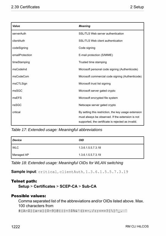
MeaningValue
SSL/TLS Web server authenticationserverAuth
SSL/TLS Web client authenticationclientAuth
Code signingcodeSigning
E-mail protection (S/MIME)emailProtection
Trusted time stampingtimeStamping
Microsoft personal code signing (Authenticode)msCodeInd
Microsoft commercial code signing (Authenticode)msCodeCom
Microsoft trust list signingmsCTLSign
Microsoft server gated cryptomsSGC
Microsoft encrypted file systemmsEFS
Netscape server gated cryptonsSGC
By setting this restriction, the key usage extension
must always be observed. If the extension is not
supported, the certificate is rejected as invalid.
critical
Table 17: Extended usage: Meaningful abbreviations
OIDDevice
1.3.6.1.5.5.7.3.18WLC
1.3.6.1.5.5.7.3.19Managed AP
Table 18: Extended usage: Meaningful OIDs for WLAN switching
Sample input: critical,clientAuth,1.3.6.1.5.5.7.3.19
Telnet path:Setup > Certificates > SCEP-CA > Sub-CA
Possible values:Comma separated list of the abbreviations and/or OIDs listed above. Max.100 characters from#[A-Z][a-z][0-9]@{|}~!$%&'()+-,/:;<=>?[\]^_. `
RM CLI HiLCOS 1222
2.39 Certificates 2 Setup
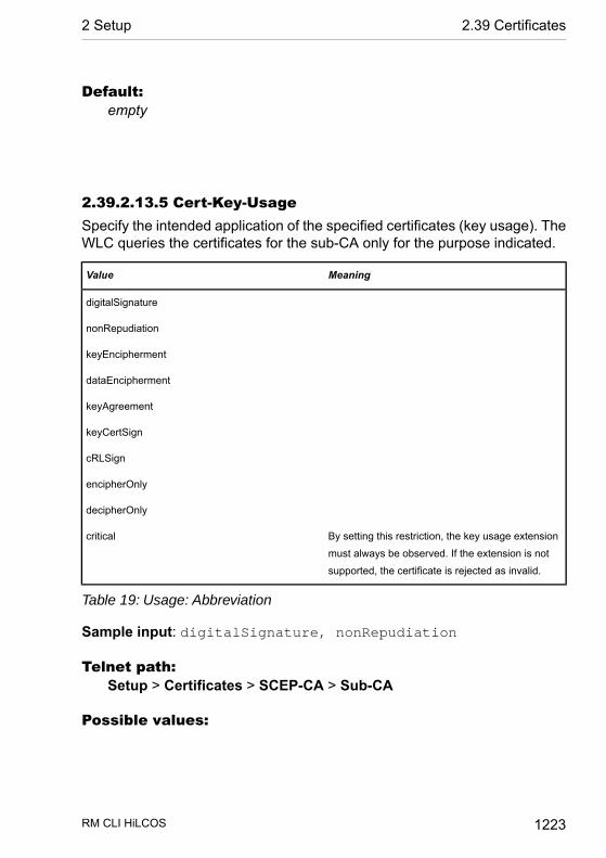
Default:empty
2.39.2.13.5 Cert-Key-UsageSpecify the intended application of the specified certificates (key usage). TheWLC queries the certificates for the sub-CA only for the purpose indicated.
MeaningValue
digitalSignature
nonRepudiation
keyEncipherment
dataEncipherment
keyAgreement
keyCertSign
cRLSign
encipherOnly
decipherOnly
By setting this restriction, the key usage extension
must always be observed. If the extension is not
supported, the certificate is rejected as invalid.
critical
Table 19: Usage: Abbreviation
Sample input: digitalSignature, nonRepudiation
Telnet path:Setup > Certificates > SCEP-CA > Sub-CA
Possible values:
RM CLI HiLCOS 1223
2 Setup 2.39 Certificates

Comma separated list of the abbreviations listed above. Max. 100 charac-ters from #[A-Z][a-z][0-9]@{|}~!$%&'()+-,/:;<=>?[\]^_.`
Default:empty
2.39.2.13.8 CA-Url-AddressSpecify the URL (address) where the parent CA is to be found. If anotherWLC with the HiLCOS operating system provides the CA, all you need to dois replace the IP address in the default value with the address where the cor-responding device is to be reached.
Telnet path:Setup > Certificates > SCEP-CA > Sub-CA
Possible values:Max. 251 characters from#[A-Z][a-z][0-9]@{|}~!$%&'()+-,/:;<=>?[\]^_. `
Default:http://127.0.0.1/cgi-bin/pkiclient.exe
2.39.2.13.9 RebootThis action causes a restart of the sub-CA. Execute this action after performingconfiguration changes on the sub-CA.
Telnet path:Setup > Certificates > SCEP-CA > Sub-CA
Possible arguments:
RM CLI HiLCOS 1224
2.39 Certificates 2 Setup
none
2.39.2.14 Web interfaceIn this directory, you configure the settings for the SCEP-CA web interface.
Telnet path:Setup > Certificates > SCEP-CA
2.39.2.14.1 ProfilesIn this table you create profiles with collected certificate properties.
Note: By default three profiles are already available for common applicationscenarios.
Telnet path:Setup > Certificates > SCEP-CA > Web-Interface
2.39.2.14.1.1 Profile nameHere you assign a unique name for the profile.
Telnet path:Setup > Certificates > SCEP-CA > Web-Interface > Profiles
Possible values:Max. 32 characters from[A-Z][0-9]@{|}~!$%&'()+-,/:;<=>?[\]^_.
RM CLI HiLCOS 1225
2 Setup 2.39 Certificates

Default:empty
2.39.2.14.1.2 Key usageSpecifies for which application the profile is to be used. The following usagesare available:
D criticalD digitalSignatureD nonRepudiationD keyEnciphermentD dataEnciphermentD keyAgreementD keyCertSignD cRLSignD encipherOnlyD decipherOnly
Multiple comma-separated entries can be selected.
Telnet path:Setup > Certificates > SCEP-CA > Web-Interface > Profiles
Possible values:Max. 251 characters from[A-Z][a-z][0-9]#@{|}~!"$%&'()*+-,/:;<=>?[\]^_. `
Default:critical,digitalSignature,keyEncipherment
RM CLI HiLCOS 1226
2.39 Certificates 2 Setup
2.39.2.14.1.3 Extended key usageSpecifies the extended application for which the profile is to be used. Thefollowing usages are available:
D criticalD serverAuth: SSL/TLS Web server authenticationD clientAuth: SSL/TLS Web client authenticationD codeSigning: Signing of program codeD emailProtection: E-mail protection (S/MIME)D timeStamping: Furnishing data with reliable time stampsD msCodeInd: Microsoft Individual Code Signing (authenticode)D msCodeCom: Microsoft Commercial Code Signing (authenticode)D msCTLSign: Microsoft Trust List SigningD msSGC: Microsoft Server Gated CryptoD msEFS: Microsoft Encrypted File SystemD nsSGC: Netscape Server Gated Crypto
Multiple comma-separated entries can be selected.
Telnet path:Setup > Certificates > SCEP-CA > Web-Interface > Profiles
Possible values:Max. 251 characters from[A-Z][a-z][0-9]#@{|}~!"$%&'()*+-,/:;<=>?[\]^_. `
Default:empty
2.39.2.14.1.4 RSA key lengthSets the length of the key.
Telnet path:Setup > Certificates > SCEP-CA > Web-Interface > Profiles
RM CLI HiLCOS 1227
2 Setup 2.39 Certificates

Possible values:10242048307240968192
Default:2048
2.39.2.14.1.5 Validity periodSpecifies the duration, in days, for which the key is valid. After this period, thekey becomes invalid unless the user renews it.
Telnet path:Setup > Certificates > SCEP-CA > Web-Interface > Profiles
Possible values:Max. 10 characters from 0123456789
Default:365
2.39.2.14.1.6 CAIndicates whether this is a CA certificate.
Telnet path:Setup > Certificates > SCEP-CA > Web-Interface > Profiles
Possible values:YesNo
RM CLI HiLCOS 1228
2.39 Certificates 2 Setup

Default:No
2.39.2.14.1.7 PasswordPassword to protect the PKCS12 certificate file.
Telnet path:Setup > Certificates > SCEP-CA > Web-Interface > Profiles
Possible values:Max. 32 characters from[A-Z][a-z][0-9]#@{|}~!$%&'()*+-,/:;<=>?[\]^_. `
Default:empty
2.39.2.14.1.8 CountryEnter the country identifier (e.g. “DE” for Germany).
This entry appears in the subject or issuer of the certificate under C= (Country).
Telnet path:Setup > Certificates > SCEP-CA > Web-Interface > Profiles
Possible values:2 characters from [A-Z][0-9]@{|}~!$%&'()+-,/:;<=>?[\]^_.
Default:empty
RM CLI HiLCOS 1229
2 Setup 2.39 Certificates

2.39.2.14.1.9 Locality nameEnter the name of the locality.
This entry appears in the subject or issuer of the certificate under L= (Locality).
Telnet path:Setup > Certificates > SCEP-CA > Web-Interface > Profiles
Possible values:Max. 32 characters from[A-Z][0-9]@{|}~!$%&'()+-,/:;<=>?[\]^_.
Default:empty
2.39.2.14.1.10 OrganizationEnter the organization that issues the certificate.
This entry appears in the subject or issuer of the certificate under O= (Organ-ization).
Telnet path:Setup > Certificates > SCEP-CA > Web-Interface > Profiles
Possible values:Max. 32 characters from[A-Z][0-9]@{|}~!$%&'()+-,/:;<=>?[\]^_.
Default:empty
RM CLI HiLCOS 1230
2.39 Certificates 2 Setup

2.39.2.14.1.11 Organization unit nameEnter the organization that issues the certificate.
This entry appears in the subject or issuer of the certificate under OU=(Organization Unit).
Telnet path:Setup > Certificates > SCEP-CA > Web-Interface > Profiles
Possible values:Max. 32 characters from[A-Z][0-9]@{|}~!$%&'()+-,/:;<=>?[\]^_.
Default:empty
2.39.2.14.1.12 State or provinceEnter the State or province.
This entry appears in the subject or issuer of the certificate under ST= (STate).
Telnet path:Setup > Certificates > SCEP-CA > Web-Interface > Profiles
Possible values:Max. 32 characters from[A-Z][0-9]@{|}~!$%&'()+-,/:;<=>?[\]^_.
Default:empty
RM CLI HiLCOS 1231
2 Setup 2.39 Certificates
2.39.2.14.1.13 E-mailEnter an e-mail address:
This entry appears in the subject or issuer of the certificate underemailAddress=.
Telnet path:Setup > Certificates > SCEP-CA > Web-Interface > Profiles
Possible values:Max. 36 characters from[A-Z][0-9]@{|}~!$%&'()+-,/:;<=>?[\]^_.
Default:empty
2.39.2.14.1.14 SurnameEnter a surname.
This entry appears in the subject or issuer of the certificate under SN=(SurName).
Telnet path:Setup > Certificates > SCEP-CA > Web-Interface > Profiles
Possible values:Max. 32 characters from[A-Z][0-9]@{|}~!$%&'()+-,/:;<=>?[\]^_.
Default:empty
RM CLI HiLCOS 1232
2.39 Certificates 2 Setup
2.39.2.14.1.15 Serial numberEnter a serial number.
This entry appears in the certificate under serialNumber=.
Telnet path:Setup > Certificates > SCEP-CA > Web-Interface > Profiles
Possible values:Max. 32 characters from[A-Z][0-9]@{|}~!$%&'()+-,/:;<=>?[\]^_.
Default:empty
2.39.2.14.1.16 Postal codeEnter the location post code.
This entry appears in the subject or issuer of the certificate underpostalCode=.
Telnet path:Setup > Certificates > SCEP-CA > Web-Interface > Profiles
Possible values:Max. 25 characters from[A-Z][0-9]@{|}~!$%&'()+-,/:;<=>?[\]^_.
Default:empty
RM CLI HiLCOS 1233
2 Setup 2.39 Certificates
2.39.2.14.1.17 TemplateSelect a suitable profile template here, if applicable.
The profile template specifies which certificate information is mandatory andwhich can be changed. Templates are created under Setup > Certificates >SCEP-CA > Web-Interface > Template.
Telnet path:Setup > Certificates > SCEP-CA > Web-Interface > Profiles
Possible values:Max. 31 characters from[A-Z][0-9]@{|}~!$%&'()+-,/:;<=>?[\]^_.
Default:empty
2.39.2.14.1.18 Subject-Alternative-NameSpecify the subject alternative name (SAN) here. The SAN contains furtherinformation for use by applications.
Telnet path:Setup > Certificates > SCEP-CA > Web-Interface > Profiles
Possible values:Max. 254 characters from[A-Z][0-9]@{|}~!$%&'()+-,/:;<=>?[\]^_.
Default:empty
RM CLI HiLCOS 1234
2.39 Certificates 2 Setup

2.39.2.14.2 TemplateIn this table, you define the templates for certificate profiles.
Here you specify which of the profile properties are mandatory and which areto be edited by the user. The following options are available:
D No: The field is invisible, the value entered is considered to be a defaultvalue.
D Fixed: The field is visible, but cannot be changed by the user.D Yes: The field is visible and can be changed by the user.D Mandatory: The field is visible, the user must enter a value.
Note: A “Default” template is already available.
Telnet path:Setup > Certificates > SCEP-CA > Web-Interface
2.39.2.14.2.1 NameGive the template a unique name here.
Telnet path:Setup > Certificates > SCEP-CA > Web-Interface > Template
Possible values:Max. 31 characters from[A-Z][a-z][0-9]#@{|}~!$%&'()*-:<>?[\]_.
Default:empty
RM CLI HiLCOS 1235
2 Setup 2.39 Certificates
2.39.2.14.2.2 Key usageSpecifies for which application the profile is to be used.
Telnet path:Setup > Certificates > SCEP-CA > Web-Interface > Template
Possible values:Yes
The field is visible and can be changed by the user.
NoThe field is invisible, the value entered is considered to be a defaultvalue.
MandatoryThe field is visible, the user must enter a value.
FixedThe field is visible, but cannot be changed by the user.
Default:Yes
2.39.2.14.2.3 Extended key usageSpecifies the extended application for which the profile is to be used.
Telnet path:Setup > Certificates > SCEP-CA > Web-Interface > Template
Possible values:Yes
The field is visible and can be changed by the user.
No
RM CLI HiLCOS 1236
2.39 Certificates 2 Setup

The field is invisible, the value entered is considered to be a defaultvalue.
MandatoryThe field is visible, the user must enter a value.
FixedThe field is visible, but cannot be changed by the user.
Default:Yes
2.39.2.14.2.4 RSA key lengthSets the length of the key.
Telnet path:Setup > Certificates > SCEP-CA > Web-Interface > Template
Possible values:Yes
The field is visible and can be changed by the user.
NoThe field is invisible, the value entered is considered to be a defaultvalue.
MandatoryThe field is visible, the user must enter a value.
FixedThe field is visible, but cannot be changed by the user.
Default:Yes
RM CLI HiLCOS 1237
2 Setup 2.39 Certificates
2.39.2.14.2.5 Validity periodSpecifies the duration, in days, for which the key is valid. After this period, thekey becomes invalid unless the user renews it.
Telnet path:Setup > Certificates > SCEP-CA > Web-Interface > Template
Possible values:Yes
The field is visible and can be changed by the user.
NoThe field is invisible, the value entered is considered to be a defaultvalue.
MandatoryThe field is visible, the user must enter a value.
FixedThe field is visible, but cannot be changed by the user.
Default:Yes
2.39.2.14.2.6 CAIndicates whether this is a CA certificate.
Telnet path:Setup > Certificates > SCEP-CA > Web-Interface > Template
Possible values:Yes
The field is visible and can be changed by the user.
RM CLI HiLCOS 1238
2.39 Certificates 2 Setup

NoThe field is invisible, the value entered is considered to be a defaultvalue.
MandatoryThe field is visible, the user must enter a value.
FixedThe field is visible, but cannot be changed by the user.
Default:Yes
2.39.2.14.2.8 CountrySpecifies the country identifier (e.g. “DE” for Germany).
Telnet path:Setup > Certificates > SCEP-CA > Web-Interface > Template
Possible values:Yes
The field is visible and can be changed by the user.
NoThe field is invisible, the value entered is considered to be a defaultvalue.
MandatoryThe field is visible, the user must enter a value.
FixedThe field is visible, but cannot be changed by the user.
Default:Yes
RM CLI HiLCOS 1239
2 Setup 2.39 Certificates

2.39.2.14.2.9 Locality nameSpecifies the locality.
Telnet path:Setup > Certificates > SCEP-CA > Web-Interface > Template
Possible values:Yes
The field is visible and can be changed by the user.
NoThe field is invisible, the value entered is considered to be a defaultvalue.
MandatoryThe field is visible, the user must enter a value.
FixedThe field is visible, but cannot be changed by the user.
Default:Yes
2.39.2.14.2.10 OrganizationSpecifies the organization issuing the certificate.
Telnet path:Setup > Certificates > SCEP-CA > Web-Interface > Template
Possible values:Yes
The field is visible and can be changed by the user.
No
RM CLI HiLCOS 1240
2.39 Certificates 2 Setup

The field is invisible, the value entered is considered to be a defaultvalue.
MandatoryThe field is visible, the user must enter a value.
FixedThe field is visible, but cannot be changed by the user.
Default:Yes
2.39.2.14.2.11 Organization unit nameSpecifies the unit within the organization that issues the certificate.
Telnet path:Setup > Certificates > SCEP-CA > Web-Interface > Template
Possible values:Yes
The field is visible and can be changed by the user.
NoThe field is invisible, the value entered is considered to be a defaultvalue.
MandatoryThe field is visible, the user must enter a value.
FixedThe field is visible, but cannot be changed by the user.
Default:Yes
RM CLI HiLCOS 1241
2 Setup 2.39 Certificates

2.39.2.14.2.12 State or provinceSpecifies the State or province.
Telnet path:Setup > Certificates > SCEP-CA > Web-Interface > Template
Possible values:Yes
The field is visible and can be changed by the user.
NoThe field is invisible, the value entered is considered to be a defaultvalue.
MandatoryThe field is visible, the user must enter a value.
FixedThe field is visible, but cannot be changed by the user.
Default:Yes
2.39.2.14.2.13 E-mailSpecifies the e-mail address.
Telnet path:Setup > Certificates > SCEP-CA > Web-Interface > Template
Possible values:Yes
The field is visible and can be changed by the user.
No
RM CLI HiLCOS 1242
2.39 Certificates 2 Setup

The field is invisible, the value entered is considered to be a defaultvalue.
MandatoryThe field is visible, the user must enter a value.
FixedThe field is visible, but cannot be changed by the user.
Default:Yes
2.39.2.14.2.14 SurnameSpecifies the surname.
Telnet path:Setup > Certificates > SCEP-CA > Web-Interface > Template
Possible values:Yes
The field is visible and can be changed by the user.
NoThe field is invisible, the value entered is considered to be a defaultvalue.
MandatoryThe field is visible, the user must enter a value.
FixedThe field is visible, but cannot be changed by the user.
Default:Yes
RM CLI HiLCOS 1243
2 Setup 2.39 Certificates
2.39.2.14.2.15 Serial numberSpecifies the serial number.
Telnet path:Setup > Certificates > SCEP-CA > Web-Interface > Template
Possible values:Yes
The field is visible and can be changed by the user.
NoThe field is invisible, the value entered is considered to be a defaultvalue.
MandatoryThe field is visible, the user must enter a value.
FixedThe field is visible, but cannot be changed by the user.
Default:Yes
2.39.2.14.2.16 Postal codeSpecifies the postal code.
Telnet path:Setup > Certificates > SCEP-CA > Web-Interface > Template
Possible values:Yes
The field is visible and can be changed by the user.
No
RM CLI HiLCOS 1244
2.39 Certificates 2 Setup
The field is invisible, the value entered is considered to be a defaultvalue.
MandatoryThe field is visible, the user must enter a value.
FixedThe field is visible, but cannot be changed by the user.
Default:Yes
2.39.2.14.2.17 Subject-Alternative-NameThe “Subject Alternative Name” (SAN) links additional data with this certificate.
Telnet path:Setup > Certificates > SCEP-CA > Web-Interface > Template
Possible values:Yes
The field is visible and can be changed by the user.
NoThe field is invisible, the value entered is considered to be a defaultvalue.
MandatoryThe field is visible, the user must enter a value.
FixedThe field is visible, but cannot be changed by the user.
Default:Yes
RM CLI HiLCOS 1245
2 Setup 2.39 Certificates

2.39.3 CRLsThis menu contains the configuration of the CRLs.
SNMP ID: 2.39.3
Telnet path: /Setup/Certificates
2.39.3.1 OperatingOperating: During the certificate check, the CRL (if available) will be consideredas well.
SNMP ID: 2.39.3.1
Telnet path: /Setup/Certificates/CRLs
Possible values:
D YesD No
Default: No
Note: If this option is activated but no valid CRL is available (e.g. if the servercan't be reached), then all connections will be rejected and existing connectionswill be interrupted.
2.39.3.4 Update-BeforeThe point in time prior to expiry of the CRL when the new CRL can be loaded.This value is increased by a random value to prevent server overload frommultiple simultaneous queries. Once within this time frame, any coincidingregular planned updates will be stopped.
SNMP ID: 2.39.3.4
Telnet path: /Setup/Certificates/CRLs
Possible values:
D Max. 10 characters
Default: 300
RM CLI HiLCOS 1246
2.39 Certificates 2 Setup

Note: If the first attempt to load the CRL fails, new attempts are made atregular short intervals.
2.39.3.5 Prefetch-PeriodThe time period after which periodic attempts are made to retrieve a new CRL.Useful for the early retreival of CRLs published at irregular intervals. The entry'0' disables regular retreival.
SNMP ID: 2.39.3.5
Telnet path: /Setup/Certificates/CRLs
Possible values:
D Max. 10 characters
Default: 0
Note: If with regular updates the CRL cannot be retreived, no further attemptswill be started until the next regular attempt.
2.39.3.6 Validity exceedanceEven after expiry of the CRL, certificate-based connections will continue tobe accepted for the period defined here. This tolerance period can preventthe unintentional rejection or interruption of connections if the CRL servershould be temporarily unavailable.
SNMP ID: 2.39.3.6
Telnet path: /Setup/Certificates/CRLs
Possible values:
D Max. 10 characters
Default: 0
Special values: Within the time period defined here, even certificates in theCRL which have expired can still be used to maintain or establish a connection.
RM CLI HiLCOS 1247
2 Setup 2.39 Certificates

Note: In the time period defined here, even expired certificates can be usedto maintain or re-establish a connection.
2.39.3.7 Refresh-CRL-NowReads the current CRL from the URL specified in the root certificate, or fromthe alternative URL (if this function is set up).
SNMP ID: 2.39.3.7
Telnet path: /Setup/Certificates/CRLs
2.39.3.8 Alternative-URL-TableThis table contains the list of alternative URLs.
The address where a certificate revocation list (CRL) can be collected is nor-mally defined in the certificate (as crlDistributionPoint). In HiLCOS, alternativeCRLs can be specified in a table. After a system start the CRLs are automat-ically collected from these URLs. These are used in addition to the lists offeredby the certificates.
SNMP ID: 2.39.3.8
Telnet path: /Setup/Certificates/CRLs/Alternative-URL-Table
2.39.3.8.1 Alternative-URLHere you enter the alternative URL where a CRL can be collected.
SNMP ID: 2.39.3.8.1
Telnet path: /Setup/Certificates/CRLs/Alternative-URL-Table/Alternative-URL
Possible values:
D Any valid URL with max. 251 characters.
Default: Blank
RM CLI HiLCOS 1248
2.39 Certificates 2 Setup

2.39.3.9 Loopback-AddressHere you can optionally define a sender address for display to the recipientinstead of the automatically generated address.
SNMP ID: 2.39.3.9
Telnet path: /Setup/Certificates/CRLs/Loopback-Address
Possible values:
D Name of the IP network whose address should be usedD "INT" for the address of the first intranetD "DMZ" for the address of the first DMZD LB0 – LBF for the 16 loopback addressesD Any valid IP address
Default: Blank
Note: If there is an interface called "DMZ", its address will be taken if youhave selected "DMZ".
2.40 GPS
This item contains the GPS settings.
SNMP ID: 2.40
Telnet path: /Setup/GPS
2.40.1 OperatingActivate or deactivate the GPS function here. You can activate the GPSmodule independently of the location verification function, for example tomonitor the current positional coordinates with LANmonitor.
Telnet path:Setup > GPS
RM CLI HiLCOS 1249
2 Setup 2.40 GPS

Possible values:No
Yes
Default:No
2.51 HiDiscovery
This menu contains the values for the HiDiscovery protocol configuration.
Telnet path: Setup
2.51.1 Server-OperatingThis parameter enables or disables the use of the HiDiscovery protocol.
Telnet path: Setup/HiDiscovery
Possible values:
D DisabledD Read-OnlyD Enabled
Default: Disabled
2.52 COM-Ports
This menu contains the configuration of the COM ports.
SNMP ID: 2.52
Telnet path: /Setup
RM CLI HiLCOS 1250
2.51 HiDiscovery 2 Setup

2.52.1 DevicesThe serial interfaces in the device can be used for various applications, forexample for the COM port server or as a WAN interface. The Devices tableallows individual serial devices to be assigned to certain applications.
SNMP ID: 2.52.1
Telnet path: /Setup/COM-Ports
2.52.1.1 Device-TypeSelects a serial interface from the list of those available in the device.
SNMP ID: 2.52.1.1
Telnet path: /Setup/COM-Ports/Devices
Possible values:
D All available serial interfaces.
Default: Outband
2.52.1.4 ServiceActivation of the port in the COM port server.
SNMP ID: 2.52.1.4
Telnet path: /Setup/COM-Ports/Devices
Possible values:
D WAND COM-port server
Default: WAN
2.52.2 COM-Port-ServerThis menu contains the configuration of the COM-port server.
SNMP ID: 2.52.2
Telnet path: /Setup/COM-Ports
RM CLI HiLCOS 1251
2 Setup 2.52 COM-Ports
2.52.2.1 OperationalThis table activates the COM port server at a port of a certain serial interface.Add an entry to this table to start a new instance of the COM port server.Delete an entry to stop the corresponding server instance.
SNMP ID: 2.52.2.1
Telnet path: /Setup/COM-Ports/COM-Port-Server
2.52.2.1.1 Device-TypeSelects a serial interface from the list of those available in the device.
SNMP ID: 2.52.2.1.1
Telnet path: /Setup/COM-Ports/COM-Port-Server/Device-Type
Possible values:
D All available serial interfaces.
Default: Outband
2.52.2.1.2 Port-NumberSome serial devices such as the CardBus have more that one serial port.Enter the port number that is to be used for the COM port server on the serialinterface.
SNMP ID: 2.52.2.1.2
Telnet path: /Setup/COM-Ports/COM-Port-Server/Device-Type
Possible values:
D Max. 10 characters
Default: 0
Special values: 0 for serial interfaces with just one port, e.g. outband.
2.52.2.1.4 OperatingActivates the COM port server on the selected port of the selected interface.
RM CLI HiLCOS 1252
2.52 COM-Ports 2 Setup

SNMP ID: 2.52.2.1.4
Telnet path: /Setup/COM-Ports/COM-Port-Server/Device-Type
Possible values:
D YesD No
Default: No
2.52.2.2 COM-Port-SettingsThis table contains the settings for data transmission over the serial interface.
Please note that all of these parameters can be overwritten by the remote siteif the RFC2217 negotiation is active. Current settings can be viewed in thestatus menu.
SNMP ID: 2.52.2.2
Telnet path: /Setup/COM-Ports/COM-Port-Server
2.52.2.2.1 Device-TypeSelects a serial interface from the list of those available in the device.
SNMP ID: 2.52.2.2.1
Telnet path: /Setup/COM-Ports/COM-Port-Server/COM-Port-Settings
Possible values:
D All available serial interfaces.
Default: Outband
2.52.2.2.2 Port-NumberSome serial devices such as the CardBus have more that one serial port.Enter the port number that is to be used for the COM port server on the serialinterface.
SNMP ID: 2.52.2.2.2
Telnet path: /Setup/COM-Ports/COM-Port-Server/COM-Port-Settings
RM CLI HiLCOS 1253
2 Setup 2.52 COM-Ports

Possible values:
D Max. 10 characters
Default: 0
Special values: 0 for serial interfaces with just one port, e.g. outband.
2.52.2.2.4 BitrateBitrate used on the COM port
SNMP ID: 2.52.2.2.4
Telnet path: /Setup/COM-Ports/COM-Port-Server/COM-Port-Settings
Possible values:
D 110 to 230400
Default: 9600
2.52.2.2.5 Data-BitsNumber of data bits.
SNMP ID: 2.52.2.2.5
Telnet path: /Setup/COM-Ports/COM-Port-Server/COM-Port-Settings
Possible values:
D 7D 8
Default: 8
2.52.2.2.6 ParityThe checking method used on the COM port.
SNMP ID: 2.52.2.2.6
Telnet path: /Setup/COM-Ports/COM-Port-Server/COM-Port-Settings
Possible values:
D None
RM CLI HiLCOS 1254
2.52 COM-Ports 2 Setup

D EvenD Odd
Default: None
2.52.2.2.7 Stop-BitsNumber of stop bits.
SNMP ID: 2.52.2.2.7
Telnet path: /Setup/COM-Ports/COM-Port-Server/COM-Port-Settings
Possible values:
D 1D 2
Default: 1
2.52.2.2.8 HandshakeThe data-flow control used on the COM port.
SNMP ID: 2.52.2.2.8
Telnet path: /Setup/COM-Ports/COM-Port-Server/COM-Port-Settings
Possible values:
D noneD RTS/CTS
Default: RTS/CTS
2.52.2.2.9 Ready-ConditionThe ready condition is an important property of any serial port. The COM portserver transmits no data between the serial port and the network if the statusis not "ready". Apart from that, in the client mode the act of switching betweenthe ready and not-ready status is used to establish and terminate TCP con-nections. The readiness of the port can be checked in two different ways. InDTR mode (default) only the DTR handshake is monitored. The serial interfaceis considered to be ready for as long as the DTR line is active. In data mode,the serial interface is considered to be active for as long as it receives data.
RM CLI HiLCOS 1255
2 Setup 2.52 COM-Ports

If no data is received during the timeout period, the port reverts to its "notready" status.
SNMP ID: 2.52.2.2.9
Telnet path: /Setup/COM-Ports/COM-Port-Server/COM-Port-Settings
Possible values:
D DTRD Data
Default: DTR
2.52.2.2.10 Ready-Data-TimeoutThe timeout switches the port back to the not-ready status if no data isreceived. This function is deactivated when timeout is set to zero. In this casethe port is always ready if the data mode is selected.
SNMP ID: 2.52.2.2.10
Telnet path: /Setup/COM-Ports/COM-Port-Server/COM-Port-Settings
Possible values:
D Max. 10 characters
Default: 0
Special values: 0 switches the Ready-data-timeout off.
2.52.2.3 Network-SettingsThis table contains all settings that define the behavior of the COM port in thenetwork.
Please note that all of these parameters can be overwritten by the remote siteif the RFC2217 negotiation is active. Current settings can be viewed in thestatus menu.
SNMP ID: 2.52.2.3
Telnet path: /Setup/COM-Ports/COM-Port-Server
RM CLI HiLCOS 1256
2.52 COM-Ports 2 Setup

2.52.2.3.1 Device-TypeSelects a serial interface from the list of those available in the device.
SNMP ID: 2.52.2.3.1
Telnet path: /Setup/COM-Ports/COM-Port-Server/Network-Settings
Possible values:
D All available serial interfaces.
Default: Outband
2.52.2.3.2 Port-NumberSome serial devices such as the CardBus have more that one serial port.Enter the port number that is to be used for the COM port server on the serialinterface.
SNMP ID: 2.52.2.3.2
Telnet path: /Setup/COM-Ports/COM-Port-Server/Network-Settings
Possible values:
D Max. 10 characters
Default: 0
Special values: 0 for serial interfaces with just one port, e.g. outband.
2.52.2.3.4 TCP-ModeEach instance of the COM port server in server mode monitors the specifiedlisten port for incoming TCP connections. Just one active connection is per-mitted per instance. All other connection requests are refused. In client mode,the instance attempts to establish a TCP connection via a defined port to thespecified remote site, as soon as the port is ready. The TCP connection isclosed again as soon as the port becomes unavailable. In both cases thedevice closes any open connections when the device is restarted.
SNMP ID: 2.52.2.3.4
Telnet path: /Setup/COM-Ports/COM-Port-Server/Network-Settings
Possible values:
RM CLI HiLCOS 1257
2 Setup 2.52 COM-Ports
D ServersD Client
Default: Servers
2.52.2.3.5 Listen-PortThe TCP port where the COM port in TCP server mode expects incomingconnections.
SNMP ID: 2.52.2.3.5
Telnet path: /Setup/COM-Ports/COM-Port-Server/Network-Settings
Possible values:
D Max. 10 characters
Default: 0
2.52.2.3.6 Connect-HostnameThe COM port in TCP client mode establishes a connection to this host assoon as the port is in the "Ready" state.
SNMP ID: 2.52.2.3.6
Telnet path: /Setup/COM-Ports/COM-Port-Server/Network-Settings
Possible values:
D DNS-NameD IP address
Default: Blank
2.52.2.3.7 Connect-PortThe COM port in TCP client mode uses this TCP port to establish a connectionas soon as the port is in the "Ready" state.
SNMP ID: 2.52.2.3.7
Telnet path: /Setup/COM-Ports/COM-Port-Server/Network-Settings
Possible values:
RM CLI HiLCOS 1258
2.52 COM-Ports 2 Setup
D Max. 10 characters
Default: 0
2.52.2.3.8 Loopback-Addr.The COM port can be reached at this address. This is its own IP address thatis taken as the source address when establishing connections. This is usedto define the IP route to be used for the connection.
SNMP ID: 2.52.2.3.8
Telnet path: /Setup/COM-Ports/COM-Port-Server/Network-Settings
Possible values:
D Max. 16 characters
Default: Blank
2.52.2.3.9 RFC2217 extensionsThe RFC2217 extensions can be activated for both TCP modes. With theseextensions activated, the device uses the IAC DO COM-PORT-OPTIONsequence to signal that it will accept Telnet control sequences. The COM portsubsequently works with the corresponding options; the configured defaultvalues are overwritten. The port also attempts to negotiate the local echo andline mode for Telnet. Using the RFC2217 extensions with incompatible remotesites is not critical. Unexpected characters may be displayed at the remotesite. A side effect of using the FRC2217 extensions may be that the port reg-ularly carries out an alive check as Telnet NOPs are transmitted to the remotesite.
SNMP ID: 2.52.2.3.9
Telnet path: /Setup/COM-Ports/COM-Port-Server/Network-Settings
Possible values:
D YesD No
Default: Yes
RM CLI HiLCOS 1259
2 Setup 2.52 COM-Ports

2.52.2.3.10 Newline-ConversionHere you select the character to be output by the serial port when binary modeis activated.
This setting is independent of the application communicating via the serialport. If the port is connected to another device, you can either enter CRLFhere or just CR. This is because the outband interface of these devices expectsa "carriage return" for the automatic determination of data-transfer speed.However, some Unix applications interpret CRLF as a prohibited double linefeed character. In these cases enter either CR or LF.
SNMP ID: 2.52.2.3.10
Telnet path: /Setup/COM-Ports/COM-Port-Server/Network-Settings
Possible values:
D CRLFD CRD LF
Default:
CRLF
Note: This setting is only relevant if binary mode is deactivated for this port.
2.52.2.3.12 TCP-Retransmit-TimeoutMaximum time for the retransmission timeout. This timeout defines the theinterval between checking TCP-connection status and reporting the result tothe application using the TCP connection.
SNMP ID: 2.52.2.3.12
Telnet path: /Setup/COM-Ports/COM-Port-Server/Network-Settings
Possible values:
D 0 to 99 secondsD Maximum 2 characters
Special values:
RM CLI HiLCOS 1260
2.52 COM-Ports 2 Setup

D 0 activates the RFC 1122 default value (60 seconds).
Default:
D 0
Note: The maximum duration of the TCP-connection check is the product ofTCP-retransmit-count and TCP-retry-count. The TCP application is onlyinformed after the timeout for all attempts has expired. With the default valuesof 60 seconds timeout and max. 5 attempts, it can take up to 300 secondsbefore the application is informed about an inactive TCP connection.
2.52.2.3.13 TCP-Retry-CountThe maximum number of attempts for checking TCP-connection status andreporting the result to the application using the TCP connection.
SNMP ID: 2.52.2.3.13
Telnet path: /Setup/COM-Ports/COM-Port-Server/Network-Settings
Possible values:
D 0 to 9D Maximum 1 characters
Special values:
D 0 activates the RFC 1122 default value (5 attempts).
Default:
D 0
Note: The maximum duration of the TCP-connection check is the product ofTCP-retransmit-count and TCP-retry-count. The TCP application is onlyinformed after the timeout for all attempts has expired. With the default valuesof 60 seconds timeout and max. 5 attempts, it can take up to 300 secondsbefore the application is informed about an inactive TCP connection.
RM CLI HiLCOS 1261
2 Setup 2.52 COM-Ports
2.52.2.3.14 TCP-KeepaliveThe RFC 1122 sets down a method of checking the availability of TCP con-nections, called TCP keepalive. An inactive transmitter queries the receivestatus from the remote station. If the TCP session to the remote site is avail-able, then the remote responds with its receive status. If the TCP session tothe remote site is not available, then the query is repeated for as long as ittakes for the remote to respond with its receive status (after which a longerinterval comes into play). As long as the basic connection functions, but theTCP session to the remote station is not available, then the remote stationsends an RST packet which triggers the establishment of the TCP sessionby the requesting application.
SNMP ID: 2.52.2.3.14
Telnet path: /Setup/COM-Ports/COM-Port-Server/Network-Settings
Possible values:
D Inactive: TCP keepalive is not used.D Active: TCP keepalive is active; only RST packets cause the disconnection
of TCP sessions.D Proactive: TCP keepalive is active, but the request for the receive status
from the remote site is only repeated for the number of times defined under"TCP retry count". If this number of requests expires without a responsewith the receive status, then the TCP sessions is classified as "not avail-able" and the application is informed. If an RST packet is received duringthe wait time, the TCP session will be disconnected prematurely.
Default:
D Down
Note: The setting "active" is recommended for server applications.
2.52.2.3.15 TCP-Keepalive-IntervalThis value defines the interval between sending requests for receive status ifthe first request is not affirmed. The associated timeout is defined as beinginterval/3 (max. 75 sec.).
SNMP ID: 2.52.2.3.15
RM CLI HiLCOS 1262
2.52 COM-Ports 2 Setup
Telnet path: /Setup/COM-Ports/COM-Port-Server/Network-Settings
Possible values:
D Maximum 10 characters.
Default:
D 0
Special values:
D 0 activates the RFC 1122 default values (interval 7200 seconds, timeout75 seconds).
2.52.2.3.16 Binary-ModeUsing this setting you specify whether the device forwards serial data in binaryformat and therefore without CR/LF adjustment (CR/LF = carriage return/linefeed). Since binary mode can cause problems with some serial remote stations,you should maintain the default Auto.
Telnet path:Setup > COM-Ports > COM-Port-Server > Network-Settings
Possible values:Auto: For data transmission, the COM-port server initially switches toASCII mode; however, it uses telnet options to negotiate with the remotestation whether it can switch to binary mode.
Yes: For data transmission, the COM port server switches to binary modeand does not use the telnet options to negotiate this with the remotestation.
No: For data transmission, the COM port server switches to ASCII modeand does not use the telnet options to negotiate this with the remotestation.
Default:Auto
2.52.3 WANThis menu contains the configuration of the Wide Area Network (WAN).
SNMP ID: 2.52.3
RM CLI HiLCOS 1263
2 Setup 2.52 COM-Ports
Telnet path: /Setup/COM-Ports
2.52.3.1 DevicesThe table with WAN devices is a status table only. All Hotplug devices (con-nected via USB or CardBus) are automatically entered into this table.
SNMP ID: 2.52.3.1
Telnet path: /Setup/COM-Ports/WAN
2.52.3.1.1 Device-TypeList of serial interfaces available in the device.
SNMP ID: 2.52.3.1.1
Telnet path: /Setup/COM-Ports/WAN/Devices
Possible values:
D All available serial interfaces.
2.52.3.1.3 OperatingStatus of connected device.
SNMP ID: 2.52.3.1.3
Telnet path: /Setup/COM-Ports/WAN/Devices
Possible values:
D YesD No
2.52.4 Serial configurationThis menu contains the settings for the auto configuration of WLAN point-to-point links over a serial connection.
Telnet path: /Setup/COM-Ports
RM CLI HiLCOS 1264
2.52 COM-Ports 2 Setup
2.52.4.1 Bit rateThis item sets the bit rate for communications between the devices when aserial connection is used for the automatic configuration of WLAN point-to-point links.
Telnet path: /Setup/COM-Ports
Possible values:
D 1200D 2400D 4800D 9600D 19200D 38400D 57600D 115200
Default: 9600
Note: It is imperative that the same bit rate is set in all devices communicatingover serial connections to be used for the automatic configuration of WLANpoint-to-point links.
2.53 Temperature-Monitor
The settings for the temperature monitor are located here.
SNMP ID: 2.53
Telnet path: /Setup/Temperature-Monitor
2.53.1 Upper-Limit-DegreesWhen the temperature set here is exceeded, the device sends an SNMP trapof the type "trpTempMonOverTemp".
Telnet path:/Setup/Temperature-Monitor/Upper-Limit-Degrees
RM CLI HiLCOS 1265
2 Setup 2.53 Temperature-Monitor

Possible values:
D 0 – 127 ° Celsius
Default: 70
2.53.2 Lower-Limit-DegreesWhen the temperature drops below that set here, the device sends an SNMPtrap of the type "trpTempMonUnderTemp".
Telnet path:/Setup/Temperature-Monitor/Upper-Limit-Degrees
Possible values:
D 0 – 127 ° Celsius
Default: 0
2.54 TACACS
2.54.2 AuthorizationWEBconfig: /Setup/Tacacs+
WEBconfig English: /Setup/Tacacs+
Activates authorization via TACACS+ server. If TACACS+ authorization isactivated, all authorization data is transmitted via TACACS+ protocol to theconfigured TACACS+ server.
Possible values: Activated, deactivated
Default: Deactivated
Note: TACACS+ authorization will only activate if the defined TACACS+server is available. If TACACS+ authorization is activated, the TACACS+server will be queried for authorization each time a user enters a command.Data traffic during configuration will increase correspondingly. Also, the userrights must be defined in the TACACS+ server.
RM CLI HiLCOS 1266
2.54 TACACS 2 Setup
2.54.3 AccountingWEBconfig: /Setup/Tacacs+
Activates accounting via TACACS+ server. If TACACS+ accounting is activ-ated, all accounting data is transmitted via TACACS+ protocol to the configuredTACACS+ server.
Possible values: Activated, deactivated
Default: Deactivated
Note: TACACS+ accounting will only activate if the defined TACACS+ serveris available.
2.54.6 Shared-SecretWEBconfig: /Setup/Tacacs+
The password for encrypting the communications between NAS and TACACS+servers.
Possible values: 31 alphanumerical characters
Default: Blank
Note: The password must be entered identically into the device and theTACACS+ server. We recommend that you do not operate TACACS+ withoutencryption.
2.54.7 EncryptionWEBconfig: /Setup/Tacacs+
WEBconfig English: /Setup/Tacacs+
Activates or deactivates the encryption of communications between NAS andTACACS+ servers.
Possible values:
D ActivatedD Disabled
RM CLI HiLCOS 1267
2 Setup 2.54 TACACS

Default: Activated
Note: We recommend that you do not operate TACACS+ without encryption.If encryption is activated here, the password for encryption entered here mustmatch with the password on the TACACS+ server.
2.54.9 ServerTwo servers can be defined to work with TACACS+ functions. One serveracts as a backup in case the other one fails. When logging in via telnet orWEBconfig, the user can select the server to be used.
This menu contains the settings for TACACS servers.
SNMP ID: 2.54.9
Telnet path: /Setup/Tacacs+
2.54.9.1 Server-addressAddress of the TACACS+ server to which requests for authentication,authorization and accounting are to be forwarded.
SNMP ID: 2.54.9.1
Telnet path: /Setup/Tacacs+/Server-Address
Possible Telnet values:
D Valid DNS resolvable name or valid IP address.
Default: Blank
2.54.9.2 Loopback-AddressOptionally you can configure a loopback address here.
SNMP ID: 2.54.9.2
Telnet path: /Setup/Tacacs+/Loopback-Address
Possible Telnet values:
D Name of the IP networks whose address should be used
RM CLI HiLCOS 1268
2.54 TACACS 2 Setup

D "INT" for the address of the first intranetD "DMZ" for the address of the first DMZD LB0 to LBF for the 16 loopback addressesD Any valid IP address
Default: Blank
2.54.9.3 Compatibility modeTACACS+ servers are available as open-source or commercial versions, eachof which works with different messages. The compatibility mode enables theprocessing of messages from free TACACS+ servers.
SNMP ID: 2.54.9.3
Telnet path: /Setup/Tacacs+/Compatibility-Mode
Possible Telnet values:
D ActivatedD Disabled
Default: Deactivated
2.54.10 Fallback to local usersWEBconfig: /Setup/Tacacs+
WEBconfig English: /Setup/Tacacs+
Should the defined TACACS+ server be unavailable, it is possible to fallbackto local user accounts on the device. This allows for access to the device evenif the TACACS+ connection should fail, e.g. when deactivating the usage ofTACACS+ or for correcting the configuration.
Possible values: Allowed, prohibited
Default: Allowed
Note: The fallback to local user accounts presents a security risk if no rootpassword is set for the device. For this reason, TACACS+ authentication withfallback to local user accounts can only be activated if a root password hasbeen set. If no root password is set, access to the device configuration can
RM CLI HiLCOS 1269
2 Setup 2.54 TACACS

be blocked for security reasons if no connection is available to the TACACS+server. In this case, the device may have to be reset to its factory settings inorder to regain access to the configuration.
2.54.11 SNMP-GET-Requests-AuthorisationWEBconfig: /Setup/Tacacs+
WEBconfig English: /Setup/Tacacs+
This parameter allows the regulation of the behavior of devices with regardto SNMP access in order to reduce the number of TACACS+ sessions requiredfor authorization. Authentication via the TACACS+ server remains necessaryif authentication for TACACS+ is activated generally.
Possible values:
D only_for_SETUP_tree: With this setting, authorization via TACACS+server is only required for SNMP access via the setup branch of HiLCOS.
D All: With this setting, authorization by TACACS+ server will be carried outfor every SNMP access. In case of regular request for status information,for example, the load on the TACACS+ server will increase significantly.
D None: With this setting, authorization by TACACS+ server will not be carriedout for SNMP accesses.
Default: only_for_SETUP_tree
2.54.11 SNMP-GET-Requests-AccountingWEBconfig: /Setup/Tacacs+
WEBconfig English: /Setup/Tacacs+
Numerous network management tools use SNMP for requesting informationfrom network devices. LANmonitor also uses SNMP to access the devices todisplay information about current connections, etc., or to execute actions suchas disconnecting a connection. SNMP can be used to configure devices. Forthis reason TACACS+ requires authentication for SNMP access requests.Since LANmonitor regularly queries these values, a large number of unneces-sary TACACS+ connections would be established. If authentication, authoriz-ation and accounting by TACACS+ are activated, then each request wouldinitiate three sessions with the TACACS+ server.
RM CLI HiLCOS 1270
2.54 TACACS 2 Setup

This parameter allows the regulation of the behavior of devices with regardto SNMP access in order to reduce the number of TACACS+ sessions requiredfor accounting. Authentication via the TACACS+ server remains necessary ifauthentication for TACACS+ is activated generally.
Note: Entering a read-only community under /Setup/SNMP also enablesauthentication by TACACS+ to be deactivated for LANmonitor. The read-onlycommunity defined here is then entered into LANmonitor as a user name.
Possible values:
D only_for_SETUP_tree: With this setting, accounting via TACACS+ serveris only required for SNMP access via the setup branch of HiLCOS.
D All: With this setting, accounting by TACACS+ server will be carried outfor every SNMP access. In case of regular request for status information,for example, the load on the TACACS+ server will increase significantly.
D None: With this setting, accounting by TACACS+ server will not be carriedout for SNMP accesses.
Default: only_for_SETUP_tree
2.54.13 Bypass-Tacacs-for-CRON/scripts/action-tableYou can activate or deactivate the bypassing of TACACS+ authorization andTACACS+ accounting for various actions.
SNMP ID: 2.54.13
Telnet path: /Setup/Tacacs+
Possible values:
D ActivatedD Disabled
Default: Deactivated
Note: Please observe that this option influences the TACACS+ function forthe entire system. Be sure that you restrict the use of CRON, the action tables,and scripts only to an absolutely trustworthy circle of administrators!
RM CLI HiLCOS 1271
2 Setup 2.54 TACACS
2.54.14 Include-value-into-authorisation-requestIf you deactivate this function, then TACACS + only checks the rights of theuser on login. When entering values, the device no longer checks whetherthe user has permission to change certain values.
Telnet path:/Setup/Tacacs+/Include-value-into-authorization
Possible values:
D Activated: When values are submitted, TACACS + checks whether theuser has the right to make these changes
D Deactivated: TACACS + checks the identity of the user only on login
Default: Activated
2.59 WLAN-Management
This menu is used to configure the WLAN management.
2.59.1 Static-WLC-ConfigurationUse this table to define the preferred wireless LAN controllers (WLCs) thatthis managed access point should contact. This setting is not required if theaccess point and WLC are located in the same IP network.
This setting is only relevant if at least one of the device's WLAN interfaces isswitched to the 'Managed' operating mode.
SNMP ID: 2.59.1
Telnet path: /Setup/WLAN-Management/Static-WLC-Configuration
2.59.1.1 IP-AddressThis is where the name of the CAPWAP service is defined that is used totrigger the WLAN controller via the DNS server.
The name is preset, so you do not need to change anything here. However,this parameter does offer the option of using the CAPWAP service of othermanufacturers.
RM CLI HiLCOS 1272
2.59 WLAN-Management 2 Setup

SNMP ID: 2.59.1.1
Telnet path: /Setup/WLAN-Management/Static-WLC-Configuration/IP-Address
Possible values:
D Valid IP address or resolvable name of a WLC controller
Default: WLC-Address
2.59.1.2 PortThe port to be used for communication with the WLAN controller is set here.
SNMP ID: 2.59.1.2
Telnet path: /Setup/WLAN-Management/Static-WLC-Configuration/Port
Possible values:
D Valid port name
Default: 1027
2.59.1.3 Loopback-Addr.This is where you can configure an optional sender address to be used insteadof the one otherwise automatically selected for the destination address.
If you have configured loopback addresses, you can specify them here assource address.
SNMP ID: 2.59.1.3
Telnet path: /Setup/WLAN-Management/Static-WLC-Configuration/Loopback-Address
Possible values:
D Name of the IP networks whose addresses are to be used.D "INT" for the address of the first intranet.D "DMZ" for the address of the first DMZ (Note: If there is an interface named
"DMZ", its address will be taken).D LB0 ... LBF for the 16 loopback addresses.D Furthermore, any IP address can be entered in the form x.x.x.x.
RM CLI HiLCOS 1273
2 Setup 2.59 WLAN-Management

Default: Blank
Note: The sender address specified here is used unmasked for every remotestation.
2.59.3 CAPWAP-TuningHere you can configure the CAPWAP timing parameters (CAPWAP Tuning).
Telnet path:Setup > WLAN-Management
2.59.3.1 Echo-IntervalHere you specify the duration of the Echo Interval in seconds.
The Echo Interval is the time interval between the AP sends Echo Requestmessages to the controller with which the AP has joined.
Telnet path:Setup > WLAN-Management > CAPWAP-Tuning
Possible values:Max. 5 characters from [0-9]
Default:10
2.59.3.2 Retransmit-IntervalHere you specify the duration of the Retransmit Interval in seconds.
1274
2.59 WLAN-Management 2 Setup
RM CLI HiLCOS

The Retransmit Interval is the time interval in which a non-ackowledgedCAPWAP packet will be retransmitted.
Telnet path:Setup > WLAN-Management > CAPWAP-Tuning
Possible values:Max. 5 characters from [0-9]
Default:3
2.59.3.3 Discovery-IntervalHere you specify the duration of the Discovery Interval in seconds.
The Discovery Interval is the time interval in which the AP waits for moreDiscovery Responses after receiving the first Discovery Response.
Telnet path:Setup > WLAN-Management > CAPWAP-Tuning
Possible values:Max. 5 characters from [0-9]
Default:5
2.59.3.4 Max-Discovery-IntervalHere you specify the duration of the Maximum Discovery Interval in seconds.
The Maximum Discovery Interval is the maximum time interval allowed betweensending Discovery Request messages.
RM CLI HiLCOS 1275
2 Setup 2.59 WLAN-Management

Telnet path:Setup > WLAN-Management > CAPWAP-Tuning
Possible values:Max. 5 characters from [0-9]
Default:8
2.59.3.5 Silent-IntervalHere you specify the duration of the Silent Interval in seconds.
The Silent Interval is the time interval an AP must wait before it may sendDiscovery Request messages or attempt to establish a DTLS session.
Telnet path:Setup > WLAN-Management > CAPWAP-Tuning
Possible values:Max. 5 characters from [0-9]
Default:2
2.59.3.6 EnableHere you enable or disable the CAPWAP Tuning.
Telnet path:Setup > WLAN-Management > CAPWAP-Tuning
Possible values:
1276
2.59 WLAN-Management 2 Setup
RM CLI HiLCOS
NoCAPWAP Tuning disabled
YesCAPWAP Tuning enabled
Default:No
2.59.4 AutoWDSThis table contains the local factory settings of your device for the search forand the authentication at an AutoWDS base network. You use the timeouttimes to specify whether your device employs preconfigured integration,express integration, or a stepped combination of both.
As long as your device still has not received any AutoWDS settings from theWLC, the device uses the default settings specified here. However, as soonas the access point obtains an AutoWDS profile from a WLC, it takes a higherpriority until the WLC revokes the configuration via CAPWAP or you reset thedevice.
Note: The parameters specified here exclusively effect the initial login of anunassociated slave AP to a master AP for a subsequent search for a WLC.They do not affect the P2P links to a master AP that are set up later; yourdevice uses the WLC configuration it obtains then.
You can check whether the device has received an AutoWDS configurationfrom the WLC with the status table AutoWDS-Profile (SNMP-ID 1.59.106).
Telnet path:Setup > WLAN-Management
RM CLI HiLCOS 1277
2 Setup 2.59 WLAN-Management
2.59.4.1 OperatingSwitches the AutoWDS function on your device on/off. In the disabled state,the device does not attempt to autonomously integrate itself into a managedWLAN and also does not perform scans for an active AutoWDS network.
Note: If AutoWDS for your device is set to the property "Activate expressintegration as fallback setting" along with the product code, the presettingchanges to Yes.
Telnet path:Setup > WLAN-Management > AutoWDS
Possible values:NoYes
Default:No
2.59.4.2 Preconf-SSIDEnter the SSID of the AutoWDS base network here. Your device will searchhere for a preconfigured integration. AutoWDS must be enabled and the waittime until the preconfigured search has to be set to higher than 0.
After the wait time expires, the device switches all physical WLAN interfacesto client mode and starts the search for the SSID. If the device finds amatching SSID, it attempts to authenticate with the WPA2 passphrase enteredfor the corresponding WLAN.
Important: The process of preconfigured integration does not start if thesettings for the AutoWDS base network (SSID, passphrase) are incompleteor if the preconfiguration timer is set to 0.
1278
2.59 WLAN-Management 2 Setup
RM CLI HiLCOS

Telnet path:Setup > WLAN-Management > AutoWDS
Possible values:Max. 32 characters from[A-Z][0-9]@{|}~!$%&'()+-,/:;<=>?[\]^_.
Default:empty
2.59.4.3 Preconf-KeySpecify the WPA2 passphrase that your device uses for authentication on thepreconfigured AutoWDS base network.
Important: The process of preconfigured integration does not start if thesettings for the AutoWDS base network (SSID, passphrase) are incompleteor if the preconfiguration timer is set to 0.
Telnet path:Setup > WLAN-Management > AutoWDS
Possible values:Max. 63 characters from[A-Z][a-z][0-9]#@{|}~!$%&'()*+-,/:;<=>?[\]^_. `
Default:empty
RM CLI HiLCOS 1279
2 Setup 2.59 WLAN-Management
2.59.4.4 Time-till-Preconf-ScanSpecify the wait time after which the AP switches to client mode and scansfor an AutoWDS base network based on the corresponding values in thepreconfiguration (the SSID and passphrase that are stored locally). Thisassumes that there are no configuration parts from a WLC available. If theAP finds a matching SSID, the device attempts to authenticate with therespective WPA2 passphrase and then perform the configuration procedure.
Parallel to this process, the configured wait time for the start of expressintegration .
Important: The process of preconfigured integration does not start if thesettings for the AutoWDS base network (SSID, passphrase) are incompleteor if the preconfiguration timer is set to 0.
Telnet path:Setup > WLAN-Management > AutoWDS
Possible values:0 … 4294967295 Seconds
Special values:0
This value disables the wait time and the preconfigured integrationprocedure. The device immediately starts to count down the wait timefor starting the express integration.
Default:0
2.59.4.5 Time-till-Express-ScanSpecify the wait time after which the AP switches to client mode and scansfor any AutoWDS base networks. This assumes that there no configuration
1280
2.59 WLAN-Management 2 Setup
RM CLI HiLCOS
parts from a WLC available and the wait time for the start of the preconfiguredintegration (if set) has expired. If the AP finds a suitable SSID, the deviceattempts to authenticate at the WLAN in order to subsequently perform thereconfiguration process. The device authenticates with an express pre-sharedkey, which is hard-coded in the firmware.
Telnet path:Setup > WLAN-Management > AutoWDS
Possible values:0 … 4294967295 Seconds
Special values:0
This value disables the wait time and the preconfigured integrationprocedure.
Default:1
2.59.5 CAPWAP-PortIn this entry, you specify the CAPWAP port for the WLAN controller.
Telnet path:Setup > WLAN-Management
Possible values:Max. 5 characters from [0-9]
0 … 65535
Default:1027
2.59.120 Log-EntriesThis parameter defines the maximum number of log entries for the device.
RM CLI HiLCOS 1281
2 Setup 2.59 WLAN-Management

Telnet path:/Setup/WLAN-Management/Log-Entries
Possible values:
D 0 to 9999
Default: 200
2.60 Autoload
This menu is used to set up the automatic uploading of firmware, configurationsor scripts from external data media or from a URL.
SNMP ID: 2.60
Telnet path: /Setup/Autoload
2.60.1 NetworkThis menu is used to configure the automatic uploading of firmware, configur-ations or scripts over the network.
The settings defined here are used when the commands LoadFirmware,LoadConfig or LoadScript are entered at the command line. These commandsupload firmware, configurations or scripts to the device with the help of theTFTP or HTTP(S) client.
SNMP ID: 2.60.1
Telnet path: /Setup/Autoload/Network
Note: Loading firmware, configurations or scripts with the help of the TFTPor HTTP(S) client can only succeed if the URL required to load the relevantfile is fully configured and the URL is accessible when the command isexecuted. Alternatively, the URL can be entered as a parameter when thecommand is executed.
Note: The values for Condition, URL and Minimum-Version set under/Setup/Autoload/Network constitute default values. These values are onlyused in cases where no other appropriate parameters are entered when the
1282
2.60 Autoload 2 Setup
RM CLI HiLCOS
commands LoadFirmware, LoadConfig or Load Script are invoked on thecommand line.
2.60.1.1 FirmwareThis menu is used to configure the automatic uploading of firmware over thenetwork.
SNMP ID: 2.60.1.1
Telnet path: /Setup/Autoload/Network/Firmware
2.60.1.1.1 ConditionThis is where you select the condition under which the firmware specifiedunder /Setup/Autoload/Network/Firmware/URL will be uploaded when thecommand LoadFirmware is executed.
SNMP ID: 2.60.1.1.1
Telnet path: /Setup/Autoload/Network/Firmware
Possible values:
D Unconditionally: The firmware will always be uploaded to and executedfrom the memory location of the inactive firmware. This setting deactivatesversion checking and the firmware specified will be uploaded in every case.
D If different: The firmware is uploaded to and executed from the memorylocation for the inactive firmware if it is of a different version to the firmwareactive in the device and the inactive firmware. If the specified firmware isof the same version as one of the two existing firmware versions, then thefirmware will not be uploaded. The LoadFirmware command comparesthe firmware version (e.g. "8.10"), the release code (e.g. "RU1") and thefile date.
D If newer: The firmware is uploaded and executed only if it is newer thanthe firmware currently active in the device. The firmware is only uploadedto the memory location for the inactive firmware if it is newer than the activeand inactive firmware versions on the device. If the specified firmware isolder than one of the two existing firmware versions, then it will not beuploaded.
Default: Unconditionally
RM CLI HiLCOS 1283
2 Setup 2.60 Autoload

Note: If the command LoadFirmware is executed twice in succession withthe setting "unconditionally", both memory locations will contain the samefirmware version.
2.60.1.1.2 Minimum-VersionSpecify the minimum version of the firmware to be loaded over the network.
SNMP ID: 2.60.1.1.2
Telnet path: /Setup/Autoload/Network/Minimum-Version
Possible values:
D Max. 14 characters
Default: Blank
Note: Firmware versions with a lower version number will be ignored.
2.60.1.1.3 URLSpecify the URL of the firmware that is to be uploaded over the network usingthe LoadFirmware command.
SNMP ID: 2.60.1.1.3
Telnet path: /Setup/Autoload/Network/Firmware/URL
Possible values:
D Max. 127 characters beginning with "tftp://", "http://" or "https://"
Default: Blank
Note: The TFTP or HTTP(S) client will only load the file specified here if theLoadFirmware command is entered without a URL as a parameter. Defininga URL as a parameter with the command allows a different file to be loadedspecifically.
1284
2.60 Autoload 2 Setup
RM CLI HiLCOS
2.60.1.2 ConfigurationThis menu contains the settings for uploading a configuration over the network.
SNMP ID: 2.60.1.2
Telnet path: /Setup/Autoload/Network/Configuration
2.60.1.2.1 ConditionThis is where you select the condition under which the configuration specifiedunder /Setup/Autoload/Network/Configuration/URL will be uploaded when thedevice is started.
SNMP ID: 2.60.1.2.1
Telnet path: /Setup/Autoload/Network/Configuration
Possible values:
D Unconditionally: The configuration will always be uploaded.D If different: The configuration is uploaded only if it has a different version
number than the configuration currently active in the device.
Default: Unconditionally
2.60.1.2.2 URLSpecify the URL of the configuration file that is to be uploaded over the net-work.
Telnet path:Setup > Autoload > Network > Config
Possible values:Any valid URL with max. 127 characters.
Default:
2.60.1.3 ScriptThis menu contains the settings for uploading a script over the network.
SNMP ID: 2.60.1.3
RM CLI HiLCOS 1285
2 Setup 2.60 Autoload

Telnet path: /Setup/Autoload/Network/Script
2.60.1.3.1 ConditionThis is where you select the condition under which the script specified under/Setup/Autoload/Network/Configuration/URL will be uploaded when the com-mand LoadScript is executed.
SNMP ID: 2.60.1.3.1
Telnet path: /Setup/Autoload/Network/Script
Possible values:
D Unconditionally: The script will always be executed. This setting deactivatesthe checksum comparison and the specified script will always be uploadedunconditionally. In this case, the LoadScript command does not changethe checksum for the most recently executed scripts as stored in the device.
D If different: The script will only be executed if it differs from the last executedscript. The difference to the last executed script is determined using achecksum. For this the complete script is always uploaded. The LoadScriptcommand then compares the checksum of the uploaded script with thechecksum of the last executed script stored in the device. When the scriptis executed, the LoadScript command updates the checksum stored in thedevice.
Default: Unconditionally
2.60.1.3.2 URLSpecify the URL of the script file that is to be uploaded over the network.
Telnet path:Setup > Autoload > Network > Script
Possible values:Any valid URL with max. 127 characters.
Default:
2.60.1.4 TFTP-ClientThis menu contains the configuration for the TFTP client.
1286
2.60 Autoload 2 Setup
RM CLI HiLCOS
SNMP ID: 2.60.1.4
Telnet path: /Setup/Autoload/Network/TFTP-Client
2.60.1.4.1 Bytes-per-HashmarkHere you can define after how many successfully uploaded bytes the TFTPclient should display a hash mark (#) on the command line when executingLoadFirmware, LoadConfig or LoadScript. The TFTP client uses these hashmarks to draw a progress bar when downloading firmware, configuration orscript.
SNMP ID: 2.60.1.4.1
Telnet path: /Setup/Autoload/Network/TFTP-Client
Possible values:
D 4 characters
Default: 8192
Note: This value is only used when uploading via TFTP, not with HTTP orHTTPS. For HTTP or HTTPS, the hash character is sent max. every 100msif progress has been made.
2.60.56 USBThis menu is used to configure the automatic uploading of firmware or config-urations from external data media.
SNMP ID: 2.60.56
Telnet path: /Setup/Autoload/USB
2.60.56.1 Firmware-and-LoaderThis option activates the automatic loading of loader and/or firmware filesfrom a connected USB medium. Save the required loader and/or firmwarefiles in the "Firmware" directory located in the root directory of the connectedUSB media.
SNMP ID: 2.60.56.1
RM CLI HiLCOS 1287
2 Setup 2.60 Autoload

Telnet path: /Setup/Autoload/USB
Possible values:
D Inactive: Automatic loading of loader and/or firmware files is deactivated.D Active: Automatic loading of loader and/or firmware files is activated. When
a USB medium is mounted, a suitable loader and/or firmware file usuploaded to the device. The USB medium is mounted when it is pluggedinto the USB port on the device, or when it is restarted.
D If-unconfigured: Automatic loading of loader and/or firmware files is onlyactivated when the device has its factory settings. A configuration resetcan be used to return the device to its factory settings at any time.
Default:
D If-unconfigured
Note: This option is set to "inactive" in the Security Settings Wizard or theBasic Settings Wizard.
2.60.56.2 Config-and-scriptThis option activates the automatic loading of configuration and/or script filesfrom a connected USB medium. Save the required configuration and/or scriptfiles in the "Config" directory located in the root directory of the connectedUSB media.
SNMP ID: 2.60.56.2
Telnet path: /Setup/Autoload/USB
Possible values:
D Inactive: Automatic loading of configuration and/or script files is deactivated.D Active: Automatic loading of configuration and/or script files is activated.
When a USB medium is mounted, a suitable configuration and/or scriptfile us uploaded to the device. The USB medium is mounted when it isplugged into the USB port on the device, or when it is restarted.
D If-unconfigured: Automatic loading of configuration and/or script files isonly activated when the device has its factory settings. A configurationreset can be used to return the device to its factory settings at any time.
1288
2.60 Autoload 2 Setup
RM CLI HiLCOS

Default:
D If-unconfigured
Note: This option is set to "inactive" in the Security Settings Wizard or theBasic Settings Wizard.
Note: A device can be fed with an undesirable configuration by resetting itto its factory settings and inserting a prepared USB data media. To preventthis you have to deactivated the reset switch.
2.63 Packet-Capture
This menu contains the settings for recording network data traffic via LCOScapand RPCAP.
Telnet path:Setup > Packet-Capture
2.63.1 LCOSCap-OperatingThis setting activates the LCOSCAP function.
Telnet path:Setup > Packet-Capture > LCOSCap-Operating
Possible values:Yes
No
Default:Yes
2.63.2 LCOSCap-PortThis setting specifies the port used by LCOSCAP.
RM CLI HiLCOS 1289
2 Setup 2.63 Packet-Capture
Telnet path:Setup > Packet-Capture > LCOSCap-Port
Possible values:5 characters from ‘0123456789’
Default:41047
2.63.11 RPCap-OperatingThis setting activates RPCAP. RPCAP is a protocol that is supported by (theWindows version of) Wireshark with which Wireshark can directly address thedevice. This makes the detour via a capture file unnecessary. In Wiresharkyou address the RPCAP interface using the sub-menu "Remote interfaces".
Telnet path:Setup > Packet-Capture
Possible values:Yes
No
Default:No
2.63.12 RPCap-PortThis setting specifies the port used by RPCAP.
Telnet path:Setup > Packet-Capture
Possible values:0 to 65535
Default:2002
1290
2.63 Packet-Capture 2 Setup
RM CLI HiLCOS

2.70 IPv6
This menu contains the settings for IPv6.
Telnet path:Setup > IPv6
2.70.1 TunnelUse this setting to manage the tunneling protocols to provide access to theIPv6 Internet via an IPv4 Internet connection.
Telnet path:Setup > IPv6 > Tunnel
2.70.1.1 6in4The table contains the settings for the 6in4 tunnel.
Telnet path:Setup > IPv6 > Tunnel > 6in4
2.70.1.1.1 Peer nameContains the name of the 6in4 tunnel.
Telnet path:Setup > IPv6 > Tunnel > 6in4 > Peer-Name
Possible values:Max. 16 characters
Default:Blank
RM CLI HiLCOS 1291
2 Setup 2.70 IPv6

2.70.1.1.2 Rtg-TagThe interface tag that you enter here is a value that uniquely identifies thenetwork. All packets received by this device on this network will be internallymarked with this tag. The interface tag enables the routes which are valid forthis network to be separated even without explicit firewall rules.
Telnet path:Setup > IPv6 > Tunnel > 6in4 > Rtg-Tag
Possible values:Max. 5 characters in the range 0 – 65534
Default:0
2.70.1.1.3 Gateway-AddressContains the IPv4 address of the remote 6in4 gateway.
Note: The 6in4 tunnel is only set up if the gateway can be reached by pingat this address.
Telnet path:Setup > IPv6 > Tunnel > 6in4 > Gateway-Address
Possible values:IP address in IPv4 notation, max. 64 characters
Default:Blank
2.70.1.1.4 IPv4-Rtg-tagHere you specify the routing tag that the device uses to determine the routeto the associated remote gateway. The IPv4 routing tag specifies which taggedIPv4 route is to be used for the data packets to reach their destination address.The following destination addresses can be entered:
D 6to4-Anycast-Address
1292
2.70 IPv6 2 Setup
RM CLI HiLCOS
D 6in4-Gateway-AddressD 6rd-Border-Relay-Address
Telnet path:Setup > IPv6 > Tunnel > 6in4 > IPv4-Rtg-tag
Possible values:Max. 5 characters in the range 0 – 65534
Default:0
2.70.1.1.5 Gateway-IPv6-AddressContains the IPv6 address of the remote tunnel endpoint on the intermediatenetwork, for example, "2001:db8::1".
Telnet path:Setup > IPv6 > Tunnel > 6in4 > Gateway-IPv6-Address
Possible values:IPv6 address with max. 43 characters
Default:Blank
2.70.1.1.6 Lokale-IPv6-AddressContains the local IPv6 address of the device on the intermediate network,for example "2001:db8::2/64".
Telnet path:Setup > IPv6 > Tunnel > 6in4 > Local-IPv6-Address
Possible values:Max. 43 characters
Default:Blank
RM CLI HiLCOS 1293
2 Setup 2.70 IPv6

2.70.1.1.7 Routed-IPv6-PrefixContains the prefix that is routed from the remote gateway to the local deviceand that is to be used in LAN, e.g. "2001:db8:1:1::/64" or "2001:db8:1::/48".
Telnet path:Setup > IPv6 > Tunnel > 6in4 > Routed-IPv6-Prefix
Possible values:Max. 43 characters
Default:Blank
2.70.1.1.8 FirewallIf the global firewall is enabled for IPv6 interfaces, you can disable the firewallfor an individual tunnel interface here. To enable the firewall globally for allinterfaces, select IPv6 firewall/QoS enabled in the menu Firewall/QoS >General .
Note: Disabling the firewall globally means that the firewall is disabled for allinterfaces, even if you enable this option.
Telnet path:Setup > IPv6 > Tunnel > 6in4 > Firewall
Possible values:Yes
No
Default:Yes
1294
2.70 IPv6 2 Setup
RM CLI HiLCOS
2.70.1.2 6rd-Border-RelayA router can operate as a 6rd client or as a 6rd border relay. A 6rd client or6rd CE router (customer edge router) connects to an Internet service providervia a WAN connection and propagates the 6rd prefix to clients on the LAN. A6rd border relay operates in the provider's network and connects 6rd clientsto the IPv6 network. Thus a 6rd border relay used when an IPv6 connectionis to be provided to 6rd routers.
Telnet path:Setup > IPv6 > Tunnel > 6rd-Border-Relay
2.70.1.2.1 Peer nameContains the name of the 6rd border relay tunnel.
Telnet path:Setup > IPv6 > Tunnel > 6rd-Border-Relay > Peer-Name
Possible values:Max. 16 characters
Default:Blank
2.70.1.2.2 Rtg-TagThe interface tag that you enter here is a value that uniquely identifies thenetwork. All packets received by this device on this network will be internallymarked with this tag. The interface tag enables the routes which are valid forthis network to be separated even without explicit firewall rules.
Telnet path:Setup > IPv6 > Tunnel > 6rd-Border-Relay > Rtg-Tag
Possible values:Max. 5 characters in the range 0 – 65534
Default:
RM CLI HiLCOS 1295
2 Setup 2.70 IPv6

0
2.70.1.2.3 IPv4-Loopback-AddressSet the IPv4 loopback address, i.e. the address where the device operatesas a 6rd border relay.
Telnet path:Setup > IPv6 > Tunnel > 6rd-Border-Relay > IPv4-Loopback-Address
Possible values:Max. 16 characters
Default:Blank
2.70.1.2.4 6rd-PrefixDefines the prefix used by this border relay for the 6rd domain, e.g.2001:db8:/32. This prefix must also be configured on all associated 6rd clients.
Telnet path:Setup > IPv6 > Tunnel > 6rd-Border-Relay > 6rd-Prefix
Possible values:Max. 24 characters as a prefix of an IPv6 address with up to four blocksof four hexadecimal digits each
Default:Blank
2.70.1.2.5 IPv4-Mask-LengthDefines the number of significant bits of IPv4 addresses that are identicalwithin a 6rd domain. With mask length "0" there are no identical bits. In thiscase, the entire IPv4 address is used to generate the delegated 6rd prefix.
The provider sets the mask length.
Example: The IPv4 address of the device is "192.168.1.99" (in hexadecimal:"c0a8:163"). In this case, the following are examples of possible combinations:
1296
2.70 IPv6 2 Setup
RM CLI HiLCOS

6rd prefixMask length6rd domain
2001:db8:c0a8:163::/6402001:db8::/32
2001:db8:2:163::/64162001:db8:2::/48
2001:db8:2:3363::/64242001:db8:2:3300::/56
Telnet path:Setup > IPv6 > Tunnel > 6rd-Border-Relay > IPv4-Mask-Length
Possible values:Max. 2 numbers in the range 0 – 32
Default:0: The device uses the full IPv4 address.
2.70.1.2.6 DHCPv4-PropagateIf you enable this function, the 6rd border relay distributes the prefix viaDHCPv4 if the DHCPv4 client requests it.
Note: If you do not enable this feature, you must manually configure therequired 6rd settings for the 6rd clients.
Telnet path:Setup > IPv6 > Tunnel > 6rd-Border-Relay > DHCPv4-Propagate
Possible values:Yes
No
Default:No
2.70.1.2.7 FirewallIf the global firewall is enabled for IPv6 interfaces, you can disable the firewallfor an individual tunnel interface here. To enable the firewall globally for all
RM CLI HiLCOS 1297
2 Setup 2.70 IPv6

interfaces, select IPv6 firewall/QoS enabled in the menu Firewall/QoS >General .
Note: Disabling the firewall globally means that the firewall is disabled for allinterfaces, even if you enable this option.
Telnet path:Setup > IPv6 > Tunnel > 6rd-Border-Relay > Firewall
Possible values:Yes
No
Default:Yes
2.70.1.3 6rdThe table contains the settings for the 6rd tunnel.
Telnet path:Setup > IPv6 > Tunnel > 6rd
2.70.1.3.1 Peer nameContains the name of the 6rd tunnel.
Telnet path:Setup > IPv6 > Tunnel > 6rd > Peer-Name
Possible values:Max. 16 characters
Default:Blank
1298
2.70 IPv6 2 Setup
RM CLI HiLCOS Release
10.12 12/2018

2.70.1.3.2 Rtg-TagThe interface tag that you enter here is a value that uniquely identifies thenetwork. All packets received by this device on this network will be internallymarked with this tag. The interface tag enables the routes which are valid forthis network to be separated even without explicit firewall rules.
Telnet path:Setup > IPv6 > Tunnel > 6rd > Rtg-Tag
Possible values:Max. 5 characters in the range 0 – 65534
Default:0
2.70.1.3.3 Border-Relay-AddressContains the IPv4 address of the 6rd-border relay.
Telnet path:Setup > IPv6 > Tunnel > 6rd4 > Border-Relay-Address
Possible values:IPv4 address with max. 64 characters
Default:Blank
2.70.1.3.4 IPv4-Rtg-tagHere you specify the routing tag that the device uses to determine the routeto the associated remote gateway. The IPv4 routing tag specifies which taggedIPv4 route is to be used for the data packets to reach their destination address.The following destination addresses can be entered:
D 6to4-Anycast-AddressD 6in4-Gateway-AddressD 6rd-Border-Relay-Address
RM CLI HiLCOS 1299
2 Setup 2.70 IPv6

Telnet path:Setup > IPv6 > Tunnel > 6rd > IPv4-Rtg-tag
Possible values:Max. 5 characters in the range 0 – 65534
Default:0
2.70.1.3.5 6rd-PrefixContains the prefix used by the provider for 6rd services, e.g. 2001:db8::/32.
Note: If the 6rd prefix is assigned through DHCPv4, you have to enter "::/32"here.
Telnet path:Setup > IPv6 > Tunnel > 6rd > 6rd-Prefix
Possible values:Max. 24 characters
Default:Blank
2.70.1.3.6 IPv4-Mask-LengthDefines the number of significant bits of IPv4 addresses that are identicalwithin a 6rd domain. With mask length "0" there are no identical bits. In thiscase, the entire IPv4 address is used to generate the delegated 6rd prefix.
The provider sets the mask length.
Example: The IPv4 address of the device is "192.168.1.99" (in hexadecimal:"c0a8:163"). In this case, the following are examples of possible combinations:
6rd prefixMask length6rd domain
2001:db8:c0a8:163::/6402001:db8::/32
2001:db8:2:163::/64162001:db8:2::/48
RM CLI HiLCOS 1300
2.70 IPv6 2 Setup
6rd prefixMask length6rd domain
2001:db8:2:3363::/64242001:db8:2:3300::/56
Telnet path:Setup > IPv6 > Tunnel > 6rd > IPv4-Mask-Length
Possible values:Max. 2 numbers in the range 0 – 32
Default:0
2.70.1.3.7 FirewallIf the global firewall is enabled for IPv6 interfaces, you can disable the firewallfor an individual tunnel interface here. To enable the firewall globally for allinterfaces, select IPv6 firewall/QoS enabled in the menu Firewall/QoS >General .
Note: Disabling the firewall globally means that the firewall is disabled for allinterfaces, even if you enable this option.
Telnet path:Setup > IPv6 > Tunnel > 6rd4 > Firewall
Possible values:Yes
No
Default:Yes
2.70.1.4 6to4The table contains the settings for the 6to4 tunnel.
RM CLI HiLCOS 1301
2 Setup 2.70 IPv6
Note: Connections through a 6to4 tunnel work with relays that are selectedby the IPv4 Internet provider's backbone. The device administrator has noinfluence on relay selection. Furthermore, the selected relay can changewithout the administrator knowing about it. For this reason, connections viaa 6to4 tunnels are suitable for test purposes only. In particular, avoid using6to4-tunnel data connections for productive systems or for the transmissionof confidential data.
Telnet path:Setup > IPv6 > Tunnel > 6to4
2.70.1.4.1 Peer nameContains the name of the 6to4 tunnel.
Telnet path:Setup > IPv6 > Tunnel > 6to4 > Peer-Name
Possible values:Max. 16 characters
Default:Blank
2.70.1.4.2 Rtg-TagThe interface tag that you enter here is a value that uniquely identifies thenetwork. All packets received by this device on this network will be internallymarked with this tag. The interface tag enables the routes which are valid forthis network to be separated even without explicit firewall rules.
Telnet path:Setup > IPv6 > Tunnel > 6to4 > Rtg-Tag
Possible values:Max. 5 characters in the range 0 – 65535
Default:0
RM CLI HiLCOS 1302
2.70 IPv6 2 Setup
2.70.1.4.3 Gateway-AddressContains the IPv4 address of the 6to4 relay or 6to4 gateway. Default value isthe anycast address "192.88.99.1". In general, you can leave this addressunchanged as it will always give you access to the closest 6to4 relay on theInternet.
Note: The 6to4 tunnel is only set up if the gateway can be reached by pingat this address.
Telnet path:Setup > IPv6 > Tunnel > 6to4 > Gateway-Address
Possible values:IPv4 address with max. 64 characters
Default:192.88.99.1
2.70.1.4.4 IPv4-Rtg-tagHere you specify the routing tag that the device uses to determine the routeto the associated remote gateway. The IPv4 routing tag specifies which taggedIPv4 route is to be used for the data packets to reach their destination address.The following destination addresses can be entered:
D 6to4-Anycast-AddressD 6in4-Gateway-AddressD 6rd-Border-Relay-Address
Telnet path:Setup > IPv6 > Tunnel > 6to4 > IPv4-Rtg-tag
Possible values:Max. 5 characters in the range 0 – 65534
Default:0
RM CLI HiLCOS 1303
2 Setup 2.70 IPv6
2.70.1.4.5 FirewallIf the global firewall is enabled for IPv6 interfaces, you can disable the firewallfor an individual tunnel interface here. To enable the firewall globally for allinterfaces, select IPv6 firewall/QoS enabled in the menu Firewall/QoS >General .
Note: Disabling the firewall globally means that the firewall is disabled for allinterfaces, even if you enable this option.
Telnet path:Setup > IPv6 > Tunnel > 6to4 > Firewall
Possible values:Yes
No
Default:Yes
2.70.2 Router-AdvertisementThese settings are used to manage the router advertisements, which are usedto announce the device's availability as a router to the network.
Telnet path:Setup > IPv6 > Router-Advertisement
2.70.2.1 Prefix-OptionenThe table contains the settings for IPv6 prefixes for each interface.
Telnet path:Setup > IPv6 > Router-Advertisement > Prefix-Options
2.70.2.1.1 Interface-NameDefines the name of the logical interface.
RM CLI HiLCOS 1304
2.70 IPv6 2 Setup

Telnet path:Setup > IPv6 > Router-Advertisement > Prefix-Options
Possible values:Max. 16 characters
Default:Blank
2.70.2.1.2 PrefixEnter the prefix that is transmitted with the router advertisements, e.g."2001:db8::/64".
The length of the prefix must always be exactly 64 bits ("/64"), or else the cli-ents will not be able to generate their own addresses by adding their "interfaceidentifier" (64 bits long).
Note: If you wish to automatically use the prefix issued by the provider, thenconfigure "::/64" here and enter the name of the corresponding WAN interfacein the field PD-Source.
Telnet path:Setup > IPv6 > Router-Advertisement > Prefix-Options
Possible values:Max. 43 characters
Default:Blank
2.70.2.1.3 Subnet-IDHere you set the subnet ID that is to be combined with the prefix issued bythe provider.
If the provider assigns the prefix "2001:db8:a::/48", for example, and youassign the subnet ID "0001" (or "1" for short), then the router advertisementon this interface is given the prefix "2001:db8:a:0001::/64".
RM CLI HiLCOS 1305
2 Setup 2.70 IPv6
The maximum subnet length with a 48-bit long, delegated prefix is 16 bits(65,536 subnets of "0000" to "FFFF"). With a delegated prefix of "/56", themaximum subnet length is 8 bits (256 subnets of "00" to "FF").
Note: In general, the subnet ID "0" is used when the WAN IPv6 address iscompiled automatically. For this reason you should start with "1" whenassigning subnet IDs for LANs.
Telnet path:Setup > IPv6 > Router-Advertisement > Prefix-Options
Possible values:Max. 19 characters
Default:1
2.70.2.1.4 Adv.-OnLinkIndicates whether the prefix is "on link".
Telnet path:Setup > IPv6 > Router-Advertisement > Prefix-Options
Possible values:Yes
No
Default:Yes
2.70.2.1.5 Adv.-AutonomousIndicates whether a host can use the prefix for a "Stateless Address Autocon-figuration". If this is the case, it can connect directly to the Internet.
Telnet path:Setup > IPv6 > Router-Advertisement > Prefix-Options
RM CLI HiLCOS 1306
2.70 IPv6 2 Setup

Possible values:Yes
No
Default:Yes
2.70.2.1.6 PD-SourceUse the name of the interface that receives a prefix issued by the provider.This prefix is combined with the string entered in the field Prefix to form asubnet that announces router advertisements (DHCPv6 prefix delegation).
Telnet path:Setup > IPv6 > Router-Advertisement > Prefix-Options
Possible values:Max. 16 characters
Default:Blank
2.70.2.1.7 Adv.-Pref.-LifetimeDefines the time in milliseconds for which an IPv6 address is "Preferred". Theclient also uses this lifetime for its generated IPv6 address. If the lifetime ofthe prefix has expired, the client no longer uses the corresponding IPv6address. Is the "preferred lifetime" of an address expires, it will be marked as"deprecated". This address is then used only by already active connectionsuntil those connections end. Expired addresses are no longer available fornew connections.
Telnet path:Setup > IPv6 > Router-Advertisement > Prefix-Options
Possible values:Max. 10 numbers in the range 0 – 2147483647
Default:
RM CLI HiLCOS 1307
2 Setup 2.70 IPv6

604800
2.70.2.1.8 Adv.-Valid-LifetimeDefines the time in seconds, after which the validity of an IPv6 address expires.Expired addresses are no longer available for new connections.
Telnet path:Setup > IPv6 > Router-Advertisement > Prefix-Options
Possible values:Max. 10 numbers in the range 0 – 2147483647
Default:2592000
2.70.2.1.9 DecrementLifetimesIf this option is enabled, the preferred and valid lifetime of the prefix in therouter advertisements are automatically counted down over time or extended.The preferred and valid lifetimes of the prefix in the router advertisements aresynchronized with the times from the delegated prefix as retrieved from theWAN. If the prefix from the provider is not updated, then the preferred andvalid lifetimes are counted down to 0, and thus expire. As soon as the deviceupdates the lifetimes of the delegated prefix from the WAN, then the prefix inthe router advertisements is extended again. If this option is disabled, arepreferred and valid lifetime from the delegated prefix are applied statically,but they not reduced or extended. This parameter has no effect on tunneledWAN connections (6to4, 6in4 and 6rd), because in this case the prefixes arenot retrieved by DHCPv6 prefix delegation, and thus they have no lifetimes.Here, the statically-configured preferred and valid lifetimes from the prefix areapplied. This parameter also has no effect if the value for PD source is leftempty, because in this case there is no synchronization with the delegatedWAN prefix.
Telnet path:Setup > IPv6 > Router-Advertisement > Prefix-Options
Possible values:Yes
RM CLI HiLCOS 1308
2.70 IPv6 2 Setup

No
Default:Yes
2.70.2.2 Interface-OptionsThe table contains the settings for the IPv6 interfaces.
Telnet path:Setup > IPv6 > Router-Advertisement > Interface-Options
2.70.2.2.1 Interface-NameDefines the name of the logical interface to be used for sending routeradvertisements.
Telnet path:Setup > IPv6 >Router-Advertisements > Interface-Options > Interface-Name
Possible values:Max. 16 characters
Default:Blank
2.70.2.2.2 Send-AdvertsEnables the periodic transmission of router advertisements and the responseto router solicitations.
Telnet path:Setup > IPv6 > Router-Advertisements > Interface-Options > Send-Adverts
Possible values:Yes
No
RM CLI HiLCOS 1309
2 Setup 2.70 IPv6
Default:Yes
2.70.2.2.3 Min-RTR-IntervalDefines in seconds the minimum time allowed between the transmission ofconsecutive unsolicited multicast router advertisements. Min-RTR-Intervaland Max-RTR-Interval form a time space within which the device sends arouter advertisement at random.
Telnet path:Setup > IPv6 > Router-Advertisements > Interface-Options > Min-RTR-Interval
Possible values:Min. 3 seconds
Max. 0.75 * Max-RTR-Interval
Max. 10 numbers
Default:0.33 * Max-RTR-Interval (if Max-RTR-Interval >= 9 seconds)
Max-RTR-Interval (if Max-RTR-Interval < 9 seconds)
2.70.2.2.4 Max-RTR-IntervalDefines in seconds the maximum time allowed between the transmission ofconsecutive unsolicited multicast router advertisements. Min-RTR-Intervaland Max-RTR-Interval form a time space within which the device sends arouter advertisement at random.
Telnet path:Setup > IPv6 > Router-Advertisements > Interface-Options > Max-RTR-Interval
Possible values:Min. 4 seconds
Max. 1800 seconds
RM CLI HiLCOS 1310
2.70 IPv6 2 Setup

Max. 10 numbers
Default:600 seconds
2.70.2.2.5 Managed-FlagSets the "Managed address configuration" flag in the router advertisement.
Setting this flag causes the clients to configure all addresses via "StatefulAutoconfiguration" (DHCPv6). In this case the clients also automatically retrieveother information, such as DNS server addresses.
Telnet path:Setup > IPv6 >Router-Advertisements > Interface-Options >Managed-Flag
Possible values:Yes
No
Default:No
2.70.2.2.6 Other-Config-FlagSets the "Other configuration" flag in the router advertisement.
If this flag is set, the device instructs the clients to retrieve additional information(but not the addresses for the client) such as DNS server addresses viaDHCPv6.
Telnet path:Setup > IPv6 > Router-Advertisements > Interface-Options > Other-Config-Flag
Possible values:Yes
No
RM CLI HiLCOS 1311
2 Setup 2.70 IPv6

Default:Yes
2.70.2.2.7 Link-MTUHere you set the valid MTU for the corresponding link.
Telnet path:Setup > IPv6 > Router-Advertisements > Interface-Options > Link-MTU
Possible values:Max. 5 numbers in the range 0 – 99999
Default:1500
2.70.2.2.8 Reachable-TimeSpecifies the time in seconds for which the router is considered to be reach-able.
The default value of "0" means that the router advertisements have no spe-cifications for reachable time.
Telnet path:Setup > IPv6 > Router-Advertisements > Interface-Options > Reach-able-Time
Possible values:Max. 10 numbers in the range 0 – 2147483647
Default:0
2.70.2.2.10 Hop-LimitDefines the maximum number of routers to be used to forward a data packet.One router corresponds to one "hop".
Telnet path:
RM CLI HiLCOS 1312
2.70 IPv6 2 Setup

Setup > IPv6 > Router-Advertisements > Interface-Options > Hop-Limit
Possible values:Max. 5 numbers in the range 0 – 255
Default:0: No hop limit defined
2.70.2.2.11 Def.-LifetimeSpecifies the time in seconds for which the router is considered to be reachablein the network.
Note: If this value is set to 0, the operating system will not use this router asthe default router.
Telnet path:Setup > IPv6 > Router-Advertisements > Interface-Options > Def.-Lifetime
Possible values:Max. 10 numbers in the range 0 – 2147483647
Default:1800
2.70.2.2.12 Default-Router-ModeDefines how the device advertises itself as the default gateway or router.
The settings have the following functions:
D Auto: As long as a WAN connection exists, the router sends a positiverouter lifetime in the router advertisement messages. The result is that aclient uses this router as the default gateway. If there is no WAN connection,the router sets the router lifetime to "0". A client then stops using this routeras the default gateway. This behavior is compliant with RFC 6204.
D Always: The router lifetime is always positive—i.e. greater than "0"—irre-spective of the WAN connection status.
RM CLI HiLCOS 1313
2 Setup 2.70 IPv6

D Never: The router lifetime is always "0".
Telnet path:Setup > IPv6 >Router-Advertisements > Interface-Options >Default-Router-Modus
Possible values:Auto
Always
Never
Default:Auto
2.70.2.2.13 Router-PreferenceDefines the preference of this router. Clients enter this preference into theirlocal routing tables.
Telnet path:Setup > IPv6 > Router-Advertisements > Interface-Options > Router-Preference
Possible values:Low
Medium
High
Default:Medium
2.70.2.2.14 RTR-TimeSpecifies the time in seconds between successive transmissions of neighbor-solicitation messages to a neighbor if the address is being resolved or theaccessibility is being tested.
Telnet path:
RM CLI HiLCOS 1314
2.70 IPv6 2 Setup

Setup > IPv6 > Router-Advertisement > Interface-Options
Possible values:0 to 4294967295
Default:0
2.70.2.3 Route-OptionsThe table contains the settings for the route options.
Telnet path:Setup > IPv6 > Router-Advertisement > Route-Options
2.70.2.3.1 Interface-NameDefines the name of the interface that this route option applies to.
Telnet path:Setup > IPv6 > Router-Advertisement > Route-Options > Interface-Name
Possible values:Max. 16 characters
Default:Blank
2.70.2.3.2 PrefixSet the prefix for this route. This should not exceed 64 bits in length if it is tobe used for auto-configuration.
Telnet path:Setup > IPv6 > Router-Advertisement > Route-Options > Prefix
Possible values:IPv6 prefix with max. 43 characters, e.g. 2001:db8::/64
Default:
RM CLI HiLCOS 1315
2 Setup 2.70 IPv6

Blank
2.70.2.3.3 Route-LifetimeSet how long in seconds the route should remain valid.
Telnet path:Setup > IPv6 > Router-Advertisement > Route-Options > Route-Life-time
Possible values:Max. 5 numbers in the range 0 – 65335
Default:0: No route lifetime specified
2.70.2.3.4 Route-PreferenceThis parameter specifies the priority of an advertised route. A router receivinga router advertisement with two routes of different preference will choose theroute with the higher priority.
Telnet path:Setup > IPv6 > Router-Advertisement > Route-Options > Route-Preference
Possible values:Low
Medium
High
Default:Medium
2.70.2.5 RDNSS-OptionsThis table contains the settings of RDNSS extension (recursive DNS server).
RM CLI HiLCOS 1316
2.70 IPv6 2 Setup

Note: This function is not currently supported by Windows. Propagation of aDNS server, where required, is performed via DHCPv6.
Telnet path:Setup > IPv6 > Router-Advertisements > RDNSS-Options
2.70.2.5.1 Interface-NameName of the interface used by the device to announce information about theIPv6 DNS server in router advertisements.
Telnet path:Setup > IPv6 > Router-Advertisements > RDNSS-Options
Possible values:Max. 16 characters
Default:Blank
2.70.2.5.2 Primary-DNSIPv6 address of the first IPv6 DNS server (recursive DNS server, RDNSS,according to RFC6106) for this interface.
Telnet path:Setup > IPv6 > Router-Advertisements > RDNSS-Options
Possible values:Valid IPv6 address
Default:Blank
2.70.2.5.3 Secondary-DNSIPv6 address of the secondary IPv6 DNS server for this interface.
Telnet path:
RM CLI HiLCOS 1317
2 Setup 2.70 IPv6

Setup > IPv6 > Router-Advertisements > RDNSS-Options
Possible values:Valid IPv6 address
Default:Blank
2.70.2.5.4 DNS-Search-ListThis parameter defines which DNS search list the device propagates on thislogical network.
Telnet path:Setup > IPv6 > Router-Advertisements > RDNSS-Options
Possible values:Internal: If you select this option, the device propagates either the DNSsearch list from the internal DNS server or the domain of this logical net-work. The domain is configured under Setup > DNS > Domain.
WAN: If you select this option, the device propagates the DNS search listfrom the provider (e.g. provider-xy.com) for this logical network. Thisfeature is available only if the prefix list is connected to the correspondingWAN interface under Receive prefix from.
Default:Internal enabled, WAN disabled.
2.70.2.5.5 LifetimeDefines the time in seconds for which a client may use this DNS server forname resolution.
Telnet path:Setup > IPv6 > Router-Advertisements > RDNSS-Options
Possible values:D Max. 5 numbers in the range 0 – 65535D 0: Discontinuation
RM CLI HiLCOS 1318
2.70 IPv6 2 Setup
Default:900
2.70.2.6 Prefix poolsIn this directory you can define pools of prefixes for remote users and/or thecorresponding RAS interfaces (PPTP, PPPoE). Define the prefixes for Ethernetinterfaces under Setup > IPv6 >Router >Router-Advertisements > Prefix-Options or in LANconfig under IPv6 > Router advertisement > Prefix list.
Telnet path:Setup > IPv6 > Router-Advertisement
2.70.2.6.1 Interface nameSpecify the name of the RAS interface applicable for this prefix pool.
Telnet path:Setup > IPv6 > Router-Advertisement > Prefix-Pools
Possible values:Max. 16 characters from[A-Z][0-9]@{|}~!$%&'()+-,/:;<=>?[\]^_.
Default:empty
2.70.2.6.2 Start prefix poolHere you specify the first prefix in the pool that is assigned to remote usersby the router advertisement, e.g., "2001:db8::". Each user is assigned preciselyone /64 prefix from the pool.
RM CLI HiLCOS 1319
2 Setup 2.70 IPv6
Telnet path:Setup > IPv6 > Router-Advertisement > Prefix-Pools
Possible values:Max. 43 characters from [A-F][a-f][0-9]:./
Default:empty
2.70.2.6.3 End prefix poolHere you specify the last prefix in the pool that is assigned to remote usersby the router advertisement, e.g. '2001:db9:FFFF::'. Each user is assignedprecisely one /64 prefix from the pool.
Telnet path:Setup > IPv6 > Router-Advertisement > Prefix-Pools
Possible values:Max. 43 characters from [A-F][a-f][0-9]:./
Default:::
2.70.2.6.4 Prefix-LengthHere you specify the length of the prefix assigned to the remote user by therouter advertisement. The size of the dial-in pool depends directly on the firstand last prefix. Each user is assigned precisely one /64 prefix from the pool.
Attention: In order for a client to be able to form an IPv6 address from theauto-configuration prefix, the prefix length must always be 64 bits.
RM CLI HiLCOS 1320
2.70 IPv6 2 Setup
Telnet path:Setup > IPv6 > Router-Advertisement > Prefix-Pools
Possible values:Max. 3 characters from 0123456789
Default:64
2.70.2.6.5 Adv.-OnLinkIndicates whether the prefix is "on link".
Telnet path:Setup > IPv6 > Router-Advertisement > Prefix-Pools
Possible values:YesNo
Default:Yes
2.70.2.6.6 Adv.-AutonomousSpecifies whether the client can use the prefix for a stateless address auto-configuration (SLAAC).
Telnet path:Setup > IPv6 > Router-Advertisement > Prefix-Pools
Possible values:Yes
RM CLI HiLCOS 1321
2 Setup 2.70 IPv6

No
Default:Yes
2.70.2.6.7 Adv.-Pref.-LifetimeSpecifies the time in milliseconds for which an IPv6 address is "Preferred".The client also uses this lifetime for its generated IPv6 address. If the lifetimeof the prefix has expired, the client no longer uses the corresponding IPv6address. Is the "preferred lifetime" of an address expires, it will be marked as"deprecated". This address is then used only by already active connectionsuntil those connections end. Expired addresses are no longer available fornew connections.
Telnet path:Setup > IPv6 > Router-Advertisement > Prefix-Pools
Possible values:Max. 10 characters from 0123456789
Default:604800
2.70.2.6.8 Adv.-Valid-LifetimeDefines the time in seconds, after which the validity of an IPv6 address expires.Expired addresses are no longer available for new connections.
Telnet path:Setup > IPv6 > Router-Advertisement > Prefix-Pools
Possible values:Max. 10 characters from 0123456789
RM CLI HiLCOS 1322
2.70 IPv6 2 Setup

Default:2592000
2.70.3 DHCPv6This menu contains the DHCPv6 settings.
Telnet path:Setup > IPv6 > DHCPv6
2.70.3.1 ServerThis menu contains the DHCP server settings for IPv6.
Telnet path:Setup > IPv6 > DHCPv6 > Server
2.70.3.1.2 Address poolsIf distribution of the DHCPv6 server is to be stateful, this table defines anaddress pool.
Telnet path:Setup > IPv6 > DHCPv6 > Server > Address-Pool
2.70.3.1.2.1 Address pool nameSpecify the name of the address pool here.
Telnet path:Setup > IPv6 > DHCPv6 > Server > Address-Pools > Address-Pool-Name
Possible values:Maximum 31 characters
Default:Blank
RM CLI HiLCOS 1323
2 Setup 2.70 IPv6
2.70.3.1.2.2 Start-Address-PoolHere you specify the first address in the pool, e.g. "2001:db8::1"
Telnet path:Setup > IPv6 > DHCPv6 > Server > Address-Pools > Start-Address-Pool
Possible values:Maximum 39 characters
Default:Blank
2.70.3.1.2.3 End-Address-PoolHere you specify the last address in the pool, e.g. "2001:db8::9"
Telnet path:Setup > IPv6 > DHCPv6 > Server > Address-Pools > End-Address-Pool
Possible values:Maximum 39 characters
Default:Blank
2.70.3.1.2.5 Pref.-LifetimeHere you specify the time in seconds that the client should treat this addressas "preferred". After this time elapses, a client classifies this address as"deprecated".
Telnet path:Setup > IPv6 > DHCPv6 > Server > Address-Pools > Pref.-Lifetime
Possible values:Maximum 10 characters.
RM CLI HiLCOS 1324
2.70 IPv6 2 Setup
Default:3600
2.70.3.1.2.6 Valid-LifetimeHere you specify the time in seconds that the client should treat this addressas "valid".
Telnet path:Setup > IPv6 > DHCPv6 > Server > Address-Pools > Valid-Lifetime
Possible values:Maximum 10 characters.
Default:86400
2.70.3.1.2.7 PD-SourceName of the WAN interface from which the client should use the prefix to formthe address or prefix.
Telnet path:Setup > IPv6 > DHCPv6 > Server > Address-Pools
Possible values:Maximum 16 characters
Default:Blank
2.70.3.1.3 PD-PoolsIn this table, you specify the prefixes that the DHCPv6 server delegates toother routers.
Telnet path:Setup > IPv6 > DHCPv6 > Server > PD-Pools
RM CLI HiLCOS 1325
2 Setup 2.70 IPv6
2.70.3.1.3.1 PD-Pool-NameSpecify the name of the PD pool here.
Telnet path:Setup > IPv6 > DHCPv6 > Server > PD-Pools > PD-Pool-Name
Possible values:Maximum 31 characters
Default:Blank
2.70.3.1.3.2 Start-PD-PoolHere you specify the first prefix for delegation in the PD pool, e.g."2001:db8:1100::"
Telnet path:Setup > IPv6 > DHCPv6 > Server > PD-Pools > Start-PD-Pool
Possible values:Maximum 39 characters
Default:Blank
2.70.3.1.3.3 End-PD-PoolHere you specify the last prefix for delegation in the PD pool, e.g."2001:db8:FF00::"
Telnet path:Setup > IPv6 > DHCPv6 > Server > PD-Pools > End-PD-Pool
Possible values:Maximum 39 characters
Default:Blank
RM CLI HiLCOS 1326
2.70 IPv6 2 Setup

2.70.3.1.3.4 Prefix-LengthHere you set the length of the prefixes in the PD pool, e.g. "56" or "60"
Telnet path:Setup > IPv6 > DHCPv6 > Server > PD-Pools > Prefix-Length
Possible values:Maximum 3 characters.
Default:56
2.70.3.1.3.5 Pref.-LifetimeHere you specify the time in seconds that the client should treat this prefix as"preferred". After this time elapses, a client classifies this address as"deprecated".
Telnet path:Setup > IPv6 > DHCPv6 > Server > PD-Pools > Pref.-Lifetime
Possible values:Maximum 10 characters.
Default:3600
2.70.3.1.3.6 Valid-LifetimeHere you specify the time in seconds that the client should treat this prefix as"valid".
Telnet path:Setup > IPv6 > DHCPv6 > Server > PD-Pools > Valid-Lifetime
Possible values:Maximum 10 characters.
Default:
RM CLI HiLCOS 1327
2 Setup 2.70 IPv6
86400
2.70.3.1.3.7 PD-SourceName of the WAN interface from which the client should use the prefix to formthe address or prefix.
Telnet path:Setup > IPv6 > DHCPv6 > Server > PD-Pools
Possible values:Maximum 16 characters
Default:Blank
2.70.3.1.4 Interface-ListThis table is used to configure the basic settings of the DHCPv6 server, andto specify which interfaces they apply to.
Telnet path:Setup > IPv6 > DHCPv6 > Server > Interface-List
2.70.3.1.4.1 Interface-Name-or-RelayName of the interface on which the DHCPv6 server is working, for example"INTRANET"
Telnet path:Setup > IPv6 > DHCPv6 > Server > Interface-List > Interface-Name
Possible values:Selection from the list of LAN interfaces defined in the device; max. 39characters
Default:Blank
RM CLI HiLCOS 1328
2.70 IPv6 2 Setup

2.70.3.1.4.2 OperatingActivates or deactivates the DHCPv6 server.
Telnet path:Setup > IPv6 > DHCPv6 > Server > Interface-List > Operating
Possible values:No
Yes
Default:Yes
2.70.3.1.4.3 Primary-DNSIPv6 address of the primary DNS server.
Telnet path:Setup > IPv6 > DHCPv6 > Server > Interface-List > Primary-DNS
Possible values:IPv6 address with max. 39 characters
Default:::
2.70.3.1.4.4 Secondary-DNSIPv6 address of the secondary DNS server.
Telnet path:Setup > IPv6 > DHCPv6 > Server > Interface-List > Secondary-DNS
Possible values:IPv6 address with max. 39 characters
Default:Blank
RM CLI HiLCOS 1329
2 Setup 2.70 IPv6
2.70.3.1.4.5 Address-Pool-NameHere you specify the address pool that the devices uses for this interface.
Note: If the DHCPv6 server operates 'stateful' addresses distribution, youmust enter the corresponding addresses into the table Setup > IPv6 >DHCPv6 > Server > Address-Pools.
Telnet path:Setup > IPv6 > DHCPv6 > Server > Interface-Liste > Address-Pool-Name
Possible values:Maximum 31 characters
Default:Blank
2.70.3.1.4.6 PD-Pool-NameSpecify the prefix-delegation pool that the devices is to use for this interface.
Note: If the DHCPv6 server is to delegate prefixes to other routers, you mustenter the corresponding prefixes in the table Setup > IPv6 > DHCPv6 >Server > PD-Pools.
Telnet path:Setup > IPv6 > DHCPv6 > Server > Interface-Liste > PD-Pool-Name
Possible values:Maximum 31 characters
Default:Blank
RM CLI HiLCOS 1330
2.70 IPv6 2 Setup
2.70.3.1.4.7 Rapid-CommitWith rapid commit activated, the DHCPv6 server responds directly to a solicitmessage with a reply message.
Note: The client must explicitly include the rapid commit option in its solicitmessage.
Telnet path:Setup > IPv6 > DHCPv6 > Server > Interface-Liste > Rapid-Commit
Possible values:No
Yes
Default:No
2.70.3.1.4.8 PreferenceWhere multiple DHCPv6 servers are operated on the network, the preferenceparameter gives you the control over which server the clients will use. Theprimary server requires a higher preference value than the backup server.
Telnet path:Setup > IPv6 > DHCPv6 > Server > Interface-Liste > Preference
Possible values:0 to 255
Default:0
2.70.3.1.4.9 Renew-TimeThis specifies the time in seconds when the client should contact the serveragain (using a renew message) to extend the address/prefix received fromthe server. The parameter is also called T1.
RM CLI HiLCOS 1331
2 Setup 2.70 IPv6
Telnet path:Setup > IPv6 > DHCPv6 > Server > Interface-List
Possible values:0 to 255
Default:0 (automatic)
2.70.3.1.4.10 Rebind-TimeThis specifies the time when the client should contact any server (using arebind message) to extend its delegated address/prefix. The rebind eventoccurs only if the client receives no answer its renew request. The parameteris also called T2.
Telnet path:Setup > IPv6 > DHCPv6 > Server > Interface-List
Possible values:0 to 255
Default:0 (automatic)
2.70.3.1.4.11 Unicast-AddressUnicast address of the DHCP server. The DHCP server uses this address inthe server unicast option to allow the client to communicate with to the servervia unicast messages. By default, multicast is used.
Telnet path:Setup > IPv6 > DHCPv6 > Server > Interface-List
Possible values:Valid Unicast address
Default:Blank
RM CLI HiLCOS 1332
2.70 IPv6 2 Setup
2.70.3.1.4.12 DNS-Search-ListThis parameter defines which DNS search list is sent to the clients by theDNS server.
Telnet path:Setup > IPv6 > DHCPv6 > Server > Interface-List
Possible values:None: The DNS server distributes no search lists to the clients.
Internal: Indicates whether the DNS search list or the own domain for thislogical network should be inserted from the internal DNS server, e.g.,"internal". The own domain can be configured under IPv4 > DNS > Gen-eral settings.
WAN: Specifies whether the DNS search list sent by the provider (e.g.,provider-xy.de) is announced in this logical network. This feature isavailable only if the prefix list is connected to the corresponding WANinterface under Receive prefix from.
Default:Internal
2.70.3.1.4.13 ReconfigureEach IPv6 address or IPv6 prefix has a default life time assigned by theserver. At certain intervals, a client asks the server to renew its address (calledrenew/rebind times).
However, if the WAN prefix changes, for example, due to disconnection andreconnection of an Internet connection or a request for a new prefix (DeutscheTelekom Privacy feature), the server has no way to inform the network devicesthat the prefix or address has changed. This means that a client is still usingan old address or an old prefix, and can no longer communicate with theInternet.
The reconfigure feature allows the DHCPv6 server to require the clients inthe network to request a renewal of leases / bindings.
Telnet path:
RM CLI HiLCOS 1333
2 Setup 2.70 IPv6
Setup > IPv6 > DHCPv6 > Server > Interface-List
Possible values:Off: Disables the reconfigure function
Prohibit: Clients that have used the Reconfigure Option in queries arerejected by the server and are not assigned an address, prefix or otheroptions.
Allow: If the client sets the Reconfigure Option in queries, the servernegotiates the necessary parameters with the client in order to start areconfiguration at a later time.
Require: Clients have to set the Reconfigure Option in queries, otherwisethe client rejects these clients. This mode is makes sense when you wantto ensure that the server only serves clients which support Reconfigure.This ensure that all clients can use Reconfigure to update their addresses,prefixes, or other information at a later point in time.
Default:Off
2.70.3.1.5 Limit-Confirm-To-Clients-With-AddressesUsing this setting you configure the behavior of the DHCPv6 server when itreceives a confirm message from a client that does not yet have an IP addressassigned to it. With the setting no, the server answers the message with a"Not-on-link" status; with the setting yes, it doesn't even answer.
Note: This parameter is only required for development tests and is not relevantfor normal operations. Never change this default setting!
Telnet path:Setup > IPv6 > DHCPv6 > Server
Possible values:Yes
No
Default:No
RM CLI HiLCOS 1334
2.70 IPv6 2 Setup
2.70.3.1.6 ReservationsIf you want to assign fixed IPv6 addresses to clients or fixed prefixes to routers,you can define a reservation for each client in this table.
Telnet path:Setup > IPv6 > DHCPv6 > Server
2.70.3.1.6.1 Interface-Name-or-RelayName of the interface on which the DHCPv6 server is working, for example"INTRANET". Alternatively, you can also enter the IPv6 address of the remoterelay agent.
Telnet path:Setup > IPv6 > DHCPv6 > Server > Reservations
Possible values:Selection from the list of LAN interfaces defined in the device; max. 39characters
Default:Blank
2.70.3.1.6.2 Address or PD prefixIPv6 address or PD prefix that you want to assign statically.
Telnet path:Setup > IPv6 > DHCPv6 > Server > Reservations
Possible values:Maximum 43 characters
Default:Blank
2.70.3.1.6.3 Client-IDDHCPv6 unique identifier (DUID) of the client.
RM CLI HiLCOS 1335
2 Setup 2.70 IPv6
DHCPv6 clients are no longer identified with their MAC addresses like DHCPv4clients, they are identified with their DUID instead. The DUID can be readfrom the respective client, for example, on Windows with the shell commandshow dhcpv6-client or in WEBconfig under Status > IPv6 > DHCPv6 >Client > Client ID.
For devices working as a DHCPv6 server, the client IDs for clients that arecurrently using retrieved IPv6 addresses are to be found under Status > IPv6 >DHCPv6 > Server >Address bindings, and retrieved IPv6 prefixes are underStatus > IPv6 > DHCPv6 > Server > PD bindings.
LANmonitor displays that client IDs under DHCPv6 server.
Telnet path:Setup > IPv6 > DHCPv6 > Server > Reservations
Possible values:Maximum 96 characters
Default:Blank
2.70.3.1.6.5 Pref.-LifetimeHere you specify the time in seconds that the client should treat this prefix as"preferred". After this time elapses, a client classifies this address as"deprecated".
Telnet path:Setup > IPv6 > DHCPv6 > Server > Reservations
Possible values:Maximum 10 characters.
Default:3600
2.70.3.1.6.6 Valid-LifetimeHere you specify the time in seconds that the client should treat this prefix as"valid".
RM CLI HiLCOS 1336
2.70 IPv6 2 Setup
Note: If you use a prefix from a WAN interface for dynamic address formation,you cannot configure values for preferred lifetime and valid lifetime. In thiscase, the device automatically determines the values that apply to the prefixdelegated by the provider.
Telnet path:Setup > IPv6 > DHCPv6 > Server > Reservations
Possible values:Maximum 10 characters.
Default:86400
2.70.3.1.6.7 PD-SourceName of the WAN interface from which the client should use the prefix to formthe address or prefix.
Telnet path:Setup > IPv6 > DHCPv6 > Server > Reservations
Possible values:Maximum 16 characters
Default:Blank
2.70.3.1.7 Create address routesThe DHCPv6 server creates an entry in the routing table for addressesassigned by IA_NA (identity association for non-temporary addresses). Thisfunction is required, for example, if the DHCPv6 server needs to assign IA_NAaddresses to PPP interfaces and an IPv6 address pool is being used viamultiple PPP interfaces. This switch is only required on point-to-point interfaces.
Telnet path:Setup > IPv6 > DHCPv6 > Server
RM CLI HiLCOS 1337
2 Setup 2.70 IPv6
Possible values:NoYes
Default:No
2.70.3.2 ClientThis menu contains the DHCP client settings for IPv6.
Telnet path:Setup > IPv6 > DHCPv6 > Client
2.70.3.2.1 Interface-ListeThis table determines the behavior of the DHCPv6 client.
Note: Normally client behavior is controlled by the auto-configuration.
Telnet path:Setup > IPv6 > DHCPv6 > Client > Interface-List
2.70.3.2.1.1 Interface-NameSpecify the name of the interface that the DHCPv6 client operates on. Thesemay be LAN interfaces or WAN interfaces (remote stations), such as"INTRANET" or "INTERNET".
Telnet path:Setup > IPv6 > DHCPv6 > Client > Interface-List > Interface-Name
Possible values:Selection from the list of LAN interfaces defined in the device; max. 16characters
Default:Blank
RM CLI HiLCOS 1338
2.70 IPv6 2 Setup
2.70.3.2.1.2 OperatingHere you specify if and how the device enables the client. Possible valuesare:
D Autoconf: The device waits for router advertisements, and then starts theDHCPv6 client. This option is the default setting.
D Yes: The device starts the DHCPv6 client as soon as the interface is active,without waiting for router advertisements.
D No: The DHCPv6 client is disabled on this interface. Even if the devicereceives router advertisements, it will not start the client.
Telnet path:Setup > IPv6 > DHCPv6 > Client > Interface-List > Operating
Possible values:Autoconf
No
Yes
Default:Autoconf
2.70.3.2.1.3 Request-DNSHere you specify whether the client should query the DHCPv6 server for DNSservers.
Note: You must enable this option in order for the device to obtain informationabout a DNS server.
Telnet path:Setup > IPv6 > DHCPv6 > Client > Interface-List > Request-DNS
Possible values:No
Yes
RM CLI HiLCOS 1339
2 Setup 2.70 IPv6

Default:Yes
2.70.3.2.1.4 Request addressHere you specify whether the client should query the DHCPv6 server for anIPv6 address.
Note: Only activate this option if addresses configured by the DHCPv6server via this interface are stateful, i.e. not distributed by 'SLAAC'.
Telnet path:Setup > IPv6 > DHCPv6 > Client > Interface-List > Request-Address
Possible values:No
Yes
Default:Yes
2.70.3.2.1.5 Request-PDHere you specify whether the client should request the DHCPv6 server for anIPv6 prefix. Activating this option is only necessary if the device itself functionsas a router and redistributes these prefixes. This option is enabled by defaulton WAN interfaces in order for the DHCPv6 client to request a prefix from theprovider for use in its local network. This option is disabled by default on LANinterfaces because devices in a local network are more likely to function asclients rather than as routers.
Telnet path:Setup > IPv6 > DHCPv6 > Client > Interface-List > Request-PD
Possible values:No
Yes
RM CLI HiLCOS 1340
2.70 IPv6 2 Setup
Default:No
2.70.3.2.1.6 Rapid-CommitWhen rapid commit is activated, the client attempts to obtain an IPv6 addressfrom the DHCPv6 server with just two messages. If the DHCPv6 server isconfigured correspondingly, it immediately responds to this solicit messagewith a reply message.
Telnet path:Setup > IPv6 > DHCPv6 > Client > Interface-List > Rapid-Commit
Possible values:No
Yes
Default:Yes
2.70.3.2.1.7 Send-FQDNWith this setting you specify whether the client should send its device nameusing the FQDN option (Fully Qualified Domain Name) or not.
Telnet path:Setup > IPv6 > DHCPv6 > Client > Interface-List
Possible values:Yes
No
Default:Yes
2.70.3.2.1.8 Accept-ReconfWith this setting you specify whether the client of the corresponding interfacecan negotiate a Reconfigure with the DHCPv6 server.
RM CLI HiLCOS 1341
2 Setup 2.70 IPv6

If you enable this setting, you allow a DHCP server to send a reconfiguremessage to a client. On its part, the client answers the server with renew orrebind. In the response to this renew or rebind, the server can then assignthe client a new IPV6 address or IPv6 prefix, or prolong it.
You can find further information about dynamic reconfiguration in the ReferenceManual under "Reconfigure" in the IPv6 section for the DHCPv6 server.
Note: In order for dynamic reconfiguration to work, you also have to enableit on the server!
Telnet path:Setup > IPv6 > DHCPv6 > Client > Interface-List
Possible values:Yes
No
Default:No
2.70.3.2.1.9 Request-Domain-ListWith this setting you specify whether a client should call up the list of theavailable domain names from the DHCP server using the appropriate interface.
Telnet path:Setup > IPv6 > DHCPv6 > Client > Interface-List
Possible values:Yes
No
Default:Yes
2.70.3.2.2 User-Class-IdentifierThis assigns the device a unique user class ID.
RM CLI HiLCOS 1342
2.70 IPv6 2 Setup
A user class identifier is used to identify the type or category of client to theserver. For example, the user class identifier can be used to identify all clientsof people in the accounting department, or all printers at a specific location.
Telnet path:Setup > IPv6 > DHCPv6 > Client > User-Class-Identifier
Possible values:Maximum 253 characters
Default:Blank
2.70.3.2.3 Vendor-Class-IdentifierThis assigns the device a unique vendor class ID.
The vendor-class-identifier is used to identify the manufacturer of the hardwarerunning the DHCP client.
Telnet path:Setup > IPv6 > DHCPv6 > Client > Vendor-Class-Identifier
Possible values:Maximum 253 characters
Default:Manufacturer name
2.70.3.2.4 Vendor-Class-NumberDetermines the enterprise number that the device manufacturer used toregister with the Internet Assigned Numbers Authority (IANA).
Telnet path:Setup > IPv6 > DHCPv6 > Client
Possible values:Maximum 10 characters
Default:
RM CLI HiLCOS 1343
2 Setup 2.70 IPv6
2356
2.70.3.3 Relay-AgentThis menu contains the DHCP relay agent settings for IPv6.
Telnet path:Setup > IPv6 > DHCPv6 > Relay-Agent
2.70.3.3.1 Interface-ListeThis table determines the behavior of the DHCPv6 relay agent.
Telnet path:Setup > IPv6 > DHCPv6 > Relay-Agent > Interface-List
2.70.3.3.1.1 Interface-NameDefine the name of the interface on which the relay agent receives requestsfrom DHCPv6 clients, e.g. "INTRANET".
Telnet path:Setup > IPv6 > DHCPv6 > Relay-Agent > Interface-List > Interface-Name
Possible values:Selection from the list of LAN interfaces defined in the device; max. 16characters
Default:Blank
2.70.3.3.1.2 Relay agent operatingWith this option you define if and how the device enables the relay agent.
Telnet path:Setup > IPv6 >DHCPv6 >Relay-Agent > Interface-List >Relay-Agent-Operating
RM CLI HiLCOS 1344
2.70 IPv6 2 Setup
Possible values:Yes: Relay agent is enabled. This option is the default setting.
No: Relay agent is not enabled.
Default:Yes
2.70.3.3.1.3 Interface-AddressSpecify the relay agent's own IPv6 address at the interface that is configuredunder Interface Name. This IPv6 address is used as a sender address inDHCP messages that are forwarded. This sender address enables DHCPv6clients to uniquely identify a relay agent. An explicit specification of the interfaceaddress is necessary because an IPv6 host can have multiple IPv6 addressesfor each interface.
Telnet path:Setup > IPv6 > DHCPv6 > Relay-Agent > Interface-List > Interface-Address
Possible values:Maximum 39 characters
Default:Blank
2.70.3.3.1.4 Dest-AddressDefine the IPv6 address of the (destination) DHCPv6 server which the relayagent is to forward DHCP requests to. The address can be either a unicastor link-local multicast address. When using a link-local multicast address, youmust specify the destination interface where the DHCPv6 server is to bereached. All DHCPv6 servers and relay agents are available at the link-localmulticast address ff02::1:2.
Telnet path:Setup > IPv6 >DHCPv6 >Relay-Agent > Interface-List >Dest-Address
Possible values:
RM CLI HiLCOS 1345
2 Setup 2.70 IPv6

Maximum 39 characters
Default:ff02::1:2
2.70.3.3.1.5 Dest-InterfaceHere you specify the destination interface where the parent DHCPv6 serveror the next relay agent is to be reached. This information is essential if a link-local multicast address is configured under the destination address, as linklocal-multicast addresses are only valid at that respective link.
Telnet path:Setup > IPv6 >DHCPv6 >Relay-Agent > Interface-List >Dest-Interface
Possible values:Maximum 39 characters
Default:Blank
2.70.3.3.2 Create address routesThe DHCPv6 server creates an entry in the routing table for addressesassigned by IA_NA (identity association for non-temporary addresses). Thisfunction is required, for example, if the DHCPv6 server needs to assign IA_NAaddresses to PPP interfaces and an IPv6 address pool is being used viamultiple PPP interfaces. This switch is only required on point-to-point interfaces.
Telnet path:Setup > IPv6 > DHCPv6 > Relay-Agent
Possible values:NoYes
Default:No
RM CLI HiLCOS 1346
2.70 IPv6 2 Setup
2.70.4 NetworkHere you can adjust further IPv6 network settings for each logical interfacesupported by your device.
Telnet path:Setup > IPv6 > Network
2.70.4.1 AddressesThis table is used to manage the IPv6 addresses.
Telnet path:Setup > IPv6 > Network > Addresses
2.70.4.1.1 Interface-NameGive a name to the interface that you want to assign the IPv6 network.
Telnet path:Setup > IPv6 > Network > Addresses > Interface-Name
Possible values:Max. 16 characters
Default:Blank
2.70.4.1.2 IPv6-Address-PrefixlengthSpecify an IPv6 address including the prefix length for this interface.
Note: The default prefix length is 64 bits ("/64"). If possible do not use IPv6addresses with longer prefixes, as many IPv6 mechanisms in the device aredesigned for a maximum length of 64 bits.
A possible address is, for example, "2001:db8::1/64". An interface can havemultiple IPv6 addresses:
D A "global unicast address", e.g. "2001:db8::1/64",
RM CLI HiLCOS 1347
2 Setup 2.70 IPv6

D A "unique local address", e.g. "fd00::1/64".
"Link local addresses" are fixed and not configurable.
Telnet path:Setup > IPv6 > Network > Addresses > IPv6-Address-Prefixlength
Possible values:Max. 43 characters
Default:Blank
2.70.4.1.3 Address typeSpecify the type of IPv6 address.
Using the address type EUI-64 causes IPv6 addresses to be formed accordingto the IEEE standard "EUI-64". The MAC address of the interface thus formsa uniquely identifiable part of the IPv6 address. The correct input format foran IPv6 address including the prefix length as per EUI-64 would be:"2001:db8:1::/64".
Note: "EUI-64" ignores any value set as "interface identifier" in the corres-ponding IPv6 address and replaces it with an "interface identifier" as per "EUI-64".
Note: The prefix length for "EUI-64" must be "/64".
Telnet path:Setup > IPv6 > Network > Addresses > Address-Type
Possible values:Unicast
Anycast
EUI-64
Default:
RM CLI HiLCOS 1348
2.70 IPv6 2 Setup
Unicast
2.70.4.1.4 NameEnter a descriptive name for this combination of IPv6 address and prefix.
Note: Entering a name is optional.
Telnet path:Setup > IPv6 > Network > Addresses > Name
Possible values:Max. 16 characters
Default:Blank
2.70.4.1.5 CommentEnter a descriptive comment for this entry.
Note: Entering a comment is optional.
Telnet path:Setup > IPv6 > Network > Addresses > Comment
Possible values:Max. 64 characters
Default:Blank
2.70.4.2 ParameterThis table is used to manage the IPv6 parameters.
Telnet path:Setup > IPv6 > Network > Parameter
RM CLI HiLCOS 1349
2 Setup 2.70 IPv6
2.70.4.2.1 Interface-NameGive a name to the interface for which the IPv6 parameters are to be con-figured.
Telnet path:Setup > IPv6 > Network > Parameter > Interface-Name
Possible values:Max. 16 characters
Default:Blank
2.70.4.2.2 IPv6-GatewaySpecify the IPv6 gateway to be used by this interface.
Note: This parameter overrides gateway information that the device mayreceive via router advertisements, for example.
Telnet path:Setup > IPv6 > Network > Parameter > IPv6-Gateway
Possible values:D Global unicast address, e.g. 2001:db8::1D Link-local address to which you add to the corresponding interface
(%<INTERFACE>), e.g. fe80::1%INTERNET
Default:::
2.70.4.2.3 Primary-DNSSpecify the primary IPv6 DNS server to be used by this interface.
Telnet path:Setup > IPv6 > Network > Parameter > Primary-DNS
RM CLI HiLCOS 1350
2.70 IPv6 2 Setup
Possible values:IPv6 address with max. 39 characters
Default:::
2.70.4.2.4 Secondary-DNSSpecify the secondary IPv6 DNS server to be used by this interface.
Telnet path:Setup > IPv6 > Network > Parameter > Secondary-DNS
Possible values:IPv6 address with max. 39 characters
Default:::
2.70.4.3 LoopbackYou can set IPv6 loopback addresses here. The device sees each of theseaddresses as its own address, which is also available if a physical interfaceis disabled, for example.
Telnet path:Setup > IPv6 > Network
2.70.4.3.1 NameEnter a unique name for this loopback address.
Telnet path:Setup > IPv6 > Network > Loopback
Possible values:
RM CLI HiLCOS 1351
2 Setup 2.70 IPv6
Max. 16 characters from[A-Z][0-9]@{|}~!$%&'()+-,/:;<=>?[\]^_.
Default:empty
2.70.4.3.2 IPv6-Loopback-Addr.Enter a valid IPv6 address here.
Telnet path:Setup > IPv6 > Network > Loopback
Possible values:Max. 39 characters from 0123456789ABCDEFabcdef:./
Default:empty
2.70.4.3.3 Rtg-TagHere you specify the routing tag of the network that the loopback addressbelongs to. Only packets with this routing tag will reach this address.
Telnet path:Setup > IPv6 > Network > Loopback
Possible values:Max. 5 characters from 0123456789
Default:0
RM CLI HiLCOS 1352
2.70 IPv6 2 Setup

2.70.4.3.4 CommentYou have the option to enter a comment here.
Telnet path:Setup > IPv6 > Network > Loopback
Possible values:Max. 64 characters from[A-Z][a-z][0-9]#@{|}~!$%&'()*+-,/:;<=>?[\]^_. `
Default:empty
2.70.5 FirewallThis menu contains the settings for the firewall.
Telnet path:Setup > IPv6 > Firewall
2.70.5.1 OperatingEnables or disables the firewall.
Note: This item enables the firewall globally. The firewall is only active if youenable it here. If you disable the firewall here and at the same time enable itfor individual interfaces, it remains disabled for all interfaces.
Telnet path:Setup > IPv6 > Firewall > Operating
Possible values:Yes
No
Default:
RM CLI HiLCOS 1353
2 Setup 2.70 IPv6
Yes
2.70.5.2 Forwarding-RulesThis table contains the rules that the firewall will apply for forwarding data.
Telnet path:Setup > IPv6 > Firewall > Forwarding-Rules
2.70.5.2.1 NameDefines the name for the forwarding rule.
Telnet path:Setup > IPv6 > Firewall > Forwarding-Rules
Possible values:Maximum 36 characters from: ABCDEFGHIJKLMNOPQR-STUVWXYZ@{|}~!$%&'()+-,/:;<=>?[\]^_.0123456789
Default:Blank
2.70.5.2.2 FlagsThese options determine how the firewall handles the rule. The options havethe following meanings:
D Deactivated: The rule is deactivated. The firewall skips this rule.D Linked After processing the rule, the firewall looks for additional rules
which come in question.D Stateless This rule does not take the statuses of the TCP sessions into
account.
You can select several options at the same time.
Telnet path:Setup > IPv6 > Firewall > Forwarding-Rules
Possible values:
RM CLI HiLCOS 1354
2.70 IPv6 2 Setup

Disabled
Linked
Stateless
Default:No selection
2.70.5.2.3 PrioThis information determines the priority with which the firewall applies the rule.A higher value determines a higher priority.
Telnet path:Setup > IPv6 > Firewall > Forwarding-Rules
Possible values:Max. 4 characters from 1234567890
Default:0
2.70.5.2.4 Rtg-TagThe interface tag that you enter here is a value that uniquely identifies thenetwork. All packets received by this device on this network will be internallymarked with this tag. The interface tag makes it possible to separate the rulesvalid for this network.
Telnet path:Setup > IPv6 > Firewall > Forwarding-Rules
Possible values:Max. 5 characters from 1234567890
Default:0
RM CLI HiLCOS 1355
2 Setup 2.70 IPv6
2.70.5.2.5 ActionSpecifies the action that the firewall performs if the rule condition is true. Thereare certain standard actions already specified in the table Setup IPv > IPv6 >Firewall > Actions. In addition, you can also define your own actions.
You can enter multiple actions, separated by commas.
Telnet path:Setup > IPv6 > Firewall > Forwarding-Rules
Possible values:Maximum 64 characters from: #ABCDEFGHIJKLMNOPQR-STUVWXYZ@{|}~!$%&'()+-,/:;<=>?[\]^_.0123456789abcdefghijklmnopqr-stuvwxyz`
Default:REJECT
2.70.5.2.7 ServicesThis information determines for which services the firewall applies this rule.There are certain services already specified in the table Setup > IPv6 >Firewall > Actions. In addition, you can also define your own services.
You can enter multiple services separated by commas.
Telnet path:Setup > IPv6 > Firewall > Forwarding-Rules
Possible values:Maximum 64 characters from: #ABCDEFGHIJKLMNOPQR-STUVWXYZ@{|}~!$%&'()+-,/:;<=>?[\]^_.0123456789abcdefghijklmnopqr-stuvwxyz`
Default:ANY
RM CLI HiLCOS 1356
2.70 IPv6 2 Setup
2.70.5.2.8 Source-StationsThis information determines for which source stations the firewall applies thisrule. There are certain stations already specified in the table Setup > IPv6 >Firewall > Stations. In addition, you can also define your own stations.
You can enter multiple stations separated by commas.
Telnet path:Setup > IPv6 > Firewall > Forwarding-Rules
Possible values:Maximum 64 characters from: #ABCDEFGHIJKLMNOPQR-STUVWXYZ@{|}~!$%&'()+-,/:;<=>?[\]^_.0123456789abcdefghijklmnopqr-stuvwxyz`
Default:ANYHOST
2.70.5.2.9 Destination-StationsThis information determines, for which destination stations the firewall appliesthis rule. There are certain stations already specified in the table Setup >IPv6 > Firewall > Stations. In addition, you can also define your own stations.
You can enter multiple stations separated by commas.
Telnet path:Setup > IPv6 > Firewall > Forwarding-Rules
Possible values:Maximum 64 characters from: #ABCDEFGHIJKLMNOPQR-STUVWXYZ@{|}~!$%&'()+-,/:;<=>?[\]^_.0123456789abcdefghijklmnopqr-stuvwxyz`
Default:ANYHOST
2.70.5.2.10 CommentEnter a descriptive comment for this entry.
RM CLI HiLCOS 1357
2 Setup 2.70 IPv6
Telnet path:Setup > IPv6 > Firewall > Forwarding-Rules
Possible values:Maximum 64 characters from: #ABCDEFGHIJKLMNOPQR-STUVWXYZ@{|}~!$%&'()+-,/:;<=>?[\]^_.0123456789abcdefghijklmnopqr-stuvwxyz`
Default:Blank
2.70.5.2.11 Src-TagThe source tag (the expected interface- or routing tag) is used to identify theARF context from which a packet was received. This can be used to restrictfirewall rules to certain ARF contexts.
Telnet path:Setup > IPv6 > Firewall > Forwarding-Rules
Possible values:0 to 65535
Comment
D 65535: The firewall rule is applied if the expected interface- or routingtag is 0.
D 1…65534: The firewall rule is applied if the expected interface- orrouting tag is 1...65534.
D 0: Wildcard. The firewall rule is applied to all ARF contexts (theexpected interface- or routing tag is 0...65535).
Default:0
2.70.5.3 Action-ListIn this table, you can group actions. Define the actions you previously underSetup > IPv6 > Firewall > Actions.
RM CLI HiLCOS 1358
2.70 IPv6 2 Setup
Note: You can not delete an action in this list if the firewall is used in a for-warding or inbound rule.
Telnet path:Setup > IPv6 > Firewall > Action-List
2.70.5.3.1 NameSpecifies the name of a group of actions.
Telnet path:Setup > IPv6 > Firewall > Action-List
Possible values:Maximum 36 characters from: ABCDEFGHIJKLMNOPQR-STUVWXYZ@{|}~!$%&'()+-,/:;<=>?[\]^_.0123456789
Default:Blank
2.70.5.3.2 DescriptionContains the list of actions that are grouped together under this group name.
Separate the individual entries with a comma.
Telnet path:Setup > IPv6 > Firewall > Action-List
Possible values:Maximum 252 characters from: #ABCDEFGHIJKLMNOPQR-STUVWXYZ@{|}~!$%&'()+-,/:;<=>?[\]^_.0123456789abcdefghijklmnopqr-stuvwxyz`
Default:Blank
RM CLI HiLCOS 1359
2 Setup 2.70 IPv6

2.70.5.5 Station-ListYou can group stations in this table. Define the actions previously underSetup > IPv6 > Firewall > Stations.
Note: You can not delete a station in this list if the firewall is used in a forward-ing or inbound rule.
Telnet path:Setup > IPv6 > Firewall > Stations-List
2.70.5.5.1 NameSpecifies the name of a group of stations.
Telnet path:Setup > IPv6 > Firewall > Stations-List
Possible values:Maximum 36 characters from: ABCDEFGHIJKLMNOPQR-STUVWXYZ@{|}~!$%&'()+-,/:;<=>?[\]^_.0123456789
Default:Blank
2.70.5.5.2 BeschreibungContains the list of stations that are grouped together under this group name.
Separate the individual entries with a comma.
Telnet path:Setup > IPv6 > Firewall > Stations-List
Possible values:Maximum 252 characters from: #ABCDEFGHIJKLMNOPQR-STUVWXYZ@{|}~!$%&'()+-,/:;<=>?[\]^_.0123456789abcdefghijklmnopqr-stuvwxyz`
RM CLI HiLCOS 1360
2.70 IPv6 2 Setup

Default:Blank
2.70.5.6 Service-ListYou can group services in this table. Define the services previously underSetup > IPv6 > Firewall > Services.
Note: You can not delete a service in this list if the firewall is used in a for-warding or inbound rule.
Telnet path:Setup > IPv6 > Firewall > Service-List
2.70.5.6.1 NameSpecifies the name of a group of services.
Telnet path:Setup > IPv6 > Firewall > Service-List
Possible values:Maximum 36 characters from: ABCDEFGHIJKLMNOPQR-STUVWXYZ@{|}~!$%&'()+-,/:;<=>?[\]^_.0123456789
Default:Blank
2.70.5.6.2 BeschreibungContains the list of services that are grouped together under this group name.
Separate the individual entries with a comma.
Telnet path:Setup > IPv6 > Firewall > Service-List
Possible values:
RM CLI HiLCOS 1361
2 Setup 2.70 IPv6
Maximum 252 characters from: #ABCDEFGHIJKLMNOPQR-STUVWXYZ@{|}~!$%&'()+-,/:;<=>?[\]^_.0123456789abcdefghijklmnopqr-stuvwxyz`
Default:Blank
2.70.5.7 ActionsThe firewall can perform the forwarding and inbound rule actions for the actionscontained in this table.
You can combine multiple actions under Setup > IPv6 > Firewall > Actions-list.
Telnet path:Setup > IPv6 > Firewall > Actions
2.70.5.7.1 NameSpecifies the name of the action.
Telnet path:Setup > IPv6 > Firewall > Actions
Possible values:Maximum 32 characters from: ABCDEFGHIJKLMNOPQR-STUVWXYZ@{|}~!$%&'()+-,/:;<=>?[\]^_.0123456789
Default:Blank
2.70.5.7.2 LimitWhen this limit is exceeded, the firewall applies the filter rule.
Telnet path:Setup > IPv6 > Firewall > Actions
Possible values:
RM CLI HiLCOS 1362
2.70 IPv6 2 Setup
Max. 10 characters from 0123456789
Special values:0: The rule will come into force immediately.
Default:0
2.70.5.7.3 UnitDetermines the unit for the limits.
Telnet path:Setup > IPv6 > Firewall > Actions
Possible values:kBit
kByte
Packets
Sessions
Bandwidth (%)
Default:Packets
2.70.5.7.4 TimeDetermines the measurement period that the firewall applies to the limit.
Telnet path:Setup > IPv6 > Firewall > Actions
Possible values:Second
Minute
Hour
Absolute
RM CLI HiLCOS 1363
2 Setup 2.70 IPv6
Default:Absolute
2.70.5.7.5 ContextDetermines the context that the firewall applies to the limit. Possible valuesare:
D Session: The limit only applies to the data traffic for the current session.D Station: The limit only applies to the data traffic for this station.D Global: All sessions to which this rule applies use the same limit counter.
Telnet path:Setup > IPv6 > Firewall > Actions
Possible values:Session
Station
Global
Default:Session
2.70.5.7.6 FlagsDetermines the properties of the limits of the action. Possible values are:
D Reset: If the limit is exceeded, the action resets the counter.D Shared: All rules to which this limit applies use the same limit counter.
Telnet path:Setup > IPv6 > Firewall > Actions
Possible values:Reset
Shared
Default:Blank
RM CLI HiLCOS 1364
2.70 IPv6 2 Setup
2.70.5.7.7 ActionDetermines the action the firewall performs when the limit is reached.
The following options are possible:
D Reject: The firewall rejects the data packet and sends an appropriatenotification to the sender.
D Drop: The firewall discards the data packet without notification.D Accept: The firewall accepts the data packet.
Telnet path:Setup > IPv6 > Firewall > Actions
Possible values:Reject
Drop
Accept
Default:.
2.70.5.7.11 DiffServDetermines the priority of the data packets (differentiated services, DiffServ),with which the firewall should transfer the data packets.
Note: Further information about DiffServ CodePoints is available in the Ref-erence Manual under the section "QoS".
Telnet path:Setup > IPv6 > Firewall > Actions
Possible values:BE
EF
CS0 to CS7
RM CLI HiLCOS 1365
2 Setup 2.70 IPv6
AF11 to AF43
No
Value
Special values:Value: You can enter the DSCP decimal value directly in the DSCP valuefield.
Default:No
2.70.5.7.12 DSCP-ValueDetermines the value for the Differentiated Services Code Point (DSCP).
If you selected the "Value" option in the DiffServ field, enter a value here.
Note: Further information about DiffServ CodePoints is available in the Ref-erence Manual under the section "QoS".
Telnet path:Setup > IPv6 > Firewall > Actions
Possible values:Max. 2 characters from 1234567890
Default:0
2.70.5.7.13 ConditionsDetermines which conditions must be met in order for the action to be per-formed. Define the conditions under Setup > IPv6 > Firewall > Conditions.
Telnet path:Setup > IPv6 > Firewall > Actions
Possible values:
RM CLI HiLCOS 1366
2.70 IPv6 2 Setup

Maximum 32 characters from: ABCDEFGHIJKLMNOPQR-STUVWXYZ@{|}~!$%&'()+-,/:;<=>?[\]^_.0123456789
Default:Blank
2.70.5.7.14 Trigger actionsDetermines which trigger actions the firewall should start in addition to filteringthe data packets. Define the trigger actions under Setup > IPv6 > Firewall >Trigger-actions.
Telnet path:Setup > IPv6 > Firewall > Actions
Possible values:Maximum 32 characters from: ABCDEFGHIJKLMNOPQR-STUVWXYZ@{|}~!$%&'()+-,/:;<=>?[\]^_.0123456789
Default:Blank
2.70.5.9 StationsThe firewall can perform the forwarding and inbound rule actions for inboundconnections from the source stations listed in this table.
You can combine multiple stations under Setup > IPv6 > Firewall > Station-list.
Telnet path:Setup > IPv6 > Firewall > Stations
2.70.5.9.1 NameSpecifies the name of the station.
Telnet path:Setup > IPv6 > Firewall > Stations
RM CLI HiLCOS 1367
2 Setup 2.70 IPv6
Possible values:Maximum 32 characters from: ABCDEFGHIJKLMNOPQR-STUVWXYZ@{|}~!$%&'()+-,/:;<=>?[\]^_.0123456789
Default:Blank
2.70.5.9.2 TypDetermines the station type.
Telnet path:Setup > IPv6 > Firewall > Stations
Possible values:Local network
Remote site
Prefix
Identifier
IP address
Named host
Default:Local network
2.70.5.9.3 Local-networkIf you selected the appropriate option in the Type field, you enter the nameof the local network here.
Telnet path:Setup > IPv6 > Firewall > Stations
Possible values:Max. 16 characters from: #ABCDEFGHIJKLMNOPQR-STUVWXYZ@{|}~!$%&'()+-,/:;<=>?[\]^_.0123456789
RM CLI HiLCOS 1368
2.70 IPv6 2 Setup
Default:Blank
2.70.5.9.6 Remote peer/local hostIf you selected the appropriate option in the Type field, you enter the nameof the remote peer or local host here.
Telnet path:Setup > IPv6 > Firewall > Stations
Possible values:Maximum 64 characters from: ABCDEFGHIJKLMNOPQR-STUVWXYZ@{|}~!$%&'()+-,/:;<=>?[\]^_.0123456789
Default:Blank
2.70.5.9.7 Address/PrefixIf you selected the appropriate option in the Type field, enter the IP addressor prefix of the station here.
Telnet path:Setup > IPv6 > Firewall > Stations
Possible values:Max. 43 characters from ABCDEFabcdef0123456789:
Default:Blank
2.70.5.10 ServicesThe firewall can perform the forwarding and inbound rule actions for the con-nection protocols of the services listed in this table.
You can combine multiple services under Setup > IPv6 > Firewall > Service-list.
RM CLI HiLCOS 1369
2 Setup 2.70 IPv6

Telnet path:Setup > IPv6 > Firewall > Services
2.70.5.10.1 NameSpecifies the name of the service.
Telnet path:Setup > IPv6 > Firewall > Services
Possible values:Maximum 32 characters from: ABCDEFGHIJKLMNOPQR-STUVWXYZ@{|}~!$%&'()+-,/:;<=>?[\]^_.0123456789
Default:Blank
2.70.5.10.2 ProtocolSpecifies the protocol of the service.
Telnet path:Setup > IPv6 > Firewall > Services
Possible values:TCP+UDP
TCP
UDP
Default:TCP+UDP
2.70.5.10.3 PortsSpecifies the port for the service. Separate multiple ports with a comma.
Note: Lists with the official protocol and port numbers are available in theInternet at www.iana.org.
RM CLI HiLCOS 1370
2.70 IPv6 2 Setup
Telnet path:Setup > IPv6 > Firewall > Services
Possible values:Max. 64 characters from 0123456789,
Default:Blank
2.70.5.10.4 Src-PortsDetermines whether the specified ports are source ports.
Note: In certain scenarios, it may be useful to specify a source port. This isunusual. Selecting "No" is recommended.
Telnet path:Setup > IPv6 > Firewall > Stations
Possible values:No
Yes
Default:No
2.70.5.11 ProtocolsThe firewall can perform the forwarding and inbound rule actions for the pro-tocols listed in this table.
Telnet path:Setup > IPv6 > Firewall > Protocols
2.70.5.11.1 NameSpecifies the name of the protocol.
RM CLI HiLCOS 1371
2 Setup 2.70 IPv6
Telnet path:Setup > IPv6 > Firewall > Protocols
Possible values:Maximum 32 characters from: ABCDEFGHIJKLMNOPQR-STUVWXYZ@{|}~!$%&'()+-,/:;<=>?[\]^_.0123456789
Default:Blank
2.70.5.11.2 ProtocolSpecifies the protocol number.
Note: Lists with the official protocol and port numbers are available in theInternet at www.iana.org.
Telnet path:Setup > IPv6 > Firewall > Protocols
Possible values:Max. 3 characters from 0123456789
Default:Blank
2.70.5.12 ConditionsThe firewall can perform the forwarding and inbound rule actions for the con-ditions listed in this table.
Telnet path:Setup > IPv6 > Firewall > Conditions
2.70.5.12.1 NameSpecifies the name of the condition.
RM CLI HiLCOS 1372
2.70 IPv6 2 Setup
Telnet path:Setup > IPv6 > Firewall > Conditions
Possible values:Maximum 32 characters from: ABCDEFGHIJKLMNOPQR-STUVWXYZ@{|}~!$%&'()+-,/:;<=>?[\]^_.0123456789
Default:Blank
2.70.5.12 ConditionsSpecifies the conditions which must be met.
Telnet path:Setup > IPv6 > Firewall > Conditions
Possible values:Not connected
Default route
Backup connection
VPN route
Transmitted
Received
Default:Blank
2.70.5.12.3 Transport directionDetermines whether the transport direction refers to the logical connection orthe physical data transmission over the respective interface.
Telnet path:Setup > IPv6 > Firewall > Conditions
Possible values:
RM CLI HiLCOS 1373
2 Setup 2.70 IPv6

Physical
Logical
Default:Physical
2.70.5.12.4 DiffServDetermines the priority that the data packets (differentiated services, DiffServ)have to have, so that the condition is met.
Note: Further information about DiffServ CodePoints is available in the Ref-erence Manual under the section "QoS".
Telnet path:Setup > IPv6 > Firewall > Actions
Possible values:BE
EF
CS0 to CS7, CSx
AF11 to AF43, AF1x, AF2x, AF3x, AF4x, AFx1, AFx2, AFx3, AFxx
No
Value
Special values:CSx: Extends the range to all class selectors.
AF1x, AF2x, AF3x, AF4x, AFx1, AFx2, AFx3, AFxx: Extends the rangeto include the corresponding assured forwarding classes (i.e. AF1xincludes the categories AF11, AF12, AF13)
Value: You can enter the DSCP decimal value directly in the DSCP valuefield.
Default:Ignore
RM CLI HiLCOS 1374
2.70 IPv6 2 Setup

2.70.5.12.5 DSCP-ValueDetermines the value for the Differentiated Services Code Point (DSCP).
If you selected the "Value" option in the DiffServ field, enter a value here.
Note: Further information about DiffServ CodePoints is available in the Ref-erence Manual under the section "QoS".
Telnet path:Setup > IPv6 > Firewall > Actions
Possible values:Max. 2 characters from 1234567890
Default:0
2.70.5.13 Trigger actionsThis table contains a list of the trigger actions, which the firewall actions canstart.
Telnet path:Setup > IPv6 > Firewall > Trigger-Actions
2.70.5.13.1 NameSpecifies the name of the trigger action.
Telnet path:Setup > IPv6 > Firewall > Trigger-Actions
Possible values:Maximum 32 characters from: ABCDEFGHIJKLMNOPQR-STUVWXYZ@{|}~!$%&'()+-,/:;<=>?[\]^_.0123456789
Default:
RM CLI HiLCOS 1375
2 Setup 2.70 IPv6

Blank
2.70.5.13.2 NotificationsDetermines whether and how a notification should be sent.
Note: If you want to receive e-mail notifications, you must enter an e-mailaddress in Setup > IP-Router > Firewall > Admin-Email.
Telnet path:Setup > IPv6 > Firewall > Trigger-Actions
Possible values:SNMP
SYSLOG
Default:Blank
2.70.5.13.3 DisconnectDetermines whether the firewall disconnects the connection to the remotestation if the filter condition is true.
Telnet path:Setup > IPv6 > Firewall > Trigger-Actions
Possible values:No
Yes
Default:No
RM CLI HiLCOS 1376
2.70 IPv6 2 Setup
2.70.5.13.4 Block-sourceDetermines whether the firewall disconnects the source if the filter conditionis true. The firewall registers the blocked IP address, the lockout period, aswell as the underlying rule in the Host-lock-list under Status > IPv6 > Fire-wall.
Telnet path:Setup > IPv6 > Firewall > Trigger-Actions
Possible values:No
Yes
Default:No
2.70.5.13.5 Lockout periodSpecifies how many minutes the firewall blocks the source.
Telnet path:Setup > IPv6 > Firewall > Trigger-Actions
Possible values:Max. 8 characters from 0123456789
Special values:0: Disables the lock because, in practice, the lockout period expires after0 minutes.
Default:0
2.70.5.13.6 Close-destinationSpecifies whether the firewall disconnects the source if the filter condition istrue. The firewall registers the blocked destination IP address, the protocol,
RM CLI HiLCOS 1377
2 Setup 2.70 IPv6

the destination port, the lockout period, as well as the underlying rule in thePort-block-list under Status > IPv6 > Firewall.
Telnet path:Setup > IPv6 > Firewall > Trigger-Actions
Possible values:No
Yes
Default:No
2.70.5.13.7 Closing timeDetermines, for how many seconds the firewall closes the destination.
Telnet path:Setup > IPv6 > Firewall > Trigger-Actions
Possible values:Max. 8 characters from 0123456789
Special values:0: Disables the lock because, in practice, the lockout period expires after0 minutes.
Default:0
2.70.5.14 ICMP-ServicesThis table contains a list of ICMP-service.
Note: Since ICMPv6 has central importance for numerous IPv6 features,basic ICMPv6 rules are already configured by default. You can not deletethese rules.
RM CLI HiLCOS 1378
2.70 IPv6 2 Setup
Telnet path:Setup > IPv6 > Firewall > ICMP-Services
2.70.5.14.1 NameSpecifies the name of the ICMP service.
Telnet path:Setup > IPv6 > Firewall > ICMP-Services
Possible values:Maximum 32 characters from: ABCDEFGHIJKLMNOPQR-STUVWXYZ@{|}~!$%&'()+-,/:;<=>?[\]^_.0123456789
Default:Blank
2.70.5.14.2 TypeSpecifies the type of the ICMP service.
Note: Lists with the official ICMP types and port codes are available in theInternet under www.iana.org.
Telnet path:Setup > IPv6 > Firewall > ICMP-Services
Possible values:Max. 3 characters from 0123456789
Default:0
2.70.5.14.3 CodeSpecifies the codes of the ICMP service.
RM CLI HiLCOS 1379
2 Setup 2.70 IPv6
Note: Lists with the official ICMP types and port codes are available in theInternet under www.iana.org.
Telnet path:Setup > IPv6 > Firewall > ICMP-Services
Possible values:Max. 3 characters from 0123456789
Default:0
2.70.5.15 Inbound-RulesThis table contains the rules that the firewall will apply to inbound connections.
The factory settings provide various rules for the most important applications.
Telnet path:Setup > IPv6 > Firewall > Inbound-Rules
2.70.5.15.1 NameSpecifies the name of the inbound rule.
Telnet path:Setup > IPv6 > Firewall > Inbound-Rules
Possible values:Maximum 36 characters from: ABCDEFGHIJKLMNOPQR-STUVWXYZ@{|}~!$%&'()+-,/:;<=>?[\]^_.0123456789
Default:Blank
2.70.5.15.2 ActiveThis option enables the inbound rule.
RM CLI HiLCOS 1380
2.70 IPv6 2 Setup
Telnet path:Setup > IPv6 > Firewall > Inbound-Rules
Possible values:Yes
No
Default:Yes
2.70.5.15.3 PriorityThis information determines the priority with which the firewall applies the rule.A higher value determines a higher priority.
Telnet path:Setup > IPv6 > Firewall > Inbound-Rules
Possible values:Max. 4 characters from 1234567890
Default:0
2.70.5.15.5 ActionSpecifies the action that the firewall performs if the rule condition is true. Thereare certain standard actions already specified in the table Setup IPv > IPv6 >Firewall > Actions. In addition, you can also define your own actions.
Telnet path:Setup > IPv6 > Firewall > Inbound-Rules
Possible values:Maximum 64 characters from: #ABCDEFGHIJKLMNOPQR-STUVWXYZ@{|}~!$%&'()+-,/:;<=>?[\]^_.0123456789abcdefghijklmnopqr-stuvwxyz`
Default:
RM CLI HiLCOS 1381
2 Setup 2.70 IPv6
REJECT
2.70.5.15.7 ServicesThis information determines for which services the firewall applies this rule.There are certain services already specified in the table Setup > IPv6 >Firewall > Actions. In addition, you can also define your own services.
Telnet path:Setup > IPv6 > Firewall > Inbound-Rules
Possible values:Maximum 64 characters from: #ABCDEFGHIJKLMNOPQR-STUVWXYZ@{|}~!$%&'()+-,/:;<=>?[\]^_.0123456789abcdefghijklmnopqr-stuvwxyz`
Default:ANY
2.70.5.15.8 Source stationsThis information determines for which source stations the firewall applies thisrule. There are certain stations already specified in the table Setup > IPv6 >Firewall > Stations. In addition, you can also define your own stations.
Telnet path:Setup > IPv6 > Firewall > Inbound-Rules
Possible values:Maximum 64 characters from: #ABCDEFGHIJKLMNOPQR-STUVWXYZ@{|}~!$%&'()+-,/:;<=>?[\]^_.0123456789abcdefghijklmnopqr-stuvwxyz`
Default:ANYHOST
2.70.5.15.10 CommentEnter a descriptive comment for this entry.
Telnet path:
RM CLI HiLCOS 1382
2.70 IPv6 2 Setup

Setup > IPv6 > Firewall > Inbound-Rules
Possible values:Maximum 64 characters from: #ABCDEFGHIJKLMNOPQR-STUVWXYZ@{|}~!$%&'()+-,/:;<=>?[\]^_.0123456789abcdefghijklmnopqr-stuvwxyz`
Default:Blank
2.70.5.15.11 Src-TagThe source tag (the expected interface- or routing tag) is used to identify theARF context from which a packet was received. This can be used to restrictfirewall rules to certain ARF contexts.
Telnet path:Setup > IPv6 > Firewall > Inbound-Rules
Possible values:0 to 65535
Comment
D 65535: The firewall rule is applied if the expected interface- or routingtag is 0.
D 1…65534: The firewall rule is applied if the expected interface- orrouting tag is 1...65534.
D 0: Wildcard. The firewall rule is applied to all ARF contexts (theexpected interface- or routing tag is 0...65535).
Default:0
2.70.5.20 Allow-Route-OptionsWith this setting you specify whether the IPv6 firewall should allow or refuserouting options. The refusal of routing options always initiates a messageabout an IDS event. This action is independent of the settings in the IDS itself.
Telnet path:
RM CLI HiLCOS 1383
2 Setup 2.70 IPv6

Setup > IPv6 > Firewall
Possible values:No
Yes
Default:No
2.70.5.21 Destination-Cache-LimitThis setting limits the number of "unanswered" destination cache entries. Thisnumber represents the number of destination addresses that do not respondduring the destination cache timeout; once this number is exceeded, the firewallblocks any further new destination addresses for this interface. With the defaultsetting (see below), this can happen if too many users on the LAN sendrequests to unreachable servers on the Internet.
Entering 0 as the limit globally disables the destination cache check for allinterfaces. To disable the check for a particular interface, switch off the firewallon that interface. With the default setting (LAN: Firewall off // WAN: Firewallon) the device does not check the traffic of users within the LAN.
Note: The default value is set high enough to avoid triggering the IDS duringnormal operation.
Telnet path:Setup > IPv6 > Firewall
Possible values:0 to 99999
Default:300
2.70.6 LAN-InterfacesThis table contains the settings for the LAN interfaces.
Telnet path:
RM CLI HiLCOS 1384
2.70 IPv6 2 Setup
Setup > IPv6 > LAN-Interfaces
2.70.6.1 Interface-NameEnter a name for the logical IPv6 interface that is defined by the physicalinterface (interface assignment) and the VLAN ID.
Telnet path:Setup > IPv6 > LAN-Interfaces > Interface-Name
Possible values:Max. 16 characters
Default:Blank
2.70.6.2 Interface-IDSelect the physical interface to be combined with the VLAN ID to form thelogical IPv6 interface.
Telnet path:Setup > IPv6 > LAN-Interfaces > Interface-ID
Possible values:All physically available interfaces on the device
Default:LAN-1
2.70.6.3 VLAN-IDSelect the VLAN ID to be combined with the physical interface to form thelogical IPv6 interface.
Note: If you enter an invalid VLAN ID here, no communication will take place.
Telnet path:
RM CLI HiLCOS 1385
2 Setup 2.70 IPv6

Setup > IPv6 > LAN-Interfaces > VLAN-ID
Possible values:0 to 4096
Max. 4 numbers
Default:0
2.70.6.4 Rtg-TagThe interface tag that you enter here is a value that uniquely identifies thenetwork. All packets received by this device on this network will be internallymarked with this tag. The interface tag enables the routes which are valid forthis network to be separated even without explicit firewall rules.
Telnet path:Setup > IPv6 > LAN-Interfaces > Rtg-Tag
Possible values:Max. 5 characters in the range 0 – 65535
Default:0
2.70.6.5 AutoconfEnable or disable "stateless address autoconfiguration" for this interface.
Note: If the device sends router advertisements from this interface, it doesnot generate any IPv6 addresses even with auto-configuration enabled.
Telnet path:Setup > IPv6 > LAN-Interfaces > Autoconf
Possible values:Yes
RM CLI HiLCOS 1386
2.70 IPv6 2 Setup

No
Default:Yes
2.70.6.6 Accept-RAEnables or disables the processing of received router advertisement messages.
Note: With processing disabled, the device ignores any prefix, DNS androuter information received via router advertisements.
Telnet path:Setup > IPv6 > LAN-Interfaces > Accept-RA
Possible values:Yes
No
Default:Yes
2.70.6.7 Interface-StatusEnables or disables this interface.
Telnet path:Setup > IPv6 > LAN-Interfaces > Interface-Status
Possible values:Up
Down
Default:Up
RM CLI HiLCOS 1387
2 Setup 2.70 IPv6
2.70.6.8 ForwardingEnables or disables the forwarding of data packets to other interfaces.
Note: With forwarding disabled, no router advertisements are transmittedfrom this interface.
Telnet path:Setup > IPv6 > LAN-Interfaces > Forwarding
Possible values:Yes
No
Default:Yes
2.70.6.9 MTUSpecify the applicable MTU for this interface.
Telnet path:Setup > IPv6 > LAN-Interfaces > MTU
Possible values:Max. 4 numbers in the range 0 – 9999
Default:1500
2.70.6.10 FirewallIf the global firewall is enabled for IPv6 interfaces, you can disable the firewallfor an individual interface here. To enable the firewall globally for all interfaces,select IPv6 firewall/QoS enabled in the menu Firewall/QoS > General .
RM CLI HiLCOS 1388
2.70 IPv6 2 Setup

Note: If you disable the global firewall, the firewall of an individual interfaceis also disabled. This applies even if you have enabled this option.
Telnet path:Setup > IPv6 > LAN-Interfaces > Firewall
Possible values:Yes
No
Default:No
2.70.6.11 CommentEnter a descriptive comment for this entry.
Note: Entering a comment is optional.
Telnet path:Setup > IPv6 > LAN-Interfaces > Comment
Possible values:Max. 64 characters
Default:Blank
2.70.6.12 DaD-AttemptsBefore the device can use an IPv6 address on an interface, it uses 'DuplicateAddress Detection (DAD)' to check to see whether the IPv6 address alreadyexists on the local network. In this way the device avoids address conflicts onthe network.
RM CLI HiLCOS 1389
2 Setup 2.70 IPv6
This option specifies the number of times that the device attempts to findduplicate IPv6 addresses on the network.
Telnet path:Setup > IPv6 > LAN-Interfaces > DaD-Attempts
Possible values:0 to 9
Default:1
2.70.6.13 RS countConfigures the number of IPv6 router solicitations that the device should sendafter the IPv6 LAN interface is started.
Telnet path:Setup > IPv6 > LAN-Interfaces
Possible values:Max. 1 characters from [0-9]
Default:3
2.70.7 WAN-InterfacesThis table contains the settings for the LAN interfaces.
Telnet path:Setup > IPv6 > WAN-Interfaces
2.70.7.1 Interface-NameSpecify the name of the WAN remote peer here. Use the name as specifiedat the remote site.
Telnet path:
RM CLI HiLCOS 1390
2.70 IPv6 2 Setup
Setup > IPv6 > WAN-Interfaces > Interface-Name
Possible values:Max. 16 characters
Default:Blank
2.70.7.2 Rtg-TagThe interface tag that you enter here is a value that uniquely identifies thenetwork. All packets received by this device on this network will be internallymarked with this tag. The interface tag enables the routes which are valid forthis network to be separated even without explicit firewall rules.
Telnet path:Setup > IPv6 > WAN-Interfaces > Rtg-Tag
Possible values:Max. 5 characters in the range 0 – 65534
Default:0
2.70.7.3 AutoconfEnable or disable "stateless address autoconfiguration" for this interface.
Note: If the device sends router advertisements from this interface, it doesnot generate any addresses even with auto-configuration enabled.
Telnet path:Setup > IPv6 > WAN-Interfaces > Autoconf
Possible values:Yes
No
RM CLI HiLCOS 1391
2 Setup 2.70 IPv6
Default:Yes
2.70.7.4 Accept-RAEnables or disables the processing of received router advertisement messages.
Note: With processing disabled, the device ignores any prefix, DNS androuter information received via router advertisements.
Telnet path:Setup > IPv6 > WAN-Interfaces > Accept-RA
Possible values:Yes
No
Default:Yes
2.70.7.5 Interface-StatusEnables or disables this interface.
Telnet path:Setup > IPv6 > WAN-Interfaces > Interface-Status
Possible values:Up
Down
Default:Up
RM CLI HiLCOS 1392
2.70 IPv6 2 Setup

2.70.7.6 ForwardingEnables or disables the forwarding of data packets to other interfaces.
Telnet path:Setup > IPv6 > WAN-Interfaces > Forwarding
Possible values:Yes
No
Default:Yes
2.70.7.7 FirewallEnables the firewall for this interface.
Note: If you disable the global firewall, the firewall of an individual interfaceis also disabled. This applies even if you have enabled this option.
Telnet path:Setup > IPv6 > WAN-Interfaces > Firewall
Possible values:Yes
No
Default:Yes
2.70.7.8 CommentEnter a descriptive comment for this entry.
RM CLI HiLCOS 1393
2 Setup 2.70 IPv6

Note: Entering a comment is optional.
Telnet path:Setup > IPv6 > WAN-Interfaces > Comment
Possible values:Max. 64 characters
Default:Blank
2.70.7.9 DaD-AttemptsBefore the device can use an IPv6 address on an interface, it uses 'DuplicateAddress Detection (DAD)' to check to see whether the IPv6 address alreadyexists on the local network. In this way the device avoids address conflicts onthe network.
This option specifies the number of times that the device attempts to findduplicate IPv6 addresses on the network.
SNMP ID:2.70.7.9
Telnet path:Setup > IPv6 > WAN-Interfaces > DaD-Attempts
Possible values:Max. 1 number
Default:1
2.70.7.10 PD-ModeMobile/cellular networks that support IPv6 only support DHCPv6 prefix deleg-ation as of 3GPP Release 10. Consequently, a terminal device in a mobilenetwork older than Release 10 can only be assigned one /64 prefix, for
RM CLI HiLCOS 1394
2.70 IPv6 2 Setup

example by means of router advertisements. IPv6 support is easy to implementfor smartphones or laptops using this method. However, an IPv6 router needsat least one more prefix that it can propagate to clients on the LAN.
IPv6 prefix delegation from the WWAN to the LAN allows clients to work onthe LAN with a /64 prefix that is assigned from the WAN. A consequence ofthis is that a router is able to operate in an IPv6 cellular network withoutDHCPv6 prefix delegation and neighbor discovery proxy (ND proxy). Therouter announces the retrieved /64 prefix on the LAN by router advertisement,instead of adding it at the WAN interface. Clients generate an address fromthis prefix and use it for their IPv6 communications.
This option allows you to set the way the router performs the prefix delegation:
D DHCPv6: Prefix delegation is performed via DHCPv6D Router advertisement: Prefix delegation is performed via router advertise-
ment and the DHCPv6 client does not start.
SNMP ID:2.70.7.10
Telnet path:Setup > IPv6 > WAN-Interfaces
Possible values:DHCPv6
Router-Advertisement
Default:DHCPv6
2.70.7.11 RS countConfigures the number of IPv6 router solicitations that the device should sendafter the IPv6 WAN interface is started.
Telnet path:Setup > IPv6 > WAN-Interfaces
Possible values:
RM CLI HiLCOS 1395
2 Setup 2.70 IPv6
Max. 1 characters from [0-9]
Default:3
2.70.10 OperatingSwitches the IPv6 stack on or off, globally. With the IPv6 stack deactivated,the device does not perform any IPv6-related functions.
Telnet path:Setup > IPv6 > Operating
Possible values:Yes
No
Default:No
2.70.11 ForwardingIf forwarding is turned off, the device transmits no data packets between IPv6interfaces.
Note: Forwarding is essential if you wish to operate the device as a router.
Telnet path:Setup > IPv6 > Forwarding
Possible values:Yes
No
Default:Yes
RM CLI HiLCOS 1396
2.70 IPv6 2 Setup
2.70.12 RouterThese are the router settings.
Telnet path:Setup > IPv6 > Router
2.70.12.1 Routing-TableThe table contains the entries to be used for routing packets with IPv6addresses.
Telnet path:Setup > IPv6 > Router > Routing-Table
2.70.12.1.1 PrefixThis prefix denotes the network range from which the current remote site, e.g.2001:db8::/32, is to receive data
Telnet path:Setup > IPv6 > Router > Routing-Table > Prefix
Possible values:Max. 43 characters
Default:Blank
2.70.12.1.2 Routing-TagSpecify the routing tag for this route. This route is active only for packets withthe same tag. The data packets receive the routing tag either from the firewallor depending on the LAN or WAN interface used.
Note: Routing tags are only necessary if used in combination with routingtags as set by firewall rules or as set at an interface.
Telnet path:
RM CLI HiLCOS 1397
2 Setup 2.70 IPv6

Setup > IPv6 > Router > Routing-Table > Routing-Tag
Possible values:Max. 5 characters
Default:Blank
2.70.12.1.3 Peer-or-IPv6This is where you specify the remote site for this route. Enter one of the fol-lowing options:
D An interface nameD An IPv6 address (e.g. 2001:db8::1)D An interface supplemented with a link-local address (e.g.
fe80::1%INTERNET)
Note: The device stores the remote sites for IPv6 routing as (WAN interfaces).
Telnet path:Setup > IPv6 > Router > Routing-Table > Peer-or-IPv6
Possible values:Max. 56 characters
Default:Blank
2.70.12.1.4 CommentEnter a descriptive comment for this entry.
Note: Entering a comment is optional.
Telnet path:Setup > IPv6 > Router > Routing-Table > Comment
Possible values:
RM CLI HiLCOS 1398
2.70 IPv6 2 Setup

Max. 64 characters
Default:Blank
2.70.12.2 Dest.-Cache-TimeoutThe 'destination cache timeout' specifies how long the device remembers thepath to a destination address when no packets are sent to it.
This value also influences the length of time the device takes to change thesettings of the firewall: It accepts state changes after at least half of the 'des-tination cache timeout' time, on average after one quarter of the timeout. Thuswith the default setting of 30 seconds, changes to the firewall come into effecton average after 7.5 seconds, but no later than after 15 seconds.
Telnet path:Setup > IPv6 > Router > Dest.-Cache-Timeout
Possible values:Max. 3 characters
Default:30 seconds
2.70.13 ICMPv6This menu contains the settings for ICMPv6.
Telnet path:Setup > IPv6
2.70.13.1 Interface-NameSpecify the name of the interface for which you want to configure ICMPv6.These may be LAN interfaces or WAN interfaces (remote stations), such as"INTRANET" or "INTERNET".
Telnet path:Setup > IPv6 > ICMPv6
RM CLI HiLCOS 1399
2 Setup 2.70 IPv6
Possible values:Selection from the list of LAN/WAN interfaces defined in the device; max.16 characters
Default:
2.70.13.2 Error-BandwidthWith this setting you define the bandwidth (in kbps) which is available to theICMPv6 protocol for sending error messages. Reduce this value in order toreduce the network load due to ICMPv6 messages.
Telnet path:Setup > IPv6 > ICMPv6
Possible values:0 to 99999
Default:1000
2.70.13.3 RedirectsYou enable or disable ICMP redirects with this setting. ICMP IPv6 neighborredirect messages make it possible for the device to inform its hosts about adestination address by using a more direct path (e.g., the shorter one, meas-ured by the number of hops).
Telnet path:Setup > IPv6 > ICMPv6
Possible values:Activating the
Deactivating an
Default:Activating the
RM CLI HiLCOS 1400
2.70 IPv6 2 Setup

2.70.14 RAS interfaceIn this directory, you specify the settings for RAS access via IPv6.
Telnet path:Setup > IPv6
2.70.14.1 Interface nameHere you define the name of the RAS interface that the IPv6 remote sites usefor access.
Telnet path:Setup > IPv6 > RAS-Interface
Possible values:Max. 16 characters from[A-Z][0-9]@{|}~!$%&'()+-,/:;<=>?[\]^_.
Default:empty
2.70.14.2 Rtg-TagThe interface tag that you enter here is a value that uniquely identifies thenetwork. All packets received by this device on this network will contain thistag. The interface tag enables the routes which are valid for this network tobe separated even without explicit firewall rules.
Telnet path:Setup > IPv6 > RAS-Interface
Possible values:
RM CLI HiLCOS 1401
2 Setup 2.70 IPv6

Max. 5 characters from 0123456789
Default:0
2.70.14.3 Interface statusEnable or disable this interface here.
Telnet path:Setup > IPv6 > RAS-Interface
Possible values:OperatingIdle
Default:Operating
2.70.14.4 ForwardingEnables or disables the forwarding of data packets to other interfaces.
Telnet path:Setup > IPv6 > RAS-Interface
Possible values:YesNo
Default:Yes
RM CLI HiLCOS 1402
2.70 IPv6 2 Setup

2.70.14.5 FirewallIf the global firewall is enabled for IPv6 interfaces, you can disable the firewallfor each interface individually here. To globally enable the firewall for allinterfaces, change the setting under IPv6 > Firewall > Enabled to yes.
Attention: If you disable the global firewall, the firewall of an individualinterface is also disabled. This applies even if you have enabled this option.
Telnet path:Setup > IPv6 > RAS-Interface
Possible values:YesNo
Default:Yes
2.70.14.6 DaD attemptsBefore the device can use an IPv6 address on an interface, it uses 'DuplicateAddress Detection (DAD)' to check to see whether the IPv6 address alreadyexists on the local network. In this way the device avoids address conflicts onthe network.
This option specifies the number of times that the device attempts to findduplicate IPv6 addresses on the network.
Telnet path:Setup > IPv6 > RAS-Interface
Possible values:1 characters from 0123456789
RM CLI HiLCOS 1403
2 Setup 2.70 IPv6

Default:0
2.70.14.7 Remote siteSpecify the remote site or a list of remote sites for RAS dial-in users.
The following values are possible:
D An individual remote site from the table under Setup >WAN > PPTP-Peersor SetupPPPoE-Server > Name-List.
D The wildcard "*" makes the interface valid for all PPTP and PPPoE peers.D The "*" wildcard as a suffix or prefix of the peer, such as "COMPANY*" or
"*TUNNEL" .
By using wildcards you can implement template interfaces, which apply topeers which are named accordingly. In this manner, the name of the IPv6RAS interface can be used many places in the IPv6 configuration.
Telnet path:Setup > IPv6 > RAS-Interface
Possible values:16 characters from [A-Z][0-9]@{|}~!$%&'()*+-,/:;<=>?[\]^_.
Default:empty
2.70.14.8 CommentEnter a descriptive comment for this entry.
Telnet path:Setup > IPv6 > RAS-Interface
RM CLI HiLCOS 1404
2.70 IPv6 2 Setup

Possible values:16 characters from [A-Z][0-9]@{|}~!$%&'()+-,/:;<=>?[\]^_.
Default:empty
2.80 Relays
Contains the settings for the relays. Relays are use to notify external systemsabout the devices status. The relays can be triggered via command lineinterface or by SNMP management software.
Telnet path: /Setup
2.80.1 Relay1Close or open the relay using this switch. If the relay is closed, contacts willoutput a signal to external connected systems.
Telnet path: /Setup/Relays
Possible values:
D Yes: Relay is closed and signal is applied to the contacts.D No: Relay is open and there is no signal applied to the contacts
Default: No
Note: After restart, reboot or firmware upload the relays are open, no signalis applied to the contacts.
2.80.2 Relay2Close or open the relay using this switch. If the relay is closed, contacts willoutput a signal to external connected systems.
Telnet path: /Setup/Relays
Possible values:
RM CLI HiLCOS 1405
2 Setup 2.80 Relays

D Yes: Relay is closed and signal is applied to the contacts.D No: Relay is open and there is no signal applied to the contacts
Default: No
Note: After restart, reboot or firmware upload the relays are open, no signalis applied to the contacts.
RM CLI HiLCOS1406
2.80 Relays 2 Setup
3 Firmware
This menu contains the actions and settings options for managing the devicefirmware.
Telnet path: /Firmware
3.1 Version table
This table contains information about the firmware version and serial numberof the device.
Telnet path: /Firmware/Version-Table
3.1.1 IfcThe interface referred to by the entry.
Telnet path: /Firmware/Version-Table/Ifc
3.1.2 ModuleFull description of the device type.
Telnet path: /Firmware/Version-Table/Module
3.1.3 VersionThe firmware version currently active in the device, along with the releasedate.
Telnet path: /Firmware/Version-Table/Version
3.1.4 Serial numberThe device serial number.
Telnet path: /Firmware/Version-Table/Serial-Number
RM CLI HiLCOS 1407
3 Firmware 3.1 Version table
3.2 Table Firmsafe
For each of the two firmware versions stored in the device, this table containsinformation on the memory space number (1 or 2), the status (active orinactive), the firmware version number, the date, the size, and the index(sequential number).
Telnet path: /Firmware/Table-Firmsafe
3.2.1 PositionPosition in memory space of the current entry.
Telnet path: /Firmware/Table-Firmsafe/Position
3.2.2 StatusStatus of the current entry.
Possible values:
D Inactive: This firmware is in a wait state and can be activated.D Active: This firmware is currently in use in the device.D Loader: This entry is not a firmware version but a loader with offering
supporting functions.
Telnet path: /Firmware/Table-Firmsafe/Status
3.2.3 VersionVersion descriptor of the firmware for the current entry.
Telnet path: /Firmware/Table-Firmsafe/Version
3.2.4 DateRelease date of the firmware for the current entry.
Telnet path: /Firmware/Table-Firmsafe/Date
RM CLI HiLCOS 1408
3.2 Table Firmsafe 3 Firmware
3.2.5 SizeSize of the firmware for the current entry.
Telnet path: /Firmware/Table-Firmsafe/Size
3.2.6 IndexIndex for the current entry.
Telnet path: /Firmware/Table-Firmsafe/Index
3.3 Firmsafe mode
Only one of the two firmware versions stored in the device can be active atany time. When new firmware is uploaded, the currently inactive firmwareversion will be overwritten. The firmsafe mode lets you decide which firmwareis to be activated after the upload.
Possible values:
D Immediate: This option allows you to upload the new firmware and activateit immediately. The following situations can arise:
The new firmware is uploaded successfully and it then becomes active asdesired. Everything is OK.
After uploading the firmware the device no longer responds. If an erroroccurred during the upload, the device will automatically activate the pre-vious firmware and will restart.
D Login: To respond to the problems of a faulty upload, there is a secondoption to upload and immediately activate the firmware.
In contrast to the first variant, the device then waits for firmsafe timeoutwhile waiting for a successful login via telnet, a terminal program orWEBconfig. Only after this login is the firmware activated.
If the device stops responding or it is not possible to login, then the oldfirmware is activated automatically and the device starts again.
RM CLI HiLCOS 1409
3 Firmware 3.3 Firmsafe mode
D Manually: The third option allows you set a time period in which you cantest the new firmware. The device starts with the new firmware and waitsfor the set time period for the uploaded firmware to be activated manually,in which case it will be activated permanently. Under LANconfig youactivate the new firmware with Device > Firmware management > Releasetested firmware, under telnet under 'Firmware/Firmsafe-Table' with thecommand 'set # active', where # is the position of the firmware in the firm-safe table. Under WEBconfig you will find the firmsafe table under Firmwarein the Expert configuration.
Default:
D Immediate
It is only possible to upload a second firmware if the device has sufficientmemory available for two complete firmware versions. Up-to-date firmwareversions (with additional software options, if applicable) may take up morethan half of the available memory in older hardware models. In this case thesedevice uses the asymmetric Firmsafe.
Telnet path: /Firmware/Firmsafe-Mode
3.4 Timeout-Firmsafe
The time in seconds for testing new firmware.
Possible values:
D 0 to 99999 seconds.
Default:
D 300 seconds
Telnet path: /Firmware/Timeout-Firmsafe
RM CLI HiLCOS 1410
3.4 Timeout-Firmsafe 3 Firmware

3.7 Feature-Word
Displays the feature bits that provide information on the options activated inthe device.
Telnet path: /Firmware/Feature-Word
RM CLI HiLCOS 1411
3 Firmware 3.7 Feature-Word

4 Other
This menu contains additional functions from the HiLCOS menu tree.
Telnet path: Other
4.1 Manual dialing
This menu contains the actions for manual connection establishment.
Telnet path: /Other/Manual-Dialing
4.1.1 ConnectThis action prompts a connection to be established to a remote site.
For the action parameter you can enter the name of the corresponding remotesite.
Telnet path: /Other/Manual-Dialing/Connect
4.1.2 DisconnectThis action causes a connection to a remote site to be disconnected.
For the action parameter you can enter the name of the corresponding remotesite.
Telnet path: /Other/Manual-Dialing/Disconnect
4.2 System-Boot
With this action you manually restart the device.
Telnet path:
RM CLI HiLCOS 1412
4.1 Manual dialing 4 Other
Other
Possible arguments:none
4.5 Cold boot
This action is used to reboot the device.
Telnet path: /Other/Cold-Boot
4.7 Flash restore
With the device in test mode, you can restore the configuration from the Flashmemory. You do this from the command-line interface with the commanddo/Other/Flash-Restore. This command restores the original configura-tion that was active before executing the command "Flash No" from the Flashmemory.
Telnet path:Other > Flash-Restore
RM CLI HiLCOS 1413
4 Other 4.5 Cold boot
RM CLI HiLCOS 1414
Further Support
Technical QuestionsFor technical questions, please contact any Hirschmann dealer in your area or Hirschmann directly.
You find the addresses of our partners on the Internet athttp://www.hirschmann.com
A list of local telephone numbers and email addresses for technicalsupport directly from Hirschmann is available athttps://hirschmann-support.belden.com
Customer Innovation CenterThe Customer Innovation Center is ahead of its competitors on three counts with its complete range of innovative services:
Support ranges from the first installation through the standby service to maintenance concepts.
This site also includes a free of charge knowledge base and a softwaredownload section.
With the Customer Innovation Center, you decide against making any compromises in any case. Our client-customized package leaves you free to choose the service components you want to use.
Consulting incorporates comprehensive technical advice, from system evaluation through network planning to project planning.
Training offers you an introduction to the basics, product briefing and user training with certification.You find the training courses on technology and products currently available athttps://www.belden.com/solutions/customer-innovation-center
Internet: https://www.belden.com/solutions/customer-innovation-center

Addendum HiLCOS Release 10.12
Technical support https://hirschmann-support.belden.com
Addendum HiLCOS Rel. 10.12

1 Configuration
1.1 Preventing password form fields in the browser from storing passwords
As of HiLCOS 10.12, it is possible to suppress the storage of passwords by your web browser for the WEBconfig login form.
Input dialogs on web pages allow web browsers to store any passwords that are entered. This makes things easier fora user accessing the page again in future. This web browser feature is a vulnerability that malicious software can exploitto read out the confidential form data.
To force the manual input of login passwords each time a page is accessed, open WEBconfig and navigate to Setup >HTTP > Disable-Password-Autocompletion and prevent the storage of passwords with the setting “Yes”.
Additions to the Setup menu
Disable-Password-Autocompletion
This switch controls whether the WEBconfig login dialog allows the browser to save user input to the password formfield for subsequent auto-completion.
SNMP ID:
2.21.22
Telnet path:
Setup > HTTP
Possible values:
No
The browser may not save the contents of the password form field. The WEBconfig input mask forcesthe user to enter the password manually.
Yes
The browser saves the input of the password form field and automatically fills-in the field the next timethe login dialog is called.
Default:
No
1
Addendum HiLCOS Rel. 10.12
1 Configuration
1.2 Support of ChaCha20/Poly1305 for SSH access
As of version 10.12, HiLCOS additionally supports the following cipher algorithms for access via SSH:
1 chacha20-poly13051 aes128-gcm1 aes256-gcm
Additions to the Setup menu
Cipher-Algorithms
The cipher algorithms are used for encrypting and decrypting data. Select one or more of the available algorithms.
SNMP ID:
2.11.28.1
Telnet path:
Setup > Config > SSH
Addendum HiLCOS Rel. 10.12
1 Configuration
Possible values:
3des-cbc3des-ctrarcfourarcfour128arcfour256blowfish-cbcblowfish-ctraes128-cbcaes192-cbcaes256-cbcaes128-ctraes192-ctraes256-ctrchacha20-poly1305aes128-gcmaes256-gcm
2

Default:
3des-cbc
3des-ctr
arcfour
arcfour128
arcfour256
blowfish-cbc
blowfish-ctr
aes128-cbc
aes192-cbc
aes256-cbc
aes128-ctr
aes192-ctr
aes256-ctr
3
Addendum HiLCOS Rel. 10.12
1 Configuration
Additions to the Setup menu
Enforce-Password-Rules
This entry gives you the option to disable or enable the enforcing of password rules.
SNMP ID:
2.11.93
Telnet path:
Setup > Config
Possible values:
No
Password rules enforcement is disabled.
Yes
Password rules enforcement is enabled.
Default:
Yes
4
Addendum HiLCOS Rel. 10.12
1 Configuration
1.3 Enforcing password complexity for device passwords

1.4 Preventing the storage of passwords in WEBconfig
As of HiLCOS 10.12, you have the option to deactivate the auto-completion of password fields.
Additions to the Setup menu
Disable-Password-Autocompletion
This switch controls whether the WEBconfig login dialog allows the browser to save user input to the password formfield for subsequent auto-completion.
SNMP ID:
2.21.22
Telnet path:
Setup > HTTP
Possible values:
No
The browser may not save the contents of the password form field. The WEBconfig input mask forcesthe user to enter the password manually.
Yes
The browser saves the input of the password form field and automatically fills-in the field the next timethe login dialog is called.
Default:
No
5
Addendum HiLCOS Rel. 10.12
1 Configuration
Additions to the Firmware menu
Switch firmware
This command line is used to switch the active firmware into the inactive state. Correspondingly, the alternative, non-activefirmware is switched to the active state.
5 The device restarts automatically and immediately starts using the alternative firmware. By switching again, yourestore the initial state.
SNMP ID:
3.8
Telnet path:
Firmware
Possible values:
do Switch-Firmware
Switch the firmware and restart the device
6
Addendum HiLCOS Rel. 10.12
1 Configuration
1.5 FirmSafe
Additions to the Setup menu
Adaptive-RF-Optimization
Adaptive RF Optimization constantly monitors the WLAN environment and evaluates the quality of the network basedon the “Wireless Quality Indicators”. If the quality drops, the Adaptive RF Optimization triggers a change to a bettersuited channel.
SNMP ID:
2.23.20.23
Telnet path:
Setup > Interfaces > WLAN
Ifc
Shows the interface for the Adaptive RF Optimization.
SNMP ID:
2.23.20.23.1
Telnet path:
Setup > Interfaces > WLAN > Adaptive-RF-Optimization
Operating
Activates or deactivates Adaptive RF Optimization for this interface.
SNMP ID:
2.23.20.23.2
Telnet path:
Setup > Interfaces > WLAN > Adaptive-RF-Optimization
7
Addendum HiLCOS Rel. 10.12
2 WLAN
2 WLAN
2.1 Adaptive RF Optimization
Possible values:
NoYes
Default:
No
Min-Client-Phy-Signal
Setting for the minimum signal strength of clients.
SNMP ID:
2.23.20.23.3
Telnet path:
Setup > Interfaces > WLAN > Adaptive-RF-Optimization
Possible values:
Max. 3 characters from [0-9]
Default:
15
Min-Client-Tx-Packets
Setting for the minimum number of packets sent to a client.
SNMP ID:
2.23.20.23.4
Telnet path:
Setup > Interfaces > WLAN > Adaptive-RF-Optimization
Possible values:
Max. 5 characters from [0-9]
Default:
30
Tx-Client-Retry-Ratio-Limit
In this field you specify how quickly a packet is resent to a client.
8
Addendum HiLCOS Rel. 10.12
2 WLAN
SNMP ID:
2.23.20.23.5
Telnet path:
Setup > Interfaces > WLAN > Adaptive-RF-Optimization
Possible values:
Max. 3 characters from [0-9]
Default:
70
Noise-Limit
Setting for the upper limit of acceptable noise on the channel.
SNMP ID:
2.23.20.23.6
Telnet path:
Setup > Interfaces > WLAN > Adaptive-RF-Optimization
Possible values:
Max. 6 characters from [0-9]-
Default:
-70
Marked-Channel-Timeout
When a channel is considered unusable it is marked/blocked for the time specified here.
SNMP ID:
2.23.20.23.7
Telnet path:
Setup > Interfaces > WLAN > Adaptive-RF-Optimization
Possible values:
Max. 5 characters from [0-9]
Default:
20
Trigger-Timespan
The trigger timespan set here determines how long a limit is continuously exceeded before an action is triggered.
9
Addendum HiLCOS Rel. 10.12
2 WLAN

SNMP ID:
2.23.20.23.8
Telnet path:
Setup > Interfaces > WLAN > Adaptive-RF-Optimization
Possible values:
Max. 5 characters from [0-9]
Default:
1
10
Addendum HiLCOS Rel. 10.12
2 WLAN
Additions to the Setup menu
Airtime-Fairness-Mode
Airtime Fairness is a feature that shares the available bandwidth fairly between all of the active clients. Especiallyuseful in high-density environments, it results in an improvement to WLAN performance. Airtime Fairness is activatedby default.
SNMP ID:
2.23.20.9.6
Telnet path:
Setup > Interfaces > WLAN > Performance
Possible values:
Round-Robin
Each client in turn receives a time slot for transmission.
Equal-Airtime
All clients will receive the same airtime. Clients with a higher data throughput benefit from this settingbecause the access point can send more data to the client in the same amount of time.
4 IEEE 802.11ac WLAN modules already use an algorithm similar to this setting.
Pref.-11n-Airtime
This setting prefers clients that use IEEE 802.11n. Clients using IEEE 802.11a or IEEE 802.11g will onlyreceive 25% of the airtime of an IEEE 802.11n client. Clients using IEEE 802.11b only receive 6.25%airtime. The result is that data is sent much faster to clients using IEEE 802.11n.
Equal-Volume
This setting distributes the airtime between the clients to ensure that all clients receive the same amountof throughput by the access point. However, slower clients will slow down all clients.
4 This setting is only recommended when it is necessary for all clients to receive the samethroughput.
Default:
Equal-Airtime
11
Addendum HiLCOS Rel. 10.12
2 WLAN
2.2 Airtime Fairness
2.3 Encrypted OKC via IAPP
Additions to the Setup menu
PMK-IAPP-SecretNetworked APs exchange data about associated WLAN clients by means of the IAPP, so ensuring that the WLAN clients
can roam securely in controller-less WLAN networks that are managed by Industrial HiVision.
The AP uses this passphrase to encrypt the PMK and to calculate the mobility domain of the respective WLAN client.
Any value other than 0 automatically triggers an exchange of the master secrets between the relevant APs.
SNMP ID:
2.23.20.3.20
Telnet path:
Setup > Interfaces > WLAN > Encryption
Possible values:
Max. 64 characters from [A-Z][a-z][0-9]#@{|}~!$%&'()*+-,/:;<=>?[\]^_. `
Default:
empty
12
Addendum HiLCOS Rel. 10.12
2 WLAN
Special values:
emptyOKC via IAPP is disabled.
2.4 Fast roaming
Additions to the Setup menu
PMK-IAPP-SecretNetworked APs exchange data about associated WLAN clients by means of the IAPP, so ensuring that the WLAN clients can roam securely in controller-less WLAN networks that are managed by Industrial HiVision. The AP uses this passphrase to encrypt the PMK and to calculate the mobility domain of the respective WLAN client. Any value other than 0 automatically triggers an exchange of the master secrets between the relevant APs.
SNMP ID:
2.23.20.3.20
Telnet path:
Setup > Interfaces > WLAN > Encryption
13
Addendum HiLCOS Rel. 10.12
2 WLAN
Possible values:
Max. 64 characters from [A-Z][a-z][0-9]#@{|}~!$%&'()*+-,/:;<=>?[\]^_. `
Default:
empty
Special values:
emptyOKC via IAPP is disabled.
Additions to the Setup menu
Redundancy settings
In this directory, you configure the dynamic adjustment of transmission power in the event of the failure of an AP acluster of several APs.
SNMP ID:
2.23.20.24
14
Addendum HiLCOS Rel. 10.12
2 WLAN
2.5 Adaptive transmission power
Telnet path:
Setup > Interfaces > WLAN
Ifc
The interface that this entry refers to.

SNMP ID:
2.23.20.24.1
Telnet path:
Setup > Interfaces > WLAN > Redundancy-Settings
Other APs expected
Use this item to specify the number of other APs that are located in the AP cluster.
So long as all of the devices are available, the transmission power reduction configured here applies to all of the APs inthis group (e.g. -6 dB). Using IAPP (Inter Access Point Protocol), the APs continually check that the correct number ofAPs is present on the network.
If an AP fails, the check reveals that the actual number number of APs does not equal the expected number, and so theremaining APs activate the backup transmission power reduction as configured (e.g. 0 dB). As soon as the failed AP isavailable again, the actual number of APs is equal to the number of expected devices. The other APs return theirtransmission power to the default value.
SNMP ID:
2.23.20.24.2
Telnet path:
Setup > Interfaces > WLAN > Redundancy-Settings
Possible values:
Max. 5 characters from [0-9]
Backup transmission power reduction
Here you specify the transmission power reduction in dB to be applied by the AP if an AP from the configured group isno longer reachable.
SNMP ID:
2.23.20.24.3
Telnet path:
Setup > Interfaces > WLAN > Redundancy-Settings
Possible values:
Max. 3 characters from [0-9]
15
Addendum HiLCOS Rel. 10.12
2 WLAN
Additions to the Setup menu
Accounting-Start-Condition
Use this entry to specify when the DHCP server reports the beginning of a billing period to a RADIUS accounting server.
SNMP ID:
2.23.20.1.27
Telnet path:
Setup > Interfaces > WLAN > Network
Possible values:
None
Accounting starts when the WLAN client takes on the status “Connected”.
Valid IP address
Accounting starts when the WLAN client receives a valid IP address (IPv4 or IPv6) from the DHCP server.
Valid IPv4 address
Accounting starts when the WLAN client receives a valid IPv4 address from the DHCP server.
Valid IPv6 address
Accounting starts when the WLAN client receives a valid IPv6 address from the DHCP server.
Default:
None
16
Addendum HiLCOS Rel. 10.12
2 WLAN
2.6 Improved start-up conditions for WLAN RADIUS accounting
2.7 Selecting a RADIUS server profile for 802.1X authentication
Additions to the Setup menu
RADIUS profile
If you are operating an authentication method based on the IEEE 802.1X standard, you specify the profile of a RADIUSserver here.
SNMP ID:
2.23.20.3.21
Telnet path:
Setup > Interfaces > WLAN > Encryption
Possible values:
Max. 16 characters from [A-Z][0-9]@{|}~!$%&'()+-,/:;<=>?[\]^_.
Default:
empty
17
Addendum HiLCOS Rel. 10.12
2 WLAN

Additions to the Setup menu
Rate selection
Some application scenarios may require you to exclude certain data rates, for example where environmental conditionsare unfavorable. For this reason it is possible to configure the data rates per SSID or P2P link precisely according to yourparticular requirements.
5 In most cases there is no need to change the default settings. Ensure that only WLAN experts adjust thesesettings, as improper changes may lead to problems with your WLAN network.
By configuring the data rates for each WLAN module, you fix the data rates used by the AP to communicate with itsclients (TX) as well as the data rates “announced” by the AP to the client for its communication with the AP (RX).
This rate adaptation specifies a minimum and a maximum data rate, and it also allows certain data rates between theselimits to be disabled. This can save airtime under certain circumstances.
4 The configuration of data rates is only possible for stand-alone APs. Using this in WLC scenarios requires the useof scripts, which the WLC rolls-out to the APs.
In this directory you configure these data rates.
SNMP ID:
2.23.20.25
Telnet path:
Setup > Interfaces > WLAN
1M
Here you configure how the AP is to handle this data rate for this interface.
SNMP ID:
2.23.20.25.1
Telnet path:
Setup > Interfaces > WLAN > Rate-Selection
18
Addendum HiLCOS Rel. 10.12
2 WLAN
2.8 Configurable data rates per WLAN module

Possible values:
No
The AP does not announce this rate and does not use it to communicate with the client.
Rx/Tx-required
The AP uses beacons and probe responses to announce to the client that the data rate is “supported”and “required”. The AP also uses this data rate to communicate with the client. If the client does notsupport a particular rate, the AP will reject a connection request.
Rx/Tx
The AP announces to the client that the rate is “supported”. The AP also uses the rate to communicatewith the client. However, the AP also accepts requests from clients that do not support this rate.
Rx-required
The AP announces to the client that the rate is “supported” and “required”, but does not use the rateto communicate with the client.
Rx
The AP announces to the client that the rate is “supported”, but does not use the rate to communicatewith the client.
Default:
Rx/Tx-required
2M
Here you configure how the AP is to handle this data rate for this interface.
SNMP ID:
2.23.20.25.2
Telnet path:
Setup > Interfaces > WLAN > Rate-Selection
Possible values:
No
The AP does not announce this rate and does not use it to communicate with the client.
Rx/Tx-required
The AP uses beacons and probe responses to announce to the client that the data rate is “supported”and “required”. The AP also uses this data rate to communicate with the client. If the client does notsupport a particular rate, the AP will reject a connection request.
Rx/Tx
The AP announces to the client that the rate is “supported”. The AP also uses the rate to communicatewith the client. However, the AP also accepts requests from clients that do not support this rate.
Rx-required
The AP announces to the client that the rate is “supported” and “required”, but does not use the rateto communicate with the client.
19
Addendum HiLCOS Rel. 10.12
2 WLAN

Rx
The AP announces to the client that the rate is “supported”, but does not use the rate to communicatewith the client.
Default:
Rx/Tx-required
Ifc
This entry shows which interface is being configured.
SNMP ID:
2.23.20.25.3
Telnet path:
Setup > Interfaces > WLAN > Rate-Selection
5.5M
Here you configure how the AP is to handle this data rate for this interface.
SNMP ID:
2.23.20.25.4
Telnet path:
Setup > Interfaces > WLAN > Rate-Selection
Possible values:
No
The AP does not announce this rate and does not use it to communicate with the client.
Rx/Tx-required
The AP uses beacons and probe responses to announce to the client that the data rate is “supported”and “required”. The AP also uses this data rate to communicate with the client. If the client does notsupport a particular rate, the AP will reject a connection request.
Rx/Tx
The AP announces to the client that the rate is “supported”. The AP also uses the rate to communicatewith the client. However, the AP also accepts requests from clients that do not support this rate.
Rx-required
The AP announces to the client that the rate is “supported” and “required”, but does not use the rateto communicate with the client.
Rx
The AP announces to the client that the rate is “supported”, but does not use the rate to communicatewith the client.
20
Addendum HiLCOS Rel. 10.12
2 WLAN

Default:
Rx/Tx
11M
Here you configure how the AP is to handle this data rate for this interface.
SNMP ID:
2.23.20.25.6
Telnet path:
Setup > Interfaces > WLAN > Rate-Selection
Possible values:
No
The AP does not announce this rate and does not use it to communicate with the client.
Rx/Tx-required
The AP uses beacons and probe responses to announce to the client that the data rate is “supported”and “required”. The AP also uses this data rate to communicate with the client. If the client does notsupport a particular rate, the AP will reject a connection request.
Rx/Tx
The AP announces to the client that the rate is “supported”. The AP also uses the rate to communicatewith the client. However, the AP also accepts requests from clients that do not support this rate.
Rx-required
The AP announces to the client that the rate is “supported” and “required”, but does not use the rateto communicate with the client.
Rx
The AP announces to the client that the rate is “supported”, but does not use the rate to communicatewith the client.
Default:
Rx/Tx
6M
Here you configure how the AP is to handle this data rate for this interface.
SNMP ID:
2.23.20.25.8
Telnet path:
Setup > Interfaces > WLAN > Rate-Selection
21
Addendum HiLCOS Rel. 10.12
2 WLAN
Possible values:
No
The AP does not announce this rate and does not use it to communicate with the client.
Rx/Tx-required
The AP uses beacons and probe responses to announce to the client that the data rate is “supported”and “required”. The AP also uses this data rate to communicate with the client. If the client does notsupport a particular rate, the AP will reject a connection request.
Rx/Tx
The AP announces to the client that the rate is “supported”. The AP also uses the rate to communicatewith the client. However, the AP also accepts requests from clients that do not support this rate.
Rx-required
The AP announces to the client that the rate is “supported” and “required”, but does not use the rateto communicate with the client.
Rx
The AP announces to the client that the rate is “supported”, but does not use the rate to communicatewith the client.
Default:
Rx/Tx
9M
Here you configure how the AP is to handle this data rate for this interface.
SNMP ID:
2.23.20.25.9
Telnet path:
Setup > Interfaces > WLAN > Rate-Selection
Possible values:
No
The AP does not announce this rate and does not use it to communicate with the client.
Rx/Tx-required
The AP uses beacons and probe responses to announce to the client that the data rate is “supported”and “required”. The AP also uses this data rate to communicate with the client. If the client does notsupport a particular rate, the AP will reject a connection request.
Rx/Tx
The AP announces to the client that the rate is “supported”. The AP also uses the rate to communicatewith the client. However, the AP also accepts requests from clients that do not support this rate.
Rx-required
The AP announces to the client that the rate is “supported” and “required”, but does not use the rateto communicate with the client.
22
Addendum HiLCOS Rel. 10.12
2 WLAN

Rx
The AP announces to the client that the rate is “supported”, but does not use the rate to communicatewith the client.
Default:
Rx/Tx
12M
Here you configure how the AP is to handle this data rate for this interface.
SNMP ID:
2.23.20.25.10
Telnet path:
Setup > Interfaces > WLAN > Rate-Selection
Possible values:
No
The AP does not announce this rate and does not use it to communicate with the client.
Rx/Tx-required
The AP uses beacons and probe responses to announce to the client that the data rate is “supported”and “required”. The AP also uses this data rate to communicate with the client. If the client does notsupport a particular rate, the AP will reject a connection request.
Rx/Tx
The AP announces to the client that the rate is “supported”. The AP also uses the rate to communicatewith the client. However, the AP also accepts requests from clients that do not support this rate.
Rx-required
The AP announces to the client that the rate is “supported” and “required”, but does not use the rateto communicate with the client.
Rx
The AP announces to the client that the rate is “supported”, but does not use the rate to communicatewith the client.
Default:
Rx/Tx
18M
Here you configure how the AP is to handle this data rate for this interface.
23
Addendum HiLCOS Rel. 10.12
2 WLAN
SNMP ID:
2.23.20.25.11
Telnet path:
Setup > Interfaces > WLAN > Rate-Selection
Possible values:
No
The AP does not announce this rate and does not use it to communicate with the client.
Rx/Tx-required
The AP uses beacons and probe responses to announce to the client that the data rate is “supported”and “required”. The AP also uses this data rate to communicate with the client. If the client does notsupport a particular rate, the AP will reject a connection request.
Rx/Tx
The AP announces to the client that the rate is “supported”. The AP also uses the rate to communicatewith the client. However, the AP also accepts requests from clients that do not support this rate.
Rx-required
The AP announces to the client that the rate is “supported” and “required”, but does not use the rateto communicate with the client.
Rx
The AP announces to the client that the rate is “supported”, but does not use the rate to communicatewith the client.
Default:
Rx/Tx
24M
Here you configure how the AP is to handle this data rate for this interface.
SNMP ID:
2.23.20.25.12
Telnet path:
Setup > Interfaces > WLAN > Rate-Selection
Possible values:
No
The AP does not announce this rate and does not use it to communicate with the client.
Rx/Tx-required
The AP uses beacons and probe responses to announce to the client that the data rate is “supported”and “required”. The AP also uses this data rate to communicate with the client. If the client does notsupport a particular rate, the AP will reject a connection request.
24
Addendum HiLCOS Rel. 10.12
2 WLAN
Rx/Tx
The AP announces to the client that the rate is “supported”. The AP also uses the rate to communicatewith the client. However, the AP also accepts requests from clients that do not support this rate.
Rx-required
The AP announces to the client that the rate is “supported” and “required”, but does not use the rateto communicate with the client.
Rx
The AP announces to the client that the rate is “supported”, but does not use the rate to communicatewith the client.
Default:
Rx/Tx
36M
Here you configure how the AP is to handle this data rate for this interface.
SNMP ID:
2.23.20.25.13
Telnet path:
Setup > Interfaces > WLAN > Rate-Selection
Possible values:
No
The AP does not announce this rate and does not use it to communicate with the client.
Rx/Tx-required
The AP uses beacons and probe responses to announce to the client that the data rate is “supported”and “required”. The AP also uses this data rate to communicate with the client. If the client does notsupport a particular rate, the AP will reject a connection request.
Rx/Tx
The AP announces to the client that the rate is “supported”. The AP also uses the rate to communicatewith the client. However, the AP also accepts requests from clients that do not support this rate.
Rx-required
The AP announces to the client that the rate is “supported” and “required”, but does not use the rateto communicate with the client.
Rx
The AP announces to the client that the rate is “supported”, but does not use the rate to communicatewith the client.
Default:
Rx/Tx
25
Addendum HiLCOS Rel. 10.12
2 WLAN

48M
Here you configure how the AP is to handle this data rate for this interface.
SNMP ID:
2.23.20.25.14
Telnet path:
Setup > Interfaces > WLAN > Rate-Selection
Possible values:
No
The AP does not announce this rate and does not use it to communicate with the client.
Rx/Tx-required
The AP uses beacons and probe responses to announce to the client that the data rate is “supported”and “required”. The AP also uses this data rate to communicate with the client. If the client does notsupport a particular rate, the AP will reject a connection request.
Rx/Tx
The AP announces to the client that the rate is “supported”. The AP also uses the rate to communicatewith the client. However, the AP also accepts requests from clients that do not support this rate.
Rx-required
The AP announces to the client that the rate is “supported” and “required”, but does not use the rateto communicate with the client.
Rx
The AP announces to the client that the rate is “supported”, but does not use the rate to communicatewith the client.
Default:
Rx/Tx
54M
Here you configure how the AP is to handle this data rate for this interface.
SNMP ID:
2.23.20.25.15
Telnet path:
Setup > Interfaces > WLAN > Rate-Selection
Possible values:
No
The AP does not announce this rate and does not use it to communicate with the client.
26
Addendum HiLCOS Rel. 10.12
2 WLAN

Rx/Tx-required
The AP uses beacons and probe responses to announce to the client that the data rate is “supported”and “required”. The AP also uses this data rate to communicate with the client. If the client does notsupport a particular rate, the AP will reject a connection request.
Rx/Tx
The AP announces to the client that the rate is “supported”. The AP also uses the rate to communicatewith the client. However, the AP also accepts requests from clients that do not support this rate.
Rx-required
The AP announces to the client that the rate is “supported” and “required”, but does not use the rateto communicate with the client.
Rx
The AP announces to the client that the rate is “supported”, but does not use the rate to communicatewith the client.
Default:
Rx/Tx
HT-1-6.5M
Here you configure how the AP is to handle this data rate for this interface.
SNMP ID:
2.23.20.25.28
Telnet path:
Setup > Interfaces > WLAN > Rate-Selection
Possible values:
No
The AP does not announce this rate and does not use it to communicate with the client.
Rx/Tx-required
The AP uses beacons and probe responses to announce to the client that the data rate is “supported”and “required”. The AP also uses this data rate to communicate with the client. If the client does notsupport a particular rate, the AP will reject a connection request.
Rx/Tx
The AP announces to the client that the rate is “supported”. The AP also uses the rate to communicatewith the client. However, the AP also accepts requests from clients that do not support this rate.
Rx-required
The AP announces to the client that the rate is “supported” and “required”, but does not use the rateto communicate with the client.
Rx
The AP announces to the client that the rate is “supported”, but does not use the rate to communicatewith the client.
27
Addendum HiLCOS Rel. 10.12
2 WLAN
Default:
Rx/Tx
HT-1-13M
Here you configure how the AP is to handle this data rate for this interface.
SNMP ID:
2.23.20.25.29
Telnet path:
Setup > Interfaces > WLAN > Rate-Selection
Possible values:
No
The AP does not announce this rate and does not use it to communicate with the client.
Rx/Tx-required
The AP uses beacons and probe responses to announce to the client that the data rate is “supported”and “required”. The AP also uses this data rate to communicate with the client. If the client does notsupport a particular rate, the AP will reject a connection request.
Rx/Tx
The AP announces to the client that the rate is “supported”. The AP also uses the rate to communicatewith the client. However, the AP also accepts requests from clients that do not support this rate.
Rx-required
The AP announces to the client that the rate is “supported” and “required”, but does not use the rateto communicate with the client.
Rx
The AP announces to the client that the rate is “supported”, but does not use the rate to communicatewith the client.
Default:
Rx/Tx
HT-1-19.5M
Here you configure how the AP is to handle this data rate for this interface.
SNMP ID:
2.23.20.25.30
Telnet path:
Setup > Interfaces > WLAN > Rate-Selection
28
Addendum HiLCOS Rel. 10.12
2 WLAN
Possible values:
No
The AP does not announce this rate and does not use it to communicate with the client.
Rx/Tx-required
The AP uses beacons and probe responses to announce to the client that the data rate is “supported”and “required”. The AP also uses this data rate to communicate with the client. If the client does notsupport a particular rate, the AP will reject a connection request.
Rx/Tx
The AP announces to the client that the rate is “supported”. The AP also uses the rate to communicatewith the client. However, the AP also accepts requests from clients that do not support this rate.
Rx-required
The AP announces to the client that the rate is “supported” and “required”, but does not use the rateto communicate with the client.
Rx
The AP announces to the client that the rate is “supported”, but does not use the rate to communicatewith the client.
Default:
Rx/Tx
HT-1-26M
Here you configure how the AP is to handle this data rate for this interface.
SNMP ID:
2.23.20.25.31
Telnet path:
Setup > Interfaces > WLAN > Rate-Selection
Possible values:
No
The AP does not announce this rate and does not use it to communicate with the client.
Rx/Tx-required
The AP uses beacons and probe responses to announce to the client that the data rate is “supported”and “required”. The AP also uses this data rate to communicate with the client. If the client does notsupport a particular rate, the AP will reject a connection request.
Rx/Tx
The AP announces to the client that the rate is “supported”. The AP also uses the rate to communicatewith the client. However, the AP also accepts requests from clients that do not support this rate.
Rx-required
The AP announces to the client that the rate is “supported” and “required”, but does not use the rateto communicate with the client.
29
Addendum HiLCOS Rel. 10.12
2 WLAN
Rx
The AP announces to the client that the rate is “supported”, but does not use the rate to communicatewith the client.
Default:
Rx/Tx
HT-1-39M
Here you configure how the AP is to handle this data rate for this interface.
SNMP ID:
2.23.20.25.32
Telnet path:
Setup > Interfaces > WLAN > Rate-Selection
Possible values:
No
The AP does not announce this rate and does not use it to communicate with the client.
Rx/Tx-required
The AP uses beacons and probe responses to announce to the client that the data rate is “supported”and “required”. The AP also uses this data rate to communicate with the client. If the client does notsupport a particular rate, the AP will reject a connection request.
Rx/Tx
The AP announces to the client that the rate is “supported”. The AP also uses the rate to communicatewith the client. However, the AP also accepts requests from clients that do not support this rate.
Rx-required
The AP announces to the client that the rate is “supported” and “required”, but does not use the rateto communicate with the client.
Rx
The AP announces to the client that the rate is “supported”, but does not use the rate to communicatewith the client.
Default:
Rx/Tx
HT-1-52M
Here you configure how the AP is to handle this data rate for this interface.
30
Addendum HiLCOS Rel. 10.12
2 WLAN
SNMP ID:
2.23.20.25.33
Telnet path:
Setup > Interfaces > WLAN > Rate-Selection
Possible values:
No
The AP does not announce this rate and does not use it to communicate with the client.
Rx/Tx-required
The AP uses beacons and probe responses to announce to the client that the data rate is “supported”and “required”. The AP also uses this data rate to communicate with the client. If the client does notsupport a particular rate, the AP will reject a connection request.
Rx/Tx
The AP announces to the client that the rate is “supported”. The AP also uses the rate to communicatewith the client. However, the AP also accepts requests from clients that do not support this rate.
Rx-required
The AP announces to the client that the rate is “supported” and “required”, but does not use the rateto communicate with the client.
Rx
The AP announces to the client that the rate is “supported”, but does not use the rate to communicatewith the client.
Default:
Rx/Tx
HT-1-58.5M
Here you configure how the AP is to handle this data rate for this interface.
SNMP ID:
2.23.20.25.34
Telnet path:
Setup > Interfaces > WLAN > Rate-Selection
Possible values:
No
The AP does not announce this rate and does not use it to communicate with the client.
Rx/Tx-required
The AP uses beacons and probe responses to announce to the client that the data rate is “supported”and “required”. The AP also uses this data rate to communicate with the client. If the client does notsupport a particular rate, the AP will reject a connection request.
31
Addendum HiLCOS Rel. 10.12
2 WLAN
Rx/Tx
The AP announces to the client that the rate is “supported”. The AP also uses the rate to communicatewith the client. However, the AP also accepts requests from clients that do not support this rate.
Rx-required
The AP announces to the client that the rate is “supported” and “required”, but does not use the rateto communicate with the client.
Rx
The AP announces to the client that the rate is “supported”, but does not use the rate to communicatewith the client.
Default:
Rx/Tx
HT-1-65M
Here you configure how the AP is to handle this data rate for this interface.
SNMP ID:
2.23.20.25.35
Telnet path:
Setup > Interfaces > WLAN > Rate-Selection
Possible values:
No
The AP does not announce this rate and does not use it to communicate with the client.
Rx/Tx-required
The AP uses beacons and probe responses to announce to the client that the data rate is “supported”and “required”. The AP also uses this data rate to communicate with the client. If the client does notsupport a particular rate, the AP will reject a connection request.
Rx/Tx
The AP announces to the client that the rate is “supported”. The AP also uses the rate to communicatewith the client. However, the AP also accepts requests from clients that do not support this rate.
Rx-required
The AP announces to the client that the rate is “supported” and “required”, but does not use the rateto communicate with the client.
Rx
The AP announces to the client that the rate is “supported”, but does not use the rate to communicatewith the client.
Default:
Rx/Tx
32
Addendum HiLCOS Rel. 10.12
2 WLAN
HT-2-13M
Here you configure how the AP is to handle this data rate for this interface.
SNMP ID:
2.23.20.25.36
Telnet path:
Setup > Interfaces > WLAN > Rate-Selection
Possible values:
No
The AP does not announce this rate and does not use it to communicate with the client.
Rx/Tx-required
The AP uses beacons and probe responses to announce to the client that the data rate is “supported”and “required”. The AP also uses this data rate to communicate with the client. If the client does notsupport a particular rate, the AP will reject a connection request.
Rx/Tx
The AP announces to the client that the rate is “supported”. The AP also uses the rate to communicatewith the client. However, the AP also accepts requests from clients that do not support this rate.
Rx-required
The AP announces to the client that the rate is “supported” and “required”, but does not use the rateto communicate with the client.
Rx
The AP announces to the client that the rate is “supported”, but does not use the rate to communicatewith the client.
Default:
Rx/Tx
HT-2-26M
Here you configure how the AP is to handle this data rate for this interface.
SNMP ID:
2.23.20.25.37
Telnet path:
Setup > Interfaces > WLAN > Rate-Selection
Possible values:
No
The AP does not announce this rate and does not use it to communicate with the client.
33
Addendum HiLCOS Rel. 10.12
2 WLAN

Rx/Tx-required
The AP uses beacons and probe responses to announce to the client that the data rate is “supported”and “required”. The AP also uses this data rate to communicate with the client. If the client does notsupport a particular rate, the AP will reject a connection request.
Rx/Tx
The AP announces to the client that the rate is “supported”. The AP also uses the rate to communicatewith the client. However, the AP also accepts requests from clients that do not support this rate.
Rx-required
The AP announces to the client that the rate is “supported” and “required”, but does not use the rateto communicate with the client.
Rx
The AP announces to the client that the rate is “supported”, but does not use the rate to communicatewith the client.
Default:
Rx/Tx
HT-2-39M
Here you configure how the AP is to handle this data rate for this interface.
SNMP ID:
2.23.20.25.38
Telnet path:
Setup > Interfaces > WLAN > Rate-Selection
Possible values:
No
The AP does not announce this rate and does not use it to communicate with the client.
Rx/Tx-required
The AP uses beacons and probe responses to announce to the client that the data rate is “supported”and “required”. The AP also uses this data rate to communicate with the client. If the client does notsupport a particular rate, the AP will reject a connection request.
Rx/Tx
The AP announces to the client that the rate is “supported”. The AP also uses the rate to communicatewith the client. However, the AP also accepts requests from clients that do not support this rate.
Rx-required
The AP announces to the client that the rate is “supported” and “required”, but does not use the rateto communicate with the client.
Rx
The AP announces to the client that the rate is “supported”, but does not use the rate to communicatewith the client.
34
Addendum HiLCOS Rel. 10.12
2 WLAN

Default:
Rx/Tx
HT-2-52M
Here you configure how the AP is to handle this data rate for this interface.
SNMP ID:
2.23.20.25.39
Telnet path:
Setup > Interfaces > WLAN > Rate-Selection
Possible values:
No
The AP does not announce this rate and does not use it to communicate with the client.
Rx/Tx-required
The AP uses beacons and probe responses to announce to the client that the data rate is “supported”and “required”. The AP also uses this data rate to communicate with the client. If the client does notsupport a particular rate, the AP will reject a connection request.
Rx/Tx
The AP announces to the client that the rate is “supported”. The AP also uses the rate to communicatewith the client. However, the AP also accepts requests from clients that do not support this rate.
Rx-required
The AP announces to the client that the rate is “supported” and “required”, but does not use the rateto communicate with the client.
Rx
The AP announces to the client that the rate is “supported”, but does not use the rate to communicatewith the client.
Default:
Rx/Tx
HT-2-78M
Here you configure how the AP is to handle this data rate for this interface.
SNMP ID:
2.23.20.25.40
Telnet path:
Setup > Interfaces > WLAN > Rate-Selection
35
Addendum HiLCOS Rel. 10.12
2 WLAN

Possible values:
No
The AP does not announce this rate and does not use it to communicate with the client.
Rx/Tx-required
The AP uses beacons and probe responses to announce to the client that the data rate is “supported”and “required”. The AP also uses this data rate to communicate with the client. If the client does notsupport a particular rate, the AP will reject a connection request.
Rx/Tx
The AP announces to the client that the rate is “supported”. The AP also uses the rate to communicatewith the client. However, the AP also accepts requests from clients that do not support this rate.
Rx-required
The AP announces to the client that the rate is “supported” and “required”, but does not use the rateto communicate with the client.
Rx
The AP announces to the client that the rate is “supported”, but does not use the rate to communicatewith the client.
Default:
Rx/Tx
HT-2-104M
Here you configure how the AP is to handle this data rate for this interface.
SNMP ID:
2.23.20.25.41
Telnet path:
Setup > Interfaces > WLAN > Rate-Selection
Possible values:
No
The AP does not announce this rate and does not use it to communicate with the client.
Rx/Tx-required
The AP uses beacons and probe responses to announce to the client that the data rate is “supported”and “required”. The AP also uses this data rate to communicate with the client. If the client does notsupport a particular rate, the AP will reject a connection request.
Rx/Tx
The AP announces to the client that the rate is “supported”. The AP also uses the rate to communicatewith the client. However, the AP also accepts requests from clients that do not support this rate.
Rx-required
The AP announces to the client that the rate is “supported” and “required”, but does not use the rateto communicate with the client.
36
Addendum HiLCOS Rel. 10.12
2 WLAN
Rx
The AP announces to the client that the rate is “supported”, but does not use the rate to communicatewith the client.
Default:
Rx/Tx
HT-2-117M
Here you configure how the AP is to handle this data rate for this interface.
SNMP ID:
2.23.20.25.142
Telnet path:
Setup > Interfaces > WLAN > Rate-Selection
Possible values:
No
The AP does not announce this rate and does not use it to communicate with the client.
Rx/Tx-required
The AP uses beacons and probe responses to announce to the client that the data rate is “supported”and “required”. The AP also uses this data rate to communicate with the client. If the client does notsupport a particular rate, the AP will reject a connection request.
Rx/Tx
The AP announces to the client that the rate is “supported”. The AP also uses the rate to communicatewith the client. However, the AP also accepts requests from clients that do not support this rate.
Rx-required
The AP announces to the client that the rate is “supported” and “required”, but does not use the rateto communicate with the client.
Rx
The AP announces to the client that the rate is “supported”, but does not use the rate to communicatewith the client.
Default:
Rx/Tx
HT-2-130M
Here you configure how the AP is to handle this data rate for this interface.
37
Addendum HiLCOS Rel. 10.12
2 WLAN

SNMP ID:
2.23.20.25.43
Telnet path:
Setup > Interfaces > WLAN > Rate-Selection
Possible values:
No
The AP does not announce this rate and does not use it to communicate with the client.
Rx/Tx-required
The AP uses beacons and probe responses to announce to the client that the data rate is “supported”and “required”. The AP also uses this data rate to communicate with the client. If the client does notsupport a particular rate, the AP will reject a connection request.
Rx/Tx
The AP announces to the client that the rate is “supported”. The AP also uses the rate to communicatewith the client. However, the AP also accepts requests from clients that do not support this rate.
Rx-required
The AP announces to the client that the rate is “supported” and “required”, but does not use the rateto communicate with the client.
Rx
The AP announces to the client that the rate is “supported”, but does not use the rate to communicatewith the client.
Default:
Rx/Tx
HT-3-19.5M
Here you configure how the AP is to handle this data rate for this interface.
SNMP ID:
2.23.20.25.44
Telnet path:
Setup > Interfaces > WLAN > Rate-Selection
Possible values:
No
The AP does not announce this rate and does not use it to communicate with the client.
Rx/Tx-required
The AP uses beacons and probe responses to announce to the client that the data rate is “supported”and “required”. The AP also uses this data rate to communicate with the client. If the client does notsupport a particular rate, the AP will reject a connection request.
38
Addendum HiLCOS Rel. 10.12
2 WLAN

Rx/Tx
The AP announces to the client that the rate is “supported”. The AP also uses the rate to communicatewith the client. However, the AP also accepts requests from clients that do not support this rate.
Rx-required
The AP announces to the client that the rate is “supported” and “required”, but does not use the rateto communicate with the client.
Rx
The AP announces to the client that the rate is “supported”, but does not use the rate to communicatewith the client.
Default:
Rx/Tx
HT-3-39M
Here you configure how the AP is to handle this data rate for this interface.
SNMP ID:
2.23.20.25.45
Telnet path:
Setup > Interfaces > WLAN > Rate-Selection
Possible values:
No
The AP does not announce this rate and does not use it to communicate with the client.
Rx/Tx-required
The AP uses beacons and probe responses to announce to the client that the data rate is “supported”and “required”. The AP also uses this data rate to communicate with the client. If the client does notsupport a particular rate, the AP will reject a connection request.
Rx/Tx
The AP announces to the client that the rate is “supported”. The AP also uses the rate to communicatewith the client. However, the AP also accepts requests from clients that do not support this rate.
Rx-required
The AP announces to the client that the rate is “supported” and “required”, but does not use the rateto communicate with the client.
Rx
The AP announces to the client that the rate is “supported”, but does not use the rate to communicatewith the client.
Default:
Rx/Tx
39
Addendum HiLCOS Rel. 10.12
2 WLAN

HT-3-58.5M
Here you configure how the AP is to handle this data rate for this interface.
SNMP ID:
2.23.20.25.46
Telnet path:
Setup > Interfaces > WLAN > Rate-Selection
Possible values:
No
The AP does not announce this rate and does not use it to communicate with the client.
Rx/Tx-required
The AP uses beacons and probe responses to announce to the client that the data rate is “supported”and “required”. The AP also uses this data rate to communicate with the client. If the client does notsupport a particular rate, the AP will reject a connection request.
Rx/Tx
The AP announces to the client that the rate is “supported”. The AP also uses the rate to communicatewith the client. However, the AP also accepts requests from clients that do not support this rate.
Rx-required
The AP announces to the client that the rate is “supported” and “required”, but does not use the rateto communicate with the client.
Rx
The AP announces to the client that the rate is “supported”, but does not use the rate to communicatewith the client.
Default:
Rx/Tx
HT-3-78M
Here you configure how the AP is to handle this data rate for this interface.
SNMP ID:
2.23.20.25.47
Telnet path:
Setup > Interfaces > WLAN > Rate-Selection
Possible values:
No
The AP does not announce this rate and does not use it to communicate with the client.
40
Addendum HiLCOS Rel. 10.12
2 WLAN

Rx/Tx-required
The AP uses beacons and probe responses to announce to the client that the data rate is “supported”and “required”. The AP also uses this data rate to communicate with the client. If the client does notsupport a particular rate, the AP will reject a connection request.
Rx/Tx
The AP announces to the client that the rate is “supported”. The AP also uses the rate to communicatewith the client. However, the AP also accepts requests from clients that do not support this rate.
Rx-required
The AP announces to the client that the rate is “supported” and “required”, but does not use the rateto communicate with the client.
Rx
The AP announces to the client that the rate is “supported”, but does not use the rate to communicatewith the client.
Default:
Rx/Tx
HT-3-117M
Here you configure how the AP is to handle this data rate for this interface.
SNMP ID:
2.23.20.25.48
Telnet path:
Setup > Interfaces > WLAN > Rate-Selection
Possible values:
No
The AP does not announce this rate and does not use it to communicate with the client.
Rx/Tx-required
The AP uses beacons and probe responses to announce to the client that the data rate is “supported”and “required”. The AP also uses this data rate to communicate with the client. If the client does notsupport a particular rate, the AP will reject a connection request.
Rx/Tx
The AP announces to the client that the rate is “supported”. The AP also uses the rate to communicatewith the client. However, the AP also accepts requests from clients that do not support this rate.
Rx-required
The AP announces to the client that the rate is “supported” and “required”, but does not use the rateto communicate with the client.
Rx
The AP announces to the client that the rate is “supported”, but does not use the rate to communicatewith the client.
41
Addendum HiLCOS Rel. 10.12
2 WLAN

Default:
Rx/Tx
HT-3-156M
Here you configure how the AP is to handle this data rate for this interface.
SNMP ID:
2.23.20.25.49
Telnet path:
Setup > Interfaces > WLAN > Rate-Selection
Possible values:
No
The AP does not announce this rate and does not use it to communicate with the client.
Rx/Tx-required
The AP uses beacons and probe responses to announce to the client that the data rate is “supported”and “required”. The AP also uses this data rate to communicate with the client. If the client does notsupport a particular rate, the AP will reject a connection request.
Rx/Tx
The AP announces to the client that the rate is “supported”. The AP also uses the rate to communicatewith the client. However, the AP also accepts requests from clients that do not support this rate.
Rx-required
The AP announces to the client that the rate is “supported” and “required”, but does not use the rateto communicate with the client.
Rx
The AP announces to the client that the rate is “supported”, but does not use the rate to communicatewith the client.
Default:
Rx/Tx
HT-3-175.5M
Here you configure how the AP is to handle this data rate for this interface.
SNMP ID:
2.23.20.25.50
Telnet path:
Setup > Interfaces > WLAN > Rate-Selection
42
Addendum HiLCOS Rel. 10.12
2 WLAN

Possible values:
No
The AP does not announce this rate and does not use it to communicate with the client.
Rx/Tx-required
The AP uses beacons and probe responses to announce to the client that the data rate is “supported”and “required”. The AP also uses this data rate to communicate with the client. If the client does notsupport a particular rate, the AP will reject a connection request.
Rx/Tx
The AP announces to the client that the rate is “supported”. The AP also uses the rate to communicatewith the client. However, the AP also accepts requests from clients that do not support this rate.
Rx-required
The AP announces to the client that the rate is “supported” and “required”, but does not use the rateto communicate with the client.
Rx
The AP announces to the client that the rate is “supported”, but does not use the rate to communicatewith the client.
Default:
Rx/Tx
HT-3-195M
Here you configure how the AP is to handle this data rate for this interface.
SNMP ID:
2.23.20.25.51
Telnet path:
Setup > Interfaces > WLAN > Rate-Selection
Possible values:
No
The AP does not announce this rate and does not use it to communicate with the client.
Rx/Tx-required
The AP uses beacons and probe responses to announce to the client that the data rate is “supported”and “required”. The AP also uses this data rate to communicate with the client. If the client does notsupport a particular rate, the AP will reject a connection request.
Rx/Tx
The AP announces to the client that the rate is “supported”. The AP also uses the rate to communicatewith the client. However, the AP also accepts requests from clients that do not support this rate.
Rx-required
The AP announces to the client that the rate is “supported” and “required”, but does not use the rateto communicate with the client.
43
Addendum HiLCOS Rel. 10.12
2 WLAN

Rx
The AP announces to the client that the rate is “supported”, but does not use the rate to communicatewith the client.
Default:
Rx/Tx
VHT-1-Max-Tx-MCS
Here you configure how the AP is to handle this data rate for this interface.
5 In the case of 802.11ac modules, the data rate per stream option (1, 2 or 3 streams) is restricted to the maximumMCS only.
SNMP ID:
2.23.20.25.105
Telnet path:
Setup > Interfaces > WLAN > Rate-Selection
Possible values:
NoneMCS7MCS8MCS9
Default:
MCS9
VHT-1-Max-Rx-MCS
Here you configure how the AP is to handle this data rate for this interface.
5 In the case of 802.11ac modules, the data rate per stream option (1, 2 or 3 streams) is restricted to the maximumMCS only.
SNMP ID:
2.23.20.25.106
Telnet path:
Setup > Interfaces > WLAN > Rate-Selection
44
Addendum HiLCOS Rel. 10.12
2 WLAN

Possible values:
NoneMCS7MCS8MCS9
Default:
MCS9
VHT-2-Max-Tx-MCS
Here you configure how the AP is to handle this data rate for this interface.
5 In the case of 802.11ac modules, the data rate per stream option (1, 2 or 3 streams) is restricted to the maximumMCS only.
SNMP ID:
2.23.20.25.115
Telnet path:
Setup > Interfaces > WLAN > Rate-Selection
Possible values:
NoneMCS7MCS8MCS9
Default:
MCS9
VHT-2-Max-Rx-MCS
Here you configure how the AP is to handle this data rate for this interface.
5 In the case of 802.11ac modules, the data rate per stream option (1, 2 or 3 streams) is restricted to the maximumMCS only.
SNMP ID:
2.23.20.25.116
Telnet path:
Setup > Interfaces > WLAN > Rate-Selection
45
Addendum HiLCOS Rel. 10.12
2 WLAN

Possible values:
NoneMCS7MCS8MCS9
Default:
MCS9
VHT-3-Max-Tx-MCS
Here you configure how the AP is to handle this data rate for this interface.
5 In the case of 802.11ac modules, the data rate per stream option (1, 2 or 3 streams) is restricted to the maximumMCS only.
SNMP ID:
2.23.20.25.125
Telnet path:
Setup > Interfaces > WLAN > Rate-Selection
Possible values:
NoneMCS7MCS8MCS9
Default:
MCS9
VHT-3-Max-Rx-MCS
Here you configure how the AP is to handle this data rate for this interface.
5 In the case of 802.11ac modules, the data rate per stream option (1, 2 or 3 streams) is restricted to the maximumMCS only.
SNMP ID:
2.23.20.25.126
Telnet path:
Setup > Interfaces > WLAN > Rate-Selection
46
Addendum HiLCOS Rel. 10.12
2 WLAN

Possible values:
NoneMCS7MCS8MCS9
Default:
MCS9
2.9 Maximum length of the AP device name in the WLC config increased to 64 characters
As of HiLCOS 10.12, AP device names in the access point table can be specified using up to 64 characters.
Additions to the Setup menu
Name
Name of the AP in managed mode.
SNMP ID:
2.37.1.4.2
Telnet path:
Setup > WLAN-Management > AP-Configuration > Accesspoints
Possible values:
Max. 64 characters from [A-Z][a-z][0-9]#@{|}~!$%&'()*+-,/:;<=>?[\]^_. `
Default:
empty
47
Addendum HiLCOS Rel. 10.12
2 WLAN
48
Addendum HiLCOS Rel. 10.12
2 WLAN
2.10 Support for AiRISTA Flow Blink Mode (former Ekahau Blink Mode)
Additions to the Setup menu
Blink mode
This menu contains the settings for communications with the RTLS server (Ekahau RTLS Controller, ERC).
SNMP ID:
2.12.131
Telnet path:
Setup > WLAN

Server address
Contains the IP address or the DNS name of the RTLS server.
SNMP ID:
2.12.131.1
Telnet path:
Setup > WLAN > Blink-Mode
Possible values:
Max. 64 characters from [A-Z][a-z][0-9]@{|}~! $%&’()+-,/:;<=>?[\] ^_.
Default:
empty
Server port
Contains the UDP port number of the RTLS server.
SNMP ID:
2.12.131.2
Telnet path:
Setup > WLAN > Blink-Mode
Possible values:
Max. 5 characters from [0-9]
Default:
8569
Loopback address
Contains the optional source address used by the device instead of the source address that would be automaticallyselected for this target.
SNMP ID:
2.12.131.3
Telnet path:
Setup > WLAN > Blink-Mode
Possible values:
Max. 16 characters from [A-Z][a-z][0-9]@{|}~! $%&’()+-,/:;<=>?[\] ^_.
49
Addendum HiLCOS Rel. 10.12
2 WLAN
Special values:
Name of the IP networks whose address should be used"INT"
for the address of the first intranet
"DMZ"
for the address of the first DMZ
LB0 to LBF
for the 16 loopback addresses
Any valid IP address
Default:
empty
Blink mode
In this table, you configure the blink mode for the physical WLAN interfaces.
SNMP ID:
2.23.20.26
Telnet path:
Setup > Interfaces
Ifc
Contains the name of the physical WLAN interface.
SNMP ID:
2.23.20.26.1
Telnet path:
Setup > Interfaces > Blink-Mode
Possible values:
WLAN-1WLAN-2
Operating
Activates or deactivates the blink mode for this physical interface.
SNMP ID:
2.23.20.26.2
50
Addendum HiLCOS Rel. 10.12
2 WLAN

Telnet path:
Setup > Interfaces > Blink-Mode
Possible values:
YesNo
Default:
No
Network
Here you select the logical WLAN interface that the device reports to the ERC.
SNMP ID:
2.23.20.26.3
Telnet path:
Setup > Interfaces > Blink-Mode
Possible values:
List of the available logical WLAN interfaces 'WLAN-1' to 'WLAN-x'
51
Addendum HiLCOS Rel. 10.12
2 WLAN
Additions to the Setup menu
Dyn-Auth
This menu contains the settings for dynamic authorization by RADIUS CoA (Change of Authorization). RADIUS CoA isspecified in RFC5176.
SNMP ID:
2.25.19
Telnet path:
Setup > RADIUS
Operating
This entry enables or disables the dynamic authorization by RADIUS.
SNMP ID:
2.25.19.1
Telnet path:
Setup > RADIUS > Dyn-Auth
Possible values:
NoYes
Default:
No
Port
This entry specifies the port on which CoA messages are accepted.
SNMP ID:
2.25.19.2
52
Addendum HiLCOS Rel. 10.12
2 WLAN
2.11 Managing WLAN sessions using RADIUS CoA

Telnet path:
Setup > RADIUS > Dyn-Auth
Possible values:
Max. 5 characters from [0-9]
Default:
3799
WAN access
This entry specifies whether messages are accepted from the LAN, WAN, or VPN.
SNMP ID:
2.25.19.3
Telnet path:
Setup > RADIUS > Dyn-Auth
Possible values:
NoYes
Default:
No
Clients
All of the CoA clients that send messages to the NAS are entered into this table.
SNMP ID:
2.25.19.4
Telnet path:
Setup > RADIUS > Dyn-Auth
HostName
This entry contains the unique identifier of the client that sends messages to the NAS.
SNMP ID:
2.25.19.4.1
53
Addendum HiLCOS Rel. 10.12
2 WLAN
Telnet path:
Setup > RADIUS > Dyn-Auth > Clients
Possible values:
Max. 64 characters from [A-Z][a-z][0-9]#@{|}~!$%&'()*+-,/:;<=>?[\]^_. `
Default:
empty
Secret
This entry specifies the secret required by the client for access to the NAS in the access point.
SNMP ID:
2.25.19.4.2
Telnet path:
Setup > RADIUS > Dyn-Auth > Clients
Possible values:
Max. 64 characters from [A-Z][a-z][0-9]#@{|}~!$%&'()*+-,/:;<=>?[\]^_. `
Default:
empty
Forward-Servers
To forward CoA messages, the forwarding servers are specified here.
SNMP ID:
2.25.19.5
Telnet path:
Setup > RADIUS > Dyn-Auth
Realm
This entry contains a string with which the RADIUS server identifies the forwarding destination.
SNMP ID:
2.25.19.5.1
Telnet path:
Setup > RADIUS > Dyn-Auth > Forward-Servers
54
Addendum HiLCOS Rel. 10.12
2 WLAN

Possible values:
Max. 16 characters from [A-Z][a-z][0-9]#@{|}~!$%&'()*+-,/:;<=>?[\]^_. `
Default:
empty
HostName
Here you enter the hostname of the RADIUS server to which the RADIUS client forwards the requests from WLAN clients.
SNMP ID:
2.25.19.5.2
Telnet path:
Setup > RADIUS > Dyn-Auth > Forward-Servers
Possible values:
Max. 64 characters from [A-Z][a-z][0-9]#@{|}~!$%&'()*+-,/:;<=>?[\]^_. `
Default:
empty
Port
This entry contains the port for communications with the forwarding server.
SNMP ID:
2.25.19.5.3
Telnet path:
Setup > RADIUS > Dyn-Auth > Forward-Servers
Possible values:
Max. 10 characters from [0-9]
Default:
0
Secret
This entry specifies the secret required to access the forwarding server.
SNMP ID:
2.25.19.5.4
55
Addendum HiLCOS Rel. 10.12
2 WLAN

Telnet path:
Setup > RADIUS > Dyn-Auth > Forward-Servers
Possible values:
Max. 64 characters from [A-Z][a-z][0-9]#@{|}~!$%&'()*+-,/:;<=>?[\]^_. `
Default:
empty
Loopback
Here you have the option to configure a sender address for the device to use in place of the one that would otherwisebe used automatically for this target address.
SNMP ID:
2.25.19.5.5
Telnet path:
Setup > RADIUS > Dyn-Auth > Forward-Servers
Possible values:
Max. 64 characters from [A-Z][a-z][0-9]#@{|}~!$%&'()*+-,/:;<=>?[\]^_. `
Default:
empty
Default realm
This realm is used if the supplied username uses an unknown realm that is not in the list of forwarding servers.
SNMP ID:
2.25.19.6
Telnet path:
Setup > RADIUS > Dyn-Auth
Possible values:
Max. 64 characters from [A-Z][a-z][0-9]#@{|}~!$%&'()*+-,/:;<=>?[\]^_. `
Default:
empty
Empty realm
This realm is used when the specified username does not contain a realm.
56
Addendum HiLCOS Rel. 10.12
2 WLAN

SNMP ID:
2.25.19.7
Telnet path:
Setup > RADIUS > Dyn-Auth
Possible values:
Max. 64 characters from [A-Z][a-z][0-9]#@{|}~!$%&'()*+-,/:;<=>?[\]^_. `
Default:
empty
Radclient
Use the command do Radclient [...] to send CoA messages.
The Radclient command is structured as follows:
do Radclient <server[:port]> coa/disconnect <secret> <attribute-list>
Outputs all known and active RADIUS sessions
Entering the command show dynauth sessions on the command line lists the RADIUS sessionsthat are known to the CoA module. This outputs the session reported by the Public Spot module. The knownattributes for this session are shown in the section "Context":
Session with MAC-Address: [a3:18:22:0c:ae:df] Context:[NAS-IP-Address: 192.168.1.254,User-Name: user46909, NAS-Port-Id:WLC-TUNNEL-1, Framed-IP-Address: 192.168.1.78]
The attributes "NAS-IP-Address" and "Username" identify the active session. If you wish to limit the bandwidthfor the active session, you enter the Radclient command with these values along with the attributes"LCS-TxRateLimit" and "LCS-RxRateLimit" in combination with the transmission and reception limits in kbps:
do Radclient 192.168.1.254 coa secret"User-Name=user46909;NAS-IP-Address=192.168.1.254;LCS-TxRateLimit=5000;LCS-RxRateLimit=5000"
5 Note that the identification attributes and the attributes being modified must be specified with thesame rights in the attribute list.
Terminate an active RADIUS session
A running RADIUS session is terminated by using the Radclient command to send a disconnect message:
do Radclient 192.168.1.254 disconnect secret"User-Name=user46909;NAS-IP-Address=192.168.1.254"
5 The Radclient command integrated in HiLCOS is primarily for test purposes. CoA messages are usually sent to theNAS from an external system.
SNMP ID:
2.25.19.8
Telnet path:
Setup > RADIUS > Dyn-Auth
57
Addendum HiLCOS Rel. 10.12
2 WLAN

Dyn-Auth
This entry enables or disables dynamic authorization by RADIUS CoA on the corresponding interface.
SNMP ID:
2.23.20.1.28
Telnet path:
Setup > Interfaces > WLAN > Network
Possible values:
NoYes
Default:
No
58
Addendum HiLCOS Rel. 10.12
2 WLAN

Additions to the Setup menu
VLAN no interstation traffic
This table contains combinations of SSIDs and VLANs for which data exchange between clients should be prohibited.
SNMP ID:
2.12.71
Telnet path:
Setup > WLAN
Network
From the list of available SSIDs, select the network for which data exchange between clients should be prohibited.
SNMP ID:
2.12.71.1
Telnet path:
Setup > WLAN > VLAN-No-Interstation-Traffic
VLAN-ID
Here you specify the VLAN ID for which data exchange between clients should be prohibited.
SNMP ID:
2.12.71.2
59
Addendum HiLCOS Rel. 10.12
2 WLAN
2.12 Selectively allowing inter-station traffic for clients on the same VLAN
Telnet path:
Setup > WLAN > VLAN-No-Interstation-Traffic
Possible values:
1 … 4094
Default:
0

Additions to the Setup menu
Starting an environment scan at a configurable time
This table is used to specify the daily time when the frequency band of the corresponding interface is scanned for rogueAPs. It is also possible to use the CRON syntax for this. The search relies on active scanning with probe requests as wellas passive scanning for beacons.
5 It is not always possible to use active scanning, for example where a 5-GHz channel is not DFS-free.
SNMP ID:
2.23.20.27
Telnet path:
Setup > Interfaces > WLAN
60
Addendum HiLCOS Rel. 10.12
2 WLAN
2.13 Starting an environment scan at a configurable time
Ifc
This table contains the available WLAN interfaces.
SNMP ID:
2.23.20.27.1
Telnet path:
Setup > Interfaces > WLAN > Environment-Scan
Possible values:
1
WLAN-1
2
WLAN-2
Yes
Enables/disables the environment scan.
SNMP ID:
2.23.20.27.2
Telnet path:
Setup > Interfaces > WLAN > Environment-Scan
Possible values:
0
Not active
1
Active
Default:
0
Hours
Set the hours value for the time of the environment scan here.
SNMP ID:
2.23.20.27.6
Telnet path:
Setup > Interfaces > WLAN > Environment-Scan
61
Addendum HiLCOS Rel. 10.12
2 WLAN
Possible values:
0 … 23
Default:
3
Minutes
Set the minutes value for the time of the environment scan here.
SNMP ID:
2.23.20.27.7
Telnet path:
Setup > Interfaces > WLAN > Environment-Scan
Possible values:
0 … 59
Default:
0
Frequency band
Here you set the radio band for which your WLAN module performs an environment scan.
SNMP ID:
2.23.20.27.8
Telnet path:
Setup > Interfaces > WLAN > Environment-Scan
Possible values:
2.4 GHz
Scans the 2.4-GHz frequency band.
5 GHz
Scans the 5-GHz frequency band.
2.4/5 GHz
Scans the 2.4-GHz and 5-GHz frequency bands.
Default:
2.4 GHz
62
Addendum HiLCOS Rel. 10.12
2 WLAN
Subbands-5GHz
Here you configure the subbands of your 5-GHz frequency band.
SNMP ID:
2.23.20.27.9
Telnet path:
Setup > Interfaces > WLAN > Environment-Scan
Possible values:
1+2+31+21+32+3123
Default:
1+2+3
Channel-List-2.4 GHz
Here you can limit the 2.4-GHz channels that are subject to the environment scan.
If you make no entries here, the environmental scan is performed for all channels of the 2.4-GHz frequency band.
SNMP ID:
2.23.20.27.10
Telnet path:
Setup > Interfaces > WLAN > Environment-Scan
Possible values:
emptyThe environment scan is performed for all channels in the 2.4-GHz frequency band.
1
The environment scan is performed for channel 1 in the 2.4-GHz frequency band.
2
The environment scan is performed for channel 2 in the 2.4-GHz frequency band.
3
The environment scan is performed for channel 3 in the 2.4-GHz frequency band.
4
The environment scan is performed for channel 4 in the 2.4-GHz frequency band.
5
The environment scan is performed for channel 5 in the 2.4-GHz frequency band.
63
Addendum HiLCOS Rel. 10.12
2 WLAN
Additions to the Setup menu
Convert-to-Unicast
This parameter is used to specify which type of data packets sent in a WLAN as a broadcast are automatically convertedinto unicast by the device.
SNMP ID:
2.23.20.2.25
Telnet path:
Setup > Interfaces > WLAN > Transmission
Possible values:
0
None
1
DHCP: Response messages sent from the DHCP server as a broadcast are converted into unicasts. Thisform of message delivery is more reliable because data packets sent as a broadcast have no specificaddressee, they do not use optimized transmission techniques such as ARP spoofing or IGMP/MLDsnooping, and they have a low data rate.
2
Multicast: In order for this feature to work, it is necessary to enable IGMP snooping on the device andto configure it correctly. The device uses IGMP snooping to determine which client should receive whichmulticast stream. This ensures that the appropriate target clients or addresses are available for themulticast conversion.
3
DHCP and multicast conversion
Default:
1
64
Addendum HiLCOS Rel. 10.12
2 WLAN
2.14 Converting data streams from multicast into unicast

3.1 Multiple configurable AutoWDS profiles
As of HiLCOS 10.12 WLCs are able to manage multiple AutoWDS profiles.
Additions to the Setup menu
AutoWDS profiles
This table contains the parameters for the AutoWDS profiles which you assign to the individual APs by means of theWLAN profile in order to implement meshed networks. AutoWDS profiles collect the settings and limits that form theP2P topology and the AutoWDS base networks.
In simple network environments, the use of the preset AutoWDS profile “DEFAULT” is sufficient. If you use several differentAutoWDS profiles, the following conditions should be observed:
1 APs with different AutoWDS profiles cannot be connected to one other, neither automatically nor manually.1 The maximum number of AutoWDS profiles corresponds to the maximum possible number of WLAN profiles on the
WLC.1 The entry for the AutoWDS profile “DEFAULT” cannot be deleted or renamed.1 If two different AutoWDS profiles are used, then the rollout SSIDs must also be different. Similarly, the linking of an
AutoWDS profile to a WLAN profile must be unique and unequivocal. If this is not the case, the WLC reports a profileerror.
1 Each AutoWDS profile uses its own SSID. This reduces the number of SSIDs that are available for the profiles. If anSSID is used multiple times, the WLC reports a profile error.
1 There is only one WLC-TUNNEL-AUTOWDS interface on the WLC. The individual rollout SSIDs therefore use the sameinterface on the WLC as the endpoint. By default, communication between the WLAN clients is disabled during theintegration.
1 When express integration is enabled, the rollout SSID for unconfigured WLAN clients is initially unimportant. Thismeans that during an express integration, an AP is able to retrieve its configuration from the WLC via an AP with adifferent AutoWDS profile; however, in this case it only receives its AutoWDS profile and the manually configuredtopology entries and/or P2P links. The automatic generation of a P2P configuration does not take place if the AutoWDSprofiles of the two APs do not match. If only one AutoWDS profile is transferred in this case, the AP falls back toscan mode after the usual time: however, it has by then been assigned its AutoWDS rollout SSID and it then integrateswith the corresponding AutoWDS APs (according to its profile).
SNMP ID:
2.37.1.15
Telnet path:
Setup > WLAN-Management > AP-Configuration
65
Addendum HiLCOS Rel. 10.12
3 WLAN Management
3 WLAN Management
Name
Name of the AutoWDS profile which you reference from other tables.
4 The entry for the AutoWDS profile “DEFAULT” cannot be deleted or renamed.
SNMP ID:
2.37.1.15.1
Telnet path:
Setup > WLAN-Management > AP-Configuration > AutoWDS-Profiles
Possible values:
Max. 15 characters from [A-Z][0-9]@{|}~!$%&'()+-,/:;<=>?[\]^_.
Default:
empty
Commonprofile
Enter the name of the WLAN profile which the AutoWDS base network is assigned to. All APs operating with this WLANprofile simultaneously deploy the corresponding AutoWDS base network.
4 Different AutoWDS profiles may not refer to the same WLAN profile.
SNMP ID:
2.37.1.15.2
Telnet path:
Setup > WLAN-Management > AP-Configuration > AutoWDS-Profiles
Possible values:
Name from Setup > WLAN-Management > AP-Configuration > Commonprofiles.
Max. 31 characters from [A-Z][0-9]@{|}~!$%&'()+-,/:;<=>?[\]^_.
Default:
empty
SSID
Enter the name of the logical WLAN network (SSID) that a managed AP uses to deploy the AutoWDS base network. Inclient mode, unassociated APs use the SSID entered here to receive a configuration from the WLC.
4 This SSID is reserved exclusively for this AutoWDS profile. The AutoWDS base network cannot be used by otherWLAN clients such as smartphones, laptops, etc. These devices require their own SSID within your WLANinfrastructure.
66
Addendum HiLCOS Rel. 10.12
3 WLAN Management

SNMP ID:
2.37.1.15.3
Telnet path:
Setup > WLAN-Management > AP-Configuration > AutoWDS-Profiles
Possible values:
Max. 31 characters from [A-Z][0-9]@{|}~!$%&'()+-,/:;<=>?[\]^_.
Default:
AutoWDS-Rollout
AutoWDS-Topology
Name of the AutoWDS profile for which this manual P2P configuration applies.
SNMP ID:
2.37.1.16.1
Telnet path:
Setup > WLAN-Management > AP-Configuration > AutoWDS-Topology
Possible values:
Name from Setup > WLAN-Management > AP-Configuration > AutoWDS-Profiles
Max. 15 characters from [A-Z][0-9]@{|}~!$%&'()+-,/:;<=>?[\]^_.
Default:
empty
67
Addendum HiLCOS Rel. 10.12
3 WLAN Management

3.2 WLC script rollout for certain versions of HiLCOS
As of HiLCOS 10.12, you have the option of specifying WLC-controlled script rollouts for certain versions of HiLCOS. This allows different versions of HiLCOS with their differing configurations to integrate into a common WLAN installation.
Additions to the Setup menu
Firmware version
Use this item to set the firmware version for which the corresponding script is to be rolled out.
5 Please enter the firmware version in the form xx.yy, e.g. 10.12
SNMP ID:
2.37.27.16.3
68
Addendum HiLCOS Rel. 10.12
3 WLAN Management
Telnet path:
Setup > WLAN-Management > Central-Firmware-Management > Script-Management
Possible values:
Max. 6 characters from [0-9].
Default:
empty
Additions to the Setup menu
Availability monitoring
In this directory you configure the availability monitoring.
Monitoring is performed by sending status server requests or access requests.
SNMP ID:
2.25.21
Telnet path:
Setup > RADIUS
Profiles
Here you create monitoring profiles for the availability of RADIUS servers.
SNMP ID:
2.25.21.1
Telnet path:
Setup > RADIUS > Supervision-Servers
Name
Enter the name of the availability monitoring profile here.
SNMP ID:
2.25.21.1.1
Telnet path:
Setup > RADIUS > Supervision-Servers > Profiles
69
Addendum HiLCOS Rel. 10.12
3 WLAN Management
3.3 RADIUS

Possible values:
Characters from [A-Z][a-z][0-9]#@{|}~!$%&'()*+-,/:;<=>?[\]^_. `
Default:
DEFAULT
Type
Here, you specify whether status server or access requests are sent to the RADIUS server for the purpose of availabilitymonitoring.
SNMP ID:
2.25.21.1.2
Telnet path:
Setup > RADIUS > Supervision-Servers > Profiles
Possible values:
Access requestStatus server
Default:
Access request
Attributes
If availability monitoring is performed with access requests, you can specify the attributes of the access request here bymeans of a comma-separated list in the format Attribute1=value1,Attribute2=value2, etc.. Accessibility checks bymeans of an access request require at least the specification of the attribute "User-Name", e.g. User-Name=dummyuser.
5 Status server requests do not require any attributes.
SNMP ID:
2.25.21.1.3
Telnet path:
Setup > RADIUS > Supervision-Servers > Profiles
Possible values:
Characters from [A-Z][a-z][0-9]#@{|}~!$%&'()*+-,/:;<=>?[\]^_. `
Default:
empty
70
Addendum HiLCOS Rel. 10.12
3 WLAN Management
Request interval
Here you define the interval in seconds used by the RADIUS server to check the availability.
SNMP ID:
2.25.21.1.4
Telnet path:
Setup > RADIUS > Supervision-Servers > Profiles
Possible values:
[0-9]
Default:
60
71
Addendum HiLCOS Rel. 10.12
3 WLAN Management
Additions to the Setup menu
Channel coordination
Prevents collisions on ePaper channels due to APs within range of each other.
SNMP ID:
2.88.4
Telnet path:
Setup > Wireless-ePaper
Operating
The coordinated channel selection is activated or deactivated here.
SNMP ID:
2.88.4.1
Telnet path:
Setup > Wireless-ePaper > Channel-Coordination
Possible values:
0
No
1
Yes
Default:
1
Network
Here you specify the network that the access points are to use to communicate with each other.
72
Addendum HiLCOS Rel. 10.12
3 WLAN Management
3.4 Coordinated channel selection for Wireless ePaper
SNMP ID:
2.88.4.2
Telnet path:
Setup > Wireless-ePaper > Channel-Coordination
Possible values:
16 characters from the following character set [A-Z 0-9@{|}~!$%'()#*+-,/:;?[\]^_.&<=>]
Announce address
Set the announce address here.
SNMP ID:
2.88.4.3
Telnet path:
Setup > Wireless-ePaper > Channel-Coordination
Possible values:
39 characters from the following character set: [0-9 A-F a-f :.]
Announce port
Set the announce port here.
SNMP ID:
2.88.4.4
Telnet path:
Setup > Wireless-ePaper > Channel-Coordination
Possible values:
5 characters from the following character set: [0-9]
Announce interval
Set the announce interval here.
SNMP ID:
2.88.4.5
Telnet path:
Setup > Wireless-ePaper > Channel-Coordination
73
Addendum HiLCOS Rel. 10.12
3 WLAN Management

Possible values:
10 characters from the following character set: [0-9]
Announce timeout factor
Set the announce timeout factor here.
SNMP ID:
2.88.4.6
Telnet path:
Setup > Wireless-ePaper > Channel-Coordination
Possible values:
5 characters from the following character set: [0-9]
Announce timeout interval
Set the announce timeout interval here.
SNMP ID:
2.88.4.7
Telnet path:
Setup > Wireless-ePaper > Channel-Coordination
Possible values:
10 characters from the following character set: [0-9]
Announce master backoff interval
Set the announce master backoff interval here.
SNMP ID:
2.88.4.8
Telnet path:
Setup > Wireless-ePaper > Channel-Coordination
Possible values:
3 characters from the following character set: [0-9]
Coordination port
Set the coordination port here.
74
Addendum HiLCOS Rel. 10.12
3 WLAN Management

SNMP ID:
2.88.4.9
Telnet path:
Setup > Wireless-ePaper > Channel-Coordination
Possible values:
5 characters from the following character set: [0-9]
Coordination keep-alive interval
Here you set the coordination keep-alive interval.
SNMP ID:
2.88.4.10
Telnet path:
Setup > Wireless-ePaper > Channel-Coordination
Possible values:
10 characters from the following character set: [0-9]
Coordination reconnect interval
Here you set the coordination reconnect interval.
SNMP ID:
2.88.4.11
Telnet path:
Setup > Wireless-ePaper > Channel-Coordination
Possible values:
10 characters from the following character set: [0-9]
Assignment switch threshold
Here you set the assignment switch threshold.
SNMP ID:
2.88.4.12
Telnet path:
Setup > Wireless-ePaper > Channel-Coordination
75
Addendum HiLCOS Rel. 10.12
3 WLAN Management

Possible values:
3 characters from the following character set: [0-9]
Distance weighting
Here you set the weighting of WLAN distance.
5 A higher value means a better weighting.
SNMP ID:
2.88.4.13
Telnet path:
Setup > Wireless-ePaper > Channel-Coordination
Possible values:
0 … 255
Channel weighting
Here you set the weighting of a preferred channel.
5 A higher value means a better weighting.
SNMP ID:
2.88.4.14
Telnet path:
Setup > Wireless-ePaper > Channel-Coordination
Possible values:
0 … 255
76
Addendum HiLCOS Rel. 10.12
3 WLAN Management

Additions to the Setup menu
Fallback minutes
Specifies the maximum amount of time in minutes that the backup state is maintained. If a time is specified here, thebackup connection is disconnected after this time and the backup state is terminated.
For backup scenarios via a cellular connection (multi-SIM), where for technical reasons the cellular module can onlymaintain one connection at a time, it is only the termination of the backup state that triggers the main connection toattempt to reconnect.
Regardless of the scenario, the backup event occurs again if the main connection cannot be re-established by the timethe backup time delay (set elsewhere than this dialog) expires.
SNMP ID:
2.2.24.4
Telnet path:
Setup > WAN > Backup-Peers
Possible values:
Max. 4 characters from 0123456789
Default:
0
Special values:
0
The backup connection remains active permanently.
77
Addendum HiLCOS Rel. 10.12
3 WLAN Management
3.5 Backup connections for dual-SIM services
4.1 Creating Public Spot users on a remote Public Spot gateway
Additions to the Setup menu
Radius-Server
Use this menu to specify the settings used when Public Spot user accounts are created on the RADIUS server of theremote Public Spot gateway.
SNMP ID:
2.24.41.5
Telnet path:
Setup > Public-Spot-Module > Authentication-Modules
Provider
Use this entry to specify the RADIUS server profile, which is located in the Public Spot provider table and references theRADIUS server of the remote Public Spot gateway.
SNMP ID:
2.24.41.5.1
Telnet path:
Setup > Public-Spot-Module > Authentication-Modules > Radius-Server
Possible values:
Max. 16 characters from [A-Z][a-z][0-9]#@{|}~!$%&'()*+-,/:;<=>?[\]^_. `
Default:
empty
78
Addendum HiLCOS Rel. 10.12
4 Public Spot
4 Public Spot

Name
Use this entry to specify which administrator account is used for creating user accounts on the remote Public Spotgateway.
SNMP ID:
2.24.41.5.2
Telnet path:
Setup > Public-Spot-Module > Authentication-Modules > Radius-Server
Possible values:
Max. 64 characters from [A-Z][a-z][0-9]#@{|}~!$%&'()*+-,/:;<=>?[\]^_. `
Default:
empty
Password
Use this entry to enter the password for the administrator account specified above.
SNMP ID:
2.24.41.5.3
Telnet path:
Setup > Public-Spot-Module > Authentication-Modules > Radius-Server
Possible values:
Max. 16 characters from [A-Z][a-z][0-9]#@{|}~!$%&'()*+-,/:;<=>?[\]^_. `
Default:
empty
79
Addendum HiLCOS Rel. 10.12
4 Public Spot
Additions to the Setup menu
Show expiry type
This entry gives you the option to hide the "Expiry type" column in the Setup Wizard.
SNMP ID:
2.24.44.12
Telnet path:
Setup > Public-Spot-Module > Manage-User-Wizard
Possible values:
Yes
The Setup Wizard shows the "Expiry type" column.
No
The Setup Wizard hides the "Expiry type" column.
Default:
Yes
Show abs. expiry
This entry gives you the option to hide the "Absolute expiry" column in the Setup Wizard.
SNMP ID:
2.24.44.13
Telnet path:
Setup > Public-Spot-Module > Manage-User-Wizard
80
Addendum HiLCOS Rel. 10.12
4 Public Spot
4.2 Hiding fields in the setup wizard "Manage Public Spot Account"

Possible values:
Yes
The Setup Wizard shows the "Absolute expiry" column.
No
The Setup Wizard hides the "Absolute expiry" column.
Default:
Yes
Show rel. expiry
This entry gives you the option to hide the "Relative expiry" column in the Setup Wizard.
SNMP ID:
2.24.44.14
Telnet path:
Setup > Public-Spot-Module > Manage-User-Wizard
Possible values:
Yes
The Setup Wizard shows the "Relative expiry" column.
No
The Setup Wizard hides the "Relative expiry" column.
Default:
Yes
Show time budget
This entry gives you the option to hide the "Time budget" column in the Setup Wizard.
SNMP ID:
2.24.44.15
Telnet path:
Setup > Public-Spot-Module > Manage-User-Wizard
Possible values:
Yes
The Setup Wizard shows the "Time budget" column.
81
Addendum HiLCOS Rel. 10.12
4 Public Spot

No
The Setup Wizard hides the "Time budget" column.
Default:
Yes
Show volume budget
This entry gives you the option to hide the "Volume budget MByte" column in the Setup Wizard.
SNMP ID:
2.24.44.16
Telnet path:
Setup > Public-Spot-Module > Manage-User-Wizard
Possible values:
Yes
The Setup Wizard shows the "Volume budget MByte" column.
No
The Setup Wizard hides the "Volume budget MByte" column.
Default:
Yes
Show case sensitive
This entry gives you the option to hide the "Case sensitive" column in the Setup Wizard.
SNMP ID:
2.24.44.17
Telnet path:
Setup > Public-Spot-Module > Manage-User-Wizard
Possible values:
Yes
The Setup Wizard shows the "Case sensitive" column.
No
The Setup Wizard hides the "Case sensitive" column.
82
Addendum HiLCOS Rel. 10.12
4 Public Spot

Default:
Yes
Show active
This entry gives you the option to hide the "Show active" column in the Setup Wizard.
SNMP ID:
2.24.44.18
Telnet path:
Setup > Public-Spot-Module > Manage-User-Wizard
Possible values:
Yes
The Setup Wizard shows the "Show active" column.
No
The Setup Wizard hides the "Show active" column.
Default:
Yes
Show TX limit
This entry gives you the option to hide the "TX limit" (max. transmission bandwidth) column in the Setup Wizard.
SNMP ID:
2.24.44.19
Telnet path:
Setup > Public-Spot-Module > Manage-User-Wizard
Possible values:
Yes
The Setup Wizard shows the "TX limit" column.
No
The Setup Wizard hides the "TX limit" column.
Default:
Yes
83
Addendum HiLCOS Rel. 10.12
4 Public Spot

Show RX limit
This entry gives you the option to hide the "RX limit" (max. receiving bandwidth) column in the Setup Wizard.
SNMP ID:
2.24.44.20
Telnet path:
Setup > Public-Spot-Module > Manage-User-Wizard
Possible values:
Yes
The Setup Wizard shows the "RX limit" column.
No
The Setup Wizard hides the "RX limit" column.
Default:
Yes
Show calling station
This entry gives you the option to hide the "Show calling station" column in the Setup Wizard.
SNMP ID:
2.24.44.21
Telnet path:
Setup > Public-Spot-Module > Manage-User-Wizard
Possible values:
Yes
The Setup Wizard shows the "Show calling station" column.
No
The Setup Wizard hides the "Show calling station" column.
Default:
Yes
Show called station
This entry gives you the option to hide the "Show called station" column in the Setup Wizard.
SNMP ID:
2.24.44.22
84
Addendum HiLCOS Rel. 10.12
4 Public Spot

Telnet path:
Setup > Public-Spot-Module > Manage-User-Wizard
Possible values:
Yes
The Setup Wizard shows the "Show called station" column.
No
The Setup Wizard hides the "Show called station" column.
Default:
Yes
Show online time
This entry gives you the option to hide the "Online time" column in the Setup Wizard.
SNMP ID:
2.24.44.23
Telnet path:
Setup > Public-Spot-Module > Manage-User-Wizard
Possible values:
Yes
The Setup Wizard shows the "Online time" column.
No
The Setup Wizard hides the "Online time" column.
Default:
Yes
Show traffic
This entry gives you the option to hide the "Traffic (Rx / Tx Kbyte)" column in the Setup Wizard.
SNMP ID:
2.24.44.24
Telnet path:
Setup > Public-Spot-Module > Manage-User-Wizard
85
Addendum HiLCOS Rel. 10.12
4 Public Spot

Possible values:
Yes
The Setup Wizard shows the "Traffic (Rx / Tx Kbyte)" column.
No
The Setup Wizard hides the "Traffic (Rx / Tx Kbyte)" column.
Default:
Yes
Show status column
This entry gives you the option to hide the "Status" column in the Setup Wizard.
SNMP ID:
2.24.44.25
Telnet path:
Setup > Public-Spot-Module > Manage-User-Wizard
Possible values:
Yes
The Setup Wizard shows the "Status" column.
No
The Setup Wizard hides the "Status" column.
Default:
Yes
Show MAC address
This entry gives you the option to hide the "MAC address" column in the Setup Wizard.
SNMP ID:
2.24.44.26
Telnet path:
Setup > Public-Spot-Module > Manage-User-Wizard
Possible values:
Yes
The Setup Wizard shows the "MAC address" column.
86
Addendum HiLCOS Rel. 10.12
4 Public Spot
Additions to the Setup menu
Redirect TLS connections
Use this option to determine whether the Public Spot redirects HTTPS connections for unauthenticated clients. With thisoption disabled, unauthenticated clients are unable to establish HTTPS connections.
SNMP ID:
2.24.51
Telnet path:
Setup > Public-Spot-Module
Possible values:
No
The Public Spot does not perform HTTPS redirects for unauthenticated WLAN clients.
Yes
The Public Spot performs HTTPS redirects for unauthenticated WLAN clients.
Default:
No
87
Addendum HiLCOS Rel. 10.12
4 Public Spot
4.3 Redirect for HTTPS connections switchable
Additions to the Setup menu
Syslog
Use this directory to configure the SYSLOG logging of DNS requests.
88
Addendum HiLCOS Rel. 10.12
4 Public Spot
4.4 Logging DNS requests and responses to external SYSLOG servers
SNMP ID:
2.17.20
Telnet path:
Setup > DNS
Log DNS resolutions
This option enables or disables (default setting) the sending of SYSLOG messages in the case of DNS requests.
4 This switch is independent of the global switch in the SYSLOG module under Setup > SYSLOG > Operating. Ifyou enable this option to log DNS requests, the DNS server in the device sends the corresponding SYSLOGmessages to a SYSLOG server even if the global SYSLOG module is disabled.
Each DNS resolution (ANSWER record or ADDITIONAL record) generates a SYSLOG message with the followingstructure PACKET_INFO: DNS for IP-Address, TID {Hostname}: Resource-Record.
The parameters have the following meanings:
1 The TID (transaction ID) contains a 4-character hexadecimal code.1 The {host name} is only part of the message if the DNS server cannot resolve it without a DNS request (as in
the firewall log, as well).1 The resource record consists of three parts: The request, the type or class, and the IP resolution (for examplewww.mydomain.com STD A resolved to 193.99.144.32)
SNMP ID:
2.17.20.1
Telnet path:
Setup > DNS > Syslog
Possible values:
No
Disables the logging of DNS requests and responses.
Yes
Enables the logging of DNS requests and responses.
Default:
No
Log server address
The log server address identifies the SYSLOG server by means of its DNS name or an IP address.
4 The use of the IP addresses 127.0.0.1 and ::1 to force the use of an external server is not permitted.

SNMP ID:
2.17.20.2
Telnet path:
Setup > DNS > Syslog
Possible values:
Max. 64 characters from [A-Z][a-z][0-9].-:%
Log source
Contains the log source as displayed in the SYSLOG messages.
SNMP ID:
2.17.20.3
Telnet path:
Setup > DNS > Syslog
Possible values:
SystemLoginSystem timeConsole loginConnectionsAccountingAdministrationRouter
Default:
Router
Log level
Contains the priority that is shown in the SYSLOG messages.
SNMP ID:
2.17.20.4
Telnet path:
Setup > DNS > Syslog
89
Addendum HiLCOS Rel. 10.12
4 Public Spot

Possible values:
EmergencyAlertCriticalErrorWarningNoticeInfoDebug
Default:
Notice
Loopback-Addr.
Here you can optionally specify another address (name or IP) used by your device to identify itself to the SYSLOG serveras the sender. By default, your device sends its IP address from the corresponding ARF context, without you having toenter it here. By entering an optional loopback address you change the source address and route that your device usesto contact the remote site. This can be useful, for example, if your device is available over different paths and the remotesite should use a specific path for its reply message.
4 If the source address set here is a loopback address, this will be used unmasked even on masked remote clients.
SNMP ID:
2.17.20.5
Telnet path:
Setup > DNS > Syslog
Possible values:
Max. 16 characters from [A-Z][0-9]@{|}~!$%&'()+-,/:;<=>?[\]^_.
Special values:
Name of the IP networks whose address should be used“INT” for the address of the first Intranet“DMZ” for the address of the first DMZLB0 to LBF for the 16 loopback addressesAny valid IP address
Facility
The mapping of sources to specific facilities.
SNMP ID:
2.22.3.2
90
Addendum HiLCOS Rel. 10.12
4 Public Spot

Telnet path:
Setup > SYSLOG > Facility-Mapper
Possible values:
KERNUSERMAILDAEMONAUTHSYSLOGLPRNEWSUUCPCRONAUTHPRIVSYSTEM0SYSTEM1SYSTEM2SYSTEM3SYSTEM4LOCAL0LOCAL1LOCAL2LOCAL3LOCAL4LOCAL5LOCAL6LOCAL7
IP address
Contains the IP address of the SYSLOG server. This can be specified as an IPv4 or IPv6 address, or as a DNS name.
SNMP ID:
2.22.2.7
Telnet path:
Setup > SYSLOG > SYSLOG table
Possible values:
Max. 64 characters from [A-Z][a-z][0-9].-:%
91
Addendum HiLCOS Rel. 10.12
4 Public Spot

Additions to the Setup menu
Brute force protection
This menu contains the settings for the brute-force protection used by the Public Spot.
SNMP ID:
2.24.49
Telnet path:
Setup > Public-Spot-Module
Max. login tries
Specify how many unsuccessful attempts are permitted before the login block takes effect.
SNMP ID:
2.24.49.1
92
Addendum HiLCOS Rel. 10.12
4 Public Spot
4.5 Protection against brute force attacks

Telnet path:
Setup > Public-Spot-Module > Brute-Force-Protection
Possible values:
Max. 3 characters from [0-9]
Default:
10
Blocking time in minutes
Specify how long the login block of the brute-force protection applies.
SNMP ID:
2.24.49.2
Telnet path:
Setup > Public-Spot-Module > Brute-Force-Protection
Possible values:
Max. 5 characters from [0-9]
Default:
60
Unblocking check in seconds
Specify the interval after which the AP checks for the expiry of a login block for a MAC address.
SNMP ID:
2.24.49.3
Telnet path:
Setup > Public-Spot-Module > Brute-Force-Protection
Possible values:
Max. 5 characters from [0-9]
Default:
60
Unblock
Use this action to remove the login block on a MAC address. Enter the parameters as one or more space-separated MACaddresses.
93
Addendum HiLCOS Rel. 10.12
4 Public Spot

4 MAC addresses are specified in the format 11:22:33:44:55:66, 11-22-33-44-55-66 or112233445566.
SNMP ID:
2.24.49.4
Telnet path:
Setup > Public-Spot-Module > Brute-Force-Protection
94
Addendum HiLCOS Rel. 10.12
4 Public Spot

Additions to the Setup menu
Require e-mail
This entry allows you to specify whether the e-mail address of the user should be requested.
SNMP ID:
2.24.41.4.4
Telnet path:
Setup > Public-Spot-Module > Authentication-Modules > Login-via-agreement
95
Addendum HiLCOS Rel. 10.12
4 Public Spot
4.6 Requesting the user e-mail address upon "login via agreement"
Possible values:
NoYes
Default:
No
E-Mail-List-Recipient
This entry contains the e-mail address to which the list of requested e-mail addresses is sent.
5 If you have already set the recipient e-mail address in LANconfig, it will be shown here.
SNMP ID:
2.24.41.4.7
Telnet path:
Setup > Public-Spot-Module > Authentication-Modules > Login-via-agreement
Possible values:
Max. 150 characters from [A-Z][a-z][0-9]#@{|}~!$%&'()*+-,/:;<=>?[\]^_. `
Default:
empty

Additions to the Setup menu
Login instructions
This menu is used to set a login title for your Public Spot page. You can define the title in six languages (English, German,French, Italian, Spanish and Dutch).
SNMP ID:
2.24.61
Telnet path:
Setup > Public-Spot-Module
Language
This entry displays the language selected for the login title.
SNMP ID:
2.24.61.1
Telnet path:
Setup > Public-Spot-Module > Login-Instructions
Contents
Enter the login title for your Public Spot here.
SNMP ID:
2.24.61.1
Telnet path:
Setup > Public-Spot-Module > Login-Instructions
96
Addendum HiLCOS Rel. 10.12
4 Public Spot
4.7 Configuring the headline of the Public Spot login page
Possible values:
Max. 251 characters from [A-Z][a-z][0-9]#@{|}~!$%&'()*+-,/:;<=>?[\]^_. `
Default:
empty

4.8 Confirmation of the terms of use on the PMS-login page
97
Addendum HiLCOS Rel. 10.12
4 Public Spot
Additions to the Setup menu
User-Must-Accept-GTC
With this setting you enable or disable the confirmation of the terms of use on the PMS-login page.
SNMP ID:
2.64.11.14
Telnet path:
Setup > PMS-Interface > Login-Form
Possible values:
No
The user is not prompted to accept the terms of use.
Yes
The user is prompted to accept the terms of use.
Default:
No
Additions to the Setup menu
Name
Use this entry to specify a name for this rate.
SNMP ID:
2.64.15.4
Telnet path:
Setup > PMS-Interface > Rate
98
Addendum HiLCOS Rel. 10.12
4 Public Spot
4.9 Tx and Rx bandwidths configurable for rates in the PMS module
Possible values:
Max. 20 characters from [A-Z][a-z][0-9]#@{|}~!$%&'()*+-,/:;<=>?[\]^_. `
Default:
empty
Tx bandwidth
Use this entry to restrict the transmit (Tx) bandwidth.
SNMP ID:
2.64.15.5
Telnet path:
Setup > PMS-Interface > Rate
Possible values:
Max. 10 characters from [0-9]
Default:
0
Special values:
0
The value "0" disables the restriction of the transmit bandwidth.
Rx bandwidth
Use this entry to restrict the receive (Rx) bandwidth.
SNMP ID:
2.64.15.6
Telnet path:
Setup > PMS-Interface > Rate
Possible values:
Max. 10 characters from [0-9]
Default:
0
Special values:
0
The value "0" disables the restriction of the receive bandwidth.
99
Addendum HiLCOS Rel. 10.12
4 Public Spot

4.10 Support for RADIUS CoA
Additions to the Setup menu
Accept CoA
As an alternative to an XML-based RADIUS_COA_REQUEST via the XML interface, the Public Spot can also receiveCoA requests by means of the RADIUS protocol from an external hotspot gateway or from an external RADIUS server.You have also have the option to use both forms of command transmission in parallel.
100
Addendum HiLCOS Rel. 10.12
4 Public Spot
With this entry you enable or disable the dynamic authorization of Public Spot users by means of RADIUS CoA via anexternal hotspot gateway.
SNMP ID:
2.24.55
Telnet path:
Setup > Public-Spot-Module
Possible values:
No
Dynamic authorization disabled. If there is a change to the RADIUS connection attributes, authorizedusers remain unaffected until their session expires.
Yes
Dynamic authorization enabled. The external gateway is able to modify the connection attributes ofauthorized users, or to disconnect existing sessions.
Default:
No
Additions to the Setup menu
Restricting the allowed country codes when using SmartTicket via SMS
In this table you specify the permitted country codes for the option SmartTicket via SMS. Each country requires an entryin the Allowed-Country-Codes table.
SNMP ID:
2.24.41.2.26
Telnet path:
Setup > Public-Spot-Module > Authentication-Modules > e-mail2Sms-Authentication
Country name
This is where you enter the name of the allowed country (e.g., Germany or DE) for which access to certain area dialingcodes is to be restricted.
5 Beforehand, an entry must have been created for this country in the Allowed-Country-Codes table.
SNMP ID:
2.24.41.2.26.1
101
Addendum HiLCOS Rel. 10.12
4 Public Spot
4.11 Independent user authentication (Smart Ticket)
Telnet path:
Setup > Public-Spot-Module > Authentication-Modules > e-mail2Sms-Authentication >Allowed-Prefixes
Possible values:
Max. 150 characters from [A-Z][a-z][0-9]#@{|}~!$%&'()*+-,/:;<=>?[\]^_. `
Default:
Germany

5 VPN
5.1 IKEv2 support
102
Addendum HiLCOS Rel. 10.12
5 VPN
Additions to the Setup menu
IKEv2
In this directory you configure the IKEv2 parameters.
SNMP ID:
2.19.36
Telnet path:
Setup > VPN
remote sites
In this table, you configure the IKEv2 connections to VPN partners.
4 The console command show vpn shows whether the connection is successful.
SNMP ID:
2.19.36.1
Telnet path:
Setup > VPN > IKEv2
Peer
Contains the name of the connection to the remote station.
Subsequently, this name appears in the routing table.
SNMP ID:
2.19.36.1.1
Telnet path:
Setup > VPN > IKEv2 > Peers
Possible values:
Max. 16 characters from [A-Z][a-z][0-9]@{|}~!$%&'()+-,/:;<=>?[\]^_.
Default:
DEFAULT
Active
Specifies whether the VPN peer is enabled.
SNMP ID:
2.19.36.1.2
Telnet path:
Setup > VPN > IKEv2 > Peers
Possible values:
Yes
The VPN connection is enabled.
No
The VPN connection is disabled.
103
Addendum HiLCOS Rel. 10.12
5 VPN
Default:
Yes
SH time
Specifies the hold time in seconds for which the device stays connected if there is no data flow.
SNMP ID:
2.19.36.1.3
Telnet path:
Setup > VPN > IKEv2 > Peers
Possible values:
Max. 4 characters from [0-9]
Default:
0
0 … 9999
Special values:
0
The device does not actively establish a connection, but waits for data packets to arrive.
9999
Keepalive: The device establishes a permanent connection.
Remote gateway
Contains the address (IPv4, IPv6 or FQDN) of the VPN partner.
SNMP ID:
2.19.36.1.4
Telnet path:
Setup > VPN > IKEv2 > Peers
Possible values:
Max. 40 characters from [A-Z][a-z][0-9]@{|}~!$%&'()+-,/:;<=>?[\]^_.`
Default:
empty
Rtg-Tag
Contains the routing tag for this VPN connection.
104
Addendum HiLCOS Rel. 10.12
5 VPN
SNMP ID:
2.19.36.1.5
Telnet path:
Setup > VPN > IKEv2 > Peers
Possible values:
Max. 5 characters from [0-9]
Default:
0
Encryption
Specifies the encryption method used for the VPN connection. The corresponding entry is located in the table Setup >VPN > IKEv2 > Encryption.
SNMP ID:
2.19.36.1.6
Telnet path:
Setup > VPN > IKEv2 > Peers
Possible values:
Max. 16 characters from [A-Z][0-9]@{|}~!$%&'()+-,/:;<=>?[\]^_.
Default:
DEFAULT
Authentication
Specifies the authentication method used for the VPN connection. The corresponding entry is located in the table Setup >VPN > IKEv2 > Auth > Parameter.
SNMP ID:
2.19.36.1.7
Telnet path:
Setup > VPN > IKEv2 > Peers
Possible values:
Max. 16 characters from [A-Z][0-9]@{|}~!$%&'()+-,/:;<=>?[\]^_.
Default:
empty
105
Addendum HiLCOS Rel. 10.12
5 VPN
General
Specifies the general parameters used for the VPN connection. The corresponding entry is located in the table Setup >VPN > IKEv2 > General.
SNMP ID:
2.19.36.1.8
Telnet path:
Setup > VPN > IKEv2 > Peers
Possible values:
Max. 16 characters from [A-Z][0-9]@{|}~!$%&'()+-,/:;<=>?[\]^_.
Default:
DEFAULT
Lifetimes
Specifies the lifetimes of the key used for the VPN connection. The corresponding entry is located in the table Setup >VPN > IKEv2 > Lifetimes.
SNMP ID:
2.19.36.1.9
Telnet path:
Setup > VPN > IKEv2 > Peers
Possible values:
Max. 16 characters from [A-Z][0-9]@{|}~!$%&'()+-,/:;<=>?[\]^_.
Default:
DEFAULT
IKE-CFG
Specifies the IKEv2 config mode of this connection for RAS dial-ins.
SNMP ID:
2.19.36.1.10
Telnet path:
Setup > VPN > IKEv2 > Peers
Possible values:
Off
RAS services are disabled.
106
Addendum HiLCOS Rel. 10.12
5 VPN

Client
The device works as a RAS client and dials-in to a server.
Servers
The device works as a server. RAS clients can dial-in to it.
Default:
Off
Rule creation
Specifies how VPN rules are created.
SNMP ID:
2.19.36.1.11
Telnet path:
Setup > VPN > IKEv2 > Peers
Possible values:
Auto
The device creates the VPN rules automatically.
Manual
The device uses manually created rules.
Default:
Auto
IPv4-Rules
Specifies which IPv4 rules apply to this VPN connection.
The IPv4 rules are located in the table Setup > VPN > Networks > IPv4-Rule-Lists.
SNMP ID:
2.19.36.1.12
Telnet path:
Setup > VPN > IKEv2 > Peers
Possible values:
Max. 63 characters from [A-Z][a-z][0-9]@{|}~!$%&'()+-,/:;<=>?[\]^_ .
Default:
empty
107
Addendum HiLCOS Rel. 10.12
5 VPN
IPv6-Rules
Specifies which IPv6 rules apply to this VPN connection.
The IPv6 rules are located in the table Setup > VPN > Networks > IPv6-Rule-Lists.
SNMP ID:
2.19.36.1.13
Telnet path:
Setup > VPN > IKEv2 > Peers
Possible values:
Max. 63 characters from [A-Z][a-z][0-9]@{|}~!$%&'()+-,/:;<=>?[\]^_ .
Default:
empty
Comment
Enter a comment about this entry.
SNMP ID:
2.19.36.1.17
Telnet path:
Setup > VPN > IKEv2 > Peers
Possible values:
Max. 63 characters from [A-Z][a-z][0-9]#@{|}~!$%&'()*+-,/:;<=>?[\]^_. `
Default:
empty
IPv4-CFG-Pool
Use this entry to specify an IPv4 address pool for the IKEv2 peer.
SNMP ID:
2.19.36.1.18
Telnet path:
Setup > VPN > IKEv2 > Peers
Possible values:
Max. 16 characters from [A-Z][0-9]@{|}~!$%&'()+-,/:;<=>?[\]^_.
Default:
empty
108
Addendum HiLCOS Rel. 10.12
5 VPN
IPv6-CFG-Pool
Use this entry to specify an IPv6 address pool for the IKEv2 peer.
SNMP ID:
2.19.36.1.19
Telnet path:
Setup > VPN > IKEv2 > Peers
Possible values:
Max. 16 characters from [A-Z][0-9]@{|}~!$%&'()+-,/:;<=>?[\]^_.
Encryption
Use this table to configure the parameters for the IKEv2 encryption.
SNMP ID:
2.19.36.2
Telnet path:
Setup > VPN > IKEv2
Name
Contains the name of this configuration.
SNMP ID:
2.19.36.2.1
Telnet path:
Setup > VPN > IKEv2 > Encryption
Possible values:
Max. 16 characters from [A-Z][0-9]@{|}~!$%&'()+-,/:;<=>?[\]^_.
Default:
DEFAULT
DH-Groups
Contains the selection of Diffie-Hellman groups.
SNMP ID:
2.19.36.2.2
109
Addendum HiLCOS Rel. 10.12
5 VPN

Telnet path:
Setup > VPN > IKEv2 > Encryption
Possible values:
DH16DH15DH14DH5DH2
Default:
DH14
PFS
Specifies whether perfect forward secrecy (PFS) is enabled.
SNMP ID:
2.19.36.2.3
Telnet path:
Setup > VPN > IKEv2 > Encryption
Possible values:
YesNo
Default:
Yes
IKE-SA cipher list
Specifies which encryption algorithms are enabled.
SNMP ID:
2.19.36.2.4
Telnet path:
Setup > VPN > IKEv2 > Encryption
110
Addendum HiLCOS Rel. 10.12
5 VPN

Possible values:
AES-CBC-256AES-CBC-192AES-CBC-1283DES
Default:
AES-CBC-256
IKE-SA-Integ-Alg-List
Specifies which hash algorithms are enabled.
SNMP ID:
2.19.36.2.5
Telnet path:
Setup > VPN > IKEv2 > Encryption
Possible values:
SHA-512SHA-384SHA-256SHA1MD5
Default:
SHA-256
SHA1
Child-SA-Cipher-List
Specifies which encryption algorithms are enabled in the Child-SA.
SNMP ID:
2.19.36.2.6
Telnet path:
Setup > VPN > IKEv2 > Encryption
111
Addendum HiLCOS Rel. 10.12
5 VPN

Possible values:
AES-CBC-256AES-CBC-192AES-CBC-1283DES
Default:
AES-CBC-256
Child-SA-Integ-Alg-List
Specifies which hash algorithms are enabled in the Child-SA.
SNMP ID:
2.19.36.2.7
Telnet path:
Setup > VPN > IKEv2 > Encryption
Possible values:
SHA-512SHA-384SHA-256SHA1MD5
Default:
SHA-256
SHA1
Auth
Use this menu to configure the parameters for the IKEv2 authentication.
SNMP ID:
2.19.36.3
Telnet path:
Setup > VPN > IKEv2
112
Addendum HiLCOS Rel. 10.12
5 VPN

Parameter
Use this table to configure the local and a corresponding remote identity for the IKEv2 authentication.
SNMP ID:
2.19.36.3.1
Telnet path:
Setup > VPN > IKEv2 > Auth
Name
Contains the name of this entry.
SNMP ID:
2.19.36.3.1.1
Telnet path:
Setup > VPN > IKEv2 > Auth > Parameter
Possible values:
Max. 16 characters from [A-Z][0-9]@{|}~!$%&'()+-,/:;<=>?[\]^_.
Default:
DEFAULT
Local-Auth
Sets the authentication method for the local identity.
SNMP ID:
2.19.36.3.1.2
Telnet path:
Setup > VPN > IKEv2 > Auth > Parameter
Possible values:
RSA-Signature
Authentication by RSA signature.
PSK
Authentication by pre-shared key (PSK).
Digital signature
Use of configurable authentication methods with digital certificates as per RFC 7427.
Default:
PSK
113
Addendum HiLCOS Rel. 10.12
5 VPN
Local-ID-Type
Displays the ID type of the local identity. The device interprets the entry under Local-ID accordingly.
SNMP ID:
2.19.36.3.1.3
Telnet path:
Setup > VPN > IKEv2 > Auth > Parameter
Possible values:
No-Identity
The ID is the local gateway address.
4 If this option is selected, the entry under Local-ID has no effect.
IPv4 addressIPv6 addressDomain nameE-mail addressDistinguished nameKey ID
Default:
E-mail address
Local-ID
Contains the local identity. The significance of this entry depends on the setting under Local-ID-Type.
SNMP ID:
2.19.36.3.1.4
Telnet path:
Setup > VPN > IKEv2 > Auth > Parameter
Possible values:
Max. 254 characters from [A-Z][a-z][0-9]#@{|}~!"$%&'()*+-,/:;<=>?[\]^_. `
Default:
empty
Local-Password
Contains the password of the local identity.
114
Addendum HiLCOS Rel. 10.12
5 VPN
SNMP ID:
2.19.36.3.1.5
Telnet path:
Setup > VPN > IKEv2 > Auth > Parameter
Possible values:
Max. 64 characters from [A-Z][a-z][0-9]#@{|}~!$%&'()*+-,/:;<=>?[\]^_. `
Default:
empty
Remote-Auth
Sets the authentication method for the remote identity.
SNMP ID:
2.19.36.3.1.6
Telnet path:
Setup > VPN > IKEv2 > Auth > Parameter
Possible values:
RSA-Signature
Authentication by RSA signature.
PSK
Authentication by pre-shared key (PSK).
Digital signature
Use of configurable authentication methods with digital certificates as per RFC 7427.
Default:
PSK
Remote-ID-Type
Displays the ID type of the remote identity. The device interprets the entry under Remote-ID accordingly.
SNMP ID:
2.19.36.3.1.7
Telnet path:
Setup > VPN > IKEv2 > Auth > Parameter
115
Addendum HiLCOS Rel. 10.12
5 VPN
Possible values:
No-Identity
The device accepts all connections from remote IDs.
4 If this option is selected, the entry under Remote-ID has no effect.
IPv4 addressIPv6 addressDomain nameE-mail addressDistinguished nameKey ID
Default:
E-mail address
Remote-ID
Contains the remote identity. The significance of this entry depends on the setting under Remote-ID-Type.
SNMP ID:
2.19.36.3.1.8
Telnet path:
Setup > VPN > IKEv2 > Auth > Parameter
Possible values:
Max. 254 characters from [A-Z][a-z][0-9]#@{|}~!"$%&'()*+-,/:;<=>?[\]^_. `
Default:
empty
Remote-Password
Contains the password of the remote identity.
SNMP ID:
2.19.36.3.1.9
Telnet path:
Setup > VPN > IKEv2 > Auth > Parameter
Possible values:
Max. 64 characters from [A-Z][a-z][0-9]#@{|}~!$%&'()*+-,/:;<=>?[\]^_. `
Default:
empty
116
Addendum HiLCOS Rel. 10.12
5 VPN
Local-Certificate
Contains the local VPN certificate used by the device for outbound connections.
The corresponding VPN certificates “VPN1” to “VPN9” are configured under Setup > Certificates > SCEP-Client >Certificates.
SNMP ID:
2.19.36.3.1.11
Telnet path:
Setup > VPN > IKEv2 > Auth > Parameter
Possible values:
Max. 254 characters from [A-Z][a-z][0-9]#@{|}~!"$%&'()*+-,/:;<=>?[\]^_. `
Default:
empty
Remote-Cert-ID-Check
This option determines whether the device checks that the specified remote identity is included in the received certificate.
SNMP ID:
2.19.36.3.1.12
Telnet path:
Setup > VPN > IKEv2 > Auth > Parameter
Possible values:
Yes
The device checks that the remote identity exists in the certificate.
No
The device does not check that the remote identity exists in the certificate.
Default:
Yes
Local-Dig-Sig-Profile
Contains the profile name of the local digital signature profile being used.
SNMP ID:
2.19.36.3.1.13
117
Addendum HiLCOS Rel. 10.12
5 VPN

Telnet path:
Setup > VPN > IKEv2 > Auth > Parameter
Possible values:
Max. 254 characters from [A-Z][a-z][0-9]#@{|}~!"$%&'()*+-,/:;<=>?[\]^_. `
Default:
empty
Remote-Dig-Sig-Profile
Contains the profile name of the remote digital signature profile.
SNMP ID:
2.19.36.3.1.14
Telnet path:
Setup > VPN > IKEv2 > Auth > Parameter
Possible values:
Max. 254 characters from [A-Z][a-z][0-9]#@{|}~!"$%&'()*+-,/:;<=>?[\]^_. `
Default:
empty
OCSP-Check
With this setting you enable the real-time check of a X.509 certificate via OCSP, which checks the validity of the remotestation's certificate. In order to use the OCSP check for individual VPN connections, you must first enable the globalOCSP client for VPN connections and then create profile lists of the valid certificate authorities used by the device toperform the real-time check.
SNMP ID:
2.19.36.3.1.15
Telnet path:
Setup > VPN > IKEv2 > Auth > Parameter
Possible values:
YesNo
Default:
No
118
Addendum HiLCOS Rel. 10.12
5 VPN

General
Use this table to configure the general IKEv2 parameters.
SNMP ID:
2.19.36.4
Telnet path:
Setup > VPN > IKEv2
Name
Contains the name of this entry.
SNMP ID:
2.19.36.4.1
Telnet path:
Setup > VPN > IKEv2 > General
Possible values:
Max. 16 characters from [A-Z][0-9]@{|}~!$%&'()+-,/:;<=>?[\]^_.
Default:
DEFAULT
DPD-Inact-Timeout
Contains the time in seconds after which the device disconnects from the remote peer if there is a loss of contact.
SNMP ID:
2.19.36.4.2
Telnet path:
Setup > VPN > IKEv2 > General
Possible values:
Max. 4 characters from [0-9]
Default:
30
SSL-Encaps.
Specifies whether the connection uses IKEv2 over HTTPS.
119
Addendum HiLCOS Rel. 10.12
5 VPN

SNMP ID:
2.19.36.4.4
Telnet path:
Setup > VPN > IKEv2 > General
Possible values:
YesNo
Default:
No
IPCOMP
Specifies whether the devices transmit compressed IKEv2 data packets.
SNMP ID:
2.19.36.4.5
Telnet path:
Setup > VPN > IKEv2 > General
Possible values:
YesNo
Default:
No
Encaps-Mode
Specifies the mode of transmission.
SNMP ID:
2.19.36.4.6
Telnet path:
Setup > VPN > IKEv2 > General
120
Addendum HiLCOS Rel. 10.12
5 VPN

Possible values:
Tunnel
Default:
Tunnel
Lifetimes
Use this table to configure the lifetimes of the IKEv2 keys.
SNMP ID:
2.19.36.5
Telnet path:
Setup > VPN > IKEv2
Name
Contains the name of this entry.
SNMP ID:
2.19.36.5.1
Telnet path:
Setup > VPN > IKEv2 > Lifetimes
Possible values:
Max. 16 characters from [A-Z][0-9]@{|}~!$%&'()+-,/:;<=>?[\]^_.
Default:
DEFAULT
IKE-SA-Sec
Contains the time in seconds until the IKE SA key is renewed.
SNMP ID:
2.19.36.5.2
Telnet path:
Setup > VPN > IKEv2 > Lifetimes
Possible values:
Max. 10 characters from [0-9]
121
Addendum HiLCOS Rel. 10.12
5 VPN
Default:
108000
Special values:
0
No key renewal.
IKE-SA-KB
Contains the data volume in kilobytes until the IKE SA key is renewed.
SNMP ID:
2.19.36.5.3
Telnet path:
Setup > VPN > IKEv2 > Lifetimes
Possible values:
Max. 10 characters from [0-9]
Default:
0
Special values:
0
No key renewal.
Child-SA-Sec
Contains the time in seconds until the CHILD SA key is renewed.
SNMP ID:
2.19.36.5.4
Telnet path:
Setup > VPN > IKEv2 > Lifetimes
Possible values:
Max. 10 characters from [0-9]
Default:
28800
Special values:
0
No key renewal.
122
Addendum HiLCOS Rel. 10.12
5 VPN

Child-SA-KB
Contains the data volume in kilobytes until the CHILD SA key is renewed.
SNMP ID:
2.19.36.5.5
Telnet path:
Setup > VPN > IKEv2 > Lifetimes
Possible values:
Max. 10 characters from [0-9]
Default:
2000000
Special values:
0
No key renewal.
IKE-CFG
When configuring VPN dial-in connections, there is as an alternative to fixed IP addresses for the remote sites that dialin, in that a pool of IP addresses can be made available to them. To this end, the IKE-CFG mode “Server” is specified forthe entries in the connection list.
Use this menu to configure the address pool that the device in CFG mode “Server” passes to the clients.
SNMP ID:
2.19.36.7
Telnet path:
Setup > VPN > IKEv2
IPv4
In this table, you configure the IPv4 addresses of the address pool for the IKEv2-CFG mode “Server”.
SNMP ID:
2.19.36.7.1
Telnet path:
Setup > VPN > IKEv2 > IKE-CFG
Name
Contains the name of the IPv4 address pool.
123
Addendum HiLCOS Rel. 10.12
5 VPN
SNMP ID:
2.19.36.7.1.1
Telnet path:
Setup > VPN > IKEv2 > IKE-CFG > IPv4
Possible values:
Max. 16 characters from [A-Z][0-9]@{|}~!$%&'()+-,/:;<=>?[\]^_.
Start-Address-Pool
Here you enter the first IPv4 address of the pool of addresses that you want to provide to dial-in clients.
SNMP ID:
2.19.36.7.1.2
Telnet path:
Setup > VPN > IKEv2 > IKE-CFG > IPv4
Possible values:
Max. 15 characters from [0-9]./
Default:
empty
End-Address-Pool
Here you enter the last IPv4 address of the pool of addresses that you want to provide to dial-in clients.
SNMP ID:
2.19.36.7.1.3
Telnet path:
Setup > VPN > IKEv2 > IKE-CFG > IPv4
Possible values:
Max. 15 characters from [0-9]./
Default:
empty
Primary-DNS
Specify here the address of a name server to which DNS requests are to be forwarded.
124
Addendum HiLCOS Rel. 10.12
5 VPN
SNMP ID:
2.19.36.7.1.4
Telnet path:
Setup > VPN > IKEv2 > IKE-CFG > IPv4
Possible values:
Max. 15 characters from [0-9].
Default:
0.0.0.0
Secondary-DNS
Here you specify the address of an alternative name server, to which the DNS requests are redirected if the connectionto the first name server is broken.
SNMP ID:
2.19.36.7.1.5
Telnet path:
Setup > VPN > IKEv2 > IKE-CFG > IPv4
Possible values:
Max. 15 characters from [0-9].
Default:
empty
IPv6
In this table, you configure the IPv6 addresses of the address pool for the IKEv2-CFG mode “Server”.
SNMP ID:
2.19.36.7.2
Telnet path:
Setup > VPN > IKEv2 > IKE-CFG
Name
Contains the name of the IPv6 address pool.
SNMP ID:
2.19.36.7.2.1
125
Addendum HiLCOS Rel. 10.12
5 VPN
Telnet path:
Setup > VPN > IKEv2 > IKE-CFG > IPv6
Possible values:
Max. 16 characters from [A-Z][0-9]@{|}~!$%&'()+-,/:;<=>?[\]^_.
Start-Address-Pool
Here you enter the first IPv6 address of the pool of addresses that you want to provide to dial-in clients.
SNMP ID:
2.19.36.7.2.2
Telnet path:
Setup > VPN > IKEv2 > IKE-CFG > IPv6
Possible values:
Max. 39 characters from [A-F][a-f][0-9]:.
End-Address-Pool
Here you enter the last IPv6 address of the pool of addresses that you want to provide to dial-in clients.
SNMP ID:
2.19.36.7.2.3
Telnet path:
Setup > VPN > IKEv2 > IKE-CFG > IPv6
Possible values:
Max. 39 characters from [A-F][a-f][0-9]:.
Primary-DNS
Specify here the address of a name server to which DNS requests are to be forwarded.
SNMP ID:
2.19.36.7.2.4
Telnet path:
Setup > VPN > IKEv2 > IKE-CFG > IPv6
Possible values:
Max. 39 characters from [A-F][a-f][0-9]:.
126
Addendum HiLCOS Rel. 10.12
5 VPN
Secondary-DNS
Here you specify the address of an alternative name server, to which the DNS requests are redirected if the connectionto the first name server is broken.
SNMP ID:
2.19.36.7.2.5
Telnet path:
Setup > VPN > IKEv2 > IKE-CFG > IPv6
Possible values:
Max. 39 characters from [A-F][a-f][0-9]:.
5.2 IKEv2 fragmentation support
Additions to the Setup menu
MTU
This entry contains the maximum transmission unit (MTU) for IKEv2.
SNMP ID:
2.19.36.8
Telnet path:
Setup > VPN > IKEv2
Possible values:
Max. 5 characters from [0-9]
0 … 65535
127
Addendum HiLCOS Rel. 10.12
5 VPN
Default:
0
Special values:
0
The MTU setting is disabled. The two IKEv2 endpoints negotiate the MTU between themselves.
Additions to the Setup menu
RADIUS authorization
Here you specify the RADIUS server that performs the authorization.
Here you select an entry from the table under Setup > VPN > IKEv2 > RADIUS > Authorization > Server.
4 If you do not specify a RADIUS server for authorization, the device uses the local IKEv2 configuration.
SNMP ID:
2.19.36.1.15
Telnet path:
Setup > VPN > IKEv2 > Peers
Possible values:
Max. 31 characters from [A-Z][0-9]@{|}~!$%&'()+-,/:;<=>?[\]^_.
Default:
empty
RADIUS accounting
Use this entry to specify the RADIUS server that is to be used for the accounting.
Here you select an entry from the table under Setup > VPN > IKEv2 > RADIUS > Accounting > Server.
4 If you do not specify a RADIUS server, no accounting takes place for this VPN peer.
SNMP ID:
2.19.36.1.16
Telnet path:
Setup > VPN > IKEv2 > Peers
Possible values:
Max. 31 characters from [A-Z][0-9]@{|}~!$%&'()+-,/:;<=>?[\]^_.
Default:
empty
RADIUS
This menu contains the RADIUS configuration for IKEv2.
128
Addendum HiLCOS Rel. 10.12
5 VPN
5.3 RADIUS support for IKEv2
SNMP ID:
2.19.36.9
Telnet path:
Setup > VPN > IKEv2
Authorization
This menu contains the configuration for the RADIUS authorization via IKEv2.
SNMP ID:
2.19.36.9.1
Telnet path:
Setup > VPN > IKEv2 > RADIUS
Servers
This table contains the server configuration for the RADIUS authorization under IKEv2.
SNMP ID:
2.19.36.9.1.1
Telnet path:
Setup > VPN > IKEv2 > RADIUS > Authorization
Name
Specify an identifier for this entry.
SNMP ID:
2.19.36.9.1.1.1
Telnet path:
Setup > VPN > IKEv2 > RADIUS > Authorization > Server
Possible values:
Max. 31 characters from [A-Z][0-9]@{|}~!$%&'()+-,/:;<=>?[\]^_.
Default:
empty
129
Addendum HiLCOS Rel. 10.12
5 VPN

Server host name
Specify the host name for the RADIUS server (IPv4, IPv6 or DNS address).
SNMP ID:
2.19.36.9.1.1.2
Telnet path:
Setup > VPN > IKEv2 > RADIUS > Authorization > Server
Possible values:
Max. 64 characters from [A-Z][a-z][0-9].-:%
Default:
empty
Port
Specify the UDP port of the RADIUS server.
SNMP ID:
2.19.36.9.1.1.3
Telnet path:
Setup > VPN > IKEv2 > RADIUS > Authorization > Server
Possible values:
Max. 5 characters from [0-9]
Default:
1812
Secret
This entry contains the shared secret used to authorize the Hirschmann gateway at the RADIUS server.
5 Confirm the secret by entering it again into the field that follows.
SNMP ID:
2.19.36.9.1.1.4
Telnet path:
Setup > VPN > IKEv2 > RADIUS > Authorization > Server
Possible values:
Max. 64 characters from [A-Z][a-z][0-9]#@{|}~!$%&'()*+-,/:;<=>?[\]^_. `
130
Addendum HiLCOS Rel. 10.12
5 VPN
Default:
empty
Protocol
Choose between the standard RADIUS protocol and the secure RADSEC protocol for RADIUS requests.
SNMP ID:
2.19.36.9.1.1.6
Telnet path:
Setup > VPN > IKEv2 > RADIUS > Authorization > Server
Possible values:
RADIUSRADSEC
Default:
RADIUS
Loopback address
This entry contains the loopback address of the Hirschmann gateway that sent the request to the RADIUS server.
SNMP ID:
2.19.36.9.1.1.7
Telnet path:
Setup > VPN > IKEv2 > RADIUS > Authorization > Server
Possible values:
Max. 16 characters from [A-Z][0-9]@{|}~!$%&'()+-,/:;<=>?[\]^_.
Default:
empty
Attribute-Values
HiLCOS facilitates the configuration of the RADIUS attributes used to communicate with a RADIUS server (for authentication and accounting).
The attributes are specified in a semicolon-separated list of attribute numbers or names along with a correspondingvalue in the form <Attribute_1>=<Value_1>;<Attribute_2>=<Value_2>.
As the number of characters is limited, the name can abbreviated. The abbreviation must be unique, however. Examples:
131
Addendum HiLCOS Rel. 10.12
5 VPN

1 NAS-Port=1234 is not allowed, because the attribute is not unique (NAS-Port, NAS-Port-Id orNAS-Port-Type).
1 NAS-Id=ABCD is allowed, because the attribute is unique (NAS-Identifier).
Attribute values can be used to specify names or RFC-compliant numbers. For the device , the specificationsService-Type=Framed and Service-Type=2 are identical.
Specifying a value in quotation marks ("<Value>") allows you to specify special characters such as spaces, semicolonsor equals signs. The quotation mark requires a leading backslash (\"), as does the backslash itself (\\).
The following variables are permitted as values:
%n
Device name
%e
Serial number of the device
%%
Percent sign
%{name}
Original name of the attribute as transferred by the RADIUS application. This allows attributes to be set withthe original RADIUS attributes, for example: Called-Station-Id=%{NAS-Identifier} setsthe attribute Called-Station-Id to the value with the attribute NAS-Identifier.
SNMP ID:
2.19.36.9.1.1.8
Telnet path:
Setup > VPN > IKEv2 > RADIUS > Authorization > Server
Possible values:
Max. 251 characters from [A-Z][a-z][0-9]#@{|}~!$%&'()*+-,/:;<=>?[\]^_. `
Default:
empty
Backup
To specify the backup server here, enter the name of an alternative RADIUS server from the list of already configuredRADIUS servers.
SNMP ID:
2.19.36.9.1.1.9
Telnet path:
Setup > VPN > IKEv2 > RADIUS > Authorization > Server
Possible values:
Max. 31 characters from [A-Z][0-9]@{|}~!$%&'()+-,/:;<=>?[\]^_.
132
Addendum HiLCOS Rel. 10.12
5 VPN

Default:
empty
Password
Here you set the password that the RADIUS server receives as a user password in the access-request attribute.
The RADIUS server usually associates this password directly with a VPN peer for network access authorization. With IKEv2 however, the requesting VPN peer is authorized not by the RADIUS server, but instead by the Hirschmann gateway after this receives the corresponding authorization in the access-accept message from the RADIUS server.
Accordingly, you enter a dummy password at this point.
SNMP ID:
2.19.36.9.1.2
Telnet path:
Setup > VPN > IKEv2 > RADIUS > Authorization
Possible values:
Max. 64 characters from [A-Z][a-z][0-9]#@{|}~!$%&'()*+-,/:;<=>?[\]^_. `
Default:
empty
Accounting
This menu contains the configuration for the RADIUS accounting via IKEv2.
SNMP ID:
2.19.36.9.2
Telnet path:
Setup > VPN > IKEv2 > RADIUS
Server
This table contains the server configuration for the RADIUS accounting under IKEv2.
SNMP ID:
2.19.36.9.2.1
Telnet path:
Setup > VPN > IKEv2 > RADIUS > Accounting
133
Addendum HiLCOS Rel. 10.12
5 VPN

Name
Specify an identifier for this entry.
SNMP ID:
2.19.36.9.2.1.1
Telnet path:
Setup > VPN > IKEv2 > RADIUS > Accounting > Server
Possible values:
Max. 31 characters from [A-Z][0-9]@{|}~!$%&'()+-,/:;<=>?[\]^_.
Default:
empty
Server host name
Specify the host name for the RADIUS server (IPv4, IPv6 or DNS address).
SNMP ID:
2.19.36.9.2.1.2
Telnet path:
Setup > VPN > IKEv2 > RADIUS > Accounting > Server
Possible values:
Max. 64 characters from [A-Z][a-z][0-9].-:%
Default:
empty
Port
Specify the UDP port of the RADIUS server.
SNMP ID:
2.19.36.9.2.1.3
Telnet path:
Setup > VPN > IKEv2 > RADIUS > Accounting > Server
Possible values:
Max. 5 characters from [0-9]
Default:
1813
134
Addendum HiLCOS Rel. 10.12
5 VPN

Secret
This entry contains the shared secret used to authorize the Hirschmann gateway at the RADIUS server.
5 Confirm the secret by entering it again into the field that follows.
SNMP ID:
2.19.36.9.2.1.4
Telnet path:
Setup > VPN > IKEv2 > RADIUS > Accounting > Server
Possible values:
Max. 64 characters from [A-Z][a-z][0-9]#@{|}~!$%&'()*+-,/:;<=>?[\]^_. `
Default:
empty
Protocol
Choose between the standard RADIUS protocol and the secure RADSEC protocol for RADIUS requests.
SNMP ID:
2.19.36.9.2.1.5
Telnet path:
Setup > VPN > IKEv2 > RADIUS > Accounting > Server
Possible values:
RADIUSRADSEC
Default:
RADIUS
Loopback address
This entry contains the loopback address of the Hirschmann gateway that sent the request to the RADIUS server.
SNMP ID:
2.19.36.9.2.1.6
Telnet path:
Setup > VPN > IKEv2 > RADIUS > Accounting > Server
135
Addendum HiLCOS Rel. 10.12
5 VPN

Possible values:
Max. 16 characters from [A-Z][0-9]@{|}~!$%&'()+-,/:;<=>?[\]^_.
Default:
empty
Attribute-Values
HiLCOS facilitates the configuration of the RADIUS attributes used to communicate with a RADIUS server (for authentication and accounting).
The attributes are specified in a semicolon-separated list of attribute numbers or names along with a correspondingvalue in the form <Attribute_1>=<Value_1>;<Attribute_2>=<Value_2>.
As the number of characters is limited, the name can abbreviated. The abbreviation must be unique, however. Examples:
1 NAS-Port=1234 is not allowed, because the attribute is not unique (NAS-Port, NAS-Port-Id orNAS-Port-Type).
1 NAS-Id=ABCD is allowed, because the attribute is unique (NAS-Identifier).
Attribute values can be used to specify names or RFC-compliant numbers. For the device , the specificationsService-Type=Framed and Service-Type=2 are identical.
Specifying a value in quotation marks ("<Value>") allows you to specify special characters such as spaces, semicolonsor equals signs. The quotation mark requires a leading backslash (\"), as does the backslash itself (\\).
The following variables are permitted as values:
%n
Device name
%e
Serial number of the device
%%
Percent sign
%{name}
Original name of the attribute as transferred by the RADIUS application. This allows attributes to be set withthe original RADIUS attributes, for example: Called-Station-Id=%{NAS-Identifier} setsthe attribute Called-Station-Id to the value with the attribute NAS-Identifier.
SNMP ID:
2.19.36.9.2.1.7
Telnet path:
Setup > VPN > IKEv2 > RADIUS > Accounting > Server
Possible values:
Max. 251 characters from [A-Z][a-z][0-9]#@{|}~!$%&'()*+-,/:;<=>?[\]^_. `
Default:
empty
136
Addendum HiLCOS Rel. 10.12
5 VPN

Backup
To specify the backup server here, enter the name of an alternative RADIUS server from the list of already configuredRADIUS servers.
SNMP ID:
2.19.36.9.2.1.8
Telnet path:
Setup > VPN > IKEv2 > RADIUS > Accounting > Server
Possible values:
Max. 31 characters from [A-Z][0-9]@{|}~!$%&'()+-,/:;<=>?[\]^_.
Default:
empty
Interim-Interval
Set the time in seconds between two successive interim-update messages. The device randomly inserts a tolerance of±10% to keep the update messages of parallel accounting sessions separate from one another.
SNMP ID:
2.19.36.9.2.2
Telnet path:
Setup > VPN > IKEv2 > RADIUS > Accounting
Possible values:
Max. 10 characters from [0-9]
0 … 4294967295
Default:
0
Special values:
0
The transmission of interim-update messages is disabled.
Create-Routes-For-RAS-SAs
Specifies whether routes should be generated automatically from the VPN rules for dial-in (RAS) clients operating asCFG-mode servers. Disabling automatic route generation is useful when the routes are to be created by means of arouting protocol.
SNMP ID:
2.19.36.10
137
Addendum HiLCOS Rel. 10.12
5 VPN
Telnet path:
Setup > VPN > IKEv2
Possible values:
No
No routes are generated for RAS SAs.
Yes
Routes are generated for RAS SAs.
Default:
Yes
Extended parameters
This table contains extended parameters for IKEv2 remote stations.
SNMP ID:
2.19.36.11
Telnet path:
Setup > VPN > IKEv2
Name
Name of the remote device.
SNMP ID:
2.19.36.11.1
Telnet path:
Setup > VPN > IKEv2 > Extended-Parameters
Possible values:
Max. 254 characters from [A-Z][0-9]@{|}~!$%&'()+-,/:;<=>?[\]^_.
Default:
empty
PRF-as-Sig-Hash
Specifies whether to use the PRF (pseudo-random function) of the IKEv2 negotiation as a signature hash with the RSAsignature. This function should be used for compatibility with third-party products only. The setting must be configuredidentically at both ends of the VPN connection.
138
Addendum HiLCOS Rel. 10.12
5 VPN

SNMP ID:
2.19.36.11.2
Telnet path:
Setup > VPN > IKEv2 > Extended-Parameters
Possible values:
YesNo
Default:
No
139
Addendum HiLCOS Rel. 10.12
5 VPN

Additions to the Setup menu
Routing
Specifies the route used for the VPN connection.
The routes for IPv4 and IPv6 connections are located in the menu Setup > VPN > IKEv2 > Routing.
SNMP ID:
2.19.36.1.14
Telnet path:
Setup > VPN > IKEv2 > Peers
Possible values:
Max. 31 characters from [A-Z][a-z][0-9]@{|}~!$%&'()+-,/:;<=>?[\]^_.
140
Addendum HiLCOS Rel. 10.12
5 VPN
5.4 IKEv2 routing support
Default:
empty
Routing
Use this menu to configure the routing table for the IKEv2 routing.
The routing tables specify IPv4/IPv6 routes used by the VPN connections if there is no corresponding route in the IPv4/IPv6router.
SNMP ID:
2.19.36.6
Telnet path:
Setup > VPN > IKEv2
IPv4
Use this table to configure the IPv4 tables for the IKEv2 routing.
SNMP ID:
2.19.36.6.1
Telnet path:
Setup > VPN > IKEv2 > Routing
Name
Contains the name of this entry.
SNMP ID:
2.19.36.6.1.1
Telnet path:
Setup > VPN > IKEv2 > Routing > IPv4
Possible values:
Max. 16 characters from [A-Z][0-9]@{|}~!$%&'()+-,/:;<=>?[\]^_.
Default:
DEFAULT
Networks
Contains the comma-separated list of IPv4 subnets.
141
Addendum HiLCOS Rel. 10.12
5 VPN
Networks are entered in the following available formats:
1 IP address1 IP address/IP mask1 IP address/prefix1 IP interface name
SNMP ID:
2.19.36.6.1.2
Telnet path:
Setup > VPN > IKEv2 > Routing > IPv4
Possible values:
Max. 254 characters from [A-Z][a-z][0-9]#@{|}~!$%&'()+-,/:;<=>?[\]^_.`
Send-IKE-CFG-Addr
As a client, the device sends the retrieved CFG-mode address to the VPN peer (server). This option is required only if the remote site does not automatically create a routing entry for assigned IP addresses. Hirschmann routers generate the necessary routes automatically.
SNMP ID:
2.19.36.6.1.3
Telnet path:
Setup > VPN > IKEv2 > Routing > IPv4
Possible values:
No
The IPv4 address is not sent
Yes
The IPv4 address will be sent
Default:
Yes
IPv6
Use this table to configure the IPv6 tables for the IKEv2 routing.
SNMP ID:
2.19.36.6.2
Telnet path:
Setup > VPN > IKEv2 > Routing
142
Addendum HiLCOS Rel. 10.12
5 VPN

Name
Contains the name of this entry.
SNMP ID:
2.19.36.6.2.1
Telnet path:
Setup > VPN > IKEv2 > Routing > IPv6
Possible values:
Max. 16 characters from [A-Z][0-9]@{|}~!$%&'()+-,/:;<=>?[\]^_.
Default:
DEFAULT
Networks
Contains the comma-separated list of IPv6 subnets.
Networks are entered in the following available formats:
1 IP address1 IP address/IP mask1 IP address/prefix1 IP interface name
SNMP ID:
2.19.36.6.2.2
Telnet path:
Setup > VPN > IKEv2 > Routing > IPv6
Possible values:
Max. 254 characters from [A-Z][a-z][0-9]#@{|}~!$%&'()+-,/:;<=>?[\]^_.`
Send-IKE-CFG-Addr
As a client, the device sends the retrieved CFG-mode address to the VPN peer (server). This option is required only if the remote site does not automatically create a routing entry for assigned IP addresses. Hirschmann routers generate the necessary routes automatically.
SNMP ID:
2.19.36.6.2.3
Telnet path:
Setup > VPN > IKEv2 > Routing > IPv6
143
Addendum HiLCOS Rel. 10.12
5 VPN
Possible values:
No
The IPv6 address is not sent
Yes
The IPv6 address will be sent
Default:
Yes
5.5 "Match Remote Identity" for IKEv2
144
Addendum HiLCOS Rel. 10.12
5 VPN
Additions to the Setup menu
Addit.-Remote-ID-List
Contains additional remote identities as specified in the table Setup > VPN > IKEv2 > Auth > Addit.-Remote-ID-List.

SNMP ID:
2.19.36.3.1.10
Telnet path:
Setup > VPN > IKEv2 > Auth > Parameter
Possible values:
Max. 16 characters from [A-Z][0-9]@{|}~!$%&'()+-,/:;<=>?[\]^_.
Default:
empty
Addit.-Remote-ID-List
Use this table to configure lists of additional remote identities.
SNMP ID:
2.19.36.3.2
Telnet path:
Setup > VPN > IKEv2 > Auth
Name
Sets the name of the ID list.
SNMP ID:
2.19.36.3.2.1
Telnet path:
Setup > VPN > IKEv2 > Auth > Addit.-Remote-ID-List
Possible values:
Max. 16 characters from [A-Z][0-9]@{|}~!$%&'()+-,/:;<=>?[\]^_.
Default:
empty
Addit.-Remote-IDs
Contains the remote identities that you want to collect into this list. The IDs are located in the table Addit.-Remote-IDs.
4 Specify several IDs by separating them with a space character.
SNMP ID:
2.19.36.3.2.2
145
Addendum HiLCOS Rel. 10.12
5 VPN

Telnet path:
Setup > VPN > IKEv2 > Auth > Addit.-Remote-ID-List
Possible values:
Max. 254 characters from [A-Z][0-9]@{|}~!$%&'()+-,/:;<=>?[\]^_.
Default:
empty
Addit.-Remote-IDs
Use this table to configure additional remote identities.
SNMP ID:
2.19.36.3.3
Telnet path:
Setup > VPN > IKEv2 > Auth
Name
Contains the name of this remote identity.
SNMP ID:
2.19.36.3.3.1
Telnet path:
Setup > VPN > IKEv2 > Auth > Addit.-Remote-IDs
Possible values:
Max. 16 characters from [A-Z][0-9]@{|}~!$%&'()+-,/:;<=>?[\]^_.
Default:
empty
Remote-Auth
Sets the authentication method for the remote identity.
SNMP ID:
2.19.36.3.3.2
Telnet path:
Setup > VPN > IKEv2 > Auth > Addit.-Remote-IDs
146
Addendum HiLCOS Rel. 10.12
5 VPN

Possible values:
RSA-Signature
Authentication by RSA signature.
PSK
Authentication by pre-shared key (PSK).
Digital signature
Use of configurable authentication methods with digital certificates as per RFC 7427.
Default:
PSK
Remote-ID-Type
Displays the ID type of the remote identity. The device interprets the entry under Remote-ID accordingly.
SNMP ID:
2.19.36.3.3.3
Telnet path:
Setup > VPN > IKEv2 > Auth > Addit.-Remote-IDs
Possible values:
No-Identity
The device accepts all connections from remote IDs.
IPv4 addressIPv6 addressDomain nameE-mail addressDistinguished nameKey ID
Default:
E-mail address
Remote-ID
Contains the remote identity. The significance of this entry depends on the setting under Remote-ID-Type.
SNMP ID:
2.19.36.3.3.4
Telnet path:
Setup > VPN > IKEv2 > Auth > Addit.-Remote-IDs
147
Addendum HiLCOS Rel. 10.12
5 VPN

Possible values:
Max. 254 characters from [A-Z][a-z][0-9]#@{|}~!"$%&'()*+-,/:;<=>?[\]^_. `
Default:
empty
Remote-Password
Contains the password of the remote identity.
SNMP ID:
2.19.36.3.3.5
Telnet path:
Setup > VPN > IKEv2 > Auth > Addit.-Remote-IDs
Possible values:
Max. 64 characters from [A-Z][a-z][0-9]#@{|}~!$%&'()*+-,/:;<=>?[\]^_. `
Default:
empty
Remote-Cert-ID-Check
This function checks whether the specified remote ID is also included in the certificate that was used by the peer toestablish the connection.
SNMP ID:
2.19.36.3.3.6
Telnet path:
Setup > VPN > IKEv2 > Auth > Addit.-Remote-IDs
Possible values:
YesNo
Default:
Yes
Digital-Signature-Profiles
Use this table to configure the profiles of the digital signature.
148
Addendum HiLCOS Rel. 10.12
5 VPN

SNMP ID:
2.19.36.3.4
Telnet path:
Setup > VPN > IKEv2
Name
Name of the profile.
SNMP ID:
2.19.36.3.4.1
Telnet path:
Setup > VPN > IKEv2 > Digital-Signature-Profiles
Possible values:
Max. 16 characters from [A-Z][0-9]@{|}~!$%&'()+-,/:;<=>?[\]^_.
Default:
DEFAULT
Auth-Method
Sets the authentication method for the digital signature.
SNMP ID:
2.19.36.3.4.2
Telnet path:
Setup > VPN > IKEv2 > Digital-Signature-Profiles
Possible values:
RSASSA-PSSRSASSA-PKCS1-v1_5
Default:
RSASSA-PSS
Hash algorithms
Sets the hash algorithms for the digital signature.
149
Addendum HiLCOS Rel. 10.12
5 VPN

SNMP ID:
2.19.36.3.4.3
Telnet path:
Setup > VPN > IKEv2 > Digital-Signature-Profiles
Possible values:
SHA-512, SHA-384, SHA-256, SHA1
Default:
SHA-512, SHA-384, SHA-256, SHA1
5.6 VPN network rules for IPv4 and IPv6
As of HiLCOS 10.12, current VPN devices allow the flexible configuration of network rules for VPN connections over IPv4 and IPv6.
Additions to the Setup menu
Networks
In this directory, you configure the VPN network rules for IPv4 and IPv6 connections.
SNMP ID:
2.19.35
Telnet path:
Setup > VPN
150
Addendum HiLCOS Rel. 10.12
5 VPN

IPv4-Rules
In this table, you configure the VPN network rules for IPv4 connections.
SNMP ID:
2.19.35.1
Telnet path:
Setup > VPN > Networks
Name
Contains the name of this rule.
SNMP ID:
2.19.35.1.1
Telnet path:
Setup > VPN > Networks > IPv4-Rules
Possible values:
Max. 31 characters from [A-Z][0-9]#@{|}~!$%&'()+-,/:;<=>?[\]^_.
Default:
empty
Local-Networks
Contains the local networks to which this rule applies.
The following entries are valid:
1 Name of the IP networks whose addresses should be used.1 “INT” for the address of the first intranet.1 “DMZ” for the address of the first DMZ1 LB0 to LBF for the 16 loopback addresses.1 Any valid IP address.
4 Specify multiple networks by separating them with a space character.
SNMP ID:
2.19.35.1.2
Telnet path:
Setup > VPN > Networks > IPv4-Rules
Possible values:
Max. 127 characters from [A-Z][a-z][0-9]#@{|}~!$%&'()+-,/:;<=>?[\]^_. `
151
Addendum HiLCOS Rel. 10.12
5 VPN
Default:
empty
Remote-Networks
Contains the remote networks to which this rule applies.
The following entries are valid:
1 Name of the IP networks whose addresses should be used.1 “INT” for the address of the first intranet.1 “DMZ” for the address of the first DMZ1 LB0 to LBF for the 16 loopback addresses.1 Any valid IP address.
4 Specify multiple networks by separating them with a space character.
SNMP ID:
2.19.35.1.3
Telnet path:
Setup > VPN > Networks > IPv4-Rules
Possible values:
Max. 127 characters from [A-Z][a-z][0-9]#@{|}~!$%&'()+-,/:;<=>?[\]^_. `
Default:
empty
IPv4-Rule-Lists
In this table, you collect the VPN network rules for IPv4 connections into a rule list.
SNMP ID:
2.19.35.2
Telnet path:
Setup > VPN > Networks
Name
Contains the name of this rule list.
SNMP ID:
2.19.35.2.1
152
Addendum HiLCOS Rel. 10.12
5 VPN

Telnet path:
Setup > VPN > Networks > IPv4-Rules
Possible values:
Max. 31 characters from [A-Z][0-9]#@{|}~!$%&'()+-,/:;<=>?[\]^_.
Default:
empty
Rules
Contains the rules that you want to collect into this rule list.
4 Specify several rules by separating them with a space character.
SNMP ID:
2.19.35.2.2
Telnet path:
Setup > VPN > Networks > IPv4-Rules
Possible values:
Max. 127 characters from [A-Z][0-9]@{|}~!$%&'()+-,/:;<=>?[\]^_ .
Default:
empty
IPv6-Rules
In this table, you configure the VPN network rules for IPv6 connections.
SNMP ID:
2.19.35.3
Telnet path:
Setup > VPN > Networks
Name
Contains the name of this rule.
SNMP ID:
2.19.35.3.1
Telnet path:
Setup > VPN > Networks > IPv6-Rules
153
Addendum HiLCOS Rel. 10.12
5 VPN

Possible values:
Max. 31 characters from [A-Z][0-9]#@{|}~!$%&'()+-,/:;<=>?[\]^_.
Default:
empty
Local-Networks
Contains the local networks to which this rule applies.
4 Specify multiple networks by separating them with a space character.
SNMP ID:
2.19.35.3.2
Telnet path:
Setup > VPN > Networks > IPv6-Rules
Possible values:
Max. 127 characters from [A-Z][a-z][0-9]#@{|}~!$%&'()+-,/:;<=>?[\]^_. `
Default:
empty
Remote-Networks
Contains the remote networks to which this rule applies.
4 Specify multiple networks by separating them with a space character.
SNMP ID:
2.19.35.3.3
Telnet path:
Setup > VPN > Networks > IPv6-Rules
Possible values:
Max. 127 characters from [A-Z][a-z][0-9]#@{|}~!$%&'()+-,/:;<=>?[\]^_. `
Default:
empty
IPv6-Rule-Lists
In this table, you collect the VPN network rules for IPv6 connections into a rule list.
154
Addendum HiLCOS Rel. 10.12
5 VPN

SNMP ID:
2.19.35.4
Telnet path:
Setup > VPN > Networks
Name
Contains the name of this rule list.
SNMP ID:
2.19.35.4.1
Telnet path:
Setup > VPN > Networks > IPv6-Rules
Possible values:
Max. 31 characters from [A-Z][0-9]#@{|}~!$%&'()+-,/:;<=>?[\]^_.
Default:
empty
Rules
Contains the rules that you want to collect into this rule list.
4 Specify several rules by separating them with a space character.
SNMP ID:
2.19.35.4.2
Telnet path:
Setup > VPN > Networks > IPv6-Rules
Possible values:
Max. 127 characters from [A-Z][0-9]@{|}~!$%&'()+-,/:;<=>?[\]^_ .
Default:
empty
155
Addendum HiLCOS Rel. 10.12
5 VPN

DH-Groups
Contains the selection of Diffie-Hellman groups.
SNMP ID:
2.19.36.2.2
Telnet path:
Setup > VPN > IKEv2 > Encryption
Possible values:
DH30
(as of HiLCOS 10.12)DH29
(as of HiLCOS 10.12) DH28
(as of HiLCOS 10.12) DH21
(as of HiLCOS 10.12) DH20
(as of HiLCOS 10.12) DH19
(as of HiLCOS 10.12)DH16DH15DH14DH5DH2
Default:
DH14
IKE-SA cipher listSpecifies which encryption algorithms are enabled. As of version 10.12, HiLCOS also supports AES-GCM (Galois/
Counter Mode).
SNMP ID:
2.19.36.2.4
Telnet path:
Setup > VPN > IKEv2 > Encryption
156
Addendum HiLCOS Rel. 10.12
5 VPN
5.7 Addition to the IKEv2 encryption algorithms

Possible values:
AES-CBC-256AES-CBC-192AES-CBC-1283DESAES-GCM-256
(as of HiLCOS version 10.12)AES-GCM-192
(as of HiLCOS version 10.12)AES-GCM-128
(as of HiLCOS version 10.12)
Default:
AES-CBC-256
AES-GCM-256
Child-SA cipher listSpecifies which encryption algorithms are enabled in the Child-SA. As of version 10.12, HiLCOS also supports AES-
GCM (Galois/Counter Mode).
SNMP ID:
2.19.36.2.6
Telnet path:
Setup > VPN > IKEv2 > Encryption
Possible values:
AES-CBC-256AES-CBC-192AES-CBC-1283DESAES-GCM-256
(as of HiLCOS version 10.12)AES-GCM-192
(as of HiLCOS version 10.12)AES-GCM-128
(as of HiLCOS version 10.12)
Default:
AES-CBC-256
AES-GCM-256
157
Addendum HiLCOS Rel. 10.12
5 VPN

Telnet path:
Setup > VPN > IKEv2 Load Balancer
Possible values:
Yes
Activates the IKEv2 load balancer.
No
Deactivates the IKEv2 load balancer.
Default:
No
Instances
Load balancer instances are configured in the Instances table.
SNMP ID:
2.19.50.2
Telnet path:
Setup > VPN > IKEv2 Load Balancer
VRRP-ID
VRRP-ID (router ID) to be used for this IKEv2 load balancer instance. VRRP must be activated on this device and configuredfor this VRRP ID.
SNMP ID:
2.19.50.2.1
Telnet path:
Setup > VPN > IKEv2 Load Balancer > Instances
Possible values:
0 … 255
Default:
1
Local IPv4 redirect target
IPv4 address or FQDN on which the device is to receive VPN tunnels. A VPN client is forwarded to this address by themaster in the load-balancer cluster.
158
Addendum HiLCOS Rel. 10.12
5 VPN
5.8 IKEv2 load balancer

5 This is not the virtual VRRP-IP address.
SNMP ID:
2.19.50.2.2
Telnet path:
Setup > VPN > IKEv2 Load Balancer > Instances
Message profile
Message profile to use for this instance. The message profile contains the parameters for the status log used by thedevice to communicate its status information to the load balancer cluster.
SNMP ID:
2.19.50.2.4
Telnet path:
Setup > VPN > IKEv2 Load Balancer > Instances
Possible values:
Characters from the following character set [A-Z a-z 0-9@{|}~!$%'()+-,/:;?[\]^_.&<=>]
Default:
DEFAULT
Redirection mode
Specifies at which phase of the IKEv2 negotiation the VPN gateway redirects clients to another gateway.
5 This parameter only takes effect if the device is VRRP master.
SNMP ID:
2.19.50.2.5
Telnet path:
Setup > VPN > IKEv2 Load Balancer > Instances
Possible values:
IKEv2-Init
The redirect message is sent in the IKE_SA_INIT response from the VPN gateway.
IKEv2-Auth
The redirect message is sent in the IKE_AUTH phase after the client has identified itself to the VPNgateway.
159
Addendum HiLCOS Rel. 10.12
5 VPN
Default:
IKEv2-Init
Redirection destinations
Specifies the destination to which the VPN client is redirected.
5 The parameter only takes effect if the device is VRRP master.
5 This can be used to configure scenarios in which the load balancer master only distributes the clients, but doesnot terminate any VPN tunnels itself.
SNMP ID:
2.19.50.2.6
Telnet path:
Setup > VPN > IKEv2 Load Balancer > Instances
Possible values:
Local or remote
Clients are redirected to the device's own IP address and also to other remote gateways in the cluster.
Remote only
Clients are only redirected to other VPN gateways. This results in VPN clients being evenly distributedbetween all gateways except for the master gateway.
Comment
Contains a comment about this instance.
SNMP ID:
2.19.50.2.7
Telnet path:
Setup > VPN > IKEv2 Load Balancer > Instances
Possible values:
Characters from the following character set [A-Z a-z 0-9@{|}~!$%'()+-,/:;?[\]^_.&<=>]
Message profiles
The Message profiles table contains the parameters for the status log used by the VPN gateways to communicate theirstatus information to the load balancer cluster.
160
Addendum HiLCOS Rel. 10.12
5 VPN
SNMP ID:
2.19.50.3
Telnet path:
Setup > VPN > IKEv2 Load Balancer
Name
Unique name for this profile
SNMP ID:
2.19.50.3.1
Telnet path:
Setup > VPN > IKEv2 Load Balancer > Message-Profiles
Possible values:
Characters from the following character set [A-Z a-z 0-9@{|}~!$%'()+-,/:;?[\]^_.&<=>]
Interface
Interface used by the IKEv2 load balancer to exchange status messages with other VPN gateways in the cluster.
SNMP ID:
2.19.50.3.2
Telnet path:
Setup > VPN > IKEv2 Load Balancer > Message-Profiles
Possible values:
Entries from the IPv4 networks table
IP address
Specifies the multicast IP address used by the IKEv2 load balancer to communicate on the local network.
SNMP ID:
2.19.50.3.3
Telnet path:
Setup > VPN > IKEv2 Load Balancer > Message-Profiles
Possible values:
IPv4 address [0-9.]
161
Addendum HiLCOS Rel. 10.12
5 VPN

Default:
239.255.22.11
Port
Specifies the port used by the IKEv2 load balancer to communicate on the local network.
SNMP ID:
2.19.50.3.4
Telnet path:
Setup > VPN > IKEv2 Load Balancer > Message-Profiles
Possible values:
0 … 65535
Default:
1987
Interval
Interval (in milliseconds), in which status messages are exchanged between the IKEv2 load balancers.
SNMP ID:
2.19.50.3.5
Telnet path:
Setup > VPN > IKEv2 Load Balancer > Message-Profiles
Possible values:
0 … 65535
Default:
500
Short hold time
Specifies the time in milliseconds following the last status message, after which the other IKEv2 load balancers flag thedevice as disabled.
5 The short hold time must be greater than the interval. A recommended value is at least three times the Intervalparameter.
SNMP ID:
2.19.50.3.6
162
Addendum HiLCOS Rel. 10.12
5 VPN
Telnet path:
Setup > VPN > IKEv2 Load Balancer > Message-Profiles
Possible values:
0 … 65535
Default:
3000
Replay window
Size of the replay window (the number of messages) for IKEv2 load-balancer status messages. Messages that fall outsidethe replay window are dropped.
SNMP ID:
2.19.50.3.7
Telnet path:
Setup > VPN > IKEv2 Load Balancer > Message-Profiles
Possible values:
0 … 9
Default:
5
Special values:
0
Disables the replay detection.
Max. time skew
Maximum permitted time deviation (in seconds) of the time stamps in status messages from the IKEv2 load balancer.Messages with a higher skew are dropped.
SNMP ID:
2.19.50.3.8
Telnet path:
Setup > VPN > IKEv2 Load Balancer > Message-Profiles
Possible values:
0 … 255
Default:
15
163
Addendum HiLCOS Rel. 10.12
5 VPN

Key
Shared secret for the load balancer communication log.
5 The secret must be the same on all of the VPN gateways in a cluster.
SNMP ID:
2.19.50.3.9
Telnet path:
Setup > VPN > IKEv2 Load Balancer > Message-Profiles
Possible values:
32 characters from the following character set [A-Z a-z 0-9@{|}~!$%'()+-,/:;?[\]^_.&<=>]
Cipher
Specifies the encryption algorithm used for the status messages from the IKEv2 load balancers.
SNMP ID:
2.19.50.3.10
Telnet path:
Setup > VPN > IKEv2 Load Balancer > Message-Profiles
Possible values:
NoneAES-128-GCMAES-192-GCMAES-256-GCM
Default:
None
HMAC
Specifies the signaling algorithm used for the status messages from the IKEv2 load balancers.
SNMP ID:
2.19.50.3.11
Telnet path:
Setup > VPN > IKEv2 Load Balancer > Message-Profiles
164
Addendum HiLCOS Rel. 10.12
5 VPN
Possible values:
None96 bits128 bits
Default:
96 bits
Comment
Contains a comment about this message profile.
SNMP ID:
2.19.50.3.12
Telnet path:
Setup > VPN > IKEv2 Load Balancer > Instances
Possible values:
Characters from the following character set [A-Z a-z 0-9@{|}~!$%'()+-,/:;?[\]^_.&<=>]
165
Addendum HiLCOS Rel. 10.12
5 VPN

6.1 Route monitor
166
6 Routing and WAN connections
Addendum HiLCOS Rel. 10.12
6 Routing and WAN connections
Additions to the Setup menu
Route monitor
In this directory, you configure the route monitor.
SNMP ID:
2.93.2
Telnet path:
Setup > Routing-protocols

Monitor table
In this table, you configure the route monitor.
SNMP ID:
2.93.2.1
Telnet path:
Setup > Routing-protocols > Route-monitor
Backup peer
Contains the name of the backup remote station.
SNMP ID:
2.93.2.1.1
Telnet path:
Setup > Routing-protocols > Route-monitor > Monitor-table
Possible values:
Max. 16 characters from [A-Z][a-z][0-9]@{|}~!$%&'()+-,/:;<=>?[\]^_.
Default:
empty
Prefix
Contains the prefix (IPv4 or IPv6 address) to be observed by the route monitor.
SNMP ID:
2.93.2.1.2
Telnet path:
Setup > Routing-protocols > Route-monitor > Monitor-table
Possible values:
Max. 43 characters from [A-F][a-f][0-9]:./
Default:
empty
Rtg-Tag
Contains the routing tag of the prefix being monitored.
167
Addendum HiLCOS Rel. 10.12
6 Routing and WAN connections

SNMP ID:
2.93.2.1.3
Telnet path:
Setup > Routing-protocols > Route-monitor > Monitor-table
Possible values:
Max. 5 characters from [0-9]
Default:
0
Up delay
Should the prefix fail to arrive, the device waits for this delay in seconds before it connects to the backup peer.
SNMP ID:
2.93.2.1.4
Telnet path:
Setup > Routing-protocols > Route-monitor > Monitor-table
Possible values:
Max. 10 characters from [0-9]
Default:
20
Down delay
Once the prefix arrives, the device waits for the delay in seconds specified here before it disconnects from the backuppeer.
SNMP ID:
2.93.2.1.5
Telnet path:
Setup > Routing-protocols > Route-monitor > Monitor-table
Possible values:
Max. 10 characters from [0-9]
Default:
0
Special values:
0
No delay: The device immediately closes the connection to the backup peer when the prefix arrives.
168
Addendum HiLCOS Rel. 10.12
6 Routing and WAN connections

Operating
Specifies whether this backup connection is enabled.
SNMP ID:
2.93.2.1.6
Telnet path:
Setup > Routing-protocols > Route-monitor > Monitor-table
Possible values:
Yes
The backup connection is enabled.
No
The backup connection is disabled.
Default:
No
Comment
Comment on this entry.
SNMP ID:
2.93.2.1.7
Telnet path:
Setup > Routing-protocols > Route-monitor > Monitor-table
Possible values:
Max. 254 characters from [A-Z][a-z][0-9]#@{|}~!$%&'()+-,/:;<=>?[\]^_.`
Default:
empty
Operating
This action is used to enable or disable the route monitor.
SNMP ID:
2.93.2.2
Telnet path:
Setup > Routing-protocols > Route-monitor
169
Addendum HiLCOS Rel. 10.12
6 Routing and WAN connections
Possible values:
No
The route monitor is disabled.
Yes
The route monitor is enabled.
Default:
No
6.2 DiffServ field enabled by default
Additions to the Setup menu
Routing method
Controls the analysis of ToS or DiffServ fields.
SNMP ID:
2.8.7.1
Telnet path:
Setup > IP-Router > Routing-Method
170
Addendum HiLCOS Rel. 10.12
6 Routing and WAN connections
Possible values:
Normal
The TOS/DiffServ field is ignored.
Type of service
The TOS/DiffServ field is regarded as a TOS field; the bits "low delay" and "high reliability" will beevaluated.
DiffServ
The TOS/DiffServ field is regarded as a DiffServ field and evaluated as follows.
1 CSx (including CS0 = BE): Normal transmission1 AFxx: Secure transmission1 EF: Preferred transmission
Default:
DiffServ

Additions to the Setup menu
Iperf
iPerf measures the throughput for TCP and UDP applications, as well as latency, jitter, packet loss or packet reorderingfor UDP connections.
Use this menu to configure the iPerf settings.
SNMP ID:
2.96
Telnet path:
Setup
Server daemon
This menu contains the configuration for the iPerf server daemon.
SNMP ID:
2.96.1
Telnet path:
Setup > Iperf
171
Addendum HiLCOS Rel. 10.12
6 Routing and WAN connections
6.3 iPerf-compliant server/client

Operating
This entry is used to enable or disable the iPerf server daemon.
SNMP ID:
2.96.1.1
Telnet path:
Setup > Iperf > Server-Daemon
Possible values:
No
The iPerf server daemon is not active.
Yes
The iPerf server daemon is active.
Default:
No
Transport
Use this entry to set the transfer protocol used by the iPerf server daemon.
SNMP ID:
2.96.1.2
Telnet path:
Setup > Iperf > Server-Daemon
Possible values:
UDPTCP
Default:
UDP
Port
Here you specify a port on which the iPerf server expects packets to arrive.
SNMP ID:
2.96.1.3
172
Addendum HiLCOS Rel. 10.12
6 Routing and WAN connections

Telnet path:
Setup > Iperf > Server-Daemon
Possible values:
Max. 5 characters from [0-9]
Default:
5001
IPv4-WAN-Access
Here you determine whether measurements are also permitted over a WAN connection.
4 Depending on the provider contract, additional connection charges may arise from measurements over WANconnections.
SNMP ID:
2.96.2
Telnet path:
Setup > Iperf
Possible values:
No
Bandwidth measurements are not permitted over a WAN connection.
VPN
The bandwidth measurements are permitted over a WAN connection, but only if it is protected by aVPN tunnel.
Yes
Bandwidth measurements are also permitted over a WAN connection.
Default:
No
IPv4-Access-List
In order restrict iPerf access to certain stations only, enter the connection data into this table.
SNMP ID:
2.96.3
Telnet path:
Setup > Iperf
173
Addendum HiLCOS Rel. 10.12
6 Routing and WAN connections

IP address
Enter the IPv4 address of the remote station.
SNMP ID:
2.96.3.1
Telnet path:
Setup > Iperf > IPv4-Access-List
Possible values:
Max. 15 characters from [0-9].
Default:
empty
Netmask
Enter the netmask of the remote station.
SNMP ID:
2.96.3.2
Telnet path:
Setup > Iperf > IPv4-Access-List
Possible values:
Max. 15 characters from [0-9].
Default:
255,255,255,255
Rtg-Tag
Enter the routing tag that specifies the connection to the remote station.
SNMP ID:
2.96.3.3
Telnet path:
Setup > Iperf > IPv4-Access-List
Possible values:
Max. 5 characters from [0-9]
Default:
0
174
Addendum HiLCOS Rel. 10.12
6 Routing and WAN connections

Comment
Enter a descriptive comment for this entry.
SNMP ID:
2.96.3.4
Telnet path:
Setup > Iperf > IPv4-Access-List
Possible values:
Max. 64 characters from [A-Z][a-z][0-9]#@{|}~!$%&'()+-,/:;<=>?[\]^_.`
Default:
empty
175
Addendum HiLCOS Rel. 10.12
6 Routing and WAN connections

SNMP ID:
2.45
Telnet path:
Setup
ICMP
This menu is used to configure the Internet Control Message Protocol (ICMP).
SNMP ID:
2.45.1
Telnet path:
Setup > SLA-Monitor
Name
Contains the name of the ICMP configuration.
SNMP ID:
2.45.1.1
Telnet path:
Setup > SLA-Monitor > ICMP
Possible values:
Max. 16 characters from [A-Z][a-z][0-9]#@{|}~!$%&'()*+-,/:;<=>?[\]^_. `
Default:
empty
Active
This entry controls whether the ICMP profile is actually used.
SNMP ID:
2.45.1.2
Telnet path:
Setup > SLA-Monitor > ICMP
176
Addendum HiLCOS Rel. 10.12
6 Routing and WAN connections
Additions to the Setup menu
SLA monitor
This menu contains the settings for the SLA monitor.
6.4 SLA monitor
Possible values:
YesNo
Default:
Yes
Destination
Set an IPv4 address to which the ICMP sends diagnostic and error messages.
SNMP ID:
2.45.1.3
Telnet path:
Setup > SLA-Monitor > ICMP
Possible values:
Max. 40 characters from [0-9].
Default:
0.0.0.0
Rtg-Tag
Enter the routing tag for setting the route to the relevant remote gateway.
SNMP ID:
2.45.1.4
Telnet path:
Setup > SLA-Monitor > ICMP
Possible values:
Max. 5 characters from [0-9]
Default:
0
Loopback address
The device sees this address as its own address, which is also available even if a physical interface is disabled, for example.
177
Addendum HiLCOS Rel. 10.12
6 Routing and WAN connections
SNMP ID:
2.45.1.5
Telnet path:
Setup > SLA-Monitor > ICMP
Possible values:
Max. 56 characters from [0-9]
Default:
empty
Interval
The interval in seconds in which the ICMP sends diagnostic or error messages to the specified destination.
SNMP ID:
2.45.1.6
Telnet path:
Setup > SLA-Monitor > ICMP
Possible values:
Max. 6 characters from [0-9]
Default:
30
Start offset
Here you specify a startup delay for the ICMP transmissions in milliseconds.
SNMP ID:
2.45.1.7
Telnet path:
Setup > SLA-Monitor > ICMP
Possible values:
Max. 6 characters from [0-9]
Default:
0
Count
Set the number of ICMP packets to be transmitted at the same time.
178
Addendum HiLCOS Rel. 10.12
6 Routing and WAN connections

SNMP ID:
2.45.1.8
Telnet path:
Setup > SLA-Monitor > ICMP
Possible values:
Max. 3 characters from [0-9]
Default:
5
Packet delay
Sets delay before the ICMP packets are transmitted. Delay in milliseconds.
SNMP ID:
2.45.1.9
Telnet path:
Setup > SLA-Monitor > ICMP
Possible values:
Max. 4 characters from [0-9]
Default:
1000
Packet size
Sets the packet size for ICMP messages. The value is set in bytes.
SNMP ID:
2.45.1.10
Telnet path:
Setup > SLA-Monitor > ICMP
Possible values:
Max. 5 characters from [0-9]
Default:
56
Warn-Lvl-RTT-Max
Maximum allowable packet round-trip time before the SLA monitor emits a warning.
179
Addendum HiLCOS Rel. 10.12
6 Routing and WAN connections

SNMP ID:
2.45.1.11
Telnet path:
Setup > SLA-Monitor > ICMP
Possible values:
Max. 4 characters from [0-9]
Default:
100
Crit-Lvl-RTT-Max
Maximum allowable packet round-trip time before the SLA monitor reports an error.
SNMP ID:
2.45.1.12
Telnet path:
Setup > SLA-Monitor > ICMP
Possible values:
Max. 4 characters from [0-9]
Default:
200
Warn-Lvl-RTT-Avg
Average packet round-trip time before the SLA monitor emits a warning.
SNMP ID:
2.45.1.13
Telnet path:
Setup > SLA-Monitor > ICMP
Possible values:
Max. 4 characters from [0-9]
Default:
80
Crit-Lvl-RTT-Avg
Average packet round-trip time before the SLA monitor reports an error.
180
Addendum HiLCOS Rel. 10.12
6 Routing and WAN connections

SNMP ID:
2.45.1.14
Telnet path:
Setup > SLA-Monitor > ICMP
Possible values:
Max. 4 characters from [0-9]
Default:
170
Warn-Lvl-Pkt-Loss-Percent
Number of lost data packets in percent before a warning is issued.
SNMP ID:
2.45.1.15
Telnet path:
Setup > SLA-Monitor > ICMP
Possible values:
Max. 3 characters from [0-9]
Default:
10
Crit-Lvl-Pkt-Loss-Percent
Number of lost data packets in percent before an error message is issued.
SNMP ID:
2.45.1.16
Telnet path:
Setup > SLA-Monitor > ICMP
Possible values:
Max. 3 characters from [0-9]
Default:
20
IP-Version
Specifies the IP standard used for the Internet Control Message Protocol.
181
Addendum HiLCOS Rel. 10.12
6 Routing and WAN connections

SNMP ID:
2.45.1.17
Telnet path:
Setup > SLA-Monitor > ICMP
Possible values:
AutoIPv4IPv6
Default:
Auto
Comment
Comment about this ICMP configuration.
SNMP ID:
2.45.1.19
Telnet path:
Setup > SLA-Monitor > ICMP
Possible values:
Max. 63 characters from [A-Z][a-z][0-9]#@{|}~!$%&'()*+-,/:;<=>?[\]^_. `
Default:
empty
Event count
Number of events to be logged by the SLA monitor.
SNMP ID:
2.45.2
Telnet path:
Setup > SLA-Monitor
Possible values:
Max. 3 characters from [0-9]
Default:
100
182
Addendum HiLCOS Rel. 10.12
6 Routing and WAN connections
Startup delay
Delay time in milliseconds before monitoring is started.
SNMP ID:
2.45.3
Telnet path:
Setup > SLA-Monitor
Possible values:
Max. 3 characters from [0-9]
Default:
10
183
Addendum HiLCOS Rel. 10.12
6 Routing and WAN connections
Additions to the Status menu
Connection count
This entry contains the number of DSL connections since the last system reboot.
SNMP ID:
1.75.53
Telnet path:
Status > VDSL
Connection duration
This entry contains the duration of the DSL connection since the last synchronization.
SNMP ID:
1.75.54
Telnet path:
Status > VDSL
Connection count
This entry contains the number of DSL connections since the last system reboot.
SNMP ID:
1.75.25.53
Telnet path:
Status > VDSL > Advanced
Connection duration
This entry contains the duration of the DSL connection since the last synchronization.
SNMP ID:
1.75.25.54
Telnet path:
Status > VDSL > Advanced
184
Addendum HiLCOS Rel. 10.12
6 Routing and WAN connections
6.5 Additional DSL-modem status values
6.6 Displaying the mobile/cellular standards
Additions to the Setup menu
Mode
Select the mobile networking transmission mode here.
SNMP ID:
2.23.41.1.6
Telnet path:
Setup > Interfaces > Mobile > Profiles
Possible values:
Auto
Automatic selection of transmission mode
3G
UMTS operation only
2G
GPRS operation only
3G-2G
Combined UMTS-GPRS operation
4G
LTE operation only
4G-3G
Combined LTE-UMTS operation
4G-2G
Combined LTE-GPRS operation
Default:
Auto
185
Addendum HiLCOS Rel. 10.12
6 Routing and WAN connections
Additions to the Setup menu
VLANs
This menu contains the editable configuration of VLAN assignments for different Internet service providers.
SNMP ID:
2.2.60
Telnet path:
Setup > WAN
Provider list
This table contains the Internet service providers for whom VLANs should be checked in addition to VLAN 0. For this check, HiLCOS uses the "User name" entry in the PPP list under Communication > Protocols.
SNMP ID:
2.2.60.1
Telnet path:
Setup > WAN > VLANs
Providers
Here you enter the user name specified under Communication > Protocols > PPP list in order to identify Internetservice providers that require the checking of additional VLANs.5 "*" is defined as a wild card for this field so that, for example, entering "*@t-online.de" causes the setting
to be applied to all PPP list entries that end with @t-online.de.
SNMP ID:
2.2.60.1.1
Telnet path:
Setup > WAN > VLANs > Provider-List
Possible values:
Max. 64 characters from [A-Z][a-z][0-9]#@{|}~!$%&'()*+-,/:;<=>?[\]^_. `
Default:
empty
VLAN-IDs
Here you specify the VLANs that are to be checked in addition to VLAN 0. The checking of additional VLANs only takesplace if the entry under Provider matches the user name in the PPP list.
186
Addendum HiLCOS Rel. 10.12
6 Routing and WAN connections
6.7 Editable VLAN assignment per Internet service provider
5 You have the option of specifying a single VLAN or multiple comma-separated VLANs.
SNMP ID:
2.2.60.1.2
Telnet path:
Setup > WAN > VLANs > Provider-List
Possible values:
Max. 64 characters from [0-9]-,
Default:
empty
187
Addendum HiLCOS Rel. 10.12
6 Routing and WAN connections
Additions to the Setup menu
Upstream rate
This item allows you to set the gross upstream rate for this port. The data rate entered here (kbps) limits the outgoingdata streams from the device.
SNMP ID:
2.23.6.16
Telnet path:
Setup > Interfaces > ADSL-Interface
Possible values:
Max. 6 characters from [0-9]
Default:
0
188
Addendum HiLCOS Rel. 10.12
6 Routing and WAN connections
6.8 Manually configuring VDSL/ADSL bandwidth
Special values:
0
The value used is negotiated automatically.
Downstream rate
The downstream rate is measured in kilobits and includes everything arriving at the router over the WAN interface. Forexample, on a connection with guaranteed 768 kbps downstream, the upstream rate negotiated by the modem is 864kbps. This still includes an overhead typical for this type of connection, which results from the modem using ATM as thetransport protocol. If we adjust the 864 kbps to allow for the overhead that results from the structure of an ATM cell (48bytes of payload for a cell length of 53 bytes), we arrive at 864 * 48/53 = 792 kbps gross downstream rate, which istransferred from the modem to the router over Ethernet. If data rates negotiated by the modem are unknown, it ispossible to multiply the guaranteed data rates by 56/55 to approximate the gross data rates.
SNMP ID:
2.23.6.18
Telnet path:
Setup > Interfaces > ADSL-Interface
Possible values:
Max. 6 characters from [0-9]
Default:
0
Special values:
0
The value used is negotiated automatically.
Upstream rate
This item allows you to set the gross upstream rate for this port. The data rate entered here (kbps) limits the outgoingdata streams from the device.
SNMP ID:
2.23.8.16
Telnet path:
Setup > Interfaces > VDSL
Possible values:
Max. 6 characters from [0-9]
Default:
0
189
Addendum HiLCOS Rel. 10.12
2 Routing and WAN connections

Special values:
0
The value used is negotiated automatically.
Downstream rate
The downstream rate is measured in kilobits and includes everything arriving at the router over the WAN interface. Forexample, on a connection with guaranteed 768 kbps downstream, the upstream rate negotiated by the modem is 864kbps. This still includes an overhead typical for this type of connection, which results from the modem using ATM as thetransport protocol. If we adjust the 864 kbps to allow for the overhead that results from the structure of an ATM cell (48bytes of payload for a cell length of 53 bytes), we arrive at 864 * 48/53 = 792 kbps gross downstream rate, which istransferred from the modem to the router over Ethernet. If data rates negotiated by the modem are unknown, it ispossible to multiply the guaranteed data rates by 56/55 to approximate the gross data rates.
SNMP ID:
2.23.8.18
Telnet path:
Setup > Interfaces > VDSL
Possible values:
Max. 6 characters from [0-9]
Default:
0
Special values:
0
The value used is negotiated automatically.
190
Addendum HiLCOS Rel. 10.12
6 Routing and WAN connections

Additions to the Setup menu
Bonjour proxy
This menu contains the settings for the Bonjour proxy. The Bonjour proxy allows Bonjour services to be discovered acrossnetwork boundaries.
SNMP ID:
2.104
Telnet path:
Setup
191
Addendum HiLCOS Rel. 10.12
6 Routing and WAN connections
6.9 The Bonjour proxy
Operating
This entry is used to enable or disable the Bonjour proxy.
SNMP ID:
2.104.1
Telnet path:
Setup > Bonjour-Proxy
Possible values:
NoYes
Default:
No
Query client interval
Set the interval in minutes in which the query client requests the Bonjour services configured in the Query client table.
SNMP ID:
2.104.2
Telnet path:
Setup > Bonjour-Proxy
Possible values:
0 … 999 Minutes
Default:
15
Special values:
0
Network list
Use this table to specify the networks between which Bonjour services may be discovered.
SNMP ID:
2.104.3
Telnet path:
Setup > Bonjour-Proxy
192
Addendum HiLCOS Rel. 10.12
6 Routing and WAN connections

Name
Specify a unique name for this table entry.
SNMP ID:
2.104.3.1
Telnet path:
Setup > Bonjour-Proxy > Network-List
Possible values:
Max. 16 characters from [A-Z][a-z][0-9]#@{|}~!$%&'()*+-,/:;<=>?[\]^_. `
Default:
empty
Active
This entry is used to enable or disable the Bonjour proxy for the corresponding combination of client and server network.
SNMP ID:
2.104.3.2
Telnet path:
Setup > Bonjour-Proxy > Network-List
Possible values:
NoYes
Default:
No
Server interface
Set the name of the IPv4 network or IPv6 interface that is used to provide the Bonjour services (e.g. print services).
SNMP ID:
2.104.3.3
Telnet path:
Setup > Bonjour-Proxy > Network-List
Possible values:
Max. 16 characters from [A-Z][a-z][0-9]#@{|}~!$%&'()*+-,/:;<=>?[\]^_. `
193
Addendum HiLCOS Rel. 10.12
6 Routing and WAN connections
Default:
empty
Client interface
IPv4 network name or IPv6 interface name to be used for Bonjour clients to discover services on the server network
SNMP ID:
2.104.3.4
Telnet path:
Setup > Bonjour-Proxy > Network-List
Possible values:
Max. 16 characters from [A-Z][a-z][0-9]#@{|}~!$%&'()*+-,/:;<=>?[\]^_. `
Default:
empty
Services
This references an entry in the list of services. Clients are only able to find services contained in this list. Non-listedservices are rejected.
5 If this box is left empty, all services are allowed.
SNMP ID:
2.104.3.5
Telnet path:
Setup > Bonjour-Proxy > Network-List
Possible values:
Max. 16 characters from [A-Z][a-z][0-9]#@{|}~!$%&'()*+-,/:;<=>?[\]^_. `
Default:
empty
Comment
Enter a comment about this entry.
SNMP ID:
2.104.3.6
194
Addendum HiLCOS Rel. 10.12
6 Routing and WAN connections
Telnet path:
Setup > Bonjour-Proxy > Network-List
Possible values:
Max. 64 characters from [A-Z][a-z][0-9]#@{|}~!$%&'()*+-,/:;<=>?[\]^_. `
Default:
empty
Service list
In this table, create a list of Bonjour service types that are available for use in the Bonjour network list.
SNMP ID:
2.104.4
Telnet path:
Setup > Bonjour-Proxy
Name
Enter a name for this list here.
SNMP ID:
2.104.4.1
Telnet path:
Setup > Bonjour-Proxy > Service-List
Possible values:
Max. 36 characters from [A-Z][a-z][0-9]#@{|}~!$%&'()*+-,/:;<=>?[\]^_. `
Default:
empty
Services
This table is used to specify the Bonjour service types that can be used in the services list.
5 Specify multiple services with a comma-separated list.
SNMP ID:
2.104.4.2
Telnet path:
Setup > Bonjour-Proxy > Service-List
195
Addendum HiLCOS Rel. 10.12
6 Routing and WAN connections
Possible values:
Max. 252 characters from [A-Z][a-z][0-9]#@{|}~!$%&'()*+-,/:;<=>?[\]^_. `
Default:
empty
Services
This table lists the default services for communicating between networks. You can extend the table according to yourneeds.
SNMP ID:
2.104.5
Telnet path:
Setup > Bonjour-Proxy
Name
Enter the service name here (e.g. "HTTP").
SNMP ID:
2.104.5.1
Telnet path:
Setup > Bonjour-Proxy > Services
Possible values:
Max. 16 characters from [A-Z][a-z][0-9]#@{|}~!$%&'()*+-,/:;<=>?[\]^_. `
Default:
empty
Service type
Specify the service type here (e.g. _http._tcp.local).
SNMP ID:
2.104.5.2
Telnet path:
Setup > Bonjour-Proxy > Services
Possible values:
Max. 252 characters from [A-Z][a-z][0-9]#@{|}~!$%&'()*+-,/:;<=>?[\]^_. `
196
Addendum HiLCOS Rel. 10.12
6 Routing and WAN connections

Default:
empty
Comment
Enter a comment about this service.
SNMP ID:
2.104.5.6
Telnet path:
Setup > Bonjour-Proxy > Services
Possible values:
Max. 64 characters from [A-Z][a-z][0-9]#@{|}~!$%&'()*+-,/:;<=>?[\]^_. `
Default:
empty
Query client
The table lists the services that should be requested by the router at regular intervals.
SNMP ID:
2.104.6
Telnet path:
Setup > Bonjour-Proxy
Name
Specify a unique name for the corresponding entry.
SNMP ID:
2.104.6.1
Telnet path:
Setup > Bonjour-Proxy > Query-Client
Possible values:
Max. 16 characters from [A-Z][a-z][0-9]#@{|}~!$%&'()*+-,/:;<=>?[\]^_. `
Default:
empty
197
Addendum HiLCOS Rel. 10.12
6 Routing and WAN connections

Active
Enable or disable this entry.
SNMP ID:
2.104.6.2
Telnet path:
Setup > Bonjour-Proxy > Query-Client
Possible values:
NoYes
Default:
No
Server interface
Here you specify the server interface to be used for the client query.
SNMP ID:
2.104.6.3
Telnet path:
Setup > Bonjour-Proxy > Query-Client
Possible values:
Max. 16 characters from [A-Z][a-z][0-9]#@{|}~!$%&'()*+-,/:;<=>?[\]^_. `
Default:
empty
Services
Here you specify which services should be requested.
SNMP ID:
2.104.6.4
Telnet path:
Setup > Bonjour-Proxy > Query-Client
Possible values:
Max. 16 characters from [A-Z][a-z][0-9]#@{|}~!$%&'()*+-,/:;<=>?[\]^_. `
198
Addendum HiLCOS Rel. 10.12
6 Routing and WAN connections

Default:
empty
Instance limit
Specify the maximum number of service instances that the Bonjour proxy stores at the same time.
SNMP ID:
2.104.7
Telnet path:
Setup > Bonjour-Proxy
Possible values:
0 … 4294967295
Default:
1024
Auto-query services
Activate the checkbox if the Query Client should periodically query the configured service types for their availability.
SNMP ID:
2.104.8
Telnet path:
Setup > Bonjour-Proxy
Possible values:
NoYes
Default:
Yes
199
Addendum HiLCOS Rel. 10.12
6 Routing and WAN connections

Additions to the Setup menu
OSPF
This directory enables you to configure the device for the Open Shortest Path First protocol.
SNMP ID:
2.93.3.
Telnet path:
Setup > Routing-Protocols
OSPF instance
This table is used to configure the OSPF instances.
SNMP ID:
2.93.3.1
Telnet path:
Setup > Routing-Protocols > OSPF
200
Addendum HiLCOS Rel. 10.12
6 Routing and WAN connections
6.10 OSPF

Name
This parameter contains the name of the OSPF instance.
SNMP ID:
2.93.3.1.1
Telnet path:
Setup > Routing-Protocols > OSPF > OSPF-Instance
Possible values:
Characters from the following character set [A-Z a-z 0-9@{|}~!$%'()+-,/:;?[\]^_.&<=>]
Activate OSPF instance
Activates or deactivates this OSPF instance
SNMP ID:
2.93.3.1.2
Telnet path:
Setup > Routing-Protocols > OSPF > OSPF-Instance
Possible values:
0
Disabled
1
Activated
Default:
0
Router ID
The 32-bit router ID of this particular OSPF instance. The router ID uniquely identifies this router within an OSPF domain.
SNMP ID:
2.93.3.1.3
Telnet path:
Setup > Routing-Protocols > OSPF > OSPF-Instance
Possible values:
IPv4 address [0-9.]
201
Addendum HiLCOS Rel. 10.12
6 Routing and WAN connections

Default:
0.0.0.0
Routing tag
Contains the routing tag assigned to this instance.
SNMP ID:
2.93.3.1.4
Telnet path:
Setup > Routing-Protocols > OSPF > OSPF-Instance
Possible values:
0 … 65535
Advertise default route
Specifies whether this router should advertise or propagate the default route in this instance.
SNMP ID:
2.93.3.1.5
Telnet path:
Setup > Routing-Protocols > OSPF > OSPF-Instance
Possible values:
No
The router does not advertise a default route.
Yes
The router always advertises the default route, regardless of whether the default route exists in itsrouting table.
Dynamic
The router only advertises the default route if this is also available in its routing table.
Default:
No
OSPF areas
This table is used to configure the OSPF areas.
SNMP ID:
2.93.3.2
202
Addendum HiLCOS Rel. 10.12
6 Routing and WAN connections
Telnet path:
Setup > Routing-Protocols > OSPF
OSPF instance
This parameter contains the name of the OSPF instance.
SNMP ID:
2.93.3.2.1
Telnet path:
Setup > Routing-Protocols > OSPF > OSPF-Areas
Possible values:
Characters from the following character set [A-Z a-z 0-9@{|}~!$%'()+-,/:;?[\]^_.&<=>]
Area ID
The area ID (displayed as an IPv4 address) identifies the area.
SNMP ID:
2.93.3.2.2
Telnet path:
Setup > Routing-Protocols > OSPF > OSPF-Areas
Possible values:
IPv4 address [0-9.]
Special values:
0.0.0.0
Designates this instance as the backbone area.
Area type
This parameter describes the type of the area.
SNMP ID:
2.93.3.2.3
Telnet path:
Setup > Routing-Protocols > OSPF > OSPF-Areas
203
Addendum HiLCOS Rel. 10.12
6 Routing and WAN connections
Possible values:
NormalStub
Default:
Normal
Stub default cost
If the area is configured as a stub area and the router itself is an area border router, the parameter Stub default costindicates the cost of the default summary LSA that this router should advertise in this area.
SNMP ID:
2.93.3.2.4
Telnet path:
Setup > Routing-Protocols > OSPF > OSPF-Areas
Possible values:
0 … 4294967295
Area address aggregation
This table is used to configure the area address aggregation.
SNMP ID:
2.93.3.3
Telnet path:
Setup > Routing-Protocols > OSPF
OSPF instance
This parameter contains the name of the OSPF instance.
SNMP ID:
2.93.3.3.1
Telnet path:
Setup > Routing-Protocols > OSPF > Area-Address-Aggregation
Possible values:
Characters from the following character set [A-Z a-z 0-9@{|}~!$%'()+-,/:;?[\]^_.&<=>]
204
Addendum HiLCOS Rel. 10.12
6 Routing and WAN connections

Area ID
Contains the ID of the area.
SNMP ID:
2.93.3.3.2
Telnet path:
Setup > Routing-Protocols > OSPF > Area-Address-Aggregation
Possible values:
IPv4 address [0-9.]
Default:
0.0.0.0
IP address
This parameter contains the IPv4 address.
SNMP ID:
2.93.3.3.3
Telnet path:
Setup > Routing-Protocols > OSPF > Area-Address-Aggregation
Possible values:
IPv4 address [0-9.]
Default:
0.0.0.0
IP netmask
This parameter contains the IPv4 subnet mask.
SNMP ID:
2.93.3.3.4
Telnet path:
Setup > Routing-Protocols > OSPF > Area-Address-Aggregation
Possible values:
IPv4 netmask [0-9.]
205
Addendum HiLCOS Rel. 10.12
6 Routing and WAN connections

Advertise
Enables or disables the advertisement of this address aggregation.
SNMP ID:
2.93.3.3.5
Telnet path:
Setup > Routing-Protocols > OSPF > Area-Address-Aggregation
Possible values:
No
Advertising disabled
Yes
Advertising enabled
Default:
No
OSPF interfaces
Specifies the interfaces on which OSPF is operated.
SNMP ID:
2.93.3.4
Telnet path:
Setup > Routing-Protocols > OSPF
OSPF interface
Contains the interface (IPv4 network or WAN remote station) on which OSPF is to be activated.
SNMP ID:
2.93.3.4.1
Telnet path:
Setup > Routing-Protocols > OSPF > OSPF-Interfaces
Possible values:
Characters from the following character set: [a-z A-Z 0-9 .]
OSPF instance
This parameter contains the name of the OSPF instance.
206
Addendum HiLCOS Rel. 10.12
6 Routing and WAN connections
SNMP ID:
2.93.3.4.2
Telnet path:
Setup > Routing-Protocols > OSPF > Interfaces
Possible values:
Characters from the following character set [A-Z a-z 0-9@{|}~!$%'()+-,/:;?[\]^_.&<=>]
Area ID
Contains the ID of the area.
SNMP ID:
2.93.3.4.3
Telnet path:
Setup > Routing-Protocols > OSPF > Interfaces
Possible values:
IPv4 address [0-9.]
Default:
0.0.0.0
Interface type
Contains the interface type.
SNMP ID:
2.93.3.4.4
Telnet path:
Setup > Routing-Protocols > OSPF > Interfaces
Possible values:
Broadcast
Ethernet-based network; a default router is selected and multicast is used for communication.
Point-to-point
Network consisting of two routers only (e.g. GRE tunnel) or Ethernet via P2P link; no default router isselected and multicast is used for communication.
Point-to-multipoint
Network as hub-and-spoke topology; a default router is selected and multicast is used for communication.
Non-Broadcast Multi- Access (NBMA)
Point-to-multipoint networks that do not support broadcast or multicast; a default router is selectedand unicast is used for communication. All neighbors must be configured manually.
207
Addendum HiLCOS Rel. 10.12
6 Routing and WAN connections
Default:
Broadcast
Output cost
Specifies the cost to send a packet on this interface, shown in the link-state metric. The advertisement is implementedin router LSA messages as a link cost for this interface.
SNMP ID:
2.93.3.4.5
Telnet path:
Setup > Routing-Protocols > OSPF > Interfaces
Possible values:
0 … 4294967295
Retransmit interval
Contains the number of seconds between retransmissions.
SNMP ID:
2.93.3.4.6
Telnet path:
Setup > Routing-Protocols > OSPF > Interfaces
Possible values:
0 … 4294967295
Transmit delay
Contains the estimated number of seconds required to transfer a link-state update packet over this interface.
SNMP ID:
2.93.3.4.7
Telnet path:
Setup > Routing-Protocols > OSPF > Interfaces
Possible values:
0 … 4294967295
208
Addendum HiLCOS Rel. 10.12
6 Routing and WAN connections

Router priority
The priority of this router on this interface when it is set as default router (DR). The router with the highest priority is setas the default router.
SNMP ID:
2.93.3.4.8
Telnet path:
Setup > Routing-Protocols > OSPF > Interfaces
Possible values:
0 … 255
Special values:
0
The value 0 prevents the router from becoming default router on this interface.
Hello interval
The interval in seconds in which the router sends Hello packets from this interface.
SNMP ID:
2.93.3.4.9
Telnet path:
Setup > Routing-Protocols > OSPF > Interfaces
Possible values:
0 … 4294967295
Router Dead Interval
Contains the elapsed time during which at least one hello packet must be received from a neighbor before the routerdeclares that neighbor as down.
5 This value must be greater than the Hello interval.
SNMP ID:
2.93.3.4.10
Telnet path:
Setup > Routing-Protocols > OSPF > Interfaces
Possible values:
0 … 4294967295
209
Addendum HiLCOS Rel. 10.12
6 Routing and WAN connections
Authentication type
Authentication method used for this interface.
SNMP ID:
2.93.3.4.11
Telnet path:
Setup > Routing-Protocols > OSPF > Interfaces
Possible values:
NullSimple passwordCryptographic MD5
Default:
Null
Authentication key
Authentication key for this network in the case that the authentication type Null is used.
SNMP ID:
2.93.3.4.12
Telnet path:
Setup > Routing-Protocols > OSPF > Interfaces
Possible values:
16 characters from the following character set [A-Z a-z 0-9@{|}~!$%'()#*+-,/:;?[\]^_.&<=>]
Passive
Defines whether OSPF works actively or passively on this interface.
SNMP ID:
2.93.3.4.13
Telnet path:
Setup > Routing-Protocols > OSPF > Interfaces
210
Addendum HiLCOS Rel. 10.12
6 Routing and WAN connections
Possible values:
NoYes
No routing updates or hello packets are sent from this router on this interface. Similarly, no incomingOSPF messages are processed either. However, the corresponding route or network of this interface isstill inserted into the LSDB and so is advertised on other interfaces.
Default:
No
MTU ignore
Disables the MTU value check in database description packets. This allows routers to establish a full neighbor relationshipeven if the MTU of the corresponding interfaces is not uniform.
SNMP ID:
2.93.3.4.14
Telnet path:
Possible values:
NoYes
Default:
No
Virtual links
This table is used to define virtual links (also referred to as transit area). In principle, OSPF requires all areas to be directlyconnected to the backbone area. Virtual links can be used in cases where this is not possible. A virtual link uses anon-backbone area to connect a router to the backbone area.
SNMP ID:
2.93.3.5
Telnet path:
Setup > Routing-Protocols > OSPF
OSPF instance
Contains the name of the OSPF instance.
211
Addendum HiLCOS Rel. 10.12
6 Routing and WAN connections

SNMP ID:
2.93.3.5.1
Telnet path:
Setup > Routing-Protocols > OSPF > Virtual-Links
Possible values:
Characters from the following character set [A-Z a-z 0-9@{|}~!$%'()+-,/:;?[\]^_.&<=>]
Transit area ID
Defines the area ID of the transit area.
SNMP ID:
2.93.3.5.2
Telnet path:
Setup > Routing-Protocols > OSPF > Virtual-Links
Possible values:
IPv4 address [0-9.]
Default:
0.0.0.0
Router ID
Defines the router ID of the router at the remote end of the virtual link.
SNMP ID:
2.93.3.5.3
Telnet path:
Setup > Routing-Protocols > OSPF > Virtual-Links
Possible values:
IPv4 address [0-9.]
Default:
0.0.0.0
Retransmit interval
Contains the number of seconds between retransmissions.
212
Addendum HiLCOS Rel. 10.12
6 Routing and WAN connections

SNMP ID:
2.93.3.5.4
Telnet path:
Setup > Routing-Protocols > OSPF > Virtual-Links
Possible values:
0 … 4294967295
Hello interval
The interval in seconds in which the router sends Hello packets from this interface.
SNMP ID:
2.93.3.5.5
Telnet path:
Setup > Routing-Protocols > OSPF > Virtual-Links
Possible values:
0 … 4294967295
Router Dead Interval
Contains the elapsed time during which at least one hello packet must be received from a neighbor before the routerdeclares that neighbor as down.
5 This value must be greater than the Hello interval.
SNMP ID:
2.93.3.5.6
Telnet path:
Setup > Routing-Protocols > OSPF > Virtual-Links
Possible values:
0 … 4294967295
Authentication type
Authentication method used for this interface.
SNMP ID:
2.93.3.5.7
213
Addendum HiLCOS Rel. 10.12
6 Routing and WAN connections
Telnet path:
Setup > Routing-Protocols > OSPF > Virtual-Links
Possible values:
NullSimple passwordCryptographic MD5
Default:
Null
Authentication key
Authentication key for this network in the case that the authentication type Null is used.
SNMP ID:
2.93.3.5.8
Telnet path:
Setup > Routing-Protocols > OSPF > Virtual-Links
Possible values:
16 characters from the following character set [A-Z a-z 0-9@{|}~!$%'()#*+-,/:;?[\]^_.&<=>]
NBMA neighbors
The neighbors of your non-broadcast multi-access network are configured in the NBMA neighbors menu.
Non-broadcast multi-access networks are networks containing multiple routers, but where broadcast is not supported.In this type of network, OSPF emulates operations in a broadcast network. A default router is selected for this networktype.
5 The communication takes place not by multicast, but by unicast. Neighborhood connections must be configuredmanually, as the routers are unable to discover one another automatically by multicast.
SNMP ID:
2.93.3.6
Telnet path:
Setup > Routing-Protocols > OSPF
OSPF instance
Contains the name of the OSPF instance.
214
Addendum HiLCOS Rel. 10.12
6 Routing and WAN connections
SNMP ID:
2.93.3.6.1
Telnet path:
Setup > Routing-Protocols > OSPF > NBMA-Neighbors
Possible values:
Characters from the following character set [A-Z a-z 0-9@{|}~!$%'()+-,/:;?[\]^_.&<=>]
OSPF interface
Contains the interface (IPv4 network or WAN remote station) on which OSPF is to be activated.
SNMP ID:
2.93.3.6.2
Telnet path:
Setup > Routing-Protocols > OSPF > NBMA-Neighbors
Possible values:
Characters from the following character set: [a-z A-Z 0-9 .]
IP address
Contains the IPv4 address of the neighbor router at the remote end.
SNMP ID:
2.93.3.6.3
Telnet path:
Setup > Routing-Protocols > OSPF > NBMA-Neighbors
Possible values:
IPv4 address [0-9.]
Default:
0.0.0.0
Request interval
Defines the interval in which Hello messages are sent to this router.
SNMP ID:
2.93.3.6.4
215
Addendum HiLCOS Rel. 10.12
6 Routing and WAN connections
Telnet path:
Setup > Routing-Protocols > OSPF > NBMA-Neighbors
Possible values:
0 … 4294967295
Special values:
0
Disables the transmission of Hello messages.
Eligible as default router
Specifies whether the local device itself is selectable as default router.
SNMP ID:
2.93.3.6.5
Telnet path:
Setup > Routing-Protocols > OSPF > NBMA-Neighbors
Possible values:
NoYes
Default:
No
Point-to-multipoint neighbors
This table is used to configure your point-to-multipoint neighbors.
In a point-to-multipoint network, all neighbors are treated as if point-to-point neighbors were directly connected via anon-broadcast network.
5 If no default router is selected, multicast is used for communications instead.
SNMP ID:
2.93.3.7
Telnet path:
Setup > Routing-Protocols > OSPF
OSPF instance
Contains the name of the OSPF instance.
216
Addendum HiLCOS Rel. 10.12
6 Routing and WAN connections

SNMP ID:
2.93.3.7.1
Telnet path:
Setup > Routing-Protocols > OSPF > Point-to-MultiPoint-Neighbors
Possible values:
16 characters from the following character set [A-Z a-z 0-9@{|}~!$%'()#*+-,/:;?[\]^_.&<=>]
OSPF interface
Contains the interface (IPv4 network or WAN remote station) on which OSPF is to be activated.
SNMP ID:
2.93.3.7.2
Telnet path:
Setup > Routing-Protocols > OSPF > Point-to-MultiPoint-Neighbors
Possible values:
Characters from the following character set: [a-z A-Z 0-9 .]
IP address
Contains the IPv4 address of the neighbor router at the remote end.
SNMP ID:
2.93.3.7.3
Telnet path:
Setup > Routing-Protocols > OSPF > Point-to-MultiPoint-Neighbors
Possible values:
IPv4 address [0-9.]
Default:
0.0.0.0
Request interval
Defines the interval in which Hello messages are sent to this router.
SNMP ID:
2.93.3.7.4
217
Addendum HiLCOS Rel. 10.12
6 Routing and WAN connections
Telnet path:
Setup > Routing-Protocols > OSPF > Point-to-MultiPoint-Neighbors
Possible values:
0 … 4294967295
Special values:
0
Disables the transmission of Hello messages.
BGP
in the BGP menu you configure the redistribution of routes that were learned dynamically from the Border GatewayProtocol.
SNMP ID:
2.93.3.8
Telnet path:
Setup > Routing-Protocols > OSPF
OSPF instance
Contains the name of the OSPF instance.
SNMP ID:
2.93.3.8.1
Telnet path:
Setup > Routing-Protocols > OSPF > BGP
Possible values:
Characters from the following character set [A-Z a-z 0-9@{|}~!$%'()+-,/:;?[\]^_.&<=>]
BGP instance
Contains the name of the BGP instance.
SNMP ID:
2.93.3.8.2
Telnet path:
Routing-Protocols > OSPF > BGP
218
Addendum HiLCOS Rel. 10.12
6 Routing and WAN connections

Possible values:
Characters from the following character set [A-Z a-z 0-9@{|}~!$%'()+-,/:;?[\]^_.&<=>]
Metric source
Specifies which source is used to set the OSPF metric.
SNMP ID:
2.93.3.8.3
Telnet path:
Routing-Protocols > OSPF > BGP
Possible values:
Constant
Uses a user-defined constant metric.
Protocol
Uses the "local preference" value of the BGP prefix.
Default:
Constant
Constant metric
Contains the constant for the OSPF metric of the imported routes.
5 The metric source must first have been set to Constant.
SNMP ID:
2.93.3.8.4
Telnet path:
Routing-Protocols > OSPF > BGP
Possible values:
0 … 4294967295
Path type
Specifies the type of routes that were imported into OSPF.
219
Addendum HiLCOS Rel. 10.12
6 Routing and WAN connections

SNMP ID:
2.93.3.8.5
Telnet path:
Routing-Protocols > OSPF > BGP
Possible values:
External type 1
In the OSPF routing algorithm, this type is given preference over external type 2.
The OSPF metric is formed as follows:
Redistribution metric or constant metric + the total path metric used to reach this ASBR.
External type 2
The OSPF metric is formed as follows:
Redistribution metric or constant metric.
External route tag
Specifies which external route tag the routes are imported with.
5 The value is not processed by OSPF itself.
SNMP ID:
2.93.3.8.6
Telnet path:
Routing-Protocols > OSPF > BGP
Possible values:
0 … 4294967295
Connected
Routes that are automatically entered into the routing table by the operating system are configured under Connected.
SNMP ID:
2.93.3.9
Telnet path:
Setup > Routing-Protocols > OSPF
OSPF instance
Contains the name of the OSPF instance.
220
Addendum HiLCOS Rel. 10.12
6 Routing and WAN connections

SNMP ID:
2.93.3.9.1
Telnet path:
Setup > Routing-Protocols > OSPF > Connected
Possible values:
Characters from the following character set [A-Z a-z 0-9@{|}~!$%'()+-,/:;?[\]^_.&<=>]
Metric source
Specifies which source is used to set the OSPF metric.
SNMP ID:
2.93.3.9.2
Telnet path:
Setup > Routing-Protocols > OSPF > Connected
Possible values:
Constant
Uses a user-defined constant metric.
Protocol
Uses a value set automatically.
Default:
Constant
Constant metric
Contains the constant for the OSPF metric of the imported routes.
5 The metric source must first have been set to Constant.
SNMP ID:
2.93.3.9.3
Telnet path:
Setup > Routing-Protocols > OSPF > Connected
Possible values:
0 … 4294967295
221
Addendum HiLCOS Rel. 10.12
6 Routing and WAN connections

Path type
Specifies the type of routes that were imported into OSPF.
SNMP ID:
2.93.3.9.4
Telnet path:
Setup > Routing-Protocols > OSPF > Connected
Possible values:
External type 1
In the OSPF routing algorithm, this type is given preference over external type 2.
The OSPF metric is formed as follows:
Redistribution metric or constant metric + the total path metric used to reach this ASBR.
External type 2
The OSPF metric is formed as follows:
Redistribution metric or constant metric.
External route tag
Specifies which external route tag the routes are imported with.
5 The value is not processed by OSPF itself.
SNMP ID:
2.93.3.9.5
Telnet path:
Setup > Routing-Protocols > OSPF > Connected
Possible values:
0 … 4294967295
Static
Routes that the user manually enters into the routing table are configured in the menu Static.
SNMP ID:
2.93.3.10
Telnet path:
Setup > Routing-Protocols > OSPF
222
Addendum HiLCOS Rel. 10.12
6 Routing and WAN connections
OSPF instance
Contains the name of the OSPF instance.
SNMP ID:
2.93.3.10.1
Telnet path:
Setup > Routing-Protocols > OSPF > Static
Possible values:
Characters from the following character set [A-Z a-z 0-9@{|}~!$%'()+-,/:;?[\]^_.&<=>]
Metric source
Specifies which source is used to set the OSPF metric.
SNMP ID:
2.93.3.10.2
Telnet path:
Setup > Routing-Protocols > OSPF > Static
Possible values:
Constant
Uses a user-defined constant metric.
Protocol
Uses a value set automatically.
Default:
Constant
Constant metric
Contains the constant for the OSPF metric of the imported routes.
5 The metric source must first have been set to Constant.
SNMP ID:
2.93.3.10.3
Telnet path:
Setup > Routing-Protocols > OSPF > Static
223
Addendum HiLCOS Rel. 10.12
6 Routing and WAN connections

Possible values:
0 … 4294967295
Path type
Specifies the type of routes that were imported into OSPF.
SNMP ID:
2.93.3.10.4
Telnet path:
Setup > Routing-Protocols > OSPF > Static
Possible values:
External type 1
In the OSPF routing algorithm, this type is given preference over external type 2.
The OSPF metric is formed as follows:
Redistribution metric or constant metric + the total path metric used to reach this ASBR.
External type 2
The OSPF metric is formed as follows:
Redistribution metric or constant metric.
External route tag
Specifies which external route tag the routes are imported with.
5 The value is not processed by OSPF itself.
SNMP ID:
2.93.3.10.5
Telnet path:
Setup > Routing-Protocols > OSPF > Static
Possible values:
0 … 4294967295
224
Addendum HiLCOS Rel. 10.12
6 Routing and WAN connections
7 IPv6
7.1 IPv6 support for (S)NTP client and server
225
Addendum HiLCOS Rel. 10.12
7 IPv6
Additions to the Setup menu
BC-Mode
If the device should regularly operate as a time server and send the current time to all stations in the network, enablethe “send mode” here.
4 The send mode of the device only supports IPv4 addresses.
SNMP ID:
2.26.3
Telnet path:
Setup > NTP
Possible values:
No
The send mode is disabled.
Yes
The send mode is enabled.
Default:
No
RQ-Address
Specify a time server (NTP) here for the device to synchronize with. The time server should be accessible via one of theavailable interfaces.
An address can be specified as a FQDN, IPv4 or IPv6 address. If the DNS name resolution returns an IPv6 address forthe time server, the device will use this IPv6 address preferentially.
SNMP ID:
2.26.11.1
Telnet path:
Setup > NTP > RQ-Address
Possible values:
Max. 31 characters from [A-Z][0-9]@{|}~!$%&'()+-,/:;<=>?[\]^_.
Default:
empty
Loopback-Addr.
Here you have the option to configure a sender address for the device to use in place of the one that would otherwisebe used automatically for this target address. If you have configured loopback addresses, specify them here as therespective source address.
4 If the source address set here is a loopback address, then the device will use this unmasked even for remotestations that are masked.
The device accepts addresses in various input formats:
1 Name of the IP network (ARF network), whose address should be used.1 "INT" for the address of the first intranet.
226
Addendum HiLCOS Rel. 10.12
7 IPv6
1 "DMZ" for the address of the first DMZ (caution: If there is an interface called "DMZ", then the device takes itsaddress).
1 LB0 ... LBF for one of the 16 loopback addresses or its name1 Any valid IPv4 or IPv6 address
SNMP ID:
2.26.11.2
Telnet path:
Setup > NTP > RQ-Address
Possible values:
Max. 16 characters from [A-Z][0-9]@{|}~!$%&'()+-,/:;<=>?[\]^_.
Default:
empty

Additions to the Setup menu
Request SNTP
Specify whether the DHCPv6 client requests a list of SNTP (Simple Network Time Protocol) servers from the DHCPv6server.
5 This requires regular synchronization with a timeserver.
SNMP ID:
2.70.3.2.1.10
Telnet path:
Setup > IPv6 > DHCPv6 > Client > Interface-List
Possible values:
0
No
1
Yes
Default:
0
227
Addendum HiLCOS Rel. 10.12
7 IPv6
7.2 Support for SNTP option in the DHCPv6 client
Additions to the Setup menu
PD hint
Here you specify whether the DHCPv6 client requests a desired prefix length from the DHCPv6 server.
SNMP ID:
2.70.3.2.1.11
Telnet path:
Setup > IPv6 > DHCPv6 > Client > Interface-List
Possible values:
Three characters from the following character set: [0-9]
228
Addendum HiLCOS Rel. 10.12
7 IPv6
7.3 Support of prefix hint in the DHCPv6 client

Additions to the Setup menu
Additional options
This is the Additional options table for the DHCP server.
5 In order for this option to be delivered to clients, the request sent by a client must must contain the correspondingoption code.
SNMP ID:
2.70.3.1.8
Telnet path:
Setup > IPv6 > DHCPv6 > Server
Interface-Name-or-Relay
Here you choose the name of the IPv6 interface or the remote IPv6 address of a relay agent for which the DHCPv6 servershould distribute the additional option
SNMP ID:
2.70.3.1.8.1
Telnet path:
Setup > IPv6 > DHCPv6 > Server > Additional-Options
229
Addendum HiLCOS Rel. 10.12
7 IPv6
7.4 DHCPv6 options
Possible values:
Characters from the following character set: [A-Z][a-z][0-9]#@{|}~!$%&'()*+-,/:;<=>?[\]^_. `
Option code
Enter the code of your DHCPv6 option here.
SNMP ID:
2.70.3.1.8.2
Telnet path:
Setup > IPv6 > DHCPv6 > Server > Additional-Options
Possible values:
0 … 65535
Default:
0
Option type
Select the type of your DHCPv6 option here.
SNMP ID:
2.70.3.1.8.3
Telnet path:
Setup > IPv6 > DHCPv6 > Server > Additional-Options
Possible values:
String
The characters are accepted as a string. Please note: All other types use comma- and space-delimitedlists; empty list elements are ignored; a list may be empty and results in an option of length 0.
Integer8
An 8-bit integer from -128 to 127 optionally decimal, octal with prefix '0', or hexadecimal with prefix'0x'.
Integer16
A 16-bit integer from -32768 to 32767.
Integer32
A 32-bit integer from -2147483648 to 2147483647.
IPv6 address
IPv6 addresses (case insensitive) in all permissible notations, including the mixed IPv4/IPv6 notation ofmapped V4 addresses, such as ::ffff:1.2.3.4.
230
Addendum HiLCOS Rel. 10.12
7 IPv6
Domain list
All strings that produce labels of maximum 63 characters in length. Empty labels are allowed but areignored. A domain always ends with the empty label 0.
Hexdump
Expects each block to have hex numbers only, without a leading 0x. Each block is filled with a leading0 for an even length. The block is taken as bigendian.
Option value
Enter the contents of your DHCPv6 option here. The content must be formatted according to the selected option type.
SNMP ID:
2.70.3.1.8.4
Telnet path:
Setup > IPv6 > DHCPv6 > Server > Additional-Options
Possible values:
Depending on the option type, characters from: [A-Z][a-z][0-9]#@{|}~!$%&'()*+-,/:;<=>?[\]^_. `
231
Addendum HiLCOS Rel. 10.12
7 IPv6

Additions to the Setup menu
Layer-7 app detection
This menu is used to configure layer-7 application detection.
SNMP ID:
2.101
Telnet path:
Setup
232
Addendum HiLCOS Rel. 10.12
8 Diagnosis
8.1 Layer-7 application detection
8 Diagnosis
Operating
This entry is used to enable or disable layer-7 application detection.
SNMP ID:
2.101.1
Telnet path:
Setup > Layer-7-App-Detection
Possible values:
NoYes
Default:
No
IP port applications
Set the target ports for the layer-7 application detection, or add new entries to the table.
SNMP ID:
2.101.2
Telnet path:
Setup > Layer-7-App-Detection
Application name
Specify a unique name for this application.
SNMP ID:
2.101.2.1
Telnet path:
Setup > Layer-7-App-Detection > IP-Port-Applications
Possible values:
Max. 64 characters from [A-Z][a-z][0-9]#@{|}~!$%&'()*+-,/:;<=>?[\]^_. `
Default:
empty
233
Addendum HiLCOS Rel. 10.12
8 Diagnosis
Targets
Define targets for this application.
5 Specify multiple targets with a comma-separated list.
SNMP ID:
2.101.2.2
Telnet path:
Setup > Layer-7-App-Detection > IP-Port-Applications
Possible values:
Max. 254 characters from [A-Z][a-z][0-9]#@{|}~!$%&'()*+-,/:;<=>?[\]^_. `
Default:
empty
Ports
Specify the ports to be tracked.
SNMP ID:
2.101.2.3
Telnet path:
Setup > Layer-7-App-Detection > IP-Port-Applications
Possible values:
Max. 32 characters from [A-Z][a-z][0-9]#@{|}~!$%&'()*+-,/:;<=>?[\]^_. `
Default:
empty
Port table
Here you activate or deactivate the ports to be tracked by layer-7 application detection.
5 The contents of the table are device dependent.
SNMP ID:
2.101.4
Telnet path:
Setup > Layer-7-App-Detection
234
Addendum HiLCOS Rel. 10.12
8 Diagnosis

Port
This entry contains the name of the port selected from the table.
SNMP ID:
2.101.4.2
Telnet path:
Setup > Layer-7-App-Detection > Port-Table
Traffic tracking
This entry is used to enable or disable the tracking of traffic for this port.
SNMP ID:
2.101.4.3
Telnet path:
Setup > Layer-7-App-Detection > Port-Table
Possible values:
NoYes
Default:
No
Status-Update-In-Minute
This entry sets an interval in minutes when the usage statistics are updated.
SNMP ID:
2.101.5
Telnet path:
Setup > Layer-7-App-Detection
Possible values:
Max. 5 characters from [0-9]
Default:
60
235
Addendum HiLCOS Rel. 10.12
8 Diagnosis

Max queue length
This entry specifies the maximum queue length for the usage statistics.
SNMP ID:
2.101.6
Telnet path:
Setup > Layer-7-App-Detection
Possible values:
Max. 5 characters from [0-9]
Default:
10000
Reset statistics
This entry deletes the usage statistics of the layer-7 application detection.
SNMP ID:
2.101.7
Telnet path:
Setup > Layer-7-App-Detection
HTTP-HTTPS tracking
In this menu, specify the entries for the tracking of HTTP / HTTPS connections.
SNMP ID:
2.101.8
Telnet path:
Setup > Layer-7-App-Detection
Application name
Name for the tracking of HTTP / HTTPS connections (e.g. youtube).
SNMP ID:
2.101.8.1
Telnet path:
Setup > Layer-7-App-Detection > HTTP-HTTPS-Tracking
236
Addendum HiLCOS Rel. 10.12
8 Diagnosis

Possible values:
Max. 64 characters from [A-Z][a-z][0-9]#@{|}~!$%&'()*+-,/:;<=>?[\]^_. `
Default:
empty
Targets
Here you specify the targets for the tracking of HTTP / HTTPS connections (e.g. youtube).
5 Specify multiple targets in a comma-separated list (e.g. youtube, googlevideo, ytimg)
SNMP ID:
2.101.8.2
Telnet path:
Setup > Layer-7-App-Detection > HTTP-HTTPS-Tracking
Possible values:
Max. 254 characters from [A-Z][a-z][0-9]#@{|}~!$%&'()*+-,/:;<=>?[\]^_. `
Default:
empty
Prio
Set the priority of HTTP/HTTPS tracking by the layer-7 application detection.
SNMP ID:
2.101.8.3
Telnet path:
Setup > Layer-7-App-Detection > HTTP-HTTPS-Tracking
Possible values:
Max. 5 characters from [0-9]
Default:
0
VLAN
Here you specify the VLAN IDs to be monitored and you determine the extent to which the layer-7 application detectioncollects traffic information.
5 In order for layer-7 application discovery to be active in the VLAN, the data must collect application-specific dataat the least.
237
Addendum HiLCOS Rel. 10.12
8 Diagnosis
SNMP ID:
2.101.11
Telnet path:
Setup > Layer-7-App-Detection
VLAN-ID
Use this entry to specify a VLAN ID.
SNMP ID:
2.101.11.1
Telnet path:
Setup > Layer-7-App-Detection > VLAN
Possible values:
0 … 65535
Default:
0
Track user
With this entry you enable or disable the collection of user-specific data (user or client name and MAC address).
SNMP ID:
2.101.11.2
Telnet path:
Setup > Layer-7-App-Detection > VLAN
Possible values:
NoYes
Default:
No
Tracking active
This entry is used to enable or disable the collection of general or application-specific data.
238
Addendum HiLCOS Rel. 10.12
8 Diagnosis
SNMP ID:
2.101.11.3
Telnet path:
Setup > Layer-7-App-Detection > VLAN
Possible values:
NoYes
Default:
No
Save-In-Min
Specify the interval in minutes for storing the usage statistics of the layer-7 application detection.
SNMP ID:
2.101.12
Telnet path:
Setup > Layer-7-App-Detection
Possible values:
Max. 5 characters from [0-9]
Default:
3600
239
Addendum HiLCOS Rel. 10.12
8 Diagnosis

Additions to the Setup menu
Port
This entry contains the port used for SYSLOG.
SNMP ID:
2.22.2.8
Telnet path:
Setup > SYSLOG > Server
Possible values:
514
TCP/UDP
Default:
514
Protocol
This entry contains the protocol used for SYSLOG.
SNMP ID:
2.22.2.9
240
Addendum HiLCOS Rel. 10.12
8 Diagnosis
8.2 SYSLOG messaging via TCP

Telnet path:
Setup > SYSLOG > Server
Possible values:
TCPUDP
Default:
UDP
241
Addendum HiLCOS Rel. 10.12
8 Diagnosis

Additions to the Setup menu
Auto-Cleanup-Accounting-Totals
Closed accounting sessions are deleted if the function "RADIUS cleanup user table" has removed the related RADIUSaccount.
SNMP ID:
2.25.10.18
Telnet path:
Setup > RADIUS > Server
Possible values:
No
Accounting information is not automatically deleted.
Yes
Accounting information is deleted automatically.
Default:
Yes
242
Addendum HiLCOS Rel. 10.12
9 RADIUS
9 RADIUS
9.1 Automatic clean-up of access information on the RADIUS server

Additions to the Setup menu
Dyn-Auth
This menu contains the settings for dynamic authorization by RADIUS CoA (Change of Authorization). RADIUS CoA isspecified in RFC5176 .
SNMP ID:
2.25.19
243
Addendum HiLCOS Rel. 10.12
9 RADIUS
9.2 Dynamic authorization by RADIUS CoA (Change of Authorization)
Operating
This entry enables or disables the dynamic authorization by RADIUS.
SNMP ID:
2.25.19.1
Telnet path:
Setup > RADIUS > Dyn-Auth
Possible values:
NoYes
Default:
No
Port
This entry specifies the port on which CoA messages are accepted.
SNMP ID:
2.25.19.2
Telnet path:
Setup > RADIUS > Dyn-Auth
Possible values:
Max. 5 characters from [0-9]
Default:
3799
WAN access
This entry specifies whether messages are accepted from the LAN, WAN, or VPN.
SNMP ID:
2.25.19.3
244
Addendum HiLCOS Rel. 10.12
9 RADIUS

Telnet path:
Setup > RADIUS > Dyn-Auth
Possible values:
NoYes
Default:
No
Clients
All of the CoA clients that send messages to the NAS are entered into this table.
SNMP ID:
2.25.19.4
Telnet path:
Setup > RADIUS > Dyn-Auth
HostName
This entry contains the unique identifier of the client that sends messages to the NAS.
SNMP ID:
2.25.19.4.1
Telnet path:
Setup > RADIUS > Dyn-Auth > Clients
Possible values:
Max. 64 characters from [A-Z][a-z][0-9]#@{|}~!$%&'()*+-,/:;<=>?[\]^_. `
Default:
empty
Secret
This entry specifies the secret required by the client for access to the NAS in the access point.
SNMP ID:
2.25.19.4.2
245
Addendum HiLCOS Rel. 10.12
9 RADIUS
Telnet path:
Setup > RADIUS > Dyn-Auth > Clients
Possible values:
Max. 64 characters from [A-Z][a-z][0-9]#@{|}~!$%&'()*+-,/:;<=>?[\]^_. `
Default:
empty
Forward-Servers
To forward CoA messages, the forwarding servers are specified here.
SNMP ID:
2.25.19.5
Telnet path:
Setup > RADIUS > Dyn-Auth
Realm
This entry contains a string with which the RADIUS server identifies the forwarding destination.
SNMP ID:
2.25.19.5.1
Telnet path:
Setup > RADIUS > Dyn-Auth > Forward-Servers
Possible values:
Max. 16 characters from [A-Z][a-z][0-9]#@{|}~!$%&'()*+-,/:;<=>?[\]^_. `
Default:
empty
HostName
Here you enter the hostname of the RADIUS server to which the RADIUS client forwards the requests from WLAN clients.
SNMP ID:
2.25.19.5.2
Telnet path:
Setup > RADIUS > Dyn-Auth > Forward-Servers
246
Addendum HiLCOS Rel. 10.12
9 RADIUS

Possible values:
Max. 64 characters from [A-Z][a-z][0-9]#@{|}~!$%&'()*+-,/:;<=>?[\]^_. `
Default:
empty
Port
This entry contains the port for communications with the forwarding server.
SNMP ID:
2.25.19.5.3
Telnet path:
Setup > RADIUS > Dyn-Auth > Forward-Servers
Possible values:
Max. 10 characters from [0-9]
Default:
0
Secret
This entry specifies the secret required to access the forwarding server.
SNMP ID:
2.25.19.5.4
Telnet path:
Setup > RADIUS > Dyn-Auth > Forward-Servers
Possible values:
Max. 64 characters from [A-Z][a-z][0-9]#@{|}~!$%&'()*+-,/:;<=>?[\]^_. `
Default:
empty
Loopback
Here you have the option to configure a sender address for the device to use in place of the one that would otherwisebe used automatically for this target address.
SNMP ID:
2.25.19.5.5
247
Addendum HiLCOS Rel. 10.12
9 RADIUS

Telnet path:
Setup > RADIUS > Dyn-Auth > Forward-Servers
Possible values:
Max. 64 characters from [A-Z][a-z][0-9]#@{|}~!$%&'()*+-,/:;<=>?[\]^_. `
Default:
empty
Default realm
This realm is used if the supplied username uses an unknown realm that is not in the list of forwarding servers.
SNMP ID:
2.25.19.6
Telnet path:
Setup > RADIUS > Dyn-Auth
Possible values:
Max. 64 characters from [A-Z][a-z][0-9]#@{|}~!$%&'()*+-,/:;<=>?[\]^_. `
Default:
empty
Empty realm
This realm is used when the specified username does not contain a realm.
SNMP ID:
2.25.19.7
Telnet path:
Setup > RADIUS > Dyn-Auth
Possible values:
Max. 64 characters from [A-Z][a-z][0-9]#@{|}~!$%&'()*+-,/:;<=>?[\]^_. `
Default:
empty
Radclient
Use the command do Radclient [...] to send CoA messages.
The Radclient command is structured as follows:
do Radclient <server[:port]> coa/disconnect <secret> <attribute-list>
248
Addendum HiLCOS Rel. 10.12
9 RADIUS

Outputs all known and active RADIUS sessions
Entering the command show dynauth sessions on the command line lists the RADIUS sessionsthat are known to the CoA module. This outputs the session reported by the Public Spot module. The knownattributes for this session are shown in the section "Context":
Session with MAC-Address: [a3:18:22:0c:ae:df] Context:[NAS-IP-Address: 192.168.1.254,User-Name: user46909, NAS-Port-Id:WLC-TUNNEL-1, Framed-IP-Address: 192.168.1.78]
The attributes "NAS-IP-Address" and "Username" identify the active session. If you wish to limit the bandwidthfor the active session, you enter the Radclient command with these values along with the attributes"LCS-TxRateLimit" and "LCS-RxRateLimit" in combination with the transmission and reception limits in kbps:
do Radclient 192.168.1.254 coa secret"User-Name=user46909;NAS-IP-Address=192.168.1.254;LCS-TxRateLimit=5000;LCS-RxRateLimit=5000"
5 Note that the identification attributes and the attributes being modified must be specified with thesame rights in the attribute list.
Terminate an active RADIUS session
A running RADIUS session is terminated by using the Radclient command to send a disconnect message:
do Radclient 192.168.1.254 disconnect secret"User-Name=user46909;NAS-IP-Address=192.168.1.254"
5 The Radclient command integrated in HiLCOS is primarily for test purposes. CoA messages are usually sent to theNAS from an external system.
SNMP ID:
2.25.19.8
Telnet path:
Setup > RADIUS > Dyn-Auth
249
Addendum HiLCOS Rel. 10.12
9 RADIUS

Additions to the Setup menu
Tunnel-Password
This entry sets the connection password for each user.
SNMP ID:
2.25.10.7.23
Telnet path:
Setup > RADIUS > Server > Users
Possible values:
Max. 32 characters from [A-Z][a-z][0-9]#@{|}~!$%&'()*+-,/:;<=>?[\]^_. `
Default:
empty
LCS-Routing-Tag
Specify the routing tag for this connection.
SNMP ID:
2.25.10.7.24
Telnet path:
Setup > RADIUS > Server > Users
Possible values:
Max. 5 characters from [0-9]
Default:
0
250
Addendum HiLCOS Rel. 10.12
9 RADIUS
9.3 Support of tunnel-password and LCS-routing-tag attributes

9.4 Restricting WAN access to the RADIUS server
Additions to the Setup menu
IPv4-WAN-Access
Here you specify how the RADIUS server can be accessed from the WAN.
4 Applies only to traffic from the IPv4 network. Traffic from the IPv6 network is controlled by the integrated firewall.By default, the IPv6 firewall prohibits access to the RADIUS server from the WAN.
SNMP ID:
2.25.10.22
Telnet path:
Setup > RADIUS > Server
251
Addendum HiLCOS Rel. 10.12
9 RADIUS
Possible values:
No
The RADIUS server rejects WAN traffic from the IPv4 network.
Yes
The RADIUS server accepts WAN traffic from the IPv4 network.
VPN
The RADIUS server accepts only WAN traffic from the IPv4 network that arrives at the device over a VPNconnection.
Default:
No
Additions to the Setup menu
LACP
This menu is used to configure the Link Aggregation Control Protocol (LACP).
SNMP ID:
2.4.13.12
Telnet path:
Setup > LAN > Interface-Bundling
Interfaces
Select an interface bundle here.
SNMP ID:
2.4.13.12.1
Telnet path:
Setup > LAN > Interface-Bundling > LACP
252
Addendum HiLCOS Rel. 10.12
10 Interface bundling with LACP
10. Interface bundling with LACP
10.1 Configuring the LACP interfaces
Possible values:
BUNDLE-1
Interface bundle 1
BUNDLE-2
Interface bundle 2
Interface
Use this menu to access the advanced features.
SNMP ID:
2.4.13.12.1.1
Telnet path:
Setup > LAN > Interface-Bundling > LACP > Interfaces
Possible values:
General
Contains previously known features of the interface bundling.
Advanced
Contains new features of the interface bundling.
Default:
General
System-Priority
Set the system priority here.
SNMP ID:
2.4.13.12.1.2
Telnet path:
Setup > LAN > Interface-Bundling > LACP > Interfaces
Possible values:
Multiples of 4096 [0-9]
Default:
32768
253
Addendum HiLCOS Rel. 10.12
11 Interface bundling with LACP

Key
Here, you assign a number as an identifier for the bundle.
SNMP ID:
2.4.13.12.1.3
Telnet path:
Setup > LAN > Interface-Bundling > LACP > Interfaces
Possible values:
1 … 54
Default:
42
Frame distribution policy
Outbound packets from the transmitting end are distributed to the individual interfaces within the link aggregationgroup (LAG) according to the frame distribution policy.
SNMP ID:
2.4.13.12.1.4
Telnet path:
Setup > LAN > Interface-Bundling > LACP > Interfaces
Possible values:
VLAN
Outbound packets are distributed to the individual links of the LAG according to their VLAN tags.
Flow hash
For outbound packets, a flow hash is formed from the IP addresses and the TCP/UDP ports. The flowhash determines how the packets are distributed to the individual links of the LAG.
Source MAC
Outbound packets are distributed to the individual links of the LAG according to their source MACaddress.
Destination MAC
Outbound packets are distributed to the individual links of the LAG according to their destination MACaddress.
Source-dest. MAC
Outbound packets are distributed to the individual links of the LAG according to their source MACaddress and destination MAC address.
Default:
Flow hash
254
Addendum HiLCOS Rel. 10.12
10 Interface bundling with LACP

Port priority A
Here you set the status values for port priority A.
SNMP ID:
2.4.13.12.1.5
Telnet path:
Setup > LAN > Interface-Bundling > LACP > Interfaces
Possible values:
Multiples of 4096 [0-9]
Default:
32768
Port priority B
Here you set the status values for port priority A.
SNMP ID:
2.4.13.12.1.6
Telnet path:
Setup > LAN > Interface-Bundling > LACP > Interfaces
Possible values:
Multiples of 4096 [0-9]
Default:
32768
255
Addendum HiLCOS Rel. 10.12
10 Interface bundling with LACP

Additions to the Setup menu
Max.-Lease
In addition to the global maximum lease time configured under Setup > DHCP, it is possible to configure a maximumlease time specifically for this DHCP network only.
Here you specify the maximum lease time that a client may request.
SNMP ID:
2.10.20.20
Telnet path:
Setup > DHCP > Network-List
Possible values:
Max. 5 characters from [0-9]
Default:
0
Special values:
0
There is no limit on the lease time that the DHCP client may request.
Def.-Lease
In addition to the global default lease time configured under Setup > DHCP, it is possible to configure a default leasetime specifically for this DHCP network only.
If a client requests IP-address data without specifying any particular lease time, the lease time set here is assigned to it.
SNMP ID:
2.10.20.21
Telnet path:
Setup > DHCP > Network-List
256
Addendum HiLCOS Rel. 10.12
11 Other Services
11 Other Services
Max. 5 characters from [0-9]
Default:
0
Special values:
0
There is no limit on the lease time that can be assigned to the DHCP client.
11.1 DHCP lease time per network

Additions to the Setup menu
RADIUS accounting
If RADIUS accounting is enabled and the DHCP server assigns an IP address to a DHCP client, the server sends a RADIUSaccounting start to the relevant accounting server (or the backup RADIUS server). If the DHCP lease expiresbecause no extension was requested, the DHCP server sends a RADIUS accounting stop. In between thesetwo events, the DHCP server regularly sends the RADIUS server a RADIUS accounting interim updatein a configurable interval.
This menu contains the settings for the DHCP lease RADIUS accounting.
SNMP ID:
2.10.23
Telnet path:
Setup > DHCP
Operating
Enables or disables the RADIUS accounting on this DHCP network.
SNMP ID:
2.10.23.1
Telnet path:
Setup > DHCP > RADIUS-Accounting
Possible values:
No
RADIUS accounting is disabled for this network.
257
Addendum HiLCOS Rel. 10.12
11 Other Services
11.2 DHCP lease RADIUS accounting
Yes
RADIUS accounting is enabled for this network.
Default:
No
Interim Interval
Here you specify the time interval in seconds after which the DHCP server sends a RADIUS interim updateto the accounting server.
SNMP ID:
2.10.23.2
Telnet path:
Setup > DHCP > RADIUS-Accounting
Possible values:
Max. 10 characters from [0-9]
Network list
This table contains the IP networks for the RADIUS accounting.
SNMP-ID:
2.10.23.20
Pfad Telnet:
Setup > DHCP > RADIUS-Accounting
Network name
Contains the name of the network.
SNMP-ID:
2.10.23.20.1
Pfad Telnet:
Setup > DHCP > > RADIUS-Accounting > Network-List
Mögliche Werte:
Max. 16 characters from [A-Z][a-z][0-9]#@{|}~!$%&'()*+-,/:;<=>?[\]^_. `
258
Addendum HiLCOS Rel. 10.12
11 Other Services

Default-Wert:
leer
Server host name
Enter the host name of the RADIUS accounting server here.
SNMP-ID:
2.10.23.20.2
Pfad Telnet:
Setup > DHCP > > RADIUS-Accounting > Network-List
Mögliche Werte:
Max. 64 characters from [A-Z][a-z][0-9].-:%
Default-Wert:
leer
Accnt.-Port
Enter the TCP port used by the RADIUS server to receive accounting information. That is usually the port „1813“.
SNMP-ID:
2.10.23.20.3
Pfad Telnet:
Setup > DHCP > > RADIUS-Accounting > Network-List
Mögliche Werte:
Max. 5 characters from [0-9]
Default-Wert:
1813
Secret
Enter the key (shared secret) for access to the RADIUS accounting server here. Ensure that this key is consistent withthat in the accounting server.
SNMP-ID:
2.10.23.20.4
Pfad Telnet:
Setup > DHCP > > RADIUS-Accounting > Network-List
259
Addendum HiLCOS Rel. 10.12
11 Other Services
Mögliche Werte:
Max. 64 characters from [A-Z][a-z][0-9]#@{|}~!$%&'()*+-,/:;<=>?[\]^_. `
Default-Wert:
leer
Loopback address
By default, the RADIUS server sends its replies back to the IP address of your device without having to enter it here. Byentering an optional alternative loopback address, you change the source address and route used by the device toconnect to the RADIUS server. This can be useful, for example, when the server is available over different paths and itshould use a specific path for its reply message.
SNMP-ID:
2.10.23.20.5
Pfad Telnet:
Setup > DHCP > > RADIUS-Accounting > Network-List
Mögliche Werte:
Max. 16 characters from [A-Z][0-9]@{|}~!$%&'()+-,/:;<=>?[\]^_.
Default-Wert:
leer
Protocol
Use this entry to specify the protocol used to communicate with the RADIUS accounting server.
SNMP-ID:
2.10.23.20.6
Pfad Telnet:
Setup > DHCP > > RADIUS-Accounting > Network-List
Mögliche Werte:
RADIUSRADSEC
Default-Wert:
RADIUS
260
Addendum HiLCOS Rel. 10.12
11 Other Services

Attribute-Values
HiLCOS facilitates the configuration of the RADIUS attributes used to communicate with a RADIUS server (for authentication and accounting).
The attributes are specified in a semicolon-separated list of attribute numbers or names along with a correspondingvalue in the form <Attribute_1>=<Value_1>;<Attribute_2>=<Value_2>.
As the number of characters is limited, the name can abbreviated. The abbreviation must be unique, however. Examples:
1 NAS-Port=1234 is not allowed, because the attribute is not unique (NAS-Port, NAS-Port-Id orNAS-Port-Type).
1 NAS-Id=ABCD is allowed, because the attribute is unique (NAS-Identifier).
Attribute values can be used to specify names or RFC-compliant numbers. For the device , the specificationsService-Type=Framed and Service-Type=2 are identical.
Specifying a value in quotation marks ("<Value>") allows you to specify special characters such as spaces, semicolonsor equals signs. The quotation mark requires a leading backslash (\"), as does the backslash itself (\\).
The following variables are permitted as values:
%n
Device name
%e
Serial number of the device
%%
Percent sign
%{name}
Original name of the attribute as transferred by the RADIUS application. This allows attributes to be set withthe original RADIUS attributes, for example: Called-Station-Id=%{NAS-Identifier} setsthe attribute Called-Station-Id to the value with the attribute NAS-Identifier.
SNMP-ID:
2.10.23.20.7
Pfad Telnet:
Setup > DHCP > > RADIUS-Accounting > Network-List
Mögliche Werte:
Max. 251 characters from [A-Z][a-z][0-9]#@{|}~!$%&'()*+-,/:;<=>?[\]^_. `
Default-Wert:
leer
Backup server hostname
Enter the host name of the backup server here.
SNMP-ID:
2.10.23.20.12
261
Addendum HiLCOS Rel. 10.12
11 Other Services

Pfad Telnet:
Setup > DHCP > > RADIUS-Accounting > Network-List
Mögliche Werte:
Max. 64 characters from [A-Z][a-z][0-9].-:%
Default-Wert:
leer
Backup-Accnt.-Port
Here you enter the backup port used by the backup RADIUS accounting server.
SNMP-ID:
2.10.23.20.13
Pfad Telnet:
Setup > DHCP > > RADIUS-Accounting > Network-List
Mögliche Werte:
Max. 5 characters from [0-9]
Default-Wert:
0
Backup secret
Enter the key (shared secret) for access to the backup RADIUS accounting server here. Ensure that this key is consistentwith that in the accounting server.
SNMP-ID:
2.10.23.20.14
Pfad Telnet:
Setup > DHCP > > RADIUS-Accounting > Network-List
Mögliche Werte:
Max. 64 characters from [A-Z][a-z][0-9]#@{|}~!$%&'()*+-,/:;<=>?[\]^_. `
Default-Wert:
leer
Backup-Loopback-Address
Specify a loopback address for the backup RADIUS accounting server.
262
Addendum HiLCOS Rel. 10.12
11 Other Services
SNMP-ID:
2.10.23.20.15
Pfad Telnet:
Setup > DHCP > > RADIUS-Accounting > Network-List
Mögliche Werte:
Max. 16 characters from [A-Z][0-9]@{|}~!$%&'()+-,/:;<=>?[\]^_.
Default-Wert:
leer
Backup-Protocol
Use this entry to specify the protocol used to communicate with the backup RADIUS accounting server.
SNMP-ID:
2.10.23.20.16
Pfad Telnet:
Setup > DHCP > > RADIUS-Accounting > Network-List
Mögliche Werte:
RADIUSRADSEC
Default-Wert:
RADIUS
Backup attribute values
Here you specify the attribute values for the backup RADIUS accounting server.
SNMP-ID:
2.10.23.20.17
Pfad Telnet:
Setup > DHCP > > RADIUS-Accounting > Network-List
Mögliche Werte:
Max. 251 characters from [A-Z][a-z][0-9]#@{|}~!$%&'()*+-,/:;<=>?[\]^_. `
Default-Wert:
leer
263
Addendum HiLCOS Rel. 10.12
11 Other Services
Additions to the Setup menu
Communities
SNMP agents and SNMP managers belong to SNMP communities. These communities collect certain SNMP hosts intogroups, in part so that it is easier to manage them. On the other hand, SNMP communities offer a certain degree ofsecurity because an SNMP agent only accepts SNMP requests from participants in a community that it knows.
This table is used to configure the SNMP communities.
4 The SNMP community public is set up by default, and this provides unrestricted SNMP read access.
SNMP ID:
2.9.27
Telnet path:
Setup > SNMP
Name
Enter a descriptive name for this SNMP community.
SNMP ID:
2.9.27.1
Telnet path:
Setup > SNMP > Communities
Possible values:
Max. 32 characters from [A-Z][a-z][0-9]@{|}~!$%&'()+-,/:;<=>?[\]^_.`
Default:
empty
Security-Name
Here you enter the name for the access policy that specifies the access rights for all community members.
SNMP ID:
2.9.27.3
Telnet path:
Setup > SNMP > Communities
264
Addendum HiLCOS Rel. 10.12
11 Other Services
11.3 SNMPv3 support

Possible values:
Max. 32 characters from [A-Z][a-z][0-9]@{|}~!$%&'()+-,/:;<=>?[\]^_.`
Default:
empty
Status
This entry is used to enable or disable this SNMP community.
SNMP ID:
2.9.27.8
Telnet path:
Setup > SNMP > Communities
Possible values:
Active
The community is enabled.
Inactive
The community is disabled.
Default:
Active
Groups
By configuring SNMP groups, it is easy to manage and assign the authentication and access rights of multiple users. Bydefault, the configuration is set up for SNMP access via LANmonitor.
SNMP ID:
2.9.28
Telnet path:
Setup > SNMP
Security-Model
SNMPv3 introduced the principle of the “security model”, so that the SNMP configuration in HiLCOS primarily uses the security model “SNMPv3”. However, for compatibility reasons it may be necessary to also take the versions SNMPv2c or even SNMPv1 into account, and to select these as the “security model” accordingly.
You select a security model here as is appropriate.
265
Addendum HiLCOS Rel. 10.12
11 Other Services

SNMP ID:
2.9.28.1
Telnet path:
Setup > SNMP > Groups
Possible values:
SNMPv1
Data is transmitted by SNMPv1. Users are authenticated by the community string in the SNMP messageonly. Communication is not encrypted. This corresponds to the security level “NoAuthNoPriv”.
SNMPv2
Data is transmitted by SNMPv2c. Users are authenticated by the community string in the SNMP messageonly. Communication is not encrypted. This corresponds to the security level “NoAuthNoPriv”.
SNMPv3(USM)
Data is transmitted by SNMPv3. Users can authenticate and communicate according to the followingsecurity levels:
NoAuthNoPriv
The authentication is performed by the specification and evaluation of the user name only. Data communicationis not encrypted.
AuthNoPriv
The authentication is performed with the hash algorithm HMAC-MD5 or HMAC-SHA. Data communication isnot encrypted.
AuthPriv
The authentication is performed with the hash algorithm HMAC-MD5 or HMAC-SHA. Data communication isencrypted by DES or AES algorithms.
Default:
SNMPv3(USM)
Security-Name
Here you select a security name you assigned to an SNMP community. It is also possible to specify the name of an existingconfigured user.
SNMP ID:
2.9.28.2
Telnet path:
Setup > SNMP > Groups
Possible values:
Max. 32 characters from [A-Z][a-z][0-9]#@{|}~!$%&'()*+-,/:;<=>?[\]^_. `
266
Addendum HiLCOS Rel. 10.12
11 Other Services
Default:
empty
Group-Name
Enter a descriptive name for this group. You will use this name when you go on to configure the access rights.
SNMP ID:
2.9.28.3
Telnet path:
Setup > SNMP > Groups
Possible values:
Max. 32 characters from [A-Z][a-z][0-9]#@{|}~!$%&'()*+-,/:;<=>?[\]^_. `
Default:
empty
Status
Activates or deactivates this group configuration.
SNMP ID:
2.9.28.5
Telnet path:
Setup > SNMP > Groups
Possible values:
ActiveDown
Default:
Active
Access
This table brings together the different configurations for access rights, security models, and views.
SNMP ID:
2.9.29
267
Addendum HiLCOS Rel. 10.12
11 Other Services

Telnet path:
Setup > SNMP
Group-Name
Here you select the name of a group that is to receive these assess rights.
SNMP ID:
2.9.29.1
Telnet path:
Setup > SNMP > Access
Possible values:
Max. 32 characters from [A-Z][a-z][0-9]#@{|}~!$%&'()*+-,/:;<=>?[\]^_.`
Default:
empty
Security model
Activate the appropriate security model here.
SNMP ID:
2.9.29.3
Telnet path:
Setup > SNMP > Access
Possible values:
Any
Any model is accepted.
SNMPv1
SNMPv1 is used.
SNMPv2
SNMPv2c is used.
SNMPv3(USM)
SNMPv3 is used.
Default:
Any
268
Addendum HiLCOS Rel. 10.12
11 Other Services
Read-View-Name
Set the view of the MIB entries for which this group is to receive read rights.
SNMP ID:
2.9.29.5
Telnet path:
Setup > SNMP > Access
Possible values:
Max. 32 characters from [A-Z][a-z][0-9]#@{|}~!$%&'()*+-,/:;<=>?[\]^_.`
Default:
empty
Write-View-Name
Set the view of the MIB entries for which this group is to receive write rights.
SNMP ID:
2.9.29.6
Telnet path:
Setup > SNMP > SNMPv3-Accesses
Possible values:
Max. 32 characters from [A-Z][a-z][0-9]#@{|}~!$%&'()*+-,/:;<=>?[\]^_.`
Default:
empty
Notify-View-Name
Set the view of the MIB entries for which this group is to receive notify rights.
SNMP ID:
2.9.29.7
Telnet path:
Setup > SNMP > Access
Possible values:
Max. 32 characters from [A-Z][a-z][0-9]#@{|}~!$%&'()*+-,/:;<=>?[\]^_.`
Default:
empty
269
Addendum HiLCOS Rel. 10.12
11 Other Services
Status
Activates or deactivates this entry.
SNMP ID:
2.9.29.9
Telnet path:
Setup > SNMP > Access
Possible values:
ActiveDown
Default:
Active
Min-Security-Level
Specify the minimum security level for access and data transfer.
SNMP ID:
2.9.29.10
Telnet path:
Setup > SNMP > Access
Possible values:
NoAuth-NoPriv
The SNMP request is valid without the use of specific authentication methods. Authentication merelyrequires the user to belong to an SNMP community (for SNMPv1 and SNMPv2c) or to specify a validuser name (for SNMPv3). Data transfer is not encrypted.
Auth-NoPriv
SNMP requests are only processed following authentication by means of the HMAC-MD5 or HMAC-SHAalgorithm, but data transfer is not encrypted.
Auth-Priv
SNMP requests are only processed following authentication by means of the HMAC-MD5 or HMAC-SHAalgorithm, and data transfer is encrypted by the DES or AES algorithm.
Default:
Auth-Priv
270
Addendum HiLCOS Rel. 10.12
11 Other Services

Views
This table is used to collect the different values or even entire branches of the device MIB, which each user is entitledto view or change in keeping with their corresponding access rights.
SNMP ID:
2.9.30
Telnet path:
Setup > SNMP
View-Name
Give the view a descriptive name here.
SNMP ID:
2.9.30.1
Telnet path:
Setup > SNMP > Views
Possible values:
Max. 32 characters from [A-Z][a-z][0-9]@{|}~!$%&'()+-,/:;<=>?[\]^_.`
Default:
empty
OID-Subtree
Use a comma-separated list of the relevant OIDs to decide which values and actions from the MIB are included in thisview.
4 The OIDs are taken from the device MIB, which you can download with WEBconfig under Extras > Get DeviceSNMP MIB.
SNMP ID:
2.9.30.2
Telnet path:
Setup > SNMP > Views
Possible values:
Max. 128 characters from [A-Z][a-z][0-9]@{|}~!$%&'()+-,/:;<=>?[\]^_.`
Default:
empty
271
Addendum HiLCOS Rel. 10.12
11 Other Services
Type
Here you decide whether the OID subtrees specified in the following are “Included” or “Excluded” from the view.
SNMP ID:
2.9.30.4
Telnet path:
Setup > SNMP > Views
Possible values:
Included
This setting outputs MIB values.
Excluded
This setting blocks the output of MIB values.
Default:
Included
Status
Activates or deactivates this view.
SNMP ID:
2.9.30.6
Telnet path:
Setup > SNMP > Views
Possible values:
ActiveDown
Default:
Active
SNMPv3-Users
This menu contains the user configuration.
SNMP ID:
2.9.32
272
Addendum HiLCOS Rel. 10.12
11 Other Services

Telnet path:
Setup > SNMP
User name
Specify the SNMPv3 user name here.
SNMP ID:
2.9.32.2
Telnet path:
Setup > SNMP > SNMPv3-Users
Possible values:
Max. 32 characters from [A-Z][a-z][0-9]#@{|}~!$%&'()*+-,/:;<=>?[\]^_. `
Default:
empty
Authentication-Protocol
Specify the method that the user is required to use to authenticate at the SNMP agent.
SNMP ID:
2.9.32.5
Telnet path:
Setup > SNMP > Users
Possible values:
None
Authentication of the user is not necessary.
HMAC-MD5
Authentication is performed using the hash algorithm HMAC-MD5-96 (hash length 128 bits).
HMAC-SHA
Authentication is performed using the hash algorithm HMAC-SHA-96 (hash length 160 bits).
Default:
HMAC-SHA
Authentication-Password
Enter the user password necessary for authentication here and repeat it in the box below.
273
Addendum HiLCOS Rel. 10.12
11 Other Services

SNMP ID:
2.9.32.6
Telnet path:
Setup > SNMP > Users
Possible values:
Max. 40 characters from [A-Z][a-z][0-9]#@{|}~!$%&'()*+-,/:;<=>?[\]^_. `
Default:
empty
Privacy-Protocol
Specify which encryption method is used for encrypted communication with the user.
SNMP ID:
2.9.32.8
Telnet path:
Setup > SNMP > SNMPv3-Users
Possible values:
None
Communication is not encrypted.
DES
Encryption is performed with DES (key length 56 bits).
AES128
Encryption is performed with AES128 (key length 128 bits).
AES192
Encryption is performed with AES192 (key length 192 bits).
AES256
Encryption is performed with AES256 (key length 256 bits)
Default:
AES128
Privacy-Password
Enter the user password required by the encryption here and repeat it in the box below.
SNMP ID:
2.9.32.9
274
Addendum HiLCOS Rel. 10.12
11 Other Services

Telnet path:
Setup > SNMP > Users
Possible values:
Max. 40 characters from [A-Z][a-z][0-9]#@{|}~!$%&'()*+-,/:;<=>?[\]^_. `
Default:
empty
Status
Activates or deactivates this user.
SNMP ID:
2.9.32.13
Telnet path:
Setup > SNMP > Users
Possible values:
ActiveDown
Default:
Active
SNMPv3-Notifiers
This menu contains the table with the SNMPv3 notifications.
SNMP ID:
2.9.33
Telnet path:
Setup > SNMP
Notify-Name
Enter a name for this notifier here.
SNMP ID:
2.9.33.1
275
Addendum HiLCOS Rel. 10.12
11 Other Services
Telnet path:
Setup > SNMP > SNMPv3-Notifiers
Possible values:
Max. 32 characters from [A-Z][a-z][0-9]#@{|}~!$%&'()*+-,/:;<=>?[\]^_. `
Default:
empty
Notify-Tag
Enter the notifier tag here.
SNMP ID:
2.9.33.2
Telnet path:
Setup > SNMP > SNMPv3-Notifiers
Possible values:
Max. 32 characters from [A-Z][a-z][0-9]#@{|}~!$%&'()*+-,/:;<=>?[\]^_. `
Default:
empty
Notify-Type
Contains the notification types.
SNMP ID:
2.9.33.3
Telnet path:
Setup > SNMP > SNMPv3-Notifiers
Possible values:
NOTIFICATION-TRAP
Default:
NOTIFICATION-TRAP
Target-Address
The list of target addresses is used to configure the addresses of the recipients to whom the SNMP agent sends theSNMP traps.
276
Addendum HiLCOS Rel. 10.12
11 Other Services
SNMP ID:
2.9.34
Telnet path:
Setup > SNMP
Target-Address-Name
Specify the target address name here.
SNMP ID:
2.9.34.1
Telnet path:
Setup > SNMP > Target-Address
Possible values:
Max. 32 characters from [A-Z][a-z][0-9]@{|}~!$%&'()+-,/:;<=>?[\]^_.`
Default:
empty
Target-Transport-Address
The transport address describes the IP address and port number of an SNMP trap receiver and is specified in
the syntax<IP address>:<port> (for example, 128.1.2.3:162). UDP port 162 is used for SNMP traps.
SNMP ID:
2.9.34.3
Telnet path:
Setup > SNMP > Target-Address
Possible values:
Max. 32 characters from [A-Z][a-z][0-9]@{|}~!$%&'()+-,/:;<=>?[\]^_.`
Default:
empty
Target-Tag-List
Contains a tag list for defining target addresses for specific tasks.
SNMP ID:
2.9.34.6
277
Addendum HiLCOS Rel. 10.12
11 Other Services

Telnet path:
Setup > SNMP > Target-Address
Possible values:
Max. 32 characters from [A-Z][a-z][0-9]@{|}~!$%&'()+-,/:;<=>?[\]^_.`
Default:
empty
Parameters-Name
Here you select the desired entry from the list of recipient parameters.
SNMP ID:
2.9.34.7
Telnet path:
Setup > SNMP > Target-Address
Possible values:
Max. 32 characters from [A-Z][a-z][0-9]@{|}~!$%&'()+-,/:;<=>?[\]^_.`
Default:
empty
Target-Params
In this table you configure how the SNMP agent handles the SNMP traps that it sends to the recipient.
SNMP ID:
2.9.35
Telnet path:
Setup > SNMP
Name
Give the entry a descriptive name here.
SNMP ID:
2.9.35.1
Telnet path:
Setup > SNMP > Target-Params
278
Addendum HiLCOS Rel. 10.12
11 Other Services

Possible values:
Max. 32 characters from [A-Z][a-z][0-9]@{|}~!$%&'()+-,/:;<=>?[\]^_.`
Default:
empty
Message-Processing-Model
Here you specify the protocol for which the SNMP agent structures the message.
SNMP ID:
2.9.35.2
Telnet path:
Setup > SNMP > Target-Params
Possible values:
SNMPv1SNMPv2cSNMPv3
Default:
SNMPv3
Security model
Use this entry to specify the security model.
SNMP ID:
2.9.35.3
Telnet path:
Setup > SNMP > Target-Params
Possible values:
SNMPv1SNMPv2SNMPv3(USM)
Default:
SNMPv3(USM)
279
Addendum HiLCOS Rel. 10.12
11 Other Services
Security-Name
Here you select a security name you assigned to an SNMP community. It is also possible to specify the name of an existingconfigured user.
SNMP ID:
2.9.35.4
Telnet path:
Setup > SNMP > Target-Params
Possible values:
Max. 32 characters from [A-Z][a-z][0-9]@{|}~!$%&'()+-,/:;<=>?[\]^_.`
Default:
empty
Security-Level
Set the security level that applies for the recipient to receive the SNMP trap.
SNMP ID:
2.9.35.5
Telnet path:
Setup > SNMP > Target-Params
Possible values:
NoAuth-NoPriv
The SNMP message is valid without the use of specific authentication methods. Authentication merelyrequires the user to belong to an SNMP community (for SNMPv1 and SNMPv2c) or to specify a validuser name (for SNMPv3). Data transfer is not encrypted.
Auth-NoPriv
SNMP requests are only processed following authentication by means of the HMAC-MD5 or HMAC-SHAalgorithm, but data transfer is not encrypted.
Auth-Priv
SNMP requests are only processed following authentication by means of the HMAC-MD5 or HMAC-SHAalgorithm, and data transfer is encrypted by the DES or AES algorithm.
Default:
NoAuth-NoPriv
Notification-Server-Enable
This entry specifies whether the server notification is enabled or disabled.
280
Addendum HiLCOS Rel. 10.12
11 Other Services
SNMP ID:
2.9.36
Telnet path:
Setup > SNMP
Possible values:
No
Server notification is disabled.
Yes
Server notification is enabled.
Default:
No
Admitted-Protocols
Here you enable the SNMP versions supported by the device for SNMP requests and SNMP traps.
SNMP ID:
2.9.37
Telnet path:
Setup > SNMP
Possible values:
SNMPv1SNMPv2SNMPv3
Default:
SNMPv1
SNMPv2
SNMPv3
Allow admins
Enable this option if registered administrators should also have access via SNMPv3.
SNMP-ID:
2.9.38
281
Addendum HiLCOS Rel. 10.12
11 Other Services
Pfad Telnet:
Setup > SNMP
Mögliche Werte:
NoYes
Default-Wert:
Yes
SNMPv3-Admin-Authentication
Sets the authorization method for administrators.
4 This value cannot be modified.
SNMP ID:
2.9.39
Telnet path:
Setup > SNMP
Possible values:
AUTH-HMAC-SHA
Default:
AUTH-HMAC-SHA
SNMPv3-Admin-Privacy
Specifies the encryption settings for administrators.
4 This value cannot be modified.
SNMP ID:
2.9.40
Telnet path:
Setup > SNMP
282
Addendum HiLCOS Rel. 10.12
11 Other Services

Possible values:
AES256
Default:
AES256
Operating
This entry enables or disables SNMP traps. Clear the checkbox to disable SNMP traps.
SNMP ID:
2.9.41
Telnet path:
Setup > SNMP
Possible values:
NoYes
Default:
Yes
283
Addendum HiLCOS Rel. 10.12
11 Other Services
Additions to the Setup menu
Syslog
Use this directory to configure the SYSLOG logging of DNS requests.
SNMP ID:
2.17.20
Telnet path:
Setup > DNS
Log DNS resolutions
This option enables or disables (default setting) the sending of SYSLOG messages in the case of DNS requests.
4 This switch is independent of the global switch in the SYSLOG module under Setup > SYSLOG > Operating. Ifyou enable this option to log DNS requests, the DNS server in the device sends the corresponding SYSLOGmessages to a SYSLOG server even if the global SYSLOG module is disabled.
Each DNS resolution (ANSWER record or ADDITIONAL record) generates a SYSLOG message with the followingstructure PACKET_INFO: DNS for IP-Address, TID {Hostname}: Resource-Record.
The parameters have the following meanings:
1 The TID (transaction ID) contains a 4-character hexadecimal code.1 The {host name} is only part of the message if the DNS server cannot resolve it without a DNS request (as in
the firewall log, as well).1 The resource record consists of three parts: The request, the type or class, and the IP resolution (for examplewww.mydomain.com STD A resolved to 193.99.144.32)
SNMP ID:
2.17.20.1
Telnet path:
Setup > DNS > Syslog
Possible values:
No
Disables the logging of DNS requests and responses.
Yes
Enables the logging of DNS requests and responses.
284
Addendum HiLCOS Rel. 10.12
11 Other Services
11.4 Logging DNS queries with SYSLOG
Default:
No
Log server address
The log server address identifies the SYSLOG server by means of its DNS name or an IP address.
4 The use of the IP addresses 127.0.0.1 and ::1 to force the use of an external server is not permitted.
SNMP ID:
2.17.20.2
Telnet path:
Setup > DNS > Syslog
Possible values:
Max. 64 characters from [A-Z][a-z][0-9].-:%
Log source
Contains the log source as displayed in the SYSLOG messages.
SNMP ID:
2.17.20.3
Telnet path:
Setup > DNS > Syslog
Possible values:
SystemLoginSystem timeConsole loginConnectionsAccountingAdministrationRouter
Default:
Router
Log level
Contains the priority that is shown in the SYSLOG messages.
285
Addendum HiLCOS Rel. 10.12
11 Other Services
SNMP ID:
2.17.20.4
Telnet path:
Setup > DNS > Syslog
Possible values:
EmergencyAlertCriticalErrorWarningNoticeInfoDebug
Default:
Notice
Loopback-Addr.
Here you can optionally specify another address (name or IP) used by your device to identify itself to the SYSLOG serveras the sender. By default, your device sends its IP address from the corresponding ARF context, without you having toenter it here. By entering an optional loopback address you change the source address and route that your device usesto contact the remote site. This can be useful, for example, if your device is available over different paths and the remotesite should use a specific path for its reply message.
4 If the source address set here is a loopback address, this will be used unmasked even on masked remote clients.
SNMP ID:
2.17.20.5
Telnet path:
Setup > DNS > Syslog
Possible values:
Max. 16 characters from [A-Z][0-9]@{|}~!$%&'()+-,/:;<=>?[\]^_.
286
Addendum HiLCOS Rel. 10.12
11 Other Services

Special values:
Name of the IP networks whose address should be used“INT” for the address of the first Intranet“DMZ” for the address of the first DMZLB0 to LBF for the 16 loopback addressesAny valid IP address
Source
Here you select which source is entered in the SYSLOG messages.
SNMP ID:
2.22.2.3
Telnet path:
Setup > SYSLOG > SYSLOG table
Possible values:
NoneSystemLoginSystem timeConsole loginConnectionsAccountingAdministrationRouter
Default:
None
Level
Here you select the source that is entered in the SYSLOG messages. Multiple entries can be selected.
SNMP ID:
2.22.2.4
Telnet path:
Setup > SYSLOG > SYSLOG table
287
Addendum HiLCOS Rel. 10.12
11 Other Services
Possible values:
NoneAlertErrorWarningInfoDebug
Default:
None
IP address
Contains the IP address of the SYSLOG server. This can be specified as an IPv4 or IPv6 address, or as a DNS name.
SNMP ID:
2.22.2.7
Telnet path:
Setup > SYSLOG > SYSLOG table
Possible values:
Max. 64 characters from [A-Z][a-z][0-9].-:%
Facility
The mapping of sources to specific facilities.
SNMP ID:
2.22.3.2
Telnet path:
Setup > SYSLOG > Facility-Mapper
288
Addendum HiLCOS Rel. 10.12
11 Other Services

Possible values:
KERNUSERMAILDAEMONAUTHSYSLOGLPRNEWSUUCPCRONAUTHPRIVSYSTEM0SYSTEM1SYSTEM2SYSTEM3SYSTEM4LOCAL0LOCAL1LOCAL2LOCAL3LOCAL4LOCAL5LOCAL6LOCAL7
289
Addendum HiLCOS Rel. 10.12
11 Other Services

Additions to the Setup menu
Authentication
Enables or disables MD5 authentication for the client.
SNMP ID:
2.26.11.3
Telnet path:
Setup > NTP > RQ-Address
Possible values:
No
Disabled
Yes
Enabled
Default:
No
Key-ID
Identifies the key ID used for the client for MD5 authentication.
290
Addendum HiLCOS Rel. 10.12
11 Other Services
11.5 Time server for the local network
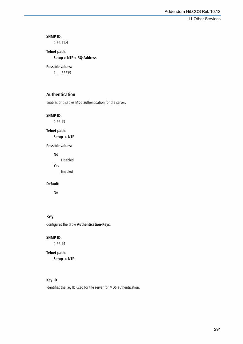
SNMP ID:
2.26.11.4
Telnet path:
Setup > NTP > RQ-Address
Possible values:
1 … 65535
Authentication
Enables or disables MD5 authentication for the server.
SNMP ID:
2.26.13
Telnet path:
Setup > NTP
Possible values:
No
Disabled
Yes
Enabled
Default:
No
Key
Configures the table Authentication-Keys.
SNMP ID:
2.26.14
Telnet path:
Setup > NTP
Key-ID
Identifies the key ID used for the server for MD5 authentication.
291
Addendum HiLCOS Rel. 10.12
11 Other Services
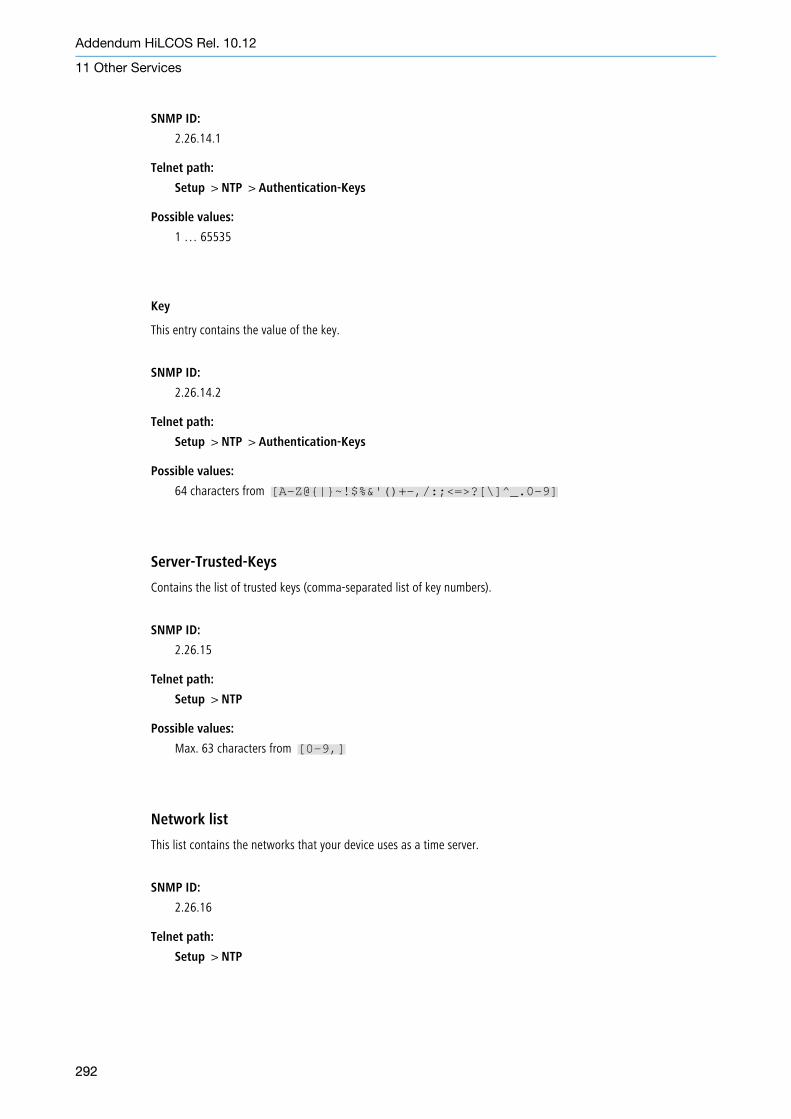
SNMP ID:
2.26.14.1
Telnet path:
Setup > NTP > Authentication-Keys
Possible values:
1 … 65535
Key
This entry contains the value of the key.
SNMP ID:
2.26.14.2
Telnet path:
Setup > NTP > Authentication-Keys
Possible values:
64 characters from [A-Z@{|}~!$%&'()+-,/:;<=>?[\]^_.0-9]
Server-Trusted-Keys
Contains the list of trusted keys (comma-separated list of key numbers).
SNMP ID:
2.26.15
Telnet path:
Setup > NTP
Possible values:
Max. 63 characters from [0-9,]
Network list
This list contains the networks that your device uses as a time server.
SNMP ID:
2.26.16
Telnet path:
Setup > NTP
292
Addendum HiLCOS Rel. 10.12
11 Other Services

Network name
Defines the name of the network on which the NTP server is to be activated.
SNMP ID:
2.26.16.1
Telnet path:
Setup > NTP > Networklist
Possible values:
Entries from Setup/TCP-IP/Networklist: Characters from [A-Z][a-z][0-9]#@{|}~!$%&'()*+-,/:;<=>?[\]^_. `
Server-Operating
Defines whether the NTP server is enabled on the selected network.
SNMP ID:
2.26.16.2
Telnet path:
Setup > NTP > Networklist
Possible values:
No
Disabled
Yes
Enabled
Default:
No
Server-WAN-Access
Configures WAN access to your device.
SNMP ID:
2.26.17
Telnet path:
Setup > NTP
293
Addendum HiLCOS Rel. 10.12
11 Other Services

Possible values:
No
Disables access to the NTP server from the WAN.
Yes
Access from the WAN to the NTP server is possible via unmasked connections, but is in principle notpossible with masked connections.
VPN
VPN access to the NTP server is enabled.
294
Addendum HiLCOS Rel. 10.12
11 Other Services
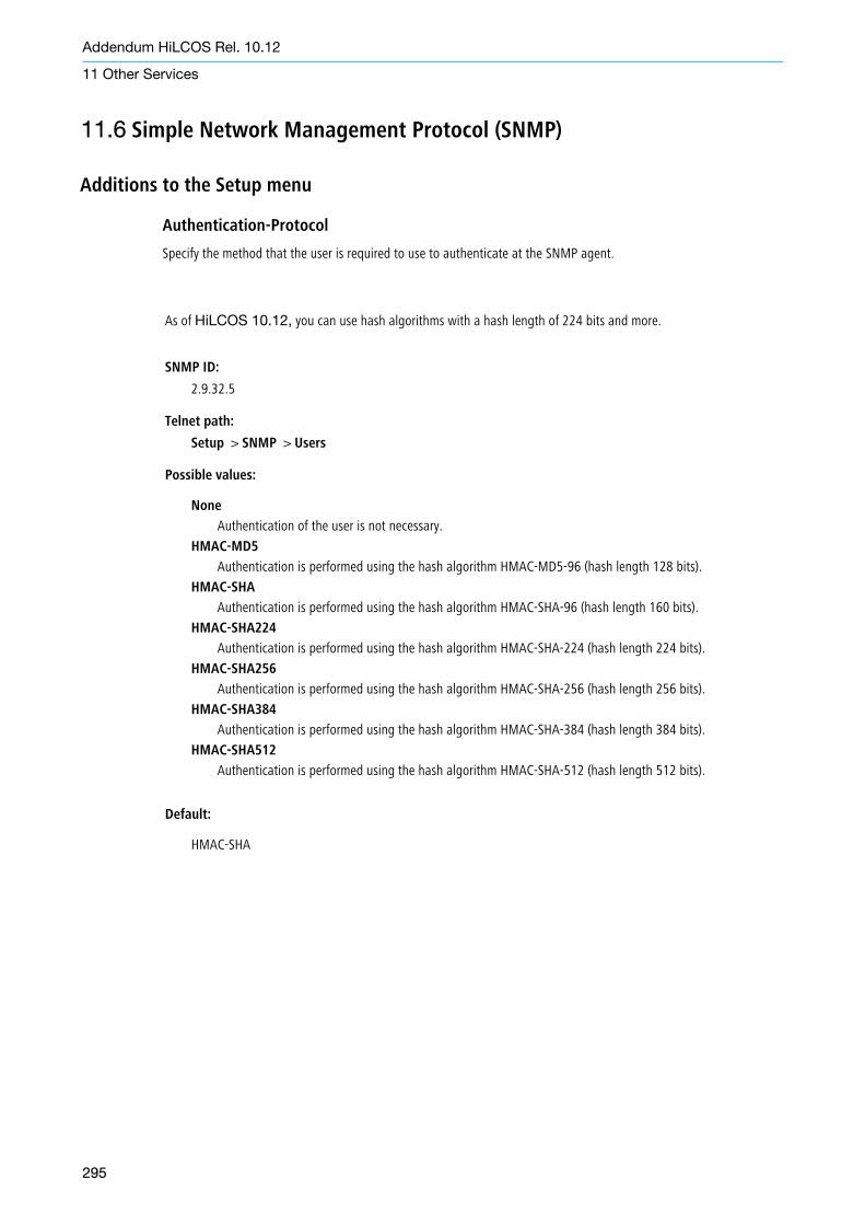
As of HiLCOS 10.12, you can use hash algorithms with a hash length of 224 bits and more.
SNMP ID:
2.9.32.5
Telnet path:
Setup > SNMP > Users
Possible values:
None
Authentication of the user is not necessary.
HMAC-MD5
Authentication is performed using the hash algorithm HMAC-MD5-96 (hash length 128 bits).
HMAC-SHA
Authentication is performed using the hash algorithm HMAC-SHA-96 (hash length 160 bits).
HMAC-SHA224
Authentication is performed using the hash algorithm HMAC-SHA-224 (hash length 224 bits).
HMAC-SHA256
Authentication is performed using the hash algorithm HMAC-SHA-256 (hash length 256 bits).
HMAC-SHA384
Authentication is performed using the hash algorithm HMAC-SHA-384 (hash length 384 bits).
HMAC-SHA512
Authentication is performed using the hash algorithm HMAC-SHA-512 (hash length 512 bits).
Default:
HMAC-SHA
295
Addendum HiLCOS Rel. 10.12
11 Other Services
11.6 Simple Network Management Protocol (SNMP)
Additions to the Setup menu
Authentication-Protocol
Specify the method that the user is required to use to authenticate at the SNMP agent.

Addendum HiLCOS Release 10.12-RU7 02/2021
Technical support https://hirschmann-support.belden.com
Addendum HiLCOS Rel. 10.12-RU7
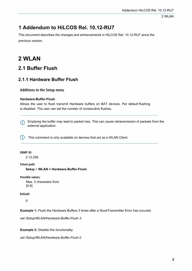
2 WLAN2.1 Buffer Flush
2.1.1 Hardware Buffer Flush
Additions to the Setup menu
Hardware-Buffer-FlushAllows the user to flush transmit Hardware buffers on BAT devices. Per default flushing is disabled. The user can set the number of consecutive flushes.
2
Addendum HiLCOS Rel. 10.12-RU7
2 WLAN
1 Addendum to HiLCOS Rel. 10.12-RU7This document describes the changes and enhancements in HiLCOS Rel. 10.12-RU7 since the
previous version.
SNMP ID:
2.12.256
Telnet path:
Setup > WLAN > Hardware-Buffer-Flush
Default:
0
Possible values:
4Emptying the buffer may lead to packet loss. This can cause retransmission of packets from theexternal application.
4
Max. 3 characters from [0-9]
This command is only available on devices that act as a WLAN Client.
Example 1: Flush the Hardware Buffers 3 times after a StuckTransmitter Error has occured.
set /Setup/WLAN/Hardware-Buffer-Flush 3
Example 2: Disable this functionality.
set /Setup/WLAN/Hardware-Buffer-Flush 0

3
Addendum HiLCOS Rel. 10.12-RU7
2 WLAN
2.1.2 Software Buffer Flush
Additions to the Setup menu
Software-Buffer-FlushAllows the user to flush transmit Software buffers on BAT devices. Per default flushing is disabled. The user can set the duration that a flush shall take in milliseconds.
SNMP ID:
2.12.257
Telnet path:
Setup > WLAN > Software-Buffer-Flush
Default:
0
Possible values:
4Emptying the buffer may lead to packet loss. This can cause retransmission of packets from theexternal application.
4
Max. 10 characters from [0-9]Unit is in milliseconds (ms)
Flushing of software buffers is only active if flushing of hardware buffers is active.
4 This command is only available on devices which act as WLAN client.
Example 1: Flush the Software Buffers for a duration of 2000 milliseconds after a StuckTransmitter Error has occured.
set /Setup/WLAN/Software-Buffer-Flush 2000
Example 2: Disable this functionality.
set /Setup/WLAN/Software-Buffer-Flush 0

2.2 Clients Disassociation Threshold
Additions to the Setup menu
Clients-Disassociation-ThresholdA hanging rate adaption leads to a permanent communication interruption between an Access Point and 1 or more Clients. This command allows the user to automatically disassociate all Clients if the rate adaption on the Access Point hangs.
4
Addendum HiLCOS Rel. 10.12-RU7
2 WLAN
4 This command takes effect only on an 11 ac Access Point.
WARNINGNON-FUNCTIONAL WIRELESS NETWORK
Using this command with wrong settings can lead to a non-functional wireless network. Therefore test the setting for this command before using it in production.
Failure to follow this instruction can result in death, serious injury, or equipment damage.
SNMP ID:
2.12.258
Telnet path:
Setup > WLAN > Clients-Disassociation-Threshold
Default:
0
Possible values:
Max. 10 characters from [0-9]Unit is packets per second (pps)
5
Addendum HiLCOS Rel. 10.12-RU7
2 WLAN
Example 2: Disable this functionality.
set /Setup/WLAN/Clients-Disassociation-Threshold 0
How to find the best setting for this commandYou find the best setting for this command doing the following steps in an iterative manner:
1) Find out maximum packets per second sent from Access Point to a Client.2) Set the maximum packets per second from 1) with this command.3) Test the sensitivity of the threshold and adjust it. The sensitivity depends on the sum of packets per secondand the amount of Clients connected to the Access Point because this is the load for the Access Point.
Example 1: The Access Point sends 20 packets per seconds to a Client (20 pps = maximum pps in our example). So let's set 20 as threshold:
set /Setup/WLAN/Clients-Disassociation-Threshold 20
What does this mean? It means that the Access Point sends 20 packets per second to the Client. If the Client does not respond to those packets with an acknowledge message, the Access Point will disassociate all Clients to resolve the hang of the rate adaption on the Access Point.
If the threshold is not sensitive enough, the threshold has to be reduced.If the threshold is too sensitive, the threshold has to be increased.
2.3 Tx Timeouts
Additions to the Setup menu
Tx-TimeoutsToo many Tx Timeouts lead to a permanent communication interruption between an Access Point and 1 or more Clients. This command allows the user to set a threshold after which the WLAN module is reset.
6
Addendum HiLCOS Rel. 10.12-RU7
2 WLAN
4 This command takes effect only on 11 ac devices.
WARNINGNON-FUNCTIONAL WIRELESS NETWORK
Using this command with wrong settings can lead to a non-functional wireless network. Therefore test the setting for this command before using it in production.
Failure to follow this instruction can result in death, serious injury, or equipment damage.
SNMP ID:
2.12.259
Telnet path:
Setup > WLAN > Tx-Timeouts
Default:
0
Possible values:
Max. 10 characters from [0-9]

7
Addendum HiLCOS Rel. 10.12-RU7
2 WLAN
Example 1: The device accepts 20 Tx Timeouts. So let's set 20 as threshold:
set /Setup/WLAN/Tx-Timeouts 20
What does this mean? It means that the WLAN module is reset if there are more than 20 Tx Timeouts.
If the threshold is not sensitive enough, the threshold has to be reduced.If the threshold is too sensitive, the threshold has to be increased.
Example 2: Disable this functionality.
set /Setup/WLAN/Tx-Timeouts 0

Addendum HiLCOS Rel. 10.32
Addendum HiLCOS Release 10.32
Technical support https://hirschmann-support.belden.com

2 Configuration
2.1 Configuration software
2.1.1 Automatic redirection of WEBconfig access to HTTPS
Additions to the Setup menu
Automatic-Redirect-to-HTTPS
This switch determines whether the WEBconfig login dialog receiving an unencrypted connection request automaticallyswitches to an encrypted HTTPS connection. This is always switched on in new configurations. Existing configurationswill not be changed.
2
Addendum HiLCOS Rel. 10.32
2 Configuration
1 Addendum to HiLCOS Rel. 10.32This document describes the changes and enhancements in HiLCOS Rel. 10.32 since the previous
version.
SNMP ID:
2.21.24
Telnet path:
Setup > HTTP
Possible values:
No
WEBconfig does not automatically switch to an encrypted connection upon receiving an unencryptedconnection request.
Yes
WEBconfig automatically switches to an encrypted connection upon receiving an unencrypted connectionrequest.
Default:
Yes
2.1.2 WEBconfig with TLS 1.3As of HiLCOS 10.32 your device supports TLS 1.3 for accessing WEBconfig. TLS 1.3 represents the latest advancement of the TLS standard and offers, for example, the exclusive use of state-of-the-art cipher suites and Perfect Forward Secrecy to provide improved security compared to previous versions.
5 An HiLCOS update automatically supplements the configuration with TLS 1.3 support for WEBconfig. If necessary,remove older methods that should no longer be available for WEBconfig.
Additions to the Setup menu
Versions
This bitmask specifies which versions of the protocol are allowed.
SNMP ID:
2.21.40.3
Telnet path:
Setup > HTTP > SSL
Possible values:
SSLv3TLSv1TLSv1.1TLSv1.2TLSv1.3
Default:
TLSv1.2
TLSv1.3
3
Addendum HiLCOS Rel. 10.32
2 Configuration

Additions to the Setup menu
Loopback-Addresses
This table allows you to store loopback addresses for each remote site. This means that there is an adjustable senderaddress for DNS forwarding. Each loopback address consists of exactly one remote site and loopback address. The remotesite must also be in the DNS Destinations table. Since only one remote site can be entered per loopback address, twoentries are required here if the DNS Destinations have been configured with two remote sites for one domain.
SNMP ID:
2.17.17
Telnet path:
Setup > DNS
Destination
The remote site as part of a loopback address. This is either an interface name, an IPv4 or IPv6 address. A routing tagcan be added after an @. The remote site must also be in the DNS Destinations table.
SNMP ID:
2.17.17.1
Telnet path:
Setup > DNS > Loopback-Addresses
Possible values:
Max. 39 characters from [A-Z][0-9]@{|}~!$%&'()+-,/:;<=>?[\]^_.
Default:
empty
4
Addendum HiLCOS Rel. 10.32
3 Routing and WAN connections
3 Routing and WAN connections
3.1 Advanced Routing and Forwarding (ARF)
3.1.1 Routing tags for DNS forwarding
Loopback address
The loopback address for a specific remote site. This is either an interface name, an IPv4 or IPv6 address or a knownloopback address.
SNMP ID:
2.17.17.2
Telnet path:
Setup > DNS > Loopback-Addresses
Possible values:
Max. 39 characters from [A-Z][0-9]@{|}~!$%&'()+-,/:;<=>?[\]^_.
Default:
empty
3.2 Locator / ID Separation Protocol (LISP)
5
Addendum HiLCOS Rel. 10.32
3 Routing and WAN connections
Additions to the Setup menu
LISP
Settings for Locator / ID Separation Protocol (LISP).
SNMP ID:
2.93.4
Telnet path:
Setup > Routing-Protocols
Instances
This table contains the global configuration of the LISP instances on the device.

SNMP ID:
2.93.4.1
Telnet path:
Setup > Routing-Protocols > LISP
Name
Specifies a unique name for a LISP instance. This name is referenced in other LISP tables.
SNMP ID:
2.93.4.1.1
Telnet path:
Setup > Routing-Protocols > LISP > Instances
Possible values:
Max. 24 characters from [A-Z][0-9]@{|}~!$%&'()+-,/:;<=>?[\]^_.
Operating
Activates or deactivates this LISP instance.
SNMP ID:
2.93.4.1.2
Telnet path:
Setup > Routing-Protocols > LISP > Instances
Possible values:
NoYes
EID-Rtg-Tag
Routing tag of the endpoint identifier (EID) of this instance.
SNMP ID:
2.93.4.1.3
Telnet path:
Setup > Routing-Protocols > LISP > Instances
Possible values:
Max. 10 characters from [0-9]
6
Addendum HiLCOS Rel. 10.32
3 Routing and WAN connections

RLOC-Rtg-Tag
Routing tag of the routing locator (RLOC) of this instance.
SNMP ID:
2.93.4.1.4
Telnet path:
Setup > Routing-Protocols > LISP > Instances
Possible values:
Max. 10 characters from [0-9]
Instance-ID
LISP instance ID as a numeric tag from RFC 8060 (LISP Canonical Address Format (LCAF)) for the segmentation of networkswith ARF.
SNMP ID:
2.93.4.1.5
Telnet path:
Setup > Routing-Protocols > LISP > Instances
Possible values:
Max. 10 characters from [0-9]
Probing-Method
Specifies the method used to periodically check the accessibility of the RLOCs for map cache entries.
SNMP ID:
2.93.4.1.6
Telnet path:
Setup > Routing-Protocols > LISP > Instances
Possible values:
Off
The availability of the RLOCs is not checked periodically.
RLOC-Probing
The availability of the RLOCs is periodically checked by LISP RLOC messages.
IPv6
Name of the IPv6 WAN profile from the IPv6 WAN interface table. An entry is required if IPv6 EIDs are used.
7
Addendum HiLCOS Rel. 10.32
3 Routing and WAN connections

SNMP ID:
2.93.4.1.8
Telnet path:
Setup > Routing-Protocols > LISP > Instances
Possible values:
Max. 16 characters from [A-Z][0-9]@{|}~!$%&'()+-,/:;<=>?[\]^_.
Default:
600
Admin-Distance
Administrative routing distance.
SNMP ID:
2.93.4.1.9
Telnet path:
Setup > Routing-Protocols > LISP > Instances
Possible values:
Max. 3 characters from [0-9]
Default:
240
EID-Mapping
This table specifies the mapping of EIDs to RLOCs to be registered with the map server.
SNMP ID:
2.93.4.2
Telnet path:
Setup > Routing-Protocols > LISP
Name
References the name of the LISP instance.
SNMP ID:
2.93.4.2.1
8
Addendum HiLCOS Rel. 10.32
3 Routing and WAN connections

Telnet path:
Setup > Routing-Protocols > LISP > EID-Mapping
Possible values:
Max. 24 characters from [A-Z][0-9]@{|}~!$%&'()+-,/:;<=>?[\]^_.
EID-Address-Type
This bitmask specifies the protocol version of the EID prefix when referencing the EID prefix via an interface or networkname.
SNMP ID:
2.93.4.2.2
Telnet path:
Setup > Routing-Protocols > LISP > EID-Mapping
Possible values:
IPv4IPv6
EID-Prefix
EID prefix of the EID mapping. Possible values are an IPv4 network name or an IPv6 interface, e.g. INTRANET, or a namedloopback address.
SNMP ID:
2.93.4.2.3
Telnet path:
Setup > Routing-Protocols > LISP > EID-Mapping
Possible values:
Max. 43 characters from [A-Z][0-9]@{|}~!$%&'()+-,/:;<=>?[\]^_.
Locator-Address-Type
This bitmask specifies the protocol version of the RLOC when referencing the EID prefix via an interface name.
SNMP ID:
2.93.4.2.4
Telnet path:
Setup > Routing-Protocols > LISP > EID-Mapping
9
Addendum HiLCOS Rel. 10.32
3 Routing and WAN connections

Possible values:
IPv4IPv6
Locator
RLOC of the EID mapping. Possible values are named remote sites, IPv6 WAN interfaces, or loopback interfaces.
SNMP ID:
2.93.4.2.5
Telnet path:
Setup > Routing-Protocols > LISP > EID-Mapping
Possible values:
Max. 39 characters from [A-Z][0-9]@{|}~!$%&'()+-,/:;<=>?[\]^_.
Operating
SNMP ID:
2.93.4.2.6
Telnet path:
Setup > Routing-Protocols > LISP > EID-Mapping
Possible values:
NoYes
Priority
The priority of the EID mapping.
SNMP ID:
2.93.4.2.7
Telnet path:
Setup > Routing-Protocols > LISP > EID-Mapping
Possible values:
Max. 3 characters from [0-9]
Default:
1
10
Addendum HiLCOS Rel. 10.32
3 Routing and WAN connections

Weight
The weight of the EID mapping.
SNMP ID:
2.93.4.2.8
Telnet path:
Setup > Routing-Protocols > LISP > EID-Mapping
Possible values:
Max. 3 characters from [0-9]
Default:
100
Comment
Enter a descriptive comment for this entry.
SNMP ID:
2.93.4.2.9
Telnet path:
Setup > Routing-Protocols > LISP > EID-Mapping
Possible values:
Max. 25 characters from [A-Z][0-9]@{|}~!$%&'()+-,/:;<=>?[\]^_.
ITR-Settings
This table specifies the parameters for the role as Ingress Tunnel Router (ITR).
SNMP ID:
2.93.4.3
Telnet path:
Setup > Routing-Protocols > LISP
Name
References the name of the LISP instance.
SNMP ID:
2.93.4.3.1
11
Addendum HiLCOS Rel. 10.32
3 Routing and WAN connections

Telnet path:
Setup > Routing-Protocols > LISP > ITR-Settings
Possible values:
Max. 24 characters from [A-Z][0-9]@{|}~!$%&'()+-,/:;<=>?[\]^_.
Map-Resolver
IPv4 or IPv6 address of the LISP map resolver.
SNMP ID:
2.93.4.3.2
Telnet path:
Setup > Routing-Protocols > LISP > ITR-Settings
Possible values:
Max. 39 characters from [A-F][a-f][0-9]:.
Operating
Activates or deactivates these ITR settings.
SNMP ID:
2.93.4.3.3
Telnet path:
Setup > Routing-Protocols > LISP > ITR-Settings
Possible values:
NoYes
Loopback address
Contains the sender address as the named interface that is used with the map resolver in LISP communication.
SNMP ID:
2.93.4.3.4
Telnet path:
Setup > Routing-Protocols > LISP > ITR-Settings
Possible values:
Max. 16 characters from [A-Z][0-9]@{|}~!$%&'()+-,/:;<=>?[\]^_.
12
Addendum HiLCOS Rel. 10.32
3 Routing and WAN connections
Rtg-Tag
Routing tag used to access the map resolver.
SNMP ID:
2.93.4.3.5
Telnet path:
Setup > Routing-Protocols > LISP > ITR-Settings
Possible values:
Max. 10 characters from [0-9]
Map-Resolver-Retries
Number of retries for map requests to the map resolver.
SNMP ID:
2.93.4.3.6
Telnet path:
Setup > Routing-Protocols > LISP > ITR-Settings
Possible values:
Max. 3 characters from [0-9]
Default:
3
Map-Request-Route-IPv4
Specifies the IPv4 route or prefix for the LISP map requests.
SNMP ID:
2.93.4.3.7
Telnet path:
Setup > Routing-Protocols > LISP > ITR-Settings
Possible values:
Max. 18 characters from [A-F][a-f][0-9]:.
Map-Request-Route-IPv6
Specifies the IPv6 route or prefix for the LISP map requests.
13
Addendum HiLCOS Rel. 10.32
3 Routing and WAN connections
SNMP ID:
2.93.4.3.8
Telnet path:
Setup > Routing-Protocols > LISP > ITR-Settings
Possible values:
Max. 43 characters from [A-F][a-f][0-9]:.
ETR-Settings
This table specifies the parameters for the role as Egress Tunnel Router (ETR).
SNMP ID:
2.93.4.4
Telnet path:
Setup > Routing-Protocols > LISP
Name
References the name of the LISP instance.
SNMP ID:
2.93.4.4.1
Telnet path:
Setup > Routing-Protocols > LISP > ETR-Settings
Possible values:
Max. 24 characters from [A-Z][0-9]@{|}~!$%&'()+-,/:;<=>?[\]^_.
Map-Server
IPv4 or IPv6 address of the LISP map server
SNMP ID:
2.93.4.4.2
Telnet path:
Setup > Routing-Protocols > LISP > ETR-Settings
Possible values:
Max. 39 characters from [A-F][a-f][0-9]:.
14
Addendum HiLCOS Rel. 10.32
3 Routing and WAN connections

Operating
Activates or deactivates these ETR settings.
SNMP ID:
2.93.4.4.3
Telnet path:
Setup > Routing-Protocols > LISP > ETR-Settings
Possible values:
NoYes
Loopback address
Contains the sender address as the named interface that is used with the map server in LISP communication.
SNMP ID:
2.93.4.4.4
Telnet path:
Setup > Routing-Protocols > LISP > ETR-Settings
Possible values:
Max. 16 characters from [A-Z][0-9]@{|}~!$%&'()+-,/:;<=>?[\]^_.
Rtg-Tag
Routing tag to be used to access the map server.
SNMP ID:
2.93.4.4.5
Telnet path:
Setup > Routing-Protocols > LISP > ETR-Settings
Possible values:
Max. 10 characters from [0-9]
Map-Cache-TTL-Minutes
Time-to-live of the EID mappings in minutes registered with the map server.
15
Addendum HiLCOS Rel. 10.32
3 Routing and WAN connections
SNMP ID:
2.93.4.4.6
Telnet path:
Setup > Routing-Protocols > LISP > ETR-Settings
Possible values:
Max. 10 characters from [0-9]
Map-Register-Interval-Seconds
Registration interval in seconds in which map registrations are sent to the map server.
SNMP ID:
2.93.4.4.7
Telnet path:
Setup > Routing-Protocols > LISP > ETR-Settings
Possible values:
Max. 10 characters from [0-9]
Key-Type
Algorithm used for authentication at the map server.
SNMP ID:
2.93.4.4.8
Telnet path:
Setup > Routing-Protocols > LISP > ETR-Settings
Possible values:
NoneHMAC-SHA-1-96HMAC-SHA-256-128
Key
Key or password used to register the EID mapping on the map server.
SNMP ID:
2.93.4.4.9
16
Addendum HiLCOS Rel. 10.32
3 Routing and WAN connections

Telnet path:
Setup > Routing-Protocols > LISP > ETR-Settings
Possible values:
Max. 24 characters from [A-Z][a-z][0-9]#@{|}~!$%&'()*+-,/:;<=>?[\]^_. `
Proxy-Reply
Determines whether the proxy reply bit is set in map registrations. In this case, the map server acts as a proxy andresponds to map requests on behalf of the ETR.
SNMP ID:
2.93.4.4.10
Telnet path:
Setup > Routing-Protocols > LISP > ETR-Settings
Possible values:
NoYes
Map-Server-Backup
IPv4 or IPv6 address of the LISP backup map server. The LISP registration is sent in parallel both to the primary mapserver and to the backup map server.
SNMP ID:
2.93.4.4.11
Telnet path:
Setup > Routing-Protocols > LISP > ETR-Settings
Possible values:
Max. 39 characters from [A-F][a-f][0-9]:.
Operating
This item switches the routing protocol Locator / ID Separation Protocol (LISP) on or off.
SNMP ID:
2.93.4.5
Telnet path:
Setup > Routing-Protocols > LISP
17
Addendum HiLCOS Rel. 10.32
3 Routing and WAN connections

Possible values:
NoYes
Default:
No
Disable-TTL-Propagation
With this switch enabled, the ITR does not copy the Time-To-Live (TTL) from the outer to the inner header. As a result, aclient running traceroute sees the LISP tunnel as a hop. If disabled, traceroute shows all of the hops between ITR andETR.
SNMP ID:
2.93.4.7
Telnet path:
Setup > Routing-Protocols > LISP
Possible values:
NoYes
Default:
No
Map-Cache-Limit
Defines the maximum number of map-cache entries across all LISP instances. After reaching the limit, new entries arerejected. Only after older entries in the map cache have become invalid will new entries be accepted. 0 means there isno restriction.
SNMP ID:
2.93.4.8
Telnet path:
Setup > Routing-Protocols > LISP
Possible values:
Max. 4 characters from [0-9]
Default:
0
18
Addendum HiLCOS Rel. 10.32
3 Routing and WAN connections
Native-Forward
SNMP ID:
2.93.4.9
Telnet path:
Setup > Routing-Protocols > LISP
Name
References the name of the LISP instance.
SNMP ID:
2.93.4.9.1
Telnet path:
Setup > Routing-Protocols > LISP > Native-Forward
Possible values:
Max. 24 characters from [A-Z][0-9]@{|}~!$%&'()+-,/:;<=>?[\]^_.
Type
SNMP ID:
2.93.4.9.3
Telnet path:
Setup > Routing-Protocols > LISP > Native-Forward
Possible values:
NoneProxyXTRInterface
Proxy-XTR
SNMP ID:
2.93.4.9.4
Telnet path:
Setup > Routing-Protocols > LISP > Native-Forward
Possible values:
Max. 43 characters from [A-F][a-f][0-9]:.
19
Addendum HiLCOS Rel. 10.32
3 Routing and WAN connections
Interface
SNMP ID:
2.93.4.9.5
Telnet path:
Setup > Routing-Protocols > LISP > Native-Forward
Possible values:
Max. 16 characters from [A-Z][0-9]@{|}~!$%&'()+-,/:;<=>?[\]^_.
Redistribution
The redistribution of routes allows routes from the routing table to be imported into the LISP map cache. Map requestsare performed for these routes.
Route redistribution also allows routes to be imported from the routing table and dynamically registered to the mapserver as an EID prefix.
SNMP ID:
2.93.4.10
Telnet path:
Setup > Routing-Protocols > LISP
Name
References the name of the LISP instance.
SNMP ID:
2.93.4.10.1
Telnet path:
Setup > Routing-Protocols > LISP > Redistribution
Possible values:
Max. 24 characters from [A-Z][0-9]@{|}~!$%&'()+-,/:;<=>?[\]^_.
Source
This bitmask specifies the route sources of the imported routes.
SNMP ID:
2.93.4.10.2
20
Addendum HiLCOS Rel. 10.32
3 Routing and WAN connections

Telnet path:
Setup > Routing-Protocols > LISP > Redistribution
Possible values:
Connected
From directly connected networks, the device imports information from the routing table into the LISPmap cache or into the EID table as an EID prefix.
Static
The device imports static routes from the routing table into the LISP map cache or into the EID table asan EID prefix.
OSPF
The device imports OSPF routes from the routing table into the LISP map cache or into the EID table asan EID prefix.
BGP
The device imports BGP routes from the routing table into the LISP map cache or into the EID table asan EID prefix.
Destination
Specifies the destination of routes imported to LISP.
SNMP ID:
2.93.4.10.3
Telnet path:
Setup > Routing-Protocols > LISP > Redistribution
Possible values:
Map-Cache
Imports the routes into the map cache. LISP performs map requests for these routes.
Eid-Table
Import the routes into the LISP EID table. These routes are registered with the map server as an EIDprefix with the configured RLOC.
Locator
Specifies the RLOC used to register the imported EID prefixes with the map server. Possible values are named remotesites, IPv6 WAN interfaces, or loopback interfaces.
SNMP ID:
2.93.4.10.4
Telnet path:
Setup > Routing-Protocols > LISP > Redistribution
21
Addendum HiLCOS Rel. 10.32
3 Routing and WAN connections

Possible values:
Max. 39 characters from [A-Z][0-9]@{|}~!$%&'()+-,/:;<=>?[\]^_.
Priority
The priority.
SNMP ID:
2.93.4.10.6
Telnet path:
Setup > Routing-Protocols > LISP > Redistribution
Possible values:
Max. 3 characters from [0-9]
Default:
1
Weight
The weight of the EID mapping.
SNMP ID:
2.93.4.2.8
Telnet path:
Setup > Routing-Protocols > LISP > EID-Mapping
Possible values:
Max. 3 characters from [0-9]
Default:
100
22
Addendum HiLCOS Rel. 10.32
3 Routing and WAN connections

4 The redistribution of RIP routes is only supported for IPv4 routes.
Additions to the Setup menu
Route redistribute
Specifies whether the device forwards certain routes to BGP neighbors of this profile.
4 If no option is selected, the device does not redistribute any routes to the BGP neighbors of this neighbor profile(default setting).
SNMP ID:
2.93.1.4.1.9
23
Addendum HiLCOS Rel. 10.32
3 Routing and WAN connections
3.3 Route redistribution of LISP and RIP routes in BGP
As of HiLCOS 10.32, route redistribution allows LISP and RIP routes be redistributed according to BGP. For this purpose, routes of the corresponding type are read out from the routing table and redistributed by BGP.
Telnet path:
Setup > Routing-Protocols > BGP > Addressfamily > IPv4
Possible values:
Static
The device distributes static routes from the routing table to the BGP neighbors.
Connected
The device redistributes routes from the networks that it is directly connected to to the BGP neighbors.
RIP
The device redistributes RIP routes from the routing table to the BGP neighbors.
OSPF
The device distributes OSPF routes from the routing table to the BGP neighbors.
LISP
The device distributes LISP routes from the routing table to the BGP neighbors.
Route redistribute
Specifies whether the device forwards certain routes to BGP neighbors of this profile.
4 If no option is selected, the device does not redistribute any routes to the BGP neighbors of this neighbor profile(default setting).
SNMP ID:
2.93.1.4.2.9
Telnet path:
Setup > Routing-Protocols > BGP > Addressfamily > IPv6
Possible values:
Static
The device distributes static routes from the routing table to the BGP neighbors.
Connected
The device redistributes routes from the networks that it is directly connected to to the BGP neighbors.
LISP
The device distributes LISP routes from the routing table to the BGP neighbors.

3.4 BGP: Setting administrative distance by policy
Additions to the Setup menu
Set-Admin-Distance
This parameter specifies the “administrative distance” given to prefixes received in the BGP when they are entered intothe routing table. The list of fixed “administrative distances” for the various system services and routing protocols canbe displayed on the CLI by show admin-distance.
SNMP ID:
2.93.1.5.2.1.9
Telnet path:
Setup > Routing-Protocols > BGP > Policy > Overrides > Basic
Possible values:
Max. 3 characters from [0-9]
24
Addendum HiLCOS Rel. 10.32
3 Routing and WAN connections

Additions to the Setup menu
Redistribution-Filter
Name of the prefix filter list from 2.93.5.1 .
SNMP ID:
2.93.1.4.1.11
Telnet path:
Setup > Routing-Protocols > BGP > Addressfamily > IPv4
Possible values:
Max. 16 characters from [A-Z][a-z][0-9]-_
Default:
empty
Default-Action
Defines the default handling of prefixes that are configured in the prefix list.
SNMP ID:
2.93.1.4.1.12
Telnet path:
Setup > Routing-Protocols > BGP > Addressfamily > IPv4
Possible values:
AllowReject
Default:
Allow
Redistribution-Filter
Name of the prefix filter list from 2.93.5.1 .
25
Addendum HiLCOS Rel. 10.32
3 Routing and WAN connections
3.5 Filter list for redistribution in BGP
SNMP ID:
2.93.1.4.2.11
Telnet path:
Setup > Routing-Protocols > BGP > Addressfamily > IPv6
Possible values:
Max. 16 characters from [A-Z][a-z][0-9]-_
Default:
empty
Default-Action
Defines the default handling of prefixes that are configured in the prefix list.
SNMP ID:
2.93.1.4.2.12
Telnet path:
Setup > Routing-Protocols > BGP > Addressfamily > IPv6
Possible values:
AllowReject
Default:
Allow
Filter
Filter lists can be used to allow or reject certain prefixes during redistribution by the BGP.
SNMP ID:
2.93.5
Setup > Routing-Protocols
Prefix-List
Here you specify a prefix list that can be referenced by BGP.
26
Addendum HiLCOS Rel. 10.32
3 Routing and WAN connections
Telnet path:
SNMP ID:
2.93.5.1
Setup > Routing-Protocols > Filter
Name
Contains the name of this entry.
SNMP ID:
2.93.5.1.1
Telnet path:
Setup > Routing-Protocols > Filter > Prefix-List
Possible values:
Max. 16 characters from [A-Z][a-z][0-9]-_
Default:
empty
IP-Address
Contains the IPv4 or IPv6 address of the network.
SNMP ID:
2.93.5.1.2
Telnet path:
Setup > Routing-Protocols > Filter > Prefix-List
Possible values:
Max. 39 characters from [A-F][a-f][0-9]:.
Default:
empty
Prefix-Length
Contains the netmask or prefix length of the network. This entry specifies how many most-significant bits (MSB) of theprefix must match to the IP address. The prefix length must exactly match this value unless Length-min and Length-maxare set to values not equal to zero.
If the value is “0”, the prefix for this rule is a match if it comes from same IP address family as that specified under IPaddress.
27
Addendum HiLCOS Rel. 10.32
3 Routing and WAN connections
Telnet path:

SNMP ID:
2.93.5.1.3
Telnet path:
Setup > Routing-Protocols > Filter > Prefix-List
Possible values:
Max. 3 characters from [0-9]
Default:
empty
Length-Min
Specifies the minimum prefix length value required for the prefix to match.
SNMP ID:
2.93.5.1.4
Telnet path:
Setup > Routing-Protocols > Filter > Prefix-List
Possible values:
Max. 3 characters from [0-9]
Default:
empty
Length-Max
Specifies the maximum prefix length value required for the prefix to match.
SNMP ID:
2.93.5.1.5
Telnet path:
Setup > Routing-Protocols > Filter > Prefix-List
Possible values:
Max. 3 characters from [0-9]
Default:
empty
Comment
Comment on this entry.
28
Addendum HiLCOS Rel. 10.32
3 Routing and WAN connections
SNMP ID:
2.93.5.1.6
Telnet path:
Setup > Routing-Protocols > Filter > Prefix-List
Possible values:
Max. 254 characters from [A-Z][a-z][0-9]#@{|}~!$%&'()+-,/:;<=>?[\]^_.`
Default:
empty
3.6 BGP: Switch for default route propagation
As of Addendum HiLCOS Rel. 10.32 your device has the option to handle default routes like normal routes with BGP.
Additions to the Setup menu
Send-Default-Route
This switch determines the behavior of the propagation of default routes.
SNMP ID:
2.93.1.3.11
Telnet path:
Setup > Routing-Protocols > BGP > Neighbor-Profiles
Possible values:
Yes
In BGP phase 3 (determining routes for redistribution), default routes are treated as normal routes.
No
Default routes are ignored if they are not sourced from the static BGP routes table (2.93.1.6.1 IPv4 or2.93.1.6.2 IPv6).
Default:
No
29
Addendum HiLCOS Rel. 10.32
3 Routing and WAN connections

4 IPv6
Additions to the Setup menu
IPv6
This entry specifies the name of the IPv6 WAN interface. Leaving this entry blank causes IPv6 to be disabled for thisinterface.
SNMP ID:
2.2.2.8
Telnet path:
Setup > WAN > Dialup-Peers
Possible values:
Max. 16 characters from [A-Z][0-9]@{|}~!$%&'()+-,/:;<=>?[\]^_.
Default:
DEFAULT
IPv6
This entry specifies the name of the IPv6 WAN interface. Leaving this entry blank causes IPv6 to be disabled for thisinterface.
SNMP ID:
2.2.19.19
Telnet path:
Setup > WAN > DSL-Broadband-Peers
Possible values:
Max. 16 characters from [A-Z][0-9]@{|}~!$%&'()+-,/:;<=>?[\]^_.
30
Addendum HiLCOS Rel. 10.32
4 IPv6
4.1 IPv6 WAN interface

Default:
DEFAULT
IPv6
This entry specifies the name of the IPv6 WAN interface. Leaving this entry blank causes IPv6 to be disabled for thisinterface.
SNMP ID:
2.2.21.9
Telnet path:
Setup > WAN > PPTP-peers
Possible values:
Max. 16 characters from [A-Z][0-9]@{|}~!$%&'()+-,/:;<=>?[\]^_.
Default:
DEFAULT
IPv6
This entry specifies the name of the IPv6 WAN interface. Leaving this entry blank causes IPv6 to be disabled for thisinterface.
SNMP ID:
2.2.37.5
Telnet path:
Setup > WAN > L2TP-Peers
Possible values:
Max. 16 characters from [A-Z][0-9]@{|}~!$%&'()+-,/:;<=>?[\]^_.
Default:
DEFAULT
IPv6
This entry specifies the name of the IPv6 WAN interface. Leaving this entry blank causes IPv6 to be disabled for thisinterface.
SNMP ID:
2.2.51.11
31
Addendum HiLCOS Rel. 10.32
4 IPv6

Telnet path:
Setup > WAN > GRE-Tunnel
Possible values:
Max. 16 characters from [A-Z][0-9]@{|}~!$%&'()+-,/:;<=>?[\]^_.
Default:
DEFAULT
IPv6
This entry specifies the name of the IPv6 WAN interface. Leaving this entry blank causes IPv6 to be disabled for thisinterface.
SNMP ID:
2.19.9.20
Telnet path:
Setup > VPN > VPN-Peers
Possible values:
Max. 16 characters from [A-Z][0-9]@{|}~!$%&'()+-,/:;<=>?[\]^_.
Default:
DEFAULT
IPv6
This entry specifies the name of the IPv6 WAN interface. Leaving this entry blank causes IPv6 to be disabled for thisinterface.
SNMP ID:
2.19.36.1.21
Telnet path:
Setup > VPN > IKEv2 > Peers
Possible values:
Max. 16 characters from [A-Z][0-9]@{|}~!$%&'()+-,/:;<=>?[\]^_.
Default:
DEFAULT
32
Addendum HiLCOS Rel. 10.32
4 IPv6
Interface name
Give a name to the device IPv6 WAN interface here. This name is specified at the remote site. It is preset with a defaultentry. This is selected automatically if nothing is explicitly specified at the remote site. Leaving this entry blank causesIPv6 to be disabled for this interface.
4 An entry in the WAN interfaces table can be referenced multiple times by remote sites.
SNMP ID:
2.70.7.1
Telnet path:
Setup > IPv6 > WAN-Interfaces
Possible values:
Max. 16 characters from [A-Z][0-9]@{|}~!$%&'()+-,/:;<=>?[\]^_.
Default:
DEFAULT
33
Addendum HiLCOS Rel. 10.32
4 IPv6

Additions to the Setup menu
Identifier
Unique identifier for the DHCPv6 client. The type used for identification is configured by the parameter Identifier type.
Possible formats:
a Specification as a client DUID, e.g. 0003000100a057000001
a Specification as a MAC address, e.g. 00a057000001
a Specification as an interface ID or remote ID, e.g. INTRANET
SNMP ID:
2.70.3.1.6.3
Telnet path:
Setup > IPv6 > DHCPv6 > Server > Reservations
Possible values:
A hex string with max. 127 characters [a-z][0-9]:-
Default:
empty
Identifier-Type
This type specifies how the identifier in 2.70.3.1.6.3 is to be interpreted.
SNMP ID:
2.70.3.1.6.8
Telnet path:
Setup > IPv6 > DHCPv6 > Server > Reservations
Possible values:
Client-ID
The identifier specifies the client DUID, e.g. 0003000100a057000001.
Mac-Address
The identifier specifies a MAC address, e.g. 00a057000001. If the client communicates directly withthe server, the MAC address is taken from the DHCPv6 packet. If relay agents are used, it is taken fromthe client link-layer address option (code 79, RFC 6939) in the relay-forward message from the relayagent that is closest to the client.
Interface-ID
The identifier specifies the interface ID from the interface-ID option (code 18) in the relay-forwardmessage from the relay agent that is closest to the client. This only works with one relay agent.
34
Addendum HiLCOS Rel. 10.32
4 IPv6
4.2 DHCPv6

Remote-ID
The identifier specifies the remote ID from the remote-ID option (code 37, RFC 4649) in the relay-forwardmessage from the relay agent that is closest to the client. This only works with one relay agent.
Comment
Enter a descriptive comment for this entry.
SNMP ID:
2.70.3.1.6.9
Telnet path:
Setup > IPv6 > DHCPv6 > Server > Reservations
Possible values:
Max. 63 characters from [A-Z][a-z][0-9]#@{|}~!$%&'()*+-,/:;<=>?[\]^_. `
Default:
empty
35
Addendum HiLCOS Rel. 10.32
4 IPv6
5 Firewall
36
Addendum HiLCOS Rel. 10.32
5 Firewall
Additions to the Setup menu
DSCP-support
If you set this parameter to Yes, then the DiffServ field in the IPv6-packet header is observed and evaluated as follows:
a CSx (including CS0 = BE): Normal transmission
a AFxx: Secure transmission
a EF: Preferred transmission
5.1 SD-WAN application routing / Layer-7 application control

SNMP ID:
2.70.5.25
Telnet path:
Setup > IPv6 > Firewall
Possible values:
NoYes
Default:
No
Firewall
Firewall settings
SNMP ID:
2.110
Telnet path:
Setup
DNS-Destinations
As of HiLCOS 10.32 DNS names can be used in the firewall. DNS names can be defined in full, e.g. “www.hirschmann.de”, or as a wildcard expression, e.g. “*hirschmann*”. These objects can be used in firewall rules as destinations. Layer-7 (web) applications can be blocked, allowed, limited, prioritized, or redirected to another routing context.Further information and recommendations are available in the Reference Manual under the Firewall section.
SNMP ID:
2.110.1
Setup > Firewall
Name
The name for this DNS destination. This name is used to reference this object.
SNMP ID:
2.110.1.1
37
Addendum HiLCOS Rel. 10.32
5 Firewall
Telnet path:
Telnet path:
Setup > Firewall > DNS-Destinations
Possible values:
Max. 36 characters from [A-Z][0-9]#@{|}~!$%&'()+-,/:;<=>?[\]^_.
Default:
empty
Wildcard-Expressions
Contains a comma-separated or space-separated list of wildcard expressions. The expressions can contain any number of ? (any character) and * (several arbitrary characters), e.g. “*.hirschmann.*”. The input is limited to 252 characters. If you need more DNS wildcard expressions for a service, then you can group multiple DNS destinations into one referenced object in the DNS destinations list.
Unicode characters for internationalized domain names can be entered as follows:
a UTF-8: Here, one to four bytes must be entered individually as '\x' followed by two hexadecimal digits.
a UTF-16: Here, one or two double bytes must be entered as '\u' followed by four hexadecimal digits.
a UTF-32: Here, the value must be entered as '\U' followed by eight hexadecimal digits.
SNMP ID:
2.110.1.2
Telnet path:
Setup > Firewall > DNS-Destinations
Possible values:
Max. 252 characters from [A-Z][a-z][0-9]#@{|}~!$%&'()*+-,/:;<=>?[\]^_. `
Default:
empty
DNS-Destination-List
In the DNS destination list, you can group multiple DNS destinations into one referenced object.
SNMP ID:
2.110.2
Setup > Firewall
Name
The name for this DNS destination list. This name is used to reference this object.
38
Addendum HiLCOS Rel. 10.32
5 Firewall
Telnet path:
SNMP ID:
2.110.2.1
Telnet path:
Setup > Firewall > DNS-Destination-List
Possible values:
Max. 36 characters from [A-Z][0-9]#@{|}~!$%&'()+-,/:;<=>?[\]^_.
Default:
empty
Targets
Contains a comma-separated or space-separated list of names of the DNS destinations.
SNMP ID:
2.110.2.2
Telnet path:
Setup > Firewall > DNS-Destination-List
Possible values:
Max. 252 characters from [A-Z][0-9]#@{|}~!$%&'()+-,/:;<=>?[\]^_.
Default:
empty
39
Addendum HiLCOS Rel. 10.32
5 Firewall

Additions to the Setup menu
WPA-Version
Data in this logical WLAN will be encrypted with this WPA version.
SNMP ID:
2.23.20.3.9
Telnet path:
Setup > Interfaces > WLAN > Encryption
Possible values:
WPA1WPA2WPA1/2WPA2/3WPA3WPA1/2/3
Default:
WPA2
40
Addendum HiLCOS Rel. 10.32
6 Wireless LAN – WLAN
6 Wireless LAN – WLAN
6.1 WPA3 (Wi-Fi Protected Access 3)
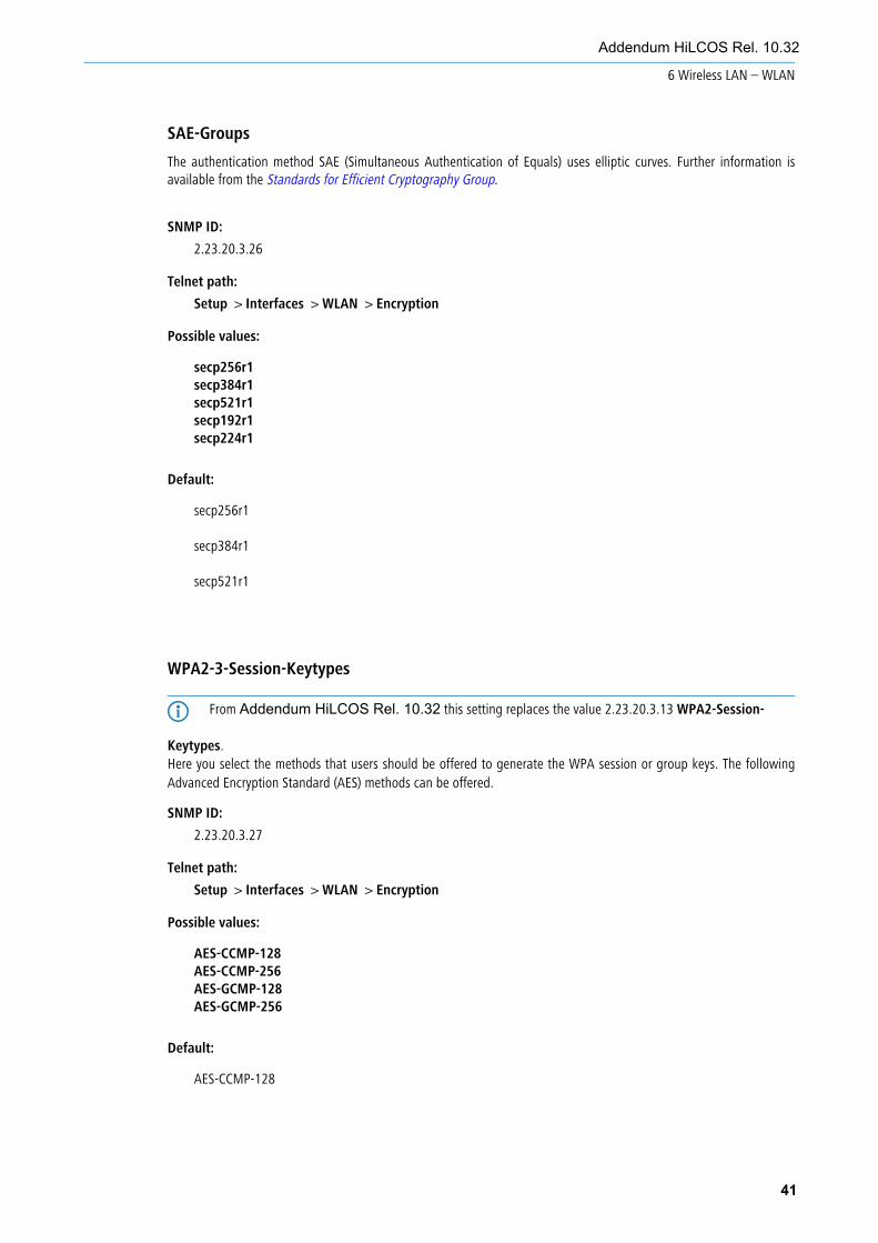
SAE-Groups
The authentication method SAE (Simultaneous Authentication of Equals) uses elliptic curves. Further information isavailable from the Standards for Efficient Cryptography Group.
SNMP ID:
2.23.20.3.26
Telnet path:
Setup > Interfaces > WLAN > Encryption
Possible values:
secp256r1secp384r1secp521r1secp192r1secp224r1
Default:
secp256r1
secp384r1
secp521r1
WPA2-3-Session-Keytypes
4 From Addendum HiLCOS Rel. 10.32 this setting replaces the value 2.23.20.3.13 WPA2-Session-
Keytypes.Here you select the methods that users should be offered to generate the WPA session or group keys. The following Advanced Encryption Standard (AES) methods can be offered.
SNMP ID:
2.23.20.3.27
Telnet path:
Setup > Interfaces > WLAN > Encryption
Possible values:
AES-CCMP-128AES-CCMP-256AES-GCMP-128AES-GCMP-256
Default:
AES-CCMP-128
41
Addendum HiLCOS Rel. 10.32
6 Wireless LAN – WLAN

WPA 802.1X security level
Setting the 802.1X security level. WPA3 features the support of CNSA Suite B cryptography, which is an optional partof WPA3-Enterprise for high-security environments.
4 Operating CNSA Suite B cryptography requires the use of certain cipher suites. Also enforced are a minimum keylength of 3072 bits for the RSA and Diffie-Hellman key exchange, as well as 384 bits for the ECDSA and ECDHEkey exchange. The session key type AES-GCMP128 is also enforced with “Suite B 128 bits”.
5 If these cipher suites are not supported by the WLAN clients or the remaining infrastructure (e.g. the RADIUSserver), then no connection is possible!
SNMP ID:
2.23.20.3.28
Telnet path:
Setup > Interfaces > WLAN > Encryption
Possible values:
DefaultSuite-B 128-bit
Enabled “Suite B 128 bits”. The following EAP cipher suites are enforced:
a TLS_ECDHE_ECDSA_WITH_AES_128_CBC_SHA256
a TLS_ECDHE_ECDSA_WITH_AES_128_GCM_SHA256
a TLS_ECDHE_ECDSA_WITH_AES_256_GCM_SHA384
a TLS_ECDHE_RSA_WITH_AES_256_GCM_SHA384
a TLS_DHE_RSA_WITH_AES_256_GCM_SHA384
Suite-B 128-bit
Enabled “Suite B 192 bits”. The following EAP cipher suites are enforced:
a TLS_ECDHE_ECDSA_WITH_AES_256_GCM_SHA384
a TLS_ECDHE_RSA_WITH_AES_256_GCM_SHA384
a TLS_DHE_RSA_WITH_AES_256_GCM_SHA384
Default:
Default
42
Addendum HiLCOS Rel. 10.32
6 Wireless LAN – WLAN
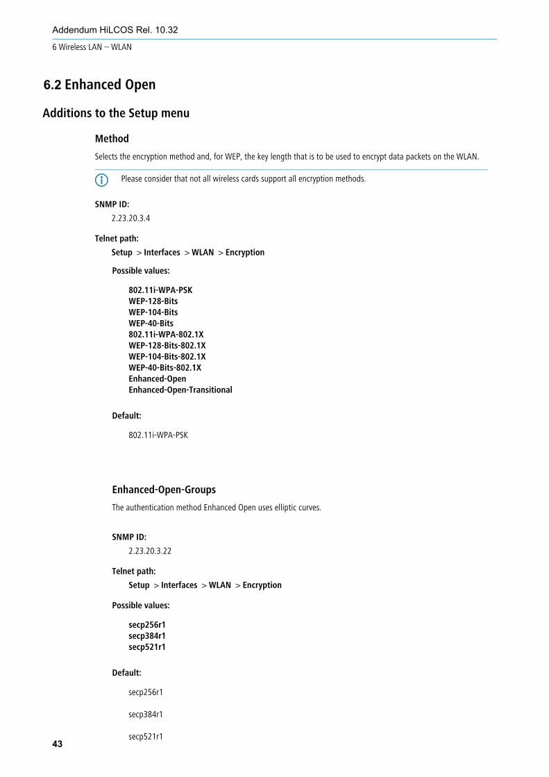
Additions to the Setup menu
Method
Selects the encryption method and, for WEP, the key length that is to be used to encrypt data packets on the WLAN.
4 Please consider that not all wireless cards support all encryption methods.
SNMP ID:
2.23.20.3.4
Telnet path:
Setup > Interfaces > WLAN > Encryption
43
Addendum HiLCOS Rel. 10.32
6 Wireless LAN – WLAN
6.2 Enhanced Open
Possible values:
802.11i-WPA-PSKWEP-128-BitsWEP-104-BitsWEP-40-Bits802.11i-WPA-802.1XWEP-128-Bits-802.1XWEP-104-Bits-802.1XWEP-40-Bits-802.1XEnhanced-OpenEnhanced-Open-Transitional
Default:
802.11i-WPA-PSK
Enhanced-Open-Groups
The authentication method Enhanced Open uses elliptic curves.
SNMP ID:
2.23.20.3.22
Telnet path:
Setup > Interfaces > WLAN > Encryption
Possible values:
secp256r1secp384r1secp521r1
Default:
secp256r1
secp384r1
secp521r1

Additions to the Setup menu
LEPS-U
Enhanced Passphrase Security User (LEPS-U) lets you assign custom passphrases to WLAN stations without having to pre-register stations by their MAC address.
SNMP ID:
2.12.133
Telnet path:
Setup > WLAN
Operating
Switches LEPS-U on or off. When switched off, LEPS-U users are ignored during WLAN client authentication.
SNMP ID:
2.12.133.1
Telnet path:
Setup > WLAN > LEPS-U
44
Addendum HiLCOS Rel. 10.32
6 Wireless LAN – WLAN
6.3 Enhanced Passphrase Security (LEPS)
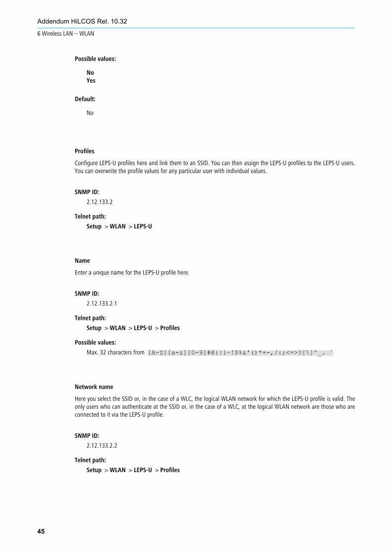
Possible values:
NoYes
Default:
No
Profiles
Configure LEPS-U profiles here and link them to an SSID. You can then assign the LEPS-U profiles to the LEPS-U users.You can overwrite the profile values for any particular user with individual values.
SNMP ID:
2.12.133.2
Telnet path:
Setup > WLAN > LEPS-U
Name
Enter a unique name for the LEPS-U profile here.
SNMP ID:
2.12.133.2.1
Telnet path:
Setup > WLAN > LEPS-U > Profiles
Possible values:
Max. 32 characters from [A-Z][a-z][0-9]#@{|}~!$%&'()*+-,/:;<=>?[\]^_. `
Network name
Here you select the SSID or, in the case of a WLC, the logical WLAN network for which the LEPS-U profile is valid. Theonly users who can authenticate at the SSID or, in the case of a WLC, at the logical WLAN network are those who areconnected to it via the LEPS-U profile.
SNMP ID:
2.12.133.2.2
Telnet path:
Setup > WLAN > LEPS-U > Profiles
45
Addendum HiLCOS Rel. 10.32
6 Wireless LAN – WLAN

Possible values:
Max. 32 characters from [A-Z][a-z][0-9]#@{|}~!$%&'()*+-,/:;<=>?[\]^_. `
Per-Client-Tx-Limit
Here you can set a transmission bandwidth limit in kbps for authenticating WLAN clients.
SNMP ID:
2.12.133.2.3
Telnet path:
Setup > WLAN > LEPS-U > Profiles
Possible values:
Max. 9 characters from [0-9]
Special values:
0
No limit.
Per-Client-Rx-Limit
Here you can set a reception bandwidth limit in kbps for authenticating WLAN clients.
SNMP ID:
2.12.133.2.4
Telnet path:
Setup > WLAN > LEPS-U > Profiles
Possible values:
Max. 9 characters from [0-9]
Special values:
0
No limit.
VLAN-ID
Here you specify which VLAN ID is assigned to a LEPS-U user who is connected to this profile.
SNMP ID:
2.12.133.2.5
Telnet path:
Setup > WLAN > LEPS-U > Profiles
46
Addendum HiLCOS Rel. 10.32
6 Wireless LAN – WLAN
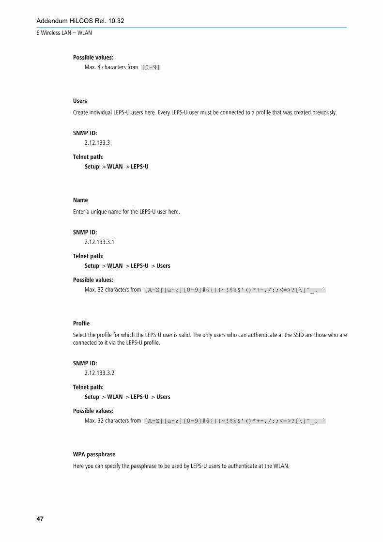
Possible values:
Max. 4 characters from [0-9]
Users
Create individual LEPS-U users here. Every LEPS-U user must be connected to a profile that was created previously.
SNMP ID:
2.12.133.3
Telnet path:
Setup > WLAN > LEPS-U
Name
Enter a unique name for the LEPS-U user here.
SNMP ID:
2.12.133.3.1
Telnet path:
Setup > WLAN > LEPS-U > Users
Possible values:
Max. 32 characters from [A-Z][a-z][0-9]#@{|}~!$%&'()*+-,/:;<=>?[\]^_. `
Profile
Select the profile for which the LEPS-U user is valid. The only users who can authenticate at the SSID are those who areconnected to it via the LEPS-U profile.
SNMP ID:
2.12.133.3.2
Telnet path:
Setup > WLAN > LEPS-U > Users
Possible values:
Max. 32 characters from [A-Z][a-z][0-9]#@{|}~!$%&'()*+-,/:;<=>?[\]^_. `
WPA passphrase
Here you can specify the passphrase to be used by LEPS-U users to authenticate at the WLAN.
47
Addendum HiLCOS Rel. 10.32
6 Wireless LAN – WLAN

SNMP ID:
2.12.133.3.3
Telnet path:
Setup > WLAN > LEPS-U > Users
Possible values:
Max. 63 characters from [A-Z][a-z][0-9]#@{|}~!"$%&'()*+-,/:;<=>?[\]^_. `
Per-Client-Tx-Limit
Here you can set a transmission bandwidth limit in kbps for authenticating WLAN clients. If no limit is configured here,the limitation configured in the LEPS-U profile (if any) applies. If a limit is configured in both the LEPS-U profile and forthe LEPS-U user, the limit configured for the LEPS-U user applies.
SNMP ID:
2.12.133.3.4
Telnet path:
Setup > WLAN > LEPS-U > Users
Possible values:
Max. 9 characters from [0-9]
Special values:
0
No limit.
Per-Client-Rx-Limit
Here you can set a reception bandwidth limit in kbps for authenticating WLAN clients. If no limit is configured here, thelimitation configured in the LEPS-U profile (if any) applies. If a limit is configured in both the LEPS-U profile and for theLEPS-U user, the limit configured for the LEPS-U user applies.
SNMP ID:
2.12.133.3.5
Telnet path:
Setup > WLAN > LEPS-U > Users
Possible values:
Max. 9 characters from [0-9]
Special values:
0
No limit.
48
Addendum HiLCOS Rel. 10.32
6 Wireless LAN – WLAN
VLAN-ID
Here you specify which VLAN ID is assigned to the LEPS-U user. If no VLAN-ID is configured here, the VLAN-ID configuredin the LEPS-U profile (if any) applies. If a VLAN-ID is configured in both the LEPS-U profile and for the LEPS-U user, theVLAN-ID configured for the LEPS-U user applies.
SNMP ID:
2.12.133.3.6
Telnet path:
Setup > WLAN > LEPS-U > Users
Possible values:
Max. 4 characters from [0-9]
LEPS-UEnhanced Passphrase Security User (LEPS-U) lets you assign custom passphrases to WLAN stations without having to
pre-register stations by their MAC address.
SNMP ID:
2.37.1.25
Telnet path:
Setup > WLAN-Management > AP-Configuration
Profiles
Configure LEPS-U profiles here and link them to an SSID. You can then assign the LEPS-U profiles to the LEPS-U users.You can overwrite the profile values for any particular user with individual values.
SNMP ID:
2.37.1.25.1
Telnet path:
Setup > WLAN-Management > AP-Configuration > LEPS-U
Name
Enter a unique name for the LEPS-U profile here.
SNMP ID:
2.37.1.25.1.1
Telnet path:
Setup > WLAN-Management > AP-Configuration > LEPS-U > Profiles
49
Addendum HiLCOS Rel. 10.32
6 Wireless LAN – WLAN

Possible values:
Max. 32 characters from [A-Z][a-z][0-9]#@{|}~!$%&'()*+-,/:;<=>?[\]^_. `
Network profile
Here you select the SSID or, in the case of a WLC, the logical WLAN network for which the LEPS-U profile is valid. Theonly users who can authenticate at the SSID or, in the case of a WLC, at the logical WLAN network are those who areconnected to it via the LEPS-U profile.
SNMP ID:
2.37.1.25.1.2
Telnet path:
Setup > WLAN-Management > AP-Configuration > LEPS-U > Profiles
Possible values:
Max. 32 characters from [A-Z][a-z][0-9]#@{|}~!$%&'()*+-,/:;<=>?[\]^_. `
Per-Client-Tx-Limit
Here you can set a transmission bandwidth limit in kbps for authenticating WLAN clients.
SNMP ID:
2.37.1.25.1.3
Telnet path:
Setup > WLAN-Management > AP-Configuration > LEPS-U > Profiles
Possible values:
Max. 9 characters from [0-9]
Special values:
0
No limit.
Per-Client-Rx-Limit
Here you can set a reception bandwidth limit in kbps for authenticating WLAN clients.
SNMP ID:
2.37.1.25.1.4
Telnet path:
Setup > WLAN-Management > AP-Configuration > LEPS-U > Profiles
50
Addendum HiLCOS Rel. 10.32
6 Wireless LAN – WLAN

Possible values:
Max. 9 characters from [0-9]
Special values:
0
No limit.
VLAN-ID
Here you specify which VLAN ID is assigned to a LEPS-U user who is connected to this profile.
SNMP ID:
2.37.1.25.1.5
Telnet path:
Setup > WLAN-Management > AP-Configuration > LEPS-U > Profiles
Possible values:
Max. 4 characters from [0-9]
Users
Create individual LEPS-U users here. Every LEPS-U user must be connected to a profile that was created previously.
SNMP ID:
2.37.1.25.2
Telnet path:
Setup > WLAN-Management > AP-Configuration > LEPS-U
Name
Enter a unique name for the LEPS-U user here.
SNMP ID:
2.37.1.25.2.1
Telnet path:
Setup > WLAN-Management > AP-Configuration > LEPS-U > Users
Possible values:
Max. 32 characters from [A-Z][a-z][0-9]#@{|}~!$%&'()*+-,/:;<=>?[\]^_. `
51
Addendum HiLCOS Rel. 10.32
6 Wireless LAN – WLAN
Profile
Select the profile for which the LEPS-U user is valid. The only users who can authenticate at the SSID are those who areconnected to it via the LEPS-U profile.
SNMP ID:
2.37.1.25.2.2
Telnet path:
Setup > WLAN-Management > AP-Configuration > LEPS-U > Users
Possible values:
Max. 32 characters from [A-Z][a-z][0-9]#@{|}~!$%&'()*+-,/:;<=>?[\]^_. `
WPA passphrase
Here you can specify the passphrase to be used by LEPS-U users to authenticate at the WLAN.
SNMP ID:
2.37.1.25.2.3
Telnet path:
Setup > WLAN-Management > AP-Configuration > LEPS-U > Users
Possible values:
Max. 63 characters from [A-Z][a-z][0-9]#@{|}~!"$%&'()*+-,/:;<=>?[\]^_. `
Per-Client-Tx-Limit
Here you can set a transmission bandwidth limit in kbps for authenticating WLAN clients. If no limit is configured here,the limitation configured in the LEPS-U profile (if any) applies. If a limit is configured in both the LEPS-U profile and forthe LEPS-U user, the limit configured for the LEPS-U user applies.
SNMP ID:
2.37.1.25.2.4
Telnet path:
Setup > WLAN-Management > AP-Configuration > LEPS-U > Users
Possible values:
Max. 9 characters from [0-9]
Special values:
0
No limit.
52
Addendum HiLCOS Rel. 10.32
6 Wireless LAN – WLAN

Per-Client-Rx-Limit
Here you can set a reception bandwidth limit in kbps for authenticating WLAN clients. If no limit is configured here, thelimitation configured in the LEPS-U profile (if any) applies. If a limit is configured in both the LEPS-U profile and for theLEPS-U user, the limit configured for the LEPS-U user applies.
SNMP ID:
2.37.1.25.2.5
Telnet path:
Setup > WLAN-Management > AP-Configuration > LEPS-U > Users
Possible values:
Max. 9 characters from [0-9]
Special values:
0
No limit.
VLAN-ID
Here you specify which VLAN ID is assigned to the LEPS-U user. If no VLAN-ID is configured here, the VLAN-ID configuredin the LEPS-U profile (if any) applies. If a VLAN-ID is configured in both the LEPS-U profile and for the LEPS-U user, theVLAN-ID configured for the LEPS-U user applies.
SNMP ID:
2.37.1.25.2.6
Telnet path:
Setup > WLAN-Management > AP-Configuration > LEPS-U > Users
Possible values:
Max. 4 characters from [0-9]
53
Addendum HiLCOS Rel. 10.32
6 Wireless LAN – WLAN
Additions to the Setup menu
Band SteeringThis is where you specify the settings for the Client Management and the WLAN Band Steering for WLAN clients registered at the access point.
SNMP ID:
2.12.87
Telnet path:
Setup > WLAN
Operating
This option enables WLAN Band Steering or Client Management in the access point.
SNMP ID:
2.12.87.1
Telnet path:
Setup > WLAN > Band-Steering
Possible values:
Client Management
Enables Client Management in the access point. The percentage settings given below refer to themaximum load of an access point. This is set to 80 clients and cannot be changed.
Radio-Band
Enables WLAN band steering in the access point.
54
Addendum HiLCOS Rel. 10.32
6 Wireless LAN – WLAN
6.4 Client Management
No
Switches this feature off. With this setting, these features are managed by a WLC, for example.
Default:
No
Dry-Run
Client Management performs a test run. The scans are performed, decisions are calculated and logged, but not executed.
SNMP ID:
2.12.87.6
Telnet path:
Setup > WLAN > Band-Steering
Possible values:
NoYes
Default:
No
Load-Recalculation-Interval
Interval in seconds, after which the load of the access point is calculated in Client Management. This results in thedecision as to whether clients should be steered. If yes, then steering also takes place within this interval.
A higher value reduces the network load and has a limited positive effect in very large networks. A lower value leads tofaster client steering. However, you should not go below 2 or above 10 seconds.
SNMP ID:
2.12.87.7
Telnet path:
Setup > WLAN > Band-Steering
Possible values:
Max. 3 characters from [0-9]
Special values:
0
This value disables the delay.
55
Addendum HiLCOS Rel. 10.32
6 Wireless LAN – WLAN
Default:
5
Load-Announcement-Delta
If Client Management detects a change in load that exceeds the specified percentage value, then messages outside ofthe usual interval report this load to the neighboring access points that were discovered by scan. The value should beincreased in environments with many moving devices. The default of 5% (4 clients) is suitable for environments with fewmoving devices, e.g. in offices or classrooms.
SNMP ID:
2.12.87.8
Telnet path:
Setup > WLAN > Band-Steering
Possible values:
Max. 3 characters from [0-9]
Default:
5
Load-Threshold
Percentage load threshold at which Client Management on an access point attempts to steer devices associated with it,irrespective of the load on neighboring access points. Increase the value in difficult environments with poor transmissionquality or a high density of associated devices. In optimal environments with a high transmission quality and highthroughput, such as in offices or classrooms, the load threshold can be reduced. The default of 80% (64 clients) liesbetween these extremes.
SNMP ID:
2.12.87.9
Telnet path:
Setup > WLAN > Band-Steering
Possible values:
Max. 3 characters from [0-9]
Default:
80
Balancing-Difference
Relating to Client Management, this is the percentage difference in load between two neighboring access points, atwhich point the access point with the higher load attempts to steer clients to the access point with a lower load. A highvalue leads to an unbalanced scenario, while a low value leads to more steering attempts. If too many steering attempts
56
Addendum HiLCOS Rel. 10.32
6 Wireless LAN – WLAN
are observed, this value should be increased. If a balanced scenario is a priority, then you have to reduce this value. Thedefault of 10% (8 clients) difference should be suitable an office or classroom environment.
SNMP ID:
2.12.87.10
Telnet path:
Setup > WLAN > Band-Steering
Possible values:
Max. 10 characters from [0-9]
Default:
10
Maximum-Neighbor-Count
Relating to Client Management, this is the number of neighboring access points taken into account for client steeringand for the exchange of information between the access points. High-density environments benefit from a lower value,as clients can be steered to nearby access points with reduced communication between the access points. As a minimumyou should consider 4 access points. The maximum is 72 access points, which is a limitation of the 802.11 protocol.Increasing the value to more than the default value of 20 produces no significant improvements.
SNMP ID:
2.12.87.11
Telnet path:
Setup > WLAN > Band-Steering
Possible values:
Max. 3 characters from [0-9]
Default:
20
Neighbor-Signal-Threshold
Signal strength in dBm at which Client Management classifies an access point as a neighbor. Lower values (-80, -90)are useful for networks that cover a wider area. Higher values (-60, -50) are useful in high-density environments.
SNMP ID:
2.12.87.12
Telnet path:
Setup > WLAN > Band-Steering
Possible values:
Max. 4 characters from -[0-9]
57
Addendum HiLCOS Rel. 10.32
6 Wireless LAN – WLAN

Default:
-70
Legacy-Steering
Normally, Client Management only attempts to steer clients to a different access point that correctly supports the 802.11vprotocol. If you set this parameter to “Yes” then steering is attempted for every client. During a steering event, the clientis denied access to the access point for a period. The intention is to force it to switch to another access point. From theuser's perspective, the WLAN simply appears to be gone for a while.
SNMP ID:
2.12.87.13
Telnet path:
Setup > WLAN > Band-Steering
Possible values:
NoYes
Default:
No
Minimal-Load-Difference
Relating to Client Management, this is the minimum percentage load difference between access points at which clientsteering takes place. Only applies if the load threshold is exceeded. Should not be set to a larger value than“Balancing-Difference” as the calculations could be incorrect. Also, no lower than 2%, otherwise there is a risk that aclient is moved back and forth between two access points.
A low value results in more steering events in high-load environments. This may be useful in environments where theclients are relatively stationary. A high value results in fewer steering events, which is useful in environments with highloads and numerous mobile clients.
SNMP ID:
2.12.87.14
Telnet path:
Setup > WLAN > Band-Steering
Possible values:
Max. 3 characters from [0-9]
Default:
5
58
Addendum HiLCOS Rel. 10.32
6 Wireless LAN – WLAN

Daily-Env-Scan-Hour
Time at which an environment scan is performed when Client Management is enabled. The scan is performed at randomwithin a 30-minute time window to minimize the chance of access points conflicting. A scan takes about 15 secondswith “Scan-Period” in the default setting. The access point is unavailable to clients throughout the scan, so the leastpossible number of clients should be active at the selected time. The default is 3 o'clock in the morning.
SNMP ID:
2.12.87.15
Telnet path:
Setup > WLAN > Band-Steering
Possible values:
0 … 23
Default:
3
Scan-Period
Time in milliseconds that the client-management environment scan searches for other access points on a given channel.This should be 2 to 2.5 times your own beacon interval. The default value works with a common beacon interval. Highervalues are only necessary with higher beacon intervals, although this increases the risk of scan conflicts when the accesspoint is starting or during the nightly scans.
SNMP ID:
2.12.87.16
Telnet path:
Setup > WLAN > Band-Steering
Possible values:
200 … 1000
Default:
400
AP-Steering-RSSI-Threshold
The signal strength in dBm that a client must have on a remote access point in order to be directed to it by ClientManagement.
A higher signal threshold reduces the number of potentially steerable clients, thus limiting the options available to theClient Management. At the same time this would be useful in environments with high quality demands, for examplewhere VoIP is heavily used. This requires very good signal coverage and a higher density of access points.
A lower signal threshold increases the number of potentially steerable clients, although there is a risk that clients couldbe assigned to access points with a poor signal quality. Clients may even refuse to be steered to an access point with apoorer signal quality. This is a help in environments with coverage over a large area. Values below -80 dBm producepoor results, as the likelihood increases that clients cannot connect to the access points they are being steered to.
59
Addendum HiLCOS Rel. 10.32
6 Wireless LAN – WLAN
The default value is ideal for office environments.
SNMP ID:
2.12.87.17
Telnet path:
Setup > WLAN > Band-Steering
Possible values:
Max. 4 characters from -[0-9]
Default:
-75
Remote-Station-Expiration
Time in seconds for which an access point remembers the information about the clients of a neighboring access point.This information is used to speed up the steering decisions made by the Client Management. The default value suitsoffice environments with a relatively static set-up and few moving clients. Set lower values in environments with largernumbers of moving clients or with clients that connect for a short time only. Values that are too high lead to incorrectsteering if the information of the cache no longer applies.
SNMP ID:
2.12.87.18
Telnet path:
Setup > WLAN > Band-Steering
Possible values:
Max. 5 characters from [0-9]
Default:
600
Blacklist-Clients
In many environments, there are certain clients that are known to be unresponsive. Imagine a hospital with custom VoIPphones that are unable to properly handle dropped calls and that tend to stick to a certain access point. To avoid havingto switch off Client Management completely, you can exclude these clients from client steering. Either explicitly or viawildcards. This provides the best user experience for compatible clients without affecting incompatible clients.
SNMP ID:
2.12.87.19
Telnet path:
Setup > WLAN > Band-Steering
60
Addendum HiLCOS Rel. 10.32
6 Wireless LAN – WLAN
MAC address
The MAC addresses of the clients to be excluded from client steering. The wildcard character * can be used, which standsfor any characters. However, this must not be used as the only character of a MAC address. Possible entries are, forexample 01:23:45:12:34:56, 01:*:56 or 01:23:*.
SNMP ID:
2.12.87.19.1
Telnet path:
Setup > WLAN > Band-Steering > Blacklist-Clients
Possible values:
Max. 20 characters from [A-Z][a-z][0-9]#@{|}~!$%&'()*+-,/:;<=>?[\]^_. `
Default:
empty
Start-Environment-Scan
This action manually starts the Client Management environment scan. This can be used if new access points have beenadded and they are not yet visible in the table of neighboring access points. Start the action using doStart-Environment-Scan.
SNMP ID:
2.12.87.20
Telnet path:
Setup > WLAN > Band-Steering
Client Management mode
Client Management operating mode. You can choose either to steer the clients between access points only or to additionallyuse band steering, which optimizes the frequency bands used by each access point.
SNMP ID:
2.12.87.21
Telnet path:
Setup > WLAN > Band-Steering
Possible values:
AP-SteeringAP+Band-Steering
Default:
AP+Band-Steering
61
Addendum HiLCOS Rel. 10.32
6 Wireless LAN – WLAN

Band-Ratio
Ratio of distribution between bands in percent. This is used for the band-steering feature of Client Management.
The ratio indicates how many 5-GHz clients are able to connect to this access point. If more clients are connected at 5GHz, clients are steered to 2.4 GHz. If more clients are connected at 2.4 GHz, clients are steered to 5 GHz.
Decrease the percentage if you are working with a channel width of 20 MHz in the 5-GHz band and your 2.4-GHzspectrum is free, i.e. there are few conflicting SSIDs and few other users such as Bluetooth. Choose a higher ratio if your2.4-GHz band is full.
SNMP ID:
2.12.87.22
Telnet path:
Setup > WLAN > Band-Steering
Possible values:
Max. 3 characters from [0-9]
Default:
75
Band-Steering-RSSI-Threshold
Signal strength in dBm that a client must have on the other band in order for it to be steered. This is used for theband-steering feature of Client Management.
A higher signal threshold reduces the number of potentially steerable clients, thus limiting the options available to theClient Management. At the same time this would be useful in environments with high quality demands, for examplewhere VoIP is heavily used. This requires very good signal coverage and a higher density of access points.
A lower signal threshold increases the number of potentially steerable clients, although there is a risk that clients couldbe assigned to a band with a poor signal quality. Clients may even refuse to be steered to a band with a poorer signalquality. This is a help in environments with coverage over a large area. Values below -80 dBm produce poor results, asthe likelihood increases that clients cannot connect to the band.
The default value is ideal for office environments.
SNMP ID:
2.12.87.23
Telnet path:
Setup > WLAN > Band-Steering
Possible values:
Max. 4 characters from -[0-9]
Default:
-65
62
Addendum HiLCOS Rel. 10.32
6 Wireless LAN – WLAN
Roaming-Targets
With Client Management enabled, the table under /Status/WLAN/Roaming-Targets is filled out automatically.The targets added manually to this table are also included into the list of neighbors by an 802.11k advertisement, evenif they are out of range. The number of automatically added roaming targets is limited by2.12.87.11 Maximum-Neighbor-Count on page 87.
SNMP ID:
2.12.132
Telnet path:
Setup > WLAN
Name
Enter the name for the roaming target here.
SNMP ID:
2.12.132.1
Telnet path:
Setup > WLAN > Roaming-Target
Possible values:
Max. 64 characters from [A-Z][a-z][0-9]@{|}~!$%&'()+-,/:;<=>?[\]^_.`
63
Addendum HiLCOS Rel. 10.32
6 Wireless LAN – WLAN

Additions to the Setup menu
Rx-Packet-Sens.-Reduction
An access point can be set artificially “deaf” by reducing the reception sensitivity. This means that transmissions furtheraway from the access point are “overheard” and the channel is detected more often as “free”. In simplified terms, moresimultaneous transmissions on the same channel are possible. On the one hand, this increases the overall throughputof a system, but on the other hand, the interference on the client side also increases.Because a client does not know anything about the artificial hearing loss, it continues to receive the desired signals fromits access point as well as the signals from other access points on the same channel. Only if the signal-to-noise ratio(SNR) remains good, the the additional transmissions will be received properly by the client thanks to this feature. Anotherside effect of the clients' ignorance is that a value set too high can reverse the effect. Since the access point cannotdistinguish between transmissions from its own clients and from other devices—both access points and clients—onlywhat is above the set threshold is heard—no matter from whom it comes. It may happen that the transmission of aconnected client from the access point is no longer “heard”. This results in an asymmetrical connection, the client maystill receive the access point properly and therefore assumes a good connection, while the access point does not noticeanything from the client anymore and ignores it. It is recommendable to set the reduction so that there is no discriminationagainst clients.
The value range from 0-20 corresponds to a minimum reception strength in the range from -95 dBm (0) to -75 dBm (20).In principle, Wi-Fi radio modules are subject to manufacturing variations. As a result, the real reception strength candeviate slightly.
64
Addendum HiLCOS Rel. 10.32
6 Wireless LAN – WLAN
6.5 Reduction of sensitivity for received packets
5 This feature is for experts! As already mentioned in the description, instead of adding value, it can also have theopposite effect and disrupt transmissions on the access point side. On the one hand, the reduction should beconfigured with a buffer to the usual RSSI values of the clients on the access point side. On the other hand, theretries and Wi-Fi quality indices must be observed. If these deteriorate significantly after increasing this value,this indicates that the value is too high.
SNMP ID:
2.23.20.8.35
Telnet path:
Setup > Interfaces > WLAN > Radio-Settings
Possible values:
0 … 20
Module-1-Rx-Packet-Sens.-Reduction
An access point can be set artificially “deaf” by reducing the reception sensitivity. This means that transmissions furtheraway from the access point are “overheard” and the channel is detected more often as “free”. In simplified terms, moresimultaneous transmissions on the same channel are possible. On the one hand, this increases the overall throughputof a system, but on the other hand, the interference on the client side also increases.
Because a client does not know anything about the artificial hearing loss, it continues to receive the desired signals fromits access point as well as the signals from other access points on the same channel. Only if the signal-to-noise ratio(SNR) remains good, the the additional transmissions will be received properly by the client thanks to this feature. Anotherside effect of the clients' ignorance is that a value set too high can reverse the effect. Since the access point cannotdistinguish between transmissions from its own clients and from other devices—both access points and clients—onlywhat is above the set threshold is heard—no matter from whom it comes. It may happen that the transmission of aconnected client from the access point is no longer “heard”. This results in an asymmetrical connection, the client maystill receive the access point properly and therefore assumes a good connection, while the access point does not noticeanything from the client anymore and ignores it. It is recommendable to set the reduction so that there is no discriminationagainst clients.
The value range from 0-20 corresponds to a minimum reception strength in the range from -95 dBm (0) to -75 dBm (20).In principle, Wi-Fi radio modules are subject to manufacturing variations. As a result, the real reception strength candeviate slightly.
5 This feature is for experts! As already mentioned in the description, instead of adding value, it can also have theopposite effect and disrupt transmissions on the access point side. On the one hand, the reduction should beconfigured with a buffer to the usual RSSI values of the clients on the access point side. On the other hand, theretries and Wi-Fi quality indices must be observed. If these deteriorate significantly after increasing this value,this indicates that the value is too high.
SNMP ID:
2.37.1.4.37
Telnet path:
Setup > WLAN-Management > AP-configuration > Accesspoints
Possible values:
0 … 20
65
Addendum HiLCOS Rel. 10.32
6 Wireless LAN – WLAN
Module-2-Rx-Packet-Sens.-Reduction
An access point can be set artificially “deaf” by reducing the reception sensitivity. This means that transmissions furtheraway from the access point are “overheard” and the channel is detected more often as “free”. In simplified terms, moresimultaneous transmissions on the same channel are possible. On the one hand, this increases the overall throughputof a system, but on the other hand, the interference on the client side also increases.
Because a client does not know anything about the artificial hearing loss, it continues to receive the desired signals fromits access point as well as the signals from other access points on the same channel. Only if the signal-to-noise ratio(SNR) remains good, the the additional transmissions will be received properly by the client thanks to this feature. Anotherside effect of the clients' ignorance is that a value set too high can reverse the effect. Since the access point cannotdistinguish between transmissions from its own clients and from other devices—both access points and clients—onlywhat is above the set threshold is heard—no matter from whom it comes. It may happen that the transmission of aconnected client from the access point is no longer “heard”. This results in an asymmetrical connection, the client maystill receive the access point properly and therefore assumes a good connection, while the access point does not noticeanything from the client anymore and ignores it. It is recommendable to set the reduction so that there is no discriminationagainst clients.
The value range from 0-20 corresponds to a minimum reception strength in the range from -95 dBm (0) to -75 dBm (20).In principle, Wi-Fi radio modules are subject to manufacturing variations. As a result, the real reception strength candeviate slightly.
5 This feature is for experts! As already mentioned in the description, instead of adding value, it can also have theopposite effect and disrupt transmissions on the access point side. On the one hand, the reduction should beconfigured with a buffer to the usual RSSI values of the clients on the access point side. On the other hand, theretries and Wi-Fi quality indices must be observed. If these deteriorate significantly after increasing this value,this indicates that the value is too high.
SNMP ID:
2.37.1.4.38
Telnet path:
Setup > WLAN-Management > AP-configuration > Accesspoints
Possible values:
0 … 20
66
Addendum HiLCOS Rel. 10.32
6 Wireless LAN – WLAN
Additions to the Setup menu
Mail-Address
Information about events in the WLAN is sent to this e-mail address if this is enabled with the 2.12.141 switch.
5 An SMTP account must be set up to make use of the e-mail function.
SNMP ID:
2.12.41
Telnet path:
Setup > WLAN
Possible values:
Max. 254 characters from [A-Z][a-z][0-9]#@{|}~!$%&'()*+-,/:;<=>?[\]^_. `
Default:
empty
Send-Mails
Determines whether notifications about WLAN events are sent to the e-mail address specified in 2.12.41 .
SNMP ID:
2.12.141
Telnet path:
Setup > WLAN
Possible values:
NoYes
Default:
No
67
Addendum HiLCOS Rel. 10.32
6 Wireless LAN – WLAN
6.6 Separate switch to enable e-mail notification
Additions to the Setup menu
Roaming-Targets
With Client Management enabled, the table under /Status/WLAN/Roaming-Targets is filled out automatically.Additionally, any targets added manually to this table are also included in the list of neighbors in an 802.11k advertisement,even if they are out of range. The number of automatically added roaming targets is limited by2.12.87.11 Maximum-Neighbor-Count.
SNMP ID:
2.12.132
Setup > WLAN
Name
As a part of client management, the names of the roaming targets for this access point are entered here after anenvironment scan. This is a part of the standard IEEE 802.11k. This standard describes a way to inform WLAN clientsabout potential roaming targets, i.e. additional access points of the same SSID that are within range. This informationis sent to the WLAN client in the “Neighbor Report” as defined for the standard.
Client management makes these entries automatically. In some cases or in special scenarios, it may be necessary todispense with automatic client management and to use the sub-feature 802.11k separately. In this case, you enter thedevice names of the potential roaming targets here, i.e. other access points of the same SSID.
The device name is used so that further required information about the potential roaming target (e.g. the channel number)can be communicated via IAAP. For this reason it is necessary for the participating access points to communicate withone another via IAPP.
4 Depending on the scenario, it may be desirable for a dual-radio access point to communicate its own, secondWLAN module as a potential roaming target. In this case, the device’s own name can also be entered into thetable.
SNMP ID:
2.12.132.1
Telnet path:
Setup > WLAN > Roaming-Target
68
Addendum HiLCOS Rel. 10.32
6 Wireless LAN – WLAN
Possible values:
Max. 64 characters from [A-Z][a-z][0-9]@{|}~!$%&'()+-,/:;<=>?[\]^_.`
6.7 IEEE 802.11k Roaming Targets
Telnet path:
Additions to the Setup menu
Power-Setting
In versions before HiLCOS 10.32, the current WLAN transmission power could be reduced by a fixed, configured value. This made it possible to adapt the WLAN cell size to the requirements of any particular scenario. This method reaches its limits in the case of a professional WLAN where a value has been set for the actual maximum wireless transmission power and, at the same time, clients should automatically change between the channels of the different 5-GHz subbands. For example, higher transmission powers are permitted in the 5-GHz subband 2 than in subband 1. The fixed reduction in transmission power would be applied to the higher transmission power in subband 2 and also to the lower transmission power permitted in subband 1. This would result in cells of different sizes, depending on the subband selected. As of HiLCOS 10.32, the actual maximum transmission power can be set as an absolute value, which means that the cell size is always the same, irrespective of the maximum permitted transmission power.
4 Under no circumstances will the access point exceed the legal limits for transmission power. These are alwaysrespected automatically, regardless of the settings made here.
SNMP ID:
2.23.20.8.33
Telnet path:
Setup > Interfaces > WLAN > Radio-settings
Possible values:
Automatic
The maximum permitted transmission power that can be realized by the hardware of the access pointis used.
Manual
The desired transmission power is to be set in dBm in the EIRP field.
4 If the hardware of the access point is not capable of the desired transmission power, themaximum possible value is set automatically. The actual value can be checked in LANmonitoror on the CLI by means of the command show wlan.
Default:
Automatic
EIRP
With the setting for WLAN transmission power in 2.23.20.8.33 is set to manual, the value set here is taken in dBm.
69
Addendum HiLCOS Rel. 10.32
6 Wireless LAN – WLAN
6.8 Setting target EIRP

Possible values:
Max. 4 characters from [0-9]-
70
Addendum HiLCOS Rel. 10.32
6 Wireless LAN – WLAN
SNMP ID:
2.23.20.8.34
Telnet path:
Setup > Interfaces > WLAN > Radio-settings
Additions to the Setup menu
Module-1-Ant-Gain-Mode
Until now, access points commissioned with a WLAN controller have been set up with an antenna gain of 3 dBi per module, as this is the most suitable value for most indoor access points equipped with standard antennas. As of HiLCOS 10.32, there is a configuration option, that the standard antenna gain of a managed access point can be transmitted to the WLAN controller and is used there automatically. This feature only works if both the access point and the WLAN controller have at least the firmware version 10.32. This setting for the antenna gain mode prevents you from having to manually correct some of the access points after a rollout.
SNMP ID:
2.37.1.4.35
Telnet path:
Setup > WLAN-Management > AP-Configuration > Accesspoints
71
Addendum HiLCOS Rel. 10.32
7 WLAN management
7 WLAN management
7.1 New mode for antenna gain
Possible values:
Standard
The antenna gain value preset in the access point is used.
User defined
The value for Module-1-Ant-Gain is used.
Default:
Standard
Module-2-Ant-Gain-Mode
Until now, access points commissioned with a WLAN controller have been set up with an antenna gain of 3 dBi per module, as this is the most suitable value for most indoor access points equipped with standard antennas. As of HiLCOS 10.32, there is a configuration option, that the standard antenna gain of a managed access point can be transmitted to the WLAN controller and is used there automatically. This feature only works if both the access point and the WLAN controller have at least the firmware version 10.32. This setting for the antenna gain mode prevents you from having to manually correct some of the access points after a rollout.
SNMP ID:
2.37.1.4.36
Telnet path:
Setup > WLAN-Management > AP-Configuration > Accesspoints
Possible values:
Standard
The antenna gain value preset in the access point is used.
User defined
The value for Module-2-Ant-Gain is used.
Default:
Standard
72
Addendum HiLCOS Rel. 10.32
7 WLAN management
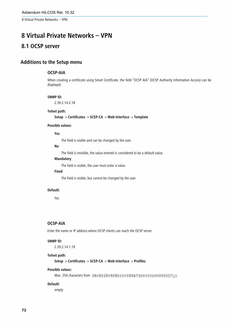
Additions to the Setup menu
73
Addendum HiLCOS Rel. 10.32
8 Virtual Private Networks – VPN
8 Virtual Private Networks – VPN
8.1 OCSP server
OCSP-AIA
When creating a certificate using Smart Certificate, the field “OCSP AIA” (OCSP Authority Information Access) can bedisplayed.
SNMP ID:
2.39.2.14.2.18
Telnet path:
Setup > Certificates > SCEP-CA > Web-Interface > Template
Possible values:
Yes
The field is visible and can be changed by the user.
No
The field is invisible, the value entered is considered to be a default value.
Mandatory
The field is visible, the user must enter a value.
Fixed
The field is visible, but cannot be changed by the user.
Default:
Yes
OCSP-AIA
Enter the name or IP address where OCSP clients can reach the OCSP server.
SNMP ID:
2.39.2.14.1.19
Telnet path:
Setup > Certificates > SCEP-CA > Web-Interface > Profiles
Possible values:
Max. 254 characters from [A-Z][0-9]@{|}~!$%&'()+-/:;<=>?[\]^_.
Default:
empty
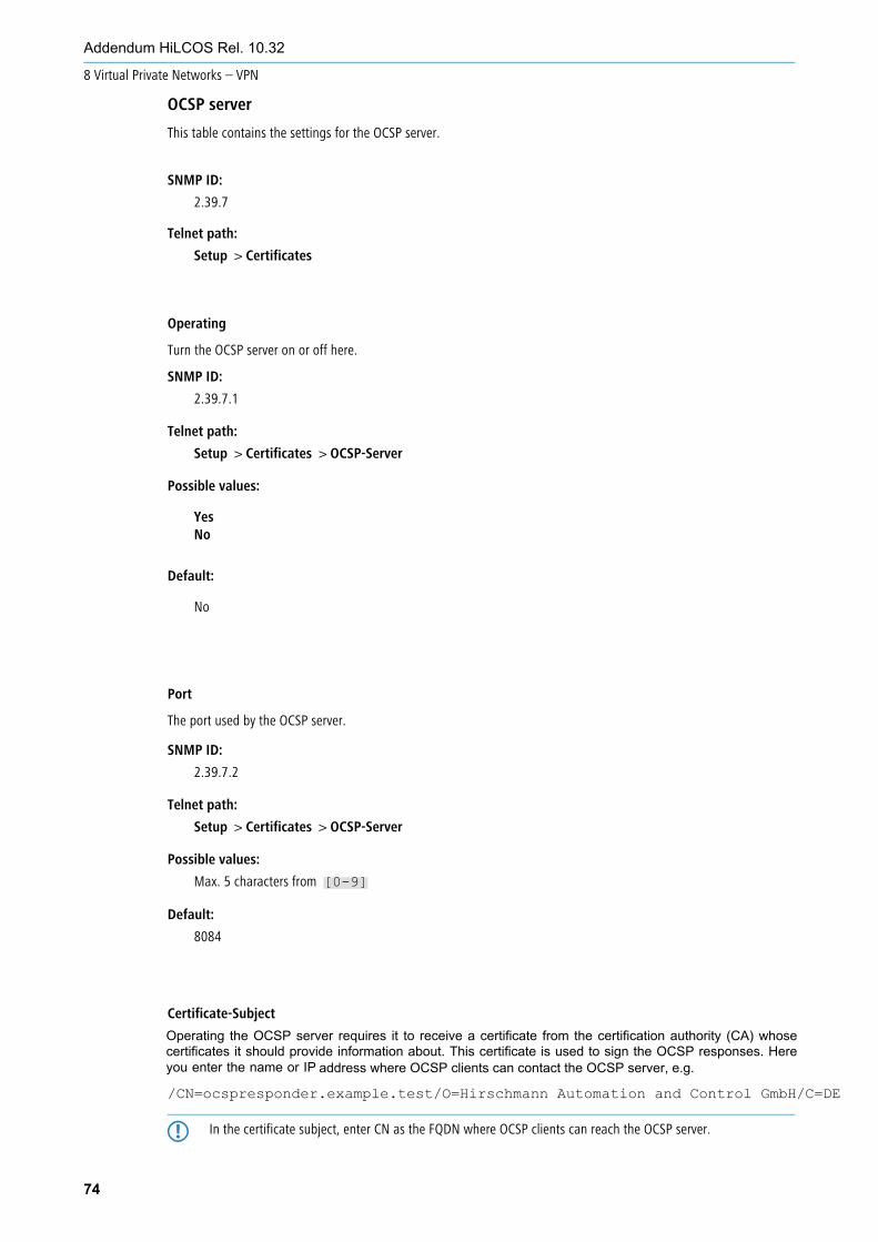
Telnet path:
Setup > Certificates
Operating
Turn the OCSP server on or off here.
SNMP ID:
2.39.7.1
Telnet path:
Setup > Certificates > OCSP-Server
Possible values:
YesNo
Default:
No
Port
The port used by the OCSP server.
SNMP ID:
2.39.7.2
Telnet path:
Setup > Certificates > OCSP-Server
Possible values:
Max. 5 characters from [0-9]
Default:
8084
Certificate-Subject
Operating the OCSP server requires it to receive a certificate from the certification authority (CA) whose certificates it should provide information about. This certificate is used to sign the OCSP responses. Here you enter the name or IP
/CN=ocspresponder.example.test/O=Hirschmann Automation and Control GmbH/C=DE
5 In the certificate subject, enter CN as the FQDN where OCSP clients can reach the OCSP server.
74
Addendum HiLCOS Rel. 10.32
8 Virtual Private Networks – VPN
address where OCSP clients can contact the OCSP server, e.g.
OCSP server
This table contains the settings for the OCSP server.
SNMP ID:
2.39.7
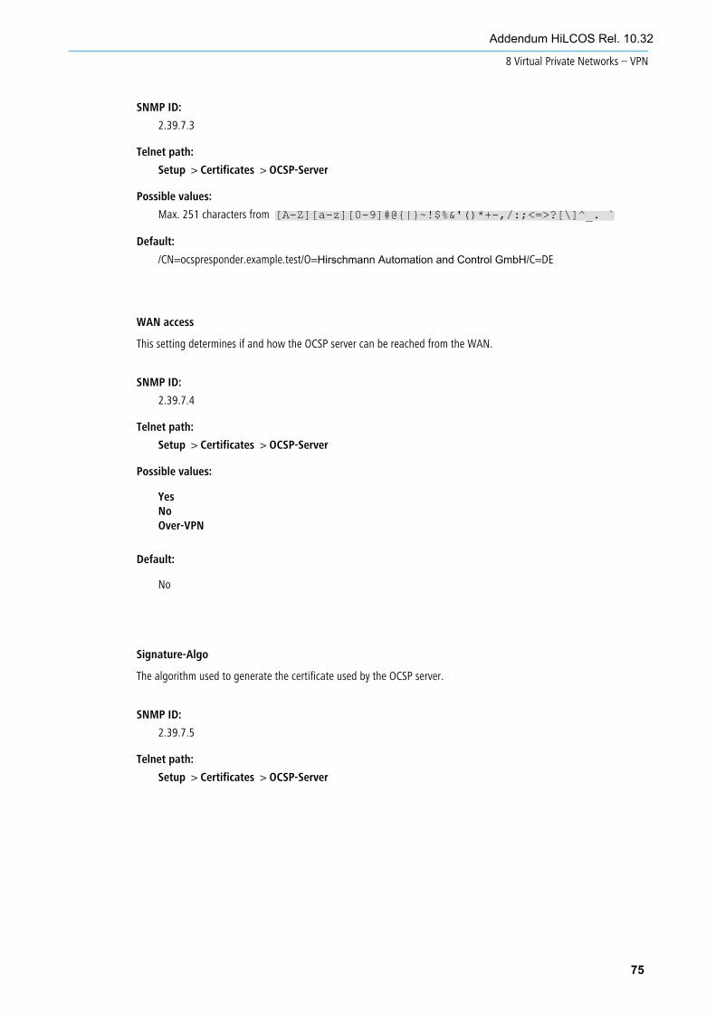
SNMP ID:
2.39.7.3
Telnet path:
Setup > Certificates > OCSP-Server
Possible values:
Max. 251 characters from [A-Z][a-z][0-9]#@{|}~!$%&'()*+-,/:;<=>?[\]^_. `
Default:
/CN=ocspresponder.example.test/O=Hirschmann Automation and Control GmbH/C=DE
WAN access
This setting determines if and how the OCSP server can be reached from the WAN.
SNMP ID:
2.39.7.4
Telnet path:
Setup > Certificates > OCSP-Server
Possible values:
YesNoOver-VPN
Default:
No
Signature-Algo
The algorithm used to generate the certificate used by the OCSP server.
SNMP ID:
2.39.7.5
Telnet path:
Setup > Certificates > OCSP-Server
75
Addendum HiLCOS Rel. 10.32
8 Virtual Private Networks – VPN

Possible values:
SHA1SHA-256SHA-384SHA-512
Default:
SHA-256
76
Addendum HiLCOS Rel. 10.32
8 Virtual Private Networks – VPN

Additions to the Setup menu
Version
The L2TP protocol version used for this L2TP endpoint, either version 2 or 3.
5 Ethernet tunnels are only possible with version 3. In this case, be sure to set the protocol “L2TPv3” here.
SNMP ID:
2.2.35.11
Telnet path:
Setup > WAN > L2TP-Endpoints
Possible values:
L2TPv2
Layer 2 Tunneling Protocol Version 2
L2TPv3
Layer 2 Tunneling Protocol Version 3
77
Addendum HiLCOS Rel. 10.32
8 Virtual Private Networks – VPN
8.2 Layer-3 Ethernet tunnel with Layer-2 Tunneling Protocol version 3 (L2TPv3)
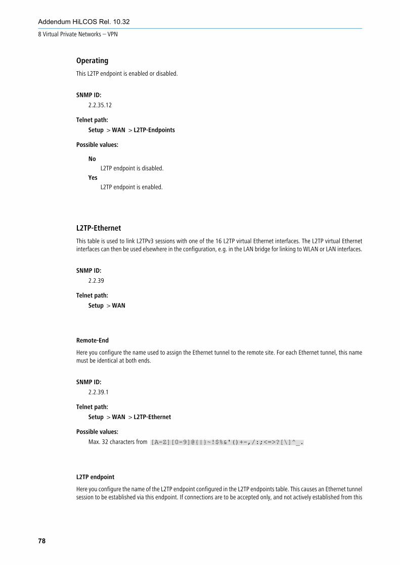
Operating
This L2TP endpoint is enabled or disabled.
SNMP ID:
2.2.35.12
Telnet path:
Setup > WAN > L2TP-Endpoints
Possible values:
No
L2TP endpoint is disabled.
Yes
L2TP endpoint is enabled.
L2TP-Ethernet
This table is used to link L2TPv3 sessions with one of the 16 L2TP virtual Ethernet interfaces. The L2TP virtual Ethernetinterfaces can then be used elsewhere in the configuration, e.g. in the LAN bridge for linking to WLAN or LAN interfaces.
SNMP ID:
2.2.39
Telnet path:
Setup > WAN
Remote-End
Here you configure the name used to assign the Ethernet tunnel to the remote site. For each Ethernet tunnel, this namemust be identical at both ends.
SNMP ID:
2.2.39.1
Telnet path:
Setup > WAN > L2TP-Ethernet
Possible values:
Max. 32 characters from [A-Z][0-9]@{|}~!$%&'()+-,/:;<=>?[\]^_.
L2TP endpoint
Here you configure the name of the L2TP endpoint configured in the L2TP endpoints table. This causes an Ethernet tunnelsession to be established via this endpoint. If connections are to be accepted only, and not actively established from this
78
Addendum HiLCOS Rel. 10.32
8 Virtual Private Networks – VPN
end, leaving this field blank allows any sessions to be accepted. Of course, these still need “to run” via anaccepted/established endpoint from the L2TP endpoints table. This can be useful in scenarios where not every endpointon the receiving side should be configured separately.
SNMP ID:
2.2.39.2
Telnet path:
Setup > WAN > L2TP-Ethernet
Possible values:
Max. 32 characters from [A-Z][0-9]@{|}~!$%&'()+-,/:;<=>?[\]^_.
Interface
The virtual L2TP Ethernet interface to be used for the L2TPv3 session.
SNMP ID:
2.2.39.3
Telnet path:
Setup > WAN > L2TP-Ethernet
Possible values:
L2TP-ETHERNET-1 … L2TP-ETHERNET-16
16 virtual L2TP Ethernet interfaces
79
Addendum HiLCOS Rel. 10.32
8 Virtual Private Networks – VPN
Additions to the Setup menu
Auth-Method
Sets the authentication method for the digital signature.
5 If RSASSA-PKCS1-v1_5 is selected, a check is made to see whether the remote site also supports the superiorRSASSA-PSS method and switches to it if necessary. If RSASSA-PSS is selected, then a fallback to the olderRSASSA-PKCS1-v1_5 is not provided.
SNMP ID:
2.19.36.3.4.2
Telnet path:
Setup > VPN > IKEv2 > Digital-Signature-Profiles
Possible values:
RSASSA-PSSRSASSA-PKCS1-v1_5
Default:
RSASSA-PSS
80
Addendum HiLCOS Rel. 10.32
8 Virtual Private Networks – VPN
8.3 IKEv2
Additions to the Setup menu
Encapsulation
In some scenarios, using the normal VPN port 500 is not an option, such as when firewalls are in the way. You can set the ports 443 or 4500 instead. Use this in combination to configure any Destination-Port. If the setting is different from 500, UDP encapsulation is performed automatically. The configurable port can be used for scenarios where a Hirschmann router already accepts VPN tunnels on the standard ports. A port forwarding rule would allow these ports to be forwarded to any destination.
4 Incoming VPN tunnels continue to be accepted on the default ports 443, 500 and 4500. These cannot be freelyconfigured.
SNMP ID:
2.19.36.4.7
Telnet path:
Setup > VPN > IKEv2 > General
Possible values:
UDP
The IKEv2 tunnel is established either with port 4500 or with the setting for the destination port. If thedestination port is set to 500, this will be ignored and port 4500 is used instead.
SSL
The IKEv2 tunnel is established either with port 443 or with the setting for the destination port. If thedestination port is set to 500 or 4500, this will be ignored and port 443 is used instead.
None
The IKEv2 tunnel is established with port 500. The setting for the destination port is ignored.
Default:
None
Destination-Port
Here you can specify the destination port for the IKEv2 connection depending on the setting in Encapsulation. If thesetting is different from 500, UDP encapsulation is performed automatically.
SNMP ID:
2.19.36.4.8
Telnet path:
Setup > VPN > IKEv2 > General
Possible values:
Max. 5 characters from [0-9]
Default:
0
81
Addendum HiLCOS Rel. 10.32
8 Virtual Private Networks – VPN

SNMP ID:
2.19.36.1.22
Telnet path:
Setup > VPN > IKEv2 > Peers
Possible values:
Max. 16 characters from [A-Z][0-9]@{|}~!$%&'()+-,/:;<=>?[\]^_.
Local-Auth
Sets the authentication method for the local identity.
SNMP ID:
2.19.36.3.1.2
Telnet path:
Setup > VPN > IKEv2 > Auth > Parameter
Possible values:
RSA-Signature
Authentication by RSA signature.
PSK
Authentication by pre-shared key (PSK).
Digital signature
Use of configurable authentication methods with digital certificates as per RFC 7427.
ECDSA-256
Elliptic Curve Digital Signature Algorithm (ECDSA) according to RFC 4754 with SHA-256 on the P-256curve.
ECDSA-384
Elliptic Curve Digital Signature Algorithm (ECDSA) according to RFC 4754 with SHA-384 on the P-384curve.
ECDSA-521
Elliptic Curve Digital Signature Algorithm (ECDSA) according to RFC 4754 with SHA-512 on the P-521curve.
Default:
PSK
Remote-Auth
Sets the authentication method for the remote identity.
SNMP ID:
2.19.36.3.1.6
82
Addendum HiLCOS Rel. 10.32
8 Virtual Private Networks – VPN
Split-DNS-Profile
Name of the Split DNS profile. The split DNS profile is only active if IKE-CFG is set to the value Server.
Telnet path:
Setup > VPN > IKEv2 > Auth > Parameter
Possible values:
RSA-Signature
Authentication by RSA signature.
PSK
Authentication by pre-shared key (PSK).
Digital signature
Use of configurable authentication methods with digital certificates as per RFC 7427.
ECDSA-256
Elliptic Curve Digital Signature Algorithm (ECDSA) according to RFC 4754 with SHA-256 on the P-256curve.
ECDSA-384
Elliptic Curve Digital Signature Algorithm (ECDSA) according to RFC 4754 with SHA-384 on the P-384curve.
ECDSA-521
Elliptic Curve Digital Signature Algorithm (ECDSA) according to RFC 4754 with SHA-512 on the P-521curve.
Default:
PSK
Remote-Auth
Sets the authentication method for the remote identity.
SNMP ID:
2.19.36.3.3.2
Telnet path:
Setup > VPN > IKEv2 > Auth > Addit.-Remote-IDs
Possible values:
RSA-Signature
Authentication by RSA signature.
PSK
Authentication by pre-shared key (PSK).
Digital signature
Use of configurable authentication methods with digital certificates as per RFC 7427.
ECDSA-256
Elliptic Curve Digital Signature Algorithm (ECDSA) according to RFC 4754 with SHA-256 on the P-256curve.
83
Addendum HiLCOS Rel. 10.32
8 Virtual Private Networks – VPN
ECDSA-384
Elliptic Curve Digital Signature Algorithm (ECDSA) according to RFC 4754 with SHA-384 on the P-384curve.
ECDSA-521
Elliptic Curve Digital Signature Algorithm (ECDSA) according to RFC 4754 with SHA-512 on the P-521curve.
Default:
PSK
PD-Source
With this parameter you can assign addresses to the VPN clients from the prefix that the router retrieved from the WANinterface via DHCPv6 prefix delegation. Select the desired WAN interface here. For example, if the provider assigned theprefix “2001:db8::/64”, you can then set the parameter “First address” to the value “::1” in the “Last address” to “::9”.In combination with the prefix “2001:db8::/64” as delegated by the provider, the clients receive addresses from the pool“2001:db8::1” to “2001:db8::9”. If the provider prefix is greater than “/64”, e.g.,“/48” or “/56”, you must take subnettingfor the logical network into account in the address.
Example:
a Assigned provider prefix: 2001:db8:abcd:aa::/56
a /64 as the prefix of the logical network (subnet ID 1): 2001:db8:abcd:aa01::/64
a First address: 0:0:0:0001::1
a Last address: 0:0:0:0001::9
SNMP ID:
2.19.36.7.2.6
Telnet path:
Setup > VPN > IKEv2 > IKE-CFG > IPv6
Possible values:
Max. 16 characters from [A-Z][0-9]@{|}~!$%&'()+-,/:;<=>?[\]^_.
Default:
empty
Split-DNS
With VPN split tunneling, only those applications that are supposed to reach endpoints behind the VPN tunnel are sentthrough the VPN tunnel. All other traffic is sent directly to the Internet and not through the VPN tunnel. The IP networkswhich should be accessible through the tunnel are defined by VPN rules.
Split DNS allows DNS to resolve specific internal domains (e.g. “*.company.com”) to a VPN tunnel, while other DNSrequests are sent to a public DNS server. When establishing a connection, the IKE Config Mode server dynamically assignsone or more split-DNS domains to the client by means of the attribute INTERNAL_DNS_DOMAIN. The client enters thereceived domain list into its local DNS forwarding list. The client must support this attribute.
84
Addendum HiLCOS Rel. 10.32
8 Virtual Private Networks – VPN
Split DNS for IKEv2 is supported by Hirschmann VPN routers in the role IKE Config Mode client and server. For site-to-site VPN connections, dynamic split-DNS assignment is not supported by the IKE protocol. Instead, the appropriate VPN endpoints have to be configured by means of static DNS forwarding.
SNMP ID:
2.19.36.7.3
Telnet path:
Setup > VPN > IKEv2 > IKE-CFG
Domain-Lists
Here you specify the domain lists for split DNS.
SNMP ID:
2.19.36.7.3.1
Telnet path:
Setup > VPN > IKEv2 > IKE-CFG > Split-DNS
Domain-name
Split-DNS domain name that the VPN gateway should send to VPN clients, e.g. “company.internal”. Multiple domainnames can be configured by multiple entries with the same identifier from the domain list.
SNMP ID:
2.19.36.7.3.1.1
Telnet path:
Setup > VPN > IKEv2 > IKE-CFG > Split-DNS > Domain-Lists
Possible values:
Max. 64 characters from [A-Z][0-9]@{|}~!$%&'()+-,/:;<=>?[\]^_.
Default:
empty
Domain-List
Enter a name for the domain lists.
SNMP ID:
2.19.36.7.3.1.3
Telnet path:
Setup > VPN > IKEv2 > IKE-CFG > Split-DNS > Domain-Lists
85
Addendum HiLCOS Rel. 10.32
8 Virtual Private Networks – VPN
Possible values:
Max. 16 characters from [A-Z][0-9]@{|}~!$%&'()+-,/:;<=>?[\]^_.
Default:
empty
Profiles
Here you set the profiles for split DNS.
SNMP ID:
2.19.36.7.3.4
Telnet path:
Setup > VPN > IKEv2 > IKE-CFG > Split-DNS
Name
Enter a name for this profile.
SNMP ID:
2.19.36.7.3.4.1
Telnet path:
Setup > VPN > IKEv2 > IKE-CFG > Split-DNS > Profiles
Possible values:
Max. 16 characters from [A-Z][0-9]@{|}~!$%&'()+-,/:;<=>?[\]^_.
Default:
empty
Send-DNS-Forwardings
Here you set whether the VPN gateway should send its locally configured DNS forwardings to VPN clients.
SNMP ID:
2.19.36.7.3.4.2
Telnet path:
Setup > VPN > IKEv2 > IKE-CFG > Split-DNS > Profiles
86
Addendum HiLCOS Rel. 10.32
8 Virtual Private Networks – VPN

Possible values:
NoYes
Default:
No
Send-local-Domain
Set whether the VPN gateway should send its own locally configured domain to VPN clients.
SNMP ID:
2.19.36.7.3.4.3
Telnet path:
Setup > VPN > IKEv2 > IKE-CFG > Split-DNS > Profiles
Possible values:
NoYes
Default:
No
Domain-List
Name of the list of split-DNS domains that the VPN gateway should send to VPN clients.
SNMP ID:
2.19.36.7.3.4.4
Telnet path:
Setup > VPN > IKEv2 > IKE-CFG > Split-DNS > Profiles
Possible values:
Max. 16 characters from [A-Z][0-9]@{|}~!$%&'()+-,/:;<=>?[\]^_.
Default:
empty
87
Addendum HiLCOS Rel. 10.32
8 Virtual Private Networks – VPN
Cookie-Challenge
IKEv2 offers cookie notification, a challenge-response procedure that the IKEv2 responder can trigger if it has too manyhalf-open IKEv2 connections. This makes the responder more resistant to DDoS attacks.
Cookie notification has been implemented to improve the compatibility with third-party VPN-enabled devices. It mustbe enabled on both VPN participants in order for a VPN connection to be established.
The IKEv2 cookie notification prevents the establishment of excessive numbers of half-open VPN connections and theattack on VPN-gateway resources (DDOS) that they cause. With cookie notification enabled, the responder only reactsto incoming VPN connections if the remote site is verified as reachable.
Enabling the IKEv2 cookie challenge adds two additional IKE messages to the VPN connection setup.
The switch activates the Cookie Challenge on the responder or gateway side.
On the initiator side, the cookie challenge is done automatically if the other side requests it. The switch has no effect onthe initiator side or on the client side.
Please note that both initiator and responder must support the cookie challenge feature. If the remote site does not support cookie challenge, the VPN tunnel cannot be established. Hirschmann VPN routers at both ends must have at least HiLCOS 10.32.
SNMP ID:
2.19.36.12
Telnet path:
Setup > VPN > IKEv2
Possible values:
OffAlways
Default:
Off
Enforce-Pre-Shared-Key-Rules
This entry gives you the option to disable or enable the enforcing of password rules. The following rules then apply forPre-Shared Keys (PSK) with IKEv2:
a The length of the password must be at least 32 characters.
a The password must contain at least 3 of the 4 character classes lower case letters, upper case letters, numbers andspecial characters.
4 These rules do not apply to PSK managed and obtained by a RADIUS server.
SNMP ID:
2.19.36.14
Telnet path:
Setup > VPN > IKEv2
88
Addendum HiLCOS Rel. 10.32
8 Virtual Private Networks – VPN
Possible values:
No
Password rules enforcement is disabled.
Yes
Password rules enforcement is enabled.
Default:
No
RSA-Padding-Method
Specifies the RSA padding method for certificates issued by the SCEP-CA.
SNMP ID:
2.39.2.15
Telnet path:
Setup > Certificates > SCEP-CA
Possible values:
PKCS1
Certificate padding is performed with the RSASSA-PKCS1-v1_5 method.
PSS
Certificate padding is performed with the RSASSA-PSS method
Default:
PKCS1
89
Addendum HiLCOS Rel. 10.32
8 Virtual Private Networks – VPN

9 RADIUS9.1 User-defined attributes for RADIUS users in the RADIUS server
Additions to the Setup menu
Attribute-Values
User-defined attributes for RADIUS users in the RADIUS server.
Along with the user-management attributes supported by the Hirschmann RADIUS server, there is a vast
array of vendor-specific attributes (VSAs). These attributes can be freely configured for RADIUS users here.
SNMP ID:
2.25.10.7.25
Telnet path:
Setup > RADIUS > Server > Users
90
Addendum HiLCOS Rel. 10.32
9 RADIUS
Possible values:
Comma-separated list of attributes and values in the form<Attribute_1>=<Value_1>,<Attribute_2>=<Value_2> ...
Max. 251 characters from [A-Z][a-z][0-9]#@{|}~!"$%&'()*+-,/:;<=>?[\]^_. `
Default:
empty
10 Other services
10.1 Automatic IP address administration with DHCP
10.1.1 Configuring DHCPv4 parameters with LANconfig
Additions to the Setup menu
Loopback address
Here you assign a loopback address to a relay agent. The loopback address (the name of an ARF network, named loopbackaddress) is used to forward client messages.
SNMP ID:
2.10.20.22
91
Addendum HiLCOS Rel. 10.32
10 Other services
Telnet path:
Setup > DHCP
Possible values:
Max. 16 characters from [A-Z][a-z][0-9]#@{|}~!$%&'()*+-,/:;<=>?[\]^_. `
Default:
empty
DHCP options
Additions to the Setup menu
Sub-option number
Number of the sub-option that should be sent to the DHCP client. A DHCP option is made up of sub-options. For example,network devices such as SIP phones are often notified about where their firmware and configuration can be downloadedby means of DHCP option 43. The sub-option settings are defined by the respective manufacturer.
SNMP ID:
2.10.26.5
Telnet path:
Setup > DHCP > Additional-Options
Possible values:
Max. 3 characters from [0-9]
Default:
empty
Vendor-class mask
When sending requests to DHCP servers, some DHCP clients submit a vendor-class ID and/or a user-class ID. These usually allow the client to be clearly assigned to a manufacturer or even a specific device class. For example, DHCP requests from Hirschmann devices always contain the string “Hirschmann” in the vendor-class ID, which is supplemented by the exact device type, if required. The DHCP server can use this information to provide the best suited DHCP options for the given device type. This is especially relevant for DHCP option 43, as its content is not standardized, but vendor-specific—the DHCP server has to transmit different information depending on the manufacturer or device type. The two fields “Vendor-class mask” and “User-class mask” can be used as filters. Strings that the DHCP server requires to be present in incoming requests can be entered here. The DHCP option is only delivered when the configured filter matches the DHCP request. The wildcards “*” (any number of characters) and “?” (exactly one character) can be used. If the fields are empty, they are ignored and the option is always delivered.
SNMP ID:
2.10.26.6
Telnet path:
Setup > DHCP > Additional-Options
Possible values:
Max. 32 characters from [A-Z][a-z][0-9]#@{|}~!$%&'()*+-,/:;<=>?[\]^_. `
Default:
empty
User class mask
When sending requests to DHCP servers, some DHCP clients submit a vendor-class ID and/or a user-class ID. This usuallyallows the manufacturer or even the specific device class of the client to be identified. The DHCP server can use thisinformation to provide the best suited DHCP options for the given device type. This is especially relevant for DHCP option43, as its content is not standardized, but vendor-specific—the DHCP server has to transmit different informationdepending on the manufacturer or device type. The two fields “Vendor-class mask” and “User-class mask” can be usedas filters. Strings that the DHCP server requires to be present in incoming requests can be entered here. The DHCP optionis only delivered when the configured filter matches the DHCP request. The wildcards “*” (any number of characters)and “?” (exactly one character) can be used. If the fields are empty, they are ignored and the option is always delivered.
SNMP ID:
2.10.26.7
92
Addendum HiLCOS Rel. 10.32
10 Other services

Telnet path:
Setup > DHCP > Additional-Options
Possible values:
Max. 32 characters from [A-Z][a-z][0-9]#@{|}~!$%&'()*+-,/:;<=>?[\]^_. `
Default:
empty
Assigning IP addresses based on DHCP option 82
93
Addendum HiLCOS Rel. 10.32
10 Other services
Additions to the Setup menu
Relay-Info-List
DHCP option 82 assigns IP addresses depending on the switch port to which the device is connected. To this end, theswitches provide the “Circuit ID” of the respective ports. Each port is then assigned exactly one IP address, host nameand a boot image. The latter works analogous to the BOOTP table.
SNMP ID:
2.10.27
Telnet path:
Setup > DHCP
Circuit-ID
SNMP ID:
2.10.27.1
Telnet path:
Setup > DHCP > Relay-Info-List
Possible values:
Max. 64 characters from [A-F][a-f]x[0-9]{}/

IP address
Enter the IP address assigned to the host on this port. Do not leave this column unspecified (0.0.0.0). Otherwise onlyone host per circuit ID would be able to authenticate. As long as there is an entry in the DHCP table, any DHCP messagesfrom other hosts using the same circuit ID would be ignored. In other words, if you want to operate another host on theport, the previous one must either log off correctly (e.g. under Microsoft Windows: ipconfig/release) or theentry must be deleted from the DHCP table.
SNMP ID:
2.10.27.2
Telnet path:
Setup > DHCP > Relay-Info-List
Host name
Enter the name that is to be used to identify the station. If the station does not communicate its name, the device willuse the name entered here.
SNMP ID:
2.10.27.3
Telnet path:
Setup > DHCP > Relay-Info-List
Possible values:
Max. 64 characters from [A-Z][a-z][0-9]#@{|}~!$%&'()*+-,/:;<=>?[\]^_. `
Default:
empty
Image-alias
If the client uses the BOOTP protocol, you can select a boot image that the client should use to load its operating systemfrom.
4 Enter the server providing the boot image and the name of the file on the server in the boot image table.
94
Addendum HiLCOS Rel. 10.32
10 Other services

SNMP ID:
2.10.27.4
Telnet path:
Setup > DHCP > Relay-Info-List
Possible values:
Max. 16 characters from [A-Z][a-z][0-9]#@{|}~!$%&'()*+-,/:;<=>?[\]^_. `
Default:
empty
95
Addendum HiLCOS Rel. 10.32
10 Other services
10.2 DHCP server – suppress ARP request
As of HiLCOS Rel. 10.32 your device supports the option to suppress the ARP request that usually precedes the assignment of an IP address.
Additions to the Setup menu
Suppress-ARP-check
Before the DHCP server assigns an IP address, an ARP request is usually used to check whether the address has beenassigned already. If there is no response to the ARP request within 3 seconds, the assignment goes ahead. This queryis especially useful when computers are booting in normal networks that use fixed IP addresses. In a Public Spot networkwhere, for example, a smartphone has to recognize that there is no Internet connection in order to display the loginpopup, this ARP request leads to an unnecessary delay. For scenarios such as this, this check can be disabled here.
SNMP ID:
2.10.20.23
Telnet path:
Setup > DHCP > Network-List
Possible values:
Yes
Do not carry out check by ARP request.
No
Perform check by ARP request.
Default:
No
96
Addendum HiLCOS Rel. 10.32
10 Other services
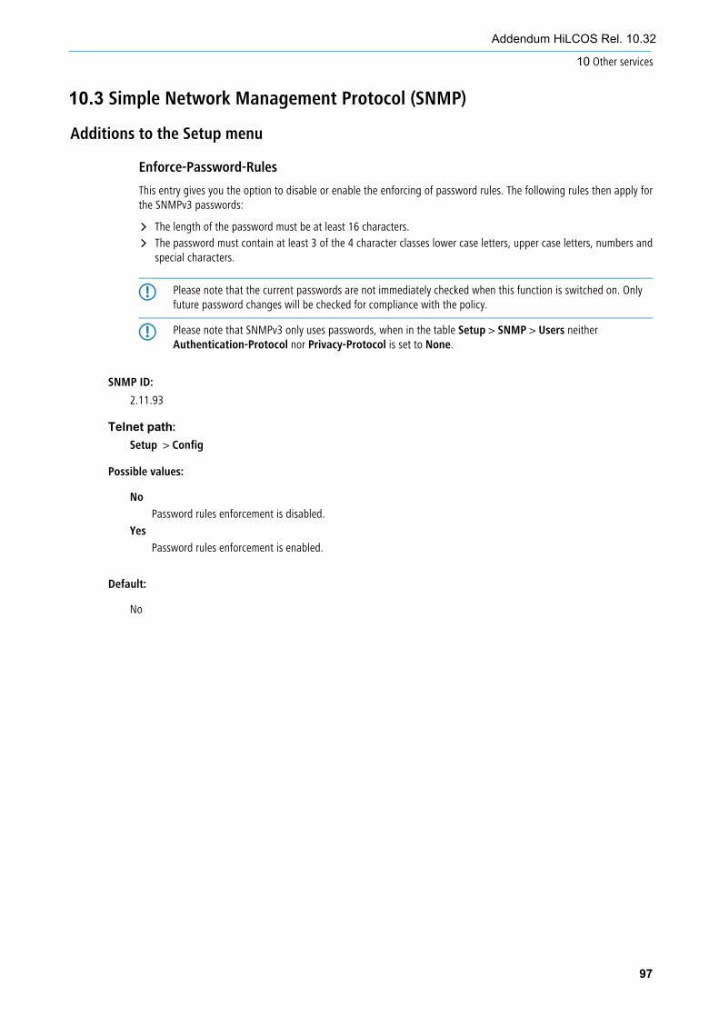
10.3 Simple Network Management Protocol (SNMP)
Additions to the Setup menu
Enforce-Password-Rules
This entry gives you the option to disable or enable the enforcing of password rules. The following rules then apply forthe SNMPv3 passwords:
a The length of the password must be at least 16 characters.
a The password must contain at least 3 of the 4 character classes lower case letters, upper case letters, numbers andspecial characters.
5 Please note that the current passwords are not immediately checked when this function is switched on. Onlyfuture password changes will be checked for compliance with the policy.
5 Please note that SNMPv3 only uses passwords, when in the table Setup > SNMP > Users neitherAuthentication-Protocol nor Privacy-Protocol is set to None.
97
Addendum HiLCOS Rel. 10.32
10 Other services
SNMP ID:
2.11.93
Telnet path:
Setup > Config
Possible values:
No
Password rules enforcement is disabled.
Yes
Password rules enforcement is enabled.
Default:
No

10.4 TACACS+
11.4.1 Configuring the TACACS+ server
Additions to the Setup menu
Server-address
DNS name, or IPv4 or IPv6 address of the TACACS+ server to which requests for authentication, authorization andaccounting are to be forwarded.
SNMP ID:
2.54.9.1
98
Addendum HiLCOS Rel. 10.32
10 Other services
Telnet path:
Setup > Tacacs+ > Server
Possible values:
Max. 31 characters from [A-Z][a-z][0-9]#@{|}~!$%&'()*+-,/:;<=>?[\]^_. `
Default:
empty

11 Quality of Service
11.1 Configurable DSCP tags for internal Hirschmann services
Additions to the Setup menu
DSCP marking
Internal HiLCOS applications can be marked with configurable DiffServ CodePoints (DSCP). This allows downstream hardware to recognize and prioritize these packets. Further information about DiffServ CodePoints is available in the Reference Manual under the section Quality of Service.
4 This configuration marks only the control messages of the respective protocols.
SNMP ID:
2.11.94
Telnet path:
Setup > Config
Application
Column with the internal applications.
SNMP ID:
2.11.94.1
Telnet path:
Setup > Config > DSCP-Marking
DSCP
Column with the DiffServ codepoints. Default values are listed for the possible internal applications.
SNMP ID:
2.11.94.2
99
Addendum HiLCOS Rel. 10.32
11 Quality of Service
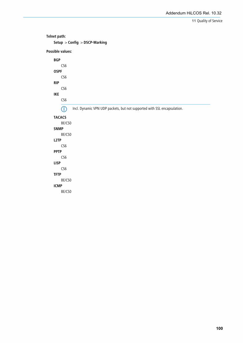
Telnet path:
Setup > Config > DSCP-Marking
Possible values:
BGP
CS6
OSPF
CS6
RIP
CS6
IKE
CS6
4 Incl. Dynamic VPN UDP packets, but not supported with SSL encapsulation.
TACACS
BE/CS0
SNMP
BE/CS0
L2TP
CS6
PPTP
CS6
LISP
CS6
TFTP
BE/CS0
ICMP
BE/CS0
100
Addendum HiLCOS Rel. 10.32
11 Quality of Service

Addendum HiLCOS Rel. 10.34
Addendum HiLCOS Release 10.34
Technical support https://hirschmann-support.belden.com

2
Addendum HiLCOS Rel. 10.34 1 Voice over IP – VoIP
Addendum to HiLCOS Rel. 10.34This document describes the changes and enhancements in HiLCOS Rel. 10.34 since the previous release.
1 Voice over IP – VoIP
1.1 Dynamic SIP lines
Additions to the Setup menu
Dynamic line
Configure the dynamic SIP lines here.
SNMP ID:
2.33.4.1.
Setup > Voice-Call-Manager > Line > SIP-Provider
Dynamic line name
Enter the name for the dynamic line here. If the dynamic line consists of several physical lines, you can also use thisdynamic line name for other table entries. This dynamic line name can later be used in the call routing table as thedestination line.
SNMP ID:
2.33.4.1.3.1
Telnet path:
Setup > Voice-Call-Manager > Lines > SIP-Provider > Dynamic-Line
Possible values:
Max. 32 characters from [A-Z][0-9]@{|}~!$%&'()+-,/:;<=>?[]^_.
SIP line name
Here you specify one of the already configured physical SIP connections.
SNMP ID:
2.33.4.1.3.2
Telnet path:
Setup > Voice-Call-Manager > Lines > SIP-Provider > Dynamic-Line
Possible values:
Max. 32 characters from [A-Z][0-9]@{|}~!$%&'()+-,/:;<=>?[]^_.
Telnet path:

3
1 Voice over IP – VoIP
Addendum HiLCOS Rel. 10.34
Priority
Here you specify the priority of the physical line for consideration when outgoing calls are distributed.
SNMP ID:
2.33.4.1.3.3
Telnet path:
Setup > Voice-Call-Manager > Lines > SIP-Provider > Dynamic-Line
Possible values:
Max. 3 characters from [0-9]
Weight
Here you specify the weighting of the physical line for consideration when outgoing calls are distributed.
SNMP ID:
2.33.4.1.3.4
Telnet path:
Setup > Voice-Call-Manager > Lines > SIP-Provider > Dynamic-Line
Possible values:
Max. 3 characters from [0-9]
Algorithm
The algorithm must be configured identically for all entries that belong to a dynamic line.
SNMP ID:
2.33.4.1.3.5
Telnet path:
Setup > Voice-Call-Manager > Lines > SIP-Provider > Dynamic-Line
Possible values:
Weight
This algorithm controls the percentage of calls being distributed between different physical lines.
Round-Robin
With this algorithm, outgoing calls are distributed sequentially to the physical lines.
Priority
The physical line with the highest priority is fully utilized first, before the physical line with the next-lowestpriority is used.

4
Addendum HiLCOS Rel. 10.34
1 Voice over IP – VoIP
Max. calls
Here you enter how many simultaneous voice channels can be used on the physical SIP line. For no restriction on thenumber of voice channels, enter 0 here.
SNMP ID:
2.33.4.1.3.6
Telnet path:
Setup > Voice-Call-Manager > Lines > SIP-Provider > Dynamic-Line
Possible values:
Max. 3 characters from [0-9]
Mode
Flex
a To the outside the line behaves like a commercially available SIP account with a single public number.

5
1 Voice over IP – VoIPAddendum HiLCOS Rel. 10.34
Additions to the Setup menuMode
This selection specifies the operating mode of the SIP line.
5 The "Service provider" can be a server in the Internet, an IP PBX, or a voice gateway. Please observe the noticesabout "SIP mapping".
SNMP ID:
2.33.4.1.1.17
Telnet path:
Setup > Voice-Call-Manager > Lines > SIP-Provider > Line
Possible values:
Provider
Externally, the line behaves like a typical SIP account with a single public number. The number isregistered with the service provider, the registration is refreshed at regular intervals (if (re-)registrationhas been activated for this SIP provider line). For outgoing calls, the calling-line number is replaced(masked) by the registered number. Incoming calls are sent to the configured internal destinationnumber. Only one connection can exist at a time.
Trunk
Externally, the line acts like an extended SIP account with a main external telephone number andmultiple extension numbers. The SIP ID is registered as the main switchboard number with the serviceprovider and the registration is refreshed at regular intervals (if (re-)registration has been activated forthis SIP provider line). For outgoing calls, the switchboard number acts as a prefix placed in front ofeach calling number (sender; SIP: “From:”). For incoming calls, the prefix is removed from the destinationnumber (SIP: “To:”). The remaining digits are used as the internal extension number. In case of error(prefix not found, destination equals prefix) the call is forwarded to the internal destination number asconfigured. The maximum number of connections at any one time is limited only by the availablebandwidth.
Gateway
Externally the line behaves like a typical SIP account with a single public number, the SIP ID. The number(SIP ID) is registered with the service provider and the registration is refreshed at regular intervals (if(re-)registration has been activated for this SIP provider line). For outgoing calls, the calling-line number(sender) is replaced (masked) by the registered number (SIP ID in SIP: “From:”) and sent in a separatefield (SIP: “Contact:”). For incoming calls the dialed number (destination) is not modified. The maximumnumber of connections at any one time is limited only by the available bandwidth.
Link
Externally, the line behaves like a typical SIP account with a single public number (SIP ID). The numberis registered with the service provider, the registration is refreshed at regular intervals (if (re-)registrationhas been activated for this SIP provider line). For outgoing calls, the calling-line number (sender; SIP:
1.2 Flex mode
"From:") is not modified. For incoming calls, the dialed number (destination; SIP: "To:") is not modified.The maximum number of connections at any one time is limited only by the available bandwidth.
Flex
a To the outside the line behaves like a commercially available SIP account with a single public number.
a The number is registered at the service provider and registration is refreshed on a regular basis.
a For outgoing calls, the calling-line number (sender) is not modified.
a For incoming calls the dialed number (destination) is not modified.
a The maximum number of connections at any one time is limited only by the available bandwidth.
Default:
Provider
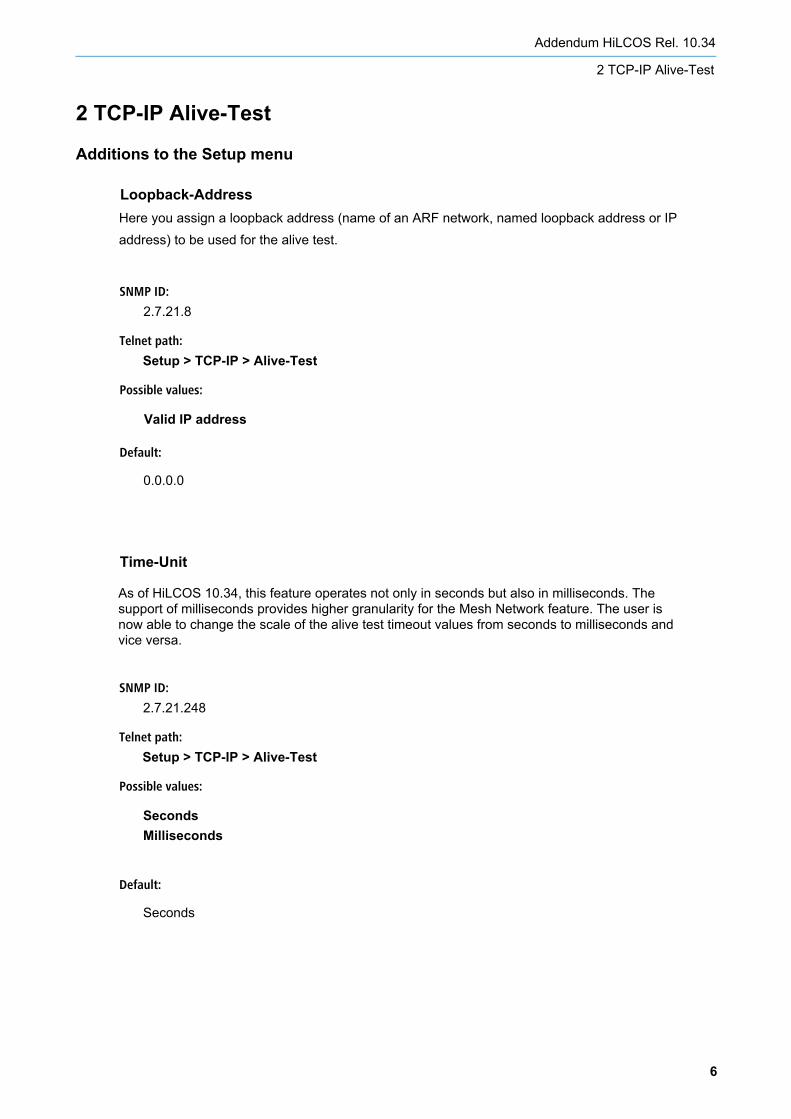
2 TCP-IP Alive-Test
Additions to the Setup menu
Time-Unit
6
Addendum HiLCOS Rel. 10.34
2 TCP-IP Alive-Test
SNMP ID:
2.7.21.248
Telnet path:
Setup > TCP-IP > Alive-Test
Possible values:
Seconds Milliseconds
Default:
Seconds
As of HiLCOS 10.34, this feature operates not only in seconds but also in milliseconds. The support of milliseconds provides higher granularity for the Mesh Network feature. The user is now able to change the scale of the alive test timeout values from seconds to milliseconds and vice versa.
SNMP ID:
2.7.21.8
Telnet path:
Setup > TCP-IP > Alive-Test
Possible values:
Valid IP address
Default:
0.0.0.0
Loopback-AddressHere you assign a loopback address (name of an ARF network, named loopback address or IP address) to be used for the alive test.

7
Addendum HiLCOS Rel. 10.34
3 WLAN
3 WLAN
3.1 Mesh Network
Mesh-Network The WLAN mesh solution establishes an automatic configuration of the links between the wireless network’s nodes. It simplifies and accelerates the network installation process in a new location. With its link detection mechanism, the connectivity with the root node can be monitored. Reconfiguration mechanisms help reduce downtime when an existing connection is terminated. This solution assumes that the wireless network will be connected to the back-haul using wired infrastructure. It will be implemented for BAT devices that have 2 radio modules. One radio module interface (WLAN-2) is configured to operate in station mode, the other WLAN interface (WLAN-1) is configured to operate in access point mode. The access point interface provides the next backhaul (mesh) network SSID and access network SSIDs. It uses the existing alive test feature to monitor the connection.
SNMP ID:
2.12.252
Telnet path:
Setup > WLAN
SNMP ID:2.12.252.1
Telnet path:Setup > WLAN > Mesh-Network
Possible values:
WLAN-1 WLAN-1-2 WLAN-1-3 WLAN-1-4 WLAN-1-5 WLAN-1-6 WLAN-1-7 WLAN-1-8
Default:
WLAN-1
Mesh-Interface This interface allows the user to select the logical interface that will connect the next node into the mesh network.
Additions to the Setup menu
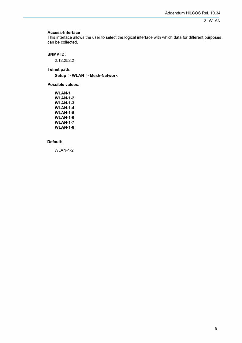
8
Addendum HiLCOS Rel. 10.34
3 WLAN
SNMP ID:2.12.252.2
Telnet path:Setup > WLAN > Mesh-Network
Possible values:
WLAN-1 WLAN-1-2 WLAN-1-3 WLAN-1-4 WLAN-1-5 WLAN-1-6 WLAN-1-7 WLAN-1-8
Access-Interface This interface allows the user to select the logical interface with which data for different purposes can be collected.
Default:
WLAN-1-2
9
Addendum HiLCOS Rel. 10.34
3 WLAN
3.2 Selection Preference Access Point Station
Additions to the Setup menu
SNMP ID:
2.12.254
Telnet path:
Setup > WLAN
Possible values:
Default:
Yes
Yes
- Access point with the least number of connected stations will be selected.- If 2 or more access points habe the same number of connected stations, the access point with the lowest channel utilization will be selected.- If the above parameters are the same, the access point with the highest signal strength will be selected.
No
- Access point with the lowest channel utilization will be selected.- If 2 or more access points habe the same lowest channel utilization, the access point with the highest signal strength will be selected.
Selection-Preference-AP-StationThis feature allows to select the access point that has the least number of stations connected to it.

4 Network
Additions to the Setup menu
10
Addendum HiLCOS Rel. 10.34
4 Network
SNMP ID:
2.23.20.1.25
Telnet path:
Setup > Interfaces > WLAN > Network
Per-Client-Tx-LimitHere, you set the transmit-direction bandwidth limit (in kbps) available to each wireless client
on this SSID. A value of 0 disables the limit.
Possible values:
Max. 10 characters from 0123456789
Default:
0
Special values:
0
Disables the limit.
SNMP ID:
2.23.20.1.26
Telnet path:
Setup > Interfaces > WLAN > Network
Per-Client-Rx-LimitHere, you set the receive-direction bandwidth limit (in kbps) available to each wireless client
on this SSID. A value of 0 disables the limit.
Possible values:
Max. 10 characters from 0123456789
Default:
0
Special values:
0
Disables the limit.
Addendum HiLCOS Rel. 10.34
4 Network
11
SNMP ID:
2.23.20.1.30
Telnet path:
Setup > Interfaces > WLAN > Network
Possible values:
No Yes
Default:
Yes
Assisted-RoamingWith this setting, you enable Neighbor Reports (802.11k) and Network assisted Roaming
(802.11v). When this setting is enabled on both the access point and the client, the client will
have more information about its network, thus resulting in better roaming performance.