vtsa-f-cb - festo
TRANSCRIPT

8099805
VTSA-F-CBValve terminal
80998052020-01[8099807]
Description | System

Translation of the original instructions
PROFIsafe® is a registered trademark of its respective trademark holder in certain countries.
2 Festo — VTSA-F-CB — 2020-01

3Festo — VTSA-F-CB — 2020-01
1 About this document................................................................................................... 7
1.1 Applicable documents.................................................................................................. 7
1.2 Product labelling.......................................................................................................... 7
1.3 Specified standards...................................................................................................... 8
2 Safety........................................................................................................................... 9
2.1 General safety instructions........................................................................................... 9
2.2 Intended use................................................................................................................ 9
2.3 Foreseeable misuse...................................................................................................... 9
2.4 Requirements for Product Use...................................................................................... 9
2.4.1 Training of qualified personnel............................................................................... 9
2.4.2 Range of application and certifications................................................................... 10
3 Further information..................................................................................................... 10
4 Service..........................................................................................................................10
5 Product overview......................................................................................................... 10
5.1 Function....................................................................................................................... 10
5.1.1 Functions Pneumatics.............................................................................................10
5.1.1.1 Pressure supply to the valve terminal..................................................................... 10
5.1.1.2 Pilot Air Supply....................................................................................................... 10
5.1.1.3 Pilot exhaust air...................................................................................................... 11
5.1.1.4 Creation of Pressure Zones..................................................................................... 11
5.1.1.5 Vertical stacking..................................................................................................... 14
5.1.2 Electrical Functions................................................................................................. 14
5.1.2.1 Formation of Voltage Zones.................................................................................... 14
5.2 Configuration................................................................................................................ 21
5.2.1 Pneumatic Components.......................................................................................... 21
5.2.1.1 Valves..................................................................................................................... 22
5.2.1.2 Manifold sub-bases................................................................................................ 25
5.2.1.3 Supply plates..........................................................................................................26
5.2.1.4 Right end plates......................................................................................................27
5.2.1.5 Soft start valves with pressure monitoring..............................................................28
5.2.1.6 Pilot air valves with pressure sensing..................................................................... 31
5.2.1.7 Pressure regulator plates........................................................................................33
5.2.1.8 Vertical supply plates............................................................................................. 37
5.2.1.9 Throttle plate.......................................................................................................... 38
5.2.1.10 Vertical Pressure Shut-off Plates.............................................................................39
5.2.1.11 Vacuum generator (optional).................................................................................. 40
5.2.1.12 Separating seals for pressure zone formation.........................................................41
5.2.2 Electrical components.............................................................................................43
5.2.2.1 Pneumatic interface................................................................................................ 43
5.2.3 Display elements of the pneumatic components.....................................................46
Table of contents

5.2.4 Display elements of the electrical components...................................................... 47
5.2.5 Control elements of the pneumatic components.................................................... 48
5.2.5.1 Manual override (MO)............................................................................................ 48
5.2.6 Connecting elements of the pneumatic components............................................. 49
5.2.7 Connection elements of the electrical components................................................ 50
5.2.8 Labelling elements................................................................................................. 50
5.3 Operating modes...........................................................................................................51
5.3.1 Vacuum or low-pressure operation........................................................................ 51
5.3.2 Reverse Operation................................................................................................. 51
5.4 Address Assignment......................................................................................................52
5.4.1 Address assignment of the working valves............................................................ 52
5.4.2 Address Assignment of the Special Valves............................................................. 53
5.4.3 Address assignment of the vacuum generator....................................................... 53
6 Transport and storage.................................................................................................. 53
7 Mounting...................................................................................................................... 54
7.1 Mounting types............................................................................................................. 54
7.2 Mounting the labelling elements................................................................................... 54
7.2.1 Mounting/dismounting the identification holder................................................... 54
8 Installation...................................................................................................................55
8.1 Installation Pneumatics................................................................................................. 55
8.1.1 Compressed Air Preparation.................................................................................. 55
8.1.1.1 Operation with unlubricated compressed air......................................................... 55
8.1.1.2 Pressure rise in the overall supply......................................................................... 55
8.1.1.3 Preventing back pressure...................................................................................... 55
8.1.1.4 Check prerequisites for vacuum or low pressure operation (valves with Ident-code VV)
.. 56
8.1.2 Connecting Pneumatic Lines.................................................................................. 56
8.1.2.1 Position and Size of the Pneumatic Ports............................................................... 56
8.1.2.2 Common pneumatic lines....................................................................................... 58
8.1.2.3 Connecting the Right End Plate.............................................................................. 59
8.1.2.4 Mounting the tubing.............................................................................................. 60
8.1.2.5 Removing the tubing.............................................................................................. 60
8.1.3 Setting pressure regulator..................................................................................... 61
8.1.3.1 Set pressure regulator with standard rotary knob.................................................. 61
8.1.3.2 Setting pressure regulator with adjusting screw.................................................... 62
8.1.3.3 Set pressure regulator with rotary knob with lock................................................. 62
8.2 Electrical Installation..................................................................................................... 63
8.2.1 Connecting electrical cables................................................................................... 63
8.2.1.1 Switch on the power supply................................................................................... 63
8.2.1.2 Pin allocation......................................................................................................... 64
4 Festo — VTSA-F-CB — 2020-01

8.2.1.3 Earthing the valve terminal..................................................................................... 66
9 Commissioning............................................................................................................ 66
9.1 Commissioning of the Pneumatic Components............................................................. 66
9.1.1 Testing Pneumatic Components..............................................................................66
9.1.1.1 Determining the exhaust times of the pressure switches........................................66
9.1.1.2 Testing valves and valve/actuator combination......................................................67
9.1.1.3 Commissioning the Pneumatic Components with Manual Override (HHB).............. 67
9.1.2 Completing commissioning of the pneumatic components.....................................71
9.1.2.1 Mounting the cover cap for manual override (optional).......................................... 71
9.1.2.2 Remove the cover cap for manual override (optional).............................................72
9.2 Commissioning of the Electrical Components............................................................... 72
9.2.1 Safe output module CPX-FVDA-P2.......................................................................... 72
9.3 Parameterisation.......................................................................................................... 72
9.3.1 Process Data...........................................................................................................72
9.3.2 Special Features of Module Numbering.................................................................. 75
9.3.3 Module Parameters.................................................................................................75
9.3.3.1 Monitoring CPX Module.......................................................................................... 75
9.3.4 Duct Parameters..................................................................................................... 76
10 Malfunctions............................................................................................................... 76
10.1 Diagnostics................................................................................................................... 76
10.1.1 Diagnostic Interfaces.............................................................................................. 77
10.1.1.1 Diagnostic Messages of the Pneumatic Interfaces.................................................. 77
10.1.1.2 LED Displays of the Valves...................................................................................... 77
10.1.1.3 LED Displays of the Soft Start Valves...................................................................... 78
10.1.1.4 LED Displays of the Pilot Air Valves.........................................................................79
10.1.1.5 LED Displays of the Pneumatic Interfaces............................................................... 79
10.2 Fault Clearance............................................................................................................. 80
10.3 Repair............................................................................................................................80
11 Modification................................................................................................................ 81
11.1 Replacing Valve Terminal Components......................................................................... 81
11.1.1 Replacing Valves or Cover Plates............................................................................ 81
11.1.2 Replacing exhaust plate or exhaust air cover..........................................................82
11.1.3 Replacing or Adding Vertical Stacking Components................................................82
11.1.4 Replacing the Manifold Sub-bases or Right End Plate.............................................84
11.2 Converting the Valve Terminal...................................................................................... 87
11.2.1 Converting to Multiple Pressure Zones................................................................... 87
11.2.2 Converting to Internal or External Pilot Air Supply.................................................. 89
11.2.3 Convert to ducted pilot exhaust air......................................................................... 89
11.2.4 Mounting the Pilot Air Valve....................................................................................90
11.2.5 Mounting the Soft Start Valve.................................................................................90
5Festo — VTSA-F-CB — 2020-01

11.2.6 Mounting the Vacuum Generator........................................................................... 90
11.3 Disconnecting the Valve Terminal and CPX Terminal..................................................... 90
11.4 Adding Valve Positions.................................................................................................. 92
12 Disposal........................................................................................................................92
13 Technical data.............................................................................................................. 93
13.1 Ambient conditions....................................................................................................... 93
13.2 Technical data, mechanical............................................................................................93
13.3 Technical Data, Pneumatic............................................................................................ 95
13.4 Technical data, electrical............................................................................................... 113
6 Festo — VTSA-F-CB — 2020-01

7Festo — VTSA-F-CB — 2020-01
1 About this documentThis document describes the use of the above-mentioned product. Certain aspects of use aredescribed in other documents and must be observed.
1.1 Applicable documents
All available documents for the product è www.festo.com/pk.
Designation Contents
Description of the CPX system (CPX-SYS-...) Mode of operation, mounting, installation andcommissioning of CPX terminals
Description of bus node Commissioning, parameterisation and dia-gnostics of the CPX terminal with the bus node
Description of CPX-FVDA-P2 Mode of operation, installation and commission-ing of the safe output module
Assembly instructions for CPX-VTSA Assembly of CPX terminals and valve terminalsVTSA
Operating instructions for VABF-S4-...-CB-VH/VL-...
Assembly, commissioning and operation of thevacuum generator
Tab. 1 Documentation for the valve terminal
1.2 Product labellingStructure of product labelling
1 Serial number with manufacturing period (encoded)
2 Technical data
3 Product label
4 Data Matrix Code
5 Product key
6 Part number
7 Product designation
Fig. 1 Product labelling
The product labelling is located on the right side of the end plate.
Manufacturing periodIn the product labelling, the first 2 characters of the serial number 1 indicate the manufacturing peri-od in encrypted form. The letter specifies the manufacturing year and the character after it (number orletter) indicates the manufacturing month.
About this document

Manufacturing year
H=2016 J=2017 K=2018 L=2019 M=2020 N=2021
P=2022 R=2023 S=2024 T=2025 U=2026 V=...
Tab. 2 Manufacturing year
Manufacturing month
1 January 2 February
3 March 4 April
5 May 6 June
7 July 8 August
9 September O October
N November D December
Tab. 3 Manufacturing month
1.3 Specified standards
Version
ISO 8573-1:2010-04 EN 60204-1:2018-09
IEC 60204-1:2016-10 DIN 51524-1…3:2017-06
Tab. 4 Standards specified in the document
About this document
8 Festo — VTSA-F-CB — 2020-01

2 Safety
2.1 General safety instructions– Only use the product in original status without unauthorised modifications. Only the conversions
or modifications described in the documentation are permitted. Conversions can change the function of the valve terminal. Check the conversion target with theconfigurator before carrying out conversions è www.festo.com.
– Only use the product if it is in perfect technical condition.– Observe labelling on the product.– Take into consideration the ambient conditions at the location of use.– Store the product in a cool, dry, UV-protected and corrosion-protected environment. Ensure that
storage times are kept to a minimum.– Prior to mounting, installation and maintenance work: Switch off power supply and secure it from
being switched back on.– Prior to mounting, installation and maintenance work: Switch off compressed air supply and
secure it from being switched back on.– For assembly and disassembly work: support the product and use suitable lifting equipment.– Do not connect or disconnect plug connector when powered.– Comply with the handling specifications for electrostatically sensitive devices.– Observe further applicable documents.
2.2 Intended useThe VTSA-F-CB valve terminal is designed for switching and controlling compressed air in industrialapplications.
2.3 Foreseeable misuse– If the load needs to be safely disconnected in safety-critical areas, use connections that have no
possibility of short circuit.– Only use manifold sub-bases and pneumatic interfaces with the following features:
– Black electrical manifold module– Identification VTSA-F-CB on the product labelling
– Only mount pilot air valves with internal communication on the left valve position of the followingmanifold sub-bases:– VABV-S4-2HS-G18-CB-2T5– VABV-S4-12HS-G-CB-2T5
– Operation of the valve terminal with lubricated compressed air is not permitted.
2.4 Requirements for Product Use
2.4.1 Training of qualified personnelWork on the product should only be conducted by qualified personnel.The specialized personnel must be familiar with the installation and operation of electrical and pneu-matic control systems.Work on safety-related systems may only be carried out by safety engineering specialists.
Safety
9Festo — VTSA-F-CB — 2020-01
2.4.2 Range of application and certifications
Certificates and declaration of conformity for the product è www.festo.com/sp.
The product bears the CE marking.
3 Further information– Accessories è www.festo.com/catalogue.– Spare parts è www.festo.com/spareparts.
4 ServiceContact your regional Festo contact person if you have technical questions è www.festo.com.
5 Product overview
5.1 Function
5.1.1 Functions Pneumatics
5.1.1.1 Pressure supply to the valve terminalThe valve terminal can be supplied with operating pressure by the following components:– Pneumatic supply plate– Right end plate– Soft start valveThe following components can be used for additional power supplies:– Pneumatic supply plates– Vertical supply plates
5.1.1.2 Pilot Air SupplyThe pilot air can be supplied to the following components:
Characteristic Internal pilot air supply External pilot air supply
Type of pilot air supply Pilot air is branched internallyfrom port (1).
Pilot air is supplied externally.
Supplying component for thefirst/right pressure zone
– Right end plate VABE-...R-...– Soft start valve
VABF-…-P5A4S1…– Pilot air valve VSVA-BT-
M32CS1-...
– Right end plateVABE-...RZ-... : Supply toport (14)
– Pilot air valveVSVA-BT-M32CS2-...:supply to port (2) of themanifold sub-base
Further information
10 Festo — VTSA-F-CB — 2020-01

Characteristic Internal pilot air supply External pilot air supply
Supplying component for theother pressure zones
– Soft start valveVABF-…-P5A4S1…
– Pilot air valveVSVA-BT-M32CS1-...
– Pilot air valveVSVA-BT-M32CS2-...:supply to port (2) of themanifold sub-base
Required pilot pressure – Diagrams of the dependencybetween working pressure andpilot pressureè 13.3 Technical Data,Pneumatic
Working pressure at port (1) 3 … 10 bar -0.9 bar … 10 bar, dependingon the valves used
Vacuum or low-pressure opera-tion
Not possible Possible
Tab. 5 Types of Pilot Air Supply
Functional Failure or Malfunctions Due to Faulty Pilot Air Supply• Supply each pressure zone with working pressure and pilot pressure. Do not form pressure-free
zones è 5.1.1.4 Creation of Pressure Zones.• Use only one supply component for the pilot air supply in each pressure zone.• Required pilot pressure at port (12/14) è 13.3 Technical Data, Pneumatic.
5.1.1.3 Pilot exhaust air– Unducted pilot exhaust air: the pilot exhaust air is exhausted directly at each valve. If a soft start
valve or pilot air valve is used, the pilot exhaust air can only be exhausted in an unducted manner.– Ducted pilot exhaust air: the pilot exhaust air is exhausted at the port (12) on the right end plate.
Convert to ducted pilot exhaust air è 11.2.3 Convert to ducted pilot exhaust air.
5.1.1.4 Creation of Pressure ZonesIn order to supply valves with different pressures, pressure zones for the working air and the pilot aircan be formed within the valve terminal. The pressure zones are limited by separating seals betweenthe manifold sub-bases è 5.2.1.12 Separating seals for pressure zone formation.Each pressure zone must be supplied with compressed air via a supplying component è Fig.2. Pres-sure-free zones must not be created.Several pressure zones are required within the valve terminal to operate vacuum or low-pressure-com-patible valves with other valves.
Product overview
11Festo — VTSA-F-CB — 2020-01
Use of Soft Start ValvesIn a pressure zone, a soft start valve must not be combined with another supplying component forduct (1).When using several soft start valves, observe the electrical regulations for creating voltage zonesè 5.1.2.1 Formation of Voltage Zones.
Use of Pilot Air ValvesIn a pressure zone, a pilot air valve must not be combined with another supplying component forduct (14).
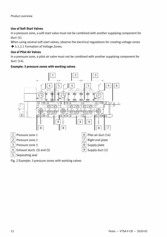
Example: 3 pressure zones with working valves
1 Pressure zone 1
2 Pressure zone 2
3 Pressure zone 3
4 Exhaust ducts (3) and (5)
5 Separating seal
6 Pilot air duct (14)
7 Right end plate
8 Supply plate
9 Supply duct (1)
Fig. 2 Example: 3 pressure zones with working valves
Product overview
12 Festo — VTSA-F-CB — 2020-01

Example: 2 pressure zones with pilot air valve, soft start valve and working valves
1 Pressure zone 1
2 Pressure zone 2
3 Exhaust port for duct (1)
4 Separating seal
5 Supply duct (1)
6 Right end plate
7 Pilot air duct (14)
8 Exhaust ducts (3) and (5)
9 Pilot air valve
10 Soft start valve
Fig. 3 Example: 2 pressure zones with pilot air valve, soft start valve and working valves
Example: 2 pressure zones with soft start valve and working valves
1 Pressure zone 1
2 Pressure zone 2
3 Exhaust port for duct (1)
4 Separating seal
5 Supply duct (1)
6 Right end plate
7 Pilot air duct (14)
8 Exhaust ducts (3) and (5)
9 Soft start valve
Fig. 4 Example: 2 pressure zones with soft start valve and working valves
Product overview
13Festo — VTSA-F-CB — 2020-01

5.1.1.5 Vertical stackingIn order to extend the functional range of a valve position, components of the vertical stackingbetween the manifold sub-base and valve can be installed.
Components
Pressure regulator plate.
Throttle plate è 5.2.1.9 Throttle plate.
Vertical pressure shut-off plateè 5.2.1.10 Vertical Pressure Shut-off Plates.
Vertical supply plateè 5.2.1.8 Vertical supply plates.
Tab. 6 Vertical stacking components
5.1.2 Electrical Functions
5.1.2.1 Formation of Voltage ZonesWith the CPX terminal and the pneumatic interfaces, voltage zones can be formed in the pneumaticpart of the valve terminal.
Product overview
14 Festo — VTSA-F-CB — 2020-01

The 24 V power supply to the valves is provided via the load voltage supply valves of the CPX terminal(Uval).The power for the pressure switches and the vacuum generators is supplied by the electronic powersupply (UEL/SEN). After switching off the load voltage supply, the pressure switches continue to be sup-plied with voltage for the valves of the CPX terminal (Uval).
Further information on the power supply of the CPX terminal è Description of the CPX system (CPX-SYS-...).
Depending on the pneumatic interface variant, up to 3 safe voltage zones can be formed in the pneu-matic part of the valve terminal. The voltage zones can be switched off independently of each otherand in an electrically safe manner. A total of up to 24 addresses can be controlled via the pneumaticinterface.
Variants of the Pneumatic Interfaces
Type code Power supply of the voltagezones
Characteristics
VABA-S6-1-X1-CB
VABA-S6-1-X2-CB
Common power supply for allvoltage zones
If a cross-fault proof ballast isused:– 1 safe zone
VABA-S6-1-X1-3V-CB
Separate power supply for eachvoltage zone possible
If a cross-fault proof ballast isused:– 3 additional supplies for
valves X0, X1, X2
Product overview
15Festo — VTSA-F-CB — 2020-01

Type code Power supply of the voltagezones
Characteristics
VABA-S6-1-X2-3V-CB If a cross-fault proof ballast isused:– 3 additional supplies for
valves X0, X1, X2
VABA-S6-1-X2-F1-CB
Integrated output module CPX-FVDA-P2 (PROFIsafe)– 3 internal safe zones: CH0,
CH1, CH2
VABA-S6-1-X2-F2-CB
Separate power supply for eachvoltage zone possible
Integrated output module CPX-FVDA-P2 (PROFIsafe)– 2 internal safe zones: CH0,
CH1– 1 safe output: CH2 (M12
connection)
Tab. 7 Variants of the Pneumatic Interfaces
Use of soft start valvesThe soft start valve completely occupies a safe zone.The system can be safely switched off and exhausted in two stages.
Product overview
16 Festo — VTSA-F-CB — 2020-01

Example: pneumatic interface without additional supplies for valvesThe figure shows the systematic assignment of the components to the stress zones.
1 Pneumatic interface VABA-S6-1-X2-CB
2 Soft start valve 1
3 Monostable valve
4 Bistable valve
5 Soft start valve 2
6 Pilot air valve
7 Vacuum generator
8 System supply of the CPX terminal
Fig. 5 Example: pneumatic interface without additional supplies for valves
Product overview
17Festo — VTSA-F-CB — 2020-01

Example: pneumatic interface with integrated output module CPX-FVDA-P2The figure shows the systematic assignment of the components to the stress zones.
1 Pneumatic interface VABA-S6-1-X2-F1-CB
2 Soft start valve 1
3 Monostable valve
4 Bistable valve
5 Soft start valve 2
6 Pilot air valve
7 Vacuum generator
8 System supply of the CPX terminal
Fig. 6 Example: pneumatic interface with integrated output module CPX-FVDA-P2
The 3 internal safe zones of the pneumatic interface are assigned as follows in this example:– CH0: Working valves– CH1: soft start valve 1– CH2: soft start valve 2The two soft start valves can be safely switched off electrically independently of the working valves.
Product overview
18 Festo — VTSA-F-CB — 2020-01

Example: pneumatic interface with integrated output module CPX-FVDA-P2 and a safe outletThe figure shows the systematic assignment of the components to the stress zones.
1 Pneumatic interface VABA-S6-1-X2-F2-CB
2 Soft start valve 1
3 Pilot air valve
4 Monostable valve
5 Bistable valve
6 Vacuum generator
7 System supply of the CPX terminal
Fig. 7 Example: pneumatic interface with integrated output module CPX-FVDA-P2 and a safe outlet
The two internal safe zones of the pneumatic interface are assigned as follows in this example:– CH0: Working valves– CH1: soft start valve 1The safe output CH2 and the soft start valve can be safely switched off electrically independently ofthe working valves.
Product overview
19Festo — VTSA-F-CB — 2020-01

Example: pneumatic interface with 3 additional supplies for valvesThe figure shows the systematic assignment of the components to the stress zones.
1 Pneumatic interface VABA-S6-1-X2-3V-CB
2 Soft start valve 1
3 Monostable valve
4 Bistable valve
5 Soft start valve 2
6 Pilot air valve
7 Vacuum generator
8 System supply of the CPX terminal
9 Plug connector X0
10 Plug connector X1
11 Plug connector X2
Fig. 8 Example: pneumatic interface with 3 additional supplies for valves
The 3 internal safe zones of the pneumatic interface are assigned as follows in this example:– CH0: Working valves– CH1: soft start valve 1
Product overview
20 Festo — VTSA-F-CB — 2020-01

– CH2: soft start valve 2The two soft start valves can be safely switched off electrically independently of the working valves.
5.2 Configuration
5.2.1 Pneumatic Components
1 Right end plate
2 Manifold sub-base
3 Vertical pressure shut-off plate
4 Vertical supply plate
5 Pilot air valve
6 Soft start valve
7 Supply plate
8 Exhaust plate for separate exhaust air
9 Exhaust air cover for common exhaust air
10 Cover plate
11 Pressure regulator plate
12 Throttle plate
13 Valve
Fig. 9 Pneumatic components of the valve terminal
Product overview
21Festo — VTSA-F-CB — 2020-01

5.2.1.1 ValvesThe valve terminal can be equipped with the following valves:– 5/2-way valves– 5/3-way mid-position valves– 2x 2/2-way valves– 2x 3/2-way valvesUnassigned valve positions can be sealed with cover plates.
Valve widths
Type code Widths
VSVA-...-A2-... 18 mm
VSVA-...-A1-... 26 mm
VSVA-...-D1-... 42 mm
VSVA-...-D2-... 52 mm
Tab. 8 Valve widths
Widths can be combined without adapter plate.Some valve functions are only available in individual widths.
Identification of the ValvesAn identification code is printed on the top of each valve. These ID codes enable equipment items onthe valve terminal to be identified.
The logic designation of the circuit symbols may differ from the designations of the connections andcontrol elements. The designations of the connections and control elements are also given in brackets.
Variants of the 5/2-way valves
Ident. code Circuit symbol Description
D 5/2-way valve, bistable– Dominant due to port 14 on the
control side
J 5/2-way valve, bistable
M 5/2-way valve, monostable– Pneumatic spring return
Product overview
22 Festo — VTSA-F-CB — 2020-01

Ident. code Circuit symbol Description
O 5/2-way valve, monostable– Mechanical spring return
Tab. 9 Variants of the 5/2-way valves
Variants of the 5/3-way Valves
ID code Circuit symbol Description
B 5/3-way valve– Mid-position pressurized
I 5/3-way valve– Mid-position exhausted
G 5/3-way valve– Mid-position closed
VG 5/3-way valve– Mid-position port 2 pressurised,
port 4 closed
Tab. 10 Variants of the 5/3-way Valves
Variants of the 2x 3/2-way valves
Ident. code Circuit symbol Description
H 2 monostable 3/2-way valves– Normal position:
– Closed at control side 14– Open at control side 12
K 2 monostable 3/2-way valves– Normally closed
Product overview
23Festo — VTSA-F-CB — 2020-01

Ident. code Circuit symbol Description
N 2 monostable 3/2-way valves– Normally open
Tab. 11 Variants of the 2x 3/2-way valves
Variants of the 2x 2/2-way valves
Ident. code Circuit symbol Description
VC 2 monostable 2/2-way valves– Normally closed
VV 2 monostable 2/2-way valves– Normally closed– Vacuum operation on 3 and 5 pos-
sible
Tab. 12 Variants of the 2x 2/2-way valves
Product overview
24 Festo — VTSA-F-CB — 2020-01

5.2.1.2 Manifold sub-bases
1 Electrical manifold module
Fig. 10 Manifold sub-base –Example
The manifold sub-bases are individually modular and supply the valves pneumatically. The electricalmanifold module in the manifold sub-bases supplies electrical power to the valves.
Variants of the manifold sub-bases
Type code
Manifold sub-bases for bistable valves
VABV-S4-2HS-G18-CB-2T2
VABV-S4-12HS-G-CB-2T2
Manifold sub-bases for monostable valves (red solenoid coil contact)
VABV-S4-1HS-G14-CB-2T2
Manifold sub-bases for soft start valves
VABV-S6-1Q-G12-CB-1T5
Manifold sub-bases for pilot air valves
VABV-S4-2HS-G18-CB-2T5
VABV-S4-12HS-G-CB-2T5
Tab. 13 Variants of the manifold sub-bases
All manifold sub-bases have a black electrical manifold module.
Product overview
25Festo — VTSA-F-CB — 2020-01

Address assignment è 5.4 Address Assignment.
5.2.1.3 Supply plates
1 Exhaust plate for separate exhaust air
2 Sub-base
3 Electrical manifold module
4 Exhaust air cover for common exhaust air
Fig. 11 Supply plates
Supply plates can be used for the following purposes:– Main supply of operating pressure to the valve terminal– Additional supplies, e. g. to increase pressurisation and exhaust performance– Exhausting of the exhaust air ducts (3) and (5) of the working air via an exhaust plate for separate
exhaust air or via an exhaust air cover for common exhaust air
Variants of the supply plates
Type code
Supply plate with exhaust plate for separate exhaust air
VABF-S6-1-P1A6-G12-CB
Supply plate with exhaust air cover for common exhaust air
VABF-S6-1-P1A7-G12-CB
Tab. 14 Variants of the supply plates
Product overview
26 Festo — VTSA-F-CB — 2020-01

5.2.1.4 Right end plates
Fig. 12 Right end plate –Example
Right end plates can be used for the following purposes:– Main supply of operating pressure to the valve terminal– Internal pilot air supply (VABE-...R-...) or external pilot air supply (VABE-...RZ-...)– Separate exhaust of exhaust air ducts (3) and (5) for working air– Exhausting of exhaust pilot air via duct (12)
Variants of the right end plates
Type code Pilot air supply Connecting thread
VABE-S6-1RZ-G12 External
VABE-S6-1R-G12 Internal
G1/2"
Tab. 15 Variants of the right end plates
Additional information:• Conversion between internal and external pilot air supplyè 11.2.2 Converting to Internal or External Pilot Air Supply.
• Installing the right end plates è 11.1.4 Replacing the Manifold Sub-bases or Right End Plate.• Combination of soft start valve and right-hand endè 5.1.1.1 Pressure supply to the valve terminalplate .
Product overview
27Festo — VTSA-F-CB — 2020-01

5.2.1.5 Soft start valves with pressure monitoring
1 LED for solenoid coil 14
2 LED for pressure switch
3 Manual override (optional)
4 Air supply time flow control screw
5 Exhaust port for duct (1)
6 Connection for pressure tapping on the switched duct(1)
7 Exhaust port duct (3/5)
8 Supply port duct (1)
9 Group error LED of the soft start valve
10 Pilot control with pressure switch
Fig. 13 Soft start valve
The soft start valve can be used for the following purposes:– adjustable, two-stage soft start of the working pressure– single-stage soft start for the pilot air supply from port (1), depending on the variant of the soft
start valve – exhausting the working pressure– Exhausting the pilot pressure– Query of the exhausted state with a pressure switch in the pilot control
The switching signal of the pressure switch is sent to the CPX terminal.
Product overview
28 Festo — VTSA-F-CB — 2020-01

Switch-on process/pressurisation
1 Pilot pressure
2 Working pressure
3 Switching voltage (LED to solenoid coil 12)
4 Pressure switch signal (LED to pressureswitch)
Fig. 14 Switch-on behaviour of soft start valve
Time Description
t0 Electrical control signal of the valve active
t1 Dead time until duct filling (1)
t2 Switching point from exhausted state to pressurised state in duct (1)
t3 Pilot pressure in duct (14) reaches operating pressure pB
t4 Working pressure in duct (1) reaches half operating pressure pB/2
t5 Working pressure in duct (1) reaches full operating pressure pB
t6 Electrical control signal of the valve inactive
t7 Dead time until exhaust of duct (1)
t8 Switching point from pressurised state to exhausted state in duct (1)
Tab. 16
Product overview
29Festo — VTSA-F-CB — 2020-01

1 Operating pressure in bar
2 Free blow-off (with silencer)
3 With filling (volume = 100 ml)
4 Number of simultaneously switching valves
Fig. 15 Operating pressure of the soft start valve as a function of the number of valves
The times depend on the volume to be filled (configuration of the valve terminal).The switch-on process takes place in 2 stages:– Duct (1) of the valve terminal is pressurised.
The pressurisation time t4 can be adjusted with the flow control screw 4.If the soft start valve is used for the pilot air supply, duct (14) is immediately supplied with the fulloperating pressure.
– When the working pressure in duct (1) reaches half the operating pressure, the soft start valvereleases the full flow rate.
Switching off/exhaustingIf the supply voltage is switched off or the output is switched off via the control, the soft start valveblocks the compressed air supply. Duct (1) is exhausted via the soft start valve.If the soft start valve is used for the pilot air supply, an additional duct (14) is exhausted via the softstart valve.
Variants of the soft start valves
Type code Circuit symbol Pilot air supply Manual over-ride (MO)
VABF-S6-1-P5A4S1Y-E-G12- 1T5-PA
Pilot air from connection (1) ofthe manifold sub-base
Self-resetting
Product overview
30 Festo — VTSA-F-CB — 2020-01

Type code Circuit symbol Pilot air supply Manual over-ride (MO)
VABF-S6-1-P5A4S1S-G12- 1T5-PA
Pilot air from connection (1) ofthe manifold sub-base
Covered
VABF-S6-1-P5A4S2Y-E-G12- 1T5-PA
Self-resetting
VABF-S6-1-P5A4S2S-G12- 1T5-PA
–
Covered
Tab. 17 Variants of the soft start valves
5.2.1.6 Pilot air valves with pressure sensing
1 M12 connection (optional)
2 LED for pressure switch
3 LED for solenoid coil 14
4 Manual override (optional)
5 Additional valve position
6 Working port (2) of the additional valve position
7 Working port (4) of the additional valve position
8 Exhaust port of the pilot air duct
9 Supply port (external)
10 Exhaust port of the pilot air duct
11 Pilot control with pressure switch
Fig. 16 Pilot air valve
The pilot air valve can be used for the following purposes:– Switching and exhausting the pilot air
The pilot air duct is additionally exhausted unmounted via the exhaust air opening aJon bothsides of the pilot air valve.
Product overview
31Festo — VTSA-F-CB — 2020-01

– Query of the exhausted state with a pressure switch in the pilot controlThe switching signal of the pressure switch can be transmitted in one of the following ways:– Internal communication: the switching signal is sent to the CPX terminal.– M12 connection: the switching signal can be used in an external controller.
Variants of the pilot air valves
Type code Circuit symbol Pilot air supply M12 con-nection
Manualoverride(MO)
VSVA-BT-M32CS2-M-YE-A2-1T5L-PA
–
VSVA-BT-M32CS2-M-YE-A2-1T1L-PZ
Pilot air supply fromport (2) of the manifoldsub-base
x
VSVA-BT-M32CS1-M-YE-A2-1T5L-PA
–
VSVA-BT-M32CS1-M-YE-A2-1T1L-PZ
Pilot air supply fromduct (1) of valve terminalor pressure zone
x
Self-reset-ting
VSVA-BT-M32CS2-M-YE-A2-1T5L-PA
–
VSVA-BT-M32CS2-M-YE-A2-1T1L-PZ
Pilot air supply fromport (2) of the manifoldsub-base
x
VSVA-BT-M32CS1-M-YE-A2-1T5L-PA
Pilot air supply fromduct (1) of valve terminalor pressure zone
–
Covered
Product overview
32 Festo — VTSA-F-CB — 2020-01

Type code Circuit symbol Pilot air supply M12 con-nection
Manualoverride(MO)
VSVA-BT-M32CS1-M-YE-A2-1T1L-PZ
Pilot air supply fromduct (1) of valve terminalor pressure zone
x Covered
Tab. 18 Variants of the pilot air valves
5.2.1.7 Pressure regulator plates
Fig. 17 Pressure regulator plate
A pressure regulator plate with adjustable pressure regulator can be installed between the manifoldsub-base and the valve in order to control the force of the connected actuators. The pressure regulatormaintains a constant output pressure (secondary side) independent of pressure fluctuations (primaryside) and air consumption.Some components of the vertical stacking are only available in individual construction widths.
Identification of the pressure regulator platesID codes are printed on the sides of the pressure regulator plates. These ID codes enable equipmentitems on the valve terminal to be identified.
Variants of the pressure regulator plates
Type code Circuit symbol Description Control range [bar]
Pressure regulator plate for port (1) (P-closed-loop controller)
VABF-S4-1-R1C2-C-10
VABF-S4-2-R1C2-C-10
VABF-S4-1-R1C2-C-10E
VABF-S4-2-R1C2-C-10E
£10
VABF-S4-1-R1C2-C-6E
– Regulates the oper-ating pressure inthe duct (1)upstream of thedirectional solen-oid valve.
£6
Product overview
33Festo — VTSA-F-CB — 2020-01

Type code Circuit symbol Description Control range [bar]
VABF-S4-2-R1C2-C-6E – The pressure regu-lator can be adjus-ted in any state.
£6
Pressure regulator plate for port (2) (B-closed-loop controller)
VABF-S4-1-R2C2-C-10E
VABF-S4-2-R2C2-C-10E
£10
VABF-S4-1-R2C2-C-6E
VABF-S4-2-R2C2-C-6E
– Regulates the oper-ating pressure inthe duct (2) down-stream of the direc-tional solenoidvalve.
– The pressure regu-lator can only beadjusted inswitched state.
£6
Pressure regulator plate for ports (2) and (4) (AB-closed-loop controller)
VABF-S4-1-R4C2-C-10E
VABF-S4-2-R4C2-C-10E
£10
VABF-S4-1-R4C2-C-6E
VABF-S4-2-R4C2-C-6E
– Regulates theworking pressurein the channels (2)and (4) down-stream of the direc-tional solenoidvalve
– The pressure regu-lator can only beadjusted inswitched state.
£6
Pressure regulator plate for port (2), reversible (B-closed-loop controller)
VABF-S4-1-R6C2-C-10E
VABF-S4-2-R6C2-C-10E
£10
VABF-S4-1-R6C2-C-6E
VABF-S4-2-R6C2-C-6E
– Reversible valvesrequired
– The pressure regu-lator can be adjus-ted in any state.
£6
Product overview
34 Festo — VTSA-F-CB — 2020-01

Type code Circuit symbol Description Control range [bar]
Pressure regulator plate for ports (2) and (4), reversible (AB-closed-loopcontroller)
VABF-S4-1-R5C2-C-10E
VABF-S4-2-R5C2-C-10E
£10
VABF-S4-1-R5C2-C-6E
VABF-S4-2-R5C2-C-6E
– Reversible valvesrequired
– Regulates the pres-sure upstream ofthe directionalsolenoid valve
– The operating pres-sure is divertedfrom duct (1) toducts (3) and (5).
– The exhaust air isdiverted from theducts (3) and (5) tothe duct (1).
– The pressure regu-lator can be adjus-ted in any state.
£6
Tab. 19 Variants of the pressure regulator plates
Reversible pressure regulators cannot be combined with the following valves:• 2x 2/2-way valves (ID codes D and I)• 2x 3/2-way valves (ID code H, K and N)These valves require operating pressure in duct (1) for pneumatic spring return.
Product overview
35Festo — VTSA-F-CB — 2020-01
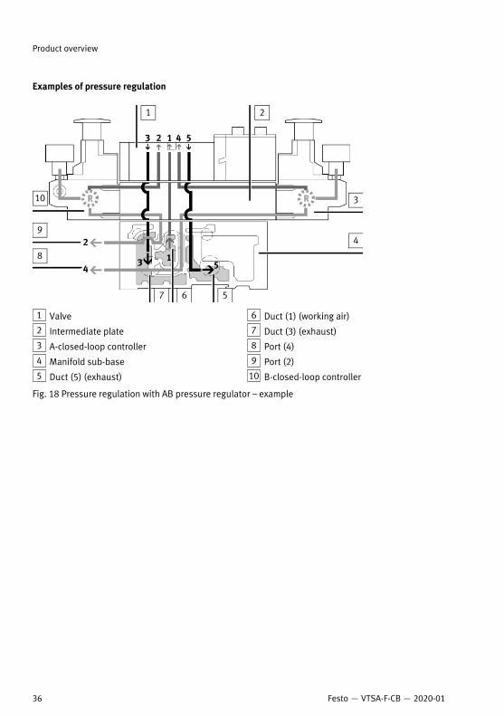
Examples of pressure regulation
1 Valve
2 Intermediate plate
3 A-closed-loop controller
4 Manifold sub-base
5 Duct (5) (exhaust)
6 Duct (1) (working air)
7 Duct (3) (exhaust)
8 Port (4)
9 Port (2)
10 B-closed-loop controller
Fig. 18 Pressure regulation with AB pressure regulator – example
Product overview
36 Festo — VTSA-F-CB — 2020-01

1 Valve
2 Intermediate plate
3 A-closed-loop controller
4 Manifold sub-base
5 Duct (5) (exhaust)
6 Duct (1) (working air)
7 Duct (3) (exhaust)
8 Port (4)
9 Port (2)
10 B-closed-loop controller
Fig. 19 Pressure regulation with a reversible AB pressure regulator – example
5.2.1.8 Vertical supply plates
Fig. 20 Vertical supply plate
In order to supply a single valve position with individual operating pressure or individual pilot pres-sure, a vertical supply plate can be installed between the sub-base and the valve.Some components of the vertical stacking are only available in individual construction widths.
Product overview
37Festo — VTSA-F-CB — 2020-01

Variants of the vertical supply plates
Type code Circuit symbol Description
VABF-S-…P1A3-… Plate with port (11) for supplying indi-vidual operating pressure for a valveposition, channel (1).
VABF-S-…P1A14-… Plate with connection (11) for supply-ing individual operating pressure andindividual pilot pressure for a valveposition, duct (1) and (14)
Tab. 20 Variants of the vertical supply plates
5.2.1.9 Throttle plate
Fig. 21 Throttle plate
To restrict the flow rate in the ducts (3) and (5) independently of each other, a throttle plate can beinstalled between the manifold sub-base and the valve. With a throttle plate, it is, for example, pos-sible to limit the cylinder speed in advance in response to known flow rate conditions.Some components of the vertical stacking are only available in individual construction widths.
Ident. code Circuit symbol Description
X Restricts the exhaust air after the valvein ducts (3) and (5)
Tab. 21 Throttle plate
Product overview
38 Festo — VTSA-F-CB — 2020-01

5.2.1.10 Vertical Pressure Shut-off Plates
Fig. 22 Vertical pressure shut-off plate
To switch off the pressure supply to a single valve, a vertical pressure shut-off plate can be installedbetween the sub-base and the valve. The ducts (1) and (14) are switched off simultaneously. With avertical pressure shut-off plate, for example, a valve can be changed without having to switch off thepressure supply to the valve terminal.The pilot air supply for the valve is branched internally from duct (1) in the vertical pressure shut-offplate, even if the valve terminal is operated with an external pilot air supply.Observe the required pilot pressure for the valves è 13.3 Technical Data, Pneumatic.Some components of the vertical stacking are only available in individual construction widths.
Variants of the vertical pressure shut-off plates
Type code Circuit symbol Description
VABF-S...L1D2-C – 3/2-way valve for shutting off theducts (1) and (14)
– Supplies the valve position withinternal pilot air
– Pressure reduction via duct (33)– Lockable with key
VABF-S4...L1D1-C – 3/2-way valve for shutting off theducts (1) and (14) at the valve pos-ition
– Supplies the valve position withinternal pilot air
– Pressure reduction via duct (33)
VABF-S2…L1D1-C – 3/2-way valve for shutting off theducts (1) and (14) at the valve pos-ition
– Supplies the valve position withinternal pilot air
Product overview
39Festo — VTSA-F-CB — 2020-01

Type code Circuit symbol Description
– Pressure reduction via duct (33)
Tab. 22 Variants of the vertical pressure shut-off plates
5.2.1.11 Vacuum generator (optional)
1 Solenoid valve VSVA
2 Vacuum port
3 Silencer
4 Manifold sub-base for valve terminal VTSA-F-CB(pneumatic and electric)
5 Electrical linkage to valve terminal VTSA-F-CB
6 Flow control screw for adjusting the intensity of theejector pulse
7 Status / error LED
8 7-segment display
9 LED switching status indication for solenoid valve
10 Manual override for vacuum generation
11 Manual override ejector pulse
Fig. 23 Operating elements and connections
The vacuum generator VABF is used to generate vacuum. Workpieces can be gripped and transportedwith the vacuum generated and a suction gripper.
Further information è Instruction manual VABF-S4-...-CB-VH/VL-....
Product overview
40 Festo — VTSA-F-CB — 2020-01

5.2.1.12 Separating seals for pressure zone formation
Fig. 24 Separating seal between manifold sub-bases
Pressure zones can be formed in the valve terminal to supply valves with different pressures. Thepressure zones are limited by separating seals between the manifold sub-bases.
Product overview
41Festo — VTSA-F-CB — 2020-01
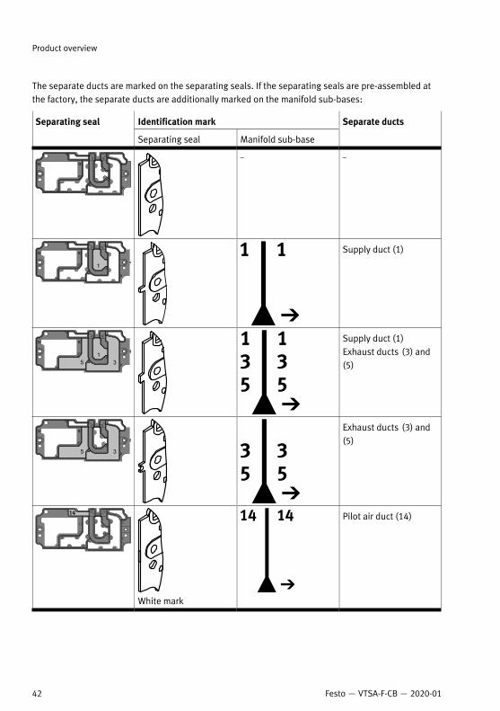
The separate ducts are marked on the separating seals. If the separating seals are pre-assembled atthe factory, the separate ducts are additionally marked on the manifold sub-bases:
Identification markSeparating seal
Separating seal Manifold sub-base
Separate ducts
– –
Supply duct (1)
Supply duct (1)Exhaust ducts (3) and(5)
Exhaust ducts (3) and(5)
White mark
Pilot air duct (14)
Product overview
42 Festo — VTSA-F-CB — 2020-01

Identification markSeparating seal
Separating seal Manifold sub-base
Separate ducts
Red mark
Pilot air duct (14)Supply duct (1)
Green mark
Pilot air duct (14)Supply duct (1)Exhaust ducts (3) and(5)
Tab. 23 Identification of the separate ducts
Additional information è Creation of Pressure Zones.
5.2.2 Electrical components
1 Left end plate (CPX terminal)
2 Other CPX modules (optional)
3 Bus node
4 Pneumatic interface
Fig. 25 Electrical connection of the valve terminal
The valve terminal is electrically connected to the CPX terminal via the pneumatic interface.
5.2.2.1 Pneumatic interfaceThe pneumatic interface connects the CPX terminal to the pneumatic part of the valve terminal.Depending on the pneumatic interface variant, up to 3 safe voltage zones can be formed in the pneu-matic part of the valve terminal è 5.1.2.1 Formation of Voltage Zones.
Product overview
43Festo — VTSA-F-CB — 2020-01

Variants of the Pneumatic Interfaces
Type code Power supply of the voltagezones
Characteristics
VABA-S6-1-X1-CB
VABA-S6-1-X2-CB
Common power supply for allvoltage zones
If a cross-fault proof ballast isused:– 1 safe zone
VABA-S6-1-X1-3V-CB
VABA-S6-1-X2-3V-CB
Separate power supply for eachvoltage zone possible
If a cross-fault proof ballast isused:– 3 additional supplies for
valves X0, X1, X2
Separate power supply for eachvoltage zone possible
Integrated output module CPX-FVDA-P2 (PROFIsafe)– 3 internal safe zones: CH0,
CH1, CH2
Product overview
44 Festo — VTSA-F-CB — 2020-01

Type code Power supply of the voltagezones
Characteristics
VABA-S6-1-X2-F1-CB
VABA-S6-1-X2-F2-CB
Separate power supply for eachvoltage zone possible Integrated output module CPX-
FVDA-P2 (PROFIsafe)– 2 internal safe zones: CH0,
CH1– 1 safe output: CH2 (M12
connection)
Tab. 24 Variants of the Pneumatic Interfaces
Product overview
45Festo — VTSA-F-CB — 2020-01

5.2.3 Display elements of the pneumatic components
1 Pressure gauge (optional)
2 Group error LED of the soft start valve
3 LED of solenoid coil 14 of special valves
4 LED of the pressure switch of the specialvalves
5 Solenoid coil LED 12
6 Solenoid coil LED 14
Fig. 26 Display elements of the pneumatic components
Meaning of the LED displays è 10.1 Diagnostics.
Product overview
46 Festo — VTSA-F-CB — 2020-01

5.2.4 Display elements of the electrical components
1 LEDs of the pneumatic interface
Fig. 27 Display elements of the electrical components
Depending on the variant of the pneumatic interface, the LEDs and the meaning of the LED displaysdiffer:• Pneumatic interfaces VABA-S6-1-X2-CB and VABA-S6-1-X2-3V-CBè 10.1.1.5 LED Displays of the Pneumatic Interfaces.
• Pneumatic interfaces with integrated output module CPX-FVDA-P2 è Brief description CPX-FVDA-P2.
Product overview
47Festo — VTSA-F-CB — 2020-01

5.2.5 Control elements of the pneumatic components
1 Cover caps for manual override
2 Adjusting knob
3 Operating pressure plug screw for one valveposition
4 Adjusting screw for controlled flow
5 “Air supply time” flow control screw
7 Manual override of the working valves (foreach pilot solenoid)
6 Manual override of the special valves
Fig. 28 Control elements of the pneumatic components
5.2.5.1 Manual override (MO)When the pressure supply is switched on, the manual override (MO) can be used to switch a valve toan electrically unactuated, de-energised state.
Manual overrides of the working valvesManual overrides are mainly used during commissioningè 9.1.1.3 Commissioning the Pneumatic Components with Manual Override (HHB).
Product overview
48 Festo — VTSA-F-CB — 2020-01

The valve-actuator combinations can be tested with the manual overridesè Testing valves and valve/actuator combination.The basic functions of the manual overrides can be changed by fitting an MO covercapè 9.1.2.1 Mounting the cover cap for manual override (optional).
Manual overrides of the special valvesManual overrides are mainly used during commissioningè 9.1.1.3 Commissioning the Pneumatic Components with Manual Override (HHB).
Product overview
49Festo — VTSA-F-CB — 2020-01

5.2.6 Connecting elements of the pneumatic components
1 Connection for pressure gauge (can beturned 90 °)
2 Connections (12) and (14) for supplying theexternal pilot air
3 Working ports (2) and (4), per valve position
4 Port (1) (individual operating pressure forone valve position)
5 Connection for pressure tapping on theswitched channel (1)
6 Exhaust port channel (3/5)
7 Supply port channel (1)
8 Exhaust port for channel (1)
9 Exhaust port channel (3)
10 Exhaust port channel (5)
Fig. 29 Connecting elements of the pneumatic components
Product overview
50 Festo — VTSA-F-CB — 2020-01

5.2.7 Connection elements of the electrical components
1 Service interface, e.g. operator unit
2 Fieldbus interface (fieldbus-specific)
3 Power supply connection
4 Earth terminal
Fig. 30 Connection elements of the electrical components
5.2.8 Labelling elements
Fig. 31 Inscription label for the pneumatic interface
Product overview
51Festo — VTSA-F-CB — 2020-01

Fig. 32 Inscription label holder
5.3 Operating modesDepending on the types of valve used, the following valve terminal operating modes can be used:– Standard operation with one or more pressure zones– Reversible operation with compressed air supply via ports (3) and (5) and exhaust via port (1)– Low-pressure operation at 0 … 3 bar– Vacuum operation at –0.9 … 0 bar
5.3.1 Vacuum or low-pressure operation
The following valves with supply via port (1) are not suitable for vacuum or low pressure:• Soft start valves• Pilot air valves with internal pilot air supply• 2x 3/2-way valves (ID codes H, K and N)
The following requirements must be fulfilled so that the valve terminal at the supply port (1) can beoperated with vacuum or low pressure between –0.9 … 3.0 bar:– The pilot control is operated with an external pilot air supply. – Pressure zones with vacuum or low pressure supply are equipped exclusively with the following
valves:– 5/2-way valves, monostable (ID codes M and O) – 5/2-way bistable valve (ID codes D and J)– 5/3-way mid-position valves (ID codes B, E and G)
5.3.2 Reverse OperationIn reverse operation of the valve terminal, the supply duct and the exhaust air ducts are interchanged:– Compressed air supply via duct (3/5) – Exhausting via duct (1)Requirements:– The valve terminal is operated with an external pilot air supply.– The valve terminal is equipped with valve types suitable for reversible operation:
– 5/2-way valves (ID codes D, J, M and O)– 5/3-way valves (ID codes B, E, G and VG)– Reversible 2x 2/2-way valves (ID code VV)
Product overview
52 Festo — VTSA-F-CB — 2020-01

– The valve terminal is not equipped with the following components:– Soft start valves– Pilot air valves with pilot pressure build-up from duct (1) of the pressure zone– Reversible pressure regulator plates– Pressure regulator plates for port (1) (P-closed-loop controller)– Vertical Pressure Shut-off Plates– Vertical supply plates
5.4 Address Assignment
5.4.1 Address assignment of the working valvesThe pneumatic interface bundles the addresses of the working valves. A total of up to 24 addressescan be controlled via the pneumatic interface.
Component Width [mm] Number of valve posi-tions
Number of occupiedaddresses per valveposition
Manifold sub-base for monostable valves
VABV-S4-2HS-G18-CB-2T1
18 2 1
VABV-S4-1HS-G14-CB-2T1
26 2 1
VABV-S2-1HS-G38-CB-T1
42 1 1
VABV-S2-2S-G12-CB-T1 52 1 1
Manifold sub-base for bistable valves
VABV-S4-2HS-G18-CB-2T2
18 2 2
1x 18, external pres-sure switch
1 2VABV-S4-12HS-G-CB-2T21)
1x 26 1 2
VABV-S4-1HS-G14-CB-2T2
26 2 2
VABV-S2-1HS-G38-CB-T2
42 1 2
VABV-S2-2S-G12-CB-T2 52 1 2
1) The switching signal of the pressure switch can be used in an external controller via the M12 connection.
Tab. 25 Address assignment of the working valves
Product overview
53Festo — VTSA-F-CB — 2020-01

5.4.2 Address Assignment of the Special ValvesThe special valves are independent bus participants. The special valves do not occupy pneumaticinterface addresses.
Component Width [mm] Number of valve posi-tions
Number of occupiedaddresses per valveposition
Manifold sub-base for the pilot air valve with additional valve position
1x 18, pressure switchplug-in
1 0VABV-S4-2HS-G18-CB-2T52)
1x 18 1 2
1x 18, pressure switchplug-in
1 0VABV-S4-12HS-G-CB-2T52)
1x 26 1 2
1x 18, external pres-sure switch
1 2VABV-S4-12HS-G-CB-2T21)
1x 26 1 2
Manifold sub-base for the soft start valve
VABV-S6-1Q-G12-CB1-T52)
VABV-S6-1Q-G38-CB-T52)
Soft start valve 1x 40 1 0
1) The switching signal of the pressure switch can be used in an external controller via the M12 connection.2) The switching signal of the pressure switch is sent to the CPX terminal via the internal communication.
Tab. 26 Address Assignment of the Special Valves
5.4.3 Address assignment of the vacuum generatorThe vacuum generator is an independent bus participant. The vacuum generator does not occupy anyaddresses of the pneumatic interface.
Component Number of valve positions Number of occupied addressesper valve position
Vacuum generator
VABF-S4-2-V2-... 1 0
Tab. 27 Address assignment of the vacuum generator
6 Transport and storageDepending on the configuration, the valve terminal can weigh >15 kg and have a large overall length. – Use suitable lifting equipment for the specified weight è Delivery note.– If present, do not remove the wooden substructure until after transport.
Transport and storage
54 Festo — VTSA-F-CB — 2020-01

7 Mounting
7.1 Mounting typesDepending on the design of the CPX modules, the following mounting types are possible:
Assembly Wall Mounting system H-rail
CPX module (metal)and VTSA/VTSA-F mod-ule (18 … 52 mm)
? ? Check mounting condi-tions
Tab. 28 Mounting types
Mounting conditions and dynamic load è Instructions for mounting CPX-VTSA.
7.2 Mounting the labelling elements
7.2.1 Mounting/dismounting the identification holderOptional identification holders can be mounted on the valves to identify pressure zones and voltagezones. The identification holder provides space for 1 IBS-6X10 inscription label and 2 ASCF-T-Sxlabels.
1 Identification holder 2 Mounting on the valve
Fig. 33 Mounting the identification holder
Assembly• Press the identification holder into the holder on the valve and snap it into place.
Mounting
55Festo — VTSA-F-CB — 2020-01

Disassembly• Pull the identification holder out of the holder on the valve.
8 Installation
8.1 Installation Pneumatics
8.1.1 Compressed Air Preparation
8.1.1.1 Operation with unlubricated compressed airUnfiltered compressed air will reduce the service life of the valve terminal.An excess of residual oil content in the compressed air will cause valves to malfunction, and will causethe life-time lubrication necessary for unlubricated operation to be washed out.• Maintain the residual oil content
– Organic oils (oils based on synthetic or native esters, e.g. rapeseed oil methyl ester): maxim-um residual oil content 0.1 mg/m3 ISO 8573-1:2010 [–:–:2]
– Mineral oils (e.g. HLP oils to DIN 51524 Parts 1 to 3) or oils based on polyalphaolefins (PAO):maximum residual oil content 5 mg/m3 ISO 8573-1:2010 [–:–:4]
8.1.1.2 Pressure rise in the overall supply
Supplying component Pressure rise in theoverall supply
Movement of the actu-ator
Pressure rise in thepilot air
Right end plate
Supply plate
Fast
Soft start valve withprovision of pilot air
Fast
Soft start valve withoutprovision of pilot air
Slow
–
Pilot air valve – Fast
Tab. 29 Pressure rise in the overall supply
The pressure increase of the total supply and the movement of the actuator depend on the supplyingcomponent.The pressure rise of the pilot air in duct (14) is independent of the supplying component. Dependingon the valve function, the working valves move immediately to the set switching position.
8.1.1.3 Preventing back pressureWhen exhausting large-volume actuators or if the exhaust performance is too low, back pressure maybuild up in the valve terminal's exhaust ducts. This back pressure can lead to pneumatic actuation ofother valves, especially with unswitched 3/2-way valves that are normally closed.
Installation
56 Festo — VTSA-F-CB — 2020-01

1. Optimise pressurisation and exhaust performance of the valve terminal, e.g. with the followingmeasures:– larger tubing diameters– additional pressure feed via pneumatic supply plates– Exhausting via pneumatic supply plates with silencer or exhaust plate– Separate è 11.2.1 Converting to Multiple Pressure Zonesexhaust air ducts by pressure zones
.2. Install check valves in common exhaust lines.
8.1.1.4 Check prerequisites for vacuum or low pressure operation (valves with Identcode VV)Before connecting valves with Identcode VV, check the requirements for vacuum or low-pressureoperation:– Supply operating pressure for the pneumatic springs at port (1).– Supply vacuum to port (5) and operating pressure to port (3) or vacuum to port (3) and operating
pressure to port (5).– To enable the ejector pulse during vacuum operation, establish a connection between the suction
line and the pressure supply line with a T-piece.
8.1.2 Connecting Pneumatic LinesObserve the following points when connecting the pneumatic lines:– For external pilot air supply, you only need to supply the pilot air at port (14).– If the internal pilot air supply (duct 14) is via a soft start valve or pilot air valve, do not connect an
additional pilot air supply.1. Mount the seals.2. Mount screw connections or silencers.3. Mount the tubing.
8.1.2.1 Position and Size of the Pneumatic Ports
Supply Ports for Valve Terminals with Pressure Supply via the Right-hand End Plate
1 Port (14) (optional)
2 Port (5)
3 Port (1)
4 Port (3)
5 Port (12)
Fig. 34 Supply ports for valve terminals with pressure supply via the right-hand end plate
Installation
57Festo — VTSA-F-CB — 2020-01

LinePort designation
Position of the connections1) Connection size
Valve terminal with valves 18 ...52 mm wide:– In the right end plate
End plate size 1:– G1/2End plate size 2:– G3/4
– In pneumatic supply plate – G1/2
Compressed air or vacuum1
– In pneumatic vertical supplyplate
Width 18 mm:– G1/8Width 26 mm:– G1/4Width 42 mm:– G3/8Width 52 mm:– G1/2
Compressed air1
– In the soft start valve – G1/2
– In exhaust plate – G1/2Exhaust air of valves3/5 or 3 and 5 Valve terminal with valves 18 ...
52 mm wide:– In the right end plate
End plate size 1:– G1/2End plate size 2:– G3/4
1) Depending on the order, the valve terminal is already equipped with connections.
Tab. 30 Supply and Disposal Connections
LinePort designation
Position of the connections 1) Connection size
Pilot control (external pilot air supply):
Pilot air2)
14Valve terminal with valves 18 ...52 mm wide:– In the right end plate
– G1/4
2 In the manifold sub-bases of thepilot air valves
– G1/8
1) Depending on the order, the valve terminal is already equipped with connections.2) The external pilot air supply is by default fed in via port (14).
Tab. 31 Pilot Air Connections
Installation
58 Festo — VTSA-F-CB — 2020-01

LinePort designation
Position of the connections1) Connection size
Working air
Working air or vacuum2 or 4
– In the manifold sub-bases Width 18 mm:– G1/8Width 26 mm:– G1/4Width 42 mm:– G3/8Width 52 mm:– G1/2
1) Depending on the order, the valve terminal is already equipped with connections.
Tab. 32 Working Ports
8.1.2.2 Common pneumatic lines
1 Valve terminal 1
2 Central pilot air exhaust line
3 Central exhaust line (3/5)
4 Valve terminal 2
5 Exhaust line 3/5
6 Pilot air exhaust line
Fig. 35 Pneumatic common lines with check valves
Installation
59Festo — VTSA-F-CB — 2020-01

8.1.2.3 Connecting the Right End Plate
End Plate VABE-… R-… (Internal Pilot Air Supply)
Fig. 36 Right end plate VABE-… R-… (internal pilot air supply)
• Check type of pilot air supply for valve terminal.The internally branched pilot air is supplied to the valves only via duct (14).
Installation
60 Festo — VTSA-F-CB — 2020-01

End Plate VABE-… RZ-… (External Pilot Air Supply)
1 Pilot exhaust air port (12) 2 Port (14) for external pilot air supply
Fig. 37 Right end plate VABE-… RZ-… (external pilot air supply)
1. Check type of pilot air supply for valve terminal.2. Supply external pilot air via port (14).
8.1.2.4 Mounting the tubing1. Press the tube into the tubing connection up to the stop.2. Right end plate in size 2: first mount the tubing at port (1) and then at ports (3) and (5).3. For better system clarity, bundle the installed tubing together with:
– Tubing straps– Multiple tubing holders
4. Seal unused connections with blanking plugs.
8.1.2.5 Removing the tubing1. Label all pneumatic tubing to avoid confusion when reconnecting them.2. Press down the lock ring of the fitting, e.g. with the releasing tool QSO from Festo.3. Remove the tubing from the fitting.
Installation
61Festo — VTSA-F-CB — 2020-01

8.1.3 Setting pressure regulator
Restrictions for AB pressure regulators:• The pressure regulator restricts the exhaust flow.• The pressure regulator cannot be adjusted in the exhausting state.
Example: the pressure regulator for duct (4) cannot be adjusted when the valve is pressurised inthe switching position from duct (1) to duct (2) and exhausted from duct (4) to duct (5).
8.1.3.1 Set pressure regulator with standard rotary knob
1 Fuse level
2 Setting level
3 Freewheel level
Fig. 38 Adjust pressure regulator - Width 18 mm and 26 mm
1 Fuse level
2 Setting level
Fig. 39 Positions of the standard rotary knob, construction width 42 mm and 52 mm
Pressure regulator in 52 mm widthIf the rotary knob to be adjusted is enclosed by the adjacent rotary knobs, briefly remove the rotaryknobs of the adjacent pressure regulators.
1. Pull the rotary knob from fuse level 1 to setting level 2.2. Setting the controlled variable è 13.3 Technical Data, Pneumatic.
Pressure regulators of 18 mm and 26 mm width:– Press the rotary knob into the freewheel level 3.
The rotary knob can be turned without changing the controlled variable.Turn the rotary knob lengthwise to the pressure regulator plate.
3. Press the rotary knob into fuse level 1.
On pressure regulators in the lockable version, a interlock prevents accidental adjustment of the con-trolled variable.
Installation
62 Festo — VTSA-F-CB — 2020-01

1 Interlock element, pushed out
Fig. 40 Locked rotary knob
• Push the interlock element 1 laterally out of the rotary knob.Ä The rotary knob is locked in the fuse level.
To fix the rotary knob, secure the interlock element with a padlock.
8.1.3.2 Setting pressure regulator with adjusting screw
1 Adjusting screw, internal hexagon socket spanner size2.0
Fig. 41 Adjusting screw
If the free space around the adjustment knob is not sufficient for adjusting the pressure regulator(width 18 mm or 26 mm), use the adjustment screw in the adjustment knob.• To adjust the controlled variable, turn è 13.3 Technical Data, Pneumaticadjusting screw 1.
8.1.3.3 Set pressure regulator with rotary knob with lock1. Turn the key 90° clockwise.Ä The rotary knob is pressed upwards and is in the control position.
2. Turn the rotary knob completely in the "-" direction.3. Pressurise valve terminal slowly.
Installation
63Festo — VTSA-F-CB — 2020-01

4. Turn the rotary knob in the “+” direction until the desired pressure is displayed on the pressuregauge.Observe permissible working pressureè Rating plate. Correctly pressurised, the input pressurep1 is at least 0.5 bar higher than the output pressure p2.
5. Press the rotary knob downward against spring force to the end position.6. Turn the key 90° anticlockwise.Ä The rotary knob is locked. The closed-loop controller cannot be adjusted.
If the key cannot be turned, the rotary knob is in an intermediate position. Turn the rotaryknob a few degrees clockwise or counterclockwise until it can be pressed down.
8.2 Electrical Installation
8.2.1 Connecting electrical cables
• Connect power supplyè Description of the CPX system (CPX-SYS-...).• Connect CPX modules è Descriptions of the CPX modules.• Long signal lines reduce the immunity to interference.
– Observe the maximum permissible signal cable length of 30 m.
8.2.1.1 Switch on the power supply
WARNING!
Risk of injury due to electric shock.• For the electrical power supply with extra-low voltages, use only PELV circuits that guarantee a
reliable separation from the mains network.• Observe IEC 60204-1/EN 60204-1.
The power supply to the valves is provided via the load voltage supply valves of the CPX terminal(UVAL).The power supply for the pressure switches and the vacuum generators is provided by the operatingpower supply (UEL/SEN). After switching off the load voltage supply, the pressure switches continue tobe supplied with voltage for the valves of the CPX terminal (UVAL).
Additional information:• Electrical installation è Description of the CPX system (CPX-SYS-...).• Address assignment è 5.4 Address Assignment.• Separate supply of the individual voltage zones è PROFIsafeSafe output module CPX-FVDA-P2
Prerequisite: the power supply of the CPX terminal is established.
Installation
64 Festo — VTSA-F-CB — 2020-01

8.2.1.2 Pin allocation
1 Plug connector X0
2 Plug connector X1
3 Plug connector X2
Fig. 42 Connections of the pneumatic interface VABA-S6-1-X2-3V-CB
Pin allocation for plug connector X0
1: not assigned
2: not assigned
3: 0 V CH0
4: +24 V CH0
5: functional earth
Tab. 33 Pin allocation pneumatic interface VABA-S6-1-X2-3V-CB
Pin allocation for plug connector X1
1: not assigned
2: not assigned
3: 0 V CH1
4: +24 V CH1
5: functional earth
Tab. 33 Pin allocation pneumatic interface VABA-S6-1-X2-3V-CB
Installation
65Festo — VTSA-F-CB — 2020-01

Pin allocation for plug connector X2
1: not assigned
2: not assigned
3: 0 V CH2
4: +24 V CH2
5: functional earth
Tab. 33 Pin allocation pneumatic interface VABA-S6-1-X2-3V-CB
Pin allocation for bushing X1
1: 0 V CH21)
2: +24 V CH21)
3: F–DO(M) CH22)
4: F–DO(P) CH22)
5: functional earth
1) Unswitched voltage UVAL can be used to supply intelligent load systems (auxiliary supply)2) All output voltages are likewise derived from the internal contact rail UVAL.
Tab. 34 Pin allocation pneumatic interface VABA-S6-1-X2-F2-CB
Pin allocation M12 connection of the pilot air valve
1: +24 V SENS
2: not assigned
3: 0 V SENS
4: SENS OUT
5: not assigned
Tab. 35 Pin allocation M12 connection of the pilot air valve
Installation
66 Festo — VTSA-F-CB — 2020-01

8.2.1.3 Earthing the valve terminal
1 Earth terminal
Fig. 43 Earth terminal
– Connect the earth terminal to the earth potential with low impedance (short cable with largecross-section).
– Further information è Description of the CPX system (CPX-SYS-...).
9 Commissioning
9.1 Commissioning of the Pneumatic Components
9.1.1 Testing Pneumatic Components
9.1.1.1 Determining the exhaust times of the pressure switchesIn order to query the exhausted status at the correct time, determine the exhaust times of the pres-sure switches.The exhaust times depend on the following factors:– Application, including drives and consumers– Configuration of the valve terminalIf the application or the configuration of the valve terminal is changed, recalculate the exhaust times.
Commissioning
67Festo — VTSA-F-CB — 2020-01

9.1.1.2 Testing valves and valve/actuator combination
Commissioning variants Activity
Preliminary test of the pneumatic tubing connec-tion
– Testing the valve-actuator combination byHHB
Complete commissioning of the complete system – Installing and connecting the overall system.– Program control via PLC/industrial PC.
Tab. 36 Commissioning variants
9.1.1.3 Commissioning the Pneumatic Components with Manual Override (HHB)
A valve that has been actuated by an electric signal cannot be reset by the manual override. The elec-trical signal is dominant in this case.• Reset the electrical signal before operating the manual override.
1. Switch on the compressed air supply.2. Reset electrical signals on controlled valves.3. Test the functioning and effect of each valve-actuator combination by actuating the corresponding
manual override.4. With detenting actuation of the HHB:
After testing the valves, make sure that all HHBs are unlocked so that the valves are back in nor-mal position.
5. Switch off the compressed air supply after testing the valves.
Non-detenting Operation of the Manual Override (Reset: Automatic)
Fig. 44
1. Use a screwdriver to push in the tappet of the MO until the valve switches.Ä The valve reverts to the switching position.
Commissioning
68 Festo — VTSA-F-CB — 2020-01

2. Keep the plunger of the MO pressed.Ä The valve remains in the switching position.
Fig. 45
3. Let go of the plunger.Ä Spring returns the MO plunger to its initial position.
Valve returns to normal position (not with bistable 5/2-way valves with ID codes D and J).
The detenting/non-detenting function of the manual override can be modified to only non-detentingactuation by mounting the MO cover cap.
Detenting Actuation of the Manual Override (Manual Reset)
Fig. 46
1. Use a screwdriver to push in the tappet of the MO until the valve switches.Ä The valve reverts to the switching position.
Commissioning
69Festo — VTSA-F-CB — 2020-01

2. Turn the plunger 90° clockwise up to the stop and leave it in position.Ä The valve remains in the switching position.
Fig. 47
3. Then turn the plunger 90° in an anti-clockwise direction up to the stop.4. Let go of the plunger.Ä Valve returns to normal position (not with bistable 5/2-way valves with ID codes D and J).
Non-detenting Operation of the HHB via Cover Cap Robust (Reset: Automatic)1. Press in the HHB plunger with the manual override (AHB) or screwdriver until the valve switches.Ä The valve reverts to the switching position.
2. Keep the plunger of the MO pressed.Ä The valve remains in the switching position.
3. Let go of the plunger.Ä Spring returns the MO plunger to its initial position.
Valve returns to normal position (not with bistable 5/2-way valves with ID codes D and J).
Detenting Actuation of HHB via Cover Cap Robust (Reset: Manual)
Fig. 48
1. Press in the manual override attachment (AHB) for HHB.Ä The valve reverts to the switching position.
Commissioning
70 Festo — VTSA-F-CB — 2020-01

2. Turn the manual override attachment clockwise by 90° to the stop in the switching position.Ä Manual override insert is locked in this position and cannot be removed.
The valve remains in the switching position.
Fig. 49
3. Turn the manual override attachment counterclockwise by 90° until it stops.Ä Manual override attachment is unlocked.
4. Pull out the manual override attachment.Ä Valve returns to normal position (not with bistable 5/2-way valves with ID codes D and J).
Detenting actuation of the manual override (manual reset)
Fig. 50
1. Press HHB down to the stop.Ä The valve reverts to the switching position.
Fig. 51
2. Pull HHB up to the stop.Ä Valve returns to normal position.
Commissioning
71Festo — VTSA-F-CB — 2020-01

Detenting operation of the manual override (reset: automatic)
Fig. 52
1. Press HHB down to the stop.Ä The valve reverts to the switching position.
2. Switch on pilot control.Ä HHB is reset by electrical signal.
Valve remains switched.
9.1.2 Completing commissioning of the pneumatic components
9.1.2.1 Mounting the cover cap for manual override (optional)
It takes additional force to remove the cover caps. The snap hooks of the cover caps can be damagedduring disassembly.• Mount the cover caps only after commissioning.
1 Cover cap for MO, non-detenting
2 Cover cap for MO, concealed
Fig. 53 Mounting of cover caps for MO, non-detenting and concealed
Commissioning
72 Festo — VTSA-F-CB — 2020-01

1 Cover cap for MO non-detenting/robust
Fig. 54 Mounting the cover cap for MO, non-detenting/robust
Prerequisite: the MO is in normal position.• Align the cover cap and clip the snap hooks into the recesses of the MO.Ä The cover cap is mounted.
9.1.2.2 Remove the cover cap for manual override (optional).
It takes additional force to remove the cover caps. The snap hooks of the cover caps can be damagedduring disassembly.
• Use a suitable screwdriver to lever the cover cap for the MO off the MO.
9.2 Commissioning of the Electrical Components
9.2.1 Safe output module CPX-FVDA-P2
Commissioning è Description CPX-FVDA-P2.
9.3 Parameterisation
9.3.1 Process Data
Process Data of the Soft Start ValvesThe process data belong to the following type codes:– VABF-S6-1-P5A4S2YE-G12-1T5-PA– VABF-S6-1-P5A4S1YE-G12-1T5-PA– VABF-S6-1-P5A4S2S-G12-1T5-PA– VABF-S6-1-P5A4S1S-G12-1T5-PA
Commissioning
73Festo — VTSA-F-CB — 2020-01
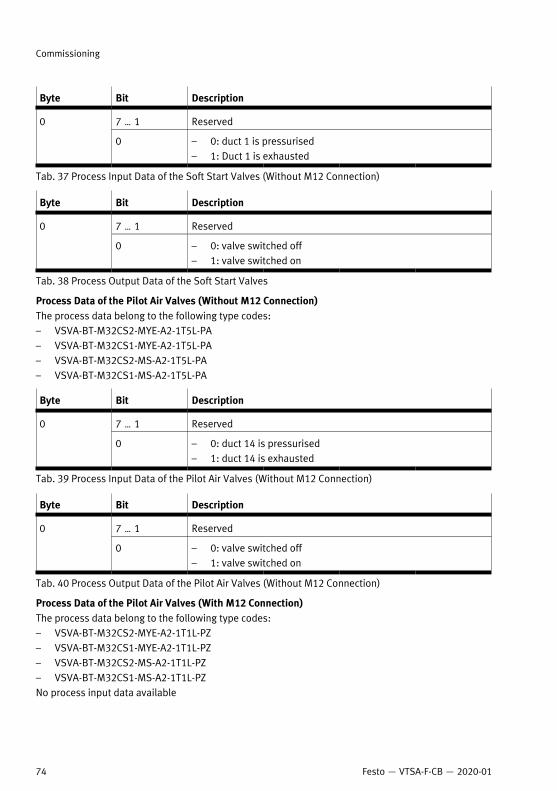
Byte Bit Description
7 … 1 Reserved0
0 – 0: duct 1 is pressurised– 1: Duct 1 is exhausted
Tab. 37 Process Input Data of the Soft Start Valves (Without M12 Connection)
Byte Bit Description
7 … 1 Reserved0
0 – 0: valve switched off– 1: valve switched on
Tab. 38 Process Output Data of the Soft Start Valves
Process Data of the Pilot Air Valves (Without M12 Connection)The process data belong to the following type codes:– VSVA-BT-M32CS2-MYE-A2-1T5L-PA– VSVA-BT-M32CS1-MYE-A2-1T5L-PA– VSVA-BT-M32CS2-MS-A2-1T5L-PA– VSVA-BT-M32CS1-MS-A2-1T5L-PA
Byte Bit Description
7 … 1 Reserved0
0 – 0: duct 14 is pressurised– 1: duct 14 is exhausted
Tab. 39 Process Input Data of the Pilot Air Valves (Without M12 Connection)
Byte Bit Description
7 … 1 Reserved0
0 – 0: valve switched off– 1: valve switched on
Tab. 40 Process Output Data of the Pilot Air Valves (Without M12 Connection)
Process Data of the Pilot Air Valves (With M12 Connection)The process data belong to the following type codes:– VSVA-BT-M32CS2-MYE-A2-1T1L-PZ– VSVA-BT-M32CS1-MYE-A2-1T1L-PZ– VSVA-BT-M32CS2-MS-A2-1T1L-PZ– VSVA-BT-M32CS1-MS-A2-1T1L-PZNo process input data available
Commissioning
74 Festo — VTSA-F-CB — 2020-01

Byte Bit Description
7 … 1 Reserved0
0 – 0: valve switched off– 1: valve switched on
Tab. 41 Process Output Data of the Pilot Air Valves (Without M12 Connection)
Process Data of the Pneumatic InterfacesThe process data belong to the following type codes:– VABA-S6-1-X1-CB– VABA-S6-1-X2-CB– VABA-S6-1-X1-3V-CB– VABA-S6-1-X2-3V-CB– VABA-S6-1-X2-F1-CB– VABA-S6-1-X2-F2-CB
Byte Bit Description
2 23 … 16 Solenoid coils SP23 … SP16
1 15 … 8 Solenoid coils SP15 … SP8
7 SP7
6 SP6
5 SP5
4 SP4
3 SP3
2 SP2
1 SP1
0
0 SP0:– 0: duct error (short circuit
or wire break)– 1: error-free operation
Tab. 42 Process Input Data of the Pneumatic Interfaces
Byte Bit Description
2 23 … 16 Solenoid coils SP23 … SP16
1 15 … 8 Solenoid coils SP15 … SP8
Commissioning
75Festo — VTSA-F-CB — 2020-01

Byte Bit Description
7 SP7
6 SP6
5 SP5
4 SP4
3 SP3
2 SP2
1 SP1
0
0 SP0:– 0: valve switched off– 1: valve switched on
Tab. 43 Process Output Data of the Pneumatic Interfaces
9.3.2 Special Features of Module Numbering
Module Numbering of the CPX TerminalEach bus participant receives a module number. The module number is counted from left to right, thebus participant on the far left receives the module number 1. Each additional bus participant receivesthe next highest module number.Working valves do not receive a module number.
Module Numbering of the Pneumatic Interfaces
Type code Characteristics Number of bus stations Number of assignedmodule numbers
VABA-S6-1-X2-CB
VABA-S6-1-X2-3V-CB
– 1
VABA-S6-1-X2-F1-CB
VABA-S6-1-X2-F2-CB
Integrated output mod-ule CPX-FVDA-P2(PROFIsafe)
2
1
Tab. 44 Module Numbering of the Pneumatic Interfaces
9.3.3 Module Parameters
9.3.3.1 Monitoring CPX ModuleMonitoring of the possible errors can be activated or deactivated (suppressed) independently for eachmodule.Active monitoring causes the following:– Error is sent to the bus node.– Error is displayed by the module common error LED.Monitoring can also be set for the entire CPX terminal è Description of CPX system (CPX-SYS -...).
Commissioning
76 Festo — VTSA-F-CB — 2020-01
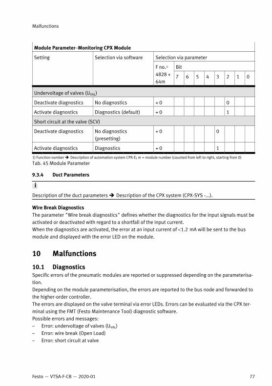
Module Parameter–Monitoring CPX Module
Selection via parameter
Bit
Setting Selection via software
F no.1)
4828 +64m
7 6 5 4 3 2 1 0
Undervoltage of valves (UVAL)
Deactivate diagnostics No diagnostics + 0 0
Activate diagnostics Diagnostics (default) + 0 1
Short circuit at the valve (SCV)
Deactivate diagnostics No diagnostics(presetting)
+ 0 0
Activate diagnostics Diagnostics + 0 1
1) Function number è Description of automation system CPX-E; m = module number (counted from left to right, starting from 0)
Tab. 45 Module Parameter
9.3.4 Duct Parameters
Description of the duct parameters è Description of the CPX system (CPX-SYS -...).
Wire Break DiagnosticsThe parameter "Wire break diagnostics" defines whether the diagnostics for the input signals must beactivated or deactivated with regard to a shortfall of the input current.When the diagnostics are activated, the error at an input current of <1.2 mA will be sent to the busmodule and displayed with the error LED on the module.
10 Malfunctions
10.1 DiagnosticsSpecific errors of the pneumatic modules are reported or suppressed depending on the parameterisa-tion. Depending on the module parameterisation, the errors are reported to the bus node and forwarded tothe higher-order controller.The errors are displayed on the valve terminal via error LEDs. Errors can be evaluated via the CPX ter-minal using the FMT (Festo Maintenance Tool) diagnostic software.Possible errors and messages:– Error: undervoltage of valves (UVAL)– Error: wire break (Open Load)– Error: short circuit at valve
Malfunctions
77Festo — VTSA-F-CB — 2020-01

10.1.1 Diagnostic Interfaces
10.1.1.1 Diagnostic Messages of the Pneumatic Interfaces
Error number Description Error handling
5 Valve load voltage faultLoad voltage of valves (UVAL) ismissing or too low.1)
– Check load voltage
11 Short circuit at valve errorShort circuit/overload at valve.
– Check valves as well as their correctassembly and electrical connection
– Replace valve if necessary
13 Wire break errorQuiescent current monitoring ofthe valve solenoid coils (openload, only with logic 0 active).
– Check valves as well as their correctassembly and electrical connection
– Replace valve if necessary– If necessary, correct incorrect paramet-
erisation (e.g. with reserved valve posi-tions or cover plates)
1) For tolerance range of load voltage supply UVAL, see technical data in the appendix
Tab. 46 Diagnostic Messages of the Pneumatic Interfaces
10.1.1.2 LED Displays of the Valves
1 Solenoid coil LED 12
2 Solenoid coil LED 14
3 Valve width 52 mm
4 Valve width 42 mm
5 Valve width 26 mm
6 Valve width 18 mm
Fig. 55 Arrangement of LEDs for the solenoid coils
Each solenoid coil is assigned an LED. The LEDs show the switching status of the solenoid coils.
Malfunctions
78 Festo — VTSA-F-CB — 2020-01

LED Meaning
LEDs of the solenoid coils 12 and 14
Off – Solenoid coil in normal position– Logic 0 (no signal)
– Solenoid coil in switching position– Logic 1 (signal is present)
Lightsupyel-low1)
– Solenoid coil in normal position– Logic 1The following malfunctions may be present:– Operating voltage of the valves is outside the permissible tolerance range (DC
21.6 V … 26.4 V)– Compressed air supply not OK– Pilot exhaust air blocked– Service required
1) With bistable valves the LED lights up only when the electric pulse is present.
Tab. 47 LED Displays of the Valves
10.1.1.3 LED Displays of the Soft Start Valves
LED Meaning
Solenoid coil LED 14
Off – Solenoid coil in normal position– Logic 0 (no signal)
– Solenoid coil in switching position– Logic 1 (signal is present)
Lightsupyellow – Solenoid coil in normal position
– Logic 1The following malfunctions may be present:– Operating voltage of the valves is outside the permissible tolerance range (DC
21.6 V … 26.4 V)– Compressed air supply not OK– Pilot exhaust air blocked– Service required
LED of the pressure switch
Lightsupgreen
– Pressure in duct (1) is exhausted.– Bit on the CPX terminal is set (bit: 1).
Malfunctions
79Festo — VTSA-F-CB — 2020-01
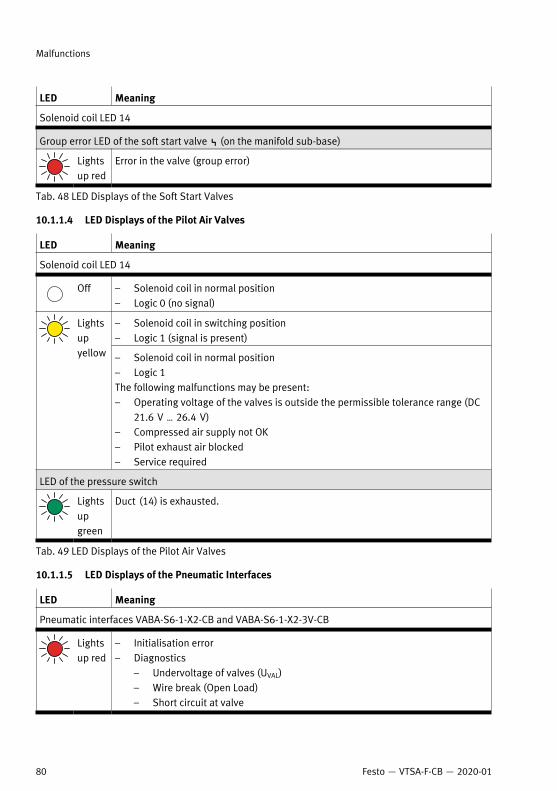
LED Meaning
Solenoid coil LED 14
Group error LED of the soft start valve P (on the manifold sub-base)
Lightsup red
Error in the valve (group error)
Tab. 48 LED Displays of the Soft Start Valves
10.1.1.4 LED Displays of the Pilot Air Valves
LED Meaning
Solenoid coil LED 14
Off – Solenoid coil in normal position– Logic 0 (no signal)
– Solenoid coil in switching position– Logic 1 (signal is present)
Lightsupyellow – Solenoid coil in normal position
– Logic 1The following malfunctions may be present:– Operating voltage of the valves is outside the permissible tolerance range (DC
21.6 V … 26.4 V)– Compressed air supply not OK– Pilot exhaust air blocked– Service required
LED of the pressure switch
Lightsupgreen
Duct (14) is exhausted.
Tab. 49 LED Displays of the Pilot Air Valves
10.1.1.5 LED Displays of the Pneumatic Interfaces
LED Meaning
Pneumatic interfaces VABA-S6-1-X2-CB and VABA-S6-1-X2-3V-CB
Lightsup red
– Initialisation error– Diagnostics
– Undervoltage of valves (UVAL)– Wire break (Open Load)– Short circuit at valve
Malfunctions
80 Festo — VTSA-F-CB — 2020-01

LED Meaning
Pneumatic interfaces VABA-S6-1-X2-CB and VABA-S6-1-X2-3V-CB
Pneumatic interfaces with integrated output module CPX-FVDA-P2
è Brief description of CPX-FVDA-P2.
Tab. 50 LED Displays of the Pneumatic Interfaces
10.2 Fault Clearance
Fault description Cause Remedy
Air flows out of a common line. Insufficient fitting of tubing intothe fittings or fitting in the sub-base.
Check tubing connections.
Air flows out of a working line. Insufficient fitting of tubing intothe fittings or fitting in the sub-base.
Check tubing connections.
Valve or pneumatic system doesnot react as expected.
– – Check routing of tubinglines.
– Check the electrical wiring.
Ducts (3), (5) or (12) intendedfor exhaust air are sealed
– Check pneumatic circuit andpressure zone formation.
– Check pressure zones forsupply with operating andpilot pressure.
Detenting manual override ofthe working valves in switchingposition
Bring the detenting manualoverride of the working valvesinto the initial position.
Valve or pneumatic system doesnot respond.
– Service required
Tab. 51
10.3 RepairSend the product to the Festo repair service for repair.
Malfunctions
81Festo — VTSA-F-CB — 2020-01

11 Modification
11.1 Replacing Valve Terminal Components
11.1.1 Replacing Valves or Cover Plates
Disassembly
Fig. 56 Dismantling of valves or cover plates (not illustrated)
1. Unscrew retaining screws of component.– Size of Allen key è Tab. 52 Tightening Torques.
2. Remove component.
Assembly1. Replace damaged seals.2. Insert the seal into the recess of the component.3. Place component onto the manifold sub-base.4. Screw in the retaining screws.5. Tighten retaining screws.
– Tightening torques è Tab. 52 Tightening Torques.
Width Valve Tightening torque ofscrew
Spanner size forinternal hexagon sock-et
18 mm VSVA-…-A2 1.0 Nm ± 10 % 2.5
Modification
82 Festo — VTSA-F-CB — 2020-01

Width Valve Tightening torque ofscrew
Spanner size forinternal hexagon sock-et
26 mm VSVA-…-A1 2.0 Nm ± 10 % 3
42 mm VSVA-…-D1 3.0 Nm ± 20 % 4
52 mm VSVA-…-D2 6.5 Nm ± 20 % 5
Soft start valve 3.0 Nm ± 20 % 4
Pilot Air Valve 1.0 Nm ± 10 % 2.5
Tab. 52 Tightening Torques
Depending on the manifold sub-base, 1 or 2 solenoid coils can be actuated per valve positionè 5.4 Address Assignment.
11.1.2 Replacing exhaust plate or exhaust air cover
Disassembly1. Loosen the retaining screws of the exhaust plate or the exhaust air cover.2. Remove the exhaust plate or exhaust air cover.
Assembly1. Replace damaged seals.2. Make sure that the seal is seated correctly in the groove in the pneumatic supply plate.3. Attach the exhaust plate or exhaust air cover.4. Screw in the retaining screws of the exhaust plate or the exhaust air cover.5. Tighten retaining screws.
– Tightening torque 2.2 Nm (± 10 %)
11.1.3 Replacing or Adding Vertical Stacking Components
If vibrations and shocks with severity level 2 are expected, install a maximum of one vertical stackingcomponent per valve position.• Reverse operation of the valve terminal è 5.3.2 Reverse Operation.• When equipped with a vertical pressure shut-off plateè 5.2.1.10 Vertical Pressure Shut-off Plates.
• To keep connections and control elements accessible, adhere to the assembly sequence.
Modification
83Festo — VTSA-F-CB — 2020-01

1 Pressure regulator plate
2 Throttle plate
3 Vertical pressure shut-off plate
4 Vertical supply plate
Fig. 57 Assembly sequence for vertical stacking
Disassembly1. Loosen the screws of the components above the new component.2. Remove components.
Assembly1. Replace damaged seals.2. Place a new component on the valve position or on a mounted component.3. Screw in the retaining screws of the new component.
Modification
84 Festo — VTSA-F-CB — 2020-01

4. Tighten the retaining screws of the new component:
WidthComponent
18 mm 26 mm 42 mm 52 mm
Valves
Width across flats 2.5 3.0 4.0 5.0
Tightening torque 1.0 Nm ± 10 % 2.0 Nm ± 10 % 3.0 Nm ± 20 % 6.5 Nm ± 20 %
Vertical stacking components
Width across flats 2.0 2.5 3.0 4.0
Tightening torque 1.0 Nm ± 10 % 2.0 Nm ± 10 % 3.0 Nm ± 15 % 5.0 Nm ± 20 %
Tab. 53 Vertical Stacking: Allen key Sizes and Tightening Torques
5. Reinstall disassembled components.
11.1.4 Replacing the Manifold Sub-bases or Right End Plate
The use of non-permitted manifold sub-bases will cause irreparable damage to the valve terminal.• Only use manifold sub-bases with a black electrical manifold module.• Only mount pilot air valves on the manifold sub-base of the pilot air valve.
The number of manifold sub-bases with which the valve terminal can be equipped depends on:• Type of manifold sub-base• Electrical connectionAddress assignment è 5.4 Address Assignment.
Disassembly1. Loosen electrical and pneumatic connections.2. Remove the valve terminal from the mounting surface è Assembly instructions VABV-S6-1Q -... .3. Place valve terminal on a flat working surface.
Modification
85Festo — VTSA-F-CB — 2020-01

Fig. 58 Position of the screws using the example of the right-hand end plate
4. Remove the screws of the component and the adjacent component.Ä The components are only held together by the electrical manifold module.
5. Remove the component from the adjacent components.
Modification
86 Festo — VTSA-F-CB — 2020-01
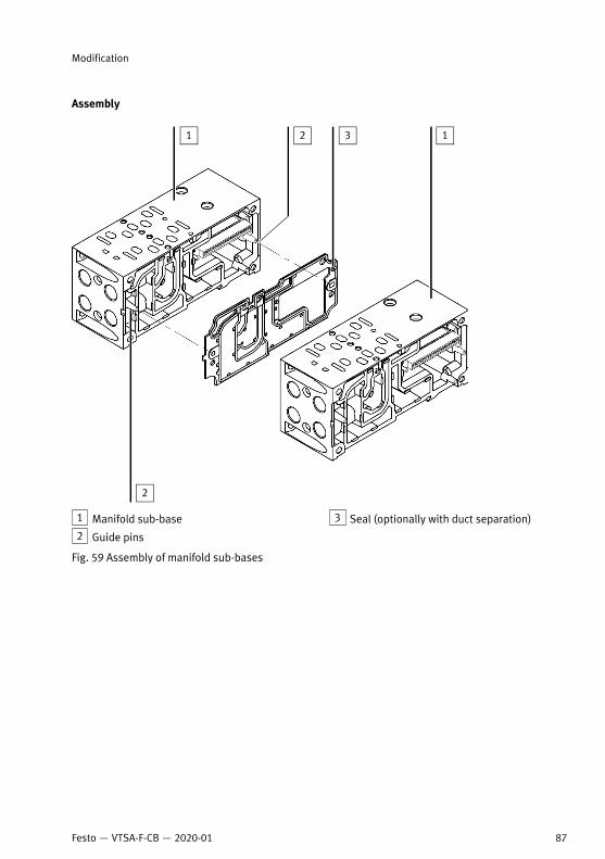
Assembly
1 Manifold sub-base
2 Guide pins
3 Seal (optionally with duct separation)
Fig. 59 Assembly of manifold sub-bases
Modification
87Festo — VTSA-F-CB — 2020-01

1 Manifold sub-base
2 Guide pins
3 Seal (optionally with duct separation)
4 Right end plate
Fig. 60 Assembly of right end plate
1. Replace damaged seals. 2. Place the seal on the guide pins.3. Screw in the screws of the components.4. Tighten screws.
– Tightening torque 3.0 Nm (± 10 %)5. Place the valve terminal on the mounting surface.6. Connect pneumatic lines è 8.1.2 Connecting Pneumatic Lines.7. Connect electrical cables è 8.2.1 Connecting electrical cables.
11.2 Converting the Valve Terminal
11.2.1 Converting to Multiple Pressure ZonesIn order to convert the valve terminal to 2 and more pressure zones, the following components arerequired for each pressure zone:– Separating seal VABD-S6-1 -...- C– Pneumatic supply plate with exhaust plate or exhaust air cover VABF -...- 1P1A...
Modification
88 Festo — VTSA-F-CB — 2020-01

Disassembly1. Loosen electrical and pneumatic connections.2. Remove valve terminal from the mounting surface.3. Place valve terminal on a flat working surface.4. Loosen the manifold sub-base to which a separating seal is to be fitted è Disassembly.
Assembly
1 Valves in pressure zone 1
2 Valves in pressure zone 2
3 Valves in pressure zone 3
4 Pneumatic supply plate with port (1) forcompressed air supply to the pressure zone3
5 Identification of the separating seal
6 Supply plate with port (1) for compressedair supply to pressure zone 2
7 Supply plate with port (1) for compressedair supply to pressure zone 1
Fig. 61 Conversion to several pressure zones
Modification
89Festo — VTSA-F-CB — 2020-01

If the valve terminal is also equipped with other valves, operate reversible 2x 2/2-way valves (ID codeVV) in a separate pressure zone with separate exhaust ducts (3) and (5).
1. Place separating seal on the guide pins of the manifold sub-base.2. Mount the manifold sub-base è Assembly.
11.2.2 Converting to Internal or External Pilot Air Supply
Right End Plates– Replace right end plate è 11.1.4 Replacing the Manifold Sub-bases or Right End Plate.
Pilot Air Valve1. Replace pilot air valve.2. If the pilot air valve is used for the internal pilot air supply, seal duct (2) on the manifold sub-base
of the pilot air valve with a blanking plug.
11.2.3 Convert to ducted pilot exhaust airRequirements:– Port (12) in the right end plate is open.– The valve terminal is not equipped with soft start valves or pilot air valves.1. Remove the valve from the manifold sub-base.
1 Designation label 2 Display window on control side 12
Fig. 62 Convert to ducted pilot exhaust air
2. Insert the seal with the designation label into the display window on control side 12.3. Mount the valve on the manifold sub-base.
Modification
90 Festo — VTSA-F-CB — 2020-01

11.2.4 Mounting the Pilot Air Valve
• Mount pilot air valves with internal communication only on the manifold sub-base for the pilot airvalve.
11.2.5 Mounting the Soft Start ValveFor valve terminals with soft start valve, the following must be observed:– When using multiple soft start valves, comply with the electrical regulations for creating voltage
zones è 5.1.2.1 Formation of Voltage Zones.– Install a maximum of one pressure-supplying component in each pressure zone, such as a soft
start valve.– Seal unused ports with blanking plugs è Assembly instructions VABV-S6-1Q -... .– Information on combining a soft start valve, pneumatic supply plate and right end plateè Assembly instructions VABV-S6-1Q -...
11.2.6 Mounting the Vacuum Generator
Mount the vacuum generator directly next to the right end plate.1. Place the vacuum generator on the manifold sub-base.2. Tighten the retaining screws of the vacuum generator.
– Tightening torque: 3 Nm (±10 %)3. Screw the manifold sub-base of the vacuum generator to other manifold sub-bases.
– Tightening torque 3 Nm (±10 %)
11.3 Disconnecting the Valve Terminal and CPX TerminalDisassembly1. Loosen electrical and pneumatic connections.2. Remove valve terminal from the mounting surface.3. Remove the screws between the pneumatic interface and the pneumatic part of the valve termin-
al.
Replace pneumatic interface è Description of CPX system (CPX-SYS -...).
Modification
91Festo — VTSA-F-CB — 2020-01

Assembly
1 Pneumatic interface
2 Guide pins
3 Seal
4 Manifold sub-base
Fig. 63 Mount the manifold sub-base to the pneumatic interface
1. Replace damaged seals.2. Place the seal on the guide pins.
Only use pneumatic interfaces with a black electrical manifold module.
3. Push the pneumatic interface together with the pneumatic part of the valve terminal.4. Turn in screws.5. Tighten screws.
– Tightening torque 3.0 Nm (± 10 %)6. Place the valve terminal on the mounting surface.7. Connect pneumatic lines è 8.1.2 Connecting Pneumatic Lines.
Modification
92 Festo — VTSA-F-CB — 2020-01

8. Connect electrical cables:– Valve terminal è 8.2.1 Connecting electrical cables.– CPX terminal è Description of CPX system (CPX-SYS -...).
11.4 Adding Valve PositionsThe smallest extension unit is a manifold sub-base:– For widths 18 mm and 26 mm with 2 valve positions– For widths 42 mm and 52 mm with 1 valve positionThe following components are required to extend the valve terminal:
Type codeComponents
Width 18 mm and 26 mm Width 42 mm and 52 mm
Manifold sub-base which sup-ports 1 solenoid coil per valveposition
VABV…-2T1 VABV…-T1
Manifold sub-base which sup-ports 2 solenoid coils per valveposition
VABV…-2T2 VABV…-T2
Valve VSVA-B-…
Cover plate VABB… -WT
Tab. 54 Required Components for Valve Position Extension
If a manifold sub-base is added, the address assignment of all valves to the right of the added mani-fold sub-base changes.
Disassembly1. Remove valve terminal from the mounting surface.2. Remove the manifold sub-base or pneumatic supply plate at the point at which the valve terminal
is extended è Disassembly.
Assembly1. Mount additional manifold sub-base and, if necessary, an additional pneumatic supply plateè Assembly.
2. Mount components– Vertical stacking components è Assembly– Valves or cover plates è Assembly
12 DisposalENVIRONMENT!
Send the packaging and product for environmentally sound recycling in accordance with the currentregulations è www.festo.com/sp.
Disposal
93Festo — VTSA-F-CB — 2020-01

13 Technical data
13.1 Ambient conditions
The valves can be operated up to a temperature of -5 °C. At low temperatures, condensate and mois-ture can freeze.Recommendation:• To remove condensate and moisture, install a dryer.
Ambient conditions
Permissible temperat-ure range
– Long-term storage [°C] -20 … 60
– Operation [°C] -5 … 50
– Medium [°C] -5 … 50
Relative humidity [%] 0 … 90
Degree of protection(with cable from Festoaccessories)
IP65
Corrosion protection Corrosion resistance class CRC 0
Mounting position As desired, with H-rail mounting, horizontal only
Vibration resistance Transport application test with severity level 2 in accordancewith FN 942017-4 and EN 60068-2-6
Shock resistance Shock test with severity level 2 in accordance with FN 942017-5and EN 60068-2-27
Tab. 55 Technical data: ambient conditions
13.2 Technical data, mechanical
WidthMechanical
18 mm 26 mm 42 mm 52 mm
Weights
Left end plate (CPX ter-minal)
[g] Approx. 80
Complete CPX module [g] Approx. 210
Pneumatic interface [g] 1470
Technical data
94 Festo — VTSA-F-CB — 2020-01

WidthMechanical
18 mm 26 mm 42 mm 52 mm
Supply plate withexhaust plate
[g] 600
Supply plate withexhaust air cover
[g] 611
Soft start valve withmanifold sub-base
[g] 1200
Right end plate (axialconnections)
[g] 339
Manifold sub-base1) [g] 447 634 340 591
Valve [g] Approx. 180 Approx. 320 Approx. 450 Approx. 726
Cover plate for unas-signed valve position
[g] 34 73 68 145
Pressure regulatorplate (P)
[g] 350 402 640 1190
Pressure regulatorplate (A or B)
[g] 367 448 640 1230
Pressure regulatorplate (AB)
[g] 611 692 920 1990
Throttle plate [g] 228 320 220 565
Vertical supply plate [g] 140 191 340 605
Vertical pressure shut-off plate
[g] 209 273 600 1030
Materials
Die-cast aluminium, aluminium, steel, brass, polyamide, nitrilerubber, elastomer, polyoxymethylene
Tightening torques
Bracket on pneumaticsupply or manifold sub-base
[Nm] 3.0 ± 10 %
Valve on manifold sub-base
[Nm]
Cover plate on mani-fold sub-base
[Nm]
1.0 ± 10 % 2.0± 10 % 3.0 ± 15 % 6.5 ± 20 %
Technical data
95Festo — VTSA-F-CB — 2020-01

WidthMechanical
18 mm 26 mm 42 mm 52 mm
Exhaust plate orexhaust air cover onsupply plate
[Nm] 2.2 ± 10 % 3.0 ± 10 % 3.3 ± 15 %
Manifold sub-base/endplate
[Nm] 3.0± 10 % 3.0± 20 % 3.0± 10 %
Vertical stacking [Nm] 1.0 ± 10 % 2.0± 10 % 3.0 ± 15 % 5.0± 20 %
Soft start valve [Nm] 3 ± 10 %
Pilot air valve [Nm] 1 ± 10 %
Vacuum generator [Nm] 4 ± 10 %
1) width 18 mm and 26 mm for two valve positions; width 42 mm for one valve position
Tab. 56 Technical data, mechanical
13.3 Technical Data, Pneumatic
Pneumatics
Medium
– Compressed air as per ISO 8573-1-2010 [7:4:4]– Inert gases– Lubricated operation not permissible
Design
– Piston spool valves– Poppet valves (pilot air valves)
Operating pressure/pilot pressure of valves
Soft start valve– Pilot air not from
connection (1) ofmanifold sub-base
[bar] 2 … 10
– Pilot air from con-nection (1) of themanifold sub-base
[bar] 3 … 10
Pilot Air Valve [bar] 3 … 10
Vacuum generator– Operating pressure
[bar] 4 … 8
– Pilot pressure [bar] 4 … 10
Technical data
96 Festo — VTSA-F-CB — 2020-01

Pneumatics
Directional controlvalve with internal pilotair supply
[bar] Port (1): 3 … 10
Directional controlvalves with externalpilot air supply– 5/2-way valves– 5/3-way valves
[bar]
– 2x 3/2-way valves(ID codes H, K, N)
– 2x 2/2-way valve(ident code VC)
[bar]
The pilot pressure depends on the operating pressureè Description Valve terminal VTSA-F-CB, Technical data pneu-matic.
Control pressure of the pressure regulator
A, B and AB pressureregulators up to 6 bar(ID codes ZH, ZHY, ZI,ZIY)
[bar] 2 … 6
A, B and AB pressureregulators up to 10 bar(ID codes ZC, ZCY, ZD,ZDY)
[bar] 2 … 10
P pressure regulatorsand reversible pressureregulators up to 6 bar(ID codes ZF, ZFY)
[bar] 0.5 … 6
P pressure regulatorsand reversible pressureregulators up to 10 bar(ID codes ZA, ZAY)
[bar] 0.5 … 10
Manual override
Working valves Non-detenting or detenting by turning
Soft start valve
Pilot Air Valve
Detenting, electrical self-resetting
Tab. 57 Medium and Pressure Range of the Valve Terminal
Technical data
97Festo — VTSA-F-CB — 2020-01

1 Pilot pressure
2 Operating range for valves with externalpilot air supply
3 Operating pressure
Fig. 64 Required pilot pressure of the external pilot air supply for 2x 2/2-way valves (ID codes VC, VV)and 2x 3/2-way valves (ident. codes H, K, N)
Technical data
98 Festo — VTSA-F-CB — 2020-01

1 Pilot pressure
3 Operating pressure
2 Operating range for valves with externalpilot air supply
Fig. 65 Required pilot pressure of the external pilot air supply for 5/2-way valves (ID codes D, J, M, O)and 5/3-way valves (ident. codes B, E, G)
The fittings of the pneumatic ports reduce the nominal flow rate of the valves.
Standard nominal flow rates valves VSVA-B-... (width 18 mm)
ID code Valve assembly Standard nominal flow rates[l/min]
VC
VV
2x 2/2-way valve 650
H
K
N
2x 3/2-way valve 550
D
J
M
O
5/2-way valve 700
Technical data
99Festo — VTSA-F-CB — 2020-01
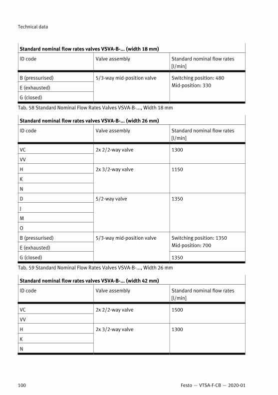
Standard nominal flow rates valves VSVA-B-... (width 18 mm)
ID code Valve assembly Standard nominal flow rates[l/min]
B (pressurised)
E (exhausted)
G (closed)
5/3-way mid-position valve Switching position: 480Mid-position: 330
Tab. 58 Standard Nominal Flow Rates Valves VSVA-B-..., Width 18 mm
Standard nominal flow rates valves VSVA-B-... (width 26 mm)
ID code Valve assembly Standard nominal flow rates[l/min]
VC
VV
2x 2/2-way valve 1300
H
K
N
2x 3/2-way valve 1150
D
J
M
O
5/2-way valve 1350
B (pressurised)
E (exhausted)
Switching position: 1350Mid-position: 700
G (closed)
5/3-way mid-position valve
1350
Tab. 59 Standard Nominal Flow Rates Valves VSVA-B-..., Width 26 mm
Standard nominal flow rates valves VSVA-B-... (width 42 mm)
ID code Valve assembly Standard nominal flow rates[l/min]
VC
VV
2x 2/2-way valve 1500
H
K
N
2x 3/2-way valve 1300
Technical data
100 Festo — VTSA-F-CB — 2020-01

Standard nominal flow rates valves VSVA-B-... (width 42 mm)
ID code Valve assembly Standard nominal flow rates[l/min]
D
J
M
O
5/2-way valve 1860
B (pressurised)
E (exhausted)
G (closed)
Switching position: 1690Mid-position: 830
VG (pressurised 1 to 2, 4 to 5closed)
5/3-way mid-position valve
Switching position: 1700Mid-position: 700
Tab. 60 Standard Nominal Flow Rates Valves VSVA-B-..., Width 42 mm
Standard nominal flow rates valves VSVA-B-... (width 52 mm)
ID code Valve assembly Standard nominal flow rates[l/min]
VC 2x 2/2-way valve 3400
H
K
N
2x 3/2-way valve 2600
D
J
M
O
5/2-way valve 3400
B (pressurised)
E (exhausted)
G (closed)
Switching position: 3200Mid-position: 1700
VG (pressurised 1 to 2, 4 to 5closed)
5/3-way mid-position valve
Switching position: 2600Mid-position: 900
Tab. 61 Standard Nominal Flow Rates Valves VSVA-B-..., Width 52 mm
Technical data
101Festo — VTSA-F-CB — 2020-01

Standard nominal flow rates soft start valves VABF-S6-1-…
Standard nominal flow rates [l/min]Soft start valve
Pressurisation Exhausting
VABF-S6-1-… 3000 3300
Tab. 62 Standard nominal flow rates soft start valves VABF-S6-1-…
Standard nominal flow rates pilot air valves VSVA-BT-M32CS...
Standard nominal flow rates [l/h]Pilot Air Valve
Pressurisation Exhausting
VSVA-BT-M32CS... 125 125
Tab. 63 Standard Nominal Flow Rates Pilot Air Valves VSVA-BT-M32CS...
Valve Switching Times VSVA-B-... With Nominal Operating Voltage 24 V DC (18 mm wide)
Valve switching times [ms]1)ID code Valve assembly
On Reverse Off
VC
VV
2x 2/2-way valve
H
K
N
2x 3/2-way valve
12 – 30
D 13
J
5/2-way valve,impulse
–
11
–
M 5/2-way valve,monostable, airspring
22 28
O 5/2-way valve,monostable,spring
12
–
38
B
I
G
5/3-way mid-posi-tion valve
15 22 44
1) Measuring method 0 - 10 %, according to FN 942032
Tab. 64 Valve Switching Times VSVA-B-... With Nominal Operating Voltage 24 V DC (18 mm wide)
Technical data
102 Festo — VTSA-F-CB — 2020-01

Valve Switching Times VSVA-B-... With Nominal Operating Voltage 24 V DC (26 mm wide)
Valve switching times [ms]ID code Valve assembly
On Reverse Off
VC
VV
2x 2/2-way valve
H
K
N
2x 3/2-way valve
20 – 38
D 21
J
5/2-way valve,impulse
–
18
–
M 5/2-way valve,monostable, airspring
25 45
O 5/2-way valve,monostable,spring
20
–
65
B
I
G
5/3-way mid-posi-tion valve
22 33 65
Tab. 65 Valve Switching Times VSVA-B-... With Nominal Operating Voltage 24 V DC (26 mm wide)
Valve Switching Times VSVA-B-... With Nominal Operating Voltage 24 V DC (42 mm wide)
Valve switching times [ms]ID code Valve assembly
On Reverse Off
VC
VV
2x 2/2-way valve
H
K
N
2x 3/2-way valve
20 – 38
D 19
J
5/2-way valve,impulse
–
16
–
Technical data
103Festo — VTSA-F-CB — 2020-01

Valve Switching Times VSVA-B-... With Nominal Operating Voltage 24 V DC (42 mm wide)
Valve switching times [ms]ID code Valve assembly
On Reverse Off
M 5/2-way valve,monostable, airspring
27 45
O 5/2-way valve,monostable,spring
22
–
60
B
I
G
VG
5/3-way mid-posi-tion valve
22 38 65
Tab. 66 Valve Switching Times VSVA-B-... With Nominal Operating Voltage 24 V DC (42 mm wide)
Valve Switching Times VSVA-B-... With Nominal Operating Voltage 24 V DC (52 mm wide)
Valve switching times [ms]ID code Valve assembly
On Reverse Off
VC 2x 2/2-way valve 14
H
K
N
2x 3/2-way valve 20
– 35
D
J
5/2-way valve,impulse
– 18 –
M 5/2-way valve,monostable, airspring
40 45
O 5/2-way valve,monostable,spring
20
–
60
B
I
G
VG
5/3-way mid-posi-tion valve
23 38 60
Tab. 67 Valve Switching Times VSVA-B-... With Nominal Operating Voltage 24 V DC (52 mm wide)
Technical data
104 Festo — VTSA-F-CB — 2020-01

Valve switching times
Valve switching times [ms]Soft start valve
On Off
VABF-S6-1-P5A4-… 20 ±20 % 85 ±20 %
Tab. 68 Valve Switching Times Soft Start Valves VABF-S6-1-...
Valve switching times
Valve switching times [ms]Pilot Air Valve
On Off
VSVA-BT-M32CS... 14 ±20 % 20 ±20 %
Tab. 69 Valve Switching Times Pilot Air Valves VSVA-BT-M32CS...
Control range [bar] for widthID code Pressure regu-lator 18 mm, 26 mm 42 mm 52 mm
ZA
ZAY
0.5 … 10
ZF
ZFY
Pressure regu-lator plate forport (1) (P-closed-loopcontroller)
0.5 … 6
ZC 1 … 10
ZCY
2 … 10
0.5 … 10
ZH 1 … 6
ZHY
Pressure regu-lator plate forport (2) (B-closed-loopcontroller)
2 … 6
0.5 … 6
ZB 2 … 10 1 … 10
ZG
Pressure regu-lator plate forport (4) (A-closed-loopcontroller)
2 … 6 0.5 … 6 1 … 6
ZD 1 … 10
ZDY
2 … 10
0.5 … 10
FI 1 … 6
ZIY
Pressure regu-lator plate forports (2)and (4) (AB-closed-loopcontroller)
2 … 6
0.5 … 6
Technical data
105Festo — VTSA-F-CB — 2020-01

Control range [bar] for widthID code Pressure regu-lator 18 mm, 26 mm 42 mm 52 mm
ZE
ZEY
0.5 … 10
ZJ
ZJY
Pressure regu-lator plate forports (2)and (4),reversible (AB-closed-loopcontroller)
0.5 … 6
ZK 0.5 … 10
ZM
Pressure regu-lator plate forport (4),reversible (A-closed-loopcontroller)
0.5 … 6
ZL
ZLY
0.5 … 10
ZN
ZNY
Pressure regu-lator plate forport (2),reversible (B-closed-loopcontroller)
0.5 … 6
Tab. 70 Control Ranges of the Pressure Regulators
Technical data
106 Festo — VTSA-F-CB — 2020-01

Flow Diagrams of the Pressure Regulator Plates
1 Width 18 mm 2 Width 26 mm
Fig. 66 Flow rate qn as a function of output pressure p2 with pressure regulator plates (P regulatorplate) for port (1), 6 bar
1 Width 18 mm 2 Width 26 mm
Fig. 67 Flow rate qn as a function of output pressure p2 with pressure regulator plates (P regulatorplate) for port (1), 10 bar
Technical data
107Festo — VTSA-F-CB — 2020-01

VABF-S2/S1...
qn [l/min]
p2
[b
ar]
0 250 500 750 1000 1250 1500 1750 2000 22500
1
2
3
4
5
6
7
Fig. 68 Flow rate qn as a function of output pressure p2 with pressure regulator plates (P regulatorplate) for port (1), input pressure 10 bar, set regulated pressure 6 bar, width 42 mm
VTSA Baubreite 52mm (ISO 2)
qn [l/min]
p2
[b
ar]
0 500 1000 1500 2000 2500 3000 3500 4000 45000
1
2
3
4
5
6
7
Fig. 69 Flow rate qn as a function of output pressure p2 with pressure regulator plates (P regulatorplate) for port (1), input pressure 10 bar, set regulated pressure 6 bar, width 52 mm
Technical data
108 Festo — VTSA-F-CB — 2020-01
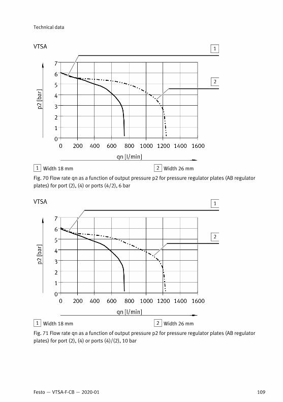
1 Width 18 mm 2 Width 26 mm
Fig. 70 Flow rate qn as a function of output pressure p2 for pressure regulator plates (AB regulatorplates) for port (2), (4) or ports (4/2), 6 bar
1 Width 18 mm 2 Width 26 mm
Fig. 71 Flow rate qn as a function of output pressure p2 for pressure regulator plates (AB regulatorplates) for port (2), (4) or ports (4)/(2), 10 bar
Technical data
109Festo — VTSA-F-CB — 2020-01

VABF-S2/S1...
qn [l/min]
p2
[b
ar]
0 250 500 750 1000 1250 1500 1750 2000 22500
1
2
3
4
5
6
7
Fig. 72 Flow rate qn as a function of output pressure p2 for pressure regulator plates (AB regulatorplates) for port (2), (4) or ports (4/2), input pressure 10 bar, set regulated pressure 6 bar, width 42mm
VTSA Baubreite 52mm (ISO 2)
qn [l/min]
p2
[b
ar]
0 1000 2000 3000 4000 5000 60000
1
2
3
4
5
6
7
Fig. 73 Flow rate qn as a function of output pressure p2 for pressure regulator plates (AB regulatorplates) for port (2), (4) or ports (4/2), input pressure 10 bar, set regulated pressure 6 bar, width 52mm
Technical data
110 Festo — VTSA-F-CB — 2020-01

1 Width 18 mm 2 Width 26 mm
Fig. 74 Flow rate qn as a function of output pressure p2 for pressure regulator plates (AB regulatorplates, reversible) for ports (4/2), reversible, 6 bar
1 Width 18 mm 2 Width 26 mm
Fig. 75 Flow rate qn as a function of output pressure p2 for pressure regulator plates (AB regulatorplates, reversible) for ports (4/2), reversible, 10 bar
Technical data
111Festo — VTSA-F-CB — 2020-01

VABF-S2/S1...
qn [l/min]
p2
[b
ar]
0 250 500 750 1000 1250 1500 1750 2000 22500
1
2
3
4
5
6
7
Fig. 76 Flow rate qn as a function of output pressure p2 for pressure regulator plates (AB regulatorplates, reversible) for ports (4/2), reversible, input pressure 10 bar, set regulated pressure 6 bar,width 42 mm
VTSA Baubreite 52mm (ISO 2)
qn [l/min]
p2
[b
ar]
0 500 1000 1500 2000 2500 3000 3500 4000 45000
1
2
3
4
5
6
7
Fig. 77 Flow rate qn as a function of output pressure p2 for pressure regulator plates (AB regulatorplates, reversible) for ports (4/2), reversible, input pressure 10 bar, set regulated pressure 6 bar,width 52 mm
Technical data
112 Festo — VTSA-F-CB — 2020-01

Flow Rate Diagrams of the Throttle Plates
1 Width 26 mm 2 Width 18 mm
Fig. 78 Flow rate qn as a function of the rotations of the adjusting screw n, widths 18 mm and 26 mm
1 Flow rate from (4) to (5) 2 Flow rate from (2) to (3)
Fig. 79 Flow rate qn as a function of the rotations of the adjusting screw n, width 42 mm
Technical data
113Festo — VTSA-F-CB — 2020-01

1 Flow rate from (2) to (3) 2 Flow rate from (4) to (5)
Fig. 80 Flow rate qn as a function of the rotations of the adjusting screw n, width 52 mm
13.4 Technical data, electrical
WidthElectrics
18 … 42 mm 52 mm
Operating voltage supply for electronics (UEL/SEN)
Nominal voltage (toler-ance) DC
[V DC] 24 ± 25 %
Intrinsic current con-sumption at 24 V(internal electronics, allvalves switched off)
[mA] Typically 20
Current consumption per solenoid coil with LED at 24 V DC and 100% duty cycle
2x 3/2-way valves [mA] 60
5/2 and 5/3-way valves [mA] 72
All valves
– Pick-up current [mA] – 165
– Holding current(after 30 ms)
[mA] – 35
Technical data
114 Festo — VTSA-F-CB — 2020-01
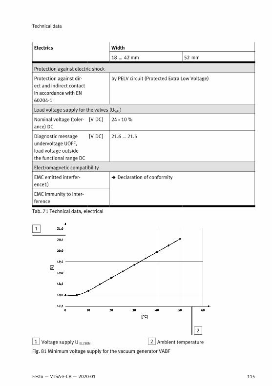
WidthElectrics
18 … 42 mm 52 mm
Protection against electric shock
Protection against dir-ect and indirect contactin accordance with EN60204-1
by PELV circuit (Protected Extra Low Voltage)
Load voltage supply for the valves (UVAL)
Nominal voltage (toler-ance) DC
[V DC] 24 ± 10 %
Diagnostic messageundervoltage UOFF,load voltage outsidethe functional range DC
[V DC] 21.6 … 21.5
Electromagnetic compatibility
EMC emitted interfer-ence1)
EMC immunity to inter-ference
è Declaration of conformity
Tab. 71 Technical data, electrical
1 Voltage supply U EL/SEN 2 Ambient temperature
Fig. 81 Minimum voltage supply for the vacuum generator VABF
Technical data
115Festo — VTSA-F-CB — 2020-01

© 2020 all rights reserved to Festo SE & Co. KG
Copyright:Festo SE & Co. KG Ruiter Straße 82 73734 Esslingen Germany
+49 711 347-0
www.festo.comInternet:
Phone: