volterra - university of maryland
TRANSCRIPT


Acknowledgements The Volterra design team wishes to acknowledge the following people and thank them for their advice and assistance. Dr. Vengalattore T. Nagaraj – Senior Research Scientist, Dept. of Aerospace Engineering, University of Maryland, College Park Dr. Inderjit Chopra – Gessow Professor, Director of Gessow Rotorcraft Center (AGRC) Professor, Dept. of Aerospace Engineering, University of Maryland, College Park Dr. J. Gordon Leishman – Minta Martin Professor of Engineering, Dept. of Aerospace Engineering, University of Maryland, College Park Dr. James Baeder – Associate Professor, Dept. of Aerospace Engineering, University of Maryland, College Park Dr. Norman Wereley – Professor, Dept. of Aerospace Engineering, University of Maryland, College Park Dr. Christopher Cadou – Associate Professor, Dept. of Aerospace Engineering, University of Maryland, College Park J. Sean Humbert, Assistant Professor/Director, Autonomous Vehicle Laboratory, Dept. of Aerospace Engineering, University of Maryland, College Park Dr. Fredric Schmitz – Senior Research Professor, Dept. of Aerospace Engineering, University of Maryland, College Park Dr. Darryll J. Pines – Professor and Chair, Dept. of Aerospace Engineering, University of Maryland, College Park Dr. Shreyas Ananthan – Assistant Research Scientist, Dept. of Aerospace Engineering, University of Maryland, College Park Dr. Sudarshan Koushik, Assistant Research Scientist, Dept. of Aerospace Engineering, University of Maryland, College Park Gaurav Gopalan, Assistant Research Scientist, , Dept. of Aerospace Engineering, University of Maryland, College Park Adrian Hood, Jaye Falls, Jason Pereira, Peter Copp, Benjamin Silbaugh, Carlos Malpica, Arun Jose, Abhishek Roy, Moble Benedict, Vikram Hrishikeshavan Alex Harris– BAE Systems for his help and advice on occupant seat protection Abraham Karem – President, Karem Aircraft, Inc. Olivier Gamard, Cabri G2 Certification, Calculation and Flight Test Engineer Automated DynamicsSteve Paxton

University of Maryland 2
TABLE OF CONTENTS 1 Introduction ......................................................................................................................................................... 1
2 Vehicle Configuration Selection ......................................................................................................................... 1
2.1 Identification of Design Drivers ................................................................................................................... 1
2.2 Quality Function Deployment ...................................................................................................................... 1
2.2.1 Design Criteria - House of Quality .......................................................................................................... 2
2.2.2 Feasible VTOL Configurations ................................................................................................................ 2
2.2.3 Pugh Decision Matrix .............................................................................................................................. 3
3 Preliminary Helicopter Sizing ............................................................................................................................ 7
3.1 Description of Algorithm ............................................................................................................................. 7
3.2 Trade Studies................................................................................................................................................ 8
3.2.1 Choice of Blade Loading (BL), CT / ....................................................................................................... 8
3.2.2 Choice of the Number of blades (Nb) ....................................................................................................... 9
3.2.3 Choice of aspect ratio (AR) .................................................................................................................... 11
3.2.4 Choice of tip speed (Vtip) ........................................................................................................................ 12
3.2.5 Choice of the type of engine .................................................................................................................. 14
3.3 Final Configuration Selection .................................................................................................................... 15
4 Engine and Transmission .................................................................................................................................. 16
4.1 Engine Types.............................................................................................................................................. 16
4.1.1 Otto, Diesel, and Brayton Cycle Engines .............................................................................................. 16
4.1.2 Fuel Cells ............................................................................................................................................... 16
4.2 Fuel Selection ............................................................................................................................................. 18
4.2.1 Chemical Equilibrium by Minimization of Gibbs Free Energy Method3,5 ............................................ 18
4.2.2 Findings from Chemical Equilibrium Analysis ..................................................................................... 19
4.3 Engine Selection – Opposed Piston Opposed Cylinder (OPOC) Engine ................................................... 20
4.3.1 Overview ............................................................................................................................................... 20
4.3.2 Performance and Specifications ............................................................................................................. 20
4.3.3 Summary ................................................................................................................................................ 21
4.4 Transmission .............................................................................................................................................. 22
4.4.1 System Layout ....................................................................................................................................... 22
5 Main Rotor/Hub Design .................................................................................................................................... 23
5.1 Main Rotor Design ..................................................................................................................................... 24
5.1.1 Airfoil Selection ..................................................................................................................................... 24
5.1.2 Twist and Taper ..................................................................................................................................... 25
5.1.3 Tip Geometry ......................................................................................................................................... 25
5.1.4 Blade Structure: ..................................................................................................................................... 26
5.1.5 Blade Composite Structure Lay-up: ....................................................................................................... 26
University of Maryland 3
5.1.6 Rotor Blade De-icing and Erosion Protection ........................................................................................ 27
5.1.7 Rotor Morphing ..................................................................................................................................... 28
5.2 Swashplateless Rotor Design ..................................................................................................................... 28
5.2.1 Trailing edge moment flap design ......................................................................................................... 29
5.2.2 Optimization of TEF design................................................................................................................... 29
5.2.3 Optimizing index angle .......................................................................................................................... 30
5.2.4 Optimizing flap span .............................................................................................................................. 30
5.2.5 Choice of flap chord ratio ...................................................................................................................... 30
5.2.6 Choice of flap mid-span location ........................................................................................................... 31
5.2.7 Actuator Design ..................................................................................................................................... 32
5.2.8 Active Vibration Control ....................................................................................................................... 34
5.2.9 Slip Ring ................................................................................................................................................ 34
5.2.10 Blade/Hub Connection ...................................................................................................................... 34
5.3 Hub Design ................................................................................................................................................ 35
5.3.1 Dynamic Analysis .................................................................................................................................. 37
5.3.2 Aeroelastic Analysis .............................................................................................................................. 37
5.3.3 Ground and Air Resonance .................................................................................................................... 38
6 Tail Rotor Design – Fenestron .......................................................................................................................... 38
6.1 Summary .................................................................................................................................................... 38
6.2 Methodology .............................................................................................................................................. 39
6.3 Duct Design................................................................................................................................................ 39
6.4 Fan Design ................................................................................................................................................. 41
6.5 Vertical Stabilizer Design .......................................................................................................................... 42
6.6 Horizontal Stabilizer Design ...................................................................................................................... 43
7 Airframe and Landing Gear Design ................................................................................................................ 43
7.1 Summary .................................................................................................................................................... 43
7.2 Airframe Design ......................................................................................................................................... 43
7.3 Structural Details ........................................................................................................................................ 44
7.4 Doors .......................................................................................................................................................... 45
7.5 Landing Gear .............................................................................................................................................. 45
7.6 Classification of Landing Gear .................................................................................................................. 45
7.6.1 Landing Gear Selection: ........................................................................................................................ 46
7.6.2 Static Stability Angles ........................................................................................................................... 46
7.6.3 Frequency placement for ground resonance .......................................................................................... 46
7.6.4 Cross Tube Sizing .................................................................................................................................. 47
8 Performance Analysis ........................................................................................................................................ 47
8.1 Drag Reduction .......................................................................................................................................... 47

University of Maryland 4
8.1.1 Drag Estimation ..................................................................................................................................... 48
8.1.2 Drag Reduction ...................................................................................................................................... 48
8.2 Hover Performance .................................................................................................................................... 50
8.3 Forward Flight Performance ...................................................................................................................... 51
8.4 Autorotational Characteristics .................................................................................................................... 53
9 Acoustics ............................................................................................................................................................. 54
9.1 Main Rotor Acoustic Design ...................................................................................................................... 55
9.2 Tail Rotor Acoustic Design ........................................................................................................................ 57
9.2.1 Harmonic Noise Phase Modulation ....................................................................................................... 57
9.2.2 Tip Speed Choice ................................................................................................................................... 58
9.2.3 Improved Placement and Sizing of Duct Obstacles ............................................................................... 58
9.2.4 Further Acoustic Reductions.................................................................................................................. 58
9.3 Flight Path Management ............................................................................................................................ 59
9.4 Active Noise Control.................................................................................................................................. 60
10 Stability and Control Analysis ..................................................................................................................... 61
10.1.1 Key Stability Derivative Estimation .................................................................................................. 61
10.1.2 Longitudinal Modes .......................................................................................................................... 63
10.1.3 Lateral Modes .................................................................................................................................... 63
10.2 Handling Qualities ..................................................................................................................................... 64
10.3 Autonomous Flight Control ....................................................................................................................... 64
10.3.1 Autonomous Classification ............................................................................................................... 64
10.3.2 Obstacle Avoidance ........................................................................................................................... 65
10.3.3 Take-off and Landing ........................................................................................................................ 66
10.3.4 Flight Certification ............................................................................................................................ 68
11 Avionics ......................................................................................................................................................... 68
11.1 Cockpit Layout ........................................................................................................................................... 68
11.1.1 Flight Display/Pilot Interface ............................................................................................................ 68
11.1.2 Minimum Equipment List (IFR) Compliance ................................................................................... 70
11.1.3 Cabin Communication ....................................................................................................................... 70
11.1.4 Force Feel Trim System .................................................................................................................... 70
11.2 Avionics Sensors ........................................................................................................................................ 70
11.2.1 Sensor configuration .......................................................................................................................... 70
11.2.2 Sensor Redundancy ........................................................................................................................... 71
11.2.3 Battery Backup for Alternator-out ..................................................................................................... 72
11.3 Flight Control System ................................................................................................................................ 72
11.3.1 Control Mixing .................................................................................................................................. 72
11.3.2 Digital Fly-by-Wire Architecture ...................................................................................................... 72
University of Maryland 5
11.3.3 Adaptive Flight Control ..................................................................................................................... 73
11.4 Task Automation ........................................................................................................................................ 73
11.4.1 Accelerated Pre-flight ........................................................................................................................ 74
11.4.2 Health and Usage Monitoring System (HUMS)5 .............................................................................. 74
11.5 Additional Equipment ................................................................................................................................ 75
11.5.1 Brownout cameras ............................................................................................................................. 75
11.6 Cost and Power Estimates .......................................................................................................................... 76
12 Safety and Comfort ...................................................................................................................................... 77
12.1 Crashworthy Seat Design ........................................................................................................................... 77
12.2 .......................................................................................................................................................................... 78
12.3 Vibration Isolation ..................................................................................................................................... 78
12.4 Seat Modularity .......................................................................................................................................... 79
12.5 Comfort Features ........................................................................................................................................ 79
13 Life Cycle Cost Analysis............................................................................................................................... 80
13.1 Direct Operating Costs (DOC) ................................................................................................................... 81
1.1. Indirect Operating Costs (IOC) .................................................................................................................. 83
14 Energy Consumption Evaluation ................................................................................................................ 84
14.1 Materials Breakdown ................................................................................................................................. 85
14.1.1 Structural Materials ........................................................................................................................... 85
14.1.2 Materials of Complete Helicopter ..................................................................................................... 86
14.1.3 Composite Resin Choice (Thermoplastics versus Thermosets) ......................................................... 86
14.2 Production and Manufacturing ................................................................................................................... 87
14.2.1 Material Properties ............................................................................................................................ 87
14.2.2 Manufacturing Energy ....................................................................................................................... 88
14.2.3 Assembly Energy .............................................................................................................................. 88
14.3 Operation .................................................................................................................................................... 89
14.4 End-of-Life (Recycling) ............................................................................................................................. 89
14.4.1 Disassembly ...................................................................................................................................... 89
14.4.2 Recycling ........................................................................................................................................... 90
14.4.3 Incineration and Landfill ................................................................................................................... 90
14.4.4 Hazardous/Non-Recyclable Components .......................................................................................... 91
14.5 Total Vehicle Life Cycle Energy Estimate ................................................................................................. 91
15 Weight Analysis ............................................................................................................................................ 92
15.1 Weight Estimates ....................................................................................................................................... 92
15.2 Weight and Balance ................................................................................................................................... 92
16 Mission Capabilities ..................................................................................................................................... 93
16.1 Standard civil transport mission ................................................................................................................. 93

University of Maryland 6
16.2 Corporate (VIP) transport mission ............................................................................................................. 94
16.3 Police/Border enforcement mission ........................................................................................................... 94
16.4 Coast guard rescue mission ........................................................................................................................ 95
16.5 EMS mission .............................................................................................................................................. 96
16.6 Long Endurance Autonomous Surveillance Mission ................................................................................. 96
17 Summary ....................................................................................................................................................... 97
18 References ..................................................................................................................................................... 99
18.1 Introduction ................................................................................................................................................ 99
18.2 Section 2 ..................................................................................................................................................... 99
18.3 Section 3 ..................................................................................................................................................... 99
18.4 Section 4 ..................................................................................................................................................... 99
18.5 Section 5 ................................................................................................................................................... 100
18.6 Section 6 ................................................................................................................................................... 101
18.7 Section 7 ................................................................................................................................................... 102
18.8 Section 8 ................................................................................................................................................... 102
18.9 Section 9 ................................................................................................................................................... 102
18.10 Section 10 ................................................................................................................................................. 103
18.11 Section 11 ................................................................................................................................................. 103
18.12 Section 12 ................................................................................................................................................. 104
18.13 Section 13 ................................................................................................................................................. 104
18.14 Section 14 ................................................................................................................................................. 104

University of Maryland 7
Table of Figures Figure 2.1: House of Quality decision matrix for ranking of customer requirements. .................................................. 5 Figure 3.1: Block diagram for the design code .............................................................................................................. 8 Figure 3.2: Variation of MTOW with blade loading for helicopters with same solidity and tip speed ......................... 9 Figure 3.3: Variation of blade loading with forward speed. .......................................................................................... 9 Figure 3.4: Variation of rotor diameter with Nb .......................................................................................................... 10 Figure 3.5: Variation of MTOW with Nb and AR. ...................................................................................................... 10 Figure 3.6: Variation of engine installed power with rotor solidity. ............................................................................ 10 Figure 3.7: Variation of fuel weight required with number of blades. ........................................................................ 10 Figure 3.8: Variation of fuel required with rotor solidity. ........................................................................................... 11 Figure 3.9: Variation of weight of fuel required with hover tip speeds. ...................................................................... 12 Figure 3.10: Variation of main rotor diameter with hover tip speeds. ......................................................................... 13 Figure 3.11: Variation of main rotor torque required with hover tip speeds. .............................................................. 13 Figure 3.12: Variation of GTOW with hover tip speeds. ............................................................................................. 13 Figure 3.13: Variation of power required with forward speeds for 6 helicopter configurations designed at different tip speeds. .................................................................................................................................................................... 13 Figure 3.14: Variation of collective angles at hover for different helicopter configurations ....................................... 14 Figure 3.15: Weight versus power data for different piston engines ........................................................................... 14 Figure 4.1: Power to weight trends. Individual engine data from Jane's All the World's Aircraft4. ............................ 17 Figure 4.2: Emissions by equivalence ratio ................................................................................................................. 19 Figure 4.3: Emissions for carbon-based fuels, normalized for each species. ............................................................... 20 Figure 4.4: Engine performance by altitude for standard atmosphere. ........................................................................ 21 Figure 4.5: Transmission diagram ............................................................................................................................... 22 Figure 4.6: Main Gear Box. ......................................................................................................................................... 22 Figure 4.7: Tail Gear Box. ........................................................................................................................................... 23 Figure 5.1: Airfoil lift-to-drag ratio versus angle of attack data .................................................................................. 25 Figure 5.2: Airfoil distribution along the blade. .......................................................................................................... 25 Figure 5.3: (top) D-spar configuration; (bottom) C-spar configuration. ...................................................................... 26 Figure 5.4: Cross-sectional parameters of a trailing-edge flap. ................................................................................... 29 Figure 5.5: Blade indexing. ......................................................................................................................................... 29 Figure 5.6: Variation of HPP flap deflection angles at different airspeeds for blades with different torsional frequencies ................................................................................................................................................................... 30 Figure 5.7: Pitch deflection angles for conventional swashplate rotor........................................................................ 30 Figure 5.8: HPP hinge moment required with index angles ....................................................................................... 31 Figure 5.9: Variation of flap deflection angles with blade index angle at different airspeeds .................................... 31 Figure 5.10: Variation of flap deflection angles with flap span at different airspeeds ................................................ 31 Figure 5.11: Variation of hinge moment required with flap span ................................................................................ 31 Figure 5.12: Variation of HPP flap deflection angles with flap chord ratio ............................................................... 31 Figure 5.13: Variation of HPP hinge moment required with flap chord ratio ............................................................. 31 Figure 5.14: Variation of flap deflection with different flap mid span locations ......................................................... 32 Figure 5.15: Variation of HPP hinge moment required with different flap mid span locations .................................. 32 Figure 5.16: Frequency Response of Trailing Edge Flap Actuator ............................................................................. 33 Figure 5.17: Schematic of IBC Closed-Loop Operation.............................................................................................. 34 Figure 5.18: Finite element analysis of the blade retention fork (left) and flap-bending clover plate (right). ............. 36 Figure 5.19: Blade mass and stiffness distribution. ..................................................................................................... 37 Figure 5.20: Rotor fan plot .......................................................................................................................................... 38 Figure 5.21: Stability Boundary for Pitch Flap Divergence and Flutter ...................................................................... 38 Figure 5.22: Ground Resonance Analysis (Coleman‟s diagram)................................................................................. 38

University of Maryland 8
Figure 5.23: Ground Resonance Analysis – Percent Damping with Rotor RPM ........................................................ 38 Figure 6.1: Comparison of flow through a conventional tail rotor and the fenestron design....................................... 39 Figure 6.2: Sketch of Fenestron Cross-Section (viewed from top) .............................................................................. 40 Figure 6.3: Side View of Fenestron duct and fan ........................................................................................................ 41 Figure 6.4: Comparison of Thrust Ratios vs. Cruise Speed. ........................................................................................ 43 Figure 7.1: Load path. .................................................................................................................................................. 44 Figure 7.2: Center of Gravity Envelope of Volterra. ................................................................................................... 46 Figure 7.3: Fuselage and landing gear natural frequency as a function of main rotor RPM. ....................................... 46 Figure 7.4: Skid shoes design for soft ground. ............................................................................................................ 47 Figure 8.1: Flow over the fuselage of EC-120 with concavity on the sides. ............................................................... 49 Figure 8.2: Major drag reduction areas on Volterra. ................................................................................................... 50 Figure 8.3: HOGE power required at maximum gross weight and power available vs. altitude. ................................ 51 Figure 8.4: Weight - Altitude - Temperature Curve. ................................................................................................... 51 Figure 8.5: Power required and fuel flow for various cruise speed for a tip speed of 645 ft/sec. ................................ 51 Figure 8.6: Specific range vs. cruise speed for various tip speed. ............................................................................... 52 Figure 8.7: Specific range vs. cruise speed for various payload and altitude. ............................................................. 52 Figure 8.8: Payload, Range and Endurance Diagram. ................................................................................................. 53 1. Figure 9.1: Four primary acoustic sources of a rotor. .......................................................................................... 55 Figure 9.2: Impact of rotor design on acoustic intensity. ............................................................................................. 56 Figure 9.3: Sound pressure level of various 4-bladed rotor designs considered. 30o below tip-path plane at 10 rotor radii .............................................................................................................................................................................. 57 Figure 9.4: Frequency Spectrums of an example fenestron with even (left) and uneven (right) blade spacing6 ......... 57 Figure 9.5: BVI intensity by flight condition............................................................................................................... 59 Figure 9.6: Optics-based tip-path-plane tracking camera. ........................................................................................... 59 Figure 9.7: Force-balance diagram of a helicopter in steady flight. ............................................................................ 60 Figure 9.8: Flight path management system overview. ............................................................................................... 60 Figure 9.9: Acoustic signature with active control. Noise field from thickness noise, and “Cone of Silence” region
with active system engaged (bottom right). ................................................................................................................. 61
Figure 10.1: Longitudinal mode stability with (a) increases in horizontal stabilizer area (=0.3) (b) increases in forward flight speed (Area = 1.3 m2 ) .......................................................................................................................... 63 Figure 10.2: Lateral Mode Stability (a) Lateral Mode (Decoupled) (b) Dynamic Mode (Coupled) ........................... 64 Figure 10.3: (a) Sample visual field, (b) vector representation of visual field from which optic flow is extracted. .... 65 Figure 10.4: Optic flow measurements provide information about the Volterra's proximity to walls, enabling feedback into the stability augmentation system. ........................................................................................................ 66 Figure 10.5: Optic flow-based obstacle avoidance schematic. The optic flow from the on the starboard wall is greater in magnitude than that from the port wall, thus the stability augmentation system is directed to correct this imbalance by moving the Volterra further port. ........................................................................................................................... 67 Figure 11.1: Automatic flight control system dependency schematic. ........................................................................ 71 Figure 11.2: Flight computer architecture. .................................................................................................................. 73 Figure 12.1: (a) Adjustable Roller Pins for Wire Bender VLEA, (b) Schematic of the limit load adjustment settings ..................................................................................................................................................................................... 78 Figure 12.2: Cabin occupant seat design showing VLEA wire bender stroking system and vibration isolation system. ..................................................................................................................................................................................... 79 Figure 13.1 Direct Operating Cost breakdown of (a) EC-120B and (b) Volterra........................................................ 82 Figure 13.2: Indirect Operating Cost breakdown of (a) EC-120B and (b) Volterra .................................................... 83 Figure 13.3 Annual direct and indirect operating cost (left hand scale) with direct operation cost per flight hour (right hand scale) ......................................................................................................................................................... 84 Figure 14.1: Volterra structural materials breakdown by percent weight. ................................................................... 85 Figure 14.2: Total Volterra materials breakdown (by percent empty weight), and materials distribution map. ......... 86 Figure 15.1: Center of gravity envelope for passenger and cargo loads. ..................................................................... 93 Figure 16.1 Cabin layout for passenger transport mission ........................................................................................... 93

University of Maryland 9
Figure 16.2 Cabin layout for cargo transport mission ................................................................................................. 93 Figure 16.3 Standard mission profile ........................................................................................................................... 94 Figure 16.4 Cabin layout for corporate/VIP mission ................................................................................................... 94 Figure 16.5 Corporate/VIP mission profile ................................................................................................................. 94 Figure 16.6 Cabin layout for enforcement mission ..................................................................................................... 95 Figure 16.7 Police/Border enforcement mission profile .............................................................................................. 95 Figure 16.8 Cabin layout for coast guard rescue mission ............................................................................................ 95 Figure 16.9 Coast guard rescue mission profile ........................................................................................................... 96 Figure 16.10 Cabin layout for EMS mission ............................................................................................................... 96 Figure 16.11 EMS mission profile ............................................................................................................................... 96 Figure 16.12 Surveillance UAV mission profile ......................................................................................................... 97

University of Maryland 10
Table of Tables
Table 2.1: Pugh decision matrix showing the top configurations to be the SMR with traditional tail-rotor or fan-in-fin. .................................................................................................................................................................................. 6
Table 3.1: Comparison of two configurations designed at different AR (CT/ =0.075, Nb= 4, Vtip = 210 m/s) ........... 12 Table 3.2: Helicopter configurations analyzed in UMARC ........................................................................................ 13 Table 3.4: Final configuration selections for the Volterra. .......................................................................................... 15 Table 3.3: Helicopter sizing parameters calculated for state-of-the-art piston, turbine and the OPOC engines. ......... 15 Table 4.1: OPOC Engine Specifications ...................................................................................................................... 21 Table 4.4.2: Engine Comparison ................................................................................................................................. 21 Table 4.3: Gear design summary. ................................................................................................................................ 23 Table 5.1: Main rotor parameters. ............................................................................................................................... 24 Table 5.2: Properties comparison of aluminum and commonly used composite fibers6. ............................................ 26 Table 5.3: Mechanical properties of rotor blade materials7,8. ...................................................................................... 27 Table 5.4: Trailing edge flap parameters ..................................................................................................................... 32 Table 5.5: Brushless motor candidates for trailing edge flap actuator25,26. .................................................................. 33 Table 5.6: Pitch Spring Design Details ........................................................................................................................ 36 Table 5.7: Main rotor blade first 6 natural frequencies ................................................................................................ 37 Table 7.1: Landing gear Pugh decision matrix. ........................................................................................................... 46 Table 8.1 Component Drag Breakdown. ..................................................................................................................... 48 Table 8.2: Recommended Cruise Speed for maximum gross weight. ......................................................................... 52 Table 8.3: Autorotation index comparison. ................................................................................................................. 53 Table 8.4: Performance Summary and Comparisons................................................................................................... 54 Table 10.1: Normalized Control Derivatives in Hover and Forward Flight ................................................................ 62 Table 10.2: Normalized Stability Derivatives in Hover and Forward Flight ............................................................... 62 Table 10.3: NASA human computer interface level 6 description. ............................................................................. 65 Table 11.1: Sensor and electronics cost, power and weight estimates. ........................................................................ 76 Table 12.1: Energy absorbing systems available for occupant seats ........................................................................... 77 Table 13.1 Factors used in computing H ..................................................................................................................... 81 Table 13.2 Comparison of estimated base price and the base price given in Ref 4 ..................................................... 81 Table 13.3 Summery of direct operating costs ............................................................................................................ 82 Table 13.4: Comparison of 20year averaged DOC/FH with that of the first operation year ....................................... 83 Table 13.5 Summery of indirect operating costs ......................................................................................................... 84 Table 14.1: Required energy and carbon dioxide emmisions for the production of various materials12. .................... 87 Table 14.2: Energy required at the manufacturing stage for various materials and processes. ................................... 88 Table 14.3: Energy required at end-of-life for the Volterra assuming 75% recycling of composite and aluminum components . ................................................................................................................................................................ 89 Table 15.1: Volterra Weight Estimates. ...................................................................................................................... 92 Table 14.4: Life cycle energy estimation of the Volterra ............................................................................................ 92 Table 16.1 Mission equipment for corporate/VIP mission .......................................................................................... 94 Table 16.2 Mission equipment for police/border enforcement .................................................................................... 95 Table 16.3 Mission equipment for coast guard rescue mission ................................................................................... 95 Table 16.4 Mission equipment for EMS mission ........................................................................................................ 96

Volterra
University of Maryland 1
RFP REQUIREMENTS AND COMPLIANCE GENERAL CAPABILITY REQUIREMENTS
Requirement Design Solution Section
VTOL capable Designed a helicopter 2.2.3, 3
Initial operational capability in 2020 OPOC engine, MEMS avionics, trailing-edge flaps, low acoustics, seating
4, 5, 9, 11
Multirole military, para-military and civil transport capability
Accessories, scouting ability, ext fuel, autonomous capability e.g. Firescout, rescue
16
Capable of transporting passengers and materials Seats removable, clamshell doors, under-slung loads
7, 12, 16
Capable of operations in high population density areas (neighborhoods and surrounding cities)
Fan-in-fin, acoustics, low disk loading, wide variety of fuels, flight path management equip,
6, 9
Capable of operation from limited infrastructure areas (devastated areas, no ground transport available, etc.)
Multi-fuel, skids, low maintenance, low disk loading, high reliability
4.3.2, 7, 11
Proposal must provide a full comparison with an equivalent payload rotorcraft
EC-120, Bell 206, R44 Raven 13, 16, 17
MISSION PROFILE REQUIREMENTS
Requirement Design Solution Section
Capable of take-off within 10 minutes of positioning
Automation of checklist, HUMS 11
Design should incorporate a semi-automatic take-off and landing system
MEMS, Automation 11
Design should minimize fuel consumption for a 1 hour flight at 120 knots
Minimized drag at cruise (vertical fin, shaft tilt, horizontal stab optimization), SFC at cruise
3, 4, 5
Design should be operable by a single pilot User-friendly flight displays, GPS navigation 11
Payload should include either 4 passengers and luggage or 500 kg freight
Removal of seats, clamshell doors 2, 3, 12.3
Minimum internal volume of design should be 1.1m×1.4m× 1.0m (H×L×W)
Removable seats, low-profile seats 7, 12
HOGE: 15min at max GTOW 1500m ISA+20oC Absolute ceiling 8000ft ISA 3, 8
Capable of minimum 100 knots cruise Forward-tilted rotor shaft, low blade loading 3, 8

Volterra
University of Maryland 2
Capable of 300 nm range Fuel tanks 3, 8
COST & ENERGY CONSUMPTION REQUIREMENTS
Requirement Design Solution Section
Proposal should provide criteria for life cycle cost comparison with similar vehicles
EC-120, Bell 206, R-44 13
Minimize life-cycle costs Transmission for life, Hub for 5,000 hours, Low insurance risk design, Low maintenance components, Lean manufacturing
4, 5, 11, 13
Minimize maintenance requirements Line replaceable units, maint. hatches, cowling becomes platform, increased welding = less fasteners = less $ = less weight
4, 5, 11
Minimize energy consumption throughout operational envelope
Mission profiles, Optimized rotor for hover and cruise flight, OPOC engine 30% reduction in fuel consumption
4, 8, 16
Proposal should estimate life-cycle waste/pollution production
All electric helicopter 14.5
Proposal should estimate life-cycle energy consumption
Ashby material analysis 14
Proposal should suggest engine with improved SFC and power-to-weight ratio
OPOC engine, 30% reduction in fuel consumption
4
Design should consider the following technologies for reducing energy consumption
-- --
Rotor morphing Trailing edge flap 5
Novel anti-torque system Novel construction of fan-in-fan 6
Drag reduction methods Hub drag, synthetic jets, wind tunnel testing 8
Engine selection OPOC 4
Hybrid energy Advanced batteries (Li-Po) 4.1
Alternative fuels Fuel cells not feasible 4.2
SAFETY & COMFORT REQUIREMENTS
Requirement Design Solution Section
Design should place emphasis on achieving a high degree of safety
Crashworthiness, vibration absorption, fan-in-fin, modular engine, multiple-flap system (redundant motor), fuselage geometry
4, 5, 6, 11, 12

Volterra
University of Maryland 3
Design should utilize advanced techniques to enhance mission survivability
Belts/braces, landing gear, fenestron, low IR sig, low acoustic sig, non-metallic LE cap -> low radar sig, composite rotor blades are impact resistant, no exposed control rods, redundant flaps
4, 5, 6, 11, 14.1.3
Design should place emphasis on minimizing external acoustic signatures
FP management, low tip speed, fenestron, OPOC
3, 6, 9
Comfort of passengers should equal that of equivalent vehicle, emphasizing the following:
-- --
Environmental Control System ECS Fan, cooling 4.4
Passenger/Crew seating Vibration absorbing seats, 12
Reduced internal noise OPOC, water damping, gearbox, spiral-bevel gears
5, 6, 9
Reduced internal vibration OPOC, ACSR gearbox active isolator struts .
5
Sun protection Nanolayer-film-coated transparencies integrated on windshield to absorb harmful UV rays
7

IntroThe aerospaperformancewealthy and intricately wsafety, reliabenvironmentrole as an inreducing theassociated w
The Volterralight transponew standarstewards of tworry about
ConcThe VolterraCompetitionminimized econjunction wa graduate svariety of arand helicoptskills requiredesign codesbeing writteComputer-aihighly synerEngineer, an
In addition required to pparamilitary operable fro
V
oductioce vision has
e barriers. Air the elite. We
woven into the bility, simplicitt and society anternational soe pollution, n
with in the eyes
a epitomizes thort or utility nerd for environtheir environmthe end-of-life
cept Da was designe request for prenergy consumwith the one-se
student team creas such as aeter crash safeted for the coms were developen, validated ided design anrgistic framew
nd Solid Works
to minimizedprovide short-roperators. Uti
om unprepared
VOLTERRA
on expanded far travel has moare fortunate fabric of our
ty of design, anas possible. Thcial and econooise and wastof the general
his new designeeds of nearly anmental friendlment without hae impact of thei
Designed in responseroposals for anmption througemester ENAEonsisting of 8
eroacoustics, coty, was assem
mprehensive deped in-house w
and applied nd conceptual work involvings.
d energy consrange, mediumilized in devas
d areas and be
A: VOL -F
beyond that ooved beyond enough to liveeveryday globnd above all el
his is the Era oomic uniting foteful energy cpopulation.
n philosophy aany civil, militliness and fueaving to sacrifiir vehicle.
n e to the 2008 n advanced VTghout its entiE 634 Helicopt
researchers spomputational f
mbled to learn esign of a VTO
with a number owithin the d
visualization wg extensive u
sumption, the m-speed, multistated areas, th
e capable of ta
French for f
f individual pibeing thoughte in a time wh
bal society. Thelse, a product wof Green, wherforce, while maconsumption t
as a multi-role tary or paramilel economy. Ofice performanc
AHS StudentTOL concept wire life cycleer Design courpecializing in fluid dynamicsand apply the
OL vehicle. Aof analysis coddesign timefrawas performed
use of CATIA
proposed veh-role transporthe vehicle hadake-off within
flight | TER
ioneers strivint of as a luxuhere the aerospe new demandwith as little hare aviation conaking monumethat it has un
helicopter caplitary operation
Operators of thce, incur large
t Design which e. In rse, a
s, e
All des ame. d in a A, Pro-
hicle was t capabilities td to require lit
10 minutes o
RRA -Latin
ng to break tecury, reserved fpace industry id is for convenarmful impact ntinues to expaental strides tonfortunately be
pable of meetinn, all while sethe Volterra wacquisition co
o civil, militarttle maintenan
of positioning.
n for earth
chnical for the is now nience, on the and its owards ecome
ng the tting a
will be osts, or
ry and nce, be
Also,

because of itechnology arequirementscapability inground effecfuel consump
The crewwhich Neverthconfig
performed toengine for toptimized fo
Core
PerformThe Volterraclass throughmore econom
Lowgeocon
its expected uaimed specificas were one pilncluded a rangct at maximumption for a one
w and mission chas traditionaheless, an ungurations was
hvehicles, and
cycle costs oselectio
hsystem.
solution stcapability.
The Volterrand rema
lower mold design
o select the nuthe Volterra.
or weight effici
e Featu
mance a is designed th greater endumical aircraft is
w-drag configometries, and ntemporary heli
use in congesteally at enhancelot plus either
ge of 300 nm, m take-off weige-hour flight at
capability requally been fillnbiased survey
conducted to concepts werehelicopters, capure vectored
of the tandem, on pool. The cohigh hub dragWith only the
ood above the
ra is designed arkably quietcost than othewhat would b
n methodologyumber of bladThe final des
iency and low a
ures
to offer superiurance and rangs designed whi
guration – Agenerous filleicopters.
ed or urban ared safety, redu
r four passenga minimum c
ght, 1500 m a120 kts target
uirements placeled by helicoy of the capa
narrow the de single-main-ranard rotor/w
d-thrust aircraftilting and rot
oaxial configurg and higher me single-main-re rest because o
to be a lightwhelicopter wit
er helicopters ibecome the V
y. Using this codes, solidity, msign convergedacoustic signat
ior performancge capabilities ich increases p
A biologicallyting lead to a
reas, the vehicuced noise, anders with lugga
cruise speed oaltitude and ISflight speed.
ed the vehicle opters of the abilities of sedesign space frotor helicopte
wing aircraft, tft. The completor/wing configration, while f
maintenance durotor choice remof its low nois
weight, low disth significantlyin its class. ThVolterra was dode, an extensivmain rotor tip d on a four-bture.
ce improvemenand simultane
ayload capacit
y-inspired fusea configuration
cle would requd minimal emiage or 500 kgf 100 kts, hovA +20oC cond
in the light utsingle-main-r
even broad cafor detailed evers, compound tandem rotors
exity, weight, agurations elimifeasible, was alue to the compmaining, the fase, safety in op
sk loading, extry lower powe
he preliminary developed baseve physics-basspeed, blade
bladed, low tip
nts over all otheously lower futy and internal
elage, optimizn that has 10
uire a high leissions. The pa
g of freight. Mver capability ditions, and mi
tility category, rotor configurategories of Vvaluation. Eva
helicopters, cs, tilt-rotor/winand consequeninated them frolso eliminated plex dual-mainan-in-fin, anti-tperation, and p
remely fuel efer requirementdesign code ued on Tishchesed optimizatioloading and typ-speed main
her helicoptersuel requiremenvolume.
zed pylon and0% lower drag
evel of ayload
Mission out of inimal
a role ration. VTOL aluated coaxial ng/fan
nt life-om the due to
n-rotor torque proven
fficient ts and
used to enko’s on was ype of
rotor,
s in its nts. A
d hub g than
EnethanRob
Higthe
Sameffi
All mai
Lararraclos
Incoffe
Mosign($22muc
Main RoThe 4-b
ener
Rotther
Enhthroicin
Interedu
Semandmairelia
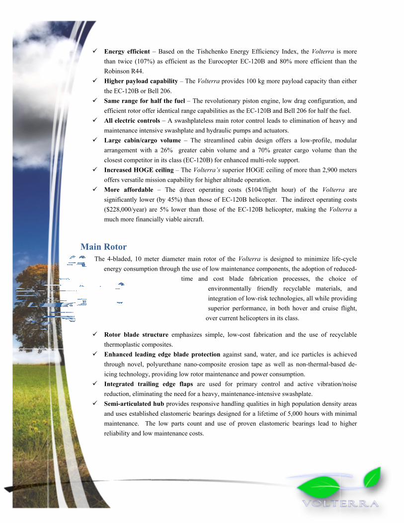
ergy efficient n twice (107%binson R44. gher payload cEC-120B or B
me range for hcient rotor offeelectric contr
intenance intenrge cabin/cargangement withsest competitorreased HOGEers versatile miore affordablenificantly lowe28,000/year) ach more financ
otor bladed, 10 mergy consumpti
tor blade strurmoplastic comhanced leadinough novel, pong technology, egrated trailiuction, elimina
mi-articulated d uses establishintenance. Thability and low
– Based on th%) as efficient
capability – TBell 206. half the fuel –er identical ranrols – A swashnsive swashplatgo volume –
h a 26% grear in its class (EE ceiling – Theission capabilite – The direer (by 45%) thare 5% lower tcially viable air
eter diameter mon through the
tim
ucture emphamposites. ng edge blade olyurethane naproviding low
ing edge flapating the need f
hub provides hed elastomeriche low parts cw maintenance
he Tishchenkoas the Euroco
he Volterra pr
– The revolutionge capabilitieshplateless mainte and hydraulThe streamlin
ater cabin voluEC-120B) for ene Volterra’s suty for higher alect operating han those of ECthan those of rcraft.
main rotor of e use of low ma
me and cost environintegratsuperio
over cur
asizes simple,
protection agano-composite rotor maintena
ps are used ffor a heavy, maresponsive ha
c bearings desicount and use costs.
o Energy Efficopter EC-120B
rovides 100 kg
onary piston ens as the EC-120n rotor controlic pumps and aned cabin desiume and a 70nhanced multi-
uperior HOGE ltitude operatiocosts ($104/f
C-120B helicothe EC-120B
the Volterra iaintenance comblade fabric
nmentally frietion of low-risk
or performancerrent helicopter
low-cost fabri
gainst sand, werosion tape
ance and powefor primary caintenance-inteandling qualitieigned for a lifeof proven ela
ciency Index, tB and 80% mo
more payload
ngine, low dra0B and Bell 20 leads to elimiactuators. ign offers a l% greater car-role support. ceiling of mor
on. flight hour) oopter. The ind
helicopter, ma
is designed to mponents, the aation processendly recyclak technologiese, in both hovrs in its class.
ication and th
water, and ice pas well as no
er consumptionontrol and acensive swashples in high popuetime of 5,000astomeric bear
the Volterra isore efficient th
d capacity than
ag configuratio06 for half the fination of heav
ow-profile, mgo volume tha
re than 2,900 m
of the Volterrdirect operatingaking the Volt
minimize lifeadoption of redses, the choiable materialss, all while prover and cruise
he use of recy
particles is achon-thermal-basen. ctive vibrationlate. ulation density hours with mrings lead to h
s more an the
either
n, and fuel. vy and
odular an the
meters
ra are g costs terra a
e-cycle duced-ce of , and viding flight,
yclable
hieved ed de-
n/noise
y areas inimal higher

Engine aThe Volterramaintenanceopposed cyliAdvanced R
450less
OPOOne
Capgas,
Sincfeat
Suptran
Comfort Inte
the constannois
Sunspecheatintiandfliggrea
Mapassisolvibr
Avionics ME
micas ccon
and Transa features an e, and ultra-lowinder (OPOC)esearch Projec
0 hp OPOC ens fuel than currOC features me module can bpable of burnin, and hydrogence the engine turing spiral bepported with nsmission syste
t Features ernal Noise – main cabin. T
nfiguration, is ndard inclusionse cancellationn Protection –ctrum absorptit gain. Becauseing, the transp
d the passengeht. This all trater overall com
agnetorheologisenger seat is lation damper crations, increas
s EMS Flight Ccroelectromechcapable as tradnsumption.
mission innovative eng
w fuel consum diesel engine
cts Agency (DA
ngine has a sperently develope
modular operatiobe deactivated dng a wide varn.
system operaevel gears and aan integrated
em has been de
Cabin noise isThe engine des
relatively quin of noise-redun, and clear inte– Nanolayer-filion of the sune the visible lig
parencies remaiers retain an uranslates into mfort for occupical Seat Vibfitted with an capable of attesing comfort an
ertified Sensohanical-based (ditional sensor
gine and transmption. The poe developed byARPA).
ecific fuel consed piston and tuon, effectivelyduring forwardiety of fuels i
ates at a lowera single planetd Health anesigned for a lif
s minimized bysign itself, withet when comp
uction headphoer-cabin commm-coated trans
n’s harmful UVght spectrum isin clear, the piunobstructed eless wear on pants. bration Daminnovative, lig
enuating up to nd pilot situatio
ors – The VoltMEMS) attitudpackages at 30
smission systemower plant of ty FEV Engine
sumption of 0.urbine engines
y making the Vd flight when pncluding diese
r RPM than ttary drive is vernd Usage Mofetime of 10,0
y placement of h its low-RPMpared with cuones provides i
munications. sparencies provV rays and res not affected ailots do not losexterior view interior comp
mpers – Eachghtweight, 2.3 90% of the doonal awareness
terra makes ude, heading an0% less weight
m that emphasthe Volterra is Technology t
.339 lb/shp/hr s.
Volterra a multpower requiremel, gasoline, bi
turbine enginery compact. onitoring Sys00 hours.
f the engine andM opposed-pistourrent piston eindividual acti
vide selective educed solar as in simple se visibility during the
ponents and
h crew and kg vibration minant 4/rev s.
use of the firstnd reference syt with a simila
sizes longevitys the opposed through the D
and consumes
ti-engine helicments are low.io-fuels, JP8, n
es, the transmi
stem (HUMS
d transmissionon opposed-cy
engines. Finallve
-ever flight-ceystem. This sysr reduction in
y, low piston efense
s 30%
opter.
natural
ission,
S), the
n aft of ylinder ly, the
ertified stem is power

Autoptisystpilocivi
ForactuVolheli
Mission Because of virtually limincluding ciemergency transport, laautonomous
SafetSafety is a hareas where
Cra12 g
Muor 4withand
Actmiccon
Duaprov
tonomous Fligic-flow obstactem, allows fuot does remainilian light utilitrce-Feel Trimuated force feelterra’s servo dicopter technol
Capabilityits powerful s
mitless. Potentiivilian transpo
medical seraw enforcemen
missions.
ty high priority foground access
ashworthinessg’s for a broad
ulti-engine des425 hp from bhout associated
d operations ovtive Obstacle croelectromechntrol system, gial Integrated vide controllab
ght Control –cle avoidance ully autonomoun in the controty helicopter is
m – The Volteredback to givedesign minimilogy to become
y tate-of-the-art ial mission scort, search anrvice transpornt, and long e
or the Volterrafor other emer
s – Independenspectrum of oign – The mod
both modules, d weight and ser water. Avoidance –
hanical cameraving the VolterTrailing-Edg
bility in the eve
The advancedand triply red
us staged take-l loop (but no
s unique. rra’s cyclic, ce pilots the addizes the weighe cost effective
engine and avenarios have
nd rescue, rt, cargo endurance
a since its misrgency equipm
nt VLEA seats ccupant weigh
dular OPOC enwhich gives th
size penalties. T
– Biologically as provide highrra the capabil
ge Flaps – Twent of a single
d automatic fligdundant sensooff, cruise, andt necessarily i
ollective and ded benefit of
ht penalty allowe for the light u
vionics, the Vobeen outlined
ssions involve ment is not poss
for all passenhts. ngine provides he added safetThis is essenti
inspired optih frequency colity to detect an
wo integrated tintegrated flap
ght control sysors for the stad landing of thn the vehicle)
yaw-pedal conf tactile situatiowing this tradiutility helicopte
Volterra’s missidemonstrating
operations in sible.
ngers and crew
up to 325 hp fty of a multi-eal for operatio
ic-flow measuontrol input to nd avoid oncomtrailing-edge pp failure.
stem, combinedability augmenhe Volterra. W, this capabilit
ntrols feature onal awarenesitionally largerer.
ion capability g these capab
congested area
w reduce g-load
from a single mengine configun in congested
urements from the automatic
ming obstaclesrimary control
d with ntation
While a ty in a
servo-s. The r-scale
list is bilities,
as and
ding to
module uration d areas
eight flight . l flaps

Envi
EfficientThe Volterraraw materialmaterials andemonstratesdevelopment
Probaseemiemivarimat
Extstruthertherresicom
TheCO
PEEcorrwhi
Theactu
Becthe itse
Thealummat
ronme
t Manufaca design focuss, to the energynd components it is possibt risk.
oduction – Thed in large paissions. To aissions, and riety of traditioterials. tensive use ofuctural compormoplastic comrmoplastic resiin, nearly 40 mponents than te Volterra min
2 emissions per
EK based comrespondingly lich in-turn make Volterra is uators. cause PEEK-baservice life oflf.
e Volterra usesminum alloysterial recovery
The 30% reits environmCO2, NOx, S
ental
cture, Effices on energy ey required to mts in the moble to use cu
he choice of rart on minimizaccomplish threcyclability sonal and non-tr
f Thermoplastonents of thmposites. Whilin in use, PEEtimes less enthe equivalent
nimizes the usr kilogram than
mposites can arge autoclave
kes assembly, an all-electric
ased compositef these materia
s environment that can be re
y at the recycli
eduction in Smental impacSOx, carcinog
Impac
cient Operefficiency of thmanufacture theost energy effurrent technolo
raw materials zing energy exhis, detailed surveys wereraditional aero
tic Compositehe Volterrae the initial pr
EK, is slightly nergy is requir
epoxy compose of titanium n aluminum, an
be more ease is not requiremaintenance, c helicopter u
es can be remals used by the
tally friendly cycled collectiing stage, hex
SFC achievedct by reducingens, and a v
ct
ration, Leahe entire vehice components,
fficient ways ogy to design
used in the Vxpenditure and
energy intenconducted fo
space construc
es – By weighare 65% re
roduction of thmore energy
red to manufasite parts. alloys which rnd require sub
sily formed ied. This reducand disassem
using no envi
olded or chope Volterra can
bio-polymersively for reducxavalent-chrom
d by the Voltng life-cycle variety of oth
ave only focle system, froto the recyclinpossible. Th
n a greener h
Volterra is d harmful nsity, or a ction
ht, the einforced he specific intensive than
facture PEEK
result in more stantially more
into large coces the parts cobly much less ironmentally u
pped into shortn be much grea
for the seat cuced energy conmium-free pai
terra significunburned h
her greenhou
footprints om the productng and reuse ofhe Volterra dhelicopter with
n a traditional composite Vo
than three time energy to ma
omponents, siount of the Voenergy intens
unfriendly hyd
t-fiber compoater than the v
ushions, compsumption and hints and electr
cantly reducehydrocarbonsuse gases
tion of f those design h low
epoxy olterra
mes the chine.
ince a olterra sive. draulic
nents, vehicle
patible higher ronics,
es s,

andhaz
AcousticThis effort inoise reducti
BasminMaiasp
Taiduc
Blatracwhi
Lowposwav
Emission CO
recyminrecyclosopeconidle
NOthe lean
ExtminpercEC-of thin-ftestblad
d high energyzardous chemi
cs s addressed at ion.
sed on the Ffwnimize the intein rotor noise h
pect ratio, and il rotor noise ct shielding. ade vortex intcking system tich helps them wer frequency itions using thves.
ns O2 – From mycling, CO2 nimized by yclable matersing the careration, the 30nsumption, redue time contribu
Ox – In additionOPOC achiev
ner fuel mixturternal Noise –nimize the inteceived reductio-120. Further rhe integrated f
fin design withed, tip-path plde-vortex inter
y density lithiicals on board.
three levels: a
wocs-Williamsensity of thickhas additionalla four-bladedhas been redu
teraction is rthat directs a fto maintain qunoise that is
he blade trai
manufacturingemissions
choosing higrials, in somerbon cycle 0% reduction uced-drag desite to significan
n to the approxves further redre. – By appropriensity of thicknon of approximreductions in nflap system whh unequally splane tracking mractions.
ium-polymer
aeroacoustic b
s and Hawkinkness noise, loaly been reduce
d rotor. uced by instal
reduced by uflight path mauiet flight traje
important foriling edge fla
g to are
ghly e cases altogether. Iin specific
ign, and reducent reductions inimately 30% r
ductions in NO
ately sizing thness noise, loa
mately 6dB has noise are achievhich reduces pepaced blades fmethod which
auxiliary batte
lade design, fl
gs equations, ading noise, ad by selecting
lling a fenestro
using an innovanagement sysctories. r detection is ps to actively
In fuel ed engine n CO2 emissioneduction below
Ox emissions b
he Volterra anding noise, anbeen achieved
ved by the actierceive noise byfor frequency
h provides a vi
eries to mini
light path man
the blade desand blade vorte
a low tip spee
on with uneve
vative optics-bstem to give v
also reduced y nullify near
ns. w current pistoby using a turb
nd optimizing nd blade vortexd over the alreaive noise suppy 4dB, a quiet spectrum spreisual aid to th
imize the ma
nagement, and
sign is optimizex interaction ed, blades of a
n blade spacin
based tip-pathvisual cues to
at distinct obr in-plane ac
n or turbine debocharger to b
the blade desx interaction noady remarkablyression functiopiston engine,
eading, and ahe pilot for av
ass of
active
zed to noise.
a high
ng and
h-plane pilots
bserver coustic
esigns, burn a
sign to oise, a y quiet onality a fan-flight-oiding
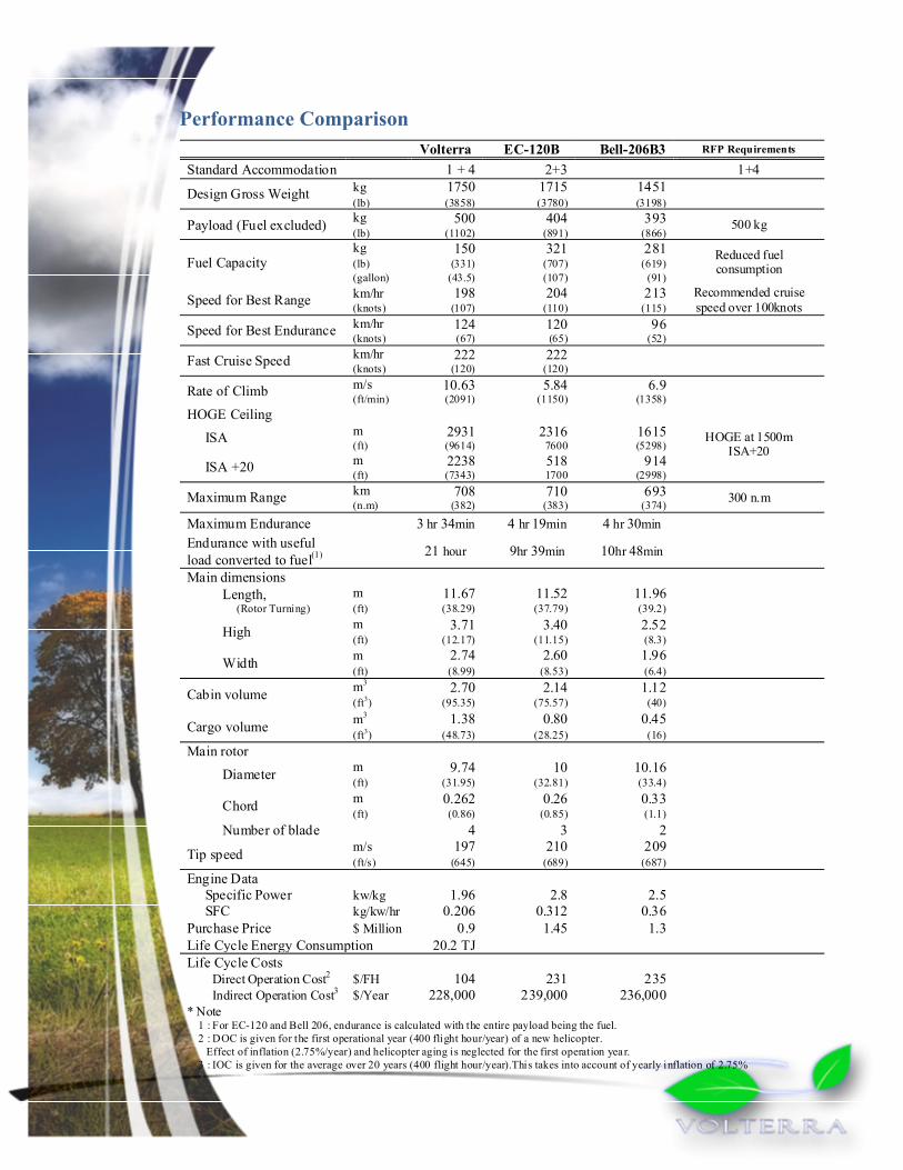
Volterra EC-120B Bell-206B3 RFP Requirements
Standard Accommodation 1 + 4 2+3 1+4
Design Gross Weight kg 1750 1715 1451 (lb) (3858) (3780) (3198)
Payload (Fuel excluded) kg 500 404 393 500 kg (lb) (1102) (891) (866)
Fuel Capacity kg 150 321 281 Reduced fuel
consumption (lb) (331) (707) (619) (gallon) (43.5) (107) (91)
Speed for Best Range km/hr 198 204 213 Recommended cruise speed over 100knots(knots) (107) (110) (115)
Speed for Best Endurance km/hr 124 120 96 (knots) (67) (65) (52)
Fast Cruise Speed km/hr 222 222 (knots) (120) (120)
Rate of Climb m/s 10.63 5.84 6.9 (ft/min) (2091) (1150) (1358)
HOGE Ceiling
HOGE at 1500m ISA+20
ISA m 2931 2316 1615 (ft) (9614) 7600 (5298)
ISA +20 m 2238 518 914 (ft) (7343) 1700 (2998)
Maximum Range km 708 710 693 300 n.m (n.m) (382) (383) (374)
Maximum Endurance 3 hr 34min 4 hr 19min 4 hr 30min Endurance with useful load converted to fuel(1) 21 hour 9hr 39min 10hr 48min
Main dimensions Length,
(Rotor Turning) m 11.67 11.52 11.96 (ft) (38.29) (37.79) (39.2)
High m 3.71 3.40 2.52 (ft) (12.17) (11.15) (8.3)
Width m 2.74 2.60 1.96 (ft) (8.99) (8.53) (6.4)
Cabin volume m3 2.70 2.14 1.12 (ft3) (95.35) (75.57) (40)
Cargo volume m3 1.38 0.80 0.45 (ft3) (48.73) (28.25) (16)
Main rotor
Diameter m 9.74 10 10.16 (ft) (31.95) (32.81) (33.4)
Chord m 0.262 0.26 0.33 (ft) (0.86) (0.85) (1.1)
Number of blade 4 3 2
Tip speed m/s 197 210 209 (ft/s) (645) (689) (687)
Engine Data Specific Power kw/kg 1.96 2.8 2.5 SFC kg/kw/hr 0.206 0.312 0.36 Purchase Price $ Million 0.9 1.45 1.3 Life Cycle Energy Consumption 20.2 TJ Life Cycle Costs
Direct Operation Cost2 $/FH 104 231 235 Indirect Operation Cost3 $/Year 228,000 239,000 236,000
* Note 1 : For EC-120 and Bell 206, endurance is calculated with the entire payload being the fuel. 2 : DOC is given for the first operational year (400 flight hour/year) of a new helicopter. Effect of inflation (2.75%/year) and helicopter aging is neglected for the first operation year. 3 : IOC is given for the average over 20 years (400 flight hour/year).This takes into account of yearly inflation of 2.75%
Performance Comparison

ConcThe Volterrahelicopter’s considerationembracing scustomer is elow noise aperformancegives multi-ethe customecapabilities, acquisition coperator look
We as a desi
clusioa represents a
life cycle hans can have thstyle of designenvironmental are unmatchede in a light utiengine safety aer demands th
advanced comcost savings intking to purchas
ign team are pr
Welcome t
ns paradigm shif
ave been conhe greatest impn does not sacfriendliness, th
d by any proility helicopterand performanhe lowest cosmposite structtroduced by thse a light transp
roud to introdu
to the Era o
ft in helicopternsidered and pact on the finacrifice performhe Volterra’s sduction helicor, the dual monce at a lower wt for these fe
tural componehe OPOC enginport helicopter
uce the rotorcra
of Green. W
r design. Enerminimized at
al production vmance or capaspecific fuel coopter. For cusodule capabilityweight and coeatures, then ents, and powene make the Vr in the 2020+
aft community
Welcome to t
rgy efficiency t the design vehicle. Most iability. If the onsumption, redstomers lookiny of the Voltest than was preven with itserful engine,
Volterra the obvtime-frame.
to the Volterra
he Era of th
in all aspects stage, where importantly, thbottom line fduced emissionng for the ulerra’s OPOC ereviously possis autonomous the operationavious choice fo
a.
he Volterra.
of the these
his all-for the ns and ltimate engine ible. If
flight al and for any


University of Maryland 1
1 INTRODUCTION Issues such as fuel efficiency, economical operation, life cycle costs, safety and noise have played significant roles in most major helicopter design efforts to date. Recently however, as nearly every global technology sector has taken increased notice of their impact on the environment, “eco-friendly” issues such as minimization of energy
consumption and reduction of pollutants have taken on a prominent role in the design process. The 25th annual AHS student design competition RFP sponsored by Eurocopter, addresses this important trend in global conservation efforts by requesting a helicopter that minimizes pollution of all types (including particulates such as soot, greenhouse gases such as CO2, and noise), maximizes fuel efficiency for a one-hour cruise, and minimizes the energy consumption over the entire life cycle of the vehicle, from manufacturing to end-of-life recycling. This “SMART-Copter” must also remain at the forefront of rotorcraft technology by incorporating advanced techniques to provide a superior power-to-weight ratio, enhanced mission survivability, as well as operational safety and comfort.
The Volterra advanced helicopter has been designed to meet, and in many cases exceed, the requirements of the RFP by utilizing both modern multi-disciplinary technologies as well as proven rotorcraft concepts. The resulting vehicle provides the customer with an ideal synergy of innovation and reliability in a robust, highly efficient, and affordable platform.
2 VEHICLE CONFIGURATION SELECTION While the conventional single main-rotor (SMR) helicopter has historically proven to be a highly versatile and efficient platform for a variety of VTOL missions, there are numerous other aircraft configurations whose performance and efficiency are as good as or better than the SMR helicopter for given missions. Thus, careful consideration of the specific design requirements and proposed mission profiles is required to decide upon the optimum vehicle configuration. This section first identifies the primary design drivers based on the RFP requirements and production feasibility. These drivers are then used to systematically eliminate infeasible designs and quantify the relative merit of potentially feasible ones.
2.1 Identification of Design Drivers The RFP seeks a medium-speed short-range transport vehicle whose primary missions would involve operations in high population areas that have potentially been devastated by a catastrophic event. There are a number of current or proposed helicopters that already have this type of capability (for example the EC-120, R44, R66, etc.), however, the RFP pushes the envelope of current technology by placing primary emphasis not on the baseline performance, but on how efficiently, safely, and innovatively that performance is achieved. Specifically, the overriding requirement governing the methods of achieving these basic mission capabilities is that of maximizing energy efficiency throughout the vehicle‟s life cycle – from production, to operation, to end-of-life disposal. While in operation the vehicle must provide enhanced safety and comfort for operators and passengers while minimizing noise and minimizing harmful emissions such as CO2,CO, NOx, and soot. Finally the vehicle must make use of feasible yet innovative and advanced technology to achieve these requirements, helping to guarantee a long service life.
2.2 Quality Function Deployment The quality function deployment (QFD) methodology is a value engineering tool that allows designers to optimally translate a set of broad design requirements into specific engineering parameters that can directly relate to the design. Depending on the size of the design space, QFD can be quite complicated. However at this preliminary design stage, only two parts of the full technique are required: 1) the House of Quality (HOQ) matrix and 2) the Pugh decision matrix. The HOQ provides an objective means of determining and ranking the criteria that will be used in the Pugh decision matrix to determine the final vehicle configuration.

University of Maryland 2
2.2.1 Design Criteria - House of Quality
Three steps are required in the typical construction of a HOQ:
Identify and rank the customer requirements (RFP requirements) Identify engineering parameters that are capable of affecting the customer requirements Rank the relative impact of each engineering parameter on each customer requirement
The completed HOQ is shown in Figure 2.1. The customer requirements and their relative rankings are given in the left columns with a rank of 5 signifying critical importance to the customer and progressively lower scores indicating reduced importance. As with the remainder of the HOQ weightings and values, the customer requirement weights are inherently subjective. However, the effect of this subjectivity is minimized by combining the assessments of all design team members, with areas of expertise ranging from aeroacoustics to microsystems. All operational requirements are treated as absolute requirements and are appropriately given the highest possible weighting. Energy consumption issues related to cruise flight are also given the highest possible weighting. In terms of costs, we feel that the focus is on total life cycle costs (LCC), therefore this customer need was given the highest weighting whereas the individual constituents of the life cycle cost, such as operational and RDTE costs, are given slightly lower weightings.
The relevant engineering parameters needed for step two of the HOQ are listed near the top of Figure 2.1. In deciding which parameters to include, care was taken to eliminate highly correlated parameters that would skew the results of the analysis in a particular direction (for example either empty weight or GTOW may be included, but not both). Finally, by again averaging the assessments of the multi-disciplinary design team, the interior of the matrix is populated with a numerical ranking (symbolically represented in the HOQ matrix) of the potential impact of each engineering parameter on each customer requirement. A weighted sum based on the customer requirement weights is performed to arrive at the raw score for each engineering parameter, as shown towards the bottom of the HOQ. Higher scores represent a more significant impact of the given parameter on the ability of the final design to meet the RFP requirements.
Bearing in mind that the specific values of the raw scores are not as important as the qualitative ranking of their values relative to each other, the final rows of the HOQ rank the findings, with a rank of 1 indicating the most significant parameter. The results of the HOQ make it clear that to best meet the needs of the customer, the final design must be one which focuses on exceptional engine performance, empty weight, power loading, and fuel selection. The rank of these parameters comes as no surprise, noting the RFP‟s focus on energy efficiency.
Similarly, the HOQ further emphasizes that in this particular design, performance aspects such as high cruise speed should not outweigh efficiency as a design goal.
2.2.2 Feasible VTOL Configurations
Seven broad categories of VTOL aircraft encompassing the majority of experimental and production vehicles are considered for inclusion in the final decision matrix. This qualitative assessment of the viability of each category is based on first-order aerodynamic principles, historical trends, and most importantly the requirements of the RFP.
2.2.2.1 Conventional Helicopters – Single Main Rotor (SMR) Configurations
Of the selected configurations, the general SMR configuration offers the most efficient hover performance, the least mechanical complexity and the most mature technology base to draw from. This translates directly into reduced life-cycle energy consumption, reduced maintenance requirements, and reduced development and operational costs. In terms of absolute performance, the SMR is limited in forward flight by retreating blade stall and the compressibility effects, however the 120 knots target cruise speed of the RFP is well within the capability of a properly designed SMR helicopter. The payload capability of the SMR configuration spans the spectrum from the R22 to the Mi-26 with its approximately 20000 kg payload capability. For these reasons, a survey of production helicopters in the payload and range class of the proposed RFP reveals an overwhelming number of SMR aircraft.

University of Maryland 3
2.2.2.2 Compound Helicopters – Lift/Thrust Compounding, ABC Concept
The compound helicopter is in general a solution to either a problem of overcoming the induced power barrier (lift compounding) or the cruise speed barrier imposed by retreating blade stall (thrust compounding). In either case, the modification to the baseline helicopter adds weight and reduces efficiency at low to moderate speeds. Because the proposed missions do not require high speed flight, compounding becomes undesirable.
2.2.2.3 Coaxial Helicopters
The main rotor shaft and control linkages of the majority of production coaxial helicopters are mechanically more complex than typical SMR counterparts. This added complexity translates into higher empty weight, maintenance requirements and costs which are undesirable for a light transport vehicle. Aerodynamically, the increased size of the rotor hub leads to a dramatically increased drag which reduces efficiency in forward flight. Nevertheless, the coaxial configuration can have a smaller footprint than an equivalent SMR configuration because it does not require an extended tail boom or tail rotor. The lack of a tail rotor provides an additional element of safety for operations in confined spaces, and for persons working on the ground around the aircraft.
2.2.2.4 Canard Rotor/Wing Aircraft – In-flight conversion of rotor to fixed-wing
Designs such as the Boeing X-50 and the Sikorsky X-Wing achieve high cruise speeds by converting the rotor to a fixed wing in forward flight. Unfortunately, this requires a compromise in terms of the blade and airfoils that may be used. The X-50 used elliptical airfoils which are not optimal for the low to moderate flight speeds at which the proposed design must operate. Additionally, the problems encountered with transition to forward flight on the few vehicles of this type that have been tested make the feasibility of this concept for a 2020 IOC difficult to justify.
2.2.2.5 Tandem Rotor Vehicles
Tandem rotors have a proven record of versatility and reliability (e.g. Piasecki H-21 and the Boeing CH-47). For the specified missions however, their typically large size limits operations in congested areas. Although more engine power is dedicated to lift and thrust, the multiple rotor system suffers from rotor interference losses. The tandem also requires additional controls, gearboxes and drive-shafts, all of which add to mechanical complexity and maintenance costs. Finally, the additional cargo capability possible with the tandem is not required for the specified missions.
2.2.2.6 Tilting Thruster Vehicles – Tilt-Rotor, Tilt-Wing, Tilt-Fan
The tilt-rotor, tilt-wing and tilt-fan designs are tandem configurations that have many of the performance trade-offs as the tandems discussed in Section 2.2.2.5. Although a high cruise speed is achievable, tilting-thruster configurations have the added complexity of the tilting mechanism, and rotors designed as compromise between efficient performance in helicopter and airplane mode (i.e. highly twisted blades). Also, in the case of tilt-wing and tilt fans an additional rear thruster is typically required to counteract adverse pitching moment during transition to and from forward flight. These additional complexities are not offset by comparable gains in performance related to satisfying the mission requirements making this class of aircraft difficult to justify for the present design.
2.2.2.7 Vectored Thrust Vehicles – Fixed wing VTOL
Of the VTOL categories, the vectored thrust fixed wing vehicles such as the Ryan V-5A (fan-in-wing) or the Lockheed F-35 (vectored thrust) are by far the fastest. This speed (which is not required by the specified missions) comes at the price of very poor hovering efficiency and large downwash from the low effective disk loading, lack of VTOL capability in the event of an engine failure, and increased mechanical complexity required to efficiently direct the thrust. Because of these and other issues, this category of aircraft is not feasible for the current design.
2.2.3 Pugh Decision Matrix
Based on the qualitative assessments of the viability of VTOL categories, it is clear that the conventional single main rotor and coaxial configurations will be able to most efficiently and cost effectively meet the mission

University of Maryland 4
requirements for the proposed vehicle size. Within these categories, a number of configurations exist that may be considered. Our analysis considers four final designs: Single Main Rotor (Tail-rotor), Single Main Rotor (Fenestron), Single Main Rotor (NOTAR), and Coaxial
Based on the HOQ assessment from Section 2.2.1, those engineering parameters that affect configuration are taken and modified for inclusion as the selection criteria in a standard Pugh decision matrix (Table 2.1). The Pugh weightings are based on an appropriate scaling of the relative HOQ rankings of the selected engineering parameters. In this way, the customer requirements directly impact the resulting scores of each design. For example, since the top scoring HOQ parameter “Engine Selection” does not affect the configuration choice, it is not included. The second place HOQ parameter “Empty Weight” does affect the configuration selection and it is included as “Low
Empty Weight” in the Pugh matrix and given the highest ranking.
The SMR with traditional tail rotor configuration is taken as the baseline configuration and Pugh scoring is based on a -2 through +2 scale, with positive values representing a configuration‟s increased capability to satisfy the specific
configuration driver over that of the traditional SMR/tail rotor. As with the HOQ, the raw score is the result of the weighted sum of the scores for each configuration.
The results clearly indicate that the NOTAR and coaxial configurations are not the preferred designs for the RFP. Lack of a tail rotor gives the NOTAR configuration positive marks in compactness, vibration levels, operational safety and noise. However these attributes are all offset primarily by the weight penalties resulting from the additional compressor required for anti-torque, and the higher life-cycle costs from the less mature technology and inherent complexities in the design. Additionally, because the primary design point based on the RFP is efficiency in cruise flight, there is some concern as to the efficiency of the NOTAR concept in forward flight, since it is known that the Coanda effect used to achieve anti-torque looses efficiency in forward flight.
The coaxial configuration similarly scored well in compactness, vibration, operational safety and noise because of the lack of a tail rotor, however the complexity of its hub and control linkages results in additional drag, additional weight and reduced efficiency in forward flight, all of which are significant disadvantages considering the RFP requirements.
Although the fenestron design was judged the best candidate configuration, the similarity of its raw score with that of the SMR with exposed tail rotor does not make it the clear winner. In terms of the overall helicopter‟s
aerodynamic performance, the two anti-torque configurations are quite similar. However several key parameters based on the RFP requirements led to the decision to use a fenestron anti-torque system instead of the more conventional tail rotor:

University of Maryland 5
Stro
ng
Imp
act
Mid
-Lev
el Im
pac
t
Min
imal
Imp
act
5 5 5 5 5 5 5 4 5 4 5 4 3 4 3 4 4 5 4 3 4 5 3 4 5 5 5 3 5 5 4
14
4.1
10
7.9
10
8.3
10
7.1
13
7.6
17
3.6
11
44
4.1
31
12
.85
7.6
39
6.1
31
08
.61
34
.58
2.5
11
9.6
76
.63
90
80
19
71
90
.56
2.1
31
24
.38
6.3
86
1.3
8
6.0
4.5
4.5
4.4
5.7
7.2
4.7
1.8
4.7
2.4
4.0
4.5
5.6
3.4
5.0
3.2
3.7
3.3
0.8
2.9
3.8
2.6
5.2
3.6
2.5
0.8
30
.62
0.6
20
.62
0.7
91
.00
0.6
60
.25
0.6
50
.33
0.5
50
.63
0.7
70
.48
0.6
90
.44
0.5
20
.46
0.1
10
.41
0.5
20
.36
0.7
20
.50
0.3
5
21
11
01
23
17
24
82
31
39
41
76
19
15
18
25
20
14
21
51
62
2
10
.90
.80
.70
.60
.50
.40
.30
.20
.1
Safe
ty, C
om
fort
, Rel
iab
ility
Fuse
lage
Envi
ron
me
nta
l
Imp
act
Customer Requirements
Engi
ne
eri
ng
De
sign
Par
ame
ters
Customer Weights (0-5)
0=unimportant; 5=very imp
Empty Weight
Cruise Speed
Operational
RequirementsDesign Considerations Cost and Energy Considerations Safety
Aer
od
ynam
ic P
erfo
rman
ce
Blade Design
Autorotative Index
Landing Gear Morphing
Rotor Morphing
Fuselage Geometry
Tip Speed
Disc loading
Power Loading
Engine Selection
Engine SFC
Hinge Offset
Op
erat
ion
in d
evas
tate
d/g
rou
nd
inac
cess
ible
are
as
Cap
able
of
take
-off
wit
hin
10
min
s o
f p
osi
tio
nin
g
Sun Protection
Avionics
Vehicle Monitoring (HUMS)
Cabin Modularity
Manufacturability
Material Selection
Alternate fuels
Vibration/crash worthy seats
MTBF, MTBR
Active/Passive Noise Suppression
Flat Plate Area
Auxilliary Power
Mu
lti-
role
cap
abili
ties
Min
imu
m in
tern
al v
olu
me
H=1
.1 m
,L=1
.4 m
,W=1
.0 m
1 P
ilot
+ 4
pas
sen
gers
wit
h lu
ggag
e o
r 5
00
kg
frei
ght
Ran
ge: 3
00
nau
tica
l mile
s
HO
GE
(15
min
) w
ith
MTO
W @
15
00
m, I
SA+2
0 Raw
Sco
re
Pe
rce
nt
Sco
re (
%)
Re
lati
ve S
core
Ener
gy c
on
sum
pti
on
: 1 h
ou
r cr
uis
e
Ener
gy c
on
sum
pti
on
: Ho
ver
RD
TE c
ost
s
Op
erat
ion
al /
rec
urr
ing
cost
s
Tota
l lif
e-cy
cle
cost
s
Cru
ise
spee
d 1
00
kts
tar
get
12
0 k
ts
Po
st-I
mp
act
surv
ivab
ility
Cra
sh w
ort
hin
ess
Op
erat
ion
al s
afet
y
Man
euve
rab
ility
Re
lati
ve R
ank
(Im
po
rtan
ce t
o D
esi
gn)
Use
of
alte
rnat
ive
fuel
s/h
ybri
d e
ner
gy
Min
imu
m o
per
atio
nal
no
ise
Low
sys
tem
co
mp
lexi
tyLege
nd
Selli
ng
pri
ce
Init
ial o
per
atio
nal
cap
abili
ty (
IOC
) in
20
20
Co
mfo
rt/a
scet
ics
Ro
tor
mo
rph
ing
Sem
i-au
to t
ake-
off
an
d la
nd
ing
Sust
ain
men
t co
sts
Pri
mar
y m
etri
c: N
ox,
Po
lluti
on
Pri
mar
y m
etri
c: F
uel
or
ener
gy c
on
sum
pti
on
Low
mai
nte
nan
ce
End
-of-
life
recy
clab
ility
Ener
gy h
arve
stin
g
Figure 2.1: House of Quality decision matrix for ranking of customer requirements.

University of Maryland 6
Improved Hover Efficiency: A conventional tail rotor can consume up to 10% of the total power required for flight1. However, momentum theory indicates that the fenestron produces a thrust equivalent to that produced by a conventional tail rotor with twice the disk area, hence it can be smaller and lighter. In addition to this prediction, it is clear that many of the losses associated with a conventional tail rotor, such as vertical fin blockage, substantial tip losses, and main rotor wake interactions, are much less likely to occur on a shrouded fan design. The added contribution of a negative static pressure at the duct inlet results in a design that is capable of providing sufficient thrust and a reduced size, a necessity for a helicopter of this nature.
Reduced Acoustic Signature: Under certain flight conditions, conventional tail rotors have been found to be the dominant source of noise for light and medium helicopters2-4. The fenestron anti-torque system has been shown to dramatically improve the acoustic signature of a similarly sized helicopter. Because they operate at higher frequencies than conventional tail rotors, fenestrons can produce noise that is more annoying at very short distances. However, this higher frequency noise is very susceptible to atmospheric attenuation, and as a result, a fenestron is much quieter at medium to long distances. Additionally, sinusoidal variations in fan blade spacing, and proper design of the stators and duct, have been shown to spread the acoustic energy of the fenestron over a wider range of frequencies, thereby reducing both the amplitude and annoyance of the fenestron. Further details concerning the acoustic benefits of a fenestron design are summarized in Section 9.
Enhanced Operational Safety: When operating in congested areas, or in the presence of untrained persons (such as might be the case in rescue missions of people or materials in devastated areas), it is imperative that the anti-torque system used be considerably safer than its conventional tail rotor counterpart. The fenestron design ensures that there are no exposed tail rotor blades, which can result in a catastrophic failure in the event of blade strike. The fenestron is also mounted higher above the ground than a conventional tail rotor, which, in conjunction with the shrouding, provides a very safe environment in which ground personnel can operate. This is of particular importance when operating in environments that have been devastated by natural disasters, where ground personal are often traumatized and less aware of their surroundings.
Good Maneuverability: When asked what his favorite aspect of flying the Eurocopter EC120 was, Sgt. Mike E. Sullivan of the San Jose Police Department said that it was “by far and away the quick response that the fenestron
tail rotor provides”. Since their conception, fenestron systems have been shown to provide excellent yaw
maneuverability and smooth handling, features that are very important for a helicopter operating in congested environments5. Additionally, the fenestrons high induced velocity and shrouding structure make it much less susceptible to control loss in strong crosswind environments, a situation in which conventional tail rotors can enter vortex ring state6.
Weight and Cost Reduction: Because the fenestron is offloaded in forward flight, the blades experience a significant reduction in dynamic loads when compared to the conventional tail rotor. Furthermore, because of its high operating rpm, fenestrons do not require additional de-icing instrumentation because it is difficult for ice to form at the high rotational velocities. The composite design of the fan blades for this design uses a carbon fiber structure embedded in a PEEK thermoplastic matrix7-9. This results in a system with a low-weight, low-cost, highly recyclable blade that has a mean time between replacement of nearly three times that of a conventional tail
Table 2.1: Pugh decision matrix showing the top configurations to be the SMR with traditional tail-rotor or fan-in-fin.
Configuration Drivers T
ail
Ro
tor
F
enes
tro
n
N
OT
AR
C
oa
xia
l
Low Empty Weight 0 -1 -1 -1
High Cruise Speed 0 0 0 0
High Power Loading 0 0 0 -1
Autorotative Performance 0 0 0 0
Low Fuselage/Hub Drag 0 -1 0 -2
Low Maintenace Requirements 0 0 -1 -1
Manufaturability 0 0 0 -1
High Operationaly Safety 0 1 2 1
Low Energy Consumption: cruise 0 1 -1 -1
Low Energy Consumption: hover 0 0 0 0
Low Operational Noise 0 1 2 1
Low RDTE Costs 0 0 -1 -1
Low Operational Costs 0 0 -1 -1
Low End-of-Life Costs 0 0 -1 -1
Low Cabin Vibration 0 1 1 1
Compactness 0 0 1 2
Raw Score 0.0 3.0 -16.0 -67.0
Rank 2 1 3 4
Single Main Rotor

University of Maryland 7
rotor5. Additionally, without the required intermediate gear box that is required for safe operation of a conventional tail rotor, fenestrons have been found to weigh and cost 20% less than a conventional tail rotor over its entire lifespan6.
3 PRELIMINARY HELICOPTER SIZING The Volterra is designed to be a light weight, low disk loading, extremely fuel efficient and remarkably less noisy helicopter with significantly low power requirements at low cost, as compared to other helicopters of its weight class. The preliminary design code developed, based on Tishchenko‟s methodology, had the capability to perform
analysis for both piston and turbine engines and to model the fan-in-fin anti torque designs. Physics based optimization was performed to select number of blades, solidity, main rotor tip speed, blade loading and type of engine for Volterra. Four blades were selected to reduce the main rotor vibrations and have lower acoustic emissions. A blade loading of 0.075 was selected to provide adequate stall margin to be able to perform 30 bank angle and to meet the 1500m HOGE requirement as given by RFP. A lower solidity rotor was selected to reduce the power requirements and weight of the helicopter. The lower tip speed of 196.5 m/s (645 ft/s) was selected for Volterra, which offers huge reduction in sound pressure level. Finally, the OPOC engine was selected that offers tremendous reduction in fuel consumption and hence makes the Volterra an extremely energy efficient vehicle.
Having decided that the most suitable VTOL configuration to meet the design goals is the single main rotor and fenestron combination, the helicopter was designed by calculating estimates for specific parameters of this configuration, such as vehicle component weights, gross takeoff weight (GTOW), the number of blades, rotor solidity, disk area, tip speed, and overall power requirements. Each parameter has an effect on the expected performance of the final vehicle, however the interdependence of these parameters makes optimization of any single parameter virtually impossible. Selecting the “best” parameters, thus, involved finding a suitable compromise based
on the mission requirements, safety concerns, cost considerations, and a potentially endless list of other issues.
To achieve this goal, an updated preliminary design sizing code was developed using Tishchenko‟s methodology1.
While this methodology is fairly general in its applicability, the new code modifies a number of the standard equations and parameters to provide the flexibility to perform analysis for both turbine and piston engines, and the ability to properly model fan-in-fin anti-torque designs.
Reiterating the mission requirements, the proposed vehicle should have multi-role capability and should be able to be operated in congested and unprepared areas. Payload, cruise speed, and range must be 500 kg (max), 120 knots, and 300 nm, respectively. The helicopter should be designed to give good cruise performance but not at the cost of hover performance. To make the helicopter environmentally friendly, emphasis was given to minimizing fuel consumption, reducing the acoustic signature, and to minimizing vibration levels, all while keeping costs in consideration.
3.1 Description of Algorithm The flow of the design methodology is depicted in Figure 3.1. The design analysis code uses an iterative process that begins with the specification of mission requirements, such as the required payload and range of the helicopter. The user is also able to specify a number of initial parameters that are not given explicitly in the mission requirements, such as vehicle lift-to-drag ratio, the figure of merit, propulsive efficiency, and transmission efficiency. These initial parameters are all updated in subsequent design iterations.
A reasonable estimate for the GTOW is assumed as an initial guess, following which a series of performance and sizing calculations are conducted based on these requirements and other user inputs. Once these calculations are complete, component weight calculations are performed based on correlation equations obtained from historical data and technological considerations1. Next, these component weights are used to compute the total empty weight and to recalculate weight efficiency. If the empty weight value does not match the initial guess, the new empty weight is taken as the updated value and the program runs iteratively until convergence on empty weight is achieved. This

University of Maryland 8
entire process is run concurrently for various combinations of number of blades, solidity, tip speeds and engine types. This process allows the direct comparison of various configurations and, ultimately, the selection of the best helicopter design to meet the mission requirements.
3.2 Trade Studies To arrive at the most suitable design choices for the helicopter, several configurations were considered based on the variation of four critical parameters affecting the main rotor: blade loading, BL = CT/, the number of main rotor blades, Nb, rotor solidity, , and hover tip speed, Vtip. In the following trade studies, the variation in rotor solidity was obtained by changing the aspect ratio (AR = R/c). Equation (3.1) gives a relation between , AR and Nb.
(3.1)
Trade studies performed to decide upon rotor solidity were achieved by changing AR for a fixed Nb, and hence AR was treated as a design variable, along with Nb and Vtip. A fourth important design parameter for the current design was the choice of engine. State-of-the-art turbine and piston engines, as well as some emerging engine concepts were considered to select an engine with the lowest possible specific fuel consumption.
3.2.1 Choice of Blade Loading (BL), CT /
In the blade loading trade studies, two of the most important considerations were the stall margin and high altitude HOGE requirement as given by the RFP. Because the helicopter did not need to be highly maneuverable, a very high stall margin was not required. This also means that the selected solidity could be lower (to reduce profile power), as long as the helicopter is both able to safely perform a standard turn of 1.15g or 30 bank angle and meet the 1,500m HOGE requirement without stalling. Different helicopter configurations were generated with same number of blades (4), solidity (0.0663) and tip speed (210m/s) but with different values of CT/ at sea level (from 0.06 to 0.08). An
Mission Requirements Payload Cruise Speed Range
Design Variables Blade Loading Tip Speed Number of Blades Aspect Ratio
Initialization Data Figure of Merit Lift-to-Drag Propulsive Efficiency Transmission
Efficiency
Estimated Takeoff Weight
Sizing Calculations Main Rotor Tail Rotor
Power Calculations Main Rotor Tail Rotor Engine Installed Power
Weight Calculations Fuel Weight Empty Weight Takeoff Weight
Mass Converged?
YES NO Cost Analysis&
Finish
Figure 3.1: Block diagram for the design code

University of Maryland 9
increase in BL for same rotor solidity results in an increase in disk loading, which results in an increase in power required. Also, this causes a reduction of overall weight of the helicopter (Figure 3.2). A blade loading of 0.075 was selected for the Volterra. This blade loading satisfies both the conditions, as shown by the following analysis.
Certification of the helicopter required a 1.15g or 30 bank angle two-minute turn rate without stalling. Figure 3.3 shows that the maximum CT/ at a target speed of 120 knots ( = 0.31) is 0.077 for the 1g condition and 0.089 at 1.15g condition. Assuming that the blade loading is approximately 1/6th that of the CLmax (See Ref. 2), then for a typical airfoil with CLmax of 1.2, stall occurs near CT/ = CLmax/6 = 0.2. Therefore, the sea level CT/ for the Volterra is significantly lower than the rotor stall limit. Similarly, the blade loading at 1,500m altitude is approximately 0.09 which is also significantly lower than the stall limit, i.e.
(3.2)
Thus, the choice of CT/ =0.075 gives reasonable stall margins for a standard turn at altitude and was taken as the assumed value for the remainder of the trade studies.
3.2.2 Choice of the Number of blades (Nb)
After selecting the blade loading, trade studies were performed to decide upon the total number of blades for the Volterra. In this study, the aspect ratio, blade loading (BL = 0.075) and main rotor hover tip speed were kept constant. For these parameters being held constant, an increase in Nb results in an increase in rotor solidity (Equation 3.1). This then increases disk loading (DL) (Equation 3.2), which results in a reduction of the main rotor diameter (Figure 3.5).
Increases in DL increases the power required by the main rotor, which in turn increases fuel, engine, and transmission weights. On the other hand, an increase in Nb results in a reduced main rotor diameter (Figure 3.4), which reduces the weight of the main rotor blades. The empty weight, and hence total weight of the helicopter, is a balance between these two factors.
0.07
0.075
0.08
0.085
0.09
0.095
0.1
0.105
0 37.5 75 112.5 150
Bla
de load
ing, C
T/
Advance ratio,
1g
1.15 g
Figure 3.2: Variation of MTOW with blade loading for helicopters with same solidity and tip speed
Figure 3.3: Variation of blade loading with forward speed.
Airspeed (knots)

University of Maryland 10
Figure 3.5 shows the variation of gross take-off weight (GTOW) with disk loading for different number of blades (from 2 to 5) and different AR (between 15 and 21) at fixed blade loading of 0.075 and tip speed of 690 ft/s. It shows that for a fixed aspect ratio, GTOW is a minimum for a 3-bladed rotor. Also, an increase in the number of blades results in an increase in the required engine power (Figure 3.6) and fuel weight (Figure 3.7) at the same AR. Installed power is calculated by taking into consideration the effects of reduced density and engine lapse rate with both altitude and temperature as required by the RFP at the 1,500 m and ISA+20 condition. These particular calculations were performed for a generic engine. The differences between piston and turbine engines will be discussed in Section 3.2.5.
One of the major requirements in the environmentally friendly helicopter is to minimize noise and vibrations. The acoustic analysis is performed using the Ffowcs-Williams and Hawkings equation. See section 9 for a detailed discussion of the equation and its uses. Figure 9.2 in the acoustics section, shows the variation of sound pressure level with tip speeds for two to five bladed rotors and with AR varying from 15.2 to 21.2. The trend clearly indicates that as the number of blades increases, the peak sound pressure level reduces significantly.
On the basis of these results, the following design decisions were made:
Nb = 4 CT / = 0.075 Tip speed = 210 m/s
Figure 3.7: Variation of fuel weight required with number of blades.
AR = 15.2
17.2
19.2
21.2
Nb = 4 CT / = 0.075 Tip speed = 210 m/s
Figure 3.6: Variation of engine installed power with rotor solidity.
CT / = 0.075 Tip speed = 210 m/s AR = 19
3
Nb = 2 4
3
5
3
AR = 21.2
AR = 19.2
AR = 17.2
AR = 15.2 CT / = 0.075 Tip speed = 210 m/s
Figure 3.4: Variation of rotor diameter with Nb
Figure 3.5: Variation of MTOW with Nb and AR.

University of Maryland 11
Configurations with two blades were rejected because of larger diameter rotors, higher vibration and higher noise levels Figure 9.2.
Configurations with five blades were rejected because of higher GTOW (Figure 3.5) and higher cost. The following justifications lead to the final selection of a four-bladed as opposed to a three-bladed rotor for the
Volterra: A four-bladed rotor resulted in a smaller diameter rotor than the three-bladed one. This gives the helicopter
a more compact design, which helps meet the mission requirements Figure 9.2 in the acoustics section shows that a four-bladed helicopter offers approximately a 3dB
reduction in peak sound pressure level as compared to the three-bladed rotor. This is a very important metric specified in RFP.
Four-bladed rotors have lower vibrations than three-bladed rotors because they filter out all frequencies lower than 4/rev and reduce the loading per blade.
The GTOW of four-bladed rotors was higher than three-bladed rotors by only 3%, and the cost of the helicopter increased by only approximately 9%. These increases are marginal as compared to the reduction
in sound pressure level (3dB reduction, which is a 50% reduction in sound power level) and vibrations, which are major driving factors in meeting the mission requirements.
3.2.3 Choice of aspect ratio (AR)
With the blade loading and number of blades decided upon, trade studies were performed to select AR and hence rotor solidity (Equation 3.1) for the helicopter. These trade studies were performed at a constant Nb, blade loading and tip speed and AR ranging from 15.2 to 19.2. Figure 3.5, and Figure 3.8 show that increasing AR for a fixed number of blades reduces disk loading, which results in reduced power requirements and hence a reduced fuel weight and GTOW. Again, referring to Figure 9.2 from the Acoustics section, it is apparent that an increase in AR also results in lower sound pressure levels. Therefore, from the perspectives of
reduced noise, reduced vibrations, reduced fuel consumption and reduced cost, the highest possible blade AR is desirable.
However, high aspect ratios also result in larger diameter rotors with smaller chords. Larger diameters can increase static droop quickly and can cause problems in gusty wind conditions with lower centrifugal forces. Also, the RFP requires the helicopter to be capable of operations from congested areas. This prevents the use of larger rotor diameters. As discussed in Section 5, the helicopter does not use a conventional swashplate system, instead relying on integrated trailing-edge flaps for primary flight control. As a result, small blade chords are not acceptable because of the need to accommodate the trailing edge flaps and their actuation mechanisms. Therefore, considering the limitations of excessively high and excessively low aspect ratios, the extreme values, AR = 15 and AR = 21 were eliminated from the selection matrix, which leaves blade aspect ratios ranging from 17.2 to 19.2 to be considered for further analysis. Table 3.1compares two four-bladed rotor configurations with blade aspect ratios 17.2 and 19.2 at a tip-speed of 210m/s and blade loading coefficient of 0.075. It shows that for AR = 19.2, rotor solidity ( = 0.0663) is lower than at 17.2 ( = 0.074). Stall margin is not a problem for this helicopter at = 0.0663 as explained previously, so this solidity can be chosen. A lower solidity rotor has lower profile drag and hence a higher figure of merit, keeping other parameters constant. Also the use of high lift airfoil (Section 5.1.1) allows the choice of lower solidity rotor.
Nb = 4 CT / = 0.075 Tip speed = 210 m/s
AR = 15.2
17.2
19.2 21.2
Figure 3.8: Variation of fuel required with rotor solidity.

University of Maryland 12
For the aforementioned reasons, the blade chord is smaller and the diameter is larger for the AR = 19.2 case (although this aspect ratio is still smaller than the main rotor blades of the EC120), however these drawbacks are overcome by sizable decreases in expected GTOW, fuel weight, power required, sound pressure level, and cost. As a result, an aspect ratio of AR = 19.2 was chosen for the final rotor designs.
3.2.4 Choice of tip speed (Vtip)
A high tip speed helps to reduce the angles of attack of the blade sections on the retreating side of the rotor disk and also provides good autorotational capabilities for the same blade area and advance ratio. However higher tip speeds of the rotor disk also increase noise levels and allow compressibility effects to become problematic at lower forward flight velocities. The choice of lower solidity rotor and higher lift airfoil motivates for the use of lower tip speed to design the helicopter. To meet the mission requirements of 120 knots target speed and to minimize noise levels, several parametric studies were done to choose an optimum “design tip speed”
for the Volterra.
Different helicopter configurations were considered for fixed Nb (4-bladed rotor), AR (19), solidity (0.0663) and CT/ (0.075) with tip speeds varying from 183m/s to 221m/s (600ft/s to 725ft/s). A reduction in tip-speed at a constant CT/ results in designs with lower disk loading (Equation 3.2), which decreases the power required. Reductions in power requirements lead to a reduced fuel weight (Figure 3.9) required to carry same payload over the same range. However, this also results in an increase in torque required (=Power/Angular Velocity) (Figure 3.10) which adds more demanding structural constraints on the gearbox design. Figure 3.12 shows that GTOW is minimum for the helicopter configuration designed at a tip speed of 196.5 m/s (645 ft/s). Moreover, the rotor blade diameter for this design is 9.8 m, which is of the order of EC120 helicopter diameter. Torque required is 6225 Nm, which is also comparable to EC120. This design has a 6 dB lower acoustic level as compared to EC120, which represents a 50% reduction in sound pressure level.
Table 3.1: Comparison of two configurations designed at different AR (CT/ =0.075, Nb= 4, Vtip = 210 m/s)
Parameter AR = 17.2 AR = 19.2
Solidity 0.0740 0.0663 Diameter (m) 9.2 9.6 Chord (m) 0.27 0.26 Engine installed power (kW) 392 364 GTOW (kg) 1749 1700 Sound pressure level (dB) 92 91 Cost of helicopter (M$)* 1.23 1.15 *Note that this preliminary cost analysis is an estimate based on Ref. 3 and should only be used for comparing relative cost.
Nb = 4 CT / = 0.075 AR = 19.2
Figure 3.9: Variation of weight of fuel required with hover tip speeds.

University of Maryland 13
In addition to the trade studies performed using the design code, various other analyses were made to understand the aerodynamics and dynamics of the different helicopter configurations (4 blades, solidity 0.0663) designed at different tip speeds in the range 180m/s to 221m/s using the University of Maryland Advanced Rotorcraft Code UMARC.
Table 3.2 summarizes the helicopter configurations which were analyzed.
Table 3.2: Helicopter configurations analyzed in UMARC
Configuration No. 1 2 3 4 5 6
Solidity 0.0663 0.0663 0.0663 0.0663 0.0663 0.0663
VTIP (ft/s) 600 625 645 675 700 725
VTIP (m/s) 183 190.5 196.5 206 213 221
No. 1 (600ft/s) No. 2 (625 ft/s)
No 3 (645 ft/s)
No. 4 (675 ft/s)
No. 5 (700 ft/s)
Configuration. 6 (725 ft/s)
Figure 3.13: Variation of power required with forward speeds for 6 helicopter configurations designed at different tip speeds.
Nb = 4 CT / = 0.075 AR = 19.2
Figure 3.12: Variation of GTOW with hover tip speeds.
Nb = 4 CT / = 0.075 AR = 19.2
Figure 3.11: Variation of main rotor torque required with hover tip speeds.
Nb = 4 CT / = 0.075 AR = 19.2
Figure 3.10: Variation of main rotor diameter with hover tip speeds.

University of Maryland 114
M_TO (kg) 1804 1787 1782 1792 1807 1810
Radius (m) 5.4 5.21 5.04 4.83 4.68 4.55
Chord (m) 0.283 0.271 0.263 0.252 0.244 0.237
Advance ratio (120 kts) 0.34 0.32 0.31 0.30 0.29 0.28
The major issues involved with rotors using low tip speeds are:
Retreating blade stall: Because the RFP requires the helicopter to have target speed of 120 knots (which is not a particularly high forward speed) retreating blade stall is not a major concern. Figure 3.13 shows the power-required curve for these configurations. It can be seen that for configurations designed with low rotor tip speeds, the power required is lower than the ones designed at higher tip speeds. Configuration 1 (Vtip = 600ft/s) has the lowest power requirement but the blades stall at a forward speed of 140 knots. Configuration 6 (Vtip = 725ft/s) has the maximum power requirement with the rotor not showing stall until 160 knots. As a compromise between the two, configuration 3 is finally selected for the present design. The analysis shows that the blades do not stall for this configuration until a speed of 155 knots is reached.
Blade pitch collective angles: Fig (3.16) shows the required blade collective angles at hover for these configurations. Note that from configuration 1 (Vtip = 600ft/s) to configuration 6 (Vtip = 725ft/s), the collective does not increase by more than 0.2 degrees.
Autorotative index (AI): Leishman2 gives AI = 10
as safe limit for multi-engine helicopters. The Sikorsky AI of the selected configuration is 25 which indicates that sufficient stored kinetic is available for Volterra to perform autorotation, especially considering that the Volterra is a multi-engine (twin-module) helicopter. Section 8.4 provides detailed AI analysis and its comparison with different helicopters.
As a result of these studies, a tip-speed of 196.5m/s (645ft/s) was selected for Volterra.
3.2.5 Choice of the type of engine
As shown in the house of quality matrix (Section 2.2.1 ), an important design selection for this helicopter is the type of engine that can minimize the weight of the fuel required at a specific cruise speed. State-of-the-art turbine and piston engines were compared for the helicopter configuration selected.
The design code was modified to calculate piston engine weight as a function of power installed by using the least squares method to fit a curve from data of over 110 piston engines from Jane‟s All the World‟s Aircraft 200420054. Figure 3.15 shows the weight versus power data for these
8.24
8.26
8.28
8.3
8.32
8.34
8.36
8.38
600 620 640 660 680 700 720
Co
llective
an
gle
(d
eg
ree
s)
Hover tip speed (ft/s)
Config 1
2
3
4
5
6
Figure 3.14: Variation of collective angles at hover for different helicopter configurations
Figure 3.15: Weight versus power data for different piston engines
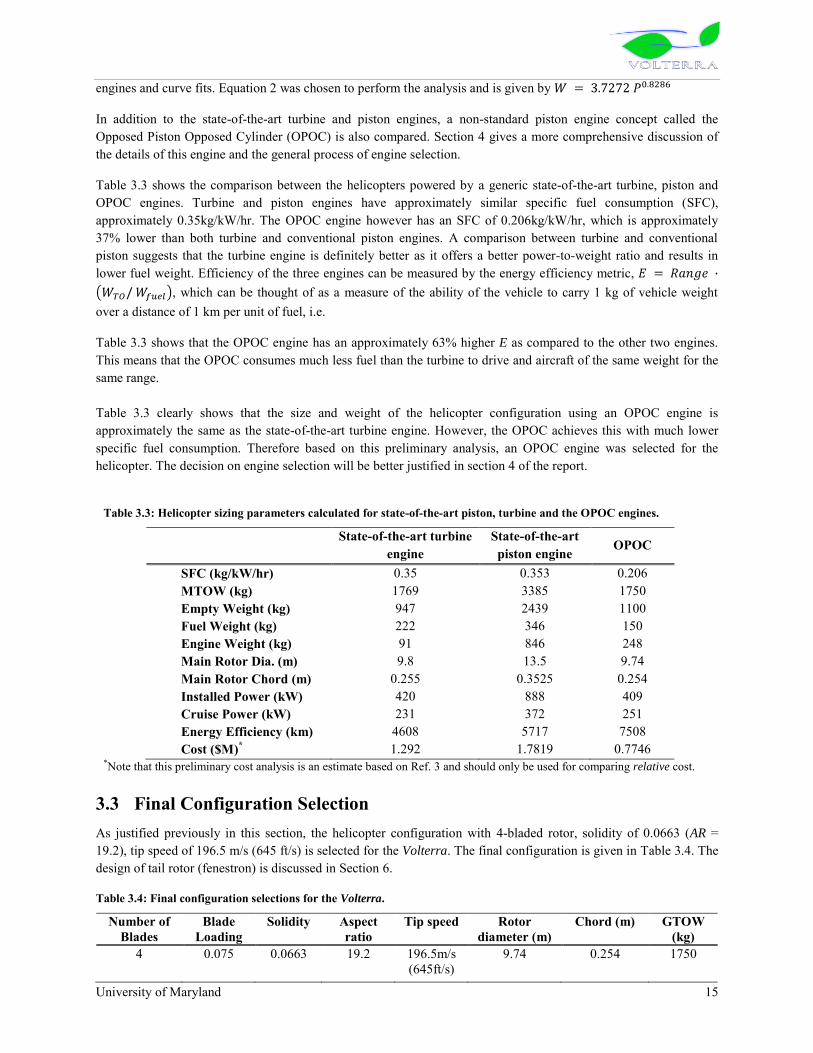
University of Maryland 15
engines and curve fits. Equation 2 was chosen to perform the analysis and is given by
In addition to the state-of-the-art turbine and piston engines, a non-standard piston engine concept called the Opposed Piston Opposed Cylinder (OPOC) is also compared. Section 4 gives a more comprehensive discussion of the details of this engine and the general process of engine selection.
Table 3.3 shows the comparison between the helicopters powered by a generic state-of-the-art turbine, piston and OPOC engines. Turbine and piston engines have approximately similar specific fuel consumption (SFC), approximately 0.35kg/kW/hr. The OPOC engine however has an SFC of 0.206kg/kW/hr, which is approximately 37% lower than both turbine and conventional piston engines. A comparison between turbine and conventional piston suggests that the turbine engine is definitely better as it offers a better power-to-weight ratio and results in lower fuel weight. Efficiency of the three engines can be measured by the energy efficiency metric,
, which can be thought of as a measure of the ability of the vehicle to carry 1 kg of vehicle weight over a distance of 1 km per unit of fuel, i.e.
Table 3.3 shows that the OPOC engine has an approximately 63% higher E as compared to the other two engines. This means that the OPOC consumes much less fuel than the turbine to drive and aircraft of the same weight for the same range. Table 3.3 clearly shows that the size and weight of the helicopter configuration using an OPOC engine is approximately the same as the state-of-the-art turbine engine. However, the OPOC achieves this with much lower specific fuel consumption. Therefore based on this preliminary analysis, an OPOC engine was selected for the helicopter. The decision on engine selection will be better justified in section 4 of the report.
3.3 Final Configuration Selection As justified previously in this section, the helicopter configuration with 4-bladed rotor, solidity of 0.0663 (AR = 19.2), tip speed of 196.5 m/s (645 ft/s) is selected for the Volterra. The final configuration is given in Table 3.4. The design of tail rotor (fenestron) is discussed in Section 6.
Table 3.4: Final configuration selections for the Volterra.
Number of Blades
Blade Loading
Solidity Aspect ratio
Tip speed Rotor diameter (m)
Chord (m) GTOW (kg)
4 0.075 0.0663 19.2 196.5m/s (645ft/s)
9.74 0.254 1750
Table 3.3: Helicopter sizing parameters calculated for state-of-the-art piston, turbine and the OPOC engines.
State-of-the-art turbine engine
State-of-the-art piston engine OPOC
SFC (kg/kW/hr) 0.35 0.353 0.206 MTOW (kg) 1769 3385 1750 Empty Weight (kg) 947 2439 1100 Fuel Weight (kg) 222 346 150 Engine Weight (kg) 91 846 248 Main Rotor Dia. (m) 9.8 13.5 9.74 Main Rotor Chord (m) 0.255 0.3525 0.254 Installed Power (kW) 420 888 409 Cruise Power (kW) 231 372 251 Energy Efficiency (km) 4608 5717 7508 Cost ($M)* 1.292 1.7819 0.7746
*Note that this preliminary cost analysis is an estimate based on Ref. 3 and should only be used for comparing relative cost.


University of Maryland 16
4 ENGINE AND TRANSMISSION The Volterra features an innovative engine and transmission system that emphasizes long life, low maintenance, and ultra low fuel consumption. For these reasons, the power plant selected is the opposed piston opposed cylinder (OPOC) diesel engine developed by FEV Engine Technology through the Defense Advanced Research Project Agency (DARPA). The OPOC engine consumes 30% less fuel than current piston and turbine engines, features modular operation so that one module can be deactivated during forward flight when power requirements are low, and is capable of burning a wide variety of fuels including gasoline, diesel, bio-fuels, JP8, natural gas, and hydrogen. Since the engine system operates at a low RPM, the transmission, featuring spiral bevel gears and a single planetary drive, is also very compact. Supported with an integrated Health and Usage Monitoring System, the transmission system has been designed for a lifetime of 10,000 hours.
4.1 Engine Types Four power plant engine concepts were considered for use in the Volterra: Otto cycle piston engines, Diesel cycle piston engines, Brayton cycle engines, and Fuel Cells. The final selection was made by evaluating the emissions, size, maintainability, and cost of each concept.
4.1.1 Otto, Diesel, and Brayton Cycle Engines
Otto, Diesel, and Brayton cycle engines have a long history in the automotive and aviation industry. However, since most of these engines burn carbon-based fuels, their ideal emissions will always include carbon dioxide. Furthermore, since combustion of these fuels occurs well above room temperature, these fuels will also produce unwanted products such as carbon monoxide (CO), nitrogen oxide compounds (NOx), and unburned hydrocarbons (UHC)1. Though the level of these later emissions can be mitigated by a properly designed engine system, they cannot be completely eliminated.
Since all three engine concepts are proven technology, their maintainability is relatively high. Because they contain relatively few moving parts, Brayton cycle engines are the easiest to maintain and can produce a large power-to-weight ratio. This makes them an attractive option for aviation applications. However, Brayton cycle engines tend to be fairly expensive and can consume more fuel than an equally powerful Otto or Diesel cycle engine.
4.1.2 Fuel Cells
In recent years, the advent of the electric car has led many automobile manufacturers to investigate fuel cells as a means of providing power. In the past decade, the proton exchange membrane fuel cell (PEMFC) has emerged as an excellent example. Such systems use an electrolyte to react oxygen from the air with hydrogen stored onboard the vehicle to produce electricity.
The biggest advantage of a fuel cell system is that the only emission is water. Current fuel cell systems are also 60% efficient in converting fuel to useful energy – a rating that far exceeds the efficiency of the best Otto, Diesel, or Brayton cycle engines. These internal combustion engines typically have efficiencies in the range of 25-40% because they lose a lot of heat energy to exhaust. However, fuel cells do have disadvantages. Firstly, the electrolyte is easily contaminated and the life of a fuel cell is only projected to be 5000 hours by 20152. Secondly, fuel cells are extremely expensive. Presently, fuel cell stacks can be priced at nearly $600/kW. While projected to decrease to $75/kW by 2015, the price of a fuel cell system still far exceeds the expense of an internal combustion engine – especially considering that the fuel cell stack would have to be completely overhauled at least once over the lifetime of the helicopter.
However, the biggest drawback of the fuel cell is the size of the system. By 2015, PEMFC fuel cell stacks are anticipated to produce between 700 and 1100 watts of power per kilogram, but those estimates do not include the

University of Maryland 17
weight associated with the power conditioning system, induction motors, fuel, or fuel containment system. Consider a typical fuel cell containing a cathode, anode, and electrolyte.
First, consider the amount of hydrogen necessary to produce one Amp of current. If each mole of H2 produces two moles of electrons, the number of moles of hydrogen per cell per amp hour can be found:
The mass of hydrogen required per amp hour is:
Assuming an efficiency of 60%, the actual mass of hydrogen per Amp-hour increases to 0.0627 grams per cell per Amp-hour.
Next, consider the potential of each cell. Assuming the cell reaction is isothermal, reversible, and operates near 25C, the voltage of a single cell is found by dividing the change of Gibbs-free energy by twice Faraday‟s constant:
To produce the desired voltage necessary to activate an electric motor, several cells must be stacked up in series. For example, if a fuel cell stack is to power a 450 kW motor for 2.5 hours of flight, 59 kg of hydrogen is required. Assuming that the gas could be pressurized to 700 bar, the tanks alone would amount to 285 kg resulting in a total system of mass over 1500 kg. Comparatively, an equally powerful Otto or Diesel cycle engine would have a mass around 380 kg and an equally powerful Brayton cycle engine would have a mass around 115 kg.
Figure 4.1 illustrates the power to weight trends for Otto cycle engines, Diesel cycle engines, Brayton cycle engines, and fuel cell systems. Note that for nearly all power requirements, the Brayton cycle engine is the lightest, but most of the Brayton engines are rated at or above 500 hp while traditional piston engines dominate the low-power region.
Thus, it is not feasible to use a fuel cell system for a helicopter slated for operation by 2020. However, as fuel cell systems mature, it is possible that in a few decades they will be compact enough for aviation use.
Figure 4.1: Power to weight trends. Individual engine data from Jane's All the World's Aircraft4.

University of Maryland 18
4.2 Fuel Selection A second consideration for selecting an engine is the fuel to be used. As mentioned previously, hydrogen-based fuel cell systems react hydrogen and oxygen which produces water. Ideally, combustion engines that burn carbon-based fuels should only produce water and carbon dioxide, but the high temperature environments of combustion engines can yield additional products including carbon monoxide, nitrogen oxide compounds, and unburned hydrocarbons. Since the products are the result of chemical equilibrium, fuel selection and mixture control are essential to reducing the quantity of unwanted products.
4.2.1 Chemical Equilibrium by Minimization of Gibbs Free Energy Method3,5
Suppose hydrogen is to react with oxygen. The balanced chemical equation in an ideal case would be:
However, as the temperature and pressure of the combustion environment increase, the water product disassociates and forms additional species. In this case, the chemical equation changes to the form:
In the above chemical equation, nx denotes the number of moles of each species, x. If, in the above equation, hydrogen were combusted with air, the nitrogen gas would yield additional products including the two NOx species NO and NO2.
To solve such multi-reaction equilibrium problems, it is common to use a technique such as the minimization of Gibbs free energy. This strategy is based on the principle that, for a given temperature and pressure, when a chemical system is in equilibrium, the net change in the Gibbs free energy is zero. The solution to a given chemical equilibrium problem can be found using the method of Lagrange‟s undetermined multipliers. Since the number of
atoms of each chemical element is fixed, these serve as the constraints. If the fugacity coefficient is assumed to be one (1) for preliminary calculations, the following set of equations is produced:
where ni, is the number of moles of the ith species, aik, is the number of atoms of the k
th element present in each molecule of chemical species i, w is the total number of elements in the system, ΔGfi is the standard Gibbs-energy change of formation for species i, R is the universal gas constant, T is the environment temperature, yi is the mole fraction of species i, P is the environment pressure, λk is the Lagrange multiplier for species k, and N are the number of equilibrium equations. The values for the standard Gibbs-energy are referenced from the CRC Handbook of Chemistry and Physics6 and JANAF Thermochemical Tables7. This approach was implemented in a chemical equilibrium code developed by our design team. The results were confirmed using the NASA Lewis Code and STANJAN Code.

University of Maryland 19
4.2.2 Findings from Chemical Equilibrium Analysis
In the chemical equilibrium analysis, general conclusions were made using air as the oxidizer and three fuel combinations: gasoline, hydrogen, and ethanol. Each study found the molecular fraction of the CO, NOx, and UHC products in the exhaust based on the equivalence ratio – the ratio of the actual fuel-to-air ratio to the theoretical fuel-to-air ratio. The results, shown in show that both gasoline and ethanol combust similarly, but gasoline produces lower quantities of CO, NOx, and UHC. As the mixture becomes increasingly lean, the nitrogen oxide compounds increase. As the mixture becomes increasingly rich, the carbon monoxide and unburned hydrocarbon levels increase. While the combustion of hydrogen with air does not produce carbon monoxide or unburned hydrocarbons, a fair amount of NOx is still produced, and the levels actually increase as more hydrogen is added to the system.Additional insight about the chemical combustion can be seen in Figure 4.3 which shows the relative emissions for various carbon-based fuels. These fuels include the alkanes methane (CH4), ethane (C2H6), propane (C3H8), n-butane (C4H10), n-pentane (C5H12), n-hexane (C6H14), n-heptane (C7H16), n-octane (C8H18) and the alcohols methnol (CH3OH), ethanol (C2H5OH), and propanol (C3H7OH). Notice that the addition of the oxygen bond results in increased production of CO, NOx, and UHC. This is particularly important since most bio-fuels contain carbon chains that include oxygen while most petroleum based fuels are primarily composed of alkane chains. Therefore, from a fuel selection standpoint, there is no clear alternative fuel. Bio-fuels may be attractive options since they do not require drilling, but the emissions during combustion are actually worse than traditional fuels. This study has also shown that hydrogen is a good choice for eliminating CO and UHC emissions, but continues to produce noticeable quantities of NOx. Furthermore, a great deal of energy must be used to harvest hydrogen gas – quantities that are only practically available from fossil-burning or nuclear reactors.
Overall, the best way to reduce the emissions of the power plant used on the Volterra is to select an engine that simply uses less fuel.
Figure 4.2: Emissions by equivalence ratio

University of Maryland 20
Figure 4.3: Emissions for carbon-based fuels, normalized for each species.
4.3 Engine Selection – Opposed Piston Opposed Cylinder (OPOC) Engine The engine ultimately selected for the Volterra is the Opposed Piston Opposed Cylinder (OPOC) Diesel engine under development by FEV Engine Technology through the Defense Advanced Research Project Agency (DARPA)8. Initially developed for the A160 helicopter, the OPOC engine is also under consideration for the Future Tactical Truck System (FTTS) and other military ground vehicles.
4.3.1 Overview
The OPOC engine system is a combination of two engine systems: the opposed piston concept, used in the JUMO 205 Junkers engine, and the opposed cylinder concept, used in the Volkswagen Wasser Boxer engine. The combined system pairs cylinders opposite each other and each cylinder contains a pair of pistons that share a common cylinder.
Simple diagrams of the three engine systems are presented in Ref 8..
Compared to the opposed piston engine and the opposed cylinder engine, the opposed piston opposed cylinder engine contains a single crankshaft and contains no valves. The result is a simple, lightweight, and compact engine that requires reduced maintenance versus traditional piston engines.
Another advantage of the OPOC engine is that it is modular. Each module contains one pair of opposed cylinders and is capable of producing 325 hp per DARPA requirements. Modules can be stacked together via a modular displacement clutch to provide up to 650 hp. This clutch can be disengaged by the pilot at any time. Therefore, in periods of low-power operation typical of cruise flight, one of the modules can be shut down to improve fuel economy. This also provides a level of redundancy in the event that a module fails.
4.3.2 Performance and Specifications
The engine specifications for the two-module OPOC engine stack required for the FTTS are listed in Table 4.1. Note that even though the OPOC is a Diesel cycle engine, the specific power is over 1.0 hp/lb and the specific fuel consumption is extremely low. Table 4.4.2 compares the OPOC specifications with some of the more commonly used power plants of equivalent power. These data indicate that the OPOC engine uses between 30% and 40% less fuel and, consequently, will have a substantially reduced emissions footprint. Additionally, the OPOC engine is designed to burn a variety of fuels including gasoline, diesel, bio-fuels, JP8, natural gas, and hydrogen. This is an attractive feature since the Volterra is designed to operate in devastated areas where particular grades of fuel may not be available.

University of Maryland 21
Per the RFP requirements, the power plant must be capable of providing power to hover 1500 m (4921 ft) above sea level at ISA +20C. Based on these requirements, the dual module operation and transmission are rated to 450 hp. However, a single turbocharged module is capable of providing the necessary power for cruise at 120 kts. Therefore, during forward flight, one module can be disengaged and shut down so as to fly at the minimal specific fuel consumption.
4.3.3 Summary
In summary, the OPOC engine is a great solution for the Volterra. Since the system uses 30% less fuel than conventional piston or turboshaft engines, the carbon dioxide and emissions footprint is substantially smaller. Because the Volterra mission may include transport missions in devastated areas, the low maintenance and wide variety of acceptable fuels are extremely favorable. Furthermore, since the OPOC engine is being developed by DARPA, the costs associated with the research, design, evaluation, and testing of the engine will be absorbed by the military. Slated for production in 2012, flight certification is certainly feasible by the target year of 2020.
Figure 4.4: Engine performance by altitude for standard atmosphere.
Table 4.4.2: Engine Comparison
Engine Type Specific Power
(kW/kg)
SFC (lb/hp-hr)
SFC (kg/kW-hr)
Teledyne Brown Engine Piston 1.2 0.550 0.335 Rolls-Royce 250-C30P Turbine 2.5 0.592 0.36
Turbomeca TM-333 Turbine 2.8 0.513 0.312 OPOC Engine Piston 1.96 0.339 0.206
Table 4.1: OPOC Engine Specifications
Property Units Expected Notes
Power hp 650 3800 rpm at Sea
Level kW 485
Weight lbs 546
Dry kg 248
Specific Power hp/lb 1.19
Dry at Sea Level kW/kg 1.96
H/W/L in 16/41/35
cm 10/104/89
Fuel Consumption lb/hp-hr 0.339
kg/kW-hr 0.206
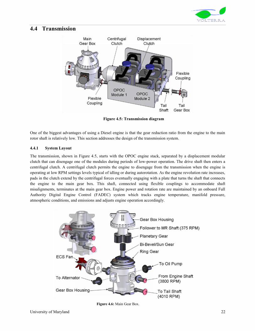
University of Maryland 22
4.4 Transmission
One of the biggest advantages of using a Diesel engine is that the gear reduction ratio from the engine to the main rotor shaft is relatively low. This section addresses the design of the transmission system.
4.4.1 System Layout
The transmission, shown in Figure 4.5, starts with the OPOC engine stack, separated by a displacement modular clutch that can disengage one of the modules during periods of low-power operation. The drive shaft then enters a centrifugal clutch. A centrifugal clutch permits the engine to disengage from the transmission when the engine is operating at low RPM settings levels typical of idling or during autorotation. As the engine revolution rate increases, pads in the clutch extend by the centrifugal forces eventually engaging with a plate that turns the shaft that connects the engine to the main gear box. This shaft, connected using flexible couplings to accommodate shaft misalignments, terminates at the main gear box. Engine power and rotation rate are maintained by an onboard Full Authority Digital Engine Control (FADEC) system which tracks engine temperature, manifold pressure, atmospheric conditions, and emissions and adjusts engine operation accordingly.
Figure 4.6: Main Gear Box.
Figure 4.5: Transmission diagram

University of Maryland 23
The main gear box, illustrated in Figure 4.6, is a combination of a bi-bevel gear set and a planetary drive. The bi-bevel gear receives the input from the main drive shaft at 3800 RPM and then distributes the power to the planetary drive with a follower speed of 375 RPM and to a second bevel gear that drives the tail rotor shaft at 4010 RPM. Accessory devices including the alternator, ECS fan, and oil pump are driven by the primary bevel gear. The oil pump drives the pressurized lubrication system for the main gear box. All bevel gears are of the spiral type to reduce vibration, noise, and contact friction.
The output to the tail is transmitted through a tail rotor shaft to a second gear box containing a set of bevel gears that drive the fenestron. The purpose of the tail gear box is primarily to reorient the axis of rotation by 90, but a slight gear reduction ratio is used to drive the fenestron at the target rate of 3540 RPM (see Figure 4.7). Splash lubrication is used for the tail gear box.
The entire transmission assembly was designed using the American Gear Manufacturers Associate Design Guidelines for Aerospace Gearing (AGMA 911-A94)9 for a life of 10,000 hours. The system is also designed to operate dry for up to 30 minutes in the event of a lubrication system failure. All spur gears were designed using ANSI/AGMA 2001-D0410. All bevel gears were designed using ANSI/AGMA 2003-B9711. These documents provide formulas for estimating contact and bending stresses. A summary of the gear design analysis is provided in Table 4.3.
The main gear box also includes an integrated Health and Usage Monitoring System (HUMS) that provides real-time diagnostics of the transmission system. Oil temperature, oil pressure, strain measurements, and vibrations are fed into the primary flight computer for vehicle health monitoring. This system also provides instantaneous alerts to the operator in the event of a failure.
5 MAIN ROTOR/HUB DESIGN The Volterra main rotor consists of a 4-bladed semi-articulated rotor with SC-1095 and SC-1095 R8 airfoil sections, which offer excellent lift-to-drag ratio and high maximum lift. The rotor is designed to minimize life-cycle energy consumption through the use of low maintenance components, the use of innovative recyclable materials, and
Table 4.3: Gear design summary.
Stress (ksi) Engine/Bi-bevel Bi-bevel/Tail Tail 90 Planetary
Pinion Gear Pinion Gear Pinion Gear Planet Sun Ring
Teeth 24 48 18 38 15 17 32 21 85 Gear Ratio 2:1 2.11:1 1.13:1 5.07:1
Contact Stress Contact 182.8 182.8 169.8 169.8 180.8 180.8 178.7 178.7 110.8
Allowable 221.4 212.3 220.7 216.0 222.4 220.6 189.7 182.0 182.0 Bending Stress
Bending 37.4 38.7 35.8 35.5 39.8 39.5 39.0 25.1 39.0 Allowable 40.2 39.7 40.2 39.9 40.2 40.1 40.9 39.7 39.7
Figure 4.7: Tail Gear Box.

University of Maryland 24
integration of low-risk technologies, while providing superior performance, in both hover and cruise flight, over current helicopters in its class. The rotor blade structure emphasizes simple, lean fabrication and the use of recyclable PEEK (polyetheretherketone) thermoplastic composites, which offer superior damage resistance and fatigue strength. The blade consists of an S-glass unidirectional fibers D-spar, ±450 graphite skin and Nomex® honeycomb core. Enhanced blade leading edge protection against sand, water, and ice particles is achieved through novel polyurethane nano-composite erosion tape as well as non-thermal-based de-icing technology, providing low rotor maintenance and power consumption. State-of-the-art integrated trailing edge flaps (0.3R span) are used for both primary control and active vibration and noise suppression, eliminating the need for a heavy, maintenance intensive swashplate. Revolutionary actuation is provided by powerful, compact, 22 mm diameter brushless motors, which offer sufficient high-bandwidth operation up to 8/rev. The individual blade control (IBC) provides advanced vibration reduction, offering superior comfort to vehicle occupants, while the redundant dual-flap arrangement allows for safe failure modes. The swashplateless rotor design eliminates the need for hydraulics, thereby reducing weight, routine maintenance, and environmental impact. The Volterra‟s semi-articulated hub provides responsive handling qualities in high population density areas and uses established elastormeric bearings designed for a lifetime of 5,000 hours with minimal maintenance. The rotor shows stable aeromechanic/aeroelastic characteristics in all flight conditions.
5.1 Main Rotor Design 5.1.1 Airfoil Selection
There are many airfoils that can be used on a helicopter‟s main rotor, all with unique aerodynamic characteristics. For the Volterra, the choice of airfoils was based on the following reasoning. A symmetric airfoil, such as the NACA 0012, is not desired; although it has zero pitching moment, the airfoil has a low maximum lift coefficient which leads to a low stall margin and limits the vehicle‟s maneuverability. Cambered airfoils such as the
Boeing/Vertol VR-12 offer higher maximum lift coefficients, however, such airfoils suffer from large pitching moments that need to be remedied inboard with a reflexed airfoil such as the ONERA OA-212. Airfoils like the NASA RC(4)-10, ONERA OA209, and the Sikorsky SC-1095 all have comparable performance characteristics; The SC-1095 was chosen due to its readily available aerodynamic characteristics and proven high performance on the UH-60 Blackhawk.
The SC-1095 and modified SC-1095 R8 airfoils offer complementary aerodynamic characteristics and were both considered to optimize rotor performance. For hovering flight, an airfoil with a high lift-to-drag (L/D) ratio is desired to achieve a high figure of merit. In cruise, the rotor encounters compressibility issues and retreating-blade stall. The Volterra‟s advancing blade tips operate at Mach 0.76 in cruise flight, while the reverse-flow region over the retreating blade extends to 31% span. Therefore it is necessary for the blade to have an airfoil with sufficient drag divergence Mach number at the tip and an airfoil with high maximum lift coefficient over the mid-blade section. From Figure 5.1 it can be seen that the SC-1095 airfoil operates at a higher L/D ratio at low Mach numbers around 0.15 and is therefore chosen for the inboard blade section, ranging from 0.2R to 0.4R, just outside the reverse flow region in cruise. The SC-1095 R8 airfoil operates at a higher maximum lift coefficient2 and is chosen to help augment the lack of lift on the retreating blade in cruise and balance the lift being generated on the advancing side. The SC-1095 R8 will be used over the critical lifting section of the blade from 0.43R to 0.87R. Finally, the SC-1095 airfoil has a drag divergence Mach number of 0.8 (Ref. 2), sufficiently above the tip Mach number of 0.76 in cruise,
Table 5.1: Main rotor parameters.
Diameter 9.74 m No. of Blades 4 Blade Chord 0.254 m Twist -100 (linear)
Airfoils SC-1095 and SC-
1095 R8 Tip Speed 197 m/s (645 ft/s)
Solidity 0.0663


University of Maryland 25
and therefore will be utilized from 0.9R to the blade tip to avoid compressibility effects on the blade. Furthermore, the high drag divergence Mach number of the SC-1095 eliminates the need to use tip sweep on the main rotor, reducing manufacturing cost and time.
It is recognized that the outboard airfoil transition region from 0.87R to 0.9R occurs over the trailing edge flap region, however this will have a negligible impact on flap effectiveness as both the SC-1095 and SC-1095 R8 airfoils have nearly identical contours over the aft 50% of the chord. The majority of the transition occurs at the leading edge and only along the outboard 10% of the flap region. Therefore significant performance gains are realized with minimal losses.
5.1.2 Twist and Taper
Incorporation of twist and taper in the main rotor blade design provides a geometric means for enhancing hover performance, as well as delaying retreating-blade stall at high forward flight speeds, by encouraging uniform inflow and allowing each blade station to operate at its best lift-to-drag ratio. The amount of blade twist is a compromise between hover and forward flight performance. Highly twisted blades are optimal for hovering flight as the nose-down twist redistributes the lift over the blade and helps reduce the induced power, while minimal twist is desired for high forward flight velocities because reduced angles of attack on the retreating blade result in degraded performance1. Based on RFP requirements and performance analysis, a blade twist of –100 is chosen.
Figure 5.2: Airfoil distribution along the blade.
The Volterra‟s main rotor uses integrated trailing edge flaps for primary control as discussed in Section 5.2. The need to contain the trailing edge flap actuation mechanism inside the blade envelope restricts extensive use of taper. Additionally, blade taper increases manufacturing cost and time as composite layup practices for fabrication become more involved. Thus, the Volterra‟s main rotor will benefit from a simple design without taper.
5.1.3 Tip Geometry
Blade tip design considerations play an important role in rotor performance. Tip sweep helps delay compressibility effects on the blade, however, it pushes the aerodynamic center and center of gravity aft and can cause the required trailing edge flap actuation forces to be larger. Therefore, since the blade tip airfoil selection alleviates the occurrence of drag divergence, tip sweep is not introduced. Anhedral tips can help reduce blade-vortex interaction (BVI) noise by displacing the vortex away from the blade, however, the Volterra is already designed to be a low-noise vehicle by using a low rotor tip speed as well as utilizing flight path management. Tip taper can help increase the rotor figure of merit, but as mentioned previously, taper increases manufacturing costs. Therefore, to minimize blade construction time and cost, the Volterra has been designed with simple rectangular tips similar to many other helicopters in its class.
Figure 5.1: Airfoil lift-to-drag ratio versus angle of attack data
0
10
20
30
40
0 4 8 12 16 20 24
L/D
AoA [degrees]
SC-1095
SC-1095 R8
Mach 0.15

University of Maryland 26
5.1.4 Blade Structure:
The blade structure is designed to carry the centrifugal loading and the steady and oscillatory stresses due to flap, lead/lag, and torsional moments and shear forces. The driving goals in the design were to minimize total rotor weight, minimize cost, and minimize adverse environmental impacts. In addition, the blade structure must provide sufficient internal geometry to house the trailing edge flap actuation system.
Several blade spar configurations were considered to determine the optimum solution to support the blade structure. After evaluation, two candidates (D-spar and C-spar) remained, which can be seen in Figure 5.3, and their structural properties were further investigated in detail. A D-spar design offers a simple, closed-section structure with high torsional rigidity and provides an excellent support to secure the trailing edge actuation system. The D-spar internal volume also allows for routing of electrical wires to the flap actuator and the de-icing system in the leading edge nose, as well as provides space for the rotor blade tip mass. A C-spar design, with a primary spar near the leading edge and a second spar near the mid-chord, allows easy placement of the center of gravity without a nonstructural nose weight5 as well as the ability to place the elastic axis at the quarter-chord. Although a small weight reduction was realized with the C-spar design, it was not chosen since it requires higher manufacturing labor due to two spars and two honeycomb core sections. Also, the trailing C-spar limits the available internal space for the flap actuator assembly. Therefore, a D-spar configuration was chosen for this design.
5.1.5 Blade Composite Structure Lay-up:
The main rotor blades are made out of fiber reinforced composite materials due to their ability to significantly reduce the rotor weight and their resistance to corrosion, as well as their superior strength, stiffness, and fatigue characteristics as compared to aluminum. Table 5.2 provides a comparison of the structural properties of aluminum and commonly used composite fibers. S-glass fiber offers excellent tensile strength as compared to E-glass or aramid fibers such as Kevlar. S-glass is also considerably less expensive than Kevlar and was therefore chosen for construction of the internal blade spar. To reduce overall blade weight, both Kevlar and graphite fibers were considered for the blade skin construction; however, Kevlar is susceptible to damage by ultra-violet light while graphite offers much greater structural stiffness. Therefore, graphite fiber was chosen for the skin construction.
Table 5.2: Properties comparison of aluminum and commonly used composite fibers6.
Material Density (Mg/m3) Young’s Modulus, E11 (GPa)
Specific Cost ($/kg)
Fiber Tensile Strength (GPa)
Aluminum 2.75 70 1 - 5 0.11 E-glass 2.55 72 3 - 5 3.4 S-glass 2.50 85 3 -5 4.6 Kevlar-49 ® 1.45 117 – 131 10 - 20 3.6 – 4.1 IM7 Graphite 1.65 275 - 345 85 4.8
Thermoplastic composites were chosen for rotor blade construction due to manufacturability and recyclability considerations as discussed in Section 14. The specific composite materials used for the rotor blade construction and their mechanical properties are listed in Table 5.3. The blade spar is constructed of unidirectional fiberglass composite tape, S-Glass/PEEK (S-2/APC-2), providing high tensile strength while minimizing material cost. At the blade root, the unidirectional plies wrap around the two retention bushings to bear the centrifugal loads. The outer
Figure 5.3: (top) D-spar configuration; (bottom) C-spar configuration.
0.05 0.1 0.15 0.2 0.25
-0.01
0
0.01
0.02
[meters][m
ete
rs]
Airfoil Cross-Section
0 0.05 0.1 0.15 0.2 0.25
-0.01
0
0.01
0.02
[meters]
[mete
rs]

University of Maryland 27
blade skin consists of graphite/PEEK (IM7/APC-2) to provide high bending stiffness and minimize weight. Nomex® honeycomb is selected as the core material due to its superior bonding characteristics with the skin as well as its lightweight and low moisture absorption properties. A tungsten mass ballast weight is used in the nose of the blade to bring the center of gravity to the quarter-chord.
Table 5.3: Mechanical properties of rotor blade materials7,8.
Material Property
Graphite/PEEK (IM7/APC-2) Vf = 61%
S-Glass/PEEK (S-2/APC-2) Vf = 61%
Nomex Honeycomb
Density [kg/m3] 1605 1993 32
Mod
ulus
[00] Tensile [N/m2] unidirectional 172 x 109 55 x 109 - [900] Tensile [N/m2] unidirectional 109 8.9 x 10⁹ -
Shear [N/m2] ±45o specimen 5.5 x 10⁹ 6.6 x 10⁹ 30 x 106
Stre
ngth
[00] Tensile [N/m2] unidirectional 2.9 x 10⁹ 1.2 x 10⁹ - [00] Comp. [N/m2] unidirectional 1.3 x 10⁹ 1.1 x 10⁹ 1.0 x 10⁶
Shear [N/m2] ±45o specimen 179 x 109 102 x 106 0.7 x 10⁶
To determine the dimensions of the blade constitutive components, a parametric study was conducted in conjunction with the comprehensive dynamics code UMARC, analyzing the sectional properties and blade natural frequencies. The design space included the material selection, the number of plies in the D-spar and blade skin, and the chordwise dimensions of the D-spar. An appropriate ply lay-up was determined to meet the blade static and dynamic requirements.
Vibration reduction was also considered in designing the blade spar. Significant reductions in 4/rev vibratory loads (14% reduction in vertical shear, 12% in in-plane shear and 18% in head moment) have been realized in wind tunnel studies on composite-tailored, Mach-scaled rotors through the use of multiple different segmented pitch-flap couplings integrated along the blade9. However, the Volterra‟s use of trailing edge flaps for primary control restricts the implementation of such couplings as they may cancel the effects of the control inputs from the flaps. Also, such performance increases are realized at the expense of increased manufacturing costs as specially-tailored ply layups result in longer construction time. While vibration reduction is not addressed through blade composite layup, it is addressed in the Volterra design through other capacities such as individual blade control with trailing edge flaps, low rotor tip speed, and occupant seat vibration isolation.
The D-spar is constructed of unidirectional [00] plies with a constant wall thickness of 3 mm. The D-spar will extend chordwise from the leading edge nose mass rearward to 35% chord. The D-spar will be formed as a separate part and later laid up with the rest of the blade structure. A silicone rubber mandrel will be used to form the D-spar which will shrink upon cooling, allowing easy removal from the composite spar. The blade skin is composed of [+45/-45]2 plies to provide high torsional rigidity.
5.1.6 Rotor Blade De-icing and Erosion Protection
In compliance with the RFP‟s request for a multi-role vehicle, the Volterra must have blade de-icing capability for operation in ice prone environments. The accumulation of ice on the main and tail rotor blades can cause severe problems such as flow separation, lower stall margins, and increased drag. Several anti-icing or de-icing methods exist to address this issue. Thermal based de-icing is carried out through resistive heating of thermal elements beneath the leading edge skin, which melt and subsequently shed the accumulated ice. Thermal de-icing consumes large amounts of power (25 W/in2) and consequently necessitates intermittent operation only, allowing thick (up to 1 cm) patches of ice to form before being shed and subsequently causing a ballistic concern10. Mechanical shearing methods include high frequency distortion of the blade skin through piezo actuators or electromagnetic excitation. High frequency skin distortion consumes significantly lower amounts of power (1.2 W/in2)10, thus allowing ice to be shed more often before it causes concern. De-icing through expandable pneumatic layers sheds ice by inflation of thin bladders, shearing the ice and causing delamination. Pneumatic methods require non-ideal deformation of the

University of Maryland 28
leading edge, causing performance loss, as well as pressurized air lines in the rotation frame, which increases complexity.
Additionally, the design must utilize the optimal choice for blade leading edge erosion protection to minimize maintenance and repair time. Erosion of the main and tail rotor blade leading edges due to collision with water particles, sand, and debris is an important consideration. Erosion leads to reduced aerodynamic performance as a result of flow separation and presents itself as decreases in lift and increases in drag. Traditionally, this protection cap is made of a ductile metal such as steel or nickel and is adhesively bonded to the nose of the blade, becoming an integral part100. After extended operation, the metallic cap erodes and must be replaced, which requires a certain amount of time and skill12. An alternative to metallics is the use of ceramic material to provide enhanced erosion protection13. However, ceramics are brittle and require isolation from the dynamic strains imposed on the blade structure, and also cannot accommodate high frequency shearing de-icing methods. Another alternative is the use of nano-composite polymers which can be applied to the leading edge in either paint or tape form. Nano-composites are superior to standard polymer coatings as the nano-sized reinforcing particles dispersed throughout the matrix distribute the impact energy from a collision over a larger volume, thus reducing the chance of erosion12.
To address these demands, a polyurethane nano-composite tape is chosen to provide enhanced erosion protection with easy repair characteristics while allowing high frequency shear de-icing to be implemented which will significantly reduce the power consumption as compared to thermal de-icing. A polyurethane based tape (8542HS MB, 0.56 mm thick) manufactured by the 3M corporation14 has already been investigated by Agusta-Westland on the Lynx BERP tip blade and provides adequate erosion protection as well as no interference with de-icing capabilities15. Nano-particles can be incorporated into this existing tape to provide superior erosion protection. High frequency shear de-icing technology has been proven by Palacios10 and offers significant reductions in power consumption as compared to thermal based strategies. Both the erosion protection and de-icing system will extend along the entire leading edge nose of each blade and rearward from the nose to 5% and 10% chord on the top and bottom surfaces, respectively. The nose lay-up, from outer-most surface inwards, is as follows: 0.56 mm thick nano-composite tape, 0.5 mm thick steel, 2 mm thick PZT-4 actuator layer, tungsten leading edge nose mass. Additionally, a thin strip of perforated aluminum foil is integrated with the top skin layer around the leading edge to provide electrical continuity and a conducting path in the event of a lightning strike on the blade.
5.1.7 Rotor Morphing
Rotor morphing is a promising area as it offers the potential to optimize the rotor at all flight conditions and dynamically control rotor behavior. The variable diameter rotor (VDR) concept uses the ability to change the rotor blade length during flight, providing an ideal rotor for both hover and forward flight. Several design concepts address the mechanism which telescopically varies the rotor diameter. These include the jack-screw mechanism16, the multi-cable strap and spooling system17, and the centrifugal retention spring system18. However, this technology has not yet been established on full-scale helicopters and currently remains a topic of research. Additionally, the performance benefits of the VDR concept are only truly realized for high-speed helicopters, so a VDR design is not necessary for the Volterra. However, the Volterra uses active trailing edge flaps which allow a portion of the rotor blades to dynamically deform, providing vibration and noise suppression as well as primary control.
5.2 Swashplateless Rotor Design The primary flight control in a helicopter is achieved by controlling the rotor thrust vector, which is achieved by changing the blade pitch as a function of azimuth angle. Traditionally, primary control of the helicopter is accomplished with a swashplate mechanism that enables collective and cyclic inputs to the rotor. An alternate approach is a swashplateless design using integrated trailing edge flaps (TEFs) located at the trailing edge of each blade, allowing collective and cyclic inputs, where cyclic frequency is only limited by the TEF actuator bandwidth. This ability not only offers primary control, but potentially vibration and noise suppression as well. TEFs have been used for primary control for over 60 years by the Kaman Aerospace Corporation32, and more recently TEFs have been demonstrated for active vibration and noise control by two leading helicopter manufacturers respectively through flight testing and windtunnel testing of full-scale vehicles. Additionally, a swashplate design requires

University of Maryland 29
significantly larger overall actuation forces to change blade pitch as compared to a flap system33; this explains why a swashplate design tends to be bulky and heavy as well as prone to cause high parasitic drag. Shen34 found the possibility that a swashplateless system can reduce parasitic drag by 15%, leading to a more energy efficient vehicle.
Trailing edge flaps can be designed to provide primary control in two ways: by changing lift characteristics (lift flaps) or by changing the pitching moment characteristics (moment flaps). Lift flaps are used to enhance the lift characteristics of torsionally stiff blades (νθ > 4/rev), where the effects of aerodynamic pitching are negligible and
only increases in sectional lift are realized, which is similar to the effect of changing blade pitch moment. Lift flaps have substantial chord length (> 35% of blade chord) to increase their efficiency and require large amounts of deflection, which results in higher drag penalties, stalled blades, and decreased rotor performance. Moment flaps are smaller in size (< 25% blade chord) and require blades of low torsional stiffness (νθ < 2/rev). Moment flaps induce a blade pitching moment which causes the blade to twist. The required flap deflections for achieving primary flight control using moment flaps are small compared to the requirements with lift flaps, resulting in a lower drag penalty and only small changes in sectional lift characteristics21.
Because of the benefits that moment flaps offer over any other swashplateless design, this control system configuration was chosen for the Volterra.
5.2.1 Trailing edge moment flap design
Figure 5.4 shows the cross-sectional parameters of a trailing-edge flap. The design parameters of trailing edge flaps are summarized as follows
Blade pitch index angle is the pre-collective given to the blades to minimize the flap deflections required to trim the helicopter for a given flight condition, as shown in Figure 5.5.Flap chord ratio is the ratio of the flap chord to the blade chord. A smaller flap chord can provide sufficient moment with a small deflection by providing larger moment arm. Radial location of flap refers to the mid-span location of the flap on the blade. Locating the flap further outboard increases the effectiveness of the flap. Flap overhang is the position of the flap hinge relative to the leading edge of the flap. Increasing the flap overhang can reduce the actuation requirement by increasing the moment arm. Blade torsional frequency: To provide good control effectiveness, the blade torsional frequency should be much lower than that for the conventional blades i.e. it should fall between 1.8 and 2.5/rev. Flap span: A larger flap span results in smaller deflection but increases hinge moments.
5.2.2 Optimization of TEF design
The University of Maryland Advanced Rotorcraft Code (UMARC)35was used to investigate the effects of these design variables on the required flap deflections and hinge moments. A propulsive trim analysis was performed to achieve the target thrust and zero hub and roll pitch moments, by varying the flap deflection angle, defined as:
Figure 5.4: Cross-sectional parameters of a trailing-edge flap. Figure 5.5: Blade indexing.

University of Maryland 30
where o, is the collective flap deflection and 1c and 1s are the cyclic flap deflections. The net /maximum flap deflection is , where is net cyclic flap deflection or half peak to peak (HPP) deflection. In these studies, the objective was to select the design parameters that minimize the HPP flap deflection angles and hinge moments required to achieve them for all flight conditions.
The parametric studies were carried out for trailing edge flap located at 75% blade radius with a chord of 15% of the blade chord, a flap span of 30% of the blade radius and a flap overhang of 25% flap chord (or 0.05c). The blade had a twist of -10. The blade and trailing edge flaps are modeled as thin airfoils and the analysis was done using uniform inflow. Figure 5.6 shows the variation of HPP flap deflection with forward speed for blades with different torsional frequencies. As frequency increases, the required flap deflection increases. For the remainder of the analysis, torsional freq. of 2.2/rev is chosen as 1.9/rev is nearer to the resonance condition.
5.2.3 Optimizing index angle
Flap deflection angles required to achieve trim at high speeds are relatively large, therefore the blades should be indexed to some pre-collective. Figure 5.7 gives the collective and cyclic pitch angles required to trim the helicopter with a conventional swashplate design and the total pitch angle required to trim. Figure 5.8 and Figure 5.9 show the variation of half peak to peak (HPP) flap deflection and hinge moments at airspeeds up to 140 knots for blade index angles of 10, 12 and 15. The figures show that as index increases, the HPP flap deflection decreases. Although, flap deflection angles are lower at 15 index angle, the hinge moments are slightly higher than at 12. The blade index angle was finally chosen as 15 for the Volterra.
5.2.4 Optimizing flap span
Different flaps were studied with their mid span location at 0.75R, total span lengths of 0.2R, 0.3R and 0.4R, and with the blades indexed at 15. Figures Figure 5.10 and Figure 5.11 show the variation of HPP flap deflection angles and hinge moments at different speeds for these designs. Therefore, larger flaps (larger spans) have smaller deflection angles but also have larger hinge moments. A span length of 0.3R was therefore selected for further studies.
5.2.5 Choice of flap chord ratio
The flap chord was varied from 15% to 30% of the blade chord. Figure 5.12 and Figure 5.13 show that HPP flap deflection angles are not affected by flap chord ratios, but the hinge moment required decreases with decreasing flap chord. This is because with a smaller flap chord, the moment arm increases and the flap becomes more effective. A flap chord ratio of 15% was selected for the Volterra. It was not reduced further because very small flaps can cause flow separation during maneuver and hence become ineffective.
Figure 5.6: Variation of HPP flap deflection angles at different airspeeds for blades with different torsional frequencies
0
1
2
3
4
5
6
0 20 40 60 80 100 120 140
HP
P fla
p d
efle
ctio
n,
|c| (d
eg
ree
s)
Airspeed (Knots)
1.9/rev
2.2/rev
= 2.4/rev
Figure 5.7: Pitch deflection angles for conventional swashplate rotor

University of Maryland 31
5.2.6 Choice of flap mid-span location
Flaps with total span of 0.3 R and mid-span locations at 65%, 75% and 80% of the blade radius were studied. Figure 5.14 and Figure 5.15 show that with outboard movement of flap, total deflection decreases but hinge moment increases. Therefore, a mid-span location of 0.75R was selected for Volterra. The details of the final optimized flap configuration are shown in Table 5.4. The final configuration consists of two flaps per blade each consisting of 15% of the rotor radius. A dual flap design was chosen to provide redundancy in the control system as well as low actuation requirements per flap. In the case of failure of one of the flap actuators, the other flap should be able to trim the helicopter in all normal flight conditions.
Figure 5.8: HPP hinge moment required with index
angles Figure 5.9: Variation of flap deflection angles with
blade index angle at different airspeeds
Figure 5.10: Variation of flap deflection angles with flap
span at different airspeeds Figure 5.11: Variation of hinge moment required with flap
span
Figure 5.12: Variation of HPP flap deflection angles with flap chord ratio
Figure 5.13: Variation of HPP hinge moment required with flap chord ratio
0
1
2
3
4
5
6
0 20 40 60 80 100 120 140
HP
P fla
p d
eflection
, |
c| (d
egre
es)
Airspeed (Knots)
10o
12o
15o
0
0.5
1
1.5
2
2.5
0 20 40 60 80 100 120 140
Index angle = 10 o
Index angle = 12 o
Index angle = 15 o
HP
P h
ing
e m
om
en
t (N
m)
Airspeed (Knots)
0
1
2
3
4
5
6
7
8
0 20 40 60 80 100 120 140
HP
P fla
p d
eflection, |
c|
Airspeed (Knots)
0.2 R
0.3 R
0.4 R
Index angle = 15 o
0
0.5
1
1.5
2
2.5
0 20 40 60 80 100 120 140
flap span = 0.2R
flap span = 0.3R
flap span = 0.4R
HP
P h
ing
e m
om
en
t (N
m)
Airspeed (Knots)
Blade index angle = 15 o
Flap chord ratio = 15%
0
1
2
3
4
5
6
0 20 40 60 80 100 120 140
0.15 c
0.2 c
0.25 c
0.3 cHP
P f
lap
de
fle
ctio
n,
|| (d
eg
ree
s)
Airspeed (Knots)
Index angle = 15 o
Flap span = 0.3 R
0
2
4
6
8
10
0 20 40 60 80 100 120 140
HP
P h
inge m
om
ent (N
m)
Airspeed (Knots)
Index angle = 15 o
Flap span = 0.3 R
0.15 c
0.2 c
0.25 c
0.3 c
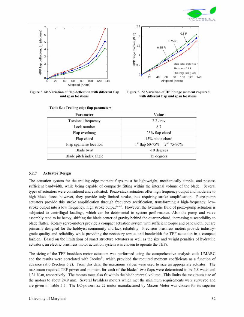
University of Maryland 32
Figure 5.14: Variation of flap deflection with different flap mid span locations
Figure 5.15: Variation of HPP hinge moment required with different flap mid span locations
5.2.7 Actuator Design
The actuation system for the trailing edge moment flaps must be lightweight, mechanically simple, and possess sufficient bandwidth, while being capable of compactly fitting within the internal volume of the blade. Several types of actuators were considered and evaluated. Piezo-stack actuators offer high frequency output and moderate to high block force; however, they provide only limited stroke, thus requiring stroke amplification. Piezo-pump actuators provide this stroke amplification through frequency rectification, transforming a high-frequency, low-stroke output into a low frequency, high stroke output22,23. However, the hydraulic fluid of piezo-pump actuators is subjected to centrifugal loadings, which can be detrimental to system performance. Also the pump and valve assembly tend to be heavy, shifting the blade center of gravity behind the quarter-chord, increasing susceptibility to blade flutter. Rotary servo-motors provide a compact actuation system with sufficient torque and bandwidth, but are primarily designed for the hobbyist community and lack reliability. Precision brushless motors provide industry-grade quality and reliability while providing the necessary torque and bandwidth for TEF actuation in a compact fashion. Based on the limitations of smart structure actuators as well as the size and weight penalties of hydraulic actuators, an electric brushless motor actuation system was chosen to operate the TEFs.
The sizing of the TEF brushless motor actuators was performed using the comprehensive analysis code UMARC and the results were correlated with Jacobs24, which provided the required moment coefficients as a function of advance ratio (Section 5.2). From this data, the maximum values were used to size an appropriate actuator. The maximum required TEF power and moment for each of the blades‟ two flaps were determined to be 5.8 watts and
1.31 N-m, respectively. The motors must also fit within the blade internal volume. This limits the maximum size of the motors to about 24.9 mm. Several brushless motors which met the minimum requirements were surveyed and are given in Table 5.5. The EC-powermax 22 motor manufactured by Maxon Motor was chosen for its superior
0
1
2
3
4
5
6
7
0 20 40 60 80 100 120 140
HP
P fla
p d
eflectio
n, |
c| (d
egre
es)
Airspeed (Knots)
0
0.5
1
1.5
2
2.5
0 20 40 60 80 100 120 140
HP
P h
ing
e m
om
ent (N
m)
Airspeed (Knots)
0.75 R
0.8 R
Blade index angle = 15 o
Flap span = 0.3 R
Flap chord ratio = 15%
0.65 R
Table 5.4: Trailing edge flap parameters
Parameter Value Torsional frequency 2.2 / rev
Lock number 8.7 Flap overhang 25% flap chord
Flap chord 15% blade chord Flap spanwise location 1st flap 60-75%, 2nd 75-90%
Blade twist -10 degrees Blade pitch index angle 15 degrees
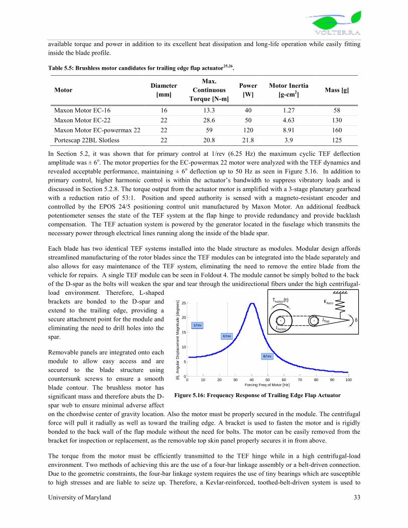
University of Maryland 33
available torque and power in addition to its excellent heat dissipation and long-life operation while easily fitting inside the blade profile.
Table 5.5: Brushless motor candidates for trailing edge flap actuator25,26.
Motor Diameter [mm]
Max. Continuous
Torque [N-m]
Power [W]
Motor Inertia [g-cm2] Mass [g]
Maxon Motor EC-16 16 13.3 40 1.27 58 Maxon Motor EC-22 22 28.6 50 4.63 130 Maxon Motor EC-powermax 22 22 59 120 8.91 160 Portescap 22BL Slotless 22 20.8 21.8 3.9 125
In Section 5.2, it was shown that for primary control at 1/rev (6.25 Hz) the maximum cyclic TEF deflection amplitude was ± 6o. The motor properties for the EC-powermax 22 motor were analyzed with the TEF dynamics and revealed acceptable performance, maintaining ± 6o deflection up to 50 Hz as seen in Figure 5.16. In addition to primary control, higher harmonic control is within the actuator‟s bandwidth to suppress vibratory loads and is
discussed in Section 5.2.8. The torque output from the actuator motor is amplified with a 3-stage planetary gearhead with a reduction ratio of 53:1. Position and speed authority is sensed with a magneto-resistant encoder and controlled by the EPOS 24/5 positioning control unit manufactured by Maxon Motor. An additional feedback potentiometer senses the state of the TEF system at the flap hinge to provide redundancy and provide backlash compensation. The TEF actuation system is powered by the generator located in the fuselage which transmits the necessary power through electrical lines running along the inside of the blade spar.
Each blade has two identical TEF systems installed into the blade structure as modules. Modular design affords streamlined manufacturing of the rotor blades since the TEF modules can be integrated into the blade separately and also allows for easy maintenance of the TEF system, eliminating the need to remove the entire blade from the vehicle for repairs. A single TEF module can be seen in Foldout 4. The module cannot be simply bolted to the back of the D-spar as the bolts will weaken the spar and tear through the unidirectional fibers under the high centrifugal-load environment. Therefore, L-shaped brackets are bonded to the D-spar and extend to the trailing edge, providing a secure attachment point for the module and eliminating the need to drill holes into the spar.
Removable panels are integrated onto each module to allow easy access and are secured to the blade structure using countersunk screws to ensure a smooth blade contour. The brushless motor has significant mass and therefore abuts the D-spar web to ensure minimal adverse affect on the chordwise center of gravity location. Also the motor must be properly secured in the module. The centrifugal force will pull it radially as well as toward the trailing edge. A bracket is used to fasten the motor and is rigidly bonded to the back wall of the flap module without the need for bolts. The motor can be easily removed from the bracket for inspection or replacement, as the removable top skin panel properly secures it in from above.
The torque from the motor must be efficiently transmitted to the TEF hinge while in a high centrifugal-load environment. Two methods of achieving this are the use of a four-bar linkage assembly or a belt-driven connection. Due to the geometric constraints, the four-bar linkage system requires the use of tiny bearings which are susceptible to high stresses and are liable to seize up. Therefore, a Kevlar-reinforced, toothed-belt-driven system is used to
Figure 5.16: Frequency Response of Trailing Edge Flap Actuator
0 10 20 30 40 50 60 70 80 90 1000
5
10
15
20
25
Forcing Freq of Motor [Hz]
||, A
ngula
r D
ispla
cem
ent
Magnitude [
degre
es] Aero Stiffness Condition
1/rev
4/rev
8/rev
Tmotor(t)
Jmotor
Jflap δ
KAero

University of Maryland 34
provide a stiff connection between the motor and flap. The 1.5 mm thick toothed belt eliminates slippage and alignment problems while the pre-stressing of the belt prevents it from loosening after millions of cycles. The flap itself is hinged about its quarter-chord to provide an aerodynamically balanced control surface, which minimizes flap actuation power. The flap hinge is supported on either end by robust thrust bearings to prevent the flap from locking under centrifugal loads.
5.2.8 Active Vibration Control
All helicopters suffer from critical vibration problems and the main rotor is a key source of vibratory loads. Vibration inducing oscillatory airloads are caused by a highly unsteady flow field, complex wake structure, coupled blade motion, and time-varying blade pitch inputs. A balanced, tracked rotor transmits only kNb/rev harmonics of blade loads from the rotating frame to the fixed frame, where k is an integer and Nb is the number of rotor blades. However, if the rotor is not tracked non-kNb/rev harmonics (mainly 1/rev) are also transmitted to the fuselage. Rotor tracking is periodically performed to alleviate this vibration problem, albeit at a significant cost to the operator. Furthermore, to minimize blade dissimilarities, tight manufacturing tolerances are imposed leading to high manufacturing cost. The Volterra‟s main rotor design addresses this problem by utilizing active TEFs onboard the
main rotor to provide individual blade control (IBC) to minimize higher harmonic vibrations and suppress non-kNb/rev loads.
IBC involves the calculation of an optimal control input for each separate blade to minimize both the kNb/rev and non-kNb/rev loads. This is achieved by measuring the steady-state rotor hub loads in the fixed frame. Once the steady-state has been established, the hub loads are sampled once per revolution and system identification is performed in real time (Figure 5.17), which involves the calculation of uncontrolled hub forces and the transfer matrix, which relates the flap deflection on each blade to hub loads. With the state estimates known, the optimal control inputs are determined by minimizing a cost function involving vibratory hub loads and higher harmonic flap control angles. A robust Kalman filter based adaptive control strategy is adopted to implement IBC27 by sampling the hub loads and control inputs once per revolution. This controller efficiently performs both vibration suppression and system identification in real time. Wind tunnel tests conducted in the Glenn L. Martin wind tunnel at the University of Maryland on a Mach-scaled rotor governed by a similar control algorithm revealed significant reductions of 40%, 91%, and 91% in the 3, 4, and 5/rev root flap bending moments harmonics, respectively27,28
5.2.9 Slip Ring
The main rotor leading edge de-icing system and trailing edge flap actuators require electrical power which is supplied by the aircraft‟s alternator. It is therefore necessary to transfer the power from the non-rotating frame to the rotating frame. This is achieved through two coaxial electrical slip rings, comprising of a stationary housing with brushes which contact a series of conducting rings in the rotating frame. The outer ring transmits the higher power signals and the inner ring passes the communication and control signals. To avoid loss of electrical contact inside the slip ring housing due to small dust particles and debris, multiple sets of “long-life”
brushes and rings are used. This increased reliability guarantees that power to the rotating frame electrical systems will not be lost due to a single loss of contact. Contactless magnetic slip ring technology was considered not mature enough for current certification and consequently not chosen for the Volterra design.
5.2.10 Blade/Hub Connection
The blade retention bushings were sized to ensure that the bearing stress on the joint, due to centrifugal loads, is less than the maximum allowable compressive strength of PEEK (APC-2). The stress allowable is 17,000 psi29, so a
Figure 5.17: Schematic of IBC Closed-Loop Operation

University of Maryland 35
safety factor of three requires two, 1” diameter by 3” long retention pins per blade. These (hollow) bolts are placed inside a bushing and usually have a 2-degree taper in order to ensure positive and more efficient load transfer. The retention pin bushings can be made simply of steel as only S-glass material will be in contact with the bushings. This will save on blade cost compared to using cadmium-plated titanium bushings which are otherwise used to prevent graphite material from corroding the steel pins.
5.3 Hub Design The main rotor hub provides the connection between the rotor mast and the rotor itself, and thus demands significant design considerations for best operation. The RFP states that the proposed rotorcraft must be designed to operate in congested, high population density areas, which requires a safe vehicle with responsive handling qualities. Teetering and gimbaled hub designs, such as those found on the Robinson R-44 and Lockheed Cheyenne AH-56A, respectively, are hinged at the rotor mast and therefore do not transmit moments to the rotor shaft as well as minimize fatigue-inducing bending stresses on the blade. However, these designs fail to offer the responsive rotor characteristics required for operation in congested environments. The RFP states that the proposed rotorcraft must be low maintenance. Conventional, fully articulated rotors, such as those found on the UH-60 Blackhawk and the AH-64 Apache, have mechanical hinges that require continuous maintenance to ensure the hinges are properly lubricated and free of contaminants. Constant maintenance of fully articulated rotors is highly time intensive and limits the amount of vehicle operation. On the other hand, bearingless rotors, such as those found on the Eurocopter EC-135, eliminate bearings and hinges all together by using a flexbeam configuration which offers a simple, low profile design. However, such rotors need to be soft-in-plane to minimize in-plane loads, therefore lead/lag damping is necessary to avoid ground and air resonance. The addition of a lead/lag damper to a bearingless hub increases system complexity and cost. Additionally, the Volterra‟s trailing edge moment flaps necessitate a soft-in-torsion blade, requiring the flexbeam design to have a large root cut-out section and consequently incurring performance losses. Alternatively, a semi-articulated hub assembly utilizing elastomeric bearings, such as that found on the Bell
Blade Retention Fork
Clover Plate
[MPa] StrainStress

University of Maryland 36
429, provides a compact solution without requiring additional in-plane damping components. Elastomeric bearings are widely used and provide maintenance-free operation and fail-safe system degradation30. The Volterra has therefore been designed with an elastomeric, semi-articulated rotor hub to minimize mechanical complexity and time-intensive routine maintenance procedures.
The Volterra hub has four primary elements: the clover plate with a virtual hinge offset of 4.6% (provides flap-bending stiffness, bears centrifugal loads, and transmits shaft torque), the elastomeric lead/lag dampers, the elastomeric torsion/centrifugal bearings, and the pitch spring linkages (provide torsional stiffness and adjusts the blade index angle).
Clover Plate - The flap-bending stiffness plate is tailored to provide responsive handling qualities and has a symmetric layup of alternating [00, ±450, 900] plies of S-glass composite material to provide superior strength for axial and in-plane loads. Two bolts secure the torsion/centrifugal bearing to the clover plate and carry the centrifugal load; the clover plate is therefore made thicker at this connection point to distribute the bearing stress over a greater surface area. The flap plate is sandwiched between the top and bottom hub plates, which all mate together with the rotor shaft through a series of eight 5/8” floating bolts, allowing torque to be transmitted to the rotor. A droop stop is integrated into the hub to alleviate static stresses on the blades while not in operation.
Lead/Lag Damper - The lead/lag damper unit provides an in-plane complex stiffness that has two functions. First, it attenuates in-plane vibrations through in-plane shearing of the silicone elastomeric damper. Secondly, the unit provides stiffness to tune the rotor in-plane frequency. A low stiffness is chosen to provide a low frequency and minimize in-plane loads to the rotor mast.
Torsion/Centrifugal Bearing - The torsion/centrifugal bearing directly connects to the outermost portion of the clover plate and features a natural rubber and steel shim construction. The bearing shims are oriented in a conical fashion to provide both soft torsional stiffness and support high centrifugal loads. Both lead/lag and torsion/centrifugal elastomeric bearings have long service life, high reliability, and are fully effective through a temperature range of -65oF to +200oF31.
Pitch Spring - The pitch spring linkage is a soft compression spring which provides the appropriate blade torsional stiffness and allows fine adjustments in the spring stiffness to tune the fundamental torsional frequency of the blades to 2.2/rev. It bears the 1/rev oscillatory loads and provides the support necessary to achieve the required pitch angles for trim of the helicopter. The spring stiffness was calculated using the comprehensive analysis code UMARC and was designed to allow a maximum blade pitch of ±20o.
Table 5.6: Pitch Spring Design Details
Length (mm)
Turns Coil Diameter (mm)
Coil Wire Diameter (mm)
Ultimate Fatigue Shear Stress (GPa)
Shear Modulus (GPa)
200 18 42 4.8 0.35 82.7
Preliminary structural analysis was performed on the centrifugal and flap-bending load-carrying members of the hub to determine proper sizing of the hub assembly components using Pro/Engineer Mechanica‟s finite element analysis
software package. The blade retention fork (seen in Figure 5.18) was analyzed in both a centrifugal and bending environment with the load applied at the two pin connections. The retention fork is a high fatigue component and is therefore made of titanium 6Al-4V STA alloy (σu = 1172 MPa ) due to its superior fatigue properties. The retention fork is sized to eliminate the need for replacement over the entire life of the helicopter. For sufficient fatigue life, the maximum allowable stress must be less than one third the endurance stress of titanium, which is 50% of the ultimate tensile strength. Therefore, the maximum allowable stress is 195 MPa. The retention fork was modeled with 1018 tetrahedral elements and the maximum stress observed was exactly 195 MPa, thus providing a highly optimized design.
The flap-bending clover plate was also analyzed for preliminary sizing. The plate is made of S-glass (S-2/APC-2) composite material with an ultimate tensile strength of 1.2 GPa and a maximum allowable fatigue strain of 0.4%. It

University of Maryland 37
is modeled using 883 tetrahedral elements under both a centrifugal and flap-bending load simulation. The maximum principle strain observed was 0.344% on the bottom surface as shown in Figure 5.18, sufficiently below the maximum allowable strain.
The main rotor system is soft in-plane, semi-articulated design with blades that are extremely soft in torsion (
2.2/rev). Hence, its dynamics characteristics were carefully examined to ensure proper frequency placement to avoid aeromechanical instabilities.
5.3.1 Dynamic Analysis
Dynamic analysis was performed using UMARC. The blade was modeled using 20 finite elements. The blade stiffness and mass distribution is shown in Figure 5.19. The increase in the mass distribution from 60% to 90% of blade radius is because of the presence of the electric motors and blast masses at the location of integrated flaps. The increase at 95% radius is due to the tip mass present there to provide better autorotational characteristics.
Figure 5.20 shows the fan plot for Volterra. In the initial phase of design, the third flap frequency was 5.02/rev and was very close to the resonance frequency. To increase the frequency there and avoid resonance, the blade stiffness was increased from 70% to 90% of the blade radius. The fan plot therefore shows that the rotor frequencies are well separated. The first six natural frequencies are given in Table 5.7.
5.3.2 Aeroelastic Analysis
Pitch-flap-flutter analysis was carried out carefully to ensure that this torsionally soft rotor is safe from this instability. Figure 5.21 shows that the critical c.g. offset to avoid the pitch-flap flutter and pitch divergence, is aft of the quarter chord, at nearly 29% of the chord from the leading edge. Ballast weights were used in the blade tips to move the c.g. ahead of the quarter-chord to 22% of chord. This provides adequate margin of safety to avoid pitch-flap flutter and static divergence. A comprehensive aeroelastic analysis (shaft-fixed) was carried out using UMARC and all the rotor modes (including low damped lag mode) were found to be adequately stable over the entire flight regime.
Figure 5.19: Blade mass and stiffness distribution.
Table 5.7: Main rotor blade first 6 natural frequencies
Mode Flap Lag Torsion First 1.037 0.28 2.2 Second 2.8 4.2 _ Third 5.2 _ _

University of Maryland 38
5.3.3 Ground and Air Resonance
Since, Volterra is a soft-in-plane semi-articulated design, ground resonance analysis was performed systematically. It can be seen from Figure 5.22 that all the rotor in-plane modes are stable and adequately damped. Soft in-plane rotors are also susceptible to air resonance which occurs due to the interaction of rotor flap and lag modes with the fuselage pitch and roll modes. A comprehensive air resonance analysis (shaft-free) was performed using UMARC which showed that the lag mode remains stable (damping > 2%) throughout the flight regime. The stability results obtained so far were calculated neglecting the elastomeric damping. So, the inclusion of these dampers will further augment the aeromechanical stability.
6 TAIL ROTOR DESIGN – FENESTRON 6.1 Summary Using the methodology described below, the fenestron for the Volterra was designed to provide both good performance and excellent maneuverability in congested areas, with a rotor diameter of 0.95 m, and a solidity of
Body Pitch
In-plane
Figure 5.23: Ground Resonance Analysis – Percent Damping with Rotor RPM
Rotor-in-plane modes
body roll
body pitch
107% RPM
90% RPM
100% RPM
Figure 5.22: Ground Resonance Analysis (Coleman’s
diagram)
Figure 5.21: Stability Boundary for Pitch Flap Divergence and Flutter
1st Lag
1st Flap
1st Torsion
2nd Flap
2nd Lag
3rd Flap
Figure 5.20: Rotor fan plot

University of Maryland 39
0.526. The rotors low tip speed (176 m/s) and sinusoidally modulated blade spacing results in a tail rotor that is not only less annoying to the human ear, but also significantly effected by atmospheric absorption. Proper design of the vertical stabilizer results in a fenestron that is completely off-loaded during 120 kt forward flight. Finally, the majority of the empennage structure is composed of highly recyclable, very light, PEEK based composite materials.
6.2 Methodology In order to design the fenestron anti-torque system for the Volterra, a combination of momentum theory predictions and historical trends were used. This method provides an estimate of the appropriate fan diameter and chord for a helicopter of this size. Design parameters, such as inlet lip, diffuser angle, etc. were then chosen based on historical information. The major components of the fenestron design are: the duct (inlet lip, hub, stator and diffuser); the fan; and the empennage (including both the horizontal and vertical fins).
Table 6.1: Survey of Existing Fenestron Tail Rotors (For similarly sized helicopters)
Parameter SA 3
41
SA 3
42
AS
350Z
Cab
ri G
2
EC 1
35
EC 1
20
XO
H-1
RA
H-6
6
EC 1
30
First Flight 1967 1973 1987 1992 1994 1995 1996 1996 2000 DMR/DTR 15.1 15 14.4 13.3 10.2 12.8 10.52 8.7 10.72 Chord (m) 0.04 0.04 0.06 0.038 0.05 0.06 0.12 0.16 0.06 Twist (deg) -12.5 -7 -7 NA NA NA -11 -7 NA Airfoil Series 16 63A OAF NA OAF OAF 64A 64 OAF σTR 0.46 0.46 0.49 0.31 0.42 0.39 0.56 0.62 0.4 VTIP,TR (m/s) 212 212 200 162 185 179 202 205 185 Nb,TR 13 13 10 7 10 8 8 8 10 Stator Blades 0 0 11 0 11 11 0 0 11 Lip Radius (% DMR) 0.08 NA 0.069 NA NA 0.07 0.07 0.075 NA Aircraft GW (kg) 3750 4190 4960 1212 5511 4409 7700 10088 5291
6.3 Duct Design Duct design is a critical component of the fenestron anti-torque system design process. As depicted in figure 6.1, a properly designed duct can provide as much as half of the thrust required during hover and low forward speeds. Further considerations must also be taken into account so as to ensure that the fan performance is maximized, and that the total drag contribution of the duct in forward flight is minimized. There are several main components responsible for these characteristics:
Conventional Tail Rotor Fenestron Tail Rotor
Figure 6.1: Comparison of flow through a conventional tail rotor and the fenestron design.


University of Maryland 40
Inlet Lip: The section of the duct that lies upstream of the fan (the collector), must be designed so as to create a negative static pressure as a result of the inflow of the fan. Experimental studies performed at the United Technologies Research Center (UTRC), as well as work done by Eurocopter, have shown that a uniform lip radius of between 5% and 8% of the fan diameter enables the duct to produce a thrust equivalent to that produced by the fan itself1,2. By surveying existing fenestron designs (Table 6.1), it is apparent that modern designs employ a lip radius of approximately 7.5% of the fan diameter. This value was chosen for the current design.
Fan Hub: The hub is responsible for housing the tail rotor gearbox, as well as any actuators required for proper fenestron operation (pitch control). With no hydraulic actuators aboard the Volterra, these controls are relatively light-weight. Additional weight decreases are gained by using the OPOC engine. Because it operates at a much lower rpm than a turbine engine, the tail rotor gearbox requires a reduction in rpm as it is transmitted from the tail rotor shaft (4000 rpm) to the fenestron fan (3540 rpm). This results in a light gearbox. The stator vanes support the fan hub.
Stator Vanes: In the fenestron‟s infancy, it was found that the use of stator vanes downstream of the fan provided
improvements in performance by recapturing some of the rotational energy usually lost through the wake swirl3. However, early use resulted in a very high pitched “whine” that was associated with the interaction between the fan blades and stator vanes. Several measures were taken to mitigate this acoustic nuisance while still providing a reduction in rotor losses. In order to prevent the simultaneous passage of two blades with two vanes, 11 effective stator vanes (10 vanes + transmission arm) were used in conjunction with the slightly distorted sinusoidal modulation of the fan blades. An additional decrease in the acoustic nuisance of this interaction was obtained by inclining the vanes an angle of 25° in the opposite direction of the blade rotation. In addition to reducing the interaction between the fan and stator, this configuration provides the benefit of a better structure for the support of the rotor torque and transmission. As utilized on the EC135, a separation of 1.5 times the blade chord between the fan and stator assembly was used to further minimize this interaction noise4. Finally, an aerodynamic profile of the NACA 65212, oriented at an angle of attach of 2° was used, as per the recommendation of Marze et al.2.
Diffuser and Outlet Lip: In order to avoid the wake contraction associated with conventional tail rotors, as well as prevent flow separation, a diffusion angle of 7.5° was used. In order to reduce the drag of the ducted rotor system in forward flight, without compromising the performance in hover, the annular outlet lip is comprised of a non-uniform lip radius. A very small lip radius of 1.5% of the fan diameter is used from 75° to 285° tail rotor azimuth of the fan outlet (0° is aft, parallel to the static ground-line of the Volterra). Alarger radius of 7.5% of the fan diameter is then used between 315° and 45°. A linear progression between the two radii is used for the 15° transition period on either side of the shaft axis2.
A sketch of the duct design and layout can be seen in Figure 6.2. Figure 6.3 shows the lip radius distribution of the outlet as well as the orientation of stator vanes.
Figure 6.2: Sketch of Fenestron Cross-Section (viewed from top)
Diffuser Angle = 7.5
Fore Outlet Lip =0.015 DTRAft Outlet Lip = 0.075 DTR
Collector Lip = 0.075 DTR
Tai
l B
oo
m
Drive Shaft
Fan Hub
Fan
Stator Vanes
Collective Control Rod
Stator/Fan Gap = 1.5 c
Thrust

University of Maryland 41
6.4 Fan Design The fenestron fan is optimized for both high aerodynamic efficiency as well as a low acoustic signature.
Fan Diameter: The fan was designed to produce sufficient thrust for hover OGE at 1500 m, with an additional 40% thrust capability for maneuverability and fulfillment of the JAR/FAR flight requirements. Assuming that 50% of this thrust can be generated by the duct itself, and a wake contraction ratio of 0.95, the resultant fan diameter is 1/9.9 that of the main rotor diameter, or 0.95 m. From Table 6.1, it is apparent that this is a typical value for fenestron tail rotors.
Figure 6.3: Side View of Fenestron duct and fan
Number of Blades: In order to ease the balancing of dynamic stresses and reduce the likelihood of simultaneous interaction of multiple fan blades and stator vanes, an even number of blades (10) was used for the Volterra fenestron. An even number of blades has been used on the most advanced fenestron designs, as shown in Table 6.1. Fan Tip Mach Number: The hover tip mach number of the fan was limited to 0.517 so as to minimize the weight of the required tail rotor gear box (3540 rpm), as well as to keep the noise at a reasonable level. Additional information with respect to the fenestron‟s noise can be found in Section 9.2. Blade Spacing: Using methods originally developed for radiator fan noise reduction in cars, it has been found that a significant reduction in the emitted far field noise can be obtained using sinusoidally modulated blade spacing. This spreads the acoustic energy over a wider range of frequencies, which in turn reduces the shrill sound emission associated with fenestron tail rotors. When combined with a high rotational frequency, this approach results in a very quiet helicopter in the far field 4,5,6. One problem that exists is that improper spacing can result in both static and dynamic instabilities of the rotor. Marze et al. provide a scheme that guarantees a minimal angular blade separation necessitated by the pitch and structural limitations of the blades and hub,which also provides sufficient modulation for noise reduction:
θn is the angular position of the nth blade, b = 10 is the number of blades, m is dependent on the number of blades used and ensures the proper dynamic balancing of the rotor, and Δθ provides the optimum distribution of acoustic

University of Maryland 42
energy7. The values used for this rotor (summarized in Table 6.2) were b =10, m = 2, and Δθ = 8.60°. The effect of
this blade spacing is discussed further in Section 9.2.
Table 6.2: Fenestron Blade Spacing
Blade 1 2 3 4 5 6 7 8 9 10 θn 44.18 77.05 102.95 135.82 180.00 224.18 257.05 282.95 315.82 360.00
Airfoil Selection: Due to their small size and high torsional stiffness, it is possible to use highly cambered airfoils as fenestron blades. A uniform cross section of the OAF095 airfoil was chosen for this purpose with a linear twist of 7°. This airfoil was originally developed specifically for use in fenestron blade design. By using a uniform cross-section, the manufacturing process of the blades can be greatly simplified. As discussed in Chapter 14, these blades can easily be made from a composite material (carbon fiber embedded in a PEEK matrix) so as to improve the recyclability, lower the production cost, and reduce the net emissions associated with many other composite materials.
Solidity: In order to provide sufficient hover maneuverability at 1500 m, ISA + 20, a blade loading coefficient (CT/σ) of 0.1 was chosen. This effectively prevents the onset of stall. With a known value of CT, the solidity and thus blade chord could then be calculated. The solidity was chosen to be 0.526 with a corresponding blade chord of 0.078 m, values that fall well within the range of existing fenestron designs.The final design parameters for the Volterra fenestron are summarized below in Table 6.3.
Table 6.3: Key Fan and Duct Design Parameters
Diameter (DTR) Solidity (σTR) RPM Airfoil Lip Radius 0.95 m 0.526 3540 OAF 095 0.075 DTR
Chord (cTR) Twist VTIP, TR Nb, TR Diffuser Angle
0.078 m - 7° 176 m/s 10 7.5°
6.5 Vertical Stabilizer Design The vertical fin of the Volterra was sized so as to provide sufficient “weathercock” stability as well as the entire
anti-torque capability required in forward flight. By doing this, the fenestron fan is almost completely unloaded when traveling at 120 knots, the Volterra‟s target cruise speed. In addition to the performance benefits provided by unloading the fan, there is also a reduction in the dynamic strain exerted on the fan assembly. This results in a dramatically higher fatigue life and significantly lower maintenance cost8. By providing the required anti-torque, the vertical fin also has additional safety benefit in that in the case of tail rotor failure, the helicopter can be flown at a considerable speed to a safe location9. Finally, by offloading the fan, there is a significant reduction in the loading noise produced by the fenestron. This is discussed further in the Acoustics Section.
In order to minimize the cruise drag penalty associated with a large vertical fin, an airfoil with a very high lift-to-drag ratio was used. The highly cambered NASA 633A618, which was most notably used for the Comanche, provides a 4° effective incidence. Using the stability analysis, the effective area of the vertical fin was calculated to be 1 m2. Using simple airfoil theory, the vertical fin was oriented so as to produce sufficient thrust at 1500 m ISA + 20 for 120 knot flight. This results in a pitch of 1° (in addition to the 4° effective incidence). Figure 6.4 shows that the fan and fin thrust requirements relative to the total thrust required by the fenestron as a function of forward velocity.

University of Maryland 43
6.6 Horizontal Stabilizer Design The most prevalent horizontal stabilizer types are the fixed aft stabilizer, the fixed forward stabilizer, the T-tail, and the movable stabilator10, as used on the UH-60 Black Hawk. Although simplistic in function, the design and positioning of the stabilizer can be a challenging problem. The fixed aft stabilizer can have aerodynamic interaction problem with the main rotor wake as the helicopter transitions from hover to forward flight. To remedy this, the fixed forward stabilizer may be used. This horizontal stabilizer type is placed forward on the tail boom so that is in the wake in hover and never has an awkward transition from operating outside of the wake to inside of it. However, this option hampers hover performance because of the download and because more tail area is required for stability than if it were mounted further back. The T-tail configuration is used by Sikorsky on its large helicopters and by McDonnell Douglas on its small ones. This puts the surface high enough that it is above the rotor wake except at very high speeds. It has been found, however, that unless the tail is placed very high, the download may still be high at low speed, especially in climbs. This installation may also put the surface inside the main rotor wake at high speed where the induced turbulence may cause dynamic problems. Finally, this arrangement is heavy because of its structural inefficiency. The movable stabilator is to mount a variable-incidence
„stabilator‟ at the end of the tail boom. (The term comes from the description of the all-flying tails used on many modern airplanes where the movable surface takes the place of both the stabilizer and the elevator). This surface can then be aligned with the flow in the wake at low speeds to minimize the airloads. This solves the trim problem but results in additional weight, cost, complexity, and the danger that the stabilator control system might do the wrong thing at the wrong time such as going to the nose-up hover position while flying at high speed.
Because the Volterra‟s disk loading is relative low,
and because of the ease of manufacturing and maintaining the fixed forward stabilizer type, this configuration is chosen for the Volterra. Based on the stability analyses performed in Section 10, the horizontal moment arm length is 4.15 m and planform area is 3.10m2. The NACA 23012 airfoil section is chosen and mounted inverted to achieve the desired download.
7 AIRFRAME AND LANDING GEAR DESIGN 7.1 Summary The primary mission for the Volterra is not a single scenario, but instead, multiple potential scenarios that might arise and require the use of a light utility VTOL aircraft. The Volterra was designed to be capable of performing well in all conceivable military, para-military, and public multi-purpose transport missions, a fact that is addressed further in Section 16, which discusses in detail these various missions. In order to provide an adequate vessel with which to efficiently conduct these missions, special care is taken in the design of both the airframe and landing gear of the Volterra, taking into account the environmental impact associated with material choice and use of fasteners.
7.2 Airframe Design The fuselage of the Volterra consists of three major sections: cockpit, center section and the tailboom and empennage. Five primary bulkheads are used to bear the majority of the loads and moments transmitted throughout the fuselage. Two keel beams run the length of the fuselage and are shaped so as to efficiently absorb energy upon impact and prevent earth plowing in the event of crash. Additional beams running the length of the transmission
Figure 6.4: Comparison of Thrust Ratios vs. Cruise Speed.

University of Maryland 44
deck serve to provide well-defined load paths for the efficient diffusion of rotor loads. The bulkheads, keel beams and the longitudinal members in the transmission deck combine to make a stiff framework with good torsion stiffness. Finally, the monocoque tailboom structure, which is cantilevered at the aft primary bulkhead, is both lightweight and easily removable for maintenance and transportation purposes.
7.3 Structural Details The Volterra‟s five primary bulkheads are composed of lightweight aluminum-lithium alloy and have lightening holes to reduce airframe weight.
The first primary bulkhead serves to interconnect the composite nose section and cockpit with the rest of the airframe. Composed from Nomex and PEEK/Kevlar composite, the nose section is impact resistant and shaped for superior aerodynamic performance and energy dissipation in the event of an accident (no earth plowing). The front bulkhead transmits loads through both the primary keel beams as well as the composite roof structure, which provides housings for ceiling windows, doors and the Environmental Control System (ECS). The roof structure also serves to interconnect the front three bulkheads, adding a significant amount of torsional stiffness to the forward cabin structure.
In addition to a very safe and lightweight cabin section, the Volterra is very spacious, with an internal cabin volume of approximately 2.701 m3. The minimum internal volume set forth by the RFP is easily fulfilled, with a cabin height of 1.29 m, width of 1.38 m, and length of 2.55 m. In addition to this large cabin area, an additional cargo hold, accessible by hatches on both sides of the fuselage as well as a rear-swinging hatch, has an internal volume of 1.38m3.The port side hatch as well as the rear hatch can be seen in the Exterior Layout Foldout.In order to provide an adequate platform on which to install the engine and transmission, longitudinal and lateral support beams interconnect the third, fourth, and fifth primary bulkheads. These beams are carefully located to provide a platform that is located behind the cabin (which improves cabin comfort) and near the preferred center of gravity of the aircraft.
During flight, the rotor thrust and mast moments must be transmitted to the airframe structure through the transmission. It is desirable to accomplish this using a well-defined load path and, as far as possible, to diffuse the rotor loads as direct loads rather than as bending loads to reduce structure weight (Figure 7.1). The rotor mast loads are first reacted through a standpipe and strut assembly. The thrust bearing inside the main gearbox is very close to the transmission deck; therefore the induced loads are transmitted directly to the deck via the struts. The gearbox loads are transmitted to the transmission deck through four active struts, which also act as smart vibration absorbers. Lateral and longitudinal beams run beneath the transmission deck, and intersect at the attachment point for the transmission support struts. These beams transmit the load directly to the bulkheads and, ultimately, to the keel beam. The structure comprising the two bulkheads, the keel beams and the longitudinal beams beneath the transmission deck form a rigid framework that diffuses the rotor loads. This structure reinforces the transmission structure in critical areas and permits the use of a lightweight panel for the deck.
Figure 7.1: Load path.


University of Maryland 45
In addition to the careful placement of the engine and transmission, special care was taken with the placement of the Volterra‟s fuel system. The crashworthy, interconnected, multi-tank fuel system was placed between the second and third bulkheads so as to balance out the relatively heavy weight of the OPOC engine. This placement of the fuel tanks also facilitated the use of short fuel lines and an easily accessible filler cap. Careful placement of these major components yields a helicopter with very small CG travel during the various modes of operation. Further details regarding the Volterra‟s center of gravity can be found in Section 15.
The floor section of the Volterra rests upon lateral support beams connected to the second and third primary bulkheads and is flat throughout the entire length of the fuselage. This makes conversion from one mission layout to another extremely easy. The floor provides ample clearance for the fuel tank system, which requires adequate ventilation.
The final section of the airframe is the tail boom and empennage. Cantilevered from the fifth primary bulkhead and keel beams, the monocoque tail boom is made of PEEK/Kevlar composite with a Nomex core. The horizontal stabilizer is mounted securely through this boom, a configuration which is proven and easily maintainable. The diameter and thickness of the boom are sized so as to withstand the torque and bending moment imposed upon it by the fenestron anti-torque system and stabilizers.
Connected to the tail boom is the empennage structure, which serves to house the rotor duct and provide support for the vertical stabilizer. It is composed of PEEK/glass composite with a Nomex core. Finally, a stainless steel tail skid is attached to the lower stabilizer, preventing any accidental tail touches during landing or takeoff. The tail boom and empennage structure are extremely lightweight and constructed almost entirely from composite materials.
The airframe as a whole provides a very lightweight and highly environmentally friendly platform for the Volterra helicopter. Through the extensive use of Thermoplastic composite materials, very few fasteners are required throughout the entire structure. Further stiffening of the airframe is obtained from the PEEK/Glass skin that encloses the airframe.
7.4 Doors The doors of the Volterra were designed to provide easy access to the entire cabin area and cargo hold. The front two doors are swinging doors with windows that can easily be removed in the event of a crash. The rear passenger doors of the Volterra are sliding doors, which provide an excellent compromise between usability and structural support for the multi-mission requirements that the Volterra must fulfill. The cabin doors are sized to allow for easy ingress and egress of passengers and fulfill FAR requirements for safety. The doors, attached to both the transmission deck and floor structure, further strengthening the fuselage core. Side hatches are located on both sides of the aircraft for easy access to the cargo area. Furthermore, a rear swing hatch allows for easy rear entry into the cabin and is sufficiently wide for use by medical staff (can fit a standard stretcher).
7.5 Landing Gear The landing gear of a helicopter facilitates landing and ground handling of the aircraft. Two primary functionalities define the design space: 1) absorb vertical energy due to impact while landing; 2) provide a resilient and stable suspension with the added capability to avoid ground resonance.
7.6 Classification of Landing Gear
Landing gear for helicopters can broadly be classified into two categories: 1) skid type and 2) wheel type. Skid type landing gear is mechanically simple to design, lighter in weight, requires lower maintenance, and costs less. Disadvantages in flight performance include ground resonance effects and higher parasitic drag. Typical skid landing gear consists of forward and rear cross tubes and two skid tubes. Replaceable wear plates are provided at the bottom of the skid tubes to prevent damage to the load bearing tubes. Landing velocity requirements are outlined in FAR 27. Landing energy is absorbed through displacement of cross tubes

University of Maryland 46
7.6.1 Landing Gear Selection:
The selection of the landing gear is based on customer desired „greenness‟ as well as the overall functionality and
safety of the vehicle and passengers. A Pugh matrix was constructed to address this selection process (Table 7.1).
Table 7.1: Landing gear Pugh decision matrix.
Parameter Weights Retractable
Tricycle Wheeled
Fixed Tricycle Wheeled
Fixed Skid
Retractable Skid
Folding Skid
Mass 4 3 6 9 8 7 Simplicity 2 3 6 10 7 5 Drag Penalty 5 10 5 6 10 9 Crash Worthiness 3 8 10 10 9 9 Maintenance 3 3 5 10 7 7 Hanger Space 3 10 10 7 8 8 Life Cycle Costs 5 4 9 9 6 6 NOx Emissions 5 5 3 10 7 7 Recyclability 3 3 4 10 8 8 Weighted Totals 185 208 292 257 244
The parameters which rate the merit of the individual solutions fall broadly into three categories. The „greenness‟
category signifies the environmental impact from cradle to grave, whereas the „functionality‟ category signifies
compliance with safety and structural demands. The financial implications define the third category and address life cycle cost for the customer, including the space used during storage. The fixed skid was chosen for as the landing gear for Volterra, based on the values of the Pugh matrix. The selected landing gear design is shown in Figure 7.4.
Figure 7.2: Center of Gravity Envelope of Volterra. Figure 7.3: Fuselage and landing gear natural frequency
as a function of main rotor RPM.
7.6.2 Static Stability Angles
The position of the ground contact points in relation to the center of gravity of the helicopter define two stability angles, pitch and roll. To ensure good lateral stability of the helicopter the roll stability angle must be below 60 degrees1. Good pitch stability of the helicopter is ensured for less than 30 degrees. Volterra ensures pitch and roll stability as the roll/tip over angle is 57.6o, and the pitch angle is 23.3o, Figure 7.2.
7.6.3 Frequency placement for ground resonance
Ground resonance is a phenomenon that can occur at certain rotor speeds when the helicopter is in contact with the ground. Due to the coupling between natural frequencies of the fuselage (aircraft on ground) with the regressing lag mode of the rotor. Volterra is designed to avoid ground resonance with adequate damping and placement of body

University of Maryland 47
natural frequencies. However, should the problem of ground resonance become an issue the pivot joint attaching the rear cross tube of the aircraft frame is capable of being adjusted2, moving the coalescence of natural frequencies away from the critical ranges outlined in blue and orange in Figure 7.3.
7.6.4 Cross Tube Sizing
The loads transmitted to the landing gear during a crash constitute the design load, as this is the largest force applied to the structure. In compliance with FAR 27.737, the limit load rating of each cross-tube must equal or exceed the maximum limit load. This load is sized based on the stroking distance of the energy absorbing seats, and the allowable g-forces apparent on the crew. Therefore the landing gear is designed to fail at a load equal to 25g‟s
applied to a single cross tube member. The cross tube used in the Volterra is a hollow D-tube which. The failure mode of long hollow D-tube is crippling. The landing gear are designed such that in the case of a crash, the landing gear breaks away as it absorbs part of the energy allowing the fuselage and stroking seat to attenuate the remaining energy, transferring a non-lethal load to the passenger.
To enable landing on soft terrain an increase in the contact area is obtained by the use of skid shoes shown in Figure 7.4. This permits landing on semi-prepared surfaces.
Figure 7.4: Skid shoes design for soft ground.
8 PERFORMANCE ANALYSIS Volterra was designed to be a very low drag helicopter that provides good performance capabilities at much reduced fuel consumption as compared to any state-of-the-art helicopter. The low flat plate area of Volterra was an outcome of many innovative decisions made in its design process. The performance calculations were performed to determine the hover ceilings for different GTOW and ambient conditions and concluded that Volterra has excellent hot and high performance capabilities in hover. Forward flight performance calculations were carried out taking into consideration the intake losses, rotor and transmission efficiencies and power required for avionics and rotor trailing edge flap actuation. The calculations showed that Volterra has very good performance capabilities, equivalent to comparable helicopters like EC-120 and Bell-206, requiring much lower fuel as compared to any other helicopter till date.
8.1 Drag Reduction In order to minimize the fuel consumption of the Volterra and to leap it to the “green” category, major attention was paid to the reduction of the drag of the overall helicopter. This section discusses the modifications carried out in the Volterra to reduce its drag coefficient.

University of Maryland 48
8.1.1 Drag Estimation
The preliminary sizing (Section 3) of the Volterra was performed using a flat plate area of 0.56 m2, estimated for a state-of-the-art helicopter of a similar weight1. In order to minimize the drag of the Volterra, several innovative ideas were attempted. Section 8.1.2 describes the design innovations adopted in Volterra, which resulted in a significant reduction in the drag and made it a revolutionary aircraft.
The parasitic drag was estimated using methods presented by Prouty2. Table 8.1 shows the component breakdown of the equivalent flat plate area. Frontal areas for the various components were calculated from the drawings and combined with empirical factors given by Prouty to calculate the flat plate area of the entire helicopter. A factor of 20% was then added to the total as recommended by Prouty for more realistic results. Efforts were made to streamline the helicopter as discussed in section 8.1.2. Table 8.1 shows that the predicted flat plate area of the Volterra with all the innovative ideas implemented is 0.5m2, which is 12% lower than the state-of-the-art helicopter. As can be seen from the table, fuselage, rotor hub, pylon and shaft are the maximum drag producing components in the helicopter, followed by landing gear and rotor fuselage interference effects. Special attention was given to reduce the drag of these areas.
Table 8.1 Component Drag Breakdown.
Component f (m2) f/A % of Total Fuselage 0.161 0.0019 39% Rotor hub and Shaft 0.140 0.0016 33% Landing Gear 0.037 0.0004 9% Horizontal Stabilizer 0.010 0.0001 2% Vertical Stabilizer 0.005 0.0001 1% Rotor-Fuselage Interference 0.045 0.0005 11% Exhaust 0.002 0.0000 0% Miscellaneous 0.019 0.0002 4% Total 0.42 0.0049 100% Additional 20% 0.50 0.0059 100%
8.1.2 Drag Reduction
8.1.2.1 Fuselage drag
Several analyses were performed to optimize the shape of the fuselage for Volterra to minimize its drag. These studies were inspired by the Boxfish design on the Mercedes Bionic car4 that has significantly low drag coefficient of 0.19. The fuselage of the EC-120 was selected as the baseline geometry and concavity was added on the side walls as in the bionic car to simulate boxfish shape. The in-house developed CFD solver IBINS, which is optimized to solve flow over biologically inspired shapes, was used to simulate the flow over all the geometries. With a moderate amount of concavity, a reduction of 5% in drag coefficient was observed. Figure 8.1 shows that the flow remains attached throughout the length of the fuselage due to the vortices formed on the sides and held by the concavity, that results in the drag reduction of the helicopter. Although, a large concavity on the sides of the fuselage reduces drag very significantly, it would also increase its cost and manufacturing energy expenditures. Therefore, a large concavity was not adopted in Volterra. However, these studies led to the emergence of a more streamlined fuselage shape for Volterra that offered very significant reduction in flat plate area.

University of Maryland 49
Figure 8.1: Flow over the modified fuselage of the EC-120 with concavity on the sides.
8.1.2.2 Rotor hub, pylon and engine installation (Figure 8.2)
By streamlining the exposed hub components, adding a fairing, reducing the height of the hub above the
pylon to 0.1m, and keeping the portion of the main rotor shaft which is exposed to free-stream as thin as
possible, the rotor hub was made low profile.
The H50 shape of hub and S40 shape of the pylon were selected3 to avoid flow separation over pylon’s
corners and hence reduce drag.
The top of the pylon is flat to minimize the Venturi effect between hub and pylon and hence leads to
reduction of dynamic pressure of the flow in this region that hence reduces drag.
Additionally, the pylon lip as shown in the Figure 8.2 guides the direction of the flow as it passes over it
and makes it move away from the main rotor and reduces upwash into main rotor.
Since Volterra is powered by a piston engine, the mass flow required by the engine is very low. Thus, the
intake and exhaust were designed low in profile, which reduces drag very significantly.
8.1.2.3 Main rotor (MR) drag (Figure 8.2)
The main rotor shaft tilt angle was pre-set to 4.5 in order to keep the fuselage near its angle of attack for
minimum drag at 120 knots. This is implemented in Volterra to serve two purposes: for lowering the
fuselage bluff body drag and for passenger comfort at high forward speeds.
Primary control in Volterra is achieved from the trailing edge flaps. This results in significant drag
reduction in two ways: 1. Removing the large and bulky swashplate reducing the parasitic drag 2.
Eliminating the need of long pitch linkages.
The airfoils used on MR blades have high lift to drag ratio and high drag divergence mach number. This
minimizes the compressibility effects on advancing blade.
The low MR tip speed (645 ft/s) reduces the profile and parasitic drag of Volterra at all forward speeds.
8.1.2.4 Tail rotor drag (Figure 8.2):
The vertical fin in Volterra has high lift to drag ratio and the duct outlet lip has an asymmetric lip radius to
reduce drag in forward speeds.
Horizontal tail setting was selected such that the nose up pitching moment of the horizontal stabilizer was
balanced out by the nose down hub pitching moment about the helicopter center of gravity. This reduces
the cyclic requirement at cruising flight at 120 knots and therefore reduces the rotor drag and rotor power.
Vertical tail setting was selected such that it could provide the complete side force required for yaw
equilibrium at cruising flight. Hence, the tail rotor is fully off loaded and requires minimum power at 120
knots. These two design modifications satisfy RFP requirement to minimize drag at 120 knots.

University of Maryland 50
8.1.2.5 Landing gear and other drag reduction efforts (Figure 8.2):
Skid landing gear used on Volterra was aerodynamically faired to reduce the drag, by changing the
effective cross-section of the landing gear cross-tubes.
TPP optical tracking system is embedded in the cowling and hence does not add any drag.
The fuselage-tail junction, tail boom-vertical fin junction, fuselage-pylon junction are faired to reduce drag.
As an outcome of the chosen design of Volterra, its drag is reduced by 10% and it has a flat plate area of 0.5m2. This
reduced drag results in reduction in the fuel consumption to carry same payload or increase in payload for same fuel.
This drag is used further for performance calculations on Volterra.
8.2 Hover Performance
The engine of the Volterra is sized to meet the requirement of the RFP for HOGE at maximum take-off weight at
1,500 m (4,921 ft) and it results in the installed SL power of the engine of 450 hp. The Volterra’s OPOC engine has
a capability of producing 650 hp at SL, ISA conditions and a transmission limit of 450 hp has been imposed in order
to obtain a light weight transmission life.
Figure 8.2: Major drag reduction areas on Volterra.
Figure 8.3 shows the power required for HOGE as a function of altitude for three temperature conditions. The power
available from the engine is also shown in Figure 8.3. For this engine, the power reduction at altitude and temperature
is not as large as for turbine engines, and this results in outstanding HOGE performance for the Volterra. For
example, the transmission power limit results in a HOGE ceiling at ISA +20˚ is 2,238 m (7,343 ft). Figure 8.4
shows the hover performance in terms of the weight, altitude and temperature capability of the Volterra. It is seen
that at a gross weight of 1,640 kg (3,616 lb), the Volterra can hover out-of- ground effect at an altitude of 5,000 m
(16,404 ft).
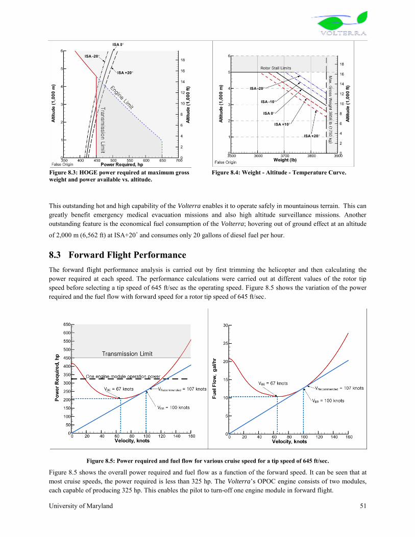
University of Maryland 51
Figure 8.3: HOGE power required at maximum gross weight and power available vs. altitude.
Figure 8.4: Weight - Altitude - Temperature Curve.
This outstanding hot and high capability of the Volterra enables it to operate safely in mountainous terrain. This can greatly benefit emergency medical evacuation missions and also high altitude surveillance missions. Another outstanding feature is the economical fuel consumption of the Volterra; hovering out of ground effect at an altitude
of 2,000 m (6,562 ft) at ISA+20˚ and consumes only 20 gallons of diesel fuel per hour.
8.3 Forward Flight Performance The forward flight performance analysis is carried out by first trimming the helicopter and then calculating the power required at each speed. The performance calculations were carried out at different values of the rotor tip speed before selecting a tip speed of 645 ft/sec as the operating speed. Figure 8.5 shows the variation of the power required and the fuel flow with forward speed for a rotor tip speed of 645 ft/sec.
Figure 8.5: Power required and fuel flow for various cruise speed for a tip speed of 645 ft/sec.
Figure 8.5 shows the overall power required and fuel flow as a function of the forward speed. It can be seen that at most cruise speeds, the power required is less than 325 hp. The Volterra‟s OPOC engine consists of two modules, each capable of producing 325 hp. This enables the pilot to turn-off one engine module in forward flight.

University of Maryland 52
The range and endurance performances were calculated using Prouty‟s method2. Figure 8.6 shows the specific range
(nautical miles per pound of fuel) for four rotor tip speeds. It is seen that the specific range increases as the rotor tip speed is reduced. At any tip speed, the velocity for maximum range (VBR) is the speed at which the specific range is the maximum. The recommended cruise speed is chosen as the velocity for 99% of the maximum specific range2 since this results in an increase in the cruise speed for a small reduction in fuel economy. Based on this reasoning, the recommended cruise speed for the Volterra is 107 knots. The corresponding specific range is 1.16 nautical miles per pound of fuel.
The specific range was also calculated for various altitudes, temperatures and payloads. Figure 8.7 shows the variation of the recommended cruise speed for different payloads and altitudes. In this figure, 100% payload corresponds to 500 kg (1,102lb); the weights of the pilot and fuel are not included in this weight. The recommended cruise speeds for the maximum gross weight configuration for different altitudes and for ISA and ISA+20˚ conditions are given in Table 8.2.
Figure 8.6: Specific range vs. cruise speed for various tip
speed. Figure 8.7: Specific range vs. cruise speed for various
payload and altitude.
Table 8.2: Recommended Cruise Speed for maximum gross weight.
ISA -20 ISA ISA +20
Sea Level 105 knots 107 knots 110 knots
1000m 109 knots 112 knots 114 knots
2000m 114 knots 117 knots 119 knots
3000m 119 knots 122 knots 125 knots
The RFP requires a range of 300 nautical miles. After allowing for 10 minutes hover and reserve fuel for 20 minute cruise at VBR, the range capability of the Volterra at maximum gross weight is 328 nm. (The range is 382 nm without allowing for reserves).

University of Maryland 53
Figure 8.8: Payload, Range and Endurance Diagram.
The maximum endurance of the Volterra on internal fuel of 150 kg (43.5 gal) and maximum gross weight, given as in Figure 8.8, is 3 hours 34 minutes at sea level. The EC-120 helicopter carries approximately twice the amount of fuel (321 kg, 107 gal) and has an endurance of 4 hours 19 minutes. This is due to the very high fuel efficiency of the OPOC engine of Volterra.
8.4 Autorotational Characteristics All helicopters are required to demonstrate autorotation capabilities for CFR certification. These depend upon several interrelated factors that include rotor disk loading, stored kinetic energy in the rotor system, as well as subjective “difficulty rating” flight assessments by pilots
5. This capability of a helicopter can be measured from Autorotation Index (AI), which is a measure of its stored kinetic energy. Sikorsky AI can be defined as:
where IR is the flap moment of inertia of blades, is the rotational velocity, W is the weight of helicopter and DL is the disk loading. This index was used to compare the autorotational characteristics of different helicopters. Table 8.3 compares AI for EC120, Bell206, R-44 and the Volterra 6,5.
Table 8.3: Autorotation index comparison.
Helicopter GTOW (kg) No. of engines Autorotation Index (ft3/lb)
Autorotation Index (m3/kg)
EC120 1715 1 24.57 1.53 Bell 206 1451 1 37.25 2.32
R-44 1134 1 41 2.56 Bell 222 2066 2 17.5 1.09
Volterra 1750 1 (Twin module) 25 1.56
This shows that the Volterra which is a single engine – twin module helicopter, has excellent autorotational capabilities with an AI of 25 ft3/lb.5 specifies the AI for single engine helicopters as 20 ft3/lb and for multi engine helicopters as 10 ft3/s, for safe autorotation. The power supplied by one engine module in Volterra is sufficient for cruising at 120 knots. So, nevertheless, there is only one engine, but twin modules of OPOC behave as two engines and provide redundancy in case of one module failure. So, Volterra can be treated as multi-engine helicopter to compare the AI with other helicopters has sufficient kinetic energy to survive autorotation in the case of one or even two modules failure.

University of Maryland 54
The very low fuel consumption of the engine is further illustrated by considering the maximum endurance obtainable by replacing the entire payload with fuel. Table 8.4 shows a comparison of the maximum endurance capability of the Volterra with that of the EC-120B when the entire useful load (payload + fuel) is converted to fuel, for example, by installing additional fuel tanks. It is seen that the Volterra has an unprecedented endurance and has the capability to stay up in the air for 21 hours using 650 kg fuel. The corresponding value for the EC-120B is 9 hours 39 minutes using 725 kg of fuel. The Volterra has nearly 120% more endurance while using less than 90% of the fuel than the EC 120B. Combined with its autonomous capabilities, this long endurance adds a valuable asset for military and paramilitary surveillance missions.
Table 8.4: Performance Summary and Comparisons.
Volterra EC-120B Bell-206B3 RFP Requirements
Design Gross Weight kg 1750 1715 1451 lb 3858 3780 3198
Payload (Fuel excluded) kg 500 404 393 500 kg lb 1102 891 866
Fuel Capacity kg 150 321 281 Reduced fuel
consumption for comparable range and
endurance lb 331 707 619 gallon 43.5 107 91
Speed for Best Range km/hr 198 204 213 Recommended cruise speed over 100knots knots 107 110 115
Speed for Best Endurance km/hr 124 120 96 knots 67 65 52
Fast Cruise Speed km/hr 222 222 knots 120 120 Rate of Climb m/s 10.63 5.84 6.9 ft/min 2091 1150 1358 HOGE Ceiling
HOGE at 1500m ISA+20
ISA m 2931 2316 1615 ft 9614 7600 5298
ISA +20˚ m 2238 518 914 ft 7343 1700 2998
Autoratation Index m3/kg 1.56 1.53 2.32 ft3/lb 25 24.57 37.25
Maximum Range km 708 710 693 300 n.m n.m 382 383 374 Maximum Endurance 3 hr 34min 4 hr 19min 4 hr 30min Endurance with useful payload converted to fuel 21 hour 9hr 39min 10hr 48min
9 ACOUSTICS Because the primary missions of the multi-role Volterra include operations in congested areas or military/para-military operations where detectibility becomes an issue, a major focus was placed on the acoustic design of the Volterra. This effort is addressed at three levels: passive blade design, flight path management, and active noise reduction. First, the blade design is optimized to minimize the intensity of thickness noise, loading noise, and blade vortex interaction noise. Main rotor noise has been reduced by selecting a low tip speed, blades of a high aspect ratio, and a four-blade rotor. Tail rotor noise has been reduced by installing a fenestron with uneven blade spacing and duct shielding. Secondly, blade vortex interaction is reduced by using an innovative optics-based tip-path-plane tracking system that directs a flight path management system to maintain subjectively quiet flight trajectories. Lastly, lower frequency noise that is important for detection is also reduced at distinct observer positions using the blade trailing edge flaps to actively cancel out near in-plane acoustic waves.

University of Maryland 55
9.1 Main Rotor Acoustic Design
1. Figure 9.1: Four primary acoustic sources of a rotor.
The acoustic signature of a rotor is a combination of four primary sources of noise: thickness noise, loading noise, blade vortex interaction (BVI) noise, and high speed impulsive (HSI) noise1 (see Figure 9.1). Thickness noise arises because the finite thickness rotor blades displace fluid (air) as they rotate and translate through the medium. This causes unsteady pressure waves to radiate to the far field near the plane of the rotor. Loading noise is caused by the fluid reaction to the lifting blade‟s thrust – the thrust of each rotor causes pressure waves to radiate to the acoustic far field. As such, loading noise radiates in the same direction as resultant force vector of the airfoil – primarily out of the plane of the rotor. Blade vortex interaction (BVI) noise is the impulsive noise resulting from rapid pressure fluctuations as the blade passes near or through previously shed rotor vortices. Since BVI noise is an impulsive form of loading noise, it too acts primarily out of the plane of the rotor. The last form of noise, high speed impulsive noise (HSI), arises when the blade tips approach the speed of sound. The blade tip region experiences local transonic aerodynamic effects that dramatically increase the radiated noise near the plane of the rotor. Since the Volterra operates with a low tip speed and a low advance ratio, HSI noise is low compared to the other three sources.
For a given rotor system, the acoustic signature is predicted theoretically by the Ffowcs-Williams and Hawking (FWH) equation. This expression, shown below, relates the acoustic pressure at a fixed observer‟s location at the
perceived retarded time,, due to the thickness noise and the loading noise as described in the rotating blade coordinate system2.
To select an appropriate rotor configuration during the preliminary design stage, a configuration matrix was selected based on variations of the aspect ratio (solidity), number of blades, and tip speed. The FWH equation was then solved numerically to predict the intensity of the acoustic radiation for each configuration assuming an observer distance of ten rotor radii and a constant CT/. The remaining parameters were provided from the preliminary rotor design described in Section 3 of this report.

University of Maryland 56
Figure 9.2: Impact of rotor design on acoustic intensity.
Three important conclusions come from this study. First, acoustic radiation intensity increases with tip speed as a result of increasing the Doppler amplification, . Secondly, increasing the aspect ratio of the blade decreases the intensity of the acoustic radiation, since blades that are long and slender have less “thickness” than
blades that are short and stubby. Thus, for a constant thickness ratio, the blades should be made with as large an aspect ratio as possible to reduce noise. Thirdly, increasing the number of blades decreases the acoustic radiation. For a given thrust, increasing the number of blades will reduce the individual thrust per blade thereby reducing the loading noise generated in the far field. Furthermore, decreasing the individual blade loading will also weaken the shed tip vortices. As a result, while the frequency of occurrence of blade vortex interaction will increase with additional blades, the intensity of the blade vortex interaction will be smaller. Ultimately, the selection of many of these design parameters were also governed by properties including the onset of blade stall, aeroelastic properties of the blades, autorotative index, and structural requirements for control devices.
Ten configurations in particular were tested and their results are provided in Figure 9.3 along with the theoretical predictions for the acoustic intensity of a Bell 206B and EC120 at equivalent observer distances. Based on the findings of the acoustic study and the additional requirements for the rotor system, the configuration labeled “8” was
ultimately selected. Note that the overall sound pressure level at the observer location for this configuration is over 6 dB-OASPL quieter than the EC120 and over 8 dB-OASPL quieter than the Bell 206B.

University of Maryland 57
Figure 9.3: Sound pressure level of various 4-bladed rotor designs considered. 30o below tip-path plane at 10 rotor radii
9.2 Tail Rotor Acoustic Design Under several flight conditions, the tail rotor has been found to be the dominant source of harmonic noise on small and medium conventional tail rotor helicopters. In fact, the tail rotor can be one of the primary sources of noise from military observability and identification standpoint11, 12. Because of this, special attention was given to the design of the anti-torque system for the Volterra so as to minimize its acoustic signature, while still providing the needed performance, safety, and maneuverability required for an energy efficient helicopter capable of operating in congested areas. As discussed in the preliminary design section, the fenestron anti-torque system was chosen. Beyond the safety, performance, maintainability, and maneuverability benefits that the fenestron provides over both conventional tail rotors and NOTAR, several additional steps were taken so as to further reduce the Volterra‟s
fenestron acoustic signature
.
Figure 9.4: Frequency Spectrums of an example fenestron with even (left) and uneven (right) blade spacing6
9.2.1 Harmonic Noise Phase Modulation
Using techniques originally developed for use by the auto industry3 and adapted to the fenestron design5,6,7,8, it is possible to suppress the typical shrill noise associated with fenestron tail rotors at close distances (where atmospheric attenuation is not significant) by employing a phase modulation technique to break the symmetry of the rotating system. Figure 9.4 shows a typical power spectrum for a hovering fenestron using both conventional and uneven blade spacing. The left power spectra in this figure is clearly dominated by the pure tones (at the blade passing frequencies) that emerge up to 15 dB above the broadband noise level. Previous work by K.D. Kryter and K.S. Pearsons4 has shown that the annoyance of rotor harmonic noise is directly related to this tone-to-broadband noise ratio. As a result, it was postulated that a single tone could be made “less noisy” by redistributing its acoustic energy of a wider range of discrete frequencies, thereby reducing the amplitude of each blade passing frequency

University of Maryland 58
harmonic5. This in turn produces a more “broadband like” noise that has been shown to be much less annoying than
an equally spaced fenestron. This redistribution of energy and the subsequent drop in overall sound pressure level is shown in the right power spectra of Figure 9.4.
In order to properly implement this technique, a sinusoidal modulation was used that provided sufficient structural stability and control feasibility in addition to the required phase modulation7. More details regarding this method and the Volterra‟s blade spacing design can be found in Section 6.
9.2.2 Tip Speed Choice
One of the most effective ways of reducing rotor harmonic noise is to reduce the tip speed of the rotor. However, significant reductions in tip-speed can have detrimental effects on the performance of conventional tail rotors. From an aerodynamic standpoint, the fenestron anti-torque system is significantly more robust with respect to tip-speed variation than a conventional tail rotor6. Because of this the tip speed of a fenestron can be dramatically reduced so as to reduce the acoustic emission, without any serious losses in performance. Because of the low operating speed of the OPOC engine, a tail rotor shaft speed of 4010 rpm was used, with a reduction to 3540 rpm in the 90° tail rotor gear box. This results in a very low 176 m/s tip speed and a hover tip Mach number of 0.517.
9.2.3 Improved Placement and Sizing of Duct Obstacles
Previous studies have shown that a considerable amount of the acoustic annoyance of a fenestron tail rotor could be attributed to the interaction between the rotor blades and the stator vanes, whose purpose was to both straighten the flow through the duct and support the gear box and control assembly8. Because of the aerodynamic benefits provided by stator vanes (they recover some of the swirl losses of the rotor), special care was taken to reduce the noise due to the interaction between the rotor wake and stators. This was done via careful alignment and placement of the stator vanes.
A total of 10 vanes (plus the rotor shaft) were used and aligned in a fashion that prevents the simultaneous passage of any two blades and stator vanes. This was done by introducing a slight variation of ±5° in the azimuth location of the vanes. The noise was further decreased by inclining the vanes at an angle of 25° in the direction opposite to blade rotation. This prevents the interaction of the wake of a blade from occurring simultaneously across the whole span of the vane7. Further reductions were gained by the placement of the vanes with respect to the rotor plane as well as the use of an aerodynamic profile for the stator vane shape.
9.2.4 Further Acoustic Reductions
In addition to aforementioned noise reduction methods, there are of course the usual benefits that come with the use of a fenestron anti-torque system. These include:
Duct Shielding: The additional shielding of high frequency noise that the duct provides both in the plane of the rotor (predominantly thickness noise) as well as to a relatively wide angle to the ground.
Loading Noise: A significant reduction in the loading noise component of the fenestron during both hover and forward flight. In hover, a substantial portion of the required thrust is provided by the duct itself, which reduces the harmonic loading noise of the tail rotor. Additionally, the fenestron is offloaded to a large extent during forward flight, substantially reducing the loading and thus loading noise produced by the rotor. A significant portion of the noise generated by fenestron has also been associated with the turbulent inflow created, in part, by the duct. In order to address this, both the inlet and outlet lips have been carefully designed so as to reduce the effect of the duct on the fenestron inflow7.
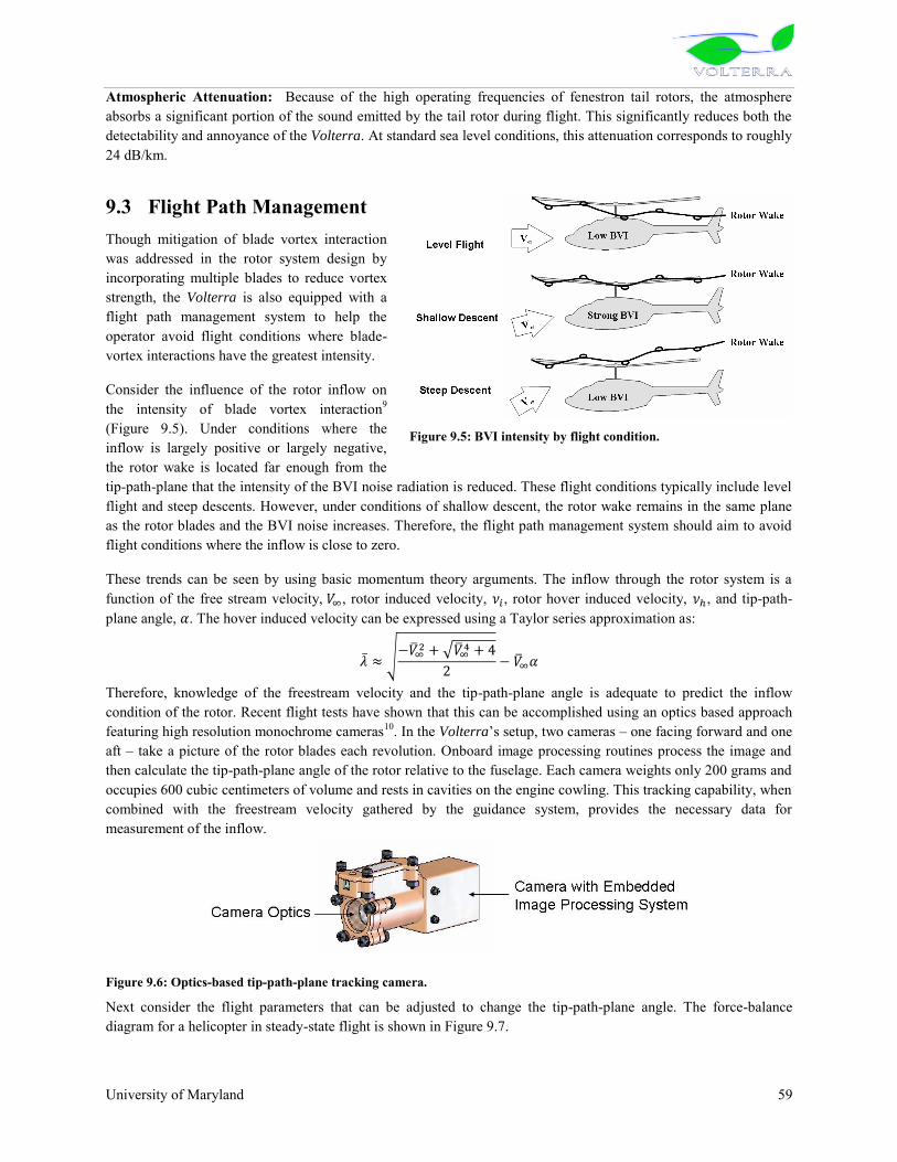
University of Maryland 59
Atmospheric Attenuation: Because of the high operating frequencies of fenestron tail rotors, the atmosphere absorbs a significant portion of the sound emitted by the tail rotor during flight. This significantly reduces both the detectability and annoyance of the Volterra. At standard sea level conditions, this attenuation corresponds to roughly 24 dB/km.
9.3 Flight Path Management Though mitigation of blade vortex interaction was addressed in the rotor system design by incorporating multiple blades to reduce vortex strength, the Volterra is also equipped with a flight path management system to help the operator avoid flight conditions where blade-vortex interactions have the greatest intensity.
Consider the influence of the rotor inflow on the intensity of blade vortex interaction9 (Figure 9.5). Under conditions where the inflow is largely positive or largely negative, the rotor wake is located far enough from the tip-path-plane that the intensity of the BVI noise radiation is reduced. These flight conditions typically include level flight and steep descents. However, under conditions of shallow descent, the rotor wake remains in the same plane as the rotor blades and the BVI noise increases. Therefore, the flight path management system should aim to avoid flight conditions where the inflow is close to zero.
These trends can be seen by using basic momentum theory arguments. The inflow through the rotor system is a function of the free stream velocity, , rotor induced velocity, , rotor hover induced velocity, , and tip-path-plane angle, . The hover induced velocity can be expressed using a Taylor series approximation as:
Therefore, knowledge of the freestream velocity and the tip-path-plane angle is adequate to predict the inflow condition of the rotor. Recent flight tests have shown that this can be accomplished using an optics based approach featuring high resolution monochrome cameras10. In the Volterra‟s setup, two cameras – one facing forward and one aft – take a picture of the rotor blades each revolution. Onboard image processing routines process the image and then calculate the tip-path-plane angle of the rotor relative to the fuselage. Each camera weights only 200 grams and occupies 600 cubic centimeters of volume and rests in cavities on the engine cowling. This tracking capability, when combined with the freestream velocity gathered by the guidance system, provides the necessary data for measurement of the inflow.
Figure 9.6: Optics-based tip-path-plane tracking camera.
Next consider the flight parameters that can be adjusted to change the tip-path-plane angle. The force-balance diagram for a helicopter in steady-state flight is shown in Figure 9.7.
Figure 9.5: BVI intensity by flight condition.

University of Maryland 60
Figure 9.7: Force-balance diagram of a helicopter in steady flight.
Taking the sum of forces acting along the free-stream velocity axis and solving for the tip-path-plane angle results in the final expression for the tip-path-plane angle:
Therefore, the inflow state of the helicopter can be adjusted by varying the freestream velocity, flight path angle, and inertial acceleration. The purpose of the flight management system is to take this information and provide the pilot cues on the primary flight display to fly a trajectory that maintains inflow values favorable to low BVI radiation. An added benefit to this flight management system is that it can also be used to reduce maintenance time for tracking and balancing of the main rotor since it continuously and accurately tracks the rotor.
Figure 9.8: Flight path management system overview.
9.4 Active Noise Control The final means of low frequency noise reduction to minimize detection is accomplished using higher harmonic flapping of the primary control blade flaps. In practice, the active controller creates additional dipole sources that, at a particular observer point, cancel out the acoustic wave generated by the blade alone. The Volterra implements this advanced noise cancellation technology using its integrated primary control flaps. When active, the blade flaps oscillate at appropriate phases and frequencies (frequencies greater than the primary control frequencies) to create a “cone of silence” using basic beam-forming techniques. The thickness noise in a cone directly in front of the helicopter is immediately and drastically reduced which substantially reduces detectibility. Although regions outside of this cone will not see any substantial reduction in noise, it is the forward noise that prematurely reveals the position of an approaching helicopter, therefore it is this noise that is most important to reduce. A typical example of

University of Maryland 61
the reduced acoustic signature for a target location is shown in Figure 9.9. Notice that the thickness pulse at the focus of the beam is substantially reduced.
It is important to note that active noise controllers do have adverse consequences. To cancel out in-plane noise, the Volterra‟s flaps must create additional in-plane forces – namely drag. Therefore, when operating as an active acoustic controller, the blade flaps will have a detrimental effect on the performance of the rotor and possibly increase in-plane rotor vibration. For these reasons, the active noise suppression mode is only activated by the pilot when they are willing to sacrifice performance and fuel economy.
Figure 9.9: Acoustic signature with active control. Noise field from thickness noise, and “Cone of Silence” region with
active system engaged (bottom right).
10 STABILITY AND CONTROL ANALYSIS A simplified linear flight model was developed based on the methods of Padfield1 and Prouty2, to carry out stability and control analysis of the Volterra. A linear model was used with stability derivatives at each trim point as in the following equation: AX = Bu, where X is the state vector, u is the control input, A is the stability matrix, and B is the control matrix. The matrix has been arranged so that the longitudinal equations form a sub matrix in upper-left-hand corner while the lateral-directional equations are located in the lower right. The other two corners represent the coupling between the primary submatrices. The stability and control analysis was developed to calculate the eigenvalues and eigenvectors of the response modes. Various stability derivatives (force and moments) were used for the purpose of this analysis, some important ones are discussed below.
10.1.1 Key Stability Derivative Estimation
A code was developed to solve the coupled longitudinal and lateral-directional equations of motion. The key stability and control derivatives of the vehicle are displayed in Table 10.2 and Table 10.1 (note that estimates are given in hover and cruise at sea level conditions). The force derivatives are normalized by the design gross weight (1750 kg) and the moment derivatives are normalized by moments of inertia (678 kg-m2, 4066 kg-m2, 3389kg-m2 for Ixx, Iyy, and Izz, respectively). The speed stability,
uM , is a function of the moment of inertia and the variation of
pitch moment with respect to perturbation in forward velocity. Also, it is a function of the stiffness of the main rotor, the effects of the tail, and the aerodynamics of the fuselage. It was estimated that the speed stability is approximately 0.013 rad/(sec-m) in hover and 0.030 rad/(sec-m) in forward flight (rotor advance ratio μ = 0.3). The angle of attack stability,
wM , is a function of the amount of flapping hinge offset of the rotor system. If flapping hinge offset is
present, and if CG is not on the mast, then there will be pitching moments generated with a change in vertical speed.
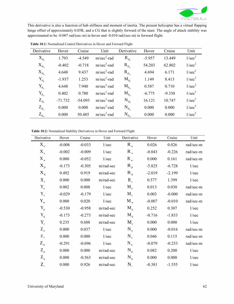
University of Maryland 62
This derivative is also a function of hub stiffness and moment of inertia. The present helicopter has a virtual flapping hinge offset of approximately 0.05R, and a CG that is slightly forward of the mast. The angle of attack stability was approximated to be -0.007 rad/(sec-m) in hover and -0.010 rad/(sec-m) in forward flight.
Table 10.2: Normalized Stability Derivatives in Hover and Forward Flight
Derivative Hover Cruise Unit Derivative Hover Cruise Unit
uX -0.008 -0.033 1/sec uR 0.026 0.026 rad/sec-m
vX -0.002 -0.009 1/sec vR -0.043 -0.226 rad/sec-m
wX 0.000 -0.052 1/sec wR 0.000 0.161 rad/sec-m
pX -0.173 -0.305 m/rad-sec pR -5.825 -6.728 1/sec
qX 0.492 0.919 m/rad-sec qR -2.019 -2.199 1/sec
rX 0.000 0.000 m/rad-sec rR 0.577 1.399 1/sec
uY 0.002 0.008 1/sec uM 0.013 0.030 rad/sec-m
vY -0.029 -0.179 1/sec vM 0.003 -0.000 rad/sec-m
wY 0.000 0.020 1/sec wM -0.007 -0.010 rad/sec-m
pY -0.530 -0.958 m/rad-sec pM 0.252 0.307 1/sec
qY -0.173 -0.273 m/rad-sec qM -0.716 -1.833 1/sec
rY 0.235 0.688 m/rad-sec rM 0.000 0.000 1/sec
uZ 0.000 0.037 1/sec uN 0.000 -0.016 rad/sec-m
vZ 0.000 0.000 1/sec vN 0.046 0.115 rad/sec-m
wZ -0.291 -0.696 1/sec wN -0.079 -0.253 rad/sec-m
pZ 0.000 0.000 m/rad-sec pN 0.082 0.200 1/sec
qZ 0.000 -0.563 m/rad-sec qN 0.000 0.000 1/sec
rZ 0.000 0.926 m/rad-sec rN -0.381 -1.555 1/sec
Table 10.1: Normalized Control Derivatives in Hover and Forward Flight
Derivative Hover Cruise Unit Derivative Hover Cruise Unit
0X
1.793 -4.549 m/sec2-rad 0
R -5.957 13.449 1/sec2
1cX
-0.402 -0.718 m/sec2-rad 1c
R 54.203 62.802 1/sec2
1sX
4.648 9.437 m/sec2-rad 1s
R 4.694 6.171 1/sec2
0Y -1.937 1.253 m/sec2-rad
0M
1.149 8.413 1/sec2
1cY 4.648 7.940 m/sec2-rad
1cM
0.587 0.710 1/sec2
1sY
0.402 0.780 m/sec2-rad 1s
M -6.775 -9.330 1/sec2
0Z -71.732 -54.093 m/sec2-rad
0N 16.121 10.747 1/sec2
1cZ 0.000 0.000 m/sec2-rad
1cN 0.000 0.000 1/sec2
1sZ 0.000 50.485 m/sec2-rad
1sN 0.000 0.000 1/sec2

University of Maryland 63
10.1.2 Longitudinal Modes
Figure 10.1 is the locus of roots of the characteristic equation as the stabilizer area (a) and advance ratio (b) are increased. Both helicopters and airplanes with enough stabilizer area provide positive angle-of attack stability will exhibit oscillations in forward flight. The oscillations typically have a period of 10 to 30 seconds and is called the Phugoid mode. The Phugoid mode is unstable for a lower value of the stabilizer area. With a stabilizer area of 1.30 m2, helicopter has a frequency of 0.348 rad/sec or a period of 18.05 seconds. An estimation of the Phugoid mode suggests that the helicopter is unstable in hover, however this is typical of most helicopter designs. But even though this point is unstable, doubling in amplitude in about 10 seconds, it would still be considered satisfactory for visual flight since the pilot can manually correct this instability. The longitudinal short period mode is stable in all regions of the flight envelope. The time associated with this mode is so short that it can be assumed that no speed change occurs while it is being excited. This stability is due largely to the strong heave damping and pitch rate damping. The size of the horizontal stabilizer was driven by both trim and stability considerations. Increasing the planform area of the horizontal tail ensures speed stability and minimizes the tendency of the vehicle to pitch nose down in forward flight. However, as the size of the horizontal stabilizer is increased, the margin of positive angle of attack stability tends to become too large. Based on these considerations, a planform area of 1.30 m2 was chosen for the Volterra.
10.1.3 Lateral Modes
Dutch roll oscillation was predicted to be neutral in hover and stable at higher airspeed with 1.07 m2 of vertical stabilizer area. The period of the dutch roll is decreased as advance ratio is increased. The spiral mode was also seen to be stable in all regions of flight. As with dutch roll, the strong dihedral effect is the dominant characteristic in all modes of flight, resulting in stability. Roll subsidence was predicted to be stable due to the strong roll damping.
Figure 10.1: Longitudinal mode stability with (a) increases in horizontal stabilizer area (=0.3) (b) increases in forward flight speed (Area = 1.3 m2 )
(b)Longitudinal mode as Horizontal Stabilizer Advance ratio is Increased
Real
Ima
gin
ary
-4 -3 -2 -1 0 1 2-3
-2
-1
0
1
2
3
0.46 m2
0.74 m2
1.02 m2
1.30 m2
1.58 m2
UnstableStable
Horizontal Stabilizer Area
Short Period
Phugoid
Real
Ima
gin
ary
-4 -3 -2 -1 0 1 2-3
-2
-1
0
1
2
3
Hover
UnstableStable
(a) (b)

University of Maryland 64
10.2 Handling Qualities Control sensitivity and damping characteristics are important handling quality parameters in hover and low speed flight. It is well understood that pilots desire a vehicle that is responsive enough to be able to achieve some level of attitude change within a certain time after a control input is applied. The pilots also predictability, an acceptable ratio of sensitivity to damping, and an acceptable level of response immediately after a control input. In very general terms, all of these conditions can be satisfied with adequate sensitivity ( or ) and damping ( or ), and the correct ratios between the two. Although the complete analysis of the longitudinal static stability cannot be predicted by merely examining the stability derivatives, one can determine relative stability, which is determined by the sign of speed stability (
uM ). Therefore, helicopter design suggests that positive longitudinal static stability
exists. Positive static lateral directional stability is a desirable aircraft characteristic in all modes of flight. This attribute can help to maintain a steady hover with reduced pilot workload, as well can reduce the pilot workload requirements in cruise flight. While it is impossible to determine the gradient or level of static stability from the ratio of
vN to TN
, the negative sign is an indication of stability in this critical flight mode. A negative vR is an
indication that the aircraft will exhibit positive dihedral effect, which helps to control the lateral directional oscillation, thus reducing the workload during up and away cruise.
10.3 Autonomous Flight Control The aforementioned sensors and digital fly-by-wire system provide the Volterra with autonomous flight capabilities far beyond those of any current production helicopter. In addition to the automated flight modes detailed in section 7, the Volterra is capable of fully autonomous take offs and landings as well as fully autonomous close-proximity collision avoidance capability. The latter capability allows the Volterra to perform a number of unique mission scenarios as discussed in Section 16. The autonomous take-off and landing capability provides the operators of all skill levels, the flexibility to focus on mission critical tasks during what would traditionally be one of the most demanding flight phases.
10.3.1 Autonomous Classification
NASA has generated an autonomy classification table based on any autonomous system‟s interaction with the
environment and the vehicle operator. The interaction is divided into four categories: Observe, Orient, Decide, and Act. The highest level of autonomy on the scale requires a system which performs all observations, analysis of data, decision making and actions without displaying any information to the operator, and without permitting the operator to intervene. The automatic flight modes available in the Volterra classifies the helicopter as Human Computer
Real
Ima
gin
ary
-10 -8 -6 -4 -2 0 2 4-4
-3
-2
-1
0
1
2
3
4
Hover
=0.1
=0.2
=0.3
=0.4
Dutch Roll
UnstableStable
Real
Ima
gin
ary
-10 -8 -6 -4 -2 0 2 4-4
-3
-2
-1
0
1
2
3
4
Hover
=0.1
=0.2
=0.3
=0.4
UnstableStable
(a) (b)
Figure 10.2: Lateral Mode Stability (a) Lateral Mode (Decoupled) (b) Dynamic Mode (Coupled)

University of Maryland 65
Interface Level 6 (Table 10.3). At this level, even during autonomous phases of flight, the Volterra Fight Control System, FCS, provides the pilot with the opportunity to view all collected information, computer decision processes and actions. Most importantly, the automatic FCS can be manually overridden and modified if desired. This means that the Volterra autonomous system, like many unmanned air vehicle systems operating today, can perform tasks automatically but still places a human in the decision loop.
Table 10.3: NASA human computer interface level 6 description.
Level Observe Orient Decide Act
6
The computer gathers, filters, and prioritizes information displayed to the human
The computer overlays predictions with analysis and interprets the data. The human is shown all the results.
The computer performs ranking tasks and displays a reduced set on ranked options while displaying “why” decisions were made to the human
Computer executes automatically, informs the human, and allows for override ability after execution. Human is shadow for contingencies.
10.3.2 Obstacle Avoidance
Autonomous functions in cruise flight are based on the same attitude, velocity, waypoint, etc, as well as sensor and control laws described in section 11, with the addition of an optic flow based obstacle avoidance capability. This additional task has been the subject of much research in recent years. Specifically, the work done in understanding the method with which insects navigate the world has recently made the most promising progress, (Ref. 4-6).It is believed that the fruitfly drosophila makes use of structures known as elementary motion detectors (EMDs) to extract the rate of optic flow across its receptors. Optic flow is simply the perceived motion of the visual field of a moving optical sensor, such as a camera or the human eye (Figure 10.3a). This apparent visual motion observed by the sensor can be represented by a vector field with poles of expansion and contraction resulting from the distance to the object (Figure 10.3b). Using an elementary motion detection sensor setup known as a Reichardt Correlate, the Volterra optic flow sensors can estimate the rate of motion of an image between adjacent sensors pairs. This is one of the fastest and least computationally intensive methods of vehicle state estimation available (as demonstrated by the rapid but precisely controlled flight of small insects). Optic flow sensors do not compute acceleration or absolute position, only proximity and relative motion.
(a) (b)
Figure 10.3: (a) Sample visual field, (b) vector representation of visual field from which optic flow is extracted.
Eight optic flow sensors are placed around the body. Six are placed circumferentially around the sides and rear of the body with their central visual axes approximately 60 degrees separated from each other. Forward sensors are not required (and are not desirable) because the most amount of optical information is available away from poles of optic flow expansion or contraction, i.e. not parallel or perpendicular to the flight direction. Two additional sensors are placed facing down on the forward and aft portions of the fuselage underside. By balancing the amount of optic flow between opposing pairs of sensors, information enabling roll, and pitch stability as well as fast obstacle avoidance feedback is obtained. In daytime flight there is sufficient light to detect obstacles and provide the stability. Nighttime flight requires IR emitter/collector pairs, which provide the IR pulse which is then interpreted by the sensor.

University of Maryland 66
This method of obstacle avoidance has been implemented for ground based robots, wheeled robots and hovercraft4, enabling robust and autonomous corridor navigation. Close proximity obstacle avoidance is essential for autopilot takeoff and landings, however, use of this technology in manual flight modes will enable pilots to perform dangerous and previously labor intensive tasks with as much ease as a simple velocity hold. Two scenarios envisioned for this capability are canyon and city navigation in close proximity to buildings or rock faces. The optic flow information is routed directly to the collective/cyclic/yaw pedal feedback response system, giving the pilot a tactile sense of what motions would cause the aircraft to approach an oncoming obstacle.
Figure 10.4: Optic flow measurements provide information about the Volterra's proximity to walls, enabling feedback into the stability augmentation system.
10.3.3 Take-off and Landing
Take-off and landing of any helicopter are potentially the most difficult phases of flight because of the complex aerodynamic and aeroelastic environment present when transitioning to and from hover. Secondly, the combination of low speed and low altitude make emergency flight maneuvers difficult, and in some conditions impossible to perform for a pilot. For the autonomous system, these same difficulties arise. The advanced avionics suite of the Volterra (Section 11) allows the system to meet these challenges in the same way that a pilot would.
For autonomous take-offs and landings, the procedure is assisted by human ground crew capable of providing ground handling, fueling, and appropriate positioning for the autonomous take-off. The primary systems involved in autonomous take-offs and landings are the primary flight controller, the GPS receiver, and the optic flow sensors. While a number of flight attitude schedules have been proposed for the safest possible autonomous take-off and landing, the implementation the Volterra employs procedures similar to those described by Yamane with some added flexibility due to the availability of optic flow sensing and obstacle avoidance procedures.
Once the helicopter is positioned in a safe area for take-off, a visual inspection is performed by the pilot (either on-board or from a ground station) to ensure that the take-off corridor is free from obstructions. The take-off is accomplished in three stages:
1) Climb to control height: The GPS system cannot feed altitude information reliably enough for control at less than approximately 50 cm above ground level. Therefore collective pitch is increased at a constant rate until the helicopter reaches this height. Below 50 cm, the flight controller provides rate and stability information using solely the accelerometers and gyroscopes. Above this control height, altitude tracking switches to the GPS system and the optic flow system becomes active. As described previously, the optic flow sensors measure variations in the perceived motion of the visual field. These measurements are transformed directly into estimates of proximity to nearby obstacles, attitude information and speed. The primary flight control system monitors the proximity information given by the optic flow sensors and executes an interrupt of the nominal flight condition (for example vertical climb) if an obstacle is detected. The current flight plan is interrupted until the obstacle is no longer present, or until the automatic flight-mode is cancelled and the controls are returned to the pilot.
2) Climb-out: Once stability and control are passed to the GPS and optic flow sensors above the control height, given that no system warning are detected, the standard climb-out procedures are implemented by the flight controller. For a low power take-off, the helicopter is accelerated at HIGE power to clear a 6 m (20 ft) obstacle at 65

University of Maryland 67
knots, following the height velocity diagram. For operations in confined areas, a vertical climb-out is also possible, in which the Volterra increases collective pitch to achieve an altitude below the avoid region on the height-velocity diagram 0 knots. It should be noted that while the Volterra operates as a multi engine helicopter, the single engine avoid region is adhered to for autonomous flight.
3) Transition to cruise. Once the 6 m obstacle has been cleared at 65 knots or the hover altitude for vertical climb-out has been reached, the helicopter is transitioned into cruise mode during which the flight control system adjusts attitude and velocity to that prescribed in the flight plan. Control in cruise is handled using the same flight control systems that enable attitude and rate holds, as well as way-point tracking. Additional control comes from the optic flow sensors which provide outer-loop obstacle detection and information as to the safe velocity required for automatic obstacle avoidance.
The performance of the automatic take-off and landing process is possible with the adaptive neural networking used in the Volterra‟s flight control system. The system can spend time learning these flight maneuvers in conjunction with vehicle test flight hours piloted by a professional test pilot. However, the Volterra design does not preclude learning by flight simulation, which could provide a cost effective and safer alternative to piloted system training.
Figure 10.5: Optic flow-based obstacle avoidance schematic. The optic flow from the on the starboard wall is greater in magnitude than that from the port wall, thus the stability augmentation system is directed to correct this imbalance by moving the Volterra further port.
The landing procedure will require a high level of decision making especially critical in un-prepared areas. First, Volterra circles the perimeter of a landing area deemed suitable either according to a prescribed designation or a suitable landing site recognition/discrimination software developed and learned by the neural network flight controller. While circling this area, the pair stereo cameras photographs and reconstructs the three-dimensional terrain, from which a landing approach is planned.
The approach begins by positioning the helicopter in hover above the landing site, ensuring that the height is below the “avoid” region in the height velocity diagram. The landing light is activated and after a system‟s check from the
vehicle management system, the vehicle descends to a HIGE at approximately 2.5 m under the stability control of the GPS altitude tracking, and the optic flow avoidance and stability system. Navigating in disaster ridden and clutter areas, even during this vertical descent, requires the optic flow obstacle avoidance system OFOAS to maintain the highest level of interrupt priority, since safely navigation the terrain is of more importance than any other function of the flight control system. In the event that an obstacle comes within a pre-determined perimeter around the helicopter, shown in blue in Figure 10.5, the optic flow system detects an imbalance in the optic flow around the vehicle. The resultant commands sent to the flight control system veers Volterra away from the object thus balancing the optic flow. The schematic view of this function in cruise shown in Figure 10.5 depicts the Volterra maintaining a forward speed while avoiding the fast approaching wall. The exact perimeter around Volterra is a function of several parameters, such as the precise vehicle the vehicle dynamics, the airspeed schedules, and the specific optic flow sensor processing rate, and cannot be reasonable determined at the preliminary design stage.

University of Maryland 68
As the Volterra descends below 2.5 m, stability and rate sensing priority is taken from the optic flow sensors and passes to the primary flight controller. This is to avoid any excessive control motions near the ground that may cause a skid to impact the ground at a skewed attitude and cause the vehicle to topple. Collective is steadily decreased until both skids are on the ground.
10.3.4 Flight Certification
The FCS utilizes a number of flight certified electronics components which will aide in the timely certification of the vehicle. Those components which have not yet been flight certified include the optical flow sensors, neural network, etc. However, similar systems have been proven to be reliable and stable on platforms, therefore we expect an experimental flight certification for the components by 2016. This allows 4 years for actual flight testing in the vehicle and a flight certification by 2020.
11 AVIONICS The goal of the avionics systems is to provide the pilot with an enhanced ability to control the helicopter while providing the necessary information to do so. The Volterra does so using modern sensors, flight displays, and control architecture which allows greater control authority, and minimizes pilot workload. These advancements are implemented in a way which minimizes cost, weight, and required maintenance while still attaining a high level of redundancy and reliability.
11.1 Cockpit Layout The cockpit of the Volterra is designed to be functional for a single pilot, with the option of having secondary cyclic/collective sticks for training, para-military and military operations. The amount of data available at any given time has the potential to inundate the pilot unless presented in a logical and task-oriented manner. Therefore, the layout of the controls and flight displays in the Volterra is designed for maximum accessibility while minimizing clutter and permitting an unobstructed view outside of the cabin.
11.1.1 Flight Display/Pilot Interface
Three primary flight displays (PFDs) are included on the main console of the Volterra cockpit.A variety of information can be interchangeably displayed on any PFD, however the nominal display information includes artificial horizon, vertical speed, altitude, airspeed, radar altitude, compass, turn coordinator/sideslip indicator, localizer indicator, glideslope indicator and pitch ladder. The engine FADEC information and HUMS are optionally displayed on the PFD. Also included on the main console is the main circuit breaker panel, which contains heating controls for the pitot tube, blade anti-ice, and front windshield heat. Two additional multifunction displays (MFDs) are provided on the center console between the pilot and passenger/co-pilot. One operates primarily as the map display while the other operates as controls and displays for the primary navigation, planning, and communications functions. These are touch screen operated and accept input from the backlit aluminum keypad located beneath the display. System warnings are displayed on the MFDs and have the highest level of interrupt priority, which for a multi-threaded operating system configuration translates into warning information always being displayed despite any other currently active tasks. Finally, a single function LCD is provided for Google terrain following, FLIR imaging and the brownout camera 3D visualizations. Efficient means of relaying all of this information to the pilot has been studied by the avionics manufacturer L-3, who have developed a variety of displays tuned for minimal pilot workload and maximum productivity3. Capitalizing on this research, the Volterra‟s flight displays are all
manufactured by L-3.
The multitude of flight displays reflects the commitment to redundancy the design of Volterra embodies. Each MFD is capable of displaying all of the information gathered by the vehicle management system. Thus mission/sortie completion is ensured in the event of the failure of one or two displays. In the event that all PFDs fail, the pilot is still provided with absolute altitude via a standby barometric pressure transducer, a standby attitude indicator, a clock a magnetic compass, and communications abilities via a standby VHF/VOR/DME.

University of Maryland 69

University of Maryland 70
11.1.2 Minimum Equipment List (IFR) Compliance
The Volterra‟s baseline avionics suite adheres to Title 14 CFR, FAR 27 Appendix B, and VFR requirements, all of which are required for IFR and instrument meteorological (IMC) flight certification. As discussed, the flight displays and associated sensors provide: altimeter, airspeed indicator, air temperature measurements, direction indicator, non-tumbling attitude indicator, vertical speed indicator, clock, speed warning device, instrument power source indicator, and back-up attitude indicator
To satisfy the stability requirements described in FAR part 27, the Volterra incorporates the following: Dual integrated flaps per blade for primary control, force-feel trim system, optic flow based stability augmentation system, coupled with traditional SAS, auto-pilot functionality for attitude hold, airspeed hold, and way-point following, and PFD provides cross pointer flight directors for aiding vertical and lateral flight.
Additional FAR required IFR equipment includes: Thunderstorm lights (because the Volterra is primarily a transport helicopter), blade de-icing system and avionics sensor (e.g. pitot tube) anti-ice provisions, multiple static grounds, an overvoltage disconnect, and battery charge disconnects
11.1.3 Cabin Communication
Although thought has been put into minimizing the cabin noise, the pilot and passengers of the helicopter will still experience noise levels that may be uncomfortable or harmful after long periods of exposure. Full spectrum active noise reduction is possible with the BOSE Aviation Headset X3 . Headset ports are available for the pilot and passenger/co-pilot on the lower portion of the center console. Rear passengers are provided with ports on the rear cabin walls, however this can be modified for various vehicle roles and configurations.
11.1.4 Force Feel Trim System
The implementation of a force-feel system in the Volterra reduces the weight penalty of a conventional system with the use of a servo-actuator implemented feedback loop around the cockpit-flight-controller which performs the function of the feel spring and trim-motor of a conventional series SAS. The servo-actuator consists of an electric motor, a gearing device, and a clutch. A commanded cockpit-flight controller position is achieved by pilot actuation of a trim switch. The position of the cockpit-flight-controller is compared with the commanded position to form a first error which is processed by a shaping function to correlate the first error with a commanded force at the cockpit-flight-controller. This commanded force attempts to center the cockpit-flight-controller giving the pilot a tactile response to the helicopter‟s attitude. This parallel implementation allows the pilot to back-drive the servo-actuator using the cockpit-flight-controller while the force feel system and SAS are engaged, or if they fail to disengage. The resulting motions and force gradient are tailored to be favorable to the pilot. In this way the mechanical spring and trim-motor are eliminated resulting in reduced weight and cost allowing implementation in Volterra. The force-feel system is used as the basic element of the stability augmentation system (SAS). The SAS provides a stabilization signal that is compared with the commanded position to form a second error signal. The two error signals are summed for processing by the shaping function. A logic flow block diagram in Figure 11.1illustrates the functionality of this type of force-feel system.
11.2 Avionics Sensors 11.2.1 Sensor configuration
The information presented on the flight displays and indicators is taken from a sensor suite consisting of magnetometers, gyroscopes, accelerometers, GPS, pitot-tubes, VHF/VOR/DME, thermisters, barometric pressure sensors, strain sensors and the OPOC engine FADEC. Attitude sensor information is fed directly to the attitude heading and reference system (AHRS). An efficient recursive Kalman filter takes the potentially noisy or incomplete data and estimates the state of the helicopter. The output is relayed to the vehicle management system (VMS) which applies a voting scheme comparing the mean of the incoming signals with the value of each AHRS contribution. Engine control information such as the FADEC and HUMS systems, feed into the VMS. The purpose of the VMS is to integrate and coordinate data before passing it onto the cockpit displays. Guidance, navigation and control data is

University of Maryland 71
passed through fiber-optic cabling eliminating the necessity of heavy shielding. The sensors interface with the VMS via the RS-232 communications protocol, while higher level communication between the vehicle management system, automatic flight control system, health and usage monitoring system, digital electronics unit, and the multi-function displays is done via the RS-422 communications protocol.
11.2.2 Sensor Redundancy
Until as recently as 20061 AHRS were too heavy and power hungry to provide light transport vehicles with multiple redundant sensing and processing components. In today‟s EC-120, a standard avionics package provides redundant units for gyro-horizon at the penalty of 5 kg per unit, with a maximum of 3 total units2. The sensing packages chosen for the Volterra minimize the size and weight penalty of each component by incorporating state-of-the-art fabrication techniques in the use of the first FAA certified MEMS (microelectromechanical systems) fabricated AHRS from CrossbowInertial Systems
1. This highly reliable inertial system provides attitude and heading measurement with static and dynamic accuracy superior to traditional spinning mass vertical and directional gyros. For an AHRS with 95% reliability, the probability that at least one of the three systems is working is 0.9999. This level of redundancy translates into approximately 40,000 expected hours of safe operation. This AHRS system currently meets all FAA requirements for FAR 23 aircraft and is expected to meet FAA requirements for FAR 27 and FAR 29 rotorcraft by 2015.
The AHRS in use on the Volterra is a standalone output only unit and does not require external sensor data such as GPS or pressure altitude. The capability of this system is based in the use of a MEMS tri-axis accelerometer, a tri-axis gyroscope, a tri-axis magnetometer and a temperature sensor. These devices provide a complete picture of the attitude and heading of the helicopter twenty-five times per second. This highly accurate state estimation enables the
Figure 11.1: Automatic flight control system dependency schematic.

University of Maryland 72
flight control system to reject higher frequency excitations resulting in smoother flight during automated flight modes, and a smooth display of attitude information for manual flight (see schematic in Figure 11.1)
11.2.3 Battery Backup for Alternator-out
The lithium-polymer (Li-Po) battery used in case of power-out provides 20 minutes of full power to electronics and servo actuators, including main and tail rotor controls, the autonomous flight control system, force-feel controller, MFDs, AHRS, HUMS, and the optic flow obstacle avoidance and stability augmentation system. Because of the high energy density of Li-Po batteries, the total battery weight is only approximately 2 kg. Comparable vehicles provide half the backup power with a higher weight penalty. To minimize the risk of overcharging, the battery charge is monitored and current is interrupted automatically at full charge. The battery pack is housed in a titanium housing (similar to the engine firewall) to prevent the spread of fire in the unlikely event of a battery pack fire.
11.3 Flight Control System The Volterra flight control system is a digital fly-by-wire system. Inputs from the flight controls are sent via slip ring to electrical motors in the rotor blades which drive the trailing edge flaps for primary control. The fenestron controls are similarly electronically actuated. This type of digital control provides a number of distinct advantages over a mechanical system:
Complex control laws can more easily be incorporated and modified as necessary Greater accuracy over the entire life of the system – mechanical linkages wear which reduces
accuracy/responsiveness, and requires maintenance Improved ability to detect and correct system failures – caveat is that pinpointing the exact cause of
problems may be more difficult Reduced weight – control signals are carried electrically Increased ability to provide control redundancy – wire routing to controls can be distributed along multiple
paths to the rotor and fenestron allowing a degree of redundancy, should one wiring path be damaged.
11.3.1 Control Mixing
The electronic control mixing implemented in the Volterra reduces pilot workload by coupling flight control inputs that are inherently linked through aerodynamic or other interactions. Electronic implementations can be more robust than mechanical systems, require less maintenance (fewer moving parts, fewer parts count), and are not necessarily optimized for a specific flight condition. The following primary couplings are implements:
An increase in collective is coupled to an increase in tail rotor thrust. This requirement arises because an increase in collective increases the main rotor torque which then requires an increase in anti-torque to maintain the previous yaw orientations.
Increasing collective leads to positive (nose down) longitudinal cyclic. This arises because in forward flight increasing main rotor thrust leads to increased advancing blade angle of attack. This causes the tip path plane to tilt back (nose up), requiring a correction
Increasing collective leads to negative (port) lateral cyclic. In forward flight, increasing the main rotor collective increases coning and thus the angle of attack of the forward blade. The result is an upwards flapping of the retreating blade and a tilting of the tip path plane to give a right roll moment.
11.3.2 Digital Fly-by-Wire Architecture
The Volterra implements a flight control system which mimics the capabilities provided by V-22 and RAH-66 digital FCS [ Tishchenko ]. The flight control computers employ architecture similar to that seen in Figure 11.2. Three FCCs form the backbone of the system and are responsible for all flight critical operations. These tasks are separated into one input/output processor (IOP) and two Primary Flight Control Processors (PFCP) enabling primary flight control functionality. The automatic flight control processor (AFCP) is responsible for handling threads tied to
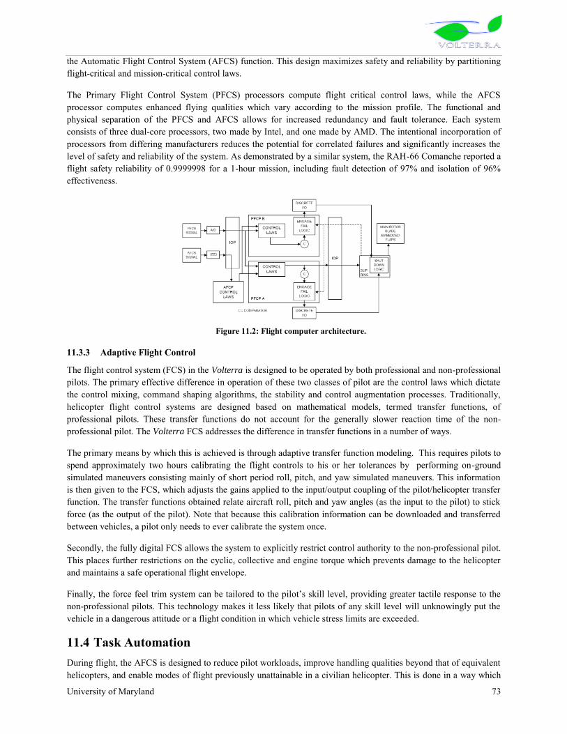
University of Maryland 73
the Automatic Flight Control System (AFCS) function. This design maximizes safety and reliability by partitioning flight-critical and mission-critical control laws.
The Primary Flight Control System (PFCS) processors compute flight critical control laws, while the AFCS processor computes enhanced flying qualities which vary according to the mission profile. The functional and physical separation of the PFCS and AFCS allows for increased redundancy and fault tolerance. Each system consists of three dual-core processors, two made by Intel, and one made by AMD. The intentional incorporation of processors from differing manufacturers reduces the potential for correlated failures and significantly increases the level of safety and reliability of the system. As demonstrated by a similar system, the RAH-66 Comanche reported a flight safety reliability of 0.9999998 for a 1-hour mission, including fault detection of 97% and isolation of 96% effectiveness.
Figure 11.2: Flight computer architecture.
11.3.3 Adaptive Flight Control
The flight control system (FCS) in the Volterra is designed to be operated by both professional and non-professional pilots. The primary effective difference in operation of these two classes of pilot are the control laws which dictate the control mixing, command shaping algorithms, the stability and control augmentation processes. Traditionally, helicopter flight control systems are designed based on mathematical models, termed transfer functions, of professional pilots. These transfer functions do not account for the generally slower reaction time of the non-professional pilot. The Volterra FCS addresses the difference in transfer functions in a number of ways.
The primary means by which this is achieved is through adaptive transfer function modeling. This requires pilots to spend approximately two hours calibrating the flight controls to his or her tolerances by performing on-ground simulated maneuvers consisting mainly of short period roll, pitch, and yaw simulated maneuvers. This information is then given to the FCS, which adjusts the gains applied to the input/output coupling of the pilot/helicopter transfer function. The transfer functions obtained relate aircraft roll, pitch and yaw angles (as the input to the pilot) to stick force (as the output of the pilot). Note that because this calibration information can be downloaded and transferred between vehicles, a pilot only needs to ever calibrate the system once.
Secondly, the fully digital FCS allows the system to explicitly restrict control authority to the non-professional pilot. This places further restrictions on the cyclic, collective and engine torque which prevents damage to the helicopter and maintains a safe operational flight envelope.
Finally, the force feel trim system can be tailored to the pilot‟s skill level, providing greater tactile response to the
non-professional pilots. This technology makes it less likely that pilots of any skill level will unknowingly put the vehicle in a dangerous attitude or a flight condition in which vehicle stress limits are exceeded.
11.4 Task Automation During flight, the AFCS is designed to reduce pilot workloads, improve handling qualities beyond that of equivalent helicopters, and enable modes of flight previously unattainable in a civilian helicopter. This is done in a way which

University of Maryland 74
increases safety, redundancy and reliability. Specifically, the system is capable of rate command, and attitude hold compliant with ADS-33E-PRF. Rate feedback and model following architecture provide inherent stability augmentation while enabling pilot commanded way-point navigation including pure altitude/latitude/longitude functionality. The capability of the AFCS extends to airspeed hold, altitude hold (barometric, DME, GPS), auto-approach/departure, auto-search mode, hover holds, and close proximity auto-obstacle avoidance. The AFCS interfaces to the vehicle management system allowing flight director controlled instrument flight. Future automatic and auto-assisted flight modes are capable of being integrated into the current neural-network-type learning architecture. The ultimate goal of task automation is to minimize pilot workload while enhancing safety and reliability.
11.4.1 Accelerated Pre-flight
The design of the pre-flight checklist and procedures for the Volterra has been given special attention in order to minimize the time required to ready the helicopter for flight without sacrificing a safe and thorough preparation. The Volterra itself is capable of all pre-flight system checks except those done in the pilot walk-around visual inspection. This includes displaying on the MFD all relevant system over-limit situations that have occurred since the last scheduled maintenance and as well provide the number of hours until maintenance for each critical system not designed for infinite life. Once the vehicle engine is running, the embedded HUMS profile the structural elements of the frame, gear box, engine, main rotor, tail rotor, and electrical system via bit checks to all process capable components. The systems in the Volterra are capable of thorough checks of non visual pre-flight and post-flight checklist items. This ability coupled with the relatively small overall vehicle dimensions allows for take-off within 10 minutes of positioning for flight.
11.4.2 Health and Usage Monitoring System (HUMS)5
Three distinct processes typify helicopter maintenance6.
(1) Hard-Time: Preventative maintenance is performed at fixed intervals. (2) On Condition: A less rigorous inspection occurring at fixed intervals in which only suspect
components are replaced and the aircraft is approved for continued operation. (3) Condition Monitoring: The non-preventive process in which information regarding the status of a
particular system or component is collected on a continuous basis in order to apply corrective measures when necessary.
Safety and reliability of the helicopter as a whole is enhanced by the addition of an integrated HUMS which provides global condition monitoring of performance and usage, the recording and measurement of dangerous loads, and identification of incipient faults.
In addition, secondary benefits include increasing the perceived safety of rotorcraft and lower insurance costs, which make helicopters more acceptable to the public as a means of transportation. All of these benefits translate into an overall decrease in direct operating costs for the helicopter. The HUMS aboard the Volterra is organized into two elements, the on-line element and the off-line element. The on-line processing element, to be used by the pilot during flight, condenses data collected that do not require extensive processing, such as average torque usage or flight regime characteristics, into a simple intuitive display that will inform the pilot of the current aircraft status, and any necessary warnings. The off-line ground processing element saves data pertinent to determining the next necessary hard-time overhaul to a flight recorder. These data are then analyzed and processed between flights.
Various sensors are required to monitor the status of the rotor components, bearings, shafts, gears, and couplings. These data collected would be ineffectual for the pilot or ground crew in completely raw form. The HUMS is

University of Maryland 75
programmed to collect data frequently enough to properly observe the system, this information is time-synchronous averaged and recorded.
11.4.2.1 Rotor
Rotor blade flaps are monitored for actuator failure and loss of control authority. In the event of a failure the HUMS alerts the vehicle management system. The integrated flight control system is capable of stable and controlled flight should this situation arise, and the additional information provided by the HUMS will allow the flight controller to stabilize the system more quickly.
11.4.2.2 Engine
The engine is equipped with a FADEC system which includes independent monitoring of critical components. This information is delivered to the HUMS which filters records and displays all relevant data. This includes: time spent above limit torque, oil filter and temperature, average flight performance data, and fault monitoring.
11.4.2.3 Main Gear Box
Two methods employed to monitor the main gearbox are as follows:
1) Oil-Based Monitoring: Individual gearbox components are monitored using in-line oil debris monitors and vibration-based health monitoring.
2) Vibration Based-Monitoring: An accelerometer and tachometer are mounted to each shaft which is connected to a gear. The vibrations observed are time-synchronously averaged using the tachometer pulse train and the averages are periodically saved.
11.4.2.4 Tail Gearbox
The tail rotor gearbox is equipped with an inductive oil debris monitor. Additionally, an accelerometer and tachometer are mounted outside of the bearings of each gear.
11.4.2.5 Structure
Accelerometers embedded in the pilot and passenger seats monitor lateral and vertical acceleration ensuring acceptable levels of vibration for the pilot and passengers. Ruggedized strain gages are mounted at critical stress points of the main load bearing structures including the stovepipe truss structure attached to the gearbox casing. Monitoring the health of these components greatly reduces the likelihood of catastrophic failure and significantly reduces the time required to diagnose the symptoms of an unknown performance problem.
11.5 Additional Equipment 11.5.1 Brownout cameras
The occurrence of brownout upon the landing of a helicopter is a major safety concern and responsible for more than a few accidents. The problem occurs in the obscured view and resultant disorientation of the pilot on approach to land and is relative close proximity to the ground. To mitigate this potentially disastrous occurrence a system capable of retaining pilot situational awareness by superimposing a simplified representation of the terrain, real-time, on the cockpit multi-function display, is proposed.
Each avionics module contains a digital camera, which observes the ground and transmits its images to a central processing unit which combines the four images to create a three-dimensional map of the terrain beneath. A flight simulation takes in the updated 3D map data, and incorporates this information into its simulation variables. This simulation contains a detailed helicopter model, which receives the dynamic information from the avionics packages. The simulator then projects the terrain, as the pilot should see it, onto the display, providing the pilot with situational awareness and enabling a safe landing.

University of Maryland 76
11.6 Cost and Power Estimates One reason that this type of fully autonomous capability and advanced FCS has not been implemented on current production helicopters is the increased cost and weight. With the rapid development of MEMS based sensors and electronics which are cheaper and lighter than their traditional counterparts, these concerns are less restrictive. The result, as is implemented in the Volterra, is a light inexpensive transport helicopter with a flight control system that is nearly as flexible and capable as that found in much larger and more expensive modern aircraft.
Table 11.1: Sensor and electronics cost, power and weight estimates.
Instrument Mass (kg) Quantity Power (W) Manufacturer VHF/VOR/DME 6 2 56 Garmen GTX327 Transponder 2.8 1 35 HoneyWell Kt 76 Emergency Locator 0.82 1 0.075 Kannad 121AF-H GPS 2.8 2 28 FreeFlight AHRS 4.8 3 12 Xbow Barometric Altitude Encoder 1.1 1 4 Setra 470 HUMS 5 1 5 Optic Flow Sensors 0.3 8 < 1 Centeye Display Electronics (graphics Processing)
5 1 150 L-3
Multi-Function Display 10.8 3 165 L-3 Center Consol Display 6.6 2 90 L-3 Li-Po battery 2.1 8 20 min @ 2300 W EEMB Co. Total 48 546 W Cost Sensors $40k
The standard package includes three sensor systems located throughout the vehicle at the penalty of 1.6 kg per unit, resulting in an equivalently safe system at ~30% of the weight. Additional benefits include a decrease in the power consumption, and the ability to have decentralized independent sensors. A potential failure of AHRS is close proximity lightning strike, although the units are capable of functioning after multiple lightening strikes, a local strike capable of disabling /disconnecting sensors. The redundancy and physical distance separating the three AHRS units would allow an otherwise un-flyable helicopter to continue controlled flight. The importance of maintaining situational awareness is amplified by the desire to reduce pilot workload with a higher level of autonomy than previously encountered in a commercial helicopter.
Energy to power the avionics suite is generated by an alternator attached to the OPEC engine. Failure of the alternator does not constitute total avionics system failure. Lithium Polymer battery backup that is provided is capable of fully powering all the avionics for a total of 20 minutes. The auxiliary power unit consist of eight Li-Po cells each contributing 3.7 V at a maximum of 4.6 kW. The eight cells output 29.6 Volts which can directly power the avionics with a 5% margin for line losses. The advantage to using this method of power supply is in avoiding additional step-down/step-up electronics to regulate the line voltage to power avionics. Additional voltage regulating electronics are unnecessary making the system overall less complex and more robust. Finally, Li-Po batteries do not suffer from adverse memory effect associated with not fully charging or discharging them.

University of Maryland 77
12 SAFETY AND COMFORT 12.1 Crashworthy Seat Design Occupant safety in the event of a crash is of critical importance, and although the Volterra‟s landing gear are
designed to a significant percentage of the crash loads, energy absorbing systems must be designed into the occupants‟ seats to further limit the deceleration of a crash to tolerable levels to prevent spinal injuries and aortic dissection. There are many different energy absorbing seat concepts incorporated on rotorcraft in operation today2 and a brief overview is given in Table 12.1.
The Fixed Load Energy Absorber (FLEA) decelerates the occupant at a predetermined fixed load, designed for the 50th percentile male in order to maximize the effectiveness over the weight range of the occupants2. Consequently, lighter occupants would receive lethally higher deceleration levels (G‟s) where as heavier occupants would receive
lower G‟s, but possibly at risk of a harmful end-stop impact. Indeed, the G-level determines the risk of spinal injury3. The Variable Load Energy Absorber (VLEA) and Variable Profile Energy Absorber (VPEA) improve upon the FLEA concept by allowing the stroking load and load profile to be adjustable in finite steps, respectively. This approximately maintains the desired G-level in a crash across the entire occupant weight range. Adaptive Energy Absorbers (AEA) such as magnetorheological fluid devices utilize real-time sensing to monitor the crash environment, offering optimal load isolation, however these systems are inherently geometrically bulky and have large weight penalties5.
Table 12.1: Energy absorbing systems available for occupant seats
Energy Absorbers Load Adjustability Additional Weight
Fixed Load (FLEA) No Minimal
Variable Load (VLEA) Finite Minimal
Variable Profile (VPEA) Finite Minimal
Adaptive (AEA) Continuous Heavy
After evaluation of the existing technology available for crashworthy occupant seats, a low weight VLEA configuration was chosen to accommodate the broadest range of occupant weights while maintaining the desired G-level for all occupants. This exceeds current standards as the Federal Aviation Administration (FAR part 27.562) requires maximum compressive lumbar loads not to exceed 1,500 lbs for only a 50th percentile male occupant (170 lbs, 77 kg), which roughly equates to a 12 G level and a 20% spinal injury rate for non-military occupants2. The current design attenuates lumbar loads to 12 G‟s or less for the entire occupant range. This improvement minimizes
the risk of spinal injury in the event of a crash.
The VLEA is a wire bender design which fits inside the structure of the seat or rear cabin wall and has negligible impact on cabin volume due to its compact geometric profile. Other energy absorber designs such as inversion tubes, tube and die apparatuses, or crushable composites require more intricate mechanisms to offer adjustability. A schematic of the VLEA system can be seen in Figure 12.1a. The wire bender system adjusts the limit load by simply positioning a roller pin with respect to the wire, thereby increasing or decreasing the impedance of wire stroking motion. A load cell sensor determines the occupant weight and appropriately positions the roller pin to one of the four pin settings. A schematic of the limit load adjustment settings can be seen in Figure XXX which displays the stroking G-level across the entire occupant weight range (5th percentile female to 95th percentile male). The lightest occupant range determines the maximum available stroke necessary to ensure the seat does not bottom out, which is 21 cm (8.3 in.) at 9.5 G‟s (Figure 12.1b). The final configuration of the wire-bender VLEA system can be seen in Figure 12.2

University of Maryland 78
Figure 12.1: (a) Adjustable Roller Pins for Wire Bender VLEA, (b) Schematic of the limit load adjustment settings
12.3 Vibration Isolation Helicopter pilots and passengers are subjected to whole body vibration which causes physical fatigue, loss of situational awareness, and discomfor4. This is a topic of growing concern as most operational helicopter seat systems today are only designed for crashworthiness requirements4. Seat system designs in operation today are effectively rigidly attached to the airframe with no vibration isolation. Magnetorheological (MR) fluid dampers address this issue and provide an effective solution through semi-active control strategies to isolate occupant seat vibration throughout the entire frequency spectrum5. Hiemenz et al.6 experimentally found that dominant rotor-induced (4/rev) vibrations can be reduced by 90% for the 50th percentile male through the use of controllable MR isolators with minimal weight penalty (2.3-2.7 kg per seat). All five of the Volterra‟s seats utilize this technology to
provide superior vibration attenuation and comfort to occupants.
The MR vibration isolators for each seat are integrated in-series with the crashworthy VLEA wire bender system8. The vibration load path passes through the VLEA system to the MR isolation suspension as the VLEA wire bender does not stroke until the requisite G-level is achieved. In the event of a crash, the MR isolation suspension bottoms out inside its housing, effectively removing it from the load path, allowing the VLEA wire bender to stroke at the appropriate G-level and protect the seated occupant. The complete VLEA and MR suspension system can be seen in Figure 12.2: Cabin occupant seat design showing VLEA wire bender stroking system and vibration isolation system.Figure 12.2. The total weight of each occupant seat is 12.7 kg (28 lbs), which is comparable to light-utility production seats in operation today (10.0 to 12.2 kg)7, but additionally offering enhanced crashworthiness and significant vibration isolation.
12.2
120 140 160 180 200 2209
10
11
12Limit G-level vs. Occupant Weight
G-le
ve
l
Occupant Weight [lb]
Position 1 Position 2 Position 3 Position 4
Adjustable Roller Pin
(a) (b)

University of Maryland 79
Figure 12.2: Cabin occupant seat design showing VLEA wire bender stroking system and vibration isolation system.
All five seats are designed with “greenness” in mind to minimize the impact on the environment. Currently
vehicular seat manufacturers primarily use 100% petroleum-based polyol foam material (also called flexible polymer foam) for seat cushions, seat backs, head restraints, and arm rests which results in 9 billion pounds of the material being consumed annually1. Recently the Ford Motor Company, an automobile manufacturer, has conducted a large amount of research involving replacing 40% of its seat foam composition with soy-based foam, offering only one-quarter the level of total environmental impact of the petroleum-based ingredients as well as significant material cost savings1. This technology reduces dependency on petroleum while providing an end product with properties comparable to pure petroleum-based seats. Due to its growing acceptance in the commercial automotive industry, all of the Volterra‟s occupant seats will use this environmentally friendly technology.
12.4 Seat Modularity The Volterra‟s cabin is designed with modularity in mind. The seats can be easily and quickly removed from the
cabin via a pull-pin lever located under the seat bucket and slid off their recessed tracks beneath the plane of the floor to which they are secured. The recessed tracks offer a clean cabin floor, free of impinging attachments points, which is perfect for alternate cabin configurations and accommodations requiring large cargo space.
12.5 Comfort Features The Volterra was designed keeping passenger comfort in mind. In addition to the vibration isolation bio-polymer foam seats discussed above, the following measures were taken to make the Volterra a passenger and pilot friendly helicopter:
Low Profile Seats
VLEA Wire Bender System
Quick Removal Recessed Floor Attachment
Steel Wires
Adjustable Roller Pins
Vertical Seat Tracks
Cabin Seating
Environmentally Friendly Soy-Based Seat Cushions
MR Vibration Isolation System
Semi-Active MR Fluid Damper Suspension

University of Maryland 80
1. Low internal noise: Cabin noise minimization was done from the design perspectives by placing the engine and transmission aft of the main cabin. The OPOC engine in the Volterra operates at lower RPM as compared to current piston engines. This makes engine much quieter and reduces the internal noise. Pilot and passengers are provided with noise-reducing headphones to cancel out active noise and inter-noise communications.
2. Innovative Sun protection measures: Sun protection was provided in the Volterra with the use of nanolayer-film-coated transparencies, both pilot and passenger. These transparencies selectively absorb part of the Sun‟s spectrum of harmful UV rays and hence reduce the solar heat gain. The advantage offered by these
transparencies over simple tinting is that they do not affect the visible light spectrum, hence the pilot‟s
visibility is not hampered. Also, passengers can enjoy the unobstructed outside view, even on bright, hot days. All these things result in lower wear and tear on the interior components and provide greater comfort to all occupants.
3. Environment Control System (ECS): Air-conditioning, heating and blowers are provided in Volterra to maintain comfortable temperature inside the cabin for pilot and passengers. The blowers were located to easily demist the windshield.
4. Main Rotor forward pre-tilt: The main rotor is tilted forward to allow the fuselage to cruise near its angle of attack for lowest drag. An added benefit of this shaft tilt is the increased passenger comfort at high forward speeds, since they are in a more natural sitting position.
5. Lighting system in the Volterra: The cabin uses compact fluorescent bulbs for visibility in dark conditions. They provide high output and long life by consuming less energy. The bulbs have luminosity equivalent to incandescent bulbs at approximately half the power.
13 LIFE CYCLE COST ANALYSIS The cost of a helicopter “from the cradle to the grave” can be divided into 4 stages: (1) cost of development, (2) cost of production, (3) cost of operation, and (4) cost of recycling. The Volterra is designed with a majority of proven technologies and lean manufacturing methods to reduce the development risk and acquisition cost. Most importantly the incorporation of the revolutionary OPOC engine results in a 30% reduction in fuel consumption that has an enormous positive impact on the operational cost and environmental emissions. Also, the easily maintainable modulated engine in conjunction with HUMS integrated transmission system greatly reduces the maintenance cost and dramatically contributes to the operational safety and life of the vehicle, which in turn will result in reduced hull insurance cost of the Volterra. Overall, the life cycle cost of Volterra is the state-of-the-art (20% lower than its leading competitor).
For the analysis, the estimation of each cost is based on historical data and empirical models. All costs are presented in 2008 U.S. dollars. The consumer price index form Ref. 1 is used to generate 2008 dollars.Acquisition cost
The helicopter cost is estimated based on the formula by Harris and Scully2,3 originally given in 1994 dollars and corrected to 2008 dollars. The formula is given as a function of, Nb, the number of blades per rotor, W0, the empty weight, P, the engine rated power and H, where H is a product of factors inTable 13.1 and it can be computed by:
Actual costs of 72 helicopters are obtained from Helicopter Blue Book4 is used to derive a new coefficient for Harris
and Scully‟s formula and it has been derived as:
(13.1)


University of Maryland 81
Table 13.1 Factors used in computing H
Engine Type No. of Engine Country
Piston 1.000 Single 1.000 U.S. Commercial 1.000 Piston (Supercharged) 1.000 Multi 1.352 Russia 0.330 Piston (Converted to Turbine) 1.180 France/Germany 0.860 Gas Turbine 1.779 U.S. Military 0.838
No. of Main Rotor Landing Gear Pressurized
Single 1.000 Fixed 1.000 No 1.000 Twin 1.046 Retractable 1.104 Yes 1.135
However, a simple update of Harris and Scully‟s formula to 2008 dollars using consumer price index (CPI), will result in a 5% underestimation of the cost. Using the new formula, the price of Volterra is estimated to be 0.9 million dollars in 2008 dollars with equipment considerations. The estimated base price of the EC-120B, R-44, and Bell 206B3 using equation (13.1) is given in Table 13.2. It is shown that there is about 10% increase from the base price to equipped price. The cost of the Volterra ($0.9 million) is 62% of the cost of the EC-120B.
Table 13.2 Comparison of estimated base price and the base price given in Ref 4
Million $(2008$) EC-120B R-44 Bell 206B3 Base Price (Ref. 4) 1.33 0.39 1.17 Estimated Base Price 1.20 0.36 0.90
Equipped Price 1.45 0.39 1.29
13.1 Direct Operating Costs (DOC) Direct Operating Costs (DOC) is defined as costs that vary in direct proportion to flight hours5. This consists of fuel, fuel additives, lubricants, inspection costs, parts and maintenance costs. For the analysis, Conklin & de Decker
Aviation Information‟s Life Cycle Cost program is used to generate detailed financial data for 20 years of service life with 400 flight hours per year. Inflation rate of 2.75% per year is applied throughout the analysis.
Direct Operating Costs have been first calculated for EC-120B and its cost fraction is shown in Figure 13.1. With the fuel cost of $6.13/gallon (Jet-A, May 2008), fuel cost is the most dominant factor (38% of total DOC) and therefore it is of most importance to reduce fuel consumption. This also coincides with reducing environmental impact. Second most dominant factor is the maintenance labor cost at 23% of total DOC. This is due to high maintenance time and requiring experienced technicians at high cost per labor hour.

University of Maryland 82
Figure 13.1 Direct Operating Cost breakdown of (a) EC-120B and (b) Volterra
Fuel cost is derived directly from the new OPOC engine‟s specific fuel consumption (0.206 kg/kw/hr) with up to date “into-aircraft” price per gallon of diesel fuel ($5.86/gal., May 2008). At optimized cruise speed, fuel consumption of is 16.7 gallon/hour. 46% reduction in fuel consumption compared to that of EC-120B (31 gallon/hour). Also the new engine‟s restoral/overhaul price is substantially reduced due to the fact that the engine itself is cheap.
For the maintenance data, Eurocopter‟s EC-120B is used as a basis for the analysis. Volterra will have a similar hourly inspection costs (e.g., 500-Hour and 1500-Hour inspections) with the EC-120B. However, since Volterra is an all electric helicopter integrated with Health Usage Monitoring System (HUMS), maintenance labor hour for airframe and avionics is reduced. About 20% of total maintenance labor hour is reduced compared to EC-120B. Also, because of its swashplateless design, there are inherently fewer dynamic components and thus having less life limited components.
In Table 13.3, the DOC of Volterra is compared with that of EC-120B and Robinson‟s R-44. Keeping in mind that R-44 is a much lighter helicopter, Volterra‟s fuel cost per flight hour is comparable to that of R-44. The maintenance labor cost of R-44 is lower than that of others not only because of lower labor hour, but because of lower labor cost itself. For Volterra and EC-120B, maintenance labor cost is $80 per man hour where as it is $55 per man hour for the R-44. DOCs are given as “Variable Costs” from the LCC program. Table 13.3 also shows that the average direct operating cost per flight hour of the Volterra is about 36% lower than that of the EC-120B.
Table 13.3 Summery of direct operating costs
Direct Operating Costs Average $/FH over 20 years
EC-120B Bell 206B3 MD-600 R-44 Volterra
Fuel + Additive 256 231 339 126 131
Maintenance Labor 146 172 198 65 116 Inspections 29 37 12 87 29 Parts 71 90 106 32 61 Engine Restoral 85 106 95 15 23 Life Limited/Overhaul Comp. 61 71 89 0 49
Total DOC 647 708 838 324 410
(a) (b)
38%
1%22%
11%
4%
13%
6%4%
31%
1%
28%
15%
7%
6%
7%5%

University of Maryland 83
The averaged DOC per flight hour given in Table 13.3 is averaged over 20 years of service life with 400 flight hours each year. This includes 2.75% inflation in prices every year and it also includes increase in maintenance time as the vehicle ages each year. Thus the values given in Table 13.3 is much higher than the usual direct operating cost provided by the manufacturer. Table 13.4 shows the comparison between the 20 year averaged direct operational cost per flight hour with that of the first operation year.
Table 13.4: Comparison of 20year averaged DOC/FH with that of the first operation year
Direct Operating Cost per Flight Hour EC-120B Bell 206B3 MD-600 R-44 Volterra
Averaged DOC over 20 years ($/FH) 647 708 838 324 410
DOC for the first operation year ($/FH) 231 235 301 107 131
13.1. Indirect Operating Costs (IOC) Indirect Operating Costs (IOC) consists of daily operating costs and fixed costs. Daily operating costs are defined as costs that are directly proportional to the number of days the helicopter is committed to perform the mission5. This includes salaries and benefits for personnel needed to accomplish the mission (i.e., pilots, technicians and crew). It also includes day based maintenance if required. The day based maintenance is maintenance required due to calendar time which would be performed regardless of flight hours. Fixed costs include buildings, management personnel, insurance, and depreciation.
Indirect Operating Costs have been calculated for EC-120B for the baseline and it is shown in Figure 13.2. The most cost consuming factor is the pilot salaries and benefits which consists 56% of the total IOC. Pilot salaries are given with respect to qualification and experience required for the helicopter. Second most cost consuming factor is the hull and liability insurance cost consisting 26% of the total IOC. The liability insurance cost is currently rated at $25,000 per year and is equal for all types of helicopters. However, hull insurance cost is calculated as a percentile of insured value, for current case, the acquisition cost and the percentage is different from one type of helicopter to another.
Figure 13.2: Indirect Operating Cost breakdown of (a) EC-120B and (b) Volterra
The Volterra pilot‟s salary for calculating IOC is equal to that of EC-120B pilot‟s because of its similarities in size and performance. Also, hull insurance percentage is equal to EC-120B (1.5% of insured value) despite the fact that all of piston engine helicopters have higher percentile then turbine engine helicopters, again for the same reason of similarities of the two considered helicopter and confirmed by David Wyndham, (Conklin & de Decker Associates,
Inc., Orleans, MA, via phone conversation). The Turbine engine helicopters percentage ranges from 0.5% to 2.5%
(a) (b)
43%
13%
2%
12%
14%
2%11%
1% 2%
45%
14%
2%
8%
14%
2%11%
1% 2%

University of Maryland 84
where, piston engine helicopters percentage ranges from 9% to 15%. Even with much lower insured value for piston engine helicopters (R-44), it is shown in Table 13.5 that their annual hull insurance cost is much higher compared to EC-120B. From the Table 13.5, the averaged indirect operating cost per year of the Volterra is about 5% lower than that of the EC-120B.
Table 13.5 Summery of indirect operating costs
Indirect Operating Costs Average $/Year over 20 years
EC-120B Bell 206B3 MD-600 R-44 Volterra
Pilot Salary + Benefits 134,183 134,183 134,183 96,380 134,183
Hangar 5,501 5,501 4,978 4,585 5,501 Hull Insurance 28,537 26,132 34,188 61,302 17,683 Liability Insurance 32,747 32,747 32,747 32,747 32,747 Miscellaneous 37,986 37,986 39,558 7,942 37,986
Total IOC 238,954 236,549 245,653 202,956 228,101
Figure 13.3 Annual direct and indirect operating cost (left hand scale) with direct operation cost per flight hour (right hand scale)
The Conklin & de Decker Life Cycle Cost program also gives annual cost of operation for Volterra as it is shown in Figure 13.3 along with direct operation cost per flight hour. Two large peaks in 8th Year and 15th Year is due to engine restoral and major overhaul of components. A smaller peak in 13th Year is due to life limited part exchange.
The total cost of operation, both direct and indirect, over 20 years service life with 400 flight hours per year is calculated to be $7.92 million for Volterra. This is a 20% saving of total cost of operation against EC-120B which is calculated to be $9.89 million.
14 ENERGY CONSUMPTION EVALUATION As first noted during the quality function deployment process in Section 2, and as is demonstrated in the other component design sections of this proposal, the Volterra design places a high degree of importance on the way in which each design choice potentially affects the environment. Considerations affecting the vehicle‟s noise footprint
during operation, greenhouse gas emissions, manufacturability, recyclability, and a number of related issues have already been addressed in a variety of innovative ways. The purpose of this section is to present the eco-friendly technologies used by the Volterra collectively in a larger and more detailed context covering the major design
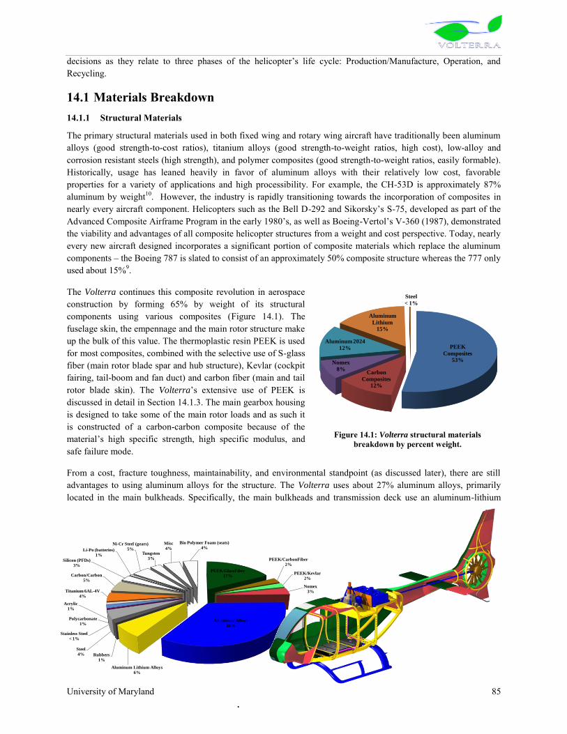
University of Maryland 85
decisions as they relate to three phases of the helicopter‟s life cycle: Production/Manufacture, Operation, and
Recycling.
14.1 Materials Breakdown 14.1.1 Structural Materials
The primary structural materials used in both fixed wing and rotary wing aircraft have traditionally been aluminum alloys (good strength-to-cost ratios), titanium alloys (good strength-to-weight ratios, high cost), low-alloy and corrosion resistant steels (high strength), and polymer composites (good strength-to-weight ratios, easily formable). Historically, usage has leaned heavily in favor of aluminum alloys with their relatively low cost, favorable properties for a variety of applications and high processibility. For example, the CH-53D is approximately 87% aluminum by weight10. However, the industry is rapidly transitioning towards the incorporation of composites in nearly every aircraft component. Helicopters such as the Bell D-292 and Sikorsky‟s S-75, developed as part of the Advanced Composite Airframe Program in the early 1980‟s, as well as Boeing-Vertol‟s V-360 (1987), demonstrated the viability and advantages of all composite helicopter structures from a weight and cost perspective. Today, nearly every new aircraft designed incorporates a significant portion of composite materials which replace the aluminum components – the Boeing 787 is slated to consist of an approximately 50% composite structure whereas the 777 only used about 15%9.
The Volterra continues this composite revolution in aerospace construction by forming 65% by weight of its structural components using various composites (Figure 14.1). The fuselage skin, the empennage and the main rotor structure make up the bulk of this value. The thermoplastic resin PEEK is used for most composites, combined with the selective use of S-glass fiber (main rotor blade spar and hub structure), Kevlar (cockpit fairing, tail-boom and fan duct) and carbon fiber (main and tail rotor blade skin). The Volterra‟s extensive use of PEEK is
discussed in detail in Section 14.1.3. The main gearbox housing is designed to take some of the main rotor loads and as such it is constructed of a carbon-carbon composite because of the material‟s high specific strength, high specific modulus, and safe failure mode.
From a cost, fracture toughness, maintainability, and environmental standpoint (as discussed later), there are still advantages to using aluminum alloys for the structure. The Volterra uses about 27% aluminum alloys, primarily located in the main bulkheads. Specifically, the main bulkheads and transmission deck use an aluminum-lithium
Figure 14.1: Volterra structural materials
breakdown by percent weight.
PEEK
Composites53%
Carbon
Composites12%
Nomex
8%
Aluminum 2024
12%
Aluminum
Lithium15%
Steel
< 1%
PEEK/GlassFiber
17%
PEEK/CarbonFiber
2%
PEEK/Kevlar
2%
Nomex
3%
Aluminum Alloys
34%
Aluminum Lithium Alloys
6%
Rubbers
1%
Steel
4%
Stainless Steel
< 1%
Polycarbonate
1%
Acrylic
1%
Titanium 6AL-4V
4%
Carbon/Carbon
5%
Silicon (PFDs)
3%
Li-Po (batteries)
1%
Ni-Cr Steel (gears)
5%Tungsten
3%
Misc
4%
Bio Polymer Foam (seats)
4%

University of Maryland 86
(Al-Li) alloy registered as Weldalite 049. As the name suggests, this alloy has superior welding properties to other aluminum alloys which allows many of the components to be welded instead of using fasteners. The resulting structure consists of fewer individual parts and as a result is significantly easier and cheaper to manufacture and maintain. Additionally, Al-Li alloys typically offer superior fatigue performance to more standard aluminum alloys. The remaining aluminum parts are constructed of either aluminum 2024 variants or aluminum 6013 where formability is a concern.
Due to its cost and high environmental impact (see Table 14.1), titanium alloys are not used on any of Volterra‟s
primary structural components, and are only used elsewhere when temperature and strength requirements necessitate its use.
14.1.2 Materials of Complete Helicopter
While material breakdowns are often quoted in terms of only the structural materials, when considering the environmental impact of the vehicle, it is essential to include as many standard components as possible. Figure 14.2 gives the complete materials breakdown for the baseline configuration of the Volterra, including engine and transmission components, avionics, the fuel system, batteries, paints, furnishings, windows and wires. In this breakdown, the aluminum is seen to be the primary component of the empty weight of the vehicle (primarily because of the aluminum casting of the engine block), but more importantly a number of non-structural materials appear that must be considered.
14.1.3 Composite Resin Choice (Thermoplastics versus Thermosets)
Fiber reinforced composite materials can be separated into two categories - thermoset and thermoplastic polymeric-based matrix composites. Thermoset polymers have strongly cross-linked molecular structures which decompose, instead of melt, with application of heat and upon solidification (curing). As a result, thermoset polymers cannot be reshaped (Ref. Agarwal). These polymers include epoxides which typically are formed as a two-part mixture of resin and hardener. Thermoplastic polymers have strong intramolecular bonds but weak intermolecular bonds resulting in the melting and solidification processes being reversible allowing reshaping of the material2. These polymers include materials such as polyether-ether ketone (PEEK) and polyphenylene sulfide (PPS).
The current common practice in composite manufacturing, especially in the aerospace industry, primarily uses fiber reinforced thermoset (FRTS) composites. This is due to the ease of impregnating the reinforcing fibers at low pressures as a result of the low pre-cure viscosities of the thermoset matrix at room temperature. Thermoset polymeric composites also lend themselves to complex shaped parts due to their pre-cure drapability and ample handling time to form the material around sharp contours of a mold. However, thermoset composites have several shortcomings such as the need for long processing time, high-touch labor, large, expensive autoclaves4, as well as the inability to be readily reshaped or recycled.
Recent advancements in composite manufacturing technology have increased the versatility of thermoplastic composites and the ability to fabricate elaborate parts. Through automated manufacturing practices and resin transfer molding (RTM) which does not require an autoclave, thermoplastics can now achieve the same if not better performance than thermosets in conforming to complex composite parts6. The transition to thermoplastics is industry-wide, as aerospace companies demand automated, repeatable manufacturing processes.
Fiber reinforced thermoplastic (FRTPs) composites offer the possibility for industrial products to be reused as raw materials for new applications instead of being thrown away1. This introduces the idea of closed-loop recycling, which saves valuable resources and prevents consuming further energy. As suggested by Kemmochi et al.1, after a FRTP component reaches the end of its useful life, it can be chopped up into shorter length fibers and remolded with the application of heat and pressure into a new product. A life-cycle chain of a FRTP could be analogous to the following example: A continuous-fiber structural member of a helicopter recycled into a long-fiber (>20 mm)

University of Maryland 87
stampable sheet for an automobile part, recycled into a short-fiber (>5 mm) injection molding material for a motorcycle helmet, then finally recycled into a powder composition (>0.2 mm) for household appliances such as a television1. In summary, the useful life of a raw material can be extended from, say 20 years to 80 years, considerably reducing the impact on the environment.
In addition to recyclability, thermoplastics have many advantages over thermosets:
Thermoplastics offer higher fatigue strength and superior damage resistance as well as permit localized repairs5
Enhanced temperature resistance and less sensitivity sensitive to moisture-induced aging5 Unlimited shelf life, no volatile organic compounds, and reduced issues with waste and material handling Thermoplastics allow in-situ construction which eliminates lengthy curing times without any post-
processing labor required Melt-bonding techniques allow construction of monolithic structures from smaller, pre-constructed parts
without the need for traditional fasteners like nuts and bolts which reduces the total part count considerably
The use of composites is continually growing in the aerospace and automotive industries as lower vehicle weights equate to less fuel consumption. In parallel with this trend, the European Union (Directive 2000/53/EC) has required that by 2015, 85% of all automobiles by weight must be recycled. The aerospace community will be forced to adopt this „green‟ mentality as commercialization of this technology results in reduced manufacturing costs. The Volterra moves to the forefront of this production trend by nearly exclusively making use of the thermoplastic PEEK, as the resin in fiber reinforced composite parts. This comes with the recognition that the cost penalty is outweighed by both the penalty‟s expected reduction in the coming decade, and the tremendous environmental
advantages offered by the material.
14.2 Production and Manufacturing 14.2.1 Material Properties
For each primary material in the Volterra, Table 14.1 gives an approximate value of the production energy and the corresponding CO2 emissions. These values are conservative approximations based on current technology, therefore we expect that the majority of these numbers will become more favorable in the near future before 2020. This is especially true where aluminum is concerned since the U.S Department of Energy has committed to and demonstrated improvements in the emissions, reduction of cost, and reduction of the energy required for smelting, the most energy intensive part of aluminum production13. Table 14.1: Required energy and carbon dioxide emmisions for the production of various materials12.
Production Energy
Material Primary Volterra Uses Energy
(MJ/kg) CO2 Burden
(kg/kg) Notes
PEEK/GlassFiber Main rotor, empennage 330 20.7 PEEK/CarbonFiber Main/Tail rotor skin 509 33.7 PEEK/Kevlar Tail boom, fan duct 623 35.7 Ref. 11 Tungsten Main rotor tip-weights 313 19.7 Nomex (nylon) Main rotor, stabilizers 105 4 Based on nylon properties Aluminum Alloys Engine, skids, hub 190 12 Al-Li Alloys Main bulkheads 203 12.8 Natural Rubber Hub bearings, fuel tanks 40 -0.5 Negative CO2 burden Butyl Rubber Hub bearings 80 2.1 Steel Engine pistons, empennage 25 2 Stainless Steel Fuel lines 65 5.4 Polycarbonate (PC) Front windshield 110 4

University of Maryland 88
Acrylic (Perspex) Side windows 99 3.5 Titanium 6AL-4V Engine, main rotor shaft 885 41.7 Carbon-Carbon Main gearbox housing 286 23 Silicon Avionics, wiring 56.9 3.2 Lithium/Polymer Batteries 68 -- primary pollutant: SOx Copper Wiring, slip-ring 63 4 Epoxy Paints 90 3.2 Ni-Cr Steel Transmission 130 8 Iron Electric motors 16.4 1 Bio Polymer Foam Seat cushions 67.8 1.195 Scaled based on bio-foams
Table 14.1 highlights a number of important factors governing material selection. As compared with aluminum alloys, PEEK based composites are not favorable from an energy or CO2 standpoint. While manufacturing advances have been made which would have allowed a viable fully PEEK composite airframe, the environmental impact would be far too great based on the design goals of the Volterra. Furthermore, in places where the composites are used, glass reinforced PEEK is chosen wherever material stress requirements permit. This minimizes the cost, environmental impact and production energy required for the composite portions of the helicopter. Similarly, the number of titanium parts is kept to a minimum, since the material‟s strength and low density did not give sufficient
cause to override its negative environmental and energy production values.
The primary pollutants produced by the lithium-polymer (Li-Po) batteries are sulfur oxides (SOx), nitrous oxides (NOx) and particulates such as soot. The amount of volatile organic compounds (VOC) created during production are relatively low. While it is known that the recyclability of these and most batteries is quite poor, the lithium polymer batteries are selected for the high energy density that the advanced avionics and flight controls require during engine startup and in emergency situations. Li-Po batteries are also lighter and generally less flame prone than lithium-ion batteries since the lithium is encased in a non-flammable polymer as opposed to the metallic casings of Li-Ion.
14.2.2 Manufacturing Energy
In addition to the energy required and pollution generated during the production of the materials, additional energy and pollution penalties are incurred during the manufacture of the raw materials into the specific parts used in the Volterra. While the expended energy and pollution vary considerably by process and component, an estimate for common process related to the major components of the vehicle is give in Table 14.2.
Although epoxy based composites (thermosets) are not used to any significant degree in the Volterra, their values are provided for comparison. Note that since the manufacture of PEEK based composites does not require the energy and time consuming autoclave process, their manufacture energy is substantially less than that of epoxy based composites. This advantage is somewhat offset by the high energy required to produce PEEK as a raw material (approximately twice that of epoxy), but the very high energy required by the autoclave process for the epoxy thermosets still makes the epoxy composites substantially more energy intensive to produce and manufacture than their PEEK counterparts.
14.2.3 Assembly Energy
For automobiles, Stodolsky et al.8 estimate that 3.8 MJ per kilogram of vehicle empty weight is required for assembling the manufactured components. Given the increased complexity, size and specialized construction
Table 14.2: Energy required at the manufacturing stage for various materials and processes.
Component Material Energy Cost (MJ/kg)
Aluminum 19 Steel 6.5 Epoxy-Based Composites Prepreg Production 40
Autoclave 600
Closed-Die 10.1 PEEK-Based Composites Prepreg Production 40
Resin Transfer Molding 12.8 Sheet Molding Compound 3.5

University of Maryland 89
methods employed on typical helicopters, we conservatively add 20% more energy per kg, resulting in an estimated 4.56 MJ/kg assembly energy cost. Because the Volterra is designed for simplicity in maintenance and manufacturing (as few fasteners as possible, compatible materials used where possible, “plug-and-play” avionics, etc.) we expect
that this value is an overestimate of the actual number, however this estimate gives approximately 4000 MJ of energy required for assembly of the helicopter.
14.3 Operation A number of factors contribute the energy consumption during the operational life of a helicopter. Examples include electricity used in the maintenance and cleaning, and the energy associated with the manufacture of replacement of parts and fluids. However, the overwhelming majority of the energy expenditure during operation comes directly from the fuel consumed during flight. Thus a reasonable estimate of operational energy expenditure can be obtained by considering the energy content of the fuel, the energy efficiency of the powerplant and the expected number of flight hours. The Volterra‟s OPOC can burn a variety of fuels, however it is optimized for use with diesel which has
an approximate energy content of 44.3 MJ/kg.
14.4 End-of-Life (Recycling) An important consideration when determining each of the materials used in the Volterra is the potential for recyclability, the costs and energy needed to remove a given material or component from the helicopter, and potential costs and energies associated with the disposal of non-recyclable parts. In general, once the helicopter has reached the end of its service life, the parts may be disassembled, and then:
Directly Reused Closed-loop recycled (recycled to become the same component) Open-loop recycled (recycled to become another component or product) Incinerated (with or without obtaining energy from the combustion process) Committed to a landfill
A number of the non-fatigue components of the Volterra are suitable for direct reuse (e.g. avionics, cabin-flooring, some components of the furnishings) which essentially requires no additional energy at end-of-life. However, as a conservative estimate, we will consider the more energy intensive options of recycling, incineration and burial in a landfill for most major parts.
Table 14.3: Energy required at end-of-life for the Volterra assuming 75% recycling of composite and aluminum components .
Process Energy
Cost (MJ/kg)
Mass on Volterra (kg)
Percent Affected
Energy Estimate
(MJ) Disassembly 1.3 877 100% 1140 Recycling Aluminum 26 351 75% 6841
Composite Fibers 4.4 189 30% 249 Total 8231
14.4.1 Disassembly
For automobiles, Stodolsky et al.8 estimate that 1.1 MJ per kilogram of vehicle empty weight is required for disassembly for recycling, primarily consumed in the form of electricity. Similar to the assembly energy estimate, due to the increased complexity, size and specialized construction methods employed on typical helicopters, we conservatively add 20% more energy per kg, resulting in an estimated 1.3 MJ/kg energy cost of disassembling a

University of Maryland 90
helicopter. Again similar to the assembly energy estimate, we expect that this value is an overestimate of the actual number, however this estimate gives approximately 1,140 MJ of energy required for disassembling the helicopter.
14.4.2 Recycling
The aluminum components are the prime candidates for recycling, both open and closed-loop. Because no smelting is required in the recycling stage, only melting, the recycling process is considerably less energy intensive than the aluminum production process. Based on the report by Stodolsky et al.8 and the material property data given by Ashby12, it is estimated that approximately 26 MJ/kg of energy is required to recycle aluminum alloys, whereas 190 MJ/kg was required to produce the original raw material. Assuming that 75% of the aluminum on the helicopter is recycled (263 kg), the energy cost for recycling is conservatively estimated at 6841.
Generally, a large percentage of cast aluminum parts (as opposed to wrought aluminum) are made from recycled raw material. This brings in the issue of alloy compatibility at the recycling stage. Although it is possible to separate alloys before melting them, it is generally preferred that they all be melted together, allowing differences in chemical composition and impurities to be diluted during the melting process. If too many different alloys are present, this simpler cost-effective solution becomes impractical. Approximately 75% of the aluminum alloys that the Volterra uses are 2024 derivatives and are highly compatible with each other at the recycling stage. This intentional design decision makes the recycling of aluminum parts from the Volterra more cost effective.
A number of methods are available for recycling the composite portions of the Volterra. As discussed in Section 14.1.3, the favored recycling method for the thermoplastic based composites in the Volterra involves generating “chopped” or “short fiber” composites which can be used in a closed loop recycling process. Adherent Technologies
Incorporated (ATI) has shown that the material properties are not significantly degraded in this process7. Additionally, thermoplastics have an ability to be reformed, offering the potential for limited forms of closed loop recycling of composite parts. A more generic possibility that was considered was Pyrolysis, in which the material is heated and broken down into a fine powder, allowing the separation at near molecular scale of the resin and fiber components. Although cost effective, this is unfortunately not practical for the Volterra or most aerospace composites because the process destroys the valuable carbon-fiber and resins before extracting them.
Using a catalytic conversion process, ATI has suggested that reclaiming composite fibers from the resins costs about 8.8 times less than producing the original fibers (for the case of carbon fibers and thermoset resins)7. If we assume that cost roughly indicates the required energy expenditure, then based on the data of Suzuki and Takahashi11 for the production energy required for raw carbon fibers (39 MJ/kg), we estimate that the carbon reclamation should require about 4.4 MJ per kg of composite fiber. Assuming conservatively that 75% of the PEEK based composites used in the Volterra are recycled in this manner, and that 40% of the composites by volume is fiber, then we arrive at 57 kg of reclaimable fiber. The energy cost of this would be approximately 249 MJ.
The bio-polymer foam used in the Volterra may be recycled in a closed loop fashion by direct reuse or reforming. If desired, the flexible polyol foam can be broken down and recycled chemically using a variety of depolymerisation processes, such as aminolysis or glycolysis.
14.4.3 Incineration and Landfill
Due to the high energy requirements, low energy reclamation possibilities (for most materials) and lack of a usable end product (as opposed to the case for the processes detailed in the previous section), the least environmentally friendly of end-of-life options for the helicopter components is incineration and/or landfilling. First of all, not all components can be incinerated or landfilled. Aluminum, for example, cannot be incinerated and is not biodegradable, although it still may be directly committed to a landfill. For those materials where incineration is possible, it may seem attractive from a short term cost perspective, but long term cost and environmental drawbacks are numerous, including:
Release of fine particulates (e.g. soot), even with careful emissions scrubbing Release of harmful heavy metals, depending on the incineration type and material being incinerated

University of Maryland 91
Incineration of carbon fibers requires special (costly) techniques to prevent the release of highly electrically conductive graphite particles
Generation of fly ash from coal-powered incinerators which requires specialized high-toxicity landfills Landfilling requires a tremendous amount of space Landfilling certain materials creates the possibility of the slow release of hazardous greenhouse gases
As environmentally friendly designers, we cannot recommend the incineration of components of the Volterra unless no other recycling means is practical.
14.4.4 Hazardous/Non-Recyclable Components
Any materials that are ignitable, corrosive, reactive or toxic may be classified by the EPA as “hazardous waste.”
Because of specific handling requirements and the need to commit the waste to special landfills, the cost to dispose of hazardous waste can be 20 times that of non-hazardous waste7. Although the use of some of these materials is currently a necessity for the foreseeable future, the Volterra design minimizes their use whenever possible by employing non-hazardous alternatives. For example, any surface painted with a primer containing hexavalent chromium may be considered a hazardous material due to the carcinogenic nature of the chromium. The compound itself is used to inhibit corrosion and surface wear, as well as a chrome pigment in some paints. Although the specific primer and paint used is not often in the hands of the designer, the Volterra design team recommends the use of alternative coatings such as nickel-iron-cobalt alloys which are non-toxic and provide better wear resistance14 at a slightly greater cost. Hexavalent chromium is also found in some electronics equipment, but because of its hazardous nature, as well as the European Union directive 2002/95/EC which prohibits the use of the compound in electronics after July 1st 2006, the Volterra‟s avionics suite and other electrical components are hexavalent
chromium-free.
Finally, the lithium in the Li-Po batteries on the Volterra constitute a bio-hazard if not handled properly at recycle-time. This is true of most battery types capable of the energy supply required, however by choosing high energy density Li-Po batteries, the required mass of lithium is reduced. While there is currently no standardized method of recycling this material, properly treated cells can be committed to landfill without significant environmental risks.
14.5 Total Vehicle Life Cycle Energy Estimate On the basis of the above discussion, life cycle energy was estimated for Volterra. Production cost was calculated based on the percentage of each material on the Volterra as seen in Figure 14.2. Table 14.4 provides the production energy per kg to produce these materials. On the basis of these, the total production cost of Volterra was estimated to be 205,626 MJ.
Secondly, the manufacturing cost was estimated based on Table 14.2 which gives the specific energy spent to produce the majority of the materials (by weight) on the Volterra. The final manufacturing energy cost of was estimated to be 19322 MJ.
Thirdly, the operation cost was estimated based on the amount of diesel fuel used for the total number of life cycle hours. The Volterra is designed based on a nominal value of 8000 flight hours in lifetime (400 hours per year for 20 years), which uses 460567 kg of fuel (17.6 gallons per flight hour). The total energy produced by burning this fuel, including heat and useful energy, is approximated as 19,956,380 MJ. The energy consumption in operation is by far the largest component of the life cycle energy consumption.
Finally , the disassembly and recycling energy cost was estimated to be 8216 MJ, based on the discussion in Section 14.4 and Table 14.3.
The total life cycle energy estimation can be summarized in Table 14.4. The analysis give an estimation of 20.2 TJ of energy spent in the whole life cycle of Volterra.

University of Maryland 92
15 WEIGHT ANALYSIS 15.1 Weight Estimates The weight estimates, based on the analysis of each respective section, is provided in Table 15.1. Lateral center of gravity is referenced from the nose of the aircraft. Vertical center of gravity is referenced from the ground.
Table 15.1: Volterra Weight Estimates.
Description Mass, kg % Mass l.c.g., mm v.c.g, mm
Airframe and Cowling 212 23% 3916 1608 Engine 248 26% 4276 2111 Transmission System 100 11% 3303 2188 Main Rotor System 91 10% 3270 2799 Avionics 66 7% 970 1216 Unconsumed Fuel 2.4 0% 2368 730 Landing Gear 35 4% 2879 378 Fuel System 6 1% 2974 730 General Furnishings & Equipment 15 2% 2303 851 Cooling System 17 2% 2954 2265 Control System 8 1% 3270 2799 Hydraulics 0 0% 174 1158 Electric System 47 5% 585 1216 Fan-in-fin & Empennage 25.3 3% 8696 2066 De-Icing System 0.3 0% 3270 2188 Crashworthiness 65.8 7% 2368 1310 Empty Weight 938.8 100% 3432.2 1818.7 Cargo 500 3408 1401 Pilot 100 1691 1417 Transmission & Engine Oil 5 4276 2111 Fuel 150 2974 730
Gross Weight 1693.8 3284.1 1576.2
15.2 Weight and Balance The longitudinal center of gravity envelope for the Volterra is provided in Figure 15.1. Extreme values for the center of gravity translation are 257 mm forward of the main rotor shaft and 166 mm aft of the shaft. The resulting range of bending moments about the mast is well within the range of the controls.
Table 14.4: Life cycle energy estimation of the Volterra
Process Energy (GJ) Production 20.56 Manufacturing 19.32 Operation 19,956.38 Disassembly and Recycling 8.22 Total Life Cycle Energy Estimation 20,189.55 (20.2 TJ)


University of Maryland 93
Figure 15.1: Center of gravity envelope for passenger and cargo loads.
16 MISSION CAPABILITIES The Volterra has versatile multi-mission capability – it can be provided with various equipment packages and cabin layouts for different missions such as commercial transport, corporate/VIP transport, police/border patrol, emergency medical service (EMS) and coast guard rescue. The typical mission profiles described in this section illustrate the Volterra‟s versatility and outstanding fuel efficiency. All calculations for flight time and range have been carried out with 20 minutes of reserve fuel at the end of the missions.
16.1 Standard civil transport mission The Volterra‟s standard mission is to transport up to 4 passengers with a single pilot or 500 kg of freight, at a maximum range of 340 nautical miles (630 km) and cruising at the speed for best range (107 knots) (Figure 16.3). The standard cabin layout (Figure 16.1) will have the option to include or remove controls for the co-pilot. For the cargo mission (Figure 16.2), three seats in the cabin can be removed to easily accommodate a cargo pallet of dimensions .
Figure 16.1 Cabin layout for passenger transport mission
Figure 16.2 Cabin layout for cargo transport mission

University of Maryland 94
Figure 16.3 Standard mission profile
16.2 Corporate (VIP) transport mission For corporate/VIP transport, maximum number of passengers is reduced to three. This allows for provision of additional passenger comfort equipment and cabin space (Figure 16.4). The weights of this equipment and furnishing modifications to the standard Volterra are given in Table 16.1. These values are the same as those provided in the EC-120B/EC-135 Technical Data brochures. The profile of a typical corporate/VIP mission is shown in Figure 16.5 in the form of a flight from Washington, D.C., to New York, NY. The very economical fuel consumption of the Volterra allows transport up to 3 VIP passengers from Washington to New York at a price of $144~ $149 per passenger, depending on a cruise speed between 107 knots and 120 knots. This one-way price is comparable to travel by an AMTRAK express train, which costs between $151 and $172 per passenger. The estimated time for the journey by express train is 2 hour 45 minutes, whereas the Volterra will only take between 1 hour 30 minutes and 1 hour 41minutes.
Figure 16.4 Cabin layout for corporate/VIP mission
Table 16.1 Mission equipment for corporate/VIP mission
Corporate/VIP Mission Equipment Weight (kg) V.I.P cabin layout 27.0 Comfortable cabin upholstery 14.0 Reinforced Soundproofing 5.2 Cabin carpet 4.3 Cabin washable cover 4.0 Protection cover for carpet 2.2 Cargo compartment upholstery 6.0 Total Weight of Mission Equipment 62.7
Figure 16.5 Corporate/VIP mission profile
16.3 Police/Border enforcement mission The Volterra can be equipped with police/border-enforcement mission equipment to carry out all-weather para-military missions. This configuration can take up to 3 crewmembers with 1 pilot or 2 crewmembers with 2 pilots. It can also be equipped with a rappelling device (Table 16.2) for 2 crewmembers that can be used when preparing for

University of Maryland 95
landing in devastated areas. The crew can also provide support for the pilot to land safely in congested or unprepared ground. Figure 16.7 shows a typical patrol mission with a patrol radius of 7.5 km (4 n.m). The patrol radius is based on the ground area covered by the Volterra for given endurance and speed. The patrol area can be up to 99 km (53.5 n.m) away from the Volterra‟s base.
Figure 16.6 Cabin layout for enforcement mission
Table 16.2 Mission equipment for police/border enforcement Police/Border Patrol Mission Equipment Weight (kg) Co-Pilot Control/Avionics 5.6 FLIR systems TALON 20.5 Search Light SX16 with I.F. filter, vendor, fixed mount 35.1 Strobe Lights, white 2.0 Landing & search light, NVG compatible 4.5 External Loudspeaker with Siren 10.1 Rappelling device 17.5 IRIDIUM satellite phone 5.0 Tactical Radio 5.0 NVG compatible cockpit / cabin 1.2 Windshield wipers 3.7 Total Weight of Mission Equipment 110.2
Figure 16.7 Police/Border enforcement mission profile
16.4 Coast guard rescue mission The twin-module engine enables the Volterra to carry out off-shore missions such as coast guard rescue missions. Table 16.3 shows the mission equipment for such an all-weather rescue mission. The mission equipment package was selected to enable the Volterra to operate in dark and unfavorable weather conditions. A crew of two members are carried to assist the victim and to simultaneously operate the rescue hoist (Figure 16.8). Figure 16.9 shows that the maximum mission radius of the Volterra for such a mission is 223 km (120 n.m). This mission radius allows for 30 minutes of low-speed search and 10 minutes of hover time for the rescue.
Figure 16.8 Cabin layout for coast guard rescue mission
Table 16.3 Mission equipment for coast guard rescue mission
Coast-Guard Rescue Mission Equipment Weight (kg) FLIR systems TALON 20.5 Search Light SX16 + fixed mount 15.5 Strobe Lights, white 2.0 Landing & search light, NVG compatible 4.5 External Loudspeaker with Siren 10.1 Hoist with observation light 80.5 Quick change EMS kit - Aerolite 33.5 IRIDIUM satellite phone 5.0 Tactical Radio 5.0 NVG compatible cockpit / cabin 1.2 Windshield wipers 3.7 Total Weight of Mission Equipment 181.5

University of Maryland 96
Figure 16.9 Coast guard rescue mission profile
16.5 EMS mission Besides the coast guard rescue mission, the Volterra can also be used for emergency medical services (EMS). For this mission, the heavy equipment such as the external hoist is removed to provide room for a sophisticated emergency medical kit (Table 16.4). The cabin layout (Figure 16.10) is very similar to that for the coast guard rescue mission. The mission profile in Figure 16.11 shows that the Volterra has a mission radius of 260 km (140 n.m), carrying a patient weighing up to 150 kg (330 lb).
Figure 16.10 Cabin layout for EMS mission
Table 16.4 Mission equipment for EMS mission
EMS Mission Equipment Weight (kg) Search Light SX16 with fixed mount 15.5 Strobe Lights, white 2.0 Landing & search light, NVG compatible 4.5 External Loudspeaker with Siren 10.1 Intensive Care EMS kit - Aerolite 151.5 IRIDIUM satellite phone 5.0 Tactical Radio 5.0 NVG compatible cockpit / cabin 1.2 Total Weight of Mission Equipment 194.8
Figure 16.11 EMS mission profile
16.6 Long Endurance Autonomous Surveillance Mission The Volterra can be converted into an unmanned vehicle (UAV) for high-endurance, high-altitude surveillance. All the internal furnishings can be removed to accommodate additional fuel tanks in the cabin area. Therefore, the entire useful payload is converted to fuel, providing the Volterra with 650 kg (1,433 lb) of fuel, and extending its endurance to up to 21 hours. This special capability is a unique characteristic of the Volterra and is allowed for by
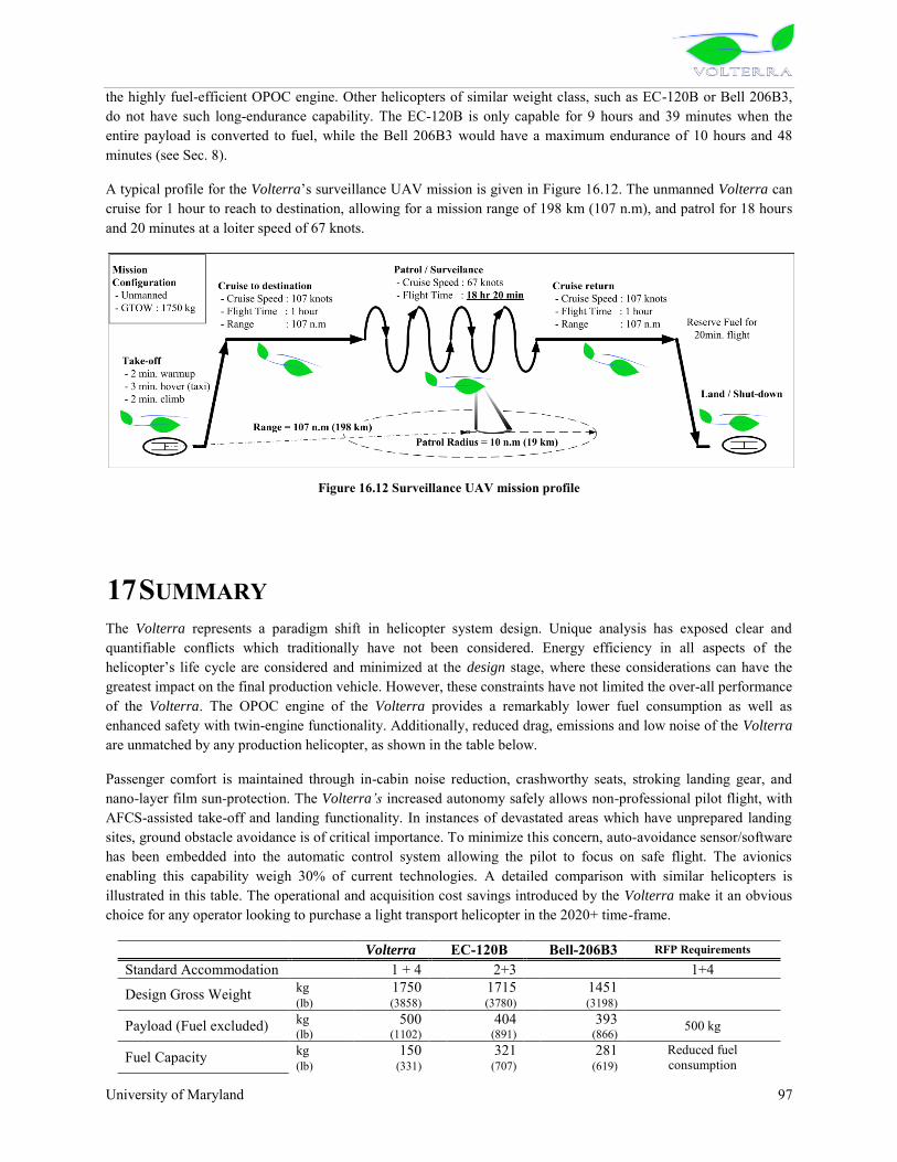
University of Maryland 97
the highly fuel-efficient OPOC engine. Other helicopters of similar weight class, such as EC-120B or Bell 206B3, do not have such long-endurance capability. The EC-120B is only capable for 9 hours and 39 minutes when the entire payload is converted to fuel, while the Bell 206B3 would have a maximum endurance of 10 hours and 48 minutes (see Sec. 8).
A typical profile for the Volterra‟s surveillance UAV mission is given in Figure 16.12. The unmanned Volterra can cruise for 1 hour to reach to destination, allowing for a mission range of 198 km (107 n.m), and patrol for 18 hours and 20 minutes at a loiter speed of 67 knots.
Figure 16.12 Surveillance UAV mission profile
17 SUMMARY The Volterra represents a paradigm shift in helicopter system design. Unique analysis has exposed clear and quantifiable conflicts which traditionally have not been considered. Energy efficiency in all aspects of the helicopter‟s life cycle are considered and minimized at the design stage, where these considerations can have the greatest impact on the final production vehicle. However, these constraints have not limited the over-all performance of the Volterra. The OPOC engine of the Volterra provides a remarkably lower fuel consumption as well as enhanced safety with twin-engine functionality. Additionally, reduced drag, emissions and low noise of the Volterra are unmatched by any production helicopter, as shown in the table below.
Passenger comfort is maintained through in-cabin noise reduction, crashworthy seats, stroking landing gear, and nano-layer film sun-protection. The Volterra’s increased autonomy safely allows non-professional pilot flight, with AFCS-assisted take-off and landing functionality. In instances of devastated areas which have unprepared landing sites, ground obstacle avoidance is of critical importance. To minimize this concern, auto-avoidance sensor/software has been embedded into the automatic control system allowing the pilot to focus on safe flight. The avionics enabling this capability weigh 30% of current technologies. A detailed comparison with similar helicopters is illustrated in this table. The operational and acquisition cost savings introduced by the Volterra make it an obvious choice for any operator looking to purchase a light transport helicopter in the 2020+ time-frame.
Volterra EC-120B Bell-206B3 RFP Requirements
Standard Accommodation 1 + 4 2+3 1+4
Design Gross Weight kg 1750 1715 1451 (lb) (3858) (3780) (3198)
Payload (Fuel excluded) kg 500 404 393 500 kg (lb) (1102) (891) (866)
Fuel Capacity kg 150 321 281 Reduced fuel consumption (lb) (331) (707) (619)

University of Maryland 98
(gallon) (43.5) (107) (91)
Speed for Best Range km/hr 198 204 213 Recommended cruise speed over 100knots (knots) (107) (110) (115)
Speed for Best Endurance km/hr 124 120 96 (knots) (67) (65) (52)
Fast Cruise Speed km/hr 222 222 (knots) (120) (120)
Rate of Climb m/s 10.63 5.84 6.9 (ft/min) (2091) (1150) (1358)
HOGE Ceiling
HOGE at 1500m ISA+20
ISA m 2931 2316 1615 (ft) (9614) 7600 (5298)
ISA +20 m 2238 518 914 (ft) (7343) 1700 (2998)
Maximum Range km 708 710 693 300 n.m (n.m) (382) (383) (374)
Maximum Endurance 3 hr 34min 4 hr 19min 4 hr 30min Endurance with useful load converted to fuel(1) 21 hour 9hr 39min 10hr 48min
Main dimensions Length,
(Rotor Turning) m 11.67 11.52 11.96 (ft) (38.29) (37.79) (39.2)
High m 3.71 3.40 2.52 (ft) (12.17) (11.15) (8.3)
Width m 2.74 2.60 1.96 (ft) (8.99) (8.53) (6.4)
Cabin volume m3 2.70 2.14 1.12 (ft3) (95.35) (75.57) (40)
Cargo volume m3 1.38 0.80 0.45 (ft3) (48.73) (28.25) (16)
Main rotor
Diameter m 9.74 10 10.16 (ft) (31.95) (32.81) (33.4)
Chord m 0.262 0.26 0.33 (ft) (0.86) (0.85) (1.1)
Number of blade 4 3 2
Tip speed m/s 197 210 209 (ft/s) (645) (689) (687)
Engine Data Specific Power kw/kg 1.96 2.8 2.5 SFC kg/kw/hr 0.206 0.312 0.36 Purchase Price $ Million 0.9 1.45 1.3 Life Cycle Energy Consumption 20.2 TJ Life Cycle Costs
Direct Operation Cost2 $/FH 104 231 235 Indirect Operation Cost3 $/Year 228,000 239,000 236,000
* Note 1 : For EC-120 and Bell 206, endurance is calculated with the entire payload being the fuel. 2 : DOC is given for the first operational year (400 flight hour/year) of a new helicopter. Effect of inflation (2.75%/year) and helicopter aging is neglected for the first operation year. 3 : IOC is given for the average over 20 years (400 flight hour/year). This takes into account of yearly inflation of 2.75%

University of Maryland 99
18 REFERENCES 18.1 Introduction
18.2 Section 2
1. Leishman, J.G., Principles of Helicopter Aerodynamics, Cambridge University Press, Cambridge, 2000. 2. Sargent, D.C, Schmitz, F.H., and Sim, B.W., "In-Flight Array Measurements of Tail Rotor Harmonic
Noise", 64th Annual Forum of the American Helicopter Society, Montreal, CA, May 2008. 3. Chou, S.T., “A Study of Rotor Broadband Noise Mechanisms and Helicopter Tail Rotor Noise”, NASA CR
177565, August 1990. 4. Lynn, R.R., Robinson, F.D., Batra, N.N., and Duhon, J.M., “Tail Rotor Design Part 1: Aerodynamics”,
Journal of the American Helicopter Society, Vol. 15, No. 4 October 1970. 5. Vuillet, A. and Morelli, F., “New Aerodynamic Design of the Fan-in-fin for Improved Performance”,
Proceedings of the 12th European Rotorcraft Forum, September 22-25, 1986. 6. Mouille, R. and d‟Ambra, F., “The ‟fan-in-fin‟: A shrouded tail rotor concept for helicopters”.Proceedings
of42nd Annual American Helicopter Society Forum, pages 597–606, 1986. 7. Coffy, R.L, “Blade made of thermoplastic composite, in particular for ducted tail rotor of a helicopter and
its method of manufacture,” Dec 14, 1993 United States Patent 5462408. 8. Guimbal, B., “Variable Pitch Rotor Blade for Shrouded rotors, In particular Helicopter Rotors”, May 9,
2006, United States Patent 7,040,863 B2. 9. Aubry, J. A., and Coffy, R.L., “Blade made of thermoplastic composite, in particular for ducted tail rotor of
a helicopter and its method of manufacture with injection step”, Oct 3, 1995, United States Patent 5,454,693.
18.3 Section 3 1. Tishchenko, M. N. and Nagaraj, V. T., ENAE 634 Helicopter Design Lecture Notes, University of
Maryland, College Park, 2008. 2. Leishman, J. G., Principles of Helicopter Aerodynamics, Cambridge University Press, Cambridge, 2006 3. Harris, F. D. and Scully, M. P., “Helicopters cost too much,” AHS 53rd Annual Forum, Virginia Beach,
April 29 - May 1, 1997. 4. Janes All the World‟s Aircrafts 2004-2005
18.4 Section 4 1. Kreith, F. and Goswami, D. Y, eds. “The CRC Handbook of Mechanical Engineering,” 2nd ed. Boca
Raton, FL: CRC Press, 2005. 2. Administrative Review Board (ARB) Independent Expert Panel. “Status and Prospects for Zero Emissions
Vehicle Technology,” Sacramento, CA. Apr. 2007. 3. Smith, Van Ness, and Abbot, “Introduction to Chemical Engineering Thermodynamics,” 5th ed. New
York: McGraw-Hill. 2005. 4. Jackson, Paul, “Jane‟s All the World‟s Aircraft 2004-2005,” Alexandria, VA: Jane‟s Information Group
Inc., 2004. 5. Hill P., Peterson, C. “Mechanics and Thermodynamics of Propulsion,” Reading, MA: Addison-Wesley
Publishing Company, Inc., 1992. 6. Lide, David R., ed, “CRC Handbook of Chemistry and Physics,” 83rd ed. Boca Raton, FL: CRC Press,
2002. 7. National Standards Reference Data System (NSRDS), “JANAF Thermochemical Tables,” 2
nd ed. (NSRDS NBS-37). Washington, D.C., 1971.

University of Maryland 100
8. Hofbauer, Peter, “Opposed Piston Opposed Cylinder (OPOC) Engine for Military Ground Vehicles,”
Society of Automotive Engineers World Congress, Detroit, Michigan, Apr. 2005. 9. American Gear Manufacturers Association (AGMA). “Design Guidelines for Aerospace Gearing.” AGMA
911-A94. Alexandria, VA, 2004. 10. American Gear Manufacturers Association (AGMA). “Fundamental Rating Factors and Calculation
Methods for Involute Spur and Helical Gear Teeth.” ANSI/AGMA 2001-D04. Alexandria, VA, 2004. 11. American Gear Manufacturers Association (AGMA). “Rating the Pitting Resistance and Bending Strength
of Generated Straight Bevel, Zerol Bevel, and Spiral Bevel Gear Teeth,” ANSI/AGMA 2003-B97. Alexandria, VA, 1997.
18.5 Section 5 1. Leishman, J., Principles of Helicopter Aerodynamics, Cambridge University Press, 2006. 2. Totah, J., “A Critical Assessment of UH-60 Main Rotor Blade Airfoil Data”, American Institute of
Aeronautics and Astronautics, 1993. AIAA-1993-3413. 3. A. Desopper, L. Philips, and J. Prier. “Effect of an Anhedral Sweptback Tip on the Performance of a
Helicopter Rotor”, American Helicopter Society 44th Annual Forum, June 1988.
4. O.L. Santa Maria and A. Mueller. “Acoustics of UH-60 Blackhawk with Growth Rotor Blades.”
American Helicopter Society 53rd Annual Forum, Virginia Beach, Virginia, April 29 – May 2, 1997. 5. Braswell, J., Covington, C., Phillips, N., Tomerlin, R., Wohlfeld, R., “Composite Rotor Blade”, US patent
4083656, April 11, 1978. 6. Niu, M., “Composite Airframe Structures: Practical Design Information and Data”, Conmilit Press Ltd.,
Hong Kong, 1992. 7. Automated Dynamics, Material Properties Data Sheets, Schenectady, New York, 2008. 8. Amber Composites Ltd, “ANC Amber Nomex Commercial Honeycomb”, Technical Data Sheet, March
2006. 9. Bao, J., Nagaraj, V., Chopra, I., Bernhard, A., “Wind tunnel testing of low vibration mach scale rotor with
composite tailored blade”, Proceedings of the 60th Annual American Helicopter Society Forum, 2004. 10. J. Palacios, E. Smith, and J. Rose, “Investigation of an Ultrasonic Ice Protection System for Helicopter
Rotor Blades”, Proceedings of the 64th Annual American Helicopter Society Forum, 2008.
11. Electromagnetic de-icing patent… 12. W. Schmidt, and H. Eaton, “Nanocomposite Layered Airfoil”, US patent 6,341,747 B1, Jan. 29, 2002. 13. H. Eaton, J. Holowczak, and W. Reinfelder, “Engineered Ceramic Components for the Leading Edge of a
Helicopter Rotor Blade”, US patent 5,542,820, Aug. 6, 1996. 14. 3M, “Polyurethane Protective Tape 8542”, Technical Data Sheet, Nov. 2004. 15. R. Harrison, S. Stacey, and B. Hansford, “BERP IV: The Design, Development and Testing of an
Advanced Rotor Blade”, Proceedings of the 64th Annual American Helicopter Society Forum, April 29 –
May 1, 2008. 16. E. Fradenburgh, R. Murrill, and E. Kiely, “Dynamic Model Wind Tunnel Tests of a Variable-Diameter,
Telescoping-Blade Rotor System (TRAC Rotor)”, Sikorsky Aircraft Division, United Aircraft Corporation,
USAAMRDL Technical Report 73-32, Eustis Directorate, U.S. Army Air Mobility R&D Laboratory, Fort Eustis, VA, July 1973.
17. Matuska, D. G. and Gronenthal, E. W., “Retraction/Extension Mechanism for Variable Diameter Rotors,”
U.S. Patent 5,642,982, July 1, 1997. 18. T. Prabhakar, F. Ghandi, J. Steiner, and D. McLaughlin, “A Centrifugal Force Actuated Variable Span
Morphing Helicopter Rotor”, Proceedings of the International Forum on Rotorcraft Multidisciplinary
Technology, Seoul, Korea, Oct. 15-17, 2007. 19. Chopra, I. “Review of the State-of-Art of Smart Structures and Integrated Systems.” AIAA Journal, Vol.
40, No. 11, November 2002. 20. J. Shen, I. Chopra, and W. Johnson. “Performance of Swashplateless Ultralight Helicopter Rotor with
Trailing-Edge Flaps for Primary Flight Control.” Proceedings of the 59th Annual Forum of the American
Helicopter Society International, Pheonix, AZ, May 2003.

University of Maryland 101
21. J. Shen, “Comprehensive Aeroelastic Analysis of Trailing Edge Flap Helicopter Rotors”, PhD Dissertation,
University of Maryland, College Park, MD, 2003. 22. J. Sirohi, and I. Chopra, “Design and Development of a High Pumping Frequency Piezoelectric-Hydraulic
Hybrid Actuator,” Journal of Intelligent Material Systems and Structures, Vol. 14, No. 3, pp. 135-147, March 2003.
23. J. Ellison, “Design and Testing of a Bi-directional Magnetostrictive-Hydraulic Hybrid Actuator”,
Proceedings of the 11th SPIE Conference on Smart Structures and Integrated Systems, San Diego, CA, March 2004.
24. E. Jacobs and R. Pinkerton, “Pressure Distribution Over a Symmetrical Airfoil Section with Trailing Edge
Flap”, NACA Technical Report No. 360, Langley Field, VA, April 2, 1930. 25. Maxon Motor, Brushless DC Motor Data Sheets, May 2008,
<http://www.maxonmotor.com/EC_motor.asp>. 26. Portescap – Danaher Motion Company, Brushless Slotless DC Motor Data Sheets, 2007,
<http://www.portescap.com/>. 27. B. Roget and I. Chopra, “Wind Tunnel Testing of an Individual Blade Controller for a Dissimilar Rotor”,
60th Annual Forum of the American Helicopter Society International, Baltimore, MD, June 7-10, 2004. 28. B. Roget and I. Chopra, “Robust Individual Blade Control Algorithm for a Dissimilar Rotor”, Journal of
Guidance, Control and Dynamics, Vol. 25, No. 4, July-Aug. 2002. 29. Parker-Texloc, PEEK Detailed Properties Data Sheet, 2005. <www.texloc.com>. 30. Lord Corporation, “Elastomeric Bearings, Dampers and Isolators: Comfort, Care and Feeding”,
http://www.lord.com, 2006. 31. “Lord Corporation – Lead Lag Dampers”, http://www.lord.com, May 25, 2004. 32. (Wei 03) Wei, Fu-Shang (John), “Design of an Integrated Servo-flap Main Rotor”, Proceedings of the 59
th Annual Forum of the American Helicopter Society International, Phoenix, AZ, May 2003.
33. (Chopra 02) Chopra, I., “Review of the State-of-Art of Smart Structures and Integrated Systems”,AIAA
Journal, Vol. 40, No. 11, November 2002.
34. (Shen ) Shen, J., Chopra, I., and Johnson, W., “Performance of Swashplateless Ultralight Helicopter Rotor with Trailing-Edge Flaps for Primary Flight Control”, Proceedings of the 59
th Annual Forum of the American Helicopter Socirty International, Phoenix, AZ, May 2003.
35. (Falls 08) Falls, J., Datta, A., Chopra, I., “Performance Analysis of Trailing-Edge Flaps in Helicopter Primary Control”, AHS Aeromechanics Specialists Conference, Jan 23-25, 2008, San Francisco, CA.
18.6 Section 6
1. Keys, C., Sheffler, M., Weiner, S. and Heminway, R., “LH Wind Tunnel Testing: Key to Advanced Aerodynamic Design”, Proceedings of the 47th Annual American Helicopter Society Forum, May 1991,
pp. 77-87. 2. Marze, H.R. ,Routhieau, V.J., Arnaud, G.L., and Arnaud, R.E.,“Counter-torque device with rotor and flow
straighteningstator, both of which are ducted, and inclined flow-straightening vanes”, June 3, 1997. United
StatesPatent 5,634,611. 3. Vuillet, A. and Morelli, F., “New Aerodynamic Design of the Fan-in-fin for Improved Performance”,
Proceedings of the 12th European Rotorcraft Forum, September 22-25, 1986. 4. Niesl, G., Arnaud, G., “Low Noise Design of the EC 135 Helicopter”, Proceedings of the 52
nd American Helicopter Society Annual Forum, Washington, D.C., June 1996.
5. Riley, R.G., “Effects of Uneven Blade Spacing on Ducted Tail Rotor Acoustics”, Proceedings of the 52nd American Helicopter Society Annual Forum, Washington, D.C., June 1996.
6. Roger, M., and Fournier, F., “An Analysis of In-Fin Tail Rotor Noise”, 12th Annual European Rotorcraft
Forum, Paper No. 40, Sept. 1986.
University of Maryland 102
7. Ewald, D. et al, “Noise Reduction by Applying Modulation Principles”, Journal of the Acoustical Society
of America, vol. 49, No. 5, 1971, pp. 1381 – 1385. 8. Mouille, R. “The Fenestron, Shrouded Tail Rotor of the SA 341 Gazelle”, Journal of the American
Helicopter Society, October 1970 9. Mouille, R. and d‟Ambra, F., “The ‟fan-in-fin‟: A shrouded tail rotor concept for helicopters”. Proceedings
of42nd Annual American Helicopter Society Forum, pages 597–606, 1986. 10. Prouty, R. W., Military Helicopter Design Technology, Jane‟s Defence Data, 1989.
18.7 Section 7 1. R. Selvin, A. P. Satish, S. Viswanath, RWR&DC, HAL, Bangalore-560017, HELICOPTER LANDING
GEAR SYSTEM 2. Pieter Minderhoud, Bell Helicopter Textron, DEVELOPMENT OF BELL HELICOPTER‟S MODEL 429
SLEIGH TYPE SKID LANDING GEAR
18.8 Section 8 1. Johnson, W., Yamauchi, G. K., and Watts M E, “Design and Technology Requirement for Civil Heavy Lift
Rotorcraft”, Proceedings of the American Helicopter Society Heavy Lift Aircraft Design Conference, San
Francisco, CA, Jan 2006. 2. Prouty, R. W., Helicopter Performance, Stability, and Control, Kreiger Publishing Company, Malabar,
Florida 1995. 3. Sung, D. Y., Lance, M. B., Young, L. A., and Stroub, R. H., “An Experimental Investigation of Helicopter
Rotor Hub Fairing Drag Characteristics,” NASA Technical Memorandum, September 1989. 4. Bartol, I. K., Gharib, M., Webb, P., Weihs, D., Gordon, M. S., “Body-induced vortical flows: a common
mechanism for self-corrective trimming control in boxfishes,” The Journal of Experimental Biology 208,
327-344. 5. Leishman, J. G., Principles of Helicopter Aerodynamics, Cambridge University Press, Cambridge, 2006. 6. Hanson, T. F., “A Designer Friendly Handbook of Helicopter Rotor Hubs,” November, 1998.
18.9 Section 9 1. Brentner, K. S., and Farassat, F., “Modeling Aerodynamically Generated Sound of Helicopter Rotors,”
Penn State University. 2. Schmitz, F. H. and Yu, Y. H. “Helicopter Impulsive Noise: Theoretical and Experimental Status.” Journal
of Sound and Vibration 109 (3), (1986): 361-422. 3. Mellin, R.R., and Sovran, G., “Controlling the Tonal Characteristics of the Aerodynamic Noise Generated
by Fan Rotors,” Journal of Basic Elements, March 1970, pp 143-154. 4. Kryter, K.D., and Pearsons, K.S., “Judged Noisiness of a Band of Random Noise Containing Audible Pure
Tone,” Journal of the Acoustical Society of America, Vol.38, 1965. 5. Riley, R.G., “Effects of Uneven Blade Spacing on Ducted Tail Rotor Acoustics”, Proceedings of the 52nd
American Helicopter Society Annual Forum, Washington, D.C., June 1996. 6. Niesl, G., Arnaud, G., “Low Noise Design of the EC 135 Helicopter”, Proceedings of the 52nd American
Helicopter Society Annual Forum, Washington, D.C., June 1996. 7. Marze, H.R., “Counter-Torque Device with Rotor and Flow Straightening Stator, both of which are ducted,
and inclined flow-straightening vanes”, US Patent 5634611, June 3, 1997. 8. Roger, M., and Fournier, F., “An Analysis of In-Fin Tail Rotor Noise”, 12th Annual European Rotorcraft
Forum, Paper No. 40, Sept. 1986.

University of Maryland 103
9. Schmitz, F. H., “Reduction of Blade Vortex Interaction (BVI) Noise through X-Force Control,” NASA
TM-110371, Sept. 1995. 10. Sickenberger, R. D. and Schmitz, F. H., “Longitudinal Tip-Path-Plane Measurement using an Optics Based
Approach,” 63rd Annual American Helicopter Society Forum. May, 2007. 11. Robinson, F. “Component Noise Variables of a Light Observation Helicopter”, NASA CR-114761, January
1973. 12. Barlow, W.H., McCluskey, W.C., Ferris, H.W., “OH-6A Phase II Quiet Helicopter Program”,
USAAMRDL Technical Report 72-29, September 1972. 13. Gopalan, G., and Schmitz, F. H., “High-Speed Impulsive Helicopter Noise Reduction Possibilities Through
On-Blade Acoustic Control,” International Forum on Rotorcraft Multidisciplinary Technology. Seoul,
Korea. Oct. 2007.
18.10 Section 10 1. Padfield, G. D., Helicopter Flight Dynamics: The Theory and Application of Flying Qualities and
Simulation Modeling, 2nd ed., AIAA Educational Series, 2007. 2. Prouty, R. W., Helicopter Performance, Stability, and Control, PWS Engineering, Boston, 1986. 3. Humbert, Sean, California Institue of Technology, Dissertation, 2006 4. J. Serres; F.Ruffier; S. Viollet, N Franceschini, “Toward optic flow regulation for wall-following and centering
behaviours”, Biorobotic research group, Movement and Perception Lab., CNRS/Univ. de la Méditerranée31, chemin Joseph Aiguier, 13402 Marseille Cedex 20, FRANCE
5. Humbert, J. S., Murray. R. M., and Dickinson, M. H., “Pitch-Altitude Control and Terrain Following Based on Bio-Inspired Visuomotor Convergence”, AIAA Conference on Guidance, Navigation and Control, San Francisco, CA, 2005.
6. J. S Humbert , R. Murray , M. Dickinson, “Pitch-Altitude Control and Terrain Following Based on Bio-Inspired Visuomotor Convergence”, University of Maryland, College Park, California Institute of
Technology, Pasadena, CA 7. J. Serres and F. Ruffier, “Two optic flow regulators for speed control and obstacle avoidance, “Conference
on biomedical robots and biomechatronics, Biorob, 2006, Pisa, Italy
18.11 Section 11 1. [CIS08] AHRS CrossbowInertial Systems, <www.xbow.com>, May 2008.US Patent No.: US 7,108,232 B2
Date of Pattent Sept. 19, 2006 2. [EURO08] Eurocopter EC120B Technical Data 3. [L308] SmartDeck Integrated Flight Controls and Display System, <www.l-3.com> May 2008 4. [BOSE08] Aviation Headset X, BOSE Corp.,< www.bose.com>, May 2008 5. [Cond04] J. Ellison, J. Conroy, J. Falls, S.John, I.Chopra, R. Preator, A. Abhishek, UMD-Condor,
Mountain Rescue Helicopter June 1, 2004. AHS Graduate Student Design Competition, 1st place. 6. [Irvi00] Irving, P.E., Place, S., Strutt, J.E., Allsopp, K.E. “Life prediction, maintenance and failure
probabilities in rotorcraft gear boxes equipped with health and usage monitoring 7. [Lard99] Larder, Brian D., “Helicopter HUM/FDR: Benefits and Developments”. Presented at the
American Helicopter Society 55th Annual Forum, Montreal, Quebec, May 25-27 1999. 8. [Gast08] GasTops, www.gastops.com, 2008. 9. [Stew77] Stewart., R.M., “Some useful analysis techniques for gearbox diagnostics”. Technical Report
HM/R/10/77, Machine Health Monitoring Group, Institute of Sound and Vibration Research, University of Southhampton, July 1977.
10. [Zakr93] Zakrajsek, J.J., Townsend, D.P., and Decker, H.J. “An analysis of gear fault detection methods as
applied to pitting fatigue failure data”. Technical Report NASA TM-105950, AVSCOM TR-92-C-035, NASA and the U.S. Army Aviation Systems Command, January 1993.
University of Maryland 104
11. [Deck94] Decker, H.J.,Handschuh, R.F., and Zakrajsek, J.J., “An enhancement to the NA4 gear vibration
diagnostic parameter”. Technical Report NASA TM-106553, ARL-TR-389, NASA and the U.S. Army Research Laboratory, July 1994.
18.12 Section 12 1. “Ford Develops Foam with 40% Soy-Based Material”, Green Car Congress, Oct. 16, 2006,
<http://www.greencarcongress.com/2006/10/ford_develops_f.html>. 2. Desjardins, S. “The Evolution of Energy Absorption Systems for Crashworthy Helicopter Seats”, Journal
of the American Helicopter Society, vol. 51, no. 2, April 2006. 3. Desjardins, S., Zimmermann, R., Bolukbasi, A., Merritt, N., “Aircraft Crash Survival Design Guide –
Volume IV”, USAAVSCOM TR 89-D-22D, Dec. 1989. 4. Harrer, K., Yniguez, D., Majar, M., Ellenbecker, D., Estrada, N., Geiger, M., “Whole Body Vibration
Exposure for MH-60S Pilots”, Proceedings of the 43rd Annual SAFE Association Symposium, Salt Lake
City, Utah, Oct. 24-26, 2005. 5. Hiemenz, G., “Semi-Active Magnetorheological Seat Suspensions for Enhanced Crashworthiness and
Vibration Isolation of Rotorcraft Seats”, Ph.D. Dissertation, University of Maryland, College Park, 2007. 6. Hiemenz, G., Gupta, P., Wei, H., Wereley, N., “Semi-Active Magnetorheological Helicopter Crew Seat
Suspension for Vibration Isolation”, Proceedings of the 64th Annual American Helicopter Society Forum, April 29 – May 1, 2008.
7. BAE Systems, “S5000 Seating – Lightweight, Energy-Absorbing Crew & Passenger Seat”, data sheet,
2007. 8. Hiemenz, G.J., Hu, W., Wereley N.M, Chen, P., “Adaptive Energy Absorption System for a Vehicle Seat,”
U.S. Patented Application Serial No. 11/819,875.
18.13 Section 13 1. U.S. Department of Labor, Consumer Price Index, Bureau of Labor Statistics, Washington, D.C., 2008 2. Harris, F. D. and Scully, M. P., “Helicopters Cost Too Much,” American Helicopter Society 53rd Annual
Forum, Virginia Beach, Virginia, April, 1997. 3. Harris, F. D. and Scully, M. P., “Supplemental Appendix : Helicopters Cost Too Much,” American
Helicopter Society 53rd Annual Forum, Virginia Beach, Virginia, April, 1997. 4. HeliValue$, Inc., “The Official Helicopter Blue Book®. The Official Helicopter Specification Book and
Helicopter Equipment Lists & Prices (H.E.L.P.)”. 5. Economics Committee, “Guide for the presentation of helicopter operating cost estimates”, Helicopter
Association International, 1635 Prince Street, Alexandria, VA 22314, 2001
18.14 Section 14 1. Kemmochi, K., Takayanagi, H., Nagasawa, C., Takahaski, J., Hayashi, R., “Possibility of Closed Loop
Material Recycling for Fiber Reinforced Thermoplastic Composites,” Advanced Performance Materials, 1995, Vol. 2, 385-394.
2. Agarwal, B., Broutman, L., Chandrashekhara, K., Analysis and Performance of Fiber Composites, 3rd Edition, John Wiley & Sons, Inc. 2006.
3. Braswell, J., Covington, C., Phillips, N., Tomerlin, R., Wohlfeld, R., “Composite Rotor Blade”, US patent
4083656, April 11, 1978. 4. Kilroy, J., O‟Bradaigh, C., Semprimoschnig, C., “Mechanical and Physical Evaluation of New Carbon
Fibre/Peek Composites for Space Applications”, SAMPE Journal, vol. 44, no. 3, May/June 2008.

University of Maryland 105
5. Coffy, R., “Blade Made of Thermoplastic Composite, in Particular for Ducted Tail Rotor of a Helicopter,
and its Method of Manufacture”, US Patent 5462408, Oct. 31, 1995. 6. Automated Dynamics, 2008, www.automateddynamics.com 7. Giulvezan, G. and Carberry, B., “Composite Recycling and Disposal an Environmental R&D Issue,”
Boeing Environmental Technotes, Vol. 8, No. 3, Nov. 2003. 8. Stodolsky, F., Vyas, A., Cuenca, R. and Gains, L., “Life-cycle energy savings potential from aluminum
intensive vehicles,” Proceedings of the 1995 Total Life Cycle Conference & Exposition, October 16-19, 1995, Vienna, Austria.
9. Moretensten, A., Concise Encyclopedia of Composite Materials, 2nd Ed., Elviser, 2006. 10. Rich, M.J., Ridgley, G.F., and Lowry, D.W., “Applications of composited to helicopter airframe and
landing gear structures,” NASA CR-112333, 1973. 11. Suzuki, T. and Takahashi, J., “Prediction of energy intensity of carbon fiber reinforced plastics for mass-
produced passenger cars,” Ninth Japan International SAMPE Symposium, Nov. 29th -Dec. 2nd, 2005.
12. Ashby, M.F., Materials Selection in Mechanical Design, 3rd Ed., Elviser, 2005. 13. United States Department of Energy, http://www.doe.gov/ 14. Graves, B.A., “Alternatives to hexavalent chromium and chromium plating”. 2000. Automotive Finishing.
http://www.afonline.com/articles/00win02.html., retrieved May 2008.