visible light photocatalytic degradation of 4-chlorophenol using vanadium and nitrogen co-doped tio...
TRANSCRIPT
Journal of Saudi Chemical Society (2015) xxx, xxx–xxx
King Saud University
Journal of Saudi Chemical Society
www.ksu.edu.sawww.sciencedirect.com
ORIGINAL ARTICLE
Visible light photocatalytic degradation
of 4-chlorophenol using C/ZnO/CdS
nanocomposite
* Corresponding author. Tel.: +91 22 22844219;
fax: +91 22 22816750.
E-mail address: [email protected] (Y.S. Malghe).
Peer review under responsibility of King Saud University.
Production and hosting by Elsevier
http://dx.doi.org/10.1016/j.jscs.2015.07.0011319-6103 ª 2015 Production and hosting by Elsevier B.V. on behalf of King Saud University.This is an open access article under the CC BY-NC-ND license (http://creativecommons.org/licenses/by-nc-nd/4.0/).
Please cite this article in press as: A.B. Lavand, Y.S. Malghe, Visible light photocatalytic degradation of 4-chlorophenol using C/ZnO/CdS nanocomposite, JoSaudi Chemical Society (2015), http://dx.doi.org/10.1016/j.jscs.2015.07.001
Atul B. Lavand, Yuvraj S. Malghe *
Department of Chemistry, The Institute of Science, Mumbai 400032, Maharashtra, India
Received 2 March 2015; revised 28 June 2015; accepted 2 July 2015
KEYWORDS
Visible light;
Photocatalysis;
C doped ZnO;
CdS;
Nanocomposite
Abstract C/ZnO/CdS nanocomposite was synthesized using the microemulsion method.
Nanocomposite synthesized in the present work was characterized using X-ray diffractometer
(XRD), scanning electron microscope (SEM), energy dispersive X-ray spectroscopy (EDX) transmission
electron microscope (TEM), diffuse reflectance and photoluminescence (PL) spectroscopy. TEM
study shows that CdS nanoparticles are successfully anchored on the surface of C doped ZnO
nanorods. UV–visible spectrum of C/ZnO/CdS nanocomposite shows a red shift. CdS nanoparticles
work as photo sensitizers to expand the photo-response of C doped ZnO to the visible region.
Photoluminescence (PL) spectroscopy reveals evidence for interaction between C/ZnO and CdS.
PL quenching observed for C/ZnO/CdS nanocomposite is attributed to improved charge separation
properties, which increases its photocatalytic efficiency. C/ZnO/CdS nanocomposite exhibits
exceptionally high photocatalytic activity for degradation of 4-chlorophenol (CP) via Z-scheme
mechanism. C/ZnO/CdS nanocomposite is a highly stable and reusable photocatalyst.ª 2015 Production and hosting by Elsevier B.V. on behalf of King Saud University. This is an open access
article under the CC BY-NC-ND license (http://creativecommons.org/licenses/by-nc-nd/4.0/).
1. Introduction
Phenolic compounds are toxic, hazardous, and commonpollutants in industrial waste water that originates from coalconversion and petroleum refining industries [1,2].
Chlorophenols (CPs) are used as herbicides, pesticides and
wood preservatives. Among the CPs, 4-chlorophenol (4-CP)is used in the production of dyes, pesticides and drugs. CP’sare most vulnerable water pollutants, which cause serious
damage to the vital organs of human beings. Hence theremoval of CP from the waste water is very essential.Heterogeneous semiconductor photocatalysis is a promisingsolution/alternative for the degradation of organic pollutants
from water [3–6]. Photocatalysis is based on the principle thatwhen a semiconductor is exposed to a light source withappropriate wavelength, the electrons from the valence band
are promoted to the conduction band leaving positive holesin the valence band. The generated electron–hole pair movesto the semiconductor surface and reacts with organic
urnal of
2 A.B. Lavand, Y.S. Malghe
pollutants degrading them into non hazardous by-products.Titanium dioxide (TiO2) based photocatalysts have been themost widely studied materials in the field of photocatalysis
[7–10]. Besides TiO2, ZnO has been intensively studied dueto its photosensitivity, nontoxic nature, abundant availability,and low cost [11,12]. ZnO has several advantages compared to
TiO2. It absorbs a large portion of the UV spectrum and morelight quanta [13,14]. However, ZnO is a wide band gap (3.3 eV)semiconductor, which means it can be activated only in UV
light. The solar spectrum consists of 4% UV and 42% visiblelight. Various strategies have been adopted to extend thespectral response of ZnO to visible light, it includes dopingwith transition metals, surface modification, semiconductor
coupling etc. [15–18]. CdS is a very important II–VI semicon-ductor with a band gap of 2.42 eV [19]. CdS is considered to bethe most suitable visible light sensitizer for ZnO because the
lattice structure of CdS is similar to that of ZnO, which couldhelp to build a close interaction between the two semiconduc-tors. Spanhel et al. reported [20] that photoexcited electron
transfer efficiency from CdS to ZnO is much less than thatfrom CdS to TiO2. Also, ZnO/CdS heterostructure is widelyused in PN junction solar cells due to its excellent carrier
transport at the interface [21]. It is reported that doping ofnon-metals such as C, N and S into the ZnO lattice createsan intermediate energy level just above the valence band ofZnO and decreases the band gap [22,23]. Among this C doping
is reported to be very efficient for visible light induced photo-catalysis. C doping promotes the separation of photoelectronsand holes by channelizing the photo excited electrons to
nanosized C on the surface of the catalyst, thereby reducingthe rate of recombination [24]. Therefore, in the present workwe report the synthesis of C/ZnO/CdS nanocomposite. Also,
the visible light photocatalytic activity of the synthesizednanocomposite was investigated for degradation of 4-CP. Inthis work C/ZnO/CdS nanocomposite was synthesized using
the microemulsion method. The major advantages of thismethod are low reaction temperature, short processing time,and control of morphology, the attractive effect of preventingagglomeration in the nanoparticles formed and nanoparticles
prepared is homogeneous [25,26].
2. Materials and methods
2.1. Materials
4-Chlorophenol (4-CP) was procured from SD FineChemicals, Mumbai and used without any furtherpurification. Cyclohexane, n-butanol, N,N,N-cetyl trimethyl
ammonium bromide (CTAB), acetone, cadmium nitrate(Cd(NO3)2Æ4H2O), zinc nitrate ((Zn(NO3)3Æ6H2O), sodiumsulfide flakes (Na2S), sodium hydroxide (NaOH) and ethanol
are of AR grade, procured from SD Fine Chemicals,Mumbai and used without further purification.
2.2. Preparation of catalyst
2.2.1. Preparation of C/ZnO/CdS nanocomposite
14.4 mL of zinc nitrate, 2.95 g CTAB, 4 mL n-butanol and
17.6 mL cyclohexane were added in a beaker and solutionwas stirred for 30 min. To this solution, 14.4 mL of 0.5 M
Please cite this article in press as: A.B. Lavand, Y.S. Malghe, Visible light photocatalySaudi Chemical Society (2015), http://dx.doi.org/10.1016/j.jscs.2015.07.001
cadmium nitrate was added slowly with constant stirring. Inanother beaker 14.4 mL of 2 M sodium hydroxide, 2.95 gCTAB, 4 mL n-butanol, 17.6 mL cyclohexane and 14.4 mL
0.5 M sodium sulfide were taken and the mixture was stirredfor 30 min. Both the solutions were mixed with each other withconstant stirring. The resultant mixture was transferred to a
250 mL Teflon-lined stainless steel autoclave, followed byheating at 150 �C for 1 h. The residue formed was separatedby centrifugation, washed with distilled water followed by
ethanol and finally with acetone, then dried in an oven at40 �C. The product thus formed was used as a precursor.The precursor was calcined in air at 300 �C for 2 h to get aC/ZnO/CdS composite. ZnO/CdS nanocomposite was
obtained by heating the precursor at 500 �C for 2 h.
2.2.2. Preparation of CdS nanoparticles
In a typical procedure, 50 mL of 1 M Cadmium nitrate, 25 mLdistilled water, 25 mL ethanol and 0.34 g CTAB were mixed ina beaker. To this solution 50 mL of 1 M Na2S, 25 mL ethanoland 25 mL distilled water were added with vigorous stirring.
Following this 20 mL of 2 M NaOH was added with vigorousstirring which gives a light yellow precipitate. This mixture wastransferred to a 250 mL Teflon-lined stainless steel autoclave,
followed by heating at 100 �C for 2 h. Following this, it wascooled to room temperature and the residue obtained was sep-arated by centrifugation, washed several times with distilled
water, ethanol and finally with acetone, then dried in oven at40 �C, to get the final product.
2.2.3. Preparation of pure and C doped ZnO
Pure and C doped ZnO was prepared using the procedurereported in our previous work [22]. 1 M solution of zinc nitratewas prepared by dissolving 29.74 g Zn(NO3)2Æ6H2O in 100 mL
distilled water. 2 M sodium hydroxide solution was preparedby dissolving 8 g of NaOH in 100 mL of distilled water. To28.8 mL of 1 M zinc nitrate, 35.5 mL cyclohexane, 8 mL buta-nol and 5.90 g CTAB were added. In another solution 28.8 mL
of 2 M NaOH, 35.5 mL cyclohexane, 8 mL butanol and 5.90 gCTAB were mixed. Both these solutions were stirredcontinuously with the help of a magnetic stirrer to form clear
solutions. These clear solutions were mixed with each other.The mixture was transferred to a 250 mL Teflon linedautoclave and heated in an oven at 150 �C for 1 h. After 1 h
the autoclave was cooled to room temperature. Solid productformed was separated by filtration, washed with distilled waterfollowed by ethanol and finally with acetone and dried in an
oven at 60 �C. The precursor thus formed was calcined atdifferent temperatures to yield C doped and pure ZnO.
2.3. Characterization
X-ray diffraction (XRD) patterns of the product obtained inthe present work were recorded using an X-ray diffractometer(Rigaku; model Miniflex-II) with monochromatic Cu K-aradiation (k = 1.54178 A). Surface morphology, size and shapeof the samples were examined using field emission scanningelectron microscope (FE-SEM) (JEOL; model JSM-6360A
and ZEISS; model Ultra-55) and transmission electronmicroscope (Philips; model CM200). Optical propertieswere measured using a Shimadzu UV–vis spectrophotometer
tic degradation of 4-chlorophenol using C/ZnO/CdS nanocomposite, Journal of
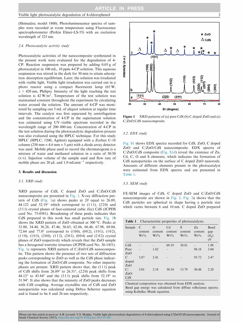
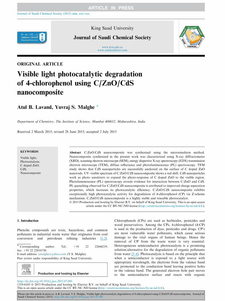
Figure 1 XRD patterns of (a) pure CdS (b) C doped ZnO and (c)
C/ZnO/CdS nanocomposite.
Table 1 Characteristic properties of photocatalysts.
Sample C
content
Wt%
O
content
Wt%
Cd
content
Wt%
S
content
Wt%
Zn
content
Wt%
Band
gap
(Eg)
eV
CdS – – 69.19 30.81 – 1.98
Pure
ZnO
– 1.82 – – 98.18 3.04
C
doped
ZnO
3.87 2.41 – – 93.72 2.47
C/
ZnO/
CdS
3.01 2.18 30.54 13.79 50.48 2.20
Chemical composition was obtained from EDX analysis.
Band gap energy was calculated from diffuse reflectance spectra
using Kubelka–Munk equation.
Visible light photocatalytic degradation of 4-chlorophenol 3
(Shimadzu; model 1800). Photoluminescence spectra of sam-ples were recorded at room temperature using Fluorescencespectrophotometer (Perkin Elmer-LS-55) with an excitation
wavelength of 325 nm.
2.4. Photocatalytic activity study
Photocatalytic activities of the nanocomposite synthesized inthe present work were evaluated for the degradation of 4-CP. Reaction suspension was prepared by adding 0.05 g of
photocatalyst in 100 mL, 10 ppm 4-CP solution. This aqueoussuspension was stirred in the dark for 30 min to attain adsorp-tion–desorption equilibrium. Later, the solution was irradiated
with visible light. Visible light irradiation was carried out in aphoto reactor using a compact fluorescent lamp (65 W,k > 420 nm, Philips). Intensity of the light reaching the testsolution is 42 W/m2. Temperature of the test solution was
maintained constant throughout the experiment by circulatingwater around the solution. The amount of 4-CP was moni-tored by sampling out 5 mL of aliquot solution at regular time
intervals. The catalyst was first separated by centrifugationand the concentration of 4-CP in the supernatant solutionwas estimated using UV–visible spectrum recorded in the
wavelength range of 200–800 nm. Concentration of 4-CP inthe test solution during the photocatalytic degradation processwas also evaluated using the HPLC technique. For this studyHPLC (HPLC; 1200, Agilent) equipped with a Zorbax C-18
column (250 mm · 4.6 mm · 5 lm) with a diode array detectorwas used. Mobile phase used to record the chromatogram is amixture of water and methanol solution in a ratio of 50:50
(v/v). Injection volume of the sample used and flow rate ofmobile phase are 20 lL and 1.0 mLmin�1 respectively.
3. Results and discussion
3.1. XRD study
XRD patterns of CdS, C doped ZnO and C/ZnO/CdSnanocomposite are presented in Fig. 1. X-ray diffraction pat-
tern of CdS (Fig. 1a) shows peaks at 2h equal to 26.89,44.122 and 52.19� which correspond to (111), (220) and(311) crystal planes of face-centered cubic (fcc) CdS (JCPDScard No. 75-0581). Broadening of these peaks indicates that
CdS prepared in this work has small particle size. Fig. 1bshows the XRD pattern of ZnO obtained at 300 �C. Peaks at31.80, 34.44, 36.28, 47.46, 56.65, 62.86, 66.46, 67.98, 69.04,
72.64 and 77.0� correspond to (100), (002), (101), (102),(110), (103), (200), (112), (201), (004) and (2 02) crystalplanes of ZnO respectively which reveals that the ZnO sample
has a hexagonal wurtzite structure (JCPDS card No. 36-1451).Fig. 1c represents XRD pattern of C/ZnO/CdS nanocompos-ite. This pattern shows the presence of two sets of diffraction
peaks corresponding to ZnO as well as the CdS phase indicat-ing the formation of ZnO/CdS composite. No other impurityphases are present. XRD pattern shows that, the (111) peakof CdS shifts from 26.89� to 26.51�, (220) peak shifts from
44.12� to 43.84� and the (311) peak shifts from 52.19� to51.94�. It also shows that the intensity of ZnO peaks decreaseswith CdS coupling. Average crystallite size of CdS and ZnO
nanoparticles was calculated using Debye–Scherrer equationand is found to be 8 and 26 nm respectively.
Please cite this article in press as: A.B. Lavand, Y.S. Malghe, Visible light photocatalySaudi Chemical Society (2015), http://dx.doi.org/10.1016/j.jscs.2015.07.001
3.2. EDX study
Fig. S1 shows EDX spectra recorded for CdS, ZnO, C dopedZnO and C/ZnO/CdS nanocomposite. EDX spectra of
C/ZnO/CdS composite (Fig. S1d) reveal the existence of Zn,Cd, C, O and S elements, which indicates the formation ofCdS nanoparticles on the surface of C doped ZnO nanorods.Amounts of different elements present in the photocatalyst
were estimated from EDX spectra and are presented inTable 1.
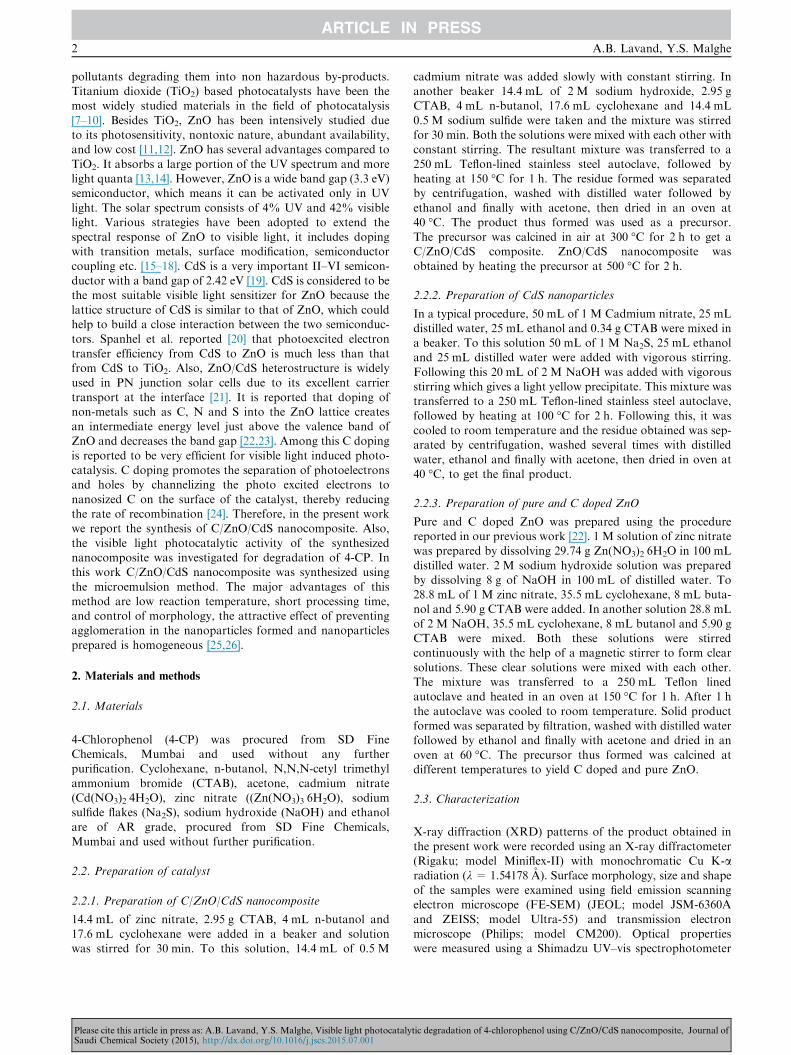
3.3. SEM study
FE-SEM images of CdS, C doped ZnO and C/ZnO/CdSnanocomposite are shown in Fig. 2. Fig. 2a shows that the
CdS particles are spherical in shape having a particle sizewhich varies between 6 and 10 nm. C doped ZnO prepared
tic degradation of 4-chlorophenol using C/ZnO/CdS nanocomposite, Journal of
Figure 2 SEM images of (a) pure CdS, (b) C doped ZnO and (c) C/ZnO/CdS nanocomposite.
Figure 3 TEM images of (a) pure CdS, (b) C doped ZnO, (c) and (d) C/ZnO/CdS nanocomposite.
4 A.B. Lavand, Y.S. Malghe
at 300 �C is having irregular shape (Fig. 2b). Fig. 2c showsthat the C/ZnO/CdS nanocomposite consists of a mixture of
flakes (C/ZnO) and spherical particles (CdS).
3.4. TEM study
Fig. 3a represents the TEM image of CdS powder. It indicatesthat CdS particles are spherical in shape with an average
Please cite this article in press as: A.B. Lavand, Y.S. Malghe, Visible light photocatalySaudi Chemical Society (2015), http://dx.doi.org/10.1016/j.jscs.2015.07.001
particle size �9 nm. It also shows that CdS nanoparticles arewell dispersed. Fig. 3b indicates that C doped ZnO prepared
at 300 �C is having a rod like structure with diameter andlength varying between 20 and 30 and 150–400 nm respec-tively. It shows that ZnO nanorods are encapsulated by an
amorphous C layer. Fig. 3candd represents TEM images ofthe C/ZnO/CdS nanocomposite. It shows that CdS nanoparti-cles are successfully deposited on the surface of C doped ZnOnanorods. The length of the C doped ZnO nanorods decreased
tic degradation of 4-chlorophenol using C/ZnO/CdS nanocomposite, Journal of
Visible light photocatalytic degradation of 4-chlorophenol 5
to 110 nm and width increased to 40 nm due to the depositionof CdS nanoparticles on its surface. Inset selected electrondiffraction (SAED) patterns show the crystalline nature of
the samples.
3.5. UV–visible absorption study
Fig. S2 illustrates the UV–visible absorption spectra of pureZnO, CdS, C doped ZnO and C/ZnO/CdS. Pure ZnO obtainedat 500 �C is a white colored powder having an absorption cut-off edge at 402 nm, corresponding to a band gap of 3.08 eV.
Black gray color C doped ZnO sample obtained after heatingthe ZnO precursor at 300 �C gives an absorption edge at460 nm, having a band gap of 2.69 nm. This shows that
C-doped ZnO exhibits a red shift and extends the absorptionedge from UV to visible region. This figure shows that pale yel-low colored CdS nano powder exhibits a band edge at 540 nm
(2.29 eV), which is consistent with the band gap of the cubicCdS phase. Band edge for C/ZnO/CdS is observed at 508 nm(2.42 eV), which indicates the ability of these nanocomposites
to harvest visible light from solar radiation. These results showthat CdS loading effectively increases the photoabsorptioncapacity of C doped ZnO nanorods in the visible region.
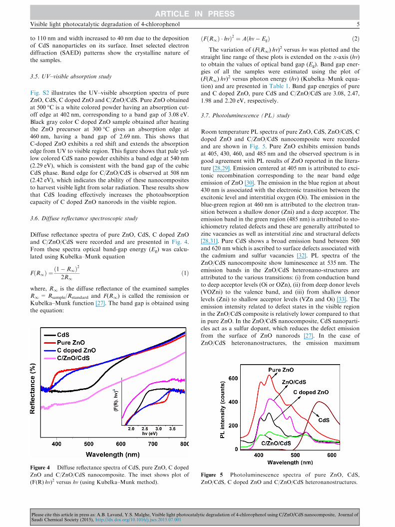
3.6. Diffuse reflectance spectroscopic study
Diffuse reflectance spectra of pure ZnO, CdS, C doped ZnOand C/ZnO/CdS were recorded and are presented in Fig. 4.
From these spectra optical band-gap energy (Eg) was calcu-lated using Kubelka–Munk equation
FðR1Þ ¼ð1� R1Þ2
2R1ð1Þ
where, R1 is the diffuse reflectance of the examined samplesR1= Rsample/Rstandard and F(R1) is called the remission or
Kubelka–Munk function [27]. The band gap is obtained usingthe equation:
Figure 4 Diffuse reflectance spectra of CdS, pure ZnO, C doped
ZnO and C/ZnO/CdS nanocomposite. The inset shows plot of
(F(R)Æhv)2 versus hv (using Kubelka–Munk method).
Please cite this article in press as: A.B. Lavand, Y.S. Malghe, Visible light photocatalySaudi Chemical Society (2015), http://dx.doi.org/10.1016/j.jscs.2015.07.001
ðFðR1Þ � hmÞ2 ¼ Aðhm� EgÞ ð2Þ
The variation of (F(R1)Æhv)2 versus hv was plotted and the
straight line range of these plots is extended on the x-axis (hv)
to obtain the values of optical band gap (Eg). Band gap ener-gies of all the samples were estimated using the plot of(F(R1)Æhv)
2 versus photon energy (hv) (Kubelka–Munk equa-
tion) and are presented in Table 1. Band gap energies of pureand C doped ZnO, pure CdS and C/ZnO/CdS are 3.08, 2.47,1.98 and 2.20 eV, respectively.
3.7. Photoluminescence (PL) study
Room temperature PL spectra of pure ZnO, CdS, ZnO/CdS, C
doped ZnO and C/ZnO/CdS nanocomposite were recordedand are shown in Fig. 5. Pure ZnO exhibits emission bandsat 405, 430, 460, and 485 nm and the observed spectrum is ingood agreement with PL results of ZnO reported in the litera-
ture [28,29]. Emission centered at 405 nm is attributed to exci-tonic recombination corresponding to the near band edgeemission of ZnO [30]. The emission in the blue region at about
430 nm is associated with the electronic transition between theexcitonic level and interstitial oxygen (Oi). The emission in theblue-green region at 460 nm is attributed to the electron tran-
sition between a shallow donor (Zni) and a deep acceptor. Theemission band in the green region (485 nm) is attributed to sto-ichiometry related defects and these are generally attributed to
zinc vacancies as well as interstitial zinc and structural defects[28,31]. Pure CdS shows a broad emission band between 500and 620 nm which is ascribed to surface defects associated withthe cadmium and sulfur vacancies [32]. PL spectra of the
ZnO/CdS nanocomposite show luminescence at 535 nm. Theemission bands in the ZnO/CdS heteronano-structures areattributed to the various transitions: (i) from conduction band
to deep acceptor levels (Oi or OZn), (ii) from deep donor levels(VOZni) to the valence band, and (iii) from shallow donorlevels (Zni) to shallow acceptor levels (VZn and Oi) [33]. The
emission intensity related to defect states in the visible regionin the ZnO/CdS composite is relatively lower compared to thatin pure ZnO. In the ZnO/CdS nanocomposite, CdS nanoparti-cles act as a sulfur dopant, which reduces the defect emission
from the surface of ZnO nanorods [27]. In the case ofZnO/CdS heteronanostructures, the emission maximum
Figure 5 Photoluminescence spectra of pure ZnO, CdS,
ZnO/CdS, C doped ZnO and C/ZnO/CdS heteronanostructures.
tic degradation of 4-chlorophenol using C/ZnO/CdS nanocomposite, Journal of
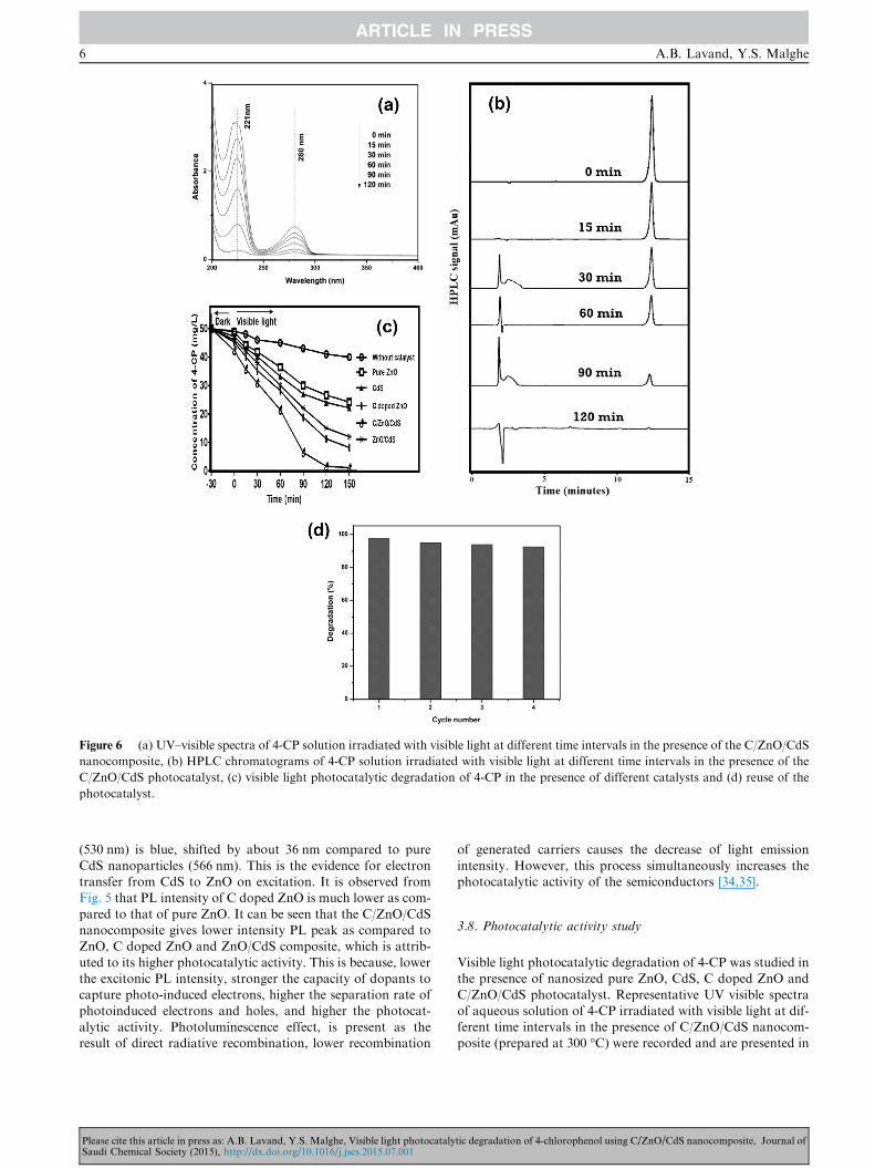
Figure 6 (a) UV–visible spectra of 4-CP solution irradiated with visible light at different time intervals in the presence of the C/ZnO/CdS
nanocomposite, (b) HPLC chromatograms of 4-CP solution irradiated with visible light at different time intervals in the presence of the
C/ZnO/CdS photocatalyst, (c) visible light photocatalytic degradation of 4-CP in the presence of different catalysts and (d) reuse of the
photocatalyst.
6 A.B. Lavand, Y.S. Malghe
(530 nm) is blue, shifted by about 36 nm compared to pure
CdS nanoparticles (566 nm). This is the evidence for electrontransfer from CdS to ZnO on excitation. It is observed fromFig. 5 that PL intensity of C doped ZnO is much lower as com-
pared to that of pure ZnO. It can be seen that the C/ZnO/CdSnanocomposite gives lower intensity PL peak as compared toZnO, C doped ZnO and ZnO/CdS composite, which is attrib-
uted to its higher photocatalytic activity. This is because, lowerthe excitonic PL intensity, stronger the capacity of dopants tocapture photo-induced electrons, higher the separation rate ofphotoinduced electrons and holes, and higher the photocat-
alytic activity. Photoluminescence effect, is present as theresult of direct radiative recombination, lower recombination
Please cite this article in press as: A.B. Lavand, Y.S. Malghe, Visible light photocatalySaudi Chemical Society (2015), http://dx.doi.org/10.1016/j.jscs.2015.07.001
of generated carriers causes the decrease of light emission
intensity. However, this process simultaneously increases thephotocatalytic activity of the semiconductors [34,35].
3.8. Photocatalytic activity study
Visible light photocatalytic degradation of 4-CP was studied inthe presence of nanosized pure ZnO, CdS, C doped ZnO and
C/ZnO/CdS photocatalyst. Representative UV visible spectraof aqueous solution of 4-CP irradiated with visible light at dif-ferent time intervals in the presence of C/ZnO/CdS nanocom-posite (prepared at 300 �C) were recorded and are presented in
tic degradation of 4-chlorophenol using C/ZnO/CdS nanocomposite, Journal of
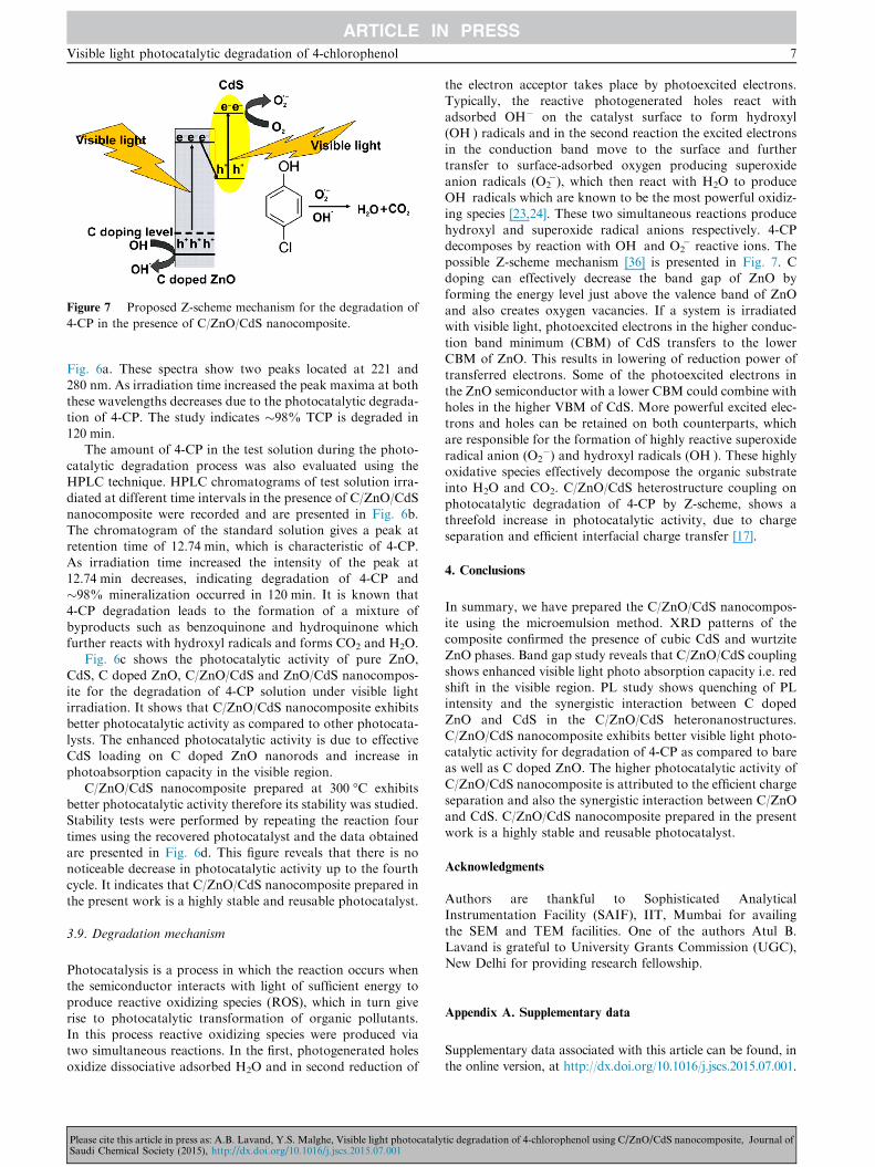
Figure 7 Proposed Z-scheme mechanism for the degradation of
4-CP in the presence of C/ZnO/CdS nanocomposite.
Visible light photocatalytic degradation of 4-chlorophenol 7
Fig. 6a. These spectra show two peaks located at 221 and280 nm. As irradiation time increased the peak maxima at both
these wavelengths decreases due to the photocatalytic degrada-tion of 4-CP. The study indicates �98% TCP is degraded in120 min.
The amount of 4-CP in the test solution during the photo-
catalytic degradation process was also evaluated using theHPLC technique. HPLC chromatograms of test solution irra-diated at different time intervals in the presence of C/ZnO/CdS
nanocomposite were recorded and are presented in Fig. 6b.The chromatogram of the standard solution gives a peak atretention time of 12.74 min, which is characteristic of 4-CP.
As irradiation time increased the intensity of the peak at12.74 min decreases, indicating degradation of 4-CP and�98% mineralization occurred in 120 min. It is known that
4-CP degradation leads to the formation of a mixture ofbyproducts such as benzoquinone and hydroquinone whichfurther reacts with hydroxyl radicals and forms CO2 and H2O.
Fig. 6c shows the photocatalytic activity of pure ZnO,
CdS, C doped ZnO, C/ZnO/CdS and ZnO/CdS nanocompos-ite for the degradation of 4-CP solution under visible lightirradiation. It shows that C/ZnO/CdS nanocomposite exhibits
better photocatalytic activity as compared to other photocata-lysts. The enhanced photocatalytic activity is due to effectiveCdS loading on C doped ZnO nanorods and increase in
photoabsorption capacity in the visible region.C/ZnO/CdS nanocomposite prepared at 300 �C exhibits
better photocatalytic activity therefore its stability was studied.Stability tests were performed by repeating the reaction four
times using the recovered photocatalyst and the data obtainedare presented in Fig. 6d. This figure reveals that there is nonoticeable decrease in photocatalytic activity up to the fourth
cycle. It indicates that C/ZnO/CdS nanocomposite prepared inthe present work is a highly stable and reusable photocatalyst.
3.9. Degradation mechanism
Photocatalysis is a process in which the reaction occurs whenthe semiconductor interacts with light of sufficient energy to
produce reactive oxidizing species (ROS), which in turn giverise to photocatalytic transformation of organic pollutants.In this process reactive oxidizing species were produced viatwo simultaneous reactions. In the first, photogenerated holes
oxidize dissociative adsorbed H2O and in second reduction of
Please cite this article in press as: A.B. Lavand, Y.S. Malghe, Visible light photocatalySaudi Chemical Society (2015), http://dx.doi.org/10.1016/j.jscs.2015.07.001
the electron acceptor takes place by photoexcited electrons.Typically, the reactive photogenerated holes react withadsorbed OH� on the catalyst surface to form hydroxyl
(OH�) radicals and in the second reaction the excited electronsin the conduction band move to the surface and furthertransfer to surface-adsorbed oxygen producing superoxide
anion radicals (O2��), which then react with H2O to produce
OH� radicals which are known to be the most powerful oxidiz-ing species [23,24]. These two simultaneous reactions produce
hydroxyl and superoxide radical anions respectively. 4-CPdecomposes by reaction with OH� and O2
�� reactive ions. Thepossible Z-scheme mechanism [36] is presented in Fig. 7. Cdoping can effectively decrease the band gap of ZnO by
forming the energy level just above the valence band of ZnOand also creates oxygen vacancies. If a system is irradiatedwith visible light, photoexcited electrons in the higher conduc-
tion band minimum (CBM) of CdS transfers to the lowerCBM of ZnO. This results in lowering of reduction power oftransferred electrons. Some of the photoexcited electrons in
the ZnO semiconductor with a lower CBM could combine withholes in the higher VBM of CdS. More powerful excited elec-trons and holes can be retained on both counterparts, which
are responsible for the formation of highly reactive superoxideradical anion (O2
��) and hydroxyl radicals (OH�). These highlyoxidative species effectively decompose the organic substrateinto H2O and CO2. C/ZnO/CdS heterostructure coupling on
photocatalytic degradation of 4-CP by Z-scheme, shows athreefold increase in photocatalytic activity, due to chargeseparation and efficient interfacial charge transfer [17].
4. Conclusions
In summary, we have prepared the C/ZnO/CdS nanocompos-
ite using the microemulsion method. XRD patterns of thecomposite confirmed the presence of cubic CdS and wurtziteZnO phases. Band gap study reveals that C/ZnO/CdS coupling
shows enhanced visible light photo absorption capacity i.e. redshift in the visible region. PL study shows quenching of PLintensity and the synergistic interaction between C doped
ZnO and CdS in the C/ZnO/CdS heteronanostructures.C/ZnO/CdS nanocomposite exhibits better visible light photo-catalytic activity for degradation of 4-CP as compared to bareas well as C doped ZnO. The higher photocatalytic activity of
C/ZnO/CdS nanocomposite is attributed to the efficient chargeseparation and also the synergistic interaction between C/ZnOand CdS. C/ZnO/CdS nanocomposite prepared in the present
work is a highly stable and reusable photocatalyst.
Acknowledgments
Authors are thankful to Sophisticated AnalyticalInstrumentation Facility (SAIF), IIT, Mumbai for availing
the SEM and TEM facilities. One of the authors Atul B.Lavand is grateful to University Grants Commission (UGC),New Delhi for providing research fellowship.
Appendix A. Supplementary data
Supplementary data associated with this article can be found, inthe online version, at http://dx.doi.org/10.1016/j.jscs.2015.07.001.
tic degradation of 4-chlorophenol using C/ZnO/CdS nanocomposite, Journal of
8 A.B. Lavand, Y.S. Malghe
References
[1] G. Waldner, M. Pourmodjib, R. Baauer, M. Neumann-spallart,
Photoelectrocatalytic degradation of 4-chlorophenol and oxalic
acid on titanium dioxide electrodes, Chemosphere 50 (2003)
989–998.
[2] M.L. Hitchman, F. Tian, Studies of TiO2 thin films prepared by
chemical vapour deposition for photocatalytic and
photoelectrocatalytic degradation of 4-chlorophenol, J.
Electroanal. Chem. 538–539 (2002) 165–172.
[3] S. Ahmed, M.G. Rasul, R. Brown, M.A. Hashib, Influence of
parameters on the heterogeneous photocatalytic degradation of
pesticides and phenolic contaminants in wastewater: a short
review, J. Environ. Manag. 92 (2011) 311–330.
[4] V. Vo, T.P.T. Thi, H.Y. Kim, S.J. Kim, Facile post synthesis
and photocatalytic activity of N-doped ZnO-SBA-15, J. Phys.
Chem. Solids 75 (2014) 403–409.
[5] R. Saravanan, M.M. Khan, V.K. Gupta, E. Mosquera, F.
Gracia, V. Narayanan, A. Stephen, ZnO/Ag/Mn2O3
nanocomposite for visible light induced industrial textile
effluent degradation, uric acid and ascorbic acid sensing and
antimicrobial activity, RSC Adv. 5 (2015) 34645–34651.
[6] M.M. Khan, S.A. Ansari, M.E. Khan, M.O. Ansari, B.K. Min,
M.H. Cho, Visible light-induced enhanced photoelectrochemical
and photocatalytic studies of gold decorated SnO2
nanostructures, New J. Chem. 39 (2015) 2758–2766.
[7] S.K. Yadav, S.R. Madeshwaran, J.W. Cho, Synthesis of a
hybrid assembly composed of titanium dioxide nanoparticles
and thin multi-walled carbon nanotubes using ‘‘click
chemistry’’, J. Coll. Int. Sci. 358 (2011) 471–476.
[8] Y. Park, W. Kim, H. Park, T. Tachikawa, T. Majima, W. Choi,
Carbon-doped TiO2 photocatalyst synthesized without using an
external carbon precursor and the visible light activity, Appl.
Catal. B Environ. 91 (2009) 355–361.
[9] X. Hu, H. Ji, L. Wu, Singlet oxygen photogeneration and 2,4,6-
TCP photodegradation at Pt/TiO2 under visible light
illumination, RSC Adv. 2 (2012) 12378–12383.
[10] T.K. Ghorai, Photocatalytic degradation of 4-chlorophenol by
CuMoO4-doped TiO2 nanoparticles synthesized by chemical
route, Open J. Phys. Chem. 1 (2011) 28–36.
[11] O. Haibo, H.J. Feng, L. Cuiyan, C. Liyun, F. Jie, Synthesis of
carbon doped ZnO with a porous structure and its solar-light
photocatalytic properties, Mater. Lett. 111 (2013) 217–220.
[12] S.J. Peatson, D.P. Norton, K. Ip, Y.W. Heo, T. Steiner, Recent
progress in processing and properties of ZnO, Prog. Mater. Sci.
50 (2005) 293–340.
[13] C.A.K. Gouvea, F. Wypych, S.G. Moraes, N. Duran, N.
Nagata, P. Peralta-Zamora, Semiconductor-assisted
photocatalytic degradation of reactive dyes in aqueous
solution, Chemosphere 40 (2000) 433–440.
[14] B. Dindar, S. Icli, Unusual photoreactivity of zinc oxide
irradiated by concentrated sunlight, J. Photochem. Photobiol.
A Chem. 140 (2001) 263–268.
[15] K. Kumar, M. Chitkara, I.S. Sandhu, D. Mehta, S. Kumar,
Photocatalytic, optical and magnetic properties of Fe-doped
ZnO nanoparticles prepared by chemical route, J. Alloys Comp.
588 (2014) 681–689.
[16] C. Li, T. Ahmed, M. Ma, T. Edvinsson, J. Zhu, A facile
approach to ZnO/CdS nanoarrays and their photocatalytic and
photoelectrochemical properties, Appl. Catal. B Environ. 138
(2013) 175–183.
[17] F. Xu, Y. Yuan, H. Han, D. Wu, Z. Gao, K. Jiang, Synthesis of
ZnO/CdS hierarchical heterostructure with enhanced
photocatalytic efficiency under nature sunlight, Cryst. Eng.
Comm. 14 (2012) 3615–3622.
[18] R. Saravanan, M. Mansoob Khan, V.K. Gupta, E. Mosquera,
F. Gracia, V. Narayanan, A. Stephen, ZnO/AG/CdO
Please cite this article in press as: A.B. Lavand, Y.S. Malghe, Visible light photocatalySaudi Chemical Society (2015), http://dx.doi.org/10.1016/j.jscs.2015.07.001
nanocomposite for visible light induced photocatalytic
degradation of industrial textile influents, J. Coll. Inter. Sci.
452 (2015) 126–133.
[19] S.L. Xiong, B.J. Xi, Y.T. Qian, CdS hierarchical nanostructures
with tunable morphologies: preparation and photocatalytic
properties, J. Phys. Chem. C 114 (2010) 14029–14035.
[20] L. Spanhel, H. Weller, A. Henglein, Photochemistry of
semiconductor colloids. 22. Electron ejection from illuminated
cadmium sulfide into attached titanium and zinc oxide particles,
J. Am. Chem. Soc. 109 (1987) 6632–6635.
[21] L. Stolt, J. Hedstrom, J. Kessler, M. Ruckh, K.O. Velthaus,
H.W. Schock, ZnO/CdS/CuInSe2 thin-film solar cells with
improved performance, Appl. Phys. Lett. 62 (1993) 597–599.
[22] A.B. Lavand, Y.S. Malghe, Synthesis characterization, and
visible light photocatalytic activity of nanosized carbon doped
zinc oxide, Int. J. Photochem. 790153 (2015) 1–9.
[23] A. Mills, S.L. Hunte, An overview of semiconductor
photocatalysis, J. Photochem. Photobiol. A 108 (1997) 1–35.
[24] M. Pelaez et al, A review on the visible light active titanium
dioxide photocatalysts for environmental applications, Appl.
Catal. B Environ. 125 (2012) 331–349.
[25] M. Inoguchi, K. Suzuki, K. Kageyama, H. Takagi, Y. Sakabe,
Monodispersed and well-crystallized zinc oxide nanoparticles
fabricated by microemulsion method, J. Am. Ceram. Soc. 91
(2008) 3850–3855.
[26] A.B. Lavand, Y.S. Malghe, Nano sized C doped TiO2 as a
visible light photocatalyst for the degradation of 2,4,6-
trichlorophenol, Adv. Mater. Lett. (2015), http://dx.doi.org/
10.5185/amlett.2015.5800.
[27] M. Misra, P. Kapur, C. Ghanshyam, M.L. Singla, ZnO@CdS
core-shell thin film: fabrication and enhancement of exciton life
time by CdS nanoparticle, J. Mater. Sci. 24 (2013) 3800–3804.
[28] X. Chong, L. Li, X. Yan, D. Hu, H. Li, Y. Wang, Synthesis,
characterization and room temperature photoluminescence
properties of Al doped ZnO nanorods, Physica E 44 (2012)
1399–1405.
[29] K. Zhong, J. Xia, H.H. Li, C.L. Liang, P. Liu, Y.X. Tong,
Morphology evolution of one-dimensional-based ZnO
nanostructures synthesized via electrochemical corrosion, J.
Phys. Chem. C 113 (2009) 15514–15523.
[30] F. Xu, V. Volkov, Y. Zhu, H. Bai, A. Rea, N.V. Valappil, W.
Su, X. Gao, I.L. Kuskovsky, H. Matsui, Long electron–hole
separation of ZnO–CdS core–shell quantum dots, J. Phys.
Chem. C 113 (2009) 19419–19423.
[31] Y.L. Wu, A.I.Y. Tok, F.Y.C. Boey, X.T. Zeng, X.H. Zhang,
Surface modification of ZnO nanocrystals, Appl. Surf. Sci. 253
(2007) 5473–5479.
[32] Q. Xiao, C. Xiao, Surface-defect-states photoluminescence in
CdS nanocrystals prepared by one-step aqueous synthesis
method, Appl. Surf. Sci. 255 (2009) 7111–7114.
[33] S. Khanchandani, S. Kundu, A. Patra, A.K. Ganguli, Shell
thickness dependent photocatalytic properties of ZnO/CdS core-
shell nanorods, J. Phys. Chem. C 116 (2012) 23653–23662.
[34] J.G. Yu, H.G. Yu, B. Chen, X.J. Zhao, J.C. Yu, W.K. Ho, The
effect of calcination temperature on the surface microstructure
and photocatalytic activity of TiO2 thin films prepared by liquid
phase deposition, J. Phys. Chem. B 107 (2003) 13871–13879.
[35] D. Wojcieszak, D. Kaczmarek, J. Domaradzki, M. Mazur,
Correlation of photocatalysis and photoluminescence effect in
relation to the surface properties of TiO2: Tb thin films, Int. J.
Photoenergy 526140 (2013) 1–9.
[36] X. Wang, G. Liu, Z.G. Chen, F. Li, L. Wang, G. Lu, H.M.
Cheng, Enhanced photocatalytic hydrogen evolution by
prolonging the lifetime of carriers in ZnO/CdS
heterostructures, Chem. Comm. 23 (2009) 3452–3454.
tic degradation of 4-chlorophenol using C/ZnO/CdS nanocomposite, Journal of