virtual ring routing: network routing inspired by dhts
TRANSCRIPT
Virtual Ring Routing: Network Routing Inspired by DHTs
Matthew Caesar∗2, Miguel Castro1, Edmund B. Nightingale∗3, Greg O’Shea1, Antony Rowstron1
1 Microsoft Research 2 University of California Berkeley 3 University of MichiganCambridge, UK Berkeley, USA Ann Arbor, USA
ABSTRACTThis paper presents Virtual Ring Routing (VRR), a new networkrouting protocol that occupies a unique point in the design space.VRR is inspired by overlay routing algorithms in Distributed HashTables (DHTs) but it does not rely on an underlying network routingprotocol. It is implemented directly on top of the link layer. VRRprovides both traditional point-to-point network routing and DHTrouting to the node responsible for a hash table key.
VRR can be used with any link layer technology but this paperdescribes a design and several implementations of VRR that aretuned for wireless networks. We evaluate the performance of VRRusing simulations and measurements from a sensor network and an802.11a testbed. The experimental results show that VRR providesrobust performance across a wide range of environments and work-loads. It performs comparably to, or better than, the best wirelessrouting protocol in each experiment. VRR performs well becauseof its unique features: it does not require network flooding or trans-lation between fixed identifiers and location-dependent addresses.
Categories and Subject DescriptorsC.2.2 [Computer-Communication Networks]: Network Protocols
General TermsAlgorithms, Measurement, Performance, Reliability
KeywordsNetwork Routing, Distributed Hash Table, Wireless
1. INTRODUCTIONThis paper presents Virtual Ring Routing (VRR), a new network
routing protocol with a unique design. The design is inspired byDistributed Hash Table (DHT) overlays (e.g.,[38, 40, 39, 44]) butVRR is a network routing protocol. Whereas DHTs assume anunderlying network routing protocol that provides connectivity be-tween all pairs of nodes, VRR is implemented directly on top of the
∗Work done during an internship at Microsoft Research Cambridge.
Permission to make digital or hard copies of all or part of this work forpersonal or classroom use is granted without fee provided that copies arenot made or distributed for profit or commercial advantage and that copiesbear this notice and the full citation on the first page. To copy otherwise, torepublish, to post on servers or to redistribute to lists, requires prior specificpermission and/or a fee.SIGCOMM’06,September 11–15, 2006, Pisa, Italy.Copyright 2006 ACM 1-59593-308-5/06/0009 ...$5.00.
link layer. VRR provides not only traditional point-to-point net-work routing but also DHT functionality: it balances the load ofmanaging hash-table keys across nodes and routes messages sent toa key to the node responsible for managing the key.
VRR is also unique because it never floods the network and usesonly location independent identifiers to route. Nodes are organizedinto a virtual ring ordered by their identifiers and each node main-tains a small number of routing paths to its neighbors in the ring.The nodes along a path store the next hop towards each path end-point in a routing table. VRR uses these routing tables to routepackets between any pair of nodes in the network: a packet is for-warded to the next hop towards the path endpoint whose identifieris numerically closest to the destination. The paths between virtualring neighbors are setup using this algorithm.
VRR can route over any link layer technology but this paperfocuses on wireless ad hoc environments. We believe that DHTfunctionality is particularly useful in these environments because itcan be used to implement scalable network services in the absenceof servers. Furthermore, VRR addresses some performance issueswith previous wireless routing protocols.
VRR performs well across a wide range of environments andworkloads because it does not flood and it does not use location-dependent addresses. Proactive wireless routing protocols floodon topology changes (e.g., [34, 6]) and reactive protocols flood todiscover routes (e.g., [22, 35]). Hybrid protocols perform scopedfloods on topology changes and flood to discover routes to nodes inother regions of the network (e.g., [18, 37]). Previous protocols thatdo not flood use location-dependent addresses to route (e.g., [5, 33,24, 26, 15]), which has some disadvantages. Location-dependentaddresses can change with mobility and, in some protocols, withcongestion and failures [5, 33, 15]. These changes can result inlosses and increased congestion, and usually require mechanismsto lookup the location of a node given a fixed identifier [28].
We compared VRR against a number of representative wirelessrouting protocols using both simulations and measurements fromreal implementations running on a sensor network and an 802.11aWindows PC testbed. The Windows implementation modifies theMesh Connectivity Layer (MCL) [10] to support VRR. The VRRnetwork appears to an unmodified TCP/IP protocol stack as a singlevirtual link. Therefore, all IP-based applications can be run over theVRR network without modification.
The experiments show that VRR provides robust performanceacross a wide range of environments and workloads. It performscomparably to, or better than, the best routing protocol in each ex-periment.
The paper is organized as follows. Section 2 presents an overview.Section 3 describes VRR in detail. We evaluate performance in Sec-tion 4. Section 5 describes related work and Section 6 concludes.
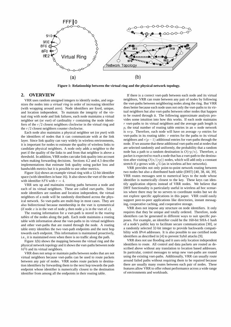
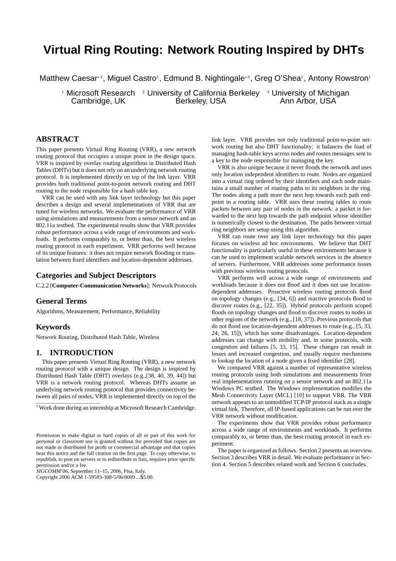
Figure 1: Relationship between the virtual ring and the physical network topology.
2. OVERVIEWVRR uses random unsigned integers to identify nodes, and orga-
nizes the nodes into avirtual ring in order of increasing identifier(with wrapping around zero). Node identifiers are fixed, unique,and location independent. To maintain the integrity of the vir-tual ring with node and link failures, each node maintains a virtualneighbor set (orvset) of cardinalityr containing the node identi-fiers of ther/2 closest neighbors clockwise in the virtual ring andther/2 closest neighbors counter clockwise.
Each node also maintains a physical neighbor set (orpset) withthe identifiers of nodes that it can communicate with at the linklayer. Since link quality can vary widely in wireless environments,it is important for nodes to estimate the quality of wireless links tocandidate physical neighbors. A node only adds a neighbor to thepset if the quality of the links to and from that neighbor is above athreshold. In addition, VRR nodes can take link quality into accountwhen making forwarding decisions. Sections 4.2 and 4.3 describeimplementations that estimate link quality using packet loss andbandwidth metrics but it is possible to use other metrics.
Figure 1(a) shows an example virtual ring with a 12-bit identifierspace (with identifiers in base 16). It also shows the vset of the nodewith identifier8F6 with r = 4.
VRR sets up and maintains routing paths between a node andeach of its virtual neighbors. These are calledvset-paths. Sincenode identifiers are random and location independent, the virtualneighbors of a node will be randomly distributed across the phys-ical network. So vset-paths are multi-hop in most cases. They arealso bidirectional because membership in the vset is symmetrical(if nodex is in the vset of nodey then nodey is in the vset ofx).
The routing information for a vset-path is stored in theroutingtablesof the nodes along the path. Each node maintains a routingtable with information about the vset-paths to its virtual neighborsand other vset-paths that are routed through the node. A routingtable entry identifies the two vset-path endpoints and the next hoptowards each endpoint. This information is maintained proactively,i.e., it is maintained even when there is no traffic along the path.
Figure 1(b) shows the mapping between the virtual ring and thephysical network topology and it shows the vset-paths between node8F6 and its virtual neighbors.
VRR does not setup or maintain paths between nodes that are notvirtual neighbors because vset-paths can be used to route packetsbetween any pair of nodes. VRR nodes route packets to destina-tion identifiers by forwarding them to the next hop towards the pathendpoint whose identifier is numerically closest to the destinationidentifier from among all the endpoints in their routing table.
If there is a correct vset-path between each node and its virtualneighbors, VRR can route between any pair of nodes by followingthe vset-paths between neighboring nodes along the ring. But VRRdoes better because each node uses not only the vset-paths to its vir-tual neighbors but also vset-paths between other nodes that happento be routed through it. The following approximate analysis pro-vides some intuition into how this works. If each node maintainsr vset-paths to its virtual neighbors and the average path length isp, the total number of routing table entries in ann node networkis nrp. Therefore, each node will have on averagerp entries forvset-paths in its routing table:r entries for the paths to its virtualneighbors andr(p−1) additional entries for vset-paths through thenode. If we assume that these additional vset-paths end at nodes thatare selected randomly and uniformly, the probability that a randomnode has a path to a random destination isO(rp/n). Therefore, apacket is expected to reach a node that has a vset-path to the destina-tion after visitingO(n/(rp)) nodes, which will add only a constantstretch ifp grows with
√n (as in wireless ad hoc networks).
VRR provides not only point-to-point network routing betweentwo nodes but also a distributed hash table (DHT) [40, 38, 44, 39].VRR routes messages sent to numerical keys to the node whoseidentifier is numerically closest to the key. These keys can iden-tify application objects instead of VRR nodes. We believe thatDHT functionality is particularly useful in wireless ad hoc scenar-ios where there may be no servers to coordinate nodes but we donot explore specific applications in this paper. VRR could easilysupport peer-to-peer applications like directories, instant messag-ing, cooperative caching, and cooperative storage.
VRR does not impose any structure on node identifiers. It onlyrequires that they be unique and totally ordered. Therefore, nodeidentifiers can be generated in different ways to suit specific pur-poses. For example, an identifier could be the 160-bit SHA-1 hashof a node’s public key to facilitate secure communication [30], ora randomly selected 32-bit integer to provide backwards compati-bility with IPv4 addresses. It is also possible to use certified nodeidentifiers as described in [4] to prevent Sybil attacks [9].
VRR does not use flooding and it uses only location independentidentifiers to route. All control and data packets are routed as de-scribed above without any translation to location based addresses.In particular, control messages to setup new vset-paths are routedusing the existing vset-paths. Additionally, VRR can usually routearound failed paths without requiring them to be repaired becausethere are usually many routes between each pair of nodes. Thesefeatures allow VRR to offer robust performance across a wide rangeof environments and workloads.
3. VIRTUAL RING ROUTINGThis section presents VRR in detail. It starts by describing the
routing state maintained by nodes and how it is used to forwardmessages. Then it describes how this state is maintained whennodes join and when nodes or links fail.
3.1 ForwardingEach node maintains a routing table with an entry for every vset-
path that includes the node. Each entry contains the identifiers ofthe two endpoints of the path, the identifier of the physical neighborto be used as the next hop towards each endpoint, and a vset-pathidentifier. The first endpoint identifier in an entry is always theidentifier of the node that initiated the vset-path setup.
Figure 2 continues the example from Figure 1 by showing therouting table of node 8F6. The first four entries in the table are forthe vset-paths from the node to its four virtual ring neighbors.
Since node 8F6 is an endpoint in these paths, the identifier of thenext hop towards the node is null. The 5th and 6th entries in thetable are for two vset-paths that are routed through node 8F6. VRRmaintains the invariant that the nextA and nextB fields in a node’srouting table entries are in the pset of the node.
endpointA endpointB nextA nextB path id8F0 8F6 20E null 038E2 8F6 F01 null 2F8F6 90E null 7E2 1E910 8F6 F01 null 2F35F 37A 20E 7E2 12A01 A10 F01 FC1 F08F6 20E null 20E FF8F6 F01 null F01 FF8F6 7E2 null 7E2 FF8F6 FC1 null FC1 FF
Figure 2: Sample routing table for the node with identifier 8F6.The first four entries are vset-paths to 8F6’s virtual neighbors,the fifth and sixth entries are for vset-paths that happen to berouted through 8F6, and the last four are paths to 8F6’s physicalneighbors.
VRR also inserts one-hop paths to physical neighbors in the rout-ing table to simplify routing. These are the last four entries in thetable and have the special path identifier FF.
The routing table in the example also shows that vset-path iden-tifiers are not necessarily distinct. The vset-path identifier is as-signed by endpointA, which is the node that initiates the path setup,such that each vset-path is uniquely identified by the pair〈pathid,endpointA〉. Vset-path identifiers can be small; each node orig-inates at most one vset-path to each of itsr virtual ring neighborsand nodes can reuse the identifiers of torn down paths after a pro-bation period to ensure that there are no routing table entries withthose identifiers.
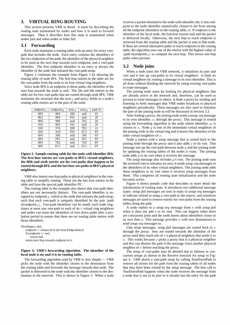
NextHop(rt, dst)endpoint:= closest id todstfrom Endpoints(rt)if (endpoint== me)
return nullreturn next hop towardsendpointin rt
Figure 3: VRR’s forwarding algorithm. The identifier of thelocal node ismeand rt is its routing table.
The forwarding algorithm used by VRR is very simple — VRRpicks the node with the identifier closest to the destination fromthe routing table and forwards the message towards that node. Thepacket is delivered to the node with the identifier closest to the des-tination in the network. This is shown in Figure 3. When a node
receives a packet destined to the node with identifierdst, it setsend-point to the node identifier numerically closest todst from amongall the endpoint identifiers in the routing table,rt. If endpointis theidentifier of the local node, the function returns null and the packetis delivered locally. Otherwise, the next hop to reachendpointisretrieved from the routing table and the packet is sent to that node.If there are several alternative paths to reachendpointin the routingtable, the algorithm uses one of the entries with the highest value of〈path id,endpointA〉 to compute the next hop. This favors one-hoppaths when present.
3.2 Node joinsWhen a node joins the VRR network, it initializes its pset and
vset and it sets up vset-paths to its virtual neighbors. It finds itsvirtual neighbors by routing a message to its own identifier. This isall done without flooding the network by using existing vset-pathsto route messages.
The joining node starts by looking for physical neighbors thatare already active in the network and, therefore, can be used asproxies to route messages to others. It finds a proxy by sending andlistening tohello messages that VRR nodes broadcast to physicalneighbors periodically. These messages are also used to initializethe pset of the joining node as will be discussed in Section 3.3.
After finding a proxy, the joining node sends asetupreqmessageto its own identifier,x, through the proxy. This message is routedusing the forwarding algorithm to the node whose identifier,y, isclosest tox. Nodey is one of the immediate virtual neighbors ofthe joining node in the virtual ring and it knows the identities of theother virtual neighbors ofx.
Nodey replies with asetupmessage that is routed back to thejoining node through the proxy and it also addsx to its vset. Thismessage sets up the vset-path between nodey and the joining nodeby updating the routing tables of the nodes it visits. The joiningnode addsy to its vset when it receives the message.
Thesetupmessage also includesy’s vset. The joining node usesthe received vset to initialize its own; it sendssetupreqmessages tothe identifiers of its other virtual neighbors. The joining node addsthese neighbors to its vset when it receivessetupmessages fromthem. This completes all routing state initialization and the nodebecomesactive.
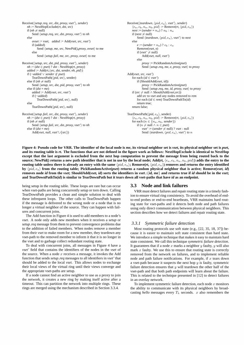
Figure 4 shows pseudo code that describes in more detail theinitialization of routing state. It introduces two additional messagetypes:setupfail messages are sent in reply tosetupreq messagesto indicate refusal to setup a vset-path to the source, andteardownmessages are used to remove entries for vset-paths from the routingtables along the path.
A node replies to asetupreq message fromx with setupfailwhen it does not addx to its vset. This can happen when thereare concurrent joins and the node learns about identifiers closer toits own thanx. This message providesx with new destinations tosendsetupreqmessages to.
Like setupmessages,setupfail messages are routed back toxthrough the proxy: they are routed towards the identifier of theproxy until they reach one ofx’s physical neighbors that sends it tox. This works becausex picks a proxy that is a physical neighborand this can shorten the path if the message visits another physicalneighbor ofx before reaching the proxy.
The setup of vset-paths may be aborted due to failures or con-current setups as shown in the Receive function forsetupin Fig-ure 4. VRR aborts a vset-path setup by calling TearDownPath toremove all entries for the path from the routing tables of all nodesthat may have been visited by thesetupmessage. The first call toTearDownPath happens when the node receives the message froma node that is not in itspsetor it already has the entry for the path
Receive(〈setupreq, src, dst, proxy, vset’〉, sender)nh := NextHopExclude(rt, dst, src)if (nh 6= null)
Send〈setupreq, src, dst, proxy, vset’〉 to nhelse
ovset:= vset; added:= Add(vset, src, vset’)if (added)
Send〈setup, me, src, NewPid(),proxy, ovset〉 to meelse
Send〈setupfail, me, src, proxy, ovset〉 to me
Receive(〈setup, src, dst, pid, proxy, vset’〉, sender)nh := (dst∈ pset) ? dst: NextHop(rt, proxy)added:= Add(rt,〈src, dst, sender, nh, pid〉)if (¬added∨ sender6∈ pset)
TearDownPath(〈pid, src〉, sender)else if (nh 6= null)
Send〈setup, src, dst, pid, proxy, vset’〉 to nhelse if (dst= me)
added:= Add(vset, src, vset’)if (¬added)
TearDownPath(〈pid, src〉, null)else
TearDownPath(〈pid, src〉, null)
Receive(〈setupfail, src, dst, proxy, vset’〉, sender)nh := (dst∈ pset) ? dst: NextHop(rt, proxy)if (nh 6= null)
Send〈setupfail, src, dst, proxy, vset’〉 to nhelse if (dst= me)
Add(vset, null, vset’∪{src})
Receive(〈teardown, 〈pid, ea〉, vset’〉, sender)〈ea, eb, na, nb, pid〉 := Remove(rt, 〈pid, ea〉)next:= (sender= na) ? nb : na
if (next 6= null)Send〈teardown, 〈pid, ea〉, vset’〉 to next
elsee := (sender= na) ? eb : ea
Remove(vset, e)if (vset’ 6= null)
Add(vset, null, vset’)else
proxy:= PickRandomActive(pset)Send〈setupreq, me, e, proxy, vset〉 to proxy
Add(vset, src, vset’)for each (id ∈ vset’)
if (ShouldAdd(vset, id))proxy:= PickRandomActive(pset)Send〈setupreq, me, id, proxy, vset〉 to proxy
if (src 6= null ∧ ShouldAdd(vset,src))addsrc to vsetand any nodes removed toremfor each (id ∈ rem) TearDownPathTo(id)return true;
return false;
TearDownPath(〈pid, ea〉, sender)〈ea, eb, na, nb, pid〉 := Remove(rt, 〈pid, ea〉)for each (n ∈ {na, nb, sender})
if (n 6= null ∧ n ∈ pset)vset’:= (sender6= null) ? vset: nullSend〈teardown, 〈pid, ea〉, vset’〉 to n
Figure 4: Pseudo code for VRR. The identifier of the local node isme, its virtual neighbor set is vset, its physical neighbor set ispset,and its routing table is rt. The functions that are not defined in the figure work as follows: NextHopExclude is identical to NextHopexcept that the last argument is excluded from the next hop computation to prevent the message from being routed back to thesource; NewPid() returns a new path identifier that is not in use by the local node; Add(rt, 〈ea, eb, na, nb, pid〉) adds the entry to therouting table unless there is already an entry with the same〈pid, ea〉; Remove(rt, 〈pid, ea〉) removes and returns the entry identifiedby 〈pid, ea〉 from the routing table; PickRandomActive(pset) returns a random physical neighbor that is active; Remove(vset, id)removes nodeid from the vset; ShouldAdd(vset, id) sorts the identifiers in vset∪{id, me} and returns true if id should be in thevset;and TearDownPathTo(id) is similar to TearDownPath but it tears down all vset-paths that haveid as an endpoint.
being setup in the routing table. These loops are rare but can occurwhen vset-paths are being concurrently setup or torn down. CallingTearDownPath provides a clean and simple solution to deal withthese infrequent loops. The other calls to TearDownPath happenif the message is delivered to the wrong node or a node that is nolonger a virtual neighbor of the source. They can happen with fail-ures and concurrent joins.
The Add function in Figure 4 is used to add members to a node’svset. A node only adds new members when it receives asetuporsetupreqmessage from them to prevent convergence problems dueto the addition of failed members. When nodes remove a memberfrom theirvsetto make room for a new member, they teardown anyvset-path to the removed member to inform it that it is no longer inthe vset and to garbage collect redundant routing state.
To deal with concurrent joins, all messages in Figure 4 have avset’ field that contains the identifiers of the nodes in thevsetofthe source. When a nodex receives a message, it invokes the Addfunction that sendssetupreqmessages to all identifiers invset’thatshould be added to the localvset. This allows nodes to exchangetheir local views of the virtual ring until their views converge andthe appropriate vset-paths are setup.
If a node cannot find an active neighbor to use as a proxy to jointhe network, it creates a new ring by making itself active after atimeout. This can partition the network into multiple rings. Theserings are merged using the mechanism described in Section 3.3.4.
3.3 Node and link failuresVRR must detect failures and repair routing state in a timely fash-
ion to ensure virtual ring consistency. To avoid the overhead of end-to-end probes or end-to-end heartbeats, VRR maintains hard rout-ing state for vset-paths and it detects both node and path failuresusing only direct communication between physical neighbors. Thissection describes how we detect failures and repair routing state.
3.3.1 Symmetric failure detectionMost routing protocols use soft state (e.g., [22, 35, 18, 37]) be-
cause it is easier to maintain soft state consistent than hard state.We introduce a simple technique that makes it easy to maintain hardstate consistent. We call this techniquesymmetric failure detection.It guarantees that if a nodex marks a neighbory faulty, y will alsomarkx faulty. We use this to ensure that routing state is correctlyremoved from the network on failures, and to implement reliablenode and path failure notifications. For example, ifx tears downa vset-path because it suspects the next hopy is faulty, symmetricfailure detection ensures thaty will teardown the other half of thevset-path and that both path endpoints will learn about the failure.This is related to the technique presented in [12] to detect failuresin an overlay network.
To implement symmetric failure detection, each nodex monitorsthe ability to communicate with its physical neighbors by broad-castinghello messages everyTh seconds.x also remembers the
nodes from which it has heard ahelloduring the last2kTh seconds.Typical values arek = 4 and Th = 1. These nodes can be inone of three states:linked if the node received hellos fromx andx received hellos from the node,pendingif x received hellos fromthe node but does not know if the node received hellos fromx, andfailed if the link to the node has been marked faulty. Other nodesare in theunknownstate. The pset ofx is the set of nodes in thelinked state andx also tracks whether these nodes are active. It ispossible to further restrict pset membership by imposing minimumthresholds on link quality (as described in Sections 4.2 and 4.3) butwe ignore this to simplify the exposition.
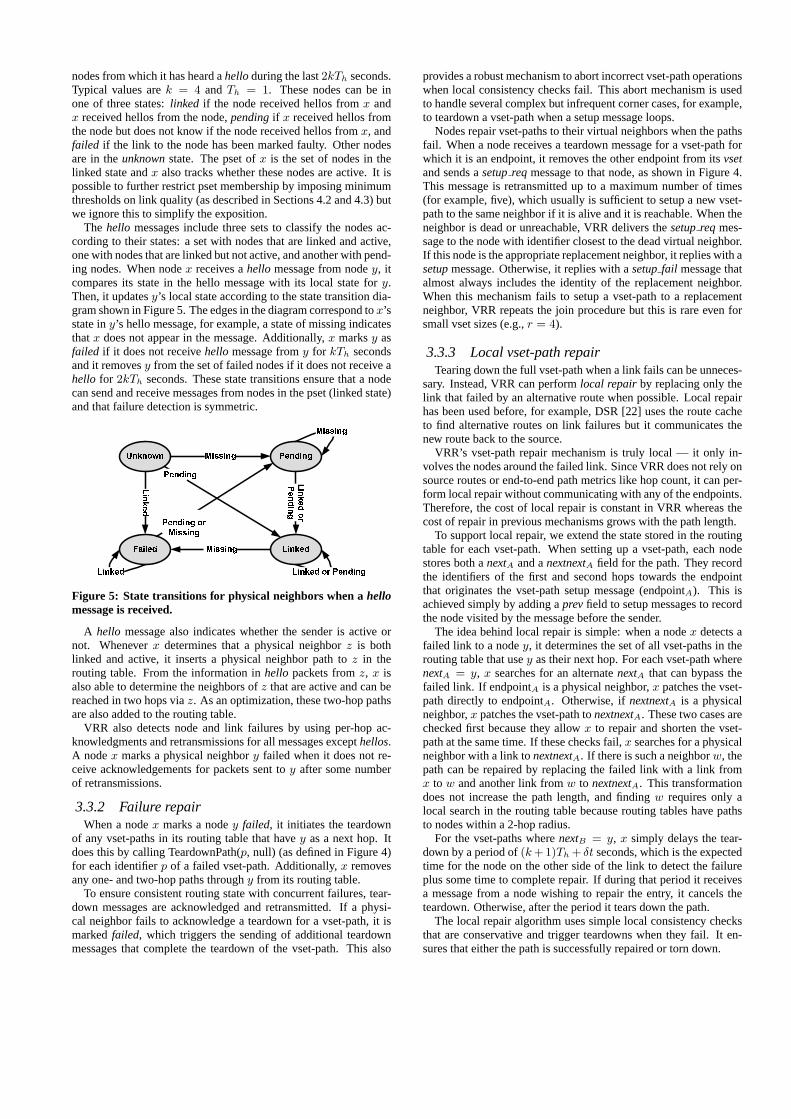
The hello messages include three sets to classify the nodes ac-cording to their states: a set with nodes that are linked and active,one with nodes that are linked but not active, and another with pend-ing nodes. When nodex receives ahello message from nodey, itcompares its state in the hello message with its local state fory.Then, it updatesy’s local state according to the state transition dia-gram shown in Figure 5. The edges in the diagram correspond tox’sstate iny’s hello message, for example, a state of missing indicatesthatx does not appear in the message. Additionally,x marksy asfailed if it does not receivehello message fromy for kTh secondsand it removesy from the set of failed nodes if it does not receive ahello for 2kTh seconds. These state transitions ensure that a nodecan send and receive messages from nodes in the pset (linked state)and that failure detection is symmetric.
Figure 5: State transitions for physical neighbors when ahellomessage is received.
A hello message also indicates whether the sender is active ornot. Wheneverx determines that a physical neighborz is bothlinked and active, it inserts a physical neighbor path toz in therouting table. From the information inhello packets fromz, x isalso able to determine the neighbors ofz that are active and can bereached in two hops viaz. As an optimization, these two-hop pathsare also added to the routing table.
VRR also detects node and link failures by using per-hop ac-knowledgments and retransmissions for all messages excepthellos.A nodex marks a physical neighbory failed when it does not re-ceive acknowledgements for packets sent toy after some numberof retransmissions.
3.3.2 Failure repairWhen a nodex marks a nodey failed, it initiates the teardown
of any vset-paths in its routing table that havey as a next hop. Itdoes this by calling TeardownPath(p, null) (as defined in Figure 4)for each identifierp of a failed vset-path. Additionally,x removesany one- and two-hop paths throughy from its routing table.
To ensure consistent routing state with concurrent failures, tear-down messages are acknowledged and retransmitted. If a physi-cal neighbor fails to acknowledge a teardown for a vset-path, it ismarkedfailed, which triggers the sending of additional teardownmessages that complete the teardown of the vset-path. This also
provides a robust mechanism to abort incorrect vset-path operationswhen local consistency checks fail. This abort mechanism is usedto handle several complex but infrequent corner cases, for example,to teardown a vset-path when a setup message loops.
Nodes repair vset-paths to their virtual neighbors when the pathsfail. When a node receives a teardown message for a vset-path forwhich it is an endpoint, it removes the other endpoint from itsvsetand sends asetupreq message to that node, as shown in Figure 4.This message is retransmitted up to a maximum number of times(for example, five), which usually is sufficient to setup a new vset-path to the same neighbor if it is alive and it is reachable. When theneighbor is dead or unreachable, VRR delivers thesetupreq mes-sage to the node with identifier closest to the dead virtual neighbor.If this node is the appropriate replacement neighbor, it replies with asetupmessage. Otherwise, it replies with asetupfail message thatalmost always includes the identity of the replacement neighbor.When this mechanism fails to setup a vset-path to a replacementneighbor, VRR repeats the join procedure but this is rare even forsmall vset sizes (e.g.,r = 4).
3.3.3 Local vset-path repairTearing down the full vset-path when a link fails can be unneces-
sary. Instead, VRR can performlocal repair by replacing only thelink that failed by an alternative route when possible. Local repairhas been used before, for example, DSR [22] uses the route cacheto find alternative routes on link failures but it communicates thenew route back to the source.
VRR’s vset-path repair mechanism is truly local — it only in-volves the nodes around the failed link. Since VRR does not rely onsource routes or end-to-end path metrics like hop count, it can per-form local repair without communicating with any of the endpoints.Therefore, the cost of local repair is constant in VRR whereas thecost of repair in previous mechanisms grows with the path length.
To support local repair, we extend the state stored in the routingtable for each vset-path. When setting up a vset-path, each nodestores both anextA and anextnextA field for the path. They recordthe identifiers of the first and second hops towards the endpointthat originates the vset-path setup message (endpointA). This isachieved simply by adding aprevfield to setup messages to recordthe node visited by the message before the sender.
The idea behind local repair is simple: when a nodex detects afailed link to a nodey, it determines the set of all vset-paths in therouting table that usey as their next hop. For each vset-path wherenextA = y, x searches for an alternatenextA that can bypass thefailed link. If endpointA is a physical neighbor,x patches the vset-path directly to endpointA. Otherwise, ifnextnextA is a physicalneighbor,x patches the vset-path tonextnextA. These two cases arechecked first because they allowx to repair and shorten the vset-path at the same time. If these checks fail,x searches for a physicalneighbor with a link tonextnextA. If there is such a neighborw, thepath can be repaired by replacing the failed link with a link fromx to w and another link fromw to nextnextA. This transformationdoes not increase the path length, and findingw requires only alocal search in the routing table because routing tables have pathsto nodes within a 2-hop radius.
For the vset-paths wherenextB = y, x simply delays the tear-down by a period of(k +1)Th + δt seconds, which is the expectedtime for the node on the other side of the link to detect the failureplus some time to complete repair. If during that period it receivesa message from a node wishing to repair the entry, it cancels theteardown. Otherwise, after the period it tears down the path.
The local repair algorithm uses simple local consistency checksthat are conservative and trigger teardowns when they fail. It en-sures that either the path is successfully repaired or torn down.
3.3.4 PartitionsNode and link failures may partition the network. When this hap-
pens, the algorithm ensures that nodes form separate rings. Typi-cally, they form one ring in each partition, which enables the nodesin a partition to communicate with each other. However, the algo-rithm that we described so far is not sufficient to ensure that theserings converge to a single ring when the partition heals. This sectiondescribes a mechanism to ensure this.
The mechanism picks arepresentativefrom each separate ringand useshello messages to maintain routes from each node to eachrepresentative. These routes are not vset-paths but they are in-serted in the routing table like routes to one- and two-hop neigh-bors. When an active node learns about a representative that shouldbe in its vset, it sends asetupmessage to that representative andadds the representative’s identifier to its vset. The routes to repre-sentatives ensure that this message can be routed across partitionedrings. Receiving thesetuptriggers the vset stabilization mecha-nism described in Figure 4, which ensures that the separate ringsare merged into one in the absence of further node and link failures.If the merge fails, the nodes form separate rings and the process isrepeated.
The representative for a ring is the node whose identifier is clos-est to zero in the ring. Each node can determine locally whether itis a representative by inspecting its vset. VRR uses a mechanismsimilar to DSDV [34] to maintain routes between each node and arepresentative. It piggybacks updates to these routes in everyhellomessage. The updates have a sequence number that is incrementedby the representative before eachhello to prevent loops. Nodes stopsending route updates for a representative if they do not receive anupdate with a fresh sequence number for more thankTh seconds.
To keep the overhead low, nodes only send route updates forthe two representatives whose identifiers are closest to zero fromamong those they have fresh routes to. This is sufficient to mergetwo rings at a time and it ensures that the overhead is constant. Thepartition repair mechanism does not add additional messages andonly adds a small amount of data tohello messages. In contrast,route update messages in DSDV [34] have sizeO(n). Addition-ally, we eliminate unnecessary messages by having nodes send asetupto a representative only when they receive route updates fortwo representatives in ahello message and only to the representa-tive farthest away from zero.
4. EVALUATIONWe evaluated VRR using both simulations onns-2[1] and mea-
surements of two prototypes running on different testbeds: a 67-node sensor network [20] and a 30-node 802.11a network of Win-dows PCs. The simulations compared the performance of VRRwith DSR [22], AODV [35], and DSDV [34], which are represen-tative wireless routing protocols with well tuned implementationsin ns-2. DSR and AODV are reactive protocols and DSDV is aproactive protocol. We compared the performance of the sensornetwork prototype with BVR [15] and the performance of the Win-dows prototype with MR-LQSR [10, 11]. BVR is representative ofthe state of the art in protocols that route using location-dependentaddresses, and MR-LQSR is representative of the state of the art inwireless mesh routing protocols.
We ran a large number of experiments. The results show thatVRR performs well across all the experiments. Other protocolstend to perform well on some experiments but poorly on others.
4.1 SimulationsThe simulation experiments ran onns-2.27 using the wireless ex-
tensions developed by the CMU Monarch project [3]. They simu-
lated an 802.11b wireless network running at 11Mbps. We ran alarge set of experiments to explore the impact of different workloadand environmental parameters on the performance of the routingprotocols; we varied the rate of mobility, the traffic load offered byeach node, the number of nodes, and the lifetime of network flows.
4.1.1 ProtocolsWe compared the performance of VRR, DSR, AODV and DSDV.
This VRR implementation supports the local repair optimization. Itwas configured to use 4-byte node identifiers, a vset size of four(r = 4), and a hello period of one second (Th = 1s). We used thedefault parameters for the other protocols, which are carefully tunedto this simulation environment. The four routing protocols unicastdata packets, use link failure notifications, and do not use RTS/CTS.We modified all the routing protocols not to use the ARP protocolto translate the addresses of physical neighbors, because this can in-troduce significant delays that obscure the performance differencesbetween the protocols. It is easy to populate ARP caches with theMAC addresses of physical neighbors using VRR’s hello messages.
4.1.2 Experimental setupOur experimental setup is very similar to the one used in [3] to
facilitate comparison with previous work. The base configurationsimulates 50 mobile nodes randomly distributed over a 1500m×300m plane as in [3]. We vary the number of nodes from 25 to 200and adjust the plane dimensions to keep the density of nodes persquare meter constant and to preserve the aspect ratio. For example,we ran 200-node simulations in a 3000m× 600m plane.
We ran experiments with and without mobility. The mobility pat-terns were generated using the random trip mobility model [2] thatfixes the slow convergence problems [42] of the original randomwaypoint model [23]. In this model, each node selects a destina-tion coordinate uniformly at random within the plane and movestowards that coordinate at constant speed. When it reaches the des-tination, the node selects a new destination and speed without paus-ing. We show results for two scenarios that represent extremes: thestatic scenariowith no movement and the20m/s mobility scenariowith fast movement. Nodes select speeds uniformly at random fromthe interval (0,20] m/s in the mobility scenario.
All the experiments ran for 1900 seconds with measurementstaken only during the last 900 seconds. The initial 1000 secondswere used to ensure that the routing protocols reached steady state.The results that we present do not include the overhead to initializerouting information when the network starts. For VRR, this over-head was small and routing state converged fast. For example whenstarting a static network with 200 nodes, the average number ofcontrol messages per node (excluding hello messages) was 110.4and all nodes were active after 24.3 seconds. In contrast, a singleflood of the network requires 200 messages.
The experiments used a variable number of UDP constant bit ratesources (CBR) as in [3]. In the default configuration each nodepicks a random destination and starts sending 100 byte packets tothat destination at a random time in the interval [1000,1180] sec-onds and at the rate of one per second [3]. We also ran experimentsvarying the number of CBRs and their lifetime.
4.1.3 Evaluation metricsWe measured the fraction of CBR packets delivered correctly, the
end-to-end delay for these packets, and the number of router-levelmessages per correct delivery (i.e., the number of messages passeddown to the MAC divided by the number of CBR packets deliveredcorrectly). Each experiment ran five times with different seeds andwe present the average result for each metric. We used the sametraffic, topology, and mobility patterns for all protocols.
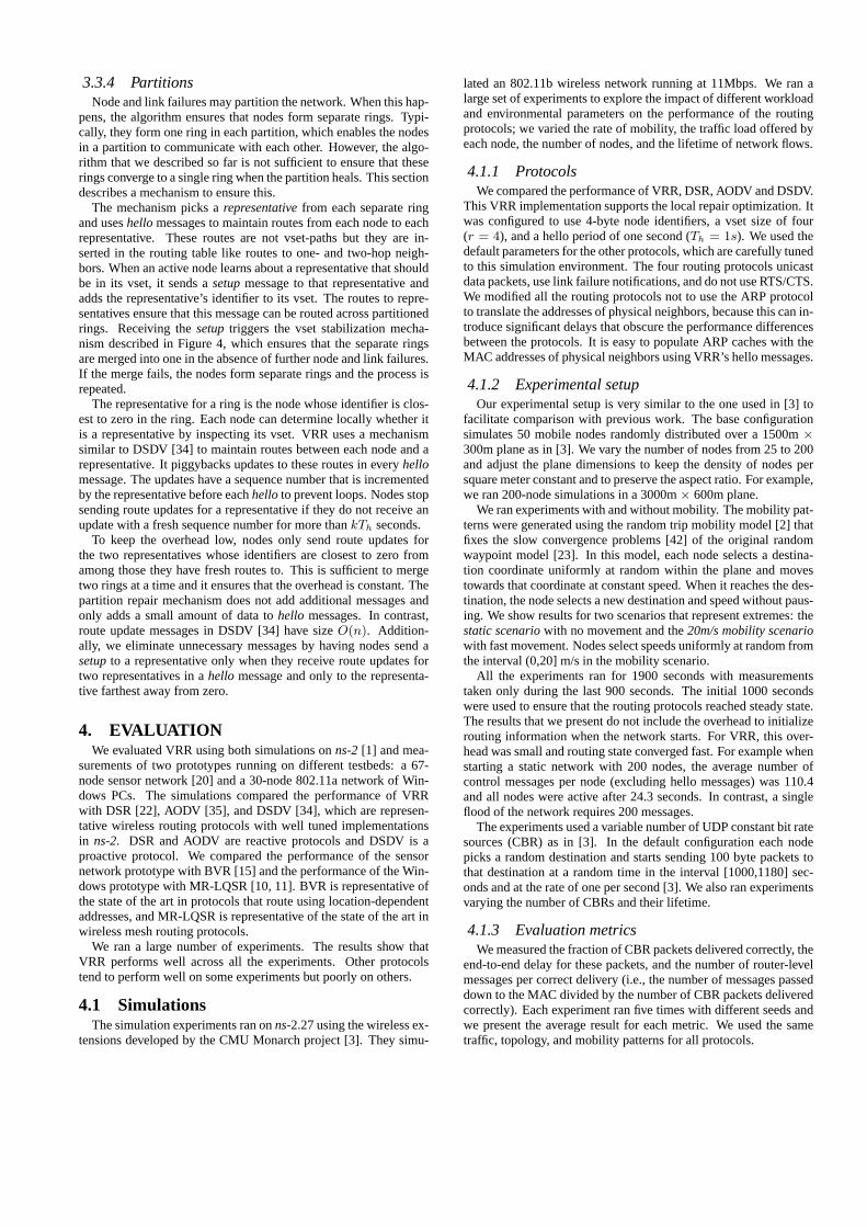
(a) Packets delivered correctly (b) End-to-end delay (c) Message overhead
Figure 6: Performance with increasing number of CBR flows in the static scenario.
(a) Packets delivered correctly (b) End-to-end delay (c) Message overhead
Figure 7: Performance with increasing number of CBR flows in the 20m/s mobility scenario.
4.1.4 Performance with increasing traffic loadThe first set of experiments compared the performance of the
routing protocols with increasing traffic load while keeping the sizeof the network constant at 100 nodes. We varied the total numberof CBR flows between 1 and 200. With less than 100 flows, weselected sources randomly such that each node sourced at most oneflow. With 100 or more flows, each node sourced at least one flowand the sources for the additional flows were selected randomlysuch that no node sourced more than two flows. The destination ofeach CBR flow was selected randomly. Figures 6 and 7 show theresults for the static and mobility scenarios, respectively.
In the static scenario, all protocols achieve nearly perfect deliv-ery ratios and low delays with 100 flows or less. As the number offlows increases, the delivery ratio drops and delays increase due tocongestion. The delays of DSR, DSDV, and AODV increase dra-matically because they queue packets while they repair routes thatfail due to congestion. This strategy improves delivery ratios but itresults in high delays. Additionally, packets spend more time in theinterface queues because of collision avoidance and packet retrans-missions at the MAC layer. The delivery ratio decreases becausepackets are dropped when the router or interface queues fill up.
VRR achieves low delay because it never queues packets waitingfor routes and it can achieve good delivery ratio because it can routearound failed links most of the time.
Figure 6(c) shows a high overhead per delivery for DSDV andVRR with one CBR flow. This is because both protocols send con-trol messages periodically between physical neighbors. DSR andAODV do not send these messages. In real wireless environments,periodic messages are required to estimate link quality [10].
The results for the mobility scenario in Figure 7 show similartrends. The difference is that routes fail not only because of conges-tion as the number of flows increases but also because nodes move.For DSR, DSDV, and AODV, this results in more packets queuedwaiting for routes and even higher delays. DSDV achieves low de-livery ratios even without congestion because routing tables are notsufficiently up to date. VRR achieves the highest delivery ratios
and lowest delays because of the reasons mentioned before. Ad-ditionally, it tends to move vset-path links from fast moving nodesto slow moving nodes because links that do not fail do not changeand those that fail are moved to new nodes. This simple mechanismto learn good routes is similar to the one used in DAR to performdynamic routing in circuit-switched networks [25].
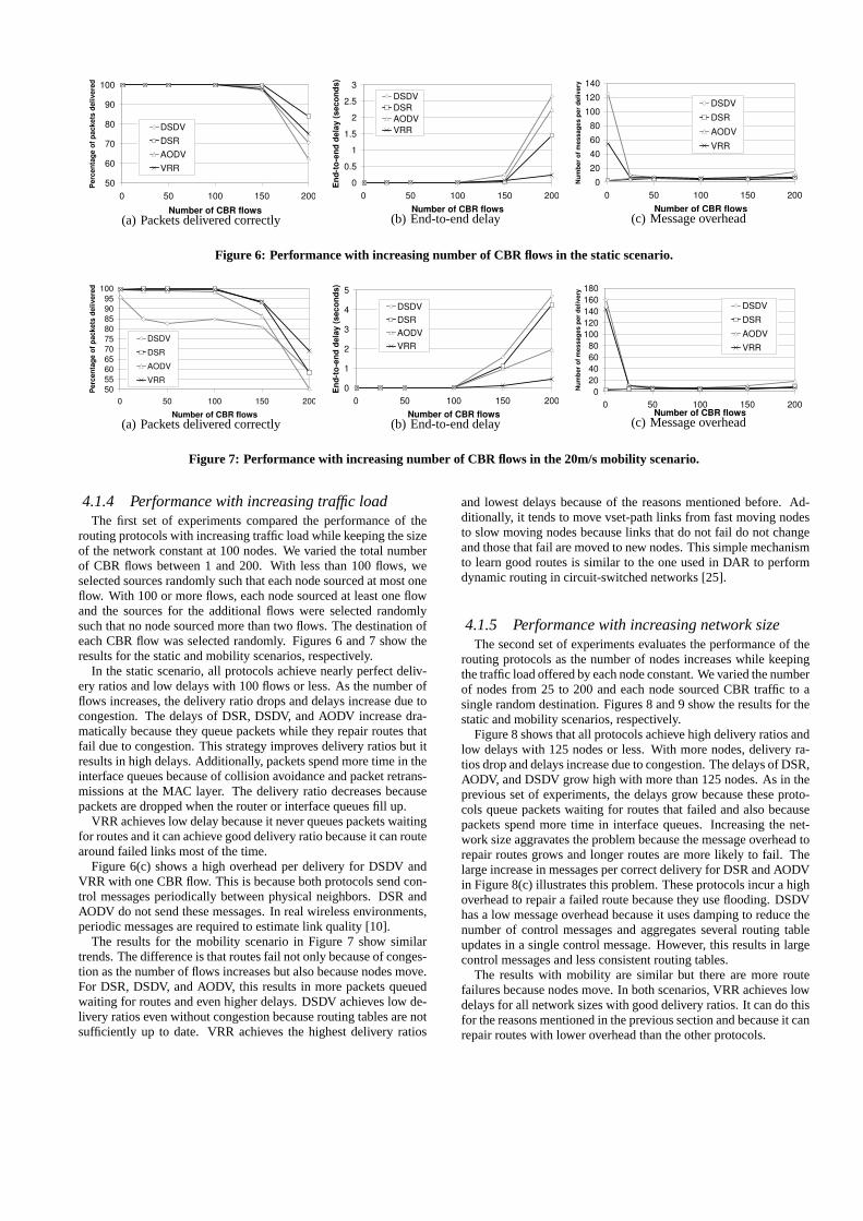
4.1.5 Performance with increasing network sizeThe second set of experiments evaluates the performance of the
routing protocols as the number of nodes increases while keepingthe traffic load offered by each node constant. We varied the numberof nodes from 25 to 200 and each node sourced CBR traffic to asingle random destination. Figures 8 and 9 show the results for thestatic and mobility scenarios, respectively.
Figure 8 shows that all protocols achieve high delivery ratios andlow delays with 125 nodes or less. With more nodes, delivery ra-tios drop and delays increase due to congestion. The delays of DSR,AODV, and DSDV grow high with more than 125 nodes. As in theprevious set of experiments, the delays grow because these proto-cols queue packets waiting for routes that failed and also becausepackets spend more time in interface queues. Increasing the net-work size aggravates the problem because the message overhead torepair routes grows and longer routes are more likely to fail. Thelarge increase in messages per correct delivery for DSR and AODVin Figure 8(c) illustrates this problem. These protocols incur a highoverhead to repair a failed route because they use flooding. DSDVhas a low message overhead because it uses damping to reduce thenumber of control messages and aggregates several routing tableupdates in a single control message. However, this results in largecontrol messages and less consistent routing tables.
The results with mobility are similar but there are more routefailures because nodes move. In both scenarios, VRR achieves lowdelays for all network sizes with good delivery ratios. It can do thisfor the reasons mentioned in the previous section and because it canrepair routes with lower overhead than the other protocols.
(a) Packets delivered correctly (b) End-to-end delay (c) Message overhead
Figure 8: Performance with increasing network size in the static scenario.
(a) Packets delivered correctly (b) End-to-end delay (c) Message overhead
Figure 9: Performance with increasing network size in the 20 m/s mobility scenario.
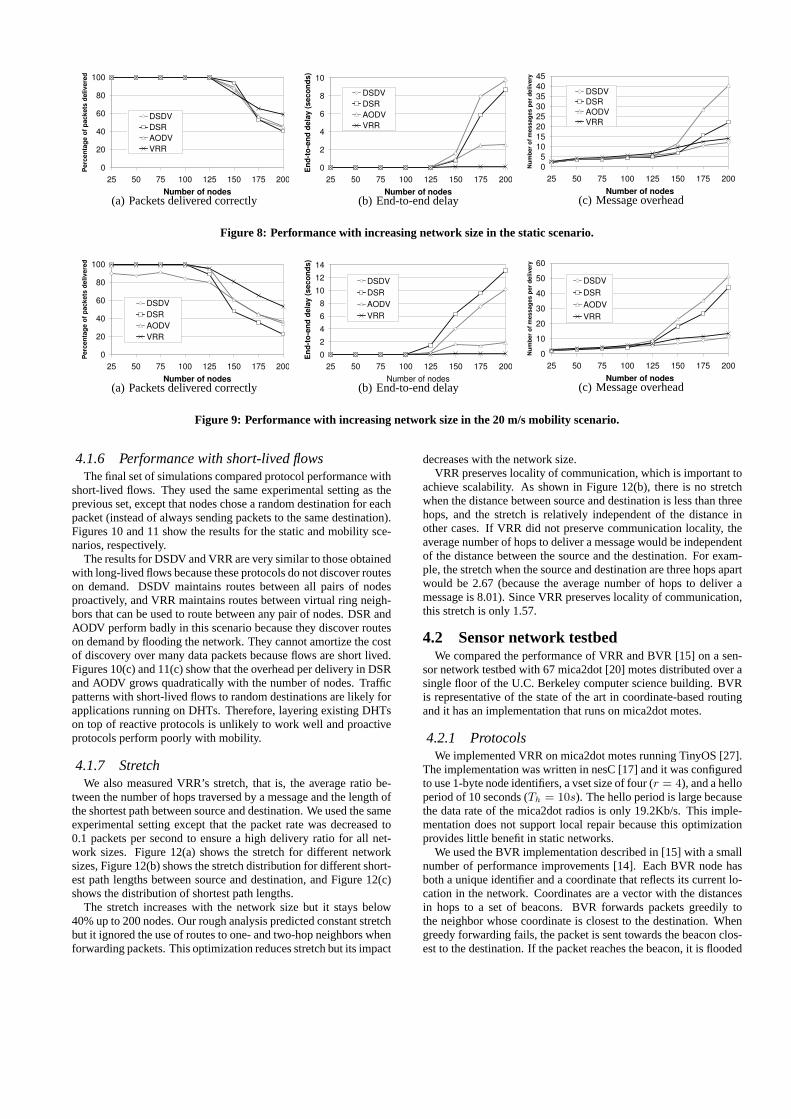
4.1.6 Performance with short-lived flowsThe final set of simulations compared protocol performance with
short-lived flows. They used the same experimental setting as theprevious set, except that nodes chose a random destination for eachpacket (instead of always sending packets to the same destination).Figures 10 and 11 show the results for the static and mobility sce-narios, respectively.
The results for DSDV and VRR are very similar to those obtainedwith long-lived flows because these protocols do not discover routeson demand. DSDV maintains routes between all pairs of nodesproactively, and VRR maintains routes between virtual ring neigh-bors that can be used to route between any pair of nodes. DSR andAODV perform badly in this scenario because they discover routeson demand by flooding the network. They cannot amortize the costof discovery over many data packets because flows are short lived.Figures 10(c) and 11(c) show that the overhead per delivery in DSRand AODV grows quadratically with the number of nodes. Trafficpatterns with short-lived flows to random destinations are likely forapplications running on DHTs. Therefore, layering existing DHTson top of reactive protocols is unlikely to work well and proactiveprotocols perform poorly with mobility.
4.1.7 StretchWe also measured VRR’s stretch, that is, the average ratio be-
tween the number of hops traversed by a message and the length ofthe shortest path between source and destination. We used the sameexperimental setting except that the packet rate was decreased to0.1 packets per second to ensure a high delivery ratio for all net-work sizes. Figure 12(a) shows the stretch for different networksizes, Figure 12(b) shows the stretch distribution for different short-est path lengths between source and destination, and Figure 12(c)shows the distribution of shortest path lengths.
The stretch increases with the network size but it stays below40% up to 200 nodes. Our rough analysis predicted constant stretchbut it ignored the use of routes to one- and two-hop neighbors whenforwarding packets. This optimization reduces stretch but its impact
decreases with the network size.VRR preserves locality of communication, which is important to
achieve scalability. As shown in Figure 12(b), there is no stretchwhen the distance between source and destination is less than threehops, and the stretch is relatively independent of the distance inother cases. If VRR did not preserve communication locality, theaverage number of hops to deliver a message would be independentof the distance between the source and the destination. For exam-ple, the stretch when the source and destination are three hops apartwould be 2.67 (because the average number of hops to deliver amessage is 8.01). Since VRR preserves locality of communication,this stretch is only 1.57.
4.2 Sensor network testbedWe compared the performance of VRR and BVR [15] on a sen-
sor network testbed with 67 mica2dot [20] motes distributed over asingle floor of the U.C. Berkeley computer science building. BVRis representative of the state of the art in coordinate-based routingand it has an implementation that runs on mica2dot motes.
4.2.1 ProtocolsWe implemented VRR on mica2dot motes running TinyOS [27].
The implementation was written in nesC [17] and it was configuredto use 1-byte node identifiers, a vset size of four (r = 4), and a helloperiod of 10 seconds (Th = 10s). The hello period is large becausethe data rate of the mica2dot radios is only 19.2Kb/s. This imple-mentation does not support local repair because this optimizationprovides little benefit in static networks.
We used the BVR implementation described in [15] with a smallnumber of performance improvements [14]. Each BVR node hasboth a unique identifier and a coordinate that reflects its current lo-cation in the network. Coordinates are a vector with the distancesin hops to a set of beacons. BVR forwards packets greedily tothe neighbor whose coordinate is closest to the destination. Whengreedy forwarding fails, the packet is sent towards the beacon clos-est to the destination. If the packet reaches the beacon, it is flooded
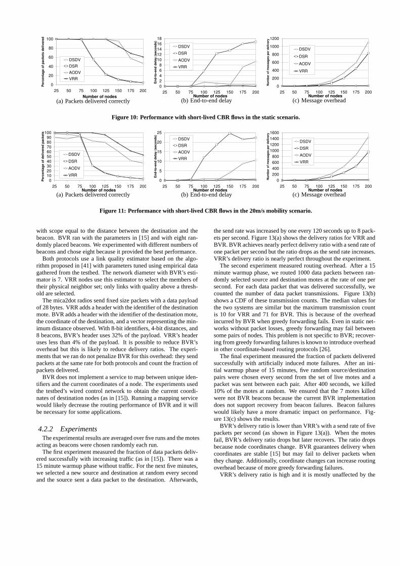
(a) Packets delivered correctly (b) End-to-end delay (c) Message overhead
Figure 10: Performance with short-lived CBR flows in the static scenario.
(a) Packets delivered correctly (b) End-to-end delay (c) Message overhead
Figure 11: Performance with short-lived CBR flows in the 20m/s mobility scenario.
with scope equal to the distance between the destination and thebeacon. BVR ran with the parameters in [15] and with eight ran-domly placed beacons. We experimented with different numbers ofbeacons and chose eight because it provided the best performance.
Both protocols use a link quality estimator based on the algo-rithm proposed in [41] with parameters tuned using empirical datagathered from the testbed. The network diameter with BVR’s esti-mator is 7. VRR nodes use this estimator to select the members oftheir physical neighbor set; only links with quality above a thresh-old are selected.
The mica2dot radios send fixed size packets with a data payloadof 28 bytes. VRR adds a header with the identifier of the destinationmote. BVR adds a header with the identifier of the destination mote,the coordinate of the destination, and a vector representing the min-imum distance observed. With 8-bit identifiers, 4-bit distances, and8 beacons, BVR’s header uses 32% of the payload. VRR’s headeruses less than 4% of the payload. It is possible to reduce BVR’soverhead but this is likely to reduce delivery ratios. The experi-ments that we ran do not penalize BVR for this overhead: they sendpackets at the same rate for both protocols and count the fraction ofpackets delivered.
BVR does not implement a service to map between unique iden-tifiers and the current coordinates of a node. The experiments usedthe testbed’s wired control network to obtain the current coordi-nates of destination nodes (as in [15]). Running a mapping servicewould likely decrease the routing performance of BVR and it willbe necessary for some applications.
4.2.2 ExperimentsThe experimental results are averaged over five runs and the motes
acting as beacons were chosen randomly each run.The first experiment measured the fraction of data packets deliv-
ered successfully with increasing traffic (as in [15]). There was a15 minute warmup phase without traffic. For the next five minutes,we selected a new source and destination at random every secondand the source sent a data packet to the destination. Afterwards,
the send rate was increased by one every 120 seconds up to 8 pack-ets per second. Figure 13(a) shows the delivery ratios for VRR andBVR. BVR achieves nearly perfect delivery ratio with a send rate ofone packet per second but the ratio drops as the send rate increases.VRR’s delivery ratio is nearly perfect throughout the experiment.
The second experiment measured routing overhead. After a 15minute warmup phase, we routed 1000 data packets between ran-domly selected source and destination motes at the rate of one persecond. For each data packet that was delivered successfully, wecounted the number of data packet transmissions. Figure 13(b)shows a CDF of these transmission counts. The median values forthe two systems are similar but the maximum transmission countis 10 for VRR and 71 for BVR. This is because of the overheadincurred by BVR when greedy forwarding fails. Even in static net-works without packet losses, greedy forwarding may fail betweensome pairs of nodes. This problem is not specific to BVR; recover-ing from greedy forwarding failures is known to introduce overheadin other coordinate-based routing protocols [26].
The final experiment measured the fraction of packets deliveredsuccessfully with artificially induced mote failures. After an ini-tial warmup phase of 15 minutes, five random source/destinationpairs were chosen every second from the set of live motes and apacket was sent between each pair. After 400 seconds, we killed10% of the motes at random. We ensured that the 7 motes killedwere not BVR beacons because the current BVR implementationdoes not support recovery from beacon failures. Beacon failureswould likely have a more dramatic impact on performance. Fig-ure 13(c) shows the results.
BVR’s delivery ratio is lower than VRR’s with a send rate of fivepackets per second (as shown in Figure 13(a)). When the motesfail, BVR’s delivery ratio drops but later recovers. The ratio dropsbecause node coordinates change. BVR guarantees delivery whencoordinates are stable [15] but may fail to deliver packets whenthey change. Additionally, coordinate changes can increase routingoverhead because of more greedy forwarding failures.
VRR’s delivery ratio is high and it is mostly unaffected by the
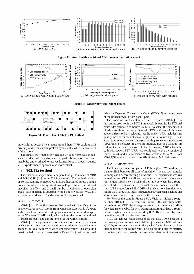
(a) Average stretch (b) Average stretch per minimum distance (c) Distribution of minimum distances
Figure 12: Stretch with short-lived CBR flows in the static scenario.
(a) Delivery rate with varying packet rate (b) Message overhead per packet (c) Packet delivery ratio with failures
Figure 13: Sensor network testbed results.
Figure 14: Floor plan of 802.11a PC testbed.
mote failures because it can route around them. VRR exploits pathdiversity and reroutes data packets dynamically when it encountersa failed mote.
The results show that both VRR and BVR perform well in sen-sor networks. BVR’s performance degrades because of coordinateinstability and overhead to recover from failures of greedy routing.VRR’s performance appears to be more robust.
4.3 802.11a testbedThe final set of experiments compared the performance of VRR
and MR-LQSR [11] on an 802.11a testbed. The testbed consistsof 30 PCs running Windows XP that are distributed across a singlefloor in our office building. As shown in Figure 14, we placed mostmachines in offices and a small number in cubicles in open-planareas. Each machine is equipped with a single NetGear WAG 311wireless network card. The diameter of the network is 4.
4.3.1 ProtocolsMR-LQSR [11] is the protocol distributed with the Mesh Con-
nectivity Layer (MCL) toolkit from Microsoft Research [10]. MCLadds a new kernel module that appears as a virtual network adapterto the Windows TCP/IP stack, which allows the use of unmodifiedIP-based protocols and applications over the wireless mesh.
MR-LQSR is representative of the state of the art in wirelessmesh routing. It is an optimized version of DSR that takes intoaccount link quality metrics when choosing routes. It uses a linkmetric called Expected Transmission Time (ETT) that is computed
using the Expected Transmission Count (ETX) [7] and an estimateof the link bandwidth from packet pair.
The Windows implementation of VRR replaces MR-LQSR asthe routing protocol in the MCL framework. It exploits the ETX andbandwidth estimates computed by MCL to select the machines inphysical neighbor sets; only links with ETX and bandwidth valuesabove a threshold are selected. Additionally, VRR includes linkquality metrics for each physical neighbor in hello messages. Theseare used to select between alternate two-hop routes to a node whenforwarding a message: if there are multiple two-hop paths to theendpoint with identifier closest to the destination, VRR selects thepath with lowest ETT. VRR was configured to use a vset size offour (r = 4), and a hello period of two seconds (Th = 2s). BothMR-LQSR and VRR route using 48-bit virtual MAC addresses.
4.3.2 ExperimentsThe first experiment compared TCP throughput. We usedttcp to
transfer 8MB between all pairs of machines. We ran each transferto completion before starting a new one. The experiment was runthree times and VRR identifiers were selected randomly before eachrun. Figure 15(a) shows a CDF of the ratio between the through-puts of MR-LQSR and VRR for each pair of nodes for all threeruns. VRR outperforms MR-LQSR when the ratio is less than one.Figure 15(b) shows the mean throughput between each machine andall other machines averaged over the three runs.
For 70% of the pairs in Figure 15(a), VRR has higher through-put than MR-LQSR. The results in Figure 15(b) also show betterthroughput for VRR: the average across all machines is 7.5 Mbpsfor VRR and 6.5 Mbps for MR-LQSR. Interestingly, these through-puts are higher than those provided by 802.11b wireless infrastruc-tures that are still in widespread use.
VRR can achieve better throughputs that MR-LQSR because ithas lower per-packet overhead. MR-LQSR uses an MTU of only1,280 bytes to reserve space in the packet for its headers, whichinclude not only the source route but also per-link quality metrics.In contrast, VRR only needs the destination identifier in the packet
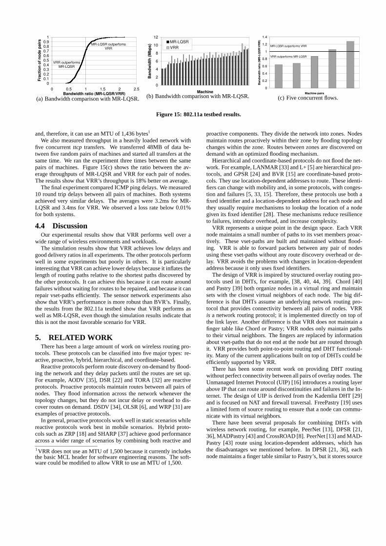
(a) Bandwidth comparison with MR-LQSR. (b) Bandwidth comparison with MR-LQSR. (c) Five concurrent flows.
Figure 15: 802.11a testbed results.
and, therefore, it can use an MTU of 1,436 bytes1
We also measured throughput in a heavily loaded network withfive concurrentttcp transfers. We transferred 48MB of data be-tween five random pairs of machines and started all transfers at thesame time. We ran the experiment three times between the samepairs of machines. Figure 15(c) shows the ratio between the av-erage throughputs of MR-LQSR and VRR for each pair of nodes.The results show that VRR’s throughput is 18% better on average.
The final experiment compared ICMP ping delays. We measured10 round trip delays between all pairs of machines. Both systemsachieved very similar delays. The averages were 3.2ms for MR-LQSR and 3.4ms for VRR. We observed a loss rate below 0.01%for both systems.
4.4 DiscussionOur experimental results show that VRR performs well over a
wide range of wireless environments and workloads.The simulation results show that VRR achieves low delays and
good delivery ratios in all experiments. The other protocols performwell in some experiments but poorly in others. It is particularlyinteresting that VRR can achieve lower delays because it inflates thelength of routing paths relative to the shortest paths discovered bythe other protocols. It can achieve this because it can route aroundfailures without waiting for routes to be repaired, and because it canrepair vset-paths efficiently. The sensor network experiments alsoshow that VRR’s performance is more robust than BVR’s. Finally,the results from the 802.11a testbed show that VRR performs aswell as MR-LQSR, even though the simulation results indicate thatthis is not the most favorable scenario for VRR.
5. RELATED WORKThere has been a large amount of work on wireless routing pro-
tocols. These protocols can be classified into five major types: re-active, proactive, hybrid, hierarchical, and coordinate-based.
Reactive protocols perform route discovery on-demand by flood-ing the network and they delay packets until the routes are set up.For example, AODV [35], DSR [22] and TORA [32] are reactiveprotocols. Proactive protocols maintain routes between all pairs ofnodes. They flood information across the network whenever thetopology changes, but they do not incur delay or overhead to dis-cover routes on demand. DSDV [34], OLSR [6], and WRP [31] areexamples of proactive protocols.
In general, proactive protocols work well in static scenarios whilereactive protocols work best in mobile scenarios. Hybrid proto-cols such as ZRP [18] and SHARP [37] achieve good performanceacross a wider range of scenarios by combining both reactive and
1VRR does not use an MTU of 1,500 because it currently includesthe basic MCL header for software engineering reasons. The soft-ware could be modified to allow VRR to use an MTU of 1,500.
proactive components. They divide the network into zones. Nodesmaintain routes proactively within their zone by flooding topologychanges within the zone. Routes between zones are discovered ondemand with an optimized flooding mechanism.
Hierarchical and coordinate-based protocols do not flood the net-work. For example, LANMAR [33] and L+ [5] are hierarchical pro-tocols, and GPSR [24] and BVR [15] are coordinate-based proto-cols. They use location-dependent addresses to route. These identi-fiers can change with mobility and, in some protocols, with conges-tion and failures [5, 33, 15]. Therefore, these protocols use both afixed identifier and a location-dependent address for each node andthey usually require mechanisms to lookup the location of a nodegiven its fixed identifier [28]. These mechanisms reduce resilienceto failures, introduce overhead, and increase complexity.
VRR represents a unique point in the design space. Each VRRnode maintains a small number of paths to its vset members proac-tively. These vset-paths are built and maintained without flood-ing. VRR is able to forward packets between any pair of nodesusing these vset-paths without any route discovery overhead or de-lay. VRR avoids the problems with changes in location-dependentaddress because it only uses fixed identifiers.
The design of VRR is inspired by structured overlay routing pro-tocols used in DHTs, for example, [38, 40, 44, 39]. Chord [40]and Pastry [39] both organize nodes in a virtual ring and maintainsets with the closest virtual neighbors of each node. The big dif-ference is that DHTs assume an underlying network routing pro-tocol that provides connectivity between all pairs of nodes. VRRis a network routing protocol; it is implemented directly on top ofthe link layer. Another difference is that VRR does not maintain afinger table like Chord or Pastry; VRR nodes only maintain pathsto their virtual neighbors. The fingers are replaced by informationabout vset-paths that do not end at the node but are routed throughit. VRR provides both point-to-point routing and DHT functional-ity. Many of the current applications built on top of DHTs could beefficiently supported by VRR.
There has been some recent work on providing DHT routingwithout perfect connectivity between all pairs of overlay nodes. TheUnmanaged Internet Protocol (UIP) [16] introduces a routing layerabove IP that can route around discontinuities and failures in the In-ternet. The design of UIP is derived from the Kademlia DHT [29]and is focused on NAT and firewall traversal. FreePastry [19] usesa limited form of source routing to ensure that a node can commu-nicate with its virtual neighbors.
There have been several proposals for combining DHTs withwireless network routing, for example, PeerNet [13], DPSR [21,36], MADPastry [43] and CrossROAD [8]. PeerNet [13] and MAD-Pastry [43] route using location-dependent addresses, which hasthe disadvantages we mentioned before. In DPSR [21, 36], eachnode maintains a finger table similar to Pastry’s, but it stores source
routes to the nodes pointed to by each finger. DPSR uses floodingto discover the source routes. CrossROAD [8] implements a DHTon top of OLSR, which is a proactive link-state protocol that floodstopology changes to all nodes. Since each node knows the identityof all the other nodes in the network, it can determine locally thenode whose identifier is closest to a hash table key and route a mes-sage to that node using OLSR. Unlike these systems, VRR does notuse flooding or location-dependent addresses.
6. CONCLUSIONSVirtual Ring Routing is a novel network routing protocol that
provides both point-to-point routing and DHT functionality. VRRroutes using only fixed location independent identifiers that deter-mine the positions of nodes in a virtual ring. Each node maintainsa small number of paths proactively to its neighbors in the virtualring. These paths can be used to forward messages between any pairof nodes and they can be set up and maintained without flooding.
In this paper, we evaluated VRR in the context of ad hoc wire-less networks. We have presented simulation results and resultsfrom two implementations running on wireless testbeds. The re-sults demonstrate that VRR provides robust performance across arange of different environments and workloads. We believe thatVRR could be used to route in other types of networks, for exam-ple, in enterprise networks or even in the Internet.
AcknowledgementsWe would like to thank Christian Huitema and Gabriel Montenegrofor many useful discussions on VRR.
7. REFERENCES[1] ns-2 network simulator.http://www.isi.edu/nsnam/ns/ .[2] J.-Y. Le Boudec and M. Vojnovic. Perfect simulation and stationarity
of a class of mobility models. InInfocom, 2005.[3] J. Broch, D. Maltz, D. Johnson, Y. Hu, and J. Jetcheva. A
performance comparison of multi-hop wireless ad hoc networkrouting protocols. InMobicom, October 1998.
[4] M. Castro, P. Druschel, A. Ganesh, A. Rowstron, and D. Wallach.Secure routing for structured peer-to-peer overlay networks. InOSDI,December 2002.
[5] B. Chen and R. Morris. L+: scalable landmark routing and addresslookup for multi-hop wireless networks. InTechnical Report 837,MIT LCS, March 2002.
[6] T. Clausen and P. Jacquet. OLSR RFC3626, October 2003.http://ietf.org/rfc/rfc3626.txt .
[7] D. De Couto, D. Aguayo, J. Bicket, and R. Morris. A high-throughputpath metric for multi-hop wireless routing. InMobicom, 2003.
[8] F. Delmastro. From Pastry to CrossROAD: Cross-layer ring overlayfor ad hoc networks. InPerCom Workshops, 2005.
[9] J. Douceur. The sybil attack. InIPTPS, March 2002.[10] R. Draves, J. Padhye, and B. Zill. Comparison of routing metrics for
static multi-hop wireless networks. InSIGCOMM, August 2004.[11] R. Draves, J. Padhye, and B. Zill. Routing in multi-radio, multi-hop
wireless mesh networks. InMobicom, September 2004.[12] J. Dunagan, N. Harvey, M. Jones, D. Kostic, M. Theimer, and
A. Wolman. Fuse: Lightweight guaranteed distributed failurenotification. InOSDI, December 2004.
[13] J. Eriksson, M. Faloutsos, and S. Krishnamurthy. Peernet: Pushingpeer-to-peer down the stack. InIPTPS, February 2003.
[14] R. Fonseca. Personal communication.[15] R. Fonseca, S. Ratnasamy, J. Zhao, C. Ee, D. Culler, S. Shenker, and
I. Stoica. Beacon vector routing: Scalable point-to-point in wirelesssensornets. InNSDI, May 2005.
[16] B. Ford. Unmanaged Internet Protocol: Taming the edge networkmanagement crisis. InHotNets II, November 2003.
[17] D. Gay, P. Levis, R. vonBehren, M. Welsh, E. Brewer, and D. Culler.The nesC Language: A Holistic Approach to Networked EmbeddedSystems. InPLDI, June 2003.
[18] Z. J. Haas and M. R. Pearlman. The zone routing protocol (ZRP) forad hoc networks. July 2002. Internet-draft,draft-ietf-manet-zone-zrp-04.txt.
[19] A. Haeberlen, J. Hoye, A. Mislove, and P. Druschel. Consistent KeyMapping in Structured Overlays. InTechnical Report TR05-456, RiceCS Department, August 2005.
[20] J. Hill and D. Culler. Mica: A wireless platform for deeply embeddednetworks.IEEE Micro, 2002.
[21] Y. Hu, H. Pucha, and S. Das. Exploiting the synergy betweenpeer-to-peer and mobile ad-hoc networks. InHot-OS IX, May 2003.
[22] D. Johnson and D. Maltz. Dynamic source routing in ad hoc wirelessnetworks. InAd Hoc Networking, 2001.
[23] D.B. Johnson and D.A. Maltz. Dynamic source routing in ad hocwireless networks.Mobile Computing, 353, 1996.
[24] B. Karp and H. Kung. Greedy perimeter stateless routing for wirelessnetworks. InMobicom, August 2000.
[25] P. Key and G. Cope. Distributed Dynamic Routing Schemes.IEEECommunications Magazine, October 1990.
[26] Y-J Kim, R. Govindan, B. Karp, and S. Shenker. Geographic routingmade practical. InNSDI, May 2005.
[27] P. Levis, S. Madden, D. Gay, J. Polastre, R. Szewczyk, A. Woo,E. Brewer, and D. Culler. The Emergence of NetworkingAbstractions and Techniques in TinyOS. InNSDI, March 2004.
[28] J. Li, J. Jannotti, D. De Couto, D. Karger, and R. Morris. A scalablelocation service for geographic ad-hoc routing. InMobicom, August2000.
[29] P. Maymounkov and D. Mazieres. Kademlia: A Peer-to-peerInformation System. InIPTPS, 2002.
[30] R. Moskowitz, P. Nikander, P. Jokela, and T. Henderson. Hostidentity protocol (HIP), 2004. draft-moskowitz-hip-08.txt.
[31] S. Murthy and J.J. Garcia-Luna-Aceves. An efficient routing protocolfor wireless networks. InMobile Networks and Applications, 1996.
[32] V. Park and M. Corson. Temporally-ordered routing algorithm(TORA) version 1: Functional specification. July 2001.Internet-draft, draft-ietf-manet-tora-spec-04.txt.
[33] G. Pei, M. Gerla, and X. Hong. LANMAR: Landmark routing forlarge scale wireless ad hoc networks with group mobility. InMobiHoc, 2000.
[34] C. Perkins and P. Bhagwat. Highly dynamic destination-sequenceddistance-vector routing (DSDV) for mobile computers. InSigcomm,August 1994.
[35] C. Perkins and E. Royer. Ad hoc on-demand distance vector routing.In Mobile Computing Systems and Applications, February 1999.
[36] H. Pucha, S. M. Das, and Y. C. Hu. Imposed route reuse in ad hocnetwork routing protocols using structured peer-to-peer overlayrouting.IEEE Transactions on Parallel and Distributed Systems (toappear), 2006.
[37] V. Ramasubramanian, Z. Haas, and E. Sirer. SHARP: A hybridadaptive routing protocol for mobile ad hoc networks. InMobihoc,June 2003.
[38] S. Ratnasamy, P. Francis, M. Handley, R. Karp, and S. Shenker. Ascalable content-addressable network. InSigcomm, August 2001.
[39] A. Rowstron and P. Druschel. Pastry: Scalable, distributed objectlocation and routing for large-scale peer-to-peer systems. InMiddleware, November 2001.
[40] I. Stoica, R. Morris, D. Karger, M. Kaashoek, and H. Balakrishnan.Chord: A scalable peer-to-peer lookup service for internetapplications. InSigcomm, August 2001.
[41] A. Woo, T. Tong, and D. Culler. Taming the underlying challenges ofreliable multihop routing in sensor networks. InSenSys, November2003.
[42] J. Yoon, M. Liu, and B. Noble. Random waypoint consideredharmful. InInfocom, 2003.
[43] T. Zahn and J. Schiller. MADPastry: A DHT substrate for practicablysized MANETs. InASWN, June 2005.
[44] B. Zhao, J. Kubiatowicz, and A. Joseph. Tapestry: an infrastructurefor fault-resilient wide-area location and routing. InTechnical reportUCB//CSD-01-1141, U.C. Berkeley, April 2001.