virtual laboratory for sliding mode and pid control of rotary inverted pendulum
TRANSCRIPT
Virtual Laboratory for SlidingMode and PID Control ofRotary Inverted PendulumMETIN DEMIRTAS,1 YUSUF ALTUN,1 AYHAN ISTANBULLU2
1Department of Electrical and Electronics Engineering, Balikesir University, Balikesir, Turkey
2Department of Computer Engineering, Balikesir University, Balikesir, Turkey
Received 9 June 2009; accepted 1 August 2010
ABSTRACT: This paper presents a new virtual laboratory tool which teaches sliding mode control (SMC) andproportional–integral–derivative (PID) control to graduate students. Additionally, it describes performance differ-ences between two control methods graphically. This educational virtual laboratory tool contains the control ofrotary inverted pendulum. This system is a typical example of nonlinear and under-actuated systems and alsowell-known in control engineering for practicing different control theories. At first, the nonlinear dynamic equa-tions of the inverted pendulum are presented. Then a virtual laboratory tool is designed for SMC and PID. Afterthat, the results are analyzed. The validity of designed tool is verified by an experiment. © 2010 Wiley Periodicals,Inc. Comput Appl Eng Educ; View this article online at wileyonlinelibrary.com; DOI 10.1002/cae.20484
Keywords: rotary inverted pendulum; virtual laboratory; sliding mode control; PID control
INTRODUCTION
The inverted pendulum is a state-of-the-art plant in control educa-tion, which is useful for illustrating how to design controller forswing-up and balance. Most control strategies are applied in thelinear and nonlinear control systems. Rotary inverted pendulum(RIP) problem, especially, is well-known as an example of non-linear and under-actuated systems. Therefore, the control of RIPsystems is commonly studied in control areas [1–5].
Sliding mode control (SMC) is robust control for nonlinearand linear feedback control method, which has been developed andapplied to nonlinear feedback control systems around more thanthree decades. SMC approach has been widely used for controldesign problem [6,7]. SMC is one of the effective nonlinear robustcontrol approaches since it provides desired system dynamics withan invariance property to uncertainties once the system dynamicsare controlled in the sliding mode [8–11]. SMC is designed so thatthe system trajectories move onto a sliding surface in a finite timeand tends to an equilibrium point along this surface [12].
Nowadays, some experimental setups are expensive and can-not be enable their parameter changes such as inverted pendulumsystems, dc and ac motors. Therefore, the virtual laboratory is quitesignificant in order to observe the effects of controller parame-ters. In particular, understanding the systems which do not haveexperiment setups well is difficult in teaching. Additionally, in the
Correspondence to M. Demirtas ([email protected]).© 2010 Wiley Periodicals, Inc.
education of these toll sets, understanding the effects of the con-troller parameters on the system by the students is difficult sincethe students cannot observe the parameters effects in mathematicalequations. In recent years, development of virtual laboratory hasreceived considerable attention in the literature [13–18]. There arestudies about educational tools for many systems [19–22]. Besides,cart-inverted pendulum system, fixed base inverted pendulum sys-tem and cart-on-track system is studied using matlab/visual C++[23].
LabVIEW simplifies the scientific computation, processcontrol, research, industrial application, and measurement appli-cations, because it has the flexibility of a programming languagecombined with built-in tools designed specifically for test, mea-surement, and control [24,25]. LabVIEW is an ideal choice forpragmatic teaching and learning. It supports and serves a widevariety of needs for test, measurement, control, and automationapplications [26]. The utilization of virtual tools for teachingand learning in engineering has been well accepted by manyresearchers [27,28].
There are many studies on the control education. Most ofthem used proportional–integral–derivative (PID) controller [29].A developed tool is used in PID education [30]. E-learning toolbased on Matlab has been developed [31]. It is used PID controllerin the system.
SMC is almost not used in the training aim although it is moreused in the applications. This study includes two different controlapproaches; SMC and PID. Therefore, the designed approach isnovelty in the literature.
1
2 DEMIRTAS ET AL.
In this study, educational software is developed for SMC andPID control of RIP using LabVIEW. It is a part of a virtual controllaboratory project for RIP carried out by the authors. The softwarecan be easily used by graduate students in control courses. Thistool provides a low-cost solution for laboratory experiments. Thetool has a flexible structure and graphical user interface, whichpermits the design of the SMC and PID control system. The controlperformance of the controllers (PID and SMC) can be monitoredaccording to different parameters of controllers. It helps students,instructors and researchers about SMC, PID and RIP.
DYNAMIC MODEL OF RIP SYSTEM
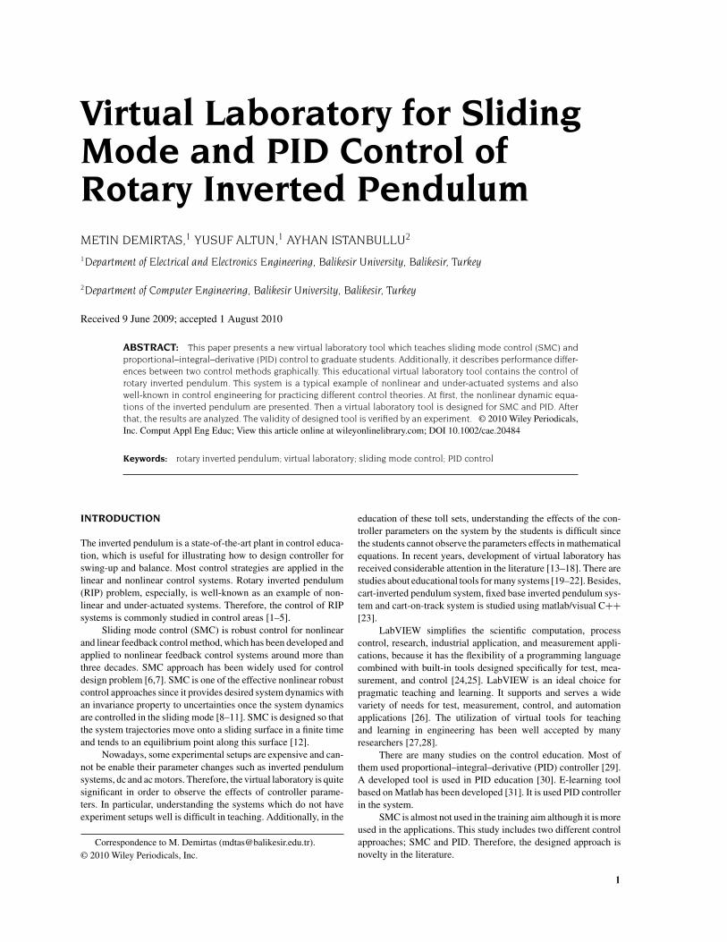
RIP system consists of two rods. The first rod is rotated by dc motor.The second rod is connected to the first rod. Figure 1 shows RIPsystem. The nonlinear dynamic equations of the inverted pendu-lum system are given in Equations (1) and (2) [29].The parameterdefinitions of the RIP control system is given in Table 1. The con-troller parameters are defined in SMC and PID Control of RIPSection.
•• (m2L
21 + J1) = u−m2l2L1
(•• cos−
• 2sin
)−r1
• (1)
••(m2l
22 + J2) = m2l2g sin + m2l2L1
( •
• sin−
•• cos
)−r2
•
(2)
Figure 1 Rotary inverted pendulum system. [Color figure can be viewedin the online issue, which is available at wileyonlinelibrary.com.]
Table 1 Parameter Definition of the RIP
m2 Mass of the second rodL1 Length of the first rodl2 Length of the second rodθ Horizontal angular displacement of the first rodg Gravitational acceleration Vertical angular displacement of the second rodr1 Viscous friction coefficient of the first rodr2 Viscous friction coefficient of the second rodJ1 Inertia moment of the first rodJ2 Inertia moment of the second rodu Horizontal control signal of the first rodVm Motor voltagenm Motor efficiencyng Gearbox efficiencyKt Motor torque constantKg Motor gear ratioKm Back electromotive force (EMF) constantRm Armature resistance.d Desired angle of the RIP
where u is
u = nmngKtKg(Vm−KgKm
•)
Rm(3)
Table 1 shows the parameter definition of RIP control system.The state space expression of the system can be written as in
Equation (4) [32].
•x1 = x2•
x2 = f1(x) + b1(x)Vm•x3 = x4•
x4 = f2(x) + b2(x)Vm
⎫⎪⎬⎪⎭ (4)
where, xi is state variable vector; fi(x) and bi(x) are the nonlinearfunctions of the state variables. Vm is motor voltage.
SMC AND PID CONTROL OF RIP
The desired angle of RIP is obtained using SMC and PID controller.
Sliding Mode Control
Sliding surface (s) is defined for SMC as follows.
s = c · x11 + x22 (5)
Here, c is positive constant defining sliding surface slope. x11
and x22 is defined as follows.
x11 = d−x22 = dx11
dt
(6)
where, d is desired angle of the second rod. It is generally 0in the applications but d can be selected for different angles. Forexample: If the d is selected 5
, designed controller can balance
the second rod. The aim of the study is to control the second rod.Therefore, only angle is controlled. The sliding surface and itsderivative are obtained by combination (5) and (6).
s = c(d−) + d(d−)dt
•s = c( dd
dt−
•) + d2(d−)
dt2
(7)
SMC AND PID CONTROL 3
The state in (8) must be provided for stability of the systemin SMC [32].
lims→0+
•s < 0 and lim
s→0−
•s > 0 (8)
The control signal is defined as;
u = U0sign(s) (9)
Sign stands for signum function defined as in Equation (10).
sign(s) =
1 s > 00 s = 0
−1 s < 0(10)
If a saturation function is used in place of sign function, thechattering problem is eliminated [33].
PID Control
PID controller structure is the most widely used in industrial con-trol systems. It is pointed out that more than 95% of the controllersused in process control applications are of PID-type. Here, P, I,and D are controller’s gains [34,35].
THE VIRTUAL LABORATORY ARCHITECTURE
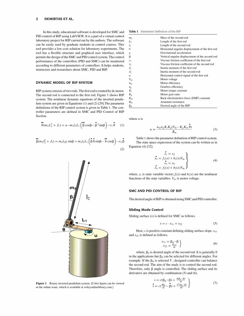
The architecture of the virtual laboratory system and designed vir-tual laboratory tool are shown in Figure 2. The client computerscommunicate with the server computer and display the designedvirtual laboratory on their screen via Internet.
The client computers run a web browser and open a web pageloaded from the server. Therefore, the remote users do not need anyother special software installed on their machine except LabVIEWplayer program. By this tool, students can access to virtual learningenvironment and make virtual experiments. They can observe theprocess outputs graphically on their computer screen.
THE DESIGNED EDUCATIONAL TOOL
The tool enables the instructors to teach SMC and PID control ofRIP to students without spending more time. The outputs of the
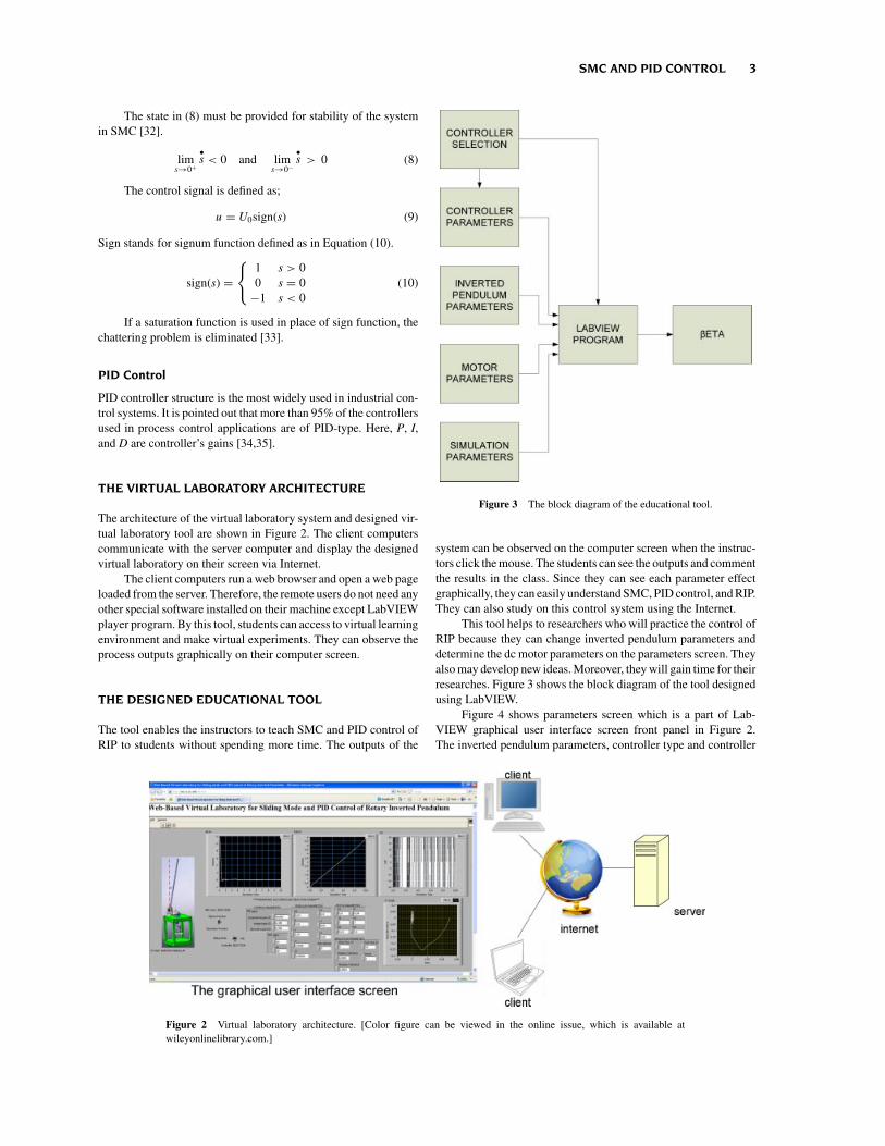
Figure 3 The block diagram of the educational tool.
system can be observed on the computer screen when the instruc-tors click the mouse. The students can see the outputs and commentthe results in the class. Since they can see each parameter effectgraphically, they can easily understand SMC, PID control, and RIP.They can also study on this control system using the Internet.
This tool helps to researchers who will practice the control ofRIP because they can change inverted pendulum parameters anddetermine the dc motor parameters on the parameters screen. Theyalso may develop new ideas. Moreover, they will gain time for theirresearches. Figure 3 shows the block diagram of the tool designedusing LabVIEW.
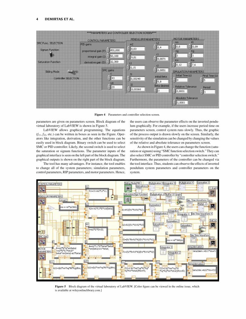
Figure 4 shows parameters screen which is a part of Lab-VIEW graphical user interface screen front panel in Figure 2.The inverted pendulum parameters, controller type and controller
Figure 2 Virtual laboratory architecture. [Color figure can be viewed in the online issue, which is available atwileyonlinelibrary.com.]
4 DEMIRTAS ET AL.
Figure 4 Parameters and controller selection screen.
parameters are given on parameters screen. Block diagram of thevirtual laboratory of LabVIEW is shown in Figure 5.
LabVIEW allows graphical programming. The equations(f11, f22, etc.) can be written in boxes as seen in the Figure. Oper-ators like integration, derivation, and the other functions can beeasily used in block diagram. Binary switch can be used to selectSMC or PID controller. Likely, the second switch is used to selectthe saturation or signum functions. The parameter inputs of thegraphical interface is seen on the left part of the block diagram. Thegraphical outputs is shown on the right part of the block diagram.
The tool has many advantages. For instance, the tool enablesto change all of the system parameters; simulation parameters,control parameters, RIP parameters, and motor parameters. Hence,
the users can observe the parameter effects on the inverted pendu-lum graphically. For example, if the users increase period time onparameters screen, control system runs slowly. Thus, the graphicof the process output is drawn slowly on the screen. Similarly, thesensitivity of the simulation can be changed by changing the valuesof the relative and absolute tolerance on parameters screen.
As shown in Figure 4, the users can change the function (satu-ration or signum) using “SMC function selection switch.” They canalso select SMC or PID controller by “controller selection switch.”Furthermore, the parameters of the controller can be changed viathe tool interface. Thus, students can observe the effects of invertedpendulum system parameters and controller parameters on thesystem.
Figure 5 Block diagram of the virtual laboratory of LabVIEW. [Color figure can be viewed in the online issue, whichis available at wileyonlinelibrary.com.]
SMC AND PID CONTROL 5
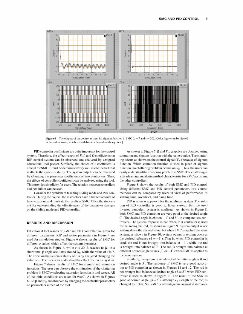
Figure 6 The outputs of the control system for signum function in SMC (c = 7 and c = 20). [Color figure can be viewedin the online issue, which is available at wileyonlinelibrary.com.]
PID controller coefficients are quite important for the controlsystem. Therefore, the effectiveness of P, I, and D coefficients onRIP control system can be observed and analyzed by designededucational tool packet. Similarly, the choice of c coefficient iscrucial for SMC. c must be determined very well due to the fact thatit affects the system stability. The system outputs can be observedby changing the parameter coefficients of two controllers. Thus,the effects of controller coefficients can be analyzed using the tool.This provides simplicity for users. The relation between controllersand pendulum can be seen.
Consider the problem of teaching sliding mode and PID con-troller. During the course, the instructors have a limited amount oftime to explain and illustrate the results of SMC. Often the studentsask for understanding the effectiveness of the parameter changeson the sliding mode and PID controller.
RESULTS AND DISCUSSION
Educational tool results of SMC and PID controller are given fordifferent parameters. RIP and motor parameters in Figure 4 areused for simulation studies. Figure 6 shows results of SMC fordifferent c values which affect the system dynamics.
As shown in Figure 6, while c is 20, reaches to d in ashort time. angle oscillates around d, while the value of c is 7.The effect on the system stability of c is by analyzed changing thevalue of c. The users can understand the effect of c on the system.
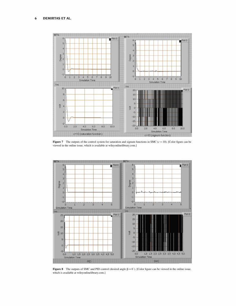
Figure 7 shows results of SMC for signum and saturationfunctions. The user can observe the elimination of the chatteringproblem in SMC by selecting saturation function in tool screen. Allof the initial conditions are taken for θ = 0
. As shown in Figures
6–12, and Vm are observed by changing the controller parameterson parameters screen of the tool.
As shown in Figure 7, and Vm graphics are obtained usingsaturation and signum function with the same c value. The chatter-ing occurs as shown on the control signal (Vm) because of signumfunction. While saturation function is used in place of signumfunction, no chattering problem occurs on Vm. Thus, the users caneasily understand the chattering problem in SMC. The chattering isa disadvantage and distinguished characteristic for SMC accordingthe other controllers.
Figure 8 shows the results of both SMC and PID control.Using different SMC and PID control parameters, two controlmethods can be compared by users in view of performance ofsettling time, overshoot, and rising time.
PID is a linear approach for the nonlinear system. The solu-tion of PID controller is good in linear system. But, the usedinverted pendulum system is nonlinear. As shown in Figure 8,both SMC and PID controller are very good at the desired angle0
. The desired angle is chosen −1
and 5
, to compare two con-
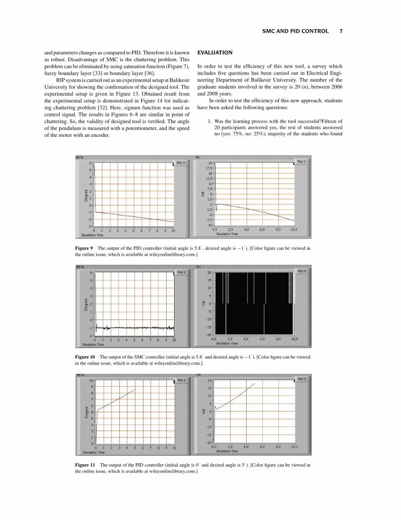
trollers. The system response is bad when PID controller is usedfor balancing the rod, as shown in Figure 9. System output is notsettling down the desired value, but when SMC is applied the samesystem, as shown in Figure 10, system output is settling down atthe desired reference ( = −1
). That is, when PID controller is
used, the rod is not brought into balance at −1, while the rod
is brought into balance at 0. The rod is brought into balance at
different desired angle values (0
or −1) when SMC is applied to
the same system.Similarly, the system is simulated while initial angle is 0 and
desired angle is 5. The response of SMC is very good accord-
ing to PID controller as shown in Figures 11 and 12. The rod isnot brought into balance at desired angle ( = 5
) when PID con-
troller is used as shown in Figure 11. The result of the SMC isgood at desired angle ( = 5
), although L1 (length of the rod) is
changed to 0.3 m. So, SMC is advantageous against disturbance
6 DEMIRTAS ET AL.
Figure 7 The outputs of the control system for saturation and signum functions in SMC (c = 10). [Color figure can beviewed in the online issue, which is available at wileyonlinelibrary.com.]
Figure 8 The outputs of SMC and PID control (desired angle = 0). [Color figure can be viewed in the online issue,
which is available at wileyonlinelibrary.com.]
SMC AND PID CONTROL 7
and parameters changes as compared to PID. Therefore it is knownas robust. Disadvantage of SMC is the chattering problem. Thisproblem can be eliminated by using saturation function (Figure 7),fuzzy boundary layer [33] or boundary layer [36].
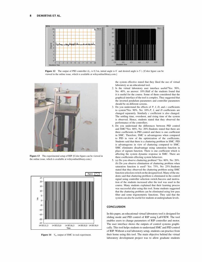
RIP system is carried out as an experimental setup at BalıkesirUniversity for showing the confirmation of the designed tool. Theexperimental setup is given in Figure 13. Obtained result fromthe experimental setup is demonstrated in Figure 14 for indicat-ing chattering problem [32]. Here, signum function was used ascontrol signal. The results in Figures 6–8 are similar in point ofchattering. So, the validity of designed tool is verified. The angleof the pendulum is measured with a potentiometer, and the speedof the motor with an encoder.
EVALUATION
In order to test the efficiency of this new tool, a survey whichincludes five questions has been carried out in Electrical Engi-neering Department of Balikesir University. The number of thegraduate students involved in the survey is 20 (n), between 2006and 2008 years.
In order to test the efficiency of this new approach, studentshave been asked the following questions:
1. Was the learning process with the tool successful?Fifteen of20 participants answered yes, the rest of students answeredno (yes: 75%, no: 25%); majority of the students who found
Figure 9 The output of the PID controller (initial angle is 5.8, desired angle is −1
). [Color figure can be viewed in
the online issue, which is available at wileyonlinelibrary.com.]
Figure 10 The output of the SMC controller (initial angle is 5.8
and desired angle is −1). [Color figure can be viewed
in the online issue, which is available at wileyonlinelibrary.com.]
Figure 11 The output of the PID controller (initial angle is 0
and desired angle is 5). [Color figure can be viewed in
the online issue, which is available at wileyonlinelibrary.com.]
8 DEMIRTAS ET AL.
Figure 12 The output of PID controller (L1 is 0.3 m, initial angle is 0
and desired angle is 5). [Color figure can be
viewed in the online issue, which is available at wileyonlinelibrary.com.]
Figure 13 The experimental setup of RIP. [Color figure can be viewed inthe online issue, which is available at wileyonlinelibrary.com.]
Figure 14 Vm output of SMC in real experiment.
the system effective stated that they liked the use of virtuallaboratory as an educational tool.
2. Is the virtual laboratory user interface useful?Yes: 50%,No: 40%, no answer: 10%.Half of the students found thatit is useful for the course. Some of them considered that thegraphical interface of the tool is complex. They suggested thatthe inverted pendulum parameters and controller parametersshould be on different screens.
3. Do you understand the effects of P, I, D, and c coefficientsto system?Yes: 90%, No: 10%.P, I, and D coefficients arechanged separately. Similarly c coefficient is also changed.The settling time, overshoot, and rising time of the systemis observed. Hence, students stated that they observed theperformance of the controllers.
4. Do you understand the differences between PID controland SMC?Yes: 80%, No: 20%.Students stated that there arethree coefficients in PID control and there is one coefficientin SMC. Therefore, SMC is advantageous when comparedto PID in view of the optimization of the coefficients.Students said that there is a chattering problem in SMC. PIDis advantageous in view of chattering compared to SMC.SMC eliminates disadvantage using saturation function inplace of signum function. There is one coefficient which isaffecting the system dynamic response in SMC. There arethree coefficients effecting system behaviors.
5. (a) Do you observe chattering problem? Yes: 80%, No: 20%.(b) Do you observe elimination of chattering problem whensaturation function is used? Yes: 75%, No: 25%.Studentsstated that they observed the chattering problem using SMCfunction selection switch on the designed tool. Many of the stu-dents said that chattering problem is eliminated in the controlsignal using controller selection switch.Success and motiva-tion of the students increased after the tool was used in thecourse. Many students explained that their learning processwas successful after using this tool. Some students suggestedthat the chattering problem can be eliminated using low passfilter and some trigonometric functions. They said that thesystem can also be useful for students at undergraduate levels.
CONCLUSION
In this paper, an educational virtual laboratory tool is designed forsliding mode and PID control of RIP using LabVIEW. The toolenables users to change parameters of RIP controller and motor.The user interface shows the outputs of control systems graphi-cally. This tool helps students to understand SMC and PID controlof RIP. Without a real laboratory setup, students can practice fromtheir home using this tool. The main objective behind the virtuallaboratory development project was to allow graduate students
SMC AND PID CONTROL 9
without any programming experience about sliding mode and PIDcontrol of RIP control system. Students can evaluate the differ-ences between PID and SMC in terms of performance. They canalso determine the best coefficients changing controller parame-ters. This tool can also be useful for undergraduate students atcontrol Engineering Department.
The instructors gain time for their researches because theywill need a shorter teaching period. They teach the control tech-niques (SMC and PID control) to their graduate students usingcomputers. The parameter effects of sliding mode and PID con-trollers can be thought by more examples in a short time. Inaddition, this tool helps researchers who will conduct a real exper-imental practice. They can change inverted pendulum parameterson parameters screen and determine dc motor parameters for realexperimental practice. Therefore, researchers will gain time forexperimental research. Moreover, they obtain simulation resultsof the control of RIP system.
This tool can be used for automatic control, nonlinear control,SMC, feedback control courses. Many Engineering Departments(electrical, control, mechatronic, and mechanical) can use this toolfor teaching SMC and PID control. In this study, the designedapproach is a novelty from the point of control education.
ACKNOWLEDGMENTS
This study was supported Balikesir University Scientific ResearchProjects (BAP-2008/09).
REFERENCES
[1] M. E. Magana and F. Holzapfel, Fuzzy-logic control of an invertedpendulum with vision feedback. IEEE Trans Educ 41 (1998), 165–170.
[2] W. Rekdalsbakken, Feedback control of an inverted pendulum withthe use of artificial intelligence computational cybernetics. J AdvComput Int Int Inform 11 (2007), 1114–1121.
[3] M. A. Khanesar, M. Teshnehlab, and M. A. Shoorehdeli, Slidingmode control of rotary inverted pendulum, Mediterranean Confer-ence on Control & Automation, 27–29 June 2007, pp. 1–6.
[4] W. Jun-feng and L. Chun-tao, Robust output-feedback control ofinverted pendulum, Industrial Electronics and Applications, ICIEA2nd IEEE Conference, 23–25 May 2007, pp. 1027–1030.
[5] M. A. Teshnehlab, M. Shoorehdeli, and M. A. Khanesar, Fuzzy slid-ing mode control of rotary inverted pendulum, IEEE InternationalConference on Computational Cybernetics, 19–21 October 2007, pp.57–62.
[6] O. Kaynak, K. Erbatur, and M. Ertugrul, The fusion of computation-ally intelligent methodologies and sliding-mode control-A survey.IEEE Trans Ind Electron 48 (2001), 4–12.
[7] V. M. Panchade, L. M. Waghmare, B. M. Patre, and P. P. Bhogle,Sliding mode control of DC drives, Mechatronics and Automation2007 International Conference, 5–8 August 2007, pp. 1576–1580.
[8] V. I. Utkin, Sliding mode control design principles and applicationsto electric drives. IEEE Trans Ind Electron 40 (1993), 23–36.
[9] J. J. E. Slotine and W. Li, Applied nonlinear control. EnglewoodCliffs, NJ, Prentice-Hall, 1991.
[10] C. K. Lai and K. K. Shyu, A novel motor drive design for incrementalmotion system via sliding-mode control method. IEEE Trans IndElectron 52 (2005), 449–507.
[11] F.-J. Lin, L.-T. Teng, and P.-H. Shieh, Intelligent sliding-mode controlusing RBFN for magnetic levitation system. IEEE Trans Ind Electron54 (2007), 1752–1762.
[12] A. J. Koshkouei and A. S. I. Zinober, Sliding mode controller-observer design for SISO linear systems. Int J Syst Sci 29 (1998),1363–1373.
[13] A. Valera, J. L. Diez, M. Valles, and P. Albertos, Virtual and remotecontrol laboratory development. IEEE Control Syst Mag 25 (2005),35–39.
[14] H. A. Basher and S. A. Isa, On-campus and online virtual labora-tory experiments with LabVIEW, Proceedings of the IEEE SoutheastConference, March 31–April 2 2005, pp. 325–330.
[15] H. A. Basher, S. A. Isa, and M. A. Henini, Virtual laboratoryfor electrical circuit course, IEEE Southeast Conference Proceed-ings, Greensboro, North Carolina, March 26–29, 2004, pp. 330–334.
[16] C. H. Ko, B. M. Chen, V. Ramakrishnan, C. D. Cheng, Y. Zhuang, andJ. Chen, A web-based virtual laboratory on a frequency modulationexperiment, IEEE Trans Syst Man, and Cyber—Part C: Applicationsand Reviews, Vol. 31, No. 3, August 2001, pp. 295–303.
[17] M. C. Plummer, C. Bittle, and V. Karani, A circuit II laboratoryaccessible by Internet. Proc Am Soc Eng Educ (2002). soa.asee.org/paper/conference/paper-view.cfm?id=16769.
[18] C. Salzmann, D. Gillet, and P. Huguenin, Introduction to real-timecontrol using LabVIEW with an application to distance learning. IntJ Eng Educ 16 (2000), 255–272.
[19] L. Foulloy, R. Boukezzoula, and S. Galichet, An educational tool forfuzzy control. IEEE Trans Fuzzy Syst 14 (2006), 217–221.
[20] C. Elmas and M. A. Akcayol, PC based educational tool for aswitched reluctance drive with fuzzy logic. Int J Electr Eng Educ40 (2003), 208–219.
[21] P. Thepsatoml, A. Numsomran, V. Tipsuwanpo, and T. Teanthong,DC motor speed control using fuzzy logic based on LabVIEW, SICE-ICASE International Joint Conference, Bexco, Busan, Korea, 18–21October 2006, pp. 3617–3620.
[22] H. Guruler, A. Istanbullu, O. N. Yigitbasi, and O. K. Ersoy, Virtualinstrument application in industry and data acquisition (In Turkish),International VII. Turkish Symposium on Artificial Intelligence andNeural Networks, Canakkale–Turkey, July 2–4 2003, pp. 69–71.
[23] A. A. Rodriguez, R. P. Metzger, O. Cifdaloz, and T. Dhirasakdanon,Description of a modeling, simulation, animation, and real-timecontrol (MoSART) environment for a class of electromechanicalsystems. IEEE Trans Educ 48 (2005), 359–374.
[24] D. Gillet, H. A. Latchman, CH. Salzmann, and O. D. Crisalle, Hands-on laboratory experiments in flexible and distance learning. Int J EngEduc 90 (2001), 187–191.
[25] C. C. Ko, B. M. Chen, J. Chen, Y. Zhuang, and K. Chen Tan, Develop-ment of a web-based laboratory for control experiments on a coupledtank apparatus. IEEE Trans Educ 44 (2001), 76–86.
[26] A. See, Rapid prototyping design and implementation of a motioncontrol integrated with an inexpensive machine vision system,IMTC—Instrumentation and Measurement Technology ConferenceOttawa, Canada, 17–19 May 2005, pp. 2065–2070.
[27] A. Istanbullu and I. Guler, Multimedia based medical instrumenta-tion course in biomedical engineering. J Med Syst 28 (2004), 447–454.
[28] M. Demirtas, Y. Altun, and A. Istanbullu, An educational virtual lab-oratory for sliding mode and PID control of inverted pendulum, IEEE11th international conference on optimization of electrical and elec-tronic equipment OPTIM’08, Brasov, Romania, 22–24 May, 2008,pp. 149–156.
[29] Z. Wang, Y. Chen, and N. Fang, Minimum-Time Swing-up of a rotaryinverted pendulum by iterative impulsive control, Proceedings of theAmerican Control Conference, Vol. 6, June 30–July 2, 2004, pp.1335–1340.
[30] M. Huba and M. Simunek, Modular approach to teaching PID control.IEEE Trans Ind Electron 54 (2007), 3112–3121.
[31] R. Dormido, H. Vargas, N. Duro, J. Sanchez, S. Dormido-Canto, G.Farias, F. Esquembre, and S. Dormido, Development of a web-basedcontrol laboratory for automation technicians: The three-tank system.IEEE Trans Educ 51 (2008), 35–44.
[32] Y. Altun, Application of hierarchical sliding mode control to invertedpendulum systems, Master Thesis, Department of Electrical Elec-tronics Engineering, Balikesir University, 2008.

10 DEMIRTAS ET AL.
[33] I. Senol, M. Demirtas, S. Rustemov, and B. Gumus, Position controlof induction motor a new-bounded fuzzy sliding mode controller.COMPEL 24 (2005), 145–157.
[34] S. V. Ustun and M. Demirtas, Optimal tuning of PI coefficients byusing fuzzy-genetic for V/f controlled induction motor. Exp SystAppl 34 (2008), 2714–2720.
[35] S. Rustemli, M. Yilmaz, and M. Demirtas, Ripple reduction at speedand torque of step motors used on a two-axis robot arm. RobotComput Integr Manuf (2010), DOI:10.1016/j.rcim.2010.05.003.
[36] M. Demirtas, DSP-based sliding mode speed control of inductionmotor using neurogenetic structure. Exp Syst Appl 36 (2009), 5533–5540.
BIOGRAPHIES
Metin Demirtas was born in Mus, Turkey, in1968. He received BSc degrees in electricalengineering from Yildiz University and KocaeliUniversity, in 1989 and 1996, respectively. Hegot a PhD degree in electrical engineering fromYildiz Technical University, Turkey, in 2002.He is currently at the Electrical and ElectronicsEngineering Department in Balikesir Universityin Turkey. His current research interests includepower electronics, power system, electric
machines and control.
Yusuf Altun was born in Karabuk, Turkey. Hereceived the Bachelors Degree in electrical andelectronics engineerings from Zonguldak Karael-mas University, Zonguldak, Turkey, in 2005. He iscurrently doing his PhD thesis in the Departmentof Control and Automation Engineering of YildizTechnical University, Istanbul, in Turkey. Since2008, he has been working as research assistantat the Yildiz Technical University. His researchinterests are in areas of control systems, intelligent
control and sliding mode control.
Ayhan Istanbullu was born in Kutahya, Turkey,in 1972. He received his undergraduate degree(1993) and his PhD from the Electronic andComputer Science Education Department of theGazi University (2003), Turkey. He worked asan instructor at the University of Mugla, Turkey,in the Department of Electronic and ComputerScience Education between 2001 and 2006. Hecurrently works as an Assistant Professor inComputer Engineering Department of BalikesirUniversity, Turkey. He has participated in Euro-pean Remote Radio Laboratory project (EU LdV)
and he has acted as project partner. His current research interests includethe investigation of information technologies to support electronic andcomputer engineering education, mobile learning and intelligent tutoring.