vgb powertech 7 (2020) - breddermann + partner
TRANSCRIPT
VGB PowerTech - Author´s Copy - © 2020
VGB
Pow
erTe
ch -
Auth
or´s
Cop
y - ©
202
0
45
VGB PowerTech 7 l 2020 Refractory linings under thermomechanical aspects
Refractory linings under thermomechanical aspects
AuthorsDipl.-Ing. Holger LeszinskiDipl.-Ing. Martin BreddermannBREDDERMANN + PARTNER Gesellschaft Beratender Ingenieure mbB Bochum, Germany
Refractory linings under thermomechanical aspectsHolger Leszinski and Martin Breddermann
Kurzfassung
Feuerfeste Auskleidungen unter thermomechanischen Gesichtspunkten
Die Auslegung feuerfester Strukturen erfolgt üblicherweise aufgrund von Forderungen, die auf die zu erwartende Ofenatmosphäre zuge-schnitten werden müssen: Dichtigkeit, thermi-sche und chemische Verträglichkeiten, Minimie-rung der Wärmeverluste etc.Diesbezügliche Erfahrungswerte des Konstruk-teurs und Wärmedurchgangsberechnungen am regulären Schichtaufbau sollen dafür sorgen, dass auf die fertiggestellte Anlage Verlass ist.Thermomechanischen Vorgängen hingegen wird vergleichsweise wenig Aufmerksamkeit ge-widmet. Oftmals sind es Zwangsspannungen – im Betrieb hervorgerufen durch behinderte Temperaturverformung und zum Teil um ein Vielfaches höher als Spannungen infolge Eigen-lasten oder Ofeninnendruck – welche Anlagen-teile „in die Knie zwingen“ können. Selbst nach Eintreten derartiger Versagensfälle werden die Ursachen häufig an falscher Stelle gesucht, un-ter anderem weil die thermomechanischen Wechselwirkungen der einzelnen Strukturkom-ponenten nicht bekannt sind oder unterschätzt werden.Selbstverständlich kann man sich dem Komplex Feuerfestbau mit seinen auch in thermomecha-nischer Hinsicht zahllosen Unwägbarkeiten nur annähern; dazu werden im vorliegenden Bei-trag die grundlegenden Mechanismen erläu-tert, beispielhafte thermomechanische Betrach-tungen verschiedener Konstruktionsbeispiele aufgezeigt, und die daraus ableitbaren Mög-lichkeiten zur Optimierung der Sicherheit und Langlebigkeit dargelegt. l
The design of refractory structures is usually based on requirements that must be matched to the expected furnace atmosphere: Tight-ness, thermal and chemical compatibility, minimization of heat losses, etc.
In this respect, the experience of the construc-tor and heat transfer calculations on the reg-ular layer structure are supposed to ensure that the completed system can be relied upon.
In contrast, comparatively little attention is paid to thermomechanical processes. Often it is constraint stresses – during operation caused by hindrance of temperature defor-mation and sometimes many times higher than stresses due to dead loads or internal furnace pressure – which can “bring furnace components to their knees”. Even after the oc-currence of such failures, the causes are often sought in the wrong direction, among other things because the thermomechanical inter-actions of the individual structural compo-nents are not known or are underestimated.
Of course, it is only possible to approximate the complex of refractory construction with its innumerable imponderables, also from a thermomechanical point of view; for this, in the given article the basic mechanisms are explained, exemplary thermomechanical considerations of various design examples are shown, and the possibilities for optimiz-ing safety and service life that can be con-cluded from this are presented.
1. Introduction
The design of refractory structures is usu-ally based on requirements that must be matched to the expected furnace atmos-phere: Tightness, thermal and chemical compatibility, minimization of heat losses, etc.
In this respect, the experience of the con-structor and heat transfer calculations on the regular layer structure are supposed to ensure that the completed system can be relied upon.
In contrast, comparatively little attention is paid to thermomechanical processes. Of-ten it is constraint stresses – during opera-tion caused by hindrance of temperature deformation and sometimes many times higher than stresses due to dead loads or internal furnace pressure – which can “bring furnace components to their knees”. Even after the occurrence of such failures, the causes are often sought in the wrong direction, among other things because the thermomechanical interactions of the indi-vidual structural components with each other – layers, anchorages, brackets, cas-ings including stiffeners – are not known or are underestimated. The generous use of expansion joints, for example, usually falls short: on the one hand, the tightness of the system is often at stake in this case, and on
TYPE OF ACTIONWear due to...
THERMOMECHANICAL...Constraint
CHEMICAL...Corrosion
THER
MAL
...Te
mpe
ratu
res M
ECHANICAL
...Erosion
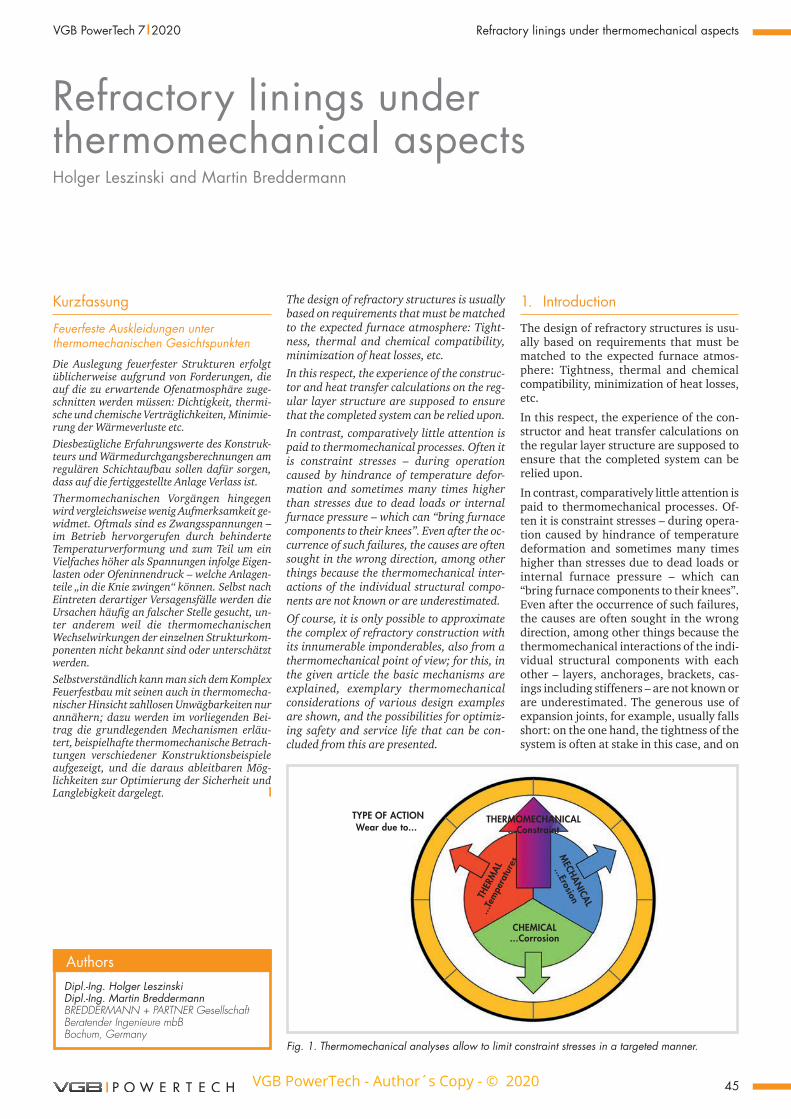
Fig. 1. Thermomechanical analyses allow to limit constraint stresses in a targeted manner.
VGB PowerTech - Author´s Copy - © 2020
VGB
Pow
erTe
ch -
Auth
or´s
Cop
y - ©
202
0
46
Refractory linings under thermomechanical aspects VGB PowerTech 7 l 2020
the other hand, not all constraining forces are avoided with this measure, as will be shown later.Of course, it is only possible to approximate the complex of refractory construction with its innumerable imponderables, also from a thermomechanical point of view; in order to advance this approximation, the basic mechanisms are explained in the fol-lowing sections, exemplary thermome-chanical considerations of various design examples are shown, and the possibilities for optimizing safety and service life that can be concluded from this are presented (F i g u r e 1 ).
2. Thermomechanical constraint
Constraint always occurs in construction elements when their free deformations caused by load or strain are hindered by adjacent components, or when their defor-mations are caused by the “pushing” of ad-jacent components in any way.For thermoprocessing facilities this typi-cally means the following: As a result of the very high temperatures, correspondingly large material strains are induced; the ma-terials expand “freely” and without stress until they face resistance from adjacent structural elements, for example by closing expansion joints. Both now “force” each other into a compatible equilibrium state. Thus, thermomechanical stresses occur only as a result of forced expansion or ex-pansion hindrance.The forces acting in this way depend not only on the temperature- and material-de-pendent expansion urge, but also on the stiffness of the structural elements in-volved; their key parameters are described in the following:
System stiffnessStiffness generally describes the resistance of a body to elastic deformation due to forces or moments: In the case of strain stiffness E*A [MN] resistance to strain/compression due to tensile/compressive forces, in the case of bending stiffness E*I [MNm2] resistance to distortion due to bending moments. It is therefore a product of the material property Young’s modulus E [MN/m2 =̂ MPa] – or more generally of the secant modulus, see below – with the cross-sectional area A [m2] or the moment of inertia I [m4].The basic laws of deformation are
Strain ε = N/(E*A) [-] (1)
and
Curvature k = M/(E*I) [m-1]. (2)
Since absolute changes in length are of in-terest for the calculation of refractory sys-tems, the structural shape is also important in addition to the above laws: For example, the axial spring stiffness of an anchor,
which can have a significant influence on the force variables of a lining, is reduced inversely proportional to its length
cA = E*A/L [MN/m]. (3)
A cylindrical structure reduces its resist-ance to expansion due to constant radial pressure in inverse proportion to the square of its radius
ccyl = E*t/R2 [MN/m3], (4) (t: sheet/layer thickness [m]).
Material stiffnessThis is expressed by the secant modulus Esec [MN/m2], which describes the ratio of stress to strain at any point on the curve of a stress-strain diagram. From the origin to the strain value at which there is propor-tionality between stress and strain, the se-cant modulus corresponds to the modulus of elasticity/Young’s modulus E (Hooke’s law σ = E*ε).The entire non-linear curve can only be de-termined in a static test, i.e. by means of compressive or flexural tensile strength tests with simultaneous recording of the deformations. In contrast, the dynamic measuring method – based on resonance frequency measurements of vibration-in-duced specimens – which is frequently used as an alternative, only provides the modulus of elasticity, i.e. does not take into account increasing yielding of the materi-al, which usually occurs under operating conditions. In a later example (chapter 5) it is shown why calculations with the stati-cally measured “complete” data provide more realistic results.
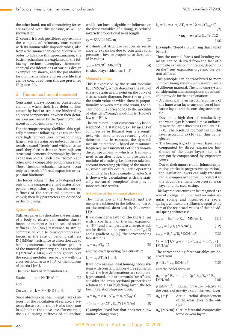
Interaction of the structural elementsThe interaction of the heated rigid ele-ments is explained in the following, based on the method described by Noakowski [1]:If we consider a layer of thickness t [m] with a coefficient of thermal expansion αT [K-1] and a temperature change, which can be divided into a constant part Tm [K] and a gradient TG [K], the corresponding free strain is
ε0 = αT ∆Tm [-] (5)
and the corresponding free curvature
k0 = αT ∆TG/t [m-1]. (6)
If we now assume ideal homogeneous sys-tems with constant temperature profiles, in which the free deformations are complete-ly prevented, or in other words “reset”, and consider the cross-sectional properties in relation to a 1 m high/long layer, the fol-lowing relationships are given:
ε0 = εR => αT ∆Tm = nR/(Esec*t) (7)
=> nR = αT ∆Tm Esec*t [MN/m] (8)
(Example: Fixed bar that does not allow uniform elongation.)
k0 = kR => αT ∆TG/t = 12 mR/(Esec*t³) (9)
=> mR = αT ∆TG Esec*t2 /12 (10)
(Example: Closed circular ring that cannot bend.)Thus the normal forces and bending mo-ments can be derived from the fact of a complete expansion hindrance, depending on the “free” expansion urge and the sys-tem stiffness. This principle can be transferred to more complex lining systems with several layers of different material. The following system consideration and assumptions are intend-ed to provide further explanation:
– A cylindrical layer structure consists of the inner wear layer, any number of insu-lation layers and the encasing steel man-tle.
– Due to its high thermal conductivity, the wear layer is heated almost uniform-ly over the layer thickness (gradient ∆TG ~ 0). The resetting moment within this layer according to (10) can thus be ne-glected.
– The heating ∆Tm of the wear layer is ac-companied by direct expansion hin-drance of the outer layers, i.e. it is not partly compensated by expansion joints.
– Due to their nature (radial joints or sepa-rating cracks in progressive operation), the insulation layers can only transmit radial compressive forces, in contrast to the circumferentially overpressed wear layer and the steel casing.
This layered structure can be imagined as a row of springs, an inner and an outer an-nular spring and intermediate radial springs, whose total stiffness is equal to the sum of the reciprocal values of the individ-ual spring stiffnesses:
ccyl,W = EW*tW/RW2 [MN/m3], (11)
crad,k = Ek/tk [MN/m3], (12)
ccyl,S = ES*tS/RS2 [MN/m3], (13)
Σc = 1/[1/ccyl,W + Σ(1/crad,k) + 1/ccyl,S][MN/m3] (14)
The corresponding force variables are de-rived from
p = Σc * uW [MN/m2] (15)
and the boiler formula
nW = p * RW = -nS = -(p * RW/RS) * RS[MN/m]. (16)
p [MN/m2]: Radial pressure relative to the centre of gravity axis of the wear layer
uW [m]: Actual radial displacement of the wear layer to the out- side
nW [MN/m]: Circumferential compressive force in wear layer
VGB PowerTech - Author´s Copy - © 2020
VGB
Pow
erTe
ch -
Auth
or´s
Cop
y - ©
202
0
47
VGB PowerTech 7 l 2020 Refractory linings under thermomechanical aspects
nS [MN/m]: Circumferential tensile force in steel casingIn order to obtain the actual radial dis-placement uW, compatibilities of the layer displacements with each other must be de-fined; since there is continuity at the layer boundaries, i.e. layers are not penetrated by other layers, the actual “compatible” displacements can only occur under con-straint forces in equilibrium.In this example this displacement compat-ibility is defined as follows:
us = uW + Σ(∆tk) (17)
us [m]: Actual radial displacement of the steel casing to the outside
uW [m]: Actual radial displacement of the wear layer to the outside
Σ(∆tk)[m]: Sum of the layer thickness changes of the solely radially pressed insulating layers
uS = u0,S + uR,S = (ε0,S + εR,S) * RS (18)
uW = u0,W + ur,W = (ε0,W + εR,W) * RW (19)
Σ(∆tk) = Σ[(ε0,tk + εR,tk) * tk] (20)
(RS, RW: Average radius of the steel casing or the wear layer, tk: Thickness of the re-spective insulation layers, k = 1, 2, …)Inserting (7) in (18), (19) and (20) in com-pliance with a uniform sign definition for the radial displacements allows to dissolve after the compressive force in the wear layer, the tensile force in the steel casing or the radial compression in the insulation layers (F i g u r e 2 ).The assumption of mean normal forces (“rod analogy”) naturally represents a sim-plification compared to the real conditions; however, if the diameter of the construc-tion is much larger than the layer thick-nesses, this approach according to the “spring-in-line principle” provides very good approximate results in many lining cases by capturing the relevant parameters of all components.
ConclusionsThe described correlations of thermome-chanically induced constraint underline the dependence of the force variables on the stiffness of all components of a layered structure. The choice of layer thicknesses, anchor cross-sections and materials there-fore represents a criterion for limiting stresses beyond the usual chemical and thermal requirements.
3. Typical behaviour characteristics of refractory linings
Considering the above, it is clear that the shape and design of the structure – curva-ture dimensions, layer thicknesses, etc. – are of elementary importance for the de-
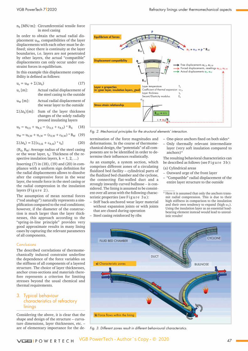
termination of the force magnitudes and deformations. In the course of thermome-chanical design, the “potentials” of all com-ponents are to be identified in order to de-termine their influences realistically.As an example, a system section, which comprises different zones of a circulating fluidized bed facility – cylindrical parts of the fluidized bed chamber and the cyclone, the connecting flat-walled duct and a strongly inwardly curved bullnose – is con-sidered. The lining is assumed to be consist-ent over all areas with the following charac-teristic properties (see F i g u r e 3 a ):
– Stiff back-anchored wear layer material without expansion joints or with joints that are closed during operation
– Steel casing reinforced by ribs
– One-piece anchors fixed on both sides* – Only thermally relevant intermediate
layer (very soft insulation compared to anchors)*
The resulting behavioral characteristics can be described as follows (see F i g u r e 3 b ):(a) Cylindrical areas
– Outward urge of the front layer – “Compatible” radial displacement of the
entire layer structure to the outside
Equilibrium of forces
Displacement compatibility
Layer n properties(n: wear layer, insulation layers, steel)— —
Stress-strain relationship
Layer temperature TnCoefficient of thermal expansion αT,nLayer thickness tnSecant/Elasticity modulus En
RW
Free displacements u0,S, u0,WForced displacements, resettings uR,S, uR,WActual displacements uS, uW
nS = nW = p * RWRW
p
σ
Esec = σ/ε
ε = uR/R
Fig. 2. Mechanical principles for the structural elements’ interaction.
* Here it is assumed that only the anchors trans-mit radial compression. This is due to their high stiffness in comparison to the insulation and their own tendency to expand (high αT). Using the insulation layer as an essential load-bearing element instead would lead to unreal-istic results!
FLUID BED CHAMBER
DUCT
a) Characteristic zones
b) Force flows within the lining
CYCLONE
BULLNOSE
Fig. 3. Different zones result in different behavioural characteristics.
VGB PowerTech - Author´s Copy - © 2020
VGB
Pow
erTe
ch -
Auth
or´s
Cop
y - ©
202
0
48
Refractory linings under thermomechanical aspects VGB PowerTech 7 l 2020
– Radial compression transmitted by the anchors
– Resetting force values primarily depend-ent on the expansion stiffness of the front layer and the steel casing
– Circumferentially high compressive and tensile forces due to the high stiffness of the wear layer and the rib-reinforced steel casing
(b) Flat-walled duct areas – Urge of the wear layer along steel casing – “Compatible” plane displacement of the
wear layer relative to the steel casing – Force coupling between wear layer and
steel shell via anchor shear forces – Force values primarily dependent on the
bending stiffness of the anchors – Compared to the cylindrical areas an-
chor for anchor decreasing compressive and tensile forces in wear layer and steel shell
– Shear force and bending in anchors(c) Bullnose
– Inward urge of the wear layer – “Compatible” rotation and inward dis-
placement of the wear layer – Force values primarily dependent on the
axial stiffness of the anchors – Bending and low residual compression
in wear layer – Bending in steel casing – Anchor tension
Beyond these locally very different behav-ioural characteristics, the mutual influence of these regions must not be ignored; the stiffer the system is in the cylindrical zones – for example through stiffeners – the more the wear layer pushes in the direction of the bullnose instead of outwards; its com-pressive stresses in the duct area are in turn co-determined by the stiffness of the bull-nose anchors.
ConclusionsThe determination of the behavioural char-acteristics requires, on the one hand, the correct assessment of qualitative force flows, which depend primarily on the de-sign elements themselves and their respec-tive position (for instance, can a specific anchor type transmit all types of forces?); decisive for the force magnitudes, on the other hand, is the integrative interaction of all components – the system stiffness (see Section 2). However, their analytical deri-vation becomes more complicated with each geometric irregularity; such complex refractory structures can be adequately solved using the finite element method.
4. Structural details and boundary conditions
As has been shown, the stiffness and ex-pansion urge of the individual structural elements and their interaction are the rel-evant characteristics for a close-to-reality
determination of the stresses; consequent-ly, any change in these characteristics af-fects the result. The following considera-tions illustrate that supposed “trivialities” can have great effects:
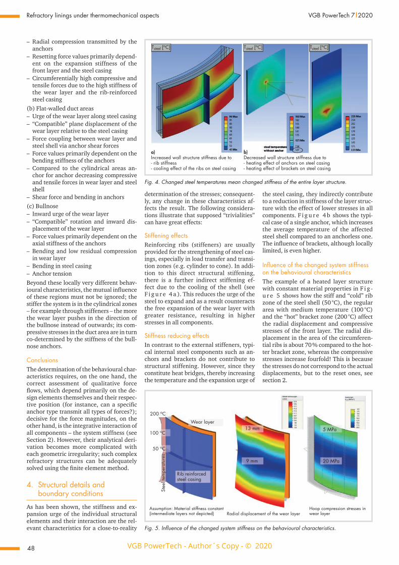
Stiffening effectsReinforcing ribs (stiffeners) are usually provided for the strengthening of steel cas-ings, especially in load transfer and transi-tion zones (e.g. cylinder to cone). In addi-tion to this direct structural stiffening, there is a further indirect stiffening ef-fect due to the cooling of the shell (see F i g u r e 4 a ). This reduces the urge of the steel to expand and as a result counteracts the free expansion of the wear layer with greater resistance, resulting in higher stresses in all components.
Stiffness reducing effectsIn contrast to the external stiffeners, typi-cal internal steel components such as an-chors and brackets do not contribute to structural stiffening. However, since they constitute heat bridges, thereby increasing the temperature and the expansion urge of
the steel casing, they indirectly contribute to a reduction in stiffness of the layer struc-ture with the effect of lower stresses in all components. F i g u r e 4 b shows the typi-cal case of a single anchor, which increases the average temperature of the affected steel shell compared to an anchorless one. The influence of brackets, although locally limited, is even higher.
Influence of the changed system stiffness on the behavioural characteristicsThe example of a heated layer structure with constant material properties in F i g -u r e 5 shows how the stiff and “cold” rib zone of the steel shell (50 °C), the regular area with medium temperature (100 °C) and the “hot” bracket zone (200 °C) affect the radial displacement and compressive stresses of the front layer. The radial dis-placement in the area of the circumferen-tial ribs is about 70 % compared to the hot-ter bracket zone, whereas the compressive stresses increase fourfold! This is because the stresses do not correspond to the actual displacements, but to the reset ones, see section 2.
a)Increased wall structure stiffness due to- rib stiffness- cooling effect of the ribs on steel casing
b)Decreased wall structure stiffness due to- heating effect of anchors on steel casing- heating effect of brackets on steel casing
Tsteel [oC] Tsteel [oC] Tsteel [oC]
Fig. 4. Changed steel temperatures mean changed stiffness of the entire layer structure.
200 oC
100 oC
50 oC
Wear layer13 mm
9 mm 20 MPa
5 MPa
Rib reinforcedsteel casing
Stee
l tem
pera
ture
s
Assumption: Material stiffness constant(intermediate layers not depicted) Radial displacement of the wear layer
Hoop compression stresses inwear layer
Fig. 5. Influence of the changed system stiffness on the behavioural characteristics.
VGB PowerTech - Author´s Copy - © 2020
VGB
Pow
erTe
ch -
Auth
or´s
Cop
y - ©
202
0
49
VGB PowerTech 7 l 2020 Refractory linings under thermomechanical aspects
ConclusionsIn order to achieve realistic results, not only the consideration of the structural compo-nent stiffness, but also the identification of the prevailing temperature distribution is essential; both have a considerable effect on the computational system stiffness. Cooling effects due to reinforcing ribs and temperature increases due to anchors or brackets result in corresponding increases or decreases in component stresses.
5 Non-linear material behaviour
As with their thermal properties, refracto-ry materials are not only subject to large scattering in terms of their stiffness, but are also dependent on temperature and stress. Depending on the compound of the material, drastic reductions in stiffness can occur under increasing temperatures and/or increasing reset strains. By means of a comparative study of two castables with different alumina contents as the wear lay-er of a cylindrical fluidized bed furnace with an outer diameter D = 10 m, the dif-ferences in the behavioral characteristics are to be pointed out.
System and action assumptionsUnder the operating temperatures Ti ~ 850 °C the considered wear layer is over-pressed despite effective expansion joint of 2 ‰ between the concrete slabs. The insu-lating layers transmit only radial compres-sion, the steel shell is stiffened and cooled by ribs. At the steel there are temperatures of about 50 °C (rib area) to 100 °C (regular area).
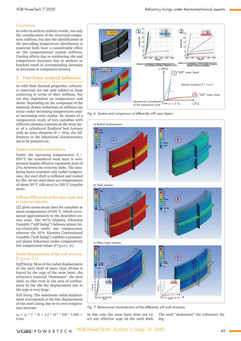
Stiffness differences of the wear layer due to material selection [2] gives stress-strain laws for castables at mean temperatures of 816 °C, which corre-spond approximately to the described sys-tem state. The 60 % Alumina Vibration Castable (“stiff lining”) behaves almost lin-ear-elastically under any compression, whereas the 45 % Alumina Conventional Castable (“soft lining”) exhibits a pronoun-ced plastic behaviour under comparatively low compression values (F i g u r e 6 ).
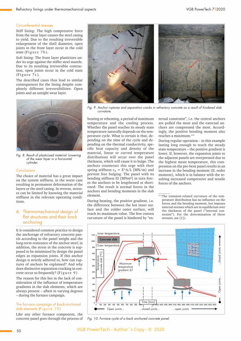
Radial displacements of the wall structure (F i g u r e 7a )Stiff lining: Most of the radial displacement of the steel shell of more than 20 mm is forced by the urge of the wear layer; the refractory material “dominates” the steel shell, so that even in the area of confine-ment by the ribs the displacement due to the urge is very large.Soft lining: The maximum radial displace-ment corresponds to the free displacement of the steel casing due to its own tempera-ture increase
uR = aT * T * R = 1.2 * 10-5 * 100 * 5,000 = 6 mm.
In this case the wear layer does not ex-ert any effective urge on the steel shell.
The steel “dominates” the refractory lin-ing.
Tsteel [oC]
Ti ~850oC
1
2
σ [MPa]“Stiff“ wear layer
Secant modulus E* = σ/ε
“Soft“ wear layer
ε [‰]Numerical considerationof the expansion joint εF = 2 ‰
Fig. 6. System and comparison of differently stiff wear layers.
a) Radial displacement
b) Steel stresses
c) Wear layer stresses
1
1
1 2
2
2
Fig. 7. Behavioural characteristics of the differently stiff wall structures.
VGB PowerTech - Author´s Copy - © 2020
VGB
Pow
erTe
ch -
Auth
or´s
Cop
y - ©
202
0
50
Refractory linings under thermomechanical aspects VGB PowerTech 7 l 2020
Circumferential stressesStiff lining: The high compressive force from the wear layer causes the steel casing to yield. Due to the resulting irreversible enlargement of the shell diameter, open joints in the front layer occur in the cold state (F i g u r e 7 b ).Soft lining: The front layer plasticizes un-der its urge against the stiffer steel mantle. Due to its resulting irreversible contrac-tion, open joints occur in the cold state (F i g u r e 7 c ).The described cases thus lead to similar consequences for the lining despite com-pletely different irreversibilities: Open joints and an untight wear layer.
heating or reheating, a period of maximum temperature and the cooling process. Whether the panel reaches its steady state temperature naturally depends on the tem-perature cycle. What is certain is that, de-pending on the time of the cycle and de-pending on the thermal conductivity, spe-cific heat capacity and density of the material, linear or curved temperature distributions will occur over the panel thickness, which will cause it to bulge. The anchors counteract this urge with their spring stiffness cA = E*A/L [MN/m] and prevent free bulging. The panel with its bending stiffness EI [MNm²] in turn forc-es the anchors to be lengthened or short-ened: The result is normal forces in the anchors and bending moments in the slab element.During heating, the positive gradient, i.e. the difference between the hot inner sur-face and the colder outer surface, will reach its maximum value. The free convex curvature of the panel is hindered by “ex-
ternal constraint”, i.e. the central anchors are pulled the most and the external an-chors are compressed the most. Accord-ingly, the positive bending moment also reaches a maximum.** During regular operation – in this example lasting long enough to reach the steady state temperature – the positive gradient is lower. If, however, the expansion joints to the adjacent panels are overpressed due to the highest mean temperature, this com-pression on the pre-bent panel results in an increase in the bending moment (II. order moment), which is in balance with the re-sulting increased compressive and tensile forces of the anchors.
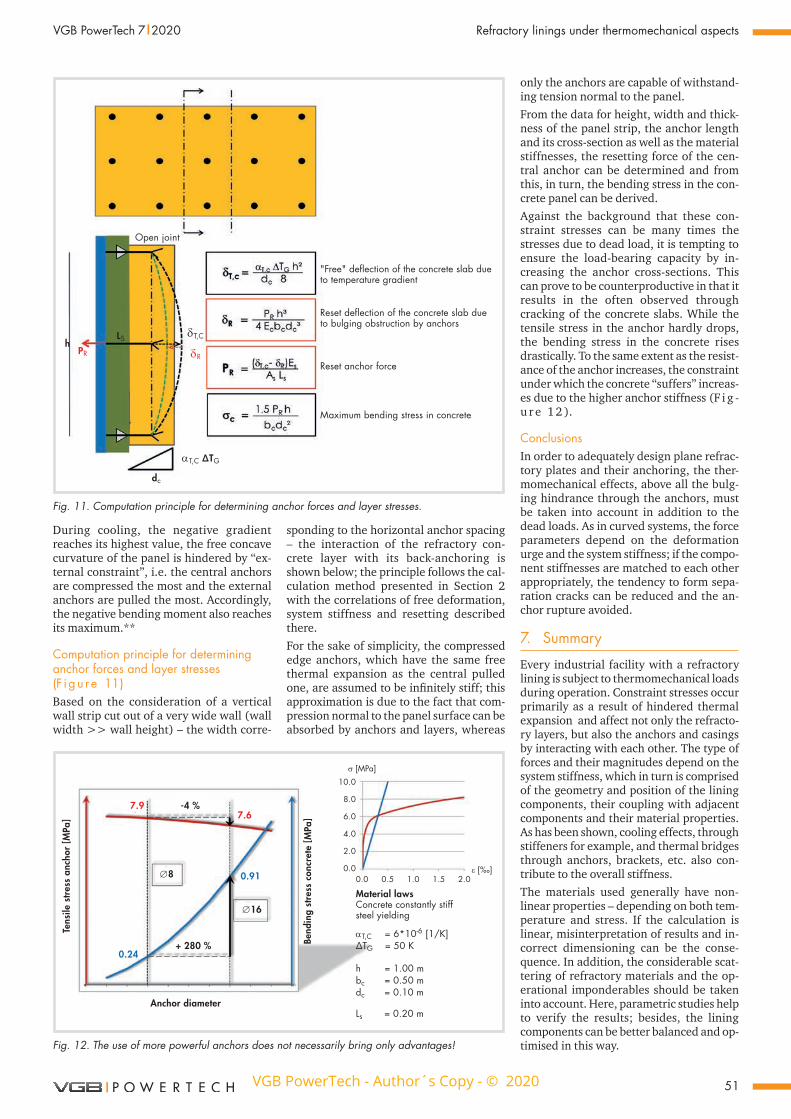
Fig. 8. Result of plasticized material: Lowering of the wear layer in a horizontal cylinder.
ConclusionsThe choice of material has a great impact on the system stiffness, in the worst case resulting in permanent deformation of the layers or the steel casing. In reverse, stress-es can be limited by knowing the material stiffness in the relevant operating condi-tions.
6. Thermomechanical design of flat structures and their back anchoring
It is considered common practice to design the anchorage of refractory concrete pan-els according to the panel weight and the long-term resistance of the anchor steel; in addition, the stress in the concrete is sup-posed to be minimized by design the panel edges as expansion joints. If this anchor design is strictly adhered to, how can rup-tures of anchors be explained? And why does distinctive separation cracking in con-crete occur so frequently? (F i g u r e 9 )The reason for this lies in the lack of con-sideration of the influence of temperature gradients in the slab elements, which are always present – albeit in varying degrees – during the furnace campaign.
The furnace campaign of back-anchored slab elements (F i g u r e 10 )Like any other furnace component, the concrete panel goes through the process of
Fig. 9. Anchor ruptures and separation cracks in refractory concrete as a result of hindered slab curvature.
Open joints... ...closed joints... ...open joints
Ope
n jo
ints.
.....
clos
ed jo
ints
Time [min]
Maximumtemperaturegradient ΔT
Inner temperature
Outer temperature
Concrete slab
Tem
pera
ture
conc
rete
sla
b [o C
]
Fig. 10. Furnace cycle of a back anchored concrete panel.
** The transient-related curvature of the tem-perature distribution has no influence on the forces and the bending moment, but imposes internal stresses which are in equilibrium over the thickness of the panel (“internal con-straint”). For the determination of these stresses, see [1]).
VGB PowerTech - Author´s Copy - © 2020
VGB
Pow
erTe
ch -
Auth
or´s
Cop
y - ©
202
0
51
VGB PowerTech 7 l 2020 Refractory linings under thermomechanical aspects
During cooling, the negative gradient reaches its highest value, the free concave curvature of the panel is hindered by “ex-ternal constraint”, i.e. the central anchors are compressed the most and the external anchors are pulled the most. Accordingly, the negative bending moment also reaches its maximum.**
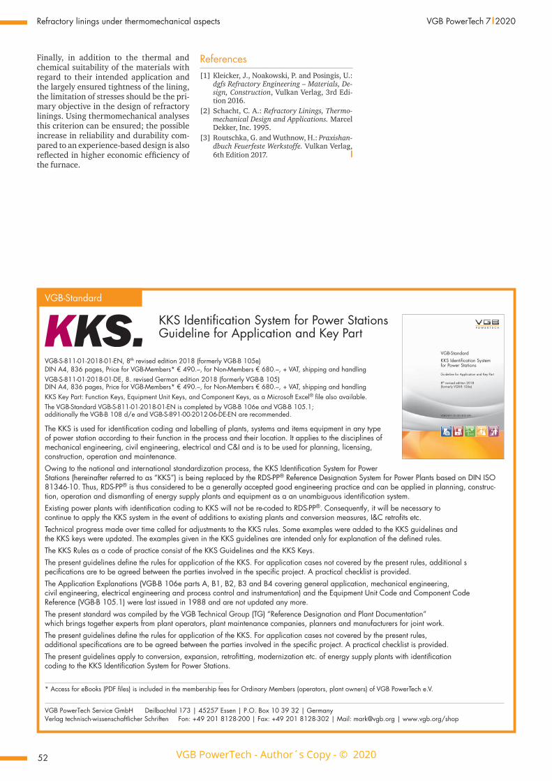
Computation principle for determining anchor forces and layer stresses (F i g u r e 11)Based on the consideration of a vertical wall strip cut out of a very wide wall (wall width >> wall height) – the width corre-
sponding to the horizontal anchor spacing – the interaction of the refractory con-crete layer with its back-anchoring is shown below; the principle follows the cal-culation method presented in Section 2 with the correlations of free deformation, system stiffness and resetting described there.For the sake of simplicity, the compressed edge anchors, which have the same free thermal expansion as the central pulled one, are assumed to be infinitely stiff; this approximation is due to the fact that com-pression normal to the panel surface can be absorbed by anchors and layers, whereas
only the anchors are capable of withstand-ing tension normal to the panel.From the data for height, width and thick-ness of the panel strip, the anchor length and its cross-section as well as the material stiffnesses, the resetting force of the cen-tral anchor can be determined and from this, in turn, the bending stress in the con-crete panel can be derived.Against the background that these con-straint stresses can be many times the stresses due to dead load, it is tempting to ensure the load-bearing capacity by in-creasing the anchor cross-sections. This can prove to be counterproductive in that it results in the often observed through cracking of the concrete slabs. While the tensile stress in the anchor hardly drops, the bending stress in the concrete rises drastically. To the same extent as the resist-ance of the anchor increases, the constraint under which the concrete “suffers” increas-es due to the higher anchor stiffness (F i g -u r e 1 2 ).
ConclusionsIn order to adequately design plane refrac-tory plates and their anchoring, the ther-momechanical effects, above all the bulg-ing hindrance through the anchors, must be taken into account in addition to the dead loads. As in curved systems, the force parameters depend on the deformation urge and the system stiffness; if the compo-nent stiffnesses are matched to each other appropriately, the tendency to form sepa-ration cracks can be reduced and the an-chor rupture avoided.
7. Summary
Every industrial facility with a refractory lining is subject to thermomechanical loads during operation. Constraint stresses occur primarily as a result of hindered thermal expansion and affect not only the refracto-ry layers, but also the anchors and casings by interacting with each other. The type of forces and their magnitudes depend on the system stiffness, which in turn is comprised of the geometry and position of the lining components, their coupling with adjacent components and their material properties. As has been shown, cooling effects, through stiffeners for example, and thermal bridges through anchors, brackets, etc. also con-tribute to the overall stiffness.The materials used generally have non-linear properties – depending on both tem-perature and stress. If the calculation is linear, misinterpretation of results and in-correct dimensioning can be the conse-quence. In addition, the considerable scat-tering of refractory materials and the op-erational imponderables should be taken into account. Here, parametric studies help to verify the results; besides, the lining components can be better balanced and op-timised in this way.
Open joint
h
"Free" deflection of the concrete slab dueto temperature gradient
Reset deflection of the concrete slab due to bulging obstruction by anchors
Reset anchor force
Maximum bending stress in concrete
PR δR
δT,C
dc
αT,C ΔTG
LS
Fig. 11. Computation principle for determining anchor forces and layer stresses.
Tens
ile s
tress
anc
hor [
MPa
]
Anchor diameter
7.97.6
0.91
0.24
-4 %
+ 280 %
∅16
∅8
Bend
ing
stre
ss c
oncr
ete
[MPa
]
Material lawsConcrete constantly stiffsteel yielding
αT,C = 6*10-6 [1/K]ΔTG = 50 K
h = 1.00 mbc = 0.50 mdc = 0.10 m
Ls = 0.20 m
10.0
8.0
6.0
4.0
2.0
0.00.0 0.5 1.0 1.5 2.0
σ [MPa]
ε [‰]
Fig. 12. The use of more powerful anchors does not necessarily bring only advantages!
VGB PowerTech - Author´s Copy - © 2020
VGB
Pow
erTe
ch -
Auth
or´s
Cop
y - ©
202
0
52
Refractory linings under thermomechanical aspects VGB PowerTech 7 l 2020
Finally, in addition to the thermal and chemical suitability of the materials with regard to their intended application and the largely ensured tightness of the lining, the limitation of stresses should be the pri-mary objective in the design of refractory linings. Using thermomechanical analyses this criterion can be ensured; the possible increase in reliability and durability com-pared to an experience-based design is also reflected in higher economic efficiency of the furnace.
References[1] Kleicker, J., Noakowski, P. and Posingis, U.:
dgfs Refractory Engineering – Materials, De-sign, Construction, Vulkan Verlag, 3rd Edi-tion 2016.
[2] Schacht, C. A.: Refractory Linings, Thermo-mechanical Design and Applications. Marcel Dekker, Inc. 1995.
[3] Routschka, G. and Wuthnow, H.: Praxishan-dbuch Feuerfeste Werkstoffe. Vulkan Verlag, 6th Edition 2017. l
VGB-Standard
KKS Identification System for Power Stations Guideline for Application and Key Part
VGB-S-811-01-2018-01-EN, 8th revised edition 2018 (formerly VGB-B 105e)DIN A4, 836 pages, Price for VGB-Members* € 490.–, for Non-Members € 680.–, + VAT, ship ping and hand lingVGB-S-811-01-2018-01-DE, 8. revised German edition 2018 (formerly VGB-B 105) DIN A4, 836 pages, Price for VGB-Members* € 490.–, for Non-Members € 680.–, + VAT, ship ping and hand lingKKS Key Part: Function Keys, Equipment Unit Keys, and Component Keys, as a Microsoft Excel® file also available.The VGB-Standard VGB-S-811-01-2018-01-EN is completed by VGB-B 106e and VGB-B 105.1; additionally the VGB-B 108 d/e and VGB-S-891-00-2012-06-DE-EN are recommended.
The KKS is used for identification coding and labelling of plants, systems and items equipment in any type of power station according to their function in the process and their location. It applies to the disciplines of mechanical engineering, civil engineering, electrical and C&I and is to be used for planning, licensing, construction, operation and maintenance.Owing to the national and international standardization process, the KKS Identification System for Power Stations (hereinafter referred to as “KKS”) is being replaced by the RDS-PP® Reference Designation System for Power Plants based on DIN ISO 81346-10. Thus, RDS-PP® is thus considered to be a generally accepted good engineering practice and can be applied in planning, construc-tion, operation and dismantling of energy supply plants and equipment as a an unambiguous identification system.Existing power plants with identification coding to KKS will not be re-coded to RDS-PP®. Consequently, it will be necessary to continue to apply the KKS system in the event of additions to existing plants and conversion measures, I&C retrofits etc.Technical progress made over time called for adjustments to the KKS rules. Some examples were added to the KKS guidelines and the KKS keys were updated. The examples given in the KKS guidelines are intended only for explanation of the defined rules.The KKS Rules as a code of practice consist of the KKS Guidelines and the KKS Keys.The present guidelines define the rules for application of the KKS. For application cases not covered by the present rules, additional s pecifications are to be agreed between the parties involved in the specific project. A practical checklist is provided.The Application Explanations (VGB-B 106e parts A, B1, B2, B3 and B4 covering general application, mechanical engineering, civil engineering, electrical engineering and process control and instrumentation) and the Equipment Unit Code and Component Code Reference (VGB-B 105.1) were last issued in 1988 and are not updated any more.The present standard was compiled by the VGB Technical Group (TG) “Reference Designation and Plant Documentation” which brings together experts from plant operators, plant maintenance companies, planners and manufacturers for joint work.The present guidelines define the rules for application of the KKS. For application cases not covered by the present rules, additional specifications are to be agreed between the parties involved in the specific project. A practical checklist is provided.The present guidelines apply to conversion, expansion, retrofitting, modernization etc. of energy supply plants with identification coding to the KKS Identification System for Power Stations.
* Access for eBooks (PDF files) is included in the membership fees for Ordinary Members (operators, plant owners) of VGB PowerTech e.V.
VGB PowerTech Service GmbH Deilbachtal 173 | 45257 Essen | P.O. Box 10 39 32 | Germany Verlag technisch-wissenschaftlicher Schriften Fon: +49 201 8128-200 | Fax: +49 201 8128-302 | Mail: [email protected] | www.vgb.org/shop
VGB-S-811-01-2018-01-EN
VGB-StandardKKS Identification System for Power Stations
Guideline for Application and Key Part
8th revised edition 2018 (formerly VGB-B 105e)

VGB PowerTechContact: Gregor Scharpey Tel: +49 201 [email protected] | www.vgb.org
The international journal for electricity and heat generation and storage. Facts, competence and data = VGB POWERTECH
www.vgb.org/shop
Diese DVD und ihre Inhalte sind urheberrechtlich geschützt.© VGB PowerTech Service GmbH
Essen | Deutschland | 2019
· 1990 bis 2019 · · 1990 bis 2019 ·
Fachzeitschrift: 1990 bis 2019
© S
erge
y N
iven
s - F
otol
ia
VGB POWERTECH as printed edition, monthly published, 11 issues a year
Annual edition as CD or DVD with alle issues from 1990 to 2019: Profount knowledge about electricity and heat generation and storage.
Order now at www.vgb.org/shop
International Journal for Electricity and Heat Generation
ISSN 1435–3199 · K 123456 l International Edition
Publication of VGB PowerTech e.V. l www.vgb.org
The electricity sector at a crossroads The role of renewables energy in Europe
Power market, technologies and acceptance
Dynamic process simulation as an engineering tool
European Generation Mix Flexibility and Storage
1/2
2012
International Journal for Electricity and Heat Generation
ISSN 1435–3199 · K 123456 l International Edition
Publication of VGB PowerTech e.V. l www.vgb.org
The electricity sector
at a crossroads
The role of renewables energy
in Europe
Power market, technologies and acceptance
Dynamic process simulation as an engineering tool
European Generation Mix
Flexibility and Storage
1/2
2012
International Journal for Electricity and Heat Generation
ISSN 1435–3199 · K 123456 l International Edition
Publication of VGB PowerTech e.V. l www.vgb.org
The electricity sector
at a crossroads
The role of
renewables energy
in Europe
Power market,
technologies and
acceptance
Dynamic process
simulation as an
engineering tool
European
Generation Mix
Flexibility and
Storage
1/2
2012

| Benefit from the image of our journal, in which only technical papers reviewed by experts are published.
| Reprints are produced individually according to your requests and with the same contents as the original paper.
| Your CI can be transferred into the paper, or you will get a copy of the original layout from our journal.
Please do not hesitate to contact us! Mr Gregor Scharpey | phone: +49 201 8128-200 | E-mail: [email protected]
Special Prints / Reprints from journal VGB PowerTech
A meaningful medium, print or digital, for your technical papers from the renown journal VGB PowerTech.