uwtc/uwrtd series - omega engineering
TRANSCRIPT

UWTC/UWRTD SERIES The Smart ConnectorTM
Wireless Thermocouple/RTD Connector/Transmitter & Receiver
User’s GuideUWTC-1/UWRTD-1 have been obsoleted. Please use the UWTC-2/UWRTD-2 for the substitute.
e-mail: [email protected] For latest product manuals:
www.omegamanual.info
Shop online at omega.com SM

The information contained in this document is believed to be correct, but OMEGA accepts no liability for any errors it contains, and reserves the right to alter specifications without notice.
omega.com [email protected]
Servicing North America:U.S.A. Omega Engineering, Inc. Headquarters: Toll-Free: 1-800-826-6342 (USA & Canada only) Customer Service: 1-800-622-2378 (USA & Canada only) Engineering Service: 1-800-872-9436 (USA & Canada only) Tel: (203) 359-1660 Fax: (203) 359-7700 e-mail: [email protected] For Other Locations Visit omega.com/worldwide

i
Table of ContentsSection PageSection 1 Introduction ......................................................................................... 1-1 1.1 Precautions ................................................................................................ 1-1 1.2 Safety Warnings and IEC Symbols ...................................................... 1-1 1.3 Product Labeling ...................................................................................... 1-2 1.4 Statement on FCC and CE Marking .................................................... 1-4 1.5 General Description & System Components ..................................... 1-4
Section 2 Hardware ............................................................................................. 2-1 2.1 Package Inspection .................................................................................. 2-1 2.2 Included Items .......................................................................................... 2-1
Section 3 Software ............................................................................................... 3-1 3.1 Getting Started ......................................................................................... 3-1 3.2 Software Download and Installation ................................................... 3-1 3.3 USB Driver Installation ........................................................................... 3-4 3.4 UWTC Universal Wireless End Device Configuration Wizard ...... 3-6 3.5 TC-Central Measurement and Recording Program ......................... 3-6 3.6 Charting Tab ........................................................................................... 3-10 3.7 Charting Options ................................................................................... 3-12 3.8 Data Logging Tab .................................................................................. 3-14 3.9 Menu Tabs .............................................................................................. 3-15
Section 4 Transmitter/Connector Operation ................................................... 4-1 4.1 Setup and Configuration ........................................................................ 4-2 4.2 Mounting, Installation and Antenna Connection ............................. 4-9 4.3 Thermocouple Connections ................................................................ 4-11 4.4 RTD Connection .................................................................................... 4-12 4.5 Battery Installation or Replacement ................................................... 4-12
Section 5 Receiver Operation ........................................................................... . 5-1 5.1 Connecting Your Receiver To Your PC ............................................... 5-7 5.2 Mounting, Installation, and Antenna Connection .......................... 5-11
Section 6 System Operation ............................................................................... 6-1 6.1 Introduction .............................................................................................. 6-1 6.2 RF Communication Basics .................................................................... .6-1 6.3 Basic System Overview ........................................................................... 6-1 6.4 Connector/Transmitter Operation ....................................................... 6-2 6.5 Receiver Operation .................................................................................. 6-3 6.6 Environment/Operating Conditions .................................................... 6-4 6.7 Determining and Maximizing Range .................................................. 6-5 6.8 Antenna Basics ......................................................................................... 6-7 6.9 Antenna Placement ................................................................................. 6-7 6.10 Factory Preset Values ............................................................................ 6-8 6.11 Transmit Rate vs. Battery Life ............................................................. 6-8
UWTC/UWRTD Series - The Smart ConnectorTM - Wireless Thermocouple/RTD
ii
Section 7 Troubleshooting ................................................................................. 7-1 7.1 Connector/Transmitter Troubleshooting ........................................... 7-1 7.2 Receiver Troubleshooting ...................................................................... 7-1
Section 8 Service and Calibration ..................................................................... 8-1 8.1 Service and Calibration .......................................................................... 8-1
Section 9 Specifications ...................................................................................... 9-1 9.1 Connector/Transmitter Specifications (Thermocouple Versions) . 9-1 9.2 RTD Connector/Transmitter Specifications ....................................... 9-2 9.3 UWTC-REC1/UWTC-REC2 Receiver Specifications ....................... 9-4 9.4 UWTC-REC4 Specifications .................................................................. 9-5
Section 10 Approvals & Regulatory Compliance ........................................ 10-1 10.1 FCC (Domestic Use: USA & Canada) .............................................. 10-1 10.2 International Usage & CE Marking (Pending) ............................... 10-1 10.3 CE Declaration of Conformity (DOC) .............................................. 10-1 10.4 Patent Notice ........................................................................................ 10-2
UWTC/UWRTD Series - The Smart ConnectorTM - Wireless Thermocouple/RTD
iii
Table of Figures Figure Description Page Section 1 Introduction 1-1 IEC Symbols ............................................................................................ 1-1 1-2A RTD Connector Front Label ................................................................. 1-2 1-2B TC Connector Front Label .................................................................... 1-2 1-3 Connector Rear Label ............................................................................ 1-2 1-4 Transmitter Front Label UWTC-1, UWTC-2, UWRTD-1, UWRTD-2 ...................................... 1-2 1-5A Receiver Front Label UWTC-REC2-D ............................................... 1-2 1-5B Receiver Front Label UWTC-REC1 .................................................... 1-2 1-6A Receiver Front Label UWTC-REC1-NEMA ...................................... 1-3 1-6B Receiver Front Label UWTC-REC1-915-NEMA .............................. 1-3 1-6C Receiver Front Label UWTC-REC2-D-*-NEMA .............................. 1-3 1-6D Receiver Front Label UWTC-REC2 .................................................... 1-3 1-7 System Components .............................................................................. 1-4 Section 3 Software 3-1 Welcome Screen ..................................................................................... 3-1 3-2 Select Install Screen ............................................................................... 3-2 3-3 Confirm Installation Screen ................................................................. 3-2 3-4 License Agreement Screen ................................................................... 3-3 3-5 Installation Complete Screen ............................................................... 3-3 3-6 Welcome To The New Found Hardware Wizard Screen ............... 3-4 3-7 Install Software Automatically Wizard Screen ................................ 3-5 3-8 Completing The New Found Hardware Wizard Screen ................ 3-5 3-9 TC-Central Program Screen ................................................................. 3-6 3-10 Channel Configuration Screen ............................................................ 3-7 3-11 Configuration Channel 1 Screen .......................................................... 3-7 3-12 Channel Display Box Screen ................................................................ 3-8 3-13 Charting Screen .................................................................................... 3-10 3-14 Start Data Logging/Plotting Screen .................................................. 3-10 3-15 Configure Chart Screen ...................................................................... 3-11 3-16 Charting Options Screen .................................................................... 3-12 3-17 Data Logging Screen ............................................................................ 3-14 3-18 File Menu Screen .................................................................................. 3-15 3-19 View Menu Screen ............................................................................... 3-16 3-20 Tools Menu Tab Screen Configuration ............................................ 3-17 3-21 End Device Screen ............................................................................... 3-18 Section 4 Connector Operation 4-1A Thermocouple Connector (UWRTD-1, UWRTD-2) ........................ 4-1 4-1B Thermocouple/RTD Connector (UWTC-2-NEMA, UWRTD-2-NEMA) ................................................ 4-1 4-2A Thermocouple Version .......................................................................... 4-2 4-2B RTD Version ............................................................................................ 4-2 4-2C Connecting Your Device ....................................................................... 4-2 4-3 Setup Mode ............................................................................................. 4-4 4-4 Launch Setup Utility Program ............................................................. 4-4 4-5 Welcome to End Device Configuration Wizard ............................... 4-5 4-6 Connect to the End Device Screen ..................................................... 4-5 4-7 Setup the End Device Screen ............................................................... 4-6 4-8 Establish a Link Screen ......................................................................... 4-6 4-9 Read Settings Screen ............................................................................. 4-7 4-10 Choose Options Screen ......................................................................... 4-7
UWTC/UWRTD Series - The Smart ConnectorTM - Wireless Thermocouple/RTD
iv
Table of Figures Figure Description Page Section 4 Connector Operation Continued 4-11 Send Settings To End Device Screen ................................................. 4-8 4-12A Mounting Bracket Installation UWTC, UWRTD .............................. 4-9 4-12B Mounting Dimensions UWTC-2-NEMA, UWRTD-2-NEMA ....... 4-9 4-13 Fresnel Zone ............................................................................................ 4-9 4-14 Thermocouple Connection ................................................................. 4-11 4-15 Recommended Thermocouple Placement ...................................... 4-11 4-16 RTD Connection ................................................................................... 4-12 4-17 Recommended RTD Placement ........................................................ 4-12 4-18A Battery Replacement UWTC, UWRTD ............................................. 4-12 4-18B Battery Replacement UWTC-2-NEMA, UWRTD-2-NEMA ........ 4-13 4-19 Battery Replacement ............................................................................ 4-14 Section 5 Receiver Operation 5-1 Receiver Operation - UWTC-REC1 .................................................... 5-1 5-2 Receiver Operation - UWTC-REC2 .................................................... 5-1 5-3 Receiver Operation - UWTC-REC2-D ............................................... 5-2 5-4 UWTC-REC2 DB9 Output Cables ....................................................... 5-2 5-5 Receiver Operation - UWTC-REC3 .................................................... 5-3 5-5A Receiver Operation - UWTC-REC1-NEMA, UWTC-REC1-915-NEMA ..................................................................... 5-3 5-5B Receiver Operation - UWTC-REC2-D-TC-NEMA .......................... 5-4 5-5C Receiver Operation - UWTC-REC2-D-*-NEMA ............................. 5-4 5-6 Receiver Operation - UWTC-REC4 .................................................... 5-5 5-7 Power Supply Connection .................................................................... 5-5 5-8 Alarm Output Connections .................................................................. 5-5 5-9 Analog Output Connections ................................................................ 5-5 5-10 4-20 mA Output Example ..................................................................... 5-6 5-11 Voltage Output Example ...................................................................... 5-6 5-12 Alarm Example, System Powered ....................................................... 5-6 5-13A Alarm Example, External Power Supply ........................................... 5-6 5-13B UWTC-REC2 or UWTC-REC2-D Alarm Example ........................... 5-7 5-14 Connecting Your Receiver To Your PC .............................................. 5-7 5-15A RJ45 Connector ....................................................................................... 5-8 5-15B UWTC REC2 Setup Screen ................................................................ 5-10 5-15C UWTC REC4 Setup Screen ................................................................ 5-10 5-16 Mounting ............................................................................................... 5-11 5-17 UWTC-NEMA Mounting ................................................................... 5-12 5-18 Installation ............................................................................................. 5-13 Section 6 System Operation 6-1 Basic System Overview ......................................................................... 6-1 6-2 Connector/Transmitter Button Operation ........................................ 6-2 6-3 Transmit and Low Battery Lights ........................................................ 6-3 6-4 Indicator Lights ....................................................................................... 6-3 6-5 Determining Maximum Range ............................................................ 6-5 6-6 Operation In Buildings .......................................................................... 6-6 6-7 Horizontal Antenna Placement ........................................................... 6-7 6-8 Vertical Antenna Placement ................................................................ 6-8
UWTC/UWRTD Series - The Smart ConnectorTM - Wireless Thermocouple/RTD
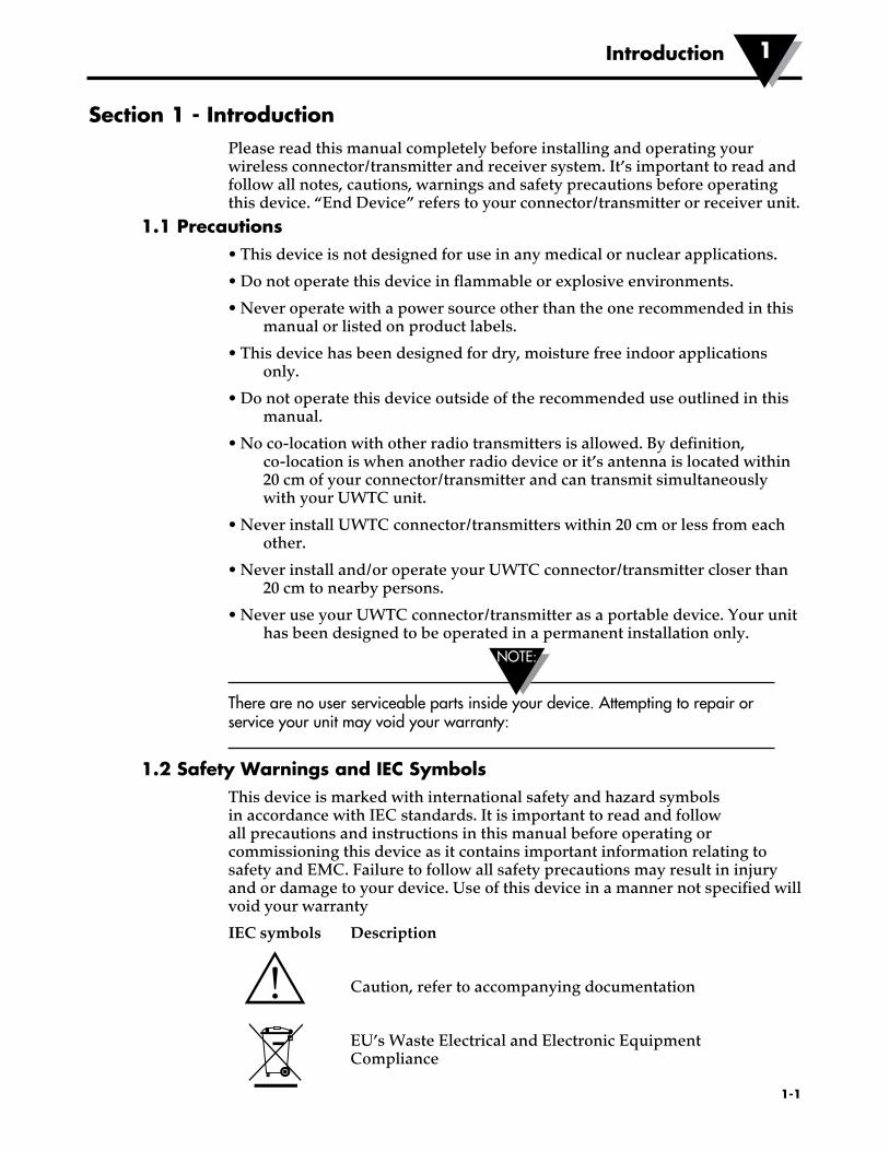
Section 1 - IntroductionPlease read this manual completely before installing and operating your wireless connector/transmitter and receiver system. It’s important to read and follow all notes, cautions, warnings and safety precautions before operating this device. “End Device” refers to your connector/transmitter or receiver unit.
1.1 Precautions• This device is not designed for use in any medical or nuclear applications.
• Do not operate this device in flammable or explosive environments.
• Never operate with a power source other than the one recommended in this manual or listed on product labels.
• This device has been designed for dry, moisture free indoor applications only.
• Do not operate this device outside of the recommended use outlined in this manual.
• No co-location with other radio transmitters is allowed. By definition, co-location is when another radio device or it’s antenna is located within 20 cm of your connector/transmitter and can transmit simultaneously with your UWTC unit.
• Never install UWTC connector/transmitters within 20 cm or less from each other.
• Never install and/or operate your UWTC connector/transmitter closer than 20 cm to nearby persons.
• Never use your UWTC connector/transmitter as a portable device. Your unit has been designed to be operated in a permanent installation only.
There are no user serviceable parts inside your device. Attempting to repair or service your unit may void your warranty:
1.2 Safety Warnings and IEC SymbolsThis device is marked with international safety and hazard symbols in accordance with IEC standards. It is important to read and follow all precautions and instructions in this manual before operating or commissioning this device as it contains important information relating to safety and EMC. Failure to follow all safety precautions may result in injury and or damage to your device. Use of this device in a manner not specified will void your warranty
IEC symbols Description
Caution, refer to accompanying documentation
EU’s Waste Electrical and Electronic Equipment Compliance
NOTE:
�1-1
Introduction 1

1.3 Product Labeling1.3.1 Connector Front Labels
1.3.2 Connector Rear Label
1.3.3 Receiver Front Labels
®TX
UNIVERSAL WIRELESS THERMOCOUPLE CONNECTOR
LOW BATT
PRESSSETUP
PRESSON/OFF
UWTC
®
Mike MacchiarelliX7947
02/15/11L-1655A-UWRTDMainLabel
Colors: Blue = PMS 293 100% Dark Gray = PMS 430 100% Light Gray = PMS 428 100%
TX
UNIVERSAL WIRELESS RTD CONNECTOR
LOW BATT
PRESS SETUP
PRESS ON/OFF
UWRTD
AN
TE
NN
A
USB
I/O 12–16 Vdc
UWTC SERIES WIRELESS TRANSCEIVER
PROCESS TEMPERATURE
AMBIENT TEMPERATURE
- +
OMEGA ENGINEERING, INC. Stamford, CT 06907 omega.com Made in USA
2.4 GHz
TX RX SB PWR
®
AN
TE
NN
A
USB
I/O 9–24 Vdc
OMEGA ENGINEERING, INC. Stamford, CT 06907
UWTC SERIES WIRELESS RF RECEIVER
2.4 GHz
omega.com
- +
!
Aika MallyaX7898
12/22/11L-1660UWTCRecLabel.eps
Colors: Blue = PMS 293 100% Dark Gray = PMS 430 100% Light Gray = PMS 428 100% Black 100% White
TRANSPARENT LED WINDOW
4 PLACES
TX RX SB PWR
This device complies with Part 15 of the FCC rules. Operation is subject to the following two conditions: 1) This device may not cause harmful interference; 2) This device must accept any interference received, including interference that may cause undesired operation.
FCC ID: OUR–XBEEPRO IC #4214A–XBEEPRO
®
Figure 1-2B. UWTC-1, UWTC-2, Connector Front Label
Figure 1-2A. UWRTD-1, UWRTD-2, Connector Front Label
Figure 1-3. Connector Rear Label (UWTC-1, UWTC-2, UWRTD-1, UWRTD-2)
Figure 1-4. Transmitter Front Label (NEMA) UWTC-1, UWTC-2, UWRTD-1, UWRTD-2
Figure 1-5B. Receiver Front Label UWTC-REC1
Figure 1-5A. Receiver Front Label UWTC-REC2-D
�1-2
Introduction1
MADE IN U.S.A.
!
This device complies with Part 15 of the FCC rules. Operation is subject to the following two conditions: 1) This device may not cause harmful interference; 2) This device must accept any interference received, including interference that may cause undesired operation.
FCC ID: OUR–XBEEPRO IC #4214A–XBEEPRO
omega.com PATENTS & PATENTS PENDING
F
WIRELESSINDUSTRIAL TRANSMITTER
2.4 GHz®
OMEGA ENGINEERING, INC. Stamford, CT 06907
omega.comMade in U.S.A.
! This device complies with Part 15 of the FCC rules. Operation is subject to the following two conditions: 1) This device may not cause harmful interference; 2) This device must accept any interference received, including interference that may cause undesired operation.
FCC ID: OUR–XBEEPROIC #4214A–XBEEPRO

�1-3
TXRXSBPWR
2.4 GHz®
AN
TE
NN
A
US
B
UWTC SERIESWIRELESS TRANSCEIVER
OMEGA ENGINEERING, INC. Stamford, CT 06907
Made in USA
This device complies with Part 15 of the FCC rules. Operation is subject to the following two conditions: 1) This device may not cause harmful interference; 2) This device must accept any interference received, including interference that may cause undesired operation.
!
®
TXRXSBPWR
915 MHz®
AN
TE
NN
A
US
B
UWTC SERIESWIRELESS TRANSCEIVER
OMEGA ENGINEERING, INC. Stamford, CT 06907
Made in USA
This device complies with Part 15 of the FCC rules. Operation is subject to the following two conditions: 1) This device may not cause harmful interference; 2) This device must accept any interference received, including interference that may cause undesired operation.
!
®
TXRXSBPWR
PWR
2.4 GHz®
AN
TE
NN
A
US
B
I/O
UWTC SERIESWIRELESS TRANSCEIVER
12–16 Vdc
-+
OMEGA ENGINEERING, INC. Stamford, CT 06907
Made in USA
This device complies with Part 15 of the FCC rules. Operation is subject to the following two conditions: 1) This device may not cause harmful interference; 2) This device must accept any interference received, including interference that may cause undesired operation.
!
FCC ID: OUR–XBEEPROIC #4214A–XBEEPRO
PROCESS TEMPERATURE
AMBIENT TEMPERATURE
®
Figure 1-6C. Receiver Front Label UWTC-REC2-D-*-NEMA
Figure 1-6A. Receiver Front Label UWTC-REC1-NEMA
Figure 1-6B. Receiver Front Label UWTC-REC1-915-NEMA
AN
TE
NN
A
USB
I/O 12–16 Vdc
UWTC SERIES WIRELESS TRANSCEIVER
- +
OMEGA ENGINEERING, INC. Stamford, CT 06907 omega.com Made in USA
2.4 GHz
TX RX SB PWR
®
Figure 1-6D. Receiver Front Label UWTC-REC2
Introduction 1

�1-4
1.4 Statement on FCC and CE Marking1.4.1 FCC Marking
FCC ID: OUR-XBEEPRO IC #4214A-XBEEPRO
This device complies with Part 15 of the FCC rules. Operation is subject to the following two conditions: 1.) This device may not cause harmful interference. 2.) This device must accept any interference received, including interference that may cause undesired operation.
1.4.2 CE Marking
It is the policy of OMEGA to comply with all worldwide safety and EMI/EMC regulations that apply. OMEGA is constantly pursuing certification of its products to the European New Approach Directives. OMEGA will add the CE mark to every appropriate device upon certification. For additional information see Section 10 - Approvals & Regulatory Compliance.
1.5 General Description and System Components1.5.1 General Description
Your Wireless Thermocouple/RTD Connector Series features stand-alone, compact, battery powered wireless connectors that transmit their readings back to a host receiver up to 120 m (400') away. Each thermocouple unit can be programmed in the field to work as a type J, K, T, E, R, S, B, N or C calibration connector. Each RTD connector can be programed for a 100 ohm, 2 or 3 wire configuration with a 0.00385 or 0.00392 curve. When activated the connector will transmit readings continuously at a pre-set time interval that was programmed by the user during the initial setup. Each unit measures and transmits: Process Input Reading, Connector Ambient Temperature, RF Signal Strength and Battery Condition to the host and is displayed on the PC screen in real-time using the downloadable software. When used with host receiver UWTC-REC1 data from up to 48 wireless connectors can be received and displayed. Each unit includes free downloadable software that converts your PC into a strip chart recorder or data logger so readings can be saved and later printed or exported to a spread sheet file.
1.5.2 System Components
OMEGA ENGINEERING INC. omega.comStamford, CT 06907 Made in U.S.A.
This device complies with Part 15 of the FCC rules. Operation is subject to the following two conditions;1) This device must may not cause harmful interference;2) This device must accept any interference received, including interference that may cause undesired operation.
AN
TE
NN
A
FCC ID: OUR-XBEEPRO
USB
SB
PWR
RX
TX
IC #4214A-XBEEPRO
WIRELESS RF RECEIVERUWTC SERIES
RR
UNIVERSAL WIRELESS THERMOCOUPLE CONNECTORUWTC
ON/OFF
PRESS
PRESS
SETUP
TX
LOW BATT
RECEIVER
CONNECTOR/TRANSMITTER
2.4 GHz
FCC !
Figure 1-7. System Components
Introduction1

2-1
Hardware 2
NOTE:
Section 2 – HardwareIt is important that you read this manual completely and follow all safety precautions before operating this instrument.
2.1 Package InspectionRemove the packing list and verify that you have received all your equipment. If you have any questions about the shipment, please contact our Customer Service Department. We can be reached on the Internet and via e-mail. When you receive the shipment, inspect the container and equipment for any signs of damage. Note any evidence of rough handling in transit. Immediately report any damage to the shipping agent.
The carrier will not honor any damage claims unless all shipping material is saved for inspection. After examining and removing contents, save packing material and carton in the event reshipment is necessary.
2.2 Included ItemsThe following items are supplied in the box.
With UWTC-1, UWTC-2, UWTC-2-NEMA, UWRTD-1, UWRTD-2, or UWRTD-2-NEMA Connector/Transmitter:
• 1 Connector/Transmitter w/Antenna
• 1 UWTC Series Quick Start Guide (MQS4432)
• 1 Type-K Thermocouple Sensor (Omega No. SC-GG-K-30-36-PP) (UWTC-1 and UWTC-2 only)
• 1 Standard (AA) 3.6V Lithium Battery, (Omega No. UWTC-BATT) (for UWTC-1 & UWRTD-1) or 1 Standard (AA) 3.6V High pulse Lithium Battery (for UWTC-2 & UWRTD-2) or 1 standard (C) 3.6V Lithium Battery Assembly (Installed) Omega No. UWTC-BATT-C (for -NB9 or -NEMA versions).
• 1 Mounting Bracket Kit
• 1 TA4F Mating Connector (UWRTD-1 and UWRTD-2 only)
With UWTC-REC1, UWTC-REC2, UMTC-REC2-D, UWTC-REC4, UWTC-REC1-NEMA, UWTC-REC1-915-NEMA, UWTC-REC2-D-*-NEMA Receivers:
• 1 Receiver Device
• 1 Antenna
• 1 UWTC Series Quick Start Manual (MQS4432)
• 1 USB Interface Cable (For NEMA versions, 1 USB NEMA 4X Connector Cable)
• 4 Rubber Enclosure Feet (Only for UWTC-REC1, UWTC-REC2, UWTC-REC2-D, versions)
• I/O Cable (Only for UWTC-REC2-D-*-NEMA)

3-1
Section 3 – Software3.1 Getting Started
The following program files are included on the UWTC User Software that can be downloaded from Omega's website.
• Universal Wireless End Device Configuration Wizard• TC-Central Measurement and Data Logging Program
3.2 Software Installation3.2.1 System Requirements
Your PC should meet the following minimum requirements:
• Pentium Class processor• Hard Drive Space: 210 meg• Ram: 256 meg or higher• 1 Available USB Port• 1 CD-ROM Drive• Windows 2000, XP, Vista or Windows 7 Operating System• Adobe Acrobat Reader
3.2.2 Software Installation
Download and install the free software that's available for your UWTC Series receiver. Your system should begin the installation process automatically. If the software installation does not start automatically please see the “Troubleshooting” Section 7.
This welcome screen should be visible on your computer screen. To continue with installing the program click the “Next >” button.
Software3
Figure 3-1. Welcome Screen

3-2
Software 3
From this screen you select the folder were you want the program files installed on your PC. The default setting will install the software under your “Program” folders in a new folder named “Omega” To continue with installing the program click the “Next >” button.
“Program” folders in a new folder named “Omega” To continue with installing the program click the “Next >” button.
The setup wizard now has all the information to complete the installation of the software on your PC. To continue with installing the program click the “Next >” button.
Figure 3-2. Select Install Screen
Figure 3-3.Confirm Installation Screen

From this screen you must select “Agree” to continue installing your program. After making your selection click the “Next >” button. The setup wizard will now install the software.
Congratulations! You have just successfully installed the TC-Central Program on your PC. To end installing the program and close the setup wizard click the “Close” Button.
Software3
3-3
Figure 3-4. License Agreement Screen
Figure 3-5. Installation CompleteScreen

Software 3
3-4
NOTE:
NOTE:
3.3 USB Driver Installation To install the USB software drivers that are required for your UWTC system components to operate correctly follow these procedures.
You need to have the TC-Central User Software that was supplied with your receiver downloaded on your PC.
1. Connect your UWTC receiver to your computer with the USB cable provided in the box with your device. You should get a notice box that indicates that your computer “Has Found New Hardware”
2. Your computer will then launch the Found New Hardware Wizard. Follow the instructions indicated on the Wizard boxes and the additional instructions noted in this manual with each box.
After completing the Found New Hardware Wizard your system will ask that you repeat this process. This is normal. You should repeat the steps outlined here twice. After the second driver is installed you should then get the “New Hardware Ready For Use” notice.
Figure 3-6. Welcome To The Found New Hardware Wizard Screen
From this box you should check the “No, not at this time” button. Then click the “Next >” button to continue with the driver installation process.

3-5
Figure 3-7. Install Software Automatically Wizard Screen
Next, check the “Install the software automatically” button. Then click the “Next>” button to continue.
Figure 3-8. Completing The Found New Hardware Wizard Screen
This screen will be displayed to indicate that the software drivers have been installed. You should click the “Finish” button to complete the process.
Software3

3-6
Software 3
3.4 UWTC Universal Wireless End Device Configuration WizardThis utility is used to program your connector/transmitter for the following operating parameters: Thermocouple Type, Channel Number and Sample Rate. For complete instructions on using this program please see Section 4.
3.5 TC-Central Measurement and Recording ProgramTo launch the TC-Central program on your PC begin by accessing the “Programs” list under your “Start Menu” Next, scroll through the list of program folders to find the “TC-Central” folder. Inside the “TC-Central” folder click on the “TC-Central” program link. This will start the software running.
3.5.1 Channels TAB
When TC-Central starts up, the “Channels” tab is displayed. This view allows you to see temperatures and properties for up to 48 connector/transmitter at one time by using the scroll bar to the right of the screen.
Figure 3-9. TC-Central Program Screen
This is a view of the TC-Central Program in operation. You will not have any blocks receiving data until you have programmed and placed into operation your connector/transmitters.
3.5.2 Setting up the TC-Central Program
Before you can make wireless measurements with your connector/transmitter the TC-Central software must be configured properly. The following steps outline how to setup your program.

3-7
3.5.3 Channel Configuration
Figure 3-10. Channel Configuration Screen
From the “Tools” pull-down menu select “Configure”….”Channel 1” or click the "Options" button in the channel box you wish to configure. This will open the program settings table were you can make selections on how you want your system to operate.
1
567
2
3
4
8
Figure 3-11. Configuration Channel 1 Screen
➀ Description Field
In the Description Field you can type a reference name that is associated with the location or process being measured by the connector/transmitter for address. Example: “Test Chamber 1”
Software3

3-8
Software 3
② Address Field
Here you must set an address number into this box that corresponds to a matching Connector/Transmitter unit that you are using in your system. For the system to work correctly each Connector/Transmitter must have a number programmed that is different then other units in your system. Click with your mouse on the “Up” and “Down” buttons to advance to a higher or lower address number.
③ Low Alarm/High Alarm
When the “High” or “Low” Alarm box is checked the alarm feature becomes active. Click with your mouse on the “Up” and “Down” buttons to advance to a higher or lower setting. The displayed temperature reading will change to RED digits and begin blinking to indicate that the process temperature has gone below the low alarm or exceeded the high alarm value.
④ Hide
When the “Hide” box is checked the particular box that you are configuring will become inactive and will not show up on the screen when running the TC-Central program. This is used to remove unused boxed when less than 12 Connector/Transmitter units are being used.
⑤ Display Timeout
The Display Timeout setting is used to set how long you want the unit to continue showing the last reading data when communication between the Connector/Transmitter and receiver has been lost. Make sure not to set this value to a time less than the current sample rate programmed into the Connector/Transmitter or you will never receive and or display any readings.
⑥ Process Units
This drop down allows selection of the engineering units displayed for the process input. A similar drop down is available for the ambient units.
⑦ Offset
Offset Calibration
➇ Device Dependent Settings
These buttons allow the user to perform additional configuration for specific end device types.
12
3
4
789
5
6
Figure 3-12. Channel Display Box Screen

3-9
① Thermocouple Sensor Type
This box indicates the type of thermocouple sensor that your connector/-transmitter has been programmed to operate with. As a default the thermocouple color codes have been set to the ANSI color codes. You can change these to IEC color codes, see section 3.5.2
② Reference
This location will display the reference name you typed into the “Description” field when this box was configured. This can be changed at any time.
③ Address
The number displayed here is the address number you specified when this display box was configured. This number must match the corresponding Connector/Transmitter that has the same number specified or your system will not receive the correct data readings.
④ Process
This is the actual process temperature reading that is being measured by your thermocouple or RTD sensor.
⑤ Ambient
This is the actual ambient temperature connector inside the body of your Connector/Transmitter. If the unit is exposed to temperatures outside the limits specified in this manual the reading will begin to blink and the digits will turn red to provide a visual warning.
⑥ Options
The Options button provides quick access to the channel configuration menu.
⑦ RX
The “RX” indicator box will display a green light that blinks each time the receiver acquires data from the corresponding connector transmitter.
⑧ Signal
This percentage bar graph indicates the radio signal strength being received by the receiver. This should be used as guidance when installing your system to help determine the best location and positioning of your equipment.
⑨ Battery
This label indicates the status of the battery. It will change from showing "Good" in green color to "Low" in red color when the battery is near the end of its useful life.
Software3
3-10
Software 3
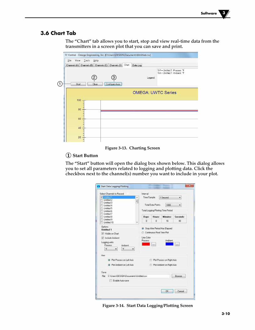
3.6 Chart TabThe “Chart” tab allows you to start, stop and view real-time data from the transmitters in a screen plot that you can save and print.
Figure 3-13. Charting Screen
① Start Button
The “Start” button will open the dialog box shown below. This dialog allows you to set all parameters related to logging and plotting data. Click the checkbox next to the channel(s) number you want to include in your plot.
Figure 3-14. Start Data Logging/Plotting Screen
1
32

3-11
Line Color
You can change the color specified for each channel’s line. Click the “Change” button to select a new color for the Channel selected.
Interval
The total logging time is displayed for the interval setting selected. In general,the interval should normally be set to a value equal to or greater than the same sample time you programmed into the corresponding connector/transmitter for that channel.
If you click the OK button, the data logging session will start, and “Recording Data” will flash in the status bar. The “Start” button above the chart will change to “Stop”, indicating that if you click it again, the logging session will be terminated.
You can choose to have the data logging/chart recording session end after 1000 data points, or have the session run continuously. After 1000 data points have been collected in the continuous mode, the oldest data point is shifted out on the left, and the newest data point is added to the right. Data will continue to be collected and displayed until you click on the “Stop” button above the chart.
Logging Units
Two drop down selections are provided to set the units used in logging and plotting. One is for the process input and one for the ambient temperature of the end device.
② Clear Button
The “Clear” button will delete all data from the chart and the data log.
③ Configure Axis Button
The Configure Axis button opens the dialog box shown below. This dialog allows you to adjustments to both the X and Y axis of the chart.
Figure 3-15. Configuration Chart Screen
Software3

3-12
Software 3
3.7 Charting OptionsYou can access all of the charting options that are available by opening the chart option menu found under the “View” Tab. Alternatively, you can simply right click anywhere on the chart itself to bring up this menu.
Figure 3-16. Charting Options Screen
Zoom In/Zoom Out
Allow you to change the size of the chart on the screen. You can also use the Control-Up Arrow and Control-Down Arrow keys as well.
Default Chart Size
Returns the chart to its normal size (after zooming or panning), and places the title and legend in their normal positions.
3-13
Reset Axes
Reset Axes will effectively cancel the results of a Data Zoom and return the axes back to their original dimensions, but will not change the size of the chart.
Chart (Mouse) Zoom
Perform the same function as mentioned above, by moving the mouse up or down, or rolling the mouse wheel.
Data (Box) Zoom
When checked, you can use the mouse to click and drag a rectangle around a line of data to magnify that portion of the chart. The chart size will remain the same, but the axes will be expanded as well and the data line(s) to allow viewing more detail. You can close either of the axis scroll bars by clicking on the Red button of each scroll bar.
Pan
Allows you to move the chart as well as the title and legend around on the screen. If the Pan item is checked, you can still use the mouse wheel to zoom in and out, while holding the left button down to move the chart as desired.
Reset Axes will effectively cancel the results of a Data Zoom and return the axes back to their original dimensions, but will not change the size of the chart.
Floating Cursor
When checked, will display a crosshair type cursor that you can move with the mouse. You can use the Floating Cursor to pinpoint a particular temperature and time. The status bar displays the data point number, the time, and the temperature, where the crosshairs meet. If the horizontal cursor line is touching a data plot line, the corresponding channel number is also displayed in the status bar.
Tracking Cursor
When checked, will perform similarly to the Floating Cursor, except that you can specify a channel for the horizontal cursor line to lock on to. This channel is also displayed in the status bar. With this option enabled, you can move the mouse left and right without regard to up and down, and the horizontal cursor will remain pointing to the line (channel) you specify. Assuming you have more than one channel plotted on the chart, you can switch tracking to another channel by moving the mouse over the data line of that channel until the mouse cursor becomes a hand with a pointing finger. If you left-click at this point, the Tracking Cursor will track that line. You can also change the channel of the Tracking Cursor from the chart’s context menu, Tracking Cursor menu item combo box. The same option is also available in the View Chart menu in the main menu bar
Line Options
Allows you to select which channel(s) you want to display, and/or change the color of each channel data line. This allows you to limit your view to either a single channel, or a selected two or more channels for comparison, instead of having all twelve channels displayed at once.
Software3

3-14
Software 3
3.8 Data Log TabThe “Data Log” tab allows you to view received data from a connector/ transmitter in a table format as it is being recorded. This data can be saved and printed.
Figure 3-17. Data Logging Screen
① Start Button
The Start button opens the dialog box shown in figure 3-14 and described in section 3.6.
② Clear Button
The “Clear” button will delete all data from the data log.
③ Adjust Button
Resizes the columns to the smallest size necessary to fit all the data in the columns.
④ Auto Scroll Rows
The Auto Scroll Rows check box causes the data to be scrolled up one line each time a new row of data is added to the grid.
4
1
32

3-15
3.9 Menu Tabs3.9.1 File Menu
Figure 3-18. File Menu Screen
Open Data File...
Displays a dialog box which allows you to choose a data file to open and display on the chart and in the data log. This file must be a file that was saved by the Save menu item in TC Central. If the file has been modified externally, you may not be able to open it.
Save Data File...
Displays a dialog box which allows you to save the data currently displayed on the chart and in the data log. The file format is either tab separated (*.txt) or (*.csv) (comma separated values), which can be opened by Microsoft Excel for further analysis and charting. It is strongly recommended that you do not modify this file, or you may not be able to open it again in TC Central. Use Excel’s “Save As” option to save it as a Microsoft Excel Workbook (*.xls), which you can then modify.
Start Data Recording…
Performs the same function as the Start button on the Chart and Data Log Tabs.
A dialog box is displayed allowing you to select one or more channels to be plotted and logged by checking the checkbox next to the channel number. You can also change the color of each channel’s line.
The interval should be set as desired for your particular needs. The total logging time is displayed for the interval setting selected. In general, the interval should normally be set to a value equal to or greater than the “Seconds per Sample” you configured into the transmitter using the UWTC Configuration Wizard.
You can choose to have the data logging/chart recording session end after 1000 data points, or have the session run continuously. After 1000 data points have been collected in the continuous mode, the oldest data point is shifted out on the left, and the newest data point is added to the right. Data will continue
Software3

3-16
Software 3
If you click the OK button, the data logging session will start, and “Recording Data” will flash in the status bar. The “Start” button above the chart and data log will change to “Stop”, indicating that if you click it again, the logging session will be terminated.
Stop Data Recording...
Performs the same function as the “Stop” buttons on the Chart and Data Log Tabs, by terminating any data logging/plotting session in progress.
Export Chart…
Displays a dialog box that allows you to either save an image of the current chart on the Chart Tab, or copy it to the clipboard.
Print Preview…
Displays a standard Windows Print Preview dialog, allowing you to view the item(s) as they would be printed on a printer. You can also print from this dialog by clicking the printer icon in the upper left corner. If the Channels Tab is displayed before choosing this option, a screen snapshot of the Channels Tab will be previewed. If the Chart Tab is displayed before choosing this option, the current chart image will be previewed. If the Data Log Tab is displayed, the data table in grid style format will be previewed.
Page Setup…
Displays a standard page setup dialog box which allows you to change the page orientation, margins, paper size, etc. You can then select the Print Preview menu to view your changes without printing.
Print…
Displays a standard print dialog box. This allows you to select printers, printer preferences, page ranges, number of copies, etc. If you click the “Print” button, the specified page(s) will be sent to the printer. If you click the “Apply” button, you can then select the Print Preview menu to view your changes without printing.
Exit…
Will exit and close the TC-Central program.
3.9.2 View Menu
Figure 3-19. View Menu Screen

3-17
Channels
Performs the same functions as the Channels context menu, except for the Configure menu item. See Channels TAB Menu (Section 3.5) for an explanation of this menu.
Additionally selection of channel tabs and thermocouple color codes can be made here. By default the setting for thermocouple color code is the American National Standards Institute (ANSI) standard. You can change the default setting to the International Electrotechnical Commission (IEC) standard or the Japanese standard.
Chart
Performs the same functions as the Chart context menu. See Chart Tab Menu (Section 3.6) for an explanation of this menu.
Data Log
Performs the same functions as the “Auto Scroll Rows” checkbox and the “Adjust” button on the data log. See Data Log Menu (Section 3.8) for an explanation of these functions.
Changing Thermocouple Color Codes.
By default the setting for thermocouple color code is the American National Standards Institute (ANSI) standard. You can change the default setting to the International Electrotechnical Commission (IEC) standard or the Japanese standard here under this menu in the CT-Central software.
3.9.3 Tools Menu
Figure 3-20. Tools Menu Tab Screen Configuration
Displays the same dialog box as the Channels context menu, Configure menu item, after you select a channel to configure. See Channels Tab above for an explanation of this dialog box.
Software 3
3-18
Software 3
Auto Connect Receiver
Normally disabled, if you have established communications with a receiver connected to your PC. If for some reason such as the receiver being replaced with a different one, this menu item will be available. When selected, TC Central will send “+++” to each and every available COM port in an attempt to identify a port with a receiver connected to it. If TC Central finds a receiver, it will perform the necessary configuration of the receiver and display the COM port number in Green in the status bar. Even though your receiver is connected via a USB Cable, the USB drivers installed create a “virtual” COM port, usually a port number greater than COM4. Once connected, TC Central saves (remembers) the port number you are using, and will automatically connect to it the next time TC Central is started.
Manual Connect Receiver
Is available if you do not want TC Central to send “+++” to all of your serial ports. If you know the COM port number used by your receiver, you can connect to it from this menu without disturbing other COM ports. You can also use this menu to connect to a second receiver connected to the PC on a different COM port.
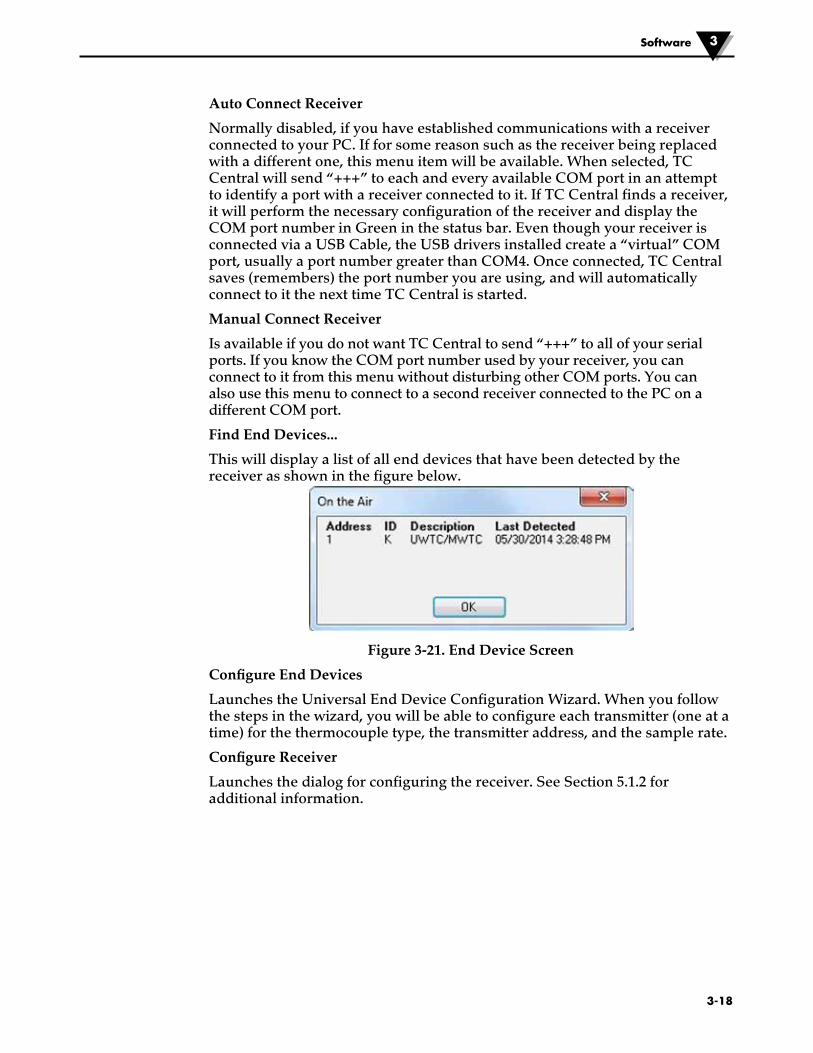
Find End Devices...
This will display a list of all end devices that have been detected by the receiver as shown in the figure below.
Figure 3-21. End Device Screen
Configure End Devices
Launches the Universal End Device Configuration Wizard. When you follow the steps in the wizard, you will be able to configure each transmitter (one at a time) for the thermocouple type, the transmitter address, and the sample rate.
Configure Receiver
Launches the dialog for configuring the receiver. See Section 5.1.2 for additional information.

4-1
Section 4 – Transmitter/Connector Operation
Figure 4-1A. Thermocouple Connector (UWTC-1, UWTC-2)
Figure 4-1B. RTD Connector (UWRTD-1, UWRTD-2)
Figure 4-1B. Thermocouple/RTD Connector (UWTC-2-NEMA, UWRTD-2-NEMA)
®TX
UNIVERSAL WIRELESS RTD CONNECTOR
LOW BATT
PRESS SETUP
PRESS ON/OFF
UWRTD
32
41
7
5
6 8
1
RTD WIRING DETAIL
2 3
4
R
IC #4214A-XBEEPROFCC ID: OUR-XBEEPRO
OMEGA ENGINEERING INC. omega.comStamford, CT 06907 Made in U.S.A.
WIRELESSINDUSTRIAL TRANSMITTER
CFCThis device complies with Part 15 of the FCC rules.Operation is subject to the following two conditions;
2) This device must accept any interference received, including interference that may cause undesired
1) This device must may not cause harmful interference;
operation.
2.4 GHz
!
1
2
®TX
UNIVERSAL WIRELESS THERMOCOUPLE CONNECTOR
LOW BATT
PRESSSETUP
PRESSON/OFF
UWTC
32
41
7
5
68
Transmitter Operation4
(1) “ON/OFF” Button (2) “SETUP” Button (3) Transmit Indicator (4) Low Battery Indicator (5) USB Port (6) Sensor Input (7) Antenna (8) Battery Compartment
(1) Antenna (2) Sensor Cable See Fig. 4-2A & 4-2B for more info.
4-2
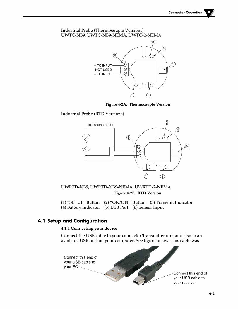
Industrial Probe (Thermocouple Versions) UWTC-NB9, UWTC-NB9-NEMA, UWTC-2-NEMA
Figure 4-2A. Thermocouple Version
Industrial Probe (RTD Versions)
UWRTD-NB9, UWRTD-NB9-NEMA, UWRTD-2-NEMAFigure 4-2B. RTD Version
(1) “SETUP” Button (2) “ON/OFF” Button (3) Transmit Indicator (4) Battery Indicator (5) USB Port (6) Sensor Input
4.1 Setup and Configuration4.1.1 Connecting your device
Connect the USB cable to your connector/transmitter unit and also to an available USB port on your computer. See figure below. This cable was
+ TC INPUTNOT USED
– TC INPUT
3
+
-
4
5
6
1 2
3
4
5
6
1 2
RTD WIRING DETAIL
Connector Operation 4
Connect this end of your USB cable to your PC
Connect this end of your USB cable to your receiver

4-3
Connector Operation4
4.1.2 Configure Your Connector/Transmitter
Now that you have connected your USB cable to your PC and connector/transmitter you will complete the following steps to configure your connector/transmitter before placing the unit into operation. You will be using the configuration software utility that you installed onto your PC in Section 3.2.
If you have not installed the configuration software utility you should do so now.
During this procedure you will be setting the following parameters in your connector/transmitter.
Connector Options:
For UWTC - Thermocouple Type: This will program your device to provide the correct temperature readings to your receiver for the type of thermocouple you will be using. Available types are J, K, T, E, R, S, N, B.
For UWRTD - RTD Type: This will program your device to provide the correct temperature readings to your receiver for the type of RTD you will be using.
If you will be using more than one receiver unit in your area it is important to set the connector/transmitter address numbers to be a corresponding number in your TC-Central software. See Examples below. For the first receiver: Set the addresses on your connector/transmitters to 101, 102, 103, 104, etc. Then set the addresses in your TC-Central user software to match. For the second receiver: Set the addresses on your connector/transmitters to 201, 202, 203, 204, etc. Then set the addresses in your TC-Central user software to match. This numbering scheme can be expanded to match the number of receivers you are using.
Transmitter Address:
This sets a unique address number for your connector/transmitter. Later, when you set up your measurement software you will again set address numbers to receive readings from the corresponding unit(s). Each connector must be set for a different address number for your system to operate correctly.
Sample Rate:
This will program your device to transmit 1 data reading to your receiver at a specified time interval. Available settings are 2, 3, 5, 15, 30, 45, 60, 75 or 90 seconds.
The sample rate you set will have the most direct effect on the life of the battery in your connector/transmitter. It is recommended that you set the longest sample time that your application can live with to extend time between battery replacement. See Section 6 for more information on battery life.
RF Network Settings:
NOTE:
NOTE:

4-4
Connector Operation 4
RF Channel:
Sets the channel number used for transmitting data to the receiver. Can be set in the for any value from 12 to 23.
Network ID:
Sets the ID of the network for the corresponding receiver.
Receiver Address:
Sets the address of the corresponding receiver.
STEP 1. Enter the “SETUP” mode.
To place your connector/transmitter into the “SETUP” mode for programming follow this procedure.
Figure 4-3. Setup Mode
Press and hold the “ON/OFF” button. While the “ON/OFF” button is being held, press the “SETUP” button one time and then release the “ON/OFF” button. The green (TX) indicator on the front of your device should be blinking at a steady rate. This indicates your connector/transmitter is ready to run the configuration utility software.
STEP 2. Launch Setup Utility Program.
To launch the End Device Configuration Wizard. program on your PC begin by accessing the “Programs” list under your “Start Menu”.
Scroll through the list of to find the “TC-Central” folder, then select the End Device Configuration Wizard.
®TX
UNIVERSAL WIRELESS THERMOCOUPLE CONNECTOR
LOW BATT
PRESSSETUP
PRESSON/OFF
UWTC
SETUPBUTTON
ON/OFFBUTTON
Figure 4-4. Launch Setup Utility Program

Connector Operation4
4-5
STEP 3. Programing your settings into a connector/transmitter.
After starting the setup utility program this will be the first screen you will see. Click the “Next >” button to proceed and continue setting up your connector/ transmitter. Each screen will provide instruction details on how to proceed.
If you have not already connected your connector/transmitter to a USB port on your PC you must do this now before continuing. After your unit has been connected click the “Next >” button to proceed and continue setting up your connector/transmitter.
Figure 4-5. Welcome To End Device Configuration Wizard screen.
Figure 4-6. Connect The End Device Screen

Connector Operation 4
4-6
If you have not already placed your connector/transmitter into the “Setup” mode you should do this now before continuing. After your unit has been placed into the “Setup” mode click the “Next >” button to proceed and continue setting up your connector/transmitter.
After successful communication between your connector/transmitter has been established you can click the “Next >” button to proceed and continue setting up your connector/transmitter. If you did not receive this confirmation of proper communication you should click the “Back” button to try connecting again. If you still do not obtain a good connection visit the “Troubleshooting” Section of this users guide for additional help.
Figure 4-7. Setup The End Device Screen
Figure 4-8. Establish A Link Screen

Connector Operation4
4-7
Figure 4-9. Read Settings Screen
Figure 4-10. Choose Options Screen

From this screen you will select the main operating settings for your connector/transmitter. Start by selecting the type of Thermocouple you will be using. Then select the address setting for this unit.
Each connector/transmitter must have a different address number than other units in your system for proper operation).
Then select the sample rate that your unit will transmit data to the receiver. After making your selections click the “Next >” button to proceed and program your settings into connector/transmitter.
Congratulations! You have successfully programmed your connector transmitter. After your unit has been programmed click the “Finish” button to close the utility program or click the “Start” button to begin setting up a second unit. You can now disconnect your connector transmitter from the programming cable. Press the “Setup” button on the connector/transmitter one time to exit the “Setup” mode.
Figure 4-11. Send Settings To End Device Screen
�4-8
Connector Operation 4
NOTE:
�4-9
Connector Operation4
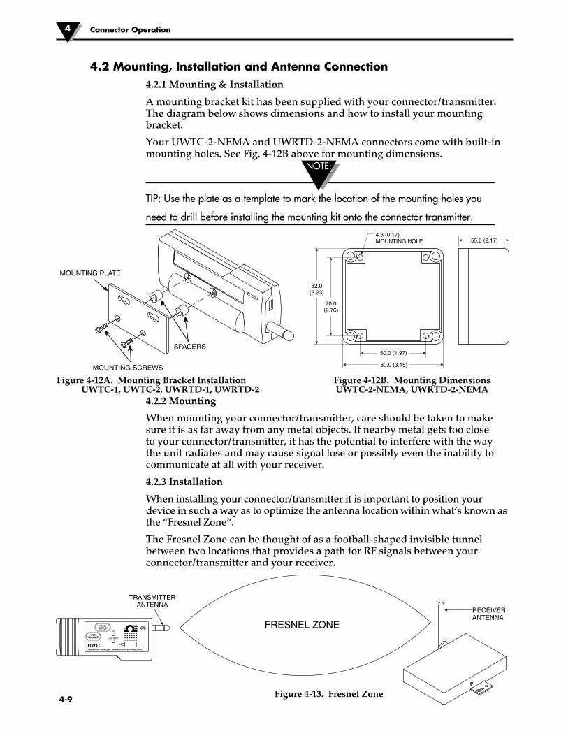
4.2 Mounting, Installation and Antenna Connection4.2.1 Mounting & Installation
A mounting bracket kit has been supplied with your connector/transmitter. The diagram below shows dimensions and how to install your mounting bracket.
Your UWTC-2-NEMA and UWRTD-2-NEMA connectors come with built-in mounting holes. See Fig. 4-12B above for mounting dimensions.
TIP: Use the plate as a template to mark the location of the mounting holes you
need to drill before installing the mounting kit onto the connector transmitter.
Figure 4-12A. Mounting Bracket Installation Figure 4-12B. Mounting Dimensions UWTC-1, UWTC-2, UWRTD-1, UWRTD-2 UWTC-2-NEMA, UWRTD-2-NEMA
4.2.2 Mounting
When mounting your connector/transmitter, care should be taken to make sure it is as far away from any metal objects. If nearby metal gets too close to your connector/transmitter, it has the potential to interfere with the way the unit radiates and may cause signal lose or possibly even the inability to communicate at all with your receiver.
4.2.3 Installation
When installing your connector/transmitter it is important to position your device in such a way as to optimize the antenna location within what’s known as the “Fresnel Zone”.
The Fresnel Zone can be thought of as a football-shaped invisible tunnel between two locations that provides a path for RF signals between your connector/transmitter and your receiver.
Figure 4-13. Fresnel Zone
SPACERS
MOUNTING PLATE
MOUNTING SCREWS
4.3 (0.17)MOUNTING HOLE
50.0 (1.97)
82.0(3.23)
70.0(2.76)
80.0 (3.15)
55.0 (2.17)
NOTE:
®TX
UNIVERSAL WIRELESS THERMOCOUPLE CONNECTOR
LOW BATT
PRESSSETUP
PRESSON/OFF
UWTC
FRESNEL ZONE
TRANSMITTERANTENNA
RECEIVERANTENNA

Connector Operation 4
4-10
In order to achieve maximum range, the football-shaped path in which radio waves travel must be free of all obstructions. Obstacles in the path (especially metal) will decrease the communication range between your connector/transmitter and receiver. Also, If the antennas are mounted just barely off the ground, over half of the Fresnel zone ends up being obstructed by the earth resulting in significant reduction in range. To avoid this problem, the antennas should be mounted high enough off of the ground so that the earth does not interfere with the central diameter of the Fresnel zone.
It is important to understand that the environment may change over time due to new equipment or machinery being installed, building construction, etc. If new obstacles exist between your connector/transmitter and receiver, the devices can be raised on one end or on both ends to hopefully clear the Fresnel Zone of obstructions.
No co-location with other radio transmitters is allowed. By definition, co-location is when another radio device or it’s antenna is located within 20 cm of your connector/transmitter and can transmit simultaneously with your UWTC unit.
Never install UWTC connector/transmitters within 20 cm or less from each other.
Never use your UWTC connector/transmitter as a portable device. Your unit has been designed to be operated in a permanent installation only.
4.2.4 Antenna Connection
Your device has been shipped to you a standard antenna already attached. You may remove and install Omega No. UWTC-ANT-LR high gain antenna to improve range and signal strength if needed. This antenna is sold as an accessory.
In some cases, a short RF cable may be used to connect an antenna to your device. Please note that RF extension cables will always add some loss to the transmitting signal strength. The longer the cable the more signal will be lost over that cable. Because of this the length of the cable should be kept as short as possible.
Use of any other antenna then what’s supplied with your device will void all FCC and CE regulatory compliance.
Additional Information on installation and system operation can be found in Section 6.
NOTE:
NOTE:
NOTE:
NOTE:
NOTE:

4-11
4.3 - Thermocouple ConnectionsYour connector/transmitter has been design with a patented universal input that will interface with most industry thermocouple connectors. Omega’s Miniature (SMP) Series and Standard (OST) Series of connectors will plug directly into the side of your unit. Omega’s line of thermocouple probes with connectors attached will also plug directly into your unit.
Patented Universal Miniature Connector Standard Connector Input OST Series
Figure 4-14. Thermocouple Connection
4.3.1 Thermocouple Operating Environment and Placement
4.3.2 Ambient Temperature Concerns
Your Connector/Transmitter is rated for use in ambient temperatures between -10°C (14°F) to 70°C (158°F). Exposure to temperatures below or above these stated temperatures can cause your device to malfunction and produce incorrect operation. When installing your thermocouple probe care should be taken to make sure your connector/transmitter will not be operated in an environment outside the specifications outlined in Section 9.
4.3.3 Recommended Placement
For applications were the ambient temperature around the thermocouple probe has the possibility of exceeding the operating conditions outlined in Section 9 of this manual, the connector/transmitter should be mounted away from the thermocouple probe in an area within the normal operating conditions of -10°C (14°F) to 70°C (158°F). See Below.
Figure 4-15. Recommended Thermocouple Placement
Installing your connector/transmitter in an application were the device will be exposed to ambient temperatures above or below the operating limits specified in this manual will damage your unit and cause the unit to malfunction and produce incorrect operation.
CAUTION:
MEASUREMENT AREATHERMOCOUPLE SAFE
AMBIENT AREA
THERMOCOUPLE PROBE
CONNECTOR/TRANSMITTER
MATING CONNECTOR
®TX
UNIVERSAL WIRELESS THERMOCOUPLE CONNECTOR
LOW BATT
PRESSSETUP
PRESSON/OFF
UWTC
HOT ZONE COLD ZONE
Connector Operation4

4-12
Connector Operation 4
4.4 RTD ConnectionYour connector/transmitter has been designed with a RTD input that will interface with Omega’s TA4F connector. This connector will plug directly into the side of your unit as shown below. A mating connector was provided in the box with your unit (UWRTD-1, UWRTD-2 only).
RTD Receptacle RTD Connector Figure 4-16. RTD Connection
4.4.1 RTD Operating Environment and Placement
4.4.2 Ambient Temperature Concerns
Your Connector/Transmitter is rated for use in ambient temperatures between -10°C (14°F) to 70°C (158°F). Exposure to temperatures below or above these stated temperatures can cause your device to malfunction and produce incorrect operation. When installing your RTD probe care should be taken to make sure your connector/transmitter will not be operated in an environment outside the specifications outlined in Section 9.
4.4.3 Recommended Placement
For applications were the ambient temperature around the RTD probe has the possibility of exceeding the operating conditions outlined in Section 9 of this manual, the connector/transmitter should be mounted away from the thermocouple probe in an area within the normal operating conditions of -10°C (14°F) to 70°C (158°F). See Below.
Figure 4-17. Recommended RTD Placement
4.5 Battery Installation or Replacement4.5.1 UWTC-1, UWTC-2, UWRTD-1, UWRTD-2
To install or replace the battery in your Connector/ Transmitter you must first remove the two screws located on the back side of your device. This will allow you to access the battery compartment.
MEASUREMENT AREARTD SAFE
AMBIENT AREA
RTD PROBE
CONNECTOR/TRANSMITTER
TA4F MATING CONNECTOR
®TX
UNIVERSAL WIRELESS THERMOCOUPLE CONNECTOR
LOW BATT
PRESSSETUP
PRESSON/OFF
UWTC
HOT ZONE COLD ZONE
BATTERY
+ –
Figure 4-18A. Battery Replacement UWTC-1, UWTC-2, UWRTD-1, UWRTD-2

Connector Operation4
4-13
4.5.2 UWTC-2-NEMA & UWRTD-2-NEMA
To install or replace the battery in your End Device you must first remove the four screws located on the Lid of the enclosure. This will allow you to access the battery compartment.
Figure 4-18B. Battery Placement UWTC-2-NEMA, UWRTD-2-NEMA
Your NEMA transmitter is equipped with a “C” size lithium power cell assembly, Omega Part Number: UWTC-BATT-C. To install a replacement battery assembly, follow the steps outlined here.
A. Remove the two screws that secure the main circuit board assembly.
B. Lift the circuit board just high enough to allow you to unplug the connector that attaches the battery assembly to the bottom of the circuit board.
C. Remove the old power cell.
D. Install your new battery assembly into the housing in the same position as the old battery was located.
E. Connect the battery assembly connector to the mating connector on the bottom of the circuit board.
F. Install the circuit board back into the housing and secure with the two screws you removed in step one.
G. Installation complete.
LID
LID SCREW
PCB SCREW
PC BOARD
BATTERY
ENCLOSURE
CABLE FITTING
ANTENNA
4-14
Lithium batteries may get hot, explode or ignite and cause serious injury if exposed to abusive conditions. Be sure to follow the safety warnings listed below: Your transmitter operates with one 3.6V Lithium Battery. Omega Replacement Part Number UWTC-BAT-C. Never operate your transmitter with a different battery than what is specified in this manual or on the product data sheet. Do not discharge the battery using any device except your Transmitter unit. When the battery is used in devices other than the specified device, it may damage the battery or reduce its life expectancy. If the device causes an abnormal current to flow, it may cause the battery to become hot, explode or ignite and cause serious injury. Refer to the Omega technical data sheet or this manual for the temperature ranges over which the battery can be operated. Use of the battery outside this temperature range may damage the Transmitter or reduce the performance and life of the battery. • Do not place the battery in fire or heat the battery. • Do not store batteries with other hazardous or combustible materials. • Do not install the battery backwards so the polarity is reversed. • Do not connect the positive terminal and negative terminal of the battery to each other with any metal object (such as wire). • Do not carry or store the battery together with metal objects. • Do not pierce the battery with nails, strike the battery with a hammer, step on the battery or otherwise subject it to strong impacts or shocks. • Do not solder directly onto the battery. • Do not expose battery to water or salt water, or allow the battery to get wet. • Do not disassemble or modify the battery. • When the battery is discharged, insulate the terminals with adhesive tape or similar materials before disposal. • Immediately discontinue use of the battery if, while using or storing the battery, the battery emits an unusual smell, feels hot, changes color or shape, leaks or appears abnormal in any other way. Contact Omega if any of these problems are observed. • Do not place the battery in microwave ovens.
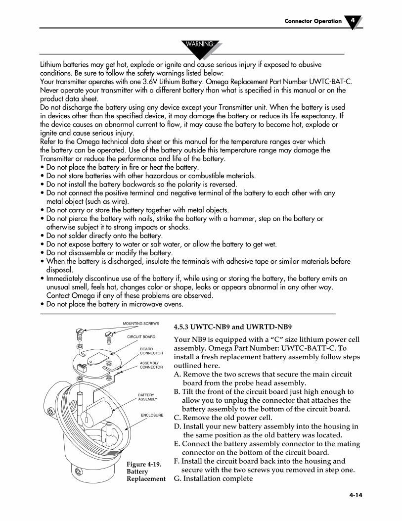
4.5.3 UWTC-NB9 and UWRTD-NB9
Your NB9 is equipped with a “C” size lithium power cell assembly. Omega Part Number: UWTC-BATT-C. To install a fresh replacement battery assembly follow steps outlined here.A. Remove the two screws that secure the main circuit
board from the probe head assembly.B. Tilt the front of the circuit board just high enough to
allow you to unplug the connector that attaches the battery assembly to the bottom of the circuit board.
C. Remove the old power cell.D. Install your new battery assembly into the housing in
the same position as the old battery was located.E. Connect the battery assembly connector to the mating
connector on the bottom of the circuit board.F. Install the circuit board back into the housing and
secure with the two screws you removed in step one.G. Installation complete
ASSEMBLYCONNECTOR
BATTERYASSEMBLY
ENCLOSURE
BOARDCONNECTOR
CIRCUIT BOARD
MOUNTING SCREWS
Figure 4-19. Battery Replacement
WARNING:
Connector Operation 4

5-1
Receiver Operation5
Section 5 - Receiver OperationUWTC-REC1 (1) Antenna (2) USB Port (mini-B) (3) Indicator Lights
Figure 5-1. Receiver Operation - UWTC-REC1
Figure 5-2. Receiver Operation - UWTC-REC2
AN
TE
NN
A
USB
OMEGA ENGINEERING, INC. Stamford, CT 06907
UWTC SERIES WIRELESS RF RECEIVER
2.4 GHz
omega.com Made in U.S.A.
!
TX RX SB PWR
This device complies with Part 15 of the FCC rules. Operation is subject to the following two conditions: 1) This device may not cause harmful interference; 2) This device must accept any interference received, including interference that may cause undesired operation.
FCC ID: OUR–XBEEPRO IC #4214A–XBEEPRO F
®
2
3
1
1 2 3 4 5
6 7 8 9
UWTC-RPT1 SIDE VIEW
AN
TE
NN
A
USB
I/O12–16 Vdc
UWTC SERIESWIRELESS TRANSCEIVER
- +
OMEGA ENGINEERING, INC. Stamford, CT 06907omega.com Made in USA
2.4 GHz
TXRXSBPWR
®
2
3
1
654
UWTC-REC2 (1) Antenna (2) USB Port (mini-B) (3) Indicator Lights (4) Output/Alarm Connection Pin#1 - Analog Output (+) Pin#2 - No Connection (Reserved) Pin#3 - No Connection (Reserved) Pin#4 - No Connection (Reserved) Pin#5 - Alarm Ground Pin#6 - No Connection (Reserved) Pin#7 - Alarm Power (0 to 24 Vdc) Pin#8 - Alarm Output (Open
Drain to Pin#8, 10K pull-up to Pin#7, 200 mA Max)
Pin#9 - Analog Output (–) (5) Power LED (6) DC Power Jack (12 to 16 Vdc @ 300 mA)
5-2
Receiver Operation 5
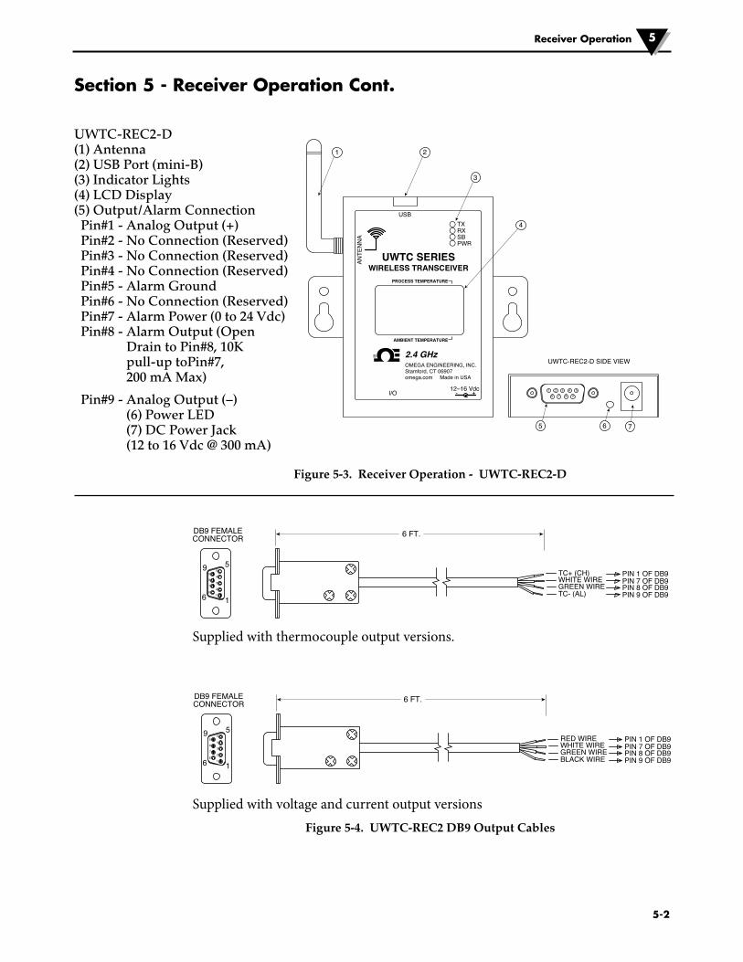
Section 5 - Receiver Operation Cont.
Figure 5-3. Receiver Operation - UWTC-REC2-D
Figure 5-4. UWTC-REC2 DB9 Output Cables
UWTC-REC2-D SIDE VIEW
1 2 3 4 5
6 7 8 9
AN
TE
NN
A
USB
I/O12–16 Vdc
UWTC SERIESWIRELESS TRANSCEIVER
PROCESS TEMPERATURE
AMBIENT TEMPERATURE
- +
OMEGA ENGINEERING, INC. Stamford, CT 06907omega.com Made in USA
2.4 GHz
TXRXSBPWR
®
2
3
1
4
765
UWTC-REC2-D (1) Antenna (2) USB Port (mini-B) (3) Indicator Lights (4) LCD Display (5) Output/Alarm Connection Pin#1 - Analog Output (+) Pin#2 - No Connection (Reserved) Pin#3 - No Connection (Reserved) Pin#4 - No Connection (Reserved) Pin#5 - Alarm Ground Pin#6 - No Connection (Reserved) Pin#7 - Alarm Power (0 to 24 Vdc) Pin#8 - Alarm Output (Open
Drain to Pin#8, 10K pull-up toPin#7, 200 mA Max)
Pin#9 - Analog Output (–) (6) Power LED (7) DC Power Jack (12 to 16 Vdc @ 300 mA)
WHITE WIREGREEN WIRE
RED WIRE
DB9 FEMALECONNECTOR
1
2
3
4
5
6
7
8
9
1
PIN 1 OF DB9PIN 7 OF DB9PIN 8 OF DB9
6 FT.
59
6 BLACK WIRE PIN 9 OF DB9
WHITE WIREGREEN WIRE
TC+ (CH)
DB9 FEMALECONNECTOR
1
2
3
4
5
6
7
8
9
1
PIN 1 OF DB9PIN 7 OF DB9PIN 8 OF DB9
6 FT.
59
6 TC- (AL) PIN 9 OF DB9
Supplied with thermocouple output versions.
Supplied with voltage and current output versions

5-3
Section 5 - Receiver Operation Cont.
Figure 5-5. Receiver Operation - UWTC-REC3
Figure 5-5A. Receiver Operation - UWTC-REC1-NEMA, UWTC-REC1-915-NEMA
1
2
3TXRXSBPWR
2.4 GHz®
AN
TE
NN
A
US
B
UWTC SERIESWIRELESS TRANSCEIVER
OMEGA ENGINEERING, INC. Stamford, CT 06907
Made in USA
This device complies with Part 15 of the FCC rules. Operation is subject to the following two conditions: 1) This device may not cause harmful interference; 2) This device must accept any interference received, including interference that may cause undesired operation.
!
FCC ID: OUR–XBEEPROIC #4214A–XBEEPRO
®
4
UWTC-REC1-NEMA(1) Antenna(2) USB NEMA 4X
Connector Sealing Cap(3) USB NEMA 4X
Connector Cable(4) Indicator Lights
Receiver Operation5
UWTC-REC3 SIDE VIEW
R OMEGAUWTC SERIES 2.4 GHz
DIAGNOSTICS
omega.com Made in USA
Omega Engineering Inc.Stamford, CT 06907
4 5
POWER
TRANSMIT
NETWORK LINKACTIVITY
6
3
2
2
1
UWTC-REC3 (1) Antenna (2) Indicator Lights (3) Power LED (4) DC Power Jack (5) Reset (6) Ethernet Connection (RJ45)

Section 5 - Receiver Operation Cont.
Figure 5-5B. Receiver Operation - UWTC-REC2-D-TC-NEMA
Figure 5-5C. Receiver Operation - UWTC-REC2-D-*-NEMA
1
25
3
4
6
UWTC-REC2-D-*-NEMA (1) Antenna (2) USB NEMA 4X Connector
Sealing Cap(3) USB NEMA 4X Connector Cable (4) Indicator Lights (5) 8 Pin Analog I/O Waterproof Cable *: V1, V2, MA Units. Cable Configuration: Green Wire: Analog Output (–) White Wire: Analog Output (+) Orange Wire: Alarm Power Yellow Wire: Alarm Output Blue Wire: Digital Ground (6) 12 Vdc Power Adaptor
1
6
7
25
3
4
UWTC-REC2--D-TC-NEMA (1) Antenna (2) USB NEMA 4X Connector Sealing Cap (3) USB NEMA 4X Connector Cable (4) Indicator Lights (5) 8 Pin Analog I/O Waterproof Cable Cable Configuration: Orange Wire: Alarm Power Yellow Wire: Alarm Output Blue Wire: Digital Ground (6) Thermocouple Cable Cable Configuration: Yellow Wire: Thermocouple Output (+) Red Wire: Thermocouple Output (-) (7) 12 Vdc Power Adaptor
Receiver Operation 5
5-4
Receiver Operation5
5-5
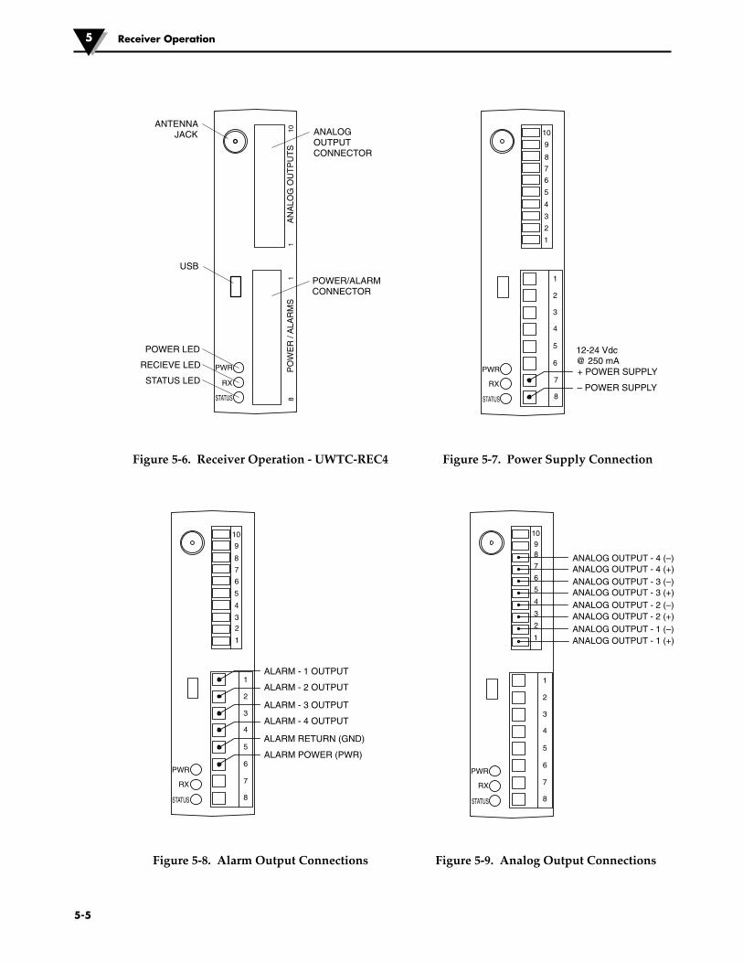
Figure 5-6. Receiver Operation - UWTC-REC4
1
2
3
4
5
6
7
8
ALARM RETURN (GND)
ALARM POWER (PWR)
ALARM - 1 OUTPUT
ALARM - 2 OUTPUT
ALARM - 3 OUTPUT
ALARM - 4 OUTPUT
RX
PWR
STATUS
10
9
8
7
6
5
4
32
1
Figure 5-8. Alarm Output Connections
ANALOG OUTPUT - 4 (–)
ANALOG OUTPUT - 3 (–)
ANALOG OUTPUT - 2 (–)
ANALOG OUTPUT - 1 (–)
ANALOG OUTPUT - 4 (+)
ANALOG OUTPUT - 3 (+)
ANALOG OUTPUT - 2 (+)
ANALOG OUTPUT - 1 (+)
RX
PWR
STATUS
1
2
3
4
5
6
7
8
1098
7
6
5
4
3
2
1
Figure 5-9. Analog Output Connections
1
2
3
4
5
6
7
8
10
9
8
7
6
5
4
3
2
1
+ POWER SUPPLY
– POWER SUPPLY
12-24 Vdc@ 250 mA
RX
PWR
STATUS
Figure 5-7. Power Supply Connection
AN
ALO
G O
UT
PU
TS
PO
WE
R /
ALA
RM
S8
101
1
STATUS LED
POWER LED
RECIEVE LED
USB
ANTENNAJACK ANALOG
OUTPUTCONNECTOR
POWER/ALARMCONNECTOR
RX
PWR
STATUS

Receiver Operation 5
5-6
RX
PWR
STATUS24 Vdc
POWER SUPPLY
4-20 mA ANALOG OUTPUTINTO PLC OR DATA LOGGER
1
2
3
4
5
6
7
8
–+
–
+
10
9
8
7
6
5
4
32
1
Figure 5-10. 4-20 mA Output Example
1
2
3
4
5
6
7
8
10
9
8
7
6
5
4
3
2
1
– +
12-24 VdcPOWERSUPPLY
ALARMRELAY
200 mA MAX
1N4004*
+
–RX
PWR
STATUS
Figure 5-12. Alarm Example, System Powered
1
2
3
4
5
6
7
8
10
9
8
7
6
5
4
3
2
1
– +
12-24 VdcPOWERSUPPLY
0-24 VdcPOWERSUPPLY
ALARMRELAY
200 mA MAX
1N4004*
+
–RX
PWR
STATUS
+
–
Figure 5-13A . Alarm Example, External Power Supply
+
–
0-5 Vdc ANALOG OUTPUTINTO PLC OR DATA LOGGER
+ –
RX
PWR
STATUS
12 - 24 VdcFROM HOSTINSTRUMENT
1
2
3
4
5
6
7
8
10
9
8
7
6
5
432
1
Figure 5-11. Voltage Output Example
*Required for magnetic relays. Not required for solid state relays.
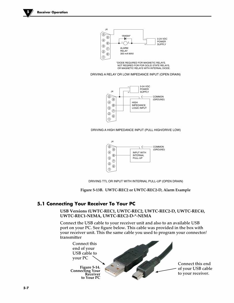
5-7
Receiver Operation5
Figure 5-13B. UWTC-REC2 or UWTC-REC2-D, Alarm Example
5.1 Connecting Your Receiver To Your PCUSB Versions (UWTC-REC1, UWTC-REC2, UWTC-REC2-D, UWTC-REC4), UWTC-REC1-NEMA, UWTC-REC2-D-*-NEMA
Connect the USB cable to your receiver unit and also to an available USB port on your PC. See figure below. This cable was provided in the box with your receiver unit. This the same cable you used to program your connector/transmitter
Connect this end of your USB cable to your receiver.
Connect this end of yourUSB cable to your PC
Figure 5-14. Connecting Your
Receiver to Your PC
91N4004*
DRIVING A RELAY OR LOW IMPEDANCE INPUT (OPEN DRAIN)
J4
ALARMRELAY300 mA MAX
*DIODE REQUIRED FOR MAGNETIC RELAYS. NOT REQIRED FOR FOR SOLID STATE RELAYS, OR MAGNETIC RELAYS WITH INTERNAL DIODE.
0-24 VDCPOWERSUPPLY
––
++8
7
6
4
5
3
2
1
9
DRIVING A HIGH IMPEDANCE INPUT (PULL HIGH/DRIVE LOW)
J4
HIGHIMPEDANCELOGIC INPUT
COMMON(GROUND)
0-24 VDCPOWERSUPPLY
–
+
8
7
6
4
5
3
2
1
9
DRIVING TTL OR INPUT WITH INTERNAL PULL-UP (OPEN DRAIN)
J4
INPUT WITHINTERNALPULL-UP
COMMON(GROUND)
8
7
6
4
5
3
2
1
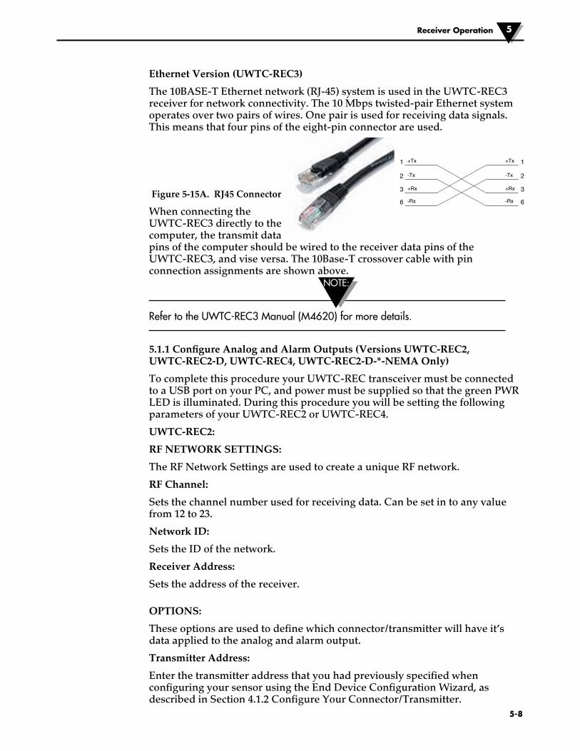
5-8
Receiver Operation 5
Ethernet Version (UWTC-REC3)
The 10BASE-T Ethernet network (RJ-45) system is used in the UWTC-REC3 receiver for network connectivity. The 10 Mbps twisted-pair Ethernet system operates over two pairs of wires. One pair is used for receiving data signals. This means that four pins of the eight-pin connector are used.
Figure 5-15A. RJ45 Connector
When connecting the UWTC-REC3 directly to the computer, the transmit data pins of the computer should be wired to the receiver data pins of the UWTC-REC3, and vise versa. The 10Base-T crossover cable with pin connection assignments are shown above.
Refer to the UWTC-REC3 Manual (M4620) for more details.
5.1.1 Configure Analog and Alarm Outputs (Versions UWTC-REC2, UWTC-REC2-D, UWTC-REC4, UWTC-REC2-D-*-NEMA Only)
To complete this procedure your UWTC-REC transceiver must be connected to a USB port on your PC, and power must be supplied so that the green PWR LED is illuminated. During this procedure you will be setting the following parameters of your UWTC-REC2 or UWTC-REC4.
UWTC-REC2:
RF NETWORK SETTINGS:
The RF Network Settings are used to create a unique RF network.
RF Channel:
Sets the channel number used for receiving data. Can be set in to any value from 12 to 23.
Network ID:
Sets the ID of the network.
Receiver Address:
Sets the address of the receiver.
OPTIONS:
These options are used to define which connector/transmitter will have it’s data applied to the analog and alarm output.
Transmitter Address:
Enter the transmitter address that you had previously specified when configuring your sensor using the End Device Configuration Wizard, as described in Section 4.1.2 Configure Your Connector/Transmitter.
1
2
3
6
1
2
3
6
+Tx
-Tx
+Rx
-Rx
+Tx
-Tx
+Rx
-Rx
NOTE:

The voltage on the Analog Output pin on the REC2 will correspond to the value of this sensor.
Timeout:
This setting is to indicate the number of seconds you want the REC2 to wait before displaying a NO SIGNAL message on the display.
Process Units:
Choose the units which will be used to set the limits of the analog output scaling.
Custom Units:
A custom unit type can be entered here.
Alarm Activation Mode:
This will set the alarm to activate on the rising or falling temperature when your setpoint is reached.
Alarm Setpoint:
Set the setpoint (in degrees F) that you want the alarm to activate at.
Alarm Deadband:
The number of units away from the Alarm Setpoint before the alarm will be activated again.
Decimal Places:
Number of decimal places in the Alarm Setpoint and Alarm Deadband values.
SCALING:
Enter one value, in Process Units, that will set the analog output to its minimum value (such as 0 V) and another value, in Process Units, that will set the analog output to its maximum value (such as 10 V).
UWTC-REC4:
The configuration window for the UWTC-REC4 features a tabbed interface that allows the user to configure all of the relevant settings described for the UWTC-REC2 for each of the four analog output channels.
5.1.2 Setting Values:
To set these values, launch TC Central (Start | Programs | TC Central) and then select Configure Receiver from the Tools menu. The following figures show what the configuration screen will look like, based on the version of your receiver:
Receiver Operation5
5-9

REC2
Figure 5-15B. UWTC-REC2 Setup Screen
REC4
Figure 5-15C. UWTC-REC4 Setup Screen
Receiver Operation 5
5-10

5.2 Mounting, Installation and Antenna Connection5.2.1 Mounting
For UWTC-REC1, UWTC-REC2-D, UWTC-REC2, UWTC-REC3
Mounting ears or brackets are built-in to your receiver enclosure The diagram below shows dimensions and mounting hole location. Rubber bumpers have also been supplied with your receiver should you wish to use the device on a desk or a work bench next to your PC.
TIP: Mounting your receiver on a wall away from your PC will provide better signal strength and help to maximize system range.
When mounting your receiver, care should be taken to make sure it is as far away from any metal objects. If nearby metal gets too close to your receivers antenna, it has the potential to interfere with the way the unit receives data and may cause signal lose or possibly even the inability to communicate at all with your connector/transmitter.
For UWTC-REC3 mounting information, refer to the UWTC-REC3 Manual (M4620).
Figure 5-16. Mounting
AN
TE
NN
A
USB
I/O 9–24 Vdc
OMEGA ENGINEERING, INC. Stamford, CT 06907
UWTC SERIES WIRELESS RF RECEIVER
2.4 GHz
omega.com Made in U.S.A.
- +
!
TX RX SB PWR
This device complies with Part 15 of the FCC rules. Operation is subject to the following two conditions: 1) This device may not cause harmful interference; 2) This device must accept any interference received, including interference that may cause undesired operation.
FCC ID: OUR–XBEEPRO IC #4214A–XBEEPRO F
®
64 mm (2.5")
89 mm (3.5")
o 3.6mm (0.140"
o 7.5mm (0.295")
76 mm (3.0") Mounting Hole Center Line
NOTE:
NOTE:
5-11
Receiver Operation5

5-12
Receiver Operation 5
For UWTC-REC1-NEMA, UWTC-REC2-D-*-NEMA
Mounting ears are built-in to your receiver enclosure The diagram below shows dimensions and mounting hole location. Rubber bumpers have also been supplied with your receiver should you wish to use the device on a desk or a work bench next to your PC.
TIP: Mounting your receiver on a wall away from your PC will provide better signal strength and help to maximize system range.
When mounting your receiver, care should be taken to make sure it is as far away from any metal objects. If nearby metal gets too close to your receivers antenna, it has the potential to interfere with the way the unit receives data and may cause signal lose or possibly even the inability to communicate at all with your connector/transmitter.
Figure 5-17. UWTC-NEMA Mounting
147.1 (5.79)
56.9 (2.24)Ø3.8 (0.15)
160 (6.30)
90 (3.54)
DIMENSIONS mm (in)
NOTE:

5-13
Receiver Operation5
5.2.2 Installation
When installing your receiver it is important to position your device in such a way as to optimize the antenna location within what’s known as the “Fresnel Zone”.
The Fresnel Zone can be thought of as a football-shaped invisible tunnel between two locations that provides a path for RF signals between your connector/transmitter and your receiver.
Figure 5-18. Installation
In order to achieve maximum range, the football-shaped path in which radio waves travel must be free of all obstructions. Obstacles in the path (especially metal) will decrease the communication range between your connector/transmitter and receiver. Also, If the antennas are mounted just barely off the ground, over half of the Fresnel zone ends up being obstructed by the earth resulting in significant reduction in range. To avoid this problem, the antennas should be mounted high enough off of the ground so that the earth does not interfere with the central diameter of the Fresnel zone.
It is important to understand that the environment may change over time due to new equipment or machinery being installed, building construction, etc. If new obstacles exist between your connector/transmitter and receiver, the devices can be raised on one end or on both ends to hopefully clear the Fresnel Zone of obstructions.
5.2.3 Antenna Connection
Your receiver has been shipped to you with a high gain antenna already attached.
In some cases, a short RF cable may be used to connect an antenna to your device. Please note that RF extension cables will always add some loss to the transmitting signal strength. The longer the cable the more signal will be lost over that cable. Because of this the length of the cable should be kept as short as possible.
Use of any other antenna then what’s supplied with your device will void all FCC and CE regulatory compliance.
Additional Information on installation and system operation can be found in Section 6.
®TX
UNIVERSAL WIRELESS THERMOCOUPLE CONNECTOR
LOW BATT
PRESSSETUP
PRESSON/OFF
UWTC
FRESNEL ZONE
TRANSMITTERANTENNA
RECEIVERANTENNA
NOTE:
NOTE:

5-14
Receiver Operation 5
NOTES:

Section 6 - System Operation6.1 Introduction
Compared to wired thermocouple systems, wireless thermocouple systems provide much simpler installation. Based on the physical principle of the propagation of radio waves, certain basic conditions should be observed. The following simple recommendations are provided to insure proper installation and correct operation of your UWTC Series system.
6.2 RF Communication BasicsThe UWTC-1 (Standard Distance) or UWTC-2 (Long Distance) wireless Thermocouple Connector/Transmitter sends wireless transmissions to the UWTC-REC1 receiver. The receiver checks the incoming data for accuracy and processes this data for use by the measurement software on your PC. Radio signals are electromagnetic waves, hence the signal becomes weaker the further it travels. While radio waves can penetrate some solid materials like a wall, they are dampened more than when a direct line-of-sight between the transmitting and receiving antenna exist.
6.3 Basic System OverviewThe UWTC wireless thermocouple system is comprised of only two main components; a Thermocouple Connector with a built-in battery powered 2.4 GHz radio transmitter, and a USB powered 2.4 GHz radio receiver.
Figure 6-1. Basic System Overview
Up to 48 each of UWTC-1 or UWTC-2 connector/transmitters can be used with one UWTC-REC1 receiver.
LOW BATT
TX
SETUPPRESS
PRESS
ON/OFF
UWTCUNIVERSAL WIRELESS THERMOCOUPLE CONNECTOR
R R
UNIVERSAL WIRELESS THERMOCOUPLE CONNECTOR
UWTC
ON/OFF
PRESS
PRESS
SETUP
TX
LOW BATT
LOW BATT
TX
SETUPPRESS
PRESS
ON/OFF
UWTCUNIVERSAL WIRELESS THERMOCOUPLE CONNECTOR
R
R
UNIVERSAL WIRELESS THERMOCOUPLE CONNECTOR
UWTC
ON/OFF
PRESS
PRESS
SETUP
TX
LOW BATTLOW BATT
TX
SETUPPRESS
PRESS
ON/OFF
UWTCUNIVERSAL WIRELESS THERMOCOUPLE CONNECTOR
R
R
UNIVERSAL WIRELESS THERMOCOUPLE CONNECTOR
UWTC
ON/OFF
PRESS
PRESS
SETUP
TX
LOW BATT
LOW BATT
TX
SETUPPRESS
PRESS
ON/OFF
UWTCUNIVERSAL WIRELESS THERMOCOUPLE CONNECTOR
R
R
UNIVERSAL WIRELESS THERMOCOUPLE CONNECTOR
UWTC
ON/OFF
PRESS
PRESS
SETUP
TX
LOW BATT LOW BATT
TX
SETUPPRESS
PRESS
ON/OFF
UWTCUNIVERSAL WIRELESS THERMOCOUPLE CONNECTOR
R
R
UNIVERSAL WIRELESS THERMOCOUPLE CONNECTOR
UWTC
ON/OFF
PRESS
PRESS
SETUP
TX
LOW BATT
LOW BATT
TX
SETUPPRESS
PRESS
ON/OFF
UWTCUNIVERSAL WIRELESS THERMOCOUPLE CONNECTOR
RR
UNIVERSAL WIRELESS THERMOCOUPLE CONNECTOR
UWTC
ON/OFF
PRESS
PRESS
SETUP
TX
LOW BATT
6-1
System Operation6

6.4 Connector/Transmitter Operation6.4.1 Button Operation
(1.) “PRESS ON/OFF” The “PRESS ON/OFF” button on the front of your connector/transmitter is used to turn your unit “ON” or “OFF”
(2.) “PRESS SETUP” The “PRESS SETUP” button on the front of your connector/transmitter is only used during the setup and configuration of your unit. See Section 4.1.2 for more information.
Figure 6-2. Connector/Transmitter Button Operation
6.4.2 Ambient Temperature Readings
The ambient temperature reading displayed on your screen when running the TC-Central program, is the actual ambient temperature that your connector/transmitter is being exposed to. This reading is only provided as reference and to aid you in proper installation of your unit. The ambient temperature reading will blink and change to RED digits to alert you that your have exceed the maximum recommended safe operating conditions for your connector/transmitter. You should not rely on this feature as sole protection. Additional protection should be taken by you “the user” to protect your unit from extreme conditions.
Operating your connector/transmitter outside the specified ambient conditions listed in Section 9 of this manual may cause your unit to malfunction and stop working correctly.
6.4.3 Indicator Lights
(1) Transmit (TX) Green Indicator Light
The green indicator light marked “TX” on the front of the connector/transmitter will blink every time the unit sends data to the receiving unit. Example; If you selected a 5 sec sample rate the green TX led will blink one time every 5 seconds.
(2) Low Battery (Low Batt) Red Indicator Light
The red indicator light marked “Low Batt” on the front of the connector/transmitter will turn on when the battery reaches a level at or below the power level required for normal operation. When this indicator turns on it’s time to install a fresh battery in your unit. For procedures on how to change your battery see Section 4.5. For information on battery life see Section 6.11.
6-2
System Operation 6
NOTE:
1
2
®TX
UNIVERSAL WIRELESS THERMOCOUPLE CONNECTOR
LOW BATT
PRESSSETUP
PRESSON/OFF
UWTC

6-3
®TX
UNIVERSAL WIRELESS THERMOCOUPLE CONNECTOR
LOW BATT
PRESSSETUP
PRESSON/OFF
UWTC
1
2
Figure 6-3. Transmit and Low Battery Lights
6.5 Receiver Operation6.5.1 Indicator Lights
(1) Transmit (TX) Green Indicator Light
The top green indicator light marked “TX” on the front of the receiver will only blink when the receiver is connected to your PC and you initialize your measurement software. After the receiver establishes communication with the program the light will no longer blink. Note: this may happen very fast and will not be noticeable.
(2) Receive (RX) Red Indicator Light
The red indicator light marked “RX” on the front of the receiver will blink each time the receiver receives incoming data from one of your connector transmitters.
(3) Standby (SB) Yellow Indicator Light
The yellow indicator light marked “SB” on the front of the receiver will blink continuously during normal operation. This indicates that the receiver is in the “Standby” mode and is waiting for incoming data from your connector/transmitter.
(4) Power (PWR) Green Indicator Light
1
2 SBPWR
RXTX
3
4
Figure 6-4. Indicator Lights
System Operation6

6-4
System Operation 6
6.6 Environment/Operating Conditions6.6.1 Environment
Omega’s UWTC or UWRTD series connector/transmitter and receiver unit has been designed to be fixed mounted and operated in a clean and dry indoor environment. Care should be taken to prevent the components of your wireless system from being exposed to moisture, toxic chemicals and extreme cold or hot temperature that are outside the specifications listed in this manual.
6.6.2 Operating Conditions
The following is a list of basic good practice you should apply when operating your wireless system.
• Never operate your wireless device outside the recommended environmental limits specified in this manual.
• Never operate your wireless device in flammable or explosive environments.
• Never use your wireless device in medical, nuclear or other dangerous applications were failure can cause damage or harm.
• Never operate your transmitter/connector with any other battery or power source than what’s specified in this manual or on the battery compartment label.
• No co-location with other radio transmitters is allowed. By definition, co-location is when another radio device or it’s antenna is located within 20 cm of your connector/transmitter and can transmit simultaneously with your UWTC unit.
• Never install a connector/transmitters within 20 cm or less from each other.
• Never use your connector/transmitter as a portable device. Your unit has been designed to be operated in a permanent installation.
• Never install and/or operate your connector transmitter closer than 20 cm to nearby persons.
• Never operate your connector transmitter with any other antenna than what is supplied or listed here in this manual for approved use.

NOTE:
6-5
6.7 Determining and Maximizing Range
The available maximum range specified for the wireless Series system in this manual is only achievable under optimum installation conditions. Mounting height, obstructions in your “Fresnel Zone” and ambient conditions can cause a decrease in signal strength resulting in a shorter range between your transmitter/connector and receiver unit.
The following recommendations will help to improve the range of your wireless system.
Position your receiver in a central location
When multiple connector/transmitters are in operation, position your receiver unit in a central space if possible in equal distance to each connector transmitter.
Figure 6-5. Determining Maximum Range
Test your system before permanent mounting
Before permanently mounting your connector/transmitters in your application try moving the devices to different locations and mounting angles to determine what installation achieves the best signal strength.
Move your system components higher off the floor and away from exterior walls
Avoid installing your system components to close to the floor or near your buildings exterior walls. The closer your connector/transmitter and receiver unit are the greater the interference and lose of signal strength will be.
Maintain a line of sight (LOS) between antennas
Maintaining a line of sight between your connector/transmitter and receiver unit will produce greatly improved signal strength over a system were the antenna’s in your system have obstacles blocking them.
Maintain a constant ambient temperature environment
Maintaining a constant ambient temperature environment is important to achieving maximum signal strength. Exposing your system components to extreme hold or cold temperatures, or sudden changes in ambient conditions will have an effect on the performance of your system.
System Operation6
STORAGE ROOM
CONTROL ROOM
OFFICE OFFICE
PCRECEIVER
UWTC-1
UWTC-2
UWTC-2
MANUFACTURINGAREA
MANUFACTURINGAREA
UWTC-1
UWTC-2
UWTC-2
CHAN 1
CHAN 2
CHAN 3
CHAN 4
CHAN 5
CHAN 6
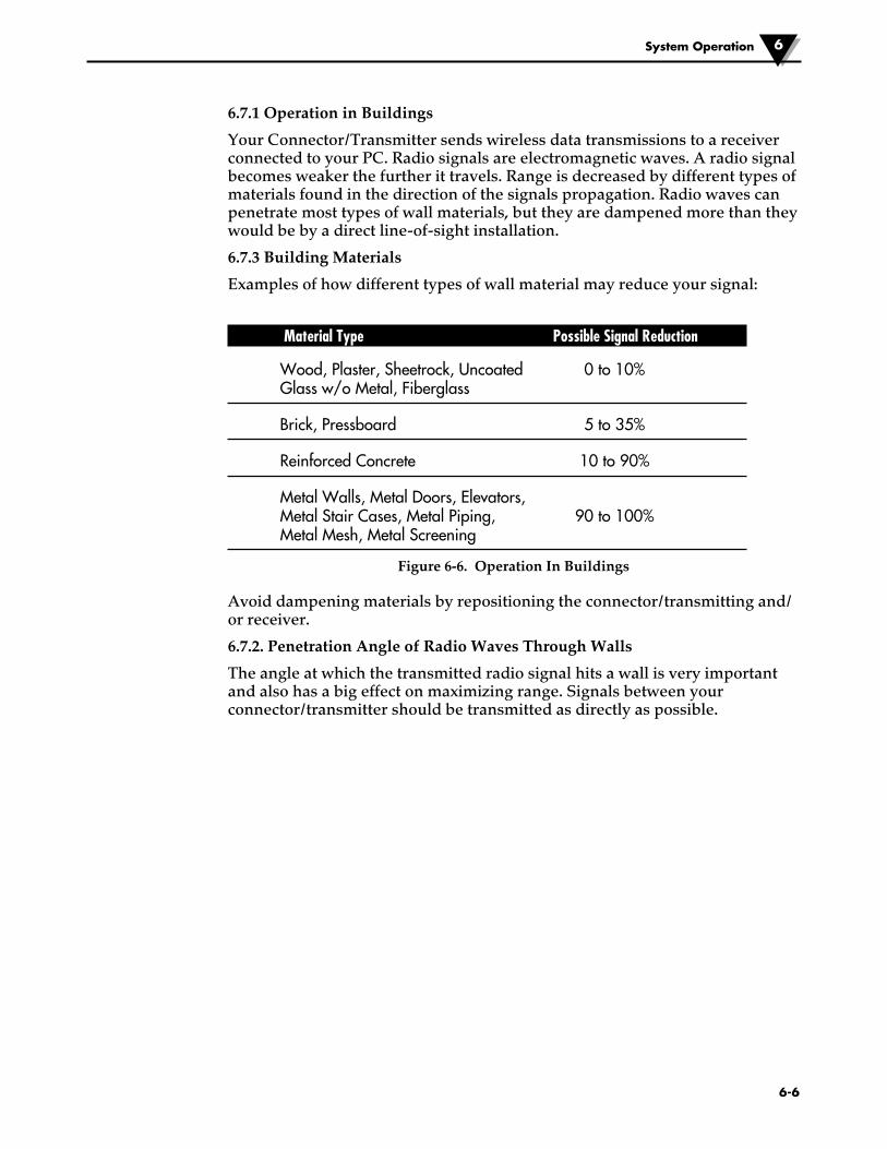
6-6
System Operation 6
6.7.1 Operation in Buildings
Your Connector/Transmitter sends wireless data transmissions to a receiver connected to your PC. Radio signals are electromagnetic waves. A radio signal becomes weaker the further it travels. Range is decreased by different types of materials found in the direction of the signals propagation. Radio waves can penetrate most types of wall materials, but they are dampened more than they would be by a direct line-of-sight installation.
6.7.3 Building Materials
Examples of how different types of wall material may reduce your signal:
Material Type Possible Signal Reduction
Wood, Plaster, Sheetrock, Uncoated 0 to 10% Glass w/o Metal, Fiberglass
Brick, Pressboard 5 to 35%
Reinforced Concrete 10 to 90%
Metal Walls, Metal Doors, Elevators, Metal Stair Cases, Metal Piping, 90 to 100% Metal Mesh, Metal Screening
Figure 6-6. Operation In Buildings
Avoid dampening materials by repositioning the connector/transmitting and/or receiver.
6.7.2. Penetration Angle of Radio Waves Through Walls
The angle at which the transmitted radio signal hits a wall is very important and also has a big effect on maximizing range. Signals between your connector/transmitter should be transmitted as directly as possible.
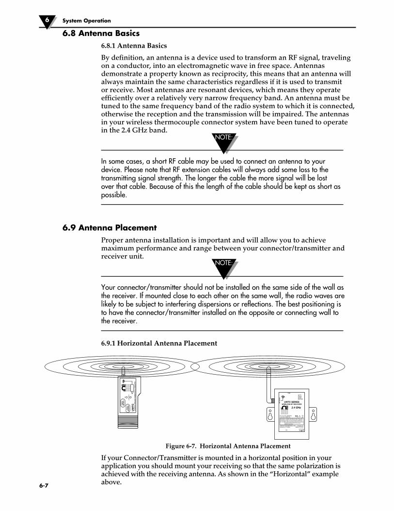
NOTE:
NOTE:
6.8 Antenna Basics 6.8.1 Antenna Basics
By definition, an antenna is a device used to transform an RF signal, traveling on a conductor, into an electromagnetic wave in free space. Antennas demonstrate a property known as reciprocity, this means that an antenna will always maintain the same characteristics regardless if it is used to transmit or receive. Most antennas are resonant devices, which means they operate efficiently over a relatively very narrow frequency band. An antenna must be tuned to the same frequency band of the radio system to which it is connected, otherwise the reception and the transmission will be impaired. The antennas in your wireless thermocouple connector system have been tuned to operate in the 2.4 GHz band.
In some cases, a short RF cable may be used to connect an antenna to your device. Please note that RF extension cables will always add some loss to the transmitting signal strength. The longer the cable the more signal will be lost over that cable. Because of this the length of the cable should be kept as short as possible.
6.9 Antenna PlacementProper antenna installation is important and will allow you to achieve maximum performance and range between your connector/transmitter and receiver unit.
Your connector/transmitter should not be installed on the same side of the wall as the receiver. If mounted close to each other on the same wall, the radio waves are likely to be subject to interfering dispersions or reflections. The best positioning is to have the connector/transmitter installed on the opposite or connecting wall to the receiver.
6.9.1 Horizontal Antenna Placement
Figure 6-7. Horizontal Antenna Placement
If your Connector/Transmitter is mounted in a horizontal position in your application you should mount your receiving so that the same polarization is achieved with the receiving antenna. As shown in the “Horizontal” example above.
®
AN
TE
NN
A
USB
I/O9–24 Vdc
OMEGA ENGINEERING, INC. Stamford, CT 06907
UWTC SERIESWIRELESS RF RECEIVER
2.4 GHz
omega.comMade in U.S.A.
- +
!
TX
UN
IVE
RS
AL
WIR
EL
ES
S T
HE
RM
OC
OU
PL
E C
ON
NE
CTO
R
LOW
BAT
T
PR
ES
SS
ET
UP
PR
ES
SO
N/O
FF
UW
TC
TXRXSBPWR
This device complies with Part 15 of the FCC rules. Operation is subject to the following two conditions: 1) This device may not cause harmful interference; 2) This device must accept any interference received, including interference that may cause undesired operation.
FCC ID: OUR–XBEEPROIC #4214A–XBEEPRO F
®
6-7
System Operation6

6.9.2 Vertical Antenna Placement
If your Connector/Transmitter is mounted in a vertical position in your application you should mount your receiving so that the same polarization is achieved with the receiving antenna. As shown in the “Vertical” example Fig 6-8.
6.10 Factory Preset ValuesYour Connector/Transmitter has been factory programmed for the following default operation; Channel Number: 1, Thermocouple Type: K, Transmit Rate: 1 sample/5 sec
6.11 Transmit Rate vs. Battery LifeMany factors such as ambient temperature conditions and transmitting rate can have a big effect on the life of the battery used in your connector/transmitter. Transmitting data places a big demand of the battery in your connector/transmitter. The transmit rate is the single most contributing factor in the life of your battery. The slower the transmit rate you set, the longer the battery in your device will last. The table below give some estimates on how long the battery should last vs. the transmit rate you selected when you setup your connector/transmitters and under normal operating conditions.
Transmit Time Estimated Battery Life
1 Sample/2 Seconds 12 days
1 Sample/3 Seconds 18 days
1 Sample/5 Seconds 30 days
1 Sample/10 Seconds 60 days
1 Sample/15 Seconds 90 days
1 Sample/30 Seconds 180 days
1 Sample/45 Seconds 270 days
1 Sample/60 Seconds 365 days
6-8
System Operation 6
For Version UWTC-1 or UWRTD-1
®
AN
TE
NN
A
USB
I/O9–24 Vdc
OMEGA ENGINEERING, INC. Stamford, CT 06907
UWTC SERIESWIRELESS RF RECEIVER
2.4 GHz
omega.comMade in U.S.A.
- +
!
TX
UNIVERSAL WIRELESS THERMOCOUPLE CONNECTOR
LOW BATT
PRESSSETUP
PRESSON/OFF
UWTC
TXRXSBPWR
This device complies with Part 15 of the FCC rules. Operation is subject to the following two conditions: 1) This device may not cause harmful interference; 2) This device must accept any interference received, including interference that may cause undesired operation.
FCC ID: OUR–XBEEPROIC #4214A–XBEEPRO F
®
Figure 6-8. Vertical Antenna Placement
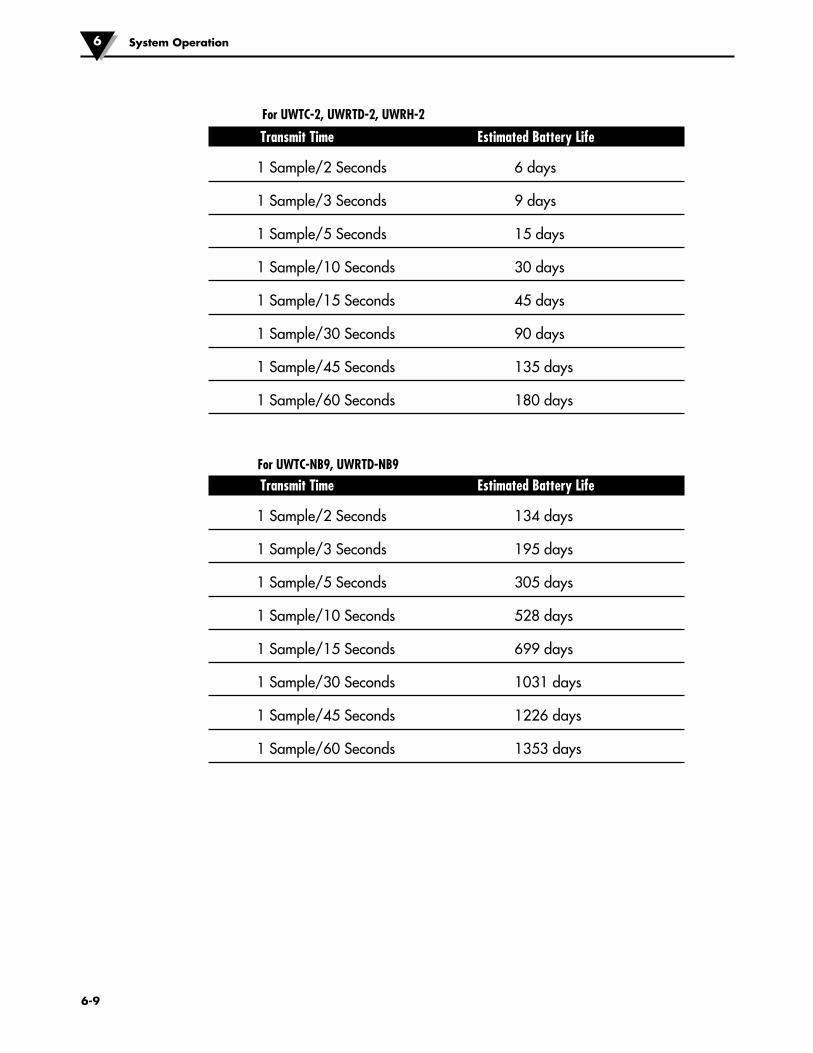
Transmit Time Estimated Battery Life
1 Sample/2 Seconds 6 days
1 Sample/3 Seconds 9 days
1 Sample/5 Seconds 15 days
1 Sample/10 Seconds 30 days
1 Sample/15 Seconds 45 days
1 Sample/30 Seconds 90 days
1 Sample/45 Seconds 135 days
1 Sample/60 Seconds 180 days
Transmit Time Estimated Battery Life
1 Sample/2 Seconds 134 days
1 Sample/3 Seconds 195 days
1 Sample/5 Seconds 305 days
1 Sample/10 Seconds 528 days
1 Sample/15 Seconds 699 days
1 Sample/30 Seconds 1031 days
1 Sample/45 Seconds 1226 days
1 Sample/60 Seconds 1353 days
For UWTC-2, UWRTD-2, UWRH-2
For UWTC-NB9, UWRTD-NB9
6-9
System Operation6

�7-1
Section 7 - TroubleshootingThe information provided in this section should solve most of the common problems you may experience when installing or operating your wireless System. If the problems and solutions outlined here do not solve your problem, please contact Omega’s customer service department. Contact information can be found in Section 2 of this manual or by visiting omega.com.
7.1 Connector/Transmitter TroubleshootingProblem Solution
1. Unit will not enter a. Check USB cable connection “Setup” mode
b. Contact Customer Service
2. Configuration Utility a. Check USB cable connection to device being will not connect programmed
b. Confirm you are in the “SETUP”mode. See Section 3
c. Contact Customer Service
7.2 Receiver TroubleshootingProblem Solution
1. Unit will not turn on a. Check power cord connections
b. Unit requires service, contact Customer Service
2. Analog output stays a. Verify that none of the following conditions exist: at maximum value 1. The end device selected for this analog channel has a (5.05V, 10.10V, 20.20mA) defective or open sensor. 2. The end device is measuring a process that has a value greater than the upper limit of the input range of the end device. 3. The end device is measuring a process that has a
value greater than the upper scale value set for the analog output of the receiver.
4. The receiver is not receiving a signal from the end device having the end device address selected for this analog channel.
3. Analog output The end device is measuring a process that has a value stays at zero equal to or less than the input range of the end device, (for voltage output): or the lower scale value that is set for the analog output of the receiver.
4. Analog output The end device is measuring a process value that is stays at 3.8mA less than the input range of the end device, or the (for mA output): lower scale value that is set for the analog output of the receiver.
Troubleshooting 7

7-2
Troubleshooting7
Problem Solution
If the problem persists a. Run the “End Device Configuration Wizard” after checking and (TC Central) with the device connected. correcting one or more b. When at the screen where all the settings appear, of the above conditions, click the “Copy to Clipboard” button. do the following before c. Paste to a text file. contacting Customer d. Next, select “Configure Receiver …” from thee Service: “Tools” menu (in TC Central). e. When at the screen where all the settings appear, click the “Copy to Clipboard” button. f. In the same file as in step c above, paste this information. g. Call Customer Service. When speaking to your Customer Service Representative, ask for an email address to send the information you just copied and pasted.

Section 8 – Service & CalibrationYour UWTC and UWRTD Series components have been built and factory calibrated to meet or exceed the specifications listed here in this manual. The following section provides information on how to have your device serviced and also on how to re-calibrate your unit in the field.
8.1 Service & CalibrationIf any of your wireless system components require service or calibration, please call our Customer Service Department. They will assist you in arranging the return and service of your device. We can also be reached on the Internet and via email. Check our website for contact information.
�8-1
Service and Calibration 8
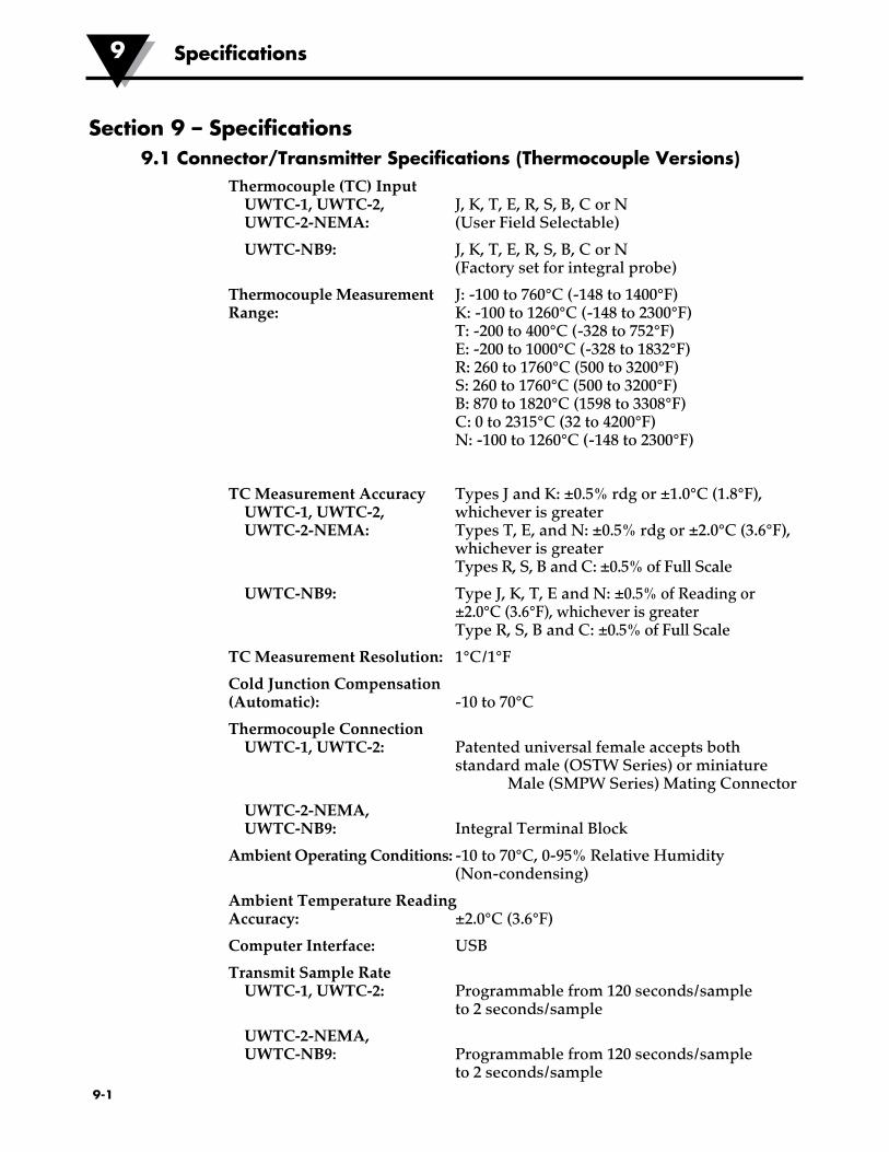
�9-1
Section 9 – Specifications9.1 Connector/Transmitter Specifications (Thermocouple Versions)
Thermocouple (TC) Input UWTC-1, UWTC-2, J, K, T, E, R, S, B, C or N UWTC-2-NEMA: (User Field Selectable)
UWTC-NB9: J, K, T, E, R, S, B, C or N (Factory set for integral probe)
Thermocouple Measurement J: -100 to 760°C (-148 to 1400°F) Range: K: -100 to 1260°C (-148 to 2300°F) T: -200 to 400°C (-328 to 752°F) E: -200 to 1000°C (-328 to 1832°F) R: 260 to 1760°C (500 to 3200°F) S: 260 to 1760°C (500 to 3200°F) B: 870 to 1820°C (1598 to 3308°F) C: 0 to 2315°C (32 to 4200°F) N: -100 to 1260°C (-148 to 2300°F)
TC Measurement Accuracy Types J and K: ±0.5% rdg or ±1.0°C (1.8°F), UWTC-1, UWTC-2, whichever is greater UWTC-2-NEMA: Types T, E, and N: ±0.5% rdg or ±2.0°C (3.6°F), whichever is greater Types R, S, B and C: ±0.5% of Full Scale
UWTC-NB9: Type J, K, T, E and N: ±0.5% of Reading or ±2.0°C (3.6°F), whichever is greater Type R, S, B and C: ±0.5% of Full Scale
TC Measurement Resolution: 1°C/1°F
Cold Junction Compensation (Automatic): -10 to 70°C
Thermocouple Connection UWTC-1, UWTC-2: Patented universal female accepts both standard male (OSTW Series) or miniature Male (SMPW Series) Mating Connector
UWTC-2-NEMA, UWTC-NB9: Integral Terminal Block
Ambient Operating Conditions: -10 to 70°C, 0-95% Relative Humidity (Non-condensing)
Ambient Temperature Reading Accuracy: ±2.0°C (3.6°F)
Computer Interface: USB
Transmit Sample Rate UWTC-1, UWTC-2: Programmable from 120 seconds/sample to 2 seconds/sample
UWTC-2-NEMA, UWTC-NB9: Programmable from 120 seconds/sample to 2 seconds/sample
Specifications9

Radio Frequency (RF): ISM 2.4 GHz, direct sequence spread
Transceiver Carrier: Spectrum, license free worldwide (2.450 to 2.490 GHz -12 channels)
RF Output Power UWTC-1: 0dBm (1 mW)
UWTC-2, UWTC-2-NEMA, UWTC-NB9: 10dBm (10 mW)
Range of RF Link: UWTC-1: Up to 60 m (200') outdoor line of UWTC-1: sight. Up to 20 m (65') indoor/urban.
UWTC-2, UWTC-2-NEMA, UWTC-NB9: Up to 120 m (400') outdoor line of sight. Up to 40 m (130') indoor/urban.
RF Data Packet Standard: IEEE 802.15.4, open communication architecture
Software (Free Download): Requires Windows, 2000, XP, Vista or Windows 7 operating system
Battery Power UWTC-1: One Standard 3.6 V lithium Battery , 2.4 Ah
capacity (AA). Omega No: UWTC-BATT UWTC-2: One Standard 3.6 V lithium Battery , 2.4 Ah
capacity (AA). Omega No: UWTC-BATT or One High Pulse 3.6 V lithium Battery, 1.2 Ah capacity (AA). Omega No: UWTC-BATT-HP
UWTC-2-NEMA, UWTC-NB9: One Standard 3.6 V lithium Battery, 7.2 Ah capacity (C). Omega No: UWTC-BATT-C
Battery Life: See Section 6 of this manual
Data Transmitted to Host: Thermocouple Temperature, Ambient Temperature, RF Signal Strength and percent of Battery Life remaining
Dimensions UWTC-1, UWTC-2: 103 L x 47 W x 28 mm H (without antenna)
UWTC-2-NEMA: 80 L x 82 W x 55 mm H (without antenna)
UWTC-NB9: 95 L x 98 W x 83 mm H (without antenna and integral probe)
Weight UWTC-1, UWTC-2: 70 grams (0.19 lbs)
UWTC-2-NEMA: 218 grams (0.58 lbs)
UWTC-NB9: 174 grams (0.47 lbs)
Enclosure/Housing UWTC-1, UWTC-2: ABS Plastic
UWTC-2-NEMA: Polycarbonate (NEMA 4X)
UWTC-NB9: Bakelite Glass Fiber (IP65)
�9-2
Specifications 9

Specifications9
�9-3
9.2 RTD Connector/Transmitter SpecificationsAvailable Types: 100 Ω (standard), 500 Ω, 1000 Ω (special order)
UWRTD-1, UWRTD-2, UWRTD-2-NEMA: PT100 - 0.00385 or 0.00392 (User Field Selectable)
UWTC-NB9: PT100 - 0.00385 or 0.00392 (Factory set for integral probe)
RTD Measurement Range: 0.00385: -200 to 600°C (-328 to 1112°F) 0.00392: -100 to 457°C (-148 to 854°F)
RTD Measurement Accuracy: ±1°C from 0 to 400°C (32 to 752°F), ±2.5°C below 0°C or above 400°C (752°F)
RTD Measurement Resolution: 1°C/1°F
Operating Environment: -10 to 70°C (14 to 158°F)
RTD Connection UWRTD-1, UWRTD-2: Omega Series “T” receptacle. Use Omega
Version TA4F mating connector (one included)
UWRTD-2-NEMA, UWRTD-NB9: Integral Terminal Block
Computer Interface: USB (one interface cable included with receiver)
Transmit Sample Rate: Programmable from 120 seconds/sample to 2 seconds/sample
Radio Frequency (RF) Transceiver Carrier: ISM 2.4 GHz, direct sequence spread spectrum, license free worldwide (2.450 to 2.490 GHz -12 channels)
RF Output Power UWRTD-1: 0dBm (1 mW)
UWRTD-2, UWRTD-2-NEMA, UWTC-NB9: 10dBm (10 mW)
Range of RF Link UWRTD-1: Up to 60 m (200') outdoor line of sight. Up to 20 m (65') indoor/urban.)
UWRTD-2, UWRTD-2-NEMA, Up to 120 m (400') outdoor line of sight. Up to UWRTD-NB9: 40 m (130') indoor/urban. RF Data Packet
Standard: IEEE 802.15.4, open communication architecture
Software (Free Download): Requires Windows 2000, XP, Vista, Windows 7 operating system
Battery Power UWRTD-1: One Standard 3.6 V lithium Battery, 2.4 Ah capacity (AA). Omega No: UWTC-BATT
UWRTD-2: One Standard 3.6 V lithium Battery, 2.4 Ah capacity (AA). Omega No: UWTC-BATT or One High Pulse 3.6 V lithium Battery, 1.2 Ah capacity (AA). Omega No: UWTC-BATT-HP
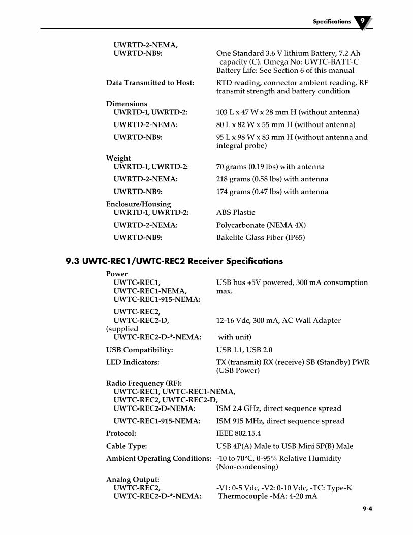
UWRTD-2-NEMA, UWRTD-NB9: One Standard 3.6 V lithium Battery, 7.2 Ah
capacity (C). Omega No: UWTC-BATT-C Battery Life: See Section 6 of this manual
Data Transmitted to Host: RTD reading, connector ambient reading, RF transmit strength and battery condition
Dimensions UWRTD-1, UWRTD-2: 103 L x 47 W x 28 mm H (without antenna)
UWRTD-2-NEMA: 80 L x 82 W x 55 mm H (without antenna)
UWRTD-NB9: 95 L x 98 W x 83 mm H (without antenna and integral probe)
Weight UWRTD-1, UWRTD-2: 70 grams (0.19 lbs) with antenna
UWRTD-2-NEMA: 218 grams (0.58 lbs) with antenna
UWRTD-NB9: 174 grams (0.47 lbs) with antenna
Enclosure/Housing UWRTD-1, UWRTD-2: ABS Plastic
UWRTD-2-NEMA: Polycarbonate (NEMA 4X)
UWRTD-NB9: Bakelite Glass Fiber (IP65)
9.3 UWTC-REC1/UWTC-REC2 Receiver SpecificationsPower UWTC-REC1, USB bus +5V powered, 300 mA consumption UWTC-REC1-NEMA, max. UWTC-REC1-915-NEMA:
UWTC-REC2, UWTC-REC2-D, 12-16 Vdc, 300 mA, AC Wall Adapter (supplied UWTC-REC2-D-*-NEMA: with unit)
USB Compatibility: USB 1.1, USB 2.0
LED Indicators: TX (transmit) RX (receive) SB (Standby) PWR (USB Power)
Radio Frequency (RF): UWTC-REC1, UWTC-REC1-NEMA, UWTC-REC2, UWTC-REC2-D, UWTC-REC2-D-NEMA: ISM 2.4 GHz, direct sequence spread
UWTC-REC1-915-NEMA: ISM 915 MHz, direct sequence spread
Protocol: IEEE 802.15.4
Cable Type: USB 4P(A) Male to USB Mini 5P(B) Male
Ambient Operating Conditions: -10 to 70°C, 0-95% Relative Humidity (Non-condensing)
Analog Output: UWTC-REC2, -V1: 0-5 Vdc, -V2: 0-10 Vdc, -TC: Type-K UWTC-REC2-D-*-NEMA: Thermocouple -MA: 4-20 mA
Specifications 9
�9-4
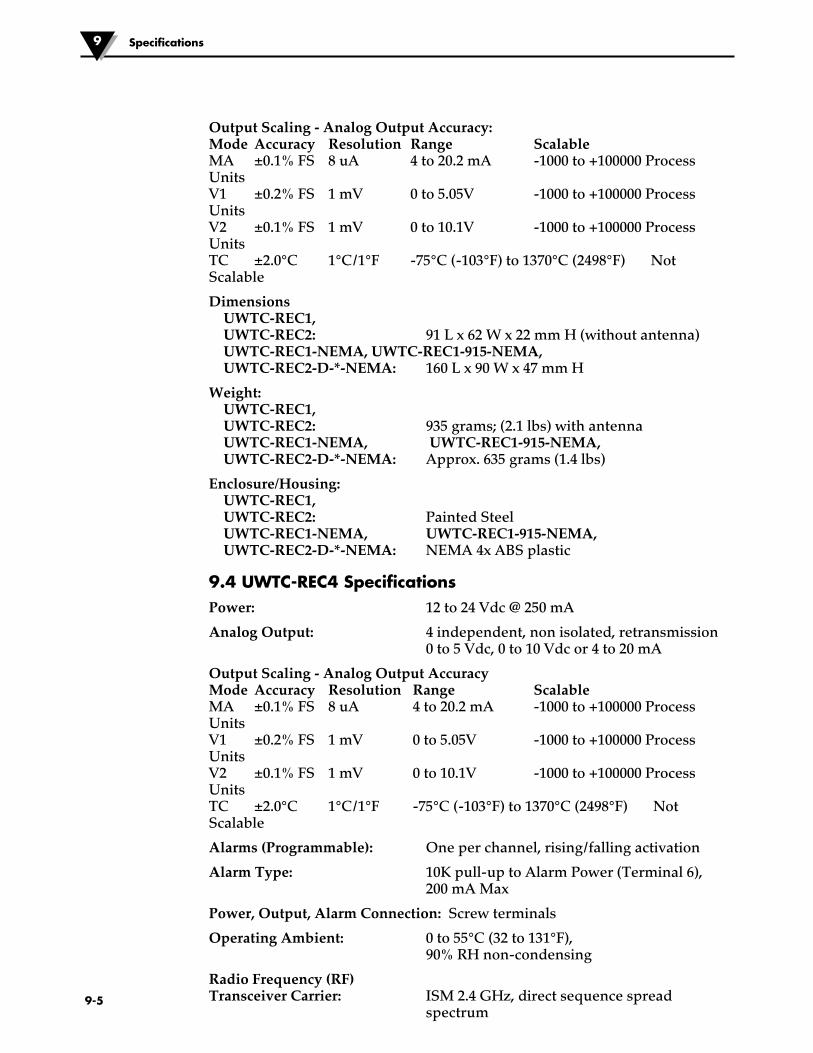
�9-5
Specifications9
Output Scaling - Analog Output Accuracy: Mode Accuracy Resolution Range Scalable MA ±0.1% FS 8 uA 4 to 20.2 mA -1000 to +100000 Process Units V1 ±0.2% FS 1 mV 0 to 5.05V -1000 to +100000 Process Units V2 ±0.1% FS 1 mV 0 to 10.1V -1000 to +100000 Process Units TC ±2.0°C 1°C/1°F -75°C (-103°F) to 1370°C (2498°F) Not Scalable
Dimensions UWTC-REC1, UWTC-REC2: 91 L x 62 W x 22 mm H (without antenna) UWTC-REC1-NEMA, UWTC-REC1-915-NEMA, UWTC-REC2-D-*-NEMA: 160 L x 90 W x 47 mm H
Weight: UWTC-REC1, UWTC-REC2: 935 grams; (2.1 lbs) with antenna UWTC-REC1-NEMA, UWTC-REC1-915-NEMA, UWTC-REC2-D-*-NEMA: Approx. 635 grams (1.4 lbs)
Enclosure/Housing: UWTC-REC1, UWTC-REC2: Painted Steel UWTC-REC1-NEMA, UWTC-REC1-915-NEMA, UWTC-REC2-D-*-NEMA: NEMA 4x ABS plastic
9.4 UWTC-REC4 SpecificationsPower: 12 to 24 Vdc @ 250 mA
Analog Output: 4 independent, non isolated, retransmission 0 to 5 Vdc, 0 to 10 Vdc or 4 to 20 mA
Output Scaling - Analog Output Accuracy Mode Accuracy Resolution Range Scalable MA ±0.1% FS 8 uA 4 to 20.2 mA -1000 to +100000 Process Units V1 ±0.2% FS 1 mV 0 to 5.05V -1000 to +100000 Process Units V2 ±0.1% FS 1 mV 0 to 10.1V -1000 to +100000 Process Units TC ±2.0°C 1°C/1°F -75°C (-103°F) to 1370°C (2498°F) Not Scalable
Alarms (Programmable): One per channel, rising/falling activation
Alarm Type: 10K pull-up to Alarm Power (Terminal 6), 200 mA Max
Power, Output, Alarm Connection: Screw terminals
Operating Ambient: 0 to 55°C (32 to 131°F), 90% RH non-condensing
Radio Frequency (RF) Transceiver Carrier: ISM 2.4 GHz, direct sequence spread
spectrum
Section 10 – Approvals, Regulatory Compliance & Patent Notice
All approvals outlined in this manual are based on testing that was done with antennas that are supplied with your wireless Series System Components. Removing and or installing a different antenna will void the product compliance demonstrated in these documents.
10.1 FCC (Domestic Use: USA & Canada)(USA) FCC ID: OUR-XBEEPRO (CANADA) IC #4214A-XBEEPRO
This device complies with Part 15 of the FCC rules. Operation is subject to the following two conditions: 1.) This device may not cause harmful interference. 2.) This device must accept any interference received, including interference that may cause undesired operation.
To satisfy FCC RF exposure requirements for mobile transmitting devices, a separation distance of 20 cm or more should be maintained between the antenna of this device and persons during device operation. To ensure compliance, operations at closer than this distance is not recommended. The antenna used for this transmitter must not be co-located in conjunction with any other antenna or transmitter.
10.2 International Usage & CE Marking (Pending)The UWTC and UWRTD Series system components are CE marked and certified for use in several European countries. Please contact OMEGA for information on International Regulatory Compliance for each country.
The single exception to this conformity is with the UWTC-REC2-TC receiver. In this case, if the unit is exposed to RF radiation at a nominal level (3 V/m) between the frequencies of 80 MHz to 1000 MHz, the accuracy of the unit may be degraded by as much as 6°C - 7°C, which is outside the normal performance specification of the unit. Under all other circumstances the product performs to specification.
It is your (the user’s) responsibility to insure that these products are operated within the guidelines here in this manual and in conformance with all local or national regulations and laws.
Transmitting Power
Your UWTC and UWRTD Series System Components have been designed and manufactured so that the transmitting power will not exceed 2 dBm (10 mW).
10.3 Declaration of Conformity (DOC)Contact OMEGA for status on CE marking and DOC availability.
10-1
NOTE:
WARNING:
Approvals, Regulatory Compliance & Patent Notice 10

10-2
UWTC/UWRTD Series10
10.4 Patent Notice
(Product is covered by patents for Super MCJ, Uniconnector and pending wireless connector)
PATENT NOTICE: U.S. PAT. NO. 6,074,089 / Canada 2,228,333 / UK GB 2,321,712 / Israel 123052 Other U.S. and international patents pending.
UWTC PATENT NOTICE

OMEGA’s policy is to make running changes, not model changes, whenever an improvement is possible. This affords our customers the latest in technology and engineering.OMEGA is a registered trademark of OMEGA ENGINEERING, INC.© Copyright 2017 OMEGA ENGINEERING, INC. All rights reserved. This document may not be copied, photocopied, reproduced, translated, or reduced to any electronic medium or machine-readable form, in whole or in part, without the prior written consent of OMEGA ENGINEERING, INC.
FOR WARRANTY RETURNS, please have the following information available BEFORE contacting OMEGA:1. Purchase Order number under which the product
was PURCHASED,2. Model and serial number of the product under
warranty, and3. Repair instructions and/or specific problems relative to the product.
FOR NON-WARRANTY REPAIRS, consult OMEGA for current repair charges. Have the following information available BEFORE contacting OMEGA:1. Purchase Order number to cover the COST of the repair,2. Model and serial number of the product, and3. Repair instructions and/or specific problems relative to the product.
RETURN REQUESTS/INQUIRIESDirect all warranty and repair requests/inquiries to the OMEGA Customer Service Department. BEFORE RETURNING ANY PRODUCT(S) TO OMEGA, PURCHASER MUST OBTAIN AN AUTHORIZED RETURN (AR) NUMBER FROM OMEGA’S CUSTOMER SERVICE DEPARTMENT (IN ORDER TO AVOID PROCESSING DELAYS). The assigned AR number should then be marked on the outside of the return package and on any correspondence.The purchaser is responsible for shipping charges, freight, insurance and proper packaging to prevent breakage in transit.
WARRANTY/DISCLAIMEROMEGA ENGINEERING, INC. warrants this unit to be free of defects in materials and workmanship for a period of 13 months from date of purchase. OMEGA’s WARRANTY adds an additional one (1) month grace period to the normal one (1) year product warranty to cover handling and shipping time. This ensures that OMEGA’s customers receive maximum coverage on each product.If the unit malfunctions, it must be returned to the factory for evaluation. OMEGA’s Customer Service Department will issue an Authorized Return (AR) number immediately upon phone or written request. Upon examination by OMEGA, if the unit is found to be defective, it will be repaired or replaced at no charge. OMEGA’s WARRANTY does not apply to defects resulting from any action of the purchaser, including but not limited to mishandling, improper interfacing, operation outside of design limits, improper repair, or unauthorized modification. This WARRANTY is VOID if the unit shows evidence of having been tampered with or shows evidence of having been damaged as a result of excessive corrosion; or current, heat, moisture or vibration; improper specification; misapplication; misuse or other operating conditions outside of OMEGA’s control. Components in which wear is not warranted, include but are not limited to contact points, fuses, and triacs.OMEGA is pleased to offer suggestions on the use of its various products. However, OMEGA neither assumes responsibility for any omissions or errors nor assumes liability for any damages that result from the use of its products in accordance with information provided by OMEGA, either verbal or written. OMEGA warrants only that the parts manufactured by the company will be as specified and free of defects. OMEGA MAKES NO OTHER WARRANTIES OR REPRESENTATIONS OF ANY KIND WHATSOEVER, EXPRESSED OR IMPLIED, EXCEPT THAT OF TITLE, AND ALL IMPLIED WARRANTIES INCLUDING ANY WARRANTY OF MERCHANTABILITY AND FITNESS FOR A PARTICULAR PURPOSE ARE HEREBY DISCLAIMED. LIMITATION OF LIABILITY: The remedies of purchaser set forth herein are exclusive, and the total liability of OMEGA with respect to this order, whether based on contract, warranty, negligence, indemnification, strict liability or otherwise, shall not exceed the purchase price of the component upon which liability is based. In no event shall OMEGA be liable for consequential, incidental or special damages.CONDITIONS: Equipment sold by OMEGA is not intended to be used, nor shall it be used: (1) as a “Basic Component” under 10 CFR 21 (NRC), used in or with any nuclear installation or activity; or (2) in medical applications or used on humans. Should any Product(s) be used in or with any nuclear installation or activity, medical application, used on humans, or misused in any way, OMEGA assumes no responsibility as set forth in our basic WARRANTY/DISCLAIMER language, and, additionally, purchaser will indemnify OMEGA and hold OMEGA harmless from any liability or damage whatsoever arising out of the use of the Product(s) in such a manner.

M4432/0917
Where Do I Find Everything I Need for Process Measurement and Control?
OMEGA…Of Course!Shop online at omega.com SM
TEMPERATUREMU Thermocouple, RTD & Thermistor Probes, Connectors, Panels & Assemblies MU Wire: Thermocouple, RTD & ThermistorMU Calibrators & Ice Point ReferencesMU Recorders, Controllers & Process MonitorsMU Infrared Pyrometers
PRESSURE, STRAIN AND FORCEMU Transducers & Strain GagesMU Load Cells & Pressure GagesMU Displacement TransducersMU Instrumentation & Accessories
FLOW/LEVELMU Rotameters, Gas Mass Flowmeters & Flow ComputersMU Air Velocity IndicatorsMU Turbine/Paddlewheel SystemsMU Totalizers & Batch Controllers
pH/CONDUCTIVITYMU pH Electrodes, Testers & AccessoriesMU Benchtop/Laboratory MetersMU Controllers, Calibrators, Simulators & PumpsMU Industrial pH & Conductivity Equipment
DATA ACQUISITIONMU Communications-Based Acquisition SystemsMU Data Logging SystemsMU Wireless Sensors, Transmitters, & ReceiversMU Signal ConditionersMU Data Acquisition Software
HEATERSMU Heating CableMU Cartridge & Strip HeatersMU Immersion & Band HeatersMU Flexible HeatersMU Laboratory Heaters
ENVIRONMENTAL MONITORING AND CONTROLMU Metering & Control InstrumentationMU RefractometersMU Pumps & TubingMU Air, Soil & Water MonitorsMU Industrial Water & Wastewater TreatmentMU pH, Conductivity & Dissolved Oxygen Instruments