utkarsha aluminium d - mishra dhatu nigam limited
TRANSCRIPT

UTKARSHA ALUMINIUM DHATU NIGAM LIMITEDPO-KANCHANBAGH, HYDERABAD, TELANGANA – 500 058, INDIA
INSTALLATION OF HIGH END ALUMINIUM ALLOY MELTING,CASTING AND FLAT ROLLED PRODUCTS PRODUCTION
FACILITY AT NELLORE, ANDHRA PRADESH
TENDER SPECIFICATION
FOR
HIGH END ALUMINIUM ALLOY MELTING AND CASTINGPLANT
(PACKAGE NO. – 01)
VOLUME – II OF II(TECHNICAL)
MECON LIMITEDRANCHI – 834002
MEC/UADNL/11/35/Q7R6/TS/01/R0 June, 2022

TECHNICAL SPECIFICATIONHIGH END ALUMINIUM ALLOY MELTING
AND CASTING PLANTPACKAGE NO. - 01
Contents Technical Specification Page 1 of 2
© 2022 MECON LIMITED. All rights reserved
CONTENT
ChapterNo. Description Page No.
From To01. Introduction 1 2
02. Intent of Specification 1 4
03. General description of the plant 1 4
04. Site Condition and Design Data 1 3
05. Special instructions to Tenderers 1 3
06. Safety 1 1
07. Scope, Battery limits and Exclusions 1 11
08. Regulation and Standards 1 2
09. Production Programme 1 2
10. Technical Specification of facilities 1 5110.01 Technological Facilities 1 1
10.01.1.A Melting & Alloying Unit 1 6
10.01.1.B Holding Furnace 6 18
10.01.1.C Vertical Direct Chill Casting Facility 18 4410.01.1.D Homogenising Unit 45 4610.01.1.E Scalping Machine 46 4710.01.1.F Band Sawing Machine 47 4810.01.1.G Chips Collection System 48 49
10.01.1.H Ultrasound Inspection System 49 51
10.02 Material Handling Facilities 1 1
10.03 Refractories 1 10
10.04 Utilities (Gas Facilities) 1 2
10.05 Air-conditioning and Ventilation System 1 1
10.06 Water Supply System 1 8
10.07 Electrics and Automation 1 76
10.08 Instrumentation 1 11
10.09 Quality Control Facilities 1 2

TECHNICAL SPECIFICATIONHIGH END ALUMINIUM ALLOY MELTING
AND CASTING PLANTPACKAGE NO. - 01
Contents Technical Specification Page 2 of 2
© 2022 MECON LIMITED. All rights reserved
ChapterNo. Description Page No.
From To10.10 Fire Protection system 1 1
10.11 Pollution Control 1 1
10.12 Hydraulics and Lubrication System 1 24
10.13 Civil Works 1 3
10.14 Structural Works 1 2
11. Spares, Consumables and Tools &Tackles 1 2
12. Completeness 1 1
13.Project Implementation Schedule andProgress Monitoring
1 4
14.Inspection, Erection, Testing andCommissioning
1 6
15. Performance Guarantee 1 9
16. Certification 1 1
17.Data / Drawings to be furnished by
Tenderer1 4
18. Time schedule for submission ofdrawings and documents
1 14
19. Training of Purchaser personnel 1 4
20. Painting 1 1
21. Disaster Management Plan 1 1
22. Questionnaires 1 13

TECHNICAL SPECIFICATION
HIGH END ALUMINIUM ALLOYMELTING AND CASTING PLANT
PACKAGE NO. - 01
01 Introduction Technical Specification Page 1 of 2 © 2022 MECON LIMITED. All rights reserved
1.0 Introduction
Utkarsha Aluminium Dhatu Nigam Limited (UADNL), is a Joint Venture (JV) company of M/s National Aluminium Company Limited (NALCO), a Navratna CPSE under Ministry of Mines and M/s Mishra Dhatu Nigam Limited (MIDHANI), a Miniratna CPSE under the Ministry of Defence. This JV Company is incorporated for Setting up a green field project to produce High End Aluminium Alloy Flat Rolled Products at SPSR Nellore district of Andhra Pradesh. The rated capacity of the Aluminium Alloy Plant shall be 60,000 TPY of different grade Plates, Sheets and Coils at Bodduvaripalem Village, Kodavalur Mandal, SPSR Nellore Distt. in Andhra Pradesh. The overall layout has been planned keeping into consideration of adequate space provision for expanding its future capacity upto 120,000 TPA. M/s MECON LIMITED has been appointed as EPCM consultant by M/s UADNL for the installation of High end Aluminium Alloy Melting, Slab Casting and further Flat Rolled Products Manufacturing facilities. The project is divided into 2 (two) main technological packages and other different Utilities and service related packages including enabling packages. This Technical Specification document covers the Package-01 i.e., the Melting, casting, homogenizing and sizing of the cast slabs & billets of different grade Aluminium Alloys which shall be further processed for Rolling into different Flat Rolled Products or other application/products. The main technological facilities of this proposed package includes the Melting & Holding Furnaces, Direct Chill Casting Machine, Homogenizing Furnaces, Scalping machines and Sawing machines as following: • 3 x 55t Aluminium Ingot & Scrap Melting Furnace
• 2 x 50t Liquid Aluminium Holding Furnace

TECHNICAL SPECIFICATION
HIGH END ALUMINIUM ALLOYMELTING AND CASTING PLANT
PACKAGE NO. - 01
01 Introduction Technical Specification Page 2 of 2 © 2022 MECON LIMITED. All rights reserved
• 2 x 50t/cast Vertical Direct Chill Casting Unit
• 4 x 50t Homogenizing Unit
• Set of Scalping & Band Sawing Machine suitable for slabs and
billets
• 1 No. Ultrasound Inspection System for slabs & billets
This Technical Specification (TS) has been prepared for Design, engineering, supply, Erection & Commissioning, Initial operation, ramp up production, performance and product guarantee of technological equipment including Electrics & control / automation system, material handling facilities (excluding EOT crane, forklift truck, FTV, hand trolley etc.), utilities facilities within the boundary limits of the shop. The system utilities e.g. Power, water, compressed Air, fuel etc. shall be provided at the defined take over point (TOP) by the purchaser. Detailed scope of work and battery limits has been indicated at Chapter No 07 of this Tech specification. Civil works are excluded from scope of work which shall be executed by the purchaser based on the detailed required inputs provided by the successful bidder. Building Structural works are also excluded from scope of work which shall be executed by the purchaser based on the detailed required inputs provided by the successful bidder. The equipment and all technological structures are to be provided by the bidders. The technology and equipment supplier shall demonstrate the production of intended aluminum alloys by using the offered line equipment and transfer the alloys making technology including training of the plant operators. A tentative layout indicating the available space for setting-up the proposed facilities related to this package is provided in the drawing no. MEC/UADNL/11/14/Q7R6/TS/01, Rev0 for reference.

PA
VE
D A
RE
A
OPEN GATE OPEN GATE
VEHICLE MOVEMENT
1
3
2
K
V
L
IN
E
13
2 K
V L
IN
E
EXISTING ROAD TO NH-16
EXISTING ROAD TO NH-16
EXIS
TIN
G C
AN
AL
1
2
3
4
5
56
7
7
7
78
910
11
12
13
14
15
16
171819
19
20
21 22
23
X+1
000
X+1
100
X+1
200
X+1
300
X+1
400
X+1
500
X+1
600
X+1
700
X+1
800
X+9
00
X+8
00
X+7
00
Y+1000
Y+900
Y+800
Y+700
Y+600
Y+500
Y+1100
Y+1200
Y+1300
AS SHOWN
DRG. NO. MEC/UADNL/11/14/Q7R6/TS/01
SCALE-
1 OF 1
SHEET REV
0
GENERAL LAYOUT
MECON LIMITEDO
SECTION
I S
GL&T
COMP A1
NY
9 0 0
THIS DRAWING IS THE PROPERTY OF MECON AND IS ISSUED FOR THESPECIFIC PROJECT MENTIONED THEREIN. THIS IS NOT TO BE COPIED ORUSED FOR OTHER PROJECTS UNLESS EXPRESSLY PERMITTED BY MECONDRG. NO.REFERENCES
AKP
APPROVED
DRAWN
CHKD
DATE
RP
LOCATION
DSGN RP
RANCHI
ALUMINIUM ALLOY FLAT ROLLEDPRODUCTS PLANT, NELLORE, A.P.
PRELIMINARY
WITH GATEBOUNDARY WALL
SYMBOL LEGEND
PROPOSED ROAD
PROPOSED UNITS
132 KV HT LINE CORRIDOR
GREEN BELT
EXISTING CANAL
UTKARSHA ALUMINIUM DHATUNIGAM LIMITED
LIST OF MAJOR UNITS
1. CASTING SHOP2. HOT & COLD
ROLLING MILLSHOP
3. MRSS4. RAW WATER
RESERVOIR5. WATER SUPPLY
FACILITIES6. FIRE WATER PUMP
HOUSE7. ECR BUILDING8. SUBSTATION9. PROPANE
STORAGE10. PSA NITROGEN &
ARGON FACILITY11. RAW MATERIAL
STORAGE YARD12. COMPRESSED AIR
STATION
13. LABORATORYBUILDING
14. ADMINISTRATIVEBUILDING
15. CENTRAL REPAIRSHOP
16. DROSS STORAGE17. ROAD
WEIGHBRIDGE18. TRUCK PARKING
AREA19. SECURITY CUM
TIME OFFICE20. ROLLING OIL
STORAGE21. CENTRAL STORE22. ZLD PLANT23. FIRE STATION
SPACE FOR FUTUREUNITS
100 0 100 200 300 400
SCALE IN METRES
DRG. NO. MEC/UADNL/11/14/Q7R6/PRL/0001, R-0
(TENTATIVE)
FOR TENDERIN
G PURPO
SE O
NLY
AREA FOR
MELTING &CASTING
FACILITIES

TECHNICAL SPECIFICATIONHIGH END ALUMINIUM ALLOY MELTING
AND CASTING PLANTPACKAGE NO. - 01
02 Intent of Specification Technical Specification Page 1 of 4
© 2022 MECON LIMITED. All rights reserved
2.0 Intent of Specification
02.01 This technical specification comprising of Aluminium Melting andCasting Facilities along with auxiliaries shall be executed onturnkey basis. The broad scope of work of tenderer covers supplyof process technology/Know-how as well as design, engineeringand supply of Aluminium Ingot & Scrap Melting Furnace, LiquidAluminium Holding Furnace, Vertical Direct Chill Casting Unit,Homogenizing Unit, Scalping & Band Sawing Machine, Ultrasoundinspection System including electrics & automation, utilities &services within the battery limit, painting, erection, testing,commissioning & demonstration of performance guaranteeparameters of the units.
The design & technology selected shall include latest technologicaldevelopments in the field and state-of-the-art technology and shallensure achievement of benchmarks in technical, technological,operating parameters, environmental norms at par withInternational Standards. The melting and casting shop shall bedesigned and equipped to cast slabs and billets of hard aluminiumalloy grades like 2xxx, 5xxx, 6xxx and 7xxx of superior qualityapplicable for defence, aerospace and other hi-end applications.The plant shall be designed in such a way that all the above gradescan be successfully cast on the casting machine and rolled in therolling mill.
02.02 The overall time schedule for commissioning of the plant &equipment covered under this package shall be 24 months fromthe effective date of contract.
02.03 The intent of this Specification is to appraise the Tenderer abouthis involvement / commitment for this package and to enable himto submit a detailed comprehensive offer as specified in thisdocument. The Tenderer shall base his offer on the informationcontained in this specification.
02.04 The Tenderer shall study the specification along with relateddocuments and satisfy himself thoroughly regarding suitability ofthe plant and equipment and system, specified in the Tenderdocument and take full responsibility for smooth and trouble free

TECHNICAL SPECIFICATIONHIGH END ALUMINIUM ALLOY MELTING
AND CASTING PLANTPACKAGE NO. - 01
02 Intent of Specification Technical Specification Page 2 of 4
© 2022 MECON LIMITED. All rights reserved
operation of the plant and equipment with respect to output,reliable working as well as ease of operation and maintenanceincluding replacement with minimum machine down time.
02.05 All equipment / systems shall be completed in all respects and anyequipment or accessories not covered in the technical specificationbut essential for proper design, operation and rated production asper the offered Technology shall be deemed to be included in thescope of the Tenderer.
02.06 It is a green field project, however, the Tenderer may visit the siteand satisfy himself before submission of the offer, the nature andlocation of work place, area available, kind of equipment, facilities,services, etc. needed during actual execution of work, performanceof work, general and local conditions as well as all other matterswhich can, in any way, affect the work covered in thisspecification.
Deviations from Technical Specification (TS) and standards, if any,shall be brought out clearly with proper justifications. Thedeviations brought out shall be specific in nature. If the deviationsfrom the technical specification or specified standards are notbrought out clearly by the Tenderer, the same will not beconsidered by the Purchaser, even if, directly or indirectlymentioned in any part of the offer. Tenderer may offer certainalternate system/equipment of improved design, if necessary, withclear justification for the same.
Technical specification is a guideline to the bidders for basicrequirement of the project w.r.t the production quantity andquality. Should the tenderer consider that improved equipmentfeatures and additional process equipment configuration arebeneficial, then they are invited to put forward the same as part oftheir offer. The perceived technical and / or commercial benefits ofthe additional features should be highlighted in the offer for reviewand acceptance. However, for evaluation of L1 bidder, costimplication will not be considered for the offered additionalfeatures.

TECHNICAL SPECIFICATIONHIGH END ALUMINIUM ALLOY MELTING
AND CASTING PLANTPACKAGE NO. - 01
02 Intent of Specification Technical Specification Page 3 of 4
© 2022 MECON LIMITED. All rights reserved
02.07 Effort shall be made by the Tenderer to maximize equipment /supplies from indigenous sources.
02.08 The Tenderer shall be responsible for co-ordinating the suppliescovered in the different areas of this Specification from differentsources and execute the contract within agreed time schedule.
02.09 The specification intends that the plant and equipment suppliedby the Tenderer shall be capable to cast special quality slabs to berolled in form of plate, sheet and coils as well as billets to be usedsuitably in the application like Defence, Aerospace, Automotive,Railway, Marine, Machinery & Equipment etc. The Tenderer has toclearly specify in the Tender how the process know-how andproduction of these special quality slabs and billets to be cast shallbe transferred to the Purchaser.
02.10 All the equipment and supplies shall be suitable for the tropicalclimatic conditions prevailing at Aluminium Alloy Plant,Bodduvaripalem Village, Kodavalur Mandal, SPSR Nellore Distt. inAndhra Pradesh, India.
The Technical Specification (TS) shall be read in conjunction withthe following standard bidding documents of Purchaserirrespective of whether attention to the same has been specificallydrawn or not.
- Invitation to Tender- Technical Specification- Commercial Part- General Technical Specification
The following General Technical Specifications (GS) shall be readin conjunction with this Technical Specification.
GS 01 : General instructions to Tenderer
GS 02 : Fluid System
GS 03 : Electrics, Drives & Controls andCommunication
GS 04 : Instrumentation & Controls
GS 05 : Quality System, Inspection & Test ofPlant/Equipment at Manufacturer’sPremises

TECHNICAL SPECIFICATIONHIGH END ALUMINIUM ALLOY MELTING
AND CASTING PLANTPACKAGE NO. - 01
02 Intent of Specification Technical Specification Page 4 of 4
© 2022 MECON LIMITED. All rights reserved
GS 06 : Steel Structures
GS 07 : Civil Works
GS 08 : Air Conditioning, Ventilation and AirPollution Control system
GS 09 : Painting
GS 10 : Hydraulics & Lubrication
GS 11 : Storage and Erection
GS 12 : Fire Fighting System
GS 13 : Material Handling Equipment
GS 14 : Preferred Makes
02.11 The weight of individual equipment shall be indicated in thedivision list.

TECHNICAL SPECIFICATIONHIGH END ALUMINIUM ALLOY MELTING
AND CASTING PLANTPACKAGE NO. - 01
03 General Description of The Plant Technical Specification Page 1 of 4
© 2022 MECON LIMITED. All rights reserved
3.0 General Description of The Plant
03.01 The melting and casting complex shall be designed for productionof billets & rolling slabs of different aluminium hard alloys. It shallcomprise Melting & Holding Furnaces, Vertical Direct Chill CastingMachine, Homogenizing Unit, Scalping & Band Sawing Machine,Ultrasound Inspection System for billets & slab. The location of thecomplex along shown in the General Layout Drawing no.MEC/UADNL/11/14/Q7R6/TS/01, Rev0.
03.02 Plant Capacity
The proposed plant shall produce about 90,000t/yr billets &rolling slabs of different aluminium hard alloys through 3 nos. ofMelting furnace for melting of virgin aluminium, quality aluminiumscrap and alloying, 2 nos. of liquid metal holding Furnaces whichsupplies the liquid metal to casting machine, 2 nos. of Direct ChillCasting Machine for production of billets & rolling slab, 4 nos. ofHomogenizing Unit, set of Scalping & Band Sawing Machinesuitable for slabs and billets, 1 nos. of Ultrasound InspectionSystem for billet & slab complex.
03.03 Process Flow
The virgin aluminium ingots, quality aluminium scrap and masteralloys are charged into the melting furnace with the help ofcharging vehicle. Once the solid metal gets melted and reached thedesired temperature necessary fluxing and de-drossing shall bedone. Further liquid metal is transferred into the holding furnacethrough launders by gravity flow from melting furnace. Sufficientholding time shall be given to liquid metal for better homogeneityin terms of metal composition & temperature. After getting thefinal composition and casting temperature of the aluminium alloyto be cast, the liquid metal is transferred through launders bygravity flow into the DC casting machine.

TECHNICAL SPECIFICATIONHIGH END ALUMINIUM ALLOY MELTING
AND CASTING PLANTPACKAGE NO. - 01
03 General Description of The Plant Technical Specification Page 2 of 4
© 2022 MECON LIMITED. All rights reserved
Molten metal from holding furnace will be first grain refined byusing Titanium boron rod. After grain refinement, molten metalwill be transferred to degassing unit through heated launder. It isvery essential to minimise the hydrogen content of the moltenmetal to avoid hydrogen embrittlement. Suggested range to achievequality is 0.11 cc of hydrogen per 100 gm of molten metal(LECO/ALSCAN or equivalent). For aerospace applications Argonwill be used for degassing purpose. Off gas from degasser will bealso taken out by duct and this duct will be linked with melting/holding furnace gas main duct. After degassing, molten metal willbe filtrated by ceramic foam filter and deep bed filter to minimizeinclusion limit in molten metal. PoDFA (or equivalent) value will bearound <0.10 mm2/Kg. On quality checking after filtration, moltenmetal will be transferred to DC casting machine.
The casting line is of the DC type, with stationary moulds cooledwith water, being capable of casting several ingots per drop. Thetreated molten aluminium alloy will be transferred to castingmachine stand by distribution trough attached with the moldtable. The VDC casting machine should be equipped with onlineultrasonic inspection system to check the defects and dimensionscontinuously throughout the cast. Each drop of a single DCcasting will produce up to 50t of billet & rolling slabs (of varyingnumber, depending on width and length). Slabs & billets of eachdrop will be taken out by a special attachment mounted EOT cranefrom the casting pit and will be stored in casting bay.
Before being rolled on the Hot Mill, the ingot needs to be heated upto a specified temperature. For some products a homogenisingpractice needs to be used whereby the billets & slab goes througha pre-defined thermal cycle to ensure the correct mechanicalproperties are achieved in the final product.
In a pusher furnace a number of slabs and billets can be placedinside and heated through the thermal cycle progressing stepwisefrom the entry to the exit of the furnace. There are multiple

TECHNICAL SPECIFICATIONHIGH END ALUMINIUM ALLOY MELTING
AND CASTING PLANTPACKAGE NO. - 01
03 General Description of The Plant Technical Specification Page 3 of 4
© 2022 MECON LIMITED. All rights reserved
heating zones designed in this type of furnace each enabling thedevelopment of different temperature profiles.
Tenderer should design the system of transferring the cast billets& slabs of different grade of alloys to the homogenizing furnace insuch a way that the tendency of cracking of billets & slabs areavoided. After homogenizing, the slabs are to be transferred to slabstorage area by means of fork lift or suitable arrangement forsubsequent sawing and scalping operation for sizing andremoval of surface oxide layer.
The scalper removes the top, bottom and (for some products) theedge layers from the cast slab. The working tool consists of millingheads with a series of blades. These milling heads are positionedabove the face and sides of the slab as it is processed. For billet aseparate suitable machine is to be considered.
High Speed Band Sawing Machine with a travelling head,engineered to efficiently and quickly cut large Aluminium slabs &billets.
After scalping, ultrasonic testing is carried out to check thesoundness of the cast products.
03.04 General Layout
A tentative General layout drawing No.MEC/UADNL/11/14/Q7R6/TS/01, Rev. 0 of the proposed HighEnd Aluminium Alloy FRP Plant showing the location of differentunits like Slab & Billet Casting Shop, Hot and Cold Rolling MillShop, MRSS, Raw water Reservoir etc. is enclosed with thisspecification.
Tenderer has to plan their entire facilities for Aluminium AlloyMelting, Casting, Homogenising, Scalping and Sizing to produceSlabs and Billets in the area marked as 1. The proposed High EndAluminium Alloy FRP Plant site & meteorological information ofplant i.e. location, climate condition, connectivity of the site with

TECHNICAL SPECIFICATIONHIGH END ALUMINIUM ALLOY MELTING
AND CASTING PLANTPACKAGE NO. - 01
03 General Description of The Plant Technical Specification Page 4 of 4
© 2022 MECON LIMITED. All rights reserved
railways, road, ports, etc. are furnished in chapter 04 sitecondition and design data of TS.
Location of the melting and casting complex layout proposed byTenderer in its offer w.r.t. overall plant general layout shall befinalized during discussion. Further, location of cable tunnels,cable galleries, water supply tunnels and utility etc. lines shall alsobe finalized.
The disposition of main technological units shall be kept strictly inconsonance with process and logistics vis-à-vis other units.Location of services units and auxiliary facilities, viz. electricalsub-station, water supply facilities, fire water pump house,administrative building, repair shop etc. shall be suitably locatedto meet the technological requirements.

TECHNICAL SPECIFICATIONHIGH END ALUMINIUM ALLOY MELTING
AND CASTING PLANTPACKAGE NO. - 01
04 Site Condition and Design Data Technical Specification Page 1 of 3
© 2022 MECON LIMITED. All rights reserved
4.0 Site Condition and Design Data
04.01 Location
The site has been identified by UADNL in the Bodduvaripalemvillage in the Kodavaluru Mandal of SPSR Nellore District atAndhra Pradesh. Nearest city/ town from the site is Nellore andthe distance is 20km. The location code or village code ofBodduvaripalem village is 591902. The Bodduvaripalem village islocated in Nellore district in Andhra Pradesh, India. The othernearest district head quarters is Ongole in Prakasham district andis situated at 110 KM distance from Bodduvaripalem. Thegeographical coordinates i.e. latitude and longitude ofBodduvaripalem is 14.436255 and 79.969225 respectively.
04.02 Climatological Data
Sr.No. Site Particulars Details
1. Site location Site is located atBodduvaripellam village inKodavalure Tehsil of NelloreDistt.
2. Site co-ordinates(two longitudinal ends)
The reference area lies betweenthe location co-ordinates (LAT14035’0” N, LONG 79057’30”E)and (LAT 14037’30” N, LONG80000’00”E)
3. Climatic conditions(Nellore Site)
a) Temperature Meanmaximum Meanminimum
39.90C (May)20.7oC (January)
b) Mean Annual Rainfall 1042.1 mmc) Relative Humidity 69%d) Predominant wind
directionsPre-monsoon: W and E Annual:W and E
4 Climatic conditions(Nellore Site)
a) Temperature Max: 45oC and Min:17.8oCb) Relative humidity Max:87% and Min: 49%

TECHNICAL SPECIFICATIONHIGH END ALUMINIUM ALLOY MELTING
AND CASTING PLANTPACKAGE NO. - 01
04 Site Condition and Design Data Technical Specification Page 2 of 3
© 2022 MECON LIMITED. All rights reserved
Sr.No. Site Particulars Details
c) Predominant winddirections
WNW, W and E
5 Plant site Elevationabove MSL
99 to 107 m above MSL
6 Plant site Topography Slope increasing towards North7 Nearest major water
bodiesPenna river (20 km)
8 Archaeologicallyimportant places
None in 15-km radius
9 Reserved / ProtectedForests
No Forest blocks in 5 km awayfrom site
10 Seismicity Seismic Zone-II as per IS 1893(Part I): 2002
11 Defence Installations None in 15-km radius area12 Major industries in 15-
km radiusNone in 10-km radius area
04.03 Railways
Padugupadu railway station is the nearest railway station fromBodduvaripalem. The straight line distance from Bodduvaripalemto Padugupadu railway station is around 10 Km. The nearestrailway station and its distance from Bodduvaripalem are follows :
Padugupadu railway station (10 KM.) Settigunta railway station (14.0 KM.) SPSR Nellore railway station (14 KM.) SPSR Nellore South railway station (16.0 KM.) Bitragunta railway station (20 KM.)
04.04 Airport
The nearest airport from Bodduvaripalem‘s is Tirupati Airport &Chennai airport.

TECHNICAL SPECIFICATIONHIGH END ALUMINIUM ALLOY MELTING
AND CASTING PLANTPACKAGE NO. - 01
04 Site Condition and Design Data Technical Specification Page 3 of 3
© 2022 MECON LIMITED. All rights reserved
04.05 Sea Port
The site can be served from Krishnapatnam, Chennai, Kakinadaand Vizag Ports. Nearest port is Krishnapatnam which is about 40km from site by road. Chennai, Kakinada and Vizag ports arerespectively 150 km, 530km and 660km away from site by road.
04.06 Roads
The plant is adjacent to NH-5 (Nellore – Vijaywada Highway).
04.07 Communication
Modern facilities for domestic and international communicationlike, telecom, fax, phone, internet, etc exist at Nellore City.

TECHNICAL SPECIFICATIONHIGH END ALUMINIUM ALLOY MELTING
AND CASTING PLANTPACKAGE NO. - 01
05 Instruction to the Tenderer Technical Specification Page 1 of 3
© 2022 MECON LIMITED. All rights reserved
5.0 Special Instructions to the Tenderers
05.01 Consortium
The Tenderer may furnish their offer on consortium basis. In suchcase, all members of the consortium shall be responsible andliable jointly and severally for the execution of the scope of workunder the technical specification and together responsible for theintegration, interfacing, co-ordination and completeness of thetotal scope of work including performance guarantee parametersspecified in the technical specification. Eligibility criteria for theconsortium and consortium leader shall be as per other relevantdocuments enclosed with tender specification.
05.02 Tendering
05.02.01 It shall be deemed that the Tenderer has clearly understood thecontent and meaning of the work and studied this document andrelated references. The Tenderer should visit the proposed site ofinstallation of the plant and study the area and installationsadjoining the proposed site so as to satisfy himself about intent,nature and implications of work involved. Any representation aftersubmission of tender for any revision / modification on thisaccount shall not be accepted.
05.02.02 The Tenderer may contact the Project Department of UADNL forany clarifications / site visits, etc. required before submitting theoffer with prior appointment.
05.02.03 The Tenderer shall submit the following details / information alongwith the offer without which offer is likely to be rejected.
i) Division list of scope of work for design, engineering, supply,erection and supervision along with detailed list ofequipment with number and item wise tentative weight ofequipment.
ii) Technological layout and reference cross-sectional drawingsof all processing units being featured in this package.
iii) Process description and material flow diagram.iv) Complete list of plant, equipment and process parameters.

TECHNICAL SPECIFICATIONHIGH END ALUMINIUM ALLOY MELTING
AND CASTING PLANTPACKAGE NO. - 01
05 Instruction to the Tenderer Technical Specification Page 2 of 3
© 2022 MECON LIMITED. All rights reserved
v) Technical Specifications and description of all technologicaland other equipment facilities offered for along withreference General Arrangement drawings, Catalogues,technical data, etc.
vi) Details of electrics, instrumentation and automation alongwith power supply schemes.
vii) Total connected load in kw, peak load of the system on 30minutes basis. Requirement of emergency supply should beclearly indicated in the offer.
viii) Specific power consumption.ix) Requirement of various utilities along with quality, flow rates
and pressure at take over point.x) List of major bought out imported and indigenous items
along with proprietary items / drawings, if any.xi) Completion schedule in the form of bar chart from effective
date of contract as zero date till successful commissioning.xii) Erection Philosophy/ Methodology.xiii) List of commissioning spare.xiv) List of recommended spares for two years normal operation
and maintenance, insurance spares and special tools andtackles required for maintenance of the units withconsumption / frequency of repair.
xv) Brief on organizational set up, nature of business, annualturnover, manufacturing and testing facilities available andquality control methods / procedures available with thetenderer.
xvi) Schedule of site mobilization with details.xvii) Preliminary Quality Assurance Plan (QAP).xviii) List of similar jobs executed indicating details like contract
value, name of company, start up date, capacity of the plant,etc. with satisfactory performance certificate issued by theowner.
xix) List of special tools and tackles.xx) Lists of handling and hoisting facilities.xxi) Training schedule
The Tenderer shall submit discipline wise training plan anda training programme in identical plant in India / abroad.
xxii) Filled up questionnaire enclosed with this TS.xxiii) Preferred makes list of Purchaser shall be followed.

TECHNICAL SPECIFICATIONHIGH END ALUMINIUM ALLOY MELTING
AND CASTING PLANTPACKAGE NO. - 01
05 Instruction to the Tenderer Technical Specification Page 3 of 3
© 2022 MECON LIMITED. All rights reserved
xxiv) 3D model for all process / Casting units shall be developedand furnished in completeness.
xxv) Assistance for getting Certification from the competentagency.
xxvi) Any other details asked for in technical specificationelsewhere.
05.02.04 The Tenderer shall adhere to the following instructions.
i) Commissioning of melting & casting equipments in 24months.
ii) Melting & casting shop shall be able to produce all grade ofaluminum hard alloys slab & billets proposed in the productmix.
iii) Performance Guarantee Requirement as specified.iv) Melting & casting shop shall incorporate all the latest
technologies/system developed and proven so for.v) Design feature/system selected will ensure latest
automation and computer system with requiring minimummanpower and maximum availability of equipment.
vi) All latest pollution control measures must be provided as pertechnological specification to meet stringent pollutionparameter.
vii) Manufacturing drawings of all spares and fast wearingcomponents to be supplied.
viii) All drawings in soft copy in Auto CAD format.ix) Civil and Structural assignment drawings in soft copy in
Auto CAD format.
05.02.05 Tenderer may offer certain alternate system equipment of improveddesign with clear justification for the same.

TECHNICAL SPECIFICATIONHIGH END ALUMINIUM ALLOY MELTING
AND CASTING PLANTPACKAGE NO. - 01
06 Safety Technical Specification Page 1 of 1
© 2022 MECON LIMITED. All rights reserved
6.0 Safety
Safety shall be an in-built feature at all the stages of project
implementation right from design stage till the successful
commissioning of all the plant and facilities covered in this specification.
All equipment shall be equipped with adequate safety devices wherever a
potential hazard to operating/maintenance personnel exists. Safe
accesses shall be provided to and around the equipment to ensure
smooth and safe operation and maintenance. Clearance of statutory
authorities to satisfy safe installation and operation shall be obtained by
the Contractor and facilities required to meet the relevant safety norms,
standards and regulations shall be provided by the Contractor.
All erection and laying including tappings from hazardous gas networks
shall be done in a safe manner so as not to cause accident/injury to
plant or personnel including Contractor's workmen and employees.
The Contractor shall comply with all the latest "Safety Rules and
Regulations" as per Indian norms for design, installation and operation
of plant and facilities.
The details given in the General Specification (GS-01) shall be referred.

TECHNICAL SPECIFICATIONHIGH END ALUMINIUM ALLOY MELTING
AND CASTING PLANTPACKAGE NO. - 01
07 Scope of Work, Battery Limits and Exclusions Technical Specification Page 1 of 11
© 2022 MECON LIMITED. All rights reserved
7.0 Scope of Work, Battery Limits and Exclusions
07.01 Scope of Work
Scope of work of the Tenderer shall include process technology/ know-how suitable for the product mix of the plant, design, engineering,transfer of process know-how, manufacture / fabrication, procurementof bought out items, assembly, inspection and testing, painting andpacking, transportation, supply of all plant and equipment, materials,site storage, spares and consumables, refractories, electrics, utilities,hydraulics, auxiliary facilities, testing, erection technical services inIndia and abroad on a fully co-coordinated basis, training ofPurchaser’s personnel, commissioning of all equipment / unitsdemonstration of performance guarantees and handing over the meltingand casting plant facilities to the Purchaser within stipulated timeschedule.
Besides, the following are also included in the scope of work of theTenderer.
i) Basic and detailed engineering of the melting and casting facilitieswith a capacity of production of 90,000 TPY billets & rolling slabsof various aluminium hard alloys.
ii) Submission of the basic and detailed engineering drawings anddocuments to Purchaser for approval/information based on thedetails specified in the relevant chapter of this TechnicalSpecification.
iii) Furnish basic data / drawings, etc. to enable thePurchaser/Consultant to engineer, procure and install the variousfollowing service facilities in suitable packages. The broad list ofdata /information required is indicated in the relevant chapter.
a) Water treatment plant and supply systemb) Gases and fuels like argon, nitrogen, LPG/Propane etc.c) Compressed air systemd) Shop illumination and area lighting

TECHNICAL SPECIFICATIONHIGH END ALUMINIUM ALLOY MELTING
AND CASTING PLANTPACKAGE NO. - 01
07 Scope of Work, Battery Limits and Exclusions Technical Specification Page 2 of 11
© 2022 MECON LIMITED. All rights reserved
e) Laboratoryf) Power supply and distributionsg) Roads and transport equipmenth) Drainage and sewerage systemi) Communication system.j) Water based fire fighting system and drinking water
system.k) Any other works connected with melting & casting shop.
iv) Tenderer shall provide basic engineering for Air Conditioning andVentilation System (ACVS).
v) Furnish of load data/drawings/basic engineering information, etc.for designing the building structures and civil foundation forequipment rooms, premises, tunnels, trenches, various floors, etc.
vi) Supply of basic engineering information for designing of EOTcranes & hoists and slab transfer system in different bays.
vii) Erection, testing and commissioning of allequipment/system/facilities including services facilities in anintegrated manner in Tenderer’s scope of supply.
viii) Demonstration of Performance Guarantee Parameters of the plantand equipment including metallurgical guarantees.
ix) Training of Purchaser’s personnel.x) Supply of commissioning spares, insurance spares, initial fill of oil,
lubricants, hydraulic oil, maintenance spares, refractories and allconsumables.
xi) List of spares for two (2) years normal operation and maintenancewith itemized price.
xii) Clarification/co-ordination (wherever required) for exchange of feedback data, interfacing, discussions, etc. to meet the requirement ofvarious consortium members, if needed, for melting & castingfacilities and auxiliary units, erection contractor, attendingvarious co-ordination / progress review meetings, designconferences, etc.
xiii) All in-shop utility, services and water piplines, valves, fittingsinstruments, etc within limits and up to the consumer.

TECHNICAL SPECIFICATIONHIGH END ALUMINIUM ALLOY MELTING
AND CASTING PLANTPACKAGE NO. - 01
07 Scope of Work, Battery Limits and Exclusions Technical Specification Page 3 of 11
© 2022 MECON LIMITED. All rights reserved
xiv) Supply of equipment, transportation, loading/unloading andstorage at site including port clearance, handling and inlandtransportation of imported equipment from port to site. Incase ofFOB or C&F basis, the port clearance, handling and inlandtransportation of imported equipment from port to site will be doneby Purchaser.
xv) Supervision during manufacturing, assembly and shop testing forequipment to be manufactured in India.
xvi) Provide necessary technical literature and documents in “Englishlanguage”, operation and maintenance manuals, safety manuals,list of spares, approved general arrangement drawings, assemblyand sub-assembly drawings of the plant and equipment,manufacturer’s test report, as-built drawings, manufacturingdrawings for spares/wearing parts and components, catalogues,specification and drawings of consumables, refractories, etc.
xvii) Clearance of drawings and installations from statutory and otherconcerned authorities.
xviii)Supply of special tools and tackles.xix) Furnish test certificate, quality assurance plan etc. as required by
the purchaser's inspection agency.xx) Supervision during Commissioning at site.xxi) Supply and storage of equipment at site.xxii) Arrangement and participation in inspection of equipment by
purchaser and/ or his representative.xxiii)Tender shall specify the repair and maintenance requirement of
the equipment in detail.
All the facilities required for day-to-day maintenance of the plant &machinery will be supplied by the tenderer. This shall be clearlyspelt out in the offer. Purchaser will provide only area / space inthe plant as per requirement of the tenderer.
xxiv)Approval/concurrence of general arrangementdrawings/schematic diagrams/design criteria, etc. adopted forengineering and execution of balance part of melting and castingcomplex like civil work, building and structural work, cranes,

TECHNICAL SPECIFICATIONHIGH END ALUMINIUM ALLOY MELTING
AND CASTING PLANTPACKAGE NO. - 01
07 Scope of Work, Battery Limits and Exclusions Technical Specification Page 4 of 11
© 2022 MECON LIMITED. All rights reserved
auxiliary equipment, etc. prepared by the Purchaser/Consultanton the basis of input basic engineering/basic drawings furnishedby the Tenderer.
xxv) All equipment shall be fully assembled and tested before dispatchto site for major equipment, etc. The equipment shall bedispatched to site in fully assembled condition. Wherevernecessary, the equipment may be disassembled in minimumnumber of sub assemblies before dispatch to site.
xxvi)The Tenderer shall take full responsibility for the suitability ofspecification and layout offered by the Tenderer in the contract forachieving rated output and required product, reliable working aswell as ease of operation, inspection and maintenance includingreplacement with minimum downtime. If any change in equipmentspecification is required to be carried out afterwards for achievingthe rated capacity of the plant as per specification of plant andequipment, the same shall be under Tenderer’s scope.
xxvii) Tenderer shall indicate the list of spares & consumables withitemized price and its frequency of requirement with duration / lifeof each part. Tenderer shall also furnish the list of commissioningspares to be supplied, however, any additional spares requiredduring commission shall be under scope of supplier free of costand without any commercial implication to the purchaser
xxviii) The schedule of preventive maintenance shall be indicated inthe offer.
xxix)The consumption of fuel; lubricants and other consumables shallbe indicated separately. The recommended make / specification oflubricants shall be furnished. The tenderer shall also furnish theIndian equivalent make for the lubricants and consumables.
07.02 Scope of supplies
The Tenderer’s scope of supply shall cover the following main unitsalong-with auxiliary facilities.
Three (3) no. of Aluminium Ingot & Scrap Melting FurnaceTwo (2) no. of Liquid Aluminium Holding FurnaceTwo (2) no. of Vertical Direct Chill Casting Unit

TECHNICAL SPECIFICATIONHIGH END ALUMINIUM ALLOY MELTING
AND CASTING PLANTPACKAGE NO. - 01
07 Scope of Work, Battery Limits and Exclusions Technical Specification Page 5 of 11
© 2022 MECON LIMITED. All rights reserved
Four (4) no. of Homogenizing UnitSet of Scalping & Band Sawing Machine suitable for slabs andbillets.One (1) unit of Ultrasound Inspection System for slabs andbillets.
The supply of above units shall be complete in all respect comprisingthe following for proper functioning and completeness in line with theoffered process technology / know-how. Equipment / supplies notcovered in the scope of supply of the Tenderer but required forintegrated functioning of complete Melting & Casting complex shall alsobe included.
- Complete equipment proper and accessories related to above
mentioned equipment
- In-shop water supply and distribution system
- Supporting structures for ducts, pipelines and equipment
- Fume extraction system, pollution control,
- Thermal insulation of equipment for human protection, noise
insulation for ducts and acoustic enclosures, wherever
required
- Facilities for industrial gases and fuel gases like argon,
nitrogen, compressed air, propane, etc. within battery limit
- Technological structures for control posts, platforms, stairs,
hand railing, etc.
- Electrics, controls, automation including Level-I automation,
instrumentation, communication and process control models
(Level - II)
- Basic data / information of Telecommunication facilities
- Complete hydraulics and lubrication systems
- Refractories (initial as indicated in this TS)

TECHNICAL SPECIFICATIONHIGH END ALUMINIUM ALLOY MELTING
AND CASTING PLANTPACKAGE NO. - 01
07 Scope of Work, Battery Limits and Exclusions Technical Specification Page 6 of 11
© 2022 MECON LIMITED. All rights reserved
- Operational and maintenance tools and tackles
- Computer facilities related to operation, maintenance, storage
of process data, software and functional control of offered
melting & casting package
- Application software for process control in melting & casting
facilities with installation and commissioning.
- Computer hardware, network and system software and process
control application software.
- Basic data for operating consumables
- Spares for two years operation and maintenance.
Commissioning spares, required up to successful
commissioning
- Special tools and tackles, instruments, appliances, etc. for
erection, testing, commissioning, operation and maintenance
- List of 2 years operation and maintenance spares and
insurance spares.
Tentative scopes of supplies of major technological facilities areindicated in the following paragraphs.
07.03 Battery Limits
Supply of various services / utilities such as fuel gas, water,compressed air and nitrogen shall be made available by the Purchaserat the Melt Shop & Casting Shop building columns (header will run throughbuilding for each utility at a height to be mutually agreed at detailedengineering stage). The Tenderer shall provide required pipes, valves andfittings to tap / draw required services from the following TOP formelting and casting plant facilities:
i) The compressed air from the nearest header running through thebuilding columns along one axis of each bay(TOP). The pressureavailable is 5.0 kg/cm2.

TECHNICAL SPECIFICATIONHIGH END ALUMINIUM ALLOY MELTING
AND CASTING PLANTPACKAGE NO. - 01
07 Scope of Work, Battery Limits and Exclusions Technical Specification Page 7 of 11
© 2022 MECON LIMITED. All rights reserved
ii) Fuel Gas shall be made available at the nearest header runningthrough the building columns along one axis of the bay TOP. Thepressure available shall be 0.5 - 1.5 kg/cm2.
iii) Nitrogen and Argon from the nearest header running through thebuilding columns along one axis of the bay (TOP). The pressureavailable shall be 5.0-7.0 kg/cm2.
iv) The raw material here is virgin Aluminium metal in the form ofstandard ingot (~20 kg) at a purity level > 99.70% along withmaster alloys like Copper, Magnesium, Zinc, Silicon, Lithium etcand Aluminium scraps. All above raw materials are picked upfrom storage area as per production requirement and shifted toMelting furnace Bay for charging into Melting Furnaces.
v) Industrial quality make-up water, recirculation (supply & return)water (contact water & non-contact water) , emergency coolingwater, fire fighting water will be made available at the nearestheader running through the building columns along one axis ofthe bay. Soft water / DM make-up water, water for drinking andall other waters shall be covered in a separate chapter no. 10.06(water supply system) of TS.
vi) Electrics, Automation and telecommunication shall be covered inseparate chapter no. 10.07 (Electrics, Automation andTelecommunication) of TS.
07.04 Exclusions
The following items shall be excluded from the Tenderer’s scope ofsupply.
- Supply of input raw material.

TECHNICAL SPECIFICATIONHIGH END ALUMINIUM ALLOY MELTING
AND CASTING PLANTPACKAGE NO. - 01
07 Scope of Work, Battery Limits and Exclusions Technical Specification Page 8 of 11
© 2022 MECON LIMITED. All rights reserved
- Generation of Propane, argon, nitrogen, compressed air andelectric power along with their supply up to take overpoints.
- Laying of make-up water, drinking water, storm water,water pipelines beyond the battery limit.
- Shop Building structure
- All civil work for equipment and building foundation,various rooms, cable tunnels, trenches etc.
- Shop illumination/Plant area lighting and lighteningprotection beyond battery limit.
- Material handling equipments like shop cranes, forklifts,FTV etc.
- Laboratory equipment
07.05 Deviations
In general, deviation to this technical specification is notacceptable. However, any specific deviation by Tenderer shall beclearly spelt out in the offer with justification.
07.06 Scope Matrix
TD - Technogy Details, BD - Basic Data, DE – DetailedEngineering, S - Supply, EC - Erection & CommissioningT – Tenderer, P – Purchaser * - If Required
Sl.No. Description of Work TD BD DE S EC
1. Raw Materials - Aluminium Ingot T P
2. Required Alloy Elements T T - P -

TECHNICAL SPECIFICATIONHIGH END ALUMINIUM ALLOY MELTING
AND CASTING PLANTPACKAGE NO. - 01
07 Scope of Work, Battery Limits and Exclusions Technical Specification Page 9 of 11
© 2022 MECON LIMITED. All rights reserved
Sl.No. Description of Work TD BD DE S EC
3. Technology for Aluminium Alloying T T T - -
4. Ingot and Alloy Charging Unit T T T* T/P* T/P*
5. Melting Furnace With all Accessories &Stack T T T T T
6. Transfer of Molten metal to HoldingFurnace T T T T T
7. Holding Furnace With all Accessories &Stack T T T T T
8.Alloying Technology Details for both typesof Furnaces with special requirement, ifany
T T T T T
9.Transfer of Molten metal for Casting withFiltration/Treatment/Grain Refinement/Degassing (as per requirement)
T T T T T
10. Furnace Skimming Unit/Furnace TendingVehicle T T T/P* T/P* T/P*
11. Degassing System T T T T T
12. Dross Collection System for all theFurnaces T T T T T
13. Caster for billets & slabs for Rolling T T T T T
14. Handling equipment/tackle of CastBillets & Slabs for Homogenising T T T* T/P* T/P*
15. Homogenising of billets & Slabs T T T T T
16.Product certification of cast billets & slabsfor all grades for it intended applicationfor mutually agreed products.
T T T T T
17. Handling System of Cast Billets & Slabsfor scalping & Sizing T T T/P* T/P* T/P*
18. Scalping System of Cast Billets & Slabs T T T T T
19. Sawing/Sizing of the Billets & Slabs T T T T T
20.Any other technological equipmentrequired for the process as per technologyprovider
T T T T T
21. Storage & handling of Process scrapsSystem T T P P P
22. Ultrasound Dimensions Detecting System T T T T T
23. Intermediate Storage Requirement &Procedure for Slabs to be rolled T T T/P* T/P* T/P*

TECHNICAL SPECIFICATIONHIGH END ALUMINIUM ALLOY MELTING
AND CASTING PLANTPACKAGE NO. - 01
07 Scope of Work, Battery Limits and Exclusions Technical Specification Page 10 of 11
© 2022 MECON LIMITED. All rights reserved
Sl.No. Description of Work TD BD DE S EC
24. Requirement of Water T T - - -
25.
Provision of Water at Take over point(TOP) near the Casting Shop buildingcolumns (header will run throughbuilding).
P P P P P
26.Water from the TOP for furtherdistribution in Casting Shop to theequipments
T T T T T
27. Requirement of Compressed Air T T - - -
28.
Provision of Compressed Air at Take overpoint (TOP) for the Casting Shop buildingcolumns (header will run throughbuilding).
P P P P P
29.Compressed Air from the TOP for furtherdistribution in Casting Shop to theequipments
T T T T T
30. Requirement of Fuel T T - - -
31.Provision of Fuel up to a close point nearthe Casting Shop building columns(header will run through building).
P P P P P
32. Fuel from the specified point near theCasting Shop to the equipments T T T T T
33. Requirement of Inert Gases T T - - -
34.
Provision of Inert Gases up to a closepoint near the Casting Shop buildingcolumns (header will run throughbuilding).
P P P P P
35. Inert gases from the specified point nearthe Casting Shop to the equipments T T T T T
36. Civil Works - T P P P
37. All equipment anchor bolts T T T T T
38. All embedded steel for equipment andtechnological structure. T T T T P
39. Equipment grouting. - - - T T
40. Civil Building works T T P P P
41. Site survey and soil data (Bearingcapacity) P P P P P
42. Building Structural Works T T P P P

TECHNICAL SPECIFICATIONHIGH END ALUMINIUM ALLOY MELTING
AND CASTING PLANTPACKAGE NO. - 01
07 Scope of Work, Battery Limits and Exclusions Technical Specification Page 11 of 11
© 2022 MECON LIMITED. All rights reserved
Sl.No. Description of Work TD BD DE S EC
43. Electrical and Automation Refer Chapter 10.07 Cl no.10.07.17 Scope Matrix
44. Fire Fighting System T T P P P
45. Cranes/Hoists/Transfer cars T T P P P
46. Requirement of Emergency Water T T P P P
47. Onboard equipment platforms, staircases,ladders, safety handrails, etc. T T T T T
48. Special tools and tackles. T T T T T
49. 2 years operation & maintenance spares T T T T T
50. Commissioning Spares T T T T T
51.First fill of all technological equipmentconsumables till plant takeover bypurchaser
T T T T T
1. Performance Guarantee for the Cast billets & Slabs is to be Established by theTenderer.
2. Store & Store management is to be done by Tenderer

TECHNICAL SPECIFICATIONHIGH END ALUMINIUM ALLOY MELTING
AND CASTING PLANTPACKAGE NO. - 01
08 Regulation and Standards Technical Specification Page 1 of 2
© 2022 MECON LIMITED. All rights reserved
8.0 Regulation and Standards
08.01 The equipment / component shall be designed and assembled andtested as per latest relevant Indian standard published by the IndianStandards institutions wherever available, so that the specific aspectsunder Indian conditions are taken care. Wherever suitable IndianStandards are not available, other international standards such as BS,ASTM, DIN, etc. may be adopted.
08.01.01 Wherever Indian standards do not exist, the components of allequipment shall be designed, assembled and tested in accordance withthe latest standards of the International Standards Institution likeInstitution of Electrical and Manufacturer’s Association, USA (IEEE),National Electrical and Manufacturer’s Association, USA (NEMA),International Electromechanical Commission (IEC) etc.
08.01.02 The equipment shall also conform to the latest Indian Electricity Rulesand State Electricity Rules, as regards safety, earthing and otheressential provisions specified therein for installation and operation ofelectrical plants.
08.01.03 All items of the equipment shall comply with the latest regulations andstipulations of Inspectorate of Factories and other applicable statutorybodies of Government of India. The successful bidder will have toobtain necessary approvals from statutory authority / authorities andother concerned agencies. All costs on this account shall be borne bythe successful bidder.
08.01.04 The successful Tenderer shall obtain the necessary clearance forinstallation of plant and equipment from statutory bodies/concernedgovt. authorities, wherever applicable.
08.01.05 The latest revisions of the relevant Indian/International Standards shallbe used by the successful Tenderer for materials, design, fabrication,manufacture, inspection, installation and testing of the plant andequipment.
TECHNICAL SPECIFICATIONHIGH END ALUMINIUM ALLOY MELTING
AND CASTING PLANTPACKAGE NO. - 01
08 Regulation and Standards Technical Specification Page 2 of 2
© 2022 MECON LIMITED. All rights reserved
08.01.06 All weights and dimensions shall be in metric system. English languageshall be used in drawings, documents, manuals, reports, officialcorrespondence, etc.
08.01.07 The list of the standards proposed to be followed by the Tenderer shallbe indicated in the offer.
08.01.08 The regulations and standards to be followed by the Bidder are alsospecified in the “General Technical Specifications”.
08.02 Standardisation
In order to minimize the inventory of spare parts and changeableequipment for operation of Melting and Casting plant, the Tenderershall ensure that the plant and equipment offered have maximuminterchangeability and similarity of equipment and components such aselectric drives, instruments, hydraulic equipment, pumps, piping,valves and fittings, etc.
The Tenderer shall select the make/manufacturer of items/equipment,such as electrical equipment, gear boxes, couplings, bearings, hydraulicequipment, instruments and controls, computer hardware or othersimilar items from the list of Preferred Makes of the Purchaser issuedalong with this Tender.

TECHNICAL SPECIFICATIONHIGH END ALUMINIUM ALLOY MELTING
AND CASTING PLANTPACKAGE NO. - 01
09 Production Programme Technical Specification Page 1 of 2
© 2022 MECON LIMITED. All rights reserved
9.0 Production Programme
The production programme of the proposed melting and casting shop isgiven in table - 09.01
Table -09.01
Production Programme of Melting and Casting Shop
Sl. No. Description Quantity, t/yr
1.Annual production of aluminium
hard alloy billets & slabs90,000
The tentative production programme for production of 90,000 t ofaluminium hard alloy ( Billets 30,000T & slab 60,000T initially) is givenin table -09.02 grade wise in detailed.
Table – 09.02Typical Annual Production Programme
Target Alloy grades Annual Production(t/yr)
Intermediate /Finalapplication in the
form of
2014, 2024, 2124, 2219 & 2618
12000
3500
Billets & Plates(Defence & Aerospace)
5052, 5083, 5086 & 5754 2500
6061 & 6082 2500
7010, 7050, 7175 & 7449 3500
2014, 2024, 2219 & 2618
7500
2100
Billets & Sheets(Defence & Aerospace)
5000, 5005, 5052, 5083 & 5754 1500
6061 & 6082 1500
7010, 7050 & 7075 2400
5052,5082,508370500
35000 Billets & Coil (ABS) -(Automotive, Railway,Marine, Machinery &
Equipment)6016,6022,6061 35500
TOTAL ANNUAL OUTPUT 90,000 T

TECHNICAL SPECIFICATIONHIGH END ALUMINIUM ALLOY MELTING
AND CASTING PLANTPACKAGE NO. - 01
09 Production Programme Technical Specification Page 2 of 2
© 2022 MECON LIMITED. All rights reserved
Bidder shall furnish capacity calculation chart indicating the annualoperating hours required and annual operating hours available of theabove production programme. The bidder shall also indicate theindicative break-up of various breakdowns, routine and capitalmaintenance schedules etc.
9.01 Product SpecificationSlabs are the final product of the Melting and Casting facility ofdeferent size depending up on the type of alloy to be cast andrequirements of the customer. However the indicative ranges of the sizeare given in table- 09.02. Billets will also be produced as intermediateproduct.
Table -09.02
Parameter DescriptionProduction Capacity 90,000 t/yProduction Rate To be furnished by tenderer
Alloy Grade 2XXX, 5XXX, 6XXX and 7XXX Series AlloyGrade
Alloying element Copper - 0-6.6%Magnesium- 0-4.9%Manganese- 0-0.6%Silicon- 0-1.3%Zinc- 0-6.5%Lithium- 0-1.3%
Range of Slab Length 2500~5500 mmRange of Slab Thickness 400 -650 mmRange of Slab Width 1000~2400 mmMaximum Slab Weight 23 tonsBillet Size 8”/9” (adjustable),18” & 26” diameter X 6500
mm lengthThe tolerance for thickness, width, flatness, straightness, etc will be asper BS 5l 100:2011 “Procedure for inspection, testing and acceptanceof wrought aluminium alloys” or equivalent standard.

TECHNICAL SPECIFICATIONHIGH END ALUMINIUM ALLOY MELTING
AND CASTING PLANTPACKAGE NO. - 01
10 Technical Specification Technical Specification Page 1 of 51
© 2022 MECON LIMITED. All rights reserved
10.0 Technological Parameters and Facilities
10.01 General
The tenderer shall supply, erect, commission, and demonstrateperformance guarantee test for alloy melting and casting facilitiescomplete with melting furnace, holding furnace, launder, metaldegassing system, Ti-Bor Rod feeder, Metal filtration system, verticaldirect chill casting machine for the casting of Aluminium Alloy billets &slabs, Homogenising unit, Ultrasound Inspection System, Band Sawingand Scalping Machine, including auxiliaries and accessories. Theequipment/system shall be designed to suit the site conditionmentioned in the T.S., however, the maximum ambient temperaturemay be considered as 500C.
The services like water, compressed air, propane gas, electric power,nitrogen, etc. shall be provided by the purchaser at a specified point.Battery limit of the shop as defined at chapter no. 07 in thisspecification.
The raw materials for the production of aluminium alloy slab are virginaluminium ingot, alloying elements in the form of masteralloys/hardeners and scrap to be generated in the various processsteps. All above raw materials are picked up from the storage area asper production requirement and shifted to furnace Bay for charging intoMelting Furnaces. The output of the facilities shall be ultrasonicallysound billets & slabs which are then preheated in a pit-type preheatingfurnace and slabs then sent to mills.
10.01.1 System Description
The major technological facilities shall include the following:
10.01.1.A Melting and Alloying Unit
TECHNICAL SPECIFICATIONHIGH END ALUMINIUM ALLOY MELTING
AND CASTING PLANTPACKAGE NO. - 01
10 Technical Specification Technical Specification Page 2 of 51
© 2022 MECON LIMITED. All rights reserved
Metal and Master alloys shall be received in melting furnaces by rail-mounted charging machines/ fork-lift trucks. 3 tilting type, meltingfurnaces shall be required of 55t capacity each. The combustion systemshall be adequate to maintain a continuous melt rate of approximately6.5t/hr. Necessary fluxing using a rotary flux injector shall be carriedout in the melting furnace. A Skimmer shall be used to collect the drossformed and the dross shall be collected in the dross pans. A forkliftshall be used to periodically remove dross pans. Electro-magneticstirrer (EMS) shall be used for stirring the molten metal. Minimumthree Propane/ Natural gas-fired burners shall be used in each meltingfurnace. Centrifugal combustion air blower shall be present. Thetemperature in the furnace during melting shall be normally keptaround 750° C. After quality checking, the liquid metal shall betransferred into the holding furnace by tilting the furnace. The liquidmetal shall be transferred into the holding furnace through launder bygravity flow. The melting furnace shall have a liquid bath volumecalculated to contain 55 t of liquid aluminum when filled.
Combustion air shall be supplied from a direct driven blower completewith filter and silencer which shall be mounted on the furnace roof. Thefurnace pressure shall be maintained slightly positive to prevent coldair ingress. The combustion product in the form of flue gases shall bedischarged into the atmosphere through a self-supported refractory-lined steel chimney. The chimney shall be designed as per IS: 6533 partI & II to fulfill CPCB norms. The flue duct from all the three meltingfurnaces shall be connected to a common chimney.
TECHNICAL PARAMETERS & DESIGN DATA FOR MELTINGFURNACE
1 Purpose : Melting of aluminium and its alloysincluding in-house scrap for Casting.
2 Type : Fuel Gas fired tilting type refractory linedrectangular bath aluminium meltingfurnaces for aluminium and its alloys.

TECHNICAL SPECIFICATIONHIGH END ALUMINIUM ALLOY MELTING
AND CASTING PLANTPACKAGE NO. - 01
10 Technical Specification Technical Specification Page 3 of 51
© 2022 MECON LIMITED. All rights reserved
3 Furnace bathcapacity
: 55t max.
4 Melt rate : 6.5t/h(39tonnes ingots charge/scrap melted over6 hours (ingot weight = 20 kgs). Chargingwill be done in steps during first threehours and charge door shall be opened fora total time of 50 minutes during completecharging. During next 3hours, doors shallremain closed. At the end of 6 hrs,39tonnes of liquid metal will be availableat 750+ 50C
5 No. of furnace : 3 (three)6 Charge
composition: 100% solids of ingots / baled scraps.
7 Furnace major dimensions will be a follows :Bath size To be indicated by the
TendererMetal depth To be indicated by the
Tenderer at centre of bathSpace above metal bath To be indicated by the
TendererOverall furnace height To be indicated by the
TendererMolten metal level below Pouringspout sill level
150 mm
8 Discharge spoutheight
: To suit a height such that moltenmetal bottom level on the commondischarge launder at 3m distance fromcentre line.
9 Furnace temp. (Roof) : 10500C max.10 Molten bath temp. : 8000C max.
7500C normal11 Bath temp.
uniformity: ± 50C at 7500C
12 Fuel : Propane/Natural Gas having a grossc.v. of approximately 22,000kcal/Nm3/9000 kcal/Nm3.
13 Skin temp. (undernormal workingconditions) i.e.
: i) Side walls above sill level : 850Cii) Side wall below sill level & hearth :
1100C

TECHNICAL SPECIFICATIONHIGH END ALUMINIUM ALLOY MELTING
AND CASTING PLANTPACKAGE NO. - 01
10 Technical Specification Technical Specification Page 4 of 51
© 2022 MECON LIMITED. All rights reserved
holding at 750 ±5 0C iii) Roof & Door : 1000C14 Mode of charging : Solid metal manually or by fork lift
trucks / mobile charger15 Mode of discharging : By tilting on discharge launders16 Tilting mechanisms : Hydraulically operated along with over
tilting limit switch.17 Heat input : To be furnished by the Tenderer
Melting Burners : Adequate no. of burners of suitablecapacity for specified melt rateTenderer to furnish the details
18 Combustion air fan : 1 No. for each furnaceCapacity : To be furnished by the TendererPressure : To be furnished by the TendererHP rating of drivemotor
: Suitable energy efficient motorTenderer to furnish the details
Location of fan : As per layout and mutually agreed19 Doors (vertical
opening):
Solid metal chargingdoor (electricallyoperated rise & falltype) non watercooled.
: 1 No.
Material ofconstruction
: HRCS Casting & M.S
20 Pouring spout : Heat resisting cast steel in 2 piecespivoted together via sprung clampedjoint.
21 Pivot supports withbush
: 2 nos. trunnions on tilt axis side withM.S brackets.
22 Exhaust duct : 1 No., common M.S exhaust duct withrefractory lining for Melting furnaces.
23 Discharge launder : Provided upto 0.5m beyond T – joint24 Damper : 1 No. pneumatically operated flap type
damper for each furnace.25 Self-supported
chimney: 1 No., common self-supporting
chimney of M.S of adequate heightfrom floor level, refractory lined uptoits full height so as to conform to the

TECHNICAL SPECIFICATIONHIGH END ALUMINIUM ALLOY MELTING
AND CASTING PLANTPACKAGE NO. - 01
10 Technical Specification Technical Specification Page 5 of 51
© 2022 MECON LIMITED. All rights reserved
latest pollution control standards andregulations.
Code of construction : IS – 6533 (part I&II ) with latest codeson pollution control norms
Material : M.S plate of tested quality (Tenderer toSpecify)
26 Piping, valves &fitting
: 1 set each for combustion air, fuel gas(Propane/NG) main system,compressed air system, hydraulic oilsystem and water system.
27 Platform, ladder,walkway and handrailing etc.
: 1 set on each furnace as required onthe roof and a platform for burneroperation on side wall meeting thestandard norms.
28 Electro-magneticstirrer (EMS).
: 1 set on each furnace
HYDRAULIC TILTING SYSTEM:1 Hydraulic power pack : Common hydraulic power pack for all
the 3 nos. of furnaces.2 No. of tilting cylinders
per furnace (alongwith over tilting limitswitch)
: 2
3 Type of cylinders : Double acting4 Total no. of pumps for
all the 3nos. offurnaces
: 4 (3 working and 1 standby)
5 Oil tank : To be indicated by the tenderer6 Heat exchangers : To be indicated by the tenderer7 Piping & valves : 1 set8 First fill of hydraulic
oil and loss duringcommissioning
: To be included as required
9 Maximum tiltingangle
: To be indicated by the tenderer
10 Normal tilting angle : To be indicated by the tenderer11 Safe automatic
descending of furnacein the event of powerfailure
: To be Provided.
12 Metal flow rate : Tenderer to indicate, (based on 10t/h

TECHNICAL SPECIFICATIONHIGH END ALUMINIUM ALLOY MELTING
AND CASTING PLANTPACKAGE NO. - 01
10 Technical Specification Technical Specification Page 6 of 51
© 2022 MECON LIMITED. All rights reserved
maximum casting speed)13 Maximum tilting rate
for up and downmovement
: Tenderer to indicate
10.01.1.B Holding Furnaces
Two tilting types, holding furnaces each of 50t capacity shall beprovided. There shall be minimum two nos. wall-mounted burners. Thefiring of burners shall run across the length of the combustion chamberto maintain the temperature uniformity of the liquid aluminum.Electro-magnetic stirrer (EMS) shall be used for stirring the moltenmetal. Combustion air shall be supplied from a direct driven blowercomplete with filter and silencer. The furnace pressure shall bemaintained slightly positive to prevent cold air ingress. The combustionproduct shall be discharged into the atmosphere through a self-supported refractory-lined steel chimney. Flue duct from both theholding furnaces shall be connected to a common Chimney which shallbe designed as per IS: 6533, part I & II for compliance with CPCBnorms. As and when required by the casting machine, the holdingfurnace shall be tilted and liquid aluminum shall be supplied to thecaster through launder by controlled tilting of the holding furnace. Theflue duct from both the two holding furnaces shall be connected to acommon chimney.
TECHNICAL PARAMETERS & DESIGN DATA FOR HOLDINGFURNACE
1 Purpose : Holding and refining of aluminium andits alloys for Casting.
2 Type : Propane / NG fired tilting typerefractory lined rectangular bathaluminium holding furnaces foraluminium and its alloys.
3 Furnace bathcapacity
: 50t max.

TECHNICAL SPECIFICATIONHIGH END ALUMINIUM ALLOY MELTING
AND CASTING PLANTPACKAGE NO. - 01
10 Technical Specification Technical Specification Page 7 of 51
© 2022 MECON LIMITED. All rights reserved
4 No. of furnace : 2 (two)5 Charge composition : 100% molten metal at 7400C max. +
alloy elements.6 Furnace major dimensions will be a follows :
Bath size To be indicated by theTenderer
Metal depth To be indicated by theTenderer at centre of bath
Space above metal bath To be indicated by theTenderer
Overall furnace height To be indicated by theTenderer
Molten metal level below Pouringspout sill level
150 mm
7 Discharge spoutheight
: To suit a height such that moltenmetal bottom level on the commondischarge launder at 3m distance fromcentre line.
8 Furnace temp. (Roof) : 10500C max.9 Molten bath temp. : 7300C normal10 Bath temp. uniformity : ± 50C at 7300C11 Fuel : Propane/Natural Gas having a gross
c.v. of approximately 22,000kcal/Nm3/9000 kcal/Nm3.
12 Skin temp. (undernormal workingconditions) i.e.holding at 730 ±5 0C
: i) Side walls above sill level : 850Cii) Side wall below sill level & hearth :
1100Ciii) Roof & Door : 1000C
13 Mode of charging : Molten metal from melting furnacethrough launders.
14 Mode of discharging : By tilting on discharge launders15 Tilting mechanisms : Hydraulically operated along with over
tilting limit switch.16 Heat input : To be furnished by the Tenderer
Holding Burners : Adequate no. of burners of suitablecapacity for holding molten metal at730 +50C Tenderer to furnish thedetails
17 Combustion air fan : 1 No. for each furnaceCapacity : To be furnished by the TendererPressure : To be furnished by the Tenderer

TECHNICAL SPECIFICATIONHIGH END ALUMINIUM ALLOY MELTING
AND CASTING PLANTPACKAGE NO. - 01
10 Technical Specification Technical Specification Page 8 of 51
© 2022 MECON LIMITED. All rights reserved
HP rating of drivemotor
: Suitable energy efficient motorTenderer to furnish the details
Location of fan : As per layout mutually agreed18 Doors (vertical
opening):
Front door(electrically operatedrise & fall type) nonwater cooled.
: 1 No.
Material ofconstruction
: HRCS Casting & M.S
19 Molten metalreceiving spout
: Heat resisting cast steel suitablyrefractory lined
20 Molten metaldischarging spout
: Heat resisting cast steel suitablyrefractory lined
21 Pivot supports withbush
: 2 nos. trunnions on tilt axis side withM.S brackets.
22 Exhaust duct : 1 No., common M.S exhaust duct withrefractory lining for holding furnaces.
23 Discharge launder : Provided up to 0.5m beyond T – joint24 Damper : 1 No. pneumatically operated flap type
damper for each furnace.25 Self-supported
chimney: 1 No., common self-supporting
chimney of M.S of adequate heightfrom floor level, refractory lined uptoits full height so as to conform to thelatest pollution control standards andregulations.
Code of construction : IS – 6533 (part I&II ) with latest codeson pollution control norms
Material : M.S plate of tested quality26 Piping, valves &
fitting: 1 set each for combustion air, fuel gas
(Propane/NG) main system,compressed air system, hydraulic oilsystem and water system.
27 Platform, ladder,walkway and handrailing etc.
: 1 set on each furnace as required onthe roof and a platform for burneroperation on side wall meeting thestandard norms.
28 Electro-magnetic : 1 set on each furnace

TECHNICAL SPECIFICATIONHIGH END ALUMINIUM ALLOY MELTING
AND CASTING PLANTPACKAGE NO. - 01
10 Technical Specification Technical Specification Page 9 of 51
© 2022 MECON LIMITED. All rights reserved
stirrerHYDRAULIC TILTING SYSTEM:1 Hydraulic power pack : Common hydraulic power pack for
both the furnaces.2 No. of tilting cylinders
per furnace (alongwith over tilting limitswitch)
: 2
3 Type of cylinders : Double acting4 Total no. of pumps for
both furnaces: 3 (2 working and 1 standby)
5 Oil tank : To be indicated by the tenderer6 Heat exchangers : To be indicated by the tenderer7 Piping & valves : 1 set8 First fill of hydraulic
oil and loss duringcommissioning
: To be included as required
9 Maximum tiltingangle
: To be indicated by the tenderer
10 Normal tilting angle : To be indicated by the tenderer11 Safe automatic
descending of furnacein the event of powerfailure
: To be Provided.
12 Metal flow rate : Tenderer to indicate, (based on 10t/hmaximum casting speed)
13 Maximum tilting ratefor up and downmovement
: Tenderer to indicate
TECHNOLOGICAL DESCRIPTION OF MELTING & HOLDINGFURNACE
01. FURNACE CASINGS
The furnace casings will be fabricated from heavy mild steel plate ofminimum 10mm thick stiffened with rolled steel sections to form arobust tank.

TECHNICAL SPECIFICATIONHIGH END ALUMINIUM ALLOY MELTING
AND CASTING PLANTPACKAGE NO. - 01
10 Technical Specification Technical Specification Page 10 of 51
© 2022 MECON LIMITED. All rights reserved
Fabricated universal beams will form the main tank stiffening and willultimately support the pivot brackets at the rear. At the front heavyrolled steel sections will form the reinforcement required to support thedoor gear and lifting cylinder brackets. Rolled steel beams will beformed to span the roof and extra stiffening will be provided around allopenings such as metal inlet, burner mountings, door frames andpouring spouts.
Extra reinforcing will be incorporated into the furnace side wallsstructure where the tilt cylinder perform the lifting action, also on theopposite side wall where the tilt bearing blocks are located.
In the resting position, the furnace will be supported on heavyfabricated stools positioned in the pit.
The hearth should preferably be made from tested quality steel plate.Tenderer will submit test certificate of the plates from their supplier.
02. SKIRT PLATES
A heavy gauge Heat Resistant Cast Steel (IS 4522GR-3) skirt plate willbe attached to the lower front face of the furnace underneath the sill todeflect molten metal from entering the pit.
Fabricated mild steel plates will similarly be fitted to the sides and rearof the furnace and in all cases skirts will protrude over the lip of the pitfoundation.
03. CHARGE DOOR OPENINGS
One opening will be provided (full furnace width) to allow access foringots charge/baled scrap charging and cleaning (for melting furnace)and One opening will be provided (full furnace width) for cleaning ofdross (for holding furnace).
The door sill will be refractory lined. It will be protected by a heavy heatresisting cast iron/cast steel sill bolted back to the furnace structure insegments to allow for expansion.

TECHNICAL SPECIFICATIONHIGH END ALUMINIUM ALLOY MELTING
AND CASTING PLANTPACKAGE NO. - 01
10 Technical Specification Technical Specification Page 11 of 51
© 2022 MECON LIMITED. All rights reserved
The sill will be surmounted by a heavy gauge continuous M.S plate. Thelintel and jambs will be protected by a sloping heavy C.I front platemanufactured in sections to accommodate expansion and againstwhich the door shall seal.
04. CHARGE DOORS
The outer door retaining side plates will be constructed from HeatResistant HK Cast Steel or equivalent.The door shall be modular type consisting of sections but mounted on asingle frame, suspended on heavy chains running on sprockets and willbe powered up and down by Electrically Operated gear boxarrangement, directly coupled to the shaft with all associated controlequipment. The door shall be operated from nearby local control posts.
05. INSPECTION DOORS
A small inspection door approx. 300 mm square shall be provided inone section of the main charging door. The door shall be manuallyoperated and of the centre hinged swing open type. It shall be locked bymeans of manual toggle clamps.
06. PIVOT SUPPORTS
The furnaces shall be supported on two trunnions individually on thetilt axis side. The trunnion shall be hard steel pins carried in heavyfabricated steel brackets mounted on a heavy mild steel frame with alarge base held down by foundation bolts. The pins run in bushesattached to fabricated mild steel brackets incorporated into thefurnaces structure.
07. ACCESS
A platform shall be provided on each furnace roofs to service door gear,combustion air fan, damper etc. Low level platforms shall also beprovided on each side to service burner equipment etc. Necessaryladders, walkways, with hand railings to approach all equipments,

TECHNICAL SPECIFICATIONHIGH END ALUMINIUM ALLOY MELTING
AND CASTING PLANTPACKAGE NO. - 01
10 Technical Specification Technical Specification Page 12 of 51
© 2022 MECON LIMITED. All rights reserved
accessories, thermocouples, valves etc. for maintenance purpose shallbe provided.
08. SAFETY DEVICES
Safety devices like low air pressure switches, Low fuel gas pressureswitches, proximity switches, solenoid valves, (manually reset type) etcshall be provided for safe operation of each furnaces. Bidder maysuggest additional safety devices as required suiting to their plant andequipment and operation requirement.
09. MOLTEN METAL RECEIVING DOOR CHUTE
The molten metal receiving opening shall be horizontally mounted onthe side wall with suitable Heat Resistant Cast Steel sill plates. Theopening shall be closed/opened by a lid operated by a pneumaticallyoperated cylinder from the top of the furnace. The valve for thepneumatic operation of door should be located suitably near the doorwithin the approach of the operator considering its inspection andmaintenance requirement.
10. POURING SPOUT
The hearth shall be profiled towards the pouring spout. The spout shallbe of a proven design made of Heat Resistant Cast Steel and shall besupplied in two pieces pivoted together via sprung clamped joint.
11. FLUE OFF-TAKE AND FLUE COLLECTOR HOOD
A stub type exhaust duct shall be situated in the side wall towards therear of the furnace to discharge combustion products directly into acommon collector hood which serves the 3 (three) Melting furnaces and2 (two) holding furnaces separately. The individual pressure controldampers shall be located over these ducts. Each of the furnaces shallhave a pneumatically operated flap type damper. An opening with doorshall be provided for removal of dusts collected the entire off takeportions.

TECHNICAL SPECIFICATIONHIGH END ALUMINIUM ALLOY MELTING
AND CASTING PLANTPACKAGE NO. - 01
10 Technical Specification Technical Specification Page 13 of 51
© 2022 MECON LIMITED. All rights reserved
12. FLUE DUCT AND STACK
The hot flue gases from the collector hood shall be carried in ahorizontal flue duct which shall be connected directly to the commonstacks. These will be of M.S Construction. The stack will be self-supporting& of height as per latest pollution control standards, butminimum height shall be not less than 35 meters. The stack will havefour nos. gas sampling ports around its periphery diametricallyopposite locations. The ports will have flanged covers. A platform withhand railing shall be provided at the gas sampling level. The position ofthe gas sampling points shall be at least 8D away from the point ofconnection of flue duct with stack. There will be a spiral stair up to thesampling platform and monkey ladder beyond this upto top of chimney.Necessary platform shall be provided at this level.
The flue-off take, hood, flue duct & stack will be lined as describedunder refractory lining section.
The stack should be located adjacent to the proposed furnaces andshall be equipped with all required safety devices and necessary lightingto fulfill standard norms and statutory requirement.
The positions of various auxiliaries and the overall layout of thefurnaces & allied equipment will be as shown.
13. COMBUSTION SYSTEM
The furnace shall be of Propane/Natural Gas fired type. Burners shallbe suitable for operation with Propane/Natural Gas.
Propane/NG burners will be installed which shall be situated towardsthe front of each side wall, firing away from the door end and angleddown slightly to ensure good heat exchange with the aluminium. Eachburner shall be adequately rated to achieve the required melt rate offurnace.
One no. combustion air blower will be provided for each furnace.

TECHNICAL SPECIFICATIONHIGH END ALUMINIUM ALLOY MELTING
AND CASTING PLANTPACKAGE NO. - 01
10 Technical Specification Technical Specification Page 14 of 51
© 2022 MECON LIMITED. All rights reserved
The above blowers will be centrifugal type & fabricated from mild steelplate suitably reinforced for smooth operation.
- The impeller shall be designed for flat pressure characteristicsstatically & dynamically balanced & mounted directly on the motorshaft.
- The blowers shall be mounted on anti-vibration mountings. Eachblower will have inlet filter cum silencer.
- Each combustion blower will have a capacity which is 20% higherthan theoretical requirement. Rating of motor to be indicated byTenderer based on design scheme.
Scope of supply of the tenderer shall include complete air pipe linesfrom the blowers to individual burner including valves & fittings. Theair pipes shall be of mild steel materials.
The Purchaser shall provide NG/ Propane at TOP. Necessary Pipes,Valves, Fittings, Control Valves, Flow Measuring instruments etc. shallbe included by the Tenderer.
14. LAUNDER SYSTEM DESCRIPTIONLaunder from melting furnace up to the “T” joint and then into acommon launder up to distance of 0.5 m to take molten metal toHolding Furnace. One launder from each holding furnace up to the ‘T’joint and then into a common launder up to distance of 0.5m to takemolten metal to the casting machine. The launders shallbe pre-heatedby means of NG/Propane fired burners to be provided by the tenderer.
LAUNDER CONSTRUCTION
The launder shall be constructed from minimum 8mm thick M.S plategenerally in sections of 2m to 3m in length with bolted flanged jointsincorporating ceramic gaskets.Removable covers will be fitted to the launder;. The hinged covers shallbe arranged to open away from the tending side.
TECHNICAL SPECIFICATIONHIGH END ALUMINIUM ALLOY MELTING
AND CASTING PLANTPACKAGE NO. - 01
10 Technical Specification Technical Specification Page 15 of 51
© 2022 MECON LIMITED. All rights reserved
LAUNDER COVERS
The removable covers shall be lined with Hysil board which will seatonto capping plates on the top of each launder segment.
Handles and stops shall be fitted for manual operation.
LAUNDER LINING
The inner lining shall be of precast slabs of 95% Al2O3 quality in500mm length with male / female joints backed up by 25mm thickCeramic fiber blanket.
LAUNDER PRE-HEATING
Tenderer shall provide at least 2 nos. portable burners suitable foroperation with NG/Propane for heating the launder.
Burners, pipes, valves, fittings, hoses etc are included in tenderer scopeof work.
LAUNDER SUPPORTSSupports shall be fabricated from mild / rolled steel sections to positionthe launders, at the required operating height with screwed adjusters toprovide fine adjustment.
The supports shall be designed to accommodate movement of thelaunder during expansion and contraction.
The supports shall be at approximately 2m pitch and foundation boltsshall be included.
Scope of work for unloading, storage, erection, testing,commissioning & PG test
Unloading of the material at the successful tenderer’s store at siteon receipt of material at Nellore district of Andhra Pradesh.

TECHNICAL SPECIFICATIONHIGH END ALUMINIUM ALLOY MELTING
AND CASTING PLANTPACKAGE NO. - 01
10 Technical Specification Technical Specification Page 16 of 51
© 2022 MECON LIMITED. All rights reserved
Custody, preservation and conservation of all equipment andmaterial up to the handing over of the Plant & equipment aftercommissioning.
Inspection of all the items/ units prior to installation to ensurethat no damage has occurred during storage and transportation.
All assemblies/ sub-assemblies of the equipment, whereverapplicable, shall be dismantled. The bearings, gears and othercomponents shall be thoroughly cleaned and lubricated beforeassembly.
The successful tenderer shall check the civil work and facilities,provided by the employer to ensure conformity with the installationrequirements.
The successful tenderer shall make his own arrangement forhandling the equipment, pipelines, refractories, instrumentationand electrics at the stores and transporting it to the site forinstallation.
Installation and erection of all equipment and auxiliary serviceswith proper alignment, leveling and fixing / fastening and layingand termination of all associated power & control cables from theEmployer’s switchboards. Complete erection shall be carried out inaccordance with approved drawings and erection manual.
Minor civil work like chipping and grouting work shall be carriedout by successful tenderer.
Installation of cable supporting structures in cable cellars, cabletunnel, cable channel or overhead cable bridge for interplantcabling.
Installation of pulpits (civil work shall be carried out by civilcontractor for which drawings to be furnished by the successfultenderer).
Scope includes arranging visits by respective automation,instrumentation & control equipment manufacturer’s

TECHNICAL SPECIFICATIONHIGH END ALUMINIUM ALLOY MELTING
AND CASTING PLANTPACKAGE NO. - 01
10 Technical Specification Technical Specification Page 17 of 51
© 2022 MECON LIMITED. All rights reserved
representatives at site, as & when required, during installation,erection & commissioning.
Preparation of earthing pit, supply of earthing materials includingcables and installation of separate earthing system for power andinstrument signal earthing.
After erection, all equipment having moving part, subject topressures or voltages shall be given trial operation. Allmodifications and rectifications required during the trial operationor required for proper operation shall be done at his own cost bythe Tenderer as accepted by the Employer. Rotating equipmentshall be checked for proper direction of rotation and shaftalignment. Equipment subject to pressures shall be carefullyexamined for leakage. All equipment, such as pressure taps,temperature measurement connections, flow measurement devicesetc. shall be provided by the Tenderer.
Calibration of all the instruments. Successful Tenderer shallarrange tools, tackles and consumables as may be required forerection, testing, calibration and commissioning activities.
To conduct Preliminary Tests on individual equipment/ unit, groupof equipment to ensure that the equipments as erected conform tothe approved drawings and manuals. Cleaning, flushing andpressure testing of piping, valves, hydraulic system, running testsof blowers, fans, combustion system, checking of sealingarrangement, alarm & annunciations, safety interlocks etc. will becarried out. Details of tests shall be mutually agreed upon at leasttwo weeks in advance.
Commissioning of the furnaces and auxiliary facilities in integratedmanner for entire plant. Commissioning shall includesynchronization of facilities under scope of this package with milloperation and hooking up the furnace automation with utilityservices.
Performance guarantee tests will be conducted within twenty-four(24) months from the effective date of contract for successfulcommissioning to establish the performance parameters as per the

TECHNICAL SPECIFICATIONHIGH END ALUMINIUM ALLOY MELTING
AND CASTING PLANTPACKAGE NO. - 01
10 Technical Specification Technical Specification Page 18 of 51
© 2022 MECON LIMITED. All rights reserved
Technical specification. Successful Tenderer will carry out anyadjustments/ fine tuning of the equipment, supplied by them todemonstrate the Performance guarantee parameters.
Periodic cleaning of site.
All materials required for fabrication, construction, testing andinspection shall be supplied by the Tenderer. No material shall befree issue to the Tenderer.
The successful tenderer shall supply all required manpower, toolsand related equipment, all hoisting equipment, all necessaryscaffoldings, all necessary transporting equipment, consumables.Construction and erection materials, petrol, diesel oil, Kerosene,solvents, sealing compound, tapes, brazing and solderingmaterials, welding and brazing gases, erection bolts, nuts andpacking sheets/compounds, temporary supports, wooden blocks,spacers, templates, jute and cotton wastes, sand/emery paper etc.as required for the satisfactory completion of work.
Adequate segmentation and interconnections shall be provided inthe distribution networks to afford maximum flexibility ofoperation and maintenance.
On completion of the work, the Tenderer shall remove and disposeoff all rubbish and other unsightly materials caused by his workingto a distance of two kilometer from the site or as directed by theEmployer and thereby leaving the premises in good, clean, safeand operable condition.
Any special civil engineering material, if required, shall be specifiedin the offer and the same shall be supplied by the successfultenderer. Supervision of such work shall be carried out by thesuccessful tenderer.
10.01.1.C Vertical Direct Chill Slab Casting Machine
Launders

TECHNICAL SPECIFICATIONHIGH END ALUMINIUM ALLOY MELTING
AND CASTING PLANTPACKAGE NO. - 01
10 Technical Specification Technical Specification Page 19 of 51
© 2022 MECON LIMITED. All rights reserved
The launder should be supplied to ensure smooth flow of moltenaluminium alloy from three nos. of Propane/natural gas-fired hydraulictilting, melting furnaces to two nos. of holding furnaces and then fromholding furnaces to the two nos. of vertical direct chill casting unit inthe required quantity and at the required temperature. The laundersshould be designed in a manner to cater to any breakdown oremergency in any of the casting units i.e., a cross launder systemshould be made available for smooth transfer of molten metal fromeither of the holding furnaces to any of the vertical direct chill castingunit.
Launders should be made of steel and lined with suitable precastrefractory for low heat loss. A suitable launder heating system shall beprovided if required. Launders should be suitably covered and insulatedif demanded as per system design. Dummy small tundish preparationtable with casting operator’s kit box to be provided.
LaundersSL.No. Description Remarks
i.Recommended Temperature atBattery limit for receipt of metal inlaunder.
To be furnished bytenderer
ii. Cross Sectional size of Launder To be furnished bytenderer
iii. Launder Refractory Material &Thickness
To be furnished bytenderer
iv. Launder Plate Material & Thickness To be furnished bytenderer
v. Launder cover, if necessary To be furnished bytenderer
vi. Skin Temperature of Launder To be furnished bytenderer
vii. Type of Metal Level Controller To be furnished bytenderer
viii. Launder heating system, if required To be furnished bytenderer

TECHNICAL SPECIFICATIONHIGH END ALUMINIUM ALLOY MELTING
AND CASTING PLANTPACKAGE NO. - 01
10 Technical Specification Technical Specification Page 20 of 51
© 2022 MECON LIMITED. All rights reserved
Grain Refining System
A suitable grain refining system to improve the grain structure of thecast product should be offered. This system may preferably be of wirefeeding system type to feed a grain refiner rod constantly into themolten metal.
Grain Refining SystemSL.No. Description Remarks
i. Speed of rod feeder (Range) To be furnished bytenderer
ii. Consumption of wire rod per ton ofhot metal
To be furnished bytenderer
iii. Diameter of rod To be furnished bytenderer
iv. Weight of wire rod coil to be fed To be furnished bytenderer
v. Composition of rod To be furnished bytenderer
vi. Relevant operational parameters, incase, other system has been offered.
To be furnished bytenderer
Metal Degassers
A dedicated degassing unit for efficient removal of hydrogen, alkalimetals, and non-metallic inclusions from molten aluminum metal shallbe supplied.
Preferably a spinning rotor type degassing system should be used,which is suited for an in-line degassing system with duplex tilting type,electrically operated for raise/lower/drain and easy for maintenance.The degasser should consist of graphite rotor and impeller.Suggested range to achieve quality is 0.10 cc of hydrogen per 100 gm ofmolten metal (LECO/ALSCAN or equivalent).

TECHNICAL SPECIFICATIONHIGH END ALUMINIUM ALLOY MELTING
AND CASTING PLANTPACKAGE NO. - 01
10 Technical Specification Technical Specification Page 21 of 51
© 2022 MECON LIMITED. All rights reserved
Safety features should be incorporated for the operator’s safety. Theunit should be of robust design and construction.
Metal DegasserSL.No. Description Remarks
i. Type of De-gasser To be furnished bytenderer
ii. Metal Flow rate – Maximum &Minimum
To be furnished bytenderer
iii. Number of Rotors To be furnished bytenderer
iv. Rotor Material (shaft, blade etc.), ifoffered
To be furnished bytenderer
v. Rotor Speed Range To be furnished bytenderer
vi. Rotor Lubrication System To be furnished bytenderer
vii. Degasser refractory material To be furnished bytenderer
viii. Motor rating To be furnished bytenderer
ix. Gas consumption details To be furnished bytenderer
x. Inlet pressure for each gas used To be furnished bytenderer
xi. Flow rate for each gas used To be furnished bytenderer
xii. Operating Temperature range To be furnished bytenderer
xiii. Degasser heating system, if any To be furnished bytenderer
xiv. Final H2 level (using N2 gas asdegassing media)
To be furnished bytenderer
xv. Alkali removal - Na, Ca, Li <1 ppm output
xvi. Inclusion removal To pass 60 ppi CeramicFoam Filter (CFF)
xvii. Degassing Efficiency To be furnished bytenderer

TECHNICAL SPECIFICATIONHIGH END ALUMINIUM ALLOY MELTING
AND CASTING PLANTPACKAGE NO. - 01
10 Technical Specification Technical Specification Page 22 of 51
© 2022 MECON LIMITED. All rights reserved
Metal DegasserSL.No. Description Remarks
xviii. Weight of complete degassing unit To be furnished by
tenderer
xix. Dimension of complete Degasser Unit To be furnished bytenderer
xx.Relevant operational parameters, incase, other system has been offered.
To be furnished bytenderer
Metal Filtration System
A suitable hot metal filtration system shall be used for removal ofmetallic and non-metallic inclusions. It may be refractory lined ceramicfoam filtration system and deep bed filtration system or superiorfiltration unit. The filter should have a dual unit with one unit inservice at a time.
Metal Filtration SystemSL.No. Description Remarks
i. Filter Material To be furnished bytenderer
ii. Life of filter (in terms of metalpassed)
To be furnished bytenderer
iii. Pore density To be furnished bytenderer
iv. Filter cake arrangement (Horizontal/ Vertical)
To be furnished bytenderer
v. Metal velocity through the filter To be furnished bytenderer
vi. Pressure drop between inlet andoutlet of filter
To be furnished bytenderer
vii. Operating Temperature range To be furnished bytenderer
viii. Dimensions & wt. of filtration unit To be furnished bytenderer

TECHNICAL SPECIFICATIONHIGH END ALUMINIUM ALLOY MELTING
AND CASTING PLANTPACKAGE NO. - 01
10 Technical Specification Technical Specification Page 23 of 51
© 2022 MECON LIMITED. All rights reserved
Metal Filtration SystemSL.No. Description Remarks
ix. Refractory material used To be furnished bytenderer
x. Heating arrangement To be furnished bytenderer
xi. Relevant operational parameters, incase, other system has been offered.
To be furnished bytenderer
Dross Collection and Processing Unit
The plant will have a dedicated Dross Collection and Processing Unit.Cold dross processing shall be carried out by pulverizer mill followed byscreening operation. Crushed dross shall then pass through eddycurrent separator for separation of metal and aluminium oxides.
Dross Collection and Processing Unit
SL.No.
Description Remarks
i. Type of Dross Collection andProcessing Unit
To be furnished by tenderer
ii. Pulverizer Mill To be furnished by tenderer
iii.Equipment for Screening ColdDross
To be furnished by tenderer
iv. Eddy Current Separator To be furnished by tenderer
v.Relevant operational parameters,in case, other system has beenoffered.
To be furnished by tenderer
General description of Casting Machine

TECHNICAL SPECIFICATIONHIGH END ALUMINIUM ALLOY MELTING
AND CASTING PLANTPACKAGE NO. - 01
10 Technical Specification Technical Specification Page 24 of 51
© 2022 MECON LIMITED. All rights reserved
The casting line shall be of the Vertical Direct Chill type, with stationarymolds cooled with water, being capable of casting several billets / slabsper drop. There shall be two DC Casting machines out of which onecomplete unit of vertical DC Casting will be dedicated for production ofslabs and the other vertical DC Casting should have the provision ofproducing both slabs and billets. For the first Vertical DC Casterdedicated for casting of slabs there shall be a provision of three set ofmolds of different sizes as mentioned below (detailed in PART A) withtheir respective spares. For the second Vertical DC Caster suitable forcasting both slabs and billets there shall be a provision of three set ofslab casting molds of different sizes as mentioned below (detailed inPART A) with their respective spares and three set of billet castingmolds of different sizes as mentioned below (detailed in PART B) withtheir respective spares. Each drop of a single DC casting shall be ableto produce up to 50t of rolling slab and/or billet (of varying number,depending on the cross section).
PART A - Slab Casting
The treated molten metal will be transferred via a distribution troughwhich is preheated. The distribution trough should contain spouts withcontrol pins which should have their own heating arrangement toprevent the freezing of metal in the spout. The treated metal shouldenter through a spout which in turn shall be connected to the moldtable of the casting machine.The mold table assembly shall consist of molds with different number ofstrands depending on the size of the billet & slab to be produced, withwater hose connections for allowing the molten metal to cool. After, themolten metal starts cooling it is held by a stainless steel starting headwith a base that lies on the hydraulic cylinder of definite stroke allowinga downward movement for the formed billet & slab. The casting cylindershall be attached with an internal guidance system and torque limiterwhich restricts the rotational movement of the cylinder. A hydraulicpower unit should be set up which controls the movement of thecylinder and also keeps in check the water level in the pit and the oillevel. The casting machine shall comprise of mold pre-heater to ease the

TECHNICAL SPECIFICATIONHIGH END ALUMINIUM ALLOY MELTING
AND CASTING PLANTPACKAGE NO. - 01
10 Technical Specification Technical Specification Page 25 of 51
© 2022 MECON LIMITED. All rights reserved
flow and reduce thermal damage to the casting. A mold spray systemshould be attached to the mold to make sure no sticking action occursbetween the molten metal and the mold.
An appropriate MMLC unit (Molten metal level control) should beincorporated with the casting machine. The casting unit shall compriseof slab cooling tunnel and layer conveyor followed by a steam hood andexhaust stack. The molten metal temperature shall be continuouslymeasured with a thermocouple and displayed to the casting machineoperator.
The casting machine should be powered with a digitally controlledvariable speed AC drive motor.The casting assembly shall be cooled by water spraying nozzles.Improvised cooling water spraying nozzles should be provided whereverrequired. Zone-wise cooling water flow control to be provided.
The cooling water distribution header should be remotely located forconvenient access. PLC-based recipe-driven cooling water spray controlshould be provided. A cooling water system is to be designedconsidering thermal load ambient temperature in hot summer.Provision for emergency water control should be installed.
Any heat exchanger system in the casting system should have a stand-by heat exchanger.
The nozzles should be preferably of fixed orifice type. Any variationrequired in the flow should be adjusted in the individual headersthrough control valves.
Two nos. of Industrial HMI screen in each station (viz. A, B, C) to beprovided. Hydraulic Pressure of Sensor Arm to be given in Console-AHMI.
Major Equipments required in Casting Machine: -
1) Casting Cylinder and associated components

TECHNICAL SPECIFICATIONHIGH END ALUMINIUM ALLOY MELTING
AND CASTING PLANTPACKAGE NO. - 01
10 Technical Specification Technical Specification Page 26 of 51
© 2022 MECON LIMITED. All rights reserved
The casting cylinder should be of hydraulic type suitable for minimum50 ton drop capacity vertical casting machine and a stroke greater than6500 mm i.e., the cast length is 5500 mm and extra stroke for easyremoval of the cast product from the casting pit. The cylinder shouldconsist of an internal anti rotation rod guide system, envisaged withtorque limiter and shear pin to protect it against overload. The cylindershould be designed to withstand a wide range of casting speed requiredto meet the production quality as well as capacity of different grades asdefined in the product mix. The hydraulic fluid to be used should beISO certified. The piston/ram to be used should have high resistance toabrasion, erosion and enhanced corrosion resistance. Sensors formeasuring the movement of cylinder should be available with propercasing for under water operation.
Casting CylinderSL.No.
Description Remarks
i Total lifting capacity To be furnished by Tendererii Type of casting cylinder Single acting with internal anti
rotation guide systemiii Coating around cylinder
surfaceTo be furnished by Tenderer
iv Thickness of Coating To be furnished by Tendererv Surface Finish To be furnished by Tenderervi Surface Hardness To be furnished by Tenderervii Type of Internal guidance
systemTo be furnished by Tenderer
viii Piston/Ram material To be furnished by Tendererix Piston/Ram diameter To be furnished by Tendererx Stroke Greater than 6500 mmxi Design pressure To be furnished by Tendererxii Test pressure To be furnished by Tendererxiii Required external load (platen,
tooling) to get a start pressurein top position
To be furnished by Tenderer

TECHNICAL SPECIFICATIONHIGH END ALUMINIUM ALLOY MELTING
AND CASTING PLANTPACKAGE NO. - 01
10 Technical Specification Technical Specification Page 27 of 51
© 2022 MECON LIMITED. All rights reserved
Casting CylinderSL.No.
Description Remarks
xiv Maximum cylinder load To be furnished by Tendererxv Cast speed range As per design requirementsxvi Maximum lifting speed (w/o
load)To be furnished by Tenderer
xvii Angle of rotation over fullstroke without load andtorque:
To be furnished by Tenderer
xviii Hydraulic fluid To be furnished by Tendererxix Maximum operation
temperatureTo be furnished by Tenderer
xx Horizontal platen deflection To be furnished by Tendererxxi Rotational tolerance To be furnished by Tenderer
Torque Limiter and associated componentsSL.No.
Description Remarks
i Material To be furnished by Tendererii Maximum Torque bearing
capacityTo be furnished by Tenderer
iii Number of shear pins required To be furnished by Tendereriv Cylinder Mounting Rings
provided or notYes/No
v Leveling Wedges provided ornot
Yes/No
Position verification sensorsi Number of sensors Minimum twoii Type of sensors To be furnished by Tenderer
2) Hydraulic power unit

TECHNICAL SPECIFICATIONHIGH END ALUMINIUM ALLOY MELTING
AND CASTING PLANTPACKAGE NO. - 01
10 Technical Specification Technical Specification Page 28 of 51
© 2022 MECON LIMITED. All rights reserved
This unit should consist of variable volume pressure compensatedpumps, motors, closed loop filtration system, heat exchanger, necessaryvalves, fittings, instruments, hydraulic fluid reservoir.
Hydraulic logic circuit manifold for controlling the movement andposition of casting cylinder, cast speed circuit for linear movement ofcylinder, float switches to notify the oil level through the PLC. Pressuregauges for the casting cylinder system pressure and pump pressuresettings. Filter clogging indicators for the loop filtration systems andcast speed circuit for feedback to the casting center PLC. Emergencycast circuit with manually adjustable flow control valve. Other requiredport flanges and fittings for field connection.
For detailed specification regarding hydraulic power unit refer tochapter 10.12 - clause 10.12.02 (Hydraulic and Lubrication).
3) Mold Table Assembly
The mold table should be designed to accommodate minimum 5 strandsof 450 mm * 1600 mm, 4 strands of 550 mm * 2000 mm & 3 strands of650 mm * 2400 mm slab casting. The table should have balanced waterdistribution system with appropriate number of water hose connectionsper stand. There should be pneumatic / hydraulic mold alignmentsystem and pneumatic / hydraulic water control system. The tableshould have high corrosion resistance. A suitable mechanism forpositioning of the mold table for easy removal of the cast slabs and easymaintenance of the mold table with its accessories should be provided.
Mold Table AssemblySL.No.
Description Remarks
i Number of strandsa) 450 mm * 1600 mm 5 strandsb) 550 mm * 2000 mm 4 strands

TECHNICAL SPECIFICATIONHIGH END ALUMINIUM ALLOY MELTING
AND CASTING PLANTPACKAGE NO. - 01
10 Technical Specification Technical Specification Page 29 of 51
© 2022 MECON LIMITED. All rights reserved
Mold Table AssemblySL.No.
Description Remarks
c) 650 mm * 2400 mm 3 strandsiiiii Water hose connection per
standTo be furnished by the Tenderer
iv Mold table movementmechanism
To be furnished by the Tenderer.Can be tilt type/rolling type.
v Type of Mold table alignmentsystem
To be furnished by the Tenderer
vi Mold water control system Tenderer to Furnish the detailsvii Type of Coating applied Details to be furnished by the
Tendererviii Approximate external
dimensionTo be furnished by the Tenderer
4) Distribution trough and associated components
The distribution trough should be such that the deflection of the troughis minimum. The outer walls made of stainless steel should support thetrough and should have an arrangement to keep the outer walls cool.The inner shell trough should support the refractory and allow forexpansion/shrinkage with each cast. The refractory should have lowthermal conductivity and a low coefficient of thermal expansion. Thetrough should have a self-supporting wire way and heat shield. Troughdesign has to accommodate quick change out design of non-contacthead sensor and pin positioner.
Trough pre-heaters, either gas or electrically fired, should be installedfor easy flow of molten metal. The downspout discharge should be belowthe metal level of the trough to keep the surface of the metal placid andcalm to reduce turbulence and unnecessary oxidation of the moltenaluminum. Electrical/Gas spout heaters are to be placed in the spoutand removed prior to the cast to eliminate aluminium from freezing inthe spout. Inductive level sensors are to be used for measuring the level

TECHNICAL SPECIFICATIONHIGH END ALUMINIUM ALLOY MELTING
AND CASTING PLANTPACKAGE NO. - 01
10 Technical Specification Technical Specification Page 30 of 51
© 2022 MECON LIMITED. All rights reserved
of molten metal in the mold bore. Metal control actuators are to be usedfor automatically setting the control pins and moving them to thedesired pre-cast position, this enhances consistency from cast to cast. Asuitable control pin heating system should be provided.
Distribution trough and associated componentsSL.No.
Description Remarks
i Number of walls intrough
2
ii Specification of outerwalls of trough
Steel walls for supporting the troughwith stainless steel reflectors onoutside and installed with anarrangement to cool the walls
iii Specification of innerwalls of trough
To be furnished by the Tenderer.Should be able to expand/shrink asper cast and support the refractory.
iv Refractory To be furnished by the Tenderer.Should have low thermalconductivity and low coefficient ofthermal expansion.
v Type and number ofTrough Preheater
Details to be furnished by theTenderer
vi Heat shield Details to be furnished by theTenderer
vii Head sensors Details to be furnished by theTenderer
viii Pin positioners Details to be furnished by theTenderer
ix Type of Trough movementmechanism To be furnished by the Tenderer
x Number and Type ofSpout heaters To be furnished by the Tenderer
xi Rating of spout heaters To be furnished by the Tendererxii Alarming system for Details to be furnished by the
TECHNICAL SPECIFICATIONHIGH END ALUMINIUM ALLOY MELTING
AND CASTING PLANTPACKAGE NO. - 01
10 Technical Specification Technical Specification Page 31 of 51
© 2022 MECON LIMITED. All rights reserved
Distribution trough and associated componentsSL.No.
Description Remarks
spout heaters Tendererxiii Indicators for control pin
heatingDetails to be furnished by the
Tendererxiv Type of level sensors for
maintaining level ofmolten metal in moldbore and itsspecifications
To be furnished by the Tenderer
5) Mold and starting block
5 strand tooling for 450 mm x 1600 mm including: Mold table,starting head base, 5 x molds, 5 x bottom blocks and wipers.
4 strand tooling for 550 mm x 2000 mm including: Mold table,starting head base, 4 x molds, 4 x bottom blocks and wipers.
3 strand tooling for 650 mm x 2400 mm including: Mold table,starting head base, 3 x molds, 3 x bottom blocks and wipers.
The mold should be designed in a manner as to produce drop of 50 t foreach casting. The mold should have the design to provide better castsurface quality, increased production, less scrap generation andreduced mold maintenance. The molds should have a mold alignmentsystem in order to automatically align the mold to the starting head.Casting lubricant if required should be attached to the mold. Watercontrol valves with appropriate spray holes should be designed as perthe mold requirement.
For different alloys, provisions should be made so that the water set-upcan be changed in the PLC program to start casts with differentcombinations of water jets. Water filter screens for added protectionagainst foreign particles if required can be designed into the mold.Starting block made of stainless steel should be placed just below moldwhich acts as dummy block for initial freezing of molten metal.

TECHNICAL SPECIFICATIONHIGH END ALUMINIUM ALLOY MELTING
AND CASTING PLANTPACKAGE NO. - 01
10 Technical Specification Technical Specification Page 32 of 51
© 2022 MECON LIMITED. All rights reserved
Starting Head base assemblySL.No.
Description Remarks
i Design of head base assembly To be furnished by theTenderer
ii Material To be furnished by theTenderer
iii Coating applied To be furnished by theTenderer
iv Approximate externaldimension
To be furnished by theTenderer
v Starting head alignmentsystem
To be furnished by theTenderer
vi Number and type of Mold tablecover plates
To be furnished by theTenderer
vii Number and type of Startinghead base cover plates
To be furnished by theTenderer
Moldsi Dimension of molds To be furnished by the
Tendererii Number of molds To be furnished by the
Tendereriii Type of Cooling technology To be furnished by the
Tendereriv Type and number of
oil/graphite spray injectorsTo be furnished by theTenderer
v Material and profile of bore To be furnished by theTenderer
vi Material of mold To be furnished by theTenderer
vii Type and number of waterfilter screens
To be furnished by theTenderer

TECHNICAL SPECIFICATIONHIGH END ALUMINIUM ALLOY MELTING
AND CASTING PLANTPACKAGE NO. - 01
10 Technical Specification Technical Specification Page 33 of 51
© 2022 MECON LIMITED. All rights reserved
Starting Head base assemblySL.No.
Description Remarks
viii Wiper assembly if any To be furnished by theTenderer
ix Type of Mold alignmentsystem
To be furnished by the Tenderer
6) Cooling water supply and control
The piping supplying the cooling water should be coated to increase thelife of pipes. The piping and wiring design should be of the nature toreduce field wiring. Water flow control valves with appropriate motoractuators should be provided allowing linear flow and more accuratecontrol. Magnetic flow meter connected to the PLC should be availableto measure the flow of water. Proper arrangement to measure the watertemperature should be made. Emergency water valve should beavailable to prevent molds from getting overheated.
Cooling water system is to be designed considering thermal loadambient temperature in hot summer. An automatic self cleaningstrainer or its equivalent should be available to allow continuouscooling water flow with minimum pressure loss. An appropriate waterlevel control system is must in casting pits for indication of low waterlevels.
However, tenderer may offer better alternative systems to meet theprocess requirement clearly indicating the merits over other systemsalong with evidence.
Cooling water controlSL.No.
Description Remarks
i Type of water flow controlvalve
To be furnished by the Tenderer
ii Number of water flow To be furnished by the Tenderer

TECHNICAL SPECIFICATIONHIGH END ALUMINIUM ALLOY MELTING
AND CASTING PLANTPACKAGE NO. - 01
10 Technical Specification Technical Specification Page 34 of 51
© 2022 MECON LIMITED. All rights reserved
Cooling water controlSL.No.
Description Remarks
control valveiii Specification of valve i.e.,
size based on pressure etc.To be furnished by the Tenderer
iv Type of water shut offvalve
To be furnished by the Tenderer
v Type of flow meter Magnetic flow metervi Equipment for water
temperature measurementTo be furnished by the Tenderer
vii Number and Type ofEmergency water valve
To be furnished by the Tenderer
viii Type of Water cleaningsystem/ strainer
To be furnished by the Tenderer
ix Pit water level controlsystem To be furnished by the Tenderer
7) Launder metal level control
Laser sensors for determining the metal level in the launder with alarmto notify for high or low metal levels are to be provided. The sensorsshould be put in such a way that the PLC gets the input from sensorsand a control loop then transmits the output for necessary action tocontrol the metal level as required (Eg: - controlling the tilt of furnace).Coolers like vortex coolers or equivalent should be attached with thelaser sensors to keep the sensors cool and laser lens clean. Launderdams with flow control valves should be available at critical positions toallow efficient fill of the launder and minimize metal temperature loss.
However, tenderer may offer better alternative systems to meet theprocess requirement clearly indicating the merits over other systemsalong with evidence.
Launder metal level control

TECHNICAL SPECIFICATIONHIGH END ALUMINIUM ALLOY MELTING
AND CASTING PLANTPACKAGE NO. - 01
10 Technical Specification Technical Specification Page 35 of 51
© 2022 MECON LIMITED. All rights reserved
SL.No.
Description Remarks
i Type of sensors Laser typeii Range of sensors To be furnished by the Tendereriii Protection for sensors and
cooling media if anyTo be furnished by the Tenderer
iv Number of sensors To be furnished by the Tendererv Position of sensors To be furnished by the Tenderervi Type of Launder dams To be furnished by the Tenderervii Number of Launder dams Minimum fourviii Position of Launder dams To be furnished by the Tendererix Refractory for Launder
damsTo be furnished by the Tenderer
8) Steam exhaust plenum
During casting, steam is generated, this can condense on castingstation equipment and help create oxides on the surface of the moltenmetal in the mold table, distribution trough and molds. The steam canalso make it impossible for the casting operator to observe the surfaceof the ingot or billet as they are being cast.
Steam exhaust plenum should be designed in to the pit shield. Theplenum consists of a rectangular duct that is slightly shorter than thelength of the casting pit, with a narrow hooded slot for steam entry. Thehood over the slot prevents cooling water from entering the ductdirectly. Appropriate coating, if required should be made on it.
PART B - Billet Casting
The treated molten metal will be transferred via launder system whichin turn is connected to mold table of the vertical DC casting machine.
The mold table assembly shall consist of molds with different number ofstrands depending on the diameter of the billet to be produced, with

TECHNICAL SPECIFICATIONHIGH END ALUMINIUM ALLOY MELTING
AND CASTING PLANTPACKAGE NO. - 01
10 Technical Specification Technical Specification Page 36 of 51
© 2022 MECON LIMITED. All rights reserved
water hose connections for allowing the molten metal to cool. After, themolten metal starts cooling it is held by a stainless steel starting headwith a base that lies on the hydraulic cylinder of definite stroke allowinga downward movement for the formed billet. The casting cylinder shallbe attached with an internal guidance system and torque limiter whichrestricts the rotational movement of the cylinder. A hydraulic powerunit should be set up which controls the movement of the cylinder andalso keeps in check the water level in the pit and the oil level. Thecasting machine shall comprise of mold pre-heater to ease the flow andreduce thermal damage to the casting. A mold spray system should beattached to the mold to make sure no sticking action occurs betweenthe molten metal and the mold.
It should be made sure that the height of the mold table during billetcasting should match the height of distribution trough during casting ofslabs as it guarantees minimum movement of launder system duringinterchangeability of casting product in the same vertical DC Castingmachine.
An appropriate MMLC unit (Molten metal level control) should beincorporated with the casting machine. The casting unit shall compriseof billet cooling tunnel and layer conveyor followed by a steam hood andexhaust stack. The molten metal temperature shall be continuouslymeasured with a thermocouple and displayed to the casting machineoperator.
The casting machine should be powered with a digitally controlledvariable speed AC drive motor.
The casting assembly shall be cooled by water spraying nozzles.Improvised cooling water spraying nozzles should be providedwherever required. Zone-wise cooling water flow control to beprovided.

TECHNICAL SPECIFICATIONHIGH END ALUMINIUM ALLOY MELTING
AND CASTING PLANTPACKAGE NO. - 01
10 Technical Specification Technical Specification Page 37 of 51
© 2022 MECON LIMITED. All rights reserved
The cooling water distribution header should be remotely located forconvenient access. PLC-based recipe-driven cooling water spraycontrol should be provided. A cooling water system is to be designedconsidering thermal load ambient temperature in hot summer.Provision for emergency water control should be installed.
Any heat exchanger system in the casting system should have astand-by heat exchanger.
The nozzles should be preferably of fixed orifice type. Any variationrequired in the flow should be adjusted in the individual headersthrough control valves.
Two nos. of Industrial HMI screen in each station (viz. A, B, C) to beprovided. Hydraulic Pressure of Sensor Arm to be given in Console-AHMI.
Major Equipments required in Casting Machine: -
1) Casting Cylinder and associated components - The castingcylinder should be of hydraulic type suitable for minimum 50 t dropcapacity vertical casting machine and a stroke greater than 6500mm i.e., the maximum cast length is 6500 mm and extra stroke foreasy removal of the cast product from the casting pit. The Castingmachine should be designed to facilitate atleast 4 number of castingper day. The cylinder should consist of an internal anti rotation rodguide system, envisaged with torque limiter and shear pin to protectit against overload The cylinder should be designed to withstand awide range of casting speed required to meet the production qualityas well as capacity of different grades as defined in the product mix..The hydraulic fluid to be used should be ISO certified. Thepiston/ram to be used should have high resistance to abrasion,erosion and enhanced corrosion resistance. Sensors for measuringthe movement of cylinder should be available with proper casing forunder water operation.

TECHNICAL SPECIFICATIONHIGH END ALUMINIUM ALLOY MELTING
AND CASTING PLANTPACKAGE NO. - 01
10 Technical Specification Technical Specification Page 38 of 51
© 2022 MECON LIMITED. All rights reserved
Casting CylinderSL.No.
Description Remarks
i Total lifting capacity To be furnished by Tendererii Type of casting cylinder Single acting with internal anti
rotation guide systemiii Coating around cylinder
surfaceTo be furnished by Tenderer
iv Thickness of Coating To be furnished by Tenderervi Surface Finish To be furnished by Tenderervii Surface Hardness To be furnished by Tendererviii Type of Internal guidance
systemTo be furnished by Tenderer
ix Piston/Ram material To be furnished by Tendererx Piston/Ram diameter To be furnished by Tendererxi Stroke Greater than 6500 mmxii Design pressure To be furnished by Tendererxiii Test pressure To be furnished by Tendererxiv Required external load (platen,
tooling) to get a start pressurein top position
To be furnished by Tenderer
xv Maximum cylinder load To be furnished by Tendererxvi Cast speed range As per design requirementsxvii Maximum lifting speed (w/o
load)To be furnished by Tenderer
xviii Angle of rotation over fullstroke withoutload and torque:
To be furnished by Tenderer
xix Hydraulic fluid To be furnished by Tendererxx Maximum operation
temperatureTo be furnished by Tenderer
xxi Horizontal platen deflection To be furnished by Tendererxxii Rotational tolerance To be furnished by Tenderer

TECHNICAL SPECIFICATIONHIGH END ALUMINIUM ALLOY MELTING
AND CASTING PLANTPACKAGE NO. - 01
10 Technical Specification Technical Specification Page 39 of 51
© 2022 MECON LIMITED. All rights reserved
Casting CylinderSL.No.
Description Remarks
Torque Limiter and associated componentsSL.No.
Description Remarks
i Material To be furnished by Tendererii Maximum Torque bearing
capacityTo be furnished by Tenderer
iii Number of shear pinsrequired
To be furnished by Tenderer
iv Cylinder Mounting Rings To be furnished by Tendererv Leveling Wedges To be furnished by Tenderer
Position verification sensorsi Number of sensors Minimum twoii Type of sensors To be furnished by Tenderer
2) Hydraulic power unit
This unit should consist of variable volume pressure compensatedpumps, motors, closed loop filtration system, heat exchanger, necessaryvalves, fittings, instruments, hydraulic fluid reservoir.
Hydraulic logic circuit manifold for controlling the movement andposition of casting cylinder, cast speed circuit for linear movement ofcylinder, float switches to notify the oil level through the PLC. Pressuregauges for the casting cylinder system pressure and pump pressuresettings. Filter clogging indicators for the loop filtration systems andcast speed circuit for feedback to the casting center PLC. Emergencycast circuit with manually adjustable flow control valve. Other requiredport flanges and fittings for field connection.
For detailed specification regarding hydraulic power unit refer tochapter 10.12 - clause 10.12.02 (Hydraulic and Lubrication).

TECHNICAL SPECIFICATIONHIGH END ALUMINIUM ALLOY MELTING
AND CASTING PLANTPACKAGE NO. - 01
10 Technical Specification Technical Specification Page 40 of 51
© 2022 MECON LIMITED. All rights reserved
3) Mold Table Assembly - The mold table should be designed toproduce billets of diameter: - 8" - 9" (adjustable mold), 18" (fixedmold) and 26"(fixed mold). The number of strands for each billet sizeshould be such that drop weight for each casting would be 50 t. Thetable should have balanced water distribution system withappropriate number of water hose connections per stand. Thereshould be pneumatic/hydraulic mold alignment system andpneumatic/hydraulic water control system. The table should havehigh corrosion resistance. A suitable mechanism for positioning ofthe mold table for easy removal of the cast billets and easymaintenance of the mold table with its accessories should beprovided.
Mold Table AssemblySL.No.
Description Remarks
i Number of strands: -To be furnished by the
Tenderera) adjustable type 8" - 9"
b) fixed type 18"
c) fixed type 26"
ii Water hose connection perstand
To be furnished by theTenderer
iii Mold table movementmechanism
To be furnished by theTenderer. Can be tilttype/rolling type.
iv Type of Mold tablealignment system
To be furnished by theTenderer
v Mold water control system To be furnished by theTenderer
vi Type of Coating applied To be furnished by theTenderer
vii Approximate externaldimension
To be furnished by theTenderer

TECHNICAL SPECIFICATIONHIGH END ALUMINIUM ALLOY MELTING
AND CASTING PLANTPACKAGE NO. - 01
10 Technical Specification Technical Specification Page 41 of 51
© 2022 MECON LIMITED. All rights reserved
4) Mold and starting block -
Adjustable mold having diameter of 8" - 9" Fixed type mold having diameter of 18" Fixed type mold having diameter of 26"
Number of strands for each size mold should be such that the totaldrop weight for each casting would be 50 t. The mold should perfectly fitto the mold table system. The mold should have the design to providebetter cast surface quality, increased production, less scrap generationand reduced mold maintenance. The molds should have a moldalignment system in order to automatically align the mold to thestarting head. Casting lubricant if required should be attached to themold. Water control valves with appropriate spray holes should bedesigned as per the mold requirement.
For different alloys, provisions should be made so that the water set-upcan be changed in the PLC program to start casts with differentcombinations of water jets. Water filter screens for added protectionagainst foreign particles if required can be designed into the mold.Starting block made of stainless steel should be placed just below moldwhich acts as dummy block for initial freezing of molten metal.
Starting Head base assemblySL.No.
Description Remarks
i Design of head baseassembly
To be furnished by the Tenderer
ii Material To be furnished by the Tendereriii Coating applied To be furnished by the Tendereriv Approximate external
dimensionTo be furnished by the Tenderer
v Starting head alignmentsystem
To be furnished by the Tenderer
vi Number and type of Mold To be furnished by the Tenderer

TECHNICAL SPECIFICATIONHIGH END ALUMINIUM ALLOY MELTING
AND CASTING PLANTPACKAGE NO. - 01
10 Technical Specification Technical Specification Page 42 of 51
© 2022 MECON LIMITED. All rights reserved
table cover platesvii Number and type of
Starting head base coverplates
To be furnished by the Tenderer
MoldsSL.No.
Description Remarks
i Dimension of molds To be furnished by the Tendererii Number of strands for:
a) Adjustable mold havingdiameter of 8" - 9"
To be furnished by the Tenderer
b) Fixed type mold havingdiameter of 18"
To be furnished by the Tenderer
c) Fixed type mold havingdiameter of 26"
To be furnished by the Tenderer
iii Type of Cooling technology To be furnished by the Tendereriv Type and number of
oil/graphite spray injectorsTo be furnished by the Tenderer
v Material and profile of bore To be furnished by the Tenderervi Material of mold To be furnished by the Tenderervii Type and number of water
filter screensTo be furnished by the Tenderer
viii Wiper assembly if any To be furnished by the Tendererix Type of Mold alignment
systemTo be furnished by the Tenderer
5) Cooling water supply and control - The piping supplying thecooling water should be coated to increase the life of pipes. The pipingand wiring design should be of the nature to reduce field wiring. Waterflow control valves with appropriate motor actuators should be providedallowing linear flow and more accurate control. Magnetic flow meterconnected to the PLC should be available to measure the flow of water.Proper arrangement to measure the water temperature should be made.Emergency water valve should be available to prevent molds fromgetting overheated.

TECHNICAL SPECIFICATIONHIGH END ALUMINIUM ALLOY MELTING
AND CASTING PLANTPACKAGE NO. - 01
10 Technical Specification Technical Specification Page 43 of 51
© 2022 MECON LIMITED. All rights reserved
Cooling water system is to be designed considering thermal loadambient temperature in hot summer. An automatic self cleaningstrainer or its equivalent should be available to allow continuouscooling water flow with minimum pressure loss. An appropriate waterlevel control system is must in casting pits for indication of low waterlevels.
Cooling water controlSL.No.
Description Remarks
i Type of water flowcontrol valve
To be furnished by the Tenderer
ii Number of water flowcontrol valve
To be furnished by the Tenderer
iii Specification of valvei.e., size based onpressure etc.
To be furnished by the Tenderer
iv Type of water shut offvalve
To be furnished by the Tenderer
v Type of flow meter Magnetic flow metervi Equipment for water
temperaturemeasurement
To be furnished by the Tenderer
vii Number and Type ofEmergency water valve
To be furnished by the Tenderer
viii Type of Water cleaningsystem/ strainer
To be furnished by the Tenderer
ix Pit water level controlsystem To be furnished by the Tenderer
6) Launder metal level control - Laser sensors for determining themetal level in the launder with alarm to notify for high or low metallevels are to be provided. The sensors should be put in such a way thatthe PLC gets the input from sensors and a control loop then transmits

TECHNICAL SPECIFICATIONHIGH END ALUMINIUM ALLOY MELTING
AND CASTING PLANTPACKAGE NO. - 01
10 Technical Specification Technical Specification Page 44 of 51
© 2022 MECON LIMITED. All rights reserved
the output for necessary action to control the metal level as required(Eg: - controlling the tilt of furnace). Coolers like vortex coolers orequivalent should be attached with the laser sensors to keep thesensors cool and laser lens clean. Launder dams with flow controlvalves should be available at critical positions to allow efficient fill ofthe launder and minimize metal temperature loss.
Launder metal level controlSL.No.
Description Remarks
i Type of sensors Laser typeii Range of sensors To be furnished by the Tendereriii Protection for sensors
and cooling media if anyTo be furnished by the Tenderer
iv Number of sensors To be furnished by the Tendererv Position of sensors To be furnished by the Tenderervi Type of Launder dams To be furnished by the Tenderervii Number of Launder
damsMinimum four
viii Position of Launderdams
To be furnished by the Tenderer
ix Refractory for Launderdams
To be furnished by the Tenderer
7) Steam exhaust plenum -During casting, steam is generated, thiscan condense on casting station equipment and help create oxides onthe surface of the molten metal in the mold table and molds. The steamcan also make it impossible for the casting operator to observe thesurface of the billet as they are being cast.
Steam exhaust plenum should be designed in to the pit shield. Theplenum consists of a rectangular duct that is slightly shorter than thelength of the casting pit, with a narrow hooded slot for steam entry. Thehood over the slot prevents cooling water from entering the ductdirectly. Appropriate coating, if required should be made on it.

TECHNICAL SPECIFICATIONHIGH END ALUMINIUM ALLOY MELTING
AND CASTING PLANTPACKAGE NO. - 01
10 Technical Specification Technical Specification Page 45 of 51
© 2022 MECON LIMITED. All rights reserved
10.01.1. D Homogenising Unit Suitable for Cast Products
Cast products needs to be heated up to a specified temperature forhomogenizing through a pre-defined thermal cycle to ensure the desiredmechanical properties.The broad details of Homogenising Unit shall be as per the followingtable:
SL.NO. DESCRIPTION DETAILS
1. No. of Furnace 4 (Four)
2. Purpose
Heat Treatment(HOMOGENISING) of Castedaluminium slabs & billets ofvarious alloys
3. Type of Furnace To be indicated by the Tenderer
4. Holding Capacity/chargeloading capacity 50t each
5. Charge materialAluminium alloy slabs & billets of2xxx, 5xxx, 6xxx, 7xxx and 8xxxseries
6. SizeSlab
400 mm to 650 mm (thick)1000 mm to 2400 mm (Width)2500 mm to 5500 mm (Length)
Billet 8", 9", 18" and 26" dia and 2500mm - 6500 mm (Length)
7. Furnace maximumtemperature 620oC+10oC
8. Operating temperature(heat treatment) To be indicated by the Tenderer
9. Furnace temperatureuniformity + 50C
10. Basic furnace (inside useful dimensions)Useful length To be indicated by the Tenderer
Useful width To be indicated by the Tenderer
Useful height To be indicated by the Tenderer

TECHNICAL SPECIFICATIONHIGH END ALUMINIUM ALLOY MELTING
AND CASTING PLANTPACKAGE NO. - 01
10 Technical Specification Technical Specification Page 46 of 51
© 2022 MECON LIMITED. All rights reserved
Overall outside dimensions (Approx.)Length To be indicated by the Tenderer
Width To be indicated by the Tenderer
Height (above floor level) To be indicated by the Tenderer
11. Heat treatment cycle time (hrs.)Charging As per operation
Heating To be indicated by the Tendereralongwith grade
Soaking To be indicated by the Tendereralongwith grade
12. Cooling rate of charge To be indicated by the Tendereralongwith grade
13. Nos. Of control zones To be indicated by the Tenderer
14.Furnace KW rating ofheaters (total)/ burnerconnected load
To be indicated by the Tenderer
10.01.1.E Scalper suitable for Cast Products
A scalper shall be required to remove the surface layers from the castproducts. The soundproof booth having two automatic doors withpneumatic drive in the entry and in the exit side for transition of castproducts shall be used.
The scalper shall feature a self-adjusting system that controls theprogress speed always according to the available torque.
ScalperSL.No.
Description Remarks
i. Type of Scalper To be furnished by tenderer
ii. Spindle Material To be furnished by tendereriii. Spindle Power To be furnished by tendereriv. Feeding Rate To be furnished by tenderer

TECHNICAL SPECIFICATIONHIGH END ALUMINIUM ALLOY MELTING
AND CASTING PLANTPACKAGE NO. - 01
10 Technical Specification Technical Specification Page 47 of 51
© 2022 MECON LIMITED. All rights reserved
ScalperSL.No.
Description Remarks
v. Depth of cut To be furnished by tenderervi. Mandrel/ Main Mill Group To be furnished by tenderervii. Side Mills, if required To be furnished by tendererviii. Entry, Intermediate and Exit
Roller way/ TableTo be furnished by tenderer
ix. Roughness of finishedsurface
To be furnished by tenderer
x. Parallelism after milling To be furnished by tendererxi. Self adjusting system To be furnished by tendererxii Rolling Turnover device
provided or not To be furnished by tenderer
xiii. Cross transfer unit To be furnished by tendererxiv. Tools Lubrication System To be furnished by tendererxv. Weight of complete Scalping
unit To be furnished by tenderer
xvi. Dimension of completeScalping unit To be furnished by tenderer
10.01.1.F Band Sawing Machine suitable for Cast Products
High Speed Band Sawing Machine with a travelling head shall berequired to cut large aluminium slabs and billets. The main movingparts include the travelling Sawing Unit and the blade rotation. Theends of the cast products needs to be removed to eliminate the areaswhere solidification is not uniform and this is done by the saw.
Band Sawing MachineSL.No.
Description Remarks
i. Type of Band Saw M/c To be furnished by tenderer
ii. Cutting Capacity To be furnished by tenderer

TECHNICAL SPECIFICATIONHIGH END ALUMINIUM ALLOY MELTING
AND CASTING PLANTPACKAGE NO. - 01
10 Technical Specification Technical Specification Page 48 of 51
© 2022 MECON LIMITED. All rights reserved
Band Sawing MachineSL.No.
Description Remarks
iii. Blade Size To be furnished by tendereriv. Blade Motor Rating To be furnished by tendererv. Blade Speed To be furnished by tenderervi. Blade Lifetime To be furnished by tenderervii. Cutting Axis (Whether single
or multiple)To be furnished by tenderer
viii. Feeding Speed To be furnished by tendererix. Accuracy To be furnished by tendererx. Roughness of finished
surfaceTo be furnished by tenderer
xi. Output (Number of slabsand/or billets/ hr)
To be furnished by tenderer
xii. Cutting Fluid Type To be furnished by tendererxiii. Cutting Fluid Pump To be furnished by tendererxiv. Entry, Intermediate and Exit
Roller way/ TableTo be furnished by tenderer
xv. Rolling Turnover Device To be furnished by tendererxvi. Self adjusting system To be furnished by tendererxvii. Cross transfer unit To be furnished by tendererxviii. Tools Lubrication System To be furnished by tendererxix. Weight of complete Band
Sawing unit To be furnished by tenderer
xx. Dimension of complete BandSawing unit To be furnished by tenderer
xxi. Relevant operationalparameters, incase, othersystem has beenoffered.
To be furnished by tenderer
10.01.1.G Chips Collection System suitable for Cast Products

TECHNICAL SPECIFICATIONHIGH END ALUMINIUM ALLOY MELTING
AND CASTING PLANTPACKAGE NO. - 01
10 Technical Specification Technical Specification Page 49 of 51
© 2022 MECON LIMITED. All rights reserved
Chips Collection System shall be provided to collect aluminium chipswhich are then transferred to scrap collection area for remeltingpurpose. It should preferably be of pneumatic type.
A fan and the relevant Venturi system shall be present to suck thescraps produced which will then be sent to chips compactor.
A chips compactor shall be able to keep the different alloys separatedand eliminate the undesired standstills.
Chips Collection SystemSL No. Description Remarks
i. Type of Chips CollectionSystem
Preferably pneumatic type
ii. Specification of Fan andVenturi System
To be furnished by tenderer
iii. Suction Pipe andSupporting Structure
To be furnished by tenderer
iv. Type of Chips CompactorSystem
To be furnished by tenderer
v. Relevant operationalparameters, in case, othersystem has been offered.
To be furnished by tenderer
vi. Type of Chips Transfer Unit To be furnished by tenderervii. Weight of Chips collection
system To be furnished by tenderer
viii. Dimension of Chipscollection system To be furnished by tenderer
10.01.1.H Ultrasonic Inspection System for Slabs
A modern age Ultrasonic Inspection System should be provided forquality inspection of the slabs & billets as well as measuring thedimension of cast slabs. The system can be online and offline both typewith ability to inspect slabs of dimensions upto 650 mm * 2400 mm *5500 mm and billets with diameter upto 26" and length of 6500 mm.

TECHNICAL SPECIFICATIONHIGH END ALUMINIUM ALLOY MELTING
AND CASTING PLANTPACKAGE NO. - 01
10 Technical Specification Technical Specification Page 50 of 51
© 2022 MECON LIMITED. All rights reserved
The system should be able to detect internal imperfections like non-metallic inclusions, metallic inclusions, porosity, insufficienthomogenization, primary phase segregation etc and detect both surface& sub-surface defects such as flakes, slivers, cracks and checks. Thesystem may preferably be provided to detect the surface flatness dataand transform them into an absolute value of material to be removed.
A typical Ultrasonic inspection equipment consists of functional unitssuch as a pulser to provide high voltage electrical energy, a transducerwhich works to convert this electrical energy to ultrasonic frequency, areceiver which works to receive the ultrasonic frequency after it passesthrough the test piece and a couplant which works as an efficientconductor between transducer and test piece. The altered sound waveis reflected in the amplitude of the wave reading device.
Early detection of defects is beneficial in a manner that the operatorcan take quick action to correct the problem and minimize theproduction of defective products.
Ultrasonic Inspection SystemSLNo.
Description Remarks
i. Type of UltrasonicInspection System
Online and Offline both. ( duringcasting and after casting)
Ii. Method To be furnished by the Tendererii. Test Sensitivity
---- For internalImperfections
To be furnished by the Tenderer
---- For SurfaceImperfections
To be furnished by the Tenderer
iv. Number of UT probes To be furnished by the Tenderervi. Lifetime of probe To be furnished by the Tenderervii. Couplant To be furnished by the Tendererviii. Pre-wetting/ Cleaning unit To be furnished by the Tenderer

TECHNICAL SPECIFICATIONHIGH END ALUMINIUM ALLOY MELTING
AND CASTING PLANTPACKAGE NO. - 01
10 Technical Specification Technical Specification Page 51 of 51
© 2022 MECON LIMITED. All rights reserved
ix. Couplant distribution unitincluding filtration
To be furnished by the Tenderer
x. Payload andSupplementary payload
To be furnished by the Tenderer
xi. Number of axes To be furnished by the Tendererxii. Sound Level To be furnished by the Tendererxiii. Weight of complete
Ultrasonic Testing unitTo be furnished by the Tenderer
xiv. Dimension of completeUltrasonic Testing unit
To be furnished by the Tenderer

TECHNICAL SPECIFICATIONHIGH END ALUMINIUM ALLOY MELTING
AND CASTING PLANTPACKAGE NO. - 01
10.02 Material Handling Facilities Technical Specification Page 1 of 1
© 2022 MECON LIMITED. All rights reserved
10.02 Material Handling Facilities
10.02.01 The Bidder shall submit all the information required in the form ofdata/drawings based on which the material handling facilitiesdetailed engineering shall be done by the Purchaser’s consultant.
10.02.02 For preparation of technical specification for handling & Hoistingfacilities required for the proposed project, Purchaser’s consultantshall require the following information to be furnished by bidder:
1. For Crane/Hoists- Location, Type, Quantity, Capacity, Span,Duty Class, Speed, Rail level, Height of Lift, Hook Approach, EndApproach, Length of travel, Type of control, Type of hook,Attachment details, Power supply arrangement type, Ambienttemperature, Other special features if any, Constraints if any.
2. Transfer Car- Location, Quantity, Capacity, Duty Class, Speed,Length of travel, Type of control, Power supply arrangementtype, Ambient temperature, Other special features if any.
3. Fork Lift Truck- Quantity, Type, capacity, Other special featuresif any.
4. Furnace tending Vehicle-Used for removing dross from thefurnace as well as for charging of scrap. Quantity, Type,capacity, Other special features if any.

TECHNICAL SPECIFICATIONHIGH END ALUMINIUM ALLOY MELTING
AND CASTING PLANTPACKAGE NO. - 01
10.03Refractories Technical Specification Page 1 of 10
© 2022 MECON LIMITED. All rights reserved
10.03 Refractories and Insulation
10.03.01 General
In order to meet the service conditions prevailing in different zonesof various Furnaces, it is necessary that the quality of Refractoriesand Insulations provided for the furnace shall conform, in general tothe refractory lining pattern and physico-chemical propertiesspecified below. However, the bidder shall fully satisfy themselvesregarding the quality specified herein and duty conditions expectedand shall have an option to quote for alternative qualities ofRefractories and Insulations other than described below for differentparts of the furnaces by giving full justification for such deviation.
10.03.02 Scope of work
Bidder shall confirm that they shall provide design, engineering,supply, inspection, testing, erection, supervision and commissioningservices for the refractory lining of Melting and Holding Furnacesand other required areas i.e. launders etc.
Bidder shall include, in his supply, additional quantities above theactual calculated refractory lining material, to cover breakage,wastage, etc.
10.03.03 Equipment wise refractory details:
A. Melting and holding furnace:
Design temperature
The refractory lining of the furnace shall be designed for a maximumworking temperature of 1200ºC in view of maximum furnace rooftemperature of 1050ºC.
Skin temperature
The selection of quality and thickness of Refractories andInsulations shall be made in such a way that the skin temperatureof side wall upto metal level, hearth & ramp/bottom shall not exceed

TECHNICAL SPECIFICATIONHIGH END ALUMINIUM ALLOY MELTING
AND CASTING PLANTPACKAGE NO. - 01
10.03Refractories Technical Specification Page 2 of 10
© 2022 MECON LIMITED. All rights reserved
110ºC & the skin temperature of roof, door shall not exceed 100ºCand skin temperature of side wall above metal level shall not exceed85°C considering maximum ambient temperature of 45ºC.
Indicative refractory lining pattern
Bidder shall propose various types of Refractories and Insulationsfor different zones / equipment of furnace considering the maximumworking temperature & skin temperature as envisaged above. Liningpattern shall include the following:
Zone Tentative refractorymaterials Thickness (mm)
Hearth &Ramp/ Bottomincluding SideWall uptoslightly abovemetal level
85% Al2O3 PhosphateBonded Bricks
45% Al2O3 Dense HighStrength Castable
40% AluminaInsulatingcastable/High StrengthCeramic Fibre Board(12600C)
Thicknessshall be decidedconsidering themaximum skintemperature as110°C
Side Wallslightly abovemetal level
45% Alumina Bricks 30% Alumina Light Wt.
Bricks Mica Insulating bricks
(8000C) 1000°C Calcium
Silicate Blocks 45% Alumina Anchor
Bricks fitted with AISI-310 Metallic Anchor
Thicknessshall be decidedconsidering themaximum skintemperature as85°C
Roof 60% Alumina LowCement Castable
40% AluminaInsulating castable
1260°C Ceramic FibreBlankets/1000°CCalcium Silicate Blocks
60% Alumina CeramicAnchor bricks fittedWith AISI-310 Anchor
Thicknessshall be decidedconsidering themaximum skintemperature as100°C

TECHNICAL SPECIFICATIONHIGH END ALUMINIUM ALLOY MELTING
AND CASTING PLANTPACKAGE NO. - 01
10.03Refractories Technical Specification Page 3 of 10
© 2022 MECON LIMITED. All rights reserved
Zone Tentative refractorymaterials Thickness (mm)
Burner Area 80% Alumina Lowcement in-situCastable/ PCPFblocks/ 80% AluminaPlastic Ramming Mass
AISI-310 MetallicAnchor
Equal to Side wallthickness
Doors High Alumina (min 45%Alumina) Low CementCastable
40% AluminaInsulating castable
1260°C Ceramic FibreBoard
AISI-310 Stud TypeMetallic Anchor
Thicknessshall be decidedconsidering themaximum skintemperature as100°C
Flue Off-takes 40% AluminaInsulating Castable /IS: 6 (Type-2) Bricks
1000°C CalciumSilicate Blocks
AISI-304 Stud TypeMetallic Anchor
125
75
Flue ducts(Bottom &wall)
40% AluminaInsulating Castablewith suitable anchors/IS: 6 (Type-2) Bricks
Mica Insulating bricks(8000C)
Red Bricks
115
115
75+75Flue ducts(Roof)
40% AluminaInsulating Castablewith suitable anchors/IS: 6 (Type-2) Bricks
Mica Insulating bricks(8000C)
230
115
Damper 40% AluminaInsulating Castable
AISI-304 MetallicAnchor
100
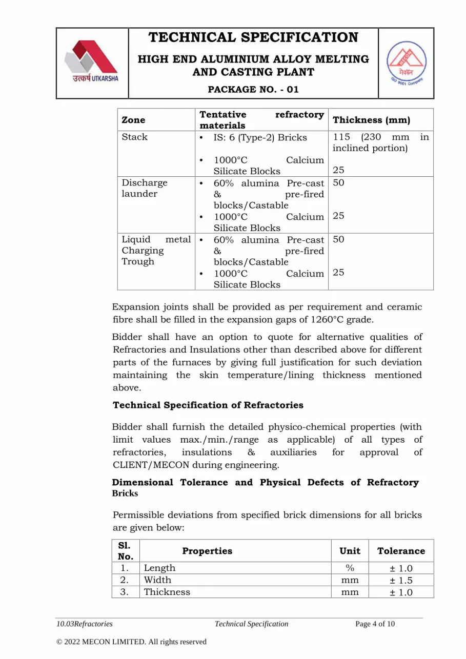
TECHNICAL SPECIFICATIONHIGH END ALUMINIUM ALLOY MELTING
AND CASTING PLANTPACKAGE NO. - 01
10.03Refractories Technical Specification Page 4 of 10
© 2022 MECON LIMITED. All rights reserved
Zone Tentative refractorymaterials Thickness (mm)
Stack IS: 6 (Type-2) Bricks
1000°C CalciumSilicate Blocks
115 (230 mm ininclined portion)
25Dischargelaunder
60% alumina Pre-cast& pre-firedblocks/Castable
1000°C CalciumSilicate Blocks
50
25
Liquid metalChargingTrough
60% alumina Pre-cast& pre-firedblocks/Castable
1000°C CalciumSilicate Blocks
50
25
Expansion joints shall be provided as per requirement and ceramicfibre shall be filled in the expansion gaps of 1260°C grade.
Bidder shall have an option to quote for alternative qualities ofRefractories and Insulations other than described above for differentparts of the furnaces by giving full justification for such deviationmaintaining the skin temperature/lining thickness mentionedabove.
Technical Specification of Refractories
Bidder shall furnish the detailed physico-chemical properties (withlimit values max./min./range as applicable) of all types ofrefractories, insulations & auxiliaries for approval ofCLIENT/MECON during engineering.
Dimensional Tolerance and Physical Defects of RefractoryBricks
Permissible deviations from specified brick dimensions for all bricksare given below:
Sl.No. Properties Unit Tolerance
1. Length % 1.02. Width mm 1.53. Thickness mm 1.0

TECHNICAL SPECIFICATIONHIGH END ALUMINIUM ALLOY MELTING
AND CASTING PLANTPACKAGE NO. - 01
10.03Refractories Technical Specification Page 5 of 10
© 2022 MECON LIMITED. All rights reserved
Sl.No. Properties Unit Tolerance
4. Taper (expressed as the differencebetween the largest and smallestdimensions) shall not exceed
mm ± 1.0
5. Warpage (expressed as the largeststraight deviation from a straight lineacross the diagonal of a brick face)shall not exceed
mm ± 1.0
6. Edge breakage shall not exceed(Refer FIG.1)
mm 25 (e+f+g)& 10 (e/f/g)
7. Corner breakage shall not exceed(Refer FIG.2) mm
25 (a+b+c)& 10(a/b/c)
Visual Inspection Characteristics of Refractory Bricks
General: The refractories shall be compact, of homogeneoustexture and shall be reasonably free of cracks, voids and otherflaws. They shall be burnt evenly and have sufficient mechanicalstrength with no soft corners. They shall show no sign of localvitrification.
Laminations: Bricks must be free of internal laminations andcracks. The hammer test is used to indicate the possibleoccurrence of such laminations and cracks. On a cut surface of a

TECHNICAL SPECIFICATIONHIGH END ALUMINIUM ALLOY MELTING
AND CASTING PLANTPACKAGE NO. - 01
10.03Refractories Technical Specification Page 6 of 10
© 2022 MECON LIMITED. All rights reserved
representative brick, laminations, if present, must be clearlyvisible to indicate a defect. A crack on a cut surface will be judgedaccording to open crack, defined below. For the hammer test, a100 gram hammer with a wooden handle is to be used.
Texture: The bricks must be free of grain segregation at cornersand edges and shall have external evidence of a strong, wellbonded and uniform texture, developed in a proper firing process.There must be no signs of local vitrification.
Craters: Craters are defined as melt phenomena, caused by ironoxide or lime. Iron oxide stains will be tested with a hammer todetermine the possible presence of craters. A crater is defined as adefect with a width larger than 6 mm and deeper than 3 mm. Morethan two such craters on any face are not acceptable. For theentire brick, the maximum allowable number of such craters isseven.
Open Cracks: Bricks must be free of open cracks. Open cracks aredefined as cracks or tears in the surface of which the length ismore than 10 mm and the width is more than 0.2 mm.
Colour: Colour shades due to variation of the firing process or thecombination of various materials in the kiln is a commonphenomenon. The inspector will verify that the bricks are of equalquality. In case of doubt a sample will be subject to chemical andphysical testing by CLIENT/MECON. Iron oxide spots onandalusite are not considered as defects.
Fins: Fins at corners and edges are not allowed. Fins are definedas :- Over 1.0 mm high and hard, which will not break under finger
pressure or- Over 0.6 mm high and soft, which will break under finger
pressure
Surface defects such as patching of surfaces are not allowed.

TECHNICAL SPECIFICATIONHIGH END ALUMINIUM ALLOY MELTING
AND CASTING PLANTPACKAGE NO. - 01
10.03Refractories Technical Specification Page 7 of 10
© 2022 MECON LIMITED. All rights reserved
Sampling, Marking & Inspection Plan
The manufacturer shall offer the refractory material for inspectionof CLIENT/MECON only after internal testing, sorting andmarking. All refractory materials shall be clearly marked withManufacturer’s Name/Brand Mark, Quality and Mark No. Markingof Dense quality bricks shall be done on the individual bricks.Marking of Insulation Bricks shall be done on the individualcarton. Marking of Monolithic items shall be done on the individualbags. Additionally manufacturing date & expiry date / shelf lifeshall be indicated on the individual bags of monolithic items.
For sampling the brick and for judging the conformity foracceptance of the product to the approved specification, theprocedure given in IS: 1528 (Part-7) shall be followed.
For Visual inspection, different shapes shall be considered asdifferent lots. Every lot will be checked as per IS: 1528 (Part 7). Ifthe lot size is less than 300 nos the following criterion shall beapplicable:
Lot Size(Nos.)
No. of SamplesPermissibleno. of PhysicalDefects
Permissible no.of DimensionalDefects
Less than200
10% or 10 Pieceswhichever is more
3 1
200-29910% or 10 Pieceswhichever is more
4 1
All the brick lots, which have passed the laboratory tests as well asvisual cum dimensional inspection as per IS: 1528 (Part-7) shall bestamped by CLIENT/MECON. The manufacturer shall despatchonly accepted & stamped bricks as per inspection certificate issuedby CLIENT/MECON.
For sampling of the castable, the procedure given in IS: 10570shall be followed.

TECHNICAL SPECIFICATIONHIGH END ALUMINIUM ALLOY MELTING
AND CASTING PLANTPACKAGE NO. - 01
10.03Refractories Technical Specification Page 8 of 10
© 2022 MECON LIMITED. All rights reserved
For sampling of the air setting mortar, the procedure given in IS:11452 shall be followed.
For sampling of the ramming mass, the procedure given in IS:10047 shall be followed.
B. Interconnecting launder system
Interconnecting launder system will include launders connectingthe melting to holding furnaces and launders connecting holdingfurnaces to the vertical DC caster. The refractory lining will be castshape inert to molten aluminium and its alloys with non-wettingagents. Refractory lining Material and thickness are to befurnished by tenderer mentioning the skin temperature (to beconfirmed by the technologist) of launder considering an ambienttemperature of 45ºC.
C. Metal Degasser System
The refractory to be used for the inline degasser system should beinert to gases like nitrogen, argon, hydrogen and any other gasevolving during functioning of the degasser. The refractory materialshould be able to withstand the speed of rotors and rate of metalflow through the degassers. The refractory lining will be cast shapeinert to molten aluminium and its alloys. Refractory lining Materialand thickness are to be furnished by tenderer mentioning the skintemperature (to be confirmed by the technologist) of launderconsidering an ambient temperature of 45ºC.
D. Metal Filtration Unit
The suitable refractory should be considered for the metal filtrationunit. Refractory lining Material and thickness are be furnished bytenderer mentioning the skin temperature (to be confirmed by thetechnologist) of launder considering an ambient temperature of45ºC.

TECHNICAL SPECIFICATIONHIGH END ALUMINIUM ALLOY MELTING
AND CASTING PLANTPACKAGE NO. - 01
10.03Refractories Technical Specification Page 9 of 10
© 2022 MECON LIMITED. All rights reserved
E. Distribution Trough
Distribution trough is the last process equipment of the VDCcasting machine from which liquid metal inserted into the moldand solidification shall start. The suitable refractory lining shouldbe considered in such a way so that no erosion of lining shall beoccurred and to avoid the chances of foreign particles entering intothe casting process may cause the quality issues in the cast slab.Refractory lining Material and thickness are to be furnished bytenderer mentioning the skin temperature (to be confirmed by thetechnologist) of launder considering an ambient temperature of45ºC.
10.03.04 Suppliers of Refractories
Before placement of order for different qualities of Refractories,Insulations & Auxiliaries on their sub-suppliers, the successfulBidder shall take prior approval of CLIENT / MECON. TheRefractories, Insulation & Auxiliaries shall be supplied only from theproven manufacturers having credentials regarding the supply ofsimilar materials with Aluminium furnace application.
10.03.05 Information to be submitted by the bidder along with the offerregarding refractories :
i. GA of refractory lining drawing indicating thickness &quality of different qualities of Refractories and Insulations.
ii. Expected refractory lining life.
iii. Estimated tonnage of Refractories and Insulationsqualitywise for different parts of the furnace & itsauxiliaries.
10.03.06 Data / Drawing / Document to be furnished by successfulbidder regarding refractories :
For Approval
General Arrangement and cross-sectional refractory liningdrawings including enlarged view of all complicatedparts/portions indicating thickness, qualities, place of

TECHNICAL SPECIFICATIONHIGH END ALUMINIUM ALLOY MELTING
AND CASTING PLANTPACKAGE NO. - 01
10.03Refractories Technical Specification Page 10 of 10
© 2022 MECON LIMITED. All rights reserved
use/location of each brick shapes, expansion joints, mortarjoints, laying pattern of brickwork, etc.
Thermal calculations justifying the thickness and qualitiesof Refractories and Insulations provided in different layersfor various parts of the furnace and its auxiliariesconsidering the ambient temperature at 45°C.
Detailed physico-chemical properties (with limit valuesmax./min./range, as applicable) of all refractories &insulations including mortars, masses, castable etc. andauxiliaries
For Information
Refractory lining erection drawings including shaped brickdrawings & bill of materials indicating shape & size of thebricks, unit weight of the bricks, total weight, place of use,actual quantities required, ordered quantities etc. of allrefractories & insulations including mortars, masses,castable etc.
Refractories erection manual containing refractory liningprocedure, mixing formula & mixing procedure for castable,mortars, etc. as well as preheating / heating procedures &curves etc.
As built refractory lining erection drawings.
All relevant drawings / documents / data not specificallymentioned above but deemed essential for successfulcompletion of refractory lining work within battery limitshall also be furnished by the Bidder.

TECHNICAL SPECIFICATIONHIGH END ALUMINIUM ALLOY MELTING
AND CASTING PLANTPACKAGE NO. - 01
10.04 Utilities (Gas Facilities) Technical Specification Page 1 of 2
© 2022 MECON LIMITED. All rights reserved
10.04 Utilities (Gas Facilities)
10.04.01 General
The gas facilities shall cover the utility system for melting andcasting package. The utility system covered herein includesdistribution system for Argon, Nitrogen, Propane gas, LPG andcompressed air. All the above utilities shall be supplied by thePurchaser at the battery limit and with specified parameters asindicated below:-
Sl.no Fuels/gases Approx. Pressure (Bar), Flow(Nm3/hr) & Temperature (degC)
1 Propane Tenderer to be mentioned2 Argon Tenderer to be mentioned3 Nitrogen Tenderer to be mentioned5. Compressed air Tenderer to be mentioned
Any change in parameters beyond the battery limit in order to meetthe requirement of individual consumers of the package shall beunder the scope of the Tenderer. Further piping downstream of takeover point for all utility systems complete with equipment, meteringdevices, controls and instruments and isolation valves, supportsetc. shall be in the scope of the Tenderer.
All the above mentioned utility services shall be made available bythe Purchaser through pipelines header running along the buildingcolumn in one axis (to be decided with successful bidder duringdetail engineering) of the melting & casting complex at an approx.elevation of 7m above ground. Taping from the headers at suitablelocations (to be decided with successful bidder) will be provided at 2meter height with isolation valves at the battery limit by thePurchaser.
10.04.02 Scope of work
1. The scope of work of the Tenderer under this specification covers,design, engineering, manufacture / procurement / assembly /

TECHNICAL SPECIFICATIONHIGH END ALUMINIUM ALLOY MELTING
AND CASTING PLANTPACKAGE NO. - 01
10.04 Utilities (Gas Facilities) Technical Specification Page 2 of 2
© 2022 MECON LIMITED. All rights reserved
inspection / testing / shop painting, supply, transportation,delivery, storage at site, erection, testing and commissioning of allthe utilities services mentioned above beyond TOP.
2. The supply shall include pipes, valves, supports, fittings,instruments, paint material, hoses and hose boxes (if required,for compressed air, Argon, Propane, Nitrogen & oxygen).
3. All the pipe work shall include, but not limited to, the following:
All pipe work for the services from the Battery Limit up to thevarious consuming points.
Flow measuring, recording and controlling facilities for theservices, as required.
Pressure indicators and temperature indicators for theservices, as required.
Control / PR valves and boosters as required.
Any item, not mentioned above but, required for smooth running ofthe system will be included by the Tenderer in their scope.
4. Supply, fabrication, erection, testing, painting and commissioningof the pipeline as mentioned above shall be carried out as perrelevant chapters of GTS.
5. The Tenderer shall furnish following drawing / document forinformation / approval.
a. Schematic layout drawing of all the fuels and gas pipelinesinside battery limit of melting and casting complex.
b. GA and cross section drawing with binding dimension showingpipe diameter, location of valves & fittings, supportingarrangement, approach platforms, elevation and consumerpoints for various services.
c. Data sheets, catalogues for valves, equipment and fittings, etc.
d. Specification of all pipes, valves, equipments, fittings, etc.
e. OD x thickness of each pipe at design limit of IPPL.

TECHNICAL SPECIFICATIONHIGH END ALUMINIUM ALLOY MELTING
AND CASTING PLANTPACKAGE NO. - 01
10.05 Air Conditioning & Ventilation Systems Technical Specification Page 1 of 1
© 2022 MECON LIMITED. All rights reserved
10.05 Air Conditioning & Ventilation System
The package #1 bidder has to provide all basic engineering datarequired for designing the Air Conditioning & Ventilation System andsuggest the schemes usually adopted for such plant to get the productsof aimed quality. If any specific feature is to be adopted/in-built inlatest process line equipment & electrical panels/ cabinets, same shallbe considered by the bidder indicating the advantages of using suchspecial feature in the offered equipment in context to air conditioning &ventilation.
All electrical cabinets, drives generating major heat load should haveair discharge from top of cabinet via duct/canopy.

TECHNICAL SPECIFICATIONHIGH END ALUMINIUM ALLOY MELTING
AND CASTING PLANTPACKAGE NO. - 01
10.06 Water Supply Facilities Technical Specification Page 1 of 8
© 2022 MECON LIMITED. All rights reserved
10.06 Water Supply Facilities
10.06.01 Scope of work
The scope of work shall include design, engineering, fabrication,manufacturing, assembly & supply, erection/construction/laying,commissioning, testing & performance guarantee tests of plant &equipment and piping etc of complete water supply facilities underthis package #1 including structural supports for piping work,valves, fittings, pipe clamps, strainers, filters, heat exchangers/chillers,, required electrics, instrumentation, automation, etc asspecified and required for complete water systems for the plant asspecified in this chapter as well as various chapters of this TenderDocument in line with General Technical Specification (GTS) andsubject to Purchaser’s approval, complete in all respect on turnkeybasis.
The scope of work shall include the following activities:
i) Design, engineering, manufacture /fabrication, assembly, shoptesting, painting, packing sequential delivery FOR site, unloading,unpacking, storage at site, preparation & submission of all drawingsfor structural support, piping, construction & erection drawings,construction & erection as per approved drawings, site-testing,painting, commissioning and fulfillment of guarantee performance ofall plant & equipment of water supply facilities under scope ofpackage#1 facility.
ii) Supply of pipeline supports, thrust blocks/ anchor blocks, structuralstockades, bridges, R.C.C. pedestals etc. for overhead / on-ground/underground pipelines, as required.
iii) Supply of all technical literature, drawings & documents, generalarrangement drawings, assembly & sub-assembly drawings of all theplant & equipment, construction & erection drawings, as-builtdrawings, operation & maintenance manuals, manufacturingdrawings / detail ordering specification, etc.
iv) Submission of all drawings at (iii) above, design calculations, datasheets for various equipments, pipeline sizing calculation and

TECHNICAL SPECIFICATIONHIGH END ALUMINIUM ALLOY MELTING
AND CASTING PLANTPACKAGE NO. - 01
10.06 Water Supply Facilities Technical Specification Page 2 of 8
© 2022 MECON LIMITED. All rights reserved
calculation for sizing of various sub-systems and integrated systemsfor approval of Purchaser/ Consultant and finalizing the same as perapproval of Purchaser/ Consultant. The approval of the samehowever does not absolve the Tenderer from his responsibilities.
v) Supply of commissioning spares & consumables; a list thereof shallbe submitted by the Tenderer.
vi) Tenderer shall submit an itemized price-list of two years operationand maintenance spares.
vii) Supply of special tools & tackles for construction, erection operationand repair & maintenance of the plant & equipment.
viii)All necessary connections for hook-up with Purchaser’s system atbattery limits. Purchaser will provide Water pipe header through thebuilding column along one axis of the shop /bay at a height (to bedecided during detail design). Pressure and quality of water in headerwill be as defined in relevant chapter. As per pipe size requirementand location defined by successful tenderer, taping will be providedfrom the water pipe line header at a height of 1.2 meter with oneisolation valve. Tender to provide all basic data pertaining to waterrequirement of Package#1 facility to enablethe purchaser to designthe water header pipe lines and water systems design. TOP oftenderer will start from this point. Further piping work till itsconsumers points or discharge points, facility for increase ordecrease of water pressure, flow control, temperature control, anyother process instruments& control, pumps, valves, electrics &automation required for proper functioning of the suppliedequipment& system will be in the scope of Package#1 tenderer.
ix) Supply of erection, testing & commissioning equipment and material.
x) Piping network flushing fluids, chemicals & consumables.
xi) First fill of oils, lubricants, filter media, resins, chemicals reagentsand other consumables within the battery limit of tenderer.
xii) Inspection and performance testing of individual equipment andsystem as a whole.

TECHNICAL SPECIFICATIONHIGH END ALUMINIUM ALLOY MELTING
AND CASTING PLANTPACKAGE NO. - 01
10.06 Water Supply Facilities Technical Specification Page 3 of 8
© 2022 MECON LIMITED. All rights reserved
xiii)Participation in design conference with the Purchaser & Consultantas and when called for.
Water supply system/ sub-systems shall be complete in all respectsand any equipment or material not specifically mentioned in thisspecification, but required for safe, efficient & smooth operation andguaranteed performance of the plant shall be deemed to be includedunder the scope of work of the Tenderer.
10.06.02 Battery Limit
a) Recirculation, Emergency water (contact & non-contact water)Cold recirculation water line (supply) from the industrial water circuitwill be provided by the Purchaser through pipe line header running(at a height to be mutually decided later) along the building columnsof the shop / bay of the proposed plant at requisite flow, pressure,temperature & quality (to be decided by the tenderer).Hot recirculation water line (return) will be left by the Tenderer uptoheader running (at a height to be mutually decided later) along thebuilding columns of the shop / bay of the proposed plant at requisiteflow, pressure (minimum 2.5 kg/cm2), temperature & quality (to bedecided by the tenderer).
b) Industrial water
Industrial make-up water quality with due treatment of raw water(raw water quality as indicated in GTS)will be made available by thePurchaserto the Tendererthrough pipe line header running (at aheight to be mutually decided later )along the building columns ofthe shop / bay of the proposed plant at a pressure of approx 1.5-2.0kgf/ cm2 (g). Suitable pipe tapping from the header along withone isolation valve will be provided as per specified locations &pipesizes of tenderer at 1.2 meter height.Tenderer shall extend the samethrough isolation gate valves in valve-pit alongwith flow meter(complete with isolation valves and by-pass arrangement) to hisproposed systems for service/make-up water requirement for thefacility under package#1.

TECHNICAL SPECIFICATIONHIGH END ALUMINIUM ALLOY MELTING
AND CASTING PLANTPACKAGE NO. - 01
10.06 Water Supply Facilities Technical Specification Page 4 of 8
© 2022 MECON LIMITED. All rights reserved
Tenderer shall indicate the make-up water quantity requirement,pipe size, end connection, MOC of pipeline, etc. at the battery limit.
Water treatment facilities as required for the proposed plant andequipment shall be provided by the Tenderer.
c) Construction Water
Construction water sourced from bore well shall be made available tothe Tenderer at one point within 50m from the proposed plant.Tenderer shall extend the same from battery limit through isolationgate/ball valve in valve-pit to the entire plant area for their usage.
10.06.03 Erection, Testing and Commissioning
1. The erection of all plant and equipment shall be carried out accordingto the latest engineering practices and according to the drawings,specifications, Instructions etc. duly approved by thePurchaser/Consultant.
2. The welding work should be carried out as per the approved WPS andPQR.
3. The Tenderer shall supply all required manpower, tools and relatedequipment, all hoisting equipment, all necessary scaffoldings, allnecessary transporting equipment, consumables. Construction anderection materials, petrol, diesel oil, kerosene, solvents, sealingcompound, tapes, brazing and soldering materials, welding andbrazing gases, erection bolts, nuts and packing sheets/compounds,temporary supports, wooden blocks, spacers, templates, jute andcotton wastes, sand/emery paper etc. as required for the satisfactorycompletion of work.
4. After erection, all equipment having moving part, subject topressures or voltages shall be given trial operation. The trialoperation shall consist of 72 hours of continuous operation. All

TECHNICAL SPECIFICATIONHIGH END ALUMINIUM ALLOY MELTING
AND CASTING PLANTPACKAGE NO. - 01
10.06 Water Supply Facilities Technical Specification Page 5 of 8
© 2022 MECON LIMITED. All rights reserved
modifications and rectifications required during the trial operation orrequired for proper operation shall be done at his own cost by theTenderer as accepted by the Purchaser/ Consultant.
5. Rotating equipment shall be checked for proper direction of rotationand shaft alignment. Equipment subject to pressures shall becarefully examined for leakage. All equipment, such as pressure taps,temperature measurement connections, flow measurement devicesetc. shall be provided by the Tenderer.
6. On completion of the work, the Tenderer shall remove and dispose offall rubbish and other unsightly materials caused by his working to alocation as directed by the Purchaser and thereby leaving thepremises in good, clean, safe and operable condition.
7. Before giving call for final inspection, all the documents shall befurnished to the Purchaser. The record of manufacturing details,inspection and tests carried out by the Tenderer shall be madeavailable to the final inspecting authority. However, approval andfinal inspection at the manufacturing works shall not relieve theTenderer of responsibility of replacing at his cost any defectivepart/material which may be detected by the purchaser duringerection and commissioning or guarantee period.
8. All materials required for fabrication, construction, testing andinspection shall be supplied by the Tenderer. No material shall befree issue to the Tenderer.
9. No equipment or part item shall be dispatched without finalinspection and issuance of inspection certificate.
10. All equipment, assemblies, sub-assemblies shall be shop tested asper relevant standards and the test certificates shall be submitted bythe supplier.

TECHNICAL SPECIFICATIONHIGH END ALUMINIUM ALLOY MELTING
AND CASTING PLANTPACKAGE NO. - 01
10.06 Water Supply Facilities Technical Specification Page 6 of 8
© 2022 MECON LIMITED. All rights reserved
11. Erection, testing & commissioning of various equipments and pipingetc shall be done also inline with details given in various chapters ofGTS.
10.06.04 Painting
The Tenderer shall follow the painting procedure as mentioned inGTS.
10.06.05 Preferred Makes
The Tenderer shall follow the list of preferred makes as per GS-13.
10.06.06 Drawings & documents
Drawings / documents to be furnished by the Tenderer for approval
1. Process flow diagram indicating the water consumption figurescomplete with temperature, pressure and quality requirements.
2. P&IDs of each circuit of the complete water supply systemshowing all the consumers, flow rate, pipe diameters, broadparameters of each equipment, instruments, alarms & interlocksfunctions using ISA symbols, water losses etc.
3. Write -up detailing the control logic for the entire water system.
4. List of instruments comprising bill of materials andinstrumentation data sheets.
5. List of safety interlocks.
6. Pipeline materials and specifications considered for varioussystems.
7. Equipment and piping sizing calculations.
8. Layout drawing showing the battery limits of make–up water,drinking water, firefighting water and the pipeline route tovarious consumers including requirement of make-up water,
TECHNICAL SPECIFICATIONHIGH END ALUMINIUM ALLOY MELTING
AND CASTING PLANTPACKAGE NO. - 01
10.06 Water Supply Facilities Technical Specification Page 7 of 8
© 2022 MECON LIMITED. All rights reserved
drinking water, firefighting water and construction water atbattery limits.
9. General arrangement and cross-sectional drawings,characteristics curves and technical details of all the equipments(pumps, strainers, cooling tower & its components, valves,expansion joints, conditioning chemicals, sluice gates, firehydrants, etc.).
10.GA drawings showing plan, elevation and sectional views of thewater system units and installations.
11.Layout drawing of piping system indicating pipe routing, locationof supports, valves and other fittings as required.
12.Quality Assurance Plan.
13.Any other drawing/ documents as required by the Purchaser /Consultant.
Drawings / documents to be furnished by the Tenderer for referenceand record
1. The Tenderer shall submit required sets of all the approveddrawings, documents and manuals for Purchaser’s/ Consultant’srecord and use. After erection of equipment, the Tenderer shallsubmit one set of linen tracings/ reproducible in requirednumber of prints along with soft copies in CD (in AutoCADformat) of each “As built drawings”.
2. Operation and maintenance manual.
3. Spare parts recommendation and price list.
4. Bill of Quantities covering all equipments, valves, strainers,pipelines, etc.
5. Test certificates for the following: Material test certificate for all major equipment and their
components. Hydraulic test of equipment, pipe fittings & valves.

TECHNICAL SPECIFICATIONHIGH END ALUMINIUM ALLOY MELTING
AND CASTING PLANTPACKAGE NO. - 01
10.06 Water Supply Facilities Technical Specification Page 8 of 8
© 2022 MECON LIMITED. All rights reserved
Static and dynamic balancing of all rotary parts/ equipments.
6. List of special tools and tackles if any.
7. List of commissioning spares.
8. List of spares for two years of normal operation and maintenancewith item wise prices.
9. Instruction for erection, testing and commissioning.
10. Test procedures for preliminary and final acceptance tests.
11. Manufacturer’s test certificates.
12. Lubrication schedule and quantity and quality of lubricant forone year’s normal operation.
13. Various equipment assembly drawings and bill of material.
14. Welding procedure.
15. Hydraulic test logs.
16. Equipment GA drawings and bill of materials.
17. Characteristics curves of the pumps, motors and otherequipments.
18. Operation and maintenance manuals for all equipments, valvesand complete water system along with soft copies.
19. Test and calibration certificates.
20. Warranty/ guarantee certificates.
21. Catalogues, literatures of all equipment.
22. Technical literature, catalogues and manufacturer’s drawings forall brought out equipment, valves and other items.
23. All inspection/ test report/ certificates.
24. Any other drawing / documents as required by thePurchaser/Consultant.
TECHNICAL SPECIFICATIONHIGH END ALUMINIUM ALLOY MELTING
AND CASTING PLANTPACKAGE NO. - 01
10.07 Electrics and Automation Technical Specification Page 1 of 76
© 2022 MECON LIMITED. All rights reserved
10.07 Electrics, Automation and Telecommunication
INDEX – ELECTRICS AND AUTOMATION
SL Clause DescriptionPageno.
1 10.07.01 SCOPE 3-7
2 10.07.02 General Technical Condition 7-14
3 10.07.02.01 Climatic Condition 7-8
4 10.07.02.02 Main Incoming Power Data 8
5 10.07.02.03 Auxiliary Voltage 8-9
6 10.07.02.04 Codes & Standard 9-10
7 10.07.02.05 Take Over Point (Battery Limit) 10
8 10.07.02.06 Preferred Makes of Equipments 10-11
9 10.07.02.07 Design Criteria 11-14
10 10.07.03 Power Supply 14-15
11 10.07.04 Drive System 15-34
12 10.07.04.01 Converter Transformer 15-19
13 10.07.04.02 Distribution Transformer 20-24
14 10.07.04.03 Driver Converter System 24-27
15 10.07.04.04 Drive Motors 28-29
16 10.07.04.05 LV Fixed Speed AC Motors 30-31
17 10.07.04.06 MCC, PDB & Other Cubicles 31-34
18 10.07.05 Automation System - General 34-52
19 10.07.05.01 Basic Automation and PLC System (L-1) 37-40
20 10.07.05.02 Process Automation System (L-2) 40-45
21 10.07.05.03 HMI System 45-48
22 10.07.05.04 Measurement System & Instruments 48
23 10.07.05.05 Control / Operator Desk 48-50
24 10.07.05.06 Structural Pulpits 50-51
25 10.07.05.07 Automation related other misc. 51-52
TECHNICAL SPECIFICATIONHIGH END ALUMINIUM ALLOY MELTING
AND CASTING PLANTPACKAGE NO. - 01
10.07 Electrics and Automation Technical Specification Page 2 of 76
© 2022 MECON LIMITED. All rights reserved
equipment
26 10.07.06 Additional Systems 52-56
27 10.07.06.01 Uninterrupted Power Supply System 52-54
28 10.07.06.02 Primary and Secondary Earthing
System
54-55
29 10.07.06.03 Lightning Protection System 55
30 10.07.06.04 Welding & Small Power Supply Socket
System
55
31 10.07.06.05 Illumination System 55-56
32 10.07.07 Cable and Erection Material 56-60
33 10.07.08 Special Tools & Tackles 61-62
34 10.07.09 Water Treatment Plant 62
35 10.07.10 Air Conditioning & VentilationSystem
62
36 10.07.11 Compress Air System 62
37 10.07.12 Laboratory System 62
38 10.07.13 Drawing & Documentation 62-63
39 10.07.14 Services 63-64
40 10.07.14.01 Inspection 63
41 10.07.14.02 Training 63
42 10.07.14.03 Erection 63-64
43 10.07.14.04 Testing & Commissioning 64
44 10.07.14.05 Spares 64
45 10.07.15 Commissioning Spares 65-68
46 10.07.16 The List drgs./documents submissionwith offer
68
47 10.07.17 Scope Division/Split-up List 68-76

TECHNICAL SPECIFICATIONHIGH END ALUMINIUM ALLOY MELTING
AND CASTING PLANTPACKAGE NO. - 01
10.07 Electrics and Automation Technical Specification Page 3 of 76
© 2022 MECON LIMITED. All rights reserved
10.07.01 Scope
Scope of Work
The scope of work of the Bidder shall necessarily include (but notlimited to) the following: Design, Basic and Detail engineering,manufacture, assembly, factory testing, inspection, packing,forwarding, delivery at site, unloading, storage at site, erection,testing, commissioning and handing over to the Employer ofelectrical equipment complete with cables, erection and earthingmaterials, supervision of Erection, Testing and Commissioningconforming to the requirements given in this TechnicalSpecification.
All necessary power distribution from the outgoing terminal ofEmployer’s MV switchboard (11 kV) to supply power to theFurnaces & Casters electrics and auxiliary system electrics beingsupplied by the Bidder shall be in Bidder’s scope.
Distribution transformers, associated, HT Cables, PCC(LCSS) andfurther distribution of LV power necessary for auxiliaries of thetechnological equipments shall be under scope of bidder. 11KV HTBreaker with protection for incoming supply of this distributiontransformer shall be provided by employer.
Necessary emergency power requirement for the Furnaces &casters system shall be specified by Bidder (giving break up of theemergency loads considered including operating / working loads).Employer shall provide one no. 415V, 3ph, 50Hz, emergency powersupply feeder from their DG / emergency sources for Bidder’s use.The KVA rating for the same shall be indicated in their offer bybidder.
Scope of Supplies
1. Power and control cables, cable termination kits, laying andtermination of all associated power and control cables fromthe Employer’s 11kV switchboard located Furnace cum CaterECR of this plant.
2. VCB with protection features controlled by drive function at

TECHNICAL SPECIFICATIONHIGH END ALUMINIUM ALLOY MELTING
AND CASTING PLANTPACKAGE NO. - 01
10.07 Electrics and Automation Technical Specification Page 4 of 76
© 2022 MECON LIMITED. All rights reserved
/before converter transformer primary side with earthingswitches as per requirement.
3. VCB without protection features at /before bidder's distribution
transformer primary side with earthing switches.
4. Converter Transformers.
5. Distribution Transformer for equipment Auxiliaries andassociated systems for LV Power distribution.
6. Drive Converter System.
7. AC motors as per process requirements.
8. LCSS for Equipments Auxiliary Power supply , Motor ControlCenters (MCC), other Cubicles.
9. Power supply distribution up to LCSS for cranes, Hoist,Transfer cars, Illumination system, Air condition andventilation systems and other associated auxiliary systems ofshop floor shall in scope of Employer. However Bidder shallkeep space provision in each ECR of further distributionPanels/Cabins of the above systems.
10. Complete Automation System for the furnaces and castersincluding Measuring Instruments, Sensor, Basic AutomationSystem (Level-1) with remote I/O panels, Process AutomationSystem (Level-2) for Furnaces and casters as per processrequirement.
11. Provide interface both in Level-1 and Level-2, betweenAutomation Systems at Preheat Furnace, WTP, PowerDistribution System, laboratory, Employer’s Level-3Automation System for Production data and ManagementInformation exchange and any other Automation systems inthe Furnaces cum casters.
12. HMI System.
13. Process Data Acquisition System.
14. Measuring Gauges, Instruments, Sensors & Encoders,Mounted Electrics / Field Devices.
15. Control Desks, Local Control Boxes/Local Control Cabinets,junction boxes (onboard & plant floor).

TECHNICAL SPECIFICATIONHIGH END ALUMINIUM ALLOY MELTING
AND CASTING PLANTPACKAGE NO. - 01
10.07 Electrics and Automation Technical Specification Page 5 of 76
© 2022 MECON LIMITED. All rights reserved
16. Consumption monitoring for Power and media supplyincluding supply of instruments for acquiring consumptiondata at respective TOPs.
17. Control / Operator Desks as per process requirement.
18. UPS system including its AC Distribution Board (ACDB).
19. MV, LV Power Cables, Control Cables, Communication Cable,Screened/ Special Cables as per requirement.
20. Basic data and basic engineering of IP Based CCTV system
21. Basic data and basic engineering of Fire Detection & AlarmSystem for furnaces, casters & other areas as specified.
22. Basic data and basic engineering of IP Based Voicecommunication system for Furnaces cum Casters.
23. Search & Signaling system including rotating flash lights andsirens at strategic locations e.g. top of pulpit etc. Any speciallighting for equipments/system, the same shall be consideredby bidder.
24. Plant production data digital display units at strategiclocations with automation interface.
25. Primary & secondary earthing including Electronicearthingsystem for automation equipment / PLC/ Drives/Electronic Equipment supplied, neutralearthing oftransformers, and earthing of all power distributionequipment.
26. Media supply (cooling water, compressed air etc) from TOP upto respective equipment flanges.
27. Electrics & Control for Sump Pumps.
28. Cable supporting structures in the cable tunnel, cablechannel or overhead cable bridge for interplant cabling,erection accessories, earthing materials & consumables asshall be necessary for Bidder’s & employer’s cables.
29. GI pipes for protection of cables at road crossing and otherplaces where cables may be subjected to mechanical stressand damage.
30. First fill of all consumables including first fill of transformer

TECHNICAL SPECIFICATIONHIGH END ALUMINIUM ALLOY MELTING
AND CASTING PLANTPACKAGE NO. - 01
10.07 Electrics and Automation Technical Specification Page 6 of 76
© 2022 MECON LIMITED. All rights reserved
oil with extra 20% oil, consumables, repair of any damagedequipment and touch up painting during handling anderection of equipment.
31. One LV CB handling trolley for each LV switchboard as perrequirement.
32. Supply of Special tools & tackles.
33. Supply of Commissioning Spares.
34. Electrics & Control for the plant Media Systems and anytechnological item covered under this specification.
35. Bidder shall plan for all the automation systems up to Level 2and price bid shall be provided for the same as indicated inprice bid format, which shall be considered for evaluation ofL-1 Bidder.
36. Bidder shall submit separately all automation hardwareand software with compliance INDUSTRY 4,O as aoptional items. Complete details of L- 0, L- 1 & L- 2hardware and software shall be included in their offer andprice for the same shall be indicated by the bidder inprice bid format. This price shall be optional and shall notbe used for evaluation of L-1 bidder
Scope of Construction Power Supply
1. Employer shall provide power at LV (415V) AC, one numberfeeder at a suitable location within the battery limits. Therequired rating of the feeder shall be mentioned in theiroffer.
2. Distribution of Construction Power Supply from the Bidder’sDistribution Board to the respective consumers.
3. Bidder’s scope shall also include stand-by DG power supplyarrangement for construction work.
4. Laying termination of cables from Employers feeder to thedistribution board of Bidders.
Scope of Services
1. Complete Design, Basic & Detailed Engineering, Software

TECHNICAL SPECIFICATIONHIGH END ALUMINIUM ALLOY MELTING
AND CASTING PLANTPACKAGE NO. - 01
10.07 Electrics and Automation Technical Specification Page 7 of 76
© 2022 MECON LIMITED. All rights reserved
Development & Testing, Erection and Commissioning of theequipment supplied.
2. Measurement of soil resistivity for designing EarthingSystem and Lightning Protection System as applicable.
3. Training of Employer’s personnel for Operation/Maintenance.
4. Association of Employer/his Consultant in systemengineering software development and testing of equipment.
5. Drawing & documents as per mutual agreement during Kickoff meeting with successful Bidder.
10.07.02 General Technical Condition
10.07.02.01 Climatic Condition
Ambient temperatures for design of electrical equipmentshall beFor Furnaces and Casters Floorequipment (in hot area)
55 deg C
For other normal Floorequipment (in cold area),Pressurized Ventilated Rooms(HT/ LT Rooms, MCC Rooms,Cable basement, Cable tunnel),Transformer room (both for dry& oil type)
50 deg C
For Air Conditioned Rooms(Automation rooms and Pulpits)
25 deg C (equipment designfor 470C internaltemperature)
For Air Conditioned Rooms(Drives)
35 deg C (equipment designfor 470C internaltemperature)
Humidity 100% (not occurringsimultaneously with max.temp.)
Cooling water inlet temperature 35 Deg CCooling water temperature rise 70C

TECHNICAL SPECIFICATIONHIGH END ALUMINIUM ALLOY MELTING
AND CASTING PLANTPACKAGE NO. - 01
10.07 Electrics and Automation Technical Specification Page 8 of 76
© 2022 MECON LIMITED. All rights reserved
Altitude Above MSL < 1000 M
10.07.02.02 Main Incoming Power Data
MVAC Power Supply
Voltage 11 KV,+10% , – 10%
Frequency 50 Hz +5%, -5%
Symmetrical short circuit 40 KA for 3 Sec
Earthing Resistive Earthed
LVAC Power Supply
Voltage 415 V, +10%, -15%
Frequency 50 Hz +5%, -5%
Symmetrical short circuit as per design
Earthing Solidly Earthed
No of 11 KV feeders to be
provided by Employer
Shall be provided by
Employer. Bidder shall
submit nos. of 11KV feeders
along with power SLD with
their offer Indicating their all
requirement positively.
Symmetrical Short Circuit for
415V switch gear
as per design
10.07.02.03 Auxiliary Voltage
AC control (Power supplies,
Single phase AC)
240 V
Solenoid valves 24 V DC
PLC power supply 240V AC, 50 Hz, obtained
through UPS (for processor)
PLC Interrogation & output 24 V DC

TECHNICAL SPECIFICATIONHIGH END ALUMINIUM ALLOY MELTING
AND CASTING PLANTPACKAGE NO. - 01
10.07 Electrics and Automation Technical Specification Page 9 of 76
© 2022 MECON LIMITED. All rights reserved
Voltage
Sockets for Welding purposes 415V, 63/100A, 3 pin plus
earth with plug interlocked
switch
Sockets for hand tools 240V, 15A, 2 pin plus earth
with plug interlocked switch
Electro-magnetic brakes 220V, DC, obtained through
individual rectifiers
Battery and battery charger 110 VDC, (employer scope)
10.07.02.04 Codes & StandardBidder’s supplied equipment shall conform to the following
documents
GTS No.: MEC/S/11/35/Q7R6/GTS/01/R0, March, 2022.
Design StandardsThe electrical equipment and the automation systems shall bedelivered in accordance with international norms, standards andregulations of
IEC (International Electric Organisation) DIN (German Industrial Standrad) VDE(Specification of the Association of German
Electrotechnicans) IS (Indian Standards)
The engineering shall be carried out in English language.
The Employer gets the right of use of the supplied software. Thecopyright remains with the Bidder.
The control software shall be used exclusively in this Employer’splant. The making of backups for safety reasons is explicitlyallowed. It is prohibited to make software accessible to thirdparties.

TECHNICAL SPECIFICATIONHIGH END ALUMINIUM ALLOY MELTING
AND CASTING PLANTPACKAGE NO. - 01
10.07 Electrics and Automation Technical Specification Page 10 of 76
© 2022 MECON LIMITED. All rights reserved
The source code of this application software shall be delivered in aform that Employer’s maintenance personnel can carry outmodifications.
10.07.02.05 Take Over Point (Battery Limit)
Power SupplyTake over point of power supply for this package shall be from theoutgoing terminals of Employer’s MV (11 kV) switchboards to beinstalled in the Furnace cum Caster ECR of the Mill.
Emergency Power SupplyFor emergency power supply, employer shall provide one no feederat LV (415V, 3 Ph, 50 Hz, AC) at the nearest established DGstation/sub-station (approximately 200 mtrs) for technologicalequipments.
Construction Power SupplyFor construction power supply, Employer shall provide onenumber of feeder for power at LV (415V, 3 Ph, 50 Hz, AC) at thenearest established sub-station (approximately 150 mtrs).
Cooling Water and Media supplyThe mounting structures, media requirement piping includingvalves & filters (for air & water supply) up to the TOP (definedelsewhere in this specification), any protection enclosure againstdust / heat / vibration, lead cables with necessary junction box,etc is included in the scope of the Bidder as per technologyprovider's motor and component list and same shall be completewith its electronics and its cabinet.
10.07.02.06 Preferred Makes of Equipment
Makes of all Electrical & Automation equipment shall be selectedout of Employer’s “Preferred makes of equipment and supplies"given under General Technical Specification (GTS). Only one makeshall be adopted for each type of equipment considering plantstandardization.
In case make of some equipment/components are not indicated in
TECHNICAL SPECIFICATIONHIGH END ALUMINIUM ALLOY MELTING
AND CASTING PLANTPACKAGE NO. - 01
10.07 Electrics and Automation Technical Specification Page 11 of 76
© 2022 MECON LIMITED. All rights reserved
the list, approval of makes for the same shall be obtained fromEmployer.
10.07.02.07 Design Criteria
Design Philosophy & Criterion for Equipment Selection
The equipment offered shall be suitable for smooth, efficient andtrouble free service in the tropical humid climate prevailing atplant site and under the ambient temperature conditions indicatedfor the different areas. In hot areas of higher temperatureconditions, the equipment shall be adequately protected againstdamage from radiant heat and hot air.
Due consideration shall be given to the dust laden atmosphere. Allequipment and accessories located outdoors shall be dulyprotected against weather.
Equipment De-Rating Criterion
Equipment selection and de-rating shall be based on ambienttemperatures as have been mentioned under supply conditions.
Selection of Motors Voltage Levels
AC squirrel cage induction motors of rating up to 200 kW shall befed at LV, 415V, 3 phase, 4 wire 50 Hz, with DOL or VFD asapplicable.
DOL start LV Motors (415V) of rating 132 kW upto 200 kW shallbe fed through independent Motor Control Panel (MCP) and shallbe provided with one number control transformer. MCPs shall inturn be fed directly from LCSS. Power devices like MCCB,Contactor, etc for drives of rating 132 kW and above shall belocated in these MCPs. Each MCP shall be located in ECR room bythe side of the respective group MCC.
AC motors of rating in excess of 200 KW shall be connected to theMV power supply system.
Selection of Motor Type

TECHNICAL SPECIFICATIONHIGH END ALUMINIUM ALLOY MELTING
AND CASTING PLANTPACKAGE NO. - 01
10.07 Electrics and Automation Technical Specification Page 12 of 76
© 2022 MECON LIMITED. All rights reserved
AC Synchronous and Asynchronous squirrel cage inductionmotors shall be used for drives requiring speed control.
Motor Starting and Permissible Voltage Dips
Voltage dip on starting of the largest LV motor shall be limited to10% of the nominal voltage at the motor terminals. Maximumallowable voltage drop in any feeder under steady state conditionshall be maintained as follows:
Total voltage drop during running 6 %
LTSB to MCC/ PDB/ MLDB 2-3 %
MCC to motor 4-5 %
In-Shop Power Supply System
Suitable numbers of 415V Motor Control Centers shall be providedfor feeding power supply to motors of rating 110 kW and below.VFDs shall be provided for equipment requiring speed control.
Automation System Redundancy concepts
Level – I system shall have no redundancy
Level – 2 system shall have hot standby CPU, DMR (Dual
modular Redundant) CPU, Hot plug Power supply unit and
redundant fan unit.
HMI system shall have hot standby server.
Data storage shall be in RAID-5 configuration having multiple
discs and with features of volume shadowing / Disc mirroring.
Automation System Spare concepts
20% mounted spare I/O channels left after commissioning on
overall I/O count including remote I/O stations.
20% spare slot for PLC and remote I/O stations( Min one slot)
Minimum 40% spare memory capacity shall be built in the

TECHNICAL SPECIFICATIONHIGH END ALUMINIUM ALLOY MELTING
AND CASTING PLANTPACKAGE NO. - 01
10.07 Electrics and Automation Technical Specification Page 13 of 76
© 2022 MECON LIMITED. All rights reserved
system after loading of application and system software
Communication Network loading shall be limited to 50% max
50% maximum network loading
50% CPU load.
Field bus shall have a cold standby (unconnected) cable laid
through different route with connectors
Automation Cable Selection Concept
Twisted pair cables shall be used for communication between
panels inside a Room and FO cable shall be used for outside
premise communication.
Network cabling shall have either ring or dual bus structure.
Network cables shall trace separate / alternate routes and shall
run through GI pipes distinctly colored and clad with heat
resistant cable along with necessary identification of cable.
Communication
Field bus connection shall be used for field instruments / RIO
unit & drives etc.
Level-1 & Level-2 network shall be through Ethernet
connection.
Layout Issue for Transformer
Oil type transformers shall be located outside the bays only.
LVAC Distribution spares
Each / MCC / PDBs etc. shall be provided with 20% spare
cubicles with modules. These spare cubicles & modules shall be
complete with circuit elements and shall be fully wired. Rating and
type of spare feeders shall be decided during detailed engineering

TECHNICAL SPECIFICATIONHIGH END ALUMINIUM ALLOY MELTING
AND CASTING PLANTPACKAGE NO. - 01
10.07 Electrics and Automation Technical Specification Page 14 of 76
© 2022 MECON LIMITED. All rights reserved
stage.
Pre-wiring Concept for Bought-out Items
All bought-out systems including valve stands, power packs etc.shall be supplied in pre-wired condition with copper cable up tojunction boxes for external cable termination.
10.07.03 Power Supply
Bidder’s scope includes all power supply equipment within thebattery limit.
Bidder’s scope also includes supply and termination of MV / LVpower, control, communication & signal cables at both ends for allelectrical equipment within the battery limit.
Bidder shall size & supply power cables, control cables & specialcables, plan the cable route, lay the cables and terminate at bothends.
Medium voltage side isolation
Medium voltage VCBs (with protection features controlled by theDrive function) as per requirement, before the convertertransformers, shall be housed inside the transformer room .
Medium voltage VCBs (without protection features) as perrequirement, before the distribution transformers, shall be housedinside the transformer room.
The above VCB panels shall also have Trip PBs (press to lock andturn to release) in the transformer rooms for tripping of upstreambreakers.
Power supply for auxiliary systems (up to LCSS)
Power Supply Data to be Furnished by Bidder
Final details of connected load (in kW), and 15 minute maximumdemand (in kVA) for each feeder / unit shall be furnished by the

TECHNICAL SPECIFICATIONHIGH END ALUMINIUM ALLOY MELTING
AND CASTING PLANTPACKAGE NO. - 01
10.07 Electrics and Automation Technical Specification Page 15 of 76
© 2022 MECON LIMITED. All rights reserved
Bidder during basic engineering. Bidder shall also submit thedetails of aux load requirement for the technologicalequipmentsand other loads under scope of the bidders fornecessary size of LV distribution systems by employer.
Power Factor Compensation & Harmonic Suppression Systems
Bidder’s shall provide necessary basic data (BD) including spacerequirement for power factor compensation & harmonicsuppression systems, as may be required by the Employer duringengineering.
Construction Power Supply
Approximately 150 kVA construction power shall be provided atone points. Bidder’s scope shall include distribution ofConstruction Power Supply from the Bidder’s Distribution Boardto the respective consumers and maintenance of the constructionpower supply system.
Bidder’s scope shall also include DG set (on hire) for stand-bypower supply arrangement for construction work.
Supply, Laying, Termination & Maintenance of cables fromEmployer’s feeder to the Construction Power Distribution Board ofBidder during installation.
10.07.04 Drive System
10.07.04.01 Converter Transformer
Converter Transformer (Oil type)
ITEM PROJECT SPECIFICATIONConstructional FeatureMaterial 1. Low loss CRGO silicon steel for core
2. Copper for winding.Lamination CRGO SteelElectrical DesignInstallation Outdoor (outside the plant building)Rated Primary voltage 11 kV

TECHNICAL SPECIFICATIONHIGH END ALUMINIUM ALLOY MELTING
AND CASTING PLANTPACKAGE NO. - 01
10.07 Electrics and Automation Technical Specification Page 16 of 76
© 2022 MECON LIMITED. All rights reserved
ITEM PROJECT SPECIFICATIONNo. of Phases ThreeNo. of Primary Windings OneNo. of secondaryWindings
As per drive configuration
Frequency 50 HzType of Cooling ONAN (Mineral Oil)Class of Insulation Class ATap Changer Off Load (At + 2.5 % and +5.0 %)Termination 1. MV XLPE armored Aluminum Cable
2. LV XLPE Un armored AluminumCable min 95 mm sq
Insulation Shall be designed according to thevoltage specified
Nominal system voltage(KV)
12
One Minute powerfrequency withstandvoltage (kV)
28
Peak impulse testwithstand voltage (kV)
75
No load losses Shall be furnished during basicengineering
Load losses Shall be furnished during basicengineering
Transformer sizingcalculation
Shall be furnished during basicengineering
Clearance in air (mm)Phase to Earth (mm) 110Phase to Phase (mm) 127Permissible temperature rise at rated output over the ambienttemp at Hot spotTransformer Oil 45 0 CWinding (Resistancemethod)
50 0 C
Fitting & Accessories Transformers shall be provided withfollowing:1. First fill of oil with 10% excess in
drums

TECHNICAL SPECIFICATIONHIGH END ALUMINIUM ALLOY MELTING
AND CASTING PLANTPACKAGE NO. - 01
10.07 Electrics and Automation Technical Specification Page 17 of 76
© 2022 MECON LIMITED. All rights reserved
ITEM PROJECT SPECIFICATION2. Neutral bushing CT with terminal
arrangement3. Conservator with oil filling hole, cap
and drain valve sump, drain valveand detachable end plate.
4. Magnetic type oil gauge with low oillevel alarm contacts
5. Silica gel breather with oil-seal6. Buchholz relay with independent
alarm and trip contacts7. Required Nos. of pressure relief
valves/vents with trip contacts8. Pockets on tank cover for
thermometers for WTI and OTI9. Oil temperature Indicator with
maximum pointer and two sets ofcontacts
10. Liquid level indicator withcontact for alarm andtripping.
11. Winding temperature indicatorwith maximum pointer and threesets of contacts
12. Winding temperature indicatorfor remote indication
13. Oil filling hole with flange andbolted cover
14. Rating & diagram plate15. Jacking pads16. Lifting Lug17. Air release devices18. Inspection cover with neoprene
gaskets19. Earthing terminals (2 nos. on
diagonally opposite sides)20. Power Terminal boxes for
Primary & Secondary21. Marshalling kiosk for termination

TECHNICAL SPECIFICATIONHIGH END ALUMINIUM ALLOY MELTING
AND CASTING PLANTPACKAGE NO. - 01
10.07 Electrics and Automation Technical Specification Page 18 of 76
© 2022 MECON LIMITED. All rights reserved
ITEM PROJECT SPECIFICATIONof control cables.
22. Flange wheel/rollersQuality of OperationPerformance As per IEC- 76 / IS-2026
Converter Transformer (Dry type up to 2 MVA and 11KV)
ITEM PROJECT SPECIFICATIONConstructional FeatureDesign Cast resin typeMaterial 1. Low loss CRGO silicon steel for core
2. Copper for winding.Lamination CRGO SteelTerminal Box Cable terminal box on primary &
secondaryElectrical DesignInstallation IndoorRated Primary voltage 11 kVRated Secondary voltage As per process requirementNo. of Phases ThreeNo. of Winding TwoFrequency 50 HzType of Cooling ANClass of Insulation Class F (VPI)Temperature rise ofwinding
70 deg C (Winding) by resistancemethod
Off Load Tap Changer At + 2.5 % &+5.0 %Termination 1. MV XLPE armored Aluminum Cable
2. LV XLPE unarmored AluminumCable
Insulation Shall be designed according to thevoltage specified
No load losses Shall be furnished during basicengineering
Load losses Shall be furnished during basicengineering
Vector group As per process requirementTransformer selection Transformers shall be supplied as per

TECHNICAL SPECIFICATIONHIGH END ALUMINIUM ALLOY MELTING
AND CASTING PLANTPACKAGE NO. - 01
10.07 Electrics and Automation Technical Specification Page 19 of 76
© 2022 MECON LIMITED. All rights reserved
ITEM PROJECT SPECIFICATIONthe system requirement.
Transformer sizingcalculation
Shall be furnished during basicengineering
Short circuit withstandtime
Time duration to withstand 3 phaseshort circuit at secondary terminalwithout any injury shall be 5 Sec.
Winding temperaturemonitoring with alarmand trip
Embedded PT-100 for windingtemperature monitoring with alarmand trip contacts shall be provided ina separate auxiliary terminal box.
The windingtemperature digitaldisplay
Shall be provided mounted on thebody of the transformer. Mim 6channel type.
Fitting & Accessories Transformers shall be provided withfollowing:1. Winding temperature indicator
(digital display on transformer body)2. Winding temperature indicator for
remote indication3. Rating & diagram plate4. Jacking pads5. Lifting Lug6. Earthing terminals (2 nos. on
diagonally opposite sides)7. Power Terminal boxes for Primary &
Secondary8. Marshalling kiosk for termination of
control cables9. Flange wheel/rollers10. Neutral bushing CT with
terminal arrangement11. Pockets for thermometers for WTI12. Internal exhaust fans separate
for each phases.Quality of OperationPerformance As per IEC- 76 & IS-2026, with type
testing for heat run , impulse andpartial discharge

TECHNICAL SPECIFICATIONHIGH END ALUMINIUM ALLOY MELTING
AND CASTING PLANTPACKAGE NO. - 01
10.07 Electrics and Automation Technical Specification Page 20 of 76
© 2022 MECON LIMITED. All rights reserved
10.07.04.02 Distribution Transformer (Dry Type up to 2.5 MVA and 11KV)
ITEM PROJECT SPECIFICATIONConstructional FeatureDesign Cast resin typeMaterial 1. Low loss CRGO silicon steel for core
2. Copper for winding.Lamination CRGO SteelTerminal Box Cable terminal box on primary
Bus duct for secondary sideElectrical DesignInstallation IndoorRated Primary voltage 11 kVRated Secondary voltage 0.433 KVNo. of Phases ThreeNo. of Winding TwoFrequency 50 HzType of Cooling ANClass of Insulation Class F (VPI)Temperature rise ofwinding
70 deg C (Winding) by resistancemethod
Off Load Tap Changer At + 2.5 % &+5.0 %Termination 1. MV XLPE armored Aluminum Cable
2. LV bus duct / LV Cable of suitablerating
Insulation Shall be designed according to thevoltage specified
Nominal power Shall be selected from 1000 or 2500KVA only
No load losses Shall be furnished during basicengineering
Load losses Shall be furnished during basicengineering
Vector group DYN-11Transformer selection Transformers shall be supplied as per
the system requirement consideringloading of individual transformer up to

TECHNICAL SPECIFICATIONHIGH END ALUMINIUM ALLOY MELTING
AND CASTING PLANTPACKAGE NO. - 01
10.07 Electrics and Automation Technical Specification Page 21 of 76
© 2022 MECON LIMITED. All rights reserved
ITEM PROJECT SPECIFICATION80% (in case of failure of onetransformer of LCSS).
Transformer sizingcalculation
Shall be furnished during basicengineering
Neutral CT To be decided during basic engineeringShort circuit withstandtime
Time duration to withstand 3 phaseshort circuit at secondary terminalwithout any injury shall be 5 Sec.
Winding temperaturemonitoring with alarmand trip
Embedded PT-100 for windingtemperature monitoring with alarmand trip contacts shall be provided ina separate auxiliary terminal box.
The windingtemperature digitaldisplay
Shall be provided mounted on thebody of the transformer.
Fitting & Accessories Transformers shall be provided withfollowing:1. Winding temperature indicator
(digital display on transformer body)2. Winding temperature indicator for
remote indication3. Rating & diagram plate4. Jacking pads5. Lifting Lug6. Earthing terminals (2 nos. on
diagonally opposite sides)7. Power Terminal boxes for Primary &
Secondary8. Marshalling kiosk for termination of
control cables9. Flange wheel/rollers10. Neutral bushing CT with
terminal arrangement11. Pockets for thermometers for WTI
Quality of OperationPerformance As per IEC- 76 & IS-2026, with type
testing Heat Run and Impulse

TECHNICAL SPECIFICATIONHIGH END ALUMINIUM ALLOY MELTING
AND CASTING PLANTPACKAGE NO. - 01
10.07 Electrics and Automation Technical Specification Page 22 of 76
© 2022 MECON LIMITED. All rights reserved
Distribution Transformer (Oil Type)
ITEM PROJECT SPECIFICATIONConstructional FeatureMaterial 1. Low loss CRGO silicon steel for core
2. Copper for winding.Lamination CRGO SteelElectrical DesignInstallation Outdoor (outside the plant building)Rated Primary voltage 11 kVNo. of Phases ThreeNo. of Primary Windings OneNo. of secondaryWindings
One
Frequency 50 HzType of Cooling ONAN (Mineral Oil)Class of Insulation Class ATap Changer Off Load (At + 2.5 % and +5.0 %)Termination 1. MV XLPE armored Aluminum Cable
2.Bus Duct/ LV XLPE Un armoredAluminum Cable
Insulation Class ANominal system voltage(KV)
12
One Minute powerfrequency withstandvoltage (kV)
28
Peak impulse testwithstand voltage (kV)
75
No load losses Shall be furnished during basicengineering
Load losses Shall be furnished during basicengineering
Transformer sizingcalculation
Shall be furnished during basicengineering
Clearance in air (mm)Phase to Earth (mm) 110Phase to Phase (mm) 127

TECHNICAL SPECIFICATIONHIGH END ALUMINIUM ALLOY MELTING
AND CASTING PLANTPACKAGE NO. - 01
10.07 Electrics and Automation Technical Specification Page 23 of 76
© 2022 MECON LIMITED. All rights reserved
ITEM PROJECT SPECIFICATIONPermissible temperature rise at rated output over the ambienttemp at Hot spotTransformer Oil 45 0 CWinding (Resistancemethod)
50 0 C
Fitting & Accessories Transformers shall be provided withfollowing:23. First fill of oil with 10% excess in
drums24. Neutral bushing CT with
terminal arrangement25. Conservator with oil filling hole,
cap and drain valve sump, drainvalve and detachable end plate.
26. Magnetic type oil gauge with lowoil level alarm contacts
27. Silica gel breather with oil-seal28. Buchholz relay with independent
alarm and trip contacts29. Required Nos. of pressure relief
valves/vents with trip contacts30. Pockets on tank cover for
thermometers for WTI and OTI31. Oil temperature Indicator with
maximum pointer and two sets ofcontacts
32. Liquid level indicator withcontact for alarm and tripping.
33. Winding temperature indicatorwith maximum pointer and threesets of contacts
34. Winding temperature indicatorfor remote indication
35. Oil filling hole with flange andbolted cover
36. Rating & diagram plate37. Jacking pads38. Lifting Lug

TECHNICAL SPECIFICATIONHIGH END ALUMINIUM ALLOY MELTING
AND CASTING PLANTPACKAGE NO. - 01
10.07 Electrics and Automation Technical Specification Page 24 of 76
© 2022 MECON LIMITED. All rights reserved
ITEM PROJECT SPECIFICATION39. Air release devices40. Inspection cover with neoprene
gaskets41. Earthing terminals (2 nos. on
diagonally opposite sides)42. Power Terminal boxes for
Primary & Secondary43. Marshalling kiosk for termination
of control cables.44. Flange wheel/rollers
Quality of OperationPerformance As per IEC- 76 / IS-2026, with Type
testing heat run and Impulse
10.07.04.03 Drive Converter System (Low Voltage Drive)
ITEM PROJECT SPECIFICATIONMECHANICAL PARAMETERSDesign Dust and Vermin proof with Hinged
doors.Front Single with Back approach facilityMounting Floor mounted, free standing with
base channel of 50 mm for fixing onfloor insert.
Sheet steel Minimum thickness 1.6 mmLifting facility For each transport section. Removable
type.Length of ShippingSection
3000 mm (max.)
Protection class IP-43Cooling Forced Air CoolingCable entry From bottom of the panel. Cable gland
plates shall be provided.Incomer Termination Aluminum Cable (min 10 sq mm size)Minimum Height ofmounting equipmentinside panel
150 mm

TECHNICAL SPECIFICATIONHIGH END ALUMINIUM ALLOY MELTING
AND CASTING PLANTPACKAGE NO. - 01
10.07 Electrics and Automation Technical Specification Page 25 of 76
© 2022 MECON LIMITED. All rights reserved
ITEM PROJECT SPECIFICATIONPanel Interior shade Off whiteOperating height Between 450- 2000 mmPower bus bars Copper with Color marked. Horizontal
at the top of panelEarth Bus Bar Aluminum. Horizontal at the bottom of
the panel. Half the size of Power Bus-Bar.
Power Terminals Suitable for Aluminum cables (min. 10sq. mm size)
Control Terminals Min 6 mm sq size with visible physicalbarriers for different voltage grades
Spare Terminal 20 % for control terminalsDoor Interlock Compartment door interlocked with
Main Power Isolating Device (withprovision of defeating it)
ELECTRICAL PARAMETERSDuty Group feeding to Roller Table Motors
and other duties as specified in the M& C ListCommon DC link shall be usedwherever possible.
Power supply 415V, 3 Ph, 50 Hz, AC, throughreactor/line choke
Rated Insulation Voltage 1100 V / As per IEC 60439Short Ckt. Rating as per systems designImpulse withstandVoltage
4 KV / As per IEC 60439
1 min Power Frequencywithstand voltage
2.5 KV for Power Circuit & 500 V forControl Circuit / As per IEC 60439
Rated peak withstandcurrent
Not less than 2.1 times specified ShortCircuit Level / As per IEC 60439.
Control voltage 240 V AC through single controltransformer with 2.5% & ± 5%tappingFor 24 V DC supply separate dedicatedpower supply unit shall be considered.
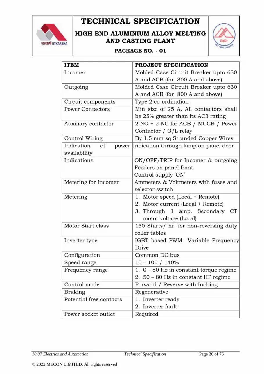
TECHNICAL SPECIFICATIONHIGH END ALUMINIUM ALLOY MELTING
AND CASTING PLANTPACKAGE NO. - 01
10.07 Electrics and Automation Technical Specification Page 26 of 76
© 2022 MECON LIMITED. All rights reserved
ITEM PROJECT SPECIFICATIONIncomer Molded Case Circuit Breaker upto 630
A and ACB (for 800 A and above)Outgoing Molded Case Circuit Breaker upto 630
A and ACB (for 800 A and above)Circuit components Type 2 co-ordinationPower Contactors Min size of 25 A. All contactors shall
be 25% greater than its AC3 ratingAuxiliary contactor 2 NO + 2 NC for ACB / MCCB / Power
Contactor / O/L relayControl Wiring By 1.5 mm sq Stranded Copper WiresIndication of poweravailability
Indication through lamp on panel door
Indications ON/OFF/TRIP for Incomer & outgoingFeeders on panel front.Control supply ‘ON’
Metering for Incomer Ammeters & Voltmeters with fuses andselector switch
Metering 1. Motor speed (Local + Remote)2. Motor current (Local + Remote)3. Through 1 amp. Secondary CT
motor voltage (Local)Motor Start class 150 Starts/ hr. for non-reversing duty
roller tablesInverter type IGBT based PWM Variable Frequency
DriveConfiguration Common DC busSpeed range 10 – 100 / 140%Frequency range 1. 0 – 50 Hz in constant torque regime
2. 50 – 80 Hz in constant HP regimeControl mode Forward / Reverse with InchingBraking RegenerativePotential free contacts 1. Inverter ready
2. Inverter faultPower socket outlet Required

TECHNICAL SPECIFICATIONHIGH END ALUMINIUM ALLOY MELTING
AND CASTING PLANTPACKAGE NO. - 01
10.07 Electrics and Automation Technical Specification Page 27 of 76
© 2022 MECON LIMITED. All rights reserved
ITEM PROJECT SPECIFICATION
Drive ProtectionFunctions
1. AC line surge suppressor2. Current limiting chokes3. Phase sequence4. Semi Conductor fuses5. Under Voltage6. Transient Over Voltage7. Earth Fault8. Over Load9. Motor over current (Instantaneous
and thermal)10. AC instantaneous short circuit11. Motor over temperature12. Regulated power supply failure
Drive ProtectionFunctions
13. Gate suppression for protectionagainst circulating currents
14. Fuse failure protection
Drive Diagnosticfunctions
1. Detection of all monitored functions2. Phase sequence failure3. Semi Conductor fuse failure4. Under Voltage failure5. Transient Over Voltage failure6. Earth Fault failure7. Motor over current (instantaneous
and thermal)8. AC instantaneous short circuit9. Motor over temperature10. Regulated power supply failure11. Communication error

TECHNICAL SPECIFICATIONHIGH END ALUMINIUM ALLOY MELTING
AND CASTING PLANTPACKAGE NO. - 01
10.07 Electrics and Automation Technical Specification Page 28 of 76
© 2022 MECON LIMITED. All rights reserved
10.07.04.04 Drive Motors (Low Voltage VFD Fed)
ITEM PROJECT SPECIFICATION
Constructional FeaturesType Inverter duty Squirrel Cage AC
Induction MotorFrame Sizes As per IEC-34 / VDE-0530 (with gear
box)/ VDE-520 (without gear box)Stator Body Material Grey Iron Casting
Motor feet Integrally cast with the stator body
Motor Winding CopperCooling Fins LongitudinalDegree of Protection IP-55Cooling IC-411 (Frame surface cooled by shaft
mounted cooling fan)IE Class IE 3Mounting As per M & C ListBearing suitable for 1. Bi-directional motion for reversible
motors2. Above 280 Frame, NDE bearing
shall be insulated to take care ofthe bearing current
Lubrication Grease for motor bearing throughnipple on both DE & NDE
Accessories Motor Fixing Bolts, Nuts and WashersEarthing terminals Two. On the opposite sides of motor
bodySpecial Design criterion 1. Stator winding insulation system
shall be subjected to highinsulation stress in the phase-to-phase, phase to enclosure andturn-to-turn insulation
2. Motors shall be designed towithstand additional stress on thewinding due to high switchingfrequency of the PWM drive
Nameplate Shall be of stainless steel and stamped

TECHNICAL SPECIFICATIONHIGH END ALUMINIUM ALLOY MELTING
AND CASTING PLANTPACKAGE NO. - 01
10.07 Electrics and Automation Technical Specification Page 29 of 76
© 2022 MECON LIMITED. All rights reserved
ITEM PROJECT SPECIFICATION
per NEMA Standard MG1 Part 10, 12& 31
Terminal BoxTerminal Box On top of the motor suitable for
termination of Aluminum cablesRotatable by 4 x 90 deg
Cable Glands Double Compression TypeSuitability The terminal box shall be suitably
sized so as to accommodate 3-coreAluminum Cable termination
Quality of OperationPerformance As per IEC-34 / VDE-0530 (with gear
box)/ VDE 520 (without gear box)Electrical DesignInput Power 415 V, 3-ph, 50 Hz, ACPower supply variations As per Supply ConditionsPower Supply From IGBT based PWM Variable
Frequency DriveService factor 1.0 for VFD powerPeak transient voltage 1500 V (Phase to Phase)Minimum rise time 0.01 - secMax DC Link Voltage 750 V DCOperation Constant Torque Up to base speed and
Constant Horsepower beyond Basespeed
Max speed permissible 150 % rated for 2 minutesDe-rating for VFD As per above-mentioned conditions and
to compensate for the losses caused bythe harmonics of the motor current(THD= 5%). Additional de-rating of themotor, if required, due to the speedrange as given in the M & C List, shallalso be considered.
Class of Insulation Class-F with Temp rise limited to ClassB
Over speed capability 120 % for 2 minsEmbedded Thermistor One PTC at hot spot per phase

TECHNICAL SPECIFICATIONHIGH END ALUMINIUM ALLOY MELTING
AND CASTING PLANTPACKAGE NO. - 01
10.07 Electrics and Automation Technical Specification Page 30 of 76
© 2022 MECON LIMITED. All rights reserved
10.07.04.05 LV Fixed Speed AC Motors
ITEM PROJECT SPECIFICATIONConstructional FeaturesType Squirrel Cage AC Induction MotorMotor Body Gray Iron CastingMotor Feet Integrally Cast with the StatorMotor Winding CopperCooling fin LongitudinalDegree of Protection IP-55Cooling IC- 411 (Frame surface cooled by shaft
mounted cooling fans)IE Class IE 3Mounting As per M & C ListAmbient Temperature 50 Deg CShaft extension As per M & C ListBearing suitable for Bi-Directional motion for reversible
motorsLubrication Grease for motor bearing through
nipple on both DE & NDECoupling Finish Boring, key seat cut and fitting
of motor half coupling is included inthe scope of motor manufacturer
Accessories Motor base plate / foundation plate,anchoring mechanism, foundationbolts, Motor fixing bolts, nuts andwashers
Earthing terminals Two. On the opposite sides of motorbody
Terminal BoxTerminal Box On RHS looking from the drive end of
the motor suitable for termination ofAluminium cables (IP- 55) Rotatable by4 x 90 deg
Extension of TB Shall be possible for acceptingAluminium cable, wherever required
Cable Glands Double Compression TypeQuality of Operation

TECHNICAL SPECIFICATIONHIGH END ALUMINIUM ALLOY MELTING
AND CASTING PLANTPACKAGE NO. - 01
10.07 Electrics and Automation Technical Specification Page 31 of 76
© 2022 MECON LIMITED. All rights reserved
ITEM PROJECT SPECIFICATIONPerformance As per IEC-34-1 / VDE-0520 (without
gear box) / VDE-0530 (with Gear Box)Electrical DesignInput Power 415 V, 3-ph, 50 Hz, ACPower Supply Fed from DOL Starter housed in MCCClass of Insulation Class-F with Temp rise limited to Class
BMin Voltage for Start &Run up
80 % of Rated Voltage
Over speed capability 120 % for 2 minsSpace Heater For motors above 75 KW
10.07.04.06 MCC, PDB, & Other Cubicles
Motor Control Center (MCC)
ITEM PROJECT SPECIFICATION
DesignConventional MCC with remote I/Opanel as part of MCC suit.
ConstructionModular construction fullycompartmentalized with partitions &free standing with base channel.
External power cabletermination
External power cables shall beterminated at terminal blocks providedin the cable alley.(compartment)
Fuse-less design
MCC shall be fuse less design i.e.incomers shall be either ACB / MCCB& outgoing feeders shall be eitherMCCB / MPCB.
Incoming circuit breaker
The incoming circuit breaker shallhave over-load, instantaneous over-current & E/F protection via inbuilt orexternal microprocessor basedprotection relay
Sheet steel thickness2 mm for load bearing, 1.6 mm fornon-load bearing
Cable entry from bottom

TECHNICAL SPECIFICATIONHIGH END ALUMINIUM ALLOY MELTING
AND CASTING PLANTPACKAGE NO. - 01
10.07 Electrics and Automation Technical Specification Page 32 of 76
© 2022 MECON LIMITED. All rights reserved
ITEM PROJECT SPECIFICATIONExtension provision Extendible on one sidePadlocking provision RequiredOperating height min. 300 mm & max. 2000 mmRemovable bottom glandplate
3 mm thick
Removable lifting hook for all shipping sections
Legible identificationlabels
Anodized aluminum with white lettersengraved on black background withletter sizes of 25-50 mm for panel, 5mm for components & module nameplates.
Danger board in front & rear in English & HindiEarthing terminals Two separate earthing terminalsControl transformer One control transformer in each MCCMaximum rating forincoming line
1600A.
Motor feeders
MPCB shall be used up to 7.5 kWmotor rating.MCCB shall be used above 7.5 kWmotor rating.Control transformer primary circuitshall have MPCB.
Standard overload relay Below 37 kWEOCR with indication For motors from 37 kW to 110 kW.Micro Processor basedrelay
For motors of above 110 kW.
Use of CT
Motors rating from 11 kW up to 22 kWshall be provided with CT in themiddle phase for connecting toammeter. However, Motors rating 30kW and above shall be provided withCT in all the three phases forconnecting to ammeter. Motors withrating 11 kW and above shall beprovided with ammeter with dualrange.
Control bus bar CopperIndication lamps 22.5 mm dia (LED cluster) for incomer

TECHNICAL SPECIFICATIONHIGH END ALUMINIUM ALLOY MELTING
AND CASTING PLANTPACKAGE NO. - 01
10.07 Electrics and Automation Technical Specification Page 33 of 76
© 2022 MECON LIMITED. All rights reserved
ITEM PROJECT SPECIFICATION& outgoing panels on/off trip &R,Y,Bindication.
Meter sizes 96 x 96 mm size meters.
Incomer relays
Microprocessor based relay withoverload, short circuit & E/Fprotection. via inbuilt or externalprotection relay
Min. size of powercontactor
32A.
Power contactor auxiliarycontract
2NO+2NC.
Breaker type selection MCCB upto 630A & ACB >630A.
DOL starterConstant speed motors up to 132 kWshall be fed with DOL starter at 415V.No star delta feeder shall be provided.
Spare feeders
Fully equipped & wired shall beprovided for each MCC with minimum20% spare feeders with at least onemost common rated feeder & onelargest feeder.
Remote I/O unitsShall be housed inside individualMCCs.
DESK / OPERATOR STATION / LOCAL BOXES
Item Project SpecificationMechanical ConstructionMounting Free standing with base channel / wall
mounted typeConstruction Control Desk Top shall be of stainless
steel with hinged sloping front. Accessto cable termination and devices shallbe from the front door.
Sheet Steel Thickness 2 mm for load bearing (min.)1.6 mm for non-load bearing (min.)3 mm for Removable bottom glandplate (min.)
Cable entry Cable entry from bottom

TECHNICAL SPECIFICATIONHIGH END ALUMINIUM ALLOY MELTING
AND CASTING PLANTPACKAGE NO. - 01
10.07 Electrics and Automation Technical Specification Page 34 of 76
© 2022 MECON LIMITED. All rights reserved
Item Project SpecificationExternal Power & ControlCable Termination
External cables shall be terminated atterminal blocks.
Identification labels Anodized aluminum with white lettersengraved on black background withletter sizes of 25-50 mm for panel, 5mm for components & module nameplates,
Danger board In front in English & HindiEarthing terminals Two separate earthing terminalsProtection class For control desk shall be IP- 43.
For local control desk & local controlboxes shall be IP-54.
Lifting hook Removable type for all shippingsections
Electrical DesignElements Push buttons, indication lamps &
selector switches as may be necessaryshall be available.
Master controllers For manual operation of Main Drives &Roller Table Motors shall be providedon control desk.
Indication lamps 22.5 mm dia (LED cluster)Meter size 96 x 96 mm size meters.Remote IO Units Shall be housed inside individual
panels as requiredPower socket outlet Shall be provided
10.07.05 Automation System
General
Thechoiceoftheautomationsystemsmakinguptheplantisrelatedtotheachievementof thefollowinghigh-priorityobjectives,namely:
Highqualityproducts Highproductivity Maximumsimplicityofoperation Operationreliability with Limitedinvestmentcosts

TECHNICAL SPECIFICATIONHIGH END ALUMINIUM ALLOY MELTING
AND CASTING PLANTPACKAGE NO. - 01
10.07 Electrics and Automation Technical Specification Page 35 of 76
© 2022 MECON LIMITED. All rights reserved
Maximumflexibilitytomeetvariousmarketdemands
Bidder’s Automation system shall be responsible for minimumfollowing process:
Melting Furnaces
Holding Furnaces
D.C Casters
Homogenizing Furnaces
Scalping and Band saw line.
However any technological area/process or interconnectedbetween process requirement for automation is there, the sameshall be considered by bidder. Take over point of material shall beAl Ingot storage and alloy storage
Control of the Furnaces and DC casters shall be achieved by Two(2) Levels of Automation System e.g. Basic Automation (Level-1)and Process Automation (Level-2).
The Automation system shall be based on Client - Serverconfiguration and shall provide on line control functions for theProcess and Equipment. The main process and equipment controlfunctions are
Sequencing & Interlocking
Reference Generation for Drives
Interfacing with Control Consoles and Drives
Storing of Data for Trending
Closed loop control functions.
Set up calculation function
Logging and storage of process parameters.
Generation of Fault Annunciation
Display of Soft Metering
Management of HMI Terminal
Gateway for Data Communication horizontally
Gateway for Data Communication Vertically to Higher Level

TECHNICAL SPECIFICATIONHIGH END ALUMINIUM ALLOY MELTING
AND CASTING PLANTPACKAGE NO. - 01
10.07 Electrics and Automation Technical Specification Page 36 of 76
© 2022 MECON LIMITED. All rights reserved
Computer.
Shift report generation
Order Management system
Temperature calculation
ladle turret
Launder System
Launder Metal Level Control
Trough metal level
Furnace monitoring
Degasser monitoring
Trough Lift control
Trough Tilt control
Trough metal temperature
Centralized lubrication system
Main hydraulic system
Detection of casting failures
Handling of casting trough
Slab/ Ingot Storage system after casting
Slab/ Ingot Handling &Storage system after homogenizing.
Marker machine (through OEM PLC)
Emergency Cast stop and start facility shall be provide in the
PLC system along with the necessary hardware and software
with all necessary interlocks in it.
Mold oscillator
Mold filling sequence
Mold level Control
Casting Speed control
Mold metal level early fill control
Mold Lubrication

TECHNICAL SPECIFICATIONHIGH END ALUMINIUM ALLOY MELTING
AND CASTING PLANTPACKAGE NO. - 01
10.07 Electrics and Automation Technical Specification Page 37 of 76
© 2022 MECON LIMITED. All rights reserved
Slab/ Ingot length measuring system
Mold cooling water flow control system
Casting pit water level control system
10.07.05.01 Basic Automation and PLC System (Level-1)
Automation (L-1) Cubicle Features
i. Incoming supply shall be through MCCB.
ii. Protection class shall be IP- 42.
iii. Remote I/Os shall have protection class of IP- 44. However,remote I/O panels shall be supplied with suitable coolingarrangement (e.g. panel mounted air conditioner) to performsatisfactorily at the plant floor ambient temperature mentionedin the TS.
iv. Interrogation power supply for Remote I/Os shall be generatedlocally
v. Power supply of remote I/O cards to MCC shall be individuallyprotected.
vi. MCC commands shall be read back to PLC.
vii. Paining shall be RAL-7035
Scope of Supply
i. Indicative number of cards (Digital & Analog I/O), countercard, PID controllers etc. shall be furnished duringengineering.
ii. Runtime version of software for each Client shall be provided.
iii. Dedicated PLC system shall be consider for each process likemelting furnaces, holding furnaces, caster and HomogenizingFurnaces.
iv. Each process system shall have one EWS for Basic AutomationSystem.

TECHNICAL SPECIFICATIONHIGH END ALUMINIUM ALLOY MELTING
AND CASTING PLANTPACKAGE NO. - 01
10.07 Electrics and Automation Technical Specification Page 38 of 76
© 2022 MECON LIMITED. All rights reserved
v. Development version software shall be provided for each of thefollowing systems
a. Each EWS for Basic Automation System (BAS) housed inindividual automation rooms and control pulpits.
b. Technological Control System (except proprietary software)
c. HMI System
d. Process Computer Server (Level-2)
Any module specifically developed for this project shall beprovided along with its source code except for mathematicalmodels.
Network Management Software: Network management software
shall be provided
Anti Virus Software (AVS) :AVS– (Enterprise Edition) provided for
Employer & server shall have 5 years up gradation license
Interface to other systemsInterface with following Automation systems at various levels, asmay be necessary for the Plant Operation, shall be included inBidder’s scope
Pre heating Furnace Automation System
Water Treatment Plant (WTP Automation System, Lab andother Utilities).
Production Planning and Control System, MaintenancePlanning & Monitoring System ( ERP/ Level-III).
Automation interface with third party automation systems shall bethe responsibility of the respective parties involved with thefollowing philosophy. Hardware (connecting cable, repeaters, ifrequired, laying & termination) & Software shall be provided by theparty receiving the information.

TECHNICAL SPECIFICATIONHIGH END ALUMINIUM ALLOY MELTING
AND CASTING PLANTPACKAGE NO. - 01
10.07 Electrics and Automation Technical Specification Page 39 of 76
© 2022 MECON LIMITED. All rights reserved
Hardware and Software
Automation hardware supply shall be as per the latest testedmodel/type available at the time of order placement on sub-vendor. One development version software shall be provided foreach Technological Control System, one for HMI server and one forProcess server.
Antivirus software (enterprise edition) provided for Employer &server shall have 5 years up-gradation license.
Necessary diagnostics software shall be provided as part of supply.
Production data and any other necessary information shall betransmitted to/from the Level-3 Automation System, by theBidder. The Bidder shall provide network/hardware connectivity tothe extended Plant Wide network and shall do necessaryprogramming to receive and send plan and actual production datato the proposed Level-3 Automation System.
Based on the production planning data from level-3/PPC data fedmanually, this module shall be used to decide the productioncycle, schedule sequence of order processing, material to beprocessed, material actual data, production data, etc.
There shall be provision to provide production information andproduction parameters to the related shops/units. In the absenceof mutual agreement of upstream and downstream units regardingdata exchange, “ASCII” format for data transfer shall be done, overTCP / IT sockets. Information shall be cyclic / event based.
Secured web access to be provided with necessary firewall and spyware software. Provision for remote maintenance from Bidder’soffice is included.
Development system shall be provided with simulation model.
Software
System software for Operate ITserver
Microsoft Windows 10/11professional
Application software forOperate IT server
License for Aspect serversoftwareLicense for Connectivityserver software

TECHNICAL SPECIFICATIONHIGH END ALUMINIUM ALLOY MELTING
AND CASTING PLANTPACKAGE NO. - 01
10.07 Electrics and Automation Technical Specification Page 40 of 76
© 2022 MECON LIMITED. All rights reserved
System software for operatorstationApplication software foroperator station
Microsoft Windows 10/11professionalLicense for Operate ITOperator Workplace
Software for engineering station Microsoft Windows 10/11Professional
Application software forengineering station
License for Operate ITEngineering Workplace
Software for PC Gateway Microsoft Windows 2019Server Latest or window10/11
Graphical User Interface System
The Level-1 control is based on PLCs and Drives, which control theactuating systems and ensure fast dynamic performances. All thesequential and interlocking functions shall be done from PLC. Itshall communicate with RIOs, VFDs, Soft starters, weighingsystem panels, etc. on a field bus. Different PLCs, PCs, HMIs etcshall be interconnected through a high speed Ethernet bus. Thesystem shall also be capable of communicating to other associatedAutomation systems. Type of PLC and drive controllers shall belimited to same type for the entire package.
All terminal blocks for digital inputs of PLC shall have suitableindividual fuse and fuse blown indication shall be provided
Safety Requirements of the Control System
Location of E-Stop push buttons shall be mentioned. E stop shallhave 2 NC contacts.
Control philosophy of furnace shall be as per technological writeup in technical chapter of different type of furnaces required forthis project and same shall be finalise during engineering stage.
10.07.05.02 Process Automation System (Level-2)
Level-2 Automation System shall be a microprocessor basedsystem and shall provide the set up functions for actuation of

TECHNICAL SPECIFICATIONHIGH END ALUMINIUM ALLOY MELTING
AND CASTING PLANTPACKAGE NO. - 01
10.07 Electrics and Automation Technical Specification Page 41 of 76
© 2022 MECON LIMITED. All rights reserved
various equipment. It shall calculate the different set valuesparameter by means of math models and shall provide it to Level-1. Proposed Automation system shall be complete with alltechnological controls. Separate Process Control & DatabaseServer shall be provided for individual process functions.
Configuration
Fault-tolerant server with dual-modular redundant (DMR)architecture (Hot standby servers). The server is comprised of twoCPU and two or four PCI modules, operating in lockstep. There isconstant crosschecking and synchronization of the modules,performed by the fault-tolerant chipset.
Two number of data base servers (stand-by) connected in RAID-5configuration with disc mirroring.
Features
The envisaged computer system shall also have optional provisionfor connectivity to the employer’s ERP (Level-3) computer systemfor receiving Primary Data Input (PDI) of the input Al Ingot andalloys as explained in Clause No- 37 & 38.
Primary Data Input (PDI) data handling procedures & Dataexchanges between with Internal and External Automationsystems shall be specified during Basic Engineering.
The Bidder shall consider the following.
i. 3 (three) numbers external Hard disk of 2TB drives shall beprovided for back-up.
ii. Monitor shall be 21’’colour LED for server & Employercomputers
iii. Printers shall be A4 laser color
iv. PDI Data (eg. Production Order and Customer Order) shall beconsidered
v. Scanned web access to be provided with necessary firewall &spy ware

TECHNICAL SPECIFICATIONHIGH END ALUMINIUM ALLOY MELTING
AND CASTING PLANTPACKAGE NO. - 01
10.07 Electrics and Automation Technical Specification Page 42 of 76
© 2022 MECON LIMITED. All rights reserved
vi. If Development system has any simulation model (Furnaces &caster), a facility for offline tuning & testing of these processmodels without interruption to online system shall beincluded.
vii. Necessary licenses for OS (Server & Employer) shall beprovided. Minimum 10 nos. named user licenses for data baseis to be provided.
Technical data
Switchgear cabinet
Dimensions approx. H 2200 W 4000 mm D 800 mm. Colour RAL7035 (grey); protection is IP42. With 240 V AC socket andillumination via separateswitch Consisting of:
- 1 power cubicle 415 VAC, 3~, PE, 50 Hz, app. 7 kVA
- 1 cubicle for digital I/O, based on PROFIBUS, digital inputsprotected - as far as possible - by fuses
- 1 cubicle for analogue I/O with terminals and interface rack,swing frame
- 1 cubicle for control rack, Ethernet switch and PC’s forprogramming and diagnostics, drawer mounted for easyaccess purposes
- fiber optic interface modules for Profibus.
Level 2 – Process Control Computer
A Level 2 automation system is been proposed for this furnacesand casters Information is of increasing importance for themanagement and operation of the plant. Complete, actual andcorrect information is the key for the right decision in time. Easysupervision and statistics, which are based on well structured andsave stored information, allow early detection of changes in theproduction or operation of the plant.Increased process visibility leads to:

TECHNICAL SPECIFICATIONHIGH END ALUMINIUM ALLOY MELTING
AND CASTING PLANTPACKAGE NO. - 01
10.07 Electrics and Automation Technical Specification Page 43 of 76
© 2022 MECON LIMITED. All rights reserved
Quick reaction to deviations from standard operation of
the plant
Fast detection of problems of the process
Improved logistics of process and production
Higher reliability, flexibility and availability of the plant
Continuously increasing demands on the quality of finished rolled
rails are an everyday requirement for the operation of the plant.
General Description
The Level 2 Automation System is built up from a set of personalcomputers operating in a client-server configuration. The databaseand the application software of the Level 2 are running on theserver computer. Several clients shall be located in the controlpulpits/offices and connected to the server via LAN. The clientsprovide the Human Machine Interface to the operators/engineersfor their supervision work. The HMI program can run on anyLevel 1 operator station or on a separate operator station, which isonly in use for the Level 2.
The HMI screens are designed in hierarchical structure in order toprovide well usability and clear overview.
Interfaces are foreseen for solid and transparent inter-operabilitybetween the basic automation and the Level-2. Also order datafrom Customers Level-3 computer system can be integrated.
The Level 2 shall support the operator to select the correct andcomplete setups to the machines in order to ensure a safe, flexibleand transparent section production on a high quality level. Furtheron the Level 2 shall collect and store quality data from the processto give actual and historical reports of the real productionconditions. The specific HMI provides the operator with display andoperation functionalities.
The application software shall be designed according to ourexperience with this type of plants and supports the staff and themanagement in planning, supervision and optimizing the plantoperation by the following functions:
Production Supervision
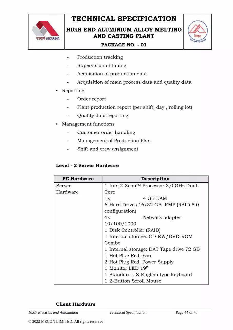
TECHNICAL SPECIFICATIONHIGH END ALUMINIUM ALLOY MELTING
AND CASTING PLANTPACKAGE NO. - 01
10.07 Electrics and Automation Technical Specification Page 44 of 76
© 2022 MECON LIMITED. All rights reserved
- Production tracking
- Supervision of timing
- Acquisition of production data
- Acquisition of main process data and quality data
Reporting
- Order report
- Plant production report (per shift, day , rolling lot)
- Quality data reporting
Management functions
- Customer order handling
- Management of Production Plan
- Shift and crew assignment
Level - 2 Server Hardware
PC Hardware DescriptionServerHardware
1 Intel® Xeon™ Processor 3,0 GHz Dual-Core1x 4 GB RAM6 Hard Drives 16/32 GB RMP (RAID 5.0configuration)4x Network adapter10/100/10001 Disk Controller (RAID)1 Internal storage: CD-RW/DVD-ROMCombo1 Internal storage: DAT Tape drive 72 GB1 Hot Plug Red. Fan2 Hot Plug Red. Power Supply1 Monitor LED 19”1 Standard US-English type keyboard1 2-Button Scroll Mouse
Client Hardware

TECHNICAL SPECIFICATIONHIGH END ALUMINIUM ALLOY MELTING
AND CASTING PLANTPACKAGE NO. - 01
10.07 Electrics and Automation Technical Specification Page 45 of 76
© 2022 MECON LIMITED. All rights reserved
General (“Office type”) user client hardware
PC Hardware DescriptionClientHardware
1 Intel® Core i7 11th generation 18 GBRAM1 Hard Drive 1TB SATA1 Network adapter 10/100/10001 Internal Storage: DVD R/RW Drive1 Monitor LED 21”1 Standard US-English type keyboard1 2 - Button Scroll Mouse, Mouse Pad
Standard SoftwareGeneral (“Office type”) user client standard software
PC Software Qty DescriptionOperating SystemSoftware
lot Windows XP incl MS InternetExplorer 6.0
Security Software lot Virus protection: McAffeeVirus Scan ProfBackup software: Norton GhostSolution Suite
Document Reader lot Adobe Reader
10.07.05.03 HMI SystemHMIs shall be provided in all pulpits for operator’s interface as perfunctional requirement of the plant. HMI system shall providefacilities like furnaces and caster Operation, Data Logging,Trending & History of Alarms, Events and operator actions.History shall be available in the server for a period of minimumtwo months. Engineering stations shall be included for each ECR,automation room etc system shall be capable of generating Reportsat certain interval or on Operator’s request and shall be as but notlimited the following: Shift report
Daily production report
Monthly production report

TECHNICAL SPECIFICATIONHIGH END ALUMINIUM ALLOY MELTING
AND CASTING PLANTPACKAGE NO. - 01
10.07 Electrics and Automation Technical Specification Page 46 of 76
© 2022 MECON LIMITED. All rights reserved
Material report
Alarm log
Protection of certain types of data, such as casting practices,
with various levels of security
Casting recipe storage, recall and password protected editing
Pre-cast checklists
Casting station color graphic overview screen with display of all
critical process variables
Replaces non-critical pushbuttons
Graphic display of cautions and alarms
User customizable experience – Layouts, colors, defaults, KPI’s,
screens
Condition lists for all critical control functions
Alarm and event notification via email and VOIP (requires email
and VOIP server accessibility)
Alarm troubleshooting information
Integrated links to drawings and manuals
Multiple display support
Multiple instance support
Display alarms and alarm status in real time as well as
historically
Real time and historical trending of process variables for aiding
in troubleshooting ingot & billet defects and improving product
quality
Casting recipe development
Mold metal level control calibration screen
Mold setup
Cast permissive checks
Level 1 alarms
Level 2 alarms

TECHNICAL SPECIFICATIONHIGH END ALUMINIUM ALLOY MELTING
AND CASTING PLANTPACKAGE NO. - 01
10.07 Electrics and Automation Technical Specification Page 47 of 76
© 2022 MECON LIMITED. All rights reserved
Level 3 alarms
Mold metal level control overview
Maintenance screens
Custom trending screens
Human Machine Interface
i. HMI servers shall be provided with hot standby facility.
ii. HMI controller shall have Intel Xeon processor or any otherlater version.
iii. 21” color LED monitors shall be provided for all HMI & EWSapplications.
iv. HMI system – Data history shall be available in server for 2months (Minimum). Event and Alarm logging data history shallbe for 1 week.
HMI Functions
HMI function shall include Utility systems overview and status(e.g. Lubrication, Hydraulics, Media, Water and Grease) forMechanical Maintenance monitoring.
In addition the HMI Employers required for the Operation of theplant, one HMI Employer each for Mechanical Maintenance,Electrical Maintenance and Shift in charge, shall be provided
Display Unit
In addition to the normal workstation one 42” LED display unitsand one LED projection system shall be provided in one centralcontrol room. One no. ceiling mounted LED projector with screenand good quality audio system with microphone shall be provided.This system shall be interfaced through Audio Visual switchingunits to all the network computers. Large display board shall beinstalled on the furnace area and casting platform for display offollowing parameters like : Melting and Holding Furnace related data like -

TECHNICAL SPECIFICATIONHIGH END ALUMINIUM ALLOY MELTING
AND CASTING PLANTPACKAGE NO. - 01
10.07 Electrics and Automation Technical Specification Page 48 of 76
© 2022 MECON LIMITED. All rights reserved
Molten Alumunium temperature in melting furnace Molten Alumunium temperature in Holding furnace Furnace wise molten Alumunium production data Any other relevant data pertaining to production
Caster System related data like - Ladle weight on ladle turret (in T) Hot metal temperature (in deg.C) Casting speed (in m/min) Casting time (in min.) Any other relevant data pertaining to production
Visualization SystemWorkplace
Workplace is the universal workspace from which Process Portalusers view and use process, system and enterprise data.Workplace interface elements specifically designed to accommodatethe specific needs of the process control system users as well asoffering easily managed workspace at which to perform tasks forthe overall management of the enterprise. The layout of Workplaceis configured by the user which means that each user can have acustomized workplace.
Window Management
Efficient and Flexible Navigation
Plant Explorer
User Profile Recognition
Security
10.07.05.04 Measurement Systems & Instruments - Refer Separate chapter.
10.07.05.05 Control / Operator Desk
Control/Operator Desks shall be designed & supplied as per GTS.Location & quantity of control/operator desk shall be finalizedduring engineering.

TECHNICAL SPECIFICATIONHIGH END ALUMINIUM ALLOY MELTING
AND CASTING PLANTPACKAGE NO. - 01
10.07 Electrics and Automation Technical Specification Page 49 of 76
© 2022 MECON LIMITED. All rights reserved
Main operator desks
The main control desks are used as a part of an overall processcontrol and monitoring system for the line area concerned. Themain control desk and its accessories shall contain allcomponents, instruments, keyboards and monitors to control theconcerned line area in all modes. All other control devices in thearea are subordinated to the main control desk. A Main controldesk shall be included for Drive Controls and Indication, solenoidoperations, pump and AC Motors on/off control, HMI. The maindesk uses discrete operator devices connected over remote I/O viaProfibus. Space for Intercommunication on desks shall beprovided.
Local operator Panel and desks
Local Control Post with stainless steel top shall be provided for theaccommodation of various controls and logics. The main desk usesdiscrete operator devices connected over remote I/O via Profibus.
Quantity : 1 Lot.
(Location to be finalized during Detail Engg.)
Local Control Boxes
The local control desks, panels and boxes are used formaintenance as well as controlling auxiliary equipment locallysuch as hydraulic stations, lubrication stations etc. Local ControlBoxes shall be provided for the accommodation of various controlsand logics with stainless steel top on each desk.
(Location to be finalised during Detail Engg.)
Note: Dimensions and layout according to requirements duringbasic engineering.
Junction Boxes for Control Cable Termination:
(1) 10 Terminals 1 Lot.
(2) 20 Terminals 1 Lot.

TECHNICAL SPECIFICATIONHIGH END ALUMINIUM ALLOY MELTING
AND CASTING PLANTPACKAGE NO. - 01
10.07 Electrics and Automation Technical Specification Page 50 of 76
© 2022 MECON LIMITED. All rights reserved
(3) 50 terminals 1 Lot.
(4) 100 terminals 1 Lot.
10.07.05.06 Structural Pulpit(Only BD,BE and DE)
The following pulpit has been envisaged to supply for this plant.However Bidder (Technologist) needs more nos. of pulpit as perprocess and operation point of view, the same shall be includebidder scope of supply and mentioned in the offer1. CP#1 for Melting Furnaces & Holding Furnaces.
2. CP#2for Casters.
3. CP#3 for Homogenizing Furnaces and Scalping & Band saw
line.
All proposed pulpits along with dimension shall be shown onoverall layout of the plant and submit along with offer by thebidder.
General Specification
Control pulpit shall be designed taking into account following
features
Location of control posts shall be decided taking care of
clear visibility.
Air lock rooms shall be provided for all the control room /
pulpits .
Inner walls shall be sound proof.
Granite flooring shall be provided.
Window glass shall be toughened, heat resistant and of
greenish tint, hinged glass to be opened from inside.
Double glass panels, wherever required, shall be provided
to make the control post heatproof.

TECHNICAL SPECIFICATIONHIGH END ALUMINIUM ALLOY MELTING
AND CASTING PLANTPACKAGE NO. - 01
10.07 Electrics and Automation Technical Specification Page 51 of 76
© 2022 MECON LIMITED. All rights reserved
Suitable wire mesh shall be provided for the glass windows
for protection against mechanical damage wherever
required.
However, Final location of the pulpit shall be finalized duringengineering. The pulpits shall be complete with sheet steel andstructural works with heat insulating material and double glassfront, false flooring, false ceiling, fire detection & alarm equipment,necessary control desks, operator’s chair etc with attractiveaesthetics. Control pulpits shall have 6 mm glass of heat resistanttype, pulpits shall be fitted with 50 mm glass wool. The glass shallbe shatterproof type. DE of pulpit shall include location co-ordinates, height of operating floor & line of sight drawing.Structural pulpit shall be designed & supplied as per GTS.
10.07.05.07 Automation related other misc. equipmentAutomation NetworkCommunication Network shall be in ring topology
Printer Supply Philosophy
Laser A3/A4 (B/W) – Each Control Pulpit (CP)
Laser color A3/A4 – Electrical Control Room (ECR)
DMP for print on continuous paper
Network Analyzer
Network analyzer (Laptop PC) for detecting & analyzing problemsof network / packet level shall be provided.
Cable analyzer
Cable analyzer for detecting network cable fault shall be provided
Consumption Monitoring
Consumption monitoring for power & utilities is included. Biddershall install necessary instruments e.g. Flow meters wired up tothe plant Automation system for recording consumption of media

TECHNICAL SPECIFICATIONHIGH END ALUMINIUM ALLOY MELTING
AND CASTING PLANTPACKAGE NO. - 01
10.07 Electrics and Automation Technical Specification Page 52 of 76
© 2022 MECON LIMITED. All rights reserved
supplies (water, Air) at the respective TOPs, acquire related data.Available consumption data shall be displayed on HMI/ Level-2and recorded as Management Information.
Archiving Server
Plant data archiving server shall be supplied for archiving ofmeasured process data/setup data/equipment health data / etc.at desired frequency and in derived form shall be made availableby Bidder in a data archival set up of one server . Plant dataarchiving shall be for at least one year.
Data Analyzer
Online hi resolution (up to 1 m-sec) data analyzer shall beprovided.
10.07.06 Additional Systems
10.07.06.01 Uninterrupted Power Supply System
Bidder shall include necessary UPS and ACDB for feeding theloads requiring UPS power supply. UPS shall be rated by 120% ofthe calculated load. Load factor or diversity factor shall not beconsidered while calculating the load on UPS. UPS shall have dualinverters, automatic changeover and 100% dual redundancy withbattery backup for minimum 30 minutes.
Battery sizing calculation shall be furnished and sizing shall bemade as per IEEE-485. Battery sizing shall consider temperaturefactor, aging factor, K factoras per the above standard. Batteryshall be VR LA type.
Two separate power supply from different sources shall beprovided to UPS – one for UPS and the other for bypass. Bypasssupply to equipment shall be through constant voltagetransformer.
UPS and SMF batteries shall be located in air conditioned room.The Uninterrupted power supply unit provides protection againstvoltage variations, transients and supply of power in case of power

TECHNICAL SPECIFICATIONHIGH END ALUMINIUM ALLOY MELTING
AND CASTING PLANTPACKAGE NO. - 01
10.07 Electrics and Automation Technical Specification Page 53 of 76
© 2022 MECON LIMITED. All rights reserved
failure for :
Servers
Workstations
PLC CPU and Memory
Local Area Network devices
Technical data
Incomer : 3 pole MCCB
Outgoing : SPN MCB
Input Voltage : 415 V AC +/- 15%, 3-Phase, 4 wire
Rating : Later during engineering
Short time rating : 50 KA for 1 Sec.
Input Frequency : 50 Hz. +/- 5%
Output Voltage : 240 V AC, 1-Phase
Output Voltage tolerance : +/- 1%
Output Frequency : 50 Hz. +/- 0.1%
Total harmonic distortion : < 5% for linear loads
Converter efficiency : Better than 94 %
Inverter efficiency : Better than 90 %
Overload : 125% of the rated output for 15 minutes
150% of the rated output for 30 sec
Redundancy : The system shall be of dual redundancy
type in hot standby mode.
Static bypass : Automatic static bypass and common
DC battery
Battery type : Sealed maintenance free Lead acid
batteries
Battery backup : 30 minutesMounting : Floor mounting with base channel of
ISMC-75

TECHNICAL SPECIFICATIONHIGH END ALUMINIUM ALLOY MELTING
AND CASTING PLANTPACKAGE NO. - 01
10.07 Electrics and Automation Technical Specification Page 54 of 76
© 2022 MECON LIMITED. All rights reserved
Enclosure : 2 mm thick CRCA for load bearing
1.6 mm thick for non load bearing
members
Degree of protection : IP-32
10.07.06.02 Primary and Secondary Earthing System
Earthing system shall conform to GTS requirements.
Primary Earthing
Bidder’s Scope
For primary earthing system, Bidder’s scope includes BD, BE, DE,Supervision of Erection & Commissioning.
Necessary earthing pits and its connection from the pits to theprimary earthinggrid(electronics) shall remain in the scope of theBidder only for electronics earthing.
Bidder is responsible to provide necessary primary earthingrequirements in respective civil assignment drawing and furnishindicative BOQ of embedded material requirement in concreteduring BE and final BOQ during DE for Employer’s scope of workfor general erathing purpose.
Supply & installation of primary earthing grid (embeddedrequirements in concrete up to earthing pits located around theplant) shall be in Employer’s Scope.
Employer’s Scope
Supply & erection of embedded requirements in concrete up to therisers near respective building columns is in employer’s scope.
Secondary Earthing
Bidder’s scope shall include BD, BE, DE, Supply, Erection,Supervision of Erection and Commissioning of Secondary Earthingin the plant area.

TECHNICAL SPECIFICATIONHIGH END ALUMINIUM ALLOY MELTING
AND CASTING PLANTPACKAGE NO. - 01
10.07 Electrics and Automation Technical Specification Page 55 of 76
© 2022 MECON LIMITED. All rights reserved
Electronic Earthing
Bidder’s scope shall include BD, BE, DE, Supply, Erection,Supervision of Erection and Commissioning of Electronic Earthingin the plant area.
DescriptionThe grounding network includes all the necessary elements toground against indirect contacts. The grounding network shallconsist of:
An underground mesh made with galavanized steel or copperconductors, integrated with earthing electrodes for dispersingthe ground current.
A set of earthing conductors which connect the mesh with maingrounding collectors (typically located in the electric cabins andat the basis of the building columns)
The grounding network shall be accomplished according to IECstandard 364 and scaled depending on resistivity values of theground, grounding failure current and operating time of thedisconnecting devices. The various connections between theconductors to make the system shall be carried out by welding and/ or appropriate compression clamps.
10.07.06.03 Lightning Protection System
Excluded from Bidder scope of work. However BD shall be inbidder scope of service.
10.07.06.04 Welding & Small Power Supply Socket System
Excluded from Bidder scope of work. However BD shall be inbidder scope of service.
10.07.06.05 Illumination System
Illumination system is excluded from Bidder’s scope. However any

TECHNICAL SPECIFICATIONHIGH END ALUMINIUM ALLOY MELTING
AND CASTING PLANTPACKAGE NO. - 01
10.07 Electrics and Automation Technical Specification Page 56 of 76
© 2022 MECON LIMITED. All rights reserved
special lighting for any equipments/system is essential foroperation/process point of view, the same shall be considered bybidder.
Signaling Equipment
Signaling equipment (e.g. hooters, rotating flash lights, permission& reset switches) as required for the operation of the plant underscope of the Bidder, shall be included in Bidder’s scope.
BD, BE, DE, Supply, Erection & Commissioning of the same shallbe included in the scope of the Bidder.
10.07.07 Cables & Erection Material
Cables
Scope
All cable specification shall be as per GTS (GS-03). Supply, laying,termination and testing of cables of MV power, LV power, LVcontrol, shielded cable, communication cables & any other cablerequired for the plant electrical & automation system is includedin Bidder’s scope.
General All 11 kV, 6.6 kV, 1.1 kV power, 1.1 kV control, 1.1 kV signal
and special cables for interconnection between the equipmentwithin the scope to make the installation complete.
All cabling accessories including cable trays, supports, exposedconduits, flexible conduits, glands, lugs, terminal boxes,termination kits for HT cables, etc. as required forcompleteness of the installation.
All power, control and special cables as well as all cablingaccessories shall be selected based on the guidelines given inUADNL General Specification.
All cables shall be protected against heat and flames prevailingin the steel melt shop and to meet that requirement properheat shields shall be provided along with required materials forpreparing the structure for supporting the same.

TECHNICAL SPECIFICATIONHIGH END ALUMINIUM ALLOY MELTING
AND CASTING PLANTPACKAGE NO. - 01
10.07 Electrics and Automation Technical Specification Page 57 of 76
© 2022 MECON LIMITED. All rights reserved
Cabling shall be carried out in line with the requirement givenUADNL GTS.
Cable laying from MRSS to the shop floor shall be in scope ofemployer
Specification
Specification of MV & LV cables shall be as per GTS. However,following shall be considered as the guidelines for cable typeselection.
a) MV cables shall be armoured, XLPE insulated, FRLS type,aluminum conductor. Cable size selected shall be in the rangeof 3x120 to 3x185mm2 only.
b) MV cables for VFD application shall be armoured, XLPEinsulated, FRLS type, copper conductor for connection from MVdrive to MV motor.
c) LV power cables for VFD application shall be unarmoured, PVC/ XLPE insulated, FRLS type, screened, aluminum conductor.
d) LV power cables shall be unarmoured, PVC / XLPE insulated,FRLS type, aluminum conductor. Minimum size of aluminumcable shall be 10mm2. For any requirement of below 10mm2,copper cables shall be used.
e) LV control cable shall be unarmoured, PVC insulated, FRLStype, copper conductor.
f) Control cables spare core philosophy shall be
Upto 10 cores – 2 reserve core
> 10 cores – 3 reserve core
Screened Cables
Screened cables for instrumentation PVC/PVC, 700 V class.
Special Cables
The special cables shall be in conforming to equipmentmanufacturer’s standards.

TECHNICAL SPECIFICATIONHIGH END ALUMINIUM ALLOY MELTING
AND CASTING PLANTPACKAGE NO. - 01
10.07 Electrics and Automation Technical Specification Page 58 of 76
© 2022 MECON LIMITED. All rights reserved
Scope of SupplyThe above types of cables as required have been included in thescope of supply.
Erection MaterialErection work shall be carried out in line with the stipulations of
GTS.
The following erection material have been considered.
- Cable racks (horizontal, vertical), ducts and supports, hot dip-
galvanised metallic
- Hot dip galvanised metallic conduits, cable protection pipes and
accessories,
- Cable fixing materials
- Cable marking material
- Terminal boxes
- Pull boxes and junction boxes,
- Sealing material for wall ducts
- Cable trays, cable protection pipes , type or hot dip galvanised
metallic
- Cable tray supports.
- Terminal lug
- Cable shoes
Ladder type cable racks, generally of 3 meter length, shall beselected from two sizes viz., 300 and 600 mm wide and shall befabricated from 50 x 50 x 6 mm steel angles for longitudinalmembers and 30 x 6 mm steel flats for cross members placed atan interval of 300 mm along the length of the rack with a provisionof double cross members at locations, where cables are to beclamped. Cable racks shall be hot-dip galvanized after fabrication.Minimum value or average mass of zinc coating shall be 610gm/sqmt. as per IS:4759.
Pre-fabricated perforated trays, generally of 3 meters length madehot-dip of galvanized 3 mm thick sheet steel shall be used for

TECHNICAL SPECIFICATIONHIGH END ALUMINIUM ALLOY MELTING
AND CASTING PLANTPACKAGE NO. - 01
10.07 Electrics and Automation Technical Specification Page 59 of 76
© 2022 MECON LIMITED. All rights reserved
laying control cables. The trays shall have vertical edge of heightnot less than 50 mm on both sides. Trays shall be selected fromtwo sizes viz. 300 and 600 mm wide.
GTS pipes for routing of cables, embedded through concretefoundations/floors/walls (including portion above floor level to belaid in continuation for protection against mechanical damage) inplant building shall be of medium gauge, hot dip galvanised,electric resistance welded (ERW), screwed type conforming toIS:1239 (Part I). GTS pipes of the following sizes shall be used:
a) 50 mm nominal bore
b) 80 mm nominal bore
c) 100 mm nominal bore
d) 150 mm nominal bore
Straight-through joints and end sealing of 6.6/11 kV XLPE cablesshall be heat shrink type/push on type as called for in thetechnical specification.
Straight-through joints for 1,100 V grade PVC insulated cablesshall be with epoxy resin compound.
Cable glands for terminating cables shall be made of brass oraluminium alloy.
Erection Services
The main scope of the erection services are as follows:Receiving, unloading and storage of equipment & material at site.Watch & ward. Transportation of equipment & material from storesto erection site.Erection, aligning and fixing of equipment on therespective foundation.Erection of cable trays and supportingstructures.Laying& termination of cables.Erection ofinstrumentation & field devices.
Commissioning
Commissioning entails the start up and taking into operation of
the equipment in Bidder’s scope of supply, as detailed below.

TECHNICAL SPECIFICATIONHIGH END ALUMINIUM ALLOY MELTING
AND CASTING PLANTPACKAGE NO. - 01
10.07 Electrics and Automation Technical Specification Page 60 of 76
© 2022 MECON LIMITED. All rights reserved
General
Specially trained engineers shall start up and take into operationthe equipment and systems supplied by the Bidder.
Measured data collected during commissioning, which areimportant for the future running, and checking of the plant shallbe collected in a commissioning report.
In addition to commissioning the equipment, the engineers shallalso endeavor to instruct selected Employer personnel in theoperation of the equipment insofar as this instruction might benecessary for operation and maintenance.
Commissioning work shall be executed in two steps:
Cold commissioning before first rolling
Hot commissioning after first rolling
Cold Commissioning
The following functions shall be executed:
Switch-on power source and auxiliary voltage to the equipment
Additional signal test within cubicle for checking of all safety andprotection interlocks
Checking of electrical protection equipment
Function test with motor, not coupled to the mechanicalequipment.
Function test with individual motor coupled to the mechanicalequipment.
Cold commissioning is completed when the electrical equipment isready for the first heat.
Hot Commissioning
After completion of cold commissioning the hot commissioningshall start with material in the plant, Services of Bidder'spersonnel shall participating in the performance test specified inthe technical specification. Hot commissioning is completed upondemonstration of performance data or by other contractualagreements.

TECHNICAL SPECIFICATIONHIGH END ALUMINIUM ALLOY MELTING
AND CASTING PLANTPACKAGE NO. - 01
10.07 Electrics and Automation Technical Specification Page 61 of 76
© 2022 MECON LIMITED. All rights reserved
10.07.08 Special Tools & Tackles
Supply of necessary Special Tools and Tackles as may be requiredfor successful commissioning and maintenance of the Furnaces &Casters are in Bidder’s scope. An indicative list is given below:Sl.No.
Description Qty.
For Electrics and Level 1 System1. AC/DC tong tester for low current measurement 5
2. AC/DC tong tester for high current measurement 5
3. Drive module handling unit 3
4. 4 channel storage oscilloscope with thermal printer 2
5. 16 channel thermal recorder 2
6. Non contact type thermometer 2
7. Digital multi-meter with current protection 10
8. 3 phase portable analyzer for energy management 2
9. Non-contact Laser based thermometer 2
10. Industrial type Vacuum Cleaner 2
11. Test kit for testing microprocessor based releases of
415V Circuit Breaker
3
12. IGBT removal tools 2set
13. Double ended and Ring spanner set for the required
sizes
2set
14. Socket spanner set for the required sizes 2set
15. Torque wrenches for the required sizes 3set
16. Electrician’s tool kit 3set
17. 40 pc Multi size Screw driver set with handle 3set
For Level 2 System1. RJ 45 & RJ 11 crimping tools and RJ 45 connectors 3
2. Tool kit with soldering iron 5

TECHNICAL SPECIFICATIONHIGH END ALUMINIUM ALLOY MELTING
AND CASTING PLANTPACKAGE NO. - 01
10.07 Electrics and Automation Technical Specification Page 62 of 76
© 2022 MECON LIMITED. All rights reserved
Sl.No.
Description Qty.
For Electrics and Level 1 System3. Kit for fibre optic testing 2
4. Fibre optic cable splicing & termination kits 2
10.07.09 Water Treatment Plant
Electrics & Controls for Water SystemExcluded from scope ofsupply of Bidder. Only Basic Data and Basic Engineering isincluded in Bidder’s scope. However sump pump for the plantshall be in bidder scope of supply.
10.07.10 Air Conditioning & Ventilation SystemElectrics & Controls for Air Conditioning &Ventilation System isexcluded from scope of supply of Bidder. Only Basic Data andBasic Engineering is included in Bidder’s scope.
10.07.11 Compressed Air System
Electrics & Controls for Compressed Air Station is excluded fromscope of supply of Bidder. Only Basic Data and Basic Engineeringis included in Bidder’s scope.
10.07.12 Laboratory Equipment
Electrics & Controls for Laboratory is excluded from scope of supply of Bidder. Only
Basic Data and Basic Engineering is included in Bidder’s scope.
10.07.13 Drawing & Documentation
Layout Issue
Bidder shall submit along with offer an overall layout of the plantshowing the proposed location of ECRs, transformer rooms,control pulpits, oil cellars, pump houses, water cellars&interconnectivity between all these premises through main cablerouting tunnel/ overhead gallery/ trench.

TECHNICAL SPECIFICATIONHIGH END ALUMINIUM ALLOY MELTING
AND CASTING PLANTPACKAGE NO. - 01
10.07 Electrics and Automation Technical Specification Page 63 of 76
© 2022 MECON LIMITED. All rights reserved
Document Submission Schedule
For engineering & technical documentation of electrical &automation systems under Civil assignment of electrical premises& plant floor, Drawing list with drawing numbering scheme, BasicEngineering, Detailed Engineering, Vendor drawing/data sheet, AsBuilt Drawing, Maintenance & operation Manual, catalog etc listand submission schedule shall be submitted by successful bidderduring Kick off meeting of this project.
10.07.14 Services
10.07.14.01 Inspection
For details, refer Commercial Part of this Tender document.
10.07.14.02 Training
Details & duration of training for electrical & automation systemshall be as other part of this Technical specification.
10.07.14.03 Erection
Scope
Erection of Electrics & Automation supplied by the Bidder,Supervision of Erection, Checking completeness of erection,Testing and complete Commissioning including CommissioningSupervision, Conducting mile stone linked tests stipulated underthis contract and Post Commissioning services. Erection shall bedone as per GTS Specification. For details scope of erection,testing & commissioning refer Scope Division Chapter.
Description
Erection shall be done as per GTS
Measurement of Soil ResistivityMeasurement of Soil Resistivity shall be the responsibility of theBidder.

TECHNICAL SPECIFICATIONHIGH END ALUMINIUM ALLOY MELTING
AND CASTING PLANTPACKAGE NO. - 01
10.07 Electrics and Automation Technical Specification Page 64 of 76
© 2022 MECON LIMITED. All rights reserved
Cable Ways
Necessary Cable way Engineering and Supply required for all theequipment under scope of supply of the Bidder, are included inBidder’s scope.
i. Cable ways shall be provided with material fully galvanized.
ii. Minimum thickness of galvanization shall be 75 microns.
iii. Cable ways for FO cables & shielded cables shall be fullycovered.
iv. Cable way engineering, supply and Erection shall conform toGTS requirements.
10.07.14.04 Testing & CommissioningFollowing shall be the responsibility of Bidder:
i. Planning and preparation of all necessary test procedures onmechanical, electrical, hydraulics/lubrications,instrumentation and automation equipment and / or system
ii. Checking, setting and adjusting of the equipment / individualcomponents such as mechanical, electrical, hydraulic, etc.under production conditions.
iii. Final adjustment of parameter and set points anddetermination of the parameters for the tests under productionconditions.
iv. Preparation of operation and acceptance test recording system
v. Supply of consumables and measuring devices duringinstallation
vi. Safety norms and protection measures to be suggested byBidder as part of erection & commissioning document.
vii.Submission of system & application software back-ups forLevel-1 & Level-2 Systems (run-time & development, asapplicable).
10.07.14.05 Spares
Bidder shall provide spares support services for at least 10 yearsfor all the equipment under Bidder’s scope.

TECHNICAL SPECIFICATIONHIGH END ALUMINIUM ALLOY MELTING
AND CASTING PLANTPACKAGE NO. - 01
10.07 Electrics and Automation Technical Specification Page 65 of 76
© 2022 MECON LIMITED. All rights reserved
10.07.15 Commissioning Spares
Necessary commissioning spares as may be required for successfulcommissioning of the plant is included in Bidder’s scope. Aproposed list of Commissioning spares is given below. However,any additional commissioning spares required duringcommissioning shall be supplied by the Bidder free of chargewithout affecting the overall time schedule of the project.
Description Qty
Drives & Distributiontransformers
Primary MV terminals 1 set of each type & size
Secondary LV terminals 1 set of each type & size
LCSS
HRC Fuses 1 set of each type & size
Flag relays 1 set of each type & size
Main MV inverters
Control card 1 of each type & size
Communication card 1 of each type & size
Power Semiconductor fuses 1 set of each type & size
Fuses 2 sets of each type & size
Aux. Contactors 1 of each type & size
Aux. Relays 1 of each type & size
Aux. contacts for contactors 2 sets of each type & size
Power supply units 1 of each type & size
Water cooling unit miscellanea
sensors
1 set of each type & size
Drive operator panel 1 of each type & size
Main & Aux. LV drives
Regulation cards 1 of each type & size
Communication cards 1 of each type & size

TECHNICAL SPECIFICATIONHIGH END ALUMINIUM ALLOY MELTING
AND CASTING PLANTPACKAGE NO. - 01
10.07 Electrics and Automation Technical Specification Page 66 of 76
© 2022 MECON LIMITED. All rights reserved
Description Qty
Fuses 2 sets of each type & size
Circuit breakers 1 of each type & size
Disconnector switch 1 of each type & size
Lamp & PB 2.5% of each type & size
Contactor 1 of each type & size
Thermal relays 1 of each type & size
Aux. relays 2 of each type & size
Aux. Transformer 1 of each type & size
Low voltage switchboard (MCC)
Circuit breakers 1 of each type & size
Dis-connector switch 1 of each type & size
Lamp & PB 2.5% of each type & size
Power contactors 1 of each type & size
Contacts for power contactors 1 of each type & size
Thermal relays 1 of each type & size
Aux. relays 2 of each type & size
Aux. contactors 2 of each type & size
Aux. Transformer 1 of each type & size
Fuses 1 set of each type & size
Aux. Contactors 1 of each type & size
Aux. contacts for contactors 2 sets of each type & size
LV AC motors
Encoder 1 of each type & size
Roller table motor 1 of each type & size
Personal Computer automation
Monitors 1 each type
Functional keyboard 1
Pointing device 1

TECHNICAL SPECIFICATIONHIGH END ALUMINIUM ALLOY MELTING
AND CASTING PLANTPACKAGE NO. - 01
10.07 Electrics and Automation Technical Specification Page 67 of 76
© 2022 MECON LIMITED. All rights reserved
Description Qty
Personal computer (client
workstation)
1
Control desk and control boxes
Selector switches 2.5% of each type & size
Pushbuttons 2.5% of each type & size
Mushroom Head Pushbuttons 3 nos.
Lamps 2.5% of each type & size
Functional keyboards 2.5% of each type & size
Operator Panel 1 of each type & size
PLC based automation
CPU card 1 of each type & size
Power Supply 2.5% of each type & size
Digital & Analog I/O cards 2.5% of each type & size
with min. 2 nos.
Fast digital input output cards 1 of each type
EPROM memories with the final
programs to be supplied at the
end of start-up
1 set
Batteries 1 of each type & size
Auxiliary Plants
Power sockets 2.5% of each type & size
LAN Components
Router/Switch 1 no.
Instrumentation and Sensors
Pyrometer 1 no.
Encoder 1 nos. of each type
Limit switches 1 of each type & size.
Proximity switches 2 of each type & size.

TECHNICAL SPECIFICATIONHIGH END ALUMINIUM ALLOY MELTING
AND CASTING PLANTPACKAGE NO. - 01
10.07 Electrics and Automation Technical Specification Page 68 of 76
© 2022 MECON LIMITED. All rights reserved
Description Qty
Photocells 1 of each type & size
Other Sensors 1 of each type & size
10.07.16 The List minimum drawings /documents shall be given bybidder with offer
10.07.16.01 Operation & Maintenance Spares for Two YearsThe bidder shall submit two years of operational & maintenancespares list for electrics and automation system along with the offerby the bidder.
10.07.16.02 Plant Layout with ECRs, Control Pulpits, Cabletunnel/trench:
Plant layout indicating Nos. of Electrical Control Room (ECR) withindicative dimension, Nos. of control Pulpits with indicativedimension, Cable tunnel & trench interconnecting above all, shallbe submitted along with the offer by the bidder.
10.07.16.03 Motor & Component List
The Motor & Component List along with all details of the Furnacescum Casters shall be submitted along with the offer by the bidder.
10.07.16.04 Power Single Line Diagram
Power single line diagram along with, nos. of 11kV feedersrequired and all details of the plant shall be submitted along withthe offer by the bidder.
10.07.16.05 Automation Configuration Diagram
Automation Configuration Diagramarea wise requirement of Level# 0, level # 1, and level # 2, interconnection with external andinternal communicationas per plant requirementalong with alldetails shall be submitted along with the offer by the bidder.
10.07.17 Scope Division/Split-up List
For detailed division list for electrical, automation &

TECHNICAL SPECIFICATIONHIGH END ALUMINIUM ALLOY MELTING
AND CASTING PLANTPACKAGE NO. - 01
10.07 Electrics and Automation Technical Specification Page 69 of 76
© 2022 MECON LIMITED. All rights reserved
telecommunication given below:
The scope of supply of equipment and services, their limits andresponsibility of all parties involved in the project are described inthe scope of supply list.
Legend of Abbreviations:P: Purchaser
T: Electrical Tenderer
BD: Basic Data
BE: Basic Engineering
DE: Detailed Engineering
SUP: Supply
INS: Installation
COM: Commissioning
Commissioning indicated as “T” shall be done by ElectricalSupplier with the assistance of trained customer personnelMCL: Motors & components list
Basic Data
The activities defined as basic data are carried out by the party asdefined in the project structure and engineering split up list.These activities are: Determination of plant data (e.g. technological limit values,limit values for the drives) Cooling of basic data for the equipment (e.g. consumptiondata for active and reactive power, cooling water, air, lubrication,heat losses) Preliminary layouts and arrangement of electrical rooms,pulpits and operating panels
Basic Engineering
Single lines for energy supply, drives, auxiliaries
Specification of motors
Preliminary layout drawings for electrical rooms.

TECHNICAL SPECIFICATIONHIGH END ALUMINIUM ALLOY MELTING
AND CASTING PLANTPACKAGE NO. - 01
10.07 Electrics and Automation Technical Specification Page 70 of 76
© 2022 MECON LIMITED. All rights reserved
Specification of plant parameters, documentation,
automation and drive configuration designation system
Determination of plant regulations, applicable standards
Specification of main equipment / type, color
Specification of engineering and software tools
Setting out guidelines and schedules for detailed engineering
Defining operator interfaces and procedures
Detailed Engineering
After the BD & BE have been approved by the Consultant & Buyer,the detailed engineering can begin. The goal of the detailedengineering is to provide completed documentation, equipment andsoftware for installation and commissioning at the Buyer’s plantsuch as Cable lists and circuit diagram
Typical arrangement drawings for installation
Cable routing single lines
Equipment drawings for construction of electrical units (e.g.
cubicles, terminal boxes, racks)
Ordering of equipment, ordering data
Software programming and testing
Design and manufacture of control desk and panels
As-delivered documentation including function
descriptions, operator procedures
Installation and commissioning schedule
Delivery and shipping schedules
Scope Matrix DivisionItem
Description Engineering
EquipSupp Erection Commis
sion
RemarksBD
BE DE Wo
rkSupervision
Work
Supervision
1 Energy Supply

TECHNICAL SPECIFICATIONHIGH END ALUMINIUM ALLOY MELTING
AND CASTING PLANTPACKAGE NO. - 01
10.07 Electrics and Automation Technical Specification Page 71 of 76
© 2022 MECON LIMITED. All rights reserved
Item
Description Engineering
EquipSupp Erection Commis
sion
RemarksBD
BE DE Wo
rkSupervision
Work
Supervision
1.1
MV-Distribution
132 kV / 11 kV transformer T/P
P P P P P P P
11 kV Switchgear T/P
P P P P P P P
Bidder’s TOP isoutgoing terminalof 11 KVswitchgear
VCB with protection features
before converter transformer T T T T T T T T
VCB without protection featuresbefore distribution transformer forAuxiliary load of Technologicalequipments
T T T T T T T T
11 kV / 415V or 690V transformerfor power supply to Bidder’sequipment
T T T T T T T T
11 kV / 415V transformer forpower supply to Plant Auxiliarysystems P
/T
P/T
P P P P P P
For power supplyto cranes, Hoist,Transfer car,ventilation, AC,lighting, powersockets, etc
11 kV / 415V transformer forpower supply to TechnologicalEquipment Auxiliary systems
T T T T T T T T
1.2
LV-Distribution
415V Load Center Sub Stations(LCSS) for power supply to Bidder’sequipment
T T T T T T T
415V Load Center Sub Stations(LCSS) for power supply to PlantAuxiliary systems P
/T
P/T
P P P P P
For power supplyto cranes, Hoist,Transfer car,ventilation, AC,lighting, powersockets, etc asper TS
1.3
Compensation System
Power Factor Compensation &Harmonic Filter Equipment 11 kV T T P P P P P provision shall be
kept by Bidder1.4
Emergency Power Supply
Uninterruptible Power Supply T T T T T T T TAC Distribution for UPS power T T T T T T T T

TECHNICAL SPECIFICATIONHIGH END ALUMINIUM ALLOY MELTING
AND CASTING PLANTPACKAGE NO. - 01
10.07 Electrics and Automation Technical Specification Page 72 of 76
© 2022 MECON LIMITED. All rights reserved
Item
Description Engineering
EquipSupp Erection Commis
sion
RemarksBD
BE DE Wo
rkSupervision
Work
Supervision
SupplyEmergency Power (Diesel) T P P P P P P P
1.5
Consumption Monitoring forEnergy supply
T T T T T T T T
CommunicableMulti Functionmeters for Buyer’sscope of Board byBuyer
2.1
LV Variable Speed Drive System
LV AC VVVF motors T T T T T T TLV AC power supply for drives T T T T T T T
2.2 Constant Speed Drive SystemAC fixed speed motors (standard) T T T T T T TMCC T T T T T T TAC fixed speed gear-motors T T T T T T T
3 Automation System3.1 Basic Automation System (Level-1)
Basic automation HardwareT T T T T T T
Amount of I/Os tobe included inMCL
Basic automation softwareT T T T T T T
Electromechanical functionaldescription
E-stop system
T T T T T T T
Definition of E-stop areasaccording tomechanicalfunctionality.
Interface to other system includingswitches, repeaters, media etc T
T/P
T/P T T T /P T
/P
3.2
Process Control System Level-2(SCADA Control system)Process Control System Level-2Hardware T T T T T T T
Process Control System Level-2Software including Mathematicalmodels
T T T T T T T
Diagnostic for Fault Analysis T T T T T T TInterface to Level-3, Furnace, WTP,N2, Compressor includingswitches, repeaters, media etc
T T - - - - -
3.3
Electrics and Automationsystem (up to Level – 2) shall becompatible to adopt withIndustry 4.0 at later date(Optional)
T T T T T T T

TECHNICAL SPECIFICATIONHIGH END ALUMINIUM ALLOY MELTING
AND CASTING PLANTPACKAGE NO. - 01
10.07 Electrics and Automation Technical Specification Page 73 of 76
© 2022 MECON LIMITED. All rights reserved
Item
Description Engineering
EquipSupp Erection Commis
sion
RemarksBD
BE DE Wo
rkSupervision
Work
Supervision
3.4
Measurement Equipment
Sensors (Position & PressureTransducers, Limit Switches, PulseGenerators, Proximity Switches,etc)
T T T T T T T
Fixing brackets for Sensors onShop Floor T T T T T T T
Piping for Instrument Air &Cooling Water including Valves,Pressure Switches etcPiping for electrics to theEquipment from TOP T T T T T T T
3.5
HMI System
Operator station (VDU) T T T T T T TS/W development systems T T T T T T T
3.6
Control Desks/ Pulpits
Control Desks T T T T T T TLocal Control Boxes for Auxsystem operation T T T T T T T
Pulpit Cabin
T T T/P P P P P
T for location,Layout, Line ofSight, Floor cutout details
False Floors & False Ceiling forPulpits P
/T
P/T
P P P P P
T for Floor loaddata, Location,Layout, Floor cutout details
ECR & Pulpit Furniture T/P
P P P P P P T for BOQ &Specification
3.7
Ethernet Network
Plant wide network (backbone toconnect HSM network) T
/P
P P P P P P
Connection ofindividual areas
(e.g. meltingplant, caster,
HSM, roll shopetc) to each other
Level-1, Level-2 & Field BusNetwork for plant AutomationSystem
T/P
T T T T T T
4 Additional systems4.1
Ventilation & Air Conditioning
Electrical Control Rooms T P P P P P P
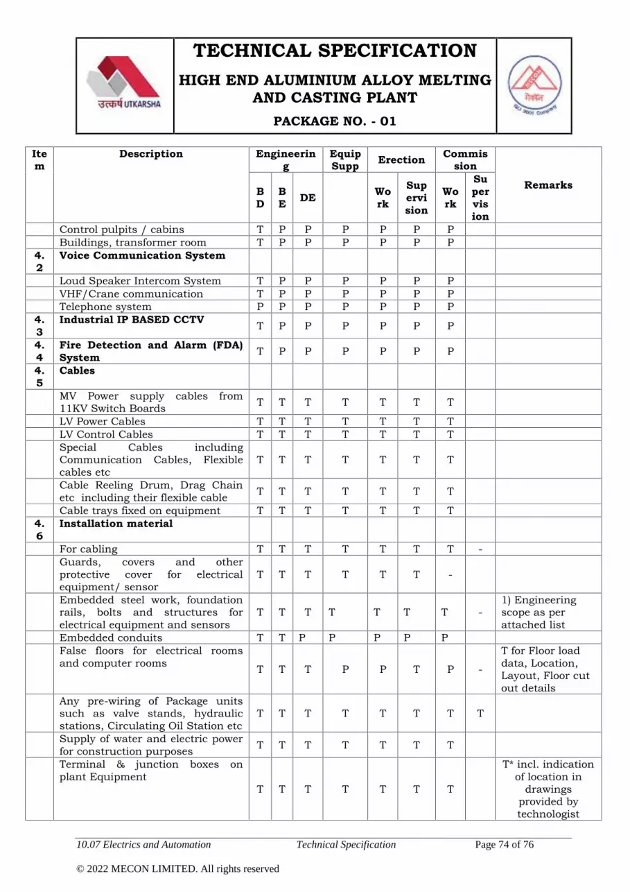
TECHNICAL SPECIFICATIONHIGH END ALUMINIUM ALLOY MELTING
AND CASTING PLANTPACKAGE NO. - 01
10.07 Electrics and Automation Technical Specification Page 74 of 76
© 2022 MECON LIMITED. All rights reserved
Item
Description Engineering
EquipSupp Erection Commis
sion
RemarksBD
BE DE Wo
rkSupervision
Work
Supervision
Control pulpits / cabins T P P P P P PBuildings, transformer room T P P P P P P
4.2
Voice Communication System
Loud Speaker Intercom System T P P P P P PVHF/Crane communication T P P P P P PTelephone system P P P P P P P
4.3
Industrial IP BASED CCTV T P P P P P P
4.4
Fire Detection and Alarm (FDA)System T P P P P P P
4.5
Cables
MV Power supply cables from11KV Switch Boards T T T T T T T
LV Power Cables T T T T T T TLV Control Cables T T T T T T TSpecial Cables includingCommunication Cables, Flexiblecables etc
T T T T T T T
Cable Reeling Drum, Drag Chainetc including their flexible cable T T T T T T T
Cable trays fixed on equipment T T T T T T T4.6
Installation material
For cabling T T T T T T T -Guards, covers and otherprotective cover for electricalequipment/ sensor
T T T T T T -
Embedded steel work, foundationrails, bolts and structures forelectrical equipment and sensors
T T T T T T T -1) Engineeringscope as perattached list
Embedded conduits T T P P P P PFalse floors for electrical roomsand computer rooms T T T P P T P -
T for Floor loaddata, Location,Layout, Floor cutout details
Any pre-wiring of Package unitssuch as valve stands, hydraulicstations, Circulating Oil Station etc
T T T T T T T T
Supply of water and electric powerfor construction purposes T T T T T T T
Terminal & junction boxes onplant Equipment
T T T T T T T
T* incl. indicationof location in
drawingsprovided bytechnologist

TECHNICAL SPECIFICATIONHIGH END ALUMINIUM ALLOY MELTING
AND CASTING PLANTPACKAGE NO. - 01
10.07 Electrics and Automation Technical Specification Page 75 of 76
© 2022 MECON LIMITED. All rights reserved
Item
Description Engineering
EquipSupp Erection Commis
sion
RemarksBD
BE DE Wo
rkSupervision
Work
Supervision
Other terminal and junction boxeson Shop Floor
T T T T T T T
T* incl. indicationof location in
drawingsprovided bytechnologist
4.7
Tools and instrumentsSpecial tools & instruments T T T T
4.8
Lighting & Power Outlets T/P
P P P P P P
Special lights required for anyequipment/system T T T T T T T
Search & Signaling systemincluding rotating flash lights andsirens at strategic locations e.g. topof pulpit, plant housing structure.
T T T T T T T
4.9
Earthing SystemPrimary Earthing T T P P P P PSecondary Earthing T T T T T T TElectronic Earthing T T T T T T T
4.10
Illumination/Lighting system P P P P P P P
4.10
Cranes / Hoists/Transfer Cars T T P P P P P
4.11
Water Treatment Plant(Electrical Equipment)
T/P
T/P
P P P P P
5.1
Training
Classroom training TSystem / maintenance training TOn-site training T
5.2 Installation / inst. SupervisionInstallation engineering (electrical) T T TInstallation work & wiretermination T T T T T T T
Cable engineering T T T T T T TCivil work electrical rooms T T P P P P PCivil work other buildings P P P P P P P BD & BE shall be
seller scope5.3
CommissioningT
See column“COM” of each
item6 Spare parts
Commissioning spares TOperation / maintenance spares T
7. BE, DE, Vendor drawing/data - - - - Nos. of set in
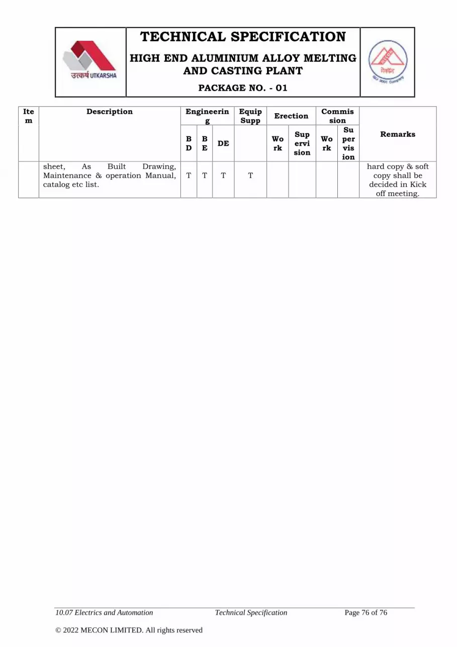
TECHNICAL SPECIFICATIONHIGH END ALUMINIUM ALLOY MELTING
AND CASTING PLANTPACKAGE NO. - 01
10.07 Electrics and Automation Technical Specification Page 76 of 76
© 2022 MECON LIMITED. All rights reserved
Item
Description Engineering
EquipSupp Erection Commis
sion
RemarksBD
BE DE Wo
rkSupervision
Work
Supervision
sheet, As Built Drawing,Maintenance & operation Manual,catalog etc list.
T T T Thard copy & soft
copy shall bedecided in Kick
off meeting.

TECHNICAL SPECIFICATIONHIGH END ALUMINIUM ALLOY MELTING
AND CASTING PLANTPACKAGE NO. - 01
10.08 Instrumentation Technical Specification Page 1 of 11
© 2022 MECON LIMITED. All rights reserved
10.08 INSTRUMENTATION
10.08.01 General:
1) Instrumentation facilities for the plants shall be as required forreliable, efficient, safe and trouble-free operation of the plant andequipment. Any equipment / accessories not explicitly indicatedin this specification, but essential for proper functioning oftechnological equipment and process shall be included byTenderer in its scope of work and supply. The completeinstrumentation of this package shall be executed on turnkeybasis by successful tenderer.
2) Instrumentation system shall be based on 4-20 mA DC signalsystem. Field transmitters and control-valve-positioners shall beHART® protocol enabled (HART® = Highway Addressable RemoteTransducer). Other equipment shall also be HART®-enabled /compatible, to the extent possible.
3) Monitoring, control, alarm & interlock functions of the process &equipment of the melting furnaces, holding furnaces and casterunits along with their auxiliaries shall be achieved through aPLC-based automation system, to be housed in an air-conditioned control room. The automation system shall becommon for both instrumentation & electrical facilities of theplant units. Further details and specifications of the automationsystem and control room have been indicated under Electricalchapter.
4) All analogue input & output (I/O) modules in the PLCrequired for interfacing of instrumentation equipment shallbe HART®-compatible. Additionally, all standard HART®
status, diagnostic, remote-configuration & troubleshootingfeatures shall be available in the PLC to facilitate automatichealth-monitoring of HART®-based field equipment.
5) Instrumentation primary power-supply shall be 240V AC, to beobtained from a UPS. Requirements and specifications of the UPS

TECHNICAL SPECIFICATIONHIGH END ALUMINIUM ALLOY MELTING
AND CASTING PLANTPACKAGE NO. - 01
10.08 Instrumentation Technical Specification Page 2 of 11
© 2022 MECON LIMITED. All rights reserved
are covered under Electrical chapter. 24V DC power supplyrequired for any instrumentation equipment shall be derived fromthe UPS power.
6) Control-valves shall be pneumatically-actuated type. For this,instrument-grade air shall be made available by Employerthrough pipe header running along the building column in oneaxis of the complex (to be decided with the successful bidder) at aheight about 7 meter from shop floor level. Taping from theheader will be provided at suitable location (to be decided withbidder) with one isolation valve at 2 meter height. Furtherdistribution of instrument air to respective pneumatic consumers,including supply of all necessary hardware / accessories, is inscope of Tenderer.
7) Earthing of instrumentation-related signal system, includingearthing of drain-wire of screened (instrumentation) cables shallbe done in a dedicated Electronic Earth grid for the PLC.However, in case any equipment (such as magnetic flowmeters)require independent earthing, same shall be provided byTenderer.
8) During design of the furnace, care shall be taken so that allinstrumentation-related field equipment, accessories andjunction-boxes are installed at man-height from the floor level, orare easily approachable for ease of maintenance. Instrumentationequipment and control valves shall not be installed on thefurnace roof.
9) All instrumentation equipment shall be from latest productranges of manufacturers selected from the List of ApprovedMakes in General Technical Specification (GTS). Features andspecifications of the equipment shall be in compliance with GTS.
10) Successful Tenderer shall co-ordinate with, and extend anynecessary assistance to Employer’s other agencies, as may berequired for smooth execution and operation of the completeplant and process.

TECHNICAL SPECIFICATIONHIGH END ALUMINIUM ALLOY MELTING
AND CASTING PLANTPACKAGE NO. - 01
10.08 Instrumentation Technical Specification Page 3 of 11
© 2022 MECON LIMITED. All rights reserved
11) All correspondences / documents shall be in English languageand for all the data, drawings & documentation metric or SI unitsshall be followed.
10.08.02 Scope of Work and Supply:
Tenderer’s scope of work and supply shall include design &engineering; manufacture / procurement; assembly; calibration;shop-testing; inspection; painting; packing; transportation to site(including loading, unloading); storage & handling; site-fabrication;erection, testing and commissioning of the complete instrumentationsystem of the package, as required for completeness of the system inall respects.
The scope of work and supply shall include but not be limited to thefollowing:a) Instrumentation equipment as per list covered under clause
no.10.08.03.
b) PLC-based automation system for the furnaces and casters, asper requirements indicated under Electrical chapter.
c) Signal & power cables; extension / compensating cables; anyother types of cables as required for this package.
d) Fully wired cabinets, transmitter cabinets, junction boxes, etc.,as required.
e) Instrumentation power supply equipment and other requiredelectrical accessories.
f) Impulse lines, isolation valves, air-filter-regulators, pipe-fittings,cable-trays, conduits, structural steel, erection hardware &accessories, canopies (for protection of exposed fieldinstruments), etc. as required for this package.
g) One portable HART Communicator - for configuration anddiagnosis of HART-enabled transmitters and equipment.
TECHNICAL SPECIFICATIONHIGH END ALUMINIUM ALLOY MELTING
AND CASTING PLANTPACKAGE NO. - 01
10.08 Instrumentation Technical Specification Page 4 of 11
© 2022 MECON LIMITED. All rights reserved
h) Approach arrangement, maintenance platforms, ladders, etc. asmay be required for reasonable maintenance access toinstrumentation items or tapping points.
i) Preparation of separate (dedicated) earth-pit, if required for anyinstrumentation equipment, including supply of earthingmaterials including cables.
j) Arranging & participation in inspection of instrumentationequipment at manufacturers’ / Tenderer’s premises.
k) Submission of drawings and documents as per clause no.10.03.04.
l) Erection, testing and commissioning of individualinstrumentation equipment and complete instrumentationsystem.
Successful Tenderer shall arrange all tools, tackles andconsumables required for the aforesaid activities.
m) Arranging visits of equipment manufacturer’s specialists to sitefor erection supervision, troubleshooting, etc., as and whenrequired, during erection & commissioning.
n) Supply of all instrumentation-related spares and consumablesrequired upto commissioning, and thereafter upto hand-over ofthe finished plant to Purchaser.
o) Any tools, tackles, instruments or calibration equipmentrequired for erection, testing, commissioning of theinstrumentation equipment and till handing over of the plant toPurchaser shall be brought to site by Tenderer on returnablebasis.
p) Supply of two years’ operation & maintenance spares forinstrumentation, if order is separately placed by Purchaser.
Tenderer shall submit a proposed list of two years’ operation &maintenance spares for instrumentation, cost of which shall beindicated separately from the main price in its offer.

TECHNICAL SPECIFICATIONHIGH END ALUMINIUM ALLOY MELTING
AND CASTING PLANTPACKAGE NO. - 01
10.08 Instrumentation Technical Specification Page 5 of 11
© 2022 MECON LIMITED. All rights reserved
10.08.03 List of Measurements, Controls, Alarms & Interlocks:
A) Melting Furnace / Holding Furnace:
An indicative list of measurements, controls, alarms & interlocks inthe scope of Tenderer for each Furnace is provided below. However,in case any other measurements, controls, alarms or interlocks arerequired for efficient and satisfactory operation of the process &equipment, the same shall be included by Tenderer in its scope,and also highlighted in the Tenderer’s offer.
1) Measurement of pressure of combustion air to each burner. Basedon this measurement, safety shut-off valve on fuel-oil line torespective burners shall be closed in case of low combustion airpressure.
2) Measurement of temperature of combustion air at header.
3) Measurement of flow of combustion air to each burner. The flowvalues shall be pressure & temperature compensated.
4) Measurement of pressure of fuel oil to each burner. Based on thismeasurement, safety shut-off valve on fuel-oil line to respectiveburners shall be closed in case of low fuel-oil pressure.
5) Measurement of temperature of fuel oil at header.
6) Measurement of flow of fuel oil.
7) Measurement of furnace bath temperature in each furnace usingthermocouples. Thermocouple shall be with thermowell of durablematerial suitable for the application.
8) Measurement of furnace roof temperature using thermocouples.
9) The bath & roof temperature signals from each furnace shall beinterfaced with the caster automation system for coordinatedoperation of both furnace & caster units.
10) Control of furnace temperature by regulating flow of combustion airand fuel oil to each burner of the furnace in required mixing ratio.Fuel-oil flow shall be measured using mass flowmeter, and shall betotalised.

TECHNICAL SPECIFICATIONHIGH END ALUMINIUM ALLOY MELTING
AND CASTING PLANTPACKAGE NO. - 01
10.08 Instrumentation Technical Specification Page 6 of 11
© 2022 MECON LIMITED. All rights reserved
Controlled variable for furnace temperature shall be either bathtemperature or roof temperature, depending operationalphilosophy.
Number and location of thermocouples (bath / roof) and theirinsertion mechanism shall be as per Tenderer’s system design.
11) Shut-off valves in oil line to respective burners: fuel lines shall beshut-off, based on furnace temperature / process requirement.
12) Sensing of flame in burners (using ultraviolet flame detectors / anyother proven method) along with required alarm & interlocks.
13) Measurement of flow of atomising air in header.
14) Measurement of pressure of atomising air to each burner.
15) Instrumentation equipment required for protection, alarm &interlocking of combustion-air fan and atomising-air blower shallalso be provided, as applicable.
16) Measurement of pressure of furnace and pressure control byregulating damper in the flue gas duct.
17) Measurement of temperature of flue gas from each furnace.
18) Continuous emission monitoring [SO2, NOx, suspended particulatematter (SPM), draft, flow, pressure, temperature, O2 (for dry-oxygencorrection of SO2, NOx & SPM data), any other requiredmeasurements] in chimney, as mandated in the latest Guidelines ofthe Central Pollution Control Board (CPCB) and / or State PollutionControl Board (SPCB). Facility for direct uploading of the monitoredparameters to the server of the CPCB) / SPCB and for remotecalibration of the analysers from CPCB / SPCB shall also beprovided. All other requirements as per latest recommendation ofthe CPCB as on the date of the plant commissioning shall becomplied by the Tenderer.
Further, Bidder shall design its furnace control philosophy so thatsignals from these monitoring systems / analysers are used forbetter control of furnace combustion system.

TECHNICAL SPECIFICATIONHIGH END ALUMINIUM ALLOY MELTING
AND CASTING PLANTPACKAGE NO. - 01
10.08 Instrumentation Technical Specification Page 7 of 11
© 2022 MECON LIMITED. All rights reserved
19) Continuous measurement of launder-level signal for executingfurnace tilting system. Launder-level shall be measured usinglaser-based molten-metal level sensor (‘Precimeter’ make).
20) Measurement and control of furnace tilt to maintain desired level ofliquid aluminium in launder between each furnace and caster.Tenderer shall supply tilt-angle feedback transmitter (‘Precimeter’make).
21) Local pressure gauges & switches at outlet of oil pumps, withnecessary alarm & interlock.
22) Local pressure gauges & switches at outlet of combustion-air /atomising air blowers / fans, with necessary alarm & interlock.
23) Pressure, temperature and flow measurement at the battery limitfor all utilities (like instrument-air, compressed air, water, etc.).
24) Any other instrumentation equipment required for efficient andsafe operation of the furnaces and their auxiliaries.
B) Caster:
An indicative list of measurements, controls, alarms & interlocks inthe scope of Tenderer for each caster is provided below. However, incase any other measurements, controls, alarms or interlocks arerequired for efficient and satisfactory operation of the process &equipment, the same shall be included by Tenderer in its scope,and also highlighted in the Tenderer’s offer.
1) Measurement of casting rate & its regulation including control ofliquid metal pouring to caster. Caster drive parameters includingcasting speed shall also be monitored.
2) Measurement of liquid metal temperature at inlet to caster.
In case thermocouple is used for this application, thermowellmaterial shall be selected for obtaining best possible life-span.Temperature transmitter shall preferably be used for themeasurement loop.
TECHNICAL SPECIFICATIONHIGH END ALUMINIUM ALLOY MELTING
AND CASTING PLANTPACKAGE NO. - 01
10.08 Instrumentation Technical Specification Page 8 of 11
© 2022 MECON LIMITED. All rights reserved
Additionally, a digital indicator installed on a wall mounted cabinetshall also be provided at the local level for the temperaturemeasurement loop.
3) Measurement and control of flow of cooling water to each coolingzone of the caster using electromagnetic flowmeter and controlvalve. Water flow rates as required for different product gradesshall be set in the automation system and controlled accordingly.
4) Measurement of temperature of cooling water at inlet & outlet ofeach cooling zone of the caster.
5) Measurement of pressure at inlet & outlet cooling water line ofeach cooling zone of the caster.
6) Pressure gauge at each cooling water line of the caster.
7) Measurement of differential pressure across heat exchanger.
8) Pressure & temperature gauges at inlet & outlet lines of heatexchanger for the water being cooled and for the water used forcooling.
9) Measurement of flow of nitrogen at inlet line to the degasser. Theflow shall be pressure & temperature compensated. Pressuretransmitter & temperature element / transmitter shall be providedin the nitrogen line for monitoring as well as for flow compensation.
10) All required instrumentation facilities for the degasser unit, suchas bath temperature measurement; heating element temperaturemeasurement & its control, etc. All instrumentation signals shallalso be interfaced with the caster automation system.
11) Measurement of casting wheel ring mould temperature for verifyingproper heating of the mould before casting.
12) Measurement of temperature of cast product at outlet of caster.
In case pyrometers are used for the measurements at sl. nos. 11 &12 above, these shall be with all required purging and coolingfacilities as per their operational requirement.
13) Any other measurement required for efficient and safe operation ofthe caster & auxiliaries.

TECHNICAL SPECIFICATIONHIGH END ALUMINIUM ALLOY MELTING
AND CASTING PLANTPACKAGE NO. - 01
10.08 Instrumentation Technical Specification Page 9 of 11
© 2022 MECON LIMITED. All rights reserved
10.08.04 Submission of Drawing & Documents:
The following is a list of drawings and documents to be submitted bythe Tenderer as minimum:
A) To be submitted along with offer:
1) Signed copy of TS as confirmation that Tenderer is agreeable to allthe clauses of this chapter, and in particular, to the List ofmeasurements, controls, alarms & interlocks in clause no.10.03.03.
2) Any other measurements, controls, alarms or interlocks feltnecessary by Tenderer for completeness of work or for satisfactoryoperation of the plant and process shall also be highlighted byTenderer.
3) Instrument-air requirement for the project.
4) List of two years’ operation & maintenance spares pertaining toInstrumentation & Automation, with details & unit-rates.
B) To be submitted by the Successful Tenderer :
I. For Approval:
1) Process and instrumentation (P&I) diagram indicating allmeasurements, controls, alarms and interlock functions at fieldand control room, using instrumentation symbols & identificationin conformance with ISA-5.1-1984, or any other instrumentationsymbol & identification system (enumerated clearly in thedrawing).
2) Detailed specification datasheet for each instrumentation item,with finalised (single) make and complete model-number.

TECHNICAL SPECIFICATIONHIGH END ALUMINIUM ALLOY MELTING
AND CASTING PLANTPACKAGE NO. - 01
10.08 Instrumentation Technical Specification Page 10 of 11
© 2022 MECON LIMITED. All rights reserved
Technical literature for the selected model number of equipmentshall be submitted in soft-copy to enable scrutiny of thedatasheets.
3) General arrangement drawings & sectional views of all cabinetsshowing external & internal disposition of all equipment, withdimensional details and bill of materials, if applicable.
4) Single-line power supply diagrams for instrumentation andautomation with bill-of-materials of electrical items andaccessories.
II. For Scrutiny and Reference:
1) Control philosophy for the plant and equipment.
2) Instrumentation cable schedule and specification.
3) Internal-wiring diagrams of cabinets, if applicable.
4) Instrumentation loop diagrams showing termination details ofsignals from instrumentation equipment upto field junction-boxesand then upto PLC marshalling racks.
5) Sizing calculation for flow elements, control valves, actuators, andany other items required to be sized; stroking time calculation forcontrol valves with actuators; along with all related charts,curves, tables, etc.
6) Fabrication drawings for orifice-plate assemblies, specialthermocouple assemblies (e.g., installed in furnace), thermowells,control valves, and any other fabricated items, as applicable.
7) Instrument Installation / hook-up diagrams.
8) Instrumentation layout drawings showing location of instrumentsand route of cables from sensors/ primary elements up to fieldjunction boxes and control room.
9) Instrument air distribution scheme with bill of quantities.

TECHNICAL SPECIFICATIONHIGH END ALUMINIUM ALLOY MELTING
AND CASTING PLANTPACKAGE NO. - 01
10.08 Instrumentation Technical Specification Page 11 of 11
© 2022 MECON LIMITED. All rights reserved
10) List of instrumentation equipment indicating tag number,application / service, finalised make, model number, scale range& quantity.
III. After Commissioning & Before Plant Handover:
1) ‘As-built’ drawings and documentation.
2) Soft copy of all the above drawings & documents in DVD or anyother storage media.

TECHNICAL SPECIFICATIONHIGH END ALUMINIUM ALLOY MELTING
AND CASTING PLANTPACKAGE NO. - 01
10.09 Quality Control Facilities Technical Specification Page 1 of 2
© 2022 MECON LIMITED. All rights reserved
10.09 Quality Control Facilities
The melting and casting plant shall produce high quality aluminiumhard alloy slabs & billets as per the quality standards. Qualityassurance shall be implemented effectively in the form of analysesand test results by operation.
To carry out the day-to-day quality control operations, to renderassistance at various stages of production and to ensure properquality of products, a laboratory with modern state-of-the-artequipment to be established to cater to the quality assurance needsof the melting and casting plant. As the plant is going to producedifferent Aluminium grades intended for aero, defence, space andother critical applications, the quality control measures to beeffectively adopted to meet the end use application.
Following functions are considered essential for melting and castingarea:
Analysis of raw materials (Al ingot, master alloy, etc.) &intermediate products
Analysis of molten metal and dross from furnace units
Collection and preparation of test samples
Laboratory facilities is excluded from scope of tenderer. However,tenderer to provide the following information.
Tests required along with the applicable National /International standard to conduct the analysis
Laboratory equipment list with quantity along with detailedtechnical specification of the equipments
Make [Original equipment manufacturer] list of the laboratoryequipment, preferably from Indian sources
Tentative equipment layout of the laboratory

TECHNICAL SPECIFICATIONHIGH END ALUMINIUM ALLOY MELTING
AND CASTING PLANTPACKAGE NO. - 01
10.09 Quality Control Facilities Technical Specification Page 2 of 2
© 2022 MECON LIMITED. All rights reserved
A write-up on standard operating procedure of laboratoryindicating the tests, sampling point, frequency of testing,duration of test, etc.
Sampling procedure for preparation of test sample and sampletransportation method
Certification agency and procedure for certification of thelaboratory equipment as per international standards for space,aero, defence and commercial application for the productsaimed in the product-mix.
Any other item required for completeness and designing oflaboratory facility
TECHNICAL SPECIFICATIONHIGH END ALUMINIUM ALLOY MELTING
AND CASTING PLANTPACKAGE NO. - 01
10.10 Fire Protection System Technical Specification Page 1 of 1
© 2022 MECON LIMITED. All rights reserved
10.10 Fire Protection system
Complete fire protection system for the Aluminium Melting & CastingFacilities shall be provided by Purchaser. The package #1 bidder has toprovide all basic engineering data required for designing the fireprotection system and suggest the schemes usually adopted for suchplant emphasizing on fire prone areas and volume of hazardous item. Ifany specific feature is to be adopted/in-built in latest process lineequipment, same shall be considered by the bidder indicating theadvantages of using such special feature in the offered equipment incontext to fire protection.

TECHNICAL SPECIFICATIONHIGH END ALUMINIUM ALLOY MELTING
AND CASTING PLANTPACKAGE NO. - 01
10.11 Pollution Control Technical Specification Page 1 of 1
© 2022 MECON LIMITED. All rights reserved
10.11 Pollution Control
10.11.01 Two number (1 no. for melting furnaces and 1 no. for holdingfurnaces) of fully refractory lined steel stacks of adequate height(minimum 35m) with a provision of gas sampling facility andapproach to the gas sampling point. The height of the stack shallbe as per latest pollution control norms/ CPCB regulations.
The stack will be lined as described under various chapters of theTS namely Chapter 10.01.1.A, 10.01.1.B, 10.03 and 10.08.
10.11.02 Steam generated during casting process shall be exhaustedthrough the centrifugal exhaust fans to the atmosphere above thebuilding roof.
10.11.03 The fine aluminium chips generated at the slab sawing & scalpingarea shall be collected in chips collection bin and send to a chipscompactor which shall be able to keep the different alloysseparated and eliminate the undesired standstills.
10.11.04 Tenderer shall indicate whether the amount of fumes generatedfrom various stages of operation need any precaution / careagainst environment pollution, in that case the facilities to beincluded in Tenderer’s scope.

TECHNICAL SPECIFICATIONHIGH END ALUMINIUM ALLOY MELTING
AND CASTING PLANTPACKAGE NO. - 01
10.12 Hydraulic and Lubrication Technical Specification Page 1 of 24
© 2022 MECON LIMITED. All rights reserved
10.12 Hydraulics and Lubrication System
10.12.01 Hydraulic Tilting System for Melting & Holding Furnaces
Each furnace will be tilted with the help of 2 nos. hydrauliccylinders and positioned around floor level at each side of thecharge door. The cylinders will be double acting and will beconnected via front rod and mountings (clevis) incorporatingbushes to a hard shaft supported on fabricated mild steelstructures bolted to the floor. The cylinders will be connected tothe furnace lift beam via front trunnion mounting on barrelincorporating bushes on shafts. The furnace shall be suitablyreinforced in this area.
Separate hydraulic power pack shall be provided for the envisaged3 (three) nos. melting furnaces and 2 (two) nos. holding furnaces.
The hydraulic system will be suitable for use with fire resistantsynthetic hydraulic fluid confirming to IS 7895 of1975. Viscositygrade-68 based on synthetic organic easter without any watercontent, phosphate easter and chlorinated hydro-carbon.
Tenderer scope of supply would include first fill of hydraulic fluidand required top up for successful commissioning.
Tilting of the furnaces will be suitably adjustable so as to get ametal flow rate of 10t/h maximum casting speed.
A safe system for descending the furnaces automatically in theevent of failure of electrical power will be provided by the tenderer.During normal operation, provision shall be made for cushioningwhen the furnaces are brought to rest from tilted positions.
Besides above, provision of an emergency switch shall be madewhich shall restrict the automatic coming back of the furnaces toits rest position from tilted condition in case of power failureduring maintenance of the furnace in tilted condition.
The furnace tilting system will work in conjunction with thelaunder level control system.

TECHNICAL SPECIFICATIONHIGH END ALUMINIUM ALLOY MELTING
AND CASTING PLANTPACKAGE NO. - 01
10.12 Hydraulic and Lubrication Technical Specification Page 2 of 24
© 2022 MECON LIMITED. All rights reserved
The hydraulic system will have the following features:-
a) For achieving the rated flow rate as per the requirement ofcaster, provision for slow rate of tilt and fast rate of tilt shall bemade in the holding furnaces.
b) Tilt speed will be controlled by a motorized oil flow control valvethrough the signal available from caster PLC. In order to achievethe desired flow rate of liquid metal, the control of tilt speedshall be affected normally on one furnace at a time. But theprovision shall exist for simultaneous tilt of 2 nos. furnaces(melting furnaces) for a short duration, say 5 minutes. Thecontroller for furnace tilting shall form a part of scope of supply.
c) A hydraulic oil flow meter (mass flow meter) for each furnace willalso be provided for interaction with the Caster PLC.
d) The tilt cylinders will be suitably located.
e) Furnace over tilting limit switch to be provided.
f) Instruments for furnace tilting to be provided for controlledtilting.
Detailed Description of Hydraulic System:
1. SCOPE OF WORK- Supply, erection and commissioning of New Hydraulic
Systems- Portable oil filling unit along with oil filtration facility- First fill- Spares
2. DESIGN CONSIDERATIONAll the components of Hydraulic system shall be designed,manufactured, assembled and tested in accordance with thelatest IS, IPSS & IEC Indian Boiler act or Pressurized vessel actstandards wherever applicable. In case of the items where abovesuitable standards are not available / applicable, these shall be

TECHNICAL SPECIFICATIONHIGH END ALUMINIUM ALLOY MELTING
AND CASTING PLANTPACKAGE NO. - 01
10.12 Hydraulic and Lubrication Technical Specification Page 3 of 24
© 2022 MECON LIMITED. All rights reserved
according to general accepted codes, practices and internationalstandards.
All electrical equipment / component of Hydraulic system shallconform to latest Indian Electricity Regulations as regards tosafety, earthing and other provisions.
3. TECHNICAL REQUIREMENT
The hydraulic system shall consist of the following majorcomponents duly piped up.
- Oil Reservoir.- Return filter shall be duplex type and Pressure filter shall be
simplex type of required micron rating. All filters shall beequipped with mechanical & electrical clogging indicators.
- Pressure filters at the pump discharge.- Offline recirculating cooling & filtering system.- Variable flow, pressure compensated axial piston pump.- Bladder accumulators / Piston accumulators with Nitrogen
bottles.- Valve stands with manifold & Control valves.- Valve stand Electric panel complete with amplifier cards,
switches, push buttons, lights, in enclosure.- Electric Junction box.- Control instruments and indicating instruments.- Interconnecting pipelines.
The scope of work covers design, manufacture, cleaning,assembly, testing, painting, packing and supply as per followingtechnical specification.
Tank Unit
The oil tank shall be of minimum 8 times the pump capacity andof SS material.
Tank of suitable dimension, shall be of welded steelconstruction, fabrication using 6 mm thick (minimum) steelplate, test certificates of same should be submitted, andprovided with structural reinforcement on outside surface.

TECHNICAL SPECIFICATIONHIGH END ALUMINIUM ALLOY MELTING
AND CASTING PLANTPACKAGE NO. - 01
10.12 Hydraulic and Lubrication Technical Specification Page 4 of 24
© 2022 MECON LIMITED. All rights reserved
Tank shall be equipped with level gauge cum level switch,temperature gauge, heater, air breathers, thermostat, manholecover, sampling and drain valve etc.
Pumping Unit
This unit shall consist of variable delivery, pressurecompensated axial piston pump (The no. of standby pumpingunit shall be either 50% of working pumping units or 2whichever is less) of adequate capacity complete with suctionand delivery flanges driven by 1450 rpm suitable electric motor,relief valves, pressure gauge, pressure filter of 10 micron rating(β10 ≥ 200) filter element suitable for system pressure withelectrical & mechanical clogging indicator (The system withservo valves shall have pressure filter of 3 micron rating β3 ≥200), pressure switches, return line duplex filter withmechanical & electrical clogging indicator etc.
Recirculating Cooling & Filtering Arrangement
The unit shall consist of screw pump with built in adjustablerelief valve of suitable capacity driven by electrical motor ofsuitable capacity of 1450 RPM and coupled with flexiblecoupling, duplex filter with mechanical & electrical cloggingindicator (Degree of filtration shall be 10 micron and systemwith servo valves the degree shall be 3 micron rating), plate typeheat exchanger (Complete with regulating valve, basket strainer,pressure gauge)
Accumulator Stand
Bladder Accumulators of suitable capacity in requisite numbers,rated for system pressure along with safety shut off block andNitrogen charging and gauging assembly and piped up to makeaccumulator stand.
Alternatively piston accumulators of required capacities andrequired Nitrogen bottles, mounted on a common stand,completely piped up.

TECHNICAL SPECIFICATIONHIGH END ALUMINIUM ALLOY MELTING
AND CASTING PLANTPACKAGE NO. - 01
10.12 Hydraulic and Lubrication Technical Specification Page 5 of 24
© 2022 MECON LIMITED. All rights reserved
Valve Stands
The valve stand shall primarily consist of various types ofcontrol valves mounted on manifold blocks. Material of manifoldblock shall be forged steel / GGG 40. All the electricalconnections shall be wired to a common junction box mountedon each valve stand.
The valve stands of adequate dimension shall be of manifoldconstruction and shall be "table type".
Portable Filter Pump Unit
This unit shall be complete with motorised pump and filtersuction and delivery hoses to fill the oil in the system tank fromoil barrels.
Spares
List of commissioning spares shall be provided. Commissioningspares shall be supplied with the systems and it shall be part ofthe supply. Any spares required during commissioning shall beunder scope of tenderer irrespective whether it appears in thecommissioning spares list or not. List of recommended sparesfor 2 years of operation shall also be provided. A separate pricefor these 2 years spares shall be indicated.
Initial fill
Scope of supply shall include First fill of hydraulic oil in requiredquantity.
Interconnecting piping
Interconnecting piping shall be of Stainless steel. All necessaryinterconnecting piping between various units i.e. tank,accumulator stand, pumping unit and valve stands and betweenvalve stands and equipment shall be provided. Theinterconnecting piping shall consist of high pressure hoses,pipes/tubes, welded nipple type with O-ring type fittings, SAE

TECHNICAL SPECIFICATIONHIGH END ALUMINIUM ALLOY MELTING
AND CASTING PLANTPACKAGE NO. - 01
10.12 Hydraulic and Lubrication Technical Specification Page 6 of 24
© 2022 MECON LIMITED. All rights reserved
four bolt flanges, heavy duty PP clamps, etc as detailed out ingeneral notes. EO tubes with ferrol fittings shall be used.
4. GENERAL INSTRUCTIONS
a) All the pipes / tubes , fittings etc. of hydraulic systemsshall be seamless stainless conforming to DIN / ANSIstandards.
b) All terminations shall be terminated by mating flanges /fittings suitable for incoming / outgoing pipe sizes. One endof the P-T-L headers in valves stands shall be provided withmating flange and other end with blind flanges.
c) All pressure switches and pressure gauges shall beconnected by hose and minimises coupling.
d) High pressure hoses, suitable for requisite system pressure,shall be used in the delivery of main pumps.
e) At pump suction, flexible connectors shall be used.f) All units such as pumping unit, tank unit, accumulator
stand and valve stands shall be provided with oil trays anddrain valves.
g) All butt-weld joints shall be welded by TIG welding. Pipe /tube upto 38mm OD shall be completely welded by TIG andabove 38mm OD shall have root welding by TIG followed bynormal welding.
h) Material of manifold block shall be IS-1875CL. III- GGG-40.Test certificates shall be submitted in this respect.
i) Direction control valves shall be selected for maximum 5Kg/cm2 (P to A and B to T taken together) pressure drop forblind end flow.
j) Speed control valves shall be selected for maximum 5Kg/cm2 (maximum open condition) pressure drop.
k) Shut off valves and check valves shall be of same size asthat of pipelines.
l) Total pressure drop in any circuit including manifold blockof valve stand, for the flow indicated for the circuit shall notexceed 15 Bar. Pressure drop shall be measured by shortcircuiting A & B ports by providing pressure gauges at P &T lines and measuring flow by a digital flow meter.

TECHNICAL SPECIFICATIONHIGH END ALUMINIUM ALLOY MELTING
AND CASTING PLANTPACKAGE NO. - 01
10.12 Hydraulic and Lubrication Technical Specification Page 7 of 24
© 2022 MECON LIMITED. All rights reserved
m) All solenoids shall be provided with indicating lamps,wherever possible, and plug in type connectors (DINconnector). All solenoid coils to be oil immersed type andmust be rated for continuous duty and they shall be epoxycoated.
All pilot operated direction control valves shall be with pilotchoke arrangement.
n) All equipment shall be supplied with drives, associatedelectrics, instruments and control equipment, technologicalstructures (if any), maintenance and working platforms,railing, safety guards etc.
o) Material handling facilities for maintenance of allequipment shall also be a part of supply.
p) Supply of following: -- Complete design data,- Design calculation,- P & ID Drawings with BOM- Detail engineering drawings,- Interconnecting piping drawings- Technical literature and documents,- Erection and Construction drawings, manuals etc.- Operation and maintenance manuals,- Quality assurance plan for all equipment.- Supply of “As Built drawings”.- List of commissioning spares and 2 years spares- List of special tools and tackles
q) Any other equipment / part / facility not specificallymentioned in the specification, but is necessary technicallyor safety point of view for the satisfactory and smoothoperation of the system shall also be included in the scopeof the supply of the tenderer.
r) There shall be properly identification of piping.s) Air vents with plugs / valves shall be provided at proper
places.t) The successful tenderer shall supply complete set of all the
special tools and tackles including required number of toolboxes as required for erection, maintenance, overhaul orcomplete replacement of the equipment and components

TECHNICAL SPECIFICATIONHIGH END ALUMINIUM ALLOY MELTING
AND CASTING PLANTPACKAGE NO. - 01
10.12 Hydraulic and Lubrication Technical Specification Page 8 of 24
© 2022 MECON LIMITED. All rights reserved
required for the offered system. All the tools shall besupplied in separate containers clearly marked with thename of the equipment they are meant for.
10.12.02 Hydraulic System For other equipments
Requisite number of hydraulic system shall be envisaged forhydraulic movements of:
a) Casting machine
b) Mold table tilt system
c) Slab and Billet scalper and band sawing line.
d) Any other
The scope of work of hydraulic system shall cover design,engineering, manufacture, procurement, assembly, shopinspection, testing, painting, packing, delivery, erection,testing at site & commissioning and demonstration ofperformance guarantee at site of equipment of hydraulicsystem including piping as described later in thisspecification and complete in all respects along with theiraccessories, commissioning spares and 2 years spares forthe following.
A. Hydraulic System
B. First fill (Fire resistant synthetic oil)
1.1. DESIGN CONSIDERATION
A. Hydraulic system:
The system will consist of following units:
Power Unit.
Valve Stands.
Accumulator Stand
Power unit
Power unit shall consist of mainly following:

TECHNICAL SPECIFICATIONHIGH END ALUMINIUM ALLOY MELTING
AND CASTING PLANTPACKAGE NO. - 01
10.12 Hydraulic and Lubrication Technical Specification Page 9 of 24
© 2022 MECON LIMITED. All rights reserved
Tank Unit
Tank shall be of welded stainless steel rectangular constructionand dimensions shall be proportioned as length: width: Height = 2:1.5:1 (approx.). The tank shall be fabricated by 6-mm thick (min.)steel plate SS-304 material and provided with structuralreinforcement on outside surface. Gross volume of tank shall be20% more than the working volume. The tank shall be completewith suitable square / rectangular / circular opening with oil tightcover in each chamber of tank for efficient cleaning, slopingbottom, baffle plate separating suction & return chamber, drainvalve in each chamber.
Following items shall be mounted on tank:
Level gauge cum level switch equipped with bicolor rotatingflappers and isolation valves. Provision shall be for continuousanalogue 4 -20 mA output to control room for on-linemonitoring of level and various alarm / tripping.
Temperature Gauge: - One (1) direct mounting back entry typetemperature gauge of 100 mm dial size, 0 100 °C range"mercury in steel" type with SS bulb &thermowell havingimmersion length 150 mm
Thermostat: - One (1) thermostat of reputed make of range 10C to 100 C and differential 3 to 24 C with remote bulb SSthermowell and 3 meter long capillary with armored covering.
Air Breathers - Air breathers shall be 3 micron absolute rating,replaceable filter element and dehydrating chamber containingsilica gel (for moisture trapping).
Drain, sampling valves and spare valves at suitable andconvenient locations.
Clean out door
Baffle plate
Pumping Unit
Main pumping Unit: This unit shall consist of following:

TECHNICAL SPECIFICATIONHIGH END ALUMINIUM ALLOY MELTING
AND CASTING PLANTPACKAGE NO. - 01
10.12 Hydraulic and Lubrication Technical Specification Page 10 of 24
© 2022 MECON LIMITED. All rights reserved
Pumps: Requisite number of variable delivery, pressurecompensated axial piston pumps (including 50% standbyminimum one (1) no) of adequate capacity complete withsuction and delivery flanges. Each pump shall be driven by1450-rpm suitable electric motor. The pump shall be handlingfire resistant synthetic oil. The pump shall be connected tomotor by flexible coupling. Flexible connection at pump suction& hose at pump delivery shall be provided. BHP at duty point tobe indicated and the Tenderer has to ensure that the motorselected has sufficient reserve kW to run pump at 125% ofsystem pressure.
Relief cum unloading Valves: Relief cum unloading valve withadjustable range suitable for the system to relieve at 110 % ofsystem pressure shall be installed for each main pump.
The relief valve and check valves for each pump unit should bemounted on separate manifold.
Pressure Gauge: - These shall be glycerin filled, heavy duty 100mm dial size, of range suitable for system pressure, completewith bourdon movement and snubber of AISI 316 SS, in diecast aluminum alloy, moisture proof case, heavy enameledblack and equipped with zero adjustment mechanism suitablefor oil service.
Pressure Transmitter: - Pressure transmitter with 4-20 mAoutput shall be provided for each main pump.
Pressure Filters: - The pressure filter shall be installed at thedelivery of each main pump with >200 filter elements,suitable for system pressure of suitable flow (not less than1.5to 2 times of pump flow) rating at 0.8 to 1.0 Bar differentialpressure (Housing + Element) in clean condition. Filter shall beprovided electrical clogging indicator. The pressure line filtersshall be simplex filter without bypass valve.
Return Line Duplex Filter: - One (1) no. Duplex type (oneoperating and one standby) with change over valves suitable forworking pressure of 10 kg/cm² with >200 filter elements. Thefilter shall be capable of handling three times the system pump

TECHNICAL SPECIFICATIONHIGH END ALUMINIUM ALLOY MELTING
AND CASTING PLANTPACKAGE NO. - 01
10.12 Hydraulic and Lubrication Technical Specification Page 11 of 24
© 2022 MECON LIMITED. All rights reserved
capacity at 0.3 to 0.5 kg/cm² pressure drop (Housing +Element) in clean condition. Electrical switches shall beprovided with for audio-visual alarm for filter clogging in casedifferential pressure exceeds 1.5 kg/cm². By- pass valve to beprovided to by-pass in case differential pressure exceeds 3kg/cm².
Recirculating unit - This unit shall consist of following: -
Recirculation Pump: - Pump (1 W + 1 S) of screw / vane typewith built in adjustable relief valve of suitable capacity forhandling fire resistant synthetic oil at 10kg/cm². The pumpshall be driven by electrical motor of suitable capacity of 1450RPM and coupled with flexible coupling.
Pressure Transmitter: - One (1) Pressure transmitter with 4-20mA output shall be installed in delivery line.
Recirculation Filter: - One no. of duplex filter with change overvalves suitable for working pressure of 10 kg/cm² with >200filter elements. The filter shall be capable of handling 1.5 to 2times of pump capacity at a pressure drop of 0.3 to 0.5 kg/cm²(Housing + Element) in clean condition. Electrical switches shallbe provided with for audio-visual alarm for filter clogging in casedifferential pressure exceeds 1.5 kg/cm². By- pass valve to beprovided to by-pass in case differential pressure exceeds 3kg/cm.
Cooler: - This should be PLATE TYPE HEAT EXCHANGER withfollowing technical parameters.
Oil Flow - l pm
Water flow - To be furnished by tenderer
Oil inlet temperature - 60 °C max.
Water inlet temperature - 35 °C
Water temperature rise - 3 °C max
kW to be removed - kW( to be furnished by tenderer)

TECHNICAL SPECIFICATIONHIGH END ALUMINIUM ALLOY MELTING
AND CASTING PLANTPACKAGE NO. - 01
10.12 Hydraulic and Lubrication Technical Specification Page 12 of 24
© 2022 MECON LIMITED. All rights reserved
Heat transfer area - To be furnished by tenderer
Pressure drop oil side - 0.8 bar
Pressure drop water side - 0.2 bar
Oil inlet and outlet - ASA 150 class slip on flanges
Cooler shall have cooling capacity of at least 30% of installed poweron unit. Cooler shall have 20% spare capacity.
Regulating Valve: - For regulation of oil temperature, solenoidoperated on -off valve suitable for water service of suitable size.Voltage 24 V DC. The solenoid shall have interlock with thethermostat mounted on the system reservoir.
Strainer: - Y strainer of suitable size and 80µ SS screen shall beprovided at water inlet.
(Note: Total pressure drop across shut off valve, Y strainerand regulating type water valve and cooler (water side) shouldnot exceed 1.0 Bar).
All the above items are to be mounted in main power unit.
Accumulator stand
Details of emergency operations shall be furnished by bidder.Requisite nos. of accumulators of suitable capacity (preferablybladder type) and rated pressure with safety shut off block shall besupplied to successfully complete emergency operation duringpower failure.
Accumulator sizing calculation shall also be submitted. One no. ofaccumulator charging & gauging hose assembly shall also besupplied. The accumulators with safety shut off blocks shall bemounted together and piped up to make accumulator stand. Shut-off valves and other valves shall be suitable for gas service for 1.5times the working pressure.
Note: If piston accumulator is selected then it shall besupplied with backup nitrogen bottles.
Valve stands

TECHNICAL SPECIFICATIONHIGH END ALUMINIUM ALLOY MELTING
AND CASTING PLANTPACKAGE NO. - 01
10.12 Hydraulic and Lubrication Technical Specification Page 13 of 24
© 2022 MECON LIMITED. All rights reserved
The valve stands of table design and standard height consisting ofall components, mounted instruments, etc. as per approvedhydraulic schematic & shall be preassembled, pre-piped andprewired on a sturdy welded steel frame made out of carbon steelmaterials. The valve stands shall broadly comprise following: -
Proportional Direction Control Valve complete with built inelectronics and control amplifier.
Direction Control Valve
Pilot Operated Check Valve
Flow Control Valve
Control Instruments
Minimess point for checking pressure at different points etc.
B. First fill
Scope of supply shall include first fill i.e. fire resistant synthetic oilin required quantity (Tank, pipeline & components) up tosuccessful commissioning & PG. System oil should be fire resistantsynthetic oil.
1.2. GENERAL INSTRUCTION TO THE TENDERERS
Interconnecting piping i.e. pipes & fittings for hydraulic systemshall be of stainless steel.
All pipes / tubes shall be as per clause 2.05 of GeneralTechnical specification.
All fasteners shall be of minimum 8.8 grade
All terminations shall be terminated by mating flanges / fittingssuitable for incoming /outgoing pipe sizes. One end of the P T Lheaders in valves stands shall be provided with companionflange and other end with blind / regular flanges.
Shut off / Isolation valves shall be with SS internals for suction,return and drain lines. Shut off valves in pressure line of size42 NB and above shall be provided with pressure equalisingvalve.

TECHNICAL SPECIFICATIONHIGH END ALUMINIUM ALLOY MELTING
AND CASTING PLANTPACKAGE NO. - 01
10.12 Hydraulic and Lubrication Technical Specification Page 14 of 24
© 2022 MECON LIMITED. All rights reserved
All pressure switches and pressure gauges shall be connectedby hose and minimize coupling
All units such as pumping unit, tank unit, accumulator standand valve stands shall be provided with oil trays and drainvalves.
All butt-weld joints shall be welded by TIG welding. Pipe / tubeup-to 38mm OD shall be completely welded by TIG and above38 mm OD shall have root welding by TIG followed by normalwelding.
Material of manifold block shall be IS 1875CL. III GGG 40/Forged steel. Test certificates shall be submitted in thisrespect.
Shut off valves and check valves shall be of same size as that ofpipelines.
Total pressure drop in any circuit including manifold block ofvalve stand, for the flow indicated for the circuit shall notexceed 15 Bar. Pressure drop shall be measured by shortcircuiting A & B ports by providing pressure gauges at P & Tlines and measuring flow by a digital flow meter.
All solenoids shall be provided with indicating lamps, whereverpossible, and plug in type connectors (DIN connector). Allsolenoid coils to be oil immersed type and must be rated forcontinuous duty and they shall be epoxy coated.
All pipes shall be pressure tested / cleaned / flushed to get thedesired cleanliness class as per the requirement of system.
All pipelines to be clamped with polypropylene heavy seriesclamp at regular interval.
Supply of following: -
Complete design data,
Design calculation,
P & ID Drawings with BOM
Basic and detail engineering drawings,

TECHNICAL SPECIFICATIONHIGH END ALUMINIUM ALLOY MELTING
AND CASTING PLANTPACKAGE NO. - 01
10.12 Hydraulic and Lubrication Technical Specification Page 15 of 24
© 2022 MECON LIMITED. All rights reserved
Interconnecting piping drawings
Technical literature and documents,
Erection and Construction drawings
Erection manuals,
Operation and maintenance manuals,
Standard operating practices,
Quality assurance plan for all equipment.
Supply of “As Built drawings”.
Any other equipment / part / facility not specifically mentionedin the specification, but is necessary technically or safety pointof view for the satisfactory and smooth operation of the systemshall also be included in the scope of the supply of theTenderer.
There shall be proper identification of piping.
The successful Tenderer shall supply complete set of all thespecial tools and tackles required for erection, maintenance,overhaul or complete replacement of the equipment andcomponents required for the offered system.
1.3. INSPECTION & TESTING
Manufacturers' Test Certificates for all bought out items e.g.Electric Motors, Coolers, Accumulators Manifold Blocks,Control Valves, Instruments, Plates for tank etc. shall besubmitted for review of Inspecting Engineer.
Valid Calibration Certificates for instruments installed andthose used additionally during inspection shall be submitted forreview of Inspecting Engineer.
PHYSICAL VERIFICATIONS:
DESCRIPTION DEVIATION PERMITTEDDimensional check as per Approved
GA drgs+/- 10.0 mm on overall
dimension
Bolt hole locations as per Approved +/- 02.0 mm

TECHNICAL SPECIFICATIONHIGH END ALUMINIUM ALLOY MELTING
AND CASTING PLANTPACKAGE NO. - 01
10.12 Hydraulic and Lubrication Technical Specification Page 16 of 24
© 2022 MECON LIMITED. All rights reserved
GA Drgs
Bolt hole sizes as per Approved GADrgs
+/- 0.5 mm
Hydraulic Circuits As per ApprovedGA drgs
NO DEVIATION
Make/Models of all the Componentsas per
Approved GA Drgs and Material ListNO DEVIATION
PERFORMANCE TEST:
TEST ACCEPTANCE CRITERIAChalk & Kerosene Swab Test on allweldedjoints of Tank
NO PERSPIRATION
Hydrostatic Test of Tank NO BULGING/ NO LEAKAGE
Load Test of Pump for 30 minutes atSystem Working Pressure
NO LEAKAGE
Hydrostatic Test of all units exceptTank for 15 minutes at 1.5 timesSystem Working Pressure
NO LEAKAGE
Internal Leakage of Pumps atSystem Working Pressure (for AxialPiston Pumps only)
As per Supplier's Engg DataSheet
Pressure drops across filters, coolers(oil side)
As per Tech Spec in TenderEnquiry/ Purchase Order
No Load Current of Electric MotorsBelow Rated Current as perTest Certi.
Full Load Current of Electric MotorsBelow Rated Current as perTest Certi.
Testing of Operation/Function ofTemp Switch, Level Switch andPressure Switch by Multimeter
NO DEVIATION
Internal Leakage of D C Valves(random) at System WorkingPressure
As per Supplier's Engg DataSheet

TECHNICAL SPECIFICATIONHIGH END ALUMINIUM ALLOY MELTING
AND CASTING PLANTPACKAGE NO. - 01
10.12 Hydraulic and Lubrication Technical Specification Page 17 of 24
© 2022 MECON LIMITED. All rights reserved
TEST ACCEPTANCE CRITERIAOperation/Function of All theComponents
As per Tech Spec in TenderEnquiry/ Purchase Order
Pressure drop across each HydraulicCircuit
As per Tech Spec PurchaseOrder
Operation/Function of SolenoidValves
NO STICKING
Operation/Function of PO CheckValves
NO LEAKAGE
1.4. PREFERRED MAKE
All the systems and components shall be selected from preferredmake list Serial No 9 of GS-14. However for any deviation priorapproval shall be taken from MIDHANI/MECON.
10.12.02 TECHNICAL SPECIFICATION OF CENTRALIZED DUAL LINEGREASE LUBRICATION SYSTEM
Dual line Centralized Grease Lubrication system consisting of thefollowing major equipment shall be provided for grease lubrication(if required):
Grease Reservoir.
Grease Pumping Stations with filters, pressure switch, reliefvalve and change over valve.
End Pressure Relay.
Metering Manifold / Dose feeders.
Grease Filling Pump.
Indicating and control instruments.
Interconnecting piping.
Electrics and controls.
Instruments.
First fill of grease of NLGI EP2 quality.

TECHNICAL SPECIFICATIONHIGH END ALUMINIUM ALLOY MELTING
AND CASTING PLANTPACKAGE NO. - 01
10.12 Hydraulic and Lubrication Technical Specification Page 18 of 24
© 2022 MECON LIMITED. All rights reserved
Special tools and tackles.
1. DESIGN CONSIDERATION
The offered system shall be of rugged design, shall be suitable forlong trouble free life under the duty condition and shall be of easymaintenance.
All the components of Grease Lubrication systems shall bedesigned, manufactured, assembled and tested in accordancewith the latest general accepted codes, practices and internationalstandards.
All electrical equipment / component of Grease Lubricationsystems shall conform to latest Indian Electricity Regulations asregards to safety, earthing and other provisions.
2. TECHNICAL REQUIREMENTMajor components of dual line grease lubrication system is asfollows:
RESERVOIR
Reservoir for grease lubrication systems shall be of adequatecapacity to feed grease for reasonable hours of operation at leastfor 15 days of operation. It shall be made from general purposestructural steel of adequate thickness fitted with accessories toachieve specific purposes. It shall be of cylindrical shape andmounted on top of pumping equipment for efficient priming. Theinterior shall be oiled but not painted.
The reservoir shall be complete with a heavy inertia follower plate,tell-tail rod, fill connection with strainers & check valve, limitswitches on the container lid to indicate full and empty reservoirfor audio-visual alarms for low level & high level and forautomatic starting of the filing pump at low level of the reservoir.
PUMPING UNIT
Two nos. of grease pumping unit (1W+1S), positive displacementplunger type of required grease flow capacity and pressure withheavy follower plate. The Tenderer shall clearly specify theworking pressure and motor power selected.

TECHNICAL SPECIFICATIONHIGH END ALUMINIUM ALLOY MELTING
AND CASTING PLANTPACKAGE NO. - 01
10.12 Hydraulic and Lubrication Technical Specification Page 19 of 24
© 2022 MECON LIMITED. All rights reserved
Pumping unit shall be complete with filter, relief valve assemblyand pressure gauge of 1.5 times the working pressure. One (1) Ytype line strainer of 75 micron brass screen, suitable for systemworking pressure, shall be located between pump and reversingvalve with 1/2" BSPT connection.
AUTOMATIC CHANGE OVER VALVE
The hydraulically / electrically / pneumatically /electromagnetically operated change over valve shall be mountedafter the pump. The change over valve shall be of spool type ofrobust construction and shall have gland packing to suit highgrease pressure. The reversing valve shall be supplied withmanual over ride. The pressure across valve with rated flow shallnot exceed 3 kg/cm².
The above components shall be assembled on a common baseframe and suitably piped up and supplied with necessaryfoundation bolts.
END PRESSURE RELAY
The system shall be equipped with adjustable pressure range typeend pressure relay. This shall be mounted at the end of thesystem circuit just before the last dose feeder / metering manifoldto ensure pressure attainment at the furthest end of the systemduring the cycle of operation and to alter the path of grease flowby reversing the directional valve (Automatic change over valve) byelectrical impulses. This relay will dictate the automatic changeover valve for supply of grease line from one line to the other line.The relay shall be equipped with two nos. of pressure gauges.
METERING MANIFOLD / DOSE FEEDER
Metering Manifolds shall have 3/8" BSP taper / parallel femaleinlet and 1/4" BSP taper/Parallel female outlet connections. Themanifold shall be complete with 5 mm thick mounting pads andfasteners. Plastic caps to be provided for all openings.
The Metering manifolds shall be suitable for delivering requiredquantity of grease per stroke per outlet. The metering manifoldsshall be suitable for 1.5 times of maximum working pressure.Leakage test shall be carried out with a lubricant of viscosity 120

TECHNICAL SPECIFICATIONHIGH END ALUMINIUM ALLOY MELTING
AND CASTING PLANTPACKAGE NO. - 01
10.12 Hydraulic and Lubrication Technical Specification Page 20 of 24
© 2022 MECON LIMITED. All rights reserved
to 150 cSt at 40 deg. C. The manifolds shall be kept at a pressureof 1.5 times of maximum working pressure for two minutes ineach extreme positions of piston. The rate of lubricant escapeshall not exceed 3 drops per outlet per minute. Required pressurefor movement of pistons against no load shall not exceed 20 bar.Dose feeder may be supplied with options of different outlets.
GREASE FILLING PUMP
Air operated / electrical motor operated pump to handle full rangeof lubricant from SAE 30 oil to NLGI 2 grease at basictemperature of 21 °C. For higher consistency or fibrous grease, afollower plate to be supplied. Pressure ratio of the pump, in caseof air operated pump (lubricant to air) will be 40 to 1 (approx.).Pump to be supplied with suitable length double wire braidedhigh pressure delivery hose equipped with end fittings suitable atone end for port on grease transfer pump and other end for porton grease transfer station. The pump capacity will be around 5liters/min. at a room temperature of 25 °C and 50 PSI airpressure. This pump shall be equipped with relief valve andpressure gauge. Operation of this pump shall be governed by thelimit switch mounted on the system reservoir. The grease fillingpump shall be equipped with pneumatic pump hoist.
PIPING
a) All lubrication points shall have ¼” BSP parallel threads.b) Tenderer has to specify suitable pipe/tube sizes of Main header Supply branch to dose feeder Dose feeder outletc) Tenderer has to ensure proper ‘O’ ring for high temperature
zone.d) Type of fitting ‘O’ ring or ferrule typee) Hose of suitable rating for movable points.f) Heavy duty polypropylene stauff clamp for tube size 12 mm
OD & above and tube clips for less than 12 mm OD shall beused. All tubes shall be supported and clamped, generally atan interval of 1.5 meters.

TECHNICAL SPECIFICATIONHIGH END ALUMINIUM ALLOY MELTING
AND CASTING PLANTPACKAGE NO. - 01
10.12 Hydraulic and Lubrication Technical Specification Page 21 of 24
© 2022 MECON LIMITED. All rights reserved
3. ELECTRIC CONTROL
For details of electrics refer Technical Specification of electrics.
4. INITIAL FILL / CONSUMABLES
Scope of supply shall include First fill of Grease in requiredquantity up to Successful commissioning & PG (as defined incontract), i.e. after commissioning all the system tanks and pipingshall be full.
5. GENERAL INSTRUCTION TO THE TENDERERS
All pipes / tubes shall be as per clause 4.05 of General Technicalspecification.
Foundation bolts, nuts and washers are to be supplied.
All isolating valves shall be ball valves and shall be equipped withvisual indicator indicating fully open or fully closed conditions ofvalve.
All butt weld joints shall be made by TIG welding only.
All equipment shall be supplied with drives, associated electrics,instruments and control equipment, technological structures (ifany), maintenance and working platforms, railing, safety guardsetc.
All the parts and mechanisms shall be designed for dusty and hotconditions.
Any other equipment / part / facility not specifically mentioned inthe specification, but are necessary technically or safety point ofview for the satisfactory and smooth operation of the system shallalso be included in the scope of the supply of the Tenderer.
The successful Tenderer shall supply complete set of all thespecial tools and tackles including required number of tool boxesas required for erection, maintenance, overhaul or completereplacement of the equipment and components required for theoffered system. All the tools shall be supplied in separatecontainers clearly marked with the name of the equipment theyare meant for.

TECHNICAL SPECIFICATIONHIGH END ALUMINIUM ALLOY MELTING
AND CASTING PLANTPACKAGE NO. - 01
10.12 Hydraulic and Lubrication Technical Specification Page 22 of 24
© 2022 MECON LIMITED. All rights reserved
The Tenderer shall furnish a complete quality assurance plan andlists of tests to be conducted in his offer to ensure that the itemssupplied are without any defect. The tests and QAP shall bemutually discussed and finalised with the successful Tenderer.
The purchaser shall have right to visit the Tenderer’s / sub-supplier’s works during various stages of manufacture.
The tests / inspection shall include broadly the following: -
Visual inspection of offered equipment, modified equipmentetc.
Checking the dimension with tolerance Performance test of individual equipment, sub-system and
total system
Complete units shall be pressure tested at 1.5 times of systemworking pressure.
Painting specification for tank (outside only) and equipment is asfollows:
Two (2) coats of red oxide zinc chromate primer and one (1) coat offinish enamel paint. Thickness of each coat should be around 30microns and total thickness should not be less than 100 microns.
Color code shall be shade no. 221 to IS: 5-1994, if not specifiedotherwise.
Power units are to be filled with system fluid to preventcorrosion/rusting due to long storage openings of all the units tobe linked for air tightness.
The successful Tenderer shall submit following drawings/ data forapproval before taking up manufacturing:
Selection criteria of size of pumping unit, reservoir capacity,motor rating tube sizing etc.
P&ID drawing, GA drawing and interconnecting pipingdrawing including location and size of inserts/ opening withcomplete BOM.
Load data for floor design along with bolt plan. Electrics as specified later in the specification.

TECHNICAL SPECIFICATIONHIGH END ALUMINIUM ALLOY MELTING
AND CASTING PLANTPACKAGE NO. - 01
10.12 Hydraulic and Lubrication Technical Specification Page 23 of 24
© 2022 MECON LIMITED. All rights reserved
6. ACCEPTANCE CRITERIA FOR INSPECTION
Manufacturers' Test Certificates for all bought out items e.g.Electric Motors, Instruments, Control Valves, etc. shall besubmitted for review of Inspecting Engineer.
Valid Calibration Certificates for instruments installed and thoseused additionally during Inspection shall be submitted for reviewof Inspecting Engineer.
PHYSICAL VERIFICATIONS :
DESCRIPTION DEVIATIONPERMITTED
Dimensional check as per ApprovedGA Drgs
+/- 10.0 mm on overalldimension
Bolt hole locations as per ApprovedGA Drgs +/- 02.0 mm
Bolt hole sizes as per Approved GADrgs +/- 0.5 mm
Pump-Motor alignment
Radial Alignment As per supplier catalogue
Angular Alignment As per supplier catalogue
Angular Alignment As per supplier catalogue
Circuit as per Approved Drgs NO DEVIATIONMake/Models of all the componentsas per Approved GA Drgs andMaterial List
NO DEVIATION
PERFORMANCE TEST :
TEST ACCEPTANCECRITERIA
Load Test of Pumping Unit for 30minutes at System Working NO LEAKAGE
Pressure Test of Pumping Units for15 minutes at 1.5 times SystemWorkingPressure
NO LEAKAGE
No Load Current of Electric Motors Below Rated Current asper Test Certificate
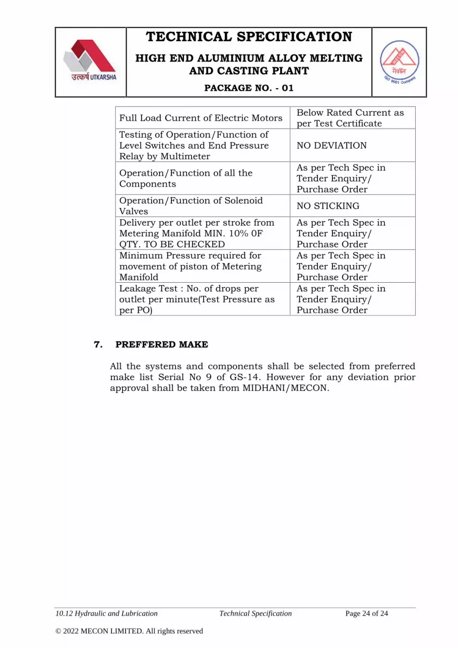
TECHNICAL SPECIFICATIONHIGH END ALUMINIUM ALLOY MELTING
AND CASTING PLANTPACKAGE NO. - 01
10.12 Hydraulic and Lubrication Technical Specification Page 24 of 24
© 2022 MECON LIMITED. All rights reserved
Full Load Current of Electric Motors Below Rated Current asper Test Certificate
Testing of Operation/Function ofLevel Switches and End PressureRelay by Multimeter
NO DEVIATION
Operation/Function of all theComponents
As per Tech Spec inTender Enquiry/Purchase Order
Operation/Function of SolenoidValves NO STICKING
Delivery per outlet per stroke fromMetering Manifold MIN. 10% 0FQTY. TO BE CHECKED
As per Tech Spec inTender Enquiry/Purchase Order
Minimum Pressure required formovement of piston of MeteringManifold
As per Tech Spec inTender Enquiry/Purchase Order
Leakage Test : No. of drops peroutlet per minute(Test Pressure asper PO)
As per Tech Spec inTender Enquiry/Purchase Order
7. PREFFERED MAKE
All the systems and components shall be selected from preferredmake list Serial No 9 of GS-14. However for any deviation priorapproval shall be taken from MIDHANI/MECON.

TECHNICAL SPECIFICATIONHIGH END ALUMINIUM ALLOY MELTING
AND CASTING PLANTPACKAGE NO. - 01
10.13 Civil Engineering Works Technical Specification Page 1 of 3
© 2022 MECON LIMITED. All rights reserved
10.13 Civil Engineering Works:-
10.13.01 The Bidder shall submit all the information required in the form ofdata/drawings based on which the civil detailed engineeringdrawings shall be prepared by the Purchaser’s consultant. TheBidder shall submit the integrated general layout with sectionalviews, blow up views, foundation bolt details, etc. The layout andsectional drawings shall show all necessary dimensions forpreparation of civil working drawings.
10.13.02 The civil engineering assignment drawings to be prepared by Biddershall include the following :
1. Buildings, basements, trenches under the scope of Purchaser.
i. Details of underground facilities like trenches, tunnels, tanks,cellars, premises, etc.
ii. Details of inserts, anchor bolts showing location of bolts,projection above concrete, threaded length, diameter, etc.
iii. Grouting details with grade, type of grout recommended, if any.
iv. Details of control rooms, electrical and hydraulics rooms, restroom, shift office rooms, store rooms, etc. showing the detail offloor loads, doors, windows & types of flooring.
v. False ceiling, False flooring requirements for various buildings.
vi. Process drainage/waste disposal requirements, if any.
2. Foundation for technological structures under the scope ofContractor.
i. Load data for all technological structures including erectionloads.
ii. Details of inserts, anchor bolts showing location of bolts,projection above concrete, threaded length, diameter, etc.
iii. Grouting details with grade, type of grout recommended.

TECHNICAL SPECIFICATIONHIGH END ALUMINIUM ALLOY MELTING
AND CASTING PLANTPACKAGE NO. - 01
10.13 Civil Engineering Works Technical Specification Page 2 of 3
© 2022 MECON LIMITED. All rights reserved
iv. Environmental details like temperature, pressure, corrosionprevailing over or around the structures.
v. Process drainage/waste disposal requirements, if any.
vi. Sequence of erection of structures / equipment and thesequence of civil structures required.
3. Machine and equipment foundations
i. Foundation plan and sections/elevations.
ii. Details of anchor bolts showing location, projection aboveconcrete, threaded length, diameter, etc.
iii. Details of anchor box/sleeve.
iv. Details of all inserts, conduits to be embedded inconcrete/brick work.
v. Complete load data and their point of application includingdynamic loads wherever applicable. Operating speed,permissible amplitude, if different from standard values.
vi. Grouting details with grade, type of grout, strength of groutrecommended.
vii. Protection requirements, if any, against heat, temperature,corrosion, pollution, etc.
viii. Process drainage/waste disposal requirements.
ix. Sequence of erection of equipment and details of erectionopenings required, if any.
10.13.03 All relevant data necessary for preparation of Civil working drawingsfor any other units under the Contractor’s scope of work / supply.
10.13.04 Floor loadings to be considered in designing of foundations/structures for the areas under the Contractor’s scope of work /supply.

TECHNICAL SPECIFICATIONHIGH END ALUMINIUM ALLOY MELTING
AND CASTING PLANTPACKAGE NO. - 01
10.13 Civil Engineering Works Technical Specification Page 3 of 3
© 2022 MECON LIMITED. All rights reserved
10.13.05 General
1. The Purchaser will carry out the detailed engineering for entire civilengineering work based on the civil assignment drawings of thepackage. The changes, if any, required to be incorporated in thebasic civil assignment drawing in course of engineering of theproject, shall be done by the package Contractor and shall besubmitted to the Purchaser. Influence of time schedule shall bemutually agreed.
2. Detailed engineering drawings for civil works relating to equipmentfoundations and structures/premises for which basic engineering isdone by package contractor shall be examined and concurred by thepackage contractor before they are released for construction.
3. Detailed engineering drawings relating to underground premises/cellars/service lines and building column foundations for whichbasic engineering is done by the Purchaser shall also be examinedand concurred by package contractor before they are released forconstruction.
4. The permissible tolerances in various levels and dimensions of civilstructures shall be specified by the package Contractor whereverrequired.
5. Concurrence by package contractor wherever applicable shall becompleted within seven days from the date of receipt. Themethodology will be decided by mutual discussions.
6. Supervision of the critical foundations, wherever felt necessary shallbe provided by the package Contractor.

TECHNICAL SPECIFICATIONHIGH END ALUMINIUM ALLOY MELTING
AND CASTING PLANTPACKAGE NO. - 01
10.14Structural Engineering Works Technical Specification Page 1 of 2
© 2022 MECON LIMITED. All rights reserved
10.14 Structural Engineering Works:-
10.14.01 The Bidder shall submit all the information required in the form ofdata/drawings based on which the structural detailed engineeringdrawings shall be prepared by the Purchaser’s consultant. TheBidder shall submit the integrated general layout with sectionalviews, blow up views etc. The layout and sectional drawings shallshow all necessary dimensions for preparation of structural workingdrawings.
10.14.02 The structural engineering assignment drawings to be prepared byBidder shall include the following:
1. Building Plan, cross section , elevations, Levels2. Equipment Loads Vertical/ horizontals/ static and dynamic3. Equipment Dispositions4. Equipment clearance Diagram5. Piping Loads6. Cables Loads7. Ducting loads8. Equipment maintenance Platforms, level and access detail9. Shop entry and Side clearance10. Entry Locations of pipes ducts, galleries with levels and
clearance diagrams11. Staircase location for access to various floor12. Requirement of shop ventilation with fixed monitor/ Turbo
ventilators
10.14.03 All relevant data necessary for preparation of structural workingdrawings for any other units under the Bidders scope.
10.14.04 General
The Purchaser will carry out the detailed engineering for entirestructural engineering work based on the structural assignmentdrawings of the package. The changes, if any, required to beincorporated in the basic structural assignment drawing in course ofengineering of the project, shall be done by the Bidder and shall be

TECHNICAL SPECIFICATIONHIGH END ALUMINIUM ALLOY MELTING
AND CASTING PLANTPACKAGE NO. - 01
10.14Structural Engineering Works Technical Specification Page 2 of 2
© 2022 MECON LIMITED. All rights reserved
submitted to the Purchaser. However, there should not be anyinfluence on time schedule.
1. General arrangement drawings for structural works relating tostructures/premises for which basic engineering is done by Biddershall be examined and concurred by them.
2. The permissible tolerances in various levels and dimensions of steelstructures shall be specified by the Bidderwherever required.
3. Concurrence by Bidder wherever applicable shall be completedwithin seven days from the date of receipt. The methodology will bedecided by mutual discussions.

TECHNICAL SPECIFICATIONHIGH END ALUMINIUM ALLOY MELTING
AND CASTING PLANTPACKAGE NO. - 01
11 Spares, Consumables and Tools & Tackles Technical Specification Page 1 of 2
© 2022 MECON LIMITED. All rights reserved
11.0 Spares, Consumables and Tool & Tackles
11.01 Commissioning spares
The Tenderer shall include in his scope of supply all spares required forsuccessful commissioning and start-up of the plant and equipmentcovered under this TS and associated facilities. The commissioningspares shall form a part of main offer and shall be supplied along withthe equipment. The list of commissioning spares for the plant andequipment shall be furnished in the tender.
11.02 Operation and maintenance spares
The Tenderer shall include in his scope of supply and submit acomprehensive list of operation and maintenance spares includinginsurance / interchangeable spares of plant and equipment requiredfor two years normal operation and maintenance of plant andequipment, except otherwise mentioned.
11.03 Insurance spares
Tenderer will indicate the list of insurance spares in their offer.
11.04 Consumables
The Tenderer shall furnish in the tender complete information onspecification and consumption norms of all consumable materials suchas refractories, lubricants, greases, hydraulic oils, chemicals, resins,etc. Tenderer shall include in his scope of supply all consumablesrequired upto 100 heats.
11.05 Tools and Tackles
The Tenderer shall include the following tools and tackles in his scopeof supply:

TECHNICAL SPECIFICATIONHIGH END ALUMINIUM ALLOY MELTING
AND CASTING PLANTPACKAGE NO. - 01
11 Spares, Consumables and Tools & Tackles Technical Specification Page 2 of 2
© 2022 MECON LIMITED. All rights reserved
- One set of special tools and tackles for erection, testing andcommissioning of plant and equipment, systems and sub-systemscovered in this TS.
- One set of special tools and tackles for operation / repair /maintenance of plant and equipment.
The list of tools to be furnished by Tenderer in each category shall beindicated along with their itemized weights.
All the tools shall be supplied in separate containers clearly markedwith the name of equipment for which they are intended.

TECHNICAL SPECIFICATIONHIGH END ALUMINIUM ALLOY MELTING
AND CASTING PLANTPACKAGE NO. - 01
12 Completeness Technical Specification Page 1 of 1
© 2022 MECON LIMITED. All rights reserved
12.0 Completeness
The Tenderer’s scope of work shall include supply of processtechnology/know-how and supply, erection, testing and commissioningof all plant and equipment, electrics, instrumentation, technologicalstructures, services, utilities, etc. as mentioned in this TechnicalSpecification within battery limits. However, any equipment, fittings,materials or supplies, not specifically, mentioned in this TechnicalSpecification but essential for their proper design, assembly, safe andsmooth operation and performance shall be deemed to be included inthe Tenderer’s scope. The offered unit along with system must becomplete in all respects and shall be in perfect running condition tocomply with the guaranteed performance.

TECHNICAL SPECIFICATIONHIGH END ALUMINIUM ALLOY MELTING
AND CASTING PLANTPACKAGE NO. – SAAP-01
13 Project Implementation Schedule and Progress Monitoring Technical Specification Page 1 of 4
© 2022 MECON LIMITED. All rights reserved
13. Project Implementation Schedule & Progress Monitoring
13.01 The project envisages installation of high end aluminium alloymelting and casting plant at Nellore, Andhra Pradesh for M/sUtkarsh Aluminium Dhatu Nigam Limited (UADNL). The proposedplant shall be commissioned within 24 months (including PAC) fromthe Zero Date which will be reckoned as effective date of contract.Zero Date and Commissioning as mentioned above and shown inschedule shall be same as defined in the technical and commercialpart of the specification.
An indicative Implementation schedule, in line with the total timeperiod and indicating the major activities, is shown in drg. no.MEC/UADNL/11/PY/Q7R6/TS/SAAP-01/01/R0 for reference.
13.02 Project Schedule
The Tenderer shall submit the following along with the tender.
i) Overall bar-chart scheduleThe overall bar-chart schedule should be planned in weeks and
shall show the major activities of the project. The major milestones
for the project are also to be highlighted in the schedule.
ii) Off-site / On-site organization charts for execution of the project.
13.03 The Tenderer shall note the following:
i) Construction Water: Construction Water shall be provided as peractual requirement within reasonable limit.
ii) Construction Power: Construction Power shall be provided as peractual requirement within reasonable limit.
iii) Construction & Storage Area: Battery limit area shall be utilized
for construction and storage. However, if any area outside the

ID Task Name Dur(w)
1 UADNL - High end aluminium alloy melting and casting plant (Pkg No.-SAAP-01)
104 w
2 Effective date of Contract (Zero-date) 0 w
3 Basic Engg. submission & Approval 8 w
4 Submission of Load Data & Feedback Data for Civil/ Structures etc. 4 w
5 Tendering & Ordering on Sub-vendors 17 w
6 Detailed Design & Engineering & Approval 30 w
7 Civil & Structural Works (by the Purchaser) 65 w
8 Manufacturing, inspection & supply of Equipment 69 w
9 Erection of Equipment 35 w
10 Testing, Trial Run, PAC & Commissioning 13 w
-1 1 2 3 4 5 6 7 8 9 10 11 12 13 14 15 16 17 18 19 20 21 22 23 24 25Year 1 Year 2
Task Milestone Summary
UTKARSHA ALUMINIUM DHATU NIGAM LIMITED (UADNL)
HIGH END ALUMINIUM ALLOY MELTING AND CASTING PLANT (PACKAGE NO. - SAAP-01)INDICATIVE IMPLEMENTATION SCHEDULE
© 2022 - MECON limited. All rights reserved Page 1 of 1 DRG. No : MEC/UADNL/11/PY/Q7R6/TS/SAAP-01/01/R0
UADNL - Melting and casting plant (Pkg-SAAP-01) TS Schedule_24Months

TECHNICAL SPECIFICATIONHIGH END ALUMINIUM ALLOY MELTING
AND CASTING PLANTPACKAGE NO. – SAAP-01
13 Project Implementation Schedule and Progress Monitoring Technical Specification Page 2 of 4
© 2022 MECON LIMITED. All rights reserved
battery limit is available, Contractor may utilize it with the
permission of the client.
13.04 The tenderer shall submit the following documents beforefinalization of contract:
i) Deployment of construction man power.ii) Details of deployment of equipment and machinery, tools &
tackles, etc.
13.05 The Successful Tenderer shall have to submit the following aftersigning of contract:
i) Load Data & feedback Data for Civil/ Structures etc. within 2months from effective date of contract.
ii) The detailed project network (Level-II network) schedule, both inhard and editable soft copy (in MS Project / Primavera) coveringfurther details of project activities, area-wise, for the total scopeof the package, within 2 months of effective date of contract forapproval and finalization by the Purchaser / Consultant.
iii) The format of progress report shall be discussed and agreed uponwithin 1 month from effective date of contract.
iv) Updated detailed project network (Level-II network) schedule (inhard and soft copies) shall be submitted along with monthlyprogress reports (in approved format) every month.
13.06 Progress Monitoring
An effective system of progress monitoring is to be evolved to ensuretimely completion of all project activities. A monthly progress reportshowing current status of various activities shall be submitted by the

TECHNICAL SPECIFICATIONHIGH END ALUMINIUM ALLOY MELTING
AND CASTING PLANTPACKAGE NO. – SAAP-01
13 Project Implementation Schedule and Progress Monitoring Technical Specification Page 3 of 4
© 2022 MECON LIMITED. All rights reserved
Contractor to the Purchaser and his Consultants. The monthlyprogress report shall indicate progress of activities against targetedquantities. Reasons for shortfalls, if any, shall be clearly brought outand proposed remedial measures to arrest the delays shall beindicated by the Contractor in the progress report, whereverapplicable.
In general, progress of the following major activities is to be reported.
Issue of ordering / technical specifications and placement oforders on sub-vendors for bought out items / components
Detailed design and engineering including submission ofdrawings and their approval, subsequent revisions andresubmissions.
Manufacturing activities at the works of the Contractors /associates / sub-vendors.
The progress report on inspection status.
Dispatch of equipment to site.
Site activities including receipt of material / equipment at site,erection, testing and commissioning.
Two months prior to start of site activities, the Contractor shallsubmit a schedule for site-execution, along with quantitativeprogramme in terms of month-wise physical targets for variousdisciplines of work. After the site activities are started, the Contractorshall furnish information on site activities viz. daily, weekly andmonthly progress reports on construction / erection, receipt ofequipment against monthly construction / erection plan, etc. The

TECHNICAL SPECIFICATIONHIGH END ALUMINIUM ALLOY MELTING
AND CASTING PLANTPACKAGE NO. – SAAP-01
13 Project Implementation Schedule and Progress Monitoring Technical Specification Page 4 of 4
© 2022 MECON LIMITED. All rights reserved
Contractor shall also indicate resource deployment at site, highlightsof critical areas and constraints faced in the site progress reports.
Other information related to site activities as may be required by thePurchaser and consultant, shall also be submitted by the contractor.
In the interest of timely completion of the project, if requires, thepriority of construction / erection may be altered by the Purchaserand consultant, in consultation with the contractor.
13.07 The Purchaser /Consultant shall also have the right to:
Invite the successful Tenderer for monthly / fortnightly meetingsto review the progress of each activity.
Depute Purchaser’s authorized representatives for ascertaining /expediting progress at contractor’s works.
Suggest remedial actions to bridge-up time gap between plannedprogress & observed progress.
Following IS codes may also be referred by the Contactor as guidelinefor preparation of project network schedule, organization chart,progress reports, etc.
I. IS 14580 (Part 1): 1998 & IS 14580 (Part 2): 2006
II. IS 15883 (Part 1): 2009 & IS 15883 (Part 2): 2013

TECHNICAL SPECIFICATIONHIGH END ALUMINIUM ALLOY MELTING
AND CASTING PLANTPACKAGE NO. - 01
14 Inspection, Erection, Testing & Commissioning Technical Specification Page 1 of 6
© 2022 MECON LIMITED. All rights reserved
14.0 Inspection, Erection, Testing and Commissioning
The contractor shall carry out the complete inspection, erection, testingand commissioning of the offered equipment/system including allaccessories. Testing shall involve trial test run, cold test, Hot test andperformance guarantee test.
The successful tenderer shall submit an erection plan for theequipment.
14.01 Inspection
1. Inspection and testing shall be carried-out by the purchaser/purchaser’s representative. The purchaser shall have under agreementwith the tenderer a general right at all reasonable time to enter anyworks, where the supplies pertaining to this contract are in the processof manufacturing or testing for the purpose of checking the progressand inspecting the items. The purchaser shall be allowed to use all thetesting facilities available with the manufacturer for the purpose oftesting. Such tests for which there are no adequate facilities with thesupplier/sub-supplier will be carried out at the mutually agreed testinglaboratories at the cost of tenderer.
2. The inspection will be carried out as per the mutually agreed procedure.Inspection shall be regarded as a checking and in no way binding onthe purchaser.
3. The purchaser shall have full right to accept or reject the materials/items, if during inspection and testing, the same are found notconforming to the specifications.
4. The inspection will be carried out based on approveddrawings/materials.
5. A copy of the orders on the sub-suppliers comprising detailedspecification, the qualities of the materials, bill of materials, relevantdrawings/ documents etc. shall be sent to the purchaser at least onemonth before the start of inspection.

TECHNICAL SPECIFICATIONHIGH END ALUMINIUM ALLOY MELTING
AND CASTING PLANTPACKAGE NO. - 01
14 Inspection, Erection, Testing & Commissioning Technical Specification Page 2 of 6
© 2022 MECON LIMITED. All rights reserved
6. The tenderer shall inspect the material/equipment before offering to thepurchaser for inspection and satisfy and issue an internal inspectioncertificate along with manufactures test certificate singed by competentauthority.
7. The tenderer shall send the intimation for inspection along with hisinternal inspection certificate at least two weeks prior of clear margin tothe start of inspection, while sending the information, the tenderer shallensure that a reasonable quality is offered for inspection.
8. For refractory/insulating materials the manufacture shall control theproduction by samples tested in his laboratory to make sure that thematerials are in accordance with the agreed data. The results of suchtests done at the place of manufacturer shall be made available to thepurchaser.
9. During the inspection of refractory/insulating materials, the purchaser,in the presence of manufacture, shall draw samples for testing ofvarious properties. The supplier will render all assistance duringdrawing samples, checking for physical appearance, size & toleranceand testing at their laboratory. The testing shall be conducted as perthe standards mentioned in technical specification or their equivalent.IS and/ or mutually agreeable standards shall be followed. All thetesting shall be carried out at the manufacture’s laboratory in thepresence of his representative and test results shall be signed by bothmanufacture and purchaser.
10. The inspection certificate will be issued by the purchaser/ MECONwithin a week after successful completion of the inspection.
11. The tenderer, on receipt of the certificate shall ensure that onlyaccepted materials are dispatched.
12. Incase of any dispute, the samples for refractory/ insulating materialsshall be sent to national laboratory for necessary testing at the fullexpense of the tenderer.
13. The tenderer on being requested shall present sufficient documentaryevidence that the materials used for the manufacture of the plant and

TECHNICAL SPECIFICATIONHIGH END ALUMINIUM ALLOY MELTING
AND CASTING PLANTPACKAGE NO. - 01
14 Inspection, Erection, Testing & Commissioning Technical Specification Page 3 of 6
© 2022 MECON LIMITED. All rights reserved
equipment will meet the specification requirements with respect tomaterials used by tenderer for the plant and equipment such asstructural steel, mild steel, cast iron, cast steel etc, the tenderer shallproduce requisite test certificates along with specification, and testpieces on which test were carried out by the manufacture, at the timeof examination. With respect to few castings or forgings the tenderershall arrange for necessary x-ray and ultrasonic test to be carried out athis own cost; however these have to be indicated in QAP/specification.
14. The purchaser or his duly authorized representative shall have the rightto be present at all the tests carried out and arrange by the tenderer. Ifcalled for, samples and specimens shall become the purchaser’sproperty. The tenderer shall notify the purchaser in an appropriatemanner as to the progress of the contract work particularly before anyassembly in order that the inspection on test can be carried out as maybe required to ascertain without prejudice to the tenderer liabilitywhether the materials and/or service are in conformity with therequirements of the contract.
14.02 Erection
The erection plan shall outline
The erection techniques to be employed Deployment of erection machinery Erection material planning Sequence of erection Safety Assurance Plan
(i) The erection contractor shall make arrangement for allconstruction equipment, tools & tackles, erection consumables,testing instrument etc.
(ii) All necessary temporary ladders, scaffolding materials, platformsand other necessary facilities required for handling and erectionof equipment shall be provided by the contractor.
TECHNICAL SPECIFICATIONHIGH END ALUMINIUM ALLOY MELTING
AND CASTING PLANTPACKAGE NO. - 01
14 Inspection, Erection, Testing & Commissioning Technical Specification Page 4 of 6
© 2022 MECON LIMITED. All rights reserved
(iii) The contractor shall deploy required number of supervisory,skilled, unskilled and auxiliary labour as required for the erectionwork.
(iv) There may be more than one contractor working in the vicinityarea at the same time and work has to be carried out in properco-ordination and in consultation with the purchaser and allother parties concerned with the work.
(v) The contractor shall maintain their own stores for the storage ofequipment. All security arrangement shall also be made by thecontractor.
(vi) Any damage during transport / storage shall be made good by thecontractor.
(vii) The contractor will align, level, couple and securely fix allequipment, steel structure and appurtenances accessories inaccordance with drawings and/or instructions.
(viii) All equipment shall be checked for free movement by hand rotationand correctly aligned and installed. After the equipment has beeninstalled, levelled and aligned, the foundation bolts shall betightened and bolts/base plates will be grouted. When the grouthas thoroughly cured, the alignment will be rechecked andrectified, if required.
(ix) Touch-up painting of damaged portion of the erectedequipment/structures shall be done by the contractor.
(x) The Tenderer shall submit with his offer, for equipment erection,necessary details such as schedule of erection, category wisedeployment of erection personnel, etc as called for in the invitation

TECHNICAL SPECIFICATIONHIGH END ALUMINIUM ALLOY MELTING
AND CASTING PLANTPACKAGE NO. - 01
14 Inspection, Erection, Testing & Commissioning Technical Specification Page 5 of 6
© 2022 MECON LIMITED. All rights reserved
to Tender and General conditions of Contract for supply anderection of plant and equipment.
14.03 Performance Guarantee Test and issue of PAC (ProvisionalAcceptance Certificate)
On completion of erection, The following general checks shall be madefor all equipment.
- Smooth running of all technological and auxiliary equipment /
drives and non-occurrence of any abnormal sound from any
equipment.
- Welding check for all structures
- Erection of all equipment, alignment as per approved drawings.
- Check on safety aspects, process interlocks etc.
- Alignment of rotating equipment
- First filling of lubricant for all system till commissioning
- Check the direction of rotation of electrical motor before fixing of the
coupling.
- No load run / movement test for all the moving devices.
- Vibration on equipment / supporting structures.
- Temperature rise in motors, gear boxes
- Working of all safety switches and zero speed switches, etc.
A defect list/observations shall be jointly prepared and duly signed byall concerned, detailing the required rectification. All the points in thedefect list will be attended and rectified by the contractor and theequipment shall be offered for re-inspection to Purchaser / Purchaser’srepresentatives.

TECHNICAL SPECIFICATIONHIGH END ALUMINIUM ALLOY MELTING
AND CASTING PLANTPACKAGE NO. - 01
14 Inspection, Erection, Testing & Commissioning Technical Specification Page 6 of 6
© 2022 MECON LIMITED. All rights reserved
When Purchaser / Purchaser’s representatives have been fully satisfiedthat all the defects have been rectified and that the equipment / systemis fit to be operated, purchaser shall allow the successful tender toproceed for Performance Guarantee Test demonstration.
Provisional acceptance certificate will be issued to the contractor by thePurchaser after the guaranteed test and values given in PerformanceGuarantee clauses are established to the satisfaction of the Purchaser,but subject to the fulfillment of the provisions and other conditions forissue of provisional acceptance certificate.
14.04 Final Acceptance Certificate (FAC)
Final acceptance certificate will be issued after continuous satisfactoryoperation of the equipment for a period of twelve (12) months afterissuance of Provisional Acceptance Certificate, but subject to thefulfillment of the provisions and other conditions for issuance of finalacceptance certificate.
14.05 Commissioning
Contractor shall commission all the equipment/system supplied by himunder full load condition.
i) The contractor shall carry out the complete erection, testing andcommissioning of the offered equipment/system including allaccessories. Testing shall involve trial test run, cold test, hot testand performance guarantee test.
ii) The successful tenderer shall submit an erection plan for theequipment.

TECHNICAL SPECIFICATIONHIGH END ALUMINIUM ALLOYMELTING
AND CASTING PLANTPACKAGE NO. - 01
Performance Guarantee Technical Specification Page 1 of 9
© 2022 MECON LIMITED. All rights reserved
15.0 Performance Guarantee
General
All equipment shall be guaranteed against poor quality of material, badworkmanship. etc. for a period of one year from the date ofcommissioning. Any such equipment/part found defective duringnormal operation and maintenance of the line (other than by way ofequipment abuse) the Tenderer shall replace/rectify such defectsimmediately without affecting the production of line.
The Tenderer shall provide a performance guarantee for the line fordelivering the rated output based on the reference sizes of materials.The detailed procedure for conducting the tests shall be indicated in thebid which shall be mutually agreed upon before placement of order.
The auxiliary systems such as hydraulic, pneumatic systems, etc. shallalso be guaranteed for delivering the rated output.
The Purchaser shall provide all necessary consumables and materialsrequired for conducting the guarantee tests except first fill for auxiliarysystems.
All necessary measuring and testing instruments required for the testsshall be provided by the tenderer.
The tenderer shall guarantee the production capacity and quality of thecast slabs & billets for package 01 output with respect to physical andmetallurgical properties.
15.01 Melting Furnaces
1. CapacityTo hold at 750 ± 50C (on the instruments) not less than 55t ofmolten aluminum when bath level i.e., molten metal level is150mm below the pouring spout level.
2. Melting Rate6.5 t/h with no heel. The melting rate will be checked for charge of39.0t charge comprising of solid pieces each weighting not morethan 20 kgs. The furnace will be heated to the operating

TECHNICAL SPECIFICATIONHIGH END ALUMINIUM ALLOYMELTING
AND CASTING PLANTPACKAGE NO. - 01
Performance Guarantee Technical Specification Page 2 of 9
© 2022 MECON LIMITED. All rights reserved
temperature of approx. 1000/ 10500C before charging. Thecharging will be in steps and the total charge weight of 39.0 t willbe introduced during the first 3 hours. It is assumed that duringthe total charging period, the door shall remain open for not morethan 50 minutes. During the next 3 hours all doors shall remainclosed. At the end of 6 hours (counted from the time when thecharge is first introduced) 39t of molten aluminium will beavailable at 750 ± 50C (on the instruments).
Average of 4 separate tests will be accepted.
3. Skin Temperature850C maximum temperature on the side walls above sill level,1100C maximum temperature on side walls below sill level, hearth& ramp/bottom and 1000C maximum temperature on the roof asmeasured at mutually agreed points except on doors, roof anchors,500mm away from any opening, hole etc.
Tests will be conducted during normal operation i.e. holding withmolten aluminium at 750 + 50C on instruments measured at 100mm below metal level with all doors closed. Ambient temperaturewill be measured at 5m distance around the furnaces. Reading willbe taken at mutually agreed time intervals for 24 hours and theaverage of three values will be considered.
4. Fuel consumption
a) Tenderer shall indicate the specific heat parameters (i.e.,GCal/ton) in sealed envelope separately for melting operationand holding operation.
b) Tenderer shall demonstrate their guaranteed specific heat formelting rate of 6.5t/h under condition / procedures outline in(2) above for achieving the temperature at the end of 6 hoursas 750+50 C on the instrument measured at 100mm belowmetal level.
c) Tenderer shall demonstrate their guaranteed fuel consumptionfor holding 55t of hot metal at 750+50C. The test duration shallstart after the bath has stabilized at 750+50C. Threeconsecutive reading shall be taken at an interval of one hour toestablish guaranteed fuel consumption to maintain 750+ 50C.

TECHNICAL SPECIFICATIONHIGH END ALUMINIUM ALLOYMELTING
AND CASTING PLANTPACKAGE NO. - 01
Performance Guarantee Technical Specification Page 3 of 9
© 2022 MECON LIMITED. All rights reserved
d) The fuel consumption shall be considered as loading parameterwhile evaluating the bid. The loading formula shall be asfollows:-
L= (PG-PL) X C X DF X 5500Where:L = Loading on Tenderer’s price.PG = Guaranteed utility consumption by the Tenderer.PL = Lowest guaranteed consumption amongst the Tenderers.C = Unit cost of utilityDF= Discount Factor calculated as follow:
DF= ∑ [1 ÷ {1 + } ]WhereK= 20 years (from 2nd to 21st year as 1st year is considered asstartup of operation), the life of the equipment.X= Interest rate = 10%5500 = Operating hours for one furnace to achieve theconsidered production, which may change to annualProduction rate and the likes as required.
e) It has been proposed that if the lowest Tenderer statuschanges due to the above loading, the new lowest Tendereremerged based on the evaluated price has to submit a BGequivalent to the loading amount on the pre-evaluated lowestTenderer in addition to CPBG.
f) Total Fuel consumption (in Gcal) for four (4) days continuousoperation of both the furnaces for production of 800t of moltenmetal (100% solid) shall be furnished by the Tenderer.
5. Noise levelNoise level shall be 85 db at a distance of 1m around the furnaceat working level.

TECHNICAL SPECIFICATIONHIGH END ALUMINIUM ALLOYMELTING
AND CASTING PLANTPACKAGE NO. - 01
Performance Guarantee Technical Specification Page 4 of 9
© 2022 MECON LIMITED. All rights reserved
15.02 Holding Furnaces
1. CapacityTo hold at 740 ± 50C (on the instruments) not less than 50t ofmolten aluminum when bath level i.e., molten metal level is150mm below the pouring spout level.
2. Skin Temperature850C maximum temperature on the side walls above sill level,1100C maximum temperature on side walls below sill level, hearth& ramp/bottom and 1000C maximum temperature on the roof asmeasured at mutually agreed points except on doors, roof anchors,500mm away from any opening, hole etc..
Tests will be conducted during normal operation i.e. holding withmolten aluminium at 740 + 50C on instruments measured at 100mm below metal level with all doors closed. Ambient temperaturewill be measured at 5m distance around the furnaces. Reading willbe taken at mutually agreed time intervals for 24 hours and theaverage of three values will be considered.
3. Fuel consumption
a) Tenderers shall indicate the specific fuel heat parameters (i.e.,Gcal/ton) in sealed envelope separately for holding operation.
b) Tenderer shall demonstrate their guaranteed fuel consumptionfor holding 50t of hot metal at 740 ± 50C. The test durationshall start after the bath has stabilized at 740 ± 50C. Threeconsecutive reading shall be taken at an interval of one hour toestablish guaranteed fuel consumption to maintain 740 ± 50C.
c) The fuel consumption shall be considered as loading parameterwhile evaluating the bid. The loading formula shall be asfollows:-
L= (PG-PL) X C X DF X 5500Where:L = Loading on Tenderer’s price.PG = Guaranteed utility consumption by the Tenderer.PL = Lowest guaranteed consumption amongst the Tenderers.C = Unit cost of utility

TECHNICAL SPECIFICATIONHIGH END ALUMINIUM ALLOYMELTING
AND CASTING PLANTPACKAGE NO. - 01
Performance Guarantee Technical Specification Page 5 of 9
© 2022 MECON LIMITED. All rights reserved
DF= Discount Factor calculated as follow:DF= ∑ [1 ÷ {1 + } ]
WhereK= 20 years (from 2nd to 21st year as 1st year is considered asstartup of operation), the life of the equipment.X= Interest rate = 10%5500 = Operating hours for one furnace to achieve theconsidered production, which may change to annualProduction rate and the likes as required.
4. Noise level
Noise level shall be 85 dB at a distance of 1m around the furnaceat working level.
15.03 Vertical DC Caster
1. Capacity:
There shall be two Vertical DC Caster. Each Vertical DC Castershould have the production rate sufficient to cast alloy of 50,000tonnes/year. The Performance guarantee parameters for any of the6 alloys from the following list of Aluminium Alloy slabs & billetswith atleast one from each alloy series (2XXX,5XXX,6XXX,7XXX)are to be demonstrated:
2014, 2124, 2219, 5052, 5083, 6061, 6082, 7010, 7050 and 7075
2. Chemical Quality Indicators
The following Chemical composition parameters of the cast slabs &billets are to be demonstrated.
Grade Copper(Cu)
Magnesium(Mg)
Silicon(Si)
Iron(Fe)
Manganese(Mn)
Zinc(Zn)
Titanium(Ti)
Chromium(Cr) Others
2014 4.2-4.7 0.3-0.7 0.7-1 0.4* 0.6-1 0.15* 0.1* 0.06* 0-0.05
2124 4.1-4.6 1.35-1.65 0.1* 0.3* 0.45-0.75 0.15* 0.1* 0.1* -
2219 6-6.6 0.02* 0.1* 0.18* 0.25-0.35 0.06* 0.04-0.08 - 0-0.05

TECHNICAL SPECIFICATIONHIGH END ALUMINIUM ALLOYMELTING
AND CASTING PLANTPACKAGE NO. - 01
Performance Guarantee Technical Specification Page 6 of 9
© 2022 MECON LIMITED. All rights reserved
Grade Copper(Cu)
Magnesium(Mg)
Silicon(Si)
Iron(Fe)
Manganese(Mn)
Zinc(Zn)
Titanium(Ti)
Chromium(Cr) Others
5052 0.06* 1.9-2.4 0.3* 0.4* 0.3* 0.1* 0.1* 0.15*Cr+Mn=
0.3*
5083 0.06* 4.2-4.7 0.2* 0.2* 0.5-0.9 0.15* 0.1* 0.1-0.2 0-0.05
6061 0.2-0.35 0.8-1.1 0.5-0.7 0.4* 0.1* 0.1* 0.1* 0.2-0.3 0-0.05
6082 0.06* 0.7-1.1 0.8-1.2 0.3* 0.6-0.8 0.1* 0.06* 0.15* 0-0.05
7010 1.6-1.9 2.2-2.5 0.08* 0.1* 0.06* 5.9-6.5 0.06* 0.04* 0.12-0.14 Zr
7050 2.1-2.5 2.1-2.4 0.1* 0.15* 0.1* 5.9-6.5 0.06* 0.04* 0.10-0.13 Zr
7075 1.4-1.8 2.3-2.7 0.2* 0.3* 0.15* 5.3-5.8 0.1* 0.20-0.26 0-0.05
Note- * denotes limits are in weight percent maximum unless shown as a rangeor stated otherwise.
3. Physical Quality Indicators
The following physical quality parameters of the cast slabs & billetsare to be demonstrated.
a) Inclusions – Should be free from inclusions of size more than10 micron. There should not be more than 2 nos. of inclusionsof maximum size of 10 micron over a sample area of 1 squareinch of the cast slab & billet.
b) The Hydrogen content should be maximum of 0.11 cc/100gmof molten metal before casting.
c) All the metals should conform ultrasonic Class-AA as perAMS2154/AMS 2630.
d) The porosity should not be more than 10 micron in size. Thereshould not be porosity more than 2 nos. of maximum size 5micron over a sample area of 1 square inch of the cast slab &billet.
e) Maximum segregation of 4% shall be allowed.f) Pit recovery should be a minimum of 98%.g) The grain size: 250 microns max.

TECHNICAL SPECIFICATIONHIGH END ALUMINIUM ALLOYMELTING
AND CASTING PLANTPACKAGE NO. - 01
Performance Guarantee Technical Specification Page 7 of 9
© 2022 MECON LIMITED. All rights reserved
h) Dimensional Tolerance: For slabs- ±2 mm for width, ±2 mm for thickness For Billet: 8” / 9”size: (+) 0 & (-) 1.0 mm
18” size: (+) 0 & (-) 1.5 mm26” size: (+) 0 & (-) 2.0 mm
i) Straightness / Billet bow: 1 mm per meter length of billet andmax 3 mm in total length.
j)Surface Defects---- lightly liquated lapped surface, no tears, no bleed outs,
no oxide patches, no dents, no scratches, longitudnaltears/drag marks acceptable upto 1 mm in depth.
--- Mechanical damage from homogenizing spacer bars,crane handling etc., not to exceed 1 mm in depth.
--- Not more than 5% surface area may have foreignmaterial, paint or rust.
15.04 Homogenizing Unit
SL.No
Parameters Target Value
1. Guaranteed Specific EnergyConsumption for production of50T cast products of aluminiumhard alloys of grade 5XXX/ 6XXXcharge + Wt. Of charge support
1) Electrical Energy (excludingfan motor power) (kWh/t)
2) Gas Consumption (kg/t)
As specified in thebid
2. Heating Rate of charge (°C/hr) As specified in thebid
3. Furnace temperature uniformity + 50C4. Noise Level Maximum
permissible noiselevel shall be 85 dBaat 1 m distance.
5. Cooling rate of charge (°C/hr) As specified in thebid
6. Shell Skin Temp As specified in thebid

TECHNICAL SPECIFICATIONHIGH END ALUMINIUM ALLOYMELTING
AND CASTING PLANTPACKAGE NO. - 01
Performance Guarantee Technical Specification Page 8 of 9
© 2022 MECON LIMITED. All rights reserved
15.05 Ultrasonic Inspection Equipment
The Performance Guarantee of Ultrasonic Inspection Equipmentshould be done for both on-line as well as off-line equipment. Theon-line Ultrasonic Inspection equipment should be able to detectflaws during casting and provide input for corrective actions inorder to avoid production of defective slabs & billets. The off-lineUltrasonic Inspection equipment should be able to detect defectsafter casting of the slabsare completed. Both type of UltrasonicInspection equipment should be equipped well to measure thedimension of slabs & billets.
1. Test Sensitivity
a) For internal defects: FBH 0.8 mm;
b) For top surface defects: longitudinal notch 0.2(D)x0.1(W)x25 (L)mm made along the slab main axis
c) For lower surfaces defects: longitudinal notches acc.
Thickness of Aluminiumslab
Detection sensitivity of longitudinalnotch (along the main axis)
(DxWxL)401mm - 500mm 0.50 x0.1 x 25 mm501mm - 600mm 0.60 x0.1 x 25 mm
d)Subsurface defects: Drilling (cylindrical) 0.6 mm in diameter,25mm long, made along the main axis,located 0 -10 mm below the each surface.
Note: For billets of different sizes (8”-9”, 18” & 26”) test sensitivityparameters to be indicated by Tenderer.
15.06 Scalper Unit
The tenderer should guarantee the production rate for producing90,000 TPA of Cast Products with two shift working for 330 days.However, the tenderer should provide the following data:
a) Feeding rate: _______ mm/minb)Parallelism after scalping: _______ mm

TECHNICAL SPECIFICATIONHIGH END ALUMINIUM ALLOYMELTING
AND CASTING PLANTPACKAGE NO. - 01
Performance Guarantee Technical Specification Page 9 of 9
© 2022 MECON LIMITED. All rights reserved
d) Roughness after scalping: _______ µm
15.07 Sawing Unit
The tenderer should guarantee the production rate for producing90,000 TPA of Cast Products with two shift working for 330 days.However, the tenderer should provide the following data:
a) Feeding rate: _______ mm/minb) Maximum cutting range: _______ mmc) Roughness after sawing: _______ µm

TECHNICAL SPECIFICATIONHIGH END ALUMINIUM ALLOY MELTING
AND CASTING PLANTPACKAGE NO. - 01
16 Certification Technical Specification Page 1 of 1
© 2022 MECON LIMITED. All rights reserved
16.0 Certification
The Tenderer shall assist UADNL to obtain the certification requiredfor the supply of cast billets & slabs to the aerospace, defense andaviation sector. Certification required will be as per latest standardslike AS 9100:2016, AS 9110, AS 9115 and AS 9120 or equivalentstandards established by the Aviation, Space and Defense industry.

TECHNICAL SPECIFICATIONHIGH END ALUMINIUM ALLOY MELTING
AND CASTING PLANTPACKAGE NO. - 01
17 Data/Drawings to be furnished by the Tenderer Technical Specification Page 1 of 4
© 2022 MECON LIMITED. All rights reserved
17.0 Data / Drawings to be furnished by the Tenderer
17.01 Shop layout and cross-sectional drawings
Overall layout drawing indicating location of different units and itsauxiliary units as described in the TS shall be furnished alongwith thebid by the tenderer.
17.02 Technical Details and Operational Data
Description of operational and technical details of each unit shall befurnished by the tenderer indicating technical parameters for each sub-unit of the equipment. The weight of major mechanical and electricalequipment/unit shall also be furnished.
Technical Details:
The tenderer shall furnish the following information and technicaldetails alongwith the bid.
a) Reference dimensional arrangement drawings indicating plan,elevation and sectional view shall be furnished for all the major sub-units for similar equipment supplied elsewhere and analogousfoundation drawings of the main sub-units of such installation.
b) Equipment schedule indicating quantity, estimated weights andsource of supply (indigenous / imported). The Tenderer shall providethe name of all sub-suppliers who are supplying importedequipment.
c) Level I and Level II automation system architecture.
d) Services, utilities and energy consumption, flow rates (average,minimum and peak), quality and pressure requirements, etc. at theconsuming points and at battery limits. Specific consumption of all

TECHNICAL SPECIFICATIONHIGH END ALUMINIUM ALLOY MELTING
AND CASTING PLANTPACKAGE NO. - 01
17 Data/Drawings to be furnished by the Tenderer Technical Specification Page 2 of 4
© 2022 MECON LIMITED. All rights reserved
consumables (operation and maintenance) including powders,refractories, grease and oil alongwith quality, lining details, etc.
e) List of probable suppliers of the main plant and equipment,hydraulic / lubrication / pneumatic equipment etc.
f) The tenderer shall furnish list of recommended spares for two yearsoperation and also furnish list of special consumable items.
g) Single line power supply of power distribution board/MCC indicatingrating and make of switches, fuses, contactors, overload relays, etc.,
h) List of tools and tackles, List of operational spares, commissioningspares and insurance spares.
i) A brief write up on the function, construction, operation and controlaspects of the equipment / system offered.
Operational Data:
The following operational data shall be furnished by the tendereralongwith the bid:
a) Production capacity in terms of hourly rate.
b) Information regarding idle time per cycle, cycle of operations etc.
c) Estimated annual availability of equipment considering mechanicaldelays, Electrical delays and all other delays.
d) Specific consumption of bulk materials, electric power, water,propane gas, inert gas, air, lubricants, hydraulic oils, services andother consumables along with their grades/specifications.
e) Product quality parameters with respect to cast billets & slabdimensions, internal cracks, surface defects, metallurgicalstructure etc.

TECHNICAL SPECIFICATIONHIGH END ALUMINIUM ALLOY MELTING
AND CASTING PLANTPACKAGE NO. - 01
17 Data/Drawings to be furnished by the Tenderer Technical Specification Page 3 of 4
© 2022 MECON LIMITED. All rights reserved
17.03 Utilities and services
The tenderer shall furnish the following information for services andutilities alongwith the bid.
a) Data for industrial quality compressed air such as quantity andpressure requirement.
b) Data for instrument quality compressed air such as quantitypressure, pressure dew point and maximum allowable oil/dustcontent requirement.
c) Data for propane gas such as quantity, quality and pressurerequirement.
d) Data for inert gas such as quantity, quality and pressurerequirement.
e) Quantity of supply water and pressure required for the systemoffered at design limits.
f) Quality of supply water required for the system shall be furnished.
g) Quality, quantity and pressure of return water from the offeredsystem at design limit.
h) Temperature rise of water during the process shall be furnished.
i) Emergency water requirement with quality and pressure withduration shall be indicated.
j) Requirement of hydraulic fluids with specification.
k) Requirement of lubricants with specification.

TECHNICAL SPECIFICATIONHIGH END ALUMINIUM ALLOY MELTING
AND CASTING PLANTPACKAGE NO. - 01
17 Data/Drawings to be furnished by the Tenderer Technical Specification Page 4 of 4
© 2022 MECON LIMITED. All rights reserved
17.04 Schedule in bar chart form
Bar chart schedule and PERT Network indicating various stages(milestones) for completion of the project / units with indication ofmajor resources envisaged in the following heads covering each unit /sub-unit :-
- Submission of input design data / basic data for civil andbuilding structural work, services / utilities required atbattery limits, auxiliary facilities, etc. to enable design andprocurement / execution by Purchaser separately.
- Basic engineering of the entire shop.
- Approval of drawings / documents by Purchaser /
Purchaser's Consultant
- Design and engineering covered under Tenderer's scope
- Placement of orders
- Manufacture and supply of items
- Technological structural supply
- Electrical and process automation equipment erection (to be
done by the Consortium partner)
- Refractory erection of process equipment
- Erection, Testing, trial run and commissioning
- Integrated performance guarantees tests
- List of Consumables
- Manpower Deployment
- Training Schedule
17.05 Fire-fighting Equipment
Requirement of fire-fighting equipment if any.

TECHNICAL SPECIFICATIONHIGH END ALUMINIUM ALLOY MELTING
AND CASTING PLANTPACKAGE NO. - 01
18 Time Schedule for Submission of drawings and documents Technical Specification Page 1 of 14
© 2022 MECON LIMITED. All rights reserved
18.0 Time Schedule for Submission of Drawings & Documents
Time schedule for submission of various drawings and documents forthe package is as indicated below. Time of submission and no. of copiesof drawings/ documents, etc. are tentative and shall be finalised beforesigning the contract with successful Tenderer. All documents /drawings shall be supplied in requisite no. of hard copies as given intable below along with 2 soft copies in CDs / DVDs.
A. Drawings / Documents for Approval
Sl.No. Description No. of
Copies
Time ofSubmission fromeffective date ofContract, weeks
1. List of drawings and documents (forinformation and to be updatedmonthly)
10 02
2. Process Engineering Assumptions andBasic Data
10 04
3. Process Flow Sheets 10 044. Material Balance Sheet 10 045. General arrangement and shop layout
drawings including cross-sections forshops/system/services includingequipment disposition and facilities(Purchaser’s facilities also to beshown)
10 06
6. Layout & cross-section ofunderground facilities such asfoundations, tunnels, trenches,basements, etc.
10 6
7. Civil foundation layout drawings withload data, insert & anchor details forequipment & facilities
10 10 –24
8. Layout drawings for technological steelstructures
10 08
9. Equipment list indicating weights (Tobe updated regularly)
10 06
10. Layout drawings indicating data ofEOT cranes
10 06

TECHNICAL SPECIFICATIONHIGH END ALUMINIUM ALLOY MELTING
AND CASTING PLANTPACKAGE NO. - 01
18 Time Schedule for Submission of drawings and documents Technical Specification Page 2 of 14
© 2022 MECON LIMITED. All rights reserved
Sl.No. Description No. of
Copies
Time ofSubmission fromeffective date ofContract, weeks
11. Equipment GA and major assembly &sub-assembly drawings (includingequipment for various services) andParts list
10 08-26
12. General arrangement & layoutdrawings for pipe work & duct workincluding design calculation
10 08-26
AFTER APPROVALAll approved drawings and documents
10 Within two (2)weeks after
approval
B. Drawings/Documents For Information/Review
Sl.No. Description No. of
Copies
Time ofSubmission fromeffective date ofContract, weeks
1. Detailed drawings for pipe work andductwork including Bill of Materials
10 15-30
2. Tech. structural drawings with Bill ofmaterials
10 12-32
3. Detailed drawings of equipmentsincluding Parts list on separate A4sheets (in bound volumes)
10 16-32
4. Performance data, characteristiccurves including duty points.
10 18-32
5. Test & Inspection Certificates 106. Drawings for approval of statutory
authoritiesAs
requiredAs required
7. List of equipments& suppliers, theirsubassemblies is in which deliveriesare to be made, their weights, drg.nos. special instruction for storage,erection, etc.
10 20
8. Instructions for storage and handling 10 20-409. Erection drawings, erection
specifications and erection10 24-60

TECHNICAL SPECIFICATIONHIGH END ALUMINIUM ALLOY MELTING
AND CASTING PLANTPACKAGE NO. - 01
18 Time Schedule for Submission of drawings and documents Technical Specification Page 3 of 14
© 2022 MECON LIMITED. All rights reserved
Sl.No. Description No. of
Copies
Time ofSubmission fromeffective date ofContract, weeks
instructions10. Refractory lining pattern drawings,
drawings for various sizes and shapesof refractories with materialspecification
10 30-40
11. Operation, maintenance and safetymanuals
10 50-69
12. List of spares (Operating maintenanceand insurance)
10 48
13. Manufacturing drawings and bill ofmaterials for all spares excludingproprietary items
10 60
14. Ordering specifications includingcatalogues and details for all sparesincluding proprietary
10 60
15. Manufacturing drawings/orderingspecifications for operatingconsumables/supplies/tools & tackles
10 60
16. Work / Foreign standards in Englishlanguage
04 Along withrelevantdrawings/documents
C. Drawings / Documents With Delivery Of Equipment
Sl.No. Description No. of
Copies
Time ofSubmission fromeffective date ofContract, weeks
1. Test & Inspection Certificates 052. Assembly & erection drawings and
instructions05

TECHNICAL SPECIFICATIONHIGH END ALUMINIUM ALLOY MELTING
AND CASTING PLANTPACKAGE NO. - 01
18 Time Schedule for Submission of drawings and documents Technical Specification Page 4 of 14
© 2022 MECON LIMITED. All rights reserved
D. As-Built Drawings and Documents
Sl.No. Description No. of Copies
Time ofSubmission fromeffective date ofContract, weeks
1. All drawings, documents,Performance data, designcalculations, Testcertificates, Standards, etc.listed under A & B
10 + 1 set softcopy for allexcept foroperation,Maintenance &Safety Manuals
Will be submittedprogressivelywithin 02 (two)months ofCommissioning
18.01 Contract drawings, documents and manuals
18.01.01 Scope
In as much as the Contractor is required to supply design calculations,drawings, documents, schedules, specifications, schemes, manuals andsoft copies, he shall furnish the same within the Contract Price to thePurchaser as part of the Contract.
i. Contract specifications and drawings shall be co-ordinated by theContractor in such a manner that any work shown on thedrawings, shall be done by the Contractor without any extracharge. Unless such work is specifically exempted, it is to beexecuted in accordance with the Contract and in the samemanner as if fully specified and shown in detail.
ii. The Contractor shall submit the drawings and documents for thePurchaser's / Consultant's approval and information / reviewaccording to the time schedule.
iii. Drawings / documents furnished by the Contractor shall becertified as correct for use and shall bear the signatures ofresponsible persons of the Contractor whose names shallpreviously be notified to the Purchaser by the Contractor inwriting.

TECHNICAL SPECIFICATIONHIGH END ALUMINIUM ALLOY MELTING
AND CASTING PLANTPACKAGE NO. - 01
18 Time Schedule for Submission of drawings and documents Technical Specification Page 5 of 14
© 2022 MECON LIMITED. All rights reserved
iv. The drawings, documents etc. shall be sent to the addresses ofthe Purchaser and / or the Consultant. The Contractor will beinformed of the details in time by the Purchaser.
18.01.02 Name Plate and Drawing Format
i. The name plates of the drawings to be used shall be furnished tothe Successful Tenderer. All drawings shall be dimensioned in themetric system and title and written notations shall be in English.
ii. All drawings submitted by the Contractor shall preferably be841 x 594 mm (size A1 as per Indian Standards; however A0 size(841 x 1189 mm) and small standard sizes A2, A3, A4 arepermitted. The contractor's standard drawings are exempted fromthe above size limitations, unless his standard drawings includedrawings of very large size or length. All design drawings shall beoriented to match the plant arrangement drawings and shall havea key plan identifying the plant area to which they apply. Alldrawings shall be made with the north arrow pointing to the topof the sheet. Drawings and bills of materials shall give quantitiesof all materials required for the work and shall be crossreferenced for easy identification.
iii. The Contractor's standard drawings used for the Contract shallhave information pertaining to the specific item underconsideration properly identified to distinguish it frominformation pertaining to other items which may be contained onthe same drawing.
iv. When a drawing is revised by the Contractor, every change madeshall be identified on the drawing and not in the covering lettersby circling the changes made and placing the revision number ina small triangle so as to be easily recognisable. When asubsequent revision is made, the circles made for the previousrevision shall be erased and the current changes circled.However, all revision numbers in the small triangles shall be

TECHNICAL SPECIFICATIONHIGH END ALUMINIUM ALLOY MELTING
AND CASTING PLANTPACKAGE NO. - 01
18 Time Schedule for Submission of drawings and documents Technical Specification Page 6 of 14
© 2022 MECON LIMITED. All rights reserved
retained. In addition, a record of revisions along with the co-ordinates showing the location of revisions shall be indicated atthe left hand bottom corner of the drawings as per standardpractice.
18.01.03 Numbering System
The Contractor shall use approved numbering system fordrawing/document, which shall be furnished to successful Tenderer.
18.01.04 Working Documents on Scope of Supply and Drawings List withSchedule
The Tenderer shall furnish working drawing along with list.
18.01.05 Specification of Works
The specification of works shall be as per technical specification.
18.01.06 Drawings list and schedule:
The Contractor shall supply to the Purchaser requisite no. of copiesof a preliminary list of all drawings for plant & facilities, which theContractor expects to supply against the Contract together with adetailed schedule for submission of the drawings.
i. Shop layout & cross section drawing shall show all the facilitiesunder the scope of the package. This shall be regularly updatedindicating the latest status.
ii. Layout & cross section drawings of underground facilities shallshow all facilities under this package. This shall be regularlyupdated to show the latest status.
iii. Drawing list to be submitted and updated monthly shall indicateschedule date of submission. This shall also indicate earlierrevisions submitted and their status. It shall indicate total

TECHNICAL SPECIFICATIONHIGH END ALUMINIUM ALLOY MELTING
AND CASTING PLANTPACKAGE NO. - 01
18 Time Schedule for Submission of drawings and documents Technical Specification Page 7 of 14
© 2022 MECON LIMITED. All rights reserved
drawings scheduled to be submitted, actually submitted, totalnos. approved, commented etc.
18.01.07 Detailed Engineering Drawings
The Contractor shall submit requisite no. of copies of the equipmentgeneral arrangement and layout drawings including cross sections.The general arrangement and layout drawings shall include thefollowing in accordance to the time schedule.
i. For equipment, this category shall include equipmentarrangement outlines and overall dimensions, locations ofequipment, centerlines and working point elevations, functionaland clearance requirements and clearance dimensions. Theparticulars of refractory and other lining work if any, and of allauxiliaries shall also be included.
ii. The piping drawings shall include flow diagrams of all utilitiesand process fluids showing flow quantities, temperatures, andpressures, all pumps, valves and instrumentation under scope ofthis package. The general arrangement and layout drawings forpiping and ductwork shall include physical location of equipmentand general pipeline / duct routings to avoid equipment andelectrical interferences and to make units requiring servicing andmaintenance accessible. Both the flow sheets and pipe / ductrouting drawings shall show interconnecting pipelines / ductsand terminal points of the Contractor's piping / ducting. Thecategory shall also include diagrams of hydraulic, pneumatic,lubrication, gas, water and any other utility required as per theprocess technology.
iii. The details furnished shall include necessary design data anddesign calculations (in A4 size sheets) and shall conform to theprovisions of the contract, applicable specifications andacceptable codes of practice.

TECHNICAL SPECIFICATIONHIGH END ALUMINIUM ALLOY MELTING
AND CASTING PLANTPACKAGE NO. - 01
18 Time Schedule for Submission of drawings and documents Technical Specification Page 8 of 14
© 2022 MECON LIMITED. All rights reserved
18.01.08 Equipment Details and Other Drawings and Documents
The Contractor shall submit within the time limits requisite sets ofdetailed drawings covering such drawings, bill of materials or otherdocuments required for manufacture, fabrication or supply of parts,site installation of piping & ductwork and for all refractory work aswell as any other lining work. The detailed drawings shall include,but not be limited to, the following:
i. Dimension drawings showing dimensions required for location ofindividual equipment including, where necessary, its auxiliariesand control panels with method and details of connections as peragreed schedule.
ii. Assembly, sub-assembly and sectional drawings as well asdetailed drawing showing details of components required forassembly as per agreed schedule. These shall be suitably crossreferred to other drawings as required. The drawings shall besufficiently detailed such that, if the Purchaser so desires, he canprocure spares and replacements from a suitable componentmanufacturer in India or abroad. Details of mechanicalequipment shall include grades of finish, heat treatment,clearances (tolerances), etc. The electrical drawings shall includelayout drawings showing locations of all electrical equipmentincluding motors, controls, limit switches, solenoid valves etc.motor list with ratings, list of electromagnetic valves, single lineinterlocking and sequence diagrams for control, signaling andcommunication system, location of devices on switch-gear,control panels, desks etc. including sectional views. The detailsfurnished shall include complete cabling drawings and cableracks, tunnels, conduits etc.
iii. Wherever the equipment or parts of the equipment requiredspecial acceptance tests like ultrasonic tests, radiographic tests,vibration measurements etc., either before assembly or afterassembly, details of such requirements shall be indicatedtogether with acceptance standards applicable, in relevant
TECHNICAL SPECIFICATIONHIGH END ALUMINIUM ALLOY MELTING
AND CASTING PLANTPACKAGE NO. - 01
18 Time Schedule for Submission of drawings and documents Technical Specification Page 9 of 14
© 2022 MECON LIMITED. All rights reserved
drawings. In the similar manner wherever any special protectivecoatings are required to be given to obtain longevity of service orother operational needs, detailed, specifications of such coatings,brand names and sources of supply shall be furnished.
iv. In all cases, component drawings and part lists will bear crossreference to detail assembly drawings which in turn will bearcross reference to assembly drawings of Contractor,subcontractors, manufacturers etc. Part lists shall be complete inall respects regardless of the fact whether these have beenindicated on the body of the drawing or not, whether detailedmanufacturing drawings have been supplied or not or whetherthese constitute standards machine elements easily available inthe market.
v. Part lists shall be arranged as per their interchangeability sub-assembly, sub-group and groups of equipment arranged as pertheir technical functions. Part lists shall be supplied in atabulated from preferably, A4 size and shall contain all detailspossible for spare parts lists.
vi. Performance data including graphs, efficiency and characteristiccurves and other pertinent information of the individual /composite items of plant and equipment as per agreed schedule.These shall be finally incorporated in operation and maintenancemanuals.
vii. Drawings for approval of statutory authorities such as the Stateand Central Pollution Control Board, Factory Inspector, IndianBoiler Inspectorate, Inspectorate of Explosives, ElectricalInspector etc, if required, at least 6 months prior to first shipmentor sufficiently in advance so as to take care of the statutoryclearances required at appropriate time.
viii. The drawings showing refractory work and lining work shallindicate complete details of types of grades of refractories, sizeand shape of bricks, specifications including physical and

TECHNICAL SPECIFICATIONHIGH END ALUMINIUM ALLOY MELTING
AND CASTING PLANTPACKAGE NO. - 01
18 Time Schedule for Submission of drawings and documents Technical Specification Page 10 of 14
© 2022 MECON LIMITED. All rights reserved
chemical properties, chemical composition, acceptablemanufacturing tolerances, methods and steps involved andprecautions to be taken while laying the bricks, and complete billof material for all the refractory materials as per agreed schedule.
ix. A list of wearing parts such as bearings, retainers, gaskets, bolts,chains etc. shall be furnished showing quantities supplied andinstalled, dimensions, materials used and expected useful life.The information furnished shall include complete specificationsfor all wearing parts including grades of finish, heat treatment,tolerances etc. Further, manufacturing drawings of components(wearing parts) excluding proprietary item shall be furnished. Allthese drawings / information shall be supplied as per the agreedschedule.
x. Other drawings, specifications and data including those notdescribed above but required by the Purchaser / Consultant forinterfacing purposes at battery limits shall be furnished by theContractor as and when required by the Purchaser / Consultantduring the execution of the contract.
18.01.09 Bills of Materials
Bills of materials shall be supplied along with the drawings to whichthey pertain and shall include listing of materials being suppliedshowing piece marks, material of construction, description andreference drawing numbers. Packing lists described in the markingand shipping instructions covered in these General Conditions musthave the same identification as shown on the applicable bills ofmaterials.
18.01.10 Assembly and Erection Instructions and Drawings
i. Contractor shall furnish total equipment list indicatingequipments requiring erection, subassemblies of equipment inwhich these are supplied, weights, any special handling orerection devices / materials / tools & tackles required.

TECHNICAL SPECIFICATIONHIGH END ALUMINIUM ALLOY MELTING
AND CASTING PLANTPACKAGE NO. - 01
18 Time Schedule for Submission of drawings and documents Technical Specification Page 11 of 14
© 2022 MECON LIMITED. All rights reserved
ii. Descriptive literature and drawings to illustrate the workingprinciples, method of assembly and dismantling.
iii. Instruction books, drgs for proper erection and assembly of allequipment including necessary instructions for checking andrecording proper assembly of the plant and equipment.
iv. Instruction sheets for proper balancing, alignment, checking andcalibration as may be necessary.
v. Instructions for re-conservation during storage of individualequipment for varying periods say 6 months, 12 months and 18months.
18.01.11 Spares List, Maintenance & Operational Manuals
i. The Contractor shall supply requisite sets of spare parts listgiving the complete list of all parts required as commissioningspares. In addition, the Contractor shall supply requisite sets ofspare parts list giving complete list of replaceable parts for twoyears' normal operation and maintenance indicating clearlyoperational, consumable, maintenance, replacement spares, etc.In the maintenance spares list, fast wearing and insurance sparesshall be clearly identified. The spare parts lists shall beaccompanied by necessary specifications, catalogues andmanufacturing drawings (except for proprietary items) and shallbe supplied in the form of a table giving item designation andapplication, name of manufacturer, manufacturer's specification,type and form reference drawing number, standards used,quantity installed, quantity recommended for two years normaloperation, unit price. Detailed instructions both for originalinstallation and future replacements shall be furnished.
ii. Requisite no. of copies of maintenance manuals covering allphases of both preventive and repair maintenance shall besupplied, including lubricating charts showing every point

TECHNICAL SPECIFICATIONHIGH END ALUMINIUM ALLOY MELTING
AND CASTING PLANTPACKAGE NO. - 01
18 Time Schedule for Submission of drawings and documents Technical Specification Page 12 of 14
© 2022 MECON LIMITED. All rights reserved
requiring lubrication, grade of lubricant, schedule for lubrication,and where required, the correct amount and grade of oil or greasenecessary for refill after drainage. Amongst other things, themaintenance manuals shall contain all details about generalspecifications about the equipment their functions and systemdiagrams; required dismantling devices and erection tools;characteristic curves, test certificates, manufactures' technicalliterature / catalogues of various mechanical and electricalequipment; preventive maintenance schedules; guidelines forundertaking, dismantling, identifying faults, possible reasons andrectification of the same, re-erection with necessary details ofprecautions and sequence to be observed; instructions for properbalancing, alignment, checking calibration and clearances to beobserved and acceptable tolerances. The tabulated part lists andtabulated lists of commonly used machine elements like chains,sprockets, ropes, valves, bearings, coupling model, type, size,number built in, manufacturing firm, number of sparesrecommended etc. shall also be included if not already suppliedin a separate volume.
iii. Requisite no. of copies of operation manuals shall be suppliedincluding all operating instructions and details necessary toensure proper procedure and sequence of operation. Amongstother things, the operation manual shall contain details likespecifications, designed capacities and speeds, flow diagrams,general features and specifications of input and output conditionsof material being handled, operating characteristics, guidelinesfor proper and safe operation precautions procedures andsequence for proper start up and stoppage, management shallalso be spelt out clearly.
iv. All manuals, documents, spare parts lists, etc. shall be suppliedin substantially bound volumes.

TECHNICAL SPECIFICATIONHIGH END ALUMINIUM ALLOY MELTING
AND CASTING PLANTPACKAGE NO. - 01
18 Time Schedule for Submission of drawings and documents Technical Specification Page 13 of 14
© 2022 MECON LIMITED. All rights reserved
18.01.12 Approval of Drawings
i. It is understood that approval by the Purchaser / Consultantdoes not include checking for drafting and other errors, but onlyreview of basic concepts and general principles involved.
ii. Approval of the Contractor's drawings shall not relieve theContractor of his responsibility to comply with the intent of thecontract. Manufacture / fabrication or procurement prior toapproval of drawings shall at the Contractor's risk.
iii. The Contractor shall submit drawings for approval in number ofprints as specified. If the drawing is approved, one print will bereturned to the contractor. If the drawing is "Not Approved" or"Approved as Noted" one marked up print with appropriatecomments will be returned to the Contractor for correction andresubmission. The Contractor shall resubmit the final drawingincorporating all the changes within 1.5 weeks after receipt ofdrawing with comments. The approved drawing shall be re-submitted in requisite no. of prints, unless otherwise required bythe purchaser. In case additional copies of approved drawings arerequired by the Contractor, he shall submit more number ofcopies to the Purchaser / Consultant for approval than thosespecified in the Contract.
iv. Upon approval by the Purchaser, the drawings shall becomecontract drawings and thereafter the Contractor shall not departfrom them in any way whatsoever except with the writtenpermission of the Purchaser.
18.01.13 Drawings / Documents with delivery of Equipment
With the delivery of Equipment, the contractor shall submit requisiteno. of sets of all test and inspection certificates, along with invoices.Requisite no. of sets of test and inspection certificates arranged in

TECHNICAL SPECIFICATIONHIGH END ALUMINIUM ALLOY MELTING
AND CASTING PLANTPACKAGE NO. - 01
18 Time Schedule for Submission of drawings and documents Technical Specification Page 14 of 14
© 2022 MECON LIMITED. All rights reserved
classified manner in bound volumes shall be submitted aftercompletion of work for records as per agreed schedule.
18.01.14 Drawings and Documents at Completion of Work
i. The Contractor shall supply for all items supplied by him or hissub-contractors the following as per agreed schedule:
ii. One reproducible as soft copy in 'CD' along with requisite no. ofprints of each original drawing, specification, bill of materials etc.made by the Contractor or his sub-contractors, incorporatingchanges, if any, made during execution/implementation .
iii. One set of design data and design calculations made by theContractor or his sub-contractors shall be furnished in CD andsuitably indexed to facilitate reference for undertakingmodification / extension work at a future date, along withrequisite no. of hard copies in bound volumes. The designcalculations for different disciplines e.g. technological, structuralsteel works, utilities, mechanical shall be submitted in separatevolumes.
iv. All work standards / foreign standards in English languageexcluding IS specifications and codes referred to or relied upon inDesign Calculations and various drawings. These shall beproperly indexed and neatly filed in hard binders.
v. Requisite no. of sets of all documents after incorporating latestrevisions shall be furnished in neat substantially found volumesand shall be suitably indexed and arranged to facilitate reference.
vi. The contractor shall submit various drawings and documentscovered in this Schedule as per time schedule.

TECHNICAL SPECIFICATIONHIGH END ALUMINIUM ALLOY MELTING
AND CASTING PLANTPACKAGE NO. - 01
19 Training of Purchase’s Personnel Technical Specification Page 1 of 4
© 2022 MECON LIMITED. All rights reserved
19.0 Training of Purchaser Personnel
19.01 General
The Tenderer shall transfer the latest standards of Aluminium alloyplant technology by imparting the training to Purchaser personnel andby providing respective documentation. Tenderer shall render trainingto purchaser’s personnel for operation and maintenance of theequipment both on-site & off-site and other related aspects in thefollowing areas:
- Metallurgy- Process technology- Quality control- Operation of Melting & Holding Furnace, VDC Casting Machine,
Homogenising Furnace and Sawing & scalping machine- Electrics & automation- Level I & II automation- Hydraulics- Water system- Maintenance- Refractory Lining technique- Commissioning, etc
The details of training programme along with duration based on on-site& off-site training shall be indicated in the offer.
19.02 Offsite training
Off site training will be carried out in operating melting and castingplants employing similar equipment or that being supplied toPurchaser. The duration of overseas site training shall be for a period of60 man weeks (to be decided mutually with the successful bidder) andthe training shall be in batches. This shall be for Melting & Holdingfurnace, VDC casting machine, Homogenising unit for billets & slabs,

TECHNICAL SPECIFICATIONHIGH END ALUMINIUM ALLOY MELTING
AND CASTING PLANTPACKAGE NO. - 01
19 Training of Purchase’s Personnel Technical Specification Page 2 of 4
© 2022 MECON LIMITED. All rights reserved
Scalping & Sawing unit and ultrasonic inspection system for slabcovering all the areas as mentioned above clause no 19.01. In addition,about 40 man-weeks (to be decided mutually with the successfulbidder) training schedule in India may be planned for indigenoussupplies of equipment.
Off site training will be executed in Tenderer’s and sub-Tenderer’spremises of Purchaser’s maintenance personnel and operationpersonnel with key functions. Practical and theoretical training will beincluded and will follow the works routine or course schedules.Management aspects will be addressed to Purchaser’s upper and middleshop management. All necessary training manuals in English languagewill be supplied to the trainees.
Off-site training will broadly cover the different area of the melting &casting plant. Each section will be covered regarding the followingsubjects.
Design considerations Operation and maintenance Control and sequencing requirement including automation Basic concept of monitoring energy consumption Special safety aspects Any other area not specifically mentioned but required.
The knowledge gained will be adapted to the plant and operationsituation at site.
19.03 Onsite training
While basic induction training for all categories of staff and for all jobpositions will be provided by the Purchaser, the Contractor shallidentify from the manpower requirement, the key positions and numberof persons to be trained for manning the key areas for plant and

TECHNICAL SPECIFICATIONHIGH END ALUMINIUM ALLOY MELTING
AND CASTING PLANTPACKAGE NO. - 01
19 Training of Purchase’s Personnel Technical Specification Page 3 of 4
© 2022 MECON LIMITED. All rights reserved
equipment offered. Purchaser will depute personnel with appropriatequalifications and experience for imparting training.
On-site shall be conducted by the Tenderer on the following: Process, automation and Operation Quality control Maintenance covering all related areas.
On-site training for owner’s 20 nos. of persons for operation andmaintenance from all discipline in 3 batches to be imparted by thetenderer at site. The same is to be mutually agreed upon.
19.04 Training Programme & Training Schedule
The Contractor shall arrange for training of the Purchaser's personnelequipment under his scope of supply. The Contractor shall furnish atraining programme including areas of training, speciality-wiseplacement of trainees, place of training, man-weeks and schedule fortraining at least six months before commencement of training. The dateof assessment of training will be mutually discussed and agreed upon.
The Contractor shall furnish final training programme for Purchaser'spersonnel well in advance of their arrival at the place of training. Thetraining programme can be modified by the Purchaser in consultationwith the Contractor depending upon the Purchaser's actualrequirement. However, the date commencement of training shall befixed only on receipt of confirmation from the Purchaser.
The language of communication & training material shall be English.
19.05 Training Materials
The Contractor shall supply all training documents / materials (trainingmanuals, instructions and other connected literature / documents) insix copies to the Purchaser in English language alongwith the detailed

TECHNICAL SPECIFICATIONHIGH END ALUMINIUM ALLOY MELTING
AND CASTING PLANTPACKAGE NO. - 01
19 Training of Purchase’s Personnel Technical Specification Page 4 of 4
© 2022 MECON LIMITED. All rights reserved
final training programme. Training documents prepared shall meet theequipment of various groups to be trained. The Purchaser reserves theright to suggest for improvement in the training material if these are notmeeting the training needs of the Purchaser's personnel. On start oftraining, each trainee shall receive one copy of agreed training materials(training manual, instructions and other connected literature /documents). Additionally 6 copies of final training materials will besubmitted to the Purchaser at the end of the training.
19.06 Objective of Training
The general and special operating knowledge and experience will betransferred through training comprising work procedures supplementedby special verbal and / or written operating and test specifications anddisclosure of specific operating performance data in accordance withpractices followed by the Contractor.
The outlined training shall introduce / expose Purchaser's personnel tothe general understanding of the operation, and maintenance ofequipment.
The design engineering and project personnel of the Purchase will betrained to familiarise with the functional and control features of theequipment.
The objective of the training is, thus, to familiarise Purchaser'spersonnel with :
i) Possible operating situations associated with maintenance.ii) Fault-finding, diagnostic approach to trouble-shooting and
measures adopted in case of troubles.iii) The overall technology of the equipment under operating
conditions.iv) Design features of the equipment.

TECHNICAL SPECIFICATIONHIGH END ALUMINIUM ALLOY MELTING
AND CASTING PLANTPACKAGE NO. - 01
20 Painting Technical Specification Page 1 of 1
© 2022 MECON LIMITED. All rights reserved
20.0 Painting
Before dispatch to site, surface of all fabricated equipment/components/ accessories which are to be painted shall be thoroughly cleaned ofrust, scales grease etc and be painted with two coats of proper undercoat as well as for colour identification for non-fabricated equipments.This shall be followed by two coats of finish paint of the color specified/approved by the purchaser at manufacturer’s place. Damage to thepainting suffered during transit /erection shall be made good by thesuccessful tenderer free of cost before the equipment is finally acceptedby the purchaser.
The paint shall provide a continuous adherence film on the surfacebeing treated and protected from atmospheric and environmentalcorrosion. The following items shall be covered under painting work.
i. Structural steel work, if any.
ii. Structural steel work for technological structures etc.
iii. Technological equipment
iv. Mechanical equipment
v. Electrical equipment including motors, transformers,
switchgears, control panels, etc.
vi. Tank and vessels
vii. Pipe work and ducting including supports, hangers etc.
viii. Auxiliary equipments/ units as envisaged
The details of painting requirement are given in General TechnicalSpecification (GS-09) and shall be followed.

TECHNICAL SPECIFICATIONHIGH END ALUMINIUM ALLOY MELTING
AND CASTING PLANTPACKAGE NO. - 01
21 Disaster Management Plan Technical Specification Page 1 of 1
© 2022 MECON LIMITED. All rights reserved
21.0 Disaster Management Plan
The Tenderer shall develop & submit a contingency plan to sustainworking of vital equipment under the following extreme conditions:
i) Power failureii) Water supply failureiii) Metal break-out / heavy splash of metaliv) Explosionv) Fire hazardvi) Other adverse conditionsvii) Casting break-outviii) Furnace break-out
Emergency conditions arising out of power at melting & castingarea are listed below:
21.01 Water Cooling
In case of power failure, emergency water from the emergencyoverhead water tank will flow for various cooling circuits of thecasting machine for about 20 - 25 minutes minimum or as perdesign calculation of the tenderer. The emergency water will flowthrough the essential equipments like mould machine and spraycooling circuits, etc and thus prevent the machine from thermaldamage caused by solidifying strand in the machine.

TECHNICAL SPECIFICATIONHIGH END ALUMINIUM ALLOY MELTING
AND CASTING PLANTPACKAGE NO. - 01
22 Questionnaire Technical Specification Page 1 of 13
© 2022 MECON LIMITED. All rights reserved
22.0 QUESTIONNAIRES
22.01 General
One copy of the filled-up questionnaire shall be submittedalongwith each copy of the tender. Consolidated information isdesired to facilita tetender processing. The information / datafurnished will form a part of the contract with the successfultenderer. The questionnaire does not supersede any instructions intender documents relating to the descriptive and other informationto be submitted with the offer for a complete understanding of theequipment offered and its operation.
A. General information
1. Tenderer’s name and address2. Contact Tel. no., Fax no. & email ID,
website, if any3. Deviation from specifications and tender
documentYes / No
4. Exclusion list indicating item detailsrequired for completeness of theequipment, its safe operation andmaintenance but not included by theTenderer
5. Time schedule- Tenderer shall give details of activity wise
schedule from issue of LOI to trial runs,commissioning, PG test to beundertaken by Tenderer
6. Spares listTenderer shall give details of spares formaintenance and operation of equipment
- Commissioning spares- Two years spares for all supplied
equipment7. List of consumables
Tenderer shall give details ofconsumables required for completion offirst 200 heats after PG test
8. Manpower requirementDetails list of manpower to be deployedfor operation and maintenance ofequipment

TECHNICAL SPECIFICATIONHIGH END ALUMINIUM ALLOY MELTING
AND CASTING PLANTPACKAGE NO. - 01
22 Questionnaire Technical Specification Page 2 of 13
© 2022 MECON LIMITED. All rights reserved
9. TrainingTenderer shall give details of trainingprogramme w.r.t. to
- Operation of equipment proper- Maintenance of equipment proper- Safety aspect
10. Consolidated consumption of power interms of metal cast
Preferably inKwh/t offinishedproduct.
B. Equipment Wise followings details shall be furnished by thebidder:
I Melting Furnace1. Furnace major dimensions will be a follows
Bath size ---- mm x mmMetal depth ---- mm at
centre of bathSpace above metal bath ---- mmOverall furnace height ---- mm
2. Discharge spout height (To suit a heightsuch that molten metal bottom level onthe common discharge launder at 3mdistance from centre line.)
3. Heat inputMelting Burners (Adequate no. of burnersof suitable capacity for specified melt rate)
4. Combustion air fan 1 No. for eachfurnace
CapacityPressureHP rating of drive motor (Suitable energyefficient motor)
HYDRAULIC TILTING SYSTEM1 Oil tank2 Heat exchangers3 Piping & valves4 First fill of hydraulic oil and loss during
commissioning5 Maximum tilting angle6 Normal tilting angle7 Safe automatic descending of furnace in
the event of power failure8 Metal flow rate (based on 10t/h maximum

TECHNICAL SPECIFICATIONHIGH END ALUMINIUM ALLOY MELTING
AND CASTING PLANTPACKAGE NO. - 01
22 Questionnaire Technical Specification Page 3 of 13
© 2022 MECON LIMITED. All rights reserved
casting speed)9 Maximum tilting rate for up and down
movementII Holding Furnace1. Furnace major dimensions will be a follows
Bath size ---- mm x mmMetal depth ---- mm at
centre of bathSpace above metal bath(To be indicated by the Tenderer)
---- mm
Overall furnace height(To be indicated by the Tenderer)
---- mm
2. Discharge spout height (To suit a heightsuch that molten metal bottom level onthe common discharge launder at 3mdistance from centre line.)
3. Heat inputHolding Burners (Adequate no. of burnersof suitable capacity for holding moltenmetal at 730 +50C)
4. Combustion air fan 1 No. for eachfurnace
CapacityPressureHP rating of drive motor (Suitable energyefficient motor)
HYDRAULIC TILTING SYSTEM1 Oil tank2 Heat exchangers3 Piping & Valves3 First fill of hydraulic oil and loss during
commissioning4 Maximum tilting angle5 Normal tilting angle6 Safe automatic descending of furnace in
the event of power failure7 Metal flow rate (based on 10t/h maximum
casting speed)8 Maximum tilting rate for up and down movement
III Homogenizing Furnace1. Basic furnace (inside useful dimensions)
Useful lengthUseful widthUseful height

TECHNICAL SPECIFICATIONHIGH END ALUMINIUM ALLOY MELTING
AND CASTING PLANTPACKAGE NO. - 01
22 Questionnaire Technical Specification Page 4 of 13
© 2022 MECON LIMITED. All rights reserved
Overall outside dimensions (Approx.)LengthWidthHeight (above floor level)
2. Heat treatment cycle time (hrs.)Charging As per
operationHeatingSoaking
3. Nos. of zones4. Furnace KW rating of heaters
(total)/burner connected loadIV Launders between holding furnace and VDC
1. Recommended Temperature at Batterylimit for receipt of metal in launder.
2. Cross Sectional size of Launder3. Launder Refractory Material & Thickness4. Launder Plate Material & Thickness5. Launder cover6. Skin Temperature of Launder7. Type of Metal Level Controller8. Launder heating systemV Grain Refining System1. Speed of rod feeder (Range)
2. Consumption of wire rod per ton of hotmetal
3. Diameter of rod4. Weight of wire rod coil to be fed5. Composition of rod
6. Relevant operational parameters, in case,other system has been offered.
VI Metal Degasser1. Type of De-gasser2. Metal Flow rate – Maximum & Minimum3. Number of Rotors4. Rotor Material (shaft, blade etc.), if offered5. Rotor Speed Range6. Rotor Lubrication System7. Degasser refractory material8. Motor rating9. Gas consumption details10. Inlet pressure for each gas used11. Flow rate for each gas used12. Operating Temperature range

TECHNICAL SPECIFICATIONHIGH END ALUMINIUM ALLOY MELTING
AND CASTING PLANTPACKAGE NO. - 01
22 Questionnaire Technical Specification Page 5 of 13
© 2022 MECON LIMITED. All rights reserved
13. Degasser heating system, if any
14. Final H2 level (using N2 gas as degassingmedia)
15. Weight of complete degassing unit16. Dimension of complete Degasser Unit
17. Relevant operational parameters, in case,other system has been offered.
VII Metal Filtration System1. Filter Material2. Life of filter (in terms of metal passed)3. Pore density
4. Filter cake arrangement (Horizontal /Vertical)
5. Metal velocity through the filter
6. Pressure drop between inlet and outlet offilter
7. Operating Temperature range8. Dimensions & wt. of filtration unit9. Refractory material used10. Heating arrangement
11. Relevant operational parameters, in case,other system has been offered.
VIII Dross Collection and Processing Unit
1.Type of Dross Collection and ProcessingUnit
2. Pulverizer Mill3. Equipment for Screening Cold Dross4. Eddy Current Separator
5. Relevant operational parameters, in case,other system has been offered.
IX Vertical Direct Chill Casting MachineA. Casting Cylinder1. Total lifting capacity2. Type of casting cylinder3. Coating around cylinder surface4. Type of Internal guidance system5. Piston/Ram material6. Piston/Ram diameter7. Stroke8. Design pressure9. Test pressure
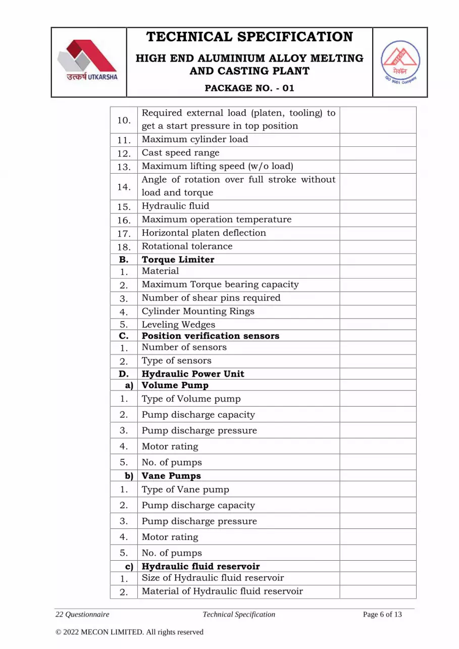
TECHNICAL SPECIFICATIONHIGH END ALUMINIUM ALLOY MELTING
AND CASTING PLANTPACKAGE NO. - 01
22 Questionnaire Technical Specification Page 6 of 13
© 2022 MECON LIMITED. All rights reserved
10.Required external load (platen, tooling) toget a start pressure in top position
11. Maximum cylinder load12. Cast speed range13. Maximum lifting speed (w/o load)
14.Angle of rotation over full stroke withoutload and torque
15. Hydraulic fluid16. Maximum operation temperature17. Horizontal platen deflection18. Rotational toleranceB. Torque Limiter1. Material2. Maximum Torque bearing capacity3. Number of shear pins required4. Cylinder Mounting Rings5. Leveling WedgesC. Position verification sensors1. Number of sensors2. Type of sensorsD. Hydraulic Power Unit
a) Volume Pump1. Type of Volume pump
2. Pump discharge capacity
3. Pump discharge pressure
4. Motor rating
5. No. of pumpsb) Vane Pumps
1. Type of Vane pump
2. Pump discharge capacity
3. Pump discharge pressure
4. Motor rating
5. No. of pumpsc) Hydraulic fluid reservoir
1. Size of Hydraulic fluid reservoir2. Material of Hydraulic fluid reservoir

TECHNICAL SPECIFICATIONHIGH END ALUMINIUM ALLOY MELTING
AND CASTING PLANTPACKAGE NO. - 01
22 Questionnaire Technical Specification Page 7 of 13
© 2022 MECON LIMITED. All rights reserved
d) Hydraulic Logic circuit1. Type of valves2. Number of valvese) Cast speed circuit
1. Type of valves2. Number of valves3. Motor Rating4. Type of flow meter5. Flow control Accuracy required6. Hydraulic oil level indicators7. Number of pressure gauges8. Range of pressure gauges
9. Type of filter clogging indicator for closedloop filtration system
10. Type of filter clogging indicator for castspeed control circuit
11. Emergency cast circuit and relatedequipments
12. Relevant operational parameters, in case,other system has been offered.
E. Mold Table Assembly (for slabs)1. Number of strands2. Table to accommodate slab of dimension3. Water hose connection per stand4. Mold table movement mechanism5. Type of Mold table alignment system6. Mold water control system7. Type of Coating applied8. Approximate external dimensionF. Mold Table Assembly (for billets)1. Number of strands2. Table to accommodate billet of dimension3. Water hose connection per stand4. Mold table movement mechanism5. Type of Mold table alignment system6. Mold water control system7. Type of Coating applied8. Approximate external dimensionG. Distribution trough

TECHNICAL SPECIFICATIONHIGH END ALUMINIUM ALLOY MELTING
AND CASTING PLANTPACKAGE NO. - 01
22 Questionnaire Technical Specification Page 8 of 13
© 2022 MECON LIMITED. All rights reserved
1. Number of walls in trough2. Specification of outer walls of trough3. Specification of inner walls of trough4. Refractory5. Type and number of Trough Preheater6. Heat shield7. Head sensors8. Pin positioners9. Type of Trough movement mechanism10. Number and Type of Spout heaters11. Rating of spout heaters12. Alarming system for spout heaters13. Indicators for control pin heating
14.Type of level sensors for maintaining levelof molten metal in mold bore and itsspecifications
H. Starting Head base assembly (for slabs)1. Design of head base assembly2. Material3. Coating applied4. Approximate external dimension5. Starting head alignment system
6. Number and type of Mold table coverplates
7. Number and type of Starting head basecover plates
I. Starting Head base assembly (for billets)1. Design of head base assembly2. Material3. Coating applied4. Approximate external dimension5. Starting head alignment system
6. Number and type of Mold table coverplates
7. Number and type of Starting head basecover plates
J. Molds (for slabs)1. Dimension of molds2. Number of molds3. Type of Cooling technology

TECHNICAL SPECIFICATIONHIGH END ALUMINIUM ALLOY MELTING
AND CASTING PLANTPACKAGE NO. - 01
22 Questionnaire Technical Specification Page 9 of 13
© 2022 MECON LIMITED. All rights reserved
4.Type and number of oil/graphite sprayinjectors
5. Material and profile of bore6. Material of mold7. Type and number of water filter screens8. Wiper assembly if any9. Type of Mold alignment systemK. Molds (for billets)1. Dimension of molds2. Number of molds3. Type of Cooling technology
4.Type and number of oil/graphite sprayinjectors
5. Material and profile of bore6. Material of mold7. Type and number of water filter screens8. Wiper assembly if any9. Type of Mold alignment systemL. Cooling water control1. Type of water flow control valve2. Number of water flow control valve
3. Specification of valve i.e., size based onpressure etc.
4. Type of water shut off valve5. Type of flow meter
6. Equipment for water temperaturemeasurement
7. Number and Type of Emergency watervalve
8. Type of Water cleaning system/ strainer9. Pit water level control systemM. Launder metal level control1. Type of sensors2. Range of sensors
3.Protection for sensors and cooling media ifany
4. Number of sensors5. Position of sensors6. Type of Launder dams

TECHNICAL SPECIFICATIONHIGH END ALUMINIUM ALLOY MELTING
AND CASTING PLANTPACKAGE NO. - 01
22 Questionnaire Technical Specification Page 10 of 13
© 2022 MECON LIMITED. All rights reserved
7. Number of Launder dams8. Position of Launder dams9. Refractory for Launder damsN. Steam Exhaust Plenum
XUltrasonic Inspection System (for slabsand billets)
1. Type of Ultrasonic Inspection System Inline &Offline
2. Test Sensitivitya) ---- For internal Imperfectionsb) ---- For Surface Imperfections
3. Technology used4. Number of UT probes5. Number of EC probes, if provided6. Lifetime of probe7. Couplant8. Pre-wetting/ Cleaning unit
9.Couplant distribution unit includingfiltration
10. Payload and Supplementary payload11. Number of axes12. Sound Level <85 dB13. Weight of complete Ultrasonic Testing unit
14. Dimension of complete Ultrasonic Testingunit
15.Relevant operational parameters andnecessary equipments as per the Systemprovided
XI Scalper (for both slabs and billets)1. Type of Scalper2. Spindle Material3. Spindle Power4. Feeding Rate5. Depth of cut6. Mandrel/ Main Mill Group7. Side Mills, if required
8.Entry, Intermediate and Exit Roller way/Table

TECHNICAL SPECIFICATIONHIGH END ALUMINIUM ALLOY MELTING
AND CASTING PLANTPACKAGE NO. - 01
22 Questionnaire Technical Specification Page 11 of 13
© 2022 MECON LIMITED. All rights reserved
9. Rolling Turnover Device10. Roughness of finished surface11. Parallelism after milling12. Self adjusting system13. Cross transfer unit14. Tools Lubrication System15. Weight of complete Scalping unit16. Dimension of complete Scalping unit
17. Relevant operational parameters, in case,other system has been offered.
XII Band Sawing Machine (for both slabsand billets)
1. Type of Band Saw M/c2. Cutting Capacity3. Blade Size4. Blade Motor Rating5. Blade Speed6. Blade Lifetime7. Cutting Axis (Whether single or multiple)8. Feeding Speed9. Accuracy10. Roughness of finished surface
11.Output (Number of slabs and/orbillets/hr)
12. Cutting Fluid Type13. Cutting Fluid Pump
14. Entry, Intermediate and Exit Roller way/Table
15. Rolling Turnover Device16. Self-adjusting system17. Cross transfer unit18. Tools Lubrication System19. Weight of complete Band Sawing unit20. Dimension of complete Band Sawing unit
21. Relevant operational parameters, in case,other system has been offered.
XIII Chips Collection System1. Type of Chips Collection System2. Specification of Fan and Venturi System

TECHNICAL SPECIFICATIONHIGH END ALUMINIUM ALLOY MELTING
AND CASTING PLANTPACKAGE NO. - 01
22 Questionnaire Technical Specification Page 12 of 13
© 2022 MECON LIMITED. All rights reserved
3. Suction Pipe and Supporting Structure4. Type of Chips Compactor System
5. Relevant operational parameters, in case,other system has been offered.
6. Type of Chips Transfer UnitXIV Operational and maintenance tools Enclose listXV Spares & consumables
1.
Complete commissioning spares as well asspares and consumables for 3 monthsoperation and maintenance included inoffer (including electrode paste, hydraulicfluid, lubricants, refractories, etc.)
2. List of commissioning spares andconsumables Attach list
3. List of spares and consumables for twoyears of normal operation Attach list
XVI Services Requirement for each unit andequipment
1. Compressed air requirementa) Flow rate, Nm3/minb) Whether intermittent or continuousc) Pressure, kg/cm2
d) Quality2. Instrument air requirementa) Typeb) Pressure, kg/cm2
c) Flow rate, Nm3/mind) Whether intermittent or continuous
3. Cooling water requirement (both industrialand soft water make up)
a) Flow rate, Nm3/minb) Pressure, kg/cm2
c) Temperature at inlet, 0Cd) Temperature rise, max 0C
e)Required Quality (give hardness, pH value,residual contents of suspended solids,particle size, settling time, etc.)
4. Emergency water requirementa) Flow rate, m3/hb) Pressure, kg/cm2
c) Duration, min5. Nitrogen/Argon Requirementa) Flow rate, Nm3/minb) Pressure, kg/cm2

TECHNICAL SPECIFICATIONHIGH END ALUMINIUM ALLOY MELTING
AND CASTING PLANTPACKAGE NO. - 01
22 Questionnaire Technical Specification Page 13 of 13
© 2022 MECON LIMITED. All rights reserved
c) Quality6. Propane/Natural Gas Requirementa) Flow rate, Nm3/minb) Pressure, kg/cm2
c) Qualityd) Whether intermittent or continuous
7. Any other requirement

MECON LIMITED RANCHI- 834002
(A Government of India Enterprise)
A House of Engineering Excellence
…….Aiming Beyond
CIN NO. : U74140JH1973GOI001199
Vivekananda Path, Doranda, Ranchi – 834002, Jharkhand, India
Phone : +91-651-24830000, Fax : +91-651-2482189/2482214 E-mail : [email protected], Website : http://www.meconlimited.co.in