utilisation of construction demolition waste as stabilised materials for road base applications
TRANSCRIPT

285
ABSTRACT: The rate of construction development in Vietnam currently increases rapidly. Many oldbuildings have been demolished and replaced by new buildings. This demolition has caused a huge con-struction waste at demolition sites but not yet been utilised. Meanwhile, natural materials to produce mor-tar, concrete and road base is limited for the environment impact of exploiting process.
This paper presents experimental results of utilising construction demolition waste (CDW) as stabi-lised materials for the subgrade or the base of roads. The CDW was used for substituting natural aggre-gates in these road structures. The results focused on effects of cement content on some subgrade proper-ties (such as: maximum dry compacted density, splitting tensile strength, compressive strength, etc.) withdifferent CDW sources (from concrete structures and from brick wall debris). The results indicated thatCDW could replace natural aggregate in road base layers in Vietnam.
1 INTRODUCTION
In Vietnam, the amount of solid waste are currently creating more in urban areas. As reported by the na-tional environment agency on solid waste in 2011 (MORE, 2011), the amount of municipal solid wastegenerated about 12.802 million tons in 2008 and estimated to be 22.352 million tons in 2015. In which,CDW is around 10-15%, mainly arisen from works of construction and demolition. Approximately 2,200apartments (about 6 million m2) were built in the 70’s - 80’s, in which approximately 90% are degradedseriously (Nguyen, 2011). According to the resolution 34/2007/NQ-CP (Government, 2007), Vietnam isstriving to complete the renovation and reconstruction of the old and damaged apartments those are dete-riorated or has expired in all urban areas by 2015. So in the coming years, a huge amount of CDW will bedischarged in the large cities or urban areas.
Recycling and reuse CDW has been studied and applied for practical since the last few decades in anumber of countries around the world (Hansen, 1992). Technical standards for recycled waste materialsto use as recycled CDW in building and road construction have been published elsewhere (ACI_555R-01,2001). This has brought great benefits in terms of economic, engineering and environment aspects.Through previous studies (Le, 2007; Tong, 2011; URENCO, 2009), most of CDW in Vietnam’s urbanareas is spread in the garbage dump, only a little amount is used for landfilling. This causes environ-mental pollution, waste landfill area and costly transportation as well as waste of material sources. In ad-dition, research on utilisation of CDW for road foundation has not been interested in Vietnam. In thestandard system of Vietnam (TCVN) and standard for transportation (22TCN). There are no constructionprocedures and standards for testing as well as specifications of recycled CDW materials when they usedfor foundation layers and pavement road.
Motorway generally consists of two parts (foundation structure and surface structure). These structurespossibly include multiple layers with different materials (Figure 1). The choice of materials for road-baseand subbase are guided in TCVN 4054: 2005 (TCVN4054, 2005) and specifications for these materialsare presented in table 1 and strength of cement treated sand in table 2.
Utilisation of construction demolition waste as stabilised materials forroad base applications
Tong T. Kien1, Le T. Thanh2 and Phung V. Lu1
1National University of Civil Engineering , Hanoi, Vietnam2Ministry of Construction, Vietnam
The International Conference on Sustainable Built Environment for Now and the Future. Hanoi, 26 - 27 March 2013

286
Figure 1: Diagram of pavement structure and foundation layers (22TCN211, 2006)
Table 1: The physical and mechanical requirements of macadammaterials (22TCN334, 2006)
Type of macadamNo. Properties
Type I Type IIExperimental
methods
1 Los Angeles abrasion (LA), % ≤35 ≤40 22TCN 318:042 CBR at compaction index K98, immersed 96h, % ≥100 N/A 22TCN 332:063 Liquid index (Wt), % ≤25 ≤35 AASHTO T89:024 The Plasticity index (Ip), % ≤6 ≤6 AASHTO T90:025 The PP index = Ip x Passing percent of 0,075mm ≤45 ≤606 Elongation and flakiness index, % ≤15 ≤15 TCVN 7572: 067 Compaction index (Kyc), % ≥98 ≥98 22TCN 333:06
Table 2: Required strength of cement treated sand (22TCN246, 1998)
Strength demand at 28 days (Mpa)Position of cement treated structures
Compressive strength Splitting tensile strength
The upper layer of the high performancepavement and surface layers with bitumiouslaminatation.
3.0 0.35
The lower base layer of the high performancepavement structures. 2.0 0.25
In other cases 1.0 0.12
In this research, an experimental investigation has been immplemented to examine the possibility ofusing CDW for road-base, subbase layer without cement or cement treated. The characteristics of base orsubbase layers such as maximum dry density, optimum water content, compressive strength, splittingstrength, etc have been tested in laboratory conditions.
2 MATERIALS AND RESEARCH METHODOLOGY
2.1 Materials
CDW is heterogeneous, the quality is also very different because they have been collected from varioussources. Components of CDW usually contains fragments of concrete structures, reinforced concrete, ma-

287
sonry structures with brick, ceramic tiles, glass, ... In this study, CDW samples were collected at variouspositions in the demolition site of the Southern hotel located at No 2nd Ton That Tung street, Hanoi city,Vietnam.
Table 3: Sources and main components of CDW samples
Labelof sample
Sources ofCDWs
Demolitionmethods Major composition of CDW Contaminants
RAC Concrete andconcretereinforcement
Drilling, cuttingand beating
Debris of cement concrete,cement and lime mortar
Small steel wire reinforced,nylon canvas
RMA Masonry struc-ture
Chiseling and beating
Debris of hollow brick,ceramic tile, lime-cementmortar and concrete
Little clay, plaster, paper,plastic and wood
a) b)
Figure 2. CDW samples from concrete structures (a) and masonry structures (b)
Both CDWs were crushed to a size of less than 40mm. There are two types of recycled aggregates(RAs) from two different sources, RA from masonry debris called recycled masonry aggregate (RMA),and RA from concrete or concrete reinforcement structures called recycled concrete aggregate (RCA). Acontrol aggregate is comprised a natural coarse aggregate (NCA) that is crushed stone 1x2 from Phu Lyquarry and a natural fine aggregate (NFA) from Lo River.
2.2 Research Methodology
The fundamental properties of NAs and RAs are determined by the Vietnamese standards TCVN 7572:2006 (TCVN7572, 2006) and TCVN 4198: 1995 (TCVN4198, 1995).
Maximum dry density and optimum moisture content are determined using the standards for transpor-tation 22TCN 333: 2006 (22TCN333, 2006). Natural coarse aggregate and RAs mixture using compac-tion method I-D (mould with 152.4mm diameter, 2.5kg compacted hammer and 305mm height, numberof compaction: 56 pcs/layer x 3 layers). Natural sand and RAs sand treated cement mixtures used com-paction method I-A (mould with 101.6mm diameter, 2.5kg compacted hammer and 305mm height, num-ber of compaction: 25 pcs / layer x 3 layers).
Vibrating compacted density is determined in the following procedure: Place the mixed material in acylindrical tank (DxH = 240x200 mm) with 2 layers, each half of the height. During vibration of the sec-ond layer, the material is fulfilled. The vibration table has a frequency vibration of 2800-3000 rounds perminnute and an amplitude of 0.5mm oscillation.
The compressive strength and splitting tensile strength are determined using the standard for transpor-tation 22TCN 73: 1984 (22TCN73, 1984). Cement treated sand is made in a cylindrical steel mould withdxh=100x200 mm by I-A compaction method, the compressive strength and splitting tensile strength aredetermined after 28 days curing in lab air (temperature of 20-250C, relative humidity of 60-80%).
Contaminants: steelwire, wood, nyloncanvas, clay, etc.Masonrystructure:brick,mortar,ceramictile, etc.
Concrete

288
3 RESULTS AND DISCUSSIONS
3.1 Properties of Natural aggregates and Recycled agregates
The properties of NAs and RAs are shown in Table 4.
Table 4: The basic properties of natural aggregate and RAs
No. Properties Unit NCA RCA RMA NFA
1 Specific gravity g/cm3 2.700 2.628 2.564 2.620
2 Bulk specific density kg/m3 1410 1241 1097 1460
3 Water absorption Mass percent 0.53 8.6 17.3 1.6
4 Elongation and flakiness index Mass percent 12.9 14.2 13.6 -
5 Content of dust, mud and clay Mass percent 0.50 1.30 2.74 1.2
6 Crushing value of coarse Aggregate (CVA) Mass percent 13.2 17.8 25.4 -
7 Los Angeles abrasion Mass percent 28.7 38.1 44.2 -
Passing Percent, %
Requirements of 22TCN 334:06,with Dmax=25 (22TCN334, 2006)
Sieve size,mm
Min Max
NCA RCA RMA NFA
37.5 100 100 100 100 100 100
25 79 90 96.2 89.8 91.5 100
19 67 83 69.9 76.6 79.5 100
9.5 49 64 13.5 55.4 58.2 100
4.75 34 54 2.9 39.8 40.6 98.6
2.36 25 40 0 26.4 32.3 91.8
0.425 12 24 0 18.0 28.3 18.7
8 Particle sizedistribution*
0.075 2 12 0 11.9 23.6 5.9
* Particle size distribution is determined following the TCVN 4198: 1995 (TCVN4198, 1995)
Figure 3. Particle size distribution of natural aggregate and RAs
- From Table 4, we found that: Elongation and flakiness index of RCA are similar to the ones of NCA,whilst the one of RMA is 5.7% higher. CVA of both RAs is also higher than that of NCA, specially

289
CVA of RMA is nearly 2 times higher than NCA’s. This is due to RMA containing more soft particlesfrom brick and mortar than NCA.
- The Los Angeles abrasion of both RAs are over 40% and higher than that of NCA and these values arehigher than the requirements in standard 22TCN 334: 06 (22TCN334, 2006).
- Water absorption of both RAs is higher than that of the natural aggregates, this suggests that RAs canbe used appropriatly for wet road base layers.Cement PCB30 Hoang Thach, available on the Vietnamese market, was used in this research to inves-
tigate the possibility of RAs used for road foundation layers reinforced with cement. The properties ofcement meets the requirement s of TCVN 6260: 1997 (TCVN6260, 2009).
3.2 Largest volume of dry weight and optimum moisture
From CDW derived (RMA, RCA), the dry density (γ0k) and water content (w) were measured by a proc-
tor test complied withstandard 22TCN 333-2006 (22TCN333, 2006), all results are shown in Figure 4.From the relation between dry density and water content of RAs as well as NAs, the optimum moistureand maximum dry density were also determined.
Figure 4: Relations between dry density and water content of RAs and NAs
- In Figure 4, maximum dry density of RCA is 2089 kg/m3 is similar to that of NCA (2253 kg/m3) butthe ones of RMA and NFA are lower (only 1749 kg/m3 and 1854 kg/m3). This may be due to the RCAcontained particles of natural stone aggregate that has greater density than NFA. And during compac-tion, the mortar in concrete and masonry was probable broken, resulted in increase of the density.RMA has composition of brick and mortar debris which is lighter than NAs, this may decrease themaximum dry density of RMA to the smallest.
- Optimal moisture of RAs are greater than that of natural materials (from 3 to 5% higher). This suggeststhat there are a lots of porosities in RAs which could absorb much more water than the natural materi-als. This supports to the ability of using RAs for wet road layers with a fast draining capability for thesurface layer.
3.3 Effects of vibration time and RAs mixture ratio to compacted density of road foundation layer
To determine the compact-ability by vibration and the optimum ratio of RAs fraction to maximizedensity. RAs particles larger 5mm and smaller than 5mm at difference ratios were mixed andtested with various vibration time. The experimental results of two types RAs are shown in Table 5and Table 6.
From the above Tables, the relationship between compacted density of RAs mixture with vibrationtime are depicted in Figure 5 and Figure 6.

290
Table 5. Dry compacted density of RMA mixture with different vibration time
Dry compacted density of RMA mixture at various ratioRMA>5:RMA<5mm, kg/m3Vibration
time, s100:20 80:20 60:40 40:60 20:80 0:100
Optimum ratio be-tween
RMA>5:RMA<5mm
Maximumdry density,
kg/m3
0 1311 1391 1458 1569 1502 1438 36.2: 63.8 1521
30 1356 1558 1692 1770 1715 1529 41.6: 58.4 1752
60 1410 1580 1715 1770 1748 1574 40.6: 59.4 1764
90 1516 1569 1703 1770 1748 1608 39.3: 60.7 1744
Table 6. Dry compacted density of RCA mixture with different vibration time
Dry compacted density of RCA mixture at various ratioRCA>5:RCA<5mm, kg/m3Vibration
time, s100:20 80:20 60:40 40:60 20:80 0:100
Optimum ratio be-tween
RCA>5:RCA<5mm
Maximumdry density,
kg/m3
0s 1383 1458 1544 1592 1626 1513 33.1: 69.9 1593
30s 1580 1793 1904 1893 1849 1726 43.9: 56.1 1915
60s 1614 1782 1927 1949 1844 1675 46.9: 53.1 1939
90s 1636 1793 1871 1837 1815 1681 47.8: 52.2 1869
Figure 5. Relations between compacted density of RMA and vibration time
Figure 6. Relations between compacted density of RCA and vibration time
- In general, increasing the vibration time increased, the compacted density of RAs mixture, especiallyat vibration from 0s to60s. Continuously increasing the vibration time up to 90s, RAs compacted den-sity increased slightly (for RMA) or even decreased (RCA).
- The content of RCA particles above 5 mm of the optimal mixture increased as vibration time in-creased. However, with RMA mixture, it appeared constant at the value of 40%.
3.4 The maximum compacted density and optimum moisture of RAs sand in cement treeated road base
When using RAs sand treated by cement, the key properties are maximum density and optimum moisture.Experiments were carired out by proctor tests with the cement content of 5, 10, 15% (by mass). The re-sults are shown in Table 7.
291
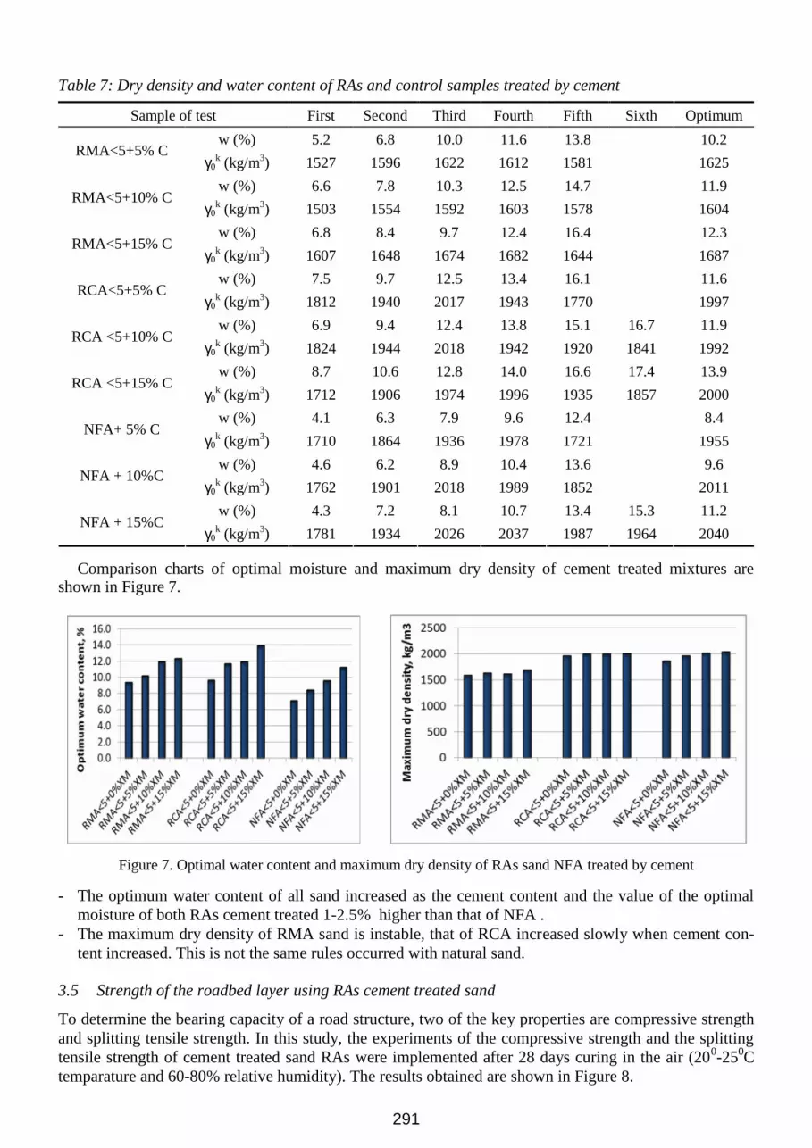
Table 7: Dry density and water content of RAs and control samples treated by cement
Sample of test First Second Third Fourth Fifth Sixth Optimum
w (%) 5.2 6.8 10.0 11.6 13.8 10.2RMA<5+5% C
γ0k (kg/m3) 1527 1596 1622 1612 1581 1625
w (%) 6.6 7.8 10.3 12.5 14.7 11.9RMA<5+10% C
γ0k (kg/m3) 1503 1554 1592 1603 1578 1604
w (%) 6.8 8.4 9.7 12.4 16.4 12.3RMA<5+15% C
γ0k (kg/m3) 1607 1648 1674 1682 1644 1687
w (%) 7.5 9.7 12.5 13.4 16.1 11.6RCA<5+5% C
γ0k (kg/m3) 1812 1940 2017 1943 1770 1997
w (%) 6.9 9.4 12.4 13.8 15.1 16.7 11.9RCA <5+10% C
γ0k (kg/m3) 1824 1944 2018 1942 1920 1841 1992
w (%) 8.7 10.6 12.8 14.0 16.6 17.4 13.9RCA <5+15% C
γ0k (kg/m3) 1712 1906 1974 1996 1935 1857 2000
w (%) 4.1 6.3 7.9 9.6 12.4 8.4NFA+ 5% C
γ0k (kg/m3) 1710 1864 1936 1978 1721 1955
w (%) 4.6 6.2 8.9 10.4 13.6 9.6NFA + 10%C
γ0k (kg/m3) 1762 1901 2018 1989 1852 2011
w (%) 4.3 7.2 8.1 10.7 13.4 15.3 11.2NFA + 15%C
γ0k (kg/m3) 1781 1934 2026 2037 1987 1964 2040
Comparison charts of optimal moisture and maximum dry density of cement treated mixtures areshown in Figure 7.
Figure 7. Optimal water content and maximum dry density of RAs sand NFA treated by cement
- The optimum water content of all sand increased as the cement content and the value of the optimalmoisture of both RAs cement treated 1-2.5% higher than that of NFA .
- The maximum dry density of RMA sand is instable, that of RCA increased slowly when cement con-tent increased. This is not the same rules occurred with natural sand.
3.5 Strength of the roadbed layer using RAs cement treated sand
To determine the bearing capacity of a road structure, two of the key properties are compressive strengthand splitting tensile strength. In this study, the experiments of the compressive strength and the splittingtensile strength of cement treated sand RAs were implemented after 28 days curing in the air (200-250Ctemparature and 60-80% relative humidity). The results obtained are shown in Figure 8.

292
Figure 8. Relations between NFA, RAs sand and cement content
- The compressive strength and splitting tensile strength of RAs sand increased as cement contentincreased, this is similar to the rules occurred with natural sand. However, when the cement contentincreased from 10% to 15%, the compressive strength increased significally while the splitting tensilestrength increased gradually.
- The compressive strength and the splitting tensile strength of RCA cement treated sand are higher thanthat of natural sand, however RMA cement treated sand is lower.
- According to standard 22TCN 246:98 (22TCN246, 1998): RAs sand can be used for lower layer of thepavement structure when being reinforced with 5.5-7.1% (for RCA sand) or 7.1-10.5% cement (forRMA sand), comparatively to the cement content of NFA is 5.9-8.1%. When RAs sand used for theupper layer of the high performance pavement and surface layers with bitumious laminatation, thecement content needs to be added about 6.2-10.5%, 7.1-10.9% and 10.1-12.8% respectively for RCAsand, natural sand and RMA sand.
4 CONCLUSIONS
The experimental results lead to draw some conclusions as follows: Recycled construction demolition waste from concrete and masonry can be utilised as natural materials
for all subgrade, base and subase layers of road foundation without cement treated. When using recycled fine aggregate (RFA) for lower base layer of the high performance pavement
structures, it should be reinforced with 7.5% cement for RFA from concrete debris and 10.5% cementfor RFA from masonry debris.
When using RFA for upper layer of the high performance pavement structures and the bituminouspavements, it should be reinforced with 10.5% and 12.5% cement respectively from concrete and ma-sonry debris.
5 ACKNOWLEDGEMENTS
The authors would like to thank National University of Civil Engineering for supporting this research.
6 REFERENCES
22TCN73 1984. Procedure to determine the splitting tensile strength of granular material stabilized bybinder. Industry standards. Vietnam: Ministry of Transport.
22TCN211 2006. Design standard for soft pavement Industry standards. Vietnam: Ministry of Transport.22TCN246 1998. Procedure of construction and acceptance of the cement treated sand layer for pave-
ments. Industry standards. Việt Nam: Ministry of Transport.22TCN333 2006. Procedure of compacted soil, crushed stone in the laboratory. Industry standards. Viet-
nam: Ministry of Transport.

293
22TCN334 2006. Procedure of construction and testing of macadam foundation layer in the pavementstructure of high way. Industry standards. Vietnam: Ministry of Transport.
ACI_555R-01 2001. Removal and Reuse of Hardened Concrete.GOVERNMENT, V. 2007. NQ34/2007/NQ-CP: A some of resolutions to removate and reconstruct of
the old damaged and degraded apartments in the big cities in Vietnam. Resolution of Vietnamgovernment.
HANSEN, T. C. 1992. Demolition and Reuse of Concrete and Masonry: recycling of demolished con-crete, recycling of masonry rubble, and localized cutting by blasting of conrete. RILEM report 6. E &EN Spon, London.
LE, V. H. 2007. Study on Using Construction and Demolition Waste to produce Concrete and Mortar.Final report of Ministry of Construction. Hanoi.
MORE 2011. Report of National Enviroment 2011- Solid Wastes Ministry Of Resources and Environ-ment, Vietnam.
NGUYEN, N. 2011. 90% old appartments in Vietnam degraded [Online]. June 2012: Ministry Of Re-sources and Environment. Available:http://www.monre.gov.vn/v35/default.aspx?tabid=428&CateID=4&ID=109687&Code=9GRM109687 [Accessed].
TCVN4054 2005. Design standard for high way. Vietnam: Ministry Of Resources and Environment.TCVN4198 1995. Construction soil- Testing method for determine partical size distribution in labratory.
Vietnam: Ministry Of Resources and Environment.TCVN6260 2009. Portland cement blended - Specifications. Vietnam: Ministry Of Resources and
Environment.TCVN7572 2006. Aggregates for concrete and mortar − Test methods. Vietnam: Ministry Of Resources
and Environment.TONG, T. K. 2011. Studying the posibility of recycling demolition watste to produce construction
materials. Hanoi: National University of Civil Engineering.URENCO, H. 2009. State of rubbish in Hanoi [Online]. Urban Environment Company. Available:
www.urenco.com.vn [Accessed June 2011].