demolition/consolidation work plan: buildings 31 ... - citeseerx
TRANSCRIPT
Dem olition/Consolidation Work Plan Buildings 31,31-5, and 31-P
General Electric Company Pittsfield, Massachusetts
June 2001
Demolition/ConsoZidatim Work Plan Buildings 31,31-J, and 31-P
General Electric Company Pittsfield, Massachusetts
June 2001
Table of Contents
2.0 BESC ION OF BLmDmG 31 A
3.0 PROJECT O W R m W
5.0 DISPOSPTION OF DEMOLPTION MATE S
6.0 FUTURE G R O m W A T E R M O m O m G
7.0 m C W A T E D SCHEDULE
FIGURES
1 Building 3 1 Location Plan 2 Building 3 1 Site Plan 3 Building 3 1 Plan Interior Features 4 Disposition Placement Sequence
ATTACHMENTS
A Project Work Tasks B General Project Conditions C Technical Specifications D Supplemental Information Package (Separately Bound)
BLASLAND, BOUCK & LEE, INC LR7C I e n g i n e e r s & s c r e n t i s t s 2991 199
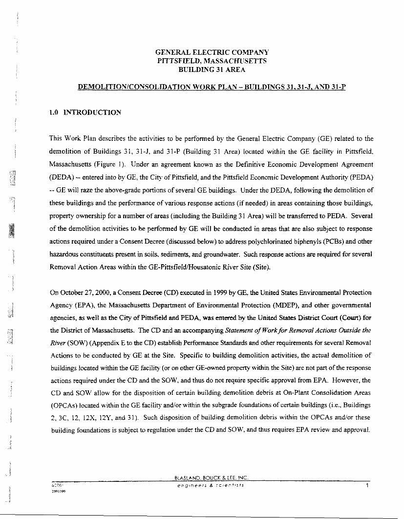
This Work Plan describes the activities to be perfomed by the General EIectric Company (GE) related to the
demolition of Buildings 3 1, 3 1-5, and 3 1-P (Building 3 1 Area) Iocated within the GE facility in Pinsfield,
Massachusetts (Figure I). Under an agreement known as the Definitive Economic Development Agreement
(DEDA) -- entered into by GE, the City of Pittsfield, and the Pittsfield Economic Development Authority (PEDA)
-- GE will raze the above-grade portions of several GE buildings. Under the DEDA, following the demolition of
these buildings and the performance of various response actions (if needed) in areas containing those buildings,
property ownership for a number of areas (including the Building 3 1 Area) will be transferred to PEDA. Several
of the demolition activities to be performed by GE will be conducted in areas that are also subject to response
actions required under a Consent Decree (discussed below) to address polychlorinated biphenyls (PCBs) and other
hazardous constituents present in soils, sediments, and groundwater. Such response actions are required for several
Removal Action Areas within the GE-PittsfieI~ousatonic River Site (Site).
On October 27,2000, a Consent Decree (CD) executed in 1999 by GE, the United States Environmental Protection
Agency (EPA), the Massachusetts Department of Environmental Protection (MDEP), and other governmental
agencies, as well as the Clty of PittsfieId and PEDA, was entered by the United States District Court (Court) for
the District of Massachusetts. The CD and an accompanying Statement of Workfor Removal Actions Outside the
River (SOW) (Appendix E to the CD) establish Performance Standards and other requirements for several Removal
Actions to be conducted by GE at the Site. Specific to building demolition activities, the actual demolition of
buildings located within the GE facility (or on other GE-owned property within the Site) are not part of the response
actions required under the CD and the SOW, and thus do not require specific approval from EPA. However, the
CD and SOW allow for the disposition of certain buiIding demolition debris at On-Plant Consolidation Areas
(OPCAs) located within the GE facility and/or within the subgrade foundations of certain buildings (i.e., Buildings
2, 3C, 12, 12X, 12Y, and 31). Such disposition of building demolition debris within the OPCAs and/or these
building foundations is subject to regulation under the CD and SOW, and thus requires EPA review and approval.
BCASCAND, BOUCK & LEE. INC &:7,c engrneers 6, sc ien t i s ts 1
i 2991 199
To the extent that GE elects to place demolition debris in such building foundations. GE is required to prepare and
submit a separate work planfs) describing the demoIition activities. associated building material cbaracterimtion
activities, and the placement of debris in the building foundations. This Work Plan summarizes the activities to
be perfomed by GE related to the demolition of Buildings 3 L,3 14, and 3 I-P and subsequent disposition of certain
demolition materials from these buildings within the Building 3 1 foundation.
The remainder of this Work Plan is preseated in several sections as follows:
2.0 Description of Building 3 1 Area
3.0 Project Overview
4.0 Work Plan Organization and Project Implementation
5.0 Disposition of Demolition Materials
6.0 Future Groundwater Monitoring
7.0 Anticipated Schedule
In addition, included in this Work Plan are several figures and attachments that supplement the summary
information presented in the text of this Work Plan. These supplemental materials will be referenced as
appropriate.
2.0 DESCRIPTION OF BUILDING 31 AREA
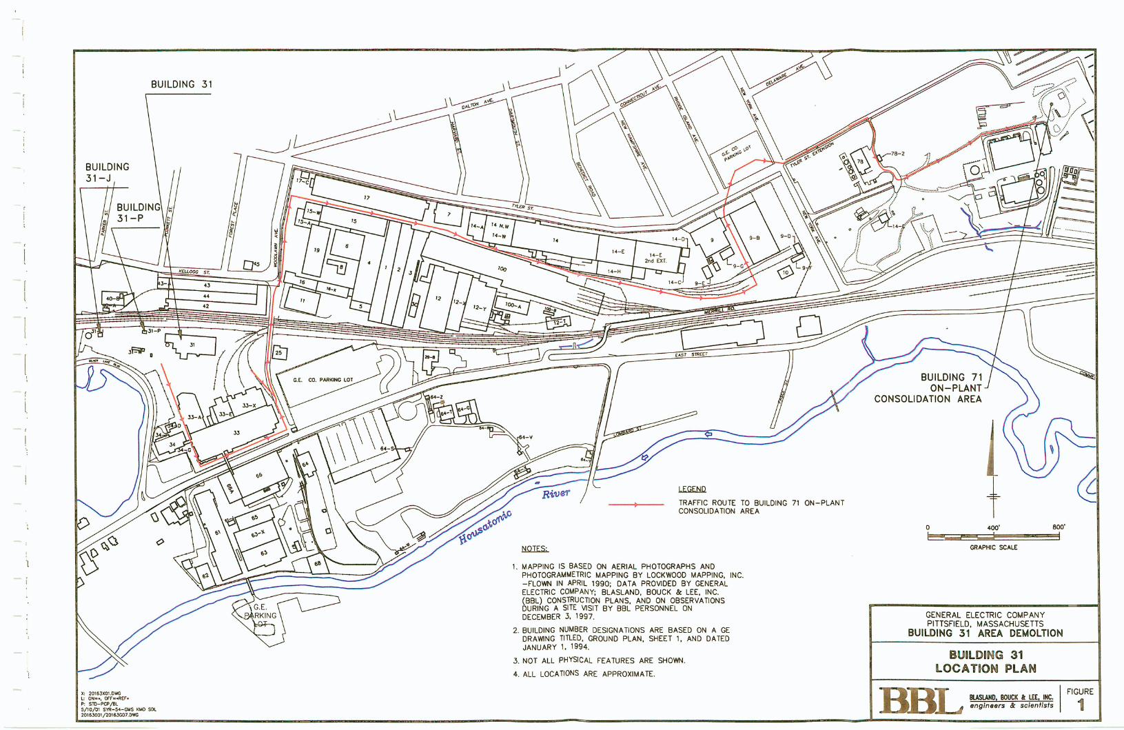
The Building 3 1 Area consists of three primary structures: Building 3 1, Building 3 1-5, and Building 3 I -P. GE
formerly used Building 3 I as a powerhouse for production of steam and compressed air for use throughout the GE
facility. Buildings 31-J and 31-P were formerly used as the pump houses for pumping 10-C oil and fuel oil,
respectively, to other portions of the GE facility. The locations of the above-referenced structures are shown on
Figures 1 and 2. Additional information concerning Buildings 3 1,3 1-5, and 3 1 -P is presented below.
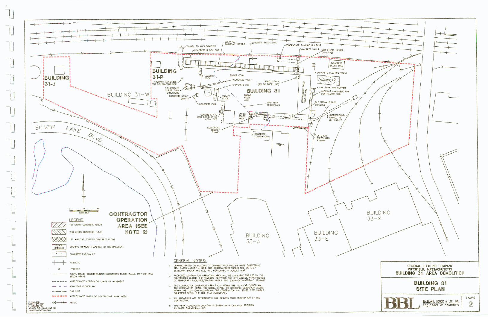
Building 31 is consm~cted mainly of brick. concrete, masow block, and steel, occupying an area of
approximately 69,000 square feet (Figure 3). The building consists of four main sections: a boiler room; a
compressor room; an engine room area; and an office area. The compressor room is located in the eastern end
of the building and is constructed at grade and wi&out a basement area: however, piping sumps and pits are
BLASLAND, BOUCK LEE. INC b/27Qi engtneers Z. sctenttsts 2 2991 199
present hneath the floor, Assorted equipment and other materials are currently present throughout the building,
including boilers, compressors, tanks, coal storage bins, piping, and ventitation units.
Undergound steam funnels are located outside of and along the southern and northern walls of the building
(Figure 3). The s tem tunnels contain inactive steam piping that extends into the eastern portion of the building.
In addition, active electrical lines are located in an undergound electrical tunnel located along the southern
portion of the building and the noahem wall of the tunnel. Two pardel Gaal asb Is are
present beneath the western portion of the building basement. A subgrade concrete vault is located at the west
end of the coal ash tunnels beyond the west wall of the building.
Two steel steam condensate surge tanks are located adjacent to (west of) Building 3 1. A smaller, active,
condensate surge tank is located directly below the larger, inactive tank. Both tanks are supported by the same
steel structure. Finally, an inactive railroad trestle is located north of Building 3 1 and is oriented in an east-west
direction. The railroad trestle is constructed of steel and wood and is approximately 15 feet above grade. Active
steam pipes are located directly below and within the railroad trestle.
Building 3 1-J is a one-story structure and occupies an area of approximately 600 square feet (Figure 2). This
building served as the pump house for 10-C oil to locations throughout the GE facility and is currentIy inactive.
The exterior walls are constructed of masonry block. The floor of the building consists of concrete siab-on-
grade. The roof is constructed of concrete, wood, and steel fiaming. Some inactive process equipment is present
in the building.
As part of a recent building reconnaissance, GE identified a water well located within Building 3 1-5. Thus far,
GE has not been able to determine the former use(s) of the well or its physical construction. As part of the
demolition activities to be performed for the Building 3 1 Area, GE will M e r assess the physical condition of
this well and proceed with well abandonment in accordance with appropriate state requirements.
Building 3 I -P is a one-story strucmre and occupies an area of approximately 1,100 square feet (Figure 2). This
building served as the pump house for pumping fuel oil to locations throughout the CE facility and is cumntly
BCASLAND. BOUCK & LEE. INC &27D e n g i n e e r s 6 s c r e n t t s t s 3 2991 I99
inactive. The exterior walls are constructed of mason? block. The floor of the building consists of concrete
slabon-grade. The roof is constructed of wood and steel framing. Some inactive process equipment is present
in the building.
Over the last several years, GE has perfom& numemw building demolitian activities at its Pittsf~Ld .dim, artd
the experience gained from these activities has served as the basis for the design of the Building 3 1 Area demolition
project and the development of this Work Plan. In general, all of the demolition-related activities will be performed
by qualified and experienced contractors using standard construction practices and in accordance with applicable
regulations. A brief summary of the anticipated activities associated with the Building 31 Area demolitiod
consolidation project is provided below. As discussed in Section 4.0 of this Work Plan, additional information to
supplement the description provided below is contained within the attachments to this Work Plan.
Prior to the initiation of building demolition activities, several activities will be performed. As discussed further
below, these activities will include: locating, disconnecting, sealing, andlor re-routing of affected utilities, tunnels,
and other subsurface conduits; removal of asbestos-containing material (ACM) as required by law; and removal
of certain equipment and other materials located within the various buiidings. Following these activities, the
basement area of Building 3 1 will be prepared for placement of demolition debris from Buildings 3 1,3 1-J, and 3 1 - P. These preparations wiH include filling of the ash, steam, and electrical subgrade tunnels and related pipelines
with concrete, and closure of subsurface structures. Following the pre-demolition activities, Buildings 3 1,3 1-5,
and 3 1-P will be demolished, with most of the demolition debris expected to be placed within the Building 3 1
foundation (disposition of building demolition debris is further discussed in Section 5.0 of this Work Plan). Once
materials have been consolidated within the Building 3 1 foundation, site restoration activities will commence and
include the placement of additional fil l materials (as needed) to achieve the necessary surface elevation and
contours of the foundation area the installation of a cover system (equivalent to an engineered barrier as described
in the SOW) over the materials consolidated within the Building 3 I founktion ( M e r discussed in Section 5-01,
and the restoration of paved and unpaved areas within the remainder of the Building 3 1 Area. It is anticipated that
the pre-demolition, building demolition, placement, and restoration activities will take approximately six to nine
months to complete following EPA approval of this Work Plan.
Based on available information regarding groundwater in the vicinity of Building 3 1, it appears that goundwater
may on occasion reach an elevation that extends above the elevation of the Building 3 1 basement floor. Thus, the
BLASLAND, BOUCK 8 LEE, INC. &:f, e n g i n e e r s d s c ~ e n t i s f s 4 2991199
potential exists for groundwater to periodicallj conbct the building demolition debris and other materials that are
to be placed within the Building 3 1 foundation. As a result. and in accordance with the SOW, GE will conduct
groundwater monitoring at wells located downgradient of this building foundation as part of the groundwater
monitoring progam for the Plant Site I Groundwater Management Area (GMA 1). which includes the area of
Building 31. This groundwater monitoring is described further in Section 6.0 below. As noted there, if this
monitoring reveals impacts to groundwater amibutable to the demolition debris in the Building 3 1 foundation, GE
will submit a proposal to EPA for appropriate additional activities.
4.0 WORK PLAN ORG-ATION AND PROJECT W L E m W A T I O N
Over the last several months, GE has performed numerous activities to prepare the Building 3 1 Area for demolition,
including removal of the Building 3 1 discharge stacks, the performance of an asbestos survey, and removal of
certain equipment and materials from within the structures. In addition, GE developed a Request for Proposal
(RFP) to identify qualified and experienced demolition contractors and to solicit cost proposals for the demolition
activities described in this Work Plan. Included in the RFP were several technical documents and other information
that provide information regarding the Building 3 1 Area and the activities associated with the demolition of this
area. Based on those documents, GE has developed a series of revised technical documents that specify the
requirements for the Building 3 1 Area demolitionlconsolidation project and provide other pertinent information
relating to this project. These documents are provided as attachments to this Work Plan and consist of the
following:
* Project Work Tasks (Attachment A to the Work Plan) - To the extent possible, the technical scope and
requirements for the Building 3 1 Area demolition project have been described in 1 1 Project Work Tasks as
follows:
P Work Task 1 - MobilizationlDemobilization P Work Task 2 - Utility Disconnections
P Work Task 3 - Pre-Demolition Removal Activities
P Work Task 4 - Removal of Asbestos-Containing Building Materials
3 Work Task 5 - Closure of Basement TunnelslSelect Piping
G Work Task 6 - Building Demolition - Enviromentaf Requirements
3 Work Task 7 - Waste Movement, Staging. and Disposition
"r Work Task 8 - Demolition Debris and Equipment/Select Fill Placement
BLAZLAND, BOUCII S LEE, INC 607E e n g r n e e r s 8 sctentrsts 5 2991109
> \Work Task 9 - Repair and Modification to Select Smctures
k Work Task 10 - Placement of a Surface Cover
> U'ork Task 11 - Final Site Grading
For each Project Work Task, information is provided to guide the demolition conwactor in the performance of
the specific activity. Collectively, these Project Work Tasks represent the key elements of the demolition
project and also m m & the techrnicd as of this Work Plan. In addition, en ' g hwings have
been included to supplement information provided in the Project Work Tasks and are referenced as appropriate.
General Project Conditions (Attachment B to the Work Plan) - This attachment provides general requirements
and instructions concerning the performance of the Building 3 1 Area demolition. Included is information that
the demolition contractor must adhere to regarding regulatory and CDlSOW requirements; contractor technical
submittals; contractor Health and Safety, Contingency, and Site Management Plans; air monitoring and dust
suppression; survey control and documentation; and other aspects related to the implementation of the project.
Technical Specifications (Attachment C to the Work Plan) - For several aspects of the demolition project,
technical specifications have been developed to define acceptable construction materials, methods of
construction, and the expected performance of the demolition contractor. In addition, certain specifications
identify quality control testing requirements and acceptable outcomes.
* Supplemental Information Package (Attachment D to the Work Plan; separately bound) - The Supplemental
Information Package (SIP) provides additional information concerning the physical features and characteristics
of the Building 3 1 Area, including the following information:
'u A summary of the most recent analytical data for Building 3 1, collected in August 1999 (Section 1 of
the SIP).
P The results of asbestos and lead surveys performed in August 1999 in Building 3 1 and December 1999
in Buildings 3 1 -J and 3 1 -P that identifv ACM and lead-containing paint on the building material
surfaces (Section 2 of the SIP).
BLASLAND, BOUCK & LEE, INC ~;RTx?* e n g i n e e r s 8. s c t e n t r s t s 6 2991 199
(-~JOM 13alo~d ayl 8u!~o~~oj pm 01 ~o!-rd sleqwqns [e3!uy.~az laylo
IuaAas ap!~old lsnw lo~wuo:, ayl '~olaq 3 @no~yl v sluauq3e~7d u! sm~d asayl JO suo!ldu3sap aql uf qvo~las
se 'ley1 palou aq os~e pinoqs q) -1e~o~dde pue "Juaurwo3 '~apar s~f) 103 ~awuo3 uoggowap atp iCq pawwqns
aq II!M sueld %u!~o~loj aqj, -13aiold atp jo sluawaja sno!Jetl ayl hressa~au se paloufploo:, rolpm pann;a!i\al say
pue say! yl3e pacold [lo jo adox ayl spwslapun lo~3eauo3 ayl ley1 alnsua 01 papualu! are 'mag jo MafhaJ s '39
ql!~ pau!qwo3 'slq!wqns asayl 'uop!ppo u1 .ylo~ ayl am3axa 01 paqnba~ -31a 'sle!~a1ew 'e!1alf13 uop.~nnsuo:,
play 'suo!suaw!p 'sapguenb IIe payyaA pue pau!uuaiap seq lo~~eauo~ uo!l!jowap ay1 ley1 uo!lsuasa~da~
o se aMas pue WOM 13aFo~cf arg JO wuatuaia tq-3 luaurnmp p~e aqpap 01 papuaxtq arr? slwpurqns asaq~,
.Ma!AaJ s,g~ 103 swa;! ledallas pxqns pue aieda~d 01 paqnba~ s! lol3em.103 uo!$gowap aql 'iCi1e31pad~ .13a[old
arl) JO uo!~suawaldw! ayl 01 palela1 paqsgqssa uaaq aAoy sluawa~!nbal leuog!ppo joJaAas 'uqd y~o~ s!yl jo
3 qffno~yl v ssluauq3euv u! pau!quo:, sa!pA!tm uo!~r~owap aqljo adoas pm svadse Io3!uq3al ayl 01 uo!pppo u1
.sluamy3wo aq u!y~f~ pau!quo3 uo!$omoju! pa[!qap alow '~ay~o 01 sa3uaraja.1 qz!~ '1uawn3op Ma!luaAo
uo se Apm!sd saiuas mid ?JON\ s!q 'llnsal e sv 'eaq I E 2uip1!na aql ~oj sap!~pe uo!l
* Dust Control Plan: and
* Demolition Plan.
5.0 DISPOSITIOS OF DEMOLITION AMATE S
As indicated in Section 1.0 of this Work Plan. EPA review and approval is required for the portions of this Work
PIan that relate to the use of the Buil&ng 3 1 on for the disposition of certain buiidtding demolith m
This section provides (for EPA review and approval) a summafv of GE's proposed course of action concerning the
disposition of building demolition materials. To supplement the general discussion presented in this section,
several of the attachments to this Work Plan provide additional, more detailed infomation. Specifically, the
following information is relevant to the disposition/consolidation of various demolition materials:
Proiect Work Tasks (Attachment A)
Work Task 5 - Closure of Basement TunnelslSelect Piping;
Work Task 6 - Building Demolition - Environmental Requirements;
Work Task 7 - Waste Movement, Staging, and Disposition;
Work Task 8 - Demolition Debris and EquipmentfSelect FilI Placement; and
Work Task 10 - Placement of a Surface Cover.
General Proiect Conditions (Attachment B')
Section 1.1 - Regulatory Requirements;
* Section 1.3 - Site Management Plan;
Section 1.19 - Survey Control;
Section 1.21 - Soil Fill Sources; and
Section 1.24 - Record Drawings.
Technical Swcifieations (Attachment C)
Section 1.0 - Flowable Fill Material;
* Section 2.0 - Select Fill Material;
* Section 3.0 - Washed Stone;
* Section 5.0 - Select Soil Fill Material;
Section 6.0 - Earthwork;
BLASLAND, BOUCK & LEE, INC Mini engtneers 8 screntrsfs 8 2-2-91 19-9
* Section 9.0 - Flexible Membrane Liner; and
Section 10.0 - Geosynthetic Drainage Composite.
Su~~IementaI Information Package (Anachment Dl
* Summav of Building 3 1 Anatpical Data;
* Chemcept, Inc. Report for Building 3 1;
* Building 3 1 Basement T m e l s ; and
* Summary of Available Pre- 1999 Data for Building 3 1
In accordance with the CD and SOW, several materials are specifically excluded from placement within the
Building 3 1 foundation (as well as the OPCAs), including free liquids, free product, intact drums and capacitors,
other equipment that contains PCBs within its internal components, and asbestos-containing materials required to
be removed from structures prior to demolition under applicable laws and regulations. To the extent that such
materials are present within the Building 3 1 Area, they will be removed for transport and disposal to appropriate
off-site facilities. In addition, prior to demolition activities, certain other materials will be removed for disposal
at an appropriate off-site facility(ies), such as mercury and chlorofluorocarbons (some of these materials have
already been removed from the Building 3 1 Area as part of predemolition preparation activities).
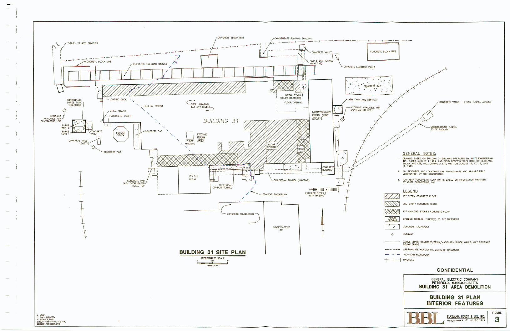
GE anticipates that most (if not all) of the remaining demolition materials (brick, masonry, concrete, steel, glass,
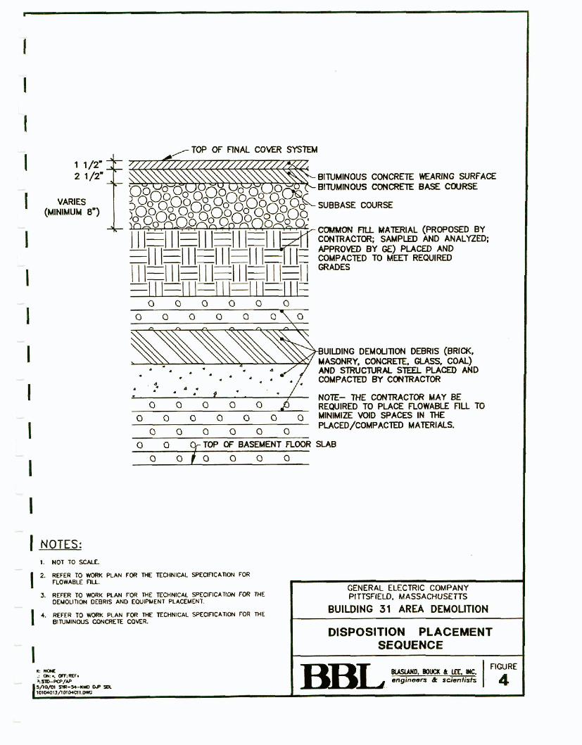
coal, etc.) will be placed within the Building 31 foundation, as illustrated on Figure 4 and described in the
attachments to this Work Plan. Regarding the chemical characteristics of these materials, the supplemental
Information Package (Attachment D to this Work Plan) contains the available sampling and analysis data. In
summary, between 1989 and 1998 GE sampled several materials within Building 31. Sampling and analysis
activities included the collection of 75 wipe samples and 54 &rab/composite/core samples for the anaiysis of PCBs,
9 pb/composite/core samples for Toxicity Characteristic Leachate Procedure (TCLP) metal analysis, and two grab
samples for analysis of asbestos. Results of these sampling activities ranged from non-detect to 120 ug'l00 cmz
for PCB wipe samples, and non-detect to 82 ppm PCBs for pb/composite/core samples. (The 82 ppm PCB
detection was from a sample of ACN associated with piping insulation and has been or will be removed from the
building.) Of the 9 samples analyzed for TCLP metals, the results indicated the presence of lead (two samples) at
concen~ations of 0.6 pprn and 1.7 ppm, chromium (two samples) at concentrations of 0.07 ppm and 0.1 ppm,
m e m w (four samples) ranging between 0.001 7 ppm and 0.021 ppm. and barium (three samples) ranging between
0.1 8 ppm and 0.34 pprn. All TCLP detected constiruents were below their respective regulatory levels. Far the
BLASLAND. BOUCK & LEE. INC 6Q7D e n g r n e e r s B s c ~ e n t r s t s 9 2991 199
two grab samples collected for asbestos, asbestos was detected at compositions of less than 1% and 24%.
respectively.
To further supplement the anaIq.tical results described above, GE perfomed additional sampling activities in
August 1999 to characterize building materials located within Building 3 1. Sampling activities consisted of the
collection of 10 concrete floor sampIes and four mason7 wall samples for analysis of PCBs. In addition. five
building samples were s u b ~ a d for analysis by TCLP. PCB canwmdons in the cowrete floor samples ranged
from non-detect to 1.47 pprn, with mason7 wall samples ranging from 0.036 ppm to 0.192 ppm. These sample
locations are depicted on figures located within the SIP (Attachment D). For the TCLP analyses, non-detect results
were reported for volatile organic compounds, semi-volatile organic compounds, and inorganic constituents. Other
testing for hazardous waste characteristics (ignitability, reactive cyanide, reactive sulfide, and corrosivity) indicated
that the material would not be classified as RCRA hazardous waste.
W i l e GE anticipates that most or all of this building demolition debris will be placed in the Building 31
foundation, it is possible that, in order to facilitate the timindsequencing of the demolition activities and/or based
on volume/capacity considerations, GE may elect to transport certain building demolition debris (brick, concrete,
etc.) to the Building 71 OPCA for consolidation.
In any event, it is expected that the volume of material subject to disposition within the Building 3 1 foundation will
be less than the capacity of that foundation. As a result, GE anticipates that filI material from an off-site location,
consistent with the applicable Technical Specification in Attachment C (Section 2.0 - Select Fill Material), will
placed within the foundation to reach capacity and support restoration activities. However, given the inexact nature
of demolition work and the difficulties in assessing the volume of material subject to disposition and the volume
of the available eonsolidation area (i.e., the Building 3 1 foundation), as well as GE's possible consolidation of some
Building 3 1 Area materials at the Building 71 OPCA, a significant excess capacity may be available following the
disposal of debris in the Building 3 1 foundation. As a result, rather than use fill material to occupy the remaining
capacity, GE may propose to EPA that any remaining capacity be used for the disposition of remediation waste
and/or other materials that would otherwise be -sported to one of the OPCAs or to an off-site location for
disposal. For example, GE would consider the following materials as "candidate" material for disposition in the
Building 3 1 foundation (subject to the aforementioned capacity issue and general prohibitions contained in the CD
and SOW regarding disposition):
BIASLAND, BOUCK 8 LEE, INC M7B e n g i n e e r s B sctentrsts 10 2991 199
* soil and debris removed as part of Removal Actions conducted within the GE Plant ,Area under the GD and
SOW;
* riverbank soils removed as part of the Upper ?4-itilile Reach Removal Action for the Housatonic Rtver; and
* building demolition debris and other materials related to GE's Brownfields activities je.g., soils removed to
perform utility disconnection/abandonment activities. etc.) conducted under the DEDA.
In the event that GE determines that it makes sense to use the excess capacity in the Building 3 1 ation for
disposition of the materials identified above, GE will submit a proposal for such use to EPA for review and
approval. Any such proposal will be subject to the same restrictions and prohibitions as apply to the disposition
of Building 3 1 Area materials in the Building 3 1 foundation (i.e., no free liquid, free product, etc.) and will present
to EPA the analytical data for the materials proposed for such disposition. Further, such a proposal will include,
as appropriate, interim plans to secure the Building 3 1 foundation until its use as a disposition area is complete.
Once all materials to be consolidated in the Building 3 1 foundation are in place, a cover system will be installed.
GE proposes to use an asphalt cover system. That cover system will be the equivalent of an engineered barrier as
described in the SOW and will, at a minimum, measure 12 inches in total thickness and be constructed of several
components, as shown in Attachment A, Figure GE 3 1 -D2. These components and the intended purpose of each
have been previously described in the SOW (Technical Attachment G) and are summarized as follows:
High Density Polyethylene (or similar) Geornembrane Liner: The geomernbrane Iiner is the primary
component of the cover system. This geomembrane Iiner will have a minimum thickness of 60 mil unless GE
proposes and EPA approves an alternate geomembme liner with equivalent physical performance
specifications. A geotextile fabric may be included as a cushioning layer beneath the Iiner depending on the
condition of the subgrade material.
Geosynthetic Drainage Composite (GDC): The primary purpose of the GDC layer is to convey water that
may infiltrate through the overlying soils and pavement to the perimeter of the cover area.
* Gravel Subbase Course, Bituminous Asphalt Base Course, and Bituminous Asphalt Wearing Surface:
An asphalt layer (2-inch minimum) will be installed to accommodate the current and/or anticipated future uses
of the Building 3 1 Area. The asphalt cover will be appropriately graded to divert precipitation to minimize
infiltration and soil erosion.
BLASLAND, BOUCK & LEE. INC 617fi1 engineers a s c ~ e n t i s t s 11
Details pertaining to Technical Specifications for each of these components are krther provided in Attachment A
(Work Task 10) and Attachment C (Sections 9.0 and 10.0).
6.0 FUT WATER M O m O m G
As required by the SOW, following the use of the Building 3 1 foundation for the disposition of the building
demolition debris (and other materials if appro\fed by EPA), GE will conduct groundwater monitoring at wells
located near and downgradient of this building foundation. Such groundwater monitoring will be conducted as part
of GE's groundwater monitoring program for GMA I , which includes this area. GE's proposed baseline monitoring
activities for GMA 1 were identified in a document entitled Baseline Monitoring Program Proposal for Plant Site
I Groundwater Management Area, which was conditionally approved by EPA in a letter dated March 20,2001.
GE has implemented certain of the proposed baseline activities and anticipates the performance of quarterly water
level measurements beginning in July 2001, and the performance of semi-annual groundwater sampling and
analysis activities beginning in October 2001. Several monitoring wells included in these baseline activities are
in close proximity to the Building 3 1 Area, including weils ES2- 19, GMAI - 1, GMAI -2, GMA1- 10, RF-3, RF-3D,
and RF- 16. (These wells are identified in a May 18,2001 letter updating EPA on the status of baseline activities
within GMA 1 .) Of these wells, RF-3, RF-3D, and RF-16 are located in mas generally downgradient of Building
31.
Given the potential that future demolition debris within the Building 3 1 foundation may come into catact with
groundwater under high water conditions, future monitoring data collected for the wells in the vicinity of the
Building 3 1 Area, as part of the GMA 1 program, will be evaluated to determine if any impacts to groundwater are
occuning attributable to the Building 3 1 Area. If such impacts are identified, GE will provide EPA a proposal for
additional activities.
7.0 ANTICIPATED SCHEDULE
Upon commencing demolition activities, site operations will Iikely be conducted during available daylight hours.
five days per week (Monday through Friday). I t is estimated that the demolition and consolidation activities will
require approximately six to nine months for completion, and that associated restoration activities will require
approximately two additional months following the completion of the demolition and consolidation activities.
Consolidation of materials within the Building 31 foundation or at the OPCAs (depending on sequencing of
activities) will not be initiated until EPA approval of the Work Plan has been received. It should be noted that this
BCASLAND, BOUCK & LEE. INC b t ~ 7 ~ ' e n g i n e e r s B s c r e n f r s t s 12 2991 199
schedule is subject to change depending on the timing of EPA review and approvat of the Work Plan. as welt as
delays induced by adverse weather conditions or other unforeseen conditions that could impact the actual activio
BCASLAND, BOUCK & LEE, INC M1n e n g r n e e r s a scientrsts 13 2991 199
Figures
BLASLAND, BOUCK & LEE, INC. e n g i n e e r s & s c i e n t i s t s
CONSOtlDATlON AREA
. TRAFFIC ROUTE TO BUILDING 71 ON-PLANT CONSOlJDATlON AREA
GRAPHIC SCAE
RMWD, engfneers WCK & scienfists & LEE, INC.
.. . --
NOTES:
I . MAPPING IS BASED ON AERIAL PHOTOGRAPHS AND PHOTOGRAMMETRIC MAPPING BY LOCKWOOD MAPPING, IMC. -FLOWN IN APRIL 1990; DATA PROVIDEO BY GENERAL ELECTRIC COMPANY; BLASLAND, BOUCK & LEE, INC. (BBL) CONSTRUCTION PLANS, AND ON OBSERVATIONS DURING A S IX MSlT BY BBL PERSONNEL ON DECEMBER 3, 1997.
2. BUILDING NUMBER DEStGNATlONS ARE BASED ON A GE DRAMNG nmO, GROUND PLAN, SHEET 1, AND DATED JANUARY 1. 1994.
3. NOT ALL PHY~CAL FEATURES ARE SHOW.
4. ALL LOCA~ONS ARE APPROXIMATE,
--. *- -* -- -* BUILDING 31-W] -* -*
-2 ,* ** -5 -**-* I
1 *** I -*.
RALROAD
B HYDRbNT
ABOVE GRME M 3 N C R E f E ~ I M ~ A S O N A R Y BLOCK WALLS, YAY mnwvE BELOW GRADE
APPRONMntE HDRIZOWTAL UWTS OF SASEMENT
- - - $&MAR F L O O O P L A ~
--DC GAS UNE
BUILDING 32- A
GENFRAI NO= t. DfZAKlNG B E E D ON WlCOlNG 31 IIRAHIWFIC PREPARED BY WHITE EMNEERIVG,
INC. DATED AUWSl 4 :999, A M OBSERVAMS WWNG SIT€ WsE 3- BLASLAND, BOUCK APIC LEE. INC. PERSMJNEL IN WWSi 1099.
2. PRwcsm CONTRACTOR OPERARW AREA MU BE AVMLABLE FM( USE 3u ME C ~ T R A C T ~ WRWG RR R E M E ~ A C Acmna FOR ~caa. cwsfiucnm 3P EUPORARY FnCIUTlES/5TAGING AREAS. AN0 EWIPMENT/MA~~ IA:~ STORAGE
3. THE CENTRACMR CPrRAl'lOlg hR€A FKLS H W l M ML. ICO-EAR FLCCDWN. WE MmTRAClaR SH~U NOT m E . S T M . a STOCKPILE p E M a l n m DEBRE WW~N WE IW-YEAR FLWDPWN. WE W;RaCTOR MAY STAQ WER tAOBlLE L w I P u m r YWIN WE 100-EM FLOWRAIN.
GENERAL ELECTRIC COMPANY PITTSflELD, MASSACHUSETTS / BUILDING 31 AREA DEHDUTlON
BUiLDING 31 SiTE PLAN
APPROXWAE UUlTS OF COHlRACT(#I YEMlK AREA. n ALL L O C A T I ~ S ARE APPREC~HATE mo REWIM FIELO ~ a l n c h n ~ ~ EY WE RGURE Y: 1 0 1 m
CONfRACtOR ,,I. ,I, - $EPrCE
BL4SL4N0, BOUCK & LEE, INC. fi SIO-PCPm 5. ~[KL-YE~R ~ 0 0 0 ~ ~ C O C A ~ O Y IS BASD w INFCRUATION PROWED englneam & scientists WOp Sla-54-AW Kim rn BY WHITE ENQN€ERlNG. WC. W ~ O J O P I / ? ~ ~ ~ ~ C O Q ~
BUILDING 31 SITE PLAN
- I
AFPR[WIMAE w SCALE
GENERAL NOTES:
CONCRETE WOCK WKE -SATE RIMFING BWLOwC - --X - g - X - X -t - x -X
TUNNEL TO 40's COMPLEX -* -X -=
_ _ _ _ _ _ - - - A -
_ / _ L _ * _. _. -. CONCRETE VNJLT
ELEVATED RAILROAD TRESnE CONCRETE RECTRIC VAULT
COwOENSAK hW TANK AND HOPPER SURGE TANK CNCREE VAULT - STEAM WRINNEL ACES
HYDRANT AVAILABLE FOR cmmncTm USE
MmCRETE VAULT
BUlLDlNG 3 I CONTRACTOR USE
COHCREE Pm '
--+---
~ ~ C R E T E PAD OLD SEAN IUNNEL (PIACTIVE) r m ~ R U G A T E D
METAL TOP
/ --
'I -- - CONCRETE FOVNDAlW
SUBSTATKlN 32
CONFIDENTIAL
1. ORAHNG BASED ON BUILDING 31 MlAMNG PREPAREO BY W T E ENGINEERING INC, DAEU AJJOUST 4 1889. At40 FlELD OBSERVATIONS MADE BY B L A S L N . BWCK AN0 CEL INC., DURING A SITE WSIT ON AUGUST 16, 17. 18. AND 19, 1999.
r UM L: w-.. OPP-REP. e s m - p e m a WO/DI SIR-$4-M KMD SDL m1em/20183CoD.oM:
3. 100-YEAR W P W N LOCATION IS BASE0 Ms INFORMAllW PROUDED BY WIT€ EwGlNEERING. INC
GENERAL ELECTRIC COMPANY PITTSFIELD, MASSACHUSETTS
BUILDING 31 AREA DEMOUTION
BUiLDING 31 PLAN INTERIOR FEATURES
FIGURE
LEGEND VTA IST S T M Y CCWCRETE RWR
-
ma smw MNCRETE FLWR
157 AND NO STCRIES CONCRETE FLOOR
-1 OPENlhKj MRWM ROWS) TO ME BASEMENT
ABOVE GRADE E+4CREl€/8MCKJMASONnRY ROCK WALL$ MAY WNnNUE BELOW C R A M
APPROXIMATE HmlZONTAL LIMITS OF BASEMENT
- - - ICQ-EAR ROtmLAIN
+++ RAILROW
2 1/2* ""I BITUMINOUS CWICRETE M N G SURFACE BtTUMINOVS eONefFTE BASE COURSE
VARlEs (MINIMUM 8')
SUBBASE COURSE
FIU MATERIAL (PROPOSED BY CWIRACTOR, SAMPLED AND A N A L W APPROVE0 BY GE) PLACED AND COMPACTED TO MEET REWIRED
NOTE- THE OONTRACTm MAY BE REQUIRED TO PLACE FLOWABLE FILL TO
0 0 0 0 0 0 MlNlMlZE W O SPACES IN THE
0 0 0 0 0 0 PLACED/COMPAC'lEX) MATERIALS.
0 0 +TOP OF BASEMENT FLOOR StAB 0 o t o 0 0 0
1 NOTES: 1. MOT TO S W .
2. R€ER TO WaRK P U N FOR THE ECHNlCAL SPEaFtCAflOPI FOR ( now- nu-
REFER M WORK P U H FOR THE TEDINICAL SPEOFlCATKW FOR THE BITUMNOVS CONC#ETE C(WER.
I
I
I
I
I
I
I
I
I
I
I
I
I
I * IK.* ; 01: .. On.llIC* +-/*P worn rm-- nr sa lmocors/l*ourlJnc
r GENERAL ELECTRIC COMPANY PiTTSFIELD. MASSACHUSETK
BUtLDlNG 31 AREA DEMOLITION
DISPOSITION PLACEMENT SEQUENCE
--L FIGURE
--
Attachments
BBL 8 D, BOUCK 8r LEE, INC. e n g l n ( ~ e r s & s c l e n t l ~ f s
Attachment A
Project Work Tasks
BWYIND, BOUCK & LEE, INC enptneera & s c l e n f i s f s
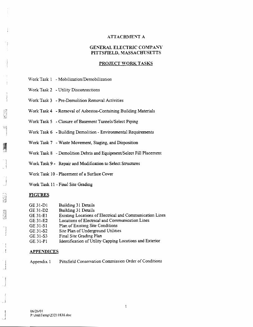
P R 0 J E . n W O W TASKS
Work Task 1 - Mobilizatioflemobilizatlon
Work Task 2 - Utility Discomections
Work Task 3 - Pre-Demolition Removal Activities
Work Task 4 - Removal of Asbestos-Containing Building Materials
Work Task 5 - Closure of Basement TunnelslSelect Piping
Work Task 6 - Building Demolition - Environmental Requirements
Work Task 7 - Waste Movement, Stagmg, and Disposition
Work Task 8 - Demolition Debris and EquiprnentlSelect Fill Placement
Work Task 9 - Repair and Modification to Select Structures
Work Task 10 - Placement of a Surface Cover
Work Task 1 1 - Final Site Grading
FIGURES
Building 3 1 Details Building 3 1 Details Existlng Locations of Electrical and Comunication Lines Locations of Electrical and Comunication Lines Plan of Existing Site Conditions Site Plan of Underground Utilities Final Site Grading Plan Identification of Utility Capping Locations and Exterior
APPEhmICES
Appendix 1 P~ttsfield Conservation Com~sslon Order of Cond~tlons
Work Task 1
General Electric Company PiMsfield, 33assachusetts
A. Mobilization
I . The Contractor is responsible for timely and complete mobilization of all equipment, materials, supplies, and personnel to the site necessary to complete all activities identified in the Work Plan.
B. Demobilization
1. The Contractor shall remove all equipment, materials, supplies, and personnel from the site. Prior to removal, all project-related equipment and materials that are used for this project shall be cleaned or disposed of as described under this work task, Work Task 7, and the Pittsfield Conservation Commission Order of Conditions (Appendix 1).
TEMPORARY SERVICES
A. As part of the mobilization activities, the Contractor shall be responsible for providing the following:
1. The Contractor shall provide, mobilize, and maintain trailer(s) at the site to sustain the Contractor's offices, equipment, storage, and operations for the duration of the project. The trailer shall be provided with an anchoring system in accordance with the manufacturer's requirements to prevent overturning due to wind forces.
2. The Contractor shall provide portable sanitary services as well as a potable water supply for use by all on-site personnel engaged in the project activities.
3. The Contractor shall provide maintenance and servicing of the sanitary facilities, trailers, and equipment h i s h e d with the trailers, as required.
4. The Contractor shall install, in accordance wrth all applicable codes and regulations, electnc semces to the trailers from a location ~ndicated by GE. The Contractor should assume that the connecnon point w~ll be located wthln 500 feet of the office tra~fer. The actual connechon of the electrical s m c e to GE's facilit)i-wlde system w~ll be perfomed by GE; however, the Contractor 1s requrred to coord~nate &IS actrvrty.
5. The Conbactor shall provide cellular telephone service, or equivalent.
6. The Contractor is lim~ted to the area m whlch they can use for the demol~tion actlvltles (~ncludmg decontamination area (s), equrprnent storage area, ete.). The work area that the Contractor has ava~fable for 11s use 1s shown on Figure 2 to thrs Work Plan.
7 . The Contractor shall provide adequate temporaq I~ghtrng for the lntenor of Buildings 3 1,3 1-P, and 3 1-5.
8. The Contractor shall provide dust control dev~ces je.g., water tank, spray hosesinozles, etc.). A non-potable water source for use in dust control will be identified by GE; howem, the C m c t o r shall provide hoses, water storage tanks, etc., and for obtarn~ng water fi-om the source.
1.03 SITE SECURITY
A. The Contractor is responsible for the installation and maintenance of temporary continuous barricades along the perimeter of the Contractor's work limits as discussed below under Section 3.01-G. The Site Management Plan shall address site security.
2.0 WORK ACTIVITIES
2.01 MOBILIZATION
A. The Contractor shall verify site conditions and fully understand the conditions that may be encountered during all project activities. Verification of site conditions shall include, but shall not be limited to, identifying the location of all utilities, equipment, and structures. The Contractor shall be responsible for all costs and liability associated with damaging any existing utility or structure (above and below grade) that is not scheduled for demolition under the Work Plan, including but not limited to, buildings, utilities, (e.g., gas, water, electric, telephone, cable, etc.) fiber optic lines, etc. The Contractor shall also be responsible for replacing (at the Contractor's cost) any damaged structures or utilities to fully operational conditions. The Contractor shall also be responsible for coordinating the deactivation of utilities (where necessary) with GE.
B. The Contractor shall acquire all necessary pennits (e.g., railroad, local, state, federal) to complete the activities described in this work task, including the State of Massachusetts Demolition Notification form and Asbestos Removal Notification form and the City of Pittsfield demolition permit.
C. If the Contractor determmes that access to Build~ng 31 from the northern slde 1s necessary, the Contractor shall be responsible for acqulnng all necessary pennlts (~.e., fiom CSX) to obtain access to the railroad n&t-of-way. n e Contractor shaII not submt any forms andor permit applicat~ons to the appropnate agency until authorized by GE. The Contractor shall also be required to comply w th the Plttsfield Conservation Comlsslon Order of Conditions mcluded as Appendix 1.
D. The Contractor shall be responsible for mobil~zlng all equtpment, material, supplies, and personnel to the sste. AII Contractor (and subcontractor) equlpmmt mobillzed to the slte shall be thoroughIy cleaned pnor to mobil~z&~on to the slte. Based upon renew by GE, equ~pment that is not v~sibly clean upon slte mobtlization w~ll be taken off-slte and cleaned by the Contractor pnor to remobilization at no cost to GE.
E. If the Contractor deternines that the removal of feenclng is necessw for site access, the Contractor must notlfy GE pnor to any removal actrvltles. The Conlractor must specify m ~ t s Site Management Plan the Iocatron of the fence to be removed and rhe marenafs and the methods that will be used to replace the fencing. The replacement fence shall be of like matmal and (along with the method of replacement) must be rev~ewed by GE. The Conllactor must recelve authonzat~on by GE pnor to the cornencement of the fence removal actlvlties.
F. The Contractor shall construct demolition support areas, demolition debris staging and processing areafs), and decontamination area(sj. Tfie demolition rt a n a s shall not be constmcted within the 100-year floodplain. At a minimum, the decontamination area(s) shall be lined with 20-mil reinforced polyethylene sheeting and sloped to a geomembrane-lined sump to allow for the collection of decontamination water. The demolition debns stagng area(s) shall be bermed and lined with a low-permeability, 10 mil (minimum) hgh-density polyethylene (HDPE) liner that shall slope to a collection sump. The demolition debris located in the staging area(s) shall be covered with low- permeability, 10 mil HDPE cover and secured (e.g., with sand bags and ropes) at the end of each workday, when the staging area is not in use, or during periods of inclement weather. The Contractor shall not be permitted to use demolition debris to secure the cover. In addition, precautions to protect the integrity of the low-permeability liner (and cover) for both the decontamination and demolition staging area(s) (e.g., installation of a drainagelsoil layer and/or geotextile over the liner) shall be required. The collected water from the decontamination and demolition debns staging areas shall be pumped from the sump and containerized on-site by the Contractor for subsequent off-site disposal by GE.
G. The Contractor shaI1 provide temporary storage of water encountered during the demolition activities.
H. The Contractor shall install and maintain temporary barriers with appropriate warning signs to limit unauthorized access or unknowing access to those areas associated with the Work Plan.
I. The Contractor shall implement and maintain storm drainage protection.
A. All equipment, materials, and personnel shall be removed from the site following completion of the demolition activities.
B. Non-dtsposable equlpment that has been used as part of the demol~tion actmities and has come ~n contact wsth srte medra shaI1 be cleaned and sampled before berng removed from the facility. The Contractor shall submlt an equlpment clean~ng plan m its S~te Management Plan. Equ~pment decontamination IS to be peribmed m a desrgnated area (to be des~gnated by the Contractor and rewewed by GE). Non-disposable equrpment clean~ng shall be deemed complete based on a revlew by GE and the analytrcal results of wpe samples. GE wll collect a mlnlmum of three wpe samples from each plece of Contractor-controlled equrpment pnor to demob~l~zat~on from the site (for the purposes of ths RFP, the Contractor shall assume that a total of five pxeces of equrpment will requzre codmatlon sampling). The wpe samples shall be subm~tted to a GE-approved laboratory for polychlonnated brphenyl (PCB) analys~s on a 24-hour turnaround basis (at
the ConEactor's expense) to confirm that PCBs are not present at eoncentrat~ons greater than or equal to 10 mlcragams per 100 square cent~meters (10 gi100 ern". The Contractor at no add~tlonal expense to GE will reclean equipment that does not meet this 0bjecll~e
C. The Contractor shall place all rnatenais generated dunng the equrpment decontaminat~on actlvit~es into Un~ted States Depamnenr of Transportat~on- WSDOT-) approved containers for stagrng and d~spos~t~on as descnbed under Work Task 8.
D. Followng completion of the demolition debns and equipment cleanmg acQvlties, the Contractor shall m o v e the temporav stagmg area (mduding, but not tlrnlted to, all equipment and matenals 1n the temporary staglng area).
Work Task 2
General Electric Cornparty Piasfieid, Massachusetts
Uti1it-v Disconnections
1.0 IhTRODUGTION
1.0 1 R'0IX.K SPECIFIED
A. AH labor, equipment, materials for segregating and isolating, capping, testing and back filling of excavations for abandoned sanitary sewer, storm drain system, fire protection and municipal water systems that serve Building 3 1. Included are modifications to storm drain system to plug abandoned lines.
B. Excavation.
C. Leakage tests.
D. Thrust block.
E. Line Capping.
F. Backfilling.
G. Surface patching.
1.02 APPLICABLE CODES, STANDARDS AND SPECIFICATIONS
A. American Water Works Association (AWWA).
B. American Society for Testing and Materials (ASTh4).
C. Massachusetts Highway Department- Standard Specifications for Highways and Bridges.
1.03 SUBMITTALS
A. Ductile iron cap fiffings.
B. Asphaltic coating.
C. Catch basin covers.
D. Submit as-built loeattons of installed underground caps to owner.
1.04 EXISTING COhTDITIONS
A. Coordtnate all achvlhes wth bu~Id~ng demolltzon actl%tles.
B. All shutdom, dramrng, fillmg and testing of municipal and fire protectton systems are to be conducted and coord~nated wtfi owner's represenatrve and rnunrc~pal authonttes.
G. Provrde, erect, and marntaln tenrporav safety and secunty dev~ces.
D. Provide shoring as required.
E. Protec~on of all duct banks, duct vaults, manholes, catch basms. steam and condensate fmes, and fire protecrion lines.
2.0 PRODUCTS
A. Ductile iron pipe and fittings shall comply with the following standards:
Ductile Iron Pipe Ductile Iron Fittings Bolts and Nuts Asphaltic Coating
A W A ASTM
C151 CllO 536 Grade 65-1 C l l l C151
1. Mechanical joints shall be assembled in accordance with the Notes on Methods of Installation, A W A C111, Appendix A. Surface cleaning is of utmost importance. All bolts shall be tightened by means of torque wrenches such that the follower shall be brought up evenly. If effective sealing is not obtained at the specific torques, the joint shall be disassembled, cleaned and reassembled.
B. Thrust Block Material - 3000 PSI @ 28 days.
C. Cast Iron Gratings - Suitable for H-20 loading.
D. Grout plug -Five Star General Purpose Grout.
E. Backfill - Mass. Highway Standards M1.03.0 Type C.
F. Surface patching - Mass. Highway Standards M3.1103, Table A.
3.0 WORK ACTIVITIES
A, Pavement and soil removed shall be tested and disposed of at GE's d~rection. Contractor to util~ze "Protocols for the Management of Excavation Activit~es" to plan and execute th~s actlvlty.
B. The Conmctor shall, at a11 Qrnes, promde and marntaul proper and sar~sfactory means and devices for the removal of all water entmng the excavations ~ncludrng drain and test water, and shall remove all such water as fast as ~t may collect, m such m m e r as shall not ~nterfere with
the proper plac~ng of pipes. Removal and d~sposai of tvater, W ~ I G ~ enters excavat~ons, shall be coordinated wlth GE.
G. hveways and roadways shall be ma~ntalned at ail t~mes. At least one-half of the dnve or road must be kept open for traffic.
D. Specla1 precautions must be taken to penn~t access to and to malntaln fire hydrants and other gotnts where access may ~nvolve the safety and welfare of personnel and others.
E. Shoring and barricades are to be used as required for the safety of d~rect and indlrect on-site persmel.
F. Excavations are to be adequate in size to allow worbng room for capping, pressure testing and thrust block ~nstallat~on activities.
G. All pipe shall be protected from lateral displacement and possible damage resulting from superimposed backfill loads, impact or unbalanced loading during demolition operations by employing necessary methods.
3.02 S m G DOWN EXISTING LINE SYSTEMS
A. The shutting down of existing live municipal and fire protection water systems shall be coordinated with GE and municipal authorities.
3.03 DFW'NING OF SYSTEMS
A. Provisions shaIl be made with GE for the disposal of water accumulated in the draining of Iive systems.
3.04 CAPPING AND TESTING OF ACTIVE WATER SYSTEMS
A. Municipal and fire protection systems that are to remain active are to be tested and witnessed with owner's representative. Successful pressure tests are to be documented. Thrust blocks an= not to be installed until successful tests have been conducted.
B. Locate caps installed in "as-built" location for submittal to GE.
3.05 GROUT PLUGGING OF ABANDONED LINES
A. For lines selected for hard grouting, refer to drawings for details and locations.
A. All excavations shall be backfilled to the onginal surface of the ground of to such other grades as may be shown, specified or directed.
B. Any settlement occmng in the backfilled excavations shall be refilled and compacted.
C. Frozen earth shall not be used for backiilllng.
D. Compact~on shall be 95 percent of maximum dry dens13 as detem~ned by the methods of ASTnil 01556 or ASmf D2922. Mo~srure-dens19 relatlonsh~p of the bacfil! rnalenals shall be detem~ned by A S W D698, Method D.
A. Patch~ng of excavat~on shall be 3" bb~nun~nous pavement,
Work Task 3
General Electric Company Pittsfreld, Massachasefts
Pre-Demotition Removal Activities
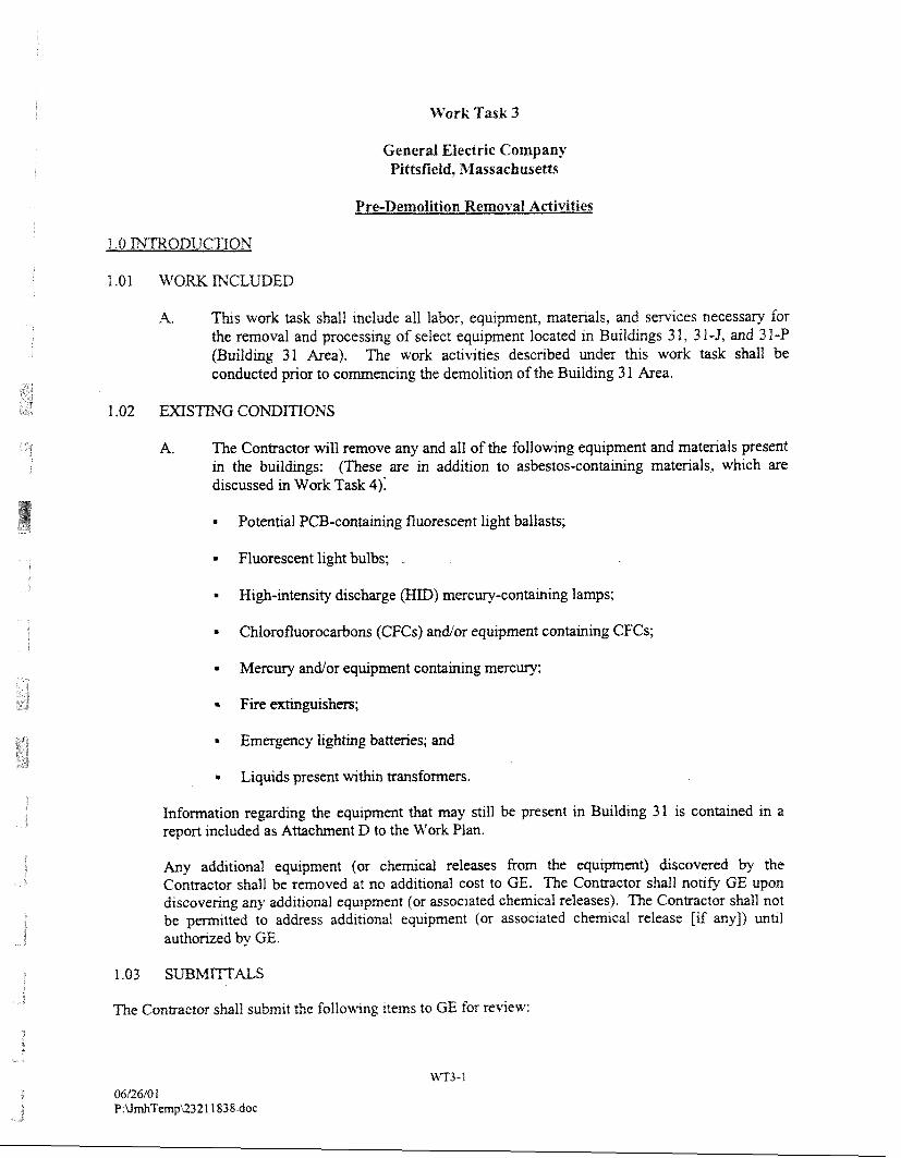
A. This work task shall include all labor, equipment, materials, and s m c e s necessary for the removal and processing of select equipment located in Buildings 3 1, 3 1-5, and 3 1 -P (Building 31 Area). The work activities described under this work task shall be conducted prior to comencing the demolition of the Building 3 1 Area.
1.02 E X S m G CONDITIONS
A. The Contractor will remove any and all of the following equipment and materials present in the buildings: (These are in addition to asbestos-containing materials, which are discussed in Work Task 4);
= Potential PCB-containing fluorescent light ballasts;
= Fluorescent light bulbs;
High-intensity discharge (HID) mercury-containing lamps;
* Chlorofluorocarbons (CFCs) andlor equipment containing CFCs;
= Mercury andlor equipment containing mercury;
Fire extinguishers;
Emergency lighting batteries; and
Liquids present within transformers.
Information regarding the equipment that may still be present in Building 31 is contained in a report included as Attachment D to the Work Plan.
Any additional equipment (or chmcal releases fiom the q u r p m t ) discovered by the Contractor shall be removed at no addttional cost to GE. The Contractor shall noafy GI2 upon dtscovenng any addltlonal equipment (or associated chemtcal releases). The Con&actor shall not be p m ~ t t e d to address add~tlonal equipment (or assoclated chemical release [if any]) unal authorized by GE.
The Contractor shall subm~t the following Items to GE for rewew:
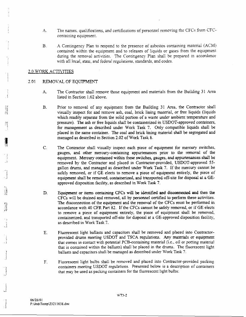
A. ?he names, qualrficat~ons, and ewt~ficatlons of personnel removmg the CFGs from CFC- coxltarnlng equlpmen?,
B. A Contmgency Plan to respond to the presence of asbestos contalnrng matenal (ACM) contarned wl-thm the equrpment and to releases of lrqulds or gases ftom the equipment dunng the removal actrvltles. The Contrngency Plan shall be prqared In accordance with all local, state, and federal regulations, standards, and codes,
A. The Contractor shall remove those equipment and materials from the Building 31 Area listed in Section 1.02 above.
B. Prior to removal of any equipment from the Building 31 Area, the Contractor shall visually inspect for and remove ash, coal, brick lining material, or free liquids (liquids which readily separate from the solid portion of a waste under ambient temperature and pressure). The ash or free liquids shall be containerized in USDOT-approved containers, for management as described under Work Task 7. Only compatible liquids shall be placed in the same container. The coal and h c k lining material shall be segregated and managed as described in Section 2.02 of Work Task 8.
The Contractor shall visually inspect each piece of equipment for mercury switches, gauges, and other mercury-containing appurtenances prior to the removal of the equipment. Mercury contained w i h these switches, gauges, and appurtenances shall be removed by the Contractor and placed in Contractor-provided, USDOT-approved 55- gallon drums, and managed as described under Work Task 7. If the mercury cannot be safely removed, or if GE elects to remove a piece of equipment entirely, the piece of equipment shall be removed, containerized, and transported off-site for disposal at a GE- approved disposition facility, as described in Work Task 7.
D. Wuipment or items containing CFCs will be identified and disconnected and then the CFCs will be drained and removed, all by persomel certified to perform these activities. The disconnection of the equipment and the removal of the CFCs must be performed in accordance with 40 CFR Part 82. If the CFCs cannot be safely removed, or if GE elects to remove a piece of equipment entirely, the piece of equipment shall be removed, containerized, and transported off-site for disposal at a GE-approved disposition facility, as described in Work Task 7.
E. Fluorescent Iight ballasts and capacltors shaII be removed and placed into Contractor- provided drums meeting USDOT and TSCA regulatrons. Any that comes m contact w ~ t h potential PCB-containmg material (i.e., oil or pomng rnatenal that is contained wthm the ballasts) shall be placed in the drum. The fluorescent I~ght ballasts and capacltors shall be managed as described under Work Task 7 .
F. Fluorescent Iight bulbs shall be removed and placed Into Contractor-prowded packrng contarners meehng USDOT regulahons. Presented below IS a desmphon of conlamers that may be used as paclung containers for the fluorescent light bulbs:
Work Task 4
General Electric Company Piasfield, Massachusetts
Removal of Asbestos-Containin-f! Buitdin~ Materials
PART I -GENE
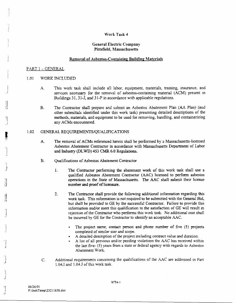
I .OI W O K MGLUDED
A. This work task shall include all labor, equipment, materials, training, insurance, and services necessary for the removal of asbestos-containing material (ACM) present in Buildings 3 1 ,3 1-5, and 3 1 -P in accordance with applicable regulations.
B. The Contractor shall prepare and submit an Asbestos Abatement Plan (AA Plan) (and other submittals identified under this work task) presenting detailed descriphons of the methods, materials, and equipment to be used for removing, handling, and containerizing any ACMs encountered.
1.02 GENERAL REQUIREMENTSfQUALWICATIONS
A. The removal of ACMs referenced herein shall be performed by a Massachusetts-licensed Asbestos Abatement Contractor in accordance with Massachusetts Department of Labor and Industry (DLWD) 453 CMR 6.0 Regulations.
B. Qualifications of Asbestos Abatement Contractor
1. The Contractor performing the abatement work of this work task shall use a qualified Asbestos Abatement Contractor (AAC) licensed to perform asbestos operations in the State of Massachusetts. The AAC shall submit their license number and proof of lieensure.
2. The Contractor shall provide the following additional infomation regarding this work task. This infomation is not required to be submitted with the General Bid, but shall be provided to GE by the successful Contractor. Failure to provide this infomation and/or meet this qualification to the satisfaction of GE will result in rejection of the Contractor who performs thrs work task. No additional cost shall be incurred by GE for the Contractor to identify an acceptable AAC.
The project name, contact person and phone number of five (5) projects completed of similar srze and scope.
= A detailed descnpt~on of the project including contract value and dwat~on. - A l~s t of all prewous andlor pending vlolataons the AAC has received w ~ t h ~ n the last five- (5) years &om a state or federal agency uqth regards to Asbestos Abatement Work.
C. Add~honal requlrernents concemlng the qualrfica.fions of the AAC are addressed xn Part 1.04.1 and 1.04.3 of t h s work task.
G. A Decontaminatton Plan that ~dent~fies the appropriate procedures and methods that wlif be employed to properly decontam~nate project-related equipment that comes m conract with s~ te media ~n accordance w~th 453 G M R 6 and ail other applrcabte local, sate, and federal regulations. The plan must address the generation, colleenon, and handl~ng of solids, Iiquids, personal protective equipment (PPE), and other related wastes generated by decontarn~nat~on actrmhes. h addlt~on, the Decontammat~on Plan must address methods to be employed for personnel decontammahon. Equipment and persomel decontam~nabon actlvrtres will be pedomed m an area to be deslpated by the Contractor and revlewed by GE. Any Iiqurds generated by decontam~natlon efforts and all disposable equipment shall be containenzed for disposal In accordance w~th appltcable focal, state, and f&mf regulations, stanbrds, and codes.
N. A Waste Chxacterization Plan that identifies the anticipated ACM waste streams and estimated volumes of waste to be generated.
I. The Contractor's AAC shall submit a notarized statement containing the following information:
a. Record of any citations issued (in the past three years) by federal, state, or local regulatory agencies relating to asbestos abatement activity, including projects, dates, and resolutions.
b. List of penalties incurred (in the past three years) through non-compliance with asbestos abatement project specifications, including liquidated damages, overruns in scheduled time limitations, and resolutions.
c . Situations (in the past three years) in which an asbestos-related contract has been terminated, including projects, dates, and reasons for terminations.
d. Listing of any asbestos-related legal proceedingsfclaims (in the past three years) in which AAC (or employees scheduled to participate in this project) have participated or are currently involved. Include descriptions of role, issue, and res01ution to date. This information is not required to be submitted with the General Bid but shall be provided at the request of GE prior to Contract Award to the General Contractor.
J. The following submittals are required for review and approval by GE before the Pre- Construction Meeting:
1. Copy of Massachusetts D L W Asbestos Abatement Contractor's Llcense. 2. Copies of certifications, not~ficattons and all applicable I~censes. 3, Wnnen Med~cal Surveillance Program mc luhg the Physlc~ans' wntten opmlon
for employees asslgned to the project m accordance wth OSHA 29 CFR 1926.1 101(m).
4. Copy of Tralnmg Records and Current DLWD Licenses for Employees assigned to project.
5. Chatn-Of-Comand 1st of all personnel on-slte and emergency contact person(s).
6 . Work Plan that dictates all removal procedures to be ~mplemented and prqecaed schedule of completion.
1.05 FEES. PEMIITS 23 LICENSES
A. The Contractor shall be responsible for costs for all l~censlng requ~rements, where appl~cable and notification requvements and all other fees related to the AAC's a b h v to perfom the work 1n t h s work task.
1.05 SUBSaXTIOK OF MATE S OR MEmODS
A. GE's approval IS requ~red for all modlfica~ons to methods, procedures, and deslgn, wh~ch may be proposed by the Contractor. It is the intent of these docments to allow the Contractor to present alternative metfiods to the abatement ses heren, for m e w by GE. Any such mod~ficaaons or subst~tutions to methods, procedures, or design shall comply ~ t h applicable regulations. The Contfactor shall submlt the proposed modification or subst~tution in accordance wth the requirements of the General Condihons, and no later than five (5) workdays pnor to planned comencement of proposed modrfication, for remew and approval by GE.
B. Unless requests for modification or substitution are made in accordance with the above instructions and the instruction of the General Conditions, supported by sufficient proof of equality, the Contractor shall be required to furnish the specifically named or designed items, methods or procedures designated in ths work task.
C. If the modification or substitution necessitates changes or additional work, they shall be provided and the Contractor shall assume the cost and the entire responsibility thereto unless performed under the approved Change Order Process.
D. GE's permission to make such substitution shall not relieve the Contractor from full responsibility for the work.
1.07 PROJECT MONITOR
A. GE may perform monitoring of Contractor work practices and performance, inspection of the worksites, and air sampling and analysis for each phase of the asbestos removal project. Quality control and testing criteria has been established under this work task, and will be strictly enforced. GE will review matters relating to safety, interpretation of the Work Plan, and scheduling of work, and will make decisions upon consultation with the Contractor.
2.0 PRODUCTS
A. All equipment and materials shall be specified and supplied by the Contractor. The Contractor shall provide a submittal on all materials and equipment to be used for review and approval by GE prior to comencement of the work.
3.0 WORK ACmTITIES
3.0 1 WMOVAL OF ASBESTOS-CON G MATERIALS
A. The Contractor shall remove AGM from equ~pment pnor to equrpment removal and from the bu~ldmg-s pnor to commencxng the dernolrtion of the Bulld~ng 31 Area. Personnel who hold a val~d license to handle asbestos shall venfj the quantlry of rnatenal. The work shall be m o r m e d ~n stnct accordance wth all federal, state, and local regulatlons, stan&r&, and codes govemrng asbestos removal work m effect at the txme of conmct award. The ACM removal and containmzatlon for d~sposal shall be performed 1x1
accordance with the folIowing w t a t i m s . as we11 as other q l r cab le
= The Asbestos National Emissions Standards for Hazardous Air Pollutants ( N E S W ) contained in 40 CFR Part 61 ; and
OSHA requirements contained in Part 1910.1001 of Title 29 of the Code of Federal Regulations (29 CFR Part 1910.1001) and 29 CFR 1926.1 101.
B. During and following the removal activities, the Contractor shall containerize and place the removed ACM into a temporary staging area(s) (if needed) separate from any other waste material. The staging area(s) shall be constructed in accordance with all applicable local, state, and federal reguhons, standards, and codes to shelter the materials from the elements (e.g., wind, precipitation, surface water runoff, etc.). The ACM containers shall meet the minimum requirements set forth in 453 CMR 6 and 40 CFR 61.50. The Contractor shall submit a description of the proposed design and location of the staging area(s) (if needed) in the Site Management Plan and the AA Plan.
C. GE will provide monitoring, which will include work area review and air sampling outside of the work area.
D. GE will also review the standard operating procedures, engineering control systems, respiratory protection and decontamination systems, packaging and disposal of asbestos waste.
E. GE shall be provided (by the Conmctor) with safe access to all areas of the asbestos removal project at all times and will monitor the performance of the Contractor to document that said performance complies with fhis work task description.
3.04 AIR QUALITY MONITORING
A. The Contractor shall be responsible for all personal and ambient au monltonng as described m the A I ~ Qualjty Monltonng Plan prepared in accordance wth Sectton 1.03 of this work task descnpt~on and as requ~red by federal, state, and local regulatlons In place at the trrne of Contract award ~ncludtng 453 CMR 6 .
B. If dmng removal act~mties, alr qua119 regulatory levels related to asbestos are exceeded, the Contractor shall take all appropnate measures to reduce the concenh-at~on of airborne
asbestos (e.g., wettmg), as described m the Gont~ngeney Plan prepared under Section 1.03, at no add~tlonal cost to GE.
3.05 OFF-SIE DISPOSAL ASBESTOS-CONmWG ASSOCUED U'ASTE S S.
A. General: The Contractor shall place ACM into Contractor-provided contarners that meet the mtnimum requuernents set forth In 453 GIVE 6. The Contractor shall be responsible for the transportation of ACM to a GE-approved dtsposal facility. A list of the GE d~sposal facilit~es 1s ~ncluded m the SIP.
B. Packaging: Pnor to post-abatement inspection, asbestos-contaming waste shall be packaged in sealed double containers and removed from the work area to a specified transportation vehicle or a designated holding area approved by GE. At the end of each work day, the Contractor shall remove the debns accumulated during that days work activities using procedures outlined herein. The Contractor shall provide a daily tally of all bags removed.
Tem~orarv Storape of Waste: During and following the removal activities, the Contractor shall containerize and place the removed ACM into a temporary staging area(s) separate from any other building materials. The staging area(s) shall be constructed in accordance with all applicable local, state, and federal regulations, standards, and codes and will shelter the materials from the elements (e.g., wind, precipitation, surface water runoff). The ACM containers shall meet the minimum requirements set forth in 453 CMR 6. The Contractor shall submit a description of the proposed design and location of the staging area(s) as part of their Site Management Plan and Asbestos Abatement Plan. GE must approve the area for temporary storage of asbestos waste. AII asbestos waste must be stored in closed-top dumpsters that are locked and labeled. Asbestos waste may only be stored in a restricted area or enclosed container which is posted and secured whenever not in use.
D. OSHAEPA Labeling: Asbestos warning labels having permanent adhesive and waterproof print, or being permanently pnnted on the container, shall be affixed to the outside of all asbestos containers, and each inside bag, except that non-friable asbestos- containing waste that has not been and does not have a high probability of becoming, crumbled, pulverized, or reduced to powder need not be labeled. Labels will be conspicuous and legible and shall contain the following warning:
DANGER CONTAJNS ASBESTOS FIBERS
AVOID CREATING DUST CANCER AND LIJNG DISEASE lLUARI3
The AAC is directed to properly label each waste bag in accordance with the latest mSW standard, Section 6 1.150, with the follou.ing infornabon:
ING A L m O M W S NAXIE SITEi NAME
E. : A USDOT class 9 sh~pprng label and USDOT mark shall be applied to or be pnnted an each packag~ng of asbestos-conb~mng materials; except for non-fnable ACMs that d ~ d nor
led, pulvmzed, or reduced to powder; or a 'i~mited qwnt~ty of ACM whlefi is not berng transported by alr.
F. Asbestos Waste Shl~ntent Records: The Contractor shall prepare the waste sh~pment records. Completed waste shipment record(s) s~gned by the Conmctor, all transporter(s), tmsfaor(s), d~sposal andior convwsion facilrty(ies) shall be provided to the Awarding Authority within 30 days of the time at which the asbestos-c k i ~ g piastcs are received at the disposal and/or conversion facil~ty (les), which shall be no longer than 40 days after the waste was accepted by the initial transporter. The Waste Shlpment Record shall specify the designating number of bags or cubic yard(s) of asbestos waste.
G. In addition to the labeling requirements specified in Parts D, E, and F above, the Conbctor shall -- for purposes of labeling -- label the ACM containers as if they contain PCBs. As such, labeling shall be consistent with all applicable federal, state, and local requirements.
H. De~ositing: Asbestos waste shall be deposited as soon as practical at a GE-approved regulated waste disposal site, except for USEPA "Category I" non-friable ACM that has not become friable, nor will be or has been sanded, ground, cut, or abraded. Waste disposal sites for asbestos materials will be in accordance with 40 CFR 61.25, Waste Disposal Sites. The GE-approved waste disposal facility for ACM is provided in the SIP.
3.06 QUALITY CONTROL AND TESTING
A. The Contractor shall be responsible for achieving acceptable visual and final air clearance testing for all abatement areas as follows:
Clearance Ins~ection: GE shall inspect the work area and surrounding areas for clearance using visual and physical methods, prior to clearing the project for air monitoring clearance procedures.
Post-Abatement Clearance Air Monitoring: For each abatehent area, post abatement clearance air samples will be taken when a visual inspection by GE indicates no visually accessible debris, and surfaces are encapsulated and dry. Phase Contrast Microscopy (PCM) clearance testing will be performed to confirm the completion of removal. Samples analyzed by Phase Contrast Microscopy (PCM) and the NIOSH 7400 method and must not exceed the maximum airborne fiber concentration of 0.01 f i h per cubic centimeter.
Note: Should results indicate a fiber concentration greater than 0.01 fibersicc of any one sample, or if the visual inspection fails, GAC shaIl reclean the entire work area utilizing the methods specified in this work task.
Work Task 5
General Electric Company Pinsfield, Massachusetts
Closure of Basement TunnefsJSelect Piping
A. This work task shall include all labor, equipment, materials, and sentices necessary to close and seal all subgrade tunnels (as required) located in or below the basement of Building 3 1.
A. Based on drawings and field observations, Building 31 contains the following basement tunnels and select piping:
1. Two parallel ash tunnels oriented in an east-west direction, each approximately 4 feet wide by 4 feet tall. A concrete vault is located at the west end of the ash tunnels and extends past the western exterior wall of Building 31. The ash tunnels reportedly extend beneath the building approximately 140 feet east of the concrete vault.
2. Steam pipingltunnels exit the basement of Building 31 at three locations, as shown in Section 4 of Attachment D to the Work Plan (Supplemental Information Package). One location is on the northexn side of the buildtng near the Compressor Room. The second location is on the southern side of the building south of the first location. The h r d is located on the southern side of the building, in the basement beneath the office sea.
3. A 36-inch diameter was intake pipe connects Building 31 to Silver Lake. According to historical GE drawings, the water intake pipe enters the southern side of Building 31 beneath the basement of the office area. The intake pipe is connected to a network of pipes and ducts that are located beneath the basement of Building 3 1. Field observations indicate that the water intake network is filled with water and contains varying thicknesses of sediment. One manhole is located between Building 31 and Silver Lake. Based on field observations, this rnanhole is filled with concrete to an elevation of 6 inches below grade. However, it is unknown if the concrete extends vertically to the intake pipe, which would separate the lake water &om Building 3 1.
4. The intenor drain plprng system consists of floor drams, trench drams, sumps, "hot" wells, plptng connectmg the drams, and a 36-mch dlmeter pipe comectlng the lntmor dram system wth the extenor stom dram system and outfalls to Silver Lake. held obsematlons mdicate that the 36-mch diameter prpe may be plugged at the first extenor m h o l e .
Basement tunnels/seleet plplng associated with Building 31 ~ncluded m Section 4 of -4tr;lchent D to the Work Plan (Suppiemental Infomat~on Package). The Contractor 1s respons~ble ibr vmfj.ing all exlshng basement
The Contractor shall subm~t the following Items to GE for review:
A. A list of equipment to be used, along with the catalog sheets.
B. ?he names of any subcontractors to be used on the project, mcfubg thm pfificatrms, locations of ongin, and descriptions of thelr project ass~gnments.
C. The names, qualifications and certifications of the designated on-site Project Manager responsible for malung decisions, and primary contacts for GE during performance of the work.
D. The Contractor shall identify the specific equipment, materials (including grout and concrete mix designs), and methods proposed to close and seal basement tunnelslselect piping associated with Building 31 based on the requirements established in t h s work task.
2.0 PRODUCTS
2.01 MATERIALS AND EQUIPMENT
A. A11 equipment and materials shall be specified and supplied by the Contractor, unless specified herein.
B. All containers utilized for containerization of water accumulatedfrernoved shall be USDOT-approved and provided by the Contractor.
3.0 WORK ACTIVITIES
3.0 1 PRE-CLOSURE ACTIVITIES
A. The Contractor shall, prior to closure of basement tunnelslselect piping, identify and verify the location of all tunnelsipiping, located in the walls and in the floors of the basement of Building 31 as described in Section 3.02 of this work task. The Contractor shall identify and close all basement tunnelslselect piping in Building 31, including but not limited to the basement tunnelsiselect piping listed in Section 1.02 of this work task. The Contractor shall notify GE upon identifyrng additional basement tunnels beyond those identified herein. The Contractor will not be permitted to close the additional basement tunnels (if any) until authorized by GE.
The Contractor shall conduct the follovsmg basement el closure actlwtles.
A. The Contractor shall venfy the locatlon and extent of the tunnels and assocrated vaults. The Gontra~tor shall then fill the ash tunnels and assoc~ated concrete vaults w ~ t h flowable fill to the elevation of the top of the basement slab. The closure of the ash include the tunnels themselves and comect-lng vault area, located m the western portion of Building 3 1, while the porhons of the steam tunnels subject to closure are shown on Figure 3 ~ncluded in n 4 of Attachent D. The Contractor shall also seal remarnlng m m c e s to the ash s (i.e., boiler hatches, roof <;frams, discharge p p g , trench drams, etc.) with Rowable fill or plpe plugs to the top of the basement slab. If required, the Gontractor shall be allowed to create access polnts (e.g., through the basement concrete Roor slab) to portions of the ash tunnel. However, the access points must be closed as part of the basement tunnels closure actlvit~es (i.e., using flowable fill). Placement of flowable fill shall be done in accordance with the Technical Specifications included in Amchunent C to the Work Plan.
B. For the 36-inch diameter water intake and discharge pipelines, the Contractor shall verify the location of these pipes at a location approximately 25 feet adjacent to (external of) Building 31. In the vicinity of this location, the Contractor shall identifj any other subsurface features and utilities that may affect the performance of a test pit'pipe excavation activity. Any such subsurface items shall be presented for GE's review and consideration (i.e., the possible relocation of the subsequent test pitcpipe excavation). Once an acceptable location has been identified, the Contractor shall excavate existing materials above the pipeline to locate the pipelines. The Contractor shall assume that all excavated materials shall be placed on (and covered with) a polyethylene sheeting that is suitably anchored to minimize contact between the materials and the existing ground surface, rainfall, or wind. Also, the Contractor shall assume that disposition of the excavated materials will be similar to the disposition of the building demolition debris (which may vary depending on the method of disposition). Once the pipelines have been identified, the Contractor shall remove a section of piping and excavation additional materials such that the following minimum trench dimensions are achreved: 3-foot section of pipe removal; 2-foot of removal beneath pipe invert; and 8-foot removal perpendicular to and centered along the pipe centerline. Once these trench dimensions are achieved, the Contractor shall place flowable fill to bacicfill the entire excavation area.
Work Task 6
General Electric Company f it.tsfreld, Massachusetts
Buifdin~ Demolition - En~ironmental Reauirernents
1.0 1 WOW fi"tCLLDED
A. This work task shall include all labor, equipment, materials, and services necessary to demolish Buildings 3 1 ,3 1-J, and 3 1 -P Puilding 3 1 Area).
A. Select work activities under this work task vary depending on the type of demolitionldisposition material being removed. As previously indicated in the Work Plan, certain materials are required to be disposed of at an appropriate off-site facility. In addition, materials may be consolidated at the Building 71 OPCA. The Contractor shall be prepared to conduct activities in thls work task in accordance with applicable regulations.
1.03 SUBMITTALS
The Contractor shall submit the following documents to GE:
A. The Contractor shall submit to GE an Employee Exposure Assessment, as described in Part 1926.62(d) of Title 29 of the Code of Federal Regulations (29 CFR Part 1926.62(d)). In accordance with thxs regulation, if the Contractor has previously (within the past 12 months) monitored for lead exposure, the Contractor may be allowed to rely on their previous monitoring data to meet the requirements of employee exposure monitoring. However, to rely on previous m o n i m ~ g data, the Contractor must demonstrate tbat the previous data were obtained under work place conditions that closely resemble the processes, type of material, control methods, work practices, and environmental conditions used and prevailing during the demolition of the Building 3 1 Area.
3. The Contractor shall submlt a Demo11Qon Plan for the Buildmg 3 1 Area for revlew. The DemoI~tion Plan shall ldenhfy the Contractor's equxpment, matenals, and methods proposed to demol~sh the Building 31 Area. The Demolition Plan shall idenhfy the Contractor's proposed phasing of the dmolltion activtties. Also, the Demolihon Plan shall idmhfy dust control systdm&ods proposed by the Contractor to be ~mplemented dunng bulld~ng demolition aetlvltres. In addrtlon, the Conmctor shall ~dent le in the Demolition Plan methods for mspomng wastes generated dunng demolition activ~ties to a GE-deslpated stagtng area (mcludmg transport container types and s~zes). The Demofltlon Plan shall mclude a figure presenting the staging areas for roll-off contarners, demolition support areas, and equipment and personnel decontam~nabon areas. Please note that the Conmctor shall use the areas desrmated for the Conmctor's use as shown in the Work Plan Figure 2). In addition, the Demollt~on Plan shall also address how the Contractor ~ntends to conduct the demollhon actlvttles without hmaging adjacent stn-tctures,
.y3qs Xm3raur aq JO uofllod 8uyu1eura.x aq JO uo!l!~ourap aql 8u.lmp paarmad aq lou f~p~ sact~~ap Ougno 8uy1ura aunru JO asn aa 'uog3a)oq lue~d 39 y8nolyz 3.1uuad 8u1mq e u~qqo ~snw aopap 2ug1ura aweg lo saggg3e 8ufgns ICue 8ur)egju.i 01 loud lol2e~uo3 au .aspap 8ug1ura amv e Butsn 1113 aq pqs leq slepaeur 8uyppnq lo ~wurd~nba aq1 39 ICq ~apa3 303 &guapy lsnw ~o~crequo~) a- -s~seq aw3-Lq-aseo E uo 39 JO uo~ss~wad 4 panaolp aq Ape [@qs 4gfq 39 aqa a saspap 8qn3 8uplm 30 asn a% -3
.lo~3wuo3 ayl 1Cq paqddns puz! pay y3ads aq 11eqs puwur pue waurd~nba lie '~aray pagpads se gia3q - 8
'(2 am81LF) uefd ~JOM aq UI u~oys se I f 8u1ppng jo apIs lsak aq uo pate301 SF laqo aq1 pue I E %UI~I!~GJO ap!s $sea aq uo pale301 SI stuerplCy aqjo aug -asn ~1~3equ03 ayl 303 alqeIfeAe sanerplCy zwm om are .sagvye uoggouxap aq1 8upnp asn lo3 39 Lq 3013~3 ayl 01 alqeIIEAe aq [I~S a3mos laleh alqqod-uou v "v
'(22 m3 PSP) zz ajdeq3 suoyxeln%a~ sUasnq3esseyr;lJo apo3 PSP put? (u) 29-9261 wi?d ~3 62 lapun pal~nbal se 'splo3a.i 13alold Ile jo sa1do3 * I
'I snp ZOJ (~lm JI) pasn SJEM 2% 4 pal~uaa aq 01 aurnloil paiedy3pue ayx ssalppe 01 paredad aq Ipqs ue-[d uo1xezua)3eley3 alseh v -3
.pazuaurmuo:, pue palctajlos aaq rated%% atg MO~ ssarppe pqs ue~d 104~03 $ma aqi 'uorssa~ddns isnp mj Ja.reM asn 01 spualut ro13eau03 ayr j~ .passa~ddns aq ~~eqs sar)mr~cte uoigrIourap ayt 3ump palelauag lsnp i~oq ssalppe 0% pa~tedald aq 11qs ire(d [O~UO~ lsna *a
3.0 W O W ACTIVITIES
3.0 1 BUILDmG DEMOLITION
A. The Contractor shall demol~sh the Buildmg 3 1 Area in accordance wlth the Contractor's revlewed Dernollt~on Plan, 3 10 Code of Massaehuserts Regulations Chapter 7 (3 10 CMR 7) and all other local, state, and federal codes, rules, and regulat~ons. Wreckrng balls or explostves shall not be p m ~ t t e d to demol~sh any poa~on of the Bullding 3 1 Area.
B. The Contractor shall remove all above-grade structures associated with the Building 31 Area with the exceptrm of the s t r u m noted in ~ ~ h s 6, D, and F below and as noted elsewhere m the Work Plan.
C. All interior walls and columns shall be demolished to the basement floor slab. Exterior walls shall be demolished to the adjacent existing grades.
D. The Contractor shall remove Surge Tank 2 of the steel condensate surge tank structure. However, the lower tank (Surge Tank 1) and the steel support for Surge Tank 1 (i.e., the steel support up to the first horizontal I-beam as shown on the Figure F2-P2-F3 in the SIP) shall remain, and be protected during the removal and demolition activities. Damage to Surge Tank 1 and associated steel support structure shall be repaired by the Contractor.
E. The former railroad trestle shall be removed (see Figure 2 in the Work Plan). However, the active steam pipes located below the former railroad trestle and the steel structure that supports the active steam pipes shall remain and shall not be damaged. It is the Contractor's responsibility to protect all active Iines. Damage to the active steam pipes andtor the supporting steel structures shall be repaired by the Contractor.
F. ?he utilities specified as to remain during demolition activities under Work Task 2 shall not be damaged during demolition activities. It is the Contractor's responsibility to protect all active utilities. The Contractor shall repair damage to the active utilities to the pre-demolition condition and to the satisfaction of GE at no additional cost to GE.
G. Equipment and methods used for demolition shall generate a minimum amount of dust and debris during the demolition activities.
H. Wood building materials present within Building 3 1 Area shall be segregated and placed into Contractor-provided roll-off containers (or other containers as requested by the Contractor and approved by GE) and managed in accordance with the requirements established under Work Task 8.
I. Bnck, concrete, m a s o v , glass, and coal (crushable building debns) shall be segregated and pulverized lnto pieces no greater than 6 inches m any dimension. In add~tion, painted and unpainted steel burldlng rnatenafs (~.e., beams, columns, catwaIks, fire escapes, re~nforclng bars, etc.) present wthln the Bullding 3 1 Area shall be segregated and cut (as needed) such that the materials can be handled, placed, and compacted consistent wzth the procedures specrfied m Work Task 8. A11 other demolitton debns generated shall be managed as described under Work Task 7.
J. If ~t IS neeessay to dlspose of building demolition debns at the Building 71 OPCA, debns shall be placed Into Contractor-provlded roll-off conamers (or other conzalners approved by CE). The Contractor shall transport the conritlners to the Buildtng 71 OPCA sbglng loeat~on wlthtn the GE Prttsfteld facility. The traffic route for transpomng the bullding demolltton debns 1s shown In the Work Plan (F~gure I). The Conuactor shall not exceed the following we~ght I~mits when ualirelmg over the Woodlawn Avenue Bndge:
20 tons for trucks designated as Type SU; 24 tons for trucks designated as Type 2-S 1 ; and 36 tons fbr trucks designated as Type 3-SZ.
K. For building demolition debris that is required to be disposed of at an appropriate off-site facility, debris shall be placed into appropriate containers in accordance with applicable regulations. The Contractor shall transport containers for off-site disposal as described under Work Task 7.
L. The Contractor shall undertake adequate measures to control dust during the project in accordance with their reviewed Demolition and Dust Control Plans, 3 10 CMR 7, and any other, local state or federal regulations.
Work Task 7
General Electric Company Pinsfield, Massachusetts
Wraste Movement, Staein~. and Dis~osition
A. This work task shall include all labor, equipment, materials, and services necessary to segregate, process, containerize, transport, and dispose the building demolition debris, equipment, and waste materials to be generated during work activities associated with the Work Plan.
B. Where off-site transportation and disposaYdisposition is specified under this work task, the Contractor shall be responsible for the transportation of the materials to the appropriate facility (and shall include costs for waste transportation in their bid proposal). GE will be responsible for the actual disposaVdisposition costs and will contract directly with the disposition facility.
2.0 WORK ACTIVITIES
Waste movement, staging, and disposition activities for demolitionldisposition are presented below
A. Wood Building Debris
1. The Contractor shall segregate and process the wood building materials as described under Section 3.01H of Work Task 6. Wood building materials will be placed into Contractor-pn,vided roll-off (or other approved) containers. The Contractor shall transport the roll-off (or other approved) containers to the Building 71 OPCA staging location within the GE Pittsfield facility. The traffic route for transporting the wood building debris is shown in the Work Plan (Figure 1). The Contractor shall not exceed the following weight limits when traveling over the Woodlawn Avenue Bridge:
20 tons for trucks designated as Type SU; 24 tons for trucks designated as Type 2-5 1 ; and 36 tons for trucks designated as Type 342.
The Contractor shall manage the wood building material as a T S C m C M - regulated waste.
B, Crushable Building Debris
1. The Contractor shall process the brick, masonry, concrete, glass and coal (and any other crushable buildmg debris) as desnibed m Sectlon 3.01 1 of Work Task 6 , and place the waste into the temporw stagrng area for future placement, or
place the waste dtrectly Into the basement of Bullding 3 1. The Contractor must identrfL In its Site Management Plan ~ t s proposed methods for processing of crushable building debns and whether the Contractor proposes to temporarily s tocb~ le these matenals on the szte pnor to placement In the Build~ng 31 basement. The Contractor shall manage the crushable build~ng debns as a TSCAi'RCM-regulated waste. If utilrzed, the temporary staglng area shall be located w r h n the area deszgnated for the Contractor's use. The crushable build~ng debns shall be placed m the basernent of Bu~ldrng 3 1 ~n accordance w~th requlrments listed under Work Task 8. Excess crushable bulldmg debns shall be placed into Contractor-prowded roll-off (or other approved) containers by the Contractor and transported to the Buildmg 7 1 OPGA Ioated wthm the PImfield facil~ty uslng the routes previously described.
C. Steel Building Materials
1. The Contractor shall process painted and unpainted steel building materials as described in Section 3.01 I of Work Task 6, and place the waste into the temporary staging area for future placement or directly into the basement of Building 31. The Contractor must identify its Site Management Plan its proposed methods for processing of steel building materials and whether the Contractor proposes to temporarily stockpile these materials on the site prior to placement in the Building 31 basement. The Contractor shall manage the building materials as a TSC-CRA-regulated waste. The temporary staging area shall be located within the area designated for the Contractor's use. The steel building material shall be placed in the basement of Building 31 in accordance with the requirements of Work Task 8. Excess steel building materials shall be placed into Contractor-provided roll-off (or other approved) containers by the Contractor. The Contractor shall transport the roll-off (or other approved) containers to the Building 71 OPCA located witkn the Pittsfield facility using the routes previously described.
D. Other Demolition Debris and Waste Materials
All other building demolition debris (i.e., builang debris that does not consist of brick, masonry, concrete, glass, structural steel, coal, or wood) is anticipated to be placed within the Building 3 1 subgrade foundation. Excess demolition debris materials that will not fit in the basement of Building 31 shall be placed into Contractor-provided roll-off (or other approved) containers by the Contractor. The Contractor shall transport the roll-off (or other approved) containers to the Building 71 OPCA located within the Pittsfield facility using the routes previously described.
E. Equipment
1. Mercury
The Contractor shall separate all mercury and contalnenze the waste as descnbed under Work Task 3. The containers shall be mnsported Iby the Contractor) OR- srte to a GE-approved d~sposrtlon facility. If the mercury cannot safely be removed, or ~f GE elects to remove a plece of equipment entrrely, the plece of
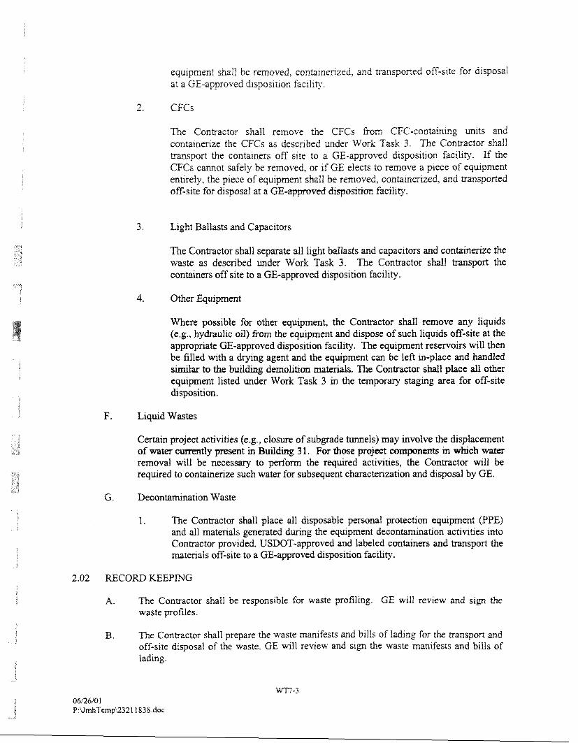
equlpmenr shall be removed, eonbmenzed, and transpaned off-site for disposal at a GE-approved d~sposlt~on facility.
2. CFCs
The Contractor shall remove the CFGs from CFC-conbtnmg unlts and contalnenze the GFGs as described under Work Task 3. The Contractor shall transport the containers off site to a GE-approved drsposrtlon facility. If the CFCs cannot safely be removed, or ~f GE elects to remove a piece of equlpment enQrely, the piece of equlpment shall be removed, contarnenzed, and @anspor?ed off-site for drsposal at a GE- d dispostrm facil~ty.
3. Light Ballasts and Capacitors
The Contractor shall separate all light ballasts and capacitors and containerize the waste as described under Work Task 3. The Contractor shall transport the containers off site to a GE-approved disposition facility.
4. Other Equipment
Where possible for other equipment, the Contractor shall remove any liquids (e.g., hydraulic oil) from the equipment and dispose of such liquids off-site at the appropriate GE-approved disposition facility. The equipment reservoirs will then be filled with a drylng agent and the equipment can be left in-place and handled similar to the building demolition matexiah. The Contractor shall place all other equipment listed under Work Task 3 in the temporary staging area for off-site disposition.
Certain project activities (e.g., closure of subgrade tunnels) may involve the displacement of water currently present in Building 3 1. For those pro~ect components m which water removal will be necessary to perform the required activities, the Contractor will be required to containerize such water for subsequent characterization and disposal by GE.
G. Decontamination Waste
1. The Contractor shall place all disposable personal protection equipment (PPE) and all materials generated during the equipment deconmination activities into Conmetor provided, USDOT-approved and labeled containers and transport the matenah off-site to a GE-approved disposition facility.
2.02 RECORD ICEEPING
A. The Contractor shaII be responsible fbr waste profilmg. GE will review and sign the waste profiles.
B, The Contractor shall prepare the waste man~fests and bills of ladrng for the transport and off-srte disposal of the waste. CE will review and sign the waste manifeests and bills of lading.
Work Task 8
General Electric Company Pittsfield, hf[assachuse~s
Demolition Debris and Eaui~rnent/Seiect Fill Placement
1.01 WORK INCLmED
A. This work task shall include all Labor, equipment, matenals, and senices necessary to place the building debris and equipment and/or select fill into the basement of Building 3 1.
A. Select work activities under this work task vary depending on the type of demolitionldisposition material being removed. As previously indicated in the Work Plan, certain materials are required to be disposed of at an appropriate off-site facility. In addition, GE may elect to consolidate certain materials at the Building 71 OPCA. The Contractor shall be prepared to conduct activities in t h~s work task in accordance with applicable regulations.
1.03 SUBMITTALS
A. In its Site Management Plan, the Contractor shalI submit a Demolition Debris and Equipment/Select Fill Placement Plan (Placement Plan) for the Building 31 Area to GE for review. The Placement Plan shall identify the Contractor's equipment, materials, and methods proposed to place the demolition debridselect fill into the basement of Building 31. The Placement Plan shall identify the Contractor's proposed phasing of the placement activities.
2.0 WORK ACTIVITIES
2.0 1 PRE-DISPOSITION ACTIVITIES
A. Prior to the disposition activities, the tunnels must be closed and sealed as described under Work Task 5.
B. Prior to the disposition activities, the demolition debris and equipment must be removed and processed as described under Work Task 6.
C. All structures in the basement must be de~nolished.
2.02 DEnilOLITION DEBRIS GW EQUIPMEhT DISPOSITfON ACTIVITIES
' b e Contractor shall conduct the activltles described below. The general d~sposition of matenals is illustrated on Figure 4 of the Work Plan.
A. Bnck, masonry, concrete, glass, and coal bulldlng matenal (emshed building matenal) w11l be placed on top of the baserneat floor. The crushed bulid~ng matenal shall be placed III maxlmum uncompacted 11fts of one foot and compacted by passlng a nlnlmum 25-ton landfill compactor (equipped with caron compaction wheels) for a mrnrmurn of five passes.
B. Structural steel shall be placed m maximum uncopacted llfts of one foot and compacted by passlng a 25-ton landfill compactor (eqmpped w~th caron compactton wheels) for a mlnlmum of five passes.
C. Foflomng the placment of any drscrete strut-1 steel layer, ur rf excessrve vo~d spaces are ident~fied following the placementicompaction of other matenals (as detem~ned by GE), the Contractor shall place 6 ~nches of flowable fill m accordance w~th the Technical Specifications for Flowable Fill Matenal provlded m Section 1.0 of Attachment C to the Work Plan. The 6-mch thickness shall be measured from the top of the prevlous layer and not include any flowable fill used to fill any vo~ds m the structural steel layer (if any). The flowable fill must be cured for a minrmurn of 72 hours [or when mlnimum compresswe strength is 150 pounds per square ~nch (PSI)] pnor to placement of any additional matenals or equipment on the flowable fill.
D. -0ughout the disposition activities, the basement of Building 3 1 shall be covered with a minimum of two low-permeability, 6-mil high density polyethylene (HDPE) covers overlapping by 2 feet in all areas and secured (e.g., with a sand bags and ropes) at the end of each workday, when placement activities are not being conducted, and during periods of inclement weather. The Contractor may propose alternative methods for covering the Building 3 1 basement for review by GE.
E. In the event that adequate quantities of processed equipment, structural building material, or crushable building material are not available to complete the placement process or to fill the basement to a depth of 12 inches below grade, the Contractor shall import borrow fill that meets the requirements of the Technical Specifications for Select Fill Material, provided in Section 2.0 of Attachment C to the Work Plan, for filling the Building 31 basement.
Work Task 9
General EIectric Company PittsBeld, Massachusetts
R e ~ a i r and Modification to Select Structures
I .O IYTRODI'CTION
1.0 1 W O W SPECIFIED
A. All labor, tools, machmwy, guarding and protection, including all excavation and incidentals necessary to satisfactorily complete modification and repair of the designated structures, including but not limited to: select electrical distribution vaults at perimeter of Building 31 and ash hopper piers at east side of building.
B. Water used for dust control.
C. Segregation of building materials, if required.
A. Submit work designated in this section as a specific project activity as part of project schedule under provisions of Contractors submittals.
m S m G CONDITIONS
A. Conduct modification and repair operations in such a manner to seal and isolate structures from adjacent Building 3 1.
B. Provide, erect and maintain temporary safety barriers and security devices.
C. Conduct operations with mini~um interference to public or private tharoughfms. Maintain protected egress and access at all times.
D. Do not close or obstruct roadways without permits or GE approval.
E. Operations to be coordinated with Building 3 1 demolition activities.
F. Refer to details as provided on Whlte Engineering Drawing GE 3 1-01,
2.0 PRODUCTS
2.01 CONCWTE
A. All concrete shall have a mlnlmum 28-day cornpresslve stragth of 3,000 psi, a maximum water-cement ratio by we~ght of 0.45, and a mlnlmum cement content of 550 pounds per cubic yard. Cement shall be ASTM (2150, Type II.
B. Slump: 4 Inch nraxlmw as detmmed by A S m C-143.
C. Air Content: 3 percent to 4 percent.
D. Reinforcing bar - Grade 60.
E. Smctural Steel - A36.
F. Fastener - ttueaded rod A36
G. Anchors.
R. Bonding Material for patching - S E P Products Sikadur 32, Hi-Mod LPL.
I. Resurfacing and repair material - S E A Products Sikadur 45 Epocem.
3.0 WORK ACTIVITIES
3.01 EXECUTfON
A. Modification and repair of designated structures and appurtenances shall be done in an orderly and careful manner.
B. Cease operations and notify GE immediately if adjacent structures appear to be endangered. Do not resume operations until corrective measures have been taken and approval by GE has been granted.
C. No b d g or t m h g shall be allowed at the demolition site without prior written approval from GE.
D. Comply with the elements of the Dust Control Plan as outlined in the contractors submittal.
E. Preparation shall consist of, but not limited to, the following:
1. Surface prepmation and penetration shaping to allow for effective powbacks and patching.
2. Core drilling vault top to allow placement of concrete, as required.
F. Accurate placement and securing of form work and associated anchors and reinforcement.
G. Application of bonding adhesives.
£3. Placing of concrete to insure no pin pockets or voids exist after forms are removed.
I. Application of patchng material after fonns are removed on Stru-1 . Patching and repair material to be applied to all horizontal and vertical extenor surfaces to grade.
J. Installation of s m c m l steel in areas desigated in details.
K. Placing of concrete on top of Stru-5 to bmg top of total structure to un~fom grade. See Drawmg GE-3 1-53,
L. Preserve two east ost plers at ash hopper stmemre to east side of bu~ldmg. Gut columns on these piers at elevatron of top of steam and condensate plpes presewmg pipe supports that are welded to colums.
Work Task 10
General Electric Company Pittsfreld, 31assachuseHs
Placement of a Surface Cover
A. This work task shall include all labor, equipment, and materials required for placement of an enpneered barrier over the basement of Building 31 and a surface cover over areas outside of the Building 3 1 foundation area, as shown on the Figures provided following the Work Task descriptions.
2.0 PRODUCTS
2.01 SURFACE COVER (Areas outside of the Building 3 1 foundation)
The following products shall be supplied by the Contractor.
A. Subbase Course
1. Subbase course shall be gravel borrow. The gravel borrow shall be bank run, or filler may be added by approved methods, and shall consist of sound, durable particles of crushed or uncrushed gravel free from loam, clay, soft vegetable matter, and elongated pieces of rock. The material shall conform to the Massachusetts Department of Highways Standard Specifications for Highways and Bridges for M1.030, Type C grave1 borrow.
B. Base Course Aggregate
1. The crushed stone aggregate for the bituminous concrete base course shall conform to the requirements of the Massachusetts Department of Highways Standard Specifications for Highways and Bridges Division III Section M. The maximum aggregate size shall be 2.5 inches.
C. Bituminous Binder
1. The binder shall be asphalt cement confodng to the requirements of AASHTO 20.
D. Wearing Surface
1. The weanng surface shall be Type 1-2. The matenal shall conform to the qualrty requirements as stated in the Massachusetts D e p m e n t of Highways Standard Specificatrons for Highways and Bndges Divrslon ILI Sect~on N.
E. Tack Coat
1. Tack coat shall be Asphalt Emulsion, RS-1. The matenal shall conform to the quaf~ty requirements as stated in the Massachusens Department of Highways Standard Speclficatlons for Highways and Bndges Division 111 Sect~on M.
E N G m E W D B ER (Area of the Buiid~ng 3 1 foundat~on)
The following products shall be supplied by the Contractor, as s h o w on the Figures.
A. HDPE G e o m m h n e Liner
1. The geomembrane shall be a 60-mil thick high density polyethylene (HDPE) liner with a textured surface on each side. The material and perfonnance requirements for the geomembrane liner are specified in Section 9.0 of Attachment C to this Work Plan.
B. Geosynthetic Drainage Composite
1. The geosynthetic drainage composite (GDC) shall be composed of an HDPE drainage net composited with two (21, 6 oz;iyd2 non-woven geotextiles. The geotextiles shall be heat bonded to both sides of the drainage net. The material and performance requirements for the GDC are provided in Section 10.0 of Attachment C to this Work Plan.
C. Subbase Course
1. The subbase course shall meet the same requirements listed in Section 2.0.1 .A. 1 above, but shall consist entirely of uncrushed (i.e., round, run-of-bank) gravel.
D. Base Course Aggregate
1. The crushed stone aggregate for the brtuminous concrete base course shall conform to the requirements of the Massachusetts Department of Highways
' Standard Specifications for Highways and Bridges Division Ill Section M. The maximum aggregate size shall be 2.5 inches.
E. Bituminous Binder
1. The binder shall be asphalt cement conforming to the requirements of AASHTO 20.
F. Wearing Surface
1. The wearing surface shall be Type 1-2. The matenal shall conform to the qual~ty requirements as stated in the Massachusetts Depament of H~ghways Standard Specifications for Highways and Bndges Dit?sion I11 Section M.
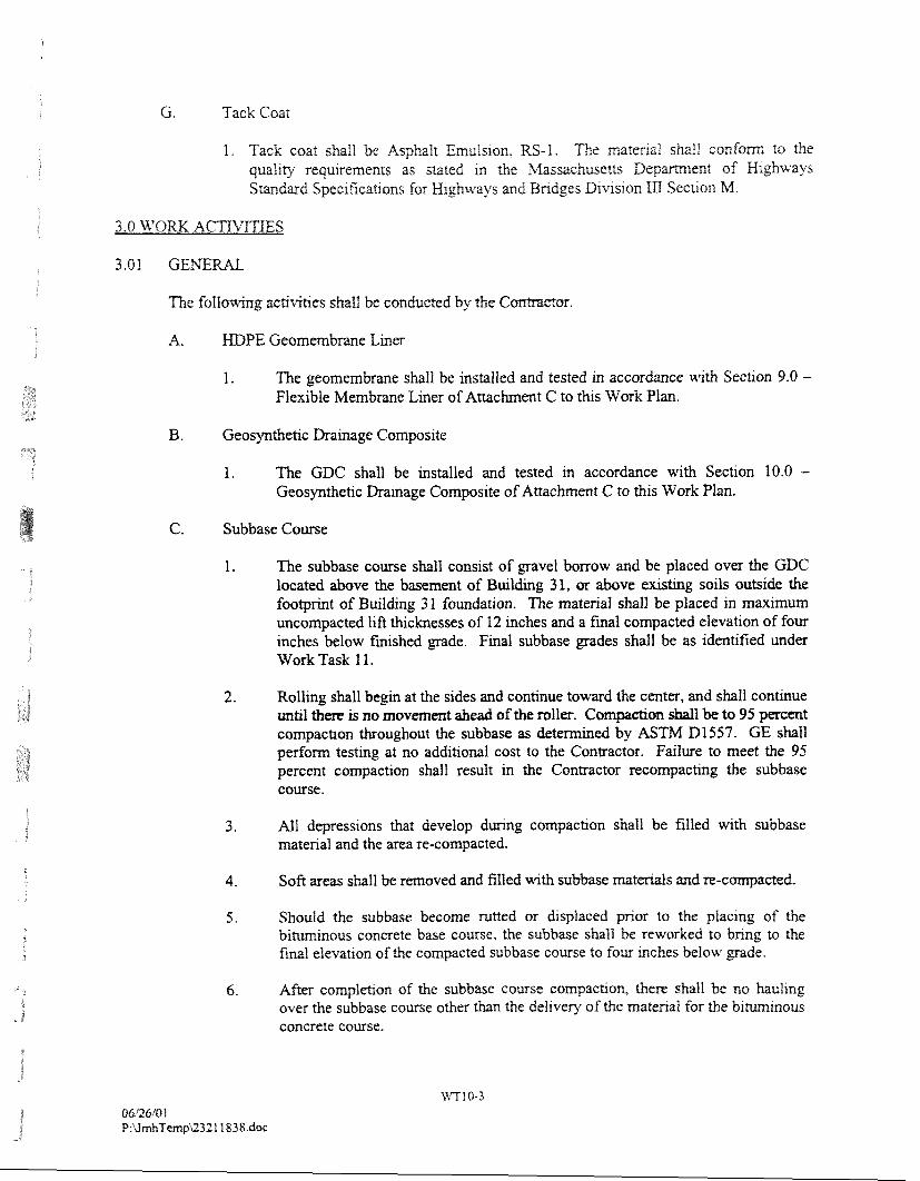
G. Tack Coat
I . Tack coat shall be Asphalt Emulston, RS-1. The materlai shall conform to the qu;if~ty requirements as stated m the Massachusetts Depament of W~ghufays Standard Specrfications for M~ghurays and Bndges D~vision I11 Secaon M.
The f o l l o ~ k g activities shaI1 be conduced by the C
A. HI>PE Geomembmne Liner
1. The geomembrane shall be insblled and tested in accordance with Section 9.0 - Flexible Membrane Liner of Attachment C to this Work Plan.
B. Geosynthetic Drainage Composite
1. The GDC shall be installed and tested in accordance with Section 10.0 - Geosynthetic Drainage Composite of Attachment C to this Work Plan.
C. Subbase Course
1. The subbase course shall consist of gravel borrow and be placed over the GDC located above the. basement of B u i l h g 31, or above existing soils outside the footprint of Building 3 1 foundation. The material shaIl be placed in maximum uncompacted lift thicknesses of 12 inches and a final compacted elevation of four inches below finished grade. Final subbase grades shall be as identified under Work Task 1 1.
2. Rolling shall begm at the sides and continue toward the center, and shall continue until there is no movement ahead of the roller. Compctim shall be to 95 percent compaction ~ o u g h o u t the subbase as d e t b n e d by ASTh4 D1557. GE shall perform testing at no additional cost to the Contractor. Failure to meet the 95 percent compaction shall result in the Contractor recompacting the subbase course.
3. All depressions that develop during compaction shall be filled with subbase material and the area re-compacted.
4. Soft areas shall be removed and filled with subbase materials and re-compacted.
5. Should the subbase become rutted or d~splaced pnor to the placing of the bihuninous concrete base course, the subbase shall be reworked to bnng to the final elevation of the compacted subbase course to four Inches below grade.
6. After compIetlon of the subbase course compacbon, there shall be no hauling over the subbase course other than the del~very of the matenal for the b ~ m m o u s concrete course.

Followng cornplet~on of the subbase preparation and ~mmedtately pnor to blturnlnous concrete ~nstallat~on, the compacted area shall be proof rolled w t h a 20-ton fully loaded tandem. Uncompacted (areas ~nd~catrng a one-inch or deeper impression) areas ~dent~fied as a result of the proof roll~ng actlwties shall be re- compacted at no addit~onal cost to GE and the repalred areas re-proof rolled to ven& adequate cornpactlon. In the event that preeiprtatlon occurs ibIlourmg complet~on of a successful proof roll, but pnor to placement of the b~tumlnous concrete layer, GE may decide to re-proof roll the subbase layer at no additional cost to GE.
Biminous Concrete
1. Paving
a. Place concrete mixture on prepared surface, spread, and strike-off. Spread mixture at temperatures in the range specified in Section 460 of the Massachusetts Department of Highways Standard Specificat~ons for Highways and Bridges. Place inaccessible and small areas by hand. Place the bituminous concrete base course to a compacted thickness of 2.5 inches and the bituminous concrete wearing surface to a compacted thickness of 1.5 inches. Tack coating shall be applied to the exposed sidewalls of the basement of Building 31 prior to placement of the base course and in between the bituminous concrete base course and the bituminous wearing surface. The Contractor shall appiy the tack coat at the rate specified in Section 460 of the Massachusetts Department of Highways Standard Specifications for Eghways and Bridges.
b. Place pavement in accordance with Section 460 of the Massachusetts Department of Highways Standard Specifications for Highways and Bridges.
c. Completed grade of bituminous cap shall meet the requirements set forth under Wcnlr Task 1 1, Final Site Gradmg.
2. Compaction
a. Bituminous concrete base course and wearing surfaces shaIl be compacted in accordance with Section 460 of the Massachuserts Department of Highways Standard Specifications for Highways and Bridges.
b. After GnaI rolling, do not permit vehicular traffrc on pavement until pavement has cooled and hardened (minimum 72 hours).
C. Erect barricades to protect' paving from traffic until the mixture has cooled enough not to become marked.
3. Testing
a. The h ~ s h pavement shall be to grade.
b. Vanatrons exceeding 114-mch or dqressrons shall be sarrsfactonly conected. There shall be no depress~ons that shall retam stand~ng water.
c. GE may authorize addlt~onal testmg of the finished pavment. Failure by the Contractor to meet these spec~ficaQons as a resuit of the additional testlng shall requlre the Coneactor to replace unsatisfactor~. pavement.
tt'ork Task I I
General Electric Company Pittsfield, Massachusetts
Final Site Grading
A. All labor, supervision, materials, tools, and equipment for the site grading to be executed subsequent to the dmolition and capping activities associated with the removal of Building 3 1.
B. Backfilling, compaction and bringzng to grade all materials to achieve final site contours.
C. InstaIIation of drainage materials.
D. Installation of geotextile fabrics.
E. Installation of bituminous curbing.
F. Application of topsoil to existing slope east of Building 3 1 to restore grade. -
G. Application of topsoil as required to smooth out and dress existmg contours north of building.
H. Application of seed and associated fertilizers.
A. Procedures to be used in the installation of geotextile materials.
B. Sample of geotextile material to be used.
C. Location of source, and pH and organic content testing results of topsoil used at site.
D. Sieve analysis for gravel borrow material to be used on site. Contractor to provide a minimum. of one sieve analysis for each 100 cubic yards of material to be imported to the site. Analys~s must indicate compliance with specifications.
E. The Contractor shaII provide GE with the laboratory analytxal results inheating that PCBs are- present in the grave1 borrow material at concentrations not greater than method detection limit.
F. A listing of the source of the gravel borrow material shall be submitted for approval by GE.
G. Sreve analysis for p1anQng matmal to be used on slte. Con&actor to provlde a minimum of one sleve analys~s for each 50 cubic yards of topsoil to be imported to the site. Analys~s must ~ndicate compl~ance wth sgec~fications.
H. The ConWactor shall provide GE with the laboratory analyt~cal results mdlcanng that PCBs are present in the tops011 material at concenn-atlons no1 greater than method detection ilrnlt.
I. Mo~smre dens19 curve for each matma] to be used for embankment construction.
J. Compaction denslty reports.
1.03 SCHEDULE
A. A schedule of restoration operations shalI be submitted to the Contractor for revlew.
1. After an accepted schedule has been agreed upon, it shall be adhered to unless otherwise revised wth the approval of GE.
B. The replacement of surfaces at any times, as scheduled or directed, shall not relieve the Contractor of responsibility to repair damages by settlement or other failures which may occur after restoration of surfaces.
2.0 PRODUCTS
2.0 1 MATERIAL AND EQUIPMENT
A. Borrow Material - Massachusetts Highway Department Standard Specification MI .03.0, Type B.
-
B. Rip-Rap - Rip-rap shall be sound, durable rock, which is angular in shape and nominal dimension to be 4 inch to 6 inch.
C. Bituminous Curb (dense mix) - Massachusetts Highway Department Standard Specification M3.11.03, Tabie A, Type 2.
D. Topsoil - Any topsoil brought from off-site locations shall be unfrozen, iiiable, natural loam and shall be free of clay lumps, brush needs, litter, shunps, stones, and other extraneous matter. The topsoil shall have an organic content between 5 and 20 percent and a pH between 5.5 and 7.5 percent.
E. Fertilizer - Massachusetts Highway Department Standard Specification M6.02.0.
F. Seeds - Massachusetts Highway Department Standard Specification M6.03.0. Mix to meet proportions for slopes and shoulders.
G. Interfiace Between &p-Rap and Bmow Fill - Mi& 140 N.
H. Erosion Control'murf Reinforcement - North Amhean Green C-350.
3.0 WORK AGTIkqTIES
A. The sequence of embankment construction shall be eoordlnated wth bu~ldmg demolltlon act~v~ties and to plans and details as s h o w on anached drawings.
B. Placement of gravel borrow. Place fill layers wrth a maximum loose thckness of 12 ~nches pnor to compaction. Compact each layer to at least 95 percent maximum dry dens19 at optlmum moisture content, as detemlned by standard ASTM D1557, Method D.
C. Place geotextile as indicated in areas shown on plans and associated details,
D. Install curbing as shown on plans and associated details. Locate openings in curbs where shown. Curbing to be set on binder course of substrate.
A. Place topsoil as shown on embankment. Fill and dress low areas of existing bank. At north side of building site, dress by filling only. Level new material only. Existing fill is not to be excavated and is to remain undisturbed.
B. Seed and fertilize to meet specifications.
Figures
BLASLAND, BOUCK ii LE
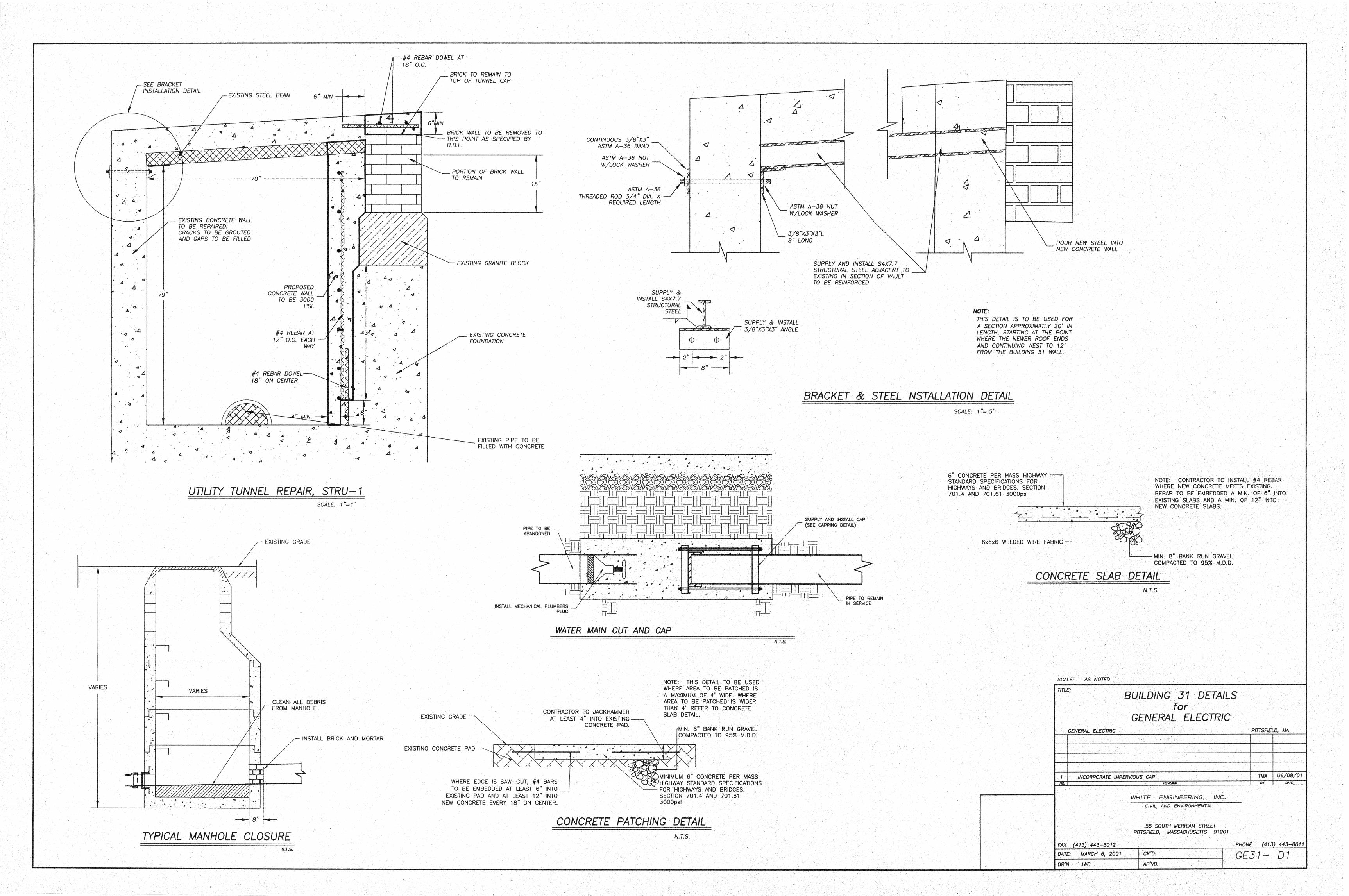
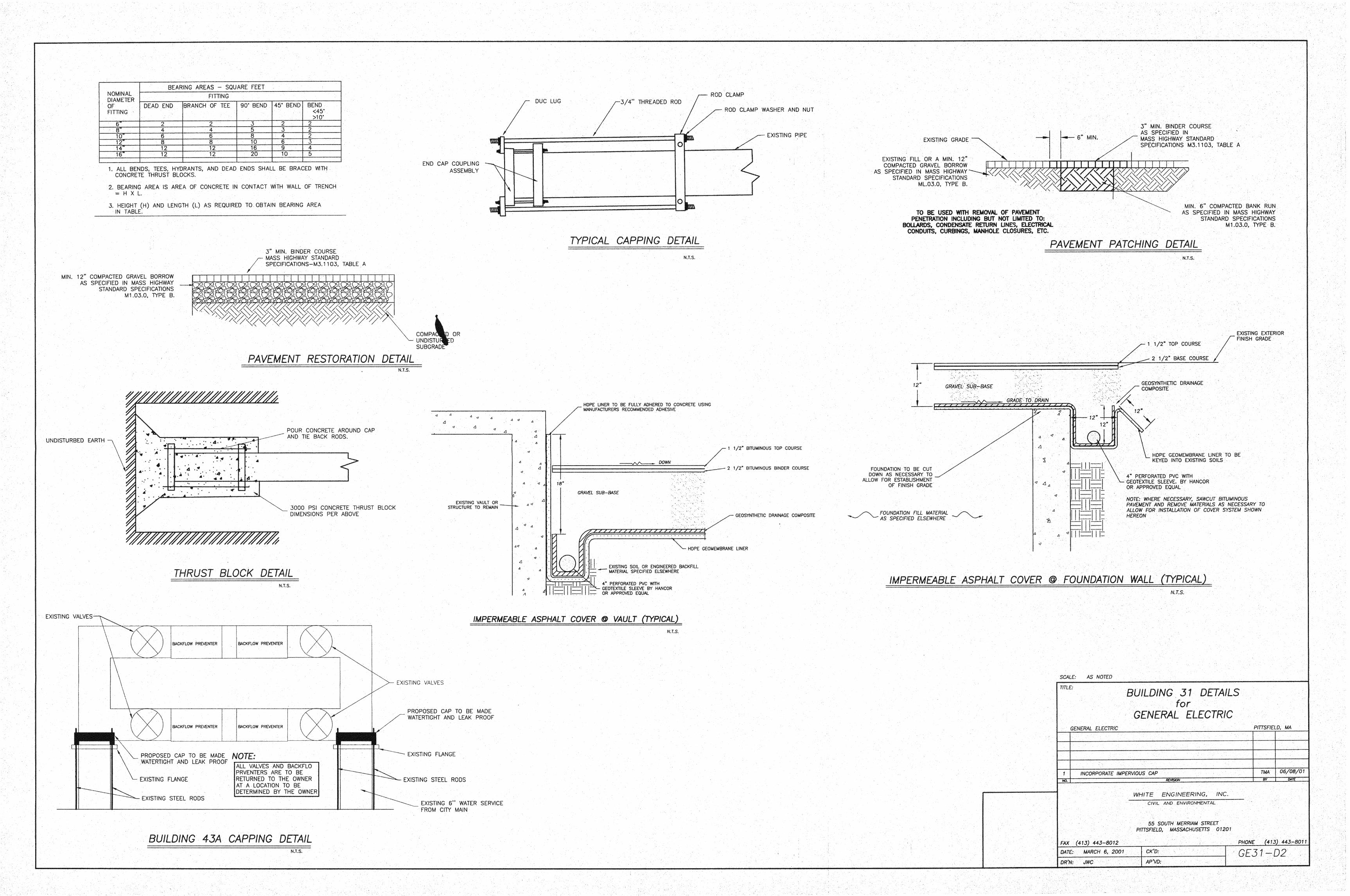
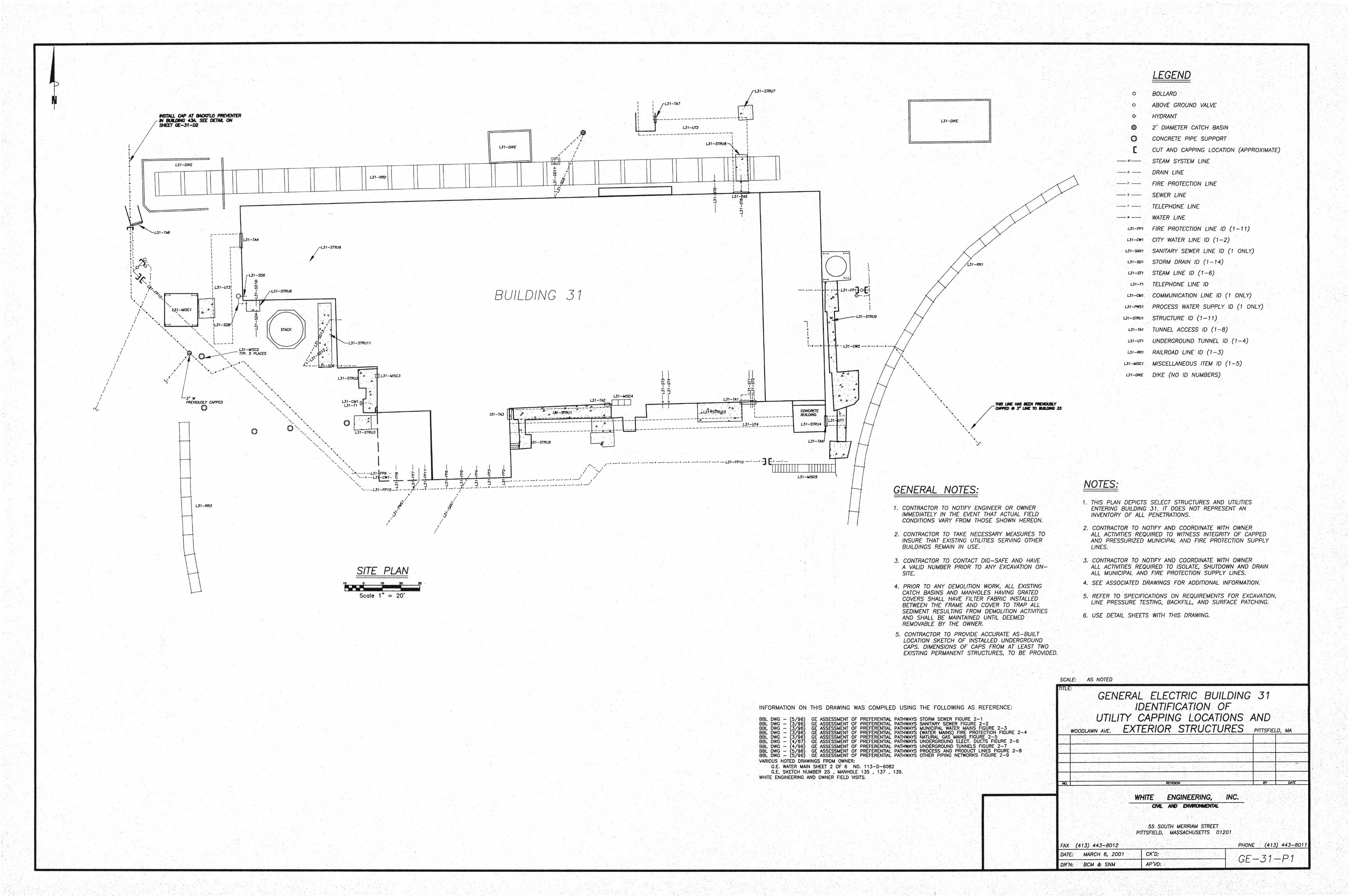
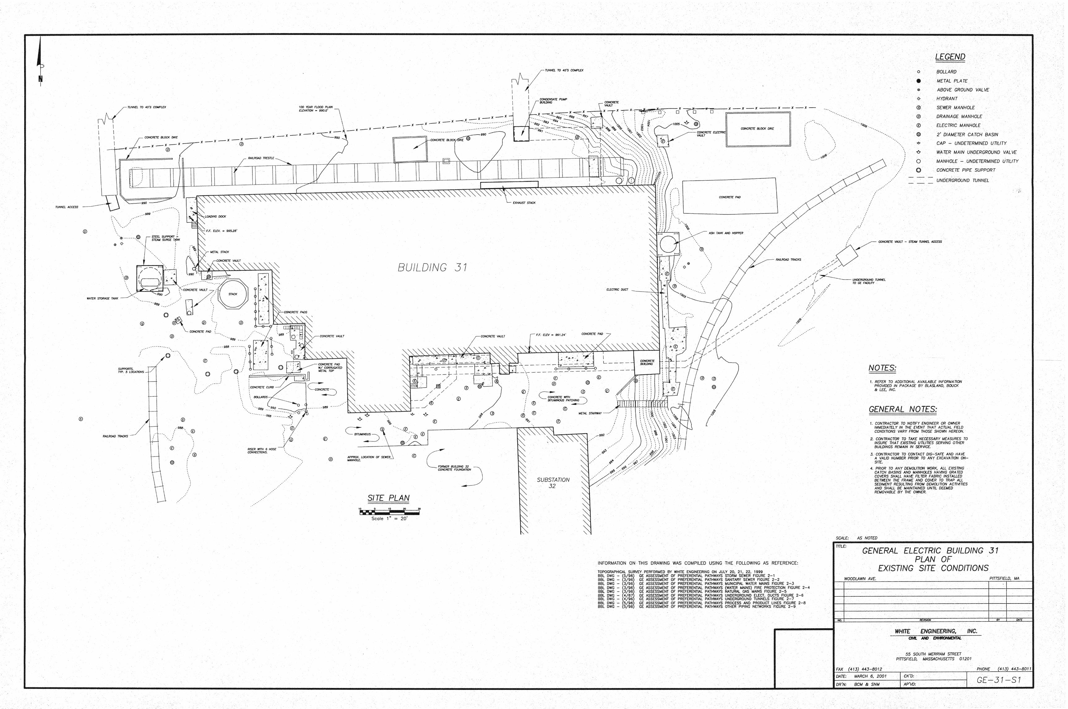
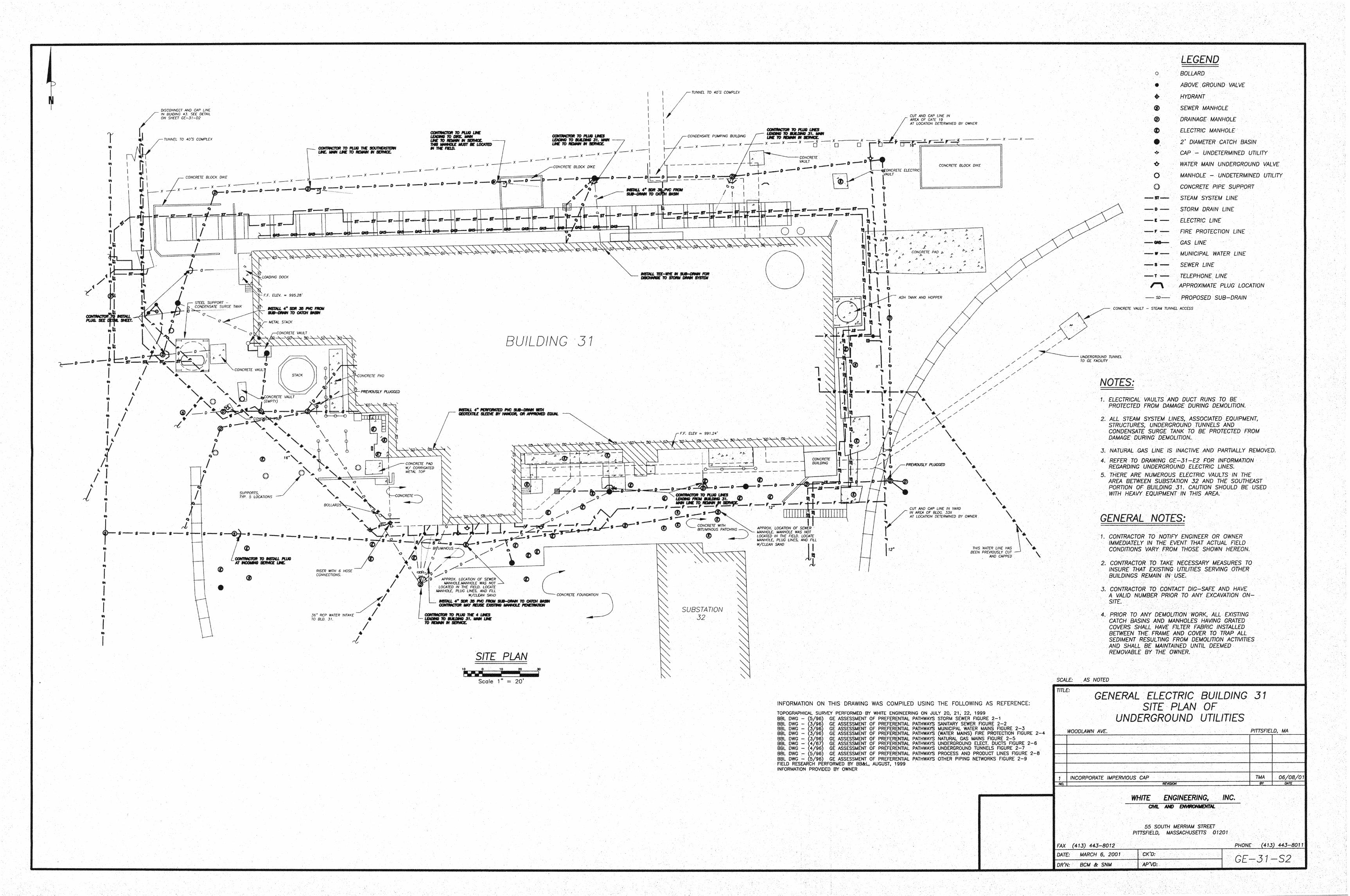
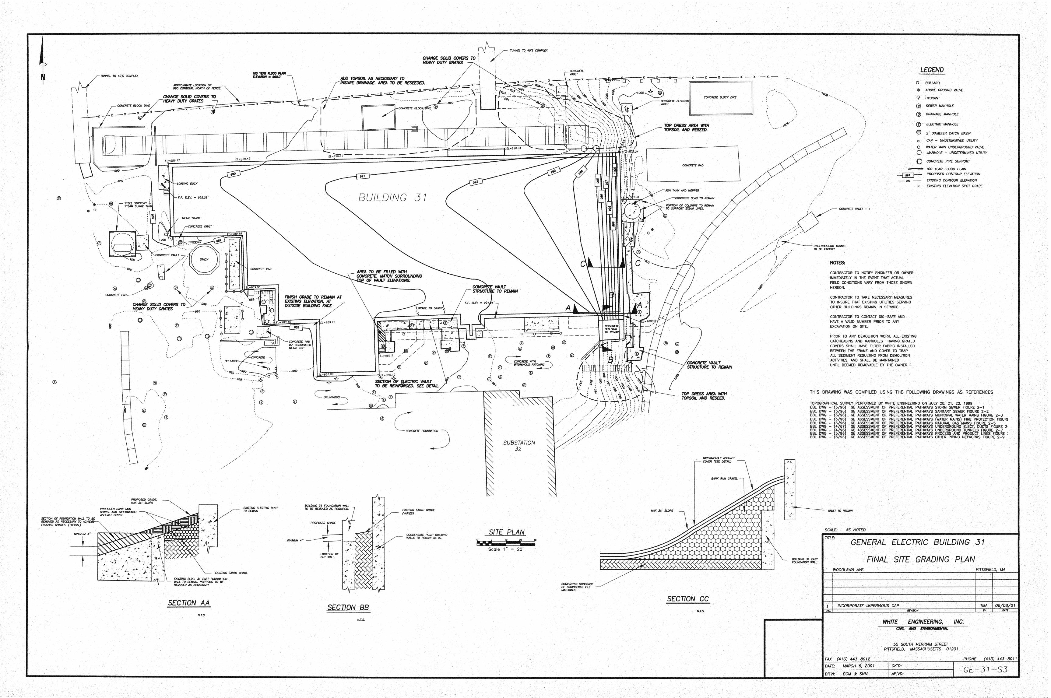
Appendix I
Pitfsfield Conservation Commission Order of Conditions
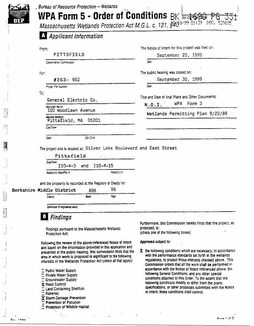
. Bureau of Resouce P mtection - Wetfands
WPA Form 5 - Order of-conditions BI::: Massachusetfs Wetlands Protection Act M. G. L. c. 13 1, $v6
Applicant information
From: The Notice of fnrent for m~s projea was hleC an. PITTSFfEtD September 20, 1999
tonswm~o, C ~ m w m Azn
Far: The public heanng was closed on:
8263- 662 September 30, 1999 F2.s Fife ~ ~ C f ' Clrc
General Elec t r ic Co. &E.*& '*.f t 100 Woodlawn Avenue
Title and Date of final Plans and Other Documents:
N.O.I. WPA Form 3
Wetlands Permitting Plan 9/22/99
The project site is located at: Silver Lake Boulevard and East Street
Pittsfield QA-w
110-4-3 and 110-4-15
and the propeny is recorded at the Registry of Deeds for:
Findings FuNlermore, this Commission hereby finds that the projeci. as
Findings pursuam to the Massachusetts Wetlands proposed, is: (dieck one of the following boxes) Protectron Act:
Fotlowing the review of the a b o m e r e n c e d Now of tntem and based on the infomration provided in tftis appircittion and presented at the public hearing, Uiis w m o n finds that me ma in which wo& is proposed is s i g n i f i m to me foltowing interests of the Wetlands Protection Act (check ail that apply):
Z Publ~c Water Supply Z: P m t e Water Supply I: Groundwater Supply p Rood Conml Z Land Contarning Shellllsh Z fiStrtncs x Stcm Damage Prevtntron r: P n v ~ l t i o n of Pollution - - on of Wldiift Habitat
Appfmnd subject to:
21: the follmng conditrons wh~ch are necessary, in actordance mttr thc performance standards set to& in the wetlands ~gulanons, to protect those interests checked above. This
n orders that at1 the work straft be performed m with the Nobu? of Intent referenced above. me
f d m n g GeneFal Condlhons, and any other s p w a l c~ndRtons mraChed to tfits Order. To the extent that tne
ng condaons mMiify or diff er from the plans, mans, or other p r o p o a s s u b m e d wtlt the Noace
of Imtnt, these cmdltrons shall control.
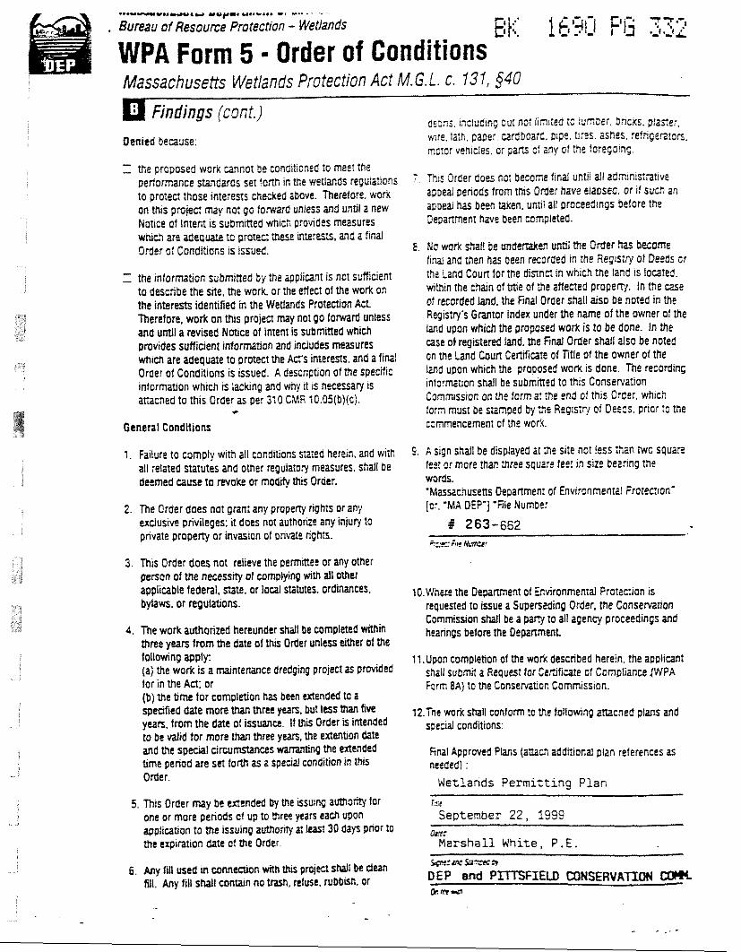
*~*~-I*.WOIY YO)LOII w..r..r r r c- r - - B u ~ a u o f Resource Protectron - Wetlands E ' t 6 i. 16qi-I -- I- 7 7 ~ ~ S J .-ti
WPA Form 5 - Order of Conditions Massachuseits Wetlands Protection Act M. G. L. c. 13 7 , $40
Findings jcont Denied because:
Z. the proposed work cannot be conditioned to meel itre p e r f o m n c e -bards se? fonh in the weztands regulations to proted those ~n te rens checked above. Therefore. work on tfus projed may not go torward unless and unrit a new Notne of Intent IS submrned wrrich provfdes measures which are adequate to protw these mErests, and a firid Order of CondEtions is issued.
Z the information submined by :he applitanl is not sufficient to describe the site, the work, or the efl ecr of the work on the interests identified in the WetIands Protection Act Therefore, work on this projea may not go forward unless and until a revised Notice of Intent is submined which provides sufficient information and includes measures which are adequare to proted the Act's interests. and a final Order of Conditions is issued. A description of the specific information which is lacking and why it is necessary is arracned to this Order as per 310 CMR 10.05(b)(c).
- C
General Conditions
aeons, tncfudmg but not frnited ic luf'nDer, bncks. pfane!. wre, lath, paper cardboard, pfpe. 11feS ashes, refngerztan, rno;or vehrctes, or p a N o: any of the foregoing
7 This Order does no: become final untrl all admtnistaive appeal penods from this Order have etased. or i f such an apoeal has been Elken, un~l ail proceedtngs before the DepaRment have been ccmpleted.
8 No work fiat1 be unde-n mi the Order has become find and then has been recorded m the R e g t s i ~ of Deeds cr tha Land Court for the d i n n d In which the land a located. wmm the chain of Mle of me affectad propent. In the cast of recorded land, the final Order shall also be noted in the Repts:ryis Grantor Index under the name of the owner of the land upon which the proposed work is to be done. In the case of registered land, the Find Order shall also be nored on the Land CouR Certif~cate of Title of the owner of the l a d upon which the proposed work IS done. The record in^ informarion shall be submmed to this Con~eRa?lOn Comm~ss~on on the form 31 the end of this Order, whlcfi :or3 musr be siamped by t:e Regls;r{ of D e ~ z s . prior :o the c;nmencemenI of the woe<.
1. Failure to comply with all conditions s x e d herein, 2nd with 5. Sign Shall be displayed 31 :he Site nor !eSS :hZn NO Square all related statutes and other regulatory measures. shall be fee? or more than three squar? fee? in siz!? berrrng the dwmed muse to revoke or modify this Order. words.
'Massanusens Oepanmenr of Environmenml Frotec?ion' 2. The Order does not grant any propeny rights or any [cr. 'MA DEP'] 'File Numbe:
exclusive privileges: it does not authoriie any injury to # 263-662 private properiy or invasion of private rights.
F:::u: 6s kmr
3. This Order does not relieve the permittee or any other pencn of me necesstfy of complying with all Other applicable federal, state, or local statutes, ordinances, 10.V4hfre the Depament of avironmental Protacion is byhws, or regulations. requested to issue a Suuerstding Order, the Conserntion
Commissron shall be a par# to 21 agency proceedings and 4. The work authorized hereunder shall be completed within heanngs before the Oepa~ment
three yean trom the date of this Order unless tither of the fo~toHin~ apply (a) the work is a mdtntenance dredging project as prcvided for in the Act; or (b) me time for completion lras been Wended to a spefif~ed date nore than three yean, but less than five years, trom the date of issuance. If this Order is intended to be d i d for more than three yean, the extention date and the special dw-s time period are sd forth as a special condition in this Order.
5. This Order may be extended by the ssutng auth0nty for one or more penods of up to mrec years each upon wplicauon to Me issutng authonry at IedS 30 days pnor to ttte cqrratfon date of the Order.
11.Upon completion of the work described herein. the applicant shrll submd a Request for Ceftificale of Compliance V P A Farm 8A) to the Conservaaon Commrss~on.
12.Tne mrk shafl contom ?a Me following artacned plans and special conditions:
knat Approved Plans (am&? additional pltn references as needed) :
Wetlands Permitting Plan r.!tt
September 22, 1999 &E:
Marsha l l White, P , E . 6. Arty fifl used m connedton with Uus p r o m snail 5e dean
*:mc%=,7
fill. Any fill sMl c o m n no mh, ntuse, rubbtrh, of DEP and P Q#trsr
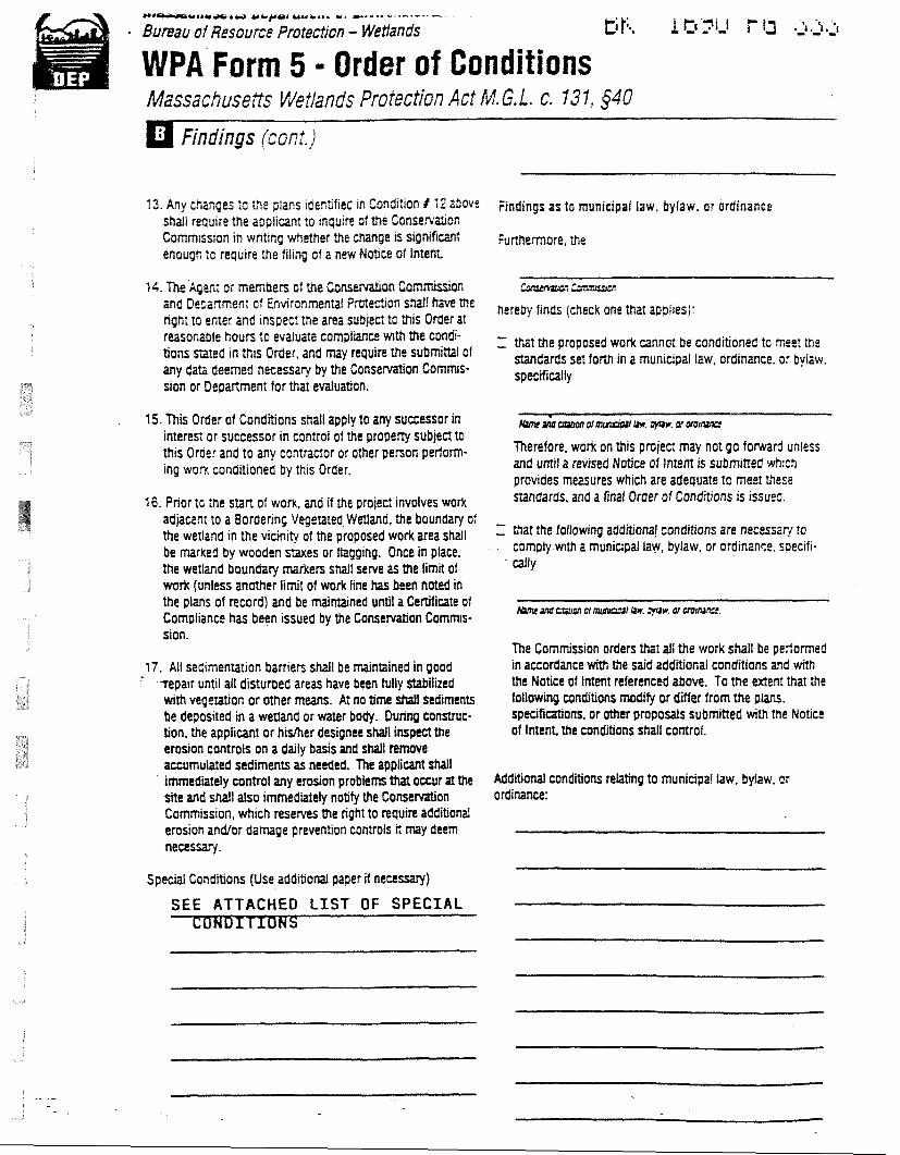
P * r C h w m u b 6 M ~ r w ucpar u v r r r r r. ---*a -------- 8umau of Resource Protection - Wetlands Ici>iJ f J J 3 3 . ~
WPA Form 5 = Order of Conditions Massachusetts WeNands Protection Act M. 6.L. c. 131, $40
Findings (con!.)
13. Any changes :o the pians idenDfied In Condtlton 1 12 above Findings a s to municipal faw, bylaw, or ordinance shall requrre the appiicanr to inquire of the Consewatlon Commrssron in wntlng whether the tttange is signifiwlt f u m e m o r e , me enough lo requlre the fiitng of a new Notlce of Intent
14. The'kenr or memners of the and tierianmen: of EnwronmenM Pmec?ion sfiafa hwe me finds (G9eck one aPpires): npht to enter and inspect the area subject to this Order at r&sonable hours to evaluate compliance wrth the condi- Z that the proposed work cannor be condiQoned to nee! the Gens S t e d in Order. and m y rewire the submim of standards set fom in a municipal law, ordinance, or by,atv, any Gat;: deemed necessary by the Conservation C O ~ ~ S - specifiollly slon or Department for that evaluation.
15 .7h i Order of Conditions shall apply to any surxessor in interest or successor in control of the property subject to this Oroer and to any contractor or other person perlorrn- ing worx conditioned by this Order.
16. Prior tc ihe start of work, and if the projec: involves work adjacent to a Bordering Vegetated Wetland, the boundary of the werland in the vicinity of the proposed work area shall be marked by wooden stakes or ftagging. Once in place, the wertand boundary markers shall serve as me limit of wurk (unless another limit of work line has b m noted in the plans of record) and be maintained until a Cenificate of Compiiance has been issued by the Conservation Commis- sion.
17. All seCinentation barriers shall be majntained in good - - --Yepair until all disturbed areas have been tuliy stabilized
with v e g m o n or other means. AT no time strati sediments be deposited in a wetland or water body. During construc- tion, the applicant or hislher designee shall inspect the erosion controls on a daily basis and shall remove ammutated sediments as needed. The applicant shall
' immedaety control any erosion problem that occur at the site and shall also immediate& notify the Conservation Commission, which reserves the right to require additioM erosion andlor damage prevention controls it may deem necesshy.
Special Conditions (Use additional paper if necessary)
SEE ATTACHED L I S T OF SPECIAL
Therefore, work on this pmjea may not go toward unless and until a revised Notice of Intent is submined whictr ~rovides measures which are adeauate to meel these A d a r d s , and a final Order of Conditions is issueg.
Z that the folfowing addhianal conditions are necessz? to . . comply-with a municipal law, bylaw, or ofdinan~e. s~ecifi-
- a l ly
The Commission orders that all the work shall be performed in accordance with me said additional conditions and with the Notice of lntent referenced above. To the extent that the tollowing anditians modify or difter from the p W . specificaiom, or other proposals submitted with Me Notice of Intent. the conditions shall control.
AdditioM conditions relating to municipa! law, byfaw. nr ordinance:
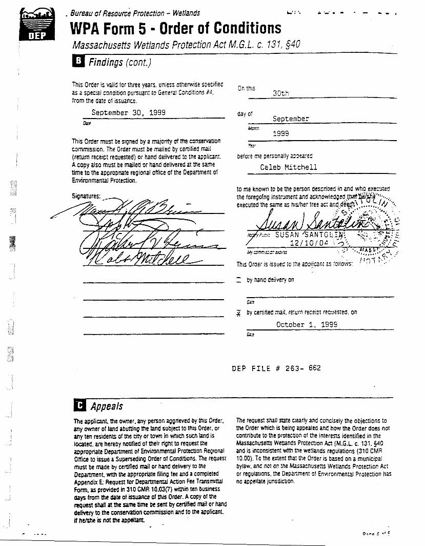
. Buaau 4f ~esou& Protection - Wetlands L.' : '. A = . - . - r - ,
WPA Form 5 = Order of Conditions Massachuse8s Wetlands Protection Act M. G.L. c. 13 1, $40
Findings (cont)
This Order IS d i d for three yean, unless olherw~se s~ectfied as a specai conditton punuanr lo Generd CConditlons td. from the date oi tssuance.
September 30, 1999 Lbu
mis Order must be ngned by a mjonty at ttre tnnSercatrOn commtssron. R e Order must be maifea by cenffied mi (return receipt requeded) or hand delivered to the applltanf. A copy also must be Miied or hand delivered a1 the Same time to the appropriate regional office of the Depanment of Envimnmental Protertion.
Appeals n e applicant the owner, any person aggnwed by tncs Order. any owner of hnd a b m n g the land subject to ths Order, or any ten ntstdents of the crty or town in wtuch such knd is located, are henby noMied of their right to request the
day of September
M r n 1999
Caleb Mi tche l l
Thts Oraer is issued io ;he apptjc;?fir 2s follows:
Z by hand ddivery on
ci:c
by cen~fied mail, rt?um recc!cr r2qutsied. on
October 1, 1999
DEP FILE P 263- 662
t h e request shall nafe dearty and concisely the objections to the Order wtuch s belnq appealed and how the Order does not m r i b u t e to the protmon of the i n t e r m idemified m the Massachusens Wetlands Prolemon Act (M.G.1 c. 131,§d0 and is ~nconststent with the Wetlands regulations (31 0 CMR 10.00). To the extent 8u1 the Order ts based on a municrpai Bylaw. and not on the Massachusens Wetiands Proteaion Act or regutauons, the DepaGment of Environmental Proternon has no appellate junsdtctlon.
- - - - -- -
B u m u of ~ e s o u d Protection - Wetlands
WPA Form 5 - Order of Conditions Massachusetts Wetlands Protection Act M.G.L. C. 131, $40
n Recording Information
ma Order of CondiBons must be recorded to the Regrstry of Deeds or Me Land C o u ~ for Me dlstnct In whr& the land is Iotatea, wtfitn me W n of MLe of the affected propeny. in the case of recorded tand, the FiMl Order sMI afso be noted in the Reg~stry's Grantor Index under the name of the owner of rhe land subted to the Order. In the Gase of registered land. Mts Order sMi also be noted on the Land Coun Certitiate of Et)e of ttM! a m r of tne tand utbw to the Order of CondiDonr. The recordrng infom&on shall be submined to the
on the form below, which must be stamped by the Registry of Deeds.
Delat3 en ~c ;zcd line ana s u ~ m i t to the Consarvation Commission. ---_._--------I-------- Sc- - - - - - -, ,, ,, ,, To:
&lli?!WE* &ZBSSUX
Please be aavised thar the Order of Conditions tor the projec: at
Pra,e L ~ S OEP Ek -I
has been recorded at the Registry of Deeds of
and has been noted in the main of ti!le of the affected propeny in
Bccr
in accordance wiM the Order of Gondifions issued on
Dur
If recorded land, the instnrmnt number wtricf! identiges His transaction is
&mxr
tf EgtReied knd. the document number Watr identrfies ttlts tmsachon ts
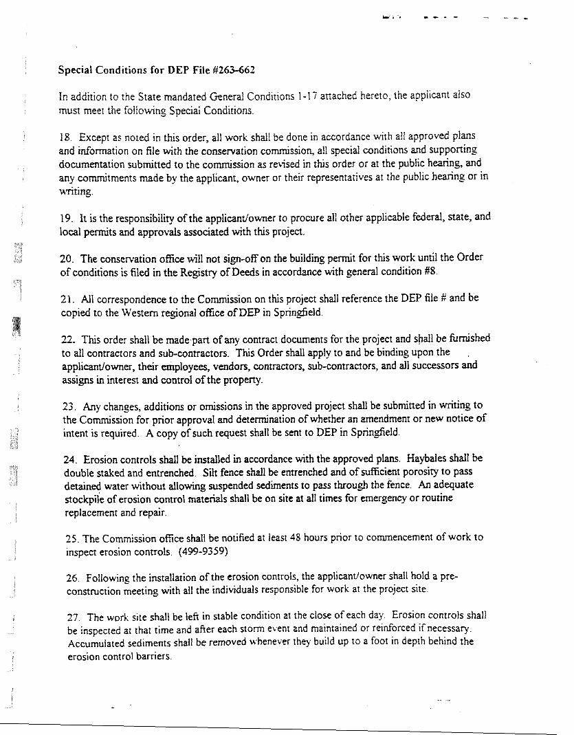
Special Conditions for DEP Fiie 51263-662
fn addition to the State mandated General Conditions 1-17 attached hereto, the applicant also must meet the fofioGng Special Conditions.
18. Except as noted in this order, all work shatl be done in aceordance with ati approved plans and infomation on file with the comemation co ssion, ail special conditions and suppofling documentation submitted to the co ed in this order or at the pubtic haring, and any cohtments made by the applicant, owner or their representatives at the public hearing or in writing.
19. It is the responsibility of the applicantlowner to procure all other applicable federal, state, and local pennits and approvals associated with this project.
20. The conservation ofice will not sign-off on the building permit for this work until the Order of conditions is filed in the Registry of Deeds in accordance with general condition #8.
21. All correspondence to the Commission on this project shall reference the DEP file fi and be copied to the Western regional office of DEP in Springfield.
22. This order shall be made.part of any contract documents for the project and shall be fUnzished to all contractors and sub-contractors. This Order shall apply to and be binding upon the ,
applicantdowner, their employees, vendors, contractors, sub-contractors, and all successors and assigns in interest and control of the property.
23. Any changes, additions or omissions in the approved project shall be submitted in writing to the Commission for prior approval and determination of whether an amendment or new notice of intent is required. A copy of such request shall be sent to DEP in Springfield.
24. Erosion controls shall be installed in accordance with the approved plans. Haybales shall be double staked and entrenched. Silt fence shall be entrenched and of sufficient porosity to pass detained water without allowing suspended sediments to pass through the fence. An adequate stockpile of erosion control materials shall be on site at all times for emergency or routine replacement and repair.
25. The Commission office shall be notified at least 48 hours prior 10 commencement of work to inspect erosion controls. (499-9359)
26. Following the installation of the erosion controls, the applicanv'owner shall hold a pre- construction meeting with ail the individuals responsible for work at the project site.
27. The work site shall be lefi in stable condition at the close of each day. Erosion controls shall be inspected ax that time and after each storm event and maintained or reinforced if necessary. Accumulated sediments shall be removed whenever they build up 10 a foot in depth behind the erosion control barriers
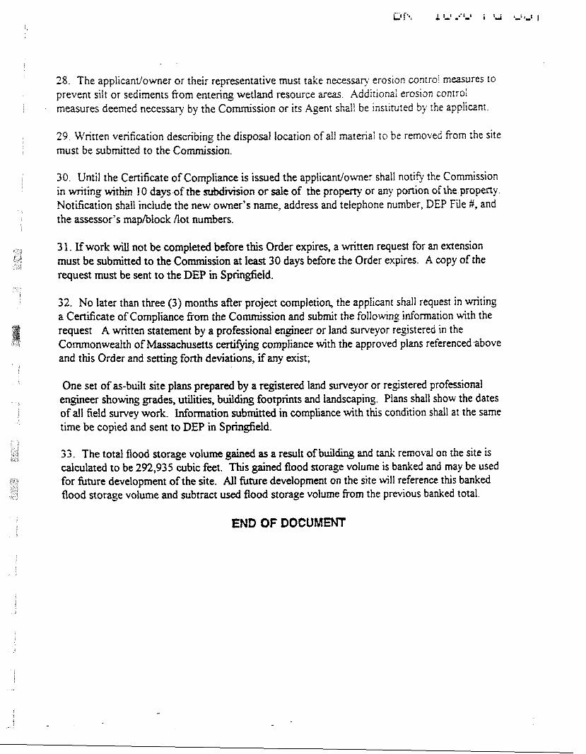
28. The applicantlower or their representative must take necessar): erosion controi measures to prevent silt or sediments from entering wetland resource areas Additional erosion conrroI measures deemed necessary by the Go ssion or its Agent shall be instimted by the applicant
29. Written verification describing the dispsat tocation of all marenal to be removed from the site must be submitted to the Co
30. Until the Certificate of Compliance is issued the appbcantiowner shdI notie the Commission in writing within I O days of the sion or safe of the property or any portion of the property. Notification shall include the new owner's name, address and telephone number, DEP File #, and the assessor's mplblock not numbers.
3 1. If work will not be completed before this Order expires, a written request for an extension must be submitted to the C o h s s i o n at least 30 days before the Order expires. A copy of the request must be sent to the DEP in Sprin&eId.
32. No later than three (3) months after project completion, the applicant shall request in writing a Certificate of Compliance from the Commission and submit the followin_e inhrmation with the request A written statement by a professional engineer or land surveyor registered in the Commonwealth of Massachusetts certifjing compliance with the approved plans referenced above and this Order and setting forth deviations, if any exist;
One set of as-built site plans prepared by a registered land surveyor or registered professional engineer showing grades, utilities, building footprints and landscaping. Plans shall show the dates of all field susvey work. Information submitted in compliance with this condition shall at the same time be copied and sent to DEP in Springfield.
33. The total flood storage volume gained as a result of buildiug and tank removal on the site is calculated to be 292,935 cubic feet. This gained fiood storage volume is banked and may be used for future development of the site. All hture development on the site will reference this banked flood storage volume and subtract used fiood storage volume from the previous banked total.
END OF D O C t f M m
General Project Conditions
B D, BOUCK & LEE, ING. e n g f n e e r s % s c l e n f l s l s
TABLE OF COSTEhTS
........................................................................................... S B-1 ................................................................................................. £3-2
.................................................................................................. B-3 PLAN ..................................................-.....................-.............. ......... B-4
.............................................................................................................. B-6 ............................................................................................................... PROJECT SCKEDULE J3-7 ................................................................................................................ PROJECT mETINGS B-7
.................................................................... OFFICE TRAILER AND SUPPORT SERVICES B-8 WORK HOURS ........................................................................................................................... B-8 W O m G L M T S .................................................................................................................... B-8 EXISTING CONDITIONS .......................................................................................................... B-8 WORK WIlTUN PtTBLIG ROADWAYS .................................................................................. B-8 PROTECTION OF EXISTING STRUCTURES AND UTILITIES ............................................ B-9
................................................................................ PROTECTION OF THE E m O - r n 3-9 ......................................................................................................... TEMPORARY FENCING B- I O ......................................................................................................... EQUIPMENT STORAGE B- 10
............................................................................................... AMBIENT AIR MONITORING B 11 .............................................................................................................. DUST SUPPRESSION B- 12
................................................................................................................ SURVEY CONTROL B- 13 .......................................... COPI'TFUCI'OR EQUTPMENT AND MATERIALS CLEANING B- 14
............................................................................................................... SOIL FILL SOURCES B- 14
............................................................................................................... RESIDUAL WASTES B- I5 ............................................................................. SITE RESTORATION AND WARRANTY B- 15
............................................................................................................. RECORD DRAWINGS B- 16
GEhXRa PROJECT COhXITf O3S
The Contractor shall comply uqth all federal, state, and local regulat~ons and guidance. The Contractor shall be familiar wth and adhere to all applicable regulations and shall be subject to requlremmts of such whether specrficafly addressed herem or not. Such local, state, and federa1 regufahons and pidelmes mctude, but may not be lirnrted to, the foliowmg:
E G a A a O N TOPIC
40 CFR 761 (TSCA) Handling, Treatment, Storage, Transportation, and Disposal of PCB-Containing Materials
40 CFR 260-267 (RCRA) Hazardous Waste Management Regulations
29 CFR 1910 and 1926 OSHA Standards
CFR Title 49 Department of Transportation (DOT) Requirements
3 10 CMR 30.0000 Massachusetts Hazardous Waste Regulations
3 1 0 CMR 40.0000 Massachusetts Contingency Plan (MCP)
310 CMR 6 Ambient Air Quality Standards for the Commonwealth of Massachusetts
310 CMR 7 Air Pollution Control
453 CMR 6 Removal, Containment or Encapsulation of Asbestos
40 CFR Part 61 Asbestos National Emissions Standards for Hazardous A r Pollutants (NESHAP)
The Contractor will be obligated to meet the requirements of applicable environmental p m i t s (to be obtauled by GE) and/or regulations.
The Contractor shall obtain all other permits that may be required under local jurisdictions. These pennits include, but are not necessarily limited to, those related to work within public roadways (Section 1.13), build~ng permits, and zoning regulations.
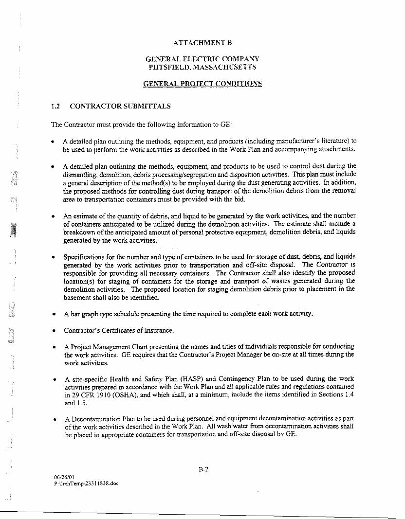
ELECTRIC COIMPA3Y PIITSWLD, MASSACKIJSETTS
The ConQactor must provide the f o l l o ~ g infomat~on to GE:
* A detailed plan outlining the methods, equipment, and products (including manufacturer's literature) to be used to perform the work activities as described in the Work Plan and accompanying attachments.
* A detailed plan outlining the methods, equipment, and products to be used to control dust during the dismantling, demolition, debris proeessingisegregation and disposition activities. This plan must include a general description of the methodls) to be. employed during the dust generating activities. In addition, the proposed methods for controlling dust during transport of the demolition debris from the removal area to transportation containers must be provided with the bid.
An estimate of the quantity of debris, and liquid to be generated by the work activities, and the number of containers anticipated to be utilized during the demolition activities. The estimate shaI1 include a breakdown of the anticipated amount of personal protective equipment, demolition debris, and liquids generated by the work activities.
Specifications for the number and type of containers to be used for storage of dust, debris, and liquids generated by the work activities prior to transportation and off-site disposal. The Contractor is responsible for providing all necessary containers. The Contractor shall also identify the proposed location(s) for staging of containers for the storage and transport of wastes generated during the demolition activities. The proposed location for staging demolition debris prior to placement in the basement shall also be identified.
.I A bar graph type schedule presenting the time required to complete each work activity.
.I Contractor's Certificates of Insurance.
A Project Management Chart presenting the names and titles of individuals responsible for conducting the work activities. GE requires that the Contractor's Project Manager be on-site at all times during the work activities.
A site-specific Wealth and Safety Plan (HASP) and Contingency Plan to be used during the work activities prepared in accordance with the Work Plan and all applicable rules and regulations contained in 29 CFR 19 10 (OSHA), and which shall, at a minimum, include the items identified in Sections 1.4 and 1.5.
* A Decontamina~on Plan to be used d m g personnel and equ~pment dec on achvlties as part of the work actlvlhes described m the Work Plan. All wash water &om deconm~mhon achvlt.les shall be placed m appropriate conralners for mnsportation and off-s~te disposal by GE.
* A Site Management Plan that provldes the mfomatlon requ~red under Secaon 1.3. (The re-aewed Site Management Plan shall be provlded to the Contractor's persomel and subcontractors dlrectly involved m the complebon of the demolition act~vlties outlrned m the Work Plan.)
* Other submittals as required under each Work Task (refer to Attacbent A to the Work Plan) as well as under the Technical Specifications (Attachment C to the Work Plan).
1.3 SITE MANAGEmhT PLAN
Pnor to site mobilization, the Contractor shall prepare a Site Management Plan for GE review and approval. This plan shall address, but not be limited to, the following items:
Identification of Contractor Site Manager;
List of equipment to be used on-site;
* Access control and signidsign-out procedures;
Safety, security, and protection of all adjacent properties;
Security provisions for Building 3 1 Area;
Work schedule;
Plan for controlling vehicular and pedestrian traffic during construction and operational activities;
Stormwater (including run-on and run-off), erosion, noise, and dust control measures;
* Copies of all permits necessary to implement the demolition activities including the Asbestos Removal Notification form required by the State of Nassachmetts and the demolition permit required by the City of Pittsfield;
Figures that depict the Contractor's approach to completing the activities presented in the Work Plan;
* Plans and sections depicting sizes and materials of constntction for the staging areas, on-site storage areas, equipment, and personnel decontammation areas;
* Methods to be used to ven& the locations of exist~ng utlllhes, structures, etc. located In the vlclnlty of the work area;
e L~sts of mticipated waste streams to be generated for off-site disposal (by GE) and m~c~pated volmes;
* Proposed methods for handling and contarnenzing each waste stream;
G E m W L PROJECT CO33ITIONS
o Equipment ciean~ng proeedwes; and
Afl other plans, submirtals, docrunents, etc. required in the Work Tasks ( A t t a c h a t A to the Work Plan).
The purpose of the Site Management Plan will be to s m e e the materials, procedures, and controls that the Contractor intends to utilize during demolition and construction activities. The Site Management Plan should address all appropriate issues described in the Work Plan.
1.4 m U T E I AN4 SAFETY PLAN
The Contractor shall prepare, submit, and implement a site-specific HASP that, at a minimum, meets the requirements of 29 CFR 1910 and 29 (3% 1926 (which includes 29 CFR 1926.65), and which is consistent with the requirements of GE's site HASP which was previously provided to EPA on January 24,2001. The Contractor's HASP shall cover all personnel who will be employed by the Contractor to perform demolitiodconsolidation work at the site, including direct employees as well as subcontractors. If the Contractor does not wish to include subcontractors under its HASP, then each subcontractor will be responsible for developing and implementing a HASP that meets the requirements outlined in the Work Plan. The Contractor will be responsible for ensuring that all of its subcontractors have adequate HASPS prior to any on-site work by the subcontractor, and are adhering to the HASPS during the work activities. If a subcontractor agrees to be included under the Contractor's HASP, then a statement to this effect shall be submitted to GE.
The areas and materials subject to demolitiodconstruGtion as part of this Contract may contain hazardous constituents. The results of prior investigation activities related to this Contract are available, and are attached to the Work Plan. It is the Contractor's respansibiEty to understand and incorporate the inf~mation obtained from these prior activities in the preparation of the cost proposal and in the development of a HASP.
For work required by the Contract involving the potential for personnel contact or exposure to PCBs and other hazardous constituents, the Contractor must comply with 29 CFR 1910,29 CFR 1926,40 CFR 260- 267, and related regulations which call for the development and implementation of a safety and health program for employees involved in hazardous waste operations. The Contractor will be required to comply wlth all requirements under these regulations for this project.
The Contractor shall also assume that the buildmg matenals are regulated as a hazardous waste under Resource Consenration and Recovery Act (RCRA). In addiQon, the Contractor shall assume that pa~nted equxpment and building matenals contain lead-based paint.
Pnor to cornencement of site activltles, the Contractor must ~ e r t ~ Q that personnel employed at the slte, who are directly mvolved tsllth removal measures, mcludrng employees and subcontractors, have completed
us waste srte health and safety mlnlng course (and mua1 refresher t ramg) m accmdance with 29 CFX 1910.120 and 29 CFR 1926.65. The Conmctor must also certify that any uld~vlduals who later became employed by the Contractor also receive such tratnlng pnor to perfommg work at the slte.
GEYTRAL PROJECT CO?;DITIOXS
The Con&actor must certify that all personnel who will be mployed by the Contractor to p r f o m work at the s~te, including direct employees as weti as subcontractors, have recerved the initial and annual ( ~ f applicable) medical examinations and are emolled m an on-gorng medical surveillance progam as required by 29 CFR 19 10 and 29 CFR 1925.
The Contractor must also comply with the Department of Labor Safety and Health Repfations for construction promulgated under the Occupational Safety and Health Act of 1970 (PL 91 -596) and under Section 107 of the Contract Work Hours and Safety Standards Act (PL 91-54).
The Contractor will be responsible for the safety of its employees, subcontractors, sqpliers, and other parties at the work area as a result of the Contractor's direction.
The Contractor must prepare, submit, and implement a WASP in accordance with 40 CFR 1910.120,29 CFR 1926.65. The plan must address, but not be limited to, the following components:
1. Identification of Key Personnel - Identify, by name and by title, the on-site and off-site health and safety personnel responsible for the implementation of health and safety procedures. All on-site personnel involved in the measures must have OSHA 40-hour Hazardous Waste Training (29 CFR 19 10.120 and 1926.65) and the corresponding 8-hour refresher course update.
2. Training - Describe and provide certification of all supervisory and on-site persormel having received appropriate health and safety training. Training requirements shall also include attending an initial site orientation prior to engaging in any on-site activities. Sign-off sheets acknowledging attendance shall be provided.
3. Medical Surveillance - Certify that all supervisory and on-site personnel have received appropriate medical examinations and are able to conduct the tasks required for this project including, but not limited to, working with chemicals, using respiratory protection, using personal protective equipment and conducting hazardous waste operations in accordance with 29 CFR 1910.120 and 1926.65.
4. Task-specific HazardRisk Analysis - Identify and provide a means of mitigating all foreseeable biological, chemical, and physical hazards associated with the work, including, but not limited to, hazards associated with exposure to consbtuents of concern, heavy equipment operation, site conditions, weather, biological hazards, materials handling, and work around excavated areas.
5 . Work Zones - Provide a Site Plan which depicts the designation of zones including: (1) Ejiclusion Zones (2) Decontamination Zones, and (3) Support Zones. The level of personal protection for each zone must be included.
6. Personal Safety Equ~pment and Protective Clothing - Identify personal safety equipment and proteGtive c l o ~ n g to be used and available on-site. This shall include identification of expected levels of protection (A, 8, C, and D) for each task and the action levels for personal protective equipment upmdes, A respiratozy protection program that meets the requlrmm& of 29 GFR 191 0.134, and whtch eshbhshes specific requirements for any resptrtttor use shall be ~ncluded,
G E m M L PROJECT COit;DImONS
7 . Personal Ax Monltomg - Idenhfy protocols and cntena assoc~ated wth personal air monitomg of on-s~te persomel.
8. Equipment Decontmination - Describe methods and procedures to be used for personnel, vehicle, and equipment dmmtamination.
9. Material Safety Data Sheets - Provide Material Safety Data Sheets (NSDSs) for all materials to be brought on site, as well as consQtuents that are expected to be encomtaed in the course of the construction activities.
10. Construction Safety Procedures (OSHA 1926.1 - 1926.652, Subpart A-P) to address excavation and trenching safety procedures, as well as daily site safety inspection checklist to evaluate these items.
1 1. Standard Operating Procedures and Safety Programs as required by applicable sections of 29 CFR 1910 and 1926.
The HASP, and all subcontractor W P s , shall be submitted to GE for recordkeeping purposes (i.e., a fonnal review of the plan will not be performed) at least 7 days pnor to mobilization to the site. Determination of the appropriate level of worker safety equipment, procedures, or modification to equipment and procedures based on site conditions must be made by the Contractor as a result of site visit(s), review of available information, and anticipated site activities.
Should the Contractor identify any unforeseen or site-specific safety-related factor, hazard, or condition, or if one should become evident during the performance of work at the site, it will be the Contractor's responsibility to bring such to the attention of GE both verbally and in writing as quickly as possible for resolution. In the interim, the Contractor should take prudent action to establish and maintain safe working conditions and to safeguard employees, the public, and the environment.
Should the Contractor seek relief from, or substitution for, any w o n or provision of the HASP, such relief or substitution must be requested of GE in writing, and if approved, be authorized in writing.
Any disregard for the provisions of these Health and Safety requirements will be deemed just and sufficient cause for termination of the Contract without compromise.
1.5 CONTnVGENCrY PLAN
The Contractor must prepare, submit, and implement a Contingency Plan that includes, at a minimum, the following items:
A spill prevention control and countmeasures plan for all materials brought on the site;
* Emergency vehrcular accessiegress;
GEXE ELECTRIC CO3PArtY PETSFIELD, IMASSACmSEmS
GEmRAL PROJECT Co3BITIo3S
* Evacuation procedures of persomel from the work site:
* A listing of all contact personnel with phone numbers to incfude: GE, the Contractor; the Clly of Plttsfield; fire offic~aIs; ambulance service: local, county, and State Police; and local hospl~ls. including routes to locat hospihls and procedures for norifyrng each; and
* Identification of responsible personnel who will be in a position at all times to receive incoming phone calls and to dispatch Contractor personnel and equipment in the event of an emergency situation. The telephone number(s) must be supplied to GE not less than five (5) days prior to the cornencement of work.
The Contractor's Contingency Plan must be consistent with the Contingency and Emergency Procedures Plan prepared by GE, which was submitted to EPA in January 2001.
1.6 PROJECT SCHEDULE
As part of the Site Management Plan (see Section 1.3), the Contractor must submit a proposed draft Construction Schedule to GE for review and approval. The draft schedule should be a horizontal bar graph including all elements of the construction activities, and be neatly prepared and labeled indicating all anticipated start and completion dates. Additional requirements are provided below:
Provide separate lines for each section of work, identifLing the f ~ s t work day of each week;
* Schedule for completion for each Work Task specified in this Scope of Work;
Show complete sequence of construction by activity, identifying work of separate stages and other logically grouped activities including work by subcontractors, Indicate the early and late start, early and late fmish, float dates, and duration; and
Revise and resubmit a construction progress schedule on a weekly basis.
A pre-comtrucbon meetmg will be held follomg award of the Contract and pnor to Contractor mobilizaQon to the srte. This meetmg will be scheduled by GE after the award of Contract. The purpose of the Pre- Consmction Meettng IS to revlew Contract requirements, rev~ewimodrfy the Contractor's Consmct~on Schedule (Section 1.61, discuss the deveIopment of the Contractor's Srte Management Plan (Sectron 1.3), ~ntroduce various project team members representing the Contractor and GE, and resolve any questrons raised by said partles.
Momal or 'Tailgate" mmeetmgs will routrnely be held at the work site. These rneetrngs will be attended by on-ate representaBves of the Contractor and GE to discuss day-to-day omborn , schedule, health and safety Items, outstandrng issues, and the general status of the project. More formal meettngs (scheduled awroxlmte weekly) will be held on-s~te among representatives of the Contfactor and CE. "hese meemps
~ 1 1 1 be held to dlscuss Issues tncludmg, but not Ilm~ted to, project status, schedule, scope of work. and overall project ~mplementatlon issues.
1.8 OFFlCE R AND SUPPORT S m W a S
An existing trailer equipped with heat, and electric and telephone service, is located adjacent to the Hill 78 Consolidation Area and can be used by the Contractor koughout the demolition activities. The Contractor is required, however, to provide portable sanitary facilities at or near the Building 3 1 Area for the duration of the project. If a trailer is desired in the vicinity of the Building 3 1 Area, the contractor shall supply its own (including all utilities and hook-ups) at its own expense.
In addition, the Contractor shall provide a cellular phone at the work site for the duration of site activities. The cellular phone shall be accessible to key site personnel so that they can contact others or be contacted as required.
GE anticipates that on-site work activities can be conducted during daylight hours (as restricted by any local ordinances), five days per week (Monday through Friday), except in cases of emergency or unless prior approval has been obtained from GE.
The Contractor must restrict all work activities including, but not limited to, storage of materials and equipment to be incorporated in the project, as well as parking of vehicles, heavy equipment, project trailers, etc., to those areas approved by GE (also refer to Section 1.16). Figure 2 of the Work Plan provides a delineation of the work area that can be used by the Contractor. As noted on the figure, no demolition materials can be stockpiledistored withtn the 100-year floodplain.
1.11 EXISTING CONDITIONS
It is the Contractor's respa11sibillty to understand and verify the exact nature, character, quality, and qu8nhty of all condittons to be encomtered, and develop an lndependmt estmate of rnatmal q w t ~ Q e s . Loca~ons, depths, lengths, etc. of existlng structures (e.g., prpes, tunnels, utll~hes, etc.) described m the Work Plan, shown on the slte figures, andior provlded m the SIP are esbmates only, and as such are approxrmate, and must be field venfied pnor to the demolibon achvlt~es.
1.12 WORK WI PUBLIC ROmWAVS
The use and protection of all public roadways involved in this Consact must be m accordance with all appl~cable federal, state, county, and local reqmments. AIl mfportabon of equrprnmt and mtenals along
B-8 %a610 1 P:UmhTempQ33 1 1 8 3 8 . d ~
mP.858 1 1 EEadwLrlurn:d 10/9ZiW
6-8 ~O.~auos uorson jp# 'sarlmrqse uorlrlourap JO asrno3 ayz Buunp 39 1Cq paZOu se Sean [Euorlrppe ur ptre 'sm~ BuSlfls [eua~m~llos hwdural punore suotm~rp raze& aseps rayzo lo@m " pauq 'sasuaj 111s 'sa~eq Ley paqm 'SUAO~ pue sraurl srqseldjo a3wmzureur pm! luaura.clald aq apnp SIX .samseaur [oauos putt uorsom 110s aleudo~dde azrlrln lmur lo%seguo3 atg '(.3)a 'saqqtp 'surseq q3qes 'saf sAe.wtged a%eurerp alrs ur uollquaurrpas ssasxa luaaaxi 01 pue (qa 'saf!ctyms ~te~mx uosrfourap 'salrd t!os '-B'a) uotson o) warqns seam ur (pma 3o)go-unr uoltmrdt3a& 0% anp uo~erijrur IemIm axrs-go lua~ad o~
-suotqeln%a~ pue sinel p?3o1 pue 'ams '~tzlapaj Q+ a~~ro33e a% lo uo~lV&ap urog qe pue 's1;os %~e~punor% 'srale~ aszps 'sawto3 lala [Ie jDa$ord amur rolsequo3 aw '0s 8qop rq -twmolfnua ay) 1sa1o~d 08 suopnesaui hssasu I@ aqva lsnm rot:,~uo3 aq 'sapwg:,e uog:,mo3 jo asuewoyad aq %u~a
'101;7~03 ay) jo (-3la 'sleplew 'roqel 'aurg) asuadxa aq ZE apeur aq ~~eqs sqedai aleudorddv pue (a~qe:,ydde 31) Itueduro3 &g!an a~~i3adsai aqj 01 pavodai IC~ale!pam~ aq lsnur sagFgse
uogsn~mo3 aq flqmp pa%amp s1 q3qm 4ygn lo any:,w flqsva Luff -Xuedtuo:, dlr~gn aq Aq paqysard lam e UI paz~aaoid aq rsnm (wslCs pe0qp.z aAg.Je atg qw pqe~mm sapgpn %ypn~:,u!) say111tn ay,L .sapmgDe airs-uo flqeg!~ 05 loud pauneao sey uopeoygou q3ns ,mlt L~pn 01 g-~ ioj uogez~uoj* IDQUO:,
&!{gn 1Cnrssa3au aq appoid 11% ~0~3equ03 aa 'pms am sagfnp3e 31s-uo aroJaq smoq (ZL) om-&ua~as $Sea1 le ([~sQI~ suasny3t?sm~ '.%.a] sa3ws a~ejmsqns 11ejo aauasaxi aq almqap o) sapxIuro:, Lqpn ay) ICq pazuoy)na s1 oqm uogm~ue%.~o a~enpd Xue io/pue) sa~ueduro:, &qgn aq Qgou Jsnw 1~3equo3 ay,L 'sagfIpn lo sam3nqs i3upstxa Xue oy a%eurep asnm lo qlpi aiapjy IOU jsnw ~oa~equo~ aa 'juawd~nba pue 'sam3n~s 'sa11111ln %y~s!xa 01 1ua3erpe TIOM. 01 hssa:,au aq 11~~ 11 '~equo3 sqjo asmo:, aq %uyna
-($-I uoy$:,ag aas) mid luaura8etrel;y apS aq % papnpq aq plnoqs atFs yiom q3ea le saypy:,e uogonqsuo:, %u'!.mp 3yjeq. treysapad/mp:,gan %UIIIO~UO:, roj poqaur pasodoid s,zo%xmuo3 ayJ, '313~ ueu~~apdd/n!in3gah 104~03 01 pm sapp113e uog~suo:, aa~1113ej 03 la:,r.~~o ao11od 10 uodea auo my1 alour asn 03 $gala Xour JOZ:,~~UO~ aq3 'sr~3w treqsapad/~e[n:,ga 30 aumfon, ay) pue pauuopd 'i7maq sa~urlse ~JOM JO lunouze ay) uo Su~puadaa 'ap OM aq %ug~xa lo flqwua an! (sam '.%a) sap~qa~ paijsiano uaqM a11s ~JOM aqa le papaau aq II~A uosmc~e~ e ~q awns= ~~eqs 1oamu03 aq -UI~ e av
.sag$p3e alp-uo jo uogemp aq loj paqavew aq qsnw sloauo:, ysns jo asn au .a$!s ayl sqlxa lo swua ~uaurd~nba heay uaq~ sa~m~sq Bupnp lasgjo asqod lo uos;tad%eg e jo asn ayt pua 'sla+eq 'su31s %UI~M 'oq palIury IOU are Inq 'apnlq 11pi s~oquos pue s8ufu.m~ qsn~ 'ap ayt 01 ssa33e luaurd~nba jo qu!od ~p roj sloquo:, pm s%u~un?~ sg312.q aleudordde pue parrnbar 11e JOJ Led pm apmo~d [[pi lopequo3 ayl 'quaurar~bar pIarjwrdjo &IC) qj" a3ueplosse q
.&~~y~suodSa~ s, ~o3sequo3 aqI aq fpfi sa8pyq lo s,iehzpeo~ 8uysyxa 01 sa%ew~ Am 30 luauraseidal roipue r~edax 'saaj palgf3osse pa sqrwad IIe roj a~q~suodsa~ aaq ~0~3~9~03 aq, -sa13ua%e sgaqnd ate~doldde ayt wog slpuad 3urssorct a%puq pm pew hssa3au ~le jo aclmssy pw uoues~fdde arpl iCq papasa~d aq $mu sAwpeor sqqnci
GENERAL PROJECT COYDITIONS
measures must be mqected on a daily basts and after any rarnfafl to assure that maximum conh-ol IS be~ng provlded. Follo~mg mspection, and as necessary, the erosion control measures should be modified, cleaned, remforced, replaced, and/or mamtamed.
The Contractor take adequate measures for keeprng norse Iwels produced by conmetrton and demol~tlon equipment, to safe and tolerable Iim~ts as set forth by OSHA, EPA, Massachusetts codes or ordmances, and/or any local requ~ements. All construction equ~pment presenbng a potentlal noise nulsance must be provlded with noise muffling devices.
The Contractor will make available to GE (on a timely basis) the results of any air monitoring conducted by the Contractor as a form of worker or work area monitoring. The Contractor's proposed air monitoring approach must be identified in its HASP.
1.15 'JXMPORARY FENCING
The Contractor must install and maintain temporary fencing or other temporary barriers to minimize unauthorized or unknowing access to the work site. At a minimum, the following areas will be subject to this requirement:
Areas where any demolition or other construction-related activities occw
Areas designated as Contractor-identified health and safety zones (e.g., Exclusion Zones, Support Zones, etc.);
Areas utilized for personal or equipment cleaning activities;
Any areas where the activities of the Contract may cause a disruption to the nonnal vehicular or pedestrian traffic at the site; and
Existing fence line areas that are temporarily removed to facilitate cons.truction activities.
The temporary fencing or barrier should be construction-type fencing, constructed of high-density polyethylene (HDPE), or equivalent, 4 feet in height (m~mmum), and orange in color. The fencing should be supported by vertical posts InstaIIed into the ground and at an interval and depth that will withstand normal wind loads. Where the surface does not allow the use of support posts driven into the ground, alternate means should be util~zed by the Contractor. Wood barners are an acceptable alternative for paved areas or areas where the fencinglbmer is needed on a short-term basis only.
1.16 EQUIPmhT STORAGE
The area ant~c~pated to be available for storage of the Contractor's equipment and materials is shown on Flgrne 2 of the Work Plan. If the Contractor requrres additional on-s~te storage space, ~t may nohfy GE, who will attempt to make gements for add~honal storage areas ur the vlcinzty of the work. MI areas that are
.mo[aq paluasa~d st $lanai asarfl2mple2a~ uor~e~ojur jeuorlrppg. .(SOWN moq-p~ aq jo IaAaI aq 01 lualenmba) ,add 051 jo uo11wua3uos of p&~ a%w~e moy-01 e aq 11t.n. lagem ale~nssmd ~q [anal uorl3e aq, sZw@d OS~ st q3q~ 451p46 "3 (sowi@ prrrputrl~ nj11enb .IT 3uarqv jeuarze~ moy-vi: iuam'~ ayi jo ~08 auasalcr;ll [anal lagel au 'd~r~bldsd aq 01 f xrpuaddv JO p-~ UOQ~S ur payr3ads se '(maw ~rqn:, lad sur&olrtrru) ,url%d OZI mql sleaia pue uouenua3uoo (punoay3eq) pumdn a2eza~e 3mpuodsauo3 ayl my1 .xaeaB uor~e~ua3uo3 01 pqd a2mile noy-01 pmuinop e aq 11~~ Ia.ial uo~e-ie3g~ou a- '104~03 lsnp roipue %uuojruour 01 pale la^ samseaur iauorlrppe lo3 paau a% (2 pue 'saq~irj3e asuodsal pa1e.fa~-uou3wsuo:, fiuunp sale~nrtrtred auxoqne jo SlaAal arfl (1 :azmpua 01 pasn aq II~M 8mo~muour a1qnxpd loj slanal uoq3e pm sjaAal uor$e.syqo~
-suo!$!puo3 &~p!urnyjo uoye3yg~ pIag 303 pasn aq [IF m0re31pu1&1ppy anyvial a~qwod a 'uoyrppe UI -%~01!uourjo ;iep yaea uo d11enmt.u paproaa~ pm pamseaur aq amssald 3wauroreg -popad moy-0 1 %u?pa3a~d yea JOJ put! Aep ayljo moy q3ea lo3 la%8o[eaap ,quaws~ aq Aq pa%w~e pue pap~o3a~ aq [I~M nzp alepq.nzd -md 00:s 01 'me 00:~ UIO~ 'di!ep smoy 01 A~a~e~o&e 203 sa1pp3e ppale1ai-uoy3~suos 8-p pa~3npuo3 aq ~fps Ouuo~zuo~y .(D'~yd> sxaauromy 0 1 ueyz ssal la1aure:p maw e tpp ngew a~e1n3yndjo suogequa~uo~ p~o3a3 pm lo1your ox peay ~a3eduq auff-uf pm way 8u1uo1t1puoa amwadural e tpw paddfnba aq II!M lopuour y3ea 'paua8 UI 'd#&fdsd pa~oldde s,~f)~o f x!puaddv ut patuasa~d sampa~o~d atp 8u+ofloj pauuoJlad aq II~M. ~U~OZIUOLU a~elnapd aq- lea^ 'uogeas y3ea IV vsuo~~equasuo:, a.le-ln3ynd aupwlap 01 lalaumoqd 8uflaue3s 1@f1 pm anb~3a18~11dures a~!ssed e sasn mzp a= -000 1 -xad Iapox 10 0002 -aa IapoTy mep e 8gsn pauuopd %~o~~our atup-lea2 d~yp aa1oAt.g 8uuo1your aleIn3pd
-pamaura~dur~ JI 'samseaur q3ns 30 ssamns a~ilqa~ ay~ pue 'sammur ow:, pimp 103 paau aqa 'W&I ~IS-J~O pyua1od 03 a~yqa~3uqeur-uo1s~~ap ala~lpg 11p1 se 'pm sfseq aurp-1ea.t e uo (sagpg3e uo~lae asuodsa~ 01 patepi Allepualod) sIaAa1 lsnp luafqure amseaur 03 pamopd aq safep3y~~d auroq3te lo3 %uflol~uour 'sapvy3e uoil~~ourap 30 a3ueuopd ayl %-a
.slolda3a~ aars-jjo le~ua~od jo auoz %uftpealq aq1 JO ah1telUa~aJdal sr 1eq~ 11e lua~qura lo)fuour 01 asejms punoa ahoqe 1aajp pue -9 uaawaqjo ly@ay e ~e 31" lua~qurt, wa1103 01 paIjeasF aq ~uaurd~nba %qldures au -qzp 2iuf~011uour ne luarqure Our~slxa due put! '&fm3as a)rs '&1lrq~ssa33e airs 'slo$da3a~ aqs-jjo 1e1ua3odjo uoge3oi 'uoy3aqp P~& 1muropa~d csaqpg3e a11s aQj0 awu pue uoge301 aq uo paseq ean 310~ ayl punose suo!paot a& jo umu~~u~ur e patmopad aq (I* %U~I!UOW l!e luarqq .saqpyoe uoqjlourap eav 1 E %u?pf!ng aq 01 palela2 sl3edu11 aqs-330 leyuaiod ssasse 01 pawoyad aq weA301d %UUO~IUOUI 11t! 1uafqt.ue UF~
'39 01 lsos leuo~lippe ou le s1 pm ylo~ awjo ssaiaold f lou saop asn y3ns pap+& swe a3ws aqs-go mqo lo sf9 asn Aeur loz~euuo~ a=
.&g!3~3 ?J~J aq ~e suoge3ol laylo le SIE~PEW pue ~uaurd~nba JO ageiols 103 afqej!eiie apeur aq Aeur aaedg
.sanrhr)ae ylomjo uazla~d~103 uodn suotlipuo:, feur2uo ot palolsal aq [ferfs pug 'ysu S'J0~3E~U03 ayl ie ~C~IOS pam aq jjmqs '%are 8rrnfred 8urpnl3m 'sleu8aur pue ~uaurdrnba jo aSmo$s 103 pasn
GE3X ELE G CO>IPA%T PETSmLD, 3lASSACmSEnS
CEY7ER.4L PROJECT COYBITIOYS
Actions If Sotifieation Level Is Exceeded
Part~culate monitoring data will be compared to the not~FIcatlon level to detemme ~f s~te-related actlwtles are causrng an maccepBble Increase In airborne partleulate concan-atzons. On a dally basis dunng the
actions, the partieulaw data fkrn the d o m m d monitors will be c q d wth the data fntm the u p m d @aekgomd) mon~tor(s). If the 10-hour average PM,, concentrabon at a domwmd monltor exceeds the corresponding average upwnd concentration, the downunnd concentration will be compared to the notification Ievel of 120 pg/m3. Any exceedences of th~s level will be ~ m e d ~ a t e l y reported to EPA, and GE will discuss ulth EPA the need for and type of response measures.
In the event that ambient particulate concentrations at any domwind location consistently exceed the particulate notification level (i.e., 120 &m3), GE will initiate ambient air monitoring for PCBs. Specifically, if the detected particulate levels at the downwind monitoring location(s) exceed the notification level on three consecutive 10-hour days or five days in any two-week period, PCB air monitoring will be implemented on a bi-weekly basis in accordance with the procedures specified in the FSP/QAPP (specific information regarding PCB monitoring locations, frequency, and duration would be developed by GE). For PCBs, the notification level will be a 24-hour average PCB concentration of 0.05 pg/m3 and the action level will be a 24-hour average concentration of 0.1 pg/m3. Any exceedence of the PCB notification level will be immediately reported to EPA and an evaluation will be made and provided to the EPA concerning the cause of the exceedence and the need for corrective action to prevent exceedences of the action level. Following initiation of PCB air monitoring, if PCB ambient air concentrations are less than the PCB action level for two consecutive bi-weekly events, then PCB monitoring will be discontinued.
Actions If Action Level Is Exceeded
In the event that any 10-hour average PM,, concentration or 24-hour average PCB concentration (if PCB monitoring is being conducted) exceeds the action levels presented above, GE will imediately report such exceedence to EPA and will discuss with EPA appropriate irnmedrate response actions, including temporary stoppage of work activities.
In the event that (1) action levels are exceeded, (2) the monitoring data indicate a significant increase in downwind versus upwind readings, or (3) visible dust related to site operations is observed, dust control measures will be implemented. Such measures may include water spray, modification of work procedures, and/or suspension of work. If such measures do not result in reductions to below the action levels, work will be stopped pending M e r evaluation of work practices, potential upwind particulate sources, and additional control measures. Also, certain other site controls and practices will be implernenred to limit the potential for and amount of dust generation, These include c o v e g exposed areas when not in active use, covering soil stockpiles, reducing vehicle speeds, and utilizing water sprays as necessary (e.g. in roads, work areas, etc.).
1.18 DUST SljPPmSSION
The Conmctor shall be responsible for con&olllng anyiall dust generated as a result of demolition, backfillmg, mloadxng of impo~ed materials, or any other site actlwties. Dust will be controlled based on vlsual obsrrvations, monitoring perfomed by .the Conmctor, and/or the results of any airborne pmculate
B- 12 aSi26"l P UmhTempQ33 1 1838.d~
monltonng. The presence of Iarge amollnts of uncontrolled, vrsible dust dumg the perfomance of dernol~tiodconstruction activities 1s not acceptable and will requsre the temporary suspensron of work acQvlQes and the ~mplementation of appropriate dust control measures. Appropriate dust conttol measures mclude the foflowing:
Spraying water;
Hauling demolition debris in properly tarped vehicles;
0 Restricting vehicle speeds; and
Covering demolition debris piles with polyethylene sheeting.
The Contractor shall make every attempt to use existing water supplies (e.g., fire hydrants, piping networks, etc.) at no cost to GE. However, a source of water (water tank truck, storage tank, etc.) should also be made available by the Contractor at the work site. The Contractor will be responsible for maintaining, in the immediate vicinity of the work, a supply of water and means of dispersion (e.g., a water tank and sprayer, tanker truck with hose, etc.) such that water may be applied for dust control immediately as required. If the dust control measures being utilized by the Contractor do not eliminate or substantially lower dust levels as determined by GE based on visual observations andlor the results of airborne particulate monitoring, work activities must be suspended until the Contractor develops the appropriate corrective measure(s) to remedy the situation.
1.19 SURVEY CONTROL
The Contractor will be responsible for performing all survey activities, using a Massachusetts-licensed land surveyor, during the performance of construction activities. ?he survey activities will include, at a minimum, the following:
Reviewing existing infomation related to the site prior to initiating site activities, and thoroughly evaluating the existing conditions at the work site;
Staking out existing utilities and maintaining the stakes during the performance of demolitiod construction activities;
0 Installing additional stakes prior to the completion of work activities to establish final elevations and facilitate site restoration activities;
0 Performing a detailed survey follorng slte restoration actiwties to venfy that the site is restored in accorhce with the provlslons of the Contract;
* Pdoming a detailed survey following closure activities to develop final qmtities for payment
GESERAL PROJECT COSDITIOSS
* Providing all s w e y notes (e.g.. control points, baselme data, etc,) to GE to allow survey repl~cation by GE.
GE may penod~cally audit the Contractor's smeyor, both m the field and office, to rewew all accmulated data and evaluate the m ~ e y m ' s p e r f m c e . The Conmetor should a s m e that these penodic audits may be performed on a bl-weekly basrs.
All reusable equipment and materials utilized by the Contractor in the performance of this Contract must be cleaned prior to its re-location witfun the site, pnor to handling "clean" materials, and prior to its departure from the site. All cleaning activities will be performed at the site in an area approved by GE.
Non-disposable equipment cleaning shall be deemed complete based on a review by GE and the analytical results of wipe samples. GE will collect a minimum of three wipe samples from each piece of Contractor- controlled equipment prior to demobilization from the site. The wipe samples will be submitted to a GE- approved laboratory for PCB analysis on a 24-hour turnaround basis to confirm that PCBs are not present at concentrations greater than or equal to 10 micrograms per 100 square centimeters (10 pg1100 em2). Equipment that does not meet this objective will be recleaned by the Contractor.
Wash water, solids, and other materials generated during equipment cleaning operations must not contact native soils, pavements, and existing facilities, and must be collected by the Contractor and placed into designated containers. Liquids, with low solids content, must be transported to the GE treatment facility for treatment by GE. Solids, soils, and other materials contained within sealed containers will be transported to the OPCAs for fmal disposal.
The Contractor must submit proposed equipment cleaning procedures as part of the Site Management Plan (see Section 1.3).
1.21 SOIL FILL SOURCES
Only soil fill approved by GE may be utilized m the Building 3 1 foundahon. The Contractor is requrred to specify the name and locabon of the proposed fill sources. RepresentaQve samples of each fill matenal will be analyzed for PCBs and the volable organrc compounds (VOCs), semi-volatzle organic compounds (SVOCs), and metals llsted tn Appendlx IX of 40 CFR 264, plus benzidene, 2-chloroethyl vlnyl ether, and 1,2-diphenylhydraz~ne (Appendix IX+3 VOCs, SVOCs, and metals) m accordance wth GE's approved FSPIQAPP.
The ffequency of sampfrng and tesang will depend on the sourceAocation of the potenQal matenal. If the cand~date rnatenal IS from an und~smbed m-place source (e.g., an actlve gravelibonow p~t), one rqresentative sample will be collected and malyzed. For off-slte matenals that have been generated from
dlrng actlvlhes (e.g., matenals located m a stockpile), the frequency of charactenzabon tesmg will xnvolve the collect~on of 10 d~screte '"If' samples for each volume of such rnatenal eontaming up to 2,000 cubic yards (cy). (If the volume of matenal to be chmetenzed i s less than 2,000 cy, 10 "pb"
B- 14 06126fO I P UmhT-33 1 i 838 doc
samples will still be collected fiorn that mateal,) These d~screte gntb samples will be collected at spabally distributed lwations within the some mattsrial and will be compsrted into a s~ngle sample for performance of the appropriate analyses.
It is not able levels of PCBs, VOCs, or SVOGs or concentrations of metals abcwe background will be present in soil cover or backfill materials that origrnate from an undisturbed, off-site, in- place source. However, in the event that such constituents are present in the candidate material, the materials will be evaluated further in accordance with the proposed criteria described below.
Soil coverlbackfill materials originating from an off-site location will be acceptable if the material does not contain PCB concentrations exceeding 2 ppm.
The analflcal data for VOCs, SVOCs, and metals will initially be compared with the applicable EPA Region 9 Preliminary Remediation Goals (PRGs) for commerciaYindustria1 areas. If the maximum concentration of each constituent is below the PRG, the material will be considered suitable for use without limitation. If the comparisons indicate that certain constituents are present at concentrations above the PRGs, material, a comparison to background soil concentrations will be perfonned, consistent with Technical Attachment F to the SOW. If the material contains constituent concentrations that are less than or consistent with background levels of those constituents, then that material will be considered suitable for use in the Building 3 1 foundation. If the candidate soil fill material contains VOCs, SVOCs, or metals at concentrations that exceed both the PRG screening criteria and background levels, GE may M e r evaluate the material and, if it still wishes to use the material as fill in the Building 3 1 foundation, will submit a proposal for such use to EPA.
In addition to or in lieu of the use of fill material from off-site sources, GE may propose to use soil and debris removed as part of Removal Actions conducted within the GE Plant Area under the CD and the SOW, riverbank soils removed as part of the Upper %-Mile Reach Removal Action for the Housatonic River, andlor building demolition debris and other materials related to GE's Brownfield activities conducted under the DEDA. Such potential use is discussed in Section 5 of the Work Plan. Any such proposal will be submitted to EPA for review and approval.
1.22 IWSIDUAL WASTES
Residual wastes, including used personal protective equipment, gloves, solids, soils, and other materials, generated by the Contractor and GE must be collected by (when necessary), and Qmsported and disposed of in the solids content must be containerized and d to a staging area designated by GE for future handling and disposal.
Site restomtion activities will be required for all disturbed areas. Portions of fencing that are relocated as part of tfie construction activiries must be restored by the Conmctor as required to match the existing
fmcmg. The restorahon of any areas resultung from e by the Contractor due to neglrgence or improper acawties must be repaired by the Contractor.
The fmished products of restoration must be maintained and adeqmtely protected as appropriate, such that conditions at the complttim of constntc~on (as d e m m e d by GE) exist a @ d o f a n e y - foIlomng the date of completion of work. Any settlement (including wsible mcks and depresslorn greater than 1 inch) occurring in the restored areas during this time period, must be repaired by the Conb-actor.
1.24 RECORD DRAWINGS
During implementation of the construction activities, the Contractor must keep one set of the site figures provided with the Work Plan at the site on which the Contractor must clearly document all construction activities. The drawings must accurately shows all changes in, or directly associated with, the work under this Contract. Such changes must be neatly and clearly marked on the drawings using colored ink or red pencil, and the entire set of figures must be kept current on a day-to-day basis in concert with the progress of the work. Where applicable, the change marked on a drawing is to carry the notation "per Change Order No. ," or similar reference which cites the reason for the change. The day to day construction Record Drawings must be made available to GE for review upon request.
The following items are examples of some of the types of changes that could occur and are to be recorded on the Record Drawings by the Contractor.
Change in location of project components, including vertical elevations;
* Modified construction limits and explanation for change;
Change in materials;
* Additions to project;
* Elimination of a project component;
Relocation of existing underground utilities made necessary because of interference with project components;
* Unforeseen modifications made to existing structures made necessary by requirements of the work; and
* Site restoration modifications made at the request of CE.
If no changes were made to certain components of the work, a note should be added to the c or drawing indicating such.
Attachment C
Technical Specifications
B D. BOU(=K a LEE, INC. e n Q I n e s r s % s c l e n t l z t r
ELECTRIC COMPAW PITTSFIELP), %%ASS,4CHt'SEnS
TABLE OF G O h m h T S
S E a O N 1.0 - FLOWABLE FILL MATE
SECTION 2.0 - SELECT FILL U E R L A L
SECTION 3.0 - WASHED STONE
SECTION 4.0 - GEOTEXTILE FABRIC
SECllON 5.0 - SELECT SOIL FILL MATERIAL
SECTION 6.0 - EARTHWORK
SECTION 7.0 - SOIL FILL MATERLLV,
SECTION 8.0 - TOPSOIL, SEEDING, AND MULCH
SECTION 9.0 - FELXIBLE MEIUFBR.ANE L m
SECTION 10.0 - GEOSYNTHETIC DRAINAGE COMPOSITE
PART I - GENE
1 .O1 W O W SPECIFIED
A. Work under this section shall mclude, but not necessarily be hm~ted to, swplymg all labor, equipment and materials, and transporting and placing flowable fiI1 in the basement p e n e m t x o n s i o ~ g s as requrred under Work Task 5 (see Attachment A to the Work Plan).
A. Test results for aggregates, water, and field tests.
B. Mill test certificates and test reports for cement indicating compliance with these specifications.
C. Flowable fill mix designs for all classes and types of concrete to be used in the work.
D. Proposed methods of flowable fill curing.
E. Manufacturers' literature for admixtures, curing compounds, sealers, surface hardeners, etc.
F. Name and location of flowable fill supplier.
1.03 REFERENCES
A. Massachusetts Depraanent of Highways Standard Specifications for Highways and Bridges:
1. M.4.08.0 Controlled Density Fill.
B. American Concrete Institute (ACI). Tbe fo l lo~ng codes, standards and recornendations are intended to specify minimum standards of performance:
1. ACI 301 Specifications for Structural Concrete for Buildings
2. ACI 523.1 Guide for Cast-in-Place Low Density Concrete
3. ACI 3 18 Building Code Requirements for Reinforced Concrete
4. ACI229R Controlled Low-Seen@ Materials
C. h a c a n Soelety for Tesmg and Matmals (ASlhl). The follomg ASTM ~pec~ficatlons are referred to m these specifications ( ~ n add~tion to those ASTM spec~fications Ixsted m ACI) and are to be constdered a part of these specificabons:
1. C3 I Standard Method of Malung and Crulng Concrete Test Specimens In the F~eld
2. C39 Standard Test Method for Compressi.ve Strength of Cylindrical Concrete Specimens
3. C 1 50 Standard Specification for Portland Cement
4. C260 Standard Specification for Air-Enmining Admixtures for Concrete
5. C494 Standard Specification for Chemical Admixtures for Concrete
6. C495 Standard Test Method for Compressive Strength of Lightweight Insulating Concrete
7. C5 13 Standard Test Method for Obtaining and Testing Specimens of Hardened Lightweight Insulating Concrete for Compressive Strength
8. C618 Standard Specifications for Coal Fly Ash and Raw or Calcined Natural Pozzolan for Use as a Mineral Admixture in Portland Cement Concrete
1.04 QUALITY ASSURANCE
A. American Association of State Highway and Transportation Officials (AASHTO).
B. Massachusetts Department of Highways Standard Specifications for Highways and Bridges.
C. In each case the latest revision (including any supplements) shaI1 apply.
1.05 SOURCE QUALITY CONTROL
A. Portland Cement, Type I or Type I1 - Mill test certificates identifying chemical and physical analysis.
B. Aggregates - Perform tests by an approved independent testing laboratory, prior to use, to show compliance with these specifications:
1. Such tests which have been made thin six months prior to the use of the aggregates will be acceptable.
2. Gradation tests shall be pedomed at the point of use.
3. The source of the material shall not be chmged without retesting.
4. All aggegates shall be tested for compliance with the specifications at a minimum of one-year intervals dunng the course of the work.
6-2
ATTAC ?;T C
5. Coarse aggregates shall be obtained from a Massacfiusens Department of Highways- approved operating source.
6. The gra&tim of the ag shall have 100% passmg the %" slew and a maximum of 20% passrng the No. 200 sieve.
7. Use fly ash conforming to the chemical and physical requirements for mineral admixture, Class F listed in A.S.T.M. C618, including Table 2 (except for Footnote A). Waive the loss on ignition requirement.
1.06 TESTS AND INSPECTIONS
A. All required field and laboratory tests shall be at the Contractor's expense. Should any additional tests be necessary due to inadequate test results (i.e., core testing, load testing, etc.), the Contractor shall also be responsible for the cost. The Contractor shall use only an approved commercial testing laboratory.
B. The Contractor shall provide facilities necessary to obtain and handle representative samples of materials to be tested and shall furnish all necessary cooperation and assistance as requested by the Engineer. The Contractor shall provide sufficient notification to the testing laboratory and shall plan and schedule their operations to allow adequate time for all required testing and review.
C. The testing laboratory shall be responsible to GE for the field control of a11 flowable fill and may reject batches for high slump, uncontrolled air entrainment or delays. Written reports shall be issued Wediately after the testing is complete. However, if at any time the results are questionable, GE shall be notified immediately so that corrective steps may be taken. All tests and reports submitted for review shall be only for those specific items used in the work. One copy of the test reports shall be submitted directly to GE by the testing laboratory for review.
D. Criteria for the acceptance of flowable fill shall be as detailed in ACI 31 8, Chapter 4, and include the following tests:
1. Flowable Fill Test Cylinders
a. During the progress of the work, a set of six 6" x 12" cylinders shall be made for each day flowable fill is placed. These cyl~nders shall be made up and cured m accordance with A S m C31 and shall be tested xn accorbce with AS734 C39. The followng schedule shall be used m the testlng procedure:
1. Two shall be tested at seven days.
2. Two shall be tested at men%-eight days. G-3
3. The remaining two shall be tested at forty days or as directed by the Engineer.
b. The making, pick-up, and cmbg of the cylinders shall be the ibility of the testing laboratory, but the Contractor shall cooperate in protecting the cy'iinders and in notifying the testing lab of scheduled pours.
c. The report shall indicate the mix proportions, air content, water content, slump, batching time, placing time and a detailed description where the tested concrete was placed in the structure. All items shall be completely filled in on each test report.
2. Water
a. Mixing water shall be clear and fkee &om deleterious amounts of oil, acid, alkali, organic matter, and other substances. Water from an unpotable water source must be approved by GE prior to use. Questionable sources of water, as determined by GE, shall be tested in accordance with ACI 30 1.
PART 2 - PRODUCTS
2.01 FLOWABLE FILL MATERIALS
A. Cement
2.02 FLOWABLE FILL MIX DESIGN
A. A11 mix designs shall be proportioned in accordance with Massachusetts Department of Highways Standard Specifications for Highways and Bridges, M4.08.0 for Type I Controlled Density Fill.
B. The proposed mix design sMl be designed to achieve a 28-day compressive s m g t h of 150 pounds per square inch (psi).
C. Mix design submirtais shall indicate the mounts of all ingredients including cement, admixtures and the weight of the aggregates stated in a samted surface dry condition.
D. Batching and Mixing
1. Batching
a. The Conmctor shall have at their disposal, a modern and d plant w~tfun a reasonable distance fiorn the work.
C-4
GEbT ELE C COMPA%T P m S m L D , 1 m S S A C m S E n S
CAL SPECIRCATIONS
b. The batching and mixing shall confom to ACI 304.
e. The batching shall be done only with materials previously favorably reviewed by GE.
2. Mixing, Transporting, and Discharging
a. Conform to A S W C94.
b. Wastewter must be discharged and not used as mixing water for the next batch.
c. Maximum interval between successive truckloads of flowable fill discharged into the work shall not exceed 30 minutes when the portion of the work being placed requires more than one load of flowable fill.
PART 3 - EXECUTION
3.01 PLACING FLOWABLE FLL
A. Flowable fill shall be placed in conformance to ACI 304, and Section M.4.08.0 of the Massachusetts Department of Highways Standard Specifications for Highways and Bridges and with these specifications.
B. Prior to placing flowable fill:
I. A11 form work, embedded parts, reinforcements, foundation surfaces and joints involved in the work must be visually reviewed by GE.
2. All surfaces that will be in contact with the poured flowable fill shall be free from standing water, sediments, mud, debris, frost, snow and ice. The Contractor shall clean the areas of flowable fill placement, subject to a visual review by GE, prior to placement of flowable fill.
3. Earth surfaces wbich are absorptive shall be moistened to a depth of 1 inch.
4. When the ambient temperature is above 400F, all subgrade surfaces shall be wetted down with cool water just pnor to placement.
C. Placement of Ffowable Fill
1. Flowable f i f 1 shall be conveyed by means that will prevent segtegation and loss of mortar tiom the mix.
ELE C COMPk"c,Y P f m S m L D , bUSSACm-SEPS
2. Adequate manpower and equ~pment m the form of buckets, buggies, chutes, conveyors, or other approved means shall be prov~ded and propaly ma~ntained by the Contractor to ensure cclntlnuous operations.
D. h e m a t i c Placement
1. Pneumatic placement of flowable fill will be pmit ted onIy if authorized by GE in writing.
2. The equipment shall be suitable in kind and adequate in capacity for the work.
3. The equipment shaH be operated and placed so that no vibrations result which may damage freshly placed flowable fill.
4. The machine shall be located as close as practicable to the place of deposit.
5 . The position of the discharge end of the line shall not be more than 8 feet &om the point of deposit.
6. The discharge lines shall be horizontal or inclined upward from the machine.
7. At the conclusion of placement, the equipment shall be thoroughly cleaned.
E. Pumping
1. Pump placement of flowable fill will be permitted only if authorized by GE, in writing*
2. The equipment shall be suitable in kind and adequate in capacity for the work.
3. The operation of the pump shall be such that a continuous stream of flowable fill, without air pockets, is produced.
4. When pumping is completed, the flowable fill remaining in the pipeline, if it is to be used, shall be ejected in such a manner that will not produce contamination of the flowable fill or separation of the flowable fill ingrekents.
5 . Pnor to starting the pmping operations, the equipment and pipeline shall be thoroughly lubricated with a flowable fill slurry in a m m e r approved by the Engneer.
6. Mer the pumping operation has been completed, the entire equipment shall be thoroughly cleaned.
3.02 COLD WTE R P L A C E H W
A. Adequate equipment shall be proGded for heating the Bowable fili mat&als and protechg the flowable fill during freezing or near freezing weather.
£3. No frozen materials or materials containing ice shall be used.
C. All flowable fill operations in cold weather, when temperames are at, or expected to be below 40°F, shall conform to ACI 306.
1. Special attention is drawn to the minimum required placing and curing temperatures.
D. Only the non-chloride accelerators specified in ACI 306 may be used. Calcium chloride or admixtures containing more than 0.1 percent chloride ions are not permitted.
D. Flowable fill damaged by freezing shall be removed and replaced at the Contractor's expense. . .
3.03 HOT WEATHER PLACEMENT
A. Care shall be taken to protect the flowable fill or to scheduIe operations to avoid problems with flash set or conditions that produce excessively rapid drymg.
B. All flowable operations during hot weather shall conform to the requirements of ACI 305.
C. During hot weather, eonsideration shall be given to maintaining the temperature of the flowable fill, aggregates, and mixing water, such that the temperature of the flowable fill at the time of delivery to the job site in no case exceeds 90°F.
D. When the temperature of the flowable fill exceeds 80°F, the water reducing, retarding admixture, Type "D", may be required.
- END OF SECTION -
ELE C COMPkYY P I m S m L D , :\.IASSAGIPLTSEmS
TECHNICAI> SPECIFICATIOSS
S E a O h ' 2.0 - SELECT FILL MATE
A. Work under th~s section sh l l include, but not necessarily be limited to, supplytng all labor, equipment, and materials for excavating, -sporting, placing, spreading, and compacting select fill material in the basement of Building 3 1.
1.02 RELATED WORK SPECIFIED ELSE-=
A. Technical Specification entitled Earthwork (Section 6.0).
A. Identification of names and addresses of proposed select fill source.
B. Proposed dust control measures to be implemented.
C . Sample(s) for analytxcal testing by GE.
D. One particle size (ASTM D422) analysis test shall be conducted on the select fill materials and submitted to GE for review.
PART 2 - PRODUCTS
2.01 MATERIALS
A. Select fill shall be gravel borrow as specified as Type B in MI ,030 of the Massachusetts Department of Highways Standard Specifications for Highways and Bridges.
B. Select fill must meet the chemical criteria set forth in Section 1.21 of the General Project Conditions ( A t t a c h a t B) or as otherwise approved by EPA.
PART 3 - EXECLTON
3 -0 I PLACEMENT
A. For a11 select fill, the following prgraration and inspection shall be conducted by the Contractor prior to placement:
I . Venfy fill material to be used has been favorably revlewed by GE. 2. Venfy areas to be filled are properly compacted. 3, Verifj areas to be filled are free of debs , snow. ice or water and ground surfaces
are not Erozen. C-8
4. Identify requlred levels. 5. Grade and uniformly cornpact subgrade, to the required depths and grades. The
mmlmum uncompacted fill layer shall be 6 inches and the mlnlmcun compacbon shall be 92 percent as detemined by the ASTlvl testing Method 01557. Refer to the Technical Specification entitled urk (Section 6.0) for additional compaction requ~rements.
6. Demonstrate completeness of subgrade preparation in a manner acceptable to GE.
3.02 F3E3.D TESTING AND QUALITY CONTROL
A. In-place density testing may be performed by an independent testing laboratory (selected by GE). Testing shall be performed in accordance with ASTM Dl 557.
1.01 W O W SPE
A. Work under this section shall include, but not necessarily be limited to, supplying all labor, equipment, and materials for excavating, transpo*g, placing, spreading, and compacting modified rocWzll in the basement of Building 3 1.
1.02 RELA'I'ED WORE: SPECFED ELSE-=
A. Technical Specification entitled Earthwork (Section 6.0).
A. Identification of names and addresses of proposed select fill source.
B. Proposed dust control measures to be implemented. .
C. Sample(s) for analytxal testing by GE.
D. One particle size (ASTM D422) analysis test shall be conducted on the select fill materials and submitted to GE for review.
PART 2 - PRODUCTS
A. Modified rockfill shall meet the requirements specified in M2.02.4. of the Massachusetts Department Standard Specifications for Highway and Bridges Specification.
B. All modified rockfill shall be free from detectable levels of target compound list organic chemical contaminants and shall not contain target analyte list inorganics at concentrations above site background levels.
PART 3 - E X E m O N
A. For all modified rockfill, the following prqaration and inspection shall be conducted prior to placement:
1, t"fy washed stone matmal to be used has been favorably reviewed by GE. 2. Verify areas to be filled are free of debns, snow, ice or water and ground suffaces
are not frozen. C-I0
3. Identie requlred levels. 4. Cirade and unlfonnfy compact subgrade, to the required depths and grades. 5. Demonstrate completeness of subpde preparation m a manner acceptable to GE.
S E m O N 4.0 - GEOTEXmE: FABRIC
PART I - GENE
1 .O I WORK SPE-D
A. Work under this section shall include, but not necessarily be limited to, supplying all labor, equipment, and materials for placement of non-woven geotextile fabric.
A. American Society for Testing and Materials (ASTM)
ASTM D3776Unit Weight ASTM D4632 Grab Tensile ASTM D4632 Grab Elongation ASTM D3786Mullen Burst ASTM D4833 Puncture ASTM 04533 Trapezoid Tear ASTM D475 1 Apparent Opening Size ASTM D4491 Permittivity ASTM Dl 777 Thickness
A. Manufacm's data for geotextile including, at a minimum, physical properhes, packaging, and installation techniques.
B. Manufacturer's quality assmcelquality control program.
C. Certified results of all quality control testing.
D. Contractor's proposed Bansportation, handling, storage, and installation techniques.
E. Shop drawings.
F. Manufacturer's standard warranty provided for the geotextiles.
PART 2 - P R r n r n S
2.01 ACCEPTABLE RS FOR G E O E m L E FABRIC
A. Synthetics Industries; B. Amoco; or 6 . Reviewed equal.
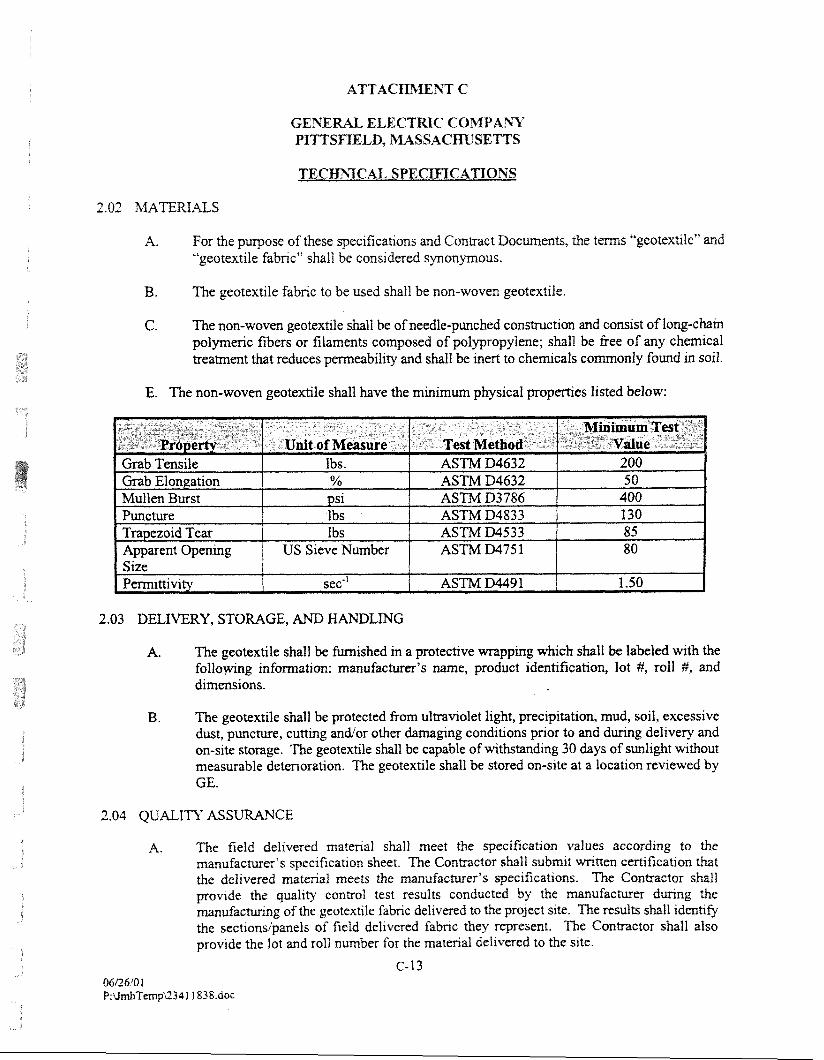
TECnqGAL, SPECIFICATIONS
A. For the p q o s e of these specifications arid Contract Docmen&, the terms '~eotextile" and "'geotextile fabnc" shall be considered synonymous.
B. The geotextile fabric to be used shall be non-woven geotextile.
C. The non-wovm geotextile shall be of needle-punched construction and consist of long-chin polymeric fibers or filaments composed of polypropylene; shall be free of any chemical treatment that reduces permeability and shII be inert to chemicals commonly found in soil.
E. The non-woven geotextile shall have the minimum physical properties listed below:
2.03 DELIVERY, STORAGE, AND HANDLING
A. The geotextile shall be furnished in a protective wrapping which shall be labeled with the following information: manufacturer's name, product identification, lot #, roll #, and dimensions.
B. The geotextile shall be protected from ultraviolet light, precipitation, mud, soil, excessive dust, puncture, cutting and/or other damaging conditions prior to and during delivery and on-site storage. The geotextile shall be capable of withstanding 30 days of sunlight without measurable detenoration. The geotextile shall be stored on-site at a location reviewed by GE.
2.04 QUALITY ASS CE
A. The field delivered matenal shall meet the specificat~on values according to the manufacturer's spec~fication sheet. The ConWactor shall submzt wntten cmficatlon that the deilvered matenal meets the manufacturef's specifications. The Contractor shall provide the qua119 control test results conducted by the manufacturer d u n g the m u f a c m n g of the geotextlle fabric del~vered to the project site. The results shall ~ d m ~ f y the sectlonsipanels of field delivered fabric they represent. The Contractor shall also provlde the lot and roll number for the matmal delivered to the site.
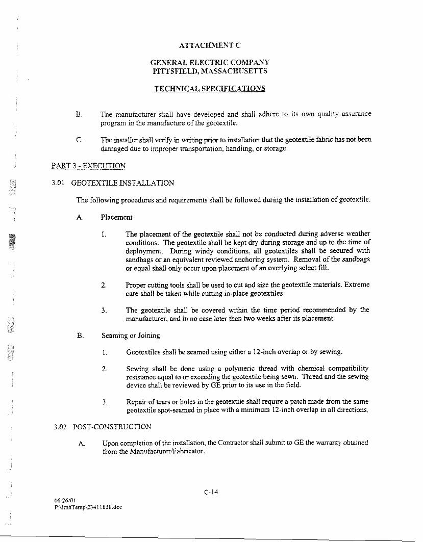
B. The mmufacturer shall have developed and shall adhere to ~ t s own qualrty assurance program in the manufacture of the geotextile.
C. The installer shall verify in writing pnor to mstaflahon h t tbe geotcdle W c has not hmaged due to improper transportation, handling, or storage.
PART 3 - EXEWTION
The following procedures and requirements shall be followed during the installation of geotextile.
A. Placement
1. The placement of the geotextile shall not be conducted during adverse weather conditions. The geotextile shall be kept dry during storage and up to the time of deployment. During windy conditions, all geotextiles shall be secured with sandbags or an equivalent reviewed anchoring system. Removal of the sandbags or equal shall only occur upon placement of an overlying select fill.
2. Proper cutting tools shall be used to cut and size the geotextile materials. Extreme care shall be taken while cutting in-place geotextiles.
3. The geotextile shall be covered within the time period recommended by the manufacturer, and in no case later than two weeks after its placement.
B. Seaming or Joining
1. Geotextiles shall be seamed using either a 12-inch overlap or by sewing.
2. Sewing shall be done using a polymeric thread with chemical compatibility resistance equal to or exceeding the geotextile being sewn. Thread and the sewing device shall be reviewed by GE prior to its use in the field.
3. Repair of tears or holes in the geotextile shall require a patch made from the same geotextile qot-seamed m place with a m i n ~ m m 12-inch overlap in all directions.
A. Upon complehon of the instaIIation, the Contractor shall submt to GE the wammty obtained from the Manufacm&r@abricator.
A. The Contractor shall obtain from the manufacturer and submit ro GE, a standard w m v provided for the geotextiles.
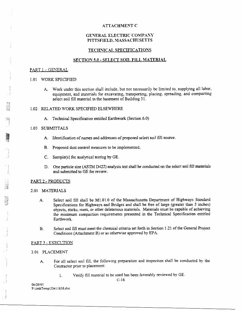
SECllON 5.0 - SELECT SOIL FILL MATERIAL
A. Work under this section shaII include, but not necessarily be limited to, supplying all labor, equipment, and materials for excavating, transporting, placing, spreading, and compacting select soil fill material in the basement of Building 3 1.
1.02 RELATED W O K SPECIEIED E L S E W E
A. Technical Specification entitled Earthwork (Section 6.0)
A. Identification of names and addresses of proposed select soil fill source.
B. Proposed dust control measures to be implemented.
C. Sample(s) for analpcal testing by GE.
D. One particle size (ASTM D422) analysis test shall be conducted on the select soil fill materials and submitted to GE for review.
PART 2 - PRODUCTS
A. Select soil fill shall be M1.O1.O of the Massachusetts Department of Highways Standard Specifications for Highways and Bridges and shall be free of large (greater than 3 inches) objects, sticks, roots, or other deleterious materials. Materials must be capable of achieving the minimum compaction requirements presented in the Technical Specification entitled Earthwork.
B. Select soil fill must meet the chemical criteria set forth in Section 1.21 of the General Project Conditions (Attactunent B) or as otherwise approved by EPA.
PART 3 - EXECrnON
A. For a11 select soil fill, the follourlng preparation and inspection shall be conducted by the Contractor prior to placement:
I . Verify fill material to be used has been favorably reviewed by GE. C-16
M6Q6i0 1 P:U&Temp52341 iS3S.doc
TECHNICAL SPECIFICATIOSS
2. Verify areas to be filled are properly compacted. 3. Verify areas to be filled are free of debns, snow, ~ c e or water and ground surfaces
are not frozen. 4. Identify requxed levels. 5. Grade and m i f m l y compact subgrade, to the required depths and grades. The
maximum uncompacted fill layer shall be 5 inches and the mmlmm compacQon shall be 92 percent as determined by the A S W testing Method 01557. Refer to the Technical Specification entitled Earthwork (Sectlon 6.0) for additional compaction requirements.
6. Demonstrate completeness of subgrade preparation in a manner acceptable to GE.
3.02 FIELD TESTING AND QUALITY CONTROL
A. In-place density testing may be performed at GE's expense by an independent testing laboratory (selected by GE). Testing shall be performed in accordance with ASTM D1557.
- END OF SECTION -
PART I - GENERAL
1.01 DES ON
A. A.ll labor, materials, services and equipment necessary to complete the earthwork activities as described in the Work Plan and/or as directed by GE.
A. Contractor's proposed method(s) of compaction and equipment.
1.03 APPLICABLE CODES, S TANDARDS AND SPECIFICATIONS
A. American Society for Testing and Materials (ASTM)
1.04 DEFINITION
A. Earthwork is defmed to include, but is not limited to, clearing, pavement removal, rough grading, excavation for subgrades, trenching, handling and disposal of surplus materials, maintenance of excavations, removal of water, backfilling operations, embankments and fills, and compaction.
PART 2 - PRODUCTS
Specified elsewhere.
PART 3 - EXECUTION
3 .O 1 UNAmORIZED EXCAVATION
A. The Contractor shall not be entitled to any compensation for excavations carried beyond or below the lines and subgrades prescribed in the Work Plan. The Contractor shall refill such u n a u t h o ~ d excavations at its own expense and in c o d o m c e with the provisions of this section.
B. Should the Contractor, ~ o u g h negf~gence or for reasons of its own, carry its excavatron below the designated subgrade, appropriate rnatenals specified in the Technrcal Specificat~on entltled Select Fill Matenal (Sectton 2.0) shall be h i s h e d and placed as bacMill in sufficient quantities to reestablish the required subgrade surface. Soil fill matmals used for backfiflmg shall be spread and compacted m confomance wth the requiremmts of later subsecbons of thls secrron and to the percentage compacbon outlmed fherem. The cost of any tests requ~red as a result of thls refill~ng operatron shall be borne by the Contractor.
GE3T ELE C GOMPk%Y P I n S m L D , W S S A C m S E m S
TECmICAI, SPECIFICATIOSS
G. All matmal wtuch slides, falls, or caves lnto the established llm~ts of excavahons due to any cause whatsoever, shall be removed and dtsposed of at the Contractor's expense and no
hen will be pard to the Contractor for any mtmals ordered for refillmg the void areas left by the shde, fall, or cave-in.
3.52 BACKFILL
A. Soil fill material or select fill or modified rockfill shall be used as specified for backfill. Requirements for off-site fill materials are specified under Work Tasks 9 and 1 1.
A. Backfill shall be started at the lowest section of the area to be backfilled.
B. Drainage of the areas being backfilled shall be maintained at all times.
C. Areas to be backiilled shall be inspected prior to backfilling opwations. All unsuitable materials and debris shall be removed.
D. Backtill material shall be inspected prior to placement and all roots, vegetation, organic matter, or other foreign debris shall be removed.
E. Stones larger than 6 inches in any dimension shall be removed or broken.
F. Stones shall not be allowed to form clusters with voids.
G. Backfxll material shall not be placed w h q moisture content is too high to allow proper compaction.
H. When material is too dry for adequate compaction, water shall be added to the extent necessary.
I. No backfill material shall be placed on frozen ground nor shall the material itself be frozen or contain frozen soil fragments when placed.
J. No calcium chloride or other chemicals shall be added to prevent freezing.
K. Material incorporated in the bacMilling operation that is not in satisfactory condition shall be subject to rejection and removal at the Contractor's expense.
L. If the Contractor fails to stockpile and protect on-site excavated material acceptable for backfill, then the Conmctor shall provlde an equal qmtlty of acceptrible 0%-site material.
GEhX ELECTRIC CO39PA"cY P m S W L D , BWSSACEPC"SEmS
TECHNICAL SPECIFICATIOS'S
A. General
1. The CmtraGtOT shaJI adopt coqaction methods that sMf produce the degree of compaction specified herem, prevent subsequent settlement, and provide adequate support.
2. Methods used shall avoid distuibance to underlying fine-grained soils and to subsurface utilities.
3. Before filling or backfilling is begun, the Contractor shall submit in its Site Management Plan the equipment and method for compaction which it proposes to use.
4. Hydraulic compaction by ponding or jetting shall not be permitted.
5. Backfill material shall not be left in an uncompacted state at the close of a day's construction.
6. Prior to terminating work, the final layer of compacted fill, after compaction, shall be rolled with a smooth-drum roller if necessary to eliminate ridges of soil left by tractors, trucks or other equipment used for compaction.
7. As backfill progresses, the surface shall be graded such that no ponding of water shall occur on the surface of the fill.
8. Fill shall not be placed on snow, ice or soil that was permitted to freeze prior to compaction.
9. Unsatisfactq materials shall be removed prior to fill placement.
3. Equipment
1. Unless specified otherwise in the Work Plan, equipment for compaction shall be the largest equipment cornistat with space l ~ t a t i o n s of the work areas and the need to protect adjacent facilities.
2. Compaction of fill material in areas with Iunited access, such as over the base liner anchor trench, shalf be accomplished by means of a -type, power dnven, hand- guided vibratory compactor, or by bd-guided vibratory plate tampers.
3. If the proposed method does not produce the degree of compaction requlred, an altmate method shall be adopted until the requlred compaction IS acbleved.
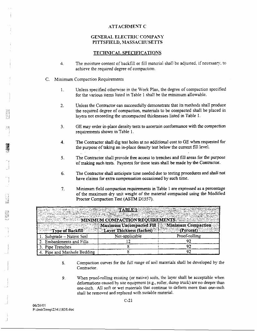
-1eualeur alqafrns EM pa3elda~ pua panomar aq ifeqs yrrur-auo mq slow uojap 01 anurluo:, imp sleualeur ram lo gas 1~ .q3ut-auo ump hap ou an? (y~ns. dump 'la1101 '"8.a) luaurdrnba arls Aq pasnerr suouemujap uaq~ alqezcta~3e aq ~jqs laAef aql 's11os (a~rreu lo) %ur~stxa %u~~fo~-joord uaw '6
.aurg q3ns Aq pauo~semo uo~lesuaduro~ wxa ~oj sur~el:, akeq tau llqs pm sampam~d Buysa101 anp papaau aq a~edpgue 11m.j~ lo~~e.~uo=) am '9
-1opegu03 aqa Aq apm aq 11-s Qsai asayt loj ~uaded -slsa$ qsns %u~m jo asodrnd aqlloj seam [~IJ pue saqx~aq 01 ssame aay aprkoxi 11m.j~ 101o~e4uo=) arU, 'S
-1anaI IIIJ xual~lls aq Molaq tsal 41suap a3eld-ur ue 8uW jo asodmd aql 103 palsanba~ uaq~ sf) 01 $so3 Ieuoyppa ou le saIoq isal KIP 11~s ~ro~~?~$uo=) am -9
-1 a1QeL tq pa3sq sassarry3yy) pal3edurooun ayl %Tpaa~xa gou s~aAe~ u1 paqd aq f~eqs pat3vduro3 aq 01 sleualm 'uogsedmos 30 aasap palrnba~ aw ampold 11~s spoqJaur s11 layl alwsuourap A[1ryssa33ns m3 row?~~uo=) ayt ssaiun -Z
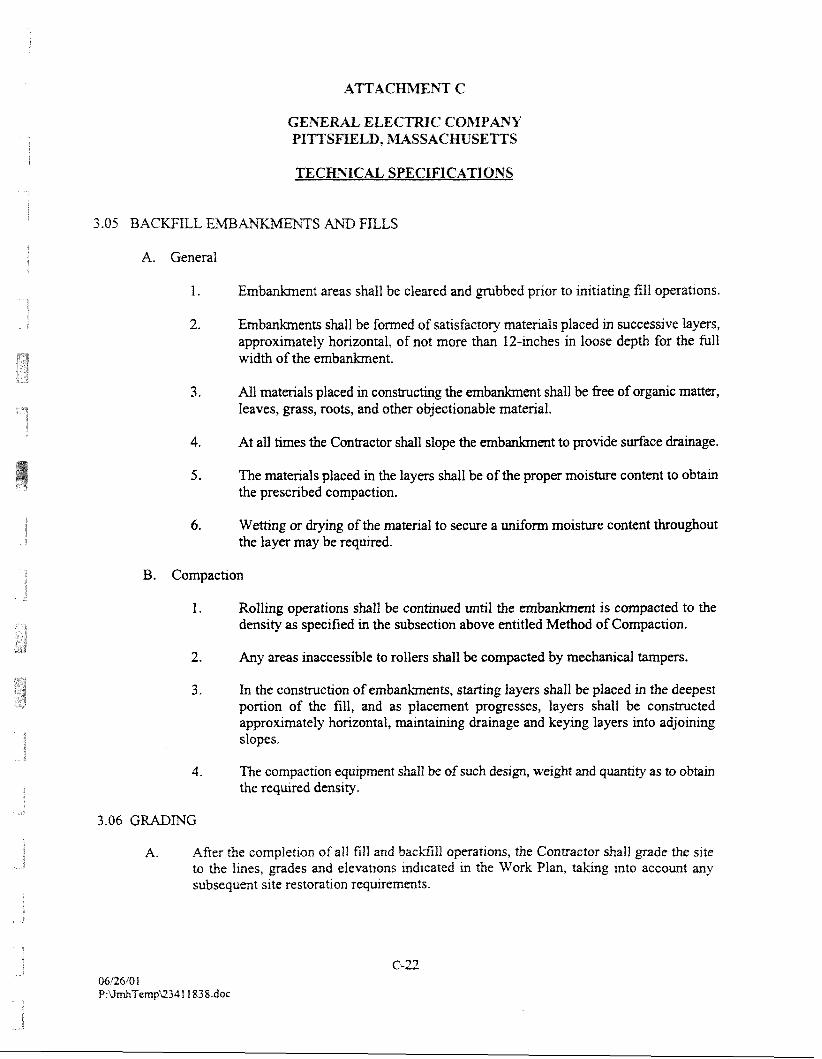
TECHTTCAI. SPECIFICATIONS
3.05 BACWILL EmA\X%fEhTS AH9 FILLS
A. General
1. ent areas shall be cleared and p b b e d prior to initiating fill operations.
2. Embankments shall be formed of satisfacto~ materials placed in successive layers, approximately horizontal, of not more than 12-inches in loose depth for the full width of the embankment.
3. All materials placed in comtructing the embanlunent shall be free of organic matter, leaves, grass, roots, and other objectionable material.
4. At all times the Contractor shall slope the embankment to provide surface drainage.
5 . The materials placed in the layers shall be of the proper moisture content to obtain the prescribed compaction.
6. Wetting or drylng of the material to secure a uniform moisture content throughout the layer may be required.
B. Compaction
1. Rolling operations shall be continued until the embankment is compacted to the density as specified in the subsection above entitled Method of Compaction.
2. Any areas inaccessible to rollers shaII be compacted by mechanical tampers.
3. In the construction of e m b h e n t s , starting layers shall be placed in the deepest portion of the fill, and as placement progresses, layers shall be constructed approximately horizontal, minbinhg drainage and keying layers into adjoining slopes.
4. The cornpackon equipment shall be of such design, weight and qmtity as to obtain the required density.
A. After the completion of all fill and backfill owattons, the Contractor shall grade the site to the lines, grades and elevations mdicated m the Work Plan, taking rnto account any subsequent site restoration requrrmmts.
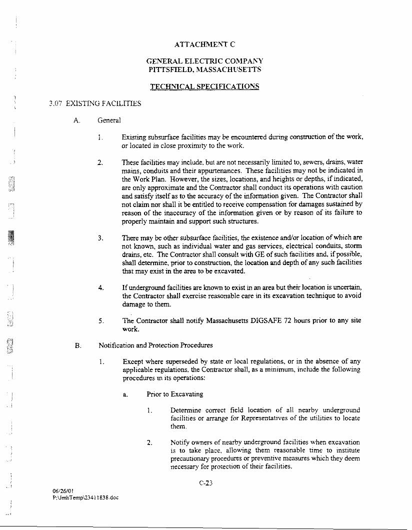
3.07 EXSTWC FACE,
A. General
I . Existing s t ibdace facilities may be encountered g construction of the w k or located in close proximity to the work.
2. These facilities may include, but are not necessarily limited to, sewers, drains, water mains, conduits and their appurtenances. These facilities may not be indicated in the Work Plan. However, the sizes, locations, and heights or depths, if indicated, are only aproximate and the Conttactor shall conduct its operations with caution and satisfy itself as to the accuracy of the information given. The Contractor shall not claim nor shall it be entitled to receive compensation for damages sustained by reason of the inaccuracy of the information given or by reason of its failure to properly maintain and support such structures.
3. There may be other subsurface facilities, the existence and/or location of which are not known, such as individual water and gas services, electrical conduits, storm drains, etc. The Contractor shall consult with GE of such facilities and, if possible, shall determine, prior to construction, the location and depth of any such facilities that may exist in the area to be excavated.
4. If underground facilities are known to exist in an area but their location is uncertain, the Contractor shall exercise reasonable care in its excavation technique to avoid damage to them.
5 . The Contractor shall notify Massachusetts DIGSAFE 72 hours prior to any site work.
B. Notification and Protection Procedures
1. Except where superseded by state or local regulations, or in the absence of any applicable regulations, the Contractor shall, as a minimum, include the following procedures in its operations:
a. Pnor to Excavating
1. Determine correct field location of all nearby underground facilities or arrange for Rqresentafves of the utilities to locate them.
2. Notie owners of nearby underground facil~ttes when excavation is to take place, allovvlng them reasonable &me to lnshtute precauhonary pmedunzs or prevmbve measures wfuch they deem necessary for protection of the~r facil~ties.
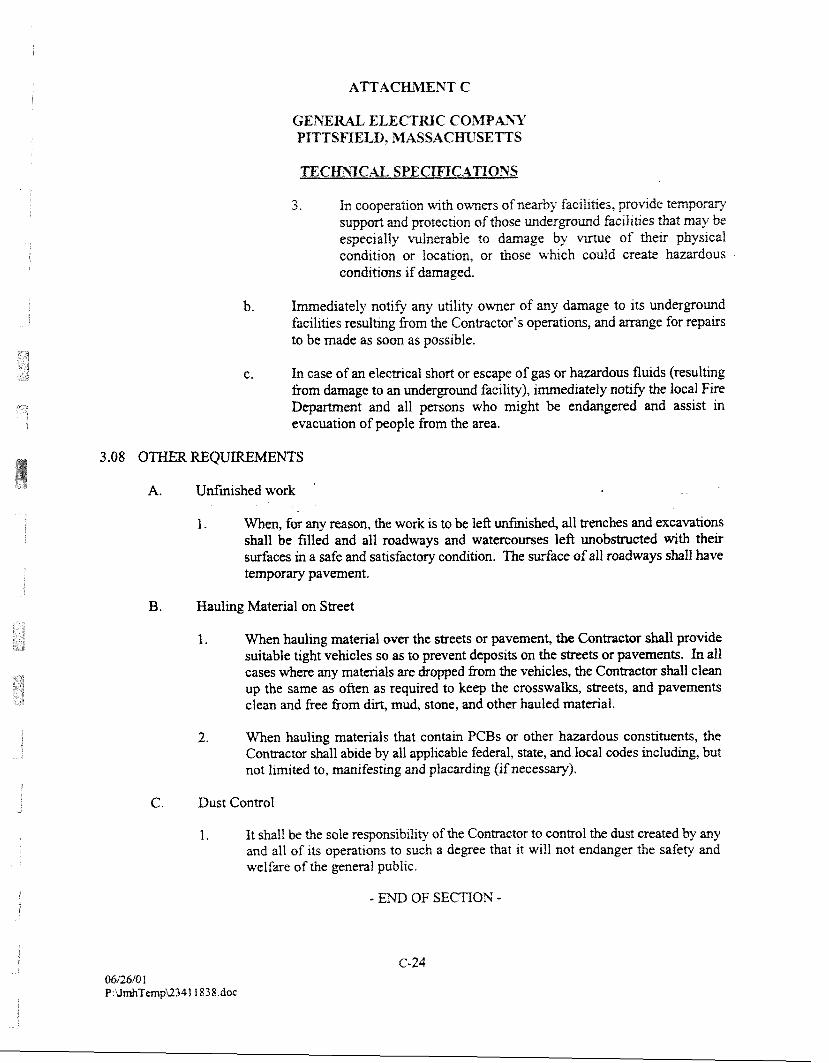
ELECTRIC COMPAN1? PImSEIELD, 3IIASSACmSEnS
3. h cooperation uqth owms of nearby hcihties, provlde t empow support and protecaon of those undergound facil~ties that may be especially vulnerable to damage by mrtue of thev pbys~cal cond~tion or locaQon, or those which ~ould create hazardous conditions if damaged.
b. Imediately notify any utility owner of any damage to its underground facilities resulting from the Contractor's operations, and arrange for repairs to be made as soon as possible.
c. In case of an electrical short or escape of gas or hazardous fluids (resulting from damage to an underground facility), immediately notify the local Fire Department and all persons who might be endangered and assist in evacuation of people from the area.
3.08 OTHER REQUIREMEmS
A. Unfinished work .
1. When, for any reason, the work is to be left unfuushed, all trenches and excavations shall be filled and all roadways and watercourses left unobstructed with their surfaces in a safe and satisfactory condition. The surface of all roadways shall have temporary pavement.
B. Hauling Material on Street
1. When hauling material over the streets or pavement, the Contractor shall provide suitable tight vehicles so as to prevent deposits on the streets or pavements. In all cases where any materials are dropped fiom the vehcles, the Contractor shall clean up the same as often as required to keep the crosswalks, streets, and pavements clean and free from dirt, mud, stone, and other hauled material.
2. When hauling materials that contain PCBs or other hazardous constituents, the Contractor shall abide by all applicable federal, state, and local codes including, but not limited to, manifesting and placarding (if necessary).
C. Dust Control
1. It shall be the sole responsibility of the Contractor to control the dust created by any and all of its operations to such a degree that it will not endanger the safety and welfare of the general public.
SECmOh' 7.0 - SOIL FILL MAWRIAL,
PART 1 - G E m M
1 .O 1 W O m SPE D
A. Work under thss section shall include, but not necessarily be limited to, su~fplyrng all labor, equipment, and materials for excavating, tranfporting, placing, spreading, and compacting soil fill material in the basement of Building 3 1.
1.02 RELATED W O K SPECIFIED ELSE==
A. Technical Specification entitled Earthwork (Section 6.0).
A. Identification of names and addresses of proposed select fill source.
B. Proposed dust control measures to be implemented.
C. Sample(s) for analflcal testing by GE.
PART 2 - PRODUCTS
A. Soil fill material shall consist of material free from excessive amounts of clay and silt, stones larger than 2 inches, large sticks and roots, and other deleterious materials. Material shall have a pH and organic content sufficient to promote vegetative growth.
B. Soil fill material must meet the chemical criteria set forth in Section 1.21 of the General Project Conditions (Attachment B) or as otherwise approved by EPA.
PART 3 - EXECUTION
A. For all soil fill, the following preparation and inspection shall be conducted prior to placement:
1. Verify fill material to be used is approved. 2. Vwify areas to be filled are properly compacted. 3. Verify areas to be filled are kee of debris. snow, ice or water and ground sdaces
are not ffozm. 4. Idenhfy required levels.
TECH?;IC.AL SPECIFICATIOYS
5. Grade and unlfomly compact suttgrade, to the required depths and grades. The maximum uncompacted fill layer shall be 5 inches and the minimum compaction shall be 90 percent as detmined by the ASTM testmg Method D1557.
6. Dmonsmte completeness of subpde preparation m a m m e r acceptable to GE.
B. Where required, the Contractor shall, at its own expense, moisture condition the fill to meet the compaction requirements. If, due to rain or other causes, the materia1 is too wet for satisfactory compaction, it shall be allowed to dry or be removed as required, before compaction.
3.02 FELD TESTING AND QUALITY CONTROL
A. In-place density testing shall be performed by an independent testing laboratory approved by GE. Testing sb l l be performed in accordance with ASTM D1557.
- END OF SECTION -
TECmTCAL SPEGIFICATlONS
SEGTIOS 8.0 - TOPSOIL, SEEDfPc"G. A 3 4 mXGfI
PART 1 - CEhTR22L
1.01 WORK mmmm
A. Work under ttus section consists of h i s h m g and placement of topsoil, fertilizer, seed, and mulch.
B. Maintenance of seeded areas until fmal acceptance.
1.02 RELATED WORK SPECIFIED ELSEWHERE
A. Technical Specification entitled Earthwork (Section 6.0).
1.03 SUBMITTALS
A. Analysis of the seed (to demonstrate compliance with the seed mix identified in Section 2.01 of this specification) and fertilizer (to identify chemical composition), and proposed application rates for seed mix and fertilizer.
B. If hydroseed is used, the Contractor shall submit all data including material and application rates.
C. Location of source, and pH and organic content testing of off-site topsoil (if required).
D. Manufacturer's specifications for Contractor's proposed temporary and permanent erosion control matting if other than North American Green.
E. Sample(s) for analpcal testing by GE.
PART 2 - PRODUCTS
A. Any off-site topsoil shall be unfiom, hable, natural loam and shall be free of clay lumps, brush weeds, l~tter, stumps, stones, and other extraneous matter. The topsoil shall have an organlc content between 5 and 20 percent, and a pH between 5.5 and 7.5.
B. Fertilizer shall be a standad quality commercial carrier of available plant food elements. A complete prepared and packaged n a m l contamlng a mrnlrnum of 5% nitrogen, 10% phovho~c acid, and 10% potash.
1. Each bag of fmilizer shall bear the manufacturer's g w t e e d statement of analysis.
G. Seed mixtwes shall be of comercia1 stock of the current seasonts crop and shall be delivered in unopened containers beanng the gwrmteed analys~s of the rnlx.
1. All seed shall meet the State standards of gemination and punty.
D. Seed mix:
- 60% Kentucky Blue Grass - 20% Perennial Rye Grass - 15% Fescue
E. Mulch shall be stalks of oats, wheat, rye or other approved crops free from noxious weeds and coarse materials.
F. Temporary erosion control matting shall be S75 as manufactured by North American Green or required equivalent.
G. Permanent erosion control matting shall be P300P as manufactured by North American Green or required equivalent, -
PART 3 - EXECUTION
3.0 1 INSTALLATION
A. The topsoil shall be applied in a single loose lift of not less than six inches. No compaction is required or allowed.
1. Following placement of topsoil and prior to fdl izer application, all stones greater than I-inch in diameter, sticks, and other deleterious material shall be removed.
B. The fertilizer shall be applied to the surface uniformly at the rate of 20 pounds per 1,000 square feet.
1. Following the application of the fertilizer and prior to application of the seed, the topsoil shall be scarified to a depth of at least 2 inches wth a dlsk or other suitable method traveling across the slope if possible.
C, After the soiI sudace has been fine graded, the seed mixture shall be e f o m l y applied upon the prepared surface with a mechanical spreader at a rate specified by the seed manufacturer.
1. The seed shall be raked lightly into the surface.
2. Seeding and muIchng shall not be done d ~ g windy weather.
D. The mulch shall be kand or ma~hule spread to form a conQnuous bidet over the seed bed, approximkly 2 mches uz u r u f m thrckness at loose measurement wth a mlnlmtun of 90% surface coverage. Excessive arnotlnts or bunctung of mulch shall not be pmltted.
I . Mulch shall be anchored by an acceptabte method.
2. Unless othe*se specified, mulch shall be left in place and allowed to decompose.
3. Any anchorage or mulch fhat has not disintegrated at time of first mowing shall be removed. For peg-type anchors, anchors may be removed or dnven flush with ground surface.
E. Seeded areas shall be watered as often as required to obtain germination and to obtain and maintain a satisfactory sod growth. Watwing shall be in such a manner as to prevent washing out of seed and mulch.
F. Hydroseeding may be accepted as an alternative method of applying fertilizer, seed and mulch. The Contractor must submit all data regarding materials and application rates to GE for review.
A. All erosion rills or gullies within the topsoil layer shall be filled with additional topsoil and graded smooth, and reseeded and mulched.
B. The Contractor shall also be responsible for repairs to all erosion of the seeded areas until all new grass is firmly established and reaches a height of not less than 4 inches. A11 bare or poorly vegetated areas must be reseeded and mulched.
- END OF SECTION -
SECTION 9.0 - mEXIBLE W?rlBRA?cZ LI3XR
1.01 DES ON
A. Work Specified
1. Under this section, the Contractor shall fmish and install 60-mil thick, textured high density polyethylene (WDPE) FML material as shown on the Technical Drawings and as specified herein and/or directed.
2. The Contractor shall be responsible for all QNQC testing specified herein and as indicated on the Technical Drawings. All QNQC testing, with the exception of non- destructive tests, shall be conducted by an independent laboratory at the Contractor's expense.
1.02 ELATED WORK SPECIFED ELSEWHEE
A. Section 10.0 - Geosynthetic Drainage Composite
1.03 APPLICABLE CODES, STANDARDS, SPECIFICATIONS, AND PUBLICATIONS
A. American Society for Testing and Materials (ASW)
1. D4 13-88 Rubber Property -- Adhesion to Flexible Substrate
2. D638-89 Tensile Properties of Plastics
3. D746-79 Brittleness Temperature of Plastics and (Rev 1987) Elastometers by Impact
4. D75 1-89 Coated Fabrics
5. D792-86 Specific Gravity and Density of Plastics by Displacement
6. D882-90 Tensile Properties of Tfun Plastic Sheeting
7. D1004-90 Initial Tear Resistance of Plastic Film and Sheeting
8. 01203-89 Volatile Loss &om Plastics Using Activated Carbon Methods
9. D1204-89 Linear Dimensional Changes of Nonrigid nmoplas t ic Sheeting or Film at Elevated Temperature
10. Dl 238-90 Flow Rates of Themoplastics by Extrusion Plastometer
I 1. Dl 505-85 Denslty of Plastics by the Density Gradient Technique
12. D1603-76 CaTbon Black in Olefin Plastics (Rev. 1988)
14. D1790-90 Brittleness Temperature of Plastic Film by Impact
15. D5995 Recornended Practice for Microscopical Examination of Pigment Dispersion in Plastic Compounds
16. D4833 Puncture Resistance
3. Geosynthetic Research Institute (GRI)
GRI Test Method GM 13 Test Properties, Testing Frequencies and Recommended Warrant for High-Density Polyethylene (HDPE) Smooth and Textured Geomembranes
- - C. Where reference is made to one of the above codes, standards, specifications or publications the
revisions in effect at the time of bid shall apply.
1.04 QUALIFICATIONS
1. The Contractor shall submit to GE or GE's Representative for approval the following infomation regarding the FML Manufacturer:
a. Corporate backgomd and infomation.
b. Manufacturing capabilities including:
e Quality control procedures for manufacang; and * List of material properties including certified test results, to which FML
samples are artached.
c. A list of at least ten completed facilities, totaling a m ~ m m of 10,000,000 ft2, for whch the Nanufactura has facmed FMLs. For each facility, the follo%g infomation shall be provided:
* N m e and pupose of facility, its location and date of installation ect Mmnagctr, cator (if any), and Instalter d a c e area o
GENE E L E C m C CO%%PAhT PfTTSmLD, IMASSACmSEmS
d. &gin (resm suwlier's name, resm produetlon plan) and ldentlfication @rand name, n u & ) of the resm.
B. Installer
1. The Installer must be trained and approved and/or licensed by the FML Manufacmer for the installation of FML.
2. The Contractor shall submit to CE or GE's Representative for approval the following written information, relative to the Installer.
a. Copy of Installer's letter of approval or license by the Manufacturer. b. Resume of the "master seamer" to be assigned to this project, including dates and
duration of employment.
3. All personnel performing seaming operations shall be qualified by experience or by successfully passing seaming tests. At least one seamer shall have experience seaming a minimum of 1,000,000 ft2 of FML of the type for this project, using the same type of seaming apparatus in use at the site.
PART 2 - PRODUCTS
2.01 ACCEPTABLE MANUFACTURERS
A. Solmax Geosynthetics; B. GSE Lining Technology, Inc.; or C. Equal.
A. HDPE Lining Material Specifications
1. B P E FML material shall meet the following rn-m specification values listed below and as listed in GN GM 13.
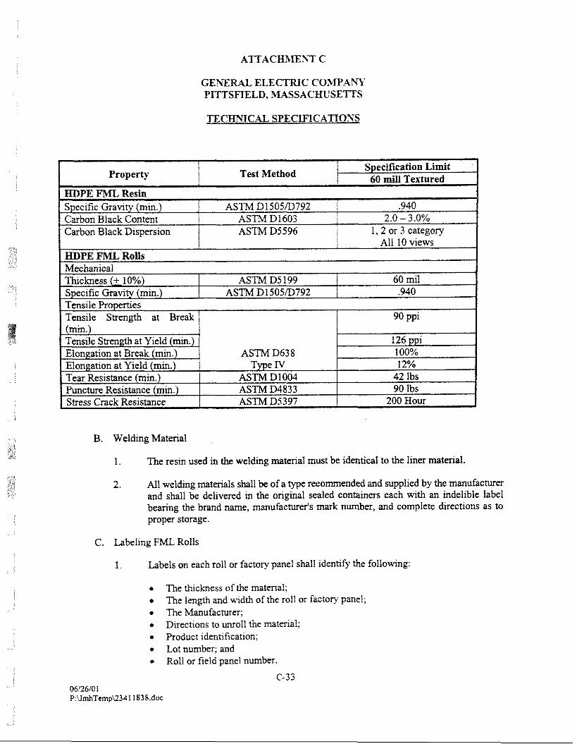
TECHSICAL SPECIFICATIOYS
B. Welding Material
1. The resin used in the welding miterial must be identical to the liner material.
2. All welding materials shall be of a type recommended and supplied by the manufacturer and shall be delivered in the origznal sealed containers each with an indelible label bearing the brand name, manufacturer's mark number, and complete directions as to proper storage.
C. Labeling FML Rolls
1. Labels on each roll or factory panel shall identify the f o l l o ~ g :
?he thickness of the material; The length and width of the roll or factory panel; The Manufacms;
* Directions to unr011 the material; 0 Product identification;
Lot n m b a ; and 0 Roll or field panel n m b s .
(2-33
2.03 DELNERY, LING STORAGE
A. The Contractor shall be liable for all damages to the materials incurred prior to and dunng transportation to the site.
B. Handling, storage and care of the Flexible Membrane Liner prior to and foflouring installation at the site, is the responsibility of the Contractor. The Contractor shall be liable for all damages to the materials incurred prior to final acceptance of the lining system by GE or GE's Representative.
C. The Contractor shall notify GE or GE's Representative of the anticipated delivery time.
2.04 ADDITIONAL SUBMITTALS
A. The Contractor shall submit the following items for approval at least one week prior to installation.
1. Shop drawings shall include:
a. Layout plan;
b. Quality control program manuals covering all phases of manufacturing and installation; and
c. Complete and detailed written instructions for the storage, handling, installation, seaming, inspection plan fail niteria for liner inspections, and QA/QC testing procedures of the liner in compliance with these specifications and the condition of its warranty.
PART 3 - EXECUTION
3.0 1 FML INSTALLATION
A. Related Earthwork
1. The Contractor shall insure that all related complied with:
a. The FML installations shall be perfomed on a fm, smooth, soil or geotextile- covered surface free from stones or promdlng objects.
shaII be placed onto an area which has become softened by precipitat;lon. Ap~opfiate methods of moisture control are the responsibil~ty of the Contractor.
c. No FbiL shall be placed on frozen soil matmal. Such material shall be removed and replaced ulth new soil fill as spec~fied m the Sect~on W-02222 - Soil Fill Matenals.
d. TLre FbE Installer shall certify in that the final d a c e on which the FIVE is to be installed is acceptable.
e. All surfaces on which the FML is to be installed shall be acceptable to GE or GE's Representative prior to FML installation.
f. Free edges of FIVE shall be secured in such a manner as to prevent uplift by wind or the intrusion of water under the liner. Edge protection shall include, sandbags, poIyethylene sheeting or other methods as deemed necessary by the Contractor and approved by GE or GE's Representative.
g. The FIVE shall be anchored within an anchor trench constructed to the dimensions shown in the Technical Drawings. Care shall be taken while backfilling the trenches to prevent damage to the FML.
B. FML Deployment
1. FML shall be deployed according to the following procedures:
a. Placement of the FML panels shall be according to the approved location and position plan provided by the Installer. Placement shaII follow ail instructions on the boxes or wrapping containing the FML materials which describe the proper methods of unrolling panels.
b. The method of placement must ensure that:
.I Deployed FML must be visually inspected for uniformity, tears, punctures, blisters or other damage or imperfections. Any such imperfections shall be immediately repaired and reinspected.
* No equipmat used shall damage the FML by handling, traficlang, leakage of hydrochns, or other means.
* No personnel worlung on the FML shall smoke, wear damaging shoes, or engage in other act~vities which could damage the IML.
* The prepared surface urderlying the FML must not be allowed to deteriorate after acceptance and must remain acceptable up to the time of and until compitetion of the project.
TECHSICAL SPECIFICATIOSS
* Adequate temporaw loadmg andlor mchonng (e.g,, sand bags), not likely to damage the FML, shall be placed to prevent upl~ft by wnd (m case of high winds, contmuous loading IS recornended along edges of panels to mlnlmlze nsk of wnd flow under the panefs).
* Direct contact with the FML shall be minimized; is. , the FML in excessively high traffic areas shall be protected by geotextiles, extra FhIL, or other suitable materials.
c. Any damage to the FML panefs or portions of the panels as a result of placement must be replaced or repaired at no cost to GE or GE's Representative. The decision to replace or repair any panel or portions of panels shall be made by GE or GE's Representative.
d. The Installer shall assign an "identification number'' to each FML panel placed. The number system used shall be simple, logical and identify the relative location in the field.
. . C. Seaming
1. The seaming procedures below shall be implemented, where applicable, d e g installation of the FML. The seaming procedures are as follows:
a. Generally, all seams whether field or factory, shall be oriented parallel to the line of slope, not across slope. At liner penetrations and comers, the number of seams shall be minimized.
b. The area of the Fh4L to be seamed shall be cleaned and prepared according to the procedures specified by the material manufacturer. Any abradmg of the FML shall not extend more than one-half inch on either side of the weld. Care shall be taken to eliminate or minimize the number of w d d e s and "fisfimouths" resulting from seam onentation.
c. Field seamlng IS prohib~ted when elther the air or sheet t m w m IS below 32°F or when the sheet temperature exceeds 122°F or when the an ternperature is above 104°F. At asr or sheet t e m m m s between 32°F and 40°F, seammg shall be conducted drrectly behind a preheat~ng devlce. In addit~on, seaming shall not be conducted when FML matenal is wet from precxpitatlon, dew, fog, etc., or when w d s are In excess of 20 rn~les per hour.
d. Seming shall not be perfomed on frozen or excessively wet underlying soil surfaces.
e. Seams shall have an overlap beyond the weld large enough to perform desmctive peel tests, but not exceed 5 inches.
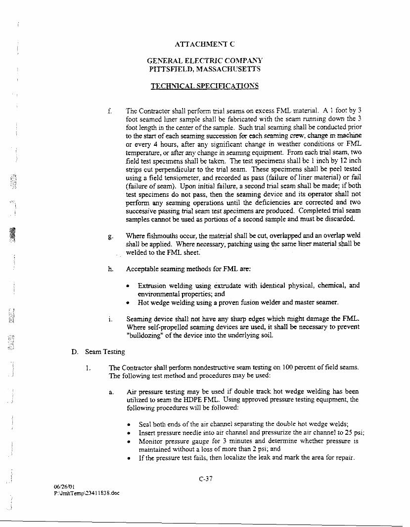
AT'I'AC 33' C
The Contractor shall p e r f m tnal seams on excess FML matenal. A 1 foot by 3 foot seamed Iina sample shall be fabncated wth the seam -1% down the 3 foot length m the center of the sample. Such trial se shall be conduGted pnor to the start of each s m m g success~on for each s m m g crew, c h g e m m c b e or every 4 hours, after any s~gnificant change m weather conditions or FML temperature, or after any change m seamrng equipment. From each ma1 seam, two field test specimens shall be taken. The test specrmens shall be 1 Inch by 12 rnch stnps cut perpendicular to the tnal seam. These specimens shall be peel tested using a field tenslometer, and recorded as pass (failure of l~ner matenal) or faif (failure of seam). Upon init~al failure, a second tnal seam shall be made; if both test specimens do not pass, then the seaming dev~ce and ~ t s operator shall not perform any seammg operations until the deficiencies are corrected and two successive passrng tnal seam test specimens are produced. Completed tnal seam samples cannot be used as portions of a second sample and must be discarded.
g. Where fishmouths occur, the material shall be cut, overlapped and an overlap weld shall be applied. Where necessary, patching using the same liner material shall be welded to the FML sheet.
h. Acceptable seaming methods for FML are:
Extrusion welding using extrudate with identical physical, chemical, and environmental properties; and Hot wedge welding using a proven fusion welder and master searner.
i. Seaming device shall not have any sharp edges which might damage the FML. Where self-propelled seaming devices are used, it shall be necessary to prevent "bulldozing" of the device into the underlymg soil.
D. Seam Testing
1. The Contractor shall perform nondesmctive seam testing on 100 p e n t of field seams. The following test method and procedures may be used:
a. Air pressure testing may be used if double track hot wedge welding has been utilized to seam the MDPE . Using awoved pressure testing equipment, the f o l l o e g procedures will be followed:
e Seal both ends of the air channel separating the double hot wedge welds; Insert pressure needle Into atr chmel and pressmze the alr chmel to 25 psi;
e Monitor presswe gauge for 3 minutes and detmzne whether pressure 1s mainwined wthout a loss of more than 2 pa; and If the pressure test fails, then local~ze the Ieak and mark the area for repalr.
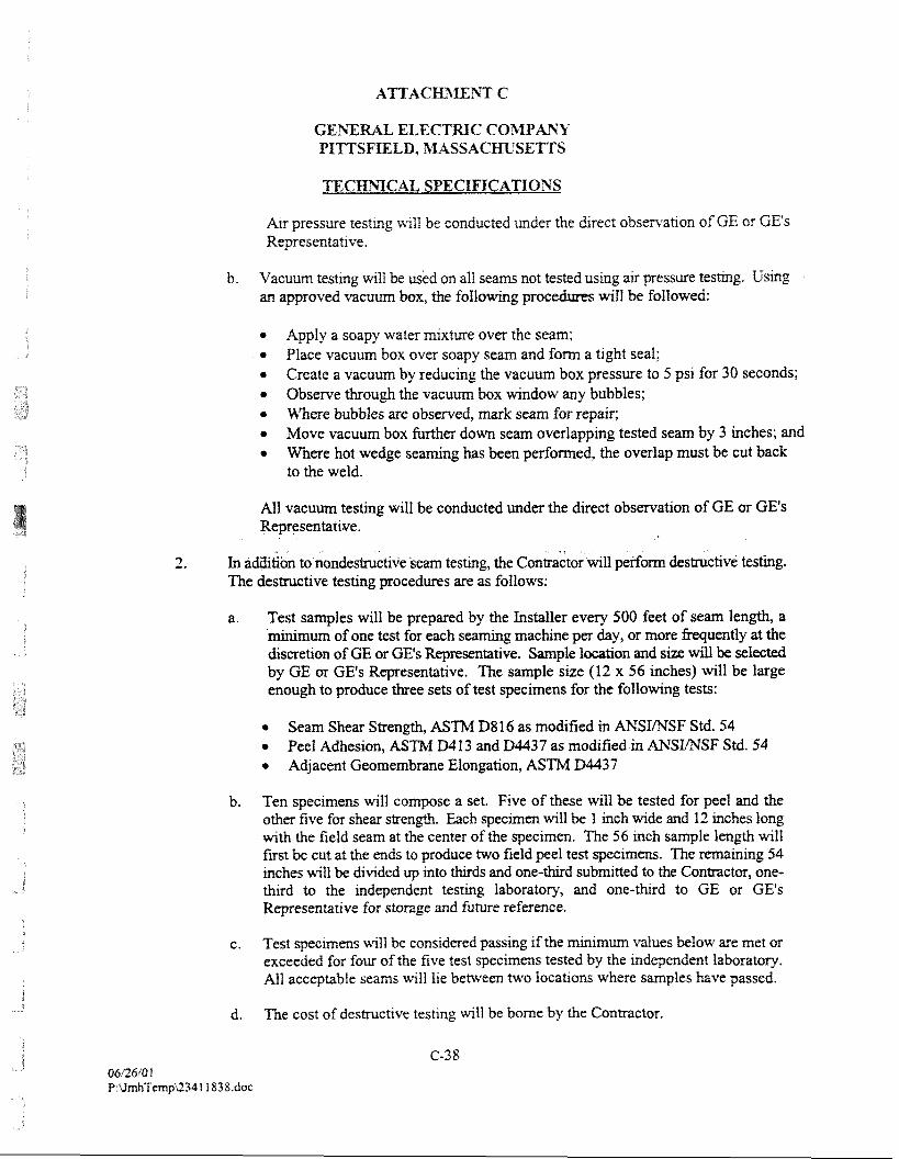
Air pressure testrng will be conducted under the drrect obseniatlon of GE or GE's Representative.
b. Vacuum testlng will be usid on a11 seams not tested usrng ax pressure testing. Using ed vacuum box, the f o l i o ~ g p will be foIlowed:
* Apply a soapy water mixture over the seam; Place vacuum box over soapy seam and form a tight seal;
* Create a vacuum by reducing the vacuum box pressure to 5 psi for 30 seconds; Observe through the vacuum box window any bubbles;
* m e r e bubbles are observed, mark seam for repair; * Move vacuum box further down seam overlapping tested seam by 3 inches; and
Where hot wedge seaming has been performed, the overlap must be cut back to the weld.
All vacuum testing will be conducted under the direct observation of GE or GE's Representative.
2. In addi6bn to nondestructive seam testing, the contra&oriuill perform destructive testing. The destructive testing procedures are as follows:
a. Test samples will be prepared by the Installer every 500 feet of seam length, a minimum of one test for each seaming machine per day, or more frequently at the discretion of GE or GE's Representative. Sample location and size will be selected by GE or GE's Representative. ?he sample size (12 x 56 inches) will be large enough to produce three sets of test specimens for the following tests:
Seam Shear Strength, ASTM D8 16 as modified in ANSL'NSF Std. 54 * Peel Adhesion, ASThif Dl13 and D4437 as modified in ANSmSF Std. 54 * Adjacent Geomembme Elongation, A S W D4437
b. Ten specimens will compose a set. Five of these will be tested for peel and the other five for shear strength. Each specimen will be 1 inch wide and 12 inches long with the field seam at the center of the specimen. The 56 mch sample length will fust be cut at the ends to produce two field peel test specimens. The remaining 54 inches will be divided up into thirds and one-third submitted to the Contractor, one- third to the independent tesbng lahmtory, and one-thud to GE or GE's Representative for storage and future reference.
c. Test specimens will be considered passing if the e i m m values below are met or exceeded for four of the five test specimens tested by the independent laboratofy. All acceptable seams will he between two locations where smples have passed.
d, The cost of destructive testing will be borne by the Conmctor.
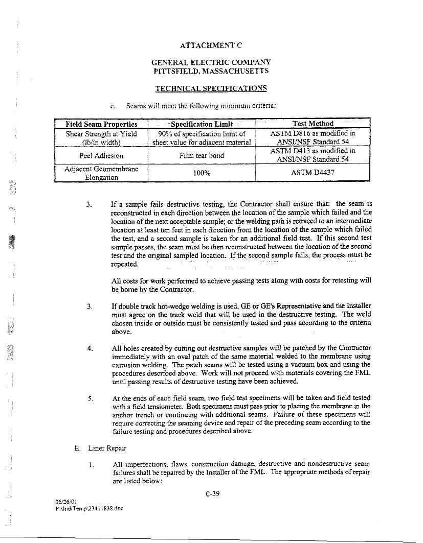
e. Seams will meet the follo%+ng minimum criteria:
3. If a sample fails destructive testing, the Contractor shall ensure that: the seam is reconstructed in each direction between the location of the sample which failed and the location of the next acceptable sample; or the welding path is retraced to an intermediate location at least ten feet in each direction from the location of the sample which failed the test, and a second sample is taken for an additional field test. If this second test sample passes, the seam must be then reconstructed between the location of the second test and the original sampled location. If the second sample fails, the process must be - . -- repeated.
All costs for work performed to achieve passing tests along with costs for retesting will be borne by the Contractor.
3. If double track hot-wedge welding is used, GE or GE's Representative and the installer must agree on the track weld that will be used in the destructive testing. The weld chosen inside or outside must be consistently tested and pass according to the criteria above.
4. All holes created by cutting out-destructive samples will be patched by the Contractor immediately with an oval patch of the same material welded to the membrane using extrusion welding. The patch seams will be tested using a vacuum box and using the procedures described above. Work will not proceed with materials covering the FML until passing results of destructive testing have been achieved.
5. At the ends of each field seam, two field test specimens wH be taken and field tested wrth a field tens~om-. Both spemm must pass pnar to plamg the r n e r n h e m the anchor trench or contlnumg wlth additlorn1 seams. Failure of these spectrnens wll requlre coRecQng the semtng devlce and repair of the precedmg seam according to the failure testrng and procedures described above.
E. Liner Repair
1. All imperfections, flaws, consmetion hmage, destruct~ve and nondestntchve seam failures shall be repalred by the Installer of the . The apvopate methds of repair are listed below:
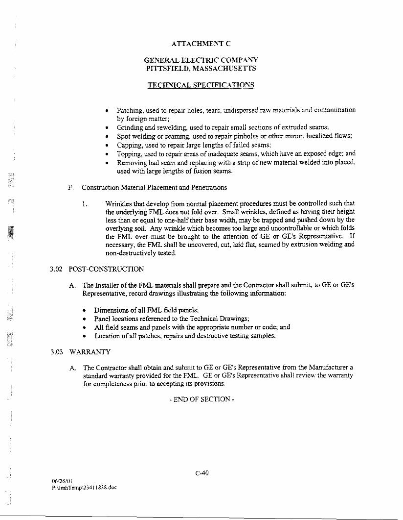
ATTAC ?iT C
CAL SPEGIFXCATIONS
Patchmg, used to repalr holes, tears, undispersed raw matenals and contamrnatron by forelgn matter;
* h d m g and reweldmg, used to repalr small sections of extruded seams; * Spot weld~ng or searnmg, used to repar prnholes or o t k mar, localized flaws;
Cappmg, used to repair large len@s of failed seams; Topping, used to repau. areas of mdequate seams, whch have an exposed edge; and Removing bad seam and replac~ng wth a stnp of new matenal welded Into placed, used wth large lengths of fusion seams.
F. Construction Material Placement and Penetrations
1. Wrinkles that develop from normal placement procedures must be controlled such that the underlying F'ML does not fold over. Small wrinkles, defmed as having their height less than or equal to one-half their base width, may be trapped and pushed down by the overlying soil. Any wrizikle which becomes too large and uncontrollable or which folds the FML over must be brought to the attention of GE or GE's Representative. If necessary, the FML shall be uncovered, cut, laid flat, seamed by extrusion welding and non-destructively tested.
3 -02 POST-CONSTRUCTION
A. The Installer of the FML materials shall prepare and the Contractor shall submit, to GE or GE's Representative, record drawings illustrating the following information:
Dimensions of all FML field panels; Panel locations referenced to the Technical Drawings; All field seams and panels with the appropriate number or code; and Location of all patches, repairs and destructive testing samples.
A. The Contractor shaIl obtain and submit to GE or GE's Representative from the Manufacmer a standard warranty provided for the FML. GE or GE's Representative shall review the warranty for completeness prior to accepting its provisions.
- END OF SECTION -
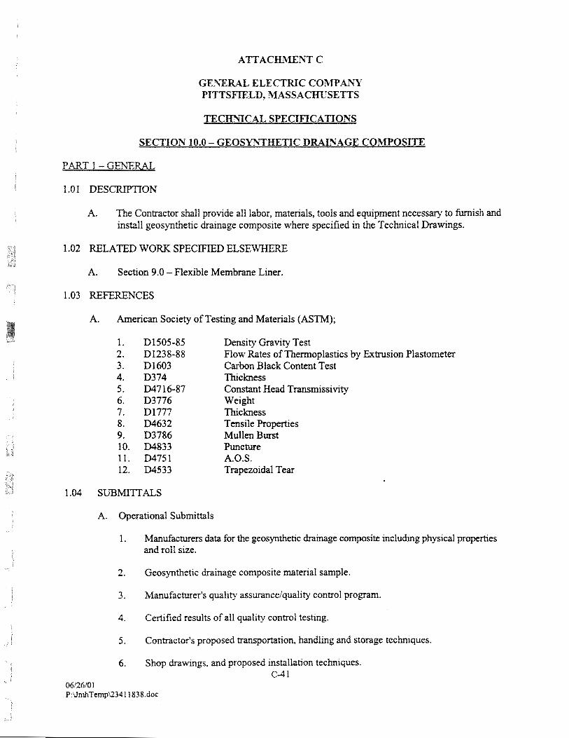
1.01 DES ON
A. The Contractor shall provide all labor, materials, tools and equipment necessary to furnish and install geosynthetic drainage composite where specified in the Technical Drawings.
1.02 RELATED WORK SPECIFIED E L S E W E E
A. Section 9.0 - Flexible Membrane Liner.
1.03 REFERENCES
A. American Society of Testing and Materials (ASTM);
Density Gravity Test Flow Rates of Thermoplastics by Extrusion Plastometer Carbon Black Content Test Thickness Constant Head Transmissivity Weight Thickness Tensile Propemes Mullen Burst Puncture A.O.S. Trapezoidal Tear
A. Operational Submittals
1. Mandacturm data for the geosm&etic drabge cowsi te including physical pmperhes and roll size.
2. Ceosyntfietic drainage composite material sample.
3. Manufacturer's quality assuranceiquality control propm.
4. Certified results of all quality control testing.
5. Contractor's proposed m n v m t i o n , handlrng and storage techniques.
6. Shop drawings, and proposed instalia~on techniques. c-4 1
06/26/0 I P:UmhTmpU34 1 1838.doc
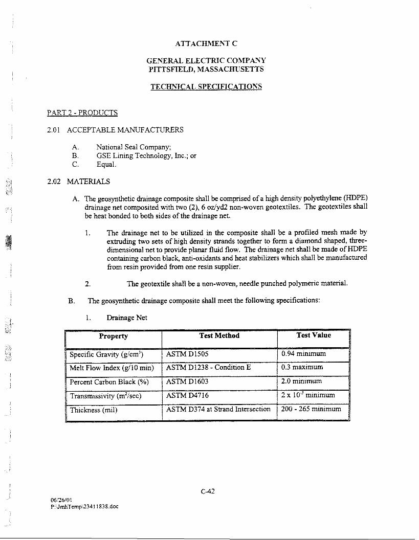
ELECTRIC GOMPk%3' PImSmLP), 32ASSACmSEnS
PART 2 - PRODUCTS
A. National Seal Company; B. GSE Lining Technology, Inc.; or C. Equal.
A. The geosynthetic drainage composite shall be comprised of a high density polyethylene (HDPE) drainage net composited with two (2), 6 odyd2 non-woven geotextiles. The geotextiles shall be heat bonded to both sides of the drainage net.
1. The drainage net to be utilized in the composite shall be a profiled mesh made by extruding two sets of high density strands together to form a diamond shaped, three- dimensional net to provide planar fluid flow. The drainage net shall be made of HDPE containing carbon black, anti-oxidants and heat stabilizers which shall be manufactured fiom resin provided from one resin supplier.
2. The geotextile shall be a non-woven, needle punched polymeric material.
B. The geosynthetic drainage composite shall meet the following specifications:
1. Drainage Net
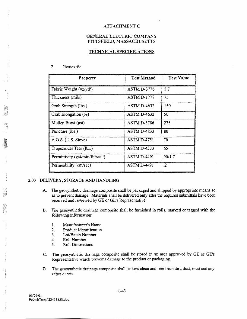
2. Geotextile
2.03 DELIVERY, STORAGE AND HANDLING
A. The geosynthetic drainage composite shall be packaged and shipped by appropriate means so as to prevent damage. Materials shaH be delivered only after the required subrni#aIs have been received and reviewed by GE or GE's Representative.
B. The geosynthetic drainage composite shall be firmished in rolls, marked or tagged with the following infomation:
1. Manufacturer's Name 2. Product Identification 3. LotlBatch Number 4. Roll Number 5. Roll Dimensions
C. The geosynthetic drainage composite shall be' stored in an area approved by GE or CE's Representarive which prevents darnage to the product or packagng.
D, The geosynthetic drainage composite shall be kept clean and free from dut, dust. mud and any other debns.
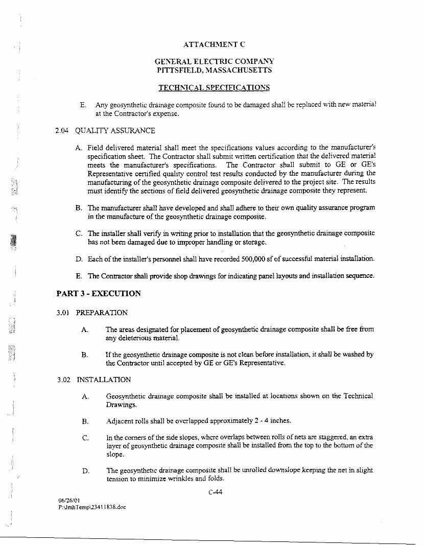
GE3X ELECTRIC COMPA%T P I m S m L D , hlASSACRt;l'SEmS
TECmIGrlI, SPECIFICATIONS
E. h y geoqthetic drainage composlte fomd to be darnaged shalt be repiaced with new matma1 at the Contractor's expense.
2.04 Qti'&Im ASS CE
A. F~eld del~vered matenal shall meet the speclficat~ons values according to the manufacturer's specrfication sheet. The Contractor shall submit wi-~tten certlficat~on that the delivered matenal meets the manufacturerk speclficat.lons. The Contractor shall submlt to GE or GE's Representat~ve cert~fied qual~ty control test results conducted by the manufacturer dunng the manufacmg of the geosynthet~c drarnage compslte delrvered to the project site. The results must identify the sectrons of field del~vered geosynthettc dramage compos~te they represent.
B. The manufacturer shall have developed and shall adhere to their own quality assurance program in the manufacture of the geosynthetic drainage composite.
C. The installer shall verify in writing prior to installation that the geosynthetic drainage composite has not been damaged due to improper handling or storage.
D. Each of the installer's personnel shall have recorded 500,000 sf of successfbl material instaIlation.
E. The Contractor shall provide shop drawings for indicating panel layouts and installation sequence.
PART 3 - EXl3CUTION
3 .O 1 PREPARATION
A. The areas designated for placement of geosynthetic drainage composite shall be free from any deleterious material.
B. If the geosynthetic drainage composite is not clean before installation, it shall be washed by the Contractor until accepted by GE or GE's Representative.
3 -02 INSTALLATION
A. Geosynthetic drainage composite shall be installed at locations shown on the Technical Drawings.
B. Adjacent rolls shall be overlapped approximately 2 - 4 inches.
C, In the comers of the side slopes, where overlaps between rolls of nets are staggered, an extra layer of geosynthet~c hmage eompslte shall be installed from the top to the bottom of the slope.
D. The geosynthetlc dramage composlte shall be molled do-slope keeprng the net m slrght tenston to minlmlze m d e s and folds.
E. Adequate loading shall be placed to prevent uplift by umd.
F. Holes or tears in the geosynfhetic drainage composite shall be reparred m accordance wrth the m m u f a c w s recomendatims, andlor tfie CQAP.
A. The Contractor shall provide as-built drawings identifying panel layout, locations or imperfections, and repairs and any other appropriate observations.
- END OF SECTION -