ussr's mrnurl - superior sewing machine & supply llc
TRANSCRIPT

Version 1.0
USSR'S MRNURLPARTS ROOK
es 5
ISO 9001 Certification of Quality System
1) FOR AT MOST USE VmH EASINESS,PLEASE OBTTAINLY READ THIS MANUALBEFORE STARTtNG
2) KEEP THIS MANUAL IN SAFE PLACEFOR RffB)BICE WHSI THE MACHINE
BREAKS DOVm.

1. Thank you for purchasing our product. Based on the rich expertise and
experience accumulated in industrial sewing machine production, SUNSTAR
wili manufacture industrial sewing machines, which deliver more diverse
functions, high performance, powerful operation, enhanced durability, and
more sophisticated design to meet a number of user's needs.
2. Please read this user's manual thoroughly before using the machine. Make
sure to properly use the machine to enjoy its full performance.
3. The specifications of the machine are subject to change, aimed to enhanceproduct performance, without prior notice.
4. This product is designed, manufactured, and sold as an industrial sewing
machine. It should not be used for other than industrial purpose.
SUNSTAR CO., LTD.From the library of Superior Sewing Machine & Supply LLC - www.supsew.com

DASCertification
Scope of Quality Approval
The following Company
SUNSTAR ELECTRIC CO., LTD.
The Company has been approvedfor the following scope ofoperation:
Manufacture, Sale and Servicing of Motors and Controllersfor Sewing Machines and Embroidery Machines
Scope ofapproval: NACE 19, Electrical and optical equipment
Date of Certificate Issue:Certificate Valid until:Certificate Number:
26"^ November 200326**^ November 2006KOl-1714
Date 03^^ December 2003
DAS CERTIFICATION Ltd.Company Number: 33845266 Amber Court, Crich Lane,Beiper,
Derbyshire DE56 1 HGTelephone & Fax: +44 (0) 1773 828586
DASCertification
ISO 9001: 2000
Approval
From the library of Superior Sewing Machine & Supply LLC - www.supsew.com
iJiiMj.H-: "«we?yi»-a-F-WTr"
US€R' S
MRNURLs^Wa
From the library of Superior Sewing Machine & Supply LLC - www.supsew.com
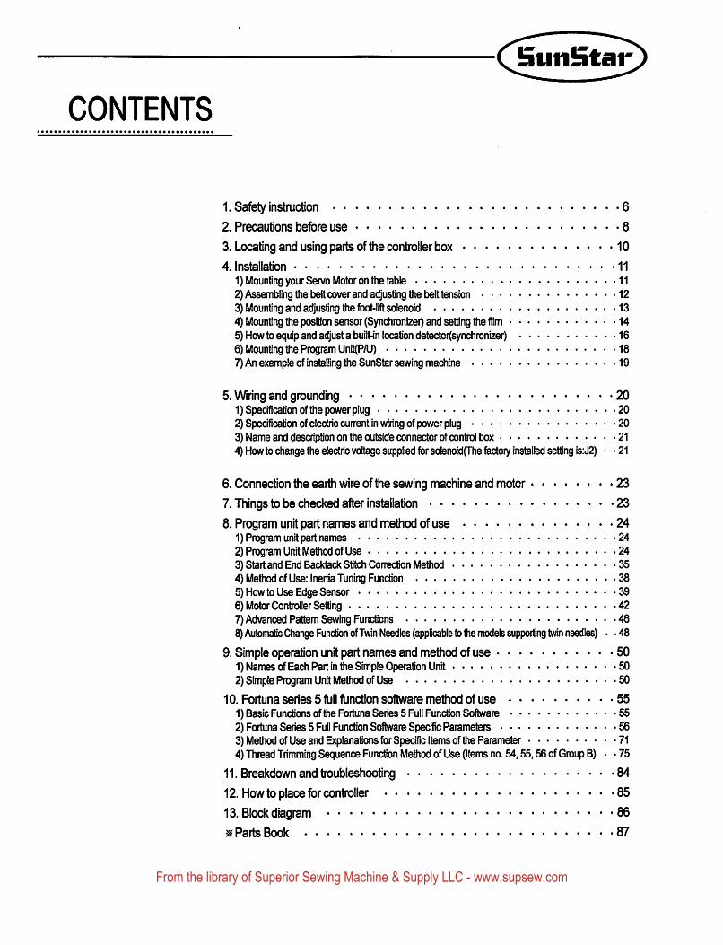
CONTENTS
1. Safety instruction 6
2. Precautions before use 8
3. Locating and using parts of the controller box 10
4. Installation 11
1) Mounting your Servo Motor on the table 112) Assembling the belt cover and adjusting the belt tension 123) Mounting and adjusting the fbot-lift solenoid 134) Mounting the position sensor (Synchronizer) and setting the film 145) How to equip and adjust a built-in location detector(synchronizer) 166) Mounting the Program Unit(P/U) 187) An example of installing the SunStar sewing machine 19
5. Wiring and grounding 201) Specification of the power plug 202) Specification of electric current in wiring of power plug 203) Name and description on the outside connector of control box 214) How to change the electric voltage supplied for solenoidfThe factory installed setting is;J2) • • 21
6. Connection the earth wire of the sewing machine and motor 23
7. Things to be checked after installation 23
8. Program unit part names and method of use 241) Program unit part names 242) Program Unit Method of Use 243) Start and End Backtack Stitch Conection Method 354) Method of Use: Inertia Tuning Function 385) How to Use Edge Sensor 396) Motor Controller Setting 427) Advanced Pattem Sewing Functions 468) Automatic Change Function ofTwin Needles (applicable to the models supporting twin needles) • -48
9. Simple operation unit part names and method of use 501) Names of Each Part in the Simple Operation Unit 502) Simple Program Unit Method of Use 50
10. Fortune series 5 full function software method of use 551) Basic Functions of the Fortune Series 5 Full Function Software 552) Fortune Series 5 Full Function Software Specific Parameters 563) Method of Use and Explanations for Specific Items of the Parameter 714) Thread Trimming Sequence Function Method of Use (Items no. 54,55,56 of Group B) • • 75
11. Breakdown and troubleshooting 84
12. How to place for controller 85
13. Block diagram 86
^ Parts Book 87
From the library of Superior Sewing Machine & Supply LLC - www.supsew.com
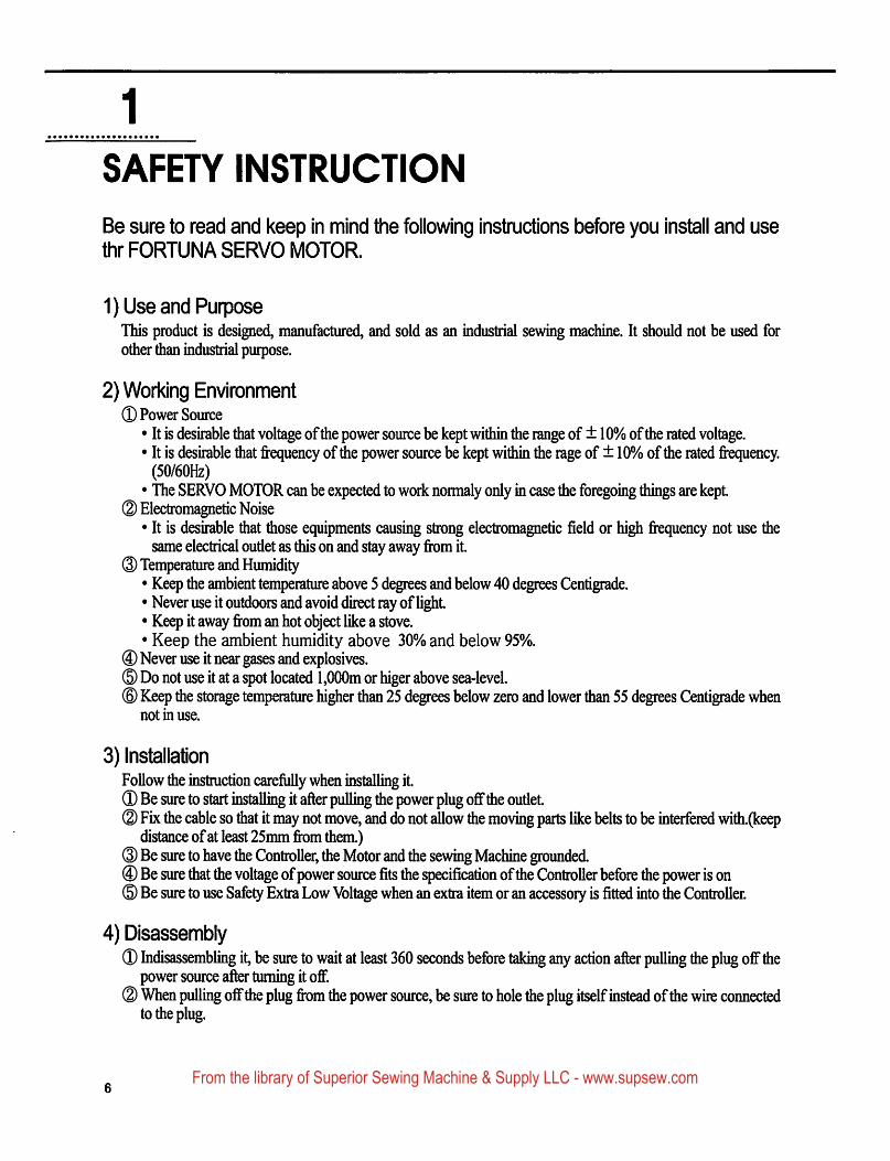
SAFETY INSTRUCTION
Be sure to read and keep in mind the following instructions before you install and usethr FORTUN A SERVO MOTOR.
1) Use and PurposeThis product is designed, manufactured, and sold as an industrial sewing machine. It should not be used forother than industrial purpose.
2) Working Environment® Power Source• It is desirable that voltage of the power source be kept within the range of ± 10% of the rated voltage.• It is desirable that frequency of die power source be kept within the rage of ± 10% of the rated frequency.(50/60HZ)• The SERVO MOTOR can be expected to work normaly only in case the foregoing things are kept.
© Electromagnetic Noise• It is desirable that those equipments causing strong electromagnetic field or high fi quency not use thesame electrical outlet as this on and stay away from it.
@ Temperature and Humidity• Keep the ambient temperature above 5 degrees and below 40 degrees Centigrade.• Never use it outdoors and avoid direct ray of light• Keep it away from an hot object like a stove.• Keep the ambient humidity above 30% and below 95%.
® Never use it near gases and explosives.® Do not use it at a spot located 1,000m or higer above sea-level.® Keep the storage temperature higher than 25 degrees below zero and lower than 55 degrees Centigrade when
not in use.
3) installationFollow the instmction carefully when installing it.® Be sure to start installing it after pulling the power plug off the outlet® Fbc the cable so that it may not move, and do not allow the moving parts like belts to be interfered with.(keep
distance of at least 25mm from them.)® Be sure to have the Controller, the Motor and the sewing Machine grounded.@ Be sure that the voltage of power source fits the specification of the Controller before the power is on® Be sure to use Safety Extra Low Voltage when an extra item or an accessory is fitted into the Controller.
4) Disassembly® Indisassembling it, be sure to wait at least 360 seconds before taking any action after pulling the plug off the
power source after turning it off.® When pulling off the plug from the power source, be sure to hole the plug itself instead of the wire connected
to the plug.
From the library of Superior Sewing Machine & Supply LLC - www.supsew.com

5) Service and Maintenance® Make sure that service and maintenance are carried out by a skilled technician,d) Never try to operate with the Motor and the Controller open.® When inserting a thread into or touching the machine, be sure to turn the power off and step down from the
platform.® Be sure to use standard products specified for replacement of parts.
6) Other Safety Instructions® Tack care not to let your fingers touch any moving parts including belts.@ In case of remodellhig or fitting of additional device, be sure to follow safety standards and do not ever try to
go ahead based on your own judgments.® Do not try to operate with the safely device removed.® Take care not to let water or coffee or something like those admitted into the Controller or the Motor.® Never drop the Controller or the Motor to the ground.
^The Inslrijc^ons piBsented above are ft)r the sal^ and more proper operation of the FcxturaMotor. Ignoring such instnictions oould cause damage to the machine or physical injury of the user.FteasetbflowaB the Instructions vvhen operating the rnachine.
From the library of Superior Sewing Machine & Supply LLC - www.supsew.com
2
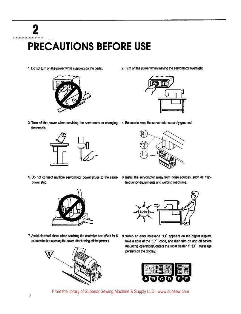
PRECAUTIONS BEFORE USE
1. Do not turn on the power while stepping on the pedal. 2. Turn off the power when leaving the servomotor overnight
S[i
3. Tum off the power when servicing the servomotor or changing 4. Be sure to keep the servomotor securely grouned.
the needle.
E
5. Do not connect multiple servomotor power plugs to the same 6. Install the servomotor away from noise sources, such as high-
power strip. frequency equipments and welding machines.
♦-rf Noise}^-*
7. Avoid electrical shock when servicing the controller box. (Wait for 6 8. When an error message "Er" appears on the digital display,minutes before opening the cover after turning off the power.) take a note of the "Er" code, and then tum on and off before
resuming operation(Contact the local dealer if "Er" messagepersists on the display)
From the library of Superior Sewing Machine & Supply LLC - www.supsew.com
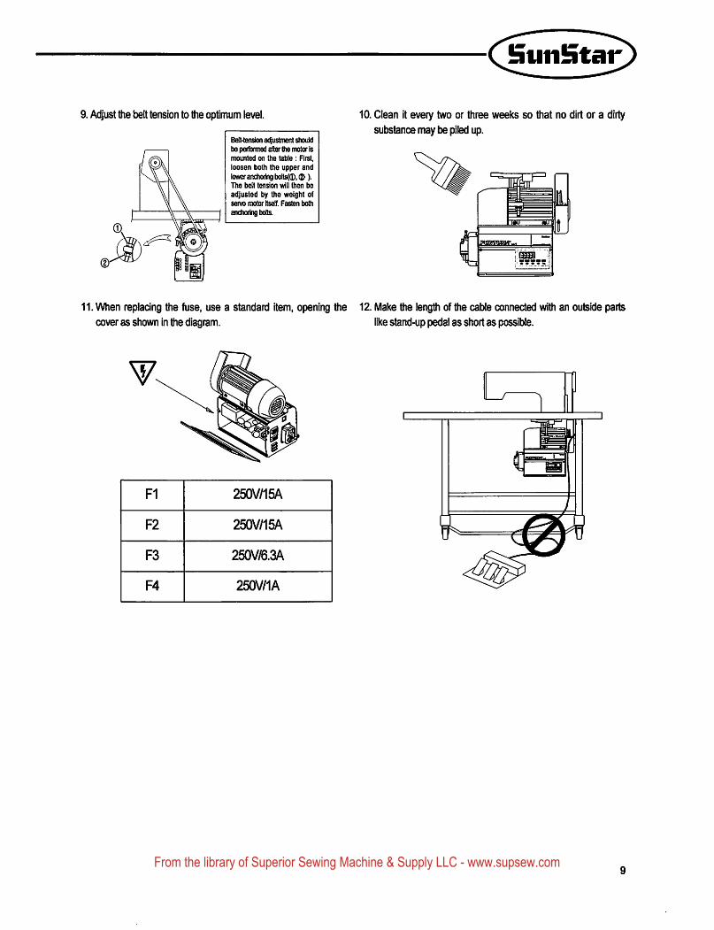
(Sun^a^9. Adjust the t)elt tension to the optimum level.
Beit-tension acfustment stiouldt)e peribrmed after ttw motor ismounted on ttie table: First,loosen botti the upper andloMer anchoring bolt^0,®).The belt tension will then be
adjusted by the weight ofservo motor Itself. Fasten both
anchoring bolts.
10. Clean it every two or three weeks so that no dirt or a dirty
substance may be piled up.
11. When repladng the fuse, use a standard item, opening the 12. Make the length of the cable connected with an outside parts
cover as shown in the diagram. like stand-up pedal as short as possible.
F1 250V/15A
F2 250V/15A
F3 250V/6.3A
F4 250V/1A
From the library of Superior Sewing Machine & Supply LLC - www.supsew.com
3
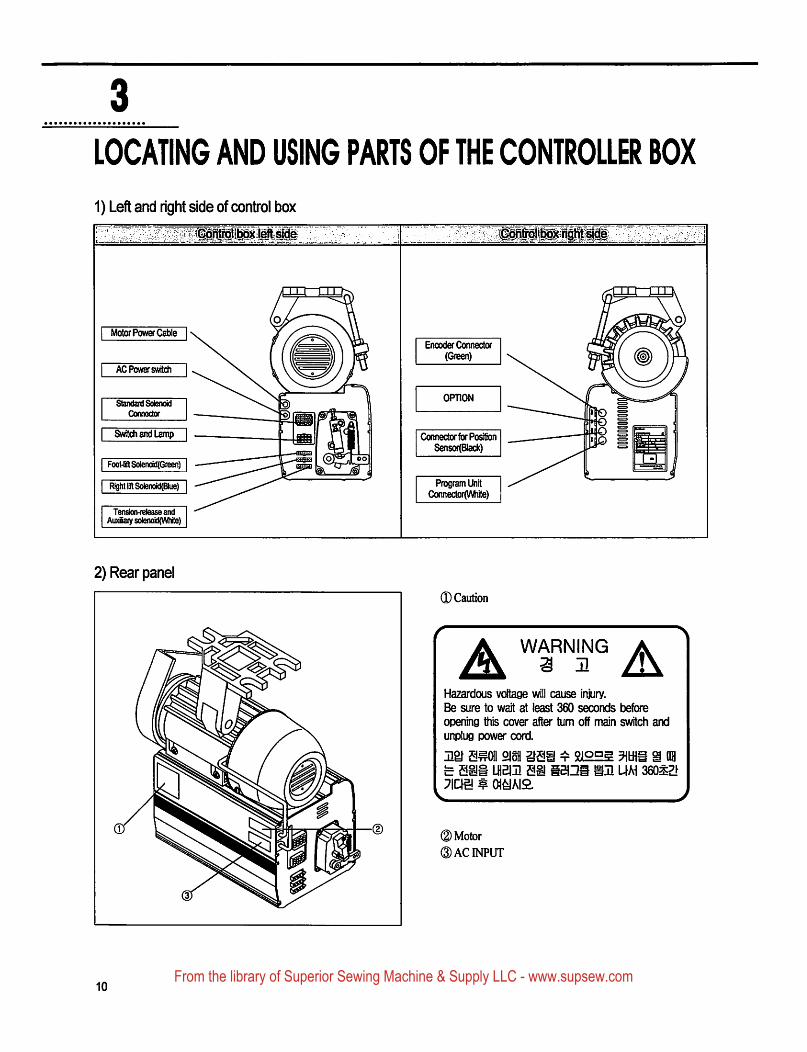
LOCATING AND USING PARTS OF THE CONTROLIS BOX
1) Left and right side of control box
Motor Power Cable
AG Power switch
Standard Solenoid
Connector
Switch and Lamp
Foot^ SoIenokltGreen]
Right InlSolenotdTBlue)
Tenson-reteaseandAuxSaiy sdenoidrwhite)
Encoder Connector
(Green)
OPTION
Connector for Position
Sensor(BIack)
Program UnitConnector(VVhite)
2) Rear panel
©Caution
WARNINGa n A
Hazardous voltage will cause in^ry.
Be sure to wait at least 360 seconds Isefore
opening this cover after turn off main switcfi and
unplug power cord.
Hgf Em 2lofl^ Em lhbiji e^
^ o\mQ.
^ 212E5 mm % aaiBini UM saoszf
©Motor
©ACINPUT
10From the library of Superior Sewing Machine & Supply LLC - www.supsew.com
4
INSTALLATION
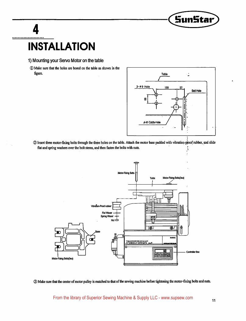
1) Mounting your Servo Motor on the table
(D Make sure that the holes are bored on the table as shown in the
figure.
LTable
3-0 9 Hole
MlCabte^tde
BeHHcle
® Insert three motor-fbcing bolts through the thiee holes on the table. Attach the motor base padded with vibration-ptoof rubber, and slideflat and spring washers over the bolt stems, and then fasten the bolts with nuts. \
Motv-FDdng Bolts
Table Motor-Fodng Bo(ts(3ea)
Vibn^Ptoofnifaber
Flatvy^
SpringWaser =}=
NutofD
aMotor-Fixing Bo!ts(3ea)
mp
Controller Box
® Make sure that the center of motor pulley is matched to diat ofdie sewing machine before tightening the motor-fixing bolts and nuts.
11From the library of Superior Sewing Machine & Supply LLC - www.supsew.com
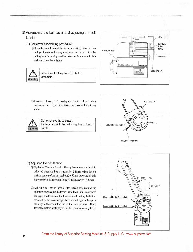
2) Assembling the belt cover and adjusting the belt
tension
(1) Belt cover assembling procedure
® Upon the completion of the motor mounting, bring the two
pulleys of motor and sewing machine closer to each other, by
pulling back the sewing machine. You can then mount the belt
easily as shown in the figure.
AWamlhd
Make sure that the power is off before
assembly.
(2) Place the belt cover 'B', making sure that the bell cover doesnot contact the bell, and Ihen fasten the cover with the fixing
AWarning
Do not remove the belt cover.
If a finger slips into the belt it might be broken orcutoff.
BeK Guide FDdng Screw
Belt Cover RoigSoew
(2) Adjusting the belt tension
iD Optimum Tension Level : The optimum lention level is
achieved when the bell is pushed by 5-lOmm when the top
surface portion ofthe belt at about 30-50mm above the tabletip
Ispressedby afingerwilhaforceof-Ikgm/sec^or 1 Newton.
© Adjusting the Tension Level : If the tension level is out of theoptimum range, adjust the tension as follows. First, loosen both
the upper and lower nuts for the anchor boll, letting the belt be
stretched by the motor weight itself. Second, tighten the upper
nut only to the extent that the motor does not move. Third,
fasten the bottom nut tightly so that the motor is securely fixed.
5-10mm ^ 1kg
Upper Nut for Ihe Anchor Bolt
lower Nut for the Anchor Bolt
From the library of Superior Sewing Machine & Supply LLC - www.supsew.com
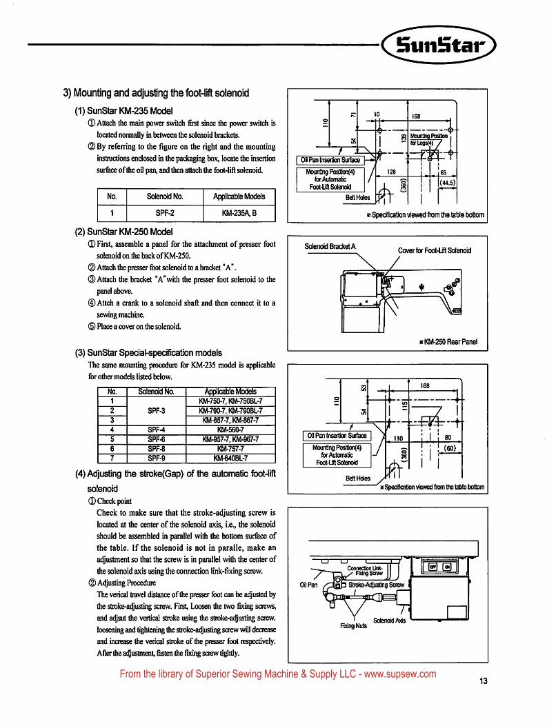
3) Mounting and adjusting the foot-lift solenoid
(1)SunStarKM-235 Model0 Attach the main power switch first since the power switch is
located normally in between the solenoid brackets.
(2) By referring to the figure on the right and the mountinginstmctions enclosed in the padcaging box, locate the insertion
surface of the oil pan, and then attach the foot-lift solenoid.
No. Solenoid No. Applicable Models
1 SPF-2 KM-235A B
(2)SunStarKM-250Model(D First, assemble a panel for the attachment of presser foot
solenoid on the backof ICM-2S0.
(D Attach the presser foot solenoid to a bracket "A".©Attach the bracket "A"with the presser foot solenoid to the
panel above.
0 Attch a crank to a solenoid shaft and then connect it to a
sewing machine.
(5) Place a cover on the solenoid.
(3) SunStar Special-specification modelsThe same mounting procedure fiir KM-235 model is q)plicable
for other models listed below.
No. Sdenotd No. Applicable Models1 KM-750-7. KM-750BL-7
2 SPF-3 KM-790-7. KM-790BL-7
3 KM-857-7.KM-867-7
4 SPF-4 KM-560-7
5 SPF-6 KM-957-7.KM-967-7
6 SPF-8 KM-757-7
7 SPF-9 KM-640BL-7
(4) Adjusting the stroke(Gap) of the automatic foot-lift
solenoid
0 Check pointCheck to make sure that the stroke-adjusting screw is
located at the center of the solenoid axis, i.e., the solenoid
should be assembled in parallel with the bottom surface ofthe table. If the solenoid is not in paralle, make an
adjustment so that the screw is in parallel with the center of
the solenoid axis using the connection link-fixing screw.
(2) Adjusting ProcedureThe verical travel distance of the presser foot can be adjusted by
the stroke-adjusting saew. First, Loosen the two fixing screws,
and adjsut the vertical stroke using the stroke-adjusting screw,
loosening and tightening the stroke-adjusting screw will decrease
and increase the verical stroke of die presser foot respectively.
After the adjustment, fasten the fixing screw tighdy.
03 Pan tnseftion Sur^
Mounting Positjcn(4)for Automatic
Foot-UflSoIenotd
Belt Holes
128
■ o
h'-
168
Mounting PosiBonfofl£BS(4)
65
(44.5)
Solenoid Bracket A
« Specification viewed from the table bottom
Cover for Foot-Lift Solenoid
r ■■[fer-
*
«KM-250 Rear Panel
T03 Par Insertion Surface
Mount'ng Position(4)for Automatic
Foot4JftSoteno(d
Beft Holes
168
110
"h'
i .l. i! (60)
» SpecHication viewed from the table bottom
Connection Unk-Fixing Screw
Oil Pan Stroke^justing Screw
FodngNutsSolenoid Axis
@ 0
13From the library of Superior Sewing Machine & Supply LLC - www.supsew.com
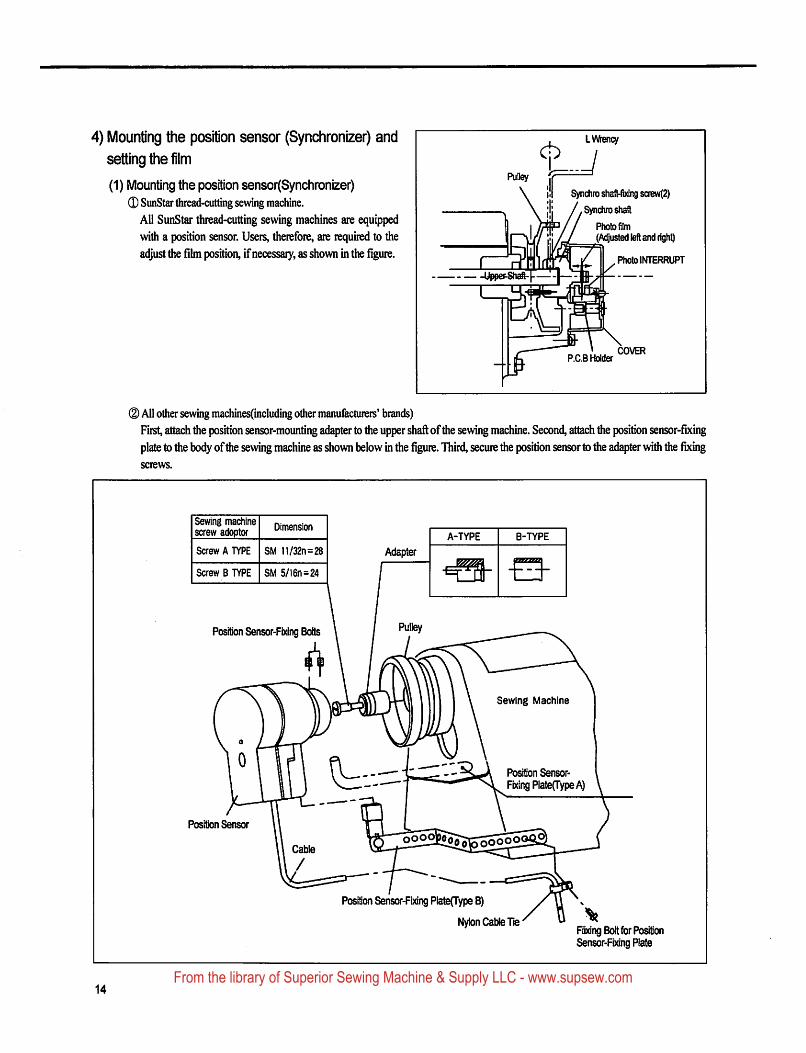
4) Mounting the position sensor (Synchronizer) and
setting the film
(1) Mounting the position sensor(Synchronizer)(D SunStar thread-cutting sewing machine.
All SunStar thread-cutting sewing machines are equipped
with a position sensor. Users, therefore, are required to the
adjust the film position, if necessary, as shown in the figure.
, LWency
^ /Puliey 1?\ ill Synchro shafl-fbdng screw(2)
. \ jlj /.Synchroshaft1 Iw^// PbotofilmJ'ji^ (Adjusted left and right)
_ _upp"n ni irlri ,U y P'"'® INTERRUPTfSh^i *-]—
I
/ \ COVERP.C.B Holder
® All other sewing machines(including other manufacturers' brands)
First, attach tiie position sensor-mounting adapter to the upper shaft of the sewing machine. Second, attach the position sensor-fixing
plate to the bocfy oftite sewing machine as shown below in the figure. Third, secure the position sensor to the ad^ter witii the fixingscrews.
Sewing machinescrew adopter
Dimension
Screw A TYPE SM 11/32n=28
Screw B TYPE SM 5/16n=24
Adapter
A-TYPE B-TYPE
Position Sensor-Fixing Bolts
Sewing Machine
t:-- Position Sensor-
Fixing PiateCTypeA)
Position Sensor
Position Sensor-Fixing Plate(Type 8)
Nylon Cable Tie'Fixing Bolt tor PositionSensor-Fixing Plate
14From the library of Superior Sewing Machine & Supply LLC - www.supsew.com
Sviiilntar
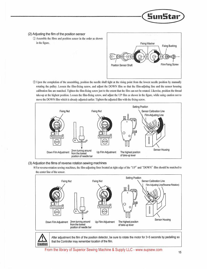
(2) Adjusting the film of the position sensor
(D Assemble the films and position sensor in the order as shown
in the figure. FExingVl^sherFixing Bushing
Position Sensor Shaft Film-Fixing Screw
© Upon the completion of the assembling, position the needle shaft tight at the rising point from the lowest needle position by manuallyrotating the pulley. Loosen the film-fixing screw, and adjust the DOWN film so that the film-adjsting line and the sensor housing
calibration line are matched. Tighten the film-fixing screw just to the extent that the film can not be rotated. Likewise, position the thread
take-up at the highest position. Loosen the film-fixing screw, and adjust the UP film as shown in the figure, while using caution not to
move die DOWN film \^ich is already adjusted earlier. Tighten the adjusted film with the fixing screw.
Fixing Nut Fixing Nut
Setting Position
\Sensor Calibration Unet Film-Adjusting Une
Down Rim Adjustment Up Rim Adjustment The highest positlcffiposition of needle bar take-up lever
Sensor Housing
(3) Adjustlon the films of reverse rotation sewing machinesFor reverse-rotation sewing machines, the film-adjusting lines located at right e<^e of the "UP" and "DOWN" film should be matched to
the center line ofdie sensor.
Fixing Nut Fixing NutSetting Position
Sensor Calibration Une
vj Rim-Adjusting Une(Reverse Rotation)
Down Film Adjustment 2mm tuming around Up Film Adjustment The highest positionfrom the lowest of take-up leverposition of needle bar
Sensor Housing
ACautioif
After adjustment the film of the position detector, be sure to rotate the motor for S-^S seconds by pedalling sothat the Controller may rememtier location of the film.
From the library of Superior Sewing Machine & Supply LLC - www.supsew.com
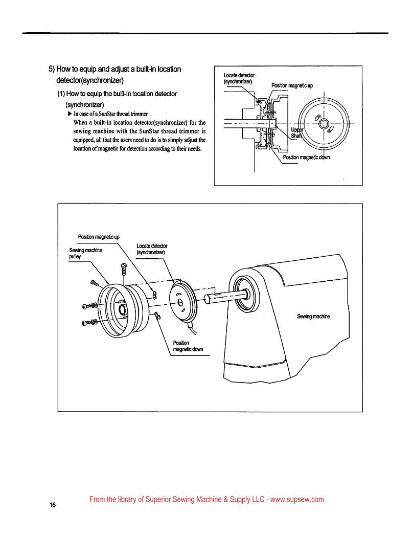
5) How to equip and adjust a built-in location
detector(synchronizer)
(1) How to equip the built-in location detector
(synchronizer)^ In case ofaSunStar thread trimmer
When a built-in location detector(synchronizer) for the
sewing machine with the SunStar thread trimmer is
equipped, all that the users need to do is to simply adjust the
location of magnetic for detection according to their needs.
Locate detector
(synchronizer)Position magnetic up
■£)
Position magneto d
Positon magnetic up
Sewing machinepulley
Locate detector(synchronize^
Sewing machine
Positionmagnetic down
16From the library of Superior Sewing Machine & Supply LLC - www.supsew.com
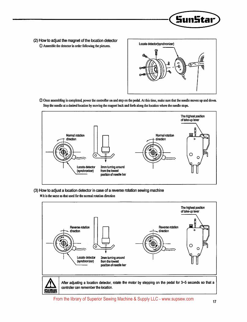
(2) How to adjust the magnet of the location detector0 Assemble the detector in order following the pictures. Locate d6tector(synchronizer)
(2) Once assembling is completed, power the controller on and step on the pedal. At this time, make sure that the needle moves up and down.Stop the needle at a desired location by moving the magnet back and forth along the location where the needle stops.
The highest positionof take-up lever
Normal rotation
direction
Nonnal rotation
direction
Locate detector 2mm turning around(synchronizer) ftom the lowest
o
\J
\ Vr
(3) How to adjust a location detector in case of a reverse rotation sewing machine^ It is the same as diat used for the normal rotation direction
The highest positionof take-up lever
Reverse rotation
direction
Reverse rotation
direction
Locate detector 2mm tuming around(synchronizeO (ix}m the lowest
J
\v
A After adjusting a location detector, rotate the motor by stepping on the pedal for 3~5 seconds so that acontroller can remember the location.
17From the library of Superior Sewing Machine & Supply LLC - www.supsew.com
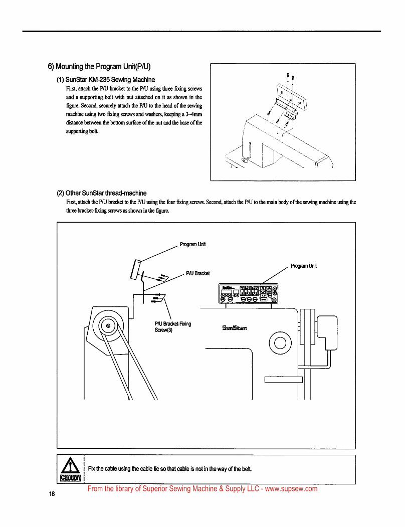
6) Mounting the Program Unit(P/U)
(1) SunStar KM-235 Sewing MachineFirst, attach the P/U bracket to the P/U using three fixing screws
and a supporting bolt with nut attached on it as shown in the
figure. Second, securely attach the PAJ to the head of the sewing
machine using two fixing screws and washers, keeping a 3~4nun
distance between the bottom surface of the nut and the base of the
supporting bolL
If
(2) Other SunStar thread-machine
First, attach the PAJ bracket to the PAJ using the four fixing screws. Second, attach the PAJ to the main body ofthe sewing machine using the
three bracket-fixing screws as shown in the figure.
Program Unit
P/U Bracket
©©©
Program Unit
PAJ Bracket-FixingScrew(3)
A Fix die cable using the cable tie so that cable is not in the way of the belt
18From the library of Superior Sewing Machine & Supply LLC - www.supsew.com
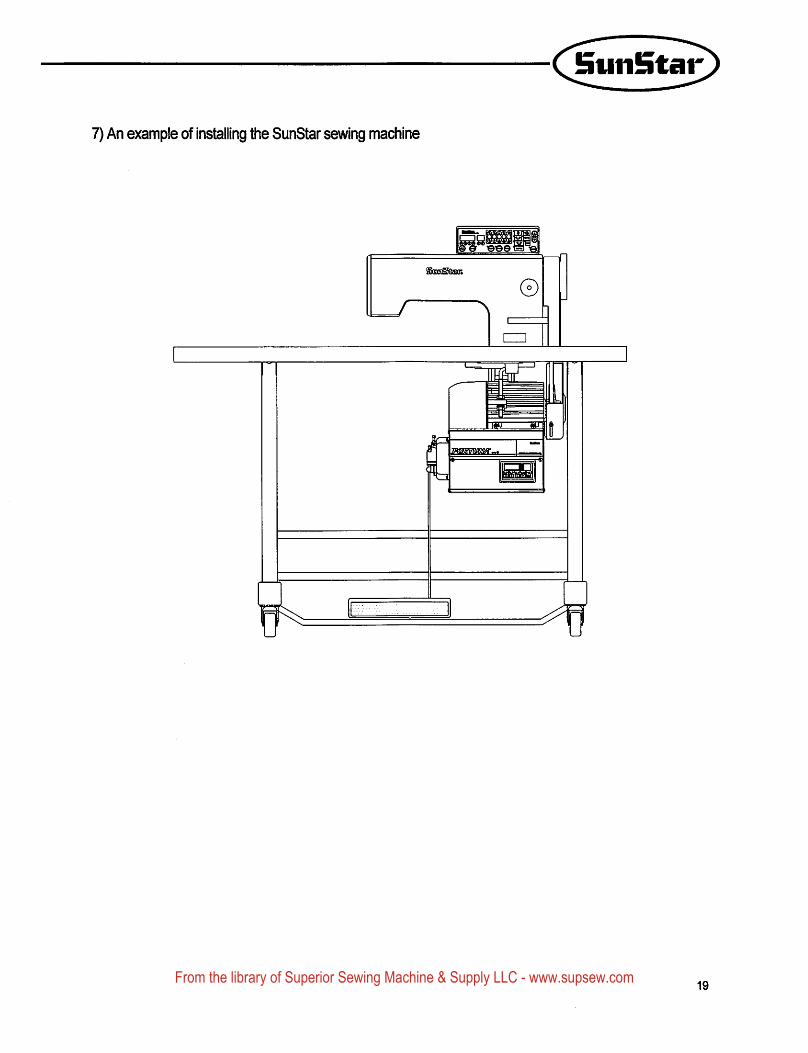
7) An example of installing the SunStar sewing machine
19From the library of Superior Sewing Machine & Supply LLC - www.supsew.com
5
WIRING AND GROUNDING
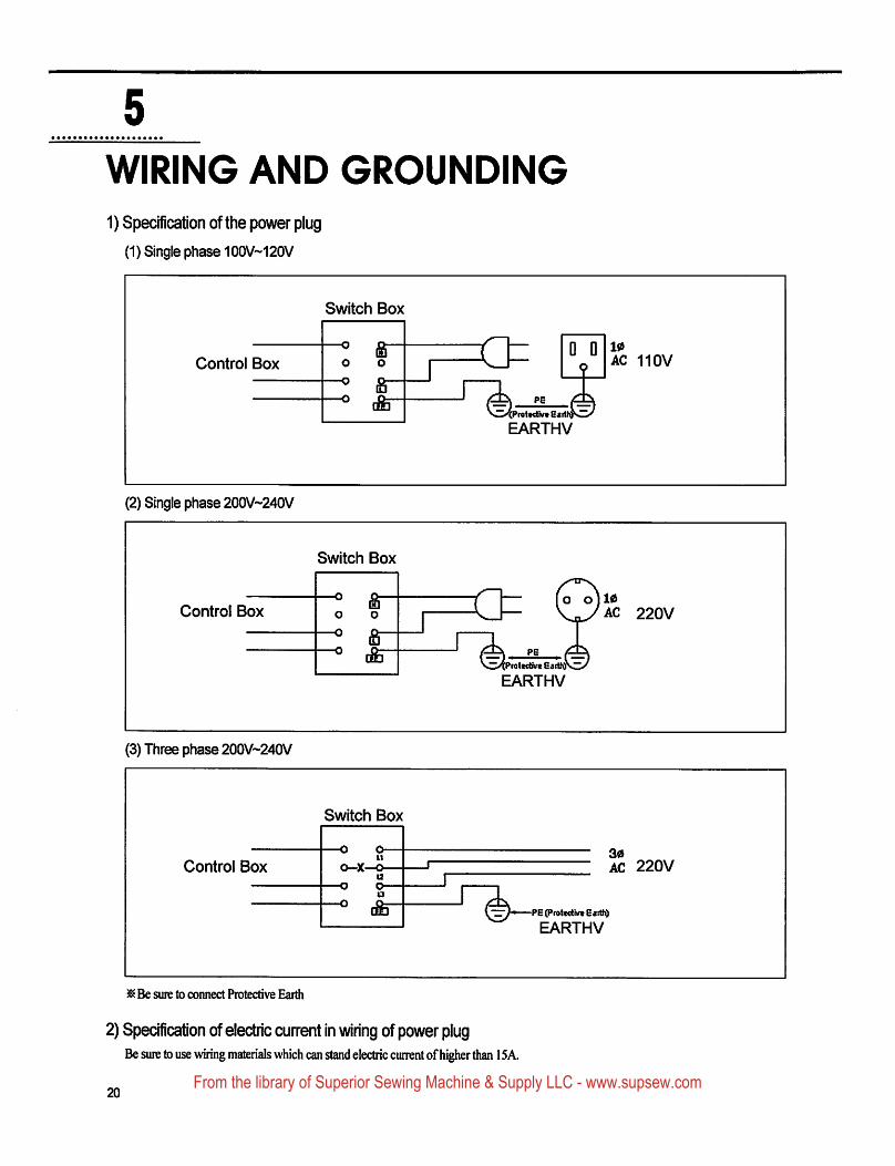
1) Specification of the power plug
(1) Single phase 100V~120V
Switch Box
Control Box o o
&■dte"
n D Do
PH
10AC 110V
>'(Prat*<tivt E«
EARTHV
(2) Single phase 200V~240V
Control Box
Switch Box
firo o
-o ra o o 110
AC 220V
Eatttv
EARTHV
(3) Three phase 200V~240V
Control Box
Switch Box
-o o-u
o-x—o-
[fe"
30AC 220V
PE (Pfottctlw EiittO
EARTHV
^Be sure to connect Protective Eaitii
2) Specification of electric current in wiring of power plugBe sure to use wiring materials which can stand electric current of higher than 15A.
20From the library of Superior Sewing Machine & Supply LLC - www.supsew.com
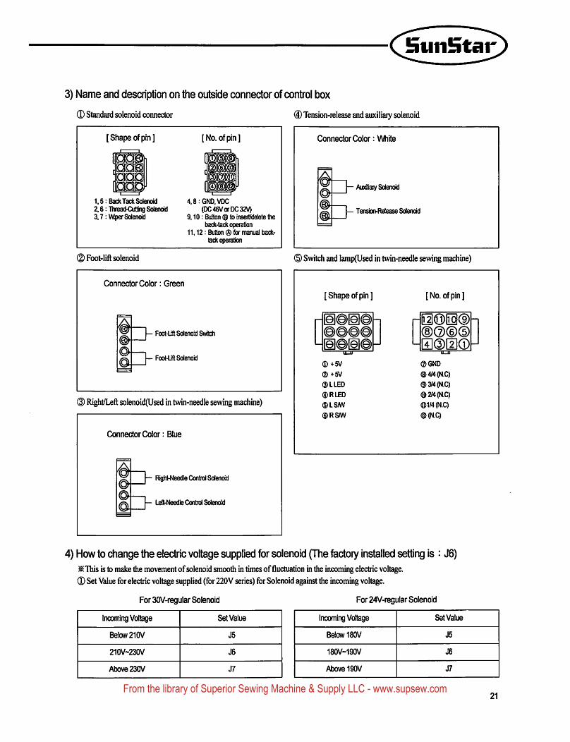
3) Name and description on the outside connector of control box
0 Standard solenoid connector
[Shape of pin] [No. ofpm]
1,5: Back Tack Solenoid2,6: Thread^^otting Solenoid3,7 :Wper Solenoid
4,8:GND.VDC(DC 46V or DC SZV)
9,10: Button ® to inseit/delete ttietiack-tack operation
11,12: Button ® for manual back-tack operation
(D Foot-lift solenoid
Connector Color: Green
— Foot-Lifl Solenoid Switch
1Foot-Lift Solenoid
(3) Right/Left solenoid(Used in twin-needle sewing machine)
Connector Color: Blue
— Right-Needle Control Solenoid
^ 1
©.—T Left-Needle Control Solenoid
® Tension-release and auxiliaiy solenoid
Connector Color: White
— Auxiliaiy Solenoid
— Tension-Release Solenoid
© Switch and lamp(Used in twin-needle sewing machine)
[Shape of pin] [No. of pin]
® +5V
®+5V
®LLED
®RLED
©ISM
©RSW
©GND
©4/4(N.C)
®3/4(N.C)
©2/4(N.C)
®1/4(N.C)
®(N.C)
4) How to change the electric voltage supplied for solenoid (The factory installed setting is : J6)^ This is to make the movement of solenoid smooth in times of fluctuation in the incoming electric voltage.
(D Set Value for electric voltage supplied (for 220V series) for Solenoid against the incoming voltage.
For 30V-regular Solenoid For 24V-regular Solenoid
Incoming Voltage Set Value
Below 210V J5
210V~230V J6
Above 230V J7
Incoming Voltage Set Value
Below 180V J5
180V-190V J6
Above 190V J7
21From the library of Superior Sewing Machine & Supply LLC - www.supsew.com
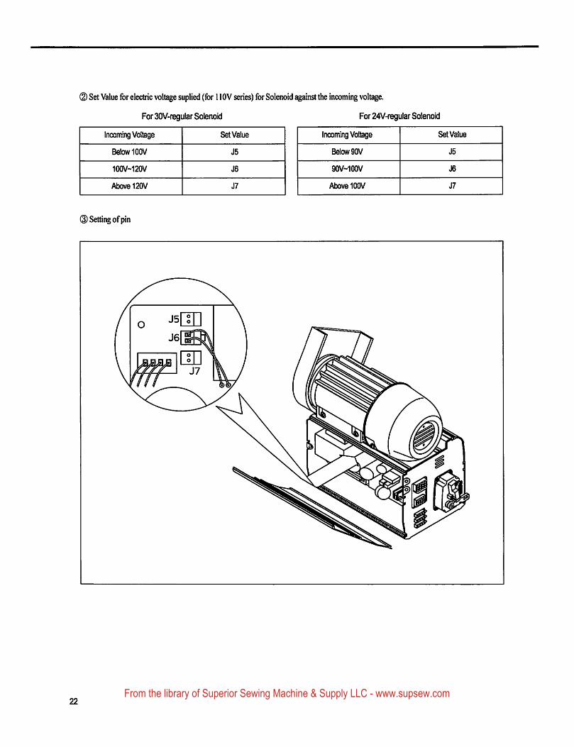
(D Set Value for electric voltage suplied (for 1 lOV series) for Solenoid against the incoming voltage.
For 30V-regular Solenoid For 24V-regular Solenoid
Incoming Voltage Set Value
Below 100V J5
100V~120V J6
Above 120V J7
@ Setting of pin
Incoming Voltage Set Value
Below 90V J5
90V~100V J6
Above 100V J7
22From the library of Superior Sewing Machine & Supply LLC - www.supsew.com
6
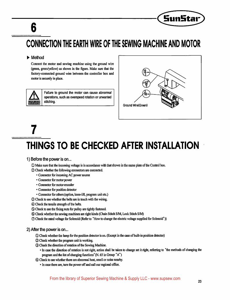
CONNECnON THE EARTH WIRE OF THE SEWING MACHINE AND MOTOR
► MethodConnect the motor and sewing machine using the ground wire(green, green/yellow) as shown in the figure. Make sure that thefactoiy-connected ground wire between the controller box andmotor is securely in place.
A Failure to ground the motor can cause abnormaloperations, such as overspeed rotation or unwantedstitching.
Ground Wlre(Green)
7THINGS TO BE CHECKED AFTER INSTALLATION1) Before the power is on...
0 Make sure that the incoming voltage is in accordance with that shown in the name plate of the Control box.(D Check whetiier the following connectors are connected.
• Connector for incoming AC power source• Connector for motor power• Connector for motor encoder
• Connector for position detector• Connector for others (option, knee-lift, program unit etc.)
0 Check to see whether the belts are in touch wifti the wiring.® Check the tensile strength of die belts.(B) Check to see the fixing nuts for pulley are tightly festened.® Check whether tiie sewing machines are right kinds (Chain Stitch S/M, Lock Stitch S/M)® Check the rated voltage for Solenoid (Refer to "How to change the electric voltage supplied for Solenoid"))
2) After the power is on...0 Check whether the lamp for the position detector is on. (Except in the case of built-in position detector)(D Check whether die program unit is woiking.
Check the direction of rotation of the Sewing Machine.• In case the direction of rotation is not right, action shall be taken to change set it right, referring to "the methods of changing the
program and the list of changing functions" (N. 65 in Group "A")0 Check to see whether there are abnormal heat, smell or noise nearby.
* In case there are, turn the power off and call our regional office.
23From the library of Superior Sewing Machine & Supply LLC - www.supsew.com
PROGRAM UNIT PART NAMES AND METHOD OF USE
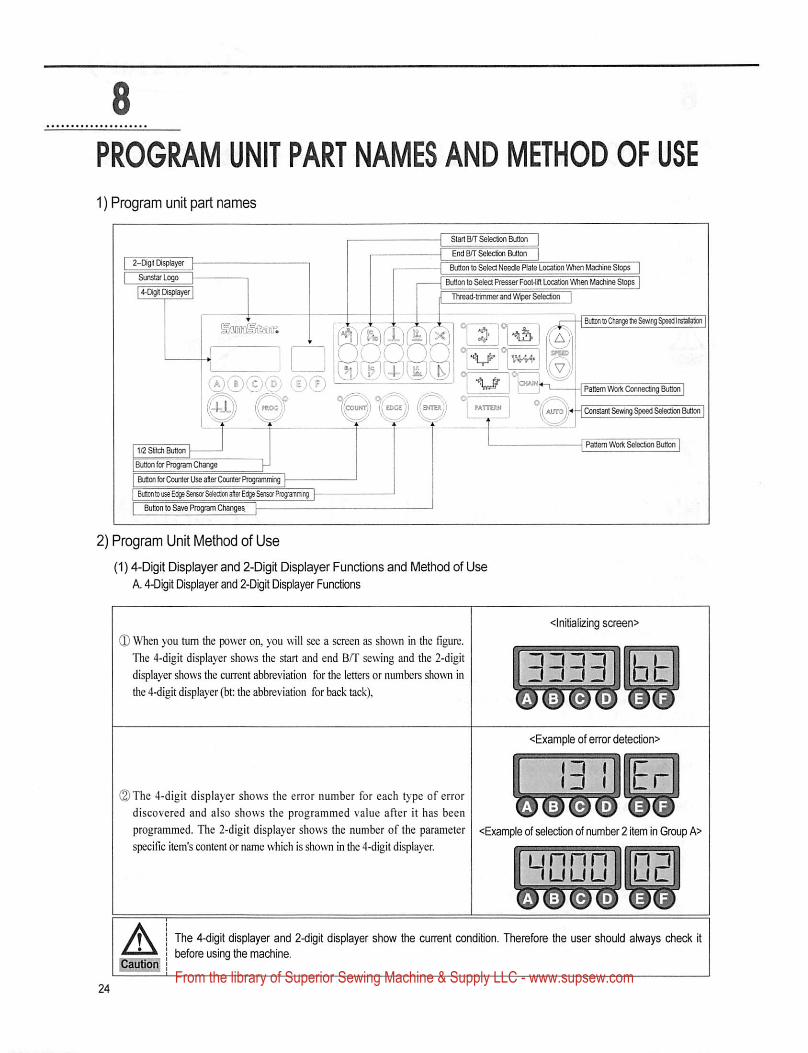
1) Program unit part names
Stan B/T Selection Button
End BH' Selection Button
Button to Select Needle Plate Location Wtien UacMne Stops
Button to Select Presser Foot-lift Location Wtien Uacfiine Stops
Ttvead-trinvner and Wtper Selection |
2-Digt Di^iiayer
SunstarLogo
4-Digit Diailayer
BiM toOiange ItR Sewing Speed Irstalalion
Pattern mtt CcnnectinQ Button
PATTERN Aino Constant SaniQ Speed Selection Button
Pattern Woili Setectnn Button1/2 SHcti Button
Button ferCcuter Use alter Couler Progranvniig
Butem to use Edge Se/Bor Selection after Ei^ Sensor Piogramming
Button to Save Program Ctianges
2) Program Unit Method of Use
(1) 4-Digit Displayer and 2-Digit Displayer Functions and Method of Use
A. 4-Digit Displayer and 2-Digrt Displayer Functions
(D When you turn the power on, you will see a screen as shown in the figure.
The 4-digit displayer shows the start and end B/T sewing and the 2-digit
displayer shows the current abbreviation for the letters or numbers shown in
the 4-digit displayer (bt: the abbreviation for back tack),
<lnjtiallzing screen>
<Example of error detection>
riTiB(2) The 4-digit displayer shows the error number for each t>-pe of error VVIWSTVdiscovered and also shows the programmed value after it has been
programmed. The 2-digit displayer shows the number of the parameter <Example of selection of number 2 item in Group A>
specific item's content or name whicii is shown in the 4-digit displayer.
lunnniin^iuuu
A The 4-digit displayer and 2-diglt displayer show the current condition. Therefore the user should always check itbefore using the machine.
From the library of Superior Sewing Machine & Supply LLC - www.supsew.com
!nuiiBtai'
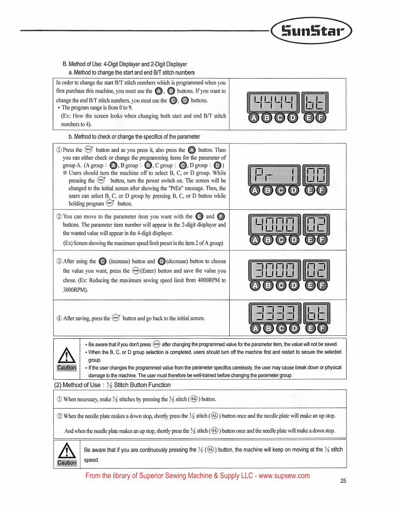
B. Method of Use; 4-Digit Displayer and 2-Digit Displayer
a. Method to change the start and end QfT stitch numbers
In order to change the start B/T stitch numbers which is programmed when you
first purchase this machine, you must use the o o buttons. If you want tochange the end B/T stitch numbers, you must use the o o buttons.• The program range is fiom 0 to 9.
(Ex: How the screen looks when changing both start and end B/T stitch
numbers to 4).
b. Method to check or change the specifics of the parameter
0 Press the 0r button and as you press it, also press the o button. Thenyou can either check or change the programming items for e parameter of^upA. (Agroup ; 0,Bgroup : Q,Cgroup ; Q,Dgroup : Q)^ Users should turn the machine olf to select B, C, or D group. While
pressing the button, turn the power switch on. The screen will bechanged to the initial screen after showing the "PrEn" message. Then, the
users can select B, C, or D group by pressing B, C, or D button whileholding program button.
0 You can move to the parameter item you want with the and Qbuttons. The parameter item number will appear in the 2-digit displayer and
the wanted value will appear in the 4-digit displayer.
(Ex) Screen showing the maximum speed limit preset in the kern 2 ofA group)
® After using the o (increase) button and ©(decrease) button to choosethe value you want, press the i@i(Enter) button and save the value youchose. (Ex: Reducing the maximum sewing speed limit fiom 4000RPM to
3000RPM).
® After saving, press the ©T button and go back to the initial screen.
HHHH bt
nnn
□ nnn□ uuu
A^autiorf^Cautiorf
' Be aware that if you don't press © after changing the programmed value for the parameter item, the vaiue will not be saved.' When the B, C, or D group selection is completed, users should tum off the machine first and restart to secure the selected
! • If toe user changes toe programmed vaiue from toe parameter specifics carelessly, the user may cause break down or physicalI damage to toe machine. The user must therefore be well-trained before changing toe parameter group.
(2) Method of Use ; % Stitch Button Function
0 When necessary, make Yz stitches by pressing the Yz stitch (@)) button.
0 When the needle plate makes a down stop, shortly press the Yz stitch (0)) button once and the needle plate will make an up stop.
And when the needle plate makes an up stop, shortly press the Yz stitch (0) button once and toe needle plate will make adown stop.
A Be aware that If you are continuously pressing the Yz (©) button, the machine will keep on moving at the Yz stitchspeed.
From the library of Superior Sewing Machine & Supply LLC - www.supsew.com
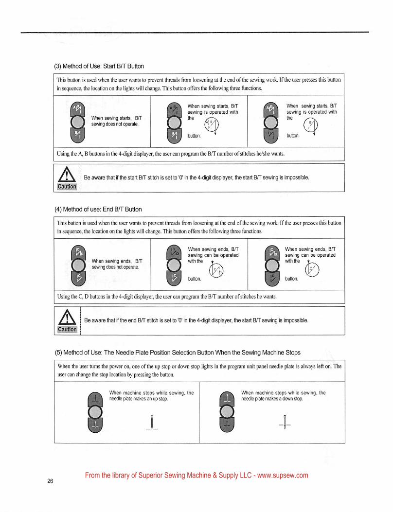
(3) Method of Use: Start B/T Button
This button is used when the user wants to prevent threads from loosening at the end ofthe sewing work. If the user presses this button
in sequence, the location on the lights will ch^ge. This button offers the following three functions.
When sewing starts, Brtsewing does not operate.
When sewing starts, B/Tsewing is operated with
When sewing starts, B/Tsewing is operated withthe y—V
Using the A, B buttons in the 4-digit displayer, the user can program the B/T number of stitches he/she wants.
A Be aware that if the start B/T stitch is set to '0' in the 4-digit displayer, the start Bff sewing is impossible.
(4) Method of use: End B/T Button
This button is used when the user wants to prevent threads fiom loosening at the end of the sewing work. If the user presses this button
in sequence, the location on the lights will change. This button offers the following three functions.
When sewing ends. B/Tsewing does not cerate.
When sewing ends, B/Tsewing can be operatedwiththe «
When sewing ends, B/Tsewing can be operatedwrthtoe t
Using the C, D buttons in the 4-digit displayer, die user can program the B/T number ofstitches he wants.
A Be aware that if the end B/T stitch is set to '0' in the 4<ligit displayer, the start B/T sewing is impossible.
(5) Method of Use: The Needle Plate Position Selection Button When the Sewing Machine Stops
When the user turns the power on, one of the up stop or down stop lights in the program unit panel needle plate is always left on. The
user can change the stop location by pressing the button.
When machine stops while sewing, theneedle plate makes an up stop.
When machine stops while sewing, theneedle plate makes a down stop.
From the library of Superior Sewing Machine & Supply LLC - www.supsew.com
Suiilntar
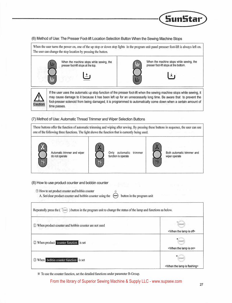
(6) Method of Use: The Presser Foot-lift Location Selection Button When the Sewing Machine Stops
When the user turns the power on, one of tiie up stop or down stop lights in the program unit panel pressser foot-lift is always left on.
The user can change the stop location by pressing the button.
When the machine stops while sewing, thepresser fbot-lifl stops at the top.
When the machine stops while sewing, thepresser foot-iifl stops at the bottom.
A;Cautiort
If the user uses the automayo up stop function of the presser foot-lift when the sewing machine stops while sewing, it
may cause damage to it because it has been left up for an unnecessarily long time. Be aware that to prevent the
foot-presser solenoid from being damaged, it Is programmed to automatically come down when a certain amount of
time passes.
(7) Method of Use: Automatic Thread Trimmer and Wiper Selection Buttons
These buttons offer the function of automatic trimming and wiping after sewing. By pressing these buttons in sequence, the user can use
one ofthe following three functions. The light shows the function that is currently being used.
Automatic trimmer and wiperdo not operate
Only automatic trimmerfunction is operate
Both automatic trimmer and
wiper operate
(8) How to use product counter and bobbin counter
® How to set product counter and bobbin counter o
A. Set/clear product counter and bobbin counter using the button in the program unit
Repeatedly press the ( ) button in the program unit to change the status ofthe lamp and functions as below.
(D When product counter and bobbin counter are not used ((coUNTyj
<\Mien the lamp is off>
(2) When productI'coutn,;
■■
<When the lamp is on>
(icouffT;^
<\Mien the lamp is flashing>
^ To use the counter function, set the detailed functions under parameter B-Group.
From the library of Superior Sewing Machine & Supply LLC - www.supsew.com
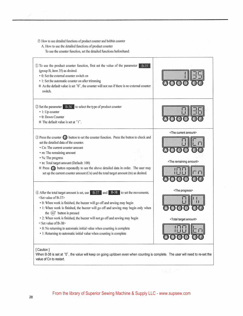
(D How to use detailed flinctioiis ofproduct counter and bobbin counter
A. How to use the detailed functions ofproduct counter
To use the counter function, set the detailed functions beforehand.
Q To use the product counter function, first set the value of the parameter ||^g[(group B, item 35) as desired.
• 0: Set the external counter switch on
• 1: Set the automatic counter on after trimming
^ As the default value is set "0", the counter will not run If there Is no external counter
switch.
(2) Set the parameter to sel• I; Up counter
• 0: Down Counter
^ The default value is set at T.
to select the type of product counter
<The oiirent amount>
(E) Press the counter Q button to set the counter function. Press the button to check andset the detailed data ofthe counter.
• Cn: The current counter amount
• m: The remaining amount
• %: The progress
• tn: Total target amount (Default: 100)
^ Press button repeatedly to see the above detailed data in order. The user mayset up the current counter amount (Cn) and the total target amount (tn) as desired.
□1^
<The remaining amount>
inn u^„\luu llrn
® Affer the total target amount is set, use and to set the movements.<Set value ofB-37>
• 0: When work is fmished, the buzzer will go offand sewing may begin• 1: When work is finished, the buzzer will go off and sewing may begin only when
the Ql" button is pressed• 2: When work is finished, the buzzer will not go offand sewing may begin
< Set value ofB-38>
• 0: No returning to automatic initial value when counting is complete• I: Retuming to automatic initial value when counting is complete
<The progress>
"Qiri
<Total taipet amount>
inn iirlUU lit
[ Caution ]When B-38 is set at "0', the value will keep on going up/down even when counting is complete. The user will need to re-set tftevalueofCntoiestarl
From the library of Superior Sewing Machine & Supply LLC - www.supsew.com
B. How to use the detailed functions of bobbin counter
Bobbin counter is designed to check the remaining amount ofthe lower thread,
a. To use the counter, set detailed functions beforehand.
HuiiStar
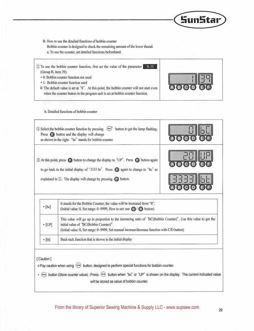
0 To use the bobbin counter function, first set the value of the parameter 1^31(Group B, item 39).
• 0: Bobbin counter function not used
• 1: Bobbin counter function used
^ The default value is set at "0". At this point, the bobbin counter will not start even
when the counter button in the program unit is set at bobbin counter function.
b. Detailed functions of bobbin counter
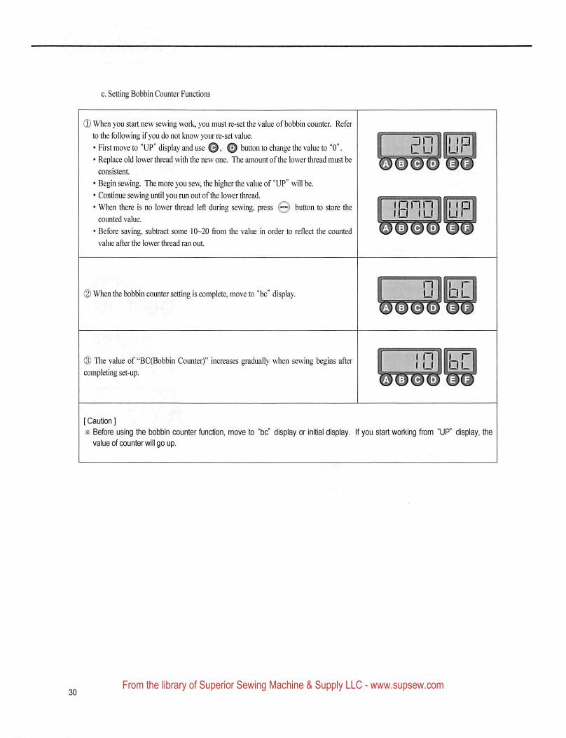
© Select the bobbin counter function by pressing @5"Press button and the display will changeas shown in the right "be" stands for bobbin counter.
but^n to get the lamp flashing.
(2) At this point, press button to change the display to "UP". Press button again
to go back to the initial display of '3333 bt". Press Q again to change to "be" as
explained in ©. The display will change by pressing Q button.
I
3333 bb
It stands for the Bobbin Counter, the value will be increased from "0".
(Initial value: 0, Set range: 0-9999, How to set: use GO button)
This value will go up in proportion to the increasing ratio of 'BC(Bobbin Counter)". Use this value to get the
initial value of "BCfBobbin Counter)"
(Initial value: 0, Set range: 0-9999, Set manual increase/decrease function with C/D button)
Back-tack function that is shown in the initial display
[ Caution ]
is Pay caution when using © button, designed to perform special functions for bobbin counter.
• © button (Store counter value): Press © button when "be" or "UP" Is shown on the display. The current Indicated valuewill be stored as value of bobbin counter.
From the library of Superior Sewing Machine & Supply LLC - www.supsew.com
c. Setting Bobbin Counter Functions
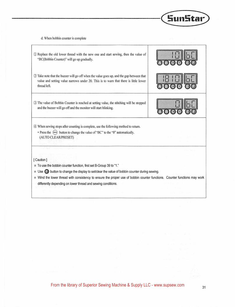
0 When you start new sewing work, you must re-set the value of bobbin counter. Refer
to the following ifyou do not know your re-set value.
• First move to "UP" display and use o o button to change the value to "0".• Replace old lower thread with the new one. The amount ofthe lower thread must be
consistent
• Begin sewing. The more you sew, the higher the value of "UP" will be.
• Continue sewing until you run out ofthe lower thread.
• When there is no lower thread left during sewing, press Q) button to store thecounted value.
• Before saving, subtract some 10-20 fiom the value in order to reflect the counted
value after die lower thread ran out
innnirTp- (ullu
(2) When the bobbin counter setting is complete, move to "be" display. OlET
0 The value of "BC(Bobbin Counter)" increases gradually when sewing begins after
completing set-up.UIK
[ Caution ]
^ Before using the bobbin counter function, move to "be" display or initial display. If you start working from "UP" display, thevalue of counter will go up.
From the library of Superior Sewing Machine & Supply LLC - www.supsew.com
SuiiStar
d. When bobbin counter is complete
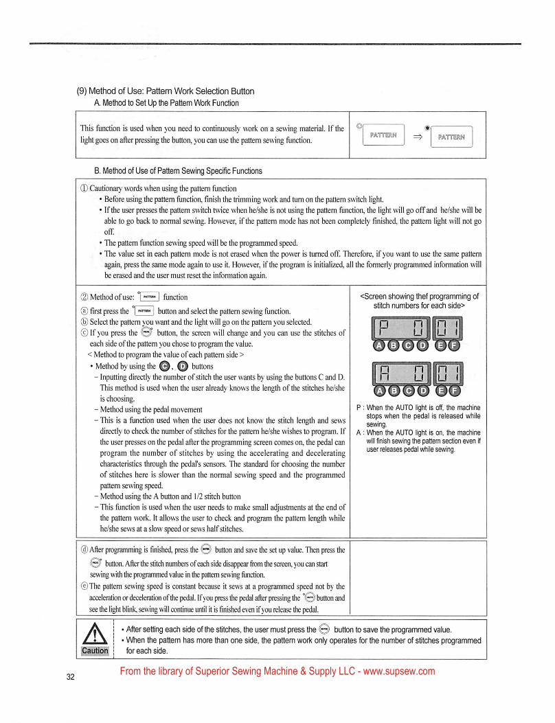
(D Replace the old lower thread with the new one and start sewing, then the value of"BC(Bobbin Counter)" will go up gradually.
(2) Take note that the buzzer will go off when the value goes up, and the g^ between thatvalue and setting value narrows under 20. This is to warn that tiiere is little lower
thread left.
® The value of Bobbin Counter is reached at setting value, the stitching will be stoppedand the buzzer will go offand the monitor will start blinking.
(D When sewing stops after counting is complete, use the following method to return.
• Press the button to change the value of"BC" to the "0" automatically.
(AUTO CLEAR/PRESET)
[ Caution ]
« To use the bobbin counter function, first set B-Group 39 to "1."
% Use button to change the display to set/clear the value of bobbin counter during sewing.iK Wind the lower thread with consistency to ensure ftie proper use of bobbin counter functions. Counter functions may work
differently depending on lower thread and sewing conditions.
From the library of Superior Sewing Machine & Supply LLC - www.supsew.com
(9) Method of Use: Pattern Work Selection Button
A Method to Set Up the Pattern Woik FuncUon
This function is used when you need to continuously work on a sewing material. If the
light goes on after pressing the button, you can use the pattem sewing function. PATTERN
8. Method of Use of Pattem Sewing Specific Functions
® Cautionary words when using the pattem function• Before using the pattem function, finish the trimming work and turn on the pattem switch light.• Ifthe user presses the pattem switch twice when he/she is not using the pattem function, the light will go off and he/she will be
able to go back to normal sewing. However, if the pattem mode has not been completely finished, the pattem light will not gooff.
• The pattem function sewing speed will be the programmed speed.• The value set in each pattem mode is not erased when the power is turned off Therefore, if you want to use the same pattem
again, press the same mode again to use it. However, if the program is initialized, all the formerly programmed information will
be erased and the user must reset the information again.
(2) Method of use: function <SCTeen showing thef programming of^ - . ft 1 . . . . . .. . stitch numbers for each side>(a) first press the I I button and select the pattem sewmg function.® Select the pattem you want and the light will go on the pattem you selected. l^^ll© If you press the button, the screen will change and you can use the stitches of | " U IILJ i|
each side ofthe pattem you chose to program the value.< Method to program the value of each pattem side >
• Method by using the O' O buttons 1^^^- Inputting directly the number of stitch the user wants by using the buttons C and D. | M U | |LJ i|This method is used when the user already knows the length of the stitches he/she
is choosing.- Method using the pedal movement 1^ • VVhen the AUTO light is off, the machineTL- • f ,• j L ,1. j ,. 1 ,1. L1 j stops when the pedal is released while- This IS a function used when the user does not know the stitch length and sews sev^ngdirectly to check the number of stitches for the pattem he/she wishes to program. If A: When the AUTO light is on, hie machinethe user presses on the pedal after the programming screen comes on, the pedal can will finish sewing the pattem section even ifprogram the number of stitches by using the accelerating and decelerating user releases pedal while sewing,characteristics through the pedal's sensors. The standard for choosing the numberof stitches here is slower than the normal sewing speed and the programmedpattem sewing speed.
- Method using the A button and 1/2 stitch button
- This function is used when the user needs to make small adjustments at the end ofthe pattem work. It allows the user to check and program the pattern length whilehe/she sews at a slow speed or sews half stitches.
® After programming is finished, press the 0 button and save die set up value. Then press the0 button. After the stitch numbers ofeach side disappear from the screen, you can startsewing with the prc^rammed value in the pattern sewing function.
® The pattem sewing speed is constant because it sews at a programmed speed not by theacceleration or deceleration ofthe pedal. If you press the pedal after pressing the °0 button andsee the li^t blink, sewing will continue until it Is finished even if jou release the pedal.
^ > I ■ , I I -
A I • After setting each side of the stitches, the user must press the © button to save the programmed value.I * When the pattem has more ftian one side, the pattem work only operates for the number of stitches programmed
l^ution I for each side.
niin {u llu I
P : When the AUTO light is off, the machinestops when the pedal is released whilesewing.
A: When the AUTO light is on, ttie machinewill finish sewing the pattem section even ifuser releases pedal while sewing.
From the library of Superior Sewing Machine & Supply LLC - www.supsew.com
SuiiStar
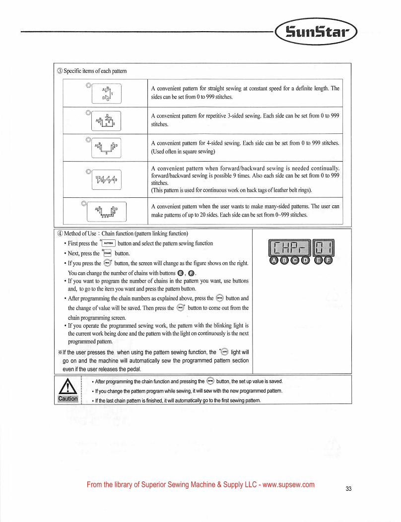
(S) Specific items ofeach pattern
A convenient pattern for straight sewing at constant speed for a definite length. The
sides can be set from 0 to 999 stitches.
A convenient pattern for repetitive 3-sided sewing. Each side can be set from 0 to 999
stitches.
A convenient pattern for 4-sided sewing. Each side can be set tfom 0 to 999 stitches.
(Used often in square sewing)
A convenient pattern when forward/backward sewing is needed continually,forward/backward sewing is possible 9 times. Also each side can be set from 0 to 999stitches.
(This pattern is used for continuous work on back tags of leather belt rings).
A convenient pattern when the user wants to make many-sided patterns. The user can
make patterns of up to 20 sides. Each side can be set from 0-999 stitches.
(3) Method of Use : Chain function (pattern linking function)
• First press the 1 | button and select the pattern sewing function
• Next, press the button.
• Ifyou press the button, the screen will change as the figure shows on the right.You can change the number of chains with buttons O > O •
• If you want to program the number of chains in the pattern you want, use buttonsand, to go to the item you want and press the pattern button.
• After programming the chain numbers as explained above, press the @ button andthe change of value will be saved. Then press the 0^ button to come out from thechain programming screen.
• If you operate the programmed sewing work, the pattern with the blinking light isthe current work being done and the pattern with the light on continuously is the nextprogrammed pattern,
^ If the user presses the when using tfie pattern sewing function, &ie "© light willgo on and the machine will automatically sew the programmed pattem section
even if the user releases e pedal.
Apautioi|
• After programming the chain function and pressing the (0 button, tfie set up value is saved.
' Ifyou change the pattem program v\4iile sewing, it will sew with the new programmed pattem.
' If the last chain pattem is finished, it will automaticaily go to the first sewing pattem.
From the library of Superior Sewing Machine & Supply LLC - www.supsew.com
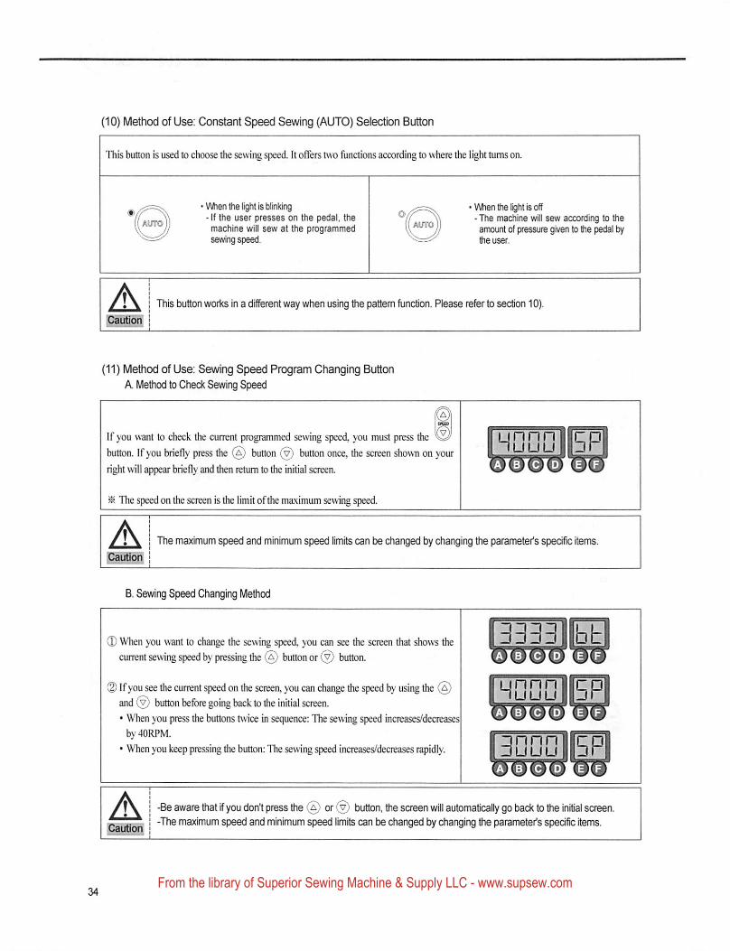
(10) Method of Use; Constant Speed Sewing (AUTO) Selection Button
This button Is used to choose the sewing speed. It offers two functions according to where the light turns on.
' When the light is blinking• If the user presses on the pedal, themachine will sew at the programmedsewing speed.
■ When tfie light is off- The machine will sew according to theamount of ixessure given to the pedal bythe user.
A'Cautioni
This button works in a different way when using the pattern function. Please refer to section 10).
(11) Method of Use: Sewing Speed Program Changing Button
A Method to Check Sewing Speed
If you want to check the current programmed sewing speed, you must press tiie
button. If you briefly press the (a) button button once, the screen shown on your
right will pear briefly and then return to the initial screen.
HsnniEP
^ The speed on the screen is the limit ofthe maximum sewing speed.
Apautiog
The maximum speed and minimum speed limits can be changed by changing the parameter's specific items.
B. Sewing Speed Changing Method
® When you want to change the sewing speed, you can see the screen that shows thecurrent sewing speed by pressing the button or button.
(D If you see the current speed on the screen, you can change the speed by using theand © button before going back to the initial screen.• When you press the buttons t\vice in sequence: The sewing speed increases/decreases
by 40RPM.
• When you keep pressing the button: The sewing speed increases/decreases r^idly.
hOOdIIsp
anSalOT
A -Be aware that if you don't press the ® or ® button, the screen will automatically go back to the initial screen.-The maximum speed and minimum speed limits can be changed by changing the parameter's specific items.
From the library of Superior Sewing Machine & Supply LLC - www.supsew.com
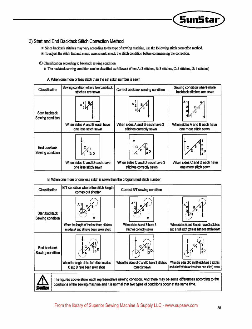
3) Start and End Backtack Stitch Correction Method^ Since backtack stitches may vaiy according to the type of sewing machine, use the following stitch correction method.
^ To adjust the stitch fast and clean, users should check die stitch condition before commencing the correction.
0 Classification according to backtack sewing condition
^ The backtack sewing condition can be classified as follows (When A: 3 stitches, B: 3 stitches, C: 3 stitches, D: 3 stitches)
A When one more or less stitch than the set stitch number is sewn
ClassificationSewing condition where few backtack
stitches are sewnCorrect backtack sewing condition
1Ag
OC f
Sewing condition where morebacktack stitches are sewn
Start backtack
Sewing condition
2| bA
When sides A and B each have
one less stitch sewn
When sides A and B each have 3
stitches correctly sewnWhen sides A and B each have
one more stitch sewn
End backtack
Sewing condition
When sides C and D each have
one less stitch sewn
When sides C and D each have 3
stitches conectly sewnWhen sides C and D each have
one more stitch sewn
B. When one more or one less stitch is sewn than the programmed stitch number
ClassificationB/T condition where the stitch length
comes out shorterCorrect B/T sewing condition
Start backtack
Sewing condition
1
{an}r
When the length of the last three stitchesin sides A and B have tieen sewn short
When sides A and 8 have 3
stitches correctly sewn.When sides A and 8 each have 3 stitches
and a half stitch (or less than one stitch) sewn
End backtack
Sewing condition
When the length of the first stitch inC and D have been sewn short
When the sides of C and D have 3 stitches
correctly sewnV\^ the sides of C and D each have 3 stitches
and a half stitch (or less than one stitch) sewn.
A The figures above show each representative sewing condition. And there may be some differences according to theconditions of the sewing machine and it is normal that two types of conditions occur at the same time.
35From the library of Superior Sewing Machine & Supply LLC - www.supsew.com
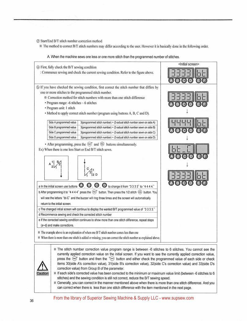
(D Start/End B/T stitch number correction method
The method to correct B/T stitch numbers may differ according to the user. However it is basically done in the following order.
A When Uie machine sews one less or one more stitch than the programmed number of stitches.
(a) First, fully check the B/T sewing condition
: Commence sewing and check the current sewing condition. Refer to the figure above.
<lnitial screen>
3333llbb
(S) If you have checked the sewing condition, first correct the stitch number that differs byone or more stitches to the programmed stitch number.
^ Correction method for stitch numbers with more than one stitch difference
• Program range: -6 stitches ~ 6 stitches
• Program unit; 1 stitch
• Method to apply correct stitch number (program using buttons A, B, C and D).
Side A progranwied value 3(progtammed Stich number) + (3-actual stitch number sewn on side A)
Side B programmed value 3(programmed sStch number) + (3-actual stitch number sewn on ade B)
Side C programmed value 3(programmed sIHch number) *■ (3-adual stitch number sewn on side C)
Side D programmed value 3(prog[ammed stitch numbeO + (3-actual stitch nuniief sewn on side D)
• After programming, press the @ and "© buttons simultaneously.Ex) When there is one less Start or End B/T stitch sewn. bb-C
zK4
2D
a in the initial screen use buttons O, O. O. O to change it from "3 3 3 3" to "4 4 4 4."b After programming it to "4 4 4 4" press the 0T button. Then press the 1/2 stitch 0 button. You
will see the letters "bl-C" and the buzzer will ring three times and the screen vrili automaticallyretum to the initial screen,
c The changed initial saeen will continue to display the wanted BT programmed value of "3 3 3 3."d Recommence sewing and check the corrected stitch numbere If the corrected sewing condition continues to show more than one stitch difference, repeat steps
(a~d) and make corrections.
^ The example above is an explanation ofwhen one B/T stitch number comes less than onei® When there is more than one stitch is added or missing, you can correct the stitch numbCT as explained ^ve.
33331EB
Ali^ution'
« The stitch number correction value program range Is between -6 stitches to 6 stitches. You cannot see thecurrently applied con"ecfon value on the initial screen. If you want to see the currently applied correction value,press the Q button and then the "© button and either check the programmed value of each side or checkitems 30(side A's correction value), 31(side B's correction value), 32(side C's correction value) and 33(side D'scorrection value) from Group B of the parameter.
^ If each side's corrected value has been conected to the minimum or maximum value limit (between -6 stitches to 6shtches) and the sewing condition is still not correct, reduce the B/T sewing speed.
jK Generally, you can correct in the manner mentioned above when friere is more than one stitch difference. /\nd youcan correct when there is less than one stitch difference with the item mentioned in the next page.
From the library of Superior Sewing Machine & Supply LLC - www.supsew.com
StinStar
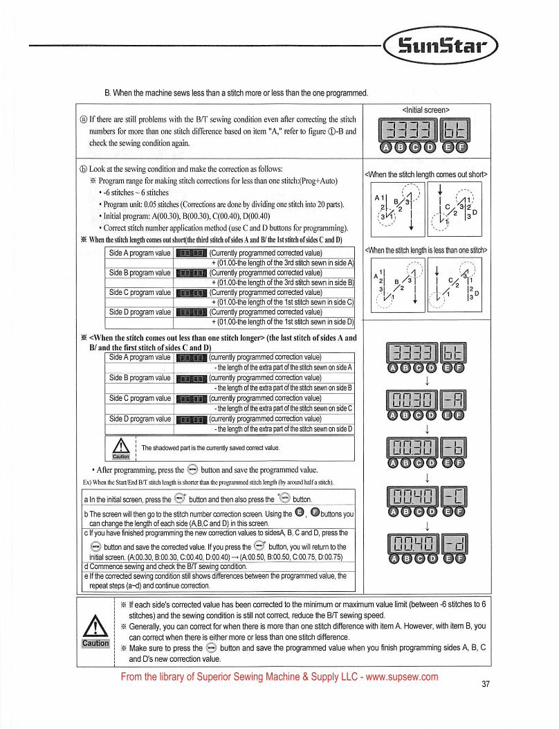
B. VJhen the machine sews less than a stitch more or less than the one programmed.
(D If there are still problems with the B/T sewing condition even after correcting the stitch
numbers for more than one stitch difference based on item "A," refer to figure ®-B and
check the sewing condition again.
<lnitial screen>
3333 bb
(£) Look at the sewing condition and make the correction as follows:
^ Program range for making stitch corrections for less than one stitch:(Prog+Aiito)
• -6 stitches ~ 6 stitches
• Program unit: 0.05 stitches (Corrections are done by dividing one stitch into 20 parts).
• Initial program: A(00.30), B(00.30), C(00.40), D(00.40)
• Correct stitch number application method (use C and D buttons for programming).
ISi \Vheo die sdtch length comes out shoi1(the third stitch ofsides X and B/ the ist stitch ofsides C and D)
Side A program value (Currently programmed corrected value)+ (01.00-the length of the 3rd stitch sewn in side A)
Side B program value (Currently programmed corrected value)1 + (01.00-the length of the 3rd stitch sewn in side B)
Side C program value 1 1(Currently programmed corrected value)
Side D program value+ (01.00-the length of the 1st stitch sewn in side C)
BuMiBa (Currently programmed corrected value)+ (01.00-the length of the 1st stitch sevm in side D)
Side A program value |HBAil (currently programmed correction value)
Side B program value |
- the lengtii of the extra part of the stitch sewn on side A
BBm (currently programmed correction value)
Side C program value |- ttie length of the extra part of the stitch sewn on side B
liillilfl (currently programmed correction value)
Side D program value 1- the lengtti of the extra part of the stitdi sewn on side 0
liilMrtll (currently fxogrammed correction value)• the length of the extra part of the stitcdi sewn on side D
The shadowed pan is the currently saved correct value.
• After programming, press the button and save the programmed value.Ex) When the Start/End BT stitch length is shorter than the pr(^rammed aitch lengdi (by around halfa stitch).
a In the initial screen, press the O button and then also press the button.b The screen will then go to the stitch number correction screen. Using the ©, ©buttons youcan change the length of each side (AB,C and D) in this screen.
c if you have finished programming the new correction values to sidesA B, C and D, press the
button and save the corrected value, if you press ttie © button, you will return to theinitial screen. (A00.30, B:00.30, C:00.40, D;00.40) {A00.50, B:00.50, C:00.75, 0:00.75)
d Commence sewing and check the BfT sewring condition.e If the corrected sewing condition still shows differences between the programmed value, therepeat steps (a~d) and continue correction.
<V\/hen the stitch length comes out shoi1>
i
(aH;,
<When the stitch length is less than one stilch>
lit <When the stitch comes out less than one stitch longer> (the last stitch of sides A and8/ and the first stitch of sides C and D)
^"2 bAI''3 /2
!
3333 btAIbTcIdmeIf
D03D -RAlBlClb'
DQ3D -baIbIcId'
nnunuu.nuaTbIcIdmeTf
AIf each side's corTected value has been corrected to the minimum or maximum value limit (between -6 stitches to 6
stitches) and the sewing condition Is sil not correct, reduce the BfT sewing speed.
58 Generally, you can correct for when there is more than one stitch difference with item A. However, vwth item B, youcan correct when there is either more or less than one stitch difference.
58 Make sure to press the © button and save the programmed value when you finish programming sides A B, Cand D's new correction value.
From the library of Superior Sewing Machine & Supply LLC - www.supsew.com
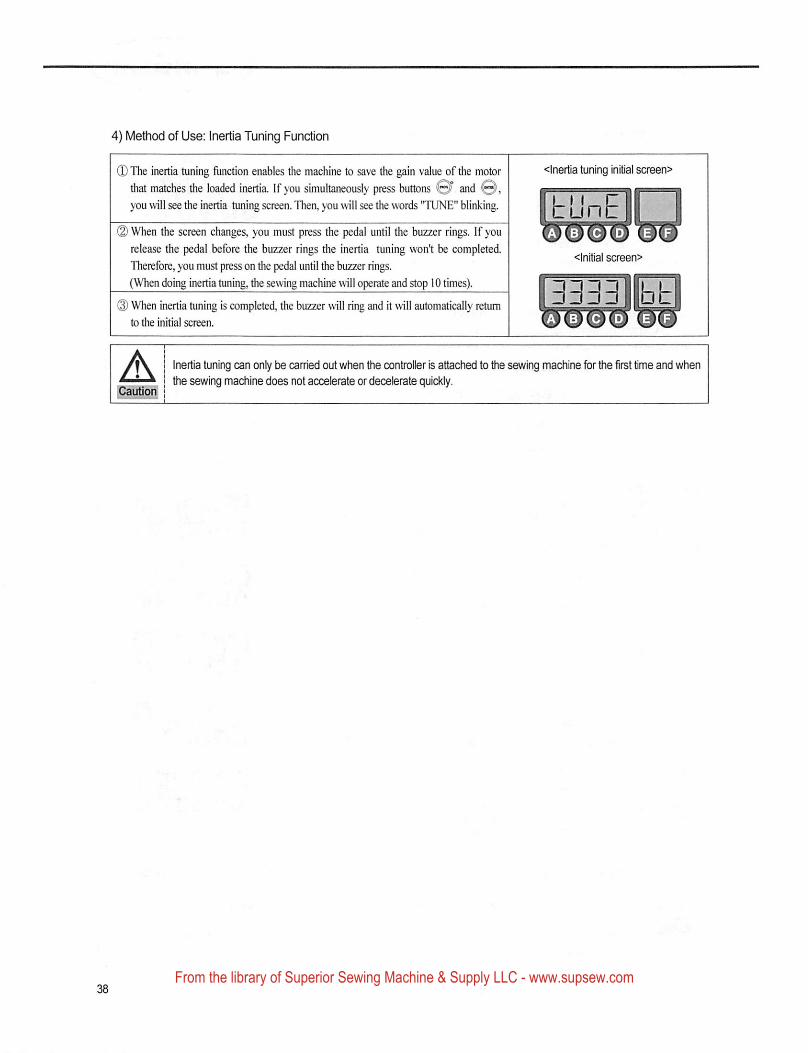
4) Mefliod of Use: Inertia Tuning Function
(D The inertia tuning ftinction enables the machine to save the gain value of the motorthat matches the loaded inertia. If you simultaneously press buttons ©J* and ©,you will see the inertia tuning screen. Then, you will see the words "TUNE" blinking.
(2) When the screen changes, you must press the pedal until the buzzer rings. If yourelease the pedal before the buzzer rings the inertia tuning won't be completed.
Therefore, you must press on the pedal until the buzzer rings.
(When doing inertia tuning, the sewing machine will operate and stop 10 times).
(3) When inertia tuning is completed, the buzzer will ring and it will automatically returnto the initial screen.
<lnertia tuning Initial screen>
fbLmn
<lnitial screen>
3333llbt
A^autiotf
Inertia tuning can only be carried out when the controller is attached to the sewing machine for the first time and whenthe sewing machine does not accelerate or decelerate quickly.
From the library of Superior Sewing Machine & Supply LLC - www.supsew.com
C^StniSta^
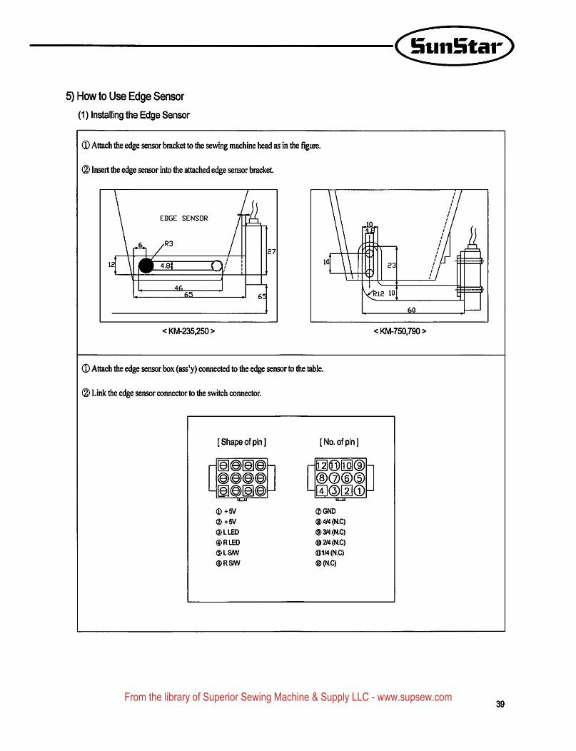
5) How to Use Edge Sensor
(1) Installing the Edge Sensor
(D Attach die edge sensor bracket to the sewing machine head as in the figure.
(2) Insert the edge sensor into the attached edge sensor bracket
EDGE SENSOR 7"
•S /M o/ 1
' 11
46
65
27
<KM-235,250>
0 Attach die edge sensor box (ass'y) connected to the edge sensor to die table.
® Link die edge sensor connector to the switch connector.
23
V<^RI2 1060
<KM-750.790>
[Shape of pin] [No. of pin]
|e|@©@-] p0©|il(D@@@@ ®(2)©®ia@[e!@
mi
—1■ - ■" " -
®+5V®+5V®LLED®RLEO®LS/W®RSW
®GND®4y4(N.C)®3M(N.C)®2/4(N.C)®1/4(N.C)®(N.C)
39From the library of Superior Sewing Machine & Supply LLC - www.supsew.com
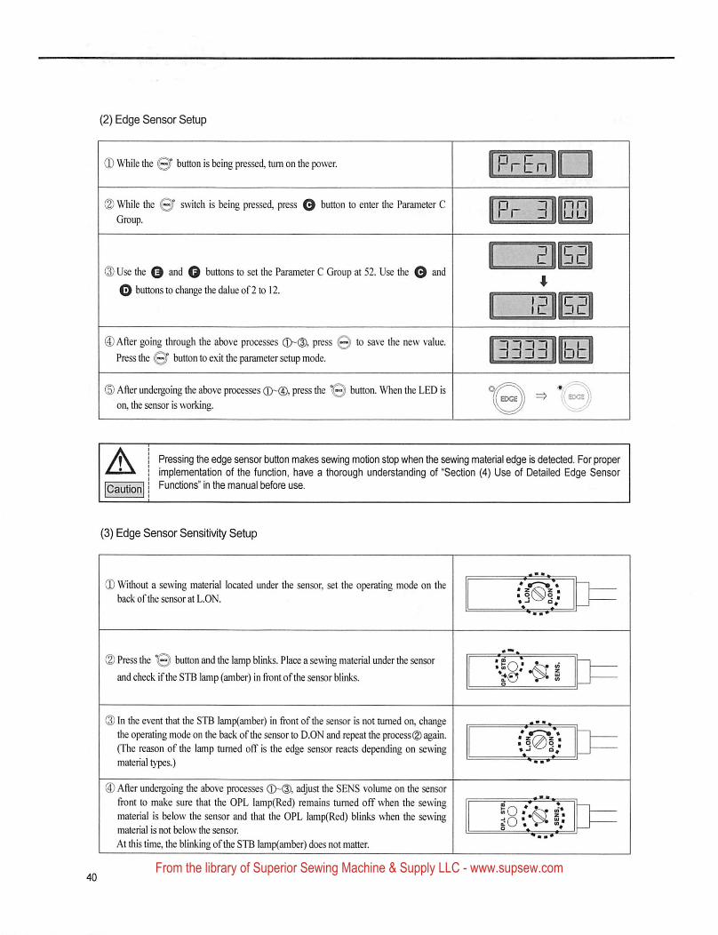
(2) Edge Sensor Setup
(D While the 0f button is being pressed, turn on the power. PrE
® While die I0f switch is being pressed, press Q button to enter the Parameter CGroup.
0 Use the 3 O t>uttons to set the Parameter C Group at 52. Use the Q and
O buttons to change the dalue of 2 to 12.
(3) After going through the above processes (T)-®, press 0 to save the new value.Press the Q" button to exit the parameter setup mode.
EEZm^
3^Ibbl
© After undeigoing the above processes press the button. When the LED ison, the sensor is working.
—y i \
A Pressing the edge sensor button makes sewing motion stop when the sewing material edge is detected. For properimplementation of the function, have a thorough understanding of "Section (4) Use of Detailed Edge SensorFunctions" in the manual before use.
(3) Edge Sensor Sensitii^ Setup
® Without a sewing material located under the sensor, set the operating mode on theback ofthe sensor at L.ON. : s.Sis
• -I Q j
(2) Press the 10) button and the lamp blinks. Place a sewing material under the sensorand check ifthe STB lamp (amber) in front ofthe sensor blinks.
(3) In the event that the STB Iamp(amber) in front of the sensor is not turned on, changethe operating mode on the back of the sensor to D.ON and repeat the process® again.(The reason of the lamp turned off is the edge sensor reacts depending on sewingmaterial types.)
® After unde^oing the above processes (3>® adjust the SENS volume on the sensorfront to make sure that the OPL lamp(Red) remains turned off when the sewingmaterial is below the sensor and that the OPL iamp(Red) blinks when the sewingmaterial is not below the sensor.
At this time, the blinking ofthe STB lamp(amber) does not matter.
From the library of Superior Sewing Machine & Supply LLC - www.supsew.com
StiiiHtar
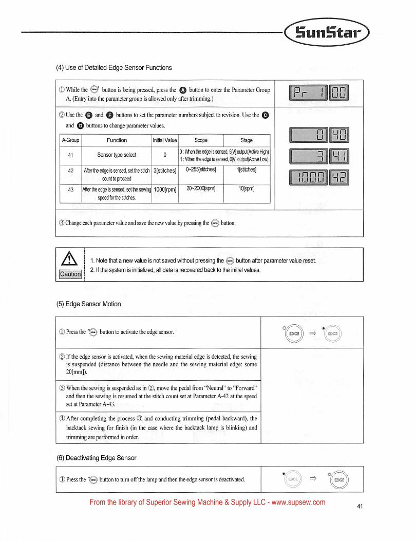
(4) Use of Detailed Edge Sensor Functions
(D While the 0F button is being pressed, press the Q button to enter the Parameter GroupA. (Entiy into the parameter group is allowed only after trimming.)
(2) Use the and Q buttons to set the parameter numbers subject to revision. Use the 0
and 0 buttons to change parameter values.
A-Group Function Initial Value
Cpn«,r tvnp f) ° OLilput(Active High)1: Vihen the edge is sensed, 0[\/] output(Ac6ve Low)
42 Aflerlheedgeisserjsed.sellhesfifch 3(stitches] 0-255[stitches] If^rtches)count to {Koceed
43 After the edge is sensed, set the sewing lOOOfrpm] 20~2000(spm] 10[spm]speed for stitches.
DlRn
^Fi
IDGO HP
(D Change each parameter value and save the new value by pressing the @) button.
A 1. Note that a new value is not saved wiUiout pressing the Q button after parameter value reset2. If the system is initialized, all data is recovered back to the initial values.
(5) Edge Sensor Motion
(3) Press the *0) button to activate the edge sensor.
(2) If the edge sensor is activated, when the sewing material edge is detected, the sewingis suspended (distance between the needle and the sewing material edge: some20[mm]).
(2) When the sewing is suspended as in (2), move the pedal from "Neutral" to "Forward"and then the sewing is resumed at the stitch count set at Parameter A-42 at the speedset at Parameter A-43.
® After completing the process (3) and conducting trimming (pedal backward), the
backtack sewing for finish (in the case where the backtack lamp is blinking) and
trimming are performed in order.
((edcs.
(6) Deactivating Edge Sensor
0 Press the 0 buton to tum offthe lamp and then the edge sensor is deactivated.
From the library of Superior Sewing Machine & Supply LLC - www.supsew.com
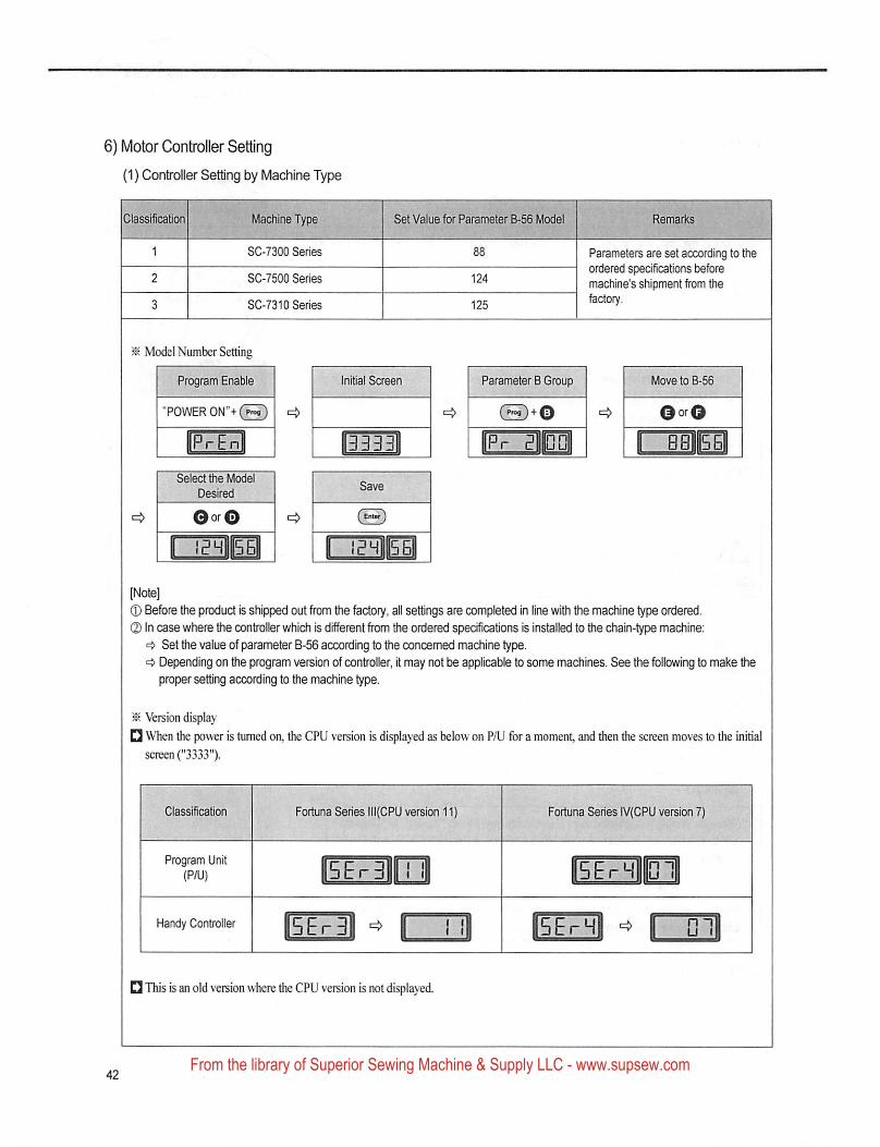
6) Motor Controller Setting
(1) Controller Setting by Machine Type
Machine Type.rmt t
SC-7300 Series
SC-7500 Series
SC-7310 Series
^ Model Number Setting
Program Enable li
"POWER ON '+C^ i=>
IP''Enl I
Desired
Qor^ 1=^
n^na T
In
Set va ue for Parameter B-56 Model
itial Screen
3333
Parameter B Group
( P>OB ) + Q
ipmiMi
Remarks
Parameters are set according to theordered specifications beforemachine's shipment from thefactory.
Move to B-56
©orO
"bbIIbI
(J) Before the product is shipped out from the factory, all settings are completed in line with the machine type ordered.
O In case where the controller which is different from the ordered specifications is installed to the chain-type machine:Set the value of parameter B-56 according to the concerned machine type.Depending on the program version of conffoller, it may not be applicable to some machines. See the following to make the
proper setting according to ffie machine type.
^ Version display
D When the power is turned on, the CPU version is displayed as below on P/U for a moment, and then the screen moves to the initialscreen ("3333").
Classification
Program Unit(P/U)
Handy Controller
Fortuna Series 1II(CPU version 11) Fortune Series IV(CPU version 7)
5ErH ni
SErHI I ni
This is an old version where the CPU version is not displayed.
From the library of Superior Sewing Machine & Supply LLC - www.supsew.com
SuiiHtar
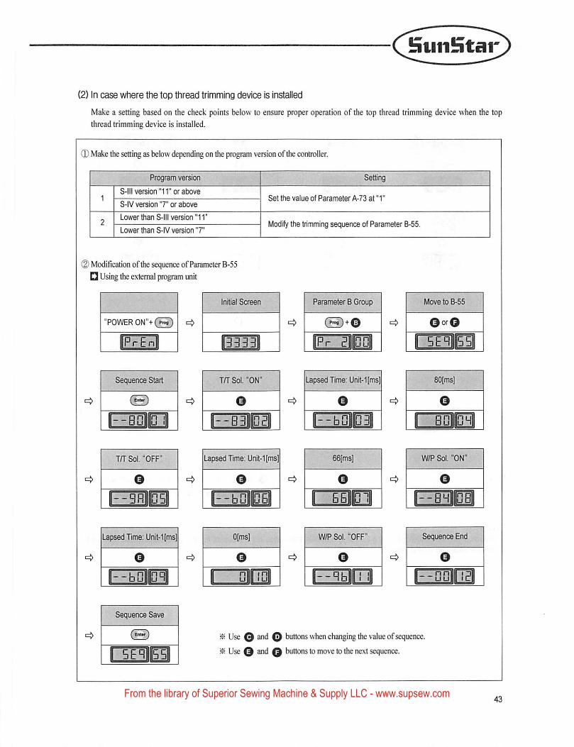
(2) In case where the top thread trimming device is installed
Make a setting based on the check points below to ensure proper operation of the top thread trimming device when the top
thread trimming device is installed.
(D Make the setting as below depending on the program version ofthe controller.
Program version
S-lll version "11" or above
S-IV version "7" or above
Lower than S-lll version "11
Set the value of Parameter A-73 at "1"
Modify the trimming sequence of Parameter B-55.Lower than S- V version T
(Z) Modification of the sequence of Parameter B-55Q Using the external program unit
Initial Screen Parameter B Group
"POWER 0N"+(HO
Lapsed Time: Llnit-1[ms)Sequence Start I . JfT Sol. ON
--BaiC II I I--B3 lEI
in" Sol. "OFF"
o
6B B1
W/P Sol. OFF"
O
Lapsed Time: Unit-1[ms]
Sequence Save
(3
From the library of Superior Sewing Machine & Supply LLC - www.supsew.com
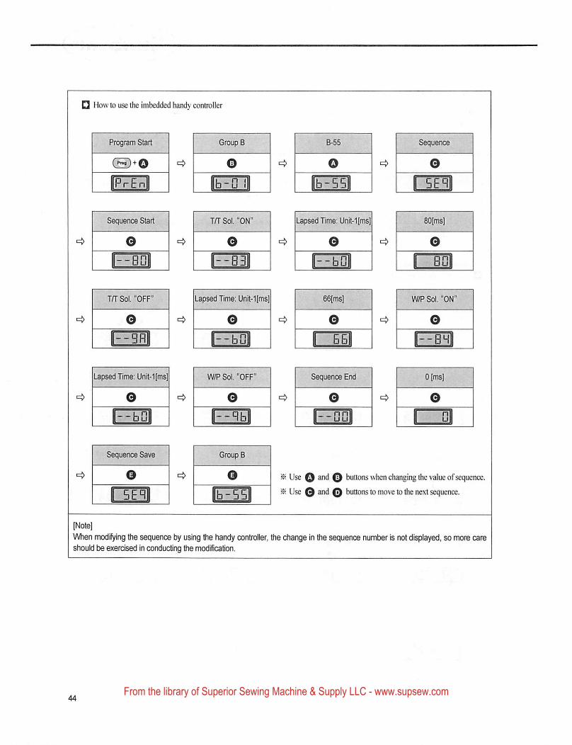
Q How to use the imbedded handy controller
Program Start Group B
@)*0 ^
Sequence Start JfJ Sot. ON Lapsed Time: Unit-1[ms]
T/TSol. "OFF" Lapsed Time: Unit-1[ms] W/PSol. "ON
Lapsed Time: Unit-1[ms1 W/P Sol. OFF Sequence End
Sequence Save Group B
Use O © buttons when changing the value ofsequence
Use 0 and A buttons to move to tire next sequence.
When modifying the sequence by using the handy controller, the change in the sequence number is not displayed, so more careshould be exercised in conducting the modification.
From the library of Superior Sewing Machine & Supply LLC - www.supsew.com
Suii!iitai'
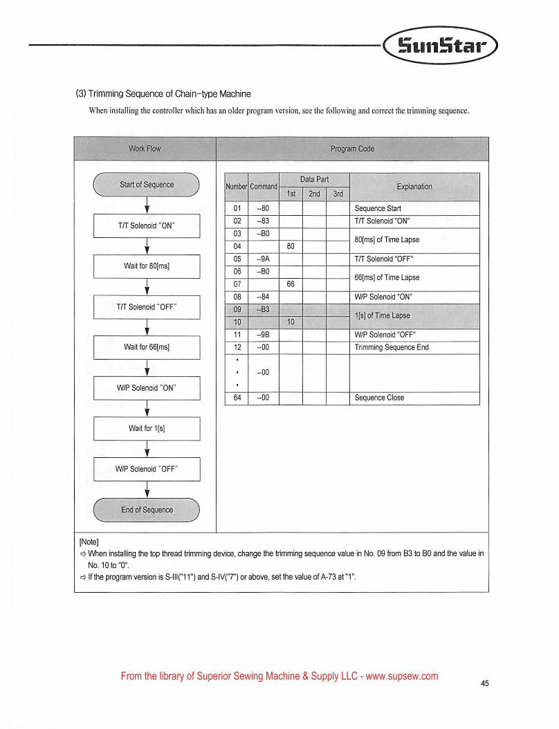
(3) Trimming Sequence of Chain-type Machine
When installing the controller which has an older program version, see the following and correct the trimming sequence.
Work Flow Program Code
Data PartStart of Sequence Number Command Explanation
1st 2nd 3rd
01 -80
02 -83
Sequence Start
T/T Solenoid "ON"T/T Solenoid ON
03 I -BO
04SOfmsj of Time Lapse
05 -9A
06 -BO
T/T So enoid OFFWait for 80 ms]
GSfmsl of Time Lapse
W/P Solenoid "ON"
T/T Solenoid'OFF' 09 I -B3
101[s]of Time Lapse
11 -98
12 -00
W/P Solenoid "OFF"
Wait for 66[msl Trimming Sequence End
W/P Solenoid "ON"
64 -00 Sequence Close
Wait forlfs
W/P Solenoid " OFF"
End of Sequence
=> When installing the top thread trimming device, change the trimming sequence value in No. 09 from B3 to BO and the value in
No. 10to"0".
^ If the program version is S-lll("11") and S-IV('T') or above, set the value of A-73 at"1".
From the library of Superior Sewing Machine & Supply LLC - www.supsew.com
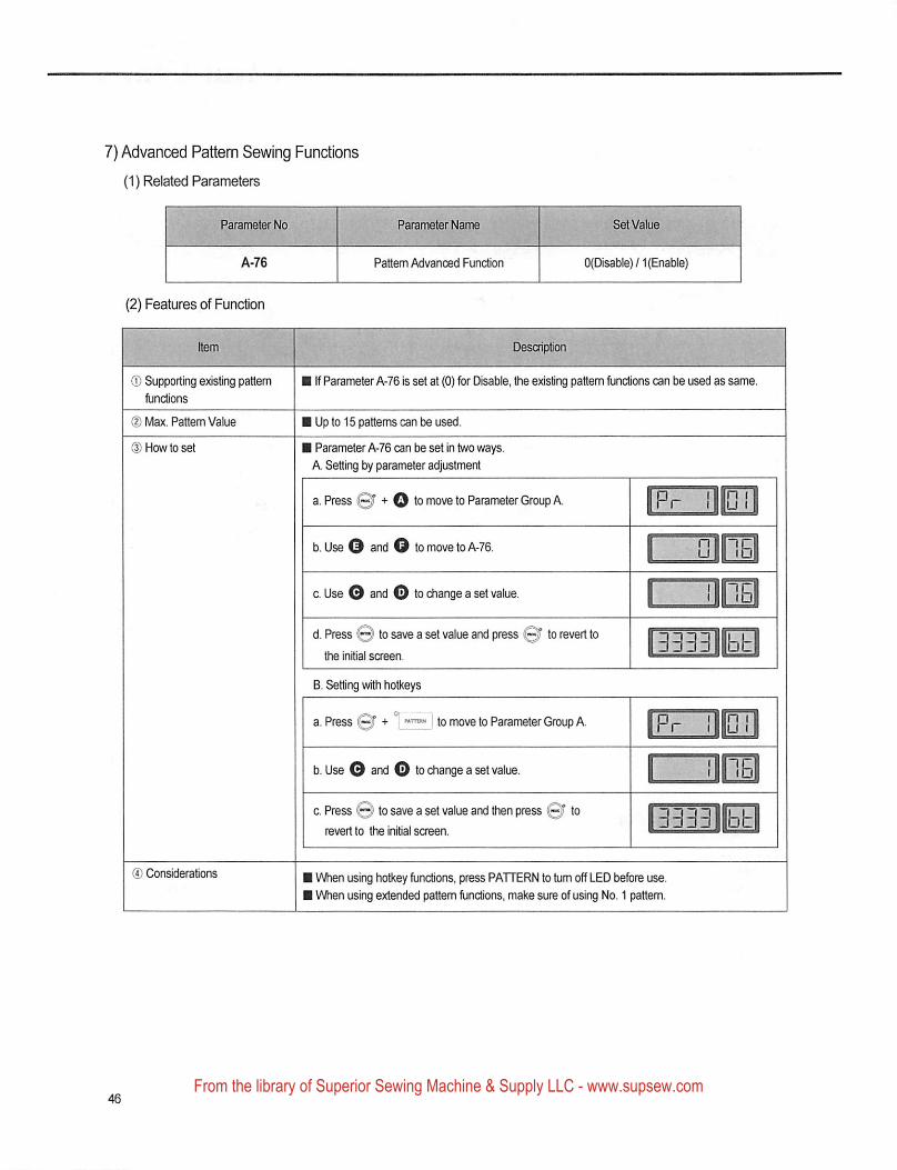
7) Advanced Pattern Sewing Functions
(1) Related Parameters
A-76 Pattern Advanced Function 0(Disable)/1(EnabIe)
(2) Features of Functon
® Supporting existing pattern
functions
(D Max. Pattern Value
® Considerations
I If Parameter A-76 is set at (0) for Disable, the existing pattern functions can be used as same.
I Up to 15 patterns can be used.
I Parameter A-76 can be set in two ways.
A. Setting by parameter adjustment
to move to Parameter Group A
b. Use O and O to move to A-76.
0. Use O and O to change a set value. nm
d. Press @ to save a set value and press Qf to revert tothe initial screen.
B. Setting with hotkeys
to move to Parameter Group A
3333llbl-
b. Use O and O to change a set value.
c. Press @ to save a set value and then press 0f torevert to the initial screen.
3333 bt
1 When using hotkey functions, press PATTERN to turn off LED before use.
I When using extended pattern functions, make sure of using No. 1 pattern.
From the library of Superior Sewing Machine & Supply LLC - www.supsew.com
StiiiHtar
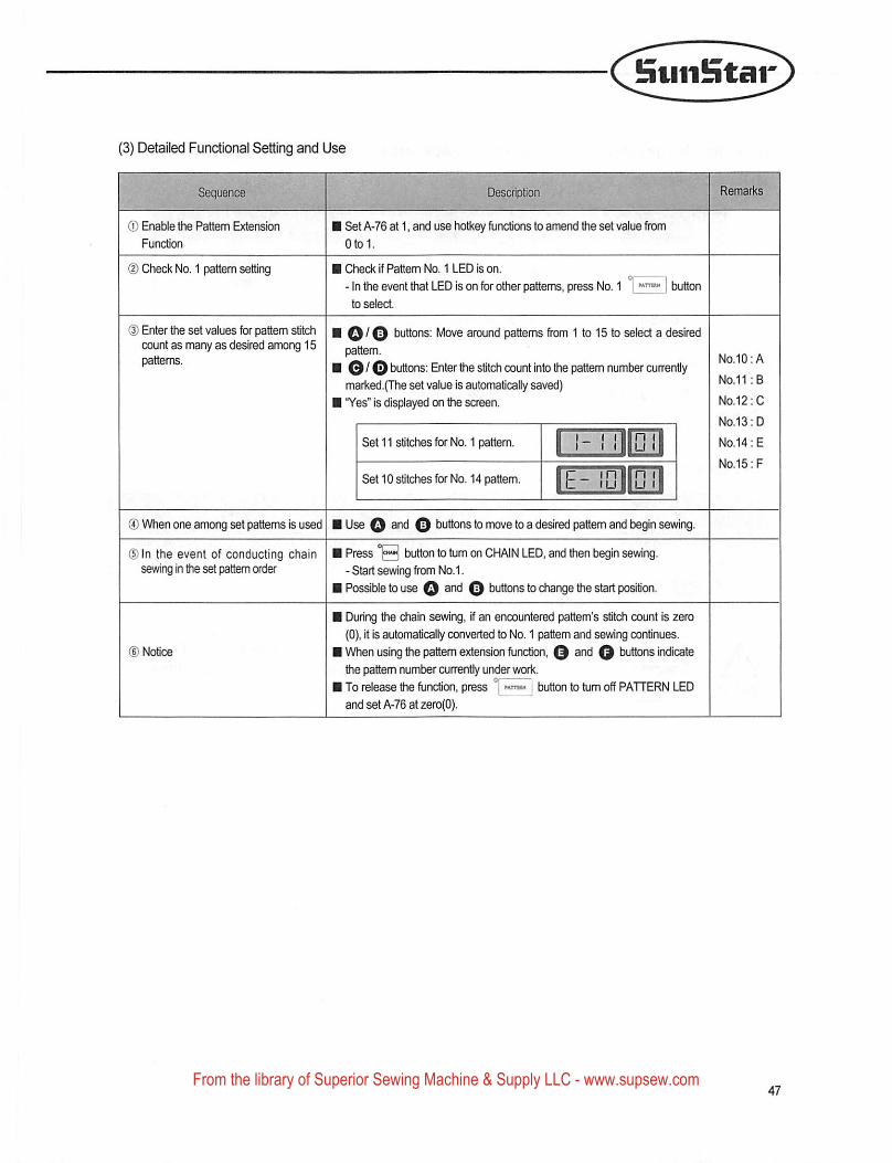
(3) Detailed Functional Setting and Use
® Enable the Pattern Extension
Function
(D Check No. 1 pattern setting
(D Enter the set values for pattern stitchcount as many as desired among 15patterns.
I Set A-76 at 1, and use hotkey fijnctlans to amend the set value from
Otol.
I Ched< if Pattern No. 1 LED is on.
- In the event that LED is on for other patterns, press No. 1 1 | buttonto select.
\ buttons; Move around patterns from 1 to 15 to select a desired
pattem.
I © / O buttons: Enter the stitch count into the pattem number currentlymarked.(lTie set value is automatically saved)
I "Yes" is displayed on the screen.
ISet 11 stitches for No. 1 pattem,
Set 10 stitches for No. 14 pattem.
(4) When one among set pattems Is used ■ Use Q and 0 buttons to move to a desired pattem and begin sewing.
®ln the event of conducting chainsaving In the set pattem order
©Notice
[ Press '0 button to turn on CHAIN LED, and then begin sewing.- Start sewing from No.1.
! Possible to use 0 and 0 buttons to change the start position.
I During the chain sewing, if an encountered pattern's stitch count is zero
(0), it is automatically converted to No. 1 pattem and sewing continues.
I When using the pattem extension function, 0 and 0 buttons indicatethe pattem number OJirently under work.
I To release the function, press | button to turn off PATTERN LEDand set A-76 at zero(O).
No.10:A
No.11 :B
No.12: C
No.13: D
No.14: E
No.15:F
From the library of Superior Sewing Machine & Supply LLC - www.supsew.com
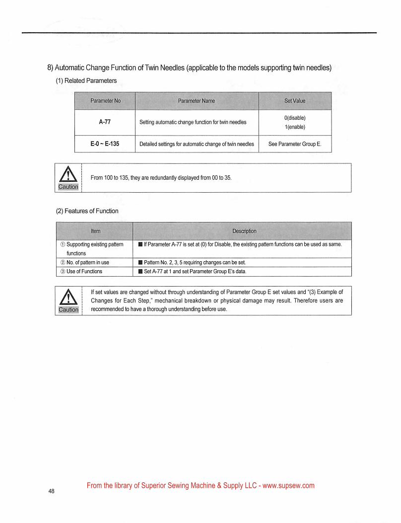
8) Automatic Change Function of Twin Needles (applicable to the models supporting twin needles)
(1) Related Parameters
Setting automatic diange functton for twin needles0(disable)
1 (enable)
E-0 ~ E-135 Detailed settings for automatic change of twin needles See Parameter Group E.
ACautiofi
From 100 to 135, ttiey are redundantly displayed from 00 to 35.
(2) Features of Function
® Supporting existing pattern
functions
(DNo. of pattern in use
(D Use of Functions
If Parameter A-77 is set at (0) for Disable, the e}dsting pattem functions can be used as same.
Pattern No. 2.3,5 requiring changes can be set.
Set A-77 at 1 and set Parameter Group E's data.
AIf set values are changed without through understanding of Parameter Group E set values and "(3) Example of
Changes for Each Step," mechanical breakdown or physical damage may result. Therefore users are
recommended to have a thorough understanding before use.
From the library of Superior Sewing Machine & Supply LLC - www.supsew.com
BviiiHtar
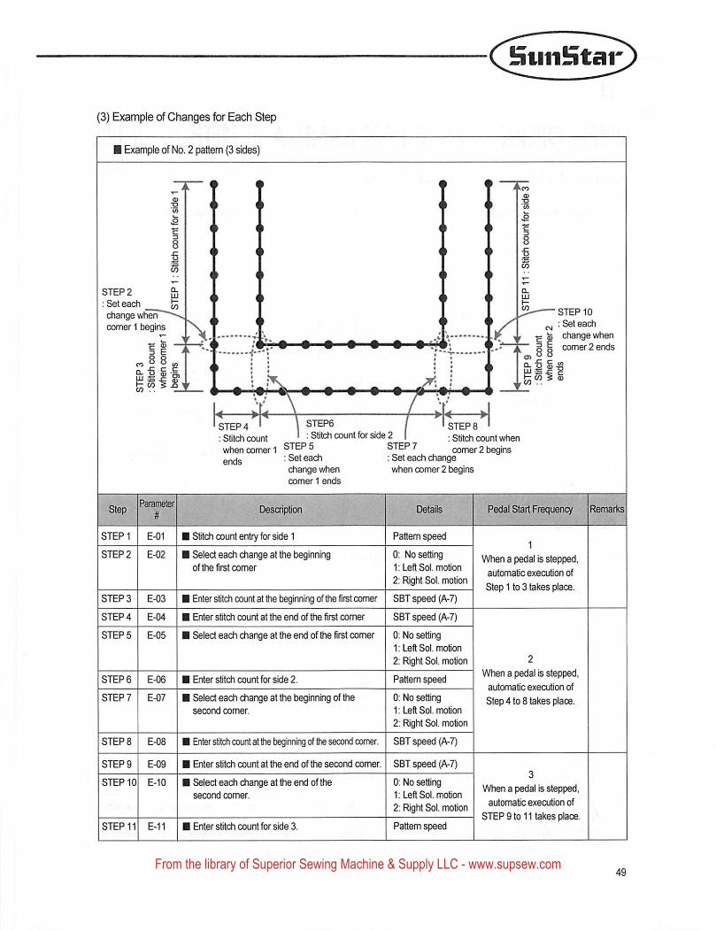
(3) Example of Changes for Each Step
i Example of No. 2 pattern (3 sides)
STEP 2
; Set each
diange wherT*comer 1 begins
STEP 10
: Set each
~ change whencomer 2 ends
STEP6
: Stitch count for side 2STEPS '
: Stitch count when
STEP 4 '
: Stitch count
when comer 1 STEPS comer 2 begins; Set each
change whencomer 1 ends
: Set each changewhen comer 2 begins
Descnptio
STEP 1 E-01
STEP 2 E-02
STEPS E-03
STEP 4 E-04
STEPS E-05
STEPS E-06
STEP? E-07
STEPS E-08
STEP 9 E-09
STEP 0 E-0
STEP11 E-11
Stitch count entry for side 1
Select each change at the t}eglnningof the first comer
Enter stitch count at the beginning of the first comer
Enter stitch count at the end of the first comer
Select eadi change at the end of the first comer
Enter stitch count for side 2.
Select each change at the beginning of thesecond comer.
Enter stitch count at the beginning of the second comer.
Enter stitch count at the end of the second comer.
Select each change at the end of thesecond comer.
Biter stitch count for side 3.
Pattern speed
0: No setting1: Left Sol. motion
2: Right Sol. motion
SBT speed (A-7)
SET speed (A-7)
0: No setting1: Left Sol. motion
2: Right Sol. motion
Pattem speed
0: No setting1: Left Sol. motion
2: Right Sol. motion
SBT speed (A-7)
SBT speed (A-7)
0; No setting1: Left Sol. motion
2; Right Sol. motion
Pattem speed
When a pedal is stepped,
automatic execution of
Step 1 to 3 takes place.
When a pedal is stepped,
automatic execution of
Step 4 to 8 takes piacs.
When a pedal is stepped,
automatic execution of
STEP 9 to 11 takes place.
From the library of Superior Sewing Machine & Supply LLC - www.supsew.com
9
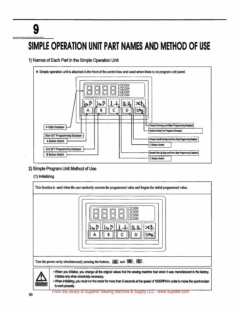
SIMPLE OPERATION UNIT PART NAMES AND METHOD OF USE
1) Names of Each Part in the Simple Operation Unit
Simple operation unit is attached in the front of the control box and used when there is no program unit panel.
□□aoi□□ODI□□DO!□□DDI
4-Dlgit Displayer
Qc,D r
Start B/T Programinirtg Displayer
A Button Switch
End B/T Programming Displayer
B Button Switch
Oq.
E/Prg.
TTncad Tifnn^ and Rogratrariing Disiibyer
Button Switch for Program Changes
PresserFocR^ Up Stop and Dom) Stop PrograrninngDteplayef
D Button Switch
Needle Plata Up Stop and OoMi Stop Programming Displayer
C Button Switch
2) Simple Program Unit Method of Use(1) Initiarizing
This function is used when the user randomly corrects the programmed value and forgets the initial programmed value.
□□DO!□□DO!□□DDI□DDQI
K KiHIo V••
Ho W 14= itA i 1 1 ^ [ D E/Prg.
Tum the power on by simultaneously pressing the buttons, K1 and
Amm
' When you Initlafize, you diange all the original values that the sevvifig rnachiie had when it was nrianufactLDed h the fectory.Initialize only when absolutely necessary.
' When Inilializrg, you rnust tun the rnotor for rnoie than 5 seconds at the speed of 10OORPM in order to rnake the synchionizerto work properly.
50From the library of Superior Sewing Machine & Supply LLC - www.supsew.com
Suiilntar
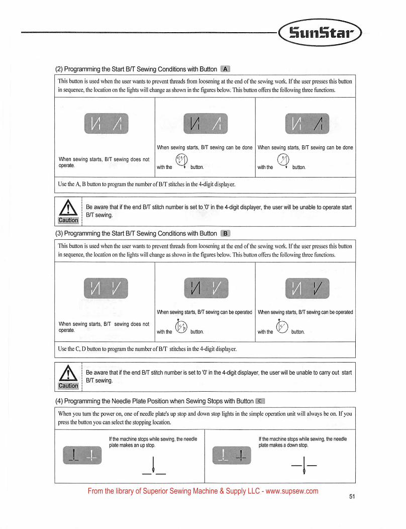
(2) Programming the Start BIT Sewing Conditions with Button
This button is used when the user wants to prevent threads from loosening at the end of the sewing work. If the user presses this button
in sequence, the location on the lights will change as shown in the figures below. TTiis button offers the following three functions.
When sewing starts. B/T sewing can be done When sewing starts, B/T sewing can be done
When sewing starts, B/T sewing does not
vflththe button. with the * button
Use the A, B button to program the number of B/T stitches in the 4-digit displayer.
A I Be aware that if the end BA" stitch numi3er is set to '0' In the 4-dlgit displayer, the user will be unable to operate starti BfT sewing.
Cautiori! ;I
(3) Programming the Start B/T Sewing Conditions with Button Hj
This button is used when the user wants to prevent threads from loosening at the end of the sewing work. If the user presses this button
in sequence, the location on the lights will change as shown in the figures below. This button offers the following three functions.
When sewing starts, B/T sewing does notoperate.
When sewing starts, B/T sewng can be operated When sewing starts, B/T sewing can be operated
with the button.viriththe button.
Use the C, D button to program the number of B/T stitches in the 4-digit displayer.
ACautioif
Be aware tiiat if frie end B/T stitch number is set to '0' In the 4-digit displayer, the user will be unable to carry out start
B/f sewing.
(4) Programming the Needle Plate Position when Sewing Stops with Button
When you turn the power on, one of needle plate's up stop and down stop lights In the simple operation unit will always be on. If you
press the button you can select the stopping location.
If the machine stops while sewing, the needleplate makes an up stop.
If the machine stops while sewing, the needleplate makes a down stop.
From the library of Superior Sewing Machine & Supply LLC - www.supsew.com
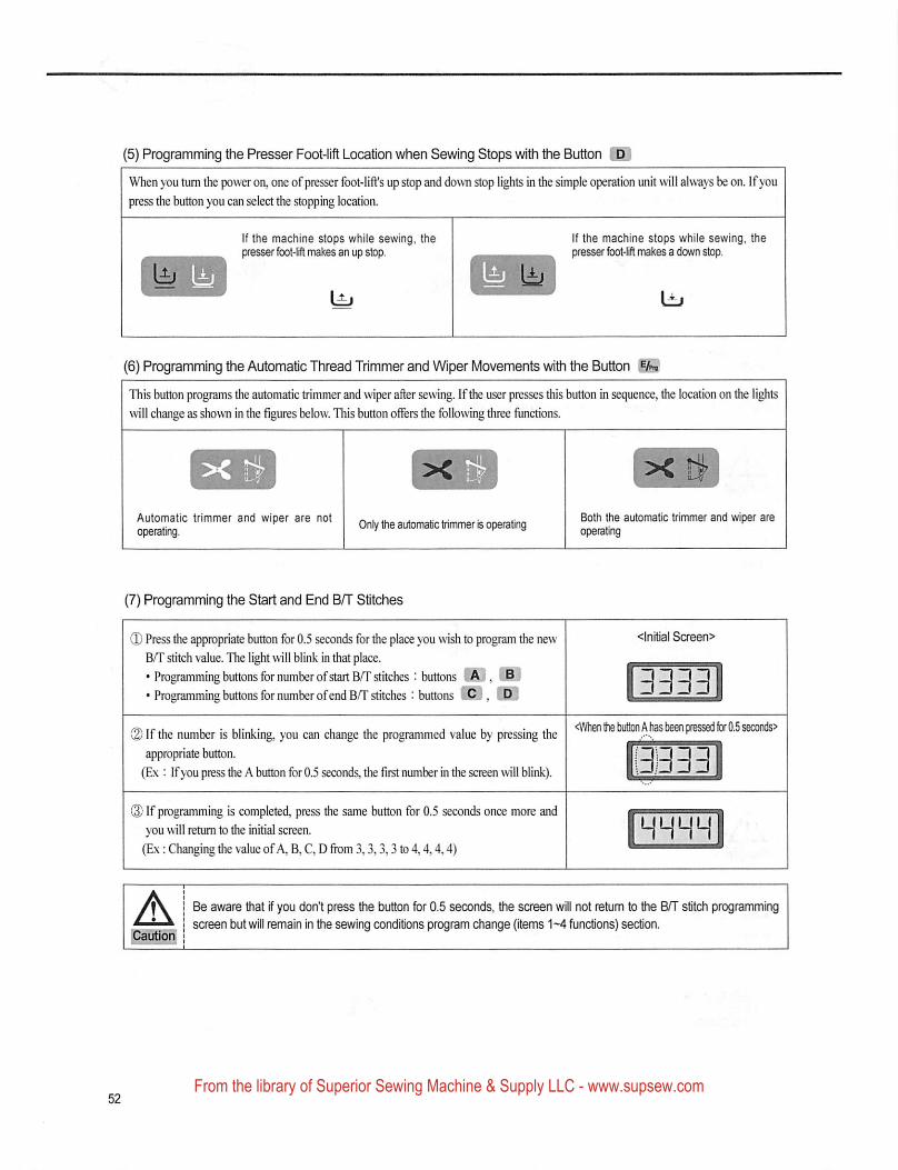
(5) Programming the Presser Foot-lift Location when Sewing Stops with the Button
When you turn the power on, one of presser foot-lift's up stop and down stop lights in the simple operation unit will always be on. If you
press the button you can select the stopping location.
If the machine stops while sewing, thepresser fbot-lift makes an up stop.
If the machine stops while sewing, thepresser foot-lift makes a down stop.
(6) Programming the Automatic Thread Trimmer and Wiper Movements with the Button
This button programs the automatic trimmer and wiper after sewing. Ifthe user presses this button in sequence, the location on the lights
will change as shown in the figures below. This button offers the following three functions.
Automatic trimmer and wiper are notoperating.
Only the automatic trimmer is operatingBoth toe automatic trimmer and wiper areoperating
(7) Programming the Start and End B/T Stitches
® Press the appropriate button for 0.5 seconds for the place you wish to program the new <lnitlal Screen>B/T stitch value. The light will blink in that place.
• Programming buttons for number ofstart B/T stitches : buttons lAj, liB j I Zj Z] Z] Z] I• Programming buttons for number ofend B/T stitches : buttons
@If the number is blinking, you can change the programmed value by pressing the ^I'Vhenthebutbn^has^er^p^^^appropriate button. IJZ iZl Z3 Z |
(Ex : If you press the A button for 0.5 seconds, the first number in the screen will blink).
3333
® If programming is completed, press the same button for 0.5 seconds once more andyou will retum to the initial screen.
(Ex: Changing the value of A, B, C, D fiom 3,3,3,3 to 4,4,4,4)HHHM
A^utioii
Be aware that if you don't press the button for 0.5 seconds, the screen will not retum to toe B/T stitch programming
screen but will remain In the sewing conditions program change (items 1-4 functions) section.
From the library of Superior Sewing Machine & Supply LLC - www.supsew.com
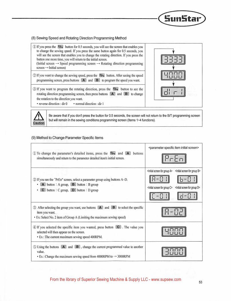
!nuii!litar
(8) Sewing Speed and Rotating Direction Programming Method
Qlfyou press the button for 0.5 seconds, you will see the screen tliat enables youto change the sewing speed. If you press the same button again for 0.5 seconds, youwill see the screen that enables you to change the rotating direction. If you press thebutton one more time, you will return to the initial screen.(Initial screen Speed programming screen —► Rotating direction programmingscreen —»Initial screen)
(2) Ifyou want to change the sewing speed, press the button. After seeing the speedprogramming screen, press buttons and iSj to program the speed you want
(D If you want to program the rotating direction, press therotating direction programming screen, then press buttons ithe rotation to the direction you want.• reverse direction: dir 0 • normal direction: dir I
w button to see the
and FjO to change
ACautlorf
Be aware that if you don't press the button for 0.6 seconds, the screen will not return to the B/T programming screenbut will remain in the sewing conditions programming saeen (Items 1-4 functions).
unnnnuuu
(9) Method to Change Parameter Specific Items
<parameter specific item initial screen>
0 To change the parameter's detailed items, press the andsimultaneously and return to the parameter detailed item's initial screen.
buttons
0 Ifyou see the "PrEn" screen, select a parameter group using buttons A-D.• button : A group, US button : B group• button : C group, LPJ button : D group
(3) After selecting the group you want, use buttons and iBl to select the specificitem you want
• Ex: Select No. 2 item ofGroup A (Limiting the maximum sewing speed)
® If you selected the specific item you wanted, press button |3 • The value youselected will then appear on the screen.• Ex: The current maximum sewing speed 400RPM.
(B) Using the buttons and .,.B] , change the current programmed value to anothervalue.
• Ex: Change the maximum sewing speed from 4000RPM to -♦ 3000RPM
<lniy soeen for group A> <lnial soeen for group 8>
H-n b-D<lnltial screen for groip O <ln!tlal screen for group D>
r_n IL u (
I□ U
unnnnuuu
From the library of Superior Sewing Machine & Supply LLC - www.supsew.com
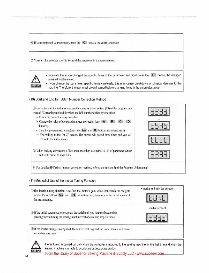
(D Ifyou completed your selection, press the to save the value you chose.
® You can change other specific items ofthe parameter in the same manner.
ABe aware &iat if you changed e specific items of the parameter and didn't press the 1^ buhon, fte changedvalue will not be saved.
If you change the parameter specific items carelessly, this may cause breakdown or physical damage to the
machine. Therefore. Uie user must be well-trained before changing items in the parameter group.
(10) Start and End B/T Stitch Number Correction Method
(D Corrections in the initial screen are the same as those in item (13) of the program unitmanual "Correcting method for when the BAT number differs by one stitch"
a. Check the present sewing condition.
b. Change the value of the part tliat needs correction (use liA ' , |B ; , C , {D ;buttons)
c. Save the programmed value(press the iifei' and IRJ buttons simultaneously).
—»You will go to the "bt-C" screen. The buzzer will sound three times and you will
return to the initial screen
3333
3^btT
(D When making corrections of less than one stitch use items 30-33 of parameter GroupB and will correct to stage 0.05. 3333
® For detailed B/T stitch number correction method, refer to the section 3) ofthe Program Unit manual.
(11) Method of Use of the Inertia Tuning Function
(DThe inertia tuning function is to find the motor's gain value that match the weightsinertia. Press buttons and simultaneously to return to the initial screen of
the inertia tuning.
<lnertia tuning initial screen>
tunE
) Ifthe initial screen comes on, press the pedal until you hear the buzzer ring.
(During inertia tuning the sewing machine will operate and stop 10 times).
<lnitlal screen>
3333
(I) If the inertia tuning is completed, the buzzer will ring and the initial screen will comeon at die same time.
A Inertia tuning is carried out only when the controller is attached to the sewing machine for the first time and when the
sewing machine is unable to accelerate or decelerate quickly.
From the library of Superior Sewing Machine & Supply LLC - www.supsew.com
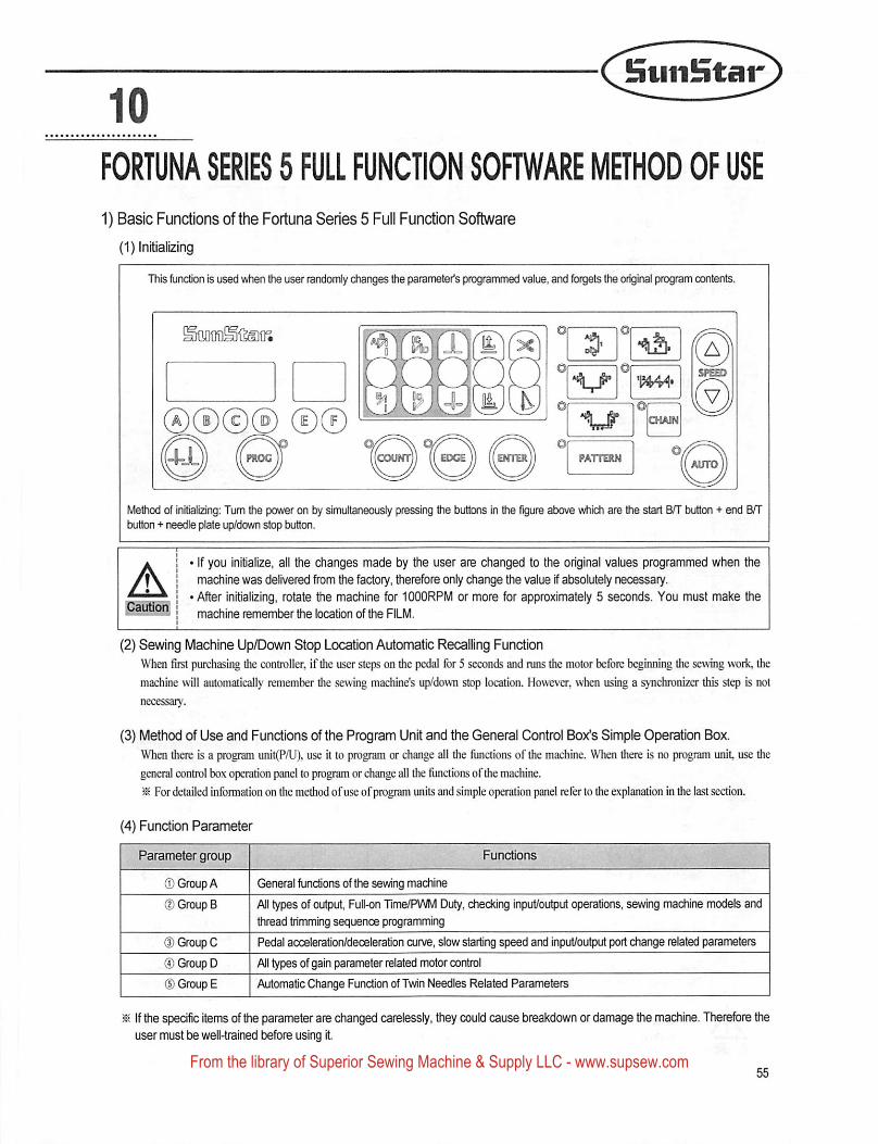
10SuiiStar
FORTUNA SERIES 5 FULL FUNCTION SOFTWARE METHOD OF USE
1) Basic Functions of the Fortuna Series 5 Full Function Software
(1) Initializing
This function is used when the user randomly changes the parameter's programmed value, and forgets the original program contents.
ww®® ©®COUNT EDGE ENTER PATTERN
Method of initializing: Tum the power on by simultaneously pressing the buttons in the figure above which are the start B/T txjtton + end B/Tbutton + needle plate up/down stop button.
ACautioij
If you initialize, all the dianges made by the user are changed to the original values programmed when the
machine was delivered from ttie factory, therefore only dtange the value if absolutely necessary.
After initializing, rotate the machine for 1000RPM or more for approximately 5 seconds. You must make the
machine remember the location of the FILM.
(2) Sewing Machine Up/Down Stop Location Automatic Recalling FunctionWhen first purchasing the controller, if the user steps on the pedal for 5 seconds and runs the motor before beginning the sewing work, the
machine will automatically remember the sewing machine's up/down stop location. However, when using a synchronizer this step is not
necessary.
(3) Method of Use and Functions of the Program Unit and the General Control Box's Simple Operation Box.When there is a program unit(P/U), use it to program or change all the functions of the machine. When there is no program unit, use the
general control box operation panel to program or change all the functions of the machine.
^ For detailed information on the method ofuse ofprogram units and simple operation panel refer to the explanation in the last section.
(4) Function Parameter
® Group A
(|) Group B
(3) Group C
® Group D
d) Group E
Functions
General functions of the sewing machine
All types of output, Full-on Tlme/PWM Duty, cheddng input/output operations, sewing machine models and
thread trimming sequence programming
Pedal acceleration/deceleration curve, slow starting speed and input/output port change related parameters
Al types of gain parameter related motor control
Automatic Change Function of Twin Needles Related Parameters
^ If the specific items of ftie parameter are changed carelessly, they could cause breakdown or damage the machine. Thereftsre theuser must be well-trained before using It.
From the library of Superior Sewing Machine & Supply LLC - www.supsew.com
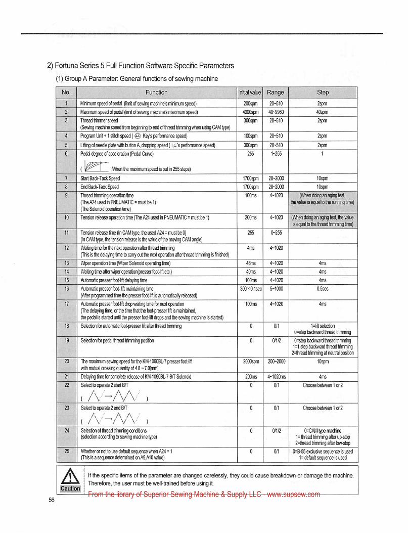
2) Fortuna Series 5 Full Function Software Specific Parameters
(1) Group A Parameter General functions of sewing machine
I No. I FunctionFunction Initial value Range
Minimum Bed of pedal (Itinit of sewing machine's minimum speed) 200spm 20-510
Maximum speed of pedal (limit of sewing machine's maximian speed) 4000spm 40-9960
Thread tiimmer speed SOOspm 20-510
(Sewing machine speed from beginning to end of thread trimming when using CAM type)
Progran Unit-t-l stitch speed (0 Key's performance speed) iCOspm 2(h510
Lifting of needle plate with button A, dropping speed ( 's performance speed) 300spm 20-510
Pedal degree of acceleration (Pedal CunB) 255 1-255
( I ;Wienttie maximum speed is putin 255 steps)
7 Start Back-Tack Speed8 End Back-Tack Speed
9 Thread Irimning operation lime(The A24 used in PNEUMATIC = must tB 1)(The Solenoid operation time)
10 Tension release operation time (The A24 used In PNEUMATIC = must Ire 1)
11 Tension release time (in CAM type, the used A24=must tB 0)(In CAM t^, the tension release is the value of the moving CAM angle)
12 Waiting time for the next operation aflerthread bimming(This is tiie d^aying lime to cany out the next cation after thread tiimming is fnshed)
13 VMper operation time (Wper Solenoid operating time)
14 Waiting lime after wiper operation(pressef foot-lift etc.)
_15 Automatic presserfoot-lifl delaying time16 Automatic presser foot-lift maintaning time
(Alter programmed time the presser footTrft is automaticalty released)
17 Automatic presser foot-lrft drop waiting time for next operation(The delaying time, or the time that the foot-press^ lift is maintained,the pedal is started until the presser foot-it drops and the sewing madtine Is started)
18 Seiedion for automatic kBt-presser lilt after tiread trimming
19 Seledion for pedal thread trirnming position
20 The maximum sewing qwed for the KM-1060BL-7 pressa'foot-liflwith mutual crossing quantity of 4.8 - 7.0(mmj
21 Delaying time for complete release of KM-1060BL-7 BIT Solenoid
22 Seled to operate 2 start B/T
( /V ~'/^v\ ' )23 Seled to operate 2 etxIBn'
A A A .( / V ~^/ V V )
24 Seledion of thread trimming conditions(selection according to sewing machine type)
25 tMielher ornot to use de^ult sequence when A24 = 1(This is a sequence determined on A9A10 value)
200ins 4~1020 (VMien doing an aging test, the valueis equ^ to llB tivBad Irirnnrig time)
2H 0^55
4H020
48ms 4-1020 4ms
40ms 4-1020 4ms
100ms 4-1020 4ins
300x0.1sec 5-1000 O.Ssec
Hlft selection
0=slep backward ttvead trirrening
0=slep backward tivead tiimmii^1=1 step backward thread trtinming2=tiiread trirrvnmg at neutid position
10^2000spm 200-2000
200ms 4-1020ms
0 oii
4ms
Choose between lor 2
Choose between lor 2
0/1/2 0=CAM tyfB madiine1=thread trimming up-st<^2=thread trimming after kw-stop
0/1 0=8-55 exdusivesequaice is used1=de^ult sequence is used
ACaution
If the specific items of the parameter are changed carelessly, they could cause breakdown or damage the machine.
IhrerefiDre, the user must be well-trained before using it
From the library of Superior Sewing Machine & Supply LLC - www.supsew.com
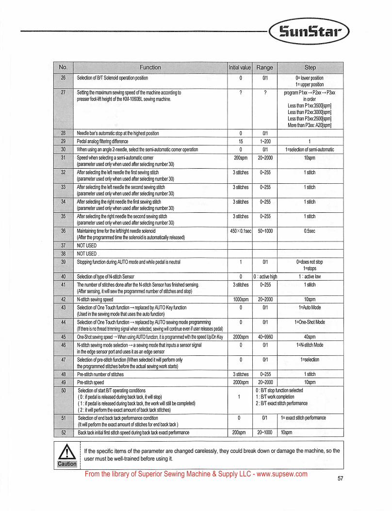
HuiiStar
' ?5.-. -.i■. ..':.
26 Selection of BH* Solenoid operation position
27 Se&'ng the maxiniumseMng speed of the machine according topresser focrt-ifl height erf the KM-1060BL sewing machine.
28 Needle tear's automatic stop at the highest position29 Pedal analog filtering difference30 VVhen using an angle 2-needle.seled the seniautornalic corner ration31 Speed when selechng a semi-automatic comer
(parameter used only when used after selecting numt)er 30)32 After selecting the left needle the first sewing stitch
(parameter used only when used after selecting nunter 30)33 After selecting the left needle the second sewing stitch
(parameter used only when used after selecting number 30)34 Afterselecting the right needle the fir^ sewing stitch
(parameter used only when used after selecting number 30)35 After selecting the right needle the second sewing stitch
(parameter used only when used after selecting nurher 30)36 Maintaining time for the left/right needle solenoid
(After the programmed time the solenoid is automatically released)37 NOT USED
38 NOTUSED,
39 Stopping fiviction during AUTO mode and while pedal is neutral
40 Selection of type of N-stitch Sensor41 The number of stitches done after the N-stitch S^isor has finished sensing.
(After sensing, it will sew the programmed ninter of stitches and st<v)42 N-stitch sewing speed43 Selection of One Touch function -• replaced by AUTO Key function
(Used in the sewing mode that uses the auto function)44 Selection of One Touch functiwi -* replaced by AUTO sewing mode programming
(If there is no tlvead trirrnting ^ when selected, sewing wll conti^ even if user rtieask pedal)45 One^seAing speed-•Vihen using AtJTOfijicljcn it is prograrnnied with tie speed Up/Dn Key46 N-stitch sewing mode selection—a sewing mode that irputs a sensor nal
in the edge sensor port and uses it as an e^e sensor47 Selection of pre-stitch function (When selected it will perfomi only
the programmed stitches before the actual sewing work starts)48 Pre-stitch number of stitdies
49 I Pre-stitch speedSelection of start BfT operating conditions
I (0: if pedal is released during back tack, it will stop)(1 : if pedal is released during back tack, the work will still be comj^eted)(2: It will perform the exact amount of bach tach stitches)
0= lower position1=upper po^on
program Pixx-" P2xx-»P3xxIn order
Less than P1xx;350(][spm]Less than P2xx:300(](spm]Less than P3xx:250(Yspm]More than P3xx:A20[spm]
0 0/1
15 1-200
0
200spm 20-20001=selecbon of sern-automatic
lOspm
Ostriches 0-255
3 slrtches 0-255
3 slrtches 0-255
3 stitches 0-255
45ax0.sec 50- 000
0 0:activehl^3 stitches 0-255
lOOOspm 20-2000
2000spm 40-99600 0/1
O^does not stop1=St(^IS
1: active low
l^ch
lOspm1=AutoMode
1=One-ShotMode
40spm1=N-strich Mode
1=seection
3stilches 0-255
2000spm 20-20000:B/r stop function selected1 :B/r work completion2; B/T exact stitch performance
51 S^ection of end back tach perfemiance condition(It will perform the exact amount of stitches fer end back tack)
0 0/1 1=exact Stitch performance
52 Back tack initial first stitch speed during back tack exact performance 200spm 20-1000 lOspm
Apautioi|
If the specie items of the parameter are changed careiessiy, they could break down or damage the machine, so theuser must be well-trained before using it
From the library of Superior Sewing Machine & Supply LLC - www.supsew.com
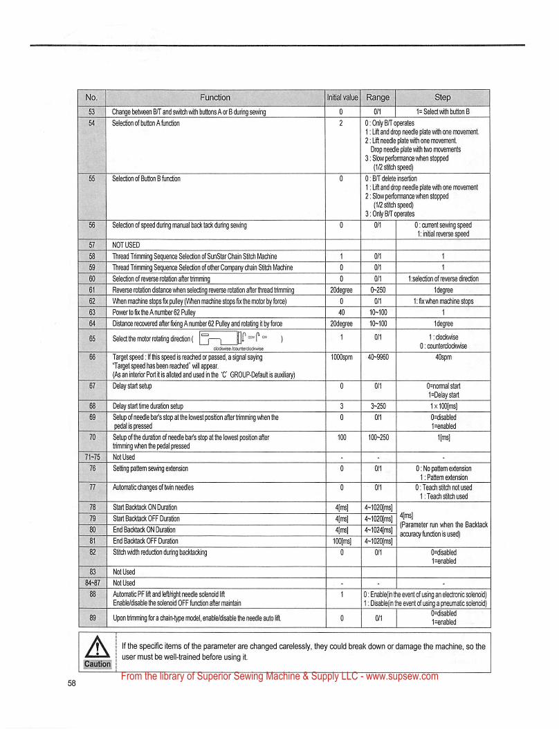
No. Function
53 Cliange between Bf\ and swildi with buttons A or B dumg sewing
54 Selection of button A function
Inittal value Range
1= Selecl with button B
55 Selection of Buttons function
56 Selection of speed during manual back tack during sewing
57 NOT USED
58 Thread Trimming Sequence Selection of SunStar Chain Stitch Machine
59 Thread Trimming Sequence Selection of otiier Company ctiain Stitch Machine
60 Selection of reverse rotation after trimming61 Reverse rotation instance wtien selecting reverse rotation after ttiread trimming
62 V\4ten machine stops fix pulley (\Mien madiine slops fix the mctof by fc«!e)
63 Power to fix the A number 62 Pulley64 Distance recovered after fixing A number 62 Pulley and rotating It by force
65 Select the motor rotating (jrectionf |°[—| jaocia»«ftoufllefciociw>i5e
66 Target speed: If tilis speed is reached or passed, a signal sayingTarget speed has been reached" will awwar.(As an Interior Port It is alloted and used in the 'C GROUP-DefaiJt is auxSiary)
67 Delay start setL4}
68 Delay start time duration setup
69 Setup of needle bar's stop at the lowest position after trimrrting when thepedal is pressed
70 Setup of the duration of needle bar's stop at the lowest position ertrimming w^n the pedal pressed
71>75 Not Used
76 Setting pattern sewing extension
77 Automatic changes of twin needles
78 Start Backtack ON Duration
79 Start Backtack OFF Duration
80 End Backtack ON Duration
81 End Baddack OFF Duration
82 Stitch width reduction during backtacking
Not Used
84-87 Not Used88 Automatic PF lilt aid left/ri^t needle solenoid fift
En^disable die solenoid OFF fijncBon after majntah
89 Upon trimming for a chain4ype model, enable/d^ble the needle auto fifl
0
40
20degree
lOOOspm I 40-9960
0: Only BT operates1: Uft and drop needle plate with one movement2: Lift neede plate with one movement[^p needle plate i#i two movements
3: Slow performance when stopped(1/2 stitch speed)
0: BT delete insertion
1 :Uftand drop needle jiiate with one movement2: Slow performance when stof^
(1/2 stitch speed)3: Only B/T operates
0/1 0: current sewing speedliirvtic^ reverse sp^
1 iselection of reverse cirection
1 degree1: fix when machine stops
1
1 degree
lidockwise
0: couiterciockwise
405pm
O=notmal start
1=Delay start
1xlO(^ms]
0=disabled
1=enabled
11ms]
Q/t 0: No pattern extension1: Pattern extension
0/1 0: Teach stitch not used
1 : Teach stitch used4~1020[ms]
4-1020(ms]. (Parameter run when the Backtack4-m24{msj accuracy function is used)
4-1020{ms]
0/1 0=disabled
1=enabled
0; Enable(in Ihe everrt of an electnyic solenoid)1 lOisatfefn the everrt of usaig a pneunaic solenoid)~ I CNJisabled
1=enal:^ed
A If the specie Items of the parameter are changed carelessly, ey could break down or damage the machine, so the
user must be well-trained before using It
From the library of Superior Sewing Machine & Supply LLC - www.supsew.com
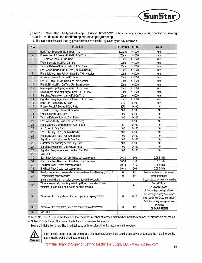
—( ^inStar
(2) Group B Parameter: All types of output, Full-on Tlme/PWM Duty, checking input/output operations, sewingmachine models and thread trimming sequence programming.^ These are functions not used by general users and must be regulated by an NS technician.
No. Function Initial v^ue Range Step . 11 Back Tack Solenoid Initial Full On Time 1020ms 4-1020 4ms
2 Presser Foot-Lift Solenoid Initial Full On Time 200ms 4-1020 4ms
3 in Solenoid Initial Full On Time 100ms 4-1020 4ms
4 Wiper Solenoid Initial Full On Time 100ms 4-1020 4ms
5 Tension Release Solenoid initial Full On Time 100ms 4-1020 4ms
6 Left Solenoid Initial Full On Time (For Twin Needle) 100ms 4-1020 4ms
7 Right Solenoid Initial Full On Time (For Twin Needle) 100ms 4-1020 4ms
8 Auxiliary Solenoid Initial Full On Time 100ms 4-1020 4ms
9 Left LED Initial Full On Time {FcxTwin Needle) 100ms 4-1020 4ms
10 Right LED Initial Full On Time (For Twin Needle) 100ms 4-1020 4t7rs
11 Needle plate up-stop signal Initial Full On Time 100ms 4-1020 4ms
12 Needle plate down-stop signal Initial Full On Time 100ms 4-1020 4ms
13 Signal notifying motor running Full On Time 100ms 4-1020 4ms
14 Signal notifying target speed achieved Full On Time 100ms 4-1020 4ms
15 Back Tack Solenoid Duty Ratio 50% 0-100 10%
16 Presser Foot-Lift Solenoid Duty Ratio 20% 0-100 10
17 Thread Trimming Solenoid Duty Ratio , 100 0-100 10
18 Wiper Sdenoid Duty Ratio i 100 0-100 10
19 Tension Release Solencxd Duty Ratio 100 0-100 10
20 Left Solaioid Duty Ratio (For Twin Needle) i 50 0-100 10
21 Right Solenoid Duty Ratio (For Twin Needle) ' 50 0-100 10
22 Aux Solenoid Duty Ratio 100 0-100 10
23 Left L£D Duty Ratio (For Twin Needle) 100 0-100 ! 10
24 Right LED Duty Ratio (For Twin Needle) 100 0-100 10
25 Signal for up stopping needle Duty Ratio 100 0-100 10
26 Signal for low stopping needle Duty Ratio 100 0-100 10
27 Signal notifying motor running Duty Ratio 100 0-100 ! 10
28 Signal notifying target speed reached Duty Ratio 100 0-100 1 10
29 NOT USED 1 1 130 Start Back Tack A numt)ef of stitches correction value 00.30 6-6 ■ 0.05 stitch
31 Start Back Tack B numt>er of stitches correction value 00.30 6-6 0.05 Stitch
32 End Back Tack C stitch correction value 00.40 6-6 0.05 Stitch
33 ; End Back Tack D stitch correction value 00.40 6-6 0.05 Stitch
34 1 Seledion for maintaining reverse solenoid movement when Ihread trimming (C Only B/T) 0 0/1 1=reverse direction maintained
35 Programming count condition(program whether or not automatic counter will be operated)
0/1 0=counter used
l^automatic counter after tivead trimming
36When automatically counting, select Up/Down count after threadtrimming (thread trimming function must be enabled) 1 0/1
1=Up COUNT0=DOWN COUNT
37 When count in completeded, the next operation is programmed 0 0/1/2
0=tHizzer rings, sewing is slowed1 =txizzer lings, sewing is not allowed
(Ifyou press the Prog Key, set up is cancelled)2=No buzzer ring, sewing is allowed
38 When count is completed, select the counter auto dear/preset 0/11=AUT0
CLEAR/PRESET
NOT USED
: Items No. 30-33: These are Wie items that make the numtjer of stitches match when back tack number of stitches do not match.
: Solenoid Duty Ratio: The power tiiat holds and maintains the solenoid.
Solenoid Initial full on tme; The time It takes to pull the solenoid to the maximum In the outset.
A If the specific Items of the parameter are changed carelessly, they could break down or damage the machine, so theuser must be well-trained before using It.
From the library of Superior Sewing Machine & Supply LLC - www.supsew.com
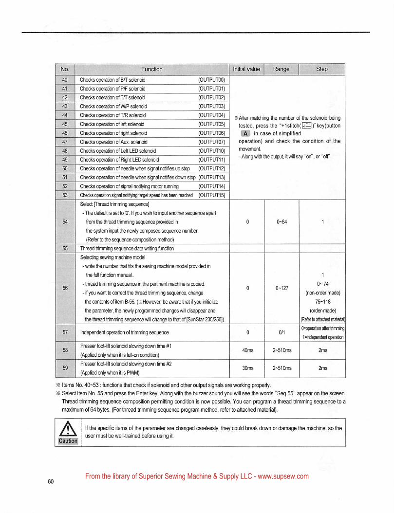
l^lnftiatvalue'" ' 'RangeChecks operation of B/T soienoid (OUTPUTOO)
Checks operation of P/F solenoid (OUTPUT01)
Checks operatiOT of TFTsdenoid (OUTPUT02)
Checks operation of W/P solenoid (OUTPUT03)
Checks operation of T/R soienoid (OUTPUT04)
Checks operation of left solenoid (OUTPUT05)
Checks operation of right solenoid (OUTPUT06)
Checks operation of Aux. solenoid (OUTPUT07)
Checks (^ration of Left LED solenoid (OUTPL1T10)
Ched(S operafon of Right LED solenoid (OUTPUT11)
Checks operaton of needle when signal notifies up stop (OUTPUT12)
Checks operation of needle when signal notifies down stop (0UTPUT13)
Ched<s (^ration of signal notifying motor running (OUTPUT14)
Checks operation signal notilying target speed has been reached (0UTPUT15)
Select [Thread trimming sequence]
- The defeult is set to '0'. If you wish to input another sequence apart
from die thread trimming sequence provided in
tfie system input the newly composed sequence number.
(Refer to the sequence composition method)
Thread trimming sequence data writing function
Selecting severing machine model
■ write the number that fits the sewing machine model provided in
the full function manual..
- thread trimming sequence in the pertinent machine is copied.
- if you want to correct the thread trimming sequence, diange
the contents of item B-55. (« However, be aware that if you initialize
the parameter, newly programmed changes will disappear and
the thread trimming sequence will change to that of [SunStar 235/250}).
Independent operation of trimming sequence
Presser fbot-lift solenoid slowing down time #1
(Applied only when it is full-on condition)
Presser fbot-lift solenoid slowing down time #2
(Applied only when it is PWM)
iitAfler matching tfie number of Ore solenoid being
tested, press the "+1 stitchf )"kevfbutton
in case of simplified
operation) and check the condition of the
movement
- Along wifli the output, it will say "on", or "off
(non-order made)
75H18
(order-made)
(Refer to attached material)
O=opefation after trimming
1=independentcpera&on
2-^10ms
2~510ms
Items No. 40-53: functions tiiat check if solenoid and other output signals are working property.
Select Item No. 55 and press the Enter key. Along with the buzzer sound you will see the words "Seq 55" appear on the screen.
Thread tn'mming sequence composition permitting condition is now possible. You can program a thread trimming sequence to a
maximum of 64 bytes. (For thread trimming sequence program method, refer to attached material).
Caution
If the specific items of the parameter are changed carelessly, they could break down or damage Uie machine, so the
user must be well-trained before using it
From the library of Superior Sewing Machine & Supply LLC - www.supsew.com
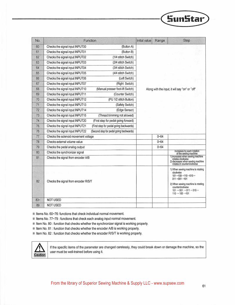
SuiiHtar
No.
60 Checks the signal input INPUTOO (Button A)
61 Checks the signal input INPUT01 (Button B)
62 Checks the signal input INPUT02 (1/4 stitch Switch)
63 Checks the dgnal input INPUT03 (2/4 stitch Switch)
64 Checks the agnal input INPUT04 (3/4 stitch Switch)
65 Checks the agnal input INPUT05 (4/4 stitch Switch)
66 Checks the signal input INPUT06 (Left Switch)
67 Checks the signal input INPUT07 (Right Switch)
68 Checks the signal input INPUTIO (Manual presser fbot-lift Switch)
69 Checks the signal input INPUT11 (Counter Switch)
70 Checks the signal input INPUT12 (PU1/2 stitch Button)
71 Checks the signal input INPUT13 (Safety Switch)
72 Checks the signal input iNPUT14 (Edge Sensor)
73 ^ Checks the signal input iNPUT15 (TTiread trimming not allowed)
74 Checks the signal input iNPUT20 (First step for pedal going forward)
75 Checks the signal input tNPUT21 (First step for pedal going backwards)
76 Checks the signal input iNPUT22 (Second step for pedal going backw^)
77 Checks the solenoid movement voltage
78 Checks external volume value
79 Checks the pedal analog output
80 Checks the synchronizer signal
81 Checks the agnai from encoder A/B
82 Checksthe signal from encoder R/SH"
83- NOT USED
89 NOT USED
Along witti the input it will say "on" or "off"
Items No. 60-76: functions that check individual normal movement.
Items No. 77-79: fijnctions that check each analog input normal movement.
Item No. 80; function that checks whether the synchronizer signal is working properly.
Item No. 81 : function that checks whether the encoder A/B is working properly.
Item No. 82: function that ched^s whether the encoder R/S/T is working properly.
A
1) When sewing machine is rotatingdodtwise
101^100^110-010-»
011-001-101
2) When sewing machine is rotatingcoierterdodrwise
101-001-011-010-
110-100-101
If the specific items of the parameter are changed carelessly, they could break down or damage the machine, so theuser must be well-trained before using it.
From the library of Superior Sewing Machine & Supply LLC - www.supsew.com
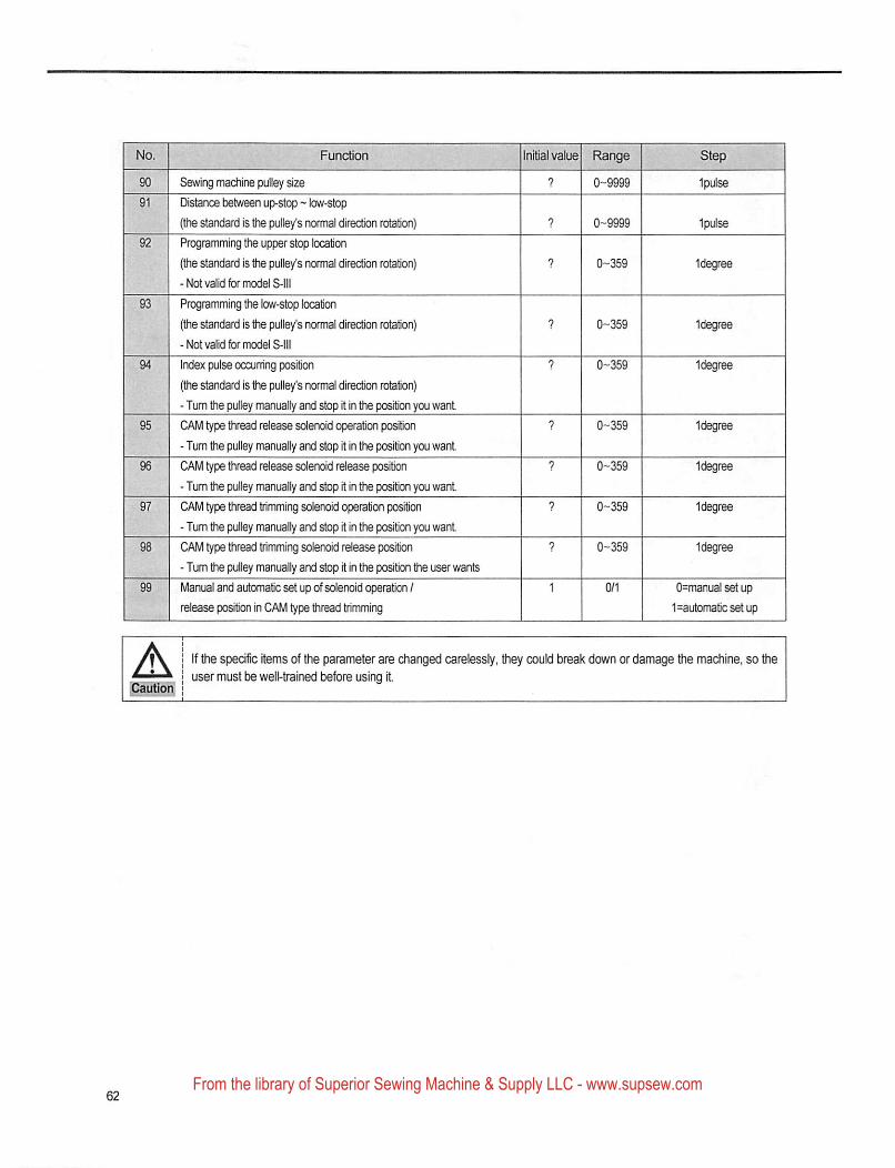
Funcbon
Sewing machine pulley size
Distance between up-stop ~ low-stop
(the standard is the pulley's normal direction rotation)
Programming the upper stop location
(the standard is the pulley's normal direction rotation)
-Not valid for model S-lll
Programming the low-stop location
(the standard is ttie pulley's normal direction rotation)
-Not valid for model S-lll
Index pulse occum'ng position
(the standard is the pulley's normal direction rotation)
- Turn the pulley manually and stop it in the position you want
CAM type thread release solenoid operation position
- Tum the pulley manually and stop it in the position you want
CAM type thread release solenoid release position
- Tum the pulley manually and stop it in the po^on you want
CAM type thread trimming solenoid operation position
- Tum the pulley manually and stop it in the position you want
CAM type thread trimming solenoid release position
- Tum the pulley manually and stop it in the position the user wants
Manual and automatic set up of solenoid operation I
r^ease po^on in CAM type thread trimming
®ai value Range ' Step
? 0-9999 Ipulse
0-9999
1 degree
1 degree
tdegree
1 degree
1 degree
1 degree
tdegree
0=manual set up
1=automatjcsetup
pautloi^
If the specific items of the parameter are changed carelessly, they could break down or damage the machine, so theuser must be welt-trained before using it
From the library of Superior Sewing Machine & Supply LLC - www.supsew.com
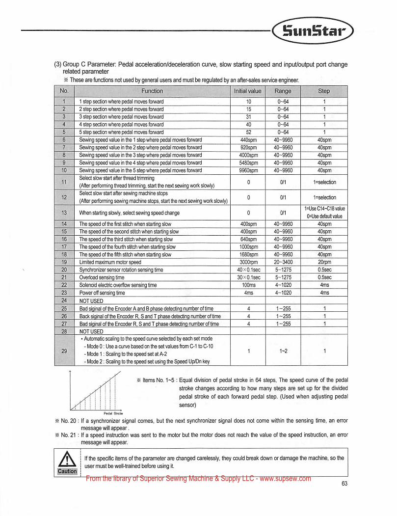
fntiiiHtar
(3) Group C Parameter: Pedal acceleration/deceieration curve, slow starting speed and input/output port changerelated parameter
^ TTiese are functions not used by general users and must be regulated by an after-sales service engineer.
Function Initial value Range Step
1 1 step section where pedal moves forward 10 0-64 1
2 2 step section where pedal moves forward 15 0-64 1
3 3 step section where pedal moves forward 31 0-64 1
4 4 step section where pedal moves forward 40 0-64 1
5 5 step section where pedal moves forward 52 0-64 1
6 Sewing speed value In the 1 step where pedal moves forward 440spm 40-9960 40spm
7 Sewing speed value in the 2 step where pedal moves forward 920spm 40-9960 40spm
8 Sewing speed value in the 3 st^ where pedal moves forward 4000spm 40-9960 40^
9 Sewing speed value in the 4 step where pedal moves forward 5480^ 40-9960 40spm
10 Sewing speed value in the 5 step where pedal moves fbiward 9960^m 40-9960 40spm
11Select slow start after thread trimming(After performing thread trimming, start the next severing work slowly)
0 0/1 1=selection
12Select slow start after sewing machine stops
(After performing sewing machine stops, start the next sewing work slowly)0 0/1 1=sele(aion
13 When starting slowly, select sewing speed diange 0 0/11=UseC14-C18 value
0=Use default value
14 The speed of the firet stitch when starting slow 400^ 40-9960 40spm
15 The speed of the second stitch when starting slow 400^ 40-9960 40spm
16 The speed of the third stitch v4ien starting slow 640spm 40-9960 40^
17 The speed of the fourth stitch when starting slow lOOOspm 40-9960 40spm
18 The speed of the fifth stitch when starting slow 1680spm 40-9960 40spm
19 Limited maximum motor speed SOOOrpm 20-3400 20rpm
20 Synchronizer sensor rotation sensing time 40x0.1sec 5-1275 0.5sec
21 Overload sensing time SOxO.lsec 5-1275 O.Ssec
22 Solenoid electric overflow sensing time 100ms 4-1020 4ms
23 Power off sensing time 4ms 4-1020 4ms
24 NOT USED
25 Bad siqinal of the Encoder A and B phase detectino number of time 4 1-255 1
26 Back siainal of the Encoder R. S and T phase detectino number of time 4 1-255 1
27 Bad siainal of the Encoder R, 8 and T phase detectino number of time 4 1-255 1
28 NOT USED
29
• Automatic scaling to the speed curve selected by each set mode
- Mode 0: Use a curve based on the set values from C-1 to C-10
- Mode 1: Scaling to the speed set at A-2
- Mode 2; Scaling to the speed set using the Speed Up/Dn key
1 1-2 1
y^\ Items No. 1~5 : Equal division of pedal stroke in 64 steps, The speed curve of the pedali 1 stroke changes according to how many steps are set up for the divided
j/j 1 I M 1 pedal stroke of each forward pedal step. (Used when adjusting pedaljr I I I f i I { V
I ! I ! M I sensor)
Pedid Stnls
^ No. 20: If a synchronizer signal comes, but the next synchronizer signal does not come within the sensing time, an errormessage will appear.
^ No. 21 : If a speed instruction was sent to the motor but the motor does not reach the value of the speed instnjction, an errormessage will appear.
A I If the specific items of the parameter are changed carelessly, they could break down or damage the machine, so the1 user must be well-trained before using it
From the library of Superior Sewing Machine & Supply LLC - www.supsew.com
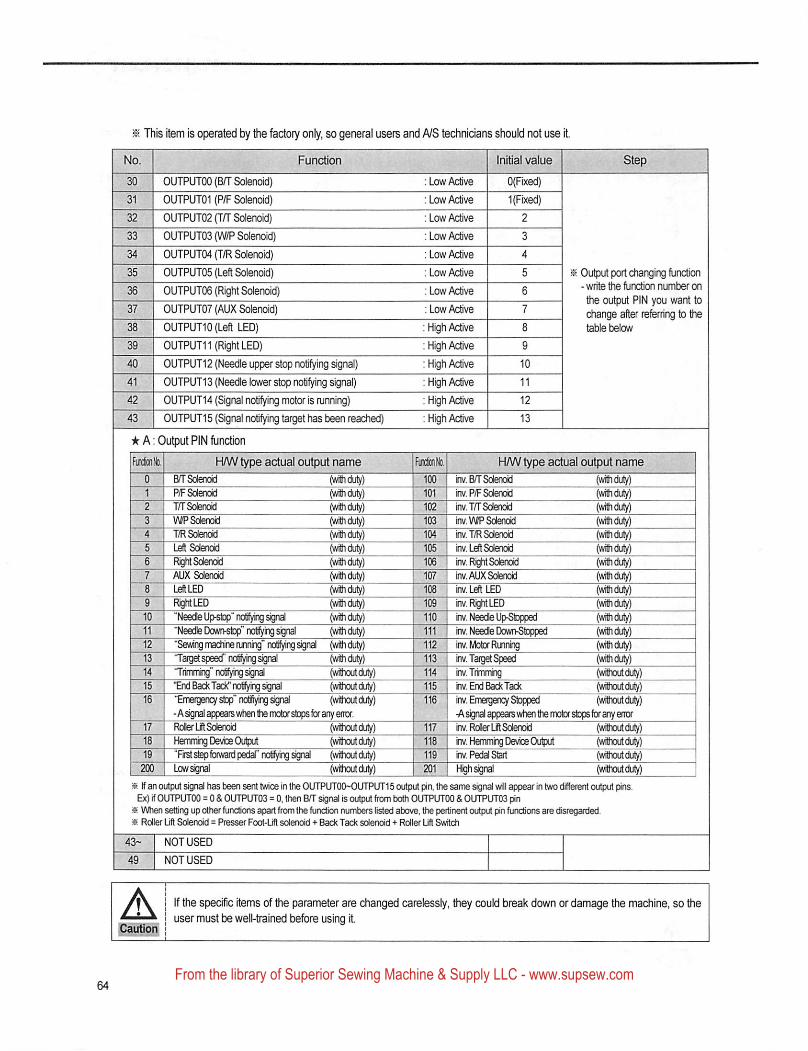
^ This item is operated by the factoiy only, so general users and A/S technicians should not use it.
<lo. Function Initial value
30 OUTPUTOO (B/T Solenoid) ; Low Active O(Fixed)
31 OUTPUT01 (P/F Solenoid) : Low Active 1 (Fixed)
32 OUTPUT02(T/T Solenoid) : Low Active 2
33 OUTPUT03(W/P Solenoid) : Low Active 3
34 OUTPUT04 (T/R Solenoid) : Low Active 4
35 OUTPUT05 (Left Solenoid) : Low Active 5 i
36 OUTPUT06 (Right Solenoid) : Low Active 6
37 OUTPUT07(AUX Solenoid) : Low Active 7
38 OUTPUT10(Left LED) : High Active 8
39 0UTPUT11 (Right LED) : High Active 9
40 OUTPUT12(Needleupperstopnotifyingsignal) :HighActive 10
41 0UTPUT13 (Needle lower stop notifying signal) : High Active 11
42 OUTPUT14(Signalnotifyingmotorisrunning) :HighActive 12
43 0UTPUT15 (Signal notifying target has been reached) ;HighAdive 13
★ A: Output PIN function
Output port changing function- write the functicwi number on
the output PIN you want tochange after referring to thetable below
Ulh FWV type actual output name Fin&nKx H/Wtype actual output name0 BT Solenoid (wHhduty) 100 inv. B/T Sdenoid (with duty)1 P/F Solenoid (with duly) 101 inv, P/F Sdenoid (with duty)2 T/T Solenoid (with duty) 102 inv. TfT Sdenoid (with duly)3 V\fP Solenoid (with duty) 103 inv. WP Sdenoid (with duty)4 T/R Solenoid (with duty) 104 inv. T/R Sdenoid (with duty)5 L^ Sdenoid (withdu^) 105 m Left Solenoid (withdut^
, 8 Right Solenoid (withdu^) 106 inv. Right Solenoid (with duty)7 AUX Solerwid (with duly) 107 inv.AUXSolendd (with duty)
' 8 Left LED (withdu^) 108 Inv. Ldt LEO (with duty)
- 9 Right LED (with duty) 109 inv. Right LED (with duty)10 "Needfe Up^" nolifyrg signal (with duty) 110 inv. Neede Up-Stopped (with duty)
11 "Needle DoMHtop" notiVing signal (with duty) 111 inv. Neede Down-Stopped (with duty)12 "Sewing machine running" notifying signd (with duty) 112 inv. Motor Running (with duty)13 'Tatgel speed" notilyingsigiai (with duty) 113 iiv.Targ^Speed (with duty)14 "Ttimrrmg" notifying signal (without duty) 114 iiv.Trmnhg (withoutduty)15 'Bxl Back Tack' noting signal (without duty) 115 rv. End Back Tack (without duty)16 "Emergency stop" notifiying signal (without duty) 116 inv. Emergency Stopped (without duty)
- A signal appears when the motorstops for any error. -A signal appears wfien the motor stopsfor any error17 RoQer lit Solenoid (without duty) 117 iTv. Rdler Ljfl Sdenoid (without duty)18 HemmtogDevce Output (without duty) 118 inv. Hemming Device Output (without duty)19 Tffst step forward pedal" notifying sign^ (without duty) 119 inv. Pedal Start (without duty)
200 Low signal (without duty) 201 High signal (without duty)
« If an output signal has t)een sent twice in the OLfTPUTOO-OUTPUT 15 output pin, the same signsd will appear in two different output pins.Ex) if OLfTPUTOO = 0 & OIJTPlJTOa = 0, then BH" signal is output from txXh OUTPUTOO & GLTTPUTOS pin^ VtAien setting up other functions apart from the ffjnction numt)ers listed atxjve, the peitinent output pin functions are disregarded.» Rdler Lift Sdendd = Presser Foot-Lift solenoid + Back Tack solenoid + Roller Lift Switch
43- I NOT USED ^NOT USED
A If the specific items of the parameter are changed carelessly, ey could break down or damage the machine, so theuser must be well-trained before using it
From the library of Superior Sewing Machine & Supply LLC - www.supsew.com
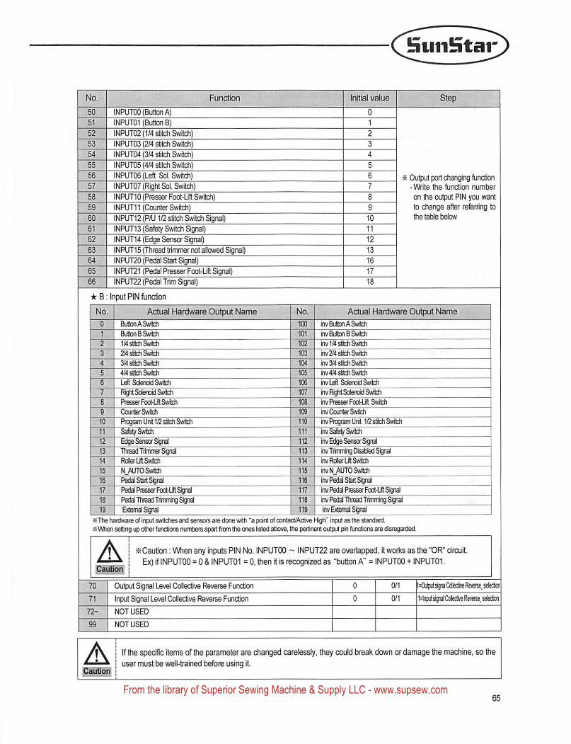
SunStar
Initial value
INPUTOO (Button A)INPUT01 (Button B)INPUT02 (1/4 stitch Swrtch)INPUT03 (2/4 stitch Switch)INPUT04 (3/4 stitch Switch)
INPUT05 (4/4 stitch Switch)INPUT06(Left Sol. Switch)INPUT07 (Right Sol. Switch)INPUT10 (Presser Foot-Ufl Switdi)
INPUT11 (Counter Switch)INPUT12 (P/U1/2 stitch Switch Signal)
INPUT13 (Safety Switch Signal)INPUT14 (Edge Sensor Signal)INPUT15 (Thread trimmer not allowed Signal)INPUT20 (Pedal Start Signal)INPUT21 (Pedal Presser Foot-Lrft Signal)
INPUT22 (Pedal Trim Signal)
★ B; input PIN function
Actual Hardware Output Name
ButtonASwtch
Button B Switidi
1/4 stitch Switch
2/4 sSth Switch
SWstfch Switch
4/4 stitoh Switch
Left Sd^iotd Switch
Right Solenoid Switch
PtesserFooHjft Switch
CounferSwitch
Ptogiam Unit 12 s6tch SwfehSal^SwitohEdge Sensor SignalThreajTfimmef SignalRolerLfft Switch
N_AUTO SwitchPecy Start Sign^Pedal Presser FooFLift SignalPedal Thread Titovning Signal
mm
mm\
jt? Output port changing fundion- Write the function number
on the output PIN you wantto change after referring tothe table below
Actual Hardware Output Name
ffivBu&xi A Switch
101 I inv Button B Switch102 inv 1/4 stitch Switch103 rv 2/4 stitch Swteh104 rv 3/4 stitch Swith
inv4/4 stitch Swith
106 invLdt Solenoid Swteh107 inv Right SdenoidSwfteh108 hv Presser FcoHl Switoh109 rvCourterSwteh110 inv Program Ur^ 12 Stitch Sv^111 inv Safety Switch112 inv Edge Sensor Signal113 nvTrimmlng Disabled Signal114 inv Rciier Lit Switch
W inv N AUTO Switch116 inv Pedal Start Signd117 inv Pedal Presser FooHit Signal118 inv Pedal Thread Tttnmng Signal119 inv External Signal19' I External Siyal j 119 | inv External Signal
iSThe hardware of input switches and sensors are done with "a point of contact/Active High" input as the standard.at When setting up other funchons numbers apart from the ones listed above, the pertinent output pin functions are disregarded
A ^Caution: When any inputs PIN No. INPUTOO ~ INPUT22 are overlapped, it works as the "OR" circuit
Ex) if INPUTOO = 0 & INPUT01 = 0. then it is recognized as "button A" = INPUTOO + INPUT01.
Output Signal Level Collective Reverse Function
Input Signal Level Collective Reverse Function
NOT USED
<lij||Xitsigna Cdlective Reverse, selection
t^nputsignal Cdedive Reverse, selection
If the specific items of the parameter are dianged carelessly, they could break down or damage the mardiine, so theuser must be well-trained before using it.
From the library of Superior Sewing Machine & Supply LLC - www.supsew.com
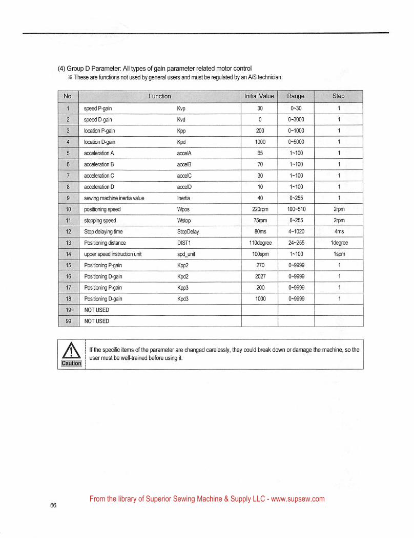
(4) Group D Parameter: All types of gain parameter related motor control
^ These are functions not used by general users and must be regulated by an A/S technician.
Function
1 speed P-gain
2 speed D-gain
3 location P-gain
4 location D-gain
5 acceleration A
6 acceleration B
7 acceleration C
8 acceleration D
9 sewing madiine inertia value
10 positioning speed
11 stopping speed
12 Stop delaying time
13 Positioning distance
14 upper speed instructicwi unit
15 Positioning P-gain
16 Positioning D-gain
17 Positioning P-gain
18 Positioning D-gain
19- NOT USED
99 NOT USED
Kvp
Kvd
Kpp
Kpd
accelA
accelB
acc^C
accelD
Inertia
Wpos
V\fetop
StopDelay
DIST1
spd_unit
Kpp2
Kpd2
Kpp3
Kpd3
Initial Value Range Step
30 0-30 1
0 0-3000 1
200 0-1000 1
1000 0-5000 1
65 1-100 1
70 1-100 1
30 1-100 1
10 1-100 1
40 0-255 1
220rpm 100-510 2rpm
75rpm 0-255 2r|wn
80ms 4-1020 4ms
HOdegree 24-255 Idegree
lOOspm 1-100 1spm
270 0-9999 1
2027 0-9999 1
200 0-9999 1
1000 0-9999 1
If the specific items of the parameter are changed carelessly, they could break down or damage the machine, so theuser must be well-trained before using it
From the library of Superior Sewing Machine & Supply LLC - www.supsew.com
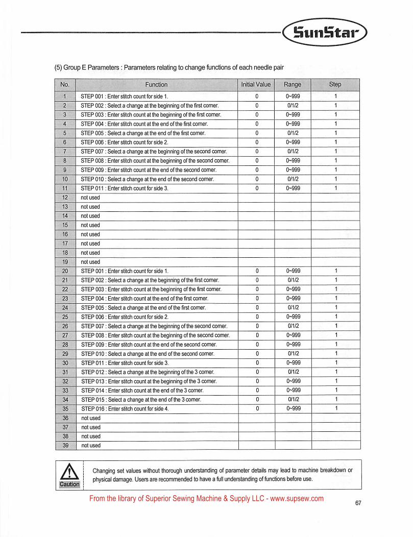
HuiiBtar
(5) Group E Parameters: Parameters relating to change functions of each needle pair
STEP 001;
STEP 002:
STEP 003:
STEP 004;
STEP 005:
STEP 006;
STEP 007:
STEP 008:
STEP 009:
STEP 010:
STEP 011:
not used
not used
not used
not used
not used
not used
not used
not used
STEP 001:
STEP 002:
STEP 003:
STEP 004:
STEP 005;
STEP 006:
STEP 007:
STEP 008:
STEP 009;
STEP 010:
STEP 011;
STEP 012:
STEP 013:
STEP 014:
STEP 015;
STEP 016:
not used
not used
not used
not used
Function
Enter strlch count for side 1.
Select a change at the beginning of the first comer.
Enter stitdi count at the beginning of the first comer.
Enter stitch count at the end of the first comer.
Select a change at the end of the first comer.
Enter stitch count for side 2.
Select a change at the beginning of the second earner.
Enter stitch count at the beginning of the second comer.
Enter stitch count at the end of the secand comer.
Select a change at the end of the second comer.
Enter stitch count for side 3.
Initial Value
Enter stitch count for side 1.
Select a change at the treginning of the first comer.
Enter stitch count at the beginning of the first comer.
Enter stitch count at the end of the first comer.
Select a change at the end of the first comer.
Enter stitch count for side 2.
Select a change at the beginning of the second comer.
Enter stitch count at the beginning of Uie second comer.
Enter stitch count at the end of the second comer.
Select a change at the end of the second comer.
Enter stitch count for side 3.
Select a change at the beginning of the 3 comer.
Enter stitch count at the beginning of the 3 comer.
Enter stitch count at the end of the 3 comer.
Select a change at the end of the 3 comer.
Enter stitch count for side 4.
A Changing set values without Uiorough understanding of parameter details may lead to machine breakdown or
physical damage. Users are recommended to have a full understanding of functions before use.
From the library of Superior Sewing Machine & Supply LLC - www.supsew.com
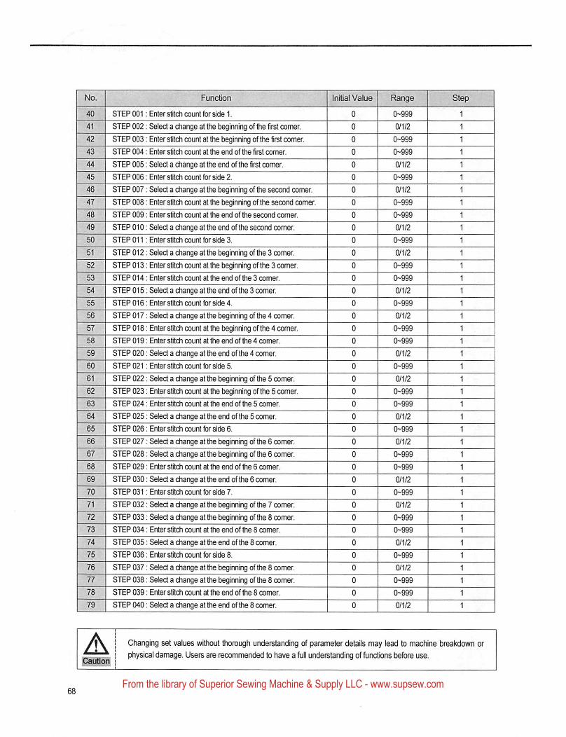
No. Function Initial Value Range
40 STEP 001: Enter stitch count for side 1. 0 0-999
41 STEP 002; Select a diange at the beginning of the first comer. 0 0/1/2
42 STEP 003: Enter stitch count at the beginning of the first comer. 0 0-999
43 STEP 004; Enter stitch count at the end of the first comer. 0 0-999
44 STEP 005: Select a change at the end of the first comer. 0 0/1/2
45 STEP 006: Enter stitch count for side 2. 0 0-999
46 STEP 007; Select a change at the beginning of the second comer. 0 0/1/2
47 STEP 008: Enter stitch count at the beginning of the second comer. 0 0-999
48 STEP 009: Enter sfitch count at the end of the second comer. 0 0-999
49 STEP 010: Select a change at the end of the second comer. 0 0/1/2
50 STEP 011 : Enter stitch count for side 3. 0 0-999
51 STEP 012: Select a change at the beginning of the 3 comer. 0 0/1/2
52 STEP 013: Enter stitdi count at the beginning of the 3 corner. 0 0-999
53 STEP 014: Enter stitch count at the end of the 3 comer. 0 0-999
54 STEP 015; Select a change at the end of the 3 comer. 0 0/1/2
55 STEP 016: Enter stitch count for side 4. 0 0-999
56 STEP 017: Select a change at the beginning of the 4 comer. 0 0/1/2
57 STEP 018: Enter stitch count at the beginning of the 4 comer. 0 0-999
58 STEP 019: Enter stitch count at the end of the 4 comer. 0 0-999
59 STEP 020: Select a change at the end of the 4 comer. 0 0/1/2
60 STEP 021: Enter stitch count for side 5. 0 0-999
61 STEP 022; Select a change at the beginning of the 5 comer. 0 0/1/2
62 STEP 023: Enter stitch count at the beginning of the 5 comer. 0 0-999
63 STEP 024; Enter stitch count at the end of the 5 comer. 0 0-999
64 STEP 025; Select a diange at foe end of the 5 comer. 0 0/1/2
65 STEP 026; Enter stitch count for side 6. 0 0-999
66 STEP 027; Seled a change at foe beginning of the 6 comer. 0 0/1/2
67 STEP 028; Seled a change at the beginning of the 6 comer. 0 0-999
68 STEP 029; Enter stitch count at the end of the 6 comer. 0 0-999
69 STEP 030; Seled a diange at foe end of foe 6 comer. 0 0/1/2
70 STEP 031; Enter stitch count for side 7. 0 0-999
71 STEP 032: Seled a change at foe beginning of the 7 comer. 0 0/1/2
72 STEP 033: Seled a diange at foe beginning of the 8 comer. 0 0-999
73 STEP 034: Enter stitch count at the end of the 8 comer. 0 0-999
74 STEP 035: Seled a change at the end of foe 8 comer. 0 0/1/2
75 STEP 036: Enter stitch count for side 8. 0 0-999
76 STEP 037; Seled a diange at foe beginning of foe 8 comer. 0 0/1/2
77 STEP 038: Seled a change at the beginning of the 8 comer. 0 0-999
78 STEP 039; Enter stitch count at the end of the 8 comer. 0 0-999
79 STEP 040: Seled a change at foe end of foe 8 comer. 0 0/1/2
Changing set values without thorough understanding of parameter details may lead to machine breakdown or
physical damage. Users are recommended to have a full understanding of func^ons before use.
From the library of Superior Sewing Machine & Supply LLC - www.supsew.com
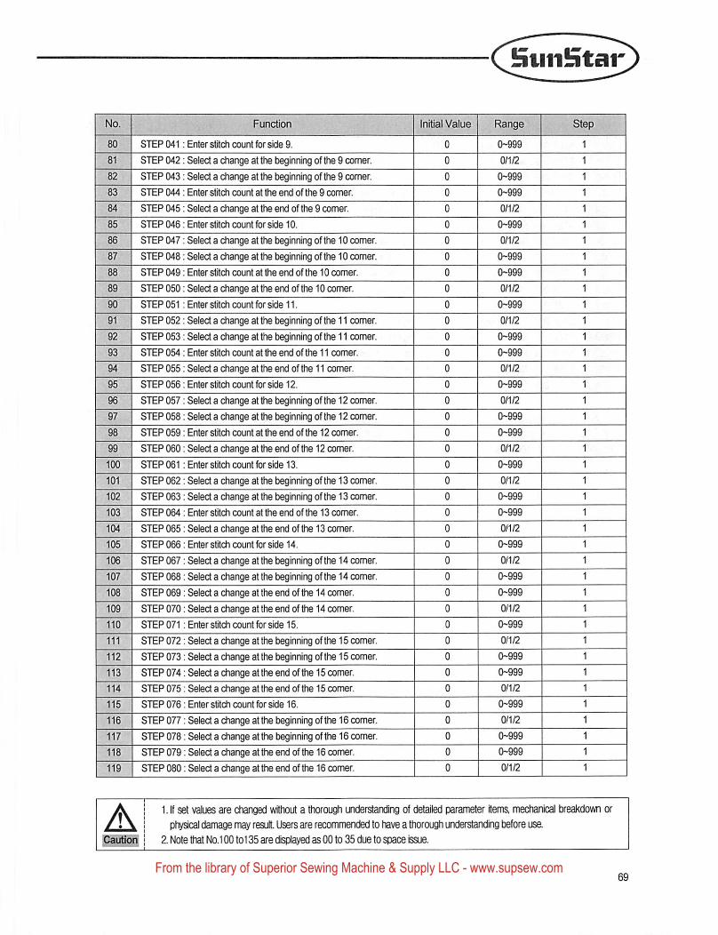
HtiiiBtar
Initial Value
STEP 041 : Enter stitch count for side 9.
STEP 042;;
STEP 043;;
STEP 044;:
STEP 045;;
STEP 046:;
STEP 047;;
STEP 048::
STEP 049;;
STEP 050;;
STEP 051;;
STEP 052;;
STEP 053;;
STEP 054;;
STEP 055;;
STEP 056;;
STEP 057;;
STEP 058;;
STEP 059;;
STEP 060;;
STEP 061;;
STEP 062;;
STEP 063;;
STEP 064;;
STEP 065::
STEP 066;;
STEP 067;;
STEP 068;;
STEP 069;;
STEP 070;;
STEP 071;;
STEP 072;;
STEP 073;;
STEP 074;;
STEP 075;;
STEP 076;;
STEP 077::
STEP 078;;
STEP 079;;
STEP 080;;
Seled a change at the beginning of the 9 comer.
Seiect a change at the beginning of the 9 comer.
Enter stitch count at the end of the 9 comer.
Select a change at the end of the 9 comer.
Enter stitdi count for side 10.
Select a change at the beginning of the 10 comer.
Select a change at the beginning of the 10 comer.
Enter stitch count at the end of the 10 comer.
Select a change at the end of the 10 comer.
Enter stitdi oiunt for side 11.
Select a change at the beginning of the 11 comer.
Select a change at the beginning of the 11 comer.
Enter stitch count at the end of the 11 comer.
Select a change at the end of the 11 comer.
Enter stitch count for side 12.
Select a change at the beginning of the 12 comer.
Select a change at the beginning of the 12 comer.
Enter stitch count at the end of the 12 comer.
Select a change at the end of the 12 comer.
Enter stitch count for side 13.
Select a change at the beginning of the 13 comer.
Select a change at the beginning of the 13 comer,
Enter stitch count at the end of the 13 comer.
Seiect a change at the end of the 13 comer.
Enter stitdi count for side 14.
Select a change at the beginning of the 14 comer.
Select a change at the beginning of the 14 comer.
Select a change at the end of the 14 comer.
Select a change at the end of the 14 comer.
Enter stitch count for side 15.
Select a change at the beginning of the 15 comer.
Select a change at the beginning of the 15 comer.
Select a change at the end of the 15 comer.
Select a change at the end of the 15 comer.
Enter stitch count for side 16.
Seiect a change at the beginning of the 16 comer.
Seiect a change at the beginning of the 16 comer.
Seiect a change at the end of the 16 comer.
Select a change at the end of the 16 comer.
1. If set values are changed without a thorough understanding of detailed parameter items, mechanical breakdown or
physical damage may result. Users are recommended to have a thorough understanding before use.
2. Note that No. 100 to 135 are displayed as GO to 35 due to space Issue.
From the library of Superior Sewing Machine & Supply LLC - www.supsew.com
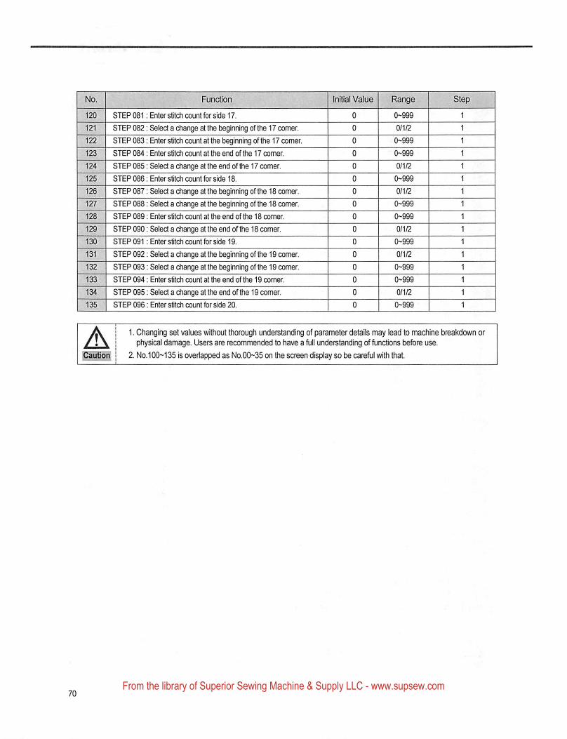
Function Initial Value Range
STEP 081: Enter stitch count for side 17.
STEP 082
STEP 083
STEP 084
STEP 085
STEP 086
STEP 087
STEP 088
STEP 089
STEP 090
STEP 091
STEP 092
STEP 093
STEP 094
STEP 095
STEP 098
Select a change at Uie beginning of the 17 comer.
Enter stitch count at the beginning of the 17 comer.
Enter sWch count at the end of the 17 comer.
Select a change at the end of the 17 comer.
Enter stitch count for side 18.
Select a change at the beginning of the 18 comer.
Select a change at the beginning of the 18 corner.
Enter stitch count at the end of the 18 comer.
Select a change at the end of the 18 comer.
Enter stitch count for side 19.
Select a change at the beginning of the 19 comer.
Select a change at the beginning of the 19 comer.
Enter stitch count at the end of the 19 comer.
Select a change attfie end of the 19 comer.
Enter stitch count for side 20.
1. Changing set values without thorough understanding of parameter details may lead to machine breakdown orphysical damage. Users are recommended to have a full understanding of functions before use.
2. NO.100--135 is overlapped as No.00~35 on the screen display so be careful with &iat.
From the library of Superior Sewing Machine & Supply LLC - www.supsew.com
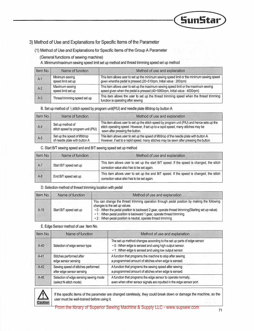
Suiifntar
3) Method of Use and Explanations for Specific items of the Parameter
(1) Method of Use and Explanations for Specific Items of the Group A Parameter
(General functions of sewing machine)
A Minimum/maxinfium sewing speed limit set up method and thread trimming speed set up me^od
Item No. Name of function Method of use and explanation .
A-1Minimum sewingspeed limit set up
This Item allows user to set up the minimum sewing speed limit or the minimum sewing speedgiven whenthe pedal is pressed.(20~510rpm, Initial value: 200rpm)
Ar2Maximum sewingspeed limit set up
This item allows user to set up the mawmum sewing speed limit or the maximum sevringspeed given when the pedal is pressed.(40~9960rpm. Initial value; 4000rpm)
A-3 Thread trimming speed set up This item allows the user to set up the thread trimming speed when Uie thread trimmingfunction is operating after sewing
B. Set up method of l^stitch speed by program unit(P/U) and needle plate lift/drop by button A
Item No. Name of function Method of use and explanation ' i
A-4Setup method ofstitch speed by program unit (PAJ)
This item allows user to set up the stitch speed by program unit (P/U) and hence sets up thestitch operating speed. However, if set up to a rapid speed, many stitches may besewn after pressing the button.
A-5Set up the speed of lift/dropof needle p^ate with button A
This item allows user to set up the speed of lift/drop of the needle plate with button AHowever, if set to a rapid speed, many stitches may be sevm after pressing tiie button.
C. Start BfT sewing speed and end BfT sewing speed set up method
Item No. Name of function Method of use and explanation ' |
A-7 Start B/T speed set upThis item allows user to set up the start B/T speed. If the speed is changed, the stitch
correction value also has to be set again.
AS End BfT speed set up1
This item allows user to set up the end B/T speed. If the speed Is changed, the stitch
correction value also has to be set again.
D. Selection method of thread trimming location with pedal
Item No. Name of function Method of use and explanation . ■'
Start BfT speed setup
You can change the thread trimming operation through pedal position by making the fsilowingchanges to the set up values.
• 0 ; When the pedal position is backward 2 gear, operate thread trimming(Starling set up value).• 1 : When pedal position is backward 1 gear, operate Uiread trimming• 2 : When pedal position is neutral, operate thread trimming.
E. Edge Sensor method of use Item No.
Item No. Name of function Method of use and explanation
A40 Selection of edge sensor typeThe set up method changes according to the set up parfo of edge sensor
• 0; When edge is sensed and using high output sensor.• 1; When edge is sensed and using low output sensor.
A41 Stitches performed afteredge sensor sensing
A function that programs the machine to stop after sevwnga programmed amount of stitches when edge is sensed.
A42 Sewing speed of stitches performedatter edge sensor sensing
A fundon that programs the sewing speed after sev/inga programmed amount of stitches when edge is sensed.
A46 Selection of edge sensing sewing mode(select N-stitch mode)
A function that programs the edge sensor to operate normally,even when other sensor signals are inputted in the edge sensor port
A If the specific items of the parameter are changed carelessly, they could break down or damage the machine, so theuser must be well-trained before using it
From the library of Superior Sewing Machine & Supply LLC - www.supsew.com
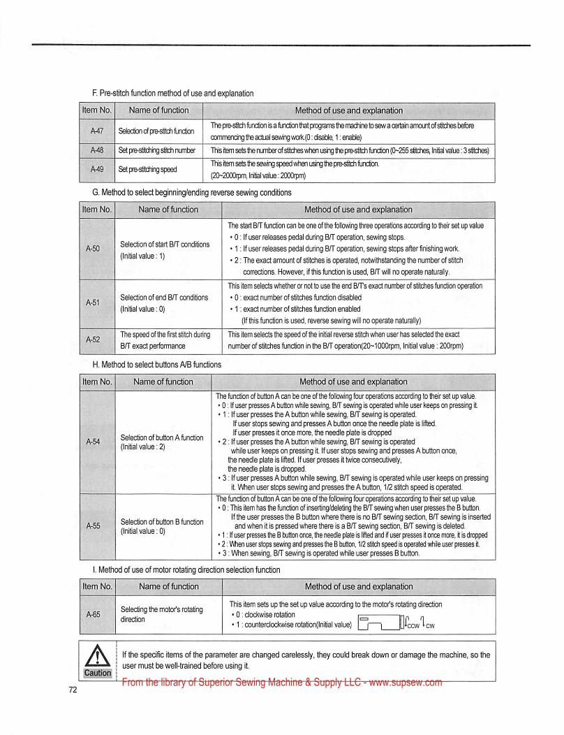
F. Pre-stitch function method of use and explanation
Item No. Name of function
Ml SefecSkxiofpre-slit^lunctCT
A48 Setpre-strtchingsljthnuntef
Af49 S^pre-sttehrig speed
Method of use and explanation
The pie-stildi function is a furxdion that programs the machine b sew a cert^ anyxjnt ofslithes bdbre
(X3rrYnerK:^tt«actijaise^w3rk.(0:cisat3le, 1 :en^)
This item sets the numter ofstidieswh^ using the pre-strldi function ((>'255slilches, Initiai value; 3 stitches)
ITiis item sete the sewing vrfien using the pre-stitch fuxSon.
{2t>-2l>D0tpm, Initial value: 2(D00ipm)
G, Method to select beginning/ending reverse sewing conditions
Item No. Name of function
Selection of start B/T conditions
(Initial value: 1)
Selection of end B/T conditions
(Initial value: 0)
Thespeedofthefirststitchduring
B/T exact performance
H. Method to select buttons A/B functions
Method of use and explanation
The start B/T fundion can t)e one of tiie following three operations according to their set up value
• 0: If user releases pedal during B/T operatic, sewing stops.
• 1: If user releases pedal during B/T operation, sewing stops after finishing worlc.
• 2: The exact amount of stitches Is operated, notwithstanding the number of stitch
corrections. However, if this function is used, B/T will no operate naturally.
This item selects whetiier or not to use the end B/Ts exact number of stitches function operation
• 0: exact number of stitches function disabled
• 1: exact number of stitches function enabled
(If this function is used, reverse sewing will no operate naturally)
This Item selects the speed of the initial reverse stitch when user has selected the exact
number of stitches function in the B/T operation(20-1 OOOrpm, Initial value: 200rpm)
item No. Name of function
S^ection of button A function
(Initiai value: 2)
Selection of button B function
(Initial value: 0)
Method of use and explanation r.- ■
The function of button A can be one of the following four operations according to their set up value.• 0: If user presses A button while sewing, B/T sewing is operated while user keeps on pressirtg it• 1: If user presses the A button while sewing, B/T sewing is operated.
If user stops sewing and presses A button once the needle plate is iifted.If user presses it once more, the needle plate Is dropped
• 2: If user presses the A button while sewing, B/T sevifing is operatedwhile user keeps on pressing it. If user stops sewing and presses A button once,
the needle plate is iift^. If user presses it twice consecutively,the needle plate is drop^.
• 3: If user presses A button while sewing, B/T sewing is operated while user keeps on pressingit When user stops sewing and presses the A button, 1/2 stitch speed is operated.
The hjnction of button A can be one of the following four operations according to their set up value.• 0: This item has the function of inserting/deleting the B/T sewing when user presses the B button.
If the user presses the B button where there is no B/T sewing section, B/T sewing is insertedand when it is pressed where there is a B/T sewing section, B/T sewing is deleted.
• 1: If user presses the B button once, the needle plate is lifted and if user presses it once more, it is dropped• 2: When user slops sewing and presses the B button, 1/2 stitch speed is operated while user presses it• 3: When sewing, B/T sewing is operated while user presses B button.
I. Method of use of motor rotating direction selection function
Item No. Name of function
Selecting the motor's rotatingdirection
Method of use and explanation
This item sets up the set up value according to the motcx's rotating direction• 0: clockwise rotation ^ „• 1: counterclockwise rotation(lnitial value) i—|__i ccw cw
If the specific items of Uie parameter are changed carelessly, they could break down or damage the machine, so theuser must be well-trained before using It.
From the library of Superior Sewing Machine & Supply LLC - www.supsew.com
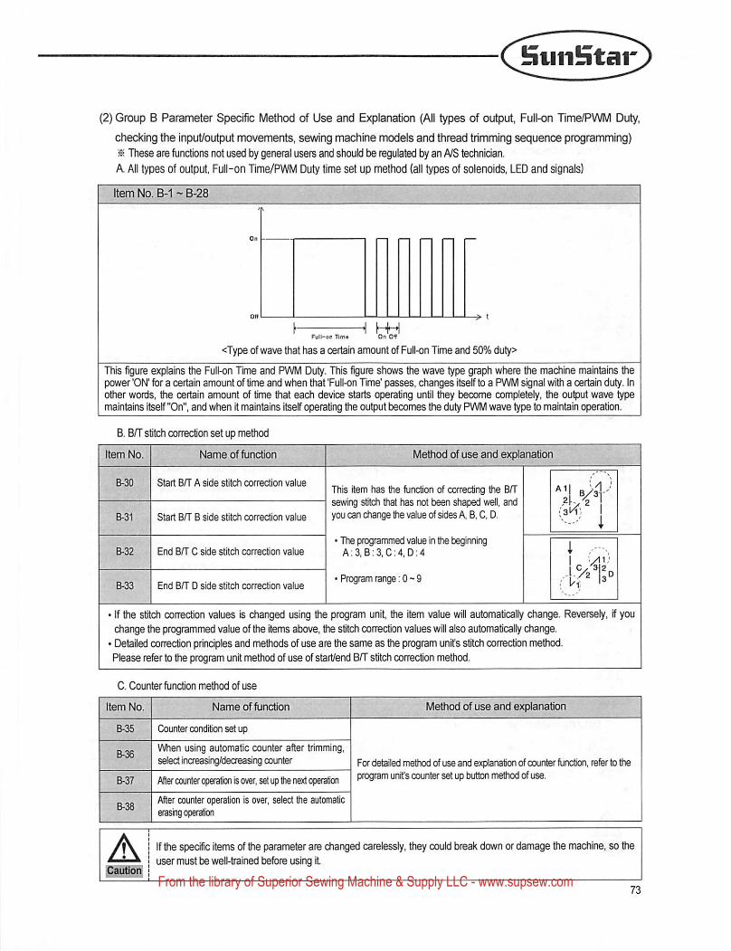
Suiiifitar
(2) Group B Parameter Specific Method of Use and Explanation (All types of output, Full-on Time/PWM Duty.
checking the input/output movements, sewing machine models and thread trimming sequence programming)
^ These are functions not used by general useis and should be regulated by an NS technician.
A All types of output. Ful!-on Time/PWM Duty time set up method (all types of solenoids, LED and signals)
Item No. B-1 - B-28
Full-on Timo On Off
<Type of wave that has a certain amount of Full-on Time and 50% duty>
This figure explains the Full-on Time and PWM Duty. This figure shows the wave type graph where the machine maintains Wiepower 'ON' for a certain amount of time and when that 'Fuil-on Time' passes, changes itseif to a PWM signal with a certain duty. Inother words, the certain amount of time that each device starts operating until they become completely, the output wave typemaintains itself "On", and when it maintains itself operating the output becomes the duty PWM wave type to maintain operation.
B. BfT stitch correction set up method
Item No. Name of function Method of use and explanation
B-30 Start B/T A side stitch correction valueThis item has the function of correcting the BfT
I I sewing stitch that has not been aped well, andB-31 Start B/T B side stitch correction value yov can change the value of sides A B, C, D.
B-32 End B/T C side stitch correction value
B-33 End B/T D side stitch correction value
The programmed value in the beginningA:3,B;3,C:4,D:4
■ Program range; 0 - 9
• if the stitch conBCtion values is changed using the program unit, the item value will automatically change. Reversely, if youchange the programmed value of the items above, the stitch correction values will also automatically change.' Detailed correction principles and methods of use are the same as the program unifs stitch correction method.Please refer to the program unit method of use of start/end BfT stitch correction method.
C. Counter fundion method of use
Item No. Name of function Method of use and explanation
B-35 Counter condition set up
For detailed metixxj of use and explanation of counter Hinction, refer to theB-36
When using automatic counter after trimming,sdect increasing/decreasing counter
B-37 After counter operation is over, set up the next operation program unifs counter set up button method of use.
B-38After counter operation is over, select the automaticerasing operation
ACautioif
If the spedfic items of the parameter are changed carelessly, they could break down or damage the machine, so theuser must be well-trained before using it
From the library of Superior Sewing Machine & Supply LLC - www.supsew.com
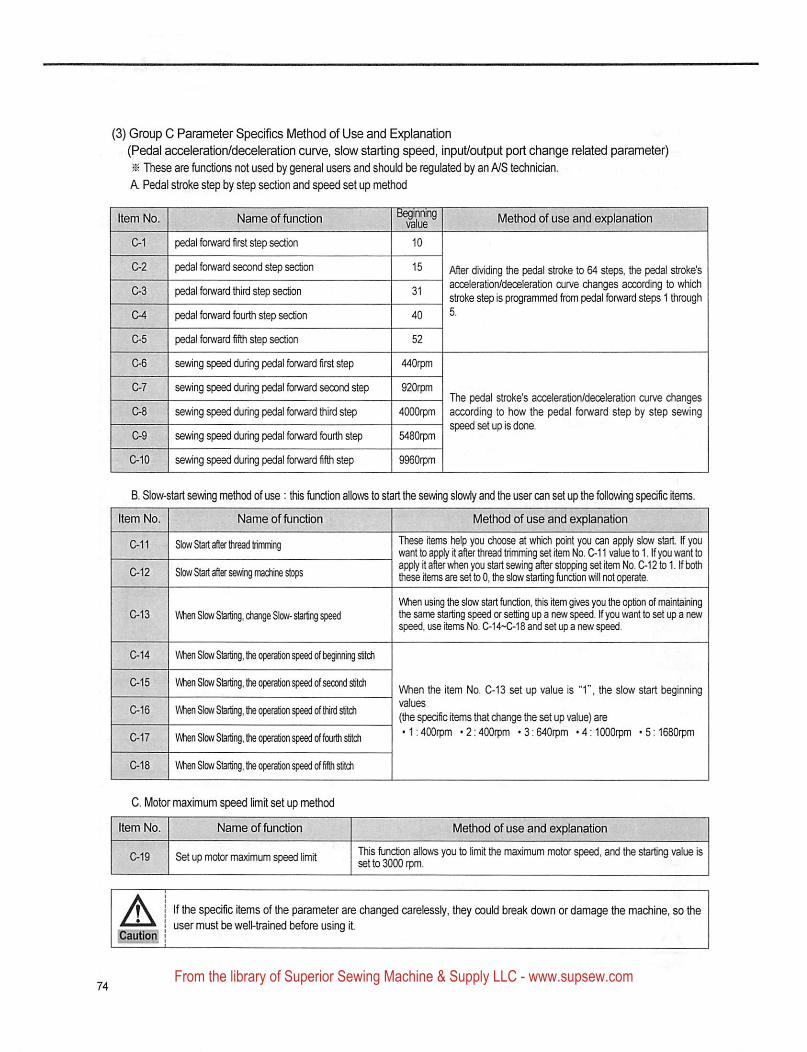
(3) Group C Parameter Specifics Method of Use and Explanation
(Pedal acceleration/deceleration curve, slow starting speed, input/output port change related parameter)
^ These are functions not used by general users and should be regulated by an A/S technician.
k Pedal stroke step by step section and speed set up method
Method of use and explanationItem No. Name of functionBeginning
value
C-1 pedal forward first step section 10
02 pedal forward second step section 15
C-3 pedal forward third step section 31
04 pedal forward fourth step section 40
C-5 pedal forward fifth step section 52
C-6 sewing speed during pedal forward first step 440rpm
C-7 sewing speed during pedal forward second step 920rpm
C-8 sewing speed during pedal forward third step 4000rpm
C-9 sewing speed during pedal fon/vard fourth st^ 5480rpm
C-10 sewing speed during pedal forward fifth step 9960rpm
After dividing the pedal stroke to 64 steps, tfie pedal stroke'sacceleration/deceleration curve changes according to whichstroke step is programmed from pedal forward steps 1 through5.
The pedal stroke's acceleration/deceleration cun/e changesaccording to how the pedal forward step by step sewingspeed set up is done.
B. Slow-start sewing method of use; this function allows to start the sewing slowly and the user can set up the following spedfic itents.
m No. Name of function Method of use and explanationItem No. Name of function
C-11 Slow Start after thread trimming
C-12 Slow Start aft^ Sevang machine stops
C-13 When Slow Starling, change Slow- starting speed
C-14 When Slow Starting, the operation speed of beginning ch
015 IMien Slow Starting, ftie operation speed of second stitch
C-16 ViAien Slow Starting, (he operation }eed of ttird stitch
C-17 V^enSlcwStarting,theoperab'onspeedoffourthstitch
C-18 VIAien Slow Starting, the operation speed of fiii ch
These items help you choose at which point you can apply slow start tf youwant to apply it after thread trimming set item No. C-11 value to 1. If you want toapply it after when you start sewing after stoppng set item No. C-12 to 1. If boftithese items are set to 0, the dow starting function will not operate.
When using the slow start function, this item gives you the option of maintainingthe same starting speed or setting up a new speed. If you want to set up a newspeed, use items No. C-14-C-18 and set up a new sp^.
When the item No. C-13 set up value is "1", the slow start beginningvalues
(the specific it^s that change the set up value) are• 1:400rpm •2;400rpm •3:640rpm MMOOOrpm 'SilBSOrpm
C. Motor maximum speed limit set up method
Item No.
A'Cautioff
Name of function
C-19 Set up motor maximum speed limit
Method of use and explanation
This function allows you to limit the maximum motor speed, and the starting value isset to 3000 rpm.
If the specific items of the parameter are changed carelessly, they could break down or damage the machine, so theuser must be well-trained before using it
From the library of Superior Sewing Machine & Supply LLC - www.supsew.com
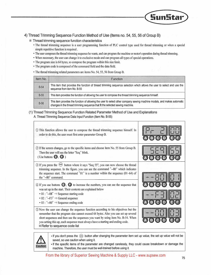
SuiiStar
4) Thread Trimming Sequence Function Method of Use (Items no. 54,55, 56 of Group B)^ Thread trimming sequence function characteristics
• The thread trimming sequence is a user programming function of PLC control type used for thread trimming or when a specialsimple repetitive function is required.
• The user composes the thread trimming sequence he wants, and can program the machine or motor's oper^on during thread trimming.• When necessary, the user can change it to exclusive mode and can program ail types of special operations.
• The program size is 64 bytes, so compose the program within this size limit.• The program code is composed ofthe command field and the data field.
• The thread trimmir^ related parameters are items No. 54,55,56 fiom Group B.
Item No.
This item that provides the function of thread trimming sequence selection which allows the user to select and use thesequence from item No. B-55
This Item provides the function of allowing the user to compose the thread trimming sequence himself.
This item provides the function of allowing the user to select other company sewing machine models, and makes automaticchanges In the thread trimming sequCTice that fit the selected sewing machine.
(1) Thread Trimming Sequence Function Related Parameter Method of Use and ExplanationsA. Thread Trimming Sequence Data Input Function (Item No. B-55)
0This function allows the user to compose the thread trimming sequence himself. Inorder to do this, the user must first enter parameter Group B.
(2) If the screen changes, go to the specific items and choose item No. 55 from Group B.Then the user will see the letter "Seq" blink.
(Usebuttons O )
@ If you press the © button where it says "Seq 55", you can now choose the threadtrimming sequence. In the figure, you can see the command '-80" which indicatesthe sequence start. The command "01" Is a number within the sequence (01-^) ofthe "-80" command.
® If you use buttons O. O to increase the numbers, you can see the sequence thatwas set up in the start. Their contents are explained below
• 01: "-08" Sequence starting code
• 02: "-F3" General sequence
• 03: "~00' => Sequence ending code
©Now the user can change the sequence function according to his objectives but theremember that the program size cannot exceed 64 bytes. Also you can set up severalshort sequences and then use the sequences you want by using item No. B-54. Whenyou setting this up, each sequence must always have a starting and ending code.^ Refer to sequence code list
5ER 55
AICaution
' If you don't press the 0 button after changing the parameter item set up value, the set up value will not besaved, so use caution when using it
' If the specific items of the parameter are changed carelessly, they could cause breakdown or damage themachine. Therefore, the user must be well-trained before using it.
From the library of Superior Sewing Machine & Supply LLC - www.supsew.com
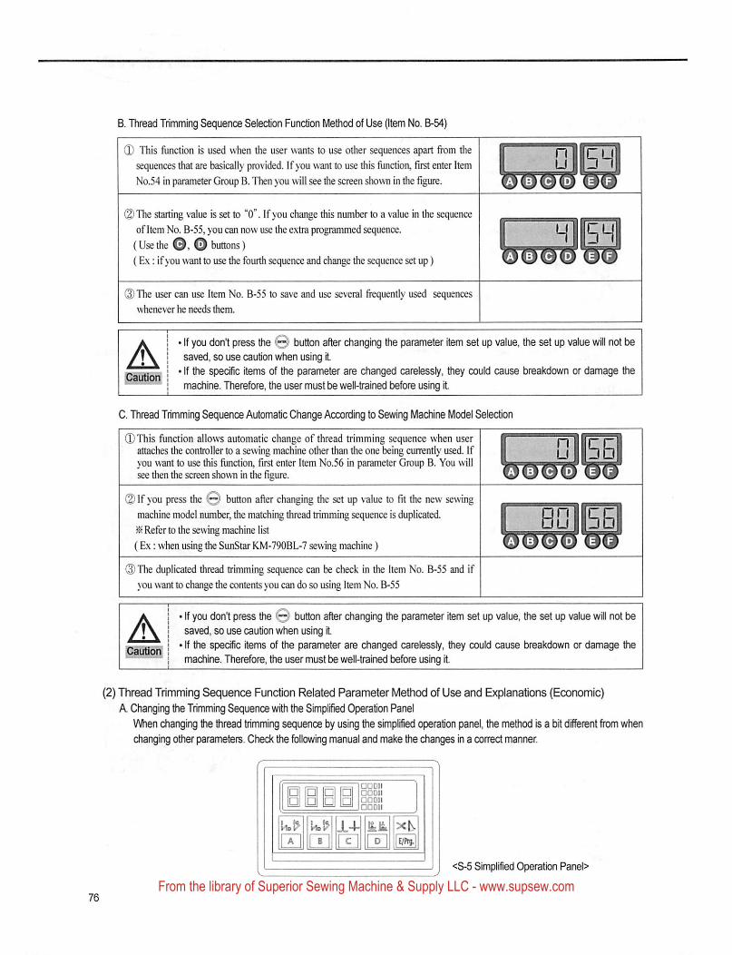
B. Tliread Trimming Sequence Selection Function Method of Use (Item No. B-54)
(D This function is used when the user wants to use other sequences apart from the
sequences that are basically provided. If you want to use this function, first enter Item
No.54 in parameter Group B. Then you will see the screen shown in the figure.
(2) The starting value is set to "0". 1 f you change this number to a value in the sequenceof Item No. B-55, you can now use the exlra programmed sequence.
(Use the o o buttons)(Ex: ifyou want to use the fourth sequence and change the sequence set up)
mm
(2) The user can use Item No. B-55 to save and use several frequently used sequences
whenever he needs them.
ACaution
' If you don't press the Q' button after changing the parameter item set up value, the set up value will not besaved, so use caution when using it
' If the specific items of the parameter are changed carelessly, they could cause breakdown or damage the
machine. Therefore, the user must be well-trained before using it
0. Thread Trimming Sequence Automatic Change According to Sewing Machine Model Selection
(DThis function allows automatic change of thread trimming sequence when user ^attaches the controller to a sewing machine other than the one being currently used. If Iyou want to use this function, first enter Item No.56 in parameter Group B. You will ^see then the screen shown in tlie figure.
(2) If you press the O button after changing the set up value to fit the new sewingmachine model number, the matching thread trimming sequence is duplicated. I^ Refer to the sewing machine list L(Ex: when using the SunStar KM-790BL-7 sewing machine) W
(3) The duplicated thread trimming sequence can be check in the item No. B-55 and if
you want to change the contents you can do so using Item No. B-55
nira
BQiEa
A> If you don't press tiie 0i button afier changing the parameter item set up value, the set up value will not besaved, so use caution when using it.
• If the spedfic items of the parameter are changed carelessly, they could cause breakdown or damage the
machine. Therefore, the user must be well-trained before using it.
(2) Thread Trimming Sequence Function Related Parameter Method of Use and Explanations (Economic)A Changing the Trimming Sequence with the Simplified Operation Panel
When changing the thiead trimming sequence by using the simplified operation panel, the method is a bit different from when
changing other parameters. Check the following manual and make the changes in a correct manner.
U.!> U.!? JL+ at 5<b.
H [|] [I] [1] H
<8-5 Simplified Operation Panel>
From the library of Superior Sewing Machine & Supply LLC - www.supsew.com
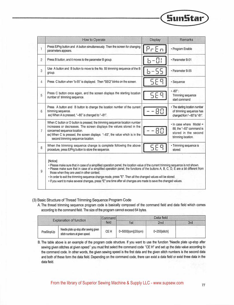
BuiiHtar
How to Operate ?f?in ■ :ftr
Press E/Prg button and A button simultaneously. Then the screen for changingparameters appears.
Press B button, and it moves to the parameter B group.
Use A button and B button to move to the No. 55 trimming sequence of the Bgroup.
Press C button when "b-55° Is displayed. Then "SEQ" blinks on the screen.
Press C button once again, and the screen displays the starting locationnumber of trimming sequence.
Press A button and B button to change the location number of the currenttrimming sequence.ex) When A is pressed, "-80" is (^langed to "-81°.
When C button or D button is pressed, the trimming sequ^ce location numberincreases or decreases. The screen displays the values stored in theconcerned sequence location.ex) When C is pressed, the screen displays "-83", the value which is in the
second trimming sequence location.
When the trimming sequence change is complete following the aboveprocedure, press E/Prg button to store the sequence.
PrE n
h~u
b-55
5EP
--BD
HI
Remarks
• Program Enable
• Parameter B01
• Parameter B-55
'Sequence
' -80":
Trimming sequencestart command
' The starling kxalion nuiterof trimming sequence haschanged frcm "^0° to "-81".
' In case where Model =
88. the "-83" command is
stored in the second
trimming location.
' Trimming sequence isstored.
[Notice]• Please make sure hat in case of a simplified operation panel, the location value of the current trimming sequence is not shovm.• Please make sure that in case of a simplified operation panel, he funcSons of he buttons A, B, C, D, E are a bit different frcHTithose when they are used in oher context• In order to exit he trimming sequence change mode, press "E". Then ail the changed values will be stored.• If you want to make several changes, press "E" one time after all changes are made to save he changed values.
(3) Basic Structure of Thread Trimming Sequence Program Code
A The thread trimming sequence program code is basically composed of the command field and data field which comes
according to the command field. The size of the program cannot exceed 64 bytes.
Explanation of functionCommand Data field
field : 1st 2nd
PosStopUpNeedle plate up-slop after sewing given
stitch nirters at given speed.CEH 0-5000[rpm](20rpm) 0~255[stitch]
B. The table above is an example of the program code structure. If you want to use the function "Needle plate up-stop aftersewing given stitches at given speed" you must first select the command code "CE H" and set up the data value according to
the command code. In other words, he given sewing speed is the first data and the given stitch numbers is the second data
and both of these form the data field. Depending on the command code, there can exist a data field or exist three data in Uie
data field.
From the library of Superior Sewing Machine & Supply LLC - www.supsew.com

(4) Thread Trimming Sequence Program Code List
Category
OutputPort
Control
Time Way
Explanation Cmd Field
B/T Solenoid On 81H
P/F Solenoid On 82H
T/T Solenoid On 83H
W/P Solenoid On 84H
T/R Solenoid On 85H
Left Solenoid On 86H
Right Solenoid On 87H
AUX Sdenoid On 88H
Left LED On 89H
Right LED On 8AH
Needle Up Signal On 8BH
Needle Down Signal On 8CH
Motor Runing Signal On 8DH
Reaching Target Speed Signal On 8EH
Motor Trimming Signal On 8FH
Motor End Tacking Signal On 90H
Emergency Stop Signal On 91H
Roller Lift Solenoid On 92H
Hemming Device Output On 93H
Pedal Forward Step1 Signal On 94H
B/T Solenoid Off 98H
P/F Solendd Off 99H
T/T Solenoid Off 9AH
W/P Solenoid Off 9BH
T/R Solenoid Off 9CH
Left Solenoid Off 9DH
Right Solenoid Off 9EH
AUX Solenoid Off 9FH
Left LED Off AOH
Right LED Off A1H
Needle Up Signal Off A2H
Needle Down Signal Off A3H
Motor Runing Signal Off A4H
Reaching Target Speed Signal Off ASH
MotorTrimming Signal Off A6H
Motor End Tacking Signal Off A7H
Emergency Stop Signal Off ASH
Roller Lift Solenoid Off A9H
Hemming Device Cutout Off AAH
Pedal Forward Step1 Signal Off ABB
Delay by 1[ms] unit BOH
Delay by 2[ms] unit B1H
Delay by 4[ms] unit B2H
Delay by 0.5[s] unit B3H
Data Re
2nd
0-255[ms](1ms)
0-510[ms](2ms)
CM020[ms](4msl
From the library of Superior Sewing Machine & Supply LLC - www.supsew.com
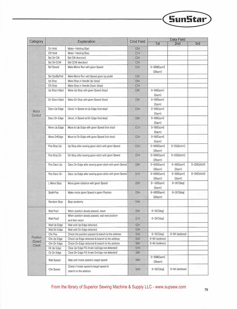
BuiiStar
Category Explanation
On Hold Motor-Holding Start
Off Hold Motor-Holding Stop
Set DirCW Set CW direction)
SetDirCCW Set CCW direction)
Set Speed Make Motor Run witti given Speed
Set SpdByPed Make Motor Run witti Speed given by pedal
Up Stop Make Stop in Needle Up (stop)
ON Stop Make Stop in Needle Down (stop)
Up Stop InSpd Make Up Stop wilti given Speed (stop)
Dn Stop tnSpd Make Dn Stop witti n Speed (stop)
Dace Up Edge ' Decel. in Speed at Up Edge (not stop)
Dace Dn Edge : Decel. in Speed at Dn Edge (not stop)
Move Up Edge Move to Up Edge with given Speed (not stop)
Move DnEdge Move to Dn Edge with given Speed (not stop)
Pos Stop Up Up Stop after sesving given stitch with given Speed
Pos Stop Dn Dn Stop after sewing given stitch with given leed
Pos Dace Up Dace Dn Edge after sewing given stitch with given Speed
Pos Dace Dn Dace Up Edge after sewing given stitch with given Speed
L Move Stop Move given distance with given Speed
SpdInPos Make motor given Speed in given Position
Random Stop Stop randomly
Wait Post When position aleady passed, return
1
Wa(tPos2When position aleady passed, wait next poafon
and ttien return
Wait Up Edge Wait until Up Edge detected.
Wait Dn Edge Wait until Dn Edge detected
Ctil<Pos Oieck the posiiton passed & branch to the address
Ctil< Up Edge Check Up Edge detected & branch to the address
Ctil< Dn Edge Check Dn Edge detected & branch to the address
CIr Up Edge Clear Up Edge FG (mark UpEdge not detected)
Clr Dn Edge Clear Dn Edge FG (mark DnEdge not detected)
Wait Speed Walt until motor speed is target speed
C^k SpeedCheck it motor speed is target jeed &
txaich to ttie address
Cmd Reldata Fie
0-5000ispm]
(20spm)
0-500[spin]
(2spm)
0-500[spm]
(2spm)
0-500[spml
(2spm)
0-500[spm]
(2sDm)
0~500[spm]
(2spm)
0-500[spm]
(2spm)
0-5000[spm]
(20spm)
0-5000(spm]
(20spm)
(}-5000[spm]
{20spm)
(}-5000(spm]
(20spm)
0- 500[spml
(2^m)
0-50C10[spm]
(20spm)
0-255[stilch]
0~255[sbtch]
0-500(spm]
(2spm)
0-500[spm]
(2sDm)
0-357(degl
0-255{stitch]
0-255[stitch]
0-357[deol
0-357 [deol
0-357[degl
0-64 address
0~5000[spm]
(20spm)
0-357 [deol 0-64 (address)
From the library of Superior Sewing Machine & Supply LLC - www.supsew.com
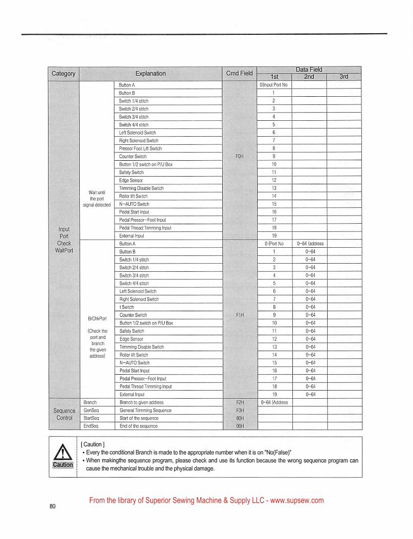
Category Cmd Field
Wait until
the port
signal detected
(Check theport and
tiranch
the givenaddress)
Sequence GenSegControl StariSeq
EndSeq
Switch 1/4 stitch
Svrtch 2/4 stitch
Switch 3/4 stitch
Switch 4/4 stitch
Left Solenoid Switch
Right Solenoid Switch
Pressor Foot Lift Switch
Counter Switch
Button 1/2 switch on P/U Box
Safety Swtch
Edge Sensor
Trimming Disable Switch
Roller lift Switch
N-AUTO Switch
Pedal Start Input
Pedal Pressor-Foot Input
Pedal Thread Trimming Input
External Input
Button A
Button B
Switch 1/4 stitch
Switch 2/4 stitch
Switch 3/4 stitch
Switch 4/4 stitch
Left Solenoid Switch
Right Solenoid Switch
t Switch
Counter Switch
Button 1/2 switch on P/LI Box
Safety Switch
Edge Sensor
Trimming Disable Switch
Roller lift Switch
N-ALTTO Switch
Pedal Start Input
Pedal Pressor-Foot Input
Pedal Thread Trimming Input
Extemal Input
Branch to given address
General Trimming Sequence
Start of the sequence
End of the sequence
ata Fie
1st
OOnput Port No
0-64 (address0 Port No
19
0-64 (Address
[ Caution ]
• Every Uie conditional Branch is made to the appropriate number when it is on "No(False)"
• When makingthe sequence program, please check and use its function because the wrong sequence program can
cause the mechanical trouble and the physical damage.
From the library of Superior Sewing Machine & Supply LLC - www.supsew.com
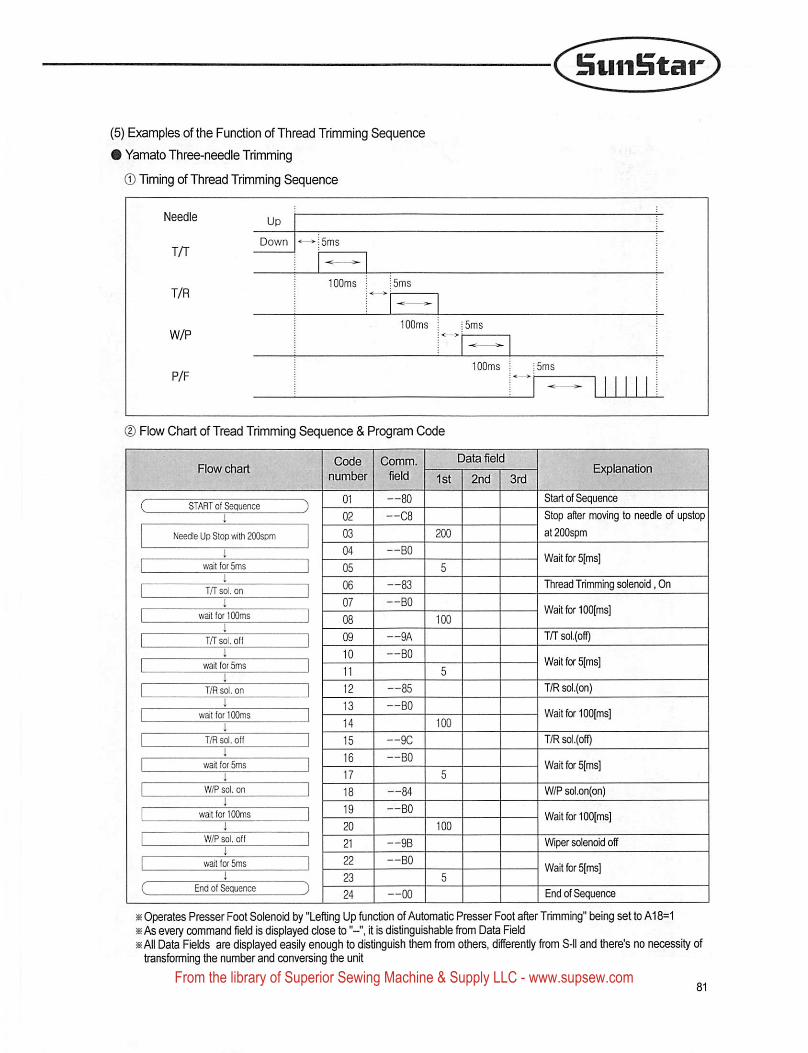
SiJii!itar
(5) Examples of the Function of Thread Trimming Sequence
# Yamato Three-needle Trimming
® Timing of Thread Trimming Sequence
100ms : 15ms
100ms i ;5ms
(D Flow Chart of Tread Trimming Sequence & Program Code
." . . Code Comm. Data fieldFlowchart u 1 \
' number field -)st 2nd 3rd
Code Comm.
number field
START of Sequence
I
Needle Up Stop witti 200som
wait for 5ms
1
T/T sol. on
wait for 100ms
T/Tsol. off
wait for 5ms
1
T/R sd. on 12 —85
13 —BOwait for 100ms
14i
T/R sol. off 15 —9C
i 16 —BOwait for 5ms
17
W/P sol. on ] 18 —84
wait for 100ms
W/Psol. off
wait fc* 5ms
i
End of Sequence
Start of Sequence
Stop after moving to needle of upstop
at 200spm
Wait for 5[ms]
Thread Trimming solenoid, On
Wait for lOOIms]
T/T sol.(off)
Wait for 5[ms]
T/R soi.(on}
Wail for 100[ms]
T/R soi.{off)
Wait for 5(ms]
W/P sol.on(on)
Wart for 100(ms]
Wiper solenoid off
Wait for 5[ms]
End of Sequence
« Operates Presser Foot Solenoid by "Lefting Up fijnction of Automatic Presser Foot after Trimming" being set to A18=1» As every command field is displayed dose to it is distinguishable from Data Field» All Data Fields are displayed easily enough to distinguish them from others, differently from S-ll and there's no necessity oftransforming the number and conversing the unit
From the library of Superior Sewing Machine & Supply LLC - www.supsew.com
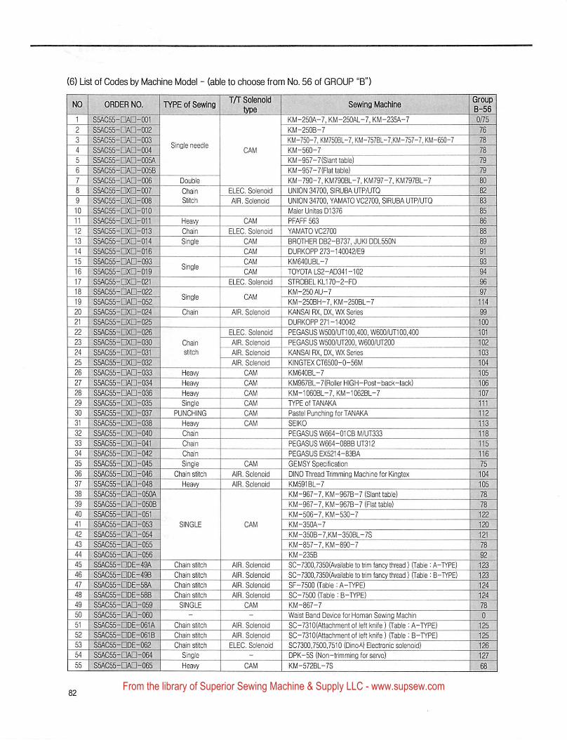
(6) List of Codes by Machine Model - (able to choose from No. 56 of GROUP "B")
ORDER NO. TYPE of SewingT/T Solenold
typeS5AC55-
S5AC55-
S5AC55-
S5AC55-
SSAC55-
SSAC55-
S5AC55-
S5AC55-
S5AC55-
S5AC55-
S5AC55-
S5AC55-
S5AC55-
S5AC55-
S5AC55-
S5AC55-
S5AC55-
S5AC55-
■□AD-001□Aa-0Q2□AD-003■□Aa-004□AO-005A■□AD-005B•□AD-006•□xn-007•□xn-008•□XD-010•□xn-011•□XD-013•□XD-014•□XD-016•□AD-093•□XD-019-□xa-021•□An-022
S5AC55-S5AC55-
S5AC55-S5AC55-S5AC55-S5AC55-S5ACS5-
S5AC55-
S5AC55-S5AC55-
S5AC55-
S5AC55-
S5AC55-S5AC55-
S5AC55-
S5AC55-S5AC55-S5AC55-
S5AC55-
S5AC55-
S5AC55-
S5AC55-
S5AC55-
S5AC55-
S5AC55-
S5AC55-
S5AC55-
S5AC55-
S5AC55-
S5AC55-S5AC55-S5AC55-S5AC55-
S5AC55-
S5AC55-S5AC55-
□XD-Q24□XD-025
□XD-026□XD-030□XD-031□xa-032□AD-033■□AD-034•□AD-036•□Xn-035•□XD-037
•□XD-038
•□xa-040•□xn-041•□xn-042
•□XD-045□XD-046•□AD-Q48•□AD-QSOA-□An-OSOB
□AD-051□AD-Q53
□Aa-054□AD-055
□Aa-056
□DE-49A□DE-49B•□DE-58A□DE-58B
□Aa-059■□Aa-06Q•□DE-061A-□DE-061B•nDE-062
□Aa-Q64□AQ-oes.
Single needle
HeavyHeavyHeavySingle
PUNCHING
HeavyChain
Chain
Chain
SingleChain stitch
Heavy
Chain stitch
Chain stitchChain stitch
Chain sMch
SINGLE
Chain sBtchChain stitch
Chain stFtchSingleHeavy
ELEC, SolenoidAIR. Solenoid
CAM
ELEC. SolenoidCAMCAMCAM
CAM
ELEC. Solenoid
AIR, Solenoid
ELEC. Solenoid
AIR. Solenoid
AIR. Solenoid
AIR. SolenoidCAMCAM
CAM
AIR. SolenoidAIR. Solenoid
AIR, Solenoid
AIR. Solenoid
AIR. SolenoidAIR. Solenoid
CAM
AIR. Solenoid
AIR, SolenoidELEC. Solenoid
KM-25QA-7. KM-25QAL-7. KM-235A-7KM-250B-7KM-750-7. KM750BL-7, KM-757BL-7.KM-757-7. KM-650-7KM-560-7KM-957-7(Slant table)KM-957-7(Flat table)KM-790-7. KM790BL-7. KM797-7. KM797BL-7UNION 34700, SIRUBA UTR/UTOUNION 34700, YAMATO VC2700, SIRUBA UTP/UTQMaier Unites D1376PFAFF 563YAMATO VC2700
BROTHER DB2-B737, JUKI DDL550NDURKOPP 273-140042/E9KM64QUBL-7TOYOTALS2-AD341-102STROBELKL170-2-FD
KM-250AU-7KM-250BH-7, KM-250BL-7KANSAI RX.DX.WX SeriesDURKOPP 271-140042PEGASUS W500/UT1Q0.400, W600/UT100,400PEGASUS W500/UT200, W600/UT200KANSAI RX, DX. WX SeriesKINGTEX CT6500-0-56MKM640BL-7KM967BL-7{RollerHIGH-Post-back-tack)KM-1060BL-7, KM-1062BL-7TYPE of TANAKA
Pastel Punching for TANAKASEIKO
PEGASUS W664-01CB M/UT333
PEGASUS W664-08BBUT312PEGASUS EX5214-83BAGEMSY SpecificationDINO Thread Trimming Machine for KingtexKM591BL-7KM-967-7, KM-967B-7 (Slant table)KM-967-7, KM-967B-7 (Flat table)KM-506-7. KM-530-7KM-350A-7KM-350B-7,KM-35QBL-7SKM-857-7. KM-890-7KM-235BSC-7300,7350(Available to trim fancy thread) (Table : A-PfPE)SC-7300,7350(Avallable to trim fancy thread) (Table : B-TYPE)SF-7500 (Table: A-TYPE)SC-7500 (Table : B-TYPE)KM-867-7Waist Band Device for Homan Sewing MachinSC-7310(Attachment of left knife) (Table : A-TYPE)SC-7310(Attachment of left knife) (Table : B-TYPE)SC7300,7500,7510 (Dino4 Electronic solenoid)DPK-5S (Non-trimming for servo)KM-572BL-7S
From the library of Superior Sewing Machine & Supply LLC - www.supsew.com
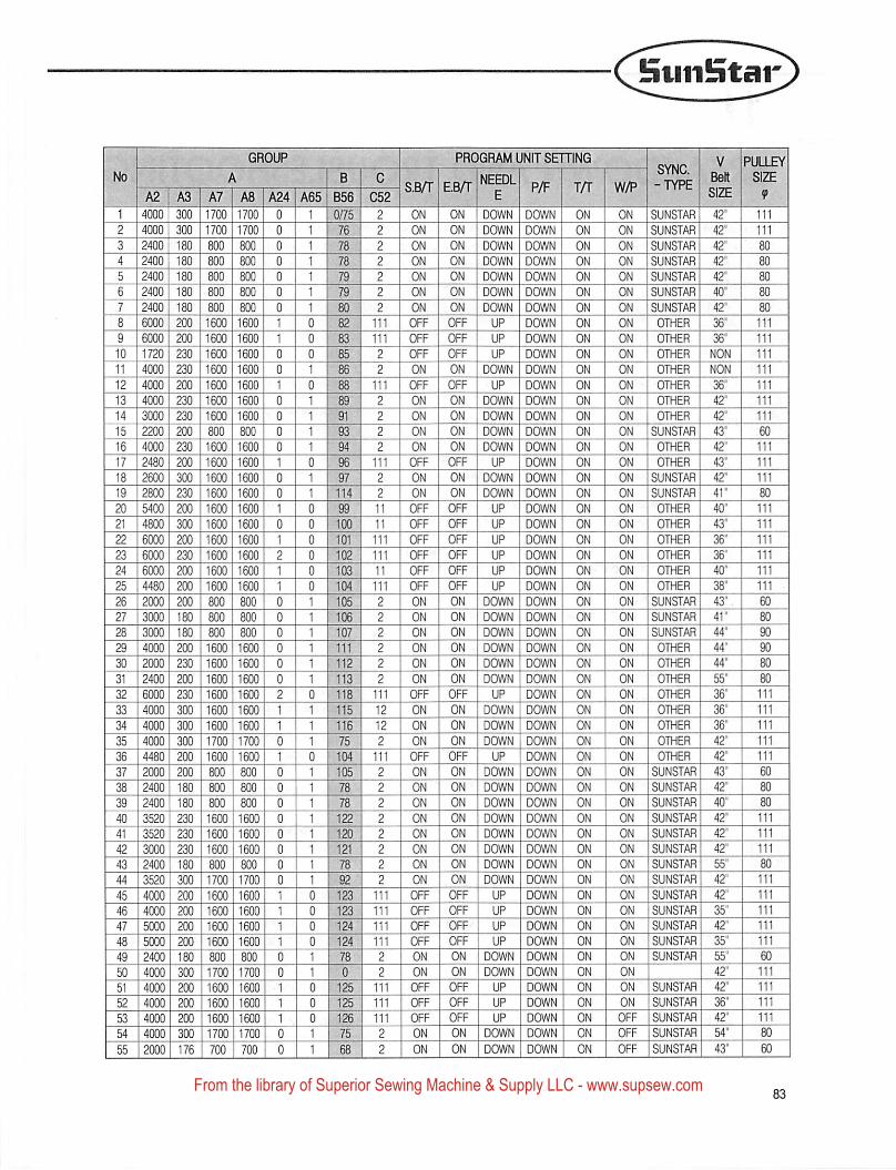
Suii!ntar
M
EEEE55BEEEEEES
HIBEES
IBE1EE3E
[•EE
lElEESIIRWB
CTMllEcaETi!?
Ieih
ll^gEESlETi!?
l^gESES^522
I^sees^
iKsnEETTil?
{■SMfI
■SBETirggaro
~E5^3EESgMKggiMmwm—ro
■aaiwliTTilil
agagnwSSIi
i|
GROUP
^ I B I CA3 I A7 I A8 !A24| A65 856 C52
2
PROGRAM UNIT SETTING
SB/T E.B/r P/F T/r
g|i^iBrauna^gggi
i|BI!i!aBgilintiBgBIM
[■E!aB;!tWB;E|IKnBir:!i!iHr;!t!il
BIBIB!
RTiBigipni—
iggigiggi—iggggggggCT""SaEElEElliwjjgigBynii
EtSllgliRtlillETiiirFmiiEl!
KTiimiiEEl
IBjcMij^iM
IKI!illjrii!iliggl
ggiBi!illh«liligjglKi|ilir;!i!t
IP!!niB;!iWI^|j|j|
iBawBiMHEEIB
IEi!iHKi!iHFiIilM■tirMlhtlillBiliiag
mm
111 OFFON
ON DOWNON DOWNON DOWNON DOWN
Kniua!S£DOWN
OFF UPOFF UP
OFF I OFF I UPON I ON DOWN
OFF UPON DOWN
ON
■•IgBBMIIM'JglOFF I UPON DOWNONOFF UPOFF I UPOFFOFFOFF I UPOFF UPON I DOWN lON
EBMllillilgqj
luuliUIIMU
■■«MliHi!iMON DOWN
OFF UPON DOWN
kuuhiuhi■flMlillim
OFF UPON DOWN
IBMESHBION I DOWNON DOWNON DOWN
■tigaiM'jgiiON DOWNON DOWNOFF UPOFF UPOFF UPOFF I UPON
111 OFF111 OFF111 I OFF
ON
mmBBMligM
UPUP
OFF UPON DOWNON DOWN
DOWN ON
DOWN ONDOWN ONDOWN ON
1 ONONON
DOWN ONDOWN ON
DOWN I ONDOWN ONDOWN ONDOWN ON
ONONON
DOWN ONDOWN ONDOWN ON
DOWN ONDOWN ONDOWN ONDOWN ON
ON
DOWN ONONONONON
ONDOWN ONDOWN ONDOWN ON
ONON
DOWN ONDOWN ONDOWN ONDOWN ONDOWN ON
DOWN ONDOWN ONDOWN ONDOWN ON
DOWN ONDOWN ONDOWN I ON
ONON
DOWN I ONDOWN ONDOWN ONDOWN ON
ONDOWN I ON
ON SUNSTAR 42"
ON SUNSTAR 42"ON
lEBMIBB
SO^^9■wiziaiM
ON 1 OTHER I NONON I OTHER NONON OTHER 36"ON OTHER 42"ON I OTHER 42"ON SUNSTAR 43"ON OTHER 42"ON OTHER 43"ON SUNSTAR 42"ON SUNSTAR | 41"ON OTHER
ON OTHERON OTHER 36"
36"40"
ON I OTHER 38"ON SUNSTAR 43"ON SUNSTAR 41"ON SUNSTAR 44"ON OTHER 44"ON OTHER 44"ON OTHER I 55"ON OTHER
■smaaiESHllI
iMMIZiaZMmanHm
ON OTHER 42"ON OTHER 42"
ItlMKHIjHf jlETj]ON SUNSTAR 42"ON SUNSTAR 42"ON SUNSTAR 42"
55"42"42"
SUNSTAR 35"ON SUNSTAR 42"ON SUNSTAR 35"ON SUNSTAR 55"ON 1 I 42"ONON I SUNSTAR | 36"
OFF SUNSTAR 42"OFF SUNSTAR 54"OFF SUNSTAR 43"
From the library of Superior Sewing Machine & Supply LLC - www.supsew.com
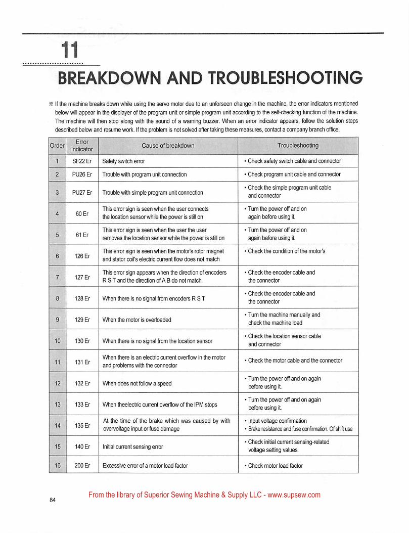
BREAKDOWN AND TROUBLESHOOTING
^ If the machine breaks down while using the servo motor due to an unforseen change in the machine, the error indicators mentioned
below will appear In the displayer of the program unit or simple program unit according to the self-checking function of the machine.
The machine will then stop along with the sound of a waming buzzer. When an error Indicator appears, follow the solution steps
described below and resume work. If the problem is not solved after taking these measures, contact a company branch office.
EiTor
indicatorCause of breakdown Troubleshooting
SF22 Er Safety switch error • Check safety switch cable and connector
PU26 Er Trouble wiUi program unit connection • Check program unit cable and connector
PU27 Er Trouble with simple program unit connection• Check the simple program unit cable
and connector
60 ErThis error sign is seen when the user connects
the location sensor while the power is still on
»Turn the power off and on
again before using it
61 ErThis error sign is seen when the user Uie user
removes the location sensor while the power is still on
• Turn the power off and on
again before using it
126 Er ■This error sign is seen when the motor's rotor magnet
and stator coil's electric current flow does not match
• Check the condition of the motor's
127 ErThis error sign appears when the direction of encoders
R S T and the direction of A B do not match.
• Check the encoder cable and
the connector
128 Er When there is no signal from encoders R S T• Check the encoder cable and
the connector
129 Er When the motor is overloaded♦ Tum the machine manually andcheck the machine load
130 Er When ti ere is no signal from the location sensor• Check frie location sensor cable
and connector
131 ErWhen there is an electric current o\rerflow in tiie motor
and problems with the connector• Check the motor cable and the connector
132 Er When does not follow a speed• Tum the power off and on again
before using it.
133 Er When theelectric current overflow of the IPM stops• Tum the power off and on again
before using it
135 ErAt the time of the brake which was caused by with
oven/oltage input or ftjse damage
• Input voltage confirmation
• Brake resistance and fuse confirmation. Of shift use
140 Er Initial current sensing error '»Check initial current sensing-related
voltage setting values
200 Er Excessive error of a motor load factor • Check motor load fector
From the library of Superior Sewing Machine & Supply LLC - www.supsew.com
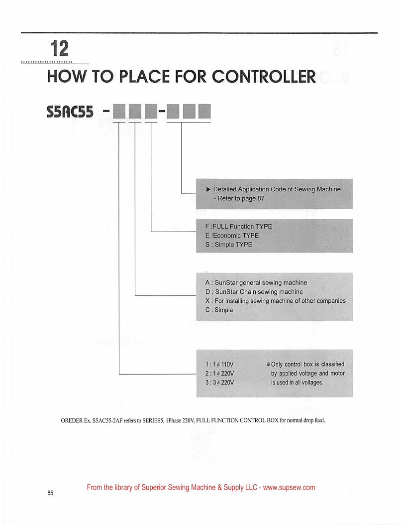
12
HOW TO PLACE FOR CONTROLLER
^ Detailed Application Code of Sewing Machine
-Refer to page 87
F :FULL Function TYPE
E lEconomic TYPE
S: Simple TYPE
A: SunStar genera! sewing machine
D : SunStar Chain sewing machine
X : For installing sewing machine of other companies
C : Simple
2;1ii220V
3;3si220V
^Only control box is classified
by applied voltage and motor
is used in all voltages.
OREDER Ex. S5AC55-2AF refers to SERIES5,1 Phase 220V, FULL FUNCTION CONTROL BOX for nomial drop feed.
From the library of Superior Sewing Machine & Supply LLC - www.supsew.com
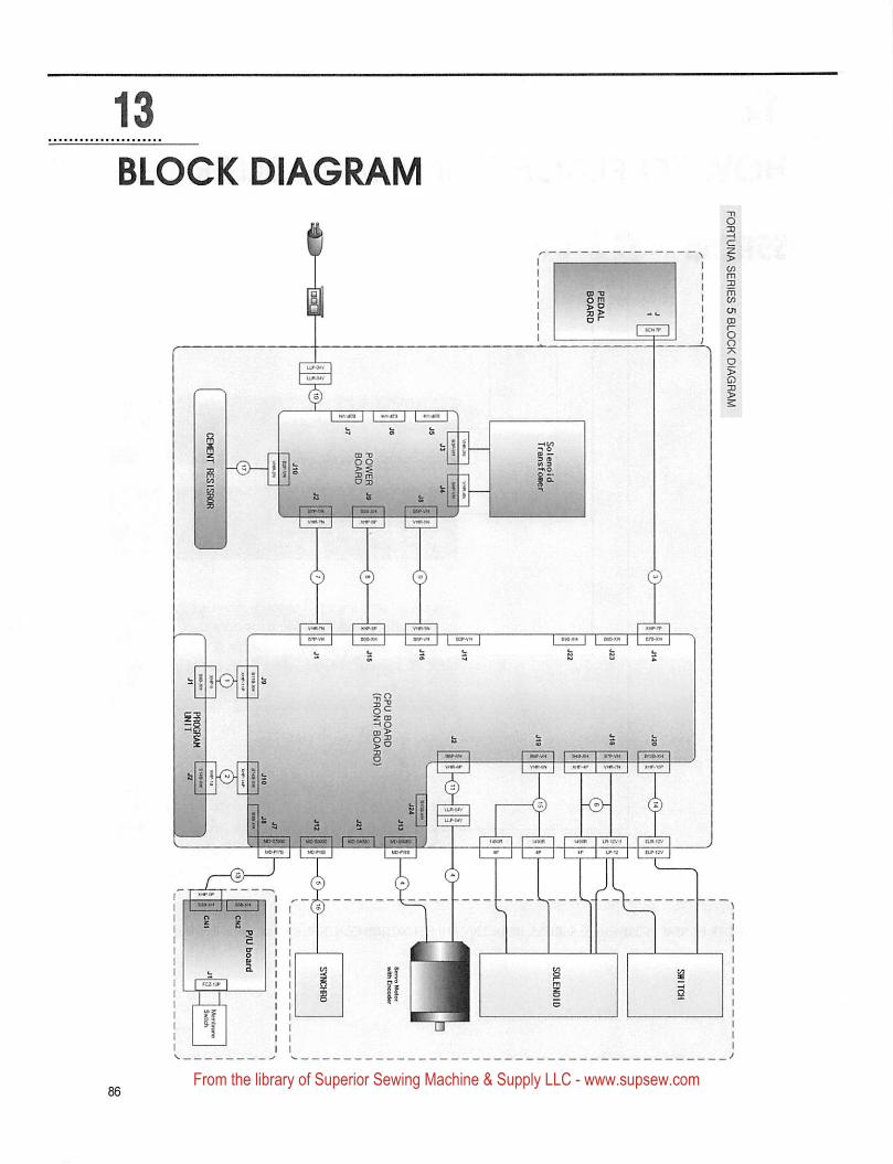
FORTUNA SERIES 5 BLOCK DIAGRAM
From the library of Superior Sewing Machine & Supply LLC - www.supsew.com
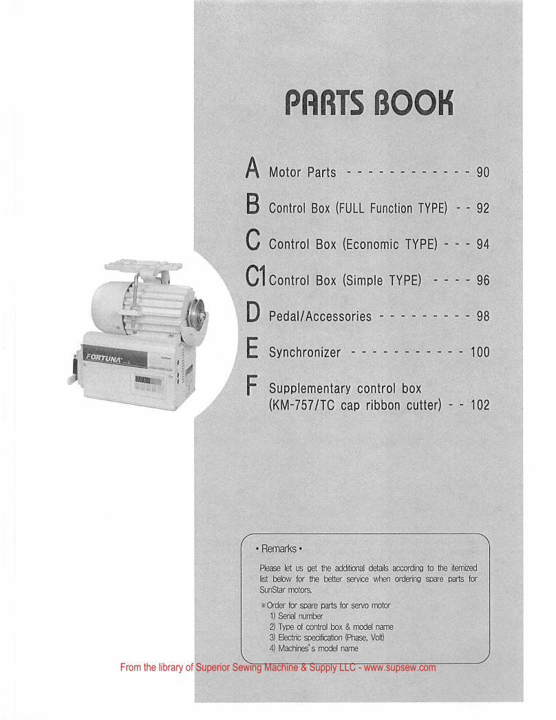
i'
PRRTS BOOK
A Motor Parts 90
B Control Box (FULL Function TYPE) - - 92
C Control Box (Economic TYPE) 94
C1 Control Box (Simple TYPE) 96
D Pedal/Accessories 98
E Synchronizer 100
F Supplementary control box(KM-757/TC cap ribbon cutter) - - 102
• Remarks •
Please let us get the additional details according to the itemized
list below for the better service when ordering spare parts for
SunStar motors.
iK Order for spare parts for servo motor
1) Serial number2) Type of control box & model name3) Electric specification (Phase, Volt}4) Machines' s model name
From the library of Superior Sewing Machine & Supply LLC - www.supsew.com
'V*
/(^l
WARNING1. sofl 4tl- 4^^ m 3.^ 1 4^5] 4^ ;<11^ ^ $10
m 4B011 1:11 IV ^ 4$]ol 7]"^tM4.
2. 4 4^ Part Book^^ 4-§- •i-7|-f-44.
3. 44 ^o] xfoj:o| i^;g ^ 4.= Sl^M4.
1. The parts classified as ass'y items may cause damage to the machine or bad sewing
when they are separtately assembled. Hence, when they are ordered, they can be
purchased as ass'y items only.
2. This is a parts book. It cannot be used as a manual.
3. Parts are Subject to change in Design Without Prior Notice.
Note• iEl- J?-#A ol-ijl mt "r
http://www.sunstarcs.com
■ 7V?]€ ^^eV it \o]^6\\ iaoj:^ 4
• 4^4 ssil- 4^4^ 7l#|: 4^4^14
m 7)^5] 4^4-1- 4 Sl4id4.
•4^4^ 4:^l*Ss. 445]«>1 4:^l-i- tJL 5144 4^ t7l4 M4M4.■m
- I
You can make an order for the parts of Sunstar machine to connect internet address,
http: //www.sunstarcs.com
You can request for parts you want after login if you are a registered member.
In parts Management - Order Management - Order Registration entry,you can place an order by entering the part number and quantity.
If you don't know the parts number, click the parts book menu bar.In a download list, you can read parts book by searching model you use.
This parts book is classified by the mechanism, therefore you can find part easily.
' \:4\
From the library of Superior Sewing Machine & Supply LLC - www.supsew.com
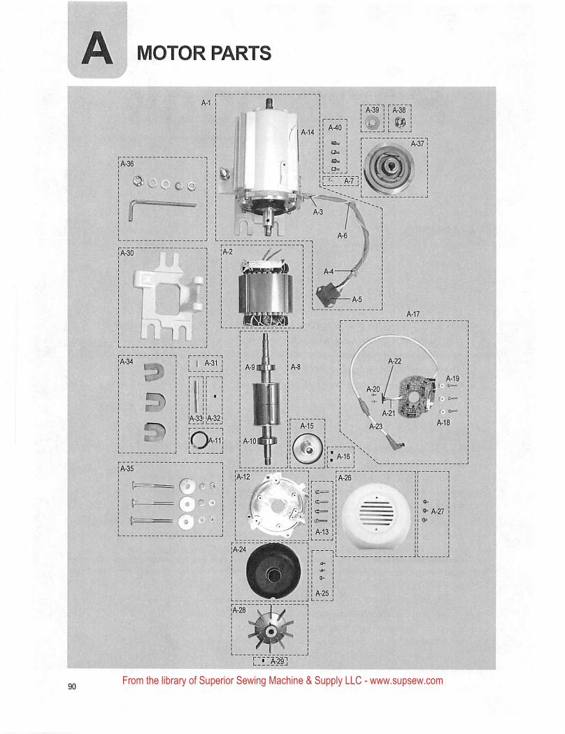
A MOTOR PARTS
r A40 "i
]A-33| [A-321
:r7' S^ ' ■
1 1 1 «^ !L_^_J I I
\ A-20\ *.
I pvifci! tX-. -I ■ ? ^11^ !I —r IIA-13 1I II 1
{! A-25!.j I 1
«■ A-27
From the library of Superior Sewing Machine & Supply LLC - www.supsew.com
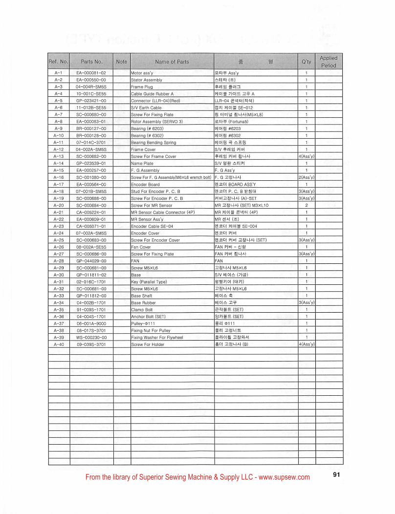
Applied
.J^-.exLo,C.Ref. No Name of Parts
EA-000081-02 Motor ass y
Stator Assembly
Frame Plua
Ass y
(S)
sain
?l|0|§ 7tO|H J2^A
LLR-04 5yiEt(Si4i|)
a*l ?IIO|# SE-012
D Etoj^ imAHMSxLB)
(ForlunaS)
uilcHg #6203
tHjOiS #6302
S/V 5HiH
imM
S/V sef iiEiH
F. G Ass'y
F. G 32§i-tAh
eilaci BOARD ASS'Y
?!!2i:i p. c. B g>SCH
5^H^I!§u^A^ (A)-SET
MR (SET) M3XL10
MR HlOj^ (4P)
MR A-l (£)
?!I2C1 ?t[0|» SE-004
•aiaci ?ifcH
?!lsci 9ia\ I!gL.^Af (SET)
FAN - dS
FAN 9m iii-Ut
EA-000550-GO
04-004R-SM5S
10-001C-SE55 Cable Guide Rubber A
Connector (LLfl-04)(Red)GP-023421-00
11-012B-SE55 S/V Earth Cable
SC-000680-00 Screw For Fixing Flate
Rotor Assembly (SERVO 3)
Bearing (# 6203)
Bearing (# 6302)
Bearing Bending Spring
EA-000083-01
BR-000127-00
BR-00012a-00
07-0140-3701
04-002A-SM5S Frame Cover
SC-000682-00 Screw For Frame Cover
GP-023S39-01
EA-000257-00 F. G Assembly
Screw For F. G Assembly(M6xL6 wrench bolt)
Encoder Board
SC-001080-00
EA-000564-00
07-001B-SM5S Stud For Encoder P. C. B
SC-000688-00 Screw For Encoder P. C. B
SC-000684-00 Screw For MR Sensor
MR Sensor Cable Connector (4P)
MR Sensor Ass'y
CA-005224-01
EA-000609-01
CA-005071-01 Encoder Cable SE-04
Encoder Cover07-002A-SM5S
SC-000683-00 Screw For Encoder Cover
08-002A-SE5S
Screw For Fixing PlateSC-000686-00
GP-044029-00
M5XL6
S/V UtiOl^ii: (7)g
S?!!?|Oi (CH?|)
:nSL.)Af M5XL6
m\±
SC-000681-00 Screw M5XL6
GP-011811-02
Key (Parallel Type)02-016C-1701
SC-000681-00 Screw M5XL6
GP-01iai2-00
04-002B-1701 Base Rubber
(SET)
(SET)
§£1 0111
Sei HSM
*C^I1§U^A^ (B)
91-009S-1701 Clamp Bolt
Anchor Bolt (SET)
Pulley-oi 11
Fixing Nut For Pulley
Fixing Washer For Flywheel
04-004S-1701
06-001A-9000
08-017S-3701
WS-000230-00
09-039S-3701 Screw For Holder
From the library of Superior Sewing Machine & Supply LLC - www.supsew.com
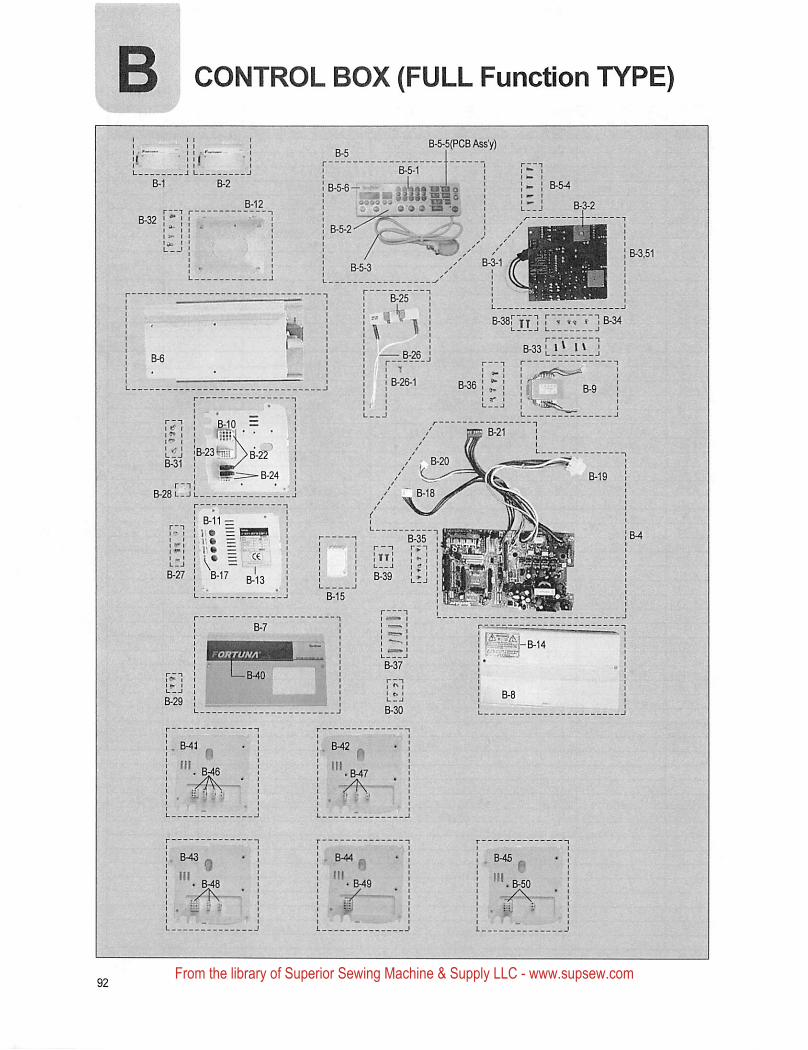
CONTROL BOX (FULL Function TYPE)
B-5-5(PCBAssV)
B-38i IT I I ^ ts t I B-34I I
B-33! 1
B-28u-Jl__.
From the library of Superior Sewing Machine & Supply LLC - www.supsew.com
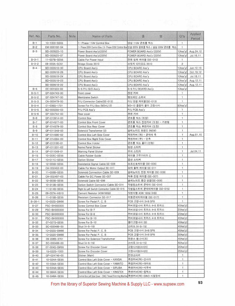
10-1000-SS55
EM-000102-04
BD-000520-10
BD-000520-07
11-007B-SE55
09-003A-SC51
BD-OOOS18-30
80-000518-28
80-000518-24
80-000518-23
BD-000518-22
EE-001523-00
GP-024743-00
GP-024747-00
CA-000479-00
01-036S-1701
BD-000255-03
GP-024744-00
GP-013914-00
GP-014577-00
GP-014579-00
GP-011348-00
GP-014580-02
GP-014584-00
GP-013180-01
GP-011331-02
GP-011049-01
10-003C-SE55
10-011C-SE55
12-0058-SE55
CA-002483-00
11-006B-SE55
CA-002487-00
12-003B-SE56
12-013B-SE55
11-014B-SE55
09-007A-HB10
11-015B-SE55
10-002S-SW66
PSC-BH000300
PSC-BH000300
PSC-BH000300
PSC-BH000300
07-027S-SE55
SC-000466-00
10-002S-SW66
10-002S-SW66
09-226S-3701
SC-000466-00
07-004S-SM55
15-0228-1000
GP-024746-00
10-024A-SE55
10-034A-SE55
10-044A-SE55
10-064A-SE55
10-046A-SE55
1 - Phase 110V Control Box Etg 110V 1
1 - Phase 220V Conlrol Box / 3- Phase 220V Control Bo* Eig220Vaef 1 gg220Vsei 1
Power Board Ass'y(220V) POWER BOARD Ass'y (220V) 1 (Ass'y)
Power Board Ass'y(220Vl POWER BOARD Ass'y (220V) 1 (Ass'y)
Cable For Power Input SS ?l|0|g (SE-010) 1
Bridge Diode 3510 £5!A| cfo|£S3510 ! 2
CPU Board Ass'y CPU BOARD Ass'y 1 (Ass'y)
CPU Board Ass'y CPU BOARD Ass'y 1 (Ass'y)
CPU Board Ass'y CPU BOARD Ass'y 1 (Ass'y)
CPU Board Ass'y CPU BOARD Ass'y 1 (Ass'y)
CPU Board Ass'y CPU BOARD Ass'y 1 (Ass'y)
S-5 P/U B/D Ass'y S-5 P/U BOARD Ass'y 1 (Ass'y)
Front cover S3 TjtH 1
Membrane Switch a£ai|ol i;?|x| 1
P/U Connector Cable(SE-013) P/U 32 ?1|0|t(SE-013) 1
Screw For P/U Box (M3XL12) M3-12 goj IlSl-fA^ 5(Ass'y)
P/U PCB Ass'y P/U PCB Ass'y 1
Rear cover ^3 ?1tH 1
Control Box SEg £i— (£o) 1
Control Box Front Cover
Control Box Rear Cover
Solenoid Transformer S3
Control Box Left Side Cover
Control Box Right Side Cover
Control Box Holder
Name Panel Sticker
Warning Panel Sticker
Cable Rubber Guide
Option Sticker
Assistance Signal Cable SE-008
Cable For Motor Output SE-011
Solenoid Connection Cable SE-009
(£§)-7|S8
taitOIH saH (NEW)
(s^) - 5y|e( S;
(gs)
|?flO|= C
fisg2.?iioig (SE-008)
££1- ?i|o|§SE-Gll
IgaiinOjHSgJ aiolg (SE-009)
Cable For DC Power SE-007 g-S S3 7llo|g (SE-007)
Solenoid Cable SE-006 ^elliiOlS gZ} 3a(SE-006)
Option Switch Connector Cable SE-014 (SE-014)
Right & Left Switch Connector Cable SE-015 SaiElTllOIS (SE-015)
Cement Resistor (40W160Q) g3it:18- 40W 160Q (MB)
Resistant Connector SE-017
Screw For Pedal P. C. B
Screw Control Box Cover
Screw For B-7
Screw For B-8
Screw For B-10
Screw For B-12
Stud (4-5-15)
Screw For Pedal P. C. B
Screw For Pedal P. C. B
Screw For Solenoid Transformer
Stud (4-5-15)
Screw For Encoder Cover
Screw For Encoder Cover
Slicker (Main)
Control Box Left Side Cover - KANSAI
Control Box Left Side Cover - YAMATO
Control Box Left Side Cover - SIRUBA
Control Box Left Side Cover - KINGTEX
(SE-017)
PCB ngi-tAhaxB SP8
NtHiiJufAf seiix 4«8 E.S{±.
4.0 EE^A;
hufSgJM-Af 4.0 EBj^
*^:•}I2g^Af (B)
£(= (4-5-15)
Ipcb usi-j-AfaxesPS
PCB 3X8 SP8
lt-)AK£)
(4-5-15)
I1§<-)a1^8(4X20)
|2S>-)A)B(4X20)
^S5HH(£f)-ota)£
^B5HEH(5^)-A|^H^
a?(kH(2f)-gi!|:i:
4(Ass'y)
2(Assy)
2(Ass'y)
|4(Ass"y)4(Ass'y)
4(Ass'y)
4(Ass'y)
]5(Ass'y)4(Ass'y)
5(Ass'y)
l2(Ass"y)
2(Ass'y)
1
1
1
Conlrol Bo* Isit Side Cover - DINO Thread Trimmirig Machinel^ 23 71 (5f)-DIN0 g*|
From the library of Superior Sewing Machine & Supply LLC - www.supsew.com
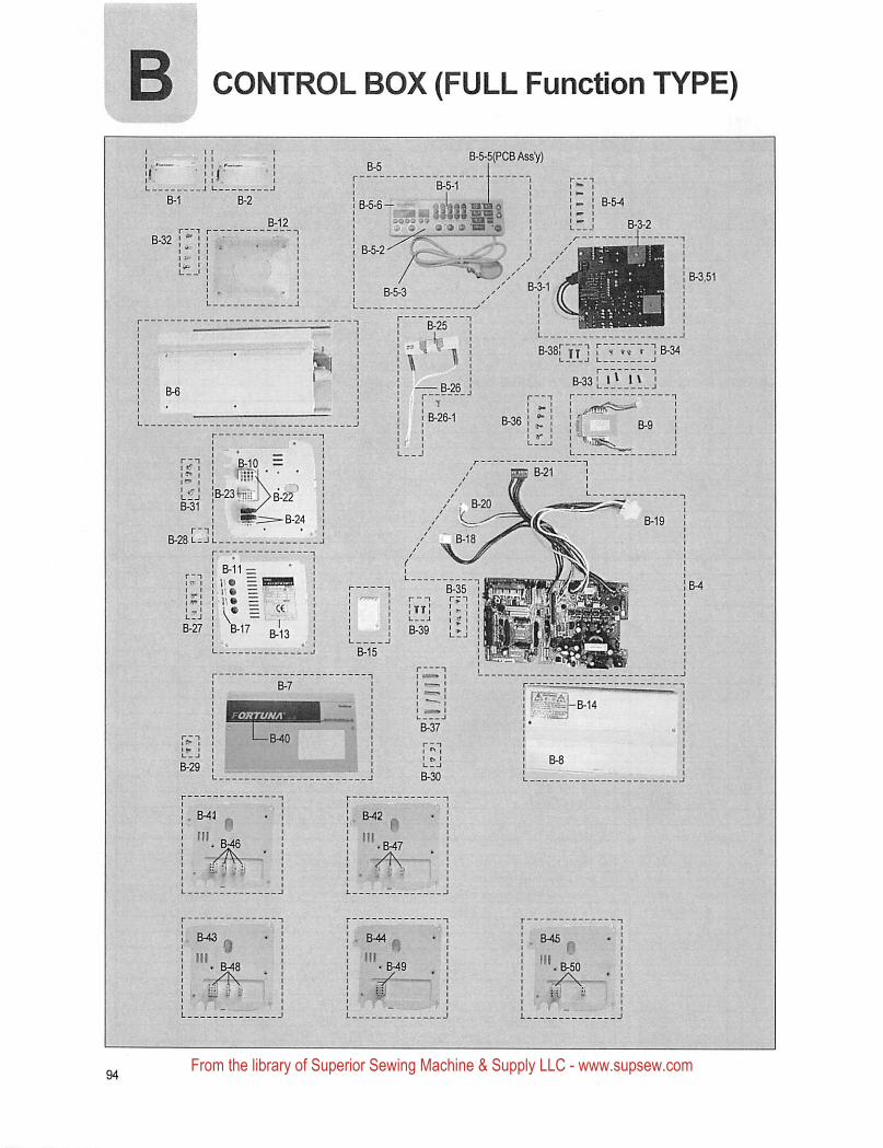
CONTROL BOX (FULL Function TYPE)
■J COS 33
SOE B-21
" "iB.28l_jl
PgtTgfe.Qli
ORTUNA
From the library of Superior Sewing Machine & Supply LLC - www.supsew.com
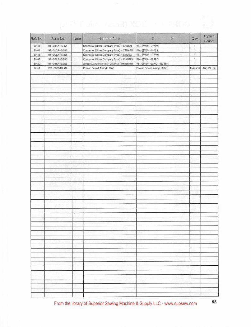
1-49
i-48
1-51
1-46
B-47
1-50
91-032A-SE55
91-046A-SE55
BD-000519-09
91-008A-SE55
91-031A-SE55
91-013A-SE55
Connector (Other Comoany Type) - KANSAI E|-Af5aiE(-7}-At-0|
Connector (Other Company Type) - YAMATO E^Afa^lE^-o^a^s.
Connector (Other Company Type) - SlflUBA EtAf5t!|E(-A| = df
Connector (Other Company Type) - KINGTEX EfAhSyjEi-a^i
ConfectorlOlhetCompanyTypel-DINOTlireaflTiimmiigMartne ■'•fS cf*i
Power Board AssV(IIOV) Power Board Ass'yd 10V) l(Ass'y) Aug.24,12
From the library of Superior Sewing Machine & Supply LLC - www.supsew.com
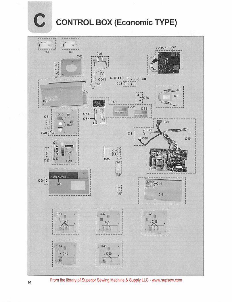
VNniHO
' e-s-D
5SSG
m
(3dAl 01UJOU003) xoa HOdlNOO0
From the library of Superior Sewing Machine & Supply LLC - www.supsew.com
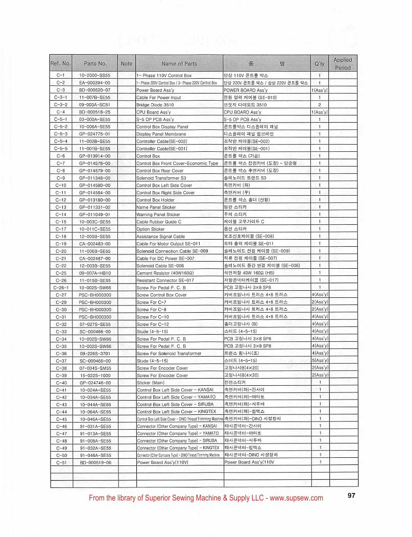
10-2000-SS55
EA-000394-00
BD-000520-07
11-007B-SE55
09-003A-SC51
BD-000518-25
03-OOOA-SE55
tO-006A-SE55
GP-024775-01
11-002B-SE55
11-001B-SE55
GP-013914-00
GP-014578-00
GP-014579-00
GP-011348-00
GP-014580-00
GP-014584-00
GP-013180-00
GP-011331-02
GP-011049-01
10-003C-SE55
10-011C-SE55
12-005B-SE55
CA-002483-00
11-006B-SE55
CA-002487-00
12-003B-SE55
09-007A-HB10
11-015B-SE55
10-002S-SW66
PSC-aH000300
PSC-BH000300
PSC-BH000300
PSC-BH000300
07-027S-SE55
SC-000466-00
10-002S-SW66
10-002S-SW66
09-226S-3701
SC-00G466-00
07-004S-SM55
15-022S-1000
GP-024746-00
10-024A-SE55
10-034A-SE55
10-044A-SE55
10-064A-SE55
iO-046A-SE55
91-031A-SE55
91-013A-SE55
91-008A-SE55
91-032A-SE55
91-046A-SE55
BD-000519-06
1- Phase 110V Control Box 110V
1- Phase 220V Control Bo* / 3- Phase 220V Control Bo* 22QV 5S1 1 an 220V ar^
Power Board Ass'y POWER BOARD Ass'y
Cable For Power Input as HIOIS (SE-010)
c:fo|2H 3510
CPU BOARD Ass'y
S-5OP PCB Assy
digital0| Dflid
Sfa) ?j|0|#(SE-002)
?iiois{SE-ooi)
Bridge Diode 3510
CPU Board Ass'y
S-5 OP PCB Ass'y
Control Box Display Panel
DiSDiay Panel Membrane
Controller Cable(SE-002)
Controller Cab1e(SE-001}
Control Box
Control Box Front Cover-Economic Type
Control Box Rear Cover
Solenoid Transformer S3
Control Box Left Side Cover
Control Box Right Side Cover
Control Box Holder
Name Panel Slicker
Warning Panel Sticker
Cable Rubber Guide C
Option Sticker
Assistance Signal Cable
Cable For Motor Output SE-011
Solenoid Connection Cable SE-009
Cable For DC Power SE-D07
Solenoid Cable SE-006
Cement Resistor (40W1602)
Resistant Connector SE-017
Screw For Pedal P. C. B
Screw Control Box Cover
Screw For C-7
Screw For C-8
Screw For C-10
Screw For C-12
Stude (4-5-15)
Screw For Pedal P. C. B
Screw For Pedal P. C. B
Screw For Solenoid Transformer
Stude (4-5-15)
Screw For Encoder Cover
Screw For Encoder Cover
Sticker (Main)
Control Box Left Side Cover - KANSAI
Control Box Left Side Cover - YAMATO
Control Box Left Side Cover - SIRUBA
Control Box Left Side Cover - KINGTEX
Control Box Left Side Cover-DINO Thread Trimming Machine^Connector (Other Company Type) - KANSAI
Connector (Other Company Type) - YAMATO
Connector (Other Company Type) - SIRUBA
Connector (Other Company Type) - KINGTEX
Connec!or(OttierCor[;MnyTyoe)-DlNOThrcaaTrirrmnjMachi(K |E^A|•g^E^-DINO A|-SSf*lPower Board Ass'y(IIOV)
eg (SS) 1
^aflitOiH £|!!=S3 1
BSPim (SJ) 1
B 1
5Hf (AJS) 1
set 1
1
?i|0|g J1^7f0!= c 1
S-a 1
a2Et!S.?1lOll (SE-008) 1
HE) ?ilo|g SE-011 1
gEllicOlS asj ?1|0|g (SE-009) 1
as HlOlt (SE-007) 1
gelicOlH git as ?l|0|# (SE-006) 1
40W 160Q (MB) 1
(SE-017) 1
PCB ZS1-W3X8SP8 1
5HlH2Eai-W 4*8 4(Ass'y)
4.8 sei^ 2(Ass'y)
PitHsiJi-W EBjA. 4.8 Ea^^ 2(Ass'y)
4*8 4(Ass'y)
St|zg^Af (B) 4(Ass'y)
EiE (4-5-15) 4(Ass'y)
PCB Jiai-tAt 3X8 SP8 4(Ass'y)
PCB ngi-waxasps 4(Ass'y)
eirtifmAKBE) 4(Ass'y)
EB\B (4-5-15) 5(Ass'y)
21ai-WB(4X20) 2(A$s'y)
2SL.fA)B(4X20) 2(Ass'y)
Ag?^b^(^^)-^^A^O|
a?i?1tH(£T)-o)DTs.
|e^A^0yjE^_o^D^£E^Af^l-J}E^_Al = Hf
[Power Board Ass'yd 10V
From the library of Superior Sewing Machine & Supply LLC - www.supsew.com
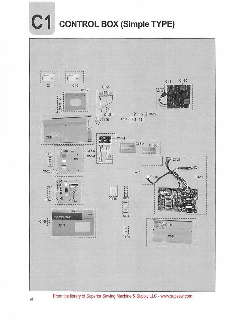
C1 CONTROL BOX (Simple TYPE)
> MS*
C1-22
C1-33 i")T'rr'C1-26-1
L. ;C1-26
C1-11-
•I.T-
ORTUNA
From the library of Superior Sewing Machine & Supply LLC - www.supsew.com
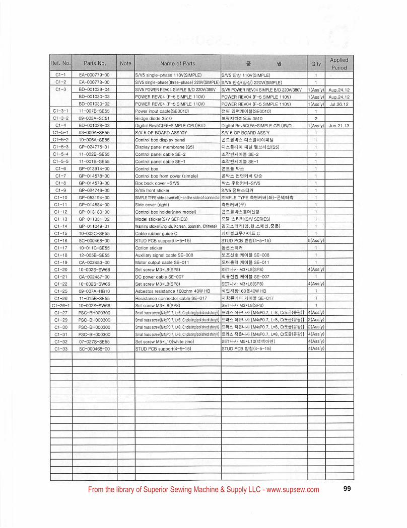
EA-000779-00
C1-2 EA-000778-00
C1-3 BD-001029-04
BD-001030-03
BD-0D1030-02
C1-3-1 ! 11-007B-SE55
01-3-2 09-003A-S051
C1-4 BD-001028-03
C1-5-1 03-000A-SE55
C1-5-2 10-006A-SE55
C1-5-3 GP-024775-01
01-5-4 11-002B-SE55
01-5-5 11-001B-SE55
01-6 GP-013914-00
01-7 GP-014578-00
01-8 GP-014579-00
01-9 GP-024746-00
01-10 GP-053194-00
01-11 GP-014584-00
01-12 ! GP-013180-00
01-13 GP-011331-02
C1-14 GP-011049-01
01-15 10-003C-SE55
01-16 ; SC-000468-00
01-17 10-011C-SE55
01-18 12-005B-SES5
01-19 CA-002483-00
01-20 10-002S-SW66
01-21 CA-002487-00
01-22 10-002S-SW66
01-25 09-007A-HB10
01-26 11-015B-SE55
01-26-1 10-002S-SW66
01-27 PSC-BH000300
01-29 PSC-BH000300
C1-30 PSC-BH000300
01-31 PSC-BH000300
01-32 07-027S-SE55
01-33 SC-000468-00
>«KB853«to»™itow,e
S/V5 single-phase 1 tOV(SIMPLE) SA/5 EftJ-1 lOV(SIMPLE)
S/V5 single-phase(lhree-pfiase) 220V{SIMPLE} S/V5 220V(SIMPLE)
S/V5 POWER REV04 SIMPLE B/0 220V/380V Sm POWER REV04 SIMPLE BID 220V/3aoV KAss'y) Aug.24.12
POWER HEV04 (F-5 SIMPLE 110V) POWER REV04 (F-5 SIMPLE 110V) l(Ass'y) Aug.24.12
POWER REV04 (F-5 SIMPLE 110V) POWER REV04 (F-5 SIMPLE 110V) KAss'y) Jui.26,12
Power input cabie{SEOOlO) SS g|^?i|0|t(SE0010) 1
Bridge diode 3510 H5J^|chO|2= 3510 2
Digital Rev5C(F5-SiMPLE CPU)B/D Digital Rev5C(F5-SIMPLE CPU)B/D KAss'y) Jun.21.l3
SA' 5 OP BOARD ASS'OY
Control box display panel
Display panel membrane (S5)
Control panel cable SE-2
Control panel cable SE-1
Control box
Control box front cover (simple)
Box back cover -S/V5
S/V5 front sticker
SIMPLE TYPE side cover(lelt)-on the side of connector
Side cover (right)
Control box holder(new model)
Model sticker(S/V SERIES)
Warning 5tick0r(Enolish, Korean, Spanish, Chinese)
Cable rubber guide C
STUD PCB support(4-5-15)
OptiOTi Sticker
Auxiliary signai cabie SE-008
Motor output cable SE-011
Set screw M3"L8(SP8)
DC power cabie SE-007
Set screw M3-L8(SP8)
Asbestos resistance 160ohm 40W HB
Resistance connector cable SE-017
Set screw M3*L8(SP8)
Smj^l truss sciewlM4xP0.7,1=0, Or piatingtoolished^lnyll
Small truss screwlM4*P07, L=0, Cr piatinglpolished shiny)]
Small truss screw[M4xP07,1=8, Ct platinfl(polished^iny)]
Smil truss screwlM4iP07, L=fl, Ct oiatinglpolished shiny)]
Set screw M5*L10(white zinc)
STUD PCB support(4-5-15)
S/V 5 OP BOARD ASS'Y
q^taioiniia
i^ir^tsiioi nfiB anaiaKss)
5fal?i|0|g SE-2
SE-1
5SS t'—
?S3HtH-S/V5
S/V5
SIMPLE TYPE 3?1tH(5h)-5y|e(^
aegaj-:i4i:it!g
Hi! i:E|5H(S/V SERIES)
§Ili:E|?((a,eh,±111! £!.#§)
7i|0|§12^7)0|= 0
STUD PCB g>S(4-5-t5)
Til big SE-008
HEiget Tiloig SE-011
SETUfAf M3*L8(SP8)
?i|0ig SE-007
SETi-)Af M3-L8(SP8)
■itgxiehi60S40W HB
lilhStSiEi ?i|0|g SE-017
SETi-hAj M3*L8(SP8)
£ei± Sfai-fAf [M4xP0,7, L=8. CrE3(-SS)]
52ii: ShS'-fA) [M<1xP0,7, L=8, Cr£g(^a)]S{± ShgLfAf [M4XP0.7, L=8, CrE3(^3h)]
ei± ShSufA) [M4xP0.7, L=8, CrEg(§S)ISETi-fAhMS'LIOiell-illohg)
STUD PCB S>S(4-5-15)
4(Ass'y)1
1
1
4{Ass'y)2(Ass'y)
2(Ass'y)
4(Ass'y)4(Ass'y)
4(Ass'y)
From the library of Superior Sewing Machine & Supply LLC - www.supsew.com
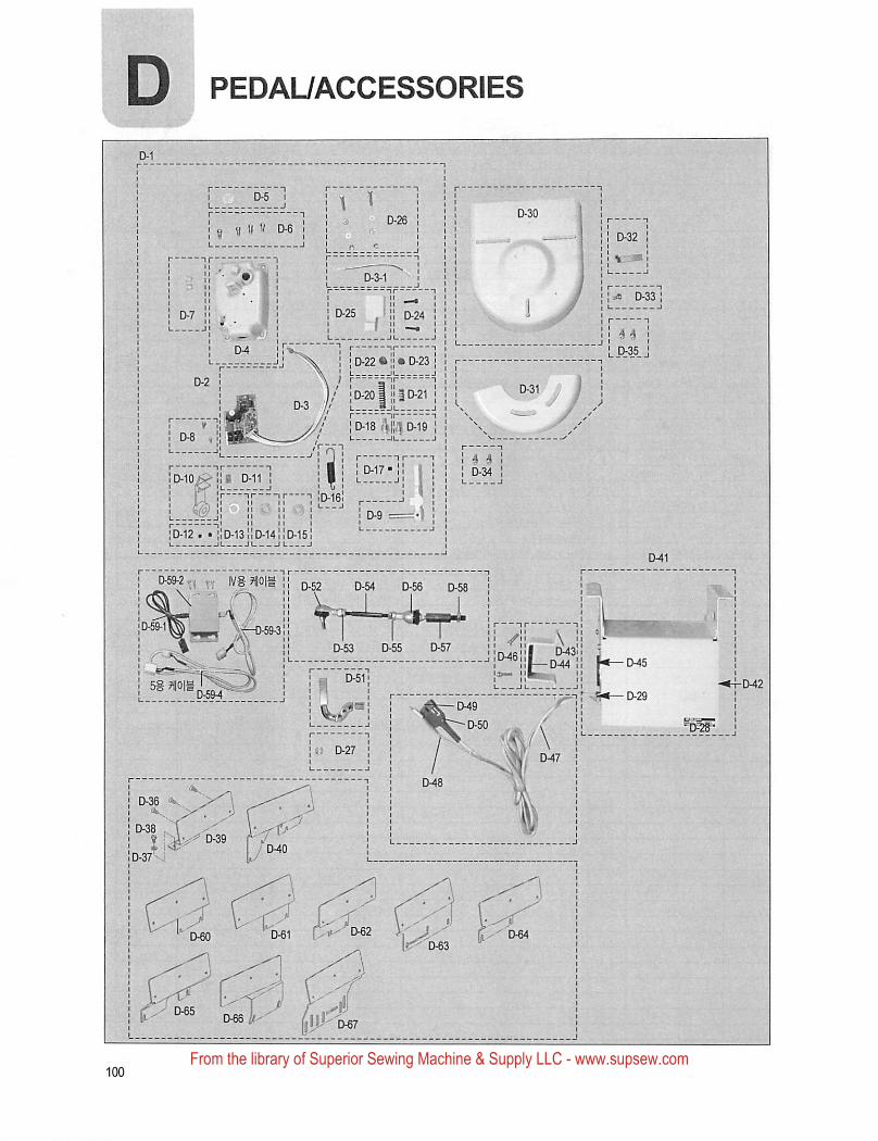
D PEDAUACCESSORIES
^ B " D-6 j
M D-24
' D-35 '0-22 • 1! • D-23 I
D-201 111D-21 ID-18 rVliJi D-19 ]
D-12 . • !:D-13;;D-14 D-15
D-54 D-56 D-58
(M7
a D-27 !
! D-38 V
i»-^I>62
From the library of Superior Sewing Machine & Supply LLC - www.supsew.com
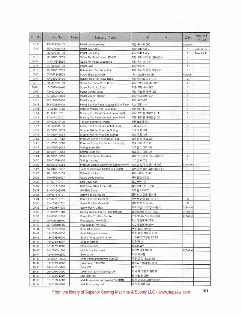
AS-004004-05
BD-001009-03
BD-001009-00
12-009B-SE55
11-017B-SE55
GP-051581-00
06-001C-SE55
07-027S-SES5
10-033C-SF55
SC-001099-00
10-002S-SW66
AS-004002-01
10-026A-SC53
PTC-AK000300
SC-000681-00
10-024W-SC53
11-012C-3701
11-012C-3701
SP-000078-00
SC-000681-00
10-030P-SC53
10-029P-SC53
10-019G-SC53
10-020G-SC53
10-025P-SC53
10-024P-SC53
10-031S-SC53
GP-014594-00
10-021S-SC53
18-0168-5607
20-106C-6100
18-0290-5607
91-001A-3701
91-101A-SA53
91-004C-SA53
09-0313-3701
07-0278-3701
01-1358-1701
91-0293-1000
01-039W-1701
91-0308-1000
GP-051355-00
GP-051356-00
18-107B-9000
18-108B-9000
18-109B-9000
18-023R-5607
17-0170-3000
01-1340-1701
12-015M-2350
02-001A-SM50
17-016B-3000
08-014C-3701
25-006A-3200
18-021A-5607
18-0158-5607
18-018B-5607
^edal Unit Assembly
^edal B/D Ass'y
^edal B/D Ass'y
Cable For Pedal Input {SE-003)
Cable For Pedal Grounding
^edal Base
Rubber Cap For Pedal Unit
Screw (Set) 5X10 OR
Rubber Cap For Pedal Base
Screw For Pedal P. 0. B Set
Screw For P, 0. B Set
Pedal Control Lever
Pedal Magnet Holder
Pedal Magnet
Fixing Bolt For Pedal Magnet & film Base
Parallel Washer For Pedal Shaft
Bushing For Pedal Control Lever Shaft
Bushing For Pedal Control Lever Shaft
Tension Soring For Pedal
Fixing Bolt For Pedal Control Lever
Stopper (B) For Pressure Spring
Stopper (A) For Pressure Spring
Pressure Spring For Presser Fool
Pressure Spring For Thread Trimming
Soring Guide (B)
Soring Guide (A)
Screw For Spring Housing
Spring Housing
Pressure Control Screw For Sprino(Ass'y)
Joint coupling rod fixation nut (right)
Solenoid sticker
Cable guide bushing
Belt Cover (B)
Belt Cover (New Type) (A)
S/V Belt Guide
Screw For Belt Guide
Screw For Belt Cover (A)
Screw For Belt Cover (B)
Screw For P/U Box
Spring Washer For P/U box Bracket
Screw For P/U Box Bracket
P/U support(KM-235)
P/U support(KM-250)
Knee lifting case
Knee lifting case cover
Stroke fixing plate (stamp)
Rubber washer
Stopper rubber
Middle bracket screw
Grey cable
Knee lifting ground wire (Ass'y))
Green plug 1490P1C
Tube (C)
Lever shaft joint coupling rod
Ball joint (6R)
Middle coupling bar fixation nut (left)
Middle coupling rod
Jun,19.12
May.25,11
(A)
§ (A
£2| e (B)
Sd ei (A)
S 7fO|H (B)
dd A --{JS
ei-M (s) 2
2
3(Ass'y)
2(Ass"y)
2(Ass'y)
sa ?1|0|±
£3
4|41i ?i|0|§
#a (s)
dIl 1490P10^41|
(0)
aiiui-^
S (6R)
3SL1E (^^)
#^^92S(A)
From the library of Superior Sewing Machine & Supply LLC - www.supsew.com
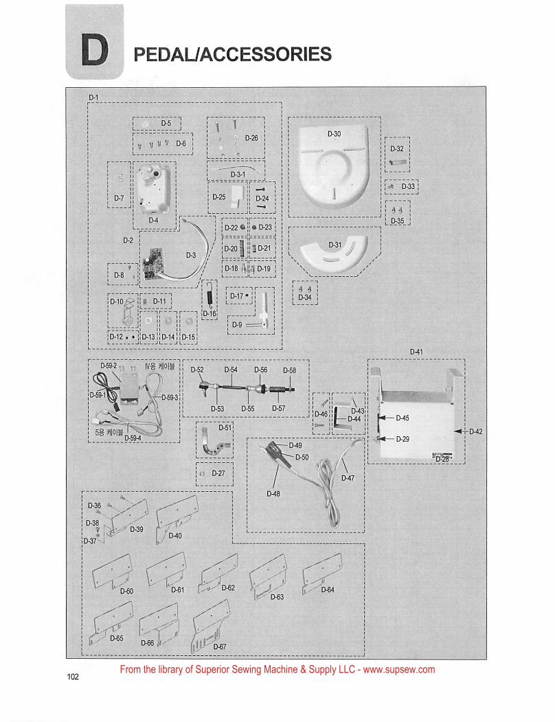
D PEDAUACCESSORIES
j • D-269 M
£M3 1I I
• D-7 !'
' I Ji a ',| ]
L D-35 '[ 0-22 • ['
0-18 im D-19
D-12 . • 110-13 ;D-14 0-15
«H—0-29
Iff) D-27 !
From the library of Superior Sewing Machine & Supply LLC - www.supsew.com

D-55 18-0163-5607
D-56 18-020A-5607
D-57 18-011B-5607
D-58 18-0198-5607
D-59-1 91-OOOO-EOGE
D-59-2 EA-000023-00
D-59-3 CA-000239-00
D-59-4 CA-000240-00
D-60 GP-014972-00
0-61 GP-051357-00
D-62 GP-051358-00
0-63 GP-051359-00
0-64 GP-051360-00
0-65 GP-051361-00
0-66 GP-051362-00
0-67 GP-051363-00
iviiaaie coupling bar fixadon nut (right) HSMB (^)
Ball joint (6L) g ££!£ (6L)
Shalt coupling bar ^ aspi
Shaft coupling bar fixation nut
Edge sensor (assembly) 1 EDGE-a^l (2)
Edge sensor box (assembly) EDGE-£!!A1 (2)
Edge sensor cable - S4 EDGEiJjA-l ?1|0|g-S4
Edge sensor cable - S5 EDGEt!!A1 ?1|0|g-S4
PU Brack6t(KM-572) PUH2(9!(Klyl-572)
PU Bracket(KM-591) PUH2J?!i(KM-591)
PU Bracket(KM-640) !PUHB1?li(KM-640)
PU Bracket(KM-790) PUH2(?!i(KM-790)
PU Bracket(KM-967) PUHaH|i(KM-967)
PU Bracket(KM-967B) PUHaf?I!(KM-967B)
PU Bracket(KM-1060) PUSat?!I(KM-1060)
PU Bfacket(For other companies) PUH2f?5(EhA>S)
From the library of Superior Sewing Machine & Supply LLC - www.supsew.com
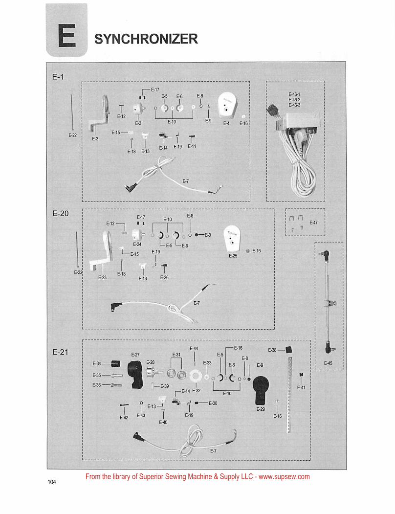
SYNCHRONIZER
T 1 TE.14 e-19 E-11f I
E-18 E-13
— E-39 IpE-14
From the library of Superior Sewing Machine & Supply LLC - www.supsew.com
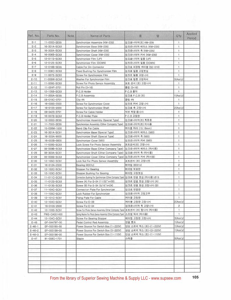
Bef, No.
E-1 11-0000-SE55
16-301A-SC53
16-302A-SC53
16-006B-SC53
12-011S-SC53
12-012S-SC53
12-016B-SE55
11-006C-SC53
11-007S-SC53
11-008W-SC53
11-009S-SC53
11-024P-3701
12-105B-SC53
11-200A-SE55
08-015C-3701
16-008S-2000
16-010S-2000
09-0423-3701
16-007B-SC53
12-0000-SE55
i1-7000-SE55
15-026M-1000
16-301A-SC51
16-303A-9000
16-003B-5600
11-009S-SC53
06-009B-SC53
06-303A-SC51
06-008B-SC53
12-105C-SC51
16-012A-2000
12-102C-SC51
12-103C-SC51
11-011C-SC53
11-012S-SC53
11-013S-SC53
11-104C-SC51
11-105C-SC51
12-101C-SC51
12-104C-SC51
16-0103-2000
12-103S-SC51
PW3-CA001400
12-104C-SC51
GP-044797-00
EP-000195-00
EP-000198-00
EP-000196-00
91-008C-1701
[Synchronizer Assemble (KM-235) ^3Si-lO|X((S) KM-235
ISynchronizer Base (KM-235) ^3£t-lO|Xi bflOizi: (KM-235)
Synchronizer Shaft {KM-235) ^as.L.lO|X1 (KM-235)
Bynchronizer Cover (KM-235) •aaMi-lOlXi (KM-235)
Synchronizer Film (UP) (UP)
Synchronizer Film (DOWN) %|fi (DOWN)
Cable For Din Connector 2|§a ?t|Olg {SE-016)
Fixed Bushing For Synchronizer Film
Screw For Synchronizer Film •S3S usi-w
Washer For Synchronizer Film 4I3S SB I!§2)A1
Screw For Photo Sensor Assembly xjjAi (s) aSi-4A(
Roil Pin (3*16) fe (3-16)
P.C.B Holder P.C.B BElH
P.C.B Assembly P.C.B (S)
Clip 4N IS 4N
Screw For Synchronizer Cover 2S4Af
Screw For Synchronizer Shaft B USt-lAf
Screw For Cable Holder 4(3 AlSHLfA)
P.C.B Holder Plate P.C.B use
Synchronizer Assembly (Special Type) i•a3S^0|A1(£)BSS
Synchronizer Assembly (Other Company Type) •a3SL.f0|x((5) EWS
Band Clip For Cable HlOjg Ehol (10.16mm)
Synchronizer Base (Special Type) ■a3Si-lOi;c| m|0|:t (560) 1
Synchronizer Shaft (Special Type) ^3S.i-lO|7H ^ (560) 1Synchronizer Cover (560) ^3Si-lO|A( 9]u\ (560)
Lock Screw For Photo Sensor Assembly
Synchronizer Base (Other Company Type) tJ||0|± (E)AfS)
Synchronizer Shaft (Other Company Type) ^ (EIA(S)
Synchronizer Cover (Other Company Type) 5H«H (E)AfS)
Lock Nut For Photo Sensor Assembly (s) iSuiE
Bearing (6001z) Uliois (6001z)
Stopper For Bearing Kloii
Stopper Bushing For Bearing BiiCHS
Connection Sushino For Synctiromzer (Other Company Type) (e(AfS)0i5
Screw (A) For E-34 (11/32"n=28) 4!3S ya 54) HSi-lAf (A)
Screw (B) For E-34 (5/16"n=24) 4ias ga 5^ :2§ufA( (b)
Connection Plate For Synchronizer 4I3S gas
Lock Rubber For Synchronizer 413^1-101x1
Fixing Plate For Cable 5HI0IB
Screw For E-39 ?iioii USE) naufAi-
Screw For E-34 4!3SI-)0|J^ B zgi-lAh
Screw For Pnolo Sensor Asserrbly (Other Company Type) ££^A-i (s) Sl-)A( (E(AhS)
Spring Washer For Ptioto Sensw AssemSly (Other Company Type) = i siM (e(A)B)
Screw For Bearing Stopper iHloia USE) Zgi-IA)
Pedal Control Rod Assembly ga 5=
Power Source For Switch Box (1-220V) g4^i^A| (S)-(1-220V)
Power Source For Switch Box (3—220V) 4)4) e):i (i)-(3~220V>
Power Source For Switch Box (1—110V) g4);::^Al (S)-(I-Iiov)
Staple
Appliedv^riod
2{Ass"y)2
3(Ass'y)
l(Ass'y)
l(Ass'y)l(Ass'y)
From the library of Superior Sewing Machine & Supply LLC - www.supsew.com
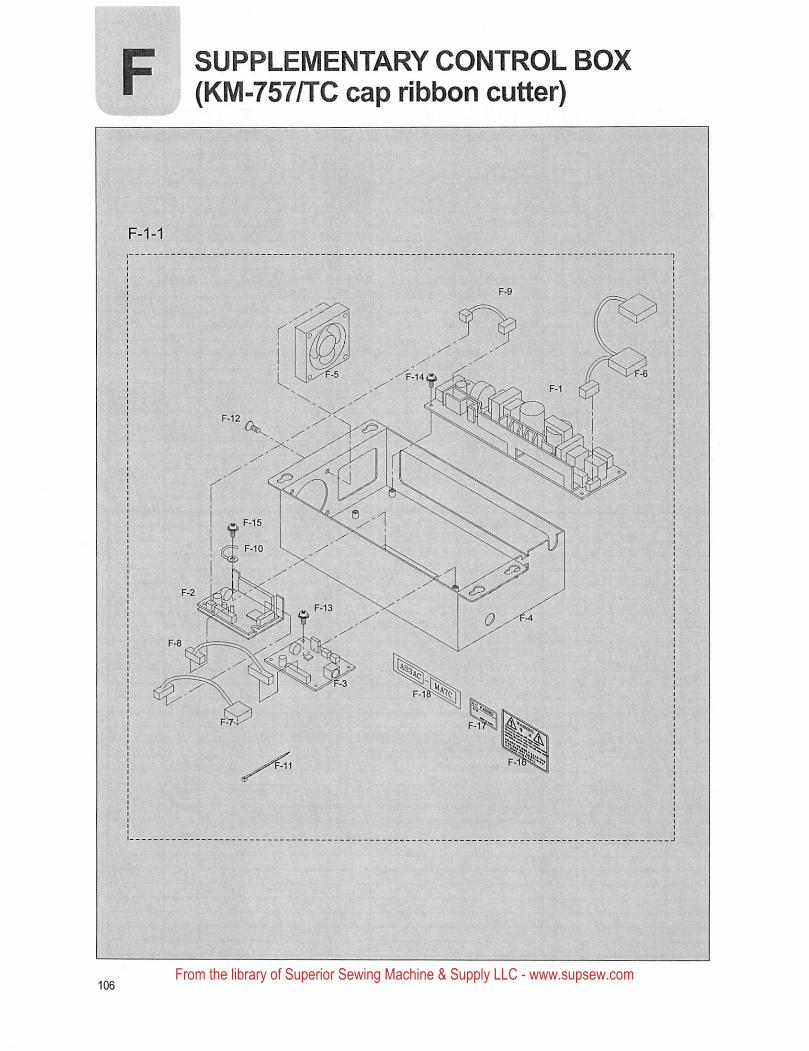
SUPPLEMENTARY CONTROL BOX
(KM-757/TC cap ribbon cutter)
From the library of Superior Sewing Machine & Supply LLC - www.supsew.com
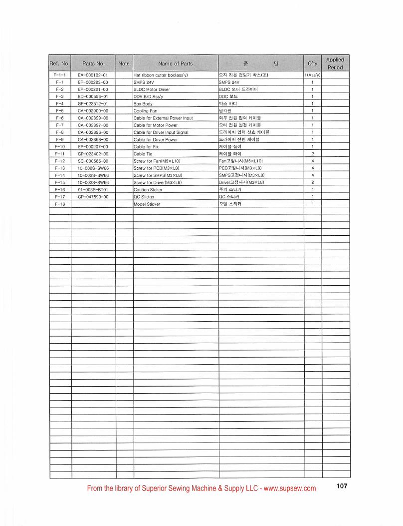
F-1-1 EA-000102-01
F-1 EP-000223-00
EP-000221-00
BD-000558-01
GP-023512-01
CA-002900-00
CA-002899-00
CA-002897-00
CA-002896-00
CA-002898-00
EP-000207-00
GP-023402-00
SC-000565-00
10-002S-SW86
10-002S-SW66
10-002S-SW66
01-003S-8T01
GP-047599-00
Hat ribbon cutter box(ass'y)
SMPS 24V
BLDC Motor Driver
DDV B/D Ass'y
Box Body
Cooling Fan
Cable for External Power Input
Cable for Motor Power
Cable for Driver Input Signal
Cable for Driver Power
Cable for Fix
Cable Tie
Screw for Fan{M5XL10)
Screw for PCB(M3xL8)
Screw for SMPS(M3xL8)
Screw for Driver(M3xL8)
Caution Sicker
QC Sticker
Model Sticker
SMPS 24V
BLOC HEf =a^ol^i^
DDC EH
sfi: Hfc|
HOIS
HEf g§! as HOIS
sa HOIS
Ihois aoi
HOIS Ehoi
FanESL4AKM5xU0)
PCBZgi-^AKM3XL8)
SMPSI19'-F-^HM3XL8)
briverHgi-|AKM3XL8)
'£|
QCiEIH
ES
From the library of Superior Sewing Machine & Supply LLC - www.supsew.com