user manual of ai module 1
TRANSCRIPT

User Manual of AI Module 1
V1.2
Contents
Preface ........................................................................................................................................................... 3
Chapter 1 Product Introduction ................................................................................................................ 4
I. MC101 Controller .......................................................................................................................... 4
II. Actuator and Sensor ..................................................................................................................... 5
Chapter 2 Software Introduction .............................................................................................................. 7
I. Software Download and Installation .............................................................................................. 7
II. Connection Controller and Downloader ...................................................................................... 7
III. Flow Chart Programming .............................................................................................................. 8
1、Introduction of flow chart interface ........................................................................................ 8
2、Module instructions .................................................................................................................... 9
3、Module introduction ................................................................................................................... 9
IV. Introduction of C Language and Python Editing Interface .................................................. 17
I.Introduction of C Language interface ....................................................................................... 17
II.Introduction of Python Language interface............................................................................ 18
Chapter 4 Programming Example ......................................................................................................... 19
I.Control Motor Stop and Rotation by Touching the Sensor.................................................. 19
II.Infrared Sensor Detection .......................................................................................................... 20
Chapter 5 Introduction to Line Patrol ................................................................................................... 21
Chapter 6 Epilogue ................................................................................................................................... 25
I.Maintenance.................................................................................................................................... 25
II. System Upgrade .......................................................................................................................... 25
III. Contact Us................................................................................................................................... 25

Preface
The book introduces the way to use AI Module 1 series building block robots and WhalesBot Scratch software. Simple programming examples are given to help users learn to use AI Module 1 series along with its software better and faster. After you get this product, please read the manual carefully.
AI Module 1 series are the latest building block robots of Whales combining controllers and software, which not only can meet the needs of daily robot teaching, but also meet a variety of application environments such as robot competition. WhalesBot Scratch software is able to teach students the most advanced Scratch and Python and also supports bar chart programming, standard C programming and Python programming. The flow chart module covers all port functions, and supports visual programming such as subroutine function. It contains seven functional modules, including action, sensor (detection), control, program, data, advanced and line patrol modules. Based on the brand-new cross-platform technology development, it can be operated on Windows, Mac and other operating system, and supports multithread programming. The bar chart can automatically generate C and Python Language, of which C Language supports pointer, array, structure and other complex applications, and the robot library functions are available.

Chapter 1 Product Introduction
I. MC101 Controller
MC101 controller is the latest generation. It is small but
stable and reliable, also it has large program storage capacity and rich interface, famous of being high performance but low power consumption. MC101 controller has such universal interfaces as I/O, I^2C and URART at the top, motor interface and MiniUSB interface at the bottom, buttons and speakers at the front and battery compartment at the back.
Processor: 32-bit Cortex-M3 processor, clock frequency 72MHz, 512KB
FlashROM, 64KRAM; Memory: 32 Mbit high-capacity memory chip with a variety of built-in sound
effects, which can expand more functions with software upgrade; Port: Provide 10 input and output interfaces, including 5 digital/analog interfaces
(AI, DO), 4 closed-loop motor control interfaces, with a single maximum current of 1.5A; 1 RS485 servo motor serial interface, with a maximum current of 6A; USB interface can support online commissioning mode to facilitate program commissioning;
Button: Set up a key to simplify user operation. Through this button, users are able to switch on and off the machine, run the program, deal with Bluetooth pairing and other functions. The built-in indicator light of the button displays various working states of the controller.
Light off: Power off White: Power on White flickering light: Running the program Yellow flickering light: Downloading the program Red flickering light: Low battery Others: The working voltage of the system is 6.8~10V. Functions include
working state display and audio playing, etc.
MC101 controller firmware upgrade The main program running in the firmware MC101. Without firmware, the
MC101 controller will not be able to work. Sometimes new firmware versions are released to enhance functionality or fix
software defects. Make sure using WhalesBot Scratch software to connect your computer to
MC101 controller with a USB cable to update firmware. 1. Turn on the MC101 controller and connect it to your computer.
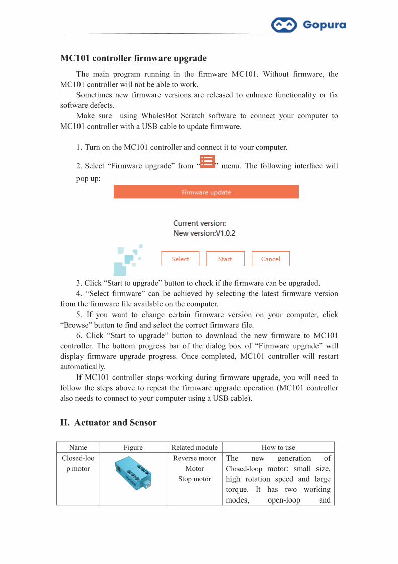
2. Select “Firmware upgrade” from “ ” menu. The following interface will pop up:
3. Click “Start to upgrade” button to check if the firmware can be upgraded. 4. “Select firmware” can be achieved by selecting the latest firmware version
from the firmware file available on the computer. 5. If you want to change certain firmware version on your computer, click
“Browse” button to find and select the correct firmware file. 6. Click “Start to upgrade” button to download the new firmware to MC101
controller. The bottom progress bar of the dialog box of “Firmware upgrade” will display firmware upgrade progress. Once completed, MC101 controller will restart automatically.
If MC101 controller stops working during firmware upgrade, you will need to follow the steps above to repeat the firmware upgrade operation (MC101 controller also needs to connect to your computer using a USB cable).
II. Actuator and Sensor
Name Figure Related module How to use Closed-loo
p motor
Reverse motor Motor
Stop motor
The new generation of Closed-loop motor: small size, high rotation speed and large torque. It has two working modes, open-loop and

closed-loop modes, which allows to accurately control rotation speed and rotating cycles ultimately driving the robot to complete various tasks.
Emotional screen
LED array-expressio
n LED
array-symbol LED
array-customization
It uses the dot-matrix LED display technology, has a variety of built-in robot expressions and over 50 kinds of symbols and is applicable to a number of scenarios, greatly enhancing the interest and performance capability of the robot.
Infrared sensor
Infrared ranging Infrared ranging sensor is a kind of analog sensor, which can detect the infrared light reflected from solid objects to achieve the purpose of detecting range. By detecting the range of objects, high-level path planning applications such as ranging and obstacle avoidance are achieved. Ranging range: 10-50cm Corresponding range of value: 0-2300
Touch sensor
Touch switch Touch sensor is a kind of digital sensor, which can be pressed down and released, and avoid obstacles by detecting the collision state of the robot. The corresponding value of touch on/off state: 0/4000
Integrated grayscale
sensor
Line patrol The integrated grayscale sensor is a detector with 5 grayscales. Through the highly integrated design and built-in high-performance co-processor, it simplifies the application difficulty of the robot, and cooperates with the controller to achieve higher-performance line patrol function.

Chapter 2 Software Introduction
I. Software Download and Installation
Please download WhalesBot Scratch software Standard Version, Setup.exe, from the official website www.gopuratech.com. Follow the steps to complete installation.
II. Connection Controller and Downloader
Please make sure that the controller is fully charged, computer and controller is also connected with USB cable when you connect with WhalesBot Scratch software. When the controller is connected to the computer, the controller shall turn on automatically under switch off mode followed with a tone “Hello! I am the Whale.”
After writing program, click the download icon “ ”, and following four prompts will pop up:
When prompting successful download, you can unplug the USB cable to run the
program offline. Attention: Please do not plug and unplug USB cable or press down the controller
button to run the program during download!

III. Flow Chart Programming
1、Introduction of flow chart interface
The flow chart program editing window is shown in the figure above. The left is the module library, the middle is the program editing window, and the right is the C or Python code bar that controls display function and content. All content of this bar is automatically generated by the flow chart program, which cannot be changed (if you need to change it, you can switch to C Language interface), allow you to learn the structure of C Language and read the parameters of each module.
WhalesBot Scratch software has eight modules, which are action module library, sensor module library, control module library, function module library, operation module library, variable module library, advanced module library and line patrol module library.
Menu bar Module bar Programediting terface
Code display area Software information

2、Module instructions
Firstly define program function, then detect corresponding module, drag it to the
lower part of the main program and connect after blue bar prompt pops up, left click the module to select parameters in the pop-up interface, download the program to the controller, run the program and achieve the function.
Example: Function: The motor at Port rotates forward at the speed of 80;
Corresponding module: Motor; drag the “motor” module to the lower part of the main program, click the module “A”, set the motor to choose Port A, click “power” to enter 80 and set the power of the motor to 80. Then connect the computer and the controller through USB cable, download the program to the controller, run the program and achieve the goal.
3. Module introduction
3.1 Action module library The action module library contains all actuator modules, including eight modules
such as reverse motor, motor, motor stop, display, indicator light, electromagnet and tone. Module name
Module diagram Control port
Interpretation
Reverse motor
Motor ports A~D
Invert the rotation of subsequent motors before placing it on the motor module that needs to be inverted.

Set the motor
Motor ports A~D
Control motor rotation, with the power range of -100~100 (which can also be controlled through variables). The advanced module can control the time or movement distance of the motor (1600 means that the motor rotates about 360°).
Turn off the motor
Motor ports A~D
The motor of corresponding port will stop rotating after checking.
Indicator light
I/O ports 1~5
Control the on/off state of corresponding (multiple choices) indicator light.
Electromagnet
I/O ports 1~5
Control the engagement and disengagement of corresponding electromagnet (multiple choices).
Tone
/ Sound corresponding tones through loudspeaker.
LED array-expressions
I/O 口
1~4 I/O ports 1~4
Select and display expressions, which requires to connect two LED arrays at the same time.
Turn off array-expressions
I/O ports 1~4
Turn of expression display, which requires to connect two LED arrays at the same time.
LED array-symbols
I/O ports 1~4
Select and display symbols.
LED array-customization
I/O ports 1~4
Can display the symbols you draw.
Turn off LED array
I/O ports 1~4
Turn off the display of LED array.

Reading
I/O ports 1~5 I/O ports 1~5
Convert settings and sensor states to values and sound them through loudspeaker.
3.2 Sensor module library The sensor module library contains all modules that can be used to collect
external environmental data, and the physical access of corresponding sensor can assign the data collected to corresponding variable. This module library contains 11 modules, including lightness and temperature. Module name
Module diagram Control port
Interpretation
Ambient light
I/O ports 1~5
Assign the detection value of lightness sensor at corresponding port to the lightness variable.
Temperature
I/O ports 1~4
Assign the detection value of temperature sensor at corresponding port to the temperature variable.
Humidity
I/O ports 1~4
Assign the detection value of humidity sensor at corresponding port to the humidity variable.
Ground grayscale
I/O
ports 1~5
Assign the detection value of ground grayscale sensor at corresponding port to the grayscale variable.
Flame
I/O
ports 1~5
Assign the detection value of flame sensor at corresponding port to the flame
variable.
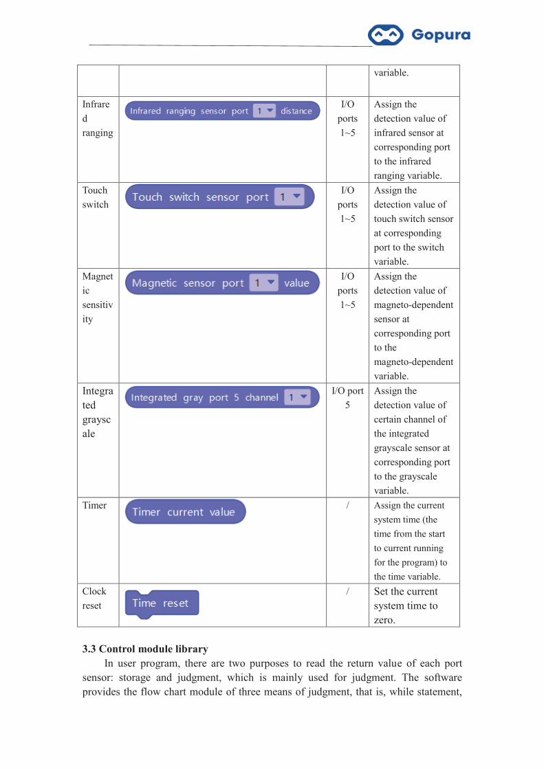
Infrared ranging
I/O
ports 1~5
Assign the detection value of infrared sensor at corresponding port to the infrared ranging variable.
Touch switch
I/O ports 1~5
Assign the detection value of touch switch sensor at corresponding port to the switch variable.
Magnetic sensitivity
I/O
ports 1~5
Assign the detection value of magneto-dependent sensor at corresponding port to the magneto-dependent variable.
Integrated grayscale
I/O port
5 Assign the detection value of certain channel of the integrated grayscale sensor at corresponding port to the grayscale variable.
Timer
/ Assign the current
system time (the time from the start to current running for the program) to the time variable.
Clock reset
/ Set the current system time to zero.
3.3 Control module library
In user program, there are two purposes to read the return value of each port sensor: storage and judgment, which is mainly used for judgment. The software provides the flow chart module of three means of judgment, that is, while statement,
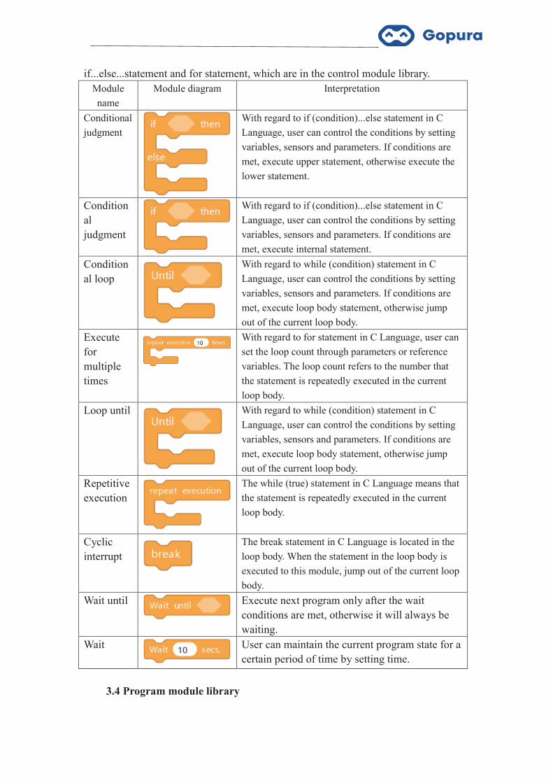
if...else...statement and for statement, which are in the control module library. Module name
Module diagram Interpretation
Conditional judgment
With regard to if (condition)...else statement in C Language, user can control the conditions by setting variables, sensors and parameters. If conditions are met, execute upper statement, otherwise execute the lower statement.
Conditional judgment
With regard to if (condition)...else statement in C Language, user can control the conditions by setting variables, sensors and parameters. If conditions are met, execute internal statement.
Conditional loop
With regard to while (condition) statement in C Language, user can control the conditions by setting variables, sensors and parameters. If conditions are met, execute loop body statement, otherwise jump out of the current loop body.
Execute for multiple times
With regard to for statement in C Language, user can set the loop count through parameters or reference variables. The loop count refers to the number that the statement is repeatedly executed in the current loop body.
Loop until
With regard to while (condition) statement in C Language, user can control the conditions by setting variables, sensors and parameters. If conditions are met, execute loop body statement, otherwise jump out of the current loop body.
Repetitive execution
The while (true) statement in C Language means that the statement is repeatedly executed in the current loop body.
Cyclic interrupt
The break statement in C Language is located in the loop body. When the statement in the loop body is executed to this module, jump out of the current loop body.
Wait until
Execute next program only after the wait conditions are met, otherwise it will always be waiting.
Wait
User can maintain the current program state for a certain period of time by setting time.
3.4 Program module library

Module name
Module diagram Interpretation
New task
Add a process to user program, which is equivalent to the fact that the controller do multiple tasks simultaneously, and these tasks are executed in parallel.
New function
Package the programs of multiple modules into one module to reduce the length of the main program. The module can be used to call subroutines of other programs, and internal parameters of subroutines can be modified by changing parameters or reference variables.
3.5 Operation module library
Module name
Module diagram Interpretation
Addition
Assign the results of the addition operation of the parameters filled in or referenced by the user to integer variable or other variables.
Subtraction
Assign the results of the subtraction operation of the parameters filled in or referenced by the user to integer variable or other variables.
Multiplication
Assign the results of the multiplication operation of the parameters filled in or referenced by the user to integer variable or other variables.
Division
Assign the results of the division operation of the parameters filled in or referenced by the user to integer variable or other variables.
Comparison-greater than
Assign the results of the greater than comparison operation of the parameters filled in or referenced by the user to integer variable or other variables.
Comparison-less than
Assign the results of the less than comparison operation of the parameters filled in or referenced by the user to integer variable or other variables.

Comparison-equal to
Assign the results of the equal to comparison operation of the parameters filled in or referenced by the user to integer variable or other variables.
Comparison-not equal to
Assign the results of the not equal to comparison operation of the parameters filled in or referenced by the user to integer variable or other variables.
Logical operation-and
Perform the logical operation on two logical variables. When “&&” operation is performed, it means that the logic is tenable when two logical variables are established.
Logical operation-or
Perform the logical operation on two logical variables. When “ǁ” operation is performed, it means that the logic is tenable when at least one of these two logical variables is established.
Logical operation-not
Perform the logical operation on the logical variables. When “!” operation is performed, it is to assign the reverse logical variables.
Remainder after division
Assign the results of the parameters filled in or referenced by the user after the operation of dividing input parameters or referencing variable to integer variable or other variables.
Rounding off
Assign the results of the rounding off operation of the parameters filled in or referenced by the user to integer variable or other variables.
Mathematical operation
Assign the results of the mathematical function operation of the parameters filled in or referenced by the user to integer variable or other variables.
Random number
Define the variable random number. The parameters are the generation interval of random number, ranging from 0 to 99999. It does not

correspond to any actuator object.
3.6 Variable module library Variable is one of the two representations of data. Variable represents a named
storage unit with specific attributes, which is used to store data. For example, the detection value of the ground grayscale sensor is assigned to the grayscale variable.
Module name
Module diagram Interpretation
Digital input
Assign the detection value of digital sensor at corresponding port to digital variable, and all digital quantity sensors can be replaced by this module.
3.7 Advanced module library
Module name
Module diagram Interpretation
Digital input
Assign the detection value of digital sensor at corresponding port to digital variable, and all digital quantity sensors can be replaced by this module.
Analog input
Assign the detection value of analog sensor at corresponding port to analog variable, and all analog quantity sensors can be replaced by this module.
Digital output
Control on/off state of corresponding digital actuator (multiple choices). All switch quantity actuators can be replaced by this module.
Read EEPROM
Read the value of certain address (0~99) of EEPROM in the controller and assign it to EEPROM variable.
Write EEPROM
Write the required parameters or referenced variables to an address in the controller EEPROM (0~99)
3. 8 Line patrol module library
See Chapter 5 Introduction of Line Patrol for details.
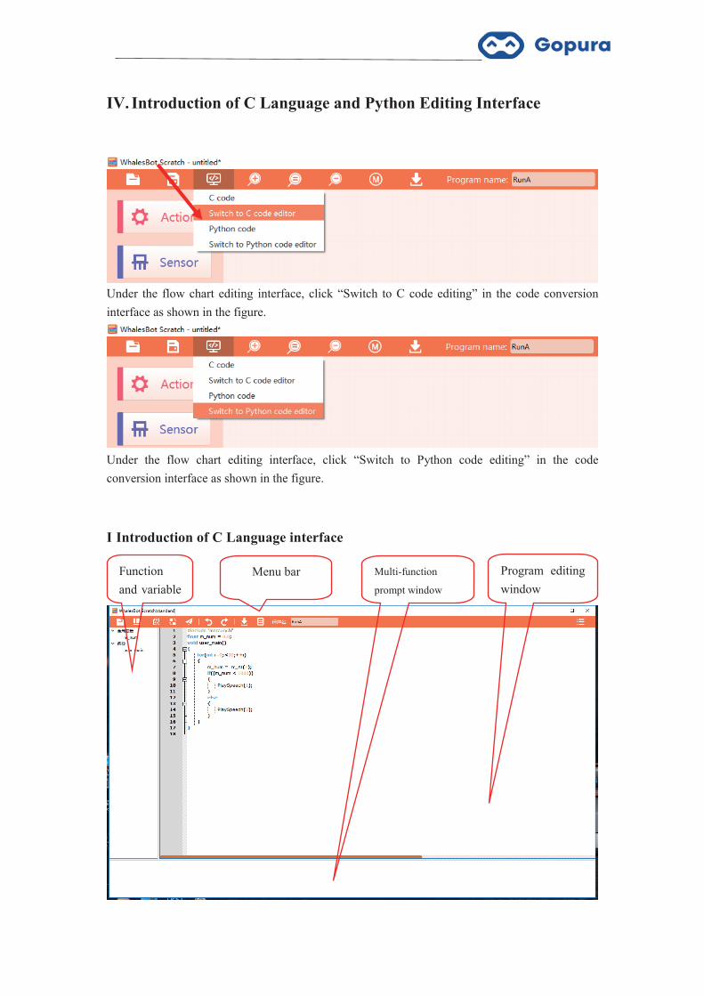
IV. Introduction of C Language and Python Editing Interface
Under the flow chart editing interface, click “Switch to C code editing” in the code conversion interface as shown in the figure.
Under the flow chart editing interface, click “Switch to Python code editing” in the code conversion interface as shown in the figure.
I Introduction of C Language interface
Function and variable display
示
Multi-function
prompt window
Program editing window
口
Menu bar

C Language editing interface is as shown in the figure above, mainly including 4 windows: Menu bar, function and variable display, program editing and multi-function prompt window. The program editing window is the larger one at upper right corner.
II Introduction of Python Language interface
Python editing interface is as shown in the figure above, mainly including 3
windows: Menu bar, program editing and multi-function prompt window. The middle one is the program editing window.
Program editing window
口
Menu bar Multi-function prompt window

Chapter 4 Programming Example
I Control Motor Stop and Rotation by Touching the Sensor
Connect touch sensor and motor to controller, use conditional loop to control
motor stop and rotation, and need to use motor, touch sensor, repetitive execution, judgment, operation-less than, motor stop and cyclic interrupt module, and the program is as shown in the figure above. Note: Ground grayscale sensor module and external sensor shall select consistent port, variables used in loop condition are corresponding variables of touch sensor, and the port checked in motor stop and motor stop module shall be consistent with the external port of the motor.

II Infrared Sensor Detection
Connect infrared sensor and motor to controller, use conditional loop to reverse
the motor for 2s and then stop the motor, and need to use motor, infrared sensor, repetitive execution, judgment, operation-less than, reverse motor, wait, motor stop and cyclic interrupt module, and the program is as shown in the figure above. Note: Ground grayscale sensor module and external sensor shall select consistent port, variables used in loop condition are corresponding variables of touch sensor, and the port checked in motor stop and motor stop module shall be consistent with the external port of the motor.

Chapter 5 Introduction to Line Patrol
The line patrol module library is a specific module library developed for line patrol robot competition. This module library uses the PID algorithm to enable the robot to accurately patrol, locate intersections and make precise turns, which can meet the needs of most line patrol competitions. The line patrol module library includes nine modules of initialization, black and white detection, line patrol intersections, line patrol timing, turns, timing start motor, distance starter motor, grayscale channel starter motor and button. Next, a brief introduction will be given (the trolley wiring is as shown in the right figure, and details are given in the product manual). 1. Initialization:
Set corresponding interfaces and related parameters of motor and sensor of the
line patrol trolley.
Module interpretation: The initial setup module of the whole line patrol module library shall be placed in the initial position of the line patrol program, which is usually placed after the main program.
Motor attribute: The left motor is defaulted to connect motor channel A while the right motor is defaulted to connect motor channel B; power value represents the percentage, the actual running speed of the trolley is multiplied by the percentage with the line patrol speed and the power can be adjusted according to actual running condition of the trolley, so that the trolley can move in a straight line when the left and right motors have the same speed; if the trolley rotates on the spot during line patrol, the power of the motor on the side of the rotation direction of the trolley shall be set to negative (for example, the power of the left motor shall be set to negative if the trolley turns left).
Ground grayscale channel: The integrated grayscale sensor shall be connected to
No. 5 I/O interface, and the ground grayscale sensors are defaulted to correspond to

channels 1-5 of the integrated grayscale sensor from left to right, respectively.
2. Black and white detection:
Calibrate the black lines and white background on the site.
Module interpretation: Constitute a complete program with the initialization
module and download it to the controller, and it is necessary to conduct black and white detection if the site or ambient light is changed.
Detection method: Running program shall be detected according to the prompt (when BLACK LINE or WHITE GROUND is prompted, the grayscale sensors shall be placed on the black lines or white background). After the detection, the controller display will display the detection values, of which the corresponding value of black lines is greater than 2,000 and that of white background is less than 400. If the detection value is not within the scope, it shall be re-detected. 3. Line patrol intersection:
Pass through certain type of intersection at a certain speed of line patrol, then
continue to advance for a period of time before stop. Intersection type:
or Check the left one, or Check the right one
or Check T-junction/intersection
Check the left or right one, and cannot check T-junction/intersection
Module interpretation: The line patrol intersection module is mostly used before the turning module, and the trolley stops after running to a certain intersection to prepare for turning; it shall be used after the initialization module.
Line patrol speed: Actual speed=Line patrol speed x power (%) (initial module setup)
Time of passing through the intersection: It refers to the time for the grayscale sensor of the trolley to continue to advance after passing through corresponding intersection (black lines); the length of the time of passing through the intersection directly affects its position relationship with black lines after the trolley turns.
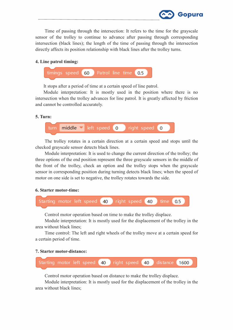
4. Line patrol timing:
It stops after a period of time at a certain speed of line patrol. Module interpretation: It is mostly used in the position where there is no
intersection when the trolley advances for line patrol. It is greatly affected by friction and cannot be controlled accurately.
5. Turn:
The trolley rotates in a certain direction at a certain speed and stops until the
checked grayscale sensor detects black lines. Module interpretation: It is used to change the current direction of the trolley; the
three options of the end position represent the three grayscale sensors in the middle of the front of the trolley, check an option and the trolley stops when the grayscale sensor in corresponding position during turning detects black lines; when the speed of motor on one side is set to negative, the trolley rotates towards the side.
6. Starter motor-time:
Control motor operation based on time to make the trolley displace. Module interpretation: It is mostly used for the displacement of the trolley in the
area without black lines; Time control: The left and right wheels of the trolley move at a certain speed for
a certain period of time.
7. Starter motor-distance:
Control motor operation based on distance to make the trolley displace. Module interpretation: It is mostly used for the displacement of the trolley in the
area without black lines;

Distance control: The left and right wheels of the trolley move at a certain speed for a certain period of time (The displacement distance shall be subject to the motor wheel with faster speed).
8. Starter motor-sensor control:
Control motor operation based on sensor to make the trolley displace. Module interpretation: It is mostly used for the displacement of the trolley in the
area without black lines; Sensor control: The left and right wheels of the trolley move at a certain speed,
and the trolley stops until the feedback value of the sensor selected meets conditions.
9. Button start:
When the program is executed to this module, it enters a loop until the controller
key is pressed down; after the program jumps out of the loop, continue to execute backwards.
Button start is mostly used after the initialization module, so that the trolley will not start immediately after running the program and adjust the time for competitors.
Chapter 6 Epilogue
I Maintenance
1. In case of low battery during use, please replace the battery in time, so as not to affect use.
2. If the controller is not used for a long time, please take the battery out. 3. Since there are a large number of precision circuits in the controller, please
place the controller in a cool and dry place when not using the controller. 4. After each use, it is recommended to separate parts for next use.
II. System Upgrade
We will upgrade the controller system from time to time. Please download the latest software version available on our official website in time. When the controller is connected to the computer through USB cable, it will automatically prompt to upgrade. You may check upgrade version from the pop-up interface of software firmware upgrade.
III. Contact Us
Our team strive to provide the best customer service. We will constantly upgrade to improve the controller system and enhance software functions. Please always check and download the latest software available on our official website.
Should you please contact us for any problems or suggestions. Website: http://www.gopuratech.com TEL:+86-021-64027078 Email:[email protected]