untitled - pipeline and hazardous materials safety administration
TRANSCRIPT

PHMSA 000114326
ConocoPhillips Alaska, Inc.
OIL DISCHARGE PREVENTION
AND
CONTINGENCY PLAN
ALPINE DEVELOPMENT PARTICIPATING AREA
NORTH SLOPE, ALASKA
FEBRUARY 2013
Alaska, Inc.
PHMSA 000114327

PHMSA 000114328
PHMSA 000114329

Alpine Development ODPCP ii February 2013, Rev. 0
BLANK PAGE
PHMSA 000114330
Alpine Development ODPCP iii January 2014, Rev. 3
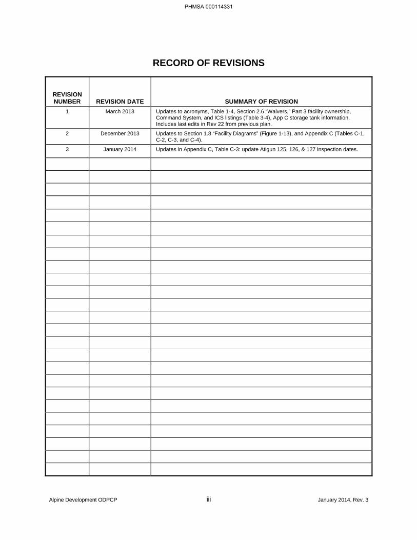
RECORD OF REVISIONS
REVISION NUMBER REVISION DATE SUMMARY OF REVISION
1 March 2013 Updates to acronyms, Table 1-4, Section 2.6 “Waivers,” Part 3 facility ownership, Command System, and ICS listings (Table 3-4), App C storage tank information. Includes last edits in Rev 22 from previous plan.
2 December 2013 Updates to Section 1.8 “Facility Diagrams” (Figure 1-13), and Appendix C (Tables C-1, C-2, C-3, and C-4).
3 January 2014 Updates in Appendix C, Table C-3: update Atigun 125, 126, & 127 inspection dates.
PHMSA 000114331
Alpine Development ODPCP iv March 2013, Rev. 1
BLANK PAGE
PHMSA 000114332
Alpine Development ODPCP T-1 February 2013, Rev. 0
OIL DISCHARGE PREVENTION AND CONTINGENCY PLAN ALPINE DEVELOPMENT PARTICIPATING AREA, NORTH SLOPE, ALASKA
TABLE OF CONTENTS
MANAGEMENT APPROVAL AND MANPOWER AUTHORIZATION ......................................................... i
RECORD OF REVISIONS ........................................................................................................................... iii
TABLE OF CONTENTS ............................................................................................................................ T-1
List of Figures ................................................................................................................................ T-5
List of Tables ................................................................................................................................. T-6
List of Acronyms ............................................................................................................................ T-9
OIL POLLUTION ACT OF 1990 (OPA 90) ADDENDUM ................................................................... OPA-1
INTRODUCTION ......................................................................................................................................... I-1
Objectives ...................................................................................................................................... I-1
ACS Technical Manual................................................................................................................... I-2
Plan Contents Organization ........................................................................................................... I-2
Plan Distribution ............................................................................................................................. I-3
Updating Procedures ..................................................................................................................... I-3
Plan Renewal ................................................................................................................................. I-4
PART 1 RESPONSE ACTION PLAN [18 AAC 75.425(e)(1)] ............................................................. 1-1
1.1 EMERGENCY ACTION CHECKLIST [18 AAC 75.425(e)(1)(A)] ..................................... 1-1
1.2 REPORTING AND NOTIFICATION [18 AAC 75.425(e)(1)(B)] ....................................... 1-3 1.2.1 Initial Reporting [18 AAC 75.425(e)(1)(B)(i)] ....................................................... 1-3 1.2.2 External Notification Procedures [18 AAC 75.425(e)(1)(B)(ii)] ........................... 1-6 1.2.3 Additional Notifications ........................................................................................ 1-6 1.2.4 Written Reporting Requirements ......................................................................... 1-9
1.3 SAFETY [18 AAC 75.425(e)(1)(C)] ................................................................................ 1-11
1.4 COMMUNICATIONS [18 AAC 75.425(e)(1)(D)] ............................................................ 1-12 1.4.1 Category 1: SRT Communications ................................................................... 1-12 1.4.2 Category 2: ACS Communications ................................................................... 1-13 1.4.3 Category 3: Alpine Telecom Resources ........................................................... 1-13 1.4.4 Category 4: Local Cellular Service.................................................................... 1-14
1.5 DEPLOYMENT STRATEGIES [18 AAC 75.425(e)(1)(E)] ............................................. 1-16 1.5.1 Transport Procedures [18 AAC 75.425(e)(1)(E)(i)] ........................................... 1-16
PHMSA 000114333
Alpine Development ODPCP T-2 February 2013, Rev. 0
1.5.2 Notification and Mobilization of Response Action Contractor [18 AAC 75.425(e)(1)(E)(ii)] .............................................................................. 1-17
1.6 RESPONSE STRATEGIES [18 AAC 75.425(e)(1)(F)] .................................................. 1-18 1.6.1 Qualifier Statement ........................................................................................... 1-18 1.6.2 Temporary Storage and Disposal [18 AAC 75.425(e)(1)(F)(x)] ........................ 1-19 1.6.3 Response Scenarios and Strategies [18 AAC 75.425(e)(1)(F)] ....................... 1-20
1.7 NON-MECHANICAL RESPONSE OPTIONS [18 AAC 75.425(e)(1)(G)] ...................... 1-68 1.7.1 Obtaining Permits and Approvals ..................................................................... 1-68 1.7.2 Decision Criteria for Use ................................................................................... 1-68 1.7.3 Implementation Procedures .............................................................................. 1-68 1.7.4 Required Equipment and Personnel ................................................................. 1-68
1.8 FACILITY DIAGRAMS [18 AAC 75.425(e)(1)(H)] .......................................................... 1-69
1.9 RESPONSE SCENARIO FOR AN EXPLORATION OR PRODUCTION FACILITY [18 AAC 75.425(e)(1)(I)] ................................................................................................ 1-87 1.9.1 Well Capping ..................................................................................................... 1-87 1.9.2 Relief Well ......................................................................................................... 1-90
PART 2 PREVENTION PLAN [18 AAC 75.425(e)(2)] ........................................................................ 2-1
2.1 PREVENTION, INSPECTION, AND MAINTENANCE PROGRAMS [18 AAC 75.425(e)(2)(A)] ................................................................................................................ 2-1 2.1.1 Oil Discharge Prevention Training and Recordkeeping [18 AAC 75.020] .......... 2-1 2.1.2 Substance Abuse Programs [18 AAC 75.007(e)] ............................................... 2-3 2.1.3 Medical Monitoring [18 AAC 75.007(e)] .............................................................. 2-4 2.1.4 Security and Surveillance Programs [18 AAC 75.007(f)] .................................... 2-5 2.1.5 Operating Requirements for Exploration and Production Facilities [18 AAC
75.045] ................................................................................................................ 2-5 2.1.6 Flowline and Facility Piping Requirements [18 AAC 75.047 and 75.080] ........ 2-10 2.1.7 Leak Detection, Monitoring, and Operating Requirements for Crude Oil
Transmission Pipelines [18 AAC 75.055] ......................................................... 2-16 2.1.8 Oil Storage Tanks [18 AAC 75.066] .................................................................. 2-17 2.1.9 Secondary Containment Areas for Oil Storage Tanks [18 AAC 75.075] .......... 2-20
2.2 DISCHARGE HISTORY [18 AAC 75.425(e)(2)(B)] ....................................................... 2-33
2.3 POTENTIAL DISCHARGE ANALYSIS [18 AAC 75.425(e)(2)(C)] ................................ 2-38
2.4 CONDITIONS INCREASING RISK OF DISCHARGE [18 AAC 75.425(e)(2)(D)].......... 2-42
2.5 DISCHARGE DETECTION [18 AAC 75.425(e)(2)(E)] ................................................... 2-44 2.5.1 Discharge Detection at Drill Sites ..................................................................... 2-44 2.5.2 Alpine Oil Pipeline Discharge Detection ........................................................... 2-44 2.5.3 Discharge Detection at Alpine Facilities ........................................................... 2-46 2.5.4 In-Field Pipelines Discharge Detection ............................................................. 2-46 2.5.5 Storage Tanks Discharge Detection ................................................................. 2-47
2.6 WAIVERS [18 AAC 75.425(e)(2)(F)] .............................................................................. 2-48
PART 3 SUPPLEMENTAL INFORMATION [18 AAC 75.425(e)(3)] .................................................. 3-1
3.1 FACILITY DESCRIPTION AND OPERATIONAL OVERVIEW [18 AAC 75.425(e)(3)(A)] ................................................................................................................ 3-1 3.1.1 Facility Ownership and General Site Description [18 AAC 75.425(e)(3)(A)] ...... 3-1
PHMSA 000114334
Alpine Development ODPCP T-3 February 2013, Rev. 0
3.1.2 Facility Oil Storage Containers [18 AAC 75.425(e)(3)(A)(i) and (ii)] ................... 3-2 3.1.3 Transfer Procedures and Major Fueling Areas [18 AAC 75.425(e)(3)(A)(vi)] .... 3-3 3.1.4 Pipelines and Processing Facilities [18 AAC 75.425(e)(3)(A)(vii)] ..................... 3-4 3.1.5 Crude Oil and Reservoir Characteristics .......................................................... 3-10
3.2 RECEIVING ENVIRONMENT [18 AAC 75.425(e)(3)(B)] .............................................. 3-12 3.2.1 Routes of Travel to Open Water [18 AAC 75.425(e)(3)(B)(i)] ........................... 3-18 3.2.2 Response Planning Standard Volume to Open Water ..................................... 3-19
3.3 COMMAND SYSTEM [18 AAC 75.425(e)(3)(C)] ........................................................... 3-20
3.4 REALISTIC MAXIMUM RESPONSE OPERATING LIMITATIONS [18 AAC 75.425(e)(3)(D)] ............................................................................................................. 3-26 3.4.1 Introduction ....................................................................................................... 3-26 3.4.2 Weather and Ice Conditions During the Shoulder Seasons ............................. 3-26 3.4.3 In Situ Burning Response Measures to Reduce Environmental
Consequences of a Spill in Ice Conditions ....................................................... 3-27 3.4.4 Environmental Conditions ................................................................................. 3-33 3.4.5 Colville River Delta ............................................................................................ 3-34
3.5 LOGISTICAL SUPPORT [18 AAC 75.425(e)(3)(E)] ...................................................... 3-36
3.6 RESPONSE EQUIPMENT [18 AAC 75.425(e)(3)(F)] .................................................... 3-37 3.6.1 Equipment Lists................................................................................................. 3-37 3.6.2 Maintenance and Inspection of Response Equipment ..................................... 3-37 3.6.3 Pre-Deployed Response Equipment ................................................................ 3-41
3.7 NON-MECHANICAL RESPONSE INFORMATION [18 AAC 75.425(e)(3)(G)] ............. 3-44 3.7.1 Environmental Consequences .......................................................................... 3-44 3.7.2 Operational Capability and Effectiveness of In Situ Burning in Ice ................... 3-45
3.8 RESPONSE CONTRACTOR INFORMATION [18 AAC 75.425(e)(3)(H)] ..................... 3-46
3.9 TRAINING AND DRILLS [18 AAC 75.425(e)(3)(I)] ........................................................ 3-48 3.9.1 North Slope Spill Response Team Spill Response Training ............................ 3-48 3.9.2 Incident Management Team Member Training ................................................. 3-48 3.9.3 Auxiliary Contract Response Team .................................................................. 3-49 3.9.4 Other Training ................................................................................................... 3-49 3.9.5 Recordkeeping .................................................................................................. 3-51 3.9.6 Spill Response Exercises ................................................................................. 3-51
3.10 PROTECTION OF ENVIRONMENTALLY SENSITIVE AREAS [18 AAC 75.425(e)(3)(J)] .............................................................................................................. 3-56
3.11 ADDITIONAL INFORMATION [18 AAC 75.425(e)(3)(K)] .............................................. 3-56
3.12 BIBLIOGRAPHY [18 AAC 75.425(e)(3)(L)] ................................................................... 3-57
PART 4 BEST AVAILABLE TECHNOLOGY [18 AAC 75.425(e)(4)] ................................................. 4-1
4.1 COMMUNICATIONS [18 AAC 75.425(e)(4)(A)(i)] ........................................................... 4-1
4.2 SOURCE CONTROL [18 AAC 75.425(e)(4)(A)(i)] ........................................................... 4-1 4.2.1 Well Source Control ............................................................................................ 4-1 4.2.2 Pipeline Source Control ...................................................................................... 4-3 4.2.3 Tank Source Control ........................................................................................... 4-3
4.3 TRAJECTORY ANALYSES AND FORECASTS [18 AAC 75.425(e)(4)(A)(i)] ............... 4-11
PHMSA 000114335
Alpine Development ODPCP T-4 February 2013, Rev. 0
4.4 WILDLIFE CAPTURE, TREATMENT, AND RELEASE PROGRAMS [18 AAC 75.425(e)(4)(A)(i)] .......................................................................................................... 4-11
4.5 CATHODIC PROTECTION FOR FIELD-CONSTRUCTED OIL STORAGE TANKS [18 AAC 75.425(e)(4)(A)(ii)] ........................................................................................... 4-11
4.6 LEAK DETECTION SYSTEM FOR FIELD-CONSTRUCTED OIL STORAGE TANKS [18 AAC 75.425(e)(4)(A)(ii)] .............................................................................. 4-11
4.7 LIQUID LEVEL DETERMINATION [18 AAC 75.425(e)(4)(A)(ii)] ................................... 4-11
4.8 MAINTENANCE PROCEDURES FOR BURIED STEEL FACILITY OIL PIPING [18 AAC 75.425(e)(4)(A)(ii)] ................................................................................................. 4-15
4.9 PROTECTIVE COATING AND CATHODIC PROTECTION FOR FACILITY OIL PIPING [18 AAC 75. 425(e)(4)(A)(ii)] ............................................................................. 4-15 4.9.1 Pipeline Corrosion Protective (Anti-Corrosion) Wrapping or Coating ............... 4-15 4.9.2 Cathodic Protection System .............................................................................. 4-16
4.10 CORROSION SURVEYS [18 AAC 75. 425(e)(4)(A)(ii)] ............................................... 4-16
4.11 PIPELINE LEAK DETECTION, MONITORING, AND OPERATIONS [18 AAC 75.425(e)(4)((A)(iv)] ....................................................................................................... 4-16 4.11.1 Aboveground Crude Oil Transmission Pipeline ................................................ 4-16 4.11.2 Belowground Crude Oil Transmission Pipeline ................................................ 4-17
PART 5 RESPONSE PLANNING STANDARD [18 AAC 75.425(e)(5)] ............................................. 5-1
5.1 STORAGE TANK RUPTURE [18 AAC 75.432] ............................................................... 5-1
5.2 PRODUCTION WELL BLOWOUT [18 AAC 75.434] ....................................................... 5-1
5.3 CRUDE OIL TRANSMISSION PIPELINE SPILL TO MILUVEACH RIVER [18 AAC 75.436] ............................................................................................................... 5-2
5.4 CRUDE OIL TRANSMISSION PIPELINE SPILL TO KACHEMACH RIVER [18 AAC 75.436] ............................................................................................................... 5-3
5.5 CRUDE OIL TRANSMISSION PIPELINE SPILL TO COLVILLE RIVER [18 AAC 75.436] ............................................................................................................... 5-4
APPENDICES
A Alpine Project: Oil Pipeline Spill Isolation Strategy
B Alpine Spill History
C ADEC Regulated Oil Storage Tanks
PHMSA 000114336
Alpine Development ODPCP T-5 February 2013, Rev. 0
LIST OF FIGURES
1-1: Spill Report Notification ................................................................................................................. 1-5 1-2: CPAI North Slope Oil Spill Communication System ................................................................... 1-15 1-3: Alpine Summer Wind Rose Diagram .......................................................................................... 1-34 1-4: Alpine CD-2 Fallout Plumes of Simulated Summer Blowout ...................................................... 1-35 1-5: Alpine Unit CD-2 Pad Detail ........................................................................................................ 1-36 1-6: Alpine Winter Wind Rose Diagram ............................................................................................. 1-47 1-7: Alpine CD-2 Fallout Plumes of Simulated Winter Blowout ......................................................... 1-48 1-8: Alpine Unit CD-2 Pad Detail, Simulated Winter Blowout ............................................................ 1-49 1-9: Miluveach River Crossing, Diagram 1 ......................................................................................... 1-58 1-10: Miluveach River Crossing, Diagram 2 ......................................................................................... 1-59 1-11: Alpine CD-1 Pad Detail, Tank Rupture in Summer ..................................................................... 1-67 1-12: Alpine Development Area Location Map..................................................................................... 1-71 1-13: Alpine Pipelines Operations Rights-of-Way ................................................................................ 1-73 1-14: Alpine CD-1 Vicinity Map ............................................................................................................ 1-75 1-15: Alpine CD-1 Pad Layout.............................................................................................................. 1-76 1-16: Alpine CD-1 Pad Detail ............................................................................................................... 1-77 1-17: Well CD-2 Vicinity Map ............................................................................................................... 1-79 1-18: Alpine CD-2 Pad Layout.............................................................................................................. 1-80 1-19: Alpine CD-3 Vicinity Map ............................................................................................................ 1-81 1-20: Alpine CD-3 Pad Layout.............................................................................................................. 1-82 1-21: Alpine CD-4 Vicinity Map ............................................................................................................ 1-83 1-22: Alpine CD-4 Pad Layout.............................................................................................................. 1-84 1-23: Alpine CD-5 Location Map .......................................................................................................... 1-85 1-24: Alpine CD-5 Pad Layout.............................................................................................................. 1-86 2-1: Alpine Central Processing Facility Tank Farm Area Site Plan .................................................... 2-23 2-2: Alpine Central Processing Facility Tank Farm Area Typical Sections ........................................ 2-25 2-3: Alpine Central Processing Facility Tank Farm Area As-Built Survey Truck Loading/Unloading
Facility ......................................................................................................................................... 2-31 2-4: Percentage of Oil Spill Incidents at Each Source at Alpine (1999 – 2012) ................................. 2-34 2-5: Percentage of Oil Spill Volume at Each Source at Alpine (1999 – 2012) ................................... 2-35 2-6: Spill Incidents by Source at Alpine (1999 – 2012) ...................................................................... 2-36 2-7: Spill Volume by Source at Alpine (1999 – 2012) ........................................................................ 2-37 3-1: Incident Command System Organization Chart for a Major Spill ............................................... 3-22 3-2: Approximate Location of Pre-Deployed Boom and Pre-Staged Spill Response Equipment in
the Colville River Delta ................................................................................................................ 3-39 3-3: ACS Statement of Contractual Terms ......................................................................................... 3-47
PHMSA 000114337
Alpine Development ODPCP T-6 February 2013, Rev. 0
LIST OF TABLES
1-1: Emergency Action Checklist ......................................................................................................... 1-1 1-2: Emergency Action and Notification Sequence .............................................................................. 1-2 1-3: Emergency Contact List ................................................................................................................ 1-4 1-4: Agency Notification Information .................................................................................................... 1-7 1-5: Agency Reporting Requirements for Oil Spills and Hazardous Materials .................................. 1-10 1-6: Seasonal Transportation Options ............................................................................................... 1-16 1-7: Estimated Response Times ........................................................................................................ 1-17 1-8: Alpine CD-2 Production Well Blowout in Summer Scenario Conditions ..................................... 1-23 1-9: Alpine CD-2 Production Well Blowout in Summer Response Strategy ...................................... 1-24 1-10: Alpine CD-2 Production Well Blowout in Summer Liquid Recovery Capability .......................... 1-29 1-11: Alpine CD-2 Production Well Blowout in Summer Liquid Handling Capability, Days 1 - 18 ....... 1-30 1-12: Alpine CD-2 Production Well Blowout in Summer Major Equipment Equivalents to Meet the
Response Planning Standard ..................................................................................................... 1-32 1-13: Alpine CD-2 Production Well Blowout in Summer Staff to Operate Oil Recovery and
Transfer Equipment, Per Shift ..................................................................................................... 1-33 1-14: Alpine CD-2 Production Well Blowout in Winter Scenario Conditions ........................................ 1-39 1-15: Alpine CD-2 Production Well Blowout in Winter Response Strategy ......................................... 1-40 1-16: Alpine CD-2 Production Well Blowout in Winter Recovery and Handling Capability .................. 1-43 1-17: Alpine CD-2 Production Well Blowout in Winter Staff for Operation of Oil Recovery and
Transfer Equipment ..................................................................................................................... 1-45 1-18: Alpine CD-2 Production Well Blowout in Winter Oil Recovery and Transfer Equipment ............ 1-46 1-19: Alpine Crude Oil Pipeline Rupture Over the Miluveach River in Summer Scenario
Conditions ................................................................................................................................... 1-53 1-20: Alpine Crude Oil Pipeline Rupture Over the Miluveach River in Summer Response Strategy .. 1-54 1-21: Alpine Crude Oil Pipeline Rupture Over the Miluveach River in Summer Liquid Recovery
Capability .................................................................................................................................... 1-56 1-22: Alpine Crude Oil Pipeline Rupture Over the Miluveach River in Summer Liquid Handling
Capability .................................................................................................................................... 1-57 1-23: Alpine CD-1 Tank Rupture in Summer Scenario Conditions ...................................................... 1-63 1-24: Alpine CD-1 Tank Rupture in Summer Response Strategy ........................................................ 1-64 1-25: Alpine CD-1 Tank Rupture in Summer Recovery and Handling Capability ................................ 1-66 1-26: Well Capping Equipment List ...................................................................................................... 1-89 2-1: Summary of Key Positions and Training ....................................................................................... 2-2 2-2: Loading/Unloading Areas at Alpine ............................................................................................. 2-29 2-3: Alpine Potential Oil Spills from Major Sources ........................................................................... 2-38 2-4: Alpine Historical Oil Spill Data .................................................................................................... 2-38 2-5: Potential Discharge of Alpine Flowlines ...................................................................................... 2-41 3-1: Cross-Country Pipeline Design Basis ........................................................................................... 3-5 3-2: Alpine Cross-Country Pipeline Vertical Loop Placement .............................................................. 3-5 3-3: Composition of Alpine Crude ...................................................................................................... 3-11 3-4: Incident Command System ......................................................................................................... 3-23 3-5: Burning Equipment ...................................................................................................................... 3-28 3-6: Safe Working Distances from the Fire ........................................................................................ 3-29 3-7: Minimum Ignitable Thickness on Water ...................................................................................... 3-30
PHMSA 000114338
Alpine Development ODPCP T-7 February 2013, Rev. 0
3-8: Burn/Removal Rates for Large Fires on Water ........................................................................... 3-31 3-9: Fire Extinguishing Slick Thickness .............................................................................................. 3-31 3-10: Pre-deployed Boom .................................................................................................................... 3-42 3-11: Safe Distances Between In Situ Burns and Downwind Human Populations in Flat Terrain:
Location of Fire Zones ................................................................................................................ 3-45 3-12: Typical North Slope Spill Response Team Training Program Courses ...................................... 3-50 3-13: Annual and Triennial Drills .......................................................................................................... 3-52 3-14: National PREP Requirements Drill Description .......................................................................... 3-53 4-1: Best Available Technology Analysis Well Blowout Source Control .............................................. 4-5 4-2: Best Available Technology Analysis Crude Oil Transmission Pipeline Source Control ............... 4-7 4-3: Best Available Technology Analysis Tank Source Control ........................................................... 4-9 4-4: Best Available Technology Analysis Tank Liquid Level Determination ...................................... 4-12 4-5: Best Available Technology Analysis Leak Detection in Crude Oil Transmission Pipeline ......... 4-18
PHMSA 000114339

Alpine Development ODPCP T-8 February 2013, Rev. 0
BLANK PAGE
PHMSA 000114340
Alpine Development ODPCP T-9 February 2013, Rev. 0
LIST OF ACRONYMS
°F degrees Fahrenheit
°C degrees Celsius
AAC Alaska Administrative Code
ACP area contingency plan
ACS Alaska Clean Seas
ADEC Alaska Department of Environmental Conservation
ADF&G Alaska Department of Fish and Game
ADNR Alaska Department of Natural Resources
AFPM American Fuel & Petrochemical Manufacturers
ANSI American National Standards Institute
AOGCC Alaska Oil and Gas Conservation Commission
API American Petroleum Institute
ARRT Alaska Regional Response Team
ASME American Society of Mechanical Engineers
ATV all-terrain vehicle
BAT best available technology
bbl barrels
Bird Rescue International Bird Rescue
BLM U.S. Department of the Interior, Bureau of Land Management
BOP blowout preventer
bopd barrels of oil per day
boph barrels of oil per hour
bpd barrel per day
bph barrels per hour
BPXA BP Exploration (Alaska) Inc.
BSEE Bureau of Safety and Environmental Enforcement
CERCLA Comprehensive Environmental Response, Compensation, and Liability Act
CFR Code of Federal Regulation
cfs cubic feet per second
CO2 carbon dioxide
CP cathodic protection
PHMSA 000114341
LIST OF ACRONYMS (CONTINUED)
Alpine Development ODPCP T-10 March 2013, Rev. 1
CPAI ConocoPhillips Alaska, Inc.
CPF Central Processing Facility
CS Control Site
CTF Containment Task Force
cu yd cubic yard
DCS distributed control system
DOT U.S. Department of Transportation
DRA drag reducing agent
EFA EFA Technologies
EPA U.S. Environmental Protection Agency
ERD extended reach drilling
ESD emergency shutdown
FBE fusion bonded epoxy
FLIR forward-looking infrared
GOR gas-to-oil ratio
gpm gallons per minute
HAZMAT Hazardous Materials
HAZWOPER hazardous waste operations and emergency response
HDD horizontal directional drilling
HDPE high density prolyethylene
HMRT hazardous materials response team
HSE health, safety, and environment
IC Incident Commander
ICS Incident Command System
IMAT Incident Management Assist Team
IMT Incident Management Team
LEPC Local Emergency Planning Committee
MAD Mutual Aid Drill
MB Mass Balance
MBLPC Mass Balance Line Pack Compensation
mph miles per hour
NACE National Association of Corrosion Engineers
PHMSA 000114342
LIST OF ACRONYMS (CONTINUED)
Alpine Development ODPCP T-11 February 2013, Rev. 0
NGL natural gas liquid
NIMS National Incident Management System
NIST National Institute of Standards and Technology
NPDES National Pollutant Discharge Elimination System
NPRA National Petroleum Reserve – Alaska
National PREP National Preparedness for Response Exercise Program
NPWM Negative Pressure Wave Monitoring
NRC National Response Center
NSB North Slope Borough
NSSRT North Slope Spill Response Team
ODPCP Oil Discharge Prevention and Contingency Plan
OSC On-Scene Commander
OSHA Occupational Safety and Health Administration
OSRO oil spill removal organization
PM preventive maintenance
PPA™ Pressure Point Analysis™
PPE personal protective equipment
ppm parts per million
psi pounds per square inch
psig pounds per square inch gauge
PVC polyvinyl chloride
QI Qualified Individual
RCRA Resource Conservation and Recovery Act
REIM remote electrical-instrument module
RPS response planning standard
RTTM Real Time Transient Model
SCADA Supervisory Control and Data Acquisition
scf/bbl standard cubic feet per barrel
SIS safety instrument system
SOP Standard Operating Procedure
SPCC Spill Prevention, Control, and Countermeasure
SPCO State Pipeline Coordinator’s Office
PHMSA 000114343
LIST OF ACRONYMS (CONTINUED)
Alpine Development ODPCP T-12 February 2013, Rev. 0
SRT Spill Response Team
TF Task Force
UHF ultra high frequency
ULSD ultra-low sulfur diesel
USCG U.S. Coast Guard
USFWS U.S. Fish and Wildlife Service
VHF very high frequency
VSM vertical support member
WCD worst case discharge
PHMSA 000114344
Alpine Development ODPCP OPA-1 February 2013, Rev. 0
OIL POLLUTION ACT OF 1990 ADDENDUM
U.S. Department of Transportation and U.S. Environmental Protection Agency
ALPINE DEVELOPMENT PARTICIPATING AREA
OIL DISCHARGE PREVENTION AND CONTINGENCY PLAN
PHMSA 000114345

BLANK PAGE
PHMSA 000114346

U.S. DEPARTMENT OF TRANSPORTATION
PHMSA 000114347

BLANK PAGE
PHMSA 000114348
Alpine Development ODPCP DOT-1 February 2013, Rev. 0
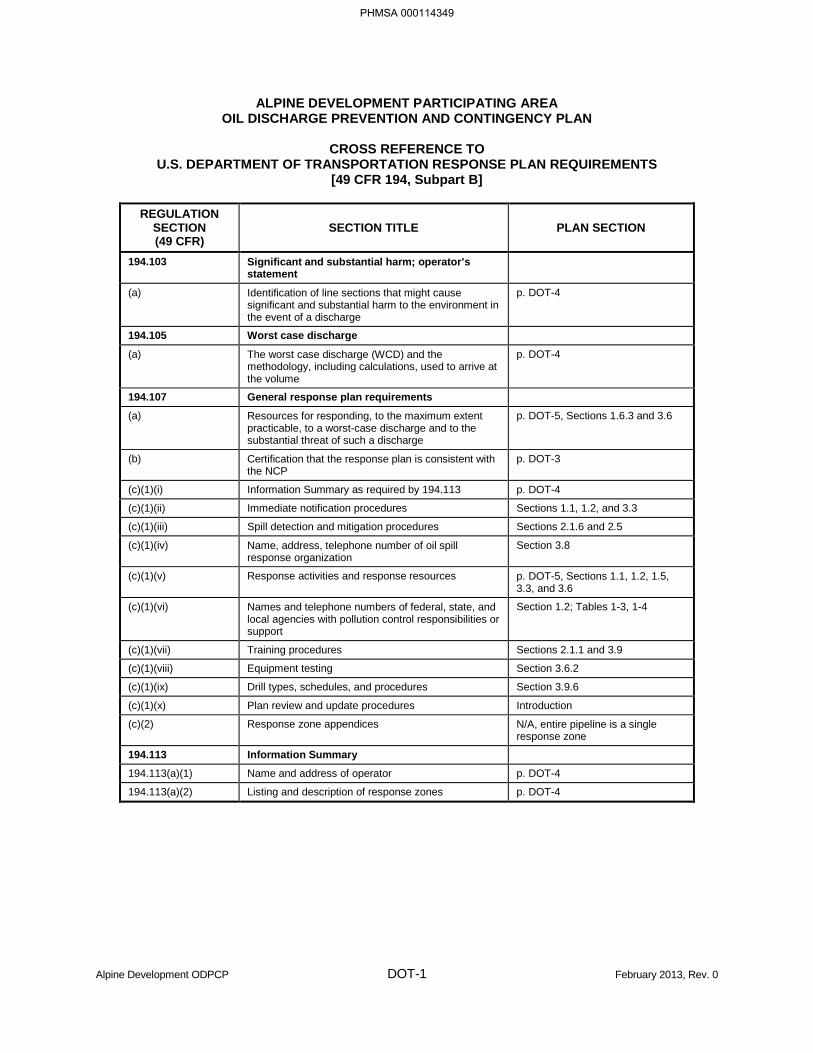
ALPINE DEVELOPMENT PARTICIPATING AREA OIL DISCHARGE PREVENTION AND CONTINGENCY PLAN
CROSS REFERENCE TO
U.S. DEPARTMENT OF TRANSPORTATION RESPONSE PLAN REQUIREMENTS [49 CFR 194, Subpart B]
REGULATION
SECTION (49 CFR)
SECTION TITLE PLAN SECTION
194.103 Significant and substantial harm; operator’s statement
(a) Identification of line sections that might cause significant and substantial harm to the environment in the event of a discharge
p. DOT-4
194.105 Worst case discharge
(a) The worst case discharge (WCD) and the methodology, including calculations, used to arrive at the volume
p. DOT-4
194.107 General response plan requirements
(a) Resources for responding, to the maximum extent practicable, to a worst-case discharge and to the substantial threat of such a discharge
p. DOT-5, Sections 1.6.3 and 3.6
(b) Certification that the response plan is consistent with the NCP
p. DOT-3
(c)(1)(i) Information Summary as required by 194.113 p. DOT-4
(c)(1)(ii) Immediate notification procedures Sections 1.1, 1.2, and 3.3
(c)(1)(iii) Spill detection and mitigation procedures Sections 2.1.6 and 2.5
(c)(1)(iv) Name, address, telephone number of oil spill response organization
Section 3.8
(c)(1)(v) Response activities and response resources p. DOT-5, Sections 1.1, 1.2, 1.5, 3.3, and 3.6
(c)(1)(vi) Names and telephone numbers of federal, state, and local agencies with pollution control responsibilities or support
Section 1.2; Tables 1-3, 1-4
(c)(1)(vii) Training procedures Sections 2.1.1 and 3.9
(c)(1)(viii) Equipment testing Section 3.6.2
(c)(1)(ix) Drill types, schedules, and procedures Section 3.9.6
(c)(1)(x) Plan review and update procedures Introduction
(c)(2) Response zone appendices N/A, entire pipeline is a single response zone
194.113 Information Summary
194.113(a)(1) Name and address of operator p. DOT-4
194.113(a)(2) Listing and description of response zones p. DOT-4
PHMSA 000114349
PHMSA 000114350
PHMSA 000114351
Alpine Development ODPCP DOT-4 February 2013, Rev. 0
U.S. DEPARTMENT OF TRANSPORTATION INFORMATION SUMMARY
NAME AND ADDRESS OF OPERATOR
ConocoPhillips Alaska, Inc. Street Address: P.O. Box 100360 700 G Street Anchorage, AK 99510-0360 Anchorage, AK 99510-0360 Phone: (907) 276-1215 Fax: (907) 265-6235
RESPONSE ZONE DESCRIPTION
The Alpine Development Participating Area, located in the North Slope Borough, Alaska, consists of a single response zone containing a product transportation system, consisting of an onshore pipeline. For purposes of this plan, all the pipelines within the Alpine Development Participating Area under the jurisdiction of Title 49 of the Code of Federal Regulations (CFR) Part 149 are considered to be one line section and, therefore, in one response zone.
The Alpine pipelines have individual numbered vertical support members (VSMs) that can be used to identify particular line segments, if necessary.
NAME AND TELEPHONE NUMBER OF QUALIFIED INDIVIDUAL
Qualified Individual: Alternate:
Manager, Western North Slope Operations Alpine Production Supervisor Steven Ovenden Mike Lyden/Warren Dobson (907) 263-4464 (907) 670-4021
CPAI Security maintains 24-hour contact numbers for the Qualified Individual and his alternates. Security can be reached in Anchorage at (907) 265-1000 or at Alpine at (907) 670-4002.
BASIS OF DETERMINATION OF SIGNIFICANT AND SUBSTANTIAL HARM
U.S. Department of Transportation (DOT) regulations state that a pipeline can be expected to cause significant and substantial harm to the environment if a pipeline section is greater than 10 miles in length [49 CFR 194.103(c)]. The crude oil transmission pipeline at Alpine is greater than 10 miles in length and meets the determination of significant and substantial harm.
TYPE OF OIL AND VOLUME OF WORST CASE DISCHARGE
PHMSA 000114352
(b) (3), (b) (7)(F)

Alpine Development ODPCP DOT-6 February 2013, Rev. 0
RESOURCES TO RESPOND TO A WORST CASE DISCHARGE
Sufficient resources are available to respond to a potential WCD or a threat of such a discharge. The WCD calculations are based on the longest portion of the DOT-regulated pipeline at Alpine,
Information regarding specific tactics and equipment that would be utilized during a WCD is provided in the Alaska Clean Seas (ACS) Technical Manual, Volume 1, Tactics Descriptions. Off-pad spill response tactics are also detailed in Scenarios 1 through 3 in Section 1.6.3 of this plan. The scenarios include a pipeline discharge to the Miluveach River.
Spill response equipment and supplies are available throughout the North Slope for immediate deployment. Equipment is pre-deployed at the CPFs, along the Kuparuk and Miluveach Rivers, and along the coastline. Spill response and/or pre-staged equipment at CPF-1 pad can be rapidly deployed via the Kuparuk road system. Off-road oil spill recovery operations can be conducted by Rolligons, Centaurs®, 6-wheelers, and 4-wheelers available to CPAI and ACS, the primary oil spill removal organization (OSRO). Infrastructure and pre-staged equipment along the portion of pipeline subject to a potential WCD is illustrated in the ACS Technical Manual, Volume 2, Map Atlas Sheets 26, 29, 53, and 54. Boom is seasonally pre-deployed at both the Miluveach River and Kalubik Creek, which intersect the portion of pipeline subject to a potential WCD.
Spill-tracking equipment includes a Twin Otter aircraft, which is equipped with a Forward-Looking Infrared (FLIR) System for aerial surveillance of released oil or temperature anomalies that could be indicative of a pipeline leak. Hand-held sensors are also available.
Waste disposal information is contained in the Alaska Waste Disposal and Reuse Guide (aka the Red Book). Released fluids can be recovered and transferred via vacuum truck, or Rolligon with tanks, to the CPF-1 hydrocarbon recycle facility or water recycle facility. Oiled gravel storage is located within the Kuparuk road system at drill site 1H. Temporary lined containment cells can be constructed at other locations.
CERTIFICATION OF RESPONSE PERSONNEL AND EQUIPMENT
Sufficient response personnel and equipment are available to respond to a WCD or threat of such a discharge. The information is provided in Sections 1.6.3, Spill Response Scenarios; 3.5, Logistical Support; 3.6, Response Equipment; and 3.8, Response Contractor Information.
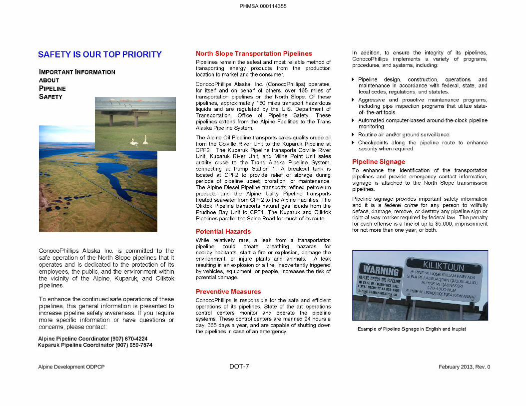
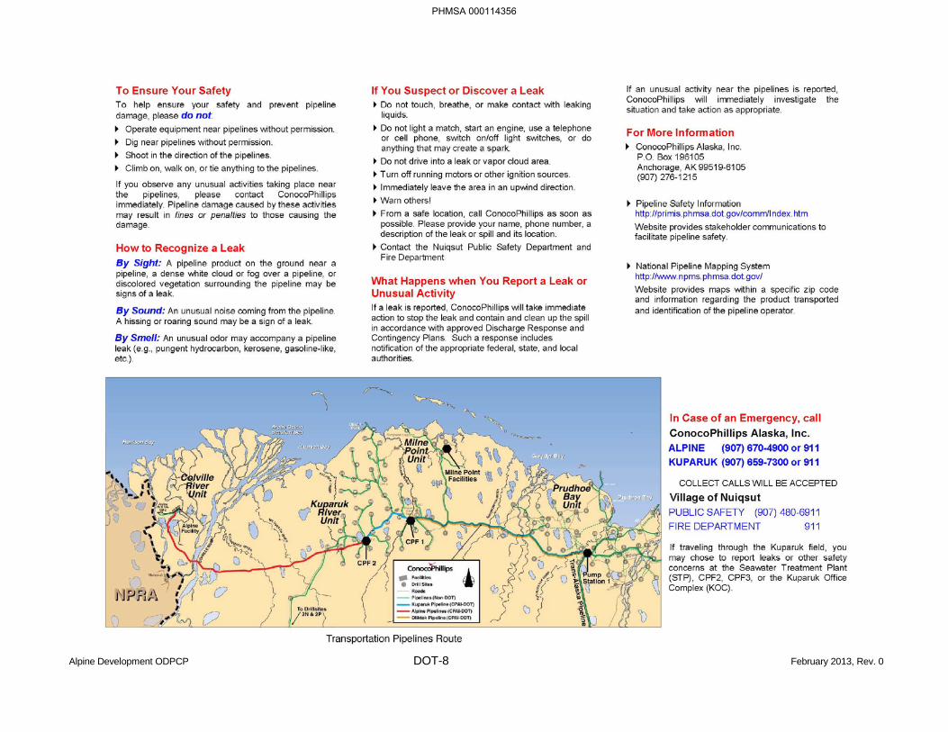
PUBLIC AWARENESS
CPAI is committed to public safety and environmental protection and maintains a public awareness program for CPAI-operated DOT-regulated pipelines, in accordance with DOT regulations. CPAI periodically provides information to the public via the Hazardous Liquids Pipeline Guide for Emergency and Public Officials and related summary bulletins; a copy of the summary bulletin is provided on pages DOT-7 and DOT-8.
PHMSA 000114354
(b) (3), (b) (7)(F)
Alpine Development ODPCP DOT-7 February 2013, Rev. 0
PHMSA 000114355
Alpine Development ODPCP DOT-8 February 2013, Rev. 0
PHMSA 000114356

U.S. ENVIRONMENTAL PROTECTION AGENCY
PHMSA 000114357

BLANK PAGE
PHMSA 000114358
Alpine Development ODPCP EPA-1 February 2013, Rev. 0
ALPINE DEVELOPMENT PARTICIPATING AREA OIL DISCHARGE PREVENTION AND CONTINGENCY PLAN
U.S. ENVIRONMENTAL PROTECTION AGENCY
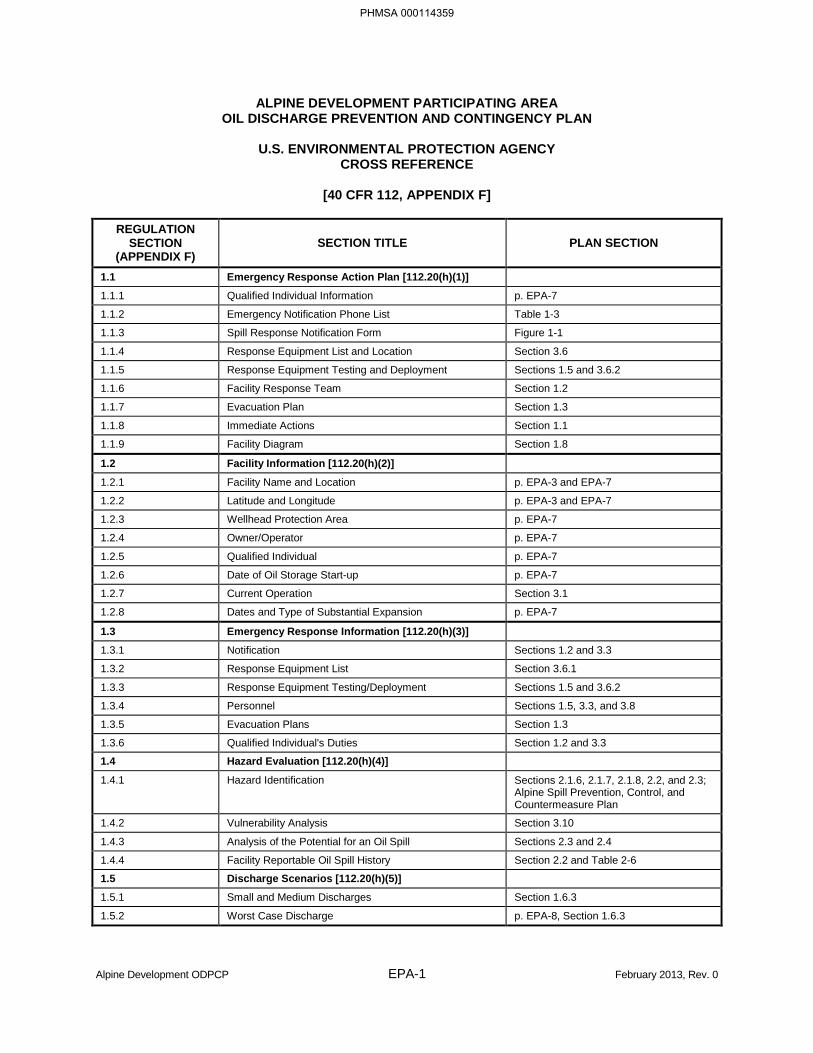
CROSS REFERENCE
[40 CFR 112, APPENDIX F]
REGULATION SECTION
(APPENDIX F) SECTION TITLE PLAN SECTION
1.1 Emergency Response Action Plan [112.20(h)(1)]
1.1.1 Qualified Individual Information p. EPA-7
1.1.2 Emergency Notification Phone List Table 1-3
1.1.3 Spill Response Notification Form Figure 1-1
1.1.4 Response Equipment List and Location Section 3.6
1.1.5 Response Equipment Testing and Deployment Sections 1.5 and 3.6.2
1.1.6 Facility Response Team Section 1.2
1.1.7 Evacuation Plan Section 1.3
1.1.8 Immediate Actions Section 1.1
1.1.9 Facility Diagram Section 1.8
1.2 Facility Information [112.20(h)(2)]
1.2.1 Facility Name and Location p. EPA-3 and EPA-7
1.2.2 Latitude and Longitude p. EPA-3 and EPA-7
1.2.3 Wellhead Protection Area p. EPA-7
1.2.4 Owner/Operator p. EPA-7
1.2.5 Qualified Individual p. EPA-7
1.2.6 Date of Oil Storage Start-up p. EPA-7
1.2.7 Current Operation Section 3.1
1.2.8 Dates and Type of Substantial Expansion p. EPA-7
1.3 Emergency Response Information [112.20(h)(3)]
1.3.1 Notification Sections 1.2 and 3.3
1.3.2 Response Equipment List Section 3.6.1
1.3.3 Response Equipment Testing/Deployment Sections 1.5 and 3.6.2
1.3.4 Personnel Sections 1.5, 3.3, and 3.8
1.3.5 Evacuation Plans Section 1.3
1.3.6 Qualified Individual's Duties Section 1.2 and 3.3
1.4 Hazard Evaluation [112.20(h)(4)]
1.4.1 Hazard Identification Sections 2.1.6, 2.1.7, 2.1.8, 2.2, and 2.3; Alpine Spill Prevention, Control, and Countermeasure Plan
1.4.2 Vulnerability Analysis Section 3.10
1.4.3 Analysis of the Potential for an Oil Spill Sections 2.3 and 2.4
1.4.4 Facility Reportable Oil Spill History Section 2.2 and Table 2-6
1.5 Discharge Scenarios [112.20(h)(5)]
1.5.1 Small and Medium Discharges Section 1.6.3
1.5.2 Worst Case Discharge p. EPA-8, Section 1.6.3
PHMSA 000114359
Alpine Development ODPCP EPA-2 February 2013, Rev. 0
ALPINE DEVELOPMENT PARTICIPATING AREA OIL DISCHARGE PREVENTION AND CONTINGENCY PLAN
U.S. ENVIRONMENTAL PROTECTION AGENCY
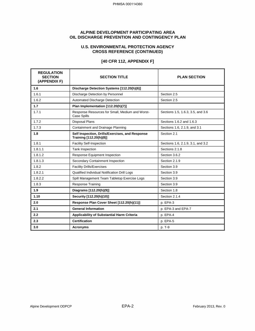
CROSS REFERENCE (CONTINUED)
[40 CFR 112, APPENDIX F]
REGULATION SECTION
(APPENDIX F) SECTION TITLE PLAN SECTION
1.6 Discharge Detection Systems [112.20(h)(6)]
1.6.1 Discharge Detection by Personnel Section 2.5
1.6.2 Automated Discharge Detection Section 2.5
1.7 Plan Implementation [112.20(h)(7)]
1.7.1 Response Resources for Small, Medium and Worst-Case Spills
Sections 1.5, 1.6.3, 3.5, and 3.6
1.7.2 Disposal Plans Sections 1.6.2 and 1.6.3
1.7.3 Containment and Drainage Planning Sections 1.6, 2.1.9, and 3.1
1.8 Self Inspection, Drills/Exercises, and Response Training [112.20(h)(8)]
Section 2.1
1.8.1 Facility Self-Inspection Sections 1.6, 2.1.9, 3.1, and 3.2
1.8.1.1 Tank Inspection Sections 2.1.8
1.8.1.2 Response Equipment Inspection Section 3.6.2
1.8.1.3 Secondary Containment Inspection Section 2.1.9
1.8.2 Facility Drills/Exercises Section 3.9
1.8.2.1 Qualified Individual Notification Drill Logs Section 3.9
1.8.2.2 Spill Management Team Tabletop Exercise Logs Section 3.9
1.8.3 Response Training Section 3.9
1.9 Diagrams [112.20(h)(9)] Section 1.8
1.10 Security [112.20(h)(10)] Section 2.1.4
2.0 Response Plan Cover Sheet [112.20(h)(11)] p. EPA-3
2.1 General Information p. EPA-3 and EPA-7
2.2 Applicability of Substantial Harm Criteria p. EPA-4
2.3 Certification p. EPA-5
3.0 Acronyms p. T-9
PHMSA 000114360
Alpine Development ODPCP EPA-3 February 2013, Rev. 0
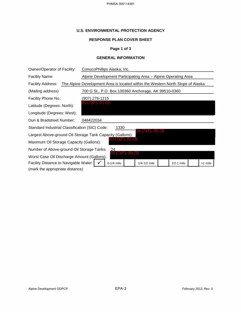
U.S. ENVIRONMENTAL PROTECTION AGENCY
RESPONSE PLAN COVER SHEET
Page 1 of 3
GENERAL INFORMATION
Owner/Operator of Facility: ConocoPhillips Alaska, Inc.
Facility Name: Alpine Development Participating Area – Alpine Operating Area
Facility Address: The Alpine Development Area is located within the Western North Slope of Alaska
(Mailing address) 700 G St., P.O. Box 100360 Anchorage, AK 99510-0360
Facility Phone No.: (907) 276-1215
Latitude (Degrees: North):
Longitude (Degrees: West):
Dun & Bradstreet Number: 048422034
Standard Industrial Classification (SIC) Code: 1330
Largest Above-ground Oil Storage Tank Capacity (Gallons):
Maximum Oil Storage Capacity (Gallons):
Number of Above-ground Oil Storage Tanks: 24
Worst Case Oil Discharge Amount (Gallons): Facility Distance to Navigable Water: 0-1/4 mile 1/4-1/2 mile 1/2-1 mile >1 mile
(mark the appropriate distance)
PHMSA 000114361
(b) (7)(F), (b) (3)
(b) (7)(F), (b) (3)
(b) (7)(F), (b) (3)
(b) (7)(F), (b) (3)
Alpine Development ODPCP EPA-4 February 2013, Rev. 0
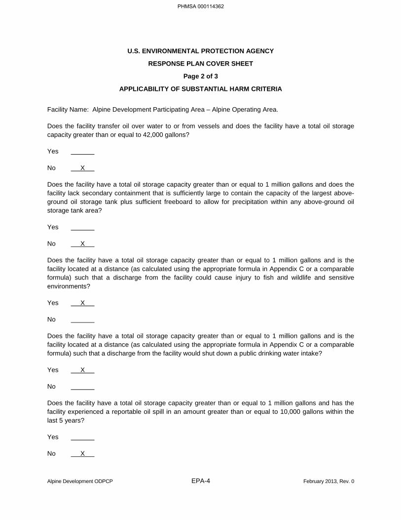
U.S. ENVIRONMENTAL PROTECTION AGENCY
RESPONSE PLAN COVER SHEET
Page 2 of 3
APPLICABILITY OF SUBSTANTIAL HARM CRITERIA
Facility Name: Alpine Development Participating Area – Alpine Operating Area.
Does the facility transfer oil over water to or from vessels and does the facility have a total oil storage capacity greater than or equal to 42,000 gallons?
Yes
No X
Does the facility have a total oil storage capacity greater than or equal to 1 million gallons and does the facility lack secondary containment that is sufficiently large to contain the capacity of the largest above-ground oil storage tank plus sufficient freeboard to allow for precipitation within any above-ground oil storage tank area?
Yes
No X
Does the facility have a total oil storage capacity greater than or equal to 1 million gallons and is the facility located at a distance (as calculated using the appropriate formula in Appendix C or a comparable formula) such that a discharge from the facility could cause injury to fish and wildlife and sensitive environments?
Yes X
No
Does the facility have a total oil storage capacity greater than or equal to 1 million gallons and is the facility located at a distance (as calculated using the appropriate formula in Appendix C or a comparable formula) such that a discharge from the facility would shut down a public drinking water intake?
Yes X
No
Does the facility have a total oil storage capacity greater than or equal to 1 million gallons and has the facility experienced a reportable oil spill in an amount greater than or equal to 10,000 gallons within the last 5 years?
Yes
No X
PHMSA 000114362
PHMSA 000114363

Alpine Development ODPCP EPA-6 February 2013, Rev. 0
BLANK PAGE
PHMSA 000114364
Alpine Development ODPCP EPA-7 February 2013, Rev. 0
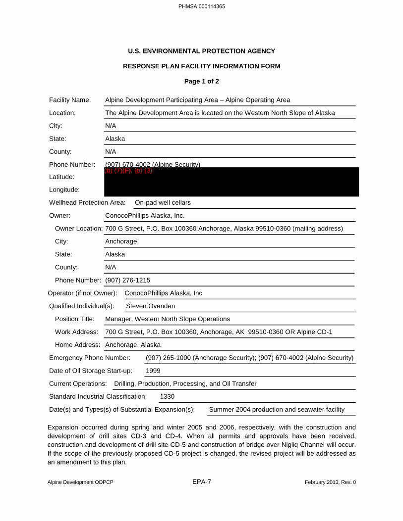
U.S. ENVIRONMENTAL PROTECTION AGENCY
RESPONSE PLAN FACILITY INFORMATION FORM
Page 1 of 2
Facility Name: Alpine Development Participating Area – Alpine Operating Area
Location: The Alpine Development Area is located on the Western North Slope of Alaska
City: N/A
State: Alaska
County: N/A
Phone Number: (907) 670-4002 (Alpine Security)
Latitude:
Longitude:
Wellhead Protection Area: On-pad well cellars
Owner: ConocoPhillips Alaska, Inc.
Owner Location: 700 G Street, P.O. Box 100360 Anchorage, Alaska 99510-0360 (mailing address)
City: Anchorage
State: Alaska
County: N/A
Phone Number: (907) 276-1215
Operator (if not Owner): ConocoPhillips Alaska, Inc
Qualified Individual(s): Steven Ovenden
Position Title: Manager, Western North Slope Operations
Work Address: 700 G Street, P.O. Box 100360, Anchorage, AK 99510-0360 OR Alpine CD-1
Home Address: Anchorage, Alaska
Emergency Phone Number: (907) 265-1000 (Anchorage Security); (907) 670-4002 (Alpine Security)
Date of Oil Storage Start-up: 1999
Current Operations: Drilling, Production, Processing, and Oil Transfer
Standard Industrial Classification: 1330
Date(s) and Types(s) of Substantial Expansion(s): Summer 2004 production and seawater facility
Expansion occurred during spring and winter 2005 and 2006, respectively, with the construction and development of drill sites CD-3 and CD-4. When all permits and approvals have been received, construction and development of drill site CD-5 and construction of bridge over Nigliq Channel will occur. If the scope of the previously proposed CD-5 project is changed, the revised project will be addressed as an amendment to this plan.
PHMSA 000114365
(b) (7)(F), (b) (3)
Alpine Development ODPCP EPA-8 February 2013, Rev. 0
U.S. ENVIRONMENTAL PROTECTION AGENCY
RESPONSE PLAN FACILITY INFORMATION FORM
Page 2 of 2
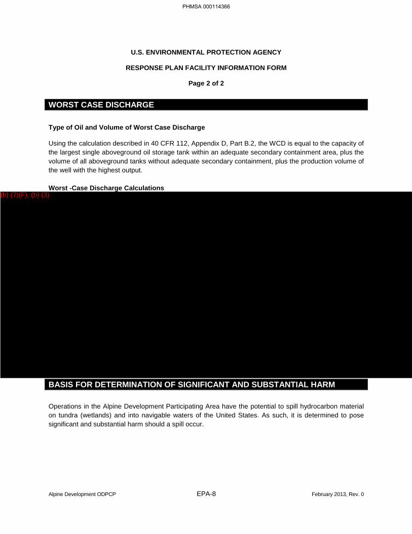
WORST CASE DISCHARGE
Type of Oil and Volume of Worst Case Discharge
Using the calculation described in 40 CFR 112, Appendix D, Part B.2, the WCD is equal to the capacity of the largest single aboveground oil storage tank within an adequate secondary containment area, plus the volume of all aboveground tanks without adequate secondary containment, plus the production volume of the well with the highest output.
Worst -Case Discharge Calculations
BASIS FOR DETERMINATION OF SIGNIFICANT AND SUBSTANTIAL HARM
Operations in the Alpine Development Participating Area have the potential to spill hydrocarbon material on tundra (wetlands) and into navigable waters of the United States. As such, it is determined to pose significant and substantial harm should a spill occur.
PHMSA 000114366
(b) (7)(F), (b) (3)
Alpine Development ODPCP EPA-9 February 2013, Rev. 0
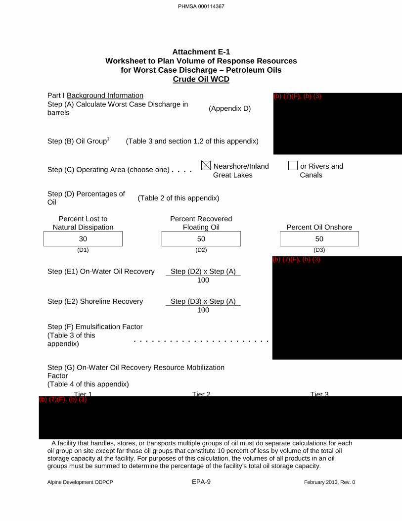
Attachment E-1 Worksheet to Plan Volume of Response Resources
for Worst Case Discharge – Petroleum Oils Crude Oil WCD
Part I Background Information Step (A) Calculate Worst Case Discharge in barrels (Appendix D)
Step (B) Oil Group1 (Table 3 and section 1.2 of this appendix)
Step (C) Operating Area (choose one) . . . . Nearshore/Inland Great Lakes
or Rivers and Canals
Step (D) Percentages of Oil (Table 2 of this appendix)
Percent Lost to
Natural Dissipation Percent Recovered
Floating Oil Percent Oil Onshore 30 50 50
(D1) (D2) (D3)
Step (E1) On-Water Oil Recovery Step (D2) x Step (A) 100
Step (E2) Shoreline Recovery Step (D3) x Step (A) 100 Step (F) Emulsification Factor (Table 3 of this appendix) . . . . . . . . . . . . . . . . . . . . . . . Step (G) On-Water Oil Recovery Resource Mobilization Factor
(Table 4 of this appendix) Tier 1 Tier 2 Tier 3
A facility that handles, stores, or transports multiple groups of oil must do separate calculations for each oil group on site except for those oil groups that constitute 10 percent of less by volume of the total oil storage capacity at the facility. For purposes of this calculation, the volumes of all products in an oil groups must be summed to determine the percentage of the facility’s total oil storage capacity.
PHMSA 000114367
(b) (7)(F), (b) (3)
(b) (7)(F), (b) (3)
(b) (7)(F), (b) (3)
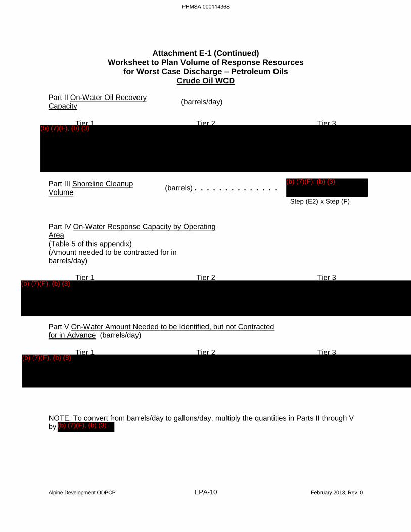
Alpine Development ODPCP EPA-10 February 2013, Rev. 0
Attachment E-1 (Continued) Worksheet to Plan Volume of Response Resources
for Worst Case Discharge – Petroleum Oils Crude Oil WCD
Part II On-Water Oil Recovery Capacity (barrels/day)
Tier 1 Tier 2 Tier 3
Part III Shoreline Cleanup Volume (barrels) . . . . . . . . . . . . . .
Step (E2) x Step (F) Part IV On-Water Response Capacity by Operating Area
(Table 5 of this appendix) (Amount needed to be contracted for in barrels/day)
Tier 1 Tier 2 Tier 3
Part V On-Water Amount Needed to be Identified, but not Contracted for in Advance (barrels/day)
Tier 1 Tier 2 Tier 3
NOTE: To convert from barrels/day to gallons/day, multiply the quantities in Parts II through V by
PHMSA 000114368
(b) (7)(F), (b) (3)
(b) (7)(F), (b) (3)
(b) (7)(F), (b) (3)
(b) (7)(F), (b) (3)
(b) (7)(F), (b) (3)
Alpine Development ODPCP EPA-11 February 2013, Rev. 0
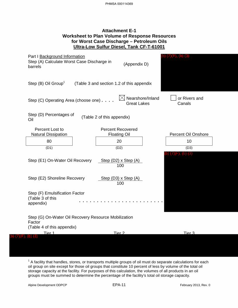
Attachment E-1 Worksheet to Plan Volume of Response Resources
for Worst Case Discharge – Petroleum Oils Ultra-Low Sulfur Diesel, Tank CF-T-61001
Part I Background Information Step (A) Calculate Worst Case Discharge in barrels (Appendix D)
Step (B) Oil Group1 (Table 3 and section 1.2 of this appendix
Step (C) Operating Area (choose one) . . . . Nearshore/Inland Great Lakes
or Rivers and Canals
Step (D) Percentages of Oil (Table 2 of this appendix)
Percent Lost to
Natural Dissipation Percent Recovered
Floating Oil Percent Oil Onshore 80 20 10
(D1) (D2) (D3)
Step (E1) On-Water Oil Recovery Step (D2) x Step (A) 100
Step (E2) Shoreline Recovery Step (D3) x Step (A) 100 Step (F) Emulsification Factor (Table 3 of this appendix) . . . . . . . . . . . . . . . . . . . . . . . . Step (G) On-Water Oil Recovery Resource Mobilization Factor
(Table 4 of this appendix) Tier 1 Tier 2 Tier 3
1 A facility that handles, stores, or transports multiple groups of oil must do separate calculations for each oil group on site except for those oil groups that constitute 10 percent of less by volume of the total oil storage capacity at the facility. For purposes of this calculation, the volumes of all products in an oil groups must be summed to determine the percentage of the facility’s total oil storage capacity.
PHMSA 000114369
(b) (7)(F), (b) (3)
(b) (7)(F), (b) (3)
(b) (7)(F), (b) (3)
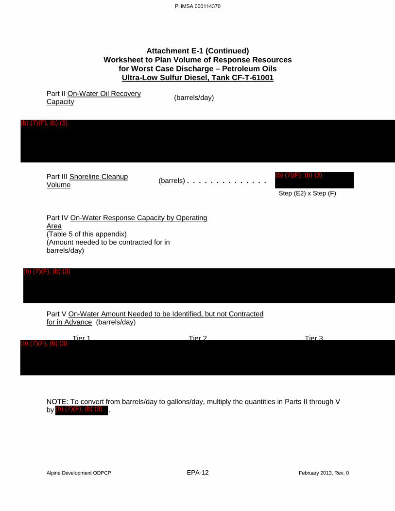
Alpine Development ODPCP EPA-12 February 2013, Rev. 0
Attachment E-1 (Continued) Worksheet to Plan Volume of Response Resources
for Worst Case Discharge – Petroleum Oils Ultra-Low Sulfur Diesel, Tank CF-T-61001
Part II On-Water Oil Recovery Capacity (barrels/day)
Part III Shoreline Cleanup Volume (barrels) . . . . . . . . . . . . . .
Step (E2) x Step (F) Part IV On-Water Response Capacity by Operating Area
(Table 5 of this appendix) (Amount needed to be contracted for in barrels/day)
Part V On-Water Amount Needed to be Identified, but not Contracted for in Advance (barrels/day)
Tier 1 Tier 2 Tier 3
NOTE: To convert from barrels/day to gallons/day, multiply the quantities in Parts II through V by .
PHMSA 000114370
(b) (7)(F), (b) (3)
(b) (7)(F), (b) (3)
(b) (7)(F), (b) (3)
(b) (7)(F), (b) (3)
(b) (7)(F), (b) (3)
Alpine Development ODPCP I-1 February 2013, Rev. 0
INTRODUCTION
This Oil Discharge Prevention and Contingency Plan (ODPCP) is for the Alpine Development Area located within the North Slope Borough, Alaska. ConocoPhillips Alaska, Inc. (CPAI) is the operator of the facility covered by this plan. CPAI’s address, phone, and fax numbers are provided below:
ConocoPhillips Alaska, Inc. Street Address: P.O. Box 100360 700 G Street Anchorage, AK 99510-0360 Anchorage, AK 99510-0360 Phone: (907) 276-1215 Fax: (907) 265-6235
OBJECTIVES
The primary goal of this plan is to prevent and/or limit the spread of a spill, thereby minimizing potential environmental impacts, and providing for the safety of personnel. Where the two may conflict, safety of personnel will always be given the first consideration.
This plan addresses requirements promulgated by the State of Alaska under Title 18, Chapter 75 of the Alaska Administrative Code (18 AAC 75), as amended through April 8, 2012. This plan also contains a section addressing federal regulations (U.S. Environmental Protection Agency [EPA] and U.S. Department of Transportation [DOT]) based on the Oil Pollution Act of 1990.
The major facilities and operations covered by this plan include:
• Alpine Central Processing Facility;
• Alpine Drill Sites CD-1, CD-2, CD-3, and CD-4 are developed, CD-5 is proposed;
• Alpine crude oil transmission pipeline;
• Alpine diesel pipeline (DOT-regulated);
• Gas/water injection facilities;
• Intra-field pipelines (flowlines); and
• Transfer operations.
CPAI assumes responsibility for containment and cleanup of oil spills from its facilities and operations within the Alpine Development Area, including the Alpine pipelines. CPAI requires that contract companies and their employees adhere strictly to CPAI safety and environmental policies and procedures while working on CPAI lease holdings. Contractors are required to report all spills to Alpine Security.
A spill response operation on the North Slope falls into one of three categories:
• Level I: Small operational spills dealt with by on-scene personnel and equipment.
• Level II: Larger spills that could affect the area around the facility or operation that require equipment and/or trained personnel located in other operating areas of the North Slope.
• Level III: A major spill requiring resources from off the North Slope.
PHMSA 000114371
Alpine Development ODPCP I-2 February 2013, Rev. 0
Both Level II and III spills may result in the activation of the Incident Management Team and/or the Spill Response Team. As necessary, resources of other North Slope operators may be utilized through Alaska Clean Seas (ACS), Mutual Aid, and contractors. The response organization structure described in this plan is based on the Incident Command System and accommodates each level of response.
ACS TECHNICAL MANUAL
CPAI is a member of ACS, which serves as the primary response action contractor for CPAI operations on the North Slope. This ODPCP incorporates by reference, wherever applicable, the ACS Technical Manual, which consists of Volume 1, Tactics Descriptions, and Volume 2, Map Atlas. Volume 1 describes the tactics that can be used in responding to a variety of spill situations. Volume 2 provides maps and a narrative description of resources at risk and key response considerations.
PLAN CONTENTS ORGANIZATION
The following is a summary of the principal contents of this ODPCP:
• Management Approval and Manpower Authorization. The front matter of this ODPCP provides approval and authorization of resources as required to implement this plan.
• Part 1 – Response Action Plan. The response action plan provides information to guide the Incident Management Team and Spill Response Team in a response to an incident. Information includes reporting and notification procedures, basic safety procedures, a communications plan, deployment and response strategies, and initial response procedures. Company personnel are familiar with the contents of this plan and other manuals necessary to carry out a successful response.
• Part 2 – Prevention Plan. The prevention plan provides a detailed description of policies, best management practices, and prevention measures employed on the North Slope. Information is included on identified risks, historical spills, and measures taken to minimize potential impacts.
• Part 3 – Supplemental Information. The supplemental information provides an overview of the facility operations, environmental information, and supporting response information.
• Part 4 – Best Available Technology. The Best Available Technology section analyzes spill prevention and response equipment to ensure it meets performance standards in 18 AAC 75.
• Part 5 – Response Planning Standard. Part 5 presents a calculation of the applicable response planning standards and detailed basis for the calculation of reductions if applied to the response planning standard volume.
This ODPCP relies upon information provided in the ACS Technical Manual, and that information is not repeated in this ODPCP. This ODPCP references specific tactics descriptions, and maps contained in the ACS Technical Manual.
PLAN DISTRIBUTION
The ODPCP is distributed to CPAI Management and staff as appropriate. Additional copies are located in the CPAI Anchorage Emergency Operations Center and in the Health, Safety, Environment and
PHMSA 000114372
Alpine Development ODPCP I-3 February 2013, Rev. 0
Emergency Response departments at Alpine. The Plan Administrator maintains a record of plan distribution. Federal, state and local agency personnel and external stakeholders are provided copies of the plan, as appropriate.
A record of plan distribution is maintained by the Health, Safety, and Environment department. Agency personnel and external stakeholders are provided copies of the plan, as appropriate.
UPDATING PROCEDURES
The ODPCP is revised and updated when major changes occur. Any significant amendment to the plan is submitted to the appropriate agency for review prior to implementation. Key factors that may cause revisions to the plan include:
• New developments or exploration activities;
• Production facility modifications that create additional spill potential, affect the potential movement of spills, or alter proposed containment basins;
• Changes in organization or Qualified Individual;
• Changes in regulations promulgated by government agencies;
• Change in response procedures;
• Improvements in state-of-the-art spill technology and equipment, and new equipment purchases;
• Change in commodities transported;
• Change in oil spill removal organizations;
• Change in ownership; or
• Change to response planning standards.
Modifications to the plan may also occur after spill response drills or incidents have been fully evaluated. In addition, plan recipients are encouraged to provide comments on the plan, which could lead to updates or modifications to the plan.
DOT regulation 194.121 requires that modifications, which could substantially affect the implementation of the response plan, be submitted for review within 30 days.
Revisions to the plan are logged on a Record of Revisions form. Upon receipt of revisions, the plan recipient replaces pages as instructed and recorded on the Record of Revisions form provided in the front of the ODPCP. This process indicates the completeness of the plan, as revisions are consecutively numbered. It is the responsibility of each plan recipient to ensure that updates are promptly incorporated into the plan.
PHMSA 000114373
Alpine Development ODPCP I-4 February 2013, Rev. 0
PLAN RENEWAL
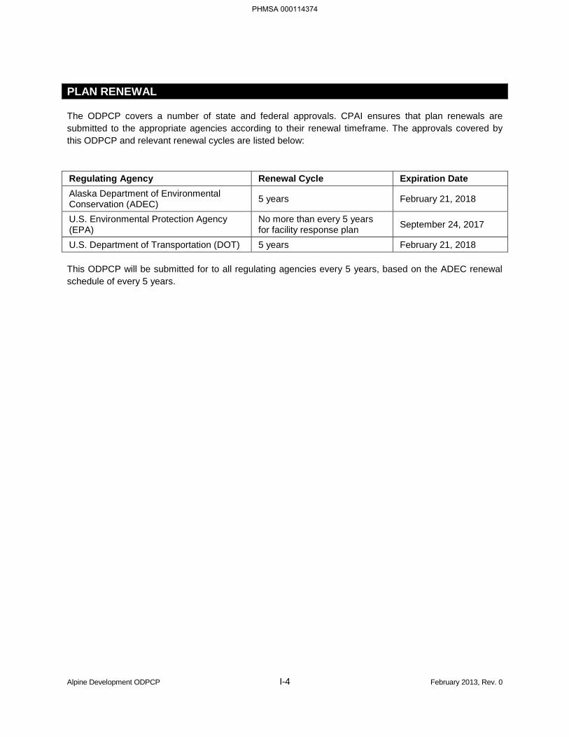
The ODPCP covers a number of state and federal approvals. CPAI ensures that plan renewals are submitted to the appropriate agencies according to their renewal timeframe. The approvals covered by this ODPCP and relevant renewal cycles are listed below:
Regulating Agency Renewal Cycle Expiration Date Alaska Department of Environmental Conservation (ADEC) 5 years February 21, 2018
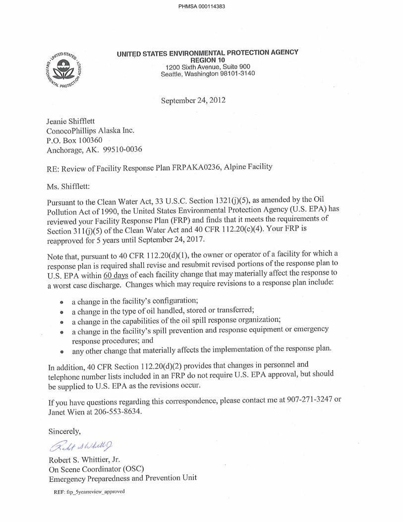
U.S. Environmental Protection Agency (EPA)
No more than every 5 years for facility response plan September 24, 2017
U.S. Department of Transportation (DOT) 5 years February 21, 2018
This ODPCP will be submitted for to all regulating agencies every 5 years, based on the ADEC renewal schedule of every 5 years.
PHMSA 000114374
PHMSA 000114375
PHMSA 000114376
PHMSA 000114377
PHMSA 000114378
PHMSA 000114379

PHMSA 000114380
PHMSA 000114381

PHMSA 000114382
PHMSA 000114383

PHMSA 000114384
PART 1 RESPONSE ACTION PLAN [18 AAC 75.425(e)(1)]
1.1 EMERGENCY ACTION CHECKLIST [18 AAC 75.425(e)(1)(A)]
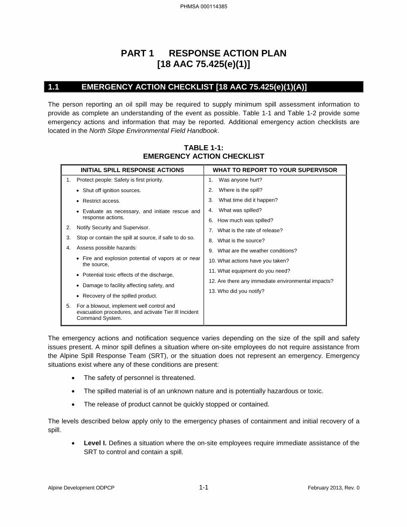
The person reporting an oil spill may be required to supply minimum spill assessment information to provide as complete an understanding of the event as possible. Table 1-1 and Table 1-2 provide some emergency actions and information that may be reported. Additional emergency action checklists are located in the North Slope Environmental Field Handbook.
TABLE 1-1: EMERGENCY ACTION CHECKLIST
INITIAL SPILL RESPONSE ACTIONS WHAT TO REPORT TO YOUR SUPERVISOR 1. Protect people: Safety is first priority.
• Shut off ignition sources.
• Restrict access.
• Evaluate as necessary, and initiate rescue and response actions.
2. Notify Security and Supervisor.
3. Stop or contain the spill at source, if safe to do so.
4. Assess possible hazards:
• Fire and explosion potential of vapors at or near the source,
• Potential toxic effects of the discharge,
• Damage to facility affecting safety, and
• Recovery of the spilled product.
5. For a blowout, implement well control and evacuation procedures, and activate Tier Ill Incident Command System.
1. Was anyone hurt?
2. Where is the spill?
3. What time did it happen?
4. What was spilled?
6. How much was spilled?
7. What is the rate of release?
8. What is the source?
9. What are the weather conditions?
10. What actions have you taken?
11. What equipment do you need?
12. Are there any immediate environmental impacts?
13. Who did you notify?
The emergency actions and notification sequence varies depending on the size of the spill and safety issues present. A minor spill defines a situation where on-site employees do not require assistance from the Alpine Spill Response Team (SRT), or the situation does not represent an emergency. Emergency situations exist where any of these conditions are present:
• The safety of personnel is threatened.
• The spilled material is of an unknown nature and is potentially hazardous or toxic.
• The release of product cannot be quickly stopped or contained.
The levels described below apply only to the emergency phases of containment and initial recovery of a spill.
• Level I. Defines a situation where the on-site employees require immediate assistance of the SRT to control and contain a spill.
Alpine Development ODPCP 1-1 February 2013, Rev. 0
PHMSA 000114385
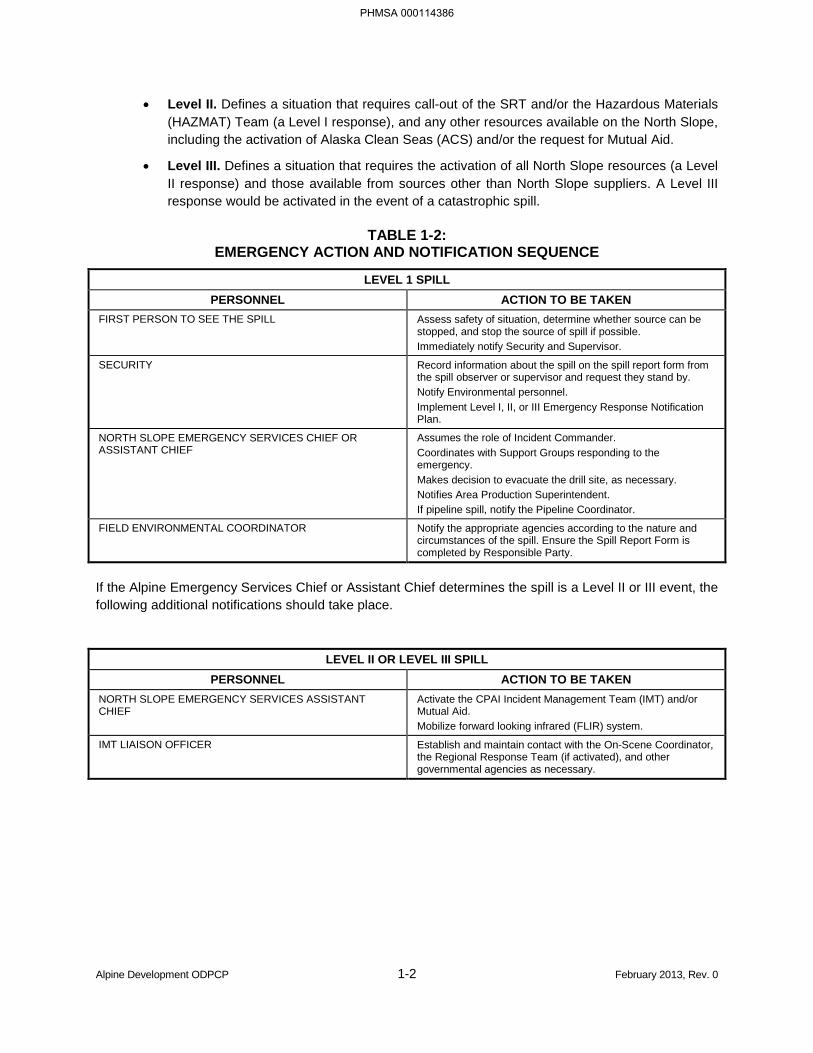
• Level II. Defines a situation that requires call-out of the SRT and/or the Hazardous Materials (HAZMAT) Team (a Level I response), and any other resources available on the North Slope, including the activation of Alaska Clean Seas (ACS) and/or the request for Mutual Aid.
• Level III. Defines a situation that requires the activation of all North Slope resources (a Level II response) and those available from sources other than North Slope suppliers. A Level III response would be activated in the event of a catastrophic spill.
TABLE 1-2: EMERGENCY ACTION AND NOTIFICATION SEQUENCE
LEVEL 1 SPILL PERSONNEL ACTION TO BE TAKEN
FIRST PERSON TO SEE THE SPILL Assess safety of situation, determine whether source can be stopped, and stop the source of spill if possible. Immediately notify Security and Supervisor.
SECURITY Record information about the spill on the spill report form from the spill observer or supervisor and request they stand by. Notify Environmental personnel. Implement Level I, II, or III Emergency Response Notification Plan.
NORTH SLOPE EMERGENCY SERVICES CHIEF OR ASSISTANT CHIEF
Assumes the role of Incident Commander. Coordinates with Support Groups responding to the emergency. Makes decision to evacuate the drill site, as necessary. Notifies Area Production Superintendent. If pipeline spill, notify the Pipeline Coordinator.
FIELD ENVIRONMENTAL COORDINATOR Notify the appropriate agencies according to the nature and circumstances of the spill. Ensure the Spill Report Form is completed by Responsible Party.
If the Alpine Emergency Services Chief or Assistant Chief determines the spill is a Level II or III event, the following additional notifications should take place.
LEVEL II OR LEVEL III SPILL
PERSONNEL ACTION TO BE TAKEN NORTH SLOPE EMERGENCY SERVICES ASSISTANT CHIEF
Activate the CPAI Incident Management Team (IMT) and/or Mutual Aid. Mobilize forward looking infrared (FLIR) system.
IMT LIAISON OFFICER Establish and maintain contact with the On-Scene Coordinator, the Regional Response Team (if activated), and other governmental agencies as necessary.
Alpine Development ODPCP 1-2 February 2013, Rev. 0
PHMSA 000114386
1.2 REPORTING AND NOTIFICATION [18 AAC 75.425(e)(1)(B)]
1.2.1 Initial Reporting [18 AAC 75.425(e)(1)(B)(i)]
Any person who causes or observes a spill will immediately report the spill to their supervisor. The supervisor makes notification to Security. If their supervisor is not available, notify Security. Contact phone numbers are listed in Table 1-3.
Once Security is alerted, they will notify the appropriate response personnel, depending on the spill size and safety issues involved (Figure 1-1). Security will activate a singular, all-call paging number to emergency responders.
Security is available and maintains 24-hour contact phone numbers for personnel including the Qualified Individual (QI) who is the Operations Manager, Alternate QI who is the Production or Operations Supervisor, and ACS, the oil spill removal organization (OSRO). Contact information for the QI and the Alternate QI is included in Section 3.3.
Alpine Development ODPCP 1-3 February 2013, Rev. 0
PHMSA 000114387
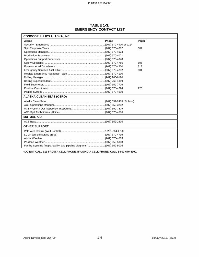
TABLE 1-3: EMERGENCY CONTACT LIST
CONOCOPHILLIPS ALASKA, INC. Alpine Phone Pager Security - Emergency .......................................................................... (907) 670-4900 or 911* Spill Response Team ........................................................................... (907) 670-4002 602 Operations Manager ............................................................................ (907) 670-4024 Production Supervisor ......................................................................... (907) 670-4021 Operations Support Supervisor ............................................................ (907) 670-4048 Safety Specialist .................................................................................. (907) 670-4756 606 Environmental Coordinator .................................................................. (907) 670-4200 718 Emergency Services Asst. Chief .......................................................... (907) 670-4752 601 Medical Emergency Response Team .................................................. (907) 670-4100 Drilling Manager .................................................................................. (907) 265-6120 Drilling Superintendent ........................................................................ (907) 265-1319 Field Supervisor ................................................................................... (907) 659-7726 Pipeline Coordinator ............................................................................ (907) 670-4224 220 Paging System ................................................................................... (907) 670-4930
ALASKA CLEAN SEAS (OSRO) Alaska Clean Seas .............................................................................. (907) 659-2405 (24 hour) ACS Operations Manager .................................................................... (907) 659-3202 ACS Western Ops Supervisor (Kuparuk) ............................................. (907) 659-7879 ACS Spill Technicians (Alpine) ............................................................ (907) 670-4586
MUTUAL AID ACS Base ............................................................................................ (907) 659-2405
OTHER SUPPORT Wild Well Control (Well Control) ........................................................... 1-281-784-4700 LCMF (on-site survey group) (907) 670-4739 Alpine Weather .................................................................................... (907) 670-4005 Prudhoe Weather ................................................................................ (907) 659-5883 Facility Systems (maps, facility, and pipeline diagrams) ....................... (907) 659-5005
*DO NOT CALL 911 FROM A CELL PHONE. IF USING A CELL PHONE, CALL 1-907-670-4900.
Alpine Development ODPCP 1-4 February 2013, Rev. 0
PHMSA 000114388
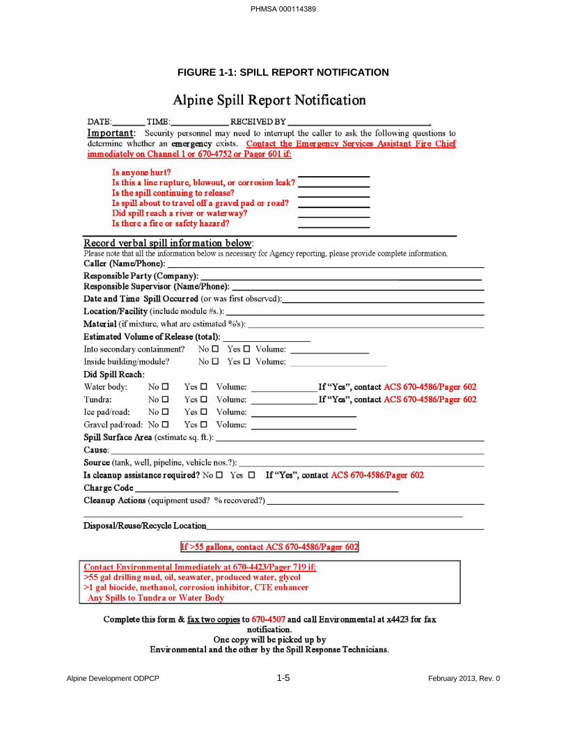
FIGURE 1-1: SPILL REPORT NOTIFICATION
Alpine Development ODPCP 1-5 February 2013, Rev. 0
PHMSA 000114389
1.2.2 External Notification Procedures [18 AAC 75.425(e)(1)(B)(ii)]
State of Alaska regulations at Title 18 of the Alaska Administrative Code (AAC), Chapter 75 (18 AAC 75.300) require prompt notification to the Alaska Department of Environmental Conservation of hazardous substance spills other than oil, any oil spill to water, or an oil spill solely to land outside of secondary containment if greater than 55 gallons. Notification within 48 hours is required for oil spills to land in excess of 10 gallons, but 55 gallons or less, or greater than 55 gallons if spilled into secondary containment.
The CPAI Field Environmental Coordinator is responsible for notifying the appropriate regulatory agencies. Agency contact information is included in Table 1-4. Depending on the type of spill, agency verbal notifications and written reports may include:
• Alaska Department of Environmental Conservation (ADEC);
• Alaska Department of Natural Resources (ADNR);
• Alaska Department of Fish & Game (ADF&G)
• Alaska Oil and Gas Conservation Commission (AOGCC);
• National Response Center (NRC);
• North Slope Borough (NSB);
• U.S. Coast Guard (USCG);
• U.S. Department of the Interior, Bureau of Land Management (BLM);
• U.S. Department of Transportation (DOT);
• U.S. Environmental Protection Agency (EPA); or
• U.S. Fish and Wildlife Service (USFWS).
1.2.3 Additional Notifications
Federal law requires that at least one of its representative agencies be notified of qualifying spills of oil or hazardous substances. Federal law also requires that the NRC be notified of all hazardous substance spills that exceed the Comprehensive Environmental Response, Compensation, and Liability Act (CERCLA) reportable quantity limit. This notification should be made within two hours of the incident.
DOT requires notification of spills from the Alpine crude oil and diesel pipelines that involve one or more of the following conditions:
• Explosions or fires,
• Death or personal injury requiring hospitalization,
• Estimated damage to property of $50,000 or more, or
• Pollution of any body of water.
DOT requires information on weather conditions for any reported spill. A telephone report made more than two hours after confirmation of a reportable condition is considered late.
Alpine Development ODPCP 1-6 February 2013, Rev. 0
PHMSA 000114390
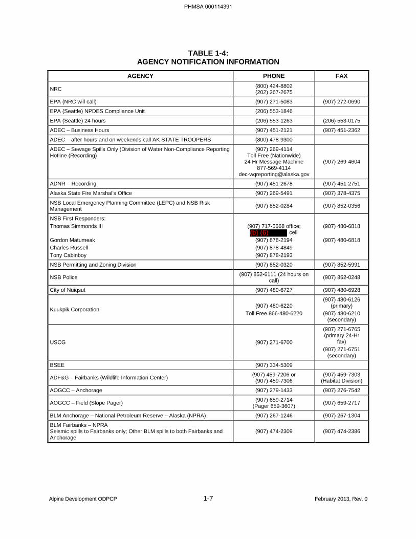
TABLE 1-4: AGENCY NOTIFICATION INFORMATION
AGENCY PHONE FAX
NRC (800) 424-8802 (202) 267-2675
EPA (NRC will call) (907) 271-5083 (907) 272-0690
EPA (Seattle) NPDES Compliance Unit (206) 553-1846
EPA (Seattle) 24 hours (206) 553-1263 (206) 553-0175
ADEC – Business Hours (907) 451-2121 (907) 451-2362
ADEC – after hours and on weekends call AK STATE TROOPERS (800) 478-9300
ADEC – Sewage Spills Only (Division of Water Non-Compliance Reporting Hotline (Recording)
(907) 269-4114 Toll Free (Nationwide)
24 Hr Message Machine 877-569-4114
(907) 269-4604
ADNR – Recording (907) 451-2678 (907) 451-2751
Alaska State Fire Marshal’s Office (907) 269-5491 (907) 378-4375
NSB Local Emergency Planning Committee (LEPC) and NSB Risk Management (907) 852-0284 (907) 852-0356
NSB First Responders: Thomas Simmonds III Gordon Matumeak Charles Russell Tony Cabinboy
(907) 717-5668 office;
cell (907) 878-2194 (907) 878-4849 (907) 878-2193
(907) 480-6818
(907) 480-6818
NSB Permitting and Zoning Division (907) 852-0320 (907) 852-5991
NSB Police (907) 852-6111 (24 hours on call) (907) 852-0248
City of Nuiqsut (907) 480-6727 (907) 480-6928
Kuukpik Corporation (907) 480-6220
Toll Free 866-480-6220
(907) 480-6126 (primary)
(907) 480-6210 (secondary)
USCG (907) 271-6700
(907) 271-6765 (primary 24-Hr
fax) (907) 271-6751
(secondary)
BSEE (907) 334-5309
ADF&G – Fairbanks (Wildlife Information Center) (907) 459-7206 or (907) 459-7306
(907) 459-7303 (Habitat Division)
AOGCC – Anchorage (907) 279-1433 (907) 276-7542
AOGCC – Field (Slope Pager) (907) 659-2714 (Pager 659-3607) (907) 659-2717
BLM Anchorage – National Petroleum Reserve – Alaska (NPRA) (907) 267-1246 (907) 267-1304
BLM Fairbanks – NPRA Seismic spills to Fairbanks only; Other BLM spills to both Fairbanks and Anchorage
(907) 474-2309 (907) 474-2386
Alpine Development ODPCP 1-7 February 2013, Rev. 0
PHMSA 000114391
(b) (6)
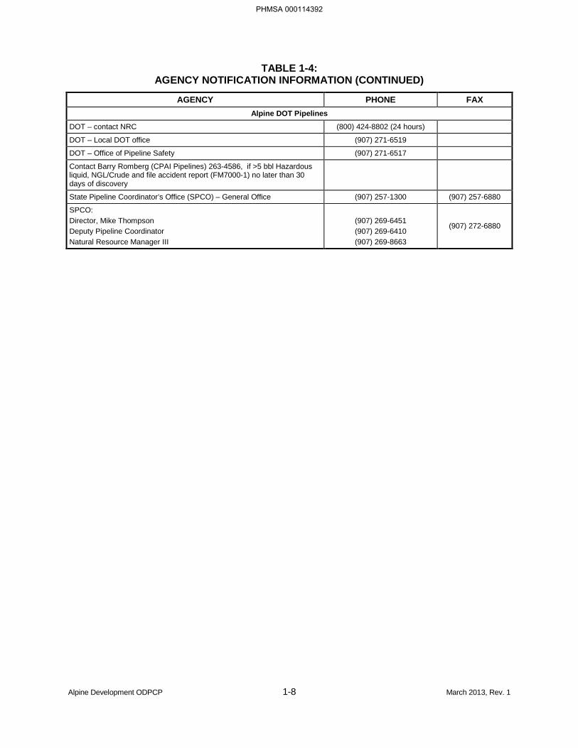
TABLE 1-4: AGENCY NOTIFICATION INFORMATION (CONTINUED)
AGENCY PHONE FAX Alpine DOT Pipelines
DOT – contact NRC (800) 424-8802 (24 hours)
DOT – Local DOT office (907) 271-6519
DOT – Office of Pipeline Safety (907) 271-6517
Contact Barry Romberg (CPAI Pipelines) 263-4586, if >5 bbl Hazardous liquid, NGL/Crude and file accident report (FM7000-1) no later than 30 days of discovery
State Pipeline Coordinator’s Office (SPCO) – General Office (907) 257-1300 (907) 257-6880
SPCO: Director, Mike Thompson Deputy Pipeline Coordinator Natural Resource Manager III
(907) 269-6451 (907) 269-6410 (907) 269-8663
(907) 272-6880
Alpine Development ODPCP 1-8 March 2013, Rev. 1
PHMSA 000114392
1.2.4 Written Reporting Requirements
Depending on the type and amount of material spilled, individual government agencies have written reporting requirements. The Field Environmental Coordinator is responsible for spill reporting to various governmental agencies. These reporting requirements are detailed in Table 1-5.
State of Alaska regulations (18 AAC 75.300) require prompt notification to ADEC of hazardous substance spills other than oil, any oil spill to water, or an oil spill solely to land outside of secondary containment if greater than 55 gallons. Notification within 48 hours is required for oil spills to land in excess of 10 gallons, but 55 gallons or less, or greater than 55 gallons if spilled into secondary containment. After notification of the discharge has been made to ADEC, the department will, at its discretion, require interim reports to assess human or environmental threat. A written final report must be submitted within 15 days of the end of cleanup operations, or if no cleanup occurs, within 15 days of the discharge. Interim and final written reporting requirements are specified in 18 AAC 75.300. The report must contain the following information:
• Date and time of discharge;
• Location of discharge;
• Name of facility or vessel;
• Name, mailing address, and telephone number of person or persons causing or responsible for the discharge and the owner and the operator of the facility or vessel;
• Type and amount of each hazardous substance discharged;
• Cause of the discharge;
• Description of any environmental damage caused by the discharge or containment to the extent the damage can be identified;
• Description of cleanup actions taken;
• Estimated amount of hazardous substance cleaned up and hazardous waste generated;
• Date, location, and method of ultimate disposal of the hazardous substance cleaned up;
• Description of actions being taken to prevent recurrence of the discharge; and
• Other information the department requires to fully assess the cause and impact of the discharge.
A person in charge of a facility or operation shall maintain, and provide to ADEC on a monthly basis, a written record of any discharge, including a cumulative discharge, of oil solely to land from 1 to 10 gallons.
Alpine Development ODPCP 1-9 February 2013, Rev. 0
PHMSA 000114393
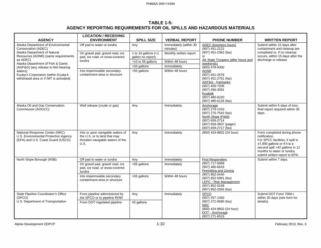
TABLE 1-5: AGENCY REPORTING REQUIREMENTS FOR OIL SPILLS AND HAZARDOUS MATERIALS
AGENCY LOCATION / RECEIVING
ENVIRONMENT SPILL SIZE VERBAL REPORT PHONE NUMBER WRITTEN REPORT Alaska Department of Environmental Conservation (ADEC) Alaska Department of Natural Resources (ADNR) (same requirements as ADEC) Alaska Department of Fish & Game (ADF&G) (any release to fish-bearing waters) Kuukp k Corporation (within Kuukp k withdrawal area or if IMT is activated)
Off pad to water or tundra Any Immediately (within 30 minutes)
ADEC (business hours) (907) 451-2121 (907) 451-2362 (fax) or AK State Troopers (after hours and weekends) (800) 478-9300 ADNR (907) 451-2678 (907) 451-2751 (fax) ADF&G - Fairbanks (907) 459-7206 (907) 456-3091 Kuukpik (907) 480-6220 (907) 480-6126 (fax)
Submit within 15 days after containment and cleanup are completed or, if no cleanup occurs, within 15 days after the discharge or release.
On gravel pad, gravel road, ice pad, ice road, or snow-covered tundra
1 to 10 gallons (<1 gallon no report)
Monthly written report
>10 to 55 gallons Within 48 hours >55 gallons Immediately
Into impermeable secondary containment area or structure
>55 gallons Within 48 hours
Alaska Oil and Gas Conservation Commission (AOGCC)
Well release (crude or gas) Any Immediately Anchorage (907) 279-1433 (907) 276-7542 (fax) North Slope (Field) (907) 659-2714 (907) 659-3607 (pager) (907) 659-2717 (fax)
Submit within 5 days of loss; final report required within 30 days.
National Response Center (NRC) U.S. Environmental Protection Agency (EPA) and U.S. Coast Guard (USCG)
Into or upon navigable waters of the U.S. or to land that may threaten navigable waters of the U.S.
Any Immediately (800) 424-8802 (24 hour) Form completed during phone notification. For SPCC facilities, if spill is ≥1,000 gallons or if it is a second spill >42 gallons in 12 months to water or tundra, submit written report to EPA.
North Slope Borough (NSB) Off pad to water or tundra Any Immediately First Responders (907) 717-5668 (907) 480-6818 Permitting and Zoning (907) 852-0440 (907) 852-5991 (fax) LEPC - Risk Management (907) 852-0248 (907) 852-0356 (fax)
Submit within 7 days. On gravel pad, gravel road, ice pad, ice road, or snow-covered tundra
>55 gallons Immediately
Into impermeable secondary containment area or structure
>55 gallons Within 48 hours
State Pipeline Coordinator’s Office (SPCO) U.S. Department of Transportation
From pipeline administered by the SPCO or to pipeline ROW
Any Immediately SPCO (907) 257-1300 (907) 272-0690 (fax) NRC (800) 424-8802 (24 hour) DOT - Anchorage (907) 271-6519
Submit DOT Form 7000-I within 30 days (see form for details). From DOT-regulated pipeline ≥5 gallons
Alpine Development ODPCP 1-10 February 2013, Rev. 0
PHMSA 000114394
1.3 SAFETY [18 AAC 75.425(e)(1)(C)]
The principal sources of information concerning safety procedures and practices to be followed in the event of a spill are:
• The ACS Technical Manual, Tactics S-1 through S-6, which includes site entry procedures, site safety plan development, and personnel protection procedures.
• The Alaska Safety Handbook available to North Slope employees and contractors.
• CPAI’s emergency action plans, which reference SOPs, operating manuals, and emergency procedures.
• Facility evacuation plans and diagrams contained in the emergency action plans.
Alpine Development ODPCP 1-11 February 2013, Rev. 0
PHMSA 000114395
1.4 COMMUNICATIONS [18 AAC 75.425(e)(1)(D)]
The CPAI Alpine spill communication system supports the organizational structure of spill response efforts and is scalable in both size and scope to serve both small- and large-scale response events. An event that is limited to a local response by the SRT is comfortably served by the local SRT communications system. An event that invokes a response by ACS or involves a significant Mutual Aid effort with other North Slope operators is able to use ACS communications equipment and upgrade smoothly from the local communication system to the ACS wide-area communications system.
The Alpine communication resources available for spill response may be loosely classified into the following four categories:
1. Those designed to support spill response and developed for the SRT and the CPAI Incident Management Post. These resources will be collectively referred to as the SRT Telecom Resource.
2. Communication resources that are part of the ACS Telecommunications Plan. These resources are available for CPAI and other North Slope operators, including ACS. This is the ACS Telecom Resource.
3. Communication resources that were not designed exclusively for spill response but may directly or indirectly play an important supportive role toward a successful response effort. This is the Alpine Telecom Resource.
4. Locally available public resources (cellular service).
1.4.1 Category 1: SRT Communications
CPAI maintains two very high frequency (VHF) radio systems at Alpine to support oil spill communications throughout the Alpine operating area – a VHF oil spill repeater, and VHF marine coast station. Each Alpine oil spill response vessel or vehicle is also equipped with VHF mobile radios tuned to these frequencies. In addition, approximately 20 hand-held VHF radios are maintained at Alpine for SRT use.
VHF Oil Spill Repeater
A wide-area VHF repeater provides oil spill radio communications for Alpine and the surrounding area. It has a range of approximately 15 miles to hand-held radios, and 30 miles to mobile radios. This repeater is tied into the ACS wide-area VHF radio network as channel OS-33, but it is also the primary means of communication for spills or spill exercises that do not include ACS or other Mutual Aid responders. Fixed Incident Command facilities at Alpine, at the Kuparuk Spill Response Center, and at ACS can monitor or access this repeater. In addition, mobile oil spill response equipment, and individual members of the SRT are equipped to access this VHF channel.
The VHF repeater frequencies assigned to Alpine are as follows:
• VHF Oil Spill (OS-33):
− Repeater Transmit – 159.585 megahertz,
− Repeater Receive – 161.235 megahertz, and
− Private Line Code – 103.5 hertz.
Alpine Development ODPCP 1-12 February 2013, Rev. 0
PHMSA 000114396
VHF Coast Station
A wide-area VHF coast station provides marine communications to oil spill response vessels working in the coastal areas around Alpine. The coast station frequencies used at Alpine are Marine Channel 16 (safety and calling) and Channel 80A (working). A dedicated receiver guards Channel 16 at all times, even when the coast station is working on Channel 80A.
The coast station frequencies are as follows:
• Marine 16 transmit and receive – 156.800 megahertz, and
• Marine 80A transmit and receive – 157.025 megahertz.
These two radio systems can communicate with mobile radios or vessels within approximately 30 miles of Alpine, and with hand-held radios within 15 miles of Alpine.
Figure 1-2 is a block diagram showing the Alpine oil spill communication systems and associated control consoles at Alpine, Kuparuk, and ACS.
1.4.2 Category 2: ACS Communications
ACS communication resources are available to CPAI for spill response when required. The VHF repeater channel OS-35 also provides a direct tie-in to the ACS communication system. With such repeaters installed across the North Slope, coverage is provided from Alpine to Badami. The range of each fixed repeater is approximately 30 to 50 miles, depending on topography. ACS solar-powered portable repeaters also can be deployed at the time of a spill. ACS will provide the repeater, coast station, antennae, hand-held radios, and back-boarded mobiles to allow for effective spill response, when necessary, in an emergency. A detailed explanation of oil spill communications on the North Slope is provided in the ACS Technical Manual, Tactic L-5.
At Alpine, a 115-foot communication tower is fitted with two ultra high frequency (UHF) beam antennae at the 95-foot level. These antennae are reserved for exclusive use by ACS communication equipment that would establish UHF radio control links to the area west of Alpine for extended VHF oil spill communications coverage beyond the normal range of the Alpine VHF systems. These antennae, along with two dedicated four-way radio control circuits wired from Alpine to ACS in Deadhorse, would allow both ACS and Kuparuk Incident Command centers to control radio systems over far distances west of Alpine.
1.4.3 Category 3: Alpine Telecom Resources
Alpine Telecom Resources are systems installed for the day-to-day operation of the Alpine field, but could be pressed into ancillary service in support of oil spill cleanup operations, given the necessary circumstances.
The Alpine telephone and computer network system is connected by fiber optic lines that follow the Alpine pipeline route to Kuparuk. The fiber optic cables for Alpine satellite drilling sites are attached to the elevated in-field pipelines and/or buried in gravel access roads, where applicable. Telephone circuits to the public-switched telephone network are then carried on Kuparuk circuits to the public network. Oil spill remote radio circuits between Alpine and ACS are also carried on the fiber optic lines.
The fiber optic lines are backed up by a digital microwave radio system between Alpine and Kuparuk that is capable of handling all telephone, computer, and remote radio traffic if the fiber optic system fails.
Alpine Development ODPCP 1-13 February 2013, Rev. 0
PHMSA 000114397
There are six UHF repeater networks used at Alpine for day-to-day operations. The six systems are used by Drilling; Operations; Health, Safety, and Environment (HSE)/Security; Maintenance; Construction; and contractors. Each of these repeaters has a range of approximately 25 miles to mobile radios, and 15 miles to hand-held radios. Existing hand-held radios and mobile radios operating on these channels are used for day-to-day operations. Approximately 180 hand-held radios and 50 mobile UHF radios are available at Alpine on these channels.
There is also a UHF digital messaging radio paging system at Alpine that can send digital text messages to individual or group pagers. Text messages can be sent from computer terminals connected to the Alpine computer network system or from a special paging terminal located at Alpine Security. A call-back phone number can be sent to the pagers from anyone with access to the Alpine telephone system. The range of the paging system is approximately 20 miles. SRT members carry pagers linked to this system. Alpine Emergency Response Center members now use two-tone voice pagers.
1.4.4 Category 4: Local Cellular Service
Cellular systems owned by Arctic Slope Telephone Association Cooperative (ASTAC) and Alaska Communications provide cellular coverage in the Alpine area. The ASTAC system provides coverage from a single base site in Nuiqsut, nine miles southwest of Alpine. The system is capable of handling 23 conversations at a time, and provides cell phone coverage to pocket phones out to 12 miles from Nuiqsut, and to bag phones out to 20 miles from Nuiqsut.
When the SRT responds to a spill, it uses Category 1 communication systems already in place at Alpine. If the spill response escalates, the Communications Unit Leader, as part of the IMT, will determine whether additional Category 2, 3, or 4 communication systems are necessary to support the SRT, ACS, or contractor response teams.
An IMT located at the Alpine Emergency Response Center and Kuparuk Emergency Operations Center manages spills at Alpine. Radio dispatch consoles at the Kuparuk Spill Response Center are capable of operating the VHF repeater and Coast Station at Alpine, but not the UHF repeaters described in the Alpine Telecom Resources (Category 3).
Alpine Development ODPCP 1-14 February 2013, Rev. 0
PHMSA 000114398
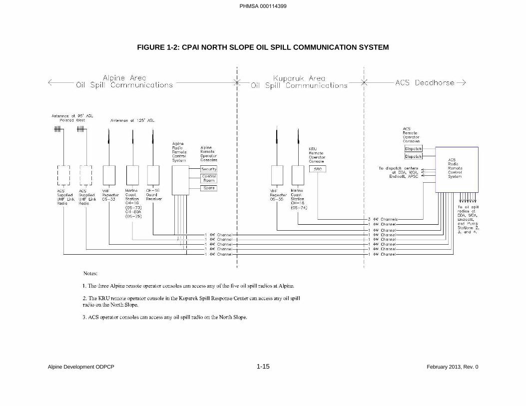
FIGURE 1-2: CPAI NORTH SLOPE OIL SPILL COMMUNICATION SYSTEM
Alpine Development ODPCP 1-15 February 2013, Rev. 0
PHMSA 000114399
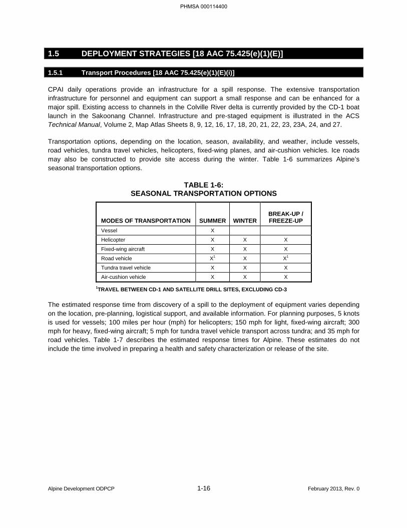
1.5 DEPLOYMENT STRATEGIES [18 AAC 75.425(e)(1)(E)]
1.5.1 Transport Procedures [18 AAC 75.425(e)(1)(E)(i)]
CPAI daily operations provide an infrastructure for a spill response. The extensive transportation infrastructure for personnel and equipment can support a small response and can be enhanced for a major spill. Existing access to channels in the Colville River delta is currently provided by the CD-1 boat launch in the Sakoonang Channel. Infrastructure and pre-staged equipment is illustrated in the ACS Technical Manual, Volume 2, Map Atlas Sheets 8, 9, 12, 16, 17, 18, 20, 21, 22, 23, 23A, 24, and 27.
Transportation options, depending on the location, season, availability, and weather, include vessels, road vehicles, tundra travel vehicles, helicopters, fixed-wing planes, and air-cushion vehicles. Ice roads may also be constructed to provide site access during the winter. Table 1-6 summarizes Alpine’s seasonal transportation options.
TABLE 1-6: SEASONAL TRANSPORTATION OPTIONS
MODES OF TRANSPORTATION SUMMER WINTER BREAK-UP / FREEZE-UP
Vessel X
Helicopter X X X
Fixed-wing aircraft X X X
Road vehicle X1 X X1
Tundra travel vehicle X X X
Air-cushion vehicle X X X
1TRAVEL BETWEEN CD-1 AND SATELLITE DRILL SITES, EXCLUDING CD-3
The estimated response time from discovery of a spill to the deployment of equipment varies depending on the location, pre-planning, logistical support, and available information. For planning purposes, 5 knots is used for vessels; 100 miles per hour (mph) for helicopters; 150 mph for light, fixed-wing aircraft; 300 mph for heavy, fixed-wing aircraft; 5 mph for tundra travel vehicle transport across tundra; and 35 mph for road vehicles. Table 1-7 describes the estimated response times for Alpine. These estimates do not include the time involved in preparing a health and safety characterization or release of the site.
Alpine Development ODPCP 1-16 February 2013, Rev. 0
PHMSA 000114400
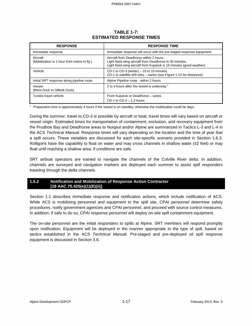
TABLE 1-7: ESTIMATED RESPONSE TIMES
RESPONSE RESPONSE TIME Immediate response Immediate response will occur with the pre-staged response equipment.
Aircraft (Mobilization is 1 hour from notice to fly.)
Aircraft from Deadhorse within 2 hours. Light fixed-wing aircraft from Deadhorse is 30 minutes. Light fixed-wing aircraft from Kuparuk is 15 minutes (good weather).
Vehicle CD-1 to CD-3 (winter) – 10 to 15 minutes. CD-1 to satellite drill sites – varies (see Figure 1-12 for distances).
Initial SRT response along pipeline route Alpine Pipeline route - within 2 hours.
Vessel (West Dock to Oliktok Dock)
2 to 4 hours after the vessel is underway.1
Tundra travel vehicle From Kuparuk or Deadhorse – varies CD-1 to CD-3 – 1.2 hours.
1 Preparation time is approximately 4 hours if the vessel is on standby; otherwise the mobilization could be days.
During the summer, travel to CD-3 is possible by aircraft or boat; travel times will vary based on aircraft or vessel origin. Estimated times for transportation of containment, exclusion, and recovery equipment from the Prudhoe Bay and Deadhorse areas to Nuiqsut and/or Alpine are summarized in Tactics L-3 and L-4 in the ACS Technical Manual. Response times will vary depending on the location and the time of year that a spill occurs. These variables are discussed for each site-specific scenario provided in Section 1.6.3. Rolligons have the capability to float on water and may cross channels in shallow water (≤2 feet) or may float until reaching a shallow area, if conditions are safe.
SRT airboat operators are trained to navigate the channels of the Colville River delta. In addition, channels are surveyed and navigation markers are deployed each summer to assist spill responders traveling through the delta channels.
1.5.2 Notification and Mobilization of Response Action Contractor [18 AAC 75.425(e)(1)(E)(ii)]
Section 1.1 describes immediate response and notification actions, which include notification of ACS. While ACS is mobilizing personnel and equipment to the spill site, CPAI personnel determine safety procedures, notify government agencies and CPAI personnel, and proceed with source control measures. In addition, if safe to do so, CPAI response personnel will deploy on-site spill containment equipment.
The on-site personnel are the initial responders to spills at Alpine. SRT members will respond promptly upon notification. Equipment will be deployed in the manner appropriate to the type of spill, based on tactics established in the ACS Technical Manual. Pre-staged and pre-deployed oil spill response equipment is discussed in Section 3.6.
Alpine Development ODPCP 1-17 February 2013, Rev. 0
PHMSA 000114401
1.6 RESPONSE STRATEGIES [18 AAC 75.425(e)(1)(F)]
1.6.1 Qualifier Statement
The scenarios and response strategies described in this plan were developed according to 18 AAC 75.425(e)(1)(F) and (I). They describe general procedures, equipment, personnel, tactics, strategies, and operational capabilities that can be used to respond to an oil spill. These scenarios are for illustration only and are not performance standards or guarantees of performance. The scenarios assume hypothetical conditions of the spills and responses to demonstrate CPAI’s ability to respond to a discharge of each applicable response planning standard (RPS) volume within the required timeframes using the resources described in this ODPCP and as required by 18 AAC 75.425(e)(1)(F) and (I). The RPS volume calculations are presented in Part 5.
The scenarios identify the location, time of year, time of day, source and cause of spill, quantity and type of oil spilled, relevant environmental conditions (including weather, sea state, and visibility), spill trajectory, expected timeline for response actions, and a description of response actions to be taken. The response scenarios and strategies are usable as a general guide for a discharge of any size, and describe the discharge containment, control, and cleanup actions to be taken, which demonstrate the strategies and procedures adopted to conduct and maintain an effective response.
Well blowout scenarios include a summary of planned methods, equipment, logistics, and timeframes proposed to be employed to control a well blowout within 15 days. CPAI also certifies that they have and maintain a separate blowout contingency plan that is available to ADEC upon request.
The response strategies illustrate specific response measures that can reduce the risk, magnitude, or environmental impact of an oil spill, considering the variation of receiving environments and seasonal conditions.
The response scenarios include the following:
i. Procedures to stop discharge,
ii. Fire prevention and control,
iii. Not used (associated regulation repealed 5/26/2004),
iv. Discharge tracking,
v. Protection of sensitive areas,
vi. Containment and control strategies,
vii. Recovery strategies,
viii. Damaged tank transfer – lightering procedures,
ix. Transfer and storage strategies,
x. Temporary storage and ultimate disposal,
xi. Wildlife protection, and
xii. Shoreline cleanup.
Some details in the scenarios are for illustration purposes; and although some equipment is named, it may be replaced by functionally similar equipment (e.g., a dump truck may be used in winter when there is road access, or an end dump trailer pulled by a semi chassis may be the functional equivalent to
Alpine Development ODPCP 1-18 February 2013, Rev. 0
PHMSA 000114402
perform a similar task in summer). These details do not limit the discretion of the persons in charge of the spill response to select any sequence or take whatever time they deem necessary to respond to a spill without jeopardizing personnel safety.
In situ burning could be used in a spill response to reduce the quantity of oil, regardless of whether a scenario hypothesizes in situ burning to help meet the RPS. Section 3.4 and Section 3.7 describe the in situ burning capabilities of CPAI and ACS during varying seasonal conditions.
Actual responses in an oil spill emergency depend on personnel safety considerations, weather, other environmental conditions, agency permits and priorities, and other factors. In any incident, considerations to ensure the safety of personnel will be given highest priority. If severe weather or other conditions limit the safety of personnel, CPAI may take precautions up to and including suspending response efforts until it is deemed safe to proceed. Likewise, if operating limitations are reached because of weather conditions, CPAI will reassess the response effort and take necessary precautions to protect personnel and equipment. The scenarios assume the agency on-scene coordinators and other agency officials will immediately grant any required permits.
1.6.2 Temporary Storage and Disposal [18 AAC 75.425(e)(1)(F)(x)]
Temporary storage of oil, oily waste, and debris recovered during a spill cleanup may be provided by tanks, pits, or basins located at facilities near the site. The spill location or other logistical problems may require storage of oil, oily waste, and debris in smaller, more portable containers that can be brought to the scene via truck, boat, or aircraft.
Other temporary storage options during a spill response include lined natural depressions (approval required), construction of lined earthen dikes, and portable storage (bladder tanks, inflatable tanks, open-top drums, vacuum trucks, dump trucks, etc.).
There are six permitted temporary solid waste cells at Pad 3 in the Prudhoe Bay Eastern Operating Area. Although it is not a permanent disposal site, long-term storage of solid hydrocarbons is possible. Requirements for use of the Pad 3 oily solid waste pits are set by ADEC solid waste disposal permit.
There are also two permitted temporary storage pits at Pad 3 – the East Pit for contaminated snow and the West Pit for contaminated gravel. Contaminated snow from the East Pit is melted each spring and injected into one of the Pad 3 Class I wells. Gravel from the West Pit is thermally remediated each summer or every other summer, depending on the volume requirements. Kuparuk DS-1H may also be used for contaminated gravel and/or snow storage, and contains 12,230 cubic yards of storage capacity. Gravel from DS-1H is thermally remediated each summer or every other summer, depending on volume requirements.
During the summer months at Alpine, when it may not be feasible to transport contaminated gravel to the Eastern Operating Area or Kuparuk, temporary storage cells would be constructed on site using appropriate liner and construction materials.
Over 667 barrels of bladder tanks and 3,286 barrels of folding tank capacity are available for temporary storage of liquids. Additional tanks and bladders will be transported to the facility if more capacity is needed (see ACS Technical Manual, Tactic L-6).
The method of disposal for oil and contaminated materials from spill recovery operations (or for oily waste from normal operations) must be approved and permitted by the appropriate state and federal agencies.
Alpine Development ODPCP 1-19 February 2013, Rev. 0
PHMSA 000114403
At the time of the spill, the Operations Chief, in consultation with the Environmental Unit Leader, determines the reuse, recycle, or disposal method best suited to the state of the oil, the degree of contamination of recovered debris, and the logistics involved in these operations. Application for agency approvals and permits are completed before the determined method of disposal is implemented. An initial determination must be made regarding the classification of the waste as exempt, hazardous, or non-hazardous. This classification can be made on a case-by-case basis. The Environmental Unit Leader provides assistance in determining the classification if the status of the waste material is in question. In general, the following guidelines apply:
• Spills from DOT pipelines are non-exempt and may need to be tested to determine whether the material to be disposed of is hazardous.
• Spills from production lines are exempt.
• Spilled material that comes out of a well, either during drilling or work-over operations, is exempt. Spilled material that did not come out of a well is non-exempt and may need to be tested to determine if the material to be disposed of is hazardous.
• Spills that occur from filling a tank (i.e., vehicle, storage, etc.) are non-exempt, even though they may occur on a well pad; product knowledge or testing may be needed to determine if the material to be disposed of is hazardous.
Should materials need to be transported off the North Slope, truck, barge, and/or air transportation would be arranged.
Use of an ice road may be possible from mid-February to mid-April. In addition, ACS maintains pre-approved emergency and non-emergency use permits to aid in immediate spill response (see ACS Technical Manual, Tactic A-3).
1.6.3 Response Scenarios and Strategies [18 AAC 75.425(e)(1)(F)]
The following response scenarios and response strategies are included in this section:
• Scenario 1: Alpine CD2-39 Production Well Blowout in Typical Summer Conditions.
• Scenario 2: Alpine CD2-39 Production Well Blowout in Typical Winter Conditions.
• Scenario 3: Alpine Pipeline Rupture to the Miluveach River in Summer.
• Scenario 4: Alpine Tank Rupture in Summer at CD-1.
Alpine Development ODPCP 1-20 February 2013, Rev. 0
PHMSA 000114404
SCENARIO 1
ALPINE CD-2 PAD
CD2-39 PRODUCTION WELL BLOWOUT
IN TYPICAL SUMMER CONDITIONS
Alpine Development ODPCP 1-21 February 2013, Rev. 0
PHMSA 000114405

BLANK PAGE
Alpine Development ODPCP 1-22 February 2013, Rev. 0
PHMSA 000114406
TABLE 1-8: ALPINE CD2-39 PRODUCTION WELL BLOWOUT IN SUMMER
SCENARIO CONDITIONS
PARAMETER PARAMETER CONDITIONS Spill Location Date Duration Cause of Spill
Quantity of Oil Spilled
Emulsification Factor Oil Type
Wind Direction and Speed
Current Air Temperature
Surface
Trajectory
Alpine Development ODPCP 1-23 February 2013, Rev. 0
PHMSA 000114407
(b) (7)(F), (b) (3)
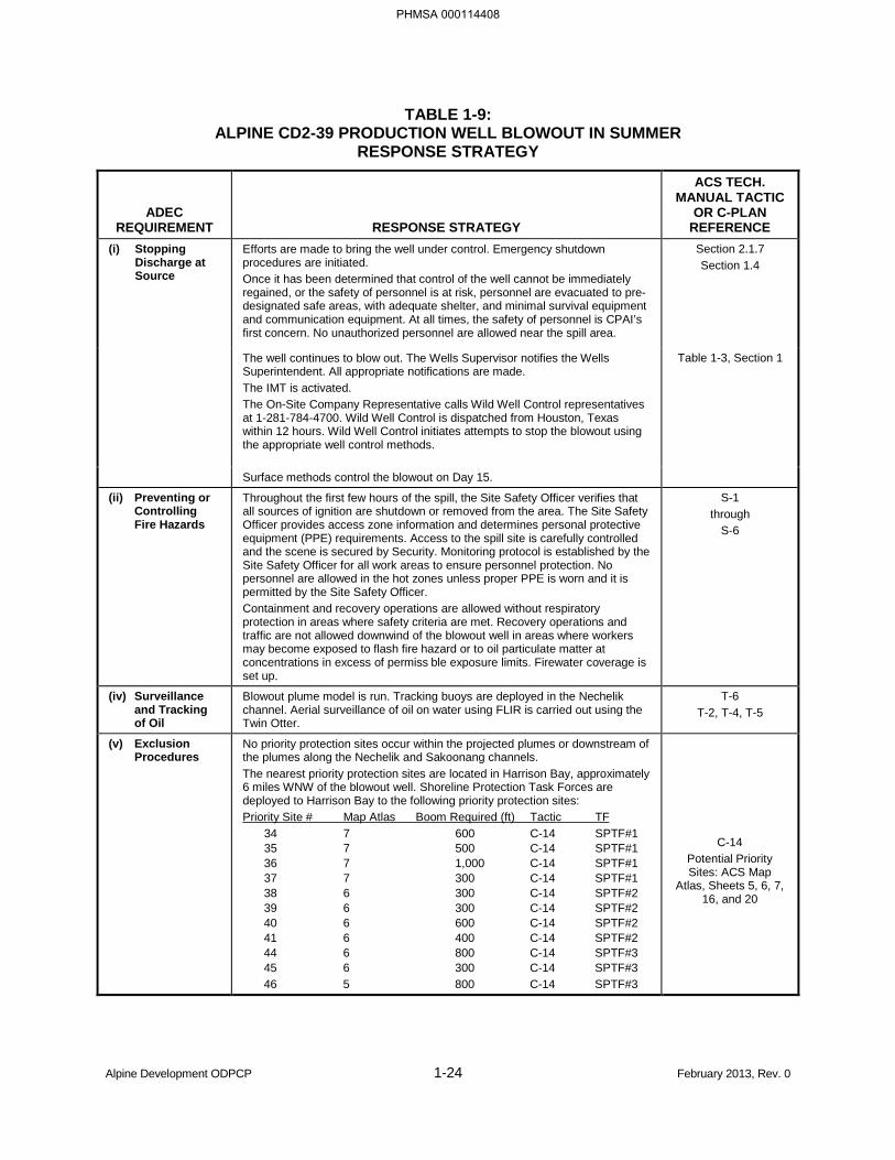
TABLE 1-9: ALPINE CD2-39 PRODUCTION WELL BLOWOUT IN SUMMER
RESPONSE STRATEGY
ADEC REQUIREMENT RESPONSE STRATEGY
ACS TECH. MANUAL TACTIC
OR C-PLAN REFERENCE
(i) Stopping Discharge at Source
Efforts are made to bring the well under control. Emergency shutdown procedures are initiated. Once it has been determined that control of the well cannot be immediately regained, or the safety of personnel is at risk, personnel are evacuated to pre-designated safe areas, with adequate shelter, and minimal survival equipment and communication equipment. At all times, the safety of personnel is CPAI’s first concern. No unauthorized personnel are allowed near the spill area.
Section 2.1.7 Section 1.4
The well continues to blow out. The Wells Supervisor notifies the Wells Superintendent. All appropriate notifications are made. The IMT is activated. The On-Site Company Representative calls Wild Well Control representatives at 1-281-784-4700. Wild Well Control is dispatched from Houston, Texas within 12 hours. Wild Well Control initiates attempts to stop the blowout using the appropriate well control methods.
Table 1-3, Section 1
Surface methods control the blowout on Day 15.
(ii) Preventing or Controlling Fire Hazards
Throughout the first few hours of the spill, the Site Safety Officer verifies that all sources of ignition are shutdown or removed from the area. The Site Safety Officer provides access zone information and determines personal protective equipment (PPE) requirements. Access to the spill site is carefully controlled and the scene is secured by Security. Monitoring protocol is established by the Site Safety Officer for all work areas to ensure personnel protection. No personnel are allowed in the hot zones unless proper PPE is worn and it is permitted by the Site Safety Officer. Containment and recovery operations are allowed without respiratory protection in areas where safety criteria are met. Recovery operations and traffic are not allowed downwind of the blowout well in areas where workers may become exposed to flash fire hazard or to oil particulate matter at concentrations in excess of permiss ble exposure limits. Firewater coverage is set up.
S-1 through
S-6
(iv) Surveillance and Tracking of Oil
Blowout plume model is run. Tracking buoys are deployed in the Nechelik channel. Aerial surveillance of oil on water using FLIR is carried out using the Twin Otter.
T-6 T-2, T-4, T-5
(v) Exclusion Procedures
No priority protection sites occur within the projected plumes or downstream of the plumes along the Nechelik and Sakoonang channels. The nearest priority protection sites are located in Harrison Bay, approximately 6 miles WNW of the blowout well. Shoreline Protection Task Forces are deployed to Harrison Bay to the following priority protection sites: Priority Site # Map Atlas Boom Required (ft) Tactic TF 34 7 600 C-14 SPTF#1 35 7 500 C-14 SPTF#1 36 7 1,000 C-14 SPTF#1 37 7 300 C-14 SPTF#1 38 6 300 C-14 SPTF#2 39 6 300 C-14 SPTF#2 40 6 600 C-14 SPTF#2 41 6 400 C-14 SPTF#2 44 6 800 C-14 SPTF#3 45 6 300 C-14 SPTF#3 46 5 800 C-14 SPTF#3
C-14 Potential Priority Sites: ACS Map
Atlas, Sheets 5, 6, 7, 16, and 20
Alpine Development ODPCP 1-24 February 2013, Rev. 0
PHMSA 000114408
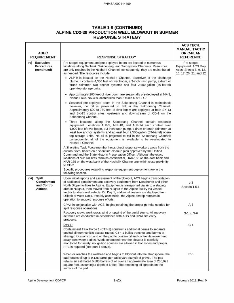
TABLE 1-9 (CONTINUED) ALPINE CD2-39 PRODUCTION WELL BLOWOUT IN SUMMER
RESPONSE STRATEGY
ADEC REQUIREMENT RESPONSE STRATEGY
ACS TECH. MANUAL TACTIC
OR C-PLAN REFERENCE
(v) Exclusion Procedures (continued)
Pre-staged equipment and pre-deployed boom are located at numerous locations along Nechelik, Sakoonang, and Tamayayak Channels. Resources are only required in the Nechel k Channel; consequently, they are redistributed as needed. The resources include: • ALP-9 is located on the Nechel k Channel, downriver of the discharge
plume. It contains 4,350 feet of river boom, a 3-inch trash pump, a drum or brush skimmer, two anchor systems and four 2,500-gallon (59-barrel) open-top storage units.
• Approximately 200 feet of river boom are seasonally pre-deployed at NK-3, Nanuq Lake. NK-3 is located less than 2 miles S of CD-2.
• Seasonal pre-deployed boom in the Sakoonang Channel is maintained; however, no oil is projected to fall in the Sakoonang Channel. Approximately 500 to 750 feet of river boom are deployed at both SK-13 and SK-15 control sites, upstream and downstream of CD-1 on the Sakoonang Channel.
• Three locations along the Sakoonang Channel contain response equipment. Locations ALP-5, ALP-10, and ALP-14 each contain over 1,000 feet of river boom, a 3-inch trash pump, a drum or brush skimmer, at least two anchor systems and at least four 2,500-gallon (59-barrel) open-top storage units. No oil is projected to fall in the Sakoonang Channel; consequently, all of the equipment is available to be re-allocated to Nechel k Channel.
A Shoreline Task Force member helps direct response workers away from the cultural sites, based on a shoreline cleanup plan approved by the Unified Command and the State Historic Preservation Officer. Although the exact locations of cultural sites remains confidential, HAR-156 on the east bank and HAR-169 on the west bank of the Nechelik Channel are within close proximity to CD-2. Specific procedures regarding response equipment deployment are in the following section.
Pre-staged Equipment: ACS Map Atlas, Sheets 8, 9, 12, 16, 17, 20, 21, and 22
(vi) Spill Containment and Control Actions
Upon initial reports and assessment of the blowout, ACS begins transportation of additional containment and recovery equipment from Deadhorse and other North Slope facilities to Alpine. Equipment is transported via air to a staging area in Nuiqsut, then moved from Nuiqsut to the Alpine facility via vessel and/or tundra travel vehicle. On Day 1, additional vessels are deployed from Oliktok or West Dock. If safely access ble, the Alpine airstrip remains in operation to support response efforts.
L-3
Section 1.5.1
CPAI, in conjunction with ACS, begins obtaining the proper permits needed for spill response operations. Recovery crews work cross-wind or upwind of the aerial plume. All recovery activities are conducted in accordance with ACS and CPAI site entry protocols.
A-3
S-1 to S-6
Day 1: Containment Task Force 1 (CTF-1) constructs additional berms to separate pooled oil from vehicle access routes. CTF-1 builds trenches and berms at strategic locations on and off the pad to contain oil and control its movement away from water bodies. Work conducted near the blowout is carefully monitored for safety; no ignition sources are allowed in hot zones and proper PPE is required (see part ii above).
C-4
When oil reaches the wellhead and begins to blowout into the atmosphere, the pad retains oil up to 0.125 barrel per cubic yard (cu yd) of gravel. The pad retains an estimated 6,583 barrels of oil over an approximate area of 236,992 square feet, assuming a depth of 6 feet. The remaining oil spreads on the surface of the pad.
R-5
Alpine Development ODPCP 1-25 February 2013, Rev. 0
PHMSA 000114409
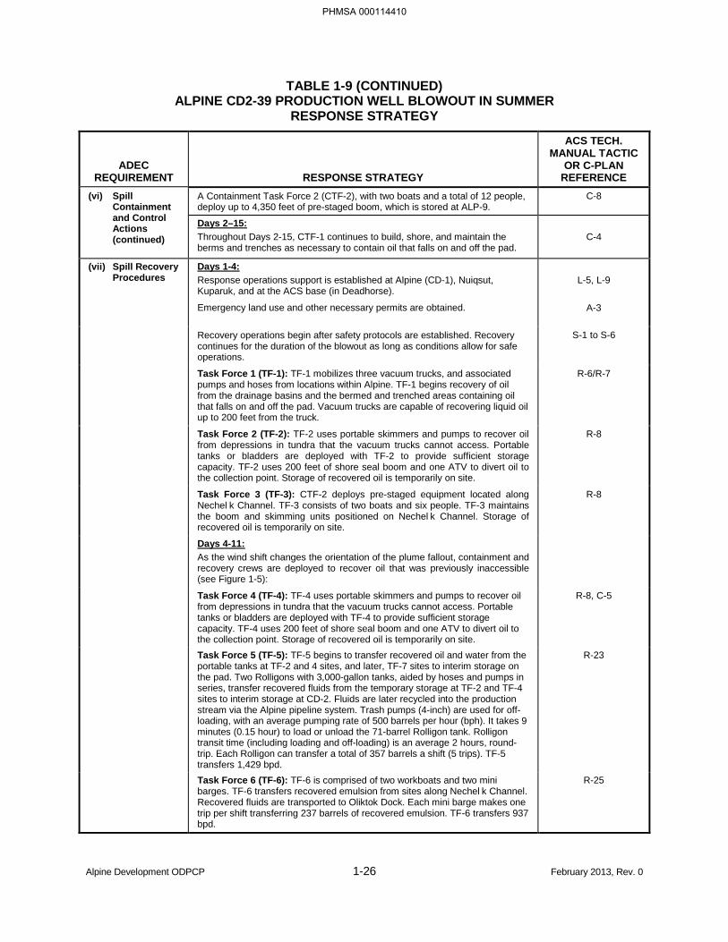
TABLE 1-9 (CONTINUED) ALPINE CD2-39 PRODUCTION WELL BLOWOUT IN SUMMER
RESPONSE STRATEGY
ADEC REQUIREMENT RESPONSE STRATEGY
ACS TECH. MANUAL TACTIC
OR C-PLAN REFERENCE
(vi) Spill Containment and Control Actions (continued)
A Containment Task Force 2 (CTF-2), with two boats and a total of 12 people, deploy up to 4,350 feet of pre-staged boom, which is stored at ALP-9.
C-8
Days 2–15: Throughout Days 2-15, CTF-1 continues to build, shore, and maintain the berms and trenches as necessary to contain oil that falls on and off the pad.
C-4
(vii) Spill Recovery Procedures
Days 1-4: Response operations support is established at Alpine (CD-1), Nuiqsut, Kuparuk, and at the ACS base (in Deadhorse).
L-5, L-9
Emergency land use and other necessary permits are obtained. A-3
Recovery operations begin after safety protocols are established. Recovery continues for the duration of the blowout as long as conditions allow for safe operations.
S-1 to S-6
Task Force 1 (TF-1): TF-1 mobilizes three vacuum trucks, and associated pumps and hoses from locations within Alpine. TF-1 begins recovery of oil from the drainage basins and the bermed and trenched areas containing oil that falls on and off the pad. Vacuum trucks are capable of recovering liquid oil up to 200 feet from the truck.
R-6/R-7
Task Force 2 (TF-2): TF-2 uses portable skimmers and pumps to recover oil from depressions in tundra that the vacuum trucks cannot access. Portable tanks or bladders are deployed with TF-2 to provide sufficient storage capacity. TF-2 uses 200 feet of shore seal boom and one ATV to divert oil to the collection point. Storage of recovered oil is temporarily on site.
R-8
Task Force 3 (TF-3): CTF-2 deploys pre-staged equipment located along Nechel k Channel. TF-3 consists of two boats and six people. TF-3 maintains the boom and skimming units positioned on Nechel k Channel. Storage of recovered oil is temporarily on site.
R-8
Days 4-11: As the wind shift changes the orientation of the plume fallout, containment and recovery crews are deployed to recover oil that was previously inaccessible (see Figure 1-5):
Task Force 4 (TF-4): TF-4 uses portable skimmers and pumps to recover oil from depressions in tundra that the vacuum trucks cannot access. Portable tanks or bladders are deployed with TF-4 to provide sufficient storage capacity. TF-4 uses 200 feet of shore seal boom and one ATV to divert oil to the collection point. Storage of recovered oil is temporarily on site.
R-8, C-5
Task Force 5 (TF-5): TF-5 begins to transfer recovered oil and water from the portable tanks at TF-2 and 4 sites, and later, TF-7 sites to interim storage on the pad. Two Rolligons with 3,000-gallon tanks, aided by hoses and pumps in series, transfer recovered fluids from the temporary storage at TF-2 and TF-4 sites to interim storage at CD-2. Fluids are later recycled into the production stream via the Alpine pipeline system. Trash pumps (4-inch) are used for off-loading, with an average pumping rate of 500 barrels per hour (bph). It takes 9 minutes (0.15 hour) to load or unload the 71-barrel Rolligon tank. Rolligon transit time (including loading and off-loading) is an average 2 hours, round-trip. Each Rolligon can transfer a total of 357 barrels a shift (5 trips). TF-5 transfers 1,429 bpd.
R-23
Task Force 6 (TF-6): TF-6 is comprised of two workboats and two mini barges. TF-6 transfers recovered emulsion from sites along Nechel k Channel. Recovered fluids are transported to Oliktok Dock. Each mini barge makes one trip per shift transferring 237 barrels of recovered emulsion. TF-6 transfers 937 bpd.
R-25
Alpine Development ODPCP 1-26 February 2013, Rev. 0
PHMSA 000114410
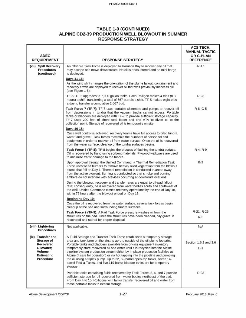
TABLE 1-9 (CONTINUED) ALPINE CD2-39 PRODUCTION WELL BLOWOUT IN SUMMER
RESPONSE STRATEGY
ADEC REQUIREMENT RESPONSE STRATEGY
ACS TECH. MANUAL TACTIC
OR C-PLAN REFERENCE
(vii) Spill Recovery Procedures (continued)
An offshore Task Force is deployed to Harrison Bay to recover any oil that may escape and move downstream. No oil is encountered and no mini barge is deployed.
R-17
Days 11-15: As the wind shift changes the orientation of the plume fallout, containment and recovery crews are deployed to recover oil that was previously inaccess ble (see Figure 1-5):
TF-5: TF-5 upgrades to 7,000-gallon tanks. Each Rolligon makes 4 trips (8.8 hours) a shift, transferring a total of 667 barrels a shift. TF-5 makes eight trips a day to transfer a cumulative 2,667 bpd.
R-23
Task Force 7 (TF-7): TF-7 uses portable skimmers and pumps to recover oil from depressions in tundra that the vacuum trucks cannot access. Portable tanks or bladders are deployed with TF-7 to provide sufficient storage capacity. TF-7 uses 200 feet of shore seal boom and one ATV to divert oil to the collection point. Storage of recovered oil is temporarily on site.
R-8, C-5
Days 16-18: Once well control is achieved, recovery teams have full access to oiled tundra, water, and gravel. Task forces maximize the numbers of personnel and equipment in order to recover oil from water surface. Once the oil is recovered from the water surface, cleanup of the tundra surfaces begins:
Task Force 8 (TF-8): TF-8 begins the process of flushing the tundra surface. Oil is recovered by hand using sorbent materials. Plywood walkways are used to minimize traffic damage to the tundra.
R-4, R-9
Upon approval through the Unified Command, a Thermal Remediation Task Force uses weed burners to remove heavily oiled vegetation from the blowout plume that fell on Day 1. Thermal remediation is conducted in areas away from the active blowout. Burning is conducted so that smoke and burning embers do not interfere with activities occurring at downwind locations.
B-2
During the blowout, recovery and transfer rates are equal to off-pad fallout rate; consequently, oil is recovered from water bodies south and southwest of the well. Unified Command closes recovery operations by the end of Day 18, within 72 hours after the blowout ended on Day 15.
Beginning Day 19: Once the oil is recovered from the water surface, several task forces begin cleanup of the pad and surrounding tundra surfaces.
Task Force 9 (TF-9): A Pad Task Force pressure washes oil from the structures on the pad. Once the structures have been cleaned, oily gravel is recovered and stored for proper disposal.
R-21, R-26
R-5
(viii) Lightering Procedures
Not applicable. N/A
(ix) Transfer and Storage of Recovered Oil/Water; Volume Estimating Procedure
A Fluid Storage and Transfer Task Force establishes a temporary storage area and tank farm on the airstrip apron, outside of the oil plume footprint. Portable tanks and bladders available from on-site equipment inventory temporarily store recovered oil and water until it is recycled into the Alpine pipeline system production stream either by in-place production facilities at Alpine (if safe for operation) or via hot tapping into the pipeline and pumping the oil using a triplex pump. Up to 22, 59-barrel open-top tanks, seven 14- barrel Fold-a-Tanks, and five 119-barrel bladder tanks are for temporary storage.
Section 1.6.2 and 3.6
D-1
Portable tanks containing fluids recovered by Task Forces 2, 4, and 7 provide sufficient storage for oil recovered from water bodies northeast of the pad. From Day 4 to 15, Rolligons with tanks transfer recovered oil and water from these portable tanks to interim storage.
R-23
Alpine Development ODPCP 1-27 February 2013, Rev. 0
PHMSA 000114411
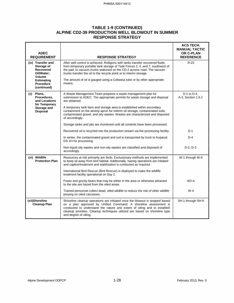
TABLE 1-9 (CONTINUED) ALPINE CD2-39 PRODUCTION WELL BLOWOUT IN SUMMER
RESPONSE STRATEGY
ADEC REQUIREMENT RESPONSE STRATEGY
ACS TECH. MANUAL TACTIC
OR C-PLAN REFERENCE
(ix) Transfer and Storage of Recovered Oil/Water; Volume Estimating Procedure (continued)
After well control is achieved, Rolligons with tanks transfer recovered fluids from temporary portable tank storage of Task Forces 2, 4, and 7, southwest of the pad, to vacuum trucks stationed on the CD-2 access road. The vacuum trucks transfer the oil to the recycle point or to interim storage.
R-23
The amount of oil is gauged using a Coliwasa tube or by other appropriate means.
(x) Plans, Procedures, and Locations for Temporary Storage and Disposal
A Waste Management Team prepares a waste management plan for submission to ADEC. The appropriate permits for waste storage and disposal are obtained.
D-1 to D-4, A-3, Section 1.6.2
A temporary tank farm and storage area is established within secondary containment on the airstrip apron for interim oil storage, contaminated soils, contaminated gravel, and oily wastes. Wastes are characterized and disposed of accordingly.
Storage tanks and pits are monitored until all contents have been processed.
Recovered oil is recycled into the production stream via the processing facility. D-1
In winter, the contaminated gravel and soil is transported by truck to Kuparuk DS-1H for processing.
D-4
Non-liquid oily wastes and non-oily wastes are classified and disposed of accordingly.
D-2, D-3
(xi) Wildlife Protection Plan
Resources at risk primarily are birds. Exclusionary methods are implemented to keep oil away from bird habitat. Additionally, hazing operations are initiated and captive/treatment and stabilization is conducted as required.
W-1 through W-6
International Bird Rescue (Bird Rescue) is deployed to make the wildlife treatment facility operational on Day 2.
Foxes and grizzly bears that may be either in the area or otherwise attracted to the site are hazed from the oiled areas.
W2-A
Trained personnel collect dead, oiled wildlife to reduce the risk of other wildlife preying on oiled carcasses.
W-4
(xii)Shoreline Cleanup Plan
Shoreline cleanup operations are initiated once the blowout is stopped based on a plan approved by Unified Command. A shoreline assessment is conducted to understand the nature and extent of oiling and to establish cleanup priorities. Cleanup techniques utilized are based on shoreline type and degree of oiling.
SH-1 through SH-6
Alpine Development ODPCP 1-28 February 2013, Rev. 0
PHMSA 000114412
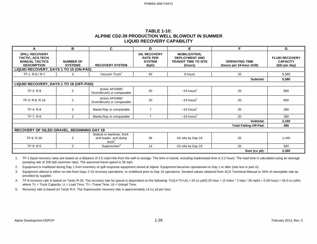
TABLE 1-10: ALPINE CD2-39 PRODUCTION WELL BLOWOUT IN SUMMER
LIQUID RECOVERY CAPABILITY A B C D E F G
SPILL RECOVERY TACTIC, ACS TECH. MANUAL TACTICS
DESCRIPTION NUMBER OF
SYSTEMS RECOVERY SYSTEM
OIL RECOVERY RATE PER SYSTEM
(bph)
MOBILIZATION, DEPLOYMENT AND
TRANSIT TIME TO SITE (hours)
OPERATING TIME (hours per 24-hour shift)
FLUID RECOVERY CAPACITY
(bbl per day) LIQUID RECOVERY, DAYS 1 TO 15 (ON-PAD)
TF-1: R-6 / R-7 3 Vacuum Truck1 93 6 hours 20 5,580 Subtotal: 5,580
LIQUID RECOVERY, DAYS 1 TO 18 (OFF-PAD)
TF-2: R-8 2 Action AP24MD Drum/Brush) or comparable 20 ~24 hours2 20 800
TF-3: R-8, R-16 2 Action AP24MD Drum/Brush) or comparable 20 ~24 hours2 20 800
TF-4: R-8 2 Manta Ray or comparable 7 ~24 hours2 20 280
TF-7: R-8 2 Manta Ray or comparable 7 ~24 hours2 20 280 Subtotal: 2,160
Total Falling Off-Pad: 485 RECOVERY OF OILED GRAVEL, BEGINNING DAY 19
TF-9: R-26 2 Bobcat or backhoe, front-
end loader, and dump truck4
36 On site by Day 19 20 1,440
TF-9: R-5 2 Supersucker5 14 On site by Day 19 20 560 Sum (cu yd): 2,360
1. TF-1 liquid recovery rates are based on a distance of 3.5 road mile from the well to storage. The time in transit, including load/unload time is 3.2 hours. The load time is calculated using an average pumping rate of 200 bph (summer rate). The assumed travel speed is 35 mph.
2. Equipment is mobilized during Day 1 from inventory of spill response equipment stored at Alpine. Equipment becomes operational on Day 1 or after (see text in part vi). 3. Equipment utilized is either on-site from Days 2-15 recovery operations, or mobilized prior to Day 16 operations. Derated values obtained from ACS Technical Manual or 20% of nameplate rate as
provided by supplier. 4. TF-9 recovery rate is based on Tactic R-26. The recovery rate for gravel is dependent on the following: Tc/(Lt+Tt+Ut) = 20 cu yd/(0.25 hour + (2 miles * 2 trips / 35 mph) + 0.08 hour) = 45.0 cu yd/hr,
where Tc = Truck Capacity, Lt = Load Time, Tt = Travel Time, Ut = Unload Time. 5. Recovery rate is based on Tactic R-5. The Supersucker recovery rate is approximately 14 cu yd per hour.
Alpine Development ODPCP 1-29 February 2013, Rev. 0
PHMSA 000114413
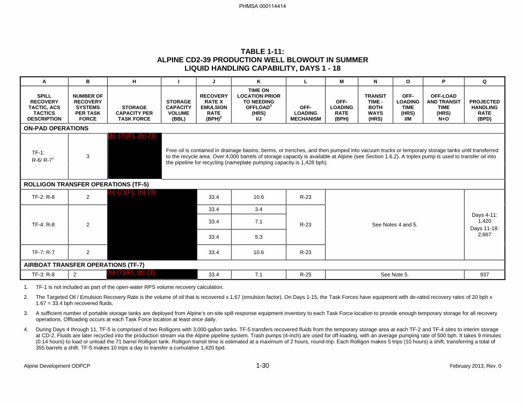
TABLE 1-11: ALPINE CD2-39 PRODUCTION WELL BLOWOUT IN SUMMER
LIQUID HANDLING CAPABILITY, DAYS 1 - 18 A B H I J K L M N O P Q
SPILL RECOVERY
TACTIC, ACS TACTICS
DESCRIPTION
NUMBER OF RECOVERY SYSTEMS PER TASK
FORCE
STORAGE CAPACITY PER TASK FORCE
STORAGE CAPACITY VOLUME
(BBL)
RECOVERY RATE X
EMULSION RATE (BPH)2
TIME ON LOCATION PRIOR
TO NEEDING OFFLOAD3
(HRS) I/J
OFF-LOADING
MECHANISM
OFF-LOADING
RATE (BPH)
TRANSIT TIME - BOTH WAYS (HRS)
OFF-LOADING
TIME (HRS)
I/M
OFF-LOAD AND TRANSIT
TIME (HRS) N+O
PROJECTED HANDLING
RATE (BPD)
ON-PAD OPERATIONS
TF-1: R-6/ R-71
3 Free oil is contained in drainage basins, berms, or trenches, and then pumped into vacuum trucks or temporary storage tanks until transferred to the recycle area. Over 4,000 barrels of storage capacity is available at Alpine (see Section 1.6.2). A triplex pump is used to transfer oil into the pipeline for recycling (nameplate pumping capacity is 1,428 bph).
ROLLIGON TRANSFER OPERATIONS (TF-5)
TF-2: R-8 2 33.4 10.6 R-23
See Notes 4 and 5.
Days 4-11: 1,420
Days 11-18: 2,667
TF-4: R-8 2
33.4 3.4
R-23 33.4 7.1
33.4 5.3
TF-7: R-7 2 33.4 10.6 R-23
AIRBOAT TRANSFER OPERATIONS (TF-7) TF-3: R-8 2 33.4 7.1 R-25 See Note 5. 937
1. TF-1 is not included as part of the open-water RPS volume recovery calculation.
2. The Targeted Oil / Emulsion Recovery Rate is the volume of oil that is recovered x 1.67 (emulsion factor). On Days 1-15, the Task Forces have equipment with de-rated recovery rates of 20 bph x 1.67 = 33.4 bph recovered fluids.
3. A sufficient number of portable storage tanks are deployed from Alpine’s on-site spill response equipment inventory to each Task Force location to provide enough temporary storage for all recovery operations. Offloading occurs at each Task Force location at least once daily.
4. During Days 4 through 11, TF-5 is comprised of two Rolligons with 3,000-gallon tanks. TF-5 transfers recovered fluids from the temporary storage area at each TF-2 and TF-4 sites to interim storage at CD-2. Fluids are later recycled into the production stream via the Alpine pipeline system. Trash pumps (4-inch) are used for off-loading, with an average pumping rate of 500 bph. It takes 9 minutes (0.14 hours) to load or unload the 71 barrel Rolligon tank. Rolligon transit time is estimated at a maximum of 2 hours, round-trip. Each Rolligon makes 5 trips (10 hours) a shift, transferring a total of 355 barrels a shift. TF-5 makes 10 trips a day to transfer a cumulative 1,420 bpd.
Alpine Development ODPCP 1-30 February 2013, Rev. 0
PHMSA 000114414
(b) (7)(F), (b) (3)
(b) (7)(F), (b) (3)
(b) (7)(F), (b) (3)
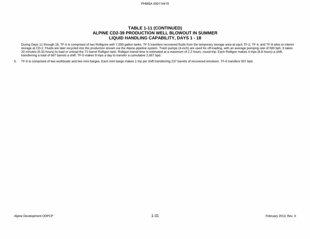
TABLE 1-11 (CONTINUED) ALPINE CD2-39 PRODUCTION WELL BLOWOUT IN SUMMER
LIQUID HANDLING CAPABILITY, DAYS 1 - 18 During Days 11 through 18, TF-5 is comprised of two Rolligons with 7,000-gallon tanks. TF-5 transfers recovered fluids from the temporary storage area at each TF-2, TF-4, and TF-8 sites to interim storage at CD-2. Fluids are later recycled into the production stream via the Alpine pipeline system. Trash pumps (4-inch) are used for off-loading, with an average pumping rate of 500 bph. It takes 20 minutes (0.33 hours) to load or unload the 71-barrel Rolligon tank. Rolligon transit time is estimated at a maximum of 2.2 hours, round-trip. Each Rolligon makes 4 trips (8.8 hours) a shift, transferring a total of 667 barrels a shift. TF-5 makes 8 trips a day to transfer a cumulative 2,667 bpd.
5. TF-6 is comprised of two workboats and two mini barges. Each mini barge makes 1 trip per shift transferring 237 barrels of recovered emulsion. TF-6 transfers 937 bpd.
Alpine Development ODPCP 1-31 February 2013, Rev. 0
PHMSA 000114415
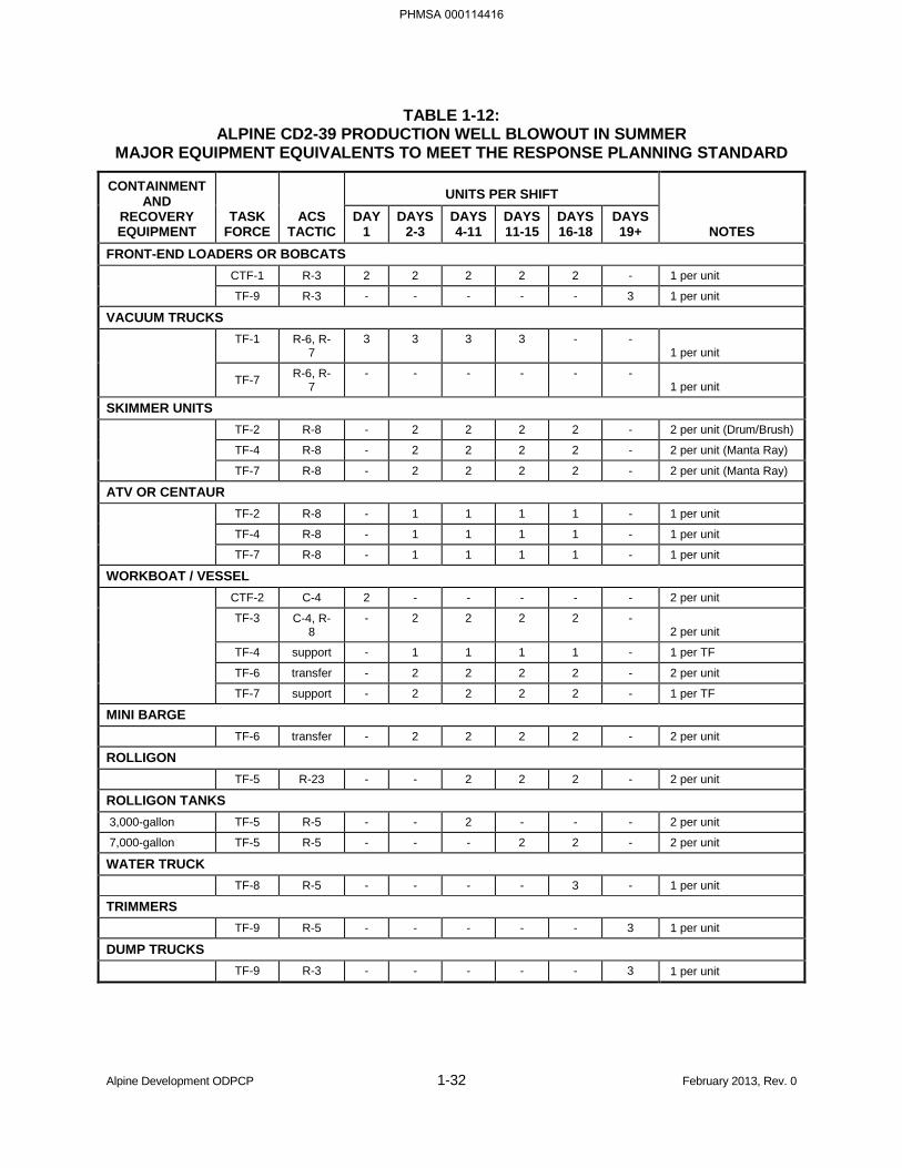
TABLE 1-12: ALPINE CD2-39 PRODUCTION WELL BLOWOUT IN SUMMER
MAJOR EQUIPMENT EQUIVALENTS TO MEET THE RESPONSE PLANNING STANDARD
CONTAINMENT AND
RECOVERY EQUIPMENT
TASK FORCE
ACS TACTIC
UNITS PER SHIFT
NOTES DAY
1 DAYS
2-3 DAYS 4-11
DAYS 11-15
DAYS 16-18
DAYS 19+
FRONT-END LOADERS OR BOBCATS CTF-1 R-3 2 2 2 2 2 - 1 per unit
TF-9 R-3 - - - - - 3 1 per unit
VACUUM TRUCKS TF-1 R-6, R-
7 3 3 3 3 - -
1 per unit
TF-7 R-6, R-7
- - - - - - 1 per unit
SKIMMER UNITS TF-2 R-8 - 2 2 2 2 - 2 per unit (Drum/Brush)
TF-4 R-8 - 2 2 2 2 - 2 per unit (Manta Ray)
TF-7 R-8 - 2 2 2 2 - 2 per unit (Manta Ray)
ATV OR CENTAUR TF-2 R-8 - 1 1 1 1 - 1 per unit
TF-4 R-8 - 1 1 1 1 - 1 per unit
TF-7 R-8 - 1 1 1 1 - 1 per unit
WORKBOAT / VESSEL CTF-2 C-4 2 - - - - - 2 per unit
TF-3 C-4, R-8
- 2 2 2 2 - 2 per unit
TF-4 support - 1 1 1 1 - 1 per TF
TF-6 transfer - 2 2 2 2 - 2 per unit
TF-7 support - 2 2 2 2 - 1 per TF
MINI BARGE TF-6 transfer - 2 2 2 2 - 2 per unit
ROLLIGON TF-5 R-23 - - 2 2 2 - 2 per unit
ROLLIGON TANKS 3,000-gallon TF-5 R-5 - - 2 - - - 2 per unit
7,000-gallon TF-5 R-5 - - - 2 2 - 2 per unit
WATER TRUCK TF-8 R-5 - - - - 3 - 1 per unit
TRIMMERS TF-9 R-5 - - - - - 3 1 per unit
DUMP TRUCKS TF-9 R-3 - - - - - 3 1 per unit
Alpine Development ODPCP 1-32 February 2013, Rev. 0
PHMSA 000114416
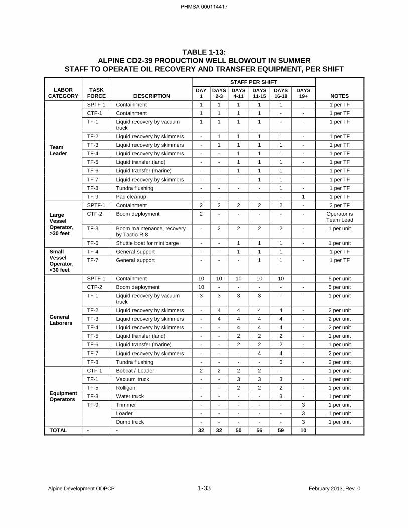
TABLE 1-13: ALPINE CD2-39 PRODUCTION WELL BLOWOUT IN SUMMER
STAFF TO OPERATE OIL RECOVERY AND TRANSFER EQUIPMENT, PER SHIFT
LABOR CATEGORY
TASK FORCE DESCRIPTION
STAFF PER SHIFT
NOTES DAY
1 DAYS
2-3 DAYS 4-11
DAYS 11-15
DAYS 16-18
DAYS 19+
Team Leader
SPTF-1 Containment 1 1 1 1 1 - 1 per TF CTF-1 Containment 1 1 1 1 - - 1 per TF TF-1 Liquid recovery by vacuum
truck 1 1 1 1 - - 1 per TF
TF-2 Liquid recovery by skimmers - 1 1 1 1 - 1 per TF TF-3 Liquid recovery by skimmers - 1 1 1 1 - 1 per TF TF-4 Liquid recovery by skimmers - - 1 1 1 - 1 per TF TF-5 Liquid transfer (land) - - 1 1 1 - 1 per TF TF-6 Liquid transfer (marine) - - 1 1 1 - 1 per TF TF-7 Liquid recovery by skimmers - - - 1 1 - 1 per TF TF-8 Tundra flushing - - - - 1 - 1 per TF TF-9 Pad cleanup - - - - - 1 1 per TF
Large Vessel Operator, >30 feet
SPTF-1 Containment 2 2 2 2 2 - 2 per TF CTF-2 Boom deployment 2 - - - - - Operator is
Team Lead TF-3 Boom maintenance, recovery
by Tactic R-8 - 2 2 2 2 - 1 per unit
TF-6 Shuttle boat for mini barge - - 1 1 1 - 1 per unit Small Vessel Operator, <30 feet
TF-4 General support - - 1 1 1 - 1 per TF TF-7 General support - - - 1 1 - 1 per TF
General Laborers
SPTF-1 Containment 10 10 10 10 10 - 5 per unit CTF-2 Boom deployment 10 - - - - - 5 per unit TF-1 Liquid recovery by vacuum
truck 3 3 3 3 - - 1 per unit
TF-2 Liquid recovery by skimmers - 4 4 4 4 - 2 per unit TF-3 Liquid recovery by skimmers - 4 4 4 4 - 2 per unit TF-4 Liquid recovery by skimmers - - 4 4 4 - 2 per unit TF-5 Liquid transfer (land) - - 2 2 2 - 1 per unit TF-6 Liquid transfer (marine) - - 2 2 2 - 1 per unit TF-7 Liquid recovery by skimmers - - - 4 4 - 2 per unit TF-8 Tundra flushing - - - - 6 - 2 per unit
Equipment Operators
CTF-1 Bobcat / Loader 2 2 2 2 - - 1 per unit TF-1 Vacuum truck - - 3 3 3 - 1 per unit TF-5 Rolligon - - 2 2 2 - 1 per unit TF-8 Water truck - - - - 3 - 1 per unit TF-9 Trimmer - - - - - 3 1 per unit
Loader - - - - - 3 1 per unit Dump truck - - - - - 3 1 per unit
TOTAL - - 32 32 50 56 59 10
Alpine Development ODPCP 1-33 February 2013, Rev. 0
PHMSA 000114417
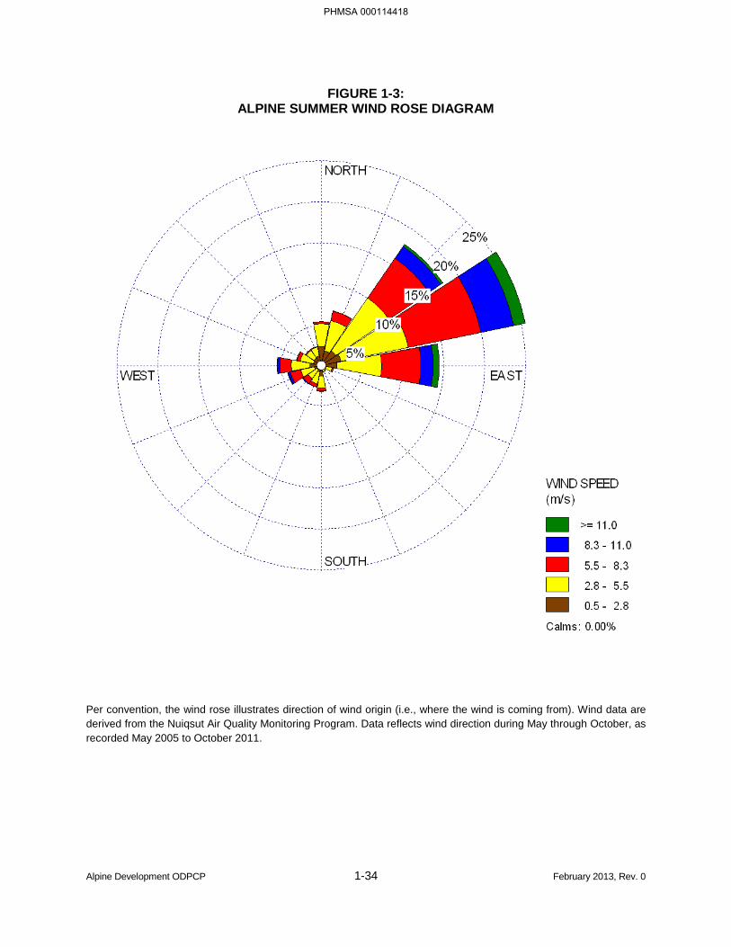
FIGURE 1-3: ALPINE SUMMER WIND ROSE DIAGRAM
Per convention, the wind rose illustrates direction of wind origin (i.e., where the wind is coming from). Wind data are derived from the Nuiqsut Air Quality Monitoring Program. Data reflects wind direction during May through October, as recorded May 2005 to October 2011.
Alpine Development ODPCP 1-34 February 2013, Rev. 0
PHMSA 000114418


SCENARIO 2
ALPINE CD-2 PAD
CD2-39 PRODUCTION WELL BLOWOUT
IN TYPICAL WINTER CONDITIONS
Alpine Development ODPCP 1-37 February 2013, Rev. 0
PHMSA 000114421

BLANK PAGE
Alpine Development ODPCP 1-38 February 2013, Rev. 0
PHMSA 000114422
TABLE 1-14: ALPINE CD2-39 PRODUCTION WELL BLOWOUT IN WINTER
SCENARIO CONDITIONS
PARAMETER Spill Location Date Duration Source of Spill
Cause of Spill Quantity of Oil Spilled
Emulsification Factor (Applicable to oil that reaches open water, for storage purposes) Type of Spilled Oil Wind Speed Wind Direction
Current Air Temperature
Surface
Trajectory
Trajectory (continued)
Alpine Development ODPCP 1-39 February 2013, Rev. 0
PHMSA 000114423
(b) (7)(F), (b) (3)
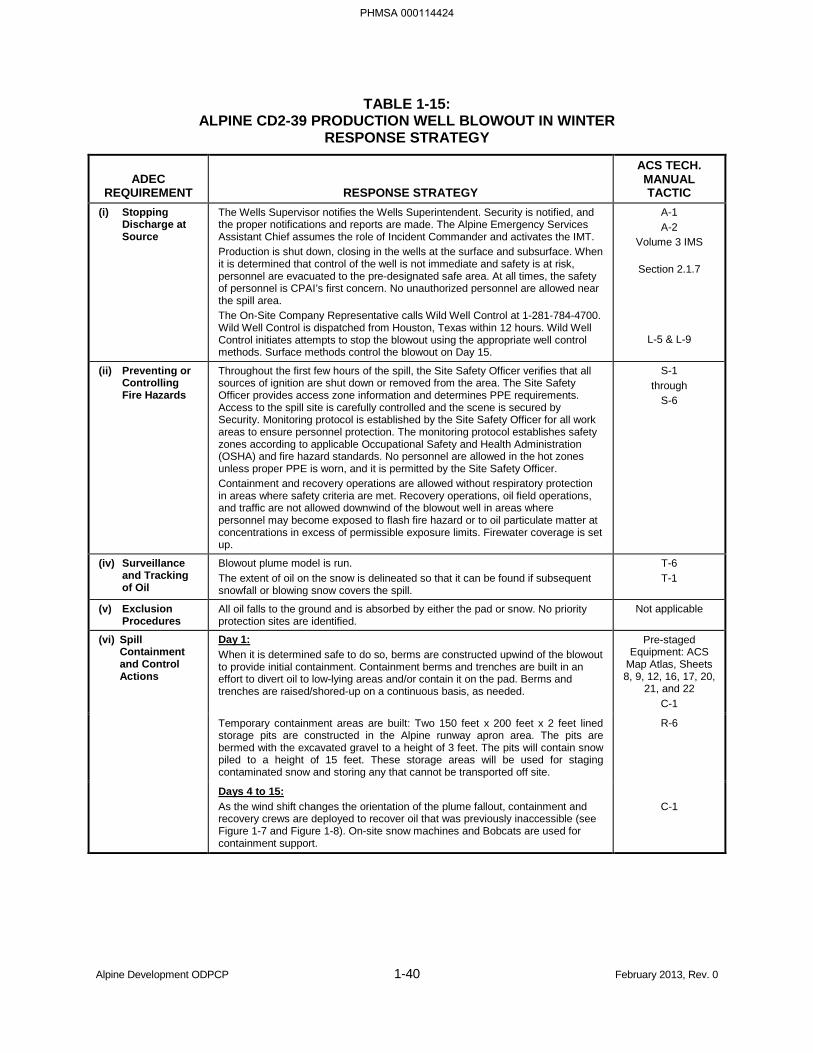
TABLE 1-15: ALPINE CD2-39 PRODUCTION WELL BLOWOUT IN WINTER
RESPONSE STRATEGY
ADEC REQUIREMENT RESPONSE STRATEGY
ACS TECH. MANUAL TACTIC
(i) Stopping Discharge at Source
The Wells Supervisor notifies the Wells Superintendent. Security is notified, and the proper notifications and reports are made. The Alpine Emergency Services Assistant Chief assumes the role of Incident Commander and activates the IMT. Production is shut down, closing in the wells at the surface and subsurface. When it is determined that control of the well is not immediate and safety is at risk, personnel are evacuated to the pre-designated safe area. At all times, the safety of personnel is CPAI’s first concern. No unauthorized personnel are allowed near the spill area. The On-Site Company Representative calls Wild Well Control at 1-281-784-4700. Wild Well Control is dispatched from Houston, Texas within 12 hours. Wild Well Control initiates attempts to stop the blowout using the appropriate well control methods. Surface methods control the blowout on Day 15.
A-1 A-2
Volume 3 IMS
Section 2.1.7
L-5 & L-9
(ii) Preventing or Controlling Fire Hazards
Throughout the first few hours of the spill, the Site Safety Officer verifies that all sources of ignition are shut down or removed from the area. The Site Safety Officer provides access zone information and determines PPE requirements. Access to the spill site is carefully controlled and the scene is secured by Security. Monitoring protocol is established by the Site Safety Officer for all work areas to ensure personnel protection. The monitoring protocol establishes safety zones according to applicable Occupational Safety and Health Administration (OSHA) and fire hazard standards. No personnel are allowed in the hot zones unless proper PPE is worn, and it is permitted by the Site Safety Officer. Containment and recovery operations are allowed without respiratory protection in areas where safety criteria are met. Recovery operations, oil field operations, and traffic are not allowed downwind of the blowout well in areas where personnel may become exposed to flash fire hazard or to oil particulate matter at concentrations in excess of permissible exposure limits. Firewater coverage is set up.
S-1 through
S-6
(iv) Surveillance and Tracking of Oil
Blowout plume model is run. The extent of oil on the snow is delineated so that it can be found if subsequent snowfall or blowing snow covers the spill.
T-6 T-1
(v) Exclusion Procedures
All oil falls to the ground and is absorbed by either the pad or snow. No priority protection sites are identified.
Not applicable
(vi) Spill Containment and Control Actions
Day 1: When it is determined safe to do so, berms are constructed upwind of the blowout to provide initial containment. Containment berms and trenches are built in an effort to divert oil to low-lying areas and/or contain it on the pad. Berms and trenches are raised/shored-up on a continuous basis, as needed.
Pre-staged Equipment: ACS
Map Atlas, Sheets 8, 9, 12, 16, 17, 20,
21, and 22 C-1
Temporary containment areas are built: Two 150 feet x 200 feet x 2 feet lined storage pits are constructed in the Alpine runway apron area. The pits are bermed with the excavated gravel to a height of 3 feet. The pits will contain snow piled to a height of 15 feet. These storage areas will be used for staging contaminated snow and storing any that cannot be transported off site.
R-6
Days 4 to 15: As the wind shift changes the orientation of the plume fallout, containment and recovery crews are deployed to recover oil that was previously inaccessible (see Figure 1-7 and Figure 1-8). On-site snow machines and Bobcats are used for containment support.
C-1
Alpine Development ODPCP 1-40 February 2013, Rev. 0
PHMSA 000114424
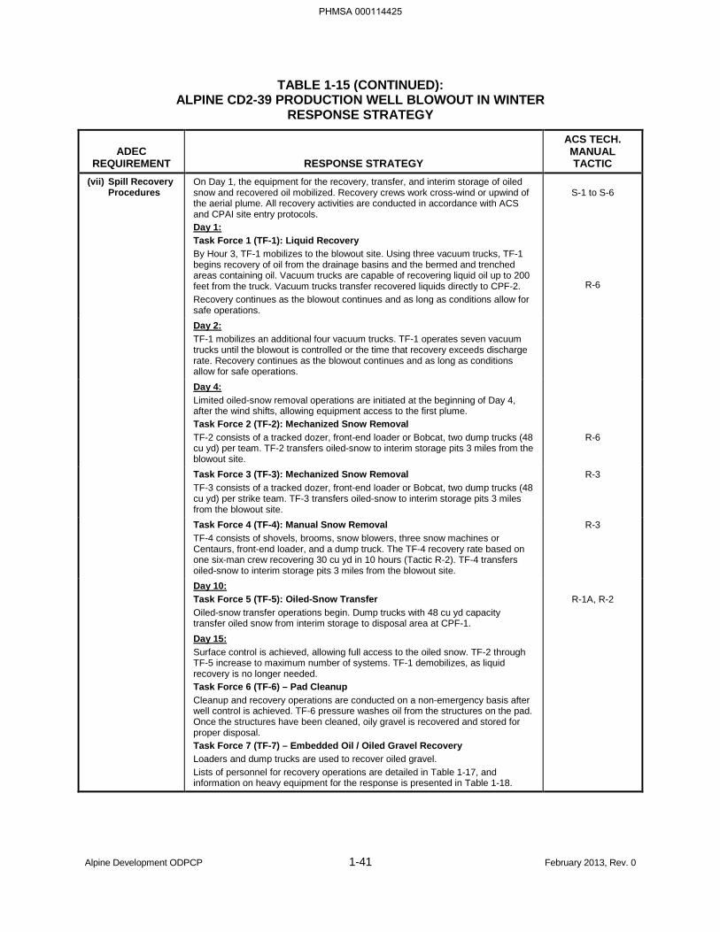
TABLE 1-15 (CONTINUED): ALPINE CD2-39 PRODUCTION WELL BLOWOUT IN WINTER
RESPONSE STRATEGY
ADEC REQUIREMENT RESPONSE STRATEGY
ACS TECH. MANUAL TACTIC
(vii) Spill Recovery Procedures
On Day 1, the equipment for the recovery, transfer, and interim storage of oiled snow and recovered oil mobilized. Recovery crews work cross-wind or upwind of the aerial plume. All recovery activities are conducted in accordance with ACS and CPAI site entry protocols. Day 1: Task Force 1 (TF-1): Liquid Recovery By Hour 3, TF-1 mobilizes to the blowout site. Using three vacuum trucks, TF-1 begins recovery of oil from the drainage basins and the bermed and trenched areas containing oil. Vacuum trucks are capable of recovering liquid oil up to 200 feet from the truck. Vacuum trucks transfer recovered liquids directly to CPF-2. Recovery continues as the blowout continues and as long as conditions allow for safe operations.
S-1 to S-6
R-6
Day 2: TF-1 mobilizes an additional four vacuum trucks. TF-1 operates seven vacuum trucks until the blowout is controlled or the time that recovery exceeds discharge rate. Recovery continues as the blowout continues and as long as conditions allow for safe operations.
Day 4: Limited oiled-snow removal operations are initiated at the beginning of Day 4, after the wind shifts, allowing equipment access to the first plume. Task Force 2 (TF-2): Mechanized Snow Removal TF-2 consists of a tracked dozer, front-end loader or Bobcat, two dump trucks (48 cu yd) per team. TF-2 transfers oiled-snow to interim storage pits 3 miles from the blowout site.
R-6
Task Force 3 (TF-3): Mechanized Snow Removal TF-3 consists of a tracked dozer, front-end loader or Bobcat, two dump trucks (48 cu yd) per strike team. TF-3 transfers oiled-snow to interim storage pits 3 miles from the blowout site.
R-3
Task Force 4 (TF-4): Manual Snow Removal TF-4 consists of shovels, brooms, snow blowers, three snow machines or Centaurs, front-end loader, and a dump truck. The TF-4 recovery rate based on one six-man crew recovering 30 cu yd in 10 hours (Tactic R-2). TF-4 transfers oiled-snow to interim storage pits 3 miles from the blowout site.
R-3
Day 10: Task Force 5 (TF-5): Oiled-Snow Transfer Oiled-snow transfer operations begin. Dump trucks with 48 cu yd capacity transfer oiled snow from interim storage to disposal area at CPF-1.
R-1A, R-2
Day 15: Surface control is achieved, allowing full access to the oiled snow. TF-2 through TF-5 increase to maximum number of systems. TF-1 demobilizes, as liquid recovery is no longer needed. Task Force 6 (TF-6) – Pad Cleanup Cleanup and recovery operations are conducted on a non-emergency basis after well control is achieved. TF-6 pressure washes oil from the structures on the pad. Once the structures have been cleaned, oily gravel is recovered and stored for proper disposal. Task Force 7 (TF-7) – Embedded Oil / Oiled Gravel Recovery Loaders and dump trucks are used to recover oiled gravel. Lists of personnel for recovery operations are detailed in Table 1-17, and information on heavy equipment for the response is presented in Table 1-18.
Alpine Development ODPCP 1-41 February 2013, Rev. 0
PHMSA 000114425
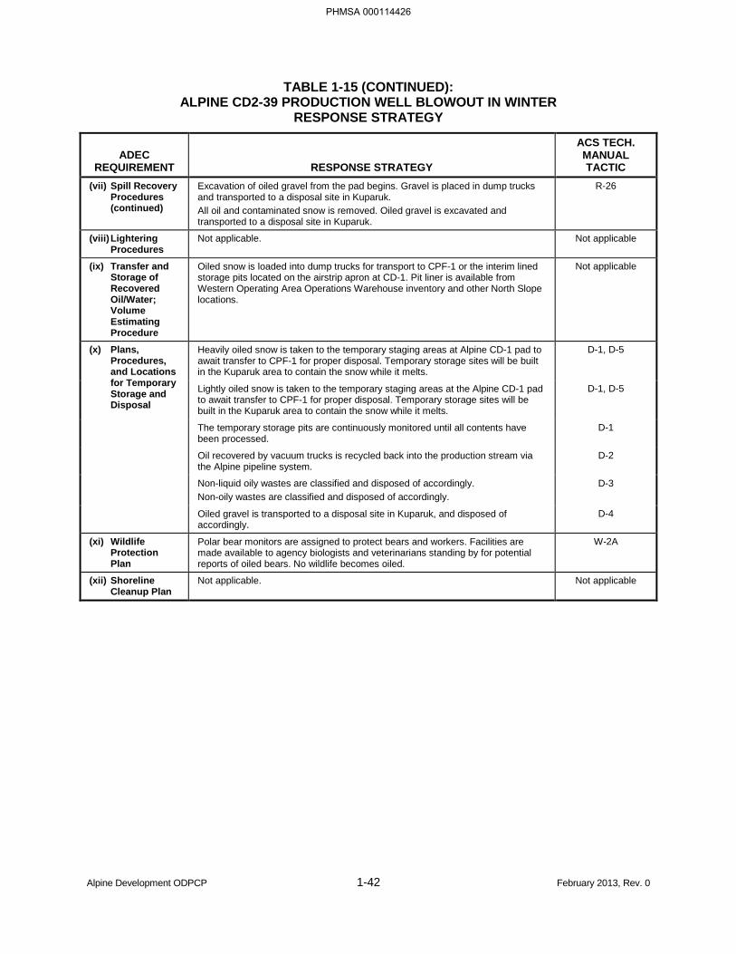
TABLE 1-15 (CONTINUED): ALPINE CD2-39 PRODUCTION WELL BLOWOUT IN WINTER
RESPONSE STRATEGY
ADEC REQUIREMENT RESPONSE STRATEGY
ACS TECH. MANUAL TACTIC
(vii) Spill Recovery Procedures (continued)
Excavation of oiled gravel from the pad begins. Gravel is placed in dump trucks and transported to a disposal site in Kuparuk. All oil and contaminated snow is removed. Oiled gravel is excavated and transported to a disposal site in Kuparuk.
R-26
(viii) Lightering Procedures
Not applicable. Not applicable
(ix) Transfer and Storage of Recovered Oil/Water; Volume Estimating Procedure
Oiled snow is loaded into dump trucks for transport to CPF-1 or the interim lined storage pits located on the airstrip apron at CD-1. Pit liner is available from Western Operating Area Operations Warehouse inventory and other North Slope locations.
Not applicable
(x) Plans, Procedures, and Locations for Temporary Storage and Disposal
Heavily oiled snow is taken to the temporary staging areas at Alpine CD-1 pad to await transfer to CPF-1 for proper disposal. Temporary storage sites will be built in the Kuparuk area to contain the snow while it melts.
D-1, D-5
Lightly oiled snow is taken to the temporary staging areas at the Alpine CD-1 pad to await transfer to CPF-1 for proper disposal. Temporary storage sites will be built in the Kuparuk area to contain the snow while it melts.
D-1, D-5
The temporary storage pits are continuously monitored until all contents have been processed.
D-1
Oil recovered by vacuum trucks is recycled back into the production stream via the Alpine pipeline system.
D-2
Non-liquid oily wastes are classified and disposed of accordingly. Non-oily wastes are classified and disposed of accordingly.
D-3
Oiled gravel is transported to a disposal site in Kuparuk, and disposed of accordingly.
D-4
(xi) Wildlife Protection Plan
Polar bear monitors are assigned to protect bears and workers. Facilities are made available to agency biologists and veterinarians standing by for potential reports of oiled bears. No wildlife becomes oiled.
W-2A
(xii) Shoreline Cleanup Plan
Not applicable. Not applicable
Alpine Development ODPCP 1-42 February 2013, Rev. 0
PHMSA 000114426
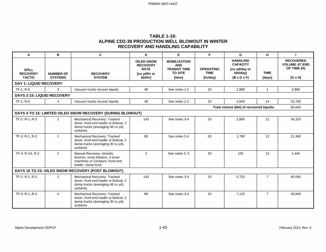
TABLE 1-16: ALPINE CD2-39 PRODUCTION WELL BLOWOUT IN WINTER
RECOVERY AND HANDLING CAPABILITY
A B C D E F G H I
SPILL RECOVERY
TACTIC NUMBER OF
SYSTEMS RECOVERY
SYSTEM
OILED SNOW RECOVERY
RATE [cu yd/hr or
bbl/hr]
MOBILIZATION AND
TRANSIT TIME TO SITE
[time]
OPERATING TIME
[hr/day]
HANDLING CAPACITY
[cu yd/day or bbl/day]
(B x D x F) TIME
[days]
RECOVERED VOLUME AT END
OF TIME (H)
(G x H)
DAY 1: LIQUID RECOVERY TF-1: R-6 3 Vacuum trucks recover liquids. 48 See notes 1-2 20 2,880 1 2,880
DAYS 2-15: LIQUID RECOVERY TF-1: R-6 4 Vacuum trucks recover liquids. 48 See notes 1-2 20 3,840 14 53,760
Total volume (bbl) of recovered liquids: 56,640
DAYS 4 TO 15: LIMITED OILED SNOW RECOVERY (DURING BLOWOUT) TF-2: R-1, R-3 1 Mechanical Recovery: Tracked
dozer, front-end loader or Bobcat, 2 dump trucks (averaging 48 cu yd), sorbents
143 See notes 3-4 20 2,860 12 34,320
TF-3: R-1, R-3 1 Mechanical Recovery: Tracked dozer, front-end loader or Bobcat, 2 dump trucks (averaging 30 cu yd), sorbents
89 See notes 3-4 20 1,780 12 21,360
TF-4: R-1A, R-2 2 Manual Recovery: shovels, brooms, snow blowers, 3 snow machines or Centaurs, front-end loader, dump truck
3 See notes 3, 5 20 120 12 1,440
DAYS 16 TO 23: OILED SNOW RECOVERY (POST BLOWOUT) TF-2: R-1, R-3 2 Mechanical Recovery: Tracked
dozer, front-end loader or Bobcat, 2 dump trucks (averaging 48 cu yd), sorbents
143 See notes 3-4 20 5,720 7 40,040
TF-3: R-1, R-3 4 Mechanical Recovery: Tracked dozer, front-end loader or Bobcat, 2 dump trucks (averaging 30 cu yd), sorbents
89 See notes 3-4 20 7,120 7 49,840
Alpine Development ODPCP 1-43 February 2013, Rev. 0
PHMSA 000114427
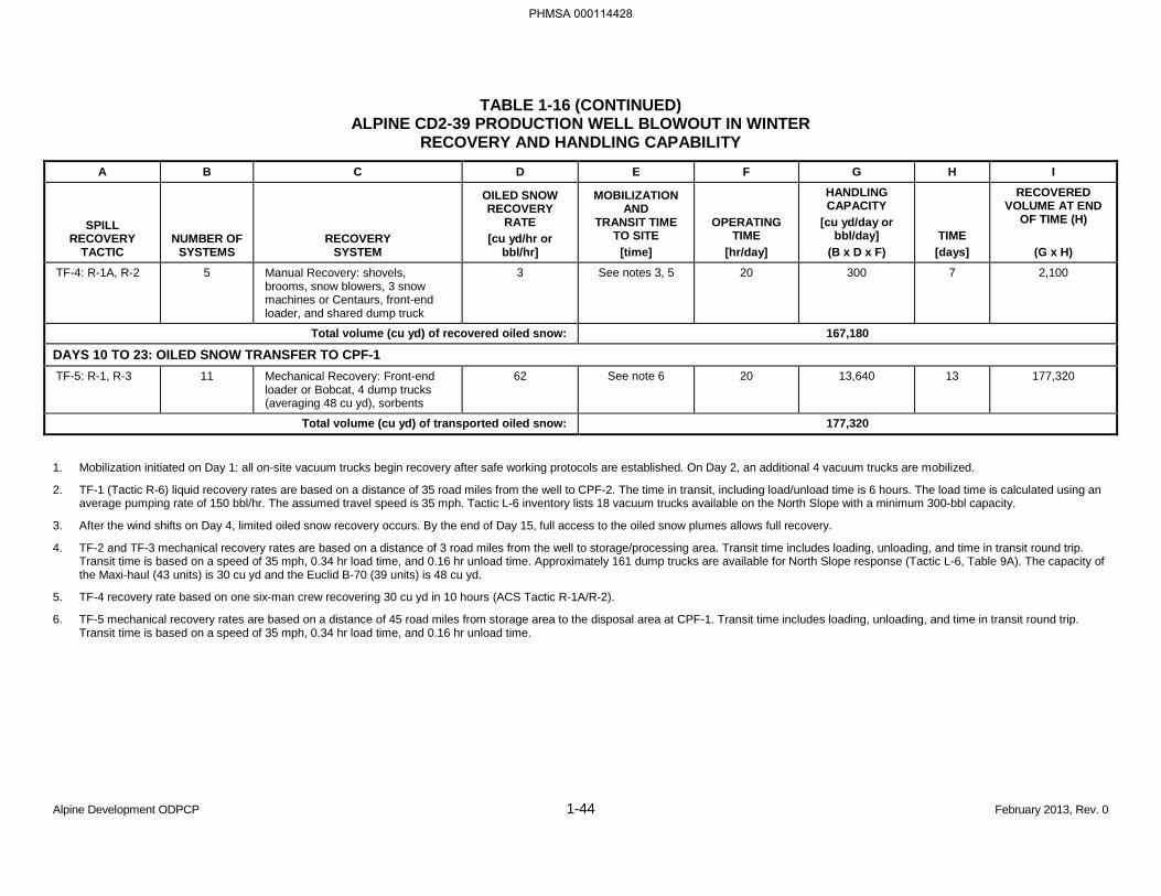
TABLE 1-16 (CONTINUED) ALPINE CD2-39 PRODUCTION WELL BLOWOUT IN WINTER
RECOVERY AND HANDLING CAPABILITY
A B C D E F G H I
SPILL RECOVERY
TACTIC NUMBER OF
SYSTEMS RECOVERY
SYSTEM
OILED SNOW RECOVERY
RATE [cu yd/hr or
bbl/hr]
MOBILIZATION AND
TRANSIT TIME TO SITE
[time]
OPERATING TIME
[hr/day]
HANDLING CAPACITY
[cu yd/day or bbl/day]
(B x D x F) TIME
[days]
RECOVERED VOLUME AT END
OF TIME (H)
(G x H)
TF-4: R-1A, R-2 5 Manual Recovery: shovels, brooms, snow blowers, 3 snow machines or Centaurs, front-end loader, and shared dump truck
3 See notes 3, 5 20 300 7 2,100
Total volume (cu yd) of recovered oiled snow: 167,180
DAYS 10 TO 23: OILED SNOW TRANSFER TO CPF-1 TF-5: R-1, R-3 11 Mechanical Recovery: Front-end
loader or Bobcat, 4 dump trucks (averaging 48 cu yd), sorbents
62 See note 6 20 13,640 13 177,320
Total volume (cu yd) of transported oiled snow: 177,320
1. Mobilization initiated on Day 1: all on-site vacuum trucks begin recovery after safe working protocols are established. On Day 2, an additional 4 vacuum trucks are mobilized.
2. TF-1 (Tactic R-6) liquid recovery rates are based on a distance of 35 road miles from the well to CPF-2. The time in transit, including load/unload time is 6 hours. The load time is calculated using an average pumping rate of 150 bbl/hr. The assumed travel speed is 35 mph. Tactic L-6 inventory lists 18 vacuum trucks available on the North Slope with a minimum 300-bbl capacity.
3. After the wind shifts on Day 4, limited oiled snow recovery occurs. By the end of Day 15, full access to the oiled snow plumes allows full recovery.
4. TF-2 and TF-3 mechanical recovery rates are based on a distance of 3 road miles from the well to storage/processing area. Transit time includes loading, unloading, and time in transit round trip. Transit time is based on a speed of 35 mph, 0.34 hr load time, and 0.16 hr unload time. Approximately 161 dump trucks are available for North Slope response (Tactic L-6, Table 9A). The capacity of the Maxi-haul (43 units) is 30 cu yd and the Euclid B-70 (39 units) is 48 cu yd.
5. TF-4 recovery rate based on one six-man crew recovering 30 cu yd in 10 hours (ACS Tactic R-1A/R-2).
6. TF-5 mechanical recovery rates are based on a distance of 45 road miles from storage area to the disposal area at CPF-1. Transit time includes loading, unloading, and time in transit round trip. Transit time is based on a speed of 35 mph, 0.34 hr load time, and 0.16 hr unload time.
Alpine Development ODPCP 1-44 February 2013, Rev. 0
PHMSA 000114428
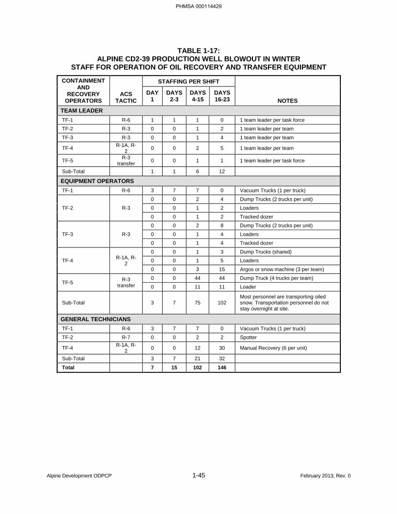
TABLE 1-17: ALPINE CD2-39 PRODUCTION WELL BLOWOUT IN WINTER
STAFF FOR OPERATION OF OIL RECOVERY AND TRANSFER EQUIPMENT
CONTAINMENT AND
RECOVERY OPERATORS
ACS TACTIC
STAFFING PER SHIFT
NOTES DAY
1 DAYS
2-3 DAYS 4-15
DAYS 16-23
TEAM LEADER TF-1 R-6 1 1 1 0 1 team leader per task force
TF-2 R-3 0 0 1 2 1 team leader per team
TF-3 R-3 0 0 1 4 1 team leader per team
TF-4 R-1A, R-2 0 0 2 5 1 team leader per team
TF-5 R-3 transfer 0 0 1 1 1 team leader per task force
Sub-Total 1 1 6 12
EQUIPMENT OPERATORS TF-1 R-6 3 7 7 0 Vacuum Trucks (1 per truck)
TF-2 R-3
0 0 2 4 Dump Trucks (2 trucks per unit)
0 0 1 2 Loaders
0 0 1 2 Tracked dozer
TF-3 R-3
0 0 2 8 Dump Trucks (2 trucks per unit)
0 0 1 4 Loaders
0 0 1 4 Tracked dozer
TF-4 R-1A, R-2
0 0 1 3 Dump Trucks (shared)
0 0 1 5 Loaders
0 0 3 15 Argos or snow machine (3 per team)
TF-5 R-3 transfer
0 0 44 44 Dump Truck (4 trucks per team)
0 0 11 11 Loader
Sub-Total 3 7 75 102 Most personnel are transporting oiled snow. Transportation personnel do not stay overnight at site.
GENERAL TECHNICIANS TF-1 R-6 3 7 7 0 Vacuum Trucks (1 per truck)
TF-2 R-7 0 0 2 2 Spotter
TF-4 R-1A, R-2 0 0 12 30 Manual Recovery (6 per unit)
Sub-Total 3 7 21 32
Total 7 15 102 146
Alpine Development ODPCP 1-45 February 2013, Rev. 0
PHMSA 000114429
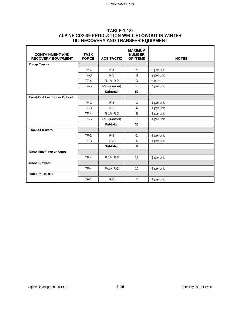
TABLE 1-18: ALPINE CD2-39 PRODUCTION WELL BLOWOUT IN WINTER
OIL RECOVERY AND TRANSFER EQUIPMENT
CONTAINMENT AND RECOVERY EQUIPMENT
TASK FORCE ACS TACTIC
MAXIMUM NUMBER OF ITEMS NOTES
Dump Trucks
TF-2 R-3 4 2 per unit
TF-3 R-3 8 2 per unit
TF-4 R-1A, R-2 3 shared
TF-5 R-3 (transfer) 44 4 per unit
Subtotal: 59 Front-End Loaders or Bobcats
TF-2 R-3 2 1 per unit
TF-3 R-3 4 1 per unit
TF-4 R-1A, R-2 5 1 per unit
TF-5 R-3 (transfer) 11 1 per unit
Subtotal: 22
Tracked Dozers
TF-2 R-3 2 1 per unit
TF-3 R-3 4 1 per unit
Subtotal: 6
Snow Machines or Argos
TF-4 R-1A, R-2 15 3 per unit
Snow Blowers
TF-4 R-1A, R-2 10 2 per unit
Vacuum Trucks
TF-1 R-6 7 1 per unit
Alpine Development ODPCP 1-46 February 2013, Rev. 0
PHMSA 000114430
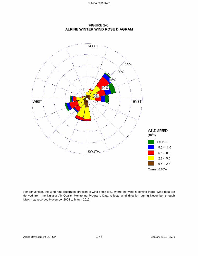
FIGURE 1-6: ALPINE WINTER WIND ROSE DIAGRAM
Per convention, the wind rose illustrates direction of wind origin (i.e., where the wind is coming from). Wind data are derived from the Nuiqsut Air Quality Monitoring Program. Data reflects wind direction during November through March, as recorded November 2004 to March 2012.
Alpine Development ODPCP 1-47 February 2013, Rev. 0
PHMSA 000114431


BLANK PAGE
Alpine Development ODPCP 1-50 February 2013, Rev. 0
PHMSA 000114434
SCENARIO 3
ALPINE PIPELINE RUPTURE TO THE MILUVEACH RIVER IN SUMMER
Alpine Development ODPCP 1-51 February 2013, Rev. 0
PHMSA 000114435

BLANK PAGE
Alpine Development ODPCP 1-52 February 2013, Rev. 0
PHMSA 000114436
TABLE 1-19: ALPINE PIPELINE RUPTURE TO THE MILUVEACH RIVER IN SUMMER
SCENARIO CONDITIONS
PARAMETER PARAMETER CONDITIONS Spill Location Date Duration Source of Spill
Cause of Spill Quantity of Oil Spilled
Emulsification Factor (for Storage Purposes) Oil Type Wind Direction and Speed
Current Air Temperature
Trajectory
Alpine Development ODPCP 1-53 February 2013, Rev. 0
PHMSA 000114437
(b) (7)(F), (b) (3)
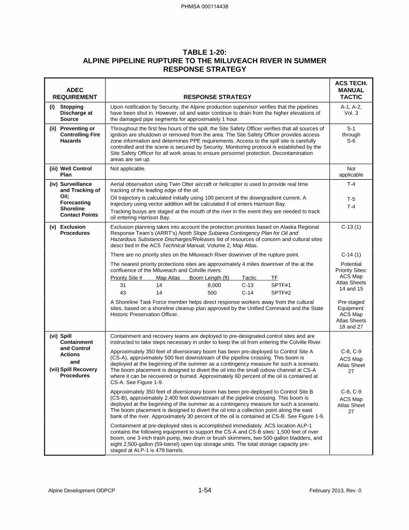
TABLE 1-20: ALPINE PIPELINE RUPTURE TO THE MILUVEACH RIVER IN SUMMER
RESPONSE STRATEGY
ADEC REQUIREMENT RESPONSE STRATEGY
ACS TECH. MANUAL TACTIC
(i) Stopping Discharge at Source
Upon notification by Security, the Alpine production supervisor verifies that the pipelines have been shut in. However, oil and water continue to drain from the higher elevations of the damaged pipe segments for approximately 1 hour.
A-1, A-2, Vol. 3
(ii) Preventing or Controlling Fire Hazards
Throughout the first few hours of the spill, the Site Safety Officer verifies that all sources of ignition are shutdown or removed from the area. The Site Safety Officer provides access zone information and determines PPE requirements. Access to the spill site is carefully controlled and the scene is secured by Security. Monitoring protocol is established by the Site Safety Officer for all work areas to ensure personnel protection. Decontamination areas are set up.
S-1 through
S-6
(iii) Well Control Plan
Not applicable. Not applicable
(iv) Surveillance and Tracking of Oil; Forecasting Shoreline Contact Points
Aerial observation using Twin Otter aircraft or helicopter is used to provide real time tracking of the leading edge of the oil. Oil trajectory is calculated initially using 100 percent of the downgradient current. A trajectory using vector addition will be calculated if oil enters Harrison Bay. Tracking buoys are staged at the mouth of the river in the event they are needed to track oil entering Harrison Bay.
T-4
T-5 T-4
(v) Exclusion Procedures
Exclusion planning takes into account the protection priorities based on Alaska Regional Response Team’s (ARRT’s) North Slope Subarea Contingency Plan for Oil and Hazardous Substance Discharges/Releases list of resources of concern and cultural sites descr bed in the ACS Technical Manual, Volume 2, Map Atlas.
C-13 (1)
There are no priority sites on the Miluveach River downriver of the rupture point. C-14 (1)
The nearest priority protections sites are approximately 4 miles downriver of the at the confluence of the Miluveach and Colville rivers: Priority Site # Map Atlas Boom Length (ft) Tactic TF 31 14 8,000 C-13 SPTF#1 43 14 500 C-14 SPTF#2
Potential Priority Sites:
ACS Map Atlas Sheets
14 and 15
A Shoreline Task Force member helps direct response workers away from the cultural sites, based on a shoreline cleanup plan approved by the Unified Command and the State Historic Preservation Officer.
Pre-staged Equipment: ACS Map
Atlas Sheets 18 and 27
(vi) Spill Containment and Control Actions
and (vii) Spill Recovery
Procedures
Containment and recovery teams are deployed to pre-designated control sites and are instructed to take steps necessary in order to keep the oil from entering the Colville River.
Approximately 350 feet of diversionary boom has been pre-deployed to Control Site A (CS-A), approximately 500 feet downstream of the pipeline crossing. This boom is deployed at the beginning of the summer as a contingency measure for such a scenario. The boom placement is designed to divert the oil into the small oxbow channel at CS-A where it can be recovered or burned. Approximately 60 percent of the oil is contained at CS-A. See Figure 1-9.
C-8, C-9 ACS Map
Atlas Sheet 27
Approximately 350 feet of diversionary boom has been pre-deployed to Control Site B (CS-B), approximately 2,400 feet downstream of the pipeline crossing. This boom is deployed at the beginning of the summer as a contingency measure for such a scenario. The boom placement is designed to divert the oil into a collection point along the east bank of the river. Approximately 30 percent of the oil is contained at CS-B. See Figure 1-9.
C-8, C-9 ACS Map
Atlas Sheet 27
Containment at pre-deployed sites is accomplished immediately. ACS location ALP-1 contains the following equipment to support the CS-A and CS-B sites: 1,500 feet of river boom, one 3-inch trash pump, two drum or brush skimmers, two 500-gallon bladders, and eight 2,500-gallon (59-barrel) open top storage units. The total storage capacity pre-staged at ALP-1 is 479 barrels.
Alpine Development ODPCP 1-54 February 2013, Rev. 0
PHMSA 000114438
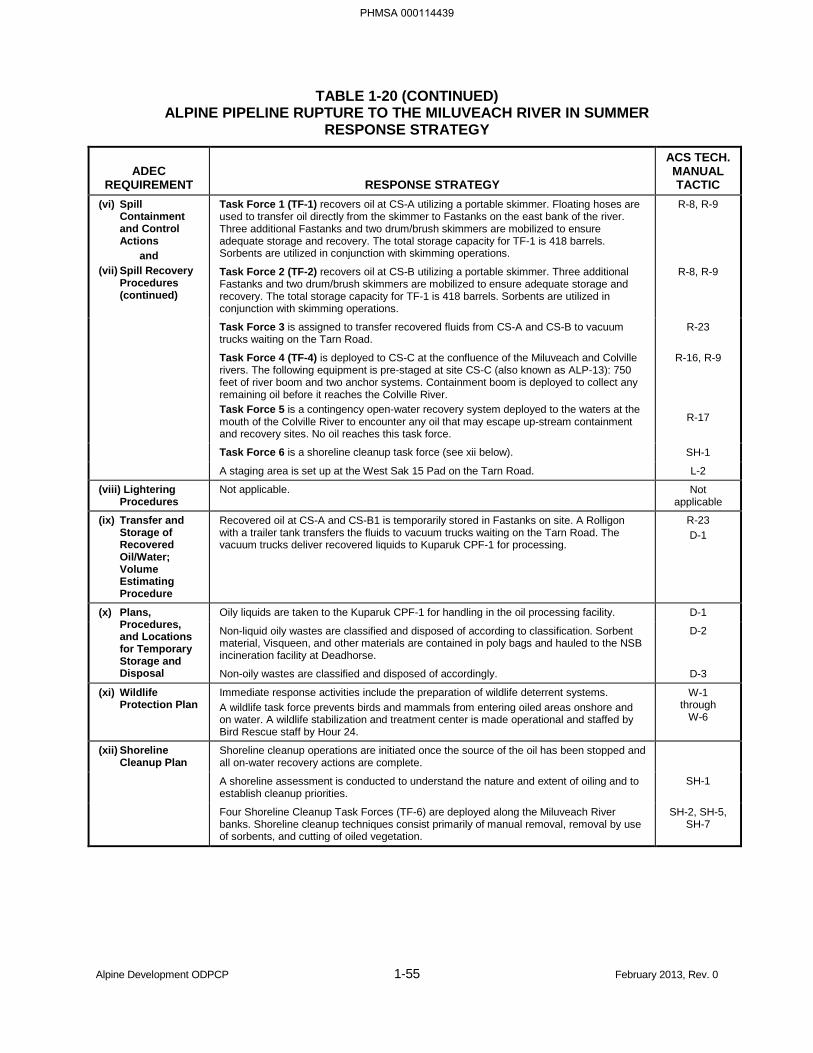
TABLE 1-20 (CONTINUED) ALPINE PIPELINE RUPTURE TO THE MILUVEACH RIVER IN SUMMER
RESPONSE STRATEGY
ADEC REQUIREMENT RESPONSE STRATEGY
ACS TECH. MANUAL TACTIC
(vi) Spill Containment and Control Actions
and (vii) Spill Recovery
Procedures (continued)
Task Force 1 (TF-1) recovers oil at CS-A utilizing a portable skimmer. Floating hoses are used to transfer oil directly from the skimmer to Fastanks on the east bank of the river. Three additional Fastanks and two drum/brush skimmers are mobilized to ensure adequate storage and recovery. The total storage capacity for TF-1 is 418 barrels. Sorbents are utilized in conjunction with skimming operations.
R-8, R-9
Task Force 2 (TF-2) recovers oil at CS-B utilizing a portable skimmer. Three additional Fastanks and two drum/brush skimmers are mobilized to ensure adequate storage and recovery. The total storage capacity for TF-1 is 418 barrels. Sorbents are utilized in conjunction with skimming operations.
R-8, R-9
Task Force 3 is assigned to transfer recovered fluids from CS-A and CS-B to vacuum trucks waiting on the Tarn Road.
R-23
Task Force 4 (TF-4) is deployed to CS-C at the confluence of the Miluveach and Colville rivers. The following equipment is pre-staged at site CS-C (also known as ALP-13): 750 feet of river boom and two anchor systems. Containment boom is deployed to collect any remaining oil before it reaches the Colville River. Task Force 5 is a contingency open-water recovery system deployed to the waters at the mouth of the Colville River to encounter any oil that may escape up-stream containment and recovery sites. No oil reaches this task force.
R-16, R-9
R-17
Task Force 6 is a shoreline cleanup task force (see xii below). SH-1
A staging area is set up at the West Sak 15 Pad on the Tarn Road. L-2
(viii) Lightering Procedures
Not applicable. Not applicable
(ix) Transfer and Storage of Recovered Oil/Water; Volume Estimating Procedure
Recovered oil at CS-A and CS-B1 is temporarily stored in Fastanks on site. A Rolligon with a trailer tank transfers the fluids to vacuum trucks waiting on the Tarn Road. The vacuum trucks deliver recovered liquids to Kuparuk CPF-1 for processing.
R-23 D-1
(x) Plans, Procedures, and Locations for Temporary Storage and Disposal
Oily liquids are taken to the Kuparuk CPF-1 for handling in the oil processing facility. D-1
Non-liquid oily wastes are classified and disposed of according to classification. Sorbent material, Visqueen, and other materials are contained in poly bags and hauled to the NSB incineration facility at Deadhorse.
D-2
Non-oily wastes are classified and disposed of accordingly. D-3
(xi) Wildlife Protection Plan
Immediate response activities include the preparation of wildlife deterrent systems. A wildlife task force prevents birds and mammals from entering oiled areas onshore and on water. A wildlife stabilization and treatment center is made operational and staffed by Bird Rescue staff by Hour 24.
W-1 through
W-6
(xii) Shoreline Cleanup Plan
Shoreline cleanup operations are initiated once the source of the oil has been stopped and all on-water recovery actions are complete.
A shoreline assessment is conducted to understand the nature and extent of oiling and to establish cleanup priorities.
SH-1
Four Shoreline Cleanup Task Forces (TF-6) are deployed along the Miluveach River banks. Shoreline cleanup techniques consist primarily of manual removal, removal by use of sorbents, and cutting of oiled vegetation.
SH-2, SH-5, SH-7
Alpine Development ODPCP 1-55 February 2013, Rev. 0
PHMSA 000114439
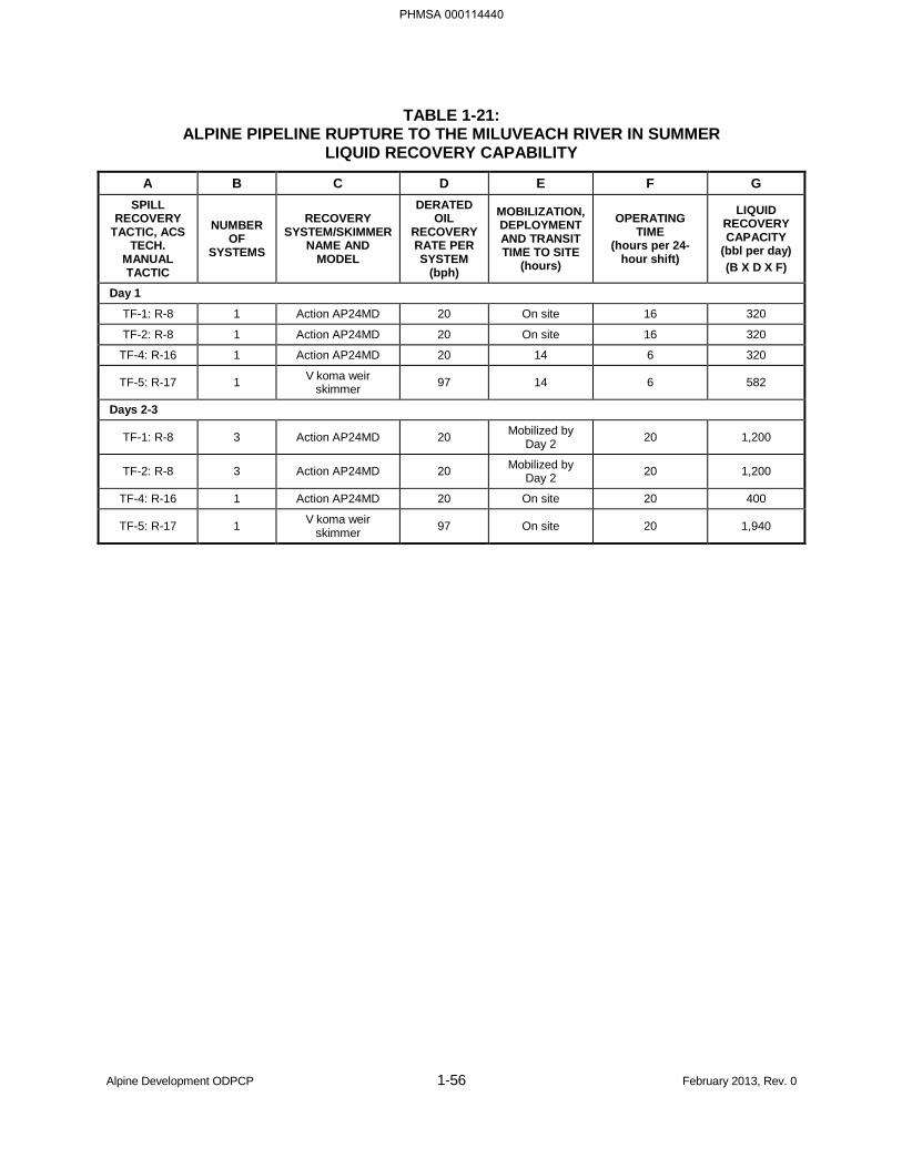
TABLE 1-21: ALPINE PIPELINE RUPTURE TO THE MILUVEACH RIVER IN SUMMER
LIQUID RECOVERY CAPABILITY
A B C D E F G SPILL
RECOVERY TACTIC, ACS
TECH. MANUAL TACTIC
NUMBER OF
SYSTEMS
RECOVERY SYSTEM/SKIMMER
NAME AND MODEL
DERATED OIL
RECOVERY RATE PER SYSTEM
(bph)
MOBILIZATION, DEPLOYMENT AND TRANSIT TIME TO SITE
(hours)
OPERATING TIME
(hours per 24-hour shift)
LIQUID RECOVERY CAPACITY
(bbl per day) (B X D X F)
Day 1
TF-1: R-8 1 Action AP24MD 20 On site 16 320
TF-2: R-8 1 Action AP24MD 20 On site 16 320
TF-4: R-16 1 Action AP24MD 20 14 6 320
TF-5: R-17 1 V koma weir skimmer 97 14 6 582
Days 2-3
TF-1: R-8 3 Action AP24MD 20 Mobilized by Day 2 20 1,200
TF-2: R-8 3 Action AP24MD 20 Mobilized by Day 2 20 1,200
TF-4: R-16 1 Action AP24MD 20 On site 20 400
TF-5: R-17 1 V koma weir skimmer 97 On site 20 1,940
Alpine Development ODPCP 1-56 February 2013, Rev. 0
PHMSA 000114440
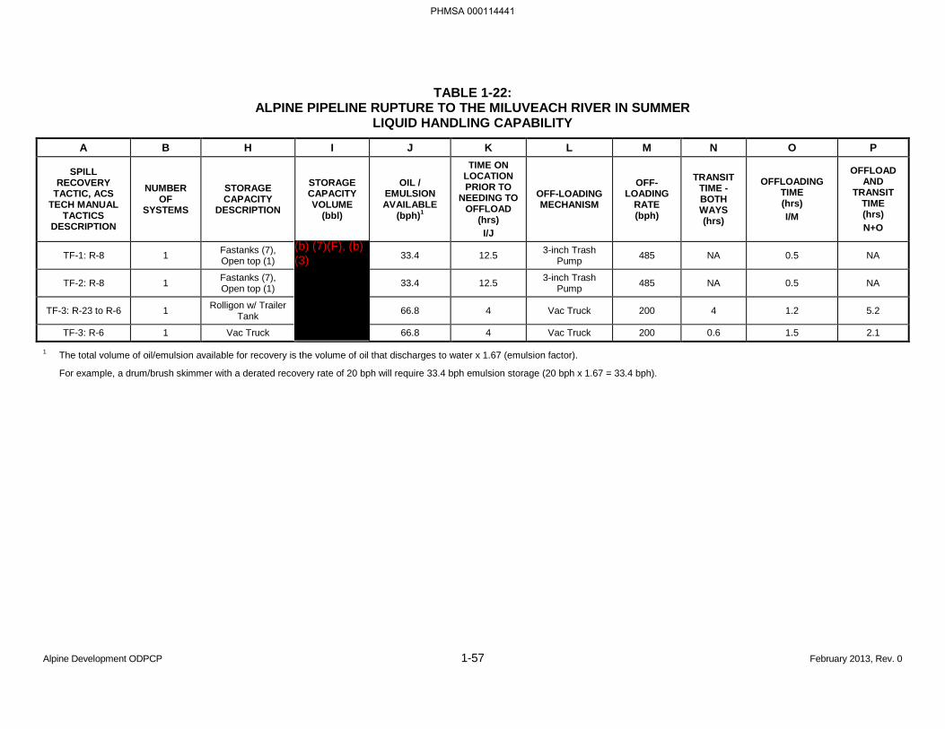
TABLE 1-22: ALPINE PIPELINE RUPTURE TO THE MILUVEACH RIVER IN SUMMER
LIQUID HANDLING CAPABILITY
A B H I J K L M N O P
SPILL RECOVERY
TACTIC, ACS TECH MANUAL
TACTICS DESCRIPTION
NUMBER OF
SYSTEMS
STORAGE CAPACITY
DESCRIPTION
STORAGE CAPACITY VOLUME
(bbl)
OIL / EMULSION AVAILABLE
(bph)1
TIME ON LOCATION PRIOR TO
NEEDING TO OFFLOAD
(hrs) I/J
OFF-LOADING MECHANISM
OFF-LOADING
RATE (bph)
TRANSIT TIME - BOTH WAYS (hrs)
OFFLOADING TIME (hrs) I/M
OFFLOAD AND
TRANSIT TIME (hrs) N+O
TF-1: R-8 1 Fastanks (7), Open top (1) 33.4 12.5 3-inch Trash
Pump 485 NA 0.5 NA
TF-2: R-8 1 Fastanks (7), Open top (1) 33.4 12.5 3-inch Trash
Pump 485 NA 0.5 NA
TF-3: R-23 to R-6 1 Rolligon w/ Trailer Tank 66.8 4 Vac Truck 200 4 1.2 5.2
TF-3: R-6 1 Vac Truck 66.8 4 Vac Truck 200 0.6 1.5 2.1
1 The total volume of oil/emulsion available for recovery is the volume of oil that discharges to water x 1.67 (emulsion factor).
For example, a drum/brush skimmer with a derated recovery rate of 20 bph will require 33.4 bph emulsion storage (20 bph x 1.67 = 33.4 bph).
Alpine Development ODPCP 1-57 February 2013, Rev. 0
PHMSA 000114441
(b) (7)(F), (b) (3)


BLANK PAGE
Alpine Development ODPCP 1-60 February 2013, Rev. 0
PHMSA 000114444
SCENARIO 4
ALPINE TANK RUPTURE IN SUMMER AT CD-1
Alpine Development ODPCP 1-61 February 2013, Rev. 0
PHMSA 000114445

BLANK PAGE
Alpine Development ODPCP 1-62 February 2013, Rev. 0
PHMSA 000114446
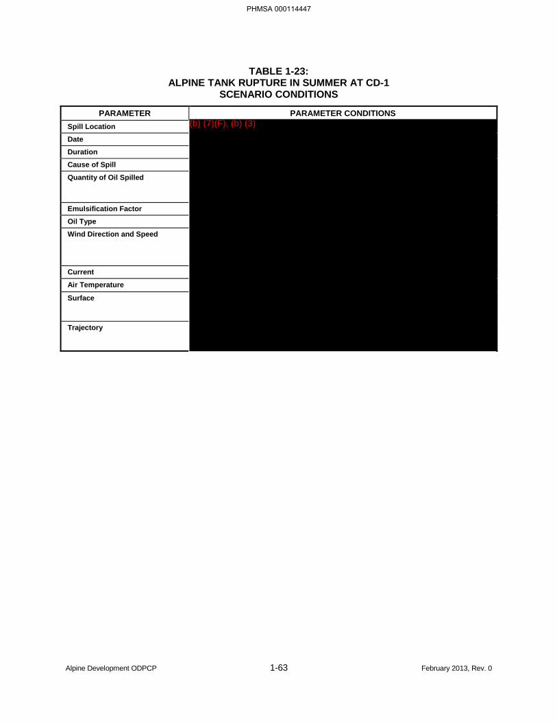
TABLE 1-23: ALPINE TANK RUPTURE IN SUMMER AT CD-1
SCENARIO CONDITIONS
PARAMETER PARAMETER CONDITIONS Spill Location Date Duration Cause of Spill
Quantity of Oil Spilled
Emulsification Factor Oil Type Wind Direction and Speed
Current
Air Temperature
Surface
Trajectory
Alpine Development ODPCP 1-63 February 2013, Rev. 0
PHMSA 000114447
(b) (7)(F), (b) (3)
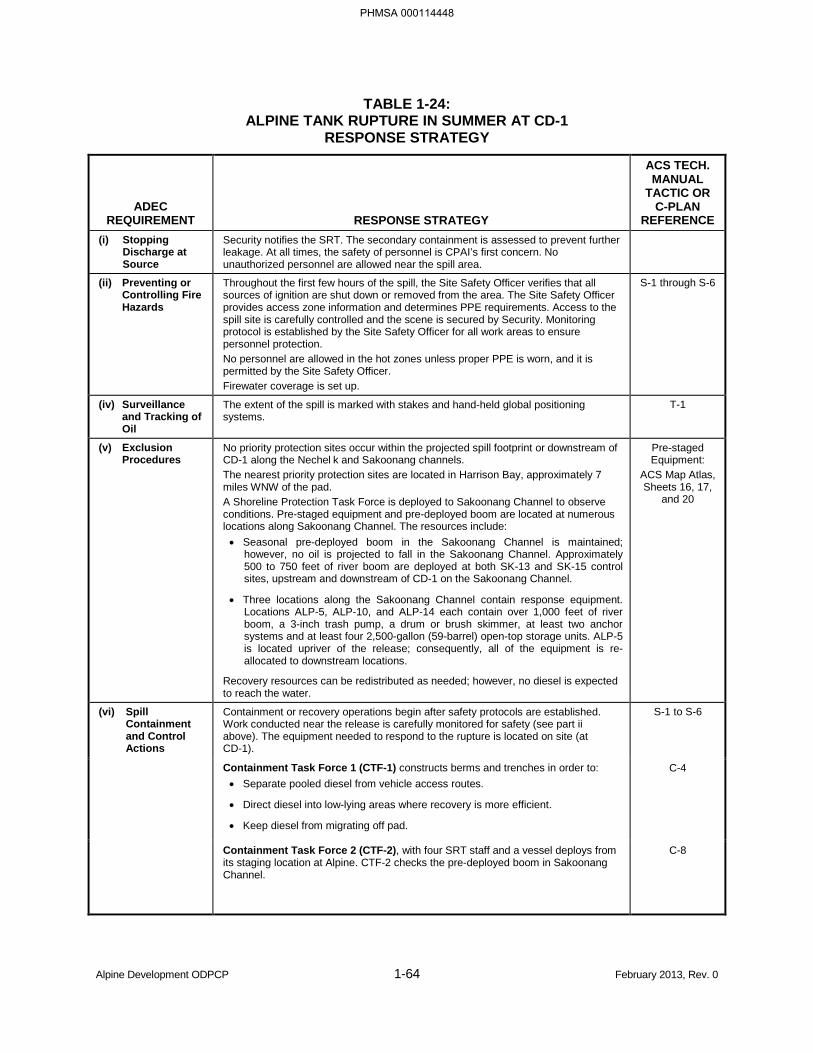
TABLE 1-24: ALPINE TANK RUPTURE IN SUMMER AT CD-1
RESPONSE STRATEGY
ADEC REQUIREMENT RESPONSE STRATEGY
ACS TECH. MANUAL
TACTIC OR C-PLAN
REFERENCE (i) Stopping
Discharge at Source
Security notifies the SRT. The secondary containment is assessed to prevent further leakage. At all times, the safety of personnel is CPAI’s first concern. No unauthorized personnel are allowed near the spill area.
(ii) Preventing or Controlling Fire Hazards
Throughout the first few hours of the spill, the Site Safety Officer verifies that all sources of ignition are shut down or removed from the area. The Site Safety Officer provides access zone information and determines PPE requirements. Access to the spill site is carefully controlled and the scene is secured by Security. Monitoring protocol is established by the Site Safety Officer for all work areas to ensure personnel protection. No personnel are allowed in the hot zones unless proper PPE is worn, and it is permitted by the Site Safety Officer. Firewater coverage is set up.
S-1 through S-6
(iv) Surveillance and Tracking of Oil
The extent of the spill is marked with stakes and hand-held global positioning systems.
T-1
(v) Exclusion Procedures
No priority protection sites occur within the projected spill footprint or downstream of CD-1 along the Nechel k and Sakoonang channels. The nearest priority protection sites are located in Harrison Bay, approximately 7 miles WNW of the pad. A Shoreline Protection Task Force is deployed to Sakoonang Channel to observe conditions. Pre-staged equipment and pre-deployed boom are located at numerous locations along Sakoonang Channel. The resources include: • Seasonal pre-deployed boom in the Sakoonang Channel is maintained;
however, no oil is projected to fall in the Sakoonang Channel. Approximately 500 to 750 feet of river boom are deployed at both SK-13 and SK-15 control sites, upstream and downstream of CD-1 on the Sakoonang Channel.
• Three locations along the Sakoonang Channel contain response equipment. Locations ALP-5, ALP-10, and ALP-14 each contain over 1,000 feet of river boom, a 3-inch trash pump, a drum or brush skimmer, at least two anchor systems and at least four 2,500-gallon (59-barrel) open-top storage units. ALP-5 is located upriver of the release; consequently, all of the equipment is re-allocated to downstream locations.
Recovery resources can be redistributed as needed; however, no diesel is expected to reach the water.
Pre-staged Equipment:
ACS Map Atlas, Sheets 16, 17,
and 20
(vi) Spill Containment and Control Actions
Containment or recovery operations begin after safety protocols are established. Work conducted near the release is carefully monitored for safety (see part ii above). The equipment needed to respond to the rupture is located on site (at CD-1).
S-1 to S-6
Containment Task Force 1 (CTF-1) constructs berms and trenches in order to: • Separate pooled diesel from vehicle access routes.
• Direct diesel into low-lying areas where recovery is more efficient.
• Keep diesel from migrating off pad.
C-4
Containment Task Force 2 (CTF-2), with four SRT staff and a vessel deploys from its staging location at Alpine. CTF-2 checks the pre-deployed boom in Sakoonang Channel.
C-8
Alpine Development ODPCP 1-64 February 2013, Rev. 0
PHMSA 000114448
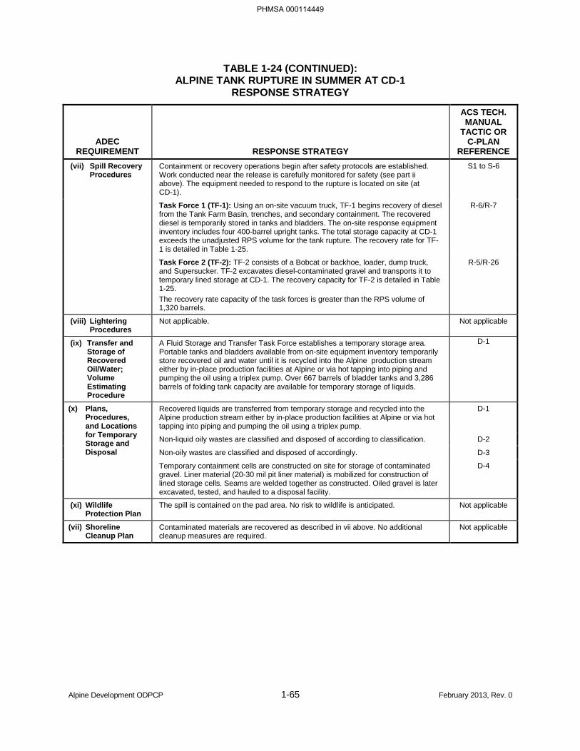
TABLE 1-24 (CONTINUED): ALPINE TANK RUPTURE IN SUMMER AT CD-1
RESPONSE STRATEGY
ADEC REQUIREMENT RESPONSE STRATEGY
ACS TECH. MANUAL
TACTIC OR C-PLAN
REFERENCE (vii) Spill Recovery
Procedures Containment or recovery operations begin after safety protocols are established. Work conducted near the release is carefully monitored for safety (see part ii above). The equipment needed to respond to the rupture is located on site (at CD-1).
S1 to S-6
Task Force 1 (TF-1): Using an on-site vacuum truck, TF-1 begins recovery of diesel from the Tank Farm Basin, trenches, and secondary containment. The recovered diesel is temporarily stored in tanks and bladders. The on-site response equipment inventory includes four 400-barrel upright tanks. The total storage capacity at CD-1 exceeds the unadjusted RPS volume for the tank rupture. The recovery rate for TF-1 is detailed in Table 1-25.
R-6/R-7
Task Force 2 (TF-2): TF-2 consists of a Bobcat or backhoe, loader, dump truck, and Supersucker. TF-2 excavates diesel-contaminated gravel and transports it to temporary lined storage at CD-1. The recovery capacity for TF-2 is detailed in Table 1-25. The recovery rate capacity of the task forces is greater than the RPS volume of 1,320 barrels.
R-5/R-26
(viii) Lightering Procedures
Not applicable. Not applicable
(ix) Transfer and Storage of Recovered Oil/Water; Volume Estimating Procedure
A Fluid Storage and Transfer Task Force establishes a temporary storage area. Portable tanks and bladders available from on-site equipment inventory temporarily store recovered oil and water until it is recycled into the Alpine production stream either by in-place production facilities at Alpine or via hot tapping into piping and pumping the oil using a triplex pump. Over 667 barrels of bladder tanks and 3,286 barrels of folding tank capacity are available for temporary storage of liquids.
D-1
(x) Plans, Procedures, and Locations for Temporary Storage and Disposal
Recovered liquids are transferred from temporary storage and recycled into the Alpine production stream either by in-place production facilities at Alpine or via hot tapping into piping and pumping the oil using a triplex pump.
D-1
Non-liquid oily wastes are classified and disposed of according to classification. D-2
Non-oily wastes are classified and disposed of accordingly. D-3
Temporary containment cells are constructed on site for storage of contaminated gravel. Liner material (20-30 mil pit liner material) is mobilized for construction of lined storage cells. Seams are welded together as constructed. Oiled gravel is later excavated, tested, and hauled to a disposal facility.
D-4
(xi) Wildlife Protection Plan
The spill is contained on the pad area. No risk to wildlife is anticipated. Not applicable
(vii) Shoreline Cleanup Plan
Contaminated materials are recovered as described in vii above. No additional cleanup measures are required.
Not applicable
Alpine Development ODPCP 1-65 February 2013, Rev. 0
PHMSA 000114449
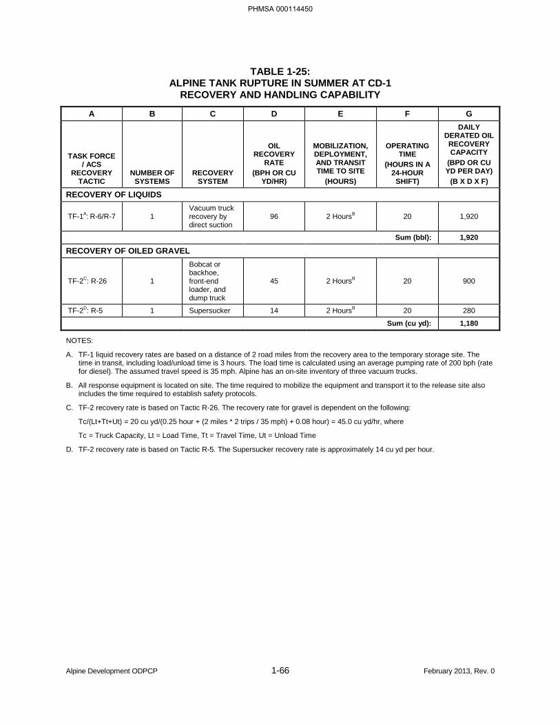
TABLE 1-25: ALPINE TANK RUPTURE IN SUMMER AT CD-1
RECOVERY AND HANDLING CAPABILITY
A B C D E F G
TASK FORCE / ACS
RECOVERY TACTIC
NUMBER OF SYSTEMS
RECOVERY SYSTEM
OIL RECOVERY
RATE (BPH OR CU
YD/HR)
MOBILIZATION, DEPLOYMENT, AND TRANSIT TIME TO SITE
(HOURS)
OPERATING TIME
(HOURS IN A 24-HOUR
SHIFT)
DAILY DERATED OIL
RECOVERY CAPACITY
(BPD OR CU YD PER DAY)
(B X D X F)
RECOVERY OF LIQUIDS
TF-1A: R-6/R-7 1 Vacuum truck recovery by direct suction
96 2 HoursB 20 1,920
Sum (bbl): 1,920
RECOVERY OF OILED GRAVEL
TF-2C: R-26 1
Bobcat or backhoe, front-end loader, and dump truck
45 2 HoursB 20 900
TF-2D: R-5 1 Supersucker 14 2 HoursB 20 280
Sum (cu yd): 1,180
NOTES:
A. TF-1 liquid recovery rates are based on a distance of 2 road miles from the recovery area to the temporary storage site. The time in transit, including load/unload time is 3 hours. The load time is calculated using an average pumping rate of 200 bph (rate for diesel). The assumed travel speed is 35 mph. Alpine has an on-site inventory of three vacuum trucks.
B. All response equipment is located on site. The time required to mobilize the equipment and transport it to the release site also includes the time required to establish safety protocols.
C. TF-2 recovery rate is based on Tactic R-26. The recovery rate for gravel is dependent on the following:
Tc/(Lt+Tt+Ut) = 20 cu yd/(0.25 hour + (2 miles * 2 trips / 35 mph) + 0.08 hour) = 45.0 cu yd/hr, where
Tc = Truck Capacity, Lt = Load Time, Tt = Travel Time, Ut = Unload Time
D. TF-2 recovery rate is based on Tactic R-5. The Supersucker recovery rate is approximately 14 cu yd per hour.
Alpine Development ODPCP 1-66 February 2013, Rev. 0
PHMSA 000114450
1.7 NON-MECHANICAL RESPONSE OPTIONS [18 AAC 75.425(e)(1)(G)]
CPAI will mechanically contain and clean up oil spills to the maximum extent possible. CPAI will request approval for in situ burning from the Federal On-Scene Coordinator and State On-Scene Coordinator when mechanical response methods prove ineffective or as a tool to minimize environmental damage. Due to the close proximity of the local resident population of Nuiqsut (see Section 3.2), additional considerations are discussed before approval of in situ burning by the Unified Command.
1.7.1 Obtaining Permits and Approvals
Burning is not conducted without approval by state and federal agencies. The CPAI Incident Commander will discuss the option of in situ burning with the Federal and State On-Scene Coordinators. CPAI will complete an “Application and Burn Plan,” see Appendix 1 in the In Situ Burning Guidelines for Alaska (http://dec.alaska.gov/spar/perp/permits/ISB_Rev1_March2008_Form.pdf).
1.7.2 Decision Criteria for Use
In situ burning of spilled oil is considered under conditions such as the following:
• Mechanical recovery is impractical or ineffective.
• Shorelines are threatened.
• Burning would augment the oil elimination capacity of mechanical recovery.
• Present and forecast wind conditions will carry the smoke plume away from populated areas.
• A successful test burn has been conducted.
1.7.3 Implementation Procedures
If the CPAI Incident Commander decides to use in situ burning and obtains the necessary authorization, ACS carries out the response as described in the ACS Technical Manual Tactics B-1 through B-6 and L-6. When implemented, Tactic B-1 will be conducted consistent with the ARRT’s Unified Plan, Annex F, Appendix II, “In Situ Burning Guidelines for Alaska” (ARRT, 2008).
1.7.4 Required Equipment and Personnel
ACS maintains the equipment and personnel for in situ burning described in the ACS Technical Manual Tactic L-6 and Tactics B-1 through B-6.
Alpine Development ODPCP 1-68 February 2013, Rev. 0
PHMSA 000114452
1.8 FACILITY DIAGRAMS [18 AAC 75.425(e)(1)(H)]
The following vicinity and facility maps are provided for the Alpine Development Area project:
• Alpine Development Area Location (Figure 1-12)
• Alpine Pipelines Operations Rights-of-Way (Figure 1-13)
• Alpine CD-1 Vicinity Map (Figure 1-14)
• Alpine CD-1 Pad Layout (Figure 1-15)
• Alpine CD-1 Pad Detail (Figure 1-16)
• Well CD-2 Vicinity Map (Figure 1-17)
• Alpine CD-2 Pad Layout (Figure 1-18)
• Alpine CD-3 Vicinity Map (Figure 1-19)
• Alpine CD-3 Pad Layout (Figure 1-20)
• Alpine CD-4 Vicinity Map (Figure 1-21)
• Alpine CD-4 Pad Layout (Figure 1-22)
• Alpine CD-5 Location Map (Figure 1-23)
• Alpine CD-5 Pad Layout (Figure 1-24)
Alpine Development ODPCP 1-69 February 2013, Rev. 0
PHMSA 000114453

BLANK PAGE
Alpine Development ODPCP 1-70 February 2013, Rev. 0
PHMSA 000114454


BLANK PAGE
Alpine Development ODPCP 1-72 February 2013, Rev. 0
PHMSA 000114456

FIGURE 1-13:
ALPINE PIPELINES OPERATIONS RIGHTS-OF-WAY
PHMSA 000114457
(b) (7)(F), (b) (3)

BLANK PAGE
Alpine Development ODPCP 1-74 February 2013, Rev. 0
PHMSA 000114458


BLANK PAGE
Alpine Development ODPCP 1-78 February 2013, Rev. 0
PHMSA 000114462


1.9 RESPONSE SCENARIO FOR AN EXPLORATION OR PRODUCTION FACILITY [18 AAC 75.425(e)(1)(I)]
Well blowout scenarios include a summary of planned methods, equipment, logistics, and timeframes proposed to be employed to control a well blowout within 15 days. CPAI certifies that they have and maintain a separate blowout contingency plan that is available to ADEC upon request. Well blowout scenarios are presented in Section 1.6.3.
CPAI has precautions in place that minimize the potential for a loss of well control. Section 2.1.7 outlines the preventive and recovery measures used to minimize spill potential during drilling operations. If an uncontrolled flow occurs at the surface, safety procedures would be employed to protect personnel, stop the spill, protect the environment, and protect the equipment.
If secondary control is lost and there is an uncontrolled loss of fluids at the surface, detailed plans are made to regain control. A thorough evaluation of the situation is necessary to determine the best course of action, although several courses of action will probably be initiated to allow for contingencies. CPAI considers mechanical surface control methods such as well capping the best available technology (BAT) versus relief well drilling for well source control. However, as required in regulation 18 AAC 75.445(d)(2), CPAI has provisions in place for drilling a relief well (see “Relief Well” discussion below). One of the first considerations in the event of a well blowout, is the need for drilling a relief well due to the lead time involved in planning the relief well, moving a rig to a surface location, and drilling the relief well.
Even though preparations for a relief well may be one of the first actions taken, regaining control of the blowout through mechanical means is typically much faster and more preferred than drilling a relief well, and generally more successful.
nother method for regaining control is diversion of the flow to allow installation of additional remotely operated well control equipment either on the existing stack or on the wellhead. Well control may also be regained by pumping mud or cement down the well to kill it. Specialized personnel and the equipment needed for well control are available on the North Slope through mutual agreement and can be mobilized within 24 to 48 hours of notification.
It is also possible that no mechanical methods will be needed to regain well control. Loss of surface control may cause a pressure drop in the wellbore. As reservoir formations flow, equalizing pressure of the reservoir, the bridging that results causes a decrease in surface flow.
1.9.1 Well Capping
Over the past decade, well capping techniques have been developed and proven to be efficient and effective in regaining control of damaged wells and in reducing associated environmental impacts. Significant improvements to well capping techniques and procedures have been developed by a variety of well control specialist companies throughout the world.
Well capping response operations are highly dependent on the severity of the well control situation. CPAI has the ability to mobilize specialized personnel and equipment (capping stack, cutting tools, etc.) to a North Slope location within 24 to 48 hours of notification. The materials required to execute typical mechanical control responses (junk shots, hot tapping, freezing, or crimping) are small enough so that they can be quickly made available to remote locations, even by helicopter, if necessary. Other equipment necessary during well capping operations is commonly available on the North Slope (e.g.,
Alpine Development ODPCP 1-87 February 2013, Rev. 0
PHMSA 000114471
(b) (3), (b) (7)(F)
bulldozers, cranes, pumps, block and tackle, large diameter casing, etc.) and can be made available within a few hours of the actual emergency.
CPAI maintains an operating agreement with Wild Well Control, a well control specialist organization that can assist in the intervention and resolution of any well control emergency. Wild Well Control acts as CPAI’s third party well control specialist for well control expertise. CPAI also has access to other supporting services and experts that includes but is not limited to Halliburton, Anadrill Schlumberger, Baker Hughes INTEQ, Dowell Schlumberger, Baroid, and MI Drilling Fluids. CPAI would access the best fit-for-purpose technology to respond to an emergency event. Available services include, but are not limited to, firefighting equipment and services, specialty blowout control equipment and services, directional drilling services, high-pressure pumping services, and experience with specialty fluids, chemicals, and additives. The 24-hour phone number for Wild Well Control is 1-281-784-4700.
In the event of an actual blowout, well capping operations would commence with CPAI’s activation of Wild Well Control and mobilization of key personnel and equipment. Attempts at dynamic and surface well control methods will continue, if safe conditions exist. If the well capping option is selected, safe reentry to the wellhead area must be established and rig equipment must be moved. If the rig-moving system is unavailable or inactive, then heavy bulldozers, block and tackle, and/or cranes will be used to remove the rig from the wellhead area. Once safe access is regained, capping operations can commence.
CPAI and partners maintain, and have available on the North Slope, most of the major equipment items that would be required to initiate well capping or other surface control options. Specialized equipment required for well capping is summarized in Table 1-26. Equipment not located on the North Slope can be mobilized in 24 hours.
Well control events where well capping would not be the preferred response involve events in which the potential to release liquid hydrocarbons to the surface is highly unlikely (i.e., shallow gas, compromised surface casing or surface casing cement jobs, broaching or reasonable concern of broaching, inaccessible wellhead and/or casing).
Alpine Development ODPCP 1-88 February 2013, Rev. 0
PHMSA 000114472
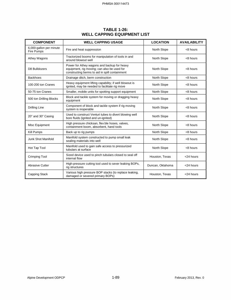
TABLE 1-26: WELL CAPPING EQUIPMENT LIST
COMPONENT WELL CAPPING USAGE LOCATION AVAILABILITY 6,000-gallon per minute Fire Pumps Fire and heat suppression North Slope <8 hours
Athey Wagons Tractorized booms for manipulation of tools in and around blowout well North Slope <8 hours
D8 Bulldozers Power for Athey wagons and backup for heavy equipment, rig moving; can also be used for constructing berms to aid in spill containment
North Slope <8 hours
Backhoes Drainage ditch, berm construction North Slope <8 hours
100-200 ton Cranes Heavy equipment lifting capability; if well blowout is ignited, may be needed to facilitate rig move North Slope <8 hours
50-75 ton Cranes Smaller, mobile units for spotting support equipment North Slope <8 hours
500 ton Drilling Blocks Block and tackle system for moving or dragging heavy equipment North Slope <8 hours
Drilling Line Component of block and tackle system if rig moving system is inoperable North Slope <8 hours
20” and 30” Casing Used to construct Venturi tubes to divert blowing well bore fluids (ignited and un-ignited) North Slope <8 hours
Misc Equipment High pressure chicksan, flex ble hoses, valves, containment boom, absorbent, hand tools North Slope <8 hours
Kill Pumps Back up to rig pumps North Slope <8 hours
Junk Shot Manifold Manifold system constructed to pump small leak sealing materials into well North Slope <8 hours
Hot Tap Tool Manifold used to gain safe access to pressurized tubulars at surface North Slope <8 hours
Crimping Tool Sized device used to pinch tubulars closed to seal off internal flow Houston, Texas <24 hours
Abrasive Cutter High-pressure cutting tool used to sever leaking BOPs, rig structures Duncan, Oklahoma <24 hours
Capping Stack Various high pressure BOP stacks (to replace leaking, damaged or severed primary BOPs) Houston, Texas <24 hours
Alpine Development ODPCP 1-89 February 2013, Rev. 0
PHMSA 000114473
1.9.2 Relief Well
Throughout the world, the number of well control incidents that escalate into the requirement of drilling a relief well is extremely small. CPAI does not rely on relief well drilling as the primary method of source control. However, due to long lead times associated with drilling a relief well, the relief well plan is initiated concurrent with the implementation of surface control methods. If surface control measures fail, CPAI relief well plans are implemented by the appropriate IMT and contractor personnel. CPAI decisions are made by management in accordance with procedures contained in the relief well plan.
Identification of surface location, equipment, and timing is dependent on the specific well site conditions. A number of options may be available for location and equipment. Timing is dependent on the success of surface-control techniques and well conditions, including any natural bridging that may occur.
Relief Well Surface Locations
The optimum surface location for a relief well depends on several factors, including the depth and direction of the wellbore, personnel safety, and weather conditions. The surface location is selected so that the relief well can be drilled in the most efficient manner practicable. Other surface-location considerations include hole angle, minimization of drilling time, and directional control.
Alpine drill site pads offer the primary surface locations, provided it is safe to work at the location. If on-site drilling rigs are still usable, then it may be possible (with certain replacement equipment, e.g., well control equipment) to drill relief wells with one of these units. Otherwise, an alternative rig would have to be deployed. Alternatively, an emergency drilling site could be created by carrying out local civil work (i.e., construction of a temporary gravel or ice pad). Use of an ice pad is possible from mid-February to mid-April.
Relief Well Drilling Rig and Equipment
All the equipment necessary for drilling a relief well is in drilling stock, either on the North Slope or in Fairbanks. Hercable rigs and truckable rigs can be mobilized, in addition to North Slope modular-wheeled rigs. Rigs capable of being airlifted can be flown into Alpine CD-1, and then transported over in-field gravel or ice roads.
CPAI can locate, contract for, and handle all the transporting issues involved with relief rig mobilization, while the alternative drill site was being constructed. In addition, ACS maintains master service agreements with various contractors, such as aviation services, whose assistance may be required during a spill response (see ACS Technical Manual Tactic L-9).
A relief well is generally considered a last resort in managing a blowout. It is far more common for a blowout to be controlled with surface-kill techniques, or for the flow to stop as a result of natural bridging mechanisms or formation depletion.
Although extensive precautions are taken, some potential exists for a loss of well control, conceivably requiring the use of a relief well. Plans have been established for initiating such emergency drilling quickly and safely.
In the event of a blowout, every effort is made to regain control of the well through mechanical means by using well control specialists from the North Slope industry through Mutual Aid, and from Wild Well Control. Relief well rig-mobilization plans begin simultaneously within minutes of a confirmed well control situation. The primary relief well option is mobilization of another rig that is in use nearby. This can be
Alpine Development ODPCP 1-90 February 2013, Rev. 0
PHMSA 000114474
accomplished by immediately suspending drilling operations on a nearby rig and moving the rig to the relief well site.
In accordance with standard oil industry practices and through mutual aid agreements, other operators would commit the necessary rigs and resources to combat a well control incident if a CPAI-operated rig is unavailable. Operator cooperation and sharing of resources often have been used on the North Slope when rigs, equipment, and other services are in short supply. Although some equipment is specified in the plan, this equipment may be replaced by functionally similar equipment, as necessary.
Relief Well Timing
Preparation for a relief well would begin as early as possible. Rapid mobilization is anticipated for most sites, assuming North Slope rigs are readily available. Use of a local rig could conceivably allow well control to be regained within the following estimated ideal timeframe:
Summer:
1. Mobilization of rig and equipment to site1 14 to 20 days 2. Construction or modification of a drill pad concurrent with rig mobilization 3. Rig-up and preparation to spud 8 to 10 days 4. Drill relief well 14 to 20 days 5. Kill well, plug and abandon relief well 7 to 14 days TOTAL: 43 to 64 days
Winter:
1. Mobilization of rig and equipment to site2 7 to 10 days 2. Construction or modification of a drill pad concurrent with rig mobilization 3. Rig-up and preparation to spud 8 to 10 days 4. Drill relief well 14 to 20 days 5. Kill well, plug and abandon relief well 7 to 14 days TOTAL: 36 to 54 days 1 Rig mobilization during summer would be primarily by Herc aircraft. 2 Rig mobilization during winter would be primarily by ice road; if blowout occurs prior to ice road construction, rig mobilization would
follow the summer timing provided above.
The time required for controlling a blowout by drilling a relief well varies, due to a number of unpredictable conditions, such as weather, cause of blowout, choice of surface location, and depth of well. The specific time required to spud and drill a relief well is dependent on the drill site and the bottomhole location.
Blowout Well Ignition
Ignition of a blowout will be a decision made by CPAI Management, and the IMT or Unified Command, in conjunction with regulatory agencies. The decision to ignite a blowout will be made only after assessing the probability of implementing successful surface control, reviewing potential safety hazards, addressing pertinent environmental considerations, and obtaining necessary agency approvals. One potential justification for the ignition of a blowout would be a gas blowout where the hydrocarbon had a toxic component to it (e.g., hydrogen sulfide). In such instances, the blowout may be ignited to control the toxic gases while preparations are being made to kill the well. Once well kill preparations were in place, the fire would be put out and the kill operations would commence. Direct telephone and/or radio communication would be maintained with the Source Control Unit Leader should any burning activities occur.
Alpine Development ODPCP 1-91 February 2013, Rev. 0
PHMSA 000114475
Permits
In the event of a well blowout, a series of federal, state, and local permits are required for response effort support. Permits are needed to authorize construction of gravel pads and/or support facilities (e.g., ice or gravel staging pads, temporary storage areas, temporary water uses).
Federal approval is required (Section 404/10 permit, U.S. Army Corps of Engineers) for placement of gravel (fill) in waters of the United States (wetlands). The Corps has issued Nationwide Permit #20 that authorizes placement of fill needed for cleanup of spilled oil. A request for this authorization requires approval from the ARRT. This request is typically approved quite rapidly, assuming the ARRT is in agreement with the overall cleanup strategy for this specific spill event.
In addition to the federal permit, it is likely that State of Alaska and NSB permits will also be required. As part of overall North Slope oil spill preparedness, ACS holds a series of emergency use permits authorizing a variety of cleanup related activities, including excavation and placement of fill (see ACS Technical Manual Tactic A-3). Key existing permits include ADNR Division of Lands Land Use Permit LAS 13877 and NSB Development Permit NSB 93-032.
Alpine Development ODPCP 1-92 February 2013, Rev. 0
PHMSA 000114476
Alpine Development ODPCP 2-1 February 2013, Rev. 0
PART 2 PREVENTION PLAN [18 AAC 75.425(e)(2)]
2.1 PREVENTION, INSPECTION, AND MAINTENANCE PROGRAMS [18 AAC 75.425(e)(2)(A)]
CPAI considers prevention the core of its spill response at Alpine. Pollution prevention begins with the drilling of wells and extends through all phases of oil production. Spill prevention methods used by CPAI include the following:
• Design,
• Inspection,
• Testing,
• Repair and replacement,
• Preventive maintenance,
• Detection and shutdown procedures,
• Training, and
• Administrative programs.
2.1.1 Oil Discharge Prevention Training and Recordkeeping [18 AAC 75.020]
All CPAI personnel with job duties directly involving inspection, maintenance, or operation of oil storage and transfer equipment regulated under 18 AAC 75.005 through 18 AAC 75.080 are required to complete training on the ODPCP and Spill Prevention, Control, and Countermeasures (SPCC) for CPAI North Slope Exploration and Production Training Module (REQ-229). This module contains information on state and federal oil pollution prevention requirements that are applicable to facility and field operations. A listing of each position required to take this training is maintained by the CPAI Health, Safety, and Environment (HSE) Training Coordinator and documented in the CPAI Training Requirements Manual.
CPAI personnel and contractors who perform maintenance and inspections are required to maintain the necessary certifications consistent with the applicable industry standard (i.e., American Petroleum Institute [API], National Association of Corrosion Engineers (NACE), and American Society of Mechanical Engineers [ASME]). A listing of training objectives and the means of achieving them, including training subject, training schedules, frequency, and type are provided in the CPAI Training Requirements Manual.
Completion of training is verified by computerized records maintained by the HSE Training Coordinator. Records are prepared and maintained in the HSE training files in a retrievable form for a minimum of five years and shall be provided to ADEC upon request. Key positions and training are summarized in Table 2-1.
PHMSA 000114477
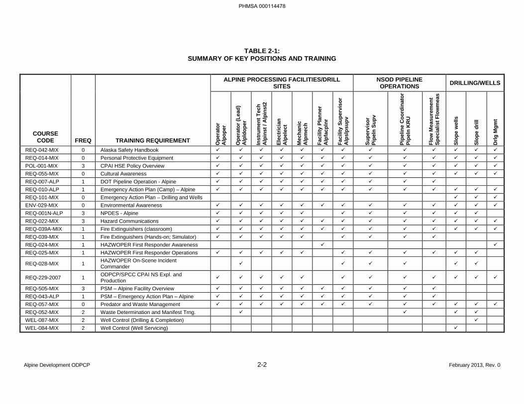
Alpine Development ODPCP 2-2 February 2013, Rev. 0
TABLE 2-1: SUMMARY OF KEY POSITIONS AND TRAINING
COURSE CODE FREQ TRAINING REQUIREMENT
ALPINE PROCESSING FACILITIES/DRILL SITES
NSOD PIPELINE OPERATIONS DRILLING/WELLS
Ope
rato
r A
lpop
er
Ope
rato
r (Le
ad)
Alp
ldop
er
Inst
rum
ent T
ech
A
lpin
st /
Alp
inst
2
Elec
tric
ian
A
lpel
ect
Mec
hani
c
Alp
mec
h
Faci
lity
Plan
ner
Alp
facp
lnr
Faci
lity
Supe
rvis
or
Alp
slps
upv
Supe
rvis
or
Pipe
ln S
upv
Pipe
line
Coo
rdin
ator
Pi
peln
KR
U
Flow
Mea
sure
men
t Sp
ecia
list F
low
mea
s
Slop
e w
ells
Slop
e dr
ill
Drlg
Mgm
t
REQ-042-MIX 0 Alaska Safety Handbook REQ-014-MIX 0 Personal Protective Equipment POL-001-MIX 3 CPAI HSE Policy Overview REQ-055-MIX 0 Cultural Awareness REQ-007-ALP 1 DOT Pipeline Operation - Alpine REQ-010-ALP 1 Emergency Action Plan (Camp) – Alpine REQ-101-MIX 0 Emergency Action Plan – Drilling and Wells ENV-029-MIX 0 Environmental Awareness REQ-001N-ALP 3 NPDES - Alpine REQ-022-MIX 3 Hazard Communications REQ-039A-MIX 1 Fire Extinguishers (classroom) REQ-039-MIX 1 Fire Extinguishers (Hands-on; Simulator) REQ-024-MIX 1 HAZWOPER First Responder Awareness REQ-025-MIX 1 HAZWOPER First Responder Operations
REQ-028-MIX 1 HAZWOPER On-Scene Incident Commander
REQ-229-2007 1 ODPCP/SPCC CPAI NS Expl. and Production
REQ-505-MIX 3 PSM – Alpine Facility Overview REQ-043-ALP 1 PSM – Emergency Action Plan – Alpine REQ-057-MIX 0 Predator and Waste Management REQ-052-MIX 2 Waste Determination and Manifest Trng. WEL-087-MIX 2 Well Control (Drilling & Completion) WEL-084-MIX 2 Well Control (Well Servicing)
PHMSA 000114478
Alpine Development ODPCP 2-3 February 2013, Rev. 0
CPAI requires its contractors to comply with all applicable local, state, and federal regulations. Contractors maintain their own training programs and records. CPAI periodically audits contractor training programs and records as part of the CPAI HSE Contactor Audit program.
2.1.2 Substance Abuse Programs [18 AAC 75.007(e)]
The CPAI drug policy was established as a measure to provide a safe working environment at all operations for its employees and contractors. CPAI’s company-wide policy is outlined in this section and applies to all employees and contractors.
“The use, possession or being under the influence of intoxicants, marijuana, or other controlled or illegal substances is STRICTLY PROHIBITED on CPAI-controlled premises. Entry onto CPAI-controlled premises constitutes CONSENT to and recognition of the right of the Company to CONDUCT SEARCHES of persons, property, vehicles and living quarters. Violation of this policy, or failure to cooperate with a search request will result in TERMINATION for CPAI personnel, and REMOVAL from Company premises for all others.”
Upon entering Company premises, all CPAI employees and contractors are expected to comply with CPAI's Substance Abuse Policy. Testing is routinely performed for pre-employment, new hires, reinstatements, cause, reasonable suspicion/belief, and post-accident/incident. Random tests are also performed.
The use, possession, distribution, or sale of unauthorized drugs while on Company premises, or while engaged in Company business, is prohibited. Persons reporting for work with unauthorized drugs in their possession are in violation of this policy.
The consumption or possession of alcohol on Company premises is prohibited. Reporting to work while under the influence of alcohol by any person is prohibited.
Illegal drugs and alcohol are prohibited at all drilling operations. If any personnel are found to be in possession or under the influence of alcohol or illegal drugs, immediate dismissal from assigned duties is required. Subcontractors are notified upon arrival at the drilling location of CPAI’s policy on alcohol and illegal drugs.
In addition, CPAI’s operation of the Alpine pipeline is under the jurisdiction of DOT regulations requiring drug testing for pre-employment, random, post-accident, reasonable cause, and return-to-duty situations for employees who operate in DOT-covered positions.
CPAI complies with requirements of the DOT regulations as set forth in Title 49 of the Code of Federal Regulations (CFR), Parts 40 and 199, which mandate biological testing and supervisory training programs. Individuals subject to drug testing include operator applicants and employees, contractors, or subcontractors who would perform tasks on a pipeline in an operating, maintenance, or emergency response function regulated by 49 CFR Parts 192, 193, or 195 (i.e., employees involved in safety-sensitive positions within natural gas, liquefied natural gas, and hazardous liquid pipeline operations). These individuals would be subject to drug testing under this program.
PHMSA 000114479
Alpine Development ODPCP 2-4 February 2013, Rev. 0
All positions (including subcontractors) are required to participate in a substance abuse program while on Company premises. In general, prospective employees are tested prior to hire. After initial hire, CPAI employees not subject to the regulations discussed above are required to comply with the Company’s Drug Testing policy and may be randomly tested using the urinalysis method. Frequency of testing is generally 5 percent of the total employees; therefore, the total number of tests per employee, per year will be random. Contract personnel maintain their own records.
2.1.3 Medical Monitoring [18 AAC 75.007(e)]
CPAI employees subject to physical fitness requirements must meet minimum physical requirements for their job classification as determined by the Medical Department. Subsequent physical examinations are also available to employees, with periodicity based on age.
Because the use of a respirator is required for many jobs, a key aspect of the physical examination is a determination of the employee’s physical capability to wear a respirator. A respiratory questionnaire is required in the interval between physical examinations. The primary purpose of the questionnaire is to evaluate whether there has been any changes in the status of the employee's health that may affect his/her ability to wear a respirator. An annual quantitative fit test is also required, as is training in the proper use, storage, and maintenance of the respirator. This training is provided in conjunction with the annual fire/respiratory protection class.
Personnel who have not been medically qualified, fit-tested, and trained will not be permitted to use respiratory protective equipment.
All members of CPAI’s Hazardous Materials (HAZMAT) Team are given a physical examination that complies with National Fire Protection Association standards. The SRT members are given a physical examination every two years.
A medical evaluation may be required if personnel are exposed to, or may be exposed to, hazardous substances at or above the permissible exposure level. If a permissible exposure level does not exist, published exposure levels may be used instead. The exposure will be the ambient air concentration (regardless of respirator use). Medical surveillance also will be provided at the employee's request.
In an emergency, injured personnel will proceed to the medical clinic for evaluation and/or treatment after completing decontamination. If there is a medical emergency, the decontamination should be completed within the shortest time possible (no shower, unless there has been skin contact; continue to flush eyes while in transit, if necessary), and immediately transport personnel to the medical clinic for prompt attention.
If overexposure is known or suspected as a result of an accidental release, the exposed person(s) shall be examined and treated as necessary. Physician’s Assistants who work under the direction of a medical doctor can render medical attention. If a Physician’s Assistant is not available at Alpine, one can be flown from Kuparuk within one hour, if necessary. Persons requiring additional medical attention are taken to Anchorage by air ambulance or by commercial or Company charter.
PHMSA 000114480
Alpine Development ODPCP 2-5 February 2013, Rev. 0
2.1.4 Security and Surveillance Programs [18 AAC 75.007(f)]
Fuel Transfer Procedures [18 AAC 75.025]
Fuel transfer procedures are found in Section 3.1.3.
2.1.5 Operating Requirements for Exploration and Production Facilities [18 AAC 75.045]
Flow Tests
Oil produced during a formation flow test or other drilling operations must be collected and stored in a manner that prevents the oil from entering state land or waters. If flow tests are conducted at Alpine, oil produced from these tests will be stored in mobile tanks or the well cleanout tank.
Platform Integrity Inspections and Isolation Valves for Pipelines Leaving Platforms
These requirements do not apply to Alpine, because Alpine is an onshore facility rather than a platform.
Drip Pans and Curbing
Drip pans and curbing are provided at transfer locations.
Catch Tanks
Requirements for catch tanks do not apply to Alpine, because Alpine is an onshore facility rather than a platform.
Other Requirements for Tanks
Onshore oil storage tanks must meet the requirements of 18 AAC 75.066 and 18 AAC 75.075. See Sections 2.1.8 and 2.1.9.
Other Requirements for Piping
Onshore piping must meet the requirements of 18 AAC 75.080. See Section 2.1.6.
Well Cellars and Wellhead Sumps
Well cellars at Alpine are intended to contain fluid leaks and facilitate cleanup. The original design used at Alpine has a corrugated metal pipe set into the gravel pad to a depth of 5 feet below grade, with a steel pipe located in the center of the corrugated metal pipe, and a 6-inch layer of concrete as an impervious base. Another design, used in Kuparuk that is applicable to new drill site installations at Alpine, has a steel pipe with a metal bottom that is seal-welded to the conductor to form a water-tight container. Fluids, such as thaw water, are removed from well cellars as needed, and walk-through visual inspections of the well houses/cellars to detect leaks or damage are conducted by field crews during routine operations. Visual inspection is the primary method for detection of spills in well houses.
PHMSA 000114481
(b) (7)(F), (b) (3)
Alpine Development ODPCP 2-6 February 2013, Rev. 0
Blowout Prevention and Emergency Shutdown
Drilling Assurance
This section outlines the preventive and recovery measures designed to minimize hydrocarbon spill potential. These measures are applied to development drilling operations and are applicable to onshore facilities. All well-control discussions presented in this section are aimed at preventing spills from occurring during drilling operations (i.e., blowouts where hydrocarbons spill to the surface). Actions taken in the event of loss of well control are summarized in CPAI’s Drilling and Wells Emergency Preparedness and Blowout Contingency Plan.
The following definitions apply to this section:
• Barrier – During drilling and well activities, the following barriers will normally exist:
− A barrier consisting of a homogenous mud column in hydrostatic overbalance in relation to the reservoir pore pressure; and
− A barrier consisting of a cemented casing, wellhead, pipe ram/annular preventer, and drill string with Kelly valve/check valve.
• Blowout – Any uncontrolled flow of formation fluids to the surface, due to formation pressure exceeding the hydrostatic pressure of the mud or fluid column and failure of second barrier.
• Shallow Gas Blowout – Any uncontrolled flow of gas from gas pockets located above the intended reservoir before the blowout preventer (BOP) is fitted.
• Completion – Covers any installation of production tubing, packers, and other equipment, as well as perforation and stimulation in production and injection wells.
• Development Drilling – Covers all operations related to production, injection, and observation wells between spudding and cementing the production casing.
• Exploration Drilling – Covers all operations related to wildcat and appraisal wells between spudding the well and plugging and abandonment.
• Kick – Unplanned introduction of hydrocarbons or fluids (brines, water) into the wellbore from formations.
• Production – Covers all wells that produce oil and/or gas but excludes well intervention, start-up, and close-in operations.
• Workover – Covers all intervention operations other than operations carried out with wireline.
• Remedial – Covers only those intervention operations where wireline or coil tubing is used.
Well Control during Planning
The process of well control commences before actual drilling operations with the planning and design of any well. Bottomhole pressure data from other wells in the area are reviewed to ascertain the expected formation pressure at the proposed well location. Seismic data and offset well information provide information for the prediction of over-pressured formations below the surface. Drilling engineers use the predictions for formation pressure to design a drilling mud program with sufficient hydrostatic head to overbalance the formation pressures from surface to well total depth. Other factors influencing the mud weight are: shale conditions, fractures, lost circulation zones, under-pressured formations, and stuck pipe
PHMSA 000114482
Alpine Development ODPCP 2-7 February 2013, Rev. 0
prevention. Casing strings are then designed to prevent several of these factors affecting the well control performance at the same time. Casing set at proper depths will allow a kick, if taken, to be safely controlled downhole.
Alpine has been drilled, and information that is already known regarding formation pressures within the drilling area will be utilized when drilling new wells. In addition, the AOGCC has specifications for drilling, casing, cementing, and blowout prevention in 20 AAC 25. All planning is done in accordance with AOGCC, and where appropriate, BLM regulations, CPAI policies and recommended practices are, at a minimum, equivalent to AOGCC and BLM regulations.
Well Control during Drilling
There are two areas where the potential for loss of well control exists during drilling. The first is during the drilling of the surface hole where the potential for a shallow gas blowout exists. Although shallow gas blowouts do not contain oil and no spill of oil occurs at the surface, the incident is critical from a safety standpoint. Loss of well control can also happen while drilling the below-surface hole where a blowout can occur while drilling into the reservoir or other hydrocarbon-bearing zones, or during completion of the well. In both cases, kick identification and management are the primary tools utilized to prevent a blowout.
Well Control during Surface Hole Drilling
During surface hole drilling, a shallow gas blowout can occur when a small, high-pressure volume of trapped gas is encountered. This causes a rapid unloading of the wellbore liquids (mud) and gas at the surface in a very short time span.
Shallow seismic surveys are carried out over the proposed drilling location to establish the presence of gas accumulations. Offset data are also valuable, but because accumulations tend to be localized, caution is vital at all times in case an incident occurs. Detection during drilling or tripping (i.e., running the drillstring into or out of the hole) will be visible by monitoring the returns to the surface from the drilling fluid system, monitoring the volume of drilling fluid required to fill the wellbore, and monitoring the drilling fluid weight in and out of the well to detect any influx of gas into the wellbore.
No attempt is made to shut in the well to contain the gas, as surface formations typically have insufficient strength to prevent gas broaching to the surface from these shallow depths. Instead, the flow of gas is directed away from the rig floor using a diverter valve and diverter line, which vents the gas at a safe distance from the drill rig to the atmosphere. Procedures are developed to keep pumping fluid to the drillstring wherever possible. This is done to establish primary well control, although most shallow blowouts deplete rapidly and/or bridge-off.
Well Control while Drilling Below the Surface Hole
A management-approved, detailed well plan is taken to the rig and the well is drilled. During drilling, the mud weight (the primary well-control mechanism) is constantly monitored and adjusted to meet actual wellbore requirements. Too low a mud weight could underbalance the well and result in a kick being taken (a flow of formation liquids, oil, gas, or water into the wellbore). Too high a mud weight might result in lost circulation to a weak formation, which can then lead to an underbalanced condition and possible kick. Generally, there is a fairly broad range of mud weight that will provide the proper well control for the hole conditions encountered.
PHMSA 000114483
Alpine Development ODPCP 2-8 February 2013, Rev. 0
The weight of the mud in the hole is the primary well-control mechanism. Minimum mud specifications are set by the AOGCC. If a kick does occur, secondary well control methods are employed. Constant monitoring of the fluid level in the wellbore and mud pits allows prompt notice of a kick in the hole. If a kick is noticed, the well is shut in by using BOP equipment installed on the wellhead after surface casing is set (below the permafrost). The BOP equipment will close off and contain liquids and pressures in the annulus and in the drill pipe. Pressure measurements are then taken; the mud in the surface pits is weighted enough to overbalance the bottomhole formation pressure. A standard well-kick procedure is then implemented to circulate the heavy mud through the well and safely remove the kick liquids from the hole. After this procedure is completed, the well is opened up and fluid levels are again monitored. Drilling operations resume when all is normal.
The blowout equipment is composed of redundant mechanisms that close the annular area between the drill pipe and the hole. The BOP stack is typically composed of an annular preventer, two pipe ram preventers, and a blind ram preventer. At least two chokes are provided in the choke manifold. Two pumps are typically available. The casing is designed to contain the maximum expected pressures shut in at the surface. Valves on the rig floor are used to shut in the inside of the drill pipe. Gas-busters and de-gassers are used to remove gas from the mud as it is circulated out of the hole. Approximately 1,000 barrels of surface pit capacity is available for storage and circulation of mud. Mud pumps used for drilling are also used to circulate the kick out of the hole.
BOP drills are performed and timed on the rig several times during drilling to verify that the well can be shut in quickly and properly. The company rig supervisor, tool pushers, drillers, and derrick men all have certified BOP training in well control that is renewed every two years. Mud men typically have BOP training, especially on exploration wells.
Backup systems and procedures are available for surface control of a kick if, for some reason, the weighted circulation procedures fail to provide the required control. It might be required that the formation liquids in the wellbore be bullheaded back into the formation. This is accomplished by pumping down both the annulus and the drill pipe at the same time and forcing the liquids back into the formation. The well is then circulated with kill mud weight, and drilling resumes. It might also be required to pump heavy mud, and then bleed off some of the annulus pressure. This is done through the choke manifold at a controlled rate such that the formation liquids are controlled. Another technique that is employed in an underground blowout situation (flow of formation liquids from one formation into another, uncontrolled) is the dynamic kill procedure. This entails pumping the kill fluid at a rate high enough to overcome the loss zone and kill the flow. Other manifestations of these basic techniques may be used depending on the situation.
Well Control during Completion
occur in the cased hole after the final casing
string/liner has been set, cemented, and pressure tested. During completion operations, well control is maintained through a minimum of two barriers. Completion fluid weight remains the primary control barrier. A secondary barrier utilizes mechanical equipment at the surface. Kick detection equipment and kick management (i.e., equipment, people/training/procedures) are as described in the preceding sections.
PHMSA 000114484
(b) (3), (b) (7)(F)
Alpine Development ODPCP 2-9 February 2013, Rev. 0
Well Control during Rig Workovers
Much of the information provided for well control during drilling is also relevant for rig workover operations. Actual production pressure data are used to establish workover fluid weights, much as offset data are used to establish drilling fluid weights. A minimum of two mechanical and/or fluid barriers are used prior to removing Xmas trees and installing BOP stacks and vice versa.
Well Control during Wireline/Coil Tubing Interventions
During intervention operations, a minimum of two mechanical barriers are maintained at the surface. Coil tubing servicing (as opposed to drilling) and wireline operations are carried out through the Xmas tree. Coil tubing utilizes high-pressure hydraulic pack-off as the primary well control mechanism, plus a BOP stack consisting of both pipe rams and blind/shear rams. Wireline also utilizes a hydraulic pack-off and lubricator as the primary well control mechanism, plus a BOP stack with wireline rams.
Well Control during Production
Spill prevention planning and activity accompany each well workover. AOGCC sets minimum requirements for prevention planning, approval, and operation. Also, during well workovers, an impermeable bib is placed over the cellar to contain any spilled liquids.
Spill Prevention Practices and Training
Drilling to all prospective formations has been done numerous times at Alpine; from a drilling standpoint, there are few true exploratory wells. All drills, training, and inspections required by federal and state law are conducted. During these drills, particular attention is paid to the driller and tool pusher understanding the importance of knowing and recording where every barrel of mud went while tripping in and out of the hole. In addition, extremely close attention is paid to volumes and fill-up pit systems to verify accurate performance during each trip. Tool pushers check all geolographs, pit level charts, and tour reports for accuracy each morning before forwarding them to the company representative. Drilling crews have First Responder training. They are responsible to the on-site supervisor or his designee, who acts as the First Responder Incident Commander for any minor spill; however, drilling crews are not part of the major response team. Drilling supervisors and/or Toolpushers will have, as a minimum, 8 hours of Hazardous Waste Operations and Emergency Response (HAZWOPER) training as outlined by Occupational Safety and Health Administration 29 CFR 1910.120, First Responder Awareness Level, paragraph (q)(6)(ii). All
PHMSA 000114485
(b) (3), (b) (7)(F)
(b) (3), (b) (7)(F)
Alpine Development ODPCP 2-10 February 2013, Rev. 0
fuel and hydrocarbon storage tanks are contained in a lined and bermed area, except for day tanks such as vehicle and drilling rig fuel tanks, which are integral parts of mobile equipment.
2.1.6 Flowline and Facility Piping Requirements [18 AAC 75.047 and 75.080]
Flowlines
Alpine has a network of in-field flowlines (three-phase oil/water/gas, miscible injection, water, and gas injection) between the processing facility at CD-1 and the satellite drill sites. Additionally, the in-field piping system between CD-1 and CD-3 includes a diesel pipeline. In-field flowlines are aboveground, with the exception of below-grade sections at road crossings.
Flowlines placed in service after December 30, 2008, will be designed and constructed as required in 18 AAC 75.047(b). Flowline piping supports will be constructed consistent with the applicable ASME Standard B31 code.
CPAI maintains a corrosion control program and an inspection program on flowlines, consistent with API 570 and Chapter VIII of ASME Standard B3.14-2002, as required in 18 AAC 75.047(c)(1). External inspections for painted or bare flowlines will be conducted every three years pursuant to ASME B31.4, and external inspections for insulated flowlines will be conducted every five years pursuant to API 570. Several engineering and design piping specifications and written CPAI corrosion control program procedures, are guiding documents for the corrosion control program.
In accordance with a waiver dated September 13, 2007, ADEC waived the requirements to place line markers at 1-mile intervals along each flowline. Pursuant to the waiver, line markers were installed at each below-grade crossing and where remote flowlines approach drill pads. A copy of the waiver letter is included in Section 2.6, “Waivers.”
After December 30, 2006, flowlines removed from service for more than one year will be free of accumulated oil and isolated from the system, as required by 18 AAC 75.047(f). For purposes of this subsection, “removed from service” means not in regular use for the service intended and not included in a regular maintenance and inspection program. CPAI will notify ADEC when flowlines are removed from service and when requirements of this subsection have been completed.
Facility Piping
Facility oil piping placed in service after December 30, 2008, will be constructed to ASME B31.3, B31.4, B31.8, or another ADEC-approved equivalent. CPAI shall ensure the piping is protected from atmospheric corrosion by the application of a protective coating or by the use of corrosion-resistant material, unless CPAI demonstrates by test, investigation, or experience appropriate to the environment of the piping segment that the anticipated extent of corrosion will only be a light surface oxide or will not affect the safe operation of the piping before the next scheduled inspection. Facility piping supports will be constructed in accordance with applicable piping construction standards.
Facility oil piping is in a corrosion control program as required by 18 AAC 75.080(b). Facility oil piping and valves are visually inspected for leaks or damage during routine operation, or at least monthly, as required by 18 AAC 75.080(n). Physical barriers in traffic areas protect exposed pipelines.
CPAI will notify ADEC of any facility piping removed from service for more than one year. Facility piping removed from service for more than one year will be free of accumulated oil, identified as to origin,
PHMSA 000114486
Alpine Development ODPCP 2-11 February 2013, Rev. 0
marked with the words “Out of Service” and the date taken out of service, secured to prevent unauthorized use, and blank-flanged or isolated from the system.
After December 30, 2008, a cathodic protection system that may be installed on facility piping will be consistent with 18 AAC 75.080(f). Compliance will include design and installation under the supervision of a corrosion expert.
Cathodic protection is not currently installed on facility piping. If installed in the future, the system will be maintained and inspected in accordance with 18 AAC 75.080(k).
Cross-country Diesel Pipeline
The 2-inch DOT-regulated cross-country diesel pipeline is non-insulated and non-coated except at the Colville River crossing. The diesel is not heated and the line operates at ambient temperature. Because the ambient temperature is below freezing during the majority of the year, external corrosion is anticipated to be limited. The pipe supports are in direct contact with the piping. A representative sampling of the pipe supports is inspected to determine external pipeline damage during each of the first five years the line is in operation and to verify that corrosion or mechanical damage in these areas is not a concern. Any damage found is recorded on a re-inspection schedule, and operations are modified, as practicable, to limit additional damage.
General Inspection Procedures
Facility piping and flowlines are under frequent observation to detect and prevent corrosion and leakage. The inspection programs are API 570-based programs that focus the inspection effort on areas of greatest potential. Inspection and monitoring of flowlines and facility piping are used to indicate if additional corrosion control is required, and provide feedback to the success of the overall corrosion control program.
At a minimum, the intervals between flowline inspections meet the requirements of ASME B31.4-2002 for bare flowlines and API 570 for insulated flowlines.
Many factors determine the interval between successive inspections. Safety, history of the piping and similar-service piping, and state and federal regulations influence the frequency of inspections. Inspection and monitoring programs for internal and external corrosion use different methods, including the following:
• Ultrasonic Inspection. Ultrasonic techniques use acoustic waves to measure metal thickness and uniformity. Corrosion can be detected by the changes in ultrasonic measurements. In addition to determining a baseline wall thickness, ultrasonic inspection can be used to determine changes in wall thickness with time. Specific locations are inspected and monitored for change with ultrasonic inspection quarterly to provide feedback to the Corrosion Control program.
• Radiographic Inspection. Radiography uses either gamma ray or X-ray sources to provide images of the metal, corrosion product, or insulation to aid in the assessment of asset condition. These techniques are useful in detecting metal loss to pipelines, both internal and external, and to assess the condition of the pipeline insulation and extent of corrosion product as a result of metal loss. In addition to providing a measure of the extent and depth of damage, radiographic inspection can be used to determine changes in damage with time.
PHMSA 000114487
Alpine Development ODPCP 2-12 February 2013, Rev. 0
Specific locations are inspected with radiographic inspection periodically to monitor change and provide feedback to the Corrosion Control program.
• Visual Inspections. There are several versions of visual inspection. A detailed visual inspection is used when the surface to be inspected is accessed and cleaned for inspection. This technique may use pit depth gauges or ultrasonic techniques to aid in the evaluation of the asset’s condition. The second type of visual inspection is the API 570 visual inspection for pipelines, which focuses on chafing, insulation damage, and pipeline support/structural integrity assessments. Visual inspections often entail ultrasonic inspection measurements along with visual observation of the piping.
• Coupon Monitoring. Metal coupons are strategically placed at designated locations to help assess the corrosiveness of the process fluid. The coupons are periodically removed, cleaned, and inspected to help evaluate the corrosion potential of the system and to monitor corrosion inhibitor effectiveness. New coupons are then installed.
• In-Line Inspection a.k.a “Smart pigs.” In-line inspections measure specific properties of the pipe as a function of length. The two most common instrumented pigs are “metal loss detection pigs” and “geometry pigs.” Metal loss detection pigs are capable of evaluating locations with corrosion or gouges. Geometry pigs are used to identify dents and out-of-round conditions, as well as pipeline deflection, depending on the type of geometry pig used. Flowlines capable of handling smart pigs are inspected with those pigs periodically, as determined by risk assessment.
• Forward Looking Infrared (FLIR) System. A FLIR system is an optical technology that uses the infrared spectrum to detect variations in temperature. This is an aircraft-based system that allows surveillance of large areas. It is an effective tool for leak detection on the North Slope, since typically, the temperature of the process systems is different than the ambient (surrounding) temperature.
In addition, equipment and facilities at Alpine are maintained through the use of a computer-based Preventive Maintenance (PM) program that ensures the continued operational reliability of any flowline system component affecting quality, safety, and pollution prevention as required by 18 AAC 75.047(d)(2). The PM program was implemented to schedule maintenance at appropriate intervals to ensure equipment is fit for service. The program undergoes continual refinement by incorporating feedback from the field based on inspection results. In general, however, most corrosion inspections are driven by CPAI’s corrosion database, which may generate more frequent inspections than those scheduled by the PM program. Corrosion inspection records are kept and maintained in the database in accordance with API 570.
The PM program is comprehensive. Inclusion in this ODPCP of all inspections performed in conjunction with PM cycles for vessels, pipelines, containment areas and tanks is impractical because of the volume of written records. At scheduled intervals, these forms are generated by an automated PM information system located and accessed on site at Alpine. At the completion of the PM inspection cycle, the forms are reviewed for completion, and results and data entered for the particular equipment. This provides an historical base for each component. A review of proposed changes in pipeline operation to evaluate potential impacts on pipeline integrity is included as a task in the CPAI Management of Change procedure.
The Alpine PM system is available for agency review upon request.
PHMSA 000114488
Alpine Development ODPCP 2-13 February 2013, Rev. 0
Flowline Pig Inspections
Flowline pig inspections are performed as part of the PM program and corrosion control program. The inspection pig launchers and receivers are located at the termini of the pig-capable pipelines. Systematic pig runs allow operators to monitor trends that can help forecast maintenance work. Based on pig data, the pipeline integrity can be assessed before a leak occurs.
Wall Thickness Measurement Pigs: Wall thickness in the pipeline is monitored for both internal and external corrosion using either magnetic flux leakage or ultrasonic wall measurement pigs.
3D Geometry Pigs (Axial, Vertical, and Lateral): The geometry of the pipelines is monitored using a 3D geometry pig, which gives an indication of pipeline bending strains and pipeline displacements.
The crude production and water injection flowlines and in-field pipelines are designed to be equipped with pig launchers and receivers at the pipeline terminals. Regular maintenance pigging is conducted periodically, as needed, for pipelines with existing pig launchers and receivers. Flowlines containing miscible injection fluids are considered to be in non-corrosive service.
Pipe Replacement Criteria
The metal loss criteria for pipe replacement are those contained in American National Standards Institute (ANSI)/ASME B31G-1991 (R2004) (Manual for Determining the Remaining Strength of Corroded Pipelines, A Supplement to ANSI/ASME B31 Code for Pressure Piping).
Below-Grade Steel Piping Inspection Program
At the Colville River crossing, the horizontal directional drilling section of the Alpine crude oil transmission pipeline, seawater pipeline, and the products pipeline are constructed with the carrier pipeline inside a casing and, by definition, are not “buried.” The carrier pipeline is isolated from the casing by insulators that hold the carrier pipe a couple of inches away from the casing. The casing isolates the carrier pipe from the soil and elements. The carrier pipe inside the buried casing is inspected in the same manner as the aboveground piping with pigging.
Although composed of non-corrosive stainless steel and encased in high density polyethylene pipe casing, the below-grade piping for the drag reducing agent tank is maintained under CPAI’s Below-Grade Pipe Monitoring program. The piping is operated under an ADEC compliance waiver of cathodic protection (CP) and protective wrapping/coating (see Section 2.1).
There are two buried lines at Alpine. These operate under an ADEC compliance waiver (see Section 2.1). The two buried lines are water lines to the WD-02 injection well and regulated pursuant to 18 AAC 75 due to the limited “oil” content in the fluids. The continued integrity of these lines are managed via an accelerated inspection program, as specified in the compliance waiver.
Corrosion Control
Applied corrosion control measures reflect the active or potential corrosion mechanisms in the relevant system. The corrosion mechanisms can be divided into internal mechanisms that vary with the service, and external mechanisms that are constant for all services.
PHMSA 000114489
Alpine Development ODPCP 2-14 February 2013, Rev. 0
CPAI tracks spill events for corrosion-related leaks and spills and conducts one or more of the following:
• Root Cause Analysis,
• Physical Cause Analysis, or
• Latent Cause Analysis, as required by the situation.
If a spill occurs from piping due to corrosion, a survey of the area is conducted, including wall thicknesses, to determine the full extent of the affected area. Additionally, historical corrosion survey information for the area is reviewed in order to better understand and analyze the corrosion mechanisms and subsequent causes of the leak. Based on the results of these studies, a decision is made to either replace or repair the equipment. As applicable, other areas in the field operating with similar environments or histories are reviewed and surveyed to prevent similar spills or leaks from occurring. Inspection priorities are adjusted based on the outcome of such an analysis. In areas of concern, such as highly corrosive environments, corrosion inhibitors may be used, and surveys may be conducted more frequently to help identify and mitigate future occurrences.
Pipelines in corrosive service may be protected from corrosion by the following techniques when inspection or monitoring data indicate that adequate protection does not exist.
• Internal Corrosion Control Techniques:
− Corrosion Inhibitors. Chemical corrosion inhibitors are used to continuously coat the inside of pipelines or to inhibit chemical corrosivity of the produced fluids.
− Biocide. Biocide is used to prevent growth of bacteria within the oil production and water system.
− Pigging. Seawater pipelines, produced water pipelines, and some production pipelines are routinely pigged to remove scale and deposits that can allow corrosion to occur. Pigging can allow corrosion inhibitors to work more effectively by providing a clean surface.
• External Corrosion Control Techniques:
− Coating. Coating with polymeric materials is used to protect the steel from corrosive fluid. These polymeric materials provide a barrier between the metal and fluid.
− Maintenance Procedures for Pipe Casings. Pipe casings under road crossings are inspected annually for the presence of soil and debris that may be in contact with piping. When encountered, the soil and debris are removed to reduce the potential for external corrosion.
All records for inspections, test, maintenance, and repairs are available to ADEC upon request. Documentation of corrosion control measures includes dates and locations of inspections and tests, test data evaluations, data and analysis of chemical optimization activities, analysis of corrosion trends, and a list and description of repair activities undertaken, as required in 18 AAC 75.047(h)(1).
External Corrosion Control
External corrosion of aboveground flowlines controlled by a corrosion control program includes an application of a protective coating, by the use of corrosion-resistant alloys or by another method approved by ADEC, unless CPAI demonstrates by test, investigation, or experience appropriate to the environment
PHMSA 000114490
Alpine Development ODPCP 2-15 February 2013, Rev. 0
of the flowline segment, that the anticipated extent of corrosion will not affect the fitness for service as required by 18 AAC 75.047(c)(3).
Field weld joints are protected by a weather-resistant insulation kit. In accordance with 18 AAC 75.080(l), the effectiveness of field-joint insulation designs or alternative corrosion mitigation methods is confirmed by inspection of a representative sampling of the weld packs after five years of service. Weld pack designs have been improved. Inspection of insulation systems is an on-going process, with resources and technology applied using a risk-based methodology. Where corrosion is found, appropriate action is taken, including repairs (such as sleeves, if required), application of tape-wrap coatings, and installation of new insulation and jacketing. This refurbishment technique has performed well, with no corrosion found under any previously-refurbished weld pack.
There are no buried or submerged flowlines at Alpine. If buried or submerged flowlines are installed, external corrosion control of buried or submerged flowlines will be consistent with NACE RP0169-2002.
Internal Corrosion Control
Internal corrosion of flowlines is controlled by mitigation and monitoring measures consistent with 18 AAC 75.047(c)(4). Methods may include maintenance pigging, treatment of residual water, and inhibitor injection.
Internal corrosion mechanisms include carbon dioxide (CO2) corrosion, microbially-induced corrosion, and chemical attack.
The potential for CO2 corrosion is low at Alpine because of the low concentration (less than 2 percent) of CO2 in the gas phase. CO2 corrosion control is achieved using corrosion inhibitors that are injected at the drill sites. The chemical treatment volumes are based on the water production of the drill site and the corrosivity of the fluids.
Microbially-induced corrosion is present in the production and water injection systems. It is controlled through use of corrosion inhibitors in the production system and through biocides and pigging in the water injection system.
Chemical attack can occur where corrosive chemicals are injected into a system without a properly-designed injection quill, where the concentrated chemical is allowed to contact the pipe wall. Chemical attack is controlled by using properly designed quills, low-corrosivity chemicals (where possible), and by frequent inspection of injection points pursuant to API 570.
Where corrosion is found, appropriate action is taken, including repairs (such as sleeves or line section replacement, if required), increased monitoring of the damage, or increased corrosion inhibitor injection.
Corrosion Control Program for Process Facilities
Weight-loss corrosion coupons from the various process streams are examined periodically, based on the historical corrosivity of a system. The frequency is typically between three months and one year. The frequency of coupon examination in specific locations is determined by a qualified corrosion engineer and adjusted over the life of the field to provide adequate process monitoring.
PHMSA 000114491
Alpine Development ODPCP 2-16 February 2013, Rev. 0
Monitoring locations are selected where water is present or may be present during process upsets, and where corrosion has been seen in other operating fields. Corrosion coupon fittings are strategically placed throughout the production, miscible injection, and seawater in-field pipeline system at Alpine.
When necessary, corrosion inhibitor is injected at well site manifolds and at the inlet separator. Injection rates vary with results from the corrosion inspection program.
2.1.7 Leak Detection, Monitoring, and Operating Requirements for Crude Oil Transmission Pipelines [18 AAC 75.055]
Metered volume balancing is performed at least once every 24 hours, as required by 18 AAC 75.055(a)(2). Computation pipeline monitoring is the primary means of providing continuous leak detection capability, as required by 18 AAC 75.055(a)(1). The flow of incoming oil can be stopped within one hour after detection of a spill, as required by 18 AAC 75.055(b). In the event of an alarm, the control board operator proceeds through a series of steps to determine its cause. Aerial or ground-based surveillance may be requested. The leak detection system details are presented in Section 2.5.2. System accuracy is described in Section 4.11.
The Alpine crude oil transmission pipeline is considered a remote pipeline because it is not always directly accessible by ground transportation. For a remote pipeline, 18 AAC 75.055(a)(3) requires weekly visual inspections to be made by aerial surveillance. The goal of these aerial surveys is visual detection of oil slicks that may develop as a result of an unlikely oil leak below the monitoring thresholds. CPAI conducts weekly visual aerial surveillance to meet requirements of 18 AAC 75.055(a)(3).
PHMSA 000114492
(b) (7)(F), (b) (3)
(b) (3), (b) (7)(F)
Alpine Development ODPCP 2-17 February 2013, Rev. 0
Natural events such as flooding, ice damage, or frost jacking could impact facilities and pipelines. Should any of these events pose a threat, visual evaluations will be performed to determine if a line or facility should remain in operation. Each DOT-regulated Alpine pipeline has an operations manual that addresses all operations and procedures related to the pipeline, including abnormal and emergency operations.
CPAI notifies ADEC in writing within 24 hours if a significant change is made to, or occurs in, the leak detection system, as required by 18 AAC 75.475(d)(2).
2.1.8 Oil Storage Tanks [18 AAC 75.066]
Section 3.1.2 contains additional information on the ADEC-regulated oil storage tanks at Alpine. There are currently no field-constructed oil storage tanks at Alpine; as such, requirements at 18 AAC 75.065 for field-constructed aboveground oil storage tanks do not apply. The following addresses the requirements of 18 AAC 75.066 for ADEC-regulated shop-fabricated aboveground oil storage tanks at Alpine.
Tank Design and Construction
In accordance with 18 AAC 75.066(a)(1), ADEC-regulated shop-fabricated aboveground oil storage tanks initially placed into service before December 30, 2008, are not subject to requirements for design and construction standards and, if of vaulted, self-diked, or double-walled design, are not subject to additional design and equipment requirements of 18 AAC 75.066(c), (d), and (e), respectively.
ADEC-regulated shop-fabricated aboveground oil storage tanks placed into service after December 30, 2008, will be consistent with 18 AAC 75.066(a)(2). Tanks placed into service after December 30, 2008, will be designed and constructed according to an ADEC-approved design, including: Underwriters Laboratory (UL) 142, API 650, API 1F, STI F921-03, UL 2085, or an engineer-certified design approved by ADEC. ADEC-regulated vaulted, self-diked, or double-walled shop-fabricated aboveground oil storage tanks placed into service after December 30, 2008, will meet requirements of 18 AAC 75.066(c), (d), and (e), respectively.
Maintenance and Inspection
Regulated oil storage containers owned and operated by CPAI are maintained and inspected in accordance with state and federal regulatory requirements. Required inspections, repairs, and alterations are discussed in the following sections. Inspection schedule information for ADEC-regulated tanks is provided in Table C-1
PHMSA 000114493
(b) (3), (b) (7)(F)
Alpine Development ODPCP 2-18 February 2013, Rev. 0
for tanks owned by CPAI and operated at Alpine, in Table C-2 for tanks owned by CPAI that may be operated at Alpine, in Table C-3 for tanks that may be directly rented by CPAI, and in Table C-4 for third-party tanks not owned or leased by CPAI (see Appendix C). Descriptions and locations of oil storage containers that are regulated by EPA, are listed in CPAI’s Alpine SPCC Plan. EPA SPCC-regulated oil containers, with capacity of 55 gallons or more, are inspected in accordance with CPAI tank management and/or PM programs, which include periodic visual inspection conducted according to written procedures. Additional description, locations, and inspection information is provided in CPAI’s Alpine SPCC Plan available at the facility.
CPAI requires regulated tanks rented or leased directly by CPAI meet all applicable regulatory requirements.
ADEC-regulated oil storage tanks at Alpine are elevated. Internal and external inspections on regulated tanks are performed by a tank inspector certified under API 653 at the frequencies required by API 653 and 18 AAC 75.066(f), or as determined by the certified inspector under best management practices.
CPAI inspects and maintains tanks in accordance with tank management and PM programs. Tanks not owned, leased, or operated by CPAI (otherwise referred to as third-party tanks) are inspected and maintained by the tank owner. CPAI may audit third-party service companies to ensure their practices are in accordance with their respective tank integrity management programs. Tanks provided by non pre-qualified companies are reviewed by CPAI prior to being put into service.
Integrity inspection of aboveground oil storage tanks is conducted by staff or contract-certified tank inspectors in accordance with API 653 and ADEC requirements for regulated tanks.
Internal tank corrosion is often mitigated by use of coatings, anodes (CP), and/or the use of corrosion-resistant alloys.
At a minimum, monthly routine operational examinations (external) are conducted for ADEC-regulated oil storage tanks. EPA SPCC-regulated oil storage containers are visually inspected at least annually. Written records of repairs or operational alerts are retained for the life of the tanks. Records of API 653 inspections are prepared according to API document guidelines and retained for the service life of the tanks. Records of visual inspections are maintained in accordance with Company policies.
Discharge Prevention
The three types of liquid level devices are:
• Hydrostatic Head or Differential Pressure Devices: These transmitters are located in the bottom of the tank and measure the liquid level by comparing atmospheric pressure and the pressure inside of the tank.
• Ultrasonic Non-Contact Transmitter: This transmitter utilizes microprocessor-based electronics and non-contact ultrasonic transducers to provide a level measurement
PHMSA 000114494
(b) (3), (b) (7)(F)
Alpine Development ODPCP 2-19 February 2013, Rev. 0
unaffected by changes in specific gravity, viscosity, or conductivity. The sensor is mounted at the top of the tank. Ultrasonic pulses are directed to the measuring surface. The returning echo is detected by the sensor, and the electronics amplify and convert the signal into a digital representation of the level.
• Microwave Radar Non-Contact Transmitter: This transmitter utilizes microwave signals, typically emitted from an antenna, that travel at light velocity to the liquid surface and then are reflected back to a sensor that detects the time taken for the microwave reflection (or echo). Unlike sound waves, microwaves require no transmission medium and can be applied in vacuum and positive-pressure conditions.
At a minimum, monthly manual tank strapping measurements are conducted on non-fuel gas-blanketed tanks or tanks without two independent level measurement devices to check tank levels and verify automated devices indicate proper level limits.
Tanks with more than one independent transmitter have additional (redundant) protection. The independent systems are measured for deviations between each other. Audible systems connected to the DCS will sound an alarm in the control room if deviations are detected. This type of backup system creates a continuous internal testing system for the liquid-level devices.
Overfill protection devices are tested before each transfer operation, or monthly, whichever is less frequent. If monthly testing would necessitate interrupting the operation of a system subject to continuous flow, monthly inspection and annual testing may be substituted for the monthly testing as required in 18 AAC 75.066(h). For tanks without automated overfill protection devices, overfill protection relies on visual surveillance. Tank fuel levels are monitored and controlled manually during filling activities.
Fueling operations will follow CPAI’s fuel transfer procedures to prevent discharge from transfer hoses, as discussed in Section 3.1.3.
CD-1 Lube Oil Tank, Completions Fluid Storage Tanks, and Brine Tanks
CD-1 Ultra-Low Sulfur Diesel Storage Tank
PHMSA 000114495
(b) (3), (b) (7)(F)
(b) (3), (b) (7)(F)
Alpine Development ODPCP 2-20 February 2013, Rev. 0
CD-1 Slop Oil Tank
Satellite Drill Site Tanks
Tanks at satellite drill sites have either automated or visual liquid-level indicator devices as the primary overfill protection device.
2.1.9 Secondary Containment Areas for Oil Storage Tanks [18 AAC 75.075]
Secondary containment is provided at all permanent tank installations and for regulated oil storage containers. Diked areas for tankage containing fuel or other hydrocarbons, including crude oil, are typically lined with a synthetic liner and sized for at least 100 percent capacity of the largest single tank, plus an additional volume for precipitation. Secondary containment information including type and volume descriptions for EPA SPCC-regulated oil storage containers with capacity 55 gallons or greater as required by 40 CFR 112.7(c), and 112.8(c), or 112.9(c), is provided in the Alpine SPCC Plan.
Liners are resistant to operational damage and weather and are sufficiently impermeable as required by 18 AAC 75.075(a)(2). In addition, personnel follow a standard operating procedure (SOP), which describes the containment dimensions based on the size and number of tanks when constructing secondary containments for portable tanks. Drainage, when required to recover containment capacity due to snowmelt or rain, is typically performed by vacuum truck. Where applicable, CPAI’s Liner and Drip Pan Policy will be followed.
Shop-fabricated aboveground oil storage tanks of a vaulted, self-diked, or double-walled design are not required by state or federal regulation to be placed within bermed, lined, secondary containment areas if they are equipped with catchments that positively hold overflow due to tank overfill, or divert it into an integral secondary containment area [18 AAC 75.075(h)]. Local agency requirements for containment of double-walled tanks are either met or waived by approval of the local agency.
CPAI notifies ADEC in writing within 24 hours if a significant change occurs in or is made to an ADEC-regulated secondary containment system, and if as a result of the change, the system no longer meets the ADEC performance requirement [18 AAC 75.475(d)].
CD-1 Impound Basin and Basin Liner
The secondary containment area for the ULSD storage tank, slop oil tank, completions fluid storage tanks, brine tanks, and lube oil storage tank at CD-1 consists of a basin that lies between Modules G1 and G2. The basin is sloped to a sump to ease collection of liquids in the event of a spill. The basin is designed with a 5,220-barrel capacity and is visually inspected for integrity. See Figure 2-1 and Figure 2-2.
The CD-1 impound basin liner is 80-mil Polyshield SS-100 or equivalent. A layer of geotextile is heat-treated on one side, and used below the elastomeric coating for strength. All joints are overlapped at least 12 inches.
PHMSA 000114496
(b) (3), (b) (7)(F)
Alpine Development ODPCP 2-21 February 2013, Rev. 0
Secondary Containment Inspections
The secondary containment area is maintained free of debris, vegetation, excessive accumulated water, and other materials or conditions that might interfere with the effectiveness of the system. Facility personnel shall visually check for the presence of oil leaks or spills within secondary containment areas during routine operations, and unless precluded by safety concerns or weather conditions, shall conduct documented weekly inspections of secondary containment areas. Inspections include checking for debris and vegetation, proper alignment and operation of drain valves, visible signs of oil leaks or spills, and defects or failures of the secondary containment system as required by 18 AAC 75.075(c). Liquids are removed with vacuum trucks; there are no drains in the secondary containment basin. Accumulated water is inspected before discharging, if applicable. Stormwater discharges are conducted under a National Pollutant Discharge Elimination System (NPDES) permit. CPAI keeps a written record of stormwater inspections conducted under NPDES permit for five years, regardless of whether a sheen is present.
PHMSA 000114497

Alpine Development ODPCP 2-22 February 2013, Rev. 0
BLANK PAGE
PHMSA 000114498


Alpine Development ODPCP 2-24 February 2013, Rev. 0
BLANK PAGE
PHMSA 000114500

Alpine Development ODPCP 2-26 February 2013, Rev. 0
BLANK PAGE
PHMSA 000114502
Alpine Development ODPCP 2-27 February 2013, Rev. 0
Loading/Unloading Areas
In accordance with 18 AAC 75.075(g), permanent loading/unloading areas are:
• Designed with secondary containment to contain 100 percent of the maximum capacity of any single compartment of a tank truck;
• Paved, surfaced, or lined with sufficiently impermeable materials;
• Maintained free of debris, vegetation, excess accumulated water, or other materials;
• Have warning lights, warning signs, or contain physical barriers to prevent premature vehicular movement; and
• Visually inspected before any transfer operation, or at least monthly.
The CD-1 fuel dispensing and truck loading/unloading area is located next to the east wall of the secondary containment (impound) basin. This area includes the fuel (ULSD) dispensing station and both G1 and G2 loading/unloading stations (see Figure 2-3). It is designed in compliance with Articles 52 and 79 of the Uniform Fire Code. The fuel dispensing and truck loading/unloading area is summarized in Table 2-2.
The loading/unloading area at CD-1 measures 95 feet long, 36.3 feet wide, and 2.1 feet deep at its maximum. The area contains 620 barrels of liquids. All regulated tanks in the CD-1 tank farm have truck-filling capability, and all truck fill connections are grouped closely together above the basin. The loading/unloading area at CD-1 is constructed of pre-cast concrete slabs with an underlying geomembrane liner (80-mil Polyshield SS-100 or equivalent). The road slopes down at a 4-percent grade toward a sump with vertical sidewalls, and then slopes up again at the opposite end. To keep a spill from running off the loading/unloading area, pre-cast curbs are used along the sides of the loading/unloading area.
The MI Swaco tank farm located at CD-1 has a primary secondary containment area that measures 90 feet long, 24 feet wide, and 2 feet deep; the loading/unloading area extension (“kick-out”) measures approximately 35 feet long, 11 feet wide, and 1 foot deep. The approximate secondary containment capacity is 605 barrels, and the area is lined with a 22-mil geomembrane. The maximum bulk truck compartment serviced here has a volume of 325 barrels, although it is filled to only 290 barrels as standard practice.
The CD-2 truck loading/unloading facility is located west of the chemical tank farm area. It is 85.6 feet long and 23.6 feet wide. It is constructed of pre-cast concrete panels and curbing with an underlying geomembrane liner. The secondary containment area is designed to contain 635 barrels of liquids.
The CD-3 truck loading/unloading facility is located north of the chemical tank farm area. It drains into secondary containment that is 81.5 feet long and 16.5 feet wide, with a maximum depth of 2 feet. It is constructed of pre-cast concrete panels and curbing, with an underlying geomembrane liner.
PHMSA 000114503

Alpine Development ODPCP 2-28 February 2013, Rev. 0
BLANK PAGE
PHMSA 000114504
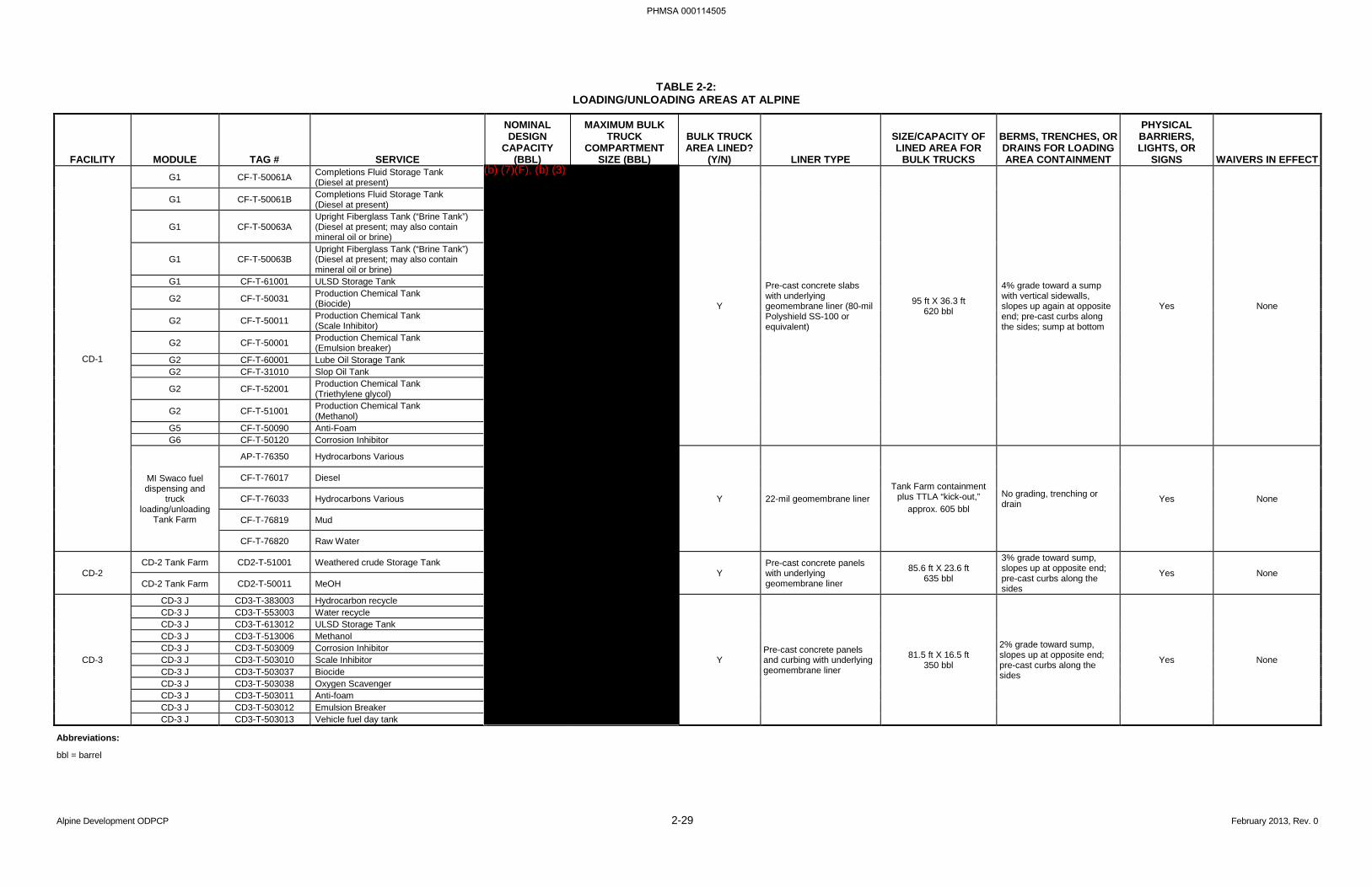
Alpine Development ODPCP 2-29 February 2013, Rev. 0
TABLE 2-2: LOADING/UNLOADING AREAS AT ALPINE
FACILITY MODULE TAG # SERVICE
NOMINAL DESIGN
CAPACITY (BBL)
MAXIMUM BULK TRUCK
COMPARTMENT SIZE (BBL)
BULK TRUCK AREA LINED?
(Y/N) LINER TYPE
SIZE/CAPACITY OF LINED AREA FOR
BULK TRUCKS
BERMS, TRENCHES, OR DRAINS FOR LOADING AREA CONTAINMENT
PHYSICAL BARRIERS, LIGHTS, OR
SIGNS WAIVERS IN EFFECT
CD-1
G1 CF-T-50061A Completions Fluid Storage Tank (Diesel at present)
Y
Pre-cast concrete slabs with underlying geomembrane liner (80-mil Polyshield SS-100 or equivalent)
95 ft X 36.3 ft 620 bbl
4% grade toward a sump with vertical sidewalls, slopes up again at opposite end; pre-cast curbs along the sides; sump at bottom
Yes None
G1 CF-T-50061B Completions Fluid Storage Tank (Diesel at present)
G1 CF-T-50063A Upright Fiberglass Tank (“Brine Tank”) (Diesel at present; may also contain mineral oil or brine)
G1 CF-T-50063B Upright Fiberglass Tank (“Brine Tank”) (Diesel at present; may also contain mineral oil or brine)
G1 CF-T-61001 ULSD Storage Tank
G2 CF-T-50031 Production Chemical Tank (Biocide)
G2 CF-T-50011 Production Chemical Tank (Scale Inhibitor)
G2 CF-T-50001 Production Chemical Tank (Emulsion breaker)
G2 CF-T-60001 Lube Oil Storage Tank G2 CF-T-31010 Slop Oil Tank
G2 CF-T-52001 Production Chemical Tank (Triethylene glycol)
G2 CF-T-51001 Production Chemical Tank (Methanol)
G5 CF-T-50090 Anti-Foam G6 CF-T-50120 Corrosion Inhibitor
MI Swaco fuel dispensing and
truck loading/unloading
Tank Farm
AP-T-76350 Hydrocarbons Various
Y 22-mil geomembrane liner Tank Farm containment
plus TTLA “kick-out,” approx. 605 bbl
No grading, trenching or drain Yes None
CF-T-76017 Diesel
CF-T-76033 Hydrocarbons Various
CF-T-76819 Mud
CF-T-76820 Raw Water
CD-2 CD-2 Tank Farm CD2-T-51001 Weathered crude Storage Tank
Y Pre-cast concrete panels with underlying geomembrane liner
85.6 ft X 23.6 ft 635 bbl
3% grade toward sump, slopes up at opposite end; pre-cast curbs along the sides
Yes None CD-2 Tank Farm CD2-T-50011 MeOH
CD-3
CD-3 J CD3-T-383003 Hydrocarbon recycle
Y Pre-cast concrete panels and curbing with underlying geomembrane liner
81.5 ft X 16.5 ft 350 bbl
2% grade toward sump, slopes up at opposite end; pre-cast curbs along the sides
Yes None
CD-3 J CD3-T-553003 Water recycle CD-3 J CD3-T-613012 ULSD Storage Tank CD-3 J CD3-T-513006 Methanol CD-3 J CD3-T-503009 Corrosion Inhibitor CD-3 J CD3-T-503010 Scale Inhibitor CD-3 J CD3-T-503037 Biocide CD-3 J CD3-T-503038 Oxygen Scavenger CD-3 J CD3-T-503011 Anti-foam CD-3 J CD3-T-503012 Emulsion Breaker CD-3 J CD3-T-503013 Vehicle fuel day tank
Abbreviations:
bbl = barrel
PHMSA 000114505
(b) (7)(F), (b) (3)

Alpine Development ODPCP 2-30 February 2013, Rev. 0
BLANK PAGE
PHMSA 000114506


Alpine Development ODPCP 2-32 February 2013, Rev. 0
BLANK PAGE
PHMSA 000114508
Alpine Development ODPCP 2-33 February 2013, Rev. 0
2.2 DISCHARGE HISTORY [18 AAC 75.425(e)(2)(B)]
Alpine participates proactively in spill prevention programs including campaigns, investigations, and training to increase employee awareness levels.
The major causes for spills greater than 55 gallons were equipment difficulties that account for most spills since 1998. Causes for the remaining number of spills can be grouped in the following categories: procedures, corrosion/erosion, and human error.
The history of known discharges of volumes greater than 55 gallons is maintained in the CPAI spill database for the life of the facility. The database includes the source, cause, amount of the discharge, and corrective actions taken. Most spills that occur at Alpine are small events that are contained on gravel pads and rarely reach the tundra or water environment. The history of known discharges greater than 55 gallons for CPAI in the Alpine field since 1998 is included in Appendix B. Copies of discharge records shall be provided to ADEC upon request.
A spill analysis was completed for oil spills over 55 gallons at Alpine since facility startup in 1999 to June 2012. The analysis showed that the sources with the highest percentage of spill incidents were tanks (36%) and heavy equipment/mobile equipment/ vehicles (23%) (Figure 2-4). The largest percentage of spill volume was from tanks (40%) and from heavy equipment/mobile equipment/vehicles (19%) (Figure 2-5). Figure 2-6 and Figure 2-7 illustrate the relationship between spill incidents, volume, and source over time.
The history of known discharges for reportable spills to tundra and/or water in the Alpine field since 1999 is included in Appendix B. Appendix B includes the information outlined in 40 CFR Part 112, Appendix F, Section 1.4.4, for spills that are identified by 40 CFR Part 110.
CPAI North Slope operations employ several measures to minimize and mitigate the occurrence of spills. A “Root Cause Failure Analysis” investigation process occurs for significant spills and corrective actions are taken based on the analysis by the review team. Lessons learned are shared with supervisors and affected workgroups to promote spill prevention. Depending on the incident, the review team may include: personnel responsible for the operation causing the spill, their foreman or supervisor, a safety representative, field environmental compliance personnel, a facility supervisor, and/or a corrosion engineer. The investigation process is aimed at increasing safety and reducing personnel exposure to spilled materials, preventing reoccurrence of spills, and identifying spill causes and early detection. Spill investigation results are communicated to the rest of the field personnel to promote spill prevention. Periodically, teams are developed to conduct an analysis of spill causes, volumes, and frequencies. Slope-wide trends of frequency, cause, and size of spills are noted.
Environmental staff attend project kick-off and operations support meetings where spill mitigation measures and reporting procedures are discussed. Environmental staff also work with responsible parties to ensure timely and accurate reporting and clean up of spills.
CPAI promotes spill prevention by encouraging proactive involvement and knowledge sharing through spill prevention programs and awareness training or communications. Personnel receive recognition for outstanding spill prevention and information or new tools/procedures are shared with other Alpine personnel.
PHMSA 000114509
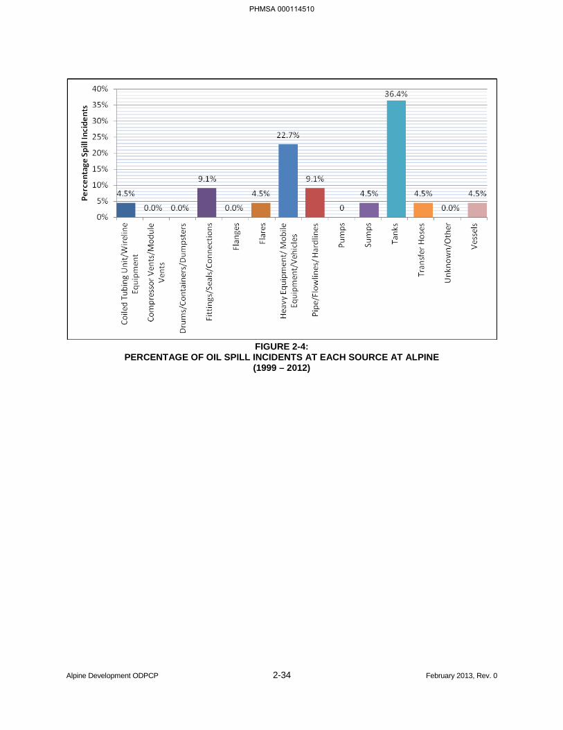
Alpine Development ODPCP 2-34 February 2013, Rev. 0
FIGURE 2-4:
PERCENTAGE OF OIL SPILL INCIDENTS AT EACH SOURCE AT ALPINE (1999 – 2012)
PHMSA 000114510
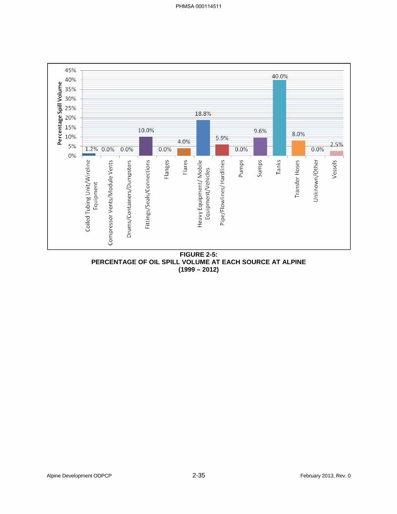
Alpine Development ODPCP 2-35 February 2013, Rev. 0
FIGURE 2-5:
PERCENTAGE OF OIL SPILL VOLUME AT EACH SOURCE AT ALPINE (1999 – 2012)
PHMSA 000114511
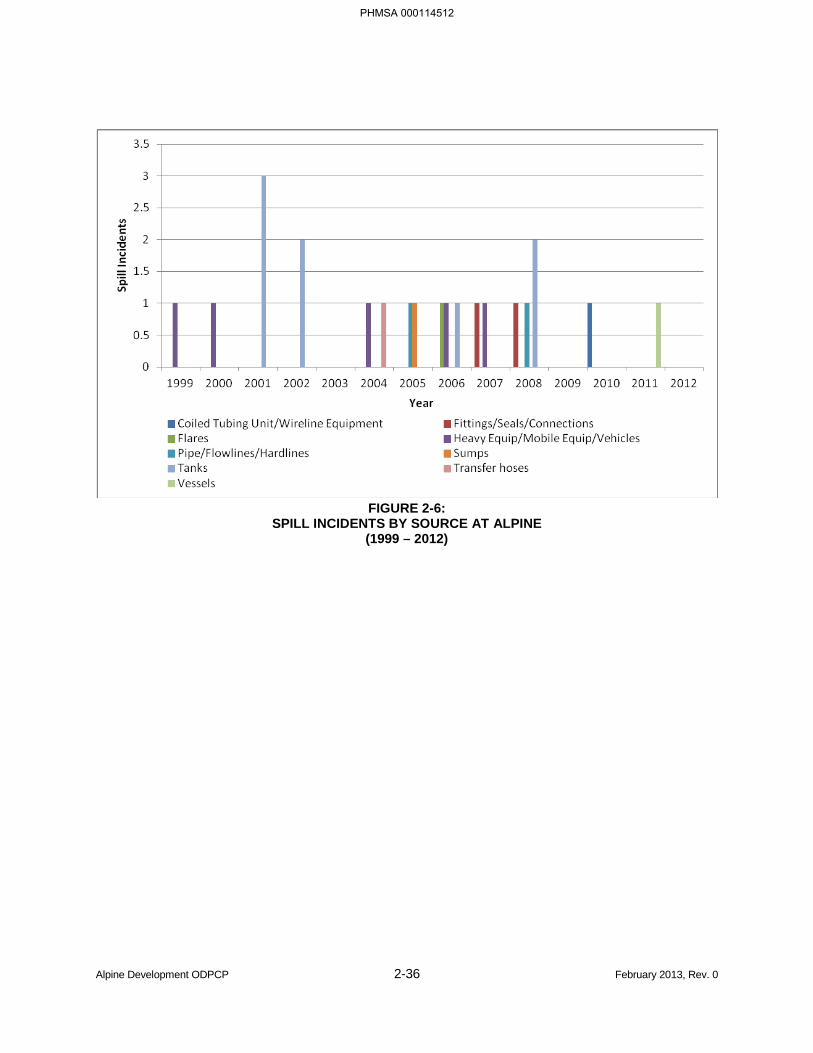
Alpine Development ODPCP 2-36 February 2013, Rev. 0
FIGURE 2-6:
SPILL INCIDENTS BY SOURCE AT ALPINE (1999 – 2012)
PHMSA 000114512
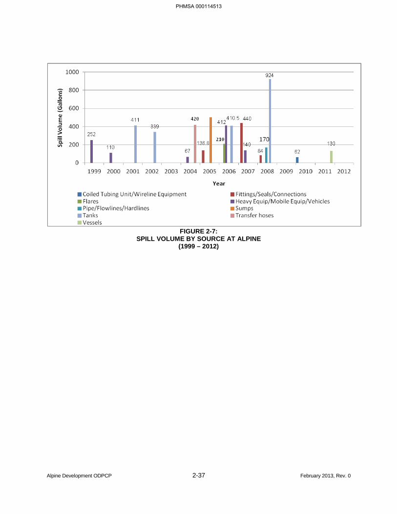
Alpine Development ODPCP 2-37 February 2013, Rev. 0
FIGURE 2-7:
SPILL VOLUME BY SOURCE AT ALPINE (1999 – 2012)
PHMSA 000114513
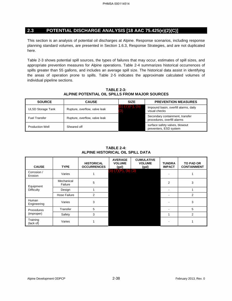
Alpine Development ODPCP 2-38 February 2013, Rev. 0
2.3 POTENTIAL DISCHARGE ANALYSIS [18 AAC 75.425(e)(2)(C)]
This section is an analysis of potential oil discharges at Alpine. Response scenarios, including response planning standard volumes, are presented in Section 1.6.3, Response Strategies, and are not duplicated here.
Table 2-3 shows potential spill sources, the types of failures that may occur, estimates of spill sizes, and appropriate prevention measures for Alpine operations. Table 2-4 summarizes historical occurrences of spills greater than 55 gallons, and includes an average spill size. The historical data assist in identifying the areas of operation prone to spills. Table 2-5 indicates the approximate calculated volumes of individual pipeline sections.
TABLE 2-3: ALPINE POTENTIAL OIL SPILLS FROM MAJOR SOURCES
SOURCE CAUSE SIZE PREVENTION MEASURES
ULSD Storage Tank Rupture, overflow, valve leak Impound basin, overfill alarms, daily visual checks
Fuel Transfer Rupture, overflow, valve leak Secondary containment, transfer procedures, overfill alarms
Production Well Sheared off surface safety valves, blowout preventers, ESD system
TABLE 2-4: ALPINE HISTORICAL OIL SPILL DATA
CAUSE TYPE HISTORICAL
OCCURRENCES
AVERAGE VOLUME
(gal)
CUMULATIVE VOLUME
(gal) TUNDRA IMPACT
TO PAD OR CONTAINMENT
Corrosion / Erosion Varies 1 - 1
Equipment Difficulty
Mechanical Failure 5 2 3
Design 1 - 1
Hose Failure 2 - 2
Human Engineering Varies 3 - 3
Procedures (improper)
Transfer 5 - 5
Safety 3 1 2
Training (lack of) Varies 1 - 1
PHMSA 000114514
(b) (7)(F), (b) (3)
(b) (7)(F), (b) (3)
Alpine Development ODPCP 2-39 February 2013, Rev. 0
The following discussions are related to potential spills, prediction, and control. The major source of failures are tanks, vessels, piping, and process equipment. The major types of failures are leaks or ruptures.
Alpine Central Processing Facility
Major process and utility equipment at Alpine including pressure vessels, pumps, gas compressors, heaters, and major piping components such as pig launchers and receivers, are housed in enclosed modules. The modules in the processing facility are provided with a 4-inch raised sill and a module sump equipped with a 30-gallon per minute pneumatic sump pump. Contents of the sumps (resulting from minor hydrocarbon and water spills) are transferred by sump pump through a six-inch low-pressure drain header to the 1,500-barrel slop tank.
In case of a major loss of containment, the overflow from each module sump is directed to the 660-gallon open-drain overflow sump through a six-inch overflow header. The contents of this sump are transferred by a 30-gallon per minute pneumatic sump pump through the 6-inch low-pressure drain header to the slop tank. Overflow from the open-drain overflow sump is directed via a six-inch line to the secondary containment basin in the tank farm. The largest possible hydrocarbon spill from the process area (the inlet separator in the A3 module) will not exceed 1,000 barrels. The ULSD storage tank and other storage tanks are contained by a 5,220-barrel lined pit and a dike. The volume of the secondary containment is greater than 100 percent of the ULSD tank, which is the largest facility tank. Small to moderate leaks from failures of bulk chemical tanks or vessels (i.e., crude, corrosion inhibitor, lube oil, methanol) within the facility would be controlled by the floor drain sump system and by the modular “cell” design of the facility itself.
Drill Sites
Small discharges from wells are contained in the well cellars.
In the event of an on-pad rupture or failure, a discharge is typically retained by the gravel pad. Personnel are summoned for spill response and containment as described in Section 1. In the event of a flowline rupture or failure, subsurface and/or surface safety valves in the well are activated to a closed position from a low-pressure sensor, preventing continued discharge. Low-pressure alarms alert Operations personnel who would initiate spill response and containment, as necessary.
Production and gas injection wells at Alpine are subject to routine integrity testing by AOGCC statutes. On a rotating basis, each well is subject to testing on a frequency determined by well type. The safety systems of the well being tested are tripped out by an artificially-created low-pressure signal which causes the safety valves to shut in the well. A manual valve downstream is then closed and the tubing pressure is observed for increases in pressure. The State of Alaska inspectors witness the successful testing of the wellhead safety systems at six-month intervals for wells capable of flowing hydrocarbons (oil producers and gas injectors).
Once every four years (at a minimum), annulus integrity of all injection wells is tested by a CPAI procedure. The State of Alaska inspectors also witness this testing.
PHMSA 000114515
Alpine Development ODPCP 2-40 February 2013, Rev. 0
Pipelines
In the event of pipeline failure, Operations personnel isolate the damaged section by closing the necessary valves to prevent further discharge from production or backflow potential. The backflow potential is further reduced by the vertical loops along the crude oil transmission pipeline and diesel pipeline.
Reaction time to isolate pipeline sections varies and is a factor in predicting spill volume potential. It is difficult to predict the rate or spill potential for any given pipeline beyond the immediate volume of the affected pipeline. Continuous production from drill sites is stopped when low pressure is sensed as a result of the failure. Both the visual observation of a pipeline leak by field personnel, and the low-pressure alarms from the primary separator vessel sensors, initiate a response and shut-in. It is unlikely that the entire volume would be drained, due to the frequent elevation changes associated with routing of pipelines and/or vertical loops.
In the event of a pipeline spill, natural depressions adjacent to the subject pipeline and nearby dry lakebed depressions will provide temporary containment. Spill response will be provided by the Alpine SRT and/or CPAI’s primary response action contractor, according to the procedures described in Section 1.
Seawater pipelines have been included in the response planning effort even though seawater is not hydrocarbon by nature. It is unlikely that seawater pipelines, should they require displacement for freeze protection in the event of upset, will be displaced with any substance other than warm fuel gas. However, a portion of the displacement process requires a glycol/water “slug” to chase the water from the pipeline, leaving a glycol residue that coats the pipeline wall. Should a failure occur during this process, glycol may be present in the seawater.
Should a spill occur from a produced water pipeline, hydrocarbons may be present and should be considered in the spill response.
Drainage maps of the Alpine area are located in the ACS Technical Manual Map Atlas and Section 1.8.
PHMSA 000114516
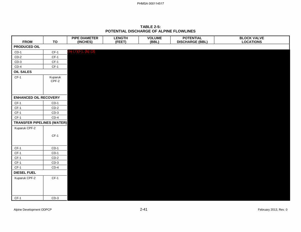
Alpine Development ODPCP 2-41 February 2013, Rev. 0
TABLE 2-5: POTENTIAL DISCHARGE OF ALPINE FLOWLINES
FROM TO PIPE DIAMETER
(INCHES) LENGTH (FEET)
VOLUME (BBL)
POTENTIAL DISCHARGE (BBL)
BLOCK VALVE LOCATIONS
PRODUCED OIL CD-1 CF-1 CD-2 CF-1 CD-3 CF-1 CD-4 CF-1
OIL SALES CF-1 Kuparuk
CPF-2
ENHANCED OIL RECOVERY CF-1 CD-1 CF-1 CD-2 CF-1 CD-3 CF-1 CD-4
TRANSFER PIPELINES (WATER)Kuparuk CPF-2
CF-1
CF-1 CD-1 CF-1 CD-1 CF-1 CD-2 CF-1 CD-3 CF-1 CD-4
DIESEL FUEL Kuparuk CPF-2 CF-1
CF-1 CD-3
PHMSA 000114517
(b) (7)(F), (b) (3)
Alpine Development ODPCP 2-42 February 2013, Rev. 0
2.4 CONDITIONS INCREASING RISK OF DISCHARGE [18 AAC 75.425(e)(2)(D)]
Conditions specific to CPAI's North Slope operations that potentially increase the risk of discharge, and actions taken to eliminate or minimize identified risks, are summarized below:
• Temperature: Heat may cause gases to expand, increasing the likelihood of discharge. North Slope facilities are engineered to accommodate temperature fluctuations.
• Weather Conditions: Icy roads, white-out conditions, and cold snaps present obvious threats to field operations. CPAI Security's strict adherence to vehicle safety, speed limits, and the posting of warning signs assist in minimizing the potential for vehicular accidents that may result in a spill. In addition, North Slope facilities are engineered to withstand Arctic conditions.
• Traffic Patterns: Changes in traffic patterns may increase the risk of vehicles colliding into well lines. CPAI Security's strict adherence to vehicle safety, speed limits, and the posting of warning signs or traffic cones will help to minimize the potential for vehicular accidents that may result in a spill.
• Unplanned Shutdown Trans-Alaska Pipeline System: If Alyeska Pipeline Service Company unexpectedly shuts down the Trans-Alaska Pipeline System, the risk to CPAI operations increases. CPAI's advanced communication system enables immediate communication between Alyeska Pipeline Service Company and the North Slope operators, which allows for the coordination of impacts and minimizes the risks due to a shutdown of the pipeline.
Conditions specific to Alpine operations that potentially increase the risk of discharge, and actions taken to eliminate or minimize identified risks, are summarized below:
• Upheaval Buckling: Buried pipelines in the Arctic are installed at temperatures that are below their operating temperatures. Because buried pipelines are restrained during thermal expansion, significant compressive force develops in pipelines that increase from their installed temperature to their operating temperature. This compressive force may cause upheaval buckling (vertical buckling displacement of a pipeline due to low lateral stability provided by the pipeline’s overlying soil). The cross-country pipelines buried at the Colville River crossing are located at sufficient depth to avoid upheaval buckling.
• High Water/Ice: High water and/or ice during spring break-up could increase the risk of discharge from pipeline crossings over rivers. To decrease risk of a discharge, pipeline crossings over rivers are built above flood levels and are engineered to withstand ice impact and jamming. The cross-country pipeline crossing at the Colville River is a below-river crossing; thus, it is not affected by high water or ice. High water could also increase the risk of discharge in locations where a large flood (200-year event) could threaten access to drill sites or in-field oil piping. In the event a large flood causes an emergency situation, to decrease risk of a discharge, Alpine Operations may initiate an emergency de-inventory of the affected pipelines. The emergency de-inventory would stop production and injection operations, and the affected pipelines would be emptied and depressurized.
PHMSA 000114518
Alpine Development ODPCP 2-43 February 2013, Rev. 0
• Permafrost Thaw Subsidence: The weight and heat from a buried operating pipeline causes some differential thaw subsidence at locations where permafrost soils exist. Permafrost soils are not found in the underground crossing area of the cross-country pipeline route.
• Roadless Areas: To decrease risk of discharge, automated process control equipment can be installed at wells and pipelines to allow continuous monitoring of production factors, such as wellhead temperature and pressure, annuli pressures, choke and valve positions, gas, and/or liquid level in the well cellar.
PHMSA 000114519
Alpine Development ODPCP 2-44 February 2013, Rev. 0
2.5 DISCHARGE DETECTION [18 AAC 75.425(e)(2)(E)]
2.5.1 Discharge Detection at Drill Sites
Routine tours of drill site facilities by Operations personnel can detect leaks or spills from the drill sites.
Production wells capable of unassisted flow are equipped with both surface and subsurface safety valves that are monitored and controlled by an automated system. The system is designed to shut in well production automatically when the pressure transmitter senses pressure below a specified set point. At CD-3, because it is remote, the wellheads are fully instrumented to allow continuous, remote monitoring of wellhead pressure and temperature, well annulus pressure (inner and outer annuli), and choke and valve positions. In addition, each well house at CD-3 is equipped with a gas detector and liquid level detector in the well cellar that ties in to the automated system.
2.5.2 Alpine Oil Pipeline Discharge Detection
The Alpine crude oil transmission pipeline (Alpine Oil Pipeline) is monitored for leaks using three different methods: 1) metered balancing, 2) computational pipeline monitoring, and 3) visual inspection.
PHMSA 000114520
(b) (3), (b) (7)(F)
Alpine Development ODPCP 2-45 February 2013, Rev. 0
Computational Pipeline Monitoring
Visual Inspection Leak Detection
The Alpine Oil Pipeline and Diesel Pipeline are aboveground pipelines supported by vertical support members, with the exception of the crossing at the Colville River. Weekly visual inspections (weather permitting) are made by aerial surveillance in accordance with 18 AAC 75.055(a)(3); a log is completed by surveillance personnel. For the sections of the pipelines located on the facility, daily inspections are performed as part of routine operations.
As an added measure of leak detection, aerial surveillance is conducted on a weekly schedule using the FLIR-equipped Twin Otter, weather and safety conditions permitting. FLIR surveillance schedules may be delayed due to emergency use of the FLIR in other locations, or mechanical failure or routine maintenance of the Twin Otter or FLIR. Therefore, CPAI relies upon weekly visual aerial surveillance to meet requirements of 18 AAC 75.055(a)(3).
If a minor leak is suspected, it is the responsibility of the Pipeline Controller or his designee to dispatch qualified personnel to visually check the line. Communications with the Pipeline Controller and facility operators is maintained so that appropriate action can be taken to mitigate a leak if discovered.
PHMSA 000114521
(b) (3), (b) (7)(F)
Leak Detection System Hardware
2.5.3 Discharge Detection at Alpine Facilities
The utility and process facilities are patrolled daily by Operations personnel. A logbook is kept for recording incidents and observations. Log sheets of process data taken at prescribed intervals are available for inspection. Personnel are on duty 24 hours a day. They are able to detect a significant spill and initiate the appropriate responses and additional containment procedures.
2.5.4 In-Field Pipelines Discharge Detection
PHMSA 000114522
(b) (7)(F), (b) (3)
(b) (7)(F), (b) (3)
Alpine Development ODPCP 2-47 February 2013, Rev. 0
2.5.5 Storage Tanks Discharge Detection
Alpine regulated storage tanks subject to 18 AAC 75 are elevated and located within lined secondary containment areas, some constructed with a sump. At a minimum, visual checks to detect leaks or spills below the tank in the containment area and/or sump occur daily at manned facilities, such as CD-1, or each time an unmanned facility, such as a satellite drill site, is visited as part of scheduled operational rounds. Inspection of secondary containment areas for ADEC-regulated oil storage tanks must occur at least once per month at unmanned drill sites without road access.
(b) (7)(F), (b) (3)
Alpine Development ODPCP 2-48 March 2013, Rev. 1
2.6 WAIVERS [18 AAC 75.425(e)(2)(F)]
Waivers follow this page, as described below:
• February 28, 2013. Tank Design Approval #2013-01, Revision 1.
• September 13, 2007. Waiver for Flow Line Marker Requirements.
• February 10, 2006. Waiver Request of Secondary Containment Area Capacity Requirements for Doyon Drill Rig 19 Fuel Tank.
• March 23, 2005. Waiver of Secondary Containment Area Capacity Requirements for Doyon Drill Rig 141 Fuel Tank.
• February 9, 2005. Waiver of Oil Storage Tank Construction Standards.
• October 7, 2004. Waiver of Cathodic Protection and Protective Wrapping/Coating Requirements for Underground Line (Tank CF-T-50090 to Module A2).
• February 26, 2003. Waiver of Oil Storage Tank Construction Standards.
• February 14, 2003. Waiver of Oil Storage Tank Construction Standards.
PHMSA 000114524
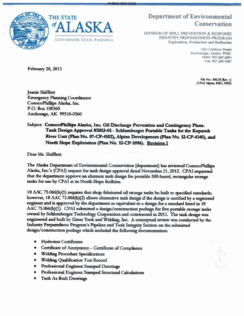
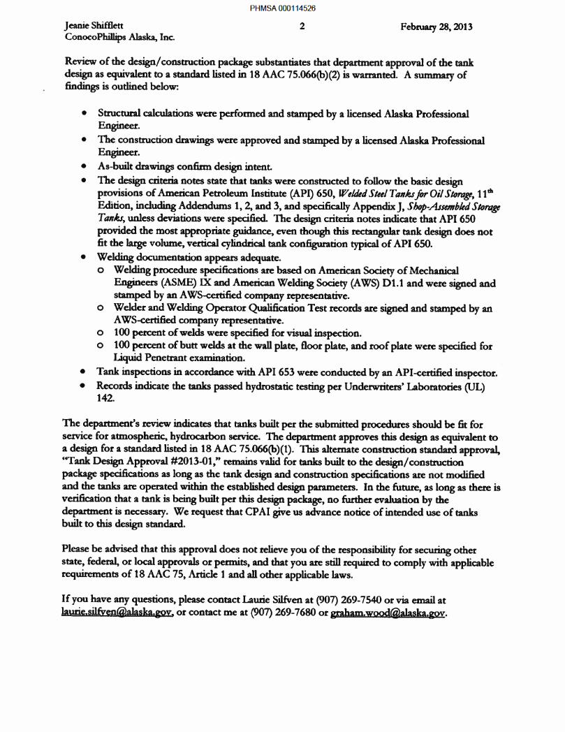

PHMSA 000114528
PHMSA 000114529
PHMSA 000114530
PHMSA 000114531
PHMSA 000114532
PHMSA 000114533
PHMSA 000114534
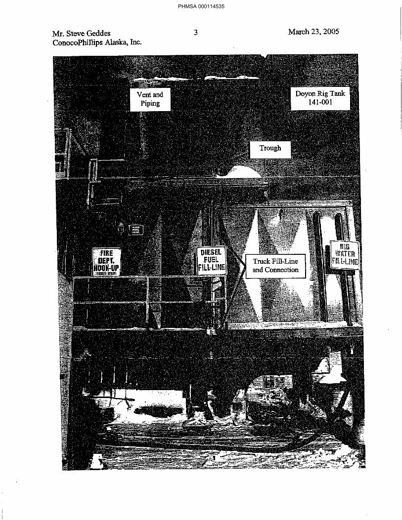
PHMSA 000114535

PHMSA 000114536
PHMSA 000114537
PHMSA 000114538
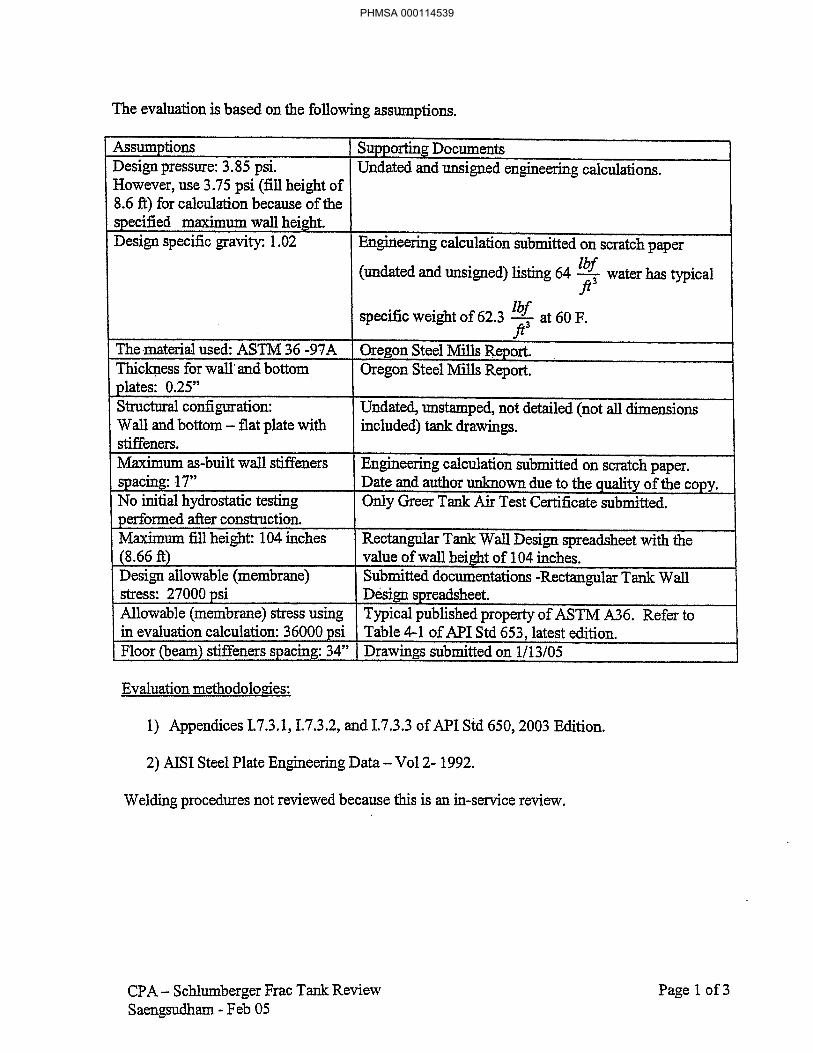
PHMSA 000114539
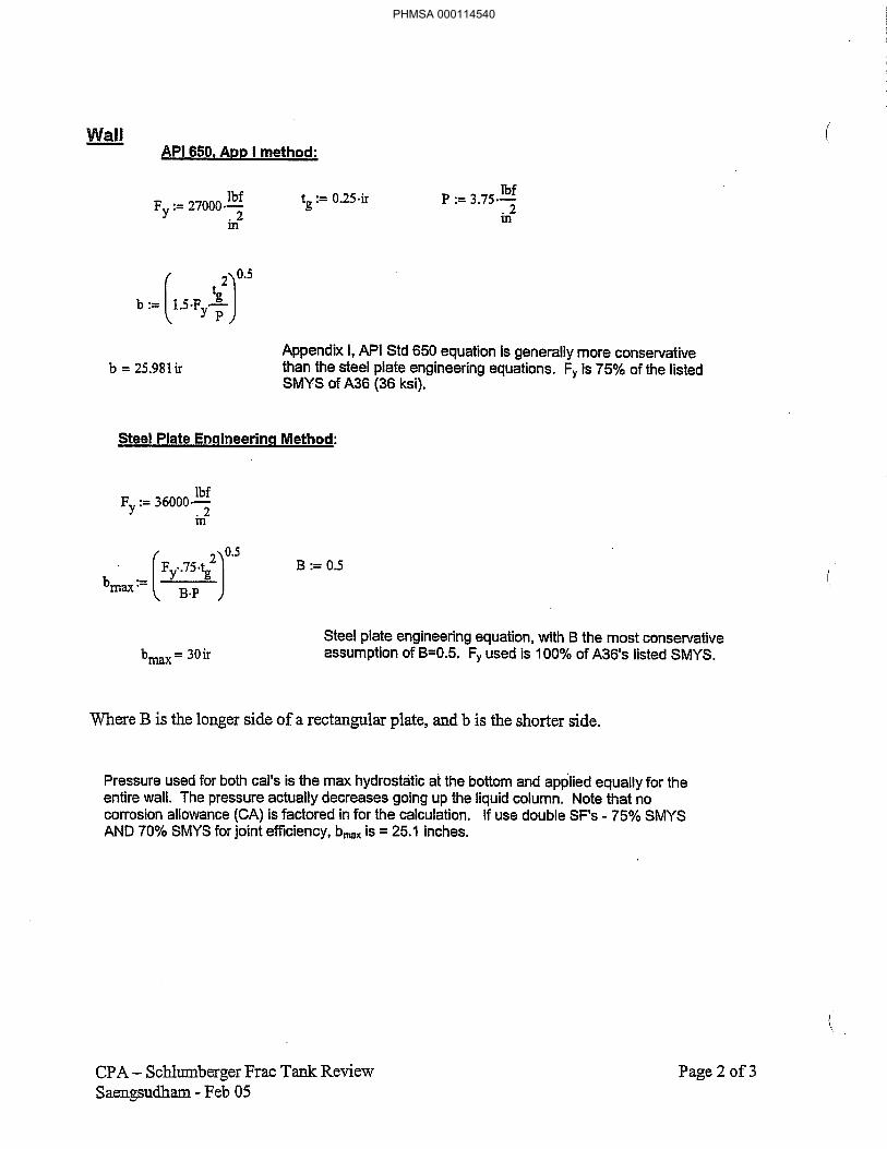
PHMSA 000114540
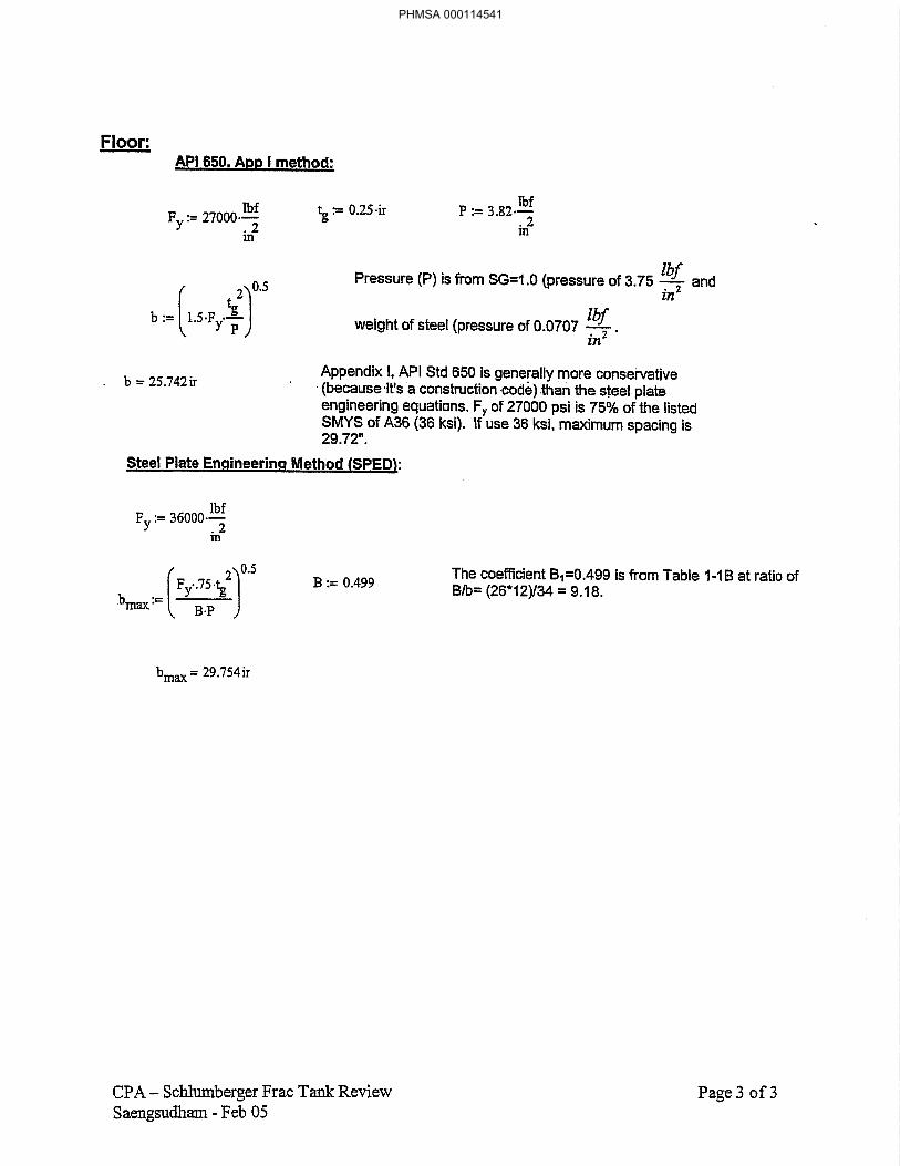
PHMSA 000114541

PHMSA 000114542
PHMSA 000114543
PHMSA 000114544
PHMSA 000114545
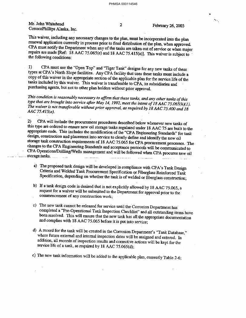
PHMSA 000114546
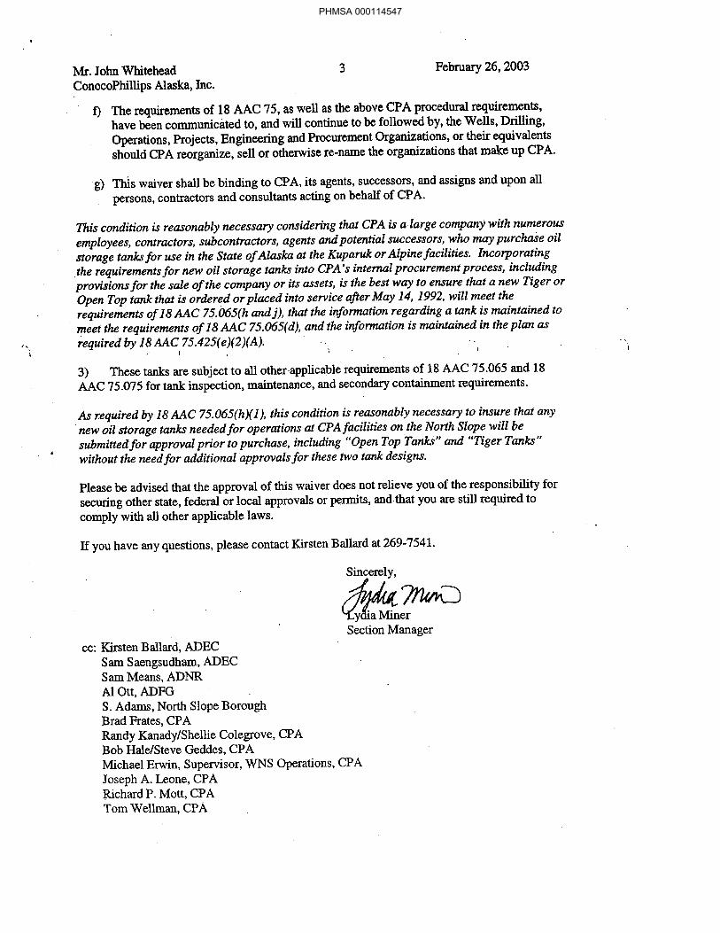
PHMSA 000114547

PHMSA 000114548
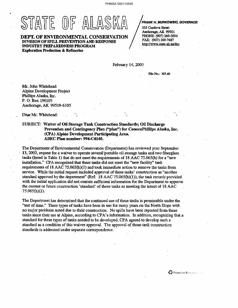
PHMSA 000114549
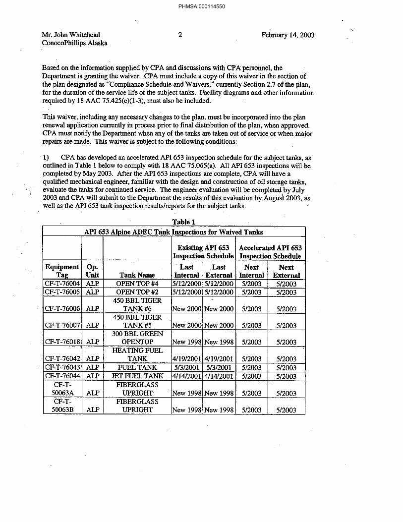
PHMSA 000114550
PHMSA 000114551
PHMSA 000114552
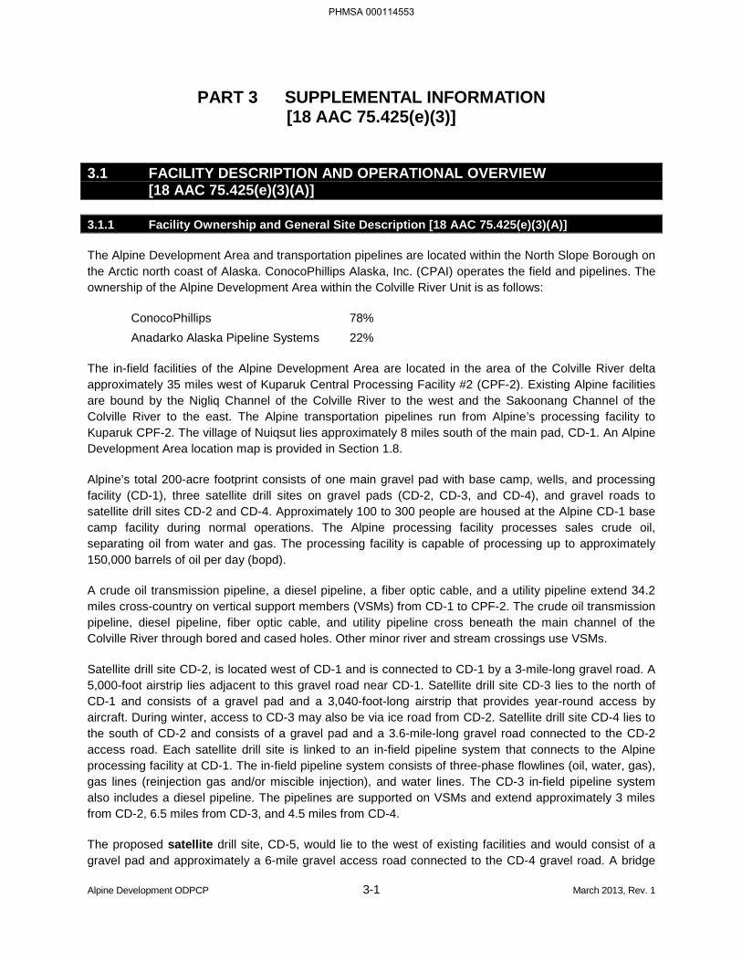
Alpine Development ODPCP 3-1 March 2013, Rev. 1
PART 3 SUPPLEMENTAL INFORMATION [18 AAC 75.425(e)(3)]
3.1 FACILITY DESCRIPTION AND OPERATIONAL OVERVIEW [18 AAC 75.425(e)(3)(A)]
3.1.1 Facility Ownership and General Site Description [18 AAC 75.425(e)(3)(A)]
The Alpine Development Area and transportation pipelines are located within the North Slope Borough on the Arctic north coast of Alaska. ConocoPhillips Alaska, Inc. (CPAI) operates the field and pipelines. The ownership of the Alpine Development Area within the Colville River Unit is as follows:
ConocoPhillips 78% Anadarko Alaska Pipeline Systems 22%
The in-field facilities of the Alpine Development Area are located in the area of the Colville River delta approximately 35 miles west of Kuparuk Central Processing Facility #2 (CPF-2). Existing Alpine facilities are bound by the Nigliq Channel of the Colville River to the west and the Sakoonang Channel of the Colville River to the east. The Alpine transportation pipelines run from Alpine’s processing facility to Kuparuk CPF-2. The village of Nuiqsut lies approximately 8 miles south of the main pad, CD-1. An Alpine Development Area location map is provided in Section 1.8.
Alpine’s total 200-acre footprint consists of one main gravel pad with base camp, wells, and processing facility (CD-1), three satellite drill sites on gravel pads (CD-2, CD-3, and CD-4), and gravel roads to satellite drill sites CD-2 and CD-4. Approximately 100 to 300 people are housed at the Alpine CD-1 base camp facility during normal operations. The Alpine processing facility processes sales crude oil, separating oil from water and gas. The processing facility is capable of processing up to approximately 150,000 barrels of oil per day (bopd).
A crude oil transmission pipeline, a diesel pipeline, a fiber optic cable, and a utility pipeline extend 34.2 miles cross-country on vertical support members (VSMs) from CD-1 to CPF-2. The crude oil transmission pipeline, diesel pipeline, fiber optic cable, and utility pipeline cross beneath the main channel of the Colville River through bored and cased holes. Other minor river and stream crossings use VSMs.
Satellite drill site CD-2, is located west of CD-1 and is connected to CD-1 by a 3-mile-long gravel road. A 5,000-foot airstrip lies adjacent to this gravel road near CD-1. Satellite drill site CD-3 lies to the north of CD-1 and consists of a gravel pad and a 3,040-foot-long airstrip that provides year-round access by aircraft. During winter, access to CD-3 may also be via ice road from CD-2. Satellite drill site CD-4 lies to the south of CD-2 and consists of a gravel pad and a 3.6-mile-long gravel road connected to the CD-2 access road. Each satellite drill site is linked to an in-field pipeline system that connects to the Alpine processing facility at CD-1. The in-field pipeline system consists of three-phase flowlines (oil, water, gas), gas lines (reinjection gas and/or miscible injection), and water lines. The CD-3 in-field pipeline system also includes a diesel pipeline. The pipelines are supported on VSMs and extend approximately 3 miles from CD-2, 6.5 miles from CD-3, and 4.5 miles from CD-4.
The proposed satellite drill site, CD-5, would lie to the west of existing facilities and would consist of a gravel pad and approximately a 6-mile gravel access road connected to the CD-4 gravel road. A bridge
PHMSA 000114553
Alpine Development ODPCP 3-2 February 2013, Rev. 0
over the Nigliq Channel would be constructed to allow vehicle and rig access to CD-5, and would carry in-field pipelines for CD-5.
Gravel Pads
The Alpine facility drill sites consist of gravel pads. The pads are, at a minimum, 5 feet above the surrounding tundra elevations. The shoulder elevations of the pads are at least 1 foot above the 200-year flood-event elevations. As a way to mitigate excessive storm water drainage, drainage basins are built into the CD-1 pad using slight gravel grading change to collect excess water. The drainage basins collect snow/ice melt and precipitation during break-up and summer, so it does not run off the pad. During this time, the drainage basins are visually checked as part of routine operations and are drained as necessary.
Waste Disposal and Water Use
Solid waste, oily waste, and sewage solids are incinerated at the site or transported to Kuparuk or Prudhoe Bay for disposal. Gray water is injected into a permitted Class 1 disposal well at CD-1. Drilling wastes are managed either by annular disposal into permitted wells at the drill site, or by transportation and injection into an approved Class 2 disposal well at CD-1. Non-combustible solid waste is transported to approved, off-site facilities for disposal.
During operations, fresh water is used at the facilities for maintenance drilling, potable water, firefighting, and dust suppression. A pump house is located at nearby lakes and is permitted to provide untreated water to CD-1, where it is processed before use. The water in the lakes is accessed by pipeline from CD-1. Additional lake water sources may be permitted and used during drilling operations.
3.1.2 Facility Oil Storage Containers [18 AAC 75.425(e)(3)(A)(i) and (ii)]
Table C-1 in Appendix C contains the number, type, and oil storage capacity of each container regulated by the Alaska Department of Environmental Conservation (ADEC) covered under this plan and its installation date, design, construction, and general condition. The type and amount of oil stored in each container is also listed. Information about containers regulated under spill prevention, control, and countermeasures (SPCC) criteria is provided in the Alpine SPCC Plan.
The majority of fuels and chemicals used at the satellite drill sites are stored and handled at CD-1. Fuel and other hydrocarbon-based materials stored at the drill sites are maintained within secondary containment according to state and federal regulations.
3.1.3 Transfer Procedures and Major Fueling Areas [18 AAC 75.425(e)(3)(A)(vi)]
Fuel or Chemical Transfer Operations
Fluid transfer personnel must follow established CPAI field-wide standard operating procedure (SOP) for conducting flammable and combustible fluid transfers. Refer to the current guidelines available on the CPAI Intranet for the field-wide SOP for fluid transfers and liner drip pan use for rolling stock and stationary equipment. Employees and contractors are required to follow CPAI’s fluid transfer procedures. Supervisors verify that employees have sufficient training or experience to conduct the operations, review procedures, and complete the checklist, if necessary.
PHMSA 000114554
Alpine Development ODPCP 3-3 February 2013, Rev. 0
CPAI employees and contractors must follow established CPAI safety procedures for conducting flammable and combustible fluid transfers. CPAI fluid transfer procedures and site-specific safety guidelines are reviewed, as necessary, during pre-job safety meetings. The safety meetings provide employees with information about their role in the overall scope of the work, review guidelines, and stress the importance of preventing and avoiding spills. All on-site flammable and combustible fluid transfers require the following:
• Adherence to the Alaska Safety Handbook “Flammable and Combustible Fluid Transfer Standard/Procedure” and/or the North Slope Environmental Field Handbook “Fluid Transfer Guidelines.”
• Personnel determine the amount to be transferred and inspect valves and/or hoses prior to and once during the transfer.
• Personnel reduce loading rates at the beginning and end of the transfer, position ignition sources away from the transfers, establish emergency exit paths and fire lanes at the site, establish the flash point and temperature of the fluid being transferred, follow specific bonding and grounding procedures, and have adequate fire suppression equipment available.
• Dry lock connectors are used on large fuel transfers, where practicable. For any flammable or combustible fluid transfer, attending personnel must know, understand, and communicate the emergency shutdown (ESD) procedures before the transfer begins.
• Aside from storage and staging of equipment, fuel and chemical transfers are not conducted within 100 feet of surface water, where practicable.
Before transfers begin, tank and container levels are checked by physically viewing the liquid level or are monitored by automated devices to prevent overfilling. Absorbents or catch basins are placed under connections and vents to contain potential leaks or drips.
An operator monitors all transfers throughout the entire operation, maintaining a constant line of sight to the transfer. Transfer operations are not left unattended. For transfers requiring two persons, the equipment operator and observer maintain constant communication by voice, radio, or hand signals. Tank levels, containment, absorbents, and piping are inspected after each transfer for signs of fuel or chemical loss, leakage, or failure.
Blinding of facility piping, tanks, and vessels is in accordance with the Alaska Safety Handbook. Blind checklists are maintained at the facility to track and advise personnel of any device or line that has been placed out of service.
Transfer from Fueling Truck to Equipment
During drilling activities and production operations, a tanker truck is used to refuel equipment. These transfer operations are conducted with the fueling truck driver in constant attendance. All fueling-hose transfer connections have a drip pan. The fueling truck also carries absorbents, waste containers, and tools to contain and clean up minor drips and spills. If necessary, the fueling truck is chocked to prevent vehicle movement during the transfer.
PHMSA 000114555
Alpine Development ODPCP 3-4 February 2013, Rev. 0
3.1.4 Pipelines and Processing Facilities [18 AAC 75.425(e)(3)(A)(vii)]
Pipelines
Flowlines
Flowlines connect the drill sites to the Alpine processing facility. The separate three-phase, gas and utility pipelines (in-field pipelines) required for CD-1 to CD-2 operations cross underneath the gravel road near the west end of the airstrip at CD-1, then run on the north side of the road to CD-2. The road provides surveillance and flood protection for the pipeline. The in-field pipelines for CD-1 and CD-2 include two 8-inch diameter lines (gas and seawater) and one 20-inch diameter, three-phase line. With the exception of the small road crossing, the CD-1 and CD-2 in-field pipelines are supported on VSMs at least 5 feet above the tundra, with 50- to 65-foot spacing for approximately 3 miles. The pipelines connecting satellite drill sites consist of three-phase gas lift and/or miscible injection, water lines, and a diesel pipeline between CD-1 and CD-3. The pipeline corridor extends approximately 6.5 miles to CD-3 and 4.5 miles to CD-4. Flowlines are illustrated in the Alaska Clean Seas (ACS) Technical Manual Map Atlas Sheet 20 and facility diagrams in Section 1.8.
Pipeline elevation breaks created by raised sections of the pipeline at channel crossings aid in reducing spill volume, because the elevation breaks would trap liquids in the damaged pipeline away from the rupture.
Facility Piping
Facility piping connects the wellhead to the flowline.
Crude Oil Transmission Pipeline
The 34.2-mile crude oil transmission pipeline is constructed of steel, covered with insulation, and has a nominal diameter of 14 inches. The pipeline is designed to U.S. Department of Transportation (DOT) standards for crude oil pipelines. The pipeline is cased within a carrier pipe where it crosses underneath the Colville River. Both the carrier pipe and the casing are fusion bonded epoxy coated and the annulus is equipped with leak detection. Detailed plans have been approved by the State Joint Pipeline Office via issuance of a pipeline right of way.`
The insulated pipeline transports hot crude oil with a maximum design temperature of 180 degrees Fahrenheit (°F). The pipeline is elevated on VSMs. A minimum height of 5 feet is maintained for the entire length of the crude oil transmission pipeline. To further enhance caribou and human crossings, selected portions of the elevated pipeline exceed the 5-foot minimum (7 to 8 feet average) near streams and lake complexes where caribou and human use is high.
The pipeline crosses three rivers, two of which are aboveground crossings, and the Colville River crossing, which is the only underground portion of the pipeline. River bank setbacks of approximately 300 feet were established for bored-hole entry and exit locations at the Colville River crossing. Horizontal directional drilling (HDD) was used to bore the crossing underneath the Colville River. These setbacks enhance caribou and human use crossings and achieve channel-migration setback allowances. The pipeline at this location is externally coated, while the aboveground portion is uncoated steel pipe, insulated with polyurethane and protected with a metal jacket.
PHMSA 000114556
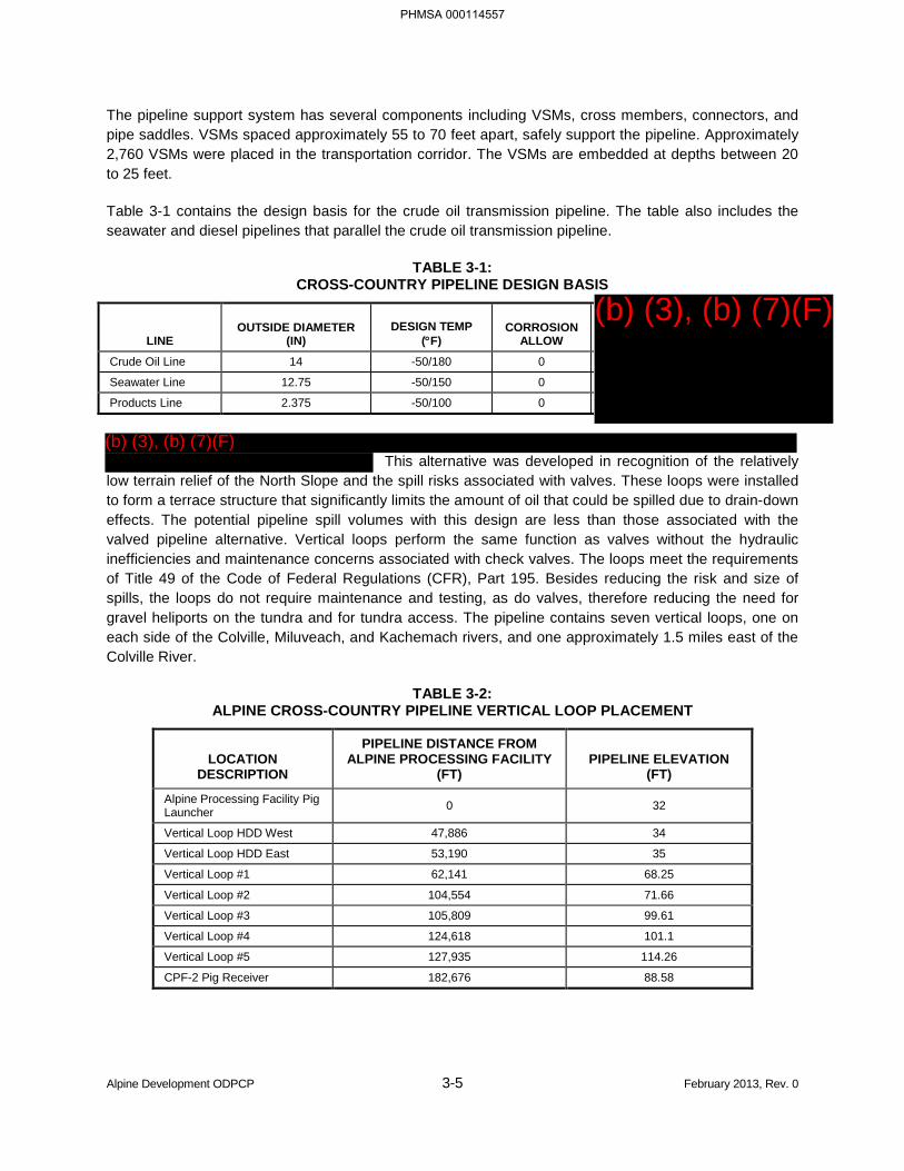
Alpine Development ODPCP 3-5 February 2013, Rev. 0
The pipeline support system has several components including VSMs, cross members, connectors, and pipe saddles. VSMs spaced approximately 55 to 70 feet apart, safely support the pipeline. Approximately 2,760 VSMs were placed in the transportation corridor. The VSMs are embedded at depths between 20 to 25 feet.
Table 3-1 contains the design basis for the crude oil transmission pipeline. The table also includes the seawater and diesel pipelines that parallel the crude oil transmission pipeline.
TABLE 3-1: CROSS-COUNTRY PIPELINE DESIGN BASIS
LINE OUTSIDE DIAMETER
(IN) DESIGN TEMP
(°F) CORROSION
ALLOW
Crude Oil Line 14 -50/180 0
Seawater Line 12.75 -50/150 0
Products Line 2.375 -50/100 0
This alternative was developed in recognition of the relatively
low terrain relief of the North Slope and the spill risks associated with valves. These loops were installed to form a terrace structure that significantly limits the amount of oil that could be spilled due to drain-down effects. The potential pipeline spill volumes with this design are less than those associated with the valved pipeline alternative. Vertical loops perform the same function as valves without the hydraulic inefficiencies and maintenance concerns associated with check valves. The loops meet the requirements of Title 49 of the Code of Federal Regulations (CFR), Part 195. Besides reducing the risk and size of spills, the loops do not require maintenance and testing, as do valves, therefore reducing the need for gravel heliports on the tundra and for tundra access. The pipeline contains seven vertical loops, one on each side of the Colville, Miluveach, and Kachemach rivers, and one approximately 1.5 miles east of the Colville River.
TABLE 3-2: ALPINE CROSS-COUNTRY PIPELINE VERTICAL LOOP PLACEMENT
LOCATION DESCRIPTION
PIPELINE DISTANCE FROM ALPINE PROCESSING FACILITY
(FT) PIPELINE ELEVATION
(FT)
Alpine Processing Facility Pig Launcher 0 32
Vertical Loop HDD West 47,886 34
Vertical Loop HDD East 53,190 35
Vertical Loop #1 62,141 68.25
Vertical Loop #2 104,554 71.66
Vertical Loop #3 105,809 99.61
Vertical Loop #4 124,618 101.1
Vertical Loop #5 127,935 114.26
CPF-2 Pig Receiver 182,676 88.58
PHMSA 000114557
(b) (3), (b) (7)(F)
(b) (3), (b) (7)(F)
Alpine Development ODPCP 3-6 February 2013, Rev. 0
Process Facilities
The oil processing facility is designed as a feed-forward operation. The production components are progressively separated by flowing through the inlet separator, the low pressure separator, and the dehydrator prior to the sales quality oil entering the Alpine crude oil transmission pipeline via the crude-oil shipping pumps.
Most of the natural gas liquid knocked out of the gas in the compressor aerial coolers is re-injected. Some natural gas liquids are passed back into the inlet separator. Produced gas, along with formation fluids and solids, are removed from the liquid stream in this vessel.
Control Strategy
The oil separation operation receives crude oil from the CD-1 and satellite drill sites. Through heating and gravity segregation, the gas is separated from the liquids. Gas is sent to the gas compression unit for compression to re-injection pressures. Oil is separated from water by settling and electrical coalescing. Gas condensate, which drops out of the gas in the compression stages, is blended with sales crude or with the gas for use in the MI system.
The primary objective of this process operation is to reduce the maximum water content of the oil to less than 0.35 percent by volume to meet final product specifications.
Water content of the oil prior to metering is measured, and alarms note when the results are outside specified ranges. There is no automatic control of water content. Water content is affected by the Alpine processing facility oil throughput, the fluids temperature in the production vessels, the effectiveness of the low pressure separator, and the effectiveness of the dehydrator. Recycling of off-specification oil to the off-spec/slop tank and/or the inlet separator is an operator-initiated action. Due to the off-spec tank’s small size, production diversion to the slop oil tank for special treatment is limited.
Inlet Crude Oil
Produced fluids from satellite drill sites are transferred via pipeline to the Alpine processing facility and mixed with the fluids from CD-1. CD-1 production wells are located adjacent to the Alpine processing facility, and the CD-1 well-test separator is located in the Alpine processing facility. The test/start-up separator is also used as the source of start-up fuel gas for the plant and for diversion of injection water/auxiliary fuel gas from Kuparuk. Except during the diversion of start-up fuel gas and injection water/auxiliary fuel gas, the test/start-up separator fluids are added back into the CD-1 and satellite drill site production fluid stream. The combined drill site fluid streams enter the Alpine processing facility at 90°F to 110°F. Flow into the Alpine processing facility is controlled by the choke valves for each producing well.
Outlet Oil
The crude cooler pre-heats the incoming production by cross-exchanging heat and subsequently cooling the sales crude oil to a range of 145°F to 150°F before going through a series of trim coolers for additional sales crude oil cooling to 115°F to 125°F depending on the time of year. In order to avoid permafrost damage at the river crossings, the maximum Alpine processing facility outlet temperature is 180°F. The crude contains 2.8 percent wax by weight (116°F wax melt-point and +5°F crude pour-point).
PHMSA 000114558
Alpine Development ODPCP 3-7 February 2013, Rev. 0
There are also minimum flow and temperature requirements for the crude oil transmission pipeline to avoid coagulation of the oil at low ambient temperatures. Falling oil temperature in the winter could result in highly viscous oil, increasing the flowing pressure drop in the pipeline and restricting throughput. Winter crude oil temperatures must exceed 116°F in order to minimize pigging, while summer temperatures are limited to the maximum specified temperature of 142°F.
A
The pipeline system is limited by the 2,100-psig pressure limit of the pipeline between Alpine and Kuparuk. Normal plant outlet oil pressure is 1,870 psig. The maximum sulfur/hydrogen sulfide content of the export oil is 50 parts per million by weight.
The minimum allowable flow rate conditions during -50°F weather for the line to Kuparuk are as follows:
• Pipeline Inlet Temperature, 180°F
• Pipeline Outlet Temperature, 100°F
Water/Gas Re-injection and Produced Water
Imported seawater and formation produced water is alternately injected with gas into the formation to enhance oil recovery. This process is referred to as miscible water-alternating-gas injection. Seawater comes from CPF-2 through the cross-country seawater (utility) pipeline.
The design-plant outlet-gas injection temperature is 205°F, with maximum wellhead injection temperature of 180°F. The facility is designed with an injection/lift gas design rate of 180 million standard cubic feet per day.
Electrical Power
PHMSA 000114559
(b) (3), (b) (7)(F)
(b) (3), (b) (7)(F)
(b) (3), (b) (7)(F)
(b) (3), (b) (7)(F)

Alpine Development ODPCP 3-8 February 2013, Rev. 0
larger primary units. Uninterruptible power supply systems provide power to the control systems and switchgear.
Lighting of Facilities
The lighting for Alpine facilities is designed to direct light to the local area. Lighting is required for safe operations and security while minimizing misdirected lighting glare to the surrounding landscape.
Remote Electrical-Instrument Module
PHMSA 000114560
(b) (3), (b) (7)(F)
(b) (3), (b) (7)(F)
(b) (3), (b) (7)(F)

Alpine Development ODPCP 3-9 February 2013, Rev. 0
PHMSA 000114561
(b) (3), (b) (7)(F)
Alpine Development ODPCP 3-10 February 2013, Rev. 0
Facility Human Machine Interface
3.1.5 Crude Oil and Reservoir Characteristics
The Alpine Development Area accesses several oil pools within the Colville River Unit. The Alpine oil pool was the first commercial discovery and development in the area, followed by satellite oil pools Fjord, Nanuq, and Qannik. The Alpine oil pool includes the Alpine Sands and Nanuq-Kuparuk reservoir which lie at approximately 7,000 feet below ground surface. The producing formation varies in thickness between 20 feet and 100 feet and has an oil gravity of 40 to 41 degrees gravity American Petroleum Institute (API). The Fjord oil pool consists of two major sand formations and an intervening, non-reservoir quality shale-sand wedge. The Fjord oil pool lies at approximately 7,100 feet below ground surface; oil gravity ranges from 28.6 to 31.3 degrees API. The Nanuq oil pool consists of an interval of sandstone, siltstone, and shale about 35 feet thick at approximately 6,500 feet below ground surface. Nanuq has an oil gravity
PHMSA 000114562
(b) (7)(F), (b) (3)
(b) (3), (b) (7)(F)
(b) (3), (b) (7)(F)
Alpine Development ODPCP 3-11 February 2013, Rev. 0
ranging from 39 to 42 degrees API. The Qannik oil pool consists of thin deposits of fine-grained sandstone present in intervals averaging 10 to 15 feet thick at approximately 6,100 feet below ground surface. Qannik has an oil gravity ranging from 27 to 32 degrees API.
Gas re-injection has been utilized since start-up to maintain reservoir pressure and improve recovery. The Alpine Development Area reservoir-depletion plan calls for importing up to approximately 150,000 barrels of water per day from the seawater line during the peak injection period.
An estimated maximum of approximately 150,000 barrels per day of crude oil will be produced during peak production. The estimated life of the field is 35 years, with production dropping significantly after 15 years.
Based on CPAI’s Alaska North Slope experience, the laboratory analysis of reservoir fluids was deemed insufficient in its characterization of the light ends and water content. Flowing characteristics of existing wells and the results of the reservoir models run for the Alpine resource indicate more gas and dissolved water in the reservoir fluid. This analysis insufficiency has been attributed to:
• A relatively small sample taken from a specific location in a relatively large pool of fluid,
• Oil weathering,
• Reporting of sample on a dry basis, or
• Possible sampling errors at the rig site.
Table 3-3 shows the composition of the fluids used to provide a “recombination” for facilities design.
TABLE 3-3: COMPOSITION OF ALPINE CRUDE
COMPONENT MOLE % Hydrogen 0
Hydrogen sulfide 0
Carbon dioxide 0.31
Nitrogen 0.28
Methane 37.39
Ethane 6.36
Propane 8.49
iso-butane 1.55
N-butane 3.96
iso-pentane 1.19
N-pentane 2.75
Hexanes 3.35
Heptanes plus 33.77
Note: Heptanes plus molecular weight and density are measured values. Heptanes plus molecular weight has been corrected for benzene content. Composition has been adjusted for hexanes, minus content identified in distillation residue.
Sample density (50oF): 0.72 Average molecular weight: 92.7
PHMSA 000114563
Alpine Development ODPCP 3-12 February 2013, Rev. 0
3.2 RECEIVING ENVIRONMENT [18 AAC 75.425(e)(3)(B)]
The receiving environment for Alpine consists of a man-made gravel pad situated in the Colville River delta. Large spills occurring at Alpine, particularly well blowouts and pipeline ruptures, are unlikely but have the potential of reaching tundra, open water, and/or ice.
Nuiqsut
The Native village of Nuiqsut is located near the main channel of the Colville River, approximately 8 miles south of the Alpine Development Area. The population measured in the 2009 consensus was 379 residents. Nuiqsut provides modern amenities such as governance, infrastructure, schools, and an airport. The proximity of Nuiqsut would require close monitoring of meteorological conditions and communication and consultation with Nuiqsut representatives concerning how best to mitigate potential health effects on the community. In addition, subsistence hunting and gathering is viewed as an essential part of the culture and community and requires protection of the natural environment and its subsistence resources.
Vegetation
The vegetation of the Alpine area reflects the severe climatic conditions of the Arctic Coastal Plain and the dynamic stream channel configurations of the Alpine area. On the delta, abandoned and active stream channels have exposed extensive mud flats. Along the coast, mud flats, sand beaches, and slumping peat bluffs add to the diversity of landforms. Inland, a more usual contingent of landforms is found, including flooded tundra, high- and low-centered polygons, and deep and shallow open lakes. Although the dominant species of vegetation in the area are associated with water-saturated soils, plants characteristic of dry areas are also present.
Wetlands
The main portion of the Colville River Unit includes the Colville River delta, Harrison Bay, and its surrounding brackish and freshwater wetlands. These wetlands are composed of a variety of habitat types that support a diverse bird community during the summer. Shore birds and waterfowl typically are most abundant. Several mammals also inhabit the area, with caribou and arctic fox most prevalent.
Harrison Bay is a relatively shallow water body with variable temperature and salinity characteristics. It supports populations of marine and anadromous fish, benthos, and marine mammals. Seals, particularly ringed seals, are the most commonly sighted marine mammal within the bay.
Soils and Landforms
The soils of the coastal lowlands are generally marine, glacial, or alluvial. A layer of unconsolidated silt, sand, and gravel, as much as 200 feet thick, covers the Arctic Coastal Plain, the largest coastal lowland deposit in Alaska. Permafrost is continuous throughout the plain and usually extends through the layer of unconsolidated sediments into bedrock. Unfrozen areas exist at perennial springs and beneath major streams. The Colville River has a thawed area beneath its bed several hundred feet thick that may perforate the permafrost in places. This does not occur at shallower, braided streams. Poor drainage due to shallow permafrost and fine, low-permeability soils contribute to numerous thaw lakes typical of this area.
PHMSA 000114564
Alpine Development ODPCP 3-13 February 2013, Rev. 0
The Alpine area is characterized by low relief with mud flats, sand dunes, and ice-rich tundra bluffs along the coastline. From sea level, the land slopes upward to a maximum elevation of 30 feet near the runway at CD-1. Microrelief in the area is provided by polygon rims, pingos, frost boils, and sand dunes.
Climatology
The Arctic climatic zone is bordered on the north by the Arctic Ocean and on the south by the Brooks Range, both of which influence the weather of the region. Meteorological data are sparse for the Arctic, with only nine weather stations providing data. Of these, seven are on the coast and two are inland. There is no weather observation station at the in-field facility location.
The climate of the region is characterized by generally low temperatures, small amounts of precipitation, moderate winds, considerable cloudiness, and frequent periods of fog.
The semi-permanent Aleutian low-pressure system, centered over the Aleutian Chain, and the polar high-pressure system play major roles in the Arctic weather. These systems determine the generally easterly winds that persist in the area, are responsible for the storm trajectories, and influence the precipitation patterns and atmospheric stability.
The warmest month of the short, cool Arctic summer is July; it is characterized by an average temperature in Barrow of about 40°F. In contrast, the coldest month is February, where in Barrow the average temperature is about -19°F. Extreme temperatures reach about 75°F in July and as low as -60°F in winter. At Prudhoe Bay, the average daily maximum temperature in July is 46°F; the average daily minimum in January is -20°F.
In the Arctic, wind chill temperature values are often more important than the ambient air temperature. Cold winter temperatures and strong winds produce chill temperatures that require extreme precaution before outdoor activity is undertaken. It is important that oil spill response personnel are adequately dressed for anticipated wind chill conditions.
The low annual precipitation of the Arctic Coastal Plain (5 inches at Oliktok) has given the name “polar desert” to the region. This name is in contrast to the existing summer conditions when the soils of the plains are saturated with water. There is an abundance of standing water in summer because of small moisture losses due to evaporation and the lack of underground aquifers due to the permafrost barrier.
The relative humidity of the Arctic atmosphere is generally high during the summer months, ranging from 90 to 95 percent at Barrow; during winter, it falls to about 60 percent. However, because of the low average temperatures, the absolute humidity is low for summer and winter.
Winds on the Arctic Coastal Plain are predominantly easterly, as a result of the proximity of the Aleutian low-pressure system and the polar high-pressure system. Because these two major pressure systems are semi-permanent in their location, the surface winds of the Arctic Coastal Plain are persistent and strong. A general yearly average for the coastal zone is 15 to 20 miles per hour at exposed locations.
In the Arctic, fog is occasionally present, particularly along the coast. Heavy fog is encountered about 72 days per year. Its occurrence increases significantly once open water appears in May or June and continues into early October.
PHMSA 000114565
Alpine Development ODPCP 3-14 February 2013, Rev. 0
The Arctic winter climate is characterized by frequent temperature inversions. These inversions often extend from the surface to 4,000 feet above ground. Their persistence depends on the existence of calm to light winds. During the summer, surface temperatures are warmer, resulting in fewer inversions.
Hydrology
The hydrologic environment of the Alpine Development Area is characterized by large flows of water during the snowmelt runoff period, reduced flows during the summer, and little or no flow in the winter. Groundwater resources are limited by the existence of permafrost. Annual precipitation is light, averaging less than 7 inches per year, much of this falling during the summer and fall. Despite the prevalence of streams, lakes, and wetlands, the area is characterized as semi-arid due to its low annual precipitation.
The Colville River is the largest freshwater surface resource in the development area, with a length of 370 miles and a drainage area of 20,920 square miles. Peak runoff and corresponding peak sediment load occur from late May through early July and are attributed to snowmelt and rainfall. A second peak, due primarily to rainfall, normally occurs in July or August. Summer flows are sustained by gradual snowmelt in the mountains. Winter flows decrease to very low values (0-1,000 cubic feet per second [cfs]).
The Colville River enters the delta north of the mouth of the Itkillik River, approximately 4 miles southeast of Nuiqsut. The delta is more than 25 miles long and covers about 250 square miles. Most of the water reaching the delta is carried to the ocean through two main channels: the East Channel and the Nigliq Channel. Approximately 80 percent of the discharge at the head of the delta flows in the East Channel and its distributaries, while the remaining 20 percent flows in the Nigliq Channel. Several distributaries branch from the East Channel, including the Sakoonang and Tamayayak channels. In general, the channels of the Colville River and its distributaries are broad and relatively shallow.
Spring break-up on the Colville River generally occurs before the break-up of coastal plain streams, such as the Kachemach and Miluveach rivers. The median date of peak break-up discharge is June 2 and the peak break-up discharge at the head of the delta averages 264,000 cfs (Ray and Aldrich, 1996). Typical summer flows at the head of the Colville River delta range between 20,000 and 80,000 cfs.
The Kachemach and Miluveach rivers, which drain the Arctic Coastal Plain east of the lower Colville River, are completely underlain by permafrost. The Kachemach River is approximately 35 miles long with a drainage area of 213 square miles. The Miluveach River is approximately 40 miles long and has a drainage area of 184 square miles. Both rivers flow into the East Channel of the Colville River.
Ponds and lakes are the most prevalent water bodies on the Colville River delta. Most of the ponds are located within low-centered ice-wedge polygons. Many of the ponds and lakes are shallow and freeze to the bottom in the winter. They are formed from thawing of ice-rich sediments during a “thaw-lake cycle” that includes thawing, expansion, drainage, ice aggradations, and eventual thawing again. Lakes of over 10 acres are numerous, covering 16 percent of the delta surface. These lakes are generally 11 to 15 feet deep but can be as deep as 28 feet. Because they have greater masses of ice and water to warm and melt at break-up, these lakes remain ice-covered into early July, much later than the smaller lakes.
Subpermafrost groundwater is often perennial, as with some springs found in the North Slope drainages. Springs are generally located in the mountain valleys, along a mountain front or in the foothills, with a few found in the Arctic Coastal Plain. Spring water quality is fresh to slightly mineralized. Eight springs, seven of which are on Sagavanirktok River tributaries, were reported to have temperatures in the range of 37°F to 48°F during a July survey. Aufeis formations are typically found downstream from the heads of these
PHMSA 000114566
Alpine Development ODPCP 3-15 February 2013, Rev. 0
springs. Because perennial springs often provide a winter water supply for fish, they are considered critical for fish populations. Subpermafrost sources other than springs are generally too saline or brackish to be considered for development as a water supply.
Nigliq Channel
The topography of the land immediately west of the Nigliq Channel, just outside the Colville River delta, slopes toward the channel. The gravel access road to CD-5 could be used for spill response access and staging, and containment and control points could be established at road-stream crossings. ACS Technical Manual, Volume 1, Tactics C-2 and C-3 describe culvert blocking techniques that could be employed to prevent oil from reaching the other side of the gravel road if a spill occurs from in-field piping. Additionally, boom is seasonally pre-staged at the Nigliq Channel as a preventative measure.
Oceanography
The general surface circulation of the Beaufort Sea is dominated by a clockwise gyre that produces offshore currents from the west. The average set is 1 to 2 nautical miles per day. In early 1960, Ice Island T-3 drifted at an average rate of 3 nautical miles per day in the southern Beaufort Sea. These prevailing currents move both water and ice shoreward throughout most of the year. In contrast, nearshore surface currents are variable and influenced by local winds. They might set in either an easterly or westerly direction, and are generally weak and unpredictable.
Seasonal freezing and melting and the freshwater input from large rivers are the major influences on the surface water characteristics of the Beaufort Sea. Salinity varies both geographically and seasonally, ranging from 29 to 36 parts per thousand. Temperature of seawater ranges from -1 degrees Celsius (°C) to -2.8°C under ice in winter, to just above freezing in summer.
Tides are small, about 1 foot in extreme. Associated tidal currents also are weak. All tidal phenomena are altered by ice coverage, especially shore-fast ice, with the time of the tide reduced and the range decreased. Nevertheless, Beaufort Sea tides have been known to form cracks in the shore-fast ice in mid- to late winter and to free seasonal shoreline ice.
Surface waves on the Beaufort Sea are restricted to summer periods when open water exists. During these periods, swells of 6 to 7 feet have been observed along the coast when the ice pack was far out to sea. Large waves are uncommon, probably because of the restricted area of fetch when open water exists.
Ice is present in the Beaufort Sea at least 9 or 10 months of the year and is an important factor in determining the dynamic events associated with the shoreline and coastal waters. Embayments, lagoons, and shore fringes are normally covered with fast ice during the long winter, as is the shoreline. As freezing begins in the fall, new ice forms along the coast and slowly builds seaward, often freezing to the bottom. This land-fast seasonal ice typically extends to the 5- to 10-fathom depth contour and can reach a thickness of 6 feet.
Farther out to sea lays the pack ice, consisting predominantly of multiyear flows from 6 to 12 feet thick. In summer, the pack ice is surrounded by open water and in winter, by first-year ice. Pack ice is constantly in motion, moving generally under the influence of the Arctic gyre. Ice islands such as T-3 are infrequently found within the pack ice. These islands originate from the Ellesmere Ice Shelf and can be quite large. During freeze-up, a shear zone of ice often produces open-water leads that freeze and form new
PHMSA 000114567
Alpine Development ODPCP 3-16 February 2013, Rev. 0
seasonal ice, which in turn can be deformed under pressure. Pressure ridges and ice hummocks are often created in this shear zone.
In summer, the land-fast ice melts and the pack ice retreats northward, leaving open water along the coast. However, during periods of northerly winds, the polar pack can be blown against the shoreline east of Point Barrow. The extent of ice cover varies greatly from year to year, with its distribution a function of meteorological conditions, currents, tides, and the topography of the sea floor.
The coastal zone of the operating area includes Harrison Bay and the growing delta of the Colville River. Offshore lies Thetis Island and numerous islands associated with the river delta. The shallow depth of Harrison Bay protects it from the dynamic ice activity that occasionally occurs along the coastline.
Limited work has been done on evaluating the nearshore patterns of the arctic coast. These currents influence sediment movement, beach movement, and the movement of possible pollutants. Measurements of the wind-driven currents in Simpson Lagoon, predominated by northwest and northeast wind patterns, showed nearshore transport of lagoon water to be pronounced. Current speeds of 0 to 3/4 knot were measured under wind regimes of 0 to 15 knots. These currents, being strongly influenced by local winds, are unsteady and because of the predominance of easterly winds, have an average drift to the west.
Coastal erosion is insignificant during the winter when the seas are frozen. However, during the summer, mechanical erosion of thawed beaches and thermal erosion of coastal banks causes the shoreline to recede inland at rates of as much as 30 feet per year. Also, severe storms with significant waves can bring about changes in local topography through erosion and deposition. Sediments enter the coastal waters of the Beaufort Sea, as a result of river flow during the summer and from the coastal erosion processes discussed earlier. This results in coastal-shelf bottom materials high in silts and sands and with lesser amounts of gravel.
Marine Water
Coastal waters of the Beaufort Sea are generally cold (30°F to 37°F) and saline (27 to 32 parts per thousand) for much of the year. During summer, the nearshore region is characterized by relatively warm (41°F to 50°F), turbid, and often brackish water. Turbidity from the Colville River during the annual June flood, together with other factors, blocks light and measurably reduces the phytoplankton productivity of inshore waters.
Due to little or no industrial activity in the area, most contaminants are at low levels in the Beaufort Sea. However, turbidity, trace metals, and hydrocarbons are introduced into the marine environment through river runoff, coastal erosion, atmospheric deposition, and natural seeps. Marine sediment data indicate historical water quality conditions. Steinhauer and Boehm (1992) identified the Colville River as the source for high concentrations of saturated hydrocarbons in Harrison Bay, relative to other areas of the Beaufort Sea, and for the higher year-to-year variability in total saturated hydrocarbon concentrations observed in regional sediments. This organic matter includes fractions derived from coal, oil, and peat in the river’s watershed. Additional sources include natural petroleum seeps and erosion of shoreline peat.
Ecology
The project area contains a diverse array of habitats used by wildlife for feeding, breeding, and shelter. The habitats also provide other important ecological functions. Wetlands are particularly important
PHMSA 000114568
Alpine Development ODPCP 3-17 February 2013, Rev. 0
because of their influence on surface and ground water hydrology, water quality, bird nesting and feeding, and fish production. Estuarine wetlands produce nutrients that are exported to marine and river systems where they provide for a wide variety of plants and animals. River channels serve as transportation corridors for hunting, fishing, and recreation. The habitat types in the project area constitute a complex mosaic of biological communities that support a rich diversity of plant and animal resources.
The vegetation at the Alpine Development Area reflects the climatic and topographic features of the area. Many shallow ponds have formed in the low-lying areas, while peat ridges and polygonal features related to frost action and ice wedges provide slightly higher, better-drained soils. Few woody plants are present, but those that do are found on drier sites where the microrelief raises them above the standing-water table. The most abundant and widespread habitat classes in the project area are wet and moist tundra. The most prominent habitat types in these classes are Wet Sedge-Willow Meadow on the delta and Moist Sedge-Shrub Meadow and Moist Tussock Tundra in the transportation corridor. Other prominent habitat classes on the delta include estuarine, river/stream, barrens, and lake/pond.
The Colville River delta is regionally important to birds and mammals. The Colville River delta is the largest and most complex river delta on the Arctic Coastal Plain of Alaska. It provides high-quality breeding habitats for water birds such as the spectacled eider, brant, tundra swan, and yellow-billed loon, as well as other water birds, shorebirds, songbirds, and predatory birds. The delta supports 29 species of water birds including 16 species that breed there. The Colville River delta provides some of the earliest open-water and snow-free areas for migrating birds during spring. The extensive salt marshes and mudflats on the delta are used by geese and shorebirds as staging areas during fall migration and by many other birds during spring and summer. Few species inhabit the area year-round.
The U.S. Fish and Wildlife Service (USFWS) has listed the spectacled eider as a threatened species throughout its range since 1993. Biologists have reported nests and broods in several areas on the Colville River delta. Most nests lie outside of areas that might be affected by spills. Guidelines for activities within the breeding range of spectacled eiders are as follows:
• Assess whether spectacled eiders are likely to use the project area for nesting or brood-rearing. Contact the USFWS for assistance. For projects conducted during the breeding season, a Service-approved survey for spectacled eiders should be conducted in the year of construction, prior to initiation of activities.
• If spectacled eider nests are in the project area, the following activities require special permits within 200 meters of nest sites:
− Vehicle and foot traffic from May 20 through August 1, except on existing roads.
− Construction of permanent facilities, placement of fill, or alteration of habitat.
− Introduction of high noise levels from May 20 through August 1, including but not limited to noise from airports, blasting, and compressor stations.
• Eiders are present on breeding grounds from mid-May through mid-September, but activities at any time of year may affect them through habitat modification.
Spill responders follow advisories from the Environment Unit Leader and the Wildlife Leader in the Incident Command System regarding protection of spectacled eiders. The Wildlife Leader may contact the USFWS at the species’ lead office (Anchorage, Field Office, Western Alaska Ecological Services) at (907) 271-2888, and the project review office (northern Alaska, Fairbanks, Field Office, Northern Alaska Ecological Services) at (907) 456-0203.
PHMSA 000114569
Alpine Development ODPCP 3-18 February 2013, Rev. 0
The delta is also used seasonally by caribou for foraging and insect relief habitat and by foxes and polar bears for denning habitat. Many of these wildlife resources are hunted by local residents as an essential element of their subsistence lifestyle.
The marine waters of the Beaufort Sea, off the Colville River delta, provide habitat for bowhead and beluga whales; ringed, spotted, hooded, and bearded seals; and walruses. The beluga whale is the most abundant in northern Alaska and is an important subsistence resource for coastal residents. The ringed seal is a year-round resident and is the most abundant seal species in the Beaufort Sea.
The fish resource is composed of three major groups of fish; marine, anadromous, and freshwater. Freshwater species such as arctic grayling, burbot, and nine-spine stickleback typically reside within the confines of fresh or slightly brackish water and are generally restricted to the rivers and small streams that flow into the Beaufort Sea.
Anadromous species (arctic char, chum salmon, least cisco, arctic cisco, broad whitefish, and humpback whitefish) over-winter and spawn in the fresh water of larger rivers such as the Sagavanirktok and Colville rivers (Morrow, 1980), but tend to spend the summer in nearshore marine waters, often undergoing extensive coastal migrations. Pink salmon that spawn in the Colville River are also present in the nearshore coastal waters during the juvenile out-migration and adult return migration.
Marine species such as arctic cod, four-horn sculpin, and snailfish complete their entire life cycle within the marine and coastal waters of the Beaufort Sea. Occasionally, a euryhaline species (tolerant of wide salinity ranges), such as four-horn sculpin, might intrude a few miles up into a stream or river discharging into the Beaufort Sea, but all key stages within the life cycle (such as spawning, nursery, and over-wintering functions) occur within the marine and nearshore brackish water environments.
3.2.1 Routes of Travel to Open Water [18 AAC 75.425(e)(3)(B)(i)]
The ACS Technical Manual Map Atlas Sheets 7 through 29 and 53 contain potential containment sites and features including sensitive receiving environments and information on potential routes of discharge.
The Alpine Development Area encompasses portions of the Colville River delta and surrounding terrestrial environments. The marine environment adjacent to the delta could also be affected by spills from the development. The Colville is the largest river in the United States’ portion of the North Slope. This river has a major influence on local marine and terrestrial environments. At the mouth, the river forms a delta containing two major channels and several minor distributaries.
A spill on an Alpine facility pad will remain on the pad, unless the spill is near the pad edge or exceeds the retention capacity of the pad. Fuel transfers are not allowed near pad edges in order to mitigate this risk.
A spill from the cross-country transportation pipelines or the in-field flowlines will reach the tundra environment and has the potential to reach fresh-water environments. A spill from the cross-country transportation pipelines will not reach the Colville River, because of the vertical loops and the HDD-buried crossing. A spill from the cross-country transportation pipelines could reach other bodies of freshwater including the Kachemach River and the Miluveach River. A spill from in-field flowlines has the potential to reach open waters of nearby freshwater lakes, river channels, and the open marine waters of Harrison Bay. A spill from in-field flowlines over the Nigliq Channel would reach the channel and has the potential
PHMSA 000114570
Alpine Development ODPCP 3-19 February 2013, Rev. 0
to reach Harrison Bay if not swiftly contained. However, a spill from the in-field flowlines is not likely to reach the main channel of the Colville River.
In the unlikely event of an oil well blowout at Alpine, there is the potential for oil to reach open waters of nearby freshwater lakes, channels, and the marine waters of Harrison Bay. An oil well blowout is not likely to directly reach the Colville River; however, there is the potential for oil from the Sakoonang and Tamayayak channels to flow into the main channel of the Colville River.
Estimated volumes of oil that could reach open water are discussed below and are based on ACS Technical Manual Tactics T-6 and T-7.
3.2.2 Response Planning Standard Volume to Open Water
The following are descriptions of the worst-case discharge events that have the potential to occur at Alpine. These estimated percentages are based on the applicable response planning standard (RPS) calculations in Part 5.
Storage Tank Rupture
The receiving environment for a storage tank rupture is a gravel pad, lined secondary containment basin, tundra, and possibly the shoreline of the Sakoonang Channel. The adjusted RPS volume for the oil storage tank at CD-1 is 1,320 barrels. No oil reaches open water initially; however, a conservative estimate of 5 percent (66 barrels) of the volume spilled may spread to the shoreline of the Sakoonang Channel and enter its waters.
Well Blowout in Summer
The receiving environment for a well blowout in summer is open water, gravel pad, and tundra. The RPS volume for a blowout over 15 days is 30,000 barrels, of which, approximately 1,000 barrels reaches open water, including the Nigliq Channel and nearby tundra lakes.
Well Blowout in Winter
The receiving environment for a well blowout in winter is frozen lake surfaces and snow-covered, frozen tundra. The adjusted RPS volume for a blowout over 15 days is 30,000 barrels. No oil enters open water.
Crude Oil Transmission Pipeline Spill to Miluveach River in Summer
The receiving environment for a crude oil transmission pipeline spill in summer is the Miluveach River. The adjusted RPS volume for a spill from the Alpine crude oil transmission line is 2,830 barrels, all of which enters open water.
PHMSA 000114571
Alpine Development ODPCP 3-20 March 2013, Rev. 1
3.3 COMMAND SYSTEM [18 AAC 75.425(e)(3)(C)]
At Alpine, all emergency response situations will utilize the Incident Command System (ICS), which provides clear definition of roles and lines of command, together with the flexibility for expansion or contraction of the organization as necessary. Under this system, the first person discovering or responding to an emergency situation becomes the Incident Commander (person in charge) until that individual relinquishes authority to another person better able to control the situation. A description of CPAI’s Incident Management Team (IMT) structure and the general roles and responsibilities associated with various positions is provided in more detail in CPAI’s Incident Management Handbook, which is available to all CPAI IMT members to assist them in their assigned roles.
The average Alpine employee is the first line of spill containment and cleanup for minor spills (typically less than 50 gallons). Such spills are reported to the ACS Lead Technician and/or Spill Technicians who ensure proper cleanup, disposal, and handling of spill reporting.
For spills requiring additional support, the Alpine Spill Response Team (SRT) is activated. This team is staffed by volunteers who have received advanced spill response and containment training.
For major spills of hazardous materials or for Resource Conservation and Recovery Act (RCRA) hazardous waste spills which the SRT is not trained to respond to, the Hazardous Materials Response Team (HMRT) would be activated. The HMRT is equipped to clean up hazardous material spills that involve water, tundra, or gravel surfaces. The Emergency Services Assistant Chief and HMRT are responsible for not only containing hazardous material and RCRA hazardous waste spills, but also for cleaning up and working with the materials department, the spill generator, a hazmat contractor if necessary, and the Health, Safety, and Environment (HSE) Department to dispose of the hazardous material.
If the spill exceeds the response capabilities of the Alpine IMT and SRT, ACS and Mutual Aid will be activated. At that time, the Kuparuk Field assumes Incident Command. Through the North Slope Operator’s Mutual Aid Agreement, response personnel are available to respond to a Level II or Level III incident. CPAI would arrange for equipment and manpower from contractors beyond the Mutual Aid Agreement limits, if necessary, to complete a spill response. Contracts for additional trained response personnel are in place through ACS. Contracts with North Slope-based contractors for additional equipment are in place through CPAI and ACS.
The Qualified Individual (QI) would be notified during call-out of the IMT (Level II or III response). During Level II events, the Mutual Aid Agreement covers resource issues associated with personnel and equipment. During Level III events, the QI acts as the company representative for commitment of off-Slope resources. The QI and/or Incident Commander will determine if needs for additional IMT personnel or resources requires activation of the ConocoPhillips Global Incident Management Assist Team (IMAT). The Global IMAT is comprised of personnel and resources from ConocoPhillips’ worldwide operating business units, departments, or subsidiaries. The Global IMAT may be called upon to augment or fill positions on the IMT. Activation of the Global IMAT is initiated by calling the ConocoPhillips Crisis Hotline at 1-800-342-5119.
PHMSA 000114572
Alpine Development ODPCP 3-21 February 2013, Rev. 0
For significant oil spills, there may be On-Scene Coordinators from the federal, state, and local governments, and CPAI, as well as the responsible party, if other than CPAI. These individuals will become part of the Unified Command, representing their organization. Each contributes to the process of:
• Determining and establishing overall incident objectives and priorities,
• Selecting strategies,
• Planning for tactical activities,
• Conducting integrated tactical operations, and
• Using resources efficiently and effectively.
The responsible party will be the Incident Commander in the unified structure unless the State or Federal On-Scene Coordinator determines the response is inadequate. At that time, either the State or Federal On-Scene Coordinator will assume the Incident Commander's duties.
Alpine maintains the capability to provide five fully qualified spill responders at all times, and under the Mutual Aid Agreement, may release the individuals for spill response when necessary. The Mutual Aid Agreement provides guidelines for personnel response to all parties in the agreement.
An organization chart showing the ICS structure is presented as Figure 3-1. Command Staff contact information is presented in Table 3-4.
PHMSA 000114573
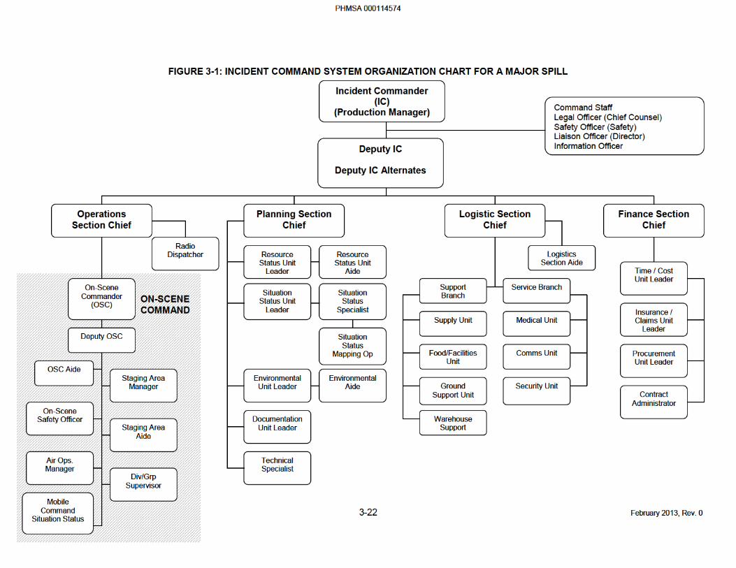
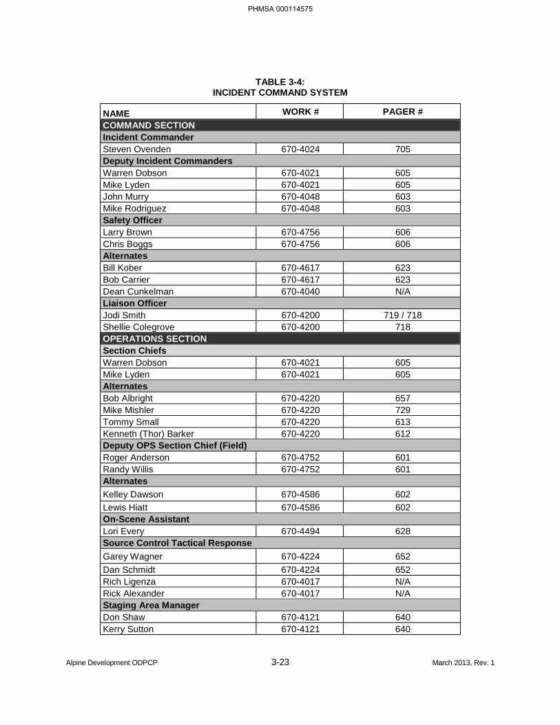
Alpine Development ODPCP 3-23 March 2013, Rev. 1
TABLE 3-4: INCIDENT COMMAND SYSTEM
NAME WORK # PAGER # COMMAND SECTION Incident Commander Steven Ovenden 670-4024 705 Deputy Incident Commanders Warren Dobson 670-4021 605 Mike Lyden 670-4021 605 John Murry 670-4048 603 Mike Rodriguez 670-4048 603 Safety Officer Larry Brown 670-4756 606 Chris Boggs 670-4756 606 Alternates Bill Kober 670-4617 623 Bob Carrier 670-4617 623 Dean Cunkelman 670-4040 N/A Liaison Officer Jodi Smith 670-4200 719 / 718 Shellie Colegrove 670-4200 718 OPERATIONS SECTION Section Chiefs Warren Dobson 670-4021 605 Mike Lyden 670-4021 605 Alternates Bob Albright 670-4220 657 Mike Mishler 670-4220 729 Tommy Small 670-4220 613 Kenneth (Thor) Barker 670-4220 612 Deputy OPS Section Chief (Field) Roger Anderson 670-4752 601 Randy Willis 670-4752 601 Alternates Kelley Dawson 670-4586 602 Lewis Hiatt 670-4586 602 On-Scene Assistant Lori Every 670-4494 628 Source Control Tactical Response Garey Wagner 670-4224 652 Dan Schmidt 670-4224 652 Rich Ligenza 670-4017 N/A Rick Alexander 670-4017 N/A Staging Area Manager Don Shaw 670-4121 640 Kerry Sutton 670-4121 640
PHMSA 000114575
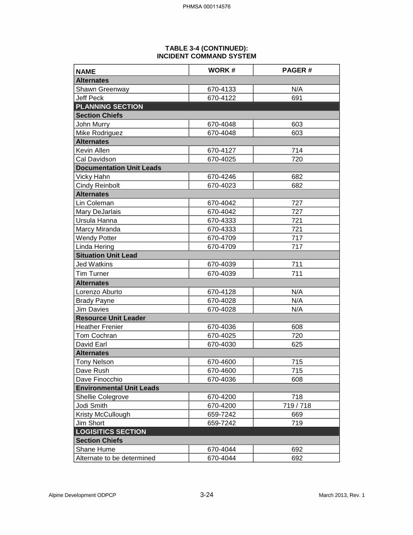
TABLE 3-4 (CONTINUED): INCIDENT COMMAND SYSTEM
Alpine Development ODPCP 3-24 March 2013, Rev. 1
NAME WORK # PAGER # Alternates Shawn Greenway 670-4133 N/A Jeff Peck 670-4122 691 PLANNING SECTION Section Chiefs John Murry 670-4048 603 Mike Rodriguez 670-4048 603 Alternates Kevin Allen 670-4127 714 Cal Davidson 670-4025 720 Documentation Unit Leads Vicky Hahn 670-4246 682 Cindy Reinbolt 670-4023 682 Alternates Lin Coleman 670-4042 727 Mary DeJarlais 670-4042 727 Ursula Hanna 670-4333 721 Marcy Miranda 670-4333 721 Wendy Potter 670-4709 717 Linda Hering 670-4709 717 Situation Unit Lead Jed Watkins 670-4039 711 Tim Turner 670-4039 711 Alternates Lorenzo Aburto 670-4128 N/A Brady Payne 670-4028 N/A Jim Davies 670-4028 N/A Resource Unit Leader Heather Frenier 670-4036 608 Tom Cochran 670-4025 720 David Earl 670-4030 625 Alternates Tony Nelson 670-4600 715 Dave Rush 670-4600 715 Dave Finocchio 670-4036 608 Environmental Unit Leads Shellie Colegrove 670-4200 718 Jodi Smith 670-4200 719 / 718 Kristy McCullough 659-7242 669 Jim Short 659-7242 719 LOGISITICS SECTION Section Chiefs Shane Hume 670-4044 692 Alternate to be determined 670-4044 692
PHMSA 000114576
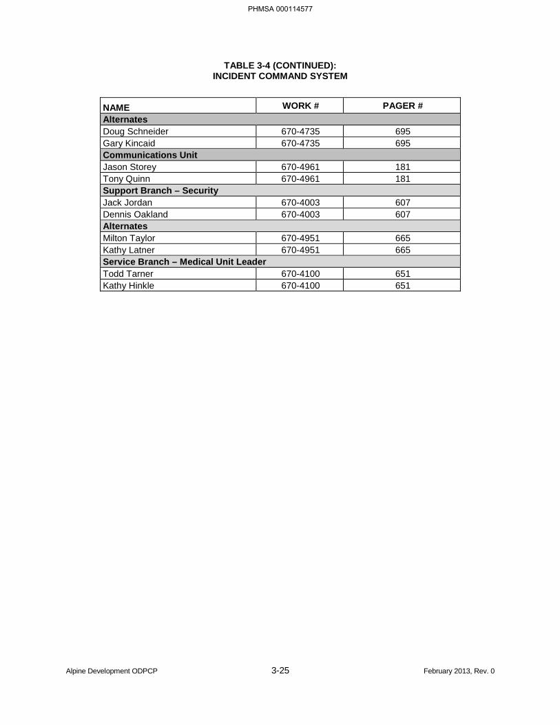
TABLE 3-4 (CONTINUED): INCIDENT COMMAND SYSTEM
Alpine Development ODPCP 3-25 February 2013, Rev. 0
NAME WORK # PAGER # Alternates Doug Schneider 670-4735 695 Gary Kincaid 670-4735 695 Communications Unit Jason Storey 670-4961 181 Tony Quinn 670-4961 181 Support Branch – Security Jack Jordan 670-4003 607 Dennis Oakland 670-4003 607 Alternates Milton Taylor 670-4951 665 Kathy Latner 670-4951 665 Service Branch – Medical Unit Leader Todd Tarner 670-4100 651 Kathy Hinkle 670-4100 651
PHMSA 000114577
Alpine Development ODPCP 3-26 February 2013, Rev. 0
3.4 REALISTIC MAXIMUM RESPONSE OPERATING LIMITATIONS [18 AAC 75.425(e)(3)(D)]
This section is provided with permission by BP Exploration (Alaska) Inc. (BPXA) for use in this ODPCP.
3.4.1 Introduction
Realistic maximum response operating limitations that might be encountered at the facility are described in the ACS Technical Manual, Volume 1, Tactics Description L-7, which is incorporated into the plan by reference. Tactic L-7 analyzes the frequency and duration, expressed as a percentage of time, of limitations that would render mechanical response methods ineffective, as required by 18 AAC 75.425(e)(3)(D). The analysis considers weather, sea conditions, ice, daylight hours, and other environmental conditions that might influence the efficiency of the oil spill response.
Broken ice conditions limit mechanical oil containment boom and recovery skimmers. As ice coverage increases, it becomes more and more difficult to maintain containment boom configurations and skirts to concentrate oil for recovery. Field tests in July 2000 demonstrated the effects of broken ice on a containment boom system (Bronson, 2002). However, broken ice conditions can promote oil removal by in situ burning.
3.4.2 Weather and Ice Conditions During the Shoulder Seasons
The following general description of break-up and freeze-up applies to the marine environment in the Prudhoe Bay region. Descriptions are of typical conditions. They cover the chronology of break-up and freeze-up. See Vaudrey and Dickins et al. (2000) and tables in Atwater (1991) for further site-specific details.
May
The Sagavanirktok River and Kuparuk River overfloods (Condition 5) commence on average May 20 and 27, respectively, based on 16 years of analysis. See DF Dickins Associates et al. (2000) for descriptions of seasonal ice conditions.
June
June 1-10: Landfast ice is intact (Condition 4) beyond the Kuparuk River and Sagavanirktok River overflood boundaries. Within the overflood zones immediately off the river deltas, fast ice lifts off the bottom of the Beaufort Sea and rapidly melts in place from the relatively warm water discharge (Conditions 6 and 7). The peak of major flooding occurs during the period June 4-7 (±6 days), at which point the Kuparuk River overflood may reach within 1 mile of the Northstar Island (Condition 5). Routine ice road operations might cease at this time. First open water appears offshore of the Sagavanirktok River and Kuparuk River by June 6 to 13, respectively, on average. Fast ice beyond the overflood zones and outside the barrier islands is still intact and more than 5 feet thick in early June.
June 15-20: Nearshore lagoon areas affected by the Kuparuk overflood and shallow waters off the Sagavanirktok delta become mostly free of ice (Condition 9). Fast ice offshore remains intact (e.g., Stump Island to Northstar) and continues to melt (Condition 7). Solid ice 4 to 5 feet thick still surrounds Northstar Island. The soft surface is 25 percent covered by melt water pools (Condition 6).
PHMSA 000114578
Alpine Development ODPCP 3-27 February 2013, Rev. 0
Air temperatures average 35oF and range from 20oF to 40oF. The wind is variable, but blows 60 percent of the time from the east and northeast, averaging 10 knots.
The ice can support response vehicles up to several weeks before break-up. The effect of deteriorating sea ice on access with specific equipment is illustrated in ACS Technical Manual, Tactic L-7, based on field trials by Coastal Frontiers (2001).
July, August, and September
July 1: A completely intact, deteriorated ice cover 3 to 4 feet thick, with many cracks and approximately 40 percent to 50 percent of its surface covered by melt pools and holes still exists in deeper water in the vicinity of Northstar (Condition 6).
July 4 (Typical): Break-up begins with fracturing and movement in the floating landfast ice (Condition 7).
July 8-12: Remaining fast ice outside the barrier islands, off the Sagavanirktok River delta and in Prudhoe Bay, decreases to less than seven-tenths coverage (Condition 8).
July 15-26: Open, ice-free water out to Northstar and surrounding West Dock and Endicott causeway (Condition 9).
Air temperatures average 40oF in July.
The median number of days with flooded and/or broken ice at break-up at production facilities range from 12 days at Point McIntyre, to 22 days at Northstar.
October
October 4, ±8 days: Freeze-up begins along shore in shallow water. Ice becomes shorefast for the season within one week following freeze-up in the nearshore lagoons (e.g., Point McIntyre 2 and Niakuk) and by October 25 offshore.
Additional time is required for the young ice sheet to gain sufficient thickness and stability to be judged safe for over-ice operations. Time from initial freeze-up to being able to commence on-ice operations with response equipment ranges on average from 40 to 43 days at coastal or nearshore locations such as Point McIntyre 1, Niakuk, and Endicott, to 55 days at Northstar.
Air temperatures at freeze-up range from 5oF to 15oF. Daylight is 9 to 10 hours per day.
3.4.3 In Situ Burning Response Measures to Reduce Environmental Consequences of a Spill in Ice Conditions
Oil spill removal during the shoulder seasons can be greatly enhanced by in situ burning. The ice slows the spread of oil, thereby increasing the response equipment’s encounter rate with the oil. The ice also provides natural containment, concentrating the oil for burning and recovery. In situ burning in shoulder-season ice conditions generally involves selective burning of oil on melt pools and in leads between floes, followed by manual recovery of residue.
PHMSA 000114579
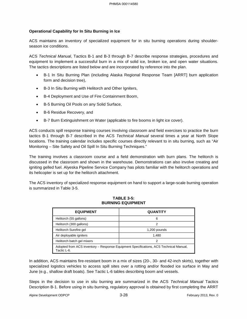
Alpine Development ODPCP 3-28 February 2013, Rev. 0
Operational Capability for In Situ Burning in Ice
ACS maintains an inventory of specialized equipment for in situ burning operations during shoulder-season ice conditions.
ACS Technical Manual, Tactics B-1 and B-3 through B-7 describe response strategies, procedures and equipment to implement a successful burn in a mix of solid ice, broken ice, and open water situations. The tactics descriptions are listed below and are incorporated by reference into the plan.
• B-1 In Situ Burning Plan (including Alaska Regional Response Team [ARRT] burn application form and decision tree),
• B-3 In Situ Burning with Helitorch and Other Igniters,
• B-4 Deployment and Use of Fire Containment Boom,
• B-5 Burning Oil Pools on any Solid Surface,
• B-6 Residue Recovery, and
• B-7 Burn Extinguishment on Water (applicable to fire booms in light ice cover).
ACS conducts spill response training courses involving classroom and field exercises to practice the burn tactics B-1 through B-7 described in the ACS Technical Manual several times a year at North Slope locations. The training calendar includes specific courses directly relevant to in situ burning, such as “Air Monitoring – Site Safety and Oil Spill In Situ Burning Techniques.”
The training involves a classroom course and a field demonstration with burn plans. The helitorch is discussed in the classroom and shown in the warehouse. Demonstrations can also involve creating and igniting gelled fuel. Alyeska Pipeline Service Company has pilots familiar with the helitorch operations and its helicopter is set up for the helitorch attachment.
The ACS inventory of specialized response equipment on hand to support a large-scale burning operation is summarized in Table 3-5.
TABLE 3-5: BURNING EQUIPMENT
EQUIPMENT QUANTITY
Helitorch (55 gallons) 6
Helitorch (300 gallons) 2
Helitorch Surefire gel 1,200 pounds
Air deployable igniters 1,480
Helitorch batch gel mixers 2
Adopted from ACS inventory – Response Equipment Specifications, ACS Technical Manual, Tactic L-6.
In addition, ACS maintains fire-resistant boom in a mix of sizes (20-, 30- and 42-inch skirts), together with specialized logistics vehicles to access spill sites over a rotting and/or flooded ice surface in May and June (e.g., shallow draft boats). See Tactic L-6 tables describing boom and vessels.
Steps in the decision to use in situ burning are summarized in the ACS Technical Manual Tactics Description B-1. Before using in situ burning, regulatory approval is obtained by first completing the ARRT
PHMSA 000114580
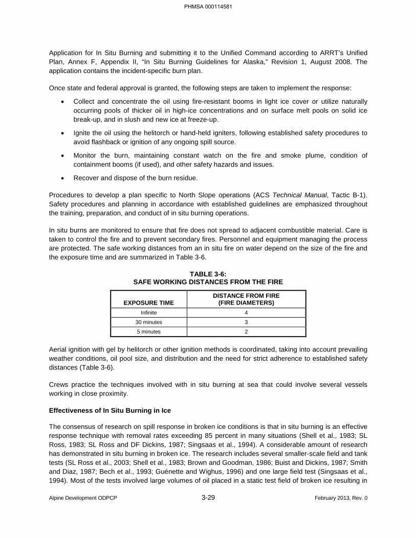
Alpine Development ODPCP 3-29 February 2013, Rev. 0
Application for In Situ Burning and submitting it to the Unified Command according to ARRT’s Unified Plan, Annex F, Appendix II, “In Situ Burning Guidelines for Alaska,” Revision 1, August 2008. The application contains the incident-specific burn plan.
Once state and federal approval is granted, the following steps are taken to implement the response:
• Collect and concentrate the oil using fire-resistant booms in light ice cover or utilize naturally occurring pools of thicker oil in high-ice concentrations and on surface melt pools on solid ice break-up, and in slush and new ice at freeze-up.
• Ignite the oil using the helitorch or hand-held igniters, following established safety procedures to avoid flashback or ignition of any ongoing spill source.
• Monitor the burn, maintaining constant watch on the fire and smoke plume, condition of containment booms (if used), and other safety hazards and issues.
• Recover and dispose of the burn residue.
Procedures to develop a plan specific to North Slope operations (ACS Technical Manual, Tactic B-1). Safety procedures and planning in accordance with established guidelines are emphasized throughout the training, preparation, and conduct of in situ burning operations.
In situ burns are monitored to ensure that fire does not spread to adjacent combustible material. Care is taken to control the fire and to prevent secondary fires. Personnel and equipment managing the process are protected. The safe working distances from an in situ fire on water depend on the size of the fire and the exposure time and are summarized in Table 3-6.
TABLE 3-6: SAFE WORKING DISTANCES FROM THE FIRE
EXPOSURE TIME DISTANCE FROM FIRE
(FIRE DIAMETERS) Infinite 4
30 minutes 3
5 minutes 2
Aerial ignition with gel by helitorch or other ignition methods is coordinated, taking into account prevailing weather conditions, oil pool size, and distribution and the need for strict adherence to established safety distances (Table 3-6).
Crews practice the techniques involved with in situ burning at sea that could involve several vessels working in close proximity.
Effectiveness of In Situ Burning in Ice
The consensus of research on spill response in broken ice conditions is that in situ burning is an effective response technique with removal rates exceeding 85 percent in many situations (Shell et al., 1983; SL Ross, 1983; SL Ross and DF Dickins, 1987; Singsaas et al., 1994). A considerable amount of research has demonstrated in situ burning in broken ice. The research includes several smaller-scale field and tank tests (SL Ross et al., 2003; Shell et al., 1983; Brown and Goodman, 1986; Buist and Dickins, 1987; Smith and Diaz, 1987; Bech et al., 1993; Guénette and Wighus, 1996) and one large field test (Singsaas et al., 1994). Most of the tests involved large volumes of oil placed in a static test field of broken ice resulting in
PHMSA 000114581
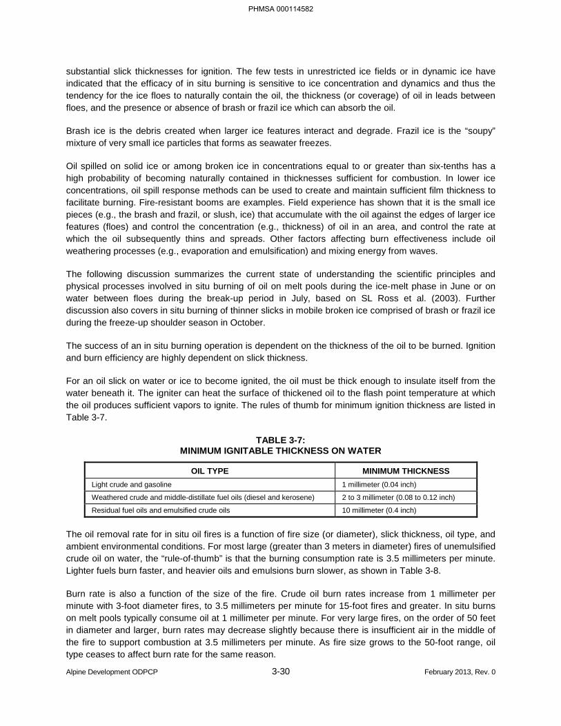
Alpine Development ODPCP 3-30 February 2013, Rev. 0
substantial slick thicknesses for ignition. The few tests in unrestricted ice fields or in dynamic ice have indicated that the efficacy of in situ burning is sensitive to ice concentration and dynamics and thus the tendency for the ice floes to naturally contain the oil, the thickness (or coverage) of oil in leads between floes, and the presence or absence of brash or frazil ice which can absorb the oil.
Brash ice is the debris created when larger ice features interact and degrade. Frazil ice is the “soupy” mixture of very small ice particles that forms as seawater freezes.
Oil spilled on solid ice or among broken ice in concentrations equal to or greater than six-tenths has a high probability of becoming naturally contained in thicknesses sufficient for combustion. In lower ice concentrations, oil spill response methods can be used to create and maintain sufficient film thickness to facilitate burning. Fire-resistant booms are examples. Field experience has shown that it is the small ice pieces (e.g., the brash and frazil, or slush, ice) that accumulate with the oil against the edges of larger ice features (floes) and control the concentration (e.g., thickness) of oil in an area, and control the rate at which the oil subsequently thins and spreads. Other factors affecting burn effectiveness include oil weathering processes (e.g., evaporation and emulsification) and mixing energy from waves.
The following discussion summarizes the current state of understanding the scientific principles and physical processes involved in situ burning of oil on melt pools during the ice-melt phase in June or on water between floes during the break-up period in July, based on SL Ross et al. (2003). Further discussion also covers in situ burning of thinner slicks in mobile broken ice comprised of brash or frazil ice during the freeze-up shoulder season in October.
The success of an in situ burning operation is dependent on the thickness of the oil to be burned. Ignition and burn efficiency are highly dependent on slick thickness.
For an oil slick on water or ice to become ignited, the oil must be thick enough to insulate itself from the water beneath it. The igniter can heat the surface of thickened oil to the flash point temperature at which the oil produces sufficient vapors to ignite. The rules of thumb for minimum ignition thickness are listed in Table 3-7.
TABLE 3-7: MINIMUM IGNITABLE THICKNESS ON WATER
OIL TYPE MINIMUM THICKNESS Light crude and gasoline 1 millimeter (0.04 inch)
Weathered crude and middle-distillate fuel oils (diesel and kerosene) 2 to 3 millimeter (0.08 to 0.12 inch)
Residual fuel oils and emulsified crude oils 10 millimeter (0.4 inch)
The oil removal rate for in situ oil fires is a function of fire size (or diameter), slick thickness, oil type, and ambient environmental conditions. For most large (greater than 3 meters in diameter) fires of unemulsified crude oil on water, the “rule-of-thumb” is that the burning consumption rate is 3.5 millimeters per minute. Lighter fuels burn faster, and heavier oils and emulsions burn slower, as shown in Table 3-8.
Burn rate is also a function of the size of the fire. Crude oil burn rates increase from 1 millimeter per minute with 3-foot diameter fires, to 3.5 millimeters per minute for 15-foot fires and greater. In situ burns on melt pools typically consume oil at 1 millimeter per minute. For very large fires, on the order of 50 feet in diameter and larger, burn rates may decrease slightly because there is insufficient air in the middle of the fire to support combustion at 3.5 millimeters per minute. As fire size grows to the 50-foot range, oil type ceases to affect burn rate for the same reason.
PHMSA 000114582
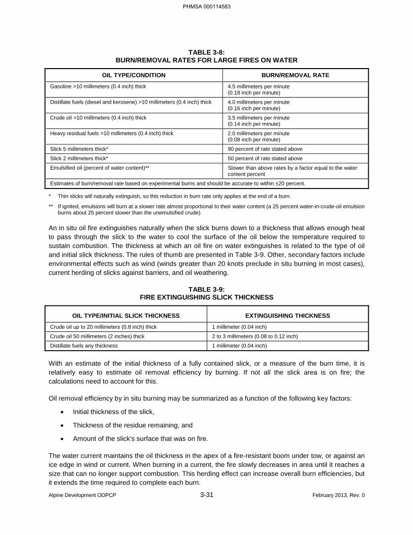
Alpine Development ODPCP 3-31 February 2013, Rev. 0
TABLE 3-8: BURN/REMOVAL RATES FOR LARGE FIRES ON WATER
OIL TYPE/CONDITION BURN/REMOVAL RATE
Gasoline >10 millimeters (0.4 inch) thick 4.5 millimeters per minute (0.18 inch per minute)
Distillate fuels (diesel and kerosene) >10 millimeters (0.4 inch) thick 4.0 millimeters per minute (0.16 inch per minute)
Crude oil >10 millimeters (0.4 inch) thick 3.5 millimeters per minute (0.14 inch per minute)
Heavy residual fuels >10 millimeters (0.4 inch) thick 2.0 millimeters per minute (0.08 inch per minute)
Slick 5 millimeters thick* 90 percent of rate stated above
Slick 2 millimeters thick* 50 percent of rate stated above
Emulsified oil (percent of water content)** Slower than above rates by a factor equal to the water content percent
Estimates of burn/removal rate based on experimental burns and should be accurate to within ±20 percent.
* Thin slicks will naturally extinguish, so this reduction in burn rate only applies at the end of a burn.
** If ignited, emulsions will burn at a slower rate almost proportional to their water content (a 25 percent water-in-crude-oil emulsion burns about 25 percent slower than the unemulsified crude).
An in situ oil fire extinguishes naturally when the slick burns down to a thickness that allows enough heat to pass through the slick to the water to cool the surface of the oil below the temperature required to sustain combustion. The thickness at which an oil fire on water extinguishes is related to the type of oil and initial slick thickness. The rules of thumb are presented in Table 3-9. Other, secondary factors include environmental effects such as wind (winds greater than 20 knots preclude in situ burning in most cases), current herding of slicks against barriers, and oil weathering.
TABLE 3-9: FIRE EXTINGUISHING SLICK THICKNESS
OIL TYPE/INITIAL SLICK THICKNESS EXTINGUISHING THICKNESS
Crude oil up to 20 millimeters (0.8 inch) thick 1 millimeter (0.04 inch)
Crude oil 50 millimeters (2 inches) thick 2 to 3 millimeters (0.08 to 0.12 inch)
Distillate fuels any thickness 1 millimeter (0.04 inch)
With an estimate of the initial thickness of a fully contained slick, or a measure of the burn time, it is relatively easy to estimate oil removal efficiency by burning. If not all the slick area is on fire; the calculations need to account for this.
Oil removal efficiency by in situ burning may be summarized as a function of the following key factors:
• Initial thickness of the slick,
• Thickness of the residue remaining, and
• Amount of the slick's surface that was on fire.
The water current maintains the oil thickness in the apex of a fire-resistant boom under tow, or against an ice edge in wind or current. When burning in a current, the fire slowly decreases in area until it reaches a size that can no longer support combustion. This herding effect can increase overall burn efficiencies, but it extends the time required to complete each burn.
PHMSA 000114583
Alpine Development ODPCP 3-32 February 2013, Rev. 0
The residue from a typical, efficient (greater than 85 percent removal) in situ burn of crude oil 10 to 20 millimeters thick is a semi-solid, tar-like layer that has an appearance similar to the skin on an old, poorly-sealed can of latex paint that has gelled. For thicker slicks, typical of what might be expected in a towed fire boom (about 150 to 300 millimeters), the residue can be a solid. Burn residue is usually denser than the original pre-burn oil, and usually it does not spread due to its increased viscosity or solid nature.
Tests indicate that the burn residues from efficient burns of heavier crude oils <32 degrees gravity API may sink once the residue cools, but their acute aquatic toxicity is very low or nonexistent. The “In Situ Burning Guidelines for Alaska,” Revision 1, August 2008 state:
“The environmental advantages of in situ burning outweigh the potential environmental drawbacks of burn residue, including the possible environmental harm if the burn residue sinks. Therefore, the on-scene coordinators do not consider the potential impacts of burn residue when deciding whether to authorize an in situ burn. Nevertheless, the responsible party or applicant is required to have a plan for residue collection.”
Compared with unemulsified slicks, emulsions are much more difficult to ignite and, once ignited, display reduced flame spreading and more sensitivity to wind and wave action. Stable emulsion water contents are typically in the 60 percent to 80 percent range with some up to 90 percent. The oil in the emulsion cannot reach a temperature higher than 100°C until the water is either boiled off or removed. The heat from the igniter or from the adjacent burning oil is used first mostly to boil the water rather than heat the oil.
The following points summarize the effect of water content on the removal efficiency of weathered crude emulsions:
• Little effect on oil removal efficiency (i.e., residue thickness) for water contents up to about 12.5 percent by volume;
• A noticeable decrease in burn efficiency with water contents above 12.5 percent, the decrease being more pronounced with weathered oils;
• Zero burn efficiency for emulsion slicks having water contents of 25 percent or more; and
• Some crudes form meso-stable emulsions that can burn efficiently at much higher water contents. Paraffinic crudes appear to fall into this category.
Fortunately, emulsion formation is slowed dramatically by high ice concentrations and may not be a significant operational factor in planning in situ burns on solid ice or naturally contained in higher concentrations of broken ice.
SL Ross et al. (2003) provides guidelines for burning thin slicks in broken ice with brash and slush, particularly relevant during the break-up and freeze-up shoulder seasons. General rules for minimum ignitable thickness and oil removal rates for burning thin slicks of crude oils on brash and/or slush with broken ice are as follows:
• The minimum ignitable thickness for fresh crude on frazil ice or small brash ice pieces is up to double that on open water, or about 1 to 2 millimeters.
• The minimum ignitable thickness for evaporated crude oil on frazil ice or small brash ice pieces can be higher than on open water, but is still within the range quoted for weathered crude on water, about 3 millimeters with gelled gasoline igniters.
PHMSA 000114584
Alpine Development ODPCP 3-33 February 2013, Rev. 0
• For a given spill diameter, the burn rate in calm conditions is about halved on relatively smooth frazil/slush ice and halved again on rougher, brash ice. Wave action slightly reduces the burn rate on open water, but the halving rule seems to apply in waves as well.
The residue remaining on broken ice in calm conditions is about 50 percent greater than that on open water, or 1.5 millimeters. The residue remaining on brash or frazil ice in waves is slightly greater than in calm conditions, at about 2 millimeters.
In summary, in situ burning of oil is efficient and rapid in broken ice conditions under the following conditions:
• The spilled oil is thicker than the minimum ignitable (a thickness of 2 to 3 millimeters results in 50 to 66 percent removal efficiency: 10-millimeter thickness, a typical thickness for wind-herded slicks on melt ponds on ice, gives 90 percent removal efficiency);
• Larger areas can be ignited (a 100-square-foot slick on a melt pool will burn at 3.5 barrels of oil per hour, a 50-foot diameter, 10-millimeters thick slick will burn at 300 barrels of oil per hour, and a 100-foot diameter slick will burn at 1,200 barrels of oil per hour); and
• The oil is not more than 25 percent emulsified.
3.4.4 Environmental Conditions
The realistic maximum response operating limitations are described in the ACS Technical Manual. Environmental conditions can sometimes limit response work. Some limitations are based on safety, and others concern equipment effectiveness. The ACS Technical Manual lists the percentage of time some variables reduce effectiveness of response for planning purposes.
Low visibility due to fog or heavy snow is an environmental condition that can limit the effectiveness of a response. Low visibility can affect transportation as well as visual pipeline leak detection and spill tracking.
The most limiting factors of mechanical containment and response effectiveness at Alpine are the remote location and the lack of road access in the event of a blowout (except when an ice road is in place). An open-orifice blowout to a remote, roadless area presents a difficult response because of the volume of oil to be contained without a road-supported response. Major factors affecting the response to a blowout in a roadless area are as follows:
• Storage Removal: Without vehicles and vacuum trucks accessing the site at collection points, a major advantage of mass storage removal is removed from the response. The collection sites must be accessed with smaller collection units, i.e., tundra travel vehicles or airboats. Other removal options include large quantities of transfer pumps and hoses or burning at the collection points.
• Vessel Access: The Colville River delta presents a unique response environment with its many channels, dead arms, sloughs and isolated lakes. Passage in many of the channels is variable. Airboats are the best vessel for use in the river channels of the delta.
• Break-up Flooding: A spring break-up flooding event usually occurs every year in the delta. High river discharge along with ice would complicate a response activity. The high water may make navigation in the channel easier, but it would disperse the oil rapidly and in an erratic manner,
PHMSA 000114585
Alpine Development ODPCP 3-34 February 2013, Rev. 0
and ice conditions may limit the effectiveness of boom containment and skimmer operation. Break-up flows last for approximately three weeks.
CPAI and North Slope spill responders plan to respond to all reported spills, including all those in spring break-up conditions. Responders evaluate the spill and do everything humanly possible to contain, control, and clean up the spill without jeopardizing personal safety. Break-up conditions do not preclude any oil spill responses at Alpine, although they may limit the effectiveness of responses.
3.4.5 Colville River Delta
Realistic maximum response operating limitations descriptions, called for in 18 AAC 75.425(c)(3)(D), are incorporated into this plan by reference to the ACS Technical Manual Tactic L-7. The Tactic L-7 descriptions of water and ice conditions of the Colville River in the spring are based on the U.S. Army Corps of Engineers report for the Endicott Environmental Monitoring Project. Tactic L-7 outlines the amount of time and typical dates that break-up conditions could reduce the effectiveness of mechanical response in the Colville River and its vicinity, as follows:
• In the lagoon, broken ice concentrations limiting the effectiveness of oil recovery by vessels may last a week.
• Ice in the Colville River may limit response effectiveness for 13 days typically.
• Over-ice flow of Colville River water may limit responses for 12 days typically.
• High water flows in the rivers may limit response effectiveness for two to three weeks typically.
Responses are not precluded during these dates.
The Colville River’s median date of peak break-up discharge is June 2. For about three weeks centered on the peak flow date, some overflow, ice movement, and ice pile-up are expected to reduce the effectiveness of mechanical oil spill response. In situ burning is an important non-mechanical response that can be effective and can be conducted safely by response personnel.
Examples of break-up conditions that may reduce the effectiveness of mechanical response are as follows:
Sheetflow Periods
Oil spill containment and removal in sheetflow conditions may involve in situ burning of oil, as well as booming and barriers. See ACS Technical Manual Tactics B-1 through B-5 and C-1 through C-5.
Ice Pile-up in the Colville River Delta
The Nigliq Channel Bridge and in-field piping crossings over channels of the delta are designed to withstand and break through ice jamming and loading events. However, broken ice, ice jams, and floodwaters in the Colville River and other channels of the delta threaten response worker safety and limit response effectiveness during break-up. Workers do not deploy response equipment on water at times and locations that are unsafe for them, including some aggressive break-up conditions. In situ burning is an important response options under these conditions.
PHMSA 000114586
Alpine Development ODPCP 3-35 February 2013, Rev. 0
Broken Ice in Rivers and Channels
During aggressive break-up in rivers and channels of the Colville River delta, when freshwater ice breaks loose and begins floating downstream, tactical spill response options are limited. Strong currents and large pieces of ice make conditions unsafe for airboat or other vessel deployment. Due to elevated safety risks to personnel, containment and/or recovery equipment may not be able to be deployed in river channels. During this time, alternative mechanical recovery or burning strategies are used in quiet-water areas downstream of the spill. See ACS Technical Manual Tactic R-12.
Broken Ice in the Lagoon
Conventional on-water containment and recovery is affected by ice concentrations greater than 30 percent coverage. At ice concentrations greater than 70 percent, on-water recovery effectiveness becomes limited (see the Deployment Considerations and Limitations statement in the ACS Technical Manual Tactics R-19A and L-7).
River Water Overflows onto the Shore-fast Lagoon Ice
Over-flooding limits mechanical response effectiveness. In situ burning is an important response option for over-flood conditions. See ACS Technical Manual Tactics L-7, B-1, B-3, and B-5.
Ice Pile-up at the Pipeline Transitions at the Colville River
The pipeline’s exit points from its transition under the Colville River lie approximately 6 inches below the 200-year flood stage elevation and are not expected to experience river ice pile-up. This means that only 6 inches of water would be expected, at worst case, during a 200-year event to cover the pad and surround the point where the pipeline exits the ground. Six inches of water is not capable of carrying significant quantities of ice. As such, a pile-up condition cannot be created.
Examples of freeze-up conditions that may reduce the effectiveness of mechanical response are as follows:
Freezing Rivers, Ponds, and Lakes
Low water flow is characteristic of Alpine-area hydrology during freeze-up and into the winter when rivers, ponds, and lakes freeze over and shallow ponds and lakes freeze to the bottom (Section 3.2). Aggressive ice pile-ups or ice jams are not expected; however, resources would be expended on ice management in water bodies to reduce the risk of boom failure and limit safety concerns. As ice coverage increases, it becomes more difficult to operate containment boom to concentrate oil for recovery from open water. Operation of some skimmers may be reduced. Aufeis formations may be present downstream of local freshwater springs or along shorelines. Safety or operational restraints on response activities on thin or new-forming ice and aufeis would limit response effectiveness. Additional response limitations during freeze-up are discussed in the ACS Technical Manual.
PHMSA 000114587
Alpine Development ODPCP 3-36 February 2013, Rev. 0
3.5 LOGISTICAL SUPPORT [18 AAC 75.425(e)(3)(E)]
CPAI has an existing logistical support infrastructure for its operations on the North Slope. Transportation equipment, coordination procedures, and maintenance procedures are in place under normal operations. CPAI has contracts for operational logistical support to support a spill response. Additionally, ACS maintains master service agreements with various contractors, which, as a member of ACS, CPAI may utilize during a spill response.
ACS Technical Manual, Volume 1, Tactics L-3, L-4, L-6, and L-8 through L-10 are incorporated here by reference.
PHMSA 000114588
Alpine Development ODPCP 3-37 February 2013, Rev. 0
3.6 RESPONSE EQUIPMENT [18 AAC 75.425(e)(3)(F)]
3.6.1 Equipment Lists
Contracted or other oil discharge containment, control, cleanup, storage, transfer, lightering, and related response equipment to meet the applicable RPS in Part 1, and to protect environmentally sensitive areas and areas of public concern in Part 3, and that may be reasonable expected to suffer an impact from a spill of the RPS volume as described in the response Scenarios in Section 1.6.4 is listed in the ACS Technical Manual, Volume 1. The location, inventory, and ownership of the equipment is listed in ACS Technical Manual Tactic L-6. The timeframe for delivery and startup of response equipment and trained personnel located outside the facility’s primary region of operation is outlined in the response scenarios in Part 1. The manufacturer’s rated capacities, limitation, and operational characteristics for each item of oil recovery equipment listed in the response scenarios are described in ACS Technical Manual Tactic L-6. Each vessel and the equipment for transferring oil from tanks mentioned in the scenarios in Part 1 is listed in Tactic L-6 as well.
In addition, Alpine has dedicated oil spill response equipment positioned throughout the field in connexes and storage areas. The general equipment locations are shown in Figure 3-2. Pre-staged equipment and support infrastructure are also illustrated in ACS Technical Manual, Volume 2, Map Atlas Sheets 8, 9, 12, 16, 17, 18, 20, 21, 22, 23, 23A, 24, and 27. With each year’s experience in operating in the Colville River delta, the staging of equipment and sites will vary. Alpine spill response equipment is maintained by ACS who can provide the most current and up-to-date equipment inventory and their locations, including remote and pre-staged locations. The Alpine response equipment list is available upon request.
In addition to the dedicated spill response equipment at Alpine, there is other equipment located on site that would be available in the event of a spill. Heavy equipment maintained at the development during drilling and production operations typically includes a forklift with snow bucket attachment, front-end loaders, Supersucker, 14G grader, backhoe, vacuum trucks, Maxi Haul, lube truck, mechanics truck, water truck, fuel truck, bobcat with trimmer, semi and trailer, avgas trailer, and four 400-barrel tanks on skids. Sandbags are also available on site. Additionally, tundra travel vehicle support may be on site during drilling and production operations. Equipment can be used for berm construction, trenching, direct suction and storage, and other spill response operations, if needed.
3.6.2 Maintenance and Inspection of Response Equipment
Response equipment is maintained in a condition for immediate use and rapid deployment. The spill response equipment located at Alpine is routinely inspected and tested by ACS personnel (see ACS Technical Manual Tactic L-6).
ACS holds the following U.S. Coast Guard (USCG) oil spill removal organization classifications:
• River/canal environments: Classes MM, W1, W2, and W3;
• Inland environments: Classes MM, W1, W2, and W3;
• Open-ocean environments: Classes MM, W1, and W2;
• Offshore environments: Classes MM, W1, and W2; and
• Nearshore environments: Classes MM, W1, and W2.
ACS has fulfilled the equipment maintenance and testing criteria that this USCG classification requires.
PHMSA 000114589

Alpine Development ODPCP 3-38 February 2013, Rev. 0
BLANK PAGE
PHMSA 000114590


Alpine Development ODPCP 3-40 February 2013, Rev. 0
BLANK PAGE
PHMSA 000114592
Alpine Development ODPCP 3-41 February 2013, Rev. 0
3.6.3 Pre-Deployed Response Equipment
The general spill prevention and response for the Alpine Development Area includes several sites for boom pre-deployment. CPAI and ACS personnel deploy diversionary and exclusion boom immediately downstream of where the pipeline crosses over the rivers (see ACS Technical Manual Tactics C-8 and C-9). This proactive plan includes conducting ongoing spill response training to enhance the skills of the local response personnel including Nuiqsut residents. With each year’s experience in operating in the Colville River delta, the staging of equipment and sites may vary. The goal is to strategically locate the staged equipment in close proximity to potential leak sources, likely containment sites, and in areas that are easily accessible so additional equipment can be quickly deployed if needed. Additional boom deployment sites may be evaluated annually. In addition to pre-deployed boom and response equipment, channel markers are deployed annually to assist responders in channel navigation.
Due to seasonal changes of the river channels and weather conditions causing fluctuating river currents, specific boom configurations and exact lengths of boom pre-deployed at each site may vary. At each pre-deployment site, sufficient boom sections and anchors are utilized to traverse the water body in a manner that optimizes its intended use for containment, diversion, exclusion, and/or recovery. Pre-deployed boom locations are summarized in Table 3-10.
PHMSA 000114593
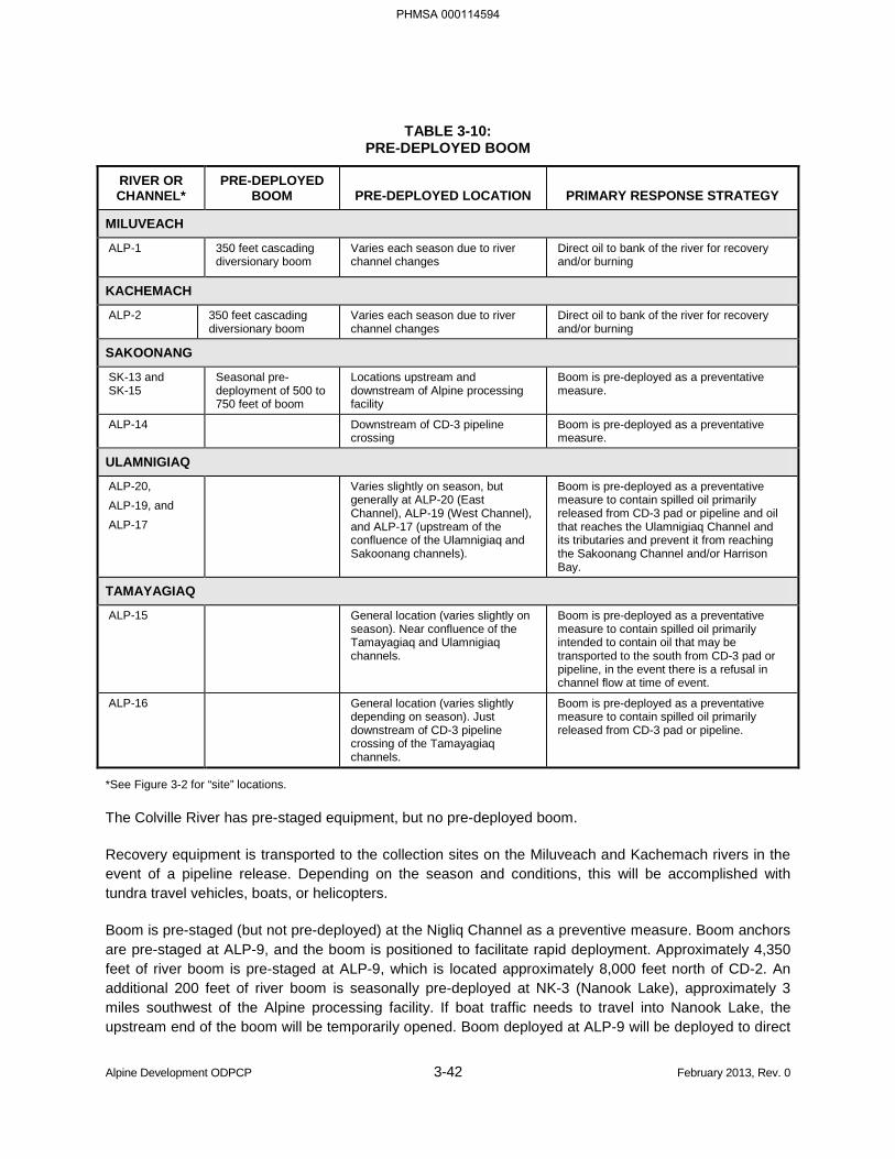
Alpine Development ODPCP 3-42 February 2013, Rev. 0
TABLE 3-10: PRE-DEPLOYED BOOM
RIVER OR CHANNEL*
PRE-DEPLOYED BOOM PRE-DEPLOYED LOCATION PRIMARY RESPONSE STRATEGY
MILUVEACH
ALP-1 350 feet cascading diversionary boom
Varies each season due to river channel changes
Direct oil to bank of the river for recovery and/or burning
KACHEMACH
ALP-2 350 feet cascading diversionary boom
Varies each season due to river channel changes
Direct oil to bank of the river for recovery and/or burning
SAKOONANG
SK-13 and SK-15
Seasonal pre-deployment of 500 to 750 feet of boom
Locations upstream and downstream of Alpine processing facility
Boom is pre-deployed as a preventative measure.
ALP-14 Downstream of CD-3 pipeline crossing
Boom is pre-deployed as a preventative measure.
ULAMNIGIAQ
ALP-20, ALP-19, and ALP-17
Varies slightly on season, but generally at ALP-20 (East Channel), ALP-19 (West Channel), and ALP-17 (upstream of the confluence of the Ulamnigiaq and Sakoonang channels).
Boom is pre-deployed as a preventative measure to contain spilled oil primarily released from CD-3 pad or pipeline and oil that reaches the Ulamnigiaq Channel and its tributaries and prevent it from reaching the Sakoonang Channel and/or Harrison Bay.
TAMAYAGIAQ
ALP-15 General location (varies slightly on season). Near confluence of the Tamayagiaq and Ulamnigiaq channels.
Boom is pre-deployed as a preventative measure to contain spilled oil primarily intended to contain oil that may be transported to the south from CD-3 pad or pipeline, in the event there is a refusal in channel flow at time of event.
ALP-16 General location (varies slightly depending on season). Just downstream of CD-3 pipeline crossing of the Tamayagiaq channels.
Boom is pre-deployed as a preventative measure to contain spilled oil primarily released from CD-3 pad or pipeline.
*See Figure 3-2 for “site” locations.
The Colville River has pre-staged equipment, but no pre-deployed boom.
Recovery equipment is transported to the collection sites on the Miluveach and Kachemach rivers in the event of a pipeline release. Depending on the season and conditions, this will be accomplished with tundra travel vehicles, boats, or helicopters.
Boom is pre-staged (but not pre-deployed) at the Nigliq Channel as a preventive measure. Boom anchors are pre-staged at ALP-9, and the boom is positioned to facilitate rapid deployment. Approximately 4,350 feet of river boom is pre-staged at ALP-9, which is located approximately 8,000 feet north of CD-2. An additional 200 feet of river boom is seasonally pre-deployed at NK-3 (Nanook Lake), approximately 3 miles southwest of the Alpine processing facility. If boat traffic needs to travel into Nanook Lake, the upstream end of the boom will be temporarily opened. Boom deployed at ALP-9 will be deployed to direct
PHMSA 000114594
Alpine Development ODPCP 3-43 February 2013, Rev. 0
oil to a collection point on the east bank of the channel. Pre-staged equipment is also located at ALP-9 and at CD-2. Should a spill occur at CD-4, boom pre-staged at CD-1 and at ALP-9 would be used for deployment in the Nigliq Channel or nearby lakes. The proximity of CD-4 to the Nigliq Channel and Alpine infrastructure allows for rapid deployment of equipment from these pre-staging locations to contain oil spilled from the CD-4 pad or pipeline.
Time Frame
The open-water time frame for river boom deployment activities follows spring break-up, typically occurring around mid-June on the Colville River and late June on surrounding rivers, and ends prior to the fall freeze-up (typically in mid-September). Initial boom pre-deployment at all sites is estimated to take approximately two weeks. Prior to fall freeze-up, all associated spill response equipment is removed from the river, cleaned, repaired, and returned to the appropriate connex staging boxes.
PHMSA 000114595
Alpine Development ODPCP 3-44 February 2013, Rev. 0
3.7 NON-MECHANICAL RESPONSE INFORMATION [18 AAC 75.425(e)(3)(G)]
It is CPAI’s policy to attempt non-mechanical responses only in situations where mechanical recovery cannot be accomplished without unacceptable environmental damage or unacceptable risk to personnel, or when mechanical recovery cannot be completed before the threat of further migration of contained oil is imminent. In situ burning will not be used as a substitute for mechanical recovery.
The following text is provided with permission by BPXA for use in this ODPCP.
In situ burning equipment inventory and deployment is described in the ACS Technical Manual Tactics L-6 and B-1 through B-7, incorporated here by reference.
Oil spill cleanup during the shoulder seasons can be greatly accelerated by in situ burning. The ice slows the spread of oil, thereby increasing the encounter rate. The ice also provides natural containment, concentrating the oil for burning and recovery. In situ burning in shoulder-season ice conditions generally involves selective burning of oil on melt pools and in leads between floes, followed by manual recovery of residue.
3.7.1 Environmental Consequences
The environmental consequences of in situ burning will be assessed by monitoring the downwind trajectory of the smoke. A trial burn will indicate the path of the smoke. Monitoring the downwind position of the smoke plume will be accomplished by a ground- or air-based member of the IMT.
Appropriate measures, as required by the Unified Command, natural resource agencies, and public safety agencies, will be carried out to protect nearby human populations and environmentally sensitive areas. In situ burns will be limited to sites that are a minimum safe distance, generally several miles upwind of human populations. The safe distance will be plotted as outlined in the “In Situ Burning Guidelines for Alaska,” Revision 1, August 2008 (ARRT, 2010). The determination takes into account a trial burn, wind conditions, and size of the expected burn area. In addition, public notifications and warnings will be issued in cooperation with agency emergency staff.
In situ burns conducted according to the Unified Plan are not expected to harm environmentally sensitive areas and areas of public concern. Heat from in situ burning affects only the upper few centimeters of the water column in contact with the oil. Smoke has not been found harmful to wildlife populations. In situ burning smoke is reduced to concentrations that are safe to people by means of burning only at safe distances.
In situ burn operations receive constant visual monitoring of the smoke plume’s behavior. The burn operations team visually monitors the smoke plume. The federal and state on-scene coordinators may authorize a trial burn to confirm anticipated plume drift direction and dispersion distances downwind before authorizing the proposed burn. Burn operations may be stopped if the plume contacts or threatens to contact the ground in a populated area.
A step-by-step process in establishing safe distances for burning is fully presented in the “In Situ Burning Guidelines for Alaska,” Revision 1, August 2008. The State and Federal On-Scene Coordinators determine whether the burn lies at a safe distance from human populations. In situ burning is not authorized if it does not meet public health regulatory standards. The safe distance separating human populations from in situ oil burns is the downwind radius from the fire at which smoke particulate matter
PHMSA 000114596
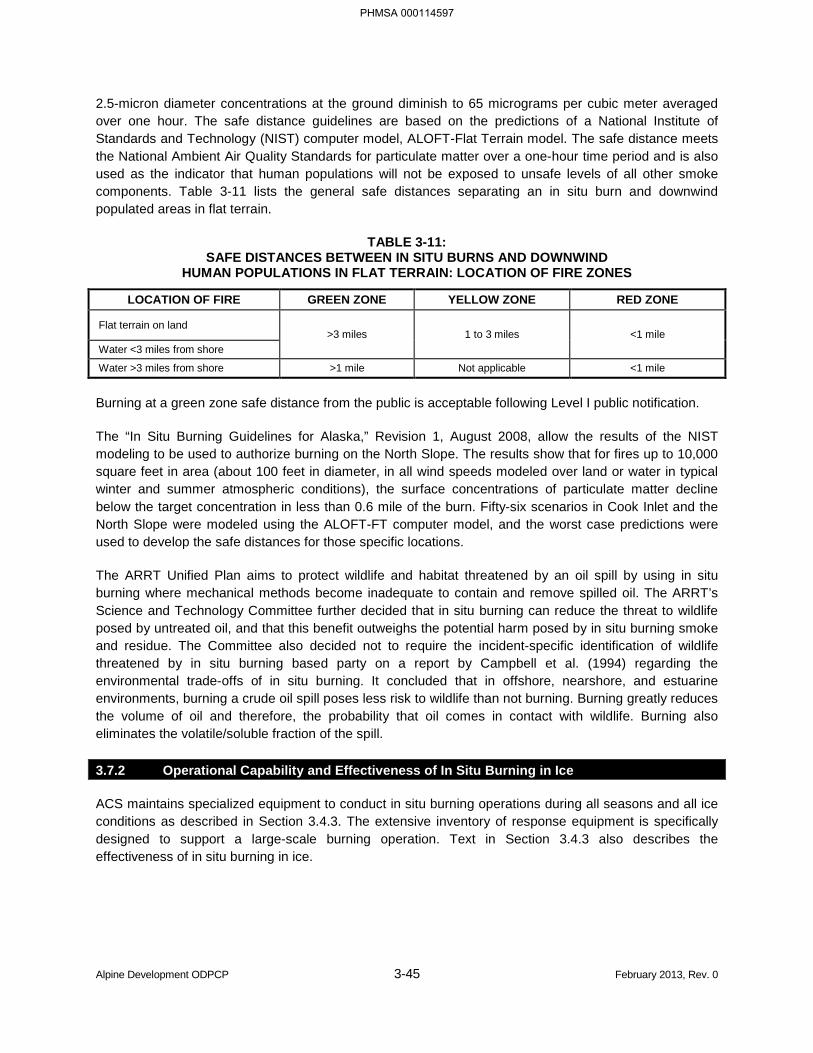
Alpine Development ODPCP 3-45 February 2013, Rev. 0
2.5-micron diameter concentrations at the ground diminish to 65 micrograms per cubic meter averaged over one hour. The safe distance guidelines are based on the predictions of a National Institute of Standards and Technology (NIST) computer model, ALOFT-Flat Terrain model. The safe distance meets the National Ambient Air Quality Standards for particulate matter over a one-hour time period and is also used as the indicator that human populations will not be exposed to unsafe levels of all other smoke components. Table 3-11 lists the general safe distances separating an in situ burn and downwind populated areas in flat terrain.
TABLE 3-11: SAFE DISTANCES BETWEEN IN SITU BURNS AND DOWNWIND
HUMAN POPULATIONS IN FLAT TERRAIN: LOCATION OF FIRE ZONES
LOCATION OF FIRE GREEN ZONE YELLOW ZONE RED ZONE
Flat terrain on land >3 miles 1 to 3 miles <1 mile
Water <3 miles from shore
Water >3 miles from shore >1 mile Not applicable <1 mile
Burning at a green zone safe distance from the public is acceptable following Level I public notification.
The “In Situ Burning Guidelines for Alaska,” Revision 1, August 2008, allow the results of the NIST modeling to be used to authorize burning on the North Slope. The results show that for fires up to 10,000 square feet in area (about 100 feet in diameter, in all wind speeds modeled over land or water in typical winter and summer atmospheric conditions), the surface concentrations of particulate matter decline below the target concentration in less than 0.6 mile of the burn. Fifty-six scenarios in Cook Inlet and the North Slope were modeled using the ALOFT-FT computer model, and the worst case predictions were used to develop the safe distances for those specific locations.
The ARRT Unified Plan aims to protect wildlife and habitat threatened by an oil spill by using in situ burning where mechanical methods become inadequate to contain and remove spilled oil. The ARRT’s Science and Technology Committee further decided that in situ burning can reduce the threat to wildlife posed by untreated oil, and that this benefit outweighs the potential harm posed by in situ burning smoke and residue. The Committee also decided not to require the incident-specific identification of wildlife threatened by in situ burning based party on a report by Campbell et al. (1994) regarding the environmental trade-offs of in situ burning. It concluded that in offshore, nearshore, and estuarine environments, burning a crude oil spill poses less risk to wildlife than not burning. Burning greatly reduces the volume of oil and therefore, the probability that oil comes in contact with wildlife. Burning also eliminates the volatile/soluble fraction of the spill.
3.7.2 Operational Capability and Effectiveness of In Situ Burning in Ice
ACS maintains specialized equipment to conduct in situ burning operations during all seasons and all ice conditions as described in Section 3.4.3. The extensive inventory of response equipment is specifically designed to support a large-scale burning operation. Text in Section 3.4.3 also describes the effectiveness of in situ burning in ice.
PHMSA 000114597
Alpine Development ODPCP 3-46 February 2013, Rev. 0
3.8 RESPONSE CONTRACTOR INFORMATION [18 AAC 75.425(e)(3)(H)]
The primary response action contractor is ACS.
Phone (907) 659-2405 Fax (907) 659-2616 Mailing Address: Pouch 340022 Prudhoe Bay, Alaska 99734-0022
CPAI will activate ACS and the North Slope Operators to provide the initial manpower and resources required to respond to a large or lengthy spill response. If additional resources are required, they will be accessed through master services agreements maintained by ACS. CPAI’s Statement of Contractual Terms with ACS is presented as Figure 3-3.
ACS maintains contracts for off-Slope response personnel.
PHMSA 000114598
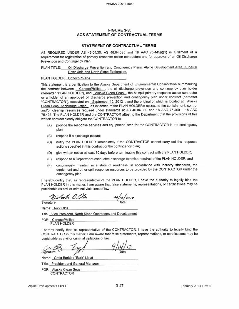
Alpine Development ODPCP 3-47 February 2013, Rev. 0
FIGURE 3-3: ACS STATEMENT OF CONTRACTUAL TERMS
PHMSA 000114599
Alpine Development ODPCP 3-48 February 2013, Rev. 0
3.9 TRAINING AND DRILLS [18 AAC 75.425(e)(3)(I)]
CPAI, in conjunction with ACS, provides an extensive training program for all employees in the Alpine Development Area. Spill prevention and response training is provided for all employees with increased emphasis for members of emergency response teams and the IMT.
At a field-wide level, spill prevention and awareness training is required of all new employees. Training is then provided on a continuing basis through field-wide spill awareness programs and at facility weekly safety meetings. Additionally, training is required annually by various spill prevention regulations for all employees at each operating facility.
3.9.1 North Slope Spill Response Team Spill Response Training
The North Slope Spill Response Team (NSSRT) consists of workers who volunteer as emergency spill response technicians. Each team member is required to have initial emergency response training and annual refresher training, which meets or exceeds the requirements in the Hazardous Waste Operations and Emergency Response (HAZWOPER) regulations, 29 CFR 1910.120(q). Annual requirements for HAZWOPER refreshers, medical physicals, and respiratory fit test are tracked by ACS through weekly reports from the ACS database (see Section 3.9.5, Recordkeeping). The NSSRT training program is available to responders from all production units on the North Slope. Responders are classified into five categories, each with minimum training requirements as described in ACS Tactic A-4 in the ACS Technical Manual. The NSSRT maintains a minimum staffing level designed to ensure response capability and to maintain compliance with all North Slope ODPCP response requirements.
Active Member Requirements
All NSSRT members must complete the following minimum annual training activities in order to be considered an active member of the NSSRT:
• 8-Hour HAZWOPER refresher certification,
• Contingency plan review, and
• Completion of five equipment proficiency checks.
The NSSRT training program offers weekly classes at each field. These classes emphasize hands-on experience, field exercises, and team building drills. The courses are selected by the facility Lead ACS Technician in conjunction with field management, and use CPAI, ACS, and external training consultants. Table 3-12 lists typical NSSRT training courses. Due to operational time constraints, many of the courses are divided by subject area and are taught in the two- or three-hour time frame of an NSSRT meeting. Training and attendance is documented and available for review. The yearly training schedule is also available at the facility and at ACS. Current NSSRT training schedules are posted on the ACS web site.
3.9.2 Incident Management Team Member Training
ICS training is provided several times a year to members of the Alpine IMT. Training course curriculums are based on the National Incident Management System (NIMS) ICS structure. NIMS certification is provided for general ICS courses that focus on organization, management, incident action planning, and forms used during an incident response. Section-specific or more specialized IMT courses provide detailed instruction into more complex components of incident responses.
PHMSA 000114600
Alpine Development ODPCP 3-49 February 2013, Rev. 0
ICS training is also conducted yearly for both the Kuparuk and Anchorage IMTs. Both of these teams could provide support to the Alpine IMT in the event of a response.
3.9.3 Auxiliary Contract Response Team
ACS maintains and operates a robust training and response program to ensure North Slope Operators have the ability to provide the personnel required to support a long-term response. The program consists of contracts and agreements with numerous emergency response service providers and provides assurance that a host of trained and qualified responders are available to respond to oil spills on the North Slope.
3.9.4 Other Training
CPAI and contract personnel involved in spill response are required to attend hydrogen sulfide and firefighting training. In addition, there may be specific departmental training requirements for Alpine facility operations. CPAI’s HSE Department maintains and conducts frequent training for health, safety, and environmental awareness.
PHMSA 000114601
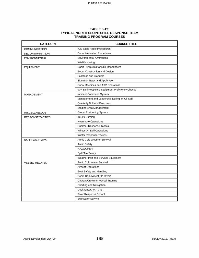
Alpine Development ODPCP 3-50 February 2013, Rev. 0
TABLE 3-12: TYPICAL NORTH SLOPE SPILL RESPONSE TEAM
TRAINING PROGRAM COURSES
CATEGORY COURSE TITLE COMMUNICATION ICS Basic Radio Procedures
DECONTAMINATION Decontamination Procedures
ENVIRONMENTAL Environmental Awareness
Wildlife Hazing
EQUIPMENT Basic Hydraulics for Spill Responders
Boom Construction and Design
Fastanks and Bladders
Skimmer Types and Application
Snow Machines and ATV Operations
90+ Spill Response Equipment Proficiency Checks
MANAGEMENT Incident Command System
Management and Leadership During an Oil Spill
Quarterly Drill and Exercises
Staging Area Management
MISCELLANEOUS Global Positioning System
RESPONSE TACTICS In Situ Burning
Nearshore Operations
Summer Response Tactics
Winter Oil Spill Operations
Winter Response Tactics
SAFETY/SURVIVAL Arctic Cold Weather Survival
Arctic Safety
HAZWOPER
Spill Site Safety
Weather Port and Survival Equipment
VESSEL-RELATED Arctic Cold Water Survival
Airboat Operations
Boat Safety and Handling
Boom Deployment On Rivers
Captain/Crewman Vessel Training
Charting and Navigation
Deckhand/Knot Tying
River Response School
Swiftwater Survival
PHMSA 000114602
Alpine Development ODPCP 3-51 February 2013, Rev. 0
3.9.5 Recordkeeping
Complete training records for all CPAI employees are kept on file in the CPAI HSE Department. ACS personnel records are maintained in a database at ACS. ACS maintains oil spill training records for all NSSRT personnel, including CPAI employees and contractors. The ACS Training Coordinator, or their designee, maintains a database as a record of the courses taken by each employee and contractor. Records are kept for a minimum of five years or for the entire time the employee or contractor is assigned responsibilities in this ODPCP. The database provides a description of the course and the date completed. Current training status of employees and contractors is available by contacting the ACS Training Coordinator.
CPAI requires its contractors to comply with all applicable local, state, and federal regulations. Contractors maintain their own training programs and records. CPAI routinely audits contractor training programs and records to ensure regulatory compliance as part of the CPAI HSE Contactor Audit Program.
The qualifications of training instructors and training organizations hired to teach courses, including the instructor's training records, are maintained by ACS and CPAI, if the course is CPAI sponsored. CPAI has fully adopted National Preparedness for Response Exercise Program (National PREP) guidelines for training and exercises. Full training records of all response team members and contractors are maintained and available for inspection.
3.9.6 Spill Response Exercises
CPAI conducts or participates in several types of exercises every year, including SRT field exercises; full-response team field exercises; IMT tabletop exercises, which may include field deployments; notification exercises; and spot equipment checks. Most drills are conducted by CPAI, some are conducted by regulatory agencies, while others are conducted by ACS or its member companies (Mutual Aid Drills [MAD]).
For all CPAI facilities, exercise and drill events are conducted and evaluated under the authority of the facility or asset manager (who is also the Incident Commander and QI). The QI is either at the facility or has a designated "step-up" on site with full authority to act on his/her behalf. The QI is a member of the IMT, and all full-response team field drills, tabletop drills, and notification drills incorporate a QI notification drill.
Both announced and unannounced drills are conducted. Typically, a control team develops and conducts the drill. An exercise begins when the Notification to Start Response is given to the appropriate party. This triggers the drills by calling the emergency number 670-4900 and announcing "This is a drill" followed by the pertinent information. Security then activates the appropriate response organization by using the personnel pager system. Part of the system mobilized in these drills is the sections that notify government agencies, as described in Section 1.2. These notifications can take place as unannounced drills called by external organizations, including government agencies. Unannounced drills are conducted at least annually and may involve tabletop drill activity and/or equipment deployment. If a government agent notifies field personnel that they are triggering a drill, the field personnel notify Security at 670-4900.
PHMSA 000114603
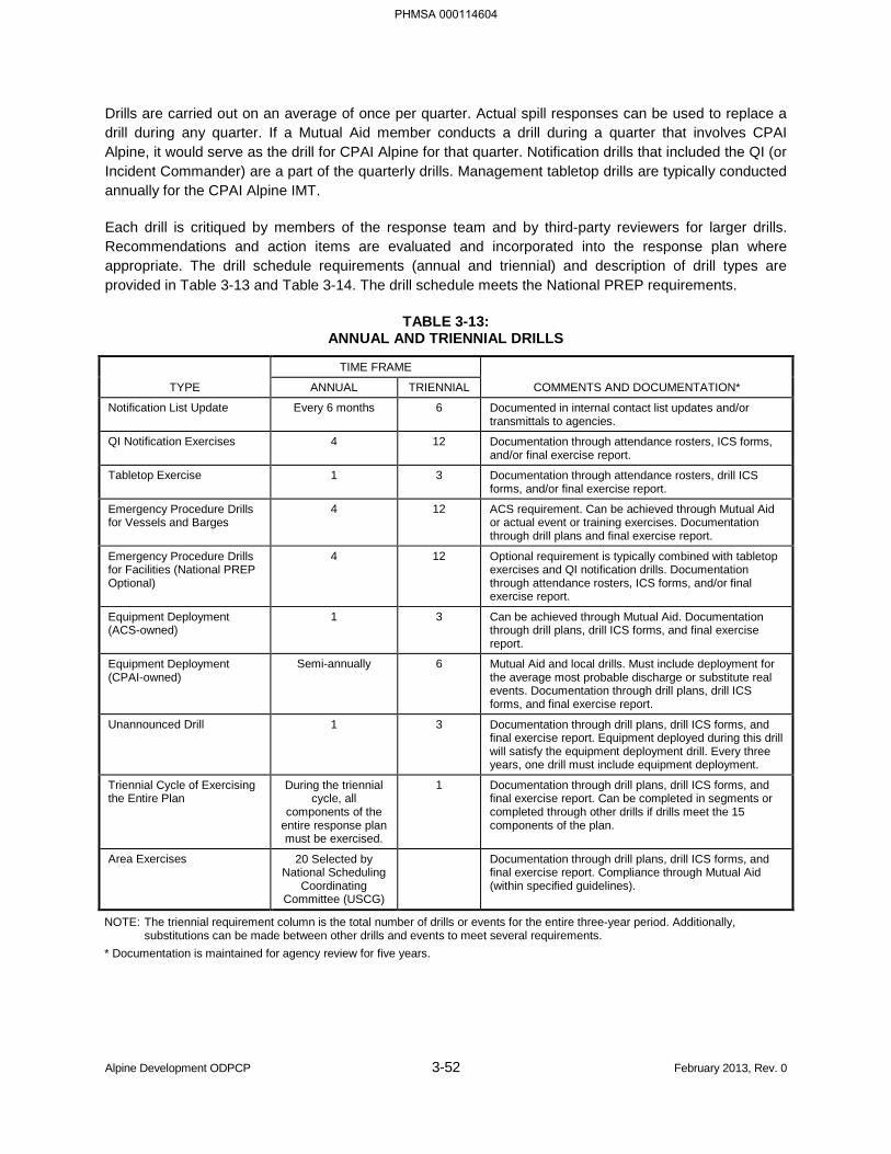
Alpine Development ODPCP 3-52 February 2013, Rev. 0
Drills are carried out on an average of once per quarter. Actual spill responses can be used to replace a drill during any quarter. If a Mutual Aid member conducts a drill during a quarter that involves CPAI Alpine, it would serve as the drill for CPAI Alpine for that quarter. Notification drills that included the QI (or Incident Commander) are a part of the quarterly drills. Management tabletop drills are typically conducted annually for the CPAI Alpine IMT.
Each drill is critiqued by members of the response team and by third-party reviewers for larger drills. Recommendations and action items are evaluated and incorporated into the response plan where appropriate. The drill schedule requirements (annual and triennial) and description of drill types are provided in Table 3-13 and Table 3-14. The drill schedule meets the National PREP requirements.
TABLE 3-13: ANNUAL AND TRIENNIAL DRILLS
TYPE
TIME FRAME
COMMENTS AND DOCUMENTATION* ANNUAL TRIENNIAL
Notification List Update Every 6 months 6 Documented in internal contact list updates and/or transmittals to agencies.
QI Notification Exercises 4 12 Documentation through attendance rosters, ICS forms, and/or final exercise report.
Tabletop Exercise 1 3 Documentation through attendance rosters, drill ICS forms, and/or final exercise report.
Emergency Procedure Drills for Vessels and Barges
4 12 ACS requirement. Can be achieved through Mutual Aid or actual event or training exercises. Documentation through drill plans and final exercise report.
Emergency Procedure Drills for Facilities (National PREP Optional)
4 12 Optional requirement is typically combined with tabletop exercises and QI notification drills. Documentation through attendance rosters, ICS forms, and/or final exercise report.
Equipment Deployment (ACS-owned)
1 3 Can be achieved through Mutual Aid. Documentation through drill plans, drill ICS forms, and final exercise report.
Equipment Deployment (CPAI-owned)
Semi-annually 6 Mutual Aid and local drills. Must include deployment for the average most probable discharge or substitute real events. Documentation through drill plans, drill ICS forms, and final exercise report.
Unannounced Drill 1 3 Documentation through drill plans, drill ICS forms, and final exercise report. Equipment deployed during this drill will satisfy the equipment deployment drill. Every three years, one drill must include equipment deployment.
Triennial Cycle of Exercising the Entire Plan
During the triennial cycle, all
components of the entire response plan must be exercised.
1 Documentation through drill plans, drill ICS forms, and final exercise report. Can be completed in segments or completed through other drills if drills meet the 15 components of the plan.
Area Exercises 20 Selected by National Scheduling
Coordinating Committee (USCG)
Documentation through drill plans, drill ICS forms, and final exercise report. Compliance through Mutual Aid (within specified guidelines).
NOTE: The triennial requirement column is the total number of drills or events for the entire three-year period. Additionally, substitutions can be made between other drills and events to meet several requirements.
* Documentation is maintained for agency review for five years.
PHMSA 000114604
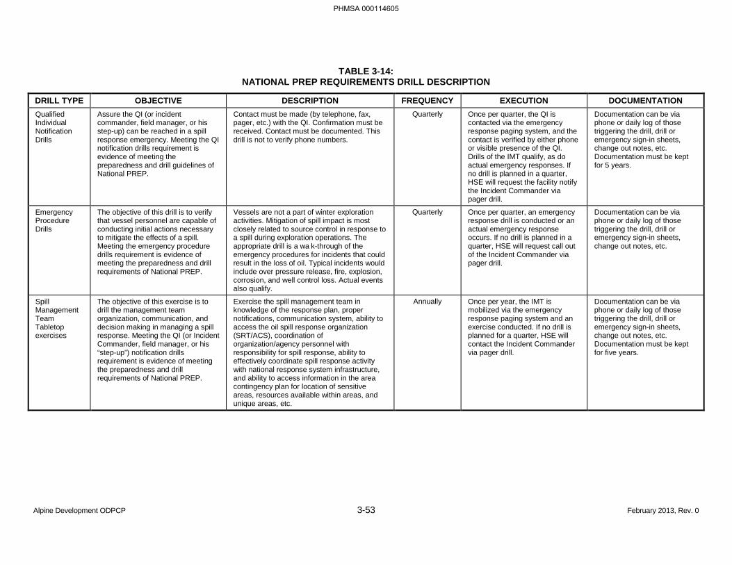
Alpine Development ODPCP 3-53 February 2013, Rev. 0
TABLE 3-14: NATIONAL PREP REQUIREMENTS DRILL DESCRIPTION
DRILL TYPE OBJECTIVE DESCRIPTION FREQUENCY EXECUTION DOCUMENTATION Qualified Individual Notification Drills
Assure the QI (or incident commander, field manager, or his step-up) can be reached in a spill response emergency. Meeting the QI notification drills requirement is evidence of meeting the preparedness and drill guidelines of National PREP.
Contact must be made (by telephone, fax, pager, etc.) with the QI. Confirmation must be received. Contact must be documented. This drill is not to verify phone numbers.
Quarterly Once per quarter, the QI is contacted via the emergency response paging system, and the contact is verified by either phone or visible presence of the QI. Drills of the IMT qualify, as do actual emergency responses. If no drill is planned in a quarter, HSE will request the facility notify the Incident Commander via pager drill.
Documentation can be via phone or daily log of those triggering the drill, drill or emergency sign-in sheets, change out notes, etc. Documentation must be kept for 5 years.
Emergency Procedure Drills
The objective of this drill is to verify that vessel personnel are capable of conducting initial actions necessary to mitigate the effects of a spill. Meeting the emergency procedure drills requirement is evidence of meeting the preparedness and drill requirements of National PREP.
Vessels are not a part of winter exploration activities. Mitigation of spill impact is most closely related to source control in response to a spill during exploration operations. The appropriate drill is a wa k-through of the emergency procedures for incidents that could result in the loss of oil. Typical incidents would include over pressure release, fire, explosion, corrosion, and well control loss. Actual events also qualify.
Quarterly Once per quarter, an emergency response drill is conducted or an actual emergency response occurs. If no drill is planned in a quarter, HSE will request call out of the Incident Commander via pager drill.
Documentation can be via phone or daily log of those triggering the drill, drill or emergency sign-in sheets, change out notes, etc.
Spill Management Team Tabletop exercises
The objective of this exercise is to drill the management team organization, communication, and decision making in managing a spill response. Meeting the QI (or Incident Commander, field manager, or his “step-up”) notification drills requirement is evidence of meeting the preparedness and drill requirements of National PREP.
Exercise the spill management team in knowledge of the response plan, proper notifications, communication system, ability to access the oil spill response organization (SRT/ACS), coordination of organization/agency personnel with responsibility for spill response, ability to effectively coordinate spill response activity with national response system infrastructure, and ability to access information in the area contingency plan for location of sensitive areas, resources available within areas, and unique areas, etc.
Annually Once per year, the IMT is mobilized via the emergency response paging system and an exercise conducted. If no drill is planned for a quarter, HSE will contact the Incident Commander via pager drill.
Documentation can be via phone or daily log of those triggering the drill, drill or emergency sign-in sheets, change out notes, etc. Documentation must be kept for five years.
PHMSA 000114605
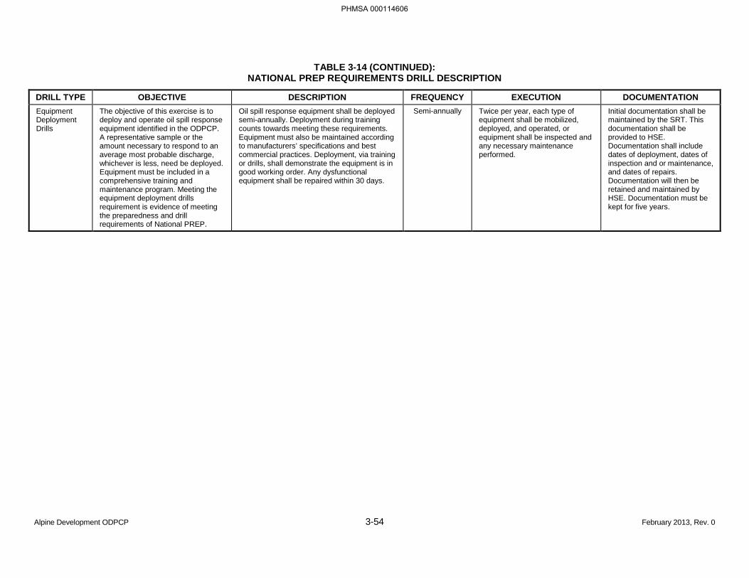
TABLE 3-14 (CONTINUED): NATIONAL PREP REQUIREMENTS DRILL DESCRIPTION
Alpine Development ODPCP 3-54 February 2013, Rev. 0
DRILL TYPE OBJECTIVE DESCRIPTION FREQUENCY EXECUTION DOCUMENTATION Equipment Deployment Drills
The objective of this exercise is to deploy and operate oil spill response equipment identified in the ODPCP. A representative sample or the amount necessary to respond to an average most probable discharge, whichever is less, need be deployed. Equipment must be included in a comprehensive training and maintenance program. Meeting the equipment deployment drills requirement is evidence of meeting the preparedness and drill requirements of National PREP.
Oil spill response equipment shall be deployed semi-annually. Deployment during training counts towards meeting these requirements. Equipment must also be maintained according to manufacturers’ specifications and best commercial practices. Deployment, via training or drills, shall demonstrate the equipment is in good working order. Any dysfunctional equipment shall be repaired within 30 days.
Semi-annually Twice per year, each type of equipment shall be mobilized, deployed, and operated, or equipment shall be inspected and any necessary maintenance performed.
Initial documentation shall be maintained by the SRT. This documentation shall be provided to HSE. Documentation shall include dates of deployment, dates of inspection and or maintenance, and dates of repairs. Documentation will then be retained and maintained by HSE. Documentation must be kept for five years.
PHMSA 000114606
Alpine Development ODPCP 3-55 February 2013, Rev. 0
Mutual Aid Drill
CPAI participates in an annual MAD exercise. In addition to actively participating in the MAD exercise, federal, state, and local agencies are involved in the development and evaluation of the drill. Every year, equipment is deployed at the MAD exercise per National PREP guidelines. The following are some of the components that may be tested through the MAD exercise:
Organizational Design
• Notifications (includes training on 24-hour notifications and reporting to the National Response Center),
• Staff mobilization, and
• Ability to operate within the response management system described in the plan.
Operational Response
• Discharge control,
• Assessment of discharge,
• Containment of discharge,
• Recovery of spilled material,
• Protection of economically and environmentally sensitive areas, and
• Disposal of recovered product.
Response Support
• Safety of response personnel,
• Communications,
• Transportation,
• Personnel support,
• Equipment maintenance and support,
• Procurement, and
• Documentation.
PHMSA 000114607
Alpine Development ODPCP 3-56 February 2013, Rev. 0
3.10 PROTECTION OF ENVIRONMENTALLY SENSITIVE AREAS [18 AAC 75.425(e)(3)(J)]
Priority protection sites, environmentally sensitive areas, and areas of public concern that may be impacted during a discharge are described in Section 1.6.3, Response Scenarios and Strategies. They are described in the ACS Technical Manual, Volume 2, Sheets 1 through 30 and 53. Protection strategies are described in the ACS Technical Manual, Volume 1, Tactics W-1 through W-6.
3.11 ADDITIONAL INFORMATION [18 AAC 75.425(e)(3)(K)]
Not applicable.
PHMSA 000114608
Alpine Development ODPCP 3-57 February 2013, Rev. 0
3.12 BIBLIOGRAPHY [18 AAC 75.425(e)(3)(L)]
Alaska Clean Seas (ACS). 2012. ACS Technical Manual, Volume 1, Tactics Descriptions; Volume 2, Map Atlas.
Alaska Regional Response Team (ARRT). 2008. The Alaska Federal/State Preparedness Plan for Response to Oil & Hazardous Substance Discharges/Releases (Unified Plan), Change 3, January 2010. Annex F, Appendix II, “In Situ Burning Guidelines for Alaska,” Revision 1, August 2008. http://dec.alaska.gov/spar/perp/permits/ISB_Rev1_March2008_Form.pdf
ARRT, 2012. Alaska Federal/State Preparedness Plan for Response to Oil & Hazardous Substance Discharges/Releases (Unified Plan), Volume II, Change 2, North Slope Subarea Contingency Plan, May.
Atwater, S.G. 1991. 1990 Endicott Environmental Monitoring Program Final Report: Ice Break-up and Freeze-up. Prepared by SAIC for the U.S. Army Corps of Engineers, Anchorage, Alaska.
Bech, C., P. Sveum, and I. Buist. 1993. The Effect of Wind, Ice and Waves on the In Situ Burning of Emulsions and Aged Oils. Proceedings of the Sixteenth Arctic and Marine Oilspill Program Technical Seminar, Calgary, AB. pp. 735-748.
Bronson, M., Thompson, E., McAdams F., and J. McHale. 2002. Ice Effects on Barge-based Oil Spill Response Systems in the Alaskan Beaufort Sea. Proceedings 25th Arctic and Marine Oilspill Program Technical Seminar (AMOP), Calgary, pp. 1253-1268.
Brown, H.M. and R.H. Goodman. 1986. In Situ Burning of Oil in Experimental Ice Leads. Environmental Studies Revolving Funds Report 064. National Energy Board, Calgary.
Buist, I.A. and D. F. Dickins. 1987. Experimental Spills of Crude Oil in Pack Ice. Proceedings of the 1987 Oil Spill Conference, April 6-9, Baltimore, Maryland. American Petroleum Institute, Washington, D.C., pp.373-382.
Campbell, T.E., Taylor, E. and D. Aurand. 1994. Ecological Risks Associated with Burning as a Spill Countermeasure in a Marine Environment. Proceedings of the 17th AMOP Technical Seminar, June 8-10, Vancouver, British Columbia, pp. 707-716.
Coastal Frontiers. 2001. Spring Breakup Equipment Access Test Program (Draft and Final), prepared for BP Exploration (Alaska), Inc., Anchorage, Alaska.
DF Dickins Associates Ltd., Vaudrey & Associates, Inc., and SL Ross Environmental Research Limited. 2000. Oil Spills in Ice Discussion Paper. Prepared for Alaska Clean Seas, Prudhoe Bay, Alaska.
Dickins, D.F. and K. Vaudrey. 2000. Typical Environmental Conditions During Freeze-Up in Nearshore Alaskan Beaufort Sea. Prepared for Alaska Clean Seas.
Guénette, C.C. and R. Wighus, 1996. In Situ Burning of Crude Oil and Emulsions in Broken Ice. Proceedings of the 19th MOP Technical Seminar. Calgary, AB. pp. 895-906.
Gavin, A. 1976. Wildlife of the North Slope. The Islands of Offshore Prudhoe Bay: The Snow Geese of Howe Island; The Seventh Year of Study. Atlantic Richfield Company. pp. 71.
Morrow, J.E. 1980. The Freshwater Fishes of Alaska. Alaska Northwest Publishing Co., Anchorage.
Norton, D.W., I.W. Ailes, and J.A. Curatolo. 1975. Ecological relationships of the island tundra avifauna near Prudhoe Bay, Alaska. J. Brown (ed.). Ecological Investigations of the Tundra Biome in the
PHMSA 000114609
Alpine Development ODPCP 3-58 February 2013, Rev. 0
Prudhoe Bay Region, Alaska. Biological Papers, University of Alaska. Special Report No. 2. pp. 125-133.
Parametrix, Inc. 1997. Alpine Development Project. Environmental Evaluation Document. September.
Polaris Applied Sciences, Inc. September 2003 (update). Oil Spill Strategy and Response Studies for the Channels of the Colville River Delta Region, Alaska. Prepared for Phillips Alaska, Inc.
Ray, S. and J.W. Aldrich. 1996. Part 4: Flood Magnitude and Frequency. pp. 35-40. In: M.T. Jorgenson, J.W. Aldrich, S.R. Ray, E.R. Pullman, Y. Shur, M.D. Smith, A. A. Stickney, and H.J. Walker. 1996. Geomorphology and Hydrology of the Colville River Delta, Alaska, 1995. Volume 1. Unpublished fourth annual report by ABR, Inc., Shannon and Wilson, Inc., and Louisiana State University to PAI Alaska, Inc., and Kuukpik Unit Owners, Anchorage, Alaska.
Scandpower A/S, Report No. 27.83.01/R1. 2001. “Blowout Frequency Assessment of Northstar.” July.
Shell Oil Company, Sohio Alaska Petroleum Company, Exxon Company, U.S.A., Amoco Production Company. 1983. Oil Spill Response in the Arctic – Part 2: Field Demonstrations in Broken Ice., Shell Oil Company, Sohio Alaska Petroleum Company, Exxon Company, U.S.A., Amoco Production Company. Anchorage, Alaska.
Singsaas, I., P. Brandvik, P. Daling, M. Reed and A. Lewis. 1994. Fate and Behavior of Oils Spilled in the Presence of Ice – a Comparison of the Results from Recent Laboratory, Mesoscale Flume and Field Tests. Proceedings of the 17th AMOP Technical Seminar, June 8-10, Vancouver, British Columbia, pp. 355-370.
SL Ross Environmental Research Ltd., DF Dickins Associates Ltd., and Alaska Clean Seas. 2003. Tests to Determine the Limits of In Situ Burning of Thin Oil Slicks in Broken Ice. Report prepared for the U.S. Minerals Management Service and ExxonMobil Upstream Research.
SL Ross Environmental Research Ltd., D.F. Dickins and Associates Ltd. and Vaudrey and Associates, Inc. 1998. Evaluation of Cleanup Capabilities for Large Blowout Spills in the Alaskan Beaufort Sea During Periods of Broken Ice. April 23.
SL Ross Environmental Research Ltd. and DF Dickins Associates Ltd. 1987. Field Research Spills to Investigate the Physical and Chemical Fate of Oil in Pack Ice. Environmental Studies Revolving Funds Report No. 062. 95 pages.
SL Ross Environmental Research Ltd. 1983. Evaluation of Industry’s Oil Spill Countermeasures Capability in Broken Ice Conditions in the Alaskan Beaufort Sea. Prepared for the Alaska Department of Environmental Conservation, Anchorage, Alaska.
Smith, N.K. and A. Diaz. 1987. In-Place Burning of Crude Oils in Broken Ice. Proceedings of the 1987 Oil Spill Conference, April 6-9, Baltimore, Maryland. American Petroleum Institute, Washington, D.C., pp. 383-387.
Steinhauer, M.S., and P.D. Boehm. 1992. The composition and distribution of saturated and aromatic hydrocarbons in nearshore sediments, river sediments, and coastal peat of the Alaskan Beaufort Sea: Implications for detecting anthropogenic hydrocarbon inputs. Marine Environmental Research. 33:223-253.
U.S. Geological Survey. 1977. Water Resources Data for Alaska, Water Year 1976. Water-Data Report AK-76-1. pp. 401.
PHMSA 000114610

Alpine Development ODPCP 3-59 February 2013, Rev. 0
Vaudrey & Associates, Inc. 1998 Memorandum. Broken ice periods for selected production sites along the Alaskan Beaufort Coast. June 27.
PHMSA 000114611

Alpine Development ODPCP 3-60 February 2013, Rev. 0
BLANK PAGE
PHMSA 000114612
Alpine Development ODPCP 4-1 February 2013, Rev. 0
PART 4 BEST AVAILABLE TECHNOLOGY [18 AAC 75.425(e)(4)]
This section discusses the best available technology (BAT) requirements contained in 18 AAC 75.425(e)(4)(A), (B), and (C) to address technologies not subject to response planning or performance standards in 18 AAC 75.445(k)(1) and (2). The discussion of each technology covers the requirement to analyze applicable technologies and to provide a justification that the technology is BAT. The spill prevention and response equipment for Alpine meets the BAT requirements.
4.1 COMMUNICATIONS [18 AAC 75.425(e)(4)(A)(i)]
The communications system for use in a spill response at Alpine is described in the Alaska Clean Seas (ACS) Technical Manual Tactic L-11A.
4.2 SOURCE CONTROL [18 AAC 75.425(e)(4)(A)(i)]
BAT analysis of source control for a well blowout, pipeline leak, and tank overflow is provided in the following subsections. CPAI maintains an Emergency Preparedness and Blowout Contingency Plan that addresses management of well control events, including notifications and resources for surface control measures, relief well drilling, and blowout ignition. CPAI will use the services of a professional well control firm if well control is not regained by conventional mechanical means or natural occurrences.
4.2.1 Well Source Control
Industry has conducted thorough investigation and research into the use of well capping to regain control of a worst-case well blowout, which is typically defined as the response planning standard (RPS) volume for an exploration or production well. This BAT analysis reviews the techniques and methods to control a “deep” well blowout that has the potential to release liquid hydrocarbons at the surface. Inherent to this analysis are the assumptions that all primary and secondary levels of well control have failed and that all dynamic and mechanical attempts to regain primary or secondary well control have been ineffective.
Once an incident has escalated to a blowout scenario of the magnitude described above, the two methods of well control are well capping and relief well drilling. Industry concludes well capping constitutes the BAT for source control of a well blowout. Historical evidence indicates well capping has greater reliability and application for well control compared to that of relief well drilling. Table 4-1 summarizes well capping as BAT for a well blowout. The rationale for acceptance of well capping as BAT is provided in the following discussion.
Well Capping
As the oil and gas industry continues to advance, well capping techniques have been developed and have proven to be efficient and effective in regaining control of damaged wells and in reducing associated environmental impacts. Significant improvements to well capping techniques and procedures have been developed by a variety of well control specialist companies throughout the world. CPAI has the ability to mobilize specialized personnel and equipment to a North Slope location within 24 to 48 hours of notification.
PHMSA 000114613
Alpine Development ODPCP 4-2 February 2013, Rev. 0
Well capping is both compatible and feasible with all drilling operations because the technology is applied at the surface. There are no sensitivities to well types (extended reach drilling [ERD], horizontal, etc.) or location (remote, island, etc.). Well capping techniques have been applied both to onshore and offshore locations and have been historically proven successful in regaining well control in shorter durations. Well capping techniques are preferred over the more time-consuming alternative of drilling a relief well. On the whole, blowouts are typically controlled with more conventional surface control or dynamic kill methods (blowout preventer [BOP] equipment, weighted drilling muds, or cement placement in the well) before well capping is attempted or required; drilling relief wells is often a last resort when surface control or kill methods fail and well capping is not feasible.
The U.S. Bureau of Ocean Energy Management (formerly Minerals Management Service) and SINTEF Civil and Environmental Engineering (Norway) data indicate well capping technologies provide the shortest duration and most effective option for regaining well control and minimizing environmental impacts once all other control measures have failed. This is shown by the consistent application of well capping instead of relief well drilling in response to well control events and also by the associated short duration to successfully regain well control using well capping, as compared to relief well drilling.
Other than the initial cost of the well control equipment currently stationed on the North Slope, maintaining an open contract with CPAI’s single point of contact for well control, Wild Well Control, is a minimal annual cost. Any additional services required during an actual response would be provided at previously agreed-to rates.
Well control events where well capping would not be the preferred response involve events in which the potential to release liquid hydrocarbons to the surface is highly unlikely (e.g., shallow gas, compromised surface casing or surface casing cement jobs, broaching or reasonable concern of broaching, inaccessible wellhead and/or casing).
Relief Well
The lead time involved in relocating a rig to a surface location and drilling a relief well necessitates early planning. Due to the long lead times associated with drilling a relief well, the relief well plan may be initiated concurrently with the implementation of surface control methods. If surface control methods fail, CPAI relief well plans are fully implemented. CPAI’s decisions are made by management in accordance with procedures contained in the incident-specific relief well plan. It should be recognized that a relief well is generally considered as a last resort to regain control of a blowout. It is far more common to kill the well with surface kill techniques or for the well to cease flowing due to depletion or the formation of a natural bridge in the wellbore.
Relief well drilling technology is compatible with North Slope drilling operations, although it may be sensitive to both the well location and well type. Multiple drilling rigs that are capable of drilling a relief well are under contract on the North Slope. Downhole and surface equipment (e.g., tubulars, wellheads, etc.) to support relief well drilling operations are also available. Rig-sharing agreements are in place between CPAI and BP Exploration (Alaska) Inc. to facilitate optimum response times and to ensure rig availability in the event of a blowout.
Relief well drilling has been attempted only once as a mitigation measure to control a blowout on the North Slope. This was the ARCO Cirque gas well blowout in 1992, where well control was regained by a combination of well capping techniques and an assist from natural bridging before the relief well reached total depth.
PHMSA 000114614
Alpine Development ODPCP 4-3 February 2013, Rev. 0
Relief well drilling is similar to current methods used to drill and complete North Slope wells today, and advances in directional drilling technology that allow for more precise wellbore placement increase the likelihood of the success of a relief well. However, relief well attempts are thus more sensitive to blowout well location and/or blowout well type. For extended reach wells, or remote locations with limited access, relief well drilling is both logistically challenging and time consuming, thereby adding an undesired increase to the overall environmental impact (volume spilled) from the blowout.
Well control events where the preferred response methods would be relief well drilling involve situations in which the potential to release liquid hydrocarbons to the surface is highly unlikely (i.e., shallow gas, compromised surface casing or surface casing cement jobs, broaching or reasonable concern of broaching, inaccessible wellhead and/or casing).
4.2.2 Pipeline Source Control
Crude Oil Transmission Pipeline
4.2.3 Tank Source Control
Source control procedures for purposes of this BAT analysis relate to the fill procedures and inlet valves controlling flow to regulated oil storage tanks identified in Appendix C, Table C-1. BAT analysis for tank source control is discussed in Table 4-3.
PHMSA 000114615
(b) (3), (b) (7)(F)
(b) (3), (b) (7)(F)
Alpine Development ODPCP 4-4 February 2013, Rev. 0
The tanks listed below are fitted with truck fill connections only. The tanks are:
• Lube oil tank,
• Completions fluid storage tanks, and
• Brine storage tanks.
Tank fill connections are grouped together on the east side of the Alpine Central Processing Facility tank farm. An impound basin will be provided under the truck loading/unloading area to ensure any minor discharges that might take place during filling operations are contained. Filling operations are closely supervised to ensure fill procedures are followed. Inlet valves on these truck fill connections are one-quarter-turn ball valves that must be operated manually.
Manual intervention is effective in source control because operators are required to remain at or near the tanks during loading and unloading operations, and because secondary containment and high-level audible and visual alarms are provided for these tanks.
The primary source of supply for the diesel fuel tank is the 2-inch-diameter diesel pipeline from Kuparuk. Filling of the tank from the pipeline will be an unmanned operation. The 2-inch-diameter diesel pipeline is fitted with an automated fail safe one-quarter-turn ball valve mounted close to the tank inlet that closes on detection of a high-level condition in the tank. The diesel tank is also fitted with a local truck fill connection so the tank can be used at times when the pipeline supply may be unavailable. Truck filling operations are closely supervised in the same manner as the three tanks discussed above. The truck fill connection on the diesel tank is fitted with a one-quarter-turn ball valve that must be operated manually. The truck fill connection is also fitted with a check valve to prevent back flow from the tank. The combination of valves is considered BAT for the service type.
PHMSA 000114616
(b) (3), (b) (7)(F)

Alpine Development ODPCP 4-5 February 2013, Rev. 0
PHMSA 000114617
(b) (3), (b) (7)(F)

Alpine Development ODPCP 4-6 February 2013, Rev. 0
PHMSA 000114618
(b) (3), (b) (7)(F)

Alpine Development ODPCP 4-7 February 2013, Rev. 0
PHMSA 000114619
(b) (3), (b) (7)(F)

Alpine Development ODPCP 4-8 February 2013, Rev. 0
PHMSA 000114620
(b) (3), (b) (7)(F)

Alpine Development ODPCP 4-9 February 2013, Rev. 0
PHMSA 000114621
(b) (3), (b) (7)(F)

Alpine Development ODPCP 4-10 February 2013, Rev. 0
PHMSA 000114622
(b) (3), (b) (7)(F)
Alpine Development ODPCP 4-11 February 2013, Rev. 0
4.3 TRAJECTORY ANALYSES AND FORECASTS [18 AAC 75.425(e)(4)(A)(i)]
Trajectory analyses and forecasts are described in the ACS Technical Manual Tactic L-11B.
4.4 WILDLIFE CAPTURE, TREATMENT, AND RELEASE PROGRAMS [18 AAC 75.425(e)(4)(A)(i)]
Wildlife capture, treatment, and release programs are described in the ACS Technical Manual Tactic L-11C.
4.5 CATHODIC PROTECTION FOR FIELD-CONSTRUCTED OIL STORAGE TANKS [18 AAC 75.425(e)(4)(A)(ii)]
Alpine tanks are shop-fabricated; the regulations requiring cathodic protection on field-constructed tanks do not apply. As such, BAT analysis for cathodic protection is not applicable.
4.6 LEAK DETECTION SYSTEM FOR FIELD-CONSTRUCTED OIL STORAGE TANKS [18 AAC 75.425(e)(4)(A)(ii)]
Alpine tanks are shop-fabricated; the regulations requiring leak detection on field-constructed tanks do not apply. BAT analysis for leak detection systems is not applicable.
4.7 LIQUID LEVEL DETERMINATION [18 AAC 75.425(e)(4)(A)(ii)]
PHMSA 000114623
(b) (3), (b) (7)(F)

Alpine Development ODPCP 4-12 February 2013, Rev. 0
PHMSA 000114624
(b) (3), (b) (7)(F)

Alpine Development ODPCP 4-13 February 2013, Rev. 0
PHMSA 000114625
(b) (3), (b) (7)(F)

Alpine Development ODPCP 4-14 February 2013, Rev. 0
PHMSA 000114626
(b) (3), (b) (7)(F)
Alpine Development ODPCP 4-15 February 2013, Rev. 0
4.8 MAINTENANCE PROCEDURES FOR BURIED STEEL FACILITY OIL PIPING [18 AAC 75.425(e)(4)(A)(ii)]
The buried piping for tank CF-T-50090 at CD-1 is abandoned in-place. However, it is composed of a non-corrosive stainless steel material, wrapped in insulation coated with polyvinyl chloride (PVC), and is centered within a fusion-joined high-density prolyethylene (HDPE) pipe casing. The HDPE pipe casing prevents the piping from contacting soil or water conditions. Corrosion is not anticipated because the pipe is stainless steel and encased in HDPE pipe casing.
4.9 PROTECTIVE COATING AND CATHODIC PROTECTION FOR FACILITY OIL PIPING [18 AAC 75.425(e)(4)(A)(ii)]
4.9.1 Pipeline Corrosion Protective (Anti-Corrosion) Wrapping or Coating
As required by 18 AAC 75.080(d) and 18 AAC 75.080(e)(2)(A), the buried pipelines in the horizontal directional drilling (HDD) segment under the Colville River are protected from external corrosion by an external coating. Available technologies for pipeline wrapping or coating are:
• Dual-layer fusion bonded epoxy (FBE) for corrosion and mechanical protection,
• Conventional single-layer FBE for corrosion protection,
• Paint,
• Ceramic,
• Cold tar enamel, and
• Neoprene or foam.
Of these six technologies, dual-layer FBE is considered BAT based on the physical properties of each technology in relation to the physical environment of the Alpine pipelines and the cost of FBE relative to a neoprene or foam coating system.
Paint and ceramic coatings are not effective for the pipelines because these materials are brittle. The pipelines require a coating material that is ductile, because the pipelines may be subjected to high-bending strains potentially caused by permafrost thaw settlement. Neoprene or foam-type coatings are ductile and durable; however, they are more costly than FBE coatings. Also, neoprene and foam coatings reduce the weight of the pipelines, and more cost would be incurred to provide additional weight to the pipelines for stability during pipe-laying operations.
Both dual-layer and single-layer FBE coatings are ductile; however, dual-layer FBE, composed of an inner layer of conventional FBE for corrosion protection and an outer layer of impact-resistant FBE for mechanical protection, is more durable (hence more transferable) than a single-layer FBE coating. Dual-layer FBE has been used on other pipelines and is readily available for the Alpine pipelines. The dual-layer FBE coating’s inner layer is the conventional FBE material that has been effective as a corrosion protection coating on marine pipelines. Both layers, which are feasible to apply, have a low coating breakdown factor that causes less impact to the environment while making the dual-layer FBE coating compatible with sacrificial anodes. High coating breakdown factors adversely affect sacrificial anode systems. The cost to apply the dual-layer FBE coating (in a new condition) is considered reasonable by
PHMSA 000114627
Alpine Development ODPCP 4-16 February 2013, Rev. 0
CPAI. Therefore, a dual-layer FBE coating is considered BAT suited for the Alpine pipelines. If it is determined that the durability of the impact-resistant layer of FBE is not required, a single layer of corrosion-protective FBE may be used.
The buried piping for tank CF-T-50090 at CD-1, which is abandoned in-place, is not wrapped or coated for corrosion protection. The piping is composed of a non-corrosive stainless steel material, wrapped in insulation coated with PVC, and is centered within a fusion-joined HDPE pipe casing. The HDPE pipe casing prevents the piping from contacting soil or water conditions. The piping is subject to an ADEC compliance waiver of cathodic protection and protective wrapping/coating (see Section 2.6).
4.9.2 Cathodic Protection System
The buried piping for tank CF-T-50090 at CD-1, which is abandoned in-place, does not have cathodic protection. The piping is composed of a non-corrosive stainless steel material, wrapped in insulation coated with PVC, and is centered within a fusion-joined HDPE pipe casing. The HDPE pipe casing prevents the piping from contacting soil or water conditions. The piping is subject to an ADEC compliance waiver of cathodic protection and protective wrapping/coating (see Section 2.6).
4.10 CORROSION SURVEYS [18 AAC 75.425(e)(4)(A)(ii)]
Not applicable; cathodic protection is not installed on facility oil piping.
4.11 PIPELINE LEAK DETECTION, MONITORING, AND OPERATIONS [18 AAC 75.425(e)(4)((A)(iv)]
4.11.1 Aboveground Crude Oil Transmission Pipeline
PHMSA 000114628
(b) (3), (b) (7)(F)

Alpine Development ODPCP 4-17 February 2013, Rev. 0
4.11.2 Belowground Crude Oil Transmission Pipeline
PHMSA 000114629
(b) (3), (b) (7)(F)
(b) (3), (b) (7)(F)

Alpine Development ODPCP 4-18 February 2013, Rev. 0
PHMSA 000114630
(b) (3), (b) (7)(F)


Alpine Development ODPCP 4-21 February 2013, Rev. 0
PHMSA 000114633
(b) (3), (b) (7)(F)

Alpine Development ODPCP 4-22 February 2013, Rev. 0
PHMSA 000114634
(b) (3), (b) (7)(F)
PART 5 RESPONSE PLANNING STANDARD [18 AAC 75.425(e)(5)]
For purposes of this plan, the applicable response planning standard (RPS) volumes are discussed in this section.
5.1 STORAGE TANK RUPTURE [18 AAC 75.432]
5.2 PRODUCTION WELL BLOWOUT [18 AAC 75.434]
The production numbers below were obtained from the Alaska Oil and Gas Conservation Commission and are publically available data.
PHMSA 000114635
(b) (7)(F), (b) (3)
(b) (7)(F), (b) (3)

The receiving environment is a gravel production well pad surrounded by tundra, tundra lakes, and channels of the Colville River system. Oil travels from the well in an aerial plume.
5.3 CRUDE OIL TRANSMISSION PIPELINE SPILL TO MILUVEACH RIVER [18 AAC 75.436]
PHMSA 000114636
(b) (7)(F), (b) (3)
5.4 CRUDE OIL TRANSMISSION PIPELINE SPILL TO KACHEMACH RIVER [18 AAC 75.436]
(b) (7)(F), (b) (3)
(b) (7)(F), (b) (3)
5.5 CRUDE OIL TRANSMISSION PIPELINE SPILL TO COLVILLE RIVER [18 AAC 75.436]
(b) (7)(F), (b) (3)
(b) (7)(F), (b) (3)

(b) (7)(F), (b) (3)

Alpine Development ODPCP 5-6 February 2013, Rev. 0
BLANK PAGE
PHMSA 000114640
APPENDIX A
ALPINE PROJECT: OIL PIPELINE SPILL ISOLATION STRATEGY
PHMSA 000114641

BLANK PAGE
PHMSA 000114642
PHMSA 000114643
PHMSA 000114644
PHMSA 000114645
PHMSA 000114648
PHMSA 000114649
PHMSA 000114650
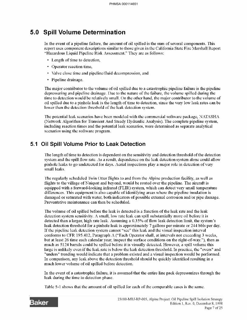
PHMSA 000114651
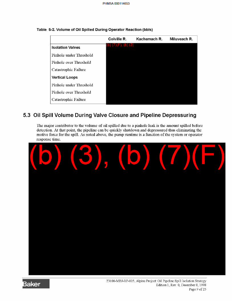
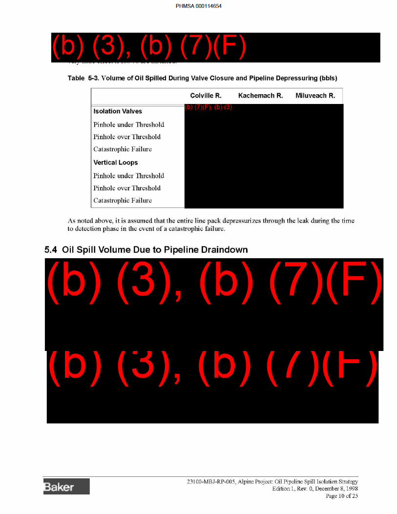
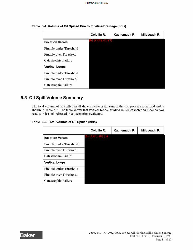

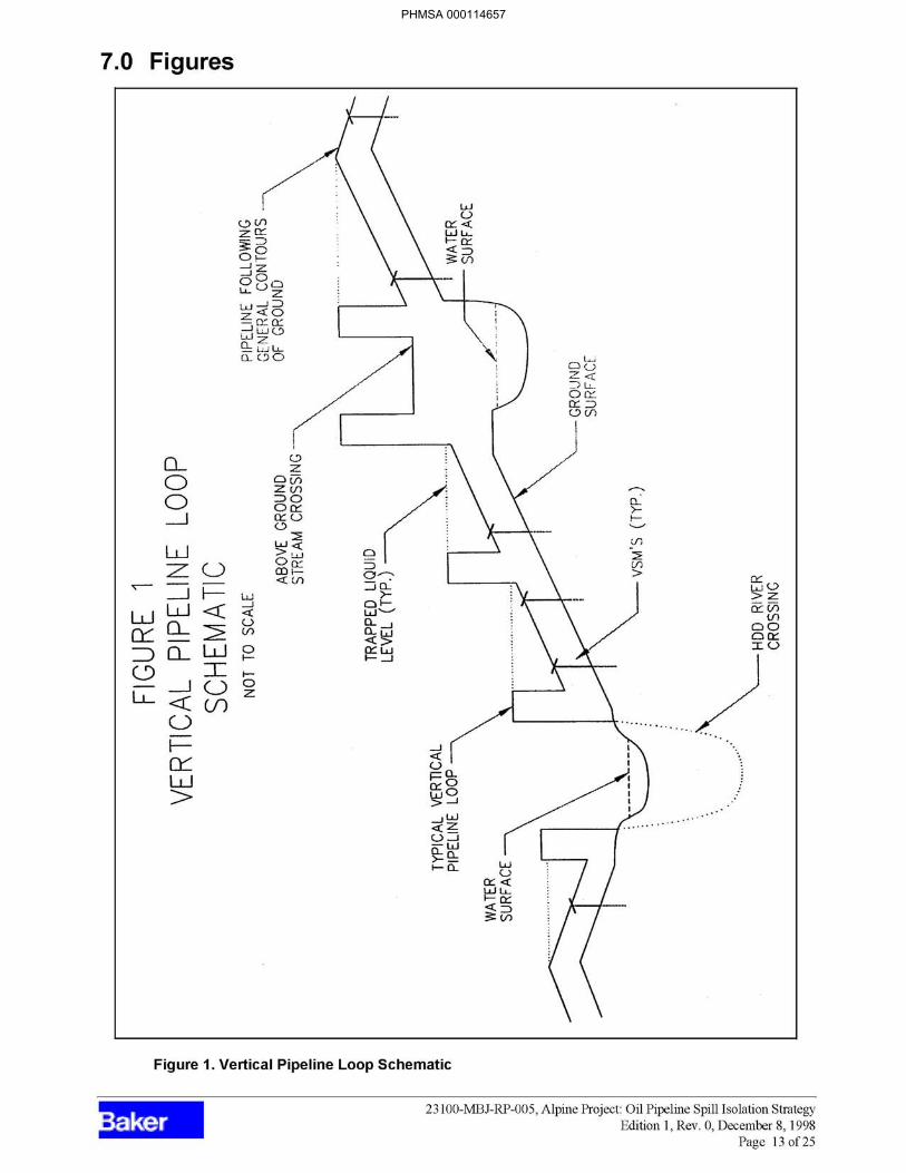
PHMSA 000114657


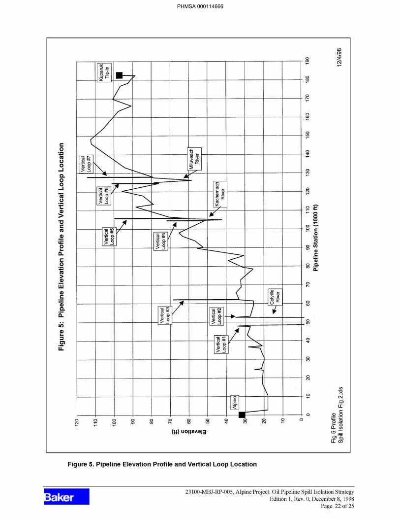
PHMSA 000114666
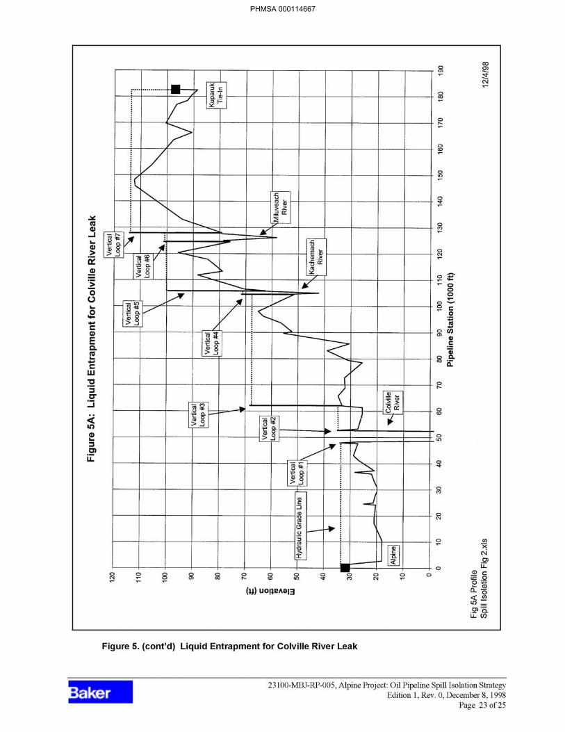
PHMSA 000114667
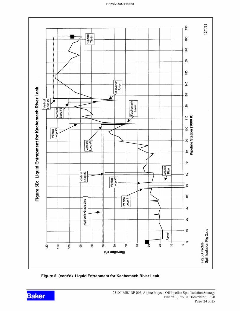
PHMSA 000114668
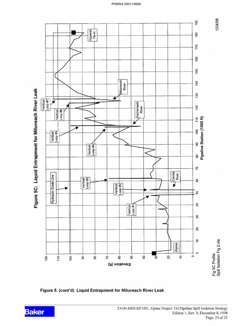
PHMSA 000114669

PHMSA 000114670
APPENDIX B
ALPINE SPILL HISTORY
PHMSA 000114671

BLANK PAGE
PHMSA 000114672
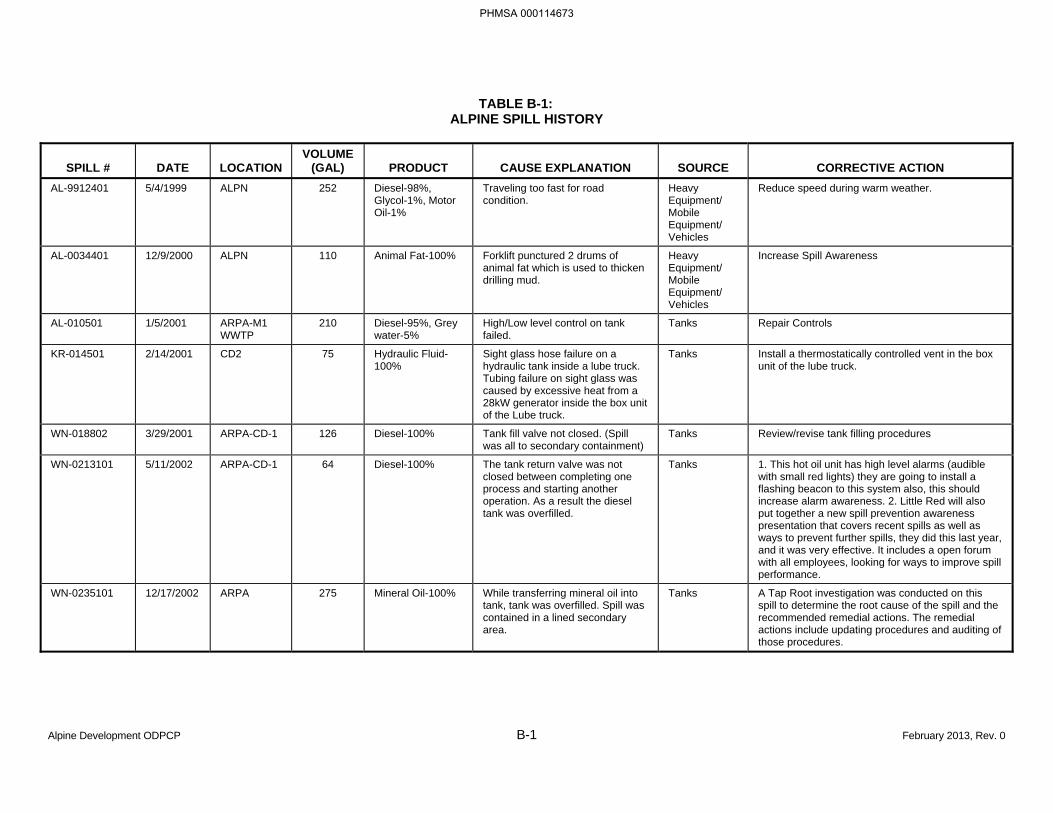
Alpine Development ODPCP B-1 February 2013, Rev. 0
TABLE B-1: ALPINE SPILL HISTORY
SPILL # DATE LOCATION VOLUME
(GAL) PRODUCT CAUSE EXPLANATION SOURCE CORRECTIVE ACTION AL-9912401 5/4/1999 ALPN 252 Diesel-98%,
Glycol-1%, Motor Oil-1%
Traveling too fast for road condition.
Heavy Equipment/ Mobile Equipment/ Vehicles
Reduce speed during warm weather.
AL-0034401 12/9/2000 ALPN 110 Animal Fat-100% Forklift punctured 2 drums of animal fat which is used to thicken drilling mud.
Heavy Equipment/ Mobile Equipment/ Vehicles
Increase Spill Awareness
AL-010501 1/5/2001 ARPA-M1 WWTP
210 Diesel-95%, Grey water-5%
High/Low level control on tank failed.
Tanks Repair Controls
KR-014501 2/14/2001 CD2 75 Hydraulic Fluid-100%
Sight glass hose failure on a hydraulic tank inside a lube truck. Tubing failure on sight glass was caused by excessive heat from a 28kW generator inside the box unit of the Lube truck.
Tanks Install a thermostatically controlled vent in the box unit of the lube truck.
WN-018802 3/29/2001 ARPA-CD-1 126 Diesel-100% Tank fill valve not closed. (Spill was all to secondary containment)
Tanks Review/revise tank filling procedures
WN-0213101 5/11/2002 ARPA-CD-1 64 Diesel-100% The tank return valve was not closed between completing one process and starting another operation. As a result the diesel tank was overfilled.
Tanks 1. This hot oil unit has high level alarms (audible with small red lights) they are going to install a flashing beacon to this system also, this should increase alarm awareness. 2. Little Red will also put together a new spill prevention awareness presentation that covers recent spills as well as ways to prevent further spills, they did this last year, and it was very effective. It includes a open forum with all employees, looking for ways to improve spill performance.
WN-0235101 12/17/2002 ARPA 275 Mineral Oil-100% While transferring mineral oil into tank, tank was overfilled. Spill was contained in a lined secondary area.
Tanks A Tap Root investigation was conducted on this spill to determine the root cause of the spill and the recommended remedial actions. The remedial actions include updating procedures and auditing of those procedures.
PHMSA 000114673
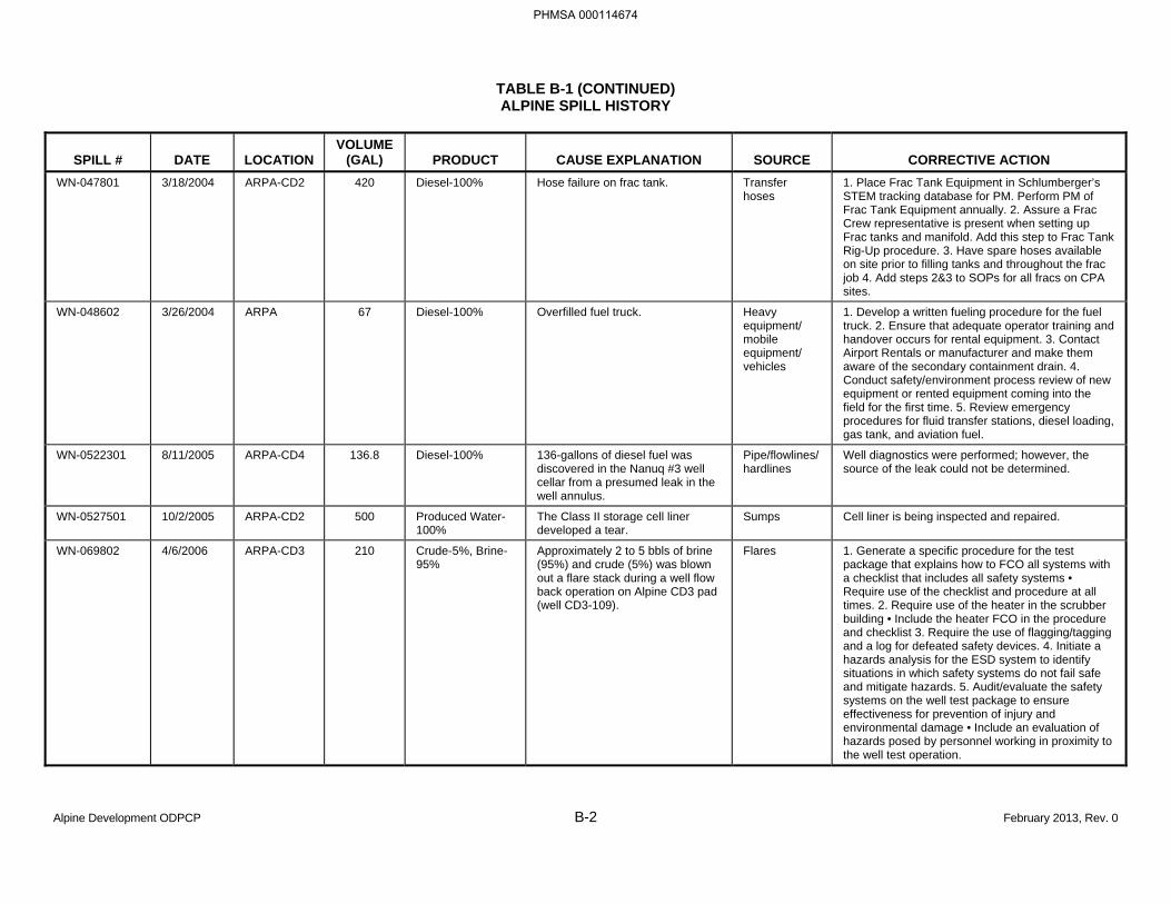
TABLE B-1 (CONTINUED) ALPINE SPILL HISTORY
Alpine Development ODPCP B-2 February 2013, Rev. 0
SPILL # DATE LOCATION VOLUME
(GAL) PRODUCT CAUSE EXPLANATION SOURCE CORRECTIVE ACTION WN-047801 3/18/2004 ARPA-CD2 420 Diesel-100% Hose failure on frac tank. Transfer
hoses 1. Place Frac Tank Equipment in Schlumberger’s STEM tracking database for PM. Perform PM of Frac Tank Equipment annually. 2. Assure a Frac Crew representative is present when setting up Frac tanks and manifold. Add this step to Frac Tank Rig-Up procedure. 3. Have spare hoses available on site prior to filling tanks and throughout the frac job 4. Add steps 2&3 to SOPs for all fracs on CPA sites.
WN-048602 3/26/2004 ARPA 67 Diesel-100% Overfilled fuel truck. Heavy equipment/ mobile equipment/ vehicles
1. Develop a written fueling procedure for the fuel truck. 2. Ensure that adequate operator training and handover occurs for rental equipment. 3. Contact Airport Rentals or manufacturer and make them aware of the secondary containment drain. 4. Conduct safety/environment process review of new equipment or rented equipment coming into the field for the first time. 5. Review emergency procedures for fluid transfer stations, diesel loading, gas tank, and aviation fuel.
WN-0522301 8/11/2005 ARPA-CD4 136.8 Diesel-100% 136-gallons of diesel fuel was discovered in the Nanuq #3 well cellar from a presumed leak in the well annulus.
Pipe/flowlines/ hardlines
Well diagnostics were performed; however, the source of the leak could not be determined.
WN-0527501 10/2/2005 ARPA-CD2 500 Produced Water-100%
The Class II storage cell liner developed a tear.
Sumps Cell liner is being inspected and repaired.
WN-069802 4/6/2006 ARPA-CD3 210 Crude-5%, Brine-95%
Approximately 2 to 5 bbls of brine (95%) and crude (5%) was blown out a flare stack during a well flow back operation on Alpine CD3 pad (well CD3-109).
Flares 1. Generate a specific procedure for the test package that explains how to FCO all systems with a checklist that includes all safety systems • Require use of the checklist and procedure at all times. 2. Require use of the heater in the scrubber building • Include the heater FCO in the procedure and checklist 3. Require the use of flagging/tagging and a log for defeated safety devices. 4. Initiate a hazards analysis for the ESD system to identify situations in which safety systems do not fail safe and mitigate hazards. 5. Audit/evaluate the safety systems on the well test package to ensure effectiveness for prevention of injury and environmental damage • Include an evaluation of hazards posed by personnel working in proximity to the well test operation.
PHMSA 000114674
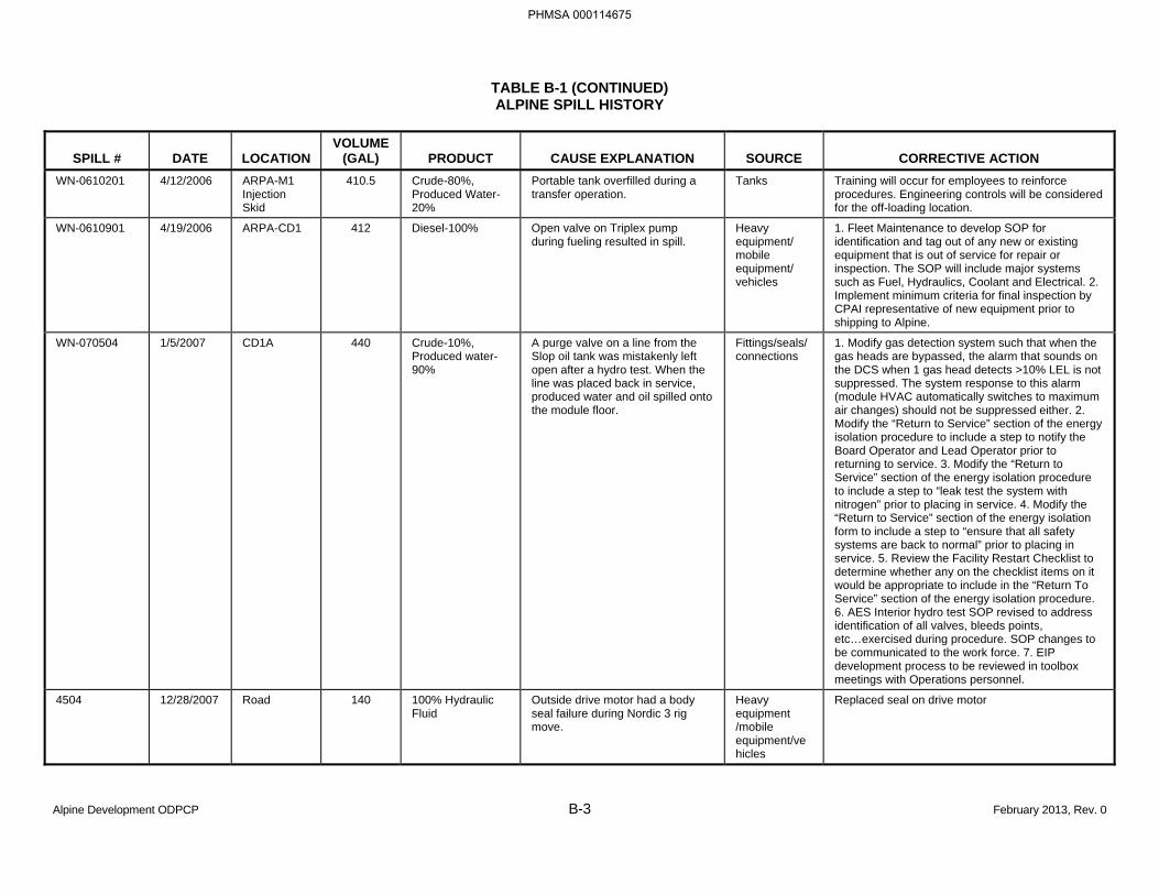
TABLE B-1 (CONTINUED) ALPINE SPILL HISTORY
Alpine Development ODPCP B-3 February 2013, Rev. 0
SPILL # DATE LOCATION VOLUME
(GAL) PRODUCT CAUSE EXPLANATION SOURCE CORRECTIVE ACTION WN-0610201 4/12/2006 ARPA-M1
Injection Skid
410.5 Crude-80%, Produced Water-20%
Portable tank overfilled during a transfer operation.
Tanks Training will occur for employees to reinforce procedures. Engineering controls will be considered for the off-loading location.
WN-0610901 4/19/2006 ARPA-CD1 412 Diesel-100% Open valve on Triplex pump during fueling resulted in spill.
Heavy equipment/ mobile equipment/ vehicles
1. Fleet Maintenance to develop SOP for identification and tag out of any new or existing equipment that is out of service for repair or inspection. The SOP will include major systems such as Fuel, Hydraulics, Coolant and Electrical. 2. Implement minimum criteria for final inspection by CPAI representative of new equipment prior to shipping to Alpine.
WN-070504 1/5/2007 CD1A 440 Crude-10%, Produced water-90%
A purge valve on a line from the Slop oil tank was mistakenly left open after a hydro test. When the line was placed back in service, produced water and oil spilled onto the module floor.
Fittings/seals/ connections
1. Modify gas detection system such that when the gas heads are bypassed, the alarm that sounds on the DCS when 1 gas head detects >10% LEL is not suppressed. The system response to this alarm (module HVAC automatically switches to maximum air changes) should not be suppressed either. 2. Modify the “Return to Service” section of the energy isolation procedure to include a step to notify the Board Operator and Lead Operator prior to returning to service. 3. Modify the “Return to Service” section of the energy isolation procedure to include a step to “leak test the system with nitrogen” prior to placing in service. 4. Modify the “Return to Service” section of the energy isolation form to include a step to “ensure that all safety systems are back to normal” prior to placing in service. 5. Review the Facility Restart Checklist to determine whether any on the checklist items on it would be appropriate to include in the “Return To Service” section of the energy isolation procedure. 6. AES Interior hydro test SOP revised to address identification of all valves, bleeds points, etc…exercised during procedure. SOP changes to be communicated to the work force. 7. EIP development process to be reviewed in toolbox meetings with Operations personnel.
4504 12/28/2007 Road 140 100% Hydraulic Fluid
Outside drive motor had a body seal failure during Nordic 3 rig move.
Heavy equipment /mobile equipment/vehicles
Replaced seal on drive motor
PHMSA 000114675
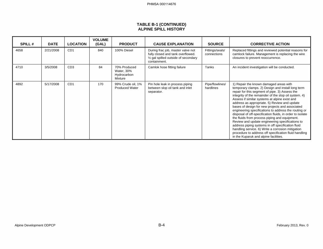
TABLE B-1 (CONTINUED) ALPINE SPILL HISTORY
Alpine Development ODPCP B-4 February 2013, Rev. 0
SPILL # DATE LOCATION VOLUME
(GAL) PRODUCT CAUSE EXPLANATION SOURCE CORRECTIVE ACTION 4658 2/21/2008 CD1 840 100% Diesel During frac job, master valve not
fully closed and tank overflowed. ½ gal spilled outside of secondary containment.
Fittings/seals/connections
Replaced fittings and reviewed potential reasons for camlock failure. Management is replacing the wire closures to prevent reoccurrence.
4710 3/5/2008 CD3 84 70% Produced Water, 30% Hydrocarbon Mixture
Camlok hose fitting failure Tanks An incident investigation will be conducted.
4892 5/17/2008 CD1 170 99% Crude oil, 1% Produced Water
Pin hole leak in process piping between slop oil tank and inlet separator.
Pipe/flowlines/hardlines
1) Repair the known damaged areas with temporary clamps. 2) Design and install long term repair for this segment of pipe. 3) Assess the integrity of the remainder of the slop oil system. 4) Assess if similar systems at alpine exist and address as appropriate. 5) Review and update bases of design for new projects and associated engineering specifications to address the routing or disposal of off-specification fluids, in order to isolate the fluids from process piping and equipment. Review and update engineering specifications to address piping systems in off specification fluid handling service. 6) Write a corrosion mitigation procedure to address off specification fluid handling in the Kuparuk and alpine facilities.
PHMSA 000114676
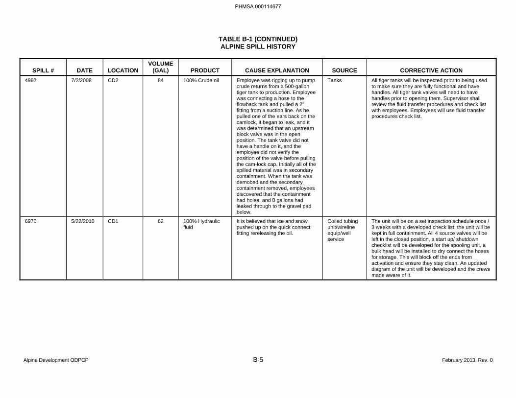
TABLE B-1 (CONTINUED) ALPINE SPILL HISTORY
Alpine Development ODPCP B-5 February 2013, Rev. 0
SPILL # DATE LOCATION VOLUME
(GAL) PRODUCT CAUSE EXPLANATION SOURCE CORRECTIVE ACTION 4982 7/2/2008 CD2 84 100% Crude oil Employee was rigging up to pump
crude returns from a 500-gallon tiger tank to production. Employee was connecting a hose to the flowback tank and pulled a 2" fitting from a suction line. As he pulled one of the ears back on the camlock, it began to leak, and it was determined that an upstream block valve was in the open position. The tank valve did not have a handle on it, and the employee did not verify the position of the valve before pulling the cam-lock cap. Initially all of the spilled material was in secondary containment. When the tank was demobed and the secondary containment removed, employees discovered that the containment had holes, and 8 gallons had leaked through to the gravel pad below.
Tanks
All tiger tanks will be inspected prior to being used to make sure they are fully functional and have handles. All tiger tank valves will need to have handles prior to opening them. Supervisor shall review the fluid transfer procedures and check list with employees. Employees will use fluid transfer procedures check list.
6970 5/22/2010 CD1 62 100% Hydraulic fluid
It is believed that ice and snow pushed up on the quick connect fitting rereleasing the oil.
Coiled tubing unit/wireline equip/well service
The unit will be on a set inspection schedule once / 3 weeks with a developed check list, the unit will be kept in full containment. All 4 source valves will be left in the closed position, a start up/ shutdown checklist will be developed for the spooling unit, a bulk head will be installed to dry connect the hoses for storage. This will block off the ends from activation and ensure they stay clean. An updated diagram of the unit will be developed and the crews made aware of it.
PHMSA 000114677
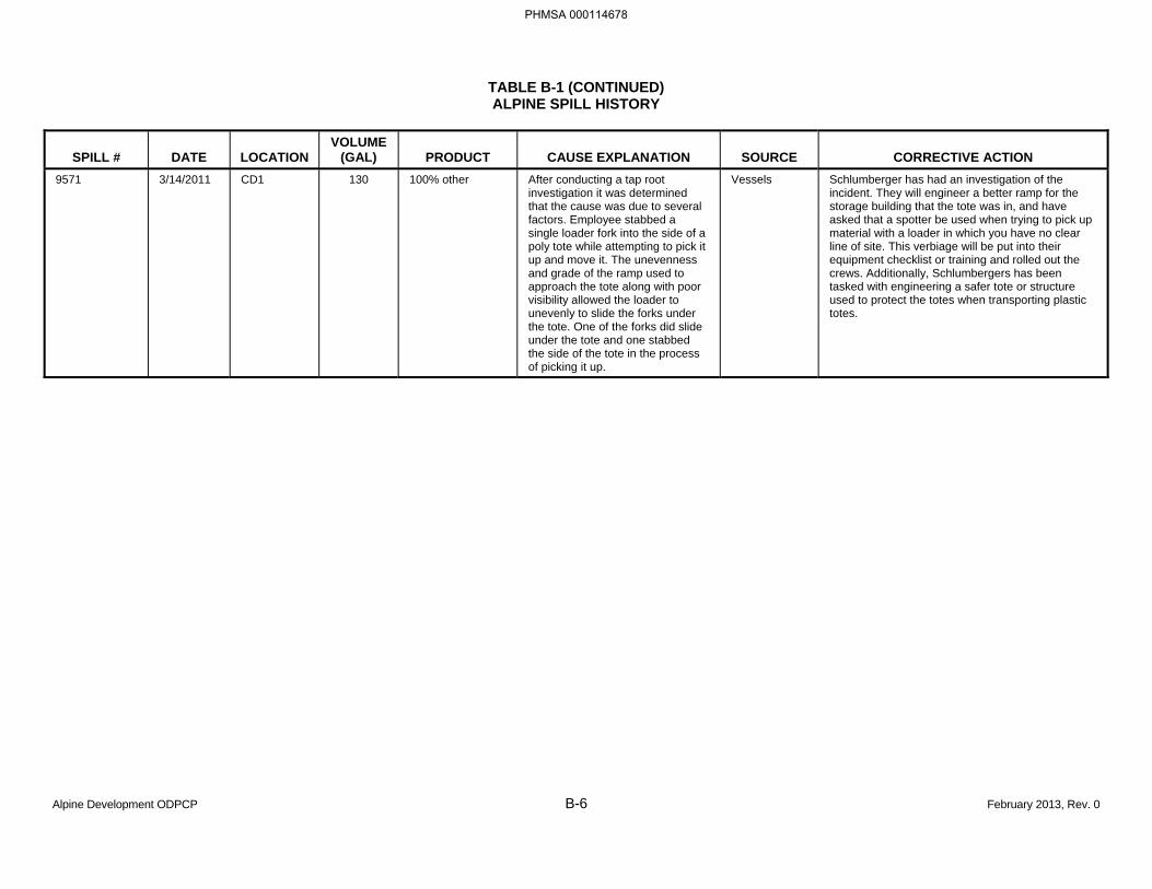
TABLE B-1 (CONTINUED) ALPINE SPILL HISTORY
Alpine Development ODPCP B-6 February 2013, Rev. 0
SPILL # DATE LOCATION VOLUME
(GAL) PRODUCT CAUSE EXPLANATION SOURCE CORRECTIVE ACTION 9571 3/14/2011 CD1 130 100% other After conducting a tap root
investigation it was determined that the cause was due to several factors. Employee stabbed a single loader fork into the side of a poly tote while attempting to pick it up and move it. The unevenness and grade of the ramp used to approach the tote along with poor visibility allowed the loader to unevenly to slide the forks under the tote. One of the forks did slide under the tote and one stabbed the side of the tote in the process of picking it up.
Vessels Schlumberger has had an investigation of the incident. They will engineer a better ramp for the storage building that the tote was in, and have asked that a spotter be used when trying to pick up material with a loader in which you have no clear line of site. This verbiage will be put into their equipment checklist or training and rolled out the crews. Additionally, Schlumbergers has been tasked with engineering a safer tote or structure used to protect the totes when transporting plastic totes.
PHMSA 000114678
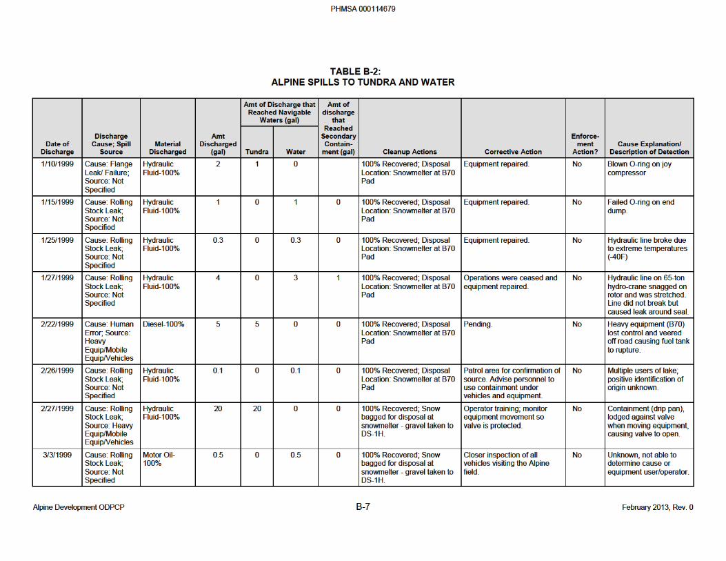
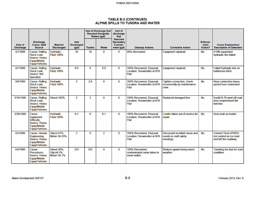
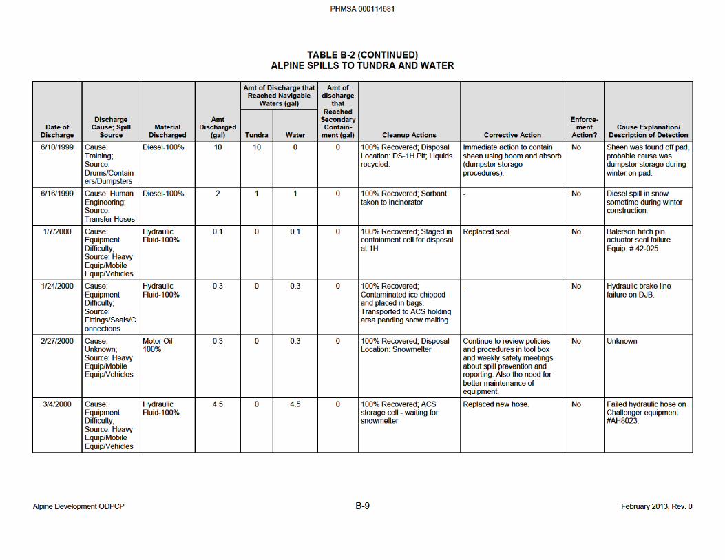
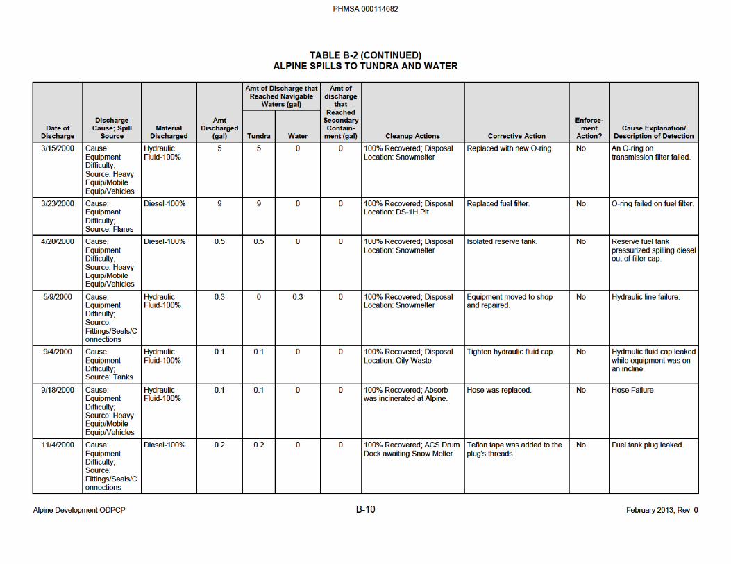
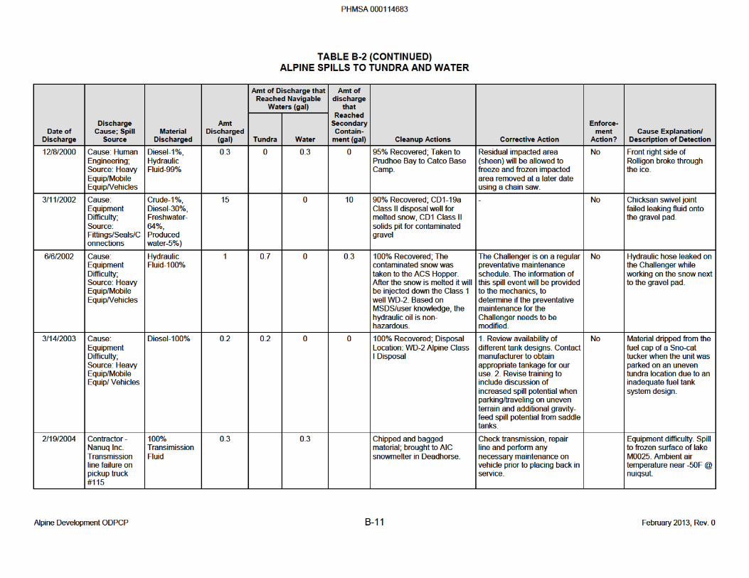
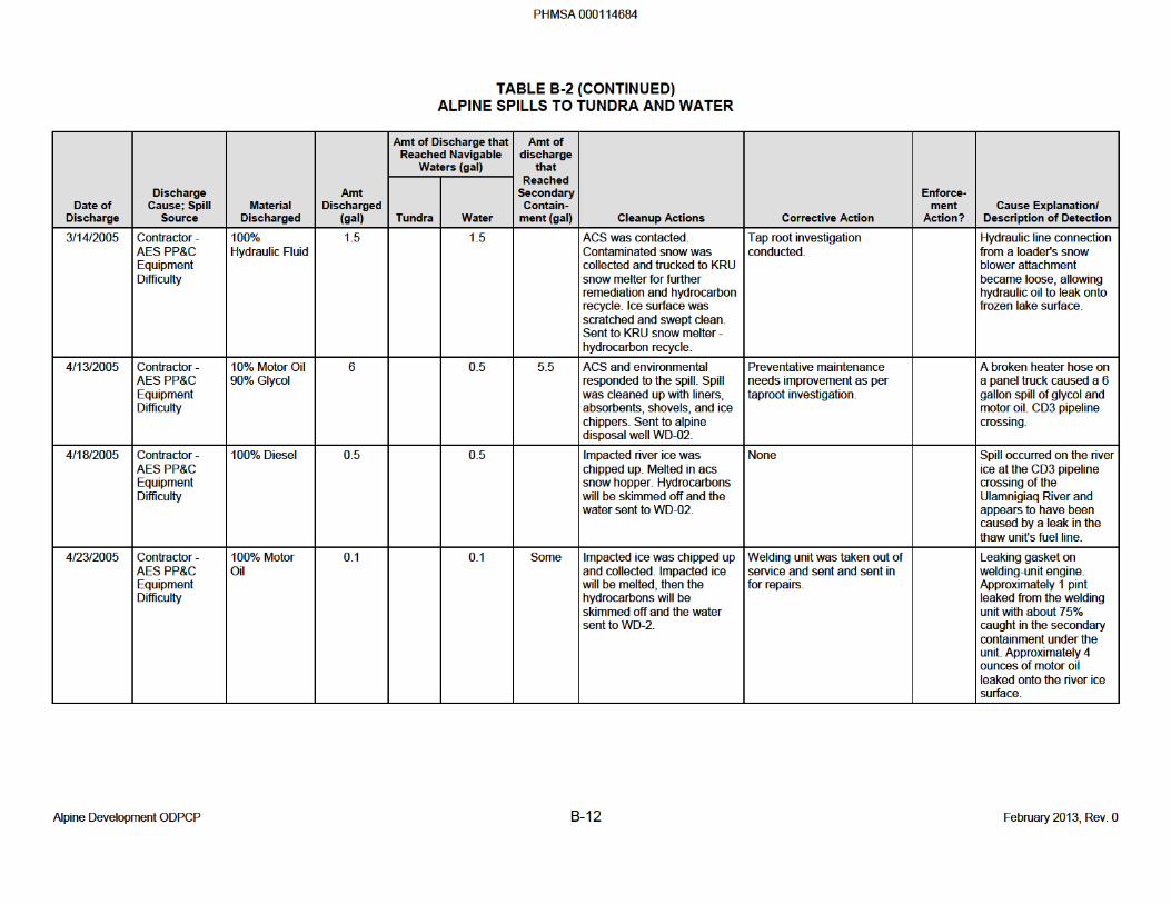
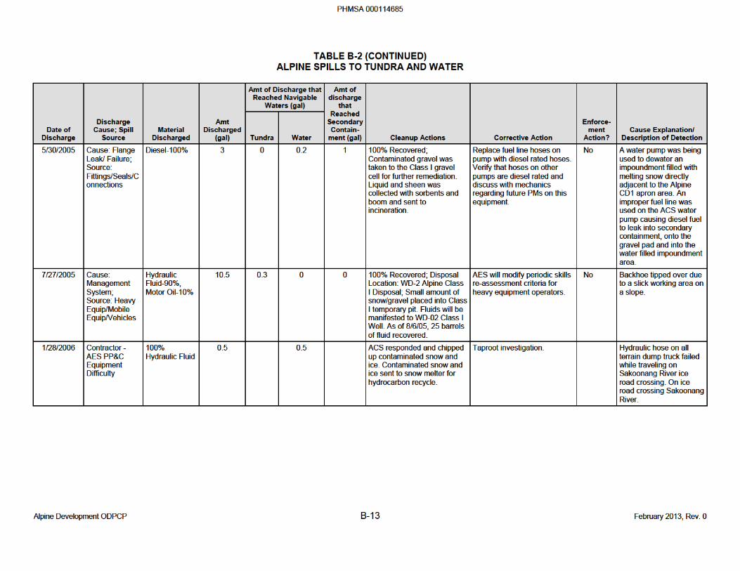
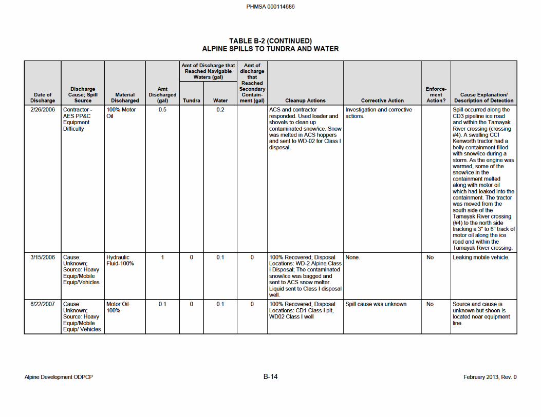
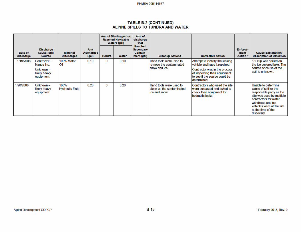
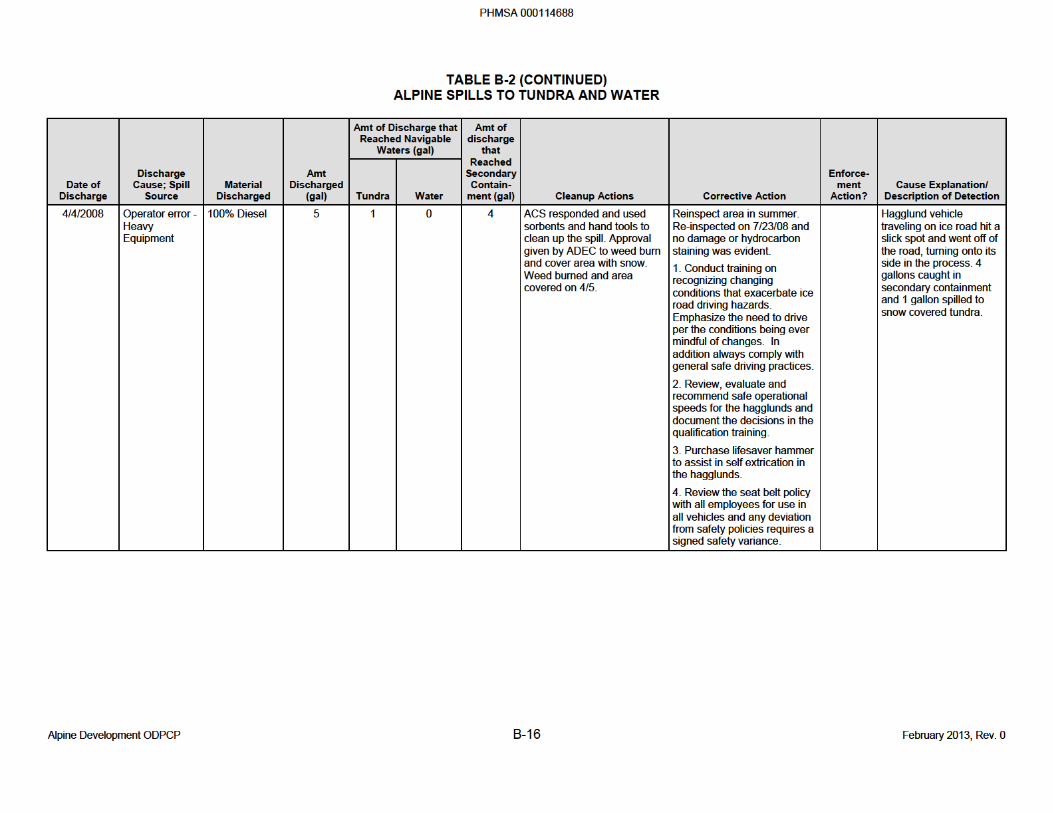
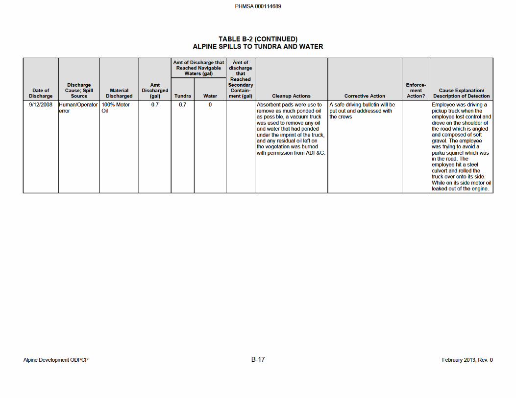
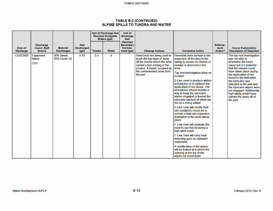
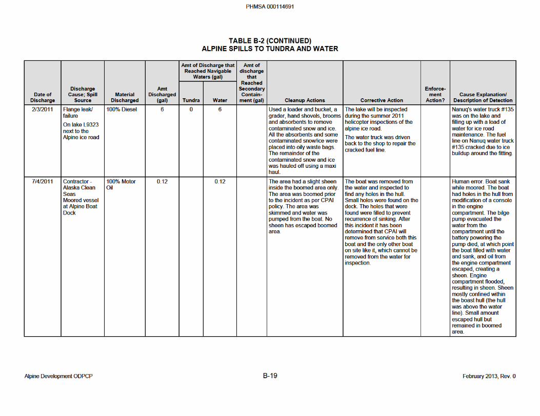
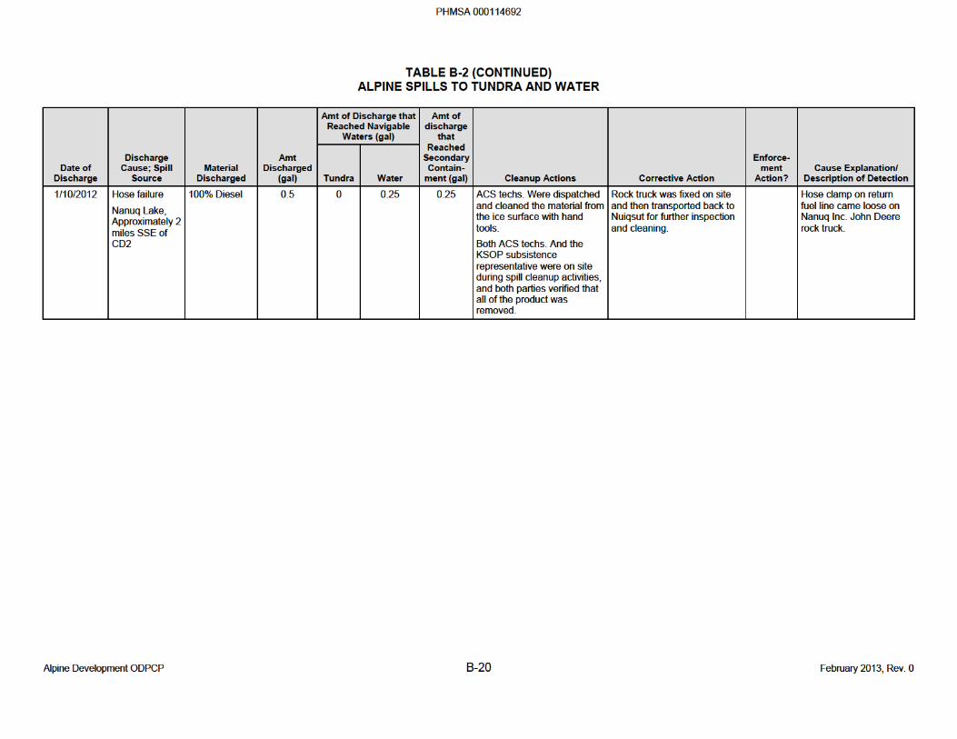
APPENDIX C
ADEC REGULATED OIL STORAGE TANKS
PHMSA 000114693

BLANK PAGE
PHMSA 000114694
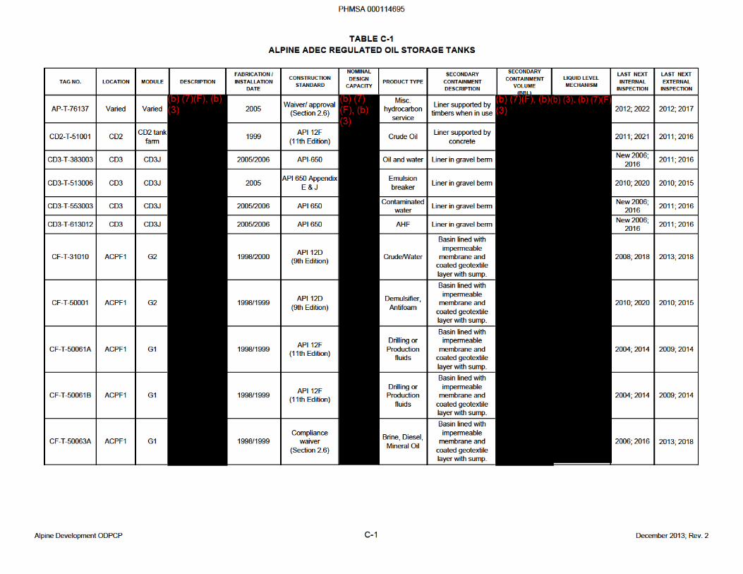
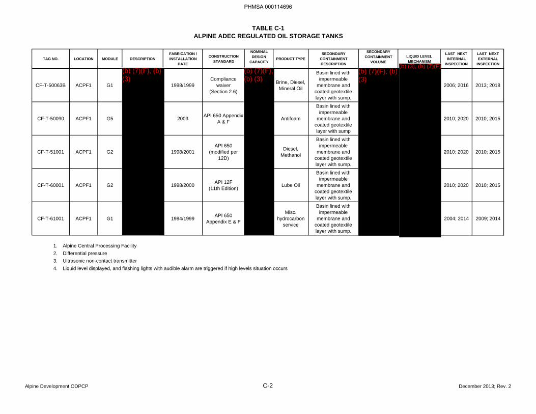
TABLE C-1ALPINE ADEC REGULATED OIL STORAGE TANKS
TAG NO. LOCATION MODULE DESCRIPTIONFABRICATION / INSTALLATION
DATE
CONSTRUCTION STANDARD
NOMINAL DESIGN
CAPACITYPRODUCT TYPE
SECONDARY CONTAINMENT DESCRIPTION
SECONDARY CONTAINMENT
VOLUMELIQUID LEVEL MECHANISM
LAST NEXT INTERNAL
INSPECTION
LAST NEXT EXTERNAL
INSPECTION
CF-T-50063B ACPF1 G1 1998/1999Compliance
waiver(Section 2.6)
Brine, Diesel, Mineral Oil
Basin lined with impermeable
membrane and coated geotextile layer with sump.
2006; 2016 2013; 2018
CF-T-50090 ACPF1 G5 2003 API 650 AppendixA & F Antifoam
Basin lined with impermeable
membrane and coated geotextile layer with sump
2010; 2020 2010; 2015
CF-T-51001 ACPF1 G2 1998/2001API 650
(modified per 12D)
Diesel, Methanol
Basin lined with impermeable
membrane and coated geotextile layer with sump.
2010; 2020 2010; 2015
CF-T-60001 ACPF1 G2 1998/2000 API 12F(11th Edition) Lube Oil
Basin lined with impermeable
membrane and coated geotextile layer with sump.
2010; 2020 2010; 2015
CF-T-61001 ACPF1 G1 1984/1999 API 650Appendix E & F
Misc. hydrocarbon
service
Basin lined with impermeable
membrane and coated geotextile layer with sump.
2004; 2014 2009; 2014
1. Alpine Central Processing Facility2. Differential pressure3. Ultrasonic non-contact transmitter4. Liquid level displayed, and flashing lights with audible alarm are triggered if high levels situation occurs
Alpine Development ODPCP C-2 December 2013; Rev. 2
PHMSA 000114696
(b) (7)(F), (b) (3)
(b) (7)(F), (b) (3)
(b) (7)(F), (b) (3)
(b) (3), (b) (7)(F)
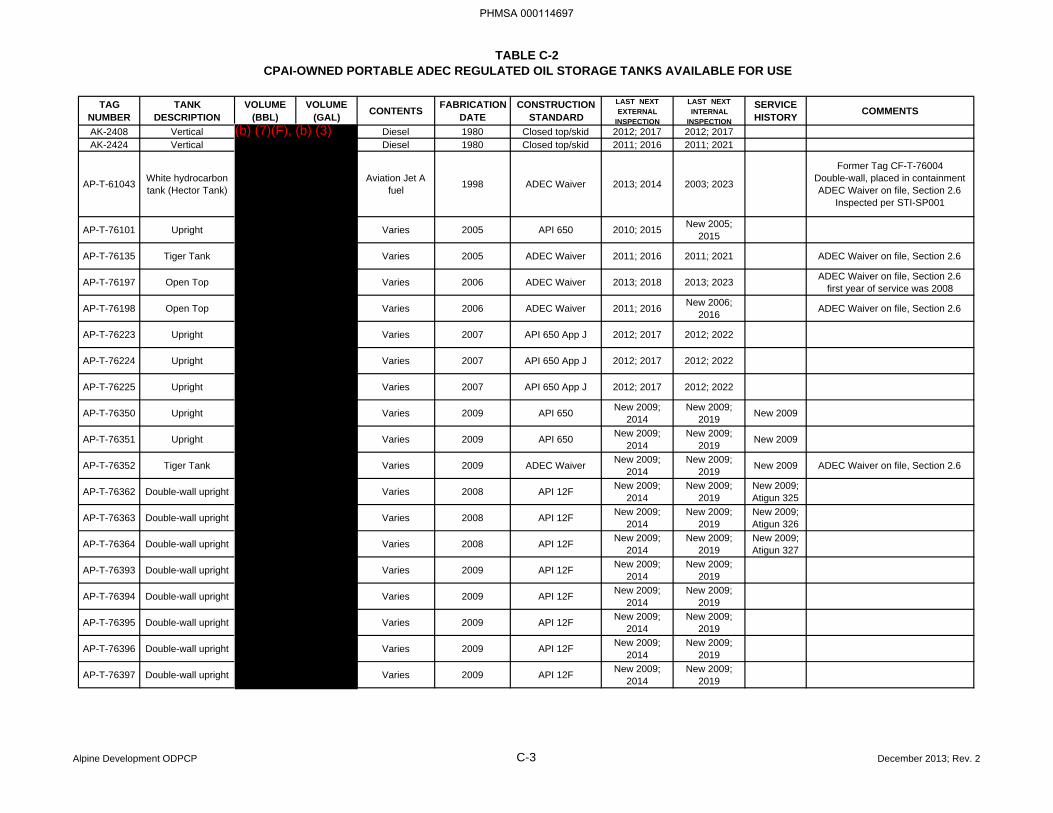
TABLE C-2CPAI-OWNED PORTABLE ADEC REGULATED OIL STORAGE TANKS AVAILABLE FOR USE
TAG NUMBER
TANK DESCRIPTION
VOLUME (BBL)
VOLUME (GAL) CONTENTS FABRICATION
DATECONSTRUCTION
STANDARDLAST NEXT EXTERNAL
INSPECTION
LAST NEXT INTERNAL
INSPECTION
SERVICE HISTORY COMMENTS
AK-2408 Vertical Diesel 1980 Closed top/skid 2012; 2017 2012; 2017 AK-2424 Vertical Diesel 1980 Closed top/skid 2011; 2016 2011; 2021
AP-T-61043 White hydrocarbon tank (Hector Tank)
Aviation Jet A fuel 1998 ADEC Waiver 2013; 2014 2003; 2023
Former Tag CF-T-76004Double-wall, placed in containmentADEC Waiver on file, Section 2.6
Inspected per STI-SP001
AP-T-76101 Upright Varies 2005 API 650 2010; 2015 New 2005; 2015
AP-T-76135 Tiger Tank Varies 2005 ADEC Waiver 2011; 2016 2011; 2021 ADEC Waiver on file, Section 2.6
AP-T-76197 Open Top Varies 2006 ADEC Waiver 2013; 2018 2013; 2023 ADEC Waiver on file, Section 2.6first year of service was 2008
AP-T-76198 Open Top Varies 2006 ADEC Waiver 2011; 2016 New 2006; 2016 ADEC Waiver on file, Section 2.6
AP-T-76223 Upright Varies 2007 API 650 App J 2012; 2017 2012; 2022
AP-T-76224 Upright Varies 2007 API 650 App J 2012; 2017 2012; 2022
AP-T-76225 Upright Varies 2007 API 650 App J 2012; 2017 2012; 2022
AP-T-76350 Upright Varies 2009 API 650 New 2009; 2014
New 2009; 2019 New 2009
AP-T-76351 Upright Varies 2009 API 650 New 2009; 2014
New 2009; 2019 New 2009
AP-T-76352 Tiger Tank Varies 2009 ADEC Waiver New 2009; 2014
New 2009; 2019 New 2009 ADEC Waiver on file, Section 2.6
AP-T-76362 Double-wall upright Varies 2008 API 12F New 2009; 2014
New 2009; 2019
New 2009; Atigun 325
AP-T-76363 Double-wall upright Varies 2008 API 12F New 2009; 2014
New 2009; 2019
New 2009; Atigun 326
AP-T-76364 Double-wall upright Varies 2008 API 12F New 2009; 2014
New 2009; 2019
New 2009; Atigun 327
AP-T-76393 Double-wall upright Varies 2009 API 12F New 2009; 2014
New 2009; 2019
AP-T-76394 Double-wall upright Varies 2009 API 12F New 2009; 2014
New 2009; 2019
AP-T-76395 Double-wall upright Varies 2009 API 12F New 2009; 2014
New 2009; 2019
AP-T-76396 Double-wall upright Varies 2009 API 12F New 2009; 2014
New 2009; 2019
AP-T-76397 Double-wall upright Varies 2009 API 12F New 2009; 2014
New 2009; 2019
Alpine Development ODPCP C-3 December 2013; Rev. 2
PHMSA 000114697
(b) (7)(F), (b) (3)
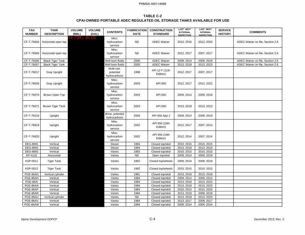
TABLE C-2CPAI-OWNED PORTABLE ADEC REGULATED OIL STORAGE TANKS AVAILABLE FOR USE
TAG NUMBER
TANK DESCRIPTION
VOLUME (BBL)
VOLUME (GAL) CONTENTS FABRICATION
DATECONSTRUCTION
STANDARDLAST NEXT EXTERNAL
INSPECTION
LAST NEXT INTERNAL
INSPECTION
SERVICE HISTORY COMMENTS
CF-T-76004 Horizontal open topMisc.
hydrocarbon service
ND ADEC Waiver 2012; 2016 2012; 2020 ADEC Waiver on file, Section 2.6
CF-T-76005 Horizontal open topMisc.
hydrocarbon service
ND ADEC Waiver 2012; 2017 2007; 2017 ADEC Waiver on file, Section 2.6
CF-T-76006 Black Tiger Tank Well bore fluids 2000 ADEC Waiver 2009; 2014 2009; 2019 ADEC Waiver on file, Section 2.6CF-T-76007 Black Tiger Tank Well bore fluids 2000 ADEC Waiver 2013; 2018 2013; 2023 ADEC Waiver on file, Section 2.6
CF-T-76017 Gray UprightMulti-use, potential
hydrocarbons1998 API 12 F (11th
Edition) 2012; 2017 2007; 2017
CF-T-76033 Gray UprightMisc.
hydrocarbon service
2003 API 650 2012; 2017 2012; 2022
CF-T-76070 Brown Open TopMisc.
hydrocarbon service
2003 API 650 2009; 2014 2009; 2018
CF-T-76071 Brown Tiger TankMisc.
hydrocarbon service
2003 API 650 2013; 2018 2013; 2023
CF-T-76210 Upright Brine, potential hydrocarbons 2004 API 650 App J 2009; 2014 2009; 2019
CF-T-76819 UprightMisc.
hydrocarbon service
2002 API 650 (10th Edition) 2012; 2017 2007; 2014
CF-T-76820 UprightMisc.
hydrocarbon service
2002 API 650 (10th Edition) 2012; 2014 2007; 2014
DEG-8691 Vertical Diesel 1984 Closed top/skid 2010; 2015 2010; 2015 DEG-8692 Vertical Diesel 1984 Closed top/skid 2013; 2018 2013; 2018 DEG-8693 Vertical Varies 1983 Closed top/skid 2010; 2015 2010; 2015 KP-4132 Horizontal Varies ND Open top/skid 2009; 2014 2009; 2019
KSP-0511 Tiger Tank Varies 1992 Closed top/wheels 2009; 2014 2009; 2019
KSP-0512 Tiger Tank Varies 1992 Closed top/wheels 2010; 2015 2010; 2015
PGE-86AD Vertical cylinder Varies 1981 Closed top/skid 2013; 2018 2013; 2018 PGE-86AH Vertical Varies 1984 Closed top/skid 2009; 2014 2009; 2014 PGE-86AI Vertical Varies 1984 Closed top/skid 2013; 2018 2013; 2023 PGE-86AN Vertical Varies 1984 Closed top/skid 2013; 2018 2013; 2023 PGE-86AP Vertical Varies 1984 Closed top/skid 2010; 2015 2010; 2020 PGE-86AR Vertical Varies 1984 Closed top/skid 2013; 2018 2008; 2018 PGE-86AU Vertical cylinder Varies ND Closed top/skid 2013; 2018 2013; 2023 PGE-86AV Vertical Varies 1984 Closed top/skid 2013; 2017 2008; 2017 PGE-86AW Vertical Varies 1984 Closed top/skid 2009; 2014 2004; 2014
Alpine Development ODPCP C-4 December 2013; Rev. 2
PHMSA 000114698
(b) (7)(F), (b) (3)
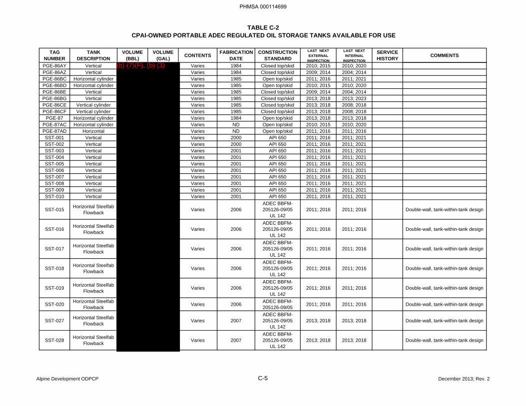
TABLE C-2CPAI-OWNED PORTABLE ADEC REGULATED OIL STORAGE TANKS AVAILABLE FOR USE
TAG NUMBER
TANK DESCRIPTION
VOLUME (BBL)
VOLUME (GAL) CONTENTS FABRICATION
DATECONSTRUCTION
STANDARDLAST NEXT EXTERNAL
INSPECTION
LAST NEXT INTERNAL
INSPECTION
SERVICE HISTORY COMMENTS
PGE-86AY Vertical Varies 1984 Closed top/skid 2010; 2015 2010; 2020 PGE-86AZ Vertical Varies 1984 Closed top/skid 2009; 2014 2004; 2014 PGE-86BC Horizontal cylinder Varies 1985 Open top/skid 2011; 2016 2011; 2021 PGE-86BD Horizontal cylinder Varies 1985 Open top/skid 2010; 2015 2010; 2020 PGE-86BE Vertical Varies 1985 Closed top/skid 2009; 2014 2004; 2014 PGE-86BG Vertical Varies 1985 Closed top/skid 2013; 2018 2013; 2023 PGE-86CE Vertical cylinder Varies 1985 Closed top/skid 2013; 2018 2008; 2018 PGE-86CF Vertical cylinder Varies 1985 Closed top/skid 2013; 2018 2008; 2018
PGE-87 Horizontal cylinder Varies 1984 Open top/skid 2013; 2018 2013; 2018 PGE-87AC Horizontal cylinder Varies ND Open top/skid 2010; 2015 2010; 2020 PGE-87AD Horizontal Varies ND Open top/skid 2011; 2016 2011; 2016 SST-001 Vertical Varies 2000 API 650 2011; 2016 2011; 2021 SST-002 Vertical Varies 2000 API 650 2011; 2016 2011; 2021 SST-003 Vertical Varies 2001 API 650 2011; 2016 2011; 2021 SST-004 Vertical Varies 2001 API 650 2011; 2016 2011; 2021 SST-005 Vertical Varies 2001 API 650 2011; 2016 2011; 2021 SST-006 Vertical Varies 2001 API 650 2011; 2016 2011; 2021 SST-007 Vertical Varies 2001 API 650 2011; 2016 2011; 2021 SST-008 Vertical Varies 2001 API 650 2011; 2016 2011; 2021 SST-009 Vertical Varies 2001 API 650 2011; 2016 2011; 2021 SST-010 Vertical Varies 2001 API 650 2011; 2016 2011; 2021
SST-015 Horizontal Steelfab Flowback Varies 2006
ADEC BBFM-205126-09/05
UL 1422011; 2016 2011; 2016 Double-wall, tank-within-tank design
SST-016 Horizontal Steelfab Flowback Varies 2006
ADEC BBFM-205126-09/05
UL 1422011; 2016 2011; 2016 Double-wall, tank-within-tank design
SST-017 Horizontal Steelfab Flowback Varies 2006
ADEC BBFM-205126-09/05
UL 1422011; 2016 2011; 2016 Double-wall, tank-within-tank design
SST-018 Horizontal Steelfab Flowback Varies 2006
ADEC BBFM-205126-09/05
UL 1422011; 2016 2011; 2016 Double-wall, tank-within-tank design
SST-019 Horizontal Steelfab Flowback Varies 2006
ADEC BBFM-205126-09/05
UL 1422011; 2016 2011; 2016 Double-wall, tank-within-tank design
SST-020 Horizontal Steelfab Flowback Varies 2006 ADEC BBFM-
205126-09/05 2011; 2016 2011; 2016 Double-wall, tank-within-tank design
SST-027 Horizontal Steelfab Flowback Varies 2007
ADEC BBFM-205126-09/05
UL 1422013; 2018 2013; 2018 Double-wall, tank-within-tank design
SST-028 Horizontal Steelfab Flowback Varies 2007
ADEC BBFM-205126-09/05
UL 1422013; 2018 2013; 2018 Double-wall, tank-within-tank design
Alpine Development ODPCP C-5 December 2013; Rev. 2
PHMSA 000114699
(b) (7)(F), (b) (3)
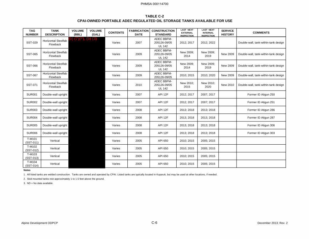
TABLE C-2CPAI-OWNED PORTABLE ADEC REGULATED OIL STORAGE TANKS AVAILABLE FOR USE
TAG NUMBER
TANK DESCRIPTION
VOLUME (BBL)
VOLUME (GAL) CONTENTS FABRICATION
DATECONSTRUCTION
STANDARDLAST NEXT EXTERNAL
INSPECTION
LAST NEXT INTERNAL
INSPECTION
SERVICE HISTORY COMMENTS
SST-029 Horizontal Steelfab Flowback Varies 2007
ADEC BBFM-205126-09/05
UL 1422012; 2017 2012; 2022 Double-wall, tank-within-tank design
SST-065 Horizontal Steelfab Flowback Varies 2009
ADEC BBFM-205126-09/05
UL 142
New 2009; 2014
New 2009; 2019 New 2009 Double-wall, tank-within-tank design
SST-066 Horizontal Steelfab Flowback Varies 2009
ADEC BBFM-205126-09/05
UL 142
New 2009; 2014
New 2009; 2019 New 2009 Double-wall, tank-within-tank design
SST-067 Horizontal Steelfab Flowback Varies 2009 ADEC BBFM-
205126-09/05 2010; 2015 2010; 2020 New 2009 Double-wall, tank-within-tank design
SST-071 Horizontal Steelfab Flowback Varies 2010
ADEC BBFM-205126-09/05
UL 142
New 2010; 2015
New 2010; 2020 New 2010 Double-wall, tank-within-tank design
SUR001 Double-wall upright Varies 2007 API 12F 2012; 2017 2007; 2017 Former ID Atigun 250
SUR002 Double-wall upright Varies 2007 API 12F 2012; 2017 2007; 2017 Former ID Atigun 251
SUR003 Double-wall upright Varies 2008 API 12F 2013; 2018 2013; 2018 Former ID Atigun 286
SUR004 Double-wall upright Varies 2008 API 12F 2013; 2018 2013; 2018 Former ID Atigun 287
SUR005 Double-wall upright Varies 2008 API 12F 2013; 2018 2013; 2018 Former ID Atigun 306
SUR006 Double-wall upright Varies 2008 API 12F 2013; 2018 2013; 2018 Former ID Atigun 303
T-M101 (SST-011) Vertical Varies 2005 API 650 2010; 2015 2005; 2015
T-M102 (SST-012) Vertical Varies 2005 API 650 2010; 2015 2005; 2015
T-M103 (SST-013) Vertical Varies 2005 API 650 2010; 2015 2005; 2015
T-M104 (SST-014) Vertical Varies 2005 API 650 2010; 2015 2005; 2015
Notes
1. All listed tanks are welded construction. Tanks are owned and operated by CPAI. Listed tanks are typically located in Kuparuk, but may be used at other locations, if needed.
2. Skid-mounted tanks rest approximately 1 to 1.5 feet above the ground.
3. ND = No data available.
Alpine Development ODPCP C-6 December 2013; Rev. 2
PHMSA 000114700
(b) (7)(F), (b) (3)
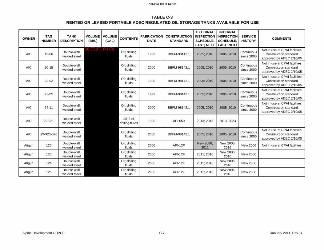
TABLE C-3RENTED OR LEASED PORTABLE ADEC REGULATED OIL STORAGE TANKS AVAILABLE FOR USE
OWNER TAG NUMBER
TANK DESCRIPTION
VOLUME (BBL)
VOLUME (GAL) CONTENTS FABRICATION
DATECONSTRUCTION
STANDARD
EXTERNAL INSPECTION SCHEDULE, LAST; NEXT
INTERNAL INSPECTION SCHEDULE, LAST; NEXT
SERVICE HISTORY COMMENTS
AIC 19-06 Double-wall, welded steel
Oil; drilling fluids 1999 BBFM-98142.1 2005; 2010 2005; 2010 Continuous
since 2000
Not in use at CPAI facilitiesConstruction standard
approved by ADEC 2/10/05
AIC 20-15 Double-wall, welded steel
Oil; drilling fluids 2000 BBFM-98142.1 2005; 2010 2005; 2010 Continuous
since 2000
Not in use at CPAI facilitiesConstruction standard
approved by ADEC 2/10/05
AIC 22-02 Double-wall, welded steel
Oil; drilling fluids 1999 BBFM-98142.1 2005; 2010 2005; 2010 Continuous
since 2000
Not in use at CPAI facilitiesConstruction standard
approved by ADEC 2/10/05
AIC 23-05 Double-wall, welded steel
Oil; drilling fluids 1999 BBFM-98142.1 2005; 2010 2005; 2010 Continuous
since 2000
Not in use at CPAI facilitiesConstruction standard
approved by ADEC 2/10/05
AIC 24-11 Double-wall, welded steel
Oil; drilling fluids 2000 BBFM-98142.1 2005; 2010 2005; 2010 Continuous
since 2000
Not in use at CPAI facilitiesConstruction standard
approved by ADEC 2/10/05
AIC 29-921 Double-wall, welded steel
Oil; fuel, drilling fluids 1999 API 650 2013; 2018 2013; 2023
AIC 29-923-070 Double-wall, welded steel
Oil; drilling fluids 2000 BBFM-98142.1 2005; 2010 2005; 2010 Continuous
since 2000
Not in use at CPAI facilitiesConstruction standard
approved by ADEC 2/10/05
Atigun 120 Double-wall, welded steel
Oil; drilling fluids 2006 API-12F New 2006;
2011New 2006;
2016 New 2006 Not in use at CPAI facilities
Atigun 123 Double-wall, welded steel
Oil; drilling fluids 2006 API-12F 2011; 2016 New 2006;
2016 New 2006
Atigun 124 Double-wall, welded steel
Oil; drilling fluids 2006 API-12F 2011; 2016 New 2006;
2016 New 2006
Atigun 125 Double-wall, welded steel
Oil; drilling fluids 2006 API-12F 2011; 2016 New 2006;
2016 New 2006
Alpine Development ODPCP C-7 January 2014; Rev. 3
PHMSA 000114701
(b) (7)(F), (b) (3)
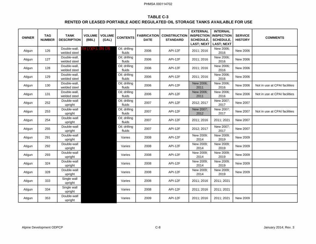
TABLE C-3RENTED OR LEASED PORTABLE ADEC REGULATED OIL STORAGE TANKS AVAILABLE FOR USE
OWNER TAG NUMBER
TANK DESCRIPTION
VOLUME (BBL)
VOLUME (GAL) CONTENTS FABRICATION
DATECONSTRUCTION
STANDARD
EXTERNAL INSPECTION SCHEDULE, LAST; NEXT
INTERNAL INSPECTION SCHEDULE, LAST; NEXT
SERVICE HISTORY COMMENTS
Atigun 126 Double-wall, welded steel
Oil; drilling fluids 2006 API-12F 2011; 2016 New 2006;
2016 New 2006
Atigun 127 Double-wall, welded steel
Oil; drilling fluids 2006 API-12F 2011; 2016 New 2006;
2016 New 2006
Atigun 128 Double-wall, welded steel
Oil; drilling fluids 2006 API-12F 2011; 2016 New 2006;
2016 New 2006
Atigun 129 Double-wall, welded steel
Oil; drilling fluids 2006 API-12F 2011; 2016 New 2006;
2016 New 2006
Atigun 130 Double-wall, welded steel
Oil; drilling fluids 2006 API-12F New 2006;
2011New 2006;
2016 New 2006 Not in use at CPAI facilities
Atigun 131 Double-wall, welded steel
Oil; drilling fluids 2006 API-12F New 2006;
2011New 2006;
2016 New 2006 Not in use at CPAI facilities
Atigun 252 Double-wall upright
Oil; drilling fluids 2007 API-12F 2012; 2017 New 2007;
2017 New 2007
Atigun 253 Double-wall upright
Oil; drilling fluids 2007 API-12F New 2007;
2012New 2007;
2017 New 2007 Not in use at CPAI facilities
Atigun 254 Double-wall upright
Oil; drilling fluids 2007 API-12F 2011; 2016 2011; 2021 New 2007
Atigun 255 Double-wall upright
Oil; drilling fluids 2007 API-12F 2012; 2017 New 2007;
2017 New 2007
Atigun 291 Double-wall upright Varies 2008 API-12F New 2009;
2014New 2009;
2019 New 2009
Atigun 292 Double-wall upright Varies 2008 API-12F New 2009;
2014New 2009;
2019 New 2009
Atigun 293 Double-wall upright Varies 2008 API-12F New 2009;
2014New 2009;
2019 New 2009
Atigun 324 Double-wall upright Varies 2008 API-12F New 2009;
2014New 2009;
2019 New 2009
Atigun 328 Double-wall upright Varies 2008 API-12F New 2009;
2014New 2009;
2019 New 2009
Atigun 333 Single wall upright Varies 2008 API-12F 2011; 2016 2011; 2021
Atigun 334 Single wall upright Varies 2008 API-12F 2011; 2016 2011; 2021
Atigun 353 Double-wall upright Varies 2009 API-12F 2011; 2016 2011; 2021 New 2009
Alpine Development ODPCP C-8 January 2014; Rev. 3
PHMSA 000114702
(b) (7)(F), (b) (3)
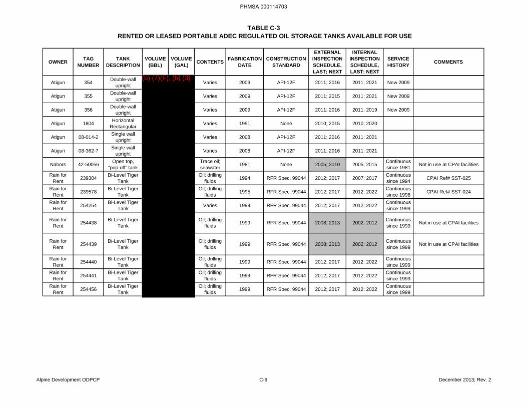
TABLE C-3RENTED OR LEASED PORTABLE ADEC REGULATED OIL STORAGE TANKS AVAILABLE FOR USE
OWNER TAG NUMBER
TANK DESCRIPTION
VOLUME (BBL)
VOLUME (GAL) CONTENTS FABRICATION
DATECONSTRUCTION
STANDARD
EXTERNAL INSPECTION SCHEDULE, LAST; NEXT
INTERNAL INSPECTION SCHEDULE, LAST; NEXT
SERVICE HISTORY COMMENTS
Atigun 354 Double-wall upright Varies 2009 API-12F 2011; 2016 2011; 2021 New 2009
Atigun 355 Double-wall upright Varies 2009 API-12F 2011; 2015 2011; 2021 New 2009
Atigun 356 Double-wall upright Varies 2009 API-12F 2011; 2016 2011; 2019 New 2009
Atigun 1804 Horizontal Rectangular Varies 1991 None 2010; 2015 2010; 2020
Atigun 08-014-2 Single wall upright Varies 2008 API-12F 2011; 2016 2011; 2021
Atigun 08-362-7 Single wall upright Varies 2008 API-12F 2011; 2016 2011; 2021
Nabors 42-50056 Open top, “pop-off” tank
Trace oil; seawater 1981 None 2005; 2010 2005; 2015 Continuous
since 1981 Not in use at CPAI facilities
Rain for Rent 239304 Bi-Level Tiger
TankOil; drilling
fluids 1994 RFR Spec. 99044 2012; 2017 2007; 2017 Continuous since 1994 CPAI Ref# SST-025
Rain for Rent 239578 Bi-Level Tiger
TankOil; drilling
fluids 1995 RFR Spec. 99044 2012; 2017 2012; 2022 Continuous since 1998 CPAI Ref# SST-024
Rain for Rent 254254 Bi-Level Tiger
Tank Varies 1999 RFR Spec. 99044 2012; 2017 2012; 2022 Continuous since 1999
Rain for Rent 254438 Bi-Level Tiger
TankOil; drilling
fluids 1999 RFR Spec. 99044 2008; 2013 2002; 2012 Continuous since 1999 Not in use at CPAI facilities
Rain for Rent 254439 Bi-Level Tiger
TankOil; drilling
fluids 1999 RFR Spec. 99044 2008; 2013 2002; 2012 Continuous since 1999 Not in use at CPAI facilities
Rain for Rent 254440 Bi-Level Tiger
TankOil; drilling
fluids 1999 RFR Spec. 99044 2012; 2017 2012; 2022 Continuous since 1999
Rain for Rent 254441 Bi-Level Tiger
TankOil; drilling
fluids 1999 RFR Spec. 99044 2012; 2017 2012; 2022 Continuous since 1999
Rain for Rent 254456 Bi-Level Tiger
TankOil; drilling
fluids 1999 RFR Spec. 99044 2012; 2017 2012; 2022 Continuous since 1999
Alpine Development ODPCP C-9 December 2013; Rev. 2
PHMSA 000114703
(b) (7)(F), (b) (3)
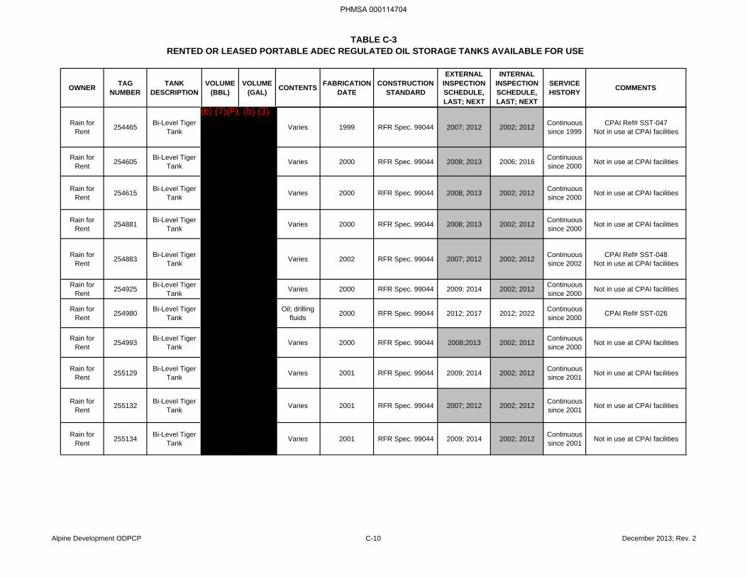
TABLE C-3RENTED OR LEASED PORTABLE ADEC REGULATED OIL STORAGE TANKS AVAILABLE FOR USE
OWNER TAG NUMBER
TANK DESCRIPTION
VOLUME (BBL)
VOLUME (GAL) CONTENTS FABRICATION
DATECONSTRUCTION
STANDARD
EXTERNAL INSPECTION SCHEDULE, LAST; NEXT
INTERNAL INSPECTION SCHEDULE, LAST; NEXT
SERVICE HISTORY COMMENTS
Rain for Rent 254465 Bi-Level Tiger
Tank Varies 1999 RFR Spec. 99044 2007; 2012 2002; 2012 Continuous since 1999
CPAI Ref# SST-047Not in use at CPAI facilities
Rain for Rent 254605 Bi-Level Tiger
Tank Varies 2000 RFR Spec. 99044 2008; 2013 2006; 2016 Continuous since 2000 Not in use at CPAI facilities
Rain for Rent 254615 Bi-Level Tiger
Tank Varies 2000 RFR Spec. 99044 2008; 2013 2002; 2012 Continuous since 2000 Not in use at CPAI facilities
Rain for Rent 254881 Bi-Level Tiger
Tank Varies 2000 RFR Spec. 99044 2008; 2013 2002; 2012 Continuous since 2000 Not in use at CPAI facilities
Rain for Rent 254883 Bi-Level Tiger
Tank Varies 2002 RFR Spec. 99044 2007; 2012 2002; 2012 Continuous since 2002
CPAI Ref# SST-048Not in use at CPAI facilities
Rain for Rent 254925 Bi-Level Tiger
Tank Varies 2000 RFR Spec. 99044 2009; 2014 2002; 2012 Continuous since 2000 Not in use at CPAI facilities
Rain for Rent 254980 Bi-Level Tiger
TankOil; drilling
fluids 2000 RFR Spec. 99044 2012; 2017 2012; 2022 Continuous since 2000 CPAI Ref# SST-026
Rain for Rent 254993 Bi-Level Tiger
Tank Varies 2000 RFR Spec. 99044 2008;2013 2002; 2012 Continuous since 2000 Not in use at CPAI facilities
Rain for Rent 255129 Bi-Level Tiger
Tank Varies 2001 RFR Spec. 99044 2009; 2014 2002; 2012 Continuous since 2001 Not in use at CPAI facilities
Rain for Rent 255132 Bi-Level Tiger
Tank Varies 2001 RFR Spec. 99044 2007; 2012 2002; 2012 Continuous since 2001 Not in use at CPAI facilities
Rain for Rent 255134 Bi-Level Tiger
Tank Varies 2001 RFR Spec. 99044 2009; 2014 2002; 2012 Continuous since 2001 Not in use at CPAI facilities
Alpine Development ODPCP C-10 December 2013; Rev. 2
PHMSA 000114704
(b) (7)(F), (b) (3)
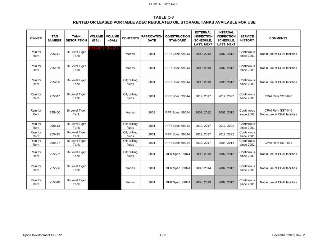
TABLE C-3RENTED OR LEASED PORTABLE ADEC REGULATED OIL STORAGE TANKS AVAILABLE FOR USE
OWNER TAG NUMBER
TANK DESCRIPTION
VOLUME (BBL)
VOLUME (GAL) CONTENTS FABRICATION
DATECONSTRUCTION
STANDARD
EXTERNAL INSPECTION SCHEDULE, LAST; NEXT
INTERNAL INSPECTION SCHEDULE, LAST; NEXT
SERVICE HISTORY COMMENTS
Rain for Rent 255141 Bi-Level Tiger
Tank Varies 2001 RFR Spec. 99044 2008; 2013 2002; 2012 Continuous since 2001 Not in use at CPAI facilities
Rain for Rent 255169 Bi-Level Tiger
Tank Varies 2001 RFR Spec. 99044 2008; 2013 2002; 2012 Continuous since 2001 Not in use at CPAI facilities
Rain for Rent 255286 Bi-Level Tiger
TankOil; drilling
fluids 2001 RFR Spec. 99044 2008; 2013 2008; 2012 Continuous since 2001 Not in use at CPAI facilities
Rain for Rent 255317 Bi-Level Tiger
TankOil; drilling
fluids 2001 RFR Spec. 99044 2012; 2017 2012; 2022 Continuous since 2001 CPAI Ref# SST-023
Rain for Rent 255400 Bi-Level Tiger
Tank Varies 2002 RFR Spec. 99044 2007; 2012 2002; 2012 Continuous since 2002
CPAI Ref# SST-046Not in use at CPAI facilities
Rain for Rent 255413 Bi-Level Tiger
TankOil; drilling
fluids 2001 RFR Spec. 99044 2012; 2017 2012; 2022 Continuous since 2001
Rain for Rent 255415 Bi-Level Tiger
TankOil; drilling
fluids 2001 RFR Spec. 99044 2012; 2017 2012; 2022 Continuous since 2001
Rain for Rent 255497 Bi-Level Tiger
TankOil; drilling
fluids 2001 RFR Spec. 99044 2012; 2017 2004; 2014 Continuous since 2001 CPAI Ref# SST-022
Rain for Rent 255532 Bi-Level Tiger
TankOil; drilling
fluids 2001 RFR Spec. 99044 2008; 2013 2002; 2012 Continuous since 2001 Not in use at CPAI facilities
Rain for Rent 255536 Bi-Level Tiger
Tank Varies 2001 RFR Spec. 99044 2009; 2014 2002; 2012 Continuous since 2001 Not in use at CPAI facilities
Rain for Rent 255548 Bi-Level Tiger
Tank Varies 2001 RFR Spec. 99044 2008; 2013 2002; 2012 Continuous since 2001 Not in use at CPAI facilities
Alpine Development ODPCP C-11 December 2013; Rev. 2
PHMSA 000114705
(b) (7)(F), (b) (3)
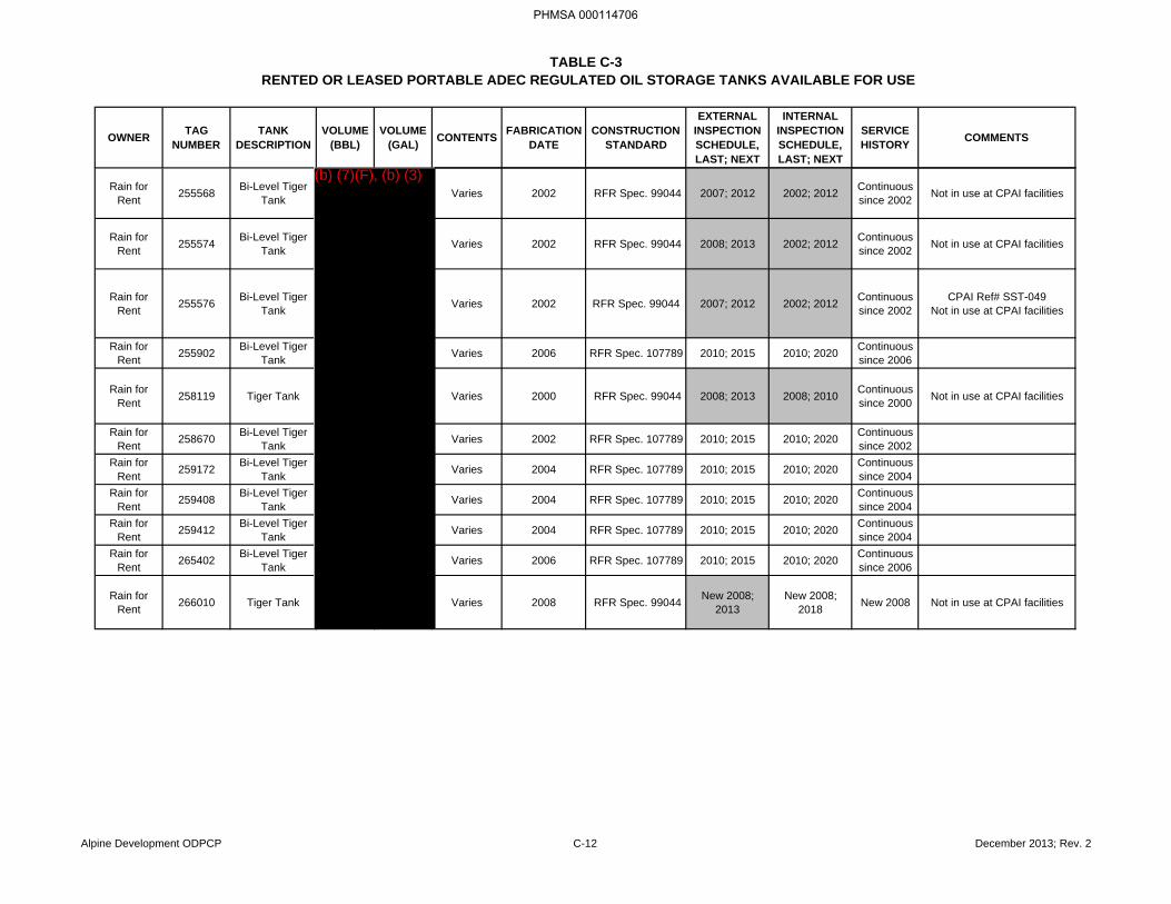
TABLE C-3RENTED OR LEASED PORTABLE ADEC REGULATED OIL STORAGE TANKS AVAILABLE FOR USE
OWNER TAG NUMBER
TANK DESCRIPTION
VOLUME (BBL)
VOLUME (GAL) CONTENTS FABRICATION
DATECONSTRUCTION
STANDARD
EXTERNAL INSPECTION SCHEDULE, LAST; NEXT
INTERNAL INSPECTION SCHEDULE, LAST; NEXT
SERVICE HISTORY COMMENTS
Rain for Rent 255568 Bi-Level Tiger
Tank Varies 2002 RFR Spec. 99044 2007; 2012 2002; 2012 Continuous since 2002 Not in use at CPAI facilities
Rain for Rent 255574 Bi-Level Tiger
Tank Varies 2002 RFR Spec. 99044 2008; 2013 2002; 2012 Continuous since 2002 Not in use at CPAI facilities
Rain for Rent 255576 Bi-Level Tiger
Tank Varies 2002 RFR Spec. 99044 2007; 2012 2002; 2012 Continuous since 2002
CPAI Ref# SST-049Not in use at CPAI facilities
Rain for Rent 255902 Bi-Level Tiger
Tank Varies 2006 RFR Spec. 107789 2010; 2015 2010; 2020 Continuous since 2006
Rain for Rent 258119 Tiger Tank Varies 2000 RFR Spec. 99044 2008; 2013 2008; 2010 Continuous
since 2000 Not in use at CPAI facilities
Rain for Rent 258670 Bi-Level Tiger
Tank Varies 2002 RFR Spec. 107789 2010; 2015 2010; 2020 Continuous since 2002
Rain for Rent 259172 Bi-Level Tiger
Tank Varies 2004 RFR Spec. 107789 2010; 2015 2010; 2020 Continuous since 2004
Rain for Rent 259408 Bi-Level Tiger
Tank Varies 2004 RFR Spec. 107789 2010; 2015 2010; 2020 Continuous since 2004
Rain for Rent 259412 Bi-Level Tiger
Tank Varies 2004 RFR Spec. 107789 2010; 2015 2010; 2020 Continuous since 2004
Rain for Rent 265402 Bi-Level Tiger
Tank Varies 2006 RFR Spec. 107789 2010; 2015 2010; 2020 Continuous since 2006
Rain for Rent 266010 Tiger Tank Varies 2008 RFR Spec. 99044 New 2008;
2013New 2008;
2018 New 2008 Not in use at CPAI facilities
Alpine Development ODPCP C-12 December 2013; Rev. 2
PHMSA 000114706
(b) (7)(F), (b) (3)
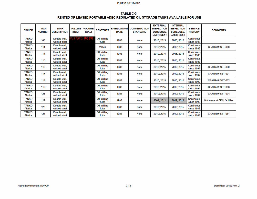
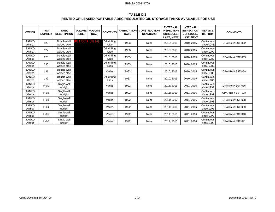
TABLE C-3RENTED OR LEASED PORTABLE ADEC REGULATED OIL STORAGE TANKS AVAILABLE FOR USE
OWNER TAG NUMBER
TANK DESCRIPTION
VOLUME (BBL)
VOLUME (GAL) CONTENTS FABRICATION
DATECONSTRUCTION
STANDARD
EXTERNAL INSPECTION SCHEDULE, LAST; NEXT
INTERNAL INSPECTION SCHEDULE, LAST; NEXT
SERVICE HISTORY COMMENTS
TANKO Alaska 125 Double-wall,
welded steelOil; drilling
fluids 1983 None 2010; 2015 2010; 2015 Continuous since 1983 CPAI Ref# SST-052
TANKO Alaska 127 Double-wall,
welded steelOil; drilling
fluids 1983 None 2010; 2015 2010; 2015 Continuous since 1992
TANKO Alaska 128 Double-wall,
welded steelOil; drilling
fluids 1983 None 2010; 2015 2010; 2015 Continuous since 1983 CPAI Ref# SST-053
TANKO Alaska 130 Double-wall,
welded steelOil; drilling
fluids 1983 None 2010; 2015 2010; 2015 Continuous since 1983
TANKO Alaska 131 Double-wall,
welded steel Varies 1983 None 2010; 2015 2010; 2015 Continuous since 1983 CPAI Ref# SST-069
TANKO Alaska 132 Double-wall,
welded steelOil; drilling
fluids 1983 None 2010; 2015 2010; 2015 Continuous since 1983
TANKO Alaska H-01 Single-wall
upright Varies 1992 None 2011; 2016 2011; 2016 Continuous since 1992 CPAI Ref# SST-036
TANKO Alaska H-02 Single-wall
upright Varies 1992 None 2011; 2016 2011; 2016 Continuous since 1992 CPAI Ref # SST-037
TANKO Alaska H-03 Single-wall
upright Varies 1992 None 2011; 2016 2011; 2016 Continuous since 1992 CPAI Ref# SST-038
TANKO Alaska H-04 Single-wall
upright Varies 1992 None 2011; 2016 2011; 2016 Continuous since 1992 CPAI Ref# SST-039
TANKO Alaska H-05 Single-wall
upright Varies 1992 None 2011; 2016 2011; 2016 Continuous since 1992 CPAI Ref# SST-040
TANKO Alaska H-06 Single-wall
upright Varies 1992 None 2011; 2016 2011; 2016 Continuous since 1992 CPAI Ref# SST-041
Alpine Development ODPCP C-14 December 2013; Rev. 2
PHMSA 000114708
(b) (7)(F), (b) (3)
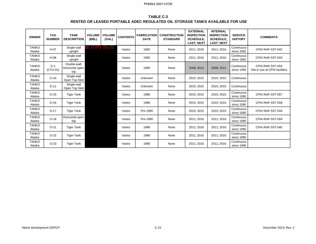
TABLE C-3RENTED OR LEASED PORTABLE ADEC REGULATED OIL STORAGE TANKS AVAILABLE FOR USE
OWNER TAG NUMBER
TANK DESCRIPTION
VOLUME (BBL)
VOLUME (GAL) CONTENTS FABRICATION
DATECONSTRUCTION
STANDARD
EXTERNAL INSPECTION SCHEDULE, LAST; NEXT
INTERNAL INSPECTION SCHEDULE, LAST; NEXT
SERVICE HISTORY COMMENTS
TANKO Alaska H-07 Single-wall
upright Varies 1992 None 2011; 2016 2011; 2016 Continuous since 1992 CPAI Ref# SST-042
TANKO Alaska H-08 Single-wall
upright Varies 1992 None 2011; 2016 2011; 2016 Continuous since 1992 CPAI Ref# SST-043
TANKO Alaska
O-1(CTU-01)
Double-wall; Horizontal open-
topVaries 1990 None 2008; 2013 2008; 2013 Continuous
since 1990CPAI Ref# SST-054
Not in use at CPAI facilities
TANKO Alaska O-10 Single-wall
Open Top Skid Varies Unknown None 2010; 2015 2010; 2015 Continuous
TANKO Alaska O-11 Single-wall
Open Top Skid Varies Unknown None 2010; 2015 2010; 2015 Continuous
TANKO Alaska O-15 Tiger Tank Varies 1986 None 2010; 2015 2010; 2015 Continuous
since 1990 CPAI Ref# SST-057
TANKO Alaska O-16 Tiger Tank Varies 1986 None 2010; 2015 2010; 2015 Continuous
since 1990 CPAI Ref# SST-058
TANKO Alaska O-17 Tiger Tank Varies Pre-1990 None 2010; 2015 2010; 2015 Continuous
since 1990 CPAI Ref# SST-044
TANKO Alaska O-18 Horizontal open-
top Varies Pre-1990 None 2011; 2016 2011; 2016 Continuous since 1990 CPAI Ref# SST-059
TANKO Alaska O-21 Tiger Tank Varies 1986 None 2011; 2016 2011; 2016 Continuous
since 1990 CPAI Ref# SST-045
TANKO Alaska O-22 Tiger Tank Varies 1986 None 2011; 2016 2011; 2016 Continuous
since 1990TANKO Alaska O-23 Tiger Tank Varies 1986 None 2011; 2016 2011; 2016 Continuous
since 1990
Alpine Development ODPCP C-15 December 2013; Rev. 2
PHMSA 000114709
(b) (7)(F), (b) (3)
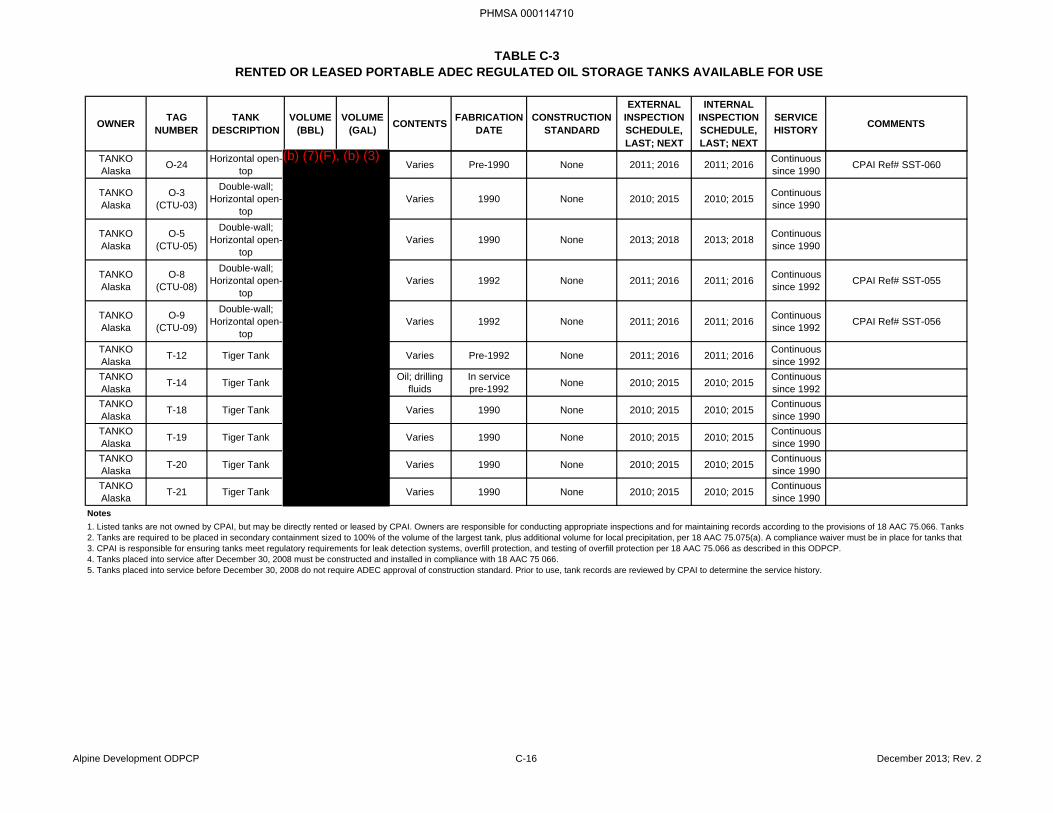
TABLE C-3RENTED OR LEASED PORTABLE ADEC REGULATED OIL STORAGE TANKS AVAILABLE FOR USE
OWNER TAG NUMBER
TANK DESCRIPTION
VOLUME (BBL)
VOLUME (GAL) CONTENTS FABRICATION
DATECONSTRUCTION
STANDARD
EXTERNAL INSPECTION SCHEDULE, LAST; NEXT
INTERNAL INSPECTION SCHEDULE, LAST; NEXT
SERVICE HISTORY COMMENTS
TANKO Alaska O-24 Horizontal open-
top Varies Pre-1990 None 2011; 2016 2011; 2016 Continuous since 1990 CPAI Ref# SST-060
TANKO Alaska
O-3(CTU-03)
Double-wall; Horizontal open-
topVaries 1990 None 2010; 2015 2010; 2015 Continuous
since 1990
TANKO Alaska
O-5(CTU-05)
Double-wall; Horizontal open-
topVaries 1990 None 2013; 2018 2013; 2018 Continuous
since 1990
TANKO Alaska
O-8(CTU-08)
Double-wall; Horizontal open-
topVaries 1992 None 2011; 2016 2011; 2016 Continuous
since 1992 CPAI Ref# SST-055
TANKO Alaska
O-9(CTU-09)
Double-wall; Horizontal open-
topVaries 1992 None 2011; 2016 2011; 2016 Continuous
since 1992 CPAI Ref# SST-056
TANKO Alaska T-12 Tiger Tank Varies Pre-1992 None 2011; 2016 2011; 2016 Continuous
since 1992TANKO Alaska T-14 Tiger Tank Oil; drilling
fluidsIn servicepre-1992 None 2010; 2015 2010; 2015 Continuous
since 1992TANKO Alaska T-18 Tiger Tank Varies 1990 None 2010; 2015 2010; 2015 Continuous
since 1990TANKO Alaska T-19 Tiger Tank Varies 1990 None 2010; 2015 2010; 2015 Continuous
since 1990TANKO Alaska T-20 Tiger Tank Varies 1990 None 2010; 2015 2010; 2015 Continuous
since 1990TANKO Alaska T-21 Tiger Tank Varies 1990 None 2010; 2015 2010; 2015 Continuous
since 1990Notes
5. Tanks placed into service before December 30, 2008 do not require ADEC approval of construction standard. Prior to use, tank records are reviewed by CPAI to determine the service history.
1. Listed tanks are not owned by CPAI, but may be directly rented or leased by CPAI. Owners are responsible for conducting appropriate inspections and for maintaining records according to the provisions of 18 AAC 75.066. Tanks 2. Tanks are required to be placed in secondary containment sized to 100% of the volume of the largest tank, plus additional volume for local precipitation, per 18 AAC 75.075(a). A compliance waiver must be in place for tanks that 3. CPAI is responsible for ensuring tanks meet regulatory requirements for leak detection systems, overfill protection, and testing of overfill protection per 18 AAC 75.066 as described in this ODPCP.4. Tanks placed into service after December 30, 2008 must be constructed and installed in compliance with 18 AAC 75 066.
Alpine Development ODPCP C-16 December 2013; Rev. 2
PHMSA 000114710
(b) (7)(F), (b) (3)
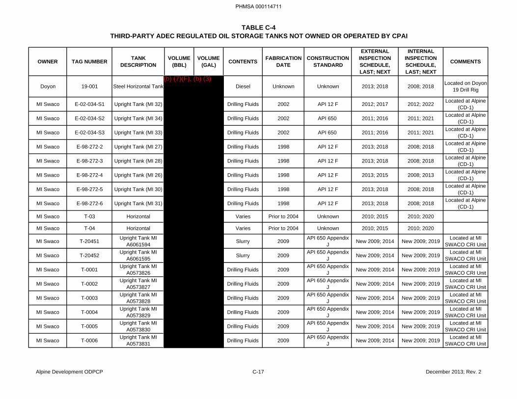
TABLE C-4THIRD-PARTY ADEC REGULATED OIL STORAGE TANKS NOT OWNED OR OPERATED BY CPAI
OWNER TAG NUMBER TANK DESCRIPTION
VOLUME (BBL)
VOLUME (GAL) CONTENTS FABRICATION
DATECONSTRUCTION
STANDARD
EXTERNAL INSPECTION SCHEDULE, LAST; NEXT
INTERNAL INSPECTION SCHEDULE, LAST; NEXT
COMMENTS
Doyon 19-001 Steel Horizontal Tank Diesel Unknown Unknown 2013; 2018 2008; 2018 Located on Doyon 19 Drill Rig
MI Swaco E-02-034-S1 Upright Tank (MI 32) Drilling Fluids 2002 API 12 F 2012; 2017 2012; 2022 Located at Alpine (CD-1)
MI Swaco E-02-034-S2 Upright Tank (MI 34) Drilling Fluids 2002 API 650 2011; 2016 2011; 2021 Located at Alpine (CD-1)
MI Swaco E-02-034-S3 Upright Tank (MI 33) Drilling Fluids 2002 API 650 2011; 2016 2011; 2021 Located at Alpine (CD-1)
MI Swaco E-98-272-2 Upright Tank (MI 27) Drilling Fluids 1998 API 12 F 2013; 2018 2008; 2018 Located at Alpine (CD-1)
MI Swaco E-98-272-3 Upright Tank (MI 28) Drilling Fluids 1998 API 12 F 2013; 2018 2008; 2018 Located at Alpine (CD-1)
MI Swaco E-98-272-4 Upright Tank (MI 26) Drilling Fluids 1998 API 12 F 2013; 2015 2008; 2013 Located at Alpine (CD-1)
MI Swaco E-98-272-5 Upright Tank (MI 30) Drilling Fluids 1998 API 12 F 2013; 2018 2008; 2018 Located at Alpine (CD-1)
MI Swaco E-98-272-6 Upright Tank (MI 31) Drilling Fluids 1998 API 12 F 2013; 2018 2008; 2018 Located at Alpine (CD-1)
MI Swaco T-03 Horizontal Varies Prior to 2004 Unknown 2010; 2015 2010; 2020
MI Swaco T-04 Horizontal Varies Prior to 2004 Unknown 2010; 2015 2010; 2020
MI Swaco T-20451 Upright Tank MI A6061594 Slurry 2009 API 650 Appendix
J New 2009; 2014 New 2009; 2019 Located at MI SWACO CRI Unit
MI Swaco T-20452 Upright Tank MI A6061595 Slurry 2009 API 650 Appendix
J New 2009; 2014 New 2009; 2019 Located at MI SWACO CRI Unit
MI Swaco T-0001 Upright Tank MI A0573826 Drilling Fluids 2009 API 650 Appendix
J New 2009; 2014 New 2009; 2019 Located at MI SWACO CRI Unit
MI Swaco T-0002 Upright Tank MI A0573827 Drilling Fluids 2009 API 650 Appendix
J New 2009; 2014 New 2009; 2019 Located at MI SWACO CRI Unit
MI Swaco T-0003 Upright Tank MI A0573828 Drilling Fluids 2009 API 650 Appendix
J New 2009; 2014 New 2009; 2019 Located at MI SWACO CRI Unit
MI Swaco T-0004 Upright Tank MI A0573829 Drilling Fluids 2009 API 650 Appendix
J New 2009; 2014 New 2009; 2019 Located at MI SWACO CRI Unit
MI Swaco T-0005 Upright Tank MI A0573830 Drilling Fluids 2009 API 650 Appendix
J New 2009; 2014 New 2009; 2019 Located at MI SWACO CRI Unit
MI Swaco T-0006 Upright Tank MI A0573831 Drilling Fluids 2009 API 650 Appendix
J New 2009; 2014 New 2009; 2019 Located at MI SWACO CRI Unit
Alpine Development ODPCP C-17 December 2013; Rev. 2
PHMSA 000114711
(b) (7)(F), (b) (3)
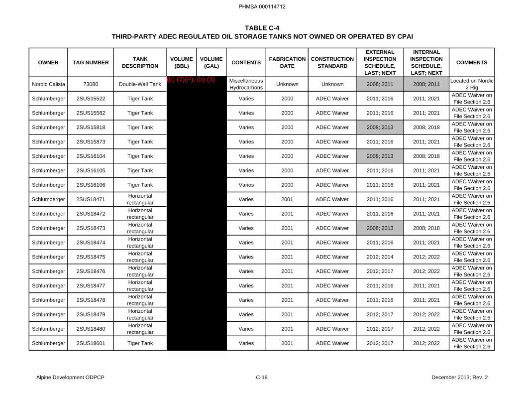
TABLE C-4THIRD-PARTY ADEC REGULATED OIL STORAGE TANKS NOT OWNED OR OPERATED BY CPAI
OWNER TAG NUMBER TANK DESCRIPTION
VOLUME (BBL)
VOLUME (GAL) CONTENTS FABRICATION
DATECONSTRUCTION
STANDARD
EXTERNAL INSPECTION SCHEDULE, LAST; NEXT
INTERNAL INSPECTION SCHEDULE, LAST; NEXT
COMMENTS
Nordic Calista 73080 Double-Wall Tank Miscellaneous Hydrocarbons Unknown Unknown 2008; 2011 2008; 2011 Located on Nordic
2 Rig
Schlumberger 2SUS15522 Tiger Tank Varies 2000 ADEC Waiver 2011; 2016 2011; 2021 ADEC Waiver on File Section 2.6
Schlumberger 2SUS15582 Tiger Tank Varies 2000 ADEC Waiver 2011; 2016 2011; 2021 ADEC Waiver on File Section 2.6
Schlumberger 2SUS15818 Tiger Tank Varies 2000 ADEC Waiver 2008; 2013 2008; 2018 ADEC Waiver on File Section 2.6
Schlumberger 2SUS15873 Tiger Tank Varies 2000 ADEC Waiver 2011; 2016 2011; 2021 ADEC Waiver on File Section 2.6
Schlumberger 2SUS16104 Tiger Tank Varies 2000 ADEC Waiver 2008; 2013 2008; 2018 ADEC Waiver on File Section 2.6
Schlumberger 2SUS16105 Tiger Tank Varies 2000 ADEC Waiver 2011; 2016 2011; 2021 ADEC Waiver on File Section 2.6
Schlumberger 2SUS16106 Tiger Tank Varies 2000 ADEC Waiver 2011; 2016 2011; 2021 ADEC Waiver on File Section 2.6
Schlumberger 2SUS18471 Horizontal rectangular Varies 2001 ADEC Waiver 2011; 2016 2011; 2021 ADEC Waiver on
File Section 2.6
Schlumberger 2SUS18472 Horizontal rectangular Varies 2001 ADEC Waiver 2011; 2016 2011; 2021 ADEC Waiver on
File Section 2.6
Schlumberger 2SUS18473 Horizontal rectangular Varies 2001 ADEC Waiver 2008; 2013 2008; 2018 ADEC Waiver on
File Section 2.6
Schlumberger 2SUS18474 Horizontal rectangular Varies 2001 ADEC Waiver 2011; 2016 2011; 2021 ADEC Waiver on
File Section 2.6
Schlumberger 2SUS18475 Horizontal rectangular Varies 2001 ADEC Waiver 2012; 2014 2012; 2022 ADEC Waiver on
File Section 2.6
Schlumberger 2SUS18476 Horizontal rectangular Varies 2001 ADEC Waiver 2012; 2017 2012; 2022 ADEC Waiver on
File Section 2.6
Schlumberger 2SUS18477 Horizontal rectangular Varies 2001 ADEC Waiver 2011; 2016 2011; 2021 ADEC Waiver on
File Section 2.6
Schlumberger 2SUS18478 Horizontal rectangular Varies 2001 ADEC Waiver 2011; 2016 2011; 2021 ADEC Waiver on
File Section 2.6
Schlumberger 2SUS18479 Horizontal rectangular Varies 2001 ADEC Waiver 2012; 2017 2012; 2022 ADEC Waiver on
File Section 2.6
Schlumberger 2SUS18480 Horizontal rectangular Varies 2001 ADEC Waiver 2012; 2017 2012; 2022 ADEC Waiver on
File Section 2.6
Schlumberger 2SUS18601 Tiger Tank Varies 2001 ADEC Waiver 2012; 2017 2012; 2022 ADEC Waiver on File Section 2.6
Alpine Development ODPCP C-18 December 2013; Rev. 2
PHMSA 000114712
(b) (7)(F), (b) (3)
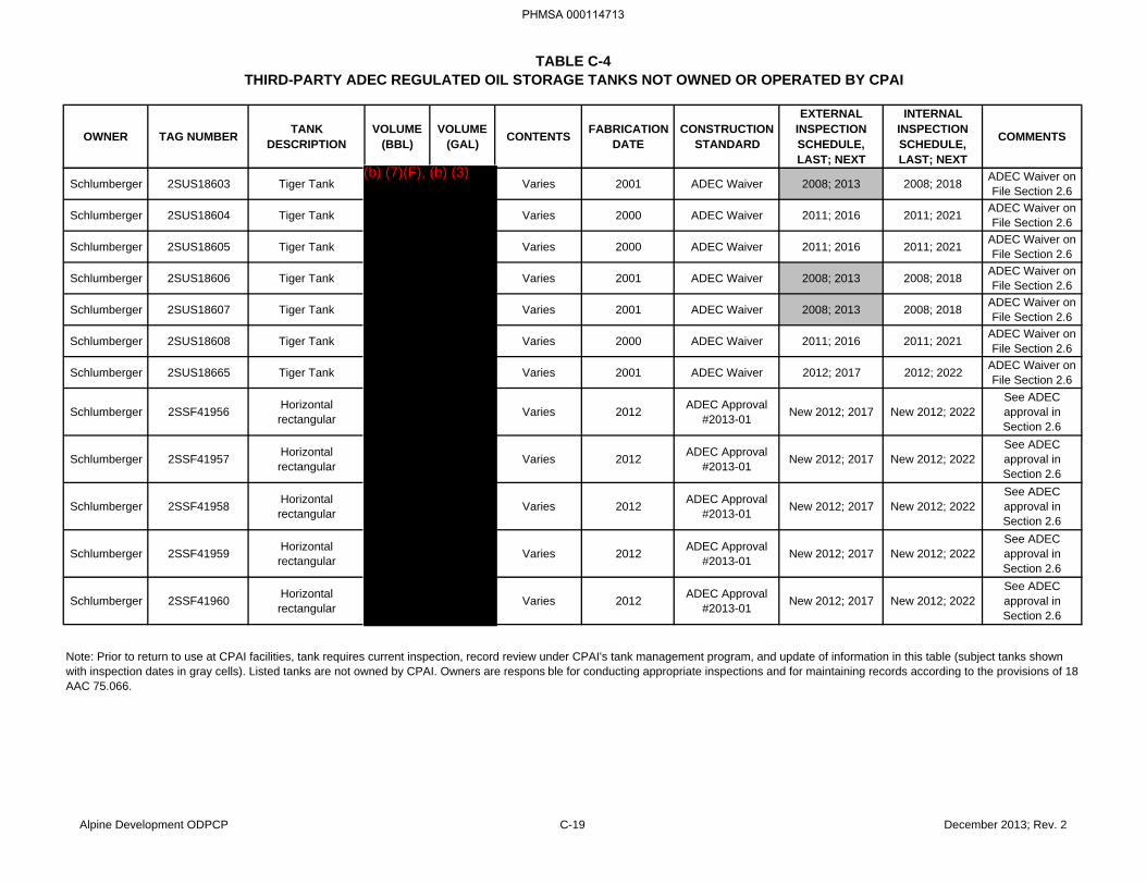
TABLE C-4THIRD-PARTY ADEC REGULATED OIL STORAGE TANKS NOT OWNED OR OPERATED BY CPAI
OWNER TAG NUMBER TANK DESCRIPTION
VOLUME (BBL)
VOLUME (GAL) CONTENTS FABRICATION
DATECONSTRUCTION
STANDARD
EXTERNAL INSPECTION SCHEDULE, LAST; NEXT
INTERNAL INSPECTION SCHEDULE, LAST; NEXT
COMMENTS
Schlumberger 2SUS18603 Tiger Tank Varies 2001 ADEC Waiver 2008; 2013 2008; 2018 ADEC Waiver on File Section 2.6
Schlumberger 2SUS18604 Tiger Tank Varies 2000 ADEC Waiver 2011; 2016 2011; 2021 ADEC Waiver on File Section 2.6
Schlumberger 2SUS18605 Tiger Tank Varies 2000 ADEC Waiver 2011; 2016 2011; 2021 ADEC Waiver on File Section 2.6
Schlumberger 2SUS18606 Tiger Tank Varies 2001 ADEC Waiver 2008; 2013 2008; 2018 ADEC Waiver on File Section 2.6
Schlumberger 2SUS18607 Tiger Tank Varies 2001 ADEC Waiver 2008; 2013 2008; 2018 ADEC Waiver on File Section 2.6
Schlumberger 2SUS18608 Tiger Tank Varies 2000 ADEC Waiver 2011; 2016 2011; 2021 ADEC Waiver on File Section 2.6
Schlumberger 2SUS18665 Tiger Tank Varies 2001 ADEC Waiver 2012; 2017 2012; 2022 ADEC Waiver on File Section 2.6
Schlumberger 2SSF41956 Horizontal rectangular Varies 2012 ADEC Approval
#2013-01 New 2012; 2017 New 2012; 2022See ADEC approval in Section 2.6
Schlumberger 2SSF41957 Horizontal rectangular Varies 2012 ADEC Approval
#2013-01 New 2012; 2017 New 2012; 2022See ADEC approval in Section 2.6
Schlumberger 2SSF41958 Horizontal rectangular Varies 2012 ADEC Approval
#2013-01 New 2012; 2017 New 2012; 2022See ADEC approval in Section 2.6
Schlumberger 2SSF41959 Horizontal rectangular Varies 2012 ADEC Approval
#2013-01 New 2012; 2017 New 2012; 2022See ADEC approval in Section 2.6
Schlumberger 2SSF41960 Horizontal rectangular Varies 2012 ADEC Approval
#2013-01 New 2012; 2017 New 2012; 2022See ADEC approval in Section 2.6
Note: Prior to return to use at CPAI facilities, tank requires current inspection, record review under CPAI's tank management program, and update of information in this table (subject tanks shown with inspection dates in gray cells). Listed tanks are not owned by CPAI. Owners are respons ble for conducting appropriate inspections and for maintaining records according to the provisions of 18 AAC 75.066.
Alpine Development ODPCP C-19 December 2013; Rev. 2
PHMSA 000114713
(b) (7)(F), (b) (3)

PHMSA 000114714
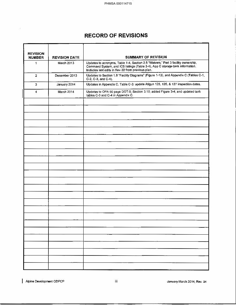
PHMSA 000114715

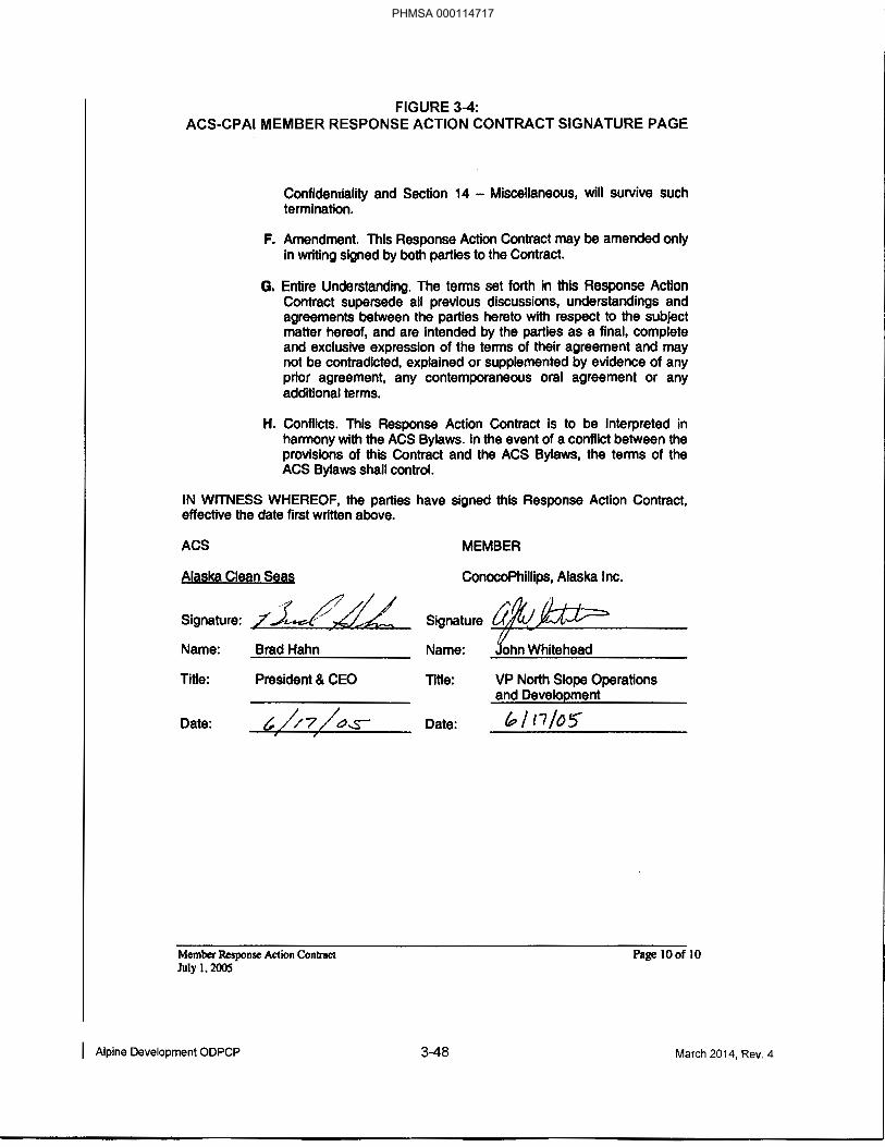
PHMSA 000114717
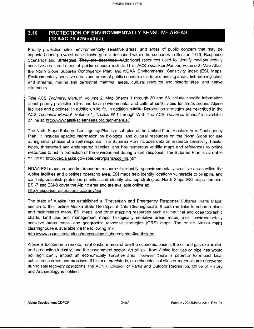
PHMSA 000114718