unofficial - tulare county - ca.gov
TRANSCRIPT

Book No: C_____
COUNTY OF TULARE STATE OF CALIFORNIA
SPECIAL PROVISIONS PROPOSAL AND CONTRACT
FOR CONSTRUCTION OF
COMMUNITY ACCESSIBILITY ENHANCEMENT PROJECT
FUNDED BY:
2006 HALF-CENT TRANSPORTATION SALES TAX MEASURE (MEASURE R)
UNOFFICIA
L
PECIAL POPOSALFOR

This page intentionally left blank
UNOFFICIA
Ltentionalltentional

This page intentionally left blank
UNOFFICIA
Ltentionalltentional

************************************************************
SPECIAL NOTICES ************************************************************
See sections 2 and 3 for contractors' registration requirements. This project is exempt from Indirect Source Rule (ISR) and a Dust Control Plan is not required
UNOFFICIA
L

This page intentionally left blank
UNOFFICIA
Ltentionalltentional
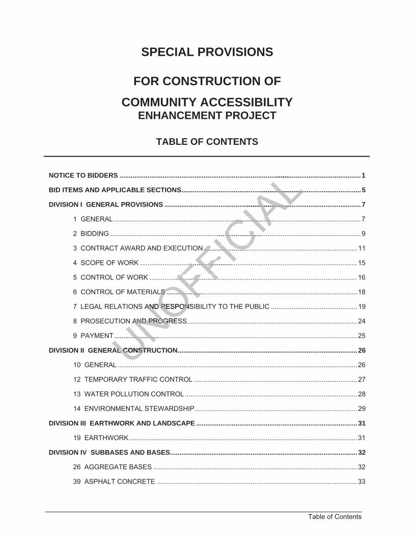
Table of Contents
SPECIAL PROVISIONS
FOR CONSTRUCTION OFCOMMUNITY ACCESSIBILITY
ENHANCEMENT PROJECT
TABLE OF CONTENTS
NOTICE TO BIDDERS ................................................................................................................................. 1
BID ITEMS AND APPLICABLE SECTIONS ................................................................................................ 5
DIVISION I GENERAL PROVISIONS ......................................................................................................... 7
1 GENERAL .................................................................................................................................... 7
2 BIDDING ...................................................................................................................................... 9
3 CONTRACT AWARD AND EXECUTION .................................................................................. 11
4 SCOPE OF WORK .................................................................................................................... 15
5 CONTROL OF WORK ............................................................................................................... 16
6 CONTROL OF MATERIALS ...................................................................................................... 18
7 LEGAL RELATIONS AND RESPONSIBILITY TO THE PUBLIC .............................................. 19
8 PROSECUTION AND PROGRESS ........................................................................................... 24
9 PAYMENT .................................................................................................................................. 25
DIVISION II GENERAL CONSTRUCTION ................................................................................................ 26
10 GENERAL ................................................................................................................................ 26
12 TEMPORARY TRAFFIC CONTROL ....................................................................................... 27
13 WATER POLLUTION CONTROL ............................................................................................ 28
14 ENVIRONMENTAL STEWARDSHIP ....................................................................................... 29
DIVISION III EARTHWORK AND LANDSCAPE ...................................................................................... 31
19 EARTHWORK .......................................................................................................................... 31
DIVISION IV SUBBASES AND BASES .................................................................................................... 32
26 AGGREGATE BASES ............................................................................................................. 32
39 ASPHALT CONCRETE ........................................................................................................... 33
UNOFFICIA
L........
.........................................
...............................................
...............................................
................................................
N ......................... .........................
...................................................
..................................................
LS ......................LS ..................
AND RESPONSAND RESPON
N AND PROGREAND PROG
.........................................
AL CONSTRAL CONST
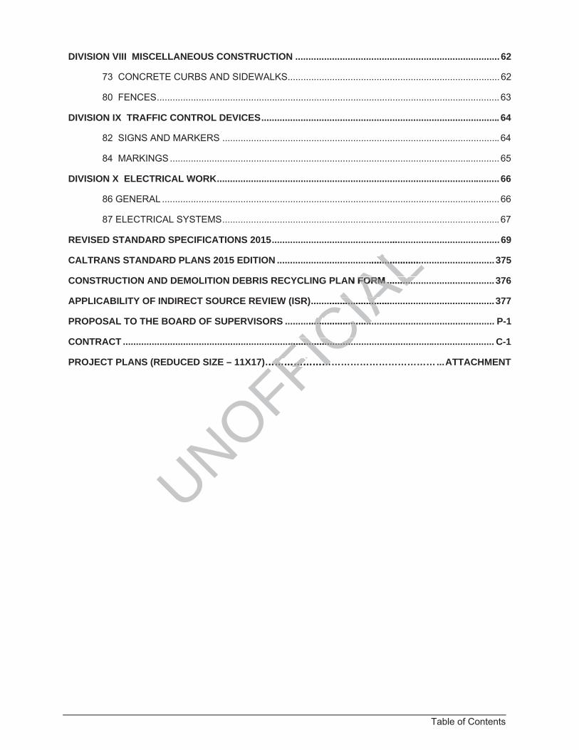
Table of Contents
DIVISION VIII MISCELLANEOUS CONSTRUCTION .............................................................................. 62
73 CONCRETE CURBS AND SIDEWALKS ................................................................................. 62
80 FENCES ................................................................................................................................... 63
DIVISION IX TRAFFIC CONTROL DEVICES ........................................................................................... 64
82 SIGNS AND MARKERS .......................................................................................................... 64
84 MARKINGS .............................................................................................................................. 65
DIVISION X ELECTRICAL WORK ............................................................................................................ 66
86 GENERAL ................................................................................................................................. 66
87 ELECTRICAL SYSTEMS .......................................................................................................... 67
REVISED STANDARD SPECIFICATIONS 2015 ....................................................................................... 69
CALTRANS STANDARD PLANS 2015 EDITION ................................................................................... 375
CONSTRUCTION AND DEMOLITION DEBRIS RECYCLING PLAN FORM ......................................... 376
APPLICABILITY OF INDIRECT SOURCE REVIEW (ISR) ...................................................................... 377
PROPOSAL TO THE BOARD OF SUPERVISORS ................................................................................ P-1
CONTRACT .............................................................................................................................................. C-1
PROJECT PLANS (REDUCED SIZE – 11X17)……………………………………………… ... ATTACHMENT
UNOFFICIA
L....
..........................
N FORM ............FORM ...........
..........................................
.................................................
....................................................
………………………………………
1 Notice to Bidders
COUNTY OF TULARE
STATE OF CALIFORNIA
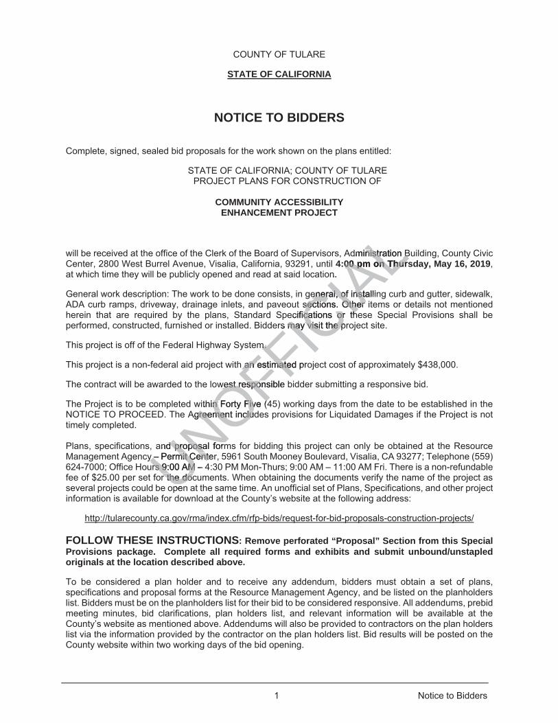
NOTICE TO BIDDERS
Complete, signed, sealed bid proposals for the work shown on the plans entitled:
STATE OF CALIFORNIA; COUNTY OF TULARE PROJECT PLANS FOR CONSTRUCTION OF
COMMUNITY ACCESSIBILITY
ENHANCEMENT PROJECT
will be received at the office of the Clerk of the Board of Supervisors, Administration Building, County Civic Center, 2800 West Burrel Avenue, Visalia, California, 93291, until 4:00 pm on Thursday, May 16, 2019, at which time they will be publicly opened and read at said location.
General work description: The work to be done consists, in general, of installing curb and gutter, sidewalk, ADA curb ramps, driveway, drainage inlets, and paveout sections. Other items or details not mentioned herein that are required by the plans, Standard Specifications or these Special Provisions shall be performed, constructed, furnished or installed. Bidders may visit the project site.
This project is off of the Federal Highway System.
This project is a non-federal aid project with an estimated project cost of approximately $438,000.
The contract will be awarded to the lowest responsible bidder submitting a responsive bid.
The Project is to be completed within Forty Five (45) working days from the date to be established in the NOTICE TO PROCEED. The Agreement includes provisions for Liquidated Damages if the Project is not timely completed. Plans, specifications, and proposal forms for bidding this project can only be obtained at the Resource Management Agency – Permit Center, 5961 South Mooney Boulevard, Visalia, CA 93277; Telephone (559) 624-7000; Office Hours 9:00 AM – 4:30 PM Mon-Thurs; 9:00 AM – 11:00 AM Fri. There is a non-refundable fee of $25.00 per set for the documents. When obtaining the documents verify the name of the project as several projects could be open at the same time. An unofficial set of Plans, Specifications, and other project information is available for download at the County’s website at the following address:
http://tularecounty.ca.gov/rma/index.cfm/rfp-bids/request-for-bid-proposals-construction-projects/
FOLLOW THESE INSTRUCTIONS: Remove perforated “Proposal” Section from this Special Provisions package. Complete all required forms and exhibits and submit unbound/unstapled originals at the location described above.
To be considered a plan holder and to receive any addendum, bidders must obtain a set of plans, specifications and proposal forms at the Resource Management Agency, and be listed on the planholders list. Bidders must be on the planholders list for their bid to be considered responsive. All addendums, prebid meeting minutes, bid clarifications, plan holders list, and relevant information will be available at the County’s website as mentioned above. Addendums will also be provided to contractors on the plan holders list via the information provided by the contractor on the plan holders list. Bid results will be posted on the County website within two working days of the bid opening.
UNOFFICIA
Ldministration Bnistration B:00 pm on Thurs00 pm on Thur
n.
eneral, of installineneral, of instsections. Other sections. Other
ecifications or thcations or thrs may visit the prrs may visit the p
m. m.
h an an estimated prostimate
west responsible west respon
ithin Forty Five (4n Forty Five (4Agreement includgreement inclu
and proposal formd proposal formy – Permit Centery – Permit Centers 9:00 AM – 4rs 9:00 AM
r the docr the docpen

2 Notice to Bidders
Technical questions should be directed in writing to Michael J. Winton, P.E. at the Resource Management Agency, 5961 S. Mooney Blvd, Visalia CA 93277 or at [email protected]. No questions shall be accepted within five working days of the bid opening (Questions shall be received by 5:00pm Wednesday, May 8, 2019). All questions and responses will be continuously posted on the County website.
Before submitting a bid, bidders shall carefully examine the Plans and Specifications, and related documents, visit the site of the work and fully inform themselves as to all existing conditions and limitations, and shall include in the bid a sum to cover the cost of all items included in the work.
A prebid meeting is scheduled for 2:00pm, Tuesday, May 7, 2019, at the Resource Management Agency Main Conference Room located at 5961 S. Mooney Blvd. Visalia, CA 93277. The meeting is not mandatory, but bidders are encouraged to attend. The bidder awarded the contract may need to obtain permits, licenses, or enter into agreements to prosecute the work. Bidders are advised that, unless otherwise stated, the contract price will be full compensation and no additional compensation will be allowed. If the bidder must obtain permits, licenses, contracts or other services to prosecute the work, the bidder will pay the cost of those items and no other compensation will be paid by the County.
Bids are required for the entire work described herein. Each bid proposal shall be accompanied by a bidder's bond, or by a certified check or cashier's check, in the amount of ten percent (10%) of the amount bid or the bid will be considered nonresponsive.
Contractor shall comply with the Title VI of the Civil Rights Act of 1964, and in accordance with said Act, no person of the grounds of race, color, sex or national origin, shall be excluded from participation in, be denied of benefits of, or be otherwise subject to discrimination under any service or activity in connection with the project.
Contractor shall comply with Title VII of the Civil Rights Act 1964, which prohibits discrimination against any employee or applicant for employment because of race, color, religion, sex or national origin.
At the time the bid is submitted, you shall possess a current valid California Class A Contractor's license.
A contractor or subcontractor shall not be qualified to bid on, be listed in a bid proposal, subject to the requirements of Section 4104 of the Public Contract Code, or engage in the performance of any contract for public work, as defined in this chapter, unless currently registered and qualified to perform public work pursuant to California Labor Code section 1725.5. It is not a violation of this section for an unregistered contractor to submit a bid that is authorized by Section 7029.1 of the Business and Professions Code or by Sections 10164 or 20103.5 of the Public Contract Code, provided the contractor is registered to perform public work pursuant to Labor Code section 1725.5 at the time the contract is awarded.
This project is subject to compliance monitoring and enforcement by the California Department of Industrial Relations.
The successful bidder must provide the performance bond, payment bond, workers compensation certificate, and liability insurance policy required by the Special Provisions and contract. Three million dollars ($3,000,000) liability coverage is required for this project.
Substitution for moneys withheld shall be permitted pursuant to Public Contract Code section 10263. This project is subject to State contract nondiscrimination and compliance requirements pursuant to Government Code, section 12990.
Pursuant to Section 1773 of the Labor Code, the general prevailing wage rates in the county, or counties, in which the work is to be done, have been determined by the Director of the California Department of Industrial Relations. These wages are set forth in the General Prevailing Wage Rates for this project, is made available on the County public works website (see link in the previous page). Also, the General Prevailing Wage Rates for this project, are on file at Resource Management Agency-Permit Center, 5961
UNOFFICIA
Lsal shalof ten percentten
of 1964, and in a964, andhall be excluded fhall be excluded
nder any serviceder any service
Rights Act 1964, wRights Act 1964e of e of race, color, rrace, color, r
all possess a curall posses
shall not be qualihall not be qua4 of the Public Che Public C
d in this chapter, un this chapteLabor Code sectiobor Code sectio
a bid that is authoa bid that is auth0103.5 of the P0103.5 of th
Labor CoLabor C
3 Notice to Bidders
South Mooney Boulevard, Visalia, CA 93277 and will be made available to any interested person on request. Also, the General Prevailing Wage Rates are available from the California Department of Industrial Relations’ Internet website at http://www.dir.ca.gov. Contractor shall be responsible to post the general prevailing wage rates at a prominent place at the job site in accordance to section 7-1.02K(2) of the Caltrans Standard Specifications. Future effective general prevailing wage rates, which have been predetermined and are on file with the California Department of Industrial Relations, are referenced, but not printed in the Special Provisions. AB 626, approved by the Governor of the State of California on September 29, 2016, created a new Public Contract Code section 9204, which specifies new procedural requirements for claims submitted by a contractor on any public works project. Please review the language of this section in the Proposal, page P-16. The U.S. Department of Transportation (DOT) provides a toll-free “hotline” service to report bid rigging activities. Bid rigging activities can be reported Mondays through Fridays, between 8:00 a.m. and 5:00 p.m., Eastern time, Telephone No. 1-800-424-9071. Anyone with knowledge of possible bid rigging, bidder collusion, or other fraudulent activities should use the “hotline” to report these activities. The “hotline” is part of the DOT’s continuing effort to identify and investigate highway construction contract fraud and abuse and is operated under the direction of the DOT Inspector General. All information will be treated confidentially and caller anonymity will be respected.
You shall be responsible for compliance by all subcontractors with Labor Code section 1776.
All bidders are invited to attend the bid opening. The results of the bid opening will be reported to the Board of Supervisors at a scheduled meeting. The contract will be awarded in the manner and within the time periods provided in Section 3 of the Standard Specifications, Department of Transportation of the State of California, 2015 Edition, as amended by the project Special Provisions, unless the Board of Supervisors exercises its right to reject any or all bids. The Board of Supervisors reserves the right to deem the bid non-responsive for any information crossed out from the bid packet including information completed by the manufacturer.
The Board of Supervisors reserves the right to reject any or all bids, and/or wave any informality in any bid, and/or determine in its discretion the responsibility of any bidder.
The Board of Supervisors further reserves the right to use County Forces, or to negotiate contracts, or both, to the extent authorized by the Public Contract Code.
By order of the Board of Supervisors.
JASON T. BRITT County Administrative Officer/ Clerk, Board of Supervisors. By Original Signed
Deputy
UNOFFICIA
Ln con
ation will btio
h Labor Code secbor Code sec
s of the biof the d openind openill be awarded inbe awarded in
cations, Departmcations, Departmct ct Special ProvisSpecial Provis
oard of Supervisoard of Supervisfrom tfrom the bid pache b
e right to reject ane right to rejee responsibility oresponsibility
er reserves the rireserves the rhe Public Contrahe Public Contra
of Supervisors. Superviso

This page intentionally left blank
UNOFFICIA
Ltentionalltentional
5 Bid Items and Applicable Sections
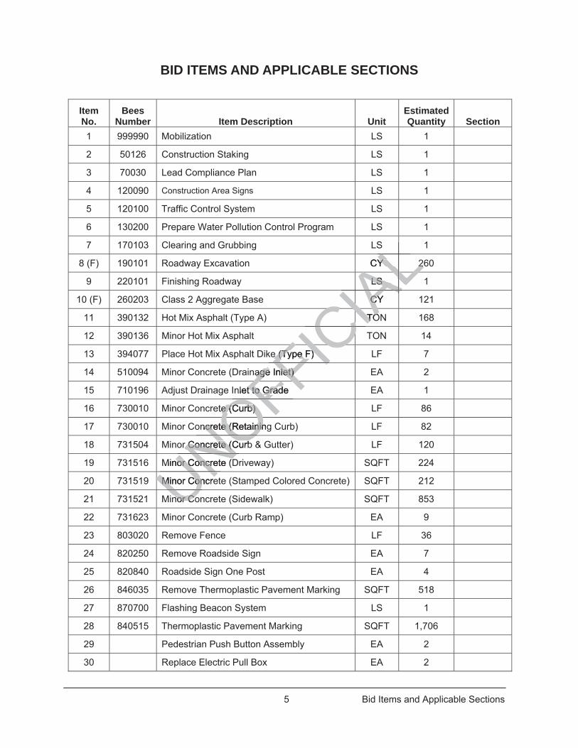
BID ITEMS AND APPLICABLE SECTIONS
ItemNo.
Bees Number Item Description Unit
Estimated Quantity Section
1 999990 Mobilization LS 1
2 50126 Construction Staking LS 1
3 70030 Lead Compliance Plan LS 1
4 120090 Construction Area Signs LS 1
5 120100 Traffic Control System LS 1
6 130200 Prepare Water Pollution Control Program LS 1
7 170103 Clearing and Grubbing LS 1
8 (F) 190101 Roadway Excavation CY 260
9 220101 Finishing Roadway LS 1
10 (F) 260203 Class 2 Aggregate Base CY 121
11 390132 Hot Mix Asphalt (Type A) TON 168
12 390136 Minor Hot Mix Asphalt TON 14
13 394077 Place Hot Mix Asphalt Dike (Type F) LF 7
14 510094 Minor Concrete (Drainage Inlet) EA 2
15 710196 Adjust Drainage Inlet to Grade EA 1
16 730010 Minor Concrete (Curb) LF 86
17 730010 Minor Concrete (Retaining Curb) LF 82
18 731504 Minor Concrete (Curb & Gutter) LF 120
19 731516 Minor Concrete (Driveway) SQFT 224
20 731519 Minor Concrete (Stamped Colored Concrete) SQFT 212
21 731521 Minor Concrete (Sidewalk) SQFT 853
22 731623 Minor Concrete (Curb Ramp) EA 9
23 803020 Remove Fence LF 36
24 820250 Remove Roadside Sign EA 7
25 820840 Roadside Sign One Post EA 4
26 846035 Remove Thermoplastic Pavement Marking SQFT 518
27 870700 Flashing Beacon System LS 1
28 840515 Thermoplastic Pavement Marking SQFT 1,706
29 Pedestrian Push Button Assembly EA 2
30 Replace Electric Pull Box EA 2
UNMinor ConcreMinor ConUUNOFFICIA
LLCY 2Y 2LALLS LS ALAALCY CYIACIAATOTOCIACIACCe (Type F) e (Type F) FIC
age Inlet) age Inlet) FInlet to Grade t to GraFF
ete (Curb) e (Curb)
OFncrete (Retainingncrete (RetaininOor Concrete (Curbr Concrete (CuNO
Minor Concrete (Dnor ConcrNUNUnor Conor CoU

This page intentionally left blank
UNOFFICIA
Ltentionalltentional
Section 1 – General 7 Special Provisions
SPECIAL PROVISIONS
ORGANIZATION
Special provisions are under headings that correspond with the main-section headings of the Standard Specifications. A main-section heading is a heading shown in the table of contents of the StandardSpecifications.
Each special provision begins with a revision clause that describes or introduces a revision to the Standard Specifications as revised by any revised standard specification.
Any paragraph added or deleted by a revision clause does not change the paragraph numbering of the Standard Specifications for any other reference to a paragraph of the Standard Specifications.
^^^^^^^^^^^^^^^^^^^^^^^^^^^^^^^^^^^^^^^^^^^^^^^^^^^^^^^^^^^^
DIVISION I GENERAL PROVISIONS
^^^^^^^^^^^^^^^^^^^^^^^^^^^^^^^^^^^^^^^^
1 GENERAL
Add to Section 1-1.01:
The work embraced herein must be done under the 2015 Standard Specifications (hereinafter referred to as the "Standard Specifications"), as amended by these Special Provisions, the 2015 Standard Plans (hereinafter referred to as the "Standard Plans"), of the Department of Transportation of the State of California, the project plans described below, and under the following Special Provisions.
Amendments to the 2015 Standard Specifications dated 4-20-18 shall be considered as included in this contract as described above.
For the purpose of this contract, the following terms or pronouns in place of them, used throughout the Standard Specifications and these Special Provisions and defined in Section 1, Definitions, of the Standard Specifications, shall be interpreted as follows:
TERM
INTERPRETATION
State
County of Tulare, when referring to the State of California, including its agencies, departments or divisions whose conduct or action is related to the work, except when used only to identify a State Form or Document.
Department or Department of Transportation, or Director
The Tulare County Board of Supervisors, except when used only to identify a State Form, Document or when in reference to a specific Federal or State department.
Engineer Tulare County Director of the Resource Management Agency/Director of Transportation, or designee and authorized agents acting within the scope of their authority.
UNOFFICIA
LONS ON
^^^^^^^^^^^ ^^^^^^^^^^^
RAL AL
Section 1-1.01:Section 1-1.0
under the 2015 under the 201 Samended by nded thes
ndard Plans"), ofndard Plans")bed below,ed below, and u and u
andard Specifard Specificaticae. e.
is contract, the foontract, thons and these Sons and these S
ee interpretedinterprete
RM

Section 1 – General 8 Special Provisions
TERM
INTERPRETATION
County
The County of Tulare, including its agencies, departments or divisions whose conduct or action is related to the work.
Transportation Laboratory or METS Tulare County Resource Management Agency, except when used to identify a State form, document, or testing procedure.
The project plans for this project were approved April 2, 2019, and are entitled:
STATE OF CALIFORNIA; COUNTY OF TULARE PROJECT PLANS FOR CONSTRUCTION OF
COMMUNITY ACCESSIBILITY
ENHANCEMENT PROJECT
The following documents will be supplied to you with the Notice to Proceed:
1. One complete set of full size (24”x36”) Project Plans 2. One complete set of half size (11”x17”) Project Plans 3. Two complete bid books including:
3.1. Notice to Contractors 3.2. Special Provisions 3.3. Technical Specifications 3.4. Proposal 3.5. Contract
4. One Compact Disk (CD) with Adobe PDF versions of full size and half size plans and Special Provisions, Proposal and Contract.
No additional copies will be provided. Additional bid books, if available, may be purchased at twenty five dollars ($25) per book.
Replace "holiday" and its definition in Section 1-1.07B with:
holiday: County legal holidays and every Sunday. When a holiday falls on a Sunday, it shall be observed on the following Monday.
Replace “South Coast Air Quality Management District” and attributes in Section 1-1.11 with:
Reference or agency or department unit Website Address Telephone no.
San Joaquin Valley Air Pollution Control District (Central)
www.valleyair.org 1990 E. Gettysburg Avenue Fresno, CA 93726-0244 (559) 230-6000
UNOFFICIA
Lroceed: oceed
e PDF versions e PDF version
ed. Additional bidd. Additional b
ce "holiday" andce "holiday" an
l holidays and evdays and day. day

Section 2 - Bidding 9 Special Provisions
^^^^^^^^^^^^^^^^^^^^^^^^^^^^^^^^^^^^^^^^
2 BIDDING
Replace Section 2-1.06 of the RSS with the following:
2-1.06 BID DOCUMENTS
2-1.06A General
The Special Provisions, Proposal and Contract (Bid) book includes bid forms and certifications. For an electronic bid, the Bid book includes forms not available through the electronic bidding service.
The Special Provisions, Proposal and Contract and project plans may be purchased at the Resource Management Agency – Permit Center, 5961 South Mooney Boulevard, Visalia, CA 93277 and viewed at the County’s Website:
http://tularecounty.ca.gov/rma/index.cfm/rfp-bids/request-for-bid-proposals-construction-projects/
The Special Provisions, Proposal and Contract includes the Notice to Bidders, revised standard specifications, and special provisions.
The Bid book, Special Provisions, Proposal and Contract, project plans, and any addenda to these documents may be accessed at the County Website.
2-1.06B Supplemental Project Information
The County makes supplemental information available as specified in the special provisions.
Logs of test borings are supplemental project information.
If an Information Handout or cross sections are available, you may view it at the County Website.
If other supplemental project information is available for inspection, you may view it by phoning in a request. Make your request at least 7 days before viewing. Include in your request:
1. Contract number 2. Viewing date 3. Contact information, including telephone number
As-built drawings may not show existing dimensions and conditions. Where new construction dimensions are dependent on existing dimensions, verify the field dimensions and adjust the dimensions of the work to fit the existing conditions, as approved by the Engineer.
Replace Section 2-1.10 of the RSS with the following:
2-1.10 SUBCONTRACTOR LIST
On the Subcontractor List form, list each subcontractor to perform work in an amount in excess of 1/2 of 1 percent of the total bid or $10,000, whichever is greater (Pub Contract Code § 4100 et seq.).
For each subcontractor listed, the Subcontractor List form must show:
1. Business name and the location of its place of business.
UNOFFICIA
Lia
osals-conconstructiostructio
ALe e Notice to Bidtice to Bid
ractct, project plan, project plan
available as speavailable
roject informationect information
sections are avaiections are ava
nformation is availrmation is ava7 days bef7 days before vieore vie
on, including on, includin
Section 2 - Bidding 10 Special Provisions
2. California contractor license number for a non-federal-aid contract and public works contractor registration number in the “Lic. No.” of the List of Subcontractors form.
3. Public works contractor registration number. 4. Portion of work it will perform. Show the portion of the work by:
4.1. Bid item numbers for the subcontracted work 4.2. Percentage of the subcontracted work for each bid item listed 4.3. Description of the subcontracted work if the percentage of the bid item listed is less than 100
percent
Replace Section 2-1.33A of the RSS with the following:
2-1.33A General
Remove the Proposal to the Board of Supervisors (Proposal) section in the Bid book and complete the forms.
Submit your forms to the Tulare County Board of Supervisors at the front desk before the bid opening time and date. The address to the Board of Supervisors is provided below:
2800 W Burrel Avenue, Visalia, CA 93291
Failure to submit the forms and information as specified may result in a nonresponsive bid.
If an agent other than the authorized corporate officer or a partnership member signs the bid, file a Power of Attorney with the County either before opening bids or with the bid. Otherwise, the bid may be nonresponsive.
Replace Section 2-1.33B of the RSS with the following:
2-1.33B Paper Bids
The County only accepts paper bid submittals. Place your completed forms inside a sealed paper envelope, and on the cover of the envelope, include:
1. Name of the contractor 2. Project title 3. Marked as a proposal 4. Bid opening date
Submit the enclosed proposal to the Clerk of the Board of Supervisors prior to bid opening.
Replace Section 2-1.34 of the RSS with the following:
2-1.34 BIDDER'S SECURITY
Submit one of the following forms of bidder's security equal to at least 10 percent of the bid:
1. Cashier's check 2. Certified check 3. Signed bidder's bond by an admitted surety insurer who is licensed in California
If using a bidder's bond, you must use the form in the Proposal. Failure to do so will render your bid non-responsive.
Submit cash, cashier’s check, certified check, or bidder's bond to the Clerk of the Board of Supervisors before the bid opening time.
UNOFFICIA
Lesk be
esult in a nonrespult in a nonresp
a partnership mempartnership mebids or with the bids or with t
2-1.33B of the R2-1.33B of the
bid submittals. Plid submittals. Plope, include: include:
ctor or
posal posa

Section 3 – Contract Award and Execution 11 Special Provisions
^^^^^^^^^^^^^^^^^^^^^^^^^^^^^^^^^^^^^^^^
3 CONTRACT AWARD AND EXECUTION
Replace all of Section 3 with:
3-1.01 AWARD OF CONTRACT
The Tulare County Board of Supervisors reserves the right to reject any or all proposals, or waive discrepancies or failures in a proposal. The decision of the Tulare County Board of Supervisors regarding the amount of a bid, or existence or treatment of a discrepancy or failure in a bid will be final. The award of the contract, if it is awarded, will be to the lowest responsive and responsible bidder whose proposal complies with all the requirements prescribed. Such award, if made, will be made within 60 days after the opening of proposal. This period may be subject to an extension for such further period as may be agreed upon in writing between the Tulare County Board of Supervisors and the bidder concerned.
All bids will be compared on the basis of the Engineer’s Estimate of the quantities of work to be done.
A responsible bidder who submitted the lowest bid as determined by this section shall be awarded the contract, if it is awarded. This section does not preclude the local agency from adding to or deducting from the contract any of the additive or deductive items after the lowest responsible bidder has been determined.
The following failures are not waivable and will cause a bid to be considered non-responsive:
1. Failure to sign the bid 2. Failure to furnish the required bid bond or equivalent as specified in 2-1.34 of the Special
Provisions 3. Failure to include a total amount of the bid 4. Failure to submit a completed addenda certification statement 5. Failure to be listed on the planholders list
The above list is not inclusive of all failures that the Tulare County Board of Supervisors will consider non-responsive. However, the Tulare County Board of Supervisors reserves the right to waive other types of discrepancies or failures. The Tulare County Board of Supervisor decision or treatment regarding a bid will be final.
The contract must be signed by the successful bidder and returned together with the contract bonds and insurance certificates within ten (10) days, not including Saturday, Sunday or Tulare County legal holidays, after the bidder has received notice from the County that the contract is scheduled for award by the Board of Supervisors.
3-1.02 BID PROTEST PROCEDURES
Bid Protests. Any bid protests must be in writing and received by County’s Director – Public Works, Tulare County Resource Management Agency, 5961 S. Mooney Boulevard, Visalia, CA 9327, before 5:00 p.m. no later than two working days following bid opening (the “Bid Protest Deadline”) and must comply with the following requirements:
A. General. Only a bidder who has actually submitted a Bid Proposal is eligible to submit a bid protest against another bidder. Subcontractors and material suppliers are not eligible to submit bid protests. A bidder may not rely on the bid protest submitted by another bidder, but must timely pursue its own protest. A bid protest against the bids of more than one bidder shall be considered as separate protests against each such bidder and will be separately considered. The protesting bidder must submit a non-refundable fee in the amount of $750.00 per protest, based upon County’s reasonable costs to administer the bid protest(s). Any such fees must be submitted to County no later than the Bid Protest Deadline, unless
UNOFFICIA
Lder
quantities of uant
ned by this sectioned by this sectical agency from agency f
owest reowest sponsiblesponsib
use a bid to be cse a bid to be
nd or equivalentnd or equiv
of the bid he bidaddenda certificaddenda cert
lanholders list nholders li
e of all failures thll failures the Tulare County Be Tulare County
s. The Tulare Co The Tulare Co
signed by signed byinn tete
Section 3 – Contract Award and Execution 12 Special Provisions
otherwise specified. For purposes of this Bid Protest Procedure, a “working day” means a day that County is open for normal business, and excludes weekends and holidays observed by County.
B. Protest Contents. Each bid protest must contain a complete statement of the basis for the protest and all supporting documentation. Material submitted after the Bid Protest Deadline will not be considered. The protest must refer to the specific portion or portions of the Contract Documents upon which the protest is based. The protest must include the name, address, email address, and telephone number of the person representing the protesting bidder if different from the protesting bidder.
C. Copies to Protested Bidders. A copy of the protest and all supporting documents must be concurrently transmitted by fax or by email, by or before the Bid Protest Deadline, by the protesting bidder to the protested bidder and any other bidder who has a reasonable prospect of receiving an award depending upon the outcome of the protest(s).
D. Response to Protest. The protested bidder may submit a written response to the protest, provided the response is received by County’s Director – Public Works, before 5:00 p.m., within two working days after the Bid Protest Deadline or after actual receipt of the bid protest, whichever is sooner (the “Response Deadline”). The response must include all supporting documentation. Material submitted after the Response Deadline will not be considered. The response must include the name, address, email address, and telephone number of the person representing the protested bidder if different from the protested bidder.
E. Copies to Protesting Bidder. A copy of the response and all supporting documents must be concurrently transmitted by fax or by email, by or before the Response Deadline, by the protested bidder to the protesting bidder and any other bidder who has a reasonable prospect of receiving an award depending upon the outcome of the protest.
F. Consideration of Protests. The Director – Public Works or his or her designee will inform the protesting and protested bidders in writing of the time and place that the Board of Supervisors will consider the protest(s).
G. Exclusive Remedy. The procedure and time limits set forth in this section are mandatory and are the bidder’s sole and exclusive remedy in the event of a bid protest. A bidder’s failure to comply with these procedures will constitute a waiver of any right to further pursue a bid protest, including filing a Government Code Claim or initiation of legal proceedings.
H. Right to Award. The County Board of Supervisors reserves the right to award the Contract to the bidder it has determined to be the responsible bidder submitting the lowest responsive bid, and to issue a notice to proceed with the Work notwithstanding any pending or continuing challenge to its determination.
3-1.03 TIED BIDS
The County breaks a tied bid with a coin toss except:
1. If a small business bidder and a non–small business bidder request preferences and the reductions result in a tied bid, the County awards the contract to the small business bidder.
2. If a DBE small business bidder and a non-DBE small business bidder request preferences and the reduction results in a tied bid, the County awards the contract to the DBE small business bidder.
3-1.04 CONTRACTOR REGISTRATION
No contractor or subcontractor may be awarded a contract for public work on a public works project unless registered with the Department of Industrial Relations pursuant to Labor Code section 1725.5.
3-1.05 BONDS
You must file with the signed contract two bonds, these bonds must be in the amount and for the purposes specified below. They must be surety bonds and must be issued by corporations duly and legally licensed to transact business in the State of California. They must be maintained by you, at your expense, during the entire term of the contract.
UNOFFICIA
LMa
name, different fromffere
d all supportingall supportingsponse Deadlinesponse Deadline
reasonable prospsonable p
Woorks or his or herks or his or hplace place that the Bothat the Bo
time limits set fotime limits e event of a bid event of a bid
ny right to further ny right to fceedings. eedings.
y Board of SupervBoard of Superesponsible biddensible bidde
notwithstanding aotwithstanding
ed bid withed bid wit
d
Section 3 – Contract Award and Execution 13 Special Provisions
A Performance Bond must be furnished in the amount of one hundred percent (100%) of the contract price and must guarantee faithful performance of the contract and must insure the County during the life of the contract and for the term of one (1) year from the date of acceptance of the work against faulty or improper materials or workmanship that may be discovered during that time.
A Payment Bond must be furnished in the amount of one hundred percent (100%) of the contract price and must guarantee the payment in full of all claims for labor and material in accordance with the provisions of Sections 9550-9566 of the Civil Code of the State of California. The life of the Payment Bond must extend to 30 days after the notice of completion is recorded.
All bonds required, whether Bid Bonds, Performance, Payment, or other Bonds, must be issued by an admitted surety insurer. The Bid Bond, Performance Bond, and Payment Bond must be issued by the same admitted surety insurer. The Payment, Bid and Performance Bonds required by these specifications will neither be accepted nor approved by the County unless the bonds are in the form shown in these Special Provisions, and are underwritten by an admitted surety.
An unrevoked attorney-in-fact must accompany the bid certifying an agent to issue the performance bond and the materials and labor bond.
The County further reserves the right to satisfy itself as to the acceptability of the surety and the form of bond. The bidder may be required to submit the following documents:
1. The original, or a certified copy, of the unrevoked appointment, power of attorney, bylaws, or other instrument authorizing the person who executed the bond to do so.
2. A certified copy of the certificate of authority of the insurer issued by the California Insurance Commissioner.
3. A certificate from the County Clerk that the certificate of authority has not been surrendered, revoked, canceled, annulled, or suspended, or in the event that it has, that renewed authority has been granted.
4. A financial statement of the assets and liabilities of the insurer to the end of the quarter calendar year prior to 30 days next preceding the date of the execution of the bond, in the form of an officers' certificate as defined in Corporations Code section 173.
3-1.06 CONTRACTOR LICENSE
For a federal-aid contract, the Contractor must be properly licensed as a contractor from contract award through Contract acceptance (Bus & Prof Code § 10164).
For a non-federal-aid contract:
1. The Contractor must be properly licensed as a contractor from bid opening through Contract acceptance (Bus & Prof Code § 7028.15).
2. Joint venture bidders must obtain a joint venture license before contract award (Bus & Prof Code § 7029.1).
The Contractor will have the required license until the project is completed.
3-1.08 CONTRACT EXECUTION
The successful bidder must sign the Contract form.
Deliver to the Engineer:
1. Signed Contract form (6 signed originals). Each copy of the Contract must be signed by both the company president or vice president and the company secretary or treasurer with the Contractors State License Board number and Federal Employer Identification Number.
UNOFFICIA
Lbility of the sity o:
ment, power of atment, power of ato do so. do s
e insurer ise insurer issued sue
ate of authoritate of authority hynt that it has, tnt that it has, thathat
ties ofies the insurethe insfhe execution of thhe execution of th
n 173. n 173
e Contractor musontractor musce (Bus & Prof Ce (Bus & Pro
contract: ract:
must be prmust be pProf CoProf Co

Section 3 – Contract Award and Execution 14 Special Provisions
2. The Statutory Performance Bond Pursuant to California Public Contract Code section 20129 and the Statutory Payment Bond Pursuant to California Civil Code Sections 9550 through 9550, with either County Clerks certificates or copies of power of attorney.
3. Certification Concerning Workers’ Compensation Insurance.
4. Certificate(s) of Insurance in compliance with the requirements of these special provisions including general liability, automobile and workers’ compensation.
5. Evidence that you possess a current, valid Contractors State License Board required to perform the work under this Contract. A copy of your license is sufficient.
The Engineer must receive these documents before the 10th business day after the bidder receives the contract.
The bidder's security may be forfeited for failure to execute the contract within the time specified (Pub Cont Code §§ 10181, 10182, and 10183).
A copy of the Contract is included in the Special Provisions Proposal and Contract.
UNOFFICIA
LContractC

Section 4 – Scope of Work 15 Special Provisions
^^^^^^^^^^^^^^^^^^^^^^^^^^^^^^^^^^^^^^^^
4 SCOPE OF WORK
Replace “Department” in the 2nd and 3rd paragraph of Section 4-1.05A with:
Engineer
Add following the last paragraph of Section 4-1.06B:
Except as provided for in Public Contract Code section 7102, you have no claim for damages or compensation for any delay or hindrance.
Section 5 – Control of Work 16 Special Provisions
^^^^^^^^^^^^^^^^^^^^^^^^^^^^^^^^^^^^^^^^
5 CONTROL OF WORK
Delete Section 5-1.09 PARTNERING
Replace Section 5-1.26 with:
5-1.26 CONSTRUCTION SURVEYS
You must set construction stakes and markers to establish the lines and grades required for the completion of the work on the plans and as specified in the Standard Specifications and these special provisions and as necessary for the Engineer to check lines, grades, alignment and elevations.
All procedures, methods, and typical stake markings shall be in accordance with Chapter 12, Construction Surveys, of the Caltrans “Survey Manual.” Copies of the “Survey Manual” may be purchased from Caltrans Publications Unit, 1900 Royal Oaks Drive, Sacramento, and California 95815, (916) 445-3520.
Staking must be performed under the direction of a licensed surveyor or registered civil engineer with the authority to perform land surveying.
Electronic drawing files in AutoCAD format, containing 2-dimensional linework of horizontal alignments, centerlines and layout lines will be furnished to you for your use in performing construction staking. A Digital Terrain Model (DTM) will not be provided.
In using, modifying, or accessing information from the electronic files, you are responsible for confirmation, accuracy, and checking of the data from the electronic files against the data contained on the contract documents. The County and the Design Engineer hereby disclaim all responsibility from any results obtained in use of electronic files and does not guarantee any accuracy of the information. You assume full responsibility for comparing the electronic file information to the contract documents and immediately notifying the Engineer in writing of any observed discrepancies.
You understand and agree that the electronic files provided pursuant to this Contract are instruments of professional services and shall remain the property of the County and will not be disseminated to others for purposes other than this project.
Because of the possibility that information and data delivered in AutoCAD format may be altered, whether inadvertently or otherwise, the County reserves the right to retain hard copy originals of all electronic files delivered to you, which originals shall be referred to and shall govern in the event of any inconsistency between the two.
In using the electronic information, you understand that the automated conversion of information and data from the system and format used by the Design Engineer to an alternate system or format cannot be accomplished without the possibility of introduction of inexactitudes, anomalies, and errors. In the event the electronic files provided to you in AutoCAD format is so converted, you agree to assume all risks associated therewith, and to the fullest extent permitted by law, to hold harmless and indemnify the County from and against all claims, liabilities, losses, damages, and costs, including but not limited to attorney's fees, arising there from or in connection therewith.
In using the electronic information, you recognize that changes or modifications to electronic media introduced by anyone other than the Design Engineer may result in adverse consequences, which the Design Engineer can neither predict nor control. Therefore, and in consideration of the Design Engineer’s agreement to deliver its instruments of professional service in AutoCAD format, Contractor agrees, to fullest extent permitted by laws, to hold harmless and indemnify the County from and against all claims, liabilities, losses, damages, and costs, including but not limited to attorney's fees, arising out of or in any way connected with the modification, misrepresentation, misuse, or reuse by others of the electronic information
UNOFFICIA
Lns
nce with Chce wual” may be purcay be purc
nia 95815, (916) a 95815, (916)
urveyor or registeveyor or re
g 2-dimensional g 2-dimensionor your use in perfr your use in perf
from the from the electronethe electronic filthe electronic
sign Engineer heEngineer hed does not guard does not gu a
e electronic file inelectronic file iof any observed of any observe
e that the electrthat the ele ond shall remain theshall remain th
his project. roject.
ility that infoility that ine, the e, the
Section 5 – Control of Work 17 Special Provisions
provided by the Design Engineer. The foregoing indemnification applies, without limitation, to any use of the electronic files on other projects.
All computations necessary to establish the exact position of the work from control points shall be made by you. All computations, survey notes, cut sheets, and other records necessary to accomplish the work shall be neat, legible, and accurate. Copies of such computation, notes, cut sheets, and other records shall be furnished to the Engineer on the same day construction stakes are set.
Upon completion of construction staking and prior to acceptance of the contract, all computations, survey notes, cut sheets, and other data used to accomplish the work shall be furnished to the Engineer and shall become the property of the County.
The contract lump sum price paid for Construction Staking shall include full compensation for furnishing all labor, materials, tools, equipment, and incidentals and for doing all the work required for construction staking, as shown on the plans, as specified in the Standard Specifications and these special provisions, and as directed by the Engineer.
Replace Section 5-1.27E with:
5-1.27E Change Order Bills
Maintain separate records for change order work costs.
Submit change order bills to the Engineer.
Replace “Reserved” in Section 5-1.28 with:
5-1.28 UTILITIES FOR CONTRACTOR’S USE
You must make arrangements to obtain electrical power, water or compressed air or other utilities required for your operations and you must make and maintain the necessary service connections at your own expense.
Replace Section 5-1.32 with:
5-1.32 AREAS FOR CONTRACTOR'S USE
No area is available within the contract limits for your exclusive use. However, temporary storage of equipment and materials on County property may be arranged with the Engineer. Use of work areas and other County-owned property shall be at your own risk. The County shall not be held liable for damage to or loss of materials or equipment located within these areas.
Remove all equipment, materials, and rubbish from the work areas and other County-owned property you occupy and leave the areas in a presentable condition. Comply with Section 4-1.13.
You must secure, at your own expense, areas required for storage of materials and equipment or for other purposes if sufficient area is not available within the contract limits.
The County does not allow temporary residences within the County right-of-way.
Add to the last sentence of the last paragraph in Section 5-1.38:
or defects in workmanship and materials.
Replace “Contract acceptance” in the first paragraph of Section 5-1.47 with:
the date that the Tulare County Board of Supervisors approves the notice of completion.
UNOFFICIA
L” in Section 5-1.2” in Section 5-1.2
SE SE
electrical poweectrical power, wrake and maintainake and m
Replace SReplace
NTRACTOR'S UNTRACTOR'S
e within the cone within the conals on Counals on Cou
perty shperty shpm
Section 6 – Control of Materials 18 Special Provisions
^^^^^^^^^^^^^^^^^^^^^^^^^^^^^^^^^^^^^^^^
6 CONTROL OF MATERIALS
Add to the 3rd paragraph of Section 6-1.01:
Materials produced by convict labor may not be used on this project.
UNOFFICIA
L
Section 7 – Legal Regulations 19 Special Provisions
^^^^^^^^^^^^^^^^^^^^^^^^^^^^^^^^^^^^^^^^
7 LEGAL RELATIONS AND RESPONSIBILITY TO THE PUBLIC
Add following the last paragraph of Section 7-1.02K(1):
Post job site notices in compliance with Title 8 California Code of Regulations Section 16451
Replace 2nd paragraph in Section 7-1.02K(2) with:
The general prevailing wage rates and any applicable changes to these wage rates are available:
1. From the Department of Industrial Relations’ website 2. On file at the Resource Management Agency Permit Center, 5961 South Mooney Boulevard,
Visalia, Ca 93277, which shall be made available to any interested person on request. 3. From the County Public Works website (see link in the Notice to Bidder section).
Delete the following from Section 7-1.02K(3):
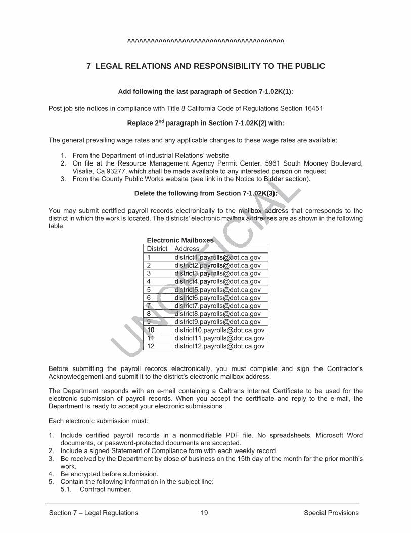
You may submit certified payroll records electronically to the mailbox address that corresponds to the district in which the work is located. The districts' electronic mailbox addresses are as shown in the following table:
Electronic Mailboxes District Address 1 [email protected] 2 [email protected] 3 [email protected] 4 [email protected] 5 [email protected] 6 [email protected] 7 [email protected] 8 [email protected] 9 [email protected] 10 [email protected] 11 [email protected] 12 [email protected]
Before submitting the payroll records electronically, you must complete and sign the Contractor's Acknowledgement and submit it to the district's electronic mailbox address.
The Department responds with an e-mail containing a Caltrans Internet Certificate to be used for the electronic submission of payroll records. When you accept the certificate and reply to the e-mail, the Department is ready to accept your electronic submissions.
Each electronic submission must:
1. Include certified payroll records in a nonmodifiable PDF file. No spreadsheets, Microsoft Word documents, or password-protected documents are accepted.
2. Include a signed Statement of Compliance form with each weekly record. 3. Be received by the Department by close of business on the 15th day of the month for the prior month's
work. 4. Be encrypted before submission. 5. Contain the following information in the subject line:
5.1. Contract number.
persoBidder secBid
.02K(3): .02K(3):
e mailbox addresmailbox addresailbox addressesailbox address
es ss
[email protected]@[email protected]
FFdistrict3.payrollsdistrict3.payroFFdistrict4.payrodistrict4FFOdistrict5.padistrict5.
OFO6 district6district6OFO7 distric7 distrONO8 disdisNONO9 9 NOUNO
10 10
UNUN11 11UNUN1UU

Section 7 – Legal Regulations 20 Special Provisions
5.2. Week ending date as W/E mm/dd/yy. 6. Contain 1 contract number and week ending date per submission. For additional information on electronic submission of certified payroll records, go to the Department's Labor Compliance website.
Add following the fourth paragraph of Section 7-1.02K(3):
Submit all certified payroll directly to the Department of Industrial Relations (DIR) in electronic format and to the Engineer on a weekly basis.
Replace “Reserved” in section 7-1.02K(6)(j)(iii) with:
7-1.02K(6)(j)(iii) Material Containing Lead – Non Hazardous Waste
Section 7-1.02K(6)(j)(iii) includes specifications for handling, removing, and disposing of non-hazardous material containing lead.
Submit a lead compliance plan.
Lead has been previously tested in the surrounding soils and traffic stripes. It was determined that lead is present in material on the job site. Average lead concentrations are below 1,000 mg/kg total lead and below 5 mg/L soluble lead, the material on the job site:
1. Is not a hazardous waste 2. Does not require disposal at a permitted landfill or solid waste disposal facility
Reuse all of the excavated material on the right-of-way. Handle the material under all applicable laws, rules, and regulations, including those of the following agencies:
1. Cal/OSHA 2. CVRWQCB, Region 5 – Central Valley Regional Water Quality Control Board 3. CA Department of Toxic Substances Control
Payment for conforming to the requirements of this section is included in the prices paid for the various Contract items of work and no additional compensation will be allowed therefore.
Replace Section 7-1.02K(6)(j)(iv) with:
7-1.02K(6)(j)(iv) Material Containing Lead – Hazardous Waste
If lead testing yields concentrations exceeding the limits described per sections in 8 California Code of Regulations and 22 California Code of Regulations, the material(s) should be treated as hazardous waste and disposal at a permitted landfill or solid waste disposal facility is required. Follow the provisions of Section 14-11 and confirm with Engineer that no other special provisions are required.
Conforming to the requirements of this section is considered change order work.
Replace "Reserved" in section 7-1.02L(1) with:
According to Public Contract Code section§ 6109, with respect to subcontractors which are ineligible to perform work on public works projects according to Labor Code section§ 1777.1 or 1777.7:
g, and disposiand disposi
nd traffic stripes. nd traffic stripesrations are below ons are below
dfill or solid wastdfill or solid wast
e right-of-way. Hanright-of-way. Hfollowing agenciefollowing a
tral Valley Regionral Valley Regioubstances Controances Contro
g to the requiremto the requiremrk and no additionk and no additi
Section 7 – Legal Regulations 21 Special Provisions
1. The Contractor must not allow any such subcontractor to work on this project. 2. The Contractor must repay to the County any money paid to any such subcontractor allowed to work
on this project. 3. The Contractor will pay the wages of the workers of any such subcontractor allowed to work on this
project.
Replace Section 7-1.05 with:
7-1.05 INDEMNIFICATION AND DEFENSE
Hold harmless, defend and indemnify County, its agents, officers and employees from and against any liability, claims, costs, damages or losses of any kind, including death or injury to any person and/or damage to property, including County property, arising from, or in connection with, the performance by Contractor or its agents, officers and employees under this Contract or also referred to as this Agreement. This indemnification specifically includes any claims that may be made against County by any taxing authority asserting that an employer-employee relationship exists by reason of this Agreement, any claims made against the County alleging civil rights violations by you under Government Code sections 12920 et seq. (California Fair Employment and Housing Act) and any fines or penalties imposed on County for your failure to provide form DE-542, when applicable. This indemnification obligation shall continue beyond the term or termination of this Agreement as to any acts or omissions occurring under this Agreement or any extension of this Agreement.
(a) To the fullest extent permitted by law, CONTRACTOR must indemnify, defend (at CONTRACTOR'S sole cost and expense and with legal counsel approved by COUNTY, which approval may not be unreasonably withheld), protect and hold harmless COUNTY, all subsidiaries, divisions and affiliated agencies of COUNTY, and all of their representatives, partners, designees, officers, directors, employees, consultants, agents, successors and assigns, (each, an “Indemnified Party” and collectively, the "Indemnified Parties"), from and against all claims (including, without limitation, claims for bodily injury, death or damage to property), demands, obligations, damages, actions, causes of action, suits, losses, judgments, fines, penalties, liabilities, costs and expenses (including, without limitation, attorneys' fees, disbursements and court costs, and all other professional expert or consultants' fees and costs and COUNTY general and administrative expenses) of every kind and nature whatsoever (individually, a "Claim"; collectively, "Claims") which may arise out of, pertain to, or relate (directly or indirectly) to the negligence, recklessness, or misconduct of CONTRACTOR with respect to any work performed or services provided under this Agreement (including, without limitation, the acts, errors and/or omissions of CONTRACTOR, its principals, officers, agents, employees, vendors, suppliers, consultants, sub-consultants, contractors, anyone employed directly or indirectly by any of them or for whose acts they may be liable or any or all of them). CONTRACTOR’S obligation to indemnify applies unless it is finally adjudicated that the liability was caused by the sole active negligence or sole willful misconduct of an Indemnified Party. If it is finally adjudicated that liability is caused by the comparative active negligence or willful misconduct of an Indemnified Party, then CONTRACTOR’S indemnification obligation shall be reduced in proportion to the established comparative liability.
(b) The duty to defend is a separate and distinct obligation from CONTRACTOR’S duty to indemnify. CONTRACTOR shall be obligated to defend, in all legal, equitable, administrative, or special proceedings, the Indemnified Parties immediately upon tender to CONTRACTOR of the Claim in any form or at any stage of an action or proceeding, whether or not liability is established. Payment to CONTRACTOR by any Indemnified Party or the payment or advance of defense costs by any Indemnified Party cannot be a condition precedent to enforcing the Indemnified Party's rights to indemnification under this Agreement. An allegation or determination that persons other than CONTRACTOR are responsible for the Claim does not relieve CONTRACTOR from its separate and distinct obligation to defend under this section. The obligation to defend extends through final judgment, including exhaustion of any appeals. The defense obligation includes an obligation to provide independent defense counsel if CONTRACTOR asserts that liability is caused in whole or in part by the negligence or willful misconduct of an Indemnified Party. CONTRACTOR'S indemnification obligations under this Agreement will survive the expiration or earlier termination of this Agreement until action against the Indemnified Parties for the matter indemnified is fully and finally barred by the applicable statute of limitations or statute of repose. CONTRACTOR'S liability
UNOFFICIA
LCo
posed opn shall continuhall
nder this Agreemnder this Agreem
TRACTOR musACTOR hh legal counsel a legal counsel
otect and hold harct and hold haand all and all of their reof their r
agents, successoagents, successoParties"),Parties" from afrom
th or dath or damage to mage to ses, judgmenses, judgments, f
ttorneys' feesorneys' fees, d,ultants' fees and ultants' fees
nd nature whatsnd nature whapertain to, or relatpertain to, or re
NTRACTOR with TRACTOR withluding, without limluding, without lim
fficers, agents, eficers, agents, nyone employed ne emplo
y or all of them).or all of them)hat the liabilithat the liab
Party. IParty. Iul
Section 7 – Legal Regulations 22 Special Provisions
for indemnification under this Agreement is in addition to any liability CONTRACTOR may have to COUNTY for a breach by CONTRACTOR of any of the provisions of this Agreement. Under no circumstances may the insurance requirements and limits set forth in this Agreement be construed to limit CONTRACTOR'S indemnification obligation or other liability under this Agreement.
(c) CONTRACTOR must indemnify and hold COUNTY harmless from all loss and liability, including attorneys’ fees, court costs and all other litigation expenses, for any infringement of the patent rights, copyright, trade secret or any other proprietary right or trademark, and all other intellectual property claims of any person or persons in consequence of the use by COUNTY, or any of its officers or agents, of articles or services to be supplied in the performance of this Agreement.
Delete Section 7-1.05C Others of the RSS.
Replace Section 7-1.06 with:
7-1.06 INSURANCE
Bidder’s and their subcontractors attention are directed to the insurance requirements below. It is highly recommended that Bidders confer with their respective insurance carriers or brokers to determine in advance of bid submission the availability of insurance certificates and endorsements as prescribed and provided herein. If an apparent low bidder fails to comply strictly with the insurance requirements, that Bidder may be disqualified from award of the Contract and forfeits its Bid Bond.
Contractor and subcontractors shall provide and maintain insurance for the duration of the warranty period against claims for injuries to persons and damage to property, which may arise from, or in connection with, performance under the Agreement by the CONTRACTOR, his agents, representatives, employees or subcontractors, if applicable.
A. Minimum Scope & Limits of Insurance
1) Coverage at least as broad as Commercial General Liability, Insurance Services Office Commercial General Liability coverage occurrence form GC 00 01, with limits no less than $3,000,000 per occurrence including products and completed operations, property damage, bodily injury and personal & advertising injury. If a general aggregate limit applies, either the general aggregate limit shall apply separately to this project/location (ISO CG 25 03 or 25 04) or the general aggregate limit shall be no less than $4,000,000.
2) Comprehensive Automobile Liability Insurance of $1,000,000 per occurrence for bodily injury and property damage. If the annual aggregate applies it must be no less than $2,000,000.
3) Workers' Compensation Insurance as required by the State of California, with Statutory Limits, and Employer’s Liability Insurance with limit of no less than $1,000,000 per accident for bodily injury or disease.
B. Specific Provisions of the Certificate
1) The General Liability and Automobile Liability policies are to be endorsed to contain the following provisions:
a. The County, its officers, agents, officials, employees and volunteers are to be covered as additional insureds as respects: liability arising out of work or operations performed by or on behalf of the Contractor; or automobiles owned, leased, hired or borrowed by the CONTRACTOR.
b. For any claims related to this project, the CONTRACTOR’s insurance coverage shall be primary insurance as respects the COUNTY, its officers, agents, officials, employees and volunteers. Any insurance or self-insurance maintained by the COUNTY, its officers, agents, officials, employees or volunteers shall be excess of the CONTRACTOR’s insurance and shall not contribute with it.
c. Each insurance policy required by this agreement shall be endorsed to state that coverage shall not be canceled by either party, except after thirty (30) days prior written notice has been provided to the County.
UNOFFICIA
Lequire
iers or berd endorsementndorsement
with the insurancwith the insurancits Bid Bond. Bid Bond.
surance for the dusurance for theerty, which may arty, which may a
CTOR, his agentsOR, his agent
as Commercial as Commerciay coverage occuoverage occu
e including prode including pnal & advertising l & advertising
mit shall apply sepit shall apply seate limit shall be limit shall be
Automobile LiabAutomobile Ldamage. If the aamage. If the a
Compensation Insensation oyer’s Liability Ioyer’s Liability
ease. ease
Section 7 – Legal Regulations 23 Special Provisions
d. CONTRACTOR hereby agrees to waive rights of subrogation which any insurer of Contractor may acquire from Contractor by virtue of the payment of any loss. Contractor agrees to obtain any endorsement that may be necessary to affect this waiver of subrogation.
e. If any of the required insurance is written on a claims made form, the retroactive date must be before the date of contract or the beginning of the contract work and must be maintained and evidence of insurance must be provided for at least five (5) years after completion of the contract work.
2) The workers' compensation policy shall be endorsed with a waiver of subrogation in favor of the COUNTY for all work performed by the CONTRACTOR, its employees, agents and subcontractors. CONTRACTOR waives all rights against the COUNTY and its officers, agents, employees and volunteers for recovery of damages to the extent these damages are covered by the workers compensation and employers liability.
C. Deductibles and Self-Insured Retentions
Deductibles and self-insured retentions must be declared and any deductible or self-insured retention over $100,000 shall be forwarded to the COUNTY Risk Manager for approval.
D. Acceptability of Insurance
Insurance must be placed with insurers with a current rating given by A.M. Best and Company of no less than A(-):VII and a Standard & Poor’s Rating (if rated) of at least BBB and from a company approved by the Department of Insurance to conduct business in California. Any waiver of these standards is subject to approval by the County Risk Manager.
E. Verification of Coverage
Prior to approval of this Agreement by the COUNTY, the CONTRACTOR shall file with the submitting department, certificates of insurance with original endorsements effecting coverage and a copy of the declarations page from the policy in effect in a form acceptable to the COUNTY. Endorsements must be signed by persons authorized to bind coverage on behalf of the insurer. The COUNTY reserves the right to require certified copies of all required insurance policies at any time.
F. Additional Construction Insurance Requirements
1) Payment Bond: For public works projects of more than $25,000 a “payment bond” is required in the full amount of the Contract price, and shall insure to the benefit of persons performing labor or furnishing materials in connection with the work of the Contract. This bond shall be maintained in full force and effect until all work under the Contract is completed and accepted by the COUNTY, or until all claims for materials and labor have been paid, whichever is longer.
2) Performance Bond: For public works projects of more than $25,000 a “performance bond” is required in the full amount of the Contract price and shall insure the faithful performance by Contractor of all work under the Contract. It shall also insure the replacing of, or making acceptable, any defective materials or faulty workmanship.
3) Acceptability of Surety: Only California admitted sureties with current AM Best Rating of no less than VII.
UNOFFICIA
LMana
ating given by A.Mgiven by A.Mf rated) of at leasrated) of at leas
uct business in Cauct business in Risk Manager. isk Manager.
by the by the COUNTYCOUNTs of insurance of insuran wit
age from the policage from the pod by persons auty persons aut
e right to require e right to requ
nsurance Requireance Require
d: For public wor: For public woount of the Contraof the Con
ng materials in cng materials in cand effecand effe
ntil alntil al
Section 8 – Prosecution and Progress 24 Special Provisions
^^^^^^^^^^^^^^^^^^^^^^^^^^^^^^^^^^^^^^^^
8 PROSECUTION AND PROGRESS
Add to Section 8-1.01:
You must procure all permits, licenses, contracts and other services needed to prosecute the work. You must pay for all permits, licenses, contracts and other services. Payment is included in the contract price and no additional compensation will be allowed.
The number of working days allowed for completion of the work shall be set forth in Section 8-1.05 of the Standard Specifications as modified by Article XIII of the Contract. In the case of a conflict between the Standard Specifications and the Contract, the Contract shall prevail.
The sum to be paid as liquidated damages shall be set forth in section 8-1.10 of the Standard Specifications as modified by Article XIII of the Contract.
Add to Section 8-1.02:
Any time the Engineer requests a practicable progress schedule in writing, submit the updated schedule within 10 working days of the Engineer's written request.
Replace section 8-1.10A and 8-1.10A of RSS with:
The County specifies liquidated damages (Pub Cont Code § 10226). Liquidated damages, if any, accrue starting on the 1st day after the expiration of the working days through the day of Contract acceptance except as specified in sections 8-1.10B and 8-1.10C.
The County withholds liquidated damages before the accrual date if the anticipated liquidated damages may exceed the value of the remaining work.
Liquidated damages for all work shall be set at $1,400 per day. UNOFFICIA
L0 of the
2:
schedule in writinhedule in writist. st.
e section 8-1.10Asection 8-1.10A
ted damages (Puamages (Puter the expir the expirationrati
ections 8-1.10B actions 8-1.10B a
ds liquidated dads liquidated daof the remof the rem
Section 9 – Payment 25 Special Provisions
^^^^^^^^^^^^^^^^^^^^^^^^^^^^^^^^^^^^^^^^
9 PAYMENT
Replace the 12th paragraph beginning with “For these payments, interest starts to accrue…” in Section 9-1.03 with:
For these payments, interest starts to accrue 30 days after the Engineer receives acceptance from you of the progress payment amount determined by the Engineer. Acceptance of the progress payment may be in the form of an invoice matching the progress payment amount or a letter indicating that you accept the amount of the progress payment.
Add the following to Section 9-1.16A:
9-1.16A General
Submit an invoice matching the progress payment amount or a signed letter indicating that you accept the progress payment amount. The Engineer does not process a progress payment without the matching invoice or the progress payment acceptance letter. Once accepted by the Engineer, submit the invoice to the following email address: [email protected] and include the Engineer’s email as well.
UNOFFICIA
Lned letter indicatd letter indicata progress paymprogress paym
cepted by the Engepted by thed include the Engiinclude the Eng
Section 10 – General 26 Special Provisions
^^^^^^^^^^^^^^^^^^^^^^^^^^^^^^^^^^^^^^^^^^^^^^^^^^^^^^^^^^^^
DIVISION II GENERAL CONSTRUCTION
^^^^^^^^^^^^^^^^^^^^^^^^^^^^^^^^^^^^^^^^
10 GENERAL
Add to Section 10-1.01:
Coccidioidomycosis, also known as “Valley Fever” or “cocci”, is a disease caused by Coccidioides fungi which infect the lungs. When the fungus spores present in soil are disturbed, the spores may become airborne and can be inhaled.
You are hereby notified that the spores which cause Valley Fever are endemic to Tulare County. Activities which disturb soil or expose workers to dust, such as digging, operating earth-moving equipment, driving vehicles, and working in wind-blown areas, may increase the risk of Valley Fever in workers.
Information regarding preventing and recognizing the symptoms of Valley Fever are available from the California Department of Public Health and the California Department of Industrial Relations.
The provisions of this section shall be made a part of every subcontract executed pursuant to this contract.
UNOFFICIA
Led
endemic to Tulaendemic to Tulaerating earth-movting earth-mov
k of Valley Fever k of Valley Fever
mptoms of Valley ptoms of Vallea Department of InDepartment of
f evf every subcontraery subcontra
Section 12 – Temporary Traffic Control 27 Special Provisions
^^^^^^^^^^^^^^^^^^^^^^^^^^^^^^^^^^^^^^^^
12 TEMPORARY TRAFFIC CONTROL
Add following to Section 12-1.01:
Submit a traffic control plan for acceptance by the Engineer. The traffic control plan shall depict the traffic control devices to be used and their location and shall be prepared by a licensed Traffic Engineer or Civil Engineer. Do not install traffic control system on the job site until the Engineer provides written acceptance of the Traffic Control Plan. Payment for the traffic control plan is included in the traffic control system.
Replace section 12-1.04 with:
You are required to pay for the cost of furnishing all flaggers, including transporting flaggers and furnishing stands and towers for flaggers to provide for the passage of traffic through the work as specified in sections 7-1.03 and 7-1.04.
Add following to Section 12-4.02A:
All detours and closures must comply with the plans and be coordinated with the Engineer and adjacent property owners.
UNOFFICIA
Lg transporting flag transporting flahrough the work aough the work a
ection 12-4.02A:ection 12-4.02
ans and be coordans and be coor

Section 13 – Water Pollution Control 28 Special Provisions
^^^^^^^^^^^^^^^^^^^^^^^^^^^^^^^^^^^^^^^^
13 WATER POLLUTION CONTROL
Add following the last paragraph of Section 13-4.03C(1):
Before any materials are stockpiled or equipment parked / stored outside of the right of way, you must first obtain written authorization from the property owner on whose property the materials are to be stockpiled or equipment parked/stored. You must file with the Engineer said authority or a certified copy thereof together with a written release from the property owner absolving the County of Tulare from any and all responsibility in connection with the stockpiling of materials or parking/storage of equipment on said property. Before any material is stockpiled or equipment parked/stored, you must obtain written permission from the Engineer to stockpile materials or park/store equipment at the location designated in said authorization.
Failure to provide written authorization shall result in the withholding of all funds due to you until said authorization is received by the County.
Obtain all permits required by all applicable regulatory agencies and comply with all applicable codes, regulations and zoning ordinances prior to establishing a storage yard for materials and/or equipment.
Provide copies of all permits acquired to the Engineer.
UNOFFICIA
Lof all funds f all
es and comply wes and comply wage yard for mateyard for m

Section 14 – Environmental Stewardship 29 Special Provisions
^^^^^^^^^^^^^^^^^^^^^^^^^^^^^^^^^^^^^^^^
14 ENVIRONMENTAL STEWARDSHIP
Add the following to Section 14-1.01:
You must comply with all applicable requirements and provisions of the environmental document(s) and the permits obtained for this project.
A delay to the controlling operation due to environmental requirements will be considered a temporary suspension of work under Section 8-1.06. No contract adjustment or additional compensation will be made for delays caused by environmental requirements. The days on which the suspension is in effect shall not be considered working days as defined in Section 8-1.06B.
Replace “Reserved” in Section 14-10.03 with:
14-10.03 RECYCLING AND DIVERSION OF CONSTRUCTION AND DEMOLITION DEBRIS
You must comply with Article 10 of the Tulare County Ordinance Code Chapter 3, Part IV, “Recycling and Diversion of Construction and Demolition Debris,” which requires you to recycle 100% of inert solids (asphalt, concrete, rock, stone, brick, sand, soil and fines) and 50% by weight of the remaining construction and demolition material generated by the work. Submit the required Pre-Plan portion of the Construction and Demolition Waste Recycling and Reuse Plan after the award of the contract to the Engineer with the contract documents identifying the material type, hauler, disposal location and the percentage of material to be reused or recycled. There is no filing fees required for this submission of this plan. A copy of the Ordinance, the form for the Construction and Demolition Waste Recycling and Reuse Plan and other information may be found at:
https://tularecounty.ca.gov/rma/index.cfm/rma-documents/public-works-documents/c-d-r-r-plan-form/
Submit to the Engineer the required Final Report of the Construction and Demolition Waste Recycling and Reuse Plan prior to the Engineer’s acceptance of the work.
Full compensation for all labor, tools, equipment and reporting requirements required for compliance with the Recycling and Diversion of Construction and Demolition Debris Ordinance shall be considered as included in the items of work generating this debris and no additional compensation will be allowed therefor.
Add after the 2nd paragraph of section 14-11.12A:
The project Location in Strathmore includes removal of yellow traffic stripe and yellow painted pavement markings that will produce hazardous waste residue.
Add after the 1st paragraph of 14-11.12E:
After the Engineer accepts the analytical test results, dispose of yellow thermoplastic and yellow paint hazardous waste residue at a Class 1 disposal facility located in California 30 days after accumulating 220 lb of residue.
If less than 220 lb of hazardous waste residue and dust is generated in total, dispose of it within 30 days after the start of accumulation of the residue.
UNOFFICIA
Lwith: ith
ND DEMOLITIOD DEMOLITIO
nce Code ChapteCode Chrequires you to requires you to
) and 50% by weind 50% by wemitit the required P the required
after the fter the award ofaward of hauler, disposalhauler, dispo
ees requirees required for ted for tand Deand molition Wmolit
x.cfm/rma-documx.cfm/rma-docu
uired Final Reporred Final Reponeer’s acceptancs acceptanc
ll labor, tools, eqlabor, tools, eqiversion of Consiversion of Coof work generaof work genera
Section 14 – Environmental Stewardship 30 Special Provisions
Replace Section 14-12.04 with:
14-12.04 PERMITS AND LICENSES
Comply with Section 5-1.20B.
Comply with the requirements of the permits acquired by the County for this project located elsewhere in these special provisions.
You must comply with all applicable SJVAPCD regulations and requirements.
Obtain a Demolition Permit Release from SJVAPCD. Nothing herein or elsewhere within these special provisions shall be construed as limiting your responsibility for complying with all applicable rules and regulations. You are responsible for payment of all the fees required to obtain the Demolition Permit Release.
Comply with Section 7-1.02, Section 7-1.07, Section 14-9.02 and Section 14-9.03.
For projects that will result in land disturbance of greater than one acre file the Notice of Intent and pay the appropriate fee as required by the terms of General Permit No. CSA000002, for the discharge of storm water associated with construction activity.
Payment for conforming to the requirements in these permits shall be considered as included in the prices paid for the various contract items of work and no additional compensation will be allowed therefor.
UNOFFICIA
Lthe No
00002, fo0002 r th
all be considered all be considered ompensation will pensation
Section 19 – Earthwork 31 Special Provisions
^^^^^^^^^^^^^^^^^^^^^^^^^^^^^^^^^^^^^^^^^^^^^^^^^^^^^^^^^^^^
DIVISION III EARTHWORK AND LANDSCAPE
^^^^^^^^^^^^^^^^^^^^^^^^^^^^^^^^^^^^^^^^
19 EARTHWORK
Add to Section 19-1.03:
Earthwork activities include clearing and grubbing, developing a water supply, and finishing the roadway. Comply with section 17-2, 10-6 and 22.
Replace the 2nd, 3rd, and 4th paragraphs of section 19-2.03B with: Dispose of surplus material. Ensure enough material is available to complete the embankments before disposing of it.
UNOFFICIA
Lon 19-2.03B w19-2.03B wcomplete the embomplete the emb
Section 26 - Aggregate Bases 32 Special Provisions
^^^^^^^^^^^^^^^^^^^^^^^^^^^^^^^^^^^^^^^^^^^^^^^^^^^^^^^^^^^^
DIVISION IV SUBBASES AND BASES
^^^^^^^^^^^^^^^^^^^^^^^^^^^^^^^^^^^^^^^^
26 AGGREGATE BASES
Replace the third paragraph in section 26-1.03E with:
The finish AB surface must not vary more than 0.05 foot from the grade established.
UNOFFICIA
L
Section 39 – Asphalt Concrete 33 Special Provisions
^^^^^^^^^^^^^^^^^^^^^^^^^^^^^^^^^^^^^^^^
39 ASPHALT CONCRETE
Replace section 39 of the RSS with:
39-1.01 GENERAL 39-1.01A Summary Section 39-1 includes general specifications for producing and placing HMA by mixing aggregate and asphalt binder at a mixing plant and spreading and compacting the HMA mixture.
Produce and place HMA Type A under the Method Construction Process.
39-1.01B Definitions coarse aggregate: Aggregate retained on a no. 4 sieve.
fine aggregate: Aggregate passing the no. 4 sieve.
supplemental fine aggregate: Aggregate passing the no. 30 sieve, including hydrated lime, portland cement, and fines from dust collectors.
39-1.02 MATERIALS 39-1.02A Geosynthetic Pavement Interlayer Geosynthetic pavement interlayer must comply with the specifications for pavement fabric, paving mat, paving grid, paving geocomposite grid, or geocomposite strip membrane.
39-1.02B Tack Coat Tack coat must comply with the specifications for asphaltic emulsion or asphalts. Choose the type and grade.
Notify the Engineer if you dilute asphaltic emulsion with water. The weight ratio of added water to asphaltic emulsion must not exceed 1 to 1.
Measure added water either by weight or volume in compliance with section 9-1.02 or you may use water meters from water districts, cities, or counties. If you measure water by volume, apply a conversion factor to determine the correct weight.
With each dilution, submit:
1. Weight ratio of water to bituminous material in the original asphaltic emulsion 2. Weight of asphaltic emulsion before diluting 3. Weight of added water 4. Final dilution weight ratio of water to asphaltic emulsion 39-1.02C Asphalt Binder Asphalt binder in HMA must comply with the specifications for asphalts or section 39-1.02D.
Asphalt binder in HMA Type A must be PG Grade 64-10.
Asphalt binder for geosynthetic pavement interlayer must comply with the specifications for asphalts. Choose from Grades PG 64-10, PG 64-16, or PG 70-10.
39-1.02D Asphalt Rubber Binder 39-1.02D(1) General
UNOFFICIA
L. 30 siev. 30 sieve, include, inc
ply with the specily with the speceocomposite stripeocomposite
pecifications foecifications for ar
ute asute phaltic emuphaltic emud 1 to 1. 1 to 1.
er either by weigher either by weigstricts, cities, ostricts, cities
t weight. t weight.
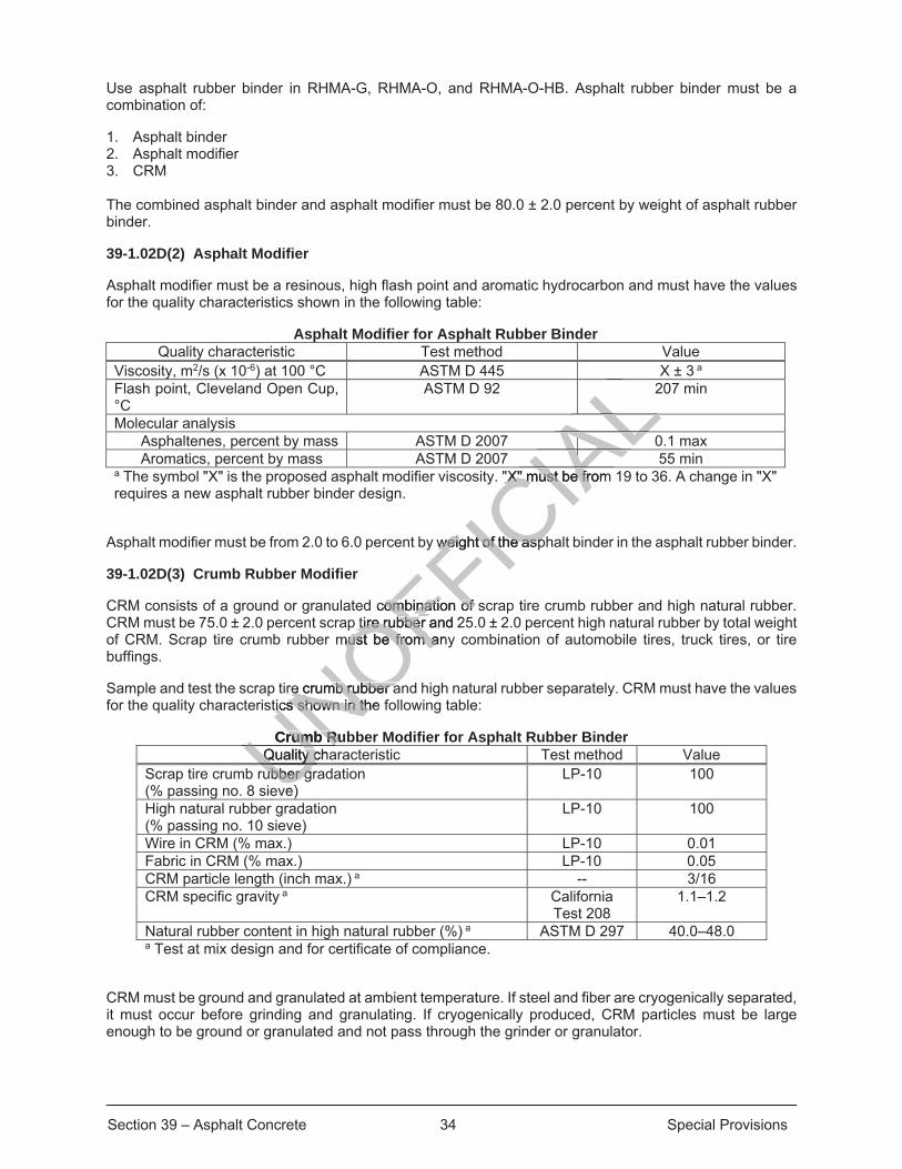
Section 39 – Asphalt Concrete 34 Special Provisions
Use asphalt rubber binder in RHMA-G, RHMA-O, and RHMA-O-HB. Asphalt rubber binder must be a combination of:
1. Asphalt binder 2. Asphalt modifier 3. CRM
The combined asphalt binder and asphalt modifier must be 80.0 ± 2.0 percent by weight of asphalt rubber binder.
39-1.02D(2) Asphalt Modifier
Asphalt modifier must be a resinous, high flash point and aromatic hydrocarbon and must have the values for the quality characteristics shown in the following table:
Asphalt Modifier for Asphalt Rubber Binder Quality characteristic Test method Value
Viscosity, m2/s (x 10-6) at 100 °C ASTM D 445 X ± 3 a Flash point, Cleveland Open Cup, °C
ASTM D 92 207 min
Molecular analysis Asphaltenes, percent by mass ASTM D 2007 0.1 max Aromatics, percent by mass ASTM D 2007 55 min
a The symbol "X" is the proposed asphalt modifier viscosity. "X" must be from 19 to 36. A change in "X" requires a new asphalt rubber binder design.
Asphalt modifier must be from 2.0 to 6.0 percent by weight of the asphalt binder in the asphalt rubber binder.
39-1.02D(3) Crumb Rubber Modifier
CRM consists of a ground or granulated combination of scrap tire crumb rubber and high natural rubber. CRM must be 75.0 ± 2.0 percent scrap tire rubber and 25.0 ± 2.0 percent high natural rubber by total weight of CRM. Scrap tire crumb rubber must be from any combination of automobile tires, truck tires, or tire buffings.
Sample and test the scrap tire crumb rubber and high natural rubber separately. CRM must have the values for the quality characteristics shown in the following table:
Crumb Rubber Modifier for Asphalt Rubber Binder Quality characteristic Test method Value
Scrap tire crumb rubber gradation (% passing no. 8 sieve)
LP-10 100
High natural rubber gradation (% passing no. 10 sieve)
LP-10 100
Wire in CRM (% max.) LP-10 0.01 Fabric in CRM (% max.) LP-10 0.05 CRM particle length (inch max.) a -- 3/16 CRM specific gravity a California
Test 208 1.1–1.2
Natural rubber content in high natural rubber (%) a ASTM D 297 40.0–48.0 a Test at mix design and for certificate of compliance.
CRM must be ground and granulated at ambient temperature. If steel and fiber are cryogenically separated, it must occur before grinding and granulating. If cryogenically produced, CRM particles must be large enough to be ground or granulated and not pass through the grinder or granulator.
Uubber gubber gve)UQuality chaQuality cUNOFFIC
IALLAALALAAIA"X" must be from"X" must be fr
CIAweight of the aspweight of the asp
combination ombinat of softire rubber and tire rubber 2
must be from anmust be from a
re crumb rubber ae crumb rubber atics shown in the tics shown in th
Crumb Rubrumb RuUNUU
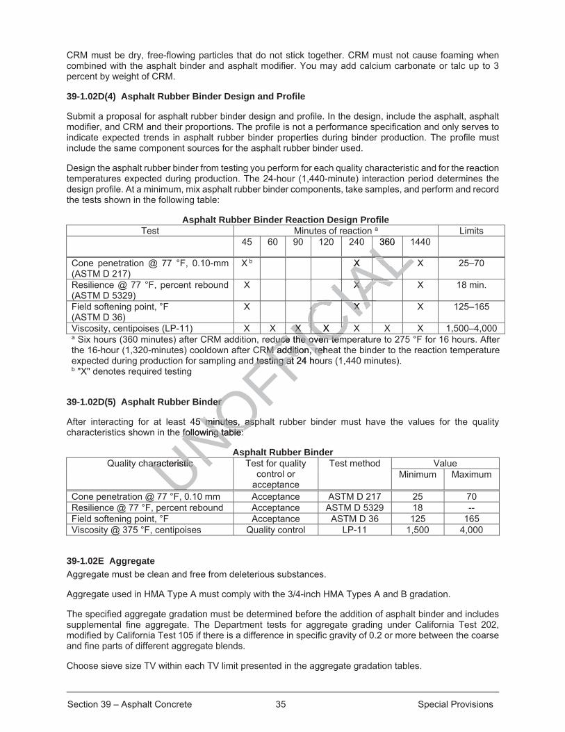
Section 39 – Asphalt Concrete 35 Special Provisions
CRM must be dry, free-flowing particles that do not stick together. CRM must not cause foaming when combined with the asphalt binder and asphalt modifier. You may add calcium carbonate or talc up to 3 percent by weight of CRM.
39-1.02D(4) Asphalt Rubber Binder Design and Profile
Submit a proposal for asphalt rubber binder design and profile. In the design, include the asphalt, asphalt modifier, and CRM and their proportions. The profile is not a performance specification and only serves to indicate expected trends in asphalt rubber binder properties during binder production. The profile must include the same component sources for the asphalt rubber binder used.
Design the asphalt rubber binder from testing you perform for each quality characteristic and for the reaction temperatures expected during production. The 24-hour (1,440-minute) interaction period determines the design profile. At a minimum, mix asphalt rubber binder components, take samples, and perform and record the tests shown in the following table:
Asphalt Rubber Binder Reaction Design Profile Test Minutes of reaction a Limits
45 60 90 120 240 360 1440
Cone penetration @ 77 °F, 0.10-mm (ASTM D 217)
X b X X 25–70
Resilience @ 77 °F, percent rebound (ASTM D 5329)
X X X 18 min.
Field softening point, °F (ASTM D 36)
X X X 125–165
Viscosity, centipoises (LP-11) X X X X X X X 1,500–4,000 a Six hours (360 minutes) after CRM addition, reduce the oven temperature to 275 °F for 16 hours. After the 16-hour (1,320-minutes) cooldown after CRM addition, reheat the binder to the reaction temperature expected during production for sampling and testing at 24 hours (1,440 minutes). b "X" denotes required testing
39-1.02D(5) Asphalt Rubber Binder
After interacting for at least 45 minutes, asphalt rubber binder must have the values for the quality characteristics shown in the following table:
Asphalt Rubber Binder Quality characteristic Test for quality
control or acceptance
Test method Value Minimum Maximum
Cone penetration @ 77 °F, 0.10 mm Acceptance ASTM D 217 25 70 Resilience @ 77 °F, percent rebound Acceptance ASTM D 5329 18 -- Field softening point, °F Acceptance ASTM D 36 125 165 Viscosity @ 375 °F, centipoises Quality control LP-11 1,500 4,000
39-1.02E Aggregate Aggregate must be clean and free from deleterious substances.
Aggregate used in HMA Type A must comply with the 3/4-inch HMA Types A and B gradation.
The specified aggregate gradation must be determined before the addition of asphalt binder and includes supplemental fine aggregate. The Department tests for aggregate grading under California Test 202, modified by California Test 105 if there is a difference in specific gravity of 0.2 or more between the coarse and fine parts of different aggregate blends.
Choose sieve size TV within each TV limit presented in the aggregate gradation tables.
UFUNOFFICduce tduce ICIA
L360 LALLX X
ALALALALALALALLLLLLAALLX X ALCIAA
L X X
CIACCIAAX X X X CICChe oven temhe oven tem
RM additiRM addition, rehe, red testing at 24 hod testing atFIC
der er
45 minutes, asp5 minutes, aspfollowing table: following table:
aracteristic aracteristic UNUU
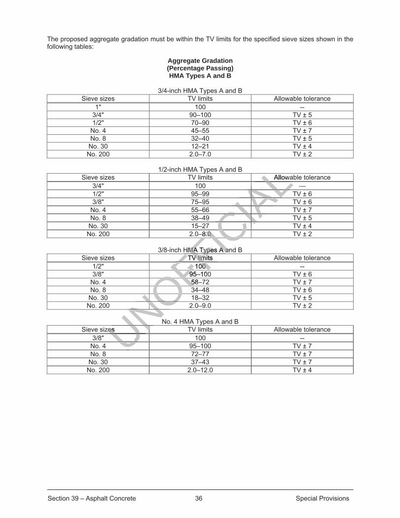
Section 39 – Asphalt Concrete 36 Special Provisions
The proposed aggregate gradation must be within the TV limits for the specified sieve sizes shown in the following tables:
Aggregate Gradation (Percentage Passing) HMA Types A and B
3/4-inch HMA Types A and B Sieve sizes TV limits Allowable tolerance
1" 100 -- 3/4" 90–100 TV ± 5 1/2" 70–90 TV ± 6
No. 4 45–55 TV ± 7 No. 8 32–40 TV ± 5
No. 30 12–21 TV ± 4 No. 200 2.0–7.0 TV ± 2
1/2-inch HMA Types A and B Sieve sizes TV limits Allowable tolerance
3/4" 100 — 1/2" 95–99 TV ± 6 3/8" 75–95 TV ± 6
No. 4 55–66 TV ± 7 No. 8 38–49 TV ± 5
No. 30 15–27 TV ± 4 No. 200 2.0–8.0 TV ± 2
3/8-inch HMA Types A and B Sieve sizes TV limits Allowable tolerance
1/2" 100 -- 3/8" 95–100 TV ± 6
No. 4 58–72 TV ± 7 No. 8 34–48 TV ± 6
No. 30 18–32 TV ± 5 No. 200 2.0–9.0 TV ± 2
No. 4 HMA Types A and B Sieve sizes TV limits Allowable tolerance
3/8" 100 -- No. 4 95–100 TV ± 7 No. 8 72–77 TV ± 7
No. 30 37–43 TV ± 7 No. 200 2.0–12.0 TV ± 4
UNOFFTV limits V lim
FFICIA
LAllowLALALAAAALAAAALIAIAIAIAIACIAIAIAIA7 CIIII
–8.0 –8.0 ICHMA Types A anHMA Types A aFICFF100 100 FFFF95–10FF58–5
OF3OFOONONONONOzes zes UNNUUUU
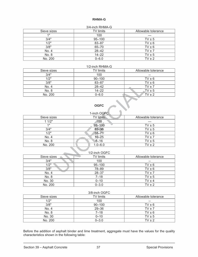
Section 39 – Asphalt Concrete 37 Special Provisions
RHMA-G
3/4-inch RHMA-G Sieve sizes TV limits Allowable tolerance
1" 100 — 3/4" 95–100 TV ± 5 1/2" 83–87 TV ± 6 3/8" 65–70 TV ± 6
No. 4 28–42 TV ± 7 No. 8 14–22 TV ± 5
No. 200 0–6.0 TV ± 2
1/2-inch RHMA-G Sieve sizes TV limits Allowable tolerance
3/4" 100 -- 1/2" 90–100 TV ± 6 3/8" 83–87 TV ± 6
No. 4 28–42 TV ± 7 No. 8 14–22 TV ± 5
No. 200 0–6.0 TV ± 2
OGFC
1-inch OGFC Sieve sizes TV limits Allowable tolerance
1 1/2" 100 — 1" 99–100 TV ± 5
3/4" 85–96 TV ± 5 1/2" 55–71 TV ± 6
No. 4 10–25 TV ± 7 No. 8 6–16 TV ± 5
No. 200 1.0–6.0 TV ± 2
1/2-inch OGFC Sieve sizes TV limits Allowable tolerance
3/4" 100 -- 1/2" 95–100 TV ± 6 3/8" 78–89 TV ± 6
No. 4 28–37 TV ± 7 No. 8 7–18 TV ± 5
No. 30 0–10 TV ± 4 No. 200 0–3.0 TV ± 2
3/8-inch OGFC Sieve sizes TV limits Allowable tolerance
1/2" 100 -- 3/8" 90–100 TV ± 6
No. 4 29–36 TV ± 7 No. 8 7–18 TV ± 6
No. 30 0–10 TV ± 5 No. 200 0–3.0 TV ± 2
Before the addition of asphalt binder and lime treatment, aggregate must have the values for the quality characteristics shown in the following table:
LTTLAAAALAAALGFC GFC
limits imits IC100 10 FICFIC99–100 99–100FI85–96 5–96
FF55–71 55–71FF10–2
OF6–6OFONONONNUNUNNNNNNNUNNNNUU
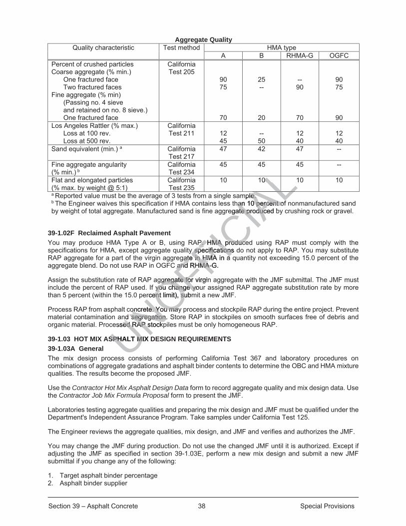
Section 39 – Asphalt Concrete 38 Special Provisions
Aggregate Quality Quality characteristic Test method HMA type
A B RHMA-G OGFC Percent of crushed particles Coarse aggregate (% min.)
One fractured face Two fractured faces
Fine aggregate (% min) (Passing no. 4 sieve and retained on no. 8 sieve.) One fractured face
California Test 205
90 75
70
25 --
20
-- 90
70
90 75
90 Los Angeles Rattler (% max.)
Loss at 100 rev. Loss at 500 rev.
California Test 211
12 45
-- 50
12 40
12 40
Sand equivalent (min.) a California Test 217
47 42 47 --
Fine aggregate angularity (% min.) b
California Test 234
45 45 45 --
Flat and elongated particles (% max. by weight @ 5:1)
California Test 235
10 10 10 10
a Reported value must be the average of 3 tests from a single sample. b The Engineer waives this specification if HMA contains less than 10 percent of nonmanufactured sand by weight of total aggregate. Manufactured sand is fine aggregate produced by crushing rock or gravel.
39-1.02F Reclaimed Asphalt Pavement You may produce HMA Type A or B, using RAP. HMA produced using RAP must comply with the specifications for HMA, except aggregate quality specifications do not apply to RAP. You may substitute RAP aggregate for a part of the virgin aggregate in HMA in a quantity not exceeding 15.0 percent of the aggregate blend. Do not use RAP in OGFC and RHMA-G.
Assign the substitution rate of RAP aggregate for virgin aggregate with the JMF submittal. The JMF must include the percent of RAP used. If you change your assigned RAP aggregate substitution rate by more than 5 percent (within the 15.0 percent limit), submit a new JMF.
Process RAP from asphalt concrete. You may process and stockpile RAP during the entire project. Prevent material contamination and segregation. Store RAP in stockpiles on smooth surfaces free of debris and organic material. Processed RAP stockpiles must be only homogeneous RAP.
39-1.03 HOT MIX ASPHALT MIX DESIGN REQUIREMENTS 39-1.03A General The mix design process consists of performing California Test 367 and laboratory procedures on combinations of aggregate gradations and asphalt binder contents to determine the OBC and HMA mixture qualities. The results become the proposed JMF.
Use the Contractor Hot Mix Asphalt Design Data form to record aggregate quality and mix design data. Use the Contractor Job Mix Formula Proposal form to present the JMF.
Laboratories testing aggregate qualities and preparing the mix design and JMF must be qualified under the Department's Independent Assurance Program. Take samples under California Test 125.
The Engineer reviews the aggregate qualities, mix design, and JMF and verifies and authorizes the JMF.
You may change the JMF during production. Do not use the changed JMF until it is authorized. Except if adjusting the JMF as specified in section 39-1.03E, perform a new mix design and submit a new JMF submittal if you change any of the following:
1. Target asphalt binder percentage 2. Asphalt binder supplier
UNOFFICIA
LL0 0 LALmple. e. ALhan 10 percan 10 percent ofent ofegate produced bte produc
P. HMA produceP. HMA producey specifications dy specifications
gate in HMgate in HMA in a C and RHMA-G. and RHMA-
ggregate for virginggregate fof you change youyou change yo
ercent limit), subment limit), su
oncrete. You mayoncrete. You maynd segregation. Snd segregation.
essed RAP stockpsed RAP s
SPHALT SPH MIX M
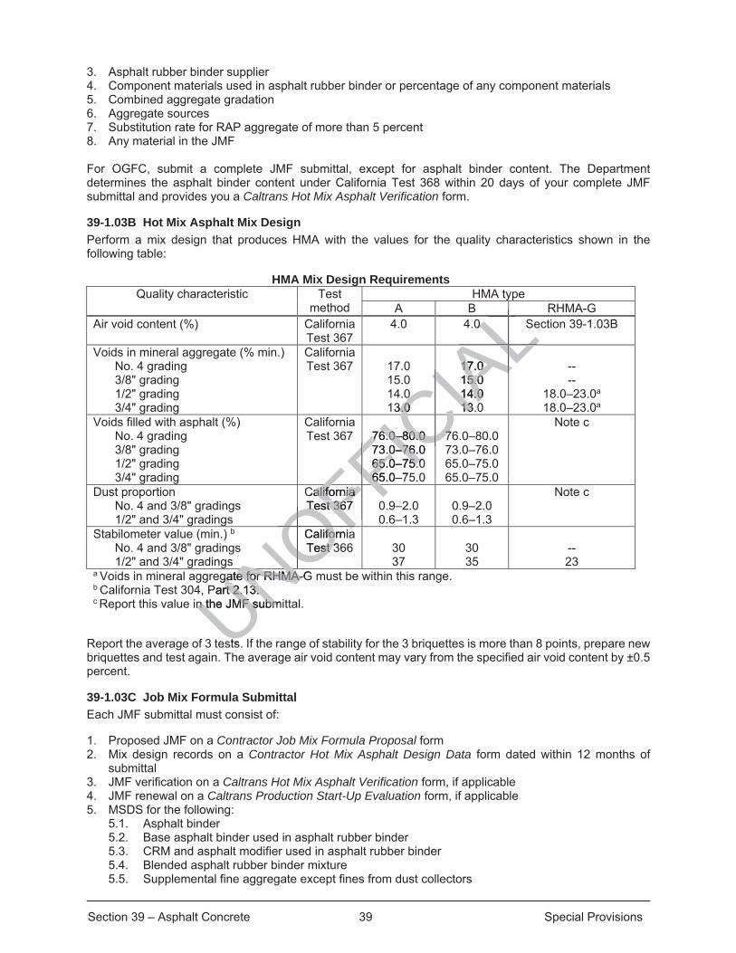
Section 39 – Asphalt Concrete 39 Special Provisions
3. Asphalt rubber binder supplier 4. Component materials used in asphalt rubber binder or percentage of any component materials 5. Combined aggregate gradation 6. Aggregate sources 7. Substitution rate for RAP aggregate of more than 5 percent 8. Any material in the JMF For OGFC, submit a complete JMF submittal, except for asphalt binder content. The Department determines the asphalt binder content under California Test 368 within 20 days of your complete JMF submittal and provides you a Caltrans Hot Mix Asphalt Verification form.
39-1.03B Hot Mix Asphalt Mix Design Perform a mix design that produces HMA with the values for the quality characteristics shown in the following table:
HMA Mix Design Requirements Quality characteristic Test
method HMA type
A B RHMA-G Air void content (%) California
Test 367 4.0 4.0 Section 39-1.03B
Voids in mineral aggregate (% min.) No. 4 grading 3/8" grading 1/2" grading 3/4" grading
California Test 367
17.0 15.0 14.0 13.0
17.0 15.0 14.0 13.0
-- --
18.0–23.0a
18.0–23.0a Voids filled with asphalt (%)
No. 4 grading 3/8" grading 1/2" grading 3/4" grading
California Test 367
76.0–80.0 73.0–76.0 65.0–75.0 65.0–75.0
76.0–80.0 73.0–76.0 65.0–75.0 65.0–75.0
Note c
Dust proportion No. 4 and 3/8" gradings 1/2" and 3/4" gradings
California Test 367
0.9–2.0 0.6–1.3
0.9–2.0 0.6–1.3
Note c
Stabilometer value (min.) b No. 4 and 3/8" gradings 1/2" and 3/4" gradings
California Test 366
30 37
30 35
-- 23
a Voids in mineral aggregate for RHMA-G must be within this range. b California Test 304, Part 2.13. c Report this value in the JMF submittal.
Report the average of 3 tests. If the range of stability for the 3 briquettes is more than 8 points, prepare new briquettes and test again. The average air void content may vary from the specified air void content by ±0.5 percent.
39-1.03C Job Mix Formula Submittal Each JMF submittal must consist of:
1. Proposed JMF on a Contractor Job Mix Formula Proposal form 2. Mix design records on a Contractor Hot Mix Asphalt Design Data form dated within 12 months of
submittal 3. JMF verification on a Caltrans Hot Mix Asphalt Verification form, if applicable 4. JMF renewal on a Caltrans Production Start-Up Evaluation form, if applicable 5. MSDS for the following:
5.1. Asphalt binder 5.2. Base asphalt binder used in asphalt rubber binder 5.3. CRM and asphalt modifier used in asphalt rubber binder 5.4. Blended asphalt rubber binder mixture 5.5. Supplemental fine aggregate except fines from dust collectors
UNOFFCalifornia alifornia Test 367 Test 36FFIC
IALL0 S0 LLLLLLLAL
0 0 3.0 .0
17.0 17.0 15.0 5.014.0 14.013.013AL
CIAL
76.0–80.0 76.0–80.0 73.0–76.0 3.0–7665.0–75.065.0–75.065.0–76
77CFF C
0FFOFFCaliforniafoTest 3st 3OF
NOgate for RHMA-Ggate for RHMA-NOPart 2.13. rt 2.13.
n the JMF submn the JMF subm
sts
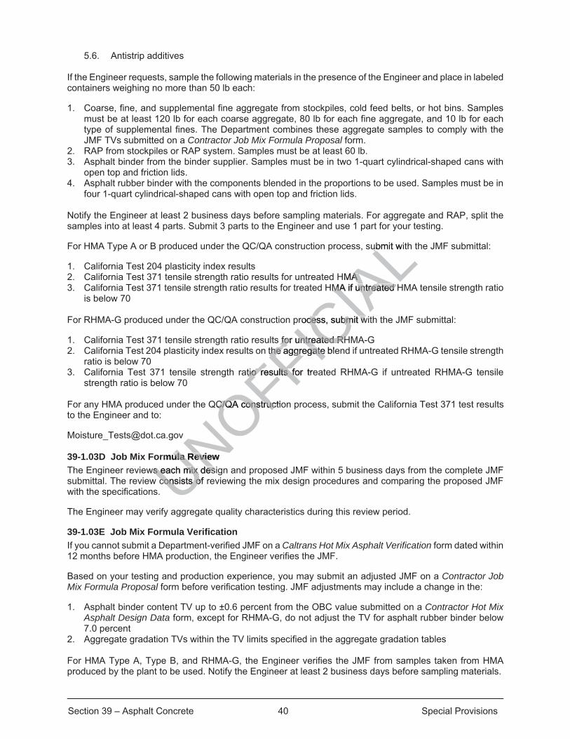
Section 39 – Asphalt Concrete 40 Special Provisions
5.6. Antistrip additives
If the Engineer requests, sample the following materials in the presence of the Engineer and place in labeled containers weighing no more than 50 lb each:
1. Coarse, fine, and supplemental fine aggregate from stockpiles, cold feed belts, or hot bins. Samples must be at least 120 lb for each coarse aggregate, 80 lb for each fine aggregate, and 10 lb for each type of supplemental fines. The Department combines these aggregate samples to comply with the JMF TVs submitted on a Contractor Job Mix Formula Proposal form.
2. RAP from stockpiles or RAP system. Samples must be at least 60 lb. 3. Asphalt binder from the binder supplier. Samples must be in two 1-quart cylindrical-shaped cans with
open top and friction lids. 4. Asphalt rubber binder with the components blended in the proportions to be used. Samples must be in
four 1-quart cylindrical-shaped cans with open top and friction lids. Notify the Engineer at least 2 business days before sampling materials. For aggregate and RAP, split the samples into at least 4 parts. Submit 3 parts to the Engineer and use 1 part for your testing.
For HMA Type A or B produced under the QC/QA construction process, submit with the JMF submittal:
1. California Test 204 plasticity index results 2. California Test 371 tensile strength ratio results for untreated HMA 3. California Test 371 tensile strength ratio results for treated HMA if untreated HMA tensile strength ratio
is below 70 For RHMA-G produced under the QC/QA construction process, submit with the JMF submittal:
1. California Test 371 tensile strength ratio results for untreated RHMA-G 2. California Test 204 plasticity index results on the aggregate blend if untreated RHMA-G tensile strength
ratio is below 70 3. California Test 371 tensile strength ratio results for treated RHMA-G if untreated RHMA-G tensile
strength ratio is below 70 For any HMA produced under the QC/QA construction process, submit the California Test 371 test results to the Engineer and to:
[email protected] 39-1.03D Job Mix Formula Review The Engineer reviews each mix design and proposed JMF within 5 business days from the complete JMF submittal. The review consists of reviewing the mix design procedures and comparing the proposed JMF with the specifications.
The Engineer may verify aggregate quality characteristics during this review period.
39-1.03E Job Mix Formula Verification If you cannot submit a Department-verified JMF on a Caltrans Hot Mix Asphalt Verification form dated within 12 months before HMA production, the Engineer verifies the JMF.
Based on your testing and production experience, you may submit an adjusted JMF on a Contractor Job Mix Formula Proposal form before verification testing. JMF adjustments may include a change in the:
1. Asphalt binder content TV up to ±0.6 percent from the OBC value submitted on a Contractor Hot Mix Asphalt Design Data form, except for RHMA-G, do not adjust the TV for asphalt rubber binder below 7.0 percent
2. Aggregate gradation TVs within the TV limits specified in the aggregate gradation tables For HMA Type A, Type B, and RHMA-G, the Engineer verifies the JMF from samples taken from HMA produced by the plant to be used. Notify the Engineer at least 2 business days before sampling materials.
UNOFFICIA
Lubmit witub
HMA A HMA if untreated HMA if untreated
rocess, submit wcess, submit w
s for untreated RHfor untreated RHthe aggregate blethe aggregate
atio results for tretio results fo
QC/QA constructioC/QA construc
mula Review ula Reviws each mix desis each mix des
consists of consists o

Section 39 – Asphalt Concrete 41 Special Provisions
In the Engineer's presence and from the same production run, take samples of:
1. Aggregate 2. Asphalt binder 3. RAP 4. HMA
Sample aggregate from cold feed belts or hot bins. Sample RAP from the RAP system. Sample HMA under California Test 125, except if you request and if authorized, you may sample from any of the following locations:
1. Plant 2. Truck 3. Windrow 4. Paver hopper 5. Mat behind the paver
You may sample from a different project, including a non-Department project, if you make arrangements for the Engineer to be present during sampling.
For aggregate, RAP, and HMA, split the samples into at least 4 parts and label their containers. Submit 3 split parts and keep 1 part for your testing.
The Engineer verifies each proposed JMF within 20 days of receiving all verification samples and the JMF submittal has been accepted. If you request, the Engineer verifies RHMA-G quality requirements within 3 business days of sampling. Verification is testing for compliance with the specifications for:
1. Aggregate quality 2. Aggregate gradation TVs within the TV limits 3. Asphalt binder content TV within the TV limit 4. HMA quality specified in the table HMA Mix Design Requirements except:
4.1. Air void content, design value ±2.0 percent 4.2. Voids filled with asphalt, report only if an adjustment for asphalt binder content TV is less than ±
0.3 percent from OBC 4.3. Dust proportion, report only if an adjustment for asphalt binder content TV is less than ±0.3
percent from OBC
The Engineer prepares 3 briquettes from a single split sample. To verify the JMF for stability and air void content, the Engineer tests the 3 briquettes and reports the average of 3 tests. The Engineer prepares new briquettes if the range of stability for the 3 briquettes is more than 8 points.
The Engineer may use the briquettes used for stability testing to determine bulk specific gravity under California Test 308. If the same briquettes are used and the tests using bulk specific gravity fail, the Engineer prepares 3 new briquettes and determines a new bulk specific gravity.
If the JMF is verified, the Engineer provides you a Caltrans Hot Mix Asphalt Verification form.
If tests on plant-produced samples do not verify the JMF, the Engineer notifies you and you must submit a new JMF submittal or submit an adjusted JMF based on your testing. JMF adjustments may include a change in:
1. Asphalt binder content TV up to ±0.6 percent from the OBC value submitted on a Contractor Hot Mix Asphalt Design Data form except do not adjust the TV for asphalt rubber binder for RHMA-G below 7.0 percent
2. Aggregate gradation TVs within the TV limits specified in the aggregate gradation tables You may adjust the JMF only once due to a failed verification test. An adjusted JMF requires a new Contractor Job Mix Formula Proposal form and verification of a plant-produced sample.
UNOFFICIA
Lct,
s and label their cs and label their
eceiving all verificving all vverifies RHMA-Gverifies RHMA-
mpliance with the sance with the
mit mitMix Design RequMix Design
±2.0 percent 2.0 perceort only if an adjuort only if a
t onlynly if an adjusadjus
briquettes from abriquettes fromests the 3 briquetts the 3 br
e of stability for te of stability for
the briqthe briqe sa

Section 39 – Asphalt Concrete 42 Special Provisions
The Engineer reverifies the JMF if HMA production has stopped for longer than 30 days and the verified JMF is older than 12 months.
For each HMA type and aggregate size specified, the Engineer verifies at the Department's expense up to 2 proposed JMF, including a JMF adjusted after verification failure. The Engineer deducts $3,000 from payments for each verification exceeding this limit. This deduction does not apply to verifications initiated by the Engineer or if a JMF expires while HMA production is stopped longer than 30 days.
For any HMA produced under the QC/QA construction process, the Department does not use California Test 371 test results for JMF verification.
39-1.03F Job Mix Formula Renewal You may request a JMF renewal by submitting:
1. Proposed JMF on a Contractor Job Mix Formula Proposal form 2. Previously verified JMF documented on a Caltrans Hot Mix Asphalt Verification form dated within 12
months 3. Mix design documentation on a Contractor Hot Mix Asphalt Design Data form used for the previously
verified JMF If the Engineer requests, sample the following materials in the presence of the Engineer and place in labeled containers weighing no more than 50 lb each:
1. Coarse, fine, and supplemental fine aggregate from stockpiles, cold feed belts, or hot bins. Samples must include at least 120 lb for each coarse aggregate, 80 lb for each fine aggregate, and 10 lb for each type of supplemental fines. The Department combines these aggregate samples to comply with the JMF TVs submitted on a Contractor Job Mix Formula Proposal form.
2. RAP from stockpiles or RAP system. Samples must be at least 60 lb. 3. Asphalt binder from the binder supplier. Samples must be in two 1-quart cylindrical-shaped cans with
open top and friction lids. 4. Asphalt rubber binder with the components blended in the proportions to be used. Samples must be in
four 1-quart cylindrical-shaped cans with open top and friction lids. Notify the Engineer at least 2 business days before sampling materials. For aggregate, RAP, and HMA, split samples into at least 4 parts. Submit 3 parts to the Engineer and use 1 part for your testing.
The Engineer reviews each complete JMF renewal submittal within 5 business days.
The Engineer may verify aggregate qualities during this review period.
The Engineer verifies the JMF under section 39-1.03E except:
1. Engineer retains samples until you provide test results for your part on a Contractor Job Mix Formula Renewal form.
2. Department tests samples of materials obtained from the HMA production unit after you submit test results that comply with the specifications for the quality characteristics in section 39-1.03E.
3. Engineer verifies each proposed JMF within 30 days of receiving verification samples. 4. You may not adjust the JMF due to a failed verification. 5. For each HMA type and aggregate gradation specified, the Engineer verifies at the Department's
expense 1 proposed JMF. If the Engineer verifies the JMF renewal, the Engineer provides you a Caltrans Hot Mix Asphalt Verification form.
39-1.03G Job Mix Formula Acceptance You may start HMA production if:
1. Engineer's review of the JMF shows compliance with the specifications 2. Department has verified the JMF within 12 months before HMA production 3. Engineer authorizes the verified JMF
fo
ce of the Engineere of the Engineer
ckpiles, cold feed kpiles, cold fte, 80 lb for eache, 80 lb for eac
ombines these agmbines these aFormula Proposalormula Proposa
must be at least 6must be at least 6mples mple must be in must be
ents blended in thents blended with open top anth open top an
ness days beforeess days befors. Submit 3 parts. Submit 3 par t
complete JMF recomplete JMF re
fy aggregate quaaggregate
s the JMF undes the JMF u
ples ples
Section 39 – Asphalt Concrete 43 Special Provisions
39-1.04 CONTRACTOR QUALITY CONTROL 39-1.04A General Establish, maintain, and change a quality control system to ensure materials and work comply with the specifications. Submit quality control test results within 3 days of a request, except if the QC/QA construction process is specified.
You must identify the HMA sampling location in your QC plan. During production, take samples under California Test 125, except if you request and if authorized, sample HMA from any of the following locations:
1. Plant 2. Truck 3. Windrow 4. Paver hopper 5. Mat behind the paver
39-1.04B Prepaving Conference Hold a prepaving conference with the Engineer at a mutually agreed time and place. Discuss methods of performing the production and paving work.
39-1.04C Asphalt Rubber Binder Take asphalt rubber binder samples from the feed line connecting the asphalt rubber binder tank to the HMA plant. Sample and test asphalt rubber binder under Laboratory Procedure LP-11.
Test asphalt rubber binder for compliance with the viscosity specifications in section 39-1.02. During the asphalt rubber binder production and HMA production using asphalt rubber binder, measure the viscosity every hour with not less than 1 reading for each asphalt rubber binder batch. Log the measurements with the corresponding time and asphalt rubber binder temperature. Submit the log daily.
Submit a certificate of compliance and test results for CRM and asphalt modifier with each truckload delivered to the HMA plant. A certificate of compliance for asphalt modifier must not represent more than 5,000 lb. Use an AASHTO-certified laboratory for testing.
Sample and test gradation and wire and fabric content of CRM once per 10,000 lb of scrap tire crumb rubber and once per 3,400 lb of high natural rubber. Sample and test scrap tire crumb rubber and high natural rubber separately.
Submit certified weight slips for the furnished CRM and asphalt modifier.
39-1.04D Aggregate Determine the aggregate moisture content and RAP moisture content in continuous mixing plants at least twice a day during production and adjust the plant controller. Determine the RAP moisture content in batch mixing plants at least twice a day during production and adjust the plant controller.
39-1.04E Reclaimed Asphalt Pavement Perform RAP quality control testing each day.
Sample RAP once daily and determine the RAP aggregate gradation under California Test 367, appendix B, and submit the results with the combined aggregate gradation.
39-1.04F Density Cores To determine density for Standard and QC/QA construction process projects, take 4- or 6-inch diameter density cores at least once every 5 business days. Take 1 density core for every 250 tons of HMA from random locations the Engineer designates. Take density cores in the Engineer's presence and backfill and compact holes with authorized material. Before submitting a density core, mark it with the density core's location and place it in a protective container.
UNOFFICIA
Land pla
cting the asphalt ing the asphalt oratory Proceduroratory Proce
osity specificationty specification ususing asphalt rug asphalt
sphphalt rubber bindalt rubber binder temperature. Sur temperature.
st results for CRst results foof compliance fof compliance fo
boratory for testinboratory for
wire and fabric coe and fabric cof high natural ruf high natural
slips for the furnisps for the furni
eee moistue moistu
ion

Section 39 – Asphalt Concrete 44 Special Provisions
If a density core is damaged, replace it with a density core taken within 1 foot longitudinally from the original density core. Relocate any density core located within 1 foot of a rumble strip to 1 foot transversely away from the rumble strip.
39-1.04G Briquettes Prepare 3 briquettes for each stability and air void content determination. Report the average of 3 tests. Prepare new briquettes and test again when the range of stability for the 3 briquettes is more than 8 points.
You may use the same briquettes used for stability testing to determine bulk specific gravity under California Test 308. If you use these briquettes and tests using bulk specific gravity fail, you may prepare 3 new briquettes and determine a new bulk specific gravity.
39-1.05 ACCEPTANCE CRITERIA HMA acceptance is specified in the sections for each HMA construction process.
The Department samples materials for testing under California Test 125 and the applicable test method, except samples may be taken:
1. At the plant from a truck or an automatic sampling device 2. From the mat behind the paver Sampling must be independent of Contractor quality control, statistically based, and random.
If you request, the Department splits samples and provides you with a part.
HMA acceptance is based on:
1. Authorized JMF 2. Accepted QC plan for Standard and QC/QA construction process projects 3. Compliance with the HMA acceptance tables 4. Lot acceptance for QC/QA construction process projects 5. Visual inspection The Department prepares 3 briquettes for each stability and air void content determination. The average of 3 tests is reported. If the range of stability for the 3 briquettes is more than 8 points, new briquettes are prepared and tested.
The Department may use the briquettes used for stability testing to determine bulk specific gravity under California Test 308. If the Engineer uses the same briquettes and the tests using that bulk specific gravity fail, the Engineer prepares 3 new briquettes and determines a new bulk specific gravity.
39-1.06 DISPUTE RESOLUTION Work with the Engineer to avoid potential conflicts and to resolve disputes regarding test result discrepancies. Notify the Engineer within 5 days of receiving a test result if you dispute the test result.
If you or the Engineer dispute each other's test results, submit quality control test results and copies of paperwork including worksheets used to determine the disputed test results. An independent third party performs referee testing. Before the independent third party participates in a dispute resolution, the party must be accredited under the Department's Independent Assurance Program. The independent third party must be independent of the project. By mutual agreement, the independent third party is chosen from:
1. Department laboratory 2. Department laboratory in a district or region not in the district or region the project is located 3. Transportation Laboratory 4. Laboratory not currently employed by you or your HMA producer If split quality control or acceptance samples are not available, the independent third party uses any available material representing the disputed HMA for evaluation.
UNOFFICIA
Lstically based, andlly based, an
ou with a part. ou with a part
construction procconstruction ples les
process projectsprocess pro
tes for each stabies for each staof stability for theof stability for
e the briquettes ue the briquettesthe Engineer usEnginee es
epares 3 new briqpares 3 new br
SOLUTIOSOLUTIOto

Section 39 – Asphalt Concrete 45 Special Provisions
39-1.07 PRODUCTION START-UP EVALUATION The Engineer evaluates HMA production and placement at production start-up.
Within the first 750 tons produced on the 1st day of HMA production, in the Engineer's presence and from the same production run, take samples of:
1. Aggregate 2. Asphalt binder 3. RAP 4. HMA Sample aggregate from cold feed belts or hot bins. Take RAP samples from the RAP system. Sample HMA under California Test 125, except if you request and if authorized, you may sample HMA from any of the following locations:
1. Plant 2. Truck 3. Windrow 4. Paver hopper 5. Mat behind the paver For aggregate, RAP, and HMA, split the samples into at least 4 parts and label their containers. Submit 3 split parts and keep 1 part.
For Standard and QC/QA construction process projects, you and the Department must test the split samples and report test results within 3 business days of sampling. If you proceed before receipt of the test results, the Engineer may consider the HMA placed to be represented by these test results.
For Standard and QC/QA construction process projects, take 4- or 6-inch diameter density cores within the first 750 tons on the 1st day of HMA production. For each density core, the Department reports the bulk specific gravity determined under California Test 308, Method A, in addition to the percent of maximum theoretical density. You may test for in-place density at the density core locations and include them in your production tests for percent of maximum theoretical density.
39-1.08 PRODUCTION 39-1.08A General Produce HMA in a batch mixing plant or a continuous mixing plant. Proportion aggregate by hot or cold feed control.
HMA plants must be Department qualified. Before production, the HMA plant must have current qualification under the Department's Materials Plant Quality Program.
During production, you may adjust:
1. Hot or cold feed proportion controls for virgin aggregate and RAP 2. Set point for asphalt binder content 39-1.08B Mixing Mix HMA ingredients into a homogeneous mixture of coated aggregates.
Asphalt binder must be from 275 to 375 degrees F when mixed with aggregate.
Asphalt rubber binder must be from 350 to 425 degrees F when mixed with aggregate.
When mixed with asphalt binder, aggregate must not be more than 325 degrees F, except aggregate for OGFC must be not more than 275 degrees F. These aggregate temperature specifications do not apply if you use RAP.
HMA with or without RAP must not be more than 325 degrees F.
UNOFFICIA
Larts and label theand label the
, you and the Dyou and the Df sampling. If youampling. If you
o be representedo be represented
projects, takerojects, take 4- o 4-ion. Foon. For each der each de
a Test 308,a Test 308, Meth Mlace densitce density at tht th
um theoretical deum theoretic
mixing plant or aixing plant o
Department quaDepartment quas Materialss Material
Section 39 – Asphalt Concrete 46 Special Provisions
39-1.08C Asphalt Rubber Binder Deliver scrap tire crumb rubber and high natural rubber in separate bags.
Either proportion and mix asphalt binder, asphalt modifier, and CRM simultaneously or premix the asphalt binder and asphalt modifier before adding CRM. If you premix the asphalt binder and asphalt modifier, the asphalt binder must be from 375 to 425 degrees F when you add the asphalt modifier. Mix for at least 20 minutes. When you add CRM, the asphalt binder and asphalt modifier must be from 375 to 425 degrees F.
Do not use asphalt rubber binder during the first 45 minutes of the reaction period. During this period, the asphalt rubber binder mixture must be from 375 to the lower of 425 degrees F or 25 degrees F below the asphalt binder's flash point described in the MSDS.
If any asphalt rubber binder is not used within 4 hours after the reaction period, discontinue heating. If the asphalt rubber binder drops below 375 degrees F, reheat before use. If you add more scrap tire crumb rubber to the reheated asphalt rubber binder, the binder must react for 45 minutes. The added scrap tire crumb rubber must not exceed 10 percent of the total asphalt rubber binder weight. Reheated and reacted asphalt rubber binder must comply with the viscosity specifications for asphalt rubber binder in section 39-1.02D. Do not reheat asphalt rubber binder more than twice.
39-1.09 SUBGRADE, TACK COAT, AND GEOSYNTHETIC PAVEMENT INTERLAYER 39-1.09A General Prepare subgrade or apply tack coat to surfaces receiving HMA. If specified, place geosynthetic pavement interlayer over a coat of asphalt binder.
39-1.09B Subgrade Subgrade to receive HMA must comply with the compaction and elevation tolerance specifications in the sections for the material involved. Subgrade must be free of loose and extraneous material. If HMA is paved on existing base or pavement, remove loose paving particles, dirt, and other extraneous material by any means including flushing and sweeping.
39-1.09C Tack Coat Apply tack coat:
1. To existing pavement, including planed surfaces 2. Between HMA layers 3. To vertical surfaces of:
3.1. Curbs 3.2. Gutters 3.3. Construction joints
Before placing HMA, apply tack coat in 1 application. The application rate must be the minimum residual rate specified for the underlying surface conditions shown in the following tables:
Tack Coat Application Rates for HMA Type A, Type B, and RHMA-G
HMA overlay over:
Minimum residual rates (gal/sq yd) CSS1/CSS1h, SS1/SS1h and QS1h/CQS1h
asphaltic emulsion
CRS1/CRS2, RS1/RS2 and QS1/CQS1 asphaltic emulsion
Asphalt binder and PMRS2/PMCRS2
and PMRS2h/PMCRS2h asphaltic emulsion
New HMA (between layers) 0.02 0.03 0.02 PCC and existing HMA (AC) surfaces 0.03 0.04 0.03
Planed PCC and HMA (AC) surfaces 0.05 0.06 0.04
UNOFFICIA
LNT INTERLAT INTERLA
If specified, placeIf specified, place
pactiac on and elevaon and elee free of loose ande free of loose and
ving partiving par cles, dircles,
ng planed surfacplaned sur
on joints on joints
ply tackply tackrlyi
Section 39 – Asphalt Concrete 47 Special Provisions
Tack Coat Application Rates for OGFC
OGFC over:
Minimum residual rates (gal/sq yd) CSS1/CSS1h, SS1/SS1h and QS1h/CQS1h
asphaltic emulsion
CRS1/CRS2, RS1/RS2 and QS1/CQS1 asphaltic emulsion
Asphalt binder and PMRS2/PMCRS2
and PMRS2h/PMCRS2h asphaltic emulsion
New HMA 0.03 0.04 0.03 PCC and existing HMA (AC) surfaces 0.05 0.06 0.04
Planed PCC and HMA (AC) surfaces 0.06 0.07 0.05
If you dilute asphaltic emulsion, mix until homogeneous before application.
For vertical surfaces, apply a residual tack coat rate that will thoroughly coat the vertical face without running off.
If you request and if authorized, you may:
1. Change tack coat rates 2. Omit tack coat between layers of new HMA during the same work shift if:
2.1. No dust, dirt, or extraneous material is present 2.2. Surface is at least 140 degrees F
Immediately in advance of placing HMA, apply additional tack coat to damaged areas or where loose or extraneous material is removed.
Close areas receiving tack coat to traffic. Do not track tack coat onto pavement surfaces beyond the job site.
Asphalt binder tack coat must be from 285 to 350 degrees F when applied.
39-1.09D Geosynthetic Pavement Interlayer Place geosynthetic pavement interlayer under the manufacturer's instruction.
Before placing the geosynthetic pavement interlayer and asphalt binder:
1. Repair cracks 1/4 inch and wider, spalls, and holes in the pavement. These repairs are change order work.
2. Clean the pavement of loose and extraneous material. Immediately before placing the interlayer, apply 0.25 ± 0.03 gal of asphalt binder per square yard of interlayer or until the fabric is saturated. Apply asphalt binder the width of the geosynthetic pavement interlayer plus 3 inches on each side. At interlayer overlaps, apply asphalt binder on the lower interlayer the same overlap distance as the upper interlayer.
Asphalt binder must be from 285 to 350 degrees F and below the minimum melting point of the geosynthetic pavement interlayer when applied.
Align and place the interlayer with no folds that result in a triple thickness, except that triple thickness layers less than 1 inch in width may remain if less than 1/2 inch in height. Folds that result in a triple layer greater than a 1 inch width must be slit and overlapped in a double thickness at least 2 inches in width.
The minimum HMA thickness over the interlayer must be 0.12 foot thick, including conform tapers. Do not place the interlayer on a wet or frozen surface.
Overlap the interlayer borders from 2 to 4 inches. In the direction of paving, overlap the following roll with the preceding roll at any break.
UNOFFICIA
Le work shift if: work shift if
tional tack coat toional tack coat t
not track tack conot track tack co
285 to 350 degre 285 to 350
ent Interlayer ent Interlayerinterlayererlayer under under rr
nthetic pavementnthetic pavemen
4 inch and wider4 inch and wide
of loosof loos

Section 39 – Asphalt Concrete 48 Special Provisions
You may use rolling equipment to correct distortions or wrinkles in the interlayer.
If asphalt binder tracked onto the interlayer or brought to the surface by construction equipment causes interlayer displacement, cover it with a small quantity of HMA.
Before placing HMA on the interlayer, do not expose the interlayer to:
1. Traffic, except for crossings under traffic control, and only after you place a small HMA quantity 2. Sharp turns from construction equipment 3. Damaging elements
Pave HMA on the interlayer during the same work shift.
39-1.10 SPREADING AND COMPACTING EQUIPMENT Paving equipment for spreading must be:
1. Self-propelled 2. Mechanical 3. Equipped with a screed or strike-off assembly that can distribute HMA the full width of a traffic lane 4. Equipped with a full-width compacting device 5. Equipped with automatic screed controls and sensing devices that control the thickness, longitudinal
grade, and transverse screed slope
Install and maintain grade and slope references.
The screed must produce a uniform HMA surface texture without tearing, shoving, or gouging.
The paver must not leave marks such as ridges and indentations, unless you can eliminate them by rolling.
Rollers must be equipped with a system that prevents HMA from sticking to the wheels. You may use a parting agent that does not damage the HMA or impede the bonding of layers.
In areas inaccessible to spreading and compacting equipment:
1. Spread the HMA by any means to obtain the specified lines, grades, and cross sections. 2. Use a pneumatic tamper, plate compactor, or equivalent to achieve thorough compaction. Edge of pavement treatment shall be per the 2015 Standard Plan P75, Case B where tapered safety edge is 30 degrees plus or minus 10 degrees. Tapered safety edge shall be extruded, densified edge of uniform grade and consistency as produced with Carlson brand safety attachment. An equivalent extruded, tapered safety edge will be accepted and approved by the County upon performing an acceptable trial example or demonstration.
39-1.11 TRANSPORTING, SPREADING, AND COMPACTING Do not pave HMA on wet pavement or a frozen surface.
You may deposit HMA in a windrow and load it in the paver if:
1. Paver is equipped with a hopper that automatically feeds the screed 2. Loading equipment can pick up the windrowed material and deposit it in the paver hopper without
damaging base material 3. Activities for deposit, pickup, loading, and paving are continuous 4. HMA temperature in the windrow does not fall below 260 degrees F You may pave HMA in 1 or more layers on areas less than 5 feet wide and outside the traveled way, including shoulders. You may use mechanical equipment other than a paver for these areas. The equipment must produce uniform smoothness and texture.
UNOFFICIA
Lthe full
hat control the thhat control the th
e without tearing, without tearing,
indentations, unlindentations, un
preventsprevents HMA fro HMA frA or impede the bA or impede
compacting equipcompactin
s to obtain tto obtain the sphe spate compactor, oate compactor,
ent shall t shall be per thbe penus 10 degrees. us 10 degrees.
y as produced wity as produced wccepted and apccepted and ap
Section 39 – Asphalt Concrete 49 Special Provisions
HMA handled, spread, or windrowed must not stain the finished surface of any improvement, including pavement.
Do not use petroleum products such as kerosene or diesel fuel to release HMA from trucks, spreaders, or compactors.
HMA must be free of:
1. Segregation 2. Coarse or fine aggregate pockets 3. Hardened lumps
Longitudinal joints in the top layer must match specified lane edges. Alternate the longitudinal joint offsets in the lower layers at least 0.5 foot from each side of the specified lane edges. You may request other longitudinal joint placement patterns.
Until the adjoining through lane's top layer has been paved, do not pave the top layer of:
1. Shoulders 2. Tapers 3. Transitions 4. Road connections 5. Driveways 6. Curve widenings 7. Chain control lanes 8. Turnouts 9. Turn pockets
If the number of lanes changes, pave each through lane's top layer before paving a tapering lane's top layer. Simultaneous to paving a through lane's top layer, you may pave an adjoining area's top layer, including shoulders. Do not operate spreading equipment on any area's top layer until completing final compaction.
If leveling with HMA is specified, fill and level irregularities and ruts with HMA before spreading HMA over the base, existing surfaces, or bridge decks. You may use mechanical equipment other than a paver for these areas. The equipment must produce uniform smoothness and texture. HMA used to change an existing surface's cross slope or profile is not paid for as HMA (leveling).
If placing HMA against the edge of existing pavement, sawcut or grind the pavement straight and vertical along the joint and remove extraneous material.
Rolling must leave the completed surface compacted and smooth without tearing, cracking, or shoving. Complete finish rolling activities before the pavement surface temperature is:
1. Below 150 degrees F for HMA with unmodified binder 2. Below 140 degrees F for HMA with modified binder 3. Below 200 degrees F for RHMA-G If a vibratory roller is used as a finish roller, turn the vibrator off.
Do not use a pneumatic-tired roller to compact RHMA-G.
Do not allow traffic on new HMA pavement until its mid-depth temperature is below 160 degrees F.
If you request and if authorized, you may cool HMA Type A and Type B with water when rolling activities are complete. Apply water under section 17-3.
Spread sand at a rate from 1 to 2 lb/sq yd on new RHMA-G, RHMA-O, and RHMA-O-HB pavement when finish rolling is complete. Sand must be free of clay or organic matter. Sand must comply with section 90-1.02C(4)(c). Keep traffic off the pavement until spreading sand is complete.
UNOFFICIA
Lough lane's top laugh lane's to
e's top lae's top layer, youyer youding equiding equipment opm
and level irregulaand level irreguidge decks. You e decks. You
must produce unust produce ue or profile is not e or profile is not
the edge of existe edge of existemove extraneousmove extraneo
completecompletetivitietivitie
Section 39 – Asphalt Concrete 50 Special Provisions
39-1.12 SMOOTHNESS 39-1.12A General Determine HMA smoothness with a profilograph and a straightedge.
Smoothness specifications do not apply to OGFC placed on existing pavement not constructed under the same project.
If concrete pavement is placed on HMA:
1. Cold plane the HMA finished surface to within specified tolerances if it is higher than the grade ordered. 2. Remove and replace HMA if the finished surface is lower than 0.05 foot below the grade ordered.
39-1.12B Straightedge The top layer of HMA pavement must not vary from the lower edge of a 12-foot straightedge:
1. More than 0.01 foot when the straightedge is laid parallel with the centerline 2. More than 0.02 foot when the straightedge is laid perpendicular to the centerline and extends from edge
to edge of a traffic lane 3. More than 0.02 foot when the straightedge is laid within 24 feet of a pavement conform 39-1.12C Profilograph For the top layer of HMA Type A, Type B, and RHMA-G pavement, determine the PI0 and must-grinds under California Test 526. Take 2 profiles within each traffic lane, 3 feet from and parallel with the edge of each lane.
A must-grind is a deviation of 0.3 inch or more in a length of 25 feet. You must correct must-grinds.
For OGFC, only determine must-grinds if placed over HMA constructed under the same project. The top layer of the underlying HMA must comply with the smoothness specifications before placing OGFC.
Profile the pavement in the Engineer's presence.
On tangents and horizontal curves with a centerline radius of curvature of 2,000 feet, the PI0 must be at most 3 inches per 0.1-mile section.
On horizontal curves with a centerline radius of curvature from 1,000 to 2,000 feet, including pavement within the superelevation transitions, the PI0 must be at most 6 inches per 0.1-mile section.
Before the Engineer accepts HMA pavement for smoothness, submit final profilograms.
Submit 1 copy of profile information in Microsoft Excel and 1 copy of longitudinal pavement profiles in ".erd" format or other ProVAL compatible format to the Engineer and to:
The following HMA pavement areas do not require a PI0. You must measure these areas with a 12-foot straightedge and determine must-grinds with a profilograph:
1. New HMA with a total thickness less than 0.25 foot 2. HMA sections of city or county streets and roads, turn lanes, and collector lanes less than 1,500 feet in
length The following HMA pavement areas do not require a PI0 and you must measure them with a 12-foot straightedge:
1. Horizontal curves with a centerline radius of curvature less than 1,000 feet, including pavement within the superelevation transitions of those curves
2. Within 12 feet of a transverse joint separating the pavement from: 2.1. Existing pavement not constructed under the same project 2.2. A bridge deck or approach slab
UNOFFICIA
Lpavement cave
ment, determine ment, determineane, 3 feet from ane, 3 feet fr
gth of 25 feet. Yogth of 25 feet. Y
overove HMA constHMA corthe the smoothness ssmoothness
esence. sence.
with a centerwith a centerline rli.
centerline radius erline radius ransitions, the PIansitions, the
ccepts HMA pavepts HMA p
e informatioe informatcompatcompat
Section 39 – Asphalt Concrete 51 Special Provisions
3. Exit ramp termini, truck weigh stations, and weigh-in-motion areas 4. If steep grades and superelevation rates greater than 6 percent are present:
4.1. Ramps 4.2. Connectors
5. Turn lanes 6. Areas within 15 feet of manholes or drainage transitions 7. Acceleration and deceleration lanes for at-grade intersections 8. Shoulders and miscellaneous areas 9. HMA pavement within 3 feet from and parallel to the construction joints formed between curbs, gutters,
or existing pavement 39-1.12D Smoothness Correction If the top layer of HMA Type A, Type B, or RHMA-G pavement does not comply with the smoothness specifications, grind the pavement to within specified tolerances, remove and replace it, or place an overlay of HMA. Do not start corrective work until your choice of methods is authorized.
Remove and replace areas of OGFC not in compliance with the must-grind and straightedge specifications, except you may grind OGFC for correcting smoothness:
1. At transverse joints separating the OGFC from pavement not constructed under the same project 2. Within 12 feet of a transverse joint separating the OGFC from a bridge deck or approach slab Corrected HMA pavement areas must be uniform rectangles with edges:
1. Parallel to the nearest HMA pavement edge or lane line 2. Perpendicular to the pavement centerline Measure the corrected HMA pavement surface with a profilograph and a 12-foot straightedge and correct the pavement to within specified tolerances. If a must-grind area or straightedged pavement cannot be corrected to within specified tolerances, remove and replace the pavement.
On areas ground but not overlaid with OGFC, apply fog seal coat under section 37-2.
39-1.13 HOT MIX ASPHALT ON BRIDGE DECKS Produce and place HMA on bridge decks under the Method construction process.
Aggregate must comply with the 1/2-inch HMA Types A and B gradation.
If authorized, aggregate may comply with the no. 4 HMA Types A and B gradation for a section or taper at a bridge end that is less than 1 inch in total depth.
If a concrete expansion dam is to be placed at a bridge deck expansion joint, tape oil-resistant construction paper to the deck over the area to be covered by the dam before placing the tack coat and HMA across the joint.
Do not leave a vertical joint more than 0.15 foot high between adjacent lanes open to traffic.
The tack coat application rate must be the minimum residual rate specified in section 39-1.09C. For HMA placed on a deck seal, use the minimum residual rate specified for a PCC underlying surface.
HMA placed on a deck seal must be placed in at least 2 approximately equal layers. The 1st layer must be at least 1 inch thick after compaction. Protect the deck seal throughout all operations.
For placement of the 1st HMA layer on a deck seal:
1. Comply with the HMA application temperature recommended by the deck seal manufacturer. 2. Deliver and place HMA using equipment with pneumatic tires or rubber-faced wheels. Do not operate
other vehicles or equipment on the bare deck seal. 3. Deposit HMA on the deck seal in such a way that the deck seal is not damaged. Do not windrow the
HMA material on the bridge deck seal.
UNOFFICIA
Ltructed under thted under thbridge deck or apbridge deck or ap
ith edges: h edges:
ne e
th a profilograph th a profilograph a a must-grind aremust-grind a
ove and replace thove and rep
GFC, apply fog sFC, apply fog s
BRIDGE DECKS RIDGE DECKSge decks ge deck under tde
th the 1/h the 1/2-inch HM2-inc
te may comply wmay compess than 1 inch ess than 1 inch
dam is tdam is tare
Section 39 – Asphalt Concrete 52 Special Provisions
4. Place HMA in a downhill direction on bridge decks with grades over 2 percent. 5. Spreading equipment need not be self-propelled. 39-1.14 MISCELLANEOUS AREAS AND DIKES The following specifications in section 39 do not apply to miscellaneous areas and dikes:
1. HMA construction process 2. HMA mix design requirements 3. Contractor quality control 4. Production start-up evaluation Miscellaneous areas are outside the traveled way and include:
1. Median areas not including inside shoulders 2. Island areas 3. Sidewalks 4. Gutters 5. Gutter flares 6. Ditches 7. Overside drains 8. Aprons at the ends of drainage structures Spread miscellaneous areas in 1 layer and compact to the specified lines and grades.
For miscellaneous areas and dikes:
1. Do not submit a JMF. 2. Choose the 3/8-inch or 1/2-inch HMA Type A and Type B aggregate gradations. 3. Minimum asphalt binder content must be 6.8 percent for 3/8-inch aggregate and 6.0 percent for 1/2-
inch aggregate. If you request and if authorized, you may reduce the minimum asphalt binder content. 4. Choose asphalt binder Grade PG 70-10 or the same grade specified for HMA. 39-1.15 MINOR HOT MIX ASPHALT 39-1.15A GENERAL 39-1.15A(1) Summary
The following specifications in section 39 do not apply to minor HMA:
1. HMA construction process 2. HMA mix design requirements 3. Contractor quality control 4. Production start-up evaluation 39-1.15A(2) Definitions
Reserved
39-1.15A(3) Submittals
Reserved
39-1.15A(4) Quality Control and Assurance
Reserved
39-1.15B MATERIALS The minimum asphalt binder content must be 6.8 percent for 3/8-inch aggregate gradation and 6.0 percent for 1/2-inch aggregate gradation.
Choose asphalt binder Grade PG 64-10, PG 64-16, or PG 70-10.
UNOFFICIA
Lcified lines and grfied lines and g
and Type B aggreand Type B aggre.8 per8 pe cent for 3/8cent for 3
orized, you may rorized, you0 or the same gra0 or the same
ns in section 39 din section 39
n process n process requirements requiremen
control control valuavalua
Section 39 – Asphalt Concrete 53 Special Provisions
If you request and if authorized, you may reduce the minimum asphalt binder content.
Choose the 3/8-inch or 1/2-inch HMA Type A or Type B aggregate gradation.
39-1.15C CONSTRUCTION Produce HMA at a central mixing plant.
Choose any method and equipment to spread and compact.
The surface must be:
1. Textured uniformly 2. Compacted firmly 3. Without depressions, humps, and irregularities Smoothness specifications do not apply.
39-1.30 PAYMENT Section 39-6 includes specifications for HMA payment. The weight of each HMA mixture designated in the Bid Item List must be the combined mixture weight.
If recorded batch weights are printed automatically, the bid item for HMA is measured by using the printed batch weights, provided:
1. Total aggregate and supplemental fine aggregate weight per batch is printed. If supplemental fine aggregate is weighed cumulatively with the aggregate, the total aggregate batch weight must include the supplemental fine aggregate weight.
2. Total asphalt binder weight per batch is printed. 3. Each truckload's zero tolerance weight is printed before weighing the 1st batch and after weighing the
last batch. 4. Time, date, mix number, load number, and truck identification is correlated with a load slip. 5. Copy of the recorded batch weights is certified by a licensed weighmaster and submitted to the
Engineer. If tack coat, asphalt binder, and asphaltic emulsion are paid with separate contract items, their contract items are measured under section 92 or section 94.
The Department does not adjust the unit price for an increase or decrease in the tack coat quantity. Section 9-1.06 does not apply to tack coat.
Place hot mix asphalt dike of the type specified is measured along the completed length.
Place hot mix asphalt (miscellaneous areas) is measured as the in-place compacted area.
HMA dike is paid for as place hot mix asphalt dike of the type specified in the Bid Item List and by weight for hot mix asphalt.
HMA specified to be placed in miscellaneous areas is paid for as place hot mix asphalt (miscellaneous area) and by weight for hot mix asphalt.
If minor hot mix asphalt is paid by area, it is measured from the dimensions shown.
Payment for tack coat for minor HMA is included in payment for minor hot mix asphalt or the bid item that requires minor HMA.
Geosynthetic pavement interlayer is measured for the actual pavement area covered.
If the dispute resolution independent third party determines the Department's test results are correct, the Engineer deducts the independent third party's testing costs from payments. If the independent third party determines your test results are correct, the Department pays the independent third party's testing costs.
h HMA m
r HMA is measureMA is measur
ght per batch isght per batch ate, the total aggr, the total agg
nnted before weighted before we
and truck identificand truck idets is certified by is certified by
asphaltic emulsiasphaltic emution 92 or sectionon 92 or sectio
adjust the unit pradjust the unit to tack coat. ack coat.
t dike of the tyt dike of the
scellscell
Section 39 – Asphalt Concrete 54 Special Provisions
39-2 METHOD CONSTRUCTION PROCESS
39-2.01 GENERAL Section 39-2 includes specifications for HMA produced and constructed under the Method construction process.
39-2.02 ACCEPTANCE CRITERIA 39-2.02A Testing The Department samples for acceptance testing and tests for the quality characteristics shown in the following table:
UNOFFICIA
L
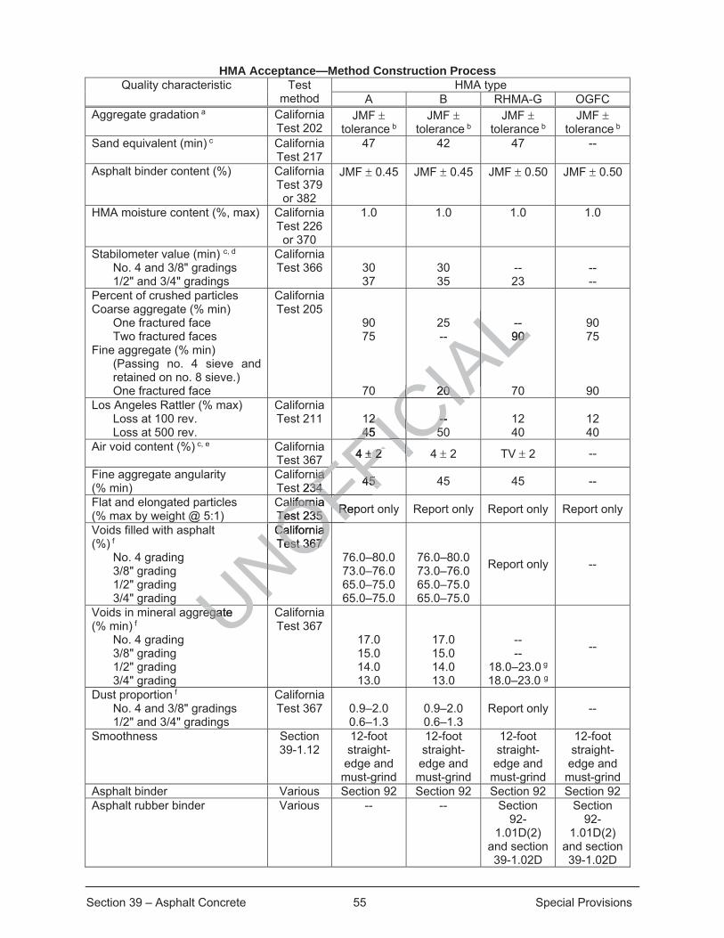
Section 39 – Asphalt Concrete 55 Special Provisions
HMA Acceptance—Method Construction Process Quality characteristic Test
method HMA type
A B RHMA-G OGFC Aggregate gradation a California
Test 202 JMF
tolerance b JMF
tolerance b JMF
tolerance b JMF
tolerance b Sand equivalent (min) c California
Test 217 47 42 47 --
Asphalt binder content (%) California Test 379 or 382
JMF 0.45 JMF 0.45 JMF 0.50 JMF 0.50
HMA moisture content (%, max) California Test 226 or 370
1.0 1.0 1.0 1.0
Stabilometer value (min) c, d No. 4 and 3/8" gradings 1/2" and 3/4" gradings
California Test 366
30 37
30 35
-- 23
-- --
Percent of crushed particles Coarse aggregate (% min)
One fractured face Two fractured faces
Fine aggregate (% min) (Passing no. 4 sieve and retained on no. 8 sieve.) One fractured face
California Test 205
90 75
70
25 --
20
-- 90
70
90 75
90 Los Angeles Rattler (% max)
Loss at 100 rev. Loss at 500 rev.
California Test 211
12 45
-- 50
12 40
12 40
Air void content (%) c, e California Test 367 4 2 4 2 TV 2 --
Fine aggregate angularity (% min)
California Test 234 45 45 45 --
Flat and elongated particles (% max by weight @ 5:1)
California Test 235 Report only Report only Report only Report only
Voids filled with asphalt (%) f
No. 4 grading 3/8" grading 1/2" grading 3/4" grading
California Test 367
76.0–80.0 73.0–76.0 65.0–75.0 65.0–75.0
76.0–80.0 73.0–76.0 65.0–75.0 65.0–75.0
Report only --
Voids in mineral aggregate (% min) f
No. 4 grading 3/8" grading 1/2" grading 3/4" grading
California Test 367
17.0 15.0 14.0 13.0
17.0 15.0 14.0 13.0
-- --
18.0–23.0 g
18.0–23.0 g
--
Dust proportion f No. 4 and 3/8" gradings 1/2" and 3/4" gradings
California Test 367
0.9–2.0 0.6–1.3
0.9–2.0 0.6–1.3
Report only --
Smoothness Section 39-1.12
12-foot straight-
edge and must-grind
12-foot straight-
edge and must-grind
12-foot straight-
edge and must-grind
12-foot straight-
edge and must-grind
Asphalt binder Various Section 92 Section 92 Section 92 Section 92 Asphalt rubber binder Various -- -- Section
92-1.01D(2)
and section 39-1.02D
Section 92-
1.01D(2) and section 39-1.02D
UNOFFICIA
L20 20
-- 90 90
CAL
2 2 45 45
-- --55CI
IC4 2 2 FICF
ICnia nia
t 234 234 45 45 FFOFalifornia alifornia
Test 235 Test 235 RepoRe
OFOFCalifornia California Test 367 Test 367 ONOO
egate egatU
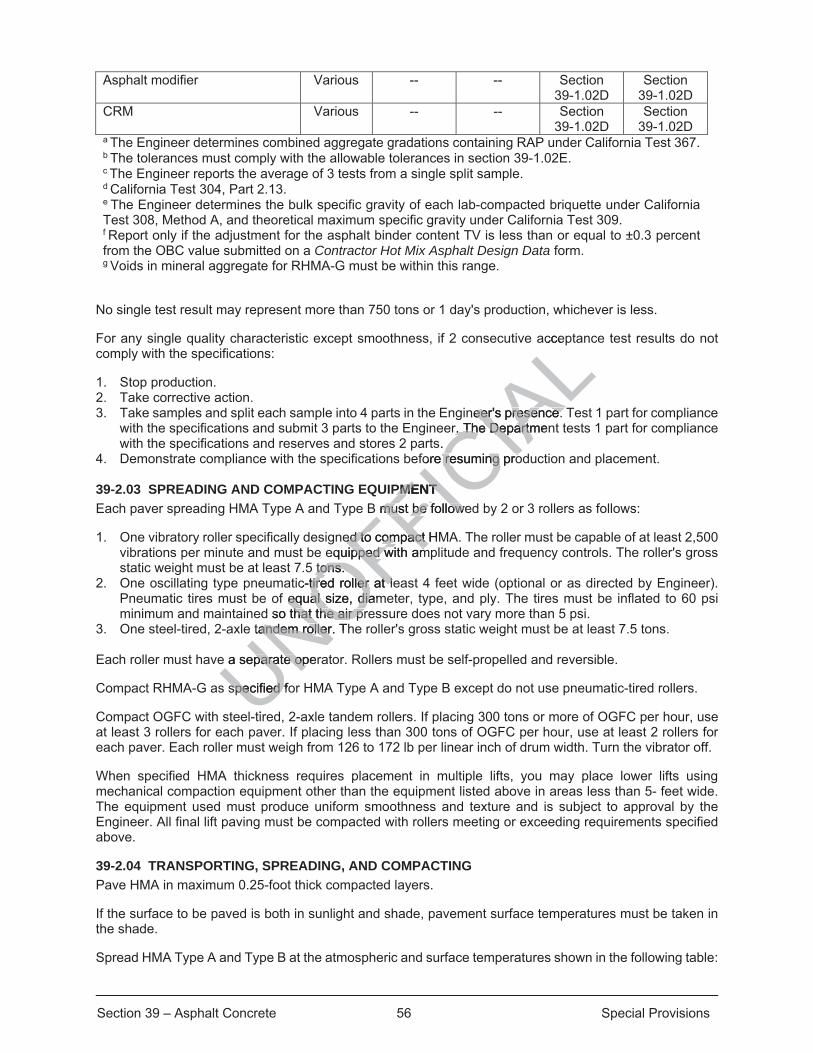
Section 39 – Asphalt Concrete 56 Special Provisions
Asphalt modifier Various -- -- Section 39-1.02D
Section 39-1.02D
CRM Various -- -- Section 39-1.02D
Section 39-1.02D
a The Engineer determines combined aggregate gradations containing RAP under California Test 367. b The tolerances must comply with the allowable tolerances in section 39-1.02E. c The Engineer reports the average of 3 tests from a single split sample. d California Test 304, Part 2.13. e The Engineer determines the bulk specific gravity of each lab-compacted briquette under California Test 308, Method A, and theoretical maximum specific gravity under California Test 309. f Report only if the adjustment for the asphalt binder content TV is less than or equal to ±0.3 percent from the OBC value submitted on a Contractor Hot Mix Asphalt Design Data form. g Voids in mineral aggregate for RHMA-G must be within this range.
No single test result may represent more than 750 tons or 1 day's production, whichever is less.
For any single quality characteristic except smoothness, if 2 consecutive acceptance test results do not comply with the specifications:
1. Stop production. 2. Take corrective action. 3. Take samples and split each sample into 4 parts in the Engineer's presence. Test 1 part for compliance
with the specifications and submit 3 parts to the Engineer. The Department tests 1 part for compliance with the specifications and reserves and stores 2 parts.
4. Demonstrate compliance with the specifications before resuming production and placement. 39-2.03 SPREADING AND COMPACTING EQUIPMENT Each paver spreading HMA Type A and Type B must be followed by 2 or 3 rollers as follows:
1. One vibratory roller specifically designed to compact HMA. The roller must be capable of at least 2,500 vibrations per minute and must be equipped with amplitude and frequency controls. The roller's gross static weight must be at least 7.5 tons.
2. One oscillating type pneumatic-tired roller at least 4 feet wide (optional or as directed by Engineer). Pneumatic tires must be of equal size, diameter, type, and ply. The tires must be inflated to 60 psi minimum and maintained so that the air pressure does not vary more than 5 psi.
3. One steel-tired, 2-axle tandem roller. The roller's gross static weight must be at least 7.5 tons. Each roller must have a separate operator. Rollers must be self-propelled and reversible.
Compact RHMA-G as specified for HMA Type A and Type B except do not use pneumatic-tired rollers.
Compact OGFC with steel-tired, 2-axle tandem rollers. If placing 300 tons or more of OGFC per hour, use at least 3 rollers for each paver. If placing less than 300 tons of OGFC per hour, use at least 2 rollers for each paver. Each roller must weigh from 126 to 172 lb per linear inch of drum width. Turn the vibrator off.
When specified HMA thickness requires placement in multiple lifts, you may place lower lifts using mechanical compaction equipment other than the equipment listed above in areas less than 5- feet wide. The equipment used must produce uniform smoothness and texture and is subject to approval by the Engineer. All final lift paving must be compacted with rollers meeting or exceeding requirements specified above.
39-2.04 TRANSPORTING, SPREADING, AND COMPACTING Pave HMA in maximum 0.25-foot thick compacted layers.
If the surface to be paved is both in sunlight and shade, pavement surface temperatures must be taken in the shade.
Spread HMA Type A and Type B at the atmospheric and surface temperatures shown in the following table:
UNOFFICIA
Lacce
neer's presence. eer's presence. r. The Departmenr. The Departm
s. fore resuming proresuming pro
PMENT PMENT B must be followeB must be follow
ed to compact ed to compact HMequipped with ampped with am
tons. tons. c-tired roller at letired roller at le
f equal size, diamequal size, dia so that the air prthat the air pr
tandem roller. Thandem roller
e a separate opere a separate op
specified fospecified f
ti
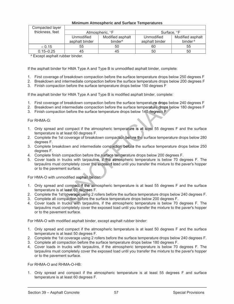
Section 39 – Asphalt Concrete 57 Special Provisions
Minimum Atmospheric and Surface Temperatures Compacted layer
thickness, feet
Atmospheric, F Surface, F Unmodified
asphalt binder Modified asphalt
bindera Unmodified
asphalt binder Modified asphalt
binder a 0.15 55 50 60 55
0.15–0.25 45 45 50 50 a Except asphalt rubber binder.
If the asphalt binder for HMA Type A and Type B is unmodified asphalt binder, complete:
1. First coverage of breakdown compaction before the surface temperature drops below 250 degrees F 2. Breakdown and intermediate compaction before the surface temperature drops below 200 degrees F 3. Finish compaction before the surface temperature drops below 150 degrees F If the asphalt binder for HMA Type A and Type B is modified asphalt binder, complete:
1. First coverage of breakdown compaction before the surface temperature drops below 240 degrees F 2. Breakdown and intermediate compaction before the surface temperature drops below 180 degrees F 3. Finish compaction before the surface temperature drops below 140 degrees F For RHMA-G:
1. Only spread and compact if the atmospheric temperature is at least 55 degrees F and the surface temperature is at least 60 degrees F.
2. Complete the 1st coverage of breakdown compaction before the surface temperature drops below 280 degrees F.
3. Complete breakdown and intermediate compaction before the surface temperature drops below 250 degrees F.
4. Complete finish compaction before the surface temperature drops below 200 degrees F. 5. Cover loads in trucks with tarpaulins, if the atmospheric temperature is below 70 degrees F. The
tarpaulins must completely cover the exposed load until you transfer the mixture to the paver's hopper or to the pavement surface.
For HMA-O with unmodified asphalt binder:
1. Only spread and compact if the atmospheric temperature is at least 55 degrees F and the surface temperature is at least 60 degrees F.
2. Complete the 1st coverage using 2 rollers before the surface temperature drops below 240 degrees F. 3. Complete all compaction before the surface temperature drops below 200 degrees F. 4. Cover loads in trucks with tarpaulins, if the atmospheric temperature is below 70 degrees F. The
tarpaulins must completely cover the exposed load until you transfer the mixture to the paver's hopper or to the pavement surface.
For HMA-O with modified asphalt binder, except asphalt rubber binder:
1. Only spread and compact if the atmospheric temperature is at least 50 degrees F and the surface temperature is at least 50 degrees F.
2. Complete the 1st coverage using 2 rollers before the surface temperature drops below 240 degrees F. 3. Complete all compaction before the surface temperature drops below 180 degrees F. 4. Cover loads in trucks with tarpaulins, if the atmospheric temperature is below 70 degrees F. The
tarpaulins must completely cover the exposed load until you transfer the mixture to the paver's hopper or to the pavement surface.
For RHMA-O and RHMA-O-HB:
1. Only spread and compact if the atmospheric temperature is at least 55 degrees F and surface temperature is at least 60 degrees F.
ture drops ureerature drops beure drops be
140 degrees F 40 degrees F
rature is at least ature is at least
ction before the sction before the
mpaction before tpaction before
e surface tempera surface tempeins, if the if the atmos
r the exposed loathe exposed
asphalt binder: alt binder:
ompact if the atmmpact if the atmleast 60 degrees60 degre
t coverage usint coverage usinaction befoaction bef
s withs with
Section 39 – Asphalt Concrete 58 Special Provisions
2 Complete the 1st coverage using 2 rollers before the surface temperature drops below 280 degrees F. 3. Complete compaction before the surface temperature drops below 250 degrees F. 4. Cover loads in trucks with tarpaulins, if the atmospheric temperature is below 70 degrees F. The
tarpaulins must completely cover the exposed load until you transfer the mixture to the paver's hopper or to the pavement surface.
For RHMA-G and OGFC, tarpaulins are not required if the time from discharging to the truck until transfer to the paver's hopper or the pavement surface is less than 30 minutes.
HMA compaction coverage is the number of passes needed to cover the paving width. A pass is 1 roller's movement parallel to the paving in either direction. Overlapping passes are part of the coverage being made and are not a subsequent coverage. Do not start a coverage until completing the prior coverage.
Start rolling at the lower edge and progress toward the highest part.
Perform breakdown compaction of each layer of HMA Type A, Type B, and RHMA-G with 3 coverages using a vibratory roller. The speed of the vibratory roller in miles per hour must not exceed the vibrations per minute divided by 1,000. If the thickness of the HMA layer is less than 0.08 foot, turn the vibrator off. The Engineer may order fewer coverages if the thickness of the HMA layer is less than 0.15 foot.
Perform intermediate compaction of each layer of HMA Type A and Type B with 3 coverages using a pneumatic-tired roller at a speed not exceeding 5 mph.
Perform finish compaction of HMA Type A, Type B, and RHMA-G with 1 coverage using a steel-tired roller.
Compact OGFC with 2 coverages using steel-tired rollers.
39-3 EXISTING ASPHALT CONCRETE 39-3.01 GENERAL
39-3.01A General
Section 39-3.01 includes general specifications for performing work on existing asphalt concrete facilities.
Work performed on existing asphalt concrete facilities must comply with section 15.
39-3.01B Materials
Not Used
39-3.01C Construction
Before removing a portion of an asphalt concrete facility, make a 2-inch deep saw cut to a true line along the limits of the removal area.
39-3.01D Payment
Not Used
39-3.02 REPLACE ASPHALT CONCRETE SURFACING
39-3.02A General
Section 39-3.02 includes specifications for replacing asphalt concrete surfacing
39-3.02B Materials
HMA to be used for replacing asphalt concrete surfacing must comply with Type A HMA as specified in section 39-2.
.0r is less
d Type B with 3d Type B with 3
A-G with 1 covera with 1 co
s.
ASPHALT CONCASPHALT C
ecifications for peecifications for
phalt concrete fachalt concrete fa
on on
of
Section 39 – Asphalt Concrete 59 Special Provisions
The grade of asphalt binder must be PG 64-10.
Tack coat must comply with section 39-1.02B.
39-3.02C Construction
Where replace asphalt concrete surfacing is shown, remove the full depth of the existing asphalt concrete surfacing and replace with HMA. The Engineer determines the exact limits of asphalt concrete surfacing to be replaced.
Replace asphalt concrete in a lane before the lane is specified to be opened to traffic.
Before removing asphalt concrete, outline the replacement area and cut neat lines with a saw or grind to full depth of the existing asphalt concrete. Do not damage asphalt concrete and base remaining in place.
If you excavate the base beyond the specified plane, replace it with HMA.
Do not use a material transfer vehicle for replacing asphalt concrete surfacing.
Before placing HMA, apply a tack coat as specified in section 39-1.09C.
Place HMA using method compaction as specified in section 39-2.
39-3.02D Payment
The payment quantity for replace asphalt concrete surfacing is the volume determined from the dimensions shown.
39-3.03 REMOVE ASPHALT CONCRETE DIKES
39-3.03A General
Section 39-3.03 applies to removing asphalt concrete dikes outside the limits of excavation.
39-3.03B Materials
Not Used
39-3.03C Construction
Reserved
39-3.03D Payment
Not Used
39-3.04 COLD PLANING ASPHALT CONCRETE PAVEMENT
39-3.04A General
Section 39-3.05 includes specifications for cold planning asphalt concrete pavement.
Cold planning asphalt concrete pavement includes the removal of pavement markers, traffic stripes, and pavement markings within the area of cold planning.
39-3.04B Materials
HMA for temporary tapers must be of the same quality that is used for the HMA overlay or comply with the specifications for minor HMA in section 39-1.15.
39-3.04C Construction
39-3.04C(1) General
UNOFFICIA
Lg is the volume deg is the volume d
alt coalt c ncrete dikescrete dik
Section 39 – Asphalt Concrete 60 Special Provisions
Do not use a heating device to soften the pavement.
The cold planing machine must be:
1. Equipped with a cutter head width that matches the planing width unless a wider cutter head is authorized.
2. Equipped with automatic controls for the longitudinal grade and transverse slope of the cutter head and: 2.1. If a ski device is used, it must be at least 30 feet long, rigid, and a 1-piece unit. The entire length
must be used in activating the sensor. 2.2. If referencing from existing pavement, the cold planing machine must be controlled by a self-
contained grade reference system. The system must be used at or near the centerline of the roadway. On the adjacent pass with the cold planing machine, a joint-matching shoe may be used.
3. Equipped to effectively control dust generated by the planing operation 4. Operated such that no fumes or smoke is produced. Replace broken, missing, or worn machine teeth.
If you do not complete placing the HMA surfacing before opening the area to traffic, you must:
1. Construct a temporary HMA taper to the level of the existing pavement. 2. Place HMA during the next work shift. 3. Submit a corrective action plan that shows you will complete cold planing and placement of HMA in the
same work shift. Do not restart cold planing activities until the corrective action plan is authorized. 39-3.04C(2) Grade Control and Surface Smoothness
Install and maintain grade and transverse slope references.
The final cut must result in a neat and uniform surface.
The completed surface of the planed pavement must not vary more than 0.02 foot when measured with a 12-foot straightedge parallel with the centerline. With the straightedge at right angles to the centerline, the transverse slope of the planed surface must not vary more than 0.03 foot.
Where lanes are open to traffic, the drop-off of between adjacent lanes must not be more than 0.15 foot.
39-3.04C(3) Planed Material
Remove cold planed material concurrently with planing activities such that the removal does not lag more than 50 feet behind the planer.
39-3.04C(4) Temporary HMA Tapers
If a drop-off between the existing pavement and the planed area at transverse joints cannot be avoided before opening to traffic, construct a temporary HMA taper. The HMA temporary taper must be:
1. Placed to the level of the existing pavement and tapered on a slope of 30:1 (horizontal:vertical) or flatter to the level of the planed area
2. Compacted by any method that will produce a smooth riding surface Completely remove temporary tapers before placing permanent surfacing.
39-3.04D Payment
Not Used
39-3.05 REMOVE BASE AND SURFACING
39-3.05A General
UNOFFICIA
Lea to traffic, ya to t
avement. ement.
ete cold cold planing aanintil the correctiventil the correctiv
ss ss
references. eferences.
m surface. m surface.
avement must noavement mcenterline. With centerline. W
rface must not vace must not va
fic, the drop-off ofhe drop-off of
aterial erial
material concumaterial concue planer. e planer.
M
Section 39 – Asphalt Concrete 61 Special Provisions
Section 39-3.06 includes specifications for removing base and asphalt concrete surfacing.
39-3.05B Materials
Not Used
39-3.05C Construction
Where base and surfacing are described to be removed, remove base and surfacing to a depth of at least 6 inches below the grade of the existing surfacing. Backfill resulting holes and depressions with embankment material under section 19.
39-3.05D Payment
The payment quantity for remove base and surfacing is the volume determined from the dimensions shown.
39-3.06–39-3.08 RESERVED
UNOFFICIA
L
Section 73 – Concrete Curbs and Sidewalks 62 Special Provisions
^^^^^^^^^^^^^^^^^^^^^^^^^^^^^^^^^^^^^^^^^^^^^^^^^^^^^^^^^^^^
DIVISION VIII MISCELLANEOUS CONSTRUCTION
^^^^^^^^^^^^^^^^^^^^^^^^^^^^^^^^^^^^^^^^
73 CONCRETE CURBS AND SIDEWALKS
Add to section 73-1.03B: Subgrade material below curbs, gutter depressions, sidewalk, and driveways shall be compacted to at least 95 percent relative compaction for at least a depth of 0.5 foot below the subgrade elevation.
Replace section 73-3.04 with: Payment for Minor Concrete (Curb Ramp) shall be per each return from beginning of curb return to end of curb return between gutter lip and right of way or easement, and includes all sidewalk, curb, gutter, curb ramp, concrete, excavation, backfill, detectable warning surface and all other work involved therewith.
Replace section 73-10.04 with: Full compensation for removal or existing concrete curb, gutter depressions, sidewalk and driveways shall be considered as included in the related items of work involved and no additional compensation will be allowed thereof.
UNOFFICIA
Lsu
n from beginning m beginning d includes all sideincludes all sid
ace and all other ace and all oth
on 73-10.04 withon 73-10.04 withete curb, gutter dete curb, gutter
s of work involvedof work involved

Section 80 – Fences 63 Special Provisions
^^^^^^^^^^^^^^^^^^^^^^^^^^^^^^^^^^^^^^^^
80 FENCES
Replace section 80-15.04 RESERVED with the following:
80-15.04 Remove Fence
Remove existing fence to the limits shown on the plans and as directed by the Engineer. Remove all fencing, gates, posts, foundations and all other fence elements completely. Payment for remove fence shall be measured per lineal foot of fence actually removed, measured along the ground surface.
UNOFFICIA
L

Section 82 – Signs and Markers 64 Special Provisions
^^^^^^^^^^^^^^^^^^^^^^^^^^^^^^^^^^^^^^^^^^^^^^^^^^^^^^^^^^^^
DIVISION IX TRAFFIC CONTROL DEVICES
^^^^^^^^^^^^^^^^^^^^^^^^^^^^^^^^^^^^^^^^
82 SIGNS AND MARKERS
Add to Section 82-2.02A:
All proposed signs shown in the plans must have a sign face reflective material that is “High Intensity Prismatic” (HIP) or equivalent.
All signs must have a graffiti protective face for easy maintenance and shall be a 3-M 1160 Protective Sheeting or approved equal.
All sign panels not reused on the project shall be returned to Tulare County Resource Management Agency or to the Engineer for recycle.
Replace Section 82-2.04:
Payment for furnishing sign panels shall be included in payment for the sign assembly.
Add to section 82-3.02A:
All sign panels shall be unframed single sheet aluminum measuring 0.080” in thickness and shall comply with the requirements of section 82-2.02E
Add to section 82-3.02E:
The top-bolt on each sign shall be mounted with model #M2G-VP56N 5/16 vandal proof nut (or approved equal).
Replace Last paragraph of Section 82-3.04 with:
Payment for furnishing all materials including post, hardware, sign panels, and post anchorage shall be included in the payment for roadside sign and no additional payment will be granted.
UNOFFICIA
Lbe a
County ResourceCounty Resource
82-2.04: 82-2
n payment for then payment for th
to section 82-3.to section
sheet aluminum eet aluminum .02E .02E
Add tAdd t
gn shall be mount shall be mount
Re
Section 84 – Markings 65 Special Provisions
84 MARKINGS
Replace Reserved in section 84-9.03C with: The project location in Poplar will have residue from the removal of painted or thermoplastic traffic stripes and pavement markings contains lead from the paint or thermoplastic. The average lead concentrations are less than 1,000 mg/kg total lead and 5 mg/L soluble lead. This residue:
1. Is a nonhazardous waste 2. Does not contain heavy metals in concentrations exceeding the thresholds established by the Health
and Safety Code and 22 CA Code of Regs 3. Is not regulated under the Federal Resource Conservation and Recovery Act (RCRA), 42 USC §
6901 et seq. Management of this material exposes workers to health hazards that must be addressed in your lead compliance plan.
UNOFFICIA
L
Section 86 – General 66 Special Provisions
^^^^^^^^^^^^^^^^^^^^^^^^^^^^^^^^^^^^^^^^^^^^^^^^^^^^^^^^^^^^
DIVISION X ELECTRICAL WORK
^^^^^^^^^^^^^^^^^^^^^^^^^^^^^^^^^^^^^^^^
86 GENERAL
Replace Section 86-1.03 of the RSS with:
Furnish and install new pedestrian push button assembly(PBA) with sign post. Extend conduits from the existing traffic signal pole pull box to the new pull box adjacent to the pedestrian PBA pole and connect to the existing pedestrian traffic signal. The pedestrian PBA shall be installed as shown in the Caltrans RSP ES-7A. See plan for locations and other details.
Replace Section 86-1.04 of the RSS with:
Payment for furnishing and installing the new pedestrian push button assembly post shall be paid for as a single unit. This payment shall include the work to extend the conduits from the existing traffic signal pole pull box to the new pedestrian push button assembly pull box, splicing the conductors, adjacent No. 5 (T) pull box with extension, and installing the required base plate component.
UNOFFICIA
Lstrian
ed as showd a
RSS with: with:
h button assemblh button assethe conduits fromhe conduits from
ull box, splicing thbox, splicing thse plate componee plate compon
Section 87 – Electrical Systems 67 Special Provisions
^^^^^^^^^^^^^^^^^^^^^^^^^^^^^^^^^^^^^^^^
87 ELECTRICAL SYSTEMS
Add to Section 87-7.02 of the RSS:
Battery shall be field replaceable with a lifespan of minimum 3 years, flash pattern shall comply with the most updated Caltrans MUTCD standards, and shall have at least 3 years of manufacturer warranty.
Replace Section 87-7.04 of the RSS with :
The Payment of the Rectangular Rapid Flashing Beacon shall be considered as included in the payment for “Flashing Beacon System”. The payment includes materials and installation for both RRFB system’s complete in place including post anchorage system, post, hardware, sign panel, top-of-pole self-contained control cabinet, rectangular rapid flashing beacon assembly, push button assembly, batteries, and all other materials required for a complete and operational system.
Replace Section 87-21.03B(1) of the RSS with:
Keep existing electrical system (traffic signal and pedestrian heads/pushbuttons) or authorized temporary replacement in working order during the progress of the work. Traffic signal shutdown must be limited to normal working hours and the Contractor shall be fully responsible to implement an authorized temporary replacement system or provide traffic during any shutdown work. Lighting system shutdown must not interfere with the regular lighting schedule. Notify Engineer before performing work on the existing system.
UNOFFICIA
Lemb
SS with: SS with:
ads/pushbuttons) ds/pushbuttons) k. Traffic signal shTraffic sign
ponsible to implemonsible to impledown work. Lightwn work. Ligh
neer before perfoneer before per

This page intentionally left blank
UNOFFICIA
Ltentionalltentional
69 Revised Standard Specifications
Page 1 of 108
REVISED STANDARD SPECIFICATIONS 2015 DATED 4-20-18
ORGANIZATION Revised standard specifications are under headings that correspond with the main-section headings of the Standard Specifications. A main-section heading is a heading shown in the table of contents of the Standard Specifications. A date under a main-section heading is the date of the latest revision to the section.
Each revision to the Standard Specifications begins with a revision clause that describes or introduces a revision to the Standard Specifications. For a revision clause that describes a revision, the date on the right above the clause is the publication date of the revision. For a revision clause that introduces a revision, the date on the right above a revised term, phrase, clause, paragraph, or section is the publication date of the revised term, phrase, clause, paragraph, or section. For a multiple-paragraph or multiple-section revision, the date on the right above a paragraph or section is the publication date of the paragraphs or sections that follow.
Any paragraph added or deleted by a revision clause does not change the paragraph numbering of the Standard Specifications for any other reference to a paragraph of the Standard Specifications.
^^^^^^^^^^^^^^^^^^^^^^^^^^^^^^^^^^^^^^^^^^^^^^^^^^^^^^^^^^^^
DIVISION I GENERAL PROVISIONS 1 GENERAL
04-20-18 01-20-17
Delete item 1 in the list in the 12th paragraph of section 1-1.01.
Add to the 1st table of section 1-1.06: 07-21-17
APCD air pollution control district AQMD air quality management district CISS cast-in-steel shell CSL crosshole sonic logging CSS cement stabilized soil GGL gamma-gamma logging
Replace plant establishment period and its definition in section 1-1.07B with: 01-20-17
plant establishment period: Number of working days shown on the Notice to Bidders for plant establishment work.
Add to section 1-1.07B:
lutiUNOFFICIA
Laus
graph, or graion. Fo. For a multr a mult
section is tsection is the pubhe pu
ot change the part change theraph of the aph of the StandStand
^^^^^^^^^^^^^^^^^^^^^^^^^
I GENERAL GENERA1 GEN1 GE
0
tem 1 in the list tem 1 in the list
AdAdU
70 Revised Standard Specifications
01-20-17 permanent erosion control establishment period: Number of working days shown on the Notice to
Bidders for permanent erosion control establishment work.
07-21-17 traffic break: Traffic operation performed by a California Highway Patrol officer or other law enforcement
officer to slow or stop traffic within the traveled way.
Replace the 1st row of the table in section 1-1.11 with: 07-21-17
Authorized Facility Audit List
http://www.dot.ca.gov/hq/esc/Translab/OSM/documents/smdocuments/Internet_auditlisting.pdf
-- --
Authorized Material List
http://www.dot.ca.gov/hq/esc/approved_products_list/ -- --
Authorized Material Source List
http://www.dot.ca.gov/hq/esc/Translab/authorized_material_source_list/ -- --
Authorized Material Systems List
http://www.dot.ca.gov/hq/esc/Translab/authorized_systems_list/ -- --
Authorized Laboratory List
http://www.dot.ca.gov/hq/esc/Translab/authorized_laboratories_list/ -- --
12-02-16 Delete the row for Bidders' Exchange in the table of section 1-1.11.
^^^^^^^^^^^^^^^^^^^^^^^^^^^^^^^^^^^^^^^^
2 BIDDING 07-21-17
Replace the headings and paragraphs of section 2 with: 12-02-16
2-1.01 GENERAL
Section 2 includes specifications related to bid eligibility and the bidding process.
2-1.02 BID INELIGIBILITY
A firm that has provided architectural or engineering services to the Department for this contract before bid submittal for this contract is prohibited from any of the following:
1. Submitting a bid 2. Subcontracting for a part of the work 3. Supplying materials 2-1.03 CONTRACTOR REGISTRATION
No contractor or subcontractor may be listed on a bid proposal for a public works project unless registered with the Department of Industrial Relations pursuant to Labor Code section 1725.5 [with limited exceptions from this requirement for bid purposes only under Labor Code section 1771.1(a)].
UNOFFICIA-- -- CIA
LAL-- -- ALALCIA
FIFIFICidders' Exchangdders' Ex
^^^^^^^^^^^^^^^^^^^^^^^^
Replace the Replace the
71 Revised Standard Specifications
01-20-17 2-1.04 PREBID OUTREACH MEETING
Section 2-1.04 applies if a mandatory prebid meeting is shown on the Notice to Bidders.
The Department will conduct a meeting to provide small businesses, including DVBEs and DBEs, the opportunity to meet and interact with prospective bidders in an effort to increase their participation in the performance of contracts.
Each bidder must attend the meeting. The bidder's representative must be a company officer, project superintendent, or project estimator. For a joint venture, one of the parties must attend the mandatory prebid meeting.
The Department does not accept a bid from a bidder who did not attend the meeting.
A sign-in sheet will be used to identify the attendees. Each bidder must include the name and title of the company representative attending the meeting.
The Department may hold a single prebid meeting for more than one contract. Sign the sign-in sheet for the contract you intend to bid on. If you are bidding on multiple contracts, sign each sign-in sheet for each contract you intend to bid on. The sign-in sheets, with the names of all companies in attendance at each prebid meeting, will be made available at the website shown on the Notice to Bidders for bidder inquiries.
The successful bidder is required to report each small business hired to work on this Contract as a result of the meeting.
2-1.05 RESERVED 12-02-16
2-1.06 BID DOCUMENTS
2-1.06A General
The Bid book includes bid forms and certifications, including forms not submitted through the electronic bidding service.
The Notice to Bidders and Special Provisions includes the Notice to Bidders, revised standard specifications, and special provisions.
The Bid book, including Bid book forms not available through the electronic bidding service, Notice to Bidders and Special Provisions, project plans, and any addenda to these documents may be accessed at the Department's Office of Construction Contract Awards website.
The Standard Specifications and Standard Plans may be viewed at the Department's Office of Construction Contract Awards website and may be purchased at the Publication Distribution Unit.
2-1.06B Supplemental Project Information
The Department makes supplemental information available as specified in the special provisions.
Logs of test borings are supplemental project information.
07-21-17 If an Information Handout or electronic design files are available, you may view them at the Contract Plans and Special Provisions link at the Department's Office of Construction Contract Awards website. Electronic design files contain design information such as cross sections, digital models, and roadway design alignments and profiles.
12-02-16 If rock cores are available, you may view them by sending a request to [email protected].
If other supplemental project information is available for inspection, you may view it by phoning in a request.
Make your request at least 7 days before viewing. Include in your request:
1. District-County-Route
UNOFFICIA
Ln ea
mpanies mpice to Biddersto Bidders
ed to work on thisto work on thi
ations, including fations, inclu
ovisionsovisions includesinclns. s.
ok forms not avak forms not avaonsons, project plans, project plans
of Constrf Construction Couction C
ficationsications and and StanStact Awards websct Awards w
ProjecProjec

72 Revised Standard Specifications
2. Contract number 3. Viewing date 4. Contact information, including telephone number
For rock cores, also include the bridge number in your request.
If bridge as-built drawings are available:
1. For a project in District 1 through 6 or 10, you may request them from the Office of Structure Maintenance and Investigations, fax (916) 227-8357
2. For a project in District 7, 8, 9, 11, or 12, you may request them from the Office of Structure Maintenance and Investigations, fax (916) 227-8357, and they are available at the Office of Structure Maintenance and Investigations, Los Angeles, CA, telephone (213) 897-0877
As-built drawings may not show existing dimensions and conditions. Where new construction dimensions are dependent on existing bridge dimensions, verify the field dimensions and adjust the dimensions of the work to fit the existing conditions.
2-1.06C–2-1.06D Reserved
2-1.07 JOB SITE AND DOCUMENT EXAMINATION
Examine the job site and bid documents. Notify the Department of apparent errors and patent ambiguities in the plans, specifications, and Bid Item List. Failure to do so may result in rejection of a bid or rescission of an award.
Bid submission is your acknowledgment that you have examined the job site and bid documents and are satisfied with:
1. General and local conditions to be encountered 2. Character, quality, and scope of work to be performed 3. Quantities of materials to be furnished 4. Character, quality, and quantity of surface and subsurface materials or obstacles 5. Requirements of the contract 2-1.08 RESERVED
2-1.09 BID ITEM LIST
Submit a bid based on the bid item quantities shown on the Bid Item List.
2-1.10 SUBCONTRACTOR LIST
On the Subcontractor List form, list each subcontractor that will perform work in an amount in excess of 1/2 of 1 percent of the total bid or $10,000, whichever is greater (Pub Cont Code § 4100 et seq.).
For each subcontractor listed, the Subcontractor List form must show:
1. Business name and the location of its place of business. 2. California contractor license number for a non-federal-aid contract. 3. Public works contractor registration number. 4. Portion of work it will perform. Show the portion of the work by:
4.1. Bid item numbers for the subcontracted work 4.2. Percentage of the subcontracted work for each bid item listed 4.3. Description of the subcontracted work if the percentage of the bid item listed is less than 100
percent
2-1.11 RESERVED
2-1.12 DISADVANTAGED BUSINESS ENTERPRISES
2-1.12A General
Section 2-1.12 applies to a federal-aid contract.
UNOFFICIA
Lapparent errors aparent errors aay result in rejectay result in rejec
xamined the job smined the job s
d d performed performe
ace and subsurfaace and subsu
e bid item quantitie bid item quan
ACTOR LIST R LIST
List form, lisList form, tal bid tal bid
73 Revised Standard Specifications
Under 49 CFR 26.13(b):
The contractor, sub recipient or subcontractor shall not discriminate on the basis of race, color, national origin, or sex in the performance of this contract. The contractor shall carry out applicable requirements of 49 CFR part 26 in the award and administration of DOT-assisted contracts. Failure by the contractor to carry out these requirements is a material breach of this contract, which may result in the termination of this contract or such other remedy as the recipient deems appropriate, which may include, but is not limited to:
(1) Withholding monthly progress payments; (2) Assessing sanctions; (3) Liquidated damages; and/or (4) Disqualifying the contractor from future bidding as non-responsible.
Include this assurance in each subcontract you sign with a subcontractor.
2-1.12B Disadvantaged Business Enterprise Goal
2-1.12B(1) General
Section 2-1.12B applies if a DBE goal is shown on the Notice to Bidders.
The Department shows a goal for DBEs to comply with the DBE program objectives provided in 49 CFR 26.1.
Make work available to DBEs and select work parts consistent with the available DBEs, including subcontractors, suppliers, service providers, and truckers.
Meet the DBE goal shown on the Notice to Bidders or demonstrate that you made adequate good faith efforts to meet this goal.
You are responsible to verify at bid opening the DBE firm is certified as a DBE by the California Unified Certification Program and possesses the work codes applicable to the type of work the firm will perform on the Contract.
Determine that selected DBEs perform a commercially useful function for the type of work the DBE will perform on the Contract as provided in 49 CFR 26.55(c)(1)–(4). Under 49 CFR 26.55(c)(1)–(4), the DBE must be responsible for the execution of a distinct element of work and must carry out its responsibility by actually performing, managing, and supervising the work.
All DBE participation will count toward the Department's federally mandated statewide overall DBE goal.
Credit for materials or supplies you purchase from DBEs will be evaluated on a contract-by-contract basis and counts toward the goal in the following manner:
1. 100 percent if the materials or supplies are obtained from a DBE manufacturer. 2. 60 percent if the materials or supplies are obtained from a DBE regular dealer. 3. Only fees, commissions, and charges for assistance in the procurement and delivery of materials or
supplies if they are obtained from a DBE that is neither a manufacturer nor a regular dealer. 49 CFR 26.55 defines manufacturer and regular dealer.
You receive credit toward the goal if you employ a DBE trucking company that is performing a commercially useful function. The Department uses the following factors in determining whether a DBE trucking company is performing a commercially useful function:
• The DBE must be responsible for the management and supervision of the entire trucking operation for which it is responsible on a particular contract, and there cannot be a contrived arrangement for the purpose of meeting DBE goals.
• The DBE must itself own and operate at least one fully licensed, insured, and operational truck used on the contract.
• The DBE receives credit for the total value of the transportation services it provides on the Contract using trucks it owns, insures, and operates using drivers it employs.
UNOFFICIA
Ls.
ogram objectivesram objectives
ent with the availaent with the ava.
r demonstrate thar demonstrate th
he DBE fie DBE firm is cerrm is ceork codes ork codes applicaap
rm a commercialrm a commerced in 49 CFR 26in 49 CFR 26
ecution of a distincution of a disting, and supervising, and supervisi
l count toward thcount toward th
or supplies yor supplies you pu pgoal in the goal in th
eria
74 Revised Standard Specifications
• The DBE may lease trucks from another DBE firm, including an owner-operator who is certified as a DBE. The DBE who leases trucks from another DBE receives credit for the total value of the transportation services the lessee DBE provides on the Contract.
• The DBE may lease trucks without drivers from a non-DBE truck leasing company. If the DBE leases trucks from a non-DBE truck leasing company and uses its own employees as drivers, it is entitled to credit for the total value of these hauling services.
• A lease must indicate that the DBE has exclusive use of and control over the truck. This does not preclude the leased truck from working for others during the term of the lease with the consent of the DBE, so long as the lease gives the DBE absolute priority for use of the leased truck. Leased trucks must display the name and identification number of the DBE.
[49 CFR 26.55(d)] 2-1.12B(2) DBE Commitment Submittal
Submit DBE information under section 2-1.33.
Submit a copy of the quote from each DBE shown on the DBE Commitment form that describes the type and dollar amount of work shown on the form. Submit a DBE Confirmation form for each DBE shown on the DBE Commitment form to establish that it will be participating in the Contract in the type and dollar amount of work shown on the form. If a DBE is participating as a joint venture partner, submit a copy of the joint venture agreement.
2-1.12B(3) DBE Good Faith Efforts Submittal
You can meet the DBE requirements by either documenting commitments to DBEs to meet the Contract goal or by documenting adequate good faith efforts to meet the Contract goal. An adequate good faith effort means that the bidder must show that it took all necessary and reasonable steps to achieve a DBE goal that, by their scope, intensity, and appropriateness to the objective, could reasonably be expected to meet the DBE goal.
If you have not met the DBE goal, complete and submit the DBE Good Faith Efforts Documentation form under section 2-1.33 showing that you made adequate good faith efforts to meet the goal. Only good faith efforts directed toward obtaining participation by DBEs are considered.
Submit good faith efforts documentation within the specified time to protect your eligibility for award of the contract in the event the Department finds that the DBE goal has not been met.
Refer to 49 CFR 26 app A for guidance regarding evaluation of good faith efforts to meet the DBE goal.
The Department considers DBE commitments of other bidders in determining whether the low bidder made good faith efforts to meet the DBE goal.
2-1.13–2-1.14 RESERVED
2-1.15 DISABLED VETERAN BUSINESS ENTERPRISES
2-1.15A General
Section 2-1.15 applies to a non-federal-aid contract.
Take necessary and reasonable steps to ensure that DVBEs have the opportunity to participate in the Contract.
Comply with Mil & Vet Code § 999 et seq.
2-1.15B Projects $5 Million or Less
Section 2-1.15B applies to a project with an estimated cost of $5 million or less.
Make work available to DVBEs and select work parts consistent with the available DVBE subcontractors and suppliers.
Meet the goal shown on the Notice to Bidders.
UNOFFICIA
Lor
form foContract in tontr
venture partnerventure partner
ng commitments tg commitments meet the Contract t the Contract
necessary and rnecessary and eneness to the objecss to the objec
e and submit and submit the Dade adequate de adequate gogo
cipation by DBEs cipation by
ntation within the tion within the tment fiment finds that thnds that
for guidance regaor guidance
ders DBE commis DBE corts to meet the Drts to meet the
VED VED
75 Revised Standard Specifications
Complete and submit the Certified DVBE Summary form under section 2-1.33. List all DVBE participation on this form.
If a DVBE joint venture is used, submit the joint venture agreement with the Certified DVBE Summary form.
List each 1st-tier DVBE subcontractor on the Subcontractor List form regardless of its percentage of the total bid.
2-1.15C Projects More Than $5 Million
2-1.15C(1) General
Section 2-1.15C applies to a project with an estimated cost of more than $5 million.
The Department encourages bidders to obtain DVBE participation to ensure the Department achieves its State-mandated overall DVBE goal.
If you obtain DVBE participation:
1. Complete and submit the Certified DVBE Summary form under section 2-1.33. List all DVBE participation on this form.
2. List each 1st-tier DVBE subcontractor on the Subcontractor List form regardless of its percentage of the total bid.
If a DVBE joint venture is used, submit the joint venture agreement with the Certified DVBE Summary form.
2-1.15C(2) DVBE Incentive
The Department grants a DVBE incentive to each bidder who achieves a DVBE participation of 1 percent or greater (Mil & Vet Code 999.5 and Code of Regs § 1896.98 et seq.).
To receive this incentive, submit the Certified DVBE Summary form under section 2-1.33.
Bidders other than the apparent low bidder, the 2nd low bidder, and the 3rd low bidder may be required to submit the Certified DVBE Summary form if the bid ranking changes. If the Department requests a Certified DVBE Summary form from you, submit the completed form within 4 business days of the request.
2-1.15C(3) Incentive Evaluation
The Department applies the small business and non–small business preference during bid verification and proceeds with the evaluation specified below for the DVBE incentive.
The DVBE incentive is a reduction, for bid comparison only, in the submitted total bid by the lesser of the following amounts:
1. Percentage of the DVBE achievement rounded to 2 decimal places of the verified total bid of the low bidder
2. 5 percent of the verified total bid of the low bidder 3. $250,000 The Department applies the DVBE incentive and determines whether the bid ranking changes.
A non–small business bidder cannot displace a small business bidder. However, a small business bidder with a higher DVBE achievement can displace another small business bidder.
The Department proceeds with awarding the contract to the new low bidder and posts the new verified bid results at the Department's website.
2-1.16–2-1.17 RESERVED
2-1.18 SMALL BUSINESS AND NON–SMALL BUSINESS SUBCONTRACTOR PREFERENCES
UNOFFICIA
Ln 2-1.33
orm regardless oorm regardless o
ement with tment with the Ceh
bidder bidd who achiewho achieRegs § 1896.98 etegs § 1896.98
ed DVBE Summaed DVBE Sum
dder, the 2nd lowdder, the 2y form if the form if the bid rabid
om you, submit tyou, subm hh
aluation uation
es the small busie small bhe evaluation spe evaluation sp
reducti reducti

76 Revised Standard Specifications
2-1.18A General
Section 2-1.18 applies to a non-federal-aid contract.
The Department applies small business preferences and non–small business preferences under Govt Code § 14835 et seq. and 2 CA Code of Regs § 1896 et seq.
Any contractor, subcontractor, supplier, or service provider who qualifies as a small business is encouraged to apply for certification as a small business by submitting its application to the Department of General Services, Office of Small Business and DVBE Services.
Contract award is based on the total bid, not the reduced bid.
2-1.18B Small Business Preference
The Department allows a bidder certified as a small business by the Department of General Services, Office of Small Business and DVBE Services, a preference if:
1. Bidder submitted a completed Request for Small Business Preference or Non–Small Business Preference form with its bid
2. Low bidder did not request the preference or is not certified as a small business The Bidder's signature on the Request for Small Business Preference or Non–Small Business Preference form certifies that the Bidder is certified as a small business at the date and time of bid or has submitted a complete application to the Department of General Services. The complete application and any required substantiating documentation must be received by the Department of General Services by 5:00 p.m. on the bid opening date.
The Department of General Services determines whether a bidder was certified on the bid opening date. The Department of Transportation confirms the Bidder's status as a small business before applying the small business preference.
The small business preference is a reduction for bid comparison in the total bid submitted by the small business contractor by the lesser of the following amounts:
1. 5 percent of the verified total bid of the low bidder 2. $50,000 If the Department determines that a certified small business bidder is the low bidder after the application of the small business preference, the Department does not consider a request for non–small business preference.
2-1.18C Non–Small Business Subcontractor Preference
The Department allows a bidder not certified as a small business by the Department of General Services, Office of Small Business and DVBE Services, a preference if:
1. Bidder submitted a completed Request for Small Business Preference or Non–Small Business Preference form with its bid
2. Certified Small Business Listing for the Non–Small Business Preference form shows that you are subcontracting at least 25 percent to certified small businesses
Each listed subcontractor and supplier must be certified as a small business at the date and time of bid or must have submitted a complete application to the Department of General Services. The complete application and any required substantiating documentation must be received by the Department of General Services by 5:00 p.m. on the bid opening date.
The non–small business subcontractor preference is a reduction for bid comparison in the total bid submitted by the non–small business contractor requesting the preference by the lesser of the following amounts:
1. 5 percent of the verified total bid of the low bidder 2. $50,000
UNOFFICIA
Lbusinesb
e or Non–Small Be or Non–Small Bdate and time ofe and time of
he complete applie complete applrtment of Generartment of Gene
ther a bidder washer a bidder wader's status as a der's status as a
n for bid n for bid compariscomollowing amountslowing amount
of the low bidder of the low bid
s that a certified st a certified serence, the Deparence, the De
l Business Subl Business Sub
a biddera biddernd
77 Revised Standard Specifications
2-1.19–2-1.26 RESERVED
2-1.27 CALIFORNIA COMPANIES
Section 2-1.27 applies to a non-federal-aid contract.
Under Pub Cont Code § 6107, the Department gives preference to a California company, as defined, for bid comparison purposes over a nonresident contractor from any state that gives or requires a preference to be given to contractors from that state on its public entity construction contracts.
Complete a California Company Preference form.
The California company's reciprocal preference amount is equal to the preference amount applied by the state of the nonresident contractor with the lowest responsive bid unless the California company is eligible for a small business preference or a non–small business subcontractor preference, in which case the preference amount is the greater of the two, but not both.
If the low bidder is not a California company and a California company's bid with reciprocal preference is equal to or less than the lowest bid, the Department awards the contract to the California company on the basis of its total bid.
2-1.28–2-1.30 RESERVED
2-1.31 OPT OUT OF PAYMENT ADJUSTMENTS FOR PRICE INDEX FLUCTUATIONS
You may opt out of the payment adjustments for price index fluctuations specified in section 9-1.07. To opt out, submit a completed Opt Out of Payment Adjustments for Price Index Fluctuations form under section 2-1.33.
2-1.32 RESERVED
2-1.33 BID DOCUMENT COMPLETION AND SUBMITTAL
2-1.33A General
Complete the forms in the Bid book.
Use the forms provided by the Department except as otherwise specified for a bidder's bond.
Do not fax forms except for the copies of forms with the public works contractor registration number submitted after the time of bid. Fax these copies to (916) 227-6282.
Failure to submit the forms and information as specified may result in a nonresponsive bid.
If an agent other than the authorized corporate officer or a partnership member signs the bid, file a Power of Attorney with the Department either before opening bids or with the bid. Otherwise, the bid may be nonresponsive.
Complete and submit the Bid book under the Electronic Bidding Guide at the Department's Office of Construction Contract Awards.
Your authorized digital signature is your confirmation of and agreement to all certifications and statements contained in the Bid book.
On forms and certifications that you submit through the electronic bidding service, you agree that each form and certification where a signature is required is deemed as having your signature.
2-1.33B Bid Form Submittal Schedules
2-1.33B(1) General
The Bid book includes forms specific to the contract. The deadlines for the submittal of the forms vary depending on the requirements of each contract. Determine the requirements of the contract and submit the forms based on the applicable schedule specified in section 2-1.33B.
UNOFFICIA
LDEX FLUCTUATEX FLUCTUAT
uctuations specifiuations spnts for Price Indexts for Price Inde
UBMITTAL UBMITTAL
artment except artment except a
e copies of forms copies of formsid. Fad. x these copx these cop
ms and informatims and informat
n the authorizedn the authorizedepartment eepartment
78 Revised Standard Specifications
Bid forms and information on the form that are due after the time of bid may be submitted at the time of bid.
2-1.33B(2) Federal-Aid Contracts
2-1.33B(2)(a) General
Section 2-1.33B(2) applies to a federal-aid contract.
2-1.33B(2)(b) Contracts with a DBE Goal
2-1.33B(2)(b)(i) General
Section 2-1.33B(2)(b) applies if a DBE goal is shown on the Notice to Bidders.
2-1.33B(2)(b)(ii) Non-Informal-Bid Contract
For a non-informal-bid contract, submit the bid forms according to the schedule shown in the following table:
03-03-17 Bid Form Submittal Schedule for a
Non-Informal Bid Federal-Aid Contract with a DBE Goal Form Submittal deadline
Bid to the Department of Transportation Time of bid except for the public works contractor registration number
Copy of the Bid to the Department of Transportation as submitted at the time of bid with the public works contractor registration number
10 days after bid opening
Subcontractor List Time of bid except for the public works contractor registration number
Copy of the Subcontractor List as submitted at the time of bid with the public works contractor registration number
10 days after bid opening
Small Business Status Time of bid Opt Out of Payment Adjustments for Price Index Fluctuationsa Time of bid
DBE Commitment No later than 4 p.m. on the 5th day after bid openingb
DBE Confirmation No later than 4 p.m. on the 5th day after bid openingb
DBE Good Faith Efforts Documentation No later than 4 p.m. on the 5th day after bid openingb
aSubmit only if you choose the option. bIf the last day for submitting the bid form falls on a Saturday or holiday, it may be submitted on the next business day with the same effect as if it had been submitted on the day specified.
12-02-16 2-1.33B(2)(b)(iii) Informal-Bid Contract
For an informal-bid contract, submit the bid forms according to the schedule shown in the following table:
UseUNOFFed at ed aontractor ntractor FFIC
IALa DBE GoalBE G
Submittal deadlSubmittal deadl
ALexcept for the puexcept for the puor registration numregistrationALAL
0 days after bid opays after bid oCIAFTime of bid eme of
contractorcontractoFICFF10 d10 FFFF
OFFnts for Price for Price OFNO
UNorts Documorts DocuUU
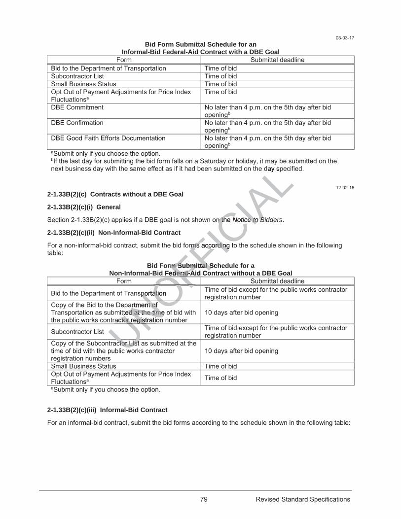
79 Revised Standard Specifications
03-03-17 Bid Form Submittal Schedule for an
Informal-Bid Federal-Aid Contract with a DBE Goal Form Submittal deadline
Bid to the Department of Transportation Time of bid Subcontractor List Time of bid Small Business Status Time of bid Opt Out of Payment Adjustments for Price Index Fluctuationsa
Time of bid
DBE Commitment No later than 4 p.m. on the 5th day after bid openingb
DBE Confirmation No later than 4 p.m. on the 5th day after bid openingb
DBE Good Faith Efforts Documentation No later than 4 p.m. on the 5th day after bid openingb
aSubmit only if you choose the option. bIf the last day for submitting the bid form falls on a Saturday or holiday, it may be submitted on the next business day with the same effect as if it had been submitted on the day specified.
12-02-16 2-1.33B(2)(c) Contracts without a DBE Goal
2-1.33B(2)(c)(i) General
Section 2-1.33B(2)(c) applies if a DBE goal is not shown on the Notice to Bidders.
2-1.33B(2)(c)(ii) Non-Informal-Bid Contract
For a non-informal-bid contract, submit the bid forms according to the schedule shown in the following table:
Bid Form Submittal Schedule for a Non-Informal-Bid Federal-Aid Contract without a DBE Goal
Form Submittal deadline
Bid to the Department of Transportation Time of bid except for the public works contractor registration number
Copy of the Bid to the Department of Transportation as submitted at the time of bid with the public works contractor registration number
10 days after bid opening
Subcontractor List Time of bid except for the public works contractor registration number
Copy of the Subcontractor List as submitted at the time of bid with the public works contractor registration numbers
10 days after bid opening
Small Business Status Time of bid Opt Out of Payment Adjustments for Price Index Fluctuationsa Time of bid aSubmit only if you choose the option.
2-1.33B(2)(c)(iii) Informal-Bid Contract
For an informal-bid contract, submit the bid forms according to the schedule shown in the following table:
Uctor ctor List ListwoUNOFFIC
IAL
day sp
on the n th Notice to Bice to B
rms according to rms according
m Submittal Scm Submittal S Federal-Aid Coderal-Aid Co
OFFportation portatio OFOF
artment of artment of tted at the time oftted at the time
ractor registrationctor registrationNOUNU
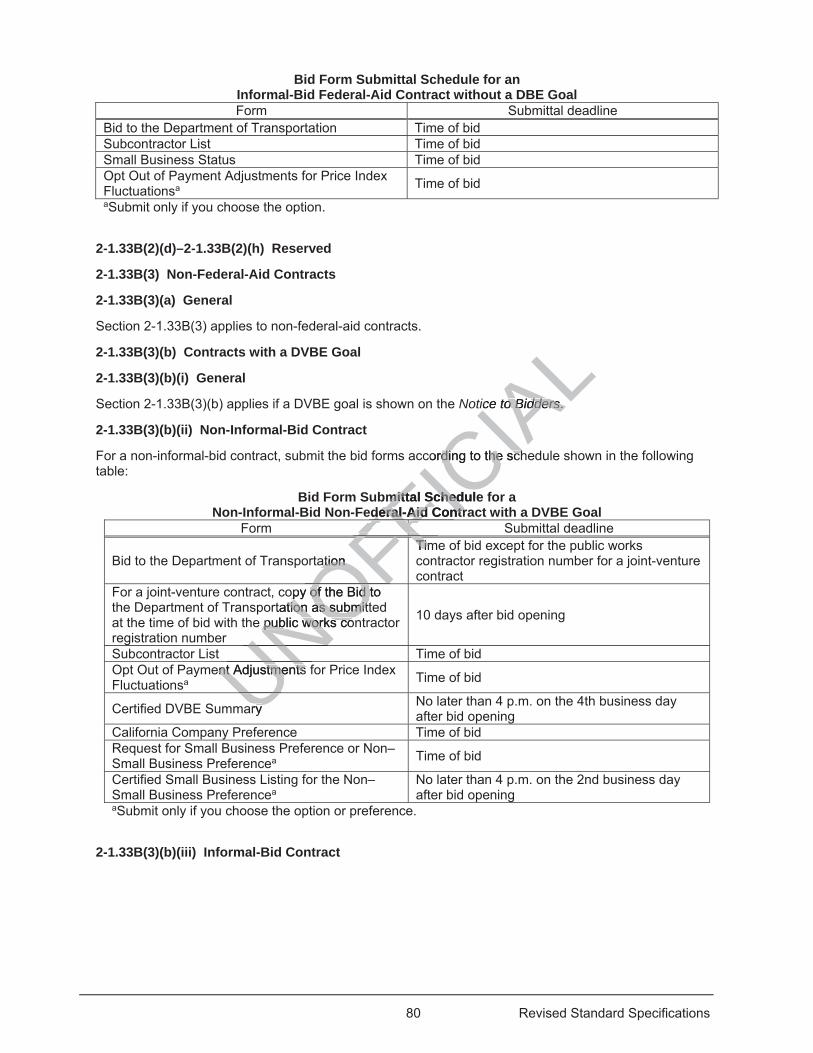
80 Revised Standard Specifications
Bid Form Submittal Schedule for an Informal-Bid Federal-Aid Contract without a DBE Goal Form Submittal deadline
Bid to the Department of Transportation Time of bid Subcontractor List Time of bid Small Business Status Time of bid Opt Out of Payment Adjustments for Price Index Fluctuationsa Time of bid aSubmit only if you choose the option.
2-1.33B(2)(d)–2-1.33B(2)(h) Reserved
2-1.33B(3) Non-Federal-Aid Contracts
2-1.33B(3)(a) General
Section 2-1.33B(3) applies to non-federal-aid contracts.
2-1.33B(3)(b) Contracts with a DVBE Goal
2-1.33B(3)(b)(i) General
Section 2-1.33B(3)(b) applies if a DVBE goal is shown on the Notice to Bidders.
2-1.33B(3)(b)(ii) Non-Informal-Bid Contract
For a non-informal-bid contract, submit the bid forms according to the schedule shown in the following table:
Bid Form Submittal Schedule for a Non-Informal-Bid Non-Federal-Aid Contract with a DVBE Goal
Form Submittal deadline
Bid to the Department of Transportation Time of bid except for the public works contractor registration number for a joint-venture contract
For a joint-venture contract, copy of the Bid to the Department of Transportation as submitted at the time of bid with the public works contractor registration number
10 days after bid opening
Subcontractor List Time of bid Opt Out of Payment Adjustments for Price Index Fluctuationsa Time of bid
Certified DVBE Summary No later than 4 p.m. on the 4th business day after bid opening
California Company Preference Time of bid Request for Small Business Preference or Non–Small Business Preferencea Time of bid
Certified Small Business Listing for the Non–Small Business Preferencea
No later than 4 p.m. on the 2nd business day after bid opening
aSubmit only if you choose the option or preference.
2-1.33B(3)(b)(iii) Informal-Bid Contract
UNOFFICIA
Ltice to Bidderso Bidders. .
cording to the schding to the sch
mittal Schedulemittal Schedderal-Aid Contrderal-Aid Contr
FFFFation ation
TimTimFFFFFFFFFFFFFFFFopy of the Bid to opy of the Bid t
rtation as submitttion as submite public works conpublic works coOFUNent Adjustments nt AdjustmentsUN
ary U
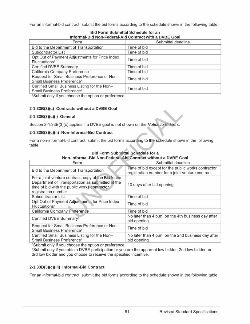
81 Revised Standard Specifications
For an informal-bid contract, submit the bid forms according to the schedule shown in the following table:
Bid Form Submittal Schedule for an Informal-Bid Non-Federal-Aid Contract with a DVBE Goal
Form Submittal deadline Bid to the Department of Transportation Time of bid Subcontractor List Time of bid Opt Out of Payment Adjustments for Price Index Fluctuationsa Time of bid
Certified DVBE Summary Time of bid California Company Preference Time of bid Request for Small Business Preference or Non–Small Business Preferencea Time of bid
Certified Small Business Listing for the Non–Small Business Preferencea Time of bid aSubmit only if you choose the option or preference.
2-1.33B(3)(c) Contracts without a DVBE Goal
2-1.33B(3)(c)(i) General
Section 2-1.33B(3)(c) applies if a DVBE goal is not shown on the Notice to Bidders.
2-1.33B(3)(c)(ii) Non-Informal-Bid Contract
For a non-informal-bid contract, submit the bid forms according to the schedule shown in the following table:
Bid Form Submittal Schedule for a Non-Informal-Bid Non-Federal-Aid Contract without a DVBE Goal
Form Submittal deadline
Bid to the Department of Transportation Time of bid except for the public works contractor registration number for a joint-venture contract
For a joint-venture contract, copy of the Bid to the Department of Transportation as submitted at the time of bid with the public works contractor registration number
10 days after bid opening
Subcontractor List Time of bid Opt Out of Payment Adjustments for Price Index Fluctuationsa Time of bid
California Company Preference Time of bid
Certified DVBE Summaryb No later than 4 p.m. on the 4th business day after bid opening
Request for Small Business Preference or Non–Small Business Preferencea Time of bid
Certified Small Business Listing for the Non–Small Business Preferencea
No later than 4 p.m. on the 2nd business day after bid opening
aSubmit only if you choose the option or preference. bSubmit only if you obtain DVBE participation or you are the apparent low bidder, 2nd low bidder, or 3rd low bidder and you choose to receive the specified incentive.
2-1.33B(3)(c)(iii) Informal-Bid Contract
For an informal-bid contract, submit the bid forms according to the schedule shown in the following table:
UNOFFICIA
LNotice to BidderNotice to Bidder
cording to the schding to the sch
mittal Schedulemittal Schederal-Aid Contraceral-Aid Contra
FFFFon TimTimFFFFFFFFFFFFFFFFof the Bid to the f the Bid to the
s submitted at thubmitted atrks contractor s contractor OFNO
Adjustments for Pustments f
UNPreference PreferenceUbbU

82 Revised Standard Specifications
Bid Form Submittal Schedule for an Informal-Bid Non-Federal-Aid Contract without a DVBE Goal
Form Submittal deadline Bid to the Department of Transportation Time of bid Subcontractor List Time of bid Opt Out of Payment Adjustments for Price Index Fluctuationsa Time of bid
Certified DVBE Summaryb Time of bid Request for Small Business Preference or Non–Small Business Preferencea Time of bid
Certified Small Business Listing for the Non–Small Business Preferencea Time of bid aSubmit only if you choose the option or preference. bSubmit only if you obtain DVBE participation or you are the apparent low bidder, 2nd low bidder, or 3rd low bidder and you choose to receive the specified incentive.
2-1.33B(3)(d)–2-1.33B(3)(h) Reserved
2-1.33B(4)–2-1.33B(9) Reserved
2-1.34 BIDDER'S SECURITY
Submit one of the following forms of bidder's security equal to at least 10 percent of the bid:
1. Cash 2. Cashier's check 3. Certified check 4. Signed bidder's bond by an admitted surety insurer 5. Electronic bidder's bond by an admitted surety insurer submitted using an electronic registry service
approved by the Department Submit cash, cashier’s check, certified check, or bidder's bond to the Department's Office of Construction Contract Awards before the bid opening time.
Submit an electronic bidder’s bond with the electronic bid.
If using a bidder's bond, you may use the form in the Bid book. If you do not use the form in the Bid book, use a form containing the same information.
2-1.35–2-1.39 RESERVED
2-1.40 BID WITHDRAWAL
Bids are not filed with the Department until the date and time of bid opening.
A bidder may withdraw or revise a bid after it has been submitted to the electronic bidding service if this is done before the bid opening date and time.
2-1.41–2-1.42 RESERVED
2-1.43 BID OPENING
The Department publicly opens and reads bids at the time and place shown on the Notice to Bidders.
2-1.44–2-1.45 RESERVED
2-1.46 DEPARTMENT'S DECISION ON A BID
The Department's decision on the bid amount is final.
The Department may reject:
1. All bids
UNOFFICIA
Lat least 10 perceleast 10 p
surer sureety inty i surer submsurer subm
check, or bick, or b dder's'ing time. ng time.
nd with the electrd with the ele
may use the formmay use the formsame informationsame informat
RVED D
AWAL AWA
Dep
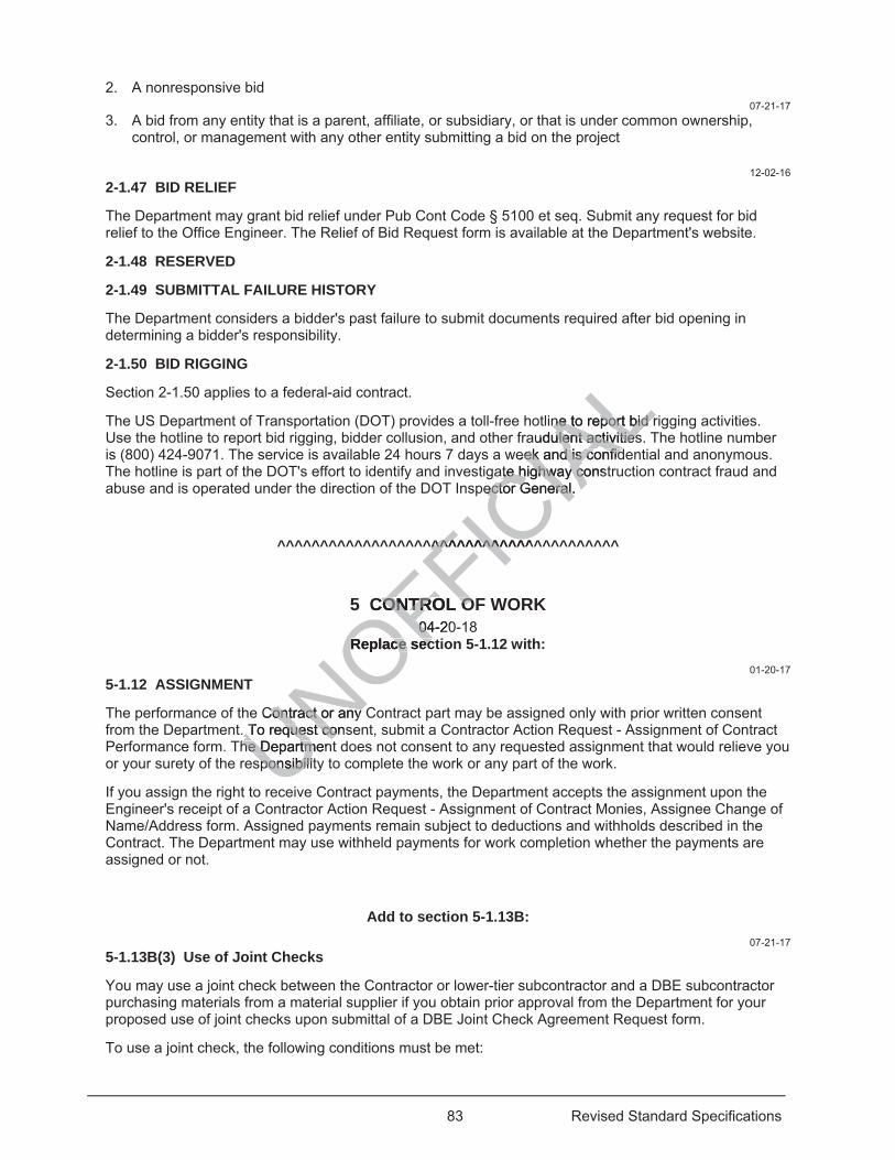
83 Revised Standard Specifications
2. A nonresponsive bid 07-21-17
3. A bid from any entity that is a parent, affiliate, or subsidiary, or that is under common ownership, control, or management with any other entity submitting a bid on the project
12-02-16
2-1.47 BID RELIEF
The Department may grant bid relief under Pub Cont Code § 5100 et seq. Submit any request for bid relief to the Office Engineer. The Relief of Bid Request form is available at the Department's website.
2-1.48 RESERVED
2-1.49 SUBMITTAL FAILURE HISTORY
The Department considers a bidder's past failure to submit documents required after bid opening in determining a bidder's responsibility.
2-1.50 BID RIGGING
Section 2-1.50 applies to a federal-aid contract.
The US Department of Transportation (DOT) provides a toll-free hotline to report bid rigging activities. Use the hotline to report bid rigging, bidder collusion, and other fraudulent activities. The hotline number is (800) 424-9071. The service is available 24 hours 7 days a week and is confidential and anonymous. The hotline is part of the DOT's effort to identify and investigate highway construction contract fraud and abuse and is operated under the direction of the DOT Inspector General.
^^^^^^^^^^^^^^^^^^^^^^^^^^^^^^^^^^^^^^^^
5 CONTROL OF WORK 04-20-18
Replace section 5-1.12 with: 01-20-17
5-1.12 ASSIGNMENT
The performance of the Contract or any Contract part may be assigned only with prior written consent from the Department. To request consent, submit a Contractor Action Request - Assignment of Contract Performance form. The Department does not consent to any requested assignment that would relieve you or your surety of the responsibility to complete the work or any part of the work.
If you assign the right to receive Contract payments, the Department accepts the assignment upon the Engineer's receipt of a Contractor Action Request - Assignment of Contract Monies, Assignee Change of Name/Address form. Assigned payments remain subject to deductions and withholds described in the Contract. The Department may use withheld payments for work completion whether the payments are assigned or not.
Add to section 5-1.13B: 07-21-17
5-1.13B(3) Use of Joint Checks
You may use a joint check between the Contractor or lower-tier subcontractor and a DBE subcontractor purchasing materials from a material supplier if you obtain prior approval from the Department for your proposed use of joint checks upon submittal of a DBE Joint Check Agreement Request form.
To use a joint check, the following conditions must be met:
UNOFFICIA
Line to report bid rne to report bid raudulent activitiesulent activities
eek and is confidek and is confidate highway consate highway co
pector General. ector General.
^^^^^^^^^^^^^^^^^^^^^^^
CONTROL OONTROL O04-2004
Replace secReplace sec
Contract or any Contract or any . To request cons. To request cohe Departmenhe Departm
sponsponsibilitsibili
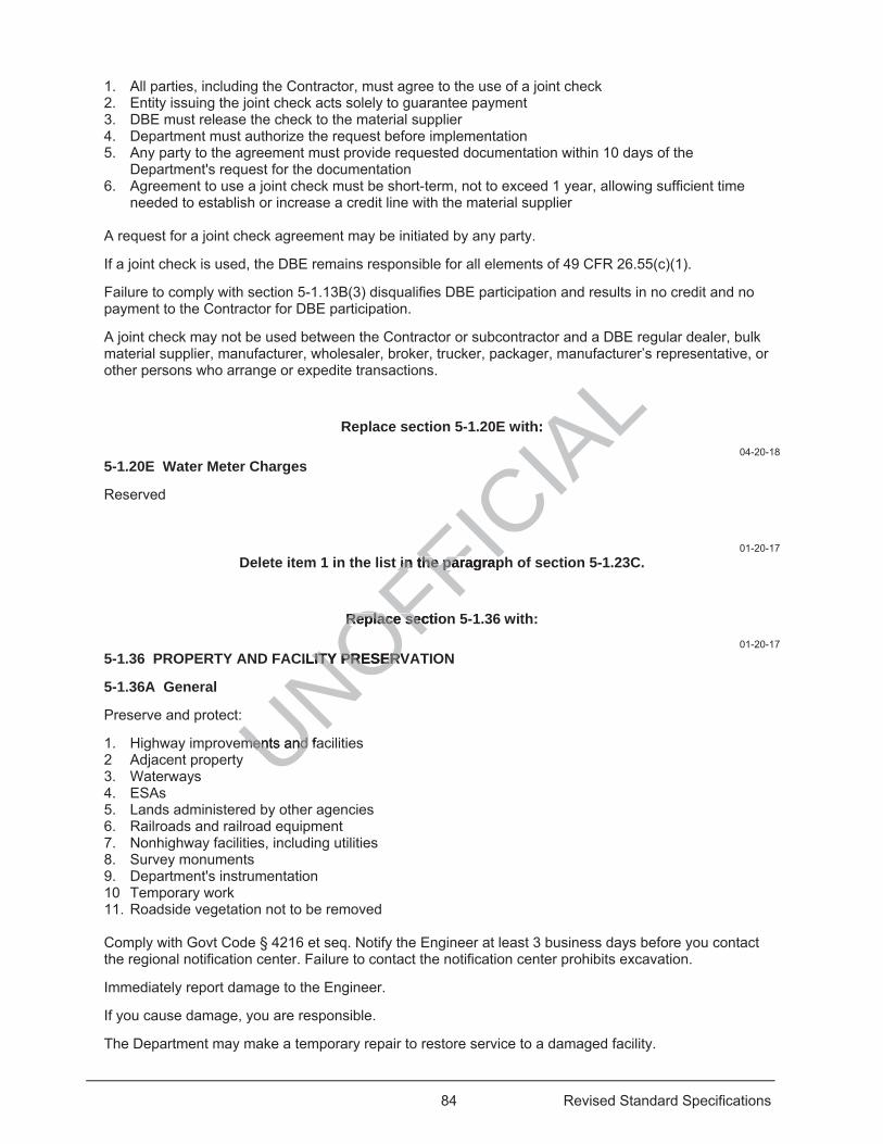
84 Revised Standard Specifications
1. All parties, including the Contractor, must agree to the use of a joint check 2. Entity issuing the joint check acts solely to guarantee payment 3. DBE must release the check to the material supplier 4. Department must authorize the request before implementation 5. Any party to the agreement must provide requested documentation within 10 days of the
Department's request for the documentation 6. Agreement to use a joint check must be short-term, not to exceed 1 year, allowing sufficient time
needed to establish or increase a credit line with the material supplier A request for a joint check agreement may be initiated by any party.
If a joint check is used, the DBE remains responsible for all elements of 49 CFR 26.55(c)(1).
Failure to comply with section 5-1.13B(3) disqualifies DBE participation and results in no credit and no payment to the Contractor for DBE participation.
A joint check may not be used between the Contractor or subcontractor and a DBE regular dealer, bulk material supplier, manufacturer, wholesaler, broker, trucker, packager, manufacturer’s representative, or other persons who arrange or expedite transactions.
Replace section 5-1.20E with: 04-20-18
5-1.20E Water Meter Charges
Reserved
01-20-17 Delete item 1 in the list in the paragraph of section 5-1.23C.
Replace section 5-1.36 with: 01-20-17
5-1.36 PROPERTY AND FACILITY PRESERVATION
5-1.36A General
Preserve and protect:
1. Highway improvements and facilities 2 Adjacent property 3. Waterways 4. ESAs 5. Lands administered by other agencies 6. Railroads and railroad equipment 7. Nonhighway facilities, including utilities 8. Survey monuments 9. Department's instrumentation 10 Temporary work 11. Roadside vegetation not to be removed
Comply with Govt Code § 4216 et seq. Notify the Engineer at least 3 business days before you contact the regional notification center. Failure to contact the notification center prohibits excavation.
Immediately report damage to the Engineer.
If you cause damage, you are responsible.
The Department may make a temporary repair to restore service to a damaged facility.
UNOFFICIA
Lh:
t in the paragrapin the paragrap
Replace sectioReplace sec
ILITY PRESERVLITY PRESERV
ments and faments and
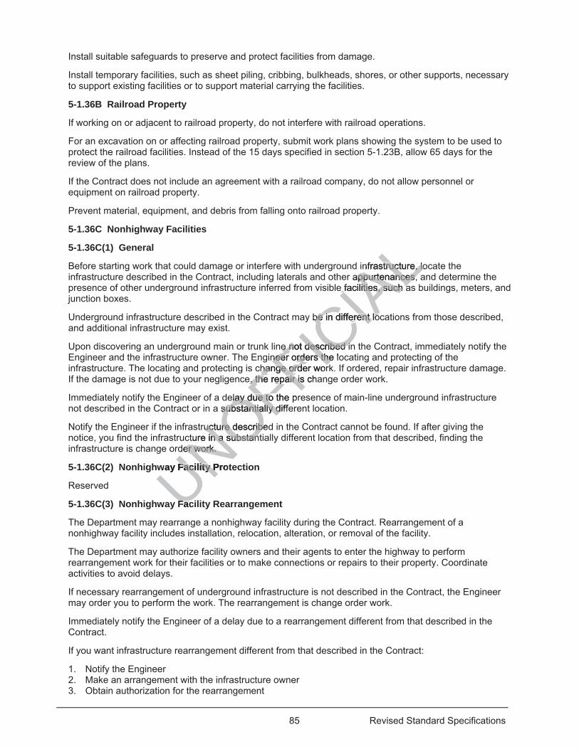
85 Revised Standard Specifications
Install suitable safeguards to preserve and protect facilities from damage.
Install temporary facilities, such as sheet piling, cribbing, bulkheads, shores, or other supports, necessary to support existing facilities or to support material carrying the facilities.
5-1.36B Railroad Property
If working on or adjacent to railroad property, do not interfere with railroad operations.
For an excavation on or affecting railroad property, submit work plans showing the system to be used to protect the railroad facilities. Instead of the 15 days specified in section 5-1.23B, allow 65 days for the review of the plans.
If the Contract does not include an agreement with a railroad company, do not allow personnel or equipment on railroad property.
Prevent material, equipment, and debris from falling onto railroad property.
5-1.36C Nonhighway Facilities
5-1.36C(1) General
Before starting work that could damage or interfere with underground infrastructure, locate the infrastructure described in the Contract, including laterals and other appurtenances, and determine the presence of other underground infrastructure inferred from visible facilities, such as buildings, meters, and junction boxes.
Underground infrastructure described in the Contract may be in different locations from those described, and additional infrastructure may exist.
Upon discovering an underground main or trunk line not described in the Contract, immediately notify the Engineer and the infrastructure owner. The Engineer orders the locating and protecting of the infrastructure. The locating and protecting is change order work. If ordered, repair infrastructure damage. If the damage is not due to your negligence, the repair is change order work.
Immediately notify the Engineer of a delay due to the presence of main-line underground infrastructure not described in the Contract or in a substantially different location.
Notify the Engineer if the infrastructure described in the Contract cannot be found. If after giving the notice, you find the infrastructure in a substantially different location from that described, finding the infrastructure is change order work.
5-1.36C(2) Nonhighway Facility Protection
Reserved
5-1.36C(3) Nonhighway Facility Rearrangement
The Department may rearrange a nonhighway facility during the Contract. Rearrangement of a nonhighway facility includes installation, relocation, alteration, or removal of the facility.
The Department may authorize facility owners and their agents to enter the highway to perform rearrangement work for their facilities or to make connections or repairs to their property. Coordinate activities to avoid delays.
If necessary rearrangement of underground infrastructure is not described in the Contract, the Engineer may order you to perform the work. The rearrangement is change order work.
Immediately notify the Engineer of a delay due to a rearrangement different from that described in the Contract.
If you want infrastructure rearrangement different from that described in the Contract:
1. Notify the Engineer 2. Make an arrangement with the infrastructure owner 3. Obtain authorization for the rearrangement
UNOFFICIA
Linfrastructure, lostructure, loappurtenances, ppurtenances,
e facilities, such ae facilities, such a
be in different lobe in different lo
e e not described inot described ineer orders the loneer orders the
change hange order wororder wore, the repair is chae, the repair is
elay due to the elay due to prsubstantially diffsubstantially d
tructure describeducture describeture in a substanin a substan
der work. er work.
way Facility ProtFacility P
FacF

86 Revised Standard Specifications
4. Pay the infrastructure owner any additional cost
The Department does not adjust time or payment for a rearrangement different from that described the Contract.
5-1.36D Survey Monuments
Protect survey monuments on and off the highway. Upon discovery of a survey monument not identified and located by the Department, immediately:
1. Stop work near the monument 2. Notify the Engineer
Do not resume work near the monument until authorized.
5-1.36E Landscape
If you damage plants not to be removed:
1. Dispose of them unless the Engineer authorizes you to reduce them to chips and spread the chips within the highway at locations designated by the Engineer
2. Replace them Replace plants with plants of the same species.
Replace trees with 24-inch-box trees.
Replace shrubs with no. 15-container shrubs.
Replace ground cover plants with plants from flats. Replace Carpobrotus ground cover plants with plants from cuttings. Plant ground cover plants 1 foot on center.
If a plant establishment or permanent erosion control establishment period is specified, replace plants before the start of the plant establishment or permanent erosion control establishment period; otherwise, replace plants at least 30 days before Contract acceptance.
Water each plant immediately after planting. Saturate the backfill soil around and below the roots or the ball of earth around the roots of each plant. Water as necessary to maintain plants in a healthy condition until Contract acceptance.
07-21-17 5-1.36F Irrigation Facilities
Keep existing irrigation facilities in place that are described to be removed, relocated, or modified until the Engineer determines they are no longer needed.
Maintain the existing water supply. If the existing water supply is interrupted for more than 3 consecutive days, provide an alternative water supply. Water the existing plants in the area irrigated from that water supply, including those maintained by the Department, as necessary to maintain healthy plant growth.
If you and the Department irrigate existing plants from the same water supply, furnish enough water to the Department for watering plantings on and off the highway as necessary to maintain a healthy condition through Contract acceptance.
If you damage irrigation facilities not to be removed:
1. Remove and dispose of them. 2. Repair and replace damaged facilities within 10 days. 3. Use similar commercial-quality components from the same manufacturer or components that are
compatible with the existing irrigation system if authorized. 4. After completing the repair or replacement of the facilities, perform an operational test in the presence
of the Engineer. If you repair or replace the remote control valves, conduct the test with the irrigation controller in the automatic mode.
UNOFFICIA
Lchips
Replace Replace CarpobrCarpobr center. center.
n control n control establishesor permanent eroor permanent e
Contract acceptanract acceptan
planting. Saturaplanting. Saturateach plant. Watereach plant. Wa
ilities ties
on facilities in pon facilities in phey are no hey are no
su
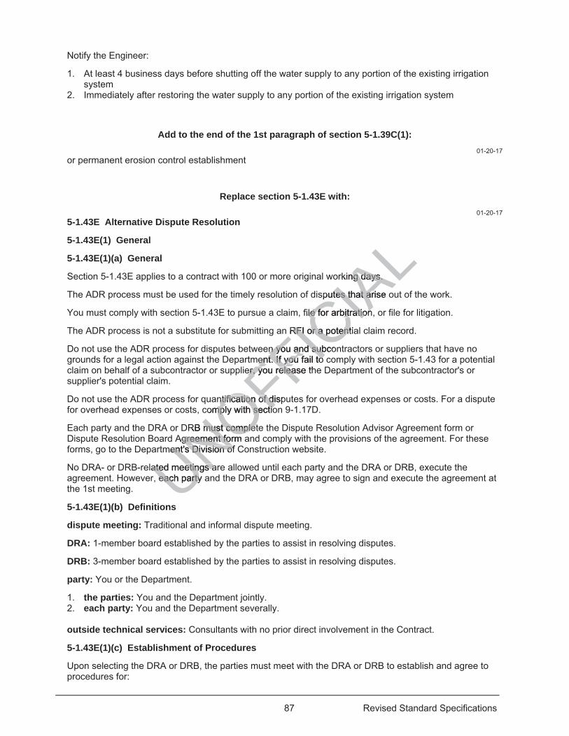
87 Revised Standard Specifications
Notify the Engineer:
1. At least 4 business days before shutting off the water supply to any portion of the existing irrigation system
2. Immediately after restoring the water supply to any portion of the existing irrigation system
Add to the end of the 1st paragraph of section 5-1.39C(1): 01-20-17
or permanent erosion control establishment
Replace section 5-1.43E with: 01-20-17
5-1.43E Alternative Dispute Resolution
5-1.43E(1) General
5-1.43E(1)(a) General
Section 5-1.43E applies to a contract with 100 or more original working days.
The ADR process must be used for the timely resolution of disputes that arise out of the work.
You must comply with section 5-1.43E to pursue a claim, file for arbitration, or file for litigation.
The ADR process is not a substitute for submitting an RFI or a potential claim record.
Do not use the ADR process for disputes between you and subcontractors or suppliers that have no grounds for a legal action against the Department. If you fail to comply with section 5-1.43 for a potential claim on behalf of a subcontractor or supplier, you release the Department of the subcontractor's or supplier's potential claim.
Do not use the ADR process for quantification of disputes for overhead expenses or costs. For a dispute for overhead expenses or costs, comply with section 9-1.17D.
Each party and the DRA or DRB must complete the Dispute Resolution Advisor Agreement form or Dispute Resolution Board Agreement form and comply with the provisions of the agreement. For these forms, go to the Department's Division of Construction website.
No DRA- or DRB-related meetings are allowed until each party and the DRA or DRB, execute the agreement. However, each party and the DRA or DRB, may agree to sign and execute the agreement at the 1st meeting.
5-1.43E(1)(b) Definitions
dispute meeting: Traditional and informal dispute meeting.
DRA: 1-member board established by the parties to assist in resolving disputes.
DRB: 3-member board established by the parties to assist in resolving disputes.
party: You or the Department.
1. the parties: You and the Department jointly. 2. each party: You and the Department severally. outside technical services: Consultants with no prior direct involvement in the Contract.
5-1.43E(1)(c) Establishment of Procedures
Upon selecting the DRA or DRB, the parties must meet with the DRA or DRB to establish and agree to procedures for:
UNOFFICIA
Lrking days. ng days.
sputes that arise otes that ar
file for arbitrationle for arbitration
n RFI or a potentia RFI or a potent
en you and subcon you and subment. If yent. If you fail to ou fail to
er, you er, you release thelea
ntification of dispntification of dicomply with sectiomply with sectio
RB must completmust completAgreement form agreement fo
ment's Division of ent's Division of
ated meetings aated meetings aeach party aeach party

88 Revised Standard Specifications
1. Submitting documents 2. Conducting hearings 3. Providing recommendations 4. Associated tasks
The established procedures must comply with the Contract and the Dispute Resolution Advisor Agreement or Dispute Resolution Board Agreement. The procedures need not comply with laws of evidence.
5-1.43E(1)(d) Progress Meetings
The parties must periodically meet with the DRA or DRB at the job site so the DRA or DRB members can keep abreast of construction activities and become familiar with the work in progress.
The meetings must be held at the start of job site activities and at least once every 3 months after that.
The parties must attend each meeting.
The parties may agree to waive the scheduled meetings when the only work remaining is plant establishment work or permanent erosion control establishment work.
5-1.43E(1)(e) Dispute Meetings
You must follow the traditional dispute meeting process to pursue a potential claim.
Either party may refer a dispute to the DRA or DRB. To request a dispute meeting, a party must submit a copy of the referral and supporting documentation to the DRA or DRB. The documentation must describe the dispute in individual discrete segments such that resolved and unresolved segments are differentiated. The party must include an estimate of the cost of the affected work and impacts to the work completion date.
A copy of all documents submitted to the DRA or DRB must be simultaneously submitted to the other party.
The Department furnishes the DRA or DRB with the Contract documents and provides meeting facilities at no cost to you.
Neither party may meet with or discuss Contract issues with the DRA or DRB members unless the other party is present.
If the dispute involves a subcontractor, the subcontractor's superintendent or project manager must attend the meeting.
Only the following persons are allowed to participate and present information at the meeting:
1. Engineer 2. Department's area construction engineer 3. Department's structure representative. 4. Your superintendent 5. Your project manager 6. Either party's employees that have direct knowledge of the dispute and direct involvement in the
project 7. Consultants directly involved in the development of the estimate or construction 8. Subcontractor's superintendent or project manager if the dispute involves a subcontractor The following persons are not allowed to attend the meeting:
1. Attorneys 2. Claim consultants 3. Outside technical services not employed by either party unless requested by the DRA or DRB
UNOFFICIA
Lre
a potential claimotential claim
est a dispute meest a dispute RA or DRB. The RA or DRB. The
olved and unresoved and unresohe cost of the affee cost of the af
or or DRB must be DRB must be
DRB with the Conwith the Con
iscuss Contract iiscuss Contrac
ubcontractor, theubcontractor, th
ersons are allowersons are allow
t

89 Revised Standard Specifications
If the DRA or DRB needs outside technical services to help the DRA or DRB make a recommendation, the parties must agree to the services before they are provided. If the parties and the DRA or DRB agree, the technical services may be provided by technical staff who works for either party.
During a dispute meeting, each party presents its position, makes rebuttals, furnishes relevant documents, and responds to DRA or DRB questions and requests. The following is not allowed:
1. Testimony under oath 2. Cross-examination 3. Reporting of the procedures by a shorthand reporter or by electronic means If either party fails to attend a dispute meeting, all documents submitted by the nonattending party is considered as the nonattending party's entire position, and the DRA or DRB and the attending party may proceed with the dispute process.
5-1.43E(1)(f) Informal Dispute Meetings
The parties may resolve small and uncomplicated disputes using an informal process. The parties may use this process only if the parties and the DRA or DRB agree its use is appropriate for resolving the dispute.
The informal dispute meeting process is independent from the traditional process. The Department does not grant time extensions for the traditional dispute process if the informal dispute process is used.
Each party furnishes the DRA or DRB a 1-page brief description of the dispute with supporting documentation and any additional information requested by the DRA or DRB.
In an informal dispute meeting, each party presents its position and receives the DRA's or DRB's recommendation orally on the same day the dispute is heard. The DRA or DRB furnishes a 1-page report confirming the recommendation within 5 business days.
Either party may ask for clarification of the DRA's or DRB's recommendation at the dispute meeting.
If the dispute remains unresolved, the parties must notify the DRA or DRB within 5 business days after receipt of the DRA's or DRB's written confirmation of the recommendation.
The DRA or DRB will not be bound by its informal recommendation if a dispute is later heard in a traditional dispute meeting.
If the dispute is not resolved using the informal dispute meeting process, the parties must comply with the traditional dispute meeting specifications.
5-1.43E(1)(g) Recommendations
Recommendations resulting from the ADR process are nonbinding.
If the parties resolve the dispute with the aid of the DRA's or DRB's recommendation, the parties must implement the resolution.
5-1.43E(1)(h) Completion of Alternative Dispute Resolution
All ADR activities must be completed before Contract acceptance. Accelerated timeframes may be used if the parties and the DRA or DRB agree.
If a dispute becomes an unresolved claim after Contract acceptance, comply with section 9-1.17D(2).
Neither party may call the DRA or DRB members who served on the Contract as a witness in arbitration or other proceedings that may arise from the Contract.
The parties must indemnify and hold harmless the DRA or DRB members from and against all claims, damages, losses, and expenses, including attorney's fees, arising out of and resulting from the findings and recommendations of the DRA or DRB.
5-1.43E(1)(i) Payment
UNOFFICIA
Lropr
nal process. Thenal process. Thenformal dispute prrmal dispute p
on of the dispute wof the dispthe DRA or DRBthe DRA or DR
position and receposition and receis heard. The DRheard. The DR
days. days
RA'sRA s or DRB's recor DRB's rec
rties must notify tes must notifyonfirmation of thenfirmation
d by its informal reby its informal r
d using the informd using the informng specifications. g specifications
mmendations mmendations
ulting fromulting from
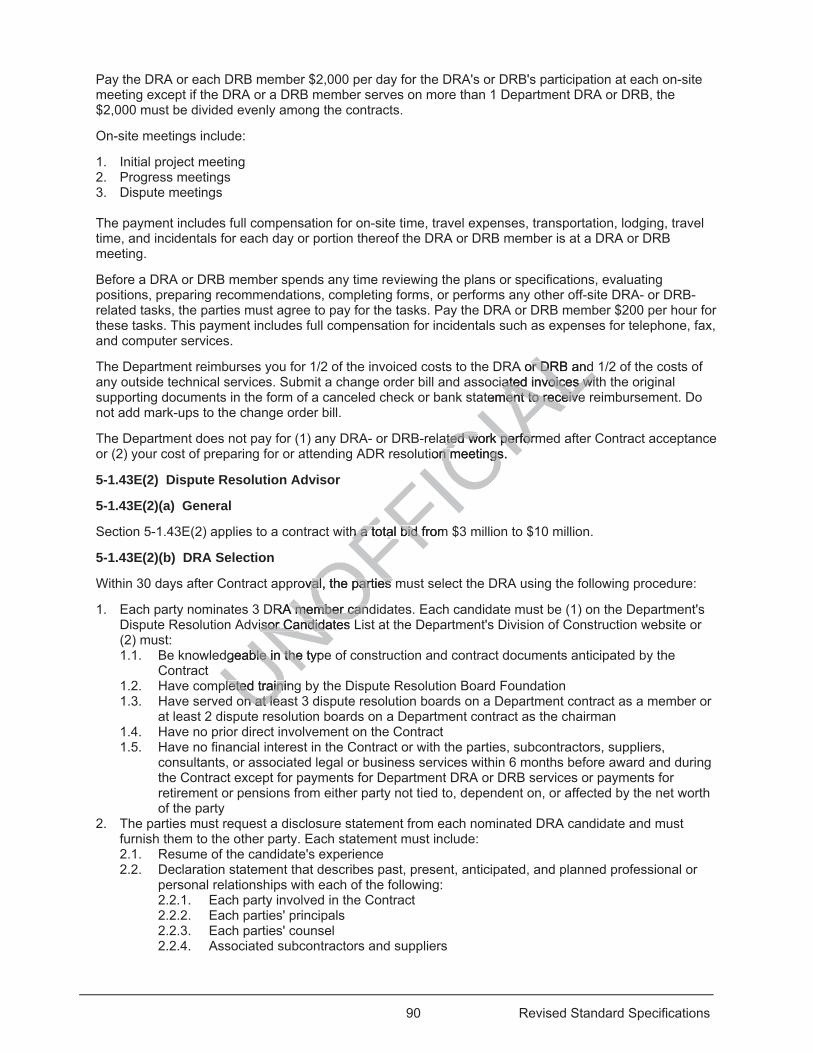
90 Revised Standard Specifications
Pay the DRA or each DRB member $2,000 per day for the DRA's or DRB's participation at each on-site meeting except if the DRA or a DRB member serves on more than 1 Department DRA or DRB, the $2,000 must be divided evenly among the contracts.
On-site meetings include:
1. Initial project meeting 2. Progress meetings 3. Dispute meetings The payment includes full compensation for on-site time, travel expenses, transportation, lodging, travel time, and incidentals for each day or portion thereof the DRA or DRB member is at a DRA or DRB meeting.
Before a DRA or DRB member spends any time reviewing the plans or specifications, evaluating positions, preparing recommendations, completing forms, or performs any other off-site DRA- or DRB-related tasks, the parties must agree to pay for the tasks. Pay the DRA or DRB member $200 per hour for these tasks. This payment includes full compensation for incidentals such as expenses for telephone, fax, and computer services.
The Department reimburses you for 1/2 of the invoiced costs to the DRA or DRB and 1/2 of the costs of any outside technical services. Submit a change order bill and associated invoices with the original supporting documents in the form of a canceled check or bank statement to receive reimbursement. Do not add mark-ups to the change order bill.
The Department does not pay for (1) any DRA- or DRB-related work performed after Contract acceptance or (2) your cost of preparing for or attending ADR resolution meetings.
5-1.43E(2) Dispute Resolution Advisor
5-1.43E(2)(a) General
Section 5-1.43E(2) applies to a contract with a total bid from $3 million to $10 million.
5-1.43E(2)(b) DRA Selection
Within 30 days after Contract approval, the parties must select the DRA using the following procedure:
1. Each party nominates 3 DRA member candidates. Each candidate must be (1) on the Department's Dispute Resolution Advisor Candidates List at the Department's Division of Construction website or (2) must: 1.1. Be knowledgeable in the type of construction and contract documents anticipated by the
Contract 1.2. Have completed training by the Dispute Resolution Board Foundation 1.3. Have served on at least 3 dispute resolution boards on a Department contract as a member or
at least 2 dispute resolution boards on a Department contract as the chairman 1.4. Have no prior direct involvement on the Contract 1.5. Have no financial interest in the Contract or with the parties, subcontractors, suppliers,
consultants, or associated legal or business services within 6 months before award and during the Contract except for payments for Department DRA or DRB services or payments for retirement or pensions from either party not tied to, dependent on, or affected by the net worth of the party
2. The parties must request a disclosure statement from each nominated DRA candidate and must furnish them to the other party. Each statement must include: 2.1. Resume of the candidate's experience 2.2. Declaration statement that describes past, present, anticipated, and planned professional or
personal relationships with each of the following: 2.2.1. Each party involved in the Contract 2.2.2. Each parties' principals 2.2.3. Each parties' counsel 2.2.4. Associated subcontractors and suppliers
UNOFFICIA
LA or DRBor D andiated invoices witated invoices wi
tement to receivement to receive
ated work performated work perfortion meetings. n meetings
h a total bid fromh a total bid f
roval, the parties val, the parties
DRA member candA member canvisor Candidates isor Candidates
dgeable in the typble in the
leted traininleted trainon at leon at le
e
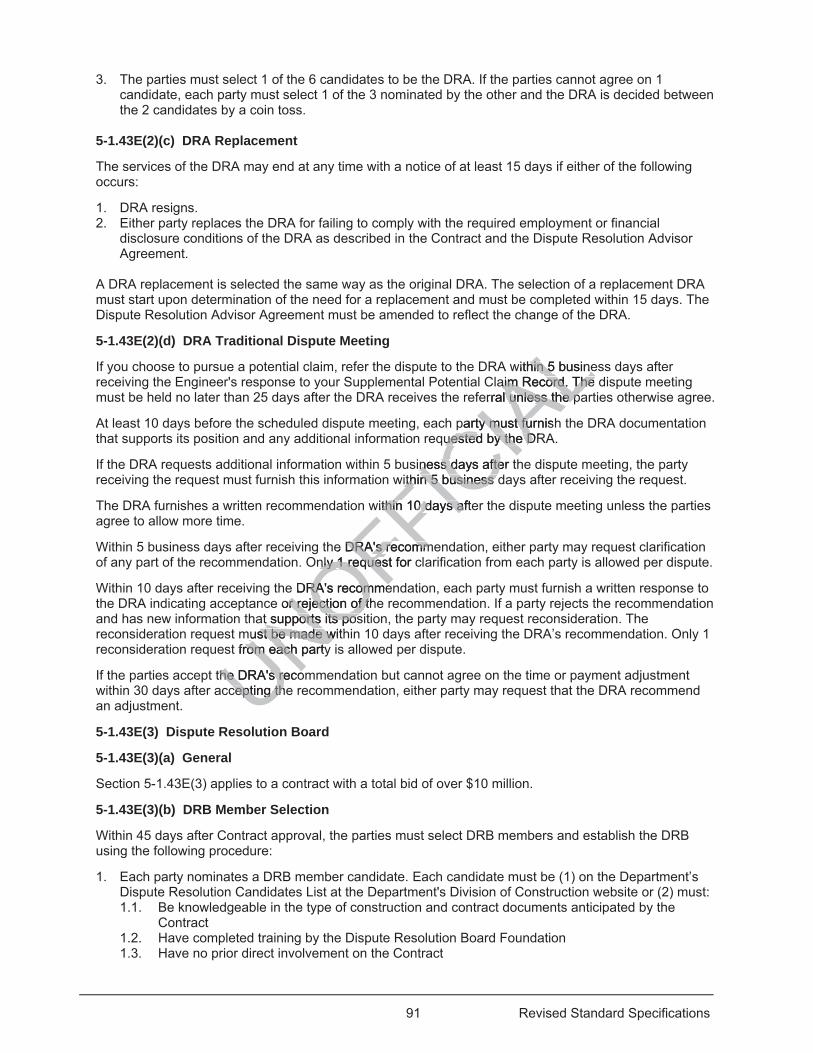
91 Revised Standard Specifications
3. The parties must select 1 of the 6 candidates to be the DRA. If the parties cannot agree on 1 candidate, each party must select 1 of the 3 nominated by the other and the DRA is decided between the 2 candidates by a coin toss.
5-1.43E(2)(c) DRA Replacement
The services of the DRA may end at any time with a notice of at least 15 days if either of the following occurs:
1. DRA resigns. 2. Either party replaces the DRA for failing to comply with the required employment or financial
disclosure conditions of the DRA as described in the Contract and the Dispute Resolution Advisor Agreement.
A DRA replacement is selected the same way as the original DRA. The selection of a replacement DRA must start upon determination of the need for a replacement and must be completed within 15 days. The Dispute Resolution Advisor Agreement must be amended to reflect the change of the DRA.
5-1.43E(2)(d) DRA Traditional Dispute Meeting
If you choose to pursue a potential claim, refer the dispute to the DRA within 5 business days after receiving the Engineer's response to your Supplemental Potential Claim Record. The dispute meeting must be held no later than 25 days after the DRA receives the referral unless the parties otherwise agree.
At least 10 days before the scheduled dispute meeting, each party must furnish the DRA documentation that supports its position and any additional information requested by the DRA.
If the DRA requests additional information within 5 business days after the dispute meeting, the party receiving the request must furnish this information within 5 business days after receiving the request.
The DRA furnishes a written recommendation within 10 days after the dispute meeting unless the parties agree to allow more time.
Within 5 business days after receiving the DRA's recommendation, either party may request clarification of any part of the recommendation. Only 1 request for clarification from each party is allowed per dispute.
Within 10 days after receiving the DRA's recommendation, each party must furnish a written response to the DRA indicating acceptance or rejection of the recommendation. If a party rejects the recommendation and has new information that supports its position, the party may request reconsideration. The reconsideration request must be made within 10 days after receiving the DRA’s recommendation. Only 1 reconsideration request from each party is allowed per dispute.
If the parties accept the DRA's recommendation but cannot agree on the time or payment adjustment within 30 days after accepting the recommendation, either party may request that the DRA recommend an adjustment.
5-1.43E(3) Dispute Resolution Board
5-1.43E(3)(a) General
Section 5-1.43E(3) applies to a contract with a total bid of over $10 million.
5-1.43E(3)(b) DRB Member Selection
Within 45 days after Contract approval, the parties must select DRB members and establish the DRB using the following procedure:
1. Each party nominates a DRB member candidate. Each candidate must be (1) on the Department’s Dispute Resolution Candidates List at the Department's Division of Construction website or (2) must: 1.1. Be knowledgeable in the type of construction and contract documents anticipated by the
Contract 1.2. Have completed training by the Dispute Resolution Board Foundation 1.3. Have no prior direct involvement on the Contract
UNOFFICIA
Lwithin 5 businehin 5 busineaim Record. The aim Record. The
erral unless the pal unless the p
party must furnishy must fuuested by the DRuested by the D
iness days after tness days aftewithin 5 business dithin 5 business
ithin 10thin 10 days afte days af
e DRA's recoDRA's re mmmmnly 1 request for cnly 1 reques
DRA's recommeRA's recommeor rejection of thor rejection of t
t supports its post supports its posmust be made withmust be made w
t from each partyrom each party
the DRA's recothe DRA's recocepting thecepting th
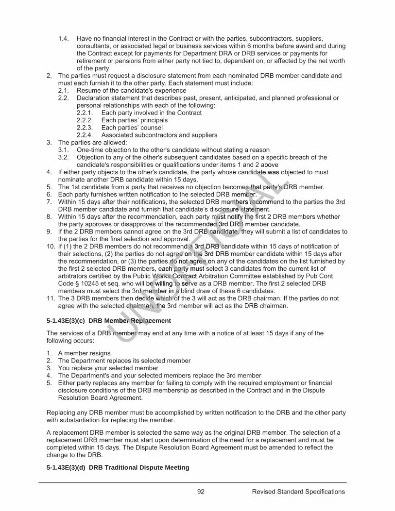
92 Revised Standard Specifications
1.4. Have no financial interest in the Contract or with the parties, subcontractors, suppliers, consultants, or associated legal or business services within 6 months before award and during the Contract except for payments for Department DRA or DRB services or payments for retirement or pensions from either party not tied to, dependent on, or affected by the net worth of the party
2. The parties must request a disclosure statement from each nominated DRB member candidate and must each furnish it to the other party. Each statement must include: 2.1. Resume of the candidate's experience 2.2. Declaration statement that describes past, present, anticipated, and planned professional or
personal relationships with each of the following: 2.2.1. Each party involved in the Contract 2.2.2. Each parties’ principals 2.2.3. Each parties’ counsel 2.2.4. Associated subcontractors and suppliers
3. The parties are allowed: 3.1. One-time objection to the other's candidate without stating a reason 3.2. Objection to any of the other's subsequent candidates based on a specific breach of the
candidate's responsibilities or qualifications under items 1 and 2 above 4. If either party objects to the other's candidate, the party whose candidate was objected to must
nominate another DRB candidate within 15 days. 5. The 1st candidate from a party that receives no objection becomes that party's DRB member. 6. Each party furnishes written notification to the selected DRB member. 7. Within 15 days after their notifications, the selected DRB members recommend to the parties the 3rd
DRB member candidate and furnish that candidate’s disclosure statement. 8. Within 15 days after the recommendation, each party must notify the first 2 DRB members whether
the party approves or disapproves of the recommended 3rd DRB member candidate. 9. If the 2 DRB members cannot agree on the 3rd DRB candidate, they will submit a list of candidates to
the parties for the final selection and approval. 10. If (1) the 2 DRB members do not recommend a 3rd DRB candidate within 15 days of notification of
their selections, (2) the parties do not agree on the 3rd DRB member candidate within 15 days after the recommendation, or (3) the parties do not agree on any of the candidates on the list furnished by the first 2 selected DRB members, each party must select 3 candidates from the current list of arbitrators certified by the Public Works Contract Arbitration Committee established by Pub Cont Code § 10245 et seq. who will be willing to serve as a DRB member. The first 2 selected DRB members must select the 3rd member in a blind draw of these 6 candidates.
11. The 3 DRB members then decide which of the 3 will act as the DRB chairman. If the parties do not agree with the selected chairman, the 3rd member will act as the DRB chairman.
5-1.43E(3)(c) DRB Member Replacement
The services of a DRB member may end at any time with a notice of at least 15 days if any of the following occurs:
1. A member resigns 2. The Department replaces its selected member 3. You replace your selected member 4. The Department's and your selected members replace the 3rd member 5. Either party replaces any member for failing to comply with the required employment or financial
disclosure conditions of the DRB membership as described in the Contract and in the Dispute Resolution Board Agreement.
Replacing any DRB member must be accomplished by written notification to the DRB and the other party with substantiation for replacing the member.
A replacement DRB member is selected the same way as the original DRB member. The selection of a replacement DRB member must start upon determination of the need for a replacement and must be completed within 15 days. The Dispute Resolution Board Agreement must be amended to reflect the change to the DRB.
5-1.43E(3)(d) DRB Traditional Dispute Meeting
UNOFFICIA
Lbov
date was oate
mes that party's Des that party's Dmember. mber.
members recommembers recommclosure statemenclosure statem
must notify the fimust notify the finded 3rd DRB med 3rd DRB
DRB caDRB candidate, thndidate, t.
nd a 3rd d a 3rd DRB canDRB caree on ree on the 3rd DRthe
s do not agree do not agree oneach party musth party s
Works Contract AWorks Contrabe willing to serve willing to serv
d member ind memb a ba n decide which ocide which o
d chairman, the 3chairman, th
Member ReplaceMember Replac
B member mB member
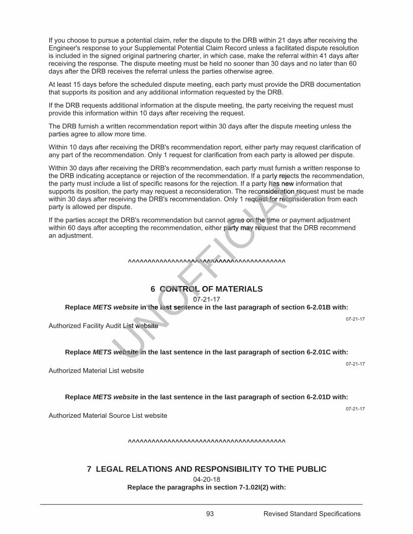
93 Revised Standard Specifications
If you choose to pursue a potential claim, refer the dispute to the DRB within 21 days after receiving the Engineer's response to your Supplemental Potential Claim Record unless a facilitated dispute resolution is included in the signed original partnering charter, in which case, make the referral within 41 days after receiving the response. The dispute meeting must be held no sooner than 30 days and no later than 60 days after the DRB receives the referral unless the parties otherwise agree.
At least 15 days before the scheduled dispute meeting, each party must provide the DRB documentation that supports its position and any additional information requested by the DRB.
If the DRB requests additional information at the dispute meeting, the party receiving the request must provide this information within 10 days after receiving the request.
The DRB furnish a written recommendation report within 30 days after the dispute meeting unless the parties agree to allow more time.
Within 10 days after receiving the DRB's recommendation report, either party may request clarification of any part of the recommendation. Only 1 request for clarification from each party is allowed per dispute.
Within 30 days after receiving the DRB's recommendation, each party must furnish a written response to the DRB indicating acceptance or rejection of the recommendation. If a party rejects the recommendation, the party must include a list of specific reasons for the rejection. If a party has new information that supports its position, the party may request a reconsideration. The reconsideration request must be made within 30 days after receiving the DRB's recommendation. Only 1 request for reconsideration from each party is allowed per dispute.
If the parties accept the DRB's recommendation but cannot agree on the time or payment adjustment within 60 days after accepting the recommendation, either party may request that the DRB recommend an adjustment.
^^^^^^^^^^^^^^^^^^^^^^^^^^^^^^^^^^^^^^^^
6 CONTROL OF MATERIALS 07-21-17
Replace METS website in the last sentence in the last paragraph of section 6-2.01B with: 07-21-17
Authorized Facility Audit List website
Replace METS website in the last sentence in the last paragraph of section 6-2.01C with: 07-21-17
Authorized Material List website
Replace METS website in the last sentence in the last paragraph of section 6-2.01D with: 07-21-17
Authorized Material Source List website
^^^^^^^^^^^^^^^^^^^^^^^^^^^^^^^^^^^^^^^^
7 LEGAL RELATIONS AND RESPONSIBILITY TO THE PUBLIC 04-20-18
Replace the paragraphs in section 7-1.02I(2) with:
UNOFFICIA
Lurn
rty rejecy has new inhas
consideration reqconsideration reqequest for reconsuest for recons
agree on the timeagree on the timr party may requeparty may requ
^^^^^^^^^^^^^^^^^^^^^^^^^
CONTROL OCONTROL07
in the last sente the last sent
List website List website
ebsiteebsite in in
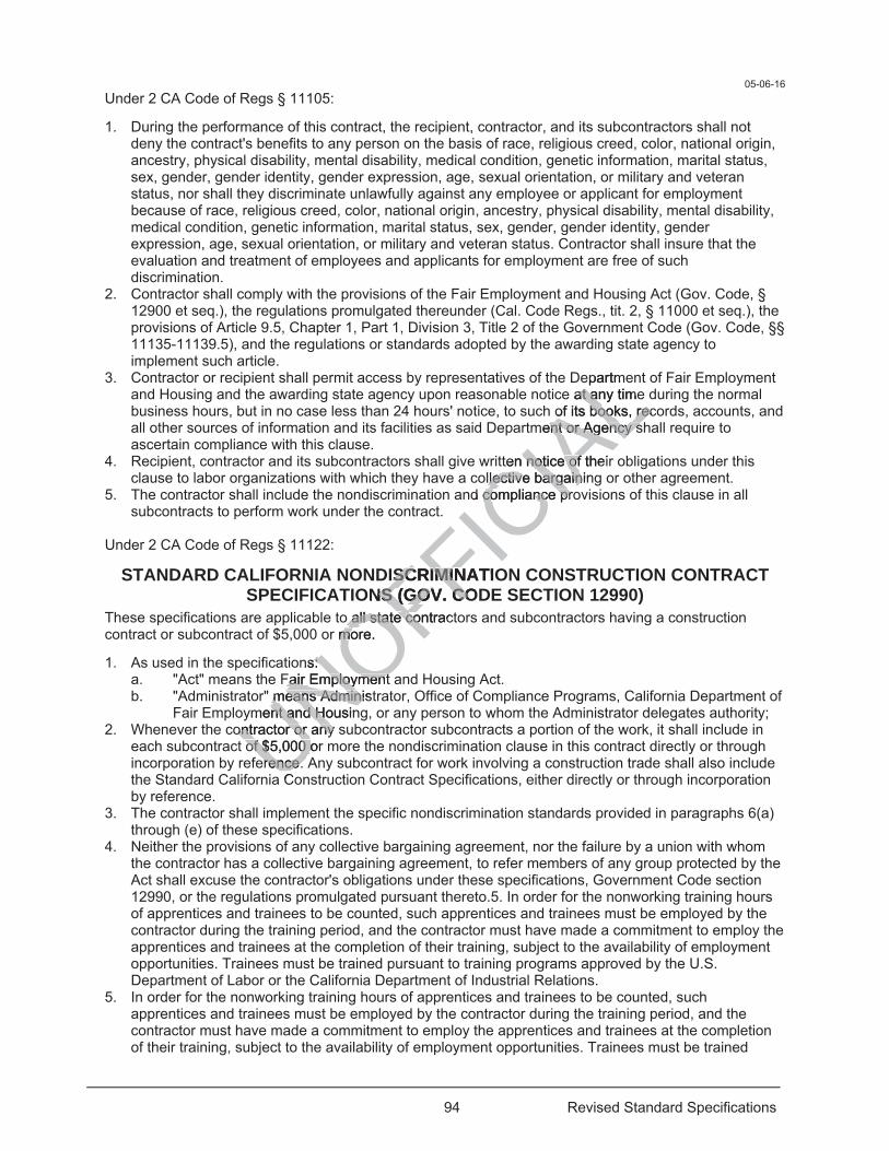
94 Revised Standard Specifications
05-06-16 Under 2 CA Code of Regs § 11105:
1. During the performance of this contract, the recipient, contractor, and its subcontractors shall not deny the contract's benefits to any person on the basis of race, religious creed, color, national origin, ancestry, physical disability, mental disability, medical condition, genetic information, marital status, sex, gender, gender identity, gender expression, age, sexual orientation, or military and veteran status, nor shall they discriminate unlawfully against any employee or applicant for employment because of race, religious creed, color, national origin, ancestry, physical disability, mental disability, medical condition, genetic information, marital status, sex, gender, gender identity, gender expression, age, sexual orientation, or military and veteran status. Contractor shall insure that the evaluation and treatment of employees and applicants for employment are free of such discrimination.
2. Contractor shall comply with the provisions of the Fair Employment and Housing Act (Gov. Code, § 12900 et seq.), the regulations promulgated thereunder (Cal. Code Regs., tit. 2, § 11000 et seq.), the provisions of Article 9.5, Chapter 1, Part 1, Division 3, Title 2 of the Government Code (Gov. Code, §§ 11135-11139.5), and the regulations or standards adopted by the awarding state agency to implement such article.
3. Contractor or recipient shall permit access by representatives of the Department of Fair Employment and Housing and the awarding state agency upon reasonable notice at any time during the normal business hours, but in no case less than 24 hours' notice, to such of its books, records, accounts, and all other sources of information and its facilities as said Department or Agency shall require to ascertain compliance with this clause.
4. Recipient, contractor and its subcontractors shall give written notice of their obligations under this clause to labor organizations with which they have a collective bargaining or other agreement.
5. The contractor shall include the nondiscrimination and compliance provisions of this clause in all subcontracts to perform work under the contract.
Under 2 CA Code of Regs § 11122:
STANDARD CALIFORNIA NONDISCRIMINATION CONSTRUCTION CONTRACT SPECIFICATIONS (GOV. CODE SECTION 12990)
These specifications are applicable to all state contractors and subcontractors having a construction contract or subcontract of $5,000 or more.
1. As used in the specifications: a. "Act" means the Fair Employment and Housing Act. b. "Administrator" means Administrator, Office of Compliance Programs, California Department of
Fair Employment and Housing, or any person to whom the Administrator delegates authority; 2. Whenever the contractor or any subcontractor subcontracts a portion of the work, it shall include in
each subcontract of $5,000 or more the nondiscrimination clause in this contract directly or through incorporation by reference. Any subcontract for work involving a construction trade shall also include the Standard California Construction Contract Specifications, either directly or through incorporation by reference.
3. The contractor shall implement the specific nondiscrimination standards provided in paragraphs 6(a) through (e) of these specifications.
4. Neither the provisions of any collective bargaining agreement, nor the failure by a union with whom the contractor has a collective bargaining agreement, to refer members of any group protected by the Act shall excuse the contractor's obligations under these specifications, Government Code section 12990, or the regulations promulgated pursuant thereto.5. In order for the nonworking training hours of apprentices and trainees to be counted, such apprentices and trainees must be employed by the contractor during the training period, and the contractor must have made a commitment to employ the apprentices and trainees at the completion of their training, subject to the availability of employment opportunities. Trainees must be trained pursuant to training programs approved by the U.S. Department of Labor or the California Department of Industrial Relations.
5. In order for the nonworking training hours of apprentices and trainees to be counted, such apprentices and trainees must be employed by the contractor during the training period, and the contractor must have made a commitment to employ the apprentices and trainees at the completion of their training, subject to the availability of employment opportunities. Trainees must be trained
UNOFFICIA
Lepartme
e at any timeat aof its books, recof its books, rec
ment or Agency sent or Agency s
ten noticnoti e of theie ofllective bargaininllective bargain
nd compliance procompliance pr
ISCRISCRIMINATIOMINONS (GOV. CONS (GOV. CO
o all state o all state contracconr more. mo
ns: s:Fair Employment Fair Employment
means Administmeans Adminiment and Housinnt and Ho
ontractor or any sontractor or any of $5,000 or of $5,000 o
erence. erence. a C
95 Revised Standard Specifications
pursuant to training programs approved by the U.S. Department of Labor or the California Department of Industrial Relations.
6. The contractor shall take specific actions to implement its nondiscrimination program. The evaluation of the contractor's compliance with these specifications shall be based upon its effort to achieve maximum results from its actions. The contractor must be able to demonstrate fully its efforts under steps a. through e. below: a. Ensure and maintain a working environment free of harassment, intimidation, and coercion at
all sites, and at all facilities at which the contractor's employees are assigned to work. The contractor shall specifically ensure that all foremen, superintendents, and other on-site supervisory personnel are aware of and carry out the contractor's obligations to maintain such a working environment.
b. Provide written notification within seven days to the director of the DFEH when the referral process of the union or unions with which the contractor has a collective bargaining agreement has impeded the contractor's efforts to meet its obligations.
c. Disseminate the contractor's equal employment opportunity policy by providing notice of the policy to unions and training, recruitment and outreach programs and requesting their cooperation in assisting the contractor to meet its obligations; and by posting the company policy on bulletin boards accessible to all employees at each location where construction work is performed.
d. Ensure all personnel making management and employment decisions regarding hiring, assignment, layoff, termination, conditions of work, training, rates of pay or other employment decisions, including all supervisory personnel, superintendents, general foremen, on-site foremen, etc., are aware of the contractor's equal employment opportunity policy and obligations, and discharge their responsibilities accordingly.
e. Ensure that seniority practices, job classifications, work assignments, and other personnel practices, do not have a discriminatory effect by continually monitoring all personnel and employment related activities to ensure that the equal employment opportunity policy and the contractor's obligations under these specifications are being carried out.
7. Contractors are encouraged to participate in voluntary associations that assist in fulfilling their equal employment opportunity obligations. The efforts of a contractor association, joint contractor-union, contractor-community, or other similar group of which the contractor is a member and participant, may be asserted as fulfilling any one or more of its obligations under these specifications provided that the contractor actively participates in the group, makes every effort to assure that the group has a positive impact on equal employment opportunity in the industry, ensures that the concrete benefits of the program are reflected in the contractor's workforce participation, and can provide access to documentation that demonstrates the effectiveness of actions taken on behalf of the contractor. The obligation to comply, however, is the contractor's.
8. The contractor is required to provide equal employment opportunity for all persons. Consequently, the contractor may be in violation of the Fair Employment and Housing Act (Government Code section 12990 et seq.) if a particular group is employed in a substantially disparate manner.
9. The contractor shall not use the nondiscrimination standards to discriminate against any person because race, religious creed, color, national origin, ancestry, physical disability, mental disability, medical condition, genetic information, marital status, sex, gender, gender identity, gender expression, age, sexual orientation, or military and veteran status.
10. The contractor shall not enter into any subcontract with any person or firm decertified from state contracts pursuant to Government Code section 12990.
11. The contractor shall carry out such sanctions and penalties for violation of these specifications and the nondiscrimination clause, including suspension, termination and cancellation of existing subcontracts as may be imposed or ordered pursuant to Government Code section 12990 and its implementing regulations by the awarding agency. Any contractor who fails to carry out such sanctions and penalties shall be in violation of these specifications and Government Code section 12990.
12. The contractor shall designate a responsible official to monitor all employment related activity to ensure that the company equal employment opportunity policy is being carried out, to submit reports relating to the provisions hereof as may be required by OCP and to keep records. Records shall at least include for each employee the name, address, telephone numbers, construction trade, union affiliation if any, employee identification number when assigned, status, (e.g., mechanic, apprentice trainee, helper, or laborer), dates of changes in status, hours worked per week in the indicated trade, rate of pay, and locations at which the work was performed. Records shall be maintained in any
UNOFFICIA
Ltion
decisions regacisions regag, rates of payg, rates of pay or or
endents, general ents, generalmployment opportployment opport
ccordingly. ccordingly. ns, work assignms, work assignm
by continually m by continuallyat the equal empat the equal emp
ecifications are beecifications are bn voluntvoluntary assocary asso
e efforts of a efforts of contrr group of whgroup of which tich
e or more of its more oipates in the groupates in the g
oyment opportunment opportunn the contractor's the contractor'
onstrates tates the effehe effehowever, is the cowever, is the
quired to provide uired to providee in violation of the in violation ofa particular groa particular gro
ll not use ll not useus creus cre

96 Revised Standard Specifications
easily understandable and retrievable form; however, to the degree that existing records satisfy this requirement, contractors shall not be required to maintain separate records.
Add to the end of the 2nd sentence in the 1st paragraph of section 7-1.02K(1): 04-22-16
, and hauling and delivery of ready-mixed concrete.
Add between the 4th and 5th paragraphs of section 7-1.02K(3): 04-22-16
Submitted certified payrolls for hauling and delivering ready-mixed concrete must be accompanied by a written time record. The time record must include:
1. Truck driver's full name and address 2. Name and address of the factory or batching plant 3. Time the concrete was loaded at the factory or batching plant 4. Time the truck returned to the factory or batching plant 5. Truck driver's signature certifying under penalty of perjury that the information contained in this written
time record is true and correct
Add between the 1st and 2nd paragraphs of section 7-1.02K(6)(a) 04-20-18
You must contact the local public health service department for information concerning public health conditions within the area of the project.
Add to the end of section 7-1.02K(6)(a): 04-20-18
The Department is not responsible for the health and safety of:
1. Contractor's personnel 2. Subcontractor's personnel 3. Supplier's personnel 4. Any other persons present at the job site at the request of you or your subcontractors.
Replace item 3 in the list in the 3rd paragraph of section 7-1.02K(6)(j)(ii) with: 04-20-18
3. Sealed and signed by a CIH with knowledge of and experience complying with 8 CA Code of Regs
Add between the 9th and 10th paragraphs of section 7-1.03: 07-15-16
If a height differential of more than 0.04 foot is created by construction activities at a joint transverse to the direction of traffic on the traveled way or a shoulder subject to public traffic, construct a temporary taper at the joint with a slope complying with the requirements shown in the following table:
UNOFFICIA
Le information cone information con
raphs of section phs of section
partment for infopartment for info
the end of sectithe end of sect
e for the health ae for the healt
nnel nnel el
ns present at the jns present at the
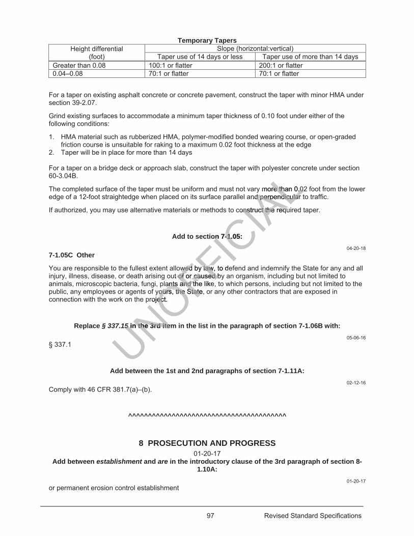
97 Revised Standard Specifications
Temporary Tapers Height differential
(foot) Slope (horizontal:vertical)
Taper use of 14 days or less Taper use of more than 14 days Greater than 0.08 100:1 or flatter 200:1 or flatter 0.04–0.08 70:1 or flatter 70:1 or flatter
For a taper on existing asphalt concrete or concrete pavement, construct the taper with minor HMA under section 39-2.07.
Grind existing surfaces to accommodate a minimum taper thickness of 0.10 foot under either of the following conditions:
1. HMA material such as rubberized HMA, polymer-modified bonded wearing course, or open-graded friction course is unsuitable for raking to a maximum 0.02 foot thickness at the edge
2. Taper will be in place for more than 14 days For a taper on a bridge deck or approach slab, construct the taper with polyester concrete under section 60-3.04B.
The completed surface of the taper must be uniform and must not vary more than 0.02 foot from the lower edge of a 12-foot straightedge when placed on its surface parallel and perpendicular to traffic.
If authorized, you may use alternative materials or methods to construct the required taper.
Add to section 7-1.05: 04-20-18
7-1.05C Other
You are responsible to the fullest extent allowed by law, to defend and indemnify the State for any and all injury, illness, disease, or death arising out of or caused by an organism, including but not limited to animals, microscopic bacteria, fungi, plants and the like, to which persons, including but not limited to the public, any employees or agents of yours, the State, or any other contractors that are exposed in connection with the work on the project.
Replace § 337.15 in the 3rd item in the list in the paragraph of section 7-1.06B with: 05-06-16
§ 337.1
Add between the 1st and 2nd paragraphs of section 7-1.11A: 02-12-16
Comply with 46 CFR 381.7(a)–(b).
^^^^^^^^^^^^^^^^^^^^^^^^^^^^^^^^^^^^^^^^
8 PROSECUTION AND PROGRESS 01-20-17
Add between establishment and are in the introductory clause of the 3rd paragraph of section 8-1.10A:
01-20-17 or permanent erosion control establishment
UNOFFICIA
Lste
y more than 0.02re than 0.0nd perpendicular d perpendicular
construct the requonstruct the requ
on 7-1.05: on 7-1
wed by law, to dewed by lawut of orof or caused by caused b
ants and the likeants and tyours, the State, oours, the State
roject. ec
155 in the 3rd itemin the 3rd ite55
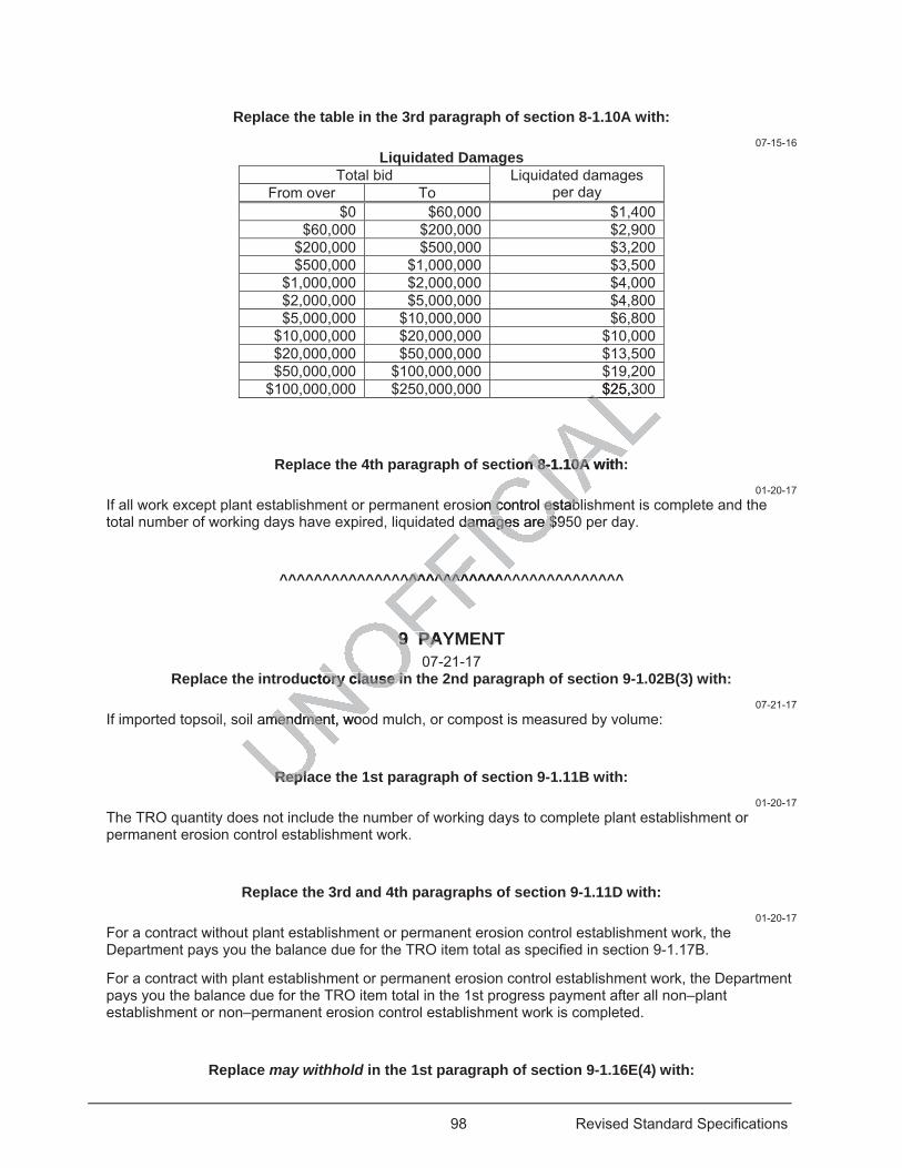
98 Revised Standard Specifications
Replace the table in the 3rd paragraph of section 8-1.10A with: 07-15-16
Liquidated Damages Total bid Liquidated damages
per day From over To $0 $60,000 $1,400
$60,000 $200,000 $2,900 $200,000 $500,000 $3,200 $500,000 $1,000,000 $3,500
$1,000,000 $2,000,000 $4,000 $2,000,000 $5,000,000 $4,800 $5,000,000 $10,000,000 $6,800
$10,000,000 $20,000,000 $10,000 $20,000,000 $50,000,000 $13,500 $50,000,000 $100,000,000 $19,200
$100,000,000 $250,000,000 $25,300
Replace the 4th paragraph of section 8-1.10A with: 01-20-17
If all work except plant establishment or permanent erosion control establishment is complete and the total number of working days have expired, liquidated damages are $950 per day.
^^^^^^^^^^^^^^^^^^^^^^^^^^^^^^^^^^^^^^^^
9 PAYMENT 07-21-17
Replace the introductory clause in the 2nd paragraph of section 9-1.02B(3) with: 07-21-17
If imported topsoil, soil amendment, wood mulch, or compost is measured by volume:
Replace the 1st paragraph of section 9-1.11B with: 01-20-17
The TRO quantity does not include the number of working days to complete plant establishment or permanent erosion control establishment work.
Replace the 3rd and 4th paragraphs of section 9-1.11D with: 01-20-17
For a contract without plant establishment or permanent erosion control establishment work, the Department pays you the balance due for the TRO item total as specified in section 9-1.17B.
For a contract with plant establishment or permanent erosion control establishment work, the Department pays you the balance due for the TRO item total in the 1st progress payment after all non–plant establishment or non–permanent erosion control establishment work is completed.
Replace may withhold in the 1st paragraph of section 9-1.16E(4) with:
$19$25,30LL
ion 8-1.10A withn 8-1.10A
ion control establn control estabdamages are $9damages are $
^^^^^^^^^^^^^^^^^^^^^
9 PAY9 PA0
ductory clause inory clause in
amendment, woomendment, woo
ReplaRepla
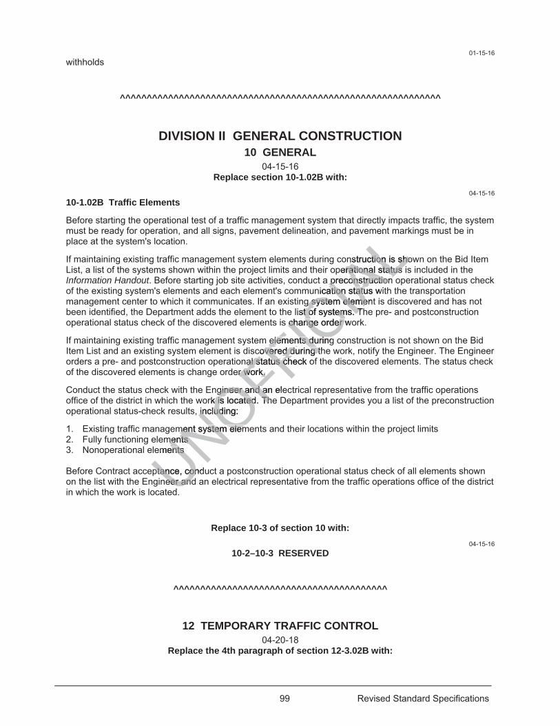
99 Revised Standard Specifications
01-15-16 withholds
^^^^^^^^^^^^^^^^^^^^^^^^^^^^^^^^^^^^^^^^^^^^^^^^^^^^^^^^^^^^
DIVISION II GENERAL CONSTRUCTION 10 GENERAL
04-15-16 Replace section 10-1.02B with:
04-15-16 10-1.02B Traffic Elements
Before starting the operational test of a traffic management system that directly impacts traffic, the system must be ready for operation, and all signs, pavement delineation, and pavement markings must be in place at the system's location.
If maintaining existing traffic management system elements during construction is shown on the Bid Item List, a list of the systems shown within the project limits and their operational status is included in the Information Handout. Before starting job site activities, conduct a preconstruction operational status check of the existing system's elements and each element's communication status with the transportation management center to which it communicates. If an existing system element is discovered and has not been identified, the Department adds the element to the list of systems. The pre- and postconstruction operational status check of the discovered elements is change order work.
If maintaining existing traffic management system elements during construction is not shown on the Bid Item List and an existing system element is discovered during the work, notify the Engineer. The Engineer orders a pre- and postconstruction operational status check of the discovered elements. The status check of the discovered elements is change order work.
Conduct the status check with the Engineer and an electrical representative from the traffic operations office of the district in which the work is located. The Department provides you a list of the preconstruction operational status-check results, including:
1. Existing traffic management system elements and their locations within the project limits 2. Fully functioning elements 3. Nonoperational elements Before Contract acceptance, conduct a postconstruction operational status check of all elements shown on the list with the Engineer and an electrical representative from the traffic operations office of the district in which the work is located.
Replace 10-3 of section 10 with: 04-15-16
10-2–10-3 RESERVED
^^^^^^^^^^^^^^^^^^^^^^^^^^^^^^^^^^^^^^^^
12 TEMPORARY TRAFFIC CONTROL 04-20-18
Replace the 4th paragraph of section 12-3.02B with:
UNOFFICIA
Len
nstruction is shonstruction is shoperational status rational status
a preconstruction preconstruction nication status wiation statu
g system elementg system elemelist of systems. Tt of systems. T
s change order wochange order
elelements during ements duringcovered during thcovered during t
al status al status check ocer work. r work.
gineer and an elegineer and ark is located. k is located TheTh
, including: includ
ment system elemment system elemments ments
ements ents
ptance, condptance, coneer andeer and
d
100 Revised Standard Specifications
01-20-17 Retroreflective cone sleeves must be permanently affixed, double-band, sleeves consisting of 2 white retroreflective bands. The top band must be 6 inches wide and placed a maximum of 4 inches from the top of the cone. The lower band must be 4 inches wide and placed 2 inches below the bottom of the top band. You may use traffic cones with double-band retroreflective cone sleeves during daylight hours.
Replace section 12-3.32 with: 04-15-16
12-3.32 PORTABLE CHANGEABLE MESSAGE SIGNS
12-3.32A General
12-3.32A(1) Summary
Section 12-3.32A includes specifications for placing portable changeable message signs.
12-3.32A(2) Definitions
Reserved
12-3.32A(3) Submittals
If requested, submit a certificate of compliance for each PCMS.
Submit your cell phone number before starting the first activity that requires a PCMS.
12-3.32A(4) Quality Assurance
Reserved
12-3.32B Materials
Each PCMS must have a message board, controller unit, power supply, and a structural support system. The unit must be assembled to form a complete self-contained PCMS that can be delivered to the job site and placed into immediate operation. The sign unit must be capable of operating at an ambient air temperature from -4 to 158 degrees F and must be unaffected by mobile radio transmissions other than those required to control the PCMS.
A PCMS must be permanently mounted on a trailer, truck bed, or truck cab under the manufacturer's instructions. The PCMS must be securely mounted on the support vehicle such that it remains attached during any impact to the vehicle. If it is mounted on a trailer, the trailer must be capable of being leveled and plumbed.
A minimum of 3 feet of retroreflective material must be permanently affixed on all 4 sides of the trailer. The retroreflective material need not be continuous but must be visible on the same plane.
The sign panel must be capable of displaying a 3-line message with at least 7 characters per line. The characters must be at least 18 inches in height where the useable shoulder area is at least 15 feet wide. To prevent encroachment onto the traveled way where the useable shoulder area is less than 15 feet wide, you may use a smaller message panel with at least 12-inch-high characters.
The message displayed on the sign must be visible from a distance of 1,500 feet and legible from a distance of 750 feet at noon on a cloudless day and during the night by persons with 20/20 vision or vision corrected to 20/20.
The characters on a sign panel may be 10 inches in height if:
1. PCMS is mounted on a service patrol truck or other incident response vehicle or used for traffic control operations on a highway facility where the posted speed limit is less than 40 mph
2. Message is legible from a distance of at least 650 feet at noon on a cloudless day and during the night by persons with 20/20 vision or vision corrected to 20/20
A matrix sign must provide a complete alphanumeric selection.
UNOFFICIA
Lty that requires aty that requires
controller unicontroller unit, potomplete self-cplete se ontn
The sign unitThe sign uni mus F and must be F and must be
MS. MS
ntly mounted on antly mounted on amust be securely must be securely
he vehicle. If it is mehicle. If
retrorefleretroreflel ne
101 Revised Standard Specifications
A PCMS must automatically adjust its brightness under varying light conditions to maintain the legibility of the message. The sign must be equipped with an automatic-dimming mode that automatically compensates for the influence of temporary light sources or abnormal lighting conditions. The sign must have 3 or more manual dimming modes of different intensities.
During the hours of darkness, a matrix sign not using lamps must be either internally or externally illuminated.
The controller must be an all solid-state unit containing the necessary circuitry for the storage of at least 5 preprogrammed messages. The controller must be installed at a location that allows the operator to perform all functions from a single position. The controller must have a keyboard entry system that allows the operator to generate an infinite number of additional messages in addition to the preprogrammed stored messages. The keyboard must be equipped with a security lockout feature to prevent unauthorized use of the controller.
The controller must have:
1. Nonvolatile memory that stores keyboard-created messages during periods when the power is not activated
2. Variable display rate that allows the operator to match the information display to the speed of approaching traffic
3. Screen upon which messages may be reviewed before being displayed on the sign The flashing-off time must be adjustable from within the control cabinet.
12-3.32C Construction
Place a PCMS as far from the traveled way as practicable where it is legible to approaching traffic without encroaching on the traveled way. Where the vertical roadway curvature restricts the sight distance of approaching traffic, place the sign on or before the crest of the curvature where it is most visible to the approaching traffic. Where the horizontal roadway curvature restricts the sight distance of approaching traffic, place the sign at or before the curve where it is most visible to approaching traffic. Where practicable, place the sign behind guardrail or Type K temporary railing.
Make a taper consisting of 9 traffic cones placed 25 feet apart to delineate the location of a PCMS except where the sign is placed behind guardrail or Type K temporary railing.
When in full operation, the bottom of a sign must be at least 7 feet above the roadway in areas where pedestrians are anticipated and 5 feet above the roadway elsewhere, and the top of the sign must be not more than 14.5 feet above the roadway.
Operate the PCMS under the manufacturer's instructions.
Keep the PCMS clean to provide maximum visibility.
If multiple signs are needed, place each sign on the same side of the road at least 1,000 feet apart on freeways and expressways and at least 500 feet apart on other types of highways.
If more than one PCMS is simultaneously visible to traffic, only 1 sign may display a sequential message at any time. Do not use dynamic message displays, such as animation, rapid flashing, dissolving, exploding, scrolling, horizontal movement, or vertical movement of messages. The message must be centered within each line of the display.
You may use an additional PCMS if more than 2 phases are needed to display a message.
Display only messages shown or ordered.
Repeat the entire message continuously in not more than 2 phases of at least 3 seconds per phase. The sum of the display times for both of the phases must be a maximum of 8 seconds. If more than 2 phases are needed to display a message, use an additional PCMS.
You must be available by cell phone during activities that require a sign. Be prepared to immediately change the displayed message if ordered. You may operate the sign with a 24-hour timer control or remote control if authorized.
display td
played on the sigplayed on the sig
cabinet. abinet.
able where it is legble where it is roadway curvaturoadway curvatu
e crese cre t of the curvf theway cuway curvature resrvature res
where it is most vwhere it is mail or Type K templ or Type K tem
ones placed 25 fones placed 2 euarrdrail or Type Kdrail or Type K
tom of a sign mum of a sign muand 5 feetand 5 feet above above
ve the roadway. e the roadway.
under the munder the manufaanuf
to provideto provide
102 Revised Standard Specifications
After the initial placement, move a sign from location to location as ordered.
When a PCMS is not in use, move it to an area at least 15 feet from the edge of the traveled way or remove it from the job site away from traffic.
12-3.32D Payment
Not Used
Add to section 12-4.02A(2): 07-21-17
Construction Zone Enhanced Enforcement Program (COZEEP): Program that provides California Highway Patrol officers to monitor the movement of traffic within the work zone.
Add between the 1st sentence and 2nd sentences in the 1st paragraph of section 12-4.02A(3)(a): 07-15-16
For a project in District 7, submit the request at least 15 days before the proposed closure date.
Add to the end of section 12-4.02A(3)(a): 07-21-17
Submit a traffic break request using LCS to show the location and time of the requested traffic break.
Replace unauthorized closures or in the last paragraph of section 12-4.02A(3)(b) with: 07-21-17
authorized and unauthorized closures and
Add to section 12-4.02A(3): 07-21-17
12-4.02A(3)(d) Traffic Break Schedule
Every Monday by noon, submit a traffic break request for the next week. Support for a traffic break is based on local California Highway Patrol staffing levels and may not be available for the date or time requested.
Traffic break requests are limited to the hours when a shoulder or lane closure is allowed.
Cancel a traffic break request using LCS at least 48 hours before the start time of the traffic break.
The Department notifies you through LCS of authorized and unauthorized traffic breaks.
The Department does not adjust time or payment if (1) a California Highway Patrol officer is unavailable for the requested date or time or (2) your request is not authorized.
Replace section 12-4.02C(2) with: 01-15-16
12-4.02C(2) Lane Closure System
12-4.02C(2)(a) General
The Department provides LCS training. Request the LCS training at least 30 days before submitting the 1st closure request. The Department provides the training within 15 days after your request.
UNOFFICIA
Le proposed cloroposed clo
4.02A(3)(a): 02A(3)(a):
ation and time of on and time of
he last paragrape last paragra
d
Add to secAdd to s
eak Schedule ak Schedule
n, submit a trafficubmit a traornia Highway Pornia Highway P
im

103 Revised Standard Specifications
LCS training is web-based or held at a time and location agreed upon by you and the Engineer. For web-based training, the Engineer provides you the website address to access the training.
With 5 business days after completion of the training, the Department provides LCS accounts and user IDs to your assigned, trained representatives.
Each representative must maintain a unique password and current user information in the LCS.
04-15-16 The project is not accessible in LCS after Contract acceptance.
01-20-17 12-4.02C(2)(b) Status Updates for Authorized Closures
Update the status of authorized closures using the LCS Mobile web page.
For a stationary closure on a traffic lane, use code:
1. 10-97 immediately before you place the 1st cone on the traffic lane 2. 10-98 immediately after you remove all of the cones from the traffic lane For a stationary closure on the shoulder, use code:
1. 10-97 immediately before you place the 1st cone after the last advance warning sign 2. 10-98 immediately after you remove the last cone before the advance warning signs
For a moving closure, use code:
1. 10-97 immediately before the actual start time of the closure 2. 10-98 immediately after the actual end time of the closure
For closures not needed on the authorized date, use code 10-22 within 2 hours after the authorized start time.
If you are unable to access the LCS Mobile web page, immediately notify the Engineer of the closure's status.
Add to the end of section 12-4.02C(7): 07-21-17
12-4.02C(7)(d) Traffic Breaks
You may request a traffic break for special operations, such as:
1. Installation, removal, or replacement of an overhead power line or other utility cable across the highway
2. Falsework adjustment 3. Installation or removal of traffic control devices in areas without a standard-width shoulder 4. Transportation of large equipment across the highway 5. Access to median areas for workers or equipment If the Department authorizes the traffic break, the Engineer notifies you and arranges the traffic break with the California Highway Patrol through COZEEP. The duration of a traffic break must not exceed 5 minutes or as authorized.
Two California Highway Patrol officers per vehicle are required for traffic breaks occurring any time from 2200 to 0600 hours.
A minimum of 2 California Highway Patrol vehicles will be assigned to conduct a traffic break.
Place a PCMS approximately 2,000 feet upstream of the work area or as agreed upon by the Engineer. The PCMS must comply with section 12-3.32 except the PCMS must not be trailer mounted. Monitor the
UNOFFICIA
Ldvance warning svance warning sadvance warning ance warning
e closure ose closure closure
use code 10-22 use code 10-2
ile web page,e web page, imm im
Add to the enAdd to the en
Breaks reaks
raffic break for sraffic break for s
, or rep, or rep
104 Revised Standard Specifications
traffic during the traffic break. If a queue develops, reposition the PCMS truck far enough upstream of the traffic break to provide real-time notification to motorists before they approach the traffic queue.
Add to the end of section 12-4.02D: 07-21-17
The Department does not pay for furnishing, placing, relocating, and removing PCMSs used for a traffic break.
The Department deducts the full cost of COZEEP support provided for the traffic break.
The hourly rate for each California Highway Patrol officer providing COZEEP support is $115. This rate includes full compensation for each hour or portion thereof that the officer provides the support. Markups are not added to any expenses associated with COZEEP support.
The minimum number of hours for an officer is 4 hours, except if a closure is already in place and the Engineer authorizes your request for an on-duty officer to conduct a traffic break, the minimum number of hours for an officer is 1 hour.
For a cancellation less than 48 hours before the scheduled start time of COZEEP support, except for a cancellation due to adverse weather or extenuating circumstances, the Department deducts:
1. Minimum of $50 per California Highway Patrol officer if the officer is notified before the start time 2. Maximum of 4 hours of pay per officer if the officer is not notified before the start time
Replace section 12-4.04 with: 04-20-18
12-4.04 TEMPORARY PEDESTRIAN ACCESS ROUTES
12-4.04A General
12-4.04A(1) Summary
Section 12-4.04 includes specifications for providing, maintaining, and removing temporary pedestrian access routes.
A temporary pedestrian access route includes temporary traffic control devices as shown except for Type K temporary railing and temporary crash cushions.
12-4.04A(2) Definitions
Reserved
12-4.04A(3) Submittals
If work activities require the closure of a pedestrian route and a temporary pedestrian access route is not shown, submit a work plan for a temporary pedestrian access route. The work plan must:
1. Describe the activities, processes, equipment, and materials that will be used to provide the temporary access route
2. Show the locations of the routes and the placement of traffic control devices for each stage of work 3. Include a time-scaled logic diagram displaying the sequence and duration of the planned activities for
each stage of work 4. Be sealed and signed by an engineer who is registered as a civil engineer in the State Submit “Temporary Pedestrian Access Route Contractor Compliance Report,” within 2 business days after construction of a temporary pedestrian access route,
Submit “Temporary Pedestrian Access Route Contractor Weekly Report,” within 2 business days of completing a weekly inspection.
UNOFFICIA
LCOZEEP suOZEhe Department dee Department de
ficer is notifficer is notified beied botified before thefied before
on 12-4.04 with: on 12-4.04 with:
SS ROUTES SS ROUTE
ations for providations for prov in
ccess route includccess route inctemporary crashemporary crash
ions ions
105 Revised Standard Specifications
12-4.04A(4) Quality Assurance
12-4.04A(4)(a) General
Reserved
12-4.04A(4)(b) Quality Control
Perform a review of the temporary pedestrian access route after it is constructed and document compliance on the “Temporary Pedestrian Access Route Contractor Compliance Report.”
The Department will conduct a verification inspection after receiving the compliance report.
For a temporary pedestrian access route in use perform a weekly review and document compliance on the “Temporary Pedestrian Access Route Contractor Weekly Report.”
12-4.04B Materials
The walkway surface must be slip resistant and surfaced with minor HMA or commercial-quality, bituminous material, commercial-quality concrete, or wood.
A handrail with a circular cross section must have an outer diameter from 1-1/4 to 2 inches. A handrail with a noncircular cross section must have a perimeter from 4 to 6-1/4 inches and a maximum cross-section dimension of 2-1/4 inches.
Fasteners must be rounded to prevent injury to a pedestrian's fingers, hands, and arms and to eliminate sharp edges that could catch on clothing.
A detectable warning surface must be on the Authorized Material List for detectable warning surfaces and match yellow color no. 33538 of FED-STD-595.
Temporary traffic control devices used to channelize pedestrians must:
1. Be free of sharp or rough edges 2. Have a continuous detectable edging at least 6 inches high and at no more than 2 inches above the
walkway surface 3. Be at least 32 inches in height 4. Have smooth connection points between devices to allow for a handrail 5. Have a top and bottom surface in the same vertical plane 12-4.04C Construction
Notify the Engineer 5 business days before closing an existing pedestrian route. Do not close the route until authorized.
If work activities require the closure of a pedestrian route and a temporary pedestrian access route is not shown, provide a temporary pedestrian access route near the traveled way. You may route pedestrians using the existing sidewalk or by constructing a temporary access route.
If a bid item for a temporary pedestrian access route is not shown on the Bid Item List, then constructing a temporary pedestrian access route is change order work except, when the closure is a result of your means and methods.
Construct a temporary pedestrian access route such that:
1. Walkway surface is firm and stable and free of irregularities 2. Cross slope of the pedestrian route is at most 50:1 (horizontal:vertical) 3. Longitudinal slope of the pedestrian route is at most 20:1 (horizontal:vertical) 4. Walkway, landings, blended transitions, and curb ramps are at least 60 inches wide except where not
feasible, the width must be at least 48 inches wide with a 60-by-60-inch passing space at least every 200 feet
5. Lateral joints or gaps between surfaces are less than 1/2 inch wide 6. Discontinuities in surface heights are less than 1/2 inch and beveled if greater than 1/4 inch with a
slope no greater than 2:1 (horizontal:vertical)
UNOFFICIA
L1-1/4 to 21-1inches and a mes and a m
ingers, hands, angers, hands, an
d Material List for aterial List for
lize pedestrians mlize pedestria
at least 6 inches at least 6 inche
ts between devicebetween devicace in the same vce in the same
business days beness days
the closthe closy p
106 Revised Standard Specifications
7. Ramps have: 7.1. Longitudinal slope of at most 12:1 (horizontal:vertical) 7.2. Rise less than 30 inches 7.3. Protective edging at least 2 inches high on each side and handrails at a height from 34 to 38
inches above the walkway surface if the rise is greater than 6 inches 8. Curb ramps have:
8.1. Longitudinal slope of at most 12:1 (horizontal:vertical) 8.2. Protective edging at least 2 inches high on each side if the curb ramp does not have flares and
the rise is greater than 6 inches 9. Pedestrians are channelized when routed off existing pedestrian routes Construct handrails such that they are continuous, smooth and free of sharp or rough edges.
Provide an overhead covering to protect pedestrians from falling objects and drippings from overhead structures.
If the temporary access route is next to traffic or work activities, place a temporary barrier to separate the route from vehicles and equipment.
Install a detectable warning surface at locations where a curb ramp, landing, or blended transition connects to a street. Install the warning surface such that it extends a minimum of 36 inches in the direction of travel and for the full width of the landing, blended transition, or curb ramp, excluding the flares.
Maintain the temporary pedestrian access route clear of obstructions. Do not allow traffic control devices, equipment, or construction materials to protrude into the walkway. Maintain a continuous unobstructed path connecting all pedestrian routes, parking lots, and bus stops located within the project limits.
Remove the temporary pedestrian access route when the Engineer determines it is no longer needed.
Provide a temporary pedestrian access route through falsework under section 16-2.02.
12-4.04D Payment
Not Used
Replace the last sentence in the 1st paragraph of section 12-6.03A with: 01-20-17
On multilane roadways, freeways, expressways, and 2-lane roadways with shoulders 4 feet or more in width, the temporary pavement delineation must also include edge line delineation for traveled ways open to traffic.
Replace the 1st sentence in the 3rd paragraph of section 12-6.03A with: 07-15-16
When the Engineer determines the temporary pavement delineation is no longer required for the direction of traffic, remove the temporary pavement delineation, including any underlying adhesive for temporary pavement markers, from the final layer of surfacing and from the pavement to remain in place.
Replace the introductory clause in the 1st paragraph of section 12-6.03C with: 01-20-17
On multilane roadways, freeways, expressways, and 2-lane roadways with shoulders 4 feet or more in width open to traffic where edge lines are obliterated and temporary pavement delineation to replace those edge lines is not shown, provide temporary pavement delineation for:
Replace 4-inch-wide at each occurrence in section 12-6.03C with:
UNOFFICIA
Lng, or blenng,minimum of 36 mum of 36
tion, or curb rampon, or curb ram
ructions. Do not auctions. Do nwalkway. Maintainalkway. Maintain
bus stops locateds stops located
en the Engineer den the Engineer d
hrough falseworkhrough falsework
ast sentence in tentence in t
, freeways, exprereeways, pavement delinepavement delin

107 Revised Standard Specifications
04-20-18 6-inch-wide
^^^^^^^^^^^^^^^^^^^^^^^^^^^^^^^^^^^^^^^^
13 WATER POLLUTION CONTROL 04-20-18
Replace construction phase and its definition in section 13-1.01B with: 01-20-17
construction phase: Phase that includes (1) the highway construction phase for building roads and structures, (2) the plant establishment, permanent erosion control establishment, and maintenance phase for placing vegetation for final stabilization, and (3) the suspension phase for suspension of work activities or a winter shutdown. The construction phase starts at the start of job site activities and ends at Contract acceptance.
Replace General Industrial Permit in the 2nd item in the list in the paragraph of section 13-1.01C(3) with:
05-06-16 Industrial General Permit
Add to the list in the paragraph of section 13-1.01C(3): 01-20-17
3. Copy of the plans for an offsite drying facility if you will be drying liquid residue from concrete grooving or grinding activities before disposal. The facility may include temporary lined ponds or other measures to prevent the liquid residue from infiltrating the soil. The plans must be sealed and signed by an engineer who is registered as a civil engineer in the State.
Replace section 13-1.01C(5) with: 01-20-17
13-1.01C(5) Disposal Documentation
At least 15 days before starting concrete grooving or grinding activities, submit a copy of one of the following documents from the disposal facility that will receive the grooving or grinding residue:
1. RWQCB permit allowing the facility to manage and dispose of the residue 2. Written approval from the RWQCB authorizing the facility to receive the residue 3. Local, state, or federal permits if the facility is located outside the State
Within 5 business days of completing concrete grooving or grinding activities, submit the disposal receipts and weight tickets as informational submittals.
Replace the 2nd paragraph of section 13-1.01D(2) with: 05-06-16
Discharges from manufacturing facilities, such as batch plants and crushing plants, must comply with the discharge requirements in the NPDES General Permit for Storm Water Discharges Associated with Industrial Activities; Order No. 2014-0057-DWQ, CAS000001 (Industrial General Permit), issued by the SWRCB. For the Industrial General Permit, go to the SWRCB website.
UNOFFICIA
Le paragraph of se paragraph of
graph of sectiongraph of section
cility if you will be cility if you isposal. The facilsposal. The fa
due from infiltfrom in ratinasas a civil enginee a civil eng
Replace Replace
al Documentatioal Documentat
e starting coe starting cm the dm the d

108 Revised Standard Specifications
Replace General Industrial Permit in the 3rd paragraph of section 13-1.01D(2) with: 05-06-16
Industrial General Permit
Add to the list in the 2nd paragraph of section 13-1.03B: 01-20-17
7. Offsite drying facilities for drying wastes before disposal
Replace item 7 in the list in the 2nd paragraph of section 13-2.01C with: 04-20-18
7. Include a copy of each permit obtained by the Department, such as the Department of Fish and Game permits, US Army Corps of Engineers permits, RWQCB 401 certifications, Docket No. ESPO-SMA 15/16-001 Soil Management Agreement for Aerially Deposited Lead-Contaminated Soils with the DTSC (ADL Agreement), ADL Agreement notification, and RWQCB waste discharge requirements for reuse of aerially deposited lead
Add between Unit and the in the 1st sentence in the 3rd paragraph of section 13-3.01A: 01-20-17
or on federal or tribal lands
Replace the paragraph in section 13-3.01C(1) with: 01-20-17
Submit the documents shown with an X in the following table:
Submittal Requirements Document Risk
level 1 Risk
level 2 Risk
level 3 EPA Lake Tahoe
Hydrologic Unit SWPPP X X X X X Construction Site Monitoring Program X X X X Xa
Job site monitoring reports X X X X X Sampling and analysis plan X X X X X Sampling and analysis plan for nonvisible pollutants
X X X X X
Sampling and analysis plan for pH and turbidity
-- X X -- X
NAL reports -- X X -- X Receiving water monitoring trigger reports
-- -- X -- --
Rain Event Action Plan -- X X -- X Annual Certification X X X X X Stormwater Annual Report X X X X X aFor a project in the Lake Tahoe Hydrologic Unit, this program is referred to as the Construction Site Monitoring and Reporting Program
Replace item 5 in the list in the 2nd paragraph of section 13-3.01C(2)(a) with: 04-20-18
5. Include a copy of each permit obtained by the Department, such as the Department of Fish and Game permits, US Army Corps of Engineers permits, RWQCB 401 certifications, Docket No. ESPO-SMA 15/16-001 Soil Management Agreement for Aerially Deposited Lead-Contaminated Soils with
UNalysis plan alysis plan UNOFFICIA
LB waste
3rd paragraph ofd paragraph o
ph in section 13ph in section 1
n the following tabthe following ta
SubmSRisR
leOFOFNONOOOOOOOng Program g Program NO
reports eports NUNalysis plan for alysis plan fss UN
s plalU

109 Revised Standard Specifications
the DTSC (ADL Agreement), ADL Agreement notification, and RWQCB waste discharge requirements for aerially deposited lead reuse
Add between Unit and discharges in the 1st paragraph of section 13-3.01D(2): 01-20-17
or on federal or tribal lands
Replace the 2nd paragraph of section 13-3.01D(2) with: 09-02-16
For a project in the Lake Tahoe Hydrologic Unit, discharges of stormwater from the project must comply with the NPDES General Permit for General Waste Discharge Requirements and National Pollutant Discharge Elimination System General Permit for Storm Water Discharges Associated with Construction Activity in the Lake Tahoe Hydrologic Unit, Counties of Alpine, El Dorado, and Placer, (Order No. R6T-2016-0010 and NPDES No. CAG616002). You may view the General Permit for the Lake Tahoe Hydrologic Unit at the Construction Storm Water Program page of the SWRCB website.
Add to the end of section 13-3.01D(2): 01-20-17
A project on federal or tribal lands must comply with the permit issued by the US EPA for National Pollutant Discharge Elimination System General Permit for Discharges from Construction Activities. This permit governs stormwater and nonstormwater discharges from work activities at the job site. This permit may be viewed at the US EPA website.
Add to the beginning of section 13-3.03: 01-20-17
Post a sign or other notice at a safe, publicly accessible location close to the job site. The notice must include the NPDES tracking number and a contact name and phone number for obtaining additional project information. Locate the sign or notice such that it is visible from the part of the highway nearest the work activities.
Replace the 2nd paragraph of section 13-4.03D(3) with: 01-20-17
Collect concrete waste simultaneously with the waste-producing activity. Concrete waste includes grout, dust, debris, residue, and slurry from demolition, saw cutting, coring, grooving, or grinding activities.
Add to the end of section 13-4.03D(3): 01-20-17
Dispose of liquid residue from concrete grooving or grinding activities at an appropriately permitted disposal facility.
If authorized, you may transport liquid grooving or grinding residue to a contractor-support facility for drying.
Replace section 13-5.02C with: 01-20-17
Section 13-5.02C Temporary Mulch
t forWRCB webR
3.01D(2): .01D(2)
ermit issued by thrmit issued by thfor Discharges frDischarges fr
arges frges from work aom work
e beginning of sbeginning of
, publicly accessipublicly accesber and a contacber and a con
sign or notice suign or notice s
Replace theReplace the
multalt
110 Revised Standard Specifications
Temporary mulch must comply with the specifications for wood mulch in section 20.
Replace the 1st paragraph of section 13-5.03C with: 01-20-17
Spread temporary mulch as specified for spreading wood mulch in section 20.
Replace the 2nd paragraph of section 13-8.01D(2) with: 09-02-16
For a project within the Lake Tahoe Hydrologic Unit, the design, installation, operation, and monitoring of the temporary ATS and monitoring of the treated effluent must comply with Attachment E of the NPDES General Permit for General Waste Discharge Requirements and National Pollutant Discharge Elimination System General Permit for Storm Water Discharges Associated with Construction Activity in the Lake Tahoe Hydrologic Unit, Counties of Alpine, El Dorado, and Placer, (Order No. R6T-2016-0010 and NPDES No. CAG616002). You may view the General Permit for the Lake Tahoe Hydrologic Unit at the Construction Storm Water Program page of the SWRCB website.
Replace high-visibility fence at each occurrence in section 13-10.02 with: 01-20-17
temporary high-visibility fence
Replace sections 13-11–13-15 with: 04-20-18
13-11 RESERVED
13-12 TEMPORARY CREEK DIVERSION SYSTEMS
Reserved
13-13–13-15 RESERVED
^^^^^^^^^^^^^^^^^^^^^^^^^^^^^^^^^^^^^^^^
14 ENVIRONMENTAL STEWARDSHIP 04-20-18
Add to section 14-6.02: 07-21-17
biological resource incident: Take of a regulated species or violation of a biological resource PLAC.
invasive species: Species whose presence in the environment causes economic or environmental harm or harm to human health.
07-21-17 Delete regulated fish and its definition in section 14-6.02.
Replace February 15 to September 1 in the 2nd paragraph of section 14-6.03B with: 07-21-17
February 1 to September 30
UNOFFICIA
Lho
in section 13-10section 13-10
ns 13-11–13-15 wns 13-11–13-15 w
3-11 RESERVE3-11 RES
ORARY CREEK DARY CREEK
13-13–13–
^^^^^^^^^^^^^^^^^
11
111 Revised Standard Specifications
Replace the 1st paragraph of section 14-6.03C with: 07-21-17
Protect all life stages of regulated fish in streams and conduct work activities to allow free passage of migratory fish.
Replace listed in the 2nd paragraph of section 14-6.03C with: 07-21-17
regulated
Replace item 4 in the list in the 2nd paragraph of section 14-6.03D(1) with: 07-21-17
4. Immediately notify the Engineer of any take of regulated species or violation of a biological resource PLAC
Add to the list in the 3rd paragraph of section 14-6.03D(1): 07-21-17
10. Details of any take of regulated species or violation of a biological resource PLAC
Add between the 1st and 2nd sentences in the 4th paragraph of section 14-6.03D(1) with: 07-21-17
If required under PLACs, the Department sends the biologist's statement of qualifications to regulatory agencies for review and approval before hiring. Allow 30 days for the regulatory agencies' review.
07-21-17 Delete the 1st sentence of the 5th paragraph of section 14-6.03D(1).
Add between is and authorized in the last paragraph of section 14-6.03D(1): 07-21-17
approved by regulatory agencies
Add between the 2nd and 3rd sentences in the 3rd paragraph of section 14-10.01: 01-20-17
Do not perform solid waste management in the median area unless there is construction activity present. Perform solid waste management monthly during the plant establishment period.
Replace the 2nd paragraph of section 14-11.01 with: 04-20-18
If hazardous waste is or will be generated on the job site, the WPC manager must be knowledgeable of proper handling and emergency procedures for hazardous waste as demonstrated by submitting a training certificate which indicates completion of training required under 22 CA Code of Regs § 66265.16.
UNOFFICIA
Ltion
ection 14-6.03D(ection 14-6.03D(
a biological resoua biological reso
in the 4th paragin the 4th par
sends the biolsends the biologisoe hiring. ring. Allow 30 Allow 30
st sentence of tentence of t
tween w iss and and auau
genciegencie
112 Revised Standard Specifications
Replace the last paragraph of section 14-11.03 with: 01-20-17
Dispose of hazardous waste within 90 days of the start of generation. Use a hazardous waste manifest and a transporter registered with the DTSC to transport the waste to an appropriately permitted hazardous waste management facility. The transporter must have completed the California Highway Patrol's Basic Inspection of Terminals Program with a satisfactory rating.
Replace 13-mils-thick in section 14-11.05A with: 04-20-18
12-mils-thick
Replace section 14-11.08 with: 04-20-18
14-11.08 REGULATED MATERIAL CONTAINING AERIALLY DEPOSITED LEAD
Reserved
Replace section 14-11.09 with: 04-20-18
14-11.09 MINIMAL DISTURBANCE OF REGULATED MATERIAL CONTAINING AERIALLY DEPOSITED LEAD
Reserved
Replace the 2nd paragraph of section 14-11.12E with: 04-20-18
The Engineer signs the manifests as the hazardous waste generator within 5 business days of 1) receiving and accepting the analytical test results and 2) receiving your request for the generator's EPA Identification Number.
Replace the 2nd paragraph of section 14-11.13A with: 04-20-18
Any work that disturbs the existing paint system produces debris containing heavy metals in amounts that exceed the established thresholds in 8 CA Code of Regs and exposes workers to health hazards which must be addressed in your lead compliance plan. Welding, cutting, or heating the surfaces coated by the existing paint system produces toxic fumes and must be done in compliance with 8 CA Code of Regs § 1537.
Any work that disturbs the existing paint system produces debris containing heavy metals in amounts that exceed the thresholds established in 22 CA Code of Regs. This debris is a Department-generated hazardous waste.
Replace the paragraph of section 14-11.13G(1) with: 04-20-18
For bidding purposes, assume the debris is a CA hazardous waste. Assume the debris is not regulated under the Federal Resource Conservation and Recovery Act, 42 USC § 6901 et seq. Disposal of hazardous waste debris identified by test results to be regulated under the Resource Conservation and Recovery Act is change order work.
UNOFFICIA
LD LE
9 with: with
MATERIAL CONATERIAL CON
d paragraph of sparagraph of
as the hazardouss the hazardousalyticalytical test results test resu
Replace the place the
e existe exist
113 Revised Standard Specifications
Replace the 2nd paragraph of section 14-11.13G(2) with: 04-20-18
Use a hazardous waste manifest and a transporter whose vehicles have current DTSC registration certificates when transporting hazardous waste. The Engineer provides the generator's EPA Identification Number and signs the manifests as the hazardous waste generator within 5 business days of accepting the waste characterization test results and receiving your request for the generator's EPA Identification Number.
Replace the 2nd paragraph of section 14-11.13G(3) with: 01-20-17
You may dispose of nonhazardous debris at a facility equipped to recycle the debris if you make all arrangements with the recycling facility's operator and perform any facility-required testing of the debris.
Replace section 14-11.16 with: 07-21-17
14–11.16 ASBESTOS-CONTAINING CONSTRUCTION MATERIALS IN BRIDGES
Reserved
^^^^^^^^^^^^^^^^^^^^^^^^^^^^^^^^^^^^^^^^
16 TEMPORARY FACILITIES 04-20-18
Replace the heading of section 16-2.03 with: 01-20-17
TEMPORARY HIGH-VISIBILITY FENCES
Replace section 16-2.03A(1) with: 01-20-17
16-2.03A(1) Summary
Section 16-2.03 includes specifications for constructing temporary high-visibility fences.
Constructing a temporary high-visibility fence includes the installation of any signs specified in the special provisions.
Replace 1 by 1 inch to 2 by 4 inches in the 3rd paragraph of section 16-2.03B with: 04-20-18
a minimum 1 by 1 inch to a maximum 2 by 4 inches
04-20-18 Delete the 5th paragraph of section 16-2.03B.
01-20-17 Delete the 2nd paragraph of section 16-2.04A(1)(a).
UNOFFICIA
LALS IN BRIDGELS IN BRIDGE
^^^^^^^^^^^^^^^^^^^^^^^^
MPORARY FACPORARY04-20-1804-20-18
the heading of the headin
Y FENCES Y FENC
Repl
yy
pe
114 Revised Standard Specifications
^^^^^^^^^^^^^^^^^^^^^^^^^^^^^^^^^^^^^^^^^^^^^^^^^^^^^^^^^^^^
DIVISION III EARTHWORK AND LANDSCAPE 19 EARTHWORK
04-20-18 Add between the 2nd and 3rd paragraphs of section 19-1.01A:
07-21-17 If paleontological resources mitigation is specified in the special provisions under section 14-7.04, performing earthwork activities includes:
1. Paleontological resources training for your staff and subcontractors 2. Submittals of your schedule of subsurface-disturbing activities and updated schedules 3. Coordination and work with the Department's mitigation team
Replace selected material and its definition in section 19-2.01B with: 04-20-18
19-2.01B Definitions
selected material: Specific material excavated from a described location on the job site. Selected material includes topsoil.
Replace section 19-2.03D with: 04-20-18
19-2.03D Selected Material
19-2.03D(1) General
If selected material is not used for a specified layer, place the selected material in the roadway prism as embankment or structure backfill.
If selected material is used as a specified layer, spread and compact it under section 25.
If practicable and unless processing of material is required, haul selected material directly from the excavation to its final position in the roadway prism and compact it in place.
Selected material must remain in place until it can be placed in its final position unless stockpiling of selected material is ordered.
If stockpiling of selected material is ordered, excavate and stockpile the selected material until the stockpiled material is to be placed in its final position in the roadway prism. This work is change order work.
19-2.03D(2) Topsoil
Reserved
Replace the last paragraph of section 19-3.02E: 04-20-18
You may use slurry cement backfill as structure backfill only for pipe culverts.
UNOFFICIA
Lction 19-2.01B wction 19-2.01B w
scribed location ocribed location o
section 19-2.03Dsection 19-2.03D
for a specified laor a specified lackfill.
sed as a specifieded as a specified
less processing ess processingposition in thposition in
mai
115 Revised Standard Specifications
Add to the list in the 6th paragraph of section 19-3.04: 04-20-18
3. Structure excavation more than 0.5 foot from the depth shown is a work-character change if you request an adjustment for an increased depth or the Engineer orders an adjustment for a decreased depth.
Replace section 19-4 with: 01-20-17
19-4 ROCK EXCAVATION
19-4.01 GENERAL
19-4.01A General
19-4.01A(1) Summary
Section 19-4 include general specifications for performing rock excavation.
19-4.01A(2) Definitions
flyrock: Rock that becomes airborne due to blasting.
near-field blasting: Blasting within 30 feet of a building, highway facility, or utilities.
19-4.01A(3) Submittals
Reserved
19-4.01A(4) Quality Assurance
Reserved
19-4.01B Materials
Not Used
19-4.01C Construction
Excavate rock by blasting, controlled blasting, using chemical expanders or hydraulic splitters, or another authorized method.
19-4.01D Payment
The payment quantity for any type of rock excavation is measured as specified for roadway excavation.
19-4.02 PRESPLITTING
19-4.02A General
19-4.02A(1) Summary
Section 19-4.02 includes specifications for presplitting rock to form rock excavation slopes in conjunction with blasting or controlled blasting.
19-4.02A(2) Definitions
presplitting: Establishing a free surface or shear plane in rock along the specified excavation slope by the controlled use of explosives and blasting accessories in appropriately aligned and spaced drilled holes.
19-4.02A(3) Submittals
Submit a copy of the explosive manufacturer's instructions as an informational submittal before using any column-type explosive for presplitting.
UNOFFICIA
Lway facility, or utily facility, o
controlled blastincontrolled bla
or any typor any ty
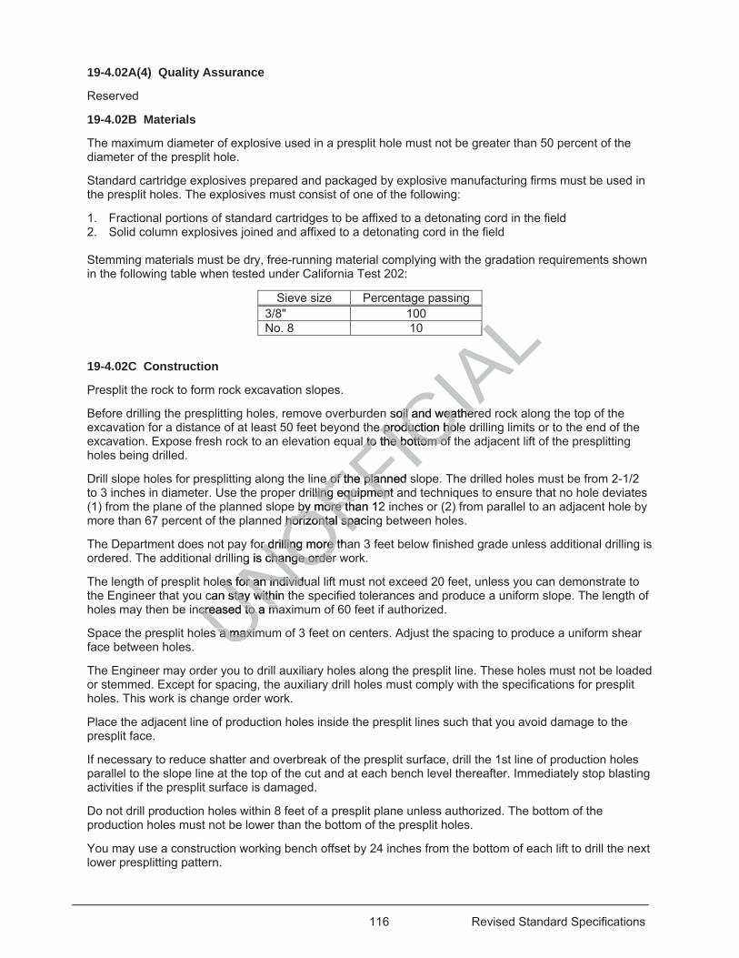
116 Revised Standard Specifications
19-4.02A(4) Quality Assurance
Reserved
19-4.02B Materials
The maximum diameter of explosive used in a presplit hole must not be greater than 50 percent of the diameter of the presplit hole.
Standard cartridge explosives prepared and packaged by explosive manufacturing firms must be used in the presplit holes. The explosives must consist of one of the following:
1. Fractional portions of standard cartridges to be affixed to a detonating cord in the field 2. Solid column explosives joined and affixed to a detonating cord in the field
Stemming materials must be dry, free-running material complying with the gradation requirements shown in the following table when tested under California Test 202:
Sieve size Percentage passing 3/8" 100 No. 8 10
19-4.02C Construction
Presplit the rock to form rock excavation slopes.
Before drilling the presplitting holes, remove overburden soil and weathered rock along the top of the excavation for a distance of at least 50 feet beyond the production hole drilling limits or to the end of the excavation. Expose fresh rock to an elevation equal to the bottom of the adjacent lift of the presplitting holes being drilled.
Drill slope holes for presplitting along the line of the planned slope. The drilled holes must be from 2-1/2 to 3 inches in diameter. Use the proper drilling equipment and techniques to ensure that no hole deviates (1) from the plane of the planned slope by more than 12 inches or (2) from parallel to an adjacent hole by more than 67 percent of the planned horizontal spacing between holes.
The Department does not pay for drilling more than 3 feet below finished grade unless additional drilling is ordered. The additional drilling is change order work.
The length of presplit holes for an individual lift must not exceed 20 feet, unless you can demonstrate to the Engineer that you can stay within the specified tolerances and produce a uniform slope. The length of holes may then be increased to a maximum of 60 feet if authorized.
Space the presplit holes a maximum of 3 feet on centers. Adjust the spacing to produce a uniform shear face between holes.
The Engineer may order you to drill auxiliary holes along the presplit line. These holes must not be loaded or stemmed. Except for spacing, the auxiliary drill holes must comply with the specifications for presplit holes. This work is change order work.
Place the adjacent line of production holes inside the presplit lines such that you avoid damage to the presplit face.
If necessary to reduce shatter and overbreak of the presplit surface, drill the 1st line of production holes parallel to the slope line at the top of the cut and at each bench level thereafter. Immediately stop blasting activities if the presplit surface is damaged.
Do not drill production holes within 8 feet of a presplit plane unless authorized. The bottom of the production holes must not be lower than the bottom of the presplit holes.
You may use a construction working bench offset by 24 inches from the bottom of each lift to drill the next lower presplitting pattern.
UNOFFICIA
LALALALsoil and weatheroil and weather
e production hole production hol to the bottom ofl to the bottom of
e of the e of the planned splarilling equiling equipment amen
by more than 12by more td horizontal spacihorizontal spa
or drilling more thr drilling more g is change ordechange orde
es for an individues for an individcan stay within thstay with
ncreased to a macreased to a m
s a maxims a maxim
117 Revised Standard Specifications
Adjust the drilling to compensate for any drift of previous levels and for the offset at the start of new levels to maintain the specified slope plane.
If the drilling and blasting methods do not produce a uniform slope and shear face without overbreak and within the specified tolerances, drill, blast, and excavate in short sections, up to 100 feet, until you achieve the desired results.
If you use a fractional portion of a standard explosive cartridge, firmly affix the cartridge to a length of detonating cord equal to the depth of the drill hole. Ensure the cartridge does not slip down the detonating cord or cock across the hole and bridge the flow of stemming material. Space the cartridges along the length of the detonating cord at a maximum of 30 inches on center. Adjust the spacing as needed to achieve the desired results.
If you use a solid column-type explosive, assemble and affix the column to the detonating cord under the explosive manufacturer's instructions.
The bottom charge of a presplit hole may be larger than the line charges but must not cause overbreak. Place the top charge of the presplitting hole far enough below the collar to avoid overbreaking the surface.
Before placing the charge, clear the hole of any obstructions for the hole's entire depth. Ensure that placing of the charge does not cause caving of material from the walls of the holes.
The Engineer may order the use of stemming materials as necessary to achieve a satisfactory presplit face. Stemmed presplit holes must be completely filled to the collar.
Simultaneously detonate charges in each presplitting pattern.
The tolerances specified in section 19-2.03G do not apply to presplit surfaces of excavation slopes where presplitting is required. The presplit face must not deviate more than 1 foot from the plane passing through adjacent drill holes, except where the character of the rock is such that irregularities are unavoidable. The average plane of the completed slopes must not deviate more than 1 foot from the plan slopes. These tolerances are measured perpendicular to the plane of the slope. No portion of the slope may encroach on the roadbed.
If equally satisfactory presplit slopes are obtained, you may either presplit the slope face before drilling for production blasting or presplit the slope face and production blast at the same time, provided that the presplitting drill holes are fired with zero delay. Detonation of the production holes must be delayed from the detonation of the presplit line and must start at the row of holes farthest from the new slope line and progressing in steps to the row of holes nearest the presplit line. Detonation of the production holes must result in a minimum 50 ms delay between detonation of the presplit holes and detonation of the row of production holes nearest the presplit line. The presplitting holes must extend either to the end of the excavation or for a distance of not less than 50 feet beyond the limits of the production holes to be detonated.
19-4.02D Payment
The payment quantity for drill hole (presplitting) is the theoretical slope length determined from the elevation taken before detonating each lift and a plane 3 feet below finished grade. For holes that comply with the specified slope and tolerances, except alignment within the plane of the slope, the payment quantity is 75 percent of the theoretical slope length.
The Department does not pay for holes that do not show a hole trace for approximately 50 percent of the drilled length.
19-4.03 BLASTING
19-4.03A General
19-4.03A(1) Summary
Section 19-4.03 includes specifications for excavating rock by blasting.
UNOFFICIA
L's ent en ire dep of the holes. of the holes.
sary to achieve asary to achieve acollar. lar.
ern. rn.
pply to presplit suply to presplit deviate more thaneviate more than
haracaracter of the rocr of the eted slopes must eted slopes must
rpendicular to therpendicular to
are obtained, yare obtained, oslope face and pope face and p
with zero delay. Dith zero delay. t line and must stline and must st
e row of holes nee row of holes nms delay betwees delay betwee
arest the presplit arest the presplistance of not stance of n
118 Revised Standard Specifications
Blasting activities must comply with federal, State, and local blasting regulations, including 8 CA Code of Regs Ch 4, Subchapter 7, Group 18, "Explosive Materials."
19-4.03A(2) Definitions
Reserved
19-4.03A(3) Submittals
Submit 3 copies of your blasting safety plan. The plan must include:
1. References to applicable federal, State, and local codes and regulations 2. Copies of permits required for blasting activities 3. Business name, contractor license number, address, and telephone number of the blasting
subcontractor 4. Proof of current liability insurance and bonding 5. Name, address, telephone number, copies of applicable licenses, and resume of:
5.1. Blaster-in-charge 5.2. Personnel responsible for blast design, loading, and conducting blasting operations 5.3. Safety officer for the blasting subcontractor
6. Name, address, and telephone number of the local fire station and law enforcement agencies 7. Detailed description of:
7.1. Location where explosives will be stored 7.2. Security measures to protect and limit access to the explosives 7.3. Means for transporting explosives 7.4. List of personnel allowed to handle the explosives
8. Exclusion zone and limited-entry zone for nonblast-related operations and personnel surrounding loading and blasting operations
9. Details of warning signals used to alert employees on the job site of an impending blast and to indicate the blast is completed and the area is safe to enter
10. Procedures for conducting blasting operations 11. Measures to protect blasting operations and personnel from lightning 12. Emergency evacuation procedures for areas where explosives may be present 13. Methods for recognizing, handling, and resolving misfires, including:
13.1. Who will be notified 13.2. How the blast zone will be secured until the misfire is resolved 13.3. Identification of equipment that may be needed to resolve misfires
14. Details of signs to be used around blasting zones, including: 14.1. Timing of when signs will be posted for a specific blast 14.2. Name and telephone number of the person responsible for placing the signs 14.3. Roadway signs for compliance with the California MUTCD, Chapter 6H, Typical Application 2
15. Traffic control details for: 15.1. Loading and blasting operations 15.2. Misfire event or other blast-related phenomenon that causes a transportation corridor to remain
closed to the public 16. Description of the possible generation of noxious gas and details of the safeguards to be used to
protect employees, work zones adjacent to the shot, private property, and the public 17. Procedure to report and resolve complaints for blast-related accidents 18. Copies of each SDS and manufacturer data sheets of explosives, caps, primers, initiators, and other
compounds If the plan requires revisions, the Department provides comments. Submit a revised plan after receiving the comments. Submit 3 copies of the revised blasting safety plan after authorization.
19-4.03A(4) Quality Assurance
Reserved
19-4.03B Materials
Not Used
UNOFFICIA
Las
aw enforcemw en
xplosives xplosives
es s elated operationsated operations
ees on the job sitees on the job sitis safe to enter s safe to enter
ions ions s and personnel fr and person
or areas where exareas where e, and resolving m, and resolv
l be secue s red untid uipment that may ment that may
sed around blastined around blastin signs will be pon signs will be p
elephone numbephone nusigns for compliasigns for complails for: ails
blastingblastingoth
119 Revised Standard Specifications
19-4.03C Construction
You may use hydraulic splitters, pneumatic hammers, blasting, or another authorized roadway excavation method to fracture rock and construct stable final rock cut faces.
19-4.03D Payment
Not Used
19-4.04 CONTROLLED BLASTING
19-4.04A General
19-4.04A(1) Summary
Section 19-4.04 includes specifications for excavating rock by controlled blasting.
Blasting activities must comply with federal, State, and local blasting regulations, including 8 CA Code of Regs Ch 4, Subchapter 7, Group 18, "Explosives and Pyrotechnics," and 22 CA Code of Regs, Division 4.5, Ch 33, "Best Management Practices for Perchlorate Materials."
19-4.04A(2) Definitions
controlled blasting: Using explosives and blasting accessories in predetermined spaced and aligned drilled holes.
19-4.04A(3) Submittals
19-4.04A(3)(a) General
Reserved
19-4.04A(3)(b) Blasting Safety Plan
Submit 3 copies of your blasting safety plan. The plan must include:
1. References to applicable federal, State, and local codes and regulations 2. Copies of permits required for blasting activities 3. Business name, contractor license number, address, and telephone number of the blasting
subcontractor 4. Proof of current liability insurance and bonding 5. Name, address, telephone number, copies of applicable licenses, and resume of:
5.1. Blaster-in-charge. 5.2. Personnel responsible for blast design, loading, and conducting blasting operations. 5.3. Safety officer for the blasting subcontractor. 5.4 Blast monitoring consultant. 5.5 Blasting consultant if the project involves near-field blasting activities. Include a list of
controlled blasting projects worked on by the blasting consultant. 6. Name, address, and telephone number of the local fire station and law enforcement agencies 7. Detailed description of:
7.1. Location where explosives will be stored 7.2. Security measures to protect and limit access to the explosives 7.3. Means for transporting explosives 7.4. List of personnel allowed to handle the explosives
8. Exclusion zone and limited-entry zone for nonblast-related operations and personnel surrounding loading and blasting operations
9. Details of warning signals used to alert employees on the job site of an impending blast and to indicate the blast is completed and the area is safe to enter
10. Procedures for conducting blasting operations 11. Measures to protect blasting operations and personnel from lightning 12. Emergency evacuation procedures for areas where explosives may be present 13. Methods for recognizing, handling, and resolving misfires, including:
13.1. Who will be notified 13.2. How the blast zone will be secured until the misfire is resolved
UNOFFICIA
Lpredetermined spaedetermined sp
. The plan must i. The plan m
State, and local cotate, and lasting activities asting activitie
ense number, adse number, ad
nsurance and bonnce and bonhone number, copone number, c
arge. ge. responsible for bresponsible for
cer for the blascer for the bring consring cons
tant t
120 Revised Standard Specifications
13.3. Identification of equipment that may be needed to resolve misfires 14. Details of signs to be used around blasting zones, including:
14.1. Timing of when signs will be posted for a specific blast 14.2. Name and telephone number of the person responsible for placing the signs 14.3. Roadway signs for compliance with the California MUTCD, Chapter 6H, Typical Application 2
15. Traffic control details for: 15.1. Loading and blasting operations 15.2. Misfire event or other blast-related phenomenon that causes a transportation corridor to remain
closed to the public 16. Description of the possible generation of noxious gas and details of the safeguards to be used to
protect employees, work zones adjacent to the shot, private property, and the public 17. Procedure to report and resolve complaints for blast-related accidents 18. Copies of each SDS and manufacturer data sheets of explosives, caps, primers, initiators, and other
compounds If the blasting safety plan requires revisions, the Department provides comments. Submit a revised plan after receiving comments. Submit 3 copies of the revised plan after authorization.
19-4.04A(3)(c) Controlled Blasting Plan
Submit 3 copies of your controlled blasting plan for each blast. The plan must include details on how each blast will be controlled and the following:
1. Blast identification by numerical and chronological sequence 2. Location, referenced to stationing, offset distance, date, and time of the blast 3. Drawings showing drill hole pattern, spacing, burden, and initiation sequence 4. Typical cross-sections through the zone to be blasted 5. Groundwater level, if present, within the prism to be blasted 6. Initiation-sequence diagram showing the actual firing time of each delay 7. Type of material to be blasted 8. Number of drill holes 9. Diameter, depth, and spacing of holes 10. Height or length of stemming 11. Types and characteristics of explosives, including the explosive's density, relative strength, and date
of manufacture 12. Type of caps and delay periods and their date of manufacture 13. Total amount of explosives to be used 14. Total amount of explosives detonating within any 8 ms period 15. Powder factor (pounds of explosive per cubic yard of material blasted) 16. Method of firing 17. Direction and distance to nearest building or structure 18. Type of instrumentation and method for monitoring vibration and noise from the blasting activities 19. Location and placement of the instrumentation 20. Measures to limit noise and flyrock 21. Measures to limit overbreak 22. Name of the blasting subcontractor 23. Name and signature of the blaster-in-charge 24. Drawings showing the spacing and proximity of shot guards relative to the blast location If you revise the controlled blasting plan to adjust for site conditions or the Department provides comments, submit a revised plan before starting controlled blasting. Submit 3 copies of the revised plan after authorization.
19-4.04A(3)(d) Preblast and Postblast Surveys
Submit a preblast survey of all structures, including buildings, within 330 feet of controlled blasting locations at least 15 days before starting the blasting activities. Submit the preblast survey with the controlled blasting plan.
The preblast survey must include:
UNOFFICIA
Lan must include an must include
ce and time of the band time of the
and initiation seqand initiation seqted ed
o be blasted be blasted al firing time of eaal firing time of e
losives, includingosives, includ
iodsods and their daand their des to be used be used
sives ves detonating wdetonatinnds of explosive ds of explosive
tance to nearetance to neation and ation and
ent nt o
121 Revised Standard Specifications
1. Written report, sketches, and photographs or video with the date and time displayed on the image 2. Name of the person who performed the survey 3. Names of the property owner and occupants 4. Property address 5. Date and time of the inspection 6. Description of the structure or other improvements, including culverts and bridges 7. Detailed description of the existing condition of the walls, ceiling, and floor of each interior room,
including any attic or basement 8. Detailed description of the existing condition of the foundations, exterior walls, roofs, doors, windows,
and porches 9. Detailed description of the existing condition of garages, outbuildings, sidewalks, driveways, and
swimming pools 10. Detailed listing of highway sign posts, light fixtures, and overhead power lines 11. Survey of wells or other private water supplies, including the total depth and existing water surface
levels 12. Identification of sites conducting procedures, processes, or operations that may be sensitive to
blasting activities 13. Scaled map or aerial photo showing the location of the structures and properties surveyed and the
location of all proposed blasting sites If blasting activities are suspended for 45 days or more, perform another preblast survey and submit the survey at least 15 days before resuming blasting activities.
Submit a postblast survey of the same buildings and other structures as in the preblast survey within 15 days after completing blasting activities. The postblast survey must include all items included in the preblast survey.
19-4.04A(3)(e) Vibration and Noise Monitoring Report
Submit a vibration and noise monitoring report for each controlled blast shot. The report must include:
1. Identification of the blasting seismograph used to record each blast shot 2. Name of the blast monitoring consultant 3. Distance and direction of the recording stations from the blast area 4. Type of ground at the recording station and type of material on which the instrumentation sits 5. Maximum particle velocity in each component and the resultant peak particle velocity of each shot 6. Copy of the seismograph readings with the date and signature of the blast monitoring consultant 7. Noise levels recorded in dB (C-network or Linear network) units 19-4.04A(3)(f) Video Recording
Submit a video recording of each controlled blast on a DVD or other Engineer-authorized data-storage device. Identify each video or section of the video with an index to identify each blast.
19-4.04A(3)(g) Blasting Complaint Report
Submit a report for each blasting complaint, including:
1. Name and address of the complainant 2. Date, time, and nature of the complaint 3. Dated photo or videotape of the physical damage 4. Name of the person who received the complaint 5. Record of the complaint investigation 6. Resolution of the complaint 19-4.04A(3)(h) Postblast Report
Submit a postblast report within 48 hours of a controlled blast. The report must include all data required in the controlled blasting plan for that shot and the following information:
1. Description of site conditions, loading, and time of blast 2. Description of weather conditions at time of blast including wind direction and cloud cover
UNOFFICIA
Lroper
other preblast survher preblast sur
ructures as in theructures as invey must include ey must include
eport eport
for eachfor each controlle controll
ph used to recordph used to rectant nt
rding stations frording stationg station and typestation and typ
n each componeneach componereadingdings with thes with the
n dB (C-network n dB (C-netw
Recording ording
ing of each cing of eacheo or seeo or se
122 Revised Standard Specifications
3. Drillers boring record 4. Copy of vibration and noise monitoring report 5. Copy of documented complaints arising from the blast
19-4.04A(4) Quality Assurance
19-4.04A(4)(a) General
Reserved
19-4.04A(4)(b) Blaster-In-Charge for Controlled Blasting
Assign a blaster-in-charge to supervise all controlled blasting activities. The blaster-in-charge must have at least 10 years of experience in performing or supervising similar blasting activities and must be a licensed blaster.
19-4.04A(4)(c) Blast Monitoring Consultant for Controlled Blasting
Assign a blast monitoring consultant to monitor blasting-generated vibrations and noise near buildings and other structures that may be subject to damage. The monitoring consultant must be responsible for collecting and interpreting the vibration and noise data. The blast monitoring consultant must:
1. Not be employed by the blasting contractor or other subcontractor on the project 2. Have a minimum 2-year associate's degree in science or engineering 3. Have at least 5 years of documented experience in collecting and interpreting ground vibrations and
noise data 19-4.04A(4)(d) Blasting Consultant for Controlled Blasting
Assign a blasting consultant to oversee near-field blasting activities. The blasting consultant must:
1. Be an engineering geologist or civil engineer who is licensed in the State 2. Have at least 10 years of experience providing specialized blasting services in near-field blasting 3. Not be employed by the blasting contractor, explosive manufacturer, or explosive distributor 19-4.04B Materials
Each seismograph used to record controlled blasting activities must be capable of:
1. Recording particle velocities for 3 mutually perpendicular components of vibration and an instantaneous resultant peak vector sum in the range generally found for controlled blasting
2. Continuously measuring, recording, and reporting vibrations along 3 primary axes 3. Measuring and recording vibration frequencies ranging from 2 to 300 Hz 4. Providing a printed record of each event showing a plot of peak particle velocity versus vibration
frequencies 5. Measuring and recording airblast noise levels The seismograph's noise transducer must be detachable from the main unit to allow its placement at elevations with a clear line of sight between the transducer and the blast.
19-4.04C Construction
19-4.04C(1) General
At least 7 days before starting or resuming controlled blasting activities, provide written notification to the occupants of the buildings within 330 feet of the blasting. Notify the occupants of pending blasting activities on the day of blasting.
Do not perform blasts within 1,200 feet of concrete placed within the previous 72 hours.
Before firing any blast, confirm that the groundwater conditions are consistent with the shot design and explosive type to be used.
UNOFFICIA
Ltant m
ring consulng
or on the project r on the project neering ring
ng and interpreting and interpretin
lasting lastin
blasting activities.lasting activities.
er who is licenseer who is licenseoviding specoviding specialize
ractor, exactor, explosive osive
rd controllrd contr ed blasbl
cities for 3 mutuacities for 3 mutuaant peak vector sant peak vector s
suring, recordingng, recordecording vibratioecording vibrati
d record of ed record of
ng
123 Revised Standard Specifications
Before firing any blast in areas where flyrock may result in personal injury or damage to property or the work, cover the rock to be blasted with blasting mats, soil, or other equally serviceable material to prevent flyrock.
If blasting causes flyrock, suspend blasting activities. The blasting consultant must review the job site to determine the cause of the flyrock problem and submit a revised controlled blasting plan that prevents flyrock.
Do not use drill cuttings as stemming in controlled blasting activities.
Keep vibration levels below a peak particle velocity of 2 inches per second at the nearest building, highway facility, or utility.
Limit noise from airblast overpressure levels to below 128 dB (C-scale or linear network) at the nearest building.
Control ground vibrations and noise created from blasting by using properly designed delay sequencing and charge weights for shots.
Provide 3 seismographs to record controlled blasting activities. Record each blast shot using the seismographs. Video record each blast from a safe location with a clear view of the blast area, activities, and progression.
Notify the Engineer no later than the start of the next day's work shift of any blasting complaint received.
19-4.04D Payment
Not Used
19-4.05–19-4.08 RESERVED
Replace the 7th paragraph of section 19-10.03A with: 01-20-17
Do not stockpile material on the geosynthetic or place more geosynthetic than can be covered within 72 hours.
Do not operate equipment or vehicles directly on geosynthetic, except you may operate vehicles and equipment on geogrid if one of the following conditions is met:
1. Vehicles and equipment are: 1.1. Equipped with rubber tires 1.2 Operated under 10 mph 1.3 Operated in a manner to avoid sudden braking and sharp turns
2. At least 0.35 feet of AB has been placed, spread, and compacted on the geogrid
Replace the 2nd heading of section 19-10.03 with: 01-20-17
19-10.03B Subgrade Enhancement Geotextile
^^^^^^^^^^^^^^^^^^^^^^^^^^^^^^^^^^^^^^^^
20 LANDSCAPE 04-20-18
Replace the 1st paragraph of section 20-1.01D(2) with:
UNOFFICIA
Lh blas
view of the ew
hift of any blastinof any blastin
aragraph of sectaragraph of
ynthetic or place ynthetic or p
vehicles directly ohicles directly oe of the following cof the following
ment are: ent are: with rubber tires with rubber tiresunder 10 mph under 10 m
a mannera manneB haB h
124 Revised Standard Specifications
01-20-17 The Engineer performs progress inspections:
1. After marking plant locations 2. Before cultivating work starts 3. Before pressure testing of irrigation pipe on the supply side of control valves 4. Before testing of low voltage control and neutral conductors 5. During irrigation system functional tests 6. Before planting the plants 7. Before completion of planting work 8. Before the start of plant establishment work 9. Once a month during the plant establishment period
07-21-17 Delete oil or in the 4th paragraph of section 20-1.02C.
Replace the 3rd paragraph of section 20-2.01B(7) with: 07-21-17
Valve box covers must be labeled. Labels must:
1. Be predrilled plate plastic consisting of 2 layers of contrasting color 2. Be at least 1/8 inch thick 3. Have mechanically engraved inscriptions at least 1 inch high
Covers for valve boxes that contain remote control valves must be labeled with the controller and station.
Covers for valve boxes that contain irrigation equipment must be labeled with the standard abbreviation for that equipment.
Replace section 20-2.01C(2) with: 07-21-17
20-2.01C(2) Trenching and Backfilling
For a project with multiple water service points, excavate and backfill the trenches 1 service point at a time.
Remove rocks and debris encountered during trenching activity. The removal of rocks and debris is change order work.
Backfill each trench with material that is excavated from the trench. Each trench must have a uniform bearing throughout the entire length and must be free of jagged rubble, rock, broken concrete, asphalt concrete and sharp objects greater than 2 inches in greatest dimension.
Compact the backfill in the trench to a minimum relative compaction of 90 percent. If the trench backfill settles, place additional material and compact until the backfill is level with the surrounding grade.
Ensure conduit, supply line, and joints are not moved or damaged by backfill activity.
If trenching requires the removal of:
1. Plants: 1.1 Remove plants as necessary under section 20-1.03C. 1.2 If plants are to remain, adjust the trench alignment to minimize damage. 1.3 If the supply line location interferes with the excavation of plant holes, relocate the plant hole
away from the supply line. 1.4 Where authorized by the Engineer, prune trees and shrubs as necessary to complete the
trenching work.
UNOFFICIA
LB(7) with: (7)
ting color g col
nch high h h
aalves must be lalves must be la
quipment must beuipment must b
Replace section eplace sectio
Backfilling ckfilling
e water service poe water service
ebris encounteebris encou
125 Revised Standard Specifications
2. Turf: 2.1 Do not remove a width of more than 12 inches. 2.2 Replace with sod under section 20-3.02C(3)(e).
3. Groundcover: 3.1 Do not remove a width of more than 6 feet. 3.2 Replace groundcover with plants from flats and plant at 12 inches on center under section 20-
3.02C. 3.3 You may rototill existing Carpobrotus and Delosperma. Backfill for the trenches must not
contain plants longer than 6 inches. No replacement of Carpobrotus and Delosperma is required if removed by rototilling.
4. Existing surface: 4.1 Make a minimum 2-inch-deep saw cut along neat lines around the perimeter of the pavement
to be removed at locations determined by the Engineer. 4.2 Place a minimum of 2 inches of sand bedding under and on top of supply lines and conduits. 4.3 Compact the backfill under the replacement surfacing to a minimum relative compaction of 95
percent. 4.4 Replace the structural section to match the removed materials. The surface must have the
same uniform smoothness, color, and texture as the adjacent surface.
If trenching in areas to receive new surfacing:
1. Place a minimum of 2 inches of sand bedding under and on top of supply lines and conduits. 2. Compact the backfill under the new surfacing to a minimum relative compaction of 95 percent.
Replace 86 in the 1st paragraph of section 20-2.01C(3) with: 04-15-16
87
Replace the paragraphs of section 20-2.03B with: 04-20-18
Each cam coupler assembly must consist of a cam coupler, dust cap, check valve, pipes, fittings, concrete thrust block, and valve box with woven wire cloth and gravel.
Cam couplers must be manufactured of brass or bronze and be able to withstand a working pressure of 150 psi.
04-20-18 Delete the 2nd paragraph of section 20-2.03C.
Replace section 20-2.04A(4) with: 04-15-16
Perform conductors test. The test must comply with the specifications in section 87.
Where the conductors are installed by trenching and backfilling, perform the test after a minimum of 6 inches of backfill material has been placed and compacted over the conductors.
Replace 5 in the 1st paragraph of section 20-2.04C(2) with: 07-21-17
10
UNOFFICIA
Lface
p of supply lines f supply lines relative compactrelative compact
h of section 20-2h of section 20
e paragraphs of sparagrap
st consist of a camst consist of a cve box box with wovewith wove
anufactured of braanufactured of b
D
126 Revised Standard Specifications
Add between the 1st and 2nd paragraphs of section 20-2.04C(2): 07-21-17
Tie a 24-inch loop of wire at all changes of direction that are greater than 45 degrees. Untie the loops after all the connections are made.
Replace the 1st paragraph of section 20-2.04C(4) with: 04-15-16
Splice low voltage control and neutral conductors under section 87, except do not use Method B.
Replace the 3rd paragraph of section 20-2.05B with: 07-15-16
The impeller must be glass reinforced nylon on a tungsten carbide shaft.
Replace 86 in the 2nd paragraph of section 20-2.06C with: 04-15-16
87
Replace section 20-2.07B(5) with: 04-15-16
20-2.07B(5) PVC Pipe Conduit Sleeve
PVC pipe conduit sleeves must be schedule 40 complying with ASTM D1785.
Fittings must be schedule 80.
Replace the 9th paragraph of section 20-2.07C(1) with: 07-21-17
Place Type G pavement markers with retroreflective face facing away from the oncoming traffic under section 81-3 on paved shoulders or dikes at irrigation conduit locations where authorized.
07-21-17 Delete the 2nd paragraph of section 20-2.07C(2)(a).
Replace section 20-2.07C(3) with: 07-21-17
20-2.07C(3) PVC Pipe Conduit Sleeve
Where PVC pipe conduit sleeves 2 inches or less in outside diameter are installed under surfacing, you may install by directional boring under section 20-2.07C(2)(b).
Cap ends of conduit until used.
07-21-17 Delete the 4th and 5th paragraph of section 20-2.08C(4).
Replace sections 20-2.09B and 20-2.09C with:
UNOFFICIA
L2.06C with:.06C
B(5) with: with
mplying with ASTmplying with AST
9th paragraph of9th paragra
rs with retroreflecs with retrorefleders or dikes at ior dikes at irr
Delete thete
127 Revised Standard Specifications
07-15-16 20-2.09B Materials
20-2.09B(1) General
Swing joints must match the inlet connection size of the riser.
Where shown, a sprinkler assembly must include a check valve.
Threaded nipples for swing joints and risers must be schedule 80, PVC 1120 or PVC 1220 pipe, and comply with ASTM D1785. Risers for sprinkler assemblies must be UV resistant.
Fittings for sprinkler assemblies must be injection-molded PVC, schedule 40, and comply with ASTM D2466.
Flexible hose for sprinkler assemblies must be leak-free, non-rigid and comply with ASTM D2287, cell Type 6564500. The hose must comply with ASTM D2122 and have the thickness shown in the following table:
Nominal hose diameter (inch)
Minimum wall thickness (inch)
1/2 0.127 3/4 0.154 1 0.179
Solvent cement and fittings for flexible hose must comply with section 20-2.08B(5).
20-2.09B(2) Pop-Up Sprinkler Assemblies
Each pop-up sprinkler assembly must include a body, nozzle, swing joint, pressure reducing device, fittings, and sprinkler protector where shown.
20-2.09B(3) Riser Sprinkler Assemblies
Each riser sprinkler assembly must include a body, flexible hose, threaded nipple, nozzle, swing joint (except for a Type V riser), pressure reducing device, fittings, and riser support where shown.
20-2.09B(4) Tree Well Sprinkler Assemblies
Each tree well sprinkler assembly must include a threaded nipple, nozzle, swing joint, fittings, perforated drainpipe, and drain grate.
The perforated drainpipe must be commercial-grade, rigid PVC pipe with holes spaced not more than 6 inches on center on 1 side of the pipe.
The drain grate must be a commercially-available, 1-piece, injection-molded grate manufactured from structural foam polyolefins with UV light inhibitors. Drain grate must be black.
Gravel for filling the drainpipe must be graded such that 100 percent passes the 3/4-inch sieve and 100 percent is retained on the 1/2-inch sieve. The gravel must be clean, washed, dry, and free from clay or organic material.
20-2.09C Construction
Where shown, install a flow shut-off device under the manufacturer's instructions, unless you use equipment with a preinstalled flow shut-off device.
Where shown, install a pressure reducing device under the manufacturer's instructions, unless you use equipment with a preinstalled pressure reducing device.
Install pop-up and riser sprinkler assembly:
1. From 6-1/2 to 8 feet from curbs, dikes, and sidewalks 2. At least 10 feet from paved shoulders 3. At least 3 feet from fences and walls
UNOFFICIA
Les
LLL54 54
ALL0.17979 ALAwith section 20-2.0ith section 20-2
ody, nozzle, swingody, nozzle, swing
lude a body, lude a bod flexie reducing reducing devicedevic
er Assemblies er Assemblies
sembly must incluembly must incle. e.
pipe must be compipe must be co side of the p side of the
comcom
128 Revised Standard Specifications
If sprinkler assembly cannot be installed within these limits, the location will be determined by the Engineer.
Set sprinkler assembly riser on slopes perpendicular to the plane of the slope.
Replace the paragraph of section 20-2.10B(3) with: 07-15-16
Each check valve must be one of the following:
1. Schedule 80 PVC with a factory setting to withstand a minimum 7-foot head on risers 2. Class 200 PVC if used on a nonpressurized plastic irrigation supply line 3. Internal to the sprinkler body with a factory setting to withstand a minimum 7-foot head
07-21-17 Delete item 3 in the list in the paragraph of section 20-2.10B(4).
Replace the paragraph of section 20-2.10C(3) with: 07-15-16
Install check valves as necessary to prevent low-head drainage.
Replace the paragraph of section 20-3.01B(3) with: 04-20-18
20-3.01B(3)(a) General
Soil amendment must comply with the provisions in the Food & Agri Code and as specified in the special provisions.
Replace the paragraphs of section 20-3.01B(10) with: 07-15-16
Each plant stake for vines must be nominal 1 by 1 inch and 18 inches long.
Each plant stake for trees must be nominal 2 by 2 inches or nominal 2 inches in diameter and long enough to keep the tree in an upright position.
Replace the paragraph of section 20-3.01B(11) with: 07-15-16
Each plant tie for vines must be extruded vinyl-based tape, 1 inch wide and at least 8 mils thick.
Each plant tie for trees must be a (1) minimum 3/4-inch-wide, UV-resistant, flexible vinyl tie complying with ASTM D412 for tensile and elongation strength, or (2) lock-stitch, woven polypropylene with a minimum 900 lb tensile strength.
Add between the 7th and 8th paragraphs of section 20-3.02C(3)(b): 07-15-16
Spread the vine shoots and tie them with a plant tie to each stake above the crossing point.
UNOFFICIA
L20-2.10
2.10C(3) with: 0C(3) with:
nage. age.
of section 20-3.of section 20-3.
provisions in thisions i e FF
place the paragraplace the paragra
nes must be nommust be
rees must be rees must bin an upin an up
129 Revised Standard Specifications
Replace the 8th paragraph of section 20-3.02C(3)(b) with: 07-15-16
Tie trees to the stakes with 2 tree ties, 1 tie to each stake. Each tie must form a figure eight by crossing the tie between the tree and the stake. Install ties at the lowest position that will support the tree in an upright position. Install the ties such that they provide trunk flexibility but do not allow the trunk to rub against the stakes. Wrap each end of the tie 1-1/2 turns around the stake and securely tie or nail it to the stake.
Replace the 1st paragraph of section 20-5.02C(1) with: 07-15-16
Where edging is used to delineate the limits of inert ground cover or wood mulch areas, install the edging before installing the inert ground cover or wood mulch.
07-15-16 Delete AND MULCHES in the heading of section 20-5.03.
07-15-16 Delete and mulches in the paragraph of section 20-5.03A(1)(a).
Replace the paragraph of section 20-5.03A(3)(a) with: 07-15-16
Before installing inert ground cover, remove plants and weeds to the ground level.
Add to the beginning of section 20-5.03A(3)(b): 07-21-17
Excavate to the depth shown.
07-15-16 Delete or mulch at each occurrence in sections 20-5.03A(3)(c) and 20-5.03A(3)(d).
Add to the end of section 20-5.03B(2)(c): 07-21-17
You may use rock with superficial chipping or jagged edges if the rock is placed such that the chipped areas and jagged edges are submerged in the concrete.
04-20-18 Delete the 1st paragraph of section 20-5.03B(3).
Add to the 2nd paragraph of section 20-5.03B(3): 07-21-17
Rock that is exposed on the finished surface must be round, smooth, clean and without jagged edges or chipped areas showing.
Replace section 20-5.03E with:
20-5.0
ection 20-5.03A(ection 20-5.03A(
ction 20-5.03A(3)n 20-5.03A(3)
s and weeds to ths and weeds to t
beginning of secginning of sec
chh at each occu at each occu
AA
130 Revised Standard Specifications
04-20-18 20-5.03E Rock Mulch
Reserved
Replace section 20-5.04 with: 07-15-16
20-5.04 WOOD MULCH
20-5.04A General
20-5.04A(1) Summary
Section 20-5.04 includes specifications for placing wood mulch.
20-5.04A(2) Definitions
Reserved
20-5.04A(3) Submittals
Submit a certificate of compliance for wood mulch.
Submit a 2 cu ft mulch sample with the mulch source shown on the bag. Obtain authorization before delivering the mulch to the job site.
20-5.04A(4) Quality Assurance
Reserved
20-5.04B Materials
20-5.04B(1) General
Mulch must not contain more than 0.1 percent of deleterious materials such as rocks, glass, plastics, metals, clods, weeds, weed seeds, coarse objects, sticks larger than the specified particle size, salts, paint, petroleum products, pesticides or chemical residues harmful to plant or animal life.
20-5.04B(2) Tree Bark Mulch
Tree bark mulch must be derived from cedar, Douglas fir, or redwood species.
The mulch must be ground such that at least 95 percent of the material by volume is less than 2 inches long in any dimension and no more than 30 percent by volume is less than 1 inch long in any dimension.
20-5.04B(3) Wood Chip Mulch
Wood chip mulch must:
1. Be derived from clean wood 2. Not contain leaves or small twigs 3. Contain at least 95 percent by volume of wood chips with a width and thickness from 1/16 to 3/8 inch
and a length from 1/2 to 3 inches 20-5.04B(4) Shredded Bark Mulch
Shredded bark mulch must:
1. Be derived from trees 2. Be a blend of loose, long, thin wood, or bark pieces 3. Contain at least 95 percent by volume of wood strands with a width and thickness from 1/8 to 1-1/2
inches and a length from 2 to 8 inches 20-5.04B(5) Tree Trimming Mulch
UNOFFICIA
Lthe bag. Obtain ahe bag. Obtain a
percent of deletpercent of ercoarse objects, stoarse objects,
des or chemics or chemical r
ch
derived from cderived from cede
ground such that ground such than and no moren and no mo
MulcMulc
131 Revised Standard Specifications
Tree trimming mulch must:
1. Be derived from chipped trees and may contain leaves and small twigs 2. Contain at least 95 percent by volume of material less than 3 inches long for any dimension and not
more than 30 percent by volume of material less than 1 inch long for any dimension 20-5.04B(6)–20-5.04B(11) Reserved
20-5.04C Construction
Before placing wood mulch, remove plants and weeds to the ground level.
Maintain the planned flow lines, slope gradients, and contours of the job site. Grade the subgrade to a smooth and uniform surface.
Place mulch after the plants have been planted.
Place mulch in the plant basin at the rate described. Mulch must not come in contact with the plant crown and stem.
Place mulch as shown in areas outside of plant basins to a uniform thickness.
Spread mulch from the outside edge of the plant basin to the adjacent edges of shoulders, paving, retaining walls, dikes, edging, curbs, sidewalks, walls, fences, and existing plantings. If the plant is 12 feet or more from the adjacent edges of any of these elements, spread the mulch 6 feet beyond the outside edge of the plant basin.
Do not place mulch within 4 feet of:
1. Flow line of earthen drainage ditches 2. Edge of paved ditches 3. Drainage flow lines 20-5.04D Payment
The payment quantity for wood mulch is the volume measured in the vehicle at the point of delivery.
Add between plants and if in the 1st sentence of section 20-10.03C(2): 04-20-18
under section 20-3.01C(2)
Add between prune and each in the 1st paragraph of section 20-10.03C(3): 04-20-18
under section 20-3.01C(2)
^^^^^^^^^^^^^^^^^^^^^^^^^^^^^^^^^^^^^^^^
21 EROSION CONTROL 04-20-18
Replace the paragraph of section 21-1.01 with: 01-20-17
Section 21-1 includes general specifications for applying permanent erosion control measures.
Replace section 21-2.02C with:
UNOFFICIA
Less. es
t edges of shouldt edges of shoulexisting plantingsisting plantings
ad the mulcad the mulch 6 feh 6 fe
is the volume meis the volum
plantsnts and and ifif ininff
C(2) )
en en prpr
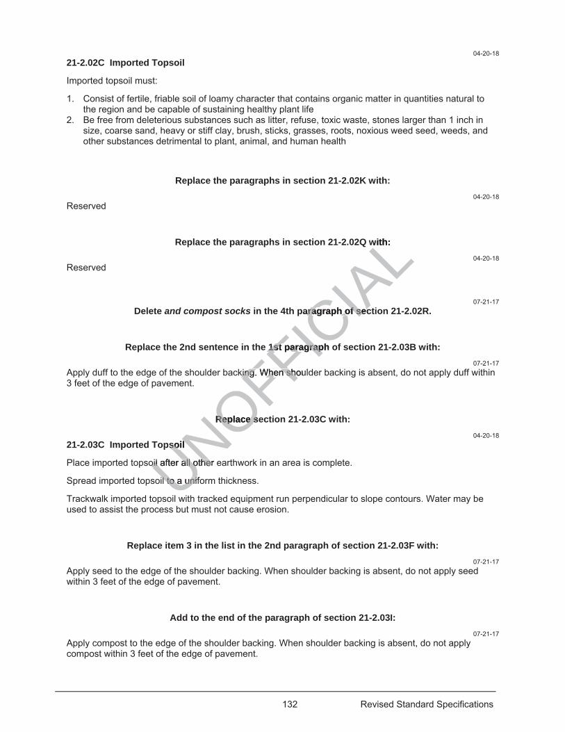
132 Revised Standard Specifications
04-20-18 21-2.02C Imported Topsoil
Imported topsoil must:
1. Consist of fertile, friable soil of loamy character that contains organic matter in quantities natural to the region and be capable of sustaining healthy plant life
2. Be free from deleterious substances such as litter, refuse, toxic waste, stones larger than 1 inch in size, coarse sand, heavy or stiff clay, brush, sticks, grasses, roots, noxious weed seed, weeds, and other substances detrimental to plant, animal, and human health
Replace the paragraphs in section 21-2.02K with: 04-20-18
Reserved
Replace the paragraphs in section 21-2.02Q with: 04-20-18
Reserved
07-21-17 Delete and compost socks in the 4th paragraph of section 21-2.02R.
Replace the 2nd sentence in the 1st paragraph of section 21-2.03B with: 07-21-17
Apply duff to the edge of the shoulder backing. When shoulder backing is absent, do not apply duff within 3 feet of the edge of pavement.
Replace section 21-2.03C with: 04-20-18
21-2.03C Imported Topsoil
Place imported topsoil after all other earthwork in an area is complete.
Spread imported topsoil to a uniform thickness.
Trackwalk imported topsoil with tracked equipment run perpendicular to slope contours. Water may be used to assist the process but must not cause erosion.
Replace item 3 in the list in the 2nd paragraph of section 21-2.03F with: 07-21-17
Apply seed to the edge of the shoulder backing. When shoulder backing is absent, do not apply seed within 3 feet of the edge of pavement.
Add to the end of the paragraph of section 21-2.03I: 07-21-17
Apply compost to the edge of the shoulder backing. When shoulder backing is absent, do not apply compost within 3 feet of the edge of pavement.
UNOFFICIA
Lwith:
paragraph of secaragraph of sec
e 1st paragraph o1st paragrap
king. When shoulking. When sho
Replace seReplace s
psoil soil
oil after all other eoil after all other
l to a unifol to a unif
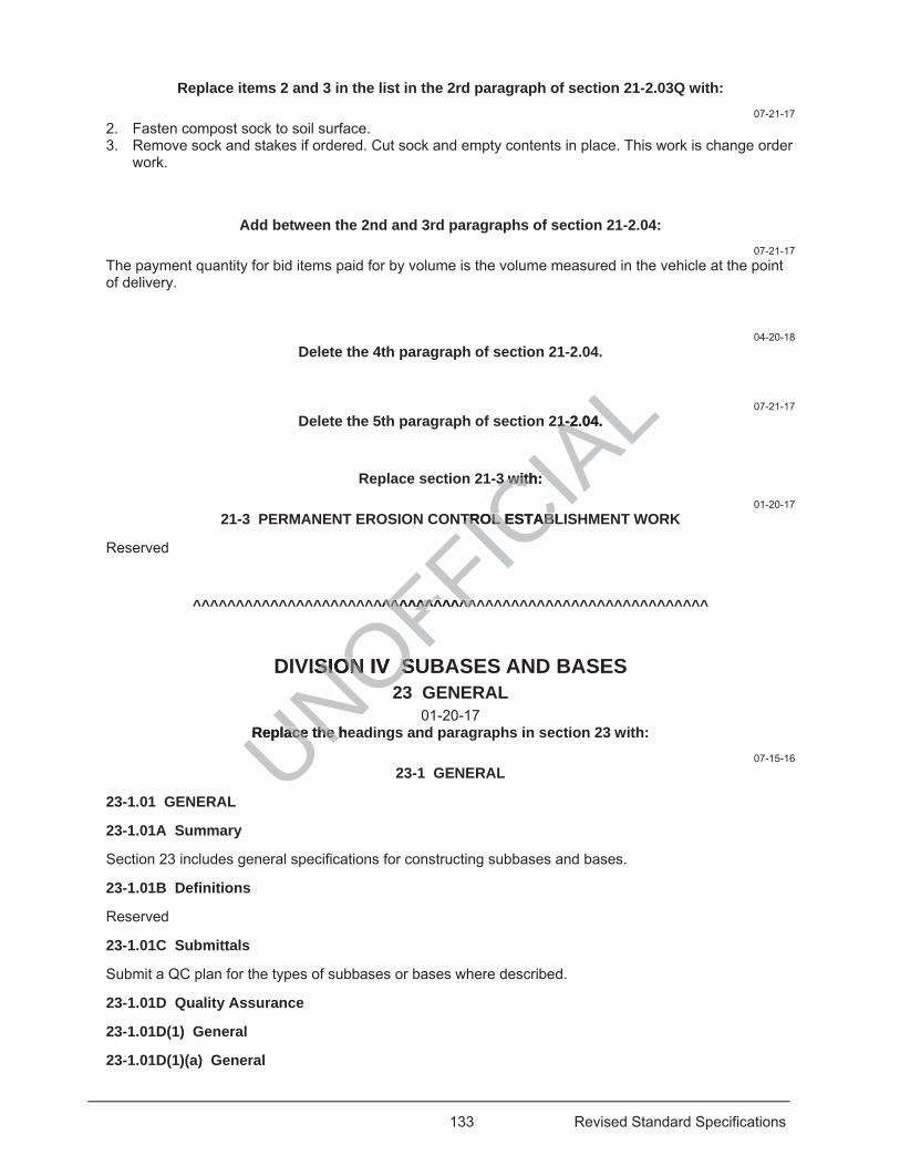
133 Revised Standard Specifications
Replace items 2 and 3 in the list in the 2rd paragraph of section 21-2.03Q with: 07-21-17
2. Fasten compost sock to soil surface. 3. Remove sock and stakes if ordered. Cut sock and empty contents in place. This work is change order
work.
Add between the 2nd and 3rd paragraphs of section 21-2.04: 07-21-17
The payment quantity for bid items paid for by volume is the volume measured in the vehicle at the point of delivery.
04-20-18 Delete the 4th paragraph of section 21-2.04.
07-21-17 Delete the 5th paragraph of section 21-2.04.
Replace section 21-3 with: 01-20-17
21-3 PERMANENT EROSION CONTROL ESTABLISHMENT WORK
Reserved
^^^^^^^^^^^^^^^^^^^^^^^^^^^^^^^^^^^^^^^^^^^^^^^^^^^^^^^^^^^^
DIVISION IV SUBASES AND BASES 23 GENERAL
01-20-17 Replace the headings and paragraphs in section 23 with:
07-15-16 23-1 GENERAL
23-1.01 GENERAL
23-1.01A Summary
Section 23 includes general specifications for constructing subbases and bases.
23-1.01B Definitions
Reserved
23-1.01C Submittals
Submit a QC plan for the types of subbases or bases where described.
23-1.01D Quality Assurance
23-1.01D(1) General
23-1.01D(1)(a) General
UNOFFICIA
L21-2.04. 21-2.04.
3 with: 3 with:
TROL ESTABLITROL ESTAB
^^^^^^^^^^^^^^^^^^^^^^^^
ISION IV SUSION IV S
Replace the heace the

134 Revised Standard Specifications
Take samples under California Test 125.
23-1.01D(1)(b) Test Result Disputes
You and the Engineer must work together to avoid potential conflicts and to resolve disputes regarding test result discrepancies. Notify the Engineer within 5 business days of receiving the test result if you dispute the test result.
01-20-17 If you or the Engineer dispute each other’s test results, submit your test results and copies of paperwork including worksheets used to determine the disputed test results. An independent third party performs referee testing. Before the independent third party participates in a dispute resolution, it must be qualified under AASHTO re:source program and the Department’s Independent Assurance Program. The independent third party must have no prior direct involvement with this Contract. By mutual agreement, the independent third party is chosen from:
1. Department laboratory in a district or region not in the district or region the project is located 2. Transportation Laboratory 3. Laboratory not currently employed by you or your material producer
07-15-16 If split acceptance samples are not available, the independent third party uses any available material representing the disputed material for evaluation.
If the independent third party determines the Department’s test results are valid, the Engineer deducts the independent third party testing costs from payments. If the independent third party determines your test results are valid, the Department pays the independent third party testing costs.
23-1.01D(2) Quality Control
23-1.01D(2)(a) General
Provide a QC manager when the quantity of subbase or base is as shown in the following table:
QC Manager Requirements Subbase or base Requirement
Stabilized soil (sq yd) 20,000 Aggregate subbases (cu yd) 20,000 Aggregate bases (cu yd) 20,000 CTB (cu yd) 10,000 Lean concrete base (cu yd) 2,000 Rapid strength concrete base (cu yd) 1,000 Lean concrete base rapid setting (cu yd) 1,000 Concrete base (cu yd) 1,000 Treated permeable bases (cu yd) 2,000 Reclaimed pavements (sq yd) 10,000
Provide a testing laboratory to perform quality control tests. Maintain sampling and testing equipment in proper working condition.
You are not entitled to compensation for the suspension of work resulting from noncompliance with quality control requirements, including those identified within the QC plan.
23-1.01D(2)(b) Quality Control Plan
The QC plan must describe the organization and procedures used to:
1. Control the production process 2. Determine if a change to the production process is needed 3. Implement a change
UNOcu yd) cu yd) NOFFICIA
Larty uses any avarty uses any av
t results are validesults are vndependent third ndependent thi
ird party testing cd party testing c
f subbase orsubbase o baser
QC Manager ReqManager Reqr base r base
OFOFOF(cu yd) cu yd) ONONO
e base (cu yd) base (cu
UNngth concrete bangth concrete bUNete base rapidete base raUe (cu yd)e (cu ydUbleU
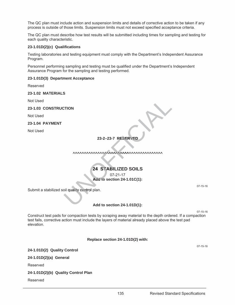
135 Revised Standard Specifications
The QC plan must include action and suspension limits and details of corrective action to be taken if any process is outside of those limits. Suspension limits must not exceed specified acceptance criteria.
The QC plan must describe how test results will be submitted including times for sampling and testing for each quality characteristic.
23-1.01D(2)(c) Qualifications
Testing laboratories and testing equipment must comply with the Department’s Independent Assurance Program.
Personnel performing sampling and testing must be qualified under the Department’s Independent Assurance Program for the sampling and testing performed.
23-1.01D(3) Department Acceptance
Reserved
23-1.02 MATERIALS
Not Used
23-1.03 CONSTRUCTION
Not Used
23-1.04 PAYMENT
Not Used
23-2–23-7 RESERVED
^^^^^^^^^^^^^^^^^^^^^^^^^^^^^^^^^^^^^^^^
24 STABILIZED SOILS 07-21-17
Add to section 24-1.01C(1): 07-15-16
Submit a stabilized soil quality control plan.
Add to section 24-1.01D(1): 07-15-16
Construct test pads for compaction tests by scraping away material to the depth ordered. If a compaction test fails, corrective action must include the layers of material already placed above the test pad elevation.
Replace section 24-1.01D(2) with: 07-15-16
24-1.01D(2) Quality Control
24-1.01D(2)(a) General
Reserved
24-1.01D(2)(b) Quality Control Plan
Reserved
UNOFFICIA
LRESERVED RESERVED
^^^^^^^^^^^^^^^^^^^^^^
24 STABIL24 STABI
Add toAdd to
il quality control pality contr
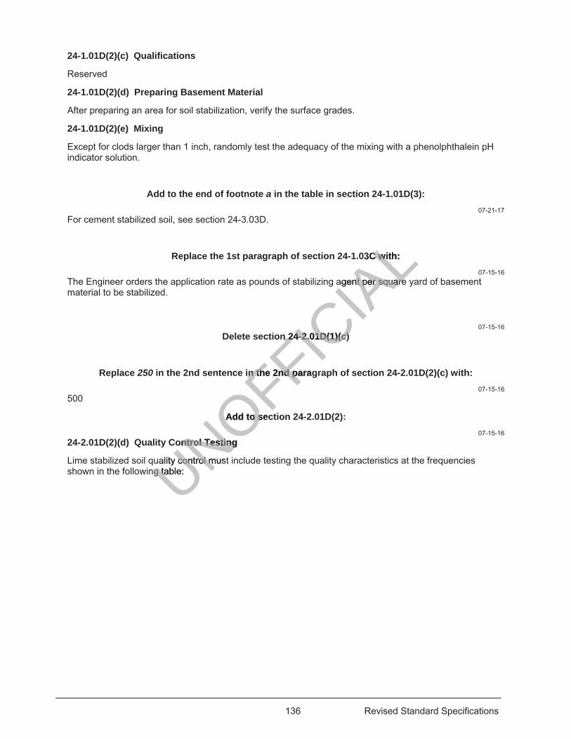
136 Revised Standard Specifications
24-1.01D(2)(c) Qualifications
Reserved
24-1.01D(2)(d) Preparing Basement Material
After preparing an area for soil stabilization, verify the surface grades.
24-1.01D(2)(e) Mixing
Except for clods larger than 1 inch, randomly test the adequacy of the mixing with a phenolphthalein pH indicator solution.
Add to the end of footnote a in the table in section 24-1.01D(3): 07-21-17
For cement stabilized soil, see section 24-3.03D.
Replace the 1st paragraph of section 24-1.03C with: 07-15-16
The Engineer orders the application rate as pounds of stabilizing agent per square yard of basement material to be stabilized.
07-15-16 Delete section 24-2.01D(1)(c)
Replace 250 in the 2nd sentence in the 2nd paragraph of section 24-2.01D(2)(c) with: 07-15-16
500
Add to section 24-2.01D(2): 07-15-16
24-2.01D(2)(d) Quality Control Testing
Lime stabilized soil quality control must include testing the quality characteristics at the frequencies shown in the following table: UNOFFIC
IAL03C with: C wi
agent per squarent per square
n 24-2.01D(1)(c) n 24-2.01D(1)(c)
in the 2nd paragin the 2nd p
Add to secAdd to s
ontrol Testing ntrol Testing
ality control mustcontrol mng table: g ta
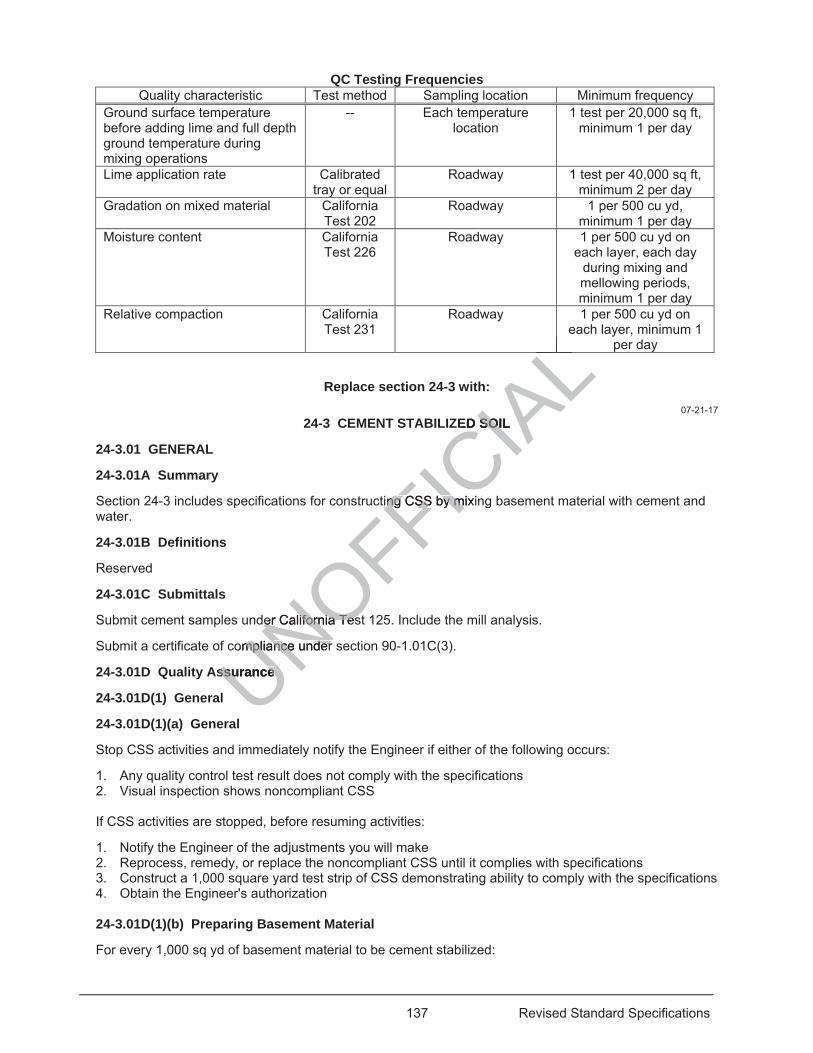
137 Revised Standard Specifications
QC Testing Frequencies Quality characteristic Test method Sampling location Minimum frequency
Ground surface temperature before adding lime and full depth ground temperature during mixing operations
-- Each temperature location
1 test per 20,000 sq ft, minimum 1 per day
Lime application rate Calibrated tray or equal
Roadway 1 test per 40,000 sq ft, minimum 2 per day
Gradation on mixed material California Test 202
Roadway 1 per 500 cu yd, minimum 1 per day
Moisture content California Test 226
Roadway 1 per 500 cu yd on each layer, each day
during mixing and mellowing periods, minimum 1 per day
Relative compaction California Test 231
Roadway 1 per 500 cu yd on each layer, minimum 1
per day
Replace section 24-3 with: 07-21-17
24-3 CEMENT STABILIZED SOIL
24-3.01 GENERAL
24-3.01A Summary
Section 24-3 includes specifications for constructing CSS by mixing basement material with cement and water.
24-3.01B Definitions
Reserved
24-3.01C Submittals
Submit cement samples under California Test 125. Include the mill analysis.
Submit a certificate of compliance under section 90-1.01C(3).
24-3.01D Quality Assurance
24-3.01D(1) General
24-3.01D(1)(a) General
Stop CSS activities and immediately notify the Engineer if either of the following occurs:
1. Any quality control test result does not comply with the specifications 2. Visual inspection shows noncompliant CSS If CSS activities are stopped, before resuming activities:
1. Notify the Engineer of the adjustments you will make 2. Reprocess, remedy, or replace the noncompliant CSS until it complies with specifications 3. Construct a 1,000 square yard test strip of CSS demonstrating ability to comply with the specifications 4. Obtain the Engineer's authorization 24-3.01D(1)(b) Preparing Basement Material
For every 1,000 sq yd of basement material to be cement stabilized:
UNOFFICIA
LLLLED SOIL SOI
titing CSS by mixinng CSS by m
der Californider California Tesa Tes
ompliampliance under nce under
ssurance ssurance
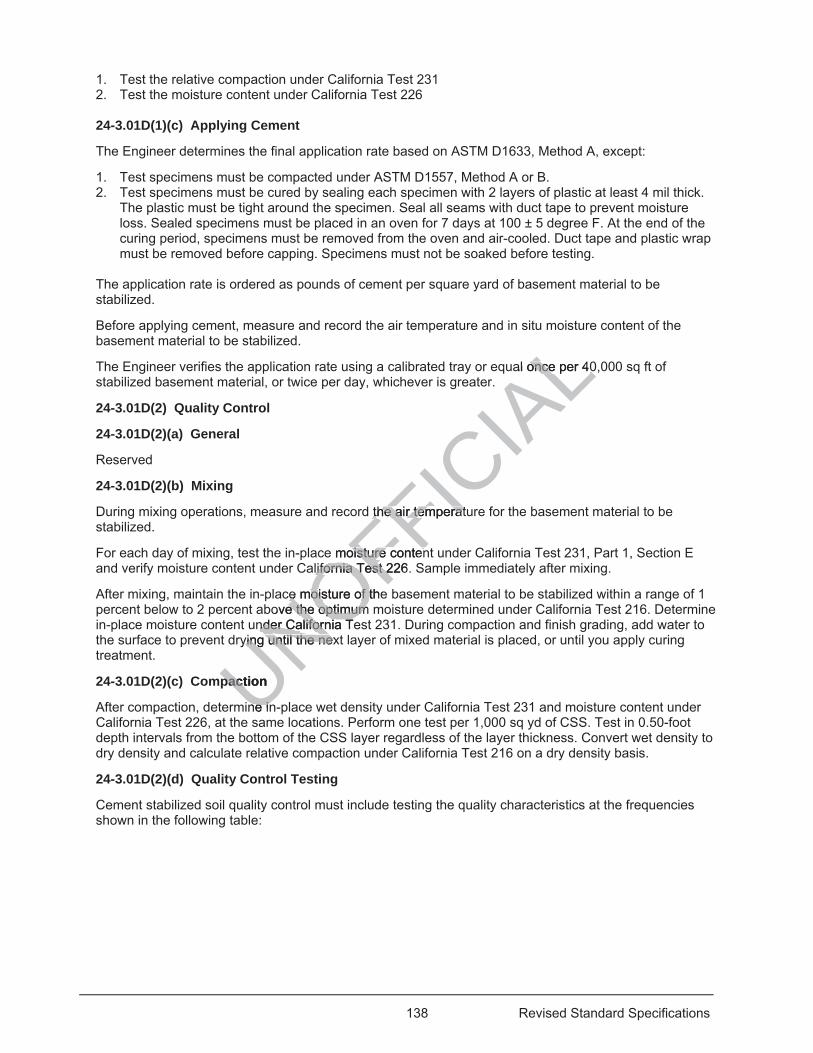
138 Revised Standard Specifications
1. Test the relative compaction under California Test 231 2. Test the moisture content under California Test 226
24-3.01D(1)(c) Applying Cement
The Engineer determines the final application rate based on ASTM D1633, Method A, except:
1. Test specimens must be compacted under ASTM D1557, Method A or B. 2. Test specimens must be cured by sealing each specimen with 2 layers of plastic at least 4 mil thick.
The plastic must be tight around the specimen. Seal all seams with duct tape to prevent moisture loss. Sealed specimens must be placed in an oven for 7 days at 100 ± 5 degree F. At the end of the curing period, specimens must be removed from the oven and air-cooled. Duct tape and plastic wrap must be removed before capping. Specimens must not be soaked before testing.
The application rate is ordered as pounds of cement per square yard of basement material to be stabilized.
Before applying cement, measure and record the air temperature and in situ moisture content of the basement material to be stabilized.
The Engineer verifies the application rate using a calibrated tray or equal once per 40,000 sq ft of stabilized basement material, or twice per day, whichever is greater.
24-3.01D(2) Quality Control
24-3.01D(2)(a) General
Reserved
24-3.01D(2)(b) Mixing
During mixing operations, measure and record the air temperature for the basement material to be stabilized.
For each day of mixing, test the in-place moisture content under California Test 231, Part 1, Section E and verify moisture content under California Test 226. Sample immediately after mixing.
After mixing, maintain the in-place moisture of the basement material to be stabilized within a range of 1 percent below to 2 percent above the optimum moisture determined under California Test 216. Determine in-place moisture content under California Test 231. During compaction and finish grading, add water to the surface to prevent drying until the next layer of mixed material is placed, or until you apply curing treatment.
24-3.01D(2)(c) Compaction
After compaction, determine in-place wet density under California Test 231 and moisture content under California Test 226, at the same locations. Perform one test per 1,000 sq yd of CSS. Test in 0.50-foot depth intervals from the bottom of the CSS layer regardless of the layer thickness. Convert wet density to dry density and calculate relative compaction under California Test 216 on a dry density basis.
24-3.01D(2)(d) Quality Control Testing
Cement stabilized soil quality control must include testing the quality characteristics at the frequencies shown in the following table:
UNOFFICIA
Lal once per 40once per 40
the aithe air temperatur temperat
e moisture contenoisture contenalifornia Test 226.lifornia Test 2
ce moisture of thece moisture of tove the optimum e the optimum
nder California Tender California Tying until the nexying until the nex
paction pact
ne inne in
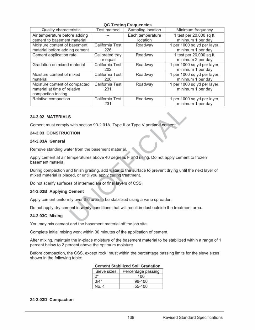
139 Revised Standard Specifications
QC Testing Frequencies Quality characteristic Test method Sampling location Minimum frequency
Air temperature before adding cement to basement material
-- Each temperature location
1 test per 20,000 sq ft, minimum 1 per day
Moisture content of basement material before adding cement
California Test 226
Roadway 1 per 1000 sq yd per layer, minimum 1 per day
Cement application rate Calibrated tray or equal
Roadway 1 test per 20,000 sq ft, minimum 2 per day
Gradation on mixed material California Test 202
Roadway 1 per 1000 sq yd per layer, minimum 1 per day
Moisture content of mixed material
California Test 226
Roadway 1 per 1000 sq yd per layer, minimum 1 per day
Moisture content of compacted material at time of relative compaction testing
California Test 231
Roadway 1 per 1000 sq yd per layer, minimum 1 per day
Relative compaction California Test 231
Roadway 1 per 1000 sq yd per layer, minimum 1 per day
24-3.02 MATERIALS
Cement must comply with section 90-2.01A, Type II or Type V portland cement.
24-3.03 CONSTRUCTION
24-3.03A General
Remove standing water from the basement material.
Apply cement at air temperatures above 40 degrees F and rising. Do not apply cement to frozen basement material.
During compaction and finish grading, add water to the surface to prevent drying until the next layer of mixed material is placed, or until you apply curing treatment.
Do not scarify surfaces of intermediate or final layers of CSS.
24-3.03B Applying Cement
Apply cement uniformly over the area to be stabilized using a vane spreader.
Do not apply dry cement in windy conditions that will result in dust outside the treatment area.
24-3.03C Mixing
You may mix cement and the basement material off the job site.
Complete initial mixing work within 30 minutes of the application of cement.
After mixing, maintain the in-place moisture of the basement material to be stabilized within a range of 1 percent below to 2 percent above the optimum moisture.
Before compaction, the CSS, except rock, must within the percentage passing limits for the sieve sizes shown in the following table:
Cement Stabilized Soil Gradation Sieve sizes Percentage passing 2" 100 3/4" 98-100 No. 4 55-100
24-3.03D Compaction
UNOFFICIA
LLrtland cement. d cement.
reees F and rising.es F and risin
d water to the water to the suspply curing treatmpply curing
diate or final layeate or final laye
over the area ver the area to bto
ment in windy conment in windy co
he
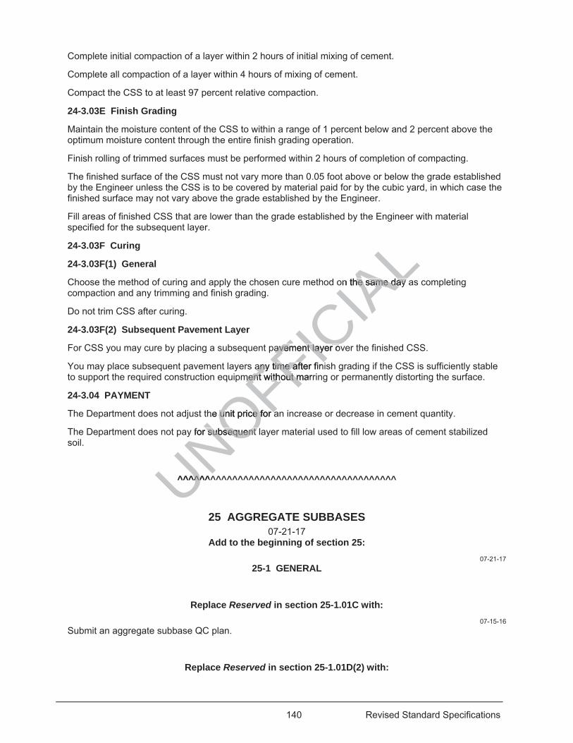
140 Revised Standard Specifications
Complete initial compaction of a layer within 2 hours of initial mixing of cement.
Complete all compaction of a layer within 4 hours of mixing of cement.
Compact the CSS to at least 97 percent relative compaction.
24-3.03E Finish Grading
Maintain the moisture content of the CSS to within a range of 1 percent below and 2 percent above the optimum moisture content through the entire finish grading operation.
Finish rolling of trimmed surfaces must be performed within 2 hours of completion of compacting.
The finished surface of the CSS must not vary more than 0.05 foot above or below the grade established by the Engineer unless the CSS is to be covered by material paid for by the cubic yard, in which case the finished surface may not vary above the grade established by the Engineer.
Fill areas of finished CSS that are lower than the grade established by the Engineer with material specified for the subsequent layer.
24-3.03F Curing
24-3.03F(1) General
Choose the method of curing and apply the chosen cure method on the same day as completing compaction and any trimming and finish grading.
Do not trim CSS after curing.
24-3.03F(2) Subsequent Pavement Layer
For CSS you may cure by placing a subsequent pavement layer over the finished CSS.
You may place subsequent pavement layers any time after finish grading if the CSS is sufficiently stable to support the required construction equipment without marring or permanently distorting the surface.
24-3.04 PAYMENT
The Department does not adjust the unit price for an increase or decrease in cement quantity.
The Department does not pay for subsequent layer material used to fill low areas of cement stabilized soil.
^^^^^^^^^^^^^^^^^^^^^^^^^^^^^^^^^^^^^^^^
25 AGGREGATE SUBBASES 07-21-17
Add to the beginning of section 25: 07-21-17
25-1 GENERAL
Replace Reserved in section 25-1.01C with: 07-15-16
Submit an aggregate subbase QC plan.
Replace Reserved in section 25-1.01D(2) with:
UNOFFICIA
Lon the same day he same day
avement layer ovavement layer ov
any time after finany time ament withment without marrout m
he unit price for unit price for aa
y for subsequent r subsequent
^^^^^^^^^^
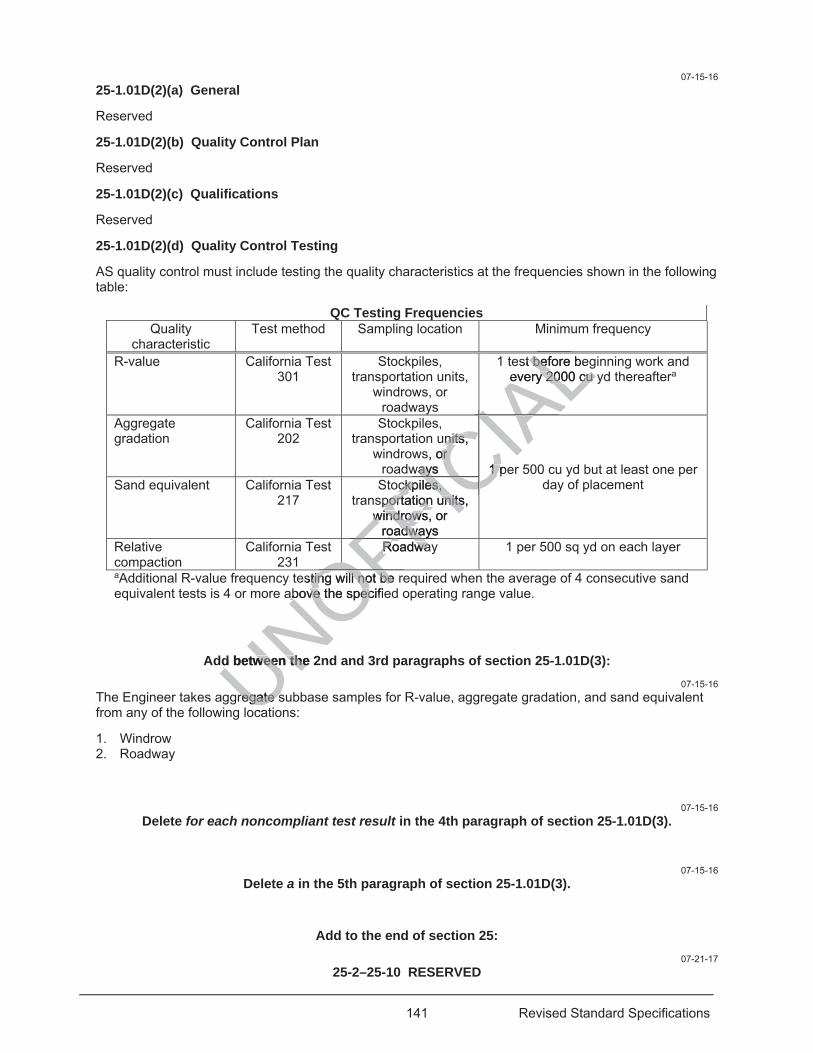
141 Revised Standard Specifications
07-15-16 25-1.01D(2)(a) General
Reserved
25-1.01D(2)(b) Quality Control Plan
Reserved
25-1.01D(2)(c) Qualifications
Reserved
25-1.01D(2)(d) Quality Control Testing
AS quality control must include testing the quality characteristics at the frequencies shown in the following table:
QC Testing Frequencies Quality
characteristic Test method Sampling location Minimum frequency
R-value California Test 301
Stockpiles, transportation units,
windrows, or roadways
1 test before beginning work and every 2000 cu yd thereaftera
Aggregate gradation
California Test 202
Stockpiles, transportation units,
windrows, or roadways 1 per 500 cu yd but at least one per
day of placement Sand equivalent California Test 217
Stockpiles, transportation units,
windrows, or roadways
Relative compaction
California Test 231
Roadway 1 per 500 sq yd on each layer
aAdditional R-value frequency testing will not be required when the average of 4 consecutive sand equivalent tests is 4 or more above the specified operating range value.
Add between the 2nd and 3rd paragraphs of section 25-1.01D(3): 07-15-16
The Engineer takes aggregate subbase samples for R-value, aggregate gradation, and sand equivalent from any of the following locations:
1. Windrow 2. Roadway
07-15-16 Delete for each noncompliant test result in the 4th paragraph of section 25-1.01D(3).
07-15-16
Delete a in the 5th paragraph of section 25-1.01D(3).
Add to the end of section 25: 07-21-17
25-2–25-10 RESERVED
UNOFesting will not be ting will not beabove tabove OFFIC
IALst before be bef
every 2000 cu every 2000 cu LLIunits, nits,
, or or ways ways 1 pe1 p
IACIockpiles, ckpiles,
portation units, portation unitswindrows, or windrows
roadways oadwaICC
RoadwayRoadwaFFOhe specifieecOF
d between the 2d between the
regate sregate sca
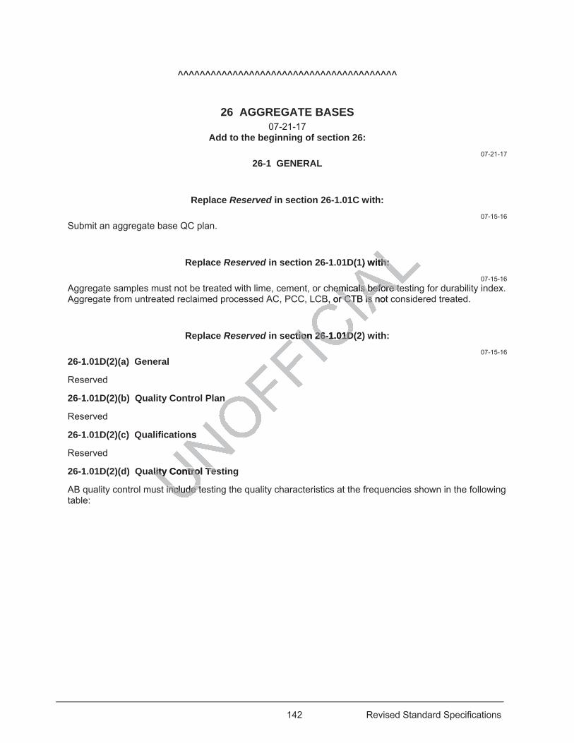
142 Revised Standard Specifications
^^^^^^^^^^^^^^^^^^^^^^^^^^^^^^^^^^^^^^^^
26 AGGREGATE BASES 07-21-17
Add to the beginning of section 26: 07-21-17
26-1 GENERAL
Replace Reserved in section 26-1.01C with: 07-15-16
Submit an aggregate base QC plan.
Replace Reserved in section 26-1.01D(1) with: 07-15-16
Aggregate samples must not be treated with lime, cement, or chemicals before testing for durability index. Aggregate from untreated reclaimed processed AC, PCC, LCB, or CTB is not considered treated.
Replace Reserved in section 26-1.01D(2) with: 07-15-16
26-1.01D(2)(a) General
Reserved
26-1.01D(2)(b) Quality Control Plan
Reserved
26-1.01D(2)(c) Qualifications
Reserved
26-1.01D(2)(d) Quality Control Testing
AB quality control must include testing the quality characteristics at the frequencies shown in the following table:
1) with: th:
emicals before teemicals before teB, or CTB is not cr CTB is
ection 26-1.01D(ection 26-1.01D
ns
lity Control Teslity Control Te
include tinclude t
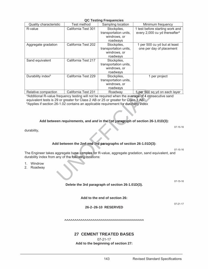
143 Revised Standard Specifications
QC Testing Frequencies Quality characteristic Test method Sampling location Minimum frequency
R-value California Test 301 Stockpiles, transportation units,
windrows, or roadways
1 test before starting work and every 2,000 cu yd thereaftera
Aggregate gradation California Test 202 Stockpiles, transportation units,
windrows, or roadways
1 per 500 cu yd but at least one per day of placement
Sand equivalent California Test 217 Stockpiles, transportation units,
windrows, or roadways
Durability indexb California Test 229 Stockpiles, transportation units,
windrows, or roadways
1 per project
Relative compaction California Test 231 Roadway 1 per 500 sq yd on each layer aAdditional R-value frequency testing will not be required when the average of 4 consecutive sand equivalent tests is 29 or greater for Class 2 AB or 25 or greater for Class 3 AB. bApplies if section 26-1.02 contains an applicable requirement for durability index
Add between requirements, and and in the 1st paragraph of section 26-1.01D(3): 07-15-16
durability,
Add between the 2nd and 3rd paragraphs of section 26-1.01D(3): 07-15-16
The Engineer takes aggregate base samples for R-value, aggregate gradation, sand equivalent, and durability index from any of the following locations:
1. Windrow 2. Roadway
07-15-16 Delete the 3rd paragraph of section 26-1.01D(3).
Add to the end of section 26: 07-21-17
26-2–26-10 RESERVED
^^^^^^^^^^^^^^^^^^^^^^^^^^^^^^^^^^^^^^^^
27 CEMENT TREATED BASES 07-21-17
Add to the beginning of section 27:
UNOFFICIA
L1 per 500 1 p Lverage verage of 4 conof 4 conr Class 3 AB. Class 3 AB.
for durability indexor durability indeALhe 1st paragraphe 1st paragrap
2nd and 3rd para2nd and 3rd
base samples for ase samples fohe following locatillowing locat
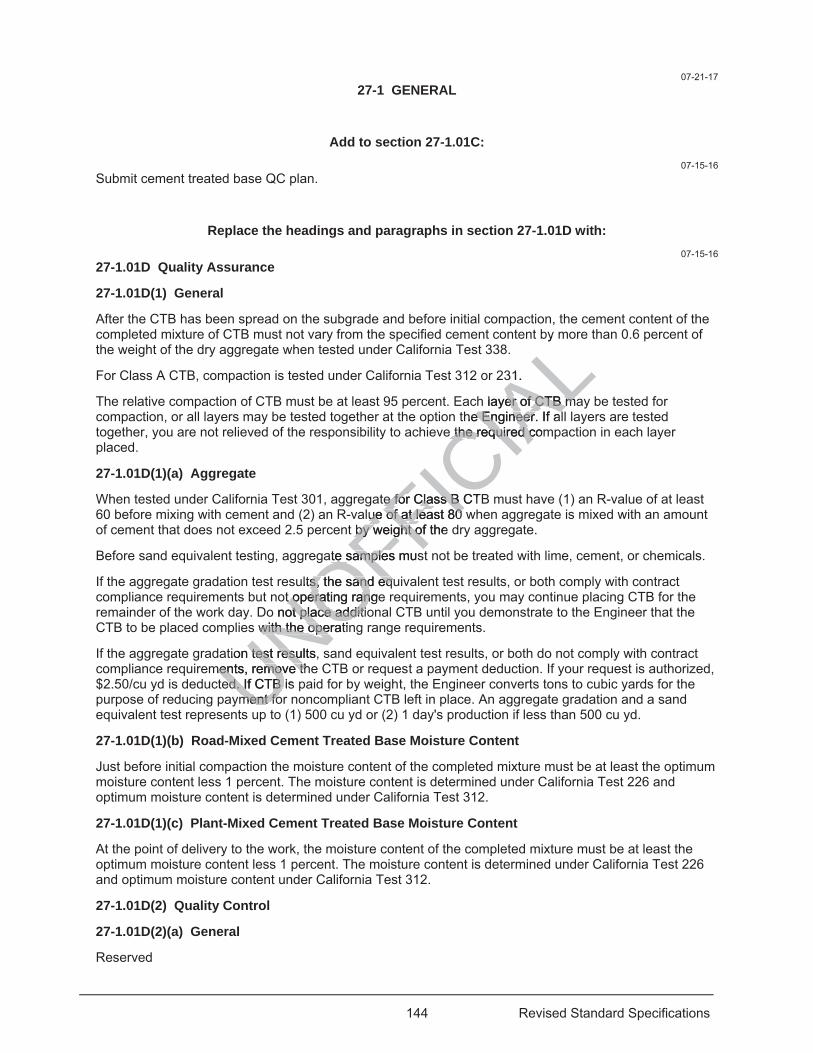
144 Revised Standard Specifications
07-21-17 27-1 GENERAL
Add to section 27-1.01C: 07-15-16
Submit cement treated base QC plan.
Replace the headings and paragraphs in section 27-1.01D with: 07-15-16
27-1.01D Quality Assurance
27-1.01D(1) General
After the CTB has been spread on the subgrade and before initial compaction, the cement content of the completed mixture of CTB must not vary from the specified cement content by more than 0.6 percent of the weight of the dry aggregate when tested under California Test 338.
For Class A CTB, compaction is tested under California Test 312 or 231.
The relative compaction of CTB must be at least 95 percent. Each layer of CTB may be tested for compaction, or all layers may be tested together at the option the Engineer. If all layers are tested together, you are not relieved of the responsibility to achieve the required compaction in each layer placed.
27-1.01D(1)(a) Aggregate
When tested under California Test 301, aggregate for Class B CTB must have (1) an R-value of at least 60 before mixing with cement and (2) an R-value of at least 80 when aggregate is mixed with an amount of cement that does not exceed 2.5 percent by weight of the dry aggregate.
Before sand equivalent testing, aggregate samples must not be treated with lime, cement, or chemicals.
If the aggregate gradation test results, the sand equivalent test results, or both comply with contract compliance requirements but not operating range requirements, you may continue placing CTB for the remainder of the work day. Do not place additional CTB until you demonstrate to the Engineer that the CTB to be placed complies with the operating range requirements.
If the aggregate gradation test results, sand equivalent test results, or both do not comply with contract compliance requirements, remove the CTB or request a payment deduction. If your request is authorized, $2.50/cu yd is deducted. If CTB is paid for by weight, the Engineer converts tons to cubic yards for the purpose of reducing payment for noncompliant CTB left in place. An aggregate gradation and a sand equivalent test represents up to (1) 500 cu yd or (2) 1 day's production if less than 500 cu yd.
27-1.01D(1)(b) Road-Mixed Cement Treated Base Moisture Content
Just before initial compaction the moisture content of the completed mixture must be at least the optimum moisture content less 1 percent. The moisture content is determined under California Test 226 and optimum moisture content is determined under California Test 312.
27-1.01D(1)(c) Plant-Mixed Cement Treated Base Moisture Content
At the point of delivery to the work, the moisture content of the completed mixture must be at least the optimum moisture content less 1 percent. The moisture content is determined under California Test 226 and optimum moisture content under California Test 312.
27-1.01D(2) Quality Control
27-1.01D(2)(a) General
Reserved
UNOFFICIA
Ly
31.
h layer of CTB maer of CTB mhe Engineer. If ale Engineer. If a
e the required come the required c
te for Class B CTe for Class B lue of atue of at least 80 least 80
t by weight of the by weight o
ate samples musate sample
ults, the sand equs, the sand eqot operating ranget operating ran
o not place additiot place additis with the operatinwith the ope
tion test results, stest resuments, remove thments, remove th
ed. If CTB is ed. If CTB ment foment fo
up
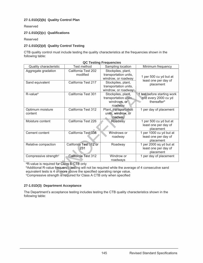
145 Revised Standard Specifications
27-1.01D(2)(b) Quality Control Plan
Reserved
27-1.01D(2)(c) Qualifications
Reserved
27-1.01D(2)(d) Quality Control Testing
CTB quality control must include testing the quality characteristics at the frequencies shown in the following table:
QC Testing Frequencies Quality characteristic Test method Sampling location Minimum frequency
Aggregate gradation California Test 202 modified
Stockpiles, plant, transportation units, windrow, or roadway 1 per 500 cu yd but at
least one per day of placement Sand equivalent California Test 217 Stockpiles, plant,
transportation units, windrow, or roadway
R-valuea California Test 301 Stockpiles, plant, transportation units,
windrows, or roadway
1 test before starting work and every 2000 cu yd
thereafterb
Optimum moisture content
California Test 312 Plant, transportation units, windrow, or
roadway
1 per day of placement
Moisture content California Test 226 Roadway 1 per 500 cu yd but at least one per day of
placement Cement content California Test 338 Windrows or
roadway 1 per 1000 cu yd but at
least one per day of placement
Relative compaction California Test 312 or 231
Roadway 1 per 2000 sq yd but at least one per day of
placement Compressive strengthc California Test 312 Windrow or
roadways 1 per day of placement
aR-value is required for Class B CTB only bAdditional R-value frequency testing will not be required while the average of 4 consecutive sand equivalent tests is 4 or more above the specified operating range value. cCompressive strength is required for Class A CTB only when specified
27-1.01D(3) Department Acceptance
The Department’s acceptance testing includes testing the CTB quality characteristics shown in the following table:
UNfor Class B CTB oClass B CTfrequency testinfrequency testior more aboor more ab
s requs requUNOFFICRoadwaRoadwaICIA
Lay y
ALant, n units, units,
ws, or ws, or oadway way
1 test b1 test bandandALAL
t, transportation , transportation nits, windrow, or ts, windrow, or
roadway roadway CIAIC
FFst 338 Wst 338 FFFFrnia Test 312 or nia Test 312 or
231 2 OFFCalifornia TesCalifornia TesNOUUN
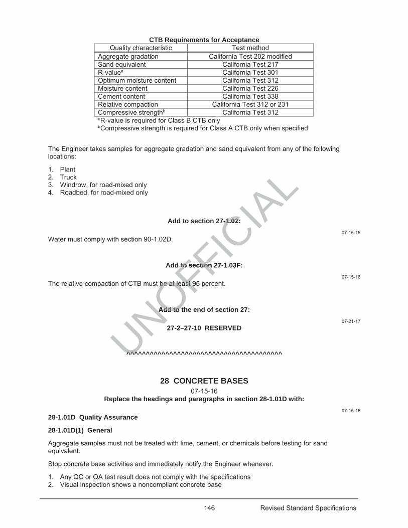
146 Revised Standard Specifications
CTB Requirements for Acceptance Quality characteristic Test method
Aggregate gradation California Test 202 modified Sand equivalent California Test 217 R-valuea California Test 301 Optimum moisture content California Test 312 Moisture content California Test 226 Cement content California Test 338 Relative compaction California Test 312 or 231 Compressive strengthb California Test 312 aR-value is required for Class B CTB only bCompressive strength is required for Class A CTB only when specified
The Engineer takes samples for aggregate gradation and sand equivalent from any of the following locations:
1. Plant 2. Truck 3. Windrow, for road-mixed only 4. Roadbed, for road-mixed only
Add to section 27-1.02: 07-15-16
Water must comply with section 90-1.02D.
Add to section 27-1.03F: 07-15-16
The relative compaction of CTB must be at least 95 percent.
Add to the end of section 27: 07-21-17
27-2–27-10 RESERVED
^^^^^^^^^^^^^^^^^^^^^^^^^^^^^^^^^^^^^^^^
28 CONCRETE BASES 07-15-16
Replace the headings and paragraphs in section 28-1.01D with: 07-15-16
28-1.01D Quality Assurance
28-1.01D(1) General
Aggregate samples must not be treated with lime, cement, or chemicals before testing for sand equivalent.
Stop concrete base activities and immediately notify the Engineer whenever:
1. Any QC or QA test result does not comply with the specifications 2. Visual inspection shows a noncompliant concrete base
UNOFFICIA
L7-1.02: -1.02:
d to section 27-1to section
be at least 95 pebe at least 9
Add to Add to
^^^^^^
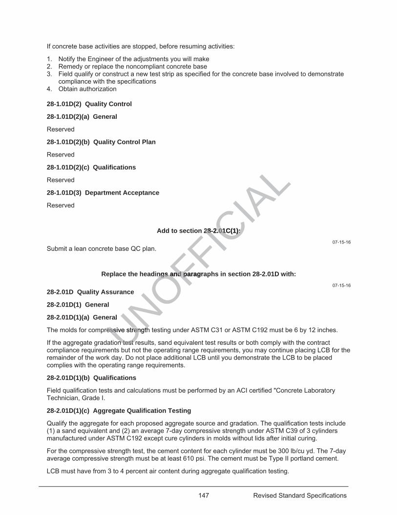
147 Revised Standard Specifications
If concrete base activities are stopped, before resuming activities:
1. Notify the Engineer of the adjustments you will make 2. Remedy or replace the noncompliant concrete base 3. Field qualify or construct a new test strip as specified for the concrete base involved to demonstrate
compliance with the specifications 4. Obtain authorization 28-1.01D(2) Quality Control
28-1.01D(2)(a) General
Reserved
28-1.01D(2)(b) Quality Control Plan
Reserved
28-1.01D(2)(c) Qualifications
Reserved
28-1.01D(3) Department Acceptance
Reserved
Add to section 28-2.01C(1): 07-15-16
Submit a lean concrete base QC plan.
Replace the headings and paragraphs in section 28-2.01D with: 07-15-16
28-2.01D Quality Assurance
28-2.01D(1) General
28-2.01D(1)(a) General
The molds for compressive strength testing under ASTM C31 or ASTM C192 must be 6 by 12 inches.
If the aggregate gradation test results, sand equivalent test results or both comply with the contract compliance requirements but not the operating range requirements, you may continue placing LCB for the remainder of the work day. Do not place additional LCB until you demonstrate the LCB to be placed complies with the operating range requirements.
28-2.01D(1)(b) Qualifications
Field qualification tests and calculations must be performed by an ACI certified "Concrete Laboratory Technician, Grade I.
28-2.01D(1)(c) Aggregate Qualification Testing
Qualify the aggregate for each proposed aggregate source and gradation. The qualification tests include (1) a sand equivalent and (2) an average 7-day compressive strength under ASTM C39 of 3 cylinders manufactured under ASTM C192 except cure cylinders in molds without lids after initial curing.
For the compressive strength test, the cement content for each cylinder must be 300 lb/cu yd. The 7-day average compressive strength must be at least 610 psi. The cement must be Type II portland cement.
LCB must have from 3 to 4 percent air content during aggregate qualification testing.
UNOFFICIA
Ln 28-2.01C(1): 28-2.01C(1):
ngs and paragrangs and p
al
ressive strengthessive strength
n test rn test rut
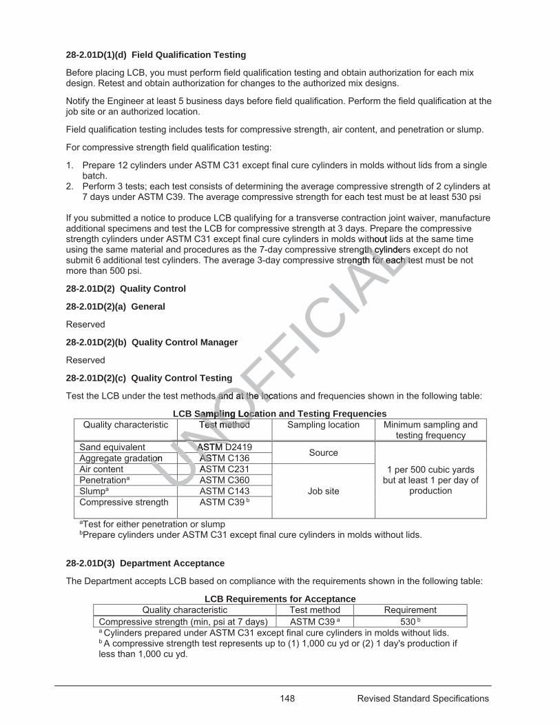
148 Revised Standard Specifications
28-2.01D(1)(d) Field Qualification Testing
Before placing LCB, you must perform field qualification testing and obtain authorization for each mix design. Retest and obtain authorization for changes to the authorized mix designs.
Notify the Engineer at least 5 business days before field qualification. Perform the field qualification at the job site or an authorized location.
Field qualification testing includes tests for compressive strength, air content, and penetration or slump.
For compressive strength field qualification testing:
1. Prepare 12 cylinders under ASTM C31 except final cure cylinders in molds without lids from a single batch.
2. Perform 3 tests; each test consists of determining the average compressive strength of 2 cylinders at 7 days under ASTM C39. The average compressive strength for each test must be at least 530 psi
If you submitted a notice to produce LCB qualifying for a transverse contraction joint waiver, manufacture additional specimens and test the LCB for compressive strength at 3 days. Prepare the compressive strength cylinders under ASTM C31 except final cure cylinders in molds without lids at the same time using the same material and procedures as the 7-day compressive strength cylinders except do not submit 6 additional test cylinders. The average 3-day compressive strength for each test must be not more than 500 psi.
28-2.01D(2) Quality Control
28-2.01D(2)(a) General
Reserved
28-2.01D(2)(b) Quality Control Manager
Reserved
28-2.01D(2)(c) Quality Control Testing
Test the LCB under the test methods and at the locations and frequencies shown in the following table:
LCB Sampling Location and Testing Frequencies Quality characteristic Test method Sampling location Minimum sampling and
testing frequency Sand equivalent ASTM D2419 Source
1 per 500 cubic yards but at least 1 per day of
production
Aggregate gradation ASTM C136 Air content ASTM C231
Job site Penetrationa ASTM C360 Slumpa ASTM C143 Compressive strength ASTM C39 b
aTest for either penetration or slump bPrepare cylinders under ASTM C31 except final cure cylinders in molds without lids.
28-2.01D(3) Department Acceptance
The Department accepts LCB based on compliance with the requirements shown in the following table:
LCB Requirements for Acceptance Quality characteristic Test method Requirement
Compressive strength (min, psi at 7 days) ASTM C39 a 530 b a Cylinders prepared under ASTM C31 except final cure cylinders in molds without lids. b A compressive strength test represents up to (1) 1,000 cu yd or (2) 1 day's production if less than 1,000 cu yd.
UNOFFICIA
Lre
thout lidngth cylinderth c
rength for each teength for each t
g
s and at the locats and at the loc
Sampling LocatSampling LocaTest method Test method
NOASTM DASTM D
UUUUUUNUNUtion ASTion ASUNUAUUUUUU
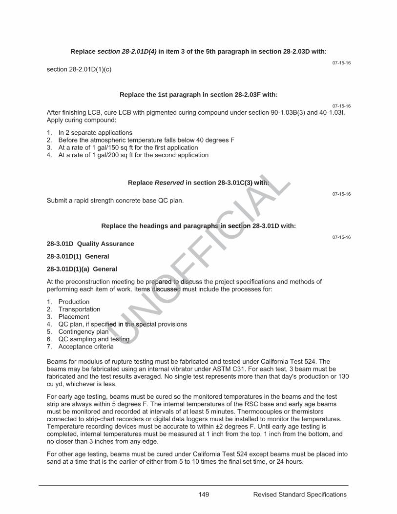
149 Revised Standard Specifications
Replace section 28-2.01D(4) in item 3 of the 5th paragraph in section 28-2.03D with: 07-15-16
section 28-2.01D(1)(c)
Replace the 1st paragraph in section 28-2.03F with: 07-15-16
After finishing LCB, cure LCB with pigmented curing compound under section 90-1.03B(3) and 40-1.03I. Apply curing compound:
1. In 2 separate applications 2. Before the atmospheric temperature falls below 40 degrees F 3. At a rate of 1 gal/150 sq ft for the first application 4. At a rate of 1 gal/200 sq ft for the second application
Replace Reserved in section 28-3.01C(3) with: 07-15-16
Submit a rapid strength concrete base QC plan.
Replace the headings and paragraphs in section 28-3.01D with: 07-15-16
28-3.01D Quality Assurance
28-3.01D(1) General
28-3.01D(1)(a) General
At the preconstruction meeting be prepared to discuss the project specifications and methods of performing each item of work. Items discussed must include the processes for:
1. Production 2. Transportation 3. Placement 4. QC plan, if specified in the special provisions 5. Contingency plan 6. QC sampling and testing 7. Acceptance criteria Beams for modulus of rupture testing must be fabricated and tested under California Test 524. The beams may be fabricated using an internal vibrator under ASTM C31. For each test, 3 beam must be fabricated and the test results averaged. No single test represents more than that day's production or 130 cu yd, whichever is less.
For early age testing, beams must be cured so the monitored temperatures in the beams and the test strip are always within 5 degrees F. The internal temperatures of the RSC base and early age beams must be monitored and recorded at intervals of at least 5 minutes. Thermocouples or thermistors connected to strip-chart recorders or digital data loggers must be installed to monitor the temperatures. Temperature recording devices must be accurate to within ±2 degrees F. Until early age testing is completed, internal temperatures must be measured at 1 inch from the top, 1 inch from the bottom, and no closer than 3 inches from any edge.
For other age testing, beams must be cured under California Test 524 except beams must be placed into sand at a time that is the earlier of either from 5 to 10 times the final set time, or 24 hours.
UNOFFICIA
L3) with: th:
aphs in section aphs in sectio
prepared to discepared to discusems discussed mums discussed
fied in the speciafied in the spec
esting esting
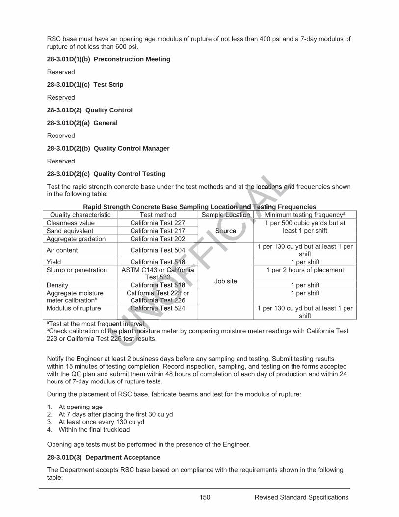
150 Revised Standard Specifications
RSC base must have an opening age modulus of rupture of not less than 400 psi and a 7-day modulus of rupture of not less than 600 psi.
28-3.01D(1)(b) Preconstruction Meeting
Reserved
28-3.01D(1)(c) Test Strip
Reserved
28-3.01D(2) Quality Control
28-3.01D(2)(a) General
Reserved
28-3.01D(2)(b) Quality Control Manager
Reserved
28-3.01D(2)(c) Quality Control Testing
Test the rapid strength concrete base under the test methods and at the locations and frequencies shown in the following table:
Rapid Strength Concrete Base Sampling Location and Testing Frequencies Quality characteristic Test method Sample Location Minimum testing frequencya
Cleanness value California Test 227 Source
1 per 500 cubic yards but at least 1 per shift Sand equivalent California Test 217
Aggregate gradation California Test 202
Air content California Test 504
Job site
1 per 130 cu yd but at least 1 per shift
Yield California Test 518 1 per shift Slump or penetration ASTM C143 or California
Test 533 1 per 2 hours of placement
Density California Test 518 1 per shift Aggregate moisture meter calibrationb
California Test 223 or California Test 226
1 per shift
Modulus of rupture California Test 524 1 per 130 cu yd but at least 1 per shift
aTest at the most frequent interval. bCheck calibration of the plant moisture meter by comparing moisture meter readings with California Test 223 or California Test 226 test results.
Notify the Engineer at least 2 business days before any sampling and testing. Submit testing results within 15 minutes of testing completion. Record inspection, sampling, and testing on the forms accepted with the QC plan and submit them within 48 hours of completion of each day of production and within 24 hours of 7-day modulus of rupture tests.
During the placement of RSC base, fabricate beams and test for the modulus of rupture:
1. At opening age 2. At 7 days after placing the first 30 cu yd 3. At least once every 130 cu yd 4. Within the final truckload Opening age tests must be performed in the presence of the Engineer.
28-3.01D(3) Department Acceptance
The Department accepts RSC base based on compliance with the requirements shown in the following table:
UNuent interval. uent interval. the plant moistthe plant moistUNOCalifornia TestCalifornia TNOFFIC
IALthe locations andthe locations and
tion and Testingn and Tesple Location Mle Location
CIAIASource Sou CIACIIIAIIAIIF4 FIC
FFt 518 518FFFFr California Californiat 533 t 533 FFFF
rnia Test 518 nia Test 51OFornia Test 223 orornia Test 223
California Test 22fornia Test 22ONOU226 test res226 test reUN
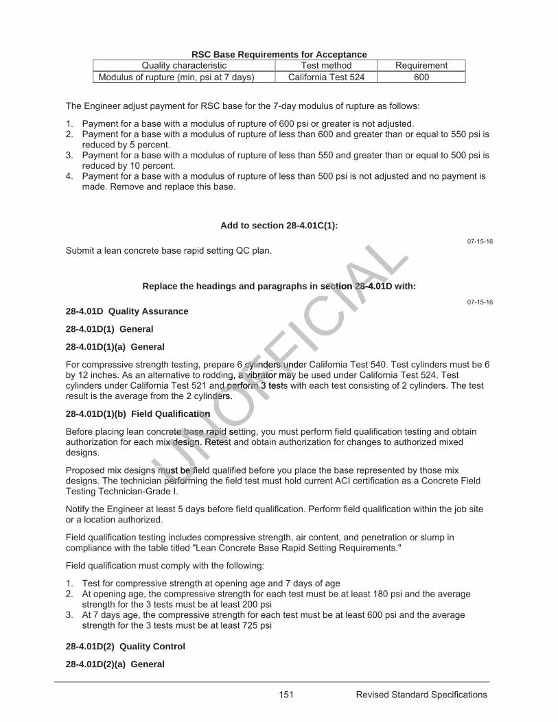
151 Revised Standard Specifications
RSC Base Requirements for Acceptance Quality characteristic Test method Requirement
Modulus of rupture (min, psi at 7 days) California Test 524 600
The Engineer adjust payment for RSC base for the 7-day modulus of rupture as follows:
1. Payment for a base with a modulus of rupture of 600 psi or greater is not adjusted. 2. Payment for a base with a modulus of rupture of less than 600 and greater than or equal to 550 psi is
reduced by 5 percent. 3. Payment for a base with a modulus of rupture of less than 550 and greater than or equal to 500 psi is
reduced by 10 percent. 4. Payment for a base with a modulus of rupture of less than 500 psi is not adjusted and no payment is
made. Remove and replace this base.
Add to section 28-4.01C(1): 07-15-16
Submit a lean concrete base rapid setting QC plan.
Replace the headings and paragraphs in section 28-4.01D with: 07-15-16
28-4.01D Quality Assurance
28-4.01D(1) General
28-4.01D(1)(a) General
For compressive strength testing, prepare 6 cylinders under California Test 540. Test cylinders must be 6 by 12 inches. As an alternative to rodding, a vibrator may be used under California Test 524. Test cylinders under California Test 521 and perform 3 tests with each test consisting of 2 cylinders. The test result is the average from the 2 cylinders.
28-4.01D(1)(b) Field Qualification
Before placing lean concrete base rapid setting, you must perform field qualification testing and obtain authorization for each mix design. Retest and obtain authorization for changes to authorized mixed designs.
Proposed mix designs must be field qualified before you place the base represented by those mix designs. The technician performing the field test must hold current ACI certification as a Concrete Field Testing Technician-Grade I.
Notify the Engineer at least 5 days before field qualification. Perform field qualification within the job site or a location authorized.
Field qualification testing includes compressive strength, air content, and penetration or slump in compliance with the table titled "Lean Concrete Base Rapid Setting Requirements."
Field qualification must comply with the following:
1. Test for compressive strength at opening age and 7 days of age 2. At opening age, the compressive strength for each test must be at least 180 psi and the average
strength for the 3 tests must be at least 200 psi 3. At 7 days age, the compressive strength for each test must be at least 600 psi and the average
strength for the 3 tests must be at least 725 psi 28-4.01D(2) Quality Control
28-4.01D(2)(a) General
UNOFFICIA
Lsection 28-4.01ection 28-4.01
6 cylinders under 6 cylinders ung, a vibrator may a vibrator may
d perform 3 testsd perform 3nders. der
ation ion
ete base rapid sete base rapid mix design. Retestx design. Retes
must be fiemust be fperformperform
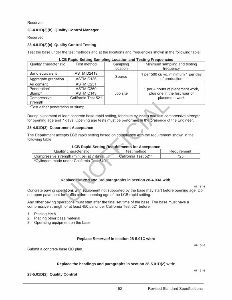
152 Revised Standard Specifications
Reserved
28-4.01D(2)(b) Quality Control Manager
Reserved
28-4.01D(2)(c) Quality Control Testing
Test the base under the test methods and at the locations and frequencies shown in the following table:
LCB Rapid Setting Sampling Location and Testing Frequencies Quality characteristic Test method Sampling
location Minimum sampling and testing
frequency Sand equivalent ASTM D2419
Source 1 per 500 cu yd, minimum 1 per day of production Aggregate gradation ASTM C136
Air content ASTM C231
Job site 1 per 4 hours of placement work,
plus one in the last hour of placement work
Penetrationa ASTM C360 Slumpa ASTM C143 Compressive strength
California Test 521
aTest either penetration or slump
During placement of lean concrete base rapid setting, fabricate cylinders and test compressive strength for opening age and 7 days. Opening age tests must be performed in the presence of the Engineer.
28-4.01D(3) Department Acceptance
The Department accepts LCB rapid setting based on compliance with the requirement shown in the following table:
LCB Rapid Setting Requirements for Acceptance Quality characteristic Test method Requirement
Compressive strength (min, psi at 7 days) California Test 521a 725 aCylinders made under California Test 540
Replace the 2nd and 3rd paragraphs in section 28-4.03A with: 07-15-16
Concrete paving operations with equipment not supported by the base may start before opening age. Do not open pavement for traffic before opening age of the LCB rapid setting.
Any other paving operations must start after the final set time of the base. The base must have a compressive strength of at least 450 psi under California Test 521 before:
1. Placing HMA 2. Placing other base material 3. Operating equipment on the base
Replace Reserved in section 28-5.01C with: 07-15-16
Submit a concrete base QC plan.
Replace the headings and paragraphs in section 28-5.01D(2) with: 07-15-16
28-5.01D(2) Quality Control
UNOFFICIA
Lpla
ALcylinders and testylinders and testrmed in the preseed in the p
compliance with compliance with
g Requirements g Requirements TeFFFFdays) Caays) CaFFFFFFFFFFFFFFFF
Test 540 Test 540
OFce the 2nd and 3e the 2nd an
erations with equrations with equr traffic beforr traffic bef
ns m
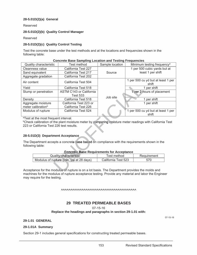
153 Revised Standard Specifications
28-5.01D(2)(a) General
Reserved
28-5.01D(2)(b) Quality Control Manager
Reserved
28-5.01D(2)(c) Quality Control Testing
Test the concrete base under the test methods and at the locations and frequencies shown in the following table:
Concrete Base Sampling Location and Testing Frequencies Quality characteristic Test method Sample location Minimum testing frequencya
Cleanness value California Test 227 Source
1 per 500 cubic yards but at least 1 per shift Sand equivalent California Test 217
Aggregate gradation California Test 202
Air content California Test 504
Job site
1 per 500 cu yd but at least 1 per shift
Yield California Test 518 1 per shift Slump or penetration ASTM C143 or California
Test 533 1 per 2 hours of placement
Density California Test 518 1 per shift Aggregate moisture meter calibrationb
California Test 223 or California Test 226
1 per shift
Modulus of rupture California Test 524 1 per 500 cu yd but at least 1 per shift
aTest at the most frequent interval. bCheck calibration of the plant moisture meter by comparing moisture meter readings with California Test 223 or California Test 226 test results.
28-5.01D(3) Department Acceptance
The Department accepts a concrete base based on compliance with the requirements shown in the following table:
Concrete Base Requirements for Acceptance Quality characteristic Test method Requirement
Modulus of rupture (min, psi at 28 days) California Test 523 570
Acceptance for the modulus of rupture is on a lot basis. The Department provides the molds and machines for the modulus of rupture acceptance testing. Provide any material and labor the Engineer may require for the testing.
^^^^^^^^^^^^^^^^^^^^^^^^^^^^^^^^^^^^^^^^
29 TREATED PERMEABLE BASES 07-15-16
Replace the headings and paragraphs in section 29-1.01 with: 07-15-16
29-1.01 GENERAL
29-1.01A Summary
Section 29-1 includes general specifications for constructing treated permeable bases.
UNOFFICIA
Le
er
L1 per 2 ho1 per 2 ho
ALAALIAIAIAII
y comparing moiscomparing moFICe e
ete base based onbase based on
Concrete BaseConcrete Bty characteristic y characteristic Nupture (min, psi aupture (min, psiUNUNUNlus of lus of
f
154 Revised Standard Specifications
29-1.01B Definitions
Reserved
29-1.01C Submittals
Submit a treated permeable base quality control plan.
29-1.01D Quality Assurance
29-1.01D(1) General
Reserved
29-1.01D(2) Quality Control
29-1.01D(2)(a) General
Reserved
29-1.01D(2)(b) Quality Control Plan
Reserved
29-1.01D(2)(c) Qualifications
Reserved
29-1.01D(3) Department Acceptance
Reserved
Replace the headings and paragraphs in section 29-2.01D with: 07-15-16
29-2.01D Quality Assurance
29-2.01D(1) General
The Engineer determines the asphalt content of the asphalt mixture under California Test 382. The bitumen ratio, pounds of asphalt per 100 lb of dry aggregate, must not vary more than 0.5 lb of asphalt above or below the quantity designated by the Engineer. Samples used to determine the bitumen ratio are obtained from trucks at the plant or from the mat behind the paver before rolling. If the sample is taken from the mat behind the paver, the bitumen ratio must not be less than the quantity designated by the Engineer, less 0.7 lb of asphalt per 100 lb of dry aggregate.
29-2.01D(2) Quality Control
29-2.01D(2)(a) General
Reserved
29-2.01D(2)(b) Quality Control Testing
ATPB quality control must include testing the quality characteristics at the frequencies shown in the following table:
UNOFFICIA
Lnd paragraphs innd paragra
asphalt content ophalt content ophalt per 100 lb ophalt per 100 lb o
tity designated byity designated bks at the plant or t the plan
ehind the paverehind the paverlb of asphallb of asph
trol
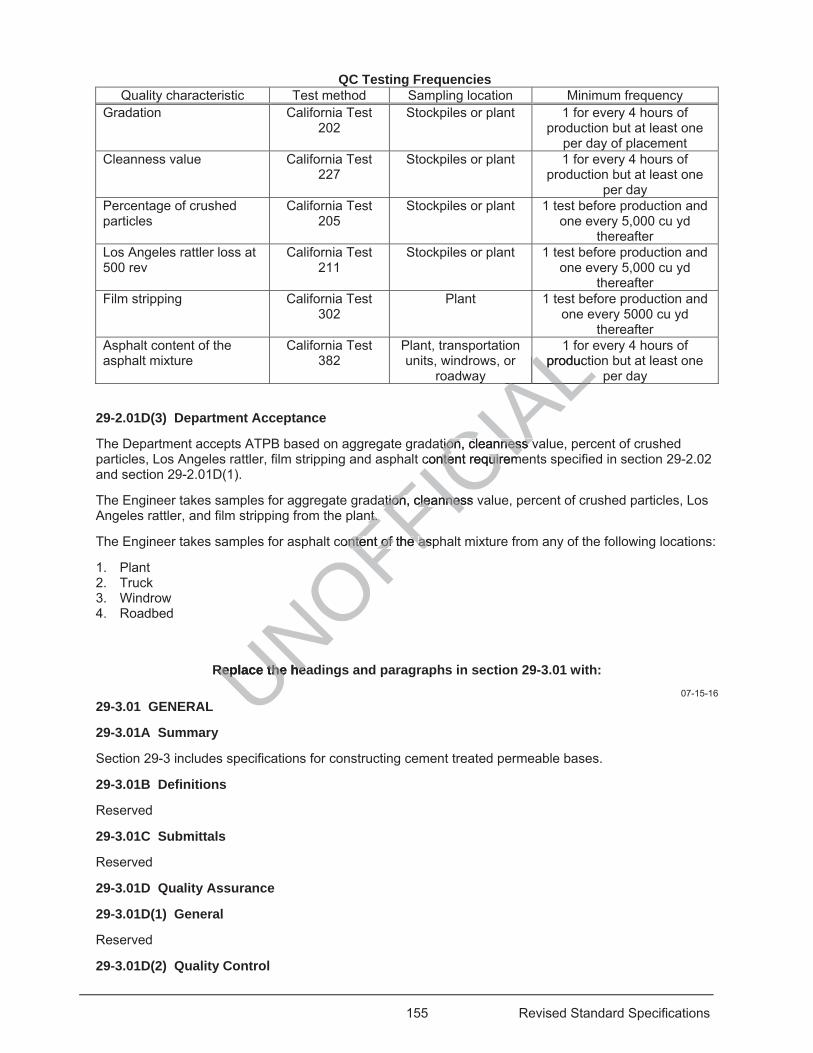
155 Revised Standard Specifications
QC Testing Frequencies Quality characteristic Test method Sampling location Minimum frequency
Gradation California Test 202
Stockpiles or plant 1 for every 4 hours of production but at least one
per day of placement Cleanness value California Test
227 Stockpiles or plant 1 for every 4 hours of
production but at least one per day
Percentage of crushed particles
California Test 205
Stockpiles or plant 1 test before production and one every 5,000 cu yd
thereafter Los Angeles rattler loss at 500 rev
California Test 211
Stockpiles or plant 1 test before production and one every 5,000 cu yd
thereafter Film stripping California Test
302 Plant 1 test before production and
one every 5000 cu yd thereafter
Asphalt content of the asphalt mixture
California Test 382
Plant, transportation units, windrows, or
roadway
1 for every 4 hours of production but at least one
per day
29-2.01D(3) Department Acceptance
The Department accepts ATPB based on aggregate gradation, cleanness value, percent of crushed particles, Los Angeles rattler, film stripping and asphalt content requirements specified in section 29-2.02 and section 29-2.01D(1).
The Engineer takes samples for aggregate gradation, cleanness value, percent of crushed particles, Los Angeles rattler, and film stripping from the plant.
The Engineer takes samples for asphalt content of the asphalt mixture from any of the following locations:
1. Plant 2. Truck 3. Windrow 4. Roadbed
Replace the headings and paragraphs in section 29-3.01 with: 07-15-16
29-3.01 GENERAL
29-3.01A Summary
Section 29-3 includes specifications for constructing cement treated permeable bases.
29-3.01B Definitions
Reserved
29-3.01C Submittals
Reserved
29-3.01D Quality Assurance
29-3.01D(1) General
Reserved
29-3.01D(2) Quality Control
UNOFFICIA
L1
productLALALALation, cleanness vtion, cleanness v
content requiremntent requirem
ation, cleanness vation, cleannesnt. nt.
content of the ontent of the aspas
Replace the heaReplace the he
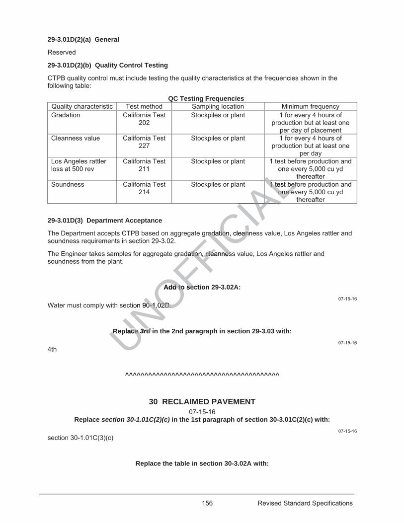
156 Revised Standard Specifications
29-3.01D(2)(a) General
Reserved
29-3.01D(2)(b) Quality Control Testing
CTPB quality control must include testing the quality characteristics at the frequencies shown in the following table:
QC Testing Frequencies Quality characteristic Test method Sampling location Minimum frequency Gradation California Test
202 Stockpiles or plant 1 for every 4 hours of
production but at least one per day of placement
Cleanness value California Test 227
Stockpiles or plant 1 for every 4 hours of production but at least one
per day Los Angeles rattler loss at 500 rev
California Test 211
Stockpiles or plant 1 test before production and one every 5,000 cu yd
thereafter Soundness California Test
214 Stockpiles or plant 1 test before production and
one every 5,000 cu yd thereafter
29-3.01D(3) Department Acceptance
The Department accepts CTPB based on aggregate gradation, cleanness value, Los Angeles rattler and soundness requirements in section 29-3.02.
The Engineer takes samples for aggregate gradation, cleanness value, Los Angeles rattler and soundness from the plant.
Add to section 29-3.02A: 07-15-16
Water must comply with section 90-1.02D.
Replace 3rd in the 2nd paragraph in section 29-3.03 with: 07-15-16
4th
^^^^^^^^^^^^^^^^^^^^^^^^^^^^^^^^^^^^^^^^
30 RECLAIMED PAVEMENT 07-15-16
Replace section 30-1.01C(2)(c) in the 1st paragraph of section 30-3.01C(2)(c) with: 07-15-16
section 30-1.01C(3)(c)
Replace the table in section 30-3.02A with:
UNOFFICIA
Lo
L1 test bef1 test befone eone eL
IAALA
gradatradation, cleanneion, clean
datdation, cleannession, cleannes
Add to sectd to sec
ion 90-1.02D. 0-1.02D.
Replace Replace 3rdrd indd
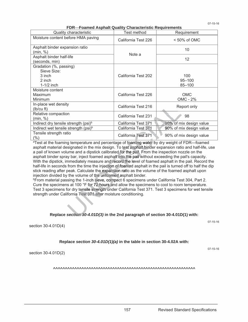
157 Revised Standard Specifications
07-15-16 FDR—Foamed Asphalt Quality Characteristic Requirements
Quality characteristic Test method Requirement Moisture content before HMA paving California Test 226 < 50% of OMC
Asphalt binder expansion ratio (min, %) Note a
10
Asphalt binder half-life (seconds, min) 12
Gradation (%, passing) Sieve Size: 3 inch 2 inch 1-1/2 inch
California Test 202 100 95–100 85–100
Moisture content Maximum Minimum
California Test 226
OMC OMC - 2%
In-place wet density (lb/cu ft) California Test 216 Report only
Relative compaction (min, %) California Test 231 98
Indirect dry tensile strength (psi)b California Test 371 90% of mix design value Indirect wet tensile strength (psi)b California Test 371 90% of mix design value Tensile strength ratio (%) California Test 371 90% of mix design value aTest at the foaming temperature and percentage of foaming water by dry weight of FDR—foamed asphalt material designated in the mix design. To test asphalt binder expansion ratio and half-life, use a pail of known volume and a dipstick calibrated for the pail. From the inspection nozzle on the asphalt binder spray bar, inject foamed asphalt into the pail without exceeding the pail's capacity. With the dipstick, immediately measure and record the level of foamed asphalt in the pail. Record the half-life in seconds from the time the injection of foamed asphalt in the pail is turned off to half the dip stick reading after peak. Calculate the expansion ratio as the volume of the foamed asphalt upon injection divided by the volume of the unfoamed asphalt binder. bFrom material passing the 1-inch sieve, compact 6 specimens under California Test 304, Part 2. Cure the specimens at 100 °F for 72 hours and allow the specimens to cool to room temperature. Test 3 specimens for dry tensile strength under California Test 371. Test 3 specimens for wet tensile strength under California Test 371 after moisture conditioning.
Replace section 30-4.01D(3) in the 2nd paragraph of section 30-4.01D(1) with: 07-15-16
section 30-4.01D(4)
Replace section 30-4.01D(1)(a) in the table in section 30-4.02A with: 07-15-16
section 30-4.01D(2)
^^^^^^^^^^^^^^^^^^^^^^^^^^^^^^^^^^^^^^^^^^^^^^^^^^^^^^^^^^^^
UNOFFICfoaming water byfoaming water tetest asphalt bindst asphalt bind
d for the pail. Frod for the pail. halt into the pail walt into the pail w
nd record thnd record the leveection of ction of foamedfoame
e expansion e expansio ratiothe unfoamed ashe unfoamed a
ch sieve, compacsieve, compaF for 72 hours anfor 72 hours a
ensile strength unensile strength un
CIALLA371 90% o371 90% oAL
IAst 371 90%371 IAIAa Test 371 Test 371
CIAIA
a Test 371 after ma Test 371 afte
C
tion 30tion 30
158 Revised Standard Specifications
DIVISION V SURFACINGS AND PAVEMENTS 36 GENERAL
04-20-18 Replace section 36-3 with:
07-21-17 36-3 PAVEMENT SMOOTHNESS
36-3.01 GENERAL
36-3.01A Summary
Section 36-3 includes specifications for measuring the smoothness of pavement surfaces.
36-3.01B Definitions
area of localized roughness: Moving average of the International Roughness Index values for each wheel path using a 25-foot continuous interval and a 250-mm filter.
Mean Roughness Index: Average of the International Roughness Index values for the left and right wheel paths for the same traffic lane using a fixed interval and a 250-mm filter.
wheel paths: Pair of lines 3 feet from and parallel to the edges of a traffic lane. Left and right wheel paths are based on the direction of travel.
36-3.01C Submittals
36-3.01C(1) General
Reserved
36-3.01C(2) Inertial Profiler Certification
At least 5 business days before starting initial profiling or changing the inertial profiler or operator, submit:
1. Inertial profiler certification issued by the Department 2. Operator certification for the inertial profiler issued by the Department 3. Manufacturer's instructions and test procedures for calibration and verification of the inertial profiler Within 2 business days after cross-correlation testing, submit a ProVAL profiler certification analysis report for the test results to the Engineer and to the electronic mailbox address [email protected].
36-3.01C(3) Inertial Profiler Data
36-3.01C(3)(a) General 04-20-18
At least 15 days before inertial profiling, you must register with the Department's secure file sharing system. To obtain information on the registration process, send an e-mail with your contact information to [email protected].
Within 2 business days after each day of profiling, submit the profile information to the Engineer and to the Department's secure file sharing system. After submitting the profile information to the Department’s file sharing system, send a notification of your electronic submittal to the Engineer and to the above electronic mailbox address with the names of the files submitted.
For each surface with inertial profile smoothness requirements, the profiling information must include:
1. Raw profile data for each lane 2. ProVAL ride quality analysis report for the Mean Roughness Index of each lane in a PDF file. Report
the following: 2.1. Listing of Mean Roughness Index values for 0.1-mile segments or portions thereof 2.2. Inputs, including the specified Mean Roughness Index threshold and fixed segment length 2.3. Raw profile data name selections 2.4. Areas exempt from inertial profile smoothness
UNOFFICIA
Lvalues fo0-mm filter. mm f
a traffic lane. Left raffic lane. Left
tial profiling tial profiling or chor
by the Departmeby the Depertitial profiler issueal profiler issu
nd testtes procedureedt
r cross-correlatior cross-correlatioto the Engineer ato the Engineer
Profiler Data Profiler Data
alal
159 Revised Standard Specifications
3. ProVAL ride quality analysis report for the International Roughness Index of the left and right wheel paths of each lane in a PDF file. Report the following: 3.1. Listing of areas of localized roughness 3.2. Inputs, including the specified area of the localized roughness threshold and continuous
segment length 3.3. Raw profile data name selections 3.4. Areas exempt from inertial profile smoothness
4. GPS data file for each lane. Submit the data file in GPS eXchange file format. 5. Manufacturer's recommended calibration and verification test results for the inertial profiler. 6. Inertial profiler's calibration and verification test results, including results for bounce, block, and the
distance measurement instrument. 7. Completed Pavement Smoothness Inertial Profiler Submittal Record.
Submit Asphalt Concrete Pavement Smoothness Corrections Information or Concrete Pavement Smoothness Corrections Information with your final profiling information submittal.
Submit the raw profile data in an unfiltered electronic pavement profile file format. Use the following file-naming convention:
YYYYMMDD_TTCCCRRR_EA_D_L_W_B_E_X_PT.PPF
where:
YYYY = year
MM = month, leading zero
DD = day of month, leading zero
TT = district, leading zero
CCC = county, 2- or 3-letter abbreviation as shown in section 1-1.08
RRR = route number with no leading zeros
EA = Contract number, excluding the district identification number, expressed as 6 characters
D = traffic direction, NB, SB, WB, or EB
L = lane number from left to right in the direction of travel
W = wheel path, L for left, R for right, or B for both
B = beginning station to the nearest foot, such as 10+20, or beginning post mile to the nearest hundredth, such as 25.06 with no leading zero
E = ending station to the nearest foot, such as 14+20, or ending post mile to the nearest hundredth, such as 28.06 with no leading zero
X = profile operation, EXIST for existing pavement, INTER for after prepaving smoothness correction, MILL for after milling, PAVE for after paving, and CORR for after final surface pavement correction, and FINAL for completed pavement documentation of compliance.
PT = type of pavement surface profiled, such as Type A HMA, RHMA-G, OGFC, JPCP, or CRCP
If you are submitting multiple inertial profiler data files, compress the files into a .ZIP file format and submit them using the file-naming convention TT_EA_X_YYYYMMDD.zip.
07-21-17 36-3.01C(3)(b) Smoothness Corrective Grinding Plan
At least 2 business days before performing corrective grinding for areas of localized roughness or areas exceeding the specified thresholds for the Mean Roughness Index, submit a corrective grinding plan as an informational submittal.
The corrective grinding plan must include:
UNOFFICIA
Ltion as shown in sion as shown in s
ding zeros ng zeros
uding the district idding the distr
SBS , WBW , or EBEB
m left to right in thm left to right in th
, LL for left, for left, R for rforR
g station to the g station to the ch as 25.06ch as 25.0
to
160 Revised Standard Specifications
1. Grinder manufacturer make and model 2. Grinder wheelbase in feet, measured from the front centerline to the back centerline of the single
wheel or tandem wheel spread 3. Grinder head position in feet, measured relative to the centerline of the front single wheel or the front
tandem wheel spread 4. Tandem wheel spreads in feet, for rear and front wheels as applicable 5. Tabular listing of the planned corrective grinding, including:
5.1. Start and stop locations in stationing to the nearest foot 5.2. Width of grind, such as left half lane, right half lane, or full width lane 5.3. Corresponding grinder head depths to the nearest 0.01 inch 5.4. Direction of grind, up to 2 passes per grind location, such as forward, reverse, forward-forward,
reverse-reverse, forward-reverse, reverse-forward 5.5. Distance from start or stop locations to the nearest semipermanent reference point
6. Forecasted improvement in terms of the Mean Roughness Index and area of localized roughness values
36-3.01C(4) Straightedge Measurements
Within 2 business days of measuring smoothness with a straightedge, submit a list of the areas requiring smoothness correction or a report stating there are no areas requiring smoothness correction. Identify the areas requiring smoothness correction by:
1. Location number 2. District-County-Route 3. Beginning station or post mile to the nearest 0.01 mile 4. For correction areas within a traffic lane:
4.1. Lane direction, NB, SB, EB, or WB 4.2. Lane number from left to right in the direction of travel 4.3. Wheel path, L for left, R for right, or B for both
5. For correction areas not within a traffic lane: 5.1. Identify the pavement area, such as shoulder, weigh station, or turnout 5.2. Direction and distance from the centerline, L for left or R for right
6. Estimated size of correction area 36-3.01D Quality Assurance
36-3.01D(1) General
Reserved
36-3.01D(2) Certifications
The inertial profiler must display a current certification decal showing the expiration date.
The operator must be certified for each model of inertial profiler operated.
The certifications issued by the Department for the inertial profiler and operator must not be more than 12 months old.
36-3.01D(3) Quality Control
36-3.01D(3)(a) General
Reserved
36-3.01D(3)(b) Smoothness
36-3.01D(3)(b)(i) General
Test pavement smoothness using an inertial profiler except use a 12-foot straightedge for the pavement at:
1. Traffic lanes less than 1,000 feet in length, including ramps, turn lanes, and acceleration and deceleration lanes
bmit a lismoothness cooothness co
ction of travel ction of travel for both or both
e: e:asas shoulder, wei shoulder
e centerline, centerlin LL for fo
cationscat
t display t display

161 Revised Standard Specifications
2. Horizontal curves with a centerline radius less than the following and within the superelevation transition of such curves: 2.1. 150 feet for asphalt concrete pavements 2.2. 300 feet for Portland cement concrete pavements
3. Areas within 12.5 feet of manholes 4. Shoulders 5. Weigh-in-motion areas 6. Miscellaneous areas such as medians, gore areas, turnouts, and maintenance pullouts Where inertial profiler testing is required:
1. Determine the pavement smoothness for each traffic lane by obtaining the International Roughness Index for the left and right wheel paths in an individual lane
2. Determine the Mean Roughness Index and areas of localized roughness using FHWA’s engineering software ProVAL
Where OGFC is required, test the pavement smoothness of the final HMA or concrete pavement surface before placing OGFC and after placing OGFC.
36-3.01D(3)(b)(ii) Inertial Profiler Calibration and Verification Tests
Notify the Engineer at least 2 business days before performing calibration and verification testing of the inertial profiler.
Conduct the following calibration and verification tests in the Engineer's presence each day before profiling:
1. Block test to verify the accuracy of the height sensor under California Test 387 2. Bounce test to verify the combined accuracy of the height sensor and accelerometer under California
Test 387 3. Distance measurement instrument test to verify the accuracy of the distance measuring instrument
under California Test 387 4. Manufacturer's recommended tests Conduct a cross-correlation verification test of the inertial profiler in the Engineer's presence before performing the initial profiling. A verification test must be performed at least annually. Conduct 5 repeat runs of the inertial profiler on an authorized test section. The test section must be a 0.1-mile segment of existing concrete pavement if you are measuring new concrete pavement or existing asphalt concrete pavement if you are measuring new asphalt concrete pavement. Where micro-milled asphalt concrete surfaces are to be measured, the cross-correlation verification test may be performed on the initial 0.1-mile section of milled asphalt concrete surface. Calculate a cross-correlation to determine the repeatability of your device under California Test 387 using a ProVAL profiler certification analysis with a 3-foot maximum offset. The cross-correlation must be a minimum of 0.92.
36-3.01D(3)(b)(iii) Performing, Analyzing, and Collecting Data
Operate the inertial profiler under the manufacturer's instructions and AASHTO R 57 at 1-inch recording intervals using a minimum 4-inch line laser sensor.
Establish semipermanent reference points for aligning inertial profiler runs and locating potential corrective grinding. Place semipermanent reference points at a frequency of 0.5 mile or less along the edge of the traffic lane or roadway. Maintain semipermanent reference points until Department acceptance testing is completed.
Collect profiling data under AASHTO R 57 and analyze it using 250 mm and International Roughness Index filters.
While collecting the profile data to determine the International Roughness Index values, record semipermanent reference points and the beginning and end of the following locations in the raw profile data:
1. Bridge approach slabs
UNOFFICIA
Lration ation and verificaand verific
Engineer's preseEngineer's pre
sor under Californor under Califothe height sensothe height senso
verify verify the accuracthe accura
tion test of the on test of the ineiverification test verification tes m
an autauthorized testhorized tesif you are measuif you are measu
suring new asphasuring new asphasured, the crossred, the c
d asphalt concretd asphalt concreevice under evice unde
The crosThe cro
162 Revised Standard Specifications
2. Bridges 3. Culverts visible on the roadway surface 4. Railroad crossings 5. At-grade intersections 6. Project limits 7. Change in pavement type
Profile the left and right wheel paths of each lane.
Determine the Mean Roughness Index for 0.1-mile fixed sections using the ProVAL ride quality analysis with a 250 mm filter. Calculate the Mean Roughness Index of each lane. A partial section equal or less than 0.05-mile length is to be included with the previous or the subsequent segment forming up to a 0.15-mile length. A partial section greater than 0.05 mile, but less than 0.10 mile, is a separate segment. Sections must comply with the Mean Roughness Index specifications for a full section. A weighted average calculation will be used for those partial sections that have been combined with previous or subsequent segments.
Determine the areas of localized roughness using ProVAL with the average International Roughness Index values for each wheel path using a 25-foot continuous interval and a 250 mm filter.
36-3.01D(4) Department Acceptance
The Department accepts pavement surfaces for smoothness based on compliance with the smoothness specifications for the type of pavement surface specified.
For areas that require pavement smoothness determined using a 12-foot straightedge, the pavement surface must not vary from the lower edge of the straightedge by more than:
1. 0.01 foot when the straightedge is laid parallel with the centerline 2. 0.02 foot when the straightedge is laid perpendicular to the centerline and extends from edge to edge
of a traffic lane 3. 0.02 foot when the straightedge is laid within 24 feet of a pavement conform Pavement located within 12.5 feet of the ends of bridges, approach slabs, culverts visible on the roadway surface, railroad crossings, at-grade intersections, and transverse surface joints with existing pavement must comply with Mean Roughness Index and 12-foot straightedge requirements. The requirements for areas of localized roughness do not apply to these areas.
For each 0.1-mile section, your International Roughness Index values must be within 10 percent of the Department's International Roughness Index values. The Engineer may order you to recalibrate your inertial profiler equipment and reprofile. If your results are inaccurate due to operator error, the Engineer may disqualify your inertial profiler operator.
36-3.02 MATERIALS
Not Used
36-3.03 CONSTRUCTION
Notify the Engineer of the start location by station and start time at least 2 business days before each day of profiling.
Before profiling, remove foreign objects from the pavement surface and mark the beginning and ending station on the pavement shoulder. The stationing must be the same when profiling more than one surface.
36-3.04 PAYMENT
Not Used
^^^^^^^^^^^^^^^^^^^^^^^^^^^^^^^^^^^^^^^^
UNOFFICIA
Lnt
250 m
ed on compliance n compliance
sing a 12-foot strsing a 12-foot stedge by more thadge by more th
with the centerlinewith the centerlinendindicular to the cencular to the
within 24 feet of a within 24 fee
e ends of bridds of b gesintersections, intersections, an
ess Index and 12-Index and 12-o not apply to thenot apply to th
your Internationaour Internatinal Roughness Inal Roughness In
ment and reprofileand reprofnertial profiler onertial profiler o
163 Revised Standard Specifications
37 BITUMINOUS SEALS 01-20-17
Replace section 37 with: 07-15-16
37 SEAL COATS 37-1 GENERAL
37-1.01 GENERAL
37-1.01A Summary
Section 37-1 includes general specifications for applying seal coats.
37-1.01B Definitions
Reserved
37-1.01C Submittals
At least 10 days before the preconstruction meeting submit a list of participants in the preconstruction meeting. Provide each participant's name, employer, title, and role in the production and placement of the seal coats.
At least 10 days before starting seal coat activities, submit the names of the authorized laboratories for quality control testing.
For each delivery of asphalt binder or asphaltic emulsion to the job site, submit a certificate of compliance and a copy of the specified test results.
For a seal coat that uses crumb rubber modifier, submit a Crumb Rubber Usage Report form monthly and at the end of project.
37-1.01D Quality Assurance
37-1.01D(1) General
For aggregate testing, quality control laboratories must be in compliance with the Department's Independent Assurance Program to be an authorized laboratory. Quality control personnel must be qualified under the Department's Independent Assurance Program.
01-20-17 For emulsion testing, quality control laboratories must participate in the AASHTO re:source proficiency sample program.
07-15-16 37-1.01D(2) Preconstruction Meeting
Hold a preconstruction meeting within 5 days before start of seal coat work at a mutually agreed time and place with the Engineer and your:
1. Project superintendent 2. Project foreman 3. Traffic control foreman
Make arrangements for the conference facility. Preconstruction meeting participants must sign an attendance sheet provided by the Engineer. Be prepared to discuss:
1. Quality control testing 2. Acceptance testing 3. Seal coat placement 4. Proposed application rates for asphaltic emulsion or asphalt binder and aggregate. 5. Training on placement methods
UNOFFICIA
Lparticipants in thearticipants in thee in the productionthe productio
the names of thethe names of the
ulsion lsion to the job sto the job s
fier, ier, submit a Cruubmi
y control laboratotrol laboratorogram to be an aogram to be a
artment's rtment's IndepenIndepe
quality controquality con
164 Revised Standard Specifications
6. Checklist of items for proper placement 7. Unique issues specific to the project, including:
7.1. Weather 7.2. Alignment and geometrics 7.3. Traffic control requirements 7.4. Haul distances 7.5. Presence and absence of shaded areas 7.6. Any other local conditions
8. Contingency plan for material deliveries, equipment breakdowns, and traffic handling 9. Who in the field has authority to adjust application rates and how adjustments will be documented 10. Schedule of sweepings 37-1.02 MATERIALS
Not Used
37-1.03 CONSTRUCTION
37-1.03A General
If seal coat activities affect access to public parking, residential property, or commercial property, post signs at 100-foot intervals on the affected streets. Signs must display No Parking – Tow Away. Signs must state the dates and hours parking or access will be restricted. Notify residents, businesses, and local agencies at least 24 hours before starting activities. The notice must:
1. Describe the work to be performed 2. Detail streets and limits of activities 3. Indicate dates and work hours 4. Be authorized Asphaltic emulsion or asphalt binder for seal coats may be reheated if necessary. After loading the asphaltic emulsion or asphalt binder into a truck for transport to the job site, do not heat asphaltic emulsion above 160 degrees F and asphalt rubber binder above 425 degrees F. During reheating, circulate or agitate the asphaltic emulsion or asphalt binder to prevent localized overheating.
Except for fog seals, apply quick setting Grade 1 asphaltic emulsions at a temperature from 75 to 130 degrees F and apply quick setting Grade 2 asphaltic emulsions at a temperature from 110 to 185 degrees F.
You determine the application rates for asphaltic emulsion or asphalt binder and aggregate and the Engineer authorizes the application rates.
37-1.03B Equipment
A self-propelled distributor truck for applying asphaltic emulsion or asphalt binder must be equipped with:
1. Pressure-type system with insulated tanks with circulating unit 2. Spray bars:
2.1. With minimum length of 9 feet and full-circulating type 2.2. With full-circulating-type extensions if needed to cover a greater width 2.3. Adjustable to allow positioning at various heights above the surface to be treated 2.4. Operated by levers such that 1 or all valves may be quickly opened or closed in one operation
3. Devices and charts to provide for accurate and rapid determination and control of asphaltic emulsion or asphalt binder quantities being applied. Include an auxiliary wheel type meter that registers: 3.1. Speed in ft/min 3.2. Trip by count 3.3. Total distance in feet
4. Distribution system: 4.1. Capable of producing a uniform application of asphaltic emulsion or asphalt binder in
controlled quantities ranging from 0.02 to 1 gal/sq yd of surface and at a pressure ranging from 25 to 75 psi
4.2. Pumps that spray asphaltic emulsion or asphalt binder within 0.02 gal/sq yd of the set rate
UNOFFICIA
Ly, oror commerccommercrry No Parking – ToNo Parking – To
d. Notify residentsotify residentsotice must: tice must:
coatoats may be rehes may be rehetruck ruck for transportor tran
halt rubber bindert rubber bindesion orsion or asphalt bin asphr
setting Grade 1 ating Grade 1 ang Grade 2 asphg Grade 2 asp
cation rates for asation rates for ahe application ratpplication
tt
trut
165 Revised Standard Specifications
4.3. With a hose and nozzle for application of asphaltic emulsion to areas inaccessible to the spray bar
4.4. With pressure gauges and a thermometer for determining temperatures of the asphaltic emulsion or asphalt binder
You may use cab-controlled valves for the application of asphaltic emulsion or asphalt binder. The valves controlling the flow from nozzles must act positively to provide a uniform unbroken application of asphaltic emulsion or asphalt binder.
Maintain distributor and storage tanks at all times to prevent dripping.
37-1.04 PAYMENT
Not Used
37-2 CHIP SEALS
37-2.01 GENERAL
37-2.01A General
37-2.01A(1) Summary
Section 37-2.01 includes general specifications for applying chip seals.
37-2.01A(2) Definitions
Reserved
37-2.01A(3) Submittals
At least 15 days before starting placement of chip seal, submit:
1. Samples for: 1.1. Asphaltic emulsion chip seal, two 1-quart wide mouth plastic containers with screw top lid of
asphaltic emulsion 1.2. Polymer modified asphaltic emulsion chip seal, two 1-quart wide mouth plastic containers with
screw top lid of polymer modified asphaltic emulsion 1.3. Asphalt rubber binder chip seal, two 1-quart cans of base asphalt binder 1.4. Asphalt rubber binder chip seal, five 1-quart cans of asphalt rubber binder
2. Asphaltic emulsion, polymer modified asphaltic emulsion, asphalt binder or asphalt rubber binder data as follows: 2.1. Supplier and Type/Grade of asphaltic emulsion or asphalt binder 2.2. Type of modifier used including polymer or crumb rubber or both 2.3. Percent of crumb rubber, if used as modifier 2.4. Copy of the specified test results for asphaltic emulsion or asphalt binder
3. 50 lb of uncoated aggregate 4. Aggregate test results for the following:
4.1. Gradation 4.2. Los Angeles Rattler 4.3. Percent of crushed particles 4.4. Flat and elongated particles 4.5. Film stripping 4.6. Cleanness value 4.7. Durability
5. Vialit test results Submit quality control test results for the quality characteristics within the reporting times allowance after sampling shown in the following table:
UNOFFICIA
Leals. s.
p seal, submit: p seal, submit
wo 1-quart wio 1-quart wide mde
c emulsion chip sc emulsion chr modified asphalmodified asphal
r chip seal, twchip seal, two 1o der chip seal, fivechip seal, five
olymer modified aymer modified
nd Type/Grade ofnd Type/Gradeodifier used incodifier used inc
rumb rubbrumb rubbecifieecifie
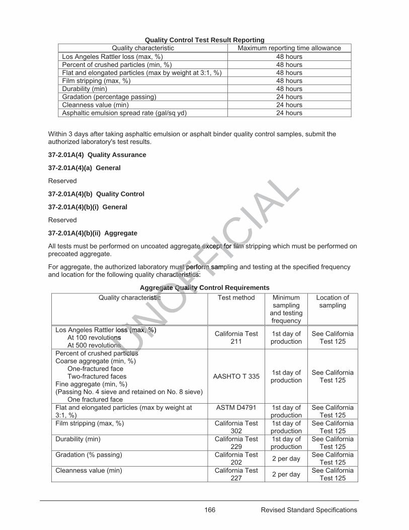
166 Revised Standard Specifications
Quality Control Test Result Reporting Quality characteristic Maximum reporting time allowance
Los Angeles Rattler loss (max, %) 48 hours Percent of crushed particles (min, %) 48 hours Flat and elongated particles (max by weight at 3:1, %) 48 hours Film stripping (max, %) 48 hours Durability (min) 48 hours Gradation (percentage passing) 24 hours Cleanness value (min) 24 hours Asphaltic emulsion spread rate (gal/sq yd) 24 hours
Within 3 days after taking asphaltic emulsion or asphalt binder quality control samples, submit the authorized laboratory's test results.
37-2.01A(4) Quality Assurance
37-2.01A(4)(a) General
Reserved
37-2.01A(4)(b) Quality Control
37-2.01A(4)(b)(i) General
Reserved
37-2.01A(4)(b)(ii) Aggregate
All tests must be performed on uncoated aggregate except for film stripping which must be performed on precoated aggregate.
For aggregate, the authorized laboratory must perform sampling and testing at the specified frequency and location for the following quality characteristics:
Aggregate Quality Control Requirements Quality characteristic Test method Minimum
sampling and testing frequency
Location of sampling
Los Angeles Rattler loss (max, %) At 100 revolutions At 500 revolutions
California Test 211
1st day of production
See California Test 125
Percent of crushed particles Coarse aggregate (min, %)
One-fractured face Two-fractured faces
Fine aggregate (min, %) (Passing No. 4 sieve and retained on No. 8 sieve)
One fractured face
AASHTO T 335 1st day of production
See California Test 125
Flat and elongated particles (max by weight at 3:1, %)
ASTM D4791 1st day of production
See California Test 125
Film stripping (max, %) California Test 302
1st day of production
See California Test 125
Durability (min) California Test 229
1st day of production
See California Test 125
Gradation (% passing) California Test 202 2 per day See California
Test 125 Cleanness value (min) California Test
227 2 per day See California Test 125
UNOFFICIA
Le exe except for film spt for film s
ust performust perform samp sracteristics: cteristics
egate Quality Coegate Quality eristic eristic OF
r loss (max, %) s (max, %ions ion
ns ns UNUNrticles rticles
%U
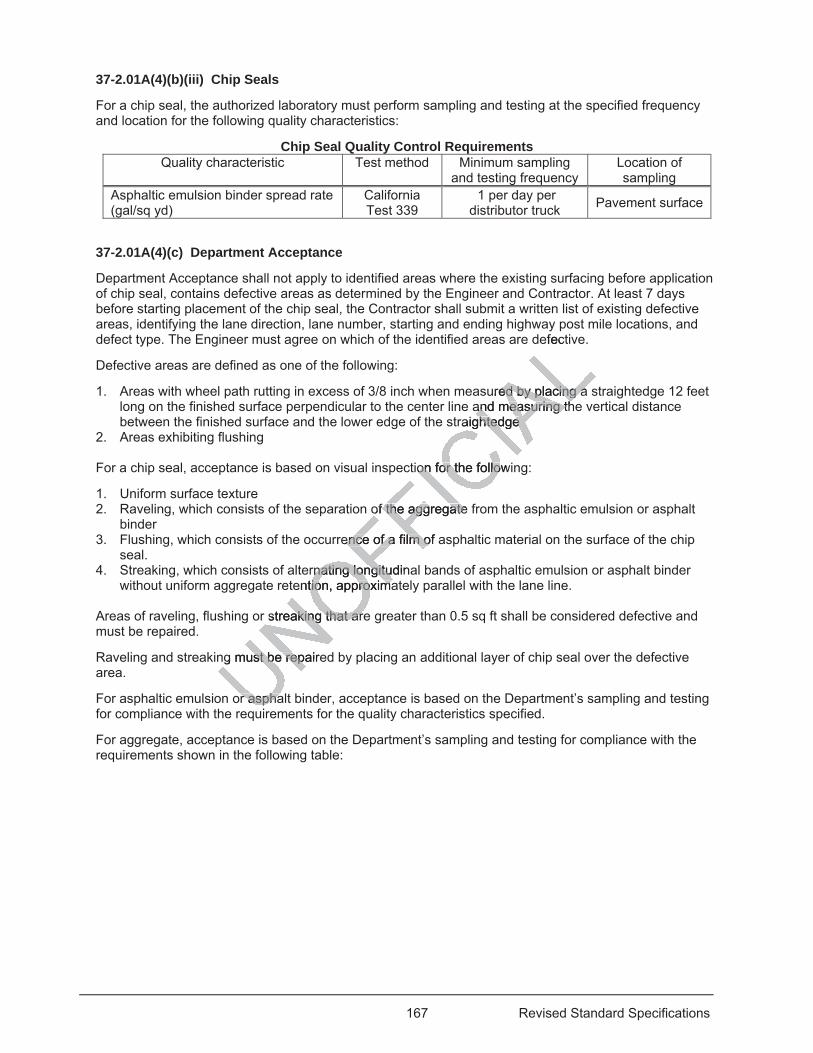
167 Revised Standard Specifications
37-2.01A(4)(b)(iii) Chip Seals
For a chip seal, the authorized laboratory must perform sampling and testing at the specified frequency and location for the following quality characteristics:
Chip Seal Quality Control Requirements Quality characteristic Test method Minimum sampling
and testing frequency Location of sampling
Asphaltic emulsion binder spread rate (gal/sq yd)
California Test 339
1 per day per distributor truck Pavement surface
37-2.01A(4)(c) Department Acceptance
Department Acceptance shall not apply to identified areas where the existing surfacing before application of chip seal, contains defective areas as determined by the Engineer and Contractor. At least 7 days before starting placement of the chip seal, the Contractor shall submit a written list of existing defective areas, identifying the lane direction, lane number, starting and ending highway post mile locations, and defect type. The Engineer must agree on which of the identified areas are defective.
Defective areas are defined as one of the following:
1. Areas with wheel path rutting in excess of 3/8 inch when measured by placing a straightedge 12 feet long on the finished surface perpendicular to the center line and measuring the vertical distance between the finished surface and the lower edge of the straightedge
2. Areas exhibiting flushing For a chip seal, acceptance is based on visual inspection for the following:
1. Uniform surface texture 2. Raveling, which consists of the separation of the aggregate from the asphaltic emulsion or asphalt
binder 3. Flushing, which consists of the occurrence of a film of asphaltic material on the surface of the chip
seal. 4. Streaking, which consists of alternating longitudinal bands of asphaltic emulsion or asphalt binder
without uniform aggregate retention, approximately parallel with the lane line.
Areas of raveling, flushing or streaking that are greater than 0.5 sq ft shall be considered defective and must be repaired.
Raveling and streaking must be repaired by placing an additional layer of chip seal over the defective area.
For asphaltic emulsion or asphalt binder, acceptance is based on the Department’s sampling and testing for compliance with the requirements for the quality characteristics specified.
For aggregate, acceptance is based on the Department’s sampling and testing for compliance with the requirements shown in the following table:
efec
ured by placing a ed by placing aand measuring thand measuring th
raightedge ghtedge
tion for the followion for the follo
of the aggregate of the aggregate
ence of a film of aence of a film o
rnating longitrnating longitudinuention, approxtion, appro imama
streaking that araking that ar
g must be repairest be rep
r asphar asphaui
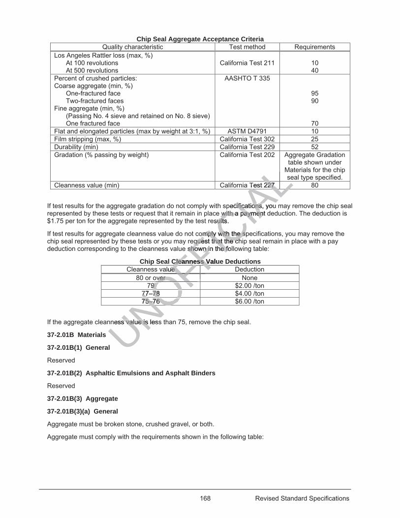
168 Revised Standard Specifications
Chip Seal Aggregate Acceptance Criteria Quality characteristic Test method Requirements
Los Angeles Rattler loss (max, %) At 100 revolutions At 500 revolutions
California Test 211
10 40
Percent of crushed particles: Coarse aggregate (min, %)
One-fractured face Two-fractured faces
Fine aggregate (min, %) (Passing No. 4 sieve and retained on No. 8 sieve) One fractured face
AASHTO T 335
95 90
70 Flat and elongated particles (max by weight at 3:1, %) ASTM D4791 10 Film stripping (max, %) California Test 302 25 Durability (min) California Test 229 52 Gradation (% passing by weight) California Test 202 Aggregate Gradation
table shown under Materials for the chip seal type specified.
Cleanness value (min) California Test 227 80
If test results for the aggregate gradation do not comply with specifications, you may remove the chip seal represented by these tests or request that it remain in place with a payment deduction. The deduction is $1.75 per ton for the aggregate represented by the test results.
If test results for aggregate cleanness value do not comply with the specifications, you may remove the chip seal represented by these tests or you may request that the chip seal remain in place with a pay deduction corresponding to the cleanness value shown in the following table:
Chip Seal Cleanness Value Deductions Cleanness value Deduction
80 or over None 79 $2.00 /ton
77–78 $4.00 /ton 75–76 $6.00 /ton
If the aggregate cleanness value is less than 75, remove the chip seal.
37-2.01B Materials
37-2.01B(1) General
Reserved
37-2.01B(2) Asphaltic Emulsions and Asphalt Binders
Reserved
37-2.01B(3) Aggregate
37-2.01B(3)(a) General
Aggregate must be broken stone, crushed gravel, or both.
Aggregate must comply with the requirements shown in the following table:
UNOFFICIA
LsLTest 227 227
ALALLLpecifications, youcifications,
with a payment dwith a paymenesults. ult
omply with the spmply with the sequequest that the chest that the ch
e shown in the folshown in the fo
Cleanness ValueCleanness Value ue FFFF
ver ver
OFOFFFFFFF79 9 OF77–78 77–78 O75–76 75–76
NONOness value is lesss value is
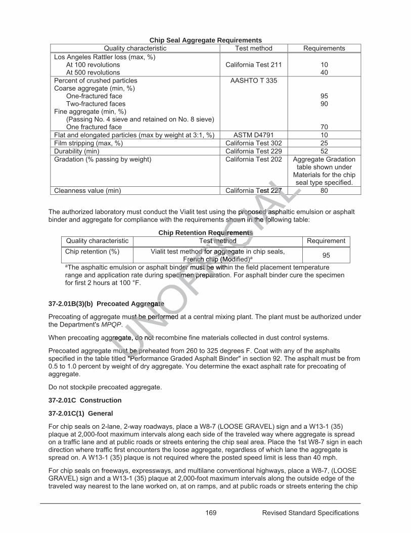
169 Revised Standard Specifications
Chip Seal Aggregate Requirements Quality characteristic Test method Requirements
Los Angeles Rattler loss (max, %) At 100 revolutions At 500 revolutions
California Test 211
10 40
Percent of crushed particles Coarse aggregate (min, %)
One-fractured face Two-fractured faces
Fine aggregate (min, %) (Passing No. 4 sieve and retained on No. 8 sieve) One fractured face
AASHTO T 335
95 90
70 Flat and elongated particles (max by weight at 3:1, %) ASTM D4791 10 Film stripping (max, %) California Test 302 25 Durability (min) California Test 229 52 Gradation (% passing by weight) California Test 202 Aggregate Gradation
table shown under Materials for the chip seal type specified.
Cleanness value (min) California Test 227 80
The authorized laboratory must conduct the Vialit test using the proposed asphaltic emulsion or asphalt binder and aggregate for compliance with the requirements shown in the following table:
Chip Retention Requirements Quality characteristic Test method Requirement Chip retention (%) Vialit test method for aggregate in chip seals,
French chip (Modified)a 95 aThe asphaltic emulsion or asphalt binder must be within the field placement temperature range and application rate during specimen preparation. For asphalt binder cure the specimen for first 2 hours at 100 °F.
37-2.01B(3)(b) Precoated Aggregate
Precoating of aggregate must be performed at a central mixing plant. The plant must be authorized under the Department's MPQP.
When precoating aggregate, do not recombine fine materials collected in dust control systems.
Precoated aggregate must be preheated from 260 to 325 degrees F. Coat with any of the asphalts specified in the table titled "Performance Graded Asphalt Binder" in section 92. The asphalt must be from 0.5 to 1.0 percent by weight of dry aggregate. You determine the exact asphalt rate for precoating of aggregate.
Do not stockpile precoated aggregate.
37-2.01C Construction
37-2.01C(1) General
For chip seals on 2-lane, 2-way roadways, place a W8-7 (LOOSE GRAVEL) sign and a W13-1 (35) plaque at 2,000-foot maximum intervals along each side of the traveled way where aggregate is spread on a traffic lane and at public roads or streets entering the chip seal area. Place the 1st W8-7 sign in each direction where traffic first encounters the loose aggregate, regardless of which lane the aggregate is spread on. A W13-1 (35) plaque is not required where the posted speed limit is less than 40 mph.
For chip seals on freeways, expressways, and multilane conventional highways, place a W8-7, (LOOSE GRAVEL) sign and a W13-1 (35) plaque at 2,000-foot maximum intervals along the outside edge of the traveled way nearest to the lane worked on, at on ramps, and at public roads or streets entering the chip
UNOFFICIA
LLTest 227 227
ALALLLe proposed asphaproposed a
shown in the folloshown in the fo
equirements equirements est method est method IChod for aggregateod for aggreg
French chip (Modirench chip (ModFICFICder mustder must be with be
pecimen preparatecimen preparaFFgregate regate
ust be perfst be performed ormeff
gregate, do not rgregate, do not
ust be prust be pr"Pe"Pe
170 Revised Standard Specifications
seal area. Place the 1st W8-7 sign where the aggregate starts with respect to the direction of travel on that lane. A W13-1 (35) plaque is not required where the posted speed limit is less than 40 mph.
Pilot cars must have cellular or radio contact with other pilot cars and personnel in the work zone. The maximum speed of the pilot cars convoying or controlling traffic through the traffic control zone must be 15 mph on 2-lane, two-way highways and 25 mph on multilane divided and undivided highways. Pilot cars must only use traffic lanes open to traffic.
On the days that closures are not allowed, you may use a moving closure to maintain the seal coat surface. The moving closure is only allowed during daylight hours when traffic will be the least inconvenienced and delayed. The Engineer determines the hours for the moving closure.
Maintain signs in place at each location until the final sweeping of the chip seal surface for that location is complete. Signs may be set on temporary portable supports with the W13-1 sign below the W8-7 sign or on barricades with the W13-1 sign alternating with the W8-7 sign.
Schedule chip seal activities so that the chip seals are placed on both lanes of the traveled way each work shift.
If traffic is routed over a surface where a chip seal application is intended, the chip seal must not be applied to more than half the width of the traveled way at a time, and the remaining width must be kept free of obstructions and open to traffic until the previously applied width is ready for traffic use.
Wherever maintenance sweeping of the chip seal surface is complete, place permanent traffic stripes and pavement markings within 10 days.
If you fail to place the permanent traffic stripes and pavement markings within the specified time, the Department withholds 50 percent of the estimated value of the chip seal work completed that has not received permanent traffic stripes and pavement markings.
37-2.01C(2) Equipment
Equipment for chip seals must include and comply with the following:
1. Aggregate haul trucks must have: 1.1. Tailgate that discharge aggregate 1.2. Device to lock onto the rear aggregate spreader hitch 1.3. Dump bed that will not push down on the spreader when fully raised 1.4. Dump bed that will not spill aggregate on the roadway when transferred to the spreader hopper 1.5. Tarpaulin to cover precoated aggregate when haul distance exceeds 30 minutes or ambient
temperature is less than 65 degrees F 2. Self-propelled aggregate spreaders must have:
2.1. Aggregate hopper in the rear 2.2. Belt conveyor that carries the aggregate to the front 2.3. Spreading hopper capable of providing a uniform aggregate spread rate over the entire width
of the traffic lane in 1 application. 3. Self-propelled power brooms must:
3.1. Not be steel-tined brooms on emulsion chip seals 3.2. Be capable of removing loose aggregate adjacent to barriers that prevent aggregate from
being swept off the roadway, including curbs, gutters, dikes, berms, and railings 4. Pneumatic or foam filled rubber tired rollers must:
4.1. Be an oscillating type at least 4 feet wide 4.2. Be self-propelled and reversible 4.3. Have tires of equal size, diameter, type, and ply 4.4. Carry at least 3,000 lbs of load on each wheel 4.5 Have tires with an air pressure of 100 ± 5 psi or be foam filled
37-2.01C(3) Surface Preparation
Before applying chip seals, cover manholes, valve and monument covers, grates, or other exposed facilities located within the area of application, using a plastic or oil resistant construction paper secured
UNOFFICIA
Lthe chip
e remaining wremath is ready for trath is ready for tra
plete, place permplete, place perm
ent markings withent markings wite of the chip seal e of the chip seal
rkings. kings
comply with the focomply with
gregate gregate rear aggregate spar aggregate s
ot push dowt push d n on ton not spill aggregaspill aggrega
ver precoated aggr precoated s less than 65 deless than 65 de
gregate spreadergregate spreade hopper in the e hopper in the
or that carror that carper cper c
171 Revised Standard Specifications
by tape or adhesive to the facility being covered. Reference the covered facilities with enough control points to relocate the facilities after the application of the chip seal.
Immediately before applying chip seals, clean the surface to receive a chip seal by removing any extraneous material affecting adhesion of the chip seal with the existing surface and drying. Use self-propelled power brooms to clean the existing pavement.
37-2.01C(4) Placement
37-2.01C(4)(a) General
Schedule the operations so that chip seals are placed on both lanes of the traveled way each work shift. At the end of the work shift, the end of the chip seals on both lanes must generally match.
37-2.01C(4)(b) Applying Asphaltic Emulsions or Asphalt Binders
Prevent spraying on existing pavement not intended for chip seals or on previously applied chip seals using a material such as building paper. Remove the material after use.
Align longitudinal joints between chip seal applications with designated traffic lanes.
For asphaltic emulsion or asphalt binder, overlap longitudinal joints by not more than 4 inches. You may overlap longitudinal joints up to 8 inches if authorized.
For areas not accessible to a truck distributor bar apply:
1. Asphaltic emulsions by hand spraying 2. Asphalt binders with a squeegee or other authorized means You may overlap the asphaltic emulsion or asphalt binder applications before the application of aggregate at longitudinal joints.
Do not apply the asphaltic emulsion or asphalt binder unless there is sufficient aggregate at the job site to cover the asphaltic emulsion or asphalt binder.
Discontinue application of asphaltic emulsion or asphalt binder early enough to comply with lane closure requirements. Apply to 1 lane at a time and cover the lane width entirely in 1 operation.
37-2.01C(4)(c) Spreading Aggregates
37-2.01C(4)(c)(i) General
Prevent vehicles from driving on asphaltic emulsion or asphalt binder before spreading aggregate.
Spread aggregate within 10 percent of your determined rate.
Spread aggregate at a uniform rate over the full lane width in 1 application. Apply to 1 lane at a time.
Sweep excess aggregate at joints before spreading adjacent aggregate.
Operate the spreader at speeds slow enough to prevent aggregate from rolling over after dropping.
If the spreader is not moving, aggregate must not drop. If you stop spreading and aggregate drops, remove the excess aggregate before resuming activities.
37-2.01C(4)(c)(ii) Precoated Aggregate Application
During transit, cover precoated aggregate with tarpaulins if the ambient air temperature is below 65 degrees F or the haul time exceeds 30 minutes.
When applied, precoated aggregate must be from 225 to 325 degrees F.
37-2.01C(4)(d) Finishing
37-2.01C(4)(d)(i) General
UNOFFICIA
Lc lan
ot more thanmo
means ean
nder applicationsnder application
t binder unlt binder un ess thhder. der.
mulsion or asphaltmulsion or ame and cover theme and cover t
gregates regates
driving on asphalving on as
thin 10 percenthin 10 perc
niformniform
172 Revised Standard Specifications
Remove piles, ridges, or unevenly distributed aggregate. Repair permanent ridges, bumps, streaks or depressions in the finished surface. Spread additional aggregate and roll if aggregate is picked up by rollers or vehicles.
Chip seal joints between adjacent applications of a chip seal must be smooth, straight, uniform, and completely covered.
A coverage is 1 roller movement over the entire width of lane. A pass is 1 roller movement parallel to the chip seal application in either direction. Overlapping passes are part of the coverage being made and are not part of a subsequent coverage. Do not start a new coverage until completing the previous coverage.
Before opening to traffic, finish the chip seals in the following sequence:
1. Perform initial rolling consisting of 1 coverage with a pneumatic-tired roller 2. Perform final rolling consisting of 2 coverages with a pneumatic-tired roller 3. Sweep excess aggregate from the roadway and adjacent abutting areas 4. Apply a flush coat if specified 5. Remove covers from the facilities 37-2.01C(4)(d)(ii) Traffic Control With Pilot Car
For 2-lane 2-way roadways under 1-way traffic control, upon completion of final rolling, traffic must be controlled with pilot cars and routed over the new chip seal for a period of 2 to 4 hours before opening the lane to traffic not controlled with pilot cars.
For multilane roadways, when traffic is controlled with pilot cars, a maximum of 1 lane in the direction of travel must be open to traffic. Traffic must be controlled with pilot cars and be routed on the new chip seal surface of the lane for a minimum of 2 hours after completion of the initial sweeping and before opening the lane to traffic not controlled with pilot cars. Once traffic controlled with pilot cars is routed over the chip seal at a particular location, continuous control must be maintained at that location until the chip seal placement and sweeping on adjacent lanes to receive a chip seal is completed.
37-2.01C(4)(d)(iii) Sweeping
Sweeping must be performed after the chip seal has set and there is no damage or dislodging of aggregate from the chip seal surface. As a minimum, sweeping is required at the following times:
1. On 2-lane 2-way roadways, from 2 to 4 hours after traffic, controlled with pilot cars, has been routed on the chip seal
2. On multilane roadways, from 2 to 4 hours after aggregate have been placed 3. In addition to previous sweeping, perform final sweeping immediately before opening any lane to
public traffic, not controlled with pilot cars 37-2.01C(4)(d)(iv) Excess Aggregate
Dispose of excess aggregate. If ordered, salvaging and stockpiling of excess aggregate is change order work.
37-2.01C(4)(e) Chip Seal Maintenance
Perform sweeping on the morning following the application of aggregate on any lane that has been open to traffic not controlled with pilot cars and before starting any other activities.
Chip seal surfaces must be maintained for 4 consecutive days from the day aggregate is applied. Maintenance must include sweeping to maintain a surface free of loose aggregate and to prevent formation of corrugations. Sweeping must not dislodge aggregate set in asphaltic emulsion or asphalt binder.
After 4 consecutive days, excess aggregate must be removed from the paved areas.
37-2.01D Payment
If there is no bid item for traffic control system, furnishing and using a pilot car is included in the various items of the work involved in applying the chip seal.
UNOFFICIA
Lon of final rollingon of final rollingeriod of 2 to 4 houod of 2 to 4 hou
cars, a maximum cars, a maximuwith pilot cars andh pilot cars and
pletion of the initipletion of the intratraffic controlled ffic controlled
uust be maintainedst be maintareceive a chip sereceive a chip se
e chip seal has see chip seal hce. As a minie. As a min mummum
, from 2 to 4 hourfrom 2 to 4 hou
ys, from 2 to 4 hos, from 2 to 4 hous sweeping, pes sweeping, pe
controlled with pcontrolled with
ess Aggess Agg
173 Revised Standard Specifications
The payment quantity for precoated aggregate is the weight measured after the aggregate is preheated and precoated with asphalt binder.
If recorded batch weights are printed automatically, the payment quantity for aggregate is the weight determined from the printed batch weights if:
1. Total weight for the precoated aggregate per batch is printed 2. Total asphalt binder weight per batch is printed 3. Zero tolerance weight is printed before weighing the first batch and after weighing the last batch for
each truckload 4. Time, date, mix number, load number, and truck identification are correlated with a load slip 5. Copy of the recorded batch weights is certified by a licensed weighmaster
37-2.02 ASPHALTIC EMULSION CHIP SEALS
37-2.02A General
37-2.02A(1) Summary
Section 37-2.02 includes specifications for applying asphaltic emulsion chip seals. An asphaltic emulsion chip seal includes applying an asphaltic emulsion, followed by aggregate, and then a flush coat.
A double asphaltic emulsion chip seal is the application of an asphaltic emulsion followed by aggregate, applied twice in sequence and then a flush coat.
37-2.02A(2) Definitions
Reserved
37-2.02A(3) Submittals
Immediately after sampling, submit two 1-quart plastic containers of asphaltic emulsion taken in the presence of the Engineer. Samples must be submitted in insulated shipping container.
37-2.02A(4) Quality Assurance
37-2.02A(4)(a) General
Reserved
37-2.02A(4)(b) Quality Control
37-2.02A(4)(b)(i) General
Reserved
37-2.02A(4)(b)(ii) Asphaltic Emulsions
Circulate asphaltic emulsion in the distributor truck before sampling. Take samples from the distributor truck at mid load or from a sampling tap or thief. Before taking samples, draw and dispose of 1 gallon. In the presence of the Engineer, take two 1-quart samples in a plastic container with lined sealed lid for acceptance testing.
For asphaltic emulsion, the authorized laboratory must perform quality control sampling and testing at the specified frequency and location for the following quality characteristics:
UNOFFICIA
Lp seals
e, and then aand
ltic emulsion folloic emulsion follo
plastiplas c containersc containesubmitted in insusubmitted
ontrol ntrol
eral al
altic Ealtic E
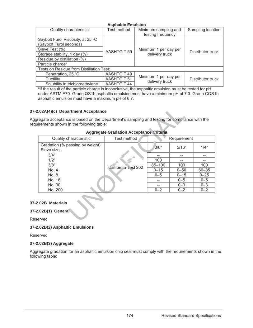
174 Revised Standard Specifications
Asphaltic Emulsion Quality characteristic Test method Minimum sampling and
testing frequency Sampling location
Saybolt Furol Viscosity, at 25 oC (Saybolt Furol seconds)
AASHTO T 59 Minimum 1 per day per delivery truck Distributor truck Sieve Test (%)
Storage stability, 1 day (%)Residue by distillation (%)Particle chargea Tests on Residue from Distillation Test:
Penetration, 25 oC AASHTO T 49 Minimum 1 per day per delivery truck Distributor truck Ductility AASHTO T 51
Solubility in trichloroethylene AASHTO T 44aIf the result of the particle charge is inconclusive, the asphaltic emulsion must be tested for pH under ASTM E70. Grade QS1h asphaltic emulsion must have a minimum pH of 7.3. Grade CQS1h asphaltic emulsion must have a maximum pH of 6.7.
37-2.02A(4)(c) Department Acceptance
Aggregate acceptance is based on the Department’s sampling and testing for compliance with the requirements shown in the following table:
Aggregate Gradation Acceptance Criteria Quality characteristic Test method Requirement
Gradation (% passing by weight) Sieve size:
California Test 202
3/8" 5/16" 1/4"
3/4" -- -- -- 1/2" 100 -- -- 3/8" 85–100 100 100 No. 4 0–15 0–50 60–85 No. 8 0–5 0–15 0–25 No. 16 -- 0–5 0–5 No. 30 -- 0–3 0–3 No. 200 0–2 0–2 0–2
37-2.02B Materials
37-2.02B(1) General
Reserved
37-2.02B(2) Asphaltic Emulsions
Reserved
37-2.02B(3) Aggregate
Aggregate gradation for an asphaltic emulsion chip seal must comply with the requirements shown in the following table:
UNOFFICIA
Lesting for compliaesting for complia
ance Criteria ance Criterid CIAC
California Test 2California Tes
3/3CCCCCCICCCCCCC lif i T t 2C lif i T
OOOOOOOONOOOalal
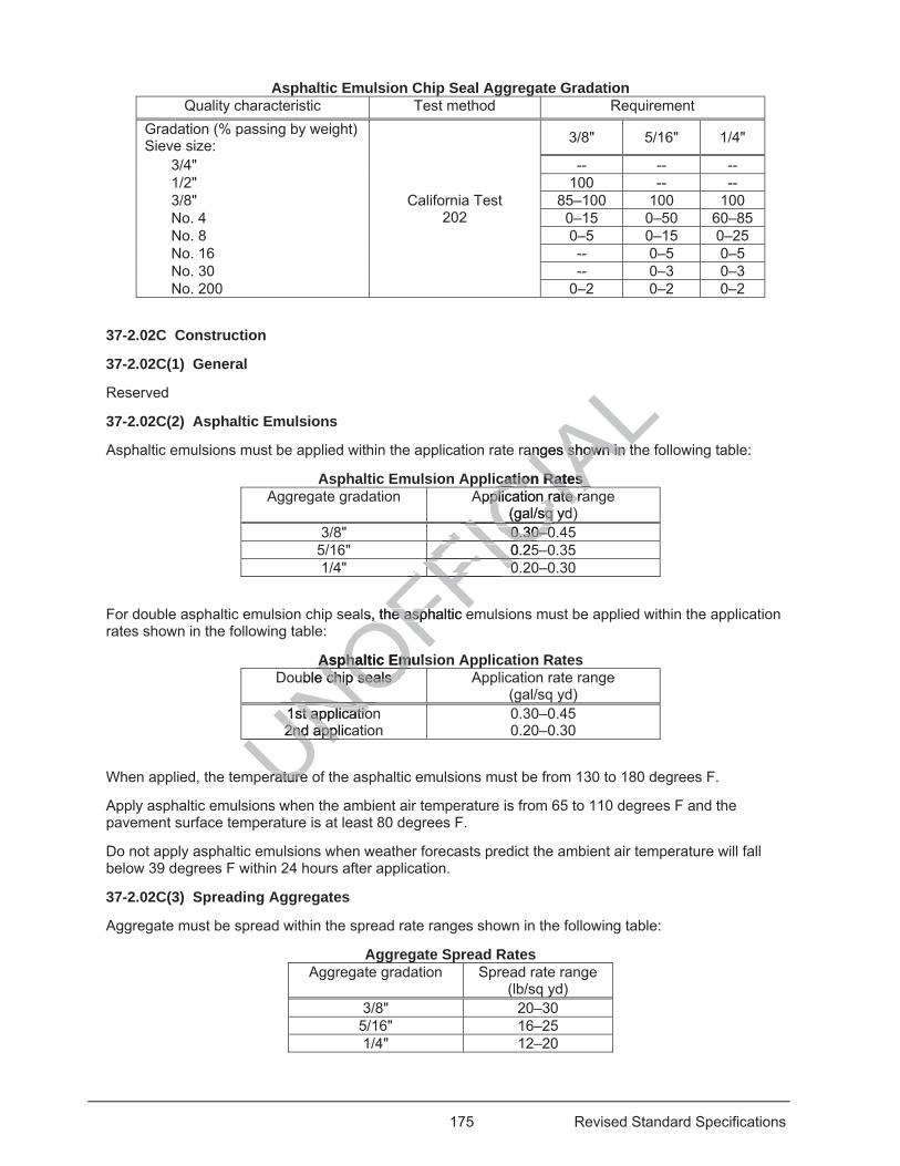
175 Revised Standard Specifications
Asphaltic Emulsion Chip Seal Aggregate Gradation Quality characteristic Test method Requirement
Gradation (% passing by weight) Sieve size:
California Test 202
3/8" 5/16" 1/4"
3/4" -- -- -- 1/2" 100 -- -- 3/8" 85–100 100 100 No. 4 0–15 0–50 60–85 No. 8 0–5 0–15 0–25 No. 16 -- 0–5 0–5 No. 30 -- 0–3 0–3 No. 200 0–2 0–2 0–2
37-2.02C Construction
37-2.02C(1) General
Reserved
37-2.02C(2) Asphaltic Emulsions
Asphaltic emulsions must be applied within the application rate ranges shown in the following table:
Asphaltic Emulsion Application Rates Aggregate gradation Application rate range
(gal/sq yd) 3/8" 0.30–0.45
5/16" 0.25–0.35 1/4" 0.20–0.30
For double asphaltic emulsion chip seals, the asphaltic emulsions must be applied within the application rates shown in the following table:
Asphaltic Emulsion Application Rates Double chip seals Application rate range
(gal/sq yd) 1st application 0.30–0.45 2nd application 0.20–0.30
When applied, the temperature of the asphaltic emulsions must be from 130 to 180 degrees F.
Apply asphaltic emulsions when the ambient air temperature is from 65 to 110 degrees F and the pavement surface temperature is at least 80 degrees F.
Do not apply asphaltic emulsions when weather forecasts predict the ambient air temperature will fall below 39 degrees F within 24 hours after application.
37-2.02C(3) Spreading Aggregates
Aggregate must be spread within the spread rate ranges shown in the following table:
Aggregate Spread Rates Aggregate gradation Spread rate range
(lb/sq yd) 3/8" 20–30
5/16" 16–25 1/4" 12–20
UNOFFICIA
Langes shown in tanges shown in t
cation Rates cation Rates Application rate rapplication rate ra
(gal/sq ydsq CIA0.30–00.30–0ICIC0.25FICF 00FI
FFFFFFls, the asphaltis, the asp c e
Asphaltic EmulAsphaltic Emuble chip seals chip seals
NO1st applicatio1st applicatioNN2nd applica2nd applUN
eratureerature
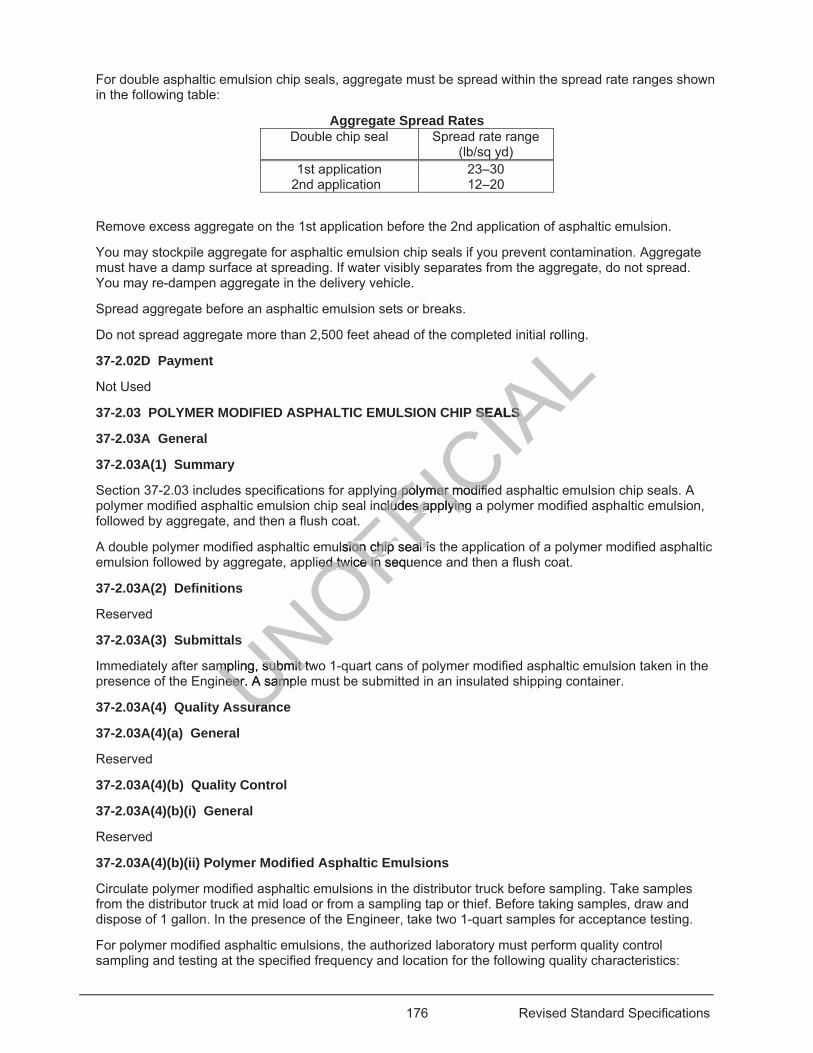
176 Revised Standard Specifications
For double asphaltic emulsion chip seals, aggregate must be spread within the spread rate ranges shown in the following table:
Aggregate Spread Rates Double chip seal Spread rate range
(lb/sq yd) 1st application 23–30
2nd application 12–20
Remove excess aggregate on the 1st application before the 2nd application of asphaltic emulsion.
You may stockpile aggregate for asphaltic emulsion chip seals if you prevent contamination. Aggregate must have a damp surface at spreading. If water visibly separates from the aggregate, do not spread. You may re-dampen aggregate in the delivery vehicle.
Spread aggregate before an asphaltic emulsion sets or breaks.
Do not spread aggregate more than 2,500 feet ahead of the completed initial rolling.
37-2.02D Payment
Not Used
37-2.03 POLYMER MODIFIED ASPHALTIC EMULSION CHIP SEALS
37-2.03A General
37-2.03A(1) Summary
Section 37-2.03 includes specifications for applying polymer modified asphaltic emulsion chip seals. A polymer modified asphaltic emulsion chip seal includes applying a polymer modified asphaltic emulsion, followed by aggregate, and then a flush coat.
A double polymer modified asphaltic emulsion chip seal is the application of a polymer modified asphaltic emulsion followed by aggregate, applied twice in sequence and then a flush coat.
37-2.03A(2) Definitions
Reserved
37-2.03A(3) Submittals
Immediately after sampling, submit two 1-quart cans of polymer modified asphaltic emulsion taken in the presence of the Engineer. A sample must be submitted in an insulated shipping container.
37-2.03A(4) Quality Assurance
37-2.03A(4)(a) General
Reserved
37-2.03A(4)(b) Quality Control
37-2.03A(4)(b)(i) General
Reserved
37-2.03A(4)(b)(ii) Polymer Modified Asphaltic Emulsions
Circulate polymer modified asphaltic emulsions in the distributor truck before sampling. Take samples from the distributor truck at mid load or from a sampling tap or thief. Before taking samples, draw and dispose of 1 gallon. In the presence of the Engineer, take two 1-quart samples for acceptance testing.
For polymer modified asphaltic emulsions, the authorized laboratory must perform quality control sampling and testing at the specified frequency and location for the following quality characteristics:
UNOFFICIA
Lro
P SEALS SEALS
gg polymer modifie polymer modifienclcludes applying udes applyin
ulsion chip sealsion chip seal isied twice in sequeed twice in
mpling, submit twmpling, submit tneer. A samplneer. A sam
uranuran
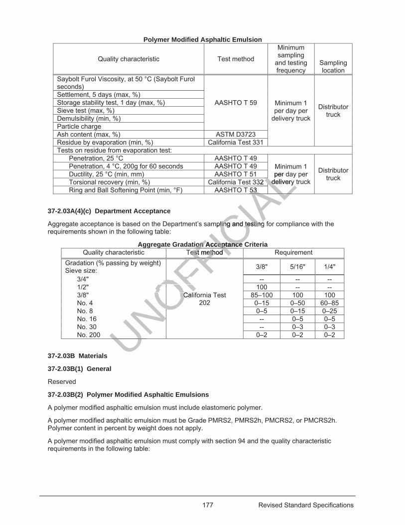
177 Revised Standard Specifications
Polymer Modified Asphaltic Emulsion
Quality characteristic Test method
Minimum sampling
and testing frequency
Sampling location
Saybolt Furol Viscosity, at 50 °C (Saybolt Furol seconds)
AASHTO T 59 Minimum 1 per day per
delivery truck
Distributor truck
Settlement, 5 days (max, %) Storage stability test, 1 day (max, %) Sieve test (max, %) Demulsibility (min, %) Particle charge Ash content (max, %) ASTM D3723 Residue by evaporation (min, %) California Test 331 Tests on residue from evaporation test:
Penetration, 25 °C AASHTO T 49 Minimum 1 per day per
delivery truck
Distributor truck
Penetration, 4 °C, 200g for 60 seconds AASHTO T 49 Ductility, 25 °C (min, mm) AASHTO T 51 Torsional recovery (min, %) California Test 332 Ring and Ball Softening Point (min, °F) AASHTO T 53
37-2.03A(4)(c) Department Acceptance
Aggregate acceptance is based on the Department’s sampling and testing for compliance with the requirements shown in the following table:
Aggregate Gradation Acceptance Criteria Quality characteristic Test method Requirement
Gradation (% passing by weight) Sieve size:
California Test 202
3/8" 5/16" 1/4"
3/4" -- -- -- 1/2" 100 -- -- 3/8" 85–100 100 100 No. 4 0–15 0–50 60–85 No. 8 0–5 0–15 0–25 No. 16 -- 0–5 0–5 No. 30 -- 0–3 0–3 No. 200 0–2 0–2 0–2
37-2.03B Materials
37-2.03B(1) General
Reserved
37-2.03B(2) Polymer Modified Asphaltic Emulsions
A polymer modified asphaltic emulsion must include elastomeric polymer.
A polymer modified asphaltic emulsion must be Grade PMRS2, PMRS2h, PMCRS2, or PMCRS2h. Polymer content in percent by weight does not apply.
A polymer modified asphaltic emulsion must comply with section 94 and the quality characteristic requirements in the following table:
UNOCCOFFICIA
LMper d
delivery delivery L32 LAL53 53
ALALALALmpling and testingling and testing
ion Acceptance on Acceptance Test method est method FICFFFF
OOOCalCONONONONONONONOU
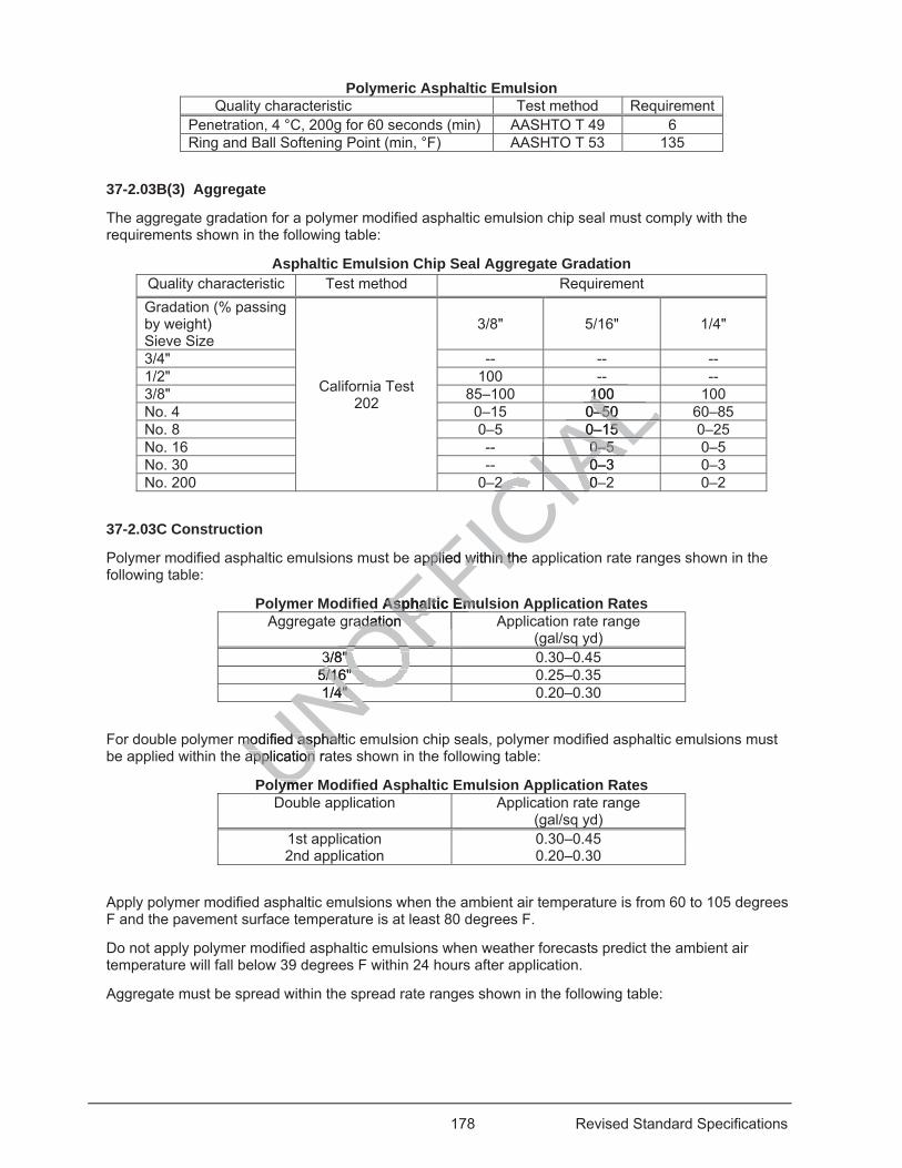
178 Revised Standard Specifications
Polymeric Asphaltic Emulsion Quality characteristic Test method Requirement
Penetration, 4 °C, 200g for 60 seconds (min) AASHTO T 49 6 Ring and Ball Softening Point (min, °F) AASHTO T 53 135
37-2.03B(3) Aggregate
The aggregate gradation for a polymer modified asphaltic emulsion chip seal must comply with the requirements shown in the following table:
Asphaltic Emulsion Chip Seal Aggregate Gradation Quality characteristic Test method Requirement Gradation (% passing by weight) Sieve Size
California Test 202
3/8" 5/16" 1/4"
3/4" -- -- -- 1/2" 100 -- -- 3/8" 85–100 100 100 No. 4 0–15 0–50 60–85 No. 8 0–5 0–15 0–25 No. 16 -- 0–5 0–5 No. 30 -- 0–3 0–3 No. 200 0–2 0–2 0–2
37-2.03C Construction
Polymer modified asphaltic emulsions must be applied within the application rate ranges shown in the following table:
Polymer Modified Asphaltic Emulsion Application Rates Aggregate gradation Application rate range
(gal/sq yd) 3/8" 0.30–0.45
5/16" 0.25–0.35 1/4" 0.20–0.30
For double polymer modified asphaltic emulsion chip seals, polymer modified asphaltic emulsions must be applied within the application rates shown in the following table:
Polymer Modified Asphaltic Emulsion Application Rates Double application Application rate range
(gal/sq yd) 1st application 0.30–0.45 2nd application 0.20–0.30
Apply polymer modified asphaltic emulsions when the ambient air temperature is from 60 to 105 degrees F and the pavement surface temperature is at least 80 degrees F.
Do not apply polymer modified asphaltic emulsions when weather forecasts predict the ambient air temperature will fall below 39 degrees F within 24 hours after application.
Aggregate must be spread within the spread rate ranges shown in the following table:
UNOFFICIA
L
100 1 L0–50 0–50 LL0–15 0–15 ALL0–5 0–5 ALIA0–3 0IAIACIA2 0–2 0
CIACIACIACIACIAapplied pplied within the within th
d Asphaltic EmuAsphaltic Emadation adation
OFF3/8" " OFOF5/16" 5/16"
NO1/4" 4" NONOmodified asphaltimodified asphalapplication raapplication
lymeyme
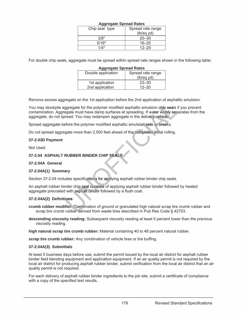
179 Revised Standard Specifications
Aggregate Spread Rates Chip seal type Spread rate range
(lb/sq yd) 3/8" 20–30
5/16" 16–25 1/4" 12–20
For double chip seals, aggregate must be spread within spread rate ranges shown in the following table:
Aggregate Spread Rates Double application Spread rate range
(lb/sq yd) 1st application 23–30
2nd application 12–20
Remove excess aggregate on the 1st application before the 2nd application of asphaltic emulsion.
You may stockpile aggregate for the polymer modified asphaltic emulsion chip seals if you prevent contamination. Aggregate must have damp surfaces at spreading. If water visibly separates from the aggregate, do not spread. You may redampen aggregate in the delivery vehicle.
Spread aggregate before the polymer modified asphaltic emulsion sets or breaks.
Do not spread aggregate more than 2,500 feet ahead of the completed initial rolling.
37-2.03D Payment
Not Used
37-2.04 ASPHALT RUBBER BINDER CHIP SEALS
37-2.04A General
37-2.04A(1) Summary
Section 37-2.04 includes specifications for applying asphalt rubber binder chip seals.
An asphalt rubber binder chip seal consists of applying asphalt rubber binder followed by heated aggregate precoated with asphalt binder followed by a flush coat.
37-2.04A(2) Definitions
crumb rubber modifier: Combination of ground or granulated high natural scrap tire crumb rubber and scrap tire crumb rubber derived from waste tires described in Pub Res Code § 42703.
descending viscosity reading: Subsequent viscosity reading at least 5 percent lower than the previous viscosity reading.
high natural scrap tire crumb rubber: Material containing 40 to 48 percent natural rubber.
scrap tire crumb rubber: Any combination of vehicle tires or tire buffing.
37-2.04A(3) Submittals
At least 5 business days before use, submit the permit issued by the local air district for asphalt rubber binder field blending equipment and application equipment. If an air quality permit is not required by the local air district for producing asphalt rubber binder, submit verification from the local air district that an air quality permit is not required.
For each delivery of asphalt rubber binder ingredients to the job site, submit a certificate of compliance with a copy of the specified test results.
UNOFFICIA
Lof a
n chip sealschiwater visibly sepavisibly sep
very vehicle. ery vehicle.
sion sets or breakon sets or break
e completed initiae completed init
SEALS SEALS
cations for cations applyipp
hip seal consists oip seal consists oh asphalt binder f asphalt binder
ions ion
er:er: Combin Combier deer de
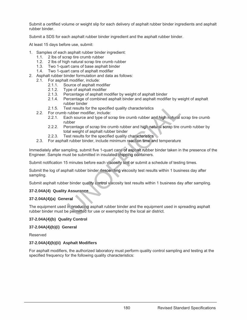
180 Revised Standard Specifications
Submit a certified volume or weight slip for each delivery of asphalt rubber binder ingredients and asphalt rubber binder.
Submit a SDS for each asphalt rubber binder ingredient and the asphalt rubber binder.
At least 15 days before use, submit:
1. Samples of each asphalt rubber binder ingredient: 1.1. 2 lbs of scrap tire crumb rubber 1.2. 2 lbs of high natural scrap tire crumb rubber 1.3. Two 1-quart cans of base asphalt binder 1.4. Two 1-quart cans of asphalt modifier
2. Asphalt rubber binder formulation and data as follows: 2.1. For asphalt modifier, include:
2.1.1. Source of asphalt modifier 2.1.2. Type of asphalt modifier 2.1.3. Percentage of asphalt modifier by weight of asphalt binder 2.1.4. Percentage of combined asphalt binder and asphalt modifier by weight of asphalt
rubber binder 2.1.5. Test results for the specified quality characteristics
2.2. For crumb rubber modifier, include: 2.2.1. Each source and type of scrap tire crumb rubber and high natural scrap tire crumb
rubber 2.2.2. Percentage of scrap tire crumb rubber and high natural scrap tire crumb rubber by
total weight of asphalt rubber binder 2.2.3. Test results for the specified quality characteristics
2.3. For asphalt rubber binder, include minimum reaction time and temperature
Immediately after sampling, submit five 1-quart cans of asphalt rubber binder taken in the presence of the Engineer. Sample must be submitted in insulated shipping containers.
Submit notification 15 minutes before each viscosity test or submit a schedule of testing times.
Submit the log of asphalt rubber binder descending viscosity test results within 1 business day after sampling.
Submit asphalt rubber binder quality control viscosity test results within 1 business day after sampling.
37-2.04A(4) Quality Assurance
37-2.04A(4)(a) General
The equipment used in producing asphalt rubber binder and the equipment used in spreading asphalt rubber binder must be permitted for use or exempted by the local air district.
37-2.04A(4)(b) Quality Control
37-2.04A(4)(b)(i) General
Reserved
37-2.04A(4)(b)(ii) Asphalt Modifiers
For asphalt modifiers, the authorized laboratory must perform quality control sampling and testing at the specified frequency for the following quality characteristics:
UNOFFICIA
Land high natural and high natural
high natural scrapgh natural scra
haracteristics aracteristics reaction time andreaction time a
ans ofns o asphalt rubasphalt rubfed shipping contaed shipping cont
viscositviscosity test or test
r descending vir descendi sc
uality control viscality control vis
urance rance
ral
in producing ain producinermittedermitted
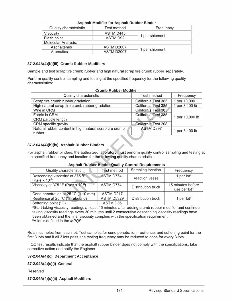
181 Revised Standard Specifications
Asphalt Modifier for Asphalt Rubber Binder Quality characteristic Test method Frequency
Viscosity ASTM D445 1 per shipment Flash point ASTM D92 Molecular Analysis:
Asphaltenes ASTM D2007 1 per shipment Aromatics ASTM D2007
37-2.04A(4)(b)(iii) Crumb Rubber Modifiers
Sample and test scrap tire crumb rubber and high natural scrap tire crumb rubber separately.
Perform quality control sampling and testing at the specified frequency for the following quality characteristics:
Crumb Rubber Modifier Quality characteristic Test method Frequency
Scrap tire crumb rubber gradation California Test 385 1 per 10,000 High natural scrap tire crumb rubber gradation California Test 385 1 per 3,400 lb Wire in CRM California Test 385
1 per 10,000 lb Fabric in CRM California Test 385 CRM particle length -- CRM specific gravity California Test 208 Natural rubber content in high natural scrap tire crumb rubber
ASTM D297 1 per 3,400 lb
37-2.04A(4)(b)(iv) Asphalt Rubber Binders
For asphalt rubber binders, the authorized laboratory must perform quality control sampling and testing at the specified frequency and location for the following quality characteristics:
Asphalt Rubber Binder Quality Control Requirements Quality characteristic Test method Sampling location Frequency
Descending viscositya at 375 °F (Pa•s x 10-3)
ASTM D7741 Reaction vessel 1 per lotb
Viscosity at 375 °F (Pa•s x 10-3) ASTM D7741 Distribution truck 15 minutes before use per lotb
Cone penetration at 25 °C (0.10 mm) ASTM D217 Distribution truck 1 per lotb Resilience at 25 °C (% rebound) ASTM D5329
Softening point (°C) ASTM D36 aStart taking viscosity readings at least 45 minutes after adding crumb rubber modifier and continue taking viscosity readings every 30 minutes until 2 consecutive descending viscosity readings have been obtained and the final viscosity complies with the specification requirement. bA lot is defined in the MPQP.
Retain samples from each lot. Test samples for cone penetration, resilience, and softening point for the first 3 lots and if all 3 lots pass, the testing frequency may be reduced to once for every 3 lots.
If QC test results indicate that the asphalt rubber binder does not comply with the specifications, take corrective action and notify the Engineer.
37-2.04A(4)(c) Department Acceptance
37-2.04A(4)(c)(i) General
Reserved
37-2.04A(4)(c)(ii) Asphalt Modifiers
UNOFFICIA
Lhod
Test 385T LLnia Test 385 Test 385 Lfornia Test 385 ornia Test 385
ALalifornia Test 385ornia Test 385AL-- --ACalifornia TeCalifornia
CIACASTM ASTM CIAICICIC
aboratory must paboratory muhe following quale following qua
ubber Binder Qubber Binder QTest TeOFO75 °F F ASAS
NONOOOOOOOPa•s x 10a•s x 10-3) Nat 25 °C (0.10 at 25 °C (0.10 UN(% reboun(% rebouUU
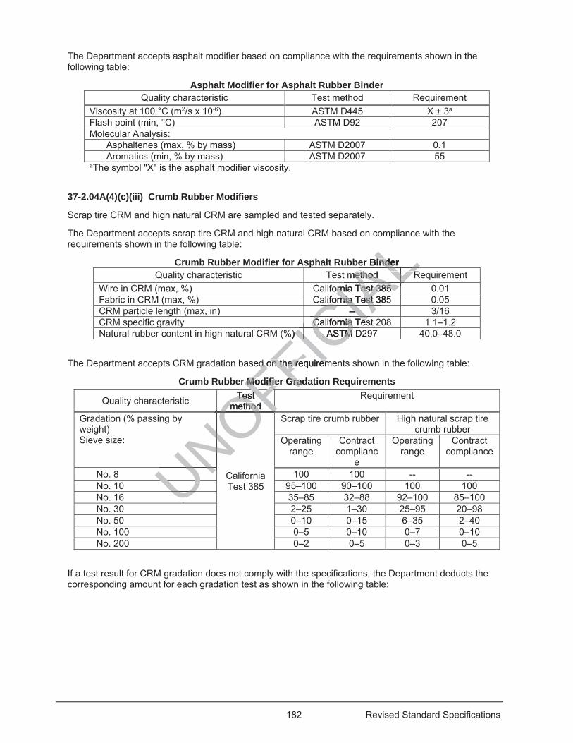
182 Revised Standard Specifications
The Department accepts asphalt modifier based on compliance with the requirements shown in the following table:
Asphalt Modifier for Asphalt Rubber Binder Quality characteristic Test method Requirement
Viscosity at 100 °C (m2/s x 10-6) ASTM D445 X ± 3a Flash point (min, °C) ASTM D92 207 Molecular Analysis:
Asphaltenes (max, % by mass) ASTM D2007 0.1 Aromatics (min, % by mass) ASTM D2007 55
aThe symbol "X" is the asphalt modifier viscosity.
37-2.04A(4)(c)(iii) Crumb Rubber Modifiers
Scrap tire CRM and high natural CRM are sampled and tested separately.
The Department accepts scrap tire CRM and high natural CRM based on compliance with the requirements shown in the following table:
Crumb Rubber Modifier for Asphalt Rubber Binder Quality characteristic Test method Requirement
Wire in CRM (max, %) California Test 385 0.01 Fabric in CRM (max, %) California Test 385 0.05 CRM particle length (max, in) -- 3/16 CRM specific gravity California Test 208 1.1–1.2 Natural rubber content in high natural CRM (%) ASTM D297 40.0–48.0
The Department accepts CRM gradation based on the requirements shown in the following table:
Crumb Rubber Modifier Gradation Requirements
Quality characteristic Test method
Requirement
Gradation (% passing by weight) Sieve size:
California Test 385
Scrap tire crumb rubber High natural scrap tire crumb rubber
Operating range
Contract complianc
e
Operating range
Contract compliance
No. 8 100 100 -- -- No. 10 95–100 90–100 100 100 No. 16 35–85 32–88 92–100 85–100 No. 30 2–25 1–30 25–95 20–98 No. 50 0–10 0–15 6–35 2–40 No. 100 0–5 0–10 0–7 0–10 No. 200 0–2 0–5 0–3 0–5
If a test result for CRM gradation does not comply with the specifications, the Department deducts the corresponding amount for each gradation test as shown in the following table:
UNOFTest Test method methodOFFIC
IAL
mp
er Binder indemethod Rmethod RALLornia Test 385 ornia Test 385 ALALLLLLLL
alifornia Test 385rnia TestIA-- -
CIACaC lifornia Tesia TesCIC%) ASTM D) ASTMCFICFICFICed on thd on the requireme requirem
er Modifier GradaModifier Gra
OFOFOOOOOOFOFFFNONONO
UNNNUUU
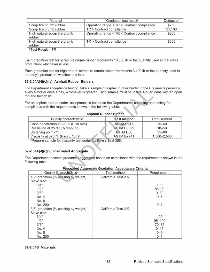
183 Revised Standard Specifications
Material Gradation test resulta Deduction Scrap tire crumb rubber Operating range < TR < Contract compliance $250 Scrap tire crumb rubber TR > Contract compliance $1,100 High natural scrap tire crumb rubber
Operating range < TR < Contract compliance $250
High natural scrap tire crumb rubber
TR > Contract compliance $600
aTest Result = TR
Each gradation test for scrap tire crumb rubber represents 10,000 lb or the quantity used in that day's production, whichever is less.
Each gradation test for high natural scrap tire crumb rubber represents 3,400 lb or the quantity used in that day's production, whichever is less.
37-2.04A(4)(c)(iv) Asphalt Rubber Binders
For Department acceptance testing, take a sample of asphalt rubber binder in the Engineer's presence every 5 lots or once a day, whichever is greater. Each sample must be in five 1-quart cans with an open top and friction lid.
For an asphalt rubber binder, acceptance is based on the Department’s sampling and testing for compliance with the requirements shown in the following table:
Asphalt Rubber Binder Quality characteristic Test method Requirement
Cone penetration at 25 °C (0.10 mm) ASTM D217 25–60 Resilience at 25 °C (% rebound) ASTM D5329 18–50 Softening point (°C) ASTM D36 55–88 Viscosity at 375 °F (Pa•s x 10-3)a ASTM D7741 1,500–2,500 aPrepare sample for viscosity test under California Test 388.
37-2.04A(4)(c)(v) Precoated Aggregate
The Department accepts precoated aggregate based on compliance with the requirements shown in the following table:
Precoated Aggregate Gradation Acceptance Criteria Quality Characteristic Test method Requirement
1/2" gradation (% passing by weight) Sieve size:
3/4" 1/2" 3/8" No. 4 No. 8 No. 200
California Test 202
100 85–90 0–30 0–5 --
0–1 3/8" gradation (% passing by weight) Sieve size:
3/4" 1/2" 3/8" No. 4 No. 8 No. 200
California Test 202
100 95–100 70–85 0–15 0–5 0–1
37-2.04B Materials
passing by wpassing byUNOFFICIA
Lin the
five 1-quafive
ment’s sampling at’s sampling a
Binder BinderTest method Test methCIASTM D2ASTM D2ICICFASTM DASFICFASTASFI
FFAS
FFFFder California Teser California TeFFgregate eg
coated aggregateed aggregate
Precoated AgPrecoatedCharacteristic Characteristic UNUU
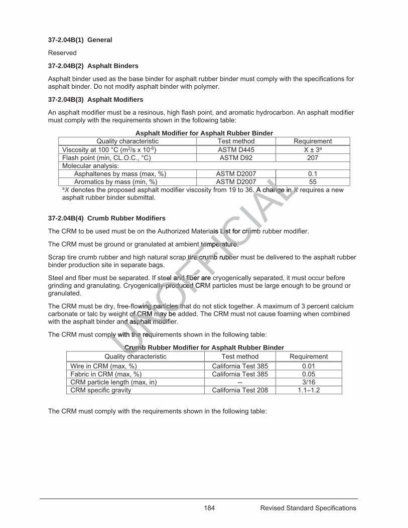
184 Revised Standard Specifications
37-2.04B(1) General
Reserved
37-2.04B(2) Asphalt Binders
Asphalt binder used as the base binder for asphalt rubber binder must comply with the specifications for asphalt binder. Do not modify asphalt binder with polymer.
37-2.04B(3) Asphalt Modifiers
An asphalt modifier must be a resinous, high flash point, and aromatic hydrocarbon. An asphalt modifier must comply with the requirements shown in the following table:
Asphalt Modifier for Asphalt Rubber Binder Quality characteristic Test method Requirement
Viscosity at 100 °C (m2/s x 10-6) ASTM D445 X ± 3a Flash point (min, CL.O.C., °C) ASTM D92 207 Molecular analysis:
Asphaltenes by mass (max, %) ASTM D2007 0.1 Aromatics by mass (min, %) ASTM D2007 55
aX denotes the proposed asphalt modifier viscosity from 19 to 36. A change in X requires a new asphalt rubber binder submittal.
37-2.04B(4) Crumb Rubber Modifiers
The CRM to be used must be on the Authorized Materials List for crumb rubber modifier.
The CRM must be ground or granulated at ambient temperature.
Scrap tire crumb rubber and high natural scrap tire crumb rubber must be delivered to the asphalt rubber binder production site in separate bags.
Steel and fiber must be separated. If steel and fiber are cryogenically separated, it must occur before grinding and granulating. Cryogenically-produced CRM particles must be large enough to be ground or granulated.
The CRM must be dry, free-flowing particles that do not stick together. A maximum of 3 percent calcium carbonate or talc by weight of CRM may be added. The CRM must not cause foaming when combined with the asphalt binder and asphalt modifier.
The CRM must comply with the requirements shown in the following table:
Crumb Rubber Modifier for Asphalt Rubber Binder Quality characteristic Test method Requirement
Wire in CRM (max, %) California Test 385 0.01 Fabric in CRM (max, %) California Test 385 0.05 CRM particle length (max, in) -- 3/16 CRM specific gravity California Test 208 1.1–1.2
The CRM must comply with the requirements shown in the following table:
UNOFFICIA
LLLLLLAL6. A change in . A change in XXXX
ALALals List for crumbList for cru
t temperature. t temperature.
p tire p tire crumb rubbecrumb rubbe
eel and fiber are cel and fiber are ally-produced CRMlly-produced C
owing particles thng particles thof CRM may be of CRM may
nd asphalt modifnd asphalt modi
ply with the requiply with the requ
CrumbCrumchaU
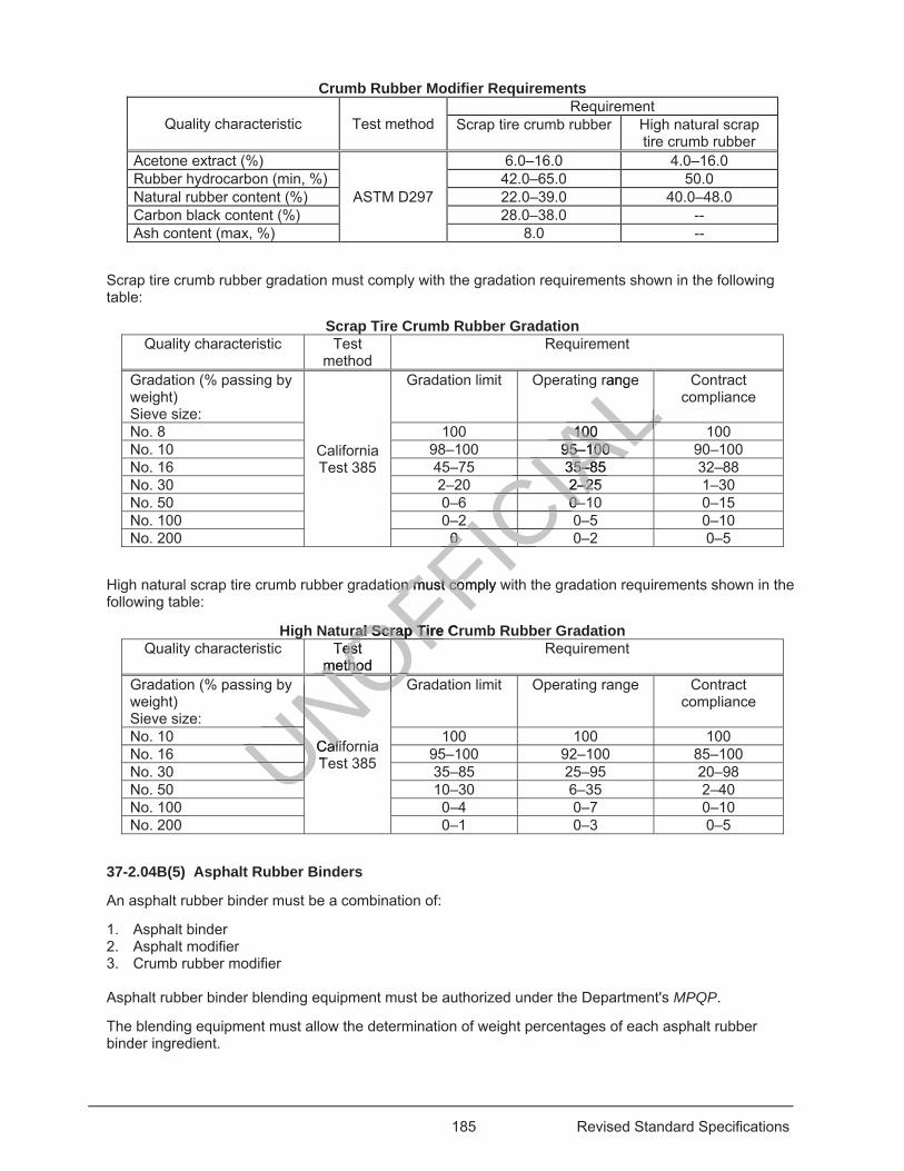
185 Revised Standard Specifications
Crumb Rubber Modifier Requirements
Quality characteristic Test method Requirement
Scrap tire crumb rubber High natural scrap tire crumb rubber
Acetone extract (%)
ASTM D297
6.0–16.0 4.0–16.0 Rubber hydrocarbon (min, %) 42.0–65.0 50.0 Natural rubber content (%) 22.0–39.0 40.0–48.0 Carbon black content (%) 28.0–38.0 -- Ash content (max, %) 8.0 --
Scrap tire crumb rubber gradation must comply with the gradation requirements shown in the following table:
Scrap Tire Crumb Rubber Gradation Quality characteristic Test
method Requirement
Gradation (% passing by weight) Sieve size:
California Test 385
Gradation limit Operating range Contract compliance
No. 8 100 100 100 No. 10 98–100 95–100 90–100 No. 16 45–75 35–85 32–88 No. 30 2–20 2–25 1–30 No. 50 0–6 0–10 0–15 No. 100 0–2 0–5 0–10 No. 200 0 0–2 0–5
High natural scrap tire crumb rubber gradation must comply with the gradation requirements shown in the following table:
High Natural Scrap Tire Crumb Rubber Gradation Quality characteristic Test
method Requirement
Gradation (% passing by weight) Sieve size:
California Test 385
Gradation limit Operating range Contract compliance
No. 10 100 100 100 No. 16 95–100 92–100 85–100 No. 30 35–85 25–95 20–98 No. 50 10–30 6–35 2–40 No. 100 0–4 0–7 0–10 No. 200 0–1 0–3 0–5
37-2.04B(5) Asphalt Rubber Binders
An asphalt rubber binder must be a combination of:
1. Asphalt binder 2. Asphalt modifier 3. Crumb rubber modifier
Asphalt rubber binder blending equipment must be authorized under the Department's MPQP.
The blending equipment must allow the determination of weight percentages of each asphalt rubber binder ingredient.
UNOFFICIA
Lrange
L100 100ALL95–100 95–100 AL35–85 35–8IAC2–25 2–2
CIAC0–0–CIAC2 2 CC0 0 ICFICCCon must coon must comply w
ral Scrap Tire Cral Scrap TirTest es
method metho OFOFCalifaliTNONOOOOOO
UNOUNUNUNUNUUU
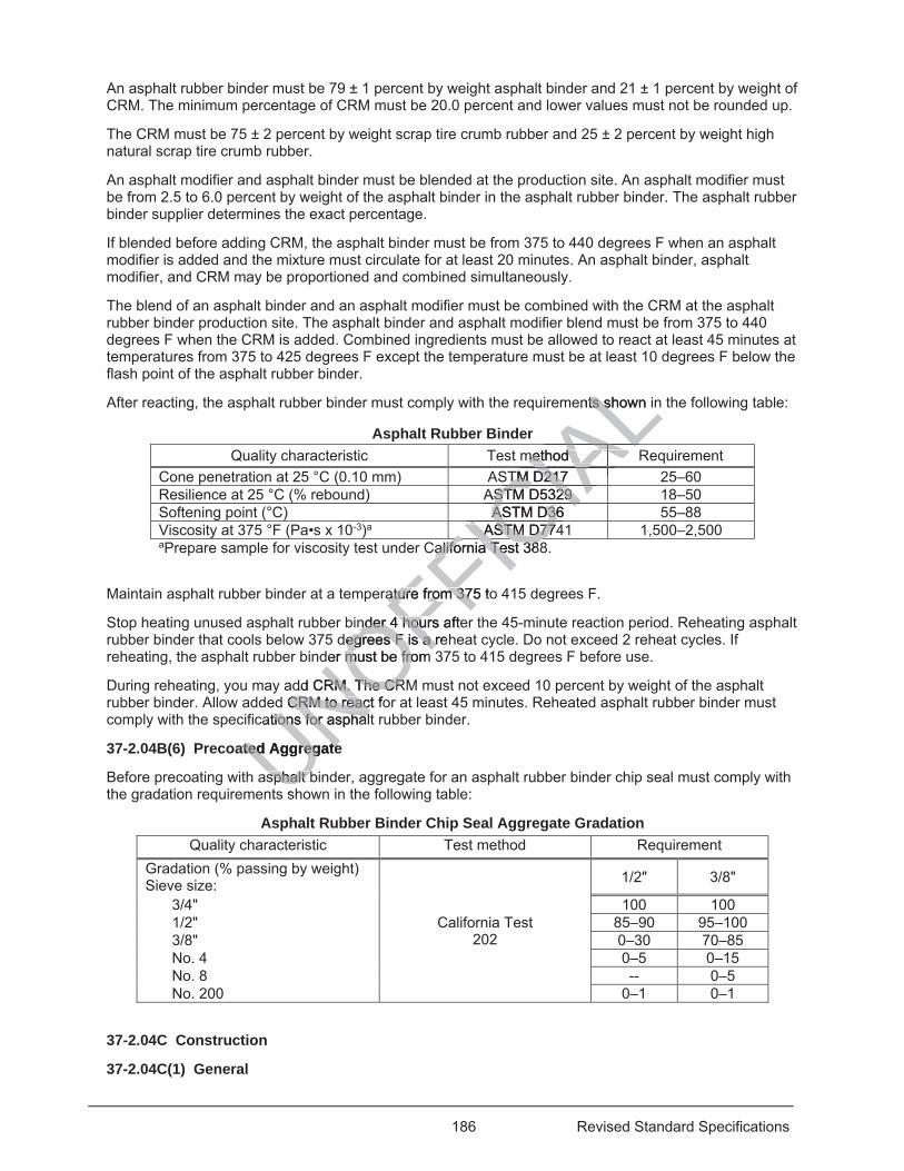
186 Revised Standard Specifications
An asphalt rubber binder must be 79 ± 1 percent by weight asphalt binder and 21 ± 1 percent by weight of CRM. The minimum percentage of CRM must be 20.0 percent and lower values must not be rounded up.
The CRM must be 75 ± 2 percent by weight scrap tire crumb rubber and 25 ± 2 percent by weight high natural scrap tire crumb rubber.
An asphalt modifier and asphalt binder must be blended at the production site. An asphalt modifier must be from 2.5 to 6.0 percent by weight of the asphalt binder in the asphalt rubber binder. The asphalt rubber binder supplier determines the exact percentage.
If blended before adding CRM, the asphalt binder must be from 375 to 440 degrees F when an asphalt modifier is added and the mixture must circulate for at least 20 minutes. An asphalt binder, asphalt modifier, and CRM may be proportioned and combined simultaneously.
The blend of an asphalt binder and an asphalt modifier must be combined with the CRM at the asphalt rubber binder production site. The asphalt binder and asphalt modifier blend must be from 375 to 440 degrees F when the CRM is added. Combined ingredients must be allowed to react at least 45 minutes at temperatures from 375 to 425 degrees F except the temperature must be at least 10 degrees F below the flash point of the asphalt rubber binder.
After reacting, the asphalt rubber binder must comply with the requirements shown in the following table:
Asphalt Rubber Binder Quality characteristic Test method Requirement
Cone penetration at 25 °C (0.10 mm) ASTM D217 25–60 Resilience at 25 °C (% rebound) ASTM D5329 18–50 Softening point (°C) ASTM D36 55–88 Viscosity at 375 °F (Pa•s x 10-3)a ASTM D7741 1,500–2,500 aPrepare sample for viscosity test under California Test 388.
Maintain asphalt rubber binder at a temperature from 375 to 415 degrees F.
Stop heating unused asphalt rubber binder 4 hours after the 45-minute reaction period. Reheating asphalt rubber binder that cools below 375 degrees F is a reheat cycle. Do not exceed 2 reheat cycles. If reheating, the asphalt rubber binder must be from 375 to 415 degrees F before use.
During reheating, you may add CRM. The CRM must not exceed 10 percent by weight of the asphalt rubber binder. Allow added CRM to react for at least 45 minutes. Reheated asphalt rubber binder must comply with the specifications for asphalt rubber binder.
37-2.04B(6) Precoated Aggregate
Before precoating with asphalt binder, aggregate for an asphalt rubber binder chip seal must comply with the gradation requirements shown in the following table:
Asphalt Rubber Binder Chip Seal Aggregate Gradation Quality characteristic Test method Requirement
Gradation (% passing by weight) Sieve size:
California Test 202
1/2" 3/8"
3/4" 100 100 1/2" 85–90 95–100 3/8" 0–30 70–85 No. 4 0–5 0–15 No. 8 -- 0–5 No. 200 0–1 0–1
37-2.04C Construction
37-2.04C(1) General
UNOFFICIA
Lents shown ints s
method method ALALSTM D217 TM D217IAIAAAAAAAASTM D5329 ASTM D5329 CIAASTM D36 ASTM D3CI
ASTM ASTM D774D77ICCalifornia Test 388California Test 38
FICature from 375 toature from 375
nder 4 hours ander 4 hou ftedegrees F is a reegrees F is a r
der must be from der must be fro
dd CRM. The CRRM. The CRd CRM to react foCRM to react
cations for asphaltions for aspha
ated Aggregateted Aggregate
sphalt bsphalt bs
187 Revised Standard Specifications
Reserved
37-2.04C(2) Equipment
Distributor trucks must be equipped with:
1. Mixing and heating unit 2. Observation platform on the rear of the truck for an observer on the platform to see the nozzles and
unplug them if needed 37-2.04C(3) Asphalt Rubber Binder Application
Apply the asphalt rubber binder when the ambient temperature is from 60 to 105 degrees F and the pavement surface temperature is at least 55 degrees F.
Do not apply the asphalt rubber binder unless enough aggregate is available at the job site to cover the asphalt rubber binder within 2 minutes. Intersections, turn lanes, gore points, and irregular areas must be covered within 15 minutes.
Do not apply asphalt rubber binder when pavement is damp or during high wind conditions. If authorized, you may adjust the distributor bar height and distribution speed and use shielding equipment during high wind conditions.
When applied, the temperature of the asphalt rubber binder must be from 385 to 415 degrees F.
Apply the asphalt rubber binder at a rate from 0.55 to 0.65 gal/sq yd. You may reduce the application rate by 0.050 gal/sq yd in the wheel paths.
37-2.04C(4) Precoated Aggregate Spreading
Spread aggregate at a rate from 28 to 40 lb/sq yd. Do not spread aggregate more than 200 feet ahead of the completed initial rolling.
37-2.04C(5) Rolling and Sweeping
Perform initial rolling within 90 seconds of spreading aggregate. If authorized for final rolling, you may use a steel-wheeled roller weighing from 8 to 10 tons in static mode only.
Perform a final sweeping before Contract acceptance. The final sweeping must not dislodge aggregate.
37-2.04D Payment
Asphalt rubber binder is measured as specified for asphalt binder.
37-2.05 STRESS ABSORBING MEMBRANE INTERLAYERS
37-2.05A General
Section 37-2.05 includes specifications for placing stress absorbing membrane interlayers (SAMI).
Comply with section 37-2.04 except a flush coat is not required.
Traffic must not be allowed on a SAMI.
37-2.05B Materials
For a SAMI, aggregate must comply with the 3/8-inch gradation.
37-2.05C Construction
If a SAMI is overlaid in the same work shift, section 37-2.01C(4)(e) does not apply.
Final sweeping is not required for a SAMI.
37-2.05D Payment
Not Used
UNOFFICIA
Lwind c
shielding ehie
be from 385 to 41rom 385 to 41
l/sq yd. You may /sq yd. You m
Do not spread aDo not spread a
s of spreading ags of spreadm 8 to 10 tons in s8 to 10 tons in
e Contract acceptContract acce
s measured as smeasured
BSORBING MBSORBING
188 Revised Standard Specifications
37-2.06 MODIFIED ASPHALT BINDER CHIP SEALS
Reserved
37-2.07 SCRUB SEALS
Reserved
37-3 SLURRY SEALS AND MICRO-SURFACINGS
37-3.01 GENERAL
37-3.01A General
37-3.01A(1) Summary
Section 37-3.01 includes general specifications for applying slurry seals and micro-surfacings.
37-3.01A(2) Definitions
Reserved
37-3.01A(3) Submittals
At least 15 days before starting placement of a slurry seal or micro-surfacing, submit:
1. Samples for: 1.1. Asphaltic emulsion slurry seal, two 1-quart wide mouth plastic containers with screw top lid of
asphaltic emulsion 1.2 Polymer modified asphaltic emulsion slurry seal, two 1-quart wide mouth plastic containers with
screw top lid of polymer modified asphaltic emulsion 1.3. Micro-surfacing, two 1-quart wide mouth plastic containers with screw top lid of micro-surfacing
emulsion 2. Asphaltic emulsion, polymer modified asphaltic emulsion, or micro-surfacing emulsion data as
follows: 2.1. Supplier and Type/Grade of asphaltic emulsion 2.2. Type of modifier polymer for polymer modified asphaltic emulsion or micro-surfacing emulsion 2.3. Copy of the specified test results for asphaltic emulsion, polymer modified asphaltic emulsion,
or micro-surfacing emulsion 3. 50 lb of aggregate 4. Aggregate test results for the followings:
4.1. Gradation 4.2. Los Angeles Rattler 4.3. Percent of crushed particles 4.4 Sand equivalent 4.5 Durability
At least 10 days before starting placement of a slurry seal or micro-surfacing, submit a laboratory report of test results and the proposed mix design from an authorized laboratory. The authorized laboratory must sign the laboratory report and mix design.
The report must include:
1. Test results used in the mix design compared with specification requirements 2. Proportions based on the dry weight of aggregate, including ranges, for:
2.1. Aggregate 2.2. Water 2.3. Additives 2.4. Mineral filler 2.5. Slurry seal emulsion or micro-surfacing emulsion residual asphalt content
3. Recommended changes to the proportions based on heating the mixture to 100 degrees F and mixing for 60 seconds, if atmospheric temperatures during application will be 90 degrees F or above, for: 3.1. Water
UNOFFICIA
Lsurfacing, submiturfacing, submi
mouth plastic contmouth plastic co
seal, eal, two 1-quart wtwo 1-quac emulsion c emulsion
h plastic containeh plastic containe
phaltic phaltic emulsion,em
asphaltic emulsiosphaltic emulsiofor polymer modifor polymer mo
est results for aspresults for aspmulsion ulsion
for the followingsor the followin
es Rattler es Rattler f crushed particf crushed partic
lent lent
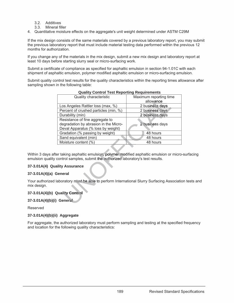
189 Revised Standard Specifications
3.2. Additives 3.3. Mineral filler
4. Quantitative moisture effects on the aggregate's unit weight determined under ASTM C29M If the mix design consists of the same materials covered by a previous laboratory report, you may submit the previous laboratory report that must include material testing data performed within the previous 12 months for authorization.
If you change any of the materials in the mix design, submit a new mix design and laboratory report at least 10 days before starting slurry seal or micro-surfacing work.
Submit a certificate of compliance as specified for asphaltic emulsion in section 94-1.01C with each shipment of asphaltic emulsion, polymer modified asphaltic emulsion or micro-surfacing emulsion.
Submit quality control test results for the quality characteristics within the reporting times allowance after sampling shown in the following table:
Quality Control Test Reporting Requirements Quality characteristic Maximum reporting time
allowance Los Angeles Rattler loss (max, %) 2 business days Percent of crushed particles (min, %) 2 business days Durability (min) 2 business days Resistance of fine aggregate to degradation by abrasion in the Micro-Deval Apparatus (% loss by weight)
2 business days
Gradation (% passing by weight) 48 hours Sand equivalent (min) 48 hours Moisture content (%) 48 hours
Within 3 days after taking asphaltic emulsion, polymer modified asphaltic emulsion or micro-surfacing emulsion quality control samples, submit the authorized laboratory's test results.
37-3.01A(4) Quality Assurance
37-3.01A(4)(a) General
Your authorized laboratory must be able to perform International Slurry Surfacing Association tests and mix design.
37-3.01A(4)(b) Quality Control
37-3.01A(4)(b)(i) General
Reserved
37-3.01A(4)(b)(ii) Aggregate
For aggregate, the authorized laboratory must perform sampling and testing at the specified frequency and location for the following quality characteristics:
UNOFFICIA
Lortin
wance wasiness days ess Lbusiness days business days
AL2 business daysusiness daysAL2 business2 busineAC4CIICICFICFICFIFICFI
on, polymer modon, polymer moit the authorized le authorized
y must be able to must be able
lity Control lity Contro
ral ral
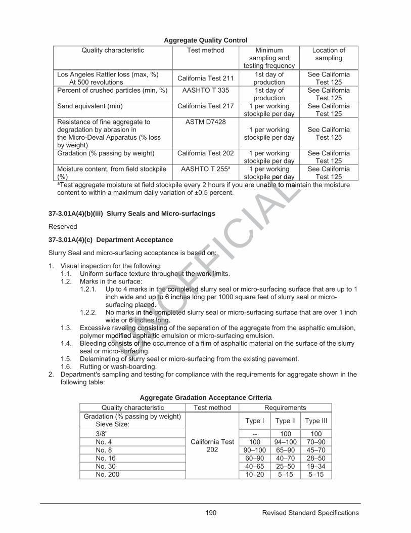
190 Revised Standard Specifications
Aggregate Quality Control Quality characteristic Test method Minimum
sampling and testing frequency
Location of sampling
Los Angeles Rattler loss (max, %) At 500 revolutions California Test 211 1st day of
production See California
Test 125 Percent of crushed particles (min, %)
AASHTO T 335 1st day of production
See California Test 125
Sand equivalent (min)
California Test 217 1 per working stockpile per day
See California Test 125
Resistance of fine aggregate to degradation by abrasion in the Micro-Deval Apparatus (% loss by weight)
ASTM D7428 1 per working
stockpile per day See California
Test 125
Gradation (% passing by weight) California Test 202 1 per working stockpile per day
See California Test 125
Moisture content, from field stockpile (%)
AASHTO T 255a 1 per working stockpile per day
See California Test 125
aTest aggregate moisture at field stockpile every 2 hours if you are unable to maintain the moisture content to within a maximum daily variation of ±0.5 percent.
37-3.01A(4)(b)(iii) Slurry Seals and Micro-surfacings
Reserved
37-3.01A(4)(c) Department Acceptance
Slurry Seal and micro-surfacing acceptance is based on:
1. Visual inspection for the following: 1.1. Uniform surface texture throughout the work limits. 1.2. Marks in the surface:
1.2.1. Up to 4 marks in the completed slurry seal or micro-surfacing surface that are up to 1 inch wide and up to 6 inches long per 1000 square feet of slurry seal or micro-surfacing placed.
1.2.2. No marks in the completed slurry seal or micro-surfacing surface that are over 1 inch wide or 6 inches long.
1.3. Excessive raveling consisting of the separation of the aggregate from the asphaltic emulsion, polymer modified asphaltic emulsion or micro-surfacing emulsion.
1.4. Bleeding consists of the occurrence of a film of asphaltic material on the surface of the slurry seal or micro-surfacing.
1.5. Delaminating of slurry seal or micro-surfacing from the existing pavement. 1.6. Rutting or wash-boarding.
2. Department's sampling and testing for compliance with the requirements for aggregate shown in the following table:
Aggregate Gradation Acceptance Criteria
Quality characteristic Test method Requirements Gradation (% passing by weight)
Sieve Size:
California Test 202
Type I Type II Type III
3/8" -- 100 100 No. 4 100 94–100 70–90 No. 8 90–100 65–90 45–70 No. 16 60–90 40–70 28–50 No. 30 40–65 25–50 19–34 No. 200 10–20 5–15 5–15
UNOFFICIA
Lrkin
e per daynable to mainble to mainL
ased on: ased on:
hout the work limout the work lim
the completed sluthe completed up to 6 inches lonto 6 inches lo
aced. ceds in the completede completed
r 6 inches long. r 6 inches longveling consisting eling consisting
modified asphaltic odified asphaltconsists of the consists of th
-surfacin-surfacinf slul
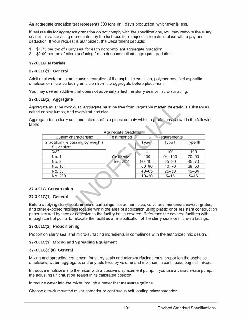
191 Revised Standard Specifications
An aggregate gradation test represents 300 tons or 1 day's production, whichever is less.
If test results for aggregate gradation do not comply with the specifications, you may remove the slurry seal or micro-surfacing represented by the test results or request it remain in place with a payment deduction. If your request is authorized, the Department deducts:
1. $1.75 per ton of slurry seal for each noncompliant aggregate gradation 2. $2.00 per ton of micro-surfacing for each noncompliant aggregate gradation
37-3.01B Materials
37-3.01B(1) General
Additional water must not cause separation of the asphaltic emulsion, polymer modified asphaltic emulsion or micro-surfacing emulsion from the aggregate before placement.
You may use an additive that does not adversely affect the slurry seal or micro-surfacing.
37-3.01B(2) Aggregate
Aggregate must be rock dust. Aggregate must be free from vegetable matter, deleterious substances, caked or clay lumps, and oversized particles.
Aggregate for a slurry seal and micro-surfacing must comply with the gradations shown in the following table:
Aggregate Gradation Quality characteristic Test method Requirements
Gradation (% passing by weight) Sieve size:
California Test 202
Type I Type II Type III
3/8" -- 100 100 No. 4 100 94–100 70–90 No. 8 90–100 65–90 45–70 No. 16 60–90 40–70 28–50 No. 30 40–65 25–50 19–34 No. 200 10–20 5–15 5–15
37-3.01C Construction
37-3.01C(1) General
Before applying slurry seals or micro-surfacings, cover manholes, valve and monument covers, grates, and other exposed facilities located within the area of application using plastic or oil resistant construction paper secured by tape or adhesive to the facility being covered. Reference the covered facilities with enough control points to relocate the facilities after application of the slurry seals or micro-surfacings.
37-3.01C(2) Proportioning
Proportion slurry seal and micro-surfacing ingredients in compliance with the authorized mix design.
37-3.01C(3) Mixing and Spreading Equipment
37-3.01C(3)(a) General
Mixing and spreading equipment for slurry seals and micro-surfacings must proportion the asphaltic emulsions, water, aggregate, and any additives by volume and mix them in continuous pug mill mixers.
Introduce emulsions into the mixer with a positive displacement pump. If you use a variable-rate pump, the adjusting unit must be sealed in its calibrated position.
Introduce water into the mixer through a meter that measures gallons.
Choose a truck mounted mixer-spreader or continuous self-loading mixer spreader.
UNOFFICIA
Ltter, delette
he gradations shogradations sh
ationationd RRCIAC
California CaliforniaTest 202 Test 202
Type I e ICCCCCCCFIC-FICFICFIFIFFFFOFOFOFOFOOFOry seals or microy seals or micro
lities locatelities locaadheadhe
192 Revised Standard Specifications
37-3.01C(3)(b) Truck Mounted Mixer Spreaders
Truck mounted mixer spreaders must comply with:
1. Rotating and reciprocating equipment must be covered with metal guards. 2. Proportion aggregate using a belt feeder with an adjustable cutoff gate. The Engineer verifies the
height of the gate opening. 3. Belt feeder must have a depth monitor device. The depth monitor device must automatically shut
down power to the belt feeder when the aggregate depth is less than 70 percent of the target depth. 4. Separate monitor device must detect the revolutions of the belt feeder. This device must
automatically shut down power to the belt feeder if it detects no revolutions. If the belt feeder is an integral part of the equipment's drive chain, the monitor device is not required.
5. Aggregate belt feeder must be connected directly to the drive on the emulsion pump. The aggregate feeder drive shaft must have a revolution counter reading the nearest 0.10 revolution for micro-surfacing, and nearest 1 revolution for slurry seal.
6. Emulsion storage must be equipped with a device that automatically shuts down power to the emulsion pump and aggregate belt feeder when the level of stored emulsion is lowered. To allow for normal fluctuations, there may be a delay of 3 seconds between detection of low emulsion storage levels or low aggregate depths and automatic power shut down.
7. Emulsion storage must be located immediately before the emulsion pump. 8. Emulsion storage tank must have a temperature indicator at the pump suction level. The indicator
must be accurate to ±5 degrees F. 9. No-flow and revolution warning devices must be in working condition. Low-flow indicators must be
visible while walking alongside the equipment. 37-3.01C(3)(c) Continuous Self-Loading Mixer Spreaders
Continuous self-loading mixer spreaders must be automatically sequenced and self-propelled. The mixing machine must deliver each material to a double shafted mixer and discharge the mixed material on a continuous flow basis. The mixing machines must have sufficient storage capacity to maintain a continuous supply of material to the proportioning controls. The mixing machine operators must have full control of forward and reverse speeds during placement.
37-3.01C(3)(d) Spreader Boxes
The spreader boxes used to spread slurry seals and micro-surfacings must be:
1. Capable of spreading the slurry seal or micro-surfacing a minimum of 12 feet wide and preventing the loss of slurry seal or micro-surfacing.
2. Equipped with flexible rubber belting on each side. The belting must contact the pavement to prevent the loss of slurry seal or micro-surfacing from the box.
3. Equipped to uniformly apply the slurry seal or micro-surfacing on superelevated sections and shoulder slopes. Micro-surfacing spreader box must be equipped with reversible motor driven augers.
4. Equipped with a series of strike-off devices at its rear. 4.1. The leading strike off device must be:
4.1.1. Fabricated of a suitable material such as steel or stiff rubber 4.1.2. Designed to maintain close contact with the pavement during spreading 4.1.3. Capable of obtaining the specified thickness 4.1.4. Capable of being adjusted to the various pavement cross sections
4.2. The final strike-off device must be: 4.2.1. Fabricated of flexible material that produces a uniform texture in the finished surface 4.2.2. Cleaned daily and changed if longitudinal scouring occurs in the slurry seal of micro-
surfacing 5. Clean and free of slurry seal or micro-surfacing at the start of each work shift. 37-3.01C(3)(e) Shoulder Equipment
Spread the slurry seal or micro-surfacing on shoulders with a device such as an edge box that forms clean and straight joints and edges.
37-3.01C(3)(f) Equipment Calibration
n
pump. umpump suction levump suction lev
condition. Low-flocondition. Low-flo
ders ers
tomattomatically sequeically sequhafted mixer and afted mixer and
ust have sufficienust have sufficieoning controls. Thoning contr
ring placement. ng placement.
ead slurry ad slu seals aal
e slurrye slurry seal or m seal or mmicro-surfacing. micro-surfacing
ble rubber beltinge rubber beltingseal or micro-surseal or micro-s
ormly apply theormly apply cro-surfacro-surfa
s of f
193 Revised Standard Specifications
Equipment calibration must comply with the MPQP. Notify the Engineer at least 5 business days before calibrating.
If the Department authorizes a truck or continuous mixer spreader, its calibration is valid for 6 months provided you:
1. Use the same truck or continuous mixer spreader verified with a unique identifying number 2. Use the same materials in compliance with the authorized mix design 3. Do not perform any repair or alteration to the proportioning systems Calibrate the adjustable cut-off gate settings of each truck or continuous mixer spreader on the project to achieve the correct delivery rate of aggregate and emulsion per revolution of the aggregate feeder under the MPQP.
Checks must be performed for each aggregate source using an authorized vehicle scale.
Individual checks of the aggregate belt feeder's delivery rate to the pug mill mixer must not vary more than 2 percent from the average of 3 runs of at least 3 tons each.
Before using a variable-rate emulsion pump, the pump must be calibrated and sealed in the calibrated condition under the MPQP.
Individual checks of the emulsion pump's delivery rate to the pug mill mixer must not vary more than 2 percent from the average of 3 runs of at least 500 gal each.
37-3.01C(4) Surface Preparation
Immediately before applying slurry seals or micro-surfacings, clean the surface to receive slurry seals or micro-surfacings by removing any extraneous material affecting adhesion of the slurry seal or micro-surfacing with the existing surface. Use self-propelled power brooms or other methods such as flushing to clean the existing pavement.
37-3.01C(5) Placement
37-3.01C(5)(a) General
If truck-mounted mixer-spreaders are used, keep at least 2 operational spreaders at the job site during placement.
Spread slurry seals and micro-surfacings uniformly and do not spot, rehandle, or shift the mixture. However in areas inaccessible to spreading equipment, spread the slurry seal or micro-surfacing mixtures with hand tools or other authorized methods. If placing with hand tools, lightly dampen the area first.
You may fog the roadway surface with water ahead of the spreader box. The fog spray must be adjusted for pavement:
1. Temperature 2. Surface texture 3. Dryness You determine the application rates for slurry seals or micro-surfacings and the Engineer authorizes the application rates. Spread within 10 percent of authorized rate.
The mixtures must be uniform and homogeneous after spreading, and there must not be separation of the emulsion and aggregate after setting.
37-3.01C(5)(b) Weather Conditions
Only place slurry seals or micro-surfacings if both the pavement and air temperatures are at least 50 degrees F and rising. The expected high temperature must be at least 65 degrees F within 24 hours after placement.
Do not place slurry seals or micro-surfacings if rain is imminent or the air temperature is expected to be below 36 degrees F within 24 hours after placement.
UNOFFICIA
Land sea
ll mixer must not mixer must not
ings, clean the sugs, clean the sual affecting adhesaffecting adhe
eed power broomsd power brooms
re used, keep at e used, keep a
ro-surfacings unifro-surfacings unifssible to spreadinssible to spread
r authorized methuthorized
dway surface wdway surface w
194 Revised Standard Specifications
37-3.01C(5)(c) Joints
Transverse and longitudinal joints must be:
1. Uniform 2. Straight 3. Neat in appearance 4. Without material buildup 5. Without uncovered areas
Transverse joints must be butt-type joints.
Prevent double placement at transverse joints over previously placed slurry seals or micro-surfacings.
Place longitudinal joints:
1. On centerlines, lane lines, edge lines, or shoulder lines 2. With overlaps not more than 4 inches
You may request other longitudinal joint patterns if they do not adversely affect the slurry seals or micro-surfacings.
The maximum difference between the pavement surface and the bottom edge of a 12-foot straightedge placed perpendicular to the longitudinal joint must be 0.04 foot.
37-3.01C(5)(d) Finished Surfaces
Finished slurry seals or micro-surfacings must be smooth and free of irregularities such as scratch or tear marks. You may leave up to 4 marks that are up to 1 inch wide and 6 inches long per 75 linear feet of slurry seal or micro-surfacing placed. Do not leave any marks that are over 1 inch wide or 6 inches long.
37-3.01C(5)(e) Maintenance Sweeping
Sweep the slurry seals or micro-surfacings 24 hours after placement without damaging the slurry seals or micro-surfacings. For 4 days afterwards, sweep the slurry seals or micro-surfacings daily unless determined otherwise by the Engineer.
37-3.01C(5)(f) Repair of Early Distress
The slurry seals or micro-surfacings must not show bleeding, raveling, separation, or other distresses for 15 days after placing. If bleeding, raveling, delaminating, rutting, or wash-boarding occurs after placing the slurry seals or micro-surfacings, make repairs using an authorized method.
37-3.01D Payment
Not Used
37-3.02 SLURRY SEALS
37-3.02A General
37-3.02A(1) Summary
Section 37-3.02 includes specifications for applying slurry seals.
Applying a slurry seal consists of spreading a mixture of asphaltic emulsion or polymer modified asphaltic emulsion, aggregate, additives, and water on a surface or pavement.
37-3.02A(2) Definitions
Reserved
37-3.02A(3) Submittals
UNOFFICIA
Lffect the
ottom edge of a 12om edge of a 1
h and free of irregand free of irrench wide and 6 innch wide and 6
any marks that aany marks that a
s 24 hours after p24 hours afters, sweep tweep the slurrhe slurr
er. er.
Distress Distres
rfacingsrfacings must not must notleeding, raveling,eeding, ravelin
o-surfacings, surfacings ma
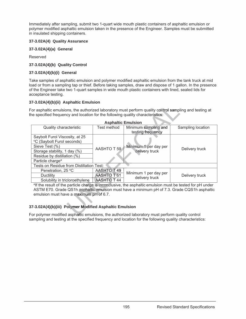
195 Revised Standard Specifications
Immediately after sampling, submit two 1-quart wide mouth plastic containers of asphaltic emulsion or polymer modified asphaltic emulsion taken in the presence of the Engineer. Samples must be submitted in insulated shipping containers.
37-3.02A(4) Quality Assurance
37-3.02A(4)(a) General
Reserved
37-3.02A(4)(b) Quality Control
37-3.02A(4)(b)(i) General
Take samples of asphaltic emulsion and polymer modified asphaltic emulsion from the tank truck at mid load or from a sampling tap or thief. Before taking samples, draw and dispose of 1 gallon. In the presence of the Engineer take two 1-quart samples in wide mouth plastic containers with lined, sealed lids for acceptance testing.
37-3.02A(4)(b)(ii) Asphaltic Emulsion
For asphaltic emulsions, the authorized laboratory must perform quality control sampling and testing at the specified frequency and location for the following quality characteristics:
Asphaltic Emulsion Quality characteristic Test method Minimum sampling and
testing frequency Sampling location
Saybolt Furol Viscosity, at 25 oC (Saybolt Furol seconds)
AASHTO T 59 Minimum 1 per day per delivery truck Delivery truck Sieve Test (%)
Storage stability, 1 day (%)Residue by distillation (%)Particle chargea Tests on Residue from Distillation Test:
Penetration, 25 oC AASHTO T 49 Minimum 1 per day per delivery truck Delivery truck Ductility AASHTO T 51
Solubility in tricloroethylene AASHTO T 44aIf the result of the particle charge is inconclusive, the asphaltic emulsion must be tested for pH under ASTM E70. Grade QS1h asphaltic emulsion must have a minimum pH of 7.3. Grade CQS1h asphaltic emulsion must have a maximum pH of 6.7.
37-3.02A(4)(b)(iii) Polymer Modified Asphaltic Emulsion
For polymer modified asphaltic emulsions, the authorized laboratory must perform quality control sampling and testing at the specified frequency and location for the following quality characteristics:
UNOcharge is inconclarge is inconcl
NOFFICIA
Lcontrol sampontroristics: rist
m sampling and sampling aesting frequency sting frequencyIA
99 Minimum 1 peMinimum 1 pedelivedelCIA
FFFFFFFFFFt: FFAASHTO T 49AASHTO T
OFFAASHTO T 51AASHTO T 5OFOnee AASHTO T AASHTO ONOh asphaltic emulsasphaltic emu maximum pH of maximum pH ofNO
olymer Modiolymer Mo
haltich lti
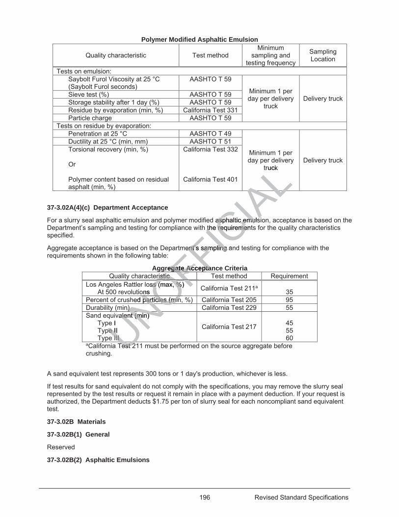
196 Revised Standard Specifications
Polymer Modified Asphaltic Emulsion
Quality characteristic Test method Minimum
sampling and testing frequency
Sampling Location
Tests on emulsion: Saybolt Furol Viscosity at 25 °C (Saybolt Furol seconds)
AASHTO T 59
Minimum 1 per day per delivery
truck Delivery truck Sieve test (%) AASHTO T 59
Storage stability after 1 day (%) AASHTO T 59 Residue by evaporation (min, %) California Test 331 Particle charge AASHTO T 59
Tests on residue by evaporation: Penetration at 25 °C AASHTO T 49
Minimum 1 per day per delivery
truck Delivery truck
Ductility at 25 °C (min, mm) AASHTO T 51 Torsional recovery (min, %) Or Polymer content based on residual asphalt (min, %)
California Test 332
California Test 401
37-3.02A(4)(c) Department Acceptance
For a slurry seal asphaltic emulsion and polymer modified asphaltic emulsion, acceptance is based on the Department’s sampling and testing for compliance with the requirements for the quality characteristics specified.
Aggregate acceptance is based on the Department’s sampling and testing for compliance with the requirements shown in the following table:
Aggregate Acceptance Criteria Quality characteristic Test method Requirement
Los Angeles Rattler loss (max, %) At 500 revolutions California Test 211a
35 Percent of crushed particles (min, %) California Test 205 95 Durability (min) California Test 229 55 Sand equivalent (min)
Type I Type II Type III
California Test 217
45 55 60
aCalifornia Test 211 must be performed on the source aggregate before crushing.
A sand equivalent test represents 300 tons or 1 day's production, whichever is less.
If test results for sand equivalent do not comply with the specifications, you may remove the slurry seal represented by the test results or request it remain in place with a payment deduction. If your request is authorized, the Department deducts $1.75 per ton of slurry seal for each noncompliant sand equivalent test.
37-3.02B Materials
37-3.02B(1) General
Reserved
37-3.02B(2) Asphaltic Emulsions
UNOFFICIA
Lruck
ALd asphaltic emulsasphaltic emuls
the requirementsthe requireme
mentent’s sampling a’s sampling
regate Acceptanegate Acceptaristic ristic
OFFoss (max, %) ss (max, %ons on OFOFFFFFFF
hed particles (mparticles (minin
NOn) ) NOvalent (min) alent (min)
e I pe II pe II
III III N
Test 2Test 2U
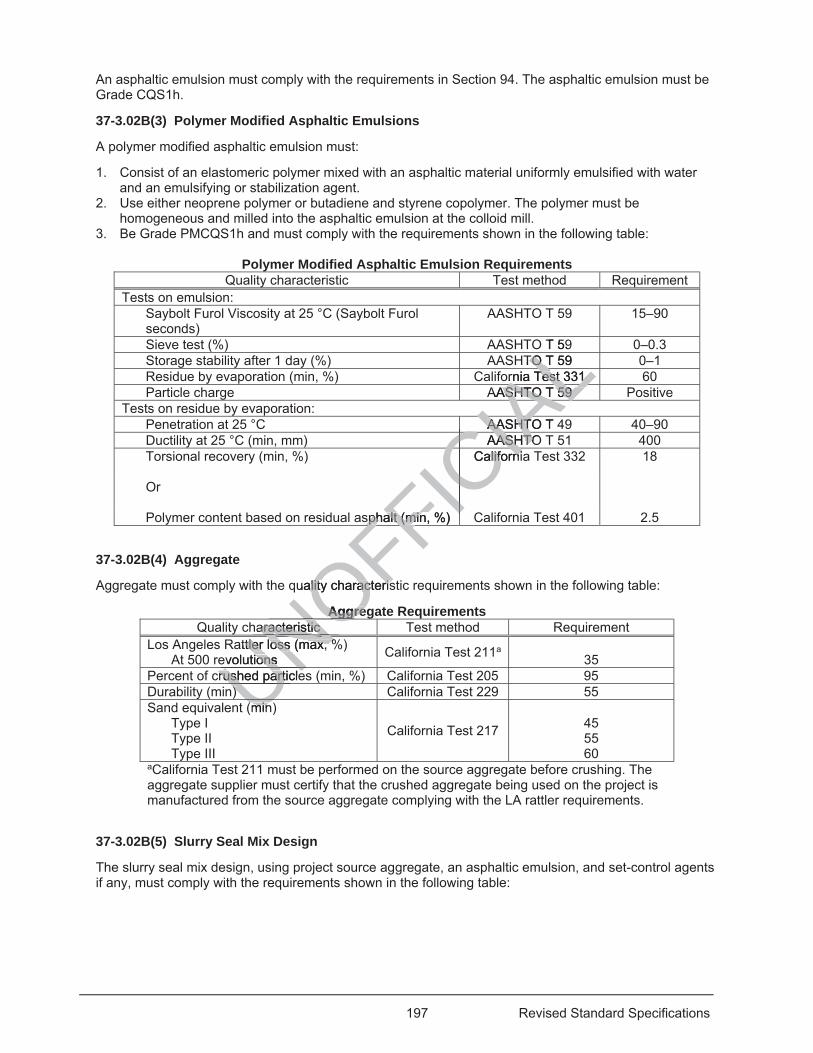
197 Revised Standard Specifications
An asphaltic emulsion must comply with the requirements in Section 94. The asphaltic emulsion must be Grade CQS1h.
37-3.02B(3) Polymer Modified Asphaltic Emulsions
A polymer modified asphaltic emulsion must:
1. Consist of an elastomeric polymer mixed with an asphaltic material uniformly emulsified with water and an emulsifying or stabilization agent.
2. Use either neoprene polymer or butadiene and styrene copolymer. The polymer must be homogeneous and milled into the asphaltic emulsion at the colloid mill.
3. Be Grade PMCQS1h and must comply with the requirements shown in the following table:
Polymer Modified Asphaltic Emulsion Requirements Quality characteristic Test method Requirement
Tests on emulsion: Saybolt Furol Viscosity at 25 °C (Saybolt Furol seconds)
AASHTO T 59 15–90
Sieve test (%) AASHTO T 59 0–0.3 Storage stability after 1 day (%) AASHTO T 59 0–1 Residue by evaporation (min, %) California Test 331 60 Particle charge AASHTO T 59 Positive
Tests on residue by evaporation: Penetration at 25 °C AASHTO T 49 40–90 Ductility at 25 °C (min, mm) AASHTO T 51 400 Torsional recovery (min, %)
California Test 332 18
Or
Polymer content based on residual asphalt (min, %) California Test 401 2.5
37-3.02B(4) Aggregate
Aggregate must comply with the quality characteristic requirements shown in the following table:
Aggregate Requirements Quality characteristic Test method Requirement
Los Angeles Rattler loss (max, %) At 500 revolutions California Test 211a
35 Percent of crushed particles (min, %) California Test 205 95 Durability (min) California Test 229 55 Sand equivalent (min)
Type I Type II Type III
California Test 217
45 55 60
aCalifornia Test 211 must be performed on the source aggregate before crushing. The aggregate supplier must certify that the crushed aggregate being used on the project is manufactured from the source aggregate complying with the LA rattler requirements.
37-3.02B(5) Slurry Seal Mix Design
The slurry seal mix design, using project source aggregate, an asphaltic emulsion, and set-control agents if any, must comply with the requirements shown in the following table:
UNOFFICIA
LO T 59
LTO T 59 TO Lornia Test 331 Test 331
ALAASHTO T 59 ASHTO T 59 ALALAASHTO T AASHTIACAASHTOASHTO
CIACCalifornialiforniCIICICsphaltsphalt (min, %) (min, %)
FFIuality characterility characteriss
AggregAggreharacteristic aracteristic NO
attler loss (max, %tler loss (max, %evolutions ions NNcrushed particlecrushed particleUN
)) U(minminU
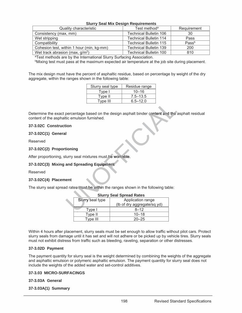
198 Revised Standard Specifications
Slurry Seal Mix Design Requirements Quality characteristic Test methoda Requirement
Consistency (max, mm) Technical Bulletin 106 30 Wet stripping Technical Bulletin 114 Pass Compatibility Technical Bulletin 115 Passb Cohesion test, within 1 hour (min, kg-mm) Technical Bulletin 139 200 Wet track abrasion (max, g/m2) Technical Bulletin 100 810 aTest methods are by the International Slurry Surfacing Association. bMixing test must pass at the maximum expected air temperature at the job site during placement.
The mix design must have the percent of asphaltic residue, based on percentage by weight of the dry aggregate, within the ranges shown in the following table:
Slurry seal type Residue range Type I 10–16 Type II 7.5–13.5 Type III 6.5–12.0
Determine the exact percentage based on the design asphalt binder content and the asphalt residual content of the asphaltic emulsion furnished.
37-3.02C Construction
37-3.02C(1) General
Reserved
37-3.02C(2) Proportioning
After proportioning, slurry seal mixtures must be workable.
37-3.02C(3) Mixing and Spreading Equipment
Reserved
37-3.02C(4) Placement
The slurry seal spread rates must be within the ranges shown in the following table:
Slurry Seal Spread Rates Slurry seal type Application range
(lb of dry aggregate/sq yd) Type I 8–12 Type II 10–18 Type III 20–25
Within 4 hours after placement, slurry seals must be set enough to allow traffic without pilot cars. Protect slurry seals from damage until it has set and will not adhere or be picked up by vehicle tires. Slurry seals must not exhibit distress from traffic such as bleeding, raveling, separation or other distresses.
37-3.02D Payment
The payment quantity for slurry seal is the weight determined by combining the weights of the aggregate and asphaltic emulsion or polymeric asphaltic emulsion. The payment quantity for slurry seal does not include the weights of the added water and set-control additives.
37-3.03 MICRO-SURFACINGS
37-3.03A General
37-3.03A(1) Summary
UNOFFICIA
Lcontent and the acontent and the a
t be workable. t be worka
quipment pment
es must be withins must be with
Slurry sSlurry sUNUUUUUU
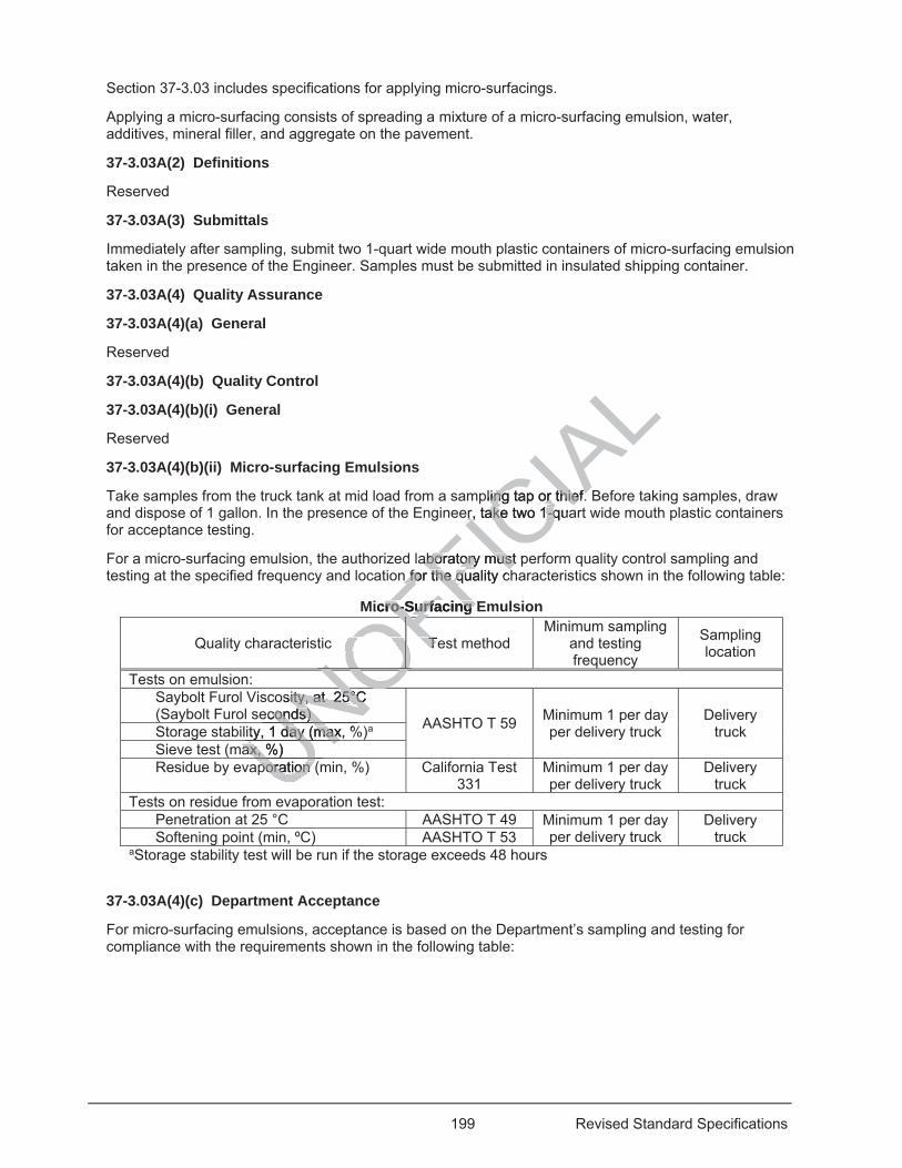
199 Revised Standard Specifications
Section 37-3.03 includes specifications for applying micro-surfacings.
Applying a micro-surfacing consists of spreading a mixture of a micro-surfacing emulsion, water, additives, mineral filler, and aggregate on the pavement.
37-3.03A(2) Definitions
Reserved
37-3.03A(3) Submittals
Immediately after sampling, submit two 1-quart wide mouth plastic containers of micro-surfacing emulsion taken in the presence of the Engineer. Samples must be submitted in insulated shipping container.
37-3.03A(4) Quality Assurance
37-3.03A(4)(a) General
Reserved
37-3.03A(4)(b) Quality Control
37-3.03A(4)(b)(i) General
Reserved
37-3.03A(4)(b)(ii) Micro-surfacing Emulsions
Take samples from the truck tank at mid load from a sampling tap or thief. Before taking samples, draw and dispose of 1 gallon. In the presence of the Engineer, take two 1-quart wide mouth plastic containers for acceptance testing.
For a micro-surfacing emulsion, the authorized laboratory must perform quality control sampling and testing at the specified frequency and location for the quality characteristics shown in the following table:
Micro-Surfacing Emulsion
Quality characteristic Test method Minimum sampling
and testing frequency
Sampling location
Tests on emulsion: Saybolt Furol Viscosity, at 25°C (Saybolt Furol seconds) AASHTO T 59 Minimum 1 per day
per delivery truck Delivery
truck Storage stability, 1 day (max, %)a Sieve test (max, %) Residue by evaporation (min, %) California Test
331 Minimum 1 per day per delivery truck
Delivery truck
Tests on residue from evaporation test: Penetration at 25 °C AASHTO T 49 Minimum 1 per day
per delivery truck Delivery
truck Softening point (min, ºC) AASHTO T 53 aStorage stability test will be run if the storage exceeds 48 hours
37-3.03A(4)(c) Department Acceptance
For micro-surfacing emulsions, acceptance is based on the Department’s sampling and testing for compliance with the requirements shown in the following table:
poration (poration UNOFFICIA
Lpling tap or thief. ing tap or thief.
er, take two 1-quaer, take two 1-q
aboaboratory must pratory mustn for the n for the quality cqu
Micro-Surfacing Ero-Surfacing
TeTOFOFNONOOOOOosity, at 25°C sity, at 25°C
econds) conds) NOity, 1 day (max, %ity, 1 day (maxUNax, %) ax, %UNU
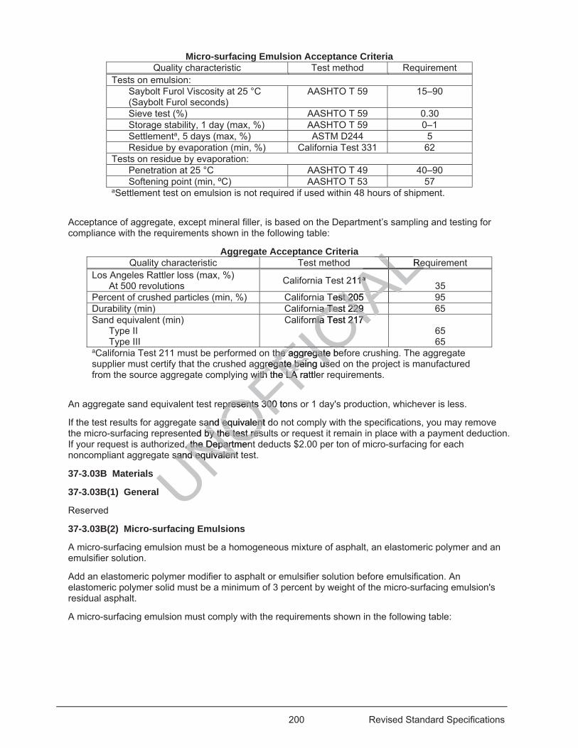
200 Revised Standard Specifications
Micro-surfacing Emulsion Acceptance Criteria Quality characteristic Test method Requirement
Tests on emulsion: Saybolt Furol Viscosity at 25 °C (Saybolt Furol seconds)
AASHTO T 59 15–90
Sieve test (%) AASHTO T 59 0.30 Storage stability, 1 day (max, %) AASHTO T 59 0–1 Settlementa, 5 days (max, %) ASTM D244 5 Residue by evaporation (min, %) California Test 331 62
Tests on residue by evaporation: Penetration at 25 °C AASHTO T 49 40–90 Softening point (min, ºC) AASHTO T 53 57
aSettlement test on emulsion is not required if used within 48 hours of shipment.
Acceptance of aggregate, except mineral filler, is based on the Department’s sampling and testing for compliance with the requirements shown in the following table:
Aggregate Acceptance Criteria Quality characteristic Test method Requirement
Los Angeles Rattler loss (max, %) At 500 revolutions California Test 211a
35 Percent of crushed particles (min, %) California Test 205 95 Durability (min) California Test 229 65 Sand equivalent (min)
Type II Type III
California Test 217 65 65
aCalifornia Test 211 must be performed on the aggregate before crushing. The aggregate supplier must certify that the crushed aggregate being used on the project is manufactured from the source aggregate complying with the LA rattler requirements.
An aggregate sand equivalent test represents 300 tons or 1 day's production, whichever is less.
If the test results for aggregate sand equivalent do not comply with the specifications, you may remove the micro-surfacing represented by the test results or request it remain in place with a payment deduction. If your request is authorized, the Department deducts $2.00 per ton of micro-surfacing for each noncompliant aggregate sand equivalent test.
37-3.03B Materials
37-3.03B(1) General
Reserved
37-3.03B(2) Micro-surfacing Emulsions
A micro-surfacing emulsion must be a homogeneous mixture of asphalt, an elastomeric polymer and an emulsifier solution.
Add an elastomeric polymer modifier to asphalt or emulsifier solution before emulsification. An elastomeric polymer solid must be a minimum of 3 percent by weight of the micro-surfacing emulsion's residual asphalt.
A micro-surfacing emulsion must comply with the requirements shown in the following table:
UNOFFICthe aggregate bethe aggregategreggregate being useate being useFIC
IALReReLAL2111aa ALALALALALALALAL
Test 205 st 205 IAAa Test 229 a Test 229
CIAAornia Test 217 nia Test 217 CIAwith the LA rattlewith the LA FIC
epresents 300 tonpresents 300
and equivalent dand equivalented by the test resby the test res
d, the Departmen, the Departmesand equivalent sand equivalent
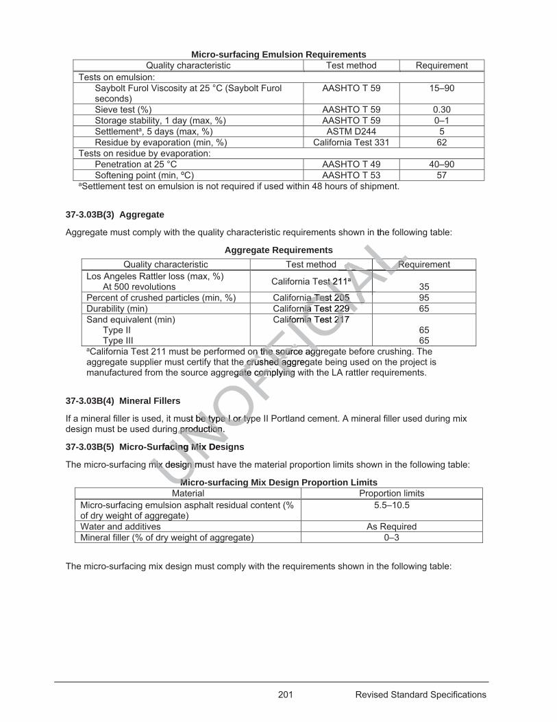
201 Revised Standard Specifications
Micro-surfacing Emulsion Requirements Quality characteristic Test method Requirement
Tests on emulsion: Saybolt Furol Viscosity at 25 °C (Saybolt Furol seconds)
AASHTO T 59 15–90
Sieve test (%) AASHTO T 59 0.30 Storage stability, 1 day (max, %) AASHTO T 59 0–1 Settlementa, 5 days (max, %) ASTM D244 5 Residue by evaporation (min, %) California Test 331 62
Tests on residue by evaporation: Penetration at 25 °C AASHTO T 49 40–90 Softening point (min, ºC) AASHTO T 53 57
aSettlement test on emulsion is not required if used within 48 hours of shipment.
37-3.03B(3) Aggregate
Aggregate must comply with the quality characteristic requirements shown in the following table:
Aggregate Requirements Quality characteristic Test method Requirement
Los Angeles Rattler loss (max, %) At 500 revolutions California Test 211a
35 Percent of crushed particles (min, %) California Test 205 95 Durability (min) California Test 229 65 Sand equivalent (min)
Type II Type III
California Test 217 65 65
aCalifornia Test 211 must be performed on the source aggregate before crushing. The aggregate supplier must certify that the crushed aggregate being used on the project is manufactured from the source aggregate complying with the LA rattler requirements.
37-3.03B(4) Mineral Fillers
If a mineral filler is used, it must be type I or type II Portland cement. A mineral filler used during mix design must be used during production.
37-3.03B(5) Micro-Surfacing Mix Designs
The micro-surfacing mix design must have the material proportion limits shown in the following table:
Micro-surfacing Mix Design Proportion Limits Material Proportion limits
Micro-surfacing emulsion asphalt residual content (% of dry weight of aggregate)
5.5–10.5
Water and additives As Required Mineral filler (% of dry weight of aggregate) 0–3
The micro-surfacing mix design must comply with the requirements shown in the following table:
UNOFFICIA
Ln the
ReRe
ALALALst 211st 2 aa ALALALALALALALALa Test 205 a Test 205
CIAAArnia Test 229 nia Test 229 CIAifornia Test 217 ifornia Test 21C
n the source aggn the source agge cruse cru hed aggreged ag
egate compgate com lying wyingFIst be type I or typbe type I or typ
g production. production.
urfacing Mix Desacing Mix
mix design mumix design
MiMiU
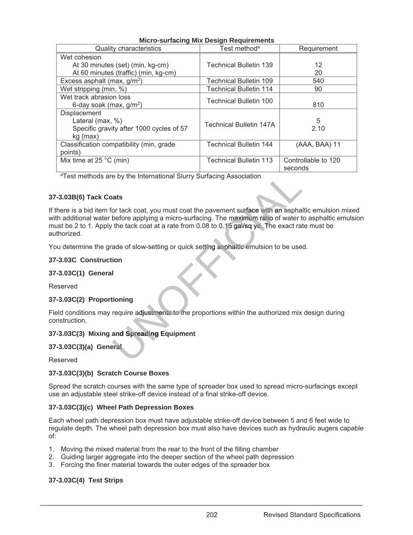
202 Revised Standard Specifications
Micro-surfacing Mix Design Requirements Quality characteristics Test methoda Requirement
Wet cohesion At 30 minutes (set) (min, kg-cm) At 60 minutes (traffic) (min, kg-cm)
Technical Bulletin 139
12 20
Excess asphalt (max, g/m2) Technical Bulletin 109 540 Wet stripping (min, %) Technical Bulletin 114 90 Wet track abrasion loss
6-day soak (max, g/m2) Technical Bulletin 100 810
Displacement Lateral (max, %) Specific gravity after 1000 cycles of 57 kg (max)
Technical Bulletin 147A
5
2.10
Classification compatibility (min, grade points)
Technical Bulletin 144 (AAA, BAA) 11
Mix time at 25 °C (min) Technical Bulletin 113 Controllable to 120 seconds
aTest methods are by the International Slurry Surfacing Association.
37-3.03B(6) Tack Coats
If there is a bid item for tack coat, you must coat the pavement surface with an asphaltic emulsion mixed with additional water before applying a micro-surfacing. The maximum ratio of water to asphaltic emulsion must be 2 to 1. Apply the tack coat at a rate from 0.08 to 0.15 gal/sq yd. The exact rate must be authorized.
You determine the grade of slow-setting or quick setting asphaltic emulsion to be used.
37-3.03C Construction
37-3.03C(1) General
Reserved
37-3.03C(2) Proportioning
Field conditions may require adjustments to the proportions within the authorized mix design during construction.
37-3.03C(3) Mixing and Spreading Equipment
37-3.03C(3)(a) General
Reserved
37-3.03C(3)(b) Scratch Course Boxes
Spread the scratch courses with the same type of spreader box used to spread micro-surfacings except use an adjustable steel strike-off device instead of a final strike-off device.
37-3.03C(3)(c) Wheel Path Depression Boxes
Each wheel path depression box must have adjustable strike-off device between 5 and 6 feet wide to regulate depth. The wheel path depression box must also have devices such as hydraulic augers capable of:
1. Moving the mixed material from the rear to the front of the filling chamber 2. Guiding larger aggregate into the deeper section of the wheel path depression 3. Forcing the finer material towards the outer edges of the spreader box 37-3.03C(4) Test Strips
UNOFFICIA
LLLsurface with an aurface with an a
maximum ratio ofmaximum ratio0.15 gal/sq yd. Th15 gal/sq yd. Th
etting asphaltic emetting asphaltic em
adjustments to thstments to th
and Spreading ESpreadin
ral ral
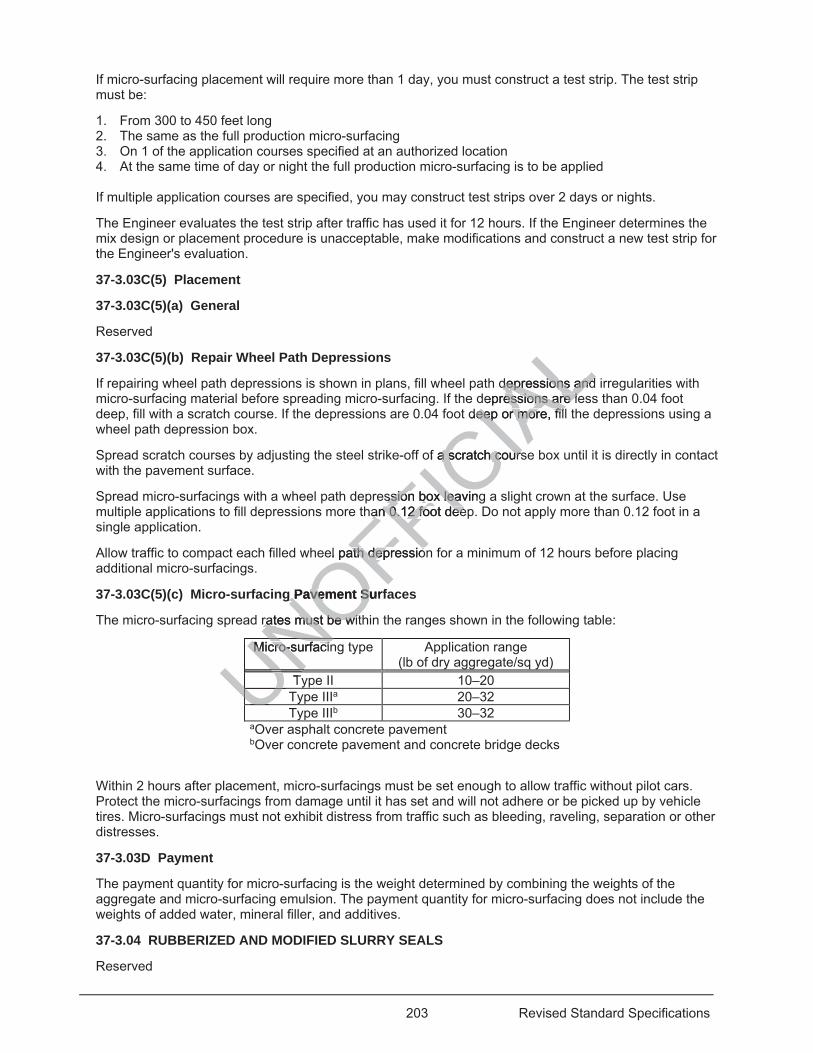
203 Revised Standard Specifications
If micro-surfacing placement will require more than 1 day, you must construct a test strip. The test strip must be:
1. From 300 to 450 feet long 2. The same as the full production micro-surfacing 3. On 1 of the application courses specified at an authorized location 4. At the same time of day or night the full production micro-surfacing is to be applied If multiple application courses are specified, you may construct test strips over 2 days or nights.
The Engineer evaluates the test strip after traffic has used it for 12 hours. If the Engineer determines the mix design or placement procedure is unacceptable, make modifications and construct a new test strip for the Engineer's evaluation.
37-3.03C(5) Placement
37-3.03C(5)(a) General
Reserved
37-3.03C(5)(b) Repair Wheel Path Depressions
If repairing wheel path depressions is shown in plans, fill wheel path depressions and irregularities with micro-surfacing material before spreading micro-surfacing. If the depressions are less than 0.04 foot deep, fill with a scratch course. If the depressions are 0.04 foot deep or more, fill the depressions using a wheel path depression box.
Spread scratch courses by adjusting the steel strike-off of a scratch course box until it is directly in contact with the pavement surface.
Spread micro-surfacings with a wheel path depression box leaving a slight crown at the surface. Use multiple applications to fill depressions more than 0.12 foot deep. Do not apply more than 0.12 foot in a single application.
Allow traffic to compact each filled wheel path depression for a minimum of 12 hours before placing additional micro-surfacings.
37-3.03C(5)(c) Micro-surfacing Pavement Surfaces
The micro-surfacing spread rates must be within the ranges shown in the following table:
Micro-surfacing type Application range (lb of dry aggregate/sq yd)
Type II 10–20 Type IIIa 20–32 Type IIIb 30–32
aOver asphalt concrete pavement bOver concrete pavement and concrete bridge decks
Within 2 hours after placement, micro-surfacings must be set enough to allow traffic without pilot cars. Protect the micro-surfacings from damage until it has set and will not adhere or be picked up by vehicle tires. Micro-surfacings must not exhibit distress from traffic such as bleeding, raveling, separation or other distresses.
37-3.03D Payment
The payment quantity for micro-surfacing is the weight determined by combining the weights of the aggregate and micro-surfacing emulsion. The payment quantity for micro-surfacing does not include the weights of added water, mineral filler, and additives.
37-3.04 RUBBERIZED AND MODIFIED SLURRY SEALS
Reserved
UNMicro-surfacinMicro-surfacinNOFFICIA
Ldepressions anddepressions andepressions are leessions are le
deep or more, filleep or more, fil
of a scratch coursa scratch coursf
ssionssion box leavingbox leahan 0.12 foot deean 0.12 foot dee
el path ath depressiodepressio
g Pavement Surfg Pavement S
rates must be witrates must be witNUTUUNUNUUUUU
204 Revised Standard Specifications
37-4 FOG SEALS AND FLUSH COATS
37-4.01 GENERAL
37-4.01A General
37-4.01A(1) Summary
Section 37-4.01 includes general specifications for applying fog seals and flush coats.
37-4.01A(2) Definitions
Reserved
37-4.01A(3) Submittals
At least 15 days before use, submit:
1. Sample of asphaltic emulsion in two 1-quart plastic container with lined, sealed lid 2. Asphaltic emulsion information and test data as follows:
2.1. Supplier 2.2. Type/Grade of asphalt emulsion 2.3. Copy of the specified test results for asphaltic emulsion
37-4.01B Materials
Not Used
37-4.01C Construction
37-4.01C(1) General
Reserved
37-4.01C(2) Weather Conditions
Only place a fog seal or flush coat if both the pavement and ambient temperatures are at least 50 degrees F and rising. Do not place a fog seal or flush coat within 24 hours of rain or within 24 hours of forecast rain or freezing temperatures.
37-4.01D Payment
Not Used
37-4.02 FOG SEALS
37-4.02A General
37-4.02A(1) Summary
Section 37-4.02 includes specifications for applying fog seals.
Applying a fog seal includes applying a diluted slow-setting or quick setting asphaltic emulsion.
37-4.02A(2) Definitions
Reserved
37-4.02A(3) Submittals
Immediately after sampling, submit two 1-quart plastic container of asphaltic emulsion taken in the presence of the Engineer. Samples must be submitted in insulated shipping container.
37-4.02A(4) Quality Assurance
37-4.02A(4)(a) General
Reserved
UNOFFICIA
L
oth the pavementoth the pava fog seal or flushfog seal or flu
tures. ures.
S S
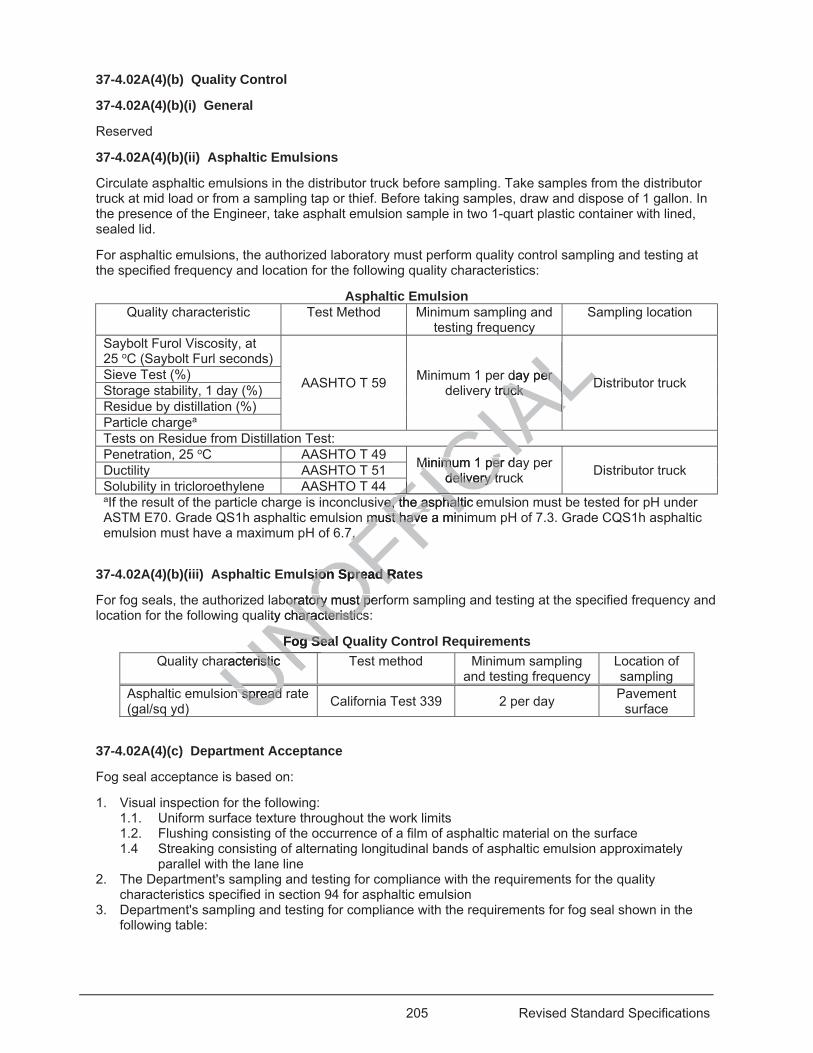
205 Revised Standard Specifications
37-4.02A(4)(b) Quality Control
37-4.02A(4)(b)(i) General
Reserved
37-4.02A(4)(b)(ii) Asphaltic Emulsions
Circulate asphaltic emulsions in the distributor truck before sampling. Take samples from the distributor truck at mid load or from a sampling tap or thief. Before taking samples, draw and dispose of 1 gallon. In the presence of the Engineer, take asphalt emulsion sample in two 1-quart plastic container with lined, sealed lid.
For asphaltic emulsions, the authorized laboratory must perform quality control sampling and testing at the specified frequency and location for the following quality characteristics:
Asphaltic Emulsion Quality characteristic Test Method Minimum sampling and
testing frequency Sampling location
Saybolt Furol Viscosity, at 25 oC (Saybolt Furl seconds)
AASHTO T 59 Minimum 1 per day per delivery truck Distributor truck Sieve Test (%)
Storage stability, 1 day (%) Residue by distillation (%) Particle chargea Tests on Residue from Distillation Test: Penetration, 25 oC AASHTO T 49 Minimum 1 per day per
delivery truck Distributor truck Ductility AASHTO T 51 Solubility in tricloroethylene AASHTO T 44 aIf the result of the particle charge is inconclusive, the asphaltic emulsion must be tested for pH under ASTM E70. Grade QS1h asphaltic emulsion must have a minimum pH of 7.3. Grade CQS1h asphaltic emulsion must have a maximum pH of 6.7.
37-4.02A(4)(b)(iii) Asphaltic Emulsion Spread Rates
For fog seals, the authorized laboratory must perform sampling and testing at the specified frequency and location for the following quality characteristics:
Fog Seal Quality Control Requirements Quality characteristic Test method Minimum sampling
and testing frequency Location of sampling
Asphaltic emulsion spread rate (gal/sq yd) California Test 339 2 per day Pavement
surface
37-4.02A(4)(c) Department Acceptance
Fog seal acceptance is based on:
1. Visual inspection for the following: 1.1. Uniform surface texture throughout the work limits 1.2. Flushing consisting of the occurrence of a film of asphaltic material on the surface 1.4 Streaking consisting of alternating longitudinal bands of asphaltic emulsion approximately
parallel with the lane line 2. The Department's sampling and testing for compliance with the requirements for the quality
characteristics specified in section 94 for asphaltic emulsion 3. Department's sampling and testing for compliance with the requirements for fog seal shown in the
following table:
Un spread n spread UNOFFICIA
Lday per day per y truck ruck DDLALALALALALALALCIAMinimum 1 per daMinimum 1 pe
delivery trdelivery tCIFve, the asphalticve, the asphalti
must have a minmust have a min7. 7. FIC
sion Spread Ratsion Spread R
boratory must peroratory must plity characteristicsharacteristics
Fog SealFog Seaaracteristic aracteristic UNNUU
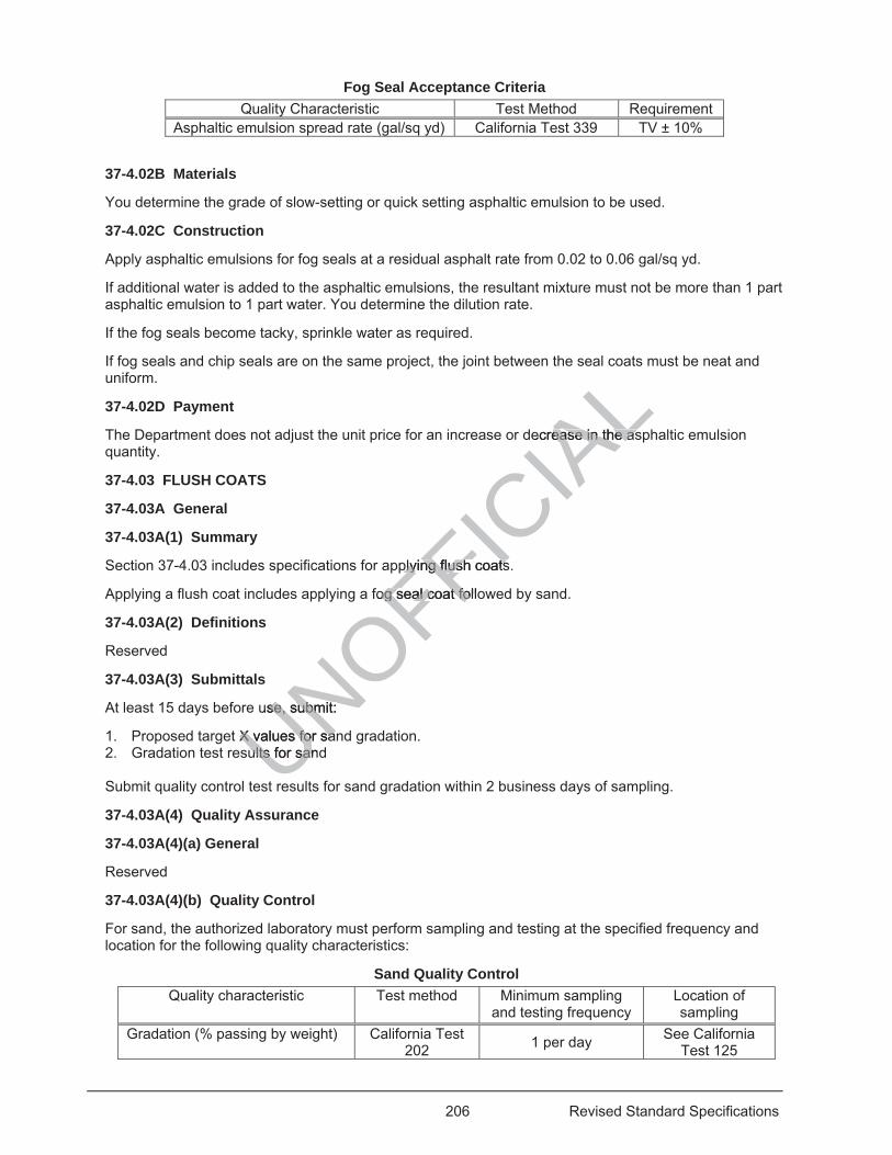
206 Revised Standard Specifications
Fog Seal Acceptance Criteria Quality Characteristic Test Method Requirement
Asphaltic emulsion spread rate (gal/sq yd) California Test 339 TV ± 10%
37-4.02B Materials
You determine the grade of slow-setting or quick setting asphaltic emulsion to be used.
37-4.02C Construction
Apply asphaltic emulsions for fog seals at a residual asphalt rate from 0.02 to 0.06 gal/sq yd.
If additional water is added to the asphaltic emulsions, the resultant mixture must not be more than 1 part asphaltic emulsion to 1 part water. You determine the dilution rate.
If the fog seals become tacky, sprinkle water as required.
If fog seals and chip seals are on the same project, the joint between the seal coats must be neat and uniform.
37-4.02D Payment
The Department does not adjust the unit price for an increase or decrease in the asphaltic emulsion quantity.
37-4.03 FLUSH COATS
37-4.03A General
37-4.03A(1) Summary
Section 37-4.03 includes specifications for applying flush coats.
Applying a flush coat includes applying a fog seal coat followed by sand.
37-4.03A(2) Definitions
Reserved
37-4.03A(3) Submittals
At least 15 days before use, submit:
1. Proposed target X values for sand gradation. 2. Gradation test results for sand Submit quality control test results for sand gradation within 2 business days of sampling.
37-4.03A(4) Quality Assurance
37-4.03A(4)(a) General
Reserved
37-4.03A(4)(b) Quality Control
For sand, the authorized laboratory must perform sampling and testing at the specified frequency and location for the following quality characteristics:
Sand Quality Control Quality characteristic Test method Minimum sampling
and testing frequency Location of sampling
Gradation (% passing by weight) California Test 202 1 per day See California
Test 125
UNOFFICIA
Lecrease in the asease in the as
plying flush coatsplying flush coats
fog seal coat folloog seal coat fo
use, submit: se, submit:
X values for sanX values for saults for sandults for san
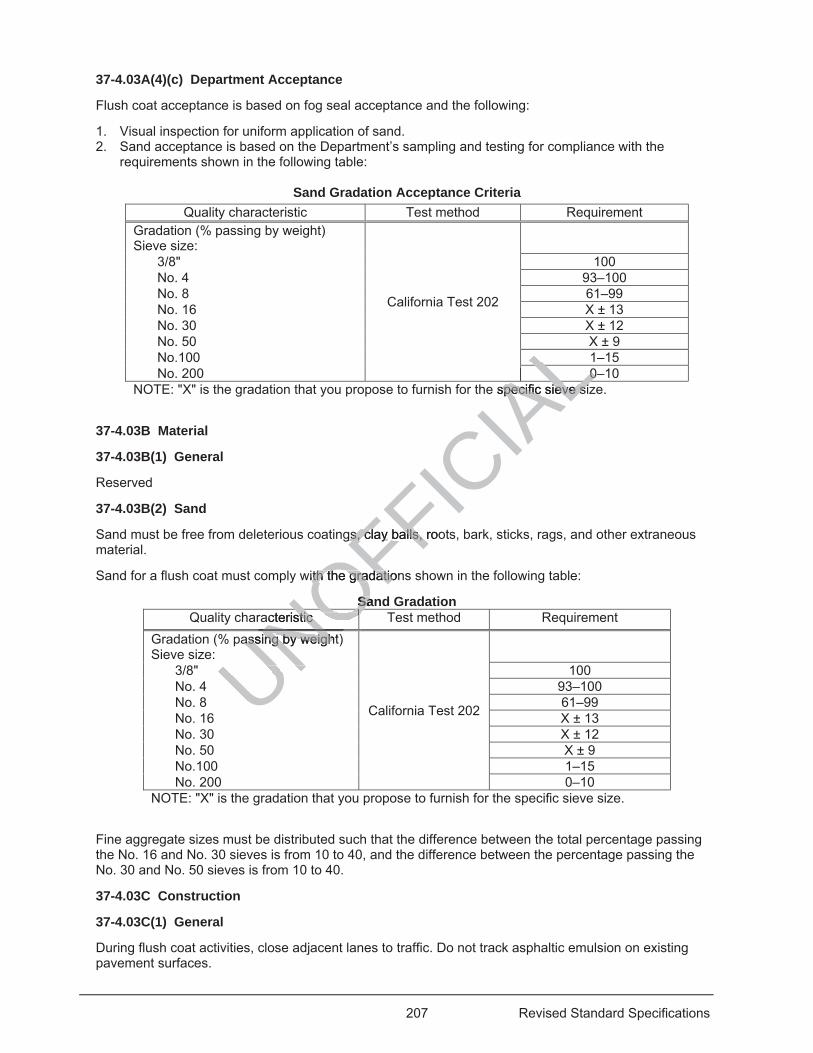
207 Revised Standard Specifications
37-4.03A(4)(c) Department Acceptance
Flush coat acceptance is based on fog seal acceptance and the following:
1. Visual inspection for uniform application of sand. 2. Sand acceptance is based on the Department’s sampling and testing for compliance with the
requirements shown in the following table:
Sand Gradation Acceptance Criteria Quality characteristic Test method Requirement
Gradation (% passing by weight) Sieve size:
California Test 202
3/8" 100 No. 4 93–100 No. 8 61–99 No. 16 X ± 13 No. 30 X ± 12 No. 50 X ± 9 No.100 1–15 No. 200 0–10
NOTE: "X" is the gradation that you propose to furnish for the specific sieve size.
37-4.03B Material
37-4.03B(1) General
Reserved
37-4.03B(2) Sand
Sand must be free from deleterious coatings, clay balls, roots, bark, sticks, rags, and other extraneous material.
Sand for a flush coat must comply with the gradations shown in the following table:
Sand Gradation Quality characteristic Test method Requirement
Gradation (% passing by weight) Sieve size:
California Test 202
3/8" 100 No. 4 93–100 No. 8 61–99 No. 16 X ± 13 No. 30 X ± 12 No. 50 X ± 9 No.100 1–15 No. 200 0–10
NOTE: "X" is the gradation that you propose to furnish for the specific sieve size.
Fine aggregate sizes must be distributed such that the difference between the total percentage passing the No. 16 and No. 30 sieves is from 10 to 40, and the difference between the percentage passing the No. 30 and No. 50 sieves is from 10 to 40.
37-4.03C Construction
37-4.03C(1) General
During flush coat activities, close adjacent lanes to traffic. Do not track asphaltic emulsion on existing pavement surfaces.
UNOFFICIA
LL00
ALAe specific sieve sizspecific sieve siALgs, clay gs, clay balls, rooballs,
with tith the gradation gradatio
SanSaacteristic acteristic NOO
assing by weight)assing by weighNONO
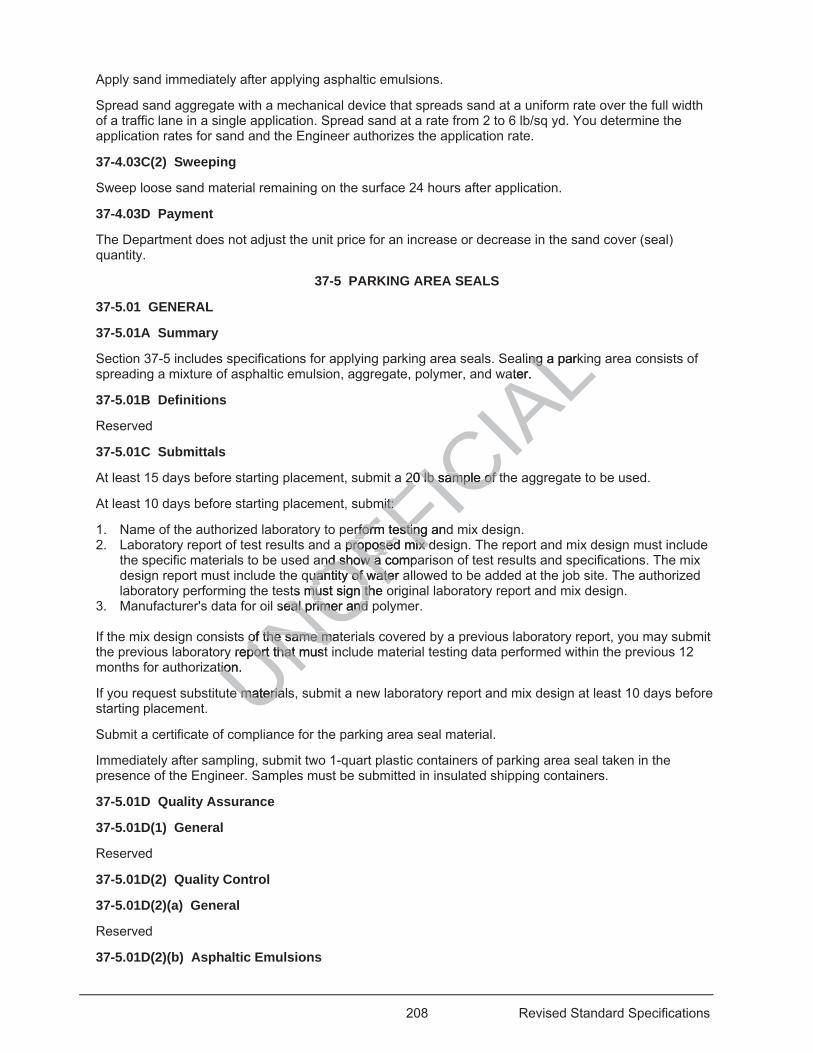
208 Revised Standard Specifications
Apply sand immediately after applying asphaltic emulsions.
Spread sand aggregate with a mechanical device that spreads sand at a uniform rate over the full width of a traffic lane in a single application. Spread sand at a rate from 2 to 6 lb/sq yd. You determine the application rates for sand and the Engineer authorizes the application rate.
37-4.03C(2) Sweeping
Sweep loose sand material remaining on the surface 24 hours after application.
37-4.03D Payment
The Department does not adjust the unit price for an increase or decrease in the sand cover (seal) quantity.
37-5 PARKING AREA SEALS
37-5.01 GENERAL
37-5.01A Summary
Section 37-5 includes specifications for applying parking area seals. Sealing a parking area consists of spreading a mixture of asphaltic emulsion, aggregate, polymer, and water.
37-5.01B Definitions
Reserved
37-5.01C Submittals
At least 15 days before starting placement, submit a 20 lb sample of the aggregate to be used.
At least 10 days before starting placement, submit:
1. Name of the authorized laboratory to perform testing and mix design. 2. Laboratory report of test results and a proposed mix design. The report and mix design must include
the specific materials to be used and show a comparison of test results and specifications. The mix design report must include the quantity of water allowed to be added at the job site. The authorized laboratory performing the tests must sign the original laboratory report and mix design.
3. Manufacturer's data for oil seal primer and polymer. If the mix design consists of the same materials covered by a previous laboratory report, you may submit the previous laboratory report that must include material testing data performed within the previous 12 months for authorization.
If you request substitute materials, submit a new laboratory report and mix design at least 10 days before starting placement.
Submit a certificate of compliance for the parking area seal material.
Immediately after sampling, submit two 1-quart plastic containers of parking area seal taken in the presence of the Engineer. Samples must be submitted in insulated shipping containers.
37-5.01D Quality Assurance
37-5.01D(1) General
Reserved
37-5.01D(2) Quality Control
37-5.01D(2)(a) General
Reserved
37-5.01D(2)(b) Asphaltic Emulsions
UNOFFICIA
Lling a parking ater.
20 lb sample of t20 lb sample of
mit: mit:
erform testing anderform testinga proposproposed mix ded mix
nd show a compand show a quantity of water auantity of wate
ts must sign the ots must sign thseal primer and peal primer and
of the same matof the same may report that mustport that
tion. tio
e materiale materia
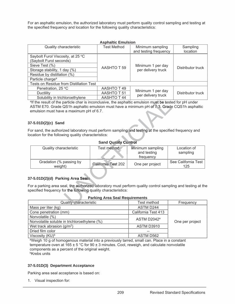
209 Revised Standard Specifications
For an asphaltic emulsion, the authorized laboratory must perform quality control sampling and testing at the specified frequency and location for the following quality characteristics:
Asphaltic Emulsion Quality characteristic Test Method Minimum sampling
and testing frequency Sampling location
Saybolt Furol Viscosity, at 25 oC (Saybolt Furol seconds)
AASHTO T 59 Minimum 1 per day per delivery truck Distributor truck Sieve Test (%)
Storage stability, 1 day (%) Residue by distillation (%) Particle chargea Tests on Residue from Distillation Test
Penetration, 25 oC AASHTO T 49 Minimum 1 per day per delivery truck Distributor truck Ductility AASHTO T 51
Solubility in trichloroethylene AASHTO T 44 aIf the result of the particle char is inconclusive, the asphaltic emulsion must be tested for pH under ASTM E70. Grade QS1h asphaltic emulsion must have a minimum pH of 7.3. Grade CQS1h asphaltic emulsion must have a maximum pH of 6.7.
37-5.01D(2)(c) Sand
For sand, the authorized laboratory must perform sampling and testing at the specified frequency and location for the following quality characteristics:
Sand Quality Control Quality characteristic Test method Minimum sampling
and testing frequency
Location of sampling
Gradation (% passing by weight) California Test 202 One per project See California Test
125
37-5.01D(2)(d) Parking Area Seals
For a parking area seal, the authorized laboratory must perform quality control sampling and testing at the specified frequency for the following quality characteristics:
Parking Area Seal Requirements Quality characteristic Test method Frequency
Mass per liter (kg) ASTM D244
One per project
Cone penetration (mm) California Test 413 Nonvolatile (%) ASTM D2042a Nonvolatile soluble in trichloroethylene (%) Wet track abrasion (g/m2) ASTM D3910 Dried film color -- Viscosity (KU)b ASTM D562 aWeigh 10 g of homogenous material into a previously tarred, small can. Place in a constant temperature oven at 165 ± 5 °C for 90 ± 3 minutes. Cool, reweigh, and calculate nonvolatile components as a percent of the original weight. bKrebs units
37-5.01D(3) Department Acceptance
Parking area seal acceptance is based on:
1. Visual inspection for:
Uty charty charUNOFFICIA
Lu
must be temusH of 7.3. Gradef 7.3. GradeL
ng and testing at and testing at
uality Control uality Control method Mimethod MFIFIFI
California Test 2California Te
OFOFOOOFea Seals ea Seals
the authorized lahe authorized laor the following quor the followingUUU
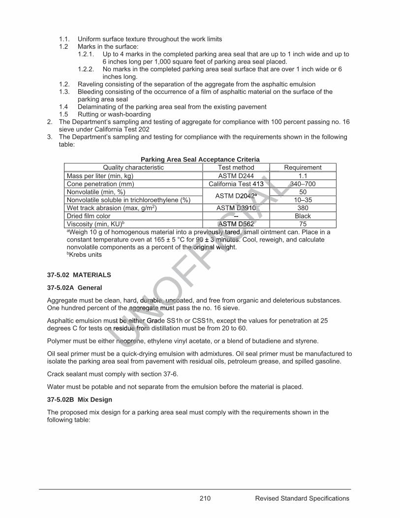
210 Revised Standard Specifications
1.1. Uniform surface texture throughout the work limits 1.2 Marks in the surface:
1.2.1. Up to 4 marks in the completed parking area seal that are up to 1 inch wide and up to 6 inches long per 1,000 square feet of parking area seal placed.
1.2.2. No marks in the completed parking area seal surface that are over 1 inch wide or 6 inches long.
1.2. Raveling consisting of the separation of the aggregate from the asphaltic emulsion 1.3. Bleeding consisting of the occurrence of a film of asphaltic material on the surface of the
parking area seal 1.4 Delaminating of the parking area seal from the existing pavement 1.5 Rutting or wash-boarding
2. The Department’s sampling and testing of aggregate for compliance with 100 percent passing no. 16 sieve under California Test 202
3. The Department’s sampling and testing for compliance with the requirements shown in the following table:
Parking Area Seal Acceptance Criteria
Quality characteristic Test method Requirement Mass per liter (min, kg) ASTM D244 1.1 Cone penetration (mm) California Test 413 340–700 Nonvolatile (min, %) ASTM D2042a 50 Nonvolatile soluble in trichloroethylene (%) 10–35 Wet track abrasion (max, g/m2) ASTM D3910 380 Dried film color -- Black Viscosity (min, KU)b ASTM D562 75 aWeigh 10 g of homogenous material into a previously tared, small ointment can. Place in a constant temperature oven at 165 ± 5 °C for 90 ± 3 minutes. Cool, reweigh, and calculate nonvolatile components as a percent of the original weight. bKrebs units
37-5.02 MATERIALS
37-5.02A General
Aggregate must be clean, hard, durable, uncoated, and free from organic and deleterious substances. One hundred percent of the aggregate must pass the no. 16 sieve.
Asphaltic emulsion must be either Grade SS1h or CSS1h, except the values for penetration at 25 degrees C for tests on residue from distillation must be from 20 to 60.
Polymer must be either neoprene, ethylene vinyl acetate, or a blend of butadiene and styrene.
Oil seal primer must be a quick-drying emulsion with admixtures. Oil seal primer must be manufactured to isolate the parking area seal from pavement with residual oils, petroleum grease, and spilled gasoline.
Crack sealant must comply with section 37-6.
Water must be potable and not separate from the emulsion before the material is placed.
37-5.02B Mix Design
The proposed mix design for a parking area seal must comply with the requirements shown in the following table:
UNOFFICIA
LLLLLLLLLALt 413 33
ALALALALD204242aaALALALALALALALTM D3910 D3910 IAAAA--
CIAASTM A D562 D562 CIeviously tared, smviously tared, s
90 ± 3 minutes. 90 ± 3 minutes. he original weighte original weigC
d, durable, uncoadurable, uncoae aggregataggregate muste m
st be either Gradbe either Gon residue from don residue from
neopreneneopren
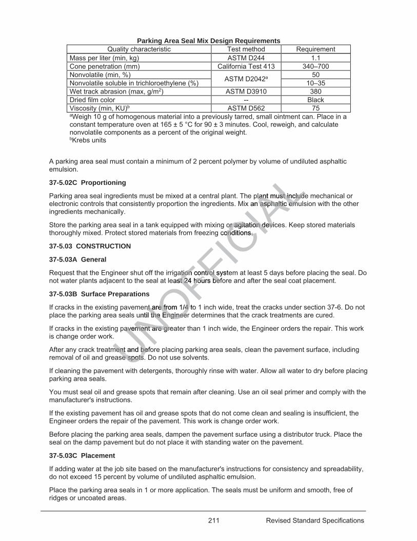
211 Revised Standard Specifications
Parking Area Seal Mix Design Requirements Quality characteristic Test method Requirement
Mass per liter (min, kg) ASTM D244 1.1 Cone penetration (mm) California Test 413 340–700 Nonvolatile (min, %) ASTM D2042a 50 Nonvolatile soluble in trichloroethylene (%) 10–35 Wet track abrasion (max, g/m2) ASTM D3910 380 Dried film color -- Black Viscosity (min, KU)b ASTM D562 75 aWeigh 10 g of homogenous material into a previously tarred, small ointment can. Place in a constant temperature oven at 165 ± 5 °C for 90 ± 3 minutes. Cool, reweigh, and calculate nonvolatile components as a percent of the original weight. bKrebs units
A parking area seal must contain a minimum of 2 percent polymer by volume of undiluted asphaltic emulsion.
37-5.02C Proportioning
Parking area seal ingredients must be mixed at a central plant. The plant must include mechanical or electronic controls that consistently proportion the ingredients. Mix an asphaltic emulsion with the other ingredients mechanically.
Store the parking area seal in a tank equipped with mixing or agitation devices. Keep stored materials thoroughly mixed. Protect stored materials from freezing conditions.
37-5.03 CONSTRUCTION
37-5.03A General
Request that the Engineer shut off the irrigation control system at least 5 days before placing the seal. Do not water plants adjacent to the seal at least 24 hours before and after the seal coat placement.
37-5.03B Surface Preparations
If cracks in the existing pavement are from 1/4 to 1 inch wide, treat the cracks under section 37-6. Do not place the parking area seals until the Engineer determines that the crack treatments are cured.
If cracks in the existing pavement are greater than 1 inch wide, the Engineer orders the repair. This work is change order work.
After any crack treatment and before placing parking area seals, clean the pavement surface, including removal of oil and grease spots. Do not use solvents.
If cleaning the pavement with detergents, thoroughly rinse with water. Allow all water to dry before placing parking area seals.
You must seal oil and grease spots that remain after cleaning. Use an oil seal primer and comply with the manufacturer's instructions.
If the existing pavement has oil and grease spots that do not come clean and sealing is insufficient, the Engineer orders the repair of the pavement. This work is change order work.
Before placing the parking area seals, dampen the pavement surface using a distributor truck. Place the seal on the damp pavement but do not place it with standing water on the pavement.
37-5.03C Placement
If adding water at the job site based on the manufacturer's instructions for consistency and spreadability, do not exceed 15 percent by volume of undiluted asphaltic emulsion.
Place the parking area seals in 1 or more application. The seals must be uniform and smooth, free of ridges or uncoated areas.
UNOFFICIA
Lplant must includelant must includean asphaltic emuasphaltic em
or agitation devicor agitation deviconditions. onditions.
ation control systeation control seast 24 st 24 hours befhours be
nt are from 1/4 tont are from 1/4 until the Engineethe Enginee
avement are greaavement are gre
ment and befoment and bese spots.se spots.
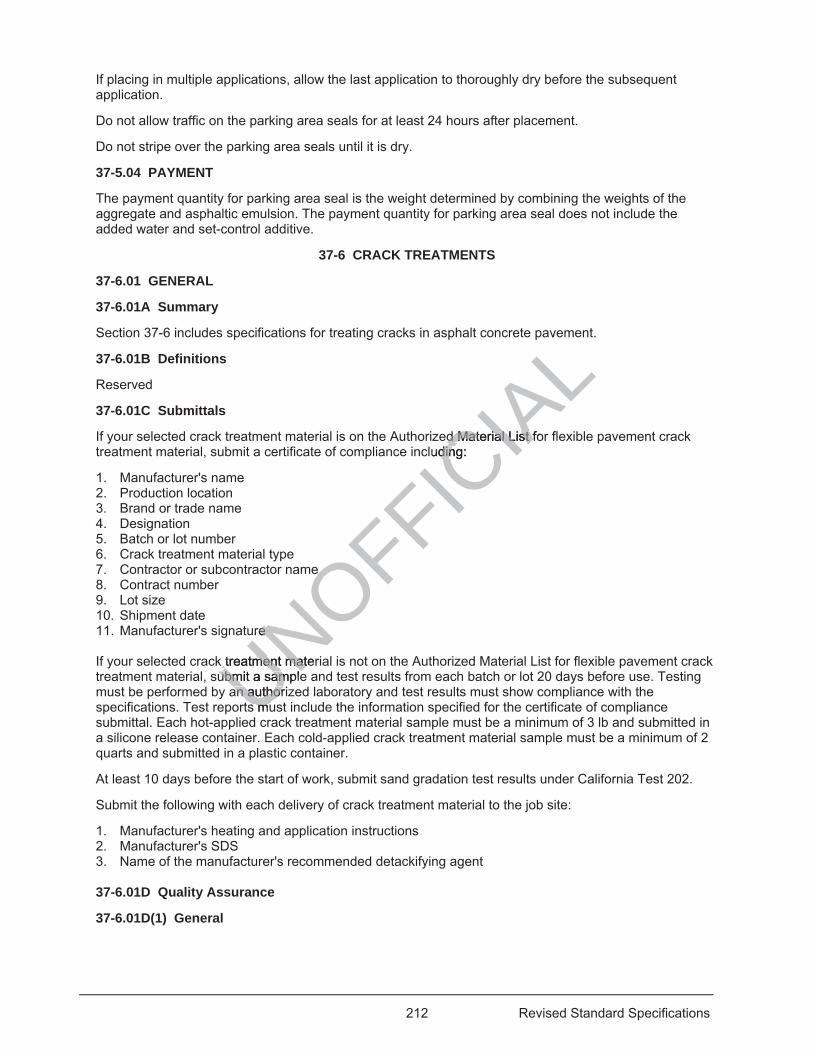
212 Revised Standard Specifications
If placing in multiple applications, allow the last application to thoroughly dry before the subsequent application.
Do not allow traffic on the parking area seals for at least 24 hours after placement.
Do not stripe over the parking area seals until it is dry.
37-5.04 PAYMENT
The payment quantity for parking area seal is the weight determined by combining the weights of the aggregate and asphaltic emulsion. The payment quantity for parking area seal does not include the added water and set-control additive.
37-6 CRACK TREATMENTS
37-6.01 GENERAL
37-6.01A Summary
Section 37-6 includes specifications for treating cracks in asphalt concrete pavement.
37-6.01B Definitions
Reserved
37-6.01C Submittals
If your selected crack treatment material is on the Authorized Material List for flexible pavement crack treatment material, submit a certificate of compliance including:
1. Manufacturer's name 2. Production location 3. Brand or trade name 4. Designation 5. Batch or lot number 6. Crack treatment material type 7. Contractor or subcontractor name 8. Contract number 9. Lot size 10. Shipment date 11. Manufacturer's signature
If your selected crack treatment material is not on the Authorized Material List for flexible pavement crack treatment material, submit a sample and test results from each batch or lot 20 days before use. Testing must be performed by an authorized laboratory and test results must show compliance with the specifications. Test reports must include the information specified for the certificate of compliance submittal. Each hot-applied crack treatment material sample must be a minimum of 3 lb and submitted in a silicone release container. Each cold-applied crack treatment material sample must be a minimum of 2 quarts and submitted in a plastic container.
At least 10 days before the start of work, submit sand gradation test results under California Test 202.
Submit the following with each delivery of crack treatment material to the job site:
1. Manufacturer's heating and application instructions 2. Manufacturer's SDS 3. Name of the manufacturer's recommended detackifying agent 37-6.01D Quality Assurance
37-6.01D(1) General
UNOFFICIA
Lave
ed Material List fod Material List fluding: din
e e
ure e
k treatment materk treatment matubmit a sampleubmit a sample
an authorian authors mus mu
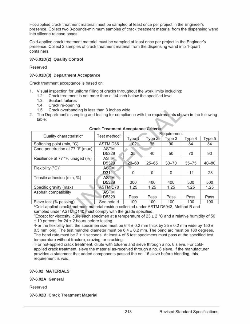
213 Revised Standard Specifications
Hot-applied crack treatment material must be sampled at least once per project in the Engineer's presence. Collect two 3-pounds-minimum samples of crack treatment material from the dispensing wand into silicone release boxes.
Cold-applied crack treatment material must be sampled at least once per project in the Engineer's presence. Collect 2 samples of crack treatment material from the dispensing wand into 1-quart containers.
37-6.01D(2) Quality Control
Reserved
37-6.01D(3) Department Acceptance
Crack treatment acceptance is based on:
1. Visual inspection for uniform filling of cracks throughout the work limits including: 1.2. Crack treatment is not more than a 1/4 inch below the specified level 1.3. Sealant failures 1.4. Crack re-opening 1.5. Crack overbanding is less than 3 inches wide
2. The Department’s sampling and testing for compliance with the requirements shown in the following table:
Crack Treatment Acceptance Criteria
Quality characteristica Test methodb Requirement Type 1 Type 2 Type 3 Type 4 Type 5
Softening point (min, °C) ASTM D36 102 96 90 84 84 Cone penetration at 77 °F (max) ASTM
D5329 35 40 50 70 90 Resilience at 77 °F, unaged (%) ASTM
D5329 20–60 25–65 30–70 35–75 40–80 Flexibility (°C)c ASTM
D3111 0 0 0 -11 -28 Tensile adhesion (min, %) ASTM
D5329 300 400 400 500 500 Specific gravity (max) ASTM D70 1.25 1.25 1.25 1.25 1.25 Asphalt compatibility ASTM
D5329 Pass Pass Pass Pass Pass Sieve test (% passing) See note d 100 100 100 100 100 aCold-applied crack treatment material residue collected under ASTM D6943, Method B and sampled under ASTM D140 must comply with the grade specified. bExcept for viscosity, cure each specimen at a temperature of 23 ± 2 °C and a relative humidity of 50 ± 10 percent for 24 ± 2 hours before testing. cFor the flexibility test, the specimen size must be 6.4 ± 0.2 mm thick by 25 ± 0.2 mm wide by 150 ± 0.5 mm long. The test mandrel diameter must be 6.4 ± 0.2 mm. The bend arc must be 180 degrees. The bend rate must be 2 ± 1 seconds. At least 4 of 5 test specimens must pass at the specified test temperature without fracture, crazing, or cracking. dFor hot-applied crack treatment, dilute with toluene and sieve through a no. 8 sieve. For cold-applied crack treatment, sieve the material as-received through a no. 8 sieve. If the manufacturer provides a statement that added components passed the no. 16 sieve before blending, this requirement is void.
37-6.02 MATERIALS
37-6.02A General
Reserved
37-6.02B Crack Treatment Material
UNck treatment matk treatment maM D140 muM D140 m
ure eaure eaUNOFFASTM STMD3111 D3111 FFIC
IALquirements shoments sho
ce Criteria Criteria RequRe
CIApe 1 Type 2 e 1 Type 2 CIACA
102 96 102 96CCCCCCCC35 35 ICF CM M
329 20–60329 2FIFFFFFF
ASTM STMD5329 29OF
NOFASTM DASTM D
NONOASTASDNONO
ng) S
UNNUN
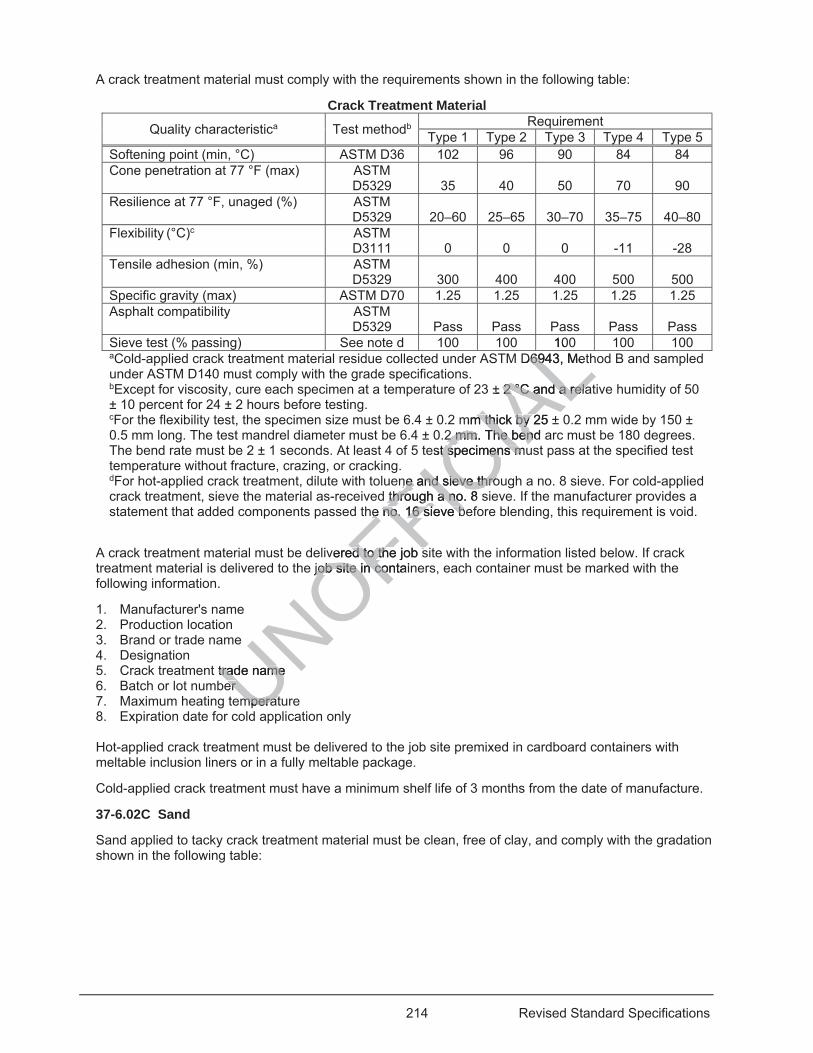
214 Revised Standard Specifications
A crack treatment material must comply with the requirements shown in the following table:
Crack Treatment Material
Quality characteristica Test methodb Requirement Type 1 Type 2 Type 3 Type 4 Type 5
Softening point (min, °C) ASTM D36 102 96 90 84 84 Cone penetration at 77 °F (max) ASTM
D5329 35 40 50 70 90 Resilience at 77 °F, unaged (%) ASTM
D5329 20–60 25–65 30–70 35–75 40–80 Flexibility (°C)c ASTM
D3111 0 0 0 -11 -28 Tensile adhesion (min, %) ASTM
D5329 300 400 400 500 500 Specific gravity (max) ASTM D70 1.25 1.25 1.25 1.25 1.25 Asphalt compatibility ASTM
D5329 Pass Pass Pass Pass Pass Sieve test (% passing) See note d 100 100 100 100 100 aCold-applied crack treatment material residue collected under ASTM D6943, Method B and sampled under ASTM D140 must comply with the grade specifications. bExcept for viscosity, cure each specimen at a temperature of 23 ± 2 °C and a relative humidity of 50 ± 10 percent for 24 ± 2 hours before testing. cFor the flexibility test, the specimen size must be 6.4 ± 0.2 mm thick by 25 ± 0.2 mm wide by 150 ± 0.5 mm long. The test mandrel diameter must be 6.4 ± 0.2 mm. The bend arc must be 180 degrees. The bend rate must be 2 ± 1 seconds. At least 4 of 5 test specimens must pass at the specified test temperature without fracture, crazing, or cracking. dFor hot-applied crack treatment, dilute with toluene and sieve through a no. 8 sieve. For cold-applied crack treatment, sieve the material as-received through a no. 8 sieve. If the manufacturer provides a statement that added components passed the no. 16 sieve before blending, this requirement is void.
A crack treatment material must be delivered to the job site with the information listed below. If crack treatment material is delivered to the job site in containers, each container must be marked with the following information.
1. Manufacturer's name 2. Production location 3. Brand or trade name 4. Designation 5. Crack treatment trade name 6. Batch or lot number 7. Maximum heating temperature 8. Expiration date for cold application only
Hot-applied crack treatment must be delivered to the job site premixed in cardboard containers with meltable inclusion liners or in a fully meltable package.
Cold-applied crack treatment must have a minimum shelf life of 3 months from the date of manufacture.
37-6.02C Sand
Sand applied to tacky crack treatment material must be clean, free of clay, and comply with the gradation shown in the following table:
UNOFFICIA
LD6943, MeD69
± 2 °C and a rela2 °C and a rela
mm thick by 25 ±m thick by 2 mm. The bend 2 mm. The ben
est specimens mut specimens m
nne and sieve throe and sieve thro through a no. 8 sthrough a no
he no. 16 sie no. 16 s
L10
eve bee b
L
vered to the job sed to the job sjob site in job site in containco
trade name trade nameerer
mperatmperata
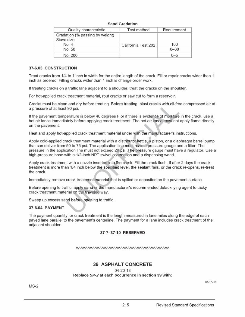
215 Revised Standard Specifications
Sand Gradation Quality characteristic Test method Requirement
Gradation (% passing by weight) Sieve size:
California Test 202
No. 4 100 No. 50 0–30 No. 200 0–5
37-6.03 CONSTRUCTION
Treat cracks from 1/4 to 1 inch in width for the entire length of the crack. Fill or repair cracks wider than 1 inch as ordered. Filling cracks wider than 1 inch is change order work.
If treating cracks on a traffic lane adjacent to a shoulder, treat the cracks on the shoulder.
For hot-applied crack treatment material, rout cracks or saw cut to form a reservoir.
Cracks must be clean and dry before treating. Before treating, blast cracks with oil-free compressed air at a pressure of at least 90 psi.
If the pavement temperature is below 40 degrees F or if there is evidence of moisture in the crack, use a hot air lance immediately before applying crack treatment. The hot air lance must not apply flame directly on the pavement.
Heat and apply hot-applied crack treatment material under with the manufacturer's instructions.
Apply cold-applied crack treatment material with a distributor kettle, a piston, or a diaphragm barrel pump that can deliver from 50 to 75 psi. The application line must have a pressure gauge and a filter. The pressure in the application line must not exceed 20 psi. The pressure gauge must have a regulator. Use a high-pressure hose with a 1/2-inch NPT swivel connection and a dispensing wand.
Apply crack treatment with a nozzle inserted into the crack. Fill the crack flush. If after 2 days the crack treatment is more than 1/4 inch below the specified level, the sealant fails, or the crack re-opens, re-treat the crack.
Immediately remove crack treatment material that is spilled or deposited on the pavement surface.
Before opening to traffic, apply sand or the manufacturer's recommended detackifying agent to tacky crack treatment material on the traveled way.
Sweep up excess sand before opening to traffic.
37-6.04 PAYMENT
The payment quantity for crack treatment is the length measured in lane miles along the edge of each paved lane parallel to the pavement's centerline. The payment for a lane includes crack treatment of the adjacent shoulder.
37-7–37-10 RESERVED
^^^^^^^^^^^^^^^^^^^^^^^^^^^^^^^^^^^^^^^^
39 ASPHALT CONCRETE 04-20-18
Replace SP-2 at each occurrence in section 39 with: 01-15-16
MS-2
UNOFFICIA
Lwith o
dence of moistureence of moistureot air lance must nlance must n
with the manufawith the manufa
ributor kettle, a pributor kettle, ane must have a pne must have a p
20 20 psi. The presspsi. The prel connection and l connection and
ted into the cracked into the crache specified levehe specifie
ment material thament material th
pply sand or the mply sand or the mon the traveled won the traveled
nd before openinnd before open
ra
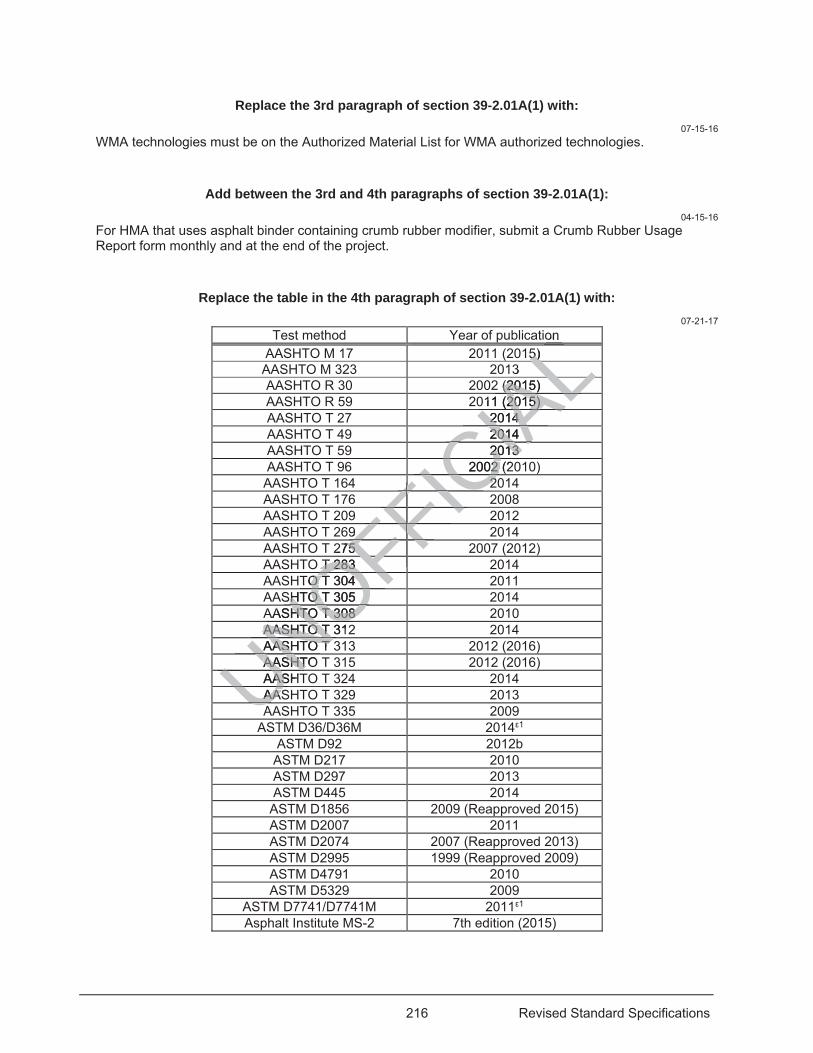
216 Revised Standard Specifications
Replace the 3rd paragraph of section 39-2.01A(1) with: 07-15-16
WMA technologies must be on the Authorized Material List for WMA authorized technologies.
Add between the 3rd and 4th paragraphs of section 39-2.01A(1): 04-15-16
For HMA that uses asphalt binder containing crumb rubber modifier, submit a Crumb Rubber Usage Report form monthly and at the end of the project.
Replace the table in the 4th paragraph of section 39-2.01A(1) with: 07-21-17
Test method Year of publication AASHTO M 17 2011 (2015) AASHTO M 323 2013 AASHTO R 30 2002 (2015) AASHTO R 59 2011 (2015) AASHTO T 27 2014 AASHTO T 49 2014 AASHTO T 59 2013 AASHTO T 96 2002 (2010) AASHTO T 164 2014 AASHTO T 176 2008 AASHTO T 209 2012 AASHTO T 269 2014 AASHTO T 275 2007 (2012) AASHTO T 283 2014 AASHTO T 304 2011 AASHTO T 305 2014 AASHTO T 308 2010 AASHTO T 312 2014 AASHTO T 313 2012 (2016) AASHTO T 315 2012 (2016) AASHTO T 324 2014 AASHTO T 329 2013 AASHTO T 335 2009
ASTM D36/D36M 2014 1 ASTM D92 2012b
ASTM D217 2010 ASTM D297 2013 ASTM D445 2014 ASTM D1856 2009 (Reapproved 2015) ASTM D2007 2011 ASTM D2074 2007 (Reapproved 2013) ASTM D2995 1999 (Reapproved 2009) ASTM D4791 2010 ASTM D5329 2009
ASTM D7741/D7741M 2011 1 Asphalt Institute MS-2 7th edition (2015)
UNOFFICIA
Lon
5) 5) LL3 L2 (2015) (2015
AL011 (2015) 011 (2015) AL2014 2014 IA2014 201
CIA2013 2013 CIA2002 (202 C22ICFFFFICFFFFI
FF9 9 FFFFFFFF275 75 FFFFFFFFT 283 T 283
OFFFFTO T 304 O T 304 OFSHTO T 305 SHTO T OAASHTO T 308 HTO T 308
NOAASHTO T 312AASHTO TNOAASHTO T AASHTO T NAASHTOAASHTUNAASHTASUNAASAASUAU
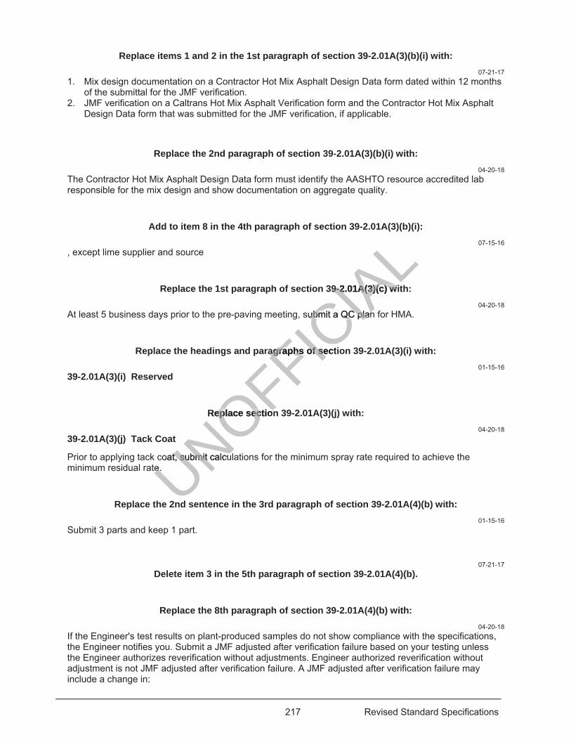
217 Revised Standard Specifications
Replace items 1 and 2 in the 1st paragraph of section 39-2.01A(3)(b)(i) with: 07-21-17
1. Mix design documentation on a Contractor Hot Mix Asphalt Design Data form dated within 12 months of the submittal for the JMF verification.
2. JMF verification on a Caltrans Hot Mix Asphalt Verification form and the Contractor Hot Mix Asphalt Design Data form that was submitted for the JMF verification, if applicable.
Replace the 2nd paragraph of section 39-2.01A(3)(b)(i) with: 04-20-18
The Contractor Hot Mix Asphalt Design Data form must identify the AASHTO resource accredited lab responsible for the mix design and show documentation on aggregate quality.
Add to item 8 in the 4th paragraph of section 39-2.01A(3)(b)(i): 07-15-16
, except lime supplier and source
Replace the 1st paragraph of section 39-2.01A(3)(c) with: 04-20-18
At least 5 business days prior to the pre-paving meeting, submit a QC plan for HMA.
Replace the headings and paragraphs of section 39-2.01A(3)(i) with: 01-15-16
39-2.01A(3)(i) Reserved
Replace section 39-2.01A(3)(j) with: 04-20-18
39-2.01A(3)(j) Tack Coat
Prior to applying tack coat, submit calculations for the minimum spray rate required to achieve the minimum residual rate.
Replace the 2nd sentence in the 3rd paragraph of section 39-2.01A(4)(b) with: 01-15-16
Submit 3 parts and keep 1 part.
07-21-17 Delete item 3 in the 5th paragraph of section 39-2.01A(4)(b).
Replace the 8th paragraph of section 39-2.01A(4)(b) with: 04-20-18
If the Engineer's test results on plant-produced samples do not show compliance with the specifications, the Engineer notifies you. Submit a JMF adjusted after verification failure based on your testing unless the Engineer authorizes reverification without adjustments. Engineer authorized reverification without adjustment is not JMF adjusted after verification failure. A JMF adjusted after verification failure may include a change in:
UNOFFICIA
L39-2.01A(3)(c) wi9-2.01A(3)(c) w
submit a QC planubmit a QC plan
agraphs of sectagraphs of se
Replace sectioneplace section
oat, submit calcut, submit te. e
d
218 Revised Standard Specifications
1. Asphalt binder content TV up to ±0.20 percent from the OBC value submitted on the Contractor Hot Mix Asphalt Design Data form
2. Aggregate gradation TV within the TV limits specified in the aggregate gradation table
Replace the 10th paragraph of section 39-2.01A(4)(b) with: 04-20-18
For each HMA type and aggregate size specified, the Engineer verifies up to 2 proposed JMF submittals including a JMF adjusted after verification failure. Do not resubmit any of the 2 proposed submittals including a JMF adjusted after verification failure that failed verification on any other Caltrans projects. If you submit more than 2 JMFs for each type of HMA and aggregate size, the Engineer deducts $3,000 from payments for each verification exceeding this limit. This deduction does not apply to verifications initiated by the Engineer or if a JMF expires while HMA production is stopped longer than 30 days.
Replace AASHTO Materials Reference Laboratory in the paragraph of section 39-2.01A(4)(f)(i) with:
01-20-17 AASHTO re:source
Add between the 1st and 2nd paragraphs of section 39-2.01A(4)(h)(i): 04-20-18
Condition each at-the-plant sample of HMA mixture for AASHTO 324 and AASHTO 283 in compliance with sections 7.1.2, 7.1.3, and 7.1.4 of AASHTO R 30. Condition each at-the-plant sample of HMA mixture when composite aggregate absorption factor is greater than 2.0 percent as indicated by the JMF in compliance with sections 7.1.2, 7.1.3, and 7.1.4 of AASHTO R 30.
04-20-18 Delete section 39-2.01A(4)(h)(ix)
Replace the 5th paragraph of section 39-2.01A(4)(i)(i) with: 04-20-18
The Engineer conditions each at-the-plant sample of HMA mixture for AASHTO 324 and AASHTO 283 in compliance with sections 7.1.2, 7.1.3, and 7.1.4 of AASHTO R 30. The Engineer conditions each at-the-plant sample of HMA mixture when composite aggregate absorption factor is greater than 2.0 percent as indicated by the JMF in compliance with sections 7.1.2, 7.1.3, and 7.1.4 of AASHTO R 30.
07-21-17 Delete the 6th paragraph of section 39-2.01A(4)(i)(i).
Add between single and test in the 7th paragraph of section 39-2.01A(4)(i)(i): 07-15-16
aggregate or HMA
Replace Engineer may accept in the introductory clause of the 3rd paragraph of section 39-2.01A(4)(i)(ii) with:
07-21-17 Engineer must accept
UNOFFICIA
Lf s
s of section 39-2s of section 39
or AASHTO 324 aAASHTO 32430. Condition ea30. Condition ea
actor isactor is greater th greater7.1.4 of AASHTO7.1.4 of AASHTO
Delete section Delete section
lace the 5th paralace the 5th pa
ons each at-the-ons each at-theons 7.1.2, 7.ons 7.1.2, 7
xture wxture wmp
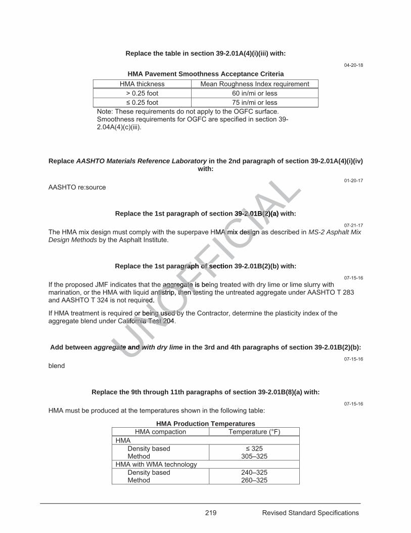
219 Revised Standard Specifications
Replace the table in section 39-2.01A(4)(i)(iii) with: 04-20-18
HMA Pavement Smoothness Acceptance Criteria HMA thickness Mean Roughness Index requirement
> 0.25 foot 60 in/mi or less 0.25 foot 75 in/mi or less
Note: These requirements do not apply to the OGFC surface. Smoothness requirements for OGFC are specified in section 39-2.04A(4)(c)(iii).
Replace AASHTO Materials Reference Laboratory in the 2nd paragraph of section 39-2.01A(4)(i)(iv) with:
01-20-17 AASHTO re:source
Replace the 1st paragraph of section 39-2.01B(2)(a) with: 07-21-17
The HMA mix design must comply with the superpave HMA mix design as described in MS-2 Asphalt Mix Design Methods by the Asphalt Institute.
Replace the 1st paragraph of section 39-2.01B(2)(b) with: 07-15-16
If the proposed JMF indicates that the aggregate is being treated with dry lime or lime slurry with marination, or the HMA with liquid antistrip, then testing the untreated aggregate under AASHTO T 283 and AASHTO T 324 is not required.
If HMA treatment is required or being used by the Contractor, determine the plasticity index of the aggregate blend under California Test 204.
Add between aggregate and with dry lime in the 3rd and 4th paragraphs of section 39-2.01B(2)(b): 07-15-16
blend
Replace the 9th through 11th paragraphs of section 39-2.01B(8)(a) with: 07-15-16
HMA must be produced at the temperatures shown in the following table:
HMA Production Temperatures HMA compaction Temperature (°F)
HMA Density based Method
325 305–325
HMA with WMA technology Density based Method
240–325 260–325
UNOFFICIA
Ln 39-2.01B(2)(a) w9-2.01B(2
HMA mix design aA mix design a
agraph of sectiongraph of s
aggregate isaggregate beiantistrip, ntis then testthen tes
ed.
or being used byor being used byalifornia Test 204alifornia Test 20
gategate and d wiw
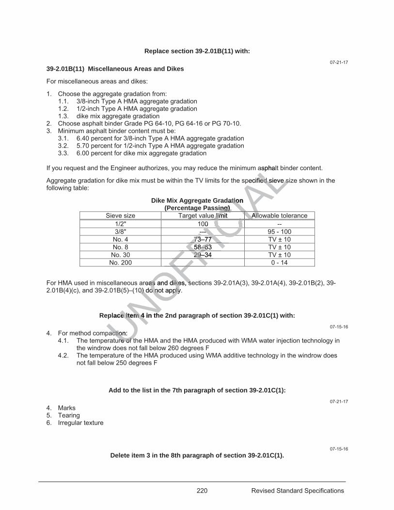
220 Revised Standard Specifications
Replace section 39-2.01B(11) with: 07-21-17
39-2.01B(11) Miscellaneous Areas and Dikes
For miscellaneous areas and dikes:
1. Choose the aggregate gradation from: 1.1. 3/8-inch Type A HMA aggregate gradation 1.2. 1/2-inch Type A HMA aggregate gradation 1.3. dike mix aggregate gradation
2. Choose asphalt binder Grade PG 64-10, PG 64-16 or PG 70-10. 3. Minimum asphalt binder content must be:
3.1. 6.40 percent for 3/8-inch Type A HMA aggregate gradation 3.2. 5.70 percent for 1/2-inch Type A HMA aggregate gradation 3.3. 6.00 percent for dike mix aggregate gradation
If you request and the Engineer authorizes, you may reduce the minimum asphalt binder content.
Aggregate gradation for dike mix must be within the TV limits for the specified sieve size shown in the following table:
Dike Mix Aggregate Gradation (Percentage Passing)
Sieve size Target value limit Allowable tolerance 1/2" 100 -- 3/8" --- 95 - 100
No. 4 73–77 TV ± 10 No. 8 58–63 TV ± 10
No. 30 29–34 TV ± 10 No. 200 0 - 14
For HMA used in miscellaneous areas and dikes, sections 39-2.01A(3), 39-2.01A(4), 39-2.01B(2), 39-2.01B(4)(c), and 39-2.01B(5)–(10) do not apply.
Replace item 4 in the 2nd paragraph of section 39-2.01C(1) with: 07-15-16
4. For method compaction: 4.1. The temperature of the HMA and the HMA produced with WMA water injection technology in
the windrow does not fall below 260 degrees F 4.2. The temperature of the HMA produced using WMA additive technology in the windrow does
not fall below 250 degrees F
Add to the list in the 7th paragraph of section 39-2.01C(1): 07-21-17
4. Marks 5. Tearing 6. Irregular texture
07-15-16 Delete item 3 in the 8th paragraph of section 39-2.01C(1).
UNOFFICIA
Lasphalt
pecified sieve sed sieve s
dation atioing) ing)
e limit Alllimit AllCIACIACIA00 0 CICICICICICICICI--- --- IC73–77 73–77
FIC58–63 8–6FI29–34 29–
FFFFOFreas and dikes, sas and dikes, s
10) do not apply. 0) do not apply
lace item 4 in thce item 4
action: actionre of tre of t
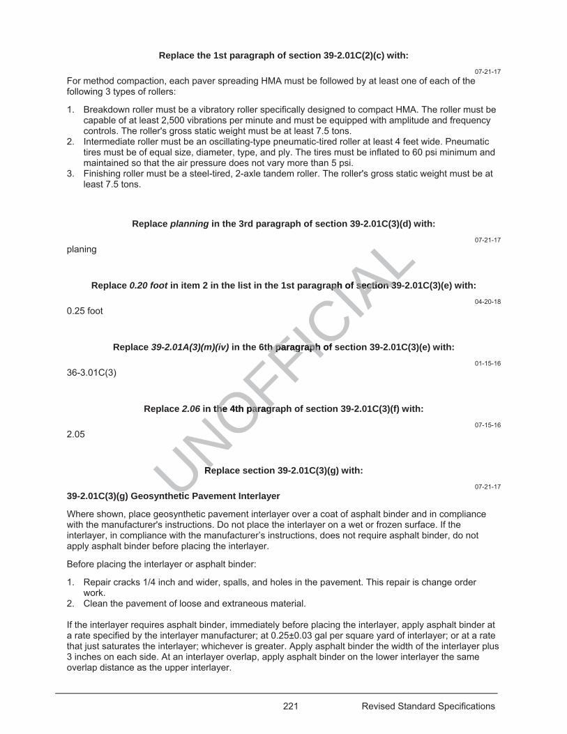
221 Revised Standard Specifications
Replace the 1st paragraph of section 39-2.01C(2)(c) with: 07-21-17
For method compaction, each paver spreading HMA must be followed by at least one of each of the following 3 types of rollers:
1. Breakdown roller must be a vibratory roller specifically designed to compact HMA. The roller must be capable of at least 2,500 vibrations per minute and must be equipped with amplitude and frequency controls. The roller's gross static weight must be at least 7.5 tons.
2. Intermediate roller must be an oscillating-type pneumatic-tired roller at least 4 feet wide. Pneumatic tires must be of equal size, diameter, type, and ply. The tires must be inflated to 60 psi minimum and maintained so that the air pressure does not vary more than 5 psi.
3. Finishing roller must be a steel-tired, 2-axle tandem roller. The roller's gross static weight must be at least 7.5 tons.
Replace planning in the 3rd paragraph of section 39-2.01C(3)(d) with: 07-21-17
planing
Replace 0.20 foot in item 2 in the list in the 1st paragraph of section 39-2.01C(3)(e) with: 04-20-18
0.25 foot
Replace 39-2.01A(3)(m)(iv) in the 6th paragraph of section 39-2.01C(3)(e) with: 01-15-16
36-3.01C(3)
Replace 2.06 in the 4th paragraph of section 39-2.01C(3)(f) with: 07-15-16
2.05
Replace section 39-2.01C(3)(g) with: 07-21-17
39-2.01C(3)(g) Geosynthetic Pavement Interlayer
Where shown, place geosynthetic pavement interlayer over a coat of asphalt binder and in compliance with the manufacturer's instructions. Do not place the interlayer on a wet or frozen surface. If the interlayer, in compliance with the manufacturer’s instructions, does not require asphalt binder, do not apply asphalt binder before placing the interlayer.
Before placing the interlayer or asphalt binder:
1. Repair cracks 1/4 inch and wider, spalls, and holes in the pavement. This repair is change order work.
2. Clean the pavement of loose and extraneous material. If the interlayer requires asphalt binder, immediately before placing the interlayer, apply asphalt binder at a rate specified by the interlayer manufacturer; at 0.25±0.03 gal per square yard of interlayer; or at a rate that just saturates the interlayer; whichever is greater. Apply asphalt binder the width of the interlayer plus 3 inches on each side. At an interlayer overlap, apply asphalt binder on the lower interlayer the same overlap distance as the upper interlayer.
UNOFFICIA
Laph of section 39ph of section 3
h paragraph of sh paragraph
n the 4th paragrthe 4th paragr
ReR
etic

222 Revised Standard Specifications
If asphalt binder tracked onto the interlayer or brought to the surface by construction equipment causes interlayer displacement, cover it with a small quantity of HMA.
If the interlayer placement does not require asphalt binder, apply tack coat prior to placing HMA at the application rates specified under section 39-2.01C(3)(f) based on the condition of the underlying surface on which the interlayer was placed.
Align and place the interlayer with no overlapping wrinkles, except a wrinkle that overlaps may remain if it is less than 1/2 inch thick. If the overlapping wrinkle is more than 1/2 inch thick, cut the wrinkle out and overlap the interlayer no more than 2 inches.
Overlap the interlayer borders between 2 to 4 inches. In the direction of paving, overlap the following roll with the preceding roll at any break.
You may use rolling equipment to correct distortions or wrinkles in the interlayer.
Before placing HMA on the interlayer, do not expose the interlayer to:
1. Traffic, except for crossings under traffic control and only after you place a small HMA quantity 2. Sharp turns from construction equipment 3. Damaging elements Pave HMA on the interlayer during the same work shift. The minimum HMA thickness over the interlayer must be 0.12 foot including at conform tapers.
Add to the end of section 39-2.01C(15)(b): 07-15-16
The compacted lift thickness must not exceed 0.25 foot.
Add between rectangles and with in the 4th paragraph of section 39-2.01C(16): 04-15-16
, half the lane width,
Add between to and the in item 1 of the 4th paragraph of section 39-2.01C(16): 04-15-16
and along
07-15-16 Delete coat in the 5th paragraph of section 39-2.01C(16).
Replace 37 in the 5th paragraph of section 39-2.01C(16) with: 07-15-16
37-4.02
Replace section 39-2.02A(3)(b) with: 01-15-16
The JMF must be based on the superpave HMA mix design as described in MS-2 Asphalt Mix Design Methods by the Asphalt Institute.
UNOFFICIA
Lm HMA thicknesm HMA thicknes
on 39-2.01C(15)(b39-2.01C(15)(b
5 foot. 5 foo
withwith in the 4th in the 4th
to and and thethe in item in i
223 Revised Standard Specifications
Replace the 1st paragraph of section 39-2.02C with: 04-20-18
Where the pavement thickness shown is 0.30 foot or greater, you may place Type A HMA in multiple lifts not less than 0.15 foot each. If placing Type A HMA in multiple lifts:
1. Table in Section 39-2.02B(4)(b) does not apply 2. Aggregate gradation must comply with the requirements shown in the following table:
Aggregate Gradation Requirements Type A HMA lift thickness Gradation 0.15 to less than 0.20 foot 1/2 inch
0.20 foot to less than 0.25 foot 3/4 inch 0.25 foot or greater 3/4 inch or 1 inch
3. Apply a tack coat before placing a subsequent lift 4. The Engineer evaluates each HMA lift individually for compliance
Add between the 1st and 2nd paragraphs of section 39-2.02C: 07-15-16
If the ambient air temperature is below 60 degrees F, cover the loads in trucks with tarpaulins. If the time for HMA discharge to truck at the HMA plant until transfer to paver's hopper is 90 minutes or greater and if the ambient air temperature is below 70 degrees F, cover the loads in trucks with tarpaulins, unless the time from discharging to the truck until transfer to the paver's hopper or the pavement surface is less than 30 minutes. The tarpaulins must completely cover the exposed load until you transfer the mixture to the paver's hopper or the pavement surface.
Replace the table in the 2nd paragraph of section 39-2.02C with:
07-15-16 Minimum Ambient Air and Surface Temperatures
Lift thickness (feet)
Ambient air ( F) Surface ( F) Unmodified
asphalt binder Modified asphalt
binder Unmodified
asphalt binder Modified asphalt
binder Type A HMA and Type A HMA produced with WMA water injection technology
0.15 55 50 60 55 0.15 45 45 50 50
Type A HMA produced with WMA additive technology 0.15 45 45 50 45 0.15 40 40 40 40
07-15-16 Delete the 3rd paragraph of section 39-2.02C.
Add between HMA and placed in the 1st sentence of the 4th paragraph of section 39-2.02C: 07-15-16
and Type A HMA produced with WMA water injection technology
Add between the 4th and the 5th paragraphs of section 39-2.02C:
UNOFFICIA
Lection 39-2.02Cection 39-2.02C
e loads in trucks woads in trucks wpaver's hopper ispaver's hoppe
er the loads in trur the loads in truaver's hopper or taver's hopper
e exposed load ue exposed load u
the 2nd paragrape 2nd paragra
um Ambient Air Ambient Air Ambient air (Ambient air ( FOmodified ed
sphalt binder phalt binder MMNOO
e A HMA producA HMA pr
UNUN55 55 UN45 45 Uwith Wwith WUU
224 Revised Standard Specifications
07-15-16 For Type A HMA produced with WMA additive technology placed under method compaction, if the asphalt binder is:
1. Unmodified, complete: 1.1 1st coverage of breakdown compaction before the surface temperature drops below 240
degrees F 1.2. Breakdown and intermediate compaction before the surface temperature drops below 190
degrees F 1.3. Finish compaction before the surface temperature drops below 140 degrees F 1.4 You may continue static rolling below 140 degrees F to remove roller marks.
2. Modified, complete: 2.1. 1st coverage of breakdown compaction before the surface temperature drops below 230
degrees F 2.2. Breakdown and intermediate compaction before the surface temperature drops below 170
degrees F 2.3. Finish compaction before the surface temperature drops below 130 degrees F 2.4. You may continue static rolling below 130 degrees F to remove roller marks.
Replace the 2nd paragraph of section 39-2.03A(3)(b) with: 01-15-16
The JMF must be based on the superpave HMA mix design as described in MS-2 Asphalt Mix Design Methods by the Asphalt Institute.
Replace the requirement in the row for Voids in mineral aggregate on plant produced HMA in the 2nd table in section 39-2.03A(4)(e)(i) with:
01-15-16 18.0-23.0
Add before the 1st paragraph of section 39-2.03A(4)(e)(ii)(C): 04-15-16
CRM used must be on the Authorized Materials List for Crumb Rubber Modifier.
CRM must be a ground or granulated combination of scrap tire crumb rubber and high natural scrap tire crumb rubber, CRM must be 75.0 ± 2.0 percent scrap tire crumb rubber and 25.0 ± 2.0 percent high natural scrap tire crumb rubber by total weight of CRM. Scrap tire crumb rubber and high natural scrap tire crumb rubber must be derived from waste tires described in Pub Res Code § 42703.
Replace the row for Hamburg wheel track in the table in section 39-2.03B(2) with: 01-15-16
Hamburg wheel track (min, number of passes at the inflection point)
Binder grade: PG 58 PG 64 PG 70
AASHTO T 324 (Modified)d
10,000 12,500 15,000
Replace AASHTO R 35 in the 4th paragraph of section 39-2.03B(2) with: 07-21-17
superpave HMA mix design as described in MS-2 Asphalt Mix Design Methods by the Asphalt Institute
UNOFFICIA
Le
.03A(3)(b) with: 03A(3)(b) with:
s described in escribed MS
in mineral aggrein mineral aggretion 39-2.03A(4)ion 39-2.03A(4
the 1st paragrathe 1st parag
Authorized MateAuthorized M
nd or granulated cgranulatemust be 75.0 ± must be 75.0 ±
b rubber byb rubber be derive deriv
225 Revised Standard Specifications
Replace RHMA-G in the 3rd and 5th paragraphs of section 39-2.03C with: 07-15-16
RHMA-G and RHMA-G produced with WMA water injection technology
Add between the 3rd and 4th paragraphs of section 39-2.03C: 01-20-17
Spread and compact RHMA-G produced with WMA addititive technology at an ambient air temperature of at least 50 degrees F and a surface temperature of at least 50 degrees F.
Add between the 5th and 6th paragraphs of section 39-2.03C: 07-15-16
For RHMA-G produced with WMA additive technology placed under method compaction:
1. Complete the 1st coverage of breakdown compaction before the surface temperature drops below 260 degrees F
2. Complete breakdown and intermediate compaction before the surface temperature drops below 230 degrees F
3. Complete finish compaction before the surface temperature drops below 180 degrees F 4. You may continue static rolling below 140 degrees F to remove roller marks
Replace 39-2.03A(4)(b)(ii) in the 1st sentence of section 39-2.04A(4)(b)(ii) with: 01-20-17
39-2.03A(4)(c)(ii)
Replace the 6th and 7th paragraphs of section 39-2.04C with: 07-15-16
For HMA-O and HMA-O produced with WMA water injection technology:
1. With unmodified asphalt binder: 1.1. Spread and compact only if the atmospheric temperature is at least 55 degrees F and the
surface temperature is at least 60 degrees F. 1.2. Complete the 1st coverage using 2 rollers before the surface temperature drops below 240
degrees F. 1.3. Complete all compaction before the surface temperature drops below 200 degrees F.
2. With modified asphalt binder, except asphalt rubber binder: 2.1. Spread and compact only if the atmospheric temperature is at least 50 degrees F and the
surface temperature is at least 50 degrees F. 2.2. Complete the 1st coverage using 2 rollers before the surface temperature drops below 240
degrees F. 2.3. Complete all compaction before the surface temperature drops below 180 degrees F.
For HMA-O produced with WMA additive technology:
1. With unmodified asphalt binder: 1.1. Spread and compact only if the atmospheric temperature is at least 45 degrees F and the
surface temperature is at least 50 degrees F. 1.2. Complete the 1st coverage using 2 rollers before the surface temperature drops below 230
degrees F. 1.3. Complete all compaction before the surface temperature drops below 190 degrees F.
2. With modified asphalt binder, except asphalt rubber binder:
UNOFFICIA
Lcom
face temperace
surface temperaturface temperat
re drops below 18drops beloremove roller maremove roller m
sentence of sectsentence of sec
6th and 7th paragh and 7th para
duced with WMA duced with WMA
phalt binder: halt binder: d compact only if d compact onlymperature is atmperature is at
e 1st covee 1st cove
226 Revised Standard Specifications
2.1. Spread and compact only if the atmospheric temperature is at least 40 degrees F and the surface temperature is at least 40 degrees F.
2.2. Complete the 1st coverage using 2 rollers before the surface temperature drops below 230 degrees F.
2.3. Complete all compaction before the surface temperature drops below 170 degrees F.
Replace RHMA-O and RHMA-O-HB in the 8th paragraph of section 39-2.04C with:07-15-16
RHMA-O and RHMA-O produced with WMA water injection technology, and RHMA-O-HB and RHMA-O-HB produced with WMA water injection technology
Add between the 8th and 9th paragraphs of section 39-2.04C: 07-15-16
For RHMA-O produced with WMA additive technology and RHMA-O-HB produced with WMA additives technology:
1. Spread and compact if the ambient air temperature is at least 45 degrees F and the surface temperature is at least 50 degrees F
2. Complete the 1st coverage using 2 rollers before the surface temperature drops below 270 degrees F 3. Complete all compaction before the surface temperature drops below 240 degrees F
Add to the 2nd paragraph of section 39-2.05A(3)(b): 01-15-16
The material transfer vehicle must receive HMA directly from the truck.
Replace Table 6.1 at each occurrence in the table in section 39-2.05B(2) with: 01-15-16
Table 8.1
Replace SP-2 Asphalt Mixture in the 1st footnote in the table in the 2nd paragraph of section 39-2.05B(2)(b) with:
01-15-16 MS-2 Asphalt Mix Design Methods
Replace Manual Series No. 2 (MS-2) in the 1st footnote in the table in the 2nd paragraph of section 39-2.05B(2)(b) with:
01-15-16 MS-2 Asphalt Mix Design Methods
Replace 39-3.05 in the 1st paragraph of section 39-3.04A with: 01-15-16
39-3.04
Add to the end of section 39-3.04A:
UNOFFICIA
Lduce
degrees F and thdegrees F and th
e temperature dro temperature drdrops below 240 drops below
h of section 39-2h of section 39-2
MA directly from thMA directly from t
ch occurrence inch occurrenc
halt MixtureMixture in th inee
MetM
227 Revised Standard Specifications
07-15-16 Schedule cold planing activities such that the pavement is cold planed, the HMA is placed, and the area is opened to traffic during the same work shift.
Add to the 1st paragraph of section 39-3.04C(2): 04-20-18
You may adjust the planed depth up to ± 0.03 foot from the depth shown to achieve uniform pavement profile, cross slope, and surface smoothness. The average cold planed depth must be equal to or greater than the depth shown.
Add between the 3rd and 4th paragraph of section 39-3.04C(2): 04-20-18
If you encounter delaminations during planing operations notify the Engineer immediately. If authorized, adjust the planed depth up to ± 0.05 foot to eliminate delaminations. Authorized work beyond the ± 0.05 foot range or other authorized mitigation work is change order work.
07-15-16 Delete the 2nd sentence of the 1st paragraph in section 39-3.04C(4).
Replace 39-3.06 in the 1st paragraph of section 39-3.05A with: 01-15-16
39-3.05
^^^^^^^^^^^^^^^^^^^^^^^^^^^^^^^^^^^^^^^^
40 CONCRETE PAVEMENT 07-21-17
Add to the end of section 40-2.02C: 01-20-17
Inorganic zinc primer must comply with AASHTO M 300, Type I or II.
Replace and wide flange beam terminal in the 2nd paragraph of section 40-2.02D with: 01-20-17
, Types WF and AN,
Add to the end of section 40-2.02D: 01-20-17
Polyethylene bond breaker for wide flange beam terminal and expansion joint support slabs must comply with section 36-2.
Add to the end of section 40-2.03B: 01-20-17
Lap splice bar reinforcement under section 52-6. For low carbon, chromium-steel bar reinforcement, the length of lap splice must be at least 30 inches.
UNOFFICIA
Lh in section 39-3 in section 39-3
aph of section 39 of section 3
^^^^^^^^^^^^^^^^^^^^^^^^
40 CONCR40 CONC
Add to tAdd to
r must complyr must comply ww
228 Revised Standard Specifications
Replace the paragraph in section 40-2.03D with: 07-21-17
All welding must comply with AWS D1.1. Weld stud ends with an electric arc welder completely fusing the studs to the wide flange beam.
Replace studs dislodged in shipping or that can be dislodged with a hammer.
Add to the end of section 40-2.03D: 01-20-17
Clean surface of wide flange beam to receive prime coat under section 59-2.01C(3)(b)(ii). The thickness of the prime coat must be 6 mils.
Add after the second sentence of the 1st paragraph of section 40-2.03E(3)(a): 01-20-17
For low carbon, chromium-steel bar reinforcement, the length of lap splice must be at least 30 inches.
^^^^^^^^^^^^^^^^^^^^^^^^^^^^^^^^^^^^^^^^
42 GROOVE AND GRIND CONCRETE 01-20-17
Replace Reserved in section 42-1.03 with: 01-20-17
Do not store grooving or grinding residue within the highway.
^^^^^^^^^^^^^^^^^^^^^^^^^^^^^^^^^^^^^^^^^^^^^^^^^^^^^^^^^^^^
DIVISION VI STRUCTURES 47 EARTH RETAINING SYSTEMS
07-15-16 Replace the 6th paragraph in section 47-2.02A with:
07-15-16 Rock for rock slope protection at drain pipe outlets must be small-rock slope protection and must comply with the gradation specified for 7-inch-thick layer in section 72-4.02.
^^^^^^^^^^^^^^^^^^^^^^^^^^^^^^^^^^^^^^^^
48 TEMPORARY STRUCTURES 01-20-17
Add between the 5th and 6th paragraphs of section 48-2.01C(2): 01-20-17
For multi-frame bridges, submit a separate shop drawing for each frame.
UNOFFICIA
Lon 4
plice must be at plice must be at
^^^^^^^^^^^^^^^^^^^^^^^
GRIND CONCGRIND CONC01-20-17 01-20-17
rvedved in section 4 in section 4dd
ue within the highwithin the high
^^^^^^^^^^^^^^^^^^^^^^^^^
DIVIDIV474
229 Revised Standard Specifications
Replace section 48-6 with: 01-20-17
48-6 TEMPORARY WOOD POLES
48-6.01 GENERAL
48-6.01A Summary
Section 48-6 includes specifications for constructing, maintaining, and removing temporary wood poles for the support of electrical systems.
Temporary wood poles include attached wire components.
48-6.01B Definitions
Reserved
48-6.01C Submittals
48-6.01C(1) General
Submit a letter of certification that certifies all components of the manufactured assemblies are used in compliance with the manufacturer's recommendations. If requested, (1) submit manufacturer's data for manufactured assemblies to verify manufacturer's recommendations or (2) perform tests demonstrating adequacy of the proposed assemblies and submit the test results.
Submit the letter before installing messenger wires, tether wires, or self-supporting conductors or cables.
You may submit a request to use alternative mounting brackets or wire termination hardware. Your request must include:
1. Structural design calculations and testing data sealed and signed by an engineer who is registered as a civil engineer in the State
2. Manufacturer's instructions 48-6.01C(2) Guy Wire Anchors
Submit the guy wire anchor manufacturer's product information and installation instructions. Do not install anchors unless authorized.
48-6.01D Quality Assurance
48-6.01D(1) General
Reserved
48-6.01D(2) Welding
Welding must comply with AWS D1.1.
48-6.02 MATERIALS
48-6.02A General
Wire used for messenger wires, tether wires, or guy wires must be 7-wire strand complying with ASTM A475, Utilities Grade.
Connection hardware for wires must provide a termination efficiency factor of not less than 0.80.
Wood poles, push braces, and stubs must comply with ANSI O5.1.
Treat wood under AWPA U1, Use Category UC4B, Commodity Specification D.
UNOFFICIA
Lanufactured asseufactured asseted, (1) submit maed, (1) submit m
dations or (2) perfons or (2)esults. esults
her wires, or self-her wires, or se
tinting brackets or wg brackets or w
ng data ng data sealed anseale
manufacturer's prfacturer's pr.
surance nce
230 Revised Standard Specifications
Except for wire, helical anchors, expanded steel plate anchors, cross plate anchors, and expanding rock anchors, steel components must comply with section 56-3.
48-6.02B Helical Anchors, Expanded Steel Plate Anchors, Cross Plate Anchors, and Expanding Rock Anchors
Fabricate helical anchors, expanded steel plate anchors, and cross plate anchors under section 75.
Fabricate attachable thimble eyes and expanding rock anchors from suitable ferrous material.
Welding must comply with AWS D1.1.
Fabricate as a continuous piece or as separate segments with mechanical connections between segments. Include integral thimble eye or include attachable thimble eye.
Galvanize all helical anchor parts under section 75.
Paint expanded steel plate anchors, cross plate anchors, and expanding rock anchors as specified for repairing damaged galvanized surfaces in section 75-1.02B.
The final assembly must have (1) a minimum ultimate tensile strength greater than the minimum required breaking strength of the guy wire and (2) a minimum ultimate torsional strength greater than twice the minimum installation torque.
48-6.02C Reuse of Materials and Relocation of Temporary Supports
You may reuse structural components and relocate temporary supports provided that the materials remain in acceptable condition for reuse, except do not reuse:
1. Components of high-strength bolt assemblies that have been or are required to be tensioned past snug tight
2. High-strength cap screws that have been or are required to be tensioned past snug tight 3. Tension control bolts 48-6.03 CONSTRUCTION
48-6.03A General
Install construction bracing as necessary to withstand all imposed loads during erection, construction, and removal of any temporary wood poles.
The Engineer may order you to install Type K temporary railing at temporary wood pole locations that are less than 15 feet from the edge of a traffic lane.
Install all temporary railing protecting temporary wood poles before erecting temporary wood poles. Do not remove temporary railing until authorized.
For overhead line construction not specifically covered in the contract documents, comply with Public Utility Commission General Order 95.
48-6.03B Foundations
Verify the design soil parameters before starting construction of temporary wood poles.
Remove any accumulated water from the pole excavation prior to placing granular backfill at the bottom of the pole excavation. Thoroughly compact and level the granular backfill at the bottom of the pole excavation prior to setting the pole.
Backfill around poles with manufactured sand that is free of rocks or other deleterious material. Place the backfill material in 4-inch thick layers. Moisten and thoroughly compact each layer.
Remove accumulated water from the anchor excavation prior to placing an expanded steel anchor. Expand the base of the expanded steel anchor prior to placing backfill. Place backfill around the expanded steel anchor in 4-inch thick layers. Thoroughly compact each layer.
Protect foundations from softening and undermining.
UNOFFICIA
Later thantrength greatengt
upports upports
ry supports providry supports prouse: se:
t have been or arhave been or a
are required to bare required to
necessary to withsecessary to witood poles. oles.
you to install Typyou to install Tythe edge of a traedge of a
ailing protecailing prote tiailing unailing un
231 Revised Standard Specifications
48-6.03C Erection
If temporary wood poles are over or adjacent to roadways or railroads, all construction bracing must (1) be installed at the time each element of the temporary wood pole is erected and (2) remain in place until the temporary wood pole is removed.
Suspend conductors from messenger wire by continuous lashing wire. No spare wire conductors or cables are allowed unless described.
Sag overhead bundles to maintain required clearances over the ambient temperature range of - 30 to 120 degrees F. The sag must be between 4.6 and 5.4 percent of horizontal span unless otherwise shown. Minimum vertical clearance over grade is 25 feet unless otherwise shown.
48-6.03D Attachments
If specific connection details are not shown, mount attachments under the manufacturer's written instructions and such that there is no loss of cross section.
48-6.03E Damping
If at any time during service the temporary structural support exhibits excessive vibration, immediately install dampers. Dampers must be effective in mitigating the vibration and must not compromise the structural supports or the supported hardware.
48-6.03F Removal
Remove temporary structural supports such that portions not yet removed remain stable at all times.
Remove temporary wood poles and helical anchors. Fill the void with excavated material or sand that is free of deleterious material. Place the backfill material in 4-inch thick layers. Moisten and thoroughly compact each layer.
Dispose of surplus excavated material uniformly along the adjacent roadway.
Dispose of temporary structural support materials and work debris.
48-6.03G Guy Wire Helical Anchors
48-6.03G(1) General
Reserved
48-6.03G(2) Installation Parameters
Use the minimum installation torque shown. You may request an alternative minimum installation torque based on a revised value for empirical torque factor.
For alternative minimum installation torque, use the following equation to calculate the installation torque:
T = Qa(FS/Kt ) where: T = Minimum installation torque, ft-lb FS = Factor of safety of 2.0 Qa = Minimum allowable tensile capacity shown, lb Kt = Empirical torque factor, 1/ft (inverse foot)
Include a geotechnical report sealed and signed by a licensed geotechnical engineer with recommended values for empirical torque factor and alternative minimum installation torque with your request.
Do not start installation unless your alternative installation parameters are authorized.
Verify the installation parameters before the start of anchor installation.
48-6.03G(3) Installation
UNOFFICIA
Lessive vibessnd must not comust not co
ot yet removed reot yet removed
l the void with exe void with al in 4-inch thick lal in 4-inch thick
mly along the adjamly along the adja
materials and woraterials and wo
rs rs
on Parameters Parameters
stallation torquestallation torqueue for empue for em
sta
232 Revised Standard Specifications
Install anchors under the manufacturer's written instructions and the following:
1. Do not install anchors underneath utilities or subsurface structures. 2. Maintain horizontal clearances as required by the Engineer. 3. Install to the minimum embedment length. 4. Continuously monitor and record torque during installation. If torque at the minimum embedment
length is not equal to or greater than the minimum required, continue installation to greater embedment until the minimum installation torque is achieved for 2 continuous feet.
48-6.03G(4) Removal
After service is complete, remove anchors using reverse torque. Fill the void with excavated material or sand free of deleterious materials. Place the backfill material in 4-inch thick layers. Moisten and thoroughly compact each layer.
48-6.03H Expanded Steel Plate Anchors, Cross Plate Anchors, and Expanding Rock Anchors
48-6.03H(1) General
Reserved.
48-6.03H(2) Installation
Install anchors under the manufacturer’s written instructions.
Locate and mark all substructures and utilities. Do not install anchors underneath subsurface utilities or structures.
48-6.03H(3) Removal
After service is complete, remove anchors to a depth of at least 3 feet below finished grade. Fill the void with sand free of deleterious materials. Place the backfill material in 4-inch thick layers. Moisten and thoroughly compact each layer.
48-6.04 PAYMENT
Not Used
^^^^^^^^^^^^^^^^^^^^^^^^^^^^^^^^^^^^^^^^
49 PILING 04-20-18
04-15-16 Delete the 2nd paragraph of section 49-1.01A.
Replace the 1st sentence in the 5th paragraph of section 49-1.01D(3) with: 07-15-16
Load test and anchor piles must comply with the specifications for piling as described and Class N steel pipe piling.
Add to the list in 7th paragraph of section 49-1.01D(3): 07-15-16
5. Welds that connect the anchor pile and the anchor pile head must be tested under section 49-2.02A(4)(b)(iii)(C)
Replace the 10th paragraph of section 49-1.01D(3) with:
UNOFFICIA
Lanchors underneahors unde
pth of at least 3 fepth of at least 3 fe e backfill materiabackfill mater
^^^^^^^^^^^^^^^^^^^^^^
DeDe
233 Revised Standard Specifications
07-15-16 Furnish labor, materials, tools, equipment, and incidentals as required to assist the Department in the transportation, installation, operation, and removal of Department-furnished steel load test beams, jacks, bearing plates, drills, and other test equipment. This is change order work.
Add to the end of the 5th paragraph of section 49-1.01D(4): 04-20-18
Penetration and bearing analyses are specific to a driving submittal. Piles located within specified control zones are represented by the associated dynamically monitored pile for bearing acceptance criteria.
Replace the 6th paragraph of section 49-1.01D(4) with: 04-20-18
Except for load test piles and anchor piles, drive the 1st production pile in the control zone and perform dynamic monitoring as specified. Do not install any additional production piles until the Engineer provides you with the bearing acceptance criteria curves for any piles represented by the dynamically monitored piles.
Replace the 7th paragraph of section 49-1.01D(4) with: 04-20-18
Piles to be dynamically monitored must:
1. Have an additional length of 2 times the largest cross-sectional dimension of the pile plus 2 feet. 2. Be available to the Department at least 2 business days before driving. 3. Be safely supported at least 6 inches off the ground in a horizontal position on at least 2 support
blocks. If ordered, rotate the piles on the blocks. 4. Be positioned to provide safe access to the entire pile length and circumference for the installation of
anchorages and control marks for monitoring.
07-15-16 Delete business in item 6 in the list in the 8th paragraph of section 49-1.01D(4).
Add to the list in 9th paragraph of section 49-1.01D(4): 07-15-16
3. Cut pile to the specified cut-off elevation after bearing acceptance criteria is provided by the Department
04-15-16 Delete the 3rd paragraph of section 49-1.03.
04-15-16 Delete the 2nd paragraph of section 49-1.04.
01-15-16 Delete the 4th paragraph of section 49-2.01C(5).
Replace item 3 in the list in the 2nd paragraph of section 49-3.01A with:
UNOFFICIA
Ly the d
49-1.01D(4) with49-1.01D(4) wit
ross-sectional dimoss-sectional dness days before ness days before
ground in a horizground in a hoblocks. blocks.
o the entiro the ent e pile lee pilmonitoring. itoring.
n item 6 in the lm 6 in the l
Add to the lito the l
ed cued cu
234 Revised Standard Specifications
07-15-16 3. CISS concrete piles
Add between undisturbed material and in a dry in the 1st paragraph of section 49-3.01C: 07-15-16
, casing, or steel shell
Replace the 2nd and 3rd paragraphs of section 49-3.01C with: 07-15-16
Place and secure reinforcement. Securely block the reinforcement to provide the minimum clearance shown between the reinforcing steel cage and the sides of the drilled hole, casing, or steel shell.
Steel shells, casings, and drilled holes must be clean and free of debris before reinforcement and concrete are placed.
Replace dewatered in the 4th paragraphs of section 49-3.01C with: 07-15-16
drilled
Add to section 49-3.02A(1): 07-15-16
Permanent steel casing and driven steel shell must comply with section 49-2.02.
Replace the paragraph of section 49-3.02A(2) with: 07-15-16
dry hole: A drilled hole that requires no work to keep it free of water.
dewatered hole: A drilled hole that:
1. Accumulates no more than 12 inches of water at the bottom during a 1 hour period without any pumping from the hole.
2. Has no more than 3 inches of water at the bottom immediately before placing concrete. 3. Does not require temporary casing to control the groundwater.
Replace item 8 in the list in the 1st paragraph of section 49-3.02A(3)(b) with: 07-15-16
8. Drilling plan and sequence 9. Concrete sequence and placement plan 10. If inspection pipes are required, methods for ensuring the inspection pipes remain straight,
undamaged, and properly aligned during concrete placement
Replace section 49-3.02A(3)(c) with: 04-20-18
49-3.02A(3)(c) Inspection Pipe and Reinforcing Cage Coupler Log
If inspection pipes are required, submit a log of the locations of inspection pipe couplers and pile reinforcing cage couplers as an informational submittal within 2 business days of completion of concrete placement in the hole.
UNOFFICIA
Ltion 49-3.01C wition 49-3.01C w
n 49-3.02A(1): 49-3.02A(1):
must comply with sust comply with
paragraph of separagrap
uires no work to kires no work to
ole that: at:
ore than 12 inchese than 12 inchee hole. n 3 inches of wn 3 inches of w
mporary cmporary
235 Revised Standard Specifications
Replace 1 business day in the paragraph of section 49-3.02A(3)(d) with: 07-15-16
2 business days
Add to section 49-3.02A(3)(d): 07-15-16
The log must:
1. Show the pile location, tip elevation, cutoff elevation, dates of excavation and concrete placement, total quantity of concrete placed, length and tip elevation of any casing, and details of any hole stabilization method and materials used.
2. Include an 8-1/2 by 11 inch graph of concrete placed versus depth of hole filled as follows: 2.1. Plot the graph continuously throughout concrete placement. Plot the depth of drilled hole filled
vertically with the pile tip at the bottom and the quantity of concrete placed horizontally. 2.2. Take readings at each 5 feet of pile depth, and indicate the time of the reading on the graph.
Add after the sentence in the paragraph of section 49-3.02A(3)(e): 07-15-16
Allow 10 days for the review.
Replace the 3rd sentence in the paragraph of section 49-3.02A(3)(f) with: 07-15-16
Allow 10 days for the review and analysis of this report.
Add after rejected pile in the 1st sentence in the 1st paragraph of section 49-3.02A(3)(g): 07-15-16
to be mitigated
07-15-16 Delete the 2nd paragraph of section 49-3.02A(3)(g).
Replace item 3 in the list in the 3rd paragraph of section 49-3.02A(3)(g) with: 07-15-16
3. Step by step description of the mitigation work to be performed, including drawings if necessary. If the ADSC Standard Mitigation Plan is an acceptable mitigation method, include the most recent version. For the most recent version of the ADSC Standard Mitigation Plan, go to:
http://www.dot.ca.gov/hq/esc/geotech/ft/adscmitplan.htm
Replace the 2nd sentence in the paragraph of section 49-3.02A(3)(i) with: 07-15-16
Allow 10 days for the review.
Add to section 49-3.02A(3):
UNOFFICIA
Le p
of the r
section 49-3.02Asection 49-3.02A
paragraph of secaragraph of sec
f this report. f this report.
e 1st sentence i1st sentence
Delete thte

236 Revised Standard Specifications
07-15-16 49-3.02A(3)(j) Certifications
If synthetic slurry is used, submit as an informational submittal the names and certifications of your employees who are trained and certified by the synthetic slurry manufacturer.
04-20-18 49-3.02A(3)(k) Slurry Test Record
If slurry is used, submit a slurry test record as an informational submittal within 2 business days of completion of concrete placement in the hole.
Add after excavated hole in the 1st sentence in the 3rd paragraph of section 49-3.02A(4)(c): 07-15-16
lined with plastic
Replace the 1st paragraph of section 49-3.02A(4)(d)(i) with: 07-15-16
Section 49-3.02A(4)(d) applies to CIDH concrete piles except for piles (1) less than 24 inches in diameter or (2) constructed in dry or dewatered holes.
Replace gamma-gamma logging in the 2nd paragraph of section 49-3.02A(4)(d)(i) with: 07-15-16
GGL
Replace the 1st sentence in the 3rd paragraph of section 49-3.02A(4)(d)(i) with: 07-15-16
After notification by the Engineer of pile acceptance, fill the inspection pipes and cored holes with grout.
Replace gamma-gamma logging in section 49-3.02A(4)(d)(ii) with: 07-15-16
GGL
Replace the 3rd and 4th paragraphs of section 49-3.02A(4)(d)(iii) with: 07-15-16
The Department may perform CSL to determine the extent of the anomalies identified by GGL and to further evaluate a rejected pile for the presence of anomalies not identified by GGL. The pile acceptance test report will indicate if the Department intends to perform CSL and when the testing will be performed. Allow the Department 20 additional days for a total of 50 days to perform CSL and to provide supplemental results.
If authorized, you may perform testing on the rejected pile.
07-15-16
Delete the 8th paragraph of section 49-3.02A(4)(d)(iii).
Add to the end of section 49-3.02A(4)(d)(iii):
NOFFICIA
L(d)(i) wit
es (1) less than 2s (1) less than 2
ragraph of sectiograph of secti
the 3rd paragraphe 3rd paragra
f pile acceptance,pile acceptance
gamma-gammagamma-gam
237 Revised Standard Specifications
07-15-16 If the Engineer determines it is not feasible to repair the rejected pile, submit a mitigation plan for replacement or supplementation of the rejected pile.
Add to section 49-3.02A(4): 07-15-16
49-3.02A(4)(e) Certifications
If synthetic slurry is used, your employees who will be providing technical assistance in the slurry activities must be trained and certified by the synthetic slurry manufacturer to show their competency to perform inspection of slurry operations.
Replace section 49-3.02B(4) with: 07-15-16
49-3.02B(4) Reserved
Replace near in the 3rd, 4th, and 5th paragraphs of section 49-3.02B(6)(b) with: 07-15-16
within 2 feet of
Replace twice per shift in item 2 in the 3rd paragraph of section 49-3.02B(6)(b) with: 07-15-16
every 4 hours
07-15-16 Delete the 7th and 8th paragraphs of section 49-3.02B(6)(b).
07-15-16 Delete the 3rd paragraph of section 49-3.02B(6)(c).
Replace near in item 2 in the 4th paragraph of section 49-3.02B(6)(c) with:
07-15-16 within 2 feet of
Replace item 5 in the 4th paragraph of section 49-3.02B(6)(c) with: 07-15-16
5. After final cleaning and immediately before placing concrete.
Replace section 49-3.02B(9) with: 07-15-16
49-3.02B(9) Inspection Pipes
Inspection pipes must be schedule 40 PVC pipe complying with ASTM D1785 with a nominal pipe size of 2 inches.
UNOFFICIA
Lection 49-3.02B(ction 49-3.02B
d paragraph of sd paragraph of s
h and 8th paragrand 8th parag
Delete the 3rd Delete the 3rd
near ne in itemit
238 Revised Standard Specifications
Watertight PVC couplers complying with ASTM D2466 are allowed to facilitate pipe lengths in excess of those commercially available.
Add to the beginning of section 49-3.02C(1): 07-15-16
Unless otherwise authorized, drilling the hole and placing reinforcement and concrete in the hole must be performed in a continuous operation.
Replace the 5th paragraph of section 49-3.02C(2) with: 07-15-16
If slurry is used during excavation, maintain the slurry level at a height required to maintain a stable hole, but not less than 10 feet above the piezometric head.
Replace the 1st sentence in the 9th paragraph of section 49-3.02C(2) with: 07-15-16
Remove water that has infiltrated the dewatered hole before placing concrete, as required for dewatered hole.
Replace the 1st sentence in the 10th paragraph of section 49-3.02C(2) with: 07-15-16
If authorized, to control caving or water seepage, you may enlarge portions of the hole, backfill the hole with slurry cement backfill, concrete, or other material, and redrill the hole to the diameter shown.
Replace the 4th paragraph of section 49-3.02C(3) with: 07-15-16
Remove the temporary casing during concrete placement. Maintain the concrete in the casing at a level required to maintain a stable hole, but not less than 5 feet above the bottom of the casing, to prevent displacement of the concrete by material from outside the casing.
Replace the 5th paragraph of section 49-3.02C(4) with: 07-15-16
For a single CIDH concrete pile supporting a column:
1. If the pile and the column share the same reinforcing cage diameter, this cage must be accurately placed as shown
2. If the pile reinforcing cage is larger in diameter than the column cage: 2.1. Maintain a clear horizontal distance of at least 3.5 inches between the two cages, if the
concrete is placed under dry conditions 2.2. Maintain a clear horizontal distance of at least 5 inches between the two cages if the concrete
is placed under slurry 2.3. The offset between the centerlines of the two cages must not exceed 6 inches
Replace the paragraphs in section 49-3.02C(5) with: 04-20-18
For acceptance testing, install and test vertical inspection pipes as follows:
UNOFFICIA
Ln 49-3.02Cn 4
g concrete, as reqconcrete, as req
ragraph of sectioraph of sectio
yyou may enlargeou may enlargematerial, and redriterial, and redr
4th paragraph of4th paragra
during concrete pluring concrete hole, but not less, but not less
ete by material froe by materia
Replace thReplace
239 Revised Standard Specifications
1. Log the location of the inspection pipe couplers and pile reinforcing cage couplers with respect to the plane of pile cutoff.
2. Cap each inspection pipe at the bottom. Extend the pipe from 3 feet above the pile cutoff to the bottom of the reinforcing cage. Provide a temporary top cap or similar means to keep the pipes clean before testing. If pile cutoff is below the ground surface or working platform, extend inspection pipes to 3 feet above the ground surface or working platform.
3. If any changes are made to the pile tip, extend the inspection pipes to the bottom of the reinforcing cage.
4. Install inspection pipes in a straight alignment and parallel to the main reinforcement. Securely fasten inspection pipes in place and provide protective measures to prevent misalignment or damage to the inspection pipes during installation of the reinforcement and placement of concrete in the hole. Construct CIDH concrete piles such that the relative distance of inspection pipes to vertical steel reinforcement remains constant.
5. After concrete placement is complete, fill inspection pipes with water to prevent debonding of the pipe.
6. Provide safe access to the tops of the inspection pipes. 7. After placing concrete and before requesting acceptance testing, test each inspection pipe in the
Engineer's presence by passing a rigid cylinder through the length of pipe. The rigid cylinder must: 7.1 Be 1-1/4-inch diameter by 4.5-foot long 7.2 Weigh 12 pounds or less 7.3 Be able to freely pass down through the entire length of the pipe under its own weight and
without the application of force 8. When performing acceptance testing, inspection pipes must provide a 2-inch-diameter clear opening
and be completely clean, unobstructed, and either dry or filled with water as authorized. 9. After acceptance testing is complete, completely fill the inspection pipes with water.
07-15-16 If the rigid cylinder fails to pass through the inspection pipe:
1. Completely fill the inspection pipes in the pile with water immediately. 2. Core a nominal 2-inch-diameter hole through the concrete for the entire length of the pile for each
inspection pipe that does not pass the rigid cylinder. Coring must not damage the pile reinforcement. 3. Locate cored holes as close as possible to the inspection pipes they are replacing and no more than
5 inches clear from the reinforcement. Core holes using a double wall core barrel system with a split tube type inner barrel. Coring with a solid type inner barrel is not allowed.
Coring methods and equipment must provide intact cores for the entire length of the pile.
Photograph and store concrete cores as specified for rock cores in section 49-1.01D(5).
The coring operation must be logged by an engineering geologist or civil engineer licensed in the State and experienced in core logging. Coring logs must comply with the Department's Soil and Rock Logging, Classification, and Presentation Manual for rock cores. Coring logs must include core recovery, rock quality designation of the concrete, locations of breaks, and complete descriptions of inclusions and voids encountered during coring.
The Department evaluates the portion of the pile represented by the cored hole based on the submitted coring logs and concrete cores. If the Department determines a pile is anomalous based on the coring logs and concrete cores, the pile is rejected.
Replace item 2 in the list in the 2nd paragraph of section 49-3.02C(7) with: 07-15-16
2. Extend at least 5 feet below the construction joint. If placing casing into rock or a dry hole, the casing must extend at least 2 feet below the construction joint.
Add to the beginning of section 49-3.02C(9):
UNOFFICIA
Lpe. T
he pipe under its e pipe under its
st provide a 2-incprovide a 2-incr filled with water r filled with wat
e inspection pipee inspection pipe
ction pipe: tion pipe:
pile with water impile with water imhrough the concrerough the con
he rigid cylinderigid cyl r. Crossible to the inspossible to the
ement. me
ll core barrel systore barrel syswed. wed.
quipment must prpment mu
e concrete coe concrete c re
st be lost be lo
240 Revised Standard Specifications
07-15-16 49-3.02C(9)(a) General
Replace the 2nd sentence of the 3rd paragraph of section 49-3.02C(9) with: 04-15-16
Do not vibrate the concrete.
Add after concrete pump in the 8th paragraph of section 49-3.02C(9): 07-15-16
and slurry pump
Replace item 3 in the list in the 11th paragraph of section 49-3.02C(9) with: 07-15-16
3. Maintain the slurry level at a height required to maintain a stable hole, but not less than 10 feet above the piezometric head.
Replace the 13th paragraph of section 49-3.02C(9) with: 07-15-16
Maintain a log of concrete placement for each drilled hole.
Replace 14th and 15th paragraphs of section 49-3.02C(9) with: 07-15-16
If a temporary casing is used, maintain concrete placed under slurry at a level required to maintain a stable hole, but not less than 5 feet above the bottom of the casing. The withdrawal of the casing must not cause contamination of the concrete with slurry.
The equivalent hydrostatic pressure inside the casing must be greater than the hydrostatic pressure on the outside of the casing to prevent intrusion of water, slurry, or soil into the column of freshly placed concrete.
Remove scum, laitance, and slurry-contaminated concrete from the top of the pile.
Add to section 49-3.02C(9): 07-15-16
49-3.02C(9)(b) Mineral Slurry
Remove any caked slurry on the sides or bottom of hole before placing reinforcement.
If concrete is not placed immediately after placing reinforcement, the reinforcement must be removed and cleaned of slurry, the sides of the drilled hole must be cleaned of caked slurry, and the reinforcement again placed in the hole for concrete placement.
49-3.02C(9)(c) Synthetic Slurry
A manufacturer's representative must:
1. Provide technical assistance for the use of their material 2. Be at the job site before introduction of the synthetic slurry into the drilled hole 3. Remain at the job site until released by the Engineer
UNOFFICIA
L, but not le bu
n 49-3.02C(9) wit49-3.02C(9) wit
.
agraphs of sectioagraphs of sec
ncrete plncrete placed undaced uve the bottom he bott of f
ete with slurry. ete with slurry
ure inside the casure inside the event intrusion ofent intrusion o
e, and slurry-contand slurry
241 Revised Standard Specifications
After the manufacturer's representative has been released by the Engineer, your employee certified by the manufacturer must be present during the construction of the pile under slurry.
Replace the heading of section 49-3.03 with: 07-15-16
CAST-IN-STEEL SHELL CONCRETE PILING
Replace the 1st paragraph of section 49-3.03A(1) with: 07-15-16
Section 49-3.03 includes specifications for constructing CISS concrete piles consisting of driven open-ended or closed-ended steel shells filled with reinforcement and concrete.
Add to the end of section 49-3.03A(1): 07-15-16
CISS concrete piles include Class 90 Alternative V and Class 140 Alternative V piles.
Add to section 49-3.03A(3): 01-15-16
Submit a Pile and Driving Data Form under section 49-2.01A(3)(a) if specified in the special provisions.
Replace the paragraph of section 49-3.03D with: 07-15-16
Furnish piling is measured along the longest side of the pile from the specified tip elevation shown to the plane of pile cutoff.
Replace section 49-4.03 with: 01-15-16
49-4.03 CONSTRUCTION
49-4.03A General
Reserved
49-4.03B Drilled Holes
Drill holes for steel soldier piles into natural foundation material. Drilled holes must be accurately located, straight, and true.
Furnish and place temporary casings or tremie seals where necessary to control water or to prevent caving of the hole.
Before placing the steel soldier pile, remove loose materials existing at the bottom of the hole after drilling operations have been completed.
Do not allow surface water to enter the hole. Remove all water in the hole before placing concrete.
If temporary casings are used, they must comply with section 49-3.02C(3).
49-4.03C Steel Soldier Piles
UNOFFICIA
Lernative V piles. ernative V piles.
03A(3): 3A(3):
-2.01A(3)(a) if spe2.01A(3)(a) if s
graph of sectiongraph of section
ngest side of the st side
ReplaceReplace
TION N
242 Revised Standard Specifications
Plumb and align the pile before placing concrete backfill and lean concrete backfill. The pile must be at least 2 inches clear of the sides of the hole for the full length of the hole to be filled with concrete backfill and lean concrete backfill. Ream or enlarge holes that do not provide the clearance around steel piles.
Maintain alignment of the pile in the hole while placing backfill material.
Clean and prepare piles in anticipated heat affected areas before splicing steel piles or welding concrete anchors.
^^^^^^^^^^^^^^^^^^^^^^^^^^^^^^^^^^^^^^^^
50 PRESTRESSING CONCRETE 04-20-18
Add to the end of section 50-1.01C: 07-15-16
50-1.01C(8) Post-tensioning Jack Calibration Chart
Submit the post-tensioning jack calibration plot.
50-1.01C(9) Pretensioning Jack Calibration Chart
For any pretensioning jack calibrated by an authorized laboratory, submit a certified calibration plot.
Replace section 50-1.01D(2)(b) with: 07-15-16
50-1.01D(2)(b) Equipment and Calibration
50-1.01D(2)(b)(i) General
Each jack body must be permanently marked with the ram area.
Each pressure gauge must be fully functional and have an accurately reading, clearly visible dial or display. The dial must be at least 6 inches in diameter and graduated in 100 psi increments or less.
Each load cell must be calibrated and have an indicator that can be used to determine the force in the prestressing steel.
The range of each load cell must be such that the lower 10 percent of the manufacturer's rated capacity is not used in determining the jacking force.
Each jack must be calibrated equipped with its gauges.
Mechanically calibrate the gauges with a dead weight tester or other authorized means before calibration of the jacking equipment.
50-1.01D(2)(b)(ii) Post-tensioning
Equip each hydraulic jack used to tension prestressing steel with 2 pressure gauges or 1 pressure gauge and a load cell. Only 1 pressure gauge must be connected to the jack during stressing.
Each jack used to tension prestressing steel permanently anchored at 25 percent or more of its specified minimum ultimate tensile strength must be calibrated by METS within 1 year of use and after each repair. You must:
1. Schedule the calibration of the jacking equipment with METS. 2. Verify that the jack and supporting systems are complete, with proper components, and are in good
operating condition.
UNOFFICIA
Lratory, submit a cratory, submit a
50-1.01D(2)(b) w50-1.01D(2)(b) w
y marked with they marked with t
ully functional anully functional aeast 6 inches in 6 inches in dd
alibrated and havalibrated and ha
ad cell must bad cell musthe jackthe jack
243 Revised Standard Specifications
3. Provide labor, equipment, and material to (1) install and support the jacking and calibration equipment and (2) remove the equipment after the calibration is complete.
4. Plot the calibration results.
Each jack used to tension prestressing steel permanently anchored at less than 25 percent of its specified minimum ultimate tensile strength must be calibrated by an authorized laboratory within 180 days of use and after each repair.
50-1.01D(2)(b)(iii) Pretensioning 04-20-18
Each jack used to pretension prestressing steel must be calibrated, equipped with its gauges, by a laboratory on the Authorized Laboratories List to perform pretensioning calibrations within 1 year of use and after each repair.
07-15-16 Calibrate pretensioning jacks:
1. Under ASTM E4 using an authorized laboratory. Certification that the calibration is performed to ASTM accuracy is not required.
2. In the presence of the Engineer. Notify the Engineer at least 2 business days before calibrating the jack.
3. Using 3 test cycles. Average the forces from each test cycle at each increment. 4. To cover the load range used in the work. Gauges for pretensioning jacks may:
1. Be electronic pressure indicators that display either: 1.1. Pressure in 100 psi increments or less 1.2. Load to 1 percent of the maximum sensor/indicator capacity or 2 percent of the maximum load
applied, whichever is smaller 2. Have a dial less than 6 inches in diameter Gauges displaying pressure must have been calibrated within 1 year of the jack calibration.
Each hydraulic jack used for pretensioning must be equipped with either 2 gauges or 1 gauge and a load cell or you must have a calibrated standby jack with its gauge present on site during stressing.
^^^^^^^^^^^^^^^^^^^^^^^^^^^^^^^^^^^^^^^^
51 CONCRETE STRUCTURES 07-21-17
Replace the 7th item in the list in the 2nd paragraph of section 51-1.01A with: 01-20-17
7. Pipe culvert headwalls, endwalls, and wingwalls
Add to the list in the 2nd paragraph of section 51-1.01A: 04-15-16
8. Pile extensions 07-15-16
9. Drainage inlets
Add to the list in the 6th paragraph of section 51-1.01A:
UNOFFICIA
Less days bess d
each increment. ach increment.
:
sor/indicaor/indicator capator capa
r r
been calibrated wen calibrated w
sioning must be eioning must bed standby jack d standby jack wi
^^^^^^^^^^^^^^^^^^^^^^
244 Revised Standard Specifications
07-15-16 7. Drainage inlets
01-20-17 8. Pipe culvert headwalls and endwalls for a pipe with a diameter of less than 5 feet
Add to section 51-1.01B: 07-21-17
age of break: Age in hours, determined by your testing, at which RSC attains its minimum specified compressive strength.
01-20-17 Delete the 1st paragraph of section 51-1.01C(5).
01-20-17 Delete the 5th item in the list in the 4th paragraph of section 51-1.01C(5).
Replace section 51-1.01D(2)(b) with: 07-21-17
51-1.01D(2)(b) Rapid Strength Concrete
51-1.01D(2)(b)(i) General
Reserved
51-1.01D(2)(b)(ii) Prequalification of Mix Design
Prequalify RSC under section 90-1.01D(5)(b) before use. Prequalification of an RSC mix design includes determining the opening age and attaining the specified minimum 28-day compressive strength.
Determine the opening age of the RSC mix design as follows:
1. Fabricate at least 5 test cylinders to be used to determine the age of break. 2. Immediately after fabrication of the 5 test cylinders, store the cylinders in a temperature medium of 70
± 3 degrees F until the cylinders are tested. 3. Determine the age of break to attain an average strength of the 5 test cylinders. 4. Opening age is the age of break plus 1 hour. The average strength of the 5 test cylinders must be at least the minimum specified compressive strength. Not more than 2 test cylinders may have a strength of less than 95 percent of the minimum specified compressive strength.
If compressive strength tests performed in the field show that the RSC has attained the minimum specified compressive strength, you may open the lane to traffic at the age of break. Perform the compressive strength tests under the specifications for sampling and testing cylinders in section 90-1.01D(5)(a). If you choose to use this option, notify the Engineer before starting construction.
51-1.01D(2)(b)(iii) Mock-ups
Reserved
Replace the 1st sentence in the 3rd paragraph of section 51-1.01D(3)(b)(iii) with:
UNOFFICIA
Lction 51-cti
b) with: b) with:
Design esign
5)(b) before us(b) before use. ening the specifiedning the sp
RSC mix designSC mix design
cylinders ders to be useto be uscation of ation of the 5 testhe 5
he cylinders are te cylinders are e of break to attabreak to a
he age of breakhe age of break
he 5 the 5 t
245 Revised Standard Specifications
01-20-17 If portions of completed deck surfaces or approach slabs have a coefficient of friction of less than 0.35, those portions must be ground or grooved parallel to the center line to produce a coefficient of friction of not less than 0.35.
Add to section 51-1.02I: 07-15-16
Metal frames, covers, grates, and other miscellaneous iron and steel used with drainage inlets must comply with section 75-2.
Add to section 51-1.03B: 07-15-16
You may use PC drainage inlets as an alternative to CIP drainage inlets.
Add between the 10th and 11th paragraphs of section 51-1.03C(2)(a): 07-15-16
For drainage inlets, extend the outside forms at least 12 inches below the top of the inlet. You may place concrete against excavated earth below this depth except:
1. You must use full-depth outside forms or other protection when work activities or unstable earth may cause hazardous conditions or contamination of the concrete.
2. You must increase the wall thickness 2 inches if placing concrete against the excavated surface. The interior dimensions must be as shown.
Add to section 51-1.03C(2)(b): 07-15-16
For drainage inlets, remove exterior forms to at least 12 inches below the final ground surface. Exterior forms below this depth may remain if their total thickness is not more than 1 inch.
Add to the end of section 51-1.03D(1): 07-21-17
If using a mobile volumetric mixer, before each work shift and after each time the mixer is washed out, discharge at least 2 cubic feet of RSC into a concrete waste container before placing RSC into the work.
Replace the 1st paragraph of section 51-1.03E(5) with: 01-20-17
For drill and bond dowel (chemical adhesive), install dowels under the chemical adhesive manufacturer's instructions.
Add to the list in the 2nd paragraph of section 51-1.03F(2): 07-15-16
4. Interior and top surfaces of drainage inlets
Replace the paragraphs of section 51-1.03F(5)(b)(i) with:
UNOFFICIA
Lon 51-1.03C(251-1.03C(2
elow the top of ththe top of th
ion when work acon when work acconcrete. nc
placing concrete placing concrete
d to section 51-1o section 51-
or forms to at leasforms to at leaain if their total thain if their total
Add to Add to
metric mixermetric mixec feet oc feet o
246 Revised Standard Specifications
01-20-17 Except for bridge widenings and bridge decks to be covered with an overlay, texture roadway surfaces of bridge decks, approach slabs, and sleeper slabs, and other roadway surfaces of concrete structures longitudinally by grinding and grooving or by longitudinal tining.
For bridge widenings, texture the roadway surfaces longitudinally by longitudinal tining.
For bridge decks that are to be covered with an overlay, texture the deck using a burlap drag or broom device that produces striations either parallel or transverse to the centerline. If these structures are opened to traffic before the overlay is placed, the deck surface must meet the coefficient of friction requirement in section 51-1.01D(3)(b)(iii).
Replace the 3rd paragraph of section 51-1.03F(5)(b)(ii) with: 01-20-17
Grind and groove the deck surface to within 18 inches of the toe of the barrier as follows:
1. Grind the surface under section 42-3. Grinding must not reduce the concrete cover on reinforcing steel to less than 1-3/4 inches.
2. Groove the ground surfaces longitudinally under section 42-2. The grooves must be parallel to the centerline.
Replace the 2nd sentence of the 3rd paragraph in section 51-1.03F(5)(b)(iii) with: 01-20-17
Grooves must be from 1/8 to 3/16 inch deep after concrete has hardened.
Replace the 8th paragraph of section 51-1.03H with: 07-21-17
Section 90-3.03 does not apply to curing RSC for bridge decks. Cure bridge decks constructed with RSC as follows:
1. Immediately after strike-off, continually mist the deck with water using atomizing nozzles. Continue misting until the concrete reaches a compressive strength of at least 2000 psi.
2. After misting, apply curing compound no. 1 to the deck under section 90-1.03B(3). Repair any damage to the film of the curing compound with additional curing compound. Repairing damaged curing compound after the deck is opened to traffic is not required.
Add to section 51-1.04: 07-15-16
The payment quantity for structural concrete, drainage inlet is the volume determined from the dimensions shown for CIP drainage inlets.
Replace the 2nd paragraph of section 51-2.02D(2)(a) with: 07-21-17
Bolts, nuts, and washers must comply with ASTM F3125, Grade A325.
Add to section 51-4.01C(1):
ret
grooves mustoove
h in section 51-1h in section 51
ncrete has hardenrete has harde
aragraph of sectaragraph o
ng RSC for bridgeng RSC for
contcon inually mist nually mise reaches a compches a comp
uring compound nring compound
to the film of the co the film of thepound after thpound after
247 Revised Standard Specifications
07-15-16 For PC drainage inlets, submit field repair procedures and a patching material test sample before repairs are made. Allow 10 days for the Engineer’s review.
Add to section 51-4.01C(2)(a): 07-15-16
For drainage inlets with oval or circular cross sections, submit shop drawings with calculations. Shop drawings and calculations must be sealed and signed by an engineer who is registered as a civil engineer in the State. Allow 15 days for the Engineer's review.
Add to section 51-4.01D(3): 07-15-16
The Engineer may reject PC drainage inlets exhibiting any of the following:
1. Cracks more than 1/32 inch wide 2. Nonrepairable honeycombed or spalled areas of more than 6 square inches 3. Noncompliance with reinforcement tolerances or cross sectional area shown 4. Wall, inlet floor, or lid less than minimum thickness 5. Internal dimensions less than dimensions shown by 1 percent or 1/2 inch, whichever is greater 6. Defects affecting performance or structural integrity
Add to section 51-4.02C: 07-15-16
Materials for PC drainage inlets must comply with the following:
1. Preformed flexible joint sealant must be butyl-rubber complying with ASTM C990 2. Resilient connectors must comply with ASTM C923 3. Sand bedding must comply with section 19-3.02F(2) 4. Bonding agents must comply with ASTM C1059/C1059, Type II
Add to section 51-4.02D: 07-15-16
51-4.02D(8) Drainage Inlets
PC units for drainage inlets must be rectangular, round, or oval in cross section, or any combination. Transitions from a rectangular grate opening to a round or oval basin must be made in not less than 8 inches. Provide means for field adjustment to meet final grade, paving, or surfacing.
If oval or circular shape cross-sections are furnished, they must comply with AASHTO LRFD Bridge Design Specifications, Sixth Edition with California Amendments.
Wall and slab thicknesses may be less than the dimensions shown by at most 5 percent or 3/16 inch, whichever is greater.
Reinforcement placement must not vary more than 1/2 inch from the positions shown.
Add to section 51-4.03: 07-15-16
51-4.03H Drainage Inlets
Repair PC drainage inlet sections to correct damage from handling or manufacturing imperfections before installation.
UNOFFICIA
Linches ncea shown show
t or 1/2 inch, whic1/2 inch, whic
on 51-4.02C: n 51-4.0
with the following: ith the following
e butyl-rubber coe butyl-rubberith ASTM C923 ASTM C923
section 19-3.02F(section 19-3.with ASTM C1059h ASTM C105
AdA
ge Inlets ge Inlets
ets musets musula
248 Revised Standard Specifications
Center pipes in openings to provide a uniform gap. Seal gaps between the pipe and the inlet opening with nonshrink grout under the grout manufacturer's instructions. For systems designated as watertight, seal these gaps with resilient connectors.
Match fit keyed joints to ensure uniform alignment of walls and lids. Keys are not required at the inlet floor level if the floor is precast integrally with the inlet wall. Seal keyed joint locations with preformed butyl rubber joint sealant. You may seal the upper lid and wall joint with nonshrink grout.
Clean keyed joint surfaces before installing sealant. Joint surfaces must be free of imperfections that may affect the joint. Use a primer if surface moisture is present. Use a sealant size recommended by the sealant manufacturer. Set joints using sealant to create a uniform bearing surface.
Flat drainage inlet floors must have a field-cast topping layer at least 2 inches thick with a slope of 4:1 (horizontal:vertical) toward the outlet. Use a bonding agent when placing the topping layer. Apply the bonding agent under the manufacturer's instructions.
Add to section 51-5.03D(1): 01-20-17
Approach slab (aggregate base) includes using AB to fill voids that remain after removing subsealing material or CTB beneath existing approach slabs.
Add to section 51-5.03E: 07-21-17
If using magnesium phosphate concrete, modified high-alumina-based concrete, or portland-cement-based concrete complying with section 51-1.02C to construct the paving notch extension, allow 1 hour between placing the paving notch extension concrete and placing the approach slab concrete.
If using RSC to construct the paving notch extension, the RSC must have a minimum compressive strength of 1,200 psi before placing the approach slab concrete and a minimum compressive strength of 2,500 psi before opening the overlaying approach slab to traffic.
Add to section 51-5.04: 01-20-17
Structural concrete used to fill voids below the approach slab that are caused by removal of subsealing material or CTB is paid for as aggregate base (approach slab). The payment quantity does not include the volume of structure concrete used to fill an overexcavation.
Replace the 2nd paragraph of section 51-7.01A with: 07-15-16
Minor structures include structures described as minor structures.
07-15-16 Delete the 4th paragraph of section 51-7.01B.
07-15-16 Delete the 1st and 3rd paragraphs of section 51-7.01C.
07-15-16 Delete the heading and paragraph of section 51-7.02.
ain after remo after remo
5.03E: 5.03E
gh-alumina-based-alumina-baseo construct the pao construct the pa
crete and placingcrete and placi
extensexten ion, the RSn, thpproach slab conproach slab co
g approach slab tg approach
Add tAdd t
d to fill voto fill voids beloids beloaid for as aggregaaid for as aggregre concretere concrete us
249 Revised Standard Specifications
^^^^^^^^^^^^^^^^^^^^^^^^^^^^^^^^^^^^^^^^
52 REINFORCEMENT 04-20-18
Add to section 52-1.02: 01-20-17
52-1.02E Dowels
Reinforcing steel dowels must be deformed bars complying with section 52-1.02B.
Threaded rods used as dowels must comply with section 75-1.02A.
Replace item 1 in the list in the 2nd paragraph of section 52-5.01D(4)(b) with: 04-20-18
1. At a laboratory on the Authorized Laboratories List for testing reinforcing steel splices
Replace Reserved in section 52-6.01B with: 07-21-17
group: Set of 5 or fewer consecutive lots after the 1st lot.
Replace Reseved in section 52-6.01C(2)(a) with: 07-21-17
Reserved
Replace Reseved in section 52-6.01C(3)(a) with: 07-21-17
Reserved
Replace the 2nd paragraph of section 52-6.01C(4)(b) with: 07-21-17
Each QC test report must include:
1. Group number, lot number, and location 2. Bar size 3. Splice type 4. Mechanical splice length 5. Location of fracture 6. Physical condition of splice test sample 7. Notable defects 8. Total measured slip 9. Ultimate tensile strength of each splice 10. The following for ultimate butt splices:
10.1. Location of visible necking area 10.2. Largest measured strain
UNOFFICIA
L5.0
orcing steel splng steel spl
52-6.01B with: 52-6.01B wit
ot. ot
in section 52-6 in section 52-6
place ace ResevedReseved idd
eplace teplace t
250 Revised Standard Specifications
Replace the paragraph in section 52-6.01C(6)(c) with: 07-21-17
For each bar size of each coupler model type of service splice or ultimate butt splice to be used in the work, submit a splice prequalification report that includes:
1. Copy of the manufacturer's product literature giving complete data on the splice material and installation procedures
2. Names of the operators who will be performing the splicing 3. Descriptions of the positions, locations, equipment, and procedures that will be used in the work 4 Certified test results from the authorized laboratory for the prequalification splice test samples 5. Certifications from the fabricator for operator and procedure prequalification 6. Manufacturer's QC Process Manual
Add between the 2nd and 3rd paragraphs of section 52-6.01D(1): 07-21-17
Before starting service or ultimate butt splicing activities, select the lots that constitute each group for QA testing.
Replace the last paragraph of section 52-6.01D(1) with: 07-21-17
Section 11-2 does not apply to resistance-butt-welded splices.
Replace the 2nd paragraph of section 52-6.01D(2)(b) with: 07-21-17
For each bar size of each splice coupler model type to be used, each operator must prepare 4 prequalification splice test samples.
Replace the last paragraph of section 52-6.01D(2)(b) with: 07-21-17
Splice test samples and testing must comply with the QC testing requirements specified in section 52-6.01D(4)(b) for the type of splice to be used in the work.
Replace the 1st paragraph of section 52-6.01D(3)(a) with: 07-21-17
Prepare splice test samples under California Test 670.
Replace the 4th paragraph of section 52-6.01D(3)(a) with: 07-21-17
When preparing or removing splice test samples for QC testing, concurrently prepare or remove 4 Department acceptance splice test samples from the same lot during:
1. 1st QC test 2. 1 QC test from each group, randomly selected by the Engineer
Add to section 52-6.01D(3)(a):
UNOFFICIA
Lconst
52-6.01D(1) with52-6.01D(1) wit
ices. ces
ph of section 52ph of section
odelodel type to be usype to be
the last paragrahe last paragr
testing must comesting must come of splice to be uf splice to
placeplace
251 Revised Standard Specifications
07-21-17 If splices from a lot will be encased in concrete prior to receiving passing Department acceptance test results, you must prepare additional samples selected by the Engineer from the same lot for additional Department acceptance testing. You may prepare the samples as specified for service splice test samples in section 52-6.01D(4)(b)(iii). The Department will test service splice test samples as specified for service splices and ultimate butt splice test samples as specified for ultimate butt splices.
Replace item 3 in the list in the 2nd paragraph of section 52-6.01D(4)(b)(i) with: 04-20-18
3. At a laboratory on the Authorized Laboratories List for testing reinforcing steel splices
Add to the list in the 5th paragraph of section 52-6.01D(4)(b)(i): 07-21-17
4. Group number of each lot
Add between the 1st and 2nd paragraphs of section 52-6.01D(5): 07-21-17
If a Department acceptance test result does not comply with the material and QA requirements, the Department rejects all splices in the lot and the group.
For the other lots in the rejected group that pass QC testing, you may request the Engineer to perform additional Department acceptance testing for additional splice samples. If a Department acceptance splice test result complies with the material and QA requirements, the Department accepts all splices in that lot.
If a lot of splices is rejected, prepare a splice rejection mitigation report for that rejected lot as specified in section 52-6.01D(4)(b)(i).
If the QC and the Department acceptance test results have different compliance determinations, the Department will sample and test all subsequent lots until QC and the Department acceptance test compliance determinations are consistent for 2 consecutive lots before resuming sampling and testing of 1 lot from every group.
Replace the paragraph in section 52-6.02B(3) with: 07-21-17
Ultimate butt splice test samples must demonstrate necking as either of the following:
1. Except for 30-inch and smaller diameter hoops, for Necking Option I as specified in California Test 670, the test sample must fracture in the reinforcing bar outside of the affected zone and show visible necking. For 30-inch and smaller diameter hoops, the test sample must show visible necking at fracture at any location.
2. For Necking Option II as specified in California Test 670, the largest measured strain must be at least: 2.1. 6 percent for no. 11 and larger bars 2.2. 9 percent for no. 10 and smaller bars
Replace the 3rd paragraph of section 52-6.03B with: 01-15-16
For uncoated and galvanized reinforcing bars complying with ASTM A615/A615M, Grade 60, ASTM A706/A706M, or ASTM A767/A767M, Class 1, the length of lap splices must be at least:
UNOFFICIA
Lection 52-6.01Dction 52-6.01D
the material and Qhe material a
esting, you may resting, you mayonal splice samplnal splice sampl
QA QA requirements,requiremen
ice rejection ce rejection mitigmi
eptance test retance test resulsuall subsequent all subsequen lo
e consistent for 2onsistent for 2
Replace la
mp
252 Revised Standard Specifications
1. 45 diameters of the smaller bar spliced for reinforcing bars no. 8 or smaller 2. 60 diameters of the smaller bar spliced for reinforcing bars nos. 9, 10, and 11
For epoxy-coated reinforcing bars and alternatives to epoxy-coated reinforcing bars complying with ASTM A775/A775M, ASTM A934/A934M, ASTM A1035/A1035M, or ASTM A1055/A1055M, the length of lap splices must be at least:
1. 65 diameters of the smaller bar spliced for reinforcing bars no. 8 or smaller 2. 85 diameters of the smaller bar spliced for reinforcing bars nos. 9, 10, and 11
^^^^^^^^^^^^^^^^^^^^^^^^^^^^^^^^^^^^^^^^
53 SHOTCRETE 01-15-16
Replace 632 in item 1 in the list in the 3rd paragraph of section 53-1.02 with: 01-15-16
675
Replace item 2 in the list in the 3rd paragraph of section 53-1.02 with: 01-15-16
2. You may substitute a maximum of 30 percent coarse aggregate for the fine aggregate. Coarse aggregate must comply with section 90-1, except section 90-1.02C(4)(d) does not apply. The gradation for the coarse aggregate must comply with the gradation specified in section 90-1.02C(4)(b) for the 1/2 inch x No. 4 or the 3/8 inch x No. 8 primary aggregate nominal size.
Replace shotcrete in the 2nd sentence of the 4th paragraph of section 53-1.02 with: 01-15-16
concrete
^^^^^^^^^^^^^^^^^^^^^^^^^^^^^^^^^^^^^^^^
55 STEEL STRUCTURES 04-20-18
Replace Welder in the 1st paragraph of section 55-1.01D(3)(a) with: 07-21-17
Welding
Replace the heading of the table in the 5th item in the 2nd paragraph of section 55-1.01D(3)(b)(iii)(2) with:
07-21-17 Table 1: Grade A325 Snug-Tight Tension Values
Replace the table in the 7th item in the 2nd paragraph of section 55-1.01D(3)(b)(iii)(2) with:
UNOFFICIA
Lction 5
raph of section 5raph of sectio
rse aggregate forse aggregate fpt section 90-1.pt section 90-1.020
mply with the gradmply with the go. 8 primary aggro. 8 primary aggr
nd sentence of tnd sentence o
^^^^^^^^^^^^^^^^
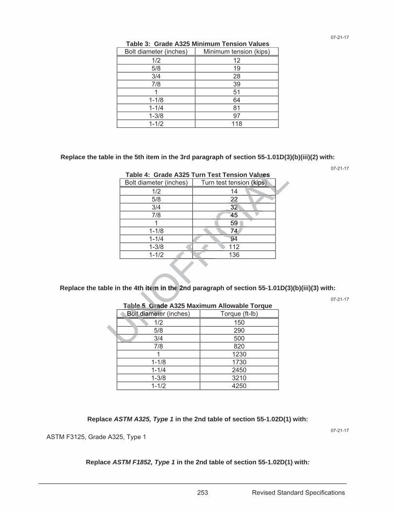
253 Revised Standard Specifications
07-21-17 Table 3: Grade A325 Minimum Tension Values Bolt diameter (inches) Minimum tension (kips)
1/2 12 5/8 19 3/4 28 7/8 39 1 51
1-1/8 64 1-1/4 81 1-3/8 97 1-1/2 118
Replace the table in the 5th item in the 3rd paragraph of section 55-1.01D(3)(b)(iii)(2) with: 07-21-17
Table 4: Grade A325 Turn Test Tension Values Bolt diameter (inches) Turn test tension (kips)
1/2 14 5/8 22 3/4 32 7/8 45 1 59
1-1/8 74 1-1/4 94 1-3/8 112 1-1/2 136
Replace the table in the 4th item in the 2nd paragraph of section 55-1.01D(3)(b)(iii)(3) with: 07-21-17
Table 5 Grade A325 Maximum Allowable Torque Bolt diameter (inches) Torque (ft-lb)
1/2 150 5/8 290 3/4 500 7/8 820 1 1230
1-1/8 1730 1-1/4 2450 1-3/8 3210 1-1/2 4250
Replace ASTM A325, Type 1 in the 2nd table of section 55-1.02D(1) with: 07-21-17
ASTM F3125, Grade A325, Type 1
Replace ASTM F1852, Type 1 in the 2nd table of section 55-1.02D(1) with:
UNOFFICIA
Lalues luen (kips) n (kips)
ALLALALLL22 22 ALLL32 32 IA45 4
CIA59 CI74 74 IC9494
FICFFFFICFFFFFFFFFFFFFh item in the 2ndh item in the 2
Table 5 Grade ATable 5 GradBolt diameteBolt diameteNUUUNUNUUUNUUUUU
254 Revised Standard Specifications
07-21-17 ASTM F3125, Grade F1852, Type 1
Replace Certification in the 5th paragraph of section 55-5.01C(1) with: 04-20-18
Test Reports
^^^^^^^^^^^^^^^^^^^^^^^^^^^^^^^^^^^^^^^^
56 OVERHEAD SIGN STRUCTURES, STANDARDS, AND POLES 04-20-18
Replace section 56-1.01 with: 07-15-16
56-1.01 GENERAL
56-1.01A Summary
Section 56-1 includes general specifications for constructing overhead sign structures, standards, and poles.
56-1.01B Definitions
Reserved
56-1.01C Submittals
Reserved
56-1.01D Quality Assurance
56-1.01D(1) General
Reserved
56-1.01D(2) Quality Control
56-1.01D(2)(a) General
Reserved
56-1.01D(2)(b) Nondestructive Testing
56-1.01D(2)(b)(i) General
Perform NDT of steel members under AWS D1.1 and the requirements shown in the following table:
UNOFFICIA
Lerhead sign structrhead sign struc
trol ol
ral
uctt
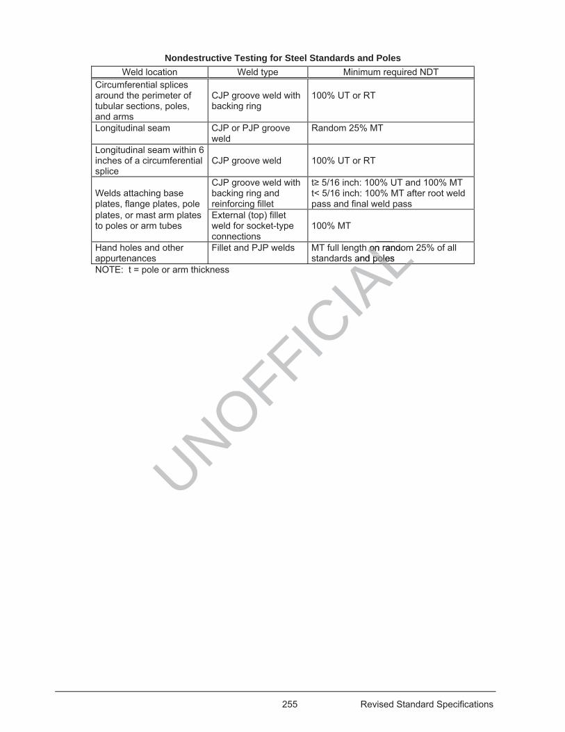
255 Revised Standard Specifications
Nondestructive Testing for Steel Standards and Poles Weld location Weld type Minimum required NDT
Circumferential splices around the perimeter of tubular sections, poles, and arms
CJP groove weld with backing ring
100% UT or RT
Longitudinal seam CJP or PJP groove weld
Random 25% MT
Longitudinal seam within 6 inches of a circumferential splice
CJP groove weld
100% UT or RT
Welds attaching base plates, flange plates, pole
CJP groove weld with backing ring and reinforcing fillet
t 5/16 inch: 100% UT and 100% MT t< 5/16 inch: 100% MT after root weld pass and final weld pass
plates, or mast arm plates to poles or arm tubes
External (top) fillet weld for socket-type connections
100% MT
Hand holes and other appurtenances
Fillet and PJP welds MT full length on random 25% of all standards and poles
NOTE: t = pole or arm thickness
UNOFFICIA
Lh on randoonand polespoleLAL
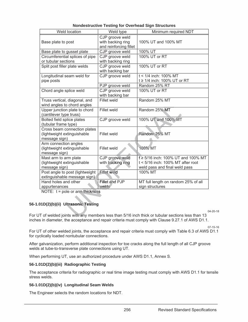
256 Revised Standard Specifications
Nondestructive Testing for Overhead Sign Structures Weld location Weld type Minimum required NDT
Base plate to post
CJP groove weld with backing ring and reinforcing fillet
100% UT and 100% MT
Base plate to gusset plate CJP groove weld 100% UTCircumferential splices of pipe or tubular sections
CJP groove weld with backing ring
100% UT or RT
Split post filler plate welds CJP groove weld with backing bar
100% UT or RT
Longitudinal seam weld for pipe posts
CJP groove weld t < 1/4 inch: 100% MT t 1/4 inch: 100% UT or RT
PJP groove weld Random 25% RT
Chord angle splice weld CJP groove weld with backing bar
100% UT or RT
Truss vertical, diagonal, and wind angles to chord angles
Fillet weld Random 25% MT
Upper junction plate to chord (cantilever type truss)
Fillet weld Random 25% MT
Bolted field splice plates (tubular frame type)
CJP groove weld 100% UT and 100% MT
Cross beam connection plates (lightweight extinguishable message sign)
Fillet weld
Random 25% MT
Arm connection angles (lightweight extinguishable message sign)
Fillet weld
100% MT
Mast arm to arm plate (lightweight extinguishable message sign)
CJP groove weld with backing ring
t 5/16 inch: 100% UT and 100% MT t < 5/16 inch: 100% MT after root weld pass and final weld pass
Post angle to post (lightweight extinguishable message sign)
Fillet weld 100% MT
Hand holes and other appurtenances
Fillet and PJP welds
MT full length on random 25% of all sign structures
NOTE: t = pole or arm thickness
56-1.01D(2)(b)(ii) Ultrasonic Testing 04-20-18
For UT of welded joints with any members less than 5/16 inch thick or tubular sections less than 13 inches in diameter, the acceptance and repair criteria must comply with Clause 9.27.1 of AWS D1.1.
07-15-16 For UT of other welded joints, the acceptance and repair criteria must comply with Table 6.3 of AWS D1.1 for cyclically loaded nontubular connections.
After galvanization, perform additional inspection for toe cracks along the full length of all CJP groove welds at tube-to-transverse plate connections using UT.
When performing UT, use an authorized procedure under AWS D1.1, Annex S.
56-1.01D(2)(b)(iii) Radiographic Testing
The acceptance criteria for radiographic or real time image testing must comply with AWS D1.1 for tensile stress welds.
56-1.01D(2)(b)(iv) Longitudinal Seam Welds
The Engineer selects the random locations for NDT.
% MT% M LUT and 100% MT and 100% MALRandom 25% MRandom 25%IAC100% M100% MCCCFICroove weld roove weld
backing ring backing ringttFIFIFIFI
n) ) Fillet weld Fillet weld
OFOFillet and anwelds welds OOONOrm thickness m thicknessNO
ltrasonic Testinltrasonic Testi
with anwith an
257 Revised Standard Specifications
Grind the cover pass smooth at the locations to be tested.
If repairs are required in a portion of a tested weld, perform NDT on the repaired portion and on 25 percent of the untested portions of the weld. If more repairs are required, perform NDT on the entire weld.
56-1.01D(3) Department Acceptance
Reserved
Replace section 56-2.01D(2)(b) with: 07-15-16
Reserved
Replace the 2nd sentence of the 1st paragraph of section 56-2.02F with: 07-15-16
Manufactured pipe posts must comply with one of the following:
Add to the list in the 1st paragraph of section 56-2.02F: 07-15-16
4. ASTM A1085, Grade A
Replace the 2nd paragraph of section 56-2.02F with: 07-15-16
You may fabricate pipe posts from structural steel complying with ASTM A36/A36M, ASTM A709/A709M, Grade 36, or ASTM A572/A572M, Grades 42 or 50.
07-15-16 Delete the last sentence in the 1st paragraph of section 56-2.02K(2).
07-15-16 Delete the 3rd paragraph of section 56-2.02K(2).
Replace the 2nd paragraph of section 56-2.02K(4) with: 07-15-16
Safety cable at walkways must not be kinked, knotted, deformed, frayed, or spliced.
Replace the 1st sentence of the paragraph in section 56-2.02K(5) with: 07-15-16
The edges of handholes and other large post and arm openings must be ground smooth.
Replace the heading of section 56-3 with: 07-15-16
56-3 STANDARDS, POLES, PEDESTALS, AND POSTS
Replace the paragraph in section 56-3.01A with:
UNOFFICIA
Lection 56-2.02F:on 56-2.02F
ph of section 56-ph of section 56
steel complying wteel complying w42 or 50. 42 or 50
sentence in the sentence in th
Delete the Delete t
eplacpla
258 Revised Standard Specifications
07-15-16 Section 56-3 includes general specifications for fabricating and installing standards, poles, pedestals, and posts.
Replace section 56-3.01B(2)(b) with: 07-15-16
Standards with handholes must comply with the following:
1. Include a UL-listed lug and 3/16-inch or larger brass or bronze bolt for attaching the bonding jumper for non-slip-base standards.
2. Attach a UL-listed lug to the bottom slip base plate with a 3/16-inch or larger brass or bronze bolt for attaching the bonding jumper for slip-base standards.
Replace the 1st sentence of the 3rd paragraph of section 56-3.01C(2)(a) with: 07-15-16
After each standard, pole, pedestal, and post is properly positioned, place mortar under the base plate.
Replace the 2nd sentence of the 4th paragraph of section 56-3.01C(2)(a) with: 07-15-16
The top of the foundation at curbs or sidewalks must be finished to curb or sidewalk grade.
Replace the 10th paragraph of section 56-3.01C(2)(a) with: 07-15-16
Except when located on a structure, construct foundations monolithically.
Replace the 13th paragraph of section 56-3.01C(2)(a) with: 07-15-16
Do not erect standards, poles, pedestals, or posts until the concrete foundation has cured for at least 7 days.
Replace the 14th paragraph in section 56-3.01C(2)(a) with: 07-15-16
The Engineer selects either the plumbing or raking technique for standards, poles, pedestals, and posts. Plumb or rake by adjusting the leveling nuts before tightening nuts. Do not use shims or similar devices. After final adjustments of both top nuts and leveling nuts on anchorage assemblies have been made and each standard, pole, pedestal, and post on the structure is properly positioned, tighten nuts as follows:
1. Tighten leveling nuts and top nuts, following a crisscross pattern, until bearing surfaces of all nuts, washers, and base plates are in firm contact.
2. Use an indelible marker to mark the top nuts and base plate with lines showing relative alignment of the nut to the base plate.
3. Tighten top nuts following a crisscross pattern: 3.1. Additional 1/6 turn for anchor bolts greater than 1-1/2 inches in diameter. 3.2. Additional 1/3 turn for other anchor bolts. 3.3. Tightening tolerance for all top nuts is ± 1/8 turn.
Replace the 1st sentence of the 4th paragraph of section 56-3.01C(2)(b) with:
e mortar unmo
f section 56-3.01section 56-3.0
nished to curb orished to curb or
ph of section 56ph of section
ruct foundations mruct foundation
e 13th paragraph3th paragrap
es, pedestals, or es, pedestals, or
Replace thReplace t
259 Revised Standard Specifications
07-15-16 If shown, use sleeve nuts on Type 1 standards.
Add to section 56-3.01C(2)(b): 07-15-16
Spiral reinforcement must be continuous above the bottom of the anchor bolts. The top termination must be either:
1. 1 -6 lap beyond the end of pitch with a 90-degree hook extending to the opposite side of the cage, or 2. 1 -6 lap beyond the end of pitch with 2 evenly spaced authorized mechanical couplers
Replace the 1st sentence of the paragraph in section 56-3.02A(4)(b) with: 07-15-16
For cast slip bases for standards and poles with shaft lengths of 15 feet or more, perform RT on 1 casting from each lot of a maximum of 50 castings under ASTM E94.
Replace the 2nd paragraph of section 56-3.02B(1) with: 07-15-16
Material for push button posts, pedestrian barricades, and guard posts must comply with ASTM A53/A53M or ASTM A500/A500M.
Add to section 56-3.02B(1): 07-15-16
Steel pipe standards and mast arms must be hot dip galvanized after manufacturing. Remove spikes from galvanized surfaces.
Replace the 2nd paragraph of section 56-3.02B(2) with: 07-15-16
HS anchor bolts, nuts, and washers must comply with section 55-1.02D(1) and the following:
1. Bolt threads must be rolled 2. Hardness of HS anchor bolts must not exceed 34 HRC when tested under ASTM F606 3. Galvanization must be by mechanical deposition 4. Nuts must be heavy-hex type 5. Each lot of nuts must be proof load tested
Replace the 8th paragraph of section 56-3.02B(2) with: 07-21-17
HS cap screws for attaching arms to standards must comply with ASTM F3125 Grade A325 or ASTM A449, and the mechanical requirements in Grade A325 after galvanizing. Coat threads of cap screws with a colored lubricant that is clean and dry to the touch. The lubricant color must contrast the zinc coating color on the cap screw such that the presence of the lubricant is visually obvious. The lubricant must be insoluble in water or the fastener components must be shipped to the job site in a sealed container.
Replace the 2nd sentence of the 9th paragraph of section 56-3.02B(2) with: 07-15-16
During manufacturing, properly locate the position of the luminaire arm on the arm plate to avoid interference with the cap screw heads.
UNOFFICIA
L.02B(1) with: .02B(1) with:
rd posts must composts must com
on 56-3.02B(1): on 56-3.02B(1):
hot dip galhot dip ga vanize
he 2nd paragrap2nd paragrap
washers must cowashers must co
be rolled rolled anchor bolts musanchor bolts must be by mecst be by me
-hex typ-hex typbe p
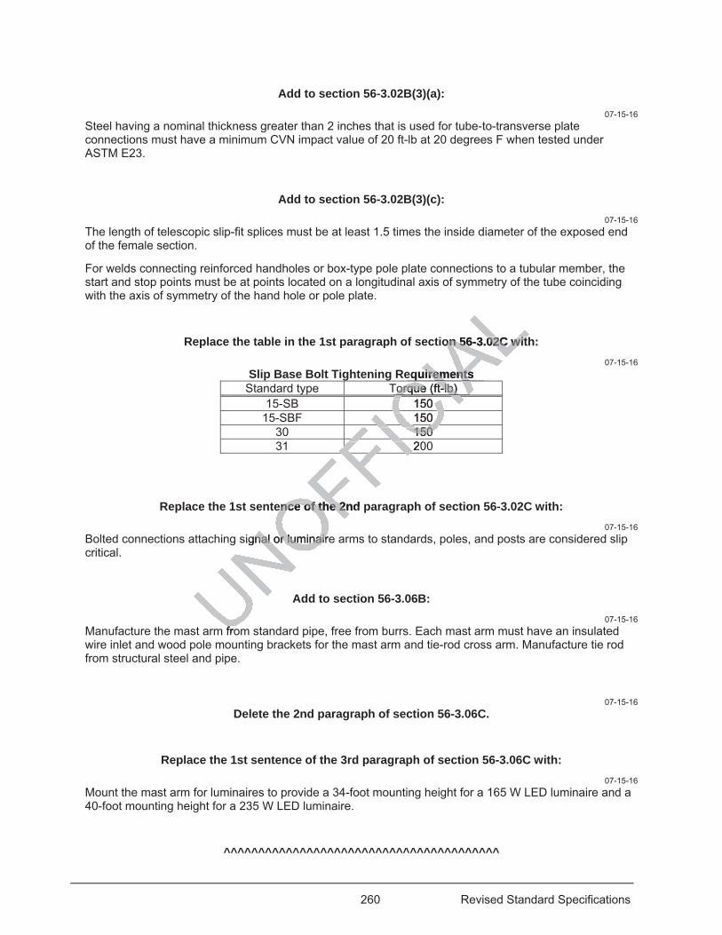
260 Revised Standard Specifications
Add to section 56-3.02B(3)(a): 07-15-16
Steel having a nominal thickness greater than 2 inches that is used for tube-to-transverse plate connections must have a minimum CVN impact value of 20 ft-lb at 20 degrees F when tested under ASTM E23.
Add to section 56-3.02B(3)(c): 07-15-16
The length of telescopic slip-fit splices must be at least 1.5 times the inside diameter of the exposed end of the female section.
For welds connecting reinforced handholes or box-type pole plate connections to a tubular member, the start and stop points must be at points located on a longitudinal axis of symmetry of the tube coinciding with the axis of symmetry of the hand hole or pole plate.
Replace the table in the 1st paragraph of section 56-3.02C with: 07-15-16
Slip Base Bolt Tightening Requirements Standard type Torque (ft-lb)
15-SB 150 15-SBF 150
30 150 31 200
Replace the 1st sentence of the 2nd paragraph of section 56-3.02C with: 07-15-16
Bolted connections attaching signal or luminaire arms to standards, poles, and posts are considered slip critical.
Add to section 56-3.06B: 07-15-16
Manufacture the mast arm from standard pipe, free from burrs. Each mast arm must have an insulated wire inlet and wood pole mounting brackets for the mast arm and tie-rod cross arm. Manufacture tie rod from structural steel and pipe.
07-15-16 Delete the 2nd paragraph of section 56-3.06C.
Replace the 1st sentence of the 3rd paragraph of section 56-3.06C with: 07-15-16
Mount the mast arm for luminaires to provide a 34-foot mounting height for a 165 W LED luminaire and a 40-foot mounting height for a 235 W LED luminaire.
^^^^^^^^^^^^^^^^^^^^^^^^^^^^^^^^^^^^^^^^
ion 56-3.02C witon 56-3.02C wit
equirements irementsTorque (ft-lb) Torque (ft-lb)
CIA150 CIACI150 C150 150 IC20FICFFFI
ence of the 2nd ence of the 2n
signal or luminairenal or luminair
frof
261 Revised Standard Specifications
58 SOUND WALLS 04-20-18
Replace 2010 CBC at each occurrence in section 58-2.01D(2)(c) with: 04-20-18
2016 CBC
Replace section 1704 in the 1st paragraph of section 58-2.01D(2)(c)(i) with: 04-20-18
section 1705
Replace section 1704.5 in the 1st paragraph of section 58-2.01D(2)(c)(ii) with: 04-20-18
section 1705.4
^^^^^^^^^^^^^^^^^^^^^^^^^^^^^^^^^^^^^^^^
59 STRUCTURAL STEEL COATINGS 04-20-18
Replace Type S in the 2nd paragraph of section 59-1.02A with: 01-15-16
Type M or Type S
Add to the list in the 2nd paragraph of section 59-1.02B: 07-15-16
5. Manufactured abrasives.
Replace Mineral and slag in the 3rd paragraph of section 59-1.02B with: 07-15-16
Mineral, manufactured, and slag
Replace the 2nd paragraph of section 59-2.01A(3)(c) with: 04-20-18
Submit the work plan after attending the prepainting meeting and include:
1. Names of the painting contractor and any subcontractors to be used. 2. 1 copy of each applicable ASTM and SSPC specification and qualification procedure. 3. Coating manufacturer's guidelines and instructions for surface preparation, painting, drying, curing,
handling, shipping, and storage of painted structural steel. Include testing methods and maximum allowable levels for soluble salts.
4. Materials, methods, and equipment to be used. 5. Proof of required SSPC-QP certifications. For work requiring SSPC-QP 1 or SSPC-QP 2 certification,
include: 5.1. List of all personnel who will perform blast cleaning or spray painting work.
UNOFFICIA
L^^^^^^^^^^^^ ^^^^^^^^^^^
TEEL COATINTEEL COAT20-18 20-18
paragraph of secparagraph of
e list in the 2nd pst in the 2nd p
s. .
ce ce Mineral anMineral
s
262 Revised Standard Specifications
5.2. Proof of CAS certifications, as required under (1) SSPC-QP 1, Mandatory Annex A and (2) the SSPC CAS Implementation Schedule in effect at the time of contract advertisement.
6. Methods to control environmental conditions. 7. Methods to protect the coating during curing, shipping, handling, and storage. 8. Rinse-water collection plan. 9. Detailed paint repair plan for damaged areas. 10. Procedures for containing blast media and water. 11. Examples of proposed daily reports for testing to be performed, including type of testing, location, lot
size, time, weather conditions, test personnel, and results.
07-15-16 Delete the 4th paragraph of section 59-2.01C(1).
Replace section 59-4.01 with: 04-20-18
59-4.01 GENERAL
Section 59-4 includes specifications for preparing and painting sign structures.
Preparing and painting of sign structures must comply with sections 59-2 and 59-3.
^^^^^^^^^^^^^^^^^^^^^^^^^^^^^^^^^^^^^^^^
60 EXISTING STRUCTURES 04-20-18
Replace section 60-3.02A with: 04-20-18
60-3.02A(1) General
60-3.02A(1) Summary
Section 60-3.02 includes specifications for (1) repairing concrete deck surfaces and (2) preparing concrete deck surfaces to receive an overlay or a deck treatment.
60-3.02A(2) Definitions
Reserved
60-3.02A(3) Submittals
Submit a work plan for chip seal removal. Include:
1. Description of equipment for chip seal removal 2. Procedure for residual chip seal removal from the deck after grinding or micro milling operations 3. Procedure for chip seal removal next to bridge rails, undulations, or drains 60-3.02A(4) Quality Assurance
Reserved
Add between the 5th and 6th paragraphs of section 60-3.02C(1): 04-20-18
Micro milling equipment must:
UNOFFICIA
Lstructures. tructures.
ons 59-2 and 59-ons 59-2 and 59
^^^^^^^^^^^^^^^^^^^^^
TING STRUCTTING STRUCT04-20-18 04-20-1
place section 60ce section 60
specifications fospecifications fos to receivreceive an ove a
ons ons
263 Revised Standard Specifications
1. Have a minimum concrete removal depth of 0.04 inch 2. Provide a surface relief of at most 0.045 inch 3. Provide a 5/32-inch grade tolerance 4. Produce consistent depth of texture in the finished surface
Micro milling equipment must have:
1. 3 or 4 riding tracks 2. Automatic grade control system with electronic averaging and 3 sensors on each side 3. Conveyer system that leaves no debris on the bridge 4. Drum that operates in an up-milling direction 5. Bullet tooth tools with polycrystalline diamond enhanced cutting tips 6. Maximum tool spacing of 0.20 inch 7. Maximum operating weight of 66,000 lb 8. Maximum track unit weight of 6,000 lb/ft 9. New tooth tools at the start of the work Produce the finished surface using 2 passes of the micro milling equipment.
Add to section 60-3.02C(1): 04-20-18
Dust must not be blown into the air while blowing the deck.
Replace the 2nd paragraph of section 60-3.02C(2) with: 04-20-18
Before removing concrete, clean the deck surface by vacuuming, then blow the deck clean with high-pressure air.
Replace the 3rd paragraph of section 60-3.02C(2) with: 04-20-18
Remove the deck surface by micro milling or high-pressure water jetting.
Replace the paragraphs in section 60-3.02C(4) with: 04-20-18
Where shown, remove bituminous chip seals, bituminous slurry seals, and polymer chip seals entirely from bridge decks by grinding or micro milling. Remove no more than 1/4 inch of concrete deck surface.
Grinding must comply with section 42-3.
Any residual chip seals and other foreign materials remaining in the bridge deck after the grinding or micro milling operation must be removed by other authorized means.
Replace the 1st paragraph of section 60-3.02C(6) with: 04-20-18
Before placing rapid setting concrete patches, abrasive blast clean the contact surfaces of existing concrete and reinforcing steel. Remove at least 1/8 inch of concrete and all foreign material. Immediately before placing new concrete, clean surfaces by vacuuming and (1) pressure jetting or (2) other authorized means to remove debris.
Replace the 2nd paragraph of section 60-3.02C(7) with:
UNOFFICIA
Lof section 60-3.of section 60-3
ace ace by vacuuminby vacuumin
e 3rd paragraph3rd paragrap
micro mo milling or hilling or h
Replace thplace th
tumintumin
264 Revised Standard Specifications
04-20-18 Perform the following activities in the order listed:
1. Abrasive blast the deck surface with steel shot. Steel shot must comply with SSPC-AB 3. Recycled steel shot must comply with SSPC-AB 2.
2. Clean the deck surface by vacuuming. 3. Blow the deck surface clean using high-pressure oil-free air.
Replace the last paragraph of section 60-3.02C(7) with: 04-20-18
If the deck surface becomes contaminated or you allow traffic on the clean deck before placing the deck treatment or overlay, abrasive blast clean the contaminated area, clean the deck by vacuuming, and blow the deck surface clean using high-pressure oil-free air.
Replace the 1st paragraph of section 60-3.03B(1)(c) with: 04-20-18
Submit a work plan for applying the methacrylate resin treatment. Include in the plan:
1. Schedule of work for the test area and for each bridge 2. Procedure for storing and handling resin components and absorbent material 3. Description of equipment for applying resin 4. Range of gel time and final cure time for resin 5. Description of absorbent material to be used 6. Description of equipment for applying and removing excess sand and absorbent material 7. Procedure for removing resin from the deck and equipment to be used 8. Procedure for avoiding spills or discharges of methacrylate, including materials and equipment 9. Procedure for cleaning up spills or discharges of methacrylate, including materials and equipment 10. Procedure for preventing resin from dripping from the structures 11. Procedure for disposing of excess resin and containers
Replace the 4th paragraph of section 60-3.03B(1)(d) with: 04-20-18
The Engineer performs friction testing of the treated test area under California Test 342. After completion of the test area, allow 10 days for the Engineer to perform the testing.
Replace the table in the 2nd paragraph of section 60-3.03B(2) with: UNOFFICIA
Lc) w
ude in the plan: n the plan:
absorbent materiabsorbent materia
ving excess sand ing excess sandnd equipment to bnd equipment to
off methacrylate, methacrylateffarges ofarges of methacry mff
ripping from the spping from theesin and containen and contain
e the 4th paragrhe 4th paragr
friction testing of iction testing ofw 10 days for the w 10 days for th
the
265 Revised Standard Specifications
04-20-18 Quality characteristic Test method Requirement
Volatile contenta (max, %) ASTM D2369 30 Viscositya (max, cP, Brookfield RV with UL adaptor , 50 RPM, at 25 °C)
ASTM D2196
25
Specific gravitya (min, at 25 °C) ASTM D1475 0.90 Flash pointa (min, °C) ASTM D3278 82 Vapor pressurea (max, mm Hg, at 25 °C) ASTM D323 1.0 Tack-free time (max, minutes) except
Sample 50 ± 5g Test 2 ± 0.05g in 55 ± 5 mm diameter disposable aluminum weighing dish
ASTM C679 400
PCC-saturated surface-dry bond strength (min, psi, at 24 hours and 70 ± 2 °F)
California Test 551 500
aPerform test before adding the initiator.
Replace the 9th paragraph of section 60-3.03B(3) with: 04-20-18
Traffic or equipment is not allowed on the treated surface until you have verified that the following requirements have been met and the opening of the treated surface to traffic and equipment is authorized:
1. Treated deck surface is tack free and not oily 2. Sand cover adheres and resists brushing by hand 3. Excess sand and absorbent material has been removed 4. No material will be tracked beyond the limits of treatment by traffic
Replace the 1st paragraph of section 60-3.04B(1)(c) with: 04-20-18
Submit a work plan for the placement of the deck overlay. Include the following in the work plan:
1. Schedule of overlay work for each bridge and a schedule of work for any trial overlays 2. Method for storage and handling of methacrylate resin and polyester concrete components 3. Description of equipment for applying methacrylate resin 4. Description of equipment for measuring, mixing, placing, and finishing the polyester concrete overlay 5. Method for isolating expansion joints and drainage 6. Cure time for polyester concrete 7. Description of equipment for applying sand 8. Method for avoiding spills or discharges of methacrylate and polyester concrete, including materials
and equipment 9. Method for cleaning up spills or discharge of methacrylate and polyester concrete, including materials
and equipment 10. Procedure for preventing resin from dripping from the structures 11. Method for disposal of excess methacrylate resin, polyester concrete, and containers
Replace the 3rd paragraph of section 60-3.04B(1)(c) with: 04-20-18
Submit test samples of methacrylate resins, polyester resins, and aggregates with a certificate of compliance and manufacturer's test results at least 15 days before use.
Replace the 4th paragraph of section 60-3.04B(1)(d) with:
UNOFFICIA
L3B(3) with: (3) w
u have verified thu have verified thurface to traffic anace to traff
d removed removed
s of treatment by of treatment b
st paragraph of sst paragrap
emment of the deckent of the de
ork for each bridgerk for each bridgand handling of mnd handling of m
uipment for applyient for apquipment for mequipment for me
ng expansiong expansier coner con
266 Revised Standard Specifications
04-20-18 The Engineer performs friction testing of the trial overlay under California Test 342. After completion of the trial overlay, allow 10 days for the Engineer to perform the testing.
Add to the section 60-3.04B(1)(d): 04-20-18
Place polyester concrete overlay on:
1. Portland cement concrete no sooner than 28 days after concrete placement 2. Portland cement based RSC no sooner than 14 days after concrete placement and your test results
for prequalification of RSC show that the concrete attained at least 3,500 psi compressive strength 3. RSC using hydraulic cement other than portland cement no sooner than 3 days after concrete
placement and your test results for prequalification of RSC show that the concrete attained at least 3,500 psi compressive strength
4. Magnesium phosphate based rapid setting concrete patch material no sooner than 3 days after final set
5. Modified high alumina based rapid setting concrete patch material no sooner than 30 minutes after final set
Replace the 3rd paragraph of section 60-3.04B(3)(b) with: 04-20-18
Clean the deck by vacuuming, then blow the deck clean with high-pressure oil-free air. Dust must not be blown into the air while blowing the deck.
04-20-18 Delete the 6th paragraph of section 60-3.04B(3)(b).
Replace the 3rd paragraph of section 60-3.04B(3)(c) with: 04-20-18
Finishing equipment for polyester concrete must:
1. Have grade control capabilities resulting in a roadway surface that meets the smoothness requirements of section 51-1.01D(3)(b)(ii) and is capable of adjusting for a variable thickness overlay along and across the existing deck surface. The use of fixed height skid-supported strike off equipment is not allowed.
2. Be used to consolidate the polyester concrete. 3. Have a 12-foot minimum paving width. 4. Be self-propelled and equipped with automatic screed controls and sensing devices that control the
thickness, longitudinal grade, and transverse screed slope. Advancing the finishing equipment with winches or a pulling device is not allowed.
07-15-16 Delete the 2nd sentence in the 11th paragraph of section 60-3.04B(3)(c).
Replace the 4th paragraph of section 60-4.02C(1) with: 04-20-18
Clean prepared areas of dust and loose and deleterious materials by vacuuming, abrasive blast cleaning, and using high-pressure oil-free air. Re-blast contaminated areas before starting concrete placement activities. Dust must not be blown into the air while blowing the deck.
UNOFFICIA
Looner
60-3.04B(3)(b) w0-3.04B(3)(b) w
with high-pressurth high-pressu
aragraph of sectaragraph of
e 3rd paragraph 3rd paragraph
ester concrete muconcrete mu
capabilities resultapabilities resulection 51-1.01D(n 51-1.01
s the existing des the existing dellowed. llowed.
te thete the
267 Revised Standard Specifications
Replace the 1st paragraph of section 60-4.02C(2) with: 04-20-18
Abrasive-blast clean concrete surfaces to be refinished. Clean blast-cleaned surfaces by vacuuming, then blow them clean using high-pressure oil-free air. Dust must not be blown into the air while blowing the deck.
Replace the paragraphs in section 60-4.02C(3) with: 04-20-18
Blow surfaces to be refinished with high-pressure oil-free air immediately before placing rapid setting concrete. Abrasive-blast clean concrete surfaces that are contaminated before the concrete is placed.
Allow traffic on new concrete under the manufacturer’s instructions and when authorized.
Replace the 3rd paragraph of section 60-4.03C(5) with: 04-20-18
Allow traffic on new concrete under the manufacturer’s instructions and when authorized.
Replace clause 3.13.2 in item 2 in the list in the 1st paragraph of section 60-4.06A(4) with: 04-20-18
clause 3.13.2(2)
Replace Suffix B in the 3rd paragraph of section 60-4.06B(1) with:
Suffix D
^^^^^^^^^^^^^^^^^^^^^^^^^^^^^^^^^^^^^^^^^^^^^^^^^^^^^^^^^^^^
DIVISION VII DRAINAGE FACILITIES 64 PLASTIC PIPE
07-15-16 Replace Reserved in section 64-3 with:
07-15-16 64-3.01 GENERAL
64-3.01A Summary
Section 64-3 includes specifications for constructing slotted plastic pipe.
Slotted plastic pipe includes structure excavation, concrete backfill, connecting new pipe to new or existing facilities, concrete collars, reinforcement, and other connecting devices.
64-3.01B Definitions
Reserved
64-3.01C Submittals
If an or equal slotted plastic pipe is being considered, it must be submitted 30 days before installation for approval.
UNOFFICIA
LC(5) with: (5)
and when authornd when author
st paragraph of st paragraph of s
3rd paragraph o3rd paragrap
^^^^^^^^^^^^^^^^^^^^^^^^
DIVISIONIVISIO
268 Revised Standard Specifications
If RSC is used for concrete backfill for slotted plastic pipe, submit the concrete mix design and test data from an authorized laboratory 10 days before excavating the pipe trench. The laboratory must specify the cure time required for the concrete mix to attain 2,000 psi compressive strength when tested under California Test 521.
Heel-resistant grates if specified must be submitted 30 days before installation for approval. Anchorage details must be included in the submittal.
64-3.01D Quality Assurance
Reserved
64-3.02 MATERIALS
64-3.02A General
Not Used
64-3.02B Slotted Plastic Pipes
Slotted plastic pipe must be one of the following or equal:
Slotted Plastic Pipe 12" diameter 18" diameter Zurn Z888-12 Zurn Z888-18
ACO Qmax 350 ACO Qmax 365 ADS Duraslot-12 ADS Duraslot-18
64-3.02C Concrete Backfill
Concrete for concrete backfill for slotted plastic pipe must comply with the specifications for minor concrete. You may use RSC instead of minor concrete for concrete backfill.
If RSC is used for concrete backfill, the RSC must:
1. Contain at least 590 pounds of cementitious material per cubic yard 2. Comply with section 90-3.02A, except section 90-1 does not apply 3. Comply with section 90-2 64-3.02D Heel-Resistant Grates
Heel-resistant grate must:
1. Be designed to carry traffic loadings 2. Comply with ADA requirements 3. Be constructed of steel or cast iron 4. Be provided by the same manufacturer of the slotted plastic pipe 5. Comply with the manufacturer's instructions 64-3.02E Bar Reinforcement
Bar reinforcement must comply with ASTM A615/A615M, Grade 60 or ASTM A706/A706M, Grade 60.
64-3.02F Miscellaneous Metal
Ductile iron, nuts, bolts, and washers must comply with section 75.
64-3.02G Grout
Grout must be non-shrink grout complying with ASTM C1107/C1107M.
64-3.02H Curing Compound
Non-pigmented curing compound must comply with ASTM C309, Type 1, Class B.
UNOA, OFFICIA
Lameter meter ALLLn Z888-18 n Z888-18 ALCO Qmax 365 O Qmax 36IAADS Duraslot-18ADS Duraslot-1
CIACIpipe must complypipe must comp
r concrete for conr concrete
RSC must: C must:
cementitious mateementitious mexcept section xcept section
t Grates Grates
must:
rry traffic loarry traffic lquiremquirem
o

269 Revised Standard Specifications
64-3.02I End Caps
End cap must:
1. Be provided by the same manufacturer of the slotted plastic pipe 2. Prevent concrete backfill from entering the pipe
64-3.03 CONSTRUCTION
64-3.03A General
Cover the grate slots with heavy-duty tape or other authorized covering during paving and concrete backfilling activities to prevent material from entering the slots.
64-3.03B Preparation
Pave adjacent traffic lanes before installing slotted plastic pipes.
Excavation must comply with section 19-3.
64-3.03C Installation
Lay and join slotted plastic pipes under the pipe manufacturer’s instructions.
Lay pipes to line and grade with sections closely jointed and adequately secured to prevent separation during placement of the concrete backfill. If the pipes do not have a positive interlocking mechanism like a slot and tongue connection, secure the sections together with nuts, bolts, and washers before backfilling.
The top of slotted plastic pipes must not extend above the completed surface. Position the pipes so that the concrete backfill is flush with the surrounding grade and above the top of the grate from 1/8 to 1/4 inch.
Place channels with the male and female ends facing each other.
Place lateral support bar reinforcement on both sides of the grate slots. The support bar reinforcement must run the full length of the slots.
Anchor heel-resistant grates to the concrete backfill under the manufacturer’s instructions.
64-3.03D Concrete Backfill
Wherever minor concrete is used for concrete backfill for slotted plastic pipe, do not allow traffic on top of the backfill within 7 days of placement.
Wherever RSC is used for concrete backfill for slotted plastic pipe, do not allow traffic on top of the backfill before the required cure time of 2,000 psi is achieved.
Place concrete backfill where shown.
Consolidate the concrete backfill with high-frequency internal vibrators.
Texture the concrete backfill surface with a broom or burlap drag to produce a durable skid-resistant surface.
Apply a non-pigmented curing compound to the exposed concrete backfill surface whenever the atmospheric temperature is 90 degrees F or greater after placement.
64-3.03E Transition Fittings
Use transition fittings to connect slotted plastic pipes to drainage inlets. The transition fittings must be supplied by the same pipe manufacturer.
Where welds are required in transition fittings, welds must comply with the pipe manufacturer’s instructions. The completed welds must not have visible pinholes.Fill the gaps around the pipes in the inlet structure wall with non-shrink grout where the pipes connect to an existing drainage structure. Install the grout under the pipe manufacturer's instructions.
UNOFFICIA
Lctions. s
uately secured toely secured tove a positive intee a positive inte
h nuts, bolts, andh nuts, bolts, a
he completed surcompleted surde and above thee and above th
s facing each othes facing each othe
n both sides both sides of theof t
concrete oncrete backfill backfil
s used for concreused for cons of placement. of placement.
ed for concrete ed for concretere time of 2re time of
ere
270 Revised Standard Specifications
Cut the pipes as shown after the grout used to seal the transition fitting has cured for at least 24 hours.
64-3.04 PAYMENT
Slotted plastic pipe is measured along the centerline of the pipe and parallel with the slope line. If the pipe is cut to fit a structure or slope, the payment quantity is the length of pipe necessary to be placed before cutting, measured in 2-foot increments.
^^^^^^^^^^^^^^^^^^^^^^^^^^^^^^^^^^^^^^^^
68 SUBSURFACE DRAINS 07-21-17
Replace the 1st sentence in the 12th paragraph of section 68-4.03 with: 07-21-17
Place Type G pavement markers with retroreflective face facing away from the oncoming traffic under section 81-3.02C on paved shoulders or dikes at outlet, vent, and cleanout locations where authorized.
^^^^^^^^^^^^^^^^^^^^^^^^^^^^^^^^^^^^^^^^
70 MISCELLANEOUS DRAINAGE FACILITIES 04-20-18
Replace section 70-6 with: 04-20-18
70-6 GRATED LINE DRAINS
70-6.01 GENERAL
70-6.01A Summary
Section 70-6 includes specifications for installing grated line drains.
Use only 1 type of grated line drain.
70-6.01B Definitions
Reserved
70-6.01C Submittals
Submit the following:
1. Certificate of compliance for the grated line drains from the manufacturer 2. Documentation of the channel discharge capacity 3. Inspection report of the completed grated line drain 70-6.01D Quality Assurance
Reserved
70-6.02 MATERIALS
70-6.02A General
Grated line drain must be on the Authorized Material List for grated line drains and must have (1) a channel discharge capacity equal to or greater than the capacity shown and (2) the minimum slope shown.
UNOFFICIA
Lthe o
ut locationt lo
^^^^^^^^^^^ ^^^^^^^^^^^
RAINAGE FACNAGE FAC20-18 20-18
section 70-6 withection 70-6 w
GRATED LINE GRATED LI
cations for installinons for installi
line drain. line drain.
s s
271 Revised Standard Specifications
Line drain sections must be either non-sloped uniform depth sections from 4-7/16 to 12 inches or pre-sloped sections with a minimum continuous 0.6 percent slope with graduated depths from 4-7/16 to 12 inches.
Concrete backfill must comply with the specifications for minor concrete.
In freeze-thaw areas, add an air entraining admixture at a rate to achieve an air content of 4 ± 1.5 percent in the freshly mixed concrete.
Reinforcing bars must be Grade 60 and comply with section 52. Mechanical splice couplers must be commercial-quality double-sleeve type with friction locking screws for use with Grade 60 steel.
70-6.02B Line Drain Channel
Line drain channel may be monolithic polymer concrete, fiberglass, high density polyethylene, or cast-in-place using expanded polystyrene form. End caps must be provided by the line drain manufacturer.
Drain channel sections must not have side extensions. The interior surface of the line drain channel must be smooth below the level of the frame, grate, and associated connections.
70-6.02C Line Drain Frames and Grates
Grated line drain frames and grates must comply with section 75-2 except grates must be ductile iron. Frames and grates include bolts, nuts, frame anchors, connector cover and other connecting hardware. Steel frame must be galvanized under section 75-1.
Frames and grates must comply with AASHTO M306 and be classified heavy duty traffic rated with a transverse proof-load strength of 25,000 pounds.
Frames and grates must be anchored into the body of the line drain or concrete backfill. Grates must be non-removable.
Steel anchoring rods and shear studs, if used, must comply with ASTM A1044.
Steel cover plate must comply with ASTM A36 and be galvanized under section 75-1.02B. Except for grates installed within designated pedestrian paths of travel, grate design must accept inflow of runoff through openings consisting of a minimum of 60 percent of the total top surface area of the grate. Individual openings or slots must have a dimension not greater than 2 inches measured in the direction of the grated line drain flow line.
Grates installed within designated pedestrian paths of travel must be certified as conforming to the provisions of the ADA.
70-6.03 CONSTRUCTION
Excavation and backfill must comply with section 19-3.
Grated line drains must be installed in trenches excavated to the lines and grades established by the Engineer. Grade and prepare the bottom of the trench to provide a firm and uniform bearing throughout the entire length of the grated line drain.
Installation of grated line drains and joints must comply with the manufacturer's instructions.
Install grated line drains with sections closely jointed and secured such that no separation of the line drains occur during backfilling.
The frame or grate must not extend above the level of the surrounding concrete backfill.
Connect grated line drains to new or existing drainage facilities as shown. Drill and bond dowels must comply with section 51-1.03E(5).
Place concrete backfill in the trench as shown. Place against undisturbed material at the sides and bottom of the trench in a manner that prevents (1) floating or shifting of the grated line drain and (2) voids or segregation in the concrete.
UNOFFICIA
Lxcept gratxcept grates muses musover and other coer and other co
e classified heavye classified hea
of tof the line drain ohe line drain o
, must comply wit, must comply wi
M A36 and A36 and be galve gaestrian paths of estrian path tr
nimum of 60 percimum of 60 pehave a dimensiove a dimensio
signated pedestriagnated pedes
CTION CTI
must comust co
272 Revised Standard Specifications
Immediately remove foreign material that falls into the trench before or during concrete placement. Prevent material from entering the grated line drain during construction.
Where necessary, construct and compact earth plugs at the ends of the concrete backfill to contain the concrete within the trench.
Place a 1/2-inch isolation joint where grated line drain is placed in PCC pavement. Isolation joint must comply with section 40-1.
Contraction and expansion joints must comply with section 73-2.
Secure frame and grate or line drain wall to the surrounding concrete backfill with steel anchoring rods as shown. Alternative securing methods must provide a minimum pullout resistance of 685 lb/ft of length of grated line drain frame.
Concrete backfill must be finished flush with the adjacent surfacing.
The surface of the concrete must be textured with a broom or burlap drag to produce a durable skid-resistant surface.
Remove all forming material from the cast-in-place drain channel without gouging or marring the surface. Patch spalls, holes or rock pockets with mortar with a cement to sand ratio of 1 to 3 by volume.
Do not allow traffic or equipment on the concrete backfill until 7 days after placement or before the concrete has attained a strength of 2,000 psi, whichever is sooner.
70-6.04 PAYMENT
Not Used
^^^^^^^^^^^^^^^^^^^^^^^^^^^^^^^^^^^^^^^^
71 EXISTING DRAINAGE FACILITIES 07-21-17
Replace items 5 and 6 in the list in the 1st paragraph of section 71-3.01D with: 01-15-16
5. Performing postrehabilitation inspection
Add after the 4th paragraph of section 71-3.01D: 01-15-16
Record the quantity of grout that is installed and submit this quantity. The Department does not pay for grout that leaks through to the inside of the culvert. The Department does not pay for grout material that is wasted, disposed of, or remaining on hand after the completion of the work.
Replace EDPM in the heading of section 71-3.05 with: 07-21-17
EPDM
Replace the 2nd heading in section 71-5.03 with: 01-15-16
71-5.03B Frames, Covers, Grates, and Manholes
UNOFFICIA
Lgouging ogoatio of 1 to 3 bo of 1 to 3 b
ys after placemenafter placemener. er.
^^^^^^^^^^^^^^^^^^^^^^^^^^
ISTING DRAINISTING DR0707
nd 6 in the list ind 6 in the list i
bilitation inspectiobilitation inspect
Add Add
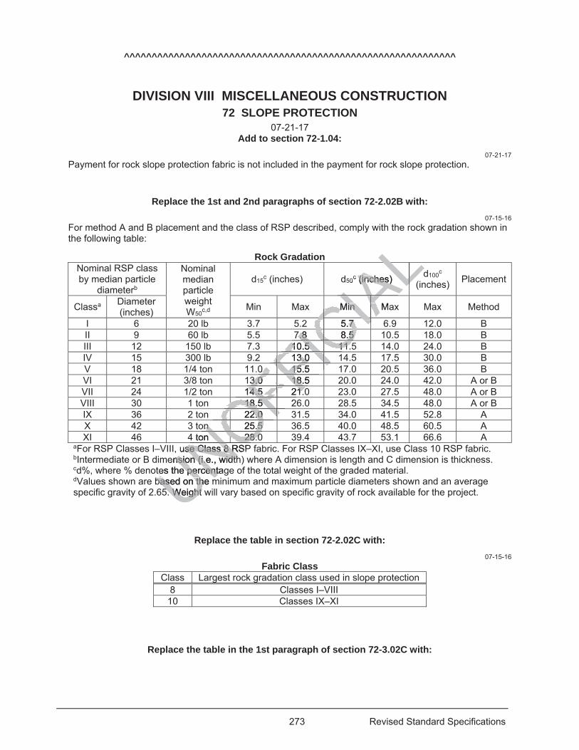
273 Revised Standard Specifications
^^^^^^^^^^^^^^^^^^^^^^^^^^^^^^^^^^^^^^^^^^^^^^^^^^^^^^^^^^^^
DIVISION VIII MISCELLANEOUS CONSTRUCTION 72 SLOPE PROTECTION
07-21-17 Add to section 72-1.04:
07-21-17 Payment for rock slope protection fabric is not included in the payment for rock slope protection.
Replace the 1st and 2nd paragraphs of section 72-2.02B with: 07-15-16
For method A and B placement and the class of RSP described, comply with the rock gradation shown in the following table:
Rock Gradation Nominal RSP class by median particle
diameterb
Nominal median particle weight W50c,d
d15c (inches) d50c (inches) d100c
(inches) Placement
Classa Diameter (inches) Min Max Min Max Max Method
I 6 20 lb 3.7 5.2 5.7 6.9 12.0 B II 9 60 lb 5.5 7.8 8.5 10.5 18.0 B III 12 150 lb 7.3 10.5 11.5 14.0 24.0 B IV 15 300 lb 9.2 13.0 14.5 17.5 30.0 B V 18 1/4 ton 11.0 15.5 17.0 20.5 36.0 B VI 21 3/8 ton 13.0 18.5 20.0 24.0 42.0 A or B VII 24 1/2 ton 14.5 21.0 23.0 27.5 48.0 A or B VIII 30 1 ton 18.5 26.0 28.5 34.5 48.0 A or B IX 36 2 ton 22.0 31.5 34.0 41.5 52.8 A X 42 3 ton 25.5 36.5 40.0 48.5 60.5 A XI 46 4 ton 28.0 39.4 43.7 53.1 66.6 A
aFor RSP Classes I–VIII, use Class 8 RSP fabric. For RSP Classes IX–XI, use Class 10 RSP fabric. bIntermediate or B dimension (i.e., width) where A dimension is length and C dimension is thickness. cd%, where % denotes the percentage of the total weight of the graded material. dValues shown are based on the minimum and maximum particle diameters shown and an average specific gravity of 2.65. Weight will vary based on specific gravity of rock available for the project.
Replace the table in section 72-2.02C with: 07-15-16
Fabric Class Class Largest rock gradation class used in slope protection
8 Classes I–VIII 10 Classes IX–XI
Replace the table in the 1st paragraph of section 72-3.02C with:
UNOuse Class 8 RSPse Class 8 Rension (i.e., widthnsion (i.e., width
tes the percentagtes the percentbased on the mbased on the mNOFFI0 15.5 0 15.5 FIC
IAL0c (inches) (inches)ALLL
Min MaMin IAIACIA2 5.7 5.7 CCIICI7.8 8.5 7.8 8.5 CCIC10.5 11.10.5 11.ICICIC13.0 113.0 FICICFICFII
FFI3.0 18.5 3.0 18FFFF14.5 21.04.5 21.FFFF
18.5 218.5
OFOF22.0 22.0 OFOFn 25.5 n 25.5 ONO4 ton 28.0 28.0
NONO5. Weight w5. Weight
NO
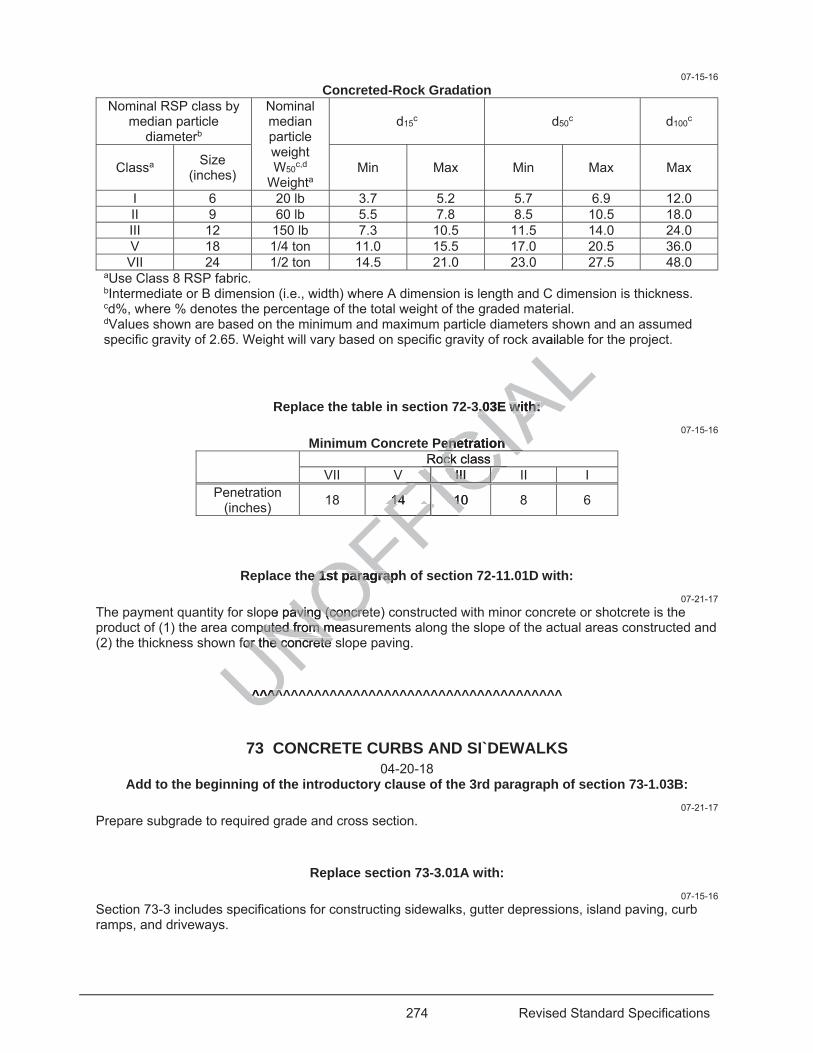
274 Revised Standard Specifications
07-15-16 Concreted-Rock Gradation
Nominal RSP class by median particle
diameterb
Nominal median particle weight W50c,d
Weighta
d15c d50c d100c
Classa Size (inches) Min Max Min Max Max
I 6 20 lb 3.7 5.2 5.7 6.9 12.0 II 9 60 lb 5.5 7.8 8.5 10.5 18.0 III 12 150 lb 7.3 10.5 11.5 14.0 24.0 V 18 1/4 ton 11.0 15.5 17.0 20.5 36.0 VII 24 1/2 ton 14.5 21.0 23.0 27.5 48.0
aUse Class 8 RSP fabric. bIntermediate or B dimension (i.e., width) where A dimension is length and C dimension is thickness. cd%, where % denotes the percentage of the total weight of the graded material. dValues shown are based on the minimum and maximum particle diameters shown and an assumed specific gravity of 2.65. Weight will vary based on specific gravity of rock available for the project.
Replace the table in section 72-3.03E with: 07-15-16
Minimum Concrete Penetration
Rock class VII V III II I
Penetration (inches) 18 14 10 8 6
Replace the 1st paragraph of section 72-11.01D with: 07-21-17
The payment quantity for slope paving (concrete) constructed with minor concrete or shotcrete is the product of (1) the area computed from measurements along the slope of the actual areas constructed and (2) the thickness shown for the concrete slope paving.
^^^^^^^^^^^^^^^^^^^^^^^^^^^^^^^^^^^^^^^^
73 CONCRETE CURBS AND SI`DEWALKS 04-20-18
Add to the beginning of the introductory clause of the 3rd paragraph of section 73-1.03B: 07-21-17
Prepare subgrade to required grade and cross section.
Replace section 73-3.01A with: 07-15-16
Section 73-3 includes specifications for constructing sidewalks, gutter depressions, island paving, curb ramps, and driveways.
UNOFFICIA
Lvaila
3.03E with: 3.03E with:
enetration enetration Rock class ock class CI
III III ICICCFICC14 10 14 10FIFIFICFICFICFICFICCFFFICF
he 1st paragraphe 1st paragrap
pe paving (caving (concreoncremputed from measputed from m
for the concrete sor the concrete
^^^^^^^^^
275 Revised Standard Specifications
Replace Not Used in section 73-3.04 with: 04-20-18
The payment quantity for minor concrete (curb ramp) does not include detectable warning surface.
Add to the end of the 1st paragraph of section 73-10.03: 07-21-17
Removal of concrete includes the removal of detectable warning surfaces.
Replace Not Used in section 73-10.04 with: 07-21-17
Detectable warning surface placed on existing concrete is paid for as a separate bid item.
^^^^^^^^^^^^^^^^^^^^^^^^^^^^^^^^^^^^^^^^
74 PUMPING EQUIPMENT AND CONTROLS 04-15-16
Replace 87-1.03K in the 4th paragraph of section 74-3.03B(2) with:04-15-16
87
^^^^^^^^^^^^^^^^^^^^^^^^^^^^^^^^^^^^^^^^
75 MISCELLANEOUS METAL 04-20-18
Replace ASTM A325, Type 1 in the row for Bolts in table in the 1st paragraph of section 75-1.02A with:
07-21-17 ASTM F3125, Grade A325, Type 1
Replace ASTM F1852, Type 1 in the row for Tension control bolts in the table in the 1st paragraph of section 75-1.02A with:
07-21-17 ASTM F3125, Grade F1852, Type 1
Replace ASTM F593 or F738M in the row for Bolts, screws, studs, threaded rods, and nonheaded anchor bolts in the table in the 1st paragraph of section 75-1.02A with:
04-20-18 ASTM F593
Replace A325 in the Material column in the table in the 1st paragraph of section 75-1.02B with:
^^^
CONTROLS ONTROLS
of section 74-3.0of section 74-3
^^^^^^^^^^^^^^^^^^^^^
5 MISCELLA5 MISCELLA0
Type 1Type 1 in the row in the ro
325, Type325, Type
276 Revised Standard Specifications
07-21-17 F3125, Grade A325
Replace A325 in the second footnote in the table in the 1st paragraph of section 75-1.02B with: 07-21-17
F3125, Grade A325
Replace compounds in the 4th paragraph of section 75-3.02B with: 04-20-18
systems
^^^^^^^^^^^^^^^^^^^^^^^^^^^^^^^^^^^^^^^^
78 INCIDENTAL CONSTRUCTION 07-21-17
Add between the 1st and 2nd paragraphs of section 78-2.01: 07-21-17
Notify the Engineer at least 7 days before you construct a survey monument or adjust a monument cover to grade. Do not disturb a survey monument without authorization.
Replace section 78-4.03 with: 07-21-17
78-4.03 PAINTING CONCRETE
78-4.03A General
78-4.03A(1) General
78-4.03A(1)(a) Summary
Section 78-4.03A includes general specifications for preparing and painting concrete surfaces.
78-4.03A(1)(b) Definitions
Reserved
78-4.03A(1)(c) Submittals
Submit the coating manufacturer's application instructions at least 7 days before use.
78-4.03A(1)(d) Quality Assurance
78-4.03A(1)(d)(i) General
Reserved
78-4.03A(1)(d)(ii) Test Panels
Reserved
78-4.03A(2) Materials
78-4.03A(2)(a) General
Coatings for concrete must be white.
UNOFFICIA
LON
s of section 78-2s of section 78-
survey msurvey onumenonumehorization. riz
section 78-4.03 section 78-4.03
des general specs general
nitions nitio
277 Revised Standard Specifications
78-4.03A(2)(b) Paint
Coatings for concrete must comply with the specifications for acrylic emulsion paint for exterior masonry.
78-4.03A(2)(c) Sealer
Reserved
78-4.03A(2)(d) Sealing Compound
Reserved
78-4.03A(3) Construction
78-4.03A(3)(a) General
Do not paint new concrete until it is at least 28 days old. Anywhere metal is adjacent to a joint, seal the joint between surfaces to be painted and the adjacent metal with a sealing compound before applying the paint.
78-4.03A(3)(b) Surface Preparation
Prepare concrete surfaces under SSPC-SP 13/NACE no. 6.
Pressure rinse the prepared surfaces before applying the coating. The surfaces must be thoroughly dry at the time of painting. You may use artificial drying methods if authorized.
78-4.03A(3)(c) Application
Apply at least 2 coats under the manufacturer's instructions and SSPC-PA 7. Protect adjacent surfaces during painting using an authorized method.
78-4.03A(4) Payment
Not Used
78-4.03B Simulated Stone Masonry and Textured Concrete
Reserved
78-4.03C–78-4.03G Reserved
Replace the paragraph of section 78-4.04A(3)(a) with: 07-21-17
Anywhere metal is adjacent to a joint, seal the joint between the surfaces to be stained and the adjacent metal with a sealing compound before applying the stain.
Replace the heading of section 78-4.04B(1)(c)(iii) with: 07-21-17
Staining Quality Work Plan
Replace an application plan in the 1st sentence in the paragraph of section 78-4.04B(1)(c)(iii) with: 07-21-17
a staining quality work plan
Replace application in the 2nd sentence in the paragraph of section 78-4.04B(1)(c)(iii) with:
UNOFFICIA
LThe surfaces mue surfaces muhorized. horized.
ions and SSPC-Pons and SSP
and Textured Coand Textu
d
Replace the peplace th
cent to acent to aoun
278 Revised Standard Specifications
07-21-17 work
Replace application plan in the 1st sentence in the paragraph of section 78-4.04B(1)(d)(iii) with: 07-21-17
staining quality work plan
^^^^^^^^^^^^^^^^^^^^^^^^^^^^^^^^^^^^^^^^
80 FENCES 04-20-18
Add to the list in the 2nd paragraph of section 80-3.02B: 04-20-18
3. Group IC, 50,000 psi yield, for round steel pipes
Add between the 2nd and 3rd paragraphs of section 80-3.02B: 04-20-18
Group IC, 50,000 psi yield, for round steel pipes may be used instead of group IA, regular grade steel round pipes of the same diameter.
Replace 3-1/4-inch-vertical and 5-1/4-inch-horizontal mesh in the 4th paragraph of section 80-3.02C with:
04-20-18 3-1/2-inch-vertical and 5-inch-horizontal mesh
Replace section 80-4 with: 07-15-16
80-4 WILDLIFE EXCLUSION FENCES
80-4.01 GENERAL
80-4.01A General
Section 80-4 includes specifications for constructing wildlife exclusion fences.
Constructing a wildlife exclusion fence includes the installation of any signs specified in the special provisions.
80-4.01B Materials
Each T post must:
1. Comply with ASTM A702 2. Be metal and have an anchor plate 3. Be painted black or galvanized 80-4.01C Construction
Not Used
80-4.01D Payment
UNOFFICIA
Ls of section 80-3of section 80-3
used instead of gsed instead of g
h-horizontal meh-horizontal me3.02C with: 3.02C w
tal mesh tal mesh
ReplaRepla
80-4 W80
279 Revised Standard Specifications
Not Used
80-4.02 DESERT TORTOISE FENCES
80-4.02A General
Section 80-4.02 includes specifications for constructing desert tortoise fences.
80-4.02B Materials
80-4.02B(1) Permanent Desert Tortoise Fences
80-4.02B(1)(a) General
Each wire tie and hog ring for a permanent desert tortoise fence must comply with section 80-2.02F.
Each hold down pin must:
1. Be U-shaped, with 2 minimum 6-inch long legs 2. Have pointed ends 3. Be at least 11-gauge wire 4 Be galvanized 5. Be commercial quality 80-4.02B(1)(b) Hardware Cloth
The hardware cloth must:
1. Comply with ASTM A740 2. Be welded or woven galvanized steel wire fabric 3. Be made of at least 14-gauge wire 4. Be 36 inches wide 80-4.02B(1)(c) Barbless Wire
The barbless wire must:
1. Comply with ASTM A641/A641M 2. Be at least 14-gauge wire 3. Have a Class 1 zinc coating 80-4.02B(1)(d) Posts
Each post must:
1. Comply with ASTM F1083 2. Be standard weight, schedule 40 steel pipe with a nominal pipe size of 1 inch 3. Be galvanized steel fence post conforming to ASTM A702 80-4.02B(2) Temporary Desert Tortoise Fences
The materials for a temporary desert tortoise fence must comply with section 80-4.02B(1), except the hardware cloth must be made of at least 16-gauge wire.
80-4.02C Construction
80-4.02C(1) General
Extend the hardware cloth a minimum of 24 inches above the ground.
Plumb the posts and pull the hardware cloth taut. Correct any alignment issues.
80-4.02C(2) Permanent Desert Tortoise Fences
UNOFFICIA
L
1M M
ting
F1083 F1083 he
280 Revised Standard Specifications
Excavate the ground to form a trench before installing the posts and hardware cloth. Embed the posts at maximum 5-foot intervals into the ground. If T posts are used, use 5-foot lengths and embed the posts to match the above-ground height shown for the posts.
Securely fasten the hardware cloth to the posts with wire ties and to barbless wire with hog rings as shown. Pass the wire ties through the hardware cloth. Encircle the posts and barbless wire with the ties and tie them by twisting a minimum of 3 complete turns.
Bend the twisted ends of the ties down to prevent possible snagging. Close hog rings with their ends overlapping.
Bury the hardware cloth a minimum of 12 inches into the ground. Install the cloth in 1 continuous piece. You may cut the cloth into shorter segments if authorized.
Overlap the hardware cloth segments at posts, with a minimum overlap of 6 inches centered at a post. Wire tie the overlapped cloth to posts as shown. Prevent fraying by threading barbless wire along the vertical edges of the hardware cloth on either side of the post or use 3 equally spaced hog rings (6 hog rings per location) along each wire cloth edge.
Where bedrock or caliche substrate is encountered, use the bent hardware cloth detail if authorized. Transitions from buried-to-bent or bent-to-buried configuration must occur at a post location with a minimum 6-inch overlap of the hardware cloth as shown. The maximum spacing for hold down pins is 24 inches on center. Anchor in place with hold down pins the beginning and end corners of the hardware cloth placed on the ground.
Backfill the removed earth material into the trench created to install the hardware cloth and posts. Use an 8 lb or heavier hand tamper to compact the backfill around the posts and hardware cloth. Install a post at each corner of the cloth segments.
If a gate must be installed, attach the hardware cloth to the gate frame such that there is contact along the entire length of the gate between the finished ground surface and the lower edge of the cloth. Install the gate under section 80-10.
80-4.02C(3) Temporary Desert Tortoise Fences
Fold the horizontal edge of the hardware cloth at a 90° angle toward the tortoise habitat area. Ensure the clearance to the ground at the bend is from 0 to 2 inches.
Where the hardware cloth overlaps, secure the bend piece with one of the following:
1. Barbless wire threaded along the width of the cloth 2. Minimum of 4 hog rings equally spaced along the edge Fasten the bent piece to the ground with hold down pins pushed completely into the ground.
When the temporary fence is no longer needed, compact soil into post holes with an 8 lb or heavier hand tamper.
80-4.02D Payment
Not Used
80-4.03–80-4.09 RESERVED
Replace length at each occurrence in section 80-10.02 with: 07-21-17
width
^^^^^^^^^^^^^^^^^^^^^^^^^^^^^^^^^^^^^^^^^^^^^^^^^^^^^^^^^^^^
UNOFFICIA
Lcloth
ur at a post lat aum spacing for hom spacing for h
g and end cornerand end corner
o install the hardwo install the hard the posts and hthe posts and h
ototh to the gate frah to the gate frad grd ground surfaceund surfac
se Fences Fences
ware cloth at a 90ware cloth at a nd is from 0 to 2 iis from 0 to 2
erlaps, secure ps, secure theth
ed along the widted along the widrings equally spas equally
to the grounto the grou
is
281 Revised Standard Specifications
DIVISION IX TRAFFIC CONTROL DEVICES 81 MISCELLANEOUS TRAFFIC CONTROL DEVICES
07-21-17 07-21-17
Delete section 81-3.02B.
Replace the 5th paragraph of section 81-3.03A with: 07-21-17
Apply pavement markers to the pavement with bituminous adhesive, flexible bituminous adhesive, standard set epoxy, or rapid set epoxy adhesive. Apply markers in pavement recesses with flexible bituminous adhesive.
Replace the 1st sentence in the 7th paragraph of section 81-3.03A with: 07-21-17
Completely cover the pavement surface where the pavement marker is to be applied or the bottom of the pavement marker with the adhesive without leaving any voids.
^^^^^^^^^^^^^^^^^^^^^^^^^^^^^^^^^^^^^^^^
83 RAILINGS AND BARRIERS 04-20-18
04-15-16 Delete to in the 4th paragraph of section 83-1.02B.
Replace the heading of section 83-2.01B with: 04-20-18
83-2.01B Minor Concrete Vegetation Control
Replace item 3 in the list in the 1st paragraph of section 83-2.02B(1)(e) with: 07-21-17
3. HS bolts must comply with ASTM F3125, Grade A325/A325M, or ASTM A449, or be fabricated from steel rods complying with ASTM A449. The bolts or rods must comply with the mechanical requirements in ASTM F3125, Grade A325/A325M after galvanizing. The nuts and washers must comply with ASTM F3125, Grade A325/A325M.
Replace the row for Bolts in the table in the 1st paragraph of section 83-2.08B with: 07-21-17
Bolts ASTM F3125, Grade A325/A325M
Replace the row for Nuts and washers for bolts and threaded rods in the table in the 1st paragraph of section 83-2.08B with:
07-21-17 Nuts for bolts and threaded rods ASTM A563/A563M Washers for bolts and threaded rods ASTM F436/F436M
UNOFFICIA
Lto be appliedbe applied
^^^^^^^^^^^^^^^^^^^^^^^^^
D BARRIERSBARRIERS20-18 20-18
paragraph of separagraph of se
the heading of sthe headin
getation Control etation Contro
tem 3 in the list im 3 in the
mply with ASmply with Awith Awith A
F
282 Revised Standard Specifications
^^^^^^^^^^^^^^^^^^^^^^^^^^^^^^^^^^^^^^^^
84 MARKINGS 04-20-18
Add to the end of item 2 in the list in the 1st paragraph of section 84-2.01C: 04-20-18
, except for thermoplastic
Add to the list in the 1st paragraph of section 84-2.01C: 07-21-17
4. Material data sheet for thermoplastic primer
Add between the 1st and 2nd paragraphs of section 84-2.01C: 04-20-18
For each lot or batch of thermoplastic, submit a manufacturer's certificate of compliance with test results for the tests specified in section 84-2.01D. The date of test must be within 1 year of use.
Add to the end of section 84-2.01D: 04-20-18
Each lot or batch of thermoplastic must be tested under California Test 423 for:
1. Brookfield Thermosel viscosity 2. Hardness 3. Yellowness index, white only 4. Daytime luminance factor 5. Yellow color, yellow only 6. Glass bead content 7. Binder content
During the installation of thermoplastic traffic stripes or markings at the job site, apply a test stripe of the thermoplastic on suitable material in the presence of the Engineer. The test stripe must be at least 1 foot in length. The test stripe will be tested for yellow color, daytime luminance factor, and yellowness index requirements.
Replace the list in the1st paragraph of section 84-2.03C(2)(a) with: 07-21-17
1. To all roadway surfaces except for asphaltic surfaces less than 6 months old 2. At a minimum rate of 1 gallon per 300 square feet 3. To allow time for the thermoplastic primer to dry and become tacky prior to application of the
thermoplastic
Replace 0.20 lb of thermoplastic per foot of 4-inch-wide solid stripe in the 2nd paragraph of section 84-2.03C(2)(b) with:
07-21-17 0.36 lb of thermoplastic per foot of 6-inch-wide solid stripe
UNOFFICIA
Lsection 84-2.01ection 84-2.01
r's certificate of cor's certificate ot must be within 1must be within 1
of section 84-2of section
tested under Calitested under
yy
n of thermoplan of thermoe materie materi
ill b
283 Revised Standard Specifications
Replace 0.13 lb of thermoplastic per foot of 4-inch-wide solid stripe in the 2nd paragraph of section 84-2.03C(2)(c) with:
07-21-17 0.24 lb of thermoplastic per foot of 6-inch-wide solid stripe
Replace 0.38 lb of thermoplastic per foot of 4-inch-wide solid stripe in the 2nd paragraph of section 84-2.03C(2)(e) with:
07-21-17 0.57 lb of thermoplastic per foot of 6-inch-wide solid stripe
Replace 4-inch-wide yellow stripes at each occurrence in section 84-2.03C(3)(a) with: 07-21-17
6-inch-wide yellow stripes
Replace 4-inch-wide yellow stripes at each occurrence in section 84-2.04 with: 07-21-17
6-inch-wide yellow stripes
Add to the beginning of section 84-8.03A: 07-15-16
Select the method and equipment for constructing ground-in indentations.
Replace the 1st paragraph of section 84-8.03A with: 07-15-16
Do not construct rumble strips:
1. On structures, approach slabs, or concrete weigh-in-motion slabs 2. At intersections 3. Bordering two-way left turn lanes, driveways, or other high-volume turning areas 4. Within 6 inches of any concrete pavement joint
Add between the 2nd and 3rd paragraphs of section 84-8.03A: 07-15-16
Modify rumble strip spacing to avoid locating a groove on a concrete pavement joint.
Replace the 3rd paragraph of section 84-8.03A with: 07-15-16
Indentations must comply with the dimensions shown and not vary more than:
1. 10 percent in length 2. 0.06 inch in depth 3. 10 percent in width 4. 1 inch in center-to-center spacing between rumble strips
UNOFFICIA
Lnce in section 8in section 8
ing of section 84ng of section 84
ucting ground-in ucting grou
the 1st paragrape 1st paragra
s:
oach slabs, or conach slabs, or co
ay left turn lanesay left turn laneany concreany concr
284 Revised Standard Specifications
Add to the end of section 84-8.03A: 07-15-16
The noise level created by the combined grinding activities must not exceed 86 dBA when measured at a distance of 50 feet at right angles to the direction of travel.
Break rumble strips before and after intersections, driveways, railroad crossings, freeway gore areas, and freeway ramps. Place breaks and break distances as shown. You may adjust breaks and the break distances as needed at low-volume driveways or other locations if authorized.
07-15-16 Delete new in the 1st paragraph of section 84-8.03B.
07-15-16 Add to the end of section 84-8.03B:
Remove grinding residue under section 13-4.03E(7).
Replace the 1st paragraph of section 84-8.03C with: 07-15-16
Construct rumble strips in the top layer of HMA and asphalt concrete surfacing by the ground-in method.
Add between the 2nd and 3rd paragraphs of section 84-8.03C: 07-15-16
Dispose of the removed material.
07-15-16 Delete the 2nd paragraph of section 84-8.03C.
Replace 37-2 in the 3rd paragraph of section 84-8.03C with: 07-15-16
37-4.02
Replace section 84-8.04 with: 07-15-16
The payment quantity for any type of rumble strip is the length measured by the station along the length of the rumble strip without deductions for gaps between indentations.
Replace the 2nd paragraph of section 84-9.03B with: 04-15-16
Completely remove traffic stripes and pavement markings, including any paint in the gaps, by methods that do not remove pavement to a depth of more than 1/8 inch.
Add between the 2nd and 3rd paragraphs of section 84-9.03B:
UNOFFICIA
L4-8.03C with: 8.03C with:
concrete surfacingoncrete surfa
paragraphs of sparagraphs of s
the 2nd paragrathe 2nd parag
ace ce 37-237-2 in the 3 in th22
285 Revised Standard Specifications
04-15-16 Submit your proposed method for removing traffic stripes and pavement markings at least 7 days before starting the removal work. Allow 2 business days for the review.
Remove pavement marking such that the old message cannot be identified. Make any area removed by grinding rectangular. Water must not puddle in the ground areas. Fog seal ground areas on asphalt concrete pavement.
04-15-16 Delete materially in the 1st paragraph of section 84-9.03D.
Replace the list in the 1st paragraph of section 84-9.04 with: 07-21-17
1. 1.34 for a single 8-inch-wide traffic stripe 2. 2 for a double traffic stripe 3. 3 for a triple traffic stripe
^^^^^^^^^^^^^^^^^^^^^^^^^^^^^^^^^^^^^^^^^^^^^^^^^^^^^^^^^^^^
DIVISION X ELECTRICAL WORK Replace section 86 with:
04-15-16
86 GENERAL 04-20-18
86-1.01 GENERAL
86-1.01A Summary
Section 86 includes general specifications for furnishing electrical equipment and materials.
Electrical equipment and materials must comply with part 4 of the California MUTCD and 8 CA Code of Regs, chapter 4, subchapter 5, "Electrical Safety Orders."
Galvanized equipment and materials must comply with section 75-1.02B.
86-1.01B Definitions
accessible pedestrian signal: Accessible pedestrian signal as defined in the California MUTCD.
accessible walk indication: Activated audible and vibrotactile action during the walk interval.
actuation: Actuation as defined in the California MUTCD.
ambient sound level: Background sound level in dB at a given location.
ambient sound sensing microphone: Microphone that measures the ambient sound level in dB and automatically adjusts the accessible pedestrian signal speaker's volume.
audible speech walk message: Audible prerecorded message that communicates to pedestrians which street has the walk interval.
channel: Discrete information path.
CALiPER: Commercially Available LED Product Evaluation and Reporting. A U.S. Department of Energy program that individually tests and provides unbiased information on the performance of commercially available LED luminaires and lights.
UNOFFICIA
L^^^^^^^^^^^^^^^^^^^^^^^^
TRICAL WORICAL WOction 86 with: ction 86 with:
6 GENERAL 6 GENERAL 04-20-18 04-20-1
ecifications for cifications for fuf
materials must coaterials must apter 5, "Electricapter 5, "Electrica
nt and materialsnt and materials
286 Revised Standard Specifications
controller assembly: Assembly for controlling a system's operations, consisting of a controller unit and auxiliary equipment housed in a waterproof cabinet.
controller unit: Part of the controller assembly performing the basic timing and logic functions.
correlated color temperature: Absolute temperature in kelvin of a blackbody whose chromaticity most nearly resembles that of the light source.
detector: Detector as defined in the California MUTCD.
electrolier: Assembly of a lighting standard and luminaire.
07-21-17 fastening hardware [ICF1]: Bolts, nuts, washer, fasteners, hex nuts, lock nuts, or other metal
components to secure or lock down a device or equipment.
04-15-16 flasher: Device for opening and closing signal circuits at a repetitive rate.
flashing beacon control assembly: Assembly of switches, circuit breakers, terminal blocks, flasher, wiring, and other necessary electrical components housed in a single enclosure for operating a beacon.
house side lumens: Lumens from a luminaire directed to light up areas between the fixture and the pole, such as sidewalks at intersection or areas off the shoulders on freeways.
illuminance gradient: Ratio of the minimum illuminance on a 1-foot square of sign panel to that on an adjacent 1-foot square of sign panel.
inductive loop detector: Detector capable of being actuated by an inductance change caused by a vehicle passing or standing over the loop. An inductive loop detector includes a loop or group of loops installed in the roadway and a lead-in cable installed and connected inside a controller cabinet.
junction temperature: Temperature of the electronic junction of the LED device. The junction temperature is critical in determining photometric performance, estimating operational life, and preventing catastrophic failure of the LED.
L70: Extrapolated life in hours of the luminaire when the luminous output depreciates 30 percent from the initial values.
lighting standard: Pole and mast arm supporting the luminaire. 04-20-18
link: Part of a system which provides a data connection between a transmitter and receiver.
04-15-16 LM-79: Test method from the Illumination Engineering Society of North America specifying the test
conditions, measurements, and report format for testing solid state lighting devices, including LED luminaires.
LM-80: Test method from the Illumination Engineering Society of North America specifying the test conditions, measurements, and report format for testing and estimating the long-term performance of LEDs for general lighting purposes.
luminaire: Assembly that houses the light source and controls the light emitted from the light source. 04-20-18
mid-span access method: Procedure in which fibers from a single buffer tube are accessed and spliced to a multi buffer tube cable without cutting the unused fibers in the buffer tube, or disturbing the remaining buffer tubes in the cable.
04-15-16 National Voluntary Laboratory Accreditation Program: U.S. Department of Energy program that
accredits independent testing laboratories.
UNOFFICIA
Lnclosu
reas between theeas between then freeways. eways.
a 1-foot square offoot squar
ctuatedctuated by an ind by an inducductive loop detetive loop dete
nstalled and connnstalled and c
electronic junctielectronic j onphotometric perfohotometric per
e LED. e LED.
he luminaire whenluminaire whe
d mast arm suppod mast arm suppo
which provides ah provide
m the Illum the Illentst
287 Revised Standard Specifications
04-20-18 optical time domain reflectometer (OTDR): Fiber optic test equipment that is used to measure the total
amount of power loss between two points and over the corresponding distance. It provides a visual and printed display of the relative location of system components such as fiber sections, splices and connectors as well as the losses that are attributed to each component and or defects in the fiber.
07-21-17 pedestrian change interval: Pedestrian change interval as defined in the California MUTCD.
04-15-16 powder coating: Coating applied electrostatically using exterior-grade, UV-stable, polymer powder.
power factor: Ratio of the real power component to the complex power component.
04-20-18 power meter: A portable fiber optic test equipment that, when coupled with a light source, is used to
perform end-to-end attenuation testing. Its display indicates the amount of power injected by the light source at the designed wavelength of the system under testing that arrives at the receiving end of the link.
04-15-16 pretimed controller assembly: Assembly operating traffic signals under a predetermined cycle length.
programming mechanism: Device to program the accessible pedestrian signal operation.
pull box: Box with a cover that is installed in an accessible place in a conduit run to facilitate the pulling in of wires or cables.
push button information message: Push button information message as defined in the California MUTCD.
push button locator tone: Push button locator tone as defined in the California MUTCD.
04-20-18 segment: A continuous cable terminated by 2 splices, 2 connectors or 1 splice and 1 connector.
04-15-16 signal face: Signal face as defined in the California MUTCD.
signal head: Signal head as defined in the California MUTCD.
signal indication: Signal indication as defined in the California MUTCD.
signal section: Signal section as defined in the California MUTCD.
signal standard: Pole with or without mast arms carrying 1 or more signal faces.
street side lumens: Lumens from a luminaire directed to light up areas between the fixture and the roadway, such as traveled ways and freeway lanes.
surge protection device: Subsystem or component that protects equipment against short-duration voltage transients in power line.
total harmonic distortion: Ratio of the rms value of the sum of the squared individual harmonic amplitudes to the rms value of the fundamental frequency of a complex waveform.
traffic-actuated controller assembly: Assembly for operating traffic signals under the varying demands of traffic as registered by detector actuation.
traffic phase: Traffic phase as defined in the California MUTCD.
vehicle: Vehicle as defined in the California Vehicle Code.
vibrotactile pedestrian device: Vibrotactile pedestrian device as defined in the California MUTCD.
86-1.01C Submittals
86-1.01C(1) General
a predetea p
strian signal operstrian signal oper
e in a conduit run e in a conduit run
ation message asion message as
ne as defined in te as defined in t
2 splices, 2 conn2 splices,
the the California MUCalifor
ned in the d i CalifornCalifor
ication as definedon as defined
ection as definedection as defined
ole with or withoule with or witho
umens froumens froveledeled

288 Revised Standard Specifications
Within 15 days after Contract approval, submit a list of equipment and materials you propose to install.
Submit the list before shipping equipment and materials to the job site. The list must include:
1. Manufacturer's name 2. Make and model number 3. Month and year of manufacture 4. Lot and serial numbers 5. Contract number 6. Your contact information
Submit confirmation of the vendor's acceptance of the order for the electrical equipment and materials as an informational submittal.
Submit 3 sets of computer-generated, schematic wiring diagrams for each cabinet.
Diagrams, plans, and drawings must be prepared using graphic symbols in IEEE 315, "Graphic Symbols for Electrical and Electronic Diagrams."
Submit a schedule of values within 15 days after Contract approval.
Do not include costs for the traffic control system in the schedule of values.
Submit a manufacturer's maintenance manual or combined maintenance and operation manual as an informational submittal. The manual must have a master item index that includes:
1. Specifications 2. Design characteristics 3. General operation theory 4. Function of all controls 5. Troubleshooting procedure 6. Parts list, descriptions, stock numbers, and settings 7. Block circuit diagram 8. Layout of components 9. Schematic diagrams
04-20-18 Submit a digital file for geographic information system mapping for:
1. Conduit 2. Pull Boxes 3. Cabinets 4. Enclosures
The digital file must consist of:
1. Longitudinal and latitude coordinates, in accordance with the WGS84 reference coordinate system. The coordinates must be in decimal format having 6 significant figures after the decimal point. Coordinates must be read at the center of pull boxes, cabinet and enclosures; and on top of conduit at 200 foot intervals before backfill.
2. Type, depth and size for conduits. 3. Type for pull boxes, cabinets and enclosures.
04-15-16 86-1.01C(2) Pull Boxes
Submit the manufacturer's installation instructions for pull boxes, including:
1. Quantity and size of entries that can be made without degrading the strength of the pull box below the load rating
2. Locations where side entries can be made 3. Acceptable method for creating the entry
UNOFFICIA
Llues.
enance and operance and operdex that includesdex that includes
d settings d settings
phic information sic information
st oft
289 Revised Standard Specifications
07-21-17 Submit load-rating test reports for pull boxes from a laboratory that is accredited to International Standards Organization/International Electrotechnical Commission 17025 by the American Association for Laboratory Accreditation (A2LA) or the ANSI-ASQ National Accreditation Board (ANAB).
04-15-16 86-1.01C(3) LED Luminaires
Submit for an LED luminaire:
1. Maximum power in watts 2. Maximum designed junction temperature 3. Heat sink area in square inches 4. Designed junction-to-ambient thermal resistance calculation with thermal resistance components
clearly defined 5. L70 in hours when extrapolated for the average nighttime operating temperature 6. Life expectancy based on the junction temperature 7. Manufacturer's data sheet for the power supply, including the rated life
Submit the manufacturer's QC test data for LED luminaires as an informational submittal.
86-1.01C(4) Low-Pressure Sodium Luminaires
Submit the manufacturer's QC test data for low-pressure sodium luminaires as an informational submittal.
86-1.01C(5) Service Equipment Enclosures
Submit shop drawings for a service equipment enclosure to METS.
86-1.01C(6) Signal Heads
Submit a certificate of compliance and the manufacturer's QC test data for signal heads as an informational submittal.
86-1.01C(7) LED Signal Modules
Submit the manufacturer's QC test data for LED signal modules as an informational submittal.
86-1.01C(8) Visors
Submit a certificate of compliance and the manufacturer's QC test data for visors as an informational submittal.
86-1.01C(9) LED Countdown Pedestrian Signal Face Modules
Submit the manufacturer's QC test data for LED countdown pedestrian signal face modules as an informational submittal.
86-1.01C(10) Accessible Pedestrian Signals
Submit the manufacturer's QC test data for accessible pedestrian signals as an informational submittal.
86-1.01D Quality Assurance
86-1.01D(1) General
Electrical equipment must comply with one or more of the following standards:
1. ANSI 2. ASTM 3. EIA/ECIA 4. NEMA 5. NETA 6. UL/NRTL 7. TIA
UNOFFICIA
Lonal su
uminaires as an inaires as an
to METS. o M
ffacturer's QC tesacturer's QC t
ata for LED signaata for LED si
liance and the mliance and the m
ountdown Pedesountdown Pede
rer's QC tesrer's QC te
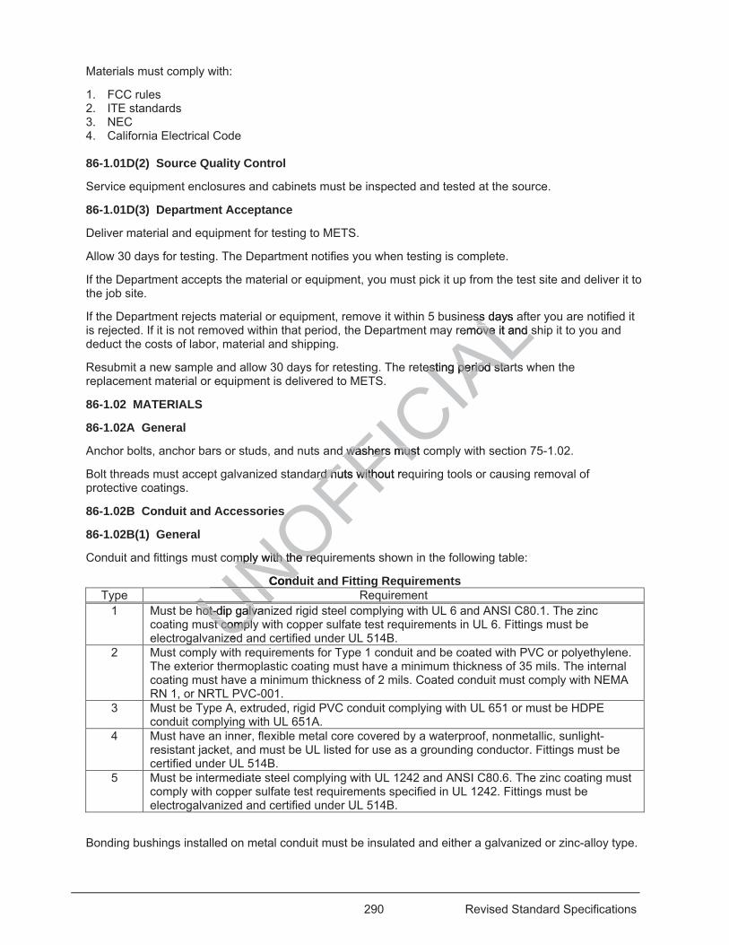
290 Revised Standard Specifications
Materials must comply with:
1. FCC rules 2. ITE standards 3. NEC 4. California Electrical Code
86-1.01D(2) Source Quality Control
Service equipment enclosures and cabinets must be inspected and tested at the source.
86-1.01D(3) Department Acceptance
Deliver material and equipment for testing to METS.
Allow 30 days for testing. The Department notifies you when testing is complete.
If the Department accepts the material or equipment, you must pick it up from the test site and deliver it to the job site.
If the Department rejects material or equipment, remove it within 5 business days after you are notified it is rejected. If it is not removed within that period, the Department may remove it and ship it to you and deduct the costs of labor, material and shipping.
Resubmit a new sample and allow 30 days for retesting. The retesting period starts when the replacement material or equipment is delivered to METS.
86-1.02 MATERIALS
86-1.02A General
Anchor bolts, anchor bars or studs, and nuts and washers must comply with section 75-1.02.
Bolt threads must accept galvanized standard nuts without requiring tools or causing removal of protective coatings.
86-1.02B Conduit and Accessories
86-1.02B(1) General
Conduit and fittings must comply with the requirements shown in the following table:
Conduit and Fitting Requirements Type Requirement
1 Must be hot-dip galvanized rigid steel complying with UL 6 and ANSI C80.1. The zinc coating must comply with copper sulfate test requirements in UL 6. Fittings must be electrogalvanized and certified under UL 514B.
2 Must comply with requirements for Type 1 conduit and be coated with PVC or polyethylene. The exterior thermoplastic coating must have a minimum thickness of 35 mils. The internal coating must have a minimum thickness of 2 mils. Coated conduit must comply with NEMA RN 1, or NRTL PVC-001.
3 Must be Type A, extruded, rigid PVC conduit complying with UL 651 or must be HDPE conduit complying with UL 651A.
4 Must have an inner, flexible metal core covered by a waterproof, nonmetallic, sunlight-resistant jacket, and must be UL listed for use as a grounding conductor. Fittings must be certified under UL 514B.
5 Must be intermediate steel complying with UL 1242 and ANSI C80.6. The zinc coating must comply with copper sulfate test requirements specified in UL 1242. Fittings must be electrogalvanized and certified under UL 514B.
Bonding bushings installed on metal conduit must be insulated and either a galvanized or zinc-alloy type.
Uhot-dip galvanhot-dip galvst complyst compl
zedUNOFFICIA
Lss days ss aemove it and sove it and s
esting period staresting period sta
d washers must c washers mus
rd nutrd n s without rewith
s s
mply with the reqmply with the req
Condd
UNUNU
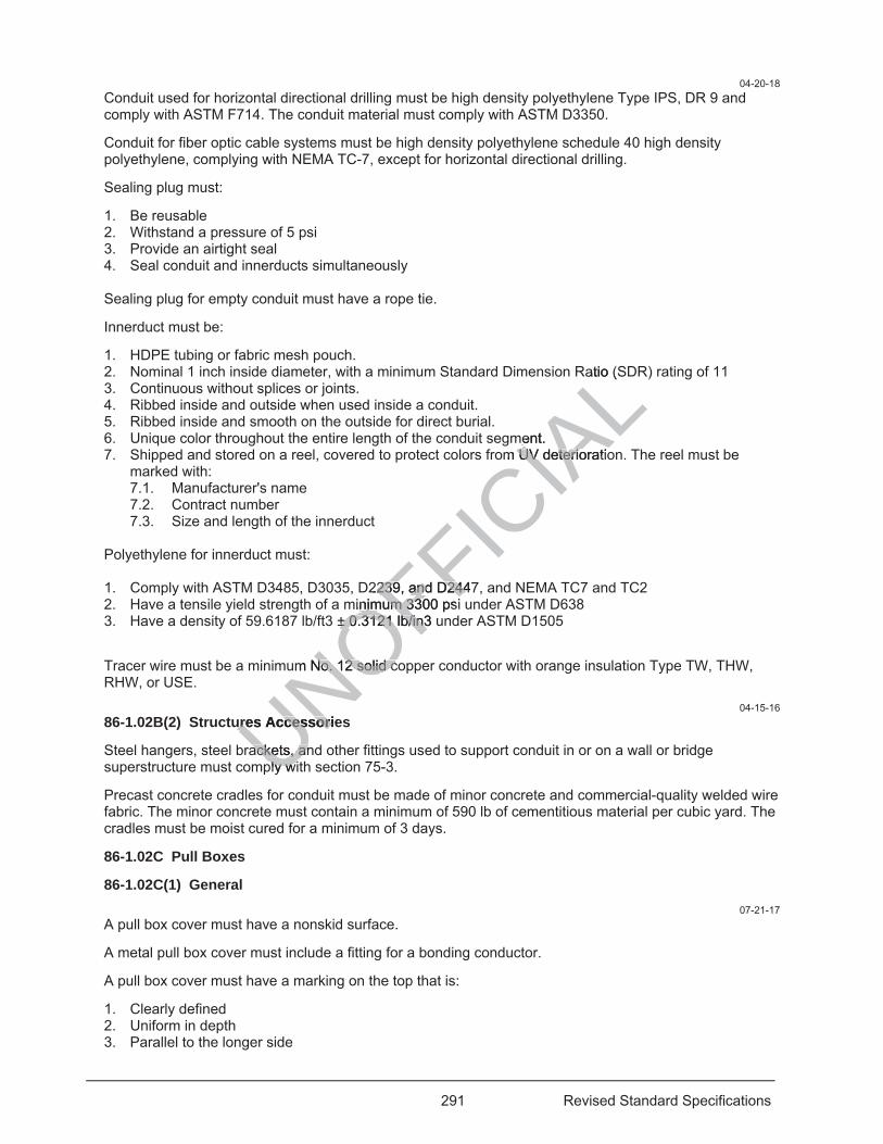
291 Revised Standard Specifications
04-20-18 Conduit used for horizontal directional drilling must be high density polyethylene Type IPS, DR 9 and comply with ASTM F714. The conduit material must comply with ASTM D3350.
Conduit for fiber optic cable systems must be high density polyethylene schedule 40 high density polyethylene, complying with NEMA TC-7, except for horizontal directional drilling.
Sealing plug must:
1. Be reusable 2. Withstand a pressure of 5 psi 3. Provide an airtight seal 4. Seal conduit and innerducts simultaneously Sealing plug for empty conduit must have a rope tie.
Innerduct must be:
1. HDPE tubing or fabric mesh pouch. 2. Nominal 1 inch inside diameter, with a minimum Standard Dimension Ratio (SDR) rating of 11 3. Continuous without splices or joints. 4. Ribbed inside and outside when used inside a conduit. 5. Ribbed inside and smooth on the outside for direct burial. 6. Unique color throughout the entire length of the conduit segment. 7. Shipped and stored on a reel, covered to protect colors from UV deterioration. The reel must be
marked with: 7.1. Manufacturer's name 7.2. Contract number 7.3. Size and length of the innerduct
Polyethylene for innerduct must: 1. Comply with ASTM D3485, D3035, D2239, and D2447, and NEMA TC7 and TC2 2. Have a tensile yield strength of a minimum 3300 psi under ASTM D638 3. Have a density of 59.6187 lb/ft3 ± 0.3121 lb/in3 under ASTM D1505
Tracer wire must be a minimum No. 12 solid copper conductor with orange insulation Type TW, THW, RHW, or USE.
04-15-16 86-1.02B(2) Structures Accessories
Steel hangers, steel brackets, and other fittings used to support conduit in or on a wall or bridge superstructure must comply with section 75-3.
Precast concrete cradles for conduit must be made of minor concrete and commercial-quality welded wire fabric. The minor concrete must contain a minimum of 590 lb of cementitious material per cubic yard. The cradles must be moist cured for a minimum of 3 days.
86-1.02C Pull Boxes
86-1.02C(1) General 07-21-17
A pull box cover must have a nonskid surface.
A metal pull box cover must include a fitting for a bonding conductor.
A pull box cover must have a marking on the top that is:
1. Clearly defined 2. Uniform in depth 3. Parallel to the longer side
UNOFFICIA
Latio (S
ment. m UV deterioratioUV deterio
2239, and D2447239, and D244minimum 3300 psiinimum 33
± 0.3121 lb/in3 u± 0.3121 lb/in3
um No. 12 solid cNo. 12 solid c
ures Accessorieures Accessori
ackets, anackets, anly wly w
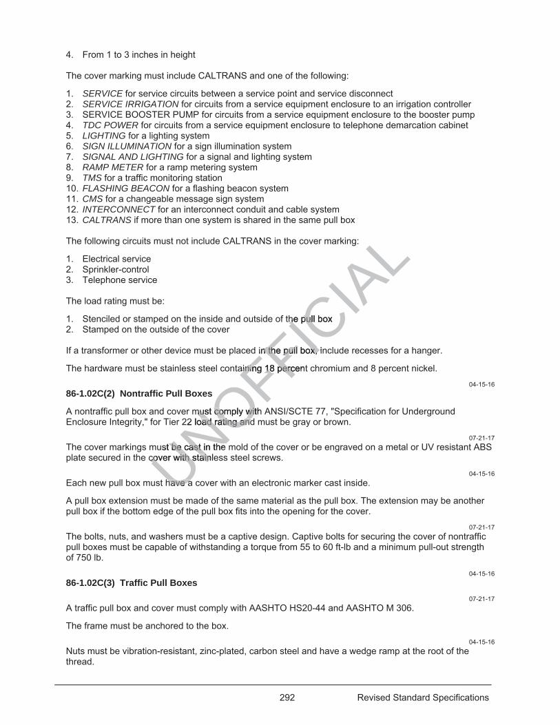
292 Revised Standard Specifications
4. From 1 to 3 inches in height
The cover marking must include CALTRANS and one of the following:
1. SERVICE for service circuits between a service point and service disconnect 2. SERVICE IRRIGATION for circuits from a service equipment enclosure to an irrigation controller 3. SERVICE BOOSTER PUMP for circuits from a service equipment enclosure to the booster pump 4. TDC POWER for circuits from a service equipment enclosure to telephone demarcation cabinet 5. LIGHTING for a lighting system 6. SIGN ILLUMINATION for a sign illumination system 7. SIGNAL AND LIGHTING for a signal and lighting system 8. RAMP METER for a ramp metering system 9. TMS for a traffic monitoring station 10. FLASHING BEACON for a flashing beacon system 11. CMS for a changeable message sign system 12. INTERCONNECT for an interconnect conduit and cable system 13. CALTRANS if more than one system is shared in the same pull box The following circuits must not include CALTRANS in the cover marking:
1. Electrical service 2. Sprinkler-control 3. Telephone service The load rating must be:
1. Stenciled or stamped on the inside and outside of the pull box 2. Stamped on the outside of the cover If a transformer or other device must be placed in the pull box, include recesses for a hanger.
The hardware must be stainless steel containing 18 percent chromium and 8 percent nickel. 04-15-16
86-1.02C(2) Nontraffic Pull Boxes
A nontraffic pull box and cover must comply with ANSI/SCTE 77, "Specification for Underground Enclosure Integrity," for Tier 22 load rating and must be gray or brown.
07-21-17 The cover markings must be cast in the mold of the cover or be engraved on a metal or UV resistant ABS plate secured in the cover with stainless steel screws.
04-15-16 Each new pull box must have a cover with an electronic marker cast inside.
A pull box extension must be made of the same material as the pull box. The extension may be another pull box if the bottom edge of the pull box fits into the opening for the cover.
07-21-17 The bolts, nuts, and washers must be a captive design. Captive bolts for securing the cover of nontraffic pull boxes must be capable of withstanding a torque from 55 to 60 ft-lb and a minimum pull-out strength of 750 lb.
04-15-16 86-1.02C(3) Traffic Pull Boxes
07-21-17 A traffic pull box and cover must comply with AASHTO HS20-44 and AASHTO M 306.
The frame must be anchored to the box.
04-15-16 Nuts must be vibration-resistant, zinc-plated, carbon steel and have a wedge ramp at the root of the thread.
UNOFFICIA
Lthe pull box he pul
in the pull box, inn the pull box,
ainiaining 18 percentng 18 perc
must comply withmust comply wit22 load rating andoad rating and
ust be cast in the be cast in the cover with stainlecover with stain
have ahave a
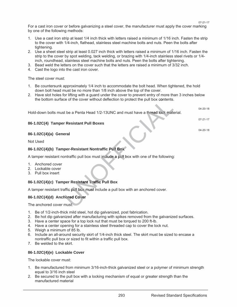
293 Revised Standard Specifications
07-21-17 For a cast iron cover or before galvanizing a steel cover, the manufacturer must apply the cover marking by one of the following methods:
1. Use a cast iron strip at least 1/4 inch thick with letters raised a minimum of 1/16 inch. Fasten the strip to the cover with 1/4-inch, flathead, stainless steel machine bolts and nuts. Peen the bolts after tightening.
2. Use a sheet steel strip at least 0.027 inch thick with letters raised a minimum of 1/16 inch. Fasten the strip to the cover by spot welding, tack welding, or brazing with 1/4-inch stainless steel rivets or 1/4-inch, roundhead, stainless steel machine bolts and nuts. Peen the bolts after tightening.
3. Bead weld the letters on the cover such that the letters are raised a minimum of 3/32 inch. 4. Cast the logo into the cast iron cover. The steel cover must:
1. Be countersunk approximately 1/4 inch to accommodate the bolt head. When tightened, the hold down bolt head must be no more than 1/8 inch above the top of the cover.
2. Have slot holes for lifting with a guard under the cover to prevent entry of more than 3 inches below the bottom surface of the cover without deflection to protect the pull box contents.
04-20-18
Hold-down bolts must be a Penta Head 1/2-13UNC and must have a thread lock material.
07-21-17 86-1.02C(4) Tamper Resistant Pull Boxes
04-20-18 86-1.02C(4)(a) General
Not Used
86-1.02C(4)(b) Tamper-Resistant Nontraffic Pull Box
A tamper resistant nontraffic pull box must include a pull box with one of the following:
1. Anchored cover 2. Lockable cover 3. Pull box insert
86-1.02C(4)(c) Tamper Resistant Traffic Pull Box
A tamper resistant traffic pull box must include a pull box with an anchored cover.
86-1.02C(4)(d) Anchored Cover
The anchored cover must:
1. Be of 1/2-inch-thick mild steel, hot dip galvanized, post fabrication. 2. Be hot dip galvanized after manufacturing with spikes removed from the galvanized surfaces. 3. Have a center space for a top lock nut that must be torqued to 200 ft-lb. 4. Have a center opening for a stainless steel threaded cap to cover the lock nut. 5. Weigh a minimum of 85 lb. 6. Include an all-around security skirt of 1/4-inch thick steel. The skirt must be sized to encase a
nontraffic pull box or sized to fit within a traffic pull box. 7. Be welded to the skirt. 86-1.02C(4)(e) Lockable Cover
The lockable cover must:
1. Be manufactured from minimum 3/16-inch-thick galvanized steel or a polymer of minimum strength equal to 3/16 inch steel
2. Be secured to the pull box with a locking mechanism of equal or greater strength than the manufactured material
UNOFFICIA
Lcont
a thread lock matthread lock mat
Pull Box Pull Box
ininclude a pull boclude a pull
esistant Traffic Psistant Traffic P
ic pull box must ipull box m
hored Cover hored Cove
t:t:
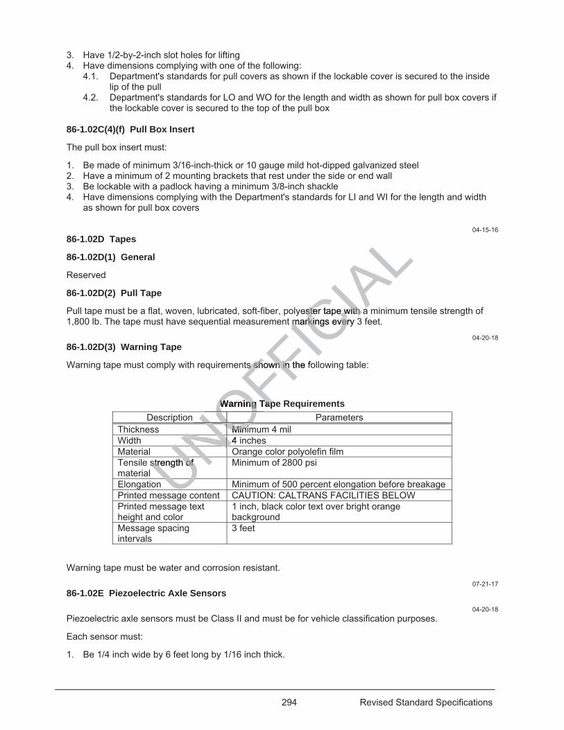
294 Revised Standard Specifications
3. Have 1/2-by-2-inch slot holes for lifting 4. Have dimensions complying with one of the following:
4.1. Department's standards for pull covers as shown if the lockable cover is secured to the inside lip of the pull
4.2. Department's standards for LO and WO for the length and width as shown for pull box covers if the lockable cover is secured to the top of the pull box
86-1.02C(4)(f) Pull Box Insert
The pull box insert must:
1. Be made of minimum 3/16-inch-thick or 10 gauge mild hot-dipped galvanized steel 2. Have a minimum of 2 mounting brackets that rest under the side or end wall 3. Be lockable with a padlock having a minimum 3/8-inch shackle 4. Have dimensions complying with the Department's standards for LI and WI for the length and width
as shown for pull box covers
04-15-16 86-1.02D Tapes
86-1.02D(1) General
Reserved
86-1.02D(2) Pull Tape
Pull tape must be a flat, woven, lubricated, soft-fiber, polyester tape with a minimum tensile strength of 1,800 lb. The tape must have sequential measurement markings every 3 feet.
04-20-18 86-1.02D(3) Warning Tape
Warning tape must comply with requirements shown in the following table:
Warning Tape Requirements Description Parameters
Thickness Minimum 4 mil Width 4 inches Material Orange color polyolefin film Tensile strength of material
Minimum of 2800 psi
Elongation Minimum of 500 percent elongation before breakage Printed message content CAUTION: CALTRANS FACILITIES BELOW Printed message text height and color
1 inch, black color text over bright orange background
Message spacing intervals
3 feet
Warning tape must be water and corrosion resistant.
07-21-17 86-1.02E Piezoelectric Axle Sensors
04-20-18 Piezoelectric axle sensors must be Class II and must be for vehicle classification purposes.
Each sensor must:
1. Be 1/4 inch wide by 6 feet long by 1/16 inch thick.
UgeUNOFFICIA
Lyester tape with a ster tape with a
markings every 3markings eve
ts shown in the fos shown in
Warning TapWarning TapONOMinimMiniNONONONONONONONO4 NONOUNNstrength of strength of UNUU
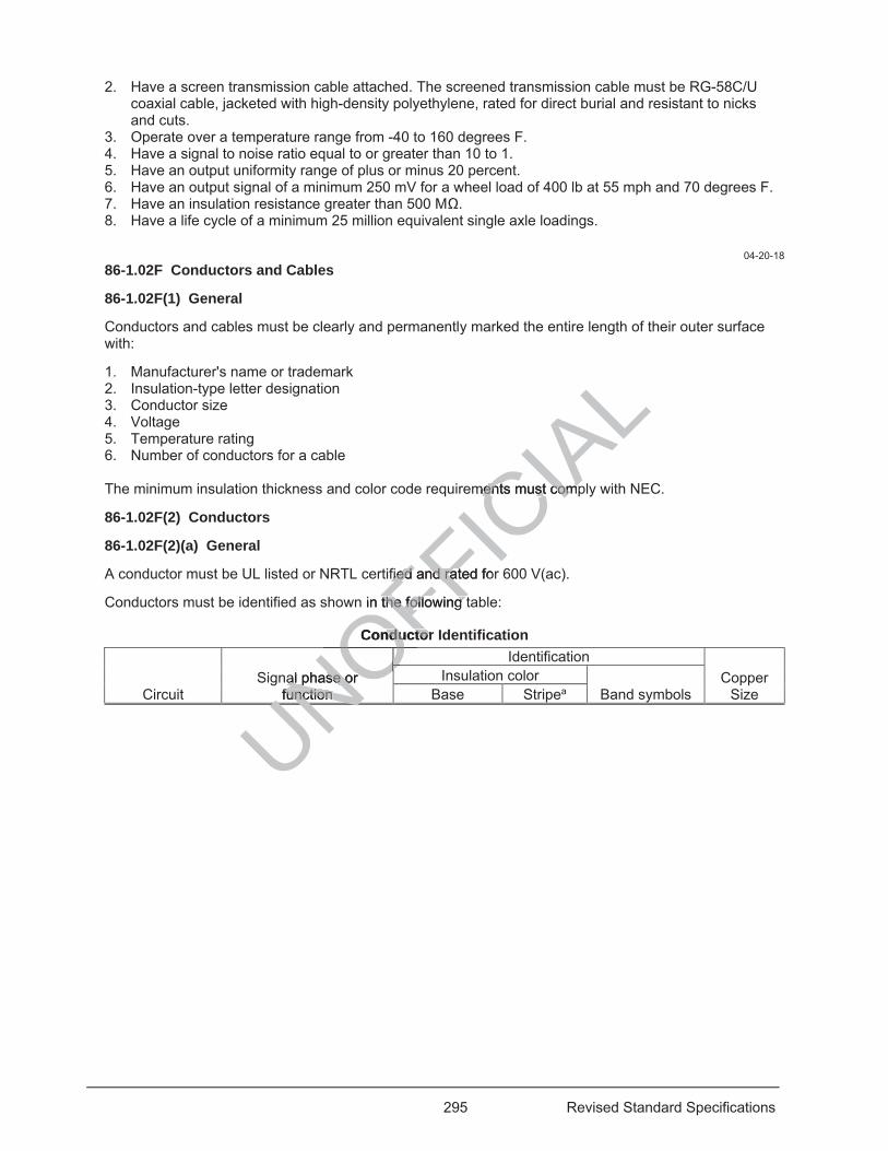
295 Revised Standard Specifications
2. Have a screen transmission cable attached. The screened transmission cable must be RG-58C/U coaxial cable, jacketed with high-density polyethylene, rated for direct burial and resistant to nicks and cuts.
3. Operate over a temperature range from -40 to 160 degrees F. 4. Have a signal to noise ratio equal to or greater than 10 to 1. 5. Have an output uniformity range of plus or minus 20 percent. 6. Have an output signal of a minimum 250 mV for a wheel load of 400 lb at 55 mph and 70 degrees F. 7. Have an insulation resistance greater than 500 M . 8. Have a life cycle of a minimum 25 million equivalent single axle loadings.
04-20-18 86-1.02F Conductors and Cables
86-1.02F(1) General
Conductors and cables must be clearly and permanently marked the entire length of their outer surface with:
1. Manufacturer's name or trademark 2. Insulation-type letter designation 3. Conductor size 4. Voltage 5. Temperature rating 6. Number of conductors for a cable The minimum insulation thickness and color code requirements must comply with NEC.
86-1.02F(2) Conductors
86-1.02F(2)(a) General
A conductor must be UL listed or NRTL certified and rated for 600 V(ac).
Conductors must be identified as shown in the following table:
Conductor Identification
Circuit Signal phase or
function
Identification Copper
Size Insulation color
Band symbols Base Stripea
UNUNUNOFFICIA
Lments must compents must comp
fied and rated forfied and ra
n in the following tthe following
Conductor nductor
al phase or al phase or function function OOOOOUN
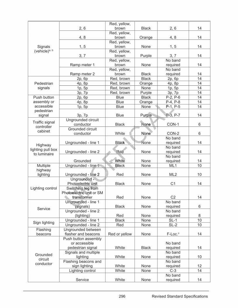
296 Revised Standard Specifications
Signals (vehicle)a, b
2, 6 Red, yellow,
brown Black 2, 6 14
4, 8 Red, yellow,
brown Orange 4, 8 14
1, 5 Red, yellow,
brown None 1, 5 14
3, 7 Red, yellow,
brown Purple 3, 7 14
Ramp meter 1 Red, yellow,
brown None No band required 14
Ramp meter 2 Red, yellow,
brown Black No band required 14
Pedestrian signals
2p, 6p Red, brown Black 2p, 6p 14 4p, 8p Red, brown Orange 4p, 8p 14 1p, 5p Red, brown None 1p, 5p 14 3p, 7p Red, brown Purple 3p, 7p 14
Push button assembly or accessible pedestrian
signal
2p, 6p Blue Black P-2, P-6 14 4p, 8p Blue Orange P-4, P-8 14 1p, 5p Blue None P-1, P-5 14
3p, 7p Blue Purple P-3, P-7 14
Traffic signal controller cabinet
Ungrounded circuit conductor Black None CON-1 6
Grounded circuit conductor White None CON-2 6
Highway lighting pull box
to luminaire
Ungrounded - line 1 Black None No band required 14
Ungrounded - line 2 Red None No band required 14
Grounded White None No band required 14
Multiple highway lighting
Ungrounded - line 1 Black None ML1 10
Ungrounded - line 2 Red None ML2 10
Lighting control
Ungrounded - Photoelectric unit Black None C1 14 Switching leg from
Photoelectric unit or SM transformer Red None C2 14
Service
Ungrounded - line 1 (signals) Black None
No band required 6
Ungrounded - line 2 (lighting) Red None
No band required 8
Sign lighting Ungrounded - line 1 Black None SL-1 10 Ungrounded - line 2 Red None SL-2 10
Flashing beacons
Ungrounded between flasher and beacons Red or yellow None F-Loc.c 14
Grounded circuit
conductor
Push button assembly or accessible
pedestrian signal White Black No band required 14
Signals and multiple lighting White None
No band required 10
Flashing beacons and sign lighting White None
No band required 12
Lighting control White None C-3 14
Service White None No band required 14
UNOFFICIA
LPLLP-1,LLLALPurple P-3ple P-3ALALALALNone None ALALALC
ALNone None CCIAAACA
Black NBlack NCCICRed RedFICICICWhite White FF
OFne 1 Blane 1
OFOFed - line 2 ed - line 2 OFOF
rounded - ded - toelectric unit oelectric uniNOO
witching leg fromwitching leg fromhotoelectric unit olectric un
transformesformNngroundengrounde
(sig(sigUU
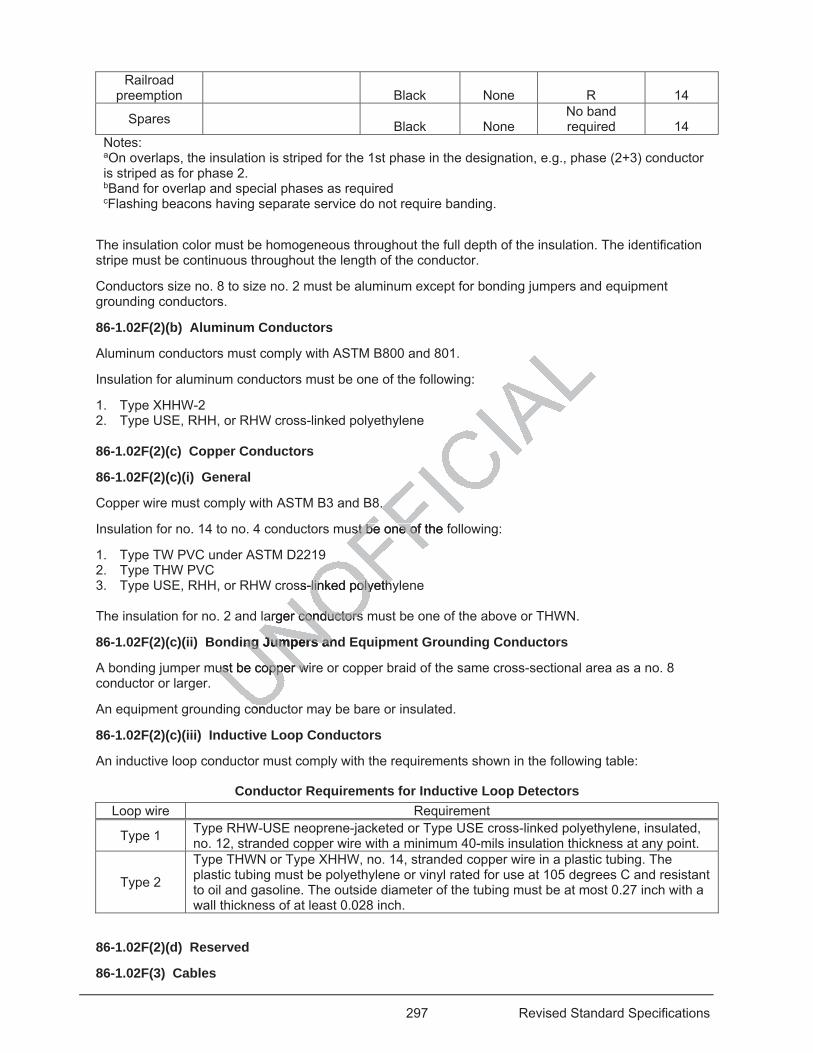
297 Revised Standard Specifications
Railroad preemption Black None R 14
Spares Black None No band required 14
Notes: aOn overlaps, the insulation is striped for the 1st phase in the designation, e.g., phase (2+3) conductor is striped as for phase 2. bBand for overlap and special phases as required cFlashing beacons having separate service do not require banding.
The insulation color must be homogeneous throughout the full depth of the insulation. The identification stripe must be continuous throughout the length of the conductor.
Conductors size no. 8 to size no. 2 must be aluminum except for bonding jumpers and equipment grounding conductors.
86-1.02F(2)(b) Aluminum Conductors
Aluminum conductors must comply with ASTM B800 and 801.
Insulation for aluminum conductors must be one of the following:
1. Type XHHW-2 2. Type USE, RHH, or RHW cross-linked polyethylene 86-1.02F(2)(c) Copper Conductors
86-1.02F(2)(c)(i) General
Copper wire must comply with ASTM B3 and B8.
Insulation for no. 14 to no. 4 conductors must be one of the following:
1. Type TW PVC under ASTM D2219 2. Type THW PVC 3. Type USE, RHH, or RHW cross-linked polyethylene The insulation for no. 2 and larger conductors must be one of the above or THWN.
86-1.02F(2)(c)(ii) Bonding Jumpers and Equipment Grounding Conductors
A bonding jumper must be copper wire or copper braid of the same cross-sectional area as a no. 8 conductor or larger.
An equipment grounding conductor may be bare or insulated.
86-1.02F(2)(c)(iii) Inductive Loop Conductors
An inductive loop conductor must comply with the requirements shown in the following table:
Conductor Requirements for Inductive Loop Detectors Loop wire Requirement
Type 1 Type RHW-USE neoprene-jacketed or Type USE cross-linked polyethylene, insulated, no. 12, stranded copper wire with a minimum 40-mils insulation thickness at any point.
Type 2
Type THWN or Type XHHW, no. 14, stranded copper wire in a plastic tubing. The plastic tubing must be polyethylene or vinyl rated for use at 105 degrees C and resistant to oil and gasoline. The outside diameter of the tubing must be at most 0.27 inch with a wall thickness of at least 0.028 inch.
86-1.02F(2)(d) Reserved
86-1.02F(3) Cables
8. .
st be one of the fst be one of
ss-linked polyethy-linked polyeth
arger conductorsconductors
ing Jumpers ng Jumpers anan
ust be copper wiust be copper w
condd
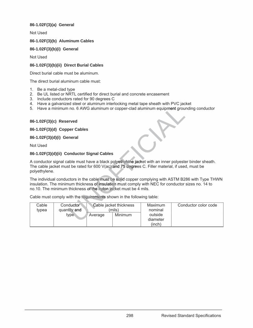
298 Revised Standard Specifications
86-1.02F(3)(a) General
Not Used
86-1.02F(3)(b) Aluminum Cables
86-1.02F(3)(b)(i) General
Not Used
86-1.02F(3)(b)(ii) Direct Burial Cables
Direct burial cable must be aluminum.
The direct burial aluminum cable must:
1. Be a metal-clad type 2. Be UL listed or NRTL certified for direct burial and concrete encasement 3. Include conductors rated for 90 degrees C 4. Have a galvanized steel or aluminum interlocking metal tape sheath with PVC jacket 5. Have a minimum no. 6 AWG aluminum or copper-clad aluminum equipment grounding conductor
86-1.02F(3)(c) Reserved
86-1.02F(3)(d) Copper Cables
86-1.02F(3)(d)(i) General
Not Used
86-1.02F(3)(d)(ii) Conductor Signal Cables
A conductor signal cable must have a black polyethylene jacket with an inner polyester binder sheath. The cable jacket must be rated for 600 V(ac) and 75 degrees C. Filler material, if used, must be polyethylene.
The individual conductors in the cable must be solid copper complying with ASTM B286 with Type THWN insulation. The minimum thickness of insulation must comply with NEC for conductor sizes no. 14 to no.10. The minimum thickness of the nylon jacket must be 4 mils.
Cable must comply with the requirements shown in the following table:
Cable typea
Conductor quantity and
type
Cable jacket thickness (mils)
Maximum nominal outside
diameter (inch)
Conductor color code
Average Minimum UNOFFICIA
LPV
pment g
olyethylolyethylene jackeenc) and 75c) and 7 degreedeg
ble must be solid e must be solidss of insulation mss of insulation
of tf the nylon jackhe nylon jac
he requirements se requirements
ductor ntity and tity
ee
CabC
UNUNAUU
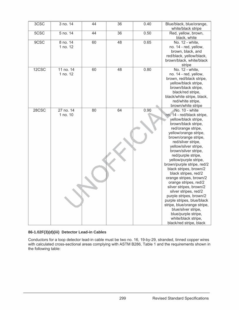
299 Revised Standard Specifications
3CSC 3 no. 14 44 36 0.40 Blue/black, blue/orange, white/black stripe
5CSC 5 no. 14 44 36 0.50 Red, yellow, brown, black, white
9CSC 8 no. 14 1 no. 12
60 48 0.65 No. 12 - white, no. 14 - red, yellow, brown, black, and
red/black, yellow/black, brown/black, white/black
stripe 12CSC 11 no. 14
1 no. 12 60 48 0.80 No. 12 - white,
no. 14 - red, yellow, brown, red/black stripe,
yellow/black stripe, brown/black stripe,
black/red stripe, black/white stripe, black,
red/white stripe, brown/white stripe
28CSC 27 no. 14 1 no. 10
80 64 0.90 No. 10 - white no. 14 - red/black stripe,
yellow/black stripe, brown/black stripe, red/orange stripe,
yellow/orange stripe, brown/orange stripe,
red/silver stripe, yellow/silver stripe, brown/silver stripe, red/purple stripe,
yellow/purple stripe, brown/purple stripe, red/2
black stripes, brown/2 black stripes, red/2
orange stripes, brown/2 orange stripes, red/2 silver stripes, brown/2
silver stripes, red/2 purple stripes, brown/2
purple stripes, blue/black stripe, blue/orange stripe,
blue/silver stripe, blue/purple stripe, white/black stripe,
black/red stripe, black
86-1.02F(3)(d)(iii) Detector Lead-in Cables
Conductors for a loop detector lead-in cable must be two no. 16, 19-by-29, stranded, tinned copper wires with calculated cross-sectional areas complying with ASTM B286, Table 1 and the requirements shown in the following table:
b
AL0 NNno. 1no. 1AL
UNOFIC
AL
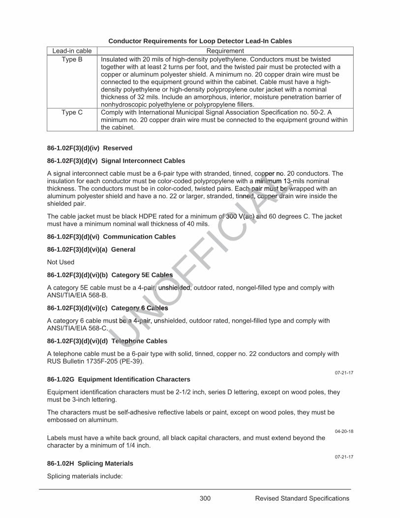
300 Revised Standard Specifications
Conductor Requirements for Loop Detector Lead-In Cables Lead-in cable Requirement
Type B Insulated with 20 mils of high-density polyethylene. Conductors must be twisted together with at least 2 turns per foot, and the twisted pair must be protected with a copper or aluminum polyester shield. A minimum no. 20 copper drain wire must be connected to the equipment ground within the cabinet. Cable must have a high-density polyethylene or high-density polypropylene outer jacket with a nominal thickness of 32 mils. Include an amorphous, interior, moisture penetration barrier of nonhydroscopic polyethylene or polypropylene fillers.
Type C Comply with International Municipal Signal Association Specification no. 50-2. A minimum no. 20 copper drain wire must be connected to the equipment ground within the cabinet.
86-1.02F(3)(d)(iv) Reserved
86-1.02F(3)(d)(v) Signal Interconnect Cables
A signal interconnect cable must be a 6-pair type with stranded, tinned, copper no. 20 conductors. The insulation for each conductor must be color-coded polypropylene with a minimum 13-mils nominal thickness. The conductors must be in color-coded, twisted pairs. Each pair must be wrapped with an aluminum polyester shield and have a no. 22 or larger, stranded, tinned, copper drain wire inside the shielded pair.
The cable jacket must be black HDPE rated for a minimum of 300 V(ac) and 60 degrees C. The jacket must have a minimum nominal wall thickness of 40 mils.
86-1.02F(3)(d)(vi) Communication Cables
86-1.02F(3)(d)(vi)(a) General
Not Used
86-1.02F(3)(d)(vi)(b) Category 5E Cables
A category 5E cable must be a 4-pair, unshielded, outdoor rated, nongel-filled type and comply with ANSI/TIA/EIA 568-B.
86-1.02F(3)(d)(vi)(c) Category 6 Cables
A category 6 cable must be a 4-pair, unshielded, outdoor rated, nongel-filled type and comply with ANSI/TIA/EIA 568-C.
86-1.02F(3)(d)(vi)(d) Telephone Cables
A telephone cable must be a 6-pair type with solid, tinned, copper no. 22 conductors and comply with RUS Bulletin 1735F-205 (PE-39).
07-21-17 86-1.02G Equipment Identification Characters
Equipment identification characters must be 2-1/2 inch, series D lettering, except on wood poles, they must be 3-inch lettering.
The characters must be self-adhesive reflective labels or paint, except on wood poles, they must be embossed on aluminum.
04-20-18 Labels must have a white back ground, all black capital characters, and must extend beyond the character by a minimum of 1/4 inch.
07-21-17 86-1.02H Splicing Materials
Splicing materials include:
UNOFFICIA
Lopperop nora minimum 13-inimum 13-
ch pair must be wh pair must be wtinned, copper draed, copper dr
of 300 V(ac) andof 300 V(ac) an
ables ables
pair, unshielr, unshielded, oded,
gory 6 Cables gory 6 Cable
st be a 4-pair, unbe a 4-pai. .
TelephonTelephon
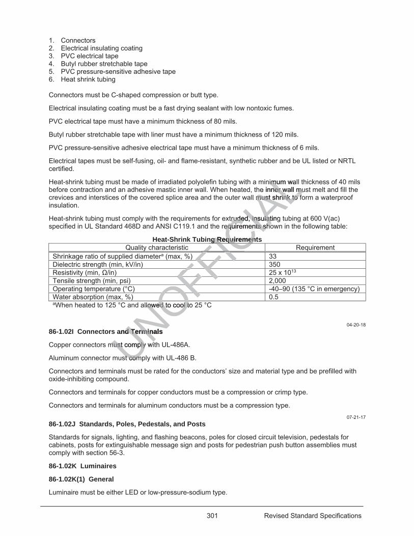
301 Revised Standard Specifications
1. Connectors 2. Electrical insulating coating 3. PVC electrical tape 4. Butyl rubber stretchable tape 5. PVC pressure-sensitive adhesive tape 6. Heat shrink tubing
Connectors must be C-shaped compression or butt type.
Electrical insulating coating must be a fast drying sealant with low nontoxic fumes.
PVC electrical tape must have a minimum thickness of 80 mils.
Butyl rubber stretchable tape with liner must have a minimum thickness of 120 mils.
PVC pressure-sensitive adhesive electrical tape must have a minimum thickness of 6 mils.
Electrical tapes must be self-fusing, oil- and flame-resistant, synthetic rubber and be UL listed or NRTL certified.
Heat-shrink tubing must be made of irradiated polyolefin tubing with a minimum wall thickness of 40 mils before contraction and an adhesive mastic inner wall. When heated, the inner wall must melt and fill the crevices and interstices of the covered splice area and the outer wall must shrink to form a waterproof insulation.
Heat-shrink tubing must comply with the requirements for extruded, insulating tubing at 600 V(ac) specified in UL Standard 468D and ANSI C119.1 and the requirements shown in the following table:
Heat-Shrink Tubing Requirements Quality characteristic Requirement
Shrinkage ratio of supplied diametera (max, %) 33 Dielectric strength (min, kV/in) 350 Resistivity (min, /in) 25 x 1013 Tensile strength (min, psi) 2,000 Operating temperature (°C) -40–90 (135 °C in emergency) Water absorption (max, %) 0.5 aWhen heated to 125 °C and allowed to cool to 25 °C
04-20-18 86-1.02I Connectors and Terminals
Copper connectors must comply with UL-486A.
Aluminum connector must comply with UL-486 B.
Connectors and terminals must be rated for the conductors’ size and material type and be prefilled with oxide-inhibiting compound.
Connectors and terminals for copper conductors must be a compression or crimp type.
Connectors and terminals for aluminum conductors must be a compression type.
07-21-17 86-1.02J Standards, Poles, Pedestals, and Posts
Standards for signals, lighting, and flashing beacons, poles for closed circuit television, pedestals for cabinets, posts for extinguishable message sign and posts for pedestrian push button assemblies must comply with section 56-3.
86-1.02K Luminaires
86-1.02K(1) General
Luminaire must be either LED or low-pressure-sodium type.
UNOFFICIA
Lnimum walimuhe inner wall muner wall mu
ll must shrink to fmust shrink to f
truded, insulatingtruded, insulatrequirements shoequirements sho
ng Requirementsg RequiremenIC) FICFICFIFFFF
OFOFllowed to cool to lowed to cool tO
and Terminals d Termin
must comply wimust comply
st comst com
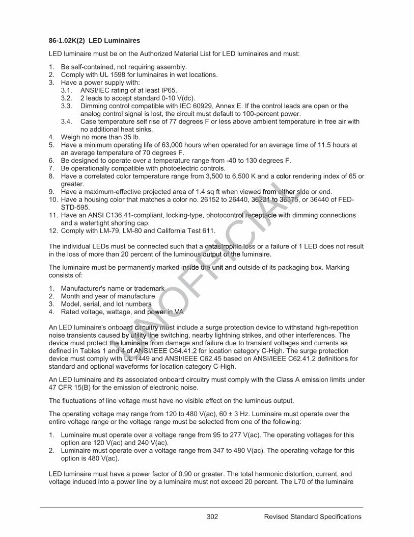
302 Revised Standard Specifications
86-1.02K(2) LED Luminaires
LED luminaire must be on the Authorized Material List for LED luminaires and must:
1. Be self-contained, not requiring assembly. 2. Comply with UL 1598 for luminaires in wet locations. 3. Have a power supply with:
3.1. ANSI/IEC rating of at least IP65. 3.2. 2 leads to accept standard 0-10 V(dc). 3.3. Dimming control compatible with IEC 60929, Annex E. If the control leads are open or the
analog control signal is lost, the circuit must default to 100-percent power. 3.4. Case temperature self rise of 77 degrees F or less above ambient temperature in free air with
no additional heat sinks. 4. Weigh no more than 35 lb. 5. Have a minimum operating life of 63,000 hours when operated for an average time of 11.5 hours at
an average temperature of 70 degrees F. 6. Be designed to operate over a temperature range from -40 to 130 degrees F. 7. Be operationally compatible with photoelectric controls. 8. Have a correlated color temperature range from 3,500 to 6,500 K and a color rendering index of 65 or
greater. 9. Have a maximum-effective projected area of 1.4 sq ft when viewed from either side or end. 10. Have a housing color that matches a color no. 26152 to 26440, 36231 to 36375, or 36440 of FED-
STD-595. 11. Have an ANSI C136.41-compliant, locking-type, photocontrol receptacle with dimming connections
and a watertight shorting cap. 12. Comply with LM-79, LM-80 and California Test 611. The individual LEDs must be connected such that a catastrophic loss or a failure of 1 LED does not result in the loss of more than 20 percent of the luminous output of the luminaire.
The luminaire must be permanently marked inside the unit and outside of its packaging box. Marking consists of:
1. Manufacturer's name or trademark 2. Month and year of manufacture 3. Model, serial, and lot numbers 4. Rated voltage, wattage, and power in VA An LED luminaire's onboard circuitry must include a surge protection device to withstand high-repetition noise transients caused by utility line switching, nearby lightning strikes, and other interferences. The device must protect the luminaire from damage and failure due to transient voltages and currents as defined in Tables 1 and 4 of ANSI/IEEE C64.41.2 for location category C-High. The surge protection device must comply with UL 1449 and ANSI/IEEE C62.45 based on ANSI/IEEE C62.41.2 definitions for standard and optional waveforms for location category C-High.
An LED luminaire and its associated onboard circuitry must comply with the Class A emission limits under 47 CFR 15(B) for the emission of electronic noise.
The fluctuations of line voltage must have no visible effect on the luminous output.
The operating voltage may range from 120 to 480 V(ac), 60 ± 3 Hz. Luminaire must operate over the entire voltage range or the voltage range must be selected from one of the following:
1. Luminaire must operate over a voltage range from 95 to 277 V(ac). The operating voltages for this option are 120 V(ac) and 240 V(ac).
2. Luminaire must operate over a voltage range from 347 to 480 V(ac). The operating voltage for this option is 480 V(ac).
LED luminaire must have a power factor of 0.90 or greater. The total harmonic distortion, current, and voltage induced into a power line by a luminaire must not exceed 20 percent. The L70 of the luminaire
UNOFFICIA
La color
d from either sidd from either sid 36231 to 36375,6231 to 36375
trol receptacle w receptac
cacatastrophic lossastrophic lossus output of the luus output of th
inside nsid the unit anthe
k k e
ers rsand power in VA power in VA
oard circuitry musard circuitry mused by utility liy utility line sne
the luminaire frothe luminaire frod 4 of ANSd 4 of ANS
UL 14UL 14f
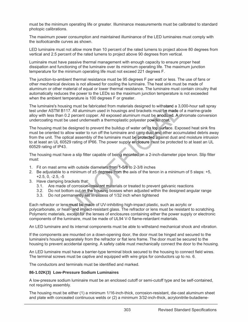
303 Revised Standard Specifications
must be the minimum operating life or greater. Illuminance measurements must be calibrated to standard photopic calibrations.
The maximum power consumption and maintained illuminance of the LED luminaires must comply with the isofootcandle curves as shown.
LED luminaire must not allow more than 10 percent of the rated lumens to project above 80 degrees from vertical and 2.5 percent of the rated lumens to project above 90 degrees from vertical.
Luminaire must have passive thermal management with enough capacity to ensure proper heat dissipation and functioning of the luminaire over its minimum operating life. The maximum junction temperature for the minimum operating life must not exceed 221 degrees F.
The junction-to-ambient thermal resistance must be 95 degrees F per watt or less. The use of fans or other mechanical devices is not allowed for cooling the luminaire. The heat sink must be made of aluminum or other material of equal or lower thermal resistance. The luminaire must contain circuitry that automatically reduces the power to the LEDs so the maximum junction temperature is not exceeded when the ambient temperature is 100 degrees F or greater.
The luminaire's housing must be fabricated from materials designed to withstand a 3,000-hour salt spray test under ASTM B117. All aluminum used in housings and brackets must be made of a marine-grade alloy with less than 0.2 percent copper. All exposed aluminum must be anodized. A chromate conversion undercoating must be used underneath a thermoplastic polyester powder coat.
The housing must be designed to prevent the buildup of water on its top surface. Exposed heat sink fins must be oriented to allow water to run off the luminaire and carry dust and other accumulated debris away from the unit. The optical assembly of the luminaire must be protected against dust and moisture intrusion to at least an UL 60529 rating of IP66. The power supply enclosure must be protected to at least an UL 60529 rating of IP43.
The housing must have a slip fitter capable of being mounted on a 2-inch-diameter pipe tenon. Slip fitter must:
1. Fit on mast arms with outside diameters from 1-5/8 to 2-3/8 inches 2. Be adjustable to a minimum of ±5 degrees from the axis of the tenon in a minimum of 5 steps: +5,
+2.5, 0, -2.5, -5 3. Have clamping brackets that:
3.1. Are made of corrosion-resistant materials or treated to prevent galvanic reactions 3.2. Do not bottom out on the housing bosses when adjusted within the designed angular range 3.3. Do not permanently set in excess of 1/32 inch when tightened
Each refractor or lens must be made of UV-inhibiting high-impact plastic, such as acrylic or polycarbonate, or heat- and impact-resistant glass. The refractor or lens must be resistant to scratching. Polymeric materials, except for the lenses of enclosures containing either the power supply or electronic components of the luminaire, must be made of UL94 V-0 flame-retardant materials.
An LED luminaire and its internal components must be able to withstand mechanical shock and vibration.
If the components are mounted on a down-opening door, the door must be hinged and secured to the luminaire's housing separately from the refractor or flat lens frame. The door must be secured to the housing to prevent accidental opening. A safety cable must mechanically connect the door to the housing.
An LED luminaire must have a barrier-type terminal block secured to the housing to connect field wires. The terminal screws must be captive and equipped with wire grips for conductors up to no. 6.
The conductors and terminals must be identified and marked.
86-1.02K(3) Low-Pressure Sodium Luminaires
A low-pressure sodium luminaire must be an enclosed cutoff or semi-cutoff type and be self-contained, not requiring assembly.
The housing must be either (1) a minimum 1/16-inch-thick, corrosion-resistant, die-cast aluminum sheet and plate with concealed continuous welds or (2) a minimum 3/32-inch-thick, acrylonitrile-butadiene-
hstand ast be made t be
e anodized. A che anodized. A chpowder coat. wder coat.
on its top surfacen its top sucarry dust and otcarry dust and
be protected agae protected agaply enclosure musply enclosure m
eing ing mounted onmounted o
ers from 1-5/8 tors from 1-5/8 todegrees from thedegrees fro
on-resistant maten-resistant matut on the housing t on the housing
nently set in exently set in excec
s must be mades must be madet- and impact- and impa
ept for ept for e
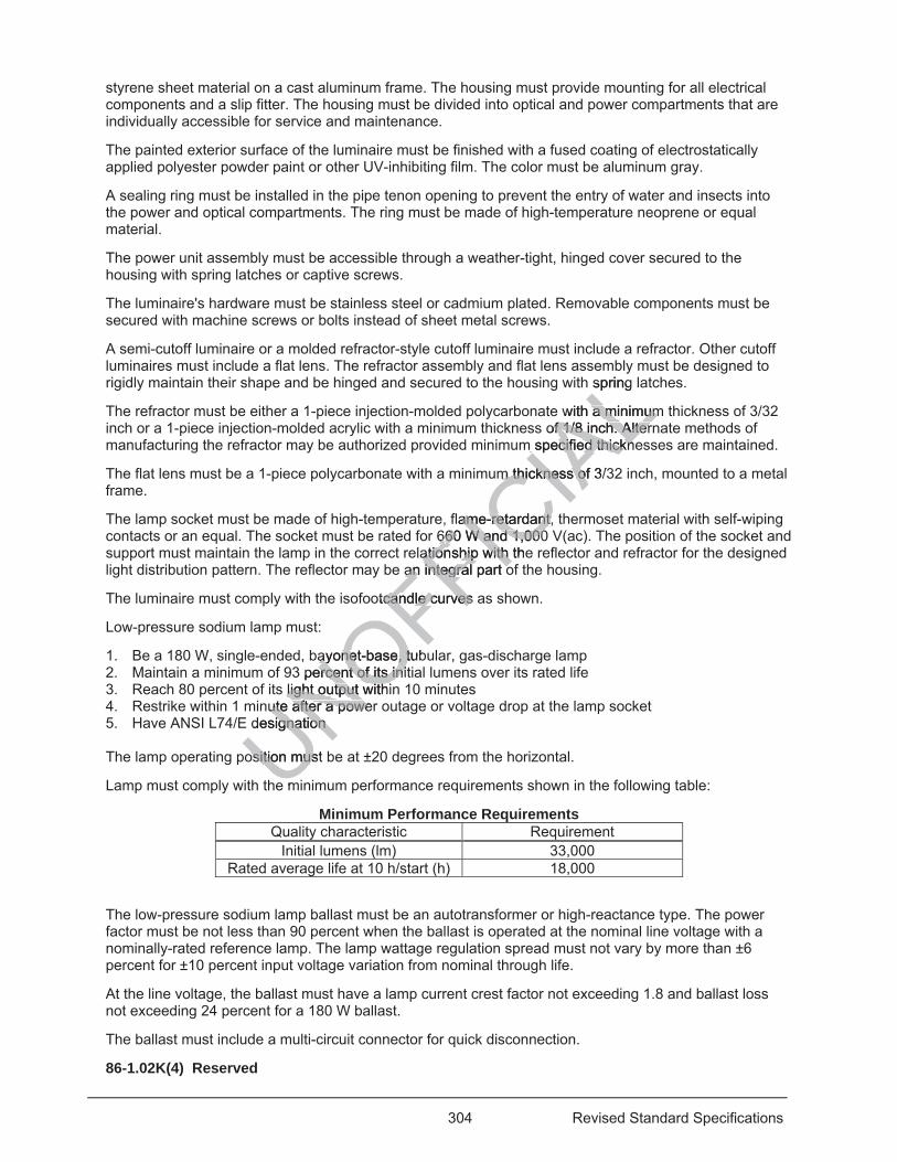
304 Revised Standard Specifications
styrene sheet material on a cast aluminum frame. The housing must provide mounting for all electrical components and a slip fitter. The housing must be divided into optical and power compartments that are individually accessible for service and maintenance.
The painted exterior surface of the luminaire must be finished with a fused coating of electrostatically applied polyester powder paint or other UV-inhibiting film. The color must be aluminum gray.
A sealing ring must be installed in the pipe tenon opening to prevent the entry of water and insects into the power and optical compartments. The ring must be made of high-temperature neoprene or equal material.
The power unit assembly must be accessible through a weather-tight, hinged cover secured to the housing with spring latches or captive screws.
The luminaire's hardware must be stainless steel or cadmium plated. Removable components must be secured with machine screws or bolts instead of sheet metal screws.
A semi-cutoff luminaire or a molded refractor-style cutoff luminaire must include a refractor. Other cutoff luminaires must include a flat lens. The refractor assembly and flat lens assembly must be designed to rigidly maintain their shape and be hinged and secured to the housing with spring latches.
The refractor must be either a 1-piece injection-molded polycarbonate with a minimum thickness of 3/32 inch or a 1-piece injection-molded acrylic with a minimum thickness of 1/8 inch. Alternate methods of manufacturing the refractor may be authorized provided minimum specified thicknesses are maintained.
The flat lens must be a 1-piece polycarbonate with a minimum thickness of 3/32 inch, mounted to a metal frame.
The lamp socket must be made of high-temperature, flame-retardant, thermoset material with self-wiping contacts or an equal. The socket must be rated for 660 W and 1,000 V(ac). The position of the socket and support must maintain the lamp in the correct relationship with the reflector and refractor for the designed light distribution pattern. The reflector may be an integral part of the housing.
The luminaire must comply with the isofootcandle curves as shown.
Low-pressure sodium lamp must:
1. Be a 180 W, single-ended, bayonet-base, tubular, gas-discharge lamp 2. Maintain a minimum of 93 percent of its initial lumens over its rated life 3. Reach 80 percent of its light output within 10 minutes 4. Restrike within 1 minute after a power outage or voltage drop at the lamp socket 5. Have ANSI L74/E designation The lamp operating position must be at ±20 degrees from the horizontal.
Lamp must comply with the minimum performance requirements shown in the following table:
Minimum Performance Requirements Quality characteristic Requirement
Initial lumens (lm) 33,000 Rated average life at 10 h/start (h) 18,000
The low-pressure sodium lamp ballast must be an autotransformer or high-reactance type. The power factor must be not less than 90 percent when the ballast is operated at the nominal line voltage with a nominally-rated reference lamp. The lamp wattage regulation spread must not vary by more than ±6 percent for ±10 percent input voltage variation from nominal through life.
At the line voltage, the ballast must have a lamp current crest factor not exceeding 1.8 and ballast loss not exceeding 24 percent for a 180 W ballast.
The ballast must include a multi-circuit connector for quick disconnection.
86-1.02K(4) Reserved
UNOFFICIA
Lmb
spring
with a minimuma minimumof 1/8 inch. Alterf 1/8 inch. Alter
m specified thicknm specified thickn
m thickness of 3/m thickness of
flame-retardant, tame-retardant,6660 W and 1,00060 W and 1,000
ationationship with thehip with an integral part oan integral part o
otcandle curves atcandle curves
ayonet-base, tubayonet-base, t percent of its initercent of its ini
light output withilight output withnute after a powerute after a powe
designation ignation
osition must osition mus
e m
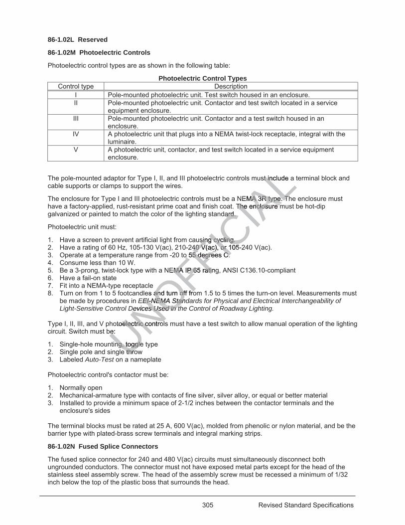
305 Revised Standard Specifications
86-1.02L Reserved
86-1.02M Photoelectric Controls
Photoelectric control types are as shown in the following table:
Photoelectric Control Types Control type Description
I Pole-mounted photoelectric unit. Test switch housed in an enclosure. II Pole-mounted photoelectric unit. Contactor and test switch located in a service
equipment enclosure. III Pole-mounted photoelectric unit. Contactor and a test switch housed in an
enclosure. IV A photoelectric unit that plugs into a NEMA twist-lock receptacle, integral with the
luminaire. V A photoelectric unit, contactor, and test switch located in a service equipment
enclosure.
The pole-mounted adaptor for Type I, II, and III photoelectric controls must include a terminal block and cable supports or clamps to support the wires.
The enclosure for Type I and III photoelectric controls must be a NEMA 3R type. The enclosure must have a factory-applied, rust-resistant prime coat and finish coat. The enclosure must be hot-dip galvanized or painted to match the color of the lighting standard.
Photoelectric unit must:
1. Have a screen to prevent artificial light from causing cycling. 2. Have a rating of 60 Hz, 105-130 V(ac), 210-240 V(ac), or 105-240 V(ac). 3. Operate at a temperature range from -20 to 55 degrees C. 4. Consume less than 10 W. 5. Be a 3-prong, twist-lock type with a NEMA IP 65 rating, ANSI C136.10-compliant 6. Have a fail-on state 7. Fit into a NEMA-type receptacle 8. Turn on from 1 to 5 footcandles and turn off from 1.5 to 5 times the turn-on level. Measurements must
be made by procedures in EEI-NEMA Standards for Physical and Electrical Interchangeability of Light-Sensitive Control Devices Used in the Control of Roadway Lighting.
Type I, II, III, and V photoelectric controls must have a test switch to allow manual operation of the lighting circuit. Switch must be:
1. Single-hole mounting, toggle type 2. Single pole and single throw 3. Labeled Auto-Test on a nameplate Photoelectric control's contactor must be:
1. Normally open 2. Mechanical-armature type with contacts of fine silver, silver alloy, or equal or better material 3. Installed to provide a minimum space of 2-1/2 inches between the contactor terminals and the
enclosure's sides The terminal blocks must be rated at 25 A, 600 V(ac), molded from phenolic or nylon material, and be the barrier type with plated-brass screw terminals and integral marking strips.
86-1.02N Fused Splice Connectors
The fused splice connector for 240 and 480 V(ac) circuits must simultaneously disconnect both ungrounded conductors. The connector must not have exposed metal parts except for the head of the stainless steel assembly screw. The head of the assembly screw must be recessed a minimum of 1/32 inch below the top of the plastic boss that surrounds the head.
UNOFFICIA
Lst inclust in de
NEMA 3R tyA 3R type. Thpe. T. The enclosure mThe enclosure m
ard. ard.
sing cycling. sing cycling. 40 V(ac), or 105-40 V(ac), or 1
o 55 degrees C. o 55 degrees C.
EMA IP 65 ratingEMA IP 65 ratin
es and turn off froand turn off froEEI-NEMA StandEI-NEMA Stan
Devices Used in tDevices Used in t
otoelectric controlelectric controbe: e
ng, toggle ng, togglee throe thro
306 Revised Standard Specifications
The connector must protect the fuse from water or weather damage. Contact between the fuse and fuse holder must be spring loaded.
Fuses must:
1. Be standard, midget, ferrule type 2. Have a nontime-delay feature 3. Be 3/32 by 1-1/2 inches
86-1.02O Grounding Electrodes
Grounding electrode must be:
1. 1 piece 2. Minimum 10-foot length of one of the following:
2.1. Galvanized steel rod or pipe not less than 3/4 inch in diameter 2.2. Copper clad steel rod not less than 5/8 inch in diameter
86-1.02P Enclosures
86-1.02P(1) General
The enclosures must be rated NEMA 3R and include a dead front panel and a hasp with a 7/16-inch-diameter hole for a padlock.
The enclosure's machine screws and bolts must not protrude outside the cabinet wall.
The fasteners on the exterior of an enclosure must be vandal resistant and not be removable. The exterior screws, nuts, bolts, and washers must be stainless steel.
86-1.02P(2) Service Equipment Enclosures
A service equipment enclosure must be factory wired and manufactured from steel and galvanized or have factory-applied, rust-resistant prime and finish coats, except Types II and III.
Type II and III service equipment enclosures must:
1. Be made of 0.125-inch minimum thickness 5052-H32 aluminum sheet complying with ASTM B209. 2. Be manufactured using gas metal arc welding with bare aluminum welding electrodes. The electrodes
must comply with AWS A5.10 Class ER5356. 3. Be manufactured using welding procedures, welders, and welding operators that comply with the
requirements for welding procedures, welders, and welding operators in in AWS B2.1, "Specification for Welding Procedure and Performance Qualification."
4. Have full-seal weld exterior seams. 5. Exterior welds must be ground smooth and edges filed to a radius of at least 0.03 inch. 6. Have a surface finish that complies with MIL-A-8625 for a Type II, Class I coating, except the anodic
coating must have a minimum thickness of 0.0007 inch and a minimum coating weight of 0.001 oz/sq in.
If a Type III enclosure houses a transformer of more than 1 kVA, the enclosure must have effective screened ventilation louvers of no less than 50 sq. in for each louver. The framed screen must be stainless no. 304 with a no. 10 size mesh and secured with at least 4 bolts.
The dead front panel on a Type III service equipment enclosure must have a continuous stainless steel or aluminum piano hinge. The panel must be secured with a latch or captive screws. No live part must be mounted on the panel.
The enclosure must be watertight and marked as specified in NEC to warn of potential electric-arc flash hazards.
Internal conductors for the photoelectric control unit must be 600 V(ac), 14 AWG (THHN) stranded machine tool wire. Where subject to flexing, 19 stranded wire must be used.
UNOFFICIA
Lanel and a hasp wnel and a hasp
e outside the cabie outside the c
ndal resistant andal resistant annless steel. nless ste
ory wiory w red and manred aand finish coatand finish coats, es
osures must: osures mus
um thickness 505 thickness 50s metal arc weldimetal arc weld
A5.10 Class ER5A5.10 Class ER5ng welding procedng welding proc
elding procedureding procecedure and Perfoedure and Perf
ld exterior seald exterior sbe groube grou
hat
307 Revised Standard Specifications
The meter area must be have a sealable, lockable, weather-tight cover that can be removed without the use of tools.
For Type III-A, III-B, and III-C enclosures, the meter socket must be a 5-clip type, and the landing lug must be suitable for multiple conductors.
For a Type III-D enclosure, the meter socket must be a 7-clip type, and the landing lug must be suitable for multiple conductors. The pedestal must comply with the Electric Utility Service Equipment Requirements Committee drawing no. 308 or 309.
Landing lugs must be (1) sized for the incoming service utility conductors, (2) compatible with either copper or aluminum conductors, and (3) made of copper or tin-plated aluminum. Live parts of the electrical equipment must be guarded against accidental contact.
The main and neutral busses of the enclosure must be made of tin-plated copper, be rated for 125 A, and be suitable for copper or aluminum conductors.
Each service equipment enclosure must have up to 2 main circuit breakers that will simultaneously disconnect ungrounded service-entrance conductors.
Circuit breaker for a service equipment enclosure must:
1. Be quick-break on either automatic or manual operation 2. Be trip indicating 3. Be internal-trip type 4. Be UL listed or NRTL certified and comply with UL 489 or equal 5. Be clearly marked with the frame size 6. Have an operating mechanism that is enclosed and trip-free from the operating handle on overload 7. Have the trip rating clearly marked on the operating handle 8. Have an interior made of copper Circuit breakers used as disconnects must have a minimum interrupting capacity of 10,000 A, rms.
The interior of the enclosure must accept plug-in circuit breakers. A minimum of 6 standard single-pole circuit breakers, 3/4" nominal, must be provided for branch circuits.
Identify each circuit breaker and component by description using an engraved phenolic nameplate attached with stainless steel rivets or screws.
Nameplate must be installed:
1. Adjacent to the breaker on the dead front panel. The characters must be a minimum of 1/8 inch high. 2. Adjacent to the component on the back panel. The characters must be a minimum of 1/8 inch high. 3. At the top exterior of the door panel. The nameplate must include the system number, voltage, and
number of phases engraved in minimum 3/16-inch-high characters. A plastic-laminated wiring diagram must be attached inside the enclosure with brass eyelets by a UL-listed or NRTL-certified method.
86-1.02P(3) Lighting and Sign Illumination Enclosures
A lighting and sign illumination enclosure must be manufactured from steel and either galvanized, cadmium plated, or powder coated.
86-1.02Q Cabinets
86-1.02Q(1) General
Cabinets must be factory wired except for battery backup system cabinets.
The fasteners on the exterior of a cabinet, except for battery backup system cabinets, must be removable and vandal resistant. The exterior screws, nuts, bolts, and washers must be stainless steel.
Terminal blocks, circuit breakers, and a power supply must be UL approved.
UNOFFICIA
Lr equal r equal
trip-free from thetrip-free from theing handle ng handle
ave a minimum inave a minim
t plug-in circuit brplug-in circuit be provided for brae provided f
component by mponent by desets or screws. ts or screws.
ed: d:
eaker on the deaer on the dcomponent on thcomponent on th
of the door of the doongravengrave
308 Revised Standard Specifications
86-1.02Q(2) Department-Furnished Controller Cabinets
A Department-furnished controller assembly consists of a Model 170E or 2070E controller unit, a wired controller cabinet, and all auxiliary equipment required to operate the system. The Department does not furnish anchor bolts.
86-1.02Q(3) Controller Cabinets
The controller cabinet must be a Model 334L, comply with TEES, and be on the Authorized Material List for traffic signal control equipment. The cabinet must have 3 drawer shelves. Each shelf must be attached to the tops of 2 supporting angles with 4 screws.
86-1.02Q(4) Telephone Demarcation Cabinets
86-1.02Q(4)(a) General 07-21-17
The doors of a telephone demarcation cabinet must be attached using stainless steel piano hinges.
04-15-16 86-1.02Q(4)(b) Type A Telephone Demarcation Cabinets
Reserved
86-1.02Q(4)(c) Type B Telephone Demarcation Cabinets
A Type B telephone demarcation cabinet consists of a mounting panel, outlets, circuit breaker, fan, dead front plates, and fuse.
The mounting panel must be made of 3/4-inch-thick ACX-grade plywood.
The mounting panel must be fastened to the cabinet with nuts, lock washers, and flat washers to 10 welded studs.
The cabinet must be made of 0.125-inch-thick anodized aluminum.
The cabinet door must be hung and secured with drawn latches, lockable with a padlock. The padlock latches must each have a minimum 7/16-inch-diameter hole.
Ventilation louvers must be located on the door.
The fan must be located in a ventilator housing and be controlled thermostatically. The thermostat control must have a range from 80 to 130 degrees F.
The thermostat and fan circuit must be protected with a fuse rated for 175 percent of the motor capacity. The fan capacity must be a minimum 25 cfm.
86-1.02Q(4)(d) Type C Telephone Demarcation Cabinets
Reserved
86-1.02Q(5) Battery Backup System Cabinets
The cabinet for a battery backup system must comply with TEES and be on the Authorized Material List for traffic signal control equipment.
86-1.02R Signal Heads
86-1.02R(1) General
A signal head consists of a signal mounting assembly, backplate, and signal face.
The head must have a terminal block attached to the back of one housing. The terminal block must have enough positions to accommodate all indications. Each position must be permanently labeled for the indications used.
UNOFFICIA
Lng panel, outlets,panel, out
CX-grade plywoodCX-grade plywo
et with nuts, lock et with nuts, lock
ck anodized alumck anodized
cured with drawncured with 7/16-inch-diamete7/16-inch-diam
ted on the door. ed on the door
a ventilator housia ventilator housi80 to 130 degrees80 to 130 degree
fan circuit must bfan circuit must st be a minimust be a minim
TelepTelep
309 Revised Standard Specifications
The metal signal heads must not fracture or deflect more than half the lens diameter when tested under California Test 666.
The plastic signal heads must not fracture or deflect when tested under California Test 605.
The deflection must not be more than 10 degrees in either the vertical or horizontal plane after the wind load has been removed from the front of the signal face or more than 6 degrees in either the vertical or horizontal plane after the wind load has been removed from the back of the signal face.
86-1.02R(2) Signal Mounting Assemblies
Signal mounting assembly must include:
1. 1-1/2-inch-diameter steel pipe or galvanized conduit 2. Pipe fitting made of ductile iron, galvanized steel, bronze, or aluminum alloy, Type AC-84B, no. 380 3. Mast arm and post-top slip fitters and terminal compartments made of cast bronze or hot-dip
galvanized ductile iron The horizontal distance between the vertical centerlines of the terminal compartment or slip fitter and of each signal face must not exceed 11 inches except where required for proper signal face alignment or to allow programming of programmed visibility signal sections.
The mounting assembly must be watertight and free of sharp edges or protrusions that might damage conductor insulation. The assembly must have positive-locking serrated fittings that prevent signal faces from rotating when the fittings are mated with similar fittings on the faces.
Each terminal compartment must be fitted with a terminal block having a minimum of 12 positions, each with 2 screw-type terminals. Each terminal must accommodate at least five no. 14 conductors. The terminal compartment must have a cover for easy access to the terminal block.
86-1.02R(3) Backplates
The backplate material must be a homogeneous black color with a lusterless finish.
A metal backplate must be made of a minimum 1/16-inch-thick 3001-14 aluminum.
A plastic backplate must have a minimum thickness of 1/16 inch and be formed from sheet plastic or assembled from extruded, molded, or cast plastic sections. Sections must be factory joined using one of the following:
1. Appropriate solvent cement. 2. Aluminum rivets and washers painted or permanently colored to match the backplate. 3. No. 10 machine screws with flat washers, lock washers, and nuts painted to match the backplate. Each plastic backplate must be secured to the plastic signal face such that it resists removal or permanent deformation.
86-1.02R(4) Signal Faces
Signal face consists of signal sections with signal housings, LED modules, and visors.
Signal face must:
1. Be adjustable and allow for 360-degree rotation about the vertical axis 2. Comply with ITE publications ST-052-E, Vehicle Traffic Control Signal Heads: Light Emitting Diode
(LED) Circular Signal Supplement and ST-054, Vehicle Traffic Control Signal Heads: Light Emitting Diode (LED) Vehicle Arrow Traffic Signal Supplement
3. Be sealed with a neoprene gasket at the top opening A metal signal face must have a metal backplate and visor.
A plastic signal face must have a plastic backplate and visor.
UNOFFICIA
Lar
per sign
or protrusions thor protrusions therrated fittings thaerrated fittings tha
n the faces. he faces.
block having a mlock having a mmodate at least fdate at least f
cess to the termincess to the term
eous black color weous black
minimum 1/16-inchmum 1/16-inch
nimum thickness mum thicknessed, or cast plasticed, or cast plas
ement. ement. nd washers paintewashers
screws with flat wscrews with flat
must be must be
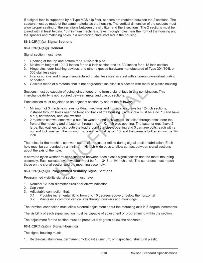
310 Revised Standard Specifications
If a signal face is supported by a Type MAS slip fitter, spacers are required between the 2 sections. The spacers must be made of the same material as the housing. The vertical dimension of the spacers must allow proper seating of the serrations between the slip fitter and the 2 sections. The 2 sections must be joined with at least two no. 10 minimum machine screws through holes near the front of the housing and the spacers and matching holes in a reinforcing plate installed in the housing.
86-1.02R(4)(a) Signal Sections
86-1.02R(4)(a)(i) General
Signal section must have:
1 Opening at the top and bottom for a 1-1/2-inch pipe 2. Maximum height of 10-1/4 inches for an 8-inch section and 14-3/4 inches for a 12-inch section 3. Hinge pins, door-latching devices, and other exposed hardware manufactured of Type 304/304L or
305 stainless steel 4. Interior screws and fittings manufactured of stainless steel or steel with a corrosion-resistant plating
or coating 5. Gaskets made of a material that is not degraded if installed in a section with metal or plastic housing Sections must be capable of being joined together to form a signal face in any combination. This interchangeability is not required between metal and plastic sections.
Each section must be joined to an adjacent section by one of the following:
1. Minimum of 3 machine screws for 8-inch sections and 4 machine screws for 12-inch sections, installed through holes near the front and back of the housing. Each screw must be a no. 10 and have a nut, flat washer, and lock washer.
2. 2 machine screws, each with a nut, flat washer, and lock washer, installed through holes near the front of the housing and a fastener through the 1-1/2-inch pipe opening. The fastener must have 2 large, flat washers to distribute the load around the pipe's opening and 3 carriage bolts, each with a nut and lock washer. The minimum screw size must be no. 10, and the carriage bolt size must be 1/4 inch.
The holes for the machine screws must be either cast or drilled during signal section fabrication. Each hole must be surrounded by a minimum 1/8-inch-wide boss to allow contact between signal sections about the axis of the hole.
A serrated nylon washer must be inserted between each plastic signal section and the metal mounting assembly. Each serrated nylon washer must be from 3/16 to 1/4 inch thick. The serrations must match those on the signal section and the mounting assembly.
86-1.02R(4)(a)(ii) Programmed Visibility Signal Sections
Programmed visibility signal section must have:
1. Nominal 12-inch-diameter circular or arrow indication 2. Cap visor 3. Adjustable connection that:
3.1. Provides incremental tilting from 0 to 10 degrees above or below the horizontal 3.2. Maintains a common vertical axis through couplers and mountings
The terminal connection must allow external adjustment about the mounting axis in 5-degree increments.
The visibility of each signal section must be capable of adjustment or programming within the section.
The adjustment for the section must be preset at 4 degrees below the horizontal.
86-1.02R(4)(a)(iii) Signal Housings
The signal housing must:
1. Be die-cast aluminum, permanent mold-cast aluminum, or if specified, structural plastic
UNOFFICIA
Lwith
in any combinany combin
e following: following:
machine screwsmachine screwhousing. Each scousing. Each s
and lock washer,and lock washere 1-e 1-1/2-inch pipe2-inch
ound the pipe's opound the pipe's ow size must w size mus be n
uust be either castst be either cnimum 1/8-inch-wum 1/8-inch-w
ust be inserted bust be inserted nylon washer mnylon washer m
ection and the moand the m
ogrammeogrammed Vd
al sl
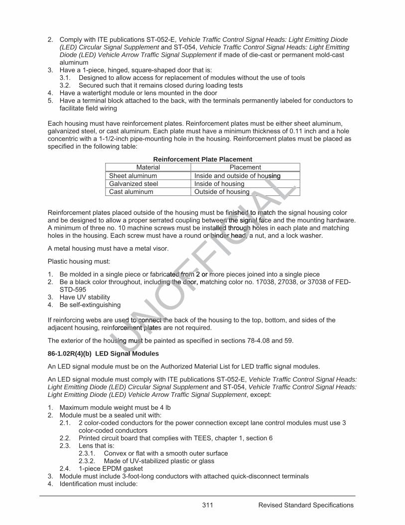
311 Revised Standard Specifications
2. Comply with ITE publications ST-052-E, Vehicle Traffic Control Signal Heads: Light Emitting Diode (LED) Circular Signal Supplement and ST-054, Vehicle Traffic Control Signal Heads: Light Emitting Diode (LED) Vehicle Arrow Traffic Signal Supplement if made of die-cast or permanent mold-cast aluminum
3. Have a 1-piece, hinged, square-shaped door that is: 3.1. Designed to allow access for replacement of modules without the use of tools 3.2. Secured such that it remains closed during loading tests
4. Have a watertight module or lens mounted in the door 5. Have a terminal block attached to the back, with the terminals permanently labeled for conductors to
facilitate field wiring Each housing must have reinforcement plates. Reinforcement plates must be either sheet aluminum, galvanized steel, or cast aluminum. Each plate must have a minimum thickness of 0.11 inch and a hole concentric with a 1-1/2-inch pipe-mounting hole in the housing. Reinforcement plates must be placed as specified in the following table:
Reinforcement Plate Placement Material Placement
Sheet aluminum Inside and outside of housing Galvanized steel Inside of housing Cast aluminum Outside of housing
Reinforcement plates placed outside of the housing must be finished to match the signal housing color and be designed to allow a proper serrated coupling between the signal face and the mounting hardware. A minimum of three no. 10 machine screws must be installed through holes in each plate and matching holes in the housing. Each screw must have a round or binder head, a nut, and a lock washer.
A metal housing must have a metal visor.
Plastic housing must:
1. Be molded in a single piece or fabricated from 2 or more pieces joined into a single piece 2. Be a black color throughout, including the door, matching color no. 17038, 27038, or 37038 of FED-
STD-595 3. Have UV stability 4. Be self-extinguishing If reinforcing webs are used to connect the back of the housing to the top, bottom, and sides of the adjacent housing, reinforcement plates are not required.
The exterior of the housing must be painted as specified in sections 78-4.08 and 59.
86-1.02R(4)(b) LED Signal Modules
An LED signal module must be on the Authorized Material List for LED traffic signal modules.
An LED signal module must comply with ITE publications ST-052-E, Vehicle Traffic Control Signal Heads: Light Emitting Diode (LED) Circular Signal Supplement and ST-054, Vehicle Traffic Control Signal Heads: Light Emitting Diode (LED) Vehicle Arrow Traffic Signal Supplement, except:
1. Maximum module weight must be 4 lb 2. Module must be a sealed unit with:
2.1. 2 color-coded conductors for the power connection except lane control modules must use 3 color-coded conductors
2.2. Printed circuit board that complies with TEES, chapter 1, section 6 2.3. Lens that is:
2.3.1. Convex or flat with a smooth outer surface 2.3.2. Made of UV-stabilized plastic or glass
2.4. 1-piece EPDM gasket 3. Module must include 3-foot-long conductors with attached quick-disconnect terminals 4. Identification must include:
UNOFFICIA
Lousing ou LLLg
ALALfinished to matchfinished to ma
een the signal facen the signal factalled through hoed through ho
or binder head, ar binder head,
cated from 2 or med from 2 or mding the door, mading the doo
sed to connect thed to connect thnforcementement plates pla
using must busing must
al Ml M
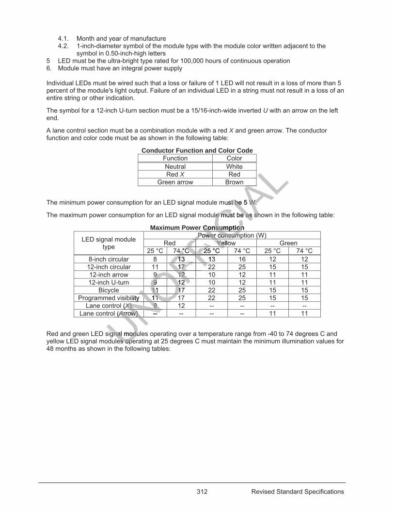
312 Revised Standard Specifications
4.1. Month and year of manufacture 4.2. 1-inch-diameter symbol of the module type with the module color written adjacent to the
symbol in 0.50-inch-high letters 5 LED must be the ultra-bright type rated for 100,000 hours of continuous operation 6. Module must have an integral power supply Individual LEDs must be wired such that a loss or failure of 1 LED will not result in a loss of more than 5 percent of the module's light output. Failure of an individual LED in a string must not result in a loss of an entire string or other indication.
The symbol for a 12-inch U-turn section must be a 15/16-inch-wide inverted U with an arrow on the left end.
A lane control section must be a combination module with a red X and green arrow. The conductor function and color code must be as shown in the following table:
Conductor Function and Color Code Function Color Neutral White Red X Red
Green arrow Brown
The minimum power consumption for an LED signal module must be 5 W.
The maximum power consumption for an LED signal module must be as shown in the following table:
Maximum Power Consumption
LED signal module type
Power consumption (W) Red Yellow Green
25 °C 74 °C 25 °C 74 °C 25 °C 74 °C 8-inch circular 8 13 13 16 12 12 12-inch circular 11 17 22 25 15 15 12-inch arrow 9 12 10 12 11 11 12-inch U-turn 9 12 10 12 11 11
Bicycle 11 17 22 25 15 15 Programmed visibility 11 17 22 25 15 15
Lane control (X) 9 12 -- -- -- -- Lane control (Arrow) -- -- -- -- 11 11
Red and green LED signal modules operating over a temperature range from -40 to 74 degrees C and yellow LED signal modules operating at 25 degrees C must maintain the minimum illumination values for 48 months as shown in the following tables: UNOFFIC
IALALALAALAL
ust be 5 W. st be 5 W.
ule must be as shle must be as sh
r Consumption ConsumptionPower consumPower consumICYellowYeFICF4 °C 25 °C 4 °C 25 °C FI
FF13 13 13 FFFFFFFFFFFFFFFF17 17 FFOFF
9 12 9 12
OFOF9 12 9 12 OFO11 1711 1ONObility 1111
NONO(XX) 9 ) 9 XXX NONOl (ArrowArrow) -- ) -- NUNNN
gnal modulgnal modues opees ope
f
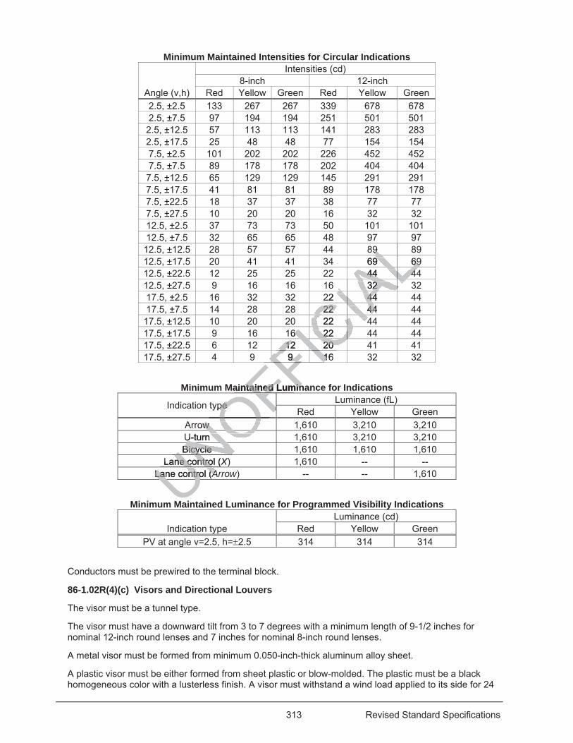
313 Revised Standard Specifications
Minimum Maintained Intensities for Circular Indications
Angle (v,h)
Intensities (cd) 8-inch 12-inch
Red Yellow Green Red Yellow Green 2.5, ±2.5 133 267 267 339 678 678 2.5, ±7.5 97 194 194 251 501 501 2.5, ±12.5 57 113 113 141 283 283 2.5, ±17.5 25 48 48 77 154 154 7.5, ±2.5 101 202 202 226 452 452 7.5, ±7.5 89 178 178 202 404 404 7.5, ±12.5 65 129 129 145 291 291 7.5, ±17.5 41 81 81 89 178 178 7.5, ±22.5 18 37 37 38 77 77 7.5, ±27.5 10 20 20 16 32 32 12.5, ±2.5 37 73 73 50 101 101 12.5, ±7.5 32 65 65 48 97 97
12.5, ±12.5 28 57 57 44 89 89 12.5, ±17.5 20 41 41 34 69 69 12.5, ±22.5 12 25 25 22 44 44 12.5, ±27.5 9 16 16 16 32 32 17.5, ±2.5 16 32 32 22 44 44 17.5, ±7.5 14 28 28 22 44 44
17.5, ±12.5 10 20 20 22 44 44 17.5, ±17.5 9 16 16 22 44 44 17.5, ±22.5 6 12 12 20 41 41 17.5, ±27.5 4 9 9 16 32 32
Minimum Maintained Luminance for Indications
Indication type Luminance (fL) Red Yellow Green
Arrow 1,610 3,210 3,210 U-turn 1,610 3,210 3,210 Bicycle 1,610 1,610 1,610
Lane control (X) 1,610 -- -- Lane control (Arrow) -- -- 1,610
Minimum Maintained Luminance for Programmed Visibility Indications
Indication type Luminance (cd)
Red Yellow Green PV at angle v=2.5, h= 2.5 314 314 314
Conductors must be prewired to the terminal block.
86-1.02R(4)(c) Visors and Directional Louvers
The visor must be a tunnel type.
The visor must have a downward tilt from 3 to 7 degrees with a minimum length of 9-1/2 inches for nominal 12-inch round lenses and 7 inches for nominal 8-inch round lenses.
A metal visor must be formed from minimum 0.050-inch-thick aluminum alloy sheet.
A plastic visor must be either formed from sheet plastic or blow-molded. The plastic must be a black homogeneous color with a lusterless finish. A visor must withstand a wind load applied to its side for 24
UNLane control (Lane control (AAUNOFFICIA
LL9 9 LL69 699 69LAL44 4444 4ALAL32 32 ALIAA
L22 44 44IACIA22 44 22 44
CIACIA22 422 4CICCI6 22 6 22 CICC12 20 12 20
FICFICC9 169 1FICFFFFICFaintained Luminntained Lumin
ype pe
OFFFFrow w OOU-turn U-turn NOBicycle Bicycle NO
Lane control (ne contro X)X
UNUNUMa
314 Revised Standard Specifications
hours without permanent deformation or removal from its door when tested under California Test 605 for plastic visors and California Test 666 for metal visors.
If directional louvers are used, the louvers must fit into full-circular signal visors. Louvers must consist of one of the following:
1. Outside cylinder constructed of sheet steel with a minimum nominal thickness of 0.030 inch and vanes constructed of sheet steel with a minimum nominal thickness of 0.016 inch.
2. Outside cylinder and vanes constructed of 5052-H32 aluminum alloy of equal thickness. 86-1.02S Pedestrian Signal Heads
86-1.02S(1) General
A pedestrian signal head consists of a pedestrian signal mounting assembly and a pedestrian signal face comprising of a pedestrian signal housing, an LED countdown pedestrian signal face module, and a front screen.
86-1.02S(2) Pedestrian Signal Mounting Assemblies
A pedestrian signal mounting assembly must comply with the specifications for a signal mounting assembly in section 86-1.02R, except mast arm slip fitters are not required.
86-1.02S(3) Pedestrian Signal Faces
86-1.02S(3)(a) General
Each pedestrian signal face must include a light-duty terminal block rated at 5 A and have 12 positions with no. 6-by-1/8-inch binder head screws. Each position must have 1 screw-type terminal.
The wiring and terminal block must comply with ITE publication ST-055-E, Pedestrian Traffic Control Signal Indicators: Light Emitting Diode (LED) Signal Modules.
86-1.02S(3)(b) Pedestrian Signal Housings
Pedestrian signal housing must comply with the specifications for a signal housing in 86-1.02R(4)(a)(iii), except the maximum overall dimensions must be 18-1/2 inches wide, 19 inches high, and 11-1/2 inches deep and without:
1. Visor 2. Watertight module or lens mounted in the door 3. Reinforcement plates The housing must have a terminal block attached to the back. The terminal block must have enough positions to accommodate all indications. Each position must be permanently labeled for the indications used.
86-1.02S(3)(c) LED Countdown Pedestrian Signal Face Modules
An LED countdown PSF module must comply with ITE publication ST-055-E, Pedestrian Traffic Control Signal Indicators: Light Emitting Diode (LED) Signal Modules, except the material must comply with ASTM D3935 and the module must have:
1. Ultra-bright-type LED rated for 100,000 hours of continuous operation. 2. Lot number and month and year of manufacture permanently marked on the back of the module 3. Prominent and permanent vertical markings for accurate indexing and orientation within the
pedestrian signal housing if a specific mounting orientation is required. Markings must be a minimum of 1 inch in height and include an up arrow and the word up or top.
4. Circuit board complying with TEES, chapter 1, section 6.
Individual LEDs must be wired such that a loss or failure of 1 LED will not result in a loss of more than 5 percent of the module's light output. Failure of an individual LED in a string must not result in a loss of an entire string or other indication.
UNOFFICIA
Lons for a signs fuired.
minal block rated nal block ratedon must have 1 son must have 1
E publication ST-E publication STignal Modulesnal Modules. .
ngs ngs
y with the specify with the s icsions must be 18-ons must be 1
ens mounted in tns mounted ies
ave a terminal bave a terminal bate all indate all ind
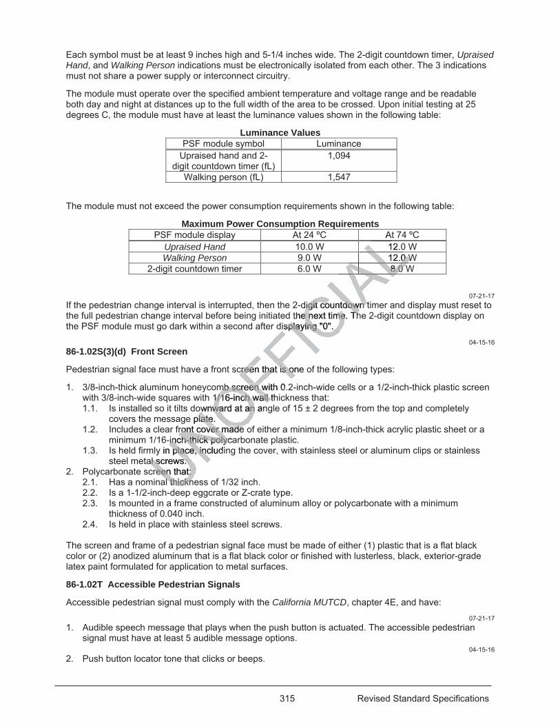
315 Revised Standard Specifications
Each symbol must be at least 9 inches high and 5-1/4 inches wide. The 2-digit countdown timer, Upraised Hand, and Walking Person indications must be electronically isolated from each other. The 3 indications must not share a power supply or interconnect circuitry.
The module must operate over the specified ambient temperature and voltage range and be readable both day and night at distances up to the full width of the area to be crossed. Upon initial testing at 25 degrees C, the module must have at least the luminance values shown in the following table:
Luminance Values PSF module symbol Luminance
Upraised hand and 2-digit countdown timer (fL)
1,094
Walking person (fL) 1,547
The module must not exceed the power consumption requirements shown in the following table:
Maximum Power Consumption Requirements PSF module display At 24 ºC At 74 ºC
Upraised Hand 10.0 W 12.0 W Walking Person 9.0 W 12.0 W
2-digit countdown timer 6.0 W 8.0 W
07-21-17 If the pedestrian change interval is interrupted, then the 2-digit countdown timer and display must reset to the full pedestrian change interval before being initiated the next time. The 2-digit countdown display on the PSF module must go dark within a second after displaying "0".
04-15-16 86-1.02S(3)(d) Front Screen
Pedestrian signal face must have a front screen that is one of the following types:
1. 3/8-inch-thick aluminum honeycomb screen with 0.2-inch-wide cells or a 1/2-inch-thick plastic screen with 3/8-inch-wide squares with 1/16-inch wall thickness that: 1.1. Is installed so it tilts downward at an angle of 15 ± 2 degrees from the top and completely
covers the message plate. 1.2. Includes a clear front cover made of either a minimum 1/8-inch-thick acrylic plastic sheet or a
minimum 1/16-inch-thick polycarbonate plastic. 1.3. Is held firmly in place, including the cover, with stainless steel or aluminum clips or stainless
steel metal screws. 2. Polycarbonate screen that:
2.1. Has a nominal thickness of 1/32 inch. 2.2. Is a 1-1/2-inch-deep eggcrate or Z-crate type. 2.3. Is mounted in a frame constructed of aluminum alloy or polycarbonate with a minimum
thickness of 0.040 inch. 2.4. Is held in place with stainless steel screws.
The screen and frame of a pedestrian signal face must be made of either (1) plastic that is a flat black color or (2) anodized aluminum that is a flat black color or finished with lusterless, black, exterior-grade latex paint formulated for application to metal surfaces.
86-1.02T Accessible Pedestrian Signals
Accessible pedestrian signal must comply with the California MUTCD, chapter 4E, and have: 07-21-17
1. Audible speech message that plays when the push button is actuated. The accessible pedestrian signal must have at least 5 audible message options.
04-15-16 2. Push button locator tone that clicks or beeps.
A12.0LL12.0 W12.0 W
ALA8.0 W8.0 ALAAALdigit countdown tdigit countdown t
the next time. The next time. Thisplaying "0". isplaying "0".
creen that is one creen that is on
mb screen with 0.mb screen w1/16-inch wall th1/16-inch wall t
wnward at an anward at ane plate. plate
ront cover made ront cover made -inch-thick polyca-inch-thick polyc
y in place, includiplace, incal screws. al screws.
reen that: reen that: l thicknl thickn
ee
316 Revised Standard Specifications
04-20-18 3. Feature that activates the pedestrian phase during any failure without causing the pedestrian phase
to be on RECALL.
04-15-16 An accessible pedestrian signal must function with the Department-furnished Model 170E/2070E controller assembly.
No part of the accessible pedestrian signal must be installed inside the controller cabinet. Power for the accessible pedestrian signal must be from the pedestrian signal housing terminal block.
The housing for the signal assembly must be made of corrosion-resistant material. Theft-proof bolts used for mounting the housing to the standard must be stainless steel with a content of 17 percent chromium and 8 percent nickel. The housing must be shaped to fit the pole's curvature.
The color of a metallic housing must match color no. 33538 of FED-STD-595.
The color of a plastic housing must match color no. 17038, 27038, or 37038 of FED-STD-595.
Accessible pedestrian signal must:
1. Have electronic switches, a potentiometer, or an access port for a device for controlling and programming the volume level and messaging
2. Be weatherproof and shockproof Enclosure for the accessible pedestrian signal must:
1. Weigh less than 7 lb 2. Measure less than 16 by 6 by 5 inches 3. Have a wiring hole with a diameter not exceeding 1-1/8 inches 5. Have a switch for a push button 6. Have a vibrotactile device on the push button or on the arrow 7. Have an internal weatherproof speaker and microphone that senses the ambient sound level
The separation between adjacent holes used for conductors and mounting must be at least twice the diameter of the larger hole.
The speaker grills must be located on the surface of the enclosure. The speakers must not interfere with the housing or its mounting hardware.
04-20-18 The cable between the accessible pedestrian signal assembly and the pedestrian signal head must have a:
1. Minimum four no. 18 stranded or larger tinned copper conductors with a minimum insulation thickness of 15 mils
2. Cable jacket with a minimum thickness of 20 mils and rated for a minimum: 2.1. 300 V(ac) 2.2. 80 degrees C
3. Nominal outside diameter less than 350 mils 4. Conductor color code of black, white, red and green
04-15-16 86-1.02U Push Button Assemblies
The housing for a push button assembly must be made of die-cast aluminum, permanent mold-cast aluminum, or UV-stabilized self-extinguishing structural plastic. The plastic housing must have a color throughout that matches color no. 17038, 27038, or 37038 of FED-STD-595.
If the push button is to be attached to a pole, the housing must be shaped to fit the pole's curvature.
The assembly must be waterproof and shockproof.
UNOFFICIA
Ldevice for contvice for cont
ng 1-1/8 inches ng 1-1/8 inches
tton or on the arroton or on the arroand miand microphone roph
es used for coes used for ndu
ted on the surfaced on the surfahardware. hardware.
e accessible pedecessible p
8 strande8 strand
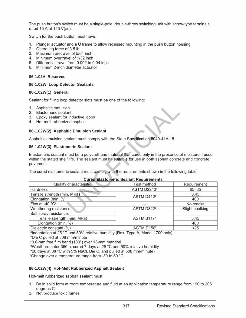
317 Revised Standard Specifications
The push button's switch must be a single-pole, double-throw switching unit with screw-type terminals rated 15 A at 125 V(ac).
Switch for the push button must have:
1. Plunger actuator and a U frame to allow recessed mounting in the push button housing 2. Operating force of 3.5 lb 3. Maximum pretravel of 5/64 inch 4. Minimum overtravel of 1/32 inch 5. Differential travel from 0.002 to 0.04 inch 6. Minimum 2-inch diameter actuator 86-1.02V Reserved
86-1.02W Loop Detector Sealants
86-1.02W(1) General
Sealant for filling loop detector slots must be one of the following:
1. Asphaltic emulsion 2. Elastomeric sealant 3. Epoxy sealant for inductive loops 4. Hot-melt rubberized asphalt 86-1.02W(2) Asphaltic Emulsion Sealant
Asphaltic emulsion sealant must comply with the State Specification 8040-41A-15.
86-1.02W(3) Elastomeric Sealant
Elastomeric sealant must be a polyurethane material that cures only in the presence of moisture if used within the stated shelf life. The sealant must be suitable for use in both asphalt concrete and concrete pavement.
The cured elastomeric sealant must comply with the requirements shown in the following table:
Cured Elastomeric Sealant Requirements Quality characteristic Test method Requirement
Hardness ASTM D2240a 65–85 Tensile strength (min, MPa) ASTM D412b 3.45 Elongation (min, %) 400 Flex at -40 °Cc -- No cracks Weathering resistance ASTM D822d Slight chalking Salt spray resistance:
ASTM B117e
Tensile strength (min, MPa) 3.45 Elongation (min, %) 400
Dielectric constant (%) ASTM D150f <25 aIndentation at 25 °C and 50% relative humidity (Rex. Type A, Model 1700 only) bDie C pulled at 508 mm/minute c0.6-mm free film bend (180°) over 13-mm mandrel dWeatherometer 350 h, cured 7 days at 25 °C and 50% relative humidity e28 days at 38 °C with 5% NaCl, Die C, and pulled at 508 mm/minute)
fChange over a temperature range from -30 to 50 °C
86-1.02W(4) Hot-Melt Rubberized Asphalt Sealant
Hot-melt rubberized asphalt sealant must:
1. Be in solid form at room temperature and fluid at an application temperature range from 190 to 205 degrees C
2. Not produce toxic fumes
UNOFFICIA
LSpecification 804Specification 804
aterial thataterial that curesresbe sube s itable for utable
comply with comply with the reth
ured Elastomeriured Elastomeristic tic
NONONOMPa) Pa) NUNUNUU
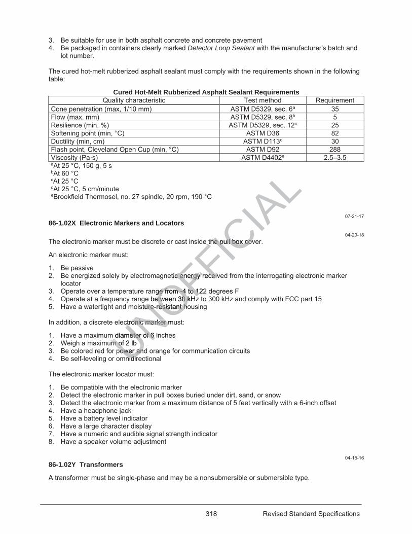
318 Revised Standard Specifications
3. Be suitable for use in both asphalt concrete and concrete pavement 4. Be packaged in containers clearly marked Detector Loop Sealant with the manufacturer's batch and
lot number. The cured hot-melt rubberized asphalt sealant must comply with the requirements shown in the following table:
Cured Hot-Melt Rubberized Asphalt Sealant Requirements Quality characteristic Test method Requirement
Cone penetration (max, 1/10 mm) ASTM D5329, sec. 6a 35 Flow (max, mm) ASTM D5329, sec. 8b 5 Resilience (min, %) ASTM D5329, sec. 12c 25 Softening point (min, °C) ASTM D36 82 Ductility (min, cm) ASTM D113d 30 Flash point, Cleveland Open Cup (min, °C) ASTM D92 288 Viscosity (Pa·s) ASTM D4402e 2.5–3.5 aAt 25 °C, 150 g, 5 s bAt 60 °C cAt 25 °C dAt 25 °C, 5 cm/minute eBrookfield Thermosel, no. 27 spindle, 20 rpm, 190 °C
07-21-17 86-1.02X Electronic Markers and Locators
04-20-18 The electronic marker must be discrete or cast inside the pull box cover.
An electronic marker must:
1. Be passive 2. Be energized solely by electromagnetic energy received from the interrogating electronic marker
locator 3. Operate over a temperature range from -4 to 122 degrees F 4. Operate at a frequency range between 30 kHz to 300 kHz and comply with FCC part 15 5. Have a watertight and moisture-resistant housing In addition, a discrete electronic marker must:
1. Have a maximum diameter of 6 inches 2. Weigh a maximum of 2 lb 3. Be colored red for power and orange for communication circuits 4. Be self-leveling or omnidirectional The electronic marker locator must:
1. Be compatible with the electronic marker 2. Detect the electronic marker in pull boxes buried under dirt, sand, or snow 3. Detect the electronic marker from a maximum distance of 5 feet vertically with a 6-inch offset 4. Have a headphone jack 5. Have a battery level indicator 6. Have a large character display 7. Have a numeric and audible signal strength indicator 8. Have a speaker volume adjustment
04-15-16 86-1.02Y Transformers
A transformer must be single-phase and may be a nonsubmersible or submersible type.
UNOFFICIA
Le the pull box cove the pull box cov
tic energy c energy receiveceiv
ge from -4 to 122ge from -4 to 1e between 30 etween 30 kHz
sture-resistant houre-resistant h
ctronic marker muctronic marker m
diameter of 6 ineter of 6 um of 2 lb m of
power andpower annidirnidir
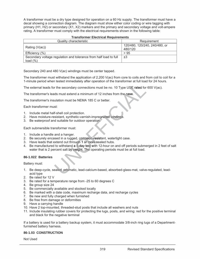
319 Revised Standard Specifications
A transformer must be a dry type designed for operation on a 60 Hz supply. The transformer must have a decal showing a connection diagram. The diagram must show either color coding or wire tagging with primary (H1, H2) or secondary (X1, X2) markers and the primary and secondary voltage and volt-ampere rating. A transformer must comply with the electrical requirements shown in the following table:
Transformer Electrical Requirements Quality characteristic Requirement
Rating (V(ac)) 120/480, 120/240, 240/480, or 480/120
Efficiency (%) > 95 Secondary voltage regulation and tolerance from half load to full load (%)
±3
Secondary 240 and 480 V(ac) windings must be center tapped.
The transformer must withstand the application of 2,200 V(ac) from core to coils and from coil to coil for a 1-minute period when tested immediately after operation of the transformer at full load for 24 hours.
The external leads for the secondary connections must be no. 10 Type USE rated for 600 V(ac).
The transformer's leads must extend a minimum of 12 inches from the case.
The transformer's insulation must be NEMA 185 C or better.
Each transformer must:
1. Include metal half-shell coil protection. 2. Have moisture-resistant, synthetic-varnish-impregnated windings. 3. Be waterproof and suitable for outdoor operation.
Each submersible transformer must:
1. Include a handle and a hanger. 2. Be securely encased in a rugged, corrosion-resistant, watertight case. 3. Have leads that extend out through 1 or more sealed hubs. 4. Be manufactured to withstand a 5-day test with 12-hour on and off periods submerged in 2 feet of salt
water that is 2 percent salt by weight. The operating periods must be at full load. 86-1.02Z Batteries
Battery must:
1. Be deep-cycle, sealed, prismatic, lead-calcium-based, absorbed-glass-mat, valve-regulated, lead-acid type
2. Be rated for 12 V 3. Be rated for a temperature range from -25 to 60 degrees C 4. Be group size 24 5. Be commercially available and stocked locally 6. Be marked with a date code, maximum recharge data, and recharge cycles 7. Be new and fully charged when furnished 8. Be free from damage or deformities 9. Have a carrying handle 10. Have 2 top-mounted, threaded-stud posts that include all washers and nuts 11. Include insulating rubber covers for protecting the lugs, posts, and wiring: red for the positive terminal
and black for the negative terminal
If a battery is used for a battery backup system, it must accommodate 3/8-inch ring lugs of a Department-furnished battery harness.
86-1.03 CONSTRUCTION
Not Used
UNOFFICIA
LSE rated fSE
e case. e ca
gnated windings.gnated windingson. on.
corrosion-resistacorrosion-rough 1 or more seugh 1 or more s
d a 5-day test witd a 5-day test t by weight. y weight. The oThe
aled, prismaled, prism
320 Revised Standard Specifications
86-1.04 PAYMENT
Not Used
Replace section 87 with: 04-15-16
87 ELECTRICAL SYSTEMS 04-20-18
87-1 GENERAL
87-1.01 GENERAL
87-1.01A Summary
Section 87 includes general specifications for constructing and installing electrical systems.
The Department deducts the cost for maintenance performed by the Department on new or portions of existing systems modified under the Contract.
87-1.01B Definitions
Reserved
87-1.01C Submittals
Reserved
87-1.01D Quality Assurance
87-1.01D(1) General
Reserved
04-20-18 87-1.01D(2) Quality Control
87-1.01D(2)(a) General
Before shipping the material to the job site, submit to METS test samples of:
1. Accessible pedestrian signals 2. LED countdown pedestrian signal face modules 3. LED signal modules 4. LED luminaires
Submit a sample size as shown in the following table: UNOFFICIA
L
he job he job site, submub
ignals gnaestrian signal facestrian signal fac
es
s shown s shown
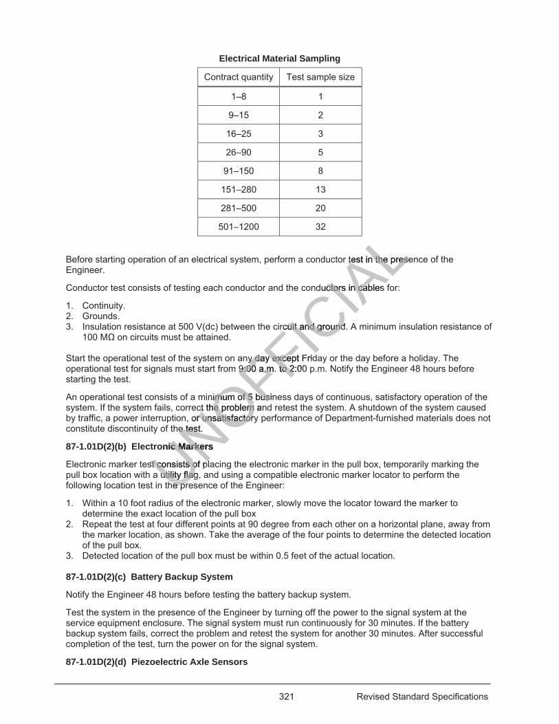
321 Revised Standard Specifications
Electrical Material Sampling
Contract quantity Test sample size
1–8 1
9–15 2
16–25 3
26–90 5
91–150 8
151–280 13
281–500 20
501–1200 32
Before starting operation of an electrical system, perform a conductor test in the presence of the Engineer.
Conductor test consists of testing each conductor and the conductors in cables for:
1. Continuity. 2. Grounds. 3. Insulation resistance at 500 V(dc) between the circuit and ground. A minimum insulation resistance of
100 M on circuits must be attained.
Start the operational test of the system on any day except Friday or the day before a holiday. The operational test for signals must start from 9:00 a.m. to 2:00 p.m. Notify the Engineer 48 hours before starting the test.
An operational test consists of a minimum of 5 business days of continuous, satisfactory operation of the system. If the system fails, correct the problem and retest the system. A shutdown of the system caused by traffic, a power interruption, or unsatisfactory performance of Department-furnished materials does not constitute discontinuity of the test.
87-1.01D(2)(b) Electronic Markers
Electronic marker test consists of placing the electronic marker in the pull box, temporarily marking the pull box location with a utility flag, and using a compatible electronic marker locator to perform the following location test in the presence of the Engineer:
1. Within a 10 foot radius of the electronic marker, slowly move the locator toward the marker to determine the exact location of the pull box
2. Repeat the test at four different points at 90 degree from each other on a horizontal plane, away from the marker location, as shown. Take the average of the four points to determine the detected location of the pull box.
3. Detected location of the pull box must be within 0.5 feet of the actual location. 87-1.01D(2)(c) Battery Backup System
Notify the Engineer 48 hours before testing the battery backup system.
Test the system in the presence of the Engineer by turning off the power to the signal system at the service equipment enclosure. The signal system must run continuously for 30 minutes. If the battery backup system fails, correct the problem and retest the system for another 30 minutes. After successful completion of the test, turn the power on for the signal system.
87-1.01D(2)(d) Piezoelectric Axle Sensors
UNOFFICIA
Ltest in the presetest in the prese
ductors in cables ctors in ca
rcuit and ground.rcuit and ground
y dayy day except Frid exce9:00 a.m.9:00 a.m to 2:00to 2
nimum of 5 businimum of 5 busct the problem anct the problem
, or unsatisfactoryr unsatisfactorhe test. e test.
onic Markers ic Marke
st consists ofst consists o plfutility flagutility flag
he prhe pr
322 Revised Standard Specifications
Piezoelectric axle sensors consists of testing each piezoelectric axle sensor for each lane of data collection as follows:
1. Capacitance must be 20 percent of the sensor's data sheet as provided by the manufacturer. 2. Dissipation factor must be less than 0.04 nF when measured in the 20 nF range. 3. Resistance must be greater than 20 Megaohms. 4. Minimum of 100 per-vehicle records must be collected for each lane. Collected data must have:
4.1 Total volume of ±3 percent accuracy. 4.2 Vehicle classification of 95 percent accuracy by type.
Collect data files from the on-site equipment using the central office host computer to verify the communication link is working.
04-15-16 87-1.02 MATERIALS
Not Used
87-1.03 CONSTRUCTION
87-1.03A General
The Engineer determines the final locations of electrical systems.
Verify the locations of electrical systems and the depths of existing detectors, conduits, and pull boxes.
Notify the Engineer before performing work on the existing system.
You may shut down the system for alteration or removal.
Where an existing Department underground facility is shown within 10 feet of any excavation, locate and field mark the facility before performing work that could damage or interfere with the existing facility.
If an existing facility is within 2 feet of an excavation, determine the exact location of the facility by excavating with hand tools before using any power-operated or power-driven excavating or boring equipment. A vacuum excavator may be used if authorized.
Notify the Engineer immediately if an existing facility is damaged by your activities.
If existing underground conduit is to be incorporated into a new system, clean it with a mandrel or cylindrical wire brush and blow it clean with compressed air.
Limit the shutdown of traffic signal systems to normal working hours. Notify the local traffic enforcement agency before shutting down the signal.
Place temporary W3-1 and R1-1 signs in each direction to direct traffic through the intersection during shutdown of the signal. Place two R1-1 signs for 2-lane approaches. The signs must comply with part 2 of the California MUTCD.
Cover signal faces when the system is shut down overnight. Cover temporary W3-1 and R1-1 signs when the system is turned on.
If you work on an existing lighting system and the roadway is to remain open to traffic, ensure the system is in operation by nightfall.
Replace detectors you damage within 72 hours, or the Department replaces them and deducts the cost.
Work performed on an existing system not described is change order work.
Do not use electrical power from existing highway facilities unless authorized.
Maintain a minimum 48-inch clearance for a pedestrian pathway when placing equipment.
Except for service installation or work on service equipment enclosures, do not work above ground until all materials are on hand to complete the electrical work at each location.
UNOFFICIA
Lng detectors, conng detectors, co
system. system
al.
y is shis s own within own within t could damage ot could damage
cavaticava on, determin, deany power-oy power peratpera
be used if authoribe used if a
an existing facilitn existing facilit
it is to be incorpos to be incorpoblow it clean with ow it clean w
raffic signal systefic signal ng down the signng down the sig
and R1-1and R1-1ace
323 Revised Standard Specifications
Bond all metal components to form a continuous grounded system as specified in NEC.
Ground metallic equipment mounted less than 8 feet above the ground surface on a wood pole.
If you damage any portion of a concrete curb, sidewalk, curb ramp, driveway, or gutter depression, replace the entire section between contraction or expansion joints under section 73.
Apply equipment identification characters.
Orient louvers, visors, and signal faces such that they are clearly visible to approaching traffic from the direction being controlled.
Test loops and the detector lead-in cable circuit for continuity, ground, and insulation resistance at the controller cabinet before connecting detector lead-in cable to the terminal block.
Perform an operational test of the systems.
Before starting the operational test for systems that impact traffic, the system must be ready for operation, and all signs, pavement delineation, and pavement markings must be in place at that location.
87-1.03B Conduit Installation
87-1.03B(1) General
The installation of conduit includes installing caps, bushings, and pull tape and terminating the conduit in pull boxes, foundations, poles, or a structure.
04-20-18 Notify the Engineer at least 4 business days before starting horizontal directional drilling method or jack and drill activities.
04-15-16 Limit the number of bends in a conduit run to no more than 360 degrees between pull points.
Use conduit to enclose conductors except where they are installed overhead or inside standards or posts.
You may use a larger size conduit than specified for the entire length between termination points. Do not use a reducing coupling.
Extend an existing conduit using the same material. Terminate conduits of different materials in a pull box.
Install 2 conduits between a controller cabinet and the adjacent pull box.
Use a minimum trade size of conduit of:
1. 1-1/2 inches from an electrolier to the adjacent pull box 2. 1 inch from a pedestrian push button post to the adjacent pull box 3. 2 inches from a signal standard to the adjacent pull box 4. 3 inches from a controller cabinet to the adjacent pull box 5. 2 inches from an overhead sign to the adjacent pull box 6. 2 inches from a service equipment enclosure to the adjacent pull box 7. 1-1/2 inches if unspecified Use Type 1 conduit:
1. On all exposed surfaces 2. In concrete structures 3. Between a structure and the nearest pull box Ream the ends of shop-cut and field-cut conduit to remove burrs and rough edges. Make the cuts square and true. Do not use slip joints and running threads to couple conduit. If a standard coupling cannot be used for metal-type conduit, use a threaded union coupling. Tighten the couplings for metal conduit to maintain a good electrical connection.
pull tape and termtape and term
ng horizontal direg horizontal dir
more than 360 dmore than 360
where they arwhere they a e ins
specified for specified the
g the same materthe same mat
n a controllen a controller cabr ca
e size of conduit oe size of condui
an electrolian electroian pan p
324 Revised Standard Specifications
04-20-18 Cap the ends of conduit to prevent debris from entering before installing the conductors or cables. Use a plastic cap for Type 1, 2, and 5 conduits and a standard pipe cap for all other types of conduit or bell.
04-15-16 For Type 1, 2, and 5 conduits, use threaded bushings and bond them using a jumper. For other types of conduit, use nonmetallic bushings.
Do not install new conduit through foundations.
Cut Type 2 conduit with pipe cutters; do not use hacksaws. Use standard conduit-threading dies for threading conduit. Tighten conduit into couplings or fittings using strap wrenches or approved groove joint pliers.
Cut Type 3 conduit with tools that do not deform the conduit. Use a solvent weld for connections.
Protect shop-cut threads from corrosion under the standards shown in the following table:
Shop-Cut Thread Corrosion Protection Conduit Standard
Types 1 and 2 ANSI C80.1 Type 5 ANSI C80.6
Apply 2 coats of unthinned, organic zinc-rich primer to metal conduit before painting. Use a primer on the Authorized Material List for organic zinc-rich primers. Do not use aerosol cans. Do not remove shop-installed conduit couplings.
For conduits, paint:
1. All exposed threads 2. Field-cut threads, before installing conduit couplings to metal conduit 3. Damaged surfaces on metal conduit If a Type 2 conduit or conduit coupling coating is damaged:
1. Clean the conduit or fitting and paint it with 1 coat of rubber-resin-based adhesive under the manufacturer's instructions
2. Wrap the damaged coating with at least 1 layer of 2-inch-wide, 20 mils-minimum-thickness, PVC tape under ASTM D1000 with a minimum tape overlap of 1/2 inch
You may repair damaged spots of 1/4 inch or less in diameter in the thermoplastic coating by painting with a brushing-type compound supplied by the conduit manufacturer.
If factory bends are not used, bend the conduit to a radius no less than 6 times its inside diameter without crimping or flattening it. Comply with the bending requirements shown in the following table:
Conduit-Bending Requirements Type Requirement
1 Use equipment and methods under the conduit manufacturer's instructions.
2 Use a standard bending tool designed for use on thermoplastic-coated conduit. The conduit must be free of burrs and pits.
3 Use equipment and methods under the conduit manufacturer's instructions. Do not expose the conduit to a direct flame.
5 Use equipment and methods under the conduit manufacturer's instructions.
Install pull tape with at least 2 feet of slack in each end of the conduit that will remain empty. Attach the tape's ends to the conduit.
Install conduit terminating in a standard or pedestal from 2 to 3 inches above the foundation. Slope the conduit toward the handhole opening.
StaANSI CLLANSI C80AN LAAALnduit before paintiduit before paint
use aerosol cans.se aerosol c
couplings to metaouplings to met
coating is damageing is damage
paint it with paint it with 1 coa1 co
g with at least 1 lwith at least 1 h a minimum taph a minimum tap
ged spots of 1/4 ispots of 1compound suppcompound sup
used, beused, beomp
325 Revised Standard Specifications
Terminate conduit installed through the bottom of a nonmetallic pull box 2 inches above the bottom and 2 inches from the wall closest to the direction of the run.
87-1.03B(2) Conduit Installation for Structures
87-1.03B(2)(a) General
Paint exposed Type 1 conduit the same color as the structure.
Install galvanized steel hangers, steel brackets, and other fittings to support conduit in or on a wall or bridge.
87-1.03B(2)(b) New Structures
Seal and make watertight the conduits which lead to soffits, wall-mounted luminaires, other lights, and fixtures located below the pull box grade.
If you place a conduit through the side of a nonmetallic pull box, terminate the conduit 2 inches from the wall and 2 inches above the bottom. Slope the conduit toward the top of the box to facilitate pulling conductors.
For ease of installation and if authorized, you may use Type 4 conduit instead of Type 1 conduit for the final 2 feet of conduit entering a pull box in a reinforced concrete structure.
Install an expansion fitting where a conduit crosses an expansion joint in a structure. Each expansion fitting for metal conduit must include a copper bonding jumper having the ampacity as specified in NEC.
Install an expansion-deflection fitting for an expansion joint with a 1-1/2-inch movement rating. The fitting must be watertight and include a molded neoprene sleeve, a bonding jumper, and 2 silicon bronze or zinc-plated iron hubs.
For an expansion joint with a movement rating greater than 1-1/2 inches, install the expansion-deflection fitting as shown.
For conduit installed inside of bridge structures, you must:
1. Install precast concrete cradles made of minor concrete and commercial-quality welded wire fabric. The minor concrete must contain a minimum of 590 lb of cementitious material per cubic yard. The cradles must be moist cured for a minimum of 3 days.
2. Bond precast concrete cradles to a wall or bridge superstructure with one of the following: 2.1. Epoxy adhesive for bonding freshly-mixed concrete to hardened concrete. 2.2. Rapid-set epoxy adhesive for pavement markers. 2.3. Standard-set epoxy adhesive for pavement markers.
3. Use a pipe sleeve or form an opening for a conduit through a bridge superstructure. The sleeve or opening through a prestressed member or conventionally reinforced precast member must be: 3.1. Oriented transverse to the member. 3.2. Located through the web. 3.3. No more than 4 inches in size.
4. Wrap the conduit with 2 layers of asphalt felt building paper and securely tape or wire the paper in place for a conduit passing through a bridge abutment wall. Fill the space around the conduit with mortar under section 51-1, except the proportion of cementitious material to sand must be 1 to 3. Fill the space around the conduits after prestressing is completed.
Thread and cap a conduit installed for future use in structures. Mark the location of the conduit's end in a structure, curb, or wall directly above the conduit with a Y that is 3 inches tall.
87-1.03B(2)(c) Existing Structures
Run surface-mounted conduit straight and true, horizontal or vertical on the wall, and parallel to walls on ceilings or similar surfaces. Support the conduit at a maximum of 5-foot intervals where needed to prevent vibration or deflection. Support the conduit using galvanized, malleable-iron, conduit clamps, and clamp backs secured with expansion anchorage devices complying with section 75-3.02C. Use the largest diameter of galvanized, threaded studs that will pass through the mounting hole in the conduit clamp.
nstead of Typteadcture. tu
n joint in a structu joint in a structuhaving the ampaaving the a
nt with a 1-1/2-incwith a 1-1/2-inceve, a bonding jumeve, a bonding
reaterreate than 1-1/2than 1-1r
ctures, you must:ures, you must
made of minor made of minor coain a minimum ofn a minimum o
d for a minimum ofor a minimumradles to a wall os to a wall o
e for bonding fresfor bonding froxy adhesive for xy adhesive for
set epoxy adhesivset epoxy adheve or form an ope or form an o
prestresseprestressverseerse
326 Revised Standard Specifications
87-1.03B(3) Conduit Installation Underground
87-1.03B(3)(a) General
Install conduit to a depth of:
1. 14 inches for the trench-in-pavement method 2. 18 inches, minimum, under sidewalk and curbed paved median areas 3. 42 inches, minimum, below the bottom of the rail of railroad tracks 4. 30 inches, minimum, everywhere else below grade
Place conduit couplings at a minimum of 6 inches from the face of a foundation.
Place a minimum of 2 inches of sand bedding in a trench before installing Type 2 or Type 3 conduit and 4 inches of sand bedding over the conduit before placing additional backfill material.
If installing conduit within the limits of hazardous locations as specified in NEC for Class I, division 1, install and seal Type 1 or Type 2 conduit with explosion-proof sealing fittings.
87-1.03B(3)(b) Conduit Installation under Paved Surfaces
You may lay conduit on existing pavement within a new curbed median constructed on top. 07-21-17
Install conduit under existing pavement by either the horizontal directional drill method or jack and drill method. You may use the trench-in-pavement method for either of the following conditions:
1. If conduit is to be installed behind the curb under the sidewalk 2. If the delay to vehicles will be less than 5 minutes
04-15-16 Do not use the trench-in-pavement method for conduit installations under freeway lanes or freeway-to-freeway connector ramps.
04-20-18 87-1.03B(3)(c) High Density Polyethylene Conduit Installation
For sweeps, maintain a conduit bend radius of a minimum 10 times the outside diameter of the conduit.
Conduits must not protrude more than 2 inches inside the pull box and vaults, and must enter at an angle less than 20 degrees from either the vertical or horizontal axis.
Demonstrate a minimum of 2 test fusions to the Engineer prior to performing fusion operations on HDPE conduit to be installed.
Join HDPE conduit using the electro fusion method recommended by the conduit manufacturer. Do not expose conduit to direct flame. The electro-fusion must be performed by a person certified by the conduit manufacturer.
Place warning tape in the trench 6 inches below finished grade.
Backfill trench with slurry concrete pigmented matching FED-STD-595 under 19-3.02E. The size of the aggregate must be no larger than 3/8 inch. Provide adequate spacers, tie-downs and bracing to maintain conduits in place during backfill.
For trenches in paved areas, only the top 4 inch of concrete backfill must be pigmented.
Blow out all conduits with compressed air until all foreign material is removed, before installing innerducts.
Install innerducts in accordance with the manufacturer's installation procedures. Innerducts must be one continuous unit between splice vaults. Innerducts may be interrupted inside pull boxes located between splice vaults and cabinets.
Lubricate innerducts per manufacturer's instructions during installation.
Install a pull tape in conduits and innerducts to remain empty.
UNOFFICIA
L constructed onstructed o
irectional drill merectional drill meer of the followingof the follo
idewalk dewal
conduiond t installatiot installati
ylene Conduit Inylene Con
end radius of a mid radius of a m
ore than 2 inchese than 2 incheseither teither the verticale vertica
m of 2 test fusionof 2 test fd. d.
ng the eleng the eleameame
327 Revised Standard Specifications
Seal the ends of conduit after cables or pull tape are installed.
04-15-16 87-1.03B(3)(d) Conduit Installation under Railroad Tracks
Install Type 1 or Type 2 conduit with a minimum diameter of 1-1/2 inches under railroad tracks. If you use the jacking or drilling method to install the conduit, construct the jacking pit a minimum of 13 feet from the tracks' centerline at the near side of the pit. Cover the jacking pit with planking if left overnight.
04-20-18 87-1.03B(4) Conduit Installation by Horizontal Directional Drilling Method
Install a conduit to a minimum depth of 4 feetand maximum depth of 6 feet. If you must install a conduit less than 4 feet in depth or greater than 6 feet in depth, the installation must be authorized.
The diameter of the bore hole must be no larger than 1.5 times the outside diameter of the conduit.
Water-based mineral slurry or wetting solution may be used to lubricate the boring tool and stabilize the soil surrounding the boring path.
Disposal of residue must comply with section 13-4.03D.
The horizontal directional drilling equipment must have directional control of the boring tool and have an electronic boring tool location detection system. During operation, the equipment must be able to determine the location of the tool both horizontally and vertically.
Do not use slurry cement backfill.
Use a mandrel to prove the conduit is free and clear of dirt, rocks, and other debris after installation.
07-21-17 87-1.03B(5) Conduit Installation by the Jack and Drill Method
04-15-16 Keep the jacking or drilling pit 2 feet away from the pavement's edge. Do not weaken the pavement or soften the subgrade with excessive use of water.
If an obstruction is encountered, obtain authorization to cut small holes in the pavement to locate or remove the obstruction.
You may install Type 2 or Type 3 conduit under the pavement if a hole larger than the conduit's diameter is predrilled. The predrilled hole must be less than one and half the conduit's diameter.
Remove the conduit used for drilling or jacking and install new conduit for the completed work.
87-1.03B(6) Conduit Installation by the Trenching-In-Pavement Method
Install conduit by the trenching-in-pavement method using a trench approximately 2 inches wider than the conduit's outside diameter but not exceeding 6 inches in width.
Where additional pavement is to be placed, you must complete the trenching before the final pavement layer is applied.
If the conduit shown is to be installed under the sidewalk, you may install it in the street within 3 feet of and parallel to the face of the curb. Install pull boxes behind the curb.
Cut the trench using a rock-cutting excavator. Minimize the shatter outside the removal area of the trench.
Dig the trench by hand to the required depth at pull boxes.
Place conduit in the trench.
Backfill the trench with minor concrete to the pavement's surface by the end of each work day. If the trench is in asphalt concrete pavement and no additional pavement is to be placed, backfill the top 0.10 foot of the trench with minor HMA within 3 days after trenching.
87-1.03C Installation of Pull Boxes
UNOFFICIA
Lrol of the boringof the boringe equipment muse equipment mus
rt, rocks, and oth rocks, and ot
nd Drill Method d Drill Method
om tom the pavementpavf water. water.
in authorization toin authorizat
e 3 conduit under3 conduit undehole must be lesshole must be less
ed for drilling or jd for drilling or j
it Installation bit Installation b
nching-nching-bu
328 Revised Standard Specifications
87-1.03C(1) General
Install pull boxes no more than 200 feet apart.
You may install larger pull boxes than specified or shown and additional pull boxes to facilitate the work except in structures.
Install a pull box on a bed of crushed rock and grout it before installing conductors. The grout must be from 0.5 to 1 inch thick and sloped toward the drain hole. Place a layer of roofing paper between the grout and the crushed rock sump. Make a 1-inch drain hole through the grout at the center of the pull box.
Set the pull box such that the top is 1-1/4 inches above the surrounding grade in unpaved areas and leveled with the finished grade in sidewalks and other paved areas.
Place the cover on the box when not working in it.
Grout around conduits that are installed through the sides of the pull box.
Bond and ground the metallic conduit before installing conductors and cables in the conduit.
Bond metallic conduits in a nonmetallic pull box using bonding bushings and bonding jumpers.
Do not install pull boxes in concrete pads, curb ramps, or driveways.
Reconstruct the sump of a pull box if disturbed by your activities. If the sump was grouted, remove and replace the grout.
87-1.03C(2) Nontraffic Pull Boxes 04-20-18
For buried pull boxes, install the electronic marker.
04-15-16 If you bury a nontraffic pull box, set the box such that the top is 6 to 8 inches below the surrounding grade. Place a 20-mil-thick plastic sheet made of HDPE or PVC virgin compounds to prevent water from entering the box.
Place mortar between a nontraffic pull box and a pull box extension.
Where a nontraffic pull box is in the vicinity of curb in an unpaved area, place the box adjacent to the back of the curb if practical.
07-21-17 Where a nontraffic pull box is adjacent to a post or standard, place the box within 5 feet downstream from traffic if practical.
04-15-16 If you replace the cover on a nontraffic pull box, anchor it to the box.
04-20-18 Perform the electronic marker test.
04-15-16 87-1.03C(3) Traffic Pull Boxes
Place minor concrete around and under a traffic pull box.
Bolt the steel cover to the box when not working in it.
Bond the steel cover to the conduit with a jumper and bolt it down after installing the conductors and cables.
87-1.03C(4) Structure Pull Boxes
Bond metallic conduit in a metal pull box in a structure using locknuts, inside and outside of the box, bonding bushings, and bonding jumpers connected to bonding wire running in the conduit system.
04-20-18 87-1.03C(5) Tamper-Resistant Pull Boxes
nd bond
f the sump was ge sump was g
ch thatch that the top is the top isade of HDPEde of HDPE or P
ull box and a pull ll box and a p
the vicinity of cuthe vicinity of c
box is adjacent toox is adjacent to
on a noon a no
329 Revised Standard Specifications
Install the tamper-resistant pull boxes under the manufacturer’s instructions.
04-15-16 04-20-18
87-1.03D Battery Backup System Cabinets
Install the battery backup system cabinet to the right of the Model 332L cabinet.
If installation on the right side is not feasible, obtain authorization for installation on the left side.
Provide access for power conductors between the cabinets using:
1. 2-inch nylon-insulated, steel chase nipple 2. 2-inch steel sealing locknut 3. 2-inch nylon-insulated, steel bushing Remove the jumper between the terminals labeled BBS-1 and BBS-2 in the 5 position terminal block in the controller cabinet before connecting the Department-furnished electronics assembly.
04-15-16 87-1.03E Excavating and Backfilling for Electrical Systems
87-1.03E(1) General
Notify the Engineer at least 72 hours before starting excavation activities.
Dispose of surplus excavated material.
Restrict closures for excavation on a street or highway to 1 lane at a time unless otherwise specified.
87-1.03E(2) Trenching 07-21-17
Dig a trench for the electrical conduits. Do not excavate until the installation of the conduit.
04-15-16 Place excavated material in a location that will not interfere with traffic or surface drainage.
07-21-17 After placing the conduit, backfill the trench with the excavated material.
04-15-16 Compact the backfill placed within the hinge points and in areas where pavement is to be constructed to a minimum relative compaction of 95 percent.
Restore the sidewalks, pavement, and landscaping at a location before starting excavation at another location.
87-1.03E(3) Concrete Pads, Foundations, and Pedestals
Construct foundations for standards, poles, metal pedestals, and posts under section 56-3.
Construct concrete pads, foundations, and pedestals for controller cabinets, telephone demarcation cabinets, and service equipment enclosures on firm ground.
Install anchor bolts using a template to provide proper spacing and alignment. Moisten the forms and ground before placing the concrete. Keep the forms in place until the concrete sets for at least 24 hours to prevent damage to the surface.
Use minor concrete for pads, foundations, and pedestals.
In unpaved areas, place the top of the foundation 6 inches above the surrounding grade, except place the top:
1. 1 foot 6 inches above the grade for Type M and 336L cabinets 2. 1 foot 8 inches above the grade for Type C telephone demarcation cabinets 3. 2 inches above the grade for Type G and Type A cabinets and Type III service equipment enclosures
UNOFFICIA
Lctivities. ies.
1 lane at a time lane at a time
excavate until theexcavate until th
at will will not interfenot interfe
he trench with thtrench with th
d within the hinge within the hingection of 95 percenction of 95 perce
ks, pavement, anks, pavement, a
ads, ads
330 Revised Standard Specifications
The pad must be 2 inches above the surrounding grade.
In and adjacent to the sidewalk and other paved areas, place the top of the foundation 4 inches above the surrounding grade, except place the top:
1. 1 foot 6 inches above the grade for Type M and 336L cabinets 2. 1 foot 8 inches above the grade for Type C telephone demarcation cabinets 3. Level with the finished grade for Type G and Type A cabinets and Type III service equipment
enclosures The pad must be level with the finished grade.
Apply an ordinary surface finish under section 51-1.03F.
Allow the foundation to cure for at least 7 days before installing any equipment.
87-1.03F Conductors and Cable Installations
87-1.03F(1) General
The installation of conductors and cables includes splicing conductors and attaching the terminals and connectors to the conductors.
Clean the conduit and pull all conductors and cables as a unit.
If new conductors or cables are to be added in an existing conduit:
1 Remove the content 2. Clean the conduit 3. Pull both old and new conductors and cables as a unit Wrap conductors and secure cables to the end of the conduit in a pull box.
Seal the ends of conduits with a sealing compound after installing conductors or cables.
Neatly arrange conductors and cables inside pull boxes and cabinets. Tie the conductors and cables together with self-clinching nylon cable ties or enclose them in a plastic tubing or raceway.
Identify conductors and cables by direct labeling, tags, or bands fastened in such a way that they will not move. Use mechanical methods for labeling.
Provide band symbol identification on each conductor or each group of conductors comprising a signal phase in each pull box and near the end of terminated conductors.
Tape the ends of unused conductors and cables in pull boxes to form a watertight seal.
Do not connect the push-button or accessible pedestrian signal neutral conductor to the signal neutral conductor.
04-20-18 Install a continuous tracer throughout the length of the trench.
04-15-16 87-1.03F(2) Cables
87-1.03F(2)(a) General
Reserved
04-20-18 87-1.03F(2)(b) Communication Cables
87-1.03F(2)(b)(i) General
Terminate the ends of the communication cables as shown.
87-1.03F(2)(b)(ii) Category 5E and 6 Cables
UNOFFICIA
Ld attachind a
duit: it:
a unit a unit
of the conduit in f the conduit in
mpound after insmpound after
inside pull boxinside pull esble ties or ble ties or enclosenclo
by direct labelingy direct labelinods for labeling. or labeling.
entification on eacntification on eax and near the end near the
sed conductosed conduc
buttott
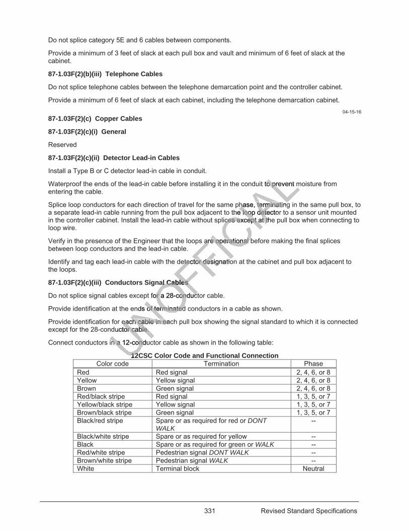
331 Revised Standard Specifications
Do not splice category 5E and 6 cables between components.
Provide a minimum of 3 feet of slack at each pull box and vault and minimum of 6 feet of slack at the cabinet.
87-1.03F(2)(b)(iii) Telephone Cables
Do not splice telephone cables between the telephone demarcation point and the controller cabinet.
Provide a minimum of 6 feet of slack at each cabinet, including the telephone demarcation cabinet.
04-15-16 87-1.03F(2)(c) Copper Cables
87-1.03F(2)(c)(i) General
Reserved
87-1.03F(2)(c)(ii) Detector Lead-in Cables
Install a Type B or C detector lead-in cable in conduit.
Waterproof the ends of the lead-in cable before installing it in the conduit to prevent moisture from entering the cable.
Splice loop conductors for each direction of travel for the same phase, terminating in the same pull box, to a separate lead-in cable running from the pull box adjacent to the loop detector to a sensor unit mounted in the controller cabinet. Install the lead-in cable without splices except at the pull box when connecting to loop wire.
Verify in the presence of the Engineer that the loops are operational before making the final splices between loop conductors and the lead-in cable.
Identify and tag each lead-in cable with the detector designation at the cabinet and pull box adjacent to the loops.
87-1.03F(2)(c)(iii) Conductors Signal Cables
Do not splice signal cables except for a 28-conductor cable.
Provide identification at the ends of terminated conductors in a cable as shown.
Provide identification for each cable in each pull box showing the signal standard to which it is connected except for the 28-conductor cable.
Connect conductors in a 12-conductor cable as shown in the following table:
12CSC Color Code and Functional Connection Color code Termination Phase
Red Red signal 2, 4, 6, or 8 Yellow Yellow signal 2, 4, 6, or 8 Brown Green signal 2, 4, 6, or 8 Red/black stripe Red signal 1, 3, 5, or 7 Yellow/black stripe Yellow signal 1, 3, 5, or 7 Brown/black stripe Green signal 1, 3, 5, or 7 Black/red stripe Spare or as required for red or DONT
WALK --
Black/white stripe Spare or as required for yellow -- Black Spare or as required for green or WALK -- Red/white stripe Pedestrian signal DONT WALK -- Brown/white stripe Pedestrian signal WALK -- White Terminal block Neutral
it to prevent mto prevent m
hase, terminatinghase, terminatingthe loop detectore loop dete
ices except at theces except at th
are operational bare operational b
etector deetector designatios
al Cables al Cables
t for a 28-conductor a 28-conduc
nds of termof terminatedinated
each cable in eaceach cable in eauctor cable. or cable.
n a 12-conducn a 12-cond
1212U
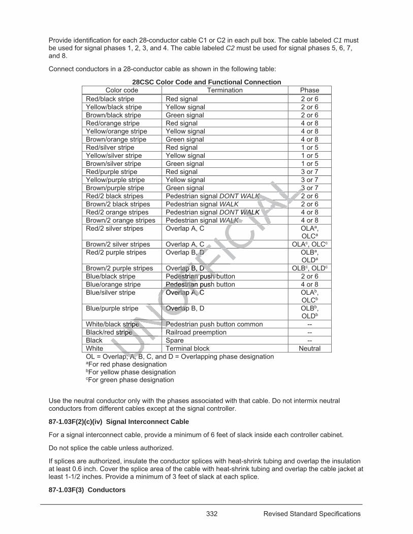
332 Revised Standard Specifications
Provide identification for each 28-conductor cable C1 or C2 in each pull box. The cable labeled C1 must be used for signal phases 1, 2, 3, and 4. The cable labeled C2 must be used for signal phases 5, 6, 7, and 8.
Connect conductors in a 28-conductor cable as shown in the following table:
28CSC Color Code and Functional Connection Color code Termination Phase
Red/black stripe Red signal 2 or 6 Yellow/black stripe Yellow signal 2 or 6 Brown/black stripe Green signal 2 or 6 Red/orange stripe Red signal 4 or 8 Yellow/orange stripe Yellow signal 4 or 8 Brown/orange stripe Green signal 4 or 8 Red/silver stripe Red signal 1 or 5 Yellow/silver stripe Yellow signal 1 or 5 Brown/silver stripe Green signal 1 or 5 Red/purple stripe Red signal 3 or 7 Yellow/purple stripe Yellow signal 3 or 7 Brown/purple stripe Green signal 3 or 7 Red/2 black stripes Pedestrian signal DONT WALK 2 or 6 Brown/2 black stripes Pedestrian signal WALK 2 or 6 Red/2 orange stripes Pedestrian signal DONT WALK 4 or 8 Brown/2 orange stripes Pedestrian signal WALK 4 or 8 Red/2 silver stripes Overlap A, C OLAa,
OLCa Brown/2 silver stripes Overlap A, C OLAc, OLCc Red/2 purple stripes Overlap B, D OLBa,
OLDa Brown/2 purple stripes Overlap B, D OLBc, OLDc Blue/black stripe Pedestrian push button 2 or 6 Blue/orange stripe Pedestrian push button 4 or 8 Blue/silver stripe Overlap A, C OLAb,
OLCb Blue/purple stripe Overlap B, D OLBb,
OLDb White/black stripe Pedestrian push button common -- Black/red stripe Railroad preemption -- Black Spare -- White Terminal block Neutral OL = Overlap; A, B, C, and D = Overlapping phase designation aFor red phase designation bFor yellow phase designation cFor green phase designation
Use the neutral conductor only with the phases associated with that cable. Do not intermix neutral conductors from different cables except at the signal controller.
87-1.03F(2)(c)(iv) Signal Interconnect Cable
For a signal interconnect cable, provide a minimum of 6 feet of slack inside each controller cabinet.
Do not splice the cable unless authorized.
If splices are authorized, insulate the conductor splices with heat-shrink tubing and overlap the insulation at least 0.6 inch. Cover the splice area of the cable with heat-shrink tubing and overlap the cable jacket at least 1-1/2 inches. Provide a minimum of 3 feet of slack at each splice.
87-1.03F(3) Conductors
p; A, Bp; A BUNOFFICIA
LLL33LLLKK KK ALLALLT WALKWAL KIAALKALK KK
CIACIAC ICB, D , D FIC
rlap B, D rlap B, D
FFedestrian push budestrian push bFFPedestrian pushPedestria
OFOverlap A, C Overlap A, COFNOOverlapOverlap
NONOstripe Pestripe PNONO
stripe pe
UNNUNUU
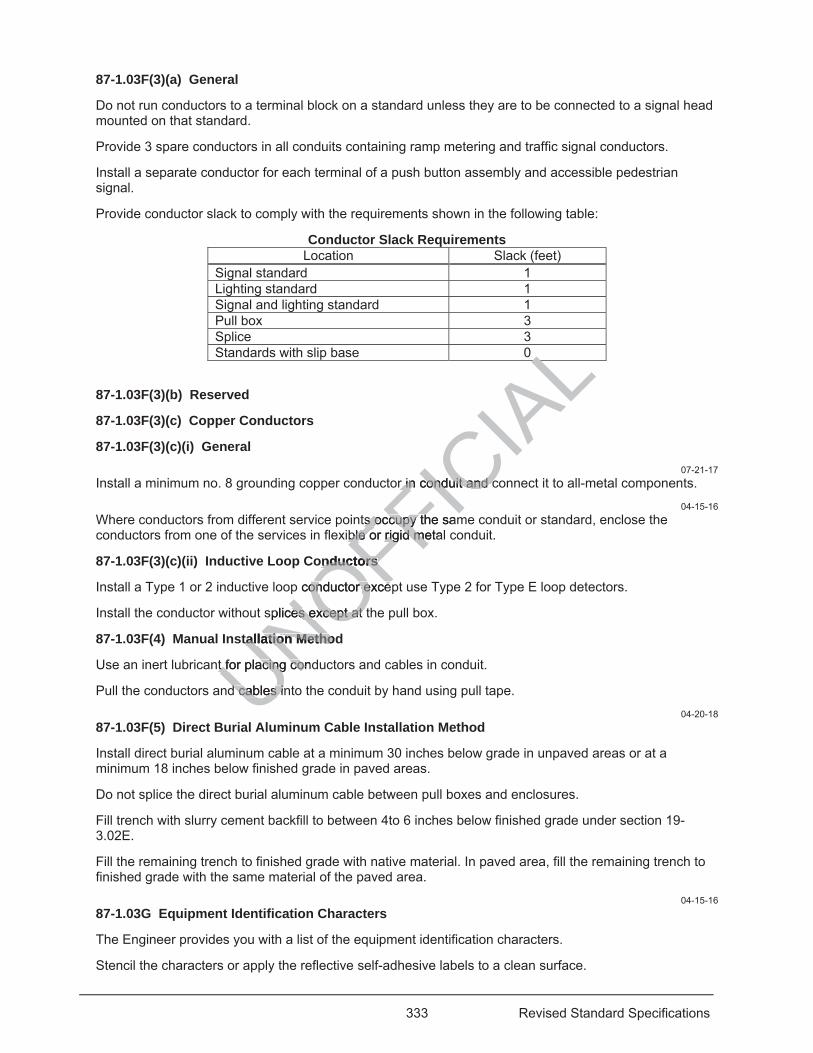
333 Revised Standard Specifications
87-1.03F(3)(a) General
Do not run conductors to a terminal block on a standard unless they are to be connected to a signal head mounted on that standard.
Provide 3 spare conductors in all conduits containing ramp metering and traffic signal conductors.
Install a separate conductor for each terminal of a push button assembly and accessible pedestrian signal.
Provide conductor slack to comply with the requirements shown in the following table:
Conductor Slack Requirements Location Slack (feet)
Signal standard 1 Lighting standard 1
Signal and lighting standard 1 Pull box 3 Splice 3 Standards with slip base 0
87-1.03F(3)(b) Reserved
87-1.03F(3)(c) Copper Conductors
87-1.03F(3)(c)(i) General 07-21-17
Install a minimum no. 8 grounding copper conductor in conduit and connect it to all-metal components.
04-15-16 Where conductors from different service points occupy the same conduit or standard, enclose the conductors from one of the services in flexible or rigid metal conduit.
87-1.03F(3)(c)(ii) Inductive Loop Conductors
Install a Type 1 or 2 inductive loop conductor except use Type 2 for Type E loop detectors.
Install the conductor without splices except at the pull box.
87-1.03F(4) Manual Installation Method
Use an inert lubricant for placing conductors and cables in conduit.
Pull the conductors and cables into the conduit by hand using pull tape.
04-20-18 87-1.03F(5) Direct Burial Aluminum Cable Installation Method
Install direct burial aluminum cable at a minimum 30 inches below grade in unpaved areas or at a minimum 18 inches below finished grade in paved areas.
Do not splice the direct burial aluminum cable between pull boxes and enclosures.
Fill trench with slurry cement backfill to between 4to 6 inches below finished grade under section 19-3.02E.
Fill the remaining trench to finished grade with native material. In paved area, fill the remaining trench to finished grade with the same material of the paved area.
04-15-16 87-1.03G Equipment Identification Characters
The Engineer provides you with a list of the equipment identification characters.
Stencil the characters or apply the reflective self-adhesive labels to a clean surface.
UNOFFICIA
LLLr in r in conduit and cconduit and c
ts octs o cupy the samcupy tible or rigid metalble or rigid me
onductors onductors
p conductor exceonductor exce
splices except at es except at
tallation Methodtallation Metho
t for placing condt for placing con
d cables ind cables i
334 Revised Standard Specifications
Treat the edges of self-adhesive characters with an edge sealant.
Place the characters on the side facing traffic on:
1. Front doors of cabinets and service equipment enclosures. 2. Wood poles, fastened with 1-1/4-inch aluminum nails, for pole mounted enclosures 3. Adjacent bent or abutment at approximately the same station as an illuminated sign or soffit luminaire 4. Underside of the structure adjacent to the illuminated sign or soffit luminaire if no bent or abutment
exists nearby 5. Posts of overhead signs 6. Standards
Before placing new characters on existing or relocated equipment, remove the existing characters. 04-20-18
For luminaires, place equipment identification character labels outside the unit on the side facing the road. Equipment identification characters consist of:
1. R1 for Roadway 1, R2 for Roadway 2, R3 for Roadway 3, and R4 for Roadway 4 2. Rated wattage
04-15-16 87-1.03H Conductor and Cables Splices
87-1.03H(1) General
You may splice:
1. Grounded conductors in a pull box 2. Accessible pedestrian signal and push bottom conductors in a pull box 3. Ungrounded signal conductors in a pull box if signals are modified 4. Ungrounded signal conductors to a terminal compartment or a signal head on a standard with
conductors of the same phase in the pull box adjacent to the standard 5. Ungrounded lighting circuit conductors in a pull box if lighting circuits are modified
07-21-17 Solder all copper conductor splices using the hot iron, pouring, or dipping method. Do not perform open-flame soldering.
04-20-18 Do not solder aluminum conductors.
04-15-16 87-1.03H(2) Splice Insulation Methods
Insulate splices in a multiconductor cable to form a watertight joint and to prevent moisture absorption by the cable.
Use heat-shrink tubing or Method B to insulate a splice.
Use heat-shrink tubing as follows:
1. Cover the splice area completely with an electrical insulating coating and allow it to dry. 2. Place mastic around each conductor before placing them inside the tubing. Use the type of mastic
specified in the tubing manufacturer's instructions. 3. Heat the area under the manufacturer's instructions. Do not perform open-flame heating. After
contraction, each end of the heat-shrink tubing or the open end of the tubing's end cap must overlap the conductor insulation at least 1-1/2 inches.
4. Cover the entire splice with an electrical insulating coating and allow it to dry. Use Method B as follows:
1. Cover the splice area completely with an electrical insulating coating and allow it to dry.
UNOFFICIA
Lad
conductors in a pconductors in a pf signals are modf signals are m
nal compartment oal compartment ull box adjacent toull box adjace
rs in in a pull box if a pull box if
es using the hot es using the h i
conductors. conductors.
nsulation Mensulation
condcond
335 Revised Standard Specifications
04-20-18 2. Apply 3 layers of half-lapped, minimum 60-mils, PVC tape.
04-15-16 3. Apply 2 layers of 120-mils, butyl-rubber, stretchable tape with liner.
04-20-18 4. Apply 3 layers of half-lapped, minimum 6-mils, PVC, pressure-sensitive, adhesive tape.
04-15-16 5. Cover the entire splice with an electrical insulating coating and allow it to dry.
87-1.03I Connectors and Terminals
Apply connectors and terminals to cables and conductors using a crimping compression tool under the manufacturer's instructions. The tool must prevent opening of the handles until the crimp is completed.
Install crimp-style terminal lugs on stranded conductors smaller than no. 14.
07-21-17 Solder no. 8 and smaller copper conductors to connectors and terminal lugs.
04-15-16 87-1.03J Standards, Poles, Pedestals, and Posts
Install standards, poles, pedestals, and posts under section 56-3.
Ground standards with a handhole by attaching a bonding jumper from the bolt or lug inside the standard to a metal conduit or to the grounding wire in the adjacent pull box. The bonding jumper must be visible when the handhole cover is removed.
Ground standards without a handhole or standards with a slip base by attaching a bonding jumper to all anchor bolts using ground clamps and connecting it to a metal conduit or to the grounding wire in the adjacent pull box. The bonding jumper must be visible after mortar has been placed on the foundation.
04-20-18 87-1.03K Piezoelectric Axle Sensors
Obtain authorization for exact locations for installation of the piezoelectric axle sensors.
Cut slots for axle sensors and screened transmission cables under section 87-1.03V(2).
Install the piezoelectric axle sensors in a channel under the manufacturer's instructions. Fill the channel with epoxy grout under section 95-1.02H. The grout must not exceed 165 degrees F while curing. Do not reopen the lane to traffic until the epoxy sets.
Perform the conductor test.
Connect the field wiring to the terminal blocks in the controller cabinet.
Perform the piezoelectric axle sensor test.
Perform the operational test. Failure of the system to record and store data as required for an accumulated time exceeding 3 hours during the 5-day period is cause for the operational test to be rejected and repeated.
04-15-16 87-1.03L Utility Service
87-1.03L(1) General
Install the service equipment early enough to allow the utility to complete its work before completion of the electrical work.
At least 15 days before permanent electrical and telecommunication service is required, request the service connections for permanent installations. The Department arranges with the utilities for completion of the connections and pays all costs and fees required by the utilities.
87-1.03L(2) Electric Service
UNOFFICIA
Lr from the bolt or r from the bolt or box. The bondingox. The bon
a slip base by ata slip base by ao a metal conduita metal condu
sible after mortar ible after mortar
for instinstallation of allation of
ened transned transmissiomissio
nsors in a channesors in a channon 95-1.02H. Theon 95-1.02H. The
until the epoxy seuntil the epoxy s
r test.
g to the termg to the te
xle
336 Revised Standard Specifications
87-1.03L(2)(a) General
If service equipment is to be installed on a utility-owned pole, furnish and install the conduit, conductors, pull boxes, and other necessary material to complete the service installation. The service utility decides the position of the riser and equipment on the pole.
87-1.03L(2)(b) Electric Service for Irrigation
Establishing electric service for irrigation includes installing conduit, conductors, and pull boxes and making connections from the service point to the irrigation controllers.
87-1.03L(2)(c) Electric Service for Booster Pumps
Establishing electric service for a booster pump includes installing conduit, conductors, and pull boxes and making connections from the service point to the booster pump enclosure.
87-1.03L(3) Telecommunications Service
Establishing telecommunication service includes installing conduit, conductors, and pull boxes and making connections from the service point to the telephone demarcation cabinet.
87-1.03M Photoelectric Controls
Mount the photoelectric unit on the top of the pole for Type I, II, and III photoelectric controls. Use mounting brackets where pole-top mounting is not possible. Orient the photoelectric unit to face north.
Mount the enclosure at a height of 6 feet above finished grade on the same standard as the photoelectric unit.
Install a minimum 100 VA, 480/120 V(ac) transformer in the contactor enclosure to provide 120 V(ac) for the photoelectric control unit when switching 480 V(ac), 60 Hz circuits.
87-1.03N Fused Splice Connectors 04-20-18
Install a fuse splice connector with a fuse:
1. In each ungrounded conductor for luminaires 2 On primary side of transformer when a transformer is installed
07-21-17 The connector must be located in the pull box adjacent to the standard.
04-15-16 Crimp the connector terminals onto the ungrounded conductors using a tool under the manufacturer's instructions. Insulate the terminals and make them watertight.
87-1.03O Grounding Electrodes
Install a grounding electrode for each cabinet, service equipment enclosure, and transformer.
Attach a grounding conductor from the electrode using either a ground clamp or exothermic weld. Connect the other end of the conductor to the cabinet, service equipment enclosure, and transformer.
87-1.03P Service Equipment Enclosures
Installing a service equipment enclosure includes constructing the foundation and pad and installing conduit, adjacent pull boxes, and grounding electrode.
Locate the foundation such that the minimum clearance around the front and back of the enclosure complies with NEC, article 110.26, "Spaces About Electrical Equipment, (600 V, nominal or less)."
Bond and ground metal conduit as specified in NEC and by the service utility except the grounding electrode conductor must be no. 6 or larger.
If circuit breakers and components do not have a description on engraved phenolic nameplates, install them using stainless steel rivets or screws under section 86-1.02P(2).
UNOFFICIA
Lbinet
III photI photoelectric lectric nt the photoelectrnt the photoelect
de on the same stde on the same
in n the contactor the contactoV(ac), 60 Hz circui(ac), 60 Hz circui
e:
for luminaires or luminaires er when a transfoer when a tran
cated in tcated in the pull he pu
terminals onto terminals onto he terminalshe termina
ctr
337 Revised Standard Specifications
87-1.03Q Cabinets
87-1.03Q(1) General
Installing a cabinet includes constructing the foundation and pad and installing conduit, adjacent pull boxes, and grounding electrode.
Apply a mastic or caulking compound before installing the cabinet on the foundation to seal the openings.
Connect the field wiring to the terminal blocks in the cabinet. Neatly arrange and lace or enclose the conductors in plastic tubing or raceway. Terminate the conductors with properly sized captive or spring spade terminals. Apply a crimp-style connector and solder them.
Install and solder a spade-type terminal on no. 12 and smaller field conductors and a spade-type or ring-type terminal on conductors larger than no. 12.
87-1.03Q(2) Department-Furnished Controller Cabinets
Arrange for the delivery of Department-furnished controller cabinets.
87-1.03Q(3) Reserved
87-1.03Q(4) Telephone Demarcation Cabinets
Installing a telephone demarcation cabinet includes installing conduit, cable, and pull boxes to the controller cabinet.
Install the cabinet with the back toward the nearest lane of traffic.
87-1.03R Signal Heads
87-1.03R(1) General
Installing a signal head includes mounting the heads on standards and mast arms, installing backplates and visors, and wiring conductors to the terminal blocks.
Keep the heads covered or direct them away from traffic until the system is ready for operation.
87-1.03R(2) Signal Faces
Use the same brand and material for the signal faces at each location.
Program the programmable visibility signal faces under the manufacturer's instructions. The indication must be visible only in those areas or lanes to be controlled.
87-1.03R(3) Backplates
Install backplates using at least six 10-24 or 10-32 self-tapping and locking stainless steel machine screws and flat washers.
If a plastic backplate requires field assembly, attach each joint using at least four no.10 machine screws. Each machine screw must have an integral or captive flat washer, a hexagonal head slotted for a standard screwdriver, and either a locking nut with an integral or captive flat washer or a nut, flat washer, and lock washer. Machine screws, nuts, and washers must be stainless steel or steel with a zinc or black oxide finish.
If a metal backplate has 2 or more sections, fasten the sections with rivets or aluminum bolts peened after assembly to avoid loosening.
Install the backplate such that the background light is not visible between the backplate and the signal face or between sections.
87-1.03R(4) Signal Mounting Assemblies
Install a signal mounting assembly such that its members are arranged symmetrically and plumb or level. Orient each mounting assembly to allow maximum horizontal clearance to the adjacent roadway.
duit, cable, and pcable, and p
traffic. traffic.
e heads e heads on standaonrminal blocks. rminal blocks.
m away fromm away from traffi
erial for the signal for the signa
ble visibility signable visibility signthose areas or lase areas
ates ates
t least leas
338 Revised Standard Specifications
For a bracket-mounted assembly, bolt the terminal compartment or pole plate to the pole or standard.
In addition to the terminal compartment mounting, attach the upper pipe fitting of Type SV-1-T with 5 sections or a SV-2-TD to the standard or pole using the mounting detail for signal heads without a terminal compartment.
Use a 4-1/2-inch slip fitter and set screws to mount an assembly on a post top.
After installing the assembly, clean and paint the exposed threads of the galvanized conduit brackets and bracket areas damaged by the wrench or vise jaws. Use a wire brush to clean and apply 2 coats of unthinned, organic zinc-rich primer. Do not use an aerosol can to apply the primer.
Install the conductors in the terminal compartment and secure the cover.
87-1.03S Pedestrian Signal Heads
Installing a pedestrian signal head includes mounting the heads on standards and wiring conductors to the terminal blocks.
Install the pedestrian signal mounting assembly under section 87-1.03R(4).
Use the same brand and material for the pedestrian signal faces at each location.
Install a pedestrian signal face such that its members are arranged symmetrically and plumb or level.
87-1.03T Accessible Pedestrian Signals
Use the same brand for the accessible pedestrian signals at each location.
Install an accessible pedestrian signal and the R10 series sign on the crosswalk side of the standard.
Attach the accessible pedestrian signal to the standard with self-tapping screws.
Attach the sign to the standard using 2 straps and saddle brackets.
Point the arrow on the accessible pedestrian signal in the same direction as the corresponding crosswalk.
Furnish the equipment and hardware to set up and calibrate the accessible pedestrian signal.
Arrange to have a manufacturer's representative at the job site to program the accessible pedestrian signal with an audible message or tone.
87-1.03U Push Button Assemblies
Install the push button assembly and the R10 series sign on the crosswalk side of the standard.
Attach the sign to the assembly for Type B assemblies.
Attach the sign to the standard using 2 straps and saddle brackets for Type C assemblies.
You may use straps and saddle brackets to secure the push button to the standard.
Use a slip fitter to secure the assembly on top of a 2-1/2-inch-diameter post.
87-1.03V Detectors
87-1.03V(1) General
Installing a detector includes installing inductive loop conductors, sealant, conduit, and pull boxes.
Center the detectors in the traffic lanes.
Do not splice the detector conductor.
87-1.03V(2) Inductive Loop Detectors
UNOFFICIA
Lh location. ocat
symmetrically anymmetrically an
at each location. at each location.
ries sign on the cies sign on the
ndard with self-tandard with self-ta
and saddle bracand sadd
rian signal in an signal the the
e to set up and ca to set up and
's rs representative presentativge or tone. or tone.
Assemblies Assemblies
on assembly and n assembly and
assembly foassembly
a
339 Revised Standard Specifications
Mark the location of the inductive loop detectors such that the distance between the side of the loop and a lead-in saw cut from an adjacent detector is at least 2 feet. The distance between lead-in saw cuts must be at least 6 inches.
Saw cut the slots under section 13-4.03E(7). The bottoms of the slots must be smooth with no sharp edges. For Type E detector loops, saw the slots such that the sides are vertical.
Wash the slots clean using water and blow dry them with compressed air to remove all moisture and debris.
Identify the start of the conductor.
Waterproof the ends of a Type 2 loop conductor before installing it in the conduit to prevent moisture from entering the cable.
Install the loop conductor in the slots and lead-in saw cuts using a 3/16- to 1/4-inch-thick wood paddle. Hold the conductors in place at the bottom of the slot with wood paddles during placement of the sealant.
Wind adjacent loops on the same sensor unit channel in opposite directions.
Twist the conductors for each loop into a pair consisting of a minimum of 2 turns per foot before placing them in the lead-in saw cut and the conduit leading to the pull box. Do not install more than 2 twisted pairs of conductors per lead-in saw cut.
Provide 5 feet of slack in the pull box.
Test each loop for continuity, circuit resistance, and insulation resistance before filling the slots with sealant.
Remove excess sealant from the adjacent road surface before it sets. Do not use solvents to remove the excess.
Identify the loop conductor pair in the pull box, marking the start with the letter S and the end with the letter F. Band conductors in pairs by lane in the pull box adjacent to the loops and in the cabinet. Identify each pair with the detector designation and loop number.
Install the conductors in a compacted layer of HMA immediately below the uppermost layer if more than one layer will be placed. Install the loop conductors before placing the uppermost layer of HMA. Fill the slot with a sealant flush to the surface.
Install the conductors in the existing pavement if one layer of HMA is to be placed. Install the loop conductors before placing the layer of HMA. Fill the slot with a sealant flush to the surface.
87-1.03V(3) Preformed Inductive Loop Detectors 04-20-18
Install a preformed inductive loop detector consisting of 4 turns in the loop and a lead-in conductor pair twisted at least 2 turns per foot all encased in conduit and sealed to prevent water penetration. The detector must be 6-foot square unless shown otherwise.
Construct the loop detector using a minimum 3/8-inch Schedule 40 or Schedule 80 PVC or polypropylene conduit and no. 16 or larger conductor with Type THWN insulation.
04-15-16 In new roadways, place the detector in the base course with the top of the conduit flush with the top of the base. Cover with HMA or concrete pavement. Protect the detector from damage before and during pavement placement.
In new reinforced concrete bridge decks, secure the detector to the top of the uppermost layer of reinforcing steel using nylon wire ties. Hold the detector parallel to the bridge deck using PVC or polypropylene spacers where necessary. Place conduit for lead-in conductors between the uppermost 2 layers of reinforcing steel.
Do not install detectors in existing bridge decks unless authorized.
Install a detector in existing pavement before placement of concrete or HMA as follows:
UNOFFICIA
L2 turns pe2 tnot install moreinstall more
on reon resistance befsistance b
ace ace before it sets.before it sets
, marking the sta, marking the stan the pull box adjan the pull box
and loop number. d loop number.
ed layer of HMA d layer of HMA ime loop conductorsoop conductor
surface. urface.
e exisexisting pavemting paveng the lag the layer of HMyer of H
med Inductive Lmed Inductive
ve lol
340 Revised Standard Specifications
04-20-18 1. Saw cut slots at least 1-1/4 inches wide into the pavement.
04-15-16 2. Place the detector in the slots. The top of the conduit must be at least 2 inches below the top of the
pavement. 3. Test each loop circuit for continuity, circuit resistance, and insulation resistance. 4. Fill saw cuts with elastomeric or hot melt rubberized asphalt sealant for asphalt concrete pavement
and with epoxy sealant or hot melt rubberized asphalt sealant for concrete pavement. 87-1.03W Sealants
87-1.03W(1) General
Reserved
87-1.03W(2) Elastomeric Sealant
Apply an elastomeric sealant with a pressure feed applicator.
87-1.03W(3) Asphaltic Emulsion Sealant
Asphaltic emulsion sealant must:
1. Be used for filling slots in asphalt concrete pavement of a maximum width of 5/8 inch 2. Not be used on concrete pavement or where the slope causes the material to run from the slot 3. Be thinned under the manufacturer's instructions 4. Be placed when the air temperature is at least 45 degrees F 87-1.03W(4) Hot-Melt Rubberized Asphalt Sealant
Melt the sealant in a jacketed, double-boiler-type, melting unit. The temperature of the heat transfer medium must not exceed 475 degrees F.
Apply the sealant with a pressure feed applicator or a pour pot when the surface temperature of the pavement is greater than 40 degrees F.
87-1.03X Reserved
87-1.03Y Transformers
Installing a transformer includes placing the transformer inside a pull box, a cabinet, or an enclosure.
Wire the transformer for the appropriate voltage.
Ground the secondary circuit of the transformer as specified in the NEC.
87-1.03Z Reserved
87-1.04 PAYMENT
Not Used
87-2 LIGHTING SYSTEMS
87-2.01 GENERAL
87-2.01A Summary
Section 87-2 includes specifications for constructing lighting systems.
Lighting system includes:
1. Foundations 2. Pull boxes 3. Conduit 4. Conductors
UNOFFICIA
Lmum width of 5/8um width of 5/8es the material toes the material t
ees F ees F
melting unit. Themelting unit.
plicator licator or a pour or a pou
cludes placing theudes placing
or the appropriatee approp
y circuit of they circuit of t
341 Revised Standard Specifications
5. Standards 6. Luminaires 7. Service equipment enclosure 8. Photoelectric control 9. Fuse splice connectors 10. High mast lighting assemblies
The components of a lighting system are shown on the project plans.
87-2.01B Definitions
Reserved
87-2.01C Submittals
Submit a certificate of compliance and test data for the high mast lighting luminaires.
87-2.01D Quality Assurance
Reserved
87-2.02 MATERIALS
87-2.02A General
Reserved
87-2.02B High Mast Lighting Assemblies
A high mast lighting assembly includes the foundation, pole, lowering device system, luminaires, and control pedestal.
Each luminaire in a high mast lighting assembly must include a housing, an optical system, and a ballast.
The housing must be made of aluminum.
A painted or powder-coated housing for a high mast lighting luminaire must be able to withstand a 1,000-hour salt spray test as specified in ASTM B117.
The optical system, consisting of the reflector, refractor or lens, lamp socket, and lamp, must be in a sealed chamber. The chamber must be sealed by a gasket between the reflector and refractor or lens and a gasket between the reflector and lamp socket. The chamber must have a separate filter or filtering gasket for flow of air.
An asymmetrical luminaire must have a refractor or reflector that is rotatable 360 degrees around a vertical axis to orient the distribution of light.
The luminaire must have a slip fitter for mounting on a 2-inch horizontal pipe tenon and must be adjustable ±3 degrees from the axis of the tenon.
The reflector must have a specular surface made of silvered glass or aluminum protected by either an anodized finish or a silicate film. The reflector must be shaped such that a minimum of light is reflected through the arc tube of the lamp.
The refractor and lens must be made of heat-resistant glass.
The lamp socket must be a porcelain-enclosed, mogul-multiple type. The shell must contain integral lamp grips to ensure electrical contact under conditions of normal vibrations. The socket must be rated for 1,500 W, 600 V(ac) and 4,000 V(ac) pulse for a 400 W lamp and 5,000 V(ac) pulse for a 1,000 W lamp.
The luminaire must have a dual fuse holder for 2 fuses rated at 5 A, 480 V(ac). The fuses must be 13/32 inch by 1-1/2 inches, standard midget ferrule type with a nontime-delay feature.
The lamps must be vertical burning, protected from undue vibration, and prevented from backing out of the socket by a stainless steel clamp attached to the luminaire.
UNOFFICIA
Ln, pole, lowering dpole, lowering
ly must include a y must include a
for a high mast ligfor a high maASTM B117. STM B117
of the reflector, rf the reflector, ber must be sealeber must be seale
e reflector and lame reflector and la
inaire must hainaire must e distribute distribu
342 Revised Standard Specifications
A 1,000 W metal halide lamp must have an initial output of 100,000 lumens and an average rated life of 12,000 hours based on 10 hours per start.
A 400 W high-pressure sodium lamp must have an initial output of 50,000 lumens. A 1,000 W high-pressure sodium lamp must have an initial output of 140,000 lumens.
The ballast for the luminaire must be a regulator type and have a core and coils, capacitors, and starting aid.
Ballast must be:
1. Mounted within a weatherproof housing that integrally attaches to the top of a luminaire support bracket and lamp support assembly
2. Readily removable without removing the luminaire from the bracket arm 3. Electrically connected to the optical assembly by a prewired quick disconnect The ballast for a metal halide luminaire must comply with luminaire manufacturer's specifications.
The wattage regulation spread at any lamp voltage, from nominal through the life of the lamp, must vary no more than 22 percent for a 1,000 W lamp and a ±10 percent input voltage variation. The ballast's starting line current must be less than its operating current.
87-2.02C Soffit and Wall-Mounted Luminaires
87-2.02C(1) General
Soffit and wall-mounted luminaires must be weatherproof and corrosion resistant.
Each luminaire must include a 70 W high-pressure sodium lamp with a minimum average rated life of 24,000 hours. The lamp socket must be positioned such that the light center of the lamp is located within 1/2 inch of the designed light center of the luminaire.
Luminaire wiring must be SFF-2.
Flush-mounted soffit luminaire must have:
1. Metal body with two 1-inch-minimum conduit hubs and a means of anchoring the body into the concrete
2. Prismatic refractor made of heat-resistant polycarbonate: 2.1. Mounted in a door frame 2.2. With the street side identified
3. Aluminum reflector with a specular anodized finish 4. Ballast located either within the housing or in a ceiling pull box if shown 5. Lamp socket The door frame assembly must be hinged, gasketed, and secured to the luminaire body with at least 3 machine screws.
A pendant soffit luminaire must be enclosed and gasketed and have an aluminum finish. Luminaire must have:
1. Aluminum reflector with a specular anodized finish 2. Refractor made of heat-resistant polycarbonate 3. Optical assembly that is hinged and latched for lamp access and a device to prevent dropping 4. Ballast designed for operation in a raintight enclosure 5. Galvanized metal box with a gasketed cover, 2 captive screws, and 2 chains to prevent dropping and
for luminaire mounting Wall-mounted luminaire must have:
1. Cast metal body 2. Prismatic refractor:
2.1. Made of glass 2.2. Mounted in a door frame
UNOFFICIA
Lli
ge varia
and corrosion resind corrosion res
dium lamp with a ium lamp with such thatsuch that the light the ligh
aire. ire.
e:
mum conduit hubmum conduit hu
f heat-resistant pheat-resistant pr frame r frame
side identified side identified r with a specular aith a spec
ither within the hither within the
mu
343 Revised Standard Specifications
3. Aluminum reflector with a specular anodized finish 4. Integral ballast 5. Lamp socket 6. Gasket between the refractor and the body 7. At least 2 mounting bolts of minimum 5/16-inch diameter
A cast aluminum body of a luminaire to be cast into or mounted against concrete must have a thick coat of alkali-resistant bituminous paint on all surfaces to be in contact with the concrete.
87-2.02C(2) High-Pressure Sodium Lamp Ballasts
87-2.02C(2)(a) General
A high-pressure sodium lamp ballast must operate the lamp for its rated wattage.
Starting aids for a ballast must be interchangeable between ballasts of the same wattage and manufacturer without adjustment.
The ballast must be provided with a heat-generating component to serve as a heat sink. The capacitor must be placed at the maximum practicable distance from the heat-generating components or thermally shielded to limit the case temperature to 75 degrees C.
The transformer and inductor must be resin impregnated for protection against moisture. Capacitors, except for those in starting aids, must be metal cased and hermetically sealed.
The ballast must have a power factor of 90 percent or greater.
For the nominal input voltage and lamp voltage, the ballast design center must not vary more than 7.5 percent from the rated lamp wattage.
87-2.02C(2)(b) Regulator-Type Ballasts
A regulator-type ballast must be designed such that a capacitance variance of ±6 percent does not cause more than ±8 percent variation in the lamp wattage regulation.
The ballast must have a current crest factor not exceeding 1.8 for an input voltage variation of ±10 percent.
The lamp wattage regulation spread for a lag-type ballast must not vary by more than 18 percent for ±10 percent input voltage variations. The primary and secondary windings must be electrically isolated.
The lamp wattage regulation spread for a constant-wattage, autoregulator, lead-type ballast must not vary by more than 30 percent for ±10 percent input voltage variations.
87-2.02C(2)(c) Nonregulator-Type Ballasts
A nonregulator-type ballast must have a current crest factor not exceeding 1.8 for an input voltage variation of ±5 percent.
The lamp wattage regulation spread for an autotransformer or high reactance type ballast must not vary by more than 25 percent for ±5 percent input voltage variations.
87-2.03 CONSTRUCTION
87-2.03A General
Set the foundations for standards such that the mast arm is perpendicular to the centerline of the roadway.
Tighten the cap screws of the luminaire's clamping bracket to 10 ft-lb for LED and low-pressure luminaires.
Label the month and year of the installation inside the luminaire housing's door.
Perform the conductor and operational tests for the system.
a hting com
ion against moistn against moisttically sealed. tically sealed.
r. r.
ast design center design center
ch that a ch that a capacitacp wattage regulatiwattage regula
factor not exfactor not e ceed
pread for a lag-tyead for a lag-tyons. The primary ons. The primary
ation spread for ation spread for acent for ±10 percecent for ±10 per
gulator-Tygulator-T
t m
344 Revised Standard Specifications
87-2.03B High Mast Lighting Assemblies
Mount and connect the luminaires to the accessory support ring. Aim the asymmetrical luminaire to orient the distribution of light.
87-2.03C Soffit and Wall-Mounted Luminaires
For a flush-mounted soffit luminaire:
1. Prevent concrete from getting into the housing during pouring of the concrete for the structure 2. Install the luminaire with the axis vertical and the street side of the refractor oriented as indicated 3. Locate the luminaire to provide a minimum 2-foot clearance from the inside surface of the girders and
1-foot clearance from the near face of the diaphragm 4. Install the bridge soffit and ceiling pull box over the same lane For a pendant soffit luminaire:
1. Cast in place the inserts for the no. 8 pull box during concrete placement for a new structure 2. Drill holes for expansion anchors to support the no. 8 pull box on existing structures 3. Bond the suspension conduit and luminaire to the pull box For a wall-mounted luminaire, provide:
1. Extension junction box or ring on a new structure 2. 4 external mounting taps on an existing structure Place the soffits or wall-mounted luminaires in operation as soon as practicable after the falsework has been removed from the structure.
If the Engineer orders soffit or wall-mounted luminaires to be activated before permanent power service is available, installing and removing the temporary power service is change order work.
87-2.04 PAYMENT
Not Used
87-3 SIGN ILLUMINATION SYSTEMS
87-3.01 GENERAL
87-3.01A Summary
Section 87-3 includes specifications for constructing sign illumination systems.
Sign illumination system includes:
1. Foundations 2. Pull boxes 3. Conduit 4. Conductors 5. Sign lighting fixtures 6. Enclosure for the disconnect circuit breaker 7. Service equipment enclosure 8. Photoelectric control The components of a sign illumination system are shown on the project plans.
87-3.01B Definitions
Reserved
87-3.01C Submittals
Submit the manufacturer's test data for the induction sign-lighting fixtures.
UNOFFICIA
Lst
as soon as practis soon as practi
aires aires to be activao be activay power service ispower service
7-3 SIGN ILLUM3 SIGN ILLUM
s specifications fos specifications
m includesm include
345 Revised Standard Specifications
87-3.01D Quality Assurance
Reserved
87-3.02 MATERIALS
An induction sign-lighting fixture must include a housing with a door, reflector, refractor or lens, lamp, socket assembly, power coupler, high-frequency generator, fuse block, and fuses.
The fixture must comply with the isofootcandle curves as shown.
Fixture must weigh no more than 44 lb, be rated for 87 W at 120/240 V(ac), and have a mounting assembly made of one of the following materials:
1. Cast aluminum 2. Hot-dip galvanized steel plate 3. Galvanized steel plate finished with one of the following:
3.1. Polymeric coating 3.2. Same finish used for the housing
Housing must:
1. Be corrosion resistant and suitable for wet locations 2. Be above the top of the mounting rails at a maximum height of 12 inches 3. Have weep holes Door must:
1. Hold a refractor or lens 2. Open without the use of special tools 3. Have a locking position at 50 degrees minimum from the plane of the door opening 4. Be hinged to the housing on the side of the fixture away from the sign panel 5. Have 2 captive latch bolts or other latching device When the door is opened, it must lock in the 50 degrees position when an 85 mph, 3-second wind-gust load strikes the door from either side.
The housing and door must be manufactured of sheet or cast aluminum and have a gray powder coat or polyester paint finish. The sheet aluminum must comply with ASTM B209 or B209M for 5052-H32 aluminum sheet. External bolts, screws, hinges, hinge pins, and door closure devices must be corrosion resistant.
The housing and door must be gasketed. The thickness of the gasket must be a minimum of 1/4 inch.
Reflector must not be attached to the outside of the housing and must be:
1. Made of a single piece of aluminum with a specular finish 2. Protected with an electrochemically applied anodized finish or a chemically applied silicate film 3. Designed to drain condensation away from it 4. Secured to the housing with a minimum of 2 screws 5. Removable without removing any fixture parts Refractor or lens must have a smooth exterior and must be manufactured from the materials shown in the following table:
Refractor and Lens Material Requirements Component Material
Flat lens Heat-resistant glass Convex lens Heat-resistant, high-impact-resistant tempered glass Refractor Borosilicate heat-resistant glass
UNOFFICIA
Lf 12 inches inches
um from the planum from the ple fixture away froe fixture away fro
hing device hing device
in the in the 50 degree50 de. .
manufactured ofmanufactured oheet aluminum muheet aluminum mu
bolts, screws, hinbolts, screws,
or must be gaskor must be gask
ached ached
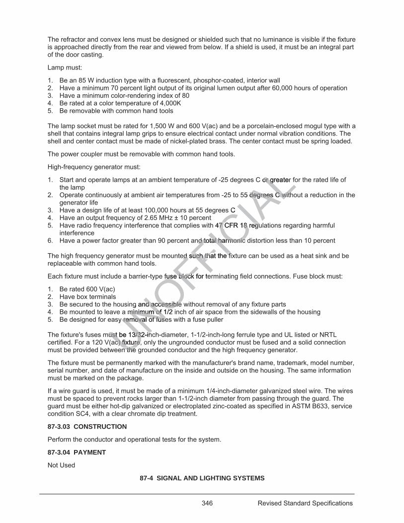
346 Revised Standard Specifications
The refractor and convex lens must be designed or shielded such that no luminance is visible if the fixture is approached directly from the rear and viewed from below. If a shield is used, it must be an integral part of the door casting.
Lamp must:
1. Be an 85 W induction type with a fluorescent, phosphor-coated, interior wall 2. Have a minimum 70 percent light output of its original lumen output after 60,000 hours of operation 3. Have a minimum color-rendering index of 80 4. Be rated at a color temperature of 4,000K 5. Be removable with common hand tools The lamp socket must be rated for 1,500 W and 600 V(ac) and be a porcelain-enclosed mogul type with a shell that contains integral lamp grips to ensure electrical contact under normal vibration conditions. The shell and center contact must be made of nickel-plated brass. The center contact must be spring loaded.
The power coupler must be removable with common hand tools.
High-frequency generator must:
1. Start and operate lamps at an ambient temperature of -25 degrees C or greater for the rated life of the lamp
2. Operate continuously at ambient air temperatures from -25 to 55 degrees C without a reduction in the generator life
3. Have a design life of at least 100,000 hours at 55 degrees C 4. Have an output frequency of 2.65 MHz ± 10 percent 5. Have radio frequency interference that complies with 47 CFR 18 regulations regarding harmful
interference 6. Have a power factor greater than 90 percent and total harmonic distortion less than 10 percent The high frequency generator must be mounted such that the fixture can be used as a heat sink and be replaceable with common hand tools.
Each fixture must include a barrier-type fuse block for terminating field connections. Fuse block must:
1. Be rated 600 V(ac) 2. Have box terminals 3. Be secured to the housing and accessible without removal of any fixture parts 4. Be mounted to leave a minimum of 1/2 inch of air space from the sidewalls of the housing 5. Be designed for easy removal of fuses with a fuse puller The fixture's fuses must be 13/32-inch-diameter, 1-1/2-inch-long ferrule type and UL listed or NRTL certified. For a 120 V(ac) fixture, only the ungrounded conductor must be fused and a solid connection must be provided between the grounded conductor and the high frequency generator.
The fixture must be permanently marked with the manufacturer's brand name, trademark, model number, serial number, and date of manufacture on the inside and outside on the housing. The same information must be marked on the package.
If a wire guard is used, it must be made of a minimum 1/4-inch-diameter galvanized steel wire. The wires must be spaced to prevent rocks larger than 1-1/2-inch diameter from passing through the guard. The guard must be either hot-dip galvanized or electroplated zinc-coated as specified in ASTM B633, service condition SC4, with a clear chromate dip treatment.
87-3.03 CONSTRUCTION
Perform the conductor and operational tests for the system.
87-3.04 PAYMENT
Not Used
87-4 SIGNAL AND LIGHTING SYSTEMS
UNOFFICIA
LC or greater or g
55 degrdegrees C withees C with
s C
h 47 CFR 18 regu7 CFR 18 regu
nd total harmonic nd total harmonic
ed such thated such tha the fe f
e fuse block fuse bloc for te
g and accessibnd accessible leminimum of 1/2 minimum of
y removal of fuseremoval of fuse
ust be 13/32-inust be 13/32-inac) fixture, oac) fixture,
n the n the
347 Revised Standard Specifications
87-4.01 GENERAL
87-4.01A Summary
Section 87-4 includes specifications for constructing signal and lighting systems.
Signal and lighting system includes:
1. Foundations 2. Pull boxes 3. Conduit
04-20-18 4. Conductors and cables 5. Standards 6. Signal heads 7. Internally illuminated street name signs 8. Service equipment enclosure 9. Department-furnished controller assembly 10. Detectors 11. Telephone demarcation cabinet 12. Accessible pedestrian signals 13. Push button assemblies 14. Pedestrian signal heads 15. Luminaires 16. Photoelectric control 17. Fuse splice connectors 18. Battery backup system 19. Flashing beacons 20. Flashing beacon control assembly
04-15-16 The components of a signal and lighting system are shown on the project plans.
87-4.01B Definitions
Reserved
87-4.01C Submittals
Submit shop drawings showing the message for each internally illuminated street sign, including the size of letters, symbols, and arrows.
87-4.01D Quality Assurance
87-4.01D(1) General
Reserved
87-4.01D(2) Quality Control
87-4.01D(2)(a) General
Reserved
87-4.02 MATERIALS
87-4.02A General
Reserved
87-4.02B Reserved
87-4.02C Internally Illuminated Street Name Signs
UNOFFICIA
Lystem are shown stem are show
owing the messaowing the messd arrows. rrows.
ssurance ssurance

348 Revised Standard Specifications
An internally illuminated street name sign includes housing, brackets, sign panels, gaskets, ballast, lampholder, terminal blocks, conductors, and fuses.
An internally illuminated street sign must be designed and constructed to prevent deformation or failure when subjected to an 85 mph, 3-second wind-gust load as specified in the AASHTO publication, "Standard Specifications for Structural Supports of Highway Signs, Luminaires and Traffic Signals."
Sign must:
1. Be Types A or B 2. Have galvanized or cadmium-plated ferrous parts 3. Have screened weep holes 4. Have fasteners, screws, and hardware made of passive stainless steel, Type 302 or 304, or
aluminum Type 6060-T6 5. Operate at a temperature from -20 to 74 degrees C Photoelectric unit sockets are not allowed.
The housing must be constructed to resist torsional twist and warp. The housing must be designed such that opening or removing the panels provides access to the interior of the sign for lamp, ballast, and fuse replacement.
The top and bottom of the sign must be manufactured from formed or extruded aluminum and attached to formed or cast aluminum end fittings. The top, bottom, and end fittings must form a sealed housing.
For a Type A sign, both sides of the sign must be hinged at the top to allow installation or removal of the sign panel.
For a Type B sign, the sign panel must be slide mounted into the housing.
The top of the housing must have 2 free-swinging mounting brackets. Each bracket must be vertically adjustable for leveling the sign to either a straight or curved mast arm. The bracket assembly must allow the lighting fixture to swing perpendicular to the sign panel.
The reflectors must be formed aluminum and have an acrylic, baked-white-enamel surface with a minimum reflectance of 0.85.
Sign panel must be translucent, high-impact-resistant, and made of one of the following plastic materials:
1. Glass-fiber-reinforced, acrylated resin 2. Polycarbonate resin 3. Cellulose acetate butyrate The sign panel must be designed not to crack or shatter if a 1-inch-diameter steel ball weighing 2.4 ounces is dropped from a height of 8.5 feet above the sign panel to any point on the panel. For this test, the sign panel must be lying in a horizontal position and supported within its frame.
The sign panel's surface must be evenly illuminated. The brightness measurements for the letters must be a minimum of 150 foot-lamberts, average. The letter-to-background brightness ratio must be from 10:1 to 20:1. The background luminance must not vary by more than 40 percent from the average background brightness measurement. The luminance of letters, symbols, and arrows must not vary by more than 20 percent from their average brightness measurement.
The sign panel's white or green color must not fade or darken if exposed to an accelerated test of UV light equivalent to 2 years of outdoor exposure.
The sign panel's legend, symbols, arrows, and border on each face must be white on a green background. The background must comply with color no. 14109 of FED-STD-595.
The message must appear on both sides of the sign and be protected from UV radiation. The letters must be 8-inch upper case and 6-inch lower case, series E.
A Type A sign must have a closed-cell, sponge-neoprene gasket installed between the sign panel frame to prevent the entry of water. The gasket must be uniform and even textured.
UNOFFICIA
Lsing
sign for lsi
or extruded alumr extruded alumfittings must form ittings must form
the top to allow inthe top to allow
nted into the housnted into the hou
g mountg mounting bracking braight or curved maght or curved ma
o the sign panel. o the sign pan
m and have anm and hav a
high-impact-resihigh-impact-re
acrylated resin acrylated resin
butyrate rate
e designed e designea heigha heigh
349 Revised Standard Specifications
The sign ballast must be a high-power-factor type for outdoor operation from 110 to 125 V(ac) and 60 Hz and must comply with ANSI C82.1 and C82.2.
The ballast for a Type A sign must be rated at 200 mA. The ballast for a Type B sign must be rated at 430 mA.
Sign lampholder must:
1. Be the spring-loaded type 2. Have silver-coated contacts and waterproofed entrance leads 3. Have a heat-resistant, circular cross section with a partially recessed neoprene ring Removal of the lamp from the socket must de-energize the primary of the ballast.
The springs for the lampholders must not be a part of the current-carrying circuit.
The sign's wiring connections must terminate on a molded, phenolic, barrier-type, terminal block rated at 15 A, 1,000 V(ac). The connections must have a white, integral, waterproof marking strip. The terminal screws must not be smaller than a no. 10.
The terminal block must be insulated from the fixture to provide protection from the line-to-ground flashover voltage.
A sectionalized terminal block must have an integral barrier on each side and must allow rigid mounting and alignment.
Fixture's conductors must:
1. Be stranded copper wire with a minimum thermoplastic insulation of 28 mils 2. Be rated at 1,000 V(ac) and for use up to 90 degrees C 3. Be a minimum of no. 16 4. Match the color coding of the ballast leads 5. Be secured with spring cross straps, installed 12 inches apart or less in the chassis or fixture Stranded copper conductors connected to screw-type terminals must terminate in crimp-type ring connectors.
No splicing is allowed within the fixture.
The sign's fuse must be the Type 3AG, miniature, slow-blow type.
The fuse holder must be a panel-mounting type with a threaded or bayonet knob that grips the fuse tightly for extraction. Each ballast must have a separate fuse.
87-4.03 CONSTRUCTION
87-4.03A General
Set the foundations for standards such that the mast arm is perpendicular to the centerline of the roadway.
Tighten the cap screws of the luminaire's clamping bracket to 10 ft-lb for LED and low-pressure luminaires.
Label the month and year of the installation inside the luminaire housing's door.
Perform the conductor and operational tests for the system.
87-4.03B Reserved
87-4.03C Internally Illuminated Street Name Signs
Mount the internally illuminated street name sign to the signal mast arm using the adjustable brackets. Connect the conductors to the terminal blocks in the signal head mounting terminal block.
87-4.04 PAYMENT
UNOFFICIA
Ln from the fro
ch side and mustside and must
astic insulation oastic insulationgrees C grees C
talled talle 12 inches a2 inc
d to screw-tyd to screw- pe te
fixture. fixture.
e Type 3AG, miniaType 3AG, min
be a panel-mounta panel-mballast must haveballast must hav
ION ION
350 Revised Standard Specifications
Not Used
87-5 RAMP METERING SYSTEMS
87-5.01 GENERAL
Section 87-5 includes specifications for constructing ramp metering systems.
Ramp metering system includes:
1. Foundations 2. Pull boxes 3. Conduit 4. Conductors 5. Standards 6. Signal heads 7. Service equipment enclosure 8. Department-furnished controller assembly 9. Detectors 10. Telephone demarcation cabinet The components of a ramp metering system are shown on the project plans.
87-5.02 MATERIALS
Not Used
87-5.03 CONSTRUCTION
Connect the field wiring to the terminal blocks in the controller cabinet. The Engineer provides you a list of field conductor terminations for each controller cabinet.
Perform the conductor and operational tests for the system.
87-5.04 PAYMENT
Not Used
87-6 TRAFFIC MONITORING STATION SYSTEMS
87-6.01 GENERAL
Section 87-6 includes specifications for constructing traffic monitoring station systems.
Traffic monitoring station system includes:
1. Foundations 2. Pull boxes 3. Conduit 4. Cables 5. Conductors 6. Service equipment enclosure 7. Controller cabinet 8. Detectors 9. Telephone demarcation cabinet
The components of a traffic monitoring station system are shown on the project plans.
87-6.02 MATERIALS
Not Used
87-6.03 CONSTRUCTION
UNOFFICIA
Lt plans. plans.
controller cabinecontroller cabinebinet. bine
for the system. for the sys
TRAFFIC MONITRAFFIC MON
specifications for ecification
ation system ination system
351 Revised Standard Specifications
Connect the field wiring to the terminal blocks in the controller cabinet. The Engineer provides you a list of field conductor terminations for the controller cabinet.
Perform the conductor and operational tests for the system.
87-6.04 PAYMENT
Not Used
87-7 FLASHING BEACON SYSTEMS
87-7.01 GENERAL
Section 87-7 includes specifications for constructing flashing beacon systems.
Flashing beacon system includes:
1. Foundations 2. Pull boxes 3. Conduit 4. Conductors 5. Standards 6. Service equipment enclosure 7. Signal heads 8. Flashing beacon control assembly
The components of a flashing beacon system are shown on the project plans.
The flash rate for the flashing beacon must comply with chapter 4L, "Flashing Beacons," of the California MUTCD.
The flashing beacon must allow alternating flashing wig-wag operation.
The flashing beacon must have a separate flasher unit installed in the flashing beacon control assembly.
87-7.02 MATERIALS
Flashing beacon control assembly must:
1. Have a NEMA 3R enclosure with a dead front panel and a hasp with a 7/16-inch hole for a padlock. The enclosure must have one of the following finishes: 1.1. Powder coating. 1.2. Hot-dip galvanized coating. 1.3. Factory-applied, rust-resistant prime coat and finish coat.
2. Have barrier-type terminal blocks rated for 25 A, 600 V(ac), made of molded phenolic or nylon material and have plated-brass screw terminals and integral marking strips.
3. Include a solid state flasher complying with section 8 of NEMA standards publication no. TS 1 for 10 A, dual circuits.
87-7.03 CONSTRUCTION
Perform the conductor and operational tests for the system.
87-7.04 PAYMENT
Not Used 04-20-18
87-8 PEDESTRIAN HYBRID BEACON SYSTEMS
87-8.01 GENERAL
87-8.01A Summary
Section 87-8 includes specifications for constructing pedestrian hybrid beacon systems.
UNOFFICIA
Ln the project plann the project pla
h chapter 4L, "Flah chapter 4L, "
hing wig-wag openg wig-wag op
flasher unit flasher unit instain
y must: mus
ure with a dead frwith a dead frve one of the follove one of the
ng. g. vanized coating. zed coatin
pplied, rust-resispplied, rust-resisterminal bloterminal b
ated-bated-b
352 Revised Standard Specifications
A pedestrian hybrid beacon system includes:
1. Foundations 2. Pull boxes 3. Conduit 4. Conductors and cables 5. Standards 6. Pedestrian hybrid beacon face 7. Pedestrian signal heads 8. Service equipment enclosure 9. Department-furnished controller assembly 10. Accessible pedestrian signals 11. Push button assemblies 12 Luminaires 13 Fuse splice connectors 14. Battery backup system 87-8.01B Definitions
Reserved
87-8.01C Submittals
Reserved
87-8.01D Quality Assurance
87-8.01D(1) General
Reserved
87-8.01D(2) Quality Control
Verify the sequence for the pedestrian hybrid beacon system per California Chapter 4F, Figure 3F-3 "Sequence for a Pedestrian Hybrid Beacon" during the operational test.
87-8.02 MATERIALS
87-8.02A General
The system must comply with California MUTCD, Chapter 4F.
87-8.02B Pedestrian Hybrid Beacon Face
A pedestrian hybrid beacon face consists of 3 12-inch signal heads.
87-8.03 CONSTRUCTION
Install pedestrian hybrid beacon system under sections 87-4.03A and 87-4.03B.
87-8.04 PAYMENT
Not Used 04-15-16
87-9–87-11 RESERVED
87-12 CHANGEABLE MESSAGE SIGN SYSTEMS
87-12.01 GENERAL
Section 87-12 includes specifications for constructing changeable message sign systems.
Changeable message sign system includes:
1. Foundations 2. Pull boxes
UNOFFICIA
L
brid beacon systerid beacon sysacon" during the oacon" durin
with California with California M
n Hybrid Beaconn Hybrid Beac
acon face cacon face
353 Revised Standard Specifications
3. Conduit 04-20-18
4. Conductors and cables 5. Service equipment enclosure 6. Department-furnished controller cabinet 7. Department-furnished changeable message sign 8. Department-furnished wiring harness 9. Sign disconnect
04-15-16 The components of a changeable message sign system are shown on the project plans.
87-12.02 MATERIALS
Not Used
87-12.03 CONSTRUCTION
Install the changeable message sign.
Connect the field wiring to the terminal blocks in the sign assembly and controller cabinet.
The Engineer provides you a list of field conductor terminations for each sign cabinet and controller cabinet.
The Department maintains the sign assemblies.
87-12.04 PAYMENT
Not Used
87-13 RESERVED 04-20-18
87-14 RADAR SPEED FEEDBACK SIGN SYSTEMS
87-14.01 GENERAL
87-14.01A Summary
Section 87-14 includes specifications for installing radar speed feedback sign systems.
Radar speed feedback sign system includes:
1. Foundations 2. Pull boxes 3. Conduit 4. Conductors and cables 5. Standards or wood posts 6 Vehicle speed feedback sign 7. Service equipment enclosure The components of a radar speed feedback sign system are shown on the project plans.
87-14.01B Definitions
Not Used
87-14.01C Submittals
Submit 2 copies of:
1. Test data report complying with NEMA-TS-2 for the vehicle speed feedback sign 2. Shop drawings or installation manuals for the sign support, electrical connections, attachments, and
mounting configurations
UNOFFICIA
Lcontroller caontro
each sign cabinetach sign cabinet
3 RESERVED 3 RESERVED
SPEED FEEDBASPEED FEEDB
cifications for instaifications for insta
sign system inclugn system inclu
354 Revised Standard Specifications
87-14.01D Quality Assurance
87-14.01D(1) General
Not Used
87-14.01D(2) Quality Control
Equipment setup must comply with the sign manufacturer's instructions.
Notify the Engineer at least 5 business days before performing the system test. Test the system in the presence of the Engineer.
Radar speed feedback sign system test consists of:
1. Turning on the radar speed feedback sign system 2 Driving a vehicle and recording the speeds displayed:
2.1 By the vehicle speedometer 2.2 On the vehicle speed feedback sign for the vehicles
3. Performing the test 5 times per lane detected 4. Ensuring that the 5 recorded speeds of the vehicle speed feedback sign are within ± 1 mph of the
vehicle speeds recorded from the vehicle speedometer After successful testing, present the recorded results to the Engineer.
87-14.01D(3) Training
Provide training to a maximum of 4 Department employees on the operation of the vehicle speed feedback sign. Training must be a minimum of 1 hour and include how to program, adjust, troubleshoot, and repair the sign.
87-14.02 MATERIALS
87-14.02A General
Not Used
87-14.02B Vehicle Speed Feedback Signs
Vehicle speed feedback sign consists of a housing, display window, and radar unit.
Sign must:
1. Comply with the California MUTCD, Chapter 2B 2. Have an operating voltage of 120 V(ac) for permanent installations 3. Have a maximum weight of 45 lb 4. Have a wind load rating of 90 mph 5. Have an operating temperature range from -34 to 165 degrees F 6. Have a retroreflective white sheeting background 87-14.02B(1) Housings
Housing must:
1. Be weather proof (NEMA 3R or better) and vandal resistant 2. Be made of 0.09-inch-gauge welded aluminum with the outer surfaces being UV resistant 3. Have the manufacturer's name, model number, serial number, date of manufacture, rated voltage and
rated current marked inside 4. Have the internal components easily accessible for field repair without removal of the sign 87-14.02B(2) Display Windows
Display window consists of a cover, LED character display, and dimming control. Character display and cover must deflect together without damage to the internal electronics and speed detection components.
gn are wign
eer.
es on the operatis on the operatand include how tand include how
back Signs ck Signs
consists of a housists of a hou
California MUTCCalifornia MUTng voltage of 12ng voltage o
weight of 4weight of ng of
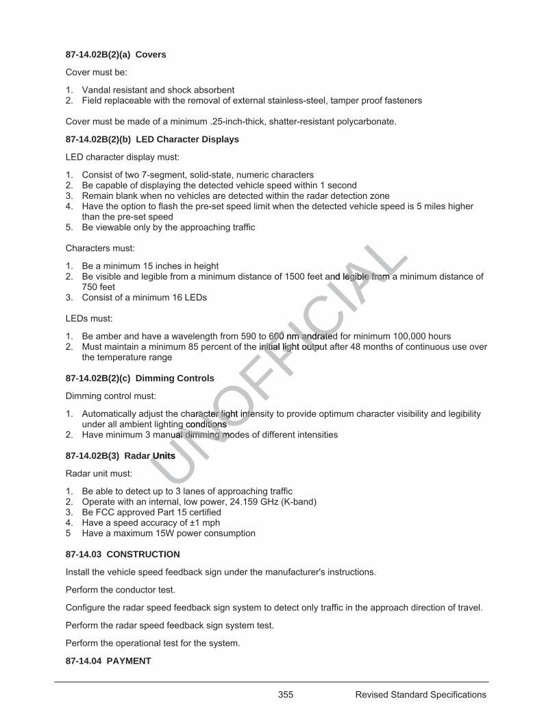
355 Revised Standard Specifications
87-14.02B(2)(a) Covers
Cover must be:
1. Vandal resistant and shock absorbent 2. Field replaceable with the removal of external stainless-steel, tamper proof fasteners
Cover must be made of a minimum .25-inch-thick, shatter-resistant polycarbonate.
87-14.02B(2)(b) LED Character Displays
LED character display must:
1. Consist of two 7-segment, solid-state, numeric characters 2. Be capable of displaying the detected vehicle speed within 1 second 3. Remain blank when no vehicles are detected within the radar detection zone 4. Have the option to flash the pre-set speed limit when the detected vehicle speed is 5 miles higher
than the pre-set speed 5. Be viewable only by the approaching traffic Characters must:
1. Be a minimum 15 inches in height 2. Be visible and legible from a minimum distance of 1500 feet and legible from a minimum distance of
750 feet 3. Consist of a minimum 16 LEDs LEDs must:
1. Be amber and have a wavelength from 590 to 600 nm andrated for minimum 100,000 hours 2. Must maintain a minimum 85 percent of the initial light output after 48 months of continuous use over
the temperature range 87-14.02B(2)(c) Dimming Controls
Dimming control must:
1. Automatically adjust the character light intensity to provide optimum character visibility and legibility under all ambient lighting conditions
2. Have minimum 3 manual dimming modes of different intensities 87-14.02B(3) Radar Units
Radar unit must:
1. Be able to detect up to 3 lanes of approaching traffic 2. Operate with an internal, low power, 24.159 GHz (K-band) 3. Be FCC approved Part 15 certified 4. Have a speed accuracy of ±1 mph 5 Have a maximum 15W power consumption 87-14.03 CONSTRUCTION
Install the vehicle speed feedback sign under the manufacturer's instructions.
Perform the conductor test.
Configure the radar speed feedback sign system to detect only traffic in the approach direction of travel.
Perform the radar speed feedback sign system test.
Perform the operational test for the system.
87-14.04 PAYMENT
UNOFFICIA
Land legible from aand legible from a
600 nm andrated600 nm andratedinitianitial light outpulight outp
aracter light intenracter light integ conditions g conditions
nual dimming modual dimming m
r Units r U
3
356 Revised Standard Specifications
Not Used
04-15-16 87-15–87-17 RESERVED
87-18 INTERCONNECTION CONDUIT AND CABLE
87-18.01 GENERAL
Section 87-18 includes specifications for constructing interconnection conduit and cable.
Interconnection conduit and cable includes:
1. Pull boxes 2. Conduit 3. Signal interconnect cables The components of an interconnection conduit and cable are shown.
87-18.02 MATERIALS
Not Used
87-18.03 CONSTRUCTION
Test the signal interconnect cable.
Connect the signal interconnect cable to the terminal block in the controller cabinets. The Engineer provides you a list of terminations for each controller cabinet.
87-18.04 PAYMENT
Not Used
04-20-18 87-19 FIBER OPTIC CABLE SYSTEMS
87-19.01 GENERAL
87-19.01A Summary
Section 87-19 includes specifications for constructing fiber optic cable systems.
A fiber optic cable system includes:
1. Conduit and accessories 2. Splice vaults 3. Warning tape 4. Fiber optic cables 5. Fiber optic splice enclosures 6. Fiber distribution units 7. Fiber optic markers 8 Fiber optic connectors and couplers The components of a fiber optic system are shown on the project plans.
87-19.01B Definitions
Reserved
87-19.01C Submittals
At least 15 days before cable installation, submit:
1. Manufacturer’s procedures for pulling fiber optic cable
UNOFFICIA
Ln the contron the controller cler
inet. et.
BER OPTIC CABBER OPTIC CA
ifications fofications for consr cons
m includes: m includes:
essories essories

357 Revised Standard Specifications
2. Test reports from a laboratory accredited to International Standards Organization/International Electrotechnical Commission 17025 by the American Association for Laboratory Accreditation (A2LA) or the ANSI-ASQ National Accreditation Board (ANAB) for: 2.1. Water penetration 2.2. Cable temperature cycling 2.3. Cable impact 2.4. Cable tensile loading and fiber strain 2.5. Cable compressive loading 2.6. Compound flow 2.7. Cyclic flexing
3. Proof of calibration for the test equipment including: 3.1. Name of calibration facility 3.2. Date of calibration 3.3. Type of equipment, model number and serial number 3.4. Calibration result
Submit the data file and software from the OTDR with the test results for all OTDR tests. The software must support Windows computer operating systems.
After performing the OTDR and the power meter and light source tests, submit within 4 business days:
1. Cable Verification Worksheet 2. Segment Verification Worksheet 3. Link Loss Budget Worksheet
The worksheets are available at the Division of Construction website and copies are included in the Information Handout. Submittals must be in Microsoft Excel format. Include hard copies and copies in an electronic format.
87-19.01D Quality Assurance
87-19.01D(1) General
Reserved
87-19.01D(2) Quality Control
Notify the Engineer 4 days before performing field tests. Include exact location of the system or components to be tested. Do not proceed with the testing until authorized. Perform each test in the presence of the Engineer.
The OTDR test consists of:
1. Inspecting the cable segment for physical damage. 2. Measuring the attenuation levels for wavelengths of 1310 nm and 1550 nm in both directions for each
fiber using a light source at one end and OTDR at the other end. 3. Comparing the test results with the data sheet provided with the shipment. If there are attenuation
deviations greater than 5 percent, the test will be considered unsatisfactory and the cable segment will be rejected. The failure of any single fiber is a cause for rejection of the entire segment. Replace any rejected cable segments and repeat the test.
The power meter and light source test consists of:
1. Testing each fiber in a link using a light source at one end of the link and a power meter at the other end
2. Measuring and recording the power loss for wavelengths of 1310 nm and 1550 nm in both directions Index matching gel is not allowed in connectors during power meter and light source test.
Test results must be generated from test equipment software and recorded, compared and proven to be within the calculated link loss budget, and filed with the other recordings of the same link.
UNOFFICIA
Lsubmit withinubmit within
tion website and n website andExcel foExcel format. Inc In
efore performing fe performing fDo not proceed wo not procee
er. .
ists of: ists
e segmene segmetioni
358 Revised Standard Specifications
Installation and splicing of the fiber optic cable system must be performed by a certified fiber optic installer.
The OTDR test and the power meter and light source test must be performed by a certified fiber optic technician.
The certification for the fiber optic installer and fiber optic technician must be from an organization recognized by the International Certification Accreditations Council and must be current through the installation of the fiber optic system.
87-19.02 MATERIALS
87-19.02A General
All metal components of the fiber optic cable system must be corrosion resistant.
All connectors must be factory-installed and tested.
Patch cords, pigtails and connectors must comply with ANSI/TIA-568.
Pigtails must have a minimum 80 N pull out strength.
Each cable reel must be labeled as specified in ANSI/ICEA S-87-640 including:
1. Contractor's name 2. Contract number 3. Cable diameter 4. Number of fibers 5. Cable attenuation loss per fiber at 1310 nm and 1550 nm The information must be on a weatherproof label or tag and in a shipping record in a weatherproof envelope. The envelope must be removed only by the Engineer.
87-19.02B Splice Vaults
A splice vault must:
1. Comply with section 86 1.02C, AASHTO HS 20-44 and AASHTO M 306. 2. Be a minimum of 4 feet wide by 4 feet high by 4 feet long nominal inside dimensions or a minimum of
4 feet outside diameter for round splice vaults. 3. Be precast either modular or monolithic. 4. Have cable racks installed on the interior sides. A rack must:
4.1. Be fabricated from ASTM A36 steel plate 4.2 Support a minimum of 100 pounds per rack arm. 4.3 Support a minimum of 4 splice enclosures and a minimum of 4 cables with a minimum slack of
50 feet each. 4.4 Be hot-dip galvanized after manufacturing. 4.5 Be bonded and grounded.
5. Have a minimum of 4 knockouts for cable entry points. Entry points must not cause the cable to exceed its maximum bend radius.
6. Have a minimum 2 inch diameter drain hole at the base. 7. Be weatherproof. 8. Have cable accesses with rubber grommets or similar material to prevent the cable from coming in
contact with the bare metal. The cover must:
1. Be in two-piece torsion-assisted sections for non-rounded enclosures. 2. Be galvanized steel with a minimum of 30 inches diameter for round enclosures. 3. Have inset lifting pull slots. 4. Have markings "CALTRANS FIBER OPTIC" on each section.
UNOFFICIA
Lncluding: ding:
50 nm 50 nm
oror tag and in a sh tag and in a shrrby the Engineer.by the Enginee
02CC, AASHTO H, AASHTO Ht wide by 4 feet hwide by 4 fe
ter for round splicer for round splimodular or monoular or mo
s installed on ths installed on thed from ASTed from AS
mum mum
359 Revised Standard Specifications
87-19.02C Fiber Optic Cable
The fiber optic cable must:
1. Comply with 7 CFR 1755.900 to 1755.902 and ANSI/ICEA S-87-640 2. Be a single mode, zero-dispersion, and have non-gel loose type buffer tubes 3. Have no splices, including factory splices 4. Have a Type H or Type M outer jacket
The fiber optic cable must:
1. Be shipped on a reel 2. Have 10 feet of length on each end of the cable accessible for testing
The fiber optic riser cable must:
1. Comply with ICEA S-104-696 2. Be rated for underground and riser application 3. Have a minimum of 4 fibers. 4. Be singlemode and operate at wavelengths of 1310 and 1550 nanometers
Fiber optic cable must be identified as shown in the following table:
UNOFFICIA
Leters ete
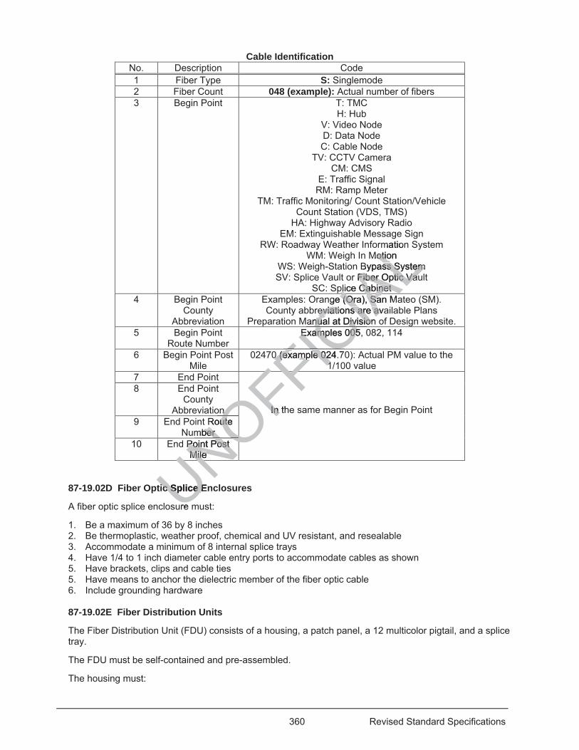
360 Revised Standard Specifications
Cable Identification No. Description Code 1 Fiber Type S: Singlemode 2 Fiber Count 048 (example): Actual number of fibers 3 Begin Point T: TMC
H: Hub V: Video Node D: Data Node C: Cable Node
TV: CCTV Camera CM: CMS
E: Traffic Signal RM: Ramp Meter
TM: Traffic Monitoring/ Count Station/Vehicle Count Station (VDS, TMS)
HA: Highway Advisory Radio EM: Extinguishable Message Sign
RW: Roadway Weather Information System WM: Weigh In Motion
WS: Weigh-Station Bypass System SV: Splice Vault or Fiber Optic Vault
SC: Splice Cabinet 4 Begin Point
County Abbreviation
Examples: Orange (Ora), San Mateo (SM). County abbreviations are available Plans
Preparation Manual at Division of Design website. 5 Begin Point
Route Number Examples 005, 082, 114
6 Begin Point Post Mile
02470 (example 024.70): Actual PM value to the 1/100 value
7 End Point
In the same manner as for Begin Point
8 End Point County
Abbreviation 9 End Point Route
Number 10 End Point Post
Mile
87-19.02D Fiber Optic Splice Enclosures
A fiber optic splice enclosure must:
1. Be a maximum of 36 by 8 inches 2. Be thermoplastic, weather proof, chemical and UV resistant, and resealable 3. Accommodate a minimum of 8 internal splice trays 4. Have 1/4 to 1 inch diameter cable entry ports to accommodate cables as shown 5. Have brackets, clips and cable ties 5. Have means to anchor the dielectric member of the fiber optic cable 6. Include grounding hardware 87-19.02E Fiber Distribution Units
The Fiber Distribution Unit (FDU) consists of a housing, a patch panel, a 12 multicolor pigtail, and a splice tray.
The FDU must be self-contained and pre-assembled.
The housing must:
UNOFFIn thIn FFIC
IAL
gmation
Motion otioBypass Systemss System
or Fiber Optic VauFiber Optic Vauplice Cabinet plice Cabinet
nge (Ora), San Mae (Ora), Sareviations are avaeviations are av
anual at Divisionnual at DivisionIAExamples 005, Examples 005C0 (example 024.70 (example 02
11FICFF
n n ORoute utember ber OOPoint Post Point Post
Mile Mile NOUNO
ic Splice Enic Splice E
ure
361 Revised Standard Specifications
1. Be a 19-inch rack mountable modular metal enclosure 2. Be a one rack unit 3. Have cable clamps to secure fiber optic cables to the chassis 4. Have cable accesses with rubber grommets or similar material to prevent the cable from coming in
contact with the bare metal 5. Be weatherproof 6. Have a hinged top door with a latch or thumbscrew to hold it in the closed position A patch panel must have a minimum of 12 single-fiber type connector sleeves.
A pigtail must:
1. Be a simplex single mode fiber in a 900 μm tight buffer with a 0.12 inch outer diameter PVC jacket 2. Have a fiber optic connector attached on one end and bare fiber on the other end 3. Be at least 3 feet in length 4. Have the manufacturer's part number on the jacket Pigtails must be single-fiber or ribbon type.
Patch cords must:
1. Be a single mode fiber in a 900 μm tight buffer with a 0.12 inch outer diameter PVC jacket 2. Have fiber optic connectors attached on both ends 3. Be at least 6 feet in length 4. Have manufacturer's part number on the jacket Duplex patch cords must be of round cable structure, and not have zip-cord structure.
Splice trays must:
1. Have brackets to spool incoming fibers a minimum of 2 turns. 2. Have means to secure and protect incoming buffer tubes, pigtails, and a minimum of 12 heat shrink
fusion splices. 3. Be stackable. 4. Have a snap-on or hinged cover. The cover may be transparent. A splice cassette may be used in place of a pigtail and a splice tray.
87-19.02F Fiber Optic Markers
Fiber optic markers must be:
1. Type K-2 (CA) object markers for splice vaults or pull boxes. 2. Type G retroreflective pavement markers for paved areas and transition points from unpaved to
paved areas. 3. Non-reflective Class 1, Type F, flexible post delineators for unpaved areas. 87-19.02G Fiber Optic Connectors and Couplers
Singlemode fiber optic connectors must have a yellow strain relief boot or a yellow base.
Connectors must be:
1. 0.1-inch ceramic ferrule pre-radiused type 2. Capped when not used Couplers must be made of the same material as the connector's housing and have ceramic sleeves.
87-19.03 CONSTRUCTION
87-19.03A General
Perform the OTDR test:
UNOFFICIA
Luter diameter PVuter diameter PV
nd not have no zip-czip-c
minimum of 2 turnminimum of 2 turnming buffer tubesming buffer
. The cover may The cover ma
in place of a pigtan place of a pig
arkers rkers
ust be: be:
bject markers bject markeve pavemve pavem
362 Revised Standard Specifications
1. On the fiber optic cable upon its arrival to the job site and before its installation. Complete the Cable Verification Worksheet. Do not install the fiber optic cable until the Engineer's written approval is received.
2. After the fiber optic cable segments have been pulled but before breakout and termination. Complete the Segment Verification Worksheet.
3. Once the passive cabling system has been installed and is ready for activation. If the measured individual fusion splice losses exceed -0.30 dB, re-splice and retest. At the conclusion of the OTDR test, perform the power meter and light source test. If the measured link loss exceeds the calculated link loss, replace the unsatisfactory cable segments or splices and retest. Complete the Link Loss Budget Worksheet.
87-19.03B Splice Vaults Installation
Install a splice vault as shown and with the side facing the roadway a minimum of 2 feet from the edge of pavement or back of dike, away from traffic.
Install the top of the vault flush with surrounding grade in paved areas and 2 inches above the surrounding grade in unpaved areas.
Place minor concrete around and under vaults. In unpaved areas, finish top of concrete at a 2 percent slope away from cover. In paved areas, finish top of concrete to match existing slope.
Bolt the steel cover to the vault when not working in it.
87-19.03C Fiber Optic Cable Installation
Install fiber optic cable under manufacturer's instructions. Fiber optic cable must be installed by a certified installer or a representative from the fiber optic cable manufacturer must be present during installation.
For installation of fiber optic cable using mechanical aids:
1. Maintain a cable bend radius at least twenty times the outside diameter of the cable. 2. Cable grips have a ball bearing swivel. 3. Pulling force on a cable must not exceed 500 pound-foot or manufacturer’s recommended pulling
tension, whichever is less. Cable installed using the air blown method must withstand a static air pressure of 110 psi.
Lubricate the cable using a lubricant recommended by the cable manufacture.
Use only a non-abrasive pull tape.
Install fiber optic cable without splices except where shown or authorized.
Provide a minimum of 65 feet of slack for each fiber optic cable at each splice vault. Divide the slack equally on each side of the splice enclosure.
Install tracer wires in the fiber optic conduits and innerducts as shown. Provide a minimum 5 feet of slack tracer wire in each pull box and splice vault from each direction. You may splice tracer wire at intervals of not less than 500 feet and only inside splice vaults or pull boxes.
If a fiber optic cable and tracer wire is installed in an innerduct, pulling a separate fiber optic cable into a spare duct to replace damaged fiber will not be allowed.
Apply a flooding material to fiber optic cable openings.
Seal the ends of conduit after cables are installed.
Install strain relief for fiber optic cable entering a fiber optic enclosure.
Identify fibers and cables by direct labeling, metal tags, or bands fastened in such a way that they will not move. Use mechanical methods for labeling.
Provide identification on each fiber or each group of fibers in each splice vault and near the end of terminated fibers.
UNOFFICIA
Lop of cop oncexisting slope. sting slope.
Fiber optic cableFiber optic cablemanufacturer musmanufacturer m
al aids: al aids:
tty times the outsy times the outs
ceed 500 ed 500 pound-fpound-
wn method mustwn method mus w
ubricant recommubricant recomm
e pull tape. pull tape
le without splicele without splice
5 feet of5 feet ofe sp
363 Revised Standard Specifications
Place labels on the cables at the following points:
1. Fiber optic splice vault entrance and exit 2. Splice enclosures entrance and exit 3. FDU entrance
For fiber optic riser cable inside controller cabinets, lace and secure the cable to the cage.
Support the fiber optic riser cable within 6 inches from a termination and every 2 feet.
Secure fiber optic cables to the cable racks. Store excess cable in a figure 8 fashion.
87-19.03D Fiber Optic Cable Splices
Use fusion splicing for fiber optic cables.
Splice single-buffer tube cable to multi-buffer tube cable using the mid-span access method under manufacturer's instructions. Any mid-span access splice or FDU termination must involve only those fibers being spliced as shown.
Place fiber splices in the splice enclosures installed in the splice vaults.
87-19.03E Splice Enclosures Installation
Maintain an equal amount of slack on each side of the splice enclosure.
Secure the fiber optic splices in splice tray.
Secure the splice trays to the inner enclosure.
Label cables and buffer tubes.
Do not seal fiber splice enclosure until authorized and the power meter and light source test is performed. Seal the enclosure under manufacturer's recommendation.
Flash test the outer enclosure under manufacturer's instructions in the presence of the Engineer. Visually inspect the enclosure. If bubbles are present, identify the locations where the bubbles are present, take corrective actions and repeat the flash test until no bubbles are present.
Attach the splice enclosure to the side wall of a splice vault or hub with a minimum 2 feet distance between the ground and the bottom of the enclosure.
Secure fiber optic cables to the chassis using cable clamps for fiber optic units.
Connect a minimum of one bonding conductor to a grounding electrode after mounting the fiber optic enclosure to the wall. If there are multiple bonding conductors, organize the conductors in a neat manner.
87-19.03F Fiber Optic Distribution Unit Installation
Spool incoming buffer tubes 2 feet in the splice tray and expose 1 foot of individual fibers.
Maintain a minimum 2-inch-bend radius during and after installation in the splice tray.
Splice incoming fibers in the splice tray.
Restrain each fiber in the splice tray. Do not apply stress on the fiber when located in its final position.
Secure buffer tubes near the entrance of the splice tray.
Secure splice trays under manufacturer's instructions.
Label splice tray after splicing is completed.
Install patch cords in FDUs and patch panels. Permanently label each cord and each connector in the panel with the system as shown.
87-19.03G Fiber Optic Markers Installation
UNOFFICIA
Llosure. losure.
ed and ed and the powerthe poweommendation. ommendat
nufacturer's instfacturer's instrurpresent, identify present, iden t
ash test until no bsh test until no
the side wall of a e side wall of ae bottom of the en bottom of the en
es to the chassis to the chassis
of one bonding of one bondingf there are f there are
str
364 Revised Standard Specifications
Install fiber optic markers at 12-inch offset on the side furthest away from the edge of travel way:
1. For fiber optic cable at 500 feet apart in areas where the distance between splice vaults or pull boxes is greater than 500 feet
2. Adjacent to pull boxes and splice vaults 3. For fiber optic cable turns at:
3.1. Beginning of the turn 3.2. Middle of the arc 3.3. End of the turn
When a fiber optic cable crosses a roadway or ramp, install a Type G marker over the conduit on:
1. Every shoulder within 6 inches from the edge of pavement 2. Delineated median 3. Each side of the barrier
Install markers under section 81 except each retroreflective face must be parallel to the road centerline and facing away from traffic.
87-19.04 PAYMENT
Not Used 04-15-16
87-20 TEMPORARY ELECTRICAL SYSTEMS
87-20.01 GENERAL
Section 87-20 includes specifications for providing temporary electrical systems.
Obtain the Department's authorization for the type of temporary electrical system and its installation method.
A temporary system must operate on a continuous, 24-hour basis.
01-20-17 Temporary wood poles must comply with section 48-6.
04-15-16 87-20.02 MATERIALS
87-20.02A General
Material and equipment may be new or used.
The components of a temporary system are shown on the project plans.
If you use Type UF-B cable, the minimum conductor size must be no. 12.
87-20.02B Temporary Flashing Beacon Systems
A temporary flashing beacon system consists of a flashing beacon system, wood post, generator, and photovoltaic system.
The system must comply with the specifications for a flashing beacon system in section 87-7, except it may be mounted on a wood post or a trailer.
87-20.02C Temporary Lighting Systems
A temporary lighting system consists of a lighting system, generator, and wood poles.
The system must comply with the specifications for a lighting system in section 87-2, except it may be mounted on a wood pole or a trailer.
87-20.02D Temporary Signal Systems
UNOFFICIA
LAL SYSTEMS L SYSTEM
mporary electricalporary electric
e ofe of temporary eletemporarff
ntinuous, 24-hountinuous, 24-ho
y with section 48-with section 4
ent may be new oent may be new
emporary semporary
e t
365 Revised Standard Specifications
A temporary signal system consists of a signal and lighting system, wood poles and posts, and a generator.
System must comply with the specifications for a signal and lighting system in section 87-4, except:
1. Signal heads may be mounted on a wood pole, mast arm, tether wire, or a trailer 2. Flashing beacons may be mounted on a wood post, or a trailer 87-20.03 CONSTRUCTION
87-20.03A General
Provide electrical and telecommunication services for temporary systems. Do not use existing services unless authorized.
Provide power for the temporary electrical systems under section 12-3.33, except you may use a photovoltaic system for the temporary flashing beacon system.
Install conductors and cables in a conduit, suspended from wood poles at least 25 feet above the roadway, or use direct burial conductors and cables.
You may saw slots across paved areas for burial conductors and cables.
Install conduit outside the paved area at a minimum of 12 inches below grade for Type 1 and 2 conduit and at a minimum of 18 inches below grade for Type 3 conduit.
Install direct burial conductors and cables outside the paved area at a minimum depth of 24 inches below grade.
Place the portions of the conductors installed on the face of wood poles in either Type 1, 2, or 3 conduit between the point 10 feet above grade at the pole and the pull box. The conduit between the pole and the pull box must be buried at a depth of at least 18 inches below grade.
Place conductors across structures in a Type 1, 2, or 3 conduit. Attach the conduit to the outside face of the railing.
Mount the photoelectric unit at the top of the standard or wood post.
You may abandon in place conductors and cables in sawed slots or in conduit installed below the ground surface.
87-20.03B Temporary Flashing Beacon Systems
Install a fused-splice connector in the pull box adjacent to each flashing beacon. Wherever conductors are run overhead, install the splice connector in the line side outside of the control assembly.
87-20.03C Temporary Lighting Systems
Wherever conductors are run overhead, install the fuse splice connectors in the line side before entering the mast arm.
87-20.03D Temporary Signal Systems
You may splice conductors that run to a terminal compartment or a signal head on a pole to the through conductors of the same phase in a pull box adjacent to the pole. Do not splice conductors or cables except in a pull box or in a NEMA 3R enclosure.
The Department provides the timing for the temporary signal.
Maintain the temporary signal except for the Department-furnished controller assembly.
87-20.04 PAYMENT
Not Used
87-21 EXISTING ELECTRICAL SYSTEMS
s.
elow grade for Tyow grade for Ty
d area at a minimd area at a mini
face of wood poleface of wood poand the pull box.and the pull box
8 inches below grnches below g
pe 1, 2, orpe 1, 2, or 3 cond 3 crr
op of the standardp of the standa
ductors and cableuctors and cab
Flashing Beaconlashing Beaco
connector in theconnector in thtall the splicetall the spli
ghtht
366 Revised Standard Specifications
87-21.01 GENERAL
Section 87-21 includes general specifications for performing work on existing electrical systems.
87-21.02 MATERIALS
Not Used
87-21.03 CONSTRUCTION
87-21.03A General
You may abandon unused underground conduit after pulling out all conductors and removing conduit terminations from the pull boxes.
If standards are to be salvaged, remove:
1. All components 2. Mast arms from the standards 3. Luminaires, signal heads, and signal mounting assemblies from the standards and mast arms
If the existing material is unsatisfactory for reuse and the Engineer orders you to replace it with new material, replacing the existing material with new material is change order work.
If the removed electrical equipment is to be reinstalled, supply all materials and equipment, including signal mounting assemblies, anchor bolts, nuts, washers, and concrete, needed to complete the new installation.
87-21.03B Maintaining Existing Electrical Systems
87-21.03B(1) General
Maintain the existing electrical system in working order during the progress of the work. Conduct your operations to avoid damage to the elements of the systems.
87-21.03B(2) Maintaining Existing Traffic Management System Elements During Construction 07-21-17
Section 87-21.03B(2) applies if a bid item for maintaining existing traffic management system elements during construction is shown on the Bid Item List.
04-15-16 Traffic management system elements include:
1. Ramp metering system 2. Traffic monitoring stations 3. Microwave vehicle detection system 4. Changeable message sign system 5. Extinguishable message sign system 6. Highway advisory radio system 7. Closed circuit television camera system 8. Roadway weather information system Obtain authorization at least 72 hours before interrupting communication between an existing system and the traffic management center.
If the Engineer notifies you that an existing system is not fully operational due to your activities, repair or replace the system within 72 hours. If the system cannot be fixed within 72 hours or it is located on a structure, provide a temporary system within 24 hours until the system can be fixed. Perform a functional test of the system in the presence of the Engineer. If you fail to perform the necessary repair or replacement work, the Department may perform the repair or replacement work and deduct the cost.
If you damage an existing fiber optic cable, install a new cable such that the length of cable slack is the same as before the damage, measured from an original splice point or termination. All splices must be made using the fusion method.
UNOFFICIA
Lda
rs you to replyouorder work. order work.
materials and eqmaterials and eqconcrete, neededncrete, ne
ng ng order during thorder during ts of the systems. of the syste
raffic Managemeaffic Manageme
bid item for mainbid item for mn the Bid Item Listhe Bid Item Li
tem elements incem elements inc
system sysstations stati
etectionetectiosig
367 Revised Standard Specifications
You may interrupt the operation of traffic monitoring stations:
1. For 60 days if another operational traffic monitoring station is located within 3 miles 2. For 15 days if another operational traffic monitoring station is located more than 3 miles away
If a traffic monitoring station must be interrupted for longer periods than specified, provide a temporary detection system. Obtain the Department's authorization for the type of temporary system and its installation method.
87-21.03C Modifying Existing Electrical Systems
Modify electrical systems as shown.
87-21.03D Removing Existing Electrical Systems
The components to be removed are shown on the project plans.
87-21.04 PAYMENT
Not Used
^^^^^^^^^^^^^^^^^^^^^^^^^^^^^^^^^^^^^^^^^^^^^^^^^^^^^^^^^^^^
DIVISION XI MATERIALS 90 CONCRETE
01-20-17 Replace Method 1 in the 4th paragraph of section 90-1.01D(5)(a) with:
07-15-16 Method 2
Add to section 90-4.01C(1): 01-20-17
Submit daily temperature data for internally monitored tier 1 PC concrete members each week as an informational submittal.
Add between the 2nd and 3rd paragraphs of section 90-4.01C(3): 01-20-17
For internally monitored tier 1 PC bridge components, include the following as part of the QC plan:
1. Authorized mix design 2. Duration and method of curing 3. Concrete temperature monitoring and recording system details 4. Temperature sensor types and locations 5. Measures to ensure compliance with maximum temperature and temperature gain requirements,
including maximum concrete temperature at discharge and controlling enclosure temperature
Replace the list in the 3rd paragraph of section 90-4.01C(3) with: 01-20-17
1. Concrete plants 2. Material sources 3. Material testing procedures
UNOFFICIA
L^^^^^^^^^^^^^^^^^^^^^^^^^
ATERIALS TERIALS CRETE CRETE
-20-17 -20-17 aragraph of secaragraph of se
Add to secAdd to s
data for internally ata for interna
betweenbetween
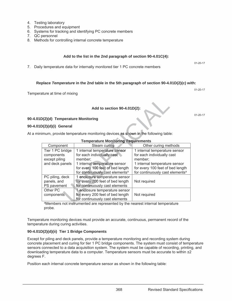
368 Revised Standard Specifications
4. Testing laboratory 5. Procedures and equipment 6. Systems for tracking and identifying PC concrete members 7. QC personnel 8. Methods for controlling internal concrete temperature
Add to the list in the 2nd paragraph of section 90-4.01C(4): 01-20-17
7. Daily temperature data for internally monitored tier 1 PC concrete members
Replace Temperature in the 2nd table in the 5th paragraph of section 90-4.01D(2)(c) with: 01-20-17
Temperature at time of mixing
Add to section 90-4.01D(2): 01-20-17
90-4.01D(2)(d) Temperature Monitoring
90-4.01D(2)(d)(i) General
At a minimum, provide temperature monitoring devices as shown in the following table:
Temperature Monitoring Requirements Component Steam curing Other curing methods
Tier 1 PC bridge components except piling and deck panels
1 internal temperature sensor for each individually cast member; 1 internal temperature sensor for every 100 feet of bed length for continuously cast elementsa
1 internal temperature sensor for each individually cast member; 1 internal temperature sensor for every 100 feet of bed length for continuously cast elementsa
PC piling, deck panels, and PS pavement
1 enclosure temperature sensor for every 200 feet of bed length for continuously cast elements
Not required
Other PC components
1 enclosure temperature sensor for every 200 feet of bed length for continuously cast elements
Not required
aMembers not instrumented are represented by the nearest internal temperature probe.
Temperature monitoring devices must provide an accurate, continuous, permanent record of the temperature during curing activities.
90-4.01D(2)(d)(ii) Tier 1 Bridge Components
Except for piling and deck panels, provide a temperature monitoring and recording system during concrete placement and curing for tier 1 PC bridge components. The system must consist of temperature sensors connected to a data acquisition system. The system must be capable of recording, printing, and downloading temperature data to a computer. Temperature sensors must be accurate to within ±2 degrees F.
Position each internal concrete temperature sensor as shown in the following table:
UNO1 enclosure tem1 enclosure temfor every 200 for every 20for continuofor continuNOFFIC
IAL
s as shown in the as shown in th
nitoring Requirenitoring Requiruring uring FII
erature sensor erature senvidually cast idually cast
nal temperature sal temperaturevery 100 feet of bry 100 feet of b
r continuously cacontinuously cFFFF
NOUN
ss1 enclos1 enclofor evor for forUNUN
struU
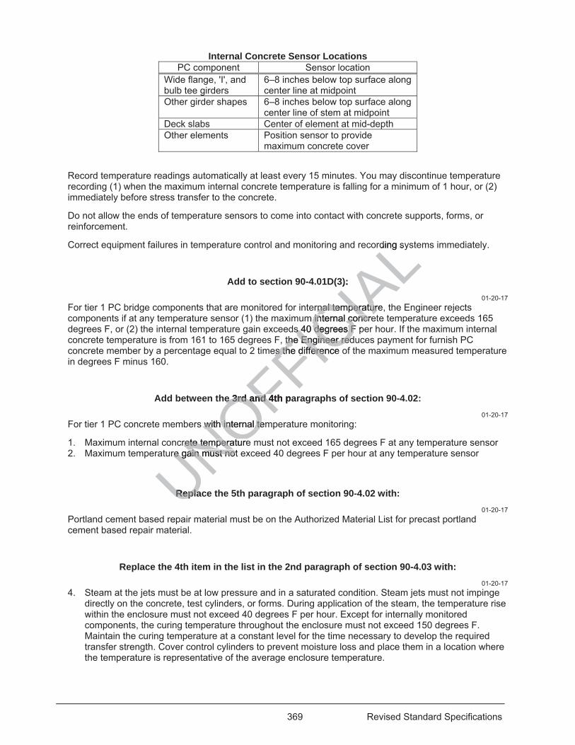
369 Revised Standard Specifications
Internal Concrete Sensor Locations PC component Sensor location
Wide flange, I', and bulb tee girders
6–8 inches below top surface along center line at midpoint
Other girder shapes 6–8 inches below top surface along center line of stem at midpoint
Deck slabs Center of element at mid-depth Other elements Position sensor to provide
maximum concrete cover
Record temperature readings automatically at least every 15 minutes. You may discontinue temperature recording (1) when the maximum internal concrete temperature is falling for a minimum of 1 hour, or (2) immediately before stress transfer to the concrete.
Do not allow the ends of temperature sensors to come into contact with concrete supports, forms, or reinforcement.
Correct equipment failures in temperature control and monitoring and recording systems immediately.
Add to section 90-4.01D(3): 01-20-17
For tier 1 PC bridge components that are monitored for internal temperature, the Engineer rejects components if at any temperature sensor (1) the maximum internal concrete temperature exceeds 165 degrees F, or (2) the internal temperature gain exceeds 40 degrees F per hour. If the maximum internal concrete temperature is from 161 to 165 degrees F, the Engineer reduces payment for furnish PC concrete member by a percentage equal to 2 times the difference of the maximum measured temperature in degrees F minus 160.
Add between the 3rd and 4th paragraphs of section 90-4.02: 01-20-17
For tier 1 PC concrete members with internal temperature monitoring:
1. Maximum internal concrete temperature must not exceed 165 degrees F at any temperature sensor 2. Maximum temperature gain must not exceed 40 degrees F per hour at any temperature sensor
Replace the 5th paragraph of section 90-4.02 with: 01-20-17
Portland cement based repair material must be on the Authorized Material List for precast portland cement based repair material.
Replace the 4th item in the list in the 2nd paragraph of section 90-4.03 with: 01-20-17
4. Steam at the jets must be at low pressure and in a saturated condition. Steam jets must not impinge directly on the concrete, test cylinders, or forms. During application of the steam, the temperature rise within the enclosure must not exceed 40 degrees F per hour. Except for internally monitored components, the curing temperature throughout the enclosure must not exceed 150 degrees F. Maintain the curing temperature at a constant level for the time necessary to develop the required transfer strength. Cover control cylinders to prevent moisture loss and place them in a location where the temperature is representative of the average enclosure temperature.
UNOFFICIA
Lrding sy
3):
rnal temperature,rnal temperaturm internal concreinternal concre
s 40 degrees F ps 40 degrees Fthe Engineer redthe Engineer red
es the difference es the differen
e 3rd and 4th pae 3rd and 4
s with internal temwith internal te
crete temperaturerete temperaturre gain must not re gain must not
ReplaRepla
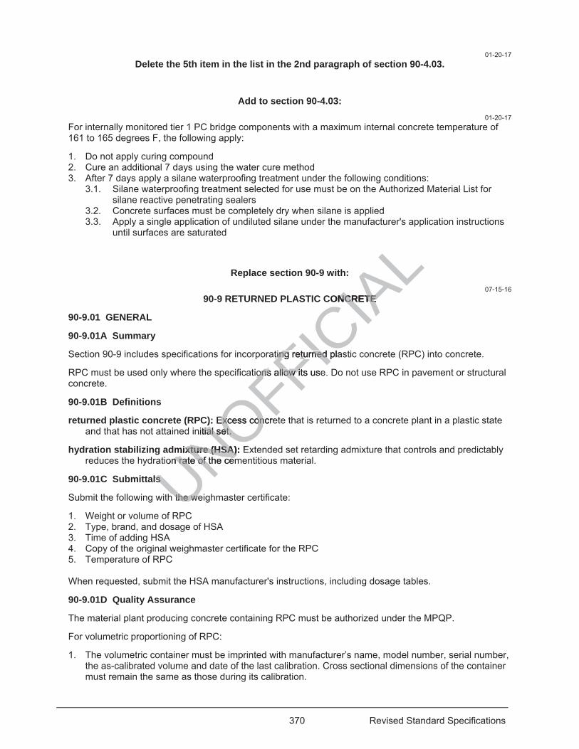
370 Revised Standard Specifications
01-20-17 Delete the 5th item in the list in the 2nd paragraph of section 90-4.03.
Add to section 90-4.03: 01-20-17
For internally monitored tier 1 PC bridge components with a maximum internal concrete temperature of 161 to 165 degrees F, the following apply:
1. Do not apply curing compound 2. Cure an additional 7 days using the water cure method 3. After 7 days apply a silane waterproofing treatment under the following conditions:
3.1. Silane waterproofing treatment selected for use must be on the Authorized Material List for silane reactive penetrating sealers
3.2. Concrete surfaces must be completely dry when silane is applied 3.3. Apply a single application of undiluted silane under the manufacturer's application instructions
until surfaces are saturated
Replace section 90-9 with: 07-15-16
90-9 RETURNED PLASTIC CONCRETE
90-9.01 GENERAL
90-9.01A Summary
Section 90-9 includes specifications for incorporating returned plastic concrete (RPC) into concrete.
RPC must be used only where the specifications allow its use. Do not use RPC in pavement or structural concrete.
90-9.01B Definitions
returned plastic concrete (RPC): Excess concrete that is returned to a concrete plant in a plastic state and that has not attained initial set.
hydration stabilizing admixture (HSA): Extended set retarding admixture that controls and predictably reduces the hydration rate of the cementitious material.
90-9.01C Submittals
Submit the following with the weighmaster certificate:
1. Weight or volume of RPC 2. Type, brand, and dosage of HSA 3. Time of adding HSA 4. Copy of the original weighmaster certificate for the RPC 5. Temperature of RPC When requested, submit the HSA manufacturer's instructions, including dosage tables.
90-9.01D Quality Assurance
The material plant producing concrete containing RPC must be authorized under the MPQP.
For volumetric proportioning of RPC:
1. The volumetric container must be imprinted with manufacturer’s name, model number, serial number, the as-calibrated volume and date of the last calibration. Cross sectional dimensions of the container must remain the same as those during its calibration.
UNOFFICIA
LONCRETE NCRETE
atting returned plaing returned
ions allow ons allow its use
):) Excess concreExcess connitial set. ial set.
mixture (HSA):mixture (HSA) Eon rate of the cemn rate of the cem
ls s
h the weh the we
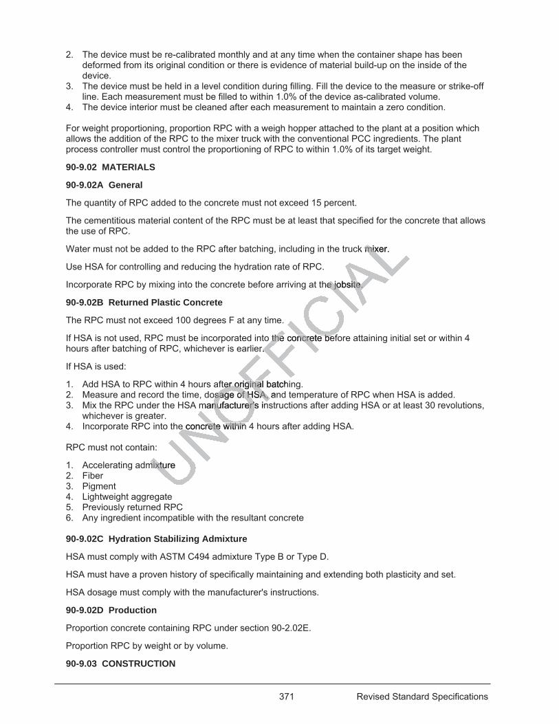
371 Revised Standard Specifications
2. The device must be re-calibrated monthly and at any time when the container shape has been deformed from its original condition or there is evidence of material build-up on the inside of the device.
3. The device must be held in a level condition during filling. Fill the device to the measure or strike-off line. Each measurement must be filled to within 1.0% of the device as-calibrated volume.
4. The device interior must be cleaned after each measurement to maintain a zero condition. For weight proportioning, proportion RPC with a weigh hopper attached to the plant at a position which allows the addition of the RPC to the mixer truck with the conventional PCC ingredients. The plant process controller must control the proportioning of RPC to within 1.0% of its target weight.
90-9.02 MATERIALS
90-9.02A General
The quantity of RPC added to the concrete must not exceed 15 percent.
The cementitious material content of the RPC must be at least that specified for the concrete that allows the use of RPC.
Water must not be added to the RPC after batching, including in the truck mixer.
Use HSA for controlling and reducing the hydration rate of RPC.
Incorporate RPC by mixing into the concrete before arriving at the jobsite.
90-9.02B Returned Plastic Concrete
The RPC must not exceed 100 degrees F at any time.
If HSA is not used, RPC must be incorporated into the concrete before attaining initial set or within 4 hours after batching of RPC, whichever is earlier.
If HSA is used:
1. Add HSA to RPC within 4 hours after original batching. 2. Measure and record the time, dosage of HSA, and temperature of RPC when HSA is added. 3. Mix the RPC under the HSA manufacturer's instructions after adding HSA or at least 30 revolutions,
whichever is greater. 4. Incorporate RPC into the concrete within 4 hours after adding HSA. RPC must not contain:
1. Accelerating admixture 2. Fiber 3. Pigment 4. Lightweight aggregate 5. Previously returned RPC 6. Any ingredient incompatible with the resultant concrete 90-9.02C Hydration Stabilizing Admixture
HSA must comply with ASTM C494 admixture Type B or Type D.
HSA must have a proven history of specifically maintaining and extending both plasticity and set.
HSA dosage must comply with the manufacturer's instructions.
90-9.02D Production
Proportion concrete containing RPC under section 90-2.02E.
Proportion RPC by weight or by volume.
90-9.03 CONSTRUCTION
ck mixer. mix
the jobsite. e jobsite.
o the the concrete befncrete beer. .
ter original batchter originaosage of HSA, anosage of HSA,
manufacturer's innufacturer's in
e concree concrete within te within
mixture mixtu
372 Revised Standard Specifications
Not Used
90-9.04 PAYMENT
Not Used
^^^^^^^^^^^^^^^^^^^^^^^^^^^^^^^^^^^^^^^^
92 ASPHALT BINDERS 04-15-16
Replace the 4th paragraph of section 92-1.02B with: 04-15-16
Crumb rubber modifier used must be on the Authorized Materials List for crumb rubber modifier.
Production equipment for PG modified asphalt binder with crumb rubber modifier must be authorized under the Department's MPQP.
Crumb rubber must be derived from waste tires described in Pub Res Code § 42703 and must be free from contaminants including fabric, metal, minerals, and other nonrubber substances.
^^^^^^^^^^^^^^^^^^^^^^^^^^^^^^^^^^^^^^^^
95 EPOXY 04-20-18
Replace the requirement in the row for Brookfield viscosity in the table in section 95-1.02H with: 04-20-18
9
^^^^^^^^^^^^^^^^^^^^^^^^^^^^^^^^^^^^^^^^
96 GEOSYNTHETICS 04-20-18
Replace product name, manufacturing source, and date of manufacture in the 2nd sentence of the 1st paragraph of section 96-1.01D with:
01-15-16 manufacturing source code
Replace Apparent opening size, (min, inches) in the table in the 2nd paragraph of section 96-1.02O with:
01-20-17 Apparent opening size, (max, inches)
Replace section 96-1.02R with: 04-20-18
96-1.02R Geomembrane
UNOFFICIA
Ldifie
Code § 42703 aCode § 42703 aubber substancebber substance
^^^^^^^^^^^^^^^^^^^^^^^^^^
EPOXY EPOXY 04-20-18 04-20-1
Brookfield viscBrookfield v
^^^^^^^^^^^^^^^^^^^^^^^^^^
man
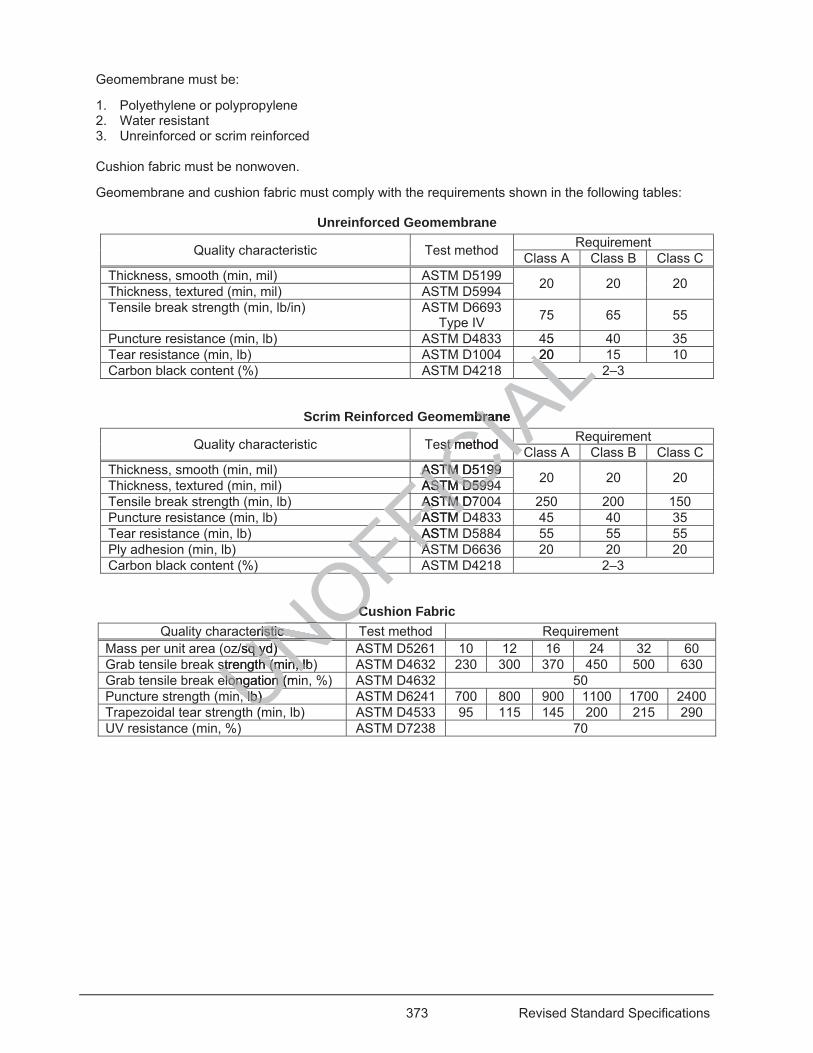
373 Revised Standard Specifications
Geomembrane must be:
1. Polyethylene or polypropylene 2. Water resistant 3. Unreinforced or scrim reinforced
Cushion fabric must be nonwoven.
Geomembrane and cushion fabric must comply with the requirements shown in the following tables:
Unreinforced Geomembrane
Quality characteristic Test method Requirement Class A Class B Class C
Thickness, smooth (min, mil) ASTM D5199 20 20 20 Thickness, textured (min, mil) ASTM D5994 Tensile break strength (min, lb/in) ASTM D6693
Type IV 75 65 55
Puncture resistance (min, lb) ASTM D4833 45 40 35 Tear resistance (min, lb) ASTM D1004 20 15 10 Carbon black content (%) ASTM D4218 2–3
Scrim Reinforced Geomembrane
Quality characteristic Test method Requirement Class A Class B Class C
Thickness, smooth (min, mil) ASTM D5199 20 20 20 Thickness, textured (min, mil) ASTM D5994 Tensile break strength (min, lb) ASTM D7004 250 200 150 Puncture resistance (min, lb) ASTM D4833 45 40 35 Tear resistance (min, lb) ASTM D5884 55 55 55 Ply adhesion (min, lb) ASTM D6636 20 20 20 Carbon black content (%) ASTM D4218 2–3
Cushion Fabric Quality characteristic Test method Requirement
Mass per unit area (oz/sq yd) ASTM D5261 10 12 16 24 32 60 Grab tensile break strength (min, lb) ASTM D4632 230 300 370 450 500 630 Grab tensile break elongation (min, %) ASTM D4632 50 Puncture strength (min, lb) ASTM D6241 700 800 900 1100 1700 2400 Trapezoidal tear strength (min, lb) ASTM D4533 95 115 145 200 215 290 UV resistance (min, %) ASTM D7238 70
UNOFFICIA
L45 20 LLLAAAL
mbrane bra
est method st methodCIAIACIAIAASTM D5199 ASTM D5199CCASTM D599ASTM D599ICFASTM D7ASTM FICFASTM ASTMFI
FFASTAFFFFAAFFFFOFOFF
CCeristic ristic NOO
z/sq yd) sq yd)
UNUNstrength (min, lb)strength (min, lUNelongation (melongation (Un, lb) n, lb) U(mU

This page intentionally left blank
UNOFFICIA
Ltentionalltentional
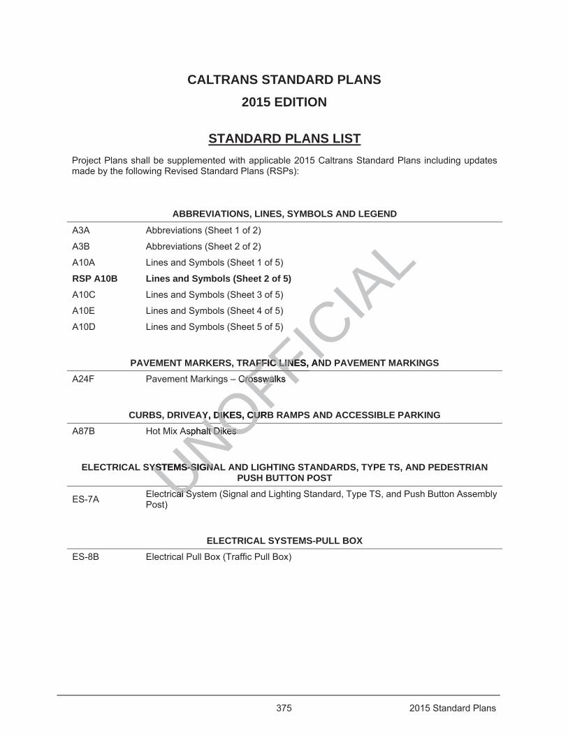
375 2015 Standard Plans
CALTRANS STANDARD PLANS 2015 EDITION
STANDARD PLANS LIST Project Plans shall be supplemented with applicable 2015 Caltrans Standard Plans including updates made by the following Revised Standard Plans (RSPs):
ABBREVIATIONS, LINES, SYMBOLS AND LEGEND
A3A Abbreviations (Sheet 1 of 2)
A3B Abbreviations (Sheet 2 of 2)
A10A Lines and Symbols (Sheet 1 of 5)
RSP A10B Lines and Symbols (Sheet 2 of 5) A10C Lines and Symbols (Sheet 3 of 5)
A10E Lines and Symbols (Sheet 4 of 5)
A10D Lines and Symbols (Sheet 5 of 5)
PAVEMENT MARKERS, TRAFFIC LINES, AND PAVEMENT MARKINGS A24F Pavement Markings – Crosswalks
CURBS, DRIVEAY, DIKES, CURB RAMPS AND ACCESSIBLE PARKING A87B Hot Mix Asphalt Dikes
ELECTRICAL SYSTEMS-SIGNAL AND LIGHTING STANDARDS, TYPE TS, AND PEDESTRIAN PUSH BUTTON POST
ES-7A Electrical System (Signal and Lighting Standard, Type TS, and Push Button Assembly Post)
ELECTRICAL SYSTEMS-PULL BOX ES-8B Electrical Pull Box (Traffic Pull Box)
UNOFFICIA
LAFFIC LIAFFIC LINES, ANN
Crosswalks CrosswalFFAY, DIKES, CURBY, DIKES, CU
Asphalt Dikes lt Dikes
NOYSTEMS-SIGNAYSTEMS-SIGNA
cal Scal SU
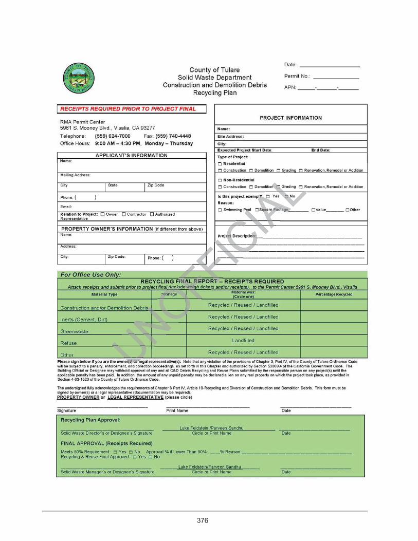
376
CONSTRUCTION AND DEMOLITION DEBRIS RECYCLING PLAN FORM
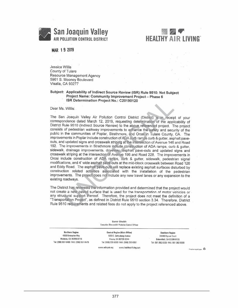
377
APPLICABILITY OF INDIRECT SOURCE REVIEW (ISR)
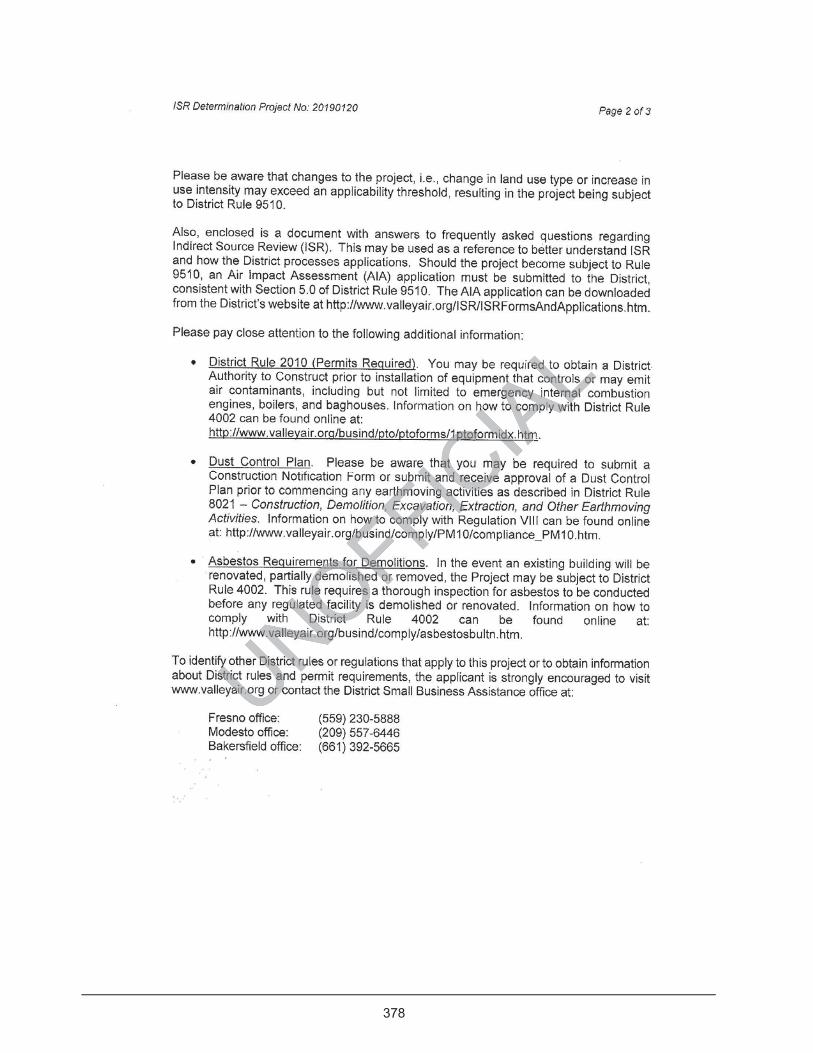
378

379
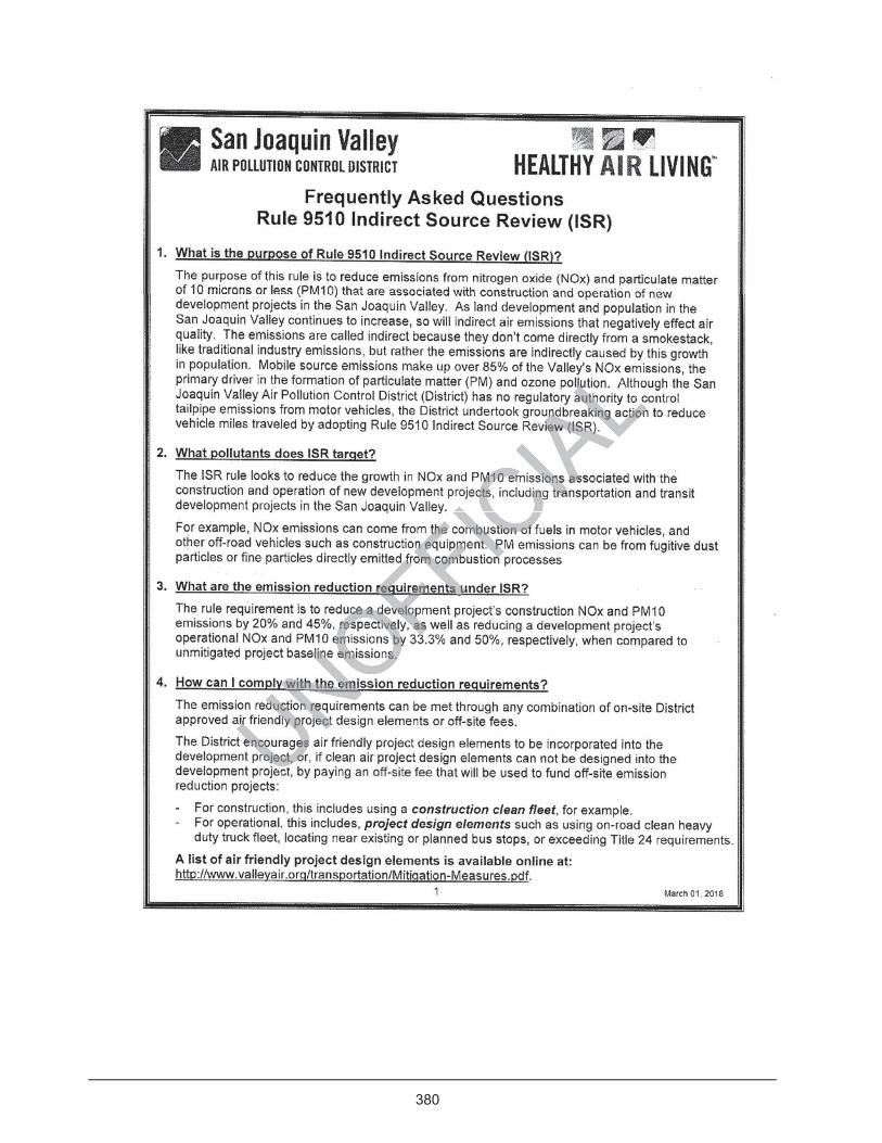
380
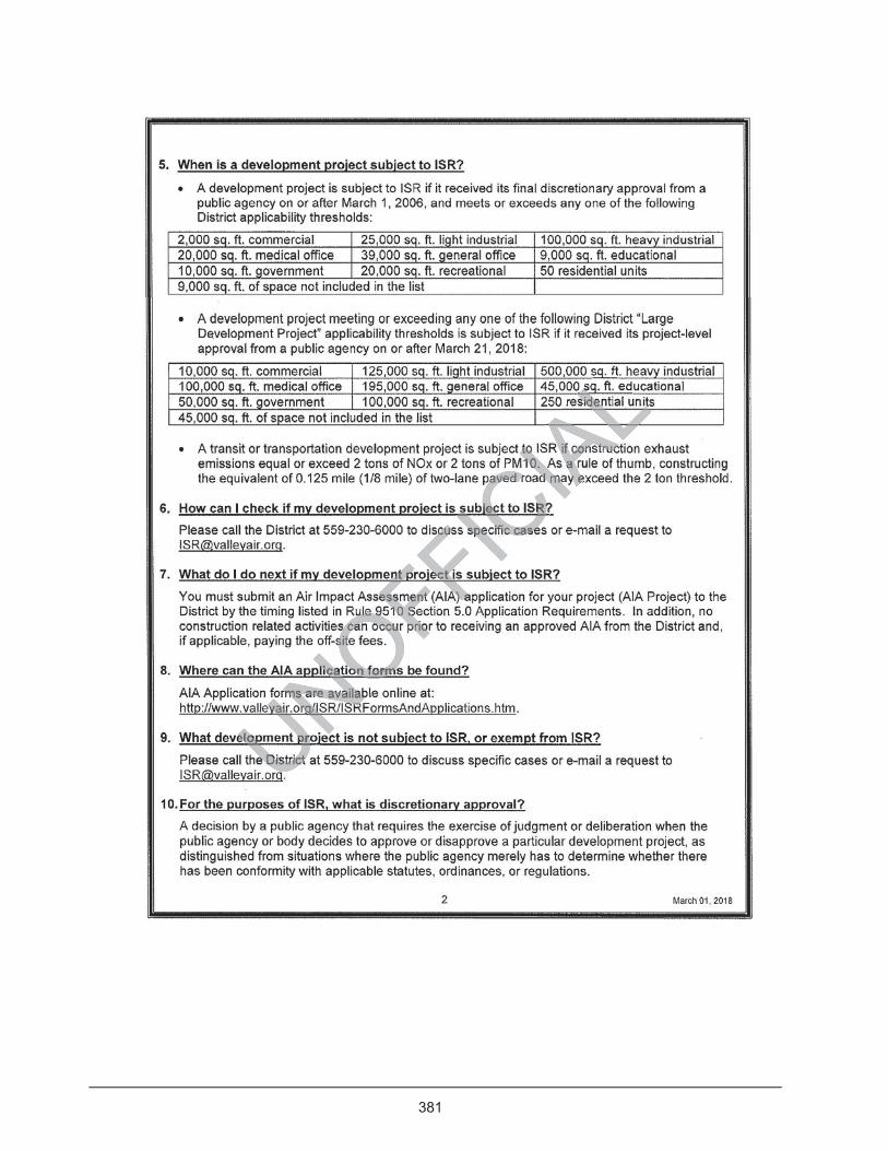
381
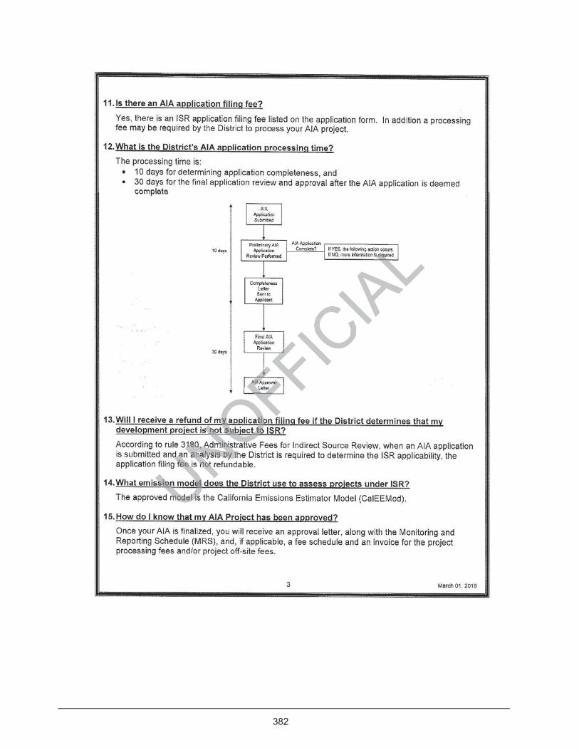
382
383

This page intentionally left blank
UNOFFICIA
Lintentionaintention
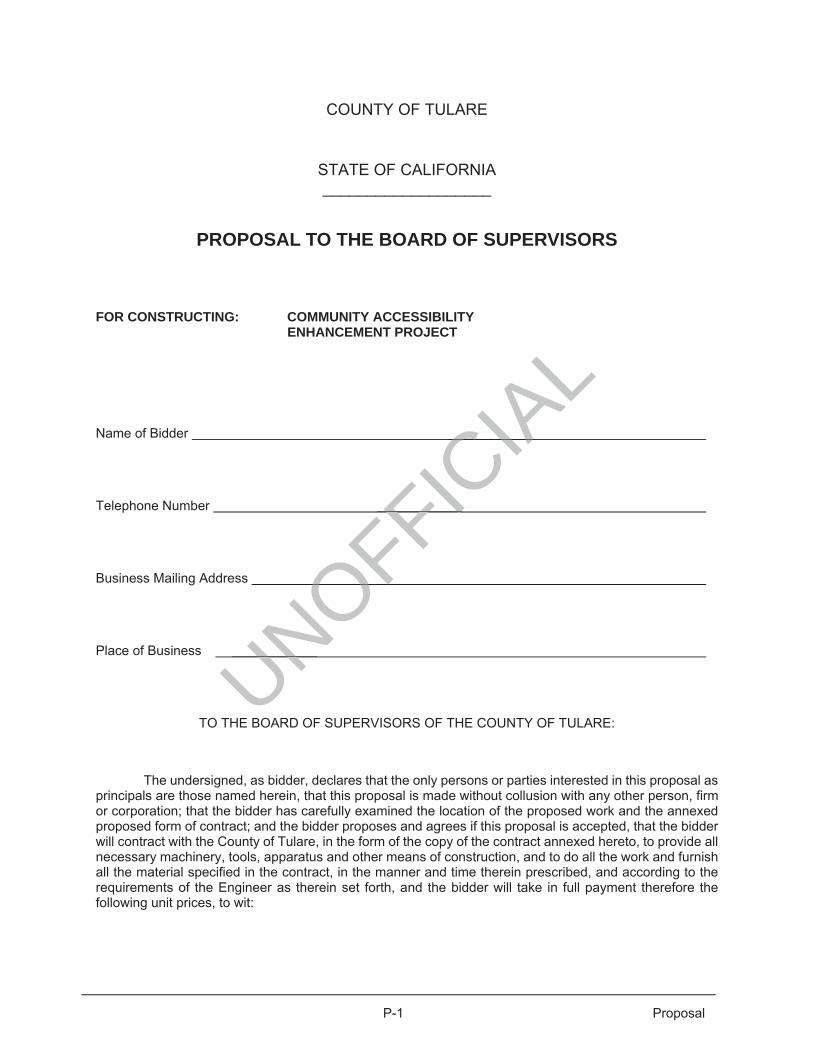
P-1 Proposal
COUNTY OF TULARE
STATE OF CALIFORNIA ___________________
PROPOSAL TO THE BOARD OF SUPERVISORS
FOR CONSTRUCTING: COMMUNITY ACCESSIBILITY ENHANCEMENT PROJECT
Name of Bidder
Telephone Number
Business Mailing Address
Place of Business
TO THE BOARD OF SUPERVISORS OF THE COUNTY OF TULARE:
The undersigned, as bidder, declares that the only persons or parties interested in this proposal as principals are those named herein, that this proposal is made without collusion with any other person, firm or corporation; that the bidder has carefully examined the location of the proposed work and the annexed proposed form of contract; and the bidder proposes and agrees if this proposal is accepted, that the bidder will contract with the County of Tulare, in the form of the copy of the contract annexed hereto, to provide all necessary machinery, tools, apparatus and other means of construction, and to do all the work and furnish all the material specified in the contract, in the manner and time therein prescribed, and according to the requirements of the Engineer as therein set forth, and the bidder will take in full payment therefore the following unit prices, to wit:
UNOFFICIA
LCIA
FIOF
UN

This page intentionally left blank
UNOFFICIA
Ltentionalltentional
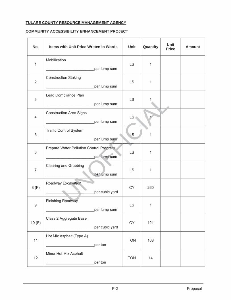
P-2 Proposal
TULARE COUNTY RESOURCE MANAGEMENT AGENCY
COMMUNITY ACCESSIBILITY ENHANCEMENT PROJECT
No. Items with Unit Price Written in Words Unit Quantity UnitPrice Amount
1 Mobilization _______________________per lump sum
LS 1
2 Construction Staking _______________________per lump sum
LS 1
3 Lead Compliance Plan _______________________per lump sum
LS 1
4 Construction Area Signs _______________________per lump sum
LS 1
5 Traffic Control System _______________________per lump sum
LS 1
6 Prepare Water Pollution Control Program _______________________per lump sum
LS 1
7 Clearing and Grubbing _______________________per lump sum
LS 1
8 (F) Roadway Excavation _______________________per cubic yard
CY 260
9 Finishing Roadway _______________________per lump sum
LS 1
10 (F) Class 2 Aggregate Base _______________________per cubic yard
CY 121
11 Hot Mix Asphalt (Type A) _______________________per ton
TON 168
12 Minor Hot Mix Asphalt _______________________per ton
TON 14
dway dwayUNOFFICIA
L AL1 1 AL
CIAAL
sum um LS LS CIA
FICCIA
rogram rogram
_per lump sum r lump s FIFI_________per lum______per lumOF
cavation avation
__________________________NOU
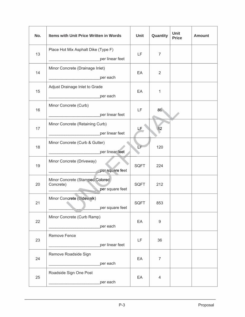
P-3 Proposal
No. Items with Unit Price Written in Words Unit Quantity UnitPrice Amount
13 Place Hot Mix Asphalt Dike (Type F) _______________________per linear feet
LF 7
14 Minor Concrete (Drainage Inlet) _______________________per each
EA 2
15 Adjust Drainage Inlet to Grade _______________________per each
EA 1
16 Minor Concrete (Curb) _______________________per linear feet
LF 86
17 Minor Concrete (Retaining Curb) _______________________per linear feet
LF 82
18 Minor Concrete (Curb & Gutter) _______________________per linear feet
LF 120
19 Minor Concrete (Driveway) _______________________per square feet
SQFT 224
20 Minor Concrete (Stamped Colored Concrete) _______________________per square feet
SQFT 212
21 Minor Concrete (Sidewalk) _______________________per square feet
SQFT 853
22 Minor Concrete (Curb Ramp) _______________________per each
EA 9
23 Remove Fence _______________________per linear feet
LF 36
24 Remove Roadside Sign _______________________per each
EA 7
25 Roadside Sign One Post _______________________per each
EA 4
UNOFFICIA
L86 86
AALLF 82 LF 8ALCCIAA
Lar feet ar fe
LF LFCFICC___per square fee___per squarFFF
mped Colored mped Colored
___________per __________OFcrete (Sidewalk) (Sidewal
_________________UNU
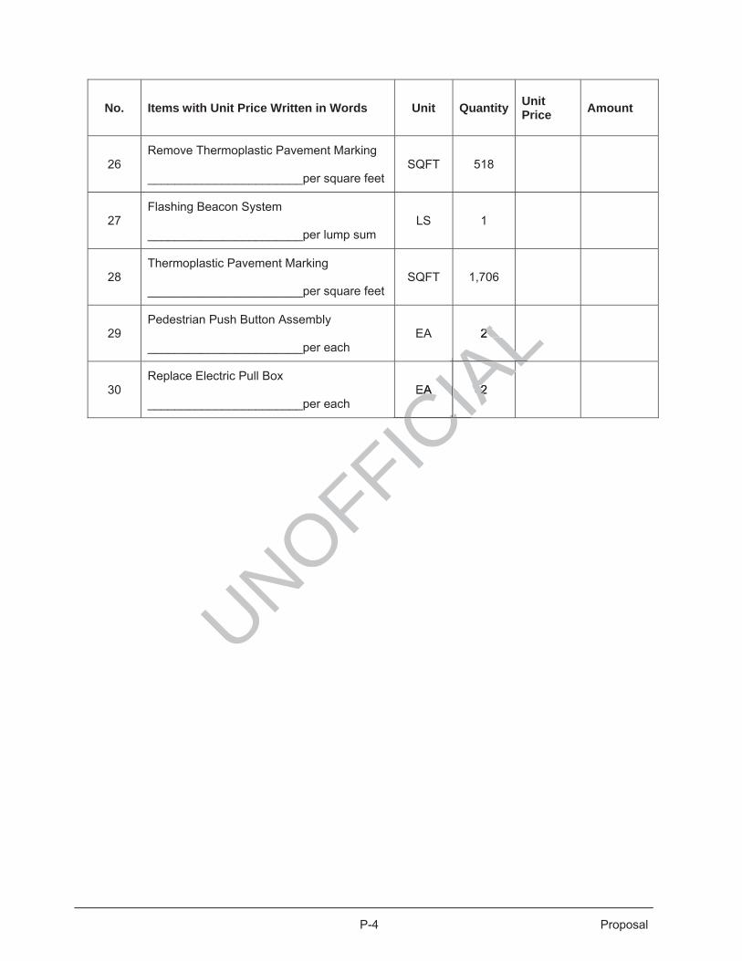
P-4 Proposal
No. Items with Unit Price Written in Words Unit Quantity UnitPrice Amount
26 Remove Thermoplastic Pavement Marking _______________________per square feet
SQFT 518
27 Flashing Beacon System _______________________per lump sum
LS 1
28 Thermoplastic Pavement Marking _______________________per square feet
SQFT 1,706
29 Pedestrian Push Button Assembly _______________________per each
EA 2
30 Replace Electric Pull Box _______________________per each
EA 2
UNOFFICIA
L2 2
AALEA 2 EA 2ALCCCCIAC
AL

This page intentionally left blank
UNOFFICIA
Ltentionalltentional

P-5 Proposal
TOTAL (In words and numbers)______________________________________________________
______________________________________________________________________________
In case of a discrepancy between words and figures, the words shall prevail. In case of a discrepancy between unit prices and total set forth for a unit basis item, the unit price shall prevail, except as provided in (a) or (b), as follows:
(a) If the amount set forth as a unit price is unreadable or otherwise unclear, or is omitted, or is the same as the amount as the entry in the item total column, then the amount set forth in the item total column for the item shall prevail and shall be divided by the estimated quantity for the item and the price thus obtained shall be the unit price;
(b) (Decimal Errors) If the product of the entered unit and the estimated quantity is exactly off by a factor
of ten, one hundred, etc., or one-tenth, or one-hundredth, etc. from the entered total, the discrepancy will be resolved by using the entered unit price or item total, whichever most closely approximates percentagewise the unit price or item total in the County's estimate of cost.
If both the unit price and the item total are unreadable or otherwise unclear, or are omitted, the bid may be deemed non-responsive. Likewise if the item total for a lump sum item is unreadable or otherwise unclear, or is omitted, the bid may be deemed non-responsive unless the project being bid has only a single item and a clear, readable total bid is provided.
Symbols such as commas and dollar signs will be ignored and have no mathematical significance in establishing any unit price or item total or lump sums. Written unit prices, item totals and lump sums will be interpreted according to the number of digits and, if applicable, decimal placements. Cents symbols also have no significance in establishing any unit price or item total since all such figures are assumed to be expressed in dollars and/or decimal fractions of a dollar. Bids on lump sum items shall be item totals only; if any unit price for a lump sum item is included in a bid and it differs from the item total, the items total shall prevail. The foregoing provisions for the resolution of specific discrepancies cannot be so comprehensive as to cover every omission, inconsistency, error or other irregularity which may occur in a bid. Any situation not specifically provided for will be determined in the discretion of the Board of Supervisors, and such discretion will be exercised in the manner deemed by the Board of Supervisors to best carry out its duty to award only to the lowest responsive, responsible bidder. The decision of the Board of Supervisors respecting the amount of a bid, or the existence or treatment of a discrepancy in a bid shall be final. If this proposal is accepted and the undersigned is awarded the Contract, given notice of the award and presented with the Contract for signature as provided in the Special Provisions, and shall fail, within the time and manner required under the Special Provisions, to sign and deliver the Agreement to the Clerk of the Board of Supervisors, together with all required insurance certificates, bonds, powers of attorney, certificate of authority, insurance rating, financial statements, proofs of licensing, and any other documents required by the Special Provisions to be filed with the signed Agreement, then the Board of Supervisors may, in its sole discretion, determine that the bidder has abandon his bid, whereupon the Board's acceptance of this proposal shall be deemed frustrated, and such bid security as may accompany this proposal shall become due and owing to the County of Tulare as liquidated damages. Accompanying this proposal is a ___________________________ for $____________________. (Insert the words "Cashier’s Check", "Certified Check" or Bidders Bond", as the case may be, and an amount equal to at least ten percent (10%) of the total bid).
The undersigned understands that the Board of Supervisors retains the option to reject any or all bids.
Further, as part of the proposal, the contractor provides the following information and representations:
UNOFFICIA
Lar, or are oar, is unreadable onreadable o
roject being bid hoject being bid h
d and have no d and have nWritten unit prices,itten unit prices
if applicable, decf applicable, dce ce or item total sor item total s
of a doof a llar. Bids ar. Bids uded in ded in a bid and a bid and
ution of specificof sp dderror or other irrerror or other
ermined in the dismined in the disdeemed by the Boeemed by the
sponsible bidder.sible bidder.stence or treatmetence or treat
cepted and the ucepted and theContract for sigContract for sig
red under red unders, togs tog

This page intentionally left blank
UNOFFICIA
Ltentionalltentional
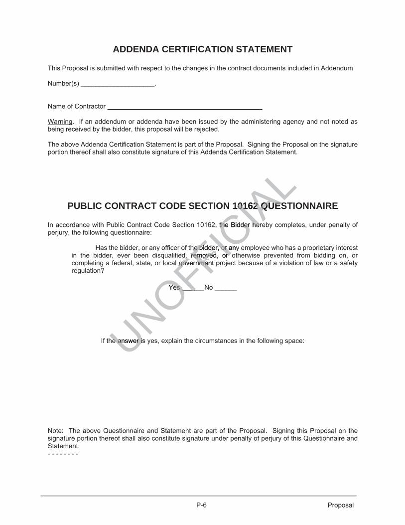
P-6 Proposal
ADDENDA CERTIFICATION STATEMENT
This Proposal is submitted with respect to the changes in the contract documents included in Addendum
Number(s) ____________________.
Name of Contractor
Warning. If an addendum or addenda have been issued by the administering agency and not noted as being received by the bidder, this proposal will be rejected.
The above Addenda Certification Statement is part of the Proposal. Signing the Proposal on the signature portion thereof shall also constitute signature of this Addenda Certification Statement.
PUBLIC CONTRACT CODE SECTION 10162 QUESTIONNAIRE
In accordance with Public Contract Code Section 10162, the Bidder hereby completes, under penalty of perjury, the following questionnaire:
Has the bidder, or any officer of the bidder, or any employee who has a proprietary interest in the bidder, ever been disqualified, removed, or otherwise prevented from bidding on, or completing a federal, state, or local government project because of a violation of law or a safety regulation?
Yes ______ No ______
If the answer is yes, explain the circumstances in the following space:
Note: The above Questionnaire and Statement are part of the Proposal. Signing this Proposal on the signature portion thereof shall also constitute signature under penalty of perjury of this Questionnaire and Statement. - - - - - - - -
UNOFFICIA
L10162 QUES0162 QUES
2, the Bidder herethe Bidder her
he bidderhe bidde , or any , or ad, removed,d, removed or oor
government progovernmen
Yes ______Yes ____
e answer is e answer i

This page intentionally left blank
UNOFFICIA
Ltentionalltentional
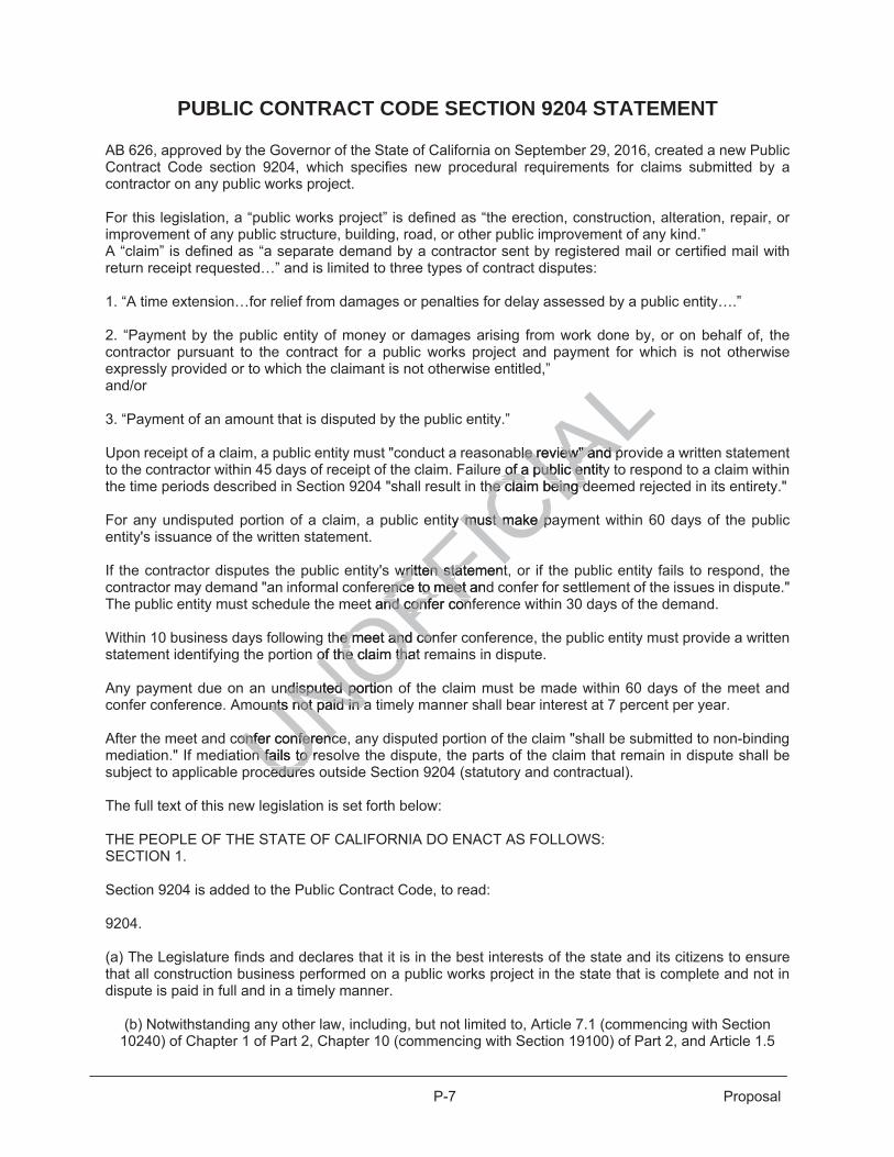
P-7 Proposal
PUBLIC CONTRACT CODE SECTION 9204 STATEMENT
AB 626, approved by the Governor of the State of California on September 29, 2016, created a new Public Contract Code section 9204, which specifies new procedural requirements for claims submitted by a contractor on any public works project. For this legislation, a “public works project” is defined as “the erection, construction, alteration, repair, or improvement of any public structure, building, road, or other public improvement of any kind.” A “claim” is defined as “a separate demand by a contractor sent by registered mail or certified mail with return receipt requested…” and is limited to three types of contract disputes: 1. “A time extension…for relief from damages or penalties for delay assessed by a public entity….” 2. “Payment by the public entity of money or damages arising from work done by, or on behalf of, the contractor pursuant to the contract for a public works project and payment for which is not otherwise expressly provided or to which the claimant is not otherwise entitled,” and/or 3. “Payment of an amount that is disputed by the public entity.” Upon receipt of a claim, a public entity must "conduct a reasonable review" and provide a written statement to the contractor within 45 days of receipt of the claim. Failure of a public entity to respond to a claim within the time periods described in Section 9204 "shall result in the claim being deemed rejected in its entirety." For any undisputed portion of a claim, a public entity must make payment within 60 days of the public entity's issuance of the written statement. If the contractor disputes the public entity's written statement, or if the public entity fails to respond, the contractor may demand "an informal conference to meet and confer for settlement of the issues in dispute." The public entity must schedule the meet and confer conference within 30 days of the demand. Within 10 business days following the meet and confer conference, the public entity must provide a written statement identifying the portion of the claim that remains in dispute. Any payment due on an undisputed portion of the claim must be made within 60 days of the meet and confer conference. Amounts not paid in a timely manner shall bear interest at 7 percent per year. After the meet and confer conference, any disputed portion of the claim "shall be submitted to non-binding mediation." If mediation fails to resolve the dispute, the parts of the claim that remain in dispute shall be subject to applicable procedures outside Section 9204 (statutory and contractual). The full text of this new legislation is set forth below: THE PEOPLE OF THE STATE OF CALIFORNIA DO ENACT AS FOLLOWS: SECTION 1. Section 9204 is added to the Public Contract Code, to read: 9204. (a) The Legislature finds and declares that it is in the best interests of the state and its citizens to ensure that all construction business performed on a public works project in the state that is complete and not in dispute is paid in full and in a timely manner.
(b) Notwithstanding any other law, including, but not limited to, Article 7.1 (commencing with Section 10240) of Chapter 1 of Part 2, Chapter 10 (commencing with Section 19100) of Part 2, and Article 1.5
UNOFFICIA
Lble review" and ple review" and p
e of a public entitye of a public enthe claim being dhe claim being d
y must make pamust make p
written stwritten statementatrence to meet rence to meet and
et and confer confand confer con
the meet and cone meet and coof tof he claim that he claim th
ndisputed portionndisputed pounts not paid in ants not paid in a
onfer conferenconfer conferencn fails to ren fails to
cedurecedure

This page intentionally left blank
UNOFFICIA
Ltentionalltentional

P-8 Proposal
(commencing with Section 20104) of Chapter 1 of Part 3, this section shall apply to any claim by a contractor in connection with a public works project.
(c) For purposes of this section:
(1) “Claim” means a separate demand by a contractor sent by registered mail or certified mail with return receipt requested, for one or more of the following: (A) A time extension, including, without limitation, for relief from damages or penalties for delay assessed by a public entity under a contract for a public works project. (B) Payment by the public entity of money or damages arising from work done by, or on behalf of, the contractor pursuant to the contract for a public works project and payment for which is not otherwise expressly provided or to which the claimant is not otherwise entitled.
(C) Payment of an amount that is disputed by the public entity. (2) “Contractor” means any type of contractor within the meaning of Chapter 9 (commencing with Section 7000) of Division 3 of the Business and Professions Code who has entered into a direct contract with a public entity for a public works project.
(3) (A) “Public entity” means, without limitation, except as provided in subparagraph (B), a state agency, department, office, division, bureau, board, or commission, the California State University, the University of California, a city, including a charter city, county, including a charter county, city and county, including a charter city and county, district, special district, public authority, political subdivision, public corporation, or nonprofit transit corporation wholly owned by a public agency and formed to carry out the purposes of the public agency. (B) “Public entity” shall not include the following: (i) The Department of Water Resources as to any project under the jurisdiction of that department. (ii) The Department of Transportation as to any project under the jurisdiction of that department. (iii) The Department of Parks and Recreation as to any project under the jurisdiction of that department. (iv) The Department of Corrections and Rehabilitation with respect to any project under its jurisdiction pursuant to Chapter 11 (commencing with Section 7000) of Title 7 of Part 3 of the Penal Code. (v) The Military Department as to any project under the jurisdiction of that department. (vi) The Department of General Services as to all other projects. (vii) The High-Speed Rail Authority. (4) “Public works project” means the erection, construction, alteration, repair, or improvement of any public structure, building, road, or other public improvement of any kind. (5) “Subcontractor” means any type of contractor within the meaning of Chapter 9 (commencing with Section 7000) of Division 3 of the Business and Professions Code who either is in direct contract with a contractor or is a lower tier subcontractor. (d) (1) (A) Upon receipt of a claim pursuant to this section, the public entity to which the claim applies shall conduct a reasonable review of the claim and, within a period not to exceed 45 days, shall provide the claimant a written statement identifying what portion of the claim is disputed and what portion is undisputed. Upon receipt of a claim, a public entity and a contractor may, by mutual agreement, extend the time period provided in this subdivision. (B) The claimant shall furnish reasonable documentation to support the claim. (C) If the public entity needs approval from its governing body to provide the claimant a written statement identifying the disputed portion and the undisputed portion of the claim, and the governing body does not meet within the 45 days or within the mutually agreed to extension of time following receipt of a claim sent by registered mail or certified mail, return receipt requested, the public entity shall have up to three days following the next duly publicly noticed meeting of the governing body after the 45-day period, or extension, expires to provide the claimant a written statement identifying the disputed portion and the undisputed portion.
UNOFFICIA
Ld in
in subparn subparagraphagraphifornia State Univnia State Uni
charter county, ciarter county, crity, political subdrity, political su
ency and formed ncy and formed
nyy project under t project undernyny project under project
ion as to any projon as to any pd Rehabilitation ehabilitation
g with Section 700g with Sectionany projecy p t undert under
Services as to alServices as to thority. ty.
t” means the erecmeans the erecad, or other publiad, or other pu
eans any eans any 3 of3 of

This page intentionally left blank
UNOFFICIA
Ltentionalltentional
P-9 Proposal
(D) Any payment due on an undisputed portion of the claim shall be processed and made within 60 days after the public entity issues its written statement. If the public entity fails to issue a written statement, paragraph (3) shall apply.
(2) (A) If the claimant disputes the public entity’s written response, or if the public entity fails to respond to a claim issued pursuant to this section within the time prescribed, the claimant may demand in writing an informal conference to meet and confer for settlement of the issues in dispute. Upon receipt of a demand in writing sent by registered mail or certified mail, return receipt requested, the public entity shall schedule a meet and confer conference within 30 days for settlement of the dispute. (B) Within 10 business days following the conclusion of the meet and confer conference, if the claim or any portion of the claim remains in dispute, the public entity shall provide the claimant a written statement identifying the portion of the claim that remains in dispute and the portion that is undisputed. Any payment due on an undisputed portion of the claim shall be processed and made within 60 days after the public entity issues its written statement. Any disputed portion of the claim, as identified by the contractor in writing, shall be submitted to nonbinding mediation, with the public entity and the claimant sharing the associated costs equally. The public entity and claimant shall mutually agree to a mediator within 10 business days after the disputed portion of the claim has been identified in writing. If the parties cannot agree upon a mediator, each party shall select a mediator and those mediators shall select a qualified neutral third party to mediate with regard to the disputed portion of the claim. Each party shall bear the fees and costs charged by its respective mediator in connection with the selection of the neutral mediator. If mediation is unsuccessful, the parts of the claim remaining in dispute shall be subject to applicable procedures outside this section. (C) For purposes of this section, mediation includes any nonbinding process, including, but not limited to, neutral evaluation or a dispute review board, in which an independent third party or board assists the parties in dispute resolution through negotiation or by issuance of an evaluation. Any mediation utilized shall conform to the timeframes in this section. (D) Unless otherwise agreed to by the public entity and the contractor in writing, the mediation conducted pursuant to this section shall excuse any further obligation under Section 20104.4 to mediate after litigation has been commenced. (E) This section does not preclude a public entity from requiring arbitration of disputes under private arbitration or the Public Works Contract Arbitration Program, if mediation under this section does not resolve the parties’ dispute. (3) Failure by the public entity to respond to a claim from a contractor within the time periods described in this subdivision or to otherwise meet the time requirements of this section shall result in the claim being deemed rejected in its entirety. A claim that is denied by reason of the public entity’s failure to have responded to a claim, or its failure to otherwise meet the time requirements of this section, shall not constitute an adverse finding with regard to the merits of the claim or the responsibility or qualifications of the claimant. (4) Amounts not paid in a timely manner as required by this section shall bear interest at 7 percent per annum. (5) If a subcontractor or a lower tier subcontractor lacks legal standing to assert a claim against a public entity because privity of contract does not exist, the contractor may present to the public entity a claim on behalf of a subcontractor or lower tier subcontractor. A subcontractor may request in writing, either on his or her own behalf or on behalf of a lower tier subcontractor, that the contractor present a claim for work which was performed by the subcontractor or by a lower tier subcontractor on behalf of the subcontractor. The subcontractor requesting that the claim be presented to the public entity shall furnish reasonable documentation to support the claim. Within 45 days of receipt of this written request, the contractor shall notify the subcontractor in writing as to whether the contractor presented the claim to the public entity and, if the original contractor did not present the claim, provide the subcontractor with a statement of the reasons for not having done so.
UNOFFICIA
L part
lect a quaechall bear the feebear the fee
he neutral medie neutral medisubject to applicaect to applica
nonbinding proceonbinding procen independent thir independent
uance of an evauance of an eva
c entity and the cc entity andurther obligation urther obligation
de a public entita public entitontraontract Arbitratioct Arbitrati
entity to respondentity to respondotherwise meet otherwise mee
its entirety. A its entirety. A or its faior its fa
ing wing w

This page intentionally left blank
UNOFFICIA
Ltentionalltentional
P-10 Proposal
(e) The text of this section or a summary of it shall be set forth in the plans or specifications for any public works project that may give rise to a claim under this section.
(f) A waiver of the rights granted by this section is void and contrary to public policy, provided, however, that (1) upon receipt of a claim, the parties may mutually agree to waive, in writing, mediation and proceed directly to the commencement of a civil action or binding arbitration, as applicable; and (2) a public entity may prescribe reasonable change order, claim, and dispute resolution procedures and requirements in addition to the provisions of this section, so long as the contractual provisions do not conflict with or otherwise impair the timeframes and procedures set forth in this section. (g) This section applies to contracts entered into on or after January 1, 2017. (h) Nothing in this section shall impose liability upon a public entity that makes loans or grants available through a competitive application process, for the failure of an awardee to meet its contractual obligations. (i) This section shall remain in effect only until January 1, 2020, and as of that date is repealed, unless a later enacted statute, that is enacted before January 1, 2020, deletes or extends that date. SEC. 2. The Legislature finds and declares that it is of statewide concern to require a charter city, charter county, or charter city and county to follow a prescribed claims resolution process to ensure there are uniform and equitable procurement practices. SEC. 3. If the Commission on State Mandates determines that this act contains costs mandated by the state, reimbursement to local agencies and school districts for those costs shall be made pursuant to Part 7 (commencing with Section 17500) of Division 4 of Title 2 of the Government Code. (Added by Stats. 2016, Ch. 810, Sec. 1. Effective January 1, 2017. Repealed as of January 1, 2020, by its own provisions.)
UNOFFICIA
Ln to requiretolution process on process
at this act containthis act contaior those costs shor those costs
2 of the Governmof the Governmary 1, 2017. Repary 1, 2017. R

This page intentionally left blank
UNOFFICIA
Ltentionalltentional
P-11 Proposal
PUBLIC CONTRACT CODE SECTION 10232 STATEMENT
In accordance with Public Contract Code section 10232, the Contractor hereby states under penalty of perjury that no more than one final unappealable finding of contempt of court by a federal court has been issued against the Contractor within the immediately preceding two year period because of the Contractor's failure to comply with an order of a federal court which orders the Contractor to comply with an order of the National Labor Relations Board. Note: The above Questionnaire and Statement are a part of the Proposal. Signing this Proposal on the
signature portion thereof shall also constitute signature, under penalty of perjury, of this Questionnaire and Statement.
Bidders are cautioned that making a false certification may subject the certifier to criminal prosecution.
PUBLIC CONTRACT CODE SECTION 10285.1 STATEMENT
In conformance with Public Contract Code section 10285.1 (Chapter 376, Stats. 1985), the bidder hereby declares under penalty of perjury under the laws of the State of California that the bidder has ___ , has not ___ been convicted within the preceding three years of any offenses referred to in that section, including any charge of fraud, bribery, collusion, conspiracy, or any other act in violation of any state or Federal antitrust law in connection with the bidding upon, award of, or performance of, any public works contract, as defined in Public Contract Code section 1101, with any public entity, as defined in Public Contract Code section 1100, including the Regents of the University of California or the Trustees of the California State University. The term "bidder" is understood to include any partner, member, officer, director, responsible managing officer, or responsible managing employee thereof, as referred to in Section 10285.1. Note: The bidder must place a check mark after "has" or "has not" in one of the blank spaces provided. The above Statement is part of the Bid. Signing this Bid on the signature portion thereof shall also constitute signature of this Statement. Bidders are cautioned that making a false certification may subject the certifier to criminal prosecution. UNOFFIC
IAL
TION 10285.ION 10285.
10285.1 (Chapte10285.1 (Chapteof the of th State of CState of
e years of any ofe years of any ofnspiracy, or nspiracy, or any
ng upon, awarg upon, award odction 1101, with action 1101,
s of tof he Universit Universunderstood to incunderstood to
ble managing empmanaging em
ust place a checkplace a cht is part of the Bidt is part of the Bment. Biddement. Bidd

This page intentionally left blank
UNOFFICIA
Ltentionalltentional
P-12 Proposal
NON-COLLUSION AFFIDAVIT
(Title 23 United States Code Section 112 and Public Contract Code Section 7106)
NON-COLLUSION DECLARATION TO BE EXECUTED BY BIDDER AND SUBMITTED WITH BID
The undersigned declares: I am the _______________________________of____________________________________, the party making the foregoing bid. The bid is not made in the interest of, or on behalf of, any undisclosed person, partnership, company, association, organization, or corporation. The bid is genuine and not collusive or sham. The bidder has not directly or indirectly induced or solicited any other bidder to put in a false or sham bid. The bidder has not directly or indirectly colluded, conspired, connived, or agreed with any bidder or anyone else to put in a sham bid, or to refrain from bidding. The bidder has not in any manner, directly or indirectly, sought by agreement, communication, or conference with anyone to fix the bid price of the bidder or any other bidder, or to fix any overhead, profit, or cost element of the bid price, or that of any other bidder. All statements contained in the bid are true. The bidder has not, directly or indirectly, submitted his or her bid price or any breakdown thereof, or the contents thereof, or divulged information or data relative thereto, to any corporation, partnership, company association, organization, bid depository, or to any member or agent thereof to effectuate a collusive or sham bid, and has not paid, and will not pay, any person or entity for such purpose. Any person executing this declaration on behalf of a bidder that is a corporation, partnership, joint venture, limited liability company, limited liability partnership, or any other entity, hereby represents that he or she has full power to execute, and does execute, this declaration on behalf of the bidder. I declare under penalty of perjury under the laws of the State of California that the foregoing is true and correct and that this declaration is executed on ______________________________ [date], at ___________________________[city], _____________________[state] __________________________________. (Signature)
UNOFFICIA
Le or
or sham ory bidder or anidder or an
nner, directlynner, directly or or d price of the biddrice of the bid
or thatr th of any othof any othndirectly, submittendirectly, subm
d information or information orzation, bid deposon, bid depos
as not paid, and ws not paid, and
alf of a biddealf of a bid r thartnership, or rtnership, or any a
cute, e, this declarathis declara
nder the laws of der the laws of
on is executed ons executed on
__________[city]_________[city
______________

This page intentionally left blank
UNOFFICIA
Ltentionalltentional
P-13 Proposal
(THE BIDDER'S EXECUTION ON THE SIGNATURE PORTION OF THIS PROPOSAL SHALL ALSO CONSTITUTE AN ENDORSEMENT AND EXECUTION OF THOSE CERTIFICATIONS WHICH ARE A PART OF THIS PROPOSAL)
EQUAL EMPLOYMENT OPPORTUNITY CERTIFICATION
The bidder_________________________________________________________________, proposed
subcontractor _______________________________________________, hereby certifies that
he has _____, has not _____ , participated in a previous contract or subcontract subject to the equal opportunity clauses, as required by Executive Orders 10925, 11114, or 11246, and that, where required, he has filed with the Joint Reporting Committee, the Director of the Office of Federal Contract Compliance, a Federal Government contracting or administering agency, or the former President's Committee on Equal Employment Opportunity, all reports due under the applicable filing requirements.
Note: The above certification is required by the Equal Employment Opportunity Regulations of the Secretary of Labor (41 CFR 60-1.7(b) (1)), and must be submitted by bidders and proposed subcontractors only in connection with contracts and subcontracts which are subject to the equal opportunity clause. Contracts and subcontracts which are exempt from the equal opportunity clause are set forth in 41 CFR 60-1.5. (Generally only contracts or subcontracts of $10,000 or under are exempt.)
Currently, Standard Form 100 (EEO-1) is the only report required by the Executive Orders or their implementing regulations. Proposed prime contractors and subcontractors who have participated in a previous contract or subcontract subject to the Executive Orders and have not filed the required reports should note that 41 CFR 60-1.7(b) (1) prevents the award of contracts and subcontracts unless such contractor submits a report covering the delinquent period or such other period specified by the Federal Highway Administration or by the Director, Office of Federal Contract Compliance, U.S. Department of Labor.
Signing this Proposal on the signature portion thereof shall also constitute signing this certificate. UNOFFIC
IAL
246, of Federaof
mer President's President's equirements. equirements.
mployment Opporployment Oppomust be submimust be subm tte
and subcontractsnd subcontractscts which are excts which are
enerallyenerally only cont only con
-1) is the only re1) is the o p
and subcontractand subcontre Executive OrdeExecutive Orde
1) prevents ) preve the awe vering the delinqg the delinq
ration or by the Diation or by the
l on the signatul on the signatu

This page intentionally left blank
UNOFFICIA
Ltentionalltentional
P-14 Proposal
DEBARMENT AND SUSPENSION CERTIFICATION
TITLE 49, CODE OF FEDERAL REGULATIONS, PART 29 The bidder, under penalty of perjury, certifies that, except as noted below, he/she or any other person
associated therewith in the capacity of owner, partner, director, officer, manager:
• is not currently under suspension, debarment, voluntary exclusion, or determination of ineligibility
by any Federal agency;
• has not been suspended, debarred, voluntarily excluded or determined ineligible by any Federal
agency within the past 3 years;
• does not have a proposed debarment pending; and
• has not been indicted, convicted, or had a civil judgment rendered against it by a court of competent jurisdiction in any matter involving fraud or official misconduct within the past 3 years.
If there are any exceptions to this certification, insert the exceptions in the following space.
Exceptions will not necessarily result in denial of award, but will be considered in determining bidder responsibility. For any exception noted above, indicate below to whom it applies, initiating agency, and dates of action. Notes: Providing false information may result in criminal prosecution or administrative sanctions. The
above certification is part of the Proposal. Signing this Proposal on the signature portion thereof shall also constitute signature of this Certification.
UNOFFICIA
Lt rendered renofficial miscondal miscond
ceptions in the folceptions in the f
arily resuarily result in denlt in denxception xception noted anoted
se informationse informaton is paon is pa
te s

This page intentionally left blank
UNOFFICIA
Ltentionalltentional
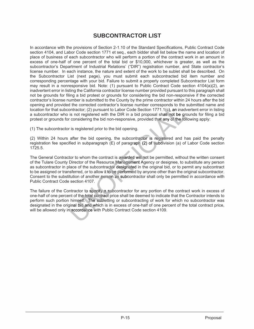
P-15 Proposal
SUBCONTRACTOR LIST
In accordance with the provisions of Section 2-1.10 of the Standard Specifications, Public Contract Code section 4104, and Labor Code section 1771 et seq., each bidder shall list below the name and location of place of business of each subcontractor who will perform a portion of the contract work in an amount in excess of one-half of one percent of the total bid or $10,000, whichever is greater, as well as the subcontractor’s Department of Industrial Relations’ (“DIR”) registration number, and State contractor’s license number. In each instance, the nature and extent of the work to be sublet shall be described. On the Subcontractor List (next page), you must submit each subcontracted bid item number and corresponding percentage with your bid. Failure to submit a properly completed Subcontractor List form may result in a nonresponsive bid. Note: (1) pursuant to Public Contract Code section 4104(a)(2), an inadvertent error in listing the California contractor license number provided pursuant to this paragraph shall not be grounds for filing a bid protest or grounds for considering the bid non-responsive if the corrected contractor’s license number is submitted to the County by the prime contractor within 24 hours after the bid opening and provided the corrected contractor’s license number corresponds to the submitted name and location for that subcontractor; (2) pursuant to Labor Code Section 1771.1(c), an inadvertent error in listing a subcontractor who is not registered with the DIR in a bid proposal shall not be grounds for filing a bid protest or grounds for considering the bid non-responsive, provided that any of the following apply: (1) The subcontractor is registered prior to the bid opening. (2) Within 24 hours after the bid opening, the subcontractor is registered and has paid the penalty registration fee specified in subparagraph (E) of paragraph (2) of subdivision (a) of Labor Code section 1725.5. The General Contractor to whom the contract is awarded will not be permitted, without the written consent of the Tulare County Director of the Resource Management Agency or designee, to substitute any person as subcontractor in place of the subcontractor designated in the original bid, or to permit any subcontract to be assigned or transferred, or to allow it to be performed by anyone other than the original subcontractor. Consent to the substitution of another person as subcontractor shall only be permitted in accordance with Public Contract Code section 4107. The failure of the Contractor to specify a subcontractor for any portion of the contract work in excess of one-half of one percent of the total contract price shall be deemed to indicate that the Contractor intends to perform such portion himself. The subletting or subcontracting of work for which no subcontractor was designated in the original bid and which is in excess of one-half of one percent of the total contract price, will be allowed only in accordance with Public Contract Code section 4109. UNOFFIC
IAL
ds to(c), an in(c
hall not be grall not be grhat any of the folhat any of the fol
ractor is registeractor is registeraph (2) of subdph (2) of subd
awarawa ded will notded will ne Management Ae Managem
ctor designated ictor designateit to be o be performedperforme
r person as subcr person as s
to specify a subcspecify a subche total cohe total contract pntr
mself. The sublemself. The sublinal bid and whicbid and w
n accordance wn accordance w

This page intentionally left blank
UNOFFICIA
Ltentionalltentional
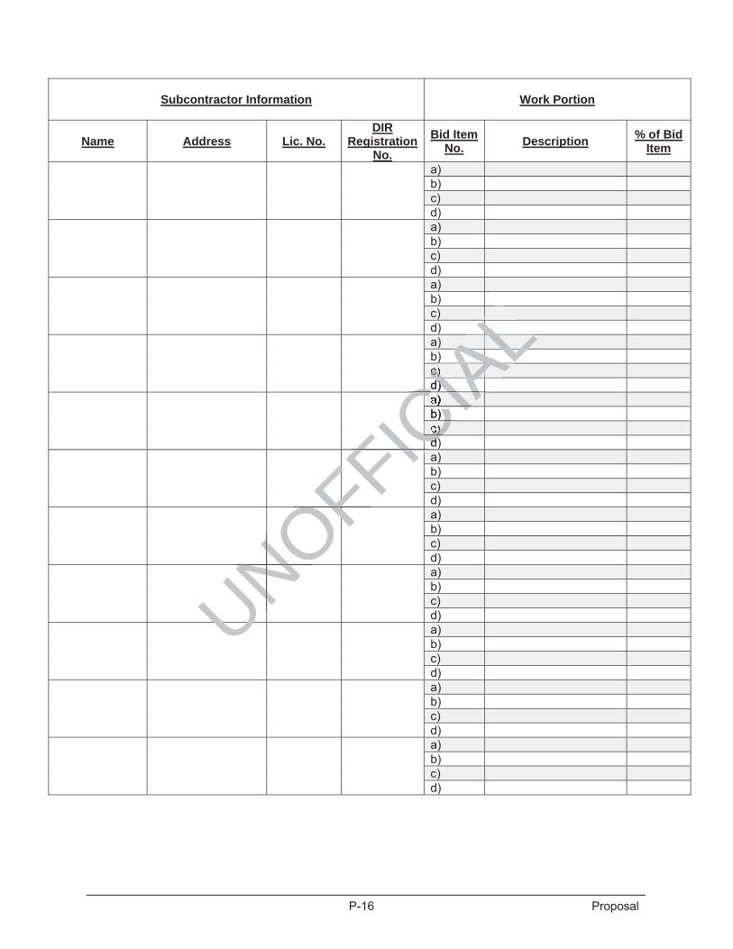
P-16 Proposal
Subcontractor Information Work Portion
Name Address Lic. No. DIR
Registration No.
Bid Item No. Description % of Bid
Item
a) b) c) d)
a) b) c) d)
a) b) c) d)
a) b) c) d)
a) b) c) d)
a) b) c) d)
a) b) c) d)
a) b) c) d)
a) b) c) d)
a) b) c) d)
a) b) c) d)
UNOFFIC CFICIA
LLLLLLLALALALALALALAL) ALALIAIAc) AAAAd) d) IACA
CIACIAACIACA
b) CICCCc) CCd)d)CCFICCFFFFOF OFOFOFOFONONN NONNNNNU

This page intentionally left blank
UNOFFICIA
Ltentionalltentional

P-17 Proposal
Further, as part of this proposal, the contractor agrees to the terms, and supplies the information required in the attached "Bidders Bond" or other security instruments (if such bond or instrument is required). Such Bond or instrument is considered part of the bid.
The names of all persons interested in the foregoing proposal as principals are as follows:
IMPORTANT NOTICE
If bidder or other interested person is a corporation, state legal name of corporation, also names of the president, vice-president, secretary, and treasurer thereof; if a co-partnership, state true name of firm, also names of all individual copartners composing firm; if bidder or other interested person is an individual, state first and last names in full.
Licensed in conformance with an act providing for the registration of Contractors,
License No. _________________________ Classification(s) ___________________________
Federal Employer Identification Number By my signature on this bid I certify, under penalty of perjury under the laws of the State of California, that the foregoing questionnaire and statements of Public Contract Code sections 10162, 10232 and 10285.1 are true and correct and that the bidder has complied with the requirements of Section 8103 of the Fair Employment and Housing Commission Regulations (Chapter 5, Title 2 of the California Administrative Code). By my signature on this Bid I further certify, under penalty of perjury under the laws of the State of California and the United States of America, that the Noncollusion Affidavit required by Title 23 United States Code, Section 112 and Public Contract Code section 7106; and the Title 49 Code of Federal Regulations, Part 29 Debarment and Suspension Certification are true and correct. Date:____________________________ ___________________________________________ ___________________________________________
___________________________________________ Signature of bidder
NOTE: If bidder is a corporation, the legal name of the corporation shall be set forth above together with the signature of the officers authorized to sign contracts on behalf of the corporation; if bidder is a co-partnership, the true name of the partner or partners authorized to sign contracts on behalf of the co-partnership; and if bidder is an individual, his signature shall be placed above. If signature is by an agent, other than an officer of the corporation or a member of a partnership, a Power of Attorney must be on file with the Board of Supervisors prior to opening bids or submitted with the bid; otherwise, the bid will be disregarded as non-responsive and unauthorized. Business Address ___________________________________________________________ Place of Business ___________________________________________________________ Date:_______________________________
UNOFFICIA
LLof Contractf Co
___________________________
y under the lawsy under the lawntract Code secttract Code sec
d wi w th the requireh the requns (Chapterns (Chapter 5, Ti5, Trr
fy, under penalty y, under penathat the Noncolluthat the Noncoll
tract Codetract Code sectipension Certificaension Certific
____ ________ ___
rporationrporatioutho

This page intentionally left blank
UNOFFICIA
Ltentionalltentional
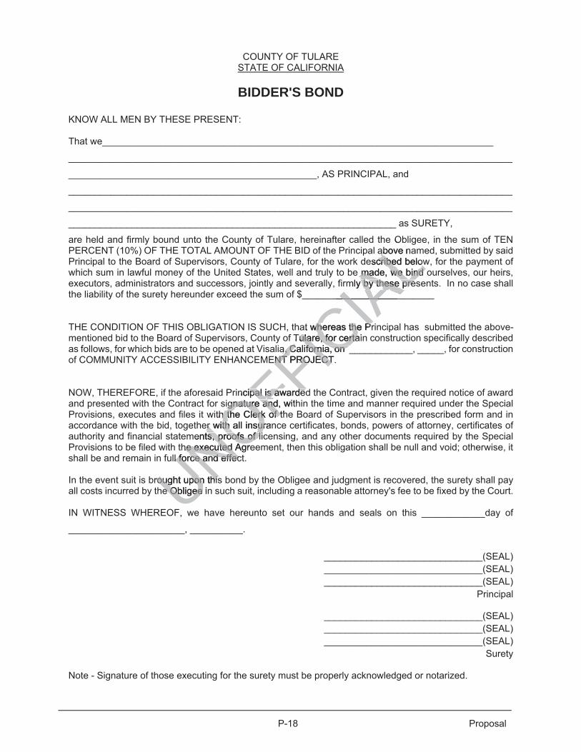
P-18 Proposal
COUNTY OF TULARE STATE OF CALIFORNIA
BIDDER'S BOND
KNOW ALL MEN BY THESE PRESENT:
That we__________________________________________________________________________
____________________________________________________________________________________
_______________________________________________, AS PRINCIPAL, and
____________________________________________________________________________________
____________________________________________________________________________________
______________________________________________________________ as SURETY,
are held and firmly bound unto the County of Tulare, hereinafter called the Obligee, in the sum of TEN PERCENT (10%) OF THE TOTAL AMOUNT OF THE BID of the Principal above named, submitted by said Principal to the Board of Supervisors, County of Tulare, for the work described below, for the payment of which sum in lawful money of the United States, well and truly to be made, we bind ourselves, our heirs, executors, administrators and successors, jointly and severally, firmly by these presents. In no case shall the liability of the surety hereunder exceed the sum of $_________________________ THE CONDITION OF THIS OBLIGATION IS SUCH, that whereas the Principal has submitted the above-mentioned bid to the Board of Supervisors, County of Tulare, for certain construction specifically described as follows, for which bids are to be opened at Visalia, California, on ____________, _____, for construction of COMMUNITY ACCESSIBILITY ENHANCEMENT PROJECT. NOW, THEREFORE, if the aforesaid Principal is awarded the Contract, given the required notice of award and presented with the Contract for signature and, within the time and manner required under the Special Provisions, executes and files it with the Clerk of the Board of Supervisors in the prescribed form and in accordance with the bid, together with all insurance certificates, bonds, powers of attorney, certificates of authority and financial statements, proofs of licensing, and any other documents required by the Special Provisions to be filed with the executed Agreement, then this obligation shall be null and void; otherwise, it shall be and remain in full force and effect. In the event suit is brought upon this bond by the Obligee and judgment is recovered, the surety shall pay all costs incurred by the Obligee in such suit, including a reasonable attorney's fee to be fixed by the Court. IN WITNESS WHEREOF, we have hereunto set our hands and seals on this ____________day of
______________________, __________.
______________________________(SEAL) ______________________________(SEAL) ______________________________(SEAL)
Principal
______________________________(SEAL) ______________________________(SEAL) ______________________________(SEAL)
Surety
Note - Signature of those executing for the surety must be properly acknowledged or notarized.
UNOFFICIA
Le O
above naabescribed belowcribed below
e made, we bind made, we bind mly by these presy by these pre
___________________________
at whereas the Prwhereas the PrTuTulare, for certailare, for certa
aa, California, on _, California, on _ENT PROJECT. ENT PROJECT
ncipal is awardedipal is awardedignature and, wiignature and th
th the Clerk of thh the Clerk of ter wither with all insuran all insur
ments, proofs of lits, proofs of lihe executed Agree executed
ll force and effecl force and effec
rought upon thisrought upon thise Obligee ine Obligee

This page intentionally left blank
UNOFFICIA
Ltentionalltentional
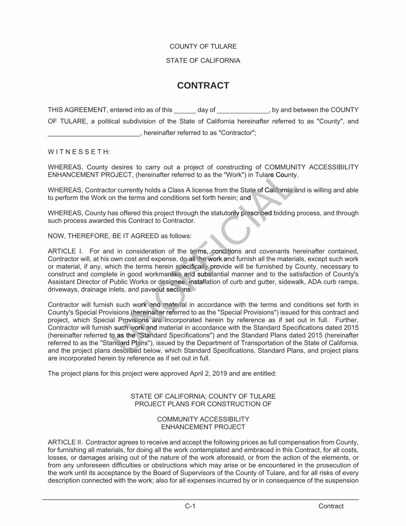
C-1 Contract
COUNTY OF TULARE
STATE OF CALIFORNIA
CONTRACT
THIS AGREEMENT, entered into as of this ______ day of ______________, by and between the COUNTY
OF TULARE, a political subdivision of the State of California hereinafter referred to as "County", and
_________________________, hereinafter referred to as "Contractor";
W I T N E S S E T H:
WHEREAS, County desires to carry out a project of constructing of COMMUNITY ACCESSIBILITY ENHANCEMENT PROJECT, (hereinafter referred to as the "Work") in Tulare County. WHEREAS, Contractor currently holds a Class A license from the State of California and is willing and able to perform the Work on the terms and conditions set forth herein; and WHEREAS, County has offered this project through the statutorily prescribed bidding process, and through such process awarded this Contract to Contractor.
NOW, THEREFORE, BE IT AGREED as follows:
ARTICLE I. For and in consideration of the terms, conditions and covenants hereinafter contained, Contractor will, at his own cost and expense, do all the work and furnish all the materials, except such work or material, if any, which the terms herein specifically provide will be furnished by County, necessary to construct and complete in good workmanlike and substantial manner and to the satisfaction of County's Assistant Director of Public Works or designee, installation of curb and gutter, sidewalk, ADA curb ramps, driveways, drainage inlets, and paveout sections.
Contractor will furnish such work and material in accordance with the terms and conditions set forth in County's Special Provisions (hereinafter referred to as the "Special Provisions") issued for this contract and project, which Special Provisions are incorporated herein by reference as if set out in full. Further, Contractor will furnish such work and material in accordance with the Standard Specifications dated 2015 (hereinafter referred to as the "Standard Specifications") and the Standard Plans dated 2015 (hereinafter referred to as the "Standard Plans"), issued by the Department of Transportation of the State of California, and the project plans described below, which Standard Specifications, Standard Plans, and project plans are incorporated herein by reference as if set out in full. The project plans for this project were approved April 2, 2019 and are entitled:
STATE OF CALIFORNIA; COUNTY OF TULARE PROJECT PLANS FOR CONSTRUCTION OF
COMMUNITY ACCESSIBILITY
ENHANCEMENT PROJECT
ARTICLE II. Contractor agrees to receive and accept the following prices as full compensation from County, for furnishing all materials, for doing all the work contemplated and embraced in this Contract, for all costs, losses, or damages arising out of the nature of the work aforesaid, or from the action of the elements, or from any unforeseen difficulties or obstructions which may arise or be encountered in the prosecution of the work until its acceptance by the Board of Supervisors of the County of Tulare, and for all risks of every description connected with the work; also for all expenses incurred by or in consequence of the suspension
UNOFFICIA
LOM
are Cou
te of California ate of California aand
orily prescribed borily prescribe
terms,terms, condition conditiodo all thdo all the work ane work an
specificalspecifically provly panlike and substaike and substa
designee, installadesignee, inveout sections. out sections.
work and materiak and materias (hereinafter refe(hereinafter ref
Provisions are inrovisions are isuch work and mh work a
to as the "Standto as the "Stanndard Plansndard Plan
scribedscribed
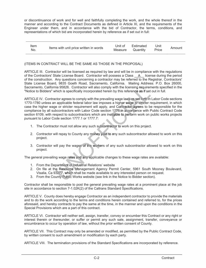
C-2 Contract
or discontinuance of work and for well and faithfully completing the work, and the whole thereof in the manner and according to the Contract Documents as defined in Article XI, and the requirements of the Engineer under them, and in accordance with the bid of Contractor, the terms, conditions, and representations of which bid are incorporated herein by reference as if set out in full:
Item No. Items with unit price written in words Unit of
Measure Estimated Quantity
Unit Price Amount
(ITEMS IN CONTRACT WILL BE THE SAME AS THOSE IN THE PROPOSAL)
ARTICLE III. Contractor will be licensed as required by law and will be in compliance with the regulations of the Contractors' State License Board. Contractor will possess a Class __A__ license during the period of the construction. Any questions concerning a contractor may be referred to the Registrar, Contractors' State License Board, 9835 Goeth Road, Sacramento, California. Mailing Address: P.O. Box 26000, Sacramento, California 95826. Contractor will also comply with the licensing requirements specified in the "Notice to Bidders" which is specifically incorporated herein by this reference as if set out in full.
ARTICLE IV. Contractor agrees to comply with the prevailing wage laws as set forth in Labor Code sections 1770-1780 unless an applicable federal labor law imposes a higher wage or stricter requirement, in which case the higher wage or stricter requirement will apply, and Contractor agrees to be responsible for the compliance by all subcontractors with Labor Code section 1776 in accordance with Public Contract Code section 6109, with respect to subcontractors which are ineligible to perform work on public works projects pursuant to Labor Code section 1777.1 or 1777.7:
1. The Contractor must not allow any such subcontractor to work on this project.
2. Contractor will repay to County any money paid to any such subcontractor allowed to work on this project.
3. Contractor will pay the wages of the workers of any such subcontractor allowed to work on this
project. The general prevailing wage rates and any applicable changes to these wage rates are available:
1. From the Department of Industrial Relations’ website 2. On file at the Resource Management Agency Permit Center, 5961 South Mooney Boulevard,
Visalia, Ca 93277, which shall be made available to any interested person on request. 3. From the County Public Works website (see link in the Notice to Bidder section).
Contractor shall be responsible to post the general prevailing wage rates at a prominent place at the job site in accordance to section 7-1.02K(2) of the Caltrans Standard Specifications. ARTICLE V. County does hereby engage Contractor as an independent contractor to provide the materials and to do the work according to the terms and conditions herein contained and referred to, for the prices aforesaid, and hereby contracts to pay the same at the time, in the manner and upon the conditions in the Special Provisions which are a part of this contract. ARTICLE VI. Contractor will neither sell, assign, transfer, convey or encumber this Contract or any right or interest therein or thereunder, or suffer or permit any such sale, assignment, transfer, conveyance or encumbrance to occur by operation of law, without the prior written consent of County. ARTICLE VII. This Contract may only be amended or modified, as permitted by the Public Contract Code, by written consent to such amendment or modification by each party. ARTICLE VIII. The termination provisions of the Standard Specifications are incorporated by reference.
g requence as if sence
aws as set forth inws as set forth inher wage or stricther wage or strict
Contractor agreesntractor ag776 in accordan776 in accorda
neligible to performligible to perfor
subcontractor to wsubcontractor
money paid tomoney paid an
es of the workerses of the work
rates and any aprates and any ap
rtment of Industriment of Industrhe Resource Mane Resource M3277, which s3277, which
ty Public ty Public
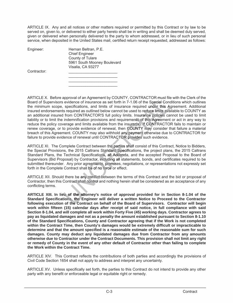
C-3 Contract
ARTICLE IX. Any and all notices or other matters required or permitted by this Contract or by law to be served on, given to, or delivered to either party hereto shall be in writing and shall be deemed duly served, given or delivered when personally delivered to the party to whom addressed, or in lieu of such personal service, when deposited in the United States mail, certified return receipt requested, addressed as follows: Engineer: Hernan Beltran, P.E. Chief Engineer County of Tulare 5961 South Mooney Boulevard Visalia, CA 93277 Contractor: _______________________ _______________________ _______________________ _______________________ ARTICLE X. Before approval of an Agreement by COUNTY, CONTRACTOR must file with the Clerk of the Board of Supervisors evidence of insurance as set forth in 7-1.06 of the Special Conditions which outlines the minimum scope, specifications, and limits of insurance required under this Agreement. Additional insured endorsements required as outlined below cannot be used to reduce limits available to COUNTY as an additional insured from CONTRACTOR'S full policy limits. Insurance policies cannot be used to limit liability or to limit the indemnification provisions and requirements of this Agreement or act in any way to reduce the policy coverage and limits available from the insurer(s). If CONTRACTOR fails to maintain or renew coverage, or to provide evidence of renewal, then COUNTY may consider that failure a material breach of this Agreement. COUNTY may also withhold any payment otherwise due to CONTRACTOR for failure to provide evidence of renewal until CONTRACTOR provides such evidence. ARTICLE XI. The Complete Contract between the parties shall consist of this Contract, Notice to Bidders, the Special Provisions, the 2015 Caltrans Standard Specifications, the project plans, the 2015 Caltrans Standard Plans, the Technical Specifications, all Addenda, and the accepted Proposal to the Board of Supervisors (Bid Proposal) by Contractor, including all statements, bonds, and certificates required to be submitted thereunder. Any prior agreements, promises, negotiations, or representations not expressly set forth in the Complete Contract shall be of no force or effect. ARTICLE XII. Should there be any conflict between the terms of this Contract and the bid or proposal of Contractor, then this Contract shall control and nothing herein shall be considered as an acceptance of any conflicting terms.
ARTICLE XIII. In lieu of the attorney's notice of approval provided for in Section 8-1.04 of the Standard Specifications, the Engineer will deliver a written Notice to Proceed to the Contractor following execution of the Contract on behalf of the Board of Supervisors. Contractor will begin work within fifteen (15) calendar days after receipt of said notice, in full compliance with said Section 8-1.04, and will complete all work within Forty Five (45) working days. Contractor agrees to pay as liquidated damages and not as a penalty the amount established pursuant to Section 8-1.10 of the Standard Specifications, County and Contractor agreeing that if the Work is not completed within the Contract Time, then County’s damages would be extremely difficult or impracticable to determine and that the amount specified is a reasonable estimate of the reasonable sum for such damages. County may deduct any liquidated damages due from Contractor from any amounts otherwise due to Contractor under the Contract Documents. This provision shall not limit any right or remedy of County in the event of any other default of Contractor other than failing to complete the Work within the Contract Time. ARTICLE XIV. This Contract reflects the contributions of both parties and accordingly the provisions of Civil Code Section 1654 shall not apply to address and interpret any uncertainty. ARTICLE XV. Unless specifically set forth, the parties to this Contract do not intend to provide any other party with any benefit or enforceable legal or equitable right or remedy.
UNOFFICIA
LR mu
Special Cope under this Agder this Ag
reduce limits avaeduce limits avasurance policies nce policies
ents of this Agreets of this Agreesurer(s). If CONTsurer(s). If CON
n COUNTY may COUNTY may any payment othany payment
CTOR providCTOR provides ses
the parties shall he parties shalStandard Spectandard S ific
ions, all Aons, all Addendaddentor, including all sncluding all s
eements, promiseements, prom eall be of no force obe of no force o
be any confliny conflict bect beact shall control act shall contr
eu of the attoeu of the attoons, the Eons, the
he Che C
C-4 Contract
ARTICLE XVI. This Contract shall be interpreted and governed under the laws of the State of California without reference to California conflicts of law principles. The parties agree that this contract is made in and shall be performed in Tulare County, California. ARTICLE XVII. The failure of either party to insist on strict compliance with any provision of this Contract shall not be considered a waiver of any right to do so, whether for that breach or any subsequent breach. The acceptance by either party of either performance or payment shall not be considered to be a waiver of any preceding breach of the Contract by the other party. ARTICLE XVIII. The Recitals and the Exhibits to this Contract are fully incorporated into and are integral parts of this Contract. ARTICLE XIX. This Contract is subject to all applicable laws and regulations. If any provision of this Contract is found by any court or other legal authority, or is agreed by the parties, to be in conflict with any code or regulation governing its subject, the conflicting provision shall be considered null and void. If the effect of nullifying any conflicting provision is such that a material benefit of the Contract to either party is lost, the Contract may be terminated at the option of the affected party. In all other cases the remainder of the Contract shall continue in full force and effect. ARTICLE XX. Each party will execute any additional documents and perform any further acts which may be reasonably required to effect the purposes of this Contract. ARTICLE XXI. If a dispute arises out of or relating to this Contract, or the breach thereof, and if said dispute cannot be settled through negotiation, the parties agree first to try in good faith to settle the dispute by non-binding mediation before resorting to litigation or some other dispute resolution procedure, unless the parties mutually agree otherwise. The mediator shall be mutually selected by the parties, but in case of disagreement, the mediator shall be selected by lot from among two nominations provided by each party. All costs and fees required by the mediator shall be split equally by the parties, otherwise each party shall bear its own costs of mediation. ARTICLE XXII. Contractor acknowledges that this Contract is subject to filing obligations pursuant to Unemployment Insurance Code section 1088.8. Accordingly, County has an obligation to file a report with the Employment Development Department, which report will include the Contractor’s full name, social security number, address, the date this contract was executed, the total amount of the contract, the contract's expiration date or whether it is ongoing. Contractor agrees to cooperate with County to make such information available and to complete DE Form 542. Failure to provide the required information may, at County’s option, prevent approval of this Contract, or be grounds for termination by County. ARTICLE XXIII. This Contract represents the entire Contract between Contractor, and County as to its subject matter and no prior oral or written understanding shall be of any force or effect. No part of this Contract may be modified without the written consent of both parties. ARTICLE XXIV. Contractor expressly understands and agrees that County is dependent upon certain Federal and/or State and/or local funding to pay the services provided in this Contract. If such Federal and/or State and/or local funding is discontinued and/or reduced, County shall have the right to terminate the Contract. In either event, County shall provide Contractor with at least 30 days prior written notice of such termination.
UNOFFICIA
Lperform any furorm any fur
act, or the breach t, or the breach to try in good faithto try in good fa
other dispute reother dispute rebe mutually selecbe mutually se
from among two from among two be spbe split equally byequally by
es that this Cs that this Contronn 1088.8. Accord88.8. Accord
artment, which reartment, whicate this contract e this contract
hether ether it is ongoinit is ongod to complete DEcomplete DE
t approval of this approval of th
s Contract reprs Contract represno prior oral or no prior oral or
ed withoued withou
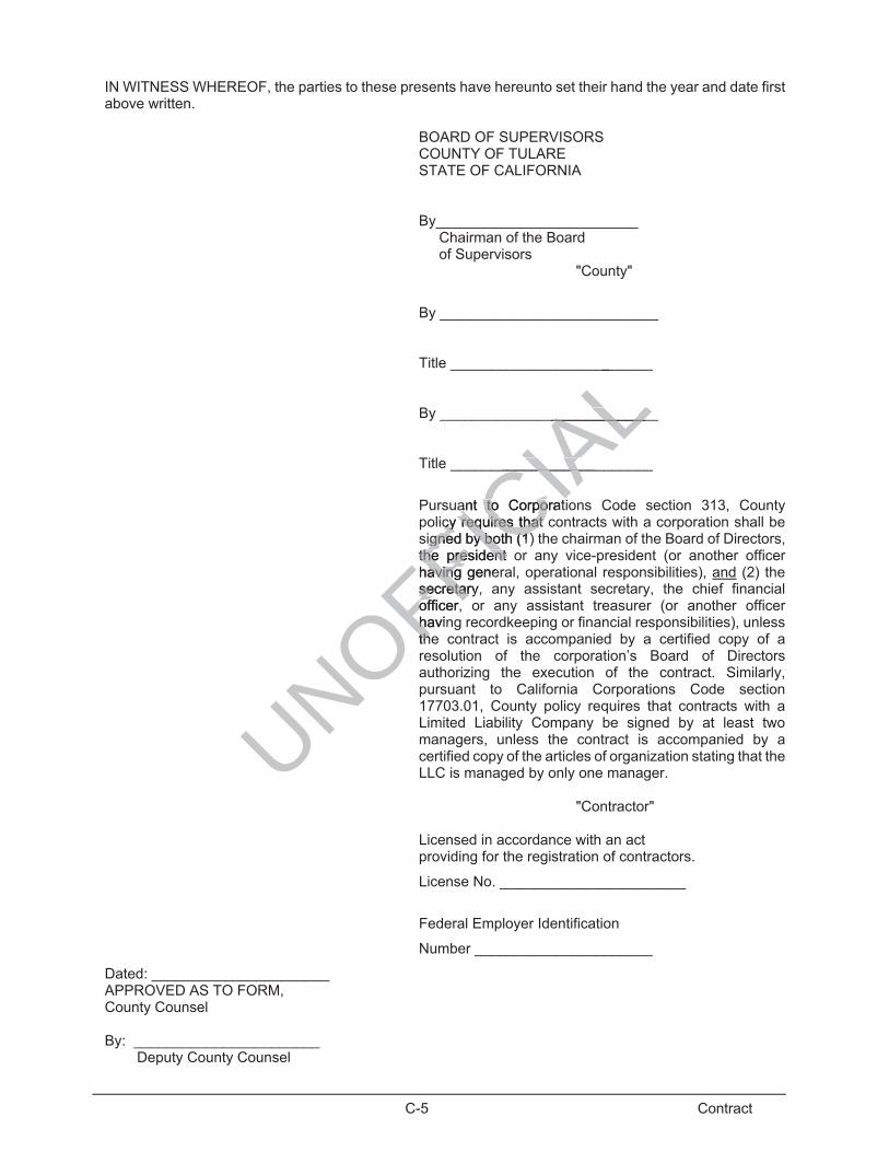
C-5 Contract
IN WITNESS WHEREOF, the parties to these presents have hereunto set their hand the year and date first above written.
BOARD OF SUPERVISORS COUNTY OF TULARE STATE OF CALIFORNIA
By_________________________ Chairman of the Board of Supervisors "County"
By ___________________________
Title _________________________
By ___________________________
Title _________________________
Pursuant to Corporations Code section 313, County policy requires that contracts with a corporation shall be signed by both (1) the chairman of the Board of Directors, the president or any vice-president (or another officer having general, operational responsibilities), and (2) the secretary, any assistant secretary, the chief financial officer, or any assistant treasurer (or another officer having recordkeeping or financial responsibilities), unless the contract is accompanied by a certified copy of a resolution of the corporation’s Board of Directors authorizing the execution of the contract. Similarly, pursuant to California Corporations Code section 17703.01, County policy requires that contracts with a Limited Liability Company be signed by at least two managers, unless the contract is accompanied by a certified copy of the articles of organization stating that the LLC is managed by only one manager.
"Contractor" Licensed in accordance with an act providing for the registration of contractors.
License No. _______________________
Federal Employer Identification
Number ______________________
Dated: ______________________ APPROVED AS TO FORM, County Counsel By: _______________________ Deputy County Counsel
UNOFFICIA
L__
____________________________
_____________________
ant to Corporatant to Corpocy requires that ccy requires that
signed by both (1)igned by both (1)the president othe president having geneavingsecretary,secretarofficer, officerhavinhtheth
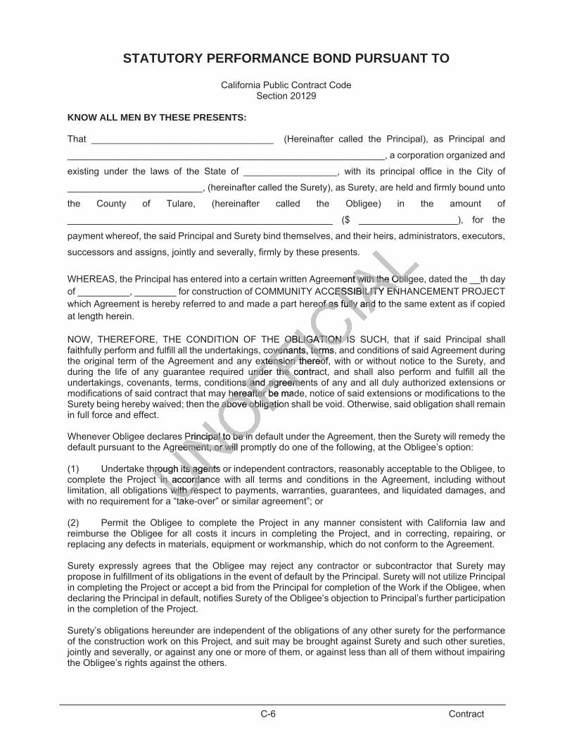
C-6 Contract
STATUTORY PERFORMANCE BOND PURSUANT TO
California Public Contract Code Section 20129
KNOW ALL MEN BY THESE PRESENTS:
That ___________________________________ (Hereinafter called the Principal), as Principal and
_____________________________________________________________, a corporation organized and
existing under the laws of the State of __________________, with its principal office in the City of
__________________________, (hereinafter called the Surety), as Surety, are held and firmly bound unto
the County of Tulare, (hereinafter called the Obligee) in the amount of
___________________________________________________ ($ ___________________), for the
payment whereof, the said Principal and Surety bind themselves, and their heirs, administrators, executors,
successors and assigns, jointly and severally, firmly by these presents.
WHEREAS, the Principal has entered into a certain written Agreement with the Obligee, dated the __th day of __________, ________ for construction of COMMUNITY ACCESSIBILITY ENHANCEMENT PROJECT which Agreement is hereby referred to and made a part hereof as fully and to the same extent as if copied at length herein. NOW, THEREFORE, THE CONDITION OF THE OBLIGATION IS SUCH, that if said Principal shall faithfully perform and fulfill all the undertakings, covenants, terms, and conditions of said Agreement during the original term of the Agreement and any extension thereof, with or without notice to the Surety, and during the life of any guarantee required under the contract, and shall also perform and fulfill all the undertakings, covenants, terms, conditions and agreements of any and all duly authorized extensions or modifications of said contract that may hereafter be made, notice of said extensions or modifications to the Surety being hereby waived; then the above obligation shall be void. Otherwise, said obligation shall remain in full force and effect. Whenever Obligee declares Principal to be in default under the Agreement, then the Surety will remedy the default pursuant to the Agreement, or will promptly do one of the following, at the Obligee’s option: (1) Undertake through its agents or independent contractors, reasonably acceptable to the Obligee, to complete the Project in accordance with all terms and conditions in the Agreement, including without limitation, all obligations with respect to payments, warranties, guarantees, and liquidated damages, and with no requirement for a “take-over” or similar agreement”; or (2) Permit the Obligee to complete the Project in any manner consistent with California law and reimburse the Obligee for all costs it incurs in completing the Project, and in correcting, repairing, or replacing any defects in materials, equipment or workmanship, which do not conform to the Agreement. Surety expressly agrees that the Obligee may reject any contractor or subcontractor that Surety may propose in fulfillment of its obligations in the event of default by the Principal. Surety will not utilize Principal in completing the Project or accept a bid from the Principal for completion of the Work if the Obligee, when declaring the Principal in default, notifies Surety of the Obligee’s objection to Principal’s further participation in the completion of the Project. Surety’s obligations hereunder are independent of the obligations of any other surety for the performance of the construction work on this Project, and suit may be brought against Surety and such other sureties, jointly and severally, or against any one or more of them, or against less than all of them without impairing the Obligee’s rights against the others.
irs,
ment with the Obligt with the ObligCESSIBILITY ENESSIBILITY EN
eof as fully and toeof as fully and
OBLIGATIOBLIGATION ISON ISovenantovenants, terms, term
extensixtension thereofon thereofunder the cunder the contra
ns and agreems and agreemenehereafter be mhereafter ad
e above obligation above obligat
Principal to be in Principal to be in greement, or will preement, or wil
hrough its agents hrough its agentin accordanin accords with ress with re
tak

C-7 Contract
No right of action will accrue on this bond to or for the use of any person or corporation other than the Obligee or its successors or assigns. If Obligee sues upon this bond, then Surety will pay reasonable attorney’s fees and costs incurred by the Obligee in such suit, irrespective of the amount of this bond. Witness our hands this ___________ day of ______________________, _______. ____________________________________ Principal Seal ____________________________________ By ____________________________________ Surety Seal ____________________________________ By ____________________________________ Agency of Record
Note: Bond surety must be admitted to transact surety insurance in the State of California.
UNOFFICIA
Lty insurance in thty insurance in th
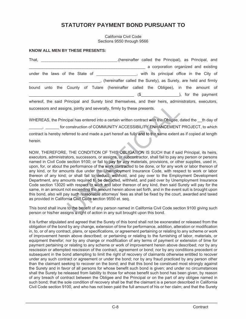
C-8 Contract
STATUTORY PAYMENT BOND PURSUANT TO
California Civil Code Sections 9550 through 9566
KNOW ALL MEN BY THESE PRESENTS: That, __________________________________.(hereinafter called the Principal), as Principal, and
____________________________________________________ a corporation organized and existing
under the laws of the State of __________________, with its principal office in the City of
________________________________, (hereinafter called the Surety), as Surety, are held and firmly
bound unto the County of Tulare (hereinafter called the Obligee), in the amount of
_______________________________________________ ($_________________), for the payment
whereof, the said Principal and Surety bind themselves, and their heirs, administrators, executors,
successors and assigns, jointly and severally, firmly by these presents.
WHEREAS, the Principal has entered into a certain written contract with the Obligee, dated the __th day of
______, ______ for construction of COMMUNITY ACCESSIBILITY ENHANCEMENT PROJECT, to which
contract is hereby referred to and made a part hereof as fully and to the same extent as if copied at length
herein.
NOW, THEREFORE, THE CONDITION OF THIS OBLIGATION IS SUCH that if said Principal, its heirs, executors, administrators, successors, or assigns, or subcontractor, shall fail to pay any person or persons named in Civil Code section 9100; or fail to pay for any materials, provisions, or other supplies, used in, upon, for, or about the performance of the work contracted to be done, or for any work or labor thereon of any kind, or for amounts due under the Unemployment Insurance Code, with respect to work or labor thereon of any kind; or shall fail to deduct, withhold, and pay over to the Employment Development Department, any amounts required to be deducted, withheld, and paid over by Unemployment Insurance Code section 13020 with respect to work and labor thereon of any kind, then said Surety will pay for the same, in an amount not exceeding the amount herein above set forth, and in the event suit is brought upon this bond, also will pay such reasonable attorneys’ fees as shall be fixed by the court, awarded and taxed as provided in California Civil Code section 9550 et. seq. This bond shall inure to the benefit of any person named in California Civil Code section 9100 giving such person or his/her assigns a right of action in any suit brought upon this bond. It is further stipulated and agreed that the Surety of this bond shall not be exonerated or released from the obligation of the bond by any change, extension of time for performance, addition, alteration or modification in, to, or of any contract, plans, or specifications, or agreement pertaining or relating to any scheme or work of improvement herein above described; or pertaining or relating to the furnishing of labor, materials, or equipment therefor; nor by any change or modification of any terms of payment or extension of time for payment pertaining or relating to any scheme or work of improvement herein above described; nor by any rescission or attempted rescission of the contract, agreement or bond; nor by any conditions precedent or subsequent in the bond attempting to limit the right of recovery of claimants otherwise entitled to recover under any such contract or agreement or under the bond; nor by any fraud practiced by any person other than the claimant seeking to recover on the bond; and that this bond be construed most strongly against the Surety and in favor of all persons for whose benefit such bond is given; and under no circumstances shall the Surety be released from liability to those for whose benefit such bond has been given, by reason of any breach of contract between the Obligee and the Principal or on the part of any obligee named in such bond; that the sole condition of recovery shall be that the claimant is a person described in California Civil Code section 9100, and who has not been paid the full amount of his or her claim; and that the Surety
UNOFFICIA
Ls,
t with the Obith the Obligeeligee
LITY ENHATY ENHANCEN
ully and to the samly and to the sa
IS OBLIGATIS OBLIGATIONOigns, or subcontragns, or subcontra
to pay for ano pay for any mayhe work contractework contracte
the Unemploymethe Unempto deduct, wito deduct, withhh
red to be deductered to be dedupect to work and t to work and
ceeding the amoueeding the amouch reasonable auch reasonable
nia Civil Code secivil Code
o the benefo the benes a righs a righ

C-9 Contract
does hereby waive notice of any such change, extension of time, addition, alteration or modification herein mentioned.
Witness our hands this ______ day of______________________, ______.
_______________________________________ Principal Seal
_______________________________________ By
_______________________________________ Surety Seal
_______________________________________ By
_______________________________________ Agency of Record
_______________________________________ Agency Address
Note: Bond surety must be admitted to transact surety insurance in the State of California
UNOFFICIA
Linsurance in the Snsurance in th

C-10 Contract
CERTIFICATION CONCERNING WORKERS' COMPENSATION INSURANCE
STATE OF CALIFORNIA ) ) SS COUNTY OF TULARE )
I am aware of the provisions of Section 3700 of the Labor Code which require every employer to be insured against liability for workers' compensation or to undertake self-insurance in accordance with the provisions of that code, and I will comply with such provisions before commencing the performance of the work of this Contract. Date____________________________ ________________________________________________ CONTRACTOR
UNOFFICIA
L

C-11 Contract
CONSTRUCTION OF COMMUNITY ACCESSIBILITY ENHANCEMENT PROJECT
CONTRACT DOCUMENT CHECKLIST
The Contractor must deliver to the County with the Contract the following items: 1. The signed Contract (six copies). Each copy of the Contract must be signed by both the company president or
vice president and the company secretary or treasurer with the Contractors State License Board number and Federal Employer Identification Number.
2. The Statutory Performance Bond Pursuant to California Public Contract Code section 20129 and the Statutory
Payment Bond Pursuant to California Civil Code sections 9550 through 9566 (forms included herein), with either County Clerk's certificates or copies of power of attorney.
3. Certification Concerning Workers' Compensation Insurance. 4. Certificate(s) of Insurance in compliance with the requirements of Section 7-1.06 of the Special Provisions
including general liability, automobile and workers' compensation (a sample form is included). 5. Evidence that the Contractor possesses a current, valid Contractors State License Board required to perform
the work under this Contract. A copy of the Contractor's license is sufficient.
UNOFFICIA
Ls ofof Section 7-1. Section 7-1fftion (a sample(a sample fo fo
Contractors StatContractors Sr's license is suff's license is suff