understanding fluorescent lamps
TRANSCRIPT
JANUARY 1990 Aust $495 NZ $650 ~r
UA S LARGEST SEWNG ELECTRONICS MAGAZINE - ESTABLISHED IN 1922
Large screen video displays
Large video screens are now foulld in many hotels clubs convention centres and offices As the technology improves they may become more common in our homes Heres a rundown on how the latest systems work (See page 12)
Sonys mighty midget
EA Editor Jim Rowe was able to try alit an advance sample of Sonys tillY new CCD-TR55 video 8 camcorder released ill Australia this month It left him asking Please Mr Sony dont make them any smaller than this See page 42
On the cover A montage of todays electronics technology Top left HewlettshyPackards new E2373A DMM top right Sonys tiny flew CCDshyTR55 camcorder bottom right Micro Networks MN5820 20MHz flash AID converter (Prishyority Electronics) bottom left Analog Devices PC-based inshystrumentation and analysis packshyage (Priority Electronics) and celltre a high density surfaceshymOllnt PCB designed using CADSlar (RCS CADCelltres)
156Feawres________________ _ 16218 US CHIP MAKERS SEE IMAGE CONTROLLER BONANZA
The next big semiconductor growth area say the experts 168 22 AMATEUR RADIO KITS IN AUSTRALIA amp OVERSEAS - 1
A survey of whats available and where you can get them 28 COMPUTER SOFTWARE REVIEW CHIWRITER
A word processing package fo r scientists and engineers t-l30 THE US FACING A SEMICONDUCTOR CHALLENGE - 2 Second part of our look at how the industry is adapting to challge 6
33 NEW IMPORTED LOUDSPEAKERS FROM JAYCAR New low cost units feature high density polypropylene cones 7
48 THE GENTLE ART OF SCROUNGING Tom Moffat explains how to acquire those hard-to-get parts 62
52 WHEN I THINK BACK Raymond Allsop - WW1 wireless operator engineer FM pioneer 68
140 COMPUTER SOFTWARE REVIEW DCCAD A powerful computer-aided drafting package 78
122
Entertainment Electronics___ 136 8 WHATS NEW IN HOME ELECTRONICS
What happened ill 1989 and what to expect in 1990 142 13 LARGE SCREEN VIDEO DISPLAYS
How the technology is developing 148 42 VIDEO CAMCORDER PREVIEW SONYS CCD-TRS5
How small can camcorders get This one sets a flew record 172
Projects and Technical____ 175
80 THE SERVICEMAN Titanic slru gles - with a Titan colour TV
84 VK POWERMATE 25 New 138V power supply design delivering up to 25A contilluously
92 CIRCUIT amp DESIGN IDEAS Low cost RS-232C data monitor TTL logic probe 121240V inverter
98 NEW VERY HIGH QUALITY STEREO POWER AMP - 2 lIow to build this exciting le lV Playmaster design
110 SIMPLE FM RECEIVER FOR THE 6M AMATEUR BAND - 1 Low cost and easy to build can be expanded to cover other bands
115 A NEW SERIES ON BASIC ELECTRONICS Introducing our flew series of articles for the beginner
116 BASIC ELECTRONICS - 1 Volts Amps alld Ohms - the basic concepts
152 MASTER CONTROL POWER SWITCH Turns your TV on and off automatically with the VCRi
4 ELECTRONICS Australia January 1990
1
Volume 52 No1 January 1990
156 BASICS OF RADIO - 12 FM bandwidth and frequency response
162 UNDERSTANDING FLUORESCENT LAMPS We take them for granted bLlt do YOU know holV they work
168 VINTAGE RADIO Pilot Radios Super Wasp shortwave receiver of 1929
News and Comment_____ 6 LETTERS TO THE EDITOR
Amiga projects isolating capacitor low industry incentive 7 EDITORIAL VIEWPOINT
The dawn of another exciting electronics decade 62 NEWS HIGHLIGHTS
Toshiba robot juggles baloons Telecom introduces FA STPAC 68 FORUM
Computer bugs viruses worms Trojan horses and other nasties 78 SILICON VALLEY NEWSLETTER
Quake disrupts Valley operations Bush proposes data superhighway 122 NEW PRODUCTS SURVEY
Expanded look at the latest test gear components power supplies eiC 136 COMPUTER NEWS amp NEW PRODUCTS
Diskless workstation pocket-sized computer 9600 baud modem 142 SOLID STATE UPDATE
64K SRAM is non-volatile 8-bil ADC operates at 300M samplessec 148 SPECTRUM
Intel VI launched UK soon for digital cellular 172 INFORMATION CENTRE
Answers to readers queries puzzlers - and red faces 175 AMATEUR RADIO NEWS
Microwave field day at Dural display at Hobby Expo
D~anmen~___________ __ 150 BOOK REVIEWS
Building a DC generator microwave lCs S- VIiS video 176 EA CROSSWORD PUZZLE
A little relaxation for that lazy holiday afternoon 176 50 AND 25 YEARS AGO
Snippets from the January 1940 md January 965 issues 177 MARKETPLACE
Classifieds and other smaller advertisemellfs - dOIlt miss themf 178 DIRECTORY OF SUPPLIERS
Where to buy that component instrument or kit 178 ADVERTISING INDEX 174 NOTES AND ERRATA
TV Frequency Standard DC Voltage Reference FM Transmitter
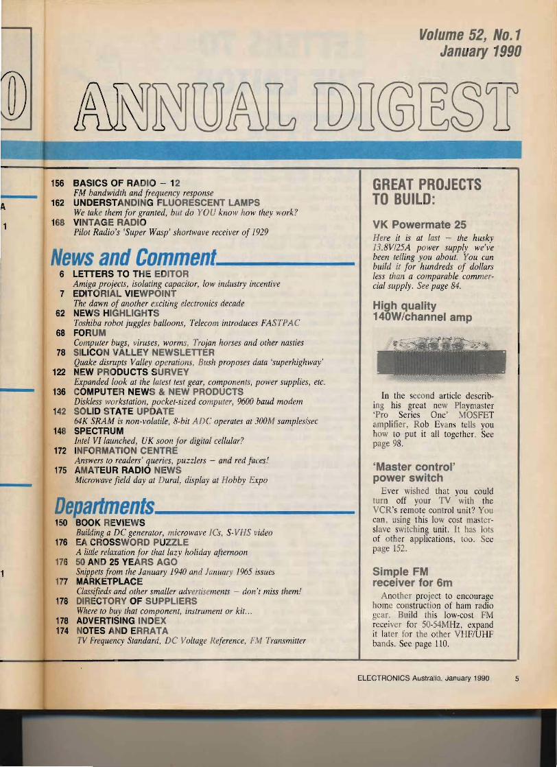
GREAT PROJECTS TO BUILD
VK Powermate 25 Here it is at last - the husky 138V25A power supply weve been telling you about You can build it for hundreds of dollars less than a comparable commershycial supply See page 84
High quality 140Wchannel amp
In the second article describshying his great new Playmaster Pro Series One MOSFET ampli fier Rob Evans tells you how to put it all together See page 98
Master control power switch
Ever wished that you could lurn off your TV with the VCRs remote control unit You can using this low cost mastershyslave switching unit It Ilas lots of nther applications t o See page l52
Simple FM receiver for 6m
Another project to encourage home construction of ham radio gear Build this low-cost FM receiver for 50-54MJ-Iz expand it later for the other VHFUHF bands See page 110
ELECTRONICS Australia January 1990 5
bull n n c t am
The humble fluorescent light is taken for granted these days Their ubiquity ensures that no-one ever thinks about them much But if you are ever asked how one works there could be trouble In this article the author examines some of their physics and chemistry
by RICHARD WALDING
Ever since I saw a fluorescent light fitting explode and blow black tar over the ceiling of my childhood home Ive been interested in these lamps Until I started teaching about them I thought I knew it all - but really knew nothing
Lets start by looking at the essential components which make up a typical fluorescent light fitting As most EA readers will probably be aware these consist of the ballast the tubular fluoshyrescent lamp itself and the automatic starter switch
The ballast is an inductor - a choke coil consisting of a winding of copper wire around a laminated soft iron core Typically the resistance is around 50 ohms and the inductance 125 henry or so
Tubes come in two diameters - the traditional 38mm (15) version which has been around since 1953 and the newer high efficiency 26mm (1) tube which was released in 1983 The new lamps (18W 36W and 58W) are electrishycally and mechanically inter-changeable with the old (20W 40W and 65W) They come in three lengths - 1200mm 1600mm and 1800mm The 1200mm 3640W is the most commonly used luminaire particularly in domestic lightshying
The inside surface of the tube is coated with a mixture of halo-phosshyphors extracted from the natural minshyeral fluor-apatite - calcium fluoro-phosshyphate (CaF2)Ca3(P04)2 - blended to produce light of the desired colour temshyperature or balance The four common types are (1) Warm white (2900 kelvin) (2) White (4100K) which is called Cool White in the USA or Daylight in the UK (3) a warmer colour called 3500K and (4) the bluish Daylight (6200K)
The 4100K tube is the most popular in offices schools and homes It proshyvides good contrast for reading black ink on white paper Specialised applicashytions such as operating theatres require tubes of special colour temperatures often made to order
The bi-pin end caps support the lamps filaments These filaments are triple coils of tungsten wire of resistshyance typically 2 ohms and with an after-
coating of free barium metal and the alshykaline earth metal oxides principally strontium and calcium The addition of a small percentage of zirconium oxide has been found to reduce barium evaposhyration by two-thirds
There is one filament at each end of the tube and they are surrounded by cathode shields to prevent end blackshyening Attached to the cathode shield is a small glass vial about lOmm long and 2mm wide which originally contains the exact amount of mercury needed for that tube For a 1200mm x 26mm tube the vial would contain about 50 microshygrams of mercury
During manufacture once the tube is filled with the inert gases and the end caps attached a wire on the cathode shield is heated electrically This melts into the vial and releases the mercury as a vapour into the partially evacuated tube
The starter consists of a hi-metallic switch inside a glow-bottle containing mercury and argon gas A 100 microfashyrad foil capacitor is connected across the terminals The device is housed inshyside a polycarbonate cap
Lampholder fittings are usually made of either polycarbonate or Noryl a polyphenylene oxide - polystyrene
The tubes contain a mixture of inert gases saturated with mercury vapour The old tubes are filled with a mixture of 10 argon and 90 neon at a presshysure of 25 torr (330Pa) This is about 0003 atmospheres Of this the partial pressure of the mercury is about 6 millishytorr at the normal operating temperashyture of 40degC The new tubes contain 25 argon and the more expensive krypton (75 ) at a pressure of 15 torr (200Pa)
A typical fluorescent ballast inductor capable of handling one 40W lamp or two 20W lamps It has an inductance of 15 henries
162 ELECTRONICS Australia January 1990
alshyilly of
ide )0-
of by kshyis
ld Ie or e 0-
is ld Ie ts IS
d
c
E
The end assembly trom a lamp showing the shielded cathode and glass sealing pinch
copolymer Ultimate temperatures inshyside lamp fittings can reach 98degC (~nshyclosed twin 65W at 240Y + 6) which is below the softening point for the above materials (130degC and 140degC reshyspectively) These plastics are specifie in the standards for lamp holder matenshyals
Polycarbonate is a break-resistant plastic used in many security applicashytions Try and break a starters cap and youll see what indestructable mean~ Occasionally the terpolymer acrylomshytrile-butyadiene-styrene (ABS) or urea formaldehyde is used Diffuser screens are made from an acrylic (polymethylshymethacrylate )polystyrene blend
How they work Having looked at the various composhy
nents separately let us now examine the way they work together in normal lamp operation The various composhynents are connected together as shown in FigI with the ballast tube filaments and starter switch in series across the mains 1 Pre-heating When the wall switch is closed 240Y AC is immediately applied across the terminals of the starter via the ballast and filaments This voltage sets up a purple glow discharge inside the glow-bottle of the starter which alshylows current to flow The current path is thus initially from mains active through the ballast one tube filament the starter the other filament and back to mains neutral
The current flowing through the tube filaments (05A) begins their pre-heatshying Within one second the heat proshyduced by the glow discharge inside the starter causes its bimetallic strip to straighten closing the switch This al-
lows the full voltage to be applied across the ballast and filaments
A lOY potential drop now occurs across each filament (3 - 5Y with the older tubes) This causes the filaments to heat more rapidly and a copious number of electrons are produced from the barium by thermionic emission In effect the electrons boil off from the sea of electrons in the filament metal like water molecules evaporating from Iiq uid water 2 Starter switching As the glow disshycharge in the starter stops when the bishymetallic switch closes the strip cools rapidly and the bi-metallic switch opens again The O5A current in the circuit drops to zero in 15 microseconds
The field in the ballast starts to deshycline but inductors being what they are a self-induced field is produced creating a striking voltage of about 800Y across the ends of the tube 3 Emission This striking voltage imshymediately starts a glow discharge along the length of the tube The resistance of the path through the gas-filled tube deshycreases rapidly from a few megohms to about 300 ohms
With the increase in current and if the voltage were maintained the current would increase without limit until the lamp was destroyed It is therefore esshysential that some stabilising impedanCe be placed in series with the circuit to limit the current A resistor could be used but this would involve a relatively high power loss consequently the stabishylising impedance is provided by the balshylast
The inductor (ballast) restricts the run-away of current by holding it at abou t 043A and maintains a 1S0Y pot ntial across the ends of the tube In
other words the ballast stabilises gaseshyous conduction so that if the current inshycreases the voltage across the tube deshycreases and vice-versa 4 Discbarge Electrons are accelerated by the potential across the tube and gain energy from the field They make collisions with each other (elastic scatshytering) which only exchanges energy between electrons they also make elasshytic collisions with the inert gas and mershycury atoms which deflect them with only small enegy losses and they make inelastic collisions with the mercury atoms which either ionises them or exshycites them to upper energy states from which the atoms radiate The inert gases undergo no electron transitions as the lowest argon excited state is a few elecshytron volts above the ionisation energy for mercury (lOAe Y)
The positive ions in the tube are acshycelerated to much lower velocities by the field about the tube because of their heavier mass - an Hg+ ion is some 350000 times the rest mass of an electron
As a result of these multiple influshyences on the electrons the electron gas in the plasma acquires a distribution of velocities which is almost exactly symshymetrical and Maxwellian
It is the presence of approximately equal numbers of free electrons and ions in the gas that results in the gas plasma being an electrically conducting medium The maintenance of this conshyductivity req uires production of elecshytron-ion pairs as fast as they are lost by recombination As recombination occurs when the pairs diffuse to the tube wall rather than in the volume of the gas
TABLE 1 Mercury discharge emissions Wavelength Spectral Intensity
(nanometres) Region
2537 UV 15000 4358 violet 4000 3650 UV 2800
10139 IR 2000 4047 violet 1800 2965 UV 1200 5641 green 1100 6149 orange 1000 1849 UV 1000 3126 UV 400 3208 UV 400 3264 UV 400 4347 violet 400 2653 UV 400 3132 UV 320 3655 UV 300 1870 UV 300 5791 yellow 280 6907 red 250 5770 yellow 240 3663 UV 240 5790 yellow 100
ELECTRONICS Austral ia January 1990 163
Fluorescent lamps the loss rate and production rates are dep ndent on tube diameter and gas fill pressure
The production rate also varies great ly with electron temperat re beshycause the fraction of electrons t at have enough energy to ionise a mercury atom increases exponentially with temperashyt reo Consequ ntly there is a charactershyistic elec ron temp rature at which the disc arge will maintain a steady state This is produced by operating the tu e in a circuit with series Impedance (the function of the ballast) so that the potential diff rence between tbe elecshytrodes decreases with increasing current S Fluorescence The UV radiation is abshysorbed by th pho phor coating on the inside of the tube raising the atoms to an excited stale Within one hundred millionth (lO-8) of a sec nd the excited electrons drop back to gr und - but not in one step Most of the atoms lose some vibrati nal energy by coll isions with the gas causing a decrease in the energy level of the excited state without emitting radiation The atom then drops back to the ground state emitting radiashytion Because the emitted radiation bas Ie s energy tban the absorbed radiat ion its waveleng h will be longer In the ca e of the fluorescent light about 40 of the absorbed radi tion is re-emitted as visible light - the final utput from the lamp
Another view ot the lamp end assembly showing the cathode filament inside Its shield
Energy losses The net effect of the operating condishy
tions within the gas discharge olumn of a tlu rescent lamp is to give the ollowshying distri bution of energy losses
Ionisation loss 1 Elastic collision loss 28 Radiation loss 71
One of the principal functions of the inert gas is to slow down the rate of difshyfusi n of electrons and ions to the tube wall The gas pressure can be adjusted so that diffusion and hence electron temperatu re is brought to the desired optimum level This level must be high enough so that excitation and radiation losses greatly exceeds elastic collisions losses but low enough that the excitashylion of 1 e desired state of the mercury atom predominates over excitation of all higher energy states including those of the inert gases
Mercury excitation Experiments by Franck and Hertz in
1914 and onwards showed that the mer-
A shot showing the mercury capsule on the side of the shield The glass Is cut after the lamp Is exhausted to release the mercury by Induction heating ot the transverse wire
164 ELECTRONICS Australia January 1990
cury atom could acce t only certain amounts of e ergy (quanta) - namely 4geY 67eY and 88eY thus confIrmshying Bohrs po tulates These energy levels of an atom are the definite states in which an atom can exist
The lowe t energy level is known as the ground stat and in a fluorescent tube 99 of mercu ry atoms at anyone instant are in this state Levels above the ground state are called the excited states There re an enormous number of these The excitation energy is the energy needed to raise an atom from the gr und state to the excited state
When an electron drops from an exshycited state to a lower state (it doesnt have to return to ground state in one step) energy is released in the form of radiation The wavelength of the radiashytion is related to the loss of energy of the electron Quite simply the wavemiddot length is in er ely proportional to the energy change - the formula is given elsewhere
The number of transitions theoretishycally possible from an excited mercury atom is enormous - 350 have been catalogued - but as selection rules forshybid many transitions for practical purmiddot poses the number of significant transimiddot tions is a dozen or two (Fig2) The spectrum of the light emitted by excited atoms contains a number of spectral lines each of which is a single colour or wavelength
In the visible region violet predomishynates giving mercury its characteristic glow discharge A closer examination of the emission spectrum shows that there are about eleven lines in the visible reshygion but the fluorescent lamp relies on the existence of just one line - the 2537 nanometre (nm) emission in the
S BALLAST
(WAll SWITCH) R L
O __ --~~~----JV~------~
TUBE
L _ _ J
S 1ST ART ER SWITCH)
UV With proper choice of operating condit ions and parameters the 71 radiation loss mentioned above can be split up into 65 due to the 2537nm UV transition and 6 useless (includshying surprisingly 2 visible) radiation loss
Table 1 lists 22 lines of the mercury spectrum in order of intensity It is easy to see why a mercury discharge is purple
If operating parameters are chosen wisely this optimum level of a 486eV ex itation will predominate over all others to produce the 2537nm radiashytion
Efficiency As noted earlier 40 of the UV
fadi tion absorbed by the phosphor coating on the waU of the tube is reshyemitted as visible light And we have just seen that 65 of the energy lost by the gas discharge in the tube is in the form of 253 7nm UV radiation Thus
the total efficiency of the tube in conshyverting electrical energy into visible light is 65 x 40 that is 26 Alshythough some of the ground state mershycury atoms will also absorb the 2537nm UV light no energy is lost as th mer-
Flg1 (left) The basic circuit used In most fluorescent lamps with the ballast tube cathodes and starter switch connected in series
cury atom will immediately re-emit it In a 1200mm long tube the firs t
30mm is dark as it is behind the cathshyode The next lOmm is bright due to the discharge and then there is a lOmm non-radiating dark space first noticed by Michael Faraday and now called the Faraday Dark Space The main glow discharge is about 1100mm long
AU fluorescent lamps produce a 100Hz flicker (two discharges per mains cycle) which can cause roblems in inshydustrial applications particularly if mashychinery operates at sub-multiples of this frequency A lathe could appear stationshyary under a fluorescent lamp In large installations capacitors can be used to change the phase relationship between two bulbs in parallel and eliminate the problem
Operating parameters The question Why are fluorescent
lights long and thin rather than short and fat can be answered by looking at experimental data
The efficiency is a maximum of 833 lumens per watt at 26mm diameter - at 20mm and 35mm diameter the output is only 7991mW
The dependence on length is easier to
10431V _~ ___ IONIZATION OCCURS __ _
9227V -~ 3---- ------shyE 0
9110V _i (j-=----~-------~ ~ ~ ~ ~ 6Jd
e84SoV ~-~ +--------88391V I ~ ~ 6 Jd
Z I- I-
9621eV -+-H--t-+--t--~ ~ ~ - - --11 gt gt )
7928eV -+-H--t-+--t-- -~---0gt0-
1128V =gt 0 __ 7)$
~ I ~ ~ 6704V -L-ly-++ -+-r-t--IH-------gt- 6
1p
544SV _ _ -l-L-+--+--+I-L-tH--t--+~- 6p
4878V ____ -L-+-L-~ -__t_t_- _ 6p
4669V _ _ ___ L __ ---t--L_t-1 6 Pc
o VIGROUNO) ~ 6 $1
Flg2 The excited mercury atom has many transitions each giving a UV wavelength
Flg3 A fluorescent lamp and ballast have a nett series resistance Rand inductive reactance L
Inside a starter switch showing the glow bottle with Its bimetallic strips
understand The power consumption by the dis hargt i divided between power consumption at the electrodes which produc s comparatively little UV radiashytion and the power consumption in the discharge column WhlCh do s produce ultravi let The column power conshysumption is proportional to the arc length and as the electr de pow r onshysumption remains constant the longer the tube the grea ter the fraction of total power input consumed by the colshyumo
The efficiency is a maximum for an infinitely long lamp For a 26mm diameshyter tube the output is 83 31mIW at 1200mm length 671mW at 600mm an 945lmIW at 1800mm length Manufacshyturers have cbosen 1200mm as a conshyvenient length withou too much Joss of efficiency
Power Factor Power in a DC circuit is eqJaI to t e
product of current and voltage In an AC circuit the power at any instant is equal to the product of current and voltage t that in ant When E and I are in phase the average power over a complete ycle is the product of these value as it i for DC but when E and 1 are out of phase E can be positive when I is negative resulting in a zero value for power at 1800 phase diff rshyence
ELECTRONICS Australia January 1990 165
Fluorescent lamps Phasor diagrams may be used to repshy
resent the sine-wave currents voltages and their phase relationships Fig3 repshyresents a circuit with resistance and inshyductance in series as is common in doshymestic fluorescent lights The phasor diagram is drawn in Fig4 The current phasor is used as a reference since the current is the same in all parts of a series circuit
Since the voltage across a resistance is in phase (phase angle = 0) with the current through the resistance the phasor ER = LR is drawn along the current phasor reference line The resistance R is due to the 50 ohms of the ballast and that of the bulb after discharge (approx 350 ohms) Howshyever the voltage across the inductor EL leads the current in the circuit by 90deg Therefore EL = LXI (where XL is the inductive reactance) is drawn 90 ahead of the current phasor 1
The applied voltage E is equal to the phasor sum of ER and EL The phasor addition is the hypotenuse of the trianshygle and represents E or r z The angle phi or the angle between the applied voltage E and the current I is the phase angle of the circuit
The Apparent Power (S) used by the lamp is given by the product of E and I while the Actual Power (P) is the lesser amount ERI This latter quantity is the true power consumed It is related to apparent power by P = Scosltgt or P = ELcosltgt The quantity cosltgt is called the power factor
When current and voltage are in phase (ltgt = 0deg) the power factor is unity because cos 0deg = 1
Electricity supply authorities specify the minimum allowable value for power factor in various installations The Wattshyhour Meter is used by the supply aushythority to measure power consumed at the instaUation The speed of the motor and hence the number of electrical units
E = IZ
E I R REFERENCE
PHASOR I
Fig4 The phasor diagram for a lamp and ballast combination showing the laggng phase angle phi
A foil capacitor is connected across the starters glow bottle switch for suppression of RFI
charged is proportional to E I cosltgt If the power factor was zero electricity would be free as the meter would not register
To increase power factor to the allowshyable minumum a capacitor can be added in series to the circuit As voltage drop across the capacitor lags current by
Xe 392 OHMS
R 347 OHMS Re 50 OHMS ------v
R 397 OHMS
Flg5(a) Impedance phasor diagram for a 26mml36W lamp and starter
V = 149V
Flg5(b) The corresponding voltage phasor diagram for Fig5(a)
90deg the voltage phasors for the inductor and capacitor are comiddotlinear but have opmiddot posite directions The phasor sum of these two is less than either resulting in a lower value for phase angle ltgt and thus a higher power factor
In domestic applications the supply authority will generally allow 240W of
The phosphor is a white powder coating the inside of the glass tube It can be tapped out of a broken lamp as shown
166 ELECTRONICS Australia January 1990
non-corrected power thus capacitors are rarely se n in household fluorescent lights In larger installations a ~apacltor will be included in the lamp fittmg or back at the central switchboard The old paper and tar capacitors in domestic fluoresc nts are a thing of the past and readers who bave had one explode over the ceiling will appreciate why
Typical phasor diagrams f~r a 26mm 36W fl uorescent are shown m Flgs5(a) and 5(b) The total resistance R is made up of the resistance of the lamp after ignition (RL = 347 ohms) plus the resistance of the ballast (RB = 50 ohms) that is 397 ohms The inductive reacta~ce XB = 21TfL which is 392 oPms at a frequency of 50Hz
The voltage across the ballast VB = IXB which equals 043 x 392 or 169V assuming a current of 043A The voltshyage drop across the resistance in the ballast VR(B) = IRB or 22V
The voltage drop across the resistance of the lamp VR(L) = IRB or 149V
The total impedance Z = VII or 240V043A which equals 558 ohms In theory total resistance R = Zcos~ thus ltlgt = cos-J RZ which equals 44 Power factor is thus 07
Electronic ballasts Recently electronic ballasts have
been introduced Their cost of $40 $50 is ten times the cost of the inductive ballast
The Australian Standards Committee was unable to decide whether these new devices were a transformer or an inducshytor as they have the features of both -so Australian manufacturers are loathe to incorporate them for fear of having to refit installations once standards have been decided
The new Parliament House in Canshyberra is one of the few places where electronic ballasts have been installed The ballasts incorporate a frequency generator and becau~e they include a small inductor to lImit current the power factor is about 095
By using a light sensor a~ a potentishyometer in a DC circuit wlthm the lamp fitting they are able to b~ dimmed aushytomatically down to 25 m response to ambient light (sunlight) in the building1)
The Author Richard Walding (BApp Sc Grad Dip Tch MSc MPhilJ is a chemistry and physics teacher at Moreton Bay College in Brisbane He is an Associate of the Australian Institute of Physics and The Royal Australian Chemical Iflstitllte
Letters Continued from page 7
met RCA executives He deliberately got lost at the San Franciso Exposition (19334) There was an area on Russian opera at the Expo and every spare minutes Ishibachi had he would hide himself away - much to the annoyance and disapproval of Takayanagi - San
c- Ishibachi married in 1936 and hiS daughter Penelope born December 1936 married John Nakoa (1930-1975) Both Nakoa and Ishibachi were tragishycally killed in an auto accident just outshyside Nara Japan in November 1975 on the way to the airport to meet four of my colleagues and I from AustralIa
It was that day I met Kenjiro Takayshyanagi then a sprightly 76 year o Id Penelope and hiS family They were all very gracious with us an~ asked us to stay for the funeral which we relucshytantly did We later ~o~nd ~ut that we had saved Takayanagl s face by attendshying such funeral I only had small talk with the great man but h~ Impressed me with his warmth and wilhngness to share all his knowledge with those that sought it
Now nearly 14 years on I have been bitten by the electronicscomputer bug
and although extremely amateur ~nd novice in my comprehension would lIke to learn more Takayanagi and his associates talked about radionics and radiesthesia and the making of such instruments to heal people at a distance by diagnosing their bodily fluids et al with these machines Would any reader of EA wish to offer salient advice
I have read Dr DV Tansleys book The Dimensions of Radionics and have descriptions and diagrams of the machines he talks about I fIrmly believe that this science radionics could help mankind
I am an Accredited Natural TherapIst and run a small Institute on Natural Science in Far North Queensland We teach courses on subjects such as rishydology Homoepathy Philosophy ~nd Human Sciences We have a SOCiety that has a Research Department and we are keen to investigate the pros and cons of radionics its usefulness or otherwise
Bill Youngson PhD Mareeba Qld
Comment Thanks for the personal recollections of Mr Takayanagi alld his family Bill If any material Oil adiollics is sent in by readers well pass It on
Plug in on one condition
Typical mains power is often alarmingly inconsistent for todays sophisticated PCs sometimes surgmg from 240 to 280 volts and sagging as low as 190 volts - extremes your PC is not deSigned to tolerate
Critecs POWERSAFE power line conditioners will protect your computer wi th a filter to reduce surges p~us a vo l t~ge conshyditioner that main tains a constant supply of precIsion power
Dont risk expensive damage to your p recious PC Plug in on one condition - power conditioned by POWERSAFE
bull ~------
C RI TEC The Sine of Computer Protection
Head Ortice (002) 730066 Pax (002) 730399 NSW 02 688 4528 VIC 034194477 QLD 07 39 18222 8A 08 234 2033
VA 09293 2000 ACT 062 5 1 5467 IT 089 41 0322 NZ (9)39 2464
ELECTRONICS Australia January 1990 167
UA S LARGEST SEWNG ELECTRONICS MAGAZINE - ESTABLISHED IN 1922
Large screen video displays
Large video screens are now foulld in many hotels clubs convention centres and offices As the technology improves they may become more common in our homes Heres a rundown on how the latest systems work (See page 12)
Sonys mighty midget
EA Editor Jim Rowe was able to try alit an advance sample of Sonys tillY new CCD-TR55 video 8 camcorder released ill Australia this month It left him asking Please Mr Sony dont make them any smaller than this See page 42
On the cover A montage of todays electronics technology Top left HewlettshyPackards new E2373A DMM top right Sonys tiny flew CCDshyTR55 camcorder bottom right Micro Networks MN5820 20MHz flash AID converter (Prishyority Electronics) bottom left Analog Devices PC-based inshystrumentation and analysis packshyage (Priority Electronics) and celltre a high density surfaceshymOllnt PCB designed using CADSlar (RCS CADCelltres)
156Feawres________________ _ 16218 US CHIP MAKERS SEE IMAGE CONTROLLER BONANZA
The next big semiconductor growth area say the experts 168 22 AMATEUR RADIO KITS IN AUSTRALIA amp OVERSEAS - 1
A survey of whats available and where you can get them 28 COMPUTER SOFTWARE REVIEW CHIWRITER
A word processing package fo r scientists and engineers t-l30 THE US FACING A SEMICONDUCTOR CHALLENGE - 2 Second part of our look at how the industry is adapting to challge 6
33 NEW IMPORTED LOUDSPEAKERS FROM JAYCAR New low cost units feature high density polypropylene cones 7
48 THE GENTLE ART OF SCROUNGING Tom Moffat explains how to acquire those hard-to-get parts 62
52 WHEN I THINK BACK Raymond Allsop - WW1 wireless operator engineer FM pioneer 68
140 COMPUTER SOFTWARE REVIEW DCCAD A powerful computer-aided drafting package 78
122
Entertainment Electronics___ 136 8 WHATS NEW IN HOME ELECTRONICS
What happened ill 1989 and what to expect in 1990 142 13 LARGE SCREEN VIDEO DISPLAYS
How the technology is developing 148 42 VIDEO CAMCORDER PREVIEW SONYS CCD-TRS5
How small can camcorders get This one sets a flew record 172
Projects and Technical____ 175
80 THE SERVICEMAN Titanic slru gles - with a Titan colour TV
84 VK POWERMATE 25 New 138V power supply design delivering up to 25A contilluously
92 CIRCUIT amp DESIGN IDEAS Low cost RS-232C data monitor TTL logic probe 121240V inverter
98 NEW VERY HIGH QUALITY STEREO POWER AMP - 2 lIow to build this exciting le lV Playmaster design
110 SIMPLE FM RECEIVER FOR THE 6M AMATEUR BAND - 1 Low cost and easy to build can be expanded to cover other bands
115 A NEW SERIES ON BASIC ELECTRONICS Introducing our flew series of articles for the beginner
116 BASIC ELECTRONICS - 1 Volts Amps alld Ohms - the basic concepts
152 MASTER CONTROL POWER SWITCH Turns your TV on and off automatically with the VCRi
4 ELECTRONICS Australia January 1990
1
Volume 52 No1 January 1990
156 BASICS OF RADIO - 12 FM bandwidth and frequency response
162 UNDERSTANDING FLUORESCENT LAMPS We take them for granted bLlt do YOU know holV they work
168 VINTAGE RADIO Pilot Radios Super Wasp shortwave receiver of 1929
News and Comment_____ 6 LETTERS TO THE EDITOR
Amiga projects isolating capacitor low industry incentive 7 EDITORIAL VIEWPOINT
The dawn of another exciting electronics decade 62 NEWS HIGHLIGHTS
Toshiba robot juggles baloons Telecom introduces FA STPAC 68 FORUM
Computer bugs viruses worms Trojan horses and other nasties 78 SILICON VALLEY NEWSLETTER
Quake disrupts Valley operations Bush proposes data superhighway 122 NEW PRODUCTS SURVEY
Expanded look at the latest test gear components power supplies eiC 136 COMPUTER NEWS amp NEW PRODUCTS
Diskless workstation pocket-sized computer 9600 baud modem 142 SOLID STATE UPDATE
64K SRAM is non-volatile 8-bil ADC operates at 300M samplessec 148 SPECTRUM
Intel VI launched UK soon for digital cellular 172 INFORMATION CENTRE
Answers to readers queries puzzlers - and red faces 175 AMATEUR RADIO NEWS
Microwave field day at Dural display at Hobby Expo
D~anmen~___________ __ 150 BOOK REVIEWS
Building a DC generator microwave lCs S- VIiS video 176 EA CROSSWORD PUZZLE
A little relaxation for that lazy holiday afternoon 176 50 AND 25 YEARS AGO
Snippets from the January 1940 md January 965 issues 177 MARKETPLACE
Classifieds and other smaller advertisemellfs - dOIlt miss themf 178 DIRECTORY OF SUPPLIERS
Where to buy that component instrument or kit 178 ADVERTISING INDEX 174 NOTES AND ERRATA
TV Frequency Standard DC Voltage Reference FM Transmitter
GREAT PROJECTS TO BUILD
VK Powermate 25 Here it is at last - the husky 138V25A power supply weve been telling you about You can build it for hundreds of dollars less than a comparable commershycial supply See page 84
High quality 140Wchannel amp
In the second article describshying his great new Playmaster Pro Series One MOSFET ampli fier Rob Evans tells you how to put it all together See page 98
Master control power switch
Ever wished that you could lurn off your TV with the VCRs remote control unit You can using this low cost mastershyslave switching unit It Ilas lots of nther applications t o See page l52
Simple FM receiver for 6m
Another project to encourage home construction of ham radio gear Build this low-cost FM receiver for 50-54MJ-Iz expand it later for the other VHFUHF bands See page 110
ELECTRONICS Australia January 1990 5
bull n n c t am
The humble fluorescent light is taken for granted these days Their ubiquity ensures that no-one ever thinks about them much But if you are ever asked how one works there could be trouble In this article the author examines some of their physics and chemistry
by RICHARD WALDING
Ever since I saw a fluorescent light fitting explode and blow black tar over the ceiling of my childhood home Ive been interested in these lamps Until I started teaching about them I thought I knew it all - but really knew nothing
Lets start by looking at the essential components which make up a typical fluorescent light fitting As most EA readers will probably be aware these consist of the ballast the tubular fluoshyrescent lamp itself and the automatic starter switch
The ballast is an inductor - a choke coil consisting of a winding of copper wire around a laminated soft iron core Typically the resistance is around 50 ohms and the inductance 125 henry or so
Tubes come in two diameters - the traditional 38mm (15) version which has been around since 1953 and the newer high efficiency 26mm (1) tube which was released in 1983 The new lamps (18W 36W and 58W) are electrishycally and mechanically inter-changeable with the old (20W 40W and 65W) They come in three lengths - 1200mm 1600mm and 1800mm The 1200mm 3640W is the most commonly used luminaire particularly in domestic lightshying
The inside surface of the tube is coated with a mixture of halo-phosshyphors extracted from the natural minshyeral fluor-apatite - calcium fluoro-phosshyphate (CaF2)Ca3(P04)2 - blended to produce light of the desired colour temshyperature or balance The four common types are (1) Warm white (2900 kelvin) (2) White (4100K) which is called Cool White in the USA or Daylight in the UK (3) a warmer colour called 3500K and (4) the bluish Daylight (6200K)
The 4100K tube is the most popular in offices schools and homes It proshyvides good contrast for reading black ink on white paper Specialised applicashytions such as operating theatres require tubes of special colour temperatures often made to order
The bi-pin end caps support the lamps filaments These filaments are triple coils of tungsten wire of resistshyance typically 2 ohms and with an after-
coating of free barium metal and the alshykaline earth metal oxides principally strontium and calcium The addition of a small percentage of zirconium oxide has been found to reduce barium evaposhyration by two-thirds
There is one filament at each end of the tube and they are surrounded by cathode shields to prevent end blackshyening Attached to the cathode shield is a small glass vial about lOmm long and 2mm wide which originally contains the exact amount of mercury needed for that tube For a 1200mm x 26mm tube the vial would contain about 50 microshygrams of mercury
During manufacture once the tube is filled with the inert gases and the end caps attached a wire on the cathode shield is heated electrically This melts into the vial and releases the mercury as a vapour into the partially evacuated tube
The starter consists of a hi-metallic switch inside a glow-bottle containing mercury and argon gas A 100 microfashyrad foil capacitor is connected across the terminals The device is housed inshyside a polycarbonate cap
Lampholder fittings are usually made of either polycarbonate or Noryl a polyphenylene oxide - polystyrene
The tubes contain a mixture of inert gases saturated with mercury vapour The old tubes are filled with a mixture of 10 argon and 90 neon at a presshysure of 25 torr (330Pa) This is about 0003 atmospheres Of this the partial pressure of the mercury is about 6 millishytorr at the normal operating temperashyture of 40degC The new tubes contain 25 argon and the more expensive krypton (75 ) at a pressure of 15 torr (200Pa)
A typical fluorescent ballast inductor capable of handling one 40W lamp or two 20W lamps It has an inductance of 15 henries
162 ELECTRONICS Australia January 1990
alshyilly of
ide )0-
of by kshyis
ld Ie or e 0-
is ld Ie ts IS
d
c
E
The end assembly trom a lamp showing the shielded cathode and glass sealing pinch
copolymer Ultimate temperatures inshyside lamp fittings can reach 98degC (~nshyclosed twin 65W at 240Y + 6) which is below the softening point for the above materials (130degC and 140degC reshyspectively) These plastics are specifie in the standards for lamp holder matenshyals
Polycarbonate is a break-resistant plastic used in many security applicashytions Try and break a starters cap and youll see what indestructable mean~ Occasionally the terpolymer acrylomshytrile-butyadiene-styrene (ABS) or urea formaldehyde is used Diffuser screens are made from an acrylic (polymethylshymethacrylate )polystyrene blend
How they work Having looked at the various composhy
nents separately let us now examine the way they work together in normal lamp operation The various composhynents are connected together as shown in FigI with the ballast tube filaments and starter switch in series across the mains 1 Pre-heating When the wall switch is closed 240Y AC is immediately applied across the terminals of the starter via the ballast and filaments This voltage sets up a purple glow discharge inside the glow-bottle of the starter which alshylows current to flow The current path is thus initially from mains active through the ballast one tube filament the starter the other filament and back to mains neutral
The current flowing through the tube filaments (05A) begins their pre-heatshying Within one second the heat proshyduced by the glow discharge inside the starter causes its bimetallic strip to straighten closing the switch This al-
lows the full voltage to be applied across the ballast and filaments
A lOY potential drop now occurs across each filament (3 - 5Y with the older tubes) This causes the filaments to heat more rapidly and a copious number of electrons are produced from the barium by thermionic emission In effect the electrons boil off from the sea of electrons in the filament metal like water molecules evaporating from Iiq uid water 2 Starter switching As the glow disshycharge in the starter stops when the bishymetallic switch closes the strip cools rapidly and the bi-metallic switch opens again The O5A current in the circuit drops to zero in 15 microseconds
The field in the ballast starts to deshycline but inductors being what they are a self-induced field is produced creating a striking voltage of about 800Y across the ends of the tube 3 Emission This striking voltage imshymediately starts a glow discharge along the length of the tube The resistance of the path through the gas-filled tube deshycreases rapidly from a few megohms to about 300 ohms
With the increase in current and if the voltage were maintained the current would increase without limit until the lamp was destroyed It is therefore esshysential that some stabilising impedanCe be placed in series with the circuit to limit the current A resistor could be used but this would involve a relatively high power loss consequently the stabishylising impedance is provided by the balshylast
The inductor (ballast) restricts the run-away of current by holding it at abou t 043A and maintains a 1S0Y pot ntial across the ends of the tube In
other words the ballast stabilises gaseshyous conduction so that if the current inshycreases the voltage across the tube deshycreases and vice-versa 4 Discbarge Electrons are accelerated by the potential across the tube and gain energy from the field They make collisions with each other (elastic scatshytering) which only exchanges energy between electrons they also make elasshytic collisions with the inert gas and mershycury atoms which deflect them with only small enegy losses and they make inelastic collisions with the mercury atoms which either ionises them or exshycites them to upper energy states from which the atoms radiate The inert gases undergo no electron transitions as the lowest argon excited state is a few elecshytron volts above the ionisation energy for mercury (lOAe Y)
The positive ions in the tube are acshycelerated to much lower velocities by the field about the tube because of their heavier mass - an Hg+ ion is some 350000 times the rest mass of an electron
As a result of these multiple influshyences on the electrons the electron gas in the plasma acquires a distribution of velocities which is almost exactly symshymetrical and Maxwellian
It is the presence of approximately equal numbers of free electrons and ions in the gas that results in the gas plasma being an electrically conducting medium The maintenance of this conshyductivity req uires production of elecshytron-ion pairs as fast as they are lost by recombination As recombination occurs when the pairs diffuse to the tube wall rather than in the volume of the gas
TABLE 1 Mercury discharge emissions Wavelength Spectral Intensity
(nanometres) Region
2537 UV 15000 4358 violet 4000 3650 UV 2800
10139 IR 2000 4047 violet 1800 2965 UV 1200 5641 green 1100 6149 orange 1000 1849 UV 1000 3126 UV 400 3208 UV 400 3264 UV 400 4347 violet 400 2653 UV 400 3132 UV 320 3655 UV 300 1870 UV 300 5791 yellow 280 6907 red 250 5770 yellow 240 3663 UV 240 5790 yellow 100
ELECTRONICS Austral ia January 1990 163
Fluorescent lamps the loss rate and production rates are dep ndent on tube diameter and gas fill pressure
The production rate also varies great ly with electron temperat re beshycause the fraction of electrons t at have enough energy to ionise a mercury atom increases exponentially with temperashyt reo Consequ ntly there is a charactershyistic elec ron temp rature at which the disc arge will maintain a steady state This is produced by operating the tu e in a circuit with series Impedance (the function of the ballast) so that the potential diff rence between tbe elecshytrodes decreases with increasing current S Fluorescence The UV radiation is abshysorbed by th pho phor coating on the inside of the tube raising the atoms to an excited stale Within one hundred millionth (lO-8) of a sec nd the excited electrons drop back to gr und - but not in one step Most of the atoms lose some vibrati nal energy by coll isions with the gas causing a decrease in the energy level of the excited state without emitting radiation The atom then drops back to the ground state emitting radiashytion Because the emitted radiation bas Ie s energy tban the absorbed radiat ion its waveleng h will be longer In the ca e of the fluorescent light about 40 of the absorbed radi tion is re-emitted as visible light - the final utput from the lamp
Another view ot the lamp end assembly showing the cathode filament inside Its shield
Energy losses The net effect of the operating condishy
tions within the gas discharge olumn of a tlu rescent lamp is to give the ollowshying distri bution of energy losses
Ionisation loss 1 Elastic collision loss 28 Radiation loss 71
One of the principal functions of the inert gas is to slow down the rate of difshyfusi n of electrons and ions to the tube wall The gas pressure can be adjusted so that diffusion and hence electron temperatu re is brought to the desired optimum level This level must be high enough so that excitation and radiation losses greatly exceeds elastic collisions losses but low enough that the excitashylion of 1 e desired state of the mercury atom predominates over excitation of all higher energy states including those of the inert gases
Mercury excitation Experiments by Franck and Hertz in
1914 and onwards showed that the mer-
A shot showing the mercury capsule on the side of the shield The glass Is cut after the lamp Is exhausted to release the mercury by Induction heating ot the transverse wire
164 ELECTRONICS Australia January 1990
cury atom could acce t only certain amounts of e ergy (quanta) - namely 4geY 67eY and 88eY thus confIrmshying Bohrs po tulates These energy levels of an atom are the definite states in which an atom can exist
The lowe t energy level is known as the ground stat and in a fluorescent tube 99 of mercu ry atoms at anyone instant are in this state Levels above the ground state are called the excited states There re an enormous number of these The excitation energy is the energy needed to raise an atom from the gr und state to the excited state
When an electron drops from an exshycited state to a lower state (it doesnt have to return to ground state in one step) energy is released in the form of radiation The wavelength of the radiashytion is related to the loss of energy of the electron Quite simply the wavemiddot length is in er ely proportional to the energy change - the formula is given elsewhere
The number of transitions theoretishycally possible from an excited mercury atom is enormous - 350 have been catalogued - but as selection rules forshybid many transitions for practical purmiddot poses the number of significant transimiddot tions is a dozen or two (Fig2) The spectrum of the light emitted by excited atoms contains a number of spectral lines each of which is a single colour or wavelength
In the visible region violet predomishynates giving mercury its characteristic glow discharge A closer examination of the emission spectrum shows that there are about eleven lines in the visible reshygion but the fluorescent lamp relies on the existence of just one line - the 2537 nanometre (nm) emission in the
S BALLAST
(WAll SWITCH) R L
O __ --~~~----JV~------~
TUBE
L _ _ J
S 1ST ART ER SWITCH)
UV With proper choice of operating condit ions and parameters the 71 radiation loss mentioned above can be split up into 65 due to the 2537nm UV transition and 6 useless (includshying surprisingly 2 visible) radiation loss
Table 1 lists 22 lines of the mercury spectrum in order of intensity It is easy to see why a mercury discharge is purple
If operating parameters are chosen wisely this optimum level of a 486eV ex itation will predominate over all others to produce the 2537nm radiashytion
Efficiency As noted earlier 40 of the UV
fadi tion absorbed by the phosphor coating on the waU of the tube is reshyemitted as visible light And we have just seen that 65 of the energy lost by the gas discharge in the tube is in the form of 253 7nm UV radiation Thus
the total efficiency of the tube in conshyverting electrical energy into visible light is 65 x 40 that is 26 Alshythough some of the ground state mershycury atoms will also absorb the 2537nm UV light no energy is lost as th mer-
Flg1 (left) The basic circuit used In most fluorescent lamps with the ballast tube cathodes and starter switch connected in series
cury atom will immediately re-emit it In a 1200mm long tube the firs t
30mm is dark as it is behind the cathshyode The next lOmm is bright due to the discharge and then there is a lOmm non-radiating dark space first noticed by Michael Faraday and now called the Faraday Dark Space The main glow discharge is about 1100mm long
AU fluorescent lamps produce a 100Hz flicker (two discharges per mains cycle) which can cause roblems in inshydustrial applications particularly if mashychinery operates at sub-multiples of this frequency A lathe could appear stationshyary under a fluorescent lamp In large installations capacitors can be used to change the phase relationship between two bulbs in parallel and eliminate the problem
Operating parameters The question Why are fluorescent
lights long and thin rather than short and fat can be answered by looking at experimental data
The efficiency is a maximum of 833 lumens per watt at 26mm diameter - at 20mm and 35mm diameter the output is only 7991mW
The dependence on length is easier to
10431V _~ ___ IONIZATION OCCURS __ _
9227V -~ 3---- ------shyE 0
9110V _i (j-=----~-------~ ~ ~ ~ ~ 6Jd
e84SoV ~-~ +--------88391V I ~ ~ 6 Jd
Z I- I-
9621eV -+-H--t-+--t--~ ~ ~ - - --11 gt gt )
7928eV -+-H--t-+--t-- -~---0gt0-
1128V =gt 0 __ 7)$
~ I ~ ~ 6704V -L-ly-++ -+-r-t--IH-------gt- 6
1p
544SV _ _ -l-L-+--+--+I-L-tH--t--+~- 6p
4878V ____ -L-+-L-~ -__t_t_- _ 6p
4669V _ _ ___ L __ ---t--L_t-1 6 Pc
o VIGROUNO) ~ 6 $1
Flg2 The excited mercury atom has many transitions each giving a UV wavelength
Flg3 A fluorescent lamp and ballast have a nett series resistance Rand inductive reactance L
Inside a starter switch showing the glow bottle with Its bimetallic strips
understand The power consumption by the dis hargt i divided between power consumption at the electrodes which produc s comparatively little UV radiashytion and the power consumption in the discharge column WhlCh do s produce ultravi let The column power conshysumption is proportional to the arc length and as the electr de pow r onshysumption remains constant the longer the tube the grea ter the fraction of total power input consumed by the colshyumo
The efficiency is a maximum for an infinitely long lamp For a 26mm diameshyter tube the output is 83 31mIW at 1200mm length 671mW at 600mm an 945lmIW at 1800mm length Manufacshyturers have cbosen 1200mm as a conshyvenient length withou too much Joss of efficiency
Power Factor Power in a DC circuit is eqJaI to t e
product of current and voltage In an AC circuit the power at any instant is equal to the product of current and voltage t that in ant When E and I are in phase the average power over a complete ycle is the product of these value as it i for DC but when E and 1 are out of phase E can be positive when I is negative resulting in a zero value for power at 1800 phase diff rshyence
ELECTRONICS Australia January 1990 165
Fluorescent lamps Phasor diagrams may be used to repshy
resent the sine-wave currents voltages and their phase relationships Fig3 repshyresents a circuit with resistance and inshyductance in series as is common in doshymestic fluorescent lights The phasor diagram is drawn in Fig4 The current phasor is used as a reference since the current is the same in all parts of a series circuit
Since the voltage across a resistance is in phase (phase angle = 0) with the current through the resistance the phasor ER = LR is drawn along the current phasor reference line The resistance R is due to the 50 ohms of the ballast and that of the bulb after discharge (approx 350 ohms) Howshyever the voltage across the inductor EL leads the current in the circuit by 90deg Therefore EL = LXI (where XL is the inductive reactance) is drawn 90 ahead of the current phasor 1
The applied voltage E is equal to the phasor sum of ER and EL The phasor addition is the hypotenuse of the trianshygle and represents E or r z The angle phi or the angle between the applied voltage E and the current I is the phase angle of the circuit
The Apparent Power (S) used by the lamp is given by the product of E and I while the Actual Power (P) is the lesser amount ERI This latter quantity is the true power consumed It is related to apparent power by P = Scosltgt or P = ELcosltgt The quantity cosltgt is called the power factor
When current and voltage are in phase (ltgt = 0deg) the power factor is unity because cos 0deg = 1
Electricity supply authorities specify the minimum allowable value for power factor in various installations The Wattshyhour Meter is used by the supply aushythority to measure power consumed at the instaUation The speed of the motor and hence the number of electrical units
E = IZ
E I R REFERENCE
PHASOR I
Fig4 The phasor diagram for a lamp and ballast combination showing the laggng phase angle phi
A foil capacitor is connected across the starters glow bottle switch for suppression of RFI
charged is proportional to E I cosltgt If the power factor was zero electricity would be free as the meter would not register
To increase power factor to the allowshyable minumum a capacitor can be added in series to the circuit As voltage drop across the capacitor lags current by
Xe 392 OHMS
R 347 OHMS Re 50 OHMS ------v
R 397 OHMS
Flg5(a) Impedance phasor diagram for a 26mml36W lamp and starter
V = 149V
Flg5(b) The corresponding voltage phasor diagram for Fig5(a)
90deg the voltage phasors for the inductor and capacitor are comiddotlinear but have opmiddot posite directions The phasor sum of these two is less than either resulting in a lower value for phase angle ltgt and thus a higher power factor
In domestic applications the supply authority will generally allow 240W of
The phosphor is a white powder coating the inside of the glass tube It can be tapped out of a broken lamp as shown
166 ELECTRONICS Australia January 1990
non-corrected power thus capacitors are rarely se n in household fluorescent lights In larger installations a ~apacltor will be included in the lamp fittmg or back at the central switchboard The old paper and tar capacitors in domestic fluoresc nts are a thing of the past and readers who bave had one explode over the ceiling will appreciate why
Typical phasor diagrams f~r a 26mm 36W fl uorescent are shown m Flgs5(a) and 5(b) The total resistance R is made up of the resistance of the lamp after ignition (RL = 347 ohms) plus the resistance of the ballast (RB = 50 ohms) that is 397 ohms The inductive reacta~ce XB = 21TfL which is 392 oPms at a frequency of 50Hz
The voltage across the ballast VB = IXB which equals 043 x 392 or 169V assuming a current of 043A The voltshyage drop across the resistance in the ballast VR(B) = IRB or 22V
The voltage drop across the resistance of the lamp VR(L) = IRB or 149V
The total impedance Z = VII or 240V043A which equals 558 ohms In theory total resistance R = Zcos~ thus ltlgt = cos-J RZ which equals 44 Power factor is thus 07
Electronic ballasts Recently electronic ballasts have
been introduced Their cost of $40 $50 is ten times the cost of the inductive ballast
The Australian Standards Committee was unable to decide whether these new devices were a transformer or an inducshytor as they have the features of both -so Australian manufacturers are loathe to incorporate them for fear of having to refit installations once standards have been decided
The new Parliament House in Canshyberra is one of the few places where electronic ballasts have been installed The ballasts incorporate a frequency generator and becau~e they include a small inductor to lImit current the power factor is about 095
By using a light sensor a~ a potentishyometer in a DC circuit wlthm the lamp fitting they are able to b~ dimmed aushytomatically down to 25 m response to ambient light (sunlight) in the building1)
The Author Richard Walding (BApp Sc Grad Dip Tch MSc MPhilJ is a chemistry and physics teacher at Moreton Bay College in Brisbane He is an Associate of the Australian Institute of Physics and The Royal Australian Chemical Iflstitllte
Letters Continued from page 7
met RCA executives He deliberately got lost at the San Franciso Exposition (19334) There was an area on Russian opera at the Expo and every spare minutes Ishibachi had he would hide himself away - much to the annoyance and disapproval of Takayanagi - San
c- Ishibachi married in 1936 and hiS daughter Penelope born December 1936 married John Nakoa (1930-1975) Both Nakoa and Ishibachi were tragishycally killed in an auto accident just outshyside Nara Japan in November 1975 on the way to the airport to meet four of my colleagues and I from AustralIa
It was that day I met Kenjiro Takayshyanagi then a sprightly 76 year o Id Penelope and hiS family They were all very gracious with us an~ asked us to stay for the funeral which we relucshytantly did We later ~o~nd ~ut that we had saved Takayanagl s face by attendshying such funeral I only had small talk with the great man but h~ Impressed me with his warmth and wilhngness to share all his knowledge with those that sought it
Now nearly 14 years on I have been bitten by the electronicscomputer bug
and although extremely amateur ~nd novice in my comprehension would lIke to learn more Takayanagi and his associates talked about radionics and radiesthesia and the making of such instruments to heal people at a distance by diagnosing their bodily fluids et al with these machines Would any reader of EA wish to offer salient advice
I have read Dr DV Tansleys book The Dimensions of Radionics and have descriptions and diagrams of the machines he talks about I fIrmly believe that this science radionics could help mankind
I am an Accredited Natural TherapIst and run a small Institute on Natural Science in Far North Queensland We teach courses on subjects such as rishydology Homoepathy Philosophy ~nd Human Sciences We have a SOCiety that has a Research Department and we are keen to investigate the pros and cons of radionics its usefulness or otherwise
Bill Youngson PhD Mareeba Qld
Comment Thanks for the personal recollections of Mr Takayanagi alld his family Bill If any material Oil adiollics is sent in by readers well pass It on
Plug in on one condition
Typical mains power is often alarmingly inconsistent for todays sophisticated PCs sometimes surgmg from 240 to 280 volts and sagging as low as 190 volts - extremes your PC is not deSigned to tolerate
Critecs POWERSAFE power line conditioners will protect your computer wi th a filter to reduce surges p~us a vo l t~ge conshyditioner that main tains a constant supply of precIsion power
Dont risk expensive damage to your p recious PC Plug in on one condition - power conditioned by POWERSAFE
bull ~------
C RI TEC The Sine of Computer Protection
Head Ortice (002) 730066 Pax (002) 730399 NSW 02 688 4528 VIC 034194477 QLD 07 39 18222 8A 08 234 2033
VA 09293 2000 ACT 062 5 1 5467 IT 089 41 0322 NZ (9)39 2464
ELECTRONICS Australia January 1990 167
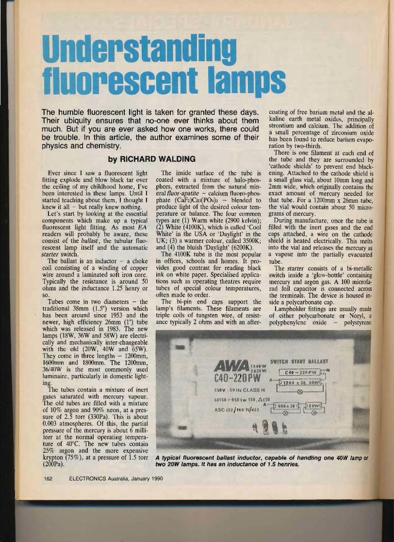
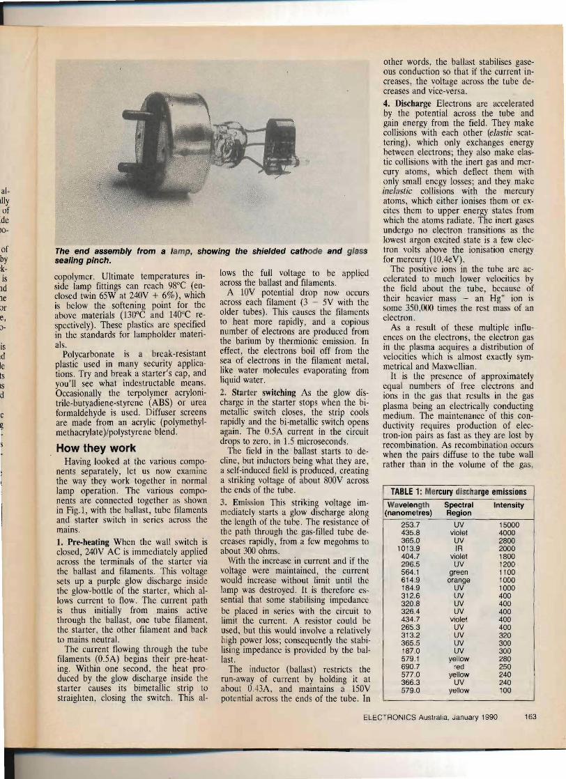
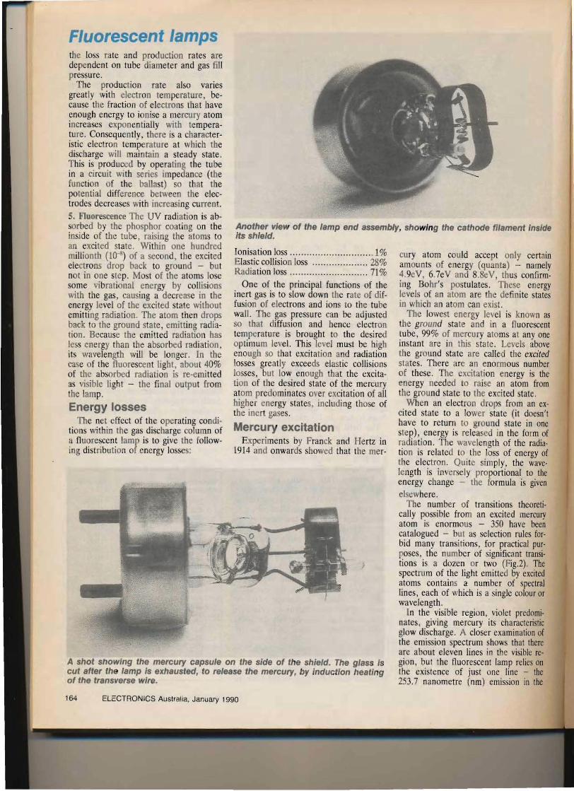
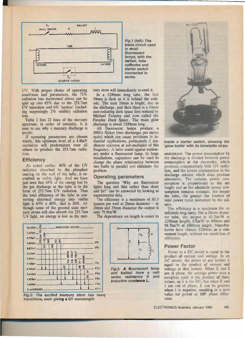
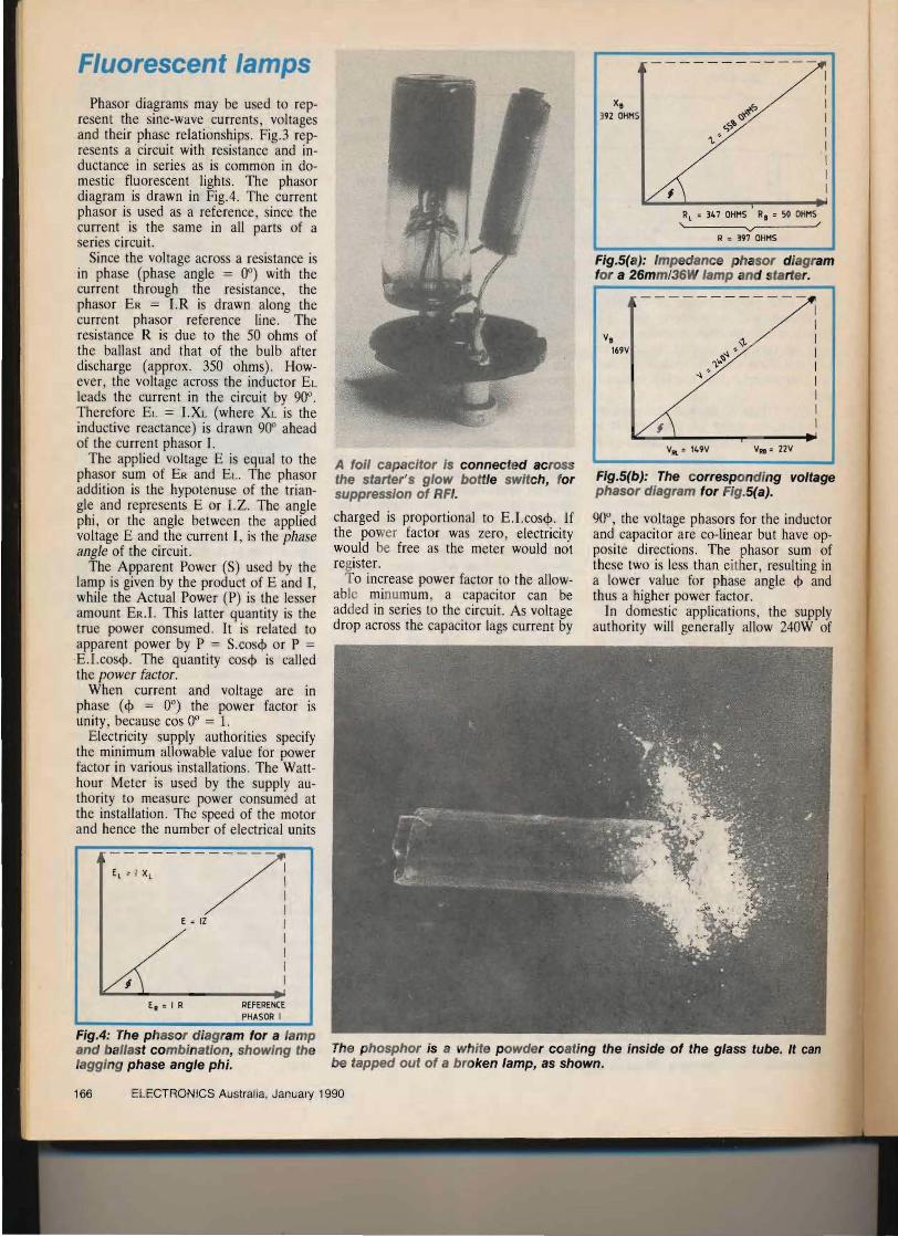
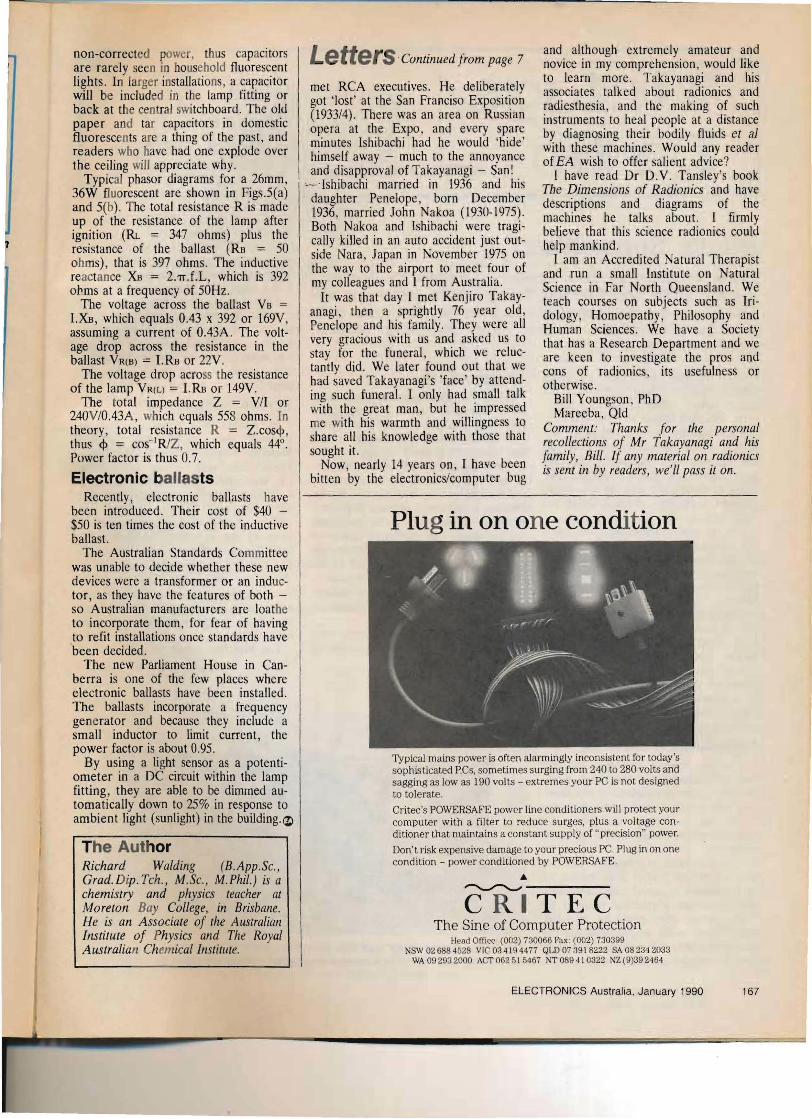