modelling of fluid-mechanical arc instability in pure-mercury hid lamps modelling of...
TRANSCRIPT

This content has been downloaded from IOPscience. Please scroll down to see the full text.
Download details:
IP Address: 178.213.240.13
This content was downloaded on 27/11/2015 at 15:58
Please note that terms and conditions apply.
Modelling of fluid-mechanical arc instability in pure-mercury HID lamps
View the table of contents for this issue, or go to the journal homepage for more
2008 J. Phys. D: Appl. Phys. 41 144023
(http://iopscience.iop.org/0022-3727/41/14/144023)
Home Search Collections Journals About Contact us My IOPscience

IOP PUBLISHING JOURNAL OF PHYSICS D: APPLIED PHYSICS
J. Phys. D: Appl. Phys. 41 (2008) 144023 (8pp) doi:10.1088/0022-3727/41/14/144023
Modelling of fluid-mechanical arcinstability in pure-mercury HID lampsThomas D Dreeben
CRSL, OSRAM SYLVANIA, 71 Cherry Hill Dr., Beverly, MA 01915, USA
E-mail: [email protected]
Received 25 October 2007, in final form 20 January 2008Published 4 July 2008Online at stacks.iop.org/JPhysD/41/144023
AbstractA fully unsteady compressible 2D flow model is used to reproduce observed fluid-mechanicalarc instability in a horizontally-running pure-mercury HID lamp. The model represents a 2Dlamp cross-section normal to the arc, and assumes an infinitely long lamp. Departure from thesteady condition is driven by oscillating lamp current. Sound-wave propagation and inducedflows result from full coupling between the current, energy balance, ideal-gas law andconservation of mass and momentum, on two separate relevant time scales. Observedacoustically generated arc instability is reproduced with the model.
M Movie sequences of figures 5, 7, 9 and 11 are available in the online edition.
1. Introduction
An HID lamp is a device that produces light from a gasdischarge enclosed in a tube with size of order centimetres,made of quartz or ceramic. The gas is ionized by imposinga current between two electrodes, bringing the gas totemperatures in the range 5000–6000 K in a light-emittingregion called the arc. HID lamps are used where large amountsof light are needed in the most space-efficient and energy-efficient possible way: common HID lamp applications areexpansive outdoor spaces such as roads, parking lots andstadiums.
Acoustic resonance has been known for some years tocause fluid-mechanical arc instabilities in HID lamps [1–3].When the driving current oscillates at an acoustic Eigenfrequency, a resonant standing sound wave is generated. Thisgenerates oscillating flows which accumulate over time andcause unstable motion of the arc. This is an effort to modeland reproduce one such instability on the computer for apure-mercury 175 W HID lamp. This instability has beenobserved and identified as an effect of streaming [4,5]. Steadystreaming refers to a class of flows in which oscillatorymotion causes a net averaged fluid motion, arising from theconvective terms of the governing momentum equations. Anumber of canonical streaming flows appear in the fluid-mechanics literature [6–18], and they offer a theoreticalstarting point for understanding the streaming inside of HID
lamps. These analyses follow Rayleigh’s approach [6] inconsidering flows that are driven by an oscillating velocity, inwhich the oscillations of instantaneous velocity are largecompared with the streaming velocity. However, we knowthat the flow in HID lamps is driven by oscillating pressure,not oscillating velocity. A previous effort for handlingthe pressure-driven aspect of HID lamp flows modelledunsteady compressible flow in an isothermal cylinder, drivenby an imposed standing pressure wave [19]. The currentwork extends the physics of that approach by includingtemperature variation throughout the lamp, and by runningfar beyond the acoustic time scale—long enough to enable arcmotion.
We obtain a comprehensive means of computing andvisualizing both instantaneous and streaming flows. Themethod is to construct a model using governing equations thatcapture the relevant physics inherent in acoustic modulationand its connection to steady streaming. Flows are drivennot from a velocity or pressure, but from an imposed HIDlamp current and its coupling to wave propagation throughthe Elenbaas–Heller equation. Fully-coupled governingequations are solved numerically using COMSOL finite-element software. This report describes the theoreticalgroundwork for this approach, plus results from a simulationfor a single test case: the two-dimensional cross-section thatcuts across the positive column of a horizontally running175 W pure-mercury HID lamp, similar to Kenty’s mercury
0022-3727/08/144023+08$30.00 1 © 2008 IOP Publishing Ltd Printed in the UK
J. Phys. D: Appl. Phys. 41 (2008) 144023 T D Dreeben
lamp [20]. For the effect of arc flicker, this case willdemonstrate how acoustic modulation brings about enoughsteady streaming to destabilize the vertical location ofthe arc.
2. Extension of model physics
Modelling acoustic streaming requires the addition of physicalmechanisms and time scales that are new to classical HID lampmodels. We incorporate and build on existing work [21–23]which includes the Elenbaas–Heller equation for the energybalance, plus the momentum and mass continuity equationsfor buoyancy-driven convection. Although these models aretypically used for steady simulations, their formulations ofteninclude unsteady terms so that they can also handle the timedependence associated with alternating current at 60 Hz, andwith the run-up of a lamp. The new physics to be addedhere enables the propagation of sound waves, which occur ontime scales associated with frequencies of 10–100 kHz in HIDlamps. This involves changes to the mass continuity equationand to the energy equation. For velocity vector �u and density ρ,the mass continuity equation is expressed in its compressibleand unsteady form
∂ρ
∂t+ �∇ · (ρ �u) = 0. (1)
In addition, the energy equation needs modification in itsthermodynamic assumptions: classical HID lamp models[21–23] assume an ideal gas, and that the pressure followinga fluid particle remains constant in time. On the basis of theseassumptions, the thermal inertia terms in the Elenbaas–Hellerequation ρcp(∂T /∂t)+ρcp �u · �∇T are cast in terms of enthalpyusing the specific heat at constant pressure cp. (We recallfrom Thermodynamics that enthalpy is internal energy plus theproduct of pressure times volume.) For propagation of soundwaves, the ideal-gas approximation remains appropriate, butthe pressure has strong time dependence which can no longerbe neglected. To properly account for the unsteady pressure,the Elenbaas–Heller equation must be cast in terms of internalenergy rather than enthalpy. This requires using the specificheat at constant volume cv , and it means we must includethe pressure-dilatation term p( �∇ · �u). This term coupleshigh-frequency power variation to sound wave propagationby describing the rate at which oscillating power does workto compress the fluid. With these changes to the governingequations, the system can create and propagate sound wavesin a physically realistic way, once it is driven by lamp currentthat varies at high frequency.
3. Model description
The physical domain of the model is half of a cross-sectionof the 175 W pure-mercury HID lamp in the positive column,a semi-circular region of radius 6 mm as shown in figure 1.This is a two-dimensional formulation which assumes aninfinitely long lamp.
Figure 1. The domain of the model—half of the cylindricalcross-section, bounded by the plane of symmetry on one side and bythe inner arc-tube wall on the other.
We define the fixed parameters of the problem:
R = 0.006 m (lamp inner radius)
TW = 1040 K (wall temperature)
Ru = 8314 J (kmol K)−1(universal gas constant)
M = 200.59 kg kmol−1(Hg molar mass) (2)
Rgas = Ru
M(gas constant for Hg)
γ = 1.6 (ratio of specific heats for Hg)
cv = Rgas
γ−1(specific heat at constant volume for Hg)
patm = 1.0133 × 10⁵ Pa (atmospheric pressure)
g = 9.8 m s−2 (acceleration due to gravity).
The constant thermodynamic properties are subject to errorat high temperatures, and this alters the local speed of soundclose to the arc through the specific-heat ratio gamma. Forhorizontal gas velocity u, vertical velocity v, temperature T ,density ρ and pressure p, the governing equations are{ρ
∂u
∂t
}+
[ρu
∂u
∂x+ ρv
∂u
∂y
]
= −{
∂p
∂x
}+
∂
∂x
(µ
(2∂u
∂x− 2
3�
))
+∂
∂y
(µ
(∂v
∂x+
∂u
∂y
))(x momentum),
{ρ
∂v
∂t
}+
[ρu
∂v
∂x+ ρv
∂v
∂y
]
= −{
∂p
∂y
}− ρg +
∂
∂x
(µ
(∂v
∂x+
∂u
∂y
))
+∂
∂y
(µ
(2∂v
∂y− 2
3�
))(y momentum),
2

J. Phys. D: Appl. Phys. 41 (2008) 144023 T D Dreeben{ρcv
∂T
∂t
}+ ρcvu
∂T
∂x+ ρcvv
∂T
∂y
= − {p�} + ε +∂
∂x
(κ
∂T
∂x
)
+∂
∂y
(κ
∂T
∂y
)+
{σE2
} − qrad (energy),
{∂ρ
∂t
}+ u
∂ρ
∂x+ v
∂ρ
∂y= − {ρ�} (mass continuity),
{p} = {ρRgasT } (ideal gas), (3)
where the dilatation is
� = div(�u) = ∂u
∂x+
∂v
∂y, (4)
and the viscous dissipation in the energy equation is
ε = µ
[2
(∂u
∂x
)2
+ 2
(∂v
∂y
)2
+
(∂v
∂x+
∂u
∂y
)2
− 2
3�2
].
(5)
The curly bracketed terms of equation (3) are significant onthe acoustic time scale. They are responsible for the excitationand propagation of sound waves. The square-bracketed termsof equation (3) are the convective link from acoustic motionto steady streaming: This occurs on a much longer time scaleand is responsible for the motion of the arc. The transportcoefficients are parameterized as a function of pressure andtemperature on the basis of previous work [24–26]
σ(T ) = 1200
√3patm
pT 0.75e−55820/T 1 (� m)−1,
κ = 6.61 × 10⁻²
(T
5621
)0.75
W (m K)−1,
µ = 5.0 × 10⁻⁸T + 5.0 × 10⁻⁵ kg (m s)−1.
(6)
To meet the computational demand of resolving the equationson two disparate time scales, the heat loss due to radiationmust be simplified considerably from its nonlocal nature.This is done by expressing it as a semi-empirical function oftemperature [24, 27] and pressure [24]:
qrad(T ) = 2.14 × 10¹⁸
T
(p
3patm
)e−86000/T W m−3. (7)
Error associated with this simplification can misrepresent theacoustic behaviour through the energy balance, the temperatureprofile, and the local speed of sound. A plausible temperatureprofile is important to establish limits on how the localizedradiation term can throw off the acoustics.
The system is driven by oscillating lamp current, with aconstant component of 1.632 A that is an approximate valuefor the 175 W pure-mercury lamp. A sinusoidal componentof current is superimposed with an amplitude of 15% of the1.632 A, and a frequency that is close to the natural frequencyof the second-azimuthal acoustic mode of figure 3. For electric
field E, the oscillating current provides an oscillating heatsource σE2 in the energy equation through ohm’s law as itapplies in the positive column:
E = I∫σ(T ) dA
. (8)
Equation (8) involves a spatial integral over the entire domain.To solve this model numerically, this integral must be evaluatedat every time step in the computation.
Boundary conditions are imposed at the two boundariesin the domain as shown in figure 1. At the plane of symmetrywe have standard symmetry conditions on the variables of thesecond-order equations:
u = 0,
∂v
∂x= 0,
∂T
∂x= 0.
(9)
On the inner surface of the arc tube, we have
u = 0,
v = 0,
T = TW.
(10)
The density ρ, governed by the first-order mass continuityequation, satisfies an integral constraint
ρave = 1
Ac
∫Ac
ρdA. (11)
For the 175 W lamp with 25 mg of mercury, equation (11)is imposed with ρave = 3.54 kg m−3 in the positive column.This constraint says that per unit length along the arc, thetotal mass of mercury in the positive column remains constantin time. In conjunction with the 2D flow/infinitely longarc-tube assumption, equation (11) neglects the exchange ofmass with end portions of the arc tube when the temperatureprofile changes during lamp operation. The pressure p has noboundary conditions or constraints, since the ideal-gas law ofequations (3) is a purely algebraic equation. The system ofequations is driven by imposing an oscillating current
I = I0[1 + 0.15 sin(nt)], (12)
where I0 = 1.632 A is the current that the model needsto generate 175 W in the lamp, and n = 2.0 × 10⁵ rad s−1
(31.8 kHz) is the angular frequency associated with the second-azimuthal mode of figure 3. Taken together, equations (2)–(12)form a comprehensive model that incorporates the physics ofacoustically driven HID lamp flow. Approximate solutionsto the model are obtained using finite-element analysis withCOMSOL Multiphysics software. The finite-element methodbreaks up the geometry of figure 1 into 1724 elements andsolves a discrete approximation of equations (3) over eachelement.
3

J. Phys. D: Appl. Phys. 41 (2008) 144023 T D Dreeben
Figure 2. The initial condition. Temperature (K) together withgas-velocity vectors for a steady, bowed arc. In the arc, themaximum vertical velocity is 8 cm s−1. Spatial dimensions areshown with the 6 mm arc-tube radius normalized to unity.
Figure 3. Sample eigenmodes for sound waves in HID lamps. Thecolour scheme shows the spatial pattern of pressure at differentnatural frequencies.
4. Model characterization: pressure and flow on theacoustic time scale
Using estimation from the above model, we obtain adescription of the fluid mechanics of the acoustically enhancedflow. The initial condition is the steady buoyant convection thatis characteristic of a horizontally running lamp with a bowedarc as shown in figure 2. This is obtained by running the modelwith the current held fixed at 1.632 A.
To implement sound waves, the solution is driven bythe imposed lamp current of 1.632 A, plus a sinusoidalperturbation of 15% amplitude at a frequency of 31.8 kHz.This frequency is chosen because it naturally excites the lamp’ssecond-azimuthal mode, shown in figure 3.
Oscillating current of equation (12) induces an oscillatingpower deposition in the gas, which is shown in figure 4.
The 15% fluctuation of current of equation (12) resultsin a 30% fluctuation of power, because ohmic heating has aquadratic dependence on current. This oscillation in power
Figure 4. Ohmic heating in the lamp. The colour map of (a) showspower per unit volume in W m−3. Power density σE2 is significantin the arc, where the electrical conductivity σ is significant.(b) shows instantaneous power per unit arc length (W m−1), obtainedby integrating the power density of (a) over the cross-sectional area.
causes sound waves through the pressure-dilatation (p�) termin the energy equation of equations (3). These waves developfrom an initial pattern that matches the oscillating heat releaseinto the known pattern of the second-azimuthal mode, shownin figure 5.
In figure 5(a), the pressure spike of 100 Pa occurs in thesame location of maximum ohmic heating, which is in the arc.In figure 5(b), the pressure has evolved to a standing wavein the second-azimuthal mode with approximate amplitude4 kPa from peak to peak. The pressure map now bears noresemblance to the pattern of its excitation which continues tofollow the temperature profile. The two colour maps show thatthe temperature profile has not changed between figures 5(a)and (b) even though the pressure map has. The time evolutionof the pressure at its antinode at the bottom of the lamp isshown in figure 6. By 1.2 ms, the amplitude of oscillation isjust under 1% of the overall lamp pressure.
The standing sound waves of figure 5(b) induce gasflows inside the lamp. The way that these flows respondinstantaneously to the pressure is shown in figure 7.
4

J. Phys. D: Appl. Phys. 41 (2008) 144023 T D Dreeben
Figure 5. Initial propagation of sound waves. Pressure is shown inPa on the vertical axis while temperature is shown in K on thecolour map. (a) shows pressure and temperature in the very firstoscillation at 5 µs. (b) shows pressure and temperature much later at1.2 ms, in a relatively stationary situation. A movie version of thisfigure is available in the online edition.
Figure 6. Instantaneous pressure as a function of time at a pressureantinode, as the pattern transitions from quiescence to resonance.
The instantaneous response of velocity to pressurecan be understood from the curly bracketed terms inthe momentum equations of equations (3)—these are thesignificant momentum terms on the acoustic time scale. They
Figure 7. Pressure (Pa) in colour maps with velocity vectors, 1/4cycle apart in time. (a) t = 1.2472 ms and (b) t = 1.2549 ms. Amovie version of this figure is available in the online edition.
amount to the vector equation
ρ∂ �u∂t
= −�∇p, (13)
which is linear in pressure and velocity. If the circumferentialpressure is a sinusoidal function in space (figure 5(b)) and intime (figure 6), then equation (13) shows that the velocity mustalso be sinusoidal and lag behind the pressure by 1/4 cycle intime. That means that the velocity is small when the pressureis large and the pressure is small when the velocity is large.Figure 7(a) shows the substantial pressure amplitude (similarto figure 5(b)), together with small gas velocities. Figure 7(b)shows the delayed velocity vectors that were driven by thepressure gradients, together with the newly relaxed pressure.This near-linear interplay of equation (13) causes oscillatingvelocities throughout the lamp on the acoustic time scale. ForHID lamps, we are most interested in the vertical velocity inthe vicinity of the arc—this is shown as a function of time infigure 8.
Although the gas velocities reach ±1 m s−1, the locationof the arc after 1 ms (shown approximately in figure 5(b)) has
5

J. Phys. D: Appl. Phys. 41 (2008) 144023 T D Dreeben
Figure 8. Instantaneous vertical velocity in the arc, taken 2.4 mmabove the centre of the lamp.
not changed substantially from its initial location of figure 2.In 1 ms, the average motion appears to change little fromthe initial convective motion of figure 2, which is on theorder of 10 cm s−1.
5. Arc flicker: flow on the streaming time scale
The oscillatory gas motion in figure 8 nearly cancels out intime, but there is a net velocity that remains. Beyond the initialflow of figure 2, this is a nonlinear effect which occurs on atime scale much longer than the acoustic one, and is a result ofthe square-bracketed convective terms of equations (3). Thisnet motion is responsible for changes in lamp performanceincluding motion of the arc and mixing of segregated species.
Observed motion of the arc in the form of flicker is shownin figure 9(b).
The arc motion is irregular both in time and space, butoccurs primarily on a time scale of 50–100 ms.
The model is not able to reproduce the bending of the arcshown in figure 9(b) because it is only two-dimensional andassumes a straight and infinitely long arc. But the model doesreproduce the vertical oscillation and show the accompanyinggas flows that are normal to the arc. The model also sharesirregularity of the arc motion in time with the real lamp. Tofocus the model output more on the motion of figure 9, weuse time averaging to filter out the oscillations associated withthe acoustic time scale, and run the model over hundreds ofmilliseconds. For any quantity φ, we define its average overthe time interval [0, τ ] to be
〈ϕ〉 = 1
τ
∫ τ
0ϕ dt . (14)
We refer to a velocity that has been averaged accordingequation (14) as a streaming velocity. The model continuedto run under oscillating current given by equation (12) up to atime of t = 0.3 s, an additional 2 orders of magnitude beyondthe results shown in figures 5–8. Time averages over a period
Figure 9. A horizontally running 175 W mercury lamp with (a) astationary bowed arc with no acoustic excitation and (b) a snapshotof the arc in motion under acoustic excitation at a single frequency(30 kHz, 30% current amplitude modulation). (b) is an example ofarc flicker. A movie version of this figure is available in the onlineedition.
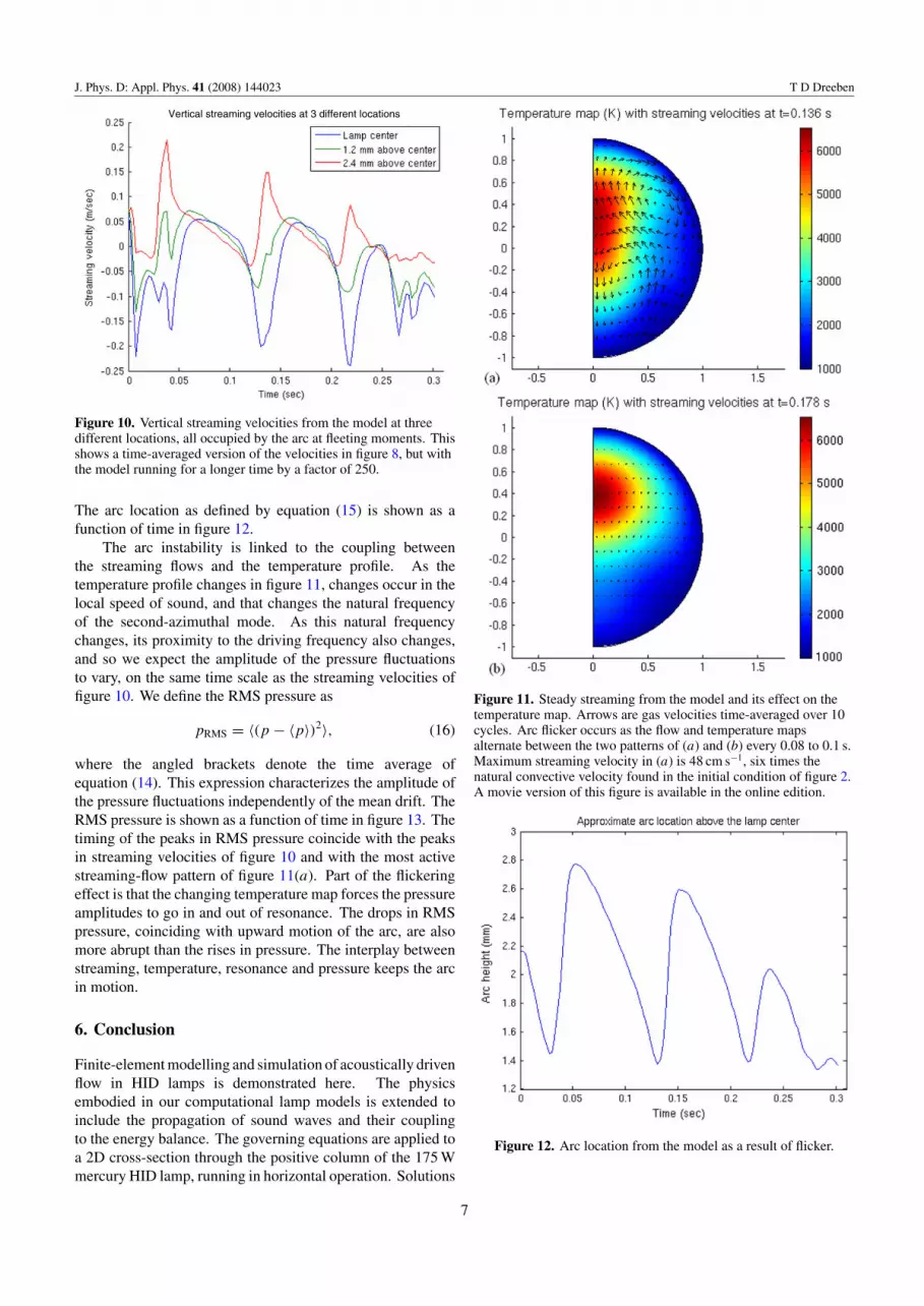
of τ = 3.14 × 10⁻⁴ s, or 10 cycles, were taken at steps alongthe way to visualize the bulk motion of the gas. This amountof time is long enough to average out acoustic fluctuations butshort enough to resolve streaming. Motion of the arc is clearin the model on the time scale of this run; vertical streamingvelocities at three different locations are shown in figure 10.
The streaming velocities of figure 10 show that significantmotion occurs on a time scale of 80–100 ms. The peakof streaming motion just before 0.14 s plus the relativelyquiescent motion at 0.18 s are shown in figures 11(a) and (b),together with their respective temperature maps.
In figure 11, the arc is located in the hottest portion of thedomain where the temperature map is red. To see the motionof the arc, we characterize the arc location as the centre ofmass of all of the gas that is hotter than 5500 K, weighted byits temperature. The mathematical expression for this is
yarc =∫
yT H(T − 5500) dA∫T H(T − 5500) dA
(15)
Where H is the Heaviside function which is unity when itsargument is positive and zero when its argument is negative.
6
J. Phys. D: Appl. Phys. 41 (2008) 144023 T D Dreeben
Figure 10. Vertical streaming velocities from the model at threedifferent locations, all occupied by the arc at fleeting moments. Thisshows a time-averaged version of the velocities in figure 8, but withthe model running for a longer time by a factor of 250.
The arc location as defined by equation (15) is shown as afunction of time in figure 12.
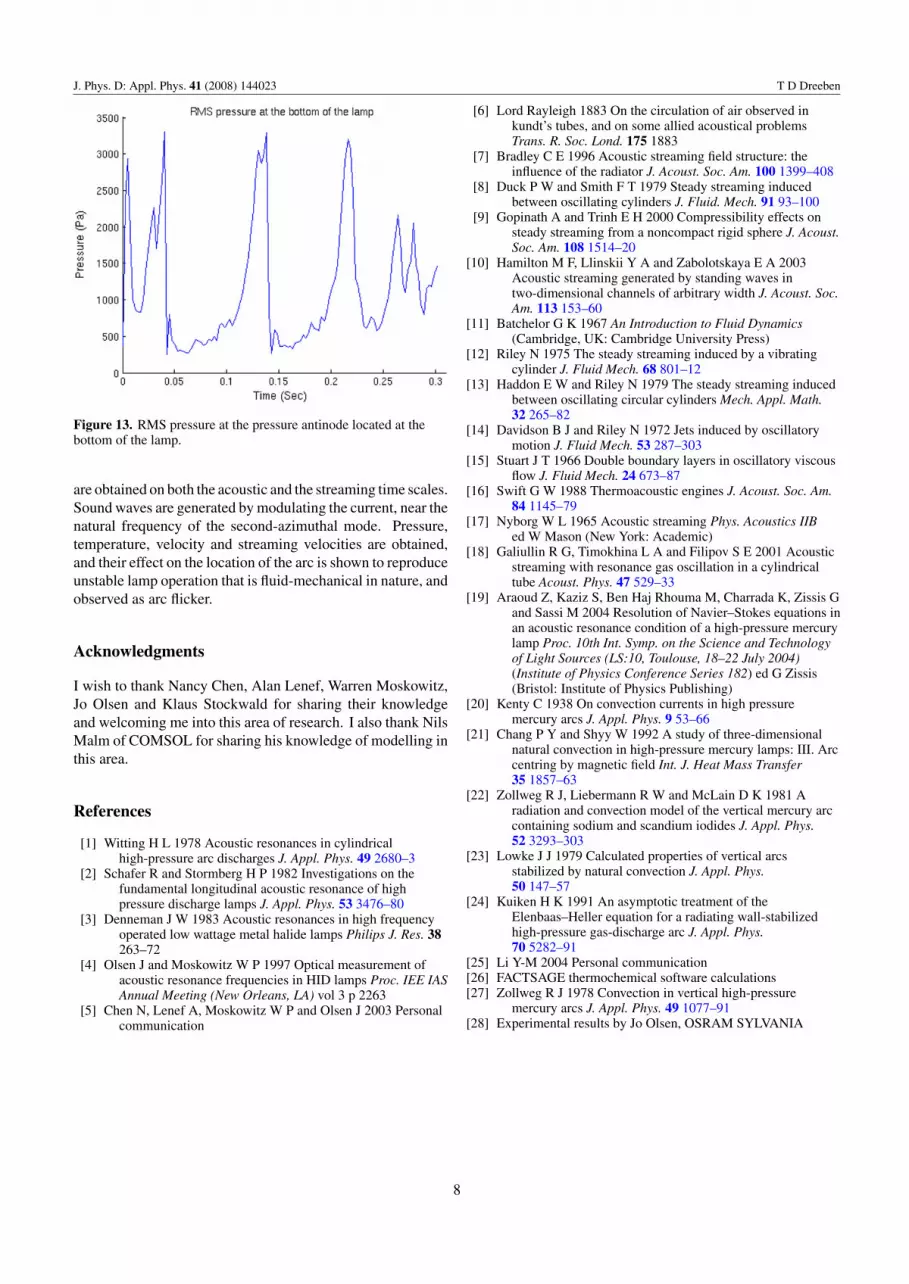
The arc instability is linked to the coupling betweenthe streaming flows and the temperature profile. As thetemperature profile changes in figure 11, changes occur in thelocal speed of sound, and that changes the natural frequencyof the second-azimuthal mode. As this natural frequencychanges, its proximity to the driving frequency also changes,and so we expect the amplitude of the pressure fluctuationsto vary, on the same time scale as the streaming velocities offigure 10. We define the RMS pressure as
pRMS = 〈(p − 〈p〉)2〉, (16)
where the angled brackets denote the time average ofequation (14). This expression characterizes the amplitude ofthe pressure fluctuations independently of the mean drift. TheRMS pressure is shown as a function of time in figure 13. Thetiming of the peaks in RMS pressure coincide with the peaksin streaming velocities of figure 10 and with the most activestreaming-flow pattern of figure 11(a). Part of the flickeringeffect is that the changing temperature map forces the pressureamplitudes to go in and out of resonance. The drops in RMSpressure, coinciding with upward motion of the arc, are alsomore abrupt than the rises in pressure. The interplay betweenstreaming, temperature, resonance and pressure keeps the arcin motion.
6. Conclusion
Finite-element modelling and simulation of acoustically drivenflow in HID lamps is demonstrated here. The physicsembodied in our computational lamp models is extended toinclude the propagation of sound waves and their couplingto the energy balance. The governing equations are applied toa 2D cross-section through the positive column of the 175 Wmercury HID lamp, running in horizontal operation. Solutions
Figure 11. Steady streaming from the model and its effect on thetemperature map. Arrows are gas velocities time-averaged over 10cycles. Arc flicker occurs as the flow and temperature mapsalternate between the two patterns of (a) and (b) every 0.08 to 0.1 s.Maximum streaming velocity in (a) is 48 cm s−1, six times thenatural convective velocity found in the initial condition of figure 2.A movie version of this figure is available in the online edition.
Figure 12. Arc location from the model as a result of flicker.
7
J. Phys. D: Appl. Phys. 41 (2008) 144023 T D Dreeben
Figure 13. RMS pressure at the pressure antinode located at thebottom of the lamp.
are obtained on both the acoustic and the streaming time scales.Sound waves are generated by modulating the current, near thenatural frequency of the second-azimuthal mode. Pressure,temperature, velocity and streaming velocities are obtained,and their effect on the location of the arc is shown to reproduceunstable lamp operation that is fluid-mechanical in nature, andobserved as arc flicker.
Acknowledgments
I wish to thank Nancy Chen, Alan Lenef, Warren Moskowitz,Jo Olsen and Klaus Stockwald for sharing their knowledgeand welcoming me into this area of research. I also thank NilsMalm of COMSOL for sharing his knowledge of modelling inthis area.
References
[1] Witting H L 1978 Acoustic resonances in cylindricalhigh-pressure arc discharges J. Appl. Phys. 49 2680–3
[2] Schafer R and Stormberg H P 1982 Investigations on thefundamental longitudinal acoustic resonance of highpressure discharge lamps J. Appl. Phys. 53 3476–80
[3] Denneman J W 1983 Acoustic resonances in high frequencyoperated low wattage metal halide lamps Philips J. Res. 38263–72
[4] Olsen J and Moskowitz W P 1997 Optical measurement ofacoustic resonance frequencies in HID lamps Proc. IEE IASAnnual Meeting (New Orleans, LA) vol 3 p 2263
[5] Chen N, Lenef A, Moskowitz W P and Olsen J 2003 Personalcommunication
[6] Lord Rayleigh 1883 On the circulation of air observed inkundt’s tubes, and on some allied acoustical problemsTrans. R. Soc. Lond. 175 1883
[7] Bradley C E 1996 Acoustic streaming field structure: theinfluence of the radiator J. Acoust. Soc. Am. 100 1399–408
[8] Duck P W and Smith F T 1979 Steady streaming inducedbetween oscillating cylinders J. Fluid. Mech. 91 93–100
[9] Gopinath A and Trinh E H 2000 Compressibility effects onsteady streaming from a noncompact rigid sphere J. Acoust.Soc. Am. 108 1514–20
[10] Hamilton M F, Llinskii Y A and Zabolotskaya E A 2003Acoustic streaming generated by standing waves intwo-dimensional channels of arbitrary width J. Acoust. Soc.Am. 113 153–60
[11] Batchelor G K 1967 An Introduction to Fluid Dynamics(Cambridge, UK: Cambridge University Press)
[12] Riley N 1975 The steady streaming induced by a vibratingcylinder J. Fluid Mech. 68 801–12
[13] Haddon E W and Riley N 1979 The steady streaming inducedbetween oscillating circular cylinders Mech. Appl. Math.32 265–82
[14] Davidson B J and Riley N 1972 Jets induced by oscillatorymotion J. Fluid Mech. 53 287–303
[15] Stuart J T 1966 Double boundary layers in oscillatory viscousflow J. Fluid Mech. 24 673–87
[16] Swift G W 1988 Thermoacoustic engines J. Acoust. Soc. Am.84 1145–79
[17] Nyborg W L 1965 Acoustic streaming Phys. Acoustics IIBed W Mason (New York: Academic)
[18] Galiullin R G, Timokhina L A and Filipov S E 2001 Acousticstreaming with resonance gas oscillation in a cylindricaltube Acoust. Phys. 47 529–33
[19] Araoud Z, Kaziz S, Ben Haj Rhouma M, Charrada K, Zissis Gand Sassi M 2004 Resolution of Navier–Stokes equations inan acoustic resonance condition of a high-pressure mercurylamp Proc. 10th Int. Symp. on the Science and Technologyof Light Sources (LS:10, Toulouse, 18–22 July 2004)(Institute of Physics Conference Series 182) ed G Zissis(Bristol: Institute of Physics Publishing)
[20] Kenty C 1938 On convection currents in high pressuremercury arcs J. Appl. Phys. 9 53–66
[21] Chang P Y and Shyy W 1992 A study of three-dimensionalnatural convection in high-pressure mercury lamps: III. Arccentring by magnetic field Int. J. Heat Mass Transfer35 1857–63
[22] Zollweg R J, Liebermann R W and McLain D K 1981 Aradiation and convection model of the vertical mercury arccontaining sodium and scandium iodides J. Appl. Phys.52 3293–303
[23] Lowke J J 1979 Calculated properties of vertical arcsstabilized by natural convection J. Appl. Phys.50 147–57
[24] Kuiken H K 1991 An asymptotic treatment of theElenbaas–Heller equation for a radiating wall-stabilizedhigh-pressure gas-discharge arc J. Appl. Phys.70 5282–91
[25] Li Y-M 2004 Personal communication[26] FACTSAGE thermochemical software calculations[27] Zollweg R J 1978 Convection in vertical high-pressure
mercury arcs J. Appl. Phys. 49 1077–91[28] Experimental results by Jo Olsen, OSRAM SYLVANIA
8