uncontained engine failure, american airlines, inc., boeing
TRANSCRIPT

Uncontained engine failure, American Airlines, Inc., Boeing 747-121,N743PA, San Francisco, California, September 18, 1970
Micro-summary: This Boeing 747-121 experienced an uncontained engine failure ofthe #1 engine on climbout.
Event Date: 1970-09-18 at 0851 PDT
Investigative Body: National Transportation Safety Board (NTSB), USA
Investigative Body's Web Site: http://www.ntsb.gov/
Cautions:
1. Accident reports can be and sometimes are revised. Be sure to consult the investigative agency for thelatest version before basing anything significant on content (e.g., thesis, research, etc).
2. Readers are advised that each report is a glimpse of events at specific points in time. While broadthemes permeate the causal events leading up to crashes, and we can learn from those, the specificregulatory and technological environments can and do change. Your company's flight operationsmanual is the final authority as to the safe operation of your aircraft!
3. Reports may or may not represent reality. Many many non-scientific factors go into an investigation,including the magnitude of the event, the experience of the investigator, the political climate, relationshipwith the regulatory authority, technological and recovery capabilities, etc. It is recommended that thereader review all reports analytically. Even a "bad" report can be a very useful launching point for learning.
4. Contact us before reproducing or redistributing a report from this anthology. Individual countries havevery differing views on copyright! We can advise you on the steps to follow.
Aircraft Accident Reports on DVD, Copyright © 2006 by Flight Simulation Systems, LLCAll rights reserved.
www.fss.aero

SA- None File No. 4-0045
AIRCRAFT INCIDENT REPORT AMERICAN ARLMES, INC.,
BOEING 747-121, N743PA SAN FRANCISCO, CALIFORNIA
SEPTEMBER 18,1970
Adopted: February 3, 1971
NATIONAL TRANSPORTATION SAFETY BOARD Washington, 0. C. 20591
REPORT NUMBER: NTSB-AAR-71-7

Synopsis . . . Investigation . .
American Airlines, Inc., being 747-121, ~743pA
San Francisco, California September 18, 1970
Phase I . . Phase I1 . . . . .
TABLE OF CONTENTS PAGE -
Analysis and Conclusions . . . . . . . . . . . . . . . . . 11 Effects of Engine Structural l<ailure Upon the Aircraft . . . . 14 Conclusions . . . . . . . . Probable Cause . . . . . . . . . . . . Recommendations and Corrective Action . . Corrective Action . . . . . . . . . . Air Carriers . . . . Aircraft Information . . Supplemental Data . ,
Attachment 1

Fi le No. 4-0045
NATIONAL TRANSPORTATION SAFETY BQABD WASHINGTON, D. C. 20591 AIRCRAFT INCIDENT REPORT
Adopted: February 3, 1971
American Airlines, Inc . , Boeing 747-121, ~ 7 4 3 ~ A
San Francisco, California September 18, 1970
SYNOPSIS
American Air l ines Sl ight 14, a Boeing 747-121, ~743PA, w a s a scheduled passenger nonstop f l i g h t which originated at San Francisco International Airport at 0830 P.d.t. I/ on September 18, 1970. I ts destination was New York, John F. ~ennedy International Airport. A t departure from San Francisco, 105 revenue passengers, 12 nonrevenue passengers, and a crew of 15 were aboard the f l igh t .
The f l i g h t ' s departure from the gate was routine with the excep- t i on of some d i f f i c u l t i e s i n s ta r t ing with No. 1 engine. The airplane was cleared for takeoff from San Francisco's International Airport, Runway 1-R, at 0851. During the takeoff, it was necessary fo r the f l i g h t engineer t o reduce power on the No. 1 engine by .10 EPR 2/ i n order t o maintain the EGT 3/ within l i m i t s . Approximately 16 seconds a f t e r l i f t - o f f at an a l t i t ude of 525 f e e t m . s . 1 . 41, the No. 1 engine sustained a separation of the second-stage turbine disk r i m . The turbine blades and r i m fragments penetrated the high-pressure turbine (HPT) case, engine cowling, and adjacent airplane structure. A l l f l u id l ines , e l e c t r i c a l cables, and pneumatic ducts located i n the pylon area were severed, and an intense f i r e ensued. Two f u e l tank access plates on the bottom of the wing inboard of No. 1 pylon were a l so penetrated by turbine fragments.
I/ A l l times used herein a re Pacific daylight based on the 24-hour clock. - 2/ Engine pressure r a t i o (EPR) i s indicated a s a measure of t h rus t devel- -
oped by the engine. This i s the r a t i o of the turbine discharge t o t a l pressure t o the equivalent compressor i n l e t t o t a l pressure.
3/ Exhaust gas temperature. - 4.1 M . s . 1 . - Mean Sea Level -

The fire warning for the No. 1 engine came on simultaneously with the engine explosion. Emergency fire control procedures were initiated and executed. The fire, which was observed by the captain, was propa- gating over the top of the left wing and lasted approximately 3 minutes. As a result of complete failure of the No. 1 hydraulic system, alternate extension of the body main landing gear, nose landing gear, and inboard trailing edge flaps was necessary. A successful landing was accomplished on San F'rancisco's International Airport. Passengers and crewmembers were deplaned on the taxiway by means of boarding steps. There were no injuries to passengers, crewmembers, or persons on the ground.
The National Transportation Safety Board determines that the prob- able cause of this incident was a progressive failure in the high- pressure turbine module in the No. 1 JTgD-3A engine. This failure was initiated by the undetected stress rupture fractures of several first- stage turbine blades and culminated in the inflight separation of the second-stage turbine disk rim.
The Safety Board sent a letter to the Federal Aviation Administration (FAA) on September 25, 1970. This letter related some of the problem areas associated with JTgD engine operations at higher than desirable turbine temperatures and made recommendations toward correction of these conditions.
The Administrator's response dated October 1, 1970, indicated that appropriate action had been taken regarding most of the Board's recom- mendations and that the remaining items were being evaluated. The Administrator's additional response dated December 23, 1970, indicated that further action had been taken to resolve the problems.

INVESTIGATION
American Airlines Flight 14 of September 18, 1970, was a regularly scheduled nonstop passenger flight between San Francisco, California, and New York's John F. Kennedy International Airport. Flight 14 was scheduled to depart San F'ranci~co International Airport at 0830.
The airplane had been serviced with 180,000 pounds of Jet A fuel. The fuel load distribution at departure was 3,350 pounds in No. 1 and No. 4 reserve tanks, 24,600 pounds in No. 1 and No. 4 main tanks, and 62,050 pounds in No. 2 and No. 3 main tanks. The combined airplane, passenger, cargo, and fuel weight was computed at 558,810 pounds for takeoff. The maximum allowable takeoff weight was 676,600 pounds for the existing ambient temperature of +60°~. light and variable winds, and the projected use of Runway 1-R.
Difficulty was experienced in starting the No. 1 engine at the ramps. Two starting attempts had to be terminated because of a rapid rise in EGT. The airplane's APU 51 system, which normally supplies a minimum of 35 p.s.1. air pressurefor starting, was inoperative. In order to obtain sufficient pneumatic pressure for satisfactory engine starting, an additional external ground air unit had to be utilized.
Flight 14 was cleared for takeoff by San F'rancisco tower local control at 0851. Takeoff power, which was computed to be 1.37 EPR, was set, and the takeoff roll was started. During the takeoff, the EGT on No. 1 engine started to climb, and it became necessary for the flight engineer to reduce power by .10 EPR in order to maintain EGT within specified limits.
Approximately 16 seconds after lift-off while climbing through 525 feet m.s.l., as the landing gear retraction cycle was in progress, the crew heard an explosive sound. This was followed immediately by activation of the fire warning system of the No. 1 engine. Engine emergency fire control procedures were initiated and both containers of fire extinguishing agent were discharged. The presence of an intense fire, with white flames propagating over the top of the left wing, had been visually confirmed by'the captain. The first discharge of extinguishing agent did not control the fire; however, the intensity of the fire decreased considerably after the second discharge. The fire continued to burn for approximately 3 minutes.
The initial approach for an emergency landing on Runway 28L had to be abandoned because of the inability of the crew to lower the body
5/ Auxiliary power unit supplies pneumatic pressure and electrical power for ground operations.

landing gear and extend the inboard leading edge f laps below the 10' ( takeoff) position. It was determined t h a t t h e No. 1 hydraulic system, which is required f o r body gear and inboard leading edge f l a p operation, had been rendered inoperative by the explosion and f i r e i n No. 1 engine. The body gear and inboard leading edge f laps were sub- sequently extended by a l te rna te means, and a second approach was in i t i a t ed at 0902. With a i rpor t emergency equipment standing by, Flight 14 landed safely on Runway 28L at 0906. During the landing r o l l , the tower control ler observed smoke coming from the area of No. 1 engine and so advised the f l i gh t .
The airplane was taxied t o the f a r end of Bunway 2 8 ~ and was stopped on the taxiway between Runway 2 8 ~ and 28R. The l e f t forward, main cabin s l ide had been deployed but was not u t i l i zed because it was determined that t he f i r e i n the No. 1 engine had been completely extinguished. A l l passengers and crewmembers evacuated the airplane by means of portable loading steps. During and subsequent t o t he evacuation of t he passengers, there was f u e l spi l lage from the two punctured f u e l tank access p la tes between wing s ta t ions 950 and 1000.
The San K-ancisco Fire Department, which provides rescue and f i r e f ight ing services f o r t he San Francisco Internat ional Airport, reported tha t it used 5,000 gallons of water t o wash down sp i l led f u e l t o elimi- nate any fur ther hazard t o t he airplane and i ts occupants. The a i r c a r r i e r ' s personnel transferred f u e l from the penetrated tank t o adjacent tanks t o prevent fur ther spil lage.
The overal l investigation of t h i s incident was conducted i n two phases. Phase I consisted of t he immediate on-the-scene invest igat ive ac t iv i t i e s , while Phase I1 consisted of t he detai led examination of the engins and laboratory analysis of fa i led parts.

Phase I
On-the-scene examination of the No. 1 engine disclosed that 'the outer rim of the second-stage turbine disk had separated from the remainder of the turbine hub. One 14.5-inch-long segment of this rim was recovered from the No. 1 pylon structure. This segment was for- warded to the metallurgical laboratories of Pratt & Whitney Aircraft for examination in the presence of the National Transportation Safety Board metallurgist.
The high-pressure turbine case had been penetrated by the rim fragments and had sustained massive deformation, both forward and aft of the penetrated areas. Similar massive deformation and tearing of engine components in the immediate area, including that of the engine oil tank, had occurred. Major damage was sustained by portions of the airplane's hydraulic, pneumatic, fuel, and electrical systems which were located in the No. 1 pylon and adjacent wing leading edge areas. All pylon plumbing extending forward of nacelle station 210, with the exception of the engine-driven hydraulic pump case drain line, was severed between nacelle stations 197 and 208 (see photographs Nos. 1 and 2). Both the throttle and thrust reverser control cables were severed at this location. All electrical wiring in the forward portion of the pylon between nacelle stations 165 and 185 was either melted or severely burned. The No. 1 hydraulic system pump supply line was severed between the system reservoir and the firewall shutoff valve (between nacelle stations 197 and 208). The No. 1 hydraulic system pressure line was also severed at this location. All usable fluid supply for the No. 1 hydraulic system was depleted.
The pylon valve-to-duct pressure line, as well as the pneumatic cross-ship manifold in the wing leading edge, was partially severed approximately 24 inches inboard of No. 1 pylon. The No. 1 pylon pneu- matic duct was severed between nacelle stations 197 and 208. The pylon pneumatic shutoff valve, however, had been placed in the "off" position by closing of the firewall shutoff valve. The No. 1 engine fuel supply line was severed between nacelle stations 197 and 208. The firewall (fuel) shutoff valve operated normally, and terminated fuel supply when it closed during engine shutdown and fire control procedures.
Major aircraft structural damage was inflicted by failed turbine fragments and the ensuing fire.
The most severe structural damage in the pylon was sustained between nacelle stations 197 and 208, (photographs NOS. 1 and 2) which was directly in the plane of rotation of the second-stage turbine wheel. The lower spar (firewall), mid-spar outboard cap and web, and inboard stiff- eners were severed. The pylon outboard skin was cut from nacelle water

l i n e 136 t o 186, while t h e inboard s ide skin was cu t from nacel le water l i n e 136 t o 164. I n t h i s same area, t h e f ron t spar chord lower f lange was bent and t h e lower flange of t h e inboard s t i f f e n e r was broken.
Shrapnel and fire damage between nacel le s t a t i o n s 168 and 192, above nacel le water l i n e 154, completely severed t h e pylon from the outboard lower spar ( f i r e w a l l ) chord ac ross t h e top t o t h e inboard lower spar chord. This a rea of the pylon i n t e r i o r a l s o exhibited t h e most in tense heat and f i r e damage. The outboard s t i f f e n e r was severed a t t h i s loca- t i o n and t h e f i r e extinguishing agent container mounting brackets were burned t o t h e degree t h a t agent containers had f a l l e n onto t h e lower spar web.
Two holes were burned through t h e pylon outboard skin between nacelle s t a t i o n s 236 and 265 and nacel le water l i n e 136 and 154. Much of t h e pylon outboard skin was discolored and buckled by heat . Although nacel le s t a t i o n 265.94 bulkhead remained otherwise i n t a c t , it a l s o was discolored and buckled by heat .
The forward por t ion of t h e pylon was found drooping approximately 6 t o 8 inches with t h e engine i n s t a l l e d .
Varying degrees of f i r e (photograph No. 3) and/or shrapnel damage were sustained by t h e l e f t outboard f l ap , outboard a i l e ron , No. 1 spoi ler , f l a p t r ack fa i r ings , leading edge panels / fa i r ings , wing leading edge support s t ruc tu re , and t r a i l i n g edge panels .
The most severe damage w a s sustained by t h e underside of t h e l e f t wing, both inboard and outboard of No. 1 pylon. The f i r s t and t h i r d f u e l tank access p l a t e s outboard of t h e No. 1 pylon exhibited evidence of heat d iscolora t ion. Two f u e l tank access p l a t e s between wing s t a t i o n s 950 and 1000 and 975 and 1000 were punctured and were t h e source of profuse f u e l leakage. There was no ign i t ion of t h e f u e l which was leaking from these two access p la tes .
I
Gouges i n - t h e lower wing skin, inboard of No. 1 pylon, formed a I
pa t t e rn which ran diagonally inboard and rearward between wing s t a t i o n s 1070 and 940 and from t h e f r o n t spar t o an a rea s l i g h t l y aft of t h e f u e l tank access p la tes . There were approximately 100 such gouges. Six r e l a t i v e l y deep gouges were concentrated i n an approximately 1-square- foo t a rea a t wing s t a t i o n 1035 j u s t forward of t h e mid-spar. The deepest of these s i x gouges measured 0.187 inches i n depth. Lower wing skin thickness at t h i s point i s .40 inches. Another concentration of gouges was located immediately forward of t h e f u e l tank access p l a t e between wing s t a t i o n s 975 and 1000. The deepest of these gouges measured 0.218 inches i n depth. Lower wing skin thickness at t h i s po in t i s .326 inches.
Phase I1
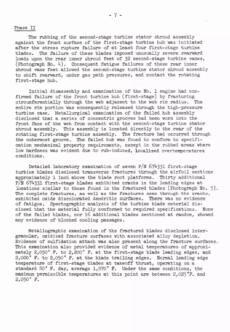
The rubbing of the second-stage turbine stator shroud assembly against the front surface ofthe first-stage turbine hub was initiated after the stress rupture failure of at least four first-stage turbine blades. The failure of these blades imposed unusually severe rearward loads upon the rear inner shroud feet of 32 second-stage turbine vanes, (Photograph No. 4). Consequent fatigue failures of these rear inner shroud vane feet allowed the second-stage turbine stator shroud assembly to shift rearward, under gas path pressures, and contact the rotating f irst-stage hub.
Initial disassembly and examination of the No. 1 engine had con- firmed failure of the front turbine hub (first-stage) by fracturing circumferentially through the web adjacent to the web rim radius. The entire rim portion was consequently released through the high-pressure turbine case. Metallurgical examination of the failed hub assembly disclosed that a series of concentric grooves had been worn into the front face of the web from contact with the second-stage turbine stator shroud assembly. This assembly is located directly to the rear of the rotating first-stage turbine assembly. The fracture had occurred through the outermost groove. The failed hub was found to conform to specifi- cation mechanical property requirements, except in the rubbed areas where low hardness was evident due to rub-induced, localized overtemperatures conditions.
Detailed laboratory examination of seven PIN 674331 first-stage turbine blades disclosed transverse fractures through the airfoil sections approximately 1 inch above the blade root platforms. Thirty additional PIN 674331 first-stage blades exhibited cracks in the leading edges at locations similar to those found in the fractured blades (Photograph No. 5). The complete fractures, as well as the fractures seen through the cracks, exhibited oxide discolorated dendritic surfaces. There was no evidence of fatigue. Spectographic analysis of the turbine blade material dis- closed that the material fully conformed to required specifications. None of the failed blades, nor 16 additional blades sectioned at random, showed any evidence of blocked cooling passages.
Metallographic examination of the fractured blades disclosed inter- granular, oxidized fracture surfaces with associated alloy depletion. Evidence of sulfidation attach was also present along the fracture surfaces. This examination also provided evidence of metal temperatures of approxi- mately 2,050' F. to 2,200' F. at the first-stage blade leading edges, and 2,000' F. to 2,050' F. at the blade trailing edges. Normal leading edge temperature of first-stage blades at takeoff thrust, operating on a standard 80' F. day, average 1,970' F. Under the same conditions, the maximum permissible temperatures at this point are between 2,025F. and 2,050' F.

Thirty-two P/N 654352 second-stage turbine vanes had transverse fatigue fractures through the vane feet. The fractures, as well as cracks in other additional vanes, originated from the base of the front face of the vane feet near the convex side. Laboratory analyses disclosed that the mechanical and chemical properties of the vanes, as well as their dimensions, conformed to existing specifications.
Tests were also conducted during this investigation to determine the effect of one broken first-stage turbine blade on the vibratory loads which are normally placed upon the second-stage vanes. These tests disclosed that the breakage of one-half of a first-stage turbine blade results in an increase of vibratory loads from 3,800 to 4,000 p. s . i . range to the 12,000 to 16,000 p. s . i. range.
The wear patterns exhibited by the second-stage turbine shroud assembly confirmed direct contact of its rear inboard face with the front web portion of the second-stage disk portion of the front turbine hub.
A review of the operating history of this engine for the 7 days and for approximately 55 flight-hours immediately preceding the turbine failure reflected several mechanical discrepancies. Dates, discrepancies, and corrective action pertaining to No. 1 engine were as follows:
DATE DISCREPANCY - CORRECTIVE ACTION
9/15/70 (24) No. I and No. 2 Checked No. 2 thrust lever throttles very far rigging and adjusted idle out of rig, unable and part power stops. Swapped T. 0. power on No. No. 1 and No. 2 EFR indicators. 1 1.21 EPR No. 2 approximately 3" back of No. 3 and No. 4. At cruise. Un- able use throttle bar account No. 2 too far back, No. 1 approxi- mately 3 inches ahead of No. 3 and No. 4.
9/16/70 (30) Throttle out of Checked and Deferred. alignment at T. 0. - power.
9/16/70 (35) Repeat Items Nos. 24 and 30.

Thro t t l e alignment is very poor. Note items 24, 30 and 35
NOTE: 3 abor t s t a r t s No. 1 engine and 1 on No. 4 ( r a p i d r i s e ex- ceeding ~ 2 ) .
CORRECTIVE ACTION
Trim checked accomplished on No. 1 engine. .
Noted S t a r t s .
No. 1 engine EGT l i m i t - Replaced EPR t r a n s m i t t e r , ed on T.O. and climb ( .09 EPR l e s s than others t o hold 775' EGT) (o ther 766' a t 1 .31 EPR).
No. 1 engine blew up shor t ly a f t e r T.O. - f i r e warn-came on - f i r e d both b o t t l e s (Wps).
Airplane records disclosed t h a t t a i l p i p e inspections were accomplished per e x i s t i n g requirements a f t e r every f l i g h t .
American A i r l i n e s ' computerized JT9D engine conditioning monitoring program provided f o r t e l e type inputs of engine operat ing data, which i s manually recorded i n f l i g h t by t h e f l i g h t engineer. The computer i s programmed t o cor rec t t h e data f o r varying f l i g h t operat ing conditions. I n order t o ensure current a v a i l a b i l i t y of data, a computer run p r in tou t was made t h r e e times a week, although American's engineering speci f ica t ions only required a weekly review of engine monitor logs. The purpose of t h i s program i s the detec t ion of inc ip ien t engine problems by in te rp re t ing parameter t rends , such as progressive o r sudden changes i n v i t a l perform- ance parameters.
A computer run and ana lys i s of da ta r e l a t i v e t o No. 1 engine on N743~A on September 23, 1970, disclosed a progressive increase in EGT and f u e l flow, and progressive decrease i n N2. 6/ Data po in t s on t h i s run, however, were not ava i l ab le p r i o r t o t h e f a i l u r e on September 18, 1970.
6/ N2 -- r.p.m. of the high-pressure compressor. -

Since the September 18 incident, American Airl ines has implemented improved data t ransmit ta l procedures i n order t o ensure a more expedited analysis of engine operating parameters and t o reduce the time l ag between the development of trends and the i n i t i a t i o n of corrective ac t iv i ty .
ANALYSIS AHS CONCLUSIONS
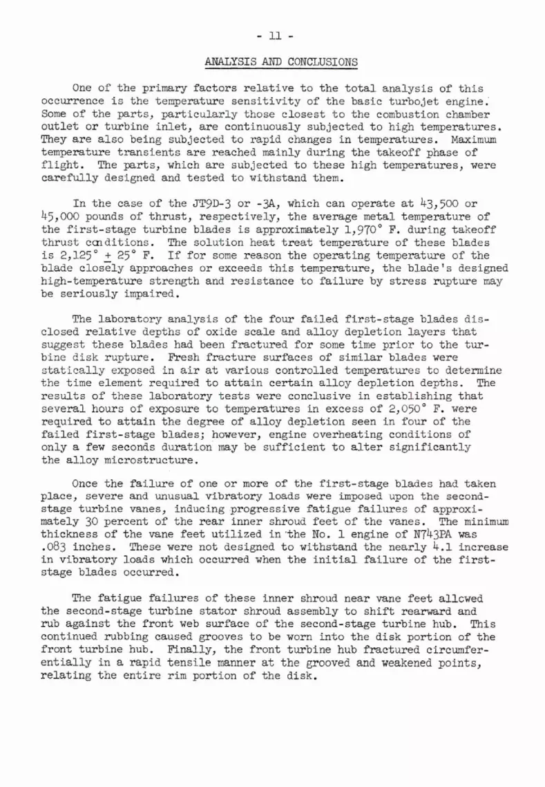
One of t h e primary f a c t o r s r e l a t i v e t o t h e t o t a l analys is of t h i s occurrence i s t h e temperature s e n s i t i v i t y of t h e basic tu rbo je t engine.' Some of t h e par ts , p a r t i c u l a r l y those c loses t t o t h e combustion chamber o u t l e t o r tu rb ine i n l e t , a r e continuously subjected t o high temperatures They a r e a l s o being subjected t o rapid changes i n temperatures. Maximum temperature t r a n s i e n t s a r e reached mainly during t h e takeoff phase of f l i g h t . The pa r t s , which a r e subjected t o these high temperatures, were c a r e f u l l y designed and t e s t e d t o withstand them.
I n t h e case of t h e JTgD-3 o r -3, which can operate at 43,500 o r 45,000 pounds of t h r u s t , respectively, t h e average metal temperature of t h e f i r s t - s t a g e turbine blades i s approximately 1,970' F. during takeoff t h r u s t condit ions. The solut ion heat t r e a t temperature of these blades i s 2 , 1 2 5 + 2 5 F. I f f o r some reason t h e operat ing temperature of t h e blade c lose ly approaches o r exceeds t h i s temperature, t h e b lade ' s designed high-temperature s t rength and res i s t ance t o f a i l u r e by s t r e s s rupture may be se r ious ly impaired.
The labora tory analys is of t h e four f a i l e d f i r s t - s t a g e blades d i s - closed r e l a t i v e depths of oxide sca le and a l l o y deplet ion l a y e r s t h a t suggest these blades had been f rac tured f o r some time p r i o r t o t h e tur- bine d i sk rupture. Fresh f r a c t u r e surfaces of similar blades were s t a t i c a l l y exposed i n air at various control led temperatures t o determine t h e time element required t o a t t a i n c e r t a i n a l l o y deplet ion depths. The r e s u l t s of these labora tory t e s t s were conclusive i n es tab l i sh ing t h a t severa l hours of exposure t o temperatures in excess of 2,050' F. were required t o a t t a i n t h e degree of a l l o y deple t ion seen i n four of t h e f a i l e d f i r s t - s t a g e blades; however, engine overheating condit ions of only a few seconds durat ion may be s u f f i c i e n t t o a l t e r s i g n i f i c a n t l y the a l l o y microstructure.
Once t h e f a i l u r e of one o r more of the f i r s t - s t a g e blades had taken place, severe and unusual v ibra tory loads were imposed, upon t h e second- stage tu rb ine vanes, inducing progressive f a t i g u e f a i l u r e s of approxi- mately 30 percent of t h e r e a r inner shroud f e e t of t h e vanes. The minimum thickness of t h e vane f e e t u t i l i z e d i n ' t h e No. 1 engine of N743~A was .083 inches. These were not designed t o withstand t h e nearly 4 .1 increase i n v ib ra to ry loads which occurred when t h e i n i t i a l f a i l u r e of t h e f i r s t - s tage blades occurred.
The f a t i g u e f a i l u r e s of these inner shroud near vane f e e t allowed t h e second-stage tu rb ine s t a t o r shroud assembly t o s h i f t rearward and rub aga ins t t h e f r o n t web surface of t h e second-stage turbine hub. This continued rubbing caused grooves t o be worn i n t o t h e d i sk por t ion of t h e f r o n t turbine hub. Finally, t h e f r o n t tu rb ine hub f rac tured circumfer- e n t i a l l y i n a rapid t e n s i l e manner a t t h e grooved and weakened points , r e l a t i n g t h e e n t i r e r i m port ion of t h e disk.

In reviewing the operating history of the engine (SIN 6622~4), it becomes quite apparent that the laboratory findings relative to the pre-existing failures of at least four first-stage turbine blades is quite accurate.
Flight discrepancies reported on three separate occasions, indi- cating "poor throttle alignment" and, in one case, the No. lthrottle's being as much as 3 inches forward of other engines, reflected an appar- ent deterioration in engine performance. However, due to the chronic throttle alignment problems which are, according to the carrier, normall; encountered on the 747, as well as on other airplanes, this symptom was improperly diagnosed. The corrective action, consisting of rig check and adjustment of No. 2 thrust lever as well as swapping of No. 1 and No. 2 EF'R indicators, was however, responsive to the flight discrepancy as reported. The flight engineer had obviously attempted to describe the cause of the problem by stating "No. 1 and No. 2 throttles very far out of rig," rather than to describe accurately the symptoms which possibly would have required more intense troubleshooting on the ground.
A subsequent flight discrepancy reported on September IT, 1 day prior to the final failure, showed the No. 1 engine to be EGT limited on takeoff and climb. It was necessary to operate No. 1 engine at .09 EPR less than others to maintain an EGT of 775O F. Other engines on the airplane, during this phase of the flight, operated at 1.31 EPR, maintaining 766' F. A thrust reduction of -09 EPR at takeoff under standard conditions can be translated into approximately 6,500 pounds of thrust and 105" F. of EGT.
Here again, it is apparent that the corrective action in replacing the EPR transmitter was based upon an erroneous assumption that an instrument error was responsible for the low-thrust indication on the No. 1 engine. An effective troubleshooting program at this point would, in all probability, have determined the reason for the high EGT and low EPR. Although tailpipe inspections were performed after every flight, the evidence of an incipient failure was either not present or was not recognized.
The inputs into the computerized JT9D condition monitoring program for this engine from September 10 through 16 likewise reflected adverse changes in trends of vital operating parameters which were indicative of the possibility of a serious engine malfunction. These data points showed a progressive increase of EGT and fuel flow while N2 showed a progressive decrease over the same period of time. Due to the time lag between data acquisition, the computer printout, and analysis of this above data, the trends shown were not available until after the failure had occurred and, consequently, could not be used effectively in diagnosing the problem.
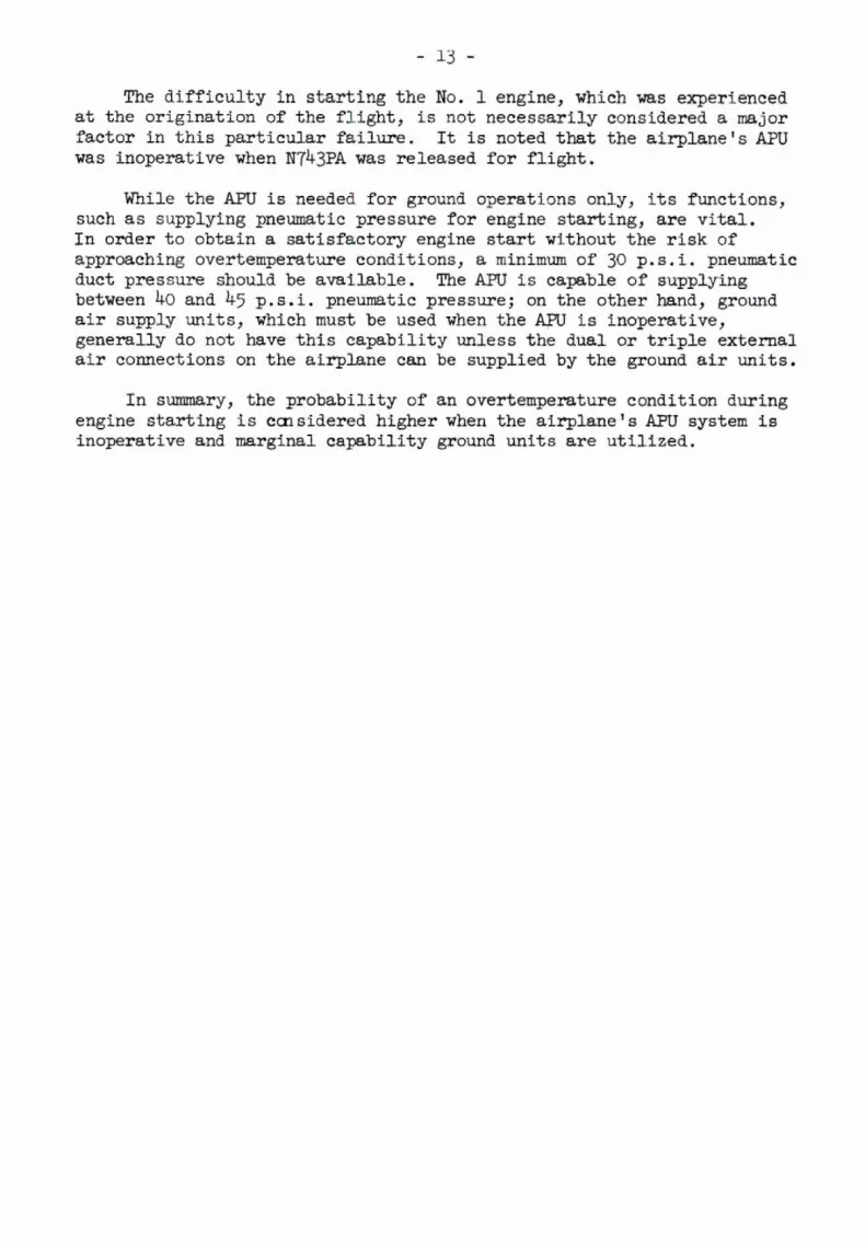
The difficulty in starting the No. 1 engine, which was experienced at the origination of the flight, is not necessarily considered a major factor in this particular failure. It is noted that the airplane's APU was inoperative when N T ~ ~ P A was released for flight.
While the APU is needed for ground operations only, its functions, such as supplying pneumatic pressure for engine starting, are vital. In order to obtain a satisfactory engine start without the risk of approaching overtemperature conditions, a minimum of 30 p.s.i. pneumatic duct pressure should be available. The APU is capable of supplying between 40 and 45 p. s. i. pneumatic pressure; on the other hand, ground air supply units, which must be used when the APU is inoperative, generally do not have this capability unless the dual or triple external air connections on the airplane can be supplied by the ground air units.
In summary, the probability of an overtemperature condition during engine starting is considered higher when the airplane's APU system is inoperative and marginal capability ground units are utilized.

EFFECTS OF ENGINE STRUCTURAL FAILURE UPON THE AIRCRAFT
I n view of t h e compounded and d i r e c t e f f e c t s of a turbine f a i l u r e such as t h i s upon the continued safe f l i g h t of t h e airplane, t h e Safe ty Board f i n d s a need f o r reviewing t h i s aspect of the occurrence.
A s indicated by t h e crew of Fl ight 14, t h e na tu ra l and most immediate concern was t h e control of the f i r e i n f l i g h t and the safe re turn t o t h e a i r p o r t . Although t h e extinguishing agent was discharged by t h e crew, t h e agen t ' s e f fec t iveness i n control l ing o r extinguishing t h e f i r e seems qu i t e questionable. The most seriousimpairment of t h e system's ef fec t iveness occurred when t h e engine and pylon enclosures were penetrated during t h e turbine f a i l u r e , allowing a subs tan t i a l por- t i o n of t h e extinguishing agent t o escape i n t o t h e atmosphere. The f i r e ins ide of t h e pylon continued with such i n t e n s i t y t h a t both of t h e agent containers became physica l ly detached from t h e i r mountings and f e l l t o t h e bottom of t h e pylon s t ructure . This f a c t alone can leave l i t t l e doubt t h a t t h e f i r e continued f o r some time a f t e r t h e agent w a s discharged. It i s t h e opinion of t h e Board t h a t t h e f i r e terminated only when the sources of flammable mater ia ls became exhausted. I n t h i s respect , termination of f u e l supply was e f f e c t i v e since t h e f u e l l i n e w a s severed downstream of t h e f i r e w a l l shutoff valve which was closed by t h e timely ac t ion of t h e f l ightcrew. Flame propagation over both t h e t o p and bottom of t h e wing was such t h a t t h e r e was danger of ign i t ion of t h e f u e l which was leaking out of the punctured f u e l tank access p l a t e s .
I n t h e case of the No. 1 hydraulic system supply, l i n e severance occurred between the rese rvo i r and t h e shutoff valve, allowing deple t ion and leakage i n t o the f i r e a r e a of t h e t o t a l f l u i d supply f o r t h e No. 1 system. Fluid supply was then no longer ava i l ab le t o the No. 1 system's a i r -d r iven hydraulic pump. This pump normally provides a backup pressure source f o r t h e No. 1 system i n case engine pump pressure is e i t h e r l o s t o r demands upon it become excessive. Of f u r t h e r s igni f icance i s t h e puncture of the l e f t wing pneumatic duct which supplies pressure f o r a l l of t h e pneumatically operated un i t s i n t h e l e f t wing. Consequently, t h e operat ion of t h e No. 2 a i r -dr iven hydraulic pump would have been impaired by g r e a t l y reduced pneumatic pressure, i f such operat ion became a requirement.
The l o s s of No. l h y d r a u l i c system, requir ing a l t e r n a t e extension of t h e body landing gear and leading edge f l aps , caused a delay i n re turning t o San Francisco Airpor t and placed an add i t iona l burden upon t h e f l ightcrew during t h e a l ready ex i s t ing f i r e emergency. Although other, l e s s v i t a l systems were e i t h e r f u l l y o r p a r t i a l l y deprived of normal hydraulic and/or pneumatic pressure, the re appeared t o be no f u r t h e r adverse e f f e c t s upon t h e operat ion of t h e a i rp lane .

CONCLUSIONS
From the investigation of this incident, the Safety Board concludes the following:
There were no material deficiencies of the HPT module which either caused or contributed to the failure.
The engine had been allowed to attain operating tempera- tures which were sufficiently in excess of design limits to initiate stress rupture failures of first-stage turbine blades.
The engine normally operates at relatively high turbine temperatures and therefore requires most precise monitoring of all vital operating parameters and effective analysis of any confirmed deviations from normal parameters.
Vibratory stresses in excess of four times their normal level were imposed upon the second-stage vane feet after stress rupture of first-stage turbine blades.
Multiple failures of second-stage vane feet and resultant rearward shift o f the nozzle inner support caused rubbing of the support against the second-stage turbine disk until separation of the disk rim occurred.
Deterioration of vital engine operating parameters was evident on both the narrative portion of the flight log and the computerized engine condition monitor log.
Maintenance actions taken by the carrier in attempting to correct the in-flight discrepancies as reported on the No. 1 engine were not responsive to the problem that existed.
While the computerized engine monitor log used by the carrier was effective in accurately identifying the progressive decrease of N2 and increase in EGT and fuel flow, the data was not available for use in time to effect corrective action prior to severe engine failure.
The fire which resulted, from the turbine failure was termi- nated by the immediate response of the flightcrew in success- fully shutting off fuel supply to the No. 1 pylon. The fire extinguishing agent appeared to have little effect in com- bating the fire.
The results of the primary failure affected other systems critical to the landing phase and compounded the already existing emergency by placing an additional burden upon the flightcrew.
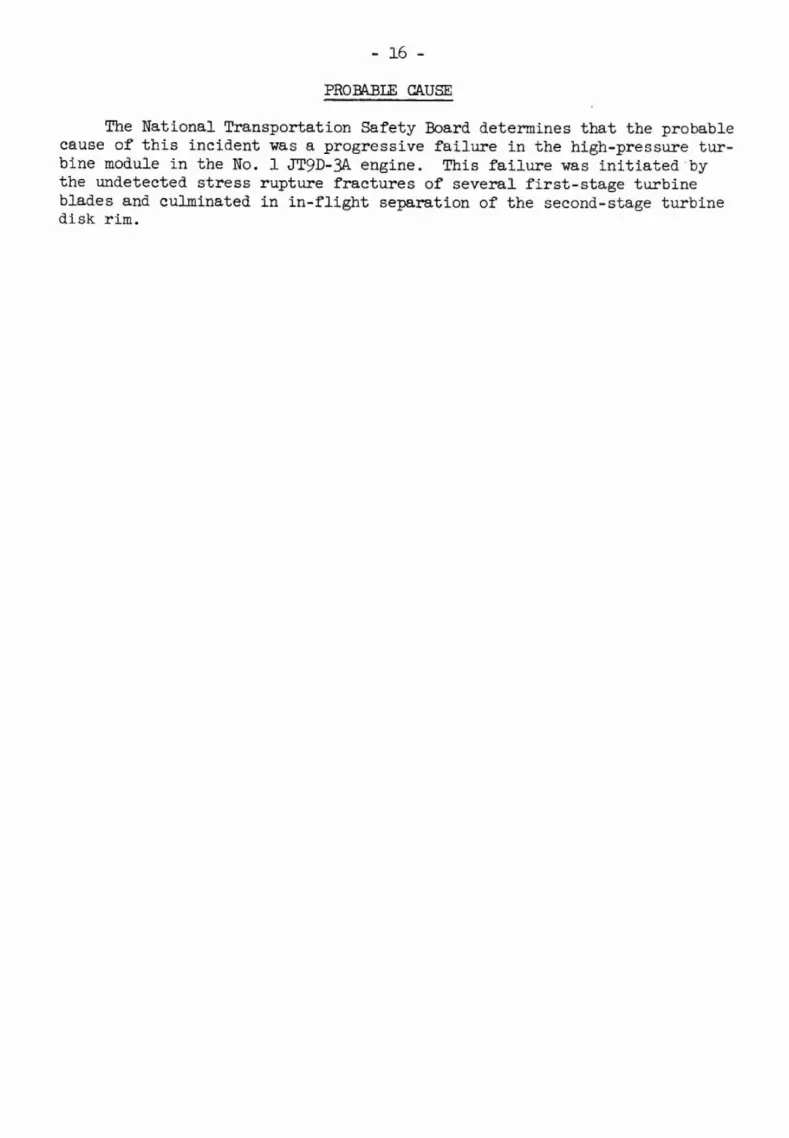
PROBABLE CAUSE
The National Transportation Safety Board determines t h a t the probable cause of t h i s incident was a progressive f a i l u r e i n t h e high-pressure tu r - bine module i n the No. 1 JTgD-3A. engine. This f a i l u r e was i n i t i a t e d b y t h e undetected s t r e s s rupture f r a c t u r e s of severa l f i r s t - s t a g e turbine blades and culminated i n i n - f l i g h t separat ion of t h e second-stage turbine d isk r i m .

BECOMMEMDATIONS AMD CORRECTIVE ACTION
On September 25, 1970, the Board sent the following letter to the Administrator of the Federal Aviation Administration:
'The National Transportation Safety Board is now investigating the JTgD-3 engine failure and in-flight fire involving American Airlines, Boeing 747, N743~A, which occurred during takeoff from the San Francisco International Airport on September 18, 1970. A failure occurred in the No. 1 engine 13 seconds after lift-off, followed by a fire warning. The flight returned to the airport after shutdown of the engine and extinguishing of the engine fire.
'During the return to the airport, the flightcrew experienced difficulty in extending the landing gear and the wing flaps after parts of the failed engine severed the hydraulic and pneumatic systems' supply lines. The captain elected to "go around" and extended the landing gear by the alternate system. The aircraft made a successful landing, and there were no injuries to the 15 cremembers or the 127 passengers.
"Our preliminary investigation of the engine failure revealed that a separation occurred to the rim portion of the second-stage turbine disk. It has been confirmed that failures of at least four of seven first-stage turbine blades contributed to the fracture of numerous second-stage turbine vane feet. As a result of the cumulative effect of the broken vane feet, an aft deflection of the nozzle support resulted, causing interference with and rubbing of the second-stage turbine disk. Progressive weakening of the disk rim area resulted in the in-flight failure of the rim. We have also confirmed that although failure mode of this second-stage turbine disk rim was similar to that of the Air France JT9D-3A.engine failure of August 17, 1970, the failure mechanism was entirely different.
'As a result of our investigation and meeting with Pratt & Whitney engineering staff personnel and your Eastern Region Flight Standards personnel, immediate inspection action was initiated. This was considered fully responsive to the immediate needs of this situation. The Safety Board commends the Administrator's formalizing this corrective action in the form of your engineering alerts of September 19 and 23, 1970.
'In view of the potentially catastrophic results of the failure such as experienced by American Airlines, the Board remains concerned about this matter in the longer range sense and would urge the Administrator to initiate further expeditious actions in order to preclude recurrence of similar failures. Accordingly, the Board offers the following observations.

"It is genera l ly recognized t h a t t h e JT9D engine is normally operat ing near c r i t i c a l turbine temperature conditions. This i s p a r t i c u l a r l y t r u e when operating i n high ambient temperatures. Several JT9D engines have recen t ly been removed from service and returned t o W a t t & Whitney f o r overhaul, because of f a i l e d f i r s t - s t age tu rb ine blades as wel l as broken second-stage vane f e e t . There i s evidence t h a t these f a i l u r e s had occurred as t h e r e s u l t of operat ion at higher-than-desirable temperatures.
' I n t h e case of t h e most recent American A i r l i n e s turbine d i sk r i m separat ion, t h e r e was evidence t h a t at l e a s t s i x f i r s t - s tage tu rb ine blades had sustained varying degrees of f r a c t u r e s some time p r i o r t o t h e f i n a l f a i l u r e . Our technical s t a f f f inds it most d i f f i c u l t t o reconci le t h e f a c t t h a t t h e airborne v ib ra t ion monitoring equipment i n s t a l l e d i n t h e a i r c r a f t w a s e i t h e r inadequate o r was not e f f e c t i v e l y u t i l i z e d i n detec t ing t h i s condition. We a l s o f e e l t h a t o the r engine instrumentation, namely: f u e l flow, engine pressure r a t i o , and exhaust gas temperature should have been capable of c o l l e c t i v e l y r e f l e c t i n g appropriate changes i n t h e engine ' s operat ing parameters, i f such instrumentation were properly ca l ib ra ted and t h e respect ive readings were recorded and c lose ly analyzed.
' I n t h i s area , we recommend t h e following be ccnsidered.
1. I n i t i a t e appropriate a c t i o n toward t h e opera tors ' maintaining a program of current engine condit ion monitoring.
. Review engine instrumentation c a l i b r a t i o n and e x i s t i n g instrument to lerances t o assure t h e most precise engine operating parameter indica t ions .
"Further, it appears t h a t t h e r e l i a b i l i t y of t h e B e i n g 747 a u x i l i a r y power u n i t s i s somewhat marginal. When engine starts must be accomplished by the use of ground un i t s , pneumatic duct pressures'may o f ten be l e s s than what i s required, even when mult iple u n i t s a r e used. The r e s u l t is usual ly a start t h a t may involve a temperature r i s e , approaching t h e "recoverable stall" condition. Since exhaust gas temperature, although above normal under these condit ions of ten do not exceed t h e published limits, no record i s made of these occurrences, and t h e r e i s no poss ib le way t o determine how many times an engine hot sec t ion has been exposed t o higher-than-normal temperatures. The e f f e c t s of thermal t r a n s i e n t s a r e known t o be cumulative and conceivably a f f e c t turbine blade r e l i a b i l i t y .

"As another measure toward improving t h e service r e l i a b i l i t y of f i r s t - s t a g e turbine blades, it i s recommended t h a t appropriate ac t ion be i n i t i a t e d to :
Improve t h e r e l i a b i l i t y of a u x i l i a r y power u n i t s i n order t o reduce t h e p robab i l i ty of high thermal t r a n s i e n t s while s t a r t i n g engines with marginal air supply.
Ensure t h a t f l ightcrews maintain adequate pneumatic air duct pressure during engine starts.
Record any abnormal starts when a n approach t o a "recoverable s t a l l " i s experienced.
Es tabl ish precise l i m i t a t i o n s regarding t h e number of "approaches t o recoverable stall1' condit ions which may be t o l e r a t e d without cumulative adverse e f f e c t s upon tu rb ine blade durab i l i ty .
"The Safety Board i s aware t h a t the manufacturer has developed an improved type f i r s t - s t a g e turbine blade (vented) which i s expected t o provide improved cooling c h a r a c t e r i s t i c s and be more r e l i a b l e when operat ing at high temperatures.
"With respect t o the improved f i r s t - s t a g e turbine blades, t h e Safe ty Board recommends:
1. Incorporation of t h e "vented" f i r s t - s t a g e turbine blade i n a l l JTgD s e r i e s engines be t h e subject of regulatory a c t i o n as soon as s u f f i c i e n t production i s assured and service b u l l e t i n s and engineering o r d e r s a r e formulated by t h e manufacturer.
'Water in jec t ion i s present ly being used on an opt ional bas i s by individual operators. Since water in jec t ion allows u t i l i z a t i o n of 45,000 pounds of t h r u s t versus 43,500 pounds f o r take-off , some opera tors e l e c t t o use water only whentakeoff weight, runway lengths, and ambient temperature condit ions requ i re the maximum t h r u s t r a t i n g of 45,000 pounds. We bel ieve t h a t t h e use of water i n j e c t i o n on those a i r c r a f t so equipped would be benef ic ia l i n providing f o r turbine blade cooling. The Safe ty Board recognizes t h a t the re a r e some operators whose engines a r e not equipped f o r water in jec t ion at t h i s time, and t o require use of water in jec t ion f o r a l l takeoffs would cons t i tu te an economic burden. However, we bel ieve t h a t t h e benef i t s may j u s t i f y t h e expense.

was the
"The Board, therefore, recommends the following:
1. Consideration should be given to require the use ot water injection for all takeoffs regardless of takeoff thrust requirements.
2. Upon installation of the improved, "vented" turbine blades in all engines, the mandatory use of water injection could be rescinded.
"Technical details of the items outlined above have been discussed by members of both your Eastern and Western Region engineer- ing staffs and our Bureau of Aviation Safety investigative personnel. Our staff members will be available for further discussions, if desired. "
The Administrator's response was received on October 1, 1970.
"This is in reply to your letter of 25 September 1970 in which you offer recommendations as a result of your continuing investi- gation of the American Airlines engine failure at San Francisco on 18 September 1970.
"We appreciate receiving your commendation on the effectiveness of the immediate inspection actions initiated by the Federal Aviation Administration. As you know, appropriate actions had already been instituted for all items except the APU engine starting procedures and required use of water injection. These items are currently being evaluated.
"We will appreciate receiving any additional information developed from your continuing investigation of the American Airlines engine failure. I'
The Administrator's additional response dated December 23, 1970, as follows and indicated that further action had been taken to resolve problems :
'This will supplement our letter of 1 October 1970 regarding the investigation of the American Airlines Pratt & Whitney JT9D engine failure on 18 September 1970 at San Francisco.
"With regard to the Boeing 747 auxiliary power units, we find that, when the recent significant improvements have been accomplished, auxiliary power unit reliability is excellent. Boeing has updated their ground-starting information for both auxiliary power units

and ground-starting equipment i n a customer l e t t e r and i n t h e Boeing 7'47 I fec i l i t i e s Planning Document. Ins t ruct ions on engine s t a r t i n g have been reviewed with the c a r r i e r s a t severa l of our indust ry meetings. Adherence t o these procedures should prevent hot s t a r t s .
"The suggested mandatory use of water in jec t ion on a l l a i r c r a f t on takeoffs is not viewed a s a panacea t o the turbine blade-cracking problem as turbine blade problems have not been confined t o "dry" engines. The use of water o f f e r s a reduction in turbine gas i n l e t temperature only f o r moderate ambient temperature takeoff condit ions More e f f e c t i v e i n t h i s a r e a i s t h e procedure of using reduced t h r u s t l e v e l s where possible t o lower t h e turbine gas temperature.
"The incorporation of improved turbine blades is considered t o be t h e bes t so lut ion f o r improving t h e d u r a b i l i t y of these p a r t s . F i r s t - se rv ice use of "vented" turbine blades has begun. Limited q u a n t i t i e s of t h e new type "vented" turbine blades a r e ava i l ab le now and a r e being i n s t a l l e d as rapidly a s pract icable . The c a r r i e r s a r e est imating completion of r e t r o f i t on t h e i r f l e e t engines in the l a t t e r ha l f of 1971.
"Pra t t & Whitney A i r c r a f t i s developing f u r t h e r improved turbine blades of a more hea t - res i s t an t mater ia l . These should be ava i l ab le i n t h e near fu ture .
"It w a s agreed on 2 October 1970 t h a t borescope inspection frequency of t h e combustion sect ion would be es tabl ished at 100-hour i n t e r v a l s on engines with more than 500 hours o r more than 250 cycles. This, we believe, w i l l e f f e c t i v e l y de tec t blades cracked from heat d i s t r e s s before they progress t o fa i lu re . ' '

- 22 -
CORRECTIVE ACTION
Manufacturer
The manufacturer, i n conjunction with FAA advisor ies , has required:
1. Radioisotope inspection program f o r a l l JT9D engines-which is i n e f f e c t t o inspect f o r vane lug f a i l u r e s .
2. I n addit ion, t h e following inspections a r e required:
a. Inspect engine t a i l p i p e f o r metal a f t e r a r r i v a l at each s t a t ion ;
b. Monitor a i r c r a f t airborne v ib ra t ion monitoring equipment;
c . If t h e r e i s an indicat ion a s a r e s u l t of inspection ( a ) o r ( b ) above, borescope o r chamberscope t h e tu rb ine area. f o r f a i l e d f i r s t - s t a g e turbine blades; and
d. Continue borescope inspection of the turbine a r e a on a scheduled basis , but i n no case exceeding 200-hour in te rva l s .
I n add i t ion t o t h e above f i e l d inspections, t h e following engineering change improvements a r e e i t h e r being incorporated i n the JT9D engine now o r a r e scheduled f o r incorporation within the next severa l months:
1. Revised f i r s t - s t a g e turbine blade leading edge cooling plus improved blade material .
2 . Impingement-cooled f i r s t - s t a g e tu rb ine blade.
3. Second-stage vane r e a r inner lug th ickness increased from .083 t o .I10 inches.
4. Increased cooling flow t o second-stage inner s e a l and support, and second-stage vane lug.
5. Second-stage vane r e a r inner l u g th ickness increased from .I10 t o .145 inches.

AIR CARRIERS
American A i r l i n e s has revised t h e i r computerized engine condit ion . monitoring program t o provide f o r more rapid t r ansmi t t a l and review of data, g r e a t l y reducing the time l a g between data acqu i s i t ion and analys is of engine t rends .
Other c a r r i e r s have e lec ted t o u t i l i z e water in jec t ion f o r takeoff operations. Water in jec t ion used on a JTgD-3A engine operated a t 43,500 pounds of t h r u s t r e s u l t s i n a 100' F. reduction i n turbine i n l e t tempera- t u r e on an 80' F. day. The same -3 engine operated with water in jec t ion at 45,000 pounds of t h r u s t on an 80' F. day r e a l i z e s a 60' F. reduction i n turbine i n l e t temperatures. A l l JTgD engines may be equipped f o r water operation. Approximately 60 percent of t h e Boeing 747 a i r c r a f t i n service a r e equipped f o r water operation.

AIRCRAIT INFORMATION
The a i rp lane , a 747-121, ~ 7 4 3 ~ ~ manufacturer's s e r i a l No. 19638, i s owned by Pan American World Airways and was being leased t o and operated by American Ai r l ines .
~ 7 4 3 ~ ~ was delivered on March 3, 1970, and had accumulated a t o t a l of 1599:09 f l i g h t hours.
P r a t t & Whitney JT9D-3A. engines were i n s t a l l e d on t h e a i rp lane as follows :
POSITION SERIAL NUMBER
NO. 1 P-662274 NO. 2 P-662513 NO. 3 P-662455 NO. 4 P-662287
TOTAL TIME
New New New New
Airplane records disclosed t h a t required inspections and l i n e maintenance operat ions had been performed a t speci f ied time in te rva l s .
P r i o r recorded i n f l i g h t mechanical discrepancies r e l a t e d t o t h i s inc ident a r e out l ined under t h e inves t igat ion por t ion of t h i s report .

- 25 - SUPPLEMENTAL DATA
Crew Information
The pilot in command, Captain Walter P. Steiner, holds a valid FAA Airline Transport Pilot Certificate No. 22991, as well as a current first-class FAA medical certificate. Captain Steiner holds type ratings for Boeing 707, 720, and 747 aircraft. His total flying time as of September 18, 1970, was 32,850.00 hours, 197:57 hours of which were accumulated in the Boeing 747.
The first officer, Joseph H. Martin, holds a valid FAA Commercial Pilot ' s Certificate No. 1600395, with multiengine, single-engine, and instrument ratings as well as a current first-class medical certificate. His total flying time as of September 18, 1970, was 5400:00 hours, 52:05 hours of which were accumulated in the Boeing 747.
The flight engineer, Marion H. Kilborn, holds a valid FAA Flight Engineer's Certificate No. 1211416 for reciprocating as well as turbojet- powered aircraft. He also holds a valid FAA Airframe and Powerplant Mechanic ' s Certificate No. 469023 and a current FAA second-class medical certificate. His total flying time as of September 18, 1970, was lk,290:00 hours, 60:37 hours of which were accumulated in the Boeing 747-
BY THE NATIONAL TRANSPORTATION SAFETY BOARD:
/s/ JOHN H . REED cha i man
/s/ OSCAR M. LAUREL Member
/s/ LOUIS M. THAYER Member
/s/ ISABEL A . BURGESS Member
Francis H . McAdams, Member, did not participate in the adoption o f this report.
February 3 , 1971.

Intentionally Left Blank in Original Document

side o f Ho. 3 pylon - N743~A showing penetration damage nacelle s t a t i ons 1" a n d 208. (nuke: Deflection of
pneumatic duct and massive deformation of adjacent s t r uc tu r e ) .


surfaces).
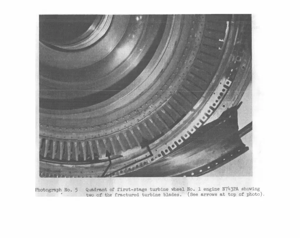
i'irat-stage turbi.rn, Ènco^ A,̂. 1 engine B T ~ & ~ P A showing wo of the fractured turbine blades. (see arrows at of photo),
