uhf tubes for communication and measuring equipment
TRANSCRIPT
PHILIPS
tubes for communication
and measuring equipment
PHILIPS ELECTRONIC TUBE DIVISION

PREFACE
The use of electronic apparatus operating at frequencies of
300 b1c/s and higher is steadily extending in a,, ever widen-
ing field of applications.
Radio and radar for communication and navigation are vital
elements of modern sea- and air-traffic and have greatly
increased its efficiency and safety. Public services, e.g.
police, fire, and medical departments largely depend on
mobile transmitting and receiving equipment for rapid and
effective action in emergencies. Balloon sondes have very
much helped to increase the accuracy of weather forecasting,
and at present, seamen, airmen and farmers all over the
world are relying upon these forecasts in making vital
decisions.
In all these applications the use of radio waves in the
decimeter and centimeter ranges is imperative for various
reasons, such as the overcrowding of longer wave ranges and
the small power supply available in mobile and portable
equipment.
To further add to the possibilities offered _by conventional
tubes with their relatively simple and reliable design and
their well-known circuit technique even at the wavelengths
required for use in the decimetric wave range, various
improvements were introduced in these tubes. The use of
centimetri c waves, however, made i t necessary to Bevel op
tube types which differ fundamentally from conventional
tubes both in design and construction.
In this bulletin our tube range for U.H.F. and S.H.F. waves
is described in detail. In addition, some applications of
tubes for the measurement of the noise factor at these
high frequencies are dealt with.
CONTENTS
page
INTRODUCTION 3
SUBMINIATURE U.H.F. TRIODE DC 70 5
Technical data 5
U.H.F. TRIODE EC 80 FOR GROUNDED-GRID CIRCUITS 7 Technical data $
H.F. section of a receiver for 300 to 400 Mc/s with the tubes EC 80, EC 80 and EC 81 11
U.H.F. OSCILLATOR TRIODE EC 81
Technical data
Simple U.H.F. oscillator with the EC 81
Oscillator with two tubes EC 81 in push-pull. for approx. 44G Mc/s
Simple oscillator with the EC 81 for use in balloon sondes at 395 Mc/s
14
15
19
21
22
U.H.F. DI5C-SEAL TRIODE EC 55 24 Technical data 24
Oscillator with the EC 55 operating between
730 and 1350 Mc/s 27
S.H.F. DISC-SEAL TRIODES EC 56 and EC 57 30 General data of the EC 56 and EC 57 (tentative data) 31 Technical data of the EC 56 (tentative data) 31 Technical data of the EC 57 (tentative data) 32
REFLEX-KLYSTRONS 2K25 and 723 A/B 37 Technical data of the 2K25 41 Technical data of the 723 A/B 42
STANDARD NOISE SOURCES K81A, K50A and K51A 43 Standard noise diode KS1A 47 Technical data 48
Gas discharge noise tubes 49 Tubes K50A and K51A 50 Technical data of the K50A 52 Technical data of the K51A 53
INTRODUCTION
The wavelengths for transmitting signals are steadily becoming
shorter, which is due to the following reasons:
(1) The longer wavebands, which are suitable for broadcasting and
telecommunication, are becoming more and more crowded.
(2) Apart from tkiis overcrowding, television and frequency-modula-
ted transmitters would occupy such wide bands with their broad
frequency spectrum that the available space in the medium and
long wavebands would scarcely be sufficient fora single trans-
mitter.
(3j In radar techuicues the use of extremely short wavelengths is
required with a view to tk~eir specific properties, sucks as the
possibility of producing narrow beams, tk.ereby being reflected
against small surfaces.
The r.ew problems which arose by the urge to apply ever decreasing
wavelengths were solved most satisfactorily by electronic engi-
neering, by means of improvements and new designs of electron tubes.
The highest frequency at which conventional tubes still operate
is determined by the following factors:
(1) Transit time effects. These effects become noticeable at fre-
quencies r.t which the duration of one cycle of tk~e alternating
voltage is no longer large compared with the time required by
an electron to travel from the cathode to the anode. At these
frequencies the mutual cor~ductance of the tube decreases, th•e
input circuit is heavily damped, and the signal-to-noise ratio
deteriorates.
(2) Undesired couplings caused by the capacitances, selfinductances
and mutual inductoucescf the electrodes and their connections.
(3) Losses that increase with the frequency, such asdi-electric los-
ses occurring in the glass envelope and dissipative losses pr~-
duced in the electrodes and their connections; at very short
wavelengths the latter losses predominate.
The most obvious method of reducing the influence of transit time
effects, consists in decreasing tk:e interelectrode spacings. Th`e
clearanr,e between the cathode and grid~is F~art.icularly important,
because in this space the velocity of the electrons is fairly
small, as c result of whick: the time required by the electrons to
cover this distance is relatively long. By mounting the cathode
and grid close to each other, the mutual conductance cf the tube
is increased. It is true that the capacitance between these
electrodes is also increcsed in this wny, but the total result is
ar. improvement of the tube properties as far as short-wave oper-
ation is concerned,
A reduction of undesired couplings and losses can be obtained by
shortening the connections betweer. the electrodes and their ter-
minals. In some of the types described in this Bulletin (the
EC 80, EC 81 and K 81 A) the electrode system is mounted on a
glass disc into which theccntact pins have been fused, which offers
the possibility cf minimising the distance between the electrodes
and the external circuit. The subminiature type DC 70 is provided
with connecting leads which are fused into the glass disc and can
be soldered directly to the wiring.
At frequencies exceeding approximately 500 Nc/s these tubes
become unsuitable, and recourse must be taken to disc-seal tri-
odes. In these tubes (the EC 55, EC 56 and EC 57) the concentric
electrode system has been replaced by flat, equidistant elec-
trodes. In this way extremely small interelectrode distances can
be obtained, such as are required for minimising the transit times.
The electrode connections are formed .by metcl discs which pro-
trude through the glass envelope into which they are fused, thus
ensuring very small self inductances. These discs are so arranged
that they can easily be included in coaxial or waveguide systems.
The EC 55 can be used on decimetric waves; the EC 56 and EC 57 are
suitable for wavelengths down to 7.5 cm (4000 iV.c/s).
By inger.ious]y taking advantage of the transit time effect, it has
been found possible to construct electron tubes which are suitable
for use on centrimetric and even on millim.etric waves, namely tubes
with velocity modulation. To this category belong, amongst others,
the klystrons; the so-called reflex-klystrons are designed for use
as oscillators. In this Bulletin two types are described, namely
the reflex-klystrons 2 k 25 and the 723 A/B, which are suitable
for use in the 3 cm band.
The noise figure. of a receiver gives very important information
regarding its quality cnd can be measured ever. at metric waves by
means of the vacuum diode K 81 P., used as a standard noise source.
For noise measurements c•n centrimetric waves it is, however, nec-
essar} to use gas-discharge tubes, such as the K 50 A and the
K 51 A, which have been designed for use on the 3 cm and on the
10 cm bands respectively.
4
SUBMINIATURE U.H.F. TRIODE DC 70
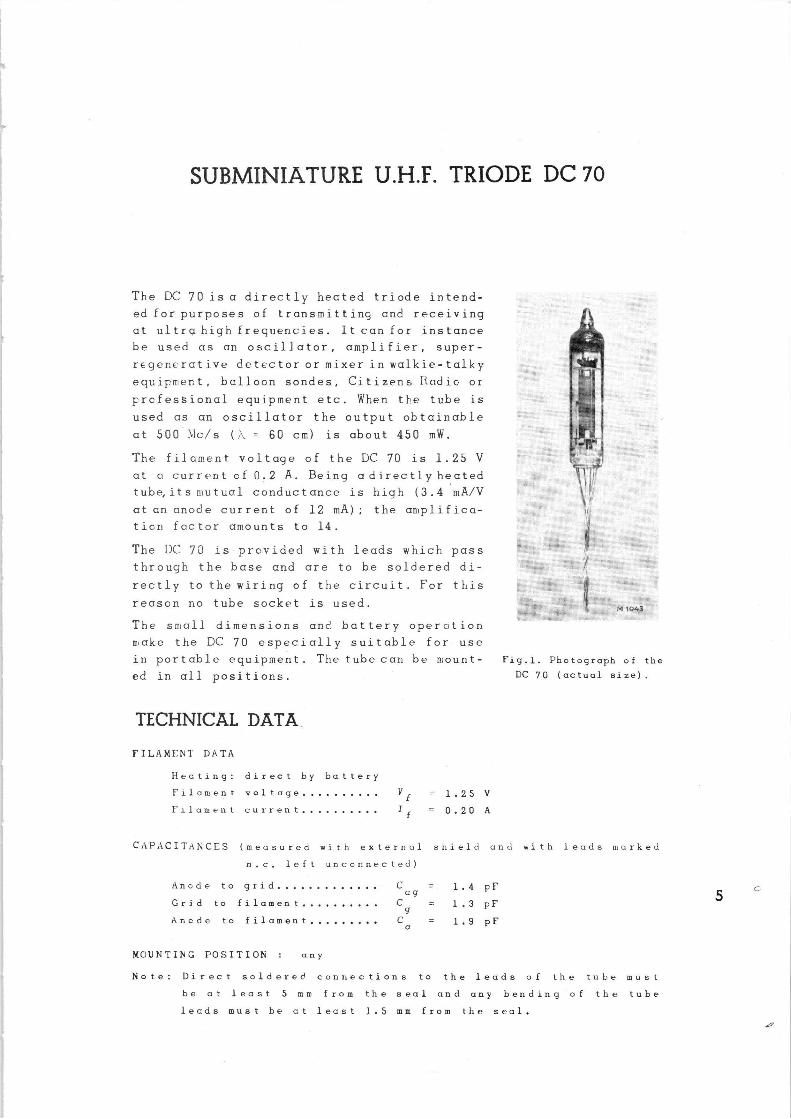
The DC 70 is a directly hected triode intend-
edfor purpcses of transmitting and receiving
at ultra high frequencies. It can for instance
be used as an oscillator, amplifier, super-
reger.erative detector or mixer in walkie-talky
equipment, balloon sondes, Citizens Radio or
prcfessional equipment etc. When the tube is
used as an oscillator the output obtainable
at 500 blc/s ( ~ = 60 cm) is about 450 mW.
The filament voltage of the DC 70 is 1.25 V
at r. current of 0.2 A. Being a directly heated
tube,itsrtutual conductance is high (3.4 mA/V
at an anode current of 12 mA) the amplifica-
ticn factor amounts to 14.
The DC 70 is provided with leads which pass
through the base and are to be soldered di-
rectly to the wiring of the circuit. For this
reason no tube socket is used.
~~
~~ to43
The small dimensions and battery operction
make the DC 70 especially suitable for use
in portable equipment. The tube can be mount- Fig.l. Photograph of the
ed in all positions.
TECHNICAL DATA,
FILAMF,NT' DATA
Hecting: direct by battery
Filament voltage
Filament current
V f = 1.25 V
If = 0.20 A
DC 70 (actual size).
Cr~PACITANCES (measured with external shield and with leads marked
n c, left unconnected)
Anode to grid
Grid to filament
Anode to filament
MOUNTING POSITION any
C ag
C 9
C a
= 1.4 pF
= 1.3 pF
1.9 pF
Note: Direct soldered cor,uections to the leads of the tube must
be at least 5 mm from the seal and any bending of the tube
lecds must be at least i.5 mm from the seal.
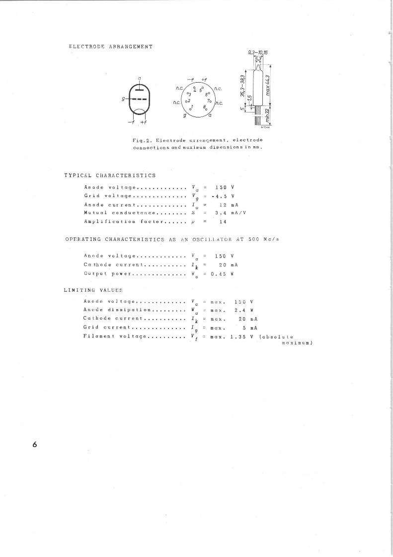
ELECTRODE ARRANGEMENT
—t +f
Fig.2. Electrode crroncement, electrode
connections and maxiu~um dimensions in mm.
TYPICAL CHARACTERISTICS
Anode voltage
Grid voltage
Va =
V = 9
150
-4.5
Anode current I = a 12
Mutual conductance S = 3.4
Amplification factor /1 = 14
V
V
mA
mA/V
OPERATING CHARACTERISTICS AS AN OSCILLATOR AT 500 Mc/s
Anode voltage Y = 15'0 V a
Ca thode current I F = 20 mA
Output power W = 0.45 W 0
LIMITING VALUES
Anode voltage
Anode dissipation
Cathode current
Grid current
Filament voltage
6
V a
W a
Ik
I 9 Vf
= max. 1s0 V
_ max. 2.4 W
max. 20 mA
= max. 5 mA
max. 1.35 V (absolute maximum)
U.H.F. TRIODE EC 80 FOR GROUNDED-GRID CIRCUITS
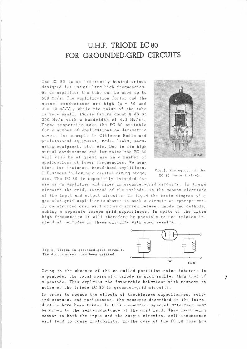
The EC 80 is an indirectly-heated triode
designed for t;se at ultra high frequer.,cies.
!As an amplifier the tube can be used up to
500 Nlc/s. The amplification foctor and the
mutual conductance are high (µ = 80 and
S = 12 mA/V), while the noise of the tube
is very small. (.Noise figure about 8 dB at
300 Alc/s with a bandwidth of 4.5 IVIc/s) .
These properties make the EC 80 suitable
for a number of applications on decimetric
waves, for example in Citizens Radio and
professional equiptent, radio links, meas-
uring equipment, etc. etc. Due to its high
mutual conductance and low noise the EC 80
will also be of great use in a number of
applications at lower frequencies. We men-
tion, for instcnce, brc~ud-band amplifiers, Fig.3. Photograph of the
I.F,stages following a crystal mixing stage, EC SO (actunl size).
etc. The EC 80 is especially intended for
use as an amplifier and mixer in grounded-grid circuits. In these
circuits the grid, instead of t'e cathode, is the common electrcde
of the input and output circuits. In fig.4 the basic diagram of a grcuncted-grid amplifier is shown; in si:ch a circuit un appropriate-
ly constructed grid will cct as a screen between anode and cathode,
making a separate screen grid superfluous. In spite of the ultra
high frequencies it will tt~erefcre be possible to use triodes in-
stead of pentodes in these circuits with good result.
Fig.4. Triode in grounded-grid circuit.
The d.c. sources have been omitted.
59755
Owing to the absence of the so-called partition noise inherent in
a pentode, the total noiseof a triode is much smaller than that of
a pentode. This explains the favourable behaviour with respect to
noise of the triode EC 80 in grounded-grid circuits.
In order to reduce the effects of troublesome capacitances, self-
inductances, and resistances, the measures described in tl-:e Intro-
duction have been taken. In this connection special attenticn must
be drawn to the self-inductance of the grid lead. This lead being
common to both the input and the output circuits, self-inductance
will tend to cause instability. In the case of the EC 80 this has
been cvcided by connecting the grid to four pins in parallel. If
the corresponding Becket contacts r.re connected to earth the self-
irductance of the grid lead and the tendency to instcbility will
be reduced to a minimum.
Whereas the gain of c tube at lower frequencies is only slightly
influenced by the input and output impedances of the tube, this
is no longer the case on decimetric waves. Due to the influence of
transit-time effects, resistcnce and self-inductance of the connect-
ing leads, etc. these input and output impedances are reduced in
such a way that their influence on the gain becomes very great,
and as a result, the control of cmplifying tubes wil,~ recuire
power. Therefore, instead of speakinc in terms of voltage amplifi-
cation, as normally is done at lower frequencies, we will have to
take into considercrtion the power gain. The definition of this
quantity is as follows:
Tne power gain of an amplifier is the optimum ratio between the
output power cnd the power avcilable at the input.
As the power gain i.s dependent upon the width of the frequency band
to be amplified, it is always necessary to mention the bandwidth
of the amplifier. As e first app-roximation the product of power
gaip and bandwidth has a constant value, so that the gain at any
bandwidth can be calculated if the gain at a certain bandwidth is
known.
The noise of a receiver or an amplifier is defined by tte noise
fioure F, representing the avcilable signal-to-noise power ratio
at tf:e input, divided by the signal-to-noise power ratio avr;ilable
at the output. Here both the noise and. the signal are expressed
as power, taken over the bandwidth of the amplifier, whilst the
noise properties of the input power source are expressed in terms
of a resistor at room temperature.
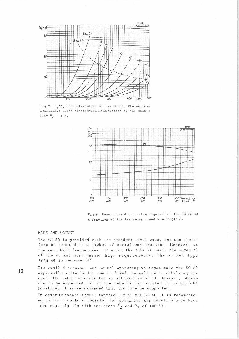
As may be seen from the operating data of the EC 80 mentioned under
Technical Data, the power gain G at c frequency of 300 Ivic/s and a
bandwidth of 4.5 Mc/s is about 15 dB and the noise figure F about
8 dB (see also fig.8).
TECHNICAL DATA HEATER DATA
Heating: indirect with a.c. or d.c. parallel supply
Heater voltage V f = 6.3 V
Heater current of = 0.48 A
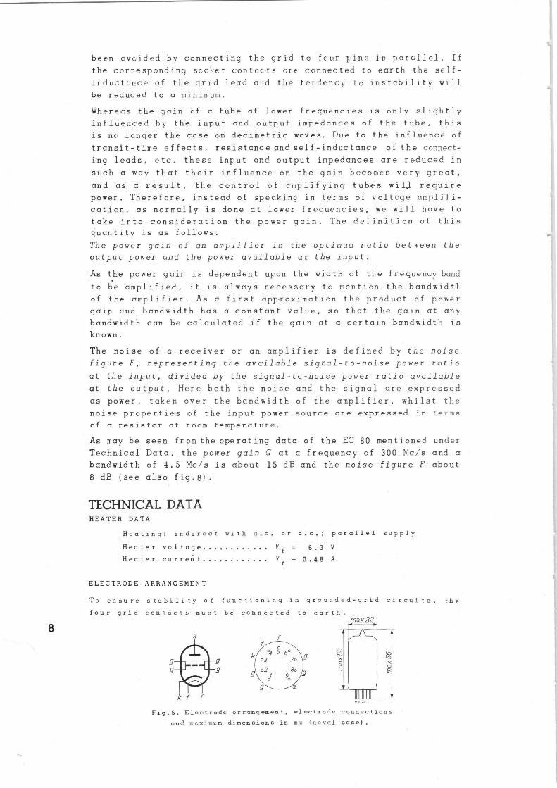
ELECTRODE ARRANGEMENT
To ensure stability of functioning in grounded-grid circuits, the
four grid contact;• must be connected to earth. max 22
f
k f f M 104fi
Fig.S. Electrode arrange¢ent, electrode connections
and moximcm dimensions in mm rnoval base).
f
9
9
~~ A li o~ k
m
CAPACITANCES (measured with the tube ccld and with yrouneed grid)
Input capacitance C(g+6)(k+f) - 5.1 pF 1 )
Input capacitance C = 9.3 pF 1)
(g+f+6)k
Capacitance between anode and cathode Cak ~ 0.075 pF
Capacitance between cnode anu cathode
plus heater Calk+f) < n.08 pF
OutF.ut capacitance Ca(q+6) = 3,4 pp 1)
Output capacitance Ca(g+f+6) - 3.4 pF 1)
Capacitance betweer. cathode and heater Ckf
< E pF
1) 6 denotes pin No,6
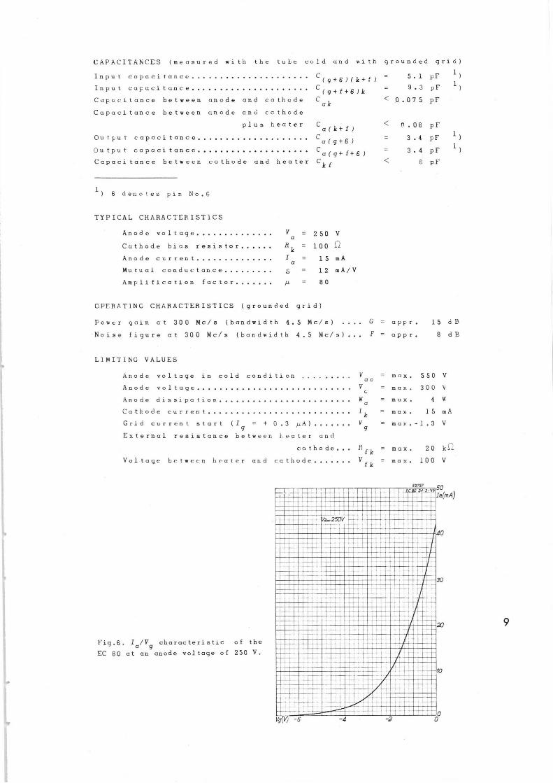
TYPICAL CHARACTERISTICS
Anode voltage V = 250 V a
Cathode bias resistor R k = 100
Anode current I = 15 mA a
Mutual conductance ,5 = 12 mA/V
Amplification factor µ = 80
OPERATING CHARACTERISTICS (grounded grid)
Power gain at 300 Mc/s (bandwidth 4.5 Mc/s) .. G = appr. 15 dB
Noise figure at 300 Mc/s (bandwidth 4.5 Mc/s)... F = appr. 8 dB
LIMITING VALUES
Anode voltage in cold condition . ~ ao
Rnode voltage V c
Anode dissipation W a
Cathode current Ik
Grid current start (I = + 0.3 µA) V 9 9
External resistance between heater and
cathode..
Voltage between heater and cathode
Fig.B. Ia/Vg characteristic of the
EC 80 at an anode voltage of 250 V.
Rfk
vfk
= max. 550 V
= max. 300 V
= max. 4 W
= max. 15 mA
= mar.-1.3 V
max. 20 k~.
max. 100 V
59757 50 Ia(mAJ N~~~~~~~~~~~~ ~~ ~
~~~~~~~~~~~N~~ ~~~~ a~~M~~~ , ~~ ~i~wMY~~~~N~
-
~~~ i ■ 25DV
ua~nn~ ~~ ~~e~i'■u~~~■~~u~~~i ~~~iu
~q~~N~~\r~~~~ ~~M ~~~~
I I' ~'~~~ ■B.
'u'wi ~.Niiiiiiiaii' :1 ~~~~~e~ ~ ~~t~~ ~ ~~~n ~~~.~~u ~~~~~ r ~~~i, ~~~~
~B
~~•
'~" _ —_
'~~
Vg V -6 -4 }
59958
Ia~mA~ ~fC 80 21-3- S9
30~ VgsOV ■~■i~ri
~ ■ ■~~ _ ~ -1.5V
~ ; L-av ~~~
i ~
20 ~~ ~ -4V ■ ~
~ ~~I~~c ■~f~~ ~ ~~/f~~~■7~■I~
1, ~~~~~~~~~~~ ~~~~ 1/ .'~i/~.i/~;~.
00 !00 200 300 400 Va V 500
Fio.7. Ia/Va characteristics of the EC 80. The maximum
admissible anode dissipation is indicated by the dashed
line Wa = q W.
BASE AND SCCKET
20
C, (db~
15
59959 ■ ■ BO f9-17-'
:■:0 ................■..._._.._... .:.. ■ ~ ■■ :i ~.: ..::::....... ■ ........:::~:_~~~ _ .~■::.:..:s. ~n:~::~„~:~~l~n~~~~~:~~;~n : iiii~~~li;= e ■■■■~ ::u■■■■■~::i■::■■■■■■■■ ~~~~:i '■::::~~~iiFi'■G _~~ :u:::i::::::ii~ii::::::~~~~__.....~~:::::::iii~::::::::ln ■■■■■i■■■■■■■■■ ■■■■■a ■ ■ ■■■■ ■■■■■■■■■■■■■■■■■ ■■■■■■u ■■■■■■■■■■ .::e::.:.:: : ....:.■ ............. .......:..... ... NI:111IN:~~~1~~1::::::::::::in::::: ~i::::l::::::::i~:~~
i~i~=.......: ::..................... ..... ~........ . . ........ ........................
■■N■~~~~~
■■■■■i■■■■■■■■■ ■ ■■■■ ■■■■■.■■■■~
100 150 200 250 300 350;FregJNk/sJ4Ll7 ?~ ~ 2Q7 150 120 100 86 a cm) 75
Fig.8. Power gain G and noise figure F of the EC 80 as
a function of the frequency f and wavelength ~.
The EC 80 is provided with the standard novel base, and can there-
fore be mounted in a socket of normal construction. However, at
the very high frequencies at which the tube is used, the material
of the socket must answer high requirements. The socket type
5908/46 is recommended.
Its small dimensions and normal operating voltages make tre EC 80
especially suitable for use in fixed, as well as in mobile equip-
ment. The tube ccn be mounted in all. positions; if, however, shocks
are to be expected, or if the tube is not mounted in an upright
position, it is recommended that the tube be supported.
In order to ensure stable functioning of the EC 80 it is recommend-
ed to use a cathode resistor for obtaining the negative crid bias
(see e.g. fig.l0a with resistors F.2 and Ry of 100 ~).

H.F. SECTION OF A RECEIVER FOR 300 to 400 Mc/s
WITH THE TUBES EC 80, EC 80 and EC 81
Figs 9 and 1,0 stow a photegrc;pl: ar,d the circuit diagram of the Y.F'.
section of o receiver using two tubes type EC 80, as an amplifier
cnd o r.!ixer respectively, in a grounded-grid circuit, and an EC 81
as alocal oscillator, The H.F. circuits are not normal L.C.circuits
as shown in the simplified circuit diagram of fig.l0a, but coaxial
line circuits (see figs 9 and l0 b) These have a short-circuiting
plunger which is adjustable for tuning purposes. The frequency
range of the receiver runs from 300 to 400 N!c/s (100 to 75 cr.:)
wk:ilst the bandwidth is 5 Iv1c/s. The power gain of the H.F,stage is
about 12 dB and the noise figure about 8 dB. The mixer is connect-
ed as a triode. It is however also possible to use it as a dicde
(grid connected to anode). In the circuit given, both the amplified
aericl signal and the locally generated voltage are applied to the
cathode.
Fig.9. H.F. section of a receiver for 300 to 400 Mc/s
(/~ = 100 to 75 cm) Mounted on the chassis are two tubes
EC 80 (H.F. amplifier and mixer), one tube EC 81 (local
oscillator) and two variable coaxial line circuits.
The aerial can be matched tc the input of the first EC 80 amplifying
tube by properly selecting the length of the connecting lead. The
self-inductance of this lead together with the input capacitance of
the tube will then give the right transformer ratio for maximum
input power.
C6
C7
L~
EC80
5
C3 C4
~~ ~~ C~
EC80
L
EC81 ~~ 'T'Cak
r (
.1. i ~~ I JC9kl
Cg
a
EC 80
.c
1
1 7'"
0
o+la
59760
I J
,,,,,,
EC 80
.c
~fu'v
p
o+Vb
EC 81
Cf_-_~I
I~
Lao 0
~ Rs --~'1N11L
Ca C3
Lao 9
4 6
Rn W C7
3
Lso (}
b
~ 004 r L~
Rfa ~UUlt~--
~~ Cd
L8o O
Lgo O
b b i
1 1 J
IF
59838
0 Vf
0
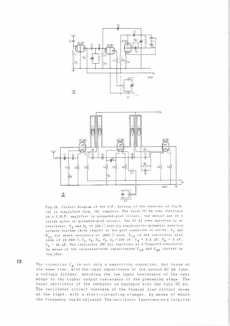
Fig.10. Circuit diagram of the H.F, section of the receiver of fig.9;
(a) in simplified form, (b) complete. The first EC 80 tube functions
as a U.H.F. amplifier in grounded-grid circuit, the second one as a
triode mixer in grounded-grid circuit. The EC 81 tube operates as au
oscillator. R2 and R~ of 100 ~~ each nze resistors for automatic positive
cathode voltage (with respect to the grid connected to earth). R S and
R11 are anode resistors of 1000 ~~ each. R 12 is the oscillator grid
leak of 10 000 ~. C1 , C2 , C3 . C~, Cy = 100 pF, C 4 = 5.6 pF, C 6 = 2 pF,
C8 = 56 pF. The oscillator (EC 81) functions as a Colpitts oscillator
by means of the interelectrode capacitances Cak and Cgk (dotted in
fig.l0a).
The capacitor C4 is not only a seporrtinc; capacitor, but forms at
the same time, with the input capacitance of the secor_~d EC 80 tube,
a voltage divider, matching the low input resistance of the next
stage to the higher output resistance of the preceding stage. The
local oscillator of the receiver is equipped with .the tube EC 81.
The oscillator circuit consists of the coaxial line circuit shown
at the right, with a short-circuiting plunger, by means of which
the frequency can be adjusted.. The oscillator functions as a Colpitts
oscillator with the aid of the interelectrode capacitances Cak and Cgk, as is indicated by the dotted capacitors in fig.l0a•The fre-quency range of the oscillator is about 30C-400 Me/s (100 to 75 cn).
The fregL~er.cy drift during the heating time cf the tube is only
50 000 c/s. Tre oscillator voltage is applied to the ccithode of
the mixer tube EC &0 via the capacitor C6 and is sufficiently high for obtrining optimum conversion gain. The heater and cathode leads
of the tubes have been provided witii I-i.F.chokes (L1 to L9). The
wire length of these chokes is about 23 cm. The anode leads have
been decoupled by feeding then through the inner conductor of the
transmission lines.
The receiver can be tuned by means of two knobs. Eac)-. knob adjusts
the plunger • of a coaxial line cirr.uit via a rack and pinion. The
tuning frequency can be indicated by a pointer movir'g along a cal-
ibrated scale, thus facilitating the operation of tl-_e receiver.
13
U.H.F. OSCILLATOR TRIODE EC 81
,r
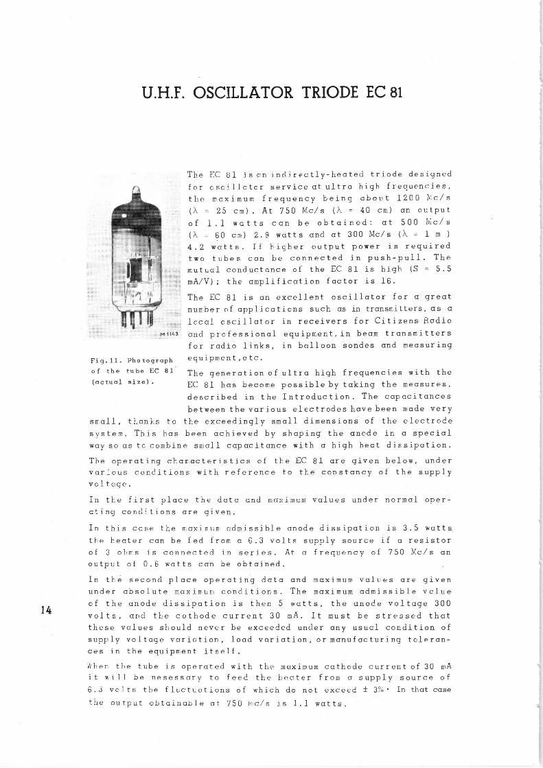
The EC 81 iscn indirectly-heated triode designed
for ascilloter service at ultra high frequencies,
the maximum frequency being about 1200 D'.c/s
(~ = 25 cm) At 750 Mc/s (~ = 40 cm) an output
of 1.1 watts can be obtained: at 500 Nic/s
(~ = 60 cm) 2.9 watts and at 300 Mc/s (~ = 1 m )
4.2 watts. If hicher output power is required
two tubes can be connected in push-pull. The
mutual conductance of the EC 81 is high (S = 5.5
mA/V); the amplification factor is 16.
The EC 81 is an excellent oscillator for a great
number of applir.aticns such as in transmitters, as a
local oscillator in receivers for Citizens Radio
Mntis and professional equipment, in beam transmitters
for radio links, in balloon sondes and measuring
Fig.11. Photograph equipment etc.
of the tube EC 81 The generation of ultra high frequencies with the (actual size) . EC 81 has become possible by taking the measures,
described in the Introduction. The capacitances
between the various electrodeshavebeen made very
small, thanks to the exceedingly small dimensions of the electrode
system. This has been achieved by shaping the anode in a special
way so as tc combine small capacitance with a high hect dissipation.
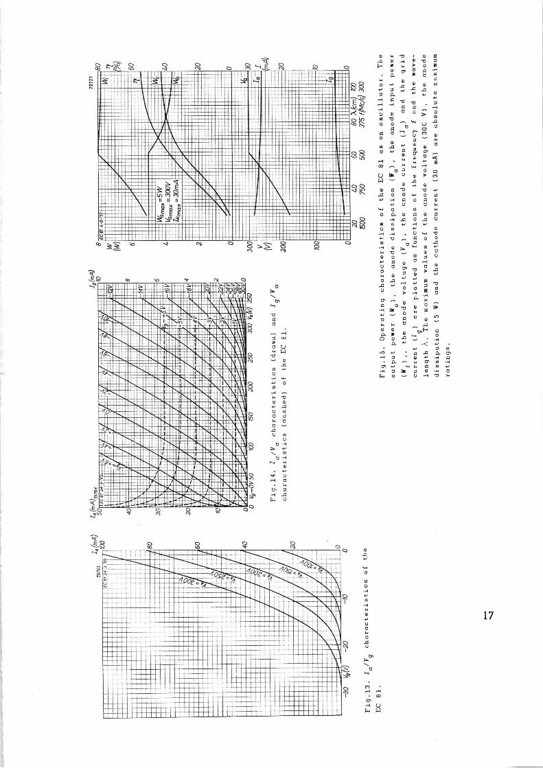
The operating characteristics of the EC 81 are given below, under
various conditions with reference to the constancy of the supply
vcltcige.
In the first place the date and maximum values under normal oper-
ating conditions are given.
In this case the maxirrum odmi.ssible anode dissipation is 3.5 watts,
the heater can be fed from a 6.3 volts supply source if a resistor
of 3 ohres is connected in series. At a frequency of 750 N.c/s an
output of 0.6 watts can be obtained.
In the second place operating data and maximum values are given
under absolute maxirt~ue~ conditions. The maximum admissible vclue
of the anode dissipation is then 5 watts, the anode voltage 30U
volts, and the cathode current 30 mA. It must be stressed that
these values should never be exceeded under any usual condition of
supply voltage variation, load variation, or manufacturing toleran-
ces in the equipment itself .
~9her the tube is operated with the maximum cathode current of 30 mA
it wi]1 be nesessary to feed the heater from a supply source of
6.s voJ is the fluctuations of which do not exceed ± 3°0' In that case
*he output obtainable at 75U iv~c/s is 1.1 watts.
TECHNICAL DATA HEATER DATA
Heating- indirect by a.c. or d.c. parallel supply
Heater voltage V f = 6.3 V 1)
Heater current I f = 0.2 A
CAPACITANCES {measured with tube cold)
Input capacitance C g 1.8 pF
Output capacitance Ca = 0.7 pF
Capacitance betweer. grid and anode Cag = 1.6 pF
Capacitance between grid and heater Cgf ~ 0.25 pF
Capacitance between cathode and heater Ckf 2.3 pF
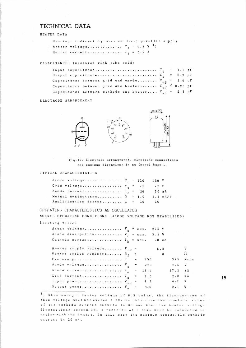
ELECTRODE RRRANGEMENT
k f f
max 22
• 1 i
a ~" ~m F
M 1144
Fig.12. Electrode arrangement, electrode connections
and maximum dimensicns in mm (naval base).
TYPICAL CHARACTERISTICS
Anode voltage V = 120 150 V a
Grid voltage V = -2 -2 V 9
Anode current I = 20 30 mA a Mutual conductance S = 4.0 5.5 mA/V
Amplification factor /1 = 16 16
OPERATING CHAPACTERI:~TICS AS OSCILLATOR
NORMAL OPERATING CONDITIONS (ANODE VOLTAGE NOT STABILISED)
Limiting values
Anode voltage V = max. 275 V a
Anode dissipation W = max. 3.5 W a Cathode current Ik = max. 20 mA
Heater supply voltage V bf Heater series resistor R f
Frequency f = 750
Anode voltage V 220 a
Anode current I = 18.6 a Grid current I = 1.5
9 Input power W. = 4.1
1. a
Output power W = p,6 0
6.3
3
V
ac
375 Mc/s
275 V
17.2 mA
2.8 mA
4.7 W
2.1 W
1) When using a heater voltaye of 6.3 volts, the fluctuations of
this voltage must not exceed ± 3%. In this case the absolute value
of the cathode current amounts to 30 mA. When the heater voltage
fluctuations exceed 3%, a resistor of 3 ohms must be connected in
seriesaith the heater. In this case the maximum admissible cathode
current is 20 mA.
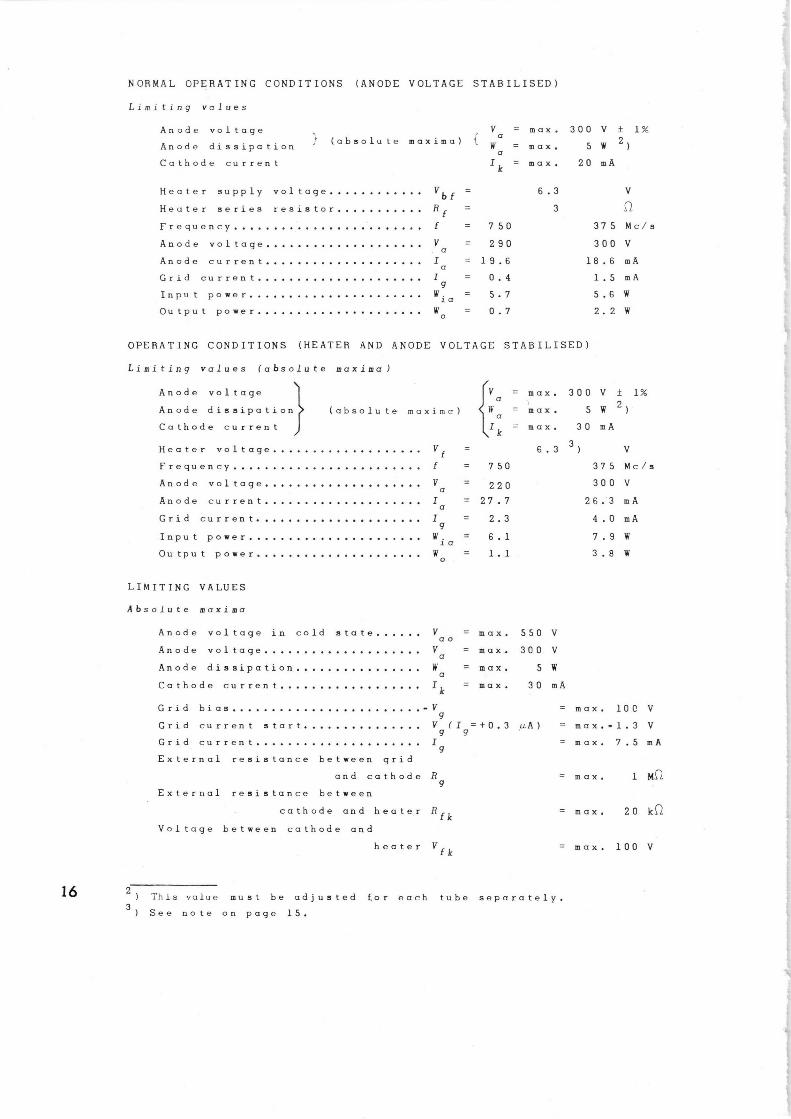
NORMAL OPERATING CONDITIONS (ANODE VOLTAGE STABILISED)
Limiting values
Anode voltage JJ V = max. 300 V f 1%
Anode dissipation ~ (absolute maxima) l Wa = max. 5 W 2) a
Cathode current Ik max. 20 mA
Heater supply voltage V bf = 6.3 V
Heater series resistor R f = 3
Frequency f = 750 375 Mc/s
Anode voltage V = 290 300 V a
Anode current I = 19.6 18.6 mA a
Grid current I = 0.4 1.5 mA 9
Input power Wia = 5.7 5.6 W
Output power W o = 0.7 2.2 W
OPERATING CONDITIONS (HEATER AND ANODE VOLTAGE STABILISED)
Limiting values (absolute maxima)
Anode voltage V = max. 300 V t 1% a
Anode dissipation (absolute maxims) iV' = max. 5 W 2) a
Cathode current Ik = max. 30 mA
Heater voltage Vf 6.3 3) V
Frequency f = 750 375 Mc/s
Anode voltage V = 220 300 V a
Anode current I = 27.7 26.3 mA a
Grid current I = 2.3 4.0 mA g
Input power W. = 6.1 7.9 W to
Output power W = 1.1 3.8 W 0
LIMITING VALUES
Absolute maxima
Anode voltage in cold state V = max. 550 V ao
Anode voltage V = max. 300 V a
Anode dissipation W = max, 5 W a
Cathode current Ik max. 30 mA
Grid bias -V = max, lOC V 4
Grid current start Vg(Ig=+0.3 µA) = max.-1.3 V
Grid current I = max. 7.5 mA g
16
External resistance between grid
and cathode R = max. g
External resistance between
cathode and heater Rfk = max. 20 k~
Voltage between cathode and
1 M~
heater Vfk = max. 100 V
2 ) This value must be adjusted f,or each tube separately.
3) See note on page 15.
0
-+-#-3' -
N O o ~,~ N O O
~g~i n u u
O b
s' ~~ ~
o,'--
m w v e v e .~ y ..~ o v a F ~ w > 0 6
b .a p, °' i o x
w v ~
~~ ~ °' " ~ M Y ~ Y x ~ —~ b a " Y ~
b
~x U a~ b ° > m° ~ `.n j O
O b W
O v
A b ~ U ~ N tl
... p w
a9 ..q •' Gi ~ b
O b u q 0, O~ _ ~O In ~ y y M ~C
OD .-. ~' w ,1 9
b 7 O p U ~ u d > r> W .~ ~ y .~
v ~ d c 'a .c o o w .+ .~ c o
d w O N o a d c
N $ .1 .G O
a u u •-~ u U m +' v ..i .,i U w b u ti G O O ~ ~
w ~
..y d , W
w v _. c b d o w p ~ Y h ~ b ~ ~
b b b~ 'b > ..0
H d b
~ yN y
U O O 6 c > .-1 ,~ b
b~ _ W %
R O ~ y O ~ •.1 ~ 'U N Ei u ~ O ~ N b w w C t:
a. s d ~ o,F a ~ v o
~ 0. " ~ w u b w
~ Y - c x a o+ a -- w rn m ..~
CT u •'1 M c N u •./ p ~ .~ m •.1 b
if
N
O
N■■NW■~■\~~\
. ~■■■1 ■■■■■NN '~N '~OfS2 ~ 1■ ■■■N■■ gyp£ ~~ ~~1
k'M■■■■N■■■■■■■■ q \~_ ■N■■■■■u■■■■■■n■■ ■■■.~_ IINiN111111111NN11111111A i■n■■■~N■iiN~■ii■NiiiiiiiiN .■N■NN■■■N■■■■■■■■N■■ I~IIIIIIIIIIIIIIIIIIIIIiI IIIi1111 11 1
~~0~, ,7
■ - 1_ _ ~
■ ~\
1=1■1■■■ ■■ ■N■■N■■■■■■■■■■■■■■■N ■ ■■ ■■■t \~■.i~~
iiNi~llilliiNIIII111N1lIIN~I~N ■ IfNlit!11C'N■:::1:::1:::1:::1::=II:C:11:::1~.■" ■■■■■■■■~\ ■■■N■■■■■■■■■■■■■■■■■_■_■■■■■■■■■■■■■■■■■■■■■■■■Ni\
INIIIIIIIIIIIN 1111 N11 N'■111:'1' ■ 11=IIICI iiiiliiiiiiiiiiiiiiiii iiiiiilliiiiiiilliiiiiiiiii ■■■■■■■■■■■ ■■■■■■■N■ie■■■■■■~■■■■■u■■■ ■■■■■■■■
ESL ~ e .' .
O
,~
W s u
N U .., Y N
Y U b
0 .~ ua
~ tlti
~ . •~ U W W
.,~
cuzzent
18
~ ~o — -.~~ ~_ tia---~6
1 ~' 3
3°~ 0 X01
~~ 1 ~ r 1~ ~!~
1 ■
~ ~
1 1 ~ _ ~__
~~ 1 ~
~m
ox=
~~
'
Van
px =
27
5V
Ik
max=
20m
<
~T
~9 1~ ~n
b ■
V ___
3 V
~D ~
O
.y ~ O N
_3 tl
11~11~~1~
~;
-. ~ ~ _. . ~ '~°
i O~
~
~~~~
_
~~
~'
li~l=. ~i
~~~:~\II ̀ : ~~~~ ~~N =~ ■ 1~ i i i ~i ~~
i~~i~ ~~~~ ~ .
: \ ~ i
~ ~.~.1 ~~~~ ~~~
,~~ 1
. . ,.~~I~ bv
11~~
1 11 ~~
k
n M
g
~O S
~O S~
V N O ~` O
N OO
~~ ~F ~~—~,
~$
o~ ~~
pN 8
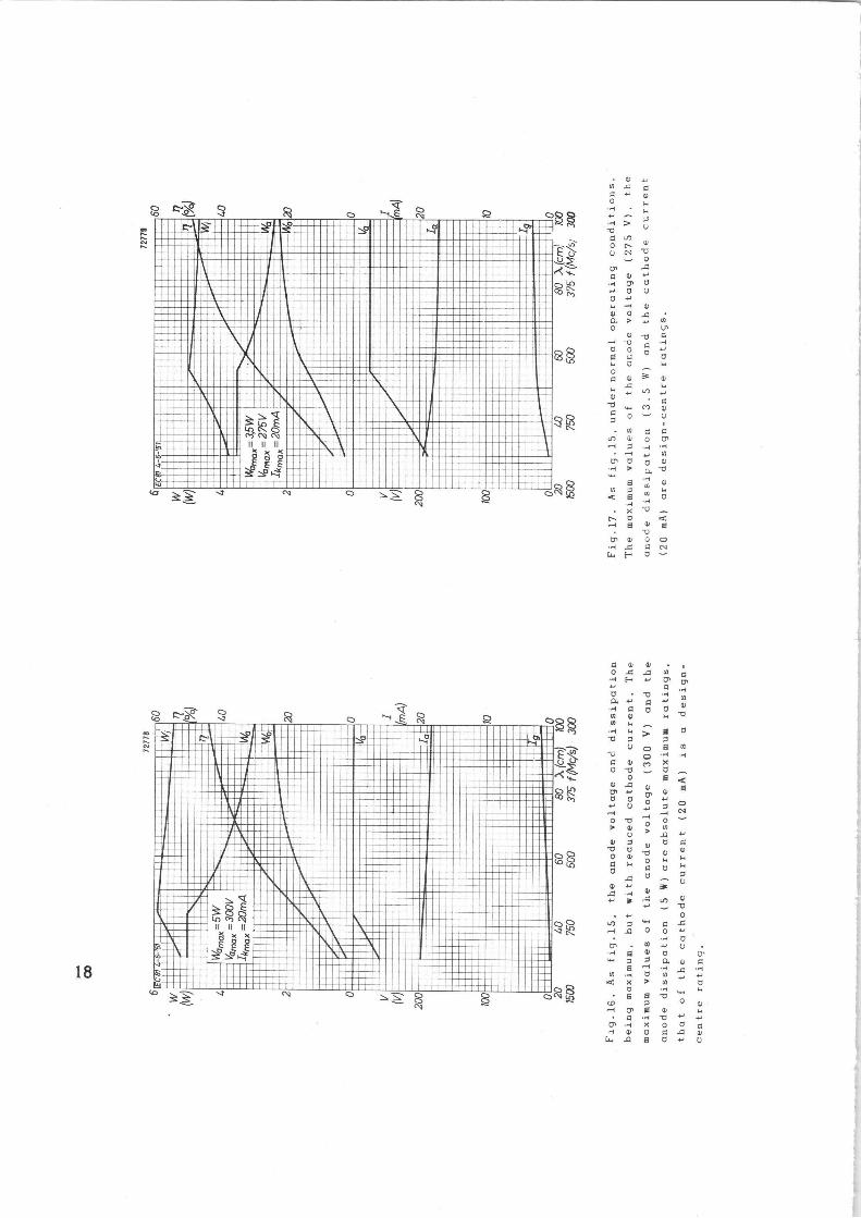
Fig.16. As
. v~, x q +' 0 N n •a 'U
Cf ~ O [~ U v
0' q ~ •a ~ ++ 0 O ~' w ~ y d O .0 a > ,~ 0
0 6 0 C ~.
b q a
.i
.~ W
N a ~ e
.a X
t~ d ~ 8
O~ d •H A W F
d A
the anode
values of
cathode current
v q d
3
[~
dissipation
v 'O O q d
b q d
the anode voltage (300
~. 'i A O
p+ tll w U ••~ g d d U~ ~«+ a a a v q ti .H A .a
d m a+ Y ~ m d
N
mA) are design-centre ratings.
O N
(5 W) are absolute maximum ratings,
d
a
6 _ a O y
T B N w
•.~ K O d q 01 O q .0 y
A 8 d ++ U
th
BASE AND SOCKET
The EC 81 isprevided with a standard noval base. OwinS to tle very
high frequencies at which the tLbe can be used the material of the
socket must cnswer very high requirements. 1'he tube socket type
5908/46 is reccmmended. In order to diminis}i as far as possible the
capacitances between tt_e various electrode leads, it is recon;menc'ed
to remove the unused contacts of the socl~et. At the highest fre-
quencies the ,tube must be used without socket. The small dimensions
and the normal operating voltages makett:e EC 81 especially snit able
for Use in fixed and mobile equipment. The tube can be mounted in
all positions; if, however, shocks have to be exl:ected, or if the
tube is not used in an upright position, it is recommended that
the tube be supported.
In order to obtain sufficient cooling, the tube must be installed
in such a way that air can circulate freely around it. This is of
special importance if the tube is used with its r;uximum admissible
anode dissipation.
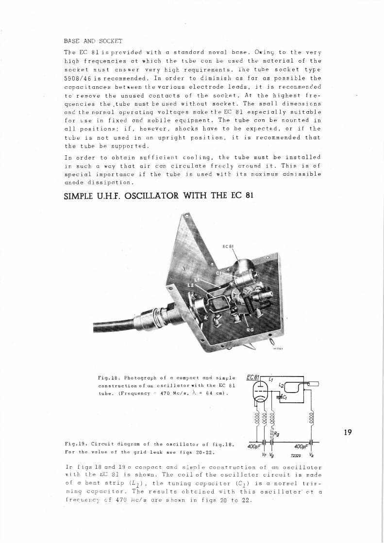
SIMPLE U.H_F. OSCILLATOR WITH THE EC 81
Fig.18. Photograph of a compact and simple
constructior.of an oscillatorpith the EC 81
tube. (Frequency = 470 Mc/s, ~ = 64 cm).
Fig.19. Circuit diagram of the oscillator of fig.18. For the value of the grid leak see figs 20-22.
EC81
Rg
400pf H ~ 400pF
Vt l/g 72329 ~a
In figs 18 ar.d 19 a compact and simple construction of an oscillator
with the t;C 31 is shown. The coil of the oscillator circuit is made
of a bent strip (L1) tre tuning capacitor (C1) is a normal trin-
ming capacitor. The results obtcined with this oscillator' rt a
f reouere~~ c f 47U i~tc/ s are s hcwn in f igs 20 to 22.
a33
■■ ~~~N ~ qp. r ~Mp ~ ~h~n~
■~~YN
.~; wo
■ w ■ I~~Y~~Y` ~~NM
r
N
~ ~~ ~
h U ~~\~,~ \Y1
~~ Y
~ ~~
~. ~N~ i~ ~~ v A ■ ' ' II vll~
mss\ r~ ~Y
1. . .Q u
~,~M~~ ~Y~
' ~ by k
~~ m~~~ ~Y V.
~~
3
y ~a 9
Q ~~
., ~' E
~-~ . ~ ~
~ v as ■Ywppi~Z ~ ~ ss~i~ui~uowl
■ ~~,'
_ ~
~ .
i~~~~ ~~~' ~ s~
i ~.~~a
:p_ ~~, ~
S ~~
>n
O
■ ®i
7! :. :~a -~ ~ r
~~
~~ I 7A•I~'O\ ~ ■
■
N1
~.'7N~
m ̂ ', A "~y-1 h
~ 33
f ~~~N~~~ iA~~i~aaY
s= ~„Y\t a~A MN~~~Y~~
Q F i ii ~!i w~wr. Q ~ _ ~ ~ _, : .. ~ _: ,:_
■ 7
~_-~
~A
7
~~~ w
h
o,~ Oh
v d d rou: .G b w q .H
+~ O C tl m U C N
..~ p, o ro
O O O CG N
a 3
~., s b ,~ •~i O
~' a+ tl w q O G .-. N "' tl
w °" ~ ~ ¢ ~ o ~ v e .c
O O U k O y~, ~., . ~ v G v
.~ ~ N y w tT U O "'~ „ O tly ~ U
w q O G ~ w o v > tl F ~ ,. ~, ~ v tl.~ -~ ~ ti v d
o v A d `y] tl ~ ~ aJ 1~ ~ a tlv CO 's ,'', U ~ '-I
a ✓ y y O tl
w D' N ti L d O w o x U
a ''' N
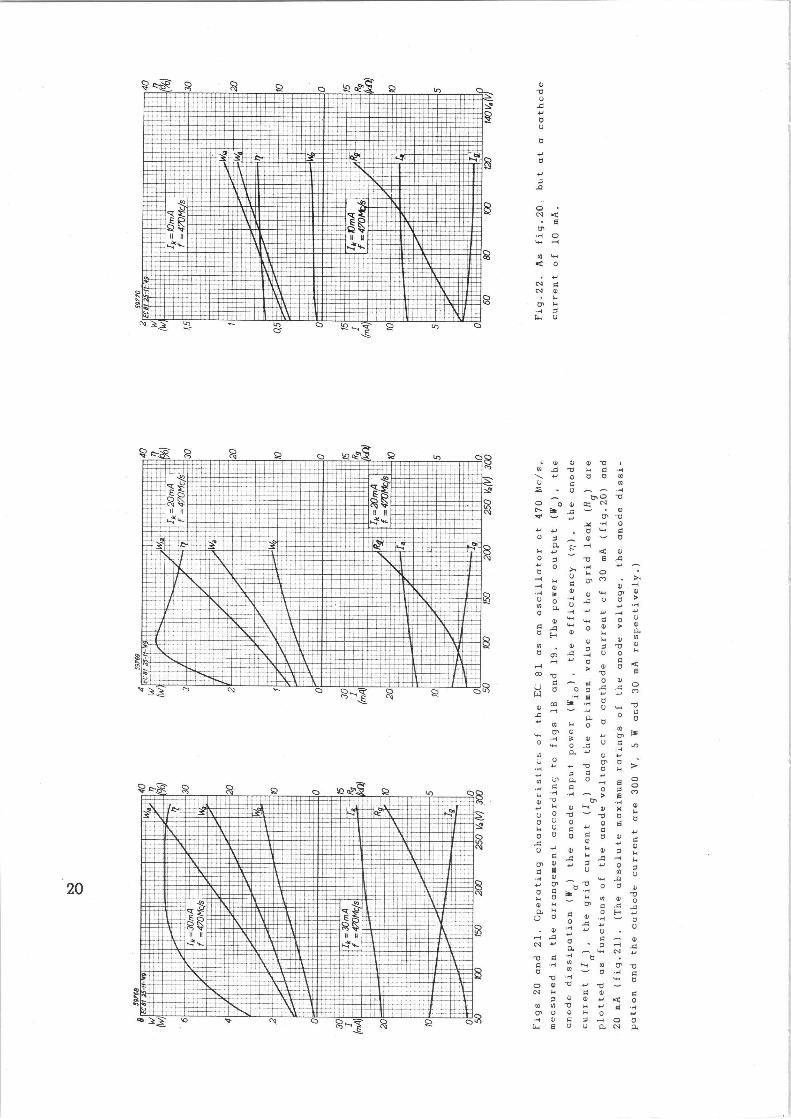
Operating characteristic
d
N tlU
tl
a+ tl
A
O N ~
8 CT •.1 O w ri
N w
d o
N[ N ~ w ~ ~ .~ 7 ta. U
O ~ ♦+ a. 'O
tl~" Y
U~ a O ~ F3 q G O 7 fO ..I ^~ > 8 ~ •.i
o ~ ~' ~ K 'tl `" b tl0 o t]
U q ++ C
tl tl ~ tl
v~ a~ fi U v w ~
.-. 'tl O
p b ,,q tl ~ ~' N N V
..- ~ G J"
'" o F tl G d .,~
y 'y +.' U.-i .G ~." .-. N +' ~ 7 •-1
~-. w N 'O G7 b q .~ '~ ti vl ~ O m ~ O .1
'U "~ w o v b ..~ .tlN H ❑ N
tl y w
~ ~ N N b a+ ~y O' U O '. p .~ v a 7 ~ o
[,., e tl o a cv
ratings of
absolute
resFectively.)
a e O
v d
3
u7
potion and
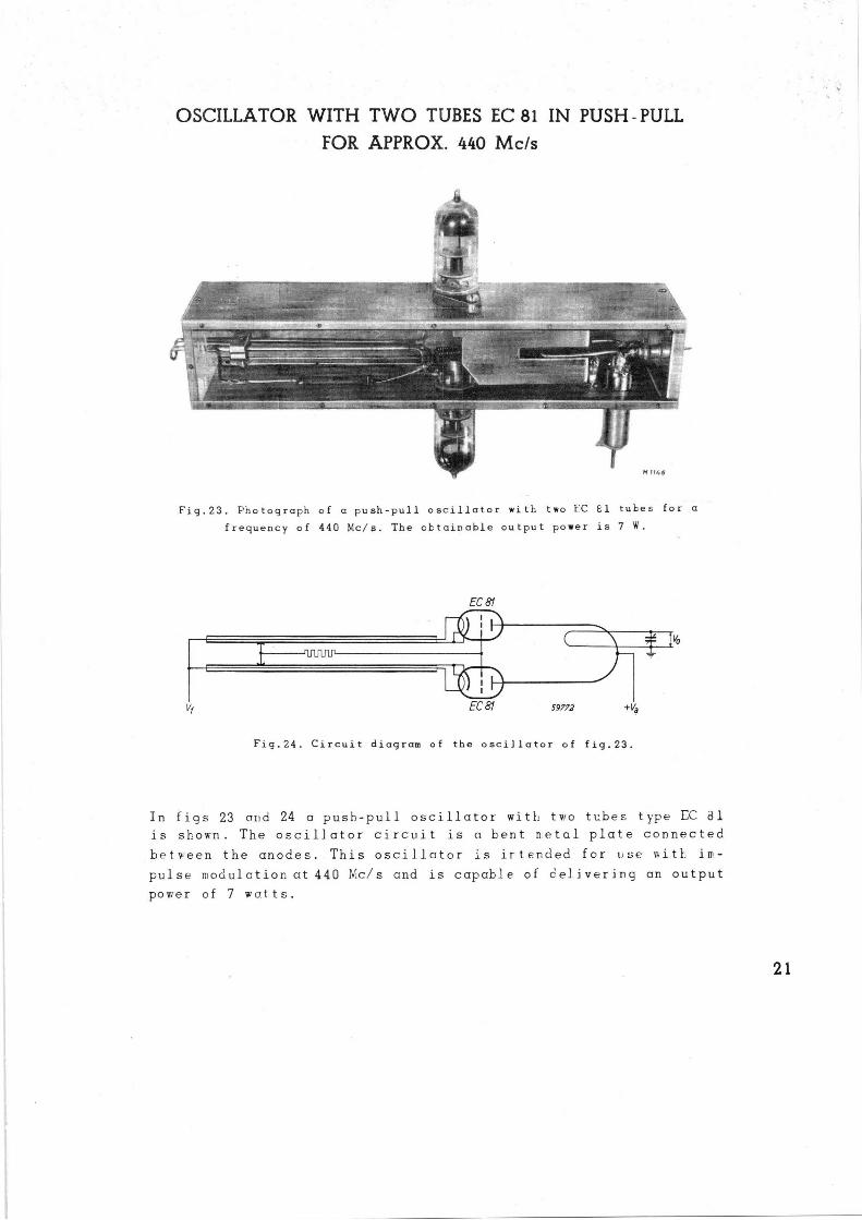
OSCILLATOR WITH TWO TUBES EC 81 IN PUSH -PULL
FOR APPROX. 440 Mc/s
Fig.23. Photograph of a push-pull oscillator with two EC E1 tubes for a
frequency of 440 Mc/s. The obtainable output power is 7 W.
EC 81
EC 81 59772 +Vy
Fig.24. Circuit diagram of the oscillator of fig.23.
In figs 23 and 24 a push-pull oscillator with two tubes type EC ~1
is shown. The oscillator circuit is a bent ❑etal plate connected
between the anodes. This oscillator is irtended for t~se eitl im-
pulse modulctior.at 440 Nc/s and is capable of cei.ivering an output
power of 7 watts.
21
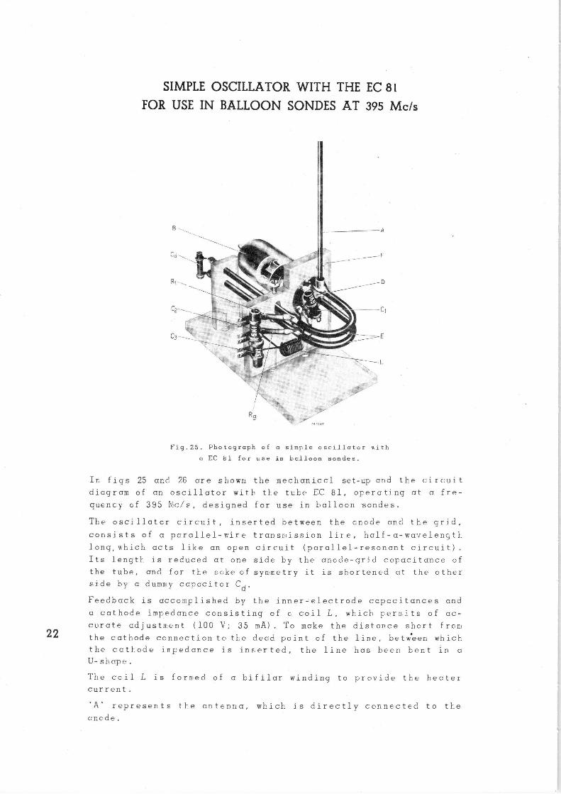
SIMPLE OSCILLATOR WITH THE EC 81 FOR USE IN BALLOON SONDES AT 395 Mc/s
Fig.25. Photograph of a simple oscillator xith
a EC $1 for use in bclloon sondes.
Ir. figs 25 ar.d 26 are shown the mechaniccl set-up and the circuit
diagram of an oscillator with the tube EC 81, operating at a fre-
quency of 395 N,c/s, designed for use in balloon sondes.
The oscillates circuit., inserted betweer. the mode and the grid,
consists of a parallel-v~ire transmission lire, half-a-wavelength
long,which acts like an open circuit (parallel-resonant circuit).
Its length is reduced at one side by the ancde-grid capacitance of
the tube, and for t1e sake cf symmetry it is shortened at the other
side by a dummy ccpaciter Cd.
Feedback is accomplished by the inner-electrode capacitances and
a cathode impedance consisting of o coil L, which pernits of ac-
curate adjustment (100 V; 35 mA) To make the distance short from
the cathode connection tc th.e dead point of the line, between which
the cat}_ode impedance is in::erted, the line has been her.t in a
U-shape.
The ccil L is forrted of a bifilar winding to provide the heater
current.
'A' represents the antenna, which is directly connected to the
anode.
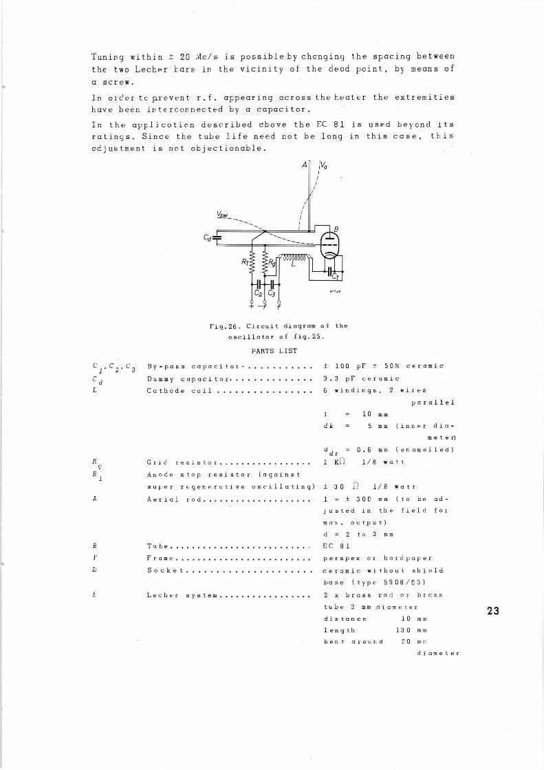
Tuning within ± 20 iNc/s is possible by changing the spacing between
the two Lecher bars in the vicinity of the dead point, by means of
a screw.
In orcertc prevent r.f. appearing across the heater the extremities
.have been interconnected by a capacitor.
In the apFlication described above the EC 81 is used beycnd its
ratings. Since the tube life need r.ot be long in this case, this
cdjustment is not objectionable.
Fig.26. Circuit diagram of the
oscillator of fig.25.
PARTS LIST
C1,C2,C3 By-pass capacitor- ± 100 pF ± 50% ceramic
C d Dummy capacitor 3.3 pF ceramic
L Cathode coil 6 windings, 2 wires
parallel
1 = 10 mm
dk = 5 mm (inner dia-
meter)
d dr = 0.6 mm (enamelled)
R Grid resistor 1 K~ 1/8 wat t n
R 1 Anode stop resistor (against
super rFgenPrative oscillating) ± 30 .~. 1/8 watt
A Aerial rod 1 = ± 300 mm (to be ad-
justed in the field for
max. output)
d = 2 to 3 mm
Tube EC 81
F Frame Perspex or hardpaper
U Socket ceramic without shield
base (type 5908/03)
L Lecher system 2 x brass rod or brass
tube 3 mm diameter
distance 10 mm
length 130 mm
bent around 20 mr
diameter
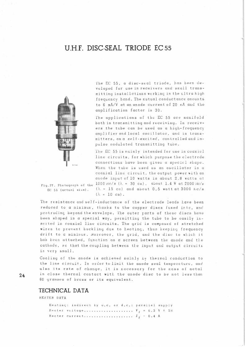
U.H.F. DISC-SEAL TRIODE EC 55
Fio.27. Photogrcph of the
EC 55 (actual size).
the EC 55, a disc-seal triode, has been de-
veloped for use in receivers and small trans-
mitting installctionsworkinc, in the ultrahigh
frequency bend. The mutual conductance amounts
to 6 mA/V at an anode current of 20 mA and the
amplification factor i= 3U.
The applications of the• EC 55 are• manifold
both in transmitting and receiving. In receiv-
ers .the tube can be used as a high-frequenc}
amplifier and local oscillator, and in trans-
mitters, as a self-excited, controlled and im-
pulse modulated transmitting tube.
'lt!e EC 55 is mcinly intended for use in coaxicl
line circuits, for which purpose the electrode
connections have been giver_ a specicl shape.
When the tube is used as an oscillator in a
coaxial line circuit, the output power with an
anode input of 10 watts is about 2.8 watts ct
1000 ,~Ic/s (~ = 30 cm) , about 1.4 W at 2000 i~ic/s
(~ = 15 cm) ar.d about 0.5 watt at 3000 h:c/s
(~ = 10 cm).
The resistance ano' self-inductance of the electrode leads lave been
reduced to a minimum, thanks to the copper discs fused into, anc'
pretrudinc, beyond the envelope. 'The outer Farts of these discs have
been sf:aped in a special way, permitting the tube to be easily in-
serted in coaxial line circuits. The grid is composed of stretched
wires tc prevent buckling due to hooting, thus keep in;; frequency
drif t to c minin~un . !vioreover, the grid, and the disc to wl_ich i t
ha•s been attached, function as a screen between the anode and the
cathode, sc that the coupling between tIe input and output circuit"
ie, very small .
Cooling of the anode is achieved mainly by thermal conduction to
the line circuit. In order to limit the anode seal tempercture, and
also its rate of change, it is necessary for the mess of metal
in close thermal contact with the anode disc to be not less than
6Q yrar!mes of brass or its equivalent.
TECHNICAL DATA HEATER DATA
Heatinc: indirect by a.c, or d.c. parallel supply
t!eater voltage V f = 6.3 V ± 5%
Hector current If = 0.4 A
25 M 115C
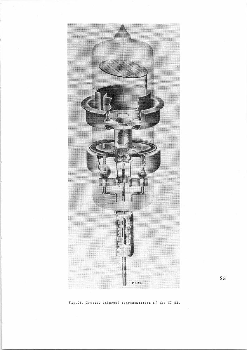
Fig. 23. Greatly enlarged representation of the EC 55.
CAPACITANCES (measured with tube cold)
Capacitance between grid and cathode
Capacitance between grid and anode
Capacitance between anode and cathode
kf f
22.23±0.13
a 19.05±0.f3~
+0 9 1905-025ID
4.76±0.10 k.f --~--
f 1.12±0.025
zl
_~ax17.220~
min 22,84
~z~T ~' .,~, o o .~, t~ ,i Qi N
SwL~ tl N
t n NlN'
I
Qi~4 o .c
E
mh T,30 M1151
59771
v
Cg = 1.8 pF
Cag < 1.3 pF
Ca = 0.03 pF
Fig.29. Electrode arrangement,
electrode connections and max-
imum dimensions in mm.
Fig.30. Excentricity. Distance
between axes of the electrodes:
g-a max.0.38 mm;
k-a max.0.38 mm;
f-k max.0.12 mm.
1) In order. to make good contact these sockets should be split.
2) Line of contact.
TYPICAL CHARACTERISTICS
Anode voltage V = 25U V a
Grid bias V = -3.5 V 9
Anode current la = 20 mA
Mutual conductance S = 6 mA/V
Rmplification foctor µ 30
LIMITING VALUES (absolute maxima)
Anode voltage V = max. 350 V a
Anode dissipation W a = max. 10 K
Cathode: current Ik = max. 40 mA
Anode seal temperature T = max. 140 °C
Grid dissipation W g = max. 0.1 W
Grid voltage -Vg = max. SG V
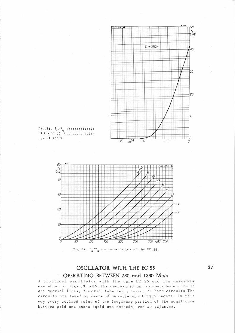
Fig.31. Ia/Vg characteristic
o f the EC 55 at an anode vol t -
age of' 250 V.
50 Ia
(mA~
40
30
20
fo
0
M 1153
M 1152
Va =250V
—15 u (v) -fo —5
~~1~ .~JN'~ ~~/I!~■~I-!.%1~1
~~~~ii~~r~ ~~ I~'--GN•:~~1~r~~~~~~~r~~~ .
~J•./III ~1/~1 I~ - __ ~~~PI'~~ ~~
~'
////".!~%I■■1111
~ b~' p ~A
EC55 30-6-'49
~_~~~~ .-
1■
0
~~ ~r~
■■i■ 50
i 100 150 200 250 300 Va (V) 350
Fig. 32. Ia/Va characteristics of the EC 55.
-~v
8V
50
(m.4)
40
30
20
f0
OSCILLATOR WITH THE EC S5 27
OPERATING BETWEEN 730 and 1350 Mc/s A proctical oscillator with the tube EC 55 and its asserbly
are shown in figs 33 to 35. The anode-grid and grid-cathode circuits
are coaxiol lines, the grid tube beiru, comr:::on to both circuits.The
circuity r.re tuned by mecns of movable shorting plungers. In this
way ever; desired vclue of the imaginary portion of the admittance
between grid and anode (gri_d and cathode) con be adjusted.
1 _I~~INIi ~i~~
~~1~ ~~~~~~~
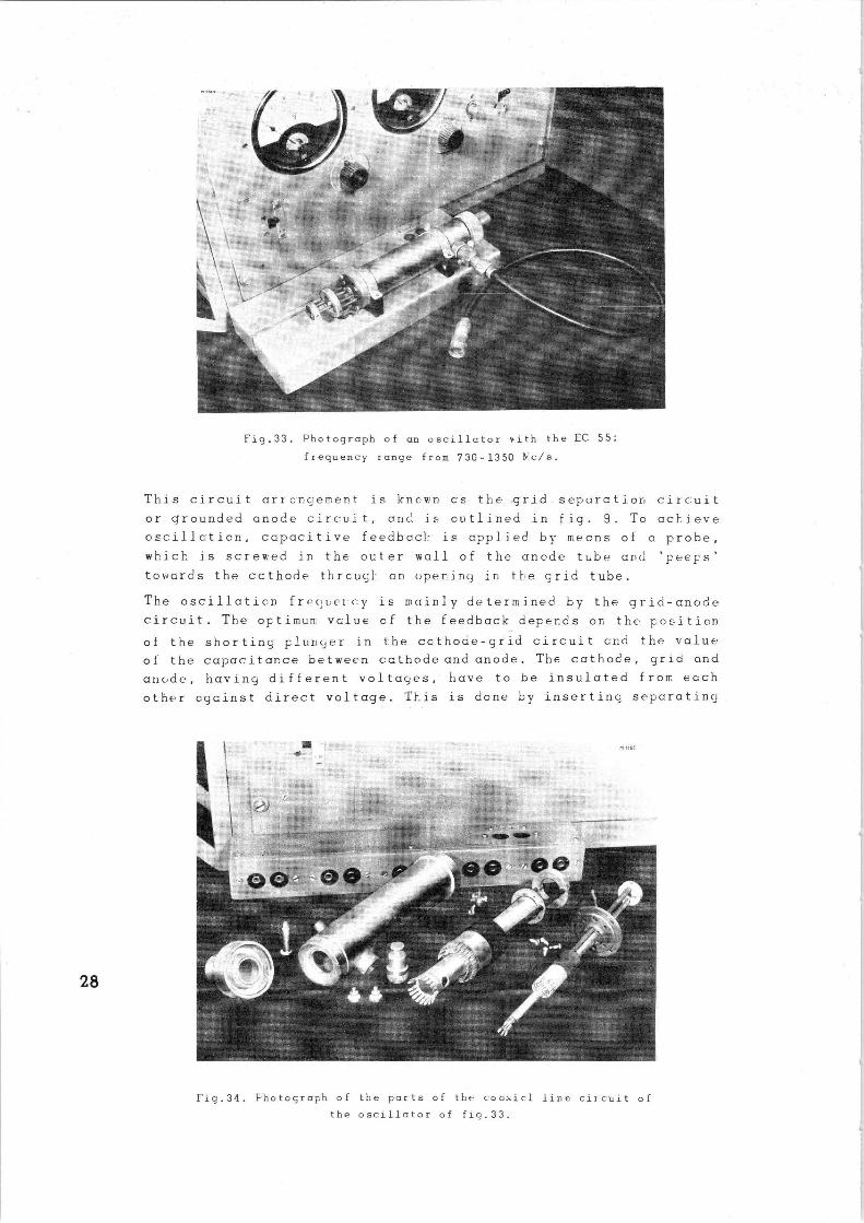
Fig.33. Photograph of an oscillator with the EC 55;
frequency range from 730-1350 hSc/s.
This circuit arranuement is known as the -g rill.separation circuit
or grounded anode circuit, and i~ outlined in fig. 9. To acl'_ieve
oscillction, capacitive feedbacl: is applied by means of a probe,
which is screwed in the outer wall of the anode tube and 'peeps'
towards the ecthode thrcucL an opering in tte grid tube.
The oscillaticn frec~uercy is mainly determined by the grid-cnode
circuit..The optimuR: Value cf the feedback depends on the poi=ition
of the shorting plunger in i:he cathode-grid circuit Ord the value
of the capacitance between cathode and anode. The cathode, grid and
anode, having different voltages, have to be insulated from each
other agcinst direct voltage. T1=is is done by inserting separating
Fig.34. Photograph of the parts of the coaxial line circuit of the oscillator of fig.33.
capor.itor_• in the moving bridges. It is also possible to use a
separating capacitor neon the anode, in orc.er to keep the cuter
wall at earth potential.
The heater lead is fed through the cathode tube and is decoupled by two capacitors in order to avoid parasitic oscillations.
The oscillator operates in the so-called j-,4 mode i.e. the length
of both the two coaxial lines is about % of a wavelength.
The material used for .the cylinders and flanges is brass; phosphorus
bronze is used for the contact springs; after assemblinc ar_d sol-
dering of the parts, the resonators have been silver-plated. The
assembly of the circuits can be seen clearly in figs 33 and 34.
The reds operating the shorting plungers are made from insulating
material in order to avoic' parasitic effects upsetting the tuning
itself. Conducting rods would also have some radiation due to leak-
age from the tuned circuit, thus introducing additional losses.
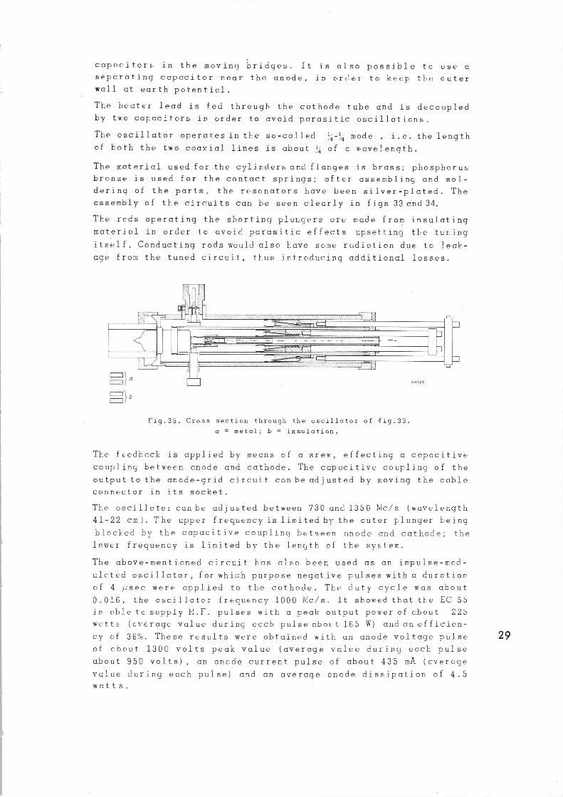
Fig.3J. Cross section through the oscillator of ~fig.33. a = metal; b = insulation.
The feedback is applied by means cf a stew, effecting a capacitive
coupling betK•een anode and cathode. The capacitive coupling of the
output to the ar.cde-grid circuit can be adjusted by moving the cable
connector in its socket.
The oscillator can be adjusted between 730 and 1350 bic/s (wavelength
41-22 cm). The upper frequency is limited by the outer plunger being
b.loched by the capacitive couplings between anode and cathode; the
lower frequency is limited by the length of the system.
The above-mentioned circuit has ,also been used as an impulse-mcd-
ulcted oscillator, for which purpose negative pulses with a duration
of 4. /.:,sec were applied to the cathode. The duty cycle was about
0.016, the oscillator frequency 1000 NIc/s. It showed that tt:e EC 55
is able tc supply H.F.. pulses with a peak output power of shout 225
wc..tts (cverage value during each pulse abot:t 165 W) and an efficien-
cy of 36%. These results were obtained with an anode voltage pulse
of shout 1300 volts peak value (average value during each pulse
about 950 volts), an oncde current pulse of about 435 mA (overage
value during each pulse) and .an average anode dissipation of 4.5
watts.
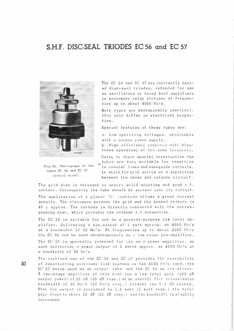
S.H.F. DISC-SEAL TRIODES EC 56 and EC 57
n ~oee
Fig.36. Photogzaph of the
tubes EC 56 and ECC 57
(actzal size).
The EC 56 and EC 57 are indirectly heat-
ed disc-seal triodes, intended for use
as oscillators or braad bard amplifiers
in microwave relay stctions at frequen-
cies up to about 4000 Mc/s.
Both types are mechanically identical;
they only differ in electrical proper-
ties.
Special features of these tubes are:
a. Low operating voltages, obtainable
with a cor.~mon power supply;
b. High efficiency comperFd vrith klys-
trons operatinc; at t}.e same frequency.
Owinc, to their special construction the
_tubes are very suitable for insertion
in coaxial lines and waveguide circuits,
in which t}.egrld servos as a separation
between the anode and ccthode circuit.
The grid disc is threaded to ensure solid mounting and gcod r.f.
contact. Consequently the tube should be screwec': into its circuit.
The application of e. planer 'L' -cathode allows a great current
density. The clearance between the grid cnd the heated cathode is
40 ~: cpprox. The cathode is directly connected vein,. the ccrres-
ponding disc, which prcvides the ccthode r.f.connection.
The EC 56 is suitable for use as a ger_eral-purpose low level am-
plifier, delivering a max.output of 1 watt approx. at 4000 Mc/s
at a bandwidth of 50 Mc/s. At fregr:encies up to about 25G0 Mc/s
the EC 56 can be used cdvantagecusly as o low noise pre-amplifier.
The EC 57 is specially intended for tse as c• power amplifier, as
such delivering a power output of 3 watts approx. a.t 4000 Dic/s at
a bandwidth of SO bic/s.
The corchined use of the EC 56 and EC 57. prcvides the possibility
3Q of constructing microwave link systems in the 4000 A".c/s bard, the
EC 57 being used as an output tube cnd the EC 56 as its driver.
A two-stage amplifier of this kind has a low• level gain (100 mW
output power) cf 29 dB (25 dB resp.) at an overall flct trcnsmission
bandwidth of 35 Nc/s (50 A'ic/s resF.} between the 0.1 dB points.
When the output is increased to 1.5 watt (1 watt resp.) tf.e total
gain drops to about 25 dB (21 dB resp.) and the bandwidth. isslightly
increased.
GENERAL DATA OF THE EC 56 and EC 57 (tentative data) Heating: indirect by a.c or d.c.; parallel supply only
Heater voltage - 6.3 V 1)
Heater current • ,0.65 A
CAPACITANCES
Inter-electrode ccpr.citances
Anode to grid 1.6
Anode to cathode 20
Grid to cathode 2.2
MAXIMUM P~ATINGS (absolute maxima)
pF
mpF
pF
Anode voltage at zero anode current 500 V
Anode voltage 300 V
Anode dissipation 10 W
Cathode current EC 56 35 mA
{ EC 57 7 0 mr'S
Grid current 10 mA
Grid positive bias 0 V
Grid negative bias -50 V
Heater to cathode voltage (cathode
positive) 50 ~
Anode seal temperature 200oC
Grid seal temperature 75oC
Cathode seal temperature 7So C
INSULATION k/f
2)
2)
2)
Heater-cathode current with a heater-cathode voltage of 50 V and a
hecter voltage of 6.3 V is maximr:m lOG ~;A.
INVERSE GRID CURRENT
At a heater voltage of 6.3 V and an anode dissipation of 10 W, the
inverse grid current is maximum 0.6 µA.
DIMENSIONS: See outline
Bt.SE CGNNF.CTIONS
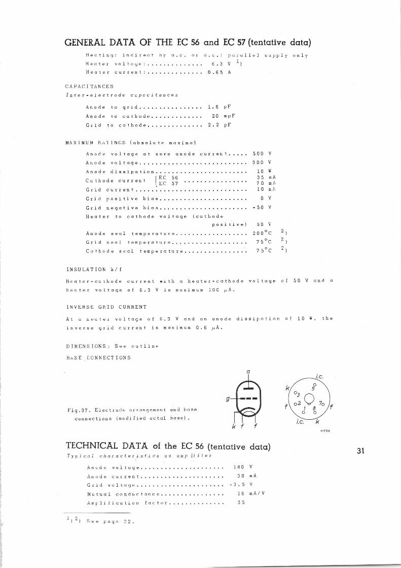
Fig.37. Electrode arrangement and base
connections (modified octal base).
TECHNICAL DATA of the EC 56 (tentative data) Typical characteristics as amplifier
Anode voltage 160
Anode current 30
Grid voltage -3.5
Mutual conductance 16
Amplification factor 35
1)2) See page 32.
V
mA
V
mA/V
M 1156
Operating conditions as amplifier at 4000 Mc/s
Anode supply voltage 220 V
Grid supply voltage +40 V
Cathode bias resistor 3)
Anode current 30 mA
Bandwidth (between half-power points) 100 50 kc/s 4)
Power gain at 1 mW output power 13 17 dB
Output power at 8 dB power gain 0.6 1.2 W
TECHNICAL DATA of the EC 57 (tentative °data) Typical characteristics at amplifier
Anode voltage 180 V
Anode current 60 mA
G r i d v o l t a g e - 1. 8 V
Mutual conductance 19 mA/V
Amplification factor 35
Operating conditions as omplifier at 4000 Mc/s
Anode supply voltage 220 V
Grid supply voltage +40 V
Cathode bias resistor 3)
Anode current 45 60 mF.
Bcr,dwidth (between half-power /~ /~
points) 100 50 100 50 4)
Power gain at 1 mW output 13.8 17.5 14.0 17.6 dB
Output power at 8 dE power gain 1.2 2.4 1.6 3.2 W
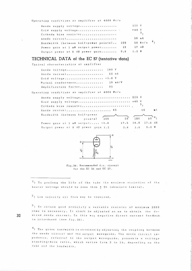
M 1141
Fig.38. Recommended d.c, circuit
for the EC 56 and EC 57.
1 ) To prolong the life of the Lobe the maximum vcriatior. of the
heater voltage should be less than + 2~. (absolute limits).
2) Low velocity nit flow may be required.
3 To obtain good stability a variable resistor of maximum 2000
ohms is necessary. It should be adjusted so as to obtain the de-
sired anode current. In this wa} negative direct current feedback
is introduced (see fiq,38) .
4) The given bandwidth is obtained by adjusting the coupling between
the anode circuit and the output waveguide. The anode circuit im-
pedance, referred to the output waveguide, presents a voltage
standing-wave ratio, which varies from 3 to 15, depending oa the
tube and the bandwidth,
21,1±0,1~
14,3±O,Q?~6,35±OOSfd
45°
R= max2,5
tl N N O" N +~ h R= ^i max 1,5
• v ~ ut•
+I o~ ~ ~~
~. ~
Zl l ±Q2 ~
31,B'~0,2s6
v v v
mox 3Z,89f
anode
grid
b
O E
u
t
Qx
E
M1157
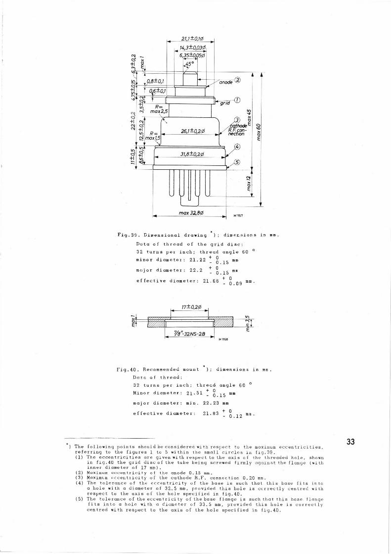
Fig.39. Dameasional drawing ~): dimensions in mm.
Data of thread of the grid disc:
32 turns per inch; thread angle 60 °
minor diameter: 21.22 ± 0,15 ®®
major diameter: 22.2 + 0.15 me
effective diameter: 21.68 + 0.09 mm.
r 17tQ29~
~~
~~ ~B"-32NS-28 ° Mtt6!
Fiq.40. Recommended mount ); dimensions in mrt.
Datc of thread:
32 turns per inch; threcd angle 60 °
Minor diameter: 21.51 ± 0.15 mm'
major diameter: min. 22.23 mm
effective diameter: 21.83 ± 0.12 m°'
The following points should be considered with respect to the maximum eccentricities, referring to the figures 1 to 5 within the small circles in fig.39. (1) The eccentricities are given with respect to the axis of the threaded hole, shown
in fig.40 the grid disc of the tube being screwed firmly against the flange (with inner diameter of 17 mm).
(2) Maximum eccentricity of the anode 0.15 mm. (3) Maximum eccentricity of the cathode R.F. connection 0.20 mm. (4) The tolerance of the eccentricity of the base is such that this base fits into
a hole with a diameter of 32.5 mm, provided this hole is ccrrectly centred with respect to the axis of the hole specified in fig.40.
(5) The tolerance of the eccentricity of the base flange is such that this base flange fits into a hole with a diameter of 33.5 mm, provided this hole is correctly centred with respect to the axis of the hole specified in fiy.40.
M 1159 EC 56 1-4-'S5
700
Va =180V
ja ~mA~
Vy(V) —6 T
—4 —2
80
60
40
20
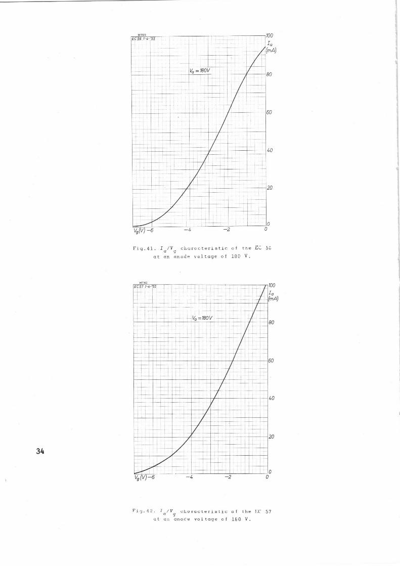
Fig.41. Ia/Vg characteristic of the %i. 50
at an anode voltage of 180 V,
M 1160 EC57 1-4-'S5
1 ~.
f —4
1
2 I I I 0
0
Fig.42. Ia/Vg characteristic of [he LC 57
at an anode voltage of 180 V.
20
Ig
(mA)-
15
10
Vy = +5V +4V +3V +2V +1 V OV —1V 2V —3V
—4V
—5V
—6V
—7V
50 100 150 200 250 Va(V) 300
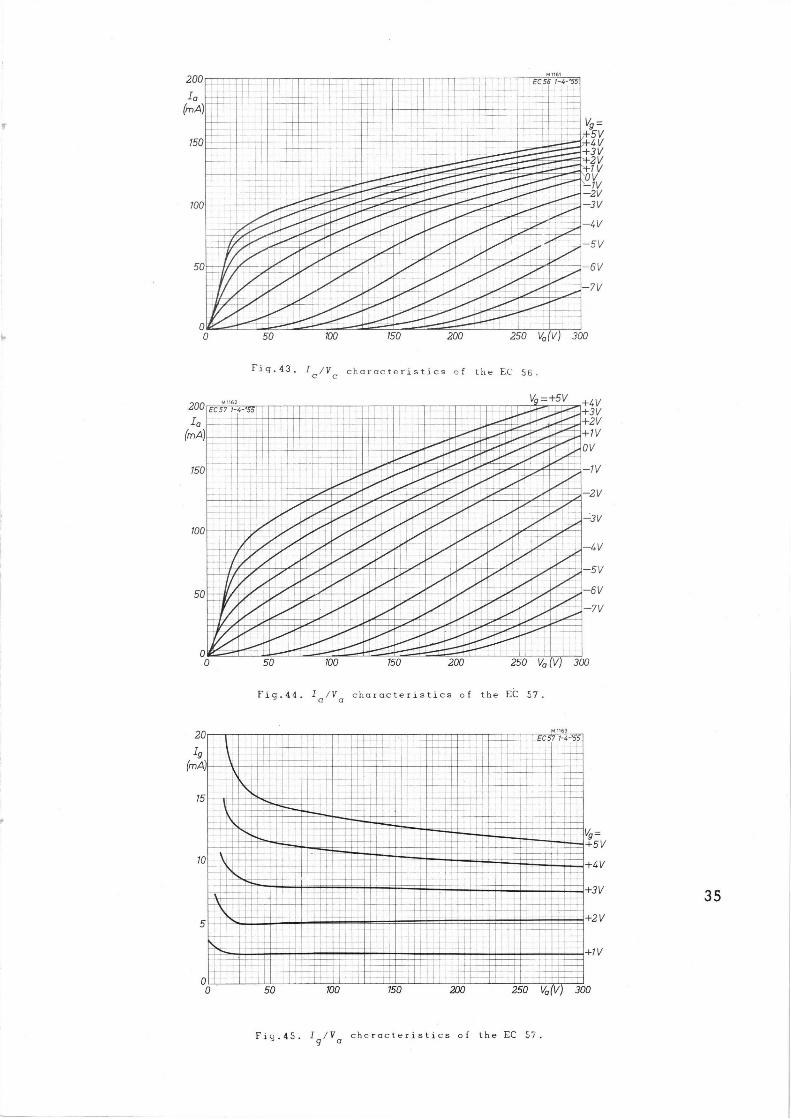
Fig.43. I~/yc characteristics of the EC 56.
+4V +3V +2V +1V
OV
1V
2V
-3V
—4V
—5V
—6V
—7V
50 100 150 200 250 Va (V) 300
Fig.44. Za/Va characteristics of the EC 57.
M 1163
EC 57 7-4 'S5
I ~
Vg = +5V
+4V
+3V
+2 V
+1V
50 100 150 200 250 Vo V) 300
Fio.45. Ig/Ya chcracteristics of the EC Si.
20
G(d b~
15
10
1 64
EC 56 7-4-'55
`'~~M~/s Vo _ X30V Io -30mA
~/s
1000 ~ ~
Wo (mW) X)000
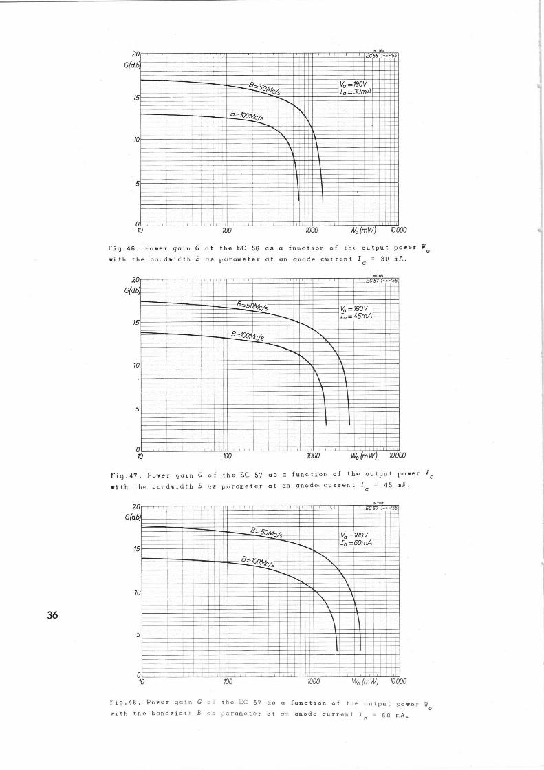
Fiy.46. Fower gain G of the EC 56 as a fuactior of thr ot;tput power Wo
with the bandwidth E as parameter at an anode current Ia = 30 ¢~~.
20
G(db)
M1165
15
10
5
0 X)
~C57 1-4-'53
~~~ T B`/s Vo _180V I o = 45mA
-B_X~i1k/s
XX) X)00 Wo (mW) 1000D
Fig.47. Fewer yain G of the EC 57 as a function of the output power Wo
with the bandwidth B 1_s parameter at an anode• current la = 45 mf.
20
G(db)
M 1166
15
10
EC57 1-4- 55
5
0
—~
Va _taov I o-60mA
'~
10 100 Xa00 Wa (mW) 10000
Fig.48. Power gain G of the ::C 57 as a function of the output - Hover W 0
with the bar.dwidti- B os parameter at an anode current I = 60 ¢A. a
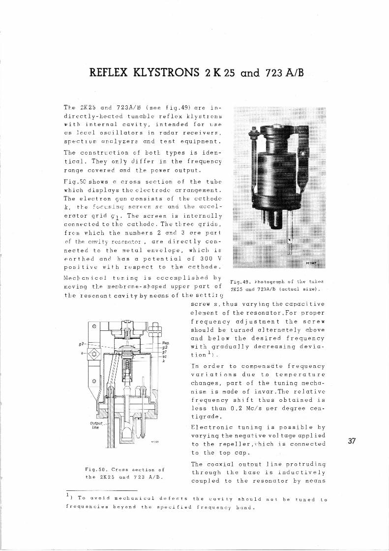
1~EFLEX KLYSTRONS 2 K 25 and 723 A/B
The ~K25 and 723A/B (see fig.49) are in-
directly-heated tunable reflex kl.ystrens
with internal cavity, intended for use.
as ~-ccr.l oscillators in radar receivers,
SpErCtIUID analyzers and test equipment.
The ccnstrLction cf both: types is iden-
tical. They only differ in the frequency
range ccvered and the power output.
Fig.50shows a cross section of the tube
which displays the electrode crrangement.
The electron run consists of the cathode
k, the focusing screen sc ar.d the accel-
erator grid gl. The screen is internally
connected to the cathode. The tl ree grids,
from which the numbers 2 anc', 3 are part
of the ccrvity ree-onutor are directly con-
nected to the metal envelope, which is
ecrthed and has a potential of 300 V
positive with respect to the ccthode.
Mechanical tuning is acccmplished by
moving the men~brrne-shaped upper part of
the resonant cavity by uieans cf
Outputl -iine
M 1i68
Fig.50. Cross section of
the 2K25 and 723 A/B.
N 7167
Fig.49. Photograph of the tubes
2K25 and 723A/B (actual size).
the sE:ttir;l
screw s,thus varying the capacitive
element of the resonator.For proper
frequency adjustment the screw
should be turned alternately above
and below the desired frequency
with gradually decreasing devia-
tion 1 ) .
In order to compensate frequency
variations due t.o temperature
changes, part of the tuning mecha-
nism is made of invar.The relative
frequency shift thus obtained is
less than 0.2 Mc/s per degree cen-
tigrade.
Electronic tuning is possible by
varying thenegative voltage applied
to the repeller,~-hich is connected
to the top cap.
The coaxial output line protruding
through the base is inductively
coupled to the resonator by means
1) To avoid mechanical defects the cavity should not be tuned to
frequencies beyond the specified frequency band.
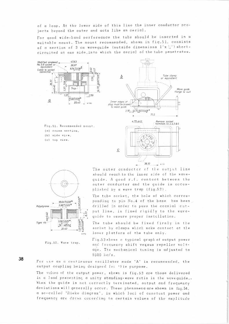
of a loop. At the lower side of this line the inner conductor pro-
jects beyond the outer and acts like an aerial.
For good wide-band performance the tube should be inserted in a
suitable mount. The mount recommended, shown in fiq.51, consists
of a section of 3 cm waveguide (outside dimensions. 1'x'~' l short-
circuited at one side,into which the aerial of the tube penetrates.
Modified amphenol fJo. S B socket or
equivalent Cabte to sock t
connection
a
47.63 26.97 ~
8.74±O.OB*' I o ~ o .;
Fig. 51. Recommended mount.
(a) cross section,
(b) side view,
(c) top view.
0 _ 19.84±aoe* _ o
Polystyrene--l _ _ _ 3.96±005* ~ N
0
E Tight fit-'" 5.56±a05*
~3/B 8 hd~ 21.43
~f .0,~
* '* 00 00 n~. o>
1~ v Mn~z
Fig.52. Waco trap.
y~r~ .
b Tube clomp or equivalent
~i -- . -- r
Inner edges of --plug must be brazed
to wave guide
3.1B~ 12.70~OD±O.OB*
4.75 drill
C
Wave guide flange to suit
71.5
Remove socket rterminals no.3, 4,5 & 6
38.10 ~ M11]1
The outer conductor c•f tl.e autl:ut line
should reach to the inner side cf the wave-
guide. A good r.f. contcct between the
outer conductor and the guide is accam-
pli hed by a wave trap (fig.52).
The tLbe sr..c:ket, the hole of which corres-
pondiner to pin No.4 of the base has been
drilled in order to pass the coaxial out-
put line, is fixed rigidly to the wave-
guide to assure proper instcllation.
The tube should be fixed firmly in the
sccl_et by clamps which make centoc'_ at the
lover platform of the tube only.
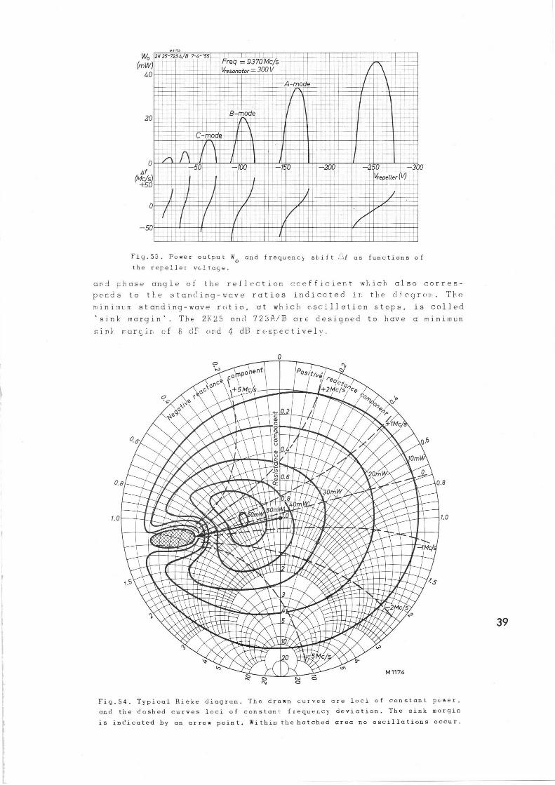
Fig.53 shov+s c typical graph of output pov~er
a r. c'. f recuer.cy shift versus repeller vclt-
cge. The rr;ecrianical tuning is adjusted to
9300 h.c/s.
For use as c continuous oscillator mode 'A' is recommended, the
output coupling being de~.igned fclx *his purpose.
The vclues of tt:e output power, spawn in fig.53 are those delivered
in n load presen.tinc,. a unity standing-wave ratio in the waveguide..
When the guide is not correctly terminated, output and frequency
deviations will generally ocr.ur. These phenomena are shown in fig.54,
a so-called 'Rieke diagram', in which loci of constant power and
frequency- are dretttir cccording to certain values of the amplitude
1193
~/1/p 2K 25-723A~B 7-4-'S5~ ~ I I ' I I I I L I i l l
(mW) -_ _ 1 Freq = 9370Mc/s -
40 V esonator = 300 V
20
—50
rt
B-mode
A-mode. . . - .
__ ~ —
—250 —_ 300. =Vrepeller (V} —
Fiy.53. Power output W and frequent} st:ift ~f as functions of 0 the repeller voltage.
ar.~d phase angle of the reflection ceefficier.t which also corres-
ponds to tl.e stanc':ing-wave ratios indicated ir: the diec,~rr•m, The
minimL.n: standing-wave rrtio, at which oscillation steps, is called
'sink margin'. The 2K25 and 7`L.sA/B are designed to have a minimum
sink. marc,in of S c]F and 4 dB respectively.
~.o
M 1174
0.8
~.o
Fig.54. Typical Aieke diagram. The drawn curves are loci of constant power,
and the dashed curves loci of constant frequency deviation. The sink margin
is inc'.icated by an arrow point. Within the hatched area no oscillations occur.
REb;ARKS
In order to prevent undesired frequency modulation care should be
taken to employ Fell. stabilised repeller and resonator voltages,
and the. connecting leads should be shielded.
It tray happen that the waveguide is not tern•irated in a matches
load, which ccuses frequency instability. When, however, very good
frequency stability is required an attenucrtor of 6 dB may be inser-
ted in the guide between tre aerial and tt,e lead.
The resistance of the repeller voltage supply should not exceed
150 ks2.
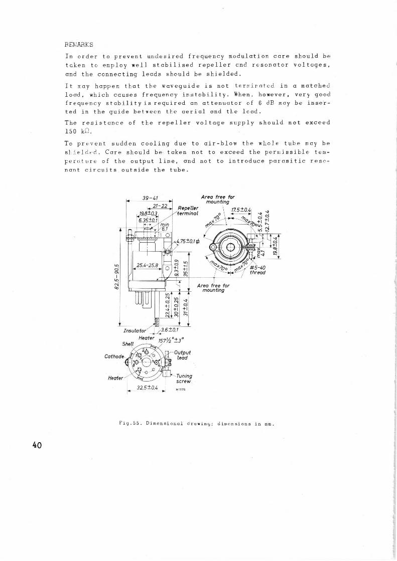
To prE~vent sudden cooling due to air-blow the whole tube may be
st~ieldf•d. Care should be taken not to exceed the permissible tem-
perature of the output line, and not to introduce parasitic rese-
nant circuits outside the tube.
0 a I
N m
39-41
N 21-22 19e±o..~6.35±0.1
Insulator Heater
Shelf
Cathode,
Heater
Area free for mounting
Repealer terminal Do
~~ ~,o
4.75±0.1 ~
3 6±0.1
157%'+3°
32.5±Q4
Output lead
Tuning screw. M 1175
1 Area free for
mounfing
17.5±0.4 ~---
7J,
#5-40 thread
Fig.55. Dimensional arowiny; dimensions in mm.
40
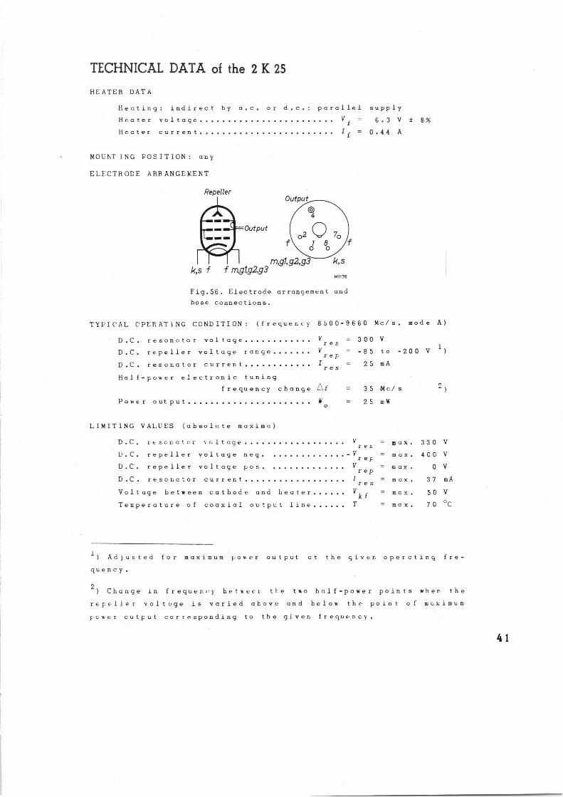
TECHNICAL DATA of the 2 K 25
HEATER DATA
Heating: indirect by a.c. or d.c. : parallel supply
Heater voltage Vf = 6.3 V t S%
Heater current if = 0.44 A
N,OUrTING FOSITION: any
ELF'CTRODE ARRANGL:biENT
Repeller
k,s f
Output
f mgfg2,g3
Output
O 4
02 ~ ~~ f\ 1 B
O O
m,gi,g2,g3' ~ k,s
M7176
Fig.56. Electrode arrangement and
base connections.
TYPIC'RL OPERATING CONDITION: (frequent}' BS00-9660 Mc/s, mode A)
D.C. resonctor voltage ores
D.C. repeller voltage range V rep
D.C. resonator current Tres
Half-power electronic tuning
frequency change ~~f
Powe r out put
LIMITING VALUES (absolute maxima)
D.C, resonator voltage
L`.C. repeller voltage neg.
D.C. repeller voltage pas.
D.C. resonctor current
Voltage between cathode and heater
Temperature of coaxial output line
1
W 0
= 300 V
= -E5
25
to
mA
-200 V 1)
= 3 5
= 25
-01c/ s
mW
~)
V res
max. 330 V
)'reF max. 4C0 V
V rep
max. 0 V
I res
= max. 37 mA
Vkf mcx. 50 V
T max. 70 °C
Adjusted for maximum power output ct the giver. operating fre-
quency.
2) Change in frequency betaeer tte two half-power points when the
repeller voltage is varied above and below the point of maximum
power output corresponding to the given frequent}.
41
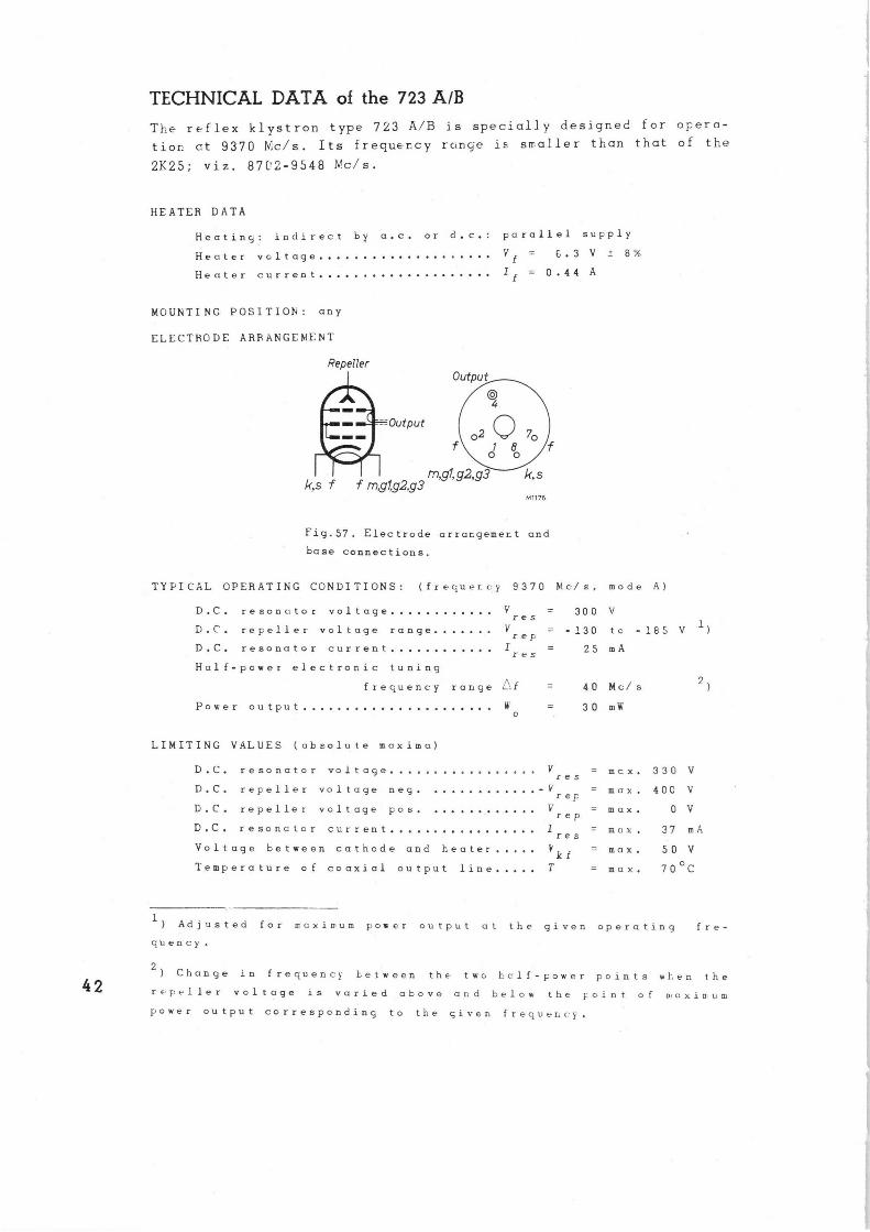
TECHNICAL DATA of the 723 A/B
The reflex klystron type 723 A/B is specially designed for opera-
tion at 9370 Nlc/s. Its frecuer.cy rc,nc~e i< smaller than that of the
2K25; viz. 87C'2-9548 Nc/s.
HEATER DATA
Heating: indirect by a.c. or d.c.: porallel supply
Heater voltage V f = 6.3 V ± 6%
Heater current I f = 0.44 A
MOUNTING POSITION: any
ELECTRODE ARRANGEMENT
Repeller
ks f f mglg2,g3 M1176
Fig.57. Electrode arrangement and
base connections.
TYPICAL OPERATING CONDITIONS: (frequency 9370 Mc/s, mode A)
D.C, resonator voltage V res
D.C. repeller voltage range V rep
D.C. resonator current I
Half-power electror.- ic tuning
f reouency range ~~:f = 40 Mc/ s
Power output W = 30 mN' 0
r e 5
LIMITING VALUES (absolute maxima)
D.C, resonator voltage V res
rep D.C, repeller voltage neg. V
D.C. repeller voltage pos. V rep
D.C. resonator current I res
Voltage between cathode and heater V kf
Temperature of coaxial output line T
m C X .
mcx .
m a x .
max .
max.
= m a x .
= 300 V
_ - 130 tc - 185 V
= 25 mA
2)
330 V
40C V
0 V
37 mA
50 V
70 oC
1) Adjusted for m,cximum poker output at the given operating fre-
quency.
2) Change in frequent} between the two half-power points when the
repeller voltage is varied above and below the Eoint of n~a xinium
power output corresponding to the given frequency.
STANDARD NOISE SOURCES K 81A, K 50A and K 51A
In the performance cf short wave apparatus, such as television and
racar equipment, noi~.e plays an important part, This is attributcble
to the inherent noise of tre receivers and amplifiers used. An im-
portant property of amplifiers and receivers is the 'noise factor',
which defines their noise properties under given conditions.
There are two main methods cf determining the noise facto. The
first is the method employing a standard signal aenerctcr. This
method is rather tine-consuming and in accurate, since it necessi-
tutes absolute measurements of power and effective handwidth. The
of}_er method is to employ a standard noise source, such as hot re-
sistors, sr.ttrccted diodes r.nd gas discharge. tubes. Since it would
be r_ecessary to heat resistors to 29000 °K for measuring a noi~•e
fectcr of 100, which map often be required, their use is however,
restricted.
Saturotad diodesare only available for measurements at frequencies
up to about 1000 D':c/s. However, at such freruencies it is hard y
possible to effect good matching between the diode and its circuit.
The K 81 A noise diode is desie~ned for t:se ct frequencies up to
300 Mc/s.
Special. ].y designed gas discharge tubes have proved to possess pra-
perties that make them verp suitable for use as standard Heise
sources at microwaves. The K 50 A and K 51 A are intended for use
in the 3 cm and tt-e 10 cm band recpectively.
.NOISE
Noise originates from the arbitrary motion of electrons in solids,
lieuids and- gases. The electron motion may be due to temperature
(thermcl agitation- or Johnson noise) cr to phenomena occurring in
gas discharges (collisions of the electrons and the ions} er in
vacuun: tubes (shot noise, partition r;oi~e, induced grid noise).
It can be proved that the mean scuare noise vcltcg- vr 2at the ter-
minals of a resistor E>qual~ 4kTBR, where k is Bol7mrann~:' con~.tcnt
(1.38 x 10⁻²³ Joule/ °C) T is the absolute temperature cf the
resistor, B i~: tf~e effective bandwidth of the frequency rcinge con- 43
sidered and R is the resistcnce of the resistor.
Accordingly a resistor ❑.ay be considered cs a noire seurr.e cf which
the e.m.f. is ✓4kTBR and arose irterr.al resistance is R, wl;ich is
assumed to be noise-free (fig.58).
Rt
M 117]
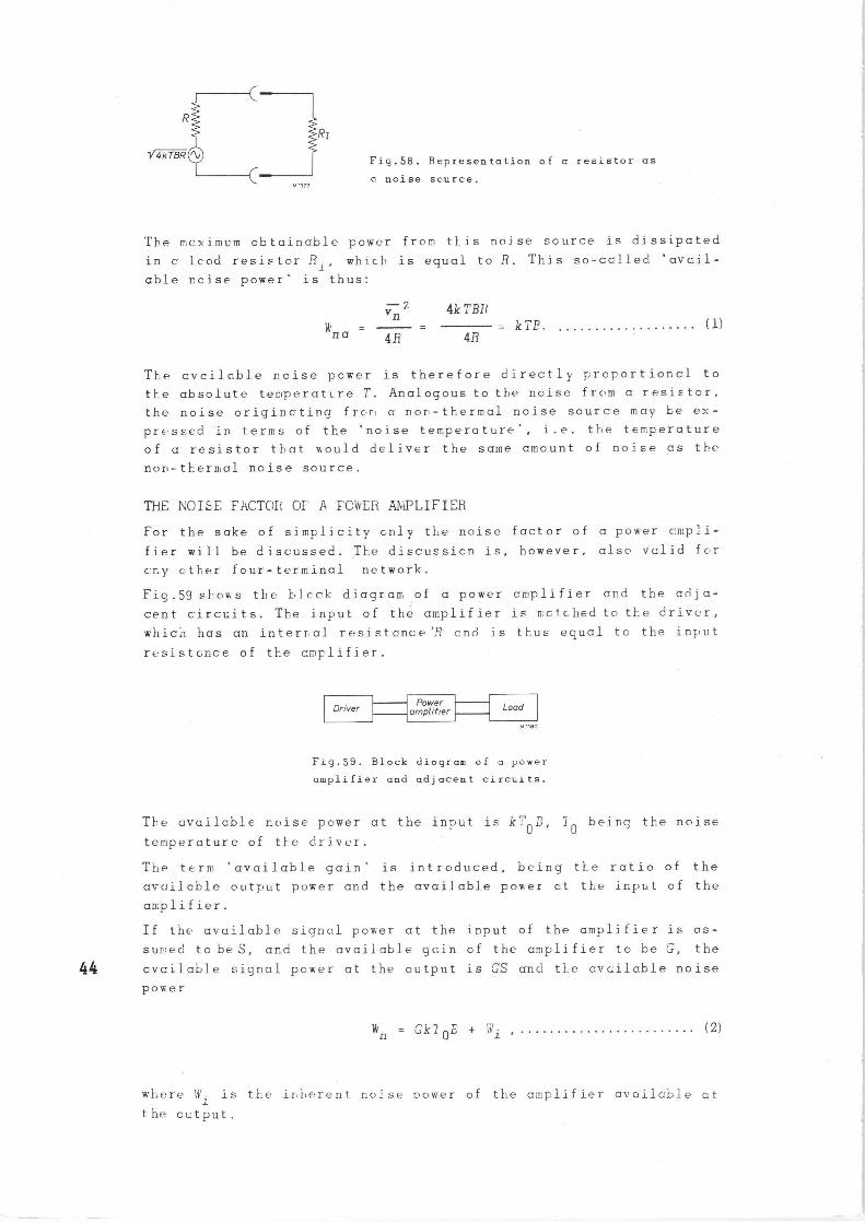
Fia.58. Representation of a resistor as
a noise source.
The maximum obtainable power from this noise source is dissipated
in c lead resistor Rj, which is equal to R. This so-called 'avail-
able noise power' is thus:
vn z 4kTBFt
was 4R 4R - kTB. (1)
The available noise power is therefore directly proportional to
the absolute temperature T. Analogous to the noise from a resistor,
the noise originating frorl a non-thermal noise source may be ex-
pressed in terms of the 'noise temperature', i.e. the temperature
of a resistor that would deliver the same amount of noise as the
non-thermal noise source.
THE NCIwE FACTOR OF' R FCR'ER Ab~1PLIFIER
For the sake of simplicity only tl~e noise factor of a power ampli-
fier will be disc.Ussed. The discussion is, however, also valid far
c:r.y other four-terminal network.
Fig.59 shows the b.l.cck diagram of a power amplifier anal the adja-
cent circuits. The input of the amplifier is metched to the driver,
whicz has an interr:al resistance :~; and is thus equal to the input
resistance of the amplifier.
Driver Power amplifier Load
M 1190
Fig.59. Block diogram of a power
amplifier and adjacent circuits.
The available noise power at the input is kTOP, T'~ being the noise
temperature of the driver.
The term 'available -gain' is introduced, being the ratio of the
available output power and the available power of trio input of the
amplifier.
If the available signal power at the input of the amplifier is as-
sur.~~ed to be S, and the available gain cf the amplifier to be G, the
44 available signal power at the output is GS and the available noise
power
wn = Gk1 ~E + (Z)
where Wi is the inherent no?se power of the amplifier avnilab].e nt
the output.
The noise factor of the amplifier is defined as the ratio of the
available signal-to-noise ratio at the input cnd the available
signal-to-noise ratic at the output of the amplifier, hence:
or:
N =
S/kT~B
GS / Wn
Wn
GkT~B
GkT pB + WiN -
GkTOB
(3)
The last expression shows that the noise factor may also be defined
as the ratio of the noise power actually available at the output
to the noise power that mould be available at the output if tke
amplifier Pere noiseless.
From (3) it follows, that:
Wn = NGkT ~B ; ( 4)
since:
Wn = GkT ~B + Wi = NGkT OB ,
TNL' SATLFiATED DIODE AS A STANDARD .NOISE SOURCE,
The cperation of a diode as a noise source is based on the following
principle. When the diode is saturated all electrons emitted by the
cathode will reach the anode. The number c•f electrons emitted during
a time interval fit, i.e. the charge transferred during this time
interval, is not constant but fluctuates around a statistical av-
erage value due to the thermal movement of the electrons in tF,e
cathode. The charge transmitted per unit time corresponds to the
direct anode current IC1, and on this average value a fluctuating
current is superimposed. Thic effect is termed the shot effect.
The mecn sruare of tfe noise current within a frequency band u is
giver. by:
_, 2 i n = 2e •I Q •B . . (6)
in which e denotes the charge of an electron, i.e. 1.6 x 1Q-19
C.
Since the invidual electrons do not influence each other,. this ex-
pression is applicable to the entire frequency spectrum, but at
extremely high frequencies the influence of the transit time effect
becomes more and more noticable and. reduces the shot effect.
When a current Ia + in passes through a resistance Ra included in
the anode circt:it of the diode a noise voltage drop vn- in.Ra will. _
be produced ir. addition to the voltage drop caused by the direct
mode current. So long as the influence of the internal resistance
of the diode is negligible compared with that of Ra, i.e. when
R i » Ra (which will always be the case when the diode is saturated,
since ~ va/a is = ~), the resistance Ra may be considered as a
noise source with an e.m.f. vn and an internal resistance _",~. The
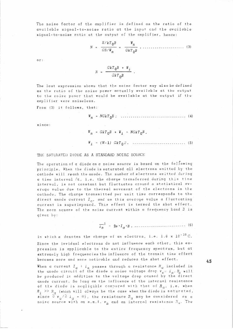
noise voltage source may be represented by the equivalent ciagrcm
shown in fig.60.
46
V~ Fig.60. Equivalent diagram of a saturated mode as
a noise source.
The availccbl_e noise; pc~+er c•f this noise scurr.e is giver. by:
W = n r.
—2 j n •Ra
rrcm (6) and (7) it fcll.ows t}•at:
Wna -
e•Ia•°•Ra
4 (7)
- 8 I a •r3•Ra • 10-20(8)
The essential fore~ulae having been given, we will now investigate-
t1e way in which the noise generator should he :;et up in order to
be rased cs a standarc' naize scarce and the recuirements to be sat-
isfied in ordE:r tc obtain reliable results.
The recuirer.~ent is imposed or. the circuit teat the interral resist-
ancE:ef the generator should be real and that no cppreciable atten-
uation should be caused by t}~e circuit at high frequencies. In or-
der to ensure that the internal resistance of the generator is real,
the ccpacitcnce introduced by the tube and the circuit may be neu-
trol~i,zed by vn inductance shunted across the tube. .7n this way a pc-
rollel tuned resoncint circuit is obtained, which is hecvily damped
by the anode lc ad resistance Ra ,(usually 60 ~ er 300 ~).
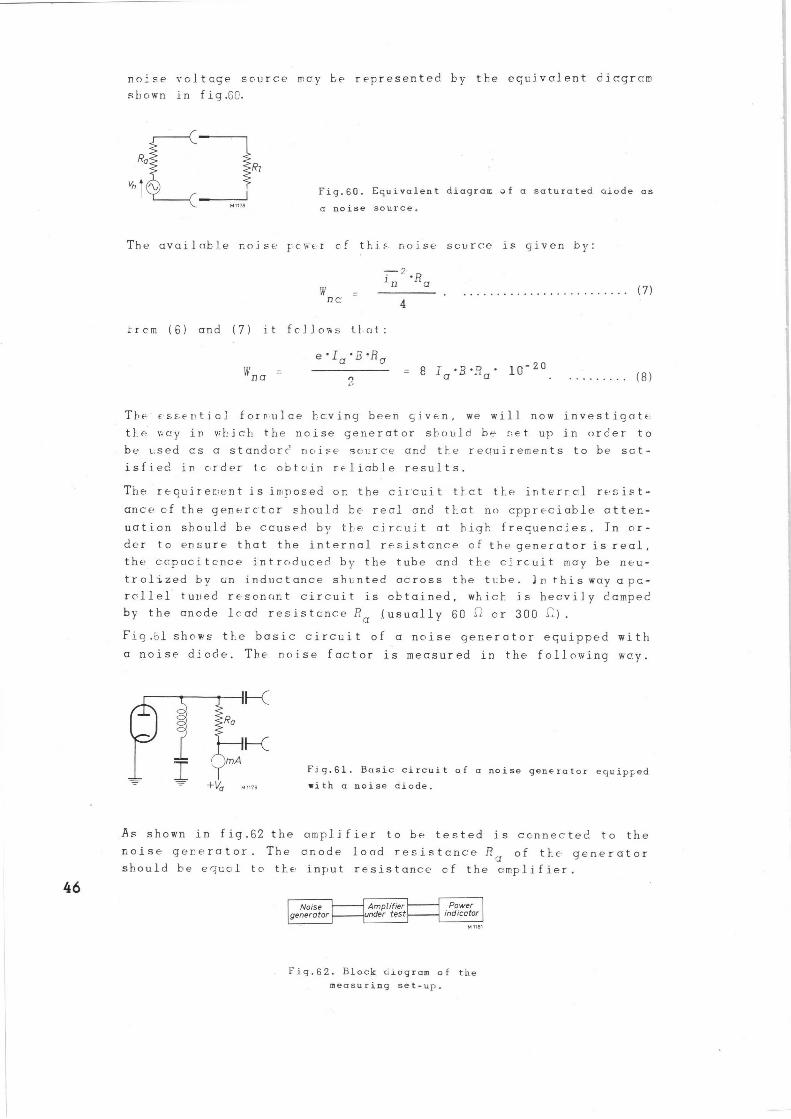
Fio.ol shows tt_e basic circuit of a noise ger.erotor equipped with
a noise diode. The noise factor is measured in the following way.
+Va
K
K
M 1179
Fig.61. Basic circuit of a noise generator equipped with a noise diode.
As shown in fig.62 the amplifier to be tested is connected to the
noise generator. The anode load resistance R1 of the generator
should be equal to they input resistance of the cmplifier.
Noise generator
Amplifier under test
Power indicator
M nei
I'ig.62. Block aiagram of the measuring set-up.
First the heater current of the diode remains switched off and a
meter indicating the relative power cutput is connected to the
output terminals of the amplifier. After a record has been made cf
the reading of this meter, which indicates a value corresponding
to a power output Wn = NGkToa ( according tc eq. (4)) , the heater
current of the diode is switched on and carefully adjusted to the
value at which the output meter indicates twice the original power.
The additional ncise output power due to the energized diode is
GWna and exactly equal to the initial power NGkToE.
Ner.ce:
GN~na = NGkT OB (9)
which gives:
N =
Plhen TO is 288 ° K:
~'na
kT OB
g.IaBRa. 10-20
kT O B
where I a i s exF:r essed in mF•. and Ra i n k~
K'hen the milli ammeter incorporoted in the anode circuit has beer,
calibrated accordingly, the noise factor can be read directly, or
it can be calculated by means of eq.(10).
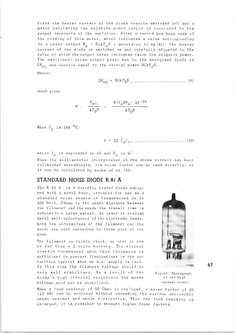
STANDARD NOISE DIODE K 81 A The K 81 A is a directly heated diode equip-
ped with a noval base, intended for use as a
standard noise source at frequencies up to
300 Nic1s. Owing to the small distance betweer.~
the filcment and the anode the transit time is
reduced to a large extent. In order to realize
small self-inductances of the electrode leads,
both the e..tremities of the filament end the
anode are each connected to three pins of the
base.
The filament is fairly thick, sc that it can
be fed from a 2 volts battery. The thermal
inertia consequent upon this thickness is
sufficient to prevent fluctuations in the sci-
turcticn current when an a.c. supply is used.
In this ccse the filament voltage should be
very well stabilised. As a result of the
diode's high internal resistance the anode
voltage need not be stabilised.
M 1183.
Fig.63. Photograph of the K81A
(actual size).
When a load resistor of 50 Ohn:s is employed, a noise factor of 20 (13 dB) can be mecsured without exceeding- the maximum admissible
anode current and anode cL'ssipatien. 4~'hen the load resistor is
enlarged, it is possible to measure higher noise factors.
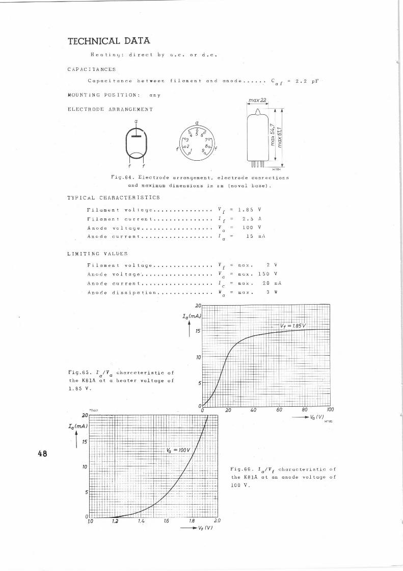
TECHNICAL DATA
Heating; direct by n.c. or d.c.
CAPACITANCES
Capacitance between filament and anode
lAOUPITiNG POSITION: any
ELECTRODE ARRANGEMENT
max22
C a f = 2 . 2 pF
n
o k D
M 1184
Fig.64. Electrode arrangement, electrode convections
and maximum dimensions in om (naval base).
TYPICAL CHARACTERISTICS
Filament voltage
Filament. current
Anode voltage
Anode current
LIMITING VALUES
Filament voltage
Anode voltage'
Anode current
Anode dissipation
20
Za (mAJ
15
~o
Fig.65. I' /V characteristic of a a
the K81A at a heater voltage of
1.85 V.
20
I a (
t
mAJ
1
to
0 l0
~94d1
V f
I f
V a
=
=
=
1.85
2.5
100
V
A
V
I a = 15 mA
Vf max. 2 V
V a
= max. 15U V
I c
= max. 20 mA
W a
= max. 3 W
■
11111111NII~/•Ilnll
~■j N■B■■NNN~■■N
1■■•-NNN:ii111 ■■■■pN ~~~■~.■N■■■■N
~:11:'~~ in1111n111n1
...N...■ j ■
~=11~~~111111
IIt =■■■■■■■N■■■N .1 -N■N■■I■■
IIIIIII;111 ■■INr~ii■L.
I
-~ = L85V
liiiii'i'ei■iinl n1111m111TH NN■■■
II..■NN
N... Inn
i t ~
1 ■~ ~■ N■NN~ '~C .i
..■SIN■■
■
N
1
■■~I N■■ ■::~~.■
C ...I... .ICI.
■■■NNN■■■■ N■■N■■Y■■■■
NI~~ ~.N■~::
NNN■ ■. ■■■ ■■w....■
N=■■s I~ I
~~~
■■ ~I~.~ il■ ■ N■ .=■.N CI■...N~
.. I:~ a. 1.2 14 l.6 1.8 2.0
>Vf (VJ
20 40 6U 80 100
Ua (VJ nines
Fig.66. Ya/VI characteristic of
the K81A at an anode voltage of
100 V.
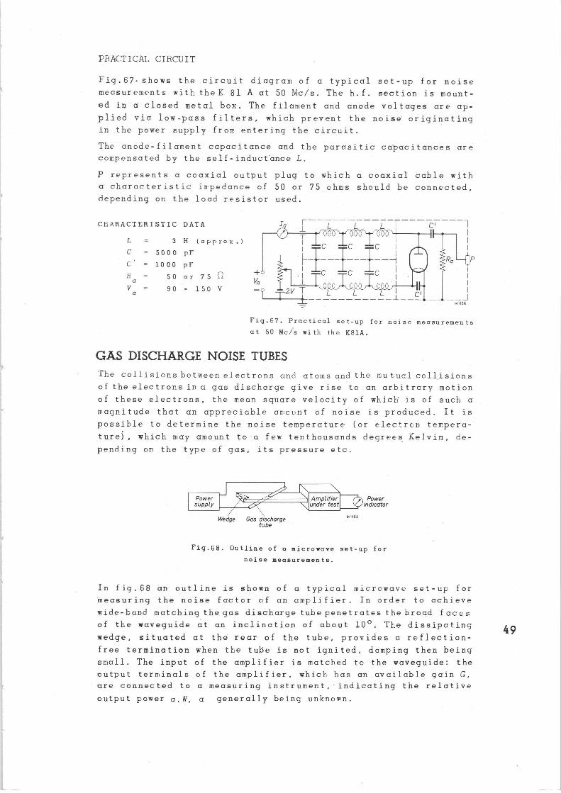
PRACTICAL CIRCUIT
Fig.67-shows the .circuit diagram of a typical set-up for noise
measurements with the K 81 A at 50 Mc/s. The h.f, section is mount-ed in a closed metal box. The filament and anode voltages are ap-
plied via low-pass filters, which prevent the noise originating
in the power supply from entering the circuit.
The anode-filament capacitance and the parasitic capacitances are
compensated by the self-inductance L.
P represents a coaxial output plug to which a coaxial cable with a characteristic impedance of 50 or 75 ohms should be connected,
depending on the load resistor used.
CHARACTERISTIC DATA
L = 3 H (approx. )
~ = 5000 pF
C' 1000 pF
N = 50 or 75 .~ v a = so - lso v a
ua
Ia 1 L L L T
© T 111 111 111 I I II C C C I
r ~
C_ ~C— ~--~
. ~ C I
_~ Tzv ~ -~ L ~ ~ I ~~
1
P
Fig,67. Practical set-up for noise measurements at 50 Mc/s with the K81A.
GAS DISCHARGE NOISE TUBES The collisions between electrons and atoms and the mutual collisions
of the electronsin a gas discharge give rise to an arbitrary motion
of these electrons, the mean square velocity of which is of such a
magnitude that an appreciable amount of noise is produced. It is
possible to determine the noise temperature (or electron tempera-
ture), which may amount to a few tenthousands degrees Kelvin, de-
pending on the type of gas, its pressure etc.
Power supply
Wedge Gas discharge tube
Amplifier under test
Power l indicator
M 1182
Fig.68. Outline of a microwave set-up for
noise measurements.
In fig.68 an outline is shown of a typical microwave set-up for
measuring the noise factor of an amplifier. In order to achieve
wide-band matching the gas discharge tube penetrates thebrocd faces
of the waveguide at an inclination of about 10°. The dissipating
wedge, situated at the rear of the tube, provides a reflection-
free termination when the tube is not ignited, damping then being
small. The input of the amplifier is matched tc the waveguide: the
output terminals of the amplifier, which has an.available gain G,
are connected to a measuring instrument, indicating the relative
output power a, W, a generally being unknown.
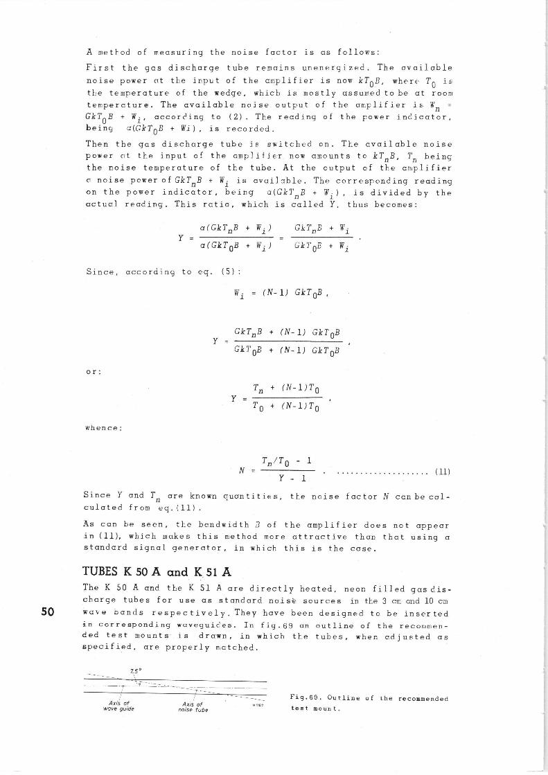
A method of measuring the noise factor is as follows:
First the gas discharge tube remains unenergized. The available
noise power at the input of the amplifier is now kTOB, where TO i~.
the temperature of the wedge, which is mostly assumed to be at room
temperature. The available noise output of the amplifier is Wn =
GkTOB + Wi, according to (2). The reading of the power indicator,
being a(GkTOB + Wi) is recorded.
Then the gas discharge tube is switched on. The available noise
power at the input of the amplifier now amounts to kTnB, Tn being
the noise temperature of the tube. At the output of the amplifier
a noise power of GkTnB + Wi is available. The correspcnding reading
on the power indicator, being a(GkTnB + Wi) is divided by the
actual reading. This ratio, which is called Y, thus becomes:
a (GkTn B + Wi ) Gk1'n B + Wiy = _
a(GkT OB + Wi ) GkT OB + Wi
Since, according to eq. (5):
Wi (N- 1) GkT OB ,
GkTn B + (N- 1) GkT OB Y = ,
GkT OB + (N- 1) GkT OB
or:
Tn + (N-1)TO
Y -TO + (N-1)TO
whence:
Tn /TO - 1 N - (11)
Y - 1
Since Y and Tn are known quantities, the ncise factor N can be cal-culated from eq.(11).
As can be seen, the bandwidth ~3 of the amplifier does not appear in (11), which makes this method more attractive than that using a standard signal generator, in which this is the case.
TUBES K 50 A and K 51 A The K 50 A and the K 51 A are directly heated, neon filled gas dis-charge tubes for use as standard noise scurces in tI-~e 3 cm and 10 cm
50 wave bands respectively. They have been designed to be inserted in corresponding waveguices. In fig.69 an outline of the recommen-ded test mounts- is drawn, in which the tubes, when adjusted as specified, are properly matched.
7.5°
Axis of wove guide
Axis of noise tube
M,~e> Fig.69. Outline of the recommended
test mount.
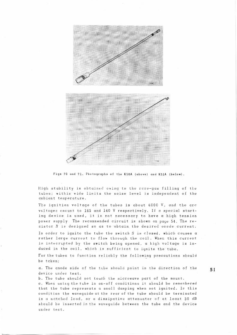
Figs 70 and 71. Photographs of the K50A (above) and K51A (belos).
}-sigh stability is obtained. owing to the rcre-gas filling of tl_e
tubes; within wide limits the noise level is independent of the
ambient temperature.
The ignition voltage of the tube. is about 6000 V, and the arc
voltages amount to 165 and 140 V respectively. If a special start-
ing device is used, it is not necessary to have a high tension
power supply. The recommended circuit is shown on page 54. The re-
~istcr R i= designed so as to obtain the desired czr.ede current.
In order to ignite the tube the switch S is r.losed, which causes a
rather large current to flow through. the coil. Wher. this current
is interrupted by the switch being opened, a high voltage is in-
duced in the coil, which is sufficient to ignite the tube.
For the tubes to function relicbly the following precautions should
be token;
a. The cnode side of the tLbe should point in the direction of the
device under test.
b. The tube should not touch the microwave part of the mount.
c. When usirg the tube in on-off conditions it should be remembered
that the tube represents a small. damping when not ignited. Ir this
condition the w•aveguide at the rear of the tube should be terminated
in a matched lc ad, or a dissipative attenuator of at least 30 dB
should be inserted in the waveguide between the tube and the device
under test.
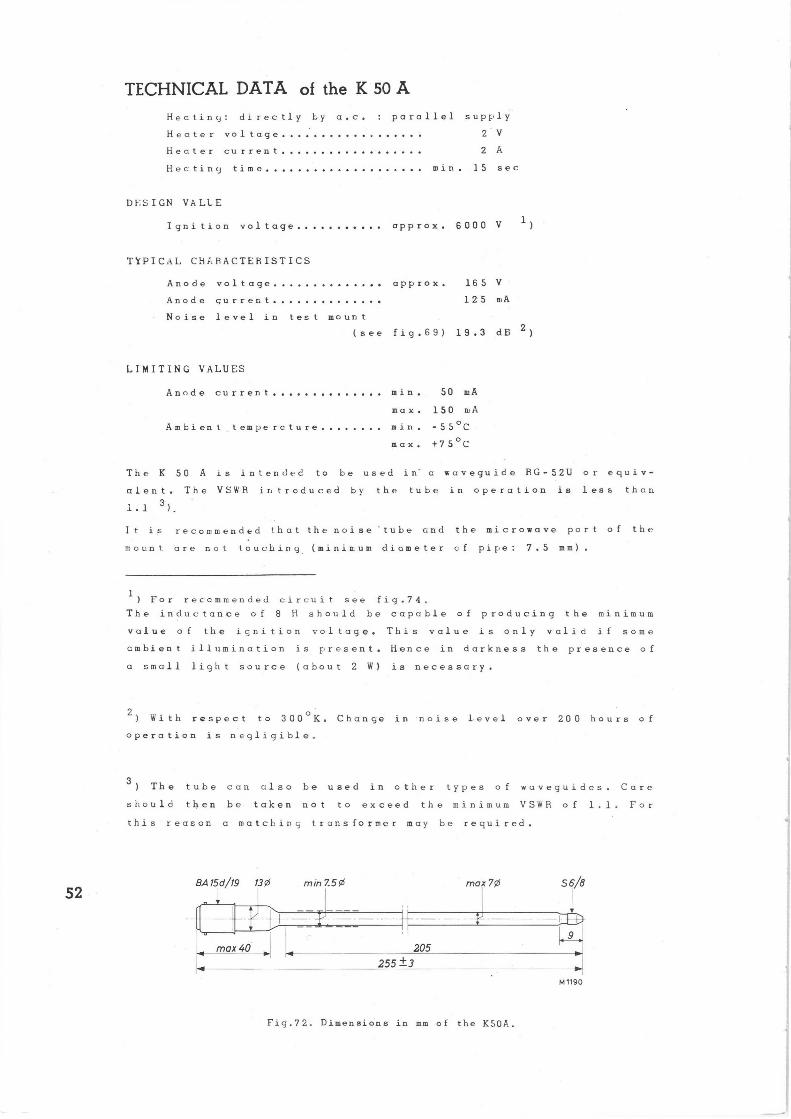
TECHNICAL DATA of the K 50 A
Heating: directly by a.c. parallel supE~ly
Heater voltage 2 V
Heater current 2 A
Hea tincl time min 15 sec
DESIGN VALLE
Ignition voltage approx. 6000 V
TYPICAL CHI.RACTERISTICS
Anode voltage approx. 165 V
Anode Gurrer.t
Noise level in test mount
125 mA
(see fig.69) 19.3 dB 2)
LIMITING VALUES
52
Anode current
Ambient temperoture
min. 50 mA
max. 150 mA
min. -55°C
max. +75oC
The K 50 A is intended to be used in' c waveguide AG -52U or equiv-
alent. The VSW'R introduced by the tube in operation is less than
1.1 3)
It is recommended that the noise 'tube and the microwave port of the
mount are not touching (minimum diameter cf pipe: 7.5 mm).
1 ) For reccmmended circuit see fig.74.
The inductance of 8 H should be capable of producing the minimum
value of the ignition voltage. This value is only valid if some
cmbient illumination is present. Hence in darkness the presence of
a small light source (about 2 W) is necessary.
2) With respect to 300oK. Change in noise level over 200 hours of
operation is negligible.
3) The tube can also be used in other types of waveguides Care
should then be taken not to exceed the minimum VSWR of 1.1. For
this reason a matching transformer may be required.
BA 15d/19 1391
~ ~ min 7.Sf~
- ~_ --- ~ mox 40
max 7¢ 56~B
205
255 ±3
Fig.72. Dimensions in mm of the K50A.
M 1190
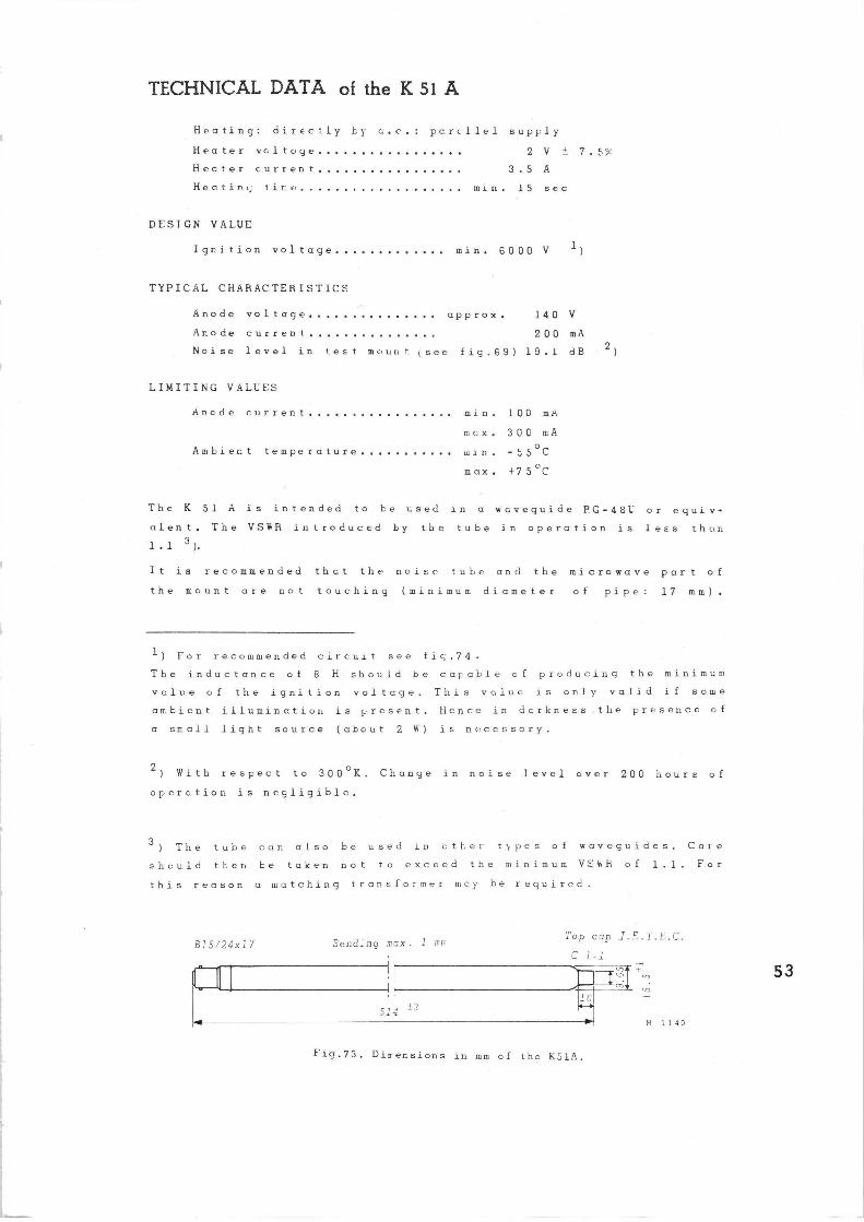
TECHNICAL DATA of the K 51 A
Heating: directly by c.c. percllel supply
Heater vcltuye 2 V +. 7.`~%
Heater current 3,5 A
Heatin.~ tice min. 15 sec
DESIGN VALUE
Ignition voltage min. 6000 V 1)
TYPICAL CHARACTERISTICS
Anode voltage approx. 140 V
Anode current 200 mA
Noise level in test mount (see fig.69) 19.1 dB 2)
LIMITING VALUES
Anode current min. 100 mA
max. 300 mA
Ambient temperature ;sin. -55oC
max. +75oC
The K 51 A is intended to be used in a waveguide P.G-48U or equiv-
alent. The VSWR introduced by the tube in operation is lees than
1.1 3 ).
It is recommended thct the noise tube an<i the microwave pert 4'f
the mount are not touching (minimum diameter of pipe: 17 mm).
1) For recommended circuit see fic.74•
The inductance of 8 H should he capable of producing the minimum
value of the ignition voltage. This value is only valid if some
ambient illumination is present. Hence in derkness .the presence of
a ssall light souice (about 2 V+) is necessary.
z) With respect to 300°K. Change in noise level over 200 hours of
operation is negligible.
3) The tube can also be used in ether tppes of waveguides. Care
should then be taken not to exceed the minimum V;;R'R of 1.1 F.or
this reason a matching transformer may be required.
B15/24x17 Bending max. 1 mm
~ ~
514 i3
Top cap J.E.T.E.C.
C 1-1 ~~.~,c +~ ~ ~
rn* ~
1n .--►
Fig.7's. Din ensions in mm of the KS1A.
n~ 11 a o
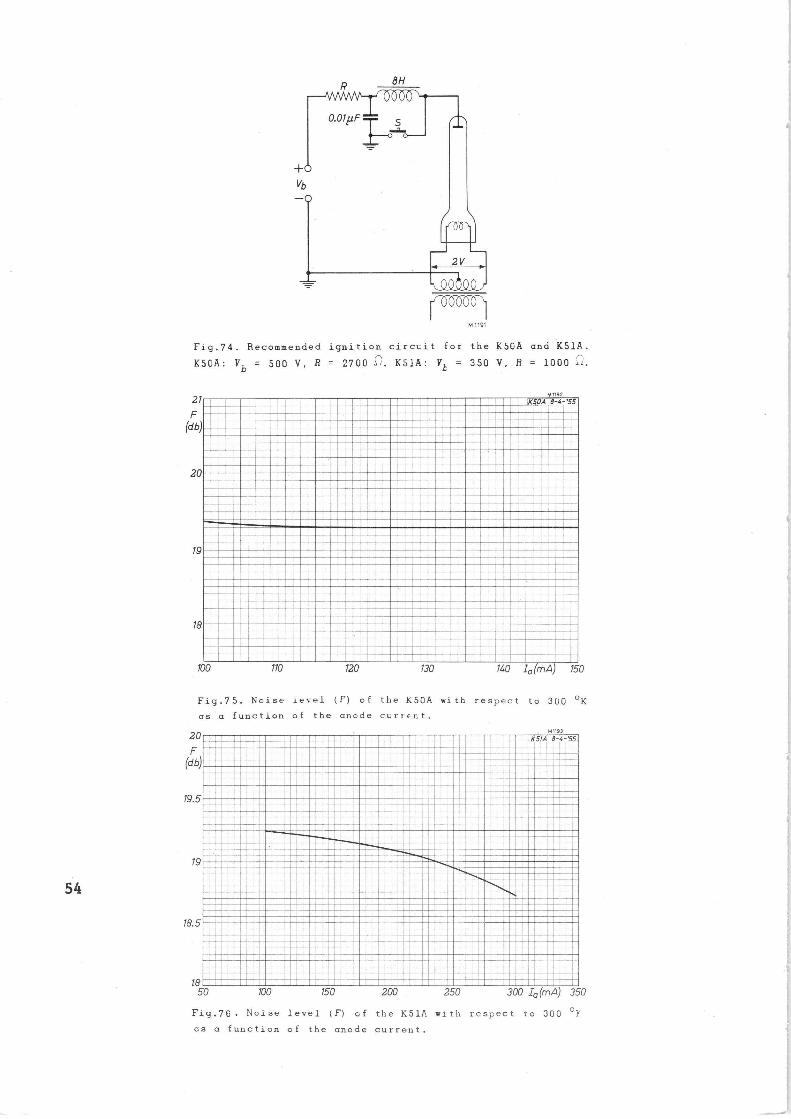
eH
M 1191
Fig.74. Recommended ignition circuit for the KSGA and K51A.
K50A: Vb = 500 V, R = 2700 1i. K5]A: Yb = 350 V, R = 1000 ~~.
21
F (db)
20
19
18
M 119]
XSOA 8-4-'S5
100 110 120 130 140 I a (mA) 150
Fig.75. Noise iecel (F) of the KSGA with respect to 300 °K
as a function of the anode current.
20
F (db)
19.5
19
93
KS/A B-4-'S5
18.5
18 50 100 150
i
~~
~~ 1 ~ ~f ~ i 200 250 300 I o (mA) 350
Fig.76• Noise level (F) of the KS1A with respect to 300 °k
as a function of the anode current.

The information given in this Bulletin does
not imply a licence under any patent.
55


Printed in Holland 20 D/5187-E-4-55