transmission line parameter calculations
TRANSCRIPT
Transmission Line parameter calculations
Prof. N.VISALI
Dept. of EEE,
JNTUA College of Engineering, Kalikiri
Chittoor District, A.P, India
Prof. N.Visali, Dept. of EEE, JNTUA College of Engineering, Kalikiri, Chittoor District, A.P, India
Outline of Presentation
Prof. N.Visali, Dept. of EEE, JNTUA College of Engineering, Kalikiri, Chittoor District, A.P, India
Basic Structure of a Power System
Conductors
Transmission line Model
Calculation of inductance
Calculation of capacitance
Previous GATE problems
Work for Students
Basic Structure of a Power System
Prof. N.Visali, Dept. of EEE, JNTUA College of Engineering, Kalikiri, Chittoor District, A.P, India
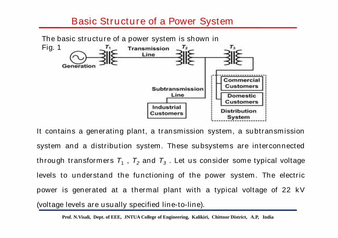
The basic structure of a power system is shown in Fig. 1
It contains a generating plant, a transmission system, a subtransmission
system and a distribution system. These subsystems are interconnected
through transformers T1 , T2 and T3 . Let us consider some typical voltage
levels to understand the functioning of the power system. The electric
power is generated at a thermal plant with a typical voltage of 22 kV
(voltage levels are usually specified line-to-line).
Prof. N.Visali, Dept. of EEE, JNTUA College of Engineering, Kalikiri, Chittoor District, A.P, India
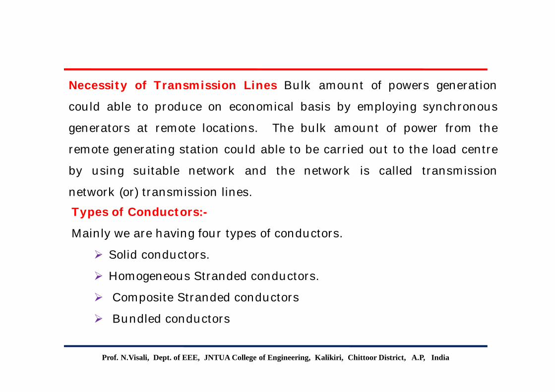
Necessity of Transmission Lines Bulk amount of powers generation
could able to produce on economical basis by employing synchronous
generators at remote locations. The bulk amount of power from the
remote generating station could able to be carried out to the load centre
by using suitable network and the network is called transmission
network (or) transmission lines.
Types of Conductors:-
Mainly we are having four types of conductors.
Solid conductors.
Homogeneous Stranded conductors.
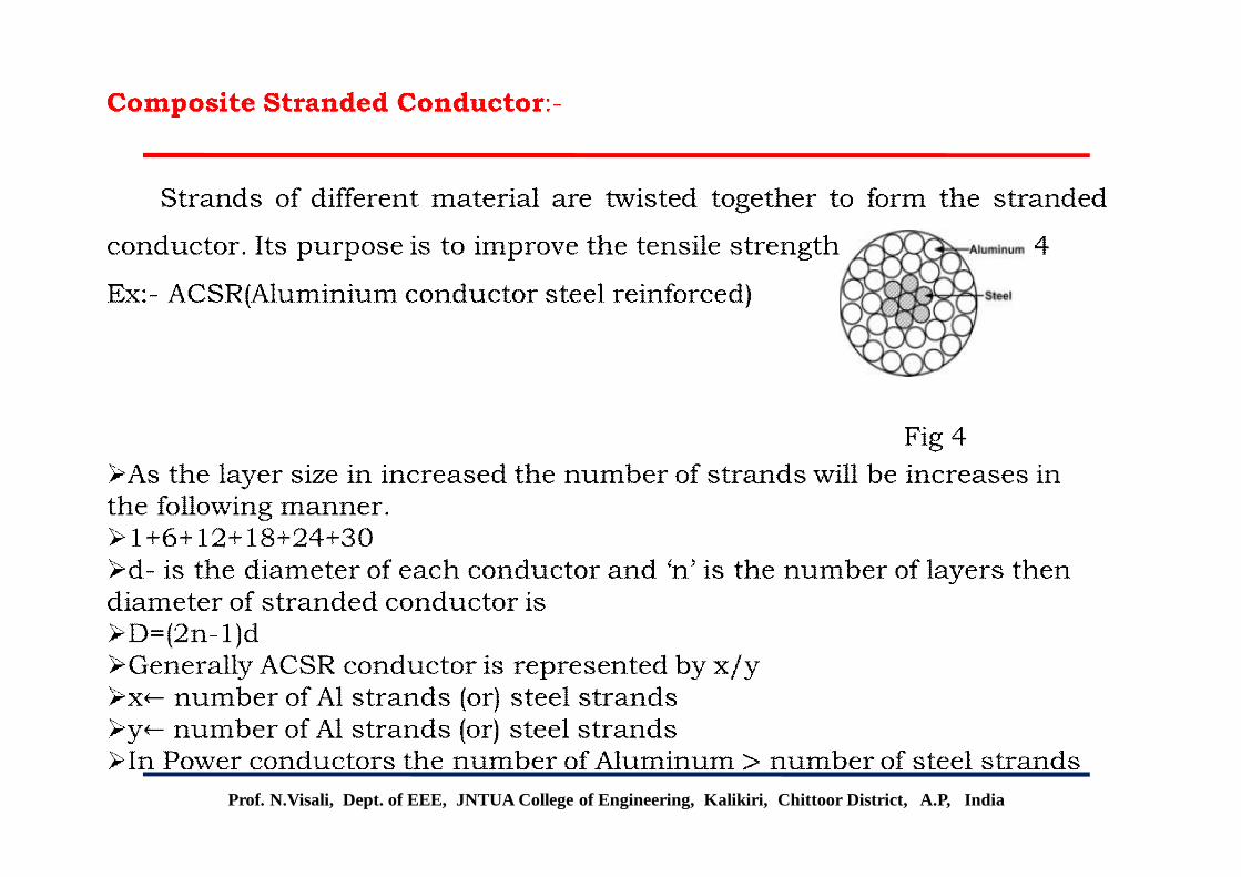
Composite Stranded conductors
Bundled conductors
Prof. N.Visali, Dept. of EEE, JNTUA College of Engineering, Kalikiri, Chittoor District, A.P, India
Solid conductors:-
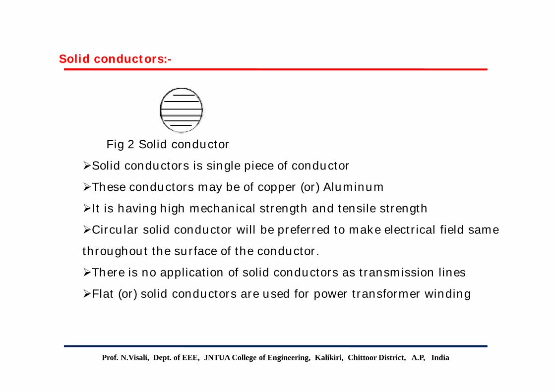
Fig 2 Solid conductor
Solid conductors is single piece of conductor
These conductors may be of copper (or) Aluminum
It is having high mechanical strength and tensile strength
Circular solid conductor will be preferred to make electrical field same
throughout the surface of the conductor.
There is no application of solid conductors as transmission lines
Flat (or) solid conductors are used for power transformer winding
Prof. N.Visali, Dept. of EEE, JNTUA College of Engineering, Kalikiri, Chittoor District, A.P, India
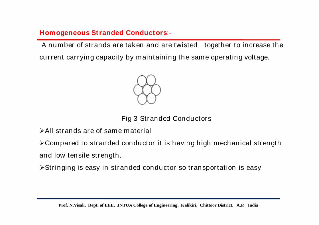
Homogeneous Stranded Conductors:-
A number of strands are taken and are twisted together to increase the
current carrying capacity by maintaining the same operating voltage.
Fig 3 Stranded Conductors
All strands are of same material
Compared to stranded conductor it is having high mechanical strength
and low tensile strength.
Stringing is easy in stranded conductor so transportation is easy
Prof. N.Visali, Dept. of EEE, JNTUA College of Engineering, Kalikiri, Chittoor District, A.P, India
Prof. N.Visali, Dept. of EEE, JNTUA College of Engineering, Kalikiri, Chittoor District, A P, India
Bundled conductorsWhen voltage is above 230kV, corona loss and interference with the
communication lines is more. Corona occurs when the surface potential
gradient of a conductor exceeds the dielectric strength of the
surrounding air. This causes ionization of the area near the conductor.
The high voltage surface gradient is reduced by using two or more
conductors per phase in close proximity. This is called conductor
bundling.
The conductors of a bundle are separated at regular intervals
with spacer dampers that prevent clashing of the conductors and prevent
them from swaying in the wind.

Prof. N.Visali, Dept. of EEE, JNTUA College of Engineering, Kalikiri, Chittoor District, A P, India
Bundled conductors Cont.The conductors are bundled in groups of two, three or four as shown in
below Fig.
3s
9 3sb3,s ddDddDD
Fig: Three conductors per phase
416 4
4, 09.12 dddDdddDD ssbs
Fig: Four conductors per phase
dDdDDselfGMDGMR ssbs 4 22,
Fig: Two conductors per phase
d
Prof. N.Visali, Dept. of EEE, JNTUA College of Engineering, Kalikiri, Chittoor District, A P, India
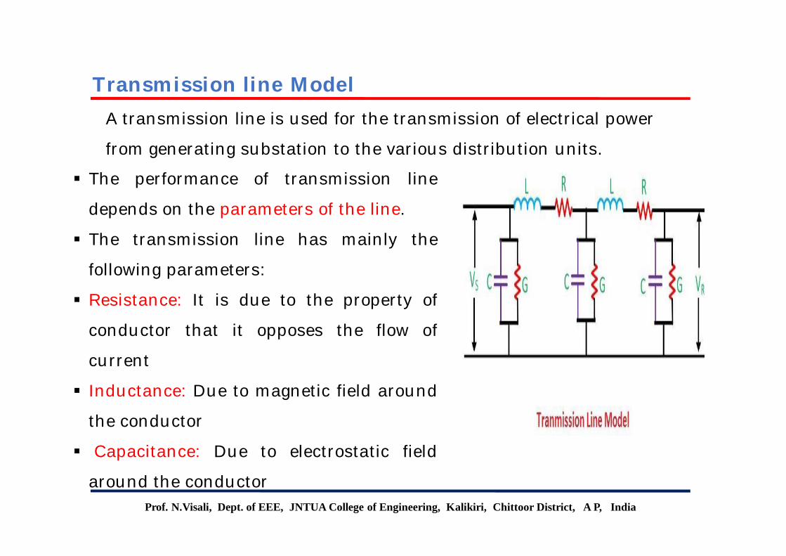
The performance of transmission line
depends on the parameters of the line.
The transmission line has mainly the
following parameters:
Resistance: It is due to the property of
conductor that it opposes the flow of
current
Inductance: Due to magnetic field around
the conductor
Capacitance: Due to electrostatic field
around the conductor
A transmission line is used for the transmission of electrical power
from generating substation to the various distribution units.
Transmission line Model
Prof. N.Visali, Dept. of EEE, JNTUA College of Engineering, Kalikiri, Chittoor District, A P, India
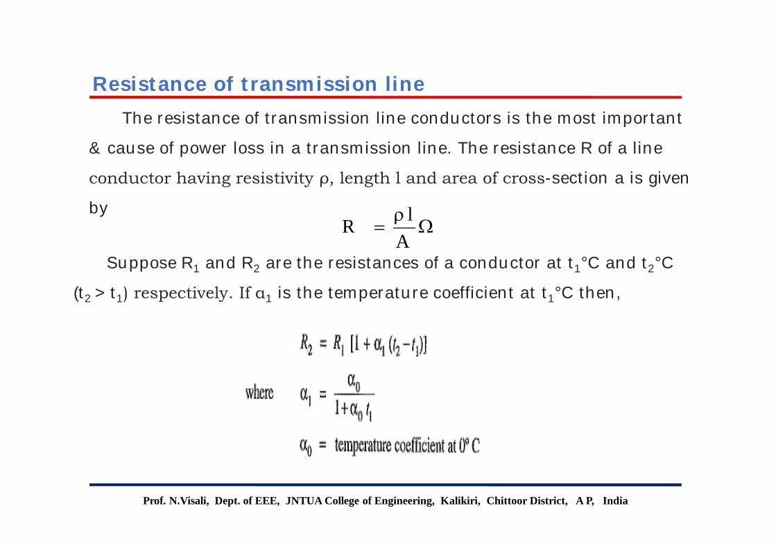
The resistance of transmission line conductors is the most important
& cause of power loss in a transmission line. The resistance R of a line
conductor having resistivity ρ, length l and area of cross-section a is given
by
Suppose R1 and R2 are the resistances of a conductor at t1°C and t2°C
(t2 > t1) respectively. If α1 is the temperature coefficient at t1°C then,
Resistance of transmission line
A
lR
Prof. N.Visali, Dept. of EEE, JNTUA College of Engineering, Kalikiri, Chittoor District, A P, India
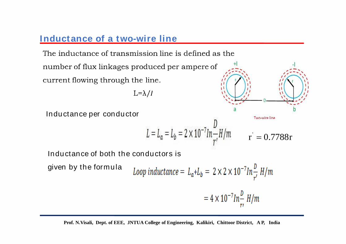
Inductance per conductor
Inductance of both the conductors is
given by the formula
Inductance of a two-wire line
r7788.0r '

Prof. N.Visali, Dept. of EEE, JNTUA College of Engineering, Kalikiri, Chittoor District, A P, India
The inductance of conductor, ‘a’ is
• The inductance of conductors b and c
will also be the same as that of a.
• The inductance of the three-phase line
is equal to the two-wire line.
Inductance of symmetrical three-phase line
Similarly,
Prof. N.Visali, Dept. of EEE, JNTUA College of Engineering, Kalikiri, Chittoor District, A P, India
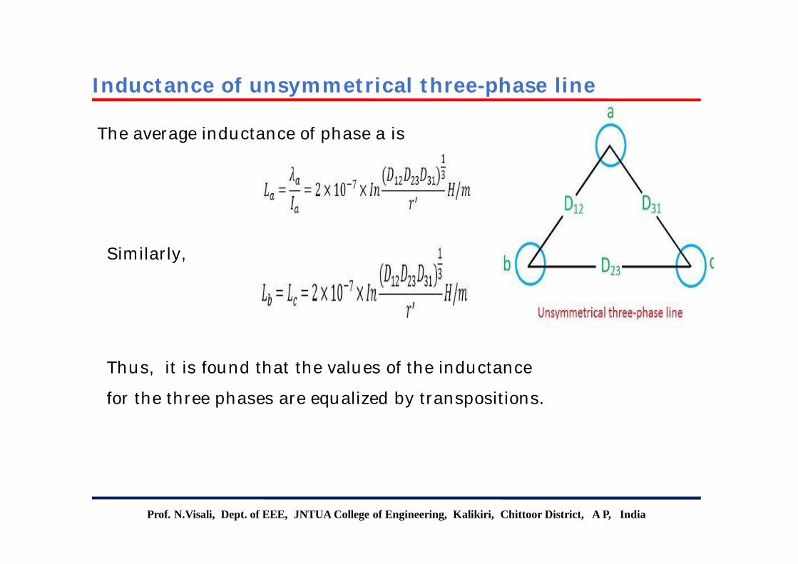
The average inductance of phase a is
Thus, it is found that the values of the inductance
for the three phases are equalized by transpositions.
Inductance of unsymmetrical three-phase line
Prof. N.Visali, Dept. of EEE, JNTUA College of Engineering, Kalikiri, Chittoor District, A P, India
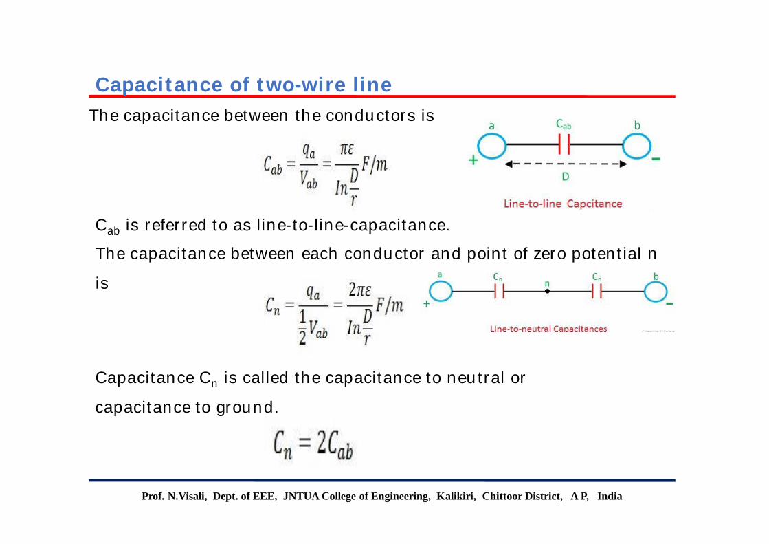
The capacitance between the conductors is
Cab is referred to as line-to-line-capacitance.
The capacitance between each conductor and point of zero potential n
is
Capacitance Cn is called the capacitance to neutral or
capacitance to ground.
Capacitance of two-wire line
Prof. N.Visali, Dept. of EEE, JNTUA College of Engineering, Kalikiri, Chittoor District, A P, India
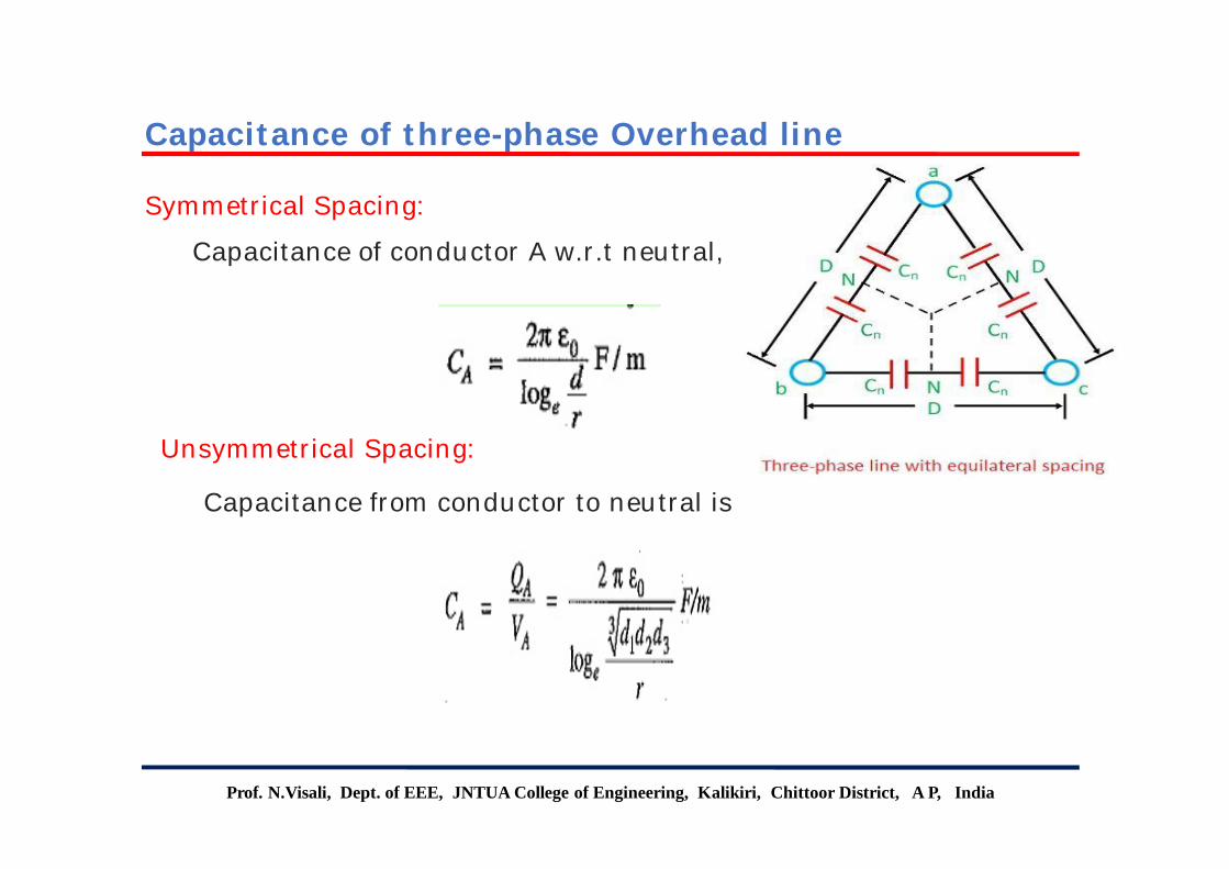
Symmetrical Spacing:
Capacitance of conductor A w.r.t neutral,
Unsymmetrical Spacing:
Capacitance from conductor to neutral is
Capacitance of three-phase Overhead line
Prof. N.Visali, Dept. of EEE, JNTUA College of Engineering, Kalikiri, Chittoor District, A.P, India
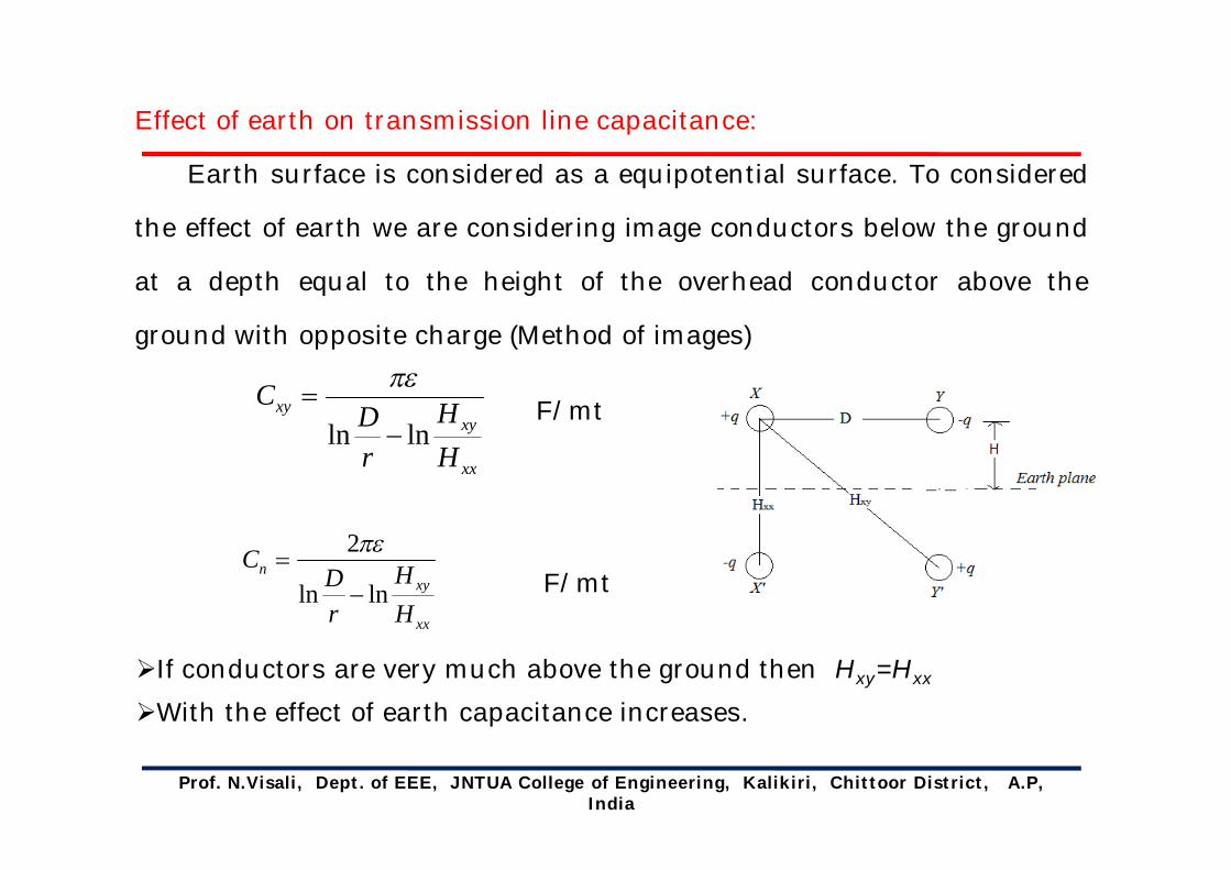
Effect of earth on transmission line capacitance:
Earth surface is considered as a equipotential surface. To considered
the effect of earth we are considering image conductors below the ground
at a depth equal to the height of the overhead conductor above the
ground with opposite charge (Method of images)
F/mt
F/mt
If conductors are very much above the ground then Hxy=Hxx
With the effect of earth capacitance increases.
xx
xyxy
HH
rD
Clnln
xx
xyn
HH
rD
Clnln
2
Prof. N.Visali, Dept. of EEE, JNTUA College of Engineering, Kalikiri, Chittoor District, A.P, India
mt/FGMRGMDln102L 7
1 mt/F
GMRGMDln
2Can
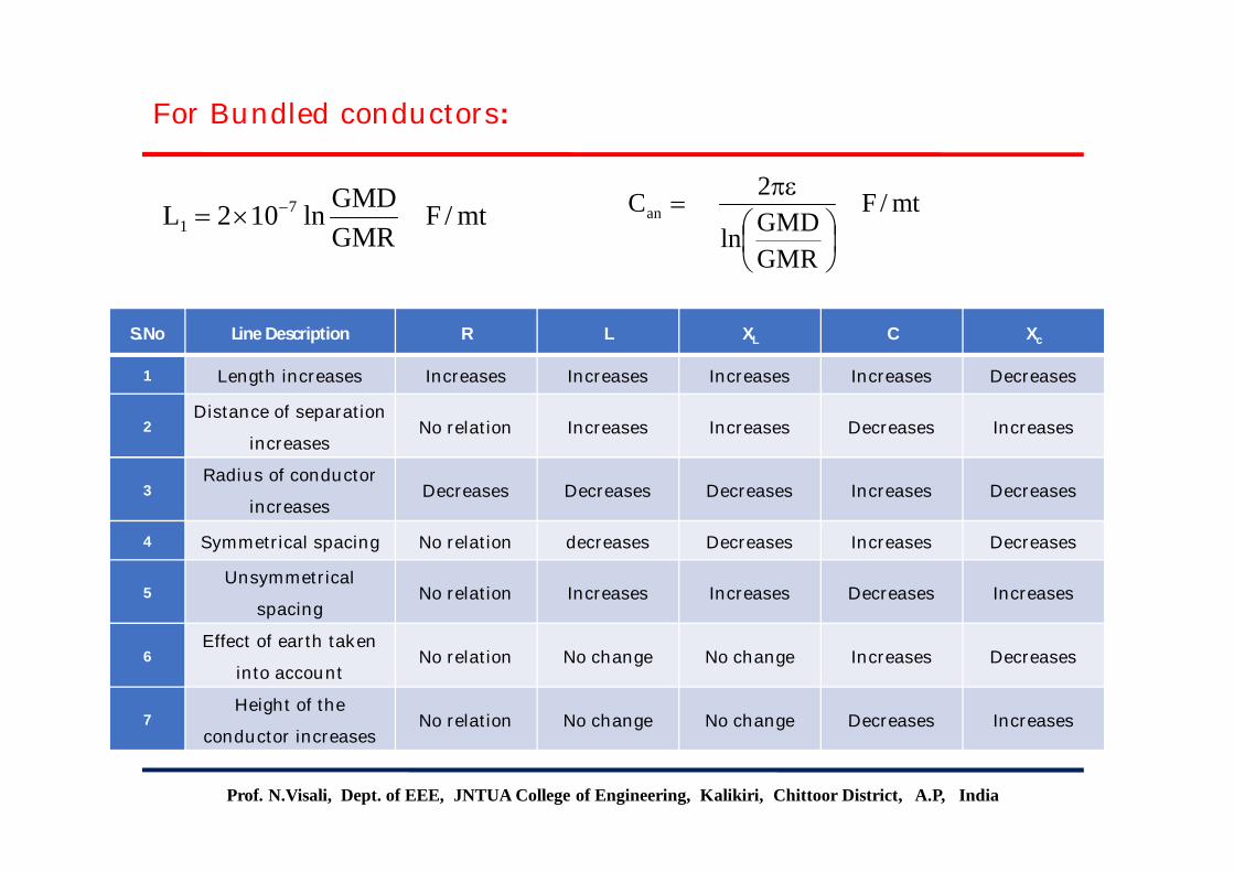
For Bundled conductors:
S.No Line Description R L XL C Xc
1 Length increases Increases Increases Increases Increases Decreases
2Distance of separation
increasesNo relation Increases Increases Decreases Increases
3Radius of conductor
increasesDecreases Decreases Decreases Increases Decreases
4 Symmetrical spacing No relation decreases Decreases Increases Decreases
5Unsymmetrical
spacingNo relation Increases Increases Decreases Increases
6Effect of earth taken
into accountNo relation No change No change Increases Decreases
7Height of the
conductor increasesNo relation No change No change Decreases Increases

Prof. N.Visali, Dept. of EEE, JNTUA College of Engineering, Kalikiri, Chittoor District, A P, India
PROBLEM: The inductance of a transmission line
increases with
a)Decrease in line length
b) Increase in diameter of conductor
c)Increase in spacing between the phase
conductors
d)Increase in load current carried by the
conductors
Previous GATE problems

Prof. N.Visali, Dept. of EEE, JNTUA College of Engineering, Kalikiri, Chittoor District, A P, India
PROBLEM: The insulation resistance of a cable of length 10km is
1 MὨ. For a length of 100km of same cable, the insulation
resistance will be
Sol:
Previous GATE problems
Prof. N.Visali, Dept. of EEE, JNTUA College of Engineering, Kalikiri, Chittoor District, A P, India
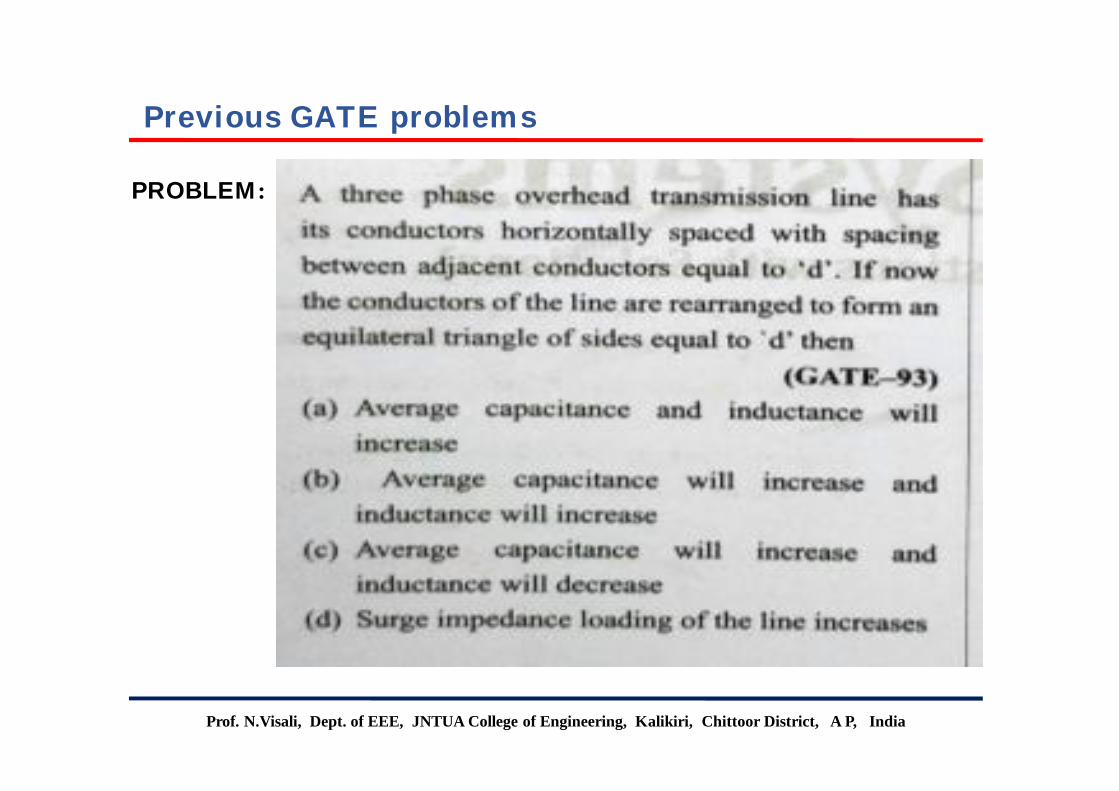
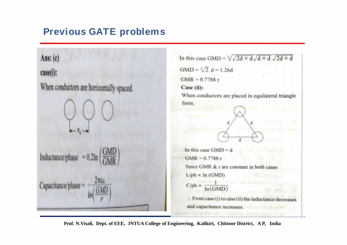
PROBLEM:
Previous GATE problems
Prof. N.Visali, Dept. of EEE, JNTUA College of Engineering, Kalikiri, Chittoor District, A P, India
Previous GATE problems
Prof. N.Visali, Dept. of EEE, JNTUA College of Engineering, Kalikiri, Chittoor District, A P, India
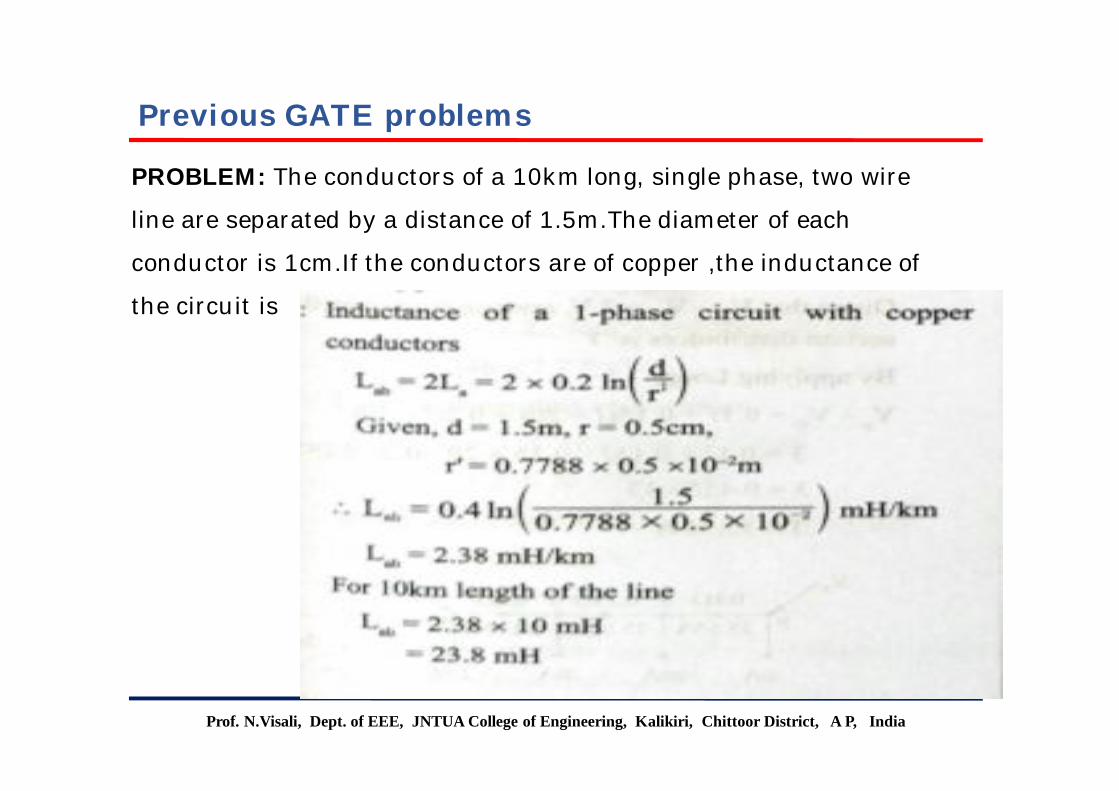
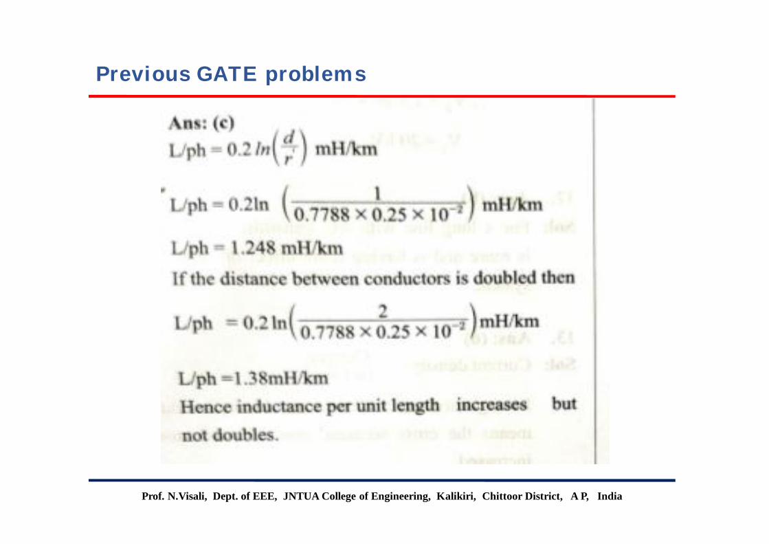
PROBLEM: The conductors of a 10km long, single phase, two wire
line are separated by a distance of 1.5m.The diameter of each
conductor is 1cm.If the conductors are of copper ,the inductance of
the circuit is
Previous GATE problems

Prof. N.Visali, Dept. of EEE, JNTUA College of Engineering, Kalikiri, Chittoor District, A P, India
PROBLEM:
Previous GATE problems
Prof. N.Visali, Dept. of EEE, JNTUA College of Engineering, Kalikiri, Chittoor District, A P, India
Previous GATE problems

Prof. N.Visali, Dept. of EEE, JNTUA College of Engineering, Kalikiri, Chittoor District, A P, India
PROBLEM: The horizontally spaced conductors of a single phase line
operating at 50hz are having outside diameter of 1.6cm and spacing
between Centre's of conductors is 6m.The permittivity of free space is
8.854*10-12 f/m. The capacitance to ground per km of each line is
Previous GATE problems
Prof. N.Visali, Dept. of EEE, JNTUA College of Engineering, Kalikiri, Chittoor District, A P, India
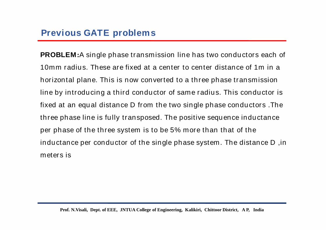
PROBLEM:A single phase transmission line has two conductors each of
10mm radius. These are fixed at a center to center distance of 1m in a
horizontal plane. This is now converted to a three phase transmission
line by introducing a third conductor of same radius. This conductor is
fixed at an equal distance D from the two single phase conductors .The
three phase line is fully transposed. The positive sequence inductance
per phase of the three system is to be 5% more than that of the
inductance per conductor of the single phase system. The distance D ,in
meters is
Previous GATE problems

Prof. N.Visali, Dept. of EEE, JNTUA College of Engineering, Kalikiri, Chittoor District, A P, India
Previous GATE problems
Prof. N.Visali, Dept. of EEE, JNTUA College of Engineering, Kalikiri, Chittoor District, A P, India
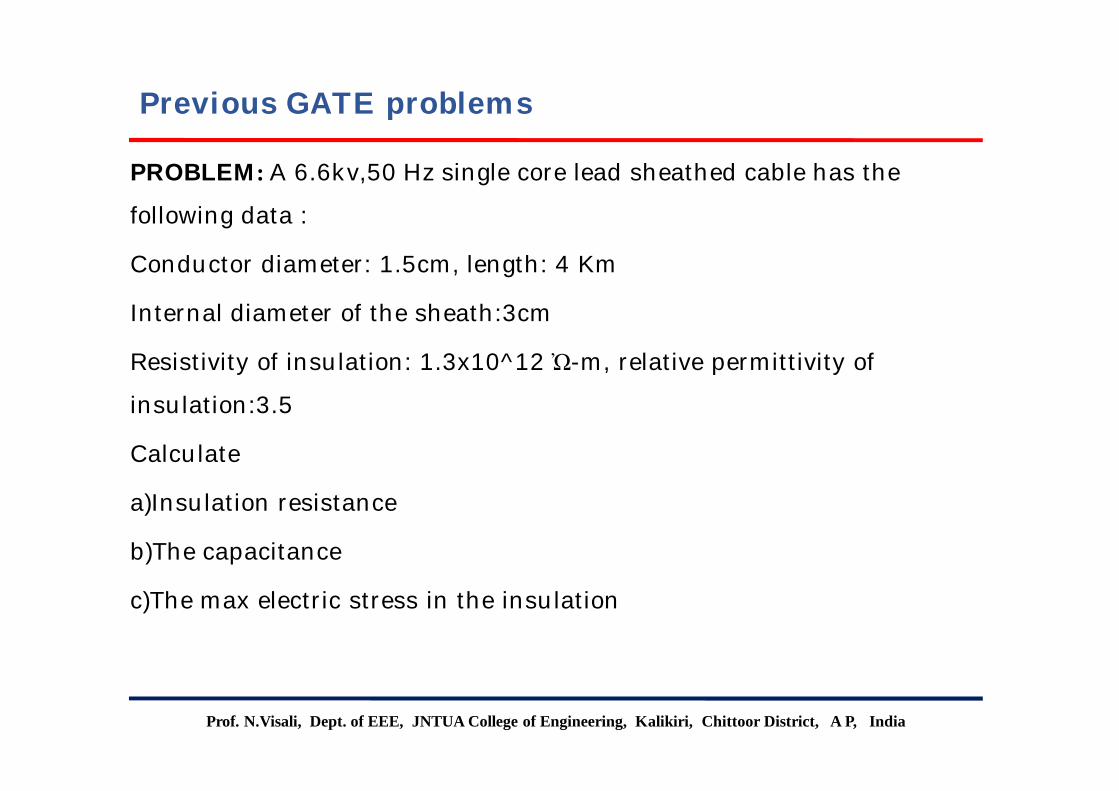
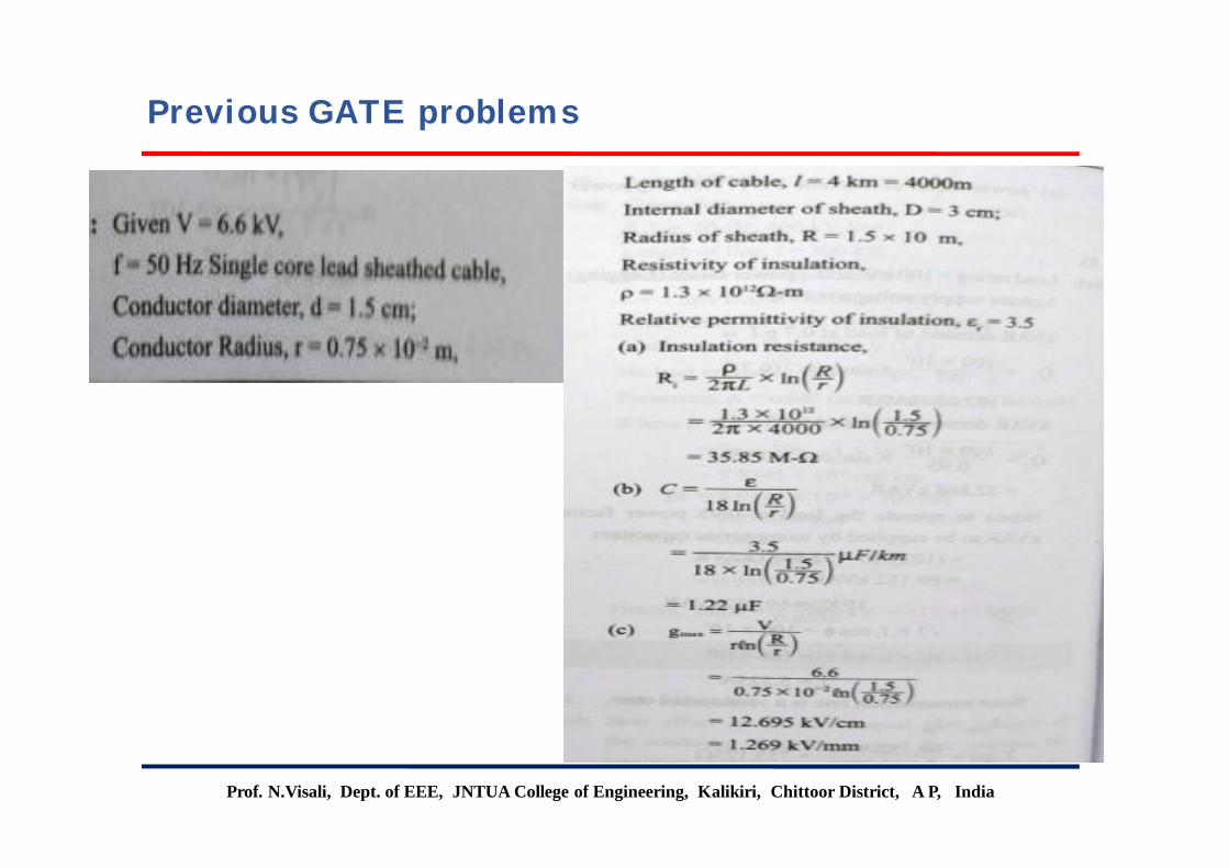
PROBLEM: A 6.6kv,50 Hz single core lead sheathed cable has the
following data :
Conductor diameter: 1.5cm, length: 4 Km
Internal diameter of the sheath:3cm
Resistivity of insulation: 1.3x10^12 Ὠ-m, relative permittivity of
insulation:3.5
Calculate
a)Insulation resistance
b)The capacitance
c)The max electric stress in the insulation
Previous GATE problems
Prof. N.Visali, Dept. of EEE, JNTUA College of Engineering, Kalikiri, Chittoor District, A P, India
Previous GATE problems

Q) The insulation level of a 400KV, EHV over head transmission line is deeded on the basis of (GATE-1995)(a)Lightning over voltage (b) Switching over voltage(c) Corona inception voltage (d) Radio and TV interference
Ans:- (b)
Hint:- In any transmission line lightning over voltages are more severe compared to switching over voltages. The lighting voltages are external voltages. Hence the insulation is provided for switching voltage.
Prof. N.Visali, Dept. of EEE, JNTUA College of Engineering, Kalikiri, Chittoor District, A P, India
Previous GATE questions
Q) A long wire composed of a smooth round conductor runs above parallel to the ground (Assumed to be a large conducting plane). A high voltage exists between the conductor and the ground. The maximum electric stress occurs at (GATE-2002)(a) The upper surface of the conductor (b)The lower surface of the conductor(c) The ground surface (d) Midway between the conductor and the ground
Ans:- (b)
Prof. N.Visali, Dept. of EEE, JNTUA College of Engineering, Kalikiri, Chittoor District, A P, India
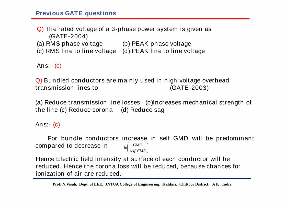
Q) The rated voltage of a 3-phase power system is given as(GATE-2004)
(a) RMS phase voltage (b) PEAK phase voltage(c) RMS line to line voltage (d) PEAK line to line voltage
Ans:- (c)
Q) Bundled conductors are mainly used in high voltage overhead transmission lines to (GATE-2003)
(a) Reduce transmission line losses (b)Increases mechanical strength of the line (c) Reduce corona (d) Reduce sag
Ans:- (c)
For bundle conductors increase in self GMD will be predominantcompared to decrease in
GMRself
GMD.
ln
Hence Electric field intensity at surface of each conductor will be reduced. Hence the corona loss will be reduced, because chances for ionization of air are reduced.
Previous GATE questions
Prof. N.Visali, Dept. of EEE, JNTUA College of Engineering, Kalikiri, Chittoor District, A P, India
Previous GATE questions
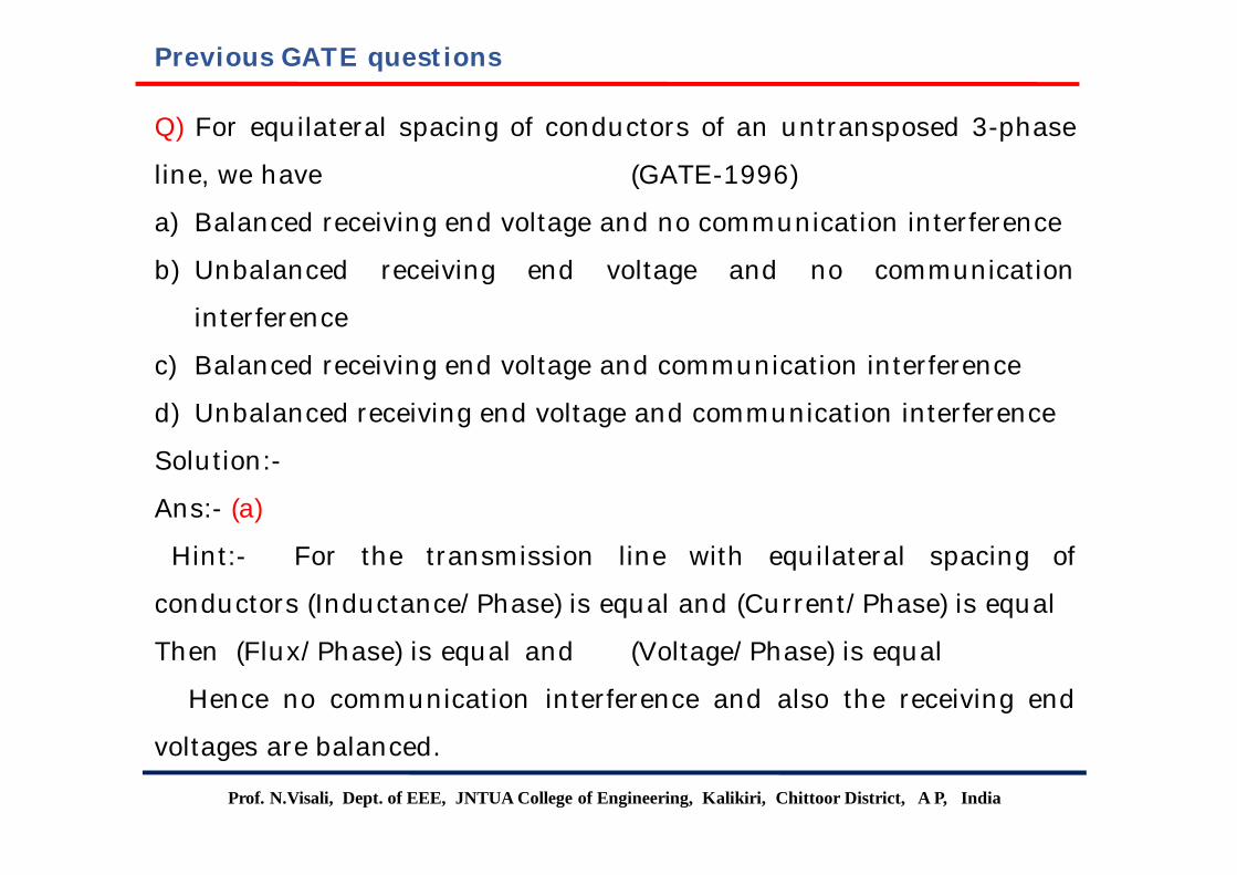
Q) For equilateral spacing of conductors of an untransposed 3-phase
line, we have (GATE-1996)
a) Balanced receiving end voltage and no communication interference
b) Unbalanced receiving end voltage and no communication
interference
c) Balanced receiving end voltage and communication interference
d) Unbalanced receiving end voltage and communication interference
Solution:-
Ans:- (a)
Hint:- For the transmission line with equilateral spacing of
conductors (Inductance/Phase) is equal and (Current/Phase) is equal
Then (Flux/Phase) is equal and (Voltage/Phase) is equal
Hence no communication interference and also the receiving end
voltages are balanced.
Prof. N.Visali, Dept. of EEE, JNTUA College of Engineering, Kalikiri, Chittoor District, A P, India
Previous GATE questions
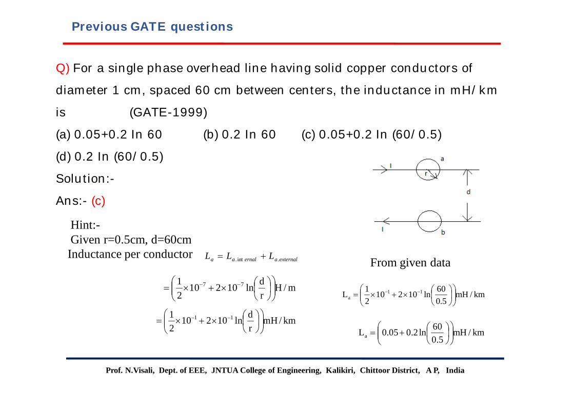
Q) For a single phase overhead line having solid copper conductors of
diameter 1 cm, spaced 60 cm between centers, the inductance in mH/km
is (GATE-1999)
(a) 0.05+0.2 In 60 (b) 0.2 In 60 (c) 0.05+0.2 In (60/0.5)
(d) 0.2 In (60/0.5)
Solution:-
Ans:- (c)
externalaernalaa LLL .int.
m/Hrdln10210
21 77
km/mHrdln10210
21 11
km/mH5.0
60ln1021021L 11
a
km/mH5.0
60ln2.005.0La
From given data
Hint:-Given r=0.5cm, d=60cmInductance per conductor
Prof. N.Visali, Dept. of EEE, JNTUA College of Engineering, Kalikiri, Chittoor District, A P, India
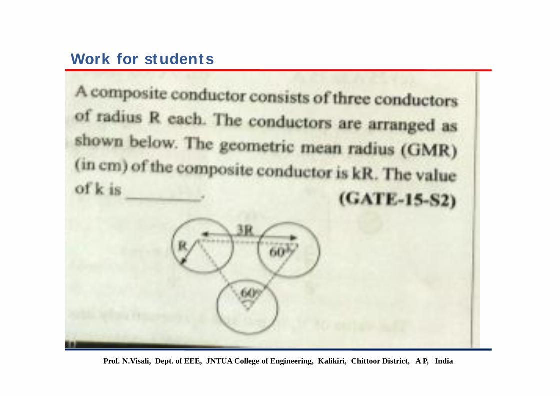
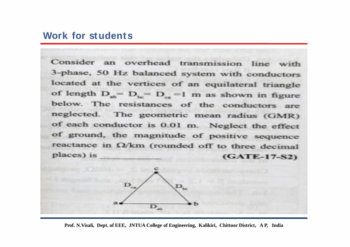
Work for students
Prof. N.Visali, Dept. of EEE, JNTUA College of Engineering, Kalikiri, Chittoor District, A P, India
Work for students
Prof. N.Visali, Dept. of EEE, JNTUA College of Engineering, Kalikiri, Chittoor District, A P, India
The End