transcritical co 2 heat pump systems: exergy analysis including heat transfer and fluid flow effects
TRANSCRIPT
www.elsevier.com/locate/enconman
Energy Conversion and Management 46 (2005) 2053–2067
Transcritical CO2 heat pump systems: exergy analysis includingheat transfer and fluid flow effects
J. Sarkar, Souvik Bhattacharyya *, M. Ram Gopal
Department of Mechanical Engineering, Indian Institute of Technology, Kharagpur 721302, India
Received 21 June 2004; received in revised form 21 June 2004; accepted 24 October 2004
Available online 13 December 2004
Abstract
This paper presents the exergetic analysis and optimization of a transcritical carbon dioxide based heat
pump cycle for simultaneous heating and cooling applications. A computer model has been developed first
to simulate the system at steady state for different operating conditions and then to evaluate the system per-formance based on COP as well as exergetic efficiency, including component wise irreversibility. The chosen
system includes the secondary fluids to supply the heating and cooling services, and the analyses also com-
prise heat transfer and fluid flow effects in detail. The optimal COP and the exergetic efficiency were found
to be functions of compressor speed, ambient temperature and secondary fluid temperature at the inlets to
the evaporator and gas cooler and the compressor discharge pressure. An optimization study for the best
allocation of the fixed total heat exchanger inventory between the evaporator and the gas cooler based on
heat transfer area has been conducted. The exergy flow diagram (Grassmann diagram) shows that all the
components except the internal heat exchanger contribute significantly to the irreversibilities of the system.Unlike a conventional system, the expansion device contributes significantly to system irreversibility.
Finally, suggestions for various improvement measures with resulting gains have been presented to attain
superior system performance through reduced component irreversibilities. This study is expected to offer
0196-8904/$ - see front matter � 2004 Elsevier Ltd. All rights reserved.
doi:10.1016/j.enconman.2004.10.022
* Corresponding author. Tel.: +91 3222 282904; fax: +91 3222 255303.
E-mail address: [email protected] (S. Bhattacharyya).
2054 J. Sarkar et al. / Energy Conversion and Management 46 (2005) 2053–2067
useful guidelines for system design and its optimisation and help toward energy conservation in heat pump
systems based on transcritical CO2 cycles.
� 2004 Elsevier Ltd. All rights reserved.
Keywords: CO2 heat pump; System simulation; Irreversibility; Exergetic optimization
1. Introduction
Discovery of the harmful effects of the synthetic refrigerants on the environment has created arenewed interest in eco-friendly natural refrigerants such as water, carbon dioxide, etc. Its ecolog-ically benign nature, low price, easy availability, non-flammability, non-toxicity, compatibilitywith various common materials, equipment compactness due to high operating pressures andexcellent transport properties are cited as some of the reasons behind the revival of carbon dioxideas a refrigerant. Carbon dioxide based heat pumps offer extensive possibilities in simultaneousheating and cooling applications due to the large temperature glide present in the gas cooler.
Exergy based second law analysis of various systems has become a very effective tool to measuresystem effectiveness and to design the system to maximize energy savings. Some researchers haveconducted exergy analyses for conventional vapour compression refrigeration systems and its com-ponents. Bridges et al. [1] have reported second law analysis of a R410a based domestic refrigeratorand a split air conditioner with fan coil optimization. Exergy analysis has been reported for anammonia based vapour compression refrigeration system [2] and also for a conventional refriger-ant based heat pump air conditioning system [3]. Apera et al. [4] conducted out exergy analyses of acompressor speed controlled vapour compression refrigeration system with refrigerant R22 and itssubstitutes R407c, R417a and R507 and chose R407C as the most suitable substitute. Exergy anal-ysis has also been done for system components such as heat exchangers for optimized performance[5]. Reported exergetic analyses of transcritical CO2 systems [6–9] have all been based only on thethermodynamic cycle using ideal assumptions. Such analyses for a complete CO2 heat pump sys-tem including the heat exchangers and the secondary fluids and considering entropy generation dueto both heat transfer and fluid flow effects have not been reported yet.
This paper presents a component level exergy analysis for the carbon dioxide based heat pumpto provide heating and cooling services simultaneously. The irreversibilities of all components andthe second law efficiency of the system for different values of the operating parameters such aswater inlet temperature, ambient temperature, compressor speed and the area ratio of the heatexchangers have been estimated. System optimization based on these results has been presentedas well. Finally, techniques to reduce the irreversibility for various components, which leads toimproved system exergertic efficiency, have been suggested.
2. Mathematical modelling
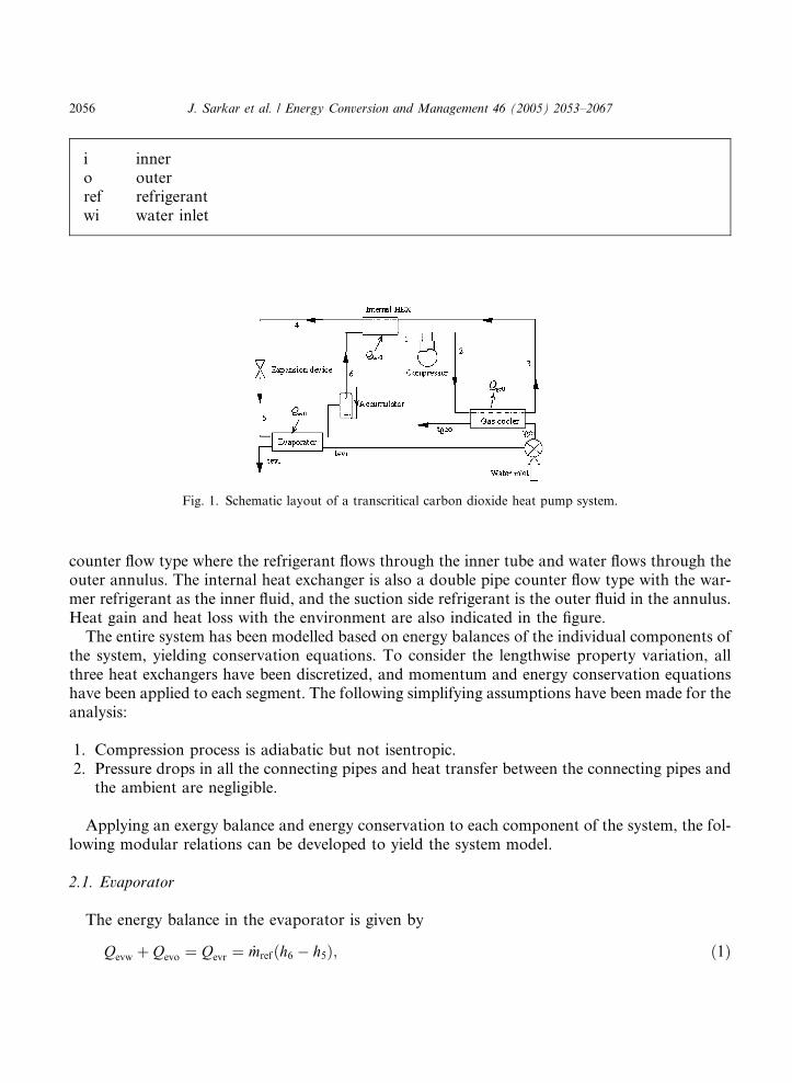
A simplified sketch of a carbon dioxide based heating and cooling system showing the maincomponents is shown in Fig. 1. Water is supplied as the heat exchanger fluid to both the gas coolerand evaporator through flow control valves. Both these heat exchangers are of the double pipe
Nomenclature
cpw water specific heat, kJkg�1K�1
d diameter of tube, mE exergy, Wf friction factorGr refrigerant mass velocity, kgm�2 s�1
h specific enthalpy, kJkg�1
I irreversibility, WL length of tube, m_mref refrigerant mass flow rate, kgs�1
_mevw water mass flow rate in evaporator, kgs�1
_mgcw water mass flow rate in gas cooler, kgs�1
Q heat transfer rate, WRe Reynolds numberRel Reynolds number for saturated liquids specific entropy, kJkg�1K�1
T temperature, KT0 ambient temperature, KTevw mean temperature of water in evaporator, KTgcw mean temperature of water in gas cooler, KThexr mean temperature of refrigerant in internal heat exchanger, KUA overall heat transfer coefficient area of heat transfer product, WK�1
x refrigerant dryness fraction in evaporatorDP pressure drop, bar
Greeksq density, kgm�3
gex second law efficiency
Subscripts1–6 state point of refrigerantev evaporatorevi evaporator inletevo evaporator outletevr evaporator, refrigerant sideevw evaporator, water sidegc gas coolergci gas cooler inletgco gas cooler outletgcr gas cooler, refrigerant sidegcw gas cooler, water side
J. Sarkar et al. / Energy Conversion and Management 46 (2005) 2053–2067 2055
i innero outerref refrigerantwi water inlet
Fig. 1. Schematic layout of a transcritical carbon dioxide heat pump system.
2056 J. Sarkar et al. / Energy Conversion and Management 46 (2005) 2053–2067
counter flow type where the refrigerant flows through the inner tube and water flows through theouter annulus. The internal heat exchanger is also a double pipe counter flow type with the war-mer refrigerant as the inner fluid, and the suction side refrigerant is the outer fluid in the annulus.Heat gain and heat loss with the environment are also indicated in the figure.
The entire system has been modelled based on energy balances of the individual components ofthe system, yielding conservation equations. To consider the lengthwise property variation, allthree heat exchangers have been discretized, and momentum and energy conservation equationshave been applied to each segment. The following simplifying assumptions have been made for theanalysis:
1. Compression process is adiabatic but not isentropic.2. Pressure drops in all the connecting pipes and heat transfer between the connecting pipes and
the ambient are negligible.
Applying an exergy balance and energy conservation to each component of the system, the fol-lowing modular relations can be developed to yield the system model.
2.1. Evaporator
The energy balance in the evaporator is given by
Q þ Q ¼ Q ¼ _mrefðh6 � h5Þ; ð1Þ
evw evo evr
J. Sarkar et al. / Energy Conversion and Management 46 (2005) 2053–2067 2057
where the heat gain in the evaporator refrigerant Qevr is given by
Qevr ¼XNi¼1
ðUAÞev;iðLMTDÞev;i; ð2Þ
Qevo is the heat gain from the ambient.The cooling effect Qevw is given by
Qevw ¼ _mevwcpwðT evi � T evoÞ: ð3Þ
The irreversibility or exergy loss in the evaporator is expressed asIev ¼ T 0 _mrefðs6 � s5Þ � _mevwcpw lnT evi
T evo
� �þ IDPevr þ IDPevw þ Qevo
T 0
T evw
� 1
� �; ð4Þ
where the temperature related terms on the right hand side are due to the temperature differenceand heat interaction with the ambient, respectively. The pressure related terms are due to the pres-sure drops in the refrigerant and water sides, respectively, and are given by
IDPevr þ IDPevw ¼ _mref
qevr
DP evr þ_mevw
qevw
DP evw; ð5Þ
DPevw is the pressure drop on the water side. The refrigerant side pressure drop DPevr (summationof pressure drops in all segments) is given by (using Lockhart and Martinelli equation)
DP evr ¼XNi¼1
4Lev
devi
fevr2
ð1� xÞ2 G2r
ql
/2l
� �i
; ð6Þ
where the friction factor is expressed as fevr ¼ 0:0791Re�0:25l .
The two phase frictional pressure drop multiplier is evaluated from
/l ¼ 1:376þ 7:242
X 1:655tt
� �1=2
; ð7Þ
where Xtt is the Lockhart–Martinelli factor.
2.2. Compressor
The exergy input to the compressor is given by
Ein ¼ _mrefðh2 � h1Þ: ð8Þ
The overall thermal efficiency for the semi-hermetic compressor has been calculated as [10]gis;c ¼ �0:26þ 0:7952rp � 0:2803r2p þ 0:0414r3p � 0:0022r4p; ð9Þ
with the compressor pressure ratio rp (=Pdis/Psuc) varying between 1.5 and 6.5.The irreversibility in the compressor is estimated from
Icomp ¼ T 0 _mrefðs2 � s1Þ: ð10Þ
2058 J. Sarkar et al. / Energy Conversion and Management 46 (2005) 2053–2067
2.3. Gas cooler
The energy balance in the gas cooler yields
Qgcw þ Qgco ¼ Qgcr ¼ _mrefðh2 � h3Þ; ð11Þ
where Qgcr is the heat transferred from the refrigerant in the gas cooler, given by
Qgcr ¼XNi¼1
ðUAÞgciðLMTDÞgci; ð12Þ
Qgco is the heat loss to the ambient.The heating effect Qgcw is given by
Qgcw ¼ _mgcwcpwðT gco � T gciÞ: ð13Þ
The resulting irreversibility is expressed as
Igc ¼ T 0 _mgcwcpw lnT gco
T gci
� _mrefðs2 � s3Þ� �
þ IDPgcr þ IDPgcw þ Qgco 1� T 0
T gcw
� �: ð14Þ
The irreversibility due to pressure drop is given by
IDPgcr þ IDPgcw ¼ _mr
qgcr
DP gcr þ_mgcw
qgcw
DP gcw; ð15Þ
where DPgcw is the water side pressure drop in the gas cooler. The refrigerant side pressure dropDPgcr is estimated by the correlation [11]
DP gcr ¼XNi¼1
G2r
qr
fgcrLgc
dgci
þ 1:2
� �� �i
ð16Þ
where the friction factor for the supercritical refrigerant flow is given by
fgcr ¼ ½0:79 lnðReÞ � 1:64��2: ð17Þ
2.4. Expansion device
The irreversibility during the expansion process is expressed as
I exp ¼ T 0 _mrefðs5 � s4Þ: ð18Þ
2.5. Internal heat exchanger
The heat balance in the internal heat exchanger yields
_mrðh1 � h6Þ ¼ _mrðh3 � h4Þ þ Qhex0; ð19Þ
where Qhex0 is the heat gain (+ sign) or loss (� sign) with the ambient.
J. Sarkar et al. / Energy Conversion and Management 46 (2005) 2053–2067 2059
The irreversibility in the internal heat exchanger is given by
Ihex ¼ T 0 _mref ½ðs1 � s6Þ � ðs3 � s4Þ� þ IDPhex þ Qhex0
T 0
T hexr
� 1
� �: ð20Þ
It may be noted that the last term on the right hand side of this equation is always positivewhether Thexr> or <T0, which indicates that the exergy is always degrading whether there is a heatloss or gain with the component. The heat transfers with the ambient for all the components havebeen estimated employing conventional natural convection equations assuming that no other heattransfer mode is existent. The UA values for all the heat exchanger segments were evaluated usingconventional overall heat transfer coefficient relations. The heat transfer coefficient for water inboth heat exchangers has been evaluated by the conventional Dittus–Boelter equation for annularflow. The refrigerant heat transfer coefficient for the gas cooler was calculated using the Pitla cor-relation [12] and that for the evaporator was estimated using the Wattelet–Carlo correlation [13].
The system performance measures are based on the system COP, which is the ratio of the totalheating and cooling output to the work input, and on the exergetic efficiency, which is the percent-age ratio of total exergy output to the exergy input. The output exergy can be found by subtract-ing the total system irreversibility (summation of irreversibilities of all the components in thesystem) from the exergy input to the system and is given by
gex ¼Ein �
PIComponents
Ein
� 100% ¼ 1�P
IComponents
Ein
� �� 100%: ð21Þ
3. Solution procedure
A computer code has been developed for the exergetic analysis of the transcritical carbondioxide based heat pump system envisaged for dairy application for various operating conditions.Using the new equation of state for CO2 [14] and transport property correlations available in theliterature [15], an exclusive code �CO2PROP� employing the technique based on the derivativesof the Helmholtz free energy function using efficient iterative procedures has been developed toestimate the thermodynamic and transport properties of carbon dioxide where the transcriticalzone has been included as well, the details of which have already been reported [9]. The propertyvariation is very abrupt near the critical region, and the gas cooler encompasses this regime. Toconsider this variation, the entire length of the gas cooler has been divided into several equal dis-crete segments, and each segment has been treated as a counter flow heat exchanger. In each seg-ment, the heat transfer coefficients for both refrigerant and water are calculated based on meanvalues. This way, the gas cooler is made equivalent to a number of counter flow heat exchangersarranged in series, and the combined heat transfer of all the segments is the total heat transfer ofthe gas cooler. Therefore, the fast changing properties of CO2 have been modelled accurately inthe gas cooler to yield good accuracy. For the evaporator and internal heat exchanger, similar dis-cretization has been performed as well to obtain good accuracy. At first, the system was simulatedbased on the energy balances for each component by a Newton–Raphson iterative method,employing heat transfer correlations and the subroutine code CO2PROP to evaluate the statepoints with all the necessary thermodynamic and transport properties, to get maximum accuracy.
2060 J. Sarkar et al. / Energy Conversion and Management 46 (2005) 2053–2067
Then, the irreversibility of each of the components, exergetic output and efficiency have been eval-uated using the exergy balance equations presented in the previous section.
4. Results and discussion
The System COP, component irreversibilities and system exergetic efficiency, based on com-bined heating and cooling, have been estimated for various inlet conditions for the heat exchangerfluid (water), compressor speed and heat exchanger dimensions of the heat pump envisaged toprovide heating at 73 �C and cooling at 4 �C simultaneously as is typically required in a dairyapplication. Stainless steel tubes with outer diameters of 3/8 in. (10 mm) and 5/8 in. (16 mm) havebeen chosen as the inner and outer tubes, respectively, for both the evaporator and gas cooler andalso for the internal heat exchanger. All these are concentric tube-in-tube type heat exchangers.The thickness of all the tubes has been taken as 0.815 mm. A Dorin compressor (TCS113) witha rated speed of 2900 rpm and a swept volume of 11.7 cm3 has been chosen [16]. Results are pre-sented for a total heat exchanger tube length of 25 m for both the evaporator and gas cooler. Theinternal heat exchanger length has been taken as 4 m, which yields an effectiveness of about 60%.Ambient temperature is taken to be 30 �C (average in the Indian sub-continent) for the analysis.
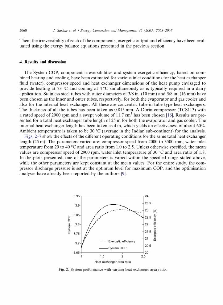
Figs. 2–7 show the effects of the different operating conditions for the same total heat exchangerlength (25 m). The parameters varied are: compressor speed from 2000 to 3500 rpm, water inlettemperature from 20 to 40 �C and area ratio from 1.0 to 2.5. Unless otherwise specified, the meanvalues are compressor speed of 2900 rpm, water inlet temperature of 30 �C and area ratio of 1.8.In the plots presented, one of the parameters is varied within the specified range stated above,while the other parameters are kept constant at the mean values. For the entire study, the com-pressor discharge pressure is set at the optimum level for maximum COP, and the optimisationanalyses have already been reported by the authors [9].
3.65
3.7
3.75
3.8
3.85
3.9
3.95
1 1.5 2.5
Heat exchanger area ratio
Syst
em C
OP
20
20.5
21
21.5
22
22.5
23
23.5
24
Exer
getic
effi
cien
cy (%
)
Exergetic efficiency
System COP
2
Fig. 2. System performance with varying heat exchanger area ratio.
J. Sarkar et al. / Energy Conversion and Management 46 (2005) 2053–2067 2061
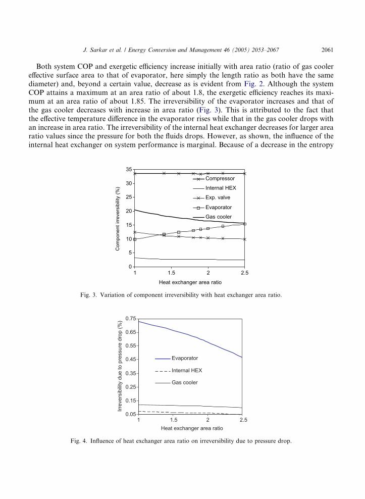
Both system COP and exergetic efficiency increase initially with area ratio (ratio of gas coolereffective surface area to that of evaporator, here simply the length ratio as both have the samediameter) and, beyond a certain value, decrease as is evident from Fig. 2. Although the systemCOP attains a maximum at an area ratio of about 1.8, the exergetic efficiency reaches its maxi-mum at an area ratio of about 1.85. The irreversibility of the evaporator increases and that ofthe gas cooler decreases with increase in area ratio (Fig. 3). This is attributed to the fact thatthe effective temperature difference in the evaporator rises while that in the gas cooler drops withan increase in area ratio. The irreversibility of the internal heat exchanger decreases for larger arearatio values since the pressure for both the fluids drops. However, as shown, the influence of theinternal heat exchanger on system performance is marginal. Because of a decrease in the entropy
0
5
10
15
20
25
30
35
1 1.5 2 2.5
Heat exchanger area ratio
Com
pone
nt ir
reve
rsib
ility
(%)
Compressor
Internal HEX
Exp. valve
Evaporator
Gas cooler
Fig. 3. Variation of component irreversibility with heat exchanger area ratio.
0.05
0.15
0.25
0.35
0.45
0.55
0.65
0.75
1 1.5 2 2.5Heat exchanger area ratio
Irrev
ersi
bilit
y du
e to
pre
ssur
e dr
op (%
)
Evaporator
Internal HEX
Gas cooler
Fig. 4. Influence of heat exchanger area ratio on irreversibility due to pressure drop.
2062 J. Sarkar et al. / Energy Conversion and Management 46 (2005) 2053–2067
generation rate at the lower pressure in the expansion valve, the irreversibility decreases as thearea ratio increases. Although the irreversibility due to pressure loss is negligible compared tothe total exergy loss (Fig. 4), that for the evaporator is significantly more than that yielded bythe internal heat exchanger and gas cooler. This could be attributed to the pressure drop in theevaporator being more than that in the gas cooler and internal heat exchanger due to both fric-tional and momentum effects.
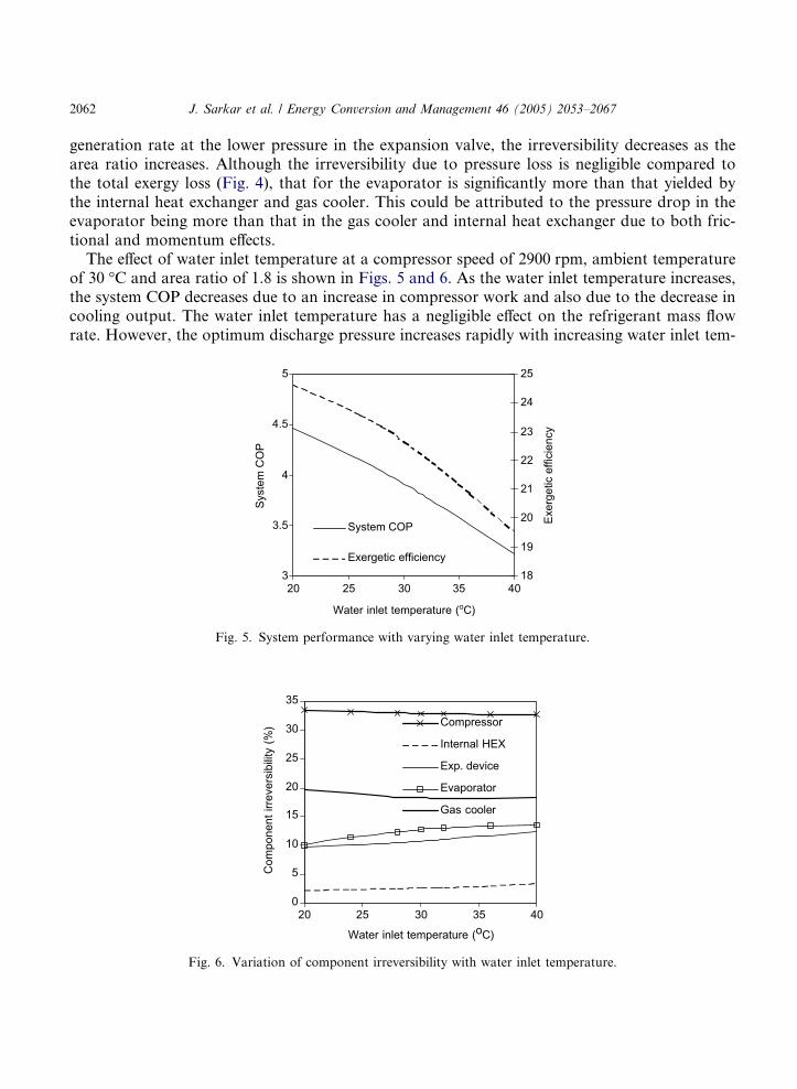
The effect of water inlet temperature at a compressor speed of 2900 rpm, ambient temperatureof 30 �C and area ratio of 1.8 is shown in Figs. 5 and 6. As the water inlet temperature increases,the system COP decreases due to an increase in compressor work and also due to the decrease incooling output. The water inlet temperature has a negligible effect on the refrigerant mass flowrate. However, the optimum discharge pressure increases rapidly with increasing water inlet tem-
3
3.5
4
4.5
5
20 25 30 35 40
Water inlet temperature (oC)
Syst
em C
OP
18
19
20
21
22
23
24
25
Exer
getic
effi
cien
cy
System COP
Exergetic efficiency
Fig. 5. System performance with varying water inlet temperature.
0
5
10
15
20
25
30
35
20 25 30 35 40
Water inlet temperature (oC)
Com
pone
nt ir
reve
rsib
ility
(%) Compressor
Internal HEX
Exp. device
Evaporator
Gas cooler
Fig. 6. Variation of component irreversibility with water inlet temperature.
3.8
3.9
4
4.1
2000 2500 3000 3500
Compressor speed (rpm)
Syst
em C
OP
20
21
22
23
24
25
Exer
getic
effi
cien
cy (%
)
System COP
Exergetic efficiency
Fig. 7. Effect of compressor speed on system performance.
J. Sarkar et al. / Energy Conversion and Management 46 (2005) 2053–2067 2063
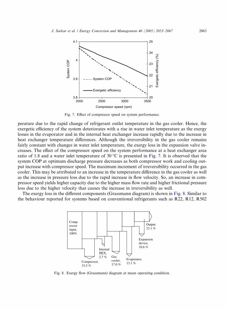
perature due to the rapid change of refrigerant outlet temperature in the gas cooler. Hence, theexergetic efficiency of the system deteriorates with a rise in water inlet temperature as the exergylosses in the evaporator and in the internal heat exchanger increase rapidly due to the increase inheat exchanger temperature differences. Although the irreversibility in the gas cooler remainsfairly constant with changes in water inlet temperature, the exergy loss in the expansion valve in-creases. The effect of the compressor speed on the system performance at a heat exchanger arearatio of 1.8 and a water inlet temperature of 30 �C is presented in Fig. 7. It is observed that thesystem COP at optimum discharge pressure decreases as both compressor work and cooling out-put increase with compressor speed. The maximum increment of irreversibility occurred in the gascooler. This may be attributed to an increase in the temperature difference in the gas cooler as wellas the increase in pressure loss due to the rapid increase in flow velocity. So, an increase in com-pressor speed yields higher capacity due to the higher mass flow rate and higher frictional pressureloss due to the higher velocity that causes the increase in irreversibility as well.
The exergy loss in the different components (Grassmann diagram) is shown in Fig. 8. Similar tothe behaviour reported for systems based on conventional refrigerants such as R22, R12, R502
Compressor, 33.5 %
InternalHEX,2.7 %
Expansion device, 10.6 %
Evaporator,13.1 %
Gascooler,17.0 %
Output23.1 %
Comp-ressor input, 100%
Fig. 8. Exergy flow (Grassmann) diagram at mean operating condition.
2064 J. Sarkar et al. / Energy Conversion and Management 46 (2005) 2053–2067
[4,17], the exergy loss is maximum in the compressor followed by that in the gas cooler, evapora-tor and expansion device, while the exergy loss in the internal heat exchanger is negligible. Becauseof the high pressure drop occurring in the system being studied, the expansion device contributes amuch larger fraction of the irreversibility compared to conventional systems.
5. Measures to improve exergetic efficiency
The exergy loss is relatively high in the compressor, gas cooler, evaporator and expansion valve,while that in the internal heat exchanger is insignificant. Hence, the contribution of the internalheat exchanger towards exergy destruction and its influence on the system performance is not pre-dominant, although by increasing the effective heat transfer area, we can modestly increase theeffectiveness as well as the system COP and exergetic efficiency of the system. The primary chal-lenge is to improve the system performance and exergetic efficiency by improving the performance(by controlling exergy loss) of the above stated four influential components. Some of the impor-tant improvement measures are presented with their associated betterment in system performance.
5.1. Compressor
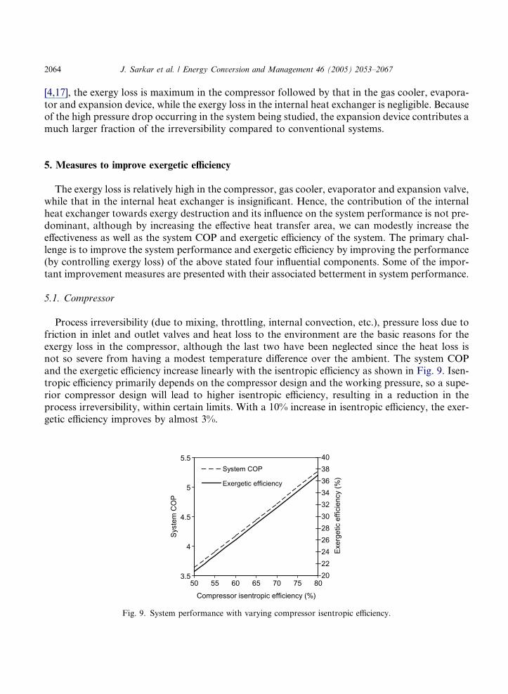
Process irreversibility (due to mixing, throttling, internal convection, etc.), pressure loss due tofriction in inlet and outlet valves and heat loss to the environment are the basic reasons for theexergy loss in the compressor, although the last two have been neglected since the heat loss isnot so severe from having a modest temperature difference over the ambient. The system COPand the exergetic efficiency increase linearly with the isentropic efficiency as shown in Fig. 9. Isen-tropic efficiency primarily depends on the compressor design and the working pressure, so a supe-rior compressor design will lead to higher isentropic efficiency, resulting in a reduction in theprocess irreversibility, within certain limits. With a 10% increase in isentropic efficiency, the exer-getic efficiency improves by almost 3%.
3.5
4
4.5
5
5.5
50 55 60 65 70 75 80
Compressor isentropic efficiency (%)
Syst
em C
OP
2022242628303234363840
Exer
getic
effi
cien
cy (%
)
System COP
Exergetic efficiency
Fig. 9. System performance with varying compressor isentropic efficiency.
J. Sarkar et al. / Energy Conversion and Management 46 (2005) 2053–2067 2065
5.2. Evaporator and gas cooler
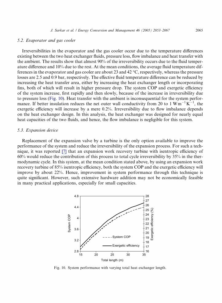
Irreversibilities in the evaporator and the gas cooler occur due to the temperature differencesexisting between the two heat exchanger fluids, pressure loss, flow imbalance and heat transfer withthe ambient. The results show that almost 90% of the irreversibility occurs due to the fluid temper-ature difference and 10% due to the rest. At the mean conditions, the average fluid temperature dif-ferences in the evaporator and gas cooler are about 23 and 42 �C, respectively, whereas the pressurelosses are 2.5 and 0.9 bar, respectively. The effective fluid temperature difference can be reduced byincreasing the heat transfer area, either by increasing the heat exchanger length or incorporatingfins, both of which will result in higher pressure drop. The system COP and exergetic efficiencyof the system increase, first rapidly and then slowly, because of the increase in irreversibility dueto pressure loss (Fig. 10). Heat transfer with the ambient is inconsequential for the system perfor-mance. If better insulation reduces the net outer wall conductivity from 20 to 1 Wm�1K�1, theexergetic efficiency will increase by a mere 0.2%. Irreversibility due to flow imbalance dependson the heat exchanger design. In this analysis, the heat exchanger was designed for nearly equalheat capacities of the two fluids, and hence, the flow imbalance is negligible for this system.
5.3. Expansion device
Replacement of the expansion valve by a turbine is the only option available to improve theperformance of the system and reduce the irreversibility of the expansion process. For such a tech-nique, it was reported [7] that an expansion work recovery turbine with isentropic efficiency of60% would reduce the contribution of this process to total cycle irreversibility by 35% in the ther-modynamic cycle. In this system, at the mean condition stated above, by using an expansion workrecovery turbine of 85% isentropic efficiency, both the system COP and the exergetic efficiency willimprove by about 22%. Hence, improvement in system performance through this technique isquite significant. However, such extensive hardware addition may not be economically feasiblein many practical applications, especially for small capacities.
2.8
3.2
3.6
4
4.4
4.8
15 20 25 30 35
Total length (m)
Syst
em C
OP
16171819202122232425262728
Exer
getic
effi
cien
cy (%
)
System COP
Exergetic efficiency
Fig. 10. System performance with varying total heat exchanger length.
2066 J. Sarkar et al. / Energy Conversion and Management 46 (2005) 2053–2067
6. Conclusions
Exergetic analyses of a transcritical carbon dioxide based heat pump to provide heating andcooling simultaneously have been presented here. Unlike previous studies reported in the litera-ture, realistic heat transfer and fluid flow effects have been included. A computer model has beendeveloped first to simulate the system at steady state for different operating conditions and then toevaluate the system performance based on COP as well as exergetic efficiency. Component levelirreversibility analyses have been performed. The highly variable thermophysical and transportproperties of the refrigerant near the critical point have been taken into account to obtain betteraccuracy. Spatial discretization of all the heat exchangers has been used as well to yield better pre-cision. Results are obtained by varying the important operating and design parameters such asheat exchanger area ratio, compressor speed, water inlet temperature and ambient temperatureover a given range. The results show that:
1. The optimum heat exchanger area ratio ranges between 1.8 and 1.9 for maximum systemCOP as well as maximum exergetic efficiency at optimum discharge pressure.
2. The favourable heat transfer properties of carbon dioxide in both the two phase and super-critical region and an efficient compression process contribute significantly toward high sys-tem COPs and exergetic efficiency values. The temperature differences in the heat exchangerscontribute more that 90% of their irreversibilities, whereas the rest occurs due to pressuredrop and the system imbalance in the heat exchanger.
3. It is more effective to maintain the secondary fluid inlet temperature as low as possible to gethigher COP and exergetic efficiency within the given range.
4. The compressor, evaporator, gas cooler and expansion device contribute to system irrevers-ibility to a larger extent, while the internal heat exchanger has a negligible effect. The expan-sion valve contributes a significant amount of exergy loss here, whereas it is negligible for aconventional system.
5. It is effective, in terms of improvement in COP and exergetic efficiency, to employ a large heatexchanger area by increasing the length or by using fins, which will also attract additionalinvestment and higher pressure drop. Hence, there is an optimal trade-off between the two.
6. Replacement of the expansion valve with a turbine will increase the COP as well as the exer-getic efficiency significantly, but it will also raise issues related to cost, design and dynamicbalancing of the system. It is advisable to employ a turbine for large systems, such as a largedairy plant or other large system where simultaneous cooling and heating is useful.
References
[1] Bridges BD, Harshbarger DS, Bullard CW. Second law analysis of refrigerator and air conditioners. ASHRAE
Trans 2001:644–51.
[2] Yumrutas R, Kundus M, Kanoglu M. Exergy analysis of vapor compression refrigeration systems. Exergy, An Int
J 2002;2(4):266–72.
[3] Bilgen E, Takahashi H. Exergy analysis and experimental study of heat pump systems. Exergy, An Int J
2002;2(4):259–65.
J. Sarkar et al. / Energy Conversion and Management 46 (2005) 2053–2067 2067
[4] Aprea C, de Rossi F, Greco A, Renno C. Refrigeration plant exergetic analysis varying the compressor capacity.
Int J Energy Res 2003;27:653–69.
[5] Cornelissen RL, Hirs GG. Thermodynamic optimisation of a heat exchanger. Int J Heat Mass Transfer
1999;42:951–9.
[6] Robinson DM, Groll EA. Efficiencies of transcritical CO2 cycles with and without an expansion turbine. Int J
Refrig 1998;21(7):577–89.
[7] Srinivasan K, Lim YK, Ho JC, Wijeysundera NE. Exergy analysis of carbon dioxide vapour compression
refrigeration cycle using the new fundamental equation of state. Energy Convers Mgmt 2003;44(20):3267–78.
[8] Fartaj A, Ting DSK, Wang WW. Second law analysis of the transcritical CO2 refrigeration cycle. Energy Convers
Mgmt 2004;45:2269–81.
[9] Sarkar J, Bhattacharyya S, Ramgopal M. Optimization of a transcritical CO2 heat pump cycle for simultaneous
cooling and heating applications. Int J Refrig 2004;27(8):830–8.
[10] Ortiz TM, Li D, Groll EA. Evaluation of the performance potential of CO2 as a refrigerant in air-to-air air
conditioners and heat pumps: system modelling and analysis. ARTI final report 2003; no. 21CR/610-10030.
[11] Fang X, Bullard CW, Hrnjak PS. Heat transfer and pressure drop of gas coolers. ASHRAE Trans 2001:255–66.
[12] Pitla SS, Groll EA, Ramadhyani S. New correlation to predict the heat transfer coefficient during in-tube cooling
of turbulent supercritical CO2. Int J Refrig 2002;25:887–95.
[13] Boewe DE, Bullard CW, Yin JM, Hrnjak PS. Contribution of internal heat exchanger to transcritical R744 cycle
performance. ASHRAE Trans 2001:189–98.
[14] Span R, Wagner W. A new equation of state for carbon dioxide covering the fluid region from triple point
temperature to 1100 K at pressure up to 800 MPa. J Phys Chem Ref Data 1996;25:1509–96.
[15] Vesovic V, Wakeham WA, Olchowy GA, Sengers JV, Watson JTR, Millat J. The transport properties of carbon
dioxide. J Phys Chem Ref Data 1990;19:763–808.
[16] Personal communication with Giacomo Pisano of Mario Dorin, Italy.
[17] Stegou-Sagia A, Paignigiannis N. Exergy losses in refrigeration systems. A study for performance comparisons in
compressor and condenser. Int J Energy Res 2003;27:1067–78.