transactions on computational science iv
TRANSCRIPT

Lecture Notes in Computer Science 5430Commenced Publication in 1973Founding and Former Series Editors:Gerhard Goos, Juris Hartmanis, and Jan van Leeuwen
Editorial Board
David HutchisonLancaster University, UK
Takeo KanadeCarnegie Mellon University, Pittsburgh, PA, USA
Josef KittlerUniversity of Surrey, Guildford, UK
Jon M. KleinbergCornell University, Ithaca, NY, USA
Alfred KobsaUniversity of California, Irvine, CA, USA
Friedemann MatternETH Zurich, Switzerland
John C. MitchellStanford University, CA, USA
Moni NaorWeizmann Institute of Science, Rehovot, Israel
Oscar NierstraszUniversity of Bern, Switzerland
C. Pandu RanganIndian Institute of Technology, Madras, India
Bernhard SteffenUniversity of Dortmund, Germany
Madhu SudanMassachusetts Institute of Technology, MA, USA
Demetri TerzopoulosUniversity of California, Los Angeles, CA, USA
Doug TygarUniversity of California, Berkeley, CA, USA
Gerhard WeikumMax-Planck Institute of Computer Science, Saarbruecken, Germany

Marina L. Gavrilova C.J. Kenneth TanEdward David Moreno (Eds.)
Transactions onComputational Science IV
Special Issue on Security in Computing
13

Editors-in-Chief
Marina L. GavrilovaUniversity of CalgaryDepartment of Computer Science2500 University Drive N.W.Calgary, AB, T2N 1N4, CanadaE-mail: [email protected]
C.J. Kenneth TanOptimaNumerics Ltd.Cathedral House23-31 Waring StreetBelfast BT1 2DX, UKE-mail: [email protected]
Guest Editor
Edward David MorenoUniversity of Amazonas State - UEAManaus, AM, BrazilE-mail: [email protected]
Library of Congress Control Number: Applied for
CR Subject Classification (1998): D.4.6, C.2-4, F.2, E.1-4, K.4.4, K.6.5
ISSN 0302-9743 (Lecture Notes in Computer Science)ISSN 1866-4733 (Transaction on Computational Science)ISBN-10 3-642-01003-2 Springer Berlin Heidelberg New YorkISBN-13 978-3-642-01003-3 Springer Berlin Heidelberg New York
This work is subject to copyright. All rights are reserved, whether the whole or part of the material isconcerned, specifically the rights of translation, reprinting, re-use of illustrations, recitation, broadcasting,reproduction on microfilms or in any other way, and storage in data banks. Duplication of this publicationor parts thereof is permitted only under the provisions of the German Copyright Law of September 9, 1965,in its current version, and permission for use must always be obtained from Springer. Violations are liableto prosecution under the German Copyright Law.
springer.com
© Springer-Verlag Berlin Heidelberg 2009Printed in Germany
Typesetting: Camera-ready by author, data conversion by Scientific Publishing Services, Chennai, IndiaPrinted on acid-free paper SPIN: 12649952 06/3180 5 4 3 2 1 0

LNCS Transactions on Computational Science
Computational science, an emerging and increasingly vital field, is now widely recognized as an integral part of scientific and technical investigations, affecting researchers and practitioners in areas ranging from aerospace and automotive research to biochemistry, electronics, geosciences, mathematics, and physics. Computer systems research and the exploitation of applied research naturally complement each other. The increased complexity of many challenges in computational science demands the use of supercomputing, parallel processing, sophisticated algorithms, and advanced system software and architecture. It is therefore invaluable to have input by systems research experts in applied computational science research.
Transactions on Computational Science focuses on original high-quality research in the realm of computational science in parallel and distributed environments, also encompassing the underlying theoretical foundations and the applications of large-scale computation. The journal offers practitioners and researchers the opportunity to share computational techniques and solutions in this area, to identify new issues, and to shape future directions for research, and it enables industrial users to apply leading-edge, large-scale, high-performance computational methods.
In addition to addressing various research and application issues, the journal aims to present material that is validated – crucial to the application and advancement of the research conducted in academic and industrial settings. In this spirit, the journal focuses on publications that present results and computational techniques that are verifiable.
Scope
The scope of the journal includes, but is not limited to, the following computational methods and applications:
• Aeronautics and Aerospace • Astrophysics • Bioinformatics • Climate and Weather Modeling • Communication and Data Networks • Compilers and Operating Systems • Computer Graphics • Computational Biology • Computational Chemistry • Computational Finance and Econometrics • Computational Fluid Dynamics • Computational Geometry

VI LNCS Transactions on Computational Science
• Computational Number Theory • Computational Physics • Data Storage and Information Retrieval • Data Mining and Data Warehousing • Grid Computing • Hardware/Software Co-design • High-Energy Physics • High-Performance Computing • Numerical and Scientific Computing • Parallel and Distributed Computing • Reconfigurable Hardware • Scientific Visualization • Supercomputing • System-on-Chip Design and Engineering

Security in Computing: Trends and Challenges
Guest Editor’s Foreword
In an increasingly connected world, security has become an essential component of modern information systems. Our ever-increasing dependence on information implies that the importance of information security is growing. Several examples of security applications are present in everyday life such as mobile phone communication, secure e-mail, internet banking, data encryption, etc.
The thrust of embedded computing has both diversified and intensified in recent years as the focus on mobile computing, ubiquitous computing, and traditional em-bedded applications has begun to converge. A side effect of this intensity is the desire to support sophisticated applications such as speech recognition, visual feature recog-nition, and secure wireless networking in a mobile, battery-powered platform. Unfor-tunately these applications are currently intractable for the embedded space.
Another consideration is related to mobile computing, and, especially, security in these environments. The first step in developing new architectures and systems which can adequately support these applications is a precise understanding of the techniques and methods that comes close to meeting the needs of security, performance, and energy requirements.
This special issue brings together high-quality and state-of-the-art contributions on “Security in Computing.” The papers included in this issue deal with some hot topics in the security research sphere: new architectures, novel hardware implementations, cryptographic algorithms and security protocols, and new tools and applications. Con-cretely, the special issue contains 14 selected papers that represent the diverse applica-tions and designs being addressed today by the security and cryptographic research community.
As a whole, this special issue provides a perspective on trends and challenges in se-curity research. With authors from around the world, these articles bring us an interna-tional sampling of significant work.
The title of the first paper is “Hardware Mechanisms for Memory Authentication: A Survey of Existing Techniques and Engines,” by Reouven Elbaz, David Champagne, Catherine Gebotys, Ruby B. Lee, Nachiketh Potlapally and Lionel Torres. This paper describes tree hardware mechanisms (Merkle Tree, PAT and TEC-Tree) that provide memory authentication and the architectural features proposed in the literature to effi-ciently implement those trees in computing platforms. The authors also discuss the im-pact of operating system compromise on the integrity verification engine and present an existing solution for secure and efficient application memory authentication despite an untrusted operating system. Finally, they show which additional security issues should be considered for data authentication at runtime in symmetric multi-processors platforms and how they differ from memory authentication in uniprocessor systems.

VIII Guest Editor’s Foreword
In the second contribution, entitled “Behavioral Characterization for Network Anomaly Detection,” Victor P. Roche and Unai Arronategui propose a methodology for detecting abnormal traffic on the net, such as worm attacks, based on the observa-tion of the behavior of different elements at the network edges. This methodology means an advance in the detection of a new infection in the backbone of the network, but also in the identification of the infected hosts of a specific network. The authors try to detect network anomalies by tracking the behavior of different network levels. This proposed method is not based on intrinsic characteristics of the worm but on their manner of acting. This methodology has proved its effectiveness in real infections caused by viruses such as SpyBot and Agobot in accordance with experimental tests.
In the third contribution, which is entitled “The Power of Anonymous Veto in Public Discussion,” Feng Hao and Piotr Zielinski propose an exceptional solution––Anonymous Veto Network (or AV-net)––to allow a group of participants to compute a boolean-OR function securely. This protocol is provably secure under the Decision Diffie-Hellman (DDH) and random oracle assumptions. When compared with other related works, this solution does not require any private channels or third parties; it has no message colli-sions, hence requires no retransmissions; being semantically secure, it provides the strongest protection of a vetoer's anonymity until all the other participants are compro-mised; it resists robustly against jamming, hence ensures each participant's veto power; it requires only two rounds of broadcast. Finally, the computational load, the bandwidth usage, and the cost of verifying zero-knowledge proofs are also interesting.
The fourth contribution, which is entitled “Collusion-Resistant Message Authenti-cation in Overlay Multicast Communication,” by Emad Eldin Mohamed and Hussein Abdel-Wahab, introduces a new technique for collusion-resistant message authentica-tion in overlay multicast. A basic feature of overlay multicast is that the receivers may also take over the responsibility of delivering the multicast traffic from the source to other group members. The proposed technique minimizes the computational cost through signature amortization. In order to evaluate their technique, the authors con-ducted a simulation study to compare the proposed technique against previous ones. Results obtained from the study show that the proposed technique is more suitable for overlay multicast than those developed for IP multicast. More specifically, the pro-posed technique has better communication and better receiver computation overheads (especially when forged messages are considered) than earlier ones.
In the fifth contribution, entitled “A Model for Authentication Credentials Transla-tion in Service-Oriented Architecture,” Emerson Ribeiro de Mello, Michelle S. Wangham, Joni da Silva Fraga, Edson T. de Camargo, and Davi da Silva Böger describe a model that enables authentication with SSO (single sign on), which was developed to simplify the interactions among clients and different service providers. This paper deals with interoperability between heterogeneous security technologies. The proposed model is based on the credential translation service that allows SSO, and even heterogeneous security technologies are considered. In the entire system, access authorizations to resources depend on this authentication, which sensibly di-minishes the data flux between the domains and the management of these data in the system as a whole. Therefore, the proposed model provides authentication credential translation and attribute transposition and, as a consequence, provides authorization involving different kinds of credentials and permissions in the federation environment.

Guest Editor’s Foreword IX
By making use of Web Services, this study is strongly based on concepts introduced in the SAML, WS-Trust, and WS-Federation specifications.
In the sixth paper, which is entitled “Secure and Efficient Group Key Agreements for Cluster Based Networks,” Ratna Dutta and Tom Dowling consider that ad hoc networks may be logically represented as a set of clusters; they then present two dy-namically efficient authenticated group key agreement protocols by reflecting ad hoc networks in a topology composed of a set of clusters. The protocols support dynamic membership events and their communication and computation efficiencies are favora-bly compared with a previous group of key agreement protocols in a cluster-based structure. The proposed protocols avoid the use of a trusted third party (TTP) or a central authority, eliminating a single point attack. They allow easy addition an removal of nodes, and achieve better performance in comparison with the existing cluster-based key agreement protocols. Additionally, their proposed schemes are sup-ported by sound security analysis in formal security models under standard crypto-graphic assumptions. The authors have distinguished between the two approaches from a performance point of view and have shown that the second scheme is the better one in the context of wireless ad hoc networks.
In the seventh paper, entitled “An Integrated ECC-MAC Based on RS Code,” Jaydeb Bhaumik and Dipanwita Roy Chowdhury propose a new integrated scheme for message authentication (MAC algorithm) based on RS code having t-symbol error correcting capability. In their proposed MAC generation algorithm, the au-thors used a function Nmix for mixing the sequence with the error-correcting check symbols. The proposed scheme is secured even if the same pad is used for more than one MAC generation. The proposed function reduces the bias of linear ap-proximations exponentially. In addition, the proposed MAC is found to be a good choice for the keyed-hash technique and evaluated successfully for bit-variance and entropy test. The proposed function can be used effectively as a key mixing func-tion in hardware-based block ciphers.
In the eighth paper, which is entitled “Optimizing Pseudonym Updation in Vehicu-lar Ad-hoc Network,” Brijesh Kumar Chaurasia, Shekhar Verma, G. S. Tomar, and Ajith Abraham focus on the problem of diminishing the possibility of forging a rela-tionship between vehicle identity and its transmissions by determining the conditions that maximize anonymity during an identity switch. A vehicle can be tracked through its transmission. The broadcast by a source contains its current identity and also al-lows estimation of its location by receivers. This mapping between the physical entity and the estimated location through the communication broadcast is a threat to privacy. Therefore, this paper addresses the challenges in providing anonymity to a moving vehicle that uses a temporary identity for transmission and continually changes this pseudonym. The authors propose a heuristic that allows a vehicle to switch its pseu-donym at a time and place where the anonymity can be maximized. Results indicate that updating pseudonyms in accordance with the heuristic maximizes the entropy and, through it, the anonymity of a vehicle.
The paper “Security Analysis of Role-Based Access Control Models Using Colored Petri Nets and CPNtools” authored by Hind Rakkay and Hanifa Boucheneb presents a formal technique to model and analyze role based access control models (RBAC) using colored Petri nets (CP-nets) and CPN-tools for editing and analyzing CP-nets

X Guest Editor’s Foreword
which describes generic access control structures based on an RBAC policy that can then be composed with different context-specific aspects depending on the application. In this way, RBAC aspects can be reused across different applications with similar access control requirements. The authors propose an analysis framework that can be used by security administrators to generate correct specification iteratively. A signifi-cant benefit of CP-nets and, particularly, CPN-tools is to provide a more intuitive way for system developers to model and analyze complex systems.
The paper “Role-Based Access Control with Spatiotemporal Context for Mobile Applications,” by Subhendu Aich, Samrat Mondal, Shamik Sural, and Arun Kumar Majumder, proposes a complete RBAC model in a spatiotemporal domain based on the idea of spatiotemporal extent. The concept of a spatiotemporal role extent and spatiotemporal permission extent introduced here enables the model to specify granu-lar spatiotemporal access control policies not specifiable in the existing approaches. In a typical access request, a user activates a suitable role where the required permission to access the requested object is available. Thus in classical RBAC, role and permis-sion are important logical entities through which a user ultimately gains the access to an object. The concept of spatiotemporal access is introduced in the form of role ex-tent, and permission extent, which is simple to understand and expressive in terms of specifying combined space time-based security policy. As a proof of concept, the authors have implemented the proposed spatiotemporal access control method in a mobile telemedicine system.
The paper “A Method for Estimation of the Success Probability of an Intrusion Process by Considering the Time Aspects of the Attacker Behavior” authored by Jaafar Almasizadeh and Mohammad Abdollahi Azgomi proposes a generic and new method for modeling and quantifying the security of computer systems. The authors utilize stochastic modeling techniques for quantitative assessment of security measures for computer systems. In the proposed method, intrusion process is divided into its principal phases. At each phase, the probability of attacker success is computed. It is assumed that the attacker will finally succeed if he can pass all steps successfully. The interaction between the attacker and the system is displayed by a semi-Markov chain (SMC). Intrusion process modeling is done by an SMC. Distribution functions as-signed to SMC transitions are uniform distributions. Uniform distributions represent the sojourn time of the attacker or the system in the transient states. This probability is a numerical measure for the security level provided by the system. Then the SMC is converted into a discrete-time Markov chain (DTMC). The DTMC is analyzed and the probability of attacker success is then computed based on mathematical theorems. Thus the security measure can be obtained.
The paper “A Hardware Architecture for Integrated-Security Services,” authored by Fabio Dacêncio Pereira and Edward David Moreno, proposes a special architecture and describes the functionalities of an embedded system of SSI (integration of the security services), which prevents malicious attacks on systems and networks. It was imple-mented in an embedded security system (into a SoC system). The different modules dedicated to security such as AES, RSA, HASH, among others, were implemented. It is important to note that the performance statistics (runtime related to circuit delays) and physical area of implementation in hardware are presented and discussed. It reaches an improved performance and the SoC prioritizes the implementation of dedicated functions

Guest Editor’s Foreword XI
in hardware such as cryptographic algorithms, communication interfaces, among others. In their prototype, initially, the flow control functions and settings are running in soft-ware. This article shows the architecture, functionality, and performance of the system developed, and the authors discuss a real implementation in FPGA.
The paper “Evaluating Resistance of MCML Technology to Power Analysis Attacks Using a Simulation-Based Methodology” authored by Francesco Regazzoni et al. presents a simulation-based methodology for evaluating the resistance of crypto-graphic circuits to power analysis attacks. The authors used a special methodology to evaluate the MCML technology as a possible counter-measure against side channel attacks based on power analysis, and demonstrated the robustness of MCML against the SPA and against the powerful variant of DPA based on correlation. To achieve this result, they developed a design flow and a SPICE-level simulation environment. Their results show that the power traces obtained by simulating two full cores, imple-menting the AES algorithm and realized in MCML, are very difficult to attack, as opposed to an CMOS implementation for which the same attacks were always successful.
The last paper in this special issue, “Putting Trojans on the Horns of a Dilemma: Redundancy for Information Theft Detection” by Jedidiah R. Crandall, John Brevik, Shaozhi Ye, Gary Wassermann, Daniela A.S. de Oliveira, Zhendong Su, S. Felix Wu, and Frederic T. Wong, presents an approach that detects information theft by measur-ing explicitly everything that could have happened. The authors propose a technique based on repeated deterministic replays in a virtual machine to detect the theft of pri-vate information. The authors prove upper bounds on the average amount of informa-tion an attacker can steal without being detected, even if they are allowed an arbitrary distribution of visible output states.
To conclude, we sincerely hope that this special issue stimulates your interest in the many issues surrounding the area of security. The topics covered in the papers are timely and important, and the authors have done an excellent job of presenting their different approaches. Regarding the reviewing process, our referees (integrated by recognized researches from the international community) made a great effort to evalu-ate the papers. We would like to acknowledge their effort in providing us with the excellent feedback at the right time. Therfore, we wish to thank all the authors and reviewers. Finally, we would also like to express our gratitude to the Editor-in-Chief of TCS, Marina L. Gravilova, for her advice, vision and support.
January 2009 Edward David Moreno

LNCS Transactions on Computational Science –
Editorial Board
Marina L. Gavrilova, Editor-in-chief University of Calgary, Canada Chih Jeng Kenneth Tan, Editor-in-chief OptimaNumerics, UK Tetsuo Asano JAIST, Japan Brian A. Barsky University of California at Berkeley, USA Alexander V. Bogdanov Institute for High Performance Computing
and Data Bases, Russia Martin Buecker Aachen University, Germany Rajkumar Buyya University of Melbourne, Australia Hyungseong Choo Sungkyunkwan University, Korea Danny Crookes Queen's University Belfast, UK Tamal Dey Ohio State University, USA Ivan Dimov Bulgarian Academy of Sciences, Bulgaria Magdy El-Tawil Cairo University, Egypt Osvaldo Gervasi Università degli Studi di Perugia, Italy Christopher Gold University of Glamorgan, UK Rodolfo Haber Council for Scientific Research, Spain Andres Iglesias University of Cantabria, Spain Deok-Soo Kim Hanyang University, Korea Ivana Kolingerova University of West Bohemia, Czech Republic Vipin Kumar Army High Performance Computing Research Center, USA Antonio Lagana Università degli Studi di Perugia, Italy D.T. Lee Institute of Information Science, Academia Sinica, Taiwan Laurence Liew Platform Computing, Singapore Nikolai Medvedev Novosibirsk Russian Academy of Sciences, Russia Graham M Megson University of Reading, UK Edward D. Moreno UEA – University of Amazonas state, Brazil Youngsong Mun Soongsil University, Korea Dimitri Plemenos Université de Limoges, France Viktor K. Prasanna University of Southern California, USA Muhammad Sarfraz KFUPM, Saudi Arabia Dale Shires Army Research Lab, USA Masha Sosonkina Ames Laboratory, USA Alexei Sourin Nanyang Technological University, Singapore David Taniar Monash University, Australia Athanasios Vasilakos University of Western Macedonia, Greece Chee Yap New York University, USA Igor Zacharov SGI Europe, Switzerland Zahari Zlatev National Environmental Research Institute, Denmark

Reviewers
Ayda Saidane University of Trento, Italy Azzedine Benameur SAP Research, Security & Trust Babak Salamat University of California, Irvine Barbara Catania University of Genoa, Italy Billy Brumley Helsinki University of Technology, Finland Brian Rogers North Carolina State University, USA Brijesh Kumar Chaurasia Indian Institute of Information Technology,
Allahabad, India Byeong Ho Kang School of Computing and ISs, Univeristy of
Tasmania, Australia Carlos Maurício Seródio Figueiredo FUCAPI – Analysis, Research and
Technological Innovation Center, Brazil Changda Wang Jiangsu University, China Christian Damsgaard Jensen Informatics & Mathematical Modelling,
Technical University of Denmark Conghua Zhou Jiangsu University, China David Champagne Princeton University, USA Denivaldo Lopes Federal University of Maranhão, Brazil E. Munivel DOEACC – Calicut, India Eduardo F. Nakamura FUCAPI – Analysis, Research and
Technological Innovation Center, Brazil Edward David Moreno UEA – University of Amazonas State,
Manaus, Brazil Emad Eldin Mohamed College of IT, United Arab Emirates
University, UAE Feng Hao Thales Information Systems Security, UK Francesco Regazzoni USI – ALaRI, Lugano, Switzerland Guilherme Ottoni Intel Research Labs Gunes Kayacik Dalhousie University, Canada Hind Rakkay École Polytechnique de Montréal, Canada Hirofumi Sakane National Institute of Advanced Industrial
Science and Technology (AIST), Japan Hoon Ko GECAD, ISEP, IPP, Portugal Jaafar Almasizadeh Iran University of Science and Technology,
Iran Jaime Velasco Medina University of Valle, Cali, Colombia Jason D. Hiser University of Virginia, USA Jedidiah Crandall University of New Mexico, Dept. of
Computer Science, USA Jeong Ok Kwon Korea University, Korea Jonathan Katz University of Maryland, USA Junho Lee Korea University, Korea

Reviewers XIV
Konstantinou Elisavet Department of Information and Communication Systems Engineering, University of the Aegean, Samos, Greece
Leonardo Augusto Ribeiro University of Pernambuco, UFPE, Brazil Luiza de Macedo Mourelle State University of Rio de Janeiro, Brazil Maria Luisa Damiani University of Milan, Italy Martin Drahansky Brno University of Technology, Faculty of
Information Technology, Czech Republic Martin Rehak Czech Technical University in Prague,
Czech Republic Mehran Misaghi SOCIESC (Sociedade Educacional de Santa
Catarina), Brazil Meuse Nogueira de Oliveira Júnior Federal Center of Technological Education of
Pernambuco State, Brazil Michael Kirkpatrick Purdue University, USA Michelle Silva Wangham University of Vale do Itajaí (UNIVALI),
Brazil Mikaël Ates Université de Lyon – University Jean Monnet
of Saint-Etienne Milena Milenkovic IBM Mohsen Toorani Iran University of Science and Technology,
Iran Nachiketh Potlapally Intel Corporation Nadia Nedjah State University of Rio de Janeiro, Brazil Naixue Xiong Department of Computer Science, Georgia
State University, USA Neil Vachharajani Google Nur Zincir-Heywood Dalhousie University, Canada Paolo Perlasca University of Milan, Italy Phongsak Keeratiwintakorn King Mongkut’s University of Technology
North Bangkok, Thailand Raimundo da Silva Barreto Federal Universitiy of Amazonas, Brazil Rami Yared JAIST – Japan Advanced Institute of Science
and Technology, Japan Ratna Dutta Claude Shannon Institute, NUIM, Maynooth,
Ireland Ren-Chiun Wang Department of Electrical Engineering,
National Taiwan University, Taiwan Reouven Elbaz University of Waterloo, Canada Ruy de Queiroz University of Pernambuco, UFPE, Brazil Shamik Sural School of Information Technology, Indian
Institute of Technology, India Siddhartha Chhabra NC State University, USA Steven Galbraith Mathematics Department at Auckland
University, New Zealand Tai-hoon Kim Hannam University, Korea Tamás Holczer BME, Budapest, Hungary

Reviewers XV
Víctor Pérez-Roche University of Zaragoza, Spain Wassim El-Hajj College of Information Technology, UAE
University, UAE Woo Kwon Koo CIST, Korea Yan Solihin NC State University, USA Yang Xiang Central Queensland University, Australia Yeu-Pong Lai Department of Computer Science and
Information Engineering, Chung Cheng Institute of Technology, National Defence University, China
Yingpeng Sang School of Computer Science at University of Adelaide, Australia

Table of Contents
Hardware Mechanisms for Memory Authentication: A Survey ofExisting Techniques and Engines . . . . . . . . . . . . . . . . . . . . . . . . . . . . . . . . . . . 1
Reouven Elbaz, David Champagne, Catherine Gebotys, Ruby B. Lee,Nachiketh Potlapally, and Lionel Torres
Behavioural Characterization for Network Anomaly Detection . . . . . . . . . 23Victor P. Roche and Unai Arronategui
The Power of Anonymous Veto in Public Discussion . . . . . . . . . . . . . . . . . . 41Feng Hao and Piotr Zielinski
Collusion-Resistant Message Authentication in Overlay MulticastCommunication . . . . . . . . . . . . . . . . . . . . . . . . . . . . . . . . . . . . . . . . . . . . . . . . . . 53
Emad Eldin Mohamed and Hussein Abdel-Wahab
A Model for Authentication Credentials Translation in Service OrientedArchitecture . . . . . . . . . . . . . . . . . . . . . . . . . . . . . . . . . . . . . . . . . . . . . . . . . . . . . 68
Emerson Ribeiro de Mello, Michelle S. Wangham,Joni da Silva Fraga, Edson T. de Camargo, andDavi da Silva Boger
Secure and Efficient Group Key Agreements for Cluster BasedNetworks . . . . . . . . . . . . . . . . . . . . . . . . . . . . . . . . . . . . . . . . . . . . . . . . . . . . . . . 87
Ratna Dutta and Tom Dowling
An Integrated ECC-MAC Based on RS Code . . . . . . . . . . . . . . . . . . . . . . . . 117Jaydeb Bhaumik and Dipanwita Roy Chowdhury
Optimizing Pseudonym Updation in Vehicular Ad-Hoc Networks . . . . . . . 136Brijesh Kumar Chaurasia, Shekhar Verma, G.S. Tomar, andAjith Abraham
Security Analysis of Role Based Access Control Models Using ColoredPetri Nets and CPNtools . . . . . . . . . . . . . . . . . . . . . . . . . . . . . . . . . . . . . . . . . 149
Hind Rakkay and Hanifa Boucheneb
Role Based Access Control with Spatiotemporal Context for MobileApplications . . . . . . . . . . . . . . . . . . . . . . . . . . . . . . . . . . . . . . . . . . . . . . . . . . . . . 177
Subhendu Aich, Samrat Mondal, Shamik Sural, andArun Kumar Majumdar
A Method for Estimation of the Success Probability of an IntrusionProcess by Considering the Temporal Aspects of the AttackerBehavior . . . . . . . . . . . . . . . . . . . . . . . . . . . . . . . . . . . . . . . . . . . . . . . . . . . . . . . . 200
Jaafar Almasizadeh and Mohammad Abdollahi Azgomi

XVIII Table of Contents
A Hardware Architecture for Integrated-Security Services . . . . . . . . . . . . . 215Fabio Dacencio Pereira and Edward David Moreno Ordonez
Evaluating Resistance of MCML Technology to Power Analysis AttacksUsing a Simulation-Based Methodology . . . . . . . . . . . . . . . . . . . . . . . . . . . . . 230
Francesco Regazzoni, Thomas Eisenbarth, Axel Poschmann,Johann Großschadl, Frank Gurkaynak, Marco Macchetti,Zeynep Toprak, Laura Pozzi, Christof Paar, Yusuf Leblebici, andPaolo Ienne
Putting Trojans on the Horns of a Dilemma: Redundancy forInformation Theft Detection . . . . . . . . . . . . . . . . . . . . . . . . . . . . . . . . . . . . . . . 244
Jedidiah R. Crandall, John Brevik, Shaozhi Ye, Gary Wassermann,Daniela A.S. de Oliveira, Zhendong Su, S. Felix Wu, andFrederic T. Chong
Author Index . . . . . . . . . . . . . . . . . . . . . . . . . . . . . . . . . . . . . . . . . . . . . . . . . . 263

M.L. Gavrilova et al. (Eds.): Trans. on Comput. Sci. IV, LNCS 5430, pp. 1–22, 2009. © Springer-Verlag Berlin Heidelberg 2009
Hardware Mechanisms for Memory Authentication: A Survey of Existing Techniques and Engines
Reouven Elbaz1,2, David Champagne2, Catherine Gebotys1, Ruby B. Lee2, Nachiketh Potlapally3, and Lionel Torres4
1 Department of Computer and Electrical Engineering, University of Waterloo Waterloo, Canada
{reouven,cgebotys}@uwaterloo.ca 2 Department of Electrical Engineering, Princeton University
Princeton, USA {relbaz,dav,rblee}@princeton.edu
3 Security Center of Excellence (SeCoE), Intel Corporation Hillsboro, USA
[email protected] 4 Department of Microelectronics, LIRMM, University of Montpellier
Montpellier, France [email protected]
Abstract. Trusted computing platforms aim to provide trust in computations performed by sensitive applications. Verifying the integrity of memory contents is a crucial security service that these platforms must provide since an adversary able to corrupt the memory space can affect the computations performed by the platform. After a description of the active attacks that threaten memory integ-rity, this paper surveys existing cryptographic techniques – namely integrity trees – allowing for memory authentication. The strategies proposed in the lit-erature for implementing such trees on general-purpose computing platforms are presented, along with their complexity. This paper also discusses the effect of a potentially compromised Operating System (OS) on computing platforms requiring memory authentication and describes an architecture recently pro-posed to provide this security service despite an untrusted OS. Existing tech-niques for memory authentication that are not based on trees are described and their performance/security trade-off is discussed. While this paper focuses on memory authentication for uniprocessor platforms, we also discuss the security issues that arise when considering data authentication in symmetric multiproc-essor (shared memory) systems.
Keywords: Security, Trusted Computing, Memory Authentication, Integrity Trees, Active attacks, Board level attacks.
1 Introduction
The increasing connectivity of computing devices coupled with rapid growth in number of services these devices offer, has resulted in more and more end users de-ploying computing platforms for a wide variety of tasks including those which handle

2 R. Elbaz et al.
sensitive data. Examples of sensitive data include bank account number, passwords, social security number, health information etc. A typical user logs into online ac-counts using secret passwords almost every day, and procuring services requires the user to create new accounts (for instance, subscribing to a cable service, and creating an online account to manage it), and consequently create and store additional pass-words. Even asking for an online insurance quote might require the user to give out personal information such as his or her social security number. Thus, going by these trends, we can say that the amount of sensitive information processed by and stored on the computing devices is projected to further increase with time. In such online transactions, users expect their sensitive data to be properly stored and handled by trusted computer systems of the service provider at the receiving end. However, if this trust assumption proves to be wrong, then the breach in user confidence can severely undermine the reputation and profits of the service provider, as was the case in a re-cent scandal where a computer previously owned by a bank and containing informa-tion on several million bank customers was sold on eBay [20]. On first glance, this appears solely to be an issue of data confidentiality and access control. However, when an attacker gets control of a computing system on which data is encrypted, the attacker can still compromise security of user transactions by appropriately manipu-lating the encrypted data. This was illustrated in an attack carried out on a crypto-processor where an adversary could alter the execution flow of software by corrupting encrypted code and data in memory to reveal confidential information [5]. Thus, it is not sufficient to just enforce data confidentiality and access controls, but, it is impera-tive to also take data integrity into account. Data integrity refers to ability to detect any adversarial corruption or tampering of data.
Several recent research efforts in academia [1, 2, 3] and industry [4] aim to provide trust in the computations performed by sensitive applications—e.g., Digital Rights Management (DRM) client, personal banking application, distributed computing client—on general-purpose computing platforms. Protecting confidentiality of private data and detecting any tampering are important features of trusted computing. Since an adversary corrupting the memory space of an application (through software [21] or physical attacks [5]) can affect the outcome of its computations, these computing platforms must provide memory authentication for sensitive applications. Memory authentication is defined as the ability to verify that the data read from memory by the processor (or by a specific application) at a given address is the data it last wrote at this address.
In past work on memory authentication, the main assumption of the trust model is that only the processor chip is trusted i.e., the trust boundary includes the computing and storage elements within the processor. A naïve approach to memory authentica-tion would be to compute a cryptographic digest of contents of the entire external memory, store it on the trusted area (i.e., the processor chip) and use that digest to check the integrity of every block read from off-chip memory. Since the digest is inaccessible to the adversary, any malicious modification of the memory can be easily detected. However, this solution requires fetching on-chip all external memory con-tents on every read operation to check the digest, and on every write operation, to update it; clearly, this generates an unacceptable overhead in memory bandwidth. Another simple solution (based on the same trust model mentioned above) would be to keep on-chip a cryptographic digest of every memory block (e.g., cache block)

Hardware Mechanisms for Memory Authentication 3
written to off-chip memory. Although this strategy greatly reduces memory band-width overhead compared to the previous solution, it imposes an unacceptable cost in terms of the amount of on-chip memory required for storing all the digests. To im-prove on these two extreme solutions (i.e., to reduce memory bandwidth overhead to a small number of metadata blocks and the on-chip memory cost to a few bytes), researchers [6, 7, 8] have proposed tree-based structures whose leaves are the memory blocks to be protected, and the value of the root is computed by successively applying an authentication primitive to tree nodes starting from the leaves. Thus, the root node captures the current state of the memory blocks, and it is made tamper-resistant by being stored on-chip. When the processor reads a datum from external memory, a dedicated on-chip memory authentication engine computes the root node hash value by using values stored in internal nodes lying on the path from the leaf (corresponding to the memory block read) to the root. If the memory block was not tampered, then the computed root value matches the one stored on-chip else they would differ. On a write, the authentication engine updates the root hash value to reflect the change in state of memory due to the newly written value.
This paper surveys tree-based memory authentication techniques. We discuss vari-ous implementation-based issues raised by the integration of these trees into general-purpose computing platforms, namely: How can the processor address tree nodes in memory? Can integrity tree nodes be cached? Do the security properties of the integ-rity tree hold under Operating System (OS) compromise? To the best of our knowl-edge, we are not aware of any other work which offers a similar comprehensive analysis of architectural issues and trade-offs arising from implementing existing tree-based memory authentication schemes. By connecting theory to implementation, our work provides insights which will prove useful in designing more efficient memory authentication schemes, and we consider this to be an important contribution of this paper. For the sake of completeness, we also describe techniques proposed in litera-ture that employ non-tree based techniques for verifying memory integrity, and show how they achieve improved performance at the cost of decrease in system security. Finally we briefly discuss the issues raised by data authentication in multiprocessor systems by highlighting the difference with a uniprocessor platform.
The paper is organized as follows. Section 2 describes the active attacks threaten-ing the integrity of the memory contents. Then Section 3 presents the existing tech-niques providing memory authentication, namely integrity trees; in particular, we show why all existing memory authentication solutions defending against the attacks in Section 2 are based on tree structures. Section 4 presents the architectural features proposed in the literature to efficiently integrate those integrity trees to general-purpose computing platforms. Section 5 discusses the security of the integrity tree under operating system compromise and describes an architecture proposed recently to efficiently deploy an integrity tree on a computing platform running an untrusted OS. Section 6 describes techniques proposed in the literature to verify memory integ-rity and not based on tree structures. While this paper focuses on memory integrity for uniprocessor platforms, we present in Section 7 the additional security issues to con-sider for data authentication in symmetric multiprocessor (shared memory) systems. Section 8 concludes the paper.

4 R. Elbaz et al.
2 Threat Model
This section describes the attacks challenging the integrity of data stored in the off-chip memory of computer systems. Section 2.1 describes the model we consider for active attacks in the context of physical adversaries. Section 2.2 widens the discussion by including the cases where these attacks are carried out through a malicious operat-ing system; we conclude the section by defining two threat models upon which exist-ing solutions for memory integrity are built.
2.1 Hardware Attacks
The common threat model considered for memory authentication assumes the pro-tected system is exposed to a hostile environment in which physical attacks are feasi-ble. The main assumption of this threat model is that the processor chip is resistant to all physical attacks, including invasive ones, and is thus trusted. Side-channel attacks are not considered.
The common objective of memory authentication techniques is to thwart active at-tackers tampering with memory contents. In an active attack, the adversary corrupts the data residing in memory or transiting over the bus; this corruption may be seen as data injection since a new value is created. Figure 1 depicts the example of a device under attack, where an adversary connects its own (malicious) memory to the targeted platform via the off-chip bus. We distinguish between three classes of active attacks, defined with respect to how the adversary chooses the inserted data. Figure 2 depicts the three active attacks; below, we provide a detailed description of each one by rely-ing on the attack framework in Figure 1:
1) Spoofing attacks: the adversary exchanges an existing memory block with an arbitrary fake one (Figure 2-a, the block defined by the adversary is stored in the malicious memory, the adversary activates the switch command when he wants to force the processor chip to use the spoofed memory block).
2) Splicing or relocation attacks: the attacker replaces a memory block at ad-dress A with a block at address B, where A≠B. Such an attack may be viewed as a spatial permutation of memory blocks (Figure 2-b: the adversary stores at address 5 in the malicious memory the content of the block at ad-dress 1 from the genuine memory. When the processor requests the data at address 5, the adversary activates the switch command so the processor reads the malicious memory. As a result, the processor reads the data at address 1).
3) Replay attacks: a memory block located at a given address is recorded and inserted at the same address at a later point in time; by doing so, the current block’s value is replaced by an older one. Such an attack may be viewed as a temporal permutation of a memory block, for a specific memory location (Figure 2-c: at time t1, the adversary stores at address 6 in the malicious memory the content of the block at address 6 from the genuine memory. At time t2, the memory location at address 6 has been updated in the genuine memory but the adversary does not perform this update in the malicious memory. The adversary activates the malicious memory when the processor requests the data at address 6, thus forcing it to read the old value stored at address 6).

Hardware Mechanisms for Memory Authentication 5
Fig. 1. An Example of Framework of Attack Targeting the External Memory of a Computing Platform
Data @0
?
SpoofingData @3
Data @1
Data @2
Data @4
Data @7
Data @5
Data @6
External Memory seen by the SoC ...
…before spoofing ...after spoofing
?
...before splicing ...after splicing
Splicing
Data @0
Data @3
Data @1
Data @2
Data @4
Data @7
Data @5
Data @6
Data @1
Data (@0;t2)
Data (@3;t2)
Data (@1;t2)
Data (@2;t2)
Data (@4;t2)
Data (@7;t2)
Data (@5;t2)
Data (@6;t1)
...after replay at time t2
Replay
Data (@0;t1)
Data (@3;t1)
Data (@1;t1)
Data (@2;t1)
Data (@4;t1)
Data (@7;t1)
Data (@5;t1)
Data (@6;t1)
...before replay at time t1
(a) (b)
(c)
Data (@1;t1)A genuine block stored at
address 1 at time t1A malicious memory block
Fig. 2. Three Kinds of Active Attacks: (a) Spoofing, (b) Splicing and (c) Replay

6 R. Elbaz et al.
2.2 Software Attacks
In a software attack, a compromised (or outright malicious) operating system or ap-plication tries to corrupt the memory space of a sensitive application. To model these attacks, we subsume all possible attack vectors into a single threat: a malicious, all-powerful operating system. Such an OS can directly read and write any memory loca-tion belonging to a sensitive application and can thus carry out any of the splicing, spoofing and replay attacks presented in the previous section.
In existing work on memory authentication, the threat model either excludes soft-ware attacks [2, 8, 9, 10, 11, 12, 13, 14] (referred in the following as threat model 1) or includes software attacks [2, 21] (referred in the following as threat model 2). In threat model 1, the hardware architecture must protect sensitive applications against attacks from software; in threat model 2, the hardware does not provide such protec-tion. When software attacks are not considered (threat model 1), the operating system (OS) or at least the OS kernel must thus be trusted to isolate sensitive applications from malicious software. In the other case, the OS can contain untrusted code since the hardware protects sensitive applications against malicious software.
Conceptually, integrity trees are built and maintained in the same way regardless of the considered threat model. Section 3 describes existing integrity trees without specifying the threat model. Section 4 presents the strategies allowing efficient inte-gration to computing platforms when threat model 1 is considered. Section 5 shows that threat model 2 requires trees built over the virtual (rather than physical) address space or, as recently proposed in [21], over a compact version of it.
3 Integrity Trees: Cryptographic Schemes for Memory Authentication
We consider there are three distinct strategies to thwart the active attacks described in our threat model. Each strategy is based on different authentication primitives, namely cryptographic hash function, Message Authentication Code (MAC) function and block-level Added Redundancy Explicit Authentication (AREA). In this section, we first de-scribe how those primitives allow for memory authentication and how they must be integrated into tree structures in order to avoid excessive overheads in on-chip memory.
3.1 Authentication Primitives for Memory Authentication
Hash Functions. The first strategy (Figure 3-a) allowing to perform memory authen-tication consists in storing on-chip a hash value for each memory block stored off-chip (write operations). The integrity checking is done on read operations by re-computing a hash over the loaded block and by then comparing the resulting hash with the on-chip hash fingerprinting the off-chip memory location. The on-chip hash is stored on the tamper-resistant area, i.e., the processor chip and is thus inaccessible to adversaries. Therefore, spoofing, splicing and replay are detected if a mismatch occurs in the hash comparison. However, this solution has an unaffordable on-chip memory cost: by considering the common strategy [2, 3, 9, 13] of computing a fin-gerprint per cache line and assuming 128-bit hashes and 512-bit cache lines, the over-head is of 25% of the memory space to protect.

Hardware Mechanisms for Memory Authentication 7
Memoryf : HASH (H)
Function
On-chip Hash storageTrusted Area: SoC
Memory
M
M
U
Cache
Memories
f : MACk,N
Function
Read / Write bus
COMP
Integrity
Checking
Flag
Nonce
Generator
CPU MUX
R / W?
M
M
U
Cache
Memories
CPU COMP
Integrity
Checking
Flag
M
M
U
Cache
Memories
f : Block-
Level AREA
(Ek,N)Read / Write bus
COMPIntegrity
Checking
Flag
Nonce
Generator
CPU MUX
R / W?
Trusted Area: SoC
Trusted Area: SoC
Read / Write bus
HASH 1
HASH 2
HASH n
DATA 1
DATA 2
DATA 3
DATA n
HASH 3
DATA 1 MAC1
DATA 2 MAC2
DATA 3 MAC3
DATA n MACn
Nonce 1Nonce 2Nonce 3
Nonce n
Nonce 1Nonce 2Nonce 3
Nonce n
Memory
C1 = Ek(D1||N1)
C2 = Ek(D2||N2)
C3 = Ek(D3||N3)
Cn = Ek(Dn||Nn)
(a) Hash functions: Hashn = H(DATA n)
(b) MAC functions: MACn = MACk(DATA n)
(c) Block-Level AREA: Cn = Ek(Dn||Nn)
Write Operation Signals
Read Operation Signals
Ek,N : Block Encryption under key K and using a Nonce N (Ek,N(D)= Ek(D||N))
MACk,N : Message Authentication Code Function under key K and using a
Nonce N (MACk,N(D)= MACk(D||N))
H : Hash Function
C : Ciphertext
D : Data
N : Nonce
|| : Concatenation Operator
Fig. 3. Authentication Primitives for Memory Integrity Checking

8 R. Elbaz et al.
MAC Functions: In the second approach (Figure 3-b), the authentication engine embedded on-chip computes a MAC for every data block it writes in the physical memory. The key used in the MAC computation is securely stored on the trusted processor chip such that only the on-chip authentication engine itself is able to com-pute valid MACs. As a result, the MACs can be stored in untrusted memory because the attacker is unable to compute a valid MAC over a corrupted data block. In addi-tion to the data contained by the block, the pre-image of the MAC function contains a nonce. This allows protection against splicing and replay attacks. The nonce precludes an attacker from passing a data block at address A, along with the associated MAC, as a valid (data block, MAC) pair for address B, where A ≠ B. It also prevents the replay of a (data block, MAC) pair by distinguishing two pairs related to the same address, but written in memory at different points in time. On read operations, the processor loads the data to read and its corresponding MAC from physical memory. It checks the integrity of the loaded block by first re-computing a MAC over this block and a copy of the nonce used upon writing, and then it compares the result with the fetched MAC. To ensure the resistance to replay and splicing, the nonce used for MAC re-computation must be genuine. A naïve solution to meet this requirement is to store the nonces on the trusted and tamper-evident area, the processor chip. The related on-chip memory overhead is 12.5% if we consider computing a MAC per 512-bit cache line and that we use 64-bit nonces.
Block-Level AREA: The last strategy [13, 14] (Figure 3-c) leverages the diffusion property of block encryption to add the integrity-checking capability to this type of encryption algorithm. To do so, the AREA (Added Redundancy Explicit Authentica-tion [22]) technique is applied at the block level:
i) Redundant data (a n-bit nonce N) is concatenated to the data D to authenticate in order to form a plaintext block P (where P=D||N); ECB (Electronic CodeBook) encryption is performed over P to generate ciphertext C.
ii) Integrity verification is done by the receiver who decrypts the ciphertext block C’ to generate plaintext block P’, and checks the n-bit redundancy in P’, i.e., as-suming P’=(D’||N’), verifies whether N=N’.
Thus, upon a memory write, the on-chip authentication engine appends an n-bit nonce to the data to be written to memory, encrypts the resulting plaintext block and then writes the ciphertext to memory. The encryption is performed using a key securely stored on the processor chip. On read operations, the authentication engine decrypts the block it fetches from memory and checks its integrity by verifying that the last n bits of the resulting plaintext block are equal to the nonce that was inserted upon encryption (on the write of the corresponding data). [13, 14] propose a System-on-Chip (SoC) imple-mentation of this technique for embedded systems. They show that this engine is effi-cient to protect the Read-Only (RO) data of an application (e.g., its code) because RO data are not sensitive to replay attacks; therefore the address of each memory block can be efficiently used as a nonce1. However, for Read/Write (RW) data (e.g., stack data), the address is not sufficient to distinguish two data writes at the same address carried out at two different points in time: the nonce must change on each write. To recover such a changing nonce on a read operation while ensuring its integrity, [13, 14] propose 1 Note that the choice of the data address as nonce also prevent spoofing and splicing attacks of
RO data when MAC functions are used as authentication primitives.

Hardware Mechanisms for Memory Authentication 9
storing the nonce on-chip. They evaluate the corresponding overhead between 25% and 50% depending on the block encryption algorithm implemented.
3.2 Integrity Trees
The previous section presented three authentication primitives preventing the active attacks described in our threat model. Those primitives require the storage of reference values – i.e., hashes or nonces – on-chip to thwart replay attacks. They do provide memory authentication but only at a high cost in terms of on-chip memory. If we con-sider a realistic case of 1GB of RAM memory, the hash, MAC (with nonce) and the block-level AREA solutions require respectively at least 256MB, 128MB and 256 MB of on-chip memory. Those on-chip memory requirements clearly are unaffordable, even for high-end processors. It is thus necessary to “securely” store these reference values off-chip. By securely, we mean that we must be able to ensure their integrity to preclude attacks on the reference values themselves.
Several research efforts suggest applying the authentication primitives recursively on the references. By doing so, a tree structure is formed and only the root of the tree—the reference value obtained in the last iteration of the recursion—needs to be stored on the processor chip, the trusted area. There are three existing tree techniques:
i) Merkle Tree [6] uses hash functions, ii) PAT (Parallelizable Authentication Tree) [7] uses MAC functions with nonces,
iii) TEC-Tree (Tamper-Evident Counter Tree) [8] uses the block-level AREA primitive.
In this section, we first present a generic model for the integrity tree, then we de-scribe the specific characteristics of each existing integrity tree; we finally compare their intrinsic properties.
Fig. 4. General Model of 2-ary Integrity Tree

10 R. Elbaz et al.
General Model of Integrity Tree. The common philosophy behind integrity trees is to split the memory space to protect into M equal size blocks which are the leaf nodes of the balanced A-ary integrity tree (Figure 4). The remaining tree levels are created by recursively applying the authentication primitive f over A-sized groups of memory blocks, until the procedure yields a single node called the root of the tree. The arity of the constructed tree is thus defined by the number of children A a tree node has. The root reflects the current state of the entire memory space; making the root tamper-resistant thus ensures tampering with the memory space can be detected. How the root is made tamper-resistant depends on the nature of f and is detailed next. Note that the number of checks required to verify the integrity of a leaf node depends on the number of iterations of f and thus on the number of blocks M in the memory space. The number of check corresponds to the number of tree levels NL defined by: NL = logA(M).
Tree Authentication Procedure. For each memory block B (i.e., leaf node), there ex-ists a branch2 – starting at B and ending at the root – composed of the tree nodes ob-tained by recursive applications of f on B. For instance in Figure 4 for the leaf node at position P8, the branch is composed of the nodes at positions P3, P1 and the root P0. Thus, when B is fetched from untrusted memory, its integrity is verified by re-computing the tree root using the fetched B and the nodes – obtained from external memory – along the branch from B to the root (i.e., the branch nodes and their sib-lings; so for the leaf node at position P8, the nodes that need to be fetched are at posi-tion P7, P3, P4, P1 and P2). We confirm B has not been tampered with during the last step of the authentication process when the re-computed root is identical to the root (which has been made tamper-resistant).
Tree Update Procedure. When a legitimate modification is carried out over a memory block B, the corresponding branch – including the tree root – is updated to reflect the new value of B. This is done by first authenticating the branch B belongs to by apply-ing the previous tree authentication procedure, then by computing on-chip the new values for the branch nodes, and finally by storing the updated branch off-chip – ex-cept for the on-chip component of the root.
Merkle Tree is historically the first integrity tree. It has been originally introduced by Merkle [6] for efficient computations in public key cryptosystems and adapted for integ-rity checking of memory content by Blum et al. [15]. In a Merkle Tree (Figure 5-a), f is a cryptographic hash function H(); the nodes of the tree are thus simple hash values. The generic verification and update procedures described above are applied in a straightfor-ward manner. The root of this tree reflects the current state of the memory space since the collision resistance property of the cryptographic hash function ensures that in prac-tice, the root hashes for any two memory spaces differing by at least one bit will not be the same. With Merkle Tree, the root is made tamper-resistant by storing it entirely on the trusted processor chip. The Merkle Tree authentication procedure is fully paralleliz-able because all the inputs required for this process can be made available before the start of this procedure; however, the update procedure is sequential because the compu-tation of a new hash node in a branch must be completed before the update to the next branch node can start. By assuming that all tree nodes have the same size, the memory overhead MOMT of a Merkle Tree [9] is of: 2 This branch is also called in the following the authentication branch.

Hardware Mechanisms for Memory Authentication 11
MOMT = )1(
1
−A.
The Parallelizable Authentication Tree (PAT) [7] overcomes the issue of non-parallelizability of the tree update procedure by using a MAC function (with nonces N) MK,N() as authentication primitive f where K and N are the key and nonce, respec-tively (Figure 5-b). The memory space is first divided into M memory blocks (in Figure 5-b, M=4). We begin by applying the MAC function to A memory blocks (in Figure 5-b, we have A=2) using an on-chip key K and a freshly generated nonce N, i.e., MACK,N(d1||…||dA) where di is a memory block. Next, the MAC is recursively applied to A-sized groups formed with the nonces generated during the last iteration of the recursion. For every step of the recursion but the last, both the nonce and the MAC values are sent to external memory. The last iteration generates a MAC and a nonce that form the root of the tree. The root MAC is sent to external memory but the nonce N is stored on-chip; this way the tree root is made tamper-resistant since an adversary cannot generate a new MAC without the secret key K stored on-chip or replay an old MAC since it will not have been generated with the current root nonce. Verifying a memory block D in a PAT requires recomputing D’s branch on-chip and verifying that the top-level MAC can indeed be obtained using the on-chip nonce.
Fig. 5. Existing Integrity Trees
12 R. Elbaz et al.
Whenever a block D is legitimately modified, the CPU re-computes D’s branch using fresh nonces. The tree authentication procedure is parallelizable since all inputs (data and nonces) are available for all branch node verifications. The tree update procedure is also parallelizable because each branch tree node is computed from independently generated inputs: the nonces. In [7] the authors highlight that the birthday paradox implies the nonce does not need to be longer that h/2, with h the MAC-size. Thus, the memory overhead MOPAT of PAT is of:
MOPAT = )1(2
3
1
1
2
1
1
1
−=
−+
− AAA
The Tamper-Evident Counter Tree (TEC-Tree). In TEC-Tree [8], the authentication primitive f is the Block-level AREA. Thus, such authentication primitive tags its input (dy in Figure 5-c) with a nonce N before ciphering it with a block encryption algorithm in ECB mode and a secret key K kept on-chip. The block-level AREA is first applied to the memory blocks to be stored off-chip, and then recursively over A-sized groups of nonces used in the last iteration of the recursion. The resulting ciphered blocks are stored in external memory and the nonce used in the ciphering of the last block created – i.e., the root of the TEC-Tree – is kept on-chip making the root tamper-resistant. In-deed, an adversary without the key cannot create a tree node and without the on-chip root nonce he cannot replay the tree root. During verification of a data block D, D’s branch is brought on-chip and decrypted. The integrity of D is validated if:
i) each decrypted node bears a tag equal to the nonce found in the payload of the node in the tree level immediately above;
ii) the nonce obtained by decrypting the highest level node matches the on-chip nonce.
The tree update procedure consists in:
i) loading D’s branch decrypting nodes, ii) updating nonces iii) re-encrypting nodes.
TEC-Tree authentication and update procedures are both parallelizable because f operates on independently generated inputs: the nonces. The distinctive characteristic of TEC-Tree is that it allows for data confidentiality. Indeed, its authentication primi-tive being based on a block encryption function, the application of this primitive on the leaf nodes (data) encrypts them. The memory overhead3 MOTEC of TEC-Tree [8] is of :
MOTEC = )1(
2
−A
3 [8] gives a different formula for their memory overhead because they consider ways to opti-
mize it (e.g. the use of the address in the construction of the nonce). For the sake of clarity, we give a simplified formula of the TEC-Tree memory overhead by considering that the nonce consists only in a counter value.

Hardware Mechanisms for Memory Authentication 13
Comparison. Table 1 sums up the properties of the existing integrity trees. PAT and TEC-Tree are both parallelizable for the tree authentication and update procedure while preventing all the attacks described in the state of the art. Parallelizability of the tree update process is an important feature when the write buffer is small (e.g., in embedded systems) to prevent bus contention due to write operation requests that may pile up. TEC-Tree additionally provides data confidentiality. However, TEC-Tree and PAT also have a higher off-chip memory overhead when compared to Merkle Tree, in particular because they require storage for additional metadata, the nonces.
Table 1. Summary of Existing Integrity Trees Properties
Merkle Tree PAT (Paralleliz-able Authentica-
tion Tree)
TEC-Tree (Tam-per-Evident
Counter Tree)
Splicing, Spoofing, Replay resistance
Yes Yes Yes
Parallelizability Tree Authentica-
tion only Tree Authentica-tion and Update
Tree Authentica-tion and Update
Data Confidential-ity
No No Yes
Memory Overhead 1/(A-1) 3/2(A-1) 2/(A-1)
4 Integration of Integrity Trees in Computing Platforms
In this section we survey the implementation strategies proposed in the literature to efficiently integrate integrity trees in computing platforms when threat model 1 is considered (i.e., active physical attacks and trusted OS kernel). We first describe the tree traversal technique allowing for node addressing in memory. Then, a scheme leveraging caching to improve tree performance is detailed. Finally, the Bonsai Merkle Tree concept is described.
4.1 Tree Traversal Technique
One of the issues arising when integrating an integrity tree into a computing platform is making it possible for the processor to retrieve tree nodes in memory. [9] proposes a method for doing so with Merkle trees, while [8] adapts it for TEC-Tree. The prin-ciple of this method is to first associate a numerical position (Px in Figure 3) to each tree node, starting at 0 for the root and incrementally up to the leaves. The position of a parent node Pl (at level l in the tree) can be easily found by subtracting one from its child at position Pl-1 (on level l-1), by dividing the result by the tree arity A and by rounding down:
⎥⎦
⎥⎢⎣
⎢ −=−
A
PP
ll 11
(eq. 1)

14 R. Elbaz et al.
Now that we know how to find a parent node position from a child position, the is-sue is to retrieve a position number from the address of a child or parent node. To solve this issue, [9] proposes a simplified layout of the memory region to authenti-cate: the tree nodes are stored starting from the top of the tree (P1 in Figure 4) down to the leaves, with respect to the order given by positions. By having all tree nodes be the same size, the translation from position to address or from address to position can be easily done by respectively multiplying or dividing the quantity to be translated by the node size.
This method imposes that the arity be a power of 2 to efficiently implement the di-vision of eq.1 in hardware. Moreover, all data to authenticate must be contained in a contiguous memory region to allow for the children to parent position and address retrieval scheme to work.
4.2 Cached Trees
The direct implementation of integrity trees can generate a high overhead in terms of execution time due to the logA(M) checks required on each load from the external memory. In [9], Gassend et al. show that the performance slowdown can reach a fac-tor of 10 with a Merkle Tree. To decrease this overhead, they propose to cache tree nodes. When a hash is requested in the tree authentication procedure, it is brought on-chip with its siblings in the tree that belong to the same cache block. This way, those siblings usually required for the next check in the authentication procedure are al-ready loaded. However, the main improvement comes from the fact that once checked and stored in the on-chip cache, a tree node is trusted and can be considered as a local tree root. As a result, the tree authentication and update procedures are terminated as soon as a cached hash (or the root) is encountered. With this cached tree solution, Gassend et al. decreased the performance overhead of a Merkle Tree to less than 25%. By changing the hash function – from SHA-1[16] to the GCM[17] – [11] even claims to keep the performance overhead under 5%.
4.3 The Bonsai Merkle Tree
Memory authentication engines based on integrity trees should be designed for effi-cient integration into computing platforms. The last engine proposed toward this ob-jective has been presented in [12] and is based on a concept called Bonsai Merkle Tree.
The idea behind the Bonsai Merkle Tree (BMT) is to reduce the amount of data to authenticate with a Merkle Tree in order to decrease its height, i.e., reduce the number of tree levels to obtain a smaller tree that can be quickly traversed (Figure 6). To do so, [12] proposes to compute a MAC M over every memory block C (i.e., every cache block) with a nonce, i.e., a counter ctr concatenated with the data address, as extra input of the MAC function MACK: M = MACK (C, addr, ctr)4. The counter ctr consists of a local counter Lctr concatenated with a global counter Gctr. Each memory block is associated with a local counter while each memory page is associated with a global counter. Each time a given memory block is updated off-chip, the corresponding Lctr
4 The authentication primitive used in [12] is basically the MAC function with nonces presented
in section 3.

Hardware Mechanisms for Memory Authentication 15
is incremented. When Lctr rolls over, Gctr is incremented. In [12], the authors pro-posed the use of a 7-bit long Lctr and of a 64-bit long Gctr; this way ctr never rolls over in practice. ctr counter values are made tamper-evident while stored off-chip using a Merkle tree, thus making the memory space protected by the MAC-with-nonce scheme also tamper-evident.
On average, an 8-bit counter is required for 4KB memory pages and 64B cache blocks. The amount of memory to authenticate with the Bonsai Merkle tree is thus decreased of a ratio 1:64 when compared to a regular Merkle tree applied directly to the memory blocks. However, the shortcoming of this scheme is that a full page needs to be cryptographically processed every time a local counter rolls over. In other words, in this case the MACs of all memory blocks belonging to the page having Gctr updated must be recomputed as well as the tree branches corresponding to the tree leaves containing the updated Gctr and Lctr. Despite this, according to [12], this ap-proach decreases the execution time overhead of integrity trees from 12.1% to 1.8% and reduces external memory overhead for node storage from 33.5% to 21.5%.
Duc et al. proposed a similar architecture in [25] except that instead of using a nonce in the MAC computation, they include a random number; therefore, their archi-tecture, called CryptoPage, is sensitive to replay with a success probability propor-tional to the size of the random value.
IntermediateTree Nodes
DATA (Tree leaves)
Merkle Tree RootOn-Chip and TrustedOff-Chip
RAM
IntermediateTree Nodes
DATA
Bonsai Merkle Tree (BMT) Root
Merkle Tree Nodes
Counters, ctr (BMT leaves)
BMT nodes and MACs M
(a) Standard Merkle Tree
(b) Bonsai Merkle Tree, BMT
: MAC M of a data cache block concatenated with its address and a counter M = MACK (C||addr||ctr)
Off-Chip RAM
On-Chip and Trusted
Fig. 6. Bonsai Merkle Tree Principle
5 Memory Authentication with an Untrusted Operating System
In many scenarios, the security policy of a computing platform must exclude the op-erating system from the trusted computing base. With modern commodity operating systems in particular, it is practically impossible to verify that no exploitable software

16 R. Elbaz et al.
vulnerability exists in such a large, complex and extendable software system. As a result, the OS cannot be trusted to isolate a sensitive application from malicious soft-ware, hence it needs to be considered as untrusted in the threat model (as in our threat model 2).
The first step towards protecting the memory of a sensitive application running on an untrusted OS is to build an integrity tree which covers only pages belonging to the application and which can only be updated when the application itself is running. This precludes the OS, with certain well-defined exceptions for communication, from effecting modifications to the application’s memory space that cause the tree to be updated, i.e., any OS write to the application’s memory is considered as corruption. Although this approach prevents the OS from carrying out splicing, spoofing and replay attacks through direct writes to the application’s memory (because such cor-ruptions would be detected by the integrity tree scheme), [21] shows that the OS can still perform splicing attacks indirectly, by corrupting the application’s page table.
The Branch Splicing Attack. The page table is a data structure maintained by the OS, which maps a page’s virtual address to its physical address. On a read operation, when a virtual-to-physical address translation is required by the processor, the page table is looked up5 using the virtual address provided by the running process to obtain the corresponding physical address. The branch splicing attack presented in [21] corrupts the physical address corresponding to the virtual address of a given memory block. This causes the on-chip integrity verification engine not only to fetch the wrong block in physical memory, but also to use the wrong tree branch in verifying the integrity of the block fetched. [21] shows that with threat model 2, building an integrity tree over the Physical Address Space (PAS tree) is insecure because it is vulnerable to the branch splicing attack. In a PAS tree, the physical address deter-mines the authentication branch to load to re-compute the root during verification. As a result, the OS can corrupt block A’s virtual-to-physical address translation to trick the integrity checking engine into using block B’s authentication branch to verify block B, hence substituting B for A (In Figure 7, substituting data at address @0 for data at address @4).
Building a Tree over the Virtual Address Space (VAS-Tree). To defend against this attack, the integrity tree can be built over the Virtual Address Space (VAS tree). In this case, the virtual address generated by the protected application is used to trav-erse the tree so page table corruption has no effect on the integrity verification proc-ess. The VAS tree, unlike a PAS tree, protects application pages that have been swapped out to disk by the OS paging mechanism since it can span all pages within the application’s virtual memory space. PAS trees only span physical memory pages: they do not keep track of memory pages sent to the on-disk page file, hence they re-quire a separate mechanism to protect swapped out pages [12]. Without such a mechanism, a PAS tree scheme cannot detect corruption of data that might occur during paging—i.e. between the time a page is moved from its physical page frame to the on-disk page file and the time that page is fetched again by the OS, from disk back into a physical page frame.
5 In modern processor, the page table is cached on-chip in a Translation Lookaside Buffer. This
does not affect the feasibility of the attack described here.

Hardware Mechanisms for Memory Authentication 17
The VAS tree is not a panacea however, as it presents two major shortcomings: it must span a huge region of memory and it requires one full-blown tree for each appli-cation requiring protection, rather than a single tree protecting all software in physical memory. In addition, this solution requires extra tag storage for the virtual address [2] in the last level of cache (when implemented) which is usually physically tagged and indexed. Indeed, on cache evictions, the virtual address is required to traverse and update the integrity tree.
Fig. 7. The Branch Splicing Attack. (a) The OS tampers with the Page Table and changes the second entry from physical address @0 to @4. (b) data at @4 are verified instead of data at @0; however, since the physical address – which is corrupted – is used to retrieved the branch nodes required to verify the data read, the attack is undetected and data at @4 are considered genuine.
Impractical VAS-Tree Overheads. The extra security afforded by the VAS tree over the PAS tree comes at the cost of very large memory capacity and initialization over-heads. Application code and data segments are usually laid out very far apart from one another in order to avoid having dynamically growing segments (e.g., the heap and stack) overwrite other application segments. The VAS tree must thus span a very large fraction of the virtual address space in order to cover both the lowest and highest vir-tual addresses that may be accessed by the application during its execution. The span of the tree is then several orders of magnitude larger than the cumulative sum of all code and data segments that require protection. In the case of a VAS tree protecting a 64-bit address space, the tree span can be so enormous as to make VAS tree impracti-cal, i.e., VAS tree is not scalable. Indeed, it not only requires allocating physical page frames for the 264 bytes of leaf nodes that are defined during initialization, but also

18 R. Elbaz et al.
requires allocating memory for the non-leaf tree nodes, which represent 20% to 100% of the leaf space size depending on the memory overhead of the underlying integrity tree [7, 8, 9]. The CPU time required to initialize such a tree is clearly unacceptable in practice.
The Reduced Address Space. To overcome these problems, [21] introduces a new processor hardware unit which builds and maintains an integrity tree over a Reduced Address Space (RAS). At any point in time, the RAS contains only those pages needed for the application’s execution; it grows dynamically as this application mem-ory footprint increases. Virtual pages are mapped into the RAS using an index that follows the page’s translation. The new hardware builds an integrity tree over the application’s RAS (a RAS tree), carries out the integrity verification and tree update procedures and expands the tree as the underlying RAS grows. Because the RAS contains the application’s memory footprint in a contiguous address space segment, the RAS tree does not suffer from the overheads of the VAS tree, built over a sparse address space. The value of tree nodes along a block’s verification path is tied to the block’s virtual address so corruption of the RAS index or the physical address transla-tion by the OS is detected.
With both the VAS and RAS trees, a full-blown integrity tree must be built and maintained for every protected application, as opposed to a single PAS tree for all software. Therefore, a scheme must be designed to manage tree roots for a Merkle Tree scheme, or the on-chip roots and secret keys for PAT and TEC-Tree. [2] presents an implementation where the processor hardware manages the roots of several Merkle Trees stored in dedicated processor registers. To provide some scalability despite a fixed amount of hardware resources, the authors suggest implementing spill and fill mechanisms between these registers and a memory region protected by a master in-tegrity tree. Minimizing the hardware resources required to operate multiple integrity trees is an open research area.
6 Memory Authentication without a Tree Structure
Several engines that are not based on tree schemes have been proposed in the litera-ture to ensure memory authentication. In most cases however, these techniques inten-tionally decrease the security of the computing platforms to cope with the overhead they generate. This section surveys these techniques.
Lhash. The researchers who proposed the cached tree principle also designed a mem-ory authentication technique not based on a tree and called Log hash (Lhash [23]). Lhash has been designed for applications requiring integrity checking after a sequence of memory operations (as opposed to checking off-chip operations on every memory access as in tree schemes). Lhash relies on an incremental multiset hash function (called Mset-Add-Hash) described by the authors in [24]). This family of hash takes as an input a message of an arbitrary size and outputs a fixed size hash as a regular hash function, but the ordering of the chunks constituting the message is not impor-tant. The Lhash scheme has been named after the fact that a write and a read log of the memory locations to be checked are maintained at runtime using an incremental multiset hash function and stored on-chip. The write and read logs are respectively called ReadHash and WriteHash.

Hardware Mechanisms for Memory Authentication 19
The Lhash scheme works as follows for a given sequence of operations. At initiali-zation WriteHash is computed over the memory chunks belonging to the memory region that needs to be authenticated; WriteHash is then updated at runtime when an off-chip write is performed or when a dirty cache block is evicted from cache. This way, WriteHash reflects the off-chip memory state (and content) at anytime. Read-Hash is computed the first time a chunk is brought in cache and updated on each sub-sequent off-chip read operations. When checking the integrity of the sequence of operations, all the blocks belonging to the memory region to authenticate and not present in cache are read to make even the number of chunks added to the read log and those added to the write log. If ReadHash happens to be different from Write-Hash, it means that the memory has been tampered with at runtime. Re-ordering at-tacks are prevented by including a nonce in each hash computation. Authors per-formed a comparison of Lhash with a cached hash tree (4-ary). They showed that overhead can be decreased from 33% to 6.25% in term of off-chip memory and from 20-30% to 5-15% at runtime. However, the scheme does not suit threat models such as the ones defined in this paper since an adversary is able to perform an active attack before the integrity checking takes place.
PE-ICE. A Parallelized Encryption and Integrity Checking Engine, PE-ICE, based on the block-level AREA technique was proposed in [13] and [14] to encrypt and authen-ticate off-chip memory. However, to avoid re-encryption of the whole memory when the nonce reaches its limit (e.g., a counter that rolls over), the authors propose to re-place it with the chunk address concatenated with a random number. For each mem-ory block processed by PE-ICE, a copy of the random value enrolled is kept on-chip to make it tamper-resistant and secret. The drawback of using a random number is that a replay attack can be performed with a probability p of success inversely propor-tional to the bit length r of the random number (p = 1/2r). Since a small random num-ber is advised [14] to keep the on-chip memory overhead reasonable, the scheme is likely to be insecure with respect to replay attacks.6
7 Data Authentication in Symmetric Multi-Processors (SMP)
High-end computing platforms are more and more based on multi-processor technol-ogy. In this section, we highlight the new security challenges related to runtime data authentication that arise on such shared memory platforms.
We have defined memory authentication as “verifying that data read from memory by the processor at a given address is the data it last wrote at this address”. However, in a multiprocessor system with shared memory, the definition of data authentication cannot be restricted to that of memory authentication: additional security issues must be considered. First, every processor core of a SMP platform may legitimately update data in memory; thus each processor must be able to differentiate a legitimate write
6 Note that in [14], the author proposes to build a tree – called PRV-Tree, for PE-ICE protected
Random Value Tree – similar to TEC-Tree except that it uses random numbers instead of nonces. The purpose of PRV-Tree is to decrease the probability of an adversary succeeding with a replay attack by increasing the length of the random number, while limiting the on-chip memory overhead to the storage of a single random number (the root of PRV-Tree).

20 R. Elbaz et al.
operation done by a core of the system from malicious data corruption. Moreover, in addition to the traditional memory authentication, the data authentication issue in a SMP platform must also consider bus transaction authentication on cache-to-cache transfers required in cache coherency protocols (Figure 8). [18] notes that to take into consideration bus transaction authentication, an additional active attack must be con-sidered: message dropping. In SMP platforms, when a processor sends a data to an-other core, it broadcasts the same data to all other SMP’s cores to maintain cache coherency. Thus, message dropping takes place upon those broadcasting cache-to-cache communications and consists in blocking a message destined to one of the processor cores (In Figure 8, CPU2 is temporarily disconnected from the bus to per-form a message dropping).
CPU0
Shared RAM Memory
CPU1 CPUnCPU3CPU2
Cache-to-cache transfers, requiring Bus Transaction Authentication
CPU-Memory Operations, requiring Memory AuthenticationA message dropping attack
on CPU2 on a cache-to-cache broadcasting
Fig. 8. Data Authentication Requirements in a Symmetric Multi-Processors (SMP) Platform
[18] and [19] propose solutions for data authentication in SMP platforms. How-ever, as highlighted in [18], [19] is sensitive to message dropping. Moreover, [18] and [19] focus on SMP systems with a small number of processors and do not evaluate the scalability of their solutions. Thus, data authentication at runtime in SMP platforms is still an open research topic.
Active research efforts [26, 27, 28] are also being carried out in the field of data authentication in multiprocessor systems with Distributed Shared Memory (DSM). Data authentication issues in these systems are similar to those mentioned for SMP platforms, except that designers of security solutions have to deal with additional difficulties due to the intrinsic characteristics of the DSM processor. First, a typical DSM system does not include a shared bus that could help synchronization of meta-data (e.g., counter values) between the processors participating in a given memory authentication scheme. Also, as mention in [28], the interconnection network that enables processor-to-memory communications is usually exposed at the back of server racks, providing an adversary with an easier way to physically connect to the targeted system compared to a motherboard in an SMP platform
8 Conclusion
In this paper we described the hardware mechanisms to provide memory authentica-tion, namely integrity trees. We presented a generic integrity tree model, the intrinsic properties of each existing integrity tree (Merkle Tree, PAT and TEC-Tree) and the architectural features proposed in the literature to efficiently implement those trees in computing platforms. We also discussed the impact of operating system compromise

Hardware Mechanisms for Memory Authentication 21
on hardware integrity verification engine and presented an existing solution for secure and efficient application memory authentication despite an untrusted OS. Finally, we showed the additional security issues to consider for data authentication at runtime in symmetric multi-processors platforms and how they differ from memory authentica-tion in uniprocessor systems.
References
1. Lie, D., Thekkath, C., Mitchell, M., Lincoln, P., Boneh, D., Mitchell, J., Horowitz, M.: Ar-chitectural Support for Copy and Tamper Resistant Software. In: Int’l. Conf. on Architec-tural Support for Programming Languages and OS (ASPLOS-IX), pp. 168–177 (2000)
2. Suh, G.E., Clarke, D., Gassend, B., van Dijk, M., Devadas, S.: AEGIS: Architecture for Tamper-Evident and Tamper-Resistant Processing. In: Proc. of the 17th Int’l. Conf. on Su-percomputing (ICS) (2003)
3. Lee, R.B., Kwan, P.C.S., McGregor, J.P., Dwoskin, J., Wang, Z.: Architecture for Protect-ing Critical Secrets in Microprocessors. In: Int’l. Symp. on Computer Architecture (ISCA-32), pp. 2–13 (June 2005)
4. IBM Extends Enhanced Data Security to Consumer Electronics Products, IBM (April 2006), http://www-03.ibm.com/press/us/en/pressrelease/19527.wss
5. Kuhn, M.G.: Cipher Instruction Search Attack on the Bus-Encryption Security Microcon-troller DS5002FP. IEEE Trans. Comput. 47, 1153–1157 (1998)
6. Merkle, R.C.: Protocols for Public Key Cryptography. In: IEEE Symp. on Security and Privacy, pp. 122–134 (1980)
7. Hall, W.E., Jutla, C.S.: Parallelizable authentication trees. In: Preneel, B., Tavares, S. (eds.) SAC 2005. LNCS, vol. 3897, pp. 95–109. Springer, Heidelberg (2006)
8. Elbaz, R., Champagne, D., Lee, R.B., Torres, L., Sassatelli, G., Guillemin, P.: EC-Tree: A Low Cost and Parallelizable Tree for Efficient Defense against Memory Replay Attacks. In: Cryptographic Hardware and embedded systems (CHES), pp. 289–302 (2007)
9. Gassend, B., Suh, G.E., Clarke, D., van Dijk, M., Devadas, S.: Caches and Merkle Trees for Efficient Memory Integrity Verification. In: Proceedings of Ninth International Sym-posium on High Performance Computer Architecture (February 2003)
10. Suh, G.E.: AEGIS: A Single-Chip Secure Processor, PhD thesis, Massachusetts Institute of Technology (September 2005)
11. Yan, C., Rogers, B., Englender, D., Solihin, Y., Prvulovic, M.: Improving Cost, Perform-ance, and Security of Memory Encryption and Authentication. In: Proc. of the Interna-tional Symposium on Computer Architecture (2006)
12. Rogers, B., Chhabra, S., Solihin, Y., Prvulovic, M.: Using Address Independent Seed En-cryption and Bonsai Merkle Trees to Make Secure Processors OS– and Performance– Friendly. In: Proc. of the 40th IEEE/ACM Symposium on Microarchitecture (MICRO) (December 2007)
13. Elbaz, R., Torres, L., Sassatelli, G., Guillemin, P., Bardouillet, M., Martinez, A.: A Paral-lelized Way to Provide Data Encryption and Integrity Checking on a Processor-Memory Bus. In: Proceedings of the 43rd Design Automation Conference DAC (July 2006)
14. Elbaz, R.: Hardware Mechanisms for Secured Processor Memory Transactions in Embed-ded Systems, PhD Thesis, University of Montpellier (December 2006)
15. Blum, M., Evans, W., Gemmell, P., Kannan, S., Naor, M.: Checking the correctness of memories. In: Proc. 32nd IEEE Symposium on Foundations of Computer Science, pp. 90–99 (1991)

22 R. Elbaz et al.
16. National Institute of Science and Technology (NIST), FIPS PUB 180-2: Secure Hash Standard (August 2002)
17. NIST Special Publication SP800-38D: Recommendation for Block Cipher Modes of Op-eration: Galois/Counter Mode (GCM) and GMAC (November 2007)
18. Zhang, Y., Gao, L., Yang, J., Zhang, X., Gupta, R.: SENSS: Security Enhancement to Symmetric Shared Memory Multiprocessors. In: Proc. of the 11th International Sympo-sium on High-Performance Computer Architecture (2005)
19. Shi, W., Lee, H.-H., Ghosh, M., Lu, C.: Architectural Support for High Speed Protection of Memory Integrity and Confidentiality in Multiprocessor Systems. In: Proc. of the 13th International Conference on Parallel Architectures and Compilation Techniques (2004)
20. http://news.bbc.co.uk/2/hi/uk_news/7581540.stm 21. Champagne, D., Elbaz, R., Lee, R.B.: The Reduced Address Space (RAS) for Application
Memory Authentication. In: Wu, T.-C., Lei, C.-L., Rijmen, V., Lee, D.-T. (eds.) ISC 2008. LNCS, vol. 5222, pp. 47–63. Springer, Heidelberg (2008)
22. Fruhwirth, C.: New Methods in Hard Disk Encryption, Institute for Computer Languages, Theory and Logic Group, Vienna University of Technology (2005)
23. Suh, G.E., Clarke, D., Gassend, B., van Dijk, M., Devadas, S.: Efficient Memory Integrity Verification and Encryption for Secure Processors. In: Proceedings of the 36th Annual In-ternational Symposium on Microarchitecture (MICRO 36), San Diego, CA, pp. 339–350 (December 2003)
24. Clarke, D., Devadas, S., van Dijk, M., Gassend, B., Suh, G.E.: Incremental multiset hash functions and their application to memory integrity checking. In: Laih, C.-S. (ed.) ASIA-CRYPT 2003. LNCS, vol. 2894, pp. 188–207. Springer, Heidelberg (2003)
25. Duc, G., Keryell, R.: CryptoPage: An Efficient Secure Architecture with Memory Encryp-tion, Integrity and Information Leakage Protection. In: Jesshope, C., Egan, C. (eds.) AC-SAC 2006. LNCS, vol. 4186, pp. 483–492. Springer, Heidelberg (2006)
26. Rogers, B., Prvulovic, M., Solihin, Y.: Effective Data Protection for Distributed Shared Memory Multiprocessors. In: Proc. of International Conference of Parallel Architecture and Compilation Techniques (PACT) (September 2006)
27. Lee, M., Ahn, M., Kim, E.J.: I2SEMS: Interconnects-Independent Security Enhanced Shared Memory Multiprocessor Systems. In: Malyshkin, V.E. (ed.) PaCT 2007. LNCS, vol. 4671, pp. 94–103. Springer, Heidelberg (2007)
28. Rogers, B., Yan, C., Chhabra, S., Prvulovic, M., Solihin, Y.: Single-Level Integrity and Confidentiality Protection for Distributed Shared Memory Multiprocessors. In: Proc. of the 14th International Symposium on High Performance Computer Architecture (HPCA) (2008)

Behavioural Characterization for NetworkAnomaly Detection
Victor P. Roche and Unai Arronategui
University of Zaragoza, [email protected],[email protected]
Abstract. In this paper we propose a methodology for detecting abnor-mal traffic on the net, such as worm attacks, based on the observationof the behaviours of different elements at the network edges. In order toachieve this, we suggest a set of critical features and we judge normalsite status based on these standards. For our goal this characterizationmust be free of virus traffic. Once this has been set, we would be able tofind abnormal situations when the observed behaviour, set against thesame features, is significantly different from the previous model. We havebased our work on NetFlow information generated by the main routersin the University of Zaragoza network, with more than 12,000 hosts.The proposed model helps to characterize the whole corporate network,sub-nets and the individual hosts. This methodology has proved its ef-fectiveness in real infections caused by viruses such as SpyBot, Agobot,etc in accordance with our experimental tests. This system would allowto detect new kind of worms, independently from the vulnerabilities ormethods used for their propagation.
1 Introduction
The use of the Internet has greatly risen in the last fifteen years. This increasehas not always been with security measures to guarantee that connected com-puters were not able to suffer from attacks that could virtually endanger them.Nowadays there is an enormous number of computers in the network which areeither infected by a worm or are able to; in fact if we connect a computer withWindows XP/2000 OS without any upgrade, it will just take ten minutes [24] tobe infected by one or more worms. These use for their propagation well knownvulnerabilities, nevertheless, there are continuous new infections on the Net.
Against this threat the “silver bullet” type solutions are not valid. Neitherfirewalls nor network antivirus can fight in an effective way against this kind ofinfection because the attacks do not proceed from outside. The threat usuallyproceeds from our own intranet.
If we observe the traffic generated by an infected host, we will soon see thatit shows several characteristics which are greatly different from habitual trafficin a user machine. On many occasions this traffic is relevant in the network ina violent way, by increasing explosively the number of connection attempts to
M.L. Gavrilova et al. (Eds.): Trans. on Comput. Sci. IV, LNCS 5430, pp. 23–40, 2009.c© Springer-Verlag Berlin Heidelberg 2009

24 V.P. Roche and U. Arronategui
other machines in an effort to spread the infection. Nevertheless, this does notalways happen, some worms can present a slow behaviour on infection spreading[26] or even potentially there might be worms that detain attempts to infect[17] after a period of propagation. These new propagation models hinder classicdetection based on observations of a traffic graphics by a human being.
Other important characteristic of worms spreading is that their infection at-tempts are directed mainly to other computers located in the same networksegment. Infection signs are more present in local area networks traffic ratherthan in backbone. This is the reason why we have focused our investigations inone Internet edge.
In this paper we propose a methodology that means an advance in the detec-tion of a new infection in the backbone of the network, but also in the identifi-cation of the infected hosts of our network. We try to detect network anomaliesby tracking behaviour of different network levels. This proposed method is notbased on intrinsic characteristics of the worm but in their manner of acting.
We use NetFlow data, the de facto standard from Cisco for network account-ing, as information base for our system. This real traffic data is harvested frommain routers on the University of Zaragoza. This network has over 12,000 hoststhat generate over 350 million of flows per day.
At first we will define a set of critical features including number of attempts ofconnection to specific ports per unit of time, number of different computers thata suspicious host is trying to talk with, etc. The objective is to characterize anormal situation of a network level with these defined features. This methodologyis valid to characterize the whole network, a segment of it or a concrete host.The second step would base on the endless observations of that network layer,evaluating it in similar intervals of time. When this evaluation results exceedspecific margins we would assure that malicious traffic, caused by the activity ofinfected hosts, is present in our net.
Apart from these objectives that we could name locals, we are able to extractimportant information about infected hosts activity and involved outer hosts.This knowledge could be shared with other organizations having similar elementsof control. As we will see, collaboration between network edges is essential fordetection and containment of the worm.
The organization of this paper is as follows: After a survey of related workin Section 2 we will pass to describe our method in Section 3 and present thefeatures used for the characterization in Section 4. In Section 5 we show a descrip-tion of the Experimental System Architecture fed by real traffic from Universityof Zaragoza network, and present the Experimental Results in subsection 5.1.Finally we will include our conclusions and future work in Section 6 and 7respectively.
2 Related Work
The field of the worm detection and anomaly based intrusion detection has beenstudied in a special way in the last seven years. Initiatives like the Internet Storm

Behavioural Characterization for Network Anomaly Detection 25
Center [14], CAIDA [1] or DDoSVax [23] are good examples of it. These systemssearch for infection signals on large scale networks. These projects work withinformation volume extremely huge, which makes it difficult to carry out hostlevel processing.
Barford et al. [3] present interesting conclusions about the detection of ab-normal behaviours in traffic signals, characterized by the number of packets andamount of transferred data by using signal processing techniques. This method-ology allows detecting abnormal situations quickly on a large scale, but does notbring a real information about the infected machines.
Ellis et al. [9] defines a series of models of behaviour used by virus to spreadtheir infection, for example the sending of similar information from an infectedhost to its victims, the propagation in tree or the change from client to server thathappens when a host is successfully compromised. This approximation presentsthe difficult of exponential computation complexity in number of hosts, whichpractically makes real-time response impossible. Besides, the patterns or modelsof behaviour are defined by the human being, which would bring forth difficultiesto succeed in this methodology for new behaviour models, like a host would havein an ad-hoc network.
Gates and Becknel [12] presents an approximation of the detection of anoma-lies in a class B network characterizing a normal behaviour of the whole networkby evaluating the traffic amount per host and per destination port in a firstphase of system training. Subsequently if there are hosts-ports that increasetheir traffic notably the system quantifies the increase and consequently it sendsan alert to the administrator of the network. This model presents computationdifficulties due to large quantity of memory required to store data structures andthe time used on searching.
Works like those of Noh et al. [21] or Wagner et al. [27] characterize a state ofnormality based on its entropy and detect abnormal situations on entropy vari-ations in a suddenly way. This approximation is very interesting but it presentsdifficulties due to the way traffic is analyzed over a wide network segment.
In MINDS project Ertoz et al. [11] try to score every connection to expresshow anomalous it is in comparison to the normal network traffic. In order todo that they define a set of characteristics based on the relations between IPdirections and the implicated ports. They evaluate the situation not only in timebut also throughout a concrete number of connections, what according to theauthors, would help to detect low activity worms. The only drawback of thismethod is the amount of alarms generated, due to it evaluates every connectionas unit of data for intrusion detection.
It is important to highlight Singh et al. [25] work with their EarlyBird System.They present three characteristics to observe. A significant increase in the send-ing of similar packets, a variation in the number of hosts that send packets in aninterval of traffic and a third parameter based on the quantity of hosts gettingthis traffic. Certainly the most interesting contribution of this paper is the useof Rabin fingerprints over segments of packet payload for the search of similar

26 V.P. Roche and U. Arronategui
packets. This is a really good approximation but limited by the requirement ofprocess huge payload data for use Rabin fingerprints over it.
Dubendorfer et al. works result especially interesting. In their article aboutBlaster and Sobig worms [8], based on stored traffic by the DDoSVax project [23]since 2003, they offer an analysis by speaking about how important is to modelthe worm infection steps as well as the monitoring of specific sensitive ports(135/TCP, 69/UDP, 4444/TCP or SMTP in the case of Sobig). They evaluateparameters like the number of packets, bytes towards those ports and size of thesent packets in the backbone of the SWITCH, the Swiss Education & ResearchNetwork. Nevertheless, in the conclusions of this article they recognize that thevast majority of the generated traffic by the infected hosts remains inside theintranet. This usually happens because the ports like 135/TCP or 445/TCP,commonly used in the infections of windows boxes, are filtered in the borderrouters or because worms usually try to spread towards the local network.
In another of their articles [7] Dubendorfer et al. characterize every host in-dividually according to some behaviour parameters like the input and outputtraffic ratio or number of connections. Tracking the quantity of hosts that thereare in each class they will be able to detect new virus outbreaks. One more timethis approximation is focuses on the backbone traffic. In case of detection ofa new massive infection it would be necessary to carry out an investigation toknow the characteristics, the origin and which hosts are infected.
Brauckhoff et al. present a set of articles ([4],[5],[6]) related with the detectionof anomalies based on NetFlow information, but centered in the generation ofsyntethic anomaly present NetFlow information. This is not our problem causewe work directly with real traffic with real anomalies.
Lakhina et al. [16] aproximation use the entropy of the IP addresses and portsdistribution and clustering techniques to detect the presence of known anomaliesor even to define new kinds of them.
Finally Munz and Carle [19] present a promising framework, TOPAS, thatperform a real-time detection of anomalies based on NetFlow information. Ac-cording with the results of the tests with real traffic presented by the autors,this project will be able to include different kinds of detection methods by theuse of pluggable modules. This solution focuses on single hosts interactions morethan whole network or subnetwork behaviour. The drawback of the cutting edgereal-time detection is that some underground behaviours could result unnoticedby the system.
3 Model
As we have explained, it is in the intranets where most infections happen. InBlaster analysis done by Thomas Dubendorfer et al. [8], they discover that onlya minimum percent of the successful infections traffic cross the backbone. Thisfact is empirically proved due to next reasons:
– Corporate networks are usually protected by firewalls which filter the traf-fic directed to critical ports like 135/TCP, 445/TCP, 1433/TCP, etc... but

Behavioural Characterization for Network Anomaly Detection 27
intranet traffic directed to these ports are normally free. As we can see inFig. 1, the infected computer placed in the Corporate Network is able tosend attack attempts to 445/TCP port of the computers located in the samenetwork area, but the same traffic directed to the Wide Area Network isfiltered by the corporate firewall.
– Most intranets use private addressing and NAT to access the Internet. Thisnormally avoids outer computers connections directed to local area networkhosts. In the Fig. 1, an infected external host tries to send 445/TCP porttraffic to the corporate network. In this case, the traffic is discarded by thecorporate firewall that could be working just as a NAT Server or as a firewallfiltering the 445/TCP port traffic. In both cases the result will be the same.
– Empirically, we have detected that viruses try to infect mainly in the subnetwhere they are sited more than to distant hosts.
Fig. 1. Network scenario with the presence of an infected host
For these reasons, we conclude that most of malicious traffic happens in our ownintranet. The proposed model is divided in four levels of characterization andanalysis of the behaviour based on:
– Entire corporate network traffic.– Each one of the subnets traffic.– Individual host traffic.– Threat features examination.
This top-down model would be valid to achieve a double objective: high levelmalicious traffic detection and reliable compromised hosts location.
Once we know which ones of the hosts are compromised, we are going tobe able to discover specific characteristics of this concrete threat. As our maintarget is to detect, announce and try to block new attacks is essential to sharethis knowledge to the rest of the community. Our method focuses the detectionof new threats in the local area network but if we want to fight against wormthreat we must think in a globally way.

28 V.P. Roche and U. Arronategui
There are some incipient projects to share basic information about wormthreats, especially command and control servers information and other relatedissues, all of them in order to defeat the worm activity. Most of those initiativesare quick start solutions, but we will need more complex information structuresto ensure the success:
– Robust detection methodology: Corporations must have automatic detec-tion methods that provide high accuracy. As we have seen there are severalapproximations that may be valid.
– Small reaction time: As Moore et al. explain [18] containment systems requireautomated methods to detect and react to worm threat, human being basedsolutions are absolutely ineffective.
– High cooperation and cooperation: If worms are everywhere we must actfrom everywhere. Protect the Internet from worms is a challenge where allsites (commercial, educational and governmental) must be implied.
– Common countermeasures tactics: Isolation, content filtering or other waysto obstruct the spreading of new worms must be agreed.
In this article we have developed a solution of the first point, a robust detectionmethodology, future works will solve the next ones.
4 Characterization and Methodology
We are going to define a set of features valid to describe the behaviour in everyproposed network levels. These are critical features to determine the differencebetween a normal and abnormal situation. Empirically we have demonstratedthat these features suffer significant variations on worm presence in the net.
The characterization at corporate network or subnet would be the same, andthe unique restriction is that the evaluated segment must have a significant num-ber of hosts. We have noticed that in networks with less than 50 hosts, legitimatebut particular behaviour of one or two hosts can considerably disturb the entirenetwork characterization. We define two features at this characterization level,first one related with destination port information and the second one with thedifferent IP numbers that act in this evaluation period.
– Network-Feature 1 - Number of flows per destination port for the entire net-work: This feature shows when there is excessive number of flows to a definedestination port. This is a basic indicator that usually present huge distur-bance on the presence of aggressive worms with high number of connectionsper unit of time.
– Network-Feature 2 - Ratio between different source-IP addresses and differ-ent destination-IP addresses. This indicator evaluates the number of con-nections attempts that are not answered. This situation appears when thedestination computer that source host is trying to establish connection withdoes not exist or destination computer is alive but by one or another reasondrops received packets and does not reply. In absence of anomalous traffic,this feature takes values in a range near 1.

Behavioural Characterization for Network Anomaly Detection 29
These features are evaluated for a precise time interval. In this level of characteri-zation, we do not propose complex features, due the large quantity of informationto process. We use the mean and standard deviation of every feature in a free ofworm status of the network to define a warning and alert level.
The possibility of evaluation these feature at a lower level than corporatenetwork (i.e. VLAN level) may result useful because of the organization of users.Normally computer users are grouped by professional profile and this usuallymeans different network behaviours of the implied hosts. Experimental testshave shown that Computer Science Department has not the same traffic outlinethan Nursing School or the School of Social Studies. For example, in Table 1 wepresent the number of active hosts in the networks of these three cases, and thenumber of internet hosts they are communicating with.
Table 1. Reation between internal and external hosts in different environments
Network Number of active hosts Number of internet hosts RatioComputer Science Department 119 9588 1:88Nursing School 50 2749 1:54School of Social Studies 62 1200 1:19
Once we have define network level features, we continue describing these fea-tures at host level. This will help us to detect the machines who are the originof the anomaly. In order to achieve this we define the following features:
– Host-Feature 1 - Traffic structure in accordance with destination port: Thisfeature let us to take a snapshot of the traffic layout of a host. Host abnormalbehaviour is detected due significant number of flows to the same destinationport. This situation is labelled as abnormal if exceed normal number of flowsper unit of time characterization for this destination port.
– Host-Feature 2 - Percentage of hosts towards suspicious machine sends trafficand receives no answer: This is an Network-Feature 2 extension at host level.Too many output flows with no answer is a very suspicious situation. A highvalue in this feature is important for decide if a host is infected or not,but the conclusions obtained by this feature are not definitive. Hosts usingP2P technology usually try to establish connections to over hundreds orthousands of different computers and not always get response from them. Inorder to differentiate these two situations we will use next Host-Feature 3.
– Host-Feature 3 - Derivative of source port values from the start time ofthe flow: Empirically we have detected a pseudo constant increment in usedsource port value of the infected hosts. This indicator is useful to differenti-ate between malicious traffic and P2P traffic. In both cases there are largenumber of connections to different hosts, but in P2P case these connectionsare grouped in one or two different source ports. Unlike this, infected hostsuse consecutive and incremental source port numbers for infection attempts.This feature is based on observed worms behaviour, but it is not impossiblethat there would be other worms that use random source ports or just onesource port for their activities.

30 V.P. Roche and U. Arronategui
All these features are defined for a generic host employed by a standard user,and normal characterizations would be valid for most of the cases, but therewould be some problems with concrete hosts i.e. server machines. A short-termsolution would be to develop a particular characterization for every networkserver.
Until this moment we have treated only existing traffic in the intranet, withoutworrying excessively of outer world. Once we have descended to host level, wewill be able to extract useful information referring to the infection. The objectiveof this task is to export this knowledge to other corporate networks or authoritiesin a superior level. In particular, we will remark the following items:
– Characterization of the traffic generated by the infected hosts: Source anddestination port(s) involved, number of bytes and packets used in infectionattempts, etc. Belligerence level in terms of number of connections per unitof time would be interesting too.
– Detection of outer hosts that all our infected hosts or some of them are tryingto connect with. This is essential in the case of botnets with their command& control servers. These hosts are neuralgic centres of the infected machinesnetworks.
– Outer hosts abnormal behaviour detection: We could be able to detectanomalies on the basis of the received traffic from a host located out ofour intranet, and even try to characterize outer machines traffic, but thisidea is so far infeasible because of two reasons: first one is that we probablyare receiving only a part of the traffic generated by this host, and the secondone is that as well as we work with over 8,000 different active host in theintranet in quarter hour, we would register over 800,000 different outer IPnumbers in the same time period.
5 Experimental System Architecture
We have chosen to make use of flow-level information rather than packet-leveldue to the huge quantity of traffic generated by the network hosts. It would beabout 8,000 active hosts in diurnal hours in the University of Zaragoza intranet.These hosts generate about 4,500 flows per second in the main backbone switch, a6500 Cisco. The chosen flow format is NetFlow v7. The generated information bythis means is processed and stored in a relational database gathered in segmentsof 15 minutes. In 24 hours we usually store about 350 millions of flows.
The hosts taking part in the network consist of investigators, personnel man-agement and students machines connected in the University or remotely fromtheir houses. This variety of examined population, especially concerning the stu-dents group, guarantees a good variety of different behaviours in the network.
As we have explained before we have based our flow storage system in arelational database. There are some publications around this idea like the paperfrom Nickless et al. [20]. Now we are working with a MySQL v5.1 slightly tunedto increase memory cache for keys. At present we are saving 24 hours of NetFlow

Behavioural Characterization for Network Anomaly Detection 31
data, divided in 15 minutes blocks that are cyclical filled. We also have definedindexes based on the IP source address and source port, and IP destinationaddress and destination port to speed up the queries.
The database is composed by 96 tables were are stored 24 hours of net-flowinformation (each table contains 15 minutes). Every table has the same set offields defined in Table 2. The tables have indexes over source IP (ipSrcX fields),destination IP (ipDstX fields), source and destination port. The number of flowsstored in a table depends on the period of time this table is refeering to. Forexample in the 12:45 to 13:00 quarter of a usual working day over 4 millions flowscould be generated, while 6:00 to 6:15 a.m. quarter it will store just 2 millions.A normal working day will generate over 21 Gb of NetFlow data plus 13 Gb ofindexes information.
Table 2. Table definition
FIELD DESCRIPTIONflowsSeen Number of flows exported in this flow frameengineID ID of the engine that has generated the NetFlow informationipSrc1 First byte of the IP source of the TCP transactionipSrc2 Second byte of the IP source of the TCP transactionipSrc3 Third byte of the IP source of the TCP transactionipSrc4 Fourth byte of the IP source of the TCP transactionipDst1 First byte of the IP destination of the TCP transactionipDst2 Second byte of the IP destination of the TCP transactionipDst3 Third byte of the IP destination of the TCP transactionipDst4 Fourth byte of the IP destination of the TCP transactionnextHop1 First byte of the next RouternextHop2 Second byte of the next RouternextHop3 Third byte of the next RouternextHop4 Fourth byte of the next RouterinboundSnmpIfIndex Index of the Switch’s interface that receibe the packets from the source IPoutboundSnmpIfIndex Index of the Switch’s interface that send the packets to the destination IPpacketCount Number of packets in the NetFlowbyteCount Number of bytes in the NetFlowstartTime SysUptime, in seconds, at start of flow.endTime SysUptime, in seconds, at the time the last packet of the flow was received.sourcePort TCP/UDP source port numberdestinationPort TCP/UDP destination port numberflagsV7 Flags indicating, among other things, what flow fields are invalid.tcpFlags TCP flagslayer4Protocol Protocol type (TCP=6, UDP=7,)typeOfService IP type of service (ToS)sourceAutonomousSysId Autonomous system number of the source, either origin or peerdestinationAutonomousSysId Autonomous system number of the destination, either origin or peersourceMaskBitsCount Source address prefix maskdestinationMaskBitsCount Destination address prefix mask
Store NetFlow data in a relational database have the drawback of spend overfour times (seven times with table index data) more disk space than save it infbinary format use for example in flow-tools [2], but queries in database are over300 times faster than using flat files systems.
The use of SQL language for queries is specially interesting. It is extremelyeasy to accomplish every aggregation of data, or any kind of query. For the

32 V.P. Roche and U. Arronategui
insertion we use INSERT DELAYED method to avoid loss of NetFlow data byconcurrent queries and insertions.
Physically we use two servers to perform every task in our system as it is shownin the Fig. 2. This is not due CPU requirements but for monitoring purposes.Balaitous receives the UDP flow data and pre-processes it to create the SQLstatements. Vignemale receives the SQL statements and does the rest of thework, it manage SQL tables and process of characterization and detection. Thisscheme is scalable up to 32,000 flows per second with a generic Pentium IV forBalaitous server, and a dual Xeon with 2 Gbytes of ram for Vignemale server.We are using actually Fecora Core 8 linux in both severs.
Fig. 2. Implied systems schema
We have observed during the preliminary test time of the project (fromSeptember 2005 to February 2006) that the features profile present three de-fined periods associated to the workers and students of the University presenceand activity. From 08:00 to 15:00 there is a big activity caused by the mainworking time of the day. From 15:00 to 22:00 most of the workers and studentsleave the University so the activity is substantially reduced. Finally from 22:00to 08:00 in the next day, most of the network traffic is generated by computerswithout human interaction. We have noticed that this division is much morebetter approach than evaluate all day quarters by equal. The evaluation hap-pens at the end of each quarter hour interval. An extensive and deep evaluationspends 2 minutes at most.
5.1 Experimental Results
As we have explained before, we have used real traffic from the University ofZaragoza network for method validation. The suspicious sample of traffic hasbeen collected in April 2006. During this month there have been no massiveinfections but we have detected some malicious activity caused by one or morespecies of bot-worms family.

Behavioural Characterization for Network Anomaly Detection 33
We begin with the Network-Feature 1 normal characterization. A completedescription of it would define warning and alert levels based on the mean andthe standard deviation of every possible destination port. To characterize thisfeature for our three daytime periods and for each one of the 65536 TCP andUDP ports is not very practical. We will characterize by this way only that portsthat present a significant activity.
Fig. 3. Normalized flow levels to 445/TCP destination port in worm free status
The graph in Fig. 3 shows normal characterization of 445/TCP port along24 hours. We define a warning level, until we consider that activity to this portis in normalized margins and an alarm level. Upper activity to this level is anabnormal indicator that alerts us about the presence of worms in the net. In aworm free network the feature evaluation result must keep under alarm levels,as the example shows.
The Fig. 4 is an example of Network-Feature 1 evaluation with worm presencein the network. As we can see traffic directed to 445/TCP largely exceeds bothlevels. Infected machines get to generate up to 30,000 flows to this destinationport. To locate problem origin we query the traffic amount to this port by VLAN,as Fig. 5 shows. In this figure we notice that malicious traffic comes out fromthree VLANs.
Network-Feature 2 tries to detect if there are infected hosts scanning thenetwork. It computes different source-IP and destination-IP addresses relation.In this analysis it does not heed traffic from and to outer LAN hosts. Theevaluation formula is:
ratio =uniqueDestinationIp
uniqueSourceIp
In absence of anomalous traffic, this ratio value would have to be around 1.Higher values for this feature indicate the presence of traffic directed to hosts that
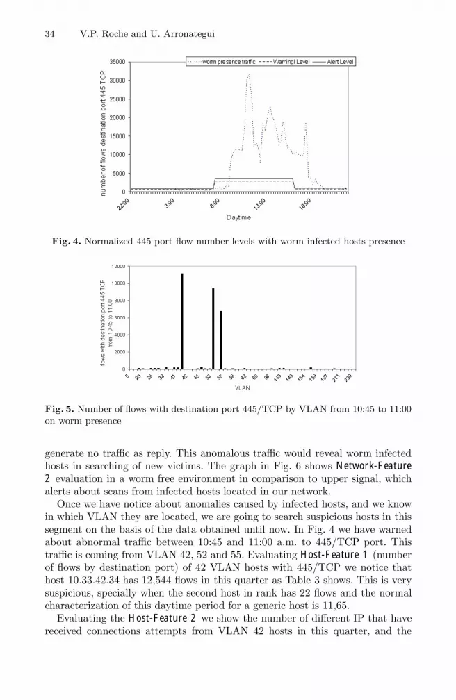
34 V.P. Roche and U. Arronategui
Fig. 4. Normalized 445 port flow number levels with worm infected hosts presence
Fig. 5. Number of flows with destination port 445/TCP by VLAN from 10:45 to 11:00on worm presence
generate no traffic as reply. This anomalous traffic would reveal worm infectedhosts in searching of new victims. The graph in Fig. 6 shows Network-Feature2 evaluation in a worm free environment in comparison to upper signal, whichalerts about scans from infected hosts located in our network.
Once we have notice about anomalies caused by infected hosts, and we knowin which VLAN they are located, we are going to search suspicious hosts in thissegment on the basis of the data obtained until now. In Fig. 4 we have warnedabout abnormal traffic between 10:45 and 11:00 a.m. to 445/TCP port. Thistraffic is coming from VLAN 42, 52 and 55. Evaluating Host-Feature 1 (numberof flows by destination port) of 42 VLAN hosts with 445/TCP we notice thathost 10.33.42.34 has 12,544 flows in this quarter as Table 3 shows. This is verysuspicious, specially when the second host in rank has 22 flows and the normalcharacterization of this daytime period for a generic host is 11,65.
Evaluating the Host-Feature 2 we show the number of different IP that havereceived connections attempts from VLAN 42 hosts in this quarter, and the

Behavioural Characterization for Network Anomaly Detection 35
Fig. 6. Ratio of uniqueDestinationIp / uniqueSourceIp
Table 3. Number of flows per IP to port 445 in VLAN 42
IP Flows10.33.42.34 1254410.33.42.110 2210.33.42.41 1810.33.42.71 1610.33.42.115 1310.33.42.73 1310.33.42.103 1210.33.42.74 1110.33.42.38 910.33.42.83 810.33.42.158 110.33.42.163 110.33.42.95 1
number of different IP that answer. This evaluation is presented in Table 4. Inthis rank appears other hosts with a high number of different destinations inaddition to our well know 10.33.42.34. In the same period of time we obtainthat it has tried to establish communication with 11,443 different hosts, andhas received answers from only 735, so most of the 90% of IP which it tries toconnect to does not reply. We have to highlight those situations where appearssome answer IP that it’s not asked. These flows are attempts of connectionsfrom other hosts that are dropped by evaluated machine, like infection tries forexample.
It is necessary to clarify that when we talk about hosts that reply to suspicioushost requests we do not refer to a standard TCP handshake, where destinationport and IP is transformed in source port and IP of the reply. We are talkingabout communication in a higher abstraction level, using all kinds of communi-cation (TCP or UDP at every port) as a reply signal.

36 V.P. Roche and U. Arronategui
Table 4. Percent of no answer IP
IP UnqIpDst UnqIpResponse Percent10.33.42.34 11445 735 93,57%10.33.42.41 5638 2232 60,41%10.33.42.249 1376 37 97,31%10.33.42.38 625 532 14,88%10.33.42.195 449 530 0%10.33.42.115 58 57 1,72%10.33.42.103 52 56 0%10.33.42.196 45 46 0%. . . . . . . . . . . .
In Host-Feature 2 evaluation, appears other hosts, for example 10.33.42.41 or10.33.42.249, with a high value in their evaluation. Both IP present an alarmlevel in Host-Feature 2, but it is not by itself an evidence of infection. In fact,this apparently suspicious behaviour is caused by the use of P2P software, butwe something that help us to differentiate between non-infected hosts runningP2P software and infected hosts. We will use the Host-Feature 3 evaluation toaccomplish this task. Empirically it is observed that scanning hosts use correla-tive source ports throughout the time, whereas these hosts that use P2P mainlyconcentrate their traffic in one or two source ports.
The Fig. 7 shows source port numbers of the two first hosts in the Table 4.There we can see how the source port number of host 10.33.42.34 increase alongtime. In the same period of time the host 10.33.42.41 groups his traffic in port3253, and occasionally uses other source ports.
Fig. 7. Source Port organization in timeline
Once we have caught worm infected host, we will trye to extract as muchinformation as we can from network traffic. To accomplish a deeper analysis wewould inspect the infected host incoming and outgoing packets payload.
Table 5 shows destination ports our 10.33.42.34 host is trying to connect with.In addition to usual connections (ICMP, DNS, HTTP, ...) we can see malicious

Behavioural Characterization for Network Anomaly Detection 37
Table 5. Suspicious host destination ports
Dst.Port Flows to Explanation0 6 ICMP attempts53 3 DNS requests80 14 Web traffic135 428 Microsoft’s DCOM RPC137 4 Netbios Name Service138 1 Netbios Datagram Service139 45 Netbios Session Service445 12544 Win2k+ SMB5226 8 HP Status ???6667 3 ircu ???
traffic grouped at 135/TCP and 445/TCP and at last a small percent not sowell known ports: 5226/TCP and 6667/TCP.
This list of implied ports, as well as a possible concentration of traffic froma same source port would serve to make a basic characterization of this wormbehaviour. These connections to no well characterized ports are specially inter-esting. If we make a query to know which hosts are behind these ports we willdiscover two outer machines. These ones have much to do with the abnormaltraffic detected in our network, in fact in 211.227.236.143 port 5226/TCP and in206.53.56.16 port 6667/TCP are running two botnet command and control IRCservers. It is sure that there will be more machines along the Internet controlledby these same servers, so an early alert to the rest of the community is essentialby two reasons: ISP that manages this servers IP numbers must block them andcorporations that have infected hosts in their networks could locate them withthis information.
6 Conclusions
We have presented a successful approximation for worm detection based on anormal status characterization and a subsequent detection of deviations fromit. As we have demonstrated this deviations are caused by abnormal behaviourpresence in the local area network traffic. Suspicious traffic sample is comparedwith the assigned normal characterization of the network segment in the samedaytime period. Dividing the evaluation of anomalies in at least two or threelevels is a useful way to accomplish the worm detection. Also we are able tolocate the malicious traffic origins and extract useful information about thethreat from the activity of the infected hosts. This knowledge could be of vitalimportance to other corporations that are suffering the same threat.
Our model has been proved with real traffic from the University of Zaragozanetwork. Within the diversity of detections that this method can accomplish it hasbeen able to alert about malicious traffic in the University network, it has locatedthe origin at one VLAN and finally it has identified several infected hosts with abot-worm and has extracted useful information related with this threat too.

38 V.P. Roche and U. Arronategui
7 Future Work
In the short term, our objectives are to reduce the initial quarter-hour evaluationperiod to less than 5 minutes. By this way we would improve the system responsetime in order to active countermeasures that could minimize the threat damageas far as possible. In addition to this we keep on working in the definition ofnew and better features and characterizations that could enhance the networkanomaly detection with more preciseness.
We have begun to work with traffic classification at application level to com-plement our NetFlow information. This kind of classification will allow us toidentify traces of a concrete protocol (i.e. IRC) independently of the source anddestination ports involved in. There are quite a number of works related withthis topic. Karagiannis et al. [15] and Erman et al. [10] or more recently [13] and[22] are good examples of this investigation line.
A natural evolution of the host generic characterization would be to defineseveral profiles that express more accurately individual host behaviour. An ex-treme model would define a normal characterization for each one of the hostsconnected to our network. This proposition has serious difficulties in terms ofscalability, but we do not discard it. Anyway this particular characterization isa good scheme for special machines as servers.
As we have explained along this paper, the target of our efforts must be theglobal defense of the Internet against massive infections threat. Next step in thispath is to define in a precise way what kind of information must be exchangedby the nodes of a worm detection/containment future network, and how couldbe its structure.
Acknowledgements
We wish thank University of Zaragoza’s network administrators and the rest ofthe communications area by their support and collaboration in NetFlow dataharvesting. Specially thanks to Manuel Jimenez, Jose Manuel Guemes, Jose An-tonio Valero and David Romero.
References
1. Caida: Cooperative association for internet data analysis, http://www.caida.org2. Flow-tools: Tool set for working with netflow data,
http://www.splintered.net/sw/flow-tools
3. Barford, P., Kline, J., Plonka, D., Ron, A.: A signal analysis of network trafficanomalies. In: ACM SIGCOMM Internet Measurement Workshop (2002)
4. Brauckhoff, D., Fiedler, U., Plattner, B.: Towards systematically evaluating flow-level anomaly detection mechanisms. In: Workshop on Monitoring, Attack Detec-tion and Mitigation (MonAM 2006), Tubingen, Germany (September 2006)
5. Brauckhoff, D., May, M., Plattner, B.: Flow-level anomaly detection - blessing orcurse? In: IEEE INFOCOM 2007, Student Workshop, Anchorage, Alaska, USA(May 2007)

Behavioural Characterization for Network Anomaly Detection 39
6. Brauckhoff, D., Wagner, A., May, M.: Flame: A flow-level anomaly modeling en-gine. In: Proceedings of CSET 2008 workshop, Usenix, San Jose, CA, USA (July2008)
7. Dubendorfer, T., Plattner, B.: Host behaviour based early detection of worm out-breaks in internet backbones. In: WETICE - Security Technologies (STCA) Work-shop (2005)
8. Dubendorfer, T., Wagner, A., Hossmann, T., Plattner, B.: Flow-level traffic analy-sis of the blaster and sobig worm outbreaks in an internet backbone. In: Julisch, K.,Krugel, C. (eds.) DIMVA 2005. LNCS, vol. 3548, pp. 103–122. Springer, Heidelberg(2005)
9. Ellis, D.R., Aiken, J.G., Attwood, K.S., Tenaglia, S.D.: A behavioral approach toworm detection. In: ACM Workshop on Rapid Malcode WORM (2005)
10. Erman, J., Arlitt, M., Mahanti, A.: Traffic classification using clustering algorithms.In: MineNet 2006: Proceedings of the 2006 SIGCOMM workshop on Mining net-work data, pp. 281–286. ACM, New York (2006)
11. Ertoz, L., Eilertson, E., Lazarevic, A., Tan, P.-N., Dokas, P., Kumar, V., Srivas-tava, J.: Minds,detection of novel network attacks using data mining. In: ICDMWorkshop on Data Mining for Computer Security (DMSEC) (2003)
12. Gates, C., Becknel, D.: Host anomalies from network data. In: IEEE SMC Infor-mation Assurance Workshop (2005)
13. Gu, R., Hong, M., Wang, H., Ji, Y.: Fast traffic classification in high speed networks.In: Ma, Y., Choi, D., Ata, S. (eds.) APNOMS 2008. LNCS, vol. 5297, pp. 429–432.Springer, Heidelberg (2008)
14. S. Institute. Internet storm center,http://isc.sans.org/, http://www.dshield.org/
15. Karagiannis, T., Papagiannaki, K., Faloutsos, M.: Blinc: Multilevel traffic classifi-cation in the dark. In: Proceedings of ACM SIGCOMM, pp. 229–240 (2005)
16. Lakhina, A., Crovella, M., Diot, C.: Mining anomalies using traffic feature distri-butions. SIGCOMM Comput. Commun. Rev. 35(4), 217–228 (2005)
17. Ma, J., Voelker, G.M., Savage, S.: Self-stopping worms. In: ACM Workshop onRapid Malcode WORM (2005)
18. Moore, D., Shannon, C., Voelker, G.M., Savage, S.: Internet quarantine: Require-ments for containing self-propagating code. In: INFOCOM (2003)
19. Munz, G., Carle, G.: Real-time analysis of flow data for network attack detection.In: Proceedings of IFIP/IEEE Symposium on Integrated Management (IM2007),Munich, Germany (May 2007)
20. Nickless, B., Navarro, J., Winkler, L.: Combining cisco netflow exports with rela-tional database technology for usage statistics, intrusion detection, and networkforensics. In: Proceedings of the Fourteenth Systems Administration Conference(LISA 2000), Berkeley, CA, December 3-8 2000, pp. 285–290. The USENIX Asso-ciation (2000)
21. Noh, S., Lee, C., Ryu, K., Choi, K., Jung, G.: Detecting worm propagation usingtraffic concentration analysis and inductive learning. In: Yang, Z.R., Yin, H., Ever-son, R.M. (eds.) IDEAL 2004. LNCS, vol. 3177, pp. 402–408. Springer, Heidelberg(2004)
22. Park, B., Won, Y.J., Choi, M.-J., Kim, M.-S., Hong, J.W.: Empirical analysis ofapplication-level traffic classification using supervised machine learning. In: Ma, Y.,Choi, D., Ata, S. (eds.) APNOMS 2008. LNCS, vol. 5297, pp. 474–477. Springer,Heidelberg (2008)

40 V.P. Roche and U. Arronategui
23. Plattner, B., Wagner, A., Dubendorfer, T.: In search of a vaccine against dis-tributed denial of service attacks (ddosvax) (2003)
24. Project, T.H.: The honeynet project & research alliance: Know your enemy: Track-ing botnets. Technical report (March 13, 2004)
25. Singh, S., Estan, C., Varghese, G., Savage, S.: The earlybird system for real-timedetection of unknown worms. In: ACM - Workshop on Hot Topics in Networks(HOTNETS) (2003)
26. Staniford, S., Paxson, V., Weaver, N.: How to 0wn the internet in your spare time(May 14, 2002)
27. Wagner, A., Plattner, B.: Entropy based worm and anomaly detection in fast ipnetworks. In: WETICE - Security Technologies (STCA) Workshop (2005)

The Power of Anonymous Veto in PublicDiscussion
Feng Hao1 and Piotr Zielinski2,�
1 Thales Information Systems Security, nCipher product line2 Google Inc.
[email protected], [email protected]
Abstract. The Dining Cryptographers problem studies how to securelycompute the boolean-OR function while preserving the privacy of eachinput bit. Since its first introduction by Chaum in 1988, it has attracteda number of solutions over the past twenty years.
In this paper, we propose an exceptionally efficient solution: Anony-mous Veto Network (or AV-net). Our protocol is provably secure underthe Decision Diffie-Hellman (DDH) and random oracle assumptions, andis better than past work in the following ways. It provides the strongestprotection of each input’s privacy against collusion attacks; it requiresonly two rounds of broadcast, fewer than any other solution; the com-putational load and bandwidth usage are the least among the availabletechniques; and the efficiency of our protocol is achieved without relyingon any private channels or trusted third parties. Overall, the efficiencyof our protocol seems as good as one may hope for.
Keywords: Dining Cryptographers problem; DC-net; anonymous veto;secure multiparty computation.
1 Introduction
In a galaxy far far away ...
During an open meeting, the Galactic Security Council must decidewhether to invade an enemy planet. One delegate wishes to veto themeasure, but worries that such a move might jeopardize the relationswith some other member states. How can he veto the proposal withoutrevealing his identity?
The above shows a picture of the council delegates – with mutual suspicion –discussing a decision in public. There are no private channels. The only way tocommunicate between each other is through public announcement; and duringannouncement, every word uttered or message sent can be traced back to itssender. There is no external help either, as trusted third parties do not exist.
� The work was done when both authors were at the Computer Laboratory, Universityof Cambridge. This is an extended version of an earlier conference paper [1].
M.L. Gavrilova et al. (Eds.): Trans. on Comput. Sci. IV, LNCS 5430, pp. 41–52, 2009.c© Springer-Verlag Berlin Heidelberg 2009

42 F. Hao and P. Zielinski
In essence, this problem requires a secure computation of the boolean-ORfunction, while preserving the privacy of each input bit. It was coined by Chaumas the Dining Cryptographers problem [5]; however, the “unconditional secrecychannels” assumed in [5] are no longer readily available in our case, which makesthe delegate’s task harder.
There have been a number of solutions in past work, ranging from circuitevaluation [20,10] and Dining Cryptographers Network (or DC-net) [5] proposednearly twenty years ago, to several anonymous veto protocols [15,11,4] publishedin recent years. However, these techniques all have various limitations, as wediscuss now.
The DC-net protocol was proposed by Chaum in 1988, and has long been con-sidered a classic privacy-preserving technique [12]. This protocol has two stages.First, n participants set up pairwise shared secrets through secret channels. Next,each participant Pi broadcasts a one bit message ai, which is the XOR of all theshared one-bit secrets that Pi holds if he has no message (i.e., no veto) to send,or the opposite bit otherwise. After the broadcast round, the sent message isdecoded by all participants through computing the XOR of the broadcast bits.More details can be found in [5].
However, deploying DC-nets is hampered for several reasons. First, the “un-conditional secrecy channels” are assumed in the protocol, but difficult to achievein practice. This problem is further compounded by the rapid increase of the totalnumber of such channels (i.e., O(n2)) when there are more participants. Second,message collisions are problematic too. Even when all participants are honest, aneven number of messages will still cancel each other out, forcing retransmissions.Third, a DC-net is vulnerable to malicious jamming. For example, the last par-ticipant Pn may send ⊕n−1
i=1 ai, so that the final outcome will always be ‘0’ (i.e.,non-veto). Countermeasures include setting up “traps” to catch misbehaviorsprobabilistically, but make the system more complex (see [5, 12, 18]).
While a DC-net is “unconditionally secure”, all the other solutions are builtupon public key cryptography, and are thus computationally secure. These in-clude the circuit evaluation technique [10] and several anonymous veto proto-cols [15,11,4]. A lack of efficiency is their common problem. We will explain thisin more detail in Section 4.
Despite the problems in a DC-net, we still find it, among all the past solutions,most attractive for its simplicity and elegance. It combines all others’ secret keysto encrypt data, but requires no secret keys to decrypt it. This idea is seminal,but undeservedly, has rarely been exploited in secure multiparty computationsfor the past twenty years.
By contrast, the mix-net protocol – a twin technique introduced by Chaum toprotect anonymity – has been extensively studied and applied in the field [6]. Itencrypts messages in multiple layers using public key cryptography, and usuallyrequires a chain of proxy servers to perform secure decryption. In comparison, aDC-net is more lightweight; it sends anonymous data by a one-round broadcastand allows rapid decryption with no servers needed.

The Power of Anonymous Veto in Public Discussion 43
Our solution, Anonymous Veto Network (or AV-net), captures the essenceof the original DC-net design [5] – it combines everyone else’s public key toencrypt data, but requires no private keys to decrypt it. This, as we will showin Section 4, leads to the optimal efficiency of our protocol in many aspects.However, despite the similarity in the underlying design principles, the technicaldevelopments for the DC-net and AV-net protocols are completely different. Inthe following section, we will explain how an AV-net works.
2 Protocol
2.1 Model
We assume an authenticated public channel available for every participant. Thisassumption is made in all the past work in this line of research [5, 15, 11, 4];in fact, an authenticated public channel is an essential requirement for generalmulti-party secure computations [10,3]. This requirement basically ensures thatthe published votes come from the legitimate or registered voters; otherwise,voting would be meaningless. There are several ways to realize such a channel:by using physical means or a public bulletin board [15]. Apart from this basicrequirement, we do not assume any secret channels or trusted third parties.
In the threat model, we consider two types of attackers: a passive one whomerely eavesdrops on the communication, and an active one who takes part inthe voting. Active attackers may collude in an effort to uncover others’ votes ormanipulate the voting result. The full collusion against a participant involves allthe other participants in the network. Any anonymous veto protocol, by nature,cannot preserve the vetoer’s anonymity under this circumstance. However, asexplained in [5], it is practically impossible to have all participants – who mistrusteach other – colluding against just one; there would be no point for that personto stay in the network. Hence, in this paper, we only consider partial collusion,which involves only some participants, but not all.
Under the threat model of partial collusion, an anonymous veto protocolshould satisfy the following three requirements.
– Veto Privacy – If one vetoes, the rest of the participants cannot tell who hasvetoed.
– Veto Completeness – If one vetoes, all participants accept the veto outcome.– Veto Soundness – If the outcome is veto, all participants accept that someone
has vetoed.
Clearly, a DC-net does not satisfy the second requirement, because of thecollision problem. More requirements are defined in [15, 11] to reflect the trust-worthiness of the third parties involved, but are not needed in our model.
2.2 Two-Round Broadcast
Let G denote a finite cyclic group of prime order q in which the Decision Diffie-Hellman (DDH) problem is intractable [2]. Let g be a generator in G. There

44 F. Hao and P. Zielinski
are n participants, and they all agree on (G, g). Each participant Pi selects arandom value as the secret: xi ∈R Zq.
Round 1. Every participant Pi publishes gxi and a knowledge proof for xi.
When this round finishes, each participant Pi computes
gyi =i−1∏
j=1
gxj
/ n∏
j=i+1
gxj
Round 2. Every participant publishes a value gciyi and a knowledge proof forci, where ci is either xi or a random value ri ∈R Zq, depending on whetherparticipant Pi vetoes or not.
gciyi =
{griyi if Pi sends ‘1’ (veto),gxiyi if Pi sends ‘0’ (no veto).
To check the final message, each participant computes∏
i gciyi . If no onevetoes, we have
∏i gciyi =
∏i gxiyi = 1. This is because
∑i xiyi = 0 (Proposi-
tion 1). Hence,∏
i gxiyi = g∑
i xiyi = 1.On the other hand, if one or more participants send the message ‘1’, we have∏i gciyi �= 1. Thus, the one-bit message has been sent anonymously.
Proposition 1 (Soundness). For the xi and yi defined in an AV-net,∑i xiyi = 0.
Proof. By definition yi =∑
j<i xj −∑
j>i xj , hence
∑
i
xiyi =∑
i
∑
j<i
xixj −∑
i
∑
j>i
xixj
=∑ ∑
j<i
xixj −∑ ∑
i<j
xixj
=∑ ∑
j<i
xixj −∑ ∑
j<i
xjxi
= 0.
Table 1 illustrates this equality in a more intuitive way.
The above proposition shows that if no one has vetoed, the outcome will be non-veto. Equivalently, if the outcome is veto, someone must have vetoed. This showsthat the protocol fulfills the “veto soundness” requirement defined in Section 2.1.
In the protocol, senders must demonstrate their knowledge of the discretelogarithms, namely the secrets xi and ci, without revealing them. This can berealized by using a Zero-Knowledge Proof (ZKP), a well-established primitive incryptography [7, 8, 16, 9].
As an example, we could use Schnorr’s signature, for it is non-interactive, andreveals nothing except the one bit information about the truth of the statement:

The Power of Anonymous Veto in Public Discussion 45
Table 1. A simple illustration of∑n
i=1 xiyi = 0 for n = 5. The sum∑n
i=1 xi (∑i−1
j=1 xj−∑nj=i+1 xj) is the addition of all the cells, where +, − represent the sign. They cancel
each other out.
x1 x2 x3 x4 x5
x1 – – – –x2 + – – –x3 + + – –x4 + + + –x5 + + + +
“the sender knows the discrete logarithm” [16]. Note that Schnorr’s signature isprovably secure under the random oracle model, so our scheme would also workin the random oracle model – that is requiring a secure hash hash function. LetH be such a secure hash function. To prove the knowledge of the exponent forgxi , one can send {gv, r = v− xih} where v ∈R Zq and h = H(g, gv, gxi, i). Thissignature can be verified by anyone through checking whether gv and grgxih areequal. Note that here the participant index i is unique and known to all. Addingi inside the hash function can effectively prevent a replay of this signature byother participants. Other ZKP techniques can be found in [9].
3 Security Analysis
Simplicity is the main goal in our protocol design. The construct of AV-net isquite straightforward, in fact much simpler than the related works [15, 11, 4].In addition, we built the protocol upon the well-established technique such asSchnorr’s signature whose zero-knowledge property has been well-understood.This greatly simplifies the task of security analysis. Therefore, in this section,we shall aim to provide intuitive (yet rigorous) security analysis without havingto go through the lengthy formalism (though formal models can be instantiated).
In the AV-net construct, each participant sends out ephemeral public keysin the first round, and then encrypts his vote by combining the public keysin the second round. To breach the anonymity of a participant, an observer –anyone within the broadcast range – may try to uncover the one-bit message fromthe announced ciphertext. In the following, we will prove that, under the DDHassumption, the proposed cryptosystem achieves semantic security [13]. This isequivalent to showing that under the hard-problem assumption, ciphertext isindistinguishable to observers [13].
In an AV-net, the value of yi is determined by the private keys of all partici-pants except Pi. The following lemma shows its security property.
Lemma 2. In an AV-net, yi is a secret random value to attackers in partialcollusion against the participant Pi.
Proof. Consider the worst case where only Pk (k �= i) is not involved in thecollusion. Hence xk is uniformly distributed over Zq and unknown to colluders.

46 F. Hao and P. Zielinski
The knowledge proofs required in the protocol show that all participants knowtheir private keys. Since yi is computed from xj (j �= i, k) known to colludersplus (or minus) a random number xk, yi must be uniformly distributed over Zq.Colluders cannot learn yi even in this worst case.
Theorem 3 (Privacy). Under the Decision Diffie-Hellman assumption, at-tackers in partial collusion against Pi cannot distinguish the two ciphertextsgxiyi and griyi .
Proof. Besides the sent ciphertext, the data available to attackers concerning Pi
include: gxi , gyi and Zero-Knowledge Proofs for the proof of the exponents xi,yi. The secret xi is chosen randomly by Pi. Lemma 2 shows that yi is a randomvalue, unknown to the attacker. The ZKP only reveal one bit: whether the senderknows the discrete logarithm1; it is provable that it does not leak anything morethan that [16]. Therefore, according to the Decision Diffie-Hellman assumption,one cannot distinguish between gxiyi and a random value in the group such asgriyi [2].
The above theorem states that the individual published ciphertext does notleak any useful information. It is the multiplication of all ciphertexts that tellsthe outcome. For each participant, the learned information from the protocolis strictly confined to the multiplied result plus his own input. If a participantvetoes, the rest of the participants cannot track down the vetoer without fullcollusion. This shows that the protocol fulfills the “veto privacy” requirementdefined in Section 2.1.
An anonymous veto protocol must resist jamming, to which a DC-net is vul-nerable. Apparently, in the second round of broadcast, we need gyi be a genera-tor for the group, so that participant Pi can produce a valid signature. Becausethe group G has prime order, any non-identity element is a generator. FromLemma 2, the value yi is random over Zq even in the face of active attacks (par-tial collusion). Thus, given that q is a large number, say 160-bit [2], the chancethat yi �= 0 is overwhelming: 1 − 2−160. Only in the full collusion case can at-tackers manipulate yi = 0, which then makes full collusion immediately evident.The resistance to jamming in an AV-net is formally proved below.
Theorem 4 (Completeness). Under the Discrete Logarithm assumption, ifPi vetoes, provided that gyi is not the identity element in the group, Pi’s vetocannot be suppressed.
Proof. Assume Pi’s veto can be suppressed, and we will show that one can thensolve the Discrete Logarithm problem. Given gri , where ri is a random value,one can compute ri by simulating the protocol with jamming: participant Pi
announces griyi = (gri)yi , but his veto is suppressed by others. The simulatorgenerates all other secrets, except ci = ri. By definition we have
∏gciyi = 1.
1 It should be noted that if we choose Schnorr’s signature to realize ZKPs, we implicitlyassume a random oracle (i.e., a secure hash function), since Schnorr’s signature isprovably secure under the random oracle model [16].

The Power of Anonymous Veto in Public Discussion 47
Table 2. Comparison to the past work
relatedwork
pubyear
rndno
knowproof
pvtch
colli-sion
3rdpty
collu-sion
securityreliance
systemcompl
GMW [10] 1987 3 O(n) yes no no half trapdoor O(n2)Chaum [5] 1988 2+ — yes yes no full uncond O(n2)KY [15] 2003 3 O(n) no no yes full DDH O(n2)Groth [11] 2004 n + 1 2 no no yes full DDH O(n)Brandt [4] 2005 4 4 no no no full DDH O(n)AV-net — 2 2 no no no full DDH O(n)
That is griyi =∏
j �=i g−cjyj . The knowledge proofs required in the protocol showthat the simulator knows the values xj (1 ≤ j ≤ n) and cj (1 ≤ j ≤ n and j �= i).Also note that gyi is not an identity element, so yi �= 0. Hence, the simulatorcan easily compute ri = y−1
i
∑j �=i−cjyj , where yi =
∑j<i xj −
∑j>i xj . With
the obtained knowledge of the ri value, the simulation is complete. Thus, onesolves the discrete logarithm of gri by simulating the protocol with jamming.This, however, contradicts the Discrete Logarithm assumption.
The above theorem states that jamming the protocol implies solving the DiscreteLogarithm problem, which is believed to be intractable. In other words, the pro-tocol ensures that when a participant vetoes, his veto message will be received byall. This makes the protocol fulfill the “veto completeness” requirement definedin Section 2.1.
Overall, the zero-knowledge proof, as a crypto primitive, is important in oursecurity analysis. Without it, several attacks would be possible. If there were noknowledge proofs in the first round, participant Pn could manipulate the valueof y1 by announcing 1/
∏n−1i=2 gxi, so that y1 = 0. Similarly, if there were no
knowledge proofs in the second round, the last participant Pn could jam theprotocol by announcing 1/
∏n−1i=1 gciyi . Hence, the zero-knowledge proof is the
technique to make the protocol self-enforcing – ensuring that participants doperform the asymmetric operations (e.g., exponentiation) as stated, rather thangive out random data. With the exception of the DC-net protocol, it is requiredin all the other solutions based on public key cryptography.
4 Efficiency
For the past twenty years, there have been a few techniques available to computethe boolean-OR function securely. They are summarized in Table 2.
Among all solutions, an AV-net stands out for its optimal efficiency in manyaspects. First, it needs only two rounds, fewer than any others. In fact, two isthe best round-efficiency achievable (see Appendix A). Second, it takes only asingle exponentiation to encrypt data, no matter how many participants thereare. Third, the size of the broadcast ciphertext gciyi is only half of that using thestandard ElGamal encryption (see [4]). It seems unlikely to be reduced further.

48 F. Hao and P. Zielinski
The AV-net protocol adopts the ZKP primitive, which may require additionalcomputation in verification. The exact computational cost depends on the choiceof the specific ZKP technique, whether the outcome is in doubt and the trustrelationships between participants. It is also significant that since all communi-cation is public in our protocol, any invalid ZKPs would present themselves aspublicly verifiable evidence on misbehavior. With the exception of the DC-netprotocol, all other solutions require verifying the ZKPs as well. As shown inTable 2, an AV-net has the fewest zero-knowledge proofs per participant: a con-stant two (i.e., one for each round). Hence, under the same evaluation conditions,the verification cost in an AV-net is the smallest among the related techniques.In the following, we will compare an AV-net with each of the past solutions indetail.
Let us first compare an AV-net with a DC-net. The DC-net protocol couldbe implemented with different topological designs. A fully-connected DC-net is“unconditionally secure”, but suffers from the scalability problem when appliedto a large system. For this reason, Chaum suggests a ring-based DC-net in [5],which presents a trade-off between security and system complexity. Recently,Wright, Adler, Levine and Shield showed that the ring-based DC-net describedby Chaum (also by Schneier [17]) is easily attacked [19]. They compared differ-ent topologies of a DC-net and concluded that the fully-connected one is mostresilient to attacks [19]. Hence, we compare an AV-net with the most secure formof a DC-net, i.e., a fully-connected DC-net.
As explained earlier, one of the most problematic parts in a DC-net is itskey setup, which produces O(n2) keys. In the original description of the DC-netprotocol, shared keys are established by secretly tossing coins behind menus.However, this requires multiple rounds of interaction between pairs of partici-pants. It is slow and tedious, especially when there are many people involved.Other means to establish keys, as suggested by Chaum, include using opticaldisks or a pseudo-random sequence generator based on short keys [5]. However,such methods are acknowledged by Chaum as being either expensive or not verysecure [5].
Our protocol replaces the key-setup phase in a DC-net with a simple one-round broadcast. This is achieved via public key cryptography. Although a DC-net can adopt a similar technique – the Diffie-Hellman key exchange protocol– to distribute keys, its use of the underlying technology is quite different fromours. Suppose a DC-net uses Diffie-Hellman to establish keys2. Each participantmust perform O(n) exponentiations in order to compute the shared keys withthe remaining n− 1 participants. (A DC-net has the desirable feature that oncepairwise keys are established, the protocol can be run continuously [5]. But itmight be a question how useful that feature is in practice given the collision andjamming problems.) However, our protocol requires only one exponentiation foreach of the two rounds, no matter how many participants in the network (thecost of multiplication is negligible as compared to that of exponentiation).
2 Note that in this case, a DC-net is no longer unconditionally secure, as the Diffie-Hellman key exchange essentially rests on the Decision Diffie-Hellman assumption [2].

The Power of Anonymous Veto in Public Discussion 49
Secure circuit evaluation is an important technique for secure Multi-PartyComputation (MPC) applications. It evaluates a given function f on the pri-vate inputs x1, . . . , xn from n participants. In other words, it computes y =f(x1, . . . , xn), while maintaining the privacy of individual inputs. At first glance,it appears trivial to apply this technique to build a veto-protocol – one only needsto define f as the boolean-OR function. However, this general technique provesto be unnecessarily complex and expensive in solving specific functions [4].
Yao [20] first proposed a general solution for the secure circuit evaluation forthe two-party case. Later, Goldreich, Micali, and Wigderson extended Yao’s pro-tocol for the multiparty case, and demonstrated that any polynomial-time func-tion can be evaluated securely in polynomial time provided the majority of theplayers are honest [10]. This conclusion is drawn based on the general assumptionof the existence of a trap-door permutation function. Although the general so-lution proposed in [10] uses an unbounded number of rounds, it was later shownthat such an evaluation can be done using only a constant number of roundsof interaction [3]. Recently, Gennaro, Ishai, Kushilevitz, and Rabin showed thatthree rounds are sufficient for arbitrary secure computation tasks [14].
Although the general GMW solution is versatile, it suffers from the way thistechnique is evolved – by extending the general solution in the two party case topairs in the multiparty case. This leads to the O(n2) system complexity. First,it requires pairwise private channels among participants [10], which could proveproblematic especially when there are many participants. Second, it requiresa large amount of traffic. Although the protocol could be completed with onlythree rounds [14], note that each round includes not only the broadcast of publicmessages, but also the transmission of private messages to everyone else throughthe pairwise secret channels [14]. The total amount of sent data is O(n2). Third,it is no longer resistant to collusion when more than half of the participants arecompromised. In such a case, the colluders can easily breach the privacy of otherinputs.
Our work shows the benefits of designing a protocol directly in the multipartycontext. It has the linear complexity, requires no pairwise secret channels, andprovides full protection against collusion instead of half. How to apply the under-lying design principle in the AV-net protocol to compute more general functionsis worth exploring in future research.
All the other techniques in Table 2 are based on the Decision Diffie-Hellmanassumption [15, 11, 4]. The first rounds of those protocols are the same as in anAV-net: broadcasting ephemeral public keys. This allows more direct compar-isons with an AV-net, as shown below.
Kiayias and Yung investigated the Distributed Decision Making problem, andproposed a 3-round veto protocol [15]. They used a third party – a bulletin boardserver – to administer the process. The bulletin board server is a common wayto realize a reliable broadcast channel. However, the server is needed for someother reasons. In the Kiayias-Yung protocol, each participant publishes O(n)data. The final result on the veto decision is computed from O(n2) data. In

50 F. Hao and P. Zielinski
large networks, it would be too demanding for individuals to store and computesuch data. The server is a natural choice to perform the intermediary processing.
Groth modified the Kiayias-Yung veto protocol in order to reduce the sys-tem complexity [11]. His approach is to trade off round-efficiency for less trafficand computation. As a result, Groth’s veto protocol allows each participant topublish a smaller amount of data, but requires participants to send their mes-sages one after another, as one’s computation depends on the result sent bythe previous participant. Hence, instead of finishing the protocol in 3 rounds asin [15], Groth’s veto protocol requires n + 1 rounds, where n is the number ofparticipants.
Brandt studied the use of ElGamal encryption techniques for multiparty com-putation applications, and gave a 4-round veto protocol [4]. The performance ofhis solution, among others, is the closest match to ours. Its main disadvantage,however, is that it requires four rounds while ours only needs two. The differencein rounds lies in the way the veto messages are encrypted.
In Brandt’s veto protocol, the first round is the same as in an AV-net: allparticipants broadcast ephemeral public keys. It requires one exponentiation tocompute a public key. In the second round, each participant applies the standardElGamal encryption algorithm to encrypt an explicit message: “veto” or “non-veto”. Such an encryption requires two exponentiations. The third and fourthrounds are arranged to decrypt the messages, while preserving the privacy ofindividual inputs. It requires two and one exponentiations in each round respec-tively. In addition, each round requires a zero-knowledge proof per participant,which amounts to four in total. Without taking the knowledge proofs into con-sideration, each participant needs to performs six exponentiations in Brandt’sprotocol.
The novelty of our protocol is that the veto message is encrypted in a veryimplicit way (i.e., by raising a base to one of two different powers). As a re-sult, the veto decision can be immediately decoded after the second broadcast.It requires only two exponentiations in total, as compared to six in Brandt’sprotocol. Besides computational load, the traffic generated is also far less in ourprotocol, due to fewer rounds.
5 Conclusion
In this paper, we propose Anonymous Veto Network (or AV-net) to allow a groupof participants to compute a boolean-OR function securely. Our technique is notonly provably secure, but also exceptionally efficient. Compared with past work,our solution does not require any private channels or trusted third parties; ithas no message collisions, hence requires no retransmissions; being semanticallysecure, it provides the strongest protection of vetoer’s anonymity until all theother participants are compromised; it resists robustly against jamming, henceensures each participant’s veto power; the execution of the protocol requires onlytwo rounds, fewer than any other solutions; and finally, the computational load,the bandwidth usage, and the cost of verifying zero-knowledge proofs are alsothe least among the related techniques.

The Power of Anonymous Veto in Public Discussion 51
Acknowledgments
We thank Markus Kuhn, Ross Anderson, George Danezis, Mike Bond, SaarDrimer, Tyler Moore and other members in the Security Group, Computer lab-oratory, University of Cambridge, for providing helpful comments and feedbacks.Special thanks go to Lihong Yang, Nick Wolfgang and Rachel Wolfgang for help-ing improve the readability of this paper.
References
1. Hao, F., Zielinski, P.: A 2-round anonymous veto protocol. In: Proceedings of the14th International Workshop on Security Protocols, Cambridge, UK (2006)
2. Boneh, D.: The Decision Diffie-Hellman Problem. In: Buhler, J.P. (ed.) ANTS 1998.LNCS, vol. 1423, pp. 48–63. Springer, Heidelberg (1998)
3. Beaver, D., Micali, S., Rogaway, P.: The round complexity of secure protocols. In:Proceedings of the twenty-second annual ACM Symposium on Theory of Comput-ing, pp. 503–513 (1990)
4. Brandt, F.: Efficient cryptographic protocol design based on distributed El Gamalencryption. In: Won, D.H., Kim, S. (eds.) ICISC 2005. LNCS, vol. 3935, pp. 32–47.Springer, Heidelberg (2006)
5. Chaum, D.: The dining cryptographers problem: unconditional sender and recipientuntraceability. Journal of Cryptology 1(1), 65–67 (1988)
6. Chaum, D.: Untraceable electronic email, return addresses, and digitalpseudonyms. Communications of the ACM 24(2), 84–88 (1981)
7. Chaum, D., Evertse, J.H., van de Graaf, J., Peralta, R.: Demonstrating possessionof a discrete logarithm without revealing it. In: Odlyzko, A.M. (ed.) CRYPTO1986. LNCS, vol. 263, pp. 200–212. Springer, Heidelberg (1987)
8. Chaum, D., Evertse, J.H., van de Graaf, J.: An Improved Protocol for Demonstrat-ing Possession of Discrete Logarithms and Some Generalizations. In: Price, W.L.,Chaum, D. (eds.) EUROCRYPT 1987. LNCS, vol. 304, pp. 127–141. Springer,Heidelberg (1988)
9. Camenisch, J., Stadler, M.: Proof systems for general statements about discrete log-arithms. Technical report TR 260, Department of Computer Science, ETH Zurich(March 1997)
10. Goldreich, O., Micali, S., Wigderson, A.: How to play any mental game or a com-pleteness theorem for protocols with honest majority. In: Proceedings of the nine-teenth annual ACM Conference on Theory of Computing, pp. 218–229 (1987)
11. Groth, J.: Efficient maximal privacy in boardroom voting and anonymous broad-cast. In: Juels, A. (ed.) FC 2004. LNCS, vol. 3110, pp. 90–104. Springer, Heidelberg(2004)
12. Golle, P., Juels, A.: Dining Cryptographers Revisited. In: Cachin, C., Camenisch,J.L. (eds.) EUROCRYPT 2004. LNCS, vol. 3027, pp. 456–473. Springer, Heidelberg(2004)
13. Goldwasser, S., Micali, S.: Probabilistic encryption. Journal of Computer and Sys-tem Sciences 28, 270–299 (1984)
14. Gennaro, R., Ishai, Y., Kushilevitz, E., Rabin, T.: On 2-round secure multipartycomputation. In: Yung, M. (ed.) CRYPTO 2002. LNCS, vol. 2442, p. 178. Springer,Heidelberg (2002)

52 F. Hao and P. Zielinski
15. Kiayias, A., Yung, M.: Non-interactive zero-sharing with applications to privatedistributed decision making. In: Wright, R.N. (ed.) FC 2003. LNCS, vol. 2742, pp.303–320. Springer, Heidelberg (2003)
16. Schnorr, C.P.: Efficient signature generation by smart cards. Journal of Cryptol-ogy 4(3), 161–174 (1991)
17. Schneier, B.: Applied Cryptography. J. Wiley and Sons, Chichester (1996)18. Waidner, M., Pfitzmann, B.: The Dining Cryptographers in the Disco: Uncondi-
tional Sender and Recipient Untraceability with Computationally Secure Service-ability. In: Quisquater, J.-J., Vandewalle, J. (eds.) EUROCRYPT 1989. LNCS,vol. 434, pp. 690–690. Springer, Heidelberg (1990)
19. Wright, M., Adler, M., Levine, B.N., Shields, C.: The predecessor attack: an anal-ysis of a threat to anonymous communications systems. ACM Transactions onInformation and Systems Security (TISSEC) 7(4) (2004)
20. Yao, A.: How to generate and exchange secrets. In: Proceedings of the twenty-seventh annual IEEE Symposium on Foundations of Computer Science, pp. 162–167 (1986)
A Lower Bound for Round Efficiency
Theorem 5. Without shared symmetric or asymmetric secrets between partici-pants, any anonymous veto protocol relying on authenticated broadcast only mustrequire at least two rounds.
Proof. To obtain a contradiction, we assume a one-round anonymous veto pro-tocol. Each participant holds a secret vote vi ∈ {0, 1}, and has no shared secretswith others. In one round, every participant Pi broadcasts fi(vi), where fi is apublicly known function.
Note that the function definition fi cannot be secret (known to Pi only).Otherwise, the value of fi(vi) would contain no useful information to the restof participants, and could be equivalently replaced by an arbitary value. Thiscontradicts the veto power that Pi has on the decision making. So fi must be apublicly known function.
The protocol allows participants to determine the Boolean-OR of all votes.Suppose every participant Pi can do so by applying a function gi to all dataavailable: gi(fi(vi), . . . , fn(vn)) = v1 ∨ . . .∨ vn. Thus participant Pi can triviallyreveal the vote of another participant, say Pk, through simulating other partici-pant’s inputs as 0: gi(fi(0), . . . , fk(vk), . . . fn(0)) = 0∨ . . .∨vk∨ . . .∨0 = vk. Thiscontradicts the secrecy of the vote vk, which shows that any such anonymousveto protocol requires at least two rounds.

M.L. Gavrilova et al. (Eds.): Trans. on Comput. Sci. IV, LNCS 5430, pp. 53–67, 2009. © Springer-Verlag Berlin Heidelberg 2009
Collusion-Resistant Message Authentication in Overlay Multicast Communication
Emad Eldin Mohamed1 and Hussein Abdel-Wahab2
1 College of Information Technology, United Arab Emirates University, Al-Ain, United Arab Emirates
2 Computer Science Department, Old Dominion University, Norfolk, Virginia 23529, USA
[email protected], [email protected]
Abstract. This paper aims at providing message authentication service in overlay multicast. Previous work has mostly focused on the network layer IP multicast and not as much work has been done on the application layer overlay multicast. A main feature of overlay multicast is that end systems carry on the responsibility of delivering the multicast traffic. Taking advantage of this fea-ture, this paper presents a new collusion resistant technique, which is based on digital signature, for overlay multicast message authentication. The proposed technique minimizes both the computational cost (through signature amortiza-tion) and the communication overhead (using retransmissions and utilizing mul-tiple multicast groups in handling message loss). In addition, it resists denial of service attacks via early dropping of forged messages. A simulation study is conducted to evaluate our proposed technique. Results of the study show that the proposed technique outperforms earlier ones.
Keywords: Multicast communication; Overlay multicast; Multicast security; Message authentication.
1 Introduction
Multicast communication concerns the transfer of data from one user (the source) to more than one user (the receivers). Multicast communication has attracted the atten-tion of many researchers since it is involved in a wide range of applications. Exam-ples of such applications are distance learning, teleconferencing, multiplayer games, real time delivery of stock quotes, distributed simulation, distribution of software updates, and distributed radar tracking; just to name a few. The multicast service can be provided either at the network layer or at the application layer. A well known ex-ample of the network layer multicast is the IP multicast which follows the host group model [7]. In this model, receivers within a multicast session are organized into a group. End systems have to explicitly join and become members of a group before they can receive data oriented to that group. End systems, however, need not be members of the group in order to send data to it.
The host group model has the advantages of flexibility and scalability. However, many security concerns—among many other difficulties such as billing—have limited

54 E.E. Mohamed and H. Abdel-Wahab
its success. Examples of security issues in this model are access control and authentica-tion. Many service providers were hesitant in delivering packets to unknown set of receivers. A more recent approach of multicast is performed at the application level; also known as overlay multicast [1], [4]. In this approach, an overlay network of the multicast end systems (nodes) is built atop the network layer and data is routed to the receivers at the application level. This approach enables nodes self-organize and man-age multicast sessions independent of the network conditions. In addition, it offers better access control and authentication services since intermediate nodes can take part in providing these services. Many techniques for overlay multicast have been proposed. Examples are Narada [5] and ALMI [16]. An important issue in overlay multicast is secure routing, which cannot be achieved without message authentication, however.
Message authentication can be defined as the assurance that the received message is from the alleged source without alteration. A simple solution to this problem in unicast communication is having the two communicating parties encrypt messages with a shared secret key. Another solution is to use message authentication codes (MACs). These two solutions, however, are inadequate in multicast communication. Sharing a key among all group members only provides group authentication—the assurance that the message originates from a member of the group—but does not provide source (data origin) authentication. In order to provide data origin authentica-tion in multicast communication, other asymmetric mechanisms such as public key encryption should be employed.
An important concern in multicast message authentication is collusion attacks: a group of receivers collude to forge messages on behalf of a source. It has been shown on the study by Boneh et al. [3] that digital signature is a necessity in building collu-sion resistant multicast message authentication. However, digital signature operations (message signing and verifying) are computationally expensive. This raises the need for efficient solutions to handle this problem.
Early solutions in multicast message authentication mainly have targeted the net-work layer IP multicast. Many of these solutions have relied on the reliable delivery of authentication information from the source to the receivers. To provide reliability in delivering the authentication information, forward error correction (FEC) has been used [11], [14], [15]. A main difficulty in using FEC, however, is that it is not known in advance how many messages will be lost.
This paper investigates message authentication in overlay multicast communica-tion. A new collusion resistant authentication technique is introduced. The proposed technique minimizes the computational cost through signature amortization. Based on a previous study [12], we provide the reliable delivery of crucial authentication mes-sages to receivers by retransmissions and we utilize multiple multicast groups to minimize the communication overhead. To reduce the effect of denial of service at-tacks, intermediate nodes of the multicast delivery structure are required to verify messages before forwarding them to other nodes; that is intermediate nodes deliver verified messages only and drop those failed the verification. To evaluate our tech-nique we have conducted a simulation study to compare the proposed technique against previous ones. Results obtained from the study show that the proposed tech-nique is more suitable for overlay multicast than those developed for IP multicast. More specifically, the proposed technique gives better receiver computational cost and better communication overhead.

Collusion-Resistant Message Authentication 55
The rest of this paper is organized as follows. Section 2 gives related work. Section 3 introduces our new technique. Performance evaluation is presented in Section 4. Section 5 is the conclusion and future work.
2 Related Work
As it is has been stated earlier, digital signature is a main building block in collusion resistant multicast message authentication [3]. Signing every message, however, is not practical, since digital signature is computationally an expensive operation. Two ap-proaches have been taken to deal with this problem. The first is to devise more effi-cient signing schemes to sign each message independent of other messages. Instances of this approach are [9], [19], which use one time signature. A main advantage of one time signing is low computational requirement. Its disadvantage, however, is high communication overhead in distributing large keys. The second approach is to amor-tize the signature among several messages. Many techniques have been introduced following this approach. Examples are Tesla [28], hash chaining [8], [9], EMSS [17], and hash tree [20].
In Tesla [18], the source initially generates a key Kn at random. From Kn, the source, using a one way function f, generates a key chain as follows:
Kn-1 = f (Kn), Kn-2 = f (Kn-1), …, K1 = f (K2).
The source uses K1 to generate MACs for a specific duration of time and reveals it after its lifetime expires. Then, the source uses K2 and the procedure is repeated until Kn is revealed. The source digitally signs Kn and sends it to all receivers. In other words, the source sends the following to the set of receivers:
Where the function is the concatenation of Zi for 1 ≤ i ≤ n, t is the time, and σ(Kn) is the digital signature of Kn. The first line in the expression gives the messages sent from the source S to the set of receivers {R} during the period t0 to t1, the second line gives the messages sent during the period t1 to t2, and so on.
At the receiving end, the receiver buffers all messages and all keys until the key Kn is revealed. The receiver then can verify all keys using the one way function f used by the source, and only then can verify messages. Receivers accept messages that are authenticated by a key during its lifetime and reject those that use the key after its lifetime. Tesla suffers from high buffering and delay requirements on the receivers and it requires synchronization between the source and the receivers.
ini
i Z==1
⎪⎪⎪⎪
⎩
⎪⎪⎪⎪
⎨
⎧
≥=<≤
=<≤
<≤
→
−−=
+=−
=+=
==
−
nnn
nnnninixixin
iixixi
iixi
i
ttKK
KfKtttMKMACMK
KfKtttMKMACMK
tttMKMACM
RS
n
n
),(
)(,),,(||||
)(,),,(||||
),,(||
:}{
1111
2121211
1011
1
2
1
1
σ
M

56 E.E. Mohamed and H. Abdel-Wahab
In hash chaining [8], [9], a stream of n messages M1, M2, …, Mn forms a block. The source computes the hash Hn = h (Mn) of the last message Mn in the block and ap-pends Hn to its predecessor Mn-1 to form a new message M'n-1 = Mn-1 || Hn. This new message M'n-1 is in turn hashed and the hash value H'n-1 is appended to its predecessor Mn-2 to form a new message M'n-2 = Mn-2 || H'n-1. The procedure is continued down-ward to the first message in the block so as to have M'1 = M1 || H'2, which is signed using one of the digital signature schemes. This can be expressed as follows:
:}{RS → )(||||...||)(||||))((|| '22
'11 nn MhMMhMMhM σ
At the receiver, the same procedure is performed but backward: verify the first message using its signature and extract the hash of the second message. The second message is verified using the hash extracted from the first message and the hash of the third message is extracted from the second message. The procedure continues up to the last message in the block. The computation effort in this approach is one hash per message and one signature per n messages at both the source and the receiver. In-creasing the number of messages n in the stream decreases the signature overhead. However, this increases the buffering requirements at the source and hence increases the delay. Moreover, a lost message may break the chain of the hashes.
In EMSS [17], the hash of each message is randomly augmented to several mes-sages. At the source, whenever a message is ready, hashes of some other messages are augmented to the current message and the hash of the augmented message is com-puted. This hash is then inserted randomly in other subsequent messages in the stream. In essence, this technique decreases the affect of message loss encountered in the hash chaining described above. The main advantage of EMSS is its high verifica-tion rate (the number of the verifiable messages in a block divided by the number of the block received messages). This, however, comes at the cost of a relatively high computation and communication overhead.
Wong et al. proposed the use of a hash tree to amortize the signature of n messages [20]. In their work, a stream of n messages M1, M2, …, Mn forms a block. The hashes H1, H2, …, Hn of the block messages are computed and a tree is built on top of these hashes. The leaf nodes of the tree are the computed message hashes. Each intermedi-ate node of the tree is the hash of its children. The root of the tree is the hash of all messages' hashes. On sending a message, the source sends some authentication in-formation particular to this message along with it. This authentication information includes the block signature (the hash of all messages within the block signed by the source), the position of the message in the block, and the hashes of the siblings of each node in the message path to the root. For a block of n messages, this can be ex-pressed as follows:
:}{RS → )H||...H||H(||||)H(|| y1 xabjni iM σ
Where Mi is the message, σ(H18) is the signature of the hash root, i is the message position in the block, and Hj through Hxy are the hashes of the siblings of each nodes in the message path to the root.

Collusion-Resistant Message Authentication 57
H1 H2 H3 H4 H5 H6 H7 H8
H12 H34 H56 H78
H14 H58
H18
Fig. 1. Tree chaining signature amortization
The receiver uses the authentication information to authenticate each message in-dependent of other messages. Fig. 1 demonstrates this technique for a block size of eight messages M1, M2, …, M8. The hashes of these messages H1, H2, …, H8 are com-puted and placed at the leaves of the tree. The intermediate nodes are the hashes of their children. For example, H12 is computed as h(H1 || H2) and H58 is computed as h(H56 || H78), where h(x) is the hash of x. The authentication information of message M5 is given as the triplet {σ(H18), 5, (H6, H78, H14)}, where σ(H18) is the signature of H18 (the block signature), 5 is the position of the message in the block, and (H6, H78, H14) are the hashes of the siblings of each node in the message path to the root. On verifying message M5, the receiver computes the following: the hash H5 of the mes-sage, the hash H56 = h(H5 || H6), the hash H58 = h(H56 || H78), the hash H18 = h(H14 || H58), and verifies against the received signature σ(H18).
This scheme has three main drawbacks. First, it involves a high communication overhead, since a large amount of authentication information is sent along with each message, which is of the order of logd n, where d is the tree order and n is the number of messages in the block. In the example given above, the block signature and the three hashes are sent along with every message. Second, the computation overhead at the source and receiver is also high and it is of the order of logd n. Third, buffering is required at the source. The main advantage is that a message loss has no affect on the authentication of other messages, since receivers authenticate each message inde-pendent of other messages.
3 New Technique
In this paper, we present a collusion resistant message authentication technique for overlay multicast. Normally, multicast communication is a best effort service in which messages may get lost. Thus, solutions targeting message authentication in such setting should tolerate message loss. In addition, we aim at efficient solutions that provide a complete verification rate and resist denial of service attacks. This work is based on the assumption that sources' public keys are already known to all end systems.
Several solutions have targeted IP multicast. These solutions, however, may not fit well in overlay multicast. For example, Tesla faces many difficulties such as high delay, high buffering requirement, and clock synchronization between the end systems.

58 E.E. Mohamed and H. Abdel-Wahab
Hash chaining and EMSS do not provide complete verification rate (a receiver may not be able to verify some of the received messages). The main approach that can provide the required service is hash tree. Hash trees are collusion-resistant, give full verifica-tion rate, and have low computation overhead. However, the communication overhead is high. The technique proposed in this paper is a more efficient variation of hash trees, which in addition resists denial of service attacks, as will be discussed later.
In our technique, we use a star topology (a hash tree that has only one level) and we provide a reliable mechanism to deliver the authentication information. The pro-posed technique consists of four elements: signing multicast messages, error control, early dropping of forged messages, and verification. In the following, we introduce these elements, after which we demonstrate them through examples.
The signing element proposed in this paper generates a signature for a block of n messages and works as follows. A stream of n messages M1, M2, …, Mn forms a block. Hashes H1, H2, …, Hn of the block messages are calculated (using for example MD5). These hashes are concatenated to each other, forming H1-n = H1 || H2 || … || Hn. The hash of H1-n is calculated resulting in the block hash H1n. The block hash is signed (using RSA for example) to get the block signature σ(H1n). The source reliably sends all message hashes along with the block signature {H1-n , σ(H1n)} to the receivers. The block signature and the message hashes must be sent reliably, since the authenticities of all block messages depend on this authentication information. However, all block messages can be sent using a best effort service as they do not affect the authenticity of each other. This can be expressed as follows (assuming a block of n messages):
⎩⎨⎧
→ )(||||...||||
...,,, :}{
121
21
nn
n
HHHH
MMMRS
σ
Where M1, M2, …, Mn are the messages of the block and they may be sent using a best effort service, and H1, H2, ..Hn, σ(H1n) are the message hashes and block signature and they are sent reliably one time per block.
Fig. 2. Error control using two multicast groups
Fixed membership
Dynamic membership
S
Main group
R1
Auxiliary group
R2 Rm

Collusion-Resistant Message Authentication 59
The second element in our proposal is error control. To provide the reliable deliv-ery of the authentication information we adapt an earlier solution in multicast error control schemes [10], [13] that utilizes multiple multicast groups to efficiently deliver the authentication information to interested receivers. In our approach, we have two multicast groups as shown in Fig. 2. The first group—which we call the main group—carries the regular multicast traffic along with authentication informa-tion. All receivers (R1, R2, …, Rm) must join this group. The other multicast group—called the auxiliary group—carries error control messages. Members of this group are the source (S in the figure), all intermediate nodes, and end systems experiencing the message loss. A receiver joins the auxiliary group when it experiences a message loss and remains a member as long as it encounters losses.
The error control unit works as follows. Messages are assigned sequence numbers. A receiver detects a message loss when there is a gap in the sequence numbers of the received messages. On detecting a gap in the messages’ sequence numbers, the re-ceiver waits for a specific duration of time (in case the message is just delayed), and if not received within this duration, the receiver assumes a message loss. When detect-ing a lost message, the receiver joins the auxiliary group. To prevent oscillation (fre-quent join/leave), the receiver joins the group for a minimum amount of time before leaving. After joining the auxiliary group, the receiver multicasts a retransmit request of the specific message to the auxiliary group. Any member of the auxiliary group having the message sends the message to the group. To prevent multiple retransmit requests of the same message sent by different receivers, a receiver waits a random time before sending its request. During this time, it listens to the auxiliary group to see if the request is already sent by another receiver. If the request is not sent by an-other receiver, the receiver can send its request. Same procedure is used in retransmit-ting the message.
The Third element in our proposal is early dropping of forged messages. In overlay multicast, intermediate nodes within the delivery structure serve as end systems and routers at the same time. Based on this fact, our technique requires intermediate nodes to verify messages before further delivery. A message can be forwarded to other nodes if it passes the verification process, otherwise it is dropped. This way, forged messages are dropped as early they are discovered saving communication and compu-tational resources of the system.
The verification element verifies messages and works as follows. On receiving the authentication information {H1 || H2 || … || Hn || σ(H1n)}, the receiver calculates the block hash H1n and verifies it against the received signature σ(H1n). The receiver buff-ers the hashes H1, H2, …, Hn for later use. On receiving a message Mi, the receiver calculates its hash Hi and compares it against the buffered hash.
H1 H2 H3 H4 H5 H6 H7 H8
H18
Fig. 3. Star chaining signature amortization

60 E.E. Mohamed and H. Abdel-Wahab
For example, suppose we have a block of eight messages M1, M2, …, M8. The hashes of these messages H1, H2, …, H8 are computed and placed as the nodes of the star (Fig. 3). The center of the star has the hash H18, which is computed as h(H1 || H2, …, || H8), where h(x) is the hash of x. The authentication information of all messages is given as the pair {(H1, H2, H3, H4, H5, H6, H7, H8), σ(H18)}, where σ(H18) is the signature of H18 (the block signature). This authentication information is sent only once for all messages. Its transmission, however, is performed reliably using the error control scheme described above. When the authentication information is received, the receiver verifies the hashes H1 || H2, …, || H8 using the signature σ(H18). On verifying a message, M5 for an instance, the receiver computes the hash (H5 in this case) of the message. The receiver compares the calculated hash against the received hash for verification.
Fig. 4. Lost message retransmission over auxiliary tree
The reliable delivery of the authentication is efficiently provided through the use of the auxiliary channel to direct retransmissions to receivers having message loss and at the same time to reduce the effect of these retransmissions on receivers that do not experience message loss (not all receivers experience the same error pattern). As Fig. 4 shows, a message is lost during its delivery from R1 to R3. Retransmitting this message to all receivers using the main tree (the continuous lines in the figure) may waste communication bandwidth and end system resources. To better deal with this situation, an auxiliary tree (the dashed lines in the figure) is formed as a subset of the main tree to retransmit the message to affected receivers only. In the example, there are three end systems (R3, D2, and D3) that experience the message loss. Every end system of them starts a random timer. On the timer expiration, the end system checks if there is any retransmission sent over the auxiliary group. If it finds a retransmission request already sent, it refrains from sending its request. Otherwise, it sends the request over the auxil-iary group. On receiving a retransmission request, an end system (receiver or router) that has the authentication information starts a random timer. When the timer expires, it checks whether the retransmission already sent by another end system before multi-casting the retransmission to the group. The reason why some routers are included within the auxiliary tree while there is no message loss in their side is that maintaining the auxiliary tree is an expensive operation—joining and leaving the tree adds a large delay to the error control procedure.
D2 D3 D4
R5
D6
R3 R4
R1 R2
S
Packet lost D1
D5

Collusion-Resistant Message Authentication 61
D3 D4
R5
D6
R3 R4
R1 R2
Forged packet
D1
Source packet
D5D2
Fig. 5. Dropping forged messages in overlay multicast
Fig. 5. demonstrates the effect of early dropping of forged messages in our tech-nique. As the figure shows, when the source S sends a message, all routers (R1 through R5) verify the message before delivery. Since the message is truly originated from the source, it will be delivered to all receivers (R1 through R5 and D1 through D6). When a forged message is inserted into the network, the first router detects it (router R1 in the figure) drops it. This saves the communication overhead in delivering the message along the path from R1 to all its children down to the leaf nodes. In addi-tion, this saves the computation overhead involved in verifying this message by other receivers. Recalling that routers are themselves end systems, requiring them to verify messages before sending is a reasonable procedure.
Our proposed technique is different from tree chaining scheme in two important aspects. The first difference, in our technique the authentication information is sent reliably only one time per block, whereas in the tree chaining scheme the source sends the full authentication information for every message. This subtle difference has a big impact on the communication overhead and receiver computation effort. The second difference is that in our technique, forged messages are dropped by the routing enti-ties. This procedure is facilitated in overlay multicast since end systems take over the routing functionalities. This difference dramatically reduces the effect of forged mes-sages on receivers' computation effort and network resources.
4 Performance Evaluation
In this paper, a simulation study is used to evaluate the proposed technique. We com-pare our technique, which is based on star topology against the tree topology if de-ployed in overlay multicast. Other techniques such as hash chaining and EMSS do not provide the required services (they do not provide full verification rate) and they are not included in our comparisons.
We model the overlay multicast network as a directed graph in which nodes are hosts in the networks and edges are connection between the hosts. A multicast delivery tree is built as a subset of this graph. The root of the tree is the source. The intermedi-ate nodes and the leaves are the receivers. The multicast traffic is modeled as a con-tinuous stream of messages. Messages are organized into blocks of equal size and the authentication information is calculated for every block. Every edge (communication

62 E.E. Mohamed and H. Abdel-Wahab
link) in the tree is characterized by its message loss rate. We assume a burst message loss [2], [21], which happens when the throughput approaches the link bandwidth (typical in many situations such as multimedia applications).
Naturally, whenever a loss occurs at a receiver it affects all of its children. Forged messages are assumed to be inserted by an adversary to any receiver (randomly se-lected). In our study, we assume RSA for digital signature where the signing process is more expensive than the verification process. We assume a signing rate of 0.7 op-erations per millisecond and a verification rate of 14 operations per milliseconds. In addition, we assume MD5 to hash messages with a hashing rate of 258 Mbytes per second and a hash size of 128 bits. These numbers are based on the Crypto++ benchmark [6]. The performance indexes that have been used are the computation overhead (expressed as the processing time at the source and the receivers) and the communication overhead.
Source Processing Time
0.00
0.05
0.10
0.15
0.20
0.25
8 16 24 32 40 48 56 64
block size (number of messages)
time
(mil
li se
c)
star
tree
Fig. 6. Source processing time
Equations 1 and 2 give the source processing time for the star and tree topologies:
n
tttt
sh
n
ihi
star
n++
=∑
=1
1 (1)
n
ttt
ts
n
jhj
n
ihi
tree
++=
∑∑−
==
1
11 (2)
Where n is the number of messages in a block, thi is the time required to hash message Mi, th1n is the time to calculate H1n (the hash of H1-n), thj is the time to calculate the intermediate hashes, and ts is the time to sign the block hash H1n. Since the signing time ts is the dominant factor in both equations (digital signature is very expensive when compared with hashing), the processing times in both the star and the tree

Collusion-Resistant Message Authentication 63
topologies are almost identical (there is a slight improvement for the star topology over the tree). This is apparent in Fig. 6, which gives the results of the simulation when varying the block size. Forging and message loss have no effect on the source processing time as it has no contribution on the source’s computational cost.
Equations 3 and 4 give the receiver processing times per message for the star and tree topologies as follows:
)1(1f
vh
n
ihi
star Pn
tttt +⋅
++=∑
= (3)
)1()log( 2
1fpf
vh
n
ihi
tree PPn
tttt ++⋅
++=∑
= (4)
Where n is the number of messages in the block, thi is the processing time required to hash a message Mi, th is the time to calculate H1n (the hash of H1-n), tv is the time to verify the messages' hashes, Pf is the direct forging factor, Pfp is the propagated forg-ing factor due to forged messages received from the receiver’s parent.
Receiver Processing Time
0.00
0.01
0.02
0.03
0.04
0.05
8 16 24 32 40 48 56 64
block size (number of messages)
time
(mil
li se
c)
star
tree
Fig. 7. Receiver processing time without forging
The simulation study shows that most of the processing time is due to hashing rather than the amortized verification. Figure 7 gives the processing times for both the star and tree topologies when there are no forged messages in the system. As the fig-ure shows, both are of almost the same performance, with a slight improvement for the proposed star topology (as it requires less hashing) over the tree. However, when forging is considered, the early dropping technique employed in the star topology has a great impact on the performance as demonstrated by the simulation results shown in Fig. 8.

64 E.E. Mohamed and H. Abdel-Wahab
Receiver Processing Time
0.00
0.02
0.04
0.06
0.08
0.10
0 0.1 0.2 0.3 0.4 0.5 0.6 0.7 0.8 0.9 1
forging factor
tim
e (m
illi
sec
)
star
tree
Fig. 8. Receiver processing time with forging
Communication Overhead
0
20
40
60
80
100
120
8 16 24 32 40 48 56 64
block size (number of messages)
ove
rhea
d (b
ytes
)
star
tree
Fig. 9. Communication overhead
(no forging, maximum error probability = 0.5, and average error probability = 0.3)
Equations 5 and 6 give the communication overhead per message for the star and tree topologies:
)1()(
1Pfn
ssnc sh
star ⋅+⋅+⋅
= (5)
)1(log2 fpshtree Pssnc +⋅+⋅= (6)
Where n is the number of messages, sh is the size of message hash, ss is the size of the signature, Pl is the probability of message loss, f is the fraction of the network affected by the loss (some nodes may experience message loss while others may not), and Pfp is the propagated forging factor. Note that the authentication information must be sent reliably in the star topology—retransmissions will be performed to those nodes af-fected by message loss.

Collusion-Resistant Message Authentication 65
In the star chaining, retransmission has a minor affect on the communication over-head as only one message (the authentication message) per block has to be sent relia-bly. If the authentication information message is lost, it will be sent only to those receivers who experience the loss. This greatly lessens the effect of message loss over the communication overhead. On the other hand, increasing the block size in the tree topology increases the size of the authentication information to be transmitted. This is demonstrated in Fig. 9, which shows that star chaining gives a better performance than tree chaining, especially for large block sizes. When forged messages are in-jected in the network, using the early dropping greatly improves the communication overhead as shown in Fig. 10.
Communication Overhead
0
20
40
60
80
100
120
140
160
0 0.1 0.2 0.3 0.4 0.5 0.6 0.7 0.8 0.9 1
forging factor
over
hea
d (b
ytes
) star
tree
Fig. 10. Communication overhead with forging (maximum error probability = 0.5, and average error probability = 0.3)
Table 1. Performance comparison between star chaining and tree chaining
Comparison criteria Star chaining Tree chaining
Computation overhead at the source
Similar to tree chaining.
Similar to star chaining.
Computation overhead at the receivers (without forging)
Slight improvement than tree chaining.
Little higher than star chaining.
Computation overhead at the receivers (with forging)
Better than tree chaining.
Higher than star chaining.
Communication over-head (with and without forging)
Better than tree chaining.
Higher than star chaining.

66 E.E. Mohamed and H. Abdel-Wahab
From the above discussion, source and receiver computation overheads in both star and tree topologies are almost the same. However, the star chaining technique given in this paper has the advantage of better communication overhead especially for large block sizes than the tree chaining. In addition, using the early dropping of forged message significantly decreases the communication and receiver computation over-head. These results are summarized in Table 1.
5 Conclusion
In this paper we have introduced a new technique for collusion resistant message authentication in overlay multicast. A basic feature of overlay multicast is that the receivers may also take over the responsibility of delivering the multicast traffic from the source to other group members. Based on this feature, we have proposed a digital signature-based authentication technique in which a star topology is built over the hashes of the messages. In addition, forged messages are dropped as early as they are detected; since the routing entities are themselves group members in overlay multi-cast. In our technique, the authentication information is sent reliably. We have pre-sented a scheme that deploys retransmission over multiple multicast groups to resend lost authentication information. We have conducted a simulation study to evaluate the performance of our work. Results of the study show that our technique has better communication and better receiver computation (especially when forged messages are considered) overheads than earlier ones.
References
1. Banerjee, S., Kommareddy, C., Kar, K., Bhattacharjee, B., Khuller, S.: OMNI: An Effi-cient Overlay Multicast Infrastructure for Real-Time Applications. Computer Net-works 50(6), 826–841 (2006)
2. Bolot, J.-C.: End-To-End Packet Delay and Loss Behavior in the Internet. In: Proc. Sig-comm 1993, San Francisco, CA (1993)
3. Boneh, D., Durfee, G., Franklin, M.: Lower Bounds for Multicast Message Authentication. In: Pfitzmann, B. (ed.) EUROCRYPT 2001. LNCS, vol. 2045, pp. 437–452. Springer, Heidelberg (2001)
4. Chu, Y., Rao, S., Seshan, S., Zhang, H.: Enabling Conferencing Applications on the Inter-net using an Overlay Multicast Architecture. In: Proc. of the 2001 Conference on Applica-tions, Technologies, Architectures, and Protocols for Computer Communications, San Diego, CA, pp. 55–67 (2001)
5. Chu, Y., Rao, S., Seshan, S., Zhang, H.: A Case for End System Multicast. IEEE Journal on Selected Areas in Communications 20(8), 1456–1471 (2002)
6. Dai, W.: Crypto++ 5.5 Benchmarks (2007), http://www.cryptopp.com/benchmarks.html
7. Deering, S.: Host Extensions for IP Multicast, Internet RFC 1112 (1989) 8. Even, S., Goldreich, O., Micali, S.: On-line/Off-line digital signatures. In: Brassard, G.
(ed.) CRYPTO 1989. LNCS, vol. 435, pp. 263–275. Springer, Heidelberg (1990) 9. Gennaro, R., Rohatgi, P.: How to Sign Digital Streams. In: Kaliski Jr., B.S. (ed.) CRYPTO
1997. LNCS, vol. 1294, pp. 180–197. Springer, Heidelberg (1997)

Collusion-Resistant Message Authentication 67
10. Kasera, S., Kurose, J., Towsley, D.: Scalable Reliable Multicast using Multiple Multicast Groups. In: Proc. ACM Sigmetrics 1997, Seattle, WA, pp. 64–74 (1997)
11. Lysyanskaya, A., Tamassia, R., Triandopoulos, N.: Multicast Authentication in Fully Ad-versarial Networks. In: Proc. IEEE Symposium on Security and Privacy, pp. 241–253 (2004)
12. Mohamed, E., Abdel-Wahab, H.: Multicast for Multimedia Collaborative Applications: Services and Mechanisms. International Journal of Advanced Media and Communication (IJAMC) 1(3), 224–236 (2007)
13. Mohamed, E., Abdel-Wahab, H.: Multicast Error Control for Multimedia Collaborative Applications. In: The 9th IEEE Symposium on Computers and Communications (ISCC 2004), Alexandria, Egypt (2004)
14. Pannetrat, A., Molva, R.: Efficient Multicast Packet Authentication. In: The 10th Annual Network and Distributed System Security Symposium (NDSS 2003), San Diego, CA (2003)
15. Park, J., Chong, E., Siegel, H.: Efficient Multicast Packet Authentication using Erasure Codes. ACM Transactions on Information and System Security 6(2), 258–285 (2003)
16. Pendarakis, D., Shi, S., Verma, D., Waldvogel, M.: ALMI: An Application Level Multi-cast Infrastructure. In: Proc. of the 3rd Usenix Symposium on Internet Technologies and Systems (2001)
17. Perrig, A.: The BiBa One-Time Signature and Broadcast Authentication Protocol. In: Proc. of the 8th ACM Conference on Computer and Communications Security, Philadelphia, PA (2001)
18. Perrig, A., Canetti, R., Tygar, J., Song, D.: The Tesla Broadcast Authentication Protocol. CryptoBytes 5(2), 2–13 (2002)
19. Rohatgi, P.: A Compact and Fast Hybrid Signature Scheme for Multicast Packet Authenti-cation. In: 6th ACM Conference of Computing and Communication Security CCS 1999, Singapore (1999)
20. Wong, C., Lam, S.: Digital Signatures for Flows and Multicasts. IEEE/ACM Transactions on Networking 7(4), 502–513 (1999)
21. Yajnik, M., Kurose, J., Towsley, D.: Packet Loss Correlation in the Mbone Multicast Net-work: Experimental Measurements and Markov Chain Models. In: Proc. IEEE Globecom, pp. 94–99 (1996)

A Model for Authentication CredentialsTranslation in Service Oriented Architecture�
Emerson Ribeiro de Mello1,2,��, Michelle S. Wangham3,��,Joni da Silva Fraga1,��, Edson T. de Camargo1, and Davi da Silva Boger1
1 Department of Automation and SystemsFederal University of Santa Catarina
Florianopolis, SC, Brazil2 Federal Institute of Santa Catarina
Sao Jose, SC, Brazil3 Embedded and Distributed Systems Group
Univali - Sao Jose, SC, Brazil{emerson,fraga,camargo,dsborger}@das.ufsc.br,[email protected]
Abstract. Due to the increasing number of service providers, the group-ing of these providers following the federation concept and the use of theSingle Sign On (SSO) concept are helping users to gain a transparentaccess to resources, without worrying about their locations. However,current industry and academic production only provide SSO in caseswith homogeneous underlying security technology. This paper deals withinteroperability between heterogeneous security technologies. The pro-posed model is based on the Credential Translation Service that allowsSSO authentication even heterogeneous security technologies are consid-ered. Therefore, the proposed model provides authentication credentialstranslation and attribute transposition and, as a consequence, providesauthorization involving different kinds of credentials and permissions inthe federation environment. By making use of Web Services, this studyis strongly based on concepts introduced in the SAML, WS-Trust andWS-Federation specifications.
Keywords: Web Services, Security, Single Sign-on.
1 Introduction
The demand for sharing information among different administrative domains ina transparent and secure manner and the need for establishing trust relationshipsare both up-to-date requirements mainly within the Internet context. Clients andservice providers are entities that are present in this domain and that seek somekind of interaction. In this scenario, there are three barriers to overcome: (1)the heterogeneity of the security infrastructures, present in the many corporate
� This work has been developed within the scope of the “Security Mechanisms forBusiness Processes in Collaborative Networks” project (CNPq 484740/2007-5).
�� Supported by CNPq - Brazil.
M.L. Gavrilova et al. (Eds.): Trans. on Comput. Sci. IV, LNCS 5430, pp. 68–86, 2009.c© Springer-Verlag Berlin Heidelberg 2009

A Model for Authentication Credentials Translation in SOA 69
domains, (2) the establishment of trust relationships among unknown entities,and (3) the management of identities carried out not only by service providersbut also by clients.
In distributed systems, traditional authorization models are based upon an au-thentication authority tomediate the trust amongunknownparties (TrustedThirdParty). Therefore, the interactions among distinct parties are done through thepresentation of credentials issued by an authentication authority known by theparties involved. In more complex environments such as the Internet, this modelof simple interaction is limited, since each domain has its own policies, securityinfrastructures, and also a particular way of managing the principals’1 identities.In other words, each domain runs its authorization controls according to its localpolicies, without considering the attributes of other domains, and thus previousauthentication is usually required in the domain itself.
Single Sign On (SSO) was developed to simplify the interactions among clientsand different service providers. Under this approach, the client authenticates onlyonce and makes use of this authentication in the interactions with other serviceproviders. In open systems, it is desirable that each domain have the freedomto choose and adopt an authentication mechanism. However, the difficulty liesin assuring the SSO’s interoperability among these domains, since the authen-tication information is no longer understood by all the entities present in thedomains with different technologies. This problem motivated the present work.
This work aims to describe a model that enables the authentication withSSO, that is, the translation of authentication credentials, even when dealingwith administrative domains with different security technologies. In this model,a principal can access resources in domains with security technologies, which aredifferent from those in its source domain, by using the credentials provided in itsown domain. In the entire system, access authorizations to resources depend onthis authentication, which sensibly diminishes the data flux between the domainsand the management of these data in the system as a whole.
According to [1], in the management of federated entities, each company buildsa domain, in which its service, identity and credential providers are present. Thedeals established among domains can allow local identities of a domain to beaccepted in the other domains participating in the agreement. Hence, a userwith an identity registered in its domain can access resources in other domainsof the federation without opening a new register or identity. In this study, themanagement of federated identities significantly contributes to the translationof the principals’ authentication credential.
The Web Services technology, based on Service Oriented Architecture (SOA),is one of the promising solutions to the integration of administrative domainsin distributed systems [2]. Although this technology contributes to overcomethe challenges involving authentication and authorization in distributed appli-cations, the large number of specifications and standards aiming at security notonly imposes a certain level of complexity but also hinders its wide adoption [3].
1 Users, processes or machines authorized by the systems policy.

70 E.R. de Mello et al.
With the support of Web Services security technologies, this article introducesa model to authentication and authorization in service oriented distributed sys-tems. Based on the concept of federated identities, this model performs the trans-lation of a principal’s authentication credential among administrative domainswith different security technologies (e.g. X.509, SPKI/SDSI) in a transparentmanner. The model also supports the transposition of client attributes. In or-der to prove the applicability of the model, a prototype was implemented andintegrated into a distributed application - an information portal in the area ofentertainment.
2 Security in Web Services
The Web Services architecture is linked to XML and to the security exten-sions of this standard, defined by W3C, such as XML-Signature[4] andXML-Encryption[5]. These specifications allow for the representation of digi-tal signatures and data encryption in the XML format, while the signed and/orencrypted data may be XML documents or not. These mechanisms make end-to-end security possible for Web Services using XML for data exchange andstorage.
The XACML (eXtensible Access Control Markup Language) specification[6] describes both a language to express policy rules and a request/responseprotocol for decisions on access control. This specification uses two elementsto implement the access control in distributed environments: PEP (Policy En-forcement Point, responsible for mediating and performing the access, and PDP(Policy Decision Point), which is called by the PEP to perform the policy pro-cessing and to decide, based on subject and resource information, whether ornot access will be granted. Two more entities defined in this specification arePIP (Policy Information Point) and PAP(Policy Access Point). The former isresponsible for retrieving information on the subject, environment and resource,while the latter is in charge of the access to the policy resource.
The SAML (Secure Assertion Markup Language) specification[7] is a securityinfrastructure projected to express information2 about authentication, authoriza-tion and attributes of a given subject. Also, it allows for the exchange of this infor-mation among business partners. The SAML does not provide the authenticationitself, but ways to express authentication information. The client can authenticateonly once and use this same authentication in the other affiliated domains (SingleSign On). These characteristics make the SAML standard an important founda-tion to the management of federated identities in the proposed model.
WS-Security [8], the main security specification to Web Services, is basedon XML-Signature[4] and XML-Encryption standards[5] to provide safe messageexchanges. The specification aims at flexibility, and thus enables the use of a va-riety of security mechanisms. More specifically, this technology provides supportto different kinds of security credentials3, which enables a client to use multiple2 With the objective of being interoperable, the information is expressed in security
assertions.3 Other security credential formats are UserNameToken, X.509, Kerberos and SAML.

A Model for Authentication Credentials Translation in SOA 71
credential formats for authentication and authorization, multiple formats forsignature and multiple technologies for data encryption. These characteristicsare very important in order for interoperability between security technologies ofdifferent administrative domains to be reached.
The WS-Policy [9] specification provides an extensible and flexible gram-mar, which allows for the expression of competencies, requirements and generalcharacteristics of Web Services. It defines a framework and a model to representthese properties as policies4. The structure of policy assertions, such as the kindsof credentials required and the encryption algorithms supported, are defined inthe WS-SecurityPolicy specification [10]. The WS-Policy does not describe howthese policies are published or how they are attached to a Web Service. Themechanisms to attach the policies to XML, WSDL and UDDI elements are de-fined in the WS-PolicyAttachement specification [11].
The WS-Trust specification [12] defines services and protocols and aims at theexchange of security attributes (e.g. SAML assertions), in order to allow for thecommunication between different administrative and security domains. The WS-Trust defines a trust model in which a client without the credentials requested bythe service provider can request the credentials to an authority which owns them.This authority is named Security Token Services (STS). This service forms thefoundation for the establishment of trust relationships and is responsible for is-suing, exchanging and validating the credentials. Nevertheless, this specificationdoes not tackle how to translate the information contained in the principal’s secu-rity credentials, when dealing with domains with different technologies.
The WS-Security, WS-Trust and WS-Policy specifications provide a founda-tion to the WS-Federation specification, which describes how these specifica-tions are combined in order to allow for the construction of domains of trust.The foundation for the establishment of trust in the WS-Federation is the STSService. However, the WS-Federation adds to this service the Identity Provider(IdP) and the Attribute/Pseudonym service functionalities, combined or not ina single entity. An identity provider functions as an authentication service, inwhich the domain members authenticate and make use of that authentication.The Attribute/Pseudonym service enables the protection of the user’s privacy,through pseudonyms5.
The WS-Federation fits into the centralized model for the management offederated identities, whereby only one identity and credential provider is usedby all the service providers of the federation. In this model, a user can access allthe services present in the federation through the use of a single identifier. Themodel resembles the federated identity model; however, unlike its counterpart, itdispenses with credential mapping [1]. This constraint ties the client to a singleidentity provider in the federation. In a fashion similar to WS-Trust, the WS-Federation does not signal how the information within the original credentialcan be translated in the presence of different security technologies.
4 It introduces ways to express quality of service policies related to security and con-fiability.
5 A random opaque identifier, which is not discernible by another entity.
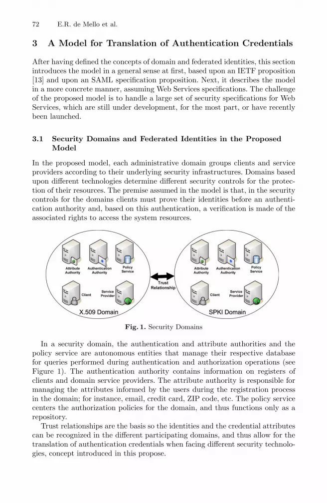
72 E.R. de Mello et al.
3 A Model for Translation of Authentication Credentials
After having defined the concepts of domain and federated identities, this sectionintroduces the model in a general sense at first, based upon an IETF proposition[13] and upon an SAML specification proposition. Next, it describes the modelin a more concrete manner, assuming Web Services specifications. The challengeof the proposed model is to handle a large set of security specifications for WebServices, which are still under development, for the most part, or have recentlybeen launched.
3.1 Security Domains and Federated Identities in the ProposedModel
In the proposed model, each administrative domain groups clients and serviceproviders according to their underlying security infrastructures. Domains basedupon different technologies determine different security controls for the protec-tion of their resources. The premise assumed in the model is that, in the securitycontrols for the domains clients must prove their identities before an authenti-cation authority and, based on this authentication, a verification is made of theassociated rights to access the system resources.
Fig. 1. Security Domains
In a security domain, the authentication and attribute authorities and thepolicy service are autonomous entities that manage their respective databasefor queries performed during authentication and authorization operations (seeFigure 1). The authentication authority contains information on registers ofclients and domain service providers. The attribute authority is responsible formanaging the attributes informed by the users during the registration processin the domain; for instance, email, credit card, ZIP code, etc. The policy servicecenters the authorization policies for the domain, and thus functions only as arepository.
Trust relationships are the basis so the identities and the credential attributescan be recognized in the different participating domains, and thus allow for thetranslation of authentication credentials when facing different security technolo-gies, concept introduced in this propose.

A Model for Authentication Credentials Translation in SOA 73
Within the context of federated identities, a clientmay be affiliated to more thanone domain, with distinct accounts and different attributes spread over differentdomains. As in studies that implement the concept of federated identities, suchas WS-Federation [14], Shibboleth [15] and Liberty Alliance [16], in the proposedmodel, the service provider is also the one responsible for retrieving the user’sinformation. The client provides only its identity or pseudonym and the serviceprovider is the one who searches, among its federation partners, for the client at-tributes.
3.2 Model Overview
The authorization model discussed in this article is based on the model proposedby IETF [13], which describes two fundamental elements for policy management:PEP (Policy Enforcement Point) and PDP (Policy Decision Point).PEP is an element, which controls the access to a resource, and its function isto apply policy decisions, whereas PDP is an entity, which defines the policy tobe applied to the required service requisition. Fig. 2 shows the proposed modeland highlights the steps of the authorization process.
Other entities were added to the IETF propositions as a starting point to themodel, the attribute and authentication authorities that are called beforethe authorization process. As authorization verifications in the model are as-sumed to be local for service providers, then both PEP and PDP are supposedto have their implementations in the service providers that control the requeststo those services.
Initially, the model is considered that domain clients have already been regis-tered and that information on their attributes is available to service providers,in the attribute authority of the domain, according to a privacy policy definedby the user itself. This policy determines which attributes the user wishes to in-form the providers of its domain and also providers of other domains. The clientauthenticates to its authentication authority and receives an authentication cre-dential with information related to the issuing authority, the client’s identity,the expiration date, etc. This credential must then be presented whenever theclient wishes to access resources in the service providers located at the domainswith which the client’s domain has trust relationships.
As the proposed model is based on the security standards of the Web Servicetechnology, it assumes a service-oriented format. The attribute and authentica-tion authorities are the Security Token Service/ Identity Provider (STS/IdP)and the Attribute and Pseudonym Service (APS), respectively (see Fig. 2). Thisproposal combines Security Token Service (STS) and IdP (Identity Provider)into a single entity, known as STS/IdP that is responsible to issue, validatesand exchanges identity and authentication credentials. Both user’s privacy andattribute provide are functions performed by Attribute and Pseudonym Service(APS), which works together with STS/IdP. The credentials issued by STS/IdPare SAML authentication assertions and the attributes retrieved from APSare SAML attribute assertions.

74 E.R. de Mello et al.
The security of SOAP messages is ensured through the WS-Security speci-fication, which provides end-to-end security and avoids attacks such as replayand man-in-the-middle, using encryption and digital signature mechanisms incompliance with the requirements defined in the quality of protection policyexpressed in compliance with the WS-Policy specification6.
In a policy server, the authorization policies that protects the resource areexpressed in XACML and the messages exchange between PEP and PDP followthe XACML specification. XACML was chosen since this de facto standard wasspecifically designed to represent access control policies. When PDP queries theauthentication authority, the STS/IdP, to validate an authentication assertionreceived, it does so through the protocol defined in the WS-Trust specification.PDP’s interactions with the STS/IdP of its domain are justified by the fact thatthe service provider may not support the format of the received credential andmight need this credential to be translated into the technology it supports. Itshould be highlighted that, in the proposed model, STS/IdP acts in a similarmanner as the PIP (Policy Information Point) of the XACML standard.
The challenges of the model appear when an access request involves differentsecurity domains, that is, the model must ensure interoperability among differ-ent administrative domains.The integration of different underlying technologiesrequires a standard language to represent security attributes, either authentica-tion or authorization ones. As aforementioned The WS-Trust and WS-Federationspecifications do not tackle how to translate the information contained in theprincipal’s security credentials, when dealing with different technologies.
In this study, we chose to describe a case composed by two security domains,both based upon PKIs. Besides, clients and service providers were considered tobe able to work only with the security technology employed in their domain, asthe client domain is based on SPKI, and the service provider domain is basedon X.509. However, the model is generic enough to allow for the use of othertechnologies.
In the proposed model, the translation of authentication credentials and theattribute transposition to different security domains is based on the Attribute/Pseudonym Service (APS), on the Security Token Service (STS/IdP), and alsoon a new service, the Credential Translation Service (CTS), introduced in thisarticle.
The Attribute/Pseudonym Service (APS) is directly linked to the STS/IdPand has two purposes: providing attributes associated with a principal7 andmanaging a pseudonym system, which allows a principal to authenticate andto use this authentication in the remaining domain entities without having itsreal identity revealed. For the proposed model, the STS/IdP of the domainsestablishes trust relationships, and thus forms “federations”. Then, in this en-vironment, there is a need for the standardization of the attributes provided byeach Attribute/Pseudonym service. In the literature, many studies have been
6 It should be noted that the security of sensitive information stored in the clients isbeyond the scope of this article.
7 Respecting the privacy policy of this principal.

A Model for Authentication Credentials Translation in SOA 75
concerned with defining a standard set of attributes needed for a federated envi-ronment [17,18,19]. Among them, approximately 40 attributes have been definedas common identity attributes [20]; 6 of which are highly recommended, 10 aresuggested, and 25 are optional. In this proposal, we adopted a standard set ofattributes composed of 6 highly recommended attributes and of 10 suggested at-tributes, as shown in the [20] document. This set is enough to allow credentialsof an SPKI domain to be converted into X.509 certificates. Nevertheless, it canalso be expanded in order to accommodate other security technologies, such asKerberos tickets and biometric credentials.
All the entities of the domain trust their STS/IdP and thus a client identifi-cation in the presence of a service provider will be attested through an SAMLauthentication assertion issued by the STS/IdP. In the model, we consider theexistence of trust relationships between STSs of different domains, given thatthese relationships allow the assertions issued in a domain to be valid in theremaining domains. In order to accomplish so, as an STS receives an SAMLauthentication assertion, it can ask the authentication authority that issued theassertion (the STS of the client domain) to provide additional information aboutthis authentication so that it can assess the level of trust of the assertion.
The specification [21] defines an XML Schema for the creation of authen-tication context declarations - XML documents that allow the authenticationauthority to provide the relying party with this additional information. Thisinformation could include: the initial user’s identification mechanisms (e.g. face-to-face, online, shared secret), the mechanisms for storing and protecting cre-dentials (e.g. smartcard, password rules) and the authentication mechanism ormethod (e.g. password, certificate-based SSL, digital signatures). Additionally,this specification defines a number of authentication context8 classes. Each classdefines a proper subset of the full set of authentication contexts. For the purposesof the model, the X.509 and SPKI authentication context classes were used. Theformer indicates that the principal authenticated by means of a digital signaturewhere the key was validated as part of an X.509 PKI, and the latter indicatesthat the principal authenticated by means of a digital signature where the keywas validated via an SPKI Infrastructure.
3.3 Dynamics for Translation of Authentication Credentials
Fig. 2 shows all the steps taken in order for a client in an domain to access resourcesin a service provider present in another domain, and also shows the interactionsamong the STS, APS and CTS (Credential Translation Service) services intro-duced below. To a better comprehension, consider a scenario where the client’sdomain is based on SPKI and the service provider’s domain uses X.509.
Before a client can call the service provider, it needs to authenticate to itsSTS (Step 1, Fig. 2), and it may request a pseudonym to associate the authenti-cation credential (Step 2). In Step 3, the client receives an SAML authentication8 Authentication context is defined as the information, additional to the authentication
assertion itself, which the relying party may require before it makes an entitlementdecision with respect to an authentication assertion [21].

76 E.R. de Mello et al.
Fig. 2. Dynamics for Translation of Authentication Credentials
assertion based on the security attributes provided by SPKI. In this case, theassertion only carries the client SPKI public key. In Step 4, the client calls theservice provider and provides, together with the request, the previously receivedSAML assertion. The enforcement of an authorization policy starts at the serviceprovider with the provider’s PEP.
When PEP intercepts a client’s request, it issues a XACML request with apolicy decision request to PDP (Step 5). PEP’s request to PDP defines oneor more policy elements, as well as information on the desired access. In orderto make the decision concerning the request, PDP may query authenticationand attribute authorities, the STS/IdP and the APS, to validate the SAMLauthentication assertion received and to obtain the client attributes.
It is known that the service provider is only apt to work with X.509 credentials.Consequently, the SAML assertion received from the client is forwarded to itsSTS (Step 6), which is in charge of assessing the trust in the SAML assertionreceived and translating the assertion into an X.509 certificate. In Step 7, theSTS calls the Credential Translation Service (CTS) (see Fig. 3) so that the CTSextracts, from the SAML assertion and authentication context, the necessaryfields to compose an X.509 certificate. In this case, the SAML assertion does notshow all the necessary attributes. Therefore, the CTS requests its STS/IdP tocall the client’s STS/IdP (which, in turn, calls its respective APS) in order toobtain the missing attributes (Step 8). Finally, the STS/IdP of the X.509 domainissues, to the service provider, (1) an X.509 certificate composed of information

A Model for Authentication Credentials Translation in SOA 77
Provider Domain Client Domain
cn: XXX
ou: XXX st: XXX
email: XXX
X.509 certificate
cn: XXX
ou: EMPTY st: EMPTY
email: XXX
X.509 certificate skeleton
[other][spki]
Certificate Assembler
Certificate writer
credential type
Other dataextract
SPKI dataextract
APS
STSfill out certificatefields
obtain missingdata
STS
SAML Assertion<auth context: spki>
CommonAttributes
1
2
3 45
Fig. 3. Credential Translation Service
provided by the client’s SAML authentication assertion, and (2) the attributesgathered in the client’s STS/IdP (Step 9). At this point, the client is identifiedthrough a credential which the service provider understands and whose issuer(the STS) the service provider trusts. Therefore, it is the service provider’s dutyto ensure whether or not the client will have access to the service, based on itsaccess control policies. Next (Step 10), PDP receives the authorization policythat protects the resource. After these queries, in Step 11, PDP returns thepolicy decision and PEP applies it, accepting or denying access (Step 12).
3.4 Credential Translation Service
The use of SAML assertions in tandem with trust relationships allows for thetranslation of authentication credentials, that is, a client that has authenticatedto domain A can use this authentication information to access resources of aservice provider present in domain B. However, as aforementioned, clients andservice providers are only able to operate with the underlying security technol-ogy of the domain and, in case the client and service providers use differenttechnologies, there appears the need for a way of mapping the authenticationinformation from one domain to another.
A solution to this problem lies in the use of the Credential Translation Service(CTS), which aims at the extraction of SAML authentication assertion infor-mation in order to compose a new authentication credential so that it can beunderstood by the domain entities (step 1 in Fig. 3). Therefore, a client makinguse of the SPKI technology will have its authentication attributes converted intoSAML assertions which, when received by a service provider using X.509, willbe converted again into this provider security technology (step 2 in Fig. 3). This

78 E.R. de Mello et al.
functioning ensures that clients and service providers keep their security featuresand thus let the CTS in charge of translating the attributes of a technology intoanother.
The use of X.509 and SPKI authentication context classes, as defined in [21],aids the translation process of authentication credentials, since the CTS makesuse of this information to perform the mapping of the SAML assertion received atthe credential required by the provider (for instance, X.509 or SPKI). Neverthe-less, information present at authentication assertions may still not suffice to thecredential’s translation. For instance, in a service provider in the X.509 domain,a client authentication is carried out by means of digital signatures, whereby thekey was validated as part of an X.509 PKI. Additionally to the client public key,it is known that X.509 certificates carry other information such as organizationalunit, city, etc. Also, it is common knowledge that, in the SPKI, this informationis absent and thus the conversion of an SAML assertion issued in a SPKI domaininto an X.509 certificate depends on the presence of all the necessary certificate’sattributes. It is at this point that the Attribute/Pseudonym Service is needed(step 3 and step 4 in Fig. 3).
4 Implementation
In this section, we discuss the implementation of the proposed model proto-type. In addition, we address the performance of our prototype implementation.Finally, we describe the integration of the prototype into a entertainment portal.
4.1 Implementation Details
A prototype was implemented in order to attest the flexibility of the proposedmodel and also the feasibility of its use in distributed applications based on aservice-oriented architecture. Figure 4 shows the prototype’s architecture. Forthe implementation Java was the programming language used and as an ap-plication server Apache Tomcat. Apache Axis 1.4 was used as implementationSOAP. Other open source libraries were adopted to compose the prototype, theyare: WSS4J library9, XML-Security library10, SunXACML11, OpenSAML 12 andSDSI1.2 library [22].
The prototype implemented consists of two security domains: one based onX.509 PKI, and other based on SPKI. One of the reasons these PKIs were chosenwas that the XML Signature specification provides support for both. However,OpenSAML, XMLSecurity e WSS4J libraries provide support only to X509. TheWSS4J library had its STS extended, having the capability to issue authentica-tion credentials by using the SPKI infrastructure. The OpenSAML library wasextended in order to sign SAMLTokens [23] with SPKI keys, because the current
9 http://ws.apache.org/wss4j10 http://xml.apache.org/security11 http://sunxacml.sourceforge.net12 http://www.opensaml.org

A Model for Authentication Credentials Translation in SOA 79
Client ServiceProvider
Services for Credential Transposition
CTS STS/IdP APS
WSS4J XMLSecurity
SDSI1.2OpenSAML
Quality of Protection
SunXACML
Access Control
PEPHandler
PDPHandler
SOAP + HTTP
ApplicationLayer
SecurityLayer
TransportLayer
CTS – Credential Translation Service APS: Attribute/Pseudonym ServiceSTS/IdP – Security Token Service/Identity Provider
Fig. 4. Prototype Architecture
RequestSecurityToken
Domain Member
(3) Validation and Translation Request
(2) Attributes Request
(1) Authentication Request
<<include>>
<<include>>
<<include>> PDP
Foreign STS/IdP
Fig. 5. Requests Handled by STS/IdP
version of OpenSAML only supports X.509 keys. Finally, some extensions wereimplemented in the XML Security library, in compliance with the recommen-dations for extensions defined by Apache Foundation, in order to define whichSPKI/SDSI elements can be inserted into an XML signature.
Each STS/IdP deals with security technology of its domain, as a consequence,for each technology was necessary to define an implementation of STS/IdP. In theprototype, the STS/IdPs must to process three requests types (see Figure 5): (1)member’s authentication requests; (2) attribute requests in the form of SAMLassertions; and (1)credential validation and translation request.
According to WS-Trust model, all such requests are to issue tokens. Thus,in all requests the element wst:RequestType in RequestSecurityToken (RST)message contains the URI field. The difference among request types is made upanalyzing the other fields of the message. The requests of type 1 are made by aclient to STS/IdP of its domain when it wants to access a service that requiresauthentication. An authentication request has the SAML assertions URI, de-fined in the SAML Token Profile, in the content of the element wst:TokenType.
80 E.R. de Mello et al.
In those requests, STS/IdP uses the OpenSAML library to issue and to signa SAML assertion that contains a subject (the requestor), an authenticationstatement and some other attributes.
The requests of type 2 also have the SAML assertions URI as the elementcontent wst:TokenType, however differ from the requests of type 1 since theyhave the element wst:Claims, it contains a list of non-empty attribute names.When the STS/IdP receives such a request, it reads the list of attributes andaccesses the APS to obtain required attributes. Then it uses the library Open-SAML to issue and sign a SAML assertion containing client’s attributes. Therequests of the type 3 are made by the PDP service provider to the STS/IdPof its domain when it wants to validate the authentication token received fromthe client. In those requests, the element wst:TokenType contains the URI in-dicating the type of credential-specific domain. When the STS / IdP receives arequest of this type, it uses the library OpenSAML to validate the SAML as-sertion received in accordance with its trust over the issuer (STS/IdP). Then,it invokes CTS to know if is necessary to get more attributes of the client. Ifyes, then STS/IdP will request attributes of the STS/IdP that issued the SAMLassertion. Finally, the CTS is required to translate the assertion to a credentialin the domain technology. The credential generated by the CTS and signed bythe STS/IdP is then returned to the service provider.
The services for implementation of credential translations (CTS and APS) arenot implemented at libraries used, so it was fully developed in prototype. APSis an attributes repository of the domain’s members and it was implementedas a STS/IdP local library. APS has two tasks in the current prototype: it re-trieves attributes according to a list of identifiers; and it defines how to transportidentifier inside of wst:Claims field.
The CTS is responsible for transforming a list of attributes in a specific cre-dential of it domain. In the prototype, the CTS was developed as a STS/IdPlocal library and has two operations: one to obtain a list of attributes necessaryto generate the credential; and another to carry out the translation. For eachsecurity technology supported by the prototype, the list of attributes needed andhow those attributes will be processed on the credentials are different. For exam-ple, in X.509 domain, the attributes needed are the fields of a X.509 certificate,as the subject’s X.500 name, the subject’s public key, etc.
To facilitate the development of client applications, a library was implementedto aid the interaction between a client and the STS/IdP of its domain. A generalPEP was implemented to help on the creation of new services. This PEP is able(1) to intercept client’s messages, (2) to interact with PDP and (3) to enforcethe PDP decision. SunXACML library was extended to carry out communicationwith the STS/IdP of service provider domain.
4.2 Performance
This section presents some results of tests applied with the purpose of evaluatingthe performance (processing time) of the prototype in three representative usagescenarios. That is, we intend to evaluate additional costs introduced by the

A Model for Authentication Credentials Translation in SOA 81
credentials translation process and the use of security mechanism in compliancewith WS-Security. We did 50 experiments using two computers with identicalconfiguration – a 3.0GHz Pentium 4 with 1 GB RAM running Linux (kernel2.6.24). Both computers had the Java 2 Software Development Kit (J2SDK),version 1.6.0.
In the first scenario, client and service provider are in the same domain thatdoes not provide security mechanisms. Client sends a simple resource requestto service provider. This scenario was ran across the department’s network atmidday and we found that, on average, it executed in 8.18 ms with a standarddeviation of 3.02ms.
In the second scenario, client and service provider are in the same securitydomain (X.509). In this experiment, client does authentication process with itsSTS/IdP (steps 1 to 3 in Figure 2) and receives a respective SAML authentica-tion assertion. In the next step, client invokes the service provider and at thispoint occours the enforcement of authorization policy. In this scenario, basicsecurity properties of all SOAP messages are ensured by WSS4J library thatimplements WS-Security specification. On average, this scenario executed in53.12ms over the same network with a standard deviation of 8.18ms.
In the third scenario we consider that the client’s security domain is basedon SPKI and the service provider’s security domain is based on X.509. Clientreceives a SAML authentication assertion based on its SPKI’s security attributesand than client involkes service provider. PEP entity intercepts client’s requestand it issues a XACML request to PDP entity. PDP queries the STS/Idp andthe APS to validate the SAML authentication assertion and to obtain client’sattributes. Finally, SAML assertion has to be translated into a X.509 certificatebecause the service provider only work with this security mechanism. On aver-age, this scenario executed in 410.74ms over the same network with a standarddeviation of 28.07 seconds.
The difference in processing time between the first and second scenarios ex-presses the computational cost of digital signatures of asymmetric cryptography.Clearly, executing the authentication credentials translation process (third sce-nario) takes longer than using a more traditional means of SSO in homogenoussecurity domain (e.g., based on X.509). The difference occurs, mainly due tothe greater number of message exchanges. They are, overall, four invocationswhere all messages are signed with asymmetric cryptography. This cost is jus-tified when the SSO authentication in heterogenous domains is desired front ofdifferent technologies that the third case provides. Additionally, the credentialstranslation process need to be executed only one time in a conversation, so thisoverhead is eliminate in the next invocations between these client and provider.Further, the prototype has not been optimized for performance. In future re-search is feasible implements a solution with much better performance.
4.3 Integrating the Prototype into a Distributed Application
An entertainment portal was integrated into the implemented prototype. Thegoal of the portal is to gather within a single interface several service providers

82 E.R. de Mello et al.
that aim at personal entertainment - for example, movie theaters, amusementparks, video stores, theaters, etc. The open source portal used was Stringbeans13.he services offered via the Portal were implemented by providers in different do-mains and trust relationships among the portal domain and the service provideswere established. When a client subscribes itself on the portal, this can customizetheir access defining what and how services are provided. Moreover, the clientinforms the portal his personal data. The portal register the data in the APSto permit that foreign STS/IdP access the attributes necessary to generate thecredentials of this client.
In order to access the services offered via the Portal, a client must authenticatethrough valid login and password, over an SSL session, as shown in Fig. 614. Thatportal, in the name of the client, asks the STS for an SAML authenticationassertion. It should be noted that SPKI is the security technology supported inthe portal. From this point onwards, all of this client’s requests will be added tothe SAML authentication assertion issued by the portal’s STS, so that the clientcan access all the resources offered by the service providers that can be withinan X.509 or an SPKI domain (see Fig. 6).
Fig. 6. Entertainment Portal
In Figure 7, the UML communication diagram illustrates the messages ex-changed among the services (in the portal and service provider domains) toenforce the authentication credentials translation, according to what was imple-mented. It should be noted that while receiving the SAML assertion, the serviceprovider requests its STS to translate the assertion into an X.509 certificate.Hence, the portal is responsible for mediate the access among the clients andthe service providers and the client can make use of a SSO authentication.
13 http://www.nabh.com/projects/sbportal14 This occurs because the clients access the portal through common browsers and, in
general, it did not supported SOAP messages.

A Model for Authentication Credentials Translation in SOA 83
Client
STS A
3: request(..., saml)
1: RST("Issue", "SAML", spki)
2: RSTR(saml)
8: translateResponse(x509)
9: RSTR(x509)
10: response(...)
ServiceProvider
STS B
CTS
6: RSTR(attrValues) 5: RST("Issue", attrList, saml)
7: translate("X.509", saml, attrList)
4: RST("Issue", "X.509", saml)
Fig. 7. UML Communication Diagram
5 Related Work
In the literature, some studies have struggled to gather a set of Web Service-related specifications to carry out authentication credentials translation. Most ofthese studies take the concept of federated identities through Web Services intoaccount, but only consider the use of X.509 as security infrastructure [24,15,25].An issue that still needs clarification is the nature of the interaction amongdomains with different security technologies.
CredEx [24] enables the safe storage of credentials and the dynamic exchangeof different kinds of credentials, by using the protocol defined in the WS-Trustspecification. However, the implementation only considers the previous associa-tion of a username and a password with an X.509 proxy certificate or vice-versa.Thus, the model neither encompasses different security technologies, such asSPKI or Kerberos, nor enables dynamic credential translation.
The Shibboleth framework [15] is an implementation of the browser profilesfrom the OASIS SAML specification, which provides a SSO service and attributeexchange from the user’s home site to the site he is accessing. This framework isbased on the concept of federations and also enables authentication credentialstranslation. Most organizations, which adopt Shibboleth use the X.509 standardfor server authentication and password-based authentication for client authen-tication. The model proposed in this article differs from Shibboleth as it givesmore flexibility to the members of the federation, which do not need to use a webbrowser when interacting with services. The proposed model also enables directcommunication among service providers, that is, provider to provider. Service

84 E.R. de Mello et al.
providers do not have to follow strict standardization in order to take part inthe federation; it will suffice to be associated with a STS/IdP. Moreover, theycan also keep their own security technology and use the Credential Translationwhen they need to deal with different technologies.
ShibGrid [26] and SHEBANGS [27] projects aim to provide Shibboleth basedauthentication for grid infrastructures, especially the UK National Grid Service(NGS). The authentication infrastructure behind NGS is based on X.509 cer-tificates and proxies15 This infrastructure is known as the Grid Security Infras-tructure (GSI). SHEBANGS has adopted a proxied push model, wherein usersfirst contact a credential translation service, which, after Shibboleth-based au-thentication and attribute retrieval, generates a credential stored in a MyProxyserver. Access to that credential is then achieved by the user logging on to theNGS portal with details returned to them from the credential translation service.On the other hand, ShibGrid uses MyProxy servers to link two user identities(Shibboleth identity and X.509 certificate DN) instead of using the credentialtranslation service. In both projects, the authentication credentials translationoccurs only when there are two security domains (Shibboleth/SAML and GridSecurity Infrastructure/X.509).
Cardea [25] makes a dynamic assessment of the authorization requests, tak-ing into account features of the resource and of the request instead of onlyassessing local identities. Users are identified by proxy X.509 certificates. Unlikewhat is proposed in the present study, Cardea builds the federation through theSAML standard, that is, SAML authorities, rather than through WS-Trust andWS-Federation specifications; besides, Cardea does not take into considerationdifferent security technologies involved in the authentication process.
The TrustBuilder project16 is investigating trust negotiation, an attribute-based access control (ABAC) model in which parties conduct bilateral and it-erative exchanges of policies and certified attributes to negotiate for access tosystem resources. In the architecture proposed in this project, a policy compli-ance checker translates the attribute credentials from X509 certificate or a neu-tral format, such as XML, into statements in the policy language [29]. However,the Trust Builder approach does not deal with SSO’s interoperability amongheterogeneous security technologies.
In [30,31], a Credential Conversion Service (CCS) is proposed to integrateauthorization schemes. This service is responsible by translate non SAML-basedcredentials, such as X.509 attribute certificates into SAML Attribute Statements.In this approach, whole security domains need supported a authentication mech-anism based on SAML assertions.
6 Conclusion
The concept of federated identities, which forms the basis of this research, (1)favors an effective and independent translation, (2) enables the client to use the15 NGS portals use MyProxy servers [28] as the means by which grid credentials are
obtained.16 http://dais.cs.uiuc.edu/dais/security/trustb.php

A Model for Authentication Credentials Translation in SOA 85
resources of the federation through authentication carried out in its domain and(3) potentially increases the number of prospective clients for service providers.
Through the definitions proposed in the model, a client that is unknown to theservice provider may undergo identity authentication thanks to the trust estab-lished among the domains. The provider does not need to know its prospectiveclients in advance, which thus makes it easier for clients to use the service andenhances business opportunities among service providers.
The model has overcome translation drawbacks by proposing the CredentialTranslation Service to translate the credentials that service providers failed tounderstand. Moreover, in the proposed solution, the model has gathered severalsecurity specifications in Web Services, which is not a simple task, given thelarge number of specifications and their complexity. In the future, by means ofthe Credential Translation Service, it will be also possible to translate not onlyX.509 and SPKI/SDSI but also authentication credentials in compliance withthe Kerberos format (tickets) and according to biometrical profiles (e.g. digitalfingerprinting). This will enable communication with providers and clients thatsupport those technologies.
As regards the scalability of the proposed model, communication among do-mains should suffice to make credential exchange possible, as each domain has itsown credential provider. Certainly, this dynamics does not pose scale problems,since this is what happens in current Internet applications. In other words, in theproposed model there is no centralizing entity in charge of mapping the creden-tials. Each domain is responsible for the required mapping and, thus, the systemscale is assured; it will suffice that well requested domains provide solutions forload distribution through, for example, the grouping of machines.
References
1. Jøsang, A., Pope, S.: User centric identity management. In: AusCERT Asia PacificInformation Technology Security Conference 2005 (May 2005)
2. W3C: Web Services Architecture. W3C Working Group (February 2004), http://www.w3.org/TR/2004/NOTE-ws-arch-20040211
3. Vogels, W.: Web services are not distributed objects. Internet Computing 7(6),59–66 (2003)
4. Bartel, M., Boyer, J., Fox, B.: XML-Signature Syntax and Processing. W3C (Febru-ary 2002), http://www.w3.org/TR/xmldsig-core
5. Imamura, T., Dillaway, B., Simon, E.: XML Encryption Syntax and Processing.W3C (December 2002), http://www.w3.org/TR/xmlenc-core
6. OASIS: eXtensible Access Control Markup Language (XACML) version 2.0. Or-ganization for the Advancement of Structured Information Standards (February2005)
7. OASIS: Security Assertion Markup Language (SAML) 2.0 Technical Overview. Or-ganization for the Advancement of Structured Information Standards (June 2005)
8. OASIS: Web Services Security: SOAP Message Security 1.0. OASIS. (March2004), http://docs.oasis-open.org/wss/2004/01/oasis-200401-wss-soap-
message-security-1.0.pdf
9. WS-Policy: Web Services Policy 1.5 (March 2007)

86 E.R. de Mello et al.
10. WS-SecurityPolicy: Web Services Security Policy Language (July 2005)11. WS-PolicyAttachment: Web Services Policy Attachment (March 2006)12. WS-Trust: Web Services Trust Language (WS-Trust) (February 2005), http://
msdn.microsoft.com/library/en-us/dnglobspec/html/WS-Trust.asp13. Yavatkar, R., Pendarakis, D., Guerin, R.: A Framework for Policy-based Admission
Control. IETF RFC 2753 (January 2000)14. WS-Federation: Web Services Federation Language (July 2003), http://msdn.
microsoft.com/ws/2003/07/ws-federation15. Shibboleth: Shibboleth Architecture (June 2005), http://shibboleth.internet2.
edu/docs/draft-mace-shibboleth-tech-overview-latest.pdf16. Liberty: Introduction to the Liberty Alliance Identity Architecture. Liberty Al-
liance (March 2003)17. Internet2, EduCause: eduperson, http://www.educause.edu/eduperson18. Wahl, M.: A Summary of the X.500(96) User Schema for use with LDAPv3. IETF
RFC 2256 (December 1997)19. Smith, M.: Definition of the inetOrgPerson LDAP Object Class. IETF RFC 2798
(April 2000)20. InComm: Incomm federation: Common identity attributes, http://www.
incommonfederation.org/docs/policies/federatedattributes.pdf21. OASIS: Authentication Context for the OASIS Security Assertion Markup Lan-
guage (SAML) v2.0. Organization for the Advancement of Structured InformationStandards (March 2005)
22. Morcos, A.: A Java implementation of Simple Distributed Security Infrastructure.Master’s thesis, MIT (May 1998)
23. OASIS: Web Services Security: SAML Token Profile. Organization for the Ad-vancement of Structured Information Standards (December 2004)
24. Vecchio, D.D., Basney, J., Nagaratnam, N.: Credex: User-centric credential man-agement for grid and web services. In: International Conference on Web Services,Orlando, Florida - EUA, pp. 149–156 (2005)
25. Lorch, M., Proctor, S., Lepro, R., Kafura, D., Shah, S.: First experiences usingxacml for access control in distributed systems. In: ACM Workshop on XML Se-curity (October 2003)
26. Spence, D., Geddes, N., Jensen, J., Richards, A., Viljoen, M., Martin, A., Dovey,M., Norman, M., Tang, K., Trefethen, A., Wallom, D., Allan, R., Meredith, D.:Shibgrid: Shibboleth access for the uk national grid service. In: Proceedings ofthe Second IEEE International Conference on e-Science and Grid Computing (e-Science 2006), p. 75. IEEE Computer Society, Los Alamitos (2006)
27. Jones, M., Pickles, S.: Shebangs final report. Technical report, University of Manch-ester (2007)
28. Basney, J., Humphrey, M., Von Welch: The myproxy online credential repository:Research articles. Softw. Pract. Exper. 35(9), 801–816 (2005)
29. Winslett, M., Yu, T., Seamons, K.E., Hess, A., Jacobson, J., Jarvis, R., Smith,B., Yu, L.: Negotiating trust on the web. IEEE Internet Computing 06(6), 30–37(2002)
30. Canovas, O., Lopez, G., Gomez-Skarmeta, A.F.: A credential conversion service forSAML-based scenarios. In: Katsikas, S.K., Gritzalis, S., Lopez, J. (eds.) EuroPKI2004. LNCS, vol. 3093, pp. 297–305. Springer, Heidelberg (2004)
31. Lopez, G., Canovas, O., Gomez-Skarmeta, A.F., Otenko, S., Chadwick, D.: A het-erogeneous network access service based on PERMIS and SAML. In: Chadwick, D.,Zhao, G. (eds.) EuroPKI 2005. LNCS, vol. 3545, pp. 55–72. Springer, Heidelberg(2005)
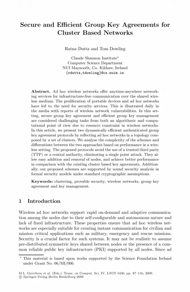
Secure and Efficient Group Key Agreements forCluster Based Networks
Ratna Dutta and Tom Dowling
Claude Shannon Institute�
Computer Science DepartmentNUI Maynooth, Co. Kildare, Ireland{rdutta,tdowling}@cs.nuim.ie
Abstract. Ad hoc wireless networks offer anytime-anywhere network-ing services for infrastructure-free communication over the shared wire-less medium. The proliferation of portable devices and ad hoc networkshave led to the need for security services. This is illustrated daily inthe media with reports of wireless network vulnerabilities. In this set-ting, secure group key agreement and efficient group key managementare considered challenging tasks from both an algorithmic and compu-tational point of view due to resource constraint in wireless networks.In this article, we present two dynamically efficient authenticated groupkey agreement protocols by reflecting ad hoc networks in a topology com-posed by a set of clusters. We analyse the complexity of the schemes anddifferentiate between the two approaches based on performance in a wire-less setting. The proposed protocols avoid the use of a trusted third party(TTP) or a central authority, eliminating a single point attack. They al-low easy addition and removal of nodes, and achieve better performancein comparison with the existing cluster based key agreements. Addition-ally, our proposed schemes are supported by sound security analysis informal security models under standard cryptographic assumptions.
Keywords: clustering, provable security, wireless networks, group keyagreement and key management.
1 Introduction
Wireless ad hoc networks support rapid on-demand and adaptive communica-tion among the nodes due to their self-configurable and autonomous nature andlack of fixed infrastructure. These properties ensure that ad hoc wireless net-works are especially suitable for creating instant communication for civilian andmission critical applications such as military, emergency and rescue missions.Security is a crucial factor for such systems. It may not be realistic to assumepre-distributed symmetric keys shared between nodes or the presence of a com-mon reliable public key infrastructure (PKI) supported by all nodes. Since ad
� This material is based upon works supported by the Science Foundation Irelandunder Grant No. 06/MI/006.
M.L. Gavrilova et al. (Eds.): Trans. on Comput. Sci. IV, LNCS 5430, pp. 87–116, 2009.c© Springer-Verlag Berlin Heidelberg 2009

88 R. Dutta and T. Dowling
hoc networks rely on the collaboration principle, the issue of key distributionin such networks represents an important problem. Secure key agreement andefficient group key management are two of the most important mechanisms tobuild a secure network. However, traditional cryptographic approaches and as-sumptions are inappropriate for ad hoc wireless networks as the nodes may beresource-constrained in energy, bandwidth, computational ability and memory.
There are quite a number of group key agreements in literature [15], [26], butall are not applicable in ad hoc networks because of dynamic and multi-hop na-ture of the mobile nodes. Clustering is a usual solution that splits the probleminto pieces. We assume ad hoc networks consist of nodes which have no priorcontact, trust or authority relation and which may move freely and communicatewith other nodes via wireless links. One may logically represent an ad hoc net-work as a set of clusters. While all nodes are identical in their capabilities, certainnodes are elected to form the sponsors which are vested with the responsibilityof routing messages for all the nodes within their clusters. Sponsors typicallycommunicate with sponsors of other clusters. The election of sponsors has beena topic of many papers as documented in [2], [3], [17]. There are several missioncritical applications (such as in military, emergency, rescue missions), scientificexplorations (such as in environmental monitoring and disaster response), civil-ians (such as in law enforcement, building automation) and other collaborativeapplications for commercial uses where sponsors have a powerful radio whichother nodes in the cluster do not have so that sponsors can communicate amongthemselves. For example, military networks consists of mobile devices carriedby soldiers, automatic weapons, sensing devices etc. In this setup, a platooncommander may play the role of sponsor and may be able to communicate withplatoon commanders of other clusters. On the other hand, soldiers are clustermobile nodes and may move from one cluster to another.
Clustering method enables nodes to be organised in an hierarchical ad hoc net-work based on their relative proximity to one another, thereby weakening the one-hop assumption in common group key agreement protocols. Contributory groupkey agreement and key management are easier to handle inside each cluster com-pared to the entire ad hoc network. This is because of the fact that clusters havemore stable internal connections due to the larger amount of links between nodeswithin the same cluster. Besides, inter-cluster key agreement is more sensible asclusters are assumed to stay together longer than the nodes do in average for wire-less ad hoc networks. Clustering may thus bring the necessary scalability into keyestablishment in very large networks. Designing provably secure key agreementprotocols in such clustered environments is always a challenging task. Li et al. [24]propose a communication efficient hybrid key agreement using the concept of con-nected dominating set. However, the protocol is inefficient in handling dynamicevents. Based on this work, Yao et al. [36] propose a hierarchical key agreementprotocol which is communication efficient in handling dynamic events. Both theprotocols of [24] and [36] employ some existed group key agreement protocol suchas GDH [35] and are unauthenticated with no security analysis against active

Secure and Efficient Group Key Agreements 89
adversary. The existing group key agreement protocols that use clusters and pair-ings are [34], [1], [23].
Our Contribution. Being inspired with these works, we propose two dynami-cally efficient authenticated group key agreement protocols, namely AP− 1 andAP−2 for clustered wireless ad hoc networks. AP−1 is designed without pairingsand is proven to be secure under Decision Diffie-Hellman (DDH) assumption.AP − 2 is pairing-based and is proven to be secure under DDH and DecisionHash Bilinear Diffie-Hellman (DHBDH) assumption.
The basic idea of our constructions is the following: In a mobile ad hoc en-vironment, the number of nodes could be very large. We divide all the nodesinto clusters based on their relative proximity to one another. We differenti-ate between two types of keys. By cluster key we mean key generated amongall the nodes within a cluster and by session key we mean a common networkkey among all the nodes in the system. All nodes within a cluster dynami-cally generate their cluster keys using a scalable constant round dynamic groupkey agreement protocol. We choose the constant round multi-party dynamic keyagreement protocol of Dutta-Barua DB [14] for this purpose, which is a variantof Burmester-Desmedt protocol BD-I [8] and is very efficient. Each cluster selectsa sponsor using a sponsor selection mechanism. Both AP−1 and AP−2 considera network of mobile nodes where all sponsors need to be able to communicateamong themselves in a single hop. AP − 1 invokes the DB protocol among thesponsors to agree upon a common session key considering the sponsors as thenodes of a virtual ring. AP − 2 invokes the pairing-based group key agreementprotocol DBS of Dutta-Barua-Sarkar [11] among the sponsors to agree upon acommon session key considering the sponsors as the leaf nodes of a virtual bal-anced ternary tree. While agreeing upon a common session key, the sponsorsmake use of their cluster keys in such a way that the resulting common sessionkey leads to a contributory group key agreed among all the nodes in the system.This shared group key can then be used by all the nodes in the network to per-form efficient symmetric encryption such as DES [29] and AES [28] for secureand faster communication among themselves.
We authenticate our protocols using digital signature schemes with appropri-ate modifications in Katz-Yung [21] compiler as described in [14]. In keepingwith the dynamic nature of mobile ad hoc networks, these protocols facilitateefficient handling of elements leaving and joining clusters. Our proposed proto-cols are highly efficient as compared to the existing cluster based key agreementprotocols [1], [19], [23], [24], [34], [36]. In contrast of invoking the DB or DBS pro-tocol from scratch among all the nodes in the system (which may be infeasible inad hoc environments), we obtain efficiency gain in terms of both communicationand computation for most of the nodes in our proposed cluster-based protocols(which are more amenable to wireless ad hoc networks). AP− 1 is communica-tionally more efficient than AP − 2. But for any dynamic membership change,AP − 2 is more economic in saving most user’s computation costs as comparedto AP− 1. AP − 2 uses a tree-structure of sponsors which enables efficient han-dling of member join/leave. For a member join, AP− 1 requires to rearrange the

90 R. Dutta and T. Dowling
virtual ring of sponsors/clusters while AP − 2 does not need to rearrange itsvirtual tree of sponsors/clusters. For a member leave, AP− 1 requires the neigh-boring clusters of the modified cluster (where the leave has occurred) to updatetheir cluster keys (by executing the initial key agreement phase of the DB pro-tocol once again among all the nodes in the respective neighboring clusters). Onthe contrary, AP−2 does not require such cluster key updations for neighbouringclusters of the modified cluster (from which a member leaves). Cluster key upda-tion for AP−2 is done only for the clusters where Join or Leave has occurred andsession key updation is done only along the paths from modified leaf nodes (clus-ters) to root in the tree. This provides gains in communication and computationfor most of the nodes in ad hoc networks as compared to group key maintenancephase of AP−1. To the best of our knowledge, our proposals are the first attemptin the context of cluster based key agreement to provide security analysis in for-mal security model under standard cryptographic assumptions and also handlingdynamic membership change efficiently to make these protocols suitable for adhoc wireless networks. We emphasize our second key agreement protocol AP− 2from a performance point of view, especially in handling dynamic operations ascompared to our first key agreement protocol AP− 1.
Related Works. Shi et al. [34] propose a hierarchical key agreement protocolsuitable for wireless ad hoc networks as it can handle the dynamic events effi-ciently. They use an unbalanced ternary tree structure with leaf nodes as usersand employ Joux’s [20] tripartite protocol and a generalized DH protocol as thebasic building blocks. However, this protocol is computationally costly as eachuser needs to compute h pairings. Here h is the height of the cluster key treewhich has order O(log3 n), where n is the number of nodes in the system. Alsothe communication round is linear to n for this protocol, whereas our pairing-based protocol AP− 2 requires �log3 n� rounds. The authentication is achievedusing an ID-based signature scheme and heuristic arguments are made in sup-port of the security of the protocol. In contrast, AP − 2 uses a most balancedternary tree with leaf nodes as sponsors and height of the tree is �log3 n�. Con-sequently, AP−2 requires less pairing computation per user as compared to [34].Moreover, AP−2 is supported by a concrete security analysis instead of heuristicarguments unlike [34].
Abdel-Hafez et al. [1] provide a partial solution to the key management prob-lem in ad hoc wireless networks and propose a protocol that uses clusters ofarbitrary size and requires a trusted authority. However, the protocol is not ef-ficient as it requires n rounds and n − 1 pairing computations per user, wheren denotes the node count in the whole network. Our protocol AP − 2 requireseach node ≤ �log3 n� pairings and �log3 n� communication rounds.
Recently, Konstantinou [23] propose two protocols using pairings, one is con-tributory and another is non-contributory. They use the concept of binary clustertrees with each cluster having 3 (or 2) nodes and incorporate Joux’s [20] tripartiteprotocol to construct the group key. The contributory scheme is similar to [11]with the exception that no mechanism is provided to make the tree structuremost balanced. The round complexity of these protocols are O(h), where h is the

Secure and Efficient Group Key Agreements 91
height of the bigger branch of the tree structure. Each participant broadcastsat most 3 messages, computes at most 2 scalar multiplications, 1 symmetric en-cryption and 1 symmetric decryption. Additionally, each user computes at most2 pairings. However, each internal node in the binary tree structure is a user.Consequently, handling dynamic membership change, especially, the leave op-eration is very difficult. More precisely, there is no clear description on how tomanage a leave event in case the tree structure becomes disconnected due to theleave of internal nodes. Also the protocols are not supported by proper securityanalysis. Thus although initial key agreement phase of the protocols presentedin [23] are more efficient as compared to initial key agreement phase in AP− 2,the protocols in [23] do not handle group key maintenance phase efficiently andcomplexity of these protocols may become huge (may be linear) as there is nomechanism in these protocols to make the binary tree most balanced.
We should mention here another work by Hietalahti [19] who presents a so-lution that uses BD protocol [8] within each cluster and then invokes AT-GDHprotocol [18] by employing a spanning tree of sponsors. Both BD and AT-GDHprotocols are static and consequently handling dynamic events are not easy forthis scheme. Our tree-based scheme AP−2 uses DB protocol within each cluster,then DBS protocol among the sponsors and both DB and DBS protocols are dy-namic. All (internal as well as leaf) nodes in the spanning tree for AT-GDH aresponsors, whereas sponsors are arranged only as leaf nodes of the tree-structurein DBS protocol. Moreover, Hietalahti [19]’s work does not provide any secu-rity analysis whereas our protocols are supported by proper security analysis informal security model instead of heuristic arguments.
Organization. In section 2 we present the background for the main ideas inthe paper. Section 3 introduces our proposed group key agreement protocolsand details their components. For the ease of understanding, we first describethe unauthenticated versions of our protocols. We then show how to transformthese unauthenticated protocols into authenticated protocols. Section 4 is con-cerned with the security analysis following standard security framework understandard cryptographic assumptions. Proofs of security for unauthenticated andauthenticated versions are dealt with here. This section is the main contributionof the paper. Section 5 considers complexity and efficiency issues. We presentconclusions in Section 6.
2 Preliminaries
2.1 Cryptographic Bilinear Maps
Let G1, G2 be two groups of the same prime order q. We view G1 as an additivegroup and G2 as a multiplicative group. A mapping e : G1 × G1 → G2 satisfy-ing the following properties is called a cryptographic bilinear map: (Bilinearity)e(aP, bQ) = e(P, Q)ab for all P, Q ∈ G1 and a, b ∈ Z∗
q ; (Non-degeneracy) if P isa generator of G1, then e(P, P ) is a generator of G2; and (Computablity) thereexists an efficient algorithm to compute e(P, Q). Modified Weil Pairing [6] andTate Pairing [5] are examples of cryptographic bilinear maps.

92 R. Dutta and T. Dowling
2.2 Decision Diffie-Hellman (DDH) Problem
Let G = 〈g〉 be a multiplicative group of some large prime order q. Then DecisionDiffie-Hellman (DDH) problem on G is defined as follows (We use the notationa←− S to denote that a is chosen randomly from S):
Instance : (ga, gb, gc) for some a, b, c ∈ Z∗q .
Output : yes if c = ab mod q and output no otherwise.We consider two distributions as:
ΔReal = {a, b←− Z∗q , A = ga, B = gb, C = gab : (A, B, C)}
ΔRand = {a, b, c←− Z∗q , A = ga, B = gb, C = gc : (A, B, C)}.
The advantage of any probabilistic, polynomial-time, 0/1-valued distinguisherD in solving DDH problem on G is defined to be :
AdvDDHD,G = |Prob[(A, B, C)←− ΔReal : D(A, B, C) = 1]−Prob[(A, B, C)←− ΔRand : D(A, B, C) = 1]|.
The probability is taken over the choice of logg A, logg B, logg C and D’s cointosses. D is said to be a (t, ε)-DDH distinguisher for G if D runs in time at mostt such that AdvDDH
D,G (t) ≥ ε. We define AdvDDHG (t) = maxD{AdvDDH
D,G (t)} where themaximum is over all D with time complexity t.
DDH assumption: There exists no (t, ε)-DDH distinguisher for G. In otherwords, for every probabilistic, polynomial-time, 0/1-valued distinguisher D,AdvDDH
D,G ≤ ε for any sufficiently small ε > 0.
2.3 Decision Hash Bilinear Diffie-Hellman (DHBDH) Problem
Let (G1, G2, e) be as in Section 2.1. We define the following problem. Given aninstance (P, aP, bP, cP, r) for some a, b, c, r∈RZ∗
q and a one way hash functionH : G2 → Z∗
q , to decide whether r = H(e(P, P )abc) mod q. This problem istermed Decision Hash Bilinear Diffie-Hellman (DHBDH) problem as definedin [11] and is a combination of the bilinear Diffie-Hellman (BDH) problem and avariation of the hash Diffie-Hellman (HDH) problem. The DHBDH assumption isthat there exists no probabilistic, polynomial time, 0/1-valued algorithm whichcan solve the DHBDH problem with non-negligible advantage.
2.4 Protocol DBS [11]
Suppose a set of n users {U1, U2, . . . , Un} wish to agree upon a secret key. Quiteoften, we identify a user with its instance during the execution of a protocol. LetUS be a subset of users (or instances). In case US is a singleton set, we will identifyUS with the instance it contains. Each user set US has a representative Rep(US)and for the sake of concreteness we take Rep(US) = Uj where j = min{k : Πdk
Uk∈
US}, where Πdk
Ukdenotes the dk-th instance of user Uk.. We use the notation

Secure and Efficient Group Key Agreements 93
B CAa b c
A Ba a b
aP bP cP aP bPaP^
H(e(P, P) )abc
H(e(P, P) )aab^
Fig. 1. procedure CombineThree and procedure CombineTwo
14
4 5 5
1 2 2 2 21211
1 2 3 4 5 12 13 1411109876
Fig. 2. procedure KeyAgreement for n = 14
A[1, . . . , n] for an array of n elements A1, . . . , An and write A[i] or Ai to denotethe ith element of array A[ ]. We take G1 to be a cyclic subgroup of an ellipticcurve group of some large prime order q and the bilinear map e : G2
1 → G2 to beeither a modified Weil pairing or a Tate pairing [5], [16]. Let P be an arbitrarygenerator of G1. Choose a hash function H : G2 → Z∗
q . The system parametersfor the unauthenticated protocol are params = 〈G1, G2, e, q, P, H〉.
Let p = �n3 � and r = n mod 3. The set of users participating in a session is
partitioned into three user sets US1, US2, US3 with respective cardinality beingp, p, p if r = 0; p, p, p + 1 if r = 1; and p, p + 1, p + 1 if r = 2. This top downrecursive procedure is invoked for further partitioning to obtain a ternary treestructure (cf. Figure 2). The lowest level 0 consists of singleton users having aprivate ephemeral key. We invoke CombineTwo, a key agreement protocol for twouser sets and CombineThree, a key agreement protocol for three user sets in thekey tree thus obtained. We demonstrate these two procedures in Figure 1.
All communications are done by representatives and users in each user sethave a common agreed key. In CombineThree, a, b, c respectively are the com-mon agreed key of user sets A, B, C. Representative of user set A sends aP toboth the user sets B, C. Similarly, representative of B sends bP to both A, Cand representative of C sends cP to both A, B. After these communications,each user can compute the common agreed key H(e(P, P )abc). In CombineTwo,users in user set A have common agreed key a, users in user set B have commonagreed key b. Representative of A sends aP to user set B and representativeof B sends bP to user set A. Moreover, representative of user set A generates

94 R. Dutta and T. Dowling
K K1Rn−1
U1 U2Un−1
x1 x2x
g gx xn−1
Unxn
Kn−1LKL
:
:
round 1
round 2
...
...
...
...
...
gx1 gxn
K2
K2L
RnKLnK
R
1
2
R
n−1
Fig. 3. Constant Round Group Key Agreement
a random key a ∈ Z∗q and sends aP to all the users in both A, B. After these
communications, each user can compute the common agreed key H(e(P, P )aab).The protocol is proven to be secure against passive adversary under the as-
sumption that Decision Hash Bilinear Diffie-Hellman (DHBDH) problem is hard.The authors incorporate authentication signature based mechanism and provedits security against active adversary under DHBDH assumption using a modifiedversion of Katz-Yung [21] security model. In [12], the authors extended this pro-tocol by additional operations that handle dynamic group change, i.e. additionand deletion of group members. Both events are handled using a sponsor andresult in the updated logical tree T ′ and the updated secret value at the rootof T ′ whereby private ephemeral keys of some users remain unchanged. The au-thentication is achieved using digital signatures and multi-signatures as in [11].This dynamic version is also proven to be secure against active adversary underDHBDH assumption using their own modifications in Katz-Yung [21] compiler.
2.5 Protocol DB [13]
Let G be a finite multiplicative group of some large prime order q where the well-known Discrete Logarithm (DL) problem is believed to be intractable and g be agenerator of G. Also consider a hash function H : {0, 1}∗ → Z∗
q . Suppose a set ofn users {U1, . . . , Un} wish to establish a common session key among themselves.Consider users U1, . . . , Un participating in the protocol are on a virtual ring andUi−1, Ui+1 are respectively left and right neighbours of Ui for 1 ≤ i ≤ n. Herethe indices are taken modulo n so that user U0 is Un and user Un+1 is U1 (i.e.index i stands for i mod n and we have U0 = Un and Un+1 = U1). The protocolconsists of three algorithms DB.Setup, DB.Join and DB.Leave for initial setup,user join and user leave respectively. The protocol is executed as follows amongn users U1, . . . , Un (cf. Figure 3).
(a) Protocol DB.Setup1. In round 1, each user Ui chooses randomly a private ephemeral key
xi ∈ Z∗q and broadcasts yi = gxi mod q.
2. In round 2, user Ui on receiving yi−1 and yi+1 computes its left keyKL
i = yxi
i−1 mod q, right key KRi = yxi
i+1 mod q, Yi = KRi /KL
i mod q andbroadcasts Yi. Here KL
i = KRi−1 is a common DH key between users
Ui, Ui−1 and KRi = KL
i+1 is a common DH key between users Ui, Ui+1.

Secure and Efficient Group Key Agreements 95
...U U1 2U
...U U Unn−1 n+1
New users
1 n n+1 n+m
n+m
U2Represented by
x x x x/ / / /
h
Fig. 4. Join operation
3. Finally, in the key computation phase, Ui computes KR
i+1, . . . , KR
i+(n−1)
as follows making use of its own right key KRi :
KR
i+1 = Yi+1KRi mod q, . . . , K
R
i+(n−1) = Yi+(n−1)KR
i+(n−2) mod q.
Then Ui verifies if KR
i+(n−1) is same as that of its own left key KLi (=
KRi+(n−1)). Ui aborts if verification fails. Otherwise, Ui has correct right
keys of all the users. Ui computes the session key sk = KR
1 KR
2 . . . KR
n
mod q which is equal to gx1x2+x2x3+···+xnx1 . Ui also computes and storesh = H(sk) for a possible subsequent join operation and stores its left keyand right key KL
i , KRi respectively for a subsequent leave operation.
(b) Protocol DB.JoinThe key agreement in Join algorithm is done in such a way that new
users are unable to know previous session keys. When a set of new usersU [n + 1, . . . , n + m] with respective private ephemeral keys x′[n + 1 . . . , n +m] wants to join a group of users U [1, . . . , n] with respective new ran-domly chosen private ephemeral keys x′[1, . . . , n], DB.Setup is invoked amongusers U1, U2, U [n, n + 1, . . . , n + m] with respective private ephemeral keysx′
1, h, x′[n, n + 1, . . . , n + m]. We consider U2 as a representative of the setU [2, 3, . . . , n − 1] and execute DB.Setup considering a virtual ring of m + 3users, instead of a virtual ring of n + m users (cf. Figure 4). Here h is thecommon seed value that users U [1, 2, . . . , n] agree upon in previous sessionbefore users U [n + 1, . . . , n + m] have joined. In addition, from transmittedmessages, users U [3, . . . , n−1] are able to compute the current session key inthe same way as U2 does, as they know the common seed value h. However,they do not participate in the communication during protocol execution,although they receive all the messages which they are supposed to receive.Here it is assumed that new members have the knowledge of who are in thesystem, whom to communicate with and who their immediate neighboursare on the virtual ring, i.e. they have the knowledge of old partner identityin the previous session before executing the Join algorithm for the currentsession. To handle join operations efficiently (without restarting the initialprotocol), participants use the saved value h in the previous session. Thusthe proposed join algorithm takes advantage of reusability of users’ precom-puted values in previous sessions in order to save most users’ computationsfor updating session keys in subsequent session in which users join the group.

96 R. Dutta and T. Dowling
...U U
...UU i i+1 i+2i−1i−2
i+1
new newnew newnewnew : round 2
: round 1
Leaving user
x x/ /
U
i−1
Fig. 5. Leave operation
(c) Protocol DB.LeaveThe key update in Leave algorithm is performed to make the set of revokedusers in a session unable to know the current and subsequent session keys.The leaving users are dropped from the virtual ring. Left and right neigh-bours of each leaving user choose new private ephemeral keys. Then the keyagreement is done as usual in the resulting ring of users with respective pri-vate ephemeral keys by invoking DB.Setup. However, in round 1, only thefirst closest non-leaving left and right neighbours of a leaving participantchoose new private ephemeral keys and broadcast new values, the secondclosest non-leaving left and right neighbours of a leaving participant broad-cast precomputed values, and other users broadcast nothing. On the otherhand, in round 2, only the following non-leaving neighbours of a leavinguser broadcast the modified new values (cf. Figure 5), while the other usersbroadcast the precomputed values that were saved in previous session:– the first closest non-leaving left neighbour of the leaving user computes its
new left key and new right key and broadcasts the modified new quotientof new right key and new left key,
– the first closest non-leaving right neighbour of the leaving user computesits new left key and new right key and broadcasts the modified newquotient of new right key and new left key,
– the second closest non-leaving left neighbour of the leaving user computesits new right key and broadcasts the modified new quotient of new rightkey and precomputed left key,
– the second closest non-leaving right neighbour of the leaving user computesits new left key and broadcasts the modified new quotient of precomputedright key and new left key
Here also, it is assumed that each user knows the positions of its partners onthe virtual ring in the current session associated with this Leave operation. Tohandle leave operations efficiently (without restarting the initial protocol),most of the participants use the saved values of their left keys and right keysprecomputed in the previous session, only a limited number of participantscompute their new left and right keys as illustrated in Figure 5. Thus theproposed leave algorithm take advantage of reusability of user’s precomputedvalues in previous sessions in order to save most user’s computations forupdating session keys in subsequent session in which users leave the group.

Secure and Efficient Group Key Agreements 97
This unauthenticated protocol can be viewed as a variant of the unauthenti-cated protocol of Burmester and Desmedt BD-I [8], [9] . However, the sessionkey computation is done differently, although with same complexity as the BD-Iprotocol. This protocol is proven to be secure against passive adversary assumingthe intractability of decision Diffie-Hellman (DDH) problem. Authors incorpo-rate authentication in the above protocol using digital signature with appropriatemodifications in Katz-Yung [21] compiler. This authenticated protocol is a sim-plification of the protocol of [21] in which authors have done away with randomnonces and have been able to reduce number of rounds by one. The securityproof is actually tighter than that in Katz-Yung [21]. This is due to the fact thatauthors use a setting of unique instance numbers instead of random nonces andare able to avoid the event Repeat that comes in Katz-Yung security proof, thusreducing complexity of Katz-Yung compiler. They further extend this static au-thenticated protocol to dynamic setting by introducing algorithms for join andleave as described above. To handle these operations efficiently (without restart-ing the initial protocol), participants use the saved values h = H(skdi
Ui), KL
i andKR
i to take advantage of reusability of user’s precomputed values in previoussessions in order to save most user’s computations for updating session keys insubsequent session in which users join and/or leave the group. Thus they gain incomputation complexity in their dynamic protocol in contrast to executing theBD-I protocol (which is static) among the new group of users. Besides, the proto-col has the ability to detect the presence of a corrupted group member, althoughit cannot detect who among the group members are behaving improperly. If aninvalid message is sent by a corrupted member, then this can be detected by alllegitimate members of the group and the protocol execution may be stopped in-stantly. This feature makes the protocol interesting when the adversarial modelno longer assumes that the group members are honest.
2.6 Security Model for Key Agreement
The following security model for key agreement is based on Bresson et al.’s [7]formal security model for group key agreement.
Let P = {U1, . . . , Un} be a set of n (fixed) users or participants. At any pointof time, any subset of P may decide to establish a session key. We identify theexecution of protocols for key agreement, member(s) join and member(s) leaveas different sessions. The adversarial model allows concurrent execution of theprotocol and consists of allowing each user an unlimited number of instanceswhere each instance may be used only once, and with which it executes theprotocol for key agreement or inclusion or exclusion of a user or a set of users.We assume adversary has complete control over all communication, but neverparticipates as a user in the protocol. We will require the following notations.
ΠiU : i-th instance of user U .
skiU : session key after execution of the protocol by Πi
U .sidi
U : session identity for instance ΠiU . We set
sidiU = S = {(U1, i1), . . . , (Uk, ik)} such that (U, i) ∈ S and

98 R. Dutta and T. Dowling
Πi1U1
, . . . , Πik
Ukwish to agree upon a common key.
pidiU : partner identity for instance Πi
U , defined by pidiU = {U1, . . . , Uk},
such that (Uj , ij) ∈ sidiU for all 1 ≤ j ≤ k.
acciU : 0/1-valued variable which is set to be 1 by Πi
U upon normaltermination of the session and 0 otherwise.
The following oracles model an adversary’s interaction with the users in thenetwork, where S, S1, S2 are three sets such that S∩S1 = ∅ and S2 ⊆ S. More pre-cisely, let S = {(U1, i1), . . . , (Ul, il)}, S1 = {(Ul+1, il+1), . . . , (Ul+k, il+k)}, S2 ={(Uj1 , ij1), . . . , (Ujk
, ijk)} where {U1, . . . , Ul} is any non-empty subset of P .
– Send(U, i, m) : The output of the query is the reply (if any) generated by theinstance Πi
U upon receipt of message m. The adversary is allowed to promptthe unused instance Πi
U to initiate the protocol with partners U2, . . . , Ul, l ≤n, by invoking Send(U, i, 〈U2, . . . , Ul〉). This query models an active attack,in which the adversary may intercept a message and then either modify it,create a new one or simply forward it to the intended participant.
– Execute(S) : The output of this query is the transcript of an honest executionof the key agreement protocol among unused instances Πi1
U1, . . . , Πil
Ul.A tran-
script consists of the messages that were exchanged during the execution ofthe protocol.
– Join(S, S1) : The output of this query is the transcript generated by the invo-cation of algorithm Join for the insertion of user instances Π
il+1Ul+1
, . . . , Πil+k
Ul+k
in the group {Πi1U1
, . . . , Πil
Ul}. If Execute(S) has not taken place, then the
adversary is given no output. This query is initiated by a send query.– Leave(S, S2) : The adversary is given the transcript generated by the honest
execution of procedure Leave for the removal of user instances Πij1Uj1
, . . . , Πijk
Ujk
from the group {Πi1U1
, . . .Πil
Ul}. If Execute(S) has not taken place, then the
adversary is given no output. This query is also initiated by a send query.– Reveal(U, i) : This unconditionally outputs session key ski
U .– Corrupt(U) : This outputs the long-term secret key (if any) of player U .– Test(U, i) : A bit b ∈ {0, 1} is chosen uniformly at random. The adversary is
given skiU if b = 1, and a random session key if b = 0.
A passive adversary has access to Execute, Join, Leave, Reveal, Corrupt andTest oracles while an active adversary is additionally given access to Send oracle.For static case, there are no Join or Leave queries as a group of fixed size isconsidered. The adversary can ask Send, Execute, Join, Leave, Reveal and Corruptqueries several times, but Test query is asked only once and on a fresh instanceas defined below.
We say that an instance ΠiU is fresh unless either the adversary, at some
point, queried Reveal(U, i) or Reveal(U ′, j) with U ′ ∈ pidiU or the adversary
queried Corrupt(V ) (with V ∈ pidiU ) before a query of the form Send(U, i, ∗) or
Send(U ′, j, ∗) where U ′ ∈ pidiU .
Finally, the adversary outputs a guess bit b′. Such an adversary is said to winthe game if b = b′, where b is the hidden bit used by Test oracle. Let Succ denote

Secure and Efficient Group Key Agreements 99
the event that the adversary A wins the game for a key agreement protocol XP.We define AdvA,XP := |2 Prob[Succ]− 1| to be the advantage of the adversary Ain attacking the protocol XP.
The protocol XP is said to be a secure unauthenticated key agreement (KA)protocol if there is no polynomial time passive adversary with non-negligible ad-vantage. We say that protocol XP is a secure authenticated key agreement (AKA)protocol if there is no polynomial time active adversary with non-negligible ad-vantage. In other words, for every probabilistic, polynomial-time, 0/1 valuedalgorithm A, AdvA,XP < 1
ML for every fixed L > 0 and sufficiently large integerM For concrete security analysis, we define
AdvKAXP(t, qE) := the maximum advantage of any passive adversary
attacking protocol XP, running in time t and makingqE calls to the Execute.
AdvAKAXP (t, qE , qS) := the maximum advantage of any active adversary
attacking protocol XP, running in time t and makingqE calls to the Execute and qS calls to the Send.
3 Proposed Group Key Agreement Protocols
In this section, we propose two cluster-based group key agreement protocols. Wefirst address the clustering technique for organization of the network nodes intoclusters and then detail the unauthenticated versions of our protocols UP−1 andUP− 2. Finally, we will show how to extend these protocols into authenticatedprotocols AP− 1 and AP− 2 respectively.
3.1 Cluster Formation
Suppose we have a large multi-hop wireless ad hoc network with no fixed infras-tructure such as switching centres or base stations. Each mobile node is assumedto have some computational power and an omni-directional antenna. A messagesent by a node can be received by all nodes within its transmission range. Onthe other hand, the nodes that are far apart have to rely on intermediate nodesto relay messages. Clustering is an efficient technique of organizing the nodesin a wireless ad hoc environment. There are large variety of clustering proto-cols [4], [30], [33]. The overhead involved in a clustering technique comprises oftwo phases: cluster initialization phase and cluster maintenance phase. Sucec etal. [33] provides a theoretical upper bound Θ(n) (n is the node count) on thecommunication overhead incurred by a particular clustering algorithm in ad hocnetworks. Most of the clustering protocols perform hierarchical routing amongthe clusters to (i) increase the robustness of routes by providing multiple possi-bilities for routing among the clusters, (ii) reduce the size of routing tables [4],and (iii) incurs less communication overhead for tracking mobile nodes in largemulti-hop mobile wireless network [4], [30].
In our proposed protocols, we use a clustering method based on [24] to (hi-erarchically) organize the mobile nodes based on their relative proximity to one

100 R. Dutta and T. Dowling
another. Our clustering algorithm divides nodes into small groups, called clus-ters. We assume that every node can find a cluster to join, i.e. all nodes arereachable by at least one other node. Each cluster elects a cluster head whichacts as a backbone node or gateway node or sponsor for cluster interaction. Thiscluster head election within a cluster can be done according to node connectivity,computational power and/or extra radio facilities. For instance, the node withthe highest connectivity in a given area may become the cluster head. We assumethat cluster heads have more computation and communication power than theordinary nodes. More precisely, cluster heads have an additional powerful radioto establish wireless links among themselves. All nodes in a cluster are withindirect transmission range of the cluster head and each node pair in the samecluster can also communicate in one-hop. We briefly review below a clusteringmethod based on [24], which consists of two phases: cluster initialization phaseand cluster maintenance phase.
• Cluster Initialization Phase
(a) Each node makes its active neighbours aware of its presence by broadcast-ing an initial IamAlive message and its identity to its one-hop away neighbours.
(b) Once the nodes have gathered information about their neighbours, thecluster head within a certain region should broadcast a message IamSponsor toits one-hop away neighbours to confirm its leadership within that cluster.
(c) A node receiving IamSponsor message marks itself as an ordinary nodeand broadcasts IamOrdinary to all its one-hop away neighbours for confirming itsinclusion in that cluster.
(d) Each node in a cluster knows the identities of all its one-hop away neigh-bours. The cluster head computes a cluster-identifier, which is concatenation ofidentities of all the cluster nodes within that cluster.
We assume that a sponsor has the knowledge that it is a designated spon-sor. In case a node gets several messages like IamSponsor, it processes only themessage that it receives first. So far, each node only has to broadcast twice toits one-hop neighbours – one for telling its identity and one for notifying itssponsor/ordinary status. Wireless nodes are not static and can move around. Ifthe node’s movement does not cause the change of the network topology, it isneedless to say that no maintenance is necessary. Otherwise, the following stepsare executed.
• Cluster Maintenance Phase
Adding Node. (a) Suppose a new node falls within the direct transmission rangeof a cluster, i.e. it is able to communicate with all the nodes in the cluster inone-hop. If this new node is willing to join the network, it broadcasts its identitytogether with a message IamAlive – thereby making aware of its presence to itsone-hop away neighbours.

Secure and Efficient Group Key Agreements 101
(b) The cluster head broadcasts the cluster-identity and a message IamSponsorto its one-hop away neighbours to confirm its leadership within that cluster.
(c) The new node receiving IamSponsor message marks itself as an ordinarynode and broadcasts to its one-hop away neighbours IamOrdinary to confirm itsinclusion in that cluster. On receiving the cluster-identity from the cluster head,the new node becomes aware of its neighbours in that cluster.
(d) The cluster head modifies the cluster-identifier by concatenating the iden-tity of the new user with the old cluster-identifier.
Removing Node. (a) Suppose a node has moved out of the range of a cluster.The cluster head would be aware of this variation. Otherwise, when a nodewants to get revoked from a cluster, it broadcasts its identity together with amessage IamLeaving to all its one-hop away neighbours. The cluster head modifiesthe cluster-identifier by dropping the identity of the revoked node from theconcatenation of the identities (old cluster-identifier).
(b) If the cluster head is revoked, then the cluster should be reconstructed.A new cluster head need to be elected among the nodes of the cluster suchthat the new cluster head has the highest connectivity with additional powerof computation and communication to establish wireless links among the othercluster heads in the network.
3.2 Unauthenticated Protocol UP − 1
We describe UP− 1 in two phases: (a) Initial Key Agreement (IKA) phase thatestablishes the initial group session key, and (b) Group Key Maintenance (GKM)phase that handles all dynamic events such as a member join/leave and thenrefreshes the group session key. Let H0 : G→ Z∗
q be a cryptographically securepublic hash function.
Initial Key Agreement. Initially, suppose the entire set of nodes in the net-work are divided into n clusters C1, . . . , Cn following our clustering algorithm asdescribed above. Let Si be the sponsor node in Ci for i = 1, . . . , n. Our protocolconsists of the following steps.
– Step 1: (Cluster Key Agreement) All clusters execute DB.Setup in paralleland compute their respective cluster keys. Let CKi be the common clusterkey agreed among all the nodes in Ci for i = 1, . . . , n. We call this procedureClusterKeyAgree. See Algorithm 1.
– Step 2: (Group Key Agreement) Consider a virtual ring of sponsors S1, S2, . . .,Sn. Alternatively, think each virtual network node in the ring as a clusterheaded by the corresponding sponsor. All sponsors execute DB.Setup amongthemselves using H0(CKi) as the private ephemeral key of Si for i = 1, . . . , nto agree upon a common session key. Note that all nodes in a cluster Ci hasthe same cluster key CKi and the sponsor Si of cluster Ci makes use of thiscluster key CKi in agreeing upon the common session key SK. Consequently,this common session key is the group key agreed among all the nodes in the

102 R. Dutta and T. Dowling
network. We assume that while executing DB.Setup among the sponsors, eachmessage broadcast by a sponsor is received by other sponsors as well as allthe cluster nodes headed by respective sponsors. Thus in agreeing upon thegroup session key, the sponsors take active participation in the execution ofDB.Setup, but the other cluster nodes remain passive, although they do re-ceive all the messages which the sponsor of that cluster is supposed to receivein order to be able to compute the group session key. We call this procedureGroupKeyAgreement− DB. See Algorithm 2.
Algorithm 1. (procedure ClusterKeyAgree) Computation of cluster key CKi
among all the nodes in the cluster Ci for i = 1, . . . , n
1: for i ← 1 to n do in parallel2: call DB.Setup among all nodes in the cluster Ci
3: Let CKi be the common cluster key agreed among all nodes of Ci
4: end for
Algorithm 2. (procedure GroupKeyAgree-DB) Agreement of group session keySK among all the nodes in the clusters (C1, C2, . . . , Cn)1: call ClusterKeyAgree(C1 , C2, . . . , Cn)2: Consider a virtual ring of sponsors S1, S2, . . . , Sn
3: call DB.Setup among all the sponsors S1, S2, . . . , Sn using H0(CK1), . . . ,H0(CKn)respectively as the private ephemeral keys
4: Let SK be the common session key agreed among S1, S2, . . . , Sn
5: for i ← 1 to n do in parallel6: Each cluster node in Ci computes the session key SK in the same way as Si
does7: end for
Group Key Maintenance. Wireless nodes are highly mobile in nature andthe nodes’ movement may cause the change of the network topology frequently.It is therefore important and necessary to update the group session key to ensuresecurity. No maintenance is necessary in case the node’s movement do not causethe change of the cluster structure. Otherwise, the following steps are performed.
– Step 1: Suppose a set of nodes U wants to join/leave the cluster Ci. Updatethe cluster key CKi in Ci by invoking DB.Join among Ci ∪ U if U wantsto join Ci and DB.Leave among Ci \ U if U wants to leave Ci. We callthis procedure ClusterKeyUpdate. See Algorithm 3. We update the clusterkeys in the clusters where membership changes have occurred by invokingClusterKeyUpdate.
– Step 2: The session key is updated as follows.(a) Case Join: We rearrange the virtual ring of clusters (or sponsors) and
virtually place the modified clusters, where joining of new nodes haveoccurred, after the other (unchanged) clusters in the virtual ring. Thiscan be done by a group controller and any designated sponsor in the

Secure and Efficient Group Key Agreements 103
system may play the role of this group controller. Then DB.Join is exe-cuted among all the sponsors using their respective cluster keys as theirprivate ephemeral keys to update the common session key. Here also weassume that other cluster nodes in a particular cluster receive all themessages which the sponsor of that cluster is supposed to receive in or-der to compute the updated common session key in the same way thesponsor of that cluster does.
(b) Case Leave: In the virtual ring of clusters, additionally the first clos-est unmodified left and right neighboring clusters of a modified cluster(where member leave has occurred) modifies their cluster keys. So weinvoke DB.Setup for each of the left and right neighbors of a modifiedcluster in the virtual ring of clusters. Then DB.Leave is executed amongall the sponsors using their respective (modified/updated) cluster keysas their private ephemeral keys to update the common session key. Herealso we assume that other cluster nodes in a particular cluster receiveall the messages which the sponsor of that cluster is supposed to receivein order to compute the updated common session key in the same waythe sponsor of that cluster does.
Algorithm 3. (procedure ClusterKeyUpdate) Cluster key update in the clusterCi when a set of users U joins/leaves Ci
1: if U wants to join Ci then2: call DB.Join among the nodes Ci ∪ U3: else if U wants to leave Ci then4: call DB.Leave among the nodes Ci \ U5: end if6: Let CKi be the updated cluster key in the new cluster
3.3 Unauthenticated Protocol UP − 2
As in UP − 1, protocol UP − 2 also consists of two phases: (a) Initial KeyAgreement (IKA) phase, and (b) Group Key Maintenance (GKM) phase. LetH0 : G→ Z∗
q be a cryptographically secure public hash function.
Initial Key Agreement. Initially, all the nodes are divided into n clustersC1, . . . , Cn with sponsors S1, . . . , Sn respectively following our clustering algo-rithm described above. Our protocol consists of the following Steps.
– Step 1: (Cluster Key Agreement) We invoke procedure ClusterKeyAgree,where all clusters C1, . . . , Cn execute DB.Setup in parallel and compute theirrespective cluster keys CK1 . . . , CKn following Algorithm 1.
– Step 2: (Group Key Agreement) Consider a most balance ternary virtualtree structure constructed in the same way as in DBS with the sponsorsS1, S2, . . . , Sn as leaf nodes. Alternatively, think each leaf node in the treeas a cluster headed by the corresponding sponsor and all other nodes in the

104 R. Dutta and T. Dowling
tree are virtual. All sponsors execute DBS among themselves with H0(CKi)as the private ephemeral key of sponsor Si for i = 1, . . . , n to agree upona common session key. Note that all nodes in a cluster Ci has the samecluster key CKi and the sponsor Si of cluster Ci makes use of this clusterkey CKi in agreeing upon the common session key SK. Consequently, thiscommon session key SK is the group key agreed among all the nodes in thenetwork. We assume that while executing DBS among the sponsors, eachmessage broadcast by a sponsor is received by other sponsors as well as allthe cluster nodes headed by respective sponsors. Thus in agreeing upon thegroup session key, the sponsors take active participation in the execution ofDBS, but the other cluster nodes remain passive, although they do receiveall the messages which the sponsor of that cluster is supposed to receive inorder to be able to compute the group session key. We call this procedureGroupKeyAgreement− DBS. See Algorithm 4.
Algorithm 4. (procedure GroupKeyAgree-DBS) Agreement of group sessionkey SK among all the nodes in the clusters (C1, C2, . . . , Cn)1: call ClusterKeyAgree(C1 , C2, . . . , Cn)2: Construct a virtual ternary tree as in DBS with the sponsors S1, S2, . . . , Sn as leaf
nodes3: call DBS among all the sponsors S1, S2, . . . , Sn using H0(CK1), . . . ,H0(CKn) re-
spectively as the private ephemeral keys4: Let SK be the common session key agreed among S1, S2, . . . , Sn
5: for i ← 1 to n do in parallel6: Each cluster node in Ci computes the session key SK in the same way as Si
does7: end for
Group Key Maintenance. The following steps are performed in order toupdate group session key to handle dynamic membership change.
– Step 1: Suppose a set of nodes U wants to join/leave the cluster Ci. Updatethe cluster keys in the clusters where membership changes have occurred byinvoking ClusterKeyUpdate. See Algorithm 3.
– Step 2: Now consider the virtual ternary tree as in DBS with leaf nodes asthe sponsors (or clusters). We update the common session key (at root level)by updating the keys along the paths from modified clusters to root node inthe tree by invoking a procedure UpdateKeyPath as described below.Let a membership change (join/leave) has occurred within a cluster. Let pathbe the path from modified leaf node (cluster) to root in the virtual ternarytree. Let h be the height of the tree and for 1 ≤ l ≤ h, il be the index ofthe node at level l whose subtree will contain the modified cluster as a leaf.Parse path = (i0, i1, . . . , ih). Then path represents the path from modifiedcluster at the leaf to the root node in the tree, where i0 is the index of theleaf node (modified cluster). The algorithm UpdateKeyPath works as followsto update keys in level 1 on dynamic membership change due to join/leave.

Secure and Efficient Group Key Agreements 105
In the key tree, the number of children of the node i1 (node at level 1) inthe key path is either 1 or 2 or 3. If i1 has 1 leaf node, then this correspondsto the modified cluster itself. The sponsor corresponding to this leaf nodeuses the updated cluster key as the new ephemeral private key for the nextlevel. In case i1 has 2 leaf nodes, the sponsors corresponding to these leavesinvoke CombineTwo with their respective cluster keys as their ephemeralprivate keys to agree upon a common key among them. If i1 has 3 leaves,then the sponsors corresponding to these leaves invoke CombineThree withtheir respective cluster keys as their ephemeral private keys to agree upon acommon key among them. The subsequent user sets are accordingly changedby algorithm UpdateKeyPath and key updates in level l + 1 (1 ≤ l ≤ h− 1)are done by invoking algorithm CombineThree among the three user setswhich are subtrees of node il+1. The modified user set corresponding to thenode il invokes CombineThree to agree upon a common key with the usersets corresponding to the other two subtrees (siblings of il) of node il+1.We proceed in this way and finally a common key is agreed among all thesponsors. We assume that other cluster nodes in a particular cluster receiveall the messages which the sponsor of that cluster is supposed receive inorder to compute the updated common session key in the same way as thesponsor of that cluster does.
3.4 Authenticated Protocols AP − 1 and AP − 2
We now describe the idea of transforming our unauthenticated protocols UP− 1and UP− 2 to secure authenticated protocols AP− 1 and AP− 2 respectively tomount attacks against an active adversary. We adapt the authentication mech-anism used by [13], [14] which is an efficient and simplified variant of Katz-Yung [21] generic technique for converting any group key agreement protocolsecure against a passive adversary to a group key agreement protocol secureagainst an active adversary. We use a digital signature scheme DSig = (K,S,V)which is strongly unforgeable under adaptive chosen plaintext attack. Here Kis key generation algorithm, S is signature generation algorithm and V is sig-nature verification algorithm. Let AdvDSig(t) denote the maximum advantage ofany adversary running in time t in gorging a new message-signature pair. Forsimplicity, we assume that the signature length is independent of the length ofthe message signed, which can be achieve in practice by using collision-resistancehash function on the message. We describe briefly the construction of AP − 1from UP− 1. A similar construction can be given for AP− 2 from UP− 2. Fromhenceforth, A|B stands for concatenation of elements A and B.
1. As part of the signature scheme, each user Ui chooses a signing and a verifica-tion key skUi and pkUi
respectively by running the key generation algorithm.2. The users in the network now execute the protocol UP−1 with the following
modifications:(a) Quite often, we identify a user Ui with its instance Πdi
Uifor some integer
di that is session specific. Let m be the t-th message broadcast by in-stance Πdi
Uiwith identity Ui as part of the protocol UP− 1. Then for the

106 R. Dutta and T. Dowling
protocol AP− 1, instance Πdi
Uireplaces m by Mi = Ui|t|m|di, computes
the signature σi = S(skUi , Mi) and broadcasts Mi|σi.(b) Let instance Πdi
Uireceives a message of the form Uj|t|m|dj |σj as part of
the protocol AP− 1. Then Πdi
Uichecks that:
– Uj ∈ piddi
Ui, piddi
Uibeing the partner identity for Πdi
Ui(see Section 2.6);
– t is the next expected message number for messages from Πdj
Uj; and
– the validity of the signature σj using the verification algorithm V andrespective verification key pkUi
. If verification fails, then Πdi
Uisets
accdi
Ui= 0, skdi
Ui= NULL and aborts. Otherwise, Πdi
Uicontinues as it
would in UP− 1 upon receiving t-th message m from instance Πdj
Uj.
3. Each non-aborted instance computes the session key as in UP−1 and buildsup the session identity as the protocol proceeds by extracting the identitiesand instance numbers of the participants from the publicly transmitted mes-sages. The detail construction of session identity will be described shortly.
We point the following issues related to the above authentication mechanism.
– Partner identity: We assume that any instance Πdj
Ujknows its partner iden-
tity piddj
Uj, which is essentially the set of users with which it is partnered in
the particular session.– Numbering of the messages: Any instance Π
dj
Ujsends out a finite (two) num-
ber of messages, which can be uniquely numbered by Πdj
Ujbased on their
order of occurrence.– Session identity: This is defined in a different way than Katz-Yung and
plays an important role in authenticating our protocols. Session identity isrequired to identify a session uniquely and all participants executing a sessionshould hold the same session identity. Conventionally, session identity sidi
U
for an instance ΠiU is set to be concatenation of all (broadcast) messages sent
and received by ΠiU during its course of execution. This essentially assumes
that all the partners of ΠiU hold the same concatenation value of sent and
received messages which may not be the case in general. Our definition ofsession identity is different and can be applied for more general protocols.Suppose users Ui1 , . . . , Uik
wish to agree upon a common key in a ses-sion using unused instances Πd1
Ui1, . . . , Πdk
Uik. According to our definition in
Section 2.6, siddj
Uij= {(Ui1 , d1), . . . , (Uik
, dk)}. At the start of the session,
Πdj
Uijneed not to know the entire set sid
dj
Uij. This set is built up as the protocol
proceeds. Of course, we assume that Πdj
Uijknows the pair (Uij , dj). Clearly,
Πdj
Uijknows Uij . Knowledge of dj can be maintained by Uij by keeping a
counter which is incremented when a new instance is created. Each instancekeeps the partial information about the session identity in a variable psidi
U .Before the start of a session an instance Π
dj
Uijsets psid
dj
Uij= {(Uij , dj)}. As
the protocol proceeds, Πdj
Uijkeeps on extracting identity- instance number

Secure and Efficient Group Key Agreements 107
pairs of other instances engaged in that session. Notice that identity- in-stance number pairs are “patched” with appropriate signatures in the pub-licly transmitted messages of AP−1. After completion of the session, psid
dj
Uij
= siddj
Uij= {(Ui1 , d1), . . . , (Uik
, dk)}. We refer to [11], [14] for join and leavealgorithms where the detail construction of session identity sid from partialsession identity psid is provided.We will make the assumption that in each session at most one instance ofeach user participates. Further, an instance of a particular user participatesin exactly one session. This is not a very restrictive assumption, since auser can spawn an instance for each session it participates in. On the otherhand, there is an important consequence of this assumption. Suppose thereare several sessions which are being concurrently executed. Let the sessionidentities be sid1, . . . , sidk. Then for any instance Πi
U , there is at most one jsuch that (U, i) ∈ sidj and for any j1 �= j2, we have sidj1 ∩ sidj2 = ∅. Thusat any particular point of time, if we consider the collection of all instancesof all users, then the relation of being in the same session is an equivalencerelation whose equivalence classes are the session identities. Moreover, aninstance Πi
U not only knows U , but also the instance number i – this beingachieved by maintaining a counter.We bind the session identity with the message transmitted during our pro-tocol execution. Since session identities uniquely identifies a session and allusers in a particular session hold the same session identity, such an inclusionof session identity in transmitted messages prevents replay attack. In replayattack, adversary uses messages transmitted in a previous session in cur-rent session to obtain some information. The use of previously transmittedmessage in the current session is not valid as session identities are different.
The above variant of Katz-Yung compiler [21] reduces communication roundsby one by avoiding random nonces. Unlike Katz-Yung, we do not need any extraround for communication of random nonces during the initialization phase. Asetting of unique instance number is used instead, which additionally avoids theevent Repeat that comes in Katz-Yung security proof, thus reducing complexityof Katz-Yung compiler with a tighter security proof.
4 Security Analysis
We consider the security of the initial key agreement (IKA) phase and the groupkey management (GKM) phase of our proposed protocols separately. Let UP−1.IKA and UP − 1.GKM respectively denote the IKA and GKM phase of theprotocol UP − 1. Similarly, we define UP − 2.IKA, UP − 2.GKM for UP − 2,AP− 1.IKA, AP− 1.GKM for AP− 1, and AP− 2.IKA, AP− 2.GKM for AP− 2.
We first state the security results of UP−2.IKA and UP−1.IKA in Theorem 1and Theorem 2 respectively and present the proof of Theorem 1 which makes useof Lemma 1 and Lemma 2. A similar proof holds for Theorem 2. Lemma 1 is thesecurity result of DBS protocol against passive adversary and we refer to [11] for

108 R. Dutta and T. Dowling
its proof. Lemma 2 is the security result of DB protocol against passive adversaryand we refer to [13], [14] for its proof.
Lemma 1. [11] The unauthenticated protocol DBS described in Section 2.4 issecure against passive adversary under DHBDH assumption.
Lemma 2. [13], [14] The unauthenticated protocol DB described in Section 2.5is secure against passive adversary under DDH assumption, achieves forwardsecrecy and satisfies the following: AdvKA
DB(t, qE) ≤ 4 AdvDDHG (t′) + 4qE
|G| wheret′ = t + O(|P| qE texp), texp is the time required to perform exponentiation inG, |P| is number of participants in the network (which is a fixed number) andqE is the number of Execute queries that an adversary may ask.
Theorem 1. The unauthenticated static group key agreement protocol UP −2.IKA described in Section 3.3 is secure against passive adversary under DDHassumption, achieves forward secrecy and satisfies the following:
AdvKAUP−2.IKA(t, qE) ≤ 2 AdvDDH
G (t′)nqE
+2|G| + AdvKA
DBS(t, qE) +1
2nqE
where t′ = t+O(|Pmax| n qE texp), texp is the time required to perform exponen-tiation in G, |Pmax| is maximum number of nodes in a cluster (which is a fixednumber), n is the number of clusters in the network, and qE is the maximumnumber of Execute queries that an adversary may ask.
Proof : The proof considers a passive adversary A who defeats the security ofour unauthenticated static group key agreement protocol UP− 2.IKA. Given A,we construct a passive adversary B attacking the unauthenticated protocol DBS.Relating the success probability of A and B gives the stated result of the Theo-rem. Before describing B, we first define event Bad and bound its probability.
Let Bad be the event that A is able to distinguish a cluster key (which isa key agreed by DB protocol) from a random value at any point during itsexecution. Let Prob[Bad] stands for ProbA,UP−2.IKA[Bad]. Let Succ denote theevent that A wins the game as described in the security model in Section 2.6for key agreement protocol DB. Notice that with n clusters in the network,each execution of UP − 2.IKA invokes DB protocol n times to form the clusterkeys and DBS protocol only once to form the group session key. The adversaryA makes qE Execute queries and consequently performs nqE execution of DBprotocol and qE execution of DBS protocol. Consequently, Prob[Bad] ≤ Prob[Succ]
nqE.
Now by definition in Section 2.6, AdvKADB,A = |2 Prob[Succ] − 1|, which implies
Prob[Succ] ≤ AdvKADB,A+1
2 .B simulates all oracle queries of A by executing the protocol UP − 2.IKA
itself. Then B provides a perfect simulation for A as long as the event Baddoes not occur. If ever the event Bad occurs, B aborts and outputs a ran-dom bit. Otherwise, B outputs whatever bit is eventually output by A. SoProbA,UP−2.IKA[Succ|Bad] = 1
2 . Now

Secure and Efficient Group Key Agreements 109
AdvB,DBS := 2 |ProbB,DBS[Succ]− 1/2|= 2 |ProbA,UP−2.IKA[Succ ∧ Bad] + ProbA,UP−2.IKA[Succ ∧ Bad]− 1/2|= 2 |ProbA,UP−2.IKA[Succ ∧ Bad] + (1/2)ProbA,UP−2.IKA[Bad]− 1/2|= 2 |ProbA,UP−2.IKA[Succ]− ProbA,UP−2.IKA[Succ ∧ Bad]
+(1/2)ProbA,UP−2.IKA[Bad]− 1/2|≥ |2 ProbA,UP−2.IKA[Succ]− 1| − |ProbA,UP−2.IKA[Bad]−2 ProbA,UP−2.IKA[Succ ∧ Bad]|
≥ AdvA,UP−2.IKA − Prob[Bad]
Also since AdvB,DBS ≤ AdvDBS(t, qE) by assumption, we obtain
AdvUP−2.IKA(t, qE) ≤ AdvDBS(t, qE) + Prob[Bad]
≤ AdvDBS(t, qE) +AdvKA
DB,A(t, nqE) + 12nqE
≤ AdvDBS(t, qE) +2 AdvDDH
G (t′)nqE
+2|G| +
12nqE
by Lemma 1 and Lemma 2 where t′ is as in the Theorem. Hence we obtainthe statement of the theorem. ��Theorem 2. The unauthenticated static group key agreement protocol UP −1.IKA described in Section 3.2 is secure against passive adversary under DDHassumption, achieves forward secrecy and satisfies the following:
AdvKAUP−1.IKA(t, qE) ≤ 2AdvDDH
G (t′)(n + 1)qE
+2|G| +
12(n + 1)qE
where t′ = t+O(|Pmax| n qE texp), texp is the time required to perform exponen-tiation in G, |Pmax| is maximum number of nodes in a cluster (which is a fixednumber), n is the number of clusters in the network, and qE is the maximumnumber of Execute queries that an adversary may ask.
Next we consider the security of the static authenticated protocols AP − 1.IKAand AP − 2.IKA and security of dynamic authenticated protocols AP − 1.GKMand AP − 2.GKM and state the respective results in Theorem 3, Theorem 4,Theorem 5 and Theorem 6. The security of all these authenticated protocols relyon that of unauthenticated UP− 1.IKA and UP− 2.IKA protocols assuming thatthe signature scheme DSig is secure. Since we use the authentication mechanismof [13], [14], the proofs of these theorems are exactly similar to the reductionproof technique used by [13], [14].
Theorem 3. The authenticated protocol AP− 1.IKA described in section 3.4 issecure against active adversary under DDH assumption, achieves forward secrecyand satisfies the following:
AdvAKAAP−1.IKA(t, qE , qS) ≤ AdvKA
UP−1.IKA(t′, qE +qS
2) + |P| AdvDSig(t′)

110 R. Dutta and T. Dowling
where t′ ≤ t + (|P|qE + qS)tAP−1.IKA, with tAP−1.IKA is the time required forexecution of AP− 1.IKA by any party, qE and qS are respectively the maximumnumber of Execute and Send query an adversary may ask.
Theorem 4. The authenticated protocol AP− 2.IKA described in section 3.4 issecure against active adversary under DDH assumption, achieves forward secrecyand satisfies the following:
AdvAKAAP−2.IKA(t, qE , qS) ≤ AdvKA
UP−2.IKA(t′, qE +qS
2) + |P| AdvDSig(t′)
where t′ ≤ t + (|P|qE + qS)tAP−2.IKA, with tAP−2.IKA is the time required forexecution of AP− 2.IKA by any party, qE and qS are respectively the maximumnumber of Execute and Send query an adversary may ask.
Theorem 5. The dynamic authenticated key agreement protocol AP − 1.GKMdescribed in Section 3.4 satisfies the following:
AdvAKAAP−1.GKM(t, qE , qJ , qL, qS) ≤ AdvKA
UP−1.IKA(t′, qE +qJ + qL + qS
2) + |P| AdvDSig(t′)
where t′ ≤ t+(|P|qE+qJ +qL+qS)tAP−1.GKM, with tAP−1.GKM is the time requiredfor execution of AP−1.GKM by any party, qE, qS, qJ and qL are respectively themaximum number of Execute, Send, Join and Leave query an adversary may ask.
Theorem 6. The dynamic authenticated key agreement protocol AP − 2.GKMdescribed in Section 3.4 satisfies the following:
AdvAKAAP−2.GKM(t, qE , qJ , qL, qS) ≤ AdvKA
UP−2.IKA(t′, qE +qJ + qL + qS
2) + |P| AdvDSig(t′)
where t′ ≤ t+(|P|qE+qJ +qL+qS)tAP−2.GKM, with tAP−2.GKM is the time requiredfor execution of AP−2.GKM by any party, qE, qS, qJ and qL are respectively themaximum number of Execute, Send, Join and Leave query an adversary may ask.
A brief sketch of how the proofs are achieved is the following: We transform an ac-tive adversaryA′ attacking authenticated protocol P ′ into a passive adversaryAattacking the underlying unauthenticated protocol P . AdversaryA generates theverification/signing keys pkU , skU for each user U ∈ P and gives the verificationkeys toA′. We define event Forge to be the event that a signature of DSig is forgedby A′ and bound its probability following [21] by Prob[Forge] ≤ |P| AdvDSig(t′).If ever the event Forge occurs, adversary A aborts and outputs a random bit.Otherwise, A outputs whatever bit is eventually output by A′. Note that sincethe signing and verification keys are generated by A, it can detect occurrence ofthe event Forge.A simulates the oracle queries of A′ using its own queries to the Execute or-
acle. The idea is that the adversary A queried its Execute oracle to obtain atranscript T of P for each Execute query of A′ and also for each initial sendquery Send0(U, i, ∗) of A′. For dynamic case also, A itself simulates all the oracle

Secure and Efficient Group Key Agreements 111
queries including Join and Leave oracles of A′ using its own Execute and Revealoracles as in [13], [14]. A then patches appropriate signatures with the messagesin T to obtain a transcript T ′ of P ′ and uses T ′ to answer queries of A′. Since A′
can not forge signatures with respect to any of the users, A′ is ‘limited’ to sendmessages already contained in T ′. This technique provides a good simulation.Finally, we relate the advantages of A′ and A as
AdvAKAA′,P ′ ≤ AdvKA
A,P (t′, qE + qS/2) + Prob[Forge]
which gives the results stated in the above theorems. We skip the proofs heredue to space constraints and refer to [13], [14] for details of oracle simulations.
The way we bind session identity with each message in our protocol run, en-ables to handle replay attacks without using random nonces as in Katz-Yung [21].In our unauthenticated protocols, there are no long term secret keys. Thus we canavoid Corrupt oracle queries and the unauthenticated protocols trivially achieveforward secrecy. Then following Katz-Yung [21], we can avoid Corrupt query forour authenticated protocols (both static and dynamic) also, because this queryfor the authenticated protocols outputs long-term secret key (if any), definedas part of the unauthenticated protocol. Thus we can trivially achieve forwardsecrecy for the authenticated protocols.
5 Efficiency
Concerning the efficiency, notice that both our proposed protocols make use ofmulti-party dynamic key agreement protocol DB which is pairing-free and oursecond protocol uses multi-party dynamic key agreement protocol DBS which ispairing-based. So we first provide the complexity of DB.Setup, DB.Join, DB.Leaveand DBS.Setup in Tables 1, 2, 3 and 4. Then we discuss a comparative summaryof the performance analysis of our two protocols AP−1 and AP−2 and mentionhow an improvement over our pairing-based protocol AP − 2 can be achievedby using pairing-less TGDH [22] protocol instead of pairing-based DBS protocoland thus avoiding use of computation-intensive pairings. Table 1 provides thecomplexity of TGDH.Setup which is initial key agreement phase of TGDH.
In the tables, R stands for total number of rounds, B is the maximum numberof broadcast communications per user, Exp is the maximum number of modularexponentiation computed per user, Mul is the maximum number of modular mul-tiplication computed per user, Hash is the maximum number of hash functions(H,H,H0) computed per user, Div is the maximum number of division com-puted per user, P is the maximum number of pairings computed per user, SM isthe maximum number of scalar multiplication in G1 computed per user, Sig isthe maximum number of signature generated per user, and Ver is the maximumnumber of signature verification per user.
Note that for initial key agreement (IKA) phase in AP−1, we invoke DB.Setuptwice - once among the cluster nodes in each cluster and once among the ringof sponsors. So complexity of each sponsor node is just twice the complexityof DB.Setup together with one H0 evaluation. On the other hand, each cluster

112 R. Dutta and T. Dowling
Table 1. Complexity of n-party TGDH.Setup and DB.Setup
Protocol Communication ComputationR B Exp Mul Div Sig Ver Hash
TGDH.Setup �log2 n� ≤ �log2 n� �log2 n� 0 0 �log2 n� �log2 n� �log2 n�DB.Setup 2 2 3 2n − 2 1 2 n + 1 1
Table 2. DB.Join - a set of users U [n + 1, . . . , n + m] joins the set of users U [1, . . . , n],resulting a user set of size n + m
DB.Join Communication ComputationR B Exp Mul Div Sig Ver Hash
U1, U2, U [n, . . . , n + m] 2 2 3 2m + 4 1 2 m + 4 1U [3, . . . , n − 1] 0 2 2m + 4 0 0 m + 5 1
Table 3. DB.Leave - users Ul1 , . . . , Ulm leave the set of users U [1, . . . , n], resulting anew user set of size n −m. Users Uli−L, Uli+R are respectively the closest non-leavingleft and right neighbours of the leaving user Uli for 1 ≤ i ≤ m. ‘Rest of the users’ inthe table means users in U [1, . . . , n]\({Ul1 , . . . , Ulm}∪{Uli−L−1, Uli−L, Uli+R, Uli+R+1,1 ≤ i ≤ m}).
DB.Leave Communication ComputationR B Exp Mul Div Sig Ver Hash
Uli−L, Uli+R, 1 ≤ i ≤ m 2 2 3 2(n − m) − 2 1 2 n − m + 1 1Uli−L−1, Uli+R+1, 1 ≤ i ≤ m 2 1 2(n − m) − 2 1 2 n − m + 1 1
Rest of the users 1 0 2(n − m) − 2 1 1 n − m + 1 1
Table 4. Complexity of pairing-based n-party DBS.Setup
Protocol Communication ComputationR B Exp in G2 SM P Sig Ver Hash
DBS.Setup �log3 n� ≤ �log3 n� �log3 n� ≤ �log3 n� �log3 n� ≤ �log3 n� �log3 n� �log3 n�
node other than the sponsors does not participate in the communication duringexecution of DB.Setup among the ring of sponsors, but they perform the samecomputation as the sponsors to compute the session key. This yields a reductionin the communication cost for most of the nodes in the system.
Similarly, for IKA phase in AP−2, we invoke DB.Setup once among the clusternodes in each cluster and DBS once among the sponsors who are arranged asleaf nodes in a balanced ternary tree. Hence complexity of each node is basedon the complexity of these two protocols (see Tables 1,4) together with oneH0 evaluation. We gain a reduction in the communication costs for most ofthe cluster nodes as they do not participate in the communication during theexecution of DBS, however they have the same computation cost as the sponsorsto compute the group session key.
Let us now analyse the complexity of each node for group key maintenance(GKM) phase of AP−1. For a member join in a cluster, DB.Join is invoked onceamong all the cluster nodes within that cluster and once again among the ring

Secure and Efficient Group Key Agreements 113
of sponsors after placing the sponsor corresponding to modified cluster (wheremember join has occurred) at the end of the ring. For a member leave from acluster, DB.Leave is invoked once among all the cluster nodes within that cluster,DB.Setup is invoked among the cluster nodes in each of the neighboring clustersof the modified cluster (where member leave has occurred) and DB.Leave isinvoked once again among the ring of sponsors. Although second invocation ofDB.Leave is only among the sponsors, the other cluster nodes perform the samecomputation as the sponsors to compute the session key without participatingactively in the communication.
Next consider the complexity of each node for GKM phase of AP − 2. For adynamic membership change in a cluster, DB.Join or DB.Leave is invoked onceamong all the cluster nodes within that cluster and session key update is donealong the path from modified leaf node (i.e. the sponsor corresponding to thecluster where membership change has occurred) to the root in the ternary treeof sponsors with communication and computation complexity ≤ �log3 n� each.This leads to a significant reduction in both communication and computationoverhead as compared to GKM phase of AP− 1.
In contrast of invoking the DB or DBS protocol from scratch among all thenodes in the system (which may be infeasible in ad hoc environments), we obtainefficiency gain in terms of both communication and computation for most of thenodes in our proposed cluster-based protocols (which are more amenable towireless ad hoc networks). Since communication complexity of DB.Setup is lessthan that of DBS.Setup as evident from Tables 1,4, IKA phase of AP − 1 iscommunicationally more efficient that the IKA phase of AP − 2. On the otherhand, as discussed above, AP−2 uses a tree structure with leaf nodes as sponsorsand consequently handling dynamic events in the clustered network is easier inits GKM phase as compared to GKM phase of AP−1 which uses a ring structureof sponsors. Moreover, AP−2 is efficient as compared to the existing contributorygroup key agreement protocols [1], [19], [23], [34] that use clusters and pairings.Now according to the results in [25], [31], the timing of pairings is more thanthat of modular exponentiation in RSA [27]. So pairings are not suitable forsome time-intensive cases. In such a scenario, AP− 1 may be more efficient thanAP − 2. We may replace DBS protocol in designing AP − 2 by TGDH protocolwhich does not use pairings. Then this yields a protocol, say AP − 3, which isdynamically more efficient than AP−2 in terms of computation with an increasein the communication overhead, because the tree structure in TGDH protocolis binary whereas that in DBS protocol is ternary. The modular exponentiationand signature computed by each node in AP− 3 is logarithmic to n, the numberof nodes in the system whereas that for AP−1 is constant. However, the modularmultiplication, signature verification by each node in AP− 3 is logarithmic to nwhereas that for AP − 1 is linear to n and handling dynamic events is easier inAP− 3 is efficient as compared to that in AP− 1.
In summary, AP−1 is communicationally more efficient that AP−2 or AP−3,but computationally AP− 2 or AP− 3 is more efficient than AP− 1. Also groupkey maintenance for dynamic membership change can be done more efficiently

114 R. Dutta and T. Dowling
in AP − 2 or AP − 3 as compared to AP − 1. We may use Scott et al.’s [32]implementation to accelerate paring computation on smart cards for our protocolAP− 2 which may then be computationally comparable with AP− 3.
Our proposed protocols are highly efficient as compared to the existing clusterbased key agreement protocols [1], [19], [23], [24], [34], [36] which are all tree-based. A detail comparison of these protocols with our tree-based scheme AP−2is provided in related works of Introduction.
6 Conclusions and Future Work
Ad hoc networks may be logically represented as a set of clusters. We havepresented two authenticated and communication efficient group key agreementprotocols in the cluster based ad hoc environment. This work is largely based onworks previously done by us and existing techniques. The protocols support dy-namic membership events and their communication and computation efficienciesare favourably compared to previous group key agreement protocols in a clusterbased structure. We have distinguished between the two approaches from a per-formance point of view and shown that the second scheme is the better schemein the context of wireless ad hoc networks. While our first scheme is designedwithout pairings and uses a ring topology of sponsors, our second scheme ispairing-based and uses a tree structure with leaf nodes as sponsors. We haveshown that our first scheme is communicationally more efficient than our sec-ond scheme whilst our second scheme is computationally more efficient than ourfirst scheme. Moreover, dynamic events such as join/leave are handled more effi-ciently in our second scheme than our first scheme with reduced communicationand computation costs for most of the nodes in the system. We have provedboth schemes to be provably secure in the standard model under standard cryp-tographic assumptions. It may be infeasible in an ad hoc environment with largenumber of nodes to invoke a group key agreement protocol from scratch amongall the nodes in the system. In contrast, our approaches are more amenableto wireless ad hoc networks with huge number of nodes and enable efficiencygain in both communication and computation for most of the users. We havealso provided an improvement over our pairing-based scheme by avoiding use ofcomputation-intensive pairings with a trade-off in communication complexity.
As a future work, we plan to implement our key agreement schemes to analyseperformance from a practical point of view in the context of Elliptic Curve Cryp-tography (ECC) as this is most suitable for resource constrained mobile devicesthat generates the smaller key sizes and provides more efficient computationcompared to other public key cryptosystems.
Acknowledgments. Authors would like to thank anonymous reviewers for pro-viding constructive and generous feedback. Despite their invaluable assistanceany error remaining in this paper is solely attributed to the author.

Secure and Efficient Group Key Agreements 115
References
1. Abdel-Hafez, A., Miri, A., Oronzo-Barbosa, L.: Authenticated Group Key Agree-ment Protocols for Ad hoc Wireless Networks. Int. Journal of Network Secu-rity 4(1), 90–98 (2007)
2. Baker, D.J., Ephremides, A.: The Architectural Organization of a Mobile RadioNetwork via a Distributed Algorithm. IEEE Transactions on Communications,COM-29(11), 1694–1701 (1981)
3. Baker, D.J., Ephremides, A., Flynn, J.A.: The Design and Simulation of a Mo-bile Radio Network with Distributed Control. IEEE Journal on Selected Areas inCommunications, 226–237 (1984)
4. Belding-Royer, E.M.: Hierarchical Routing in Ad hoc Mobile Networks. WirelessCommunication & Mobile Computing 2(5), 515–532 (2002)
5. Barreto, P.S.L.M., Kim, H.Y., Lynn, B., Scott, M.: Efficient algorithms for pairing-based cryptosystems. In: Yung, M. (ed.) CRYPTO 2002. LNCS, vol. 2442, pp.354–368. Springer, Heidelberg (2002)
6. Boneh, D., Franklin, M.: Identity-Based Encryption from the Weil Pairing. In:Kilian, J. (ed.) CRYPTO 2001. LNCS, vol. 2139, pp. 213–229. Springer, Heidelberg(2001)
7. Bresson, E., Chevassut, O., Pointcheval, D.: Dynamic Group Diffie-Hellman KeyExchange under Standard Assumptions. In: Knudsen, L.R. (ed.) EUROCRYPT2002. LNCS, vol. 2332, pp. 321–336. Springer, Heidelberg (2002)
8. Burmester, M., Desmedt, Y.: A Secure and Efficient Conference Key DistributionSystem. In: De Santis, A. (ed.) EUROCRYPT 1994. LNCS, vol. 950, pp. 275–286.Springer, Heidelberg (1995)
9. Burmester, M., Desmedt, Y.: A Secure and Scalable Group Key Exchange System.Information Processing Letters 94(3), 137–143 (2005)
10. Diffie, W., Hellman, M.: New directions in cryptography. IEEE Transaction onInformation Theory, IT-22 (6), 644–654 (1976)
11. Dutta, R., Barua, R., Sarkar, P.: Provably Secure Authenticated Tree Based GroupKey Agreement. In: Lopez, J., Qing, S., Okamoto, E. (eds.) ICICS 2004. LNCS,vol. 3269, pp. 92–104. Springer, Heidelberg (2004)
12. Dutta, R., Barua, R.: Dynamic Group Key Agreement in Tree-based Setting. In:Boyd, C., Gonzalez Nieto, J.M. (eds.) ACISP 2005. LNCS, vol. 3574, pp. 101–112.Springer, Heidelberg (2005)
13. Dutta, R., Barua, R.: Constant Round Dynamic Group Key Agreement. In: Zhou,J., Lopez, J., Deng, R.H., Bao, F. (eds.) ISC 2005. LNCS, vol. 3650, pp. 74–88.Springer, Heidelberg (2005)
14. Dutta, R., Barua, R.: Provably Secure Constant Round Contributory Group KeyAgreement in Dynamic Setting. IEEE Transactions on Information Theory 54(5),2007–2025 (2008)
15. Dutta, R., Barua, R.: Overview of Key Agreement Protocols,http://eprint.iacr.org/2005/289
16. Galbraith, S., Harrison, K., Soldera, D.: Implementing the Tate Pairing. In: Fieker,C., Kohel, D.R. (eds.) ANTS 2002. LNCS, vol. 2369, pp. 324–337. Springer, Hei-delberg (2002)
17. Gerla, M., Tsai, J.T.-C.: Multicluster, Mobile, Multimedia Radio Network. ACMBaltzer Journal of Wireless Networks 1(3), 255–265 (1995)
18. Hietalahti, M.: Efficient Key Agreement for Ad Hoc Networks. Master’s Thesis,Helsinki University of Technology, Department of Computer Science and Engi-neering, Espoo, Finland (2001)

116 R. Dutta and T. Dowling
19. Hietalahti, M.: A Clustering-based Group Key Agreement Protocol for Ad-HocNetworks. Electronic Notes in Theoretical Computer Science 192, 43–53 (2008)
20. Joux, A.: A One Round Protocol for Tripartite Diffie-Hellman. In: Bosma, W. (ed.)ANTS 2000. LNCS, vol. 1838, pp. 385–394. Springer, Heidelberg (2000)
21. Katz, J., Yung, M.: Scalable Protocols for Authenticated Group Key Exchange. In:Boneh, D. (ed.) CRYPTO 2003. LNCS, vol. 2729, pp. 110–125. Springer, Heidelberg(2003)
22. Kim, Y., Perrig, A., Tsudik, G.: Tree Based Group Key Agreement. ACM Trans-actions on Information and System Security 7(1), 60–96 (2004)
23. Konstantinou, E.: Cluster-based Group Key Agreement for Wireless Ad Hoc Net-works. In: Proc. of IEEE ARES 2008, pp. 550–557 (2008)
24. Li, X., Wang, Y., Frieder, O.: Efficient Hybrid Key Agreement Protocol for Wire-less Ad Hoc Networks. In: Proc. of IEEE International Conference on ComputerCommunications and Networks, pp. 404–409 (2002)
25. Lynn, B., Scott, M., Berreto, P.S.L.M., Lynn, H.Y.: Efficient Algorithms forPairing-Based Cryptosystems. In: Yung, M. (ed.) CRYPTO 2002. LNCS, vol. 2442,pp. 354–369. Springer, Heidelberg (2002)
26. Manulis, M.: Security-Focused Survey on Group Key Exchange Protocols,http://eprint.iacr.org/2006/395
27. Menezes, A., Van Oorschot, P.C., Vanstone, S.: Handbook of Applied Cryptogra-phy. CRC Press, Boca Raton (1997)
28. NIST. AES (December 2000), http://www.nist.gov/aes29. National Bureau of Standards. Data Encryption Standard, U.S. Department of
Commerce, FIPS pub. 46 (1977)30. Pei, G., Gerla, M., Hong, X., Chiang, C.C.: A Wireless Hierarchical Routing Pro-
tocol with Group Mobility. In: Proc. of IEEE WCNC 1999, pp. 1538–1542 (1999)31. Scott, M.: Computing the Tate Pairing. In: Menezes, A. (ed.) CT-RSA 2005. LNCS,
vol. 3376, pp. 293–304. Springer, Heidelberg (2005)32. Scott, M., Costigan, N., Abdulwahab, W.: Implementing Cryptographic Pairings
on Smart Cards, http://www.iacr.org/2006/14433. Sucec, J., Marsic, I.: Clustering Overhead for Hierarchical Routing in Mobile Adhoc
Networks. In: Proc. of IEEE Infocomm 2002, pp. 1698–1706 (2002)34. Shi, H., He, M., Qin, Z.: Authenticated and Communication Efficient Group Key
Agreement for Clustered Ah Hoc Networks. In: Pointcheval, D., Mu, Y., Chen, K.(eds.) CANS 2006. LNCS, vol. 4301, pp. 73–89. Springer, Heidelberg (2006)
35. Steiner, M., Tsudik, G., Waidner, M.: Diffie-Hellman Key Distribution Extendedto Group Communication. In: Proc. of ACM CCS 1996, pp. 31–37. ACM Press,New York (1996)
36. Yao, G., Ren, K., Bao, F., Deng, R.H., Feng, D.: Making the Key AgreementProtocol in Mobile Ad Hoc Network More Efficient. In: Zhou, J., Yung, M., Han,Y. (eds.) ACNS 2003. LNCS, vol. 2846, pp. 343–356. Springer, Heidelberg (2003)

An Integrated ECC-MAC Based on RS Code
Jaydeb Bhaumik and Dipanwita Roy Chowdhury
Indian Institute of TechnologyKharagpur-721302, India
Abstract. This paper presents a message authentication code (MAC)with error-correcting capabilities which can be used for wireless trans-mission. Also the paper introduces a new nonlinear mixing function‘Nmix ’ which is cryptographically strong compared to other existingmethod and secured against linear, differential and other conventionalcryptanalysis. This nonlinear function is used to compute proposed MACfrom check symbols of Reed-Solomon (RS) code. Our MAC is shown tobe secured even if a fixed pad is used in MAC generation.
Keywords: Error correcting code, Message authentication code, Non-linear mixing, Reed-Solomon code, ECC-MAC.
1 Introduction
A MAC is a symmetric-key method that is used to protect a message from unau-thorized alteration. MAC is a function of the message and the secret key thatproduces a fixed length value, which serves as the authenticator. It is a tag thatis appended to the message or encrypted message by the sender. At the receiverthe tag is recomputed from the received message and the secret key which isknown to both the sender and receiver. Message is accepted, when computedMAC matches with the received one. If the received message is corrupted eitherby random noise or by intentional forgeries, then the computed MAC does notmatch the received one and the message is rejected.
For an unreliable and insecure communication channel between a sender andreceiver, Error Correcting Codes (ECC) are used to transmit a MAC by first com-puting the MAC and then error correcting code is added for transmission. How-ever, this increases overhead. An integrated scheme combining MAC and ECC canbe a better solution. This combined scheme is appealing, especially in applicationswhere latency is a concern or resources are limited. Thus, it is interesting to con-struct MAC which can correct a few errors that may occur during transmission.
Applying error correcting codes to construct MAC was first exploited byKrawczyk [6]. Lam et al. have proposed error correcting MAC based on BCHand RS code in [12]. A noise tolerant MAC or NTMAC based on cyclic redun-dancy check (CRC) called CRC-NTMAC has been proposed in [15]. But the tagitself is not error tolerant. BCH-NTMAC for noisy message authentication hasbeen published in [16]. This MAC has much lower false acceptance probabilitycompared to CRC-NTMAC. Both BCH-NTMAC [16] and MAC proposed byLam et al. [12] are error tolerant. Moreover as Lam et al.’s MAC generationscheme is a LFSR based, so it is easy to implement. However, Lam et al.’s
M.L. Gavrilova et al. (Eds.): Trans. on Comput. Sci. IV, LNCS 5430, pp. 117–135, 2009.c© Springer-Verlag Berlin Heidelberg 2009

118 J. Bhaumik and D.R. Chowdhury
scheme requires truly random pad of size equal to the size of the hash outputfor each transmitted message. But in most practical applications, the successivepad r is generated using a pseudorandom generator out of a secret seed sharedby the parties. In this case the security of the authentication scheme reduces tothe security of the pseudorandom generator.
In this paper, we proposed a new integrated scheme for message authentica-tion and error correction using t-symbol error correcting RS code. Also a newnonlinear mixing function called Nmix is proposed which is used to produceMAC from check symbols of RS code. The proposed function reduces the bias oflinear approximations exponentially. Also differential property of the proposedkey mixing is better than other existing methods. The Nmix function improvesthe security against linear, differential cryptanalysis and hence MAC is securedeven if, fixed pad with Nmix is used.
The rest of this paper is organized as follows. In the next section, a briefoverview of Lam et al.’s MAC generation scheme is given. Section 3 discusses theproposed ECC-MAC scheme. The new non linear function Nmix which is usedto construct the proposed MAC is given in section 4. In section 5, security issuesare described. Section 6 describes the performance evaluation of the proposedMAC and finally the paper is concluded in section 7.
2 Overview of Lam et al.’s SchemeLam et al. have proposed two schemes for error correcting MAC [12], one of whichis based on BCH code while the other is based on RS code. Both the schemes canprovide an integrity check for corrupted data and can correct few transmissionerrors. They have shown that these MACs are secure. It is suggested that theMAC can be applied to less information- sensitive wireless transmission such asvoice and image signals. In this section, the MAC generation scheme [12] basedon RS code is reproduced.
Authors have considered a typical communication scenario in which two par-ties communicate over an unreliable channel with a malicious adversary in themiddle. The communicating parties share a secret key unknown to the adversary.For simplicity at the beginning it is assumed that the parties exchange only onemessage M of length m using that secret key. The secret key is used to draw ahash function randomly from the Hm,l family of hash functions and a randompad r of length l over Zl
2. The message M is a vector over Zm2 and the hash
value is a vector over Zl2. The message sender sends M together with a tag =
hg(M) + r, and is verified at the receiver by recalculating the tag. The hashfunction hg is associated with the polynomial g of degree l. The Hm,l family ofhash functions are defined as
hg(M) = xlM(x) mod g(x)Hm,l = {hg|∀ valid generator polynomial g} Therefore, the MAC of the messageM in polynomial form is
MAC(x) = xlM(x) mod g(x) + r(x) (1)where g(x) is a generator polynomial of degree l and r(x) is the random padin polynomial form. It is assumed that the adversary knows the family of hash

An Integrated ECC-MAC Based on RS Code 119
functions, but not the particular value of hg or the random pad r. In the typicalscenario where the parties exchange multiple messages, the hash function hg canbe reused for different messages but for each new message a different random padwill be used for encryption of hash value. Next section introduces our integratedECC-MAC scheme based on RS code.
3 Proposed Integrated ECC-MACIn this section, we describe our MAC generation scheme which is based on RScode having t- symbol error correction capability. The message data string issubjected to a padding process both in sender and receiver. The padded stringis a bit string of length an integer multiple of n-bit, where n is the length inbits of a symbol of an RS code and the codeword length is 2n − 1. RS encoderadds extra 2t-check symbol with a block of message symbols to correct t-error.Therefore, maximum size of the message block is 2n−1−2t symbols. Our aim isto develop an integrated scheme where this 2t-check symbol for error correctioncan also be used to authenticate the message.
The generator polynomial of a t-error correcting RS code [2] is
gk(x) = (x + αi)(x + αi+1)(x + αi+2)...(x + αi+2t−1)
where α is a primitive element of GF (2n). The generator polynomial dependson primitive element α and the parameter i. In this scheme, both α and i areselected by the secret key k. In GF(2n), the number of primitive elements isp = Φ(2n − 1), where φ is Euler’s totient function. The number of possiblegenerator polynomials that can be formed using a single primitive element fora t-symbol error-correcting code is q = 2n − 1 [4]. Therefore, total numberof possible generator polynomials that can be constructed using all primitiveelements is given by
N = q × p = (2n − 1)× Φ(2n − 1) (2)For n = 40 and t = 4, the number of possible generator polynomials is given byN ≈ 279.
In our scheme, any one of the N generator polynomials is selected by thekey to provide security and error correction capability. But the generator poly-nomial is fixed and known to everybody for a system where RS code is usedonly for error correction. The selected generator polynomial is used to calculate2t-check symbols. Since RS code is linear, the computed bare check symbols arevulnerable to several attacks when it is also used to provide security. Therefore,a sequence is mixed with the check symbols using a non-linear operator. In theproposed algorithm, the secret key of length is four times symbol length. Outof the 4n bits, 1st, 2nd n-bit values are used to select primitive element α, theindex i respectively and last 2n bits are used as an initial seed of the pseudorandom sequence generator. In the following subsection, our integrated schemefor message authentication and error correction is described.
3.1 Algorithm
The algorithm of t-symbol error correcting MAC is as follows.

120 J. Bhaumik and D.R. Chowdhury
MACGEN: MAC GENeration Algorithm
1. pad the message to make its length equal to an integer multiple of n bits.2. partition the padded message into symbols of n-bit each.3. Select a generator polynomial gk(x)4. Select rk ∈ Z2
2t.n ; sequence of dimension 2t.n over GF (2) , the sequence isa function of secret key.
5. Compute the Check symbols using P (x) = x2tM(x) mod gk(x)6. Compute MAC using c = F (P, rk), where F is the nonlinear function.7. Send Message MAC pair (M, c)
MACVEC: MAC Verification and Error Correction AlgorithmSuppose the received message MAC pair is ( M ′, c′).
1. Compute rk ∈ Z22t.n ; same sequence of dimension 2t.n over GF (2).
2. Compute Check symbols using P ′ = G(c′, rk), where G is the nonlinearfunction.
3. Compute Syndromes from padded M ′ and P ′.4. Verify if all syndromes are zero or not. If all are zero, go to step 7.5. For non-zero syndromes, verify whether the number of errors that have oc-
curred is greater than the error correction capability of the code or not. Ifyes, reject the message and go to step 8.
6. Correct the errors.7. Accept the message.8. Stop.
Next subsection explains the operation of sender and receiver with the help ofsuitable block diagrams. It also compares the overhead needed for error correct-ing code (ECC) embedded into the MAC and first MAC then ECC scheme.
3.2 Sender and Receiver
As depicted in Fig.1, sender block diagram consists of an RS encoder, a sequencegenerator, a nonlinear mixer and an appending block. On the other hand, Fig. 3shows that the receiver consists of a nonlinear mixer, a sequence generator and an
Systematic Non-Mixing
Sequence Generator
Secret
MACMessage
1
k2
1 || k 2
Non-Mixing
Sequence Generator
Secret
Systematic
RS EncoderNmix
Sequence Generator
Secret
Key
Message
k
k = k
Systematic Non-Mixing
Sequence Generator
Secret
MACMessage
1
k2
1 || k 2
Non-Mixing
Sequence Generator
Secret
Systematic
RS EncoderNmix
Sequence Generator
Secret
Key
Message
k
k = k
Fig. 1. Sender Block Diagram

An Integrated ECC-MAC Based on RS Code 121
Overhead
ECC
MAC
Message
Integrated
ECC-MAC
Message
a. First MAC thenECC
b. IntegratedECC-MAC
Overhead
ECC
MAC
Message
Integrated
ECC-MAC
Message
a. First MAC thenECC
b. IntegratedECC-MAC
Fig. 2. Overhead for Conventional and Integrated Scheme
Table 1. Comparison of Overhead
# of symbol Overhead in Bitserrors to be First MAC then ECC Integrated ECC-MACcorrected For MAC For ECC Total Total
1 320 80 400 3202 320 160 480 3203 320 240 560 3204 320 320 640 320
yes
Reject message
MAC
Message
I-Nmix
Sequence Generator
RS Decoder
j > t?
Accept Corrected message
Secret Key
Check Symbols
no
k = k1 || k2
k2 k1
yes
Reject message
MAC
Message
I-Nmix
Sequence Generator
RS Decoder
j > t?
Accept Corrected message
Secret Key
Check Symbols
no
k = k1 || k2
k2 k1
Fig. 3. Receiver Block Diagram
RS decoder. Here j is the number of symbol errors occurred and t is the numberof correctable symbol errors. Figure 2 shows that the conventional (first MACthen ECC) scheme needs more over head compared with integrated scheme. Acomparison of overhead between the proposed scheme and first MAC then ECCscheme (It is assumed that MAC value computation and error correcting checksymbol computation is done in same layer although MAC computation is donein higher layer) is given in Table 1. Here we have considered a MAC length of 320

122 J. Bhaumik and D.R. Chowdhury
bits, RS code of symbol length is 40 bits. Table shows that overhead is double forfirst MAC then ECC scheme compared to integrated ECC-MAC scheme for 4-symbol error correction. Next section introduces new non-linear mixing functionNmix which is used to compute the proposed MAC.
4 Nonlinear Mixing Function: Nmix
In this section, a new nonlinear mixing function called ‘Nmix ’ and inverse mixingfunction ‘I-Nmix ’ is introduced.
Sequence Mixing (Nmix): Assume X = (xn−1 xn−2 ... x0) be an n−bit data,R = (rn−1 rn−2 ... r0) be an n−bit sequence and Y = (yn−1 yn−2 ... y0) be then−bit output after mixing X with R. Then each output bit is related to theinput bits by the following relationship
yi = xi ⊕ ri ⊕ ci−1 ; ci =i⊕
j=0
xj · rj ⊕ xi−1xi ⊕ ri−1ri (3)
where 0 ≤ i < n, c−1 = 0, x−1 = 0, r−1 = 0 and ci is the carry term propagatingfrom ith bit position to (i+1)th bit position. The end carry cn−1 is neglected. Weuse the notation Y = (X†R) mod 2n = F (X, R), where † is the Nmix operator.Each yi is balanced function for all i (0 ≤ i < n).
Inverse Sequence Mixing (I-Nmix): In inverse sequence mixing, the mixertakes an n-bit data Y = (yn−1 yn−2 . . . y0) and an n−bit sequence R =(rn−1 rn−2 . . . r0) as inputs and produces an n−bit output X = (xn−1 xn−2
. . . x0). Inverse sequence mixing operation can be defined as
xi = yi ⊕ ri ⊕ di−1 ; di =i⊕
j=0
xj · rj ⊕ xi−1xi ⊕ ri−1ri (4)
where 0 ≤ i < n, d−1 = 0, x−1 = 0, r−1 = 0, and di is the carry term propagatingfrom ith bit position to (i + 1)th bit position. The end carry dn−1 is neglected.Here we use the notation X = (Y ∗R) mod 2n = G(Y, R), where ∗ is the I-Nmixoperator. Each xi is balanced function for all i (0 ≤ i < n). Next, we summarizethe results related to properties of Nmix function. The proof of the theoremsare given in appendix A.
Theorem 1. The function G is the inverse function of F .
Fact 1. For an n-bit Number X , F (X, X) �= 0.
Fact 2. The function F is commutative, i.e. F (X, R) = F (R, X), where X andR are two n-bit numbers.
Theorem 2. The function F does not hold associative law, i.e. F (F (X, Y ), Z) �=F (X, F (Y, Z)), where X , Y and Z are three n-bit numbers.
Theorem 3. Output difference (XOR) of the function F is not equal to inputdifference (XOR) when single input changes, i.e. F (X, R)⊕ F (Y, R) �= X ⊕ Y .

An Integrated ECC-MAC Based on RS Code 123
Theorem 4. If X , Y and R are the three n-bit numbers thenF (F (X, R), F (Y, R)) �= F (X, Y ).
Theorem 5. Keeping one input fixed of the two input function F , modulo-2addition of three outputs for three different inputs is not equal to output of thefunction F when input is modulo-2 addition of three individual inputs.
i.e. F (X, R)⊕ F (Y, R)⊕ F (Z, R) �= F ((X ⊕ Y ⊕ Z), R).
Theorem 6. If X , Y , Z and R are the four n-bit numbers then
F (F (F (X, R), F (Y, R)), F (Z, R)) �= F (F (F (X, Y ), Z), R)
Next we discuss the hardware requirements for implementing a n-bit key mixerbased Nmix operator. The logic diagram of Nmix and I-Nmix are given in ap-pendix B.
4.1 Hardware Requirement
Table 2 shows the gate counts for nonlinear functions addition modulo 2n, Slashmodulo 2n [19] and Nmix modulo 2n for forward as well as reverse transfor-mation. As the linear XOR is mostly used key mixing function, so the Table 2includes XOR also. It is observed that Nmix requires more hardware but providesmore security which is discussed in section 5.
Table 2. Comparison of Gate Counts
Transformation Mixing Function Number of Logic GatesXOR OR AND NOT
Bit wise XOR nForward Addition modulo2n 2n + 1 n − 2 2(n − 2)
Slash modulo2n 3(n − 1) n − 1Nmix modulo 2n 5n − 7 3n − 5Bit wise XOR n
Reverse Subtraction modulo2n 2n + 1 n − 2 2(n − 2) n − 2Reverse Slash modulo2n 3(n − 1) 2n − 3 2(n − 1)
I-Nmix modulo 2n 5n − 7 3n − 5
4.2 Logic for Using Nmix
In this section, we explain the logic for using Nmix instead of XOR. In [12],different random pads are used to compute MAC from check symbols of differentmessages. But random pad is not practical for real life applications and, on theother hand fixed pads are not secured. So, our aim is to use one nonlinearfunction in addition with fixed pad to make it secure. It can be shown thatif a fixed generator polynomial and fixed pad is used for MAC generation formany messages with XOR as mixing function then the scheme is vulnerable tofollowing two attacks.
Attack-1: Generator Polynomial RecoveryIn this attack, it is shown that computation of generator polynomial is possiblefrom few correctly received message-MAC pairs. The generator polynomial gk(x)

124 J. Bhaumik and D.R. Chowdhury
and the pad rk(x) are fixed for a sender and receiver pair because the secret key(k) is fixed. Assume M1(x) be one message polynomial. Then the correspondingcheck symbol polynomial P1(x) for a t-symbol error correcting RS code is given by
P1(x) = x2tM1(x) mod gk(x) (5)
If the code polynomial is d1(x) then
d1(x) = x2tM1(x) + P1(x) = q1(x) gk(x) (6)
where d1(x) is the code polynomial which is multiple of generator polynomialand q1(x) is a quotient polynomial. The corresponding message-MAC polynomialC1(x) is as follows
C1(x) = d1(x) + rk(x) = q1(x) gk(x) + rk(x) (7)
Assume M2(x) be another message polynomial and corresponding message-MACpolynomial C2(x) is given by
C2(x) = q2(x) gk(x) + rk(x) (8)
From equations (7) & (8) we get
C1(x) + C2(x) = [q1(x) + q2(x)] gk(x) (9)
So attacker can form few equations like equation (9). Then by taking the GCDof few such newly formed equations attacker can determine the generator poly-nomial.
Attack-2: MAC ForgeryIt can be shown that an attacker can calculate the MAC of a message which iscombination of three or more odd number of correctly received messages. This at-tack is possible only when all messages are of equal length. Assume M1(x), M2(x)and M3(x) be the three message polynomials and the corresponding MAC poly-nomials are MAC1(x), MAC2(x) and MAC3(x) then
MAC1(x) = x2tM1(x) mod gk(x) + rk(x) (10)
MAC2(x) = x2tM2(x) mod gk(x) + rk(x) (11)
MAC3(x) = x2tM3(x) mod gk(x) + rk(x) (12)
From (10),(11) and (12) we get
MAC(x) = x2t[M(x)] mod gk(x) + rk(x) (13)
where M1(x)+M2(x)+M3(x) = M(x) and MAC1(x)+MAC2(x)+MAC3(x) =MAC(x). So an attacker can produce the MAC of a message (M) which is com-bination of three messages M1, M2 and M3, provided the original messages areof equal length. This is also valid for more than three odd numbers of messages.But the generated message M may not be a meaningful message always. If it isa garbage message then there is no risk for the sender and receiver. Only ad-versary can take up the channel by sending such garbage message with a valid

An Integrated ECC-MAC Based on RS Code 125
MAC and consumes the computational resources of other node. For preventingthese attacks, we proposed a scheme which employs the function Nmix. Next weshow how it is possible to thwart the above two attacks using Nmix.
Nonlinearity has been introduced in our proposed scheme to compute MACwhich makes over all scheme nonlinear. So we can not write the message-MACpolynomial as in equation (7). Let C′
1(x) be the message-MAC polynomial inthe proposed scheme then
C′1(x) = x2tM1(x) + F (P1(x), rk(x)) (14)
or C′1(x) �= q′1(x) gk(x) + rk(x) (15)
Also from Theorem 3 of the nonlinear function F (X, R) ⊕ F (Y, R) �= X ⊕ Y ,where X , Y , and R are three n-bit numbers. Therefore, addition of two message-MAC polynomial is not a multiple of generator polynomial. So, attacker can notfind out the generator polynomial by taking GCD.The new MAC can also resist the attack 2. In our proposed scheme, let anymessage-MAC polynomial be C′
1(x) then
C′1(x) �= q′1(x) gk(x) + rk(x) (16)
Theorem 5 says that F (X, R)⊕F (Y, R)⊕F (Z, R) �= F (X⊕Y ⊕Z, R), where X ,Y , Z and R are four n−bit numbers. Since MAC generation scheme is non-linear,so we can conclude using theorem 5 that modulo-2 addition of three correctlyreceived MACs is not equal to the MAC of the message which is modulo-2addition of these three messages. Therefore an attacker can not produce theMAC of a message which is combination of three messages M1, M2 and M3.
The proposed non-linear function increases the over all nonlinearity of thescheme without affecting the error correcting performance of the integratedscheme. In key mixing by XOR, single bit error in a MAC affects only singlebit in the check symbol after inverse operation at the receiver. But in nonlinearmixing error may propagate from LSB to MSB i.e. single bit error in MAC mayproduce multiple bit errors in the check symbol. In our proposed scheme eachcheck symbol is processed separately i.e. there is no carry propagation from onesymbol to the next adjacent symbol. Since RS code can correct symbol errors,so error correcting performance will not be affected by nonlinear mixing.
5 Security Analysis
In this section, we establish that our proposed scheme is secure against someconventional attacks and robustness of the proposed scheme.
Brute force attack: In brute force attack, the level of effort require to attack ona MAC algorithm can be expressed as min(2k, 2l), where k is the key length andl is the MAC length. In our proposed scheme, MAC length is 320 bits and keylength is 160 bits. So the level of effort required is 2160, which is computationallyinfeasible.
Birthday Attack: Our proposed scheme produces 320 bits MAC output, so theeffort required for birthday attack is 2160, which is computationally infeasible.

126 J. Bhaumik and D.R. Chowdhury
MAC guessing: The attacker selects a message and simply guess the correctMAC value. The probability that the guess will be correct is 2−l, where l is thenumber of bits in the MAC. In our proposed scheme, the probability that theguess will be correct is 2−320.
Divide and Conquer Attack: In our proposed scheme, we used 80-bit secretinformation to select a particular g(x) from the set of all possible generator poly-nomials and another 80-bit as the seed of the sequence generator. So this typeof attack is not possible.
Extension Attack: From the definition of F , it can be shown that F (X, R)⊕Y �= F ((X ⊕ Y ), R) and F (F (X, R), Y ) �= F ((X ⊕ Y ), R). So we may infer thatthe proposed construction is robust against extension attack.
Linear Cryptanalysis of Nmix : Linear cryptanalysis (LC) tries to take ad-vantage of high probability of occurrences of linear expressions involving messagebits, key bits and MAC bits. The approach in LC is to determine linear expres-sions of the form which have a low or high probability of occurrence. Since thecoding scheme is linear, therefore a nonlinear sequence mixing is introduced toresist LC. In this section, we derive the probability that each MAC bit can be ex-pressed linearly in terms of check bits and sequence bits. Assuming that two n-bitinputs are X , R and the corresponding n-bit output is Y , where Y = F (X, R).The following result shows that Nmix is a good nonlinear mixing function.
Theorem 7. The bias of best linear approximation of Nmix is 2−i, where2 ≤ i < n
Proof: If two n−bit numbers X = (xn−1 . . . x0) and R = (rn−1 . . . r0) generatean n-bit number Y = (yn−1 . . . y0) such that Y = F (X, R), then one need toprove that the bias of best linear approximation of yi is 2−i, where 2 ≤ i < n.From the definition of F , it is evident that in the output yi = xi ⊕ ri ⊕ ci−1,where ci−1 is the carry input into the ith bit position and is the only nonlinearterm of the equation. Therefore, nonlinearity of yi is same as that of nonlinearityof ci−1, which can be expressed as
ci−1 = x0r0 ⊕ . . . ⊕ xi−1ri−1 ⊕ ri−1ri−2 ⊕ xi−1xi−2 (17)
If we assume that pj = xj⊕rj+1 and qj = rj⊕xj+1 then ci−1 can be expressed as
ci−1 = x0r0 ⊕ . . . ⊕ xi−3ri−3 ⊕ pi−2qi−2 (18)
where pj and qj are statistically independent if xj and rj are statistically inde-pendent and uniformly chosen. Expression of ci−1 shows that it is a function of2(i−1) variables and it is in the form of bent function. Therefore, non-linearity ofci−1 is 22i−3−2i−2, where 2 ≤ i < n. So, number of matches in the best linear ap-proximation is 22i−2− 22i−3 + 2i−2 and hence probability of matches is 1
2 + 2−i.Therefore, bias of best linear approximation is 2−i, where 2 ≤ i < n. Since,y0 = x0 ⊕ r0, so bias of best linear approximation is 1
2 . For y1 = x1 ⊕ r1 ⊕ x0r0,the bias is 1
4 . Therefore, except the first two bits Nmix posses high nonlinearityat all other bits.

An Integrated ECC-MAC Based on RS Code 127
Table 3. Comparison of Linear Probability Bias
Mixing Bias of best linear Approx. ofby y0 y1 y2 y3 y4 y5
Addition modulo 2n 0.50 0.25 0.25 0.25 0.25 0.25Slash modulo 2n 0.50 0.25 0.125 0.0625 0.0313 0.0156Nmix modulo 2n 0.50 0.25 0.25 0.125 0.0625 0.0313
Table 4. Comparison of Bias of Best Linear Approximation of yi ⊕ yi+1
Mixing Bias of best linear Approx. forby y0 ⊕ y1 y1 ⊕ y2 y2 ⊕ y3 y3 ⊕ y4 y4 ⊕ y5
Addition modulo2n 0.25 0.25 0.25 0.25 0.25Slash modulo 2n 0.25 0.25 0.25 0.25 0.25Nmix modulo 2n 0.25 0.125 0.0625 0.0625 0.0625
Table 3 shows the comparison of bias for best linear approximation for fewterms. It is observed that the bias of best linear approximation of yi decreases ex-ponentially with i. Next we compute the bias value of best linear approximationfor yi ⊕ yi+1.
It is observed that nonlinearity of yi⊕yi+1 depends solely on the nonlinearityof ci ⊕ ci−1. From the definition, ci ⊕ ci−1 can be expressed as
ci ⊕ ci−1 = xiri ⊕ xi−1(xi ⊕ xi−2)⊕ ri−1(ri ⊕ ri−2) (19)
where 2 ≤ i < n. If we assume ai = xi ⊕ xi−2 and bi = ri ⊕ ri−2, thenci⊕ci−1 = xiri⊕xi−1ai⊕ri−1bi. Therefore, ci⊕ci−1 is a function of six variablesand it is in the form of bent function. So, nonlinearity is 28 and bias of best linearapproximation is 0.0625, where 2 ≤ i < n. Since y0⊕y1 = x0⊕x1⊕r0⊕r1⊕x0r0,so nonlinearity is 1 and bias is 0.25. The nonlinearity of y1 ⊕ y2 is 6 and bias is0.125. Table 4 shows that bias of the linear approximation of yi⊕yi+1 has signifi-cant value 0.25 for addition modulo 2n and Slash modulo 2n but bias is negligible0.0625 in Nmix modulo 2n. Therefore, Nmix is cryptographically stronger thanaddition modulo 2n. Recently, Slash [19] function is used to prevent crosswordpuzzle attack [18] on stream cipher NLS [14]. The function modular Slash isnonlinear, reversible and has a strong resistance against linear cryptanalysis.However the Boolean functions like modular addition, Slash have the demeritthat the bias of XOR of consecutive bit positions in the output is held constantat 1
4 . The proposed function Nmix eliminates above disadvantage.
Differential Cryptanalysis of Nmix : In our proposed scheme, sequence mix-ing method using nonlinear function offers differential resistance. But the se-quence mixing which is done by XOR operator, does not provide any differen-tial resistance as always Δy = Δx, which is independent of the sequence. Inthe proposed scheme nonlinearity exists only in the sequence mixing so differ-ential resistance of the scheme is same as that of mixing part. Next we cal-culate the bias of linear approximation of the difference term. Assuming that

128 J. Bhaumik and D.R. Chowdhury
Table 5. Comparison of Bias of Best Linear Approximation of Δyi
Mixing Bias of best linear Approx. ofby Δy0 Δy1 Δy2 Δy3 Δy4
Addition modulo2n 0.5 0.25 0.1875 0.1719 0.1680Slash modulo2n 0.5 0.25 0.125 0.0625 0.0313Nmix modulo 2n 0.5 0.25 0.125 0.0625 0.0313
Y = (yn−1 yn−2...y0) is an n-bit MAC, R = (rn−1 rn−2...r0) is the key de-pendent sequence inputs to the non linear operator, X = (xn−1 xn−2...x0) isthe another n-bit input such that Y = F (X, R) and ci represents the carryfrom the ith level. If Y ′ = (y′
n−1 y′n−2 . . . y′
0) be the another n-bit MAC,R = (rn−1 rn−2 ...r0) be the key dependent sequence inputs to the nonlinear op-erator, X ′ = (x′
n−1 x′n−2 . . . x′
0) be the other input such that Y ′ = F (X ′, R) andc′i represents the carry from the ith level. Then Δyi = (yi ⊕ y′
i) = Δxi⊕Δci−1,where Δxi = xi ⊕ x′
i and Δci−1 = ci−1 ⊕ c′i−1 Therefore sequence mixing usingnonlinear operator offers differential resistance as the probability distribution ofΔyi for given Δxi is identical to the probability distribution of Δci−1. Fromequation (2) it can be shown that
Δci−1 = xi−2xi−1 ⊕ x′i−2x
′i−1
i−1⊕
j=0
rj(xj ⊕ x′j) (20)
It is found from Table 5 that bias of best linear approximation of Δyi is alsodecreases exponentially. But in case of addition modulo 2n, rate of decrease ofbias relatively flat compared to Nmix modulo 2n. From (20), it can be shownthat Δyi = Δxi ⊕ xi−2xi−1 ⊕ x′
i−2x′i−1
⊕i−1j=0 rjΔxj , where Δyi = yi ⊕ y′
i andΔxi = xi ⊕ x′
i, X , X ′ are the two different inputs to the function and corre-sponding outputs are Y , Y ′ for a fixed R and 0 ≤ i < n. So it is observed thatthe probability of a particular output difference ΔY occurs given a particularinput difference ΔX is function of all xi and x′
i for a fixed R. The probabil-ity Pr(ΔY |ΔX) is always much less than 1. Therefore the proposed functionprovides differential resistance.
The following section describes the performance of the proposed scheme as ahashing algorithm.
6 Evaluation of the Proposed Scheme
In this section, we discuss the computational cost of the proposed scheme aswell as the conventional scheme (first MAC then ECC). The proposed MACalgorithm is also evaluated against the metrics: (i) Bit-variance test and (ii)Entropy test proposed in [10].
6.1 Computational Cost
In our MAC generation scheme, total computational cost is equal to the compu-tation cost of a systematic RS encoder with programmable generator polynomial

An Integrated ECC-MAC Based on RS Code 129
and Nmix function. The systematic RS encoder [2] requires 2tNm number ofGF (2n) multiplication and 2tNm number of GF (2n) addition, where Nm is thetotal number of message symbols in the code word, t is the error correction ca-pability of the code and n is the size of each symbol. From Table 2 it can beshown that for Nmix, computational cost is 2t(5n − 7) number of XOR opera-tion and 2t(3n− 5) number of AND operation. Computational cost of proposedMAC verification scheme consists of computational cost of I-Nmix and a sys-tematic RS decoder with programmable generator polynomial. Computationalcost of I-Nmix is same as that of Nmix and is equal to 2t(5n − 7) number ofXOR operation and 2t(3n − 5) number of AND operation. It has been shownin [4] that for decoding RS code with programmable generator polynomial re-quire extra four Galois field multipliers and two registers of size same as that ofsymbol size. Therefore, computational cost of the stated RS decoder is equal tocomputational cost of a non programmable RS decoder and 2(Nm +Nc) numberof GF (2n) multiplication, where Nm is the number of message symbols in thecode word and Nc is the code word length in symbols.
In case of conventional scheme, first MAC is computed then ECC is computedover message and MAC. In sender, the total computational cost is equal to com-putational cost of MAC generator and RS encoder. If any HMAC algorithm isused to compute MAC then it mainly requires two hash operations. If SHA-1 isused then for each 512-bit message block round operation is processed 80 times.Each round operation performs four addition modulo 232, two circular right shiftand one logical operation. In the receiver, computational is sum of the computa-tional cost due to RS decoder and MAC generator. Therefore, the computationalcost of the integrated ECC-MAC is much less than the computational cost ofconventional scheme.
6.2 Evaluation of Our Scheme as a Hash Function
1. Bit Variance Test: Bit variance test shows the impact on the MAC bits bychanging the input message bits. Bits of an input message are changed and thecorresponding MACs (for each changed input) are calculated for a fixed secretkey. Then the difference between the original MAC (corresponding to the originalmessage) and the changed MACs are calculated. Finally, the average probabilityof 1 and 0 are calculated from all the differences of MACs. For this test, it isdifficult to check for all possible bit changes on the input message. Therefore,only changes involving 1 bit and 2 bits have been considered.
Table 6. Result of Bit Variance Test
Probability of change for the variation ofOne message bit Two message bits
Message and mixing by and mixing byXOR Nmix XOR Nmix
p0 p1 p0 p1 p0 p1 p0 p1
M1 0.499 0.500 0.501 0.498 0.498 0.501 0.501 0.498M2 0.499 0.500 0.503 0.496 0.498 0.501 0.499 0.500M3 0.499 0.500 0.499 0.500 0.498 0.501 0.505 0.494

130 J. Bhaumik and D.R. Chowdhury
Cellular Automata based RS encoder [20] with some modification in the algo-rithm, is used for our experiment with symbol size 40 bits, message length 10000bits, and generated MAC length 320 bits. The experiments were performed forthree different messages. Results are given in Table 6. It shows that for both themixing function XOR and Nmix the condition p0 ≈ p1 = 0.5 is satisfied, wherep0 and p1 are the average probability of 0 and 1.
2. Entropy Test: Entropy is a measure of uncertainty. The entropy is maxi-mum when all the MACs are equally likely. Entropy test addresses the questionabout the actual probability to find a message with given MAC or two messageswith the same MAC. Since, it is infeasible to calculate the probability of theindividual MACs , an approximate entropy assessment method is used.
Approximate Entropy: Approximate entropy is a measure of the logarithmicfrequency with which blocks of length i that are close together remain close to-gether for blocks augmented by one position. By comparing the actual frequencyof groups of digits to their expected frequency, approximate entropy of the se-quence is determined which is a measure of it’s randomness. A random sequenceshould have equal number of all possible groups. A small value of approximateentropy implies strong regularity. For this test, it is difficult to check for all pos-sible groups. Therefore, only 2 bytes block has been considered.
Approximate Entropy Assessment Method: Assume the MAC is composedof blocks where the length of each block is 1 byte. By taking all possible combi-nations of byte pairs, a set of 16 bits numbers (0 − 65535) are obtained. For alarge number of MAC if the frequencies of these numbers (0− 65535) are equal,then the approximate entropy of the 16 bit long sub sequence is maximum andthe value of this entropy is 16. For approximate entropy calculation we took260796 samples from the produced MACs with each samples of length 2-byte.The calculated approximate entropy for 16 bits subsequence is 15.8001, which isslightly less than maximum entropy 16.
7 Conclusions
In this correspondence, we have proposed a MAC algorithm based on RS codehaving t-symbol error correcting capability. In our proposed MAC generationalgorithm, we have used a function Nmix for mixing the sequence with the errorcorrecting check symbols. The proposed scheme is shown to be secure even ifsame pad is used for more than one MAC generation. Also the proposed MACis found to be a good choice for Keyed-Hash technique and has been evaluatedsuccessfully for Bit-Variance and Entropy test. The proposed function can beused effectively as a key mixing function in hardware based block ciphers.
References1. Rothaus, O.S.: On “Bent” Functions. Journal of Combinatorial Theory 20(A),
300–305 (1976)2. Lin, S., Costello, D.J.: Error control coding: Fundamentals and Applications.
Prentice-Hall, Englewood Cliffs (1983)

An Integrated ECC-MAC Based on RS Code 131
3. Mceliece, R.J., Swanson, L.: Decoder Error Probability for Reed-Solomon Codes.IEEE Transaction on Information Theory IT-32(5), 701–703 (1986)
4. Shayan, Y.R., Le-Ngoc, T.: Decoding Reed-Solomon Codes Generated by any Gen-erator Polynomial. Electronics Letters 25(18), 1223–1224 (1989)
5. Ohtal, K., Matsui, M.: Differential attack on Message Authentication Codes. In:Stinson, D.R. (ed.) CRYPTO 1993. LNCS, vol. 773, pp. 200–211. Springer, Hei-delberg (1994)
6. Krawczyk, H.: LFSR-based Hasing and Authentication. In: Desmedt, Y.G. (ed.)CRYPTO 1994. LNCS, vol. 839, pp. 129–139. Springer, Heidelberg (1994)
7. Bakhtiari, S., Safavi-Naini, R., Pieprzyk, J.: Cryptographic Hash Functions: ASurvey. Technical Report 95-09. Department of Computer Science, University ofWollongong (1995),http://www.citeseer.ist.psu.edu/bkhtiari95cryptographic.html
8. Bellare, M., Canettiy, R., Krawczykz, H.: Keying Hash Functions for Message Au-thentication. In: Koblitz, N. (ed.) CRYPTO 1996. LNCS, vol. 1109, pp. 1–15.Springer, Heidelberg (1996)
9. Preneel, B.: Cryptanalysis of Message Authentication Code. In: Okamoto, E. (ed.)ISW 1997. LNCS, vol. 1396, pp. 55–65. Springer, Heidelberg (1998)
10. Karras, D.A., Zorkadis, V.: A Novel Suite for Evaluation One-Way Hash Func-tions for Electronic Commerce Applications. In: Proc. of 26th EUROMICRO 2000,Netherlands, pp. 464–468 (2000)
11. Menezes, A., van Oorschot, P., Vanstone, S.: Handbook of Applied Cryptography,5th edn. CRC Press, Boca Raton (2001)
12. Lam, C.C.Y., Gong, G., Vanstone, S.: Message Authentication Codes with ErrorCorrecting Capabilities. In: Deng, R.H., Qing, S., Bao, F., Zhou, J. (eds.) ICICS2002. LNCS, vol. 2513, pp. 354–366. Springer, Heidelberg (2002)
13. Sarkar, P., Mitra, S.: Construction of Nonlinear Resilient Boolean Functions Using“Small” Affine functions. IEEE Transactions on Information Theory 50(9), 2185–2193 (2004)
14. Rose, G., Hawkes, P., Paddon, M., De Vries, M.W.: Primitive specification for nls(2005), http://www.ecrypt.eu.org/stream/nls.html
15. Liu, Y., Boncelet, C.G.: The CRC-NTMAC for Noisy Messages Authentication.IEEE Transaction on Information Forensics and Security 1(4), 517–523 (2006)
16. Liu, Y., Boncelet, C.G.: The BCH-NTMAC for Noisy Messages Authentication.In: Proceedings of CISS (2006)
17. Contini, S., Yin, Y.L.: Forgery and Partial Key-Recovery Attacks on HMAC andNMAC Using Hash Collisions. In: Lai, X., Chen, K. (eds.) ASIACRYPT 2006.LNCS, vol. 4284, pp. 37–53. Springer, Heidelberg (2006)
18. Cho, J.Y., Pieprzyk, J.: Crossword Puzzle Attack on NLS. In: Biham, E., Youssef,A.M. (eds.) SAC 2006. LNCS, vol. 4356, pp. 249–265. Springer, Heidelberg (2007)
19. Bhattacharya, D., Mukhopadhyay, D., Saha, D., Roy Chowdhury, D.: Strengthen-ing NLS against Crossword Puzzle Attack. In: Pieprzyk, J., Ghodosi, H., Dawson,E. (eds.) ACISP 2007. LNCS, vol. 4586, pp. 29–44. Springer, Heidelberg (2007)
20. Bhaumik, J., Roy Chowdhury, D., Chakrabarti, I.: An Improved Double Byte ErrorCorrecting Code using Cellular Automata. In: Umeo, H., Morishita, S., Nishinari,K., Komatsuzaki, T., Bandini, S. (eds.) ACRI 2008. LNCS, vol. 5191, pp. 463–470.Springer, Heidelberg (2008)

132 J. Bhaumik and D.R. Chowdhury
Appendix
A. Proof of the Nmix Properties
Theorem 1. The function G is the inverse function of F .
Proof: If X, Y and R be three n-bit data such that Y = F (X, R) and functionG is defined as X = G(Y, R),then G is the inverse function of F . From thedefinition of F , bitwise expressions of Y are as follows
y0 = x0 ⊕ r0
y1 = x1 ⊕ r1 ⊕ x0r0
y2 = x2 ⊕ r2 ⊕ x1r1 ⊕ x0r0 ⊕ x0x1 ⊕ r0r1
similarly it can be shown that
yn−1 = xn−1 ⊕ rn−1 ⊕ x0r0 ⊕ . . . ⊕ xn−3xn−2 ⊕ rn−3rn−2
Let P = G(Y, R), where P = (pn−1 . . . p0) is an n-bit number. From thedefinition of G, the bitwise expressions of P after simplification are given below
p0 = y0 ⊕ r0 = x0 ⊕ r0 ⊕ r0 = x0
p1 = y1 ⊕ r1 ⊕ p0r0 = x1 ⊕ r1 ⊕ x0r0 ⊕ r1 ⊕ x0r0 = x1
p2 = y2 ⊕ r2 ⊕ p1r1 ⊕ p0r0 ⊕ p0p1 ⊕ r0r1 = x2
similarly it can be shown that
pn−1 = yn−1 ⊕ rn−1 ⊕ . . . ⊕ yn−3yn−2 ⊕ rn−3rn−2 = xn−1
Since, pi = xi for all 0 ≤ i ≤ n− 1 therefore G is the inverse function of F .
Theorem 2. The function F does not hold associative law, i.e. F (F (X, Y ), Z) �=F (X, F (Y, Z)), where X , Y and Z are three n-bit numbers.
Proof: Let A and B be the two n-bit numbers such that A = F (F (X, Y ), Z)and B = F (X, F (Y, Z)). From the definition of F , bitwise expressions of A areas follows
a0 = x0 ⊕ y0 ⊕ z0
a1 = x1 ⊕ y1 ⊕ z1 ⊕ x0y0 ⊕ y0z0 ⊕ x0z0
a2 = x2⊕y2⊕z2⊕x1y1⊕y1z1⊕z1x1⊕x0y0⊕ . . . ⊕x0y1⊕x1y0⊕z1(x0y0⊕z0)
similarly it can be shown that
an−1 = xn−1 ⊕ yn−1 ⊕ zn−1 ⊕ . . . ⊕ zn−2(xn−3xn−4 ⊕ yn−3yn−4)Similarly bitwise expression of B can be written as
b0 = x0 ⊕ y0 ⊕ z0
b1 = x1 ⊕ y1 ⊕ z1 ⊕ x0y0 ⊕ y0z0 ⊕ z0x0
b2 = x2⊕y2⊕z2⊕x1y1⊕y1z1⊕z1x1⊕x0y0⊕ . . . ⊕y0z1⊕y1z0⊕x1(y0z0⊕x0)
similarly it can be shown that
bn−1 = xn−1 ⊕ yn−1 ⊕ zn−1 ⊕ . . . ⊕ xn−2(yn−3yn−4 ⊕ zn−3zn−4)
From the bit level expressions of A and B, it is observed that a0 = b0, a1 = b1
but ai �= bi for all 2 ≤ i < n. Hence, F does not follow associative property.

An Integrated ECC-MAC Based on RS Code 133
Theorem 3. Output difference (XOR) of the function F is not equal to inputdifference (XOR) when single input changes, i.e. F (X, R)⊕ F (Y, R) �= X ⊕ Y .
Proof: Assume X = (xn−1 xn−2 ... x0), Y = (yn−1 yn−2 ... y0), R =(rn−1 rn−2 ... r0), U = (un−1 un−2 ... u0) and V = (vn−1 vn−2 ... v0) bethe five n−bit numbers, such that U = F (X, R) and V = F (Y, R), then oneneed to prove U ⊕ V �= X ⊕ Y .
According to the definition of nonlinear function F , the bitwise expressions ofU ⊕ V are as follows
u0 ⊕ v0 = x0 ⊕ y0
u1 ⊕ v1 = (x1 ⊕ y1)⊕ r0(x0 ⊕ y0)u2 ⊕ v2 = (x2 ⊕ y2)⊕ r1(x1 ⊕ y1)⊕ r0(x0 ⊕ r0)⊕ (x0x1 ⊕ y0y1)
Similarly it can be shown that
un−1 ⊕ vn−1 = xn−1 ⊕ yn−1 ⊕ ... ⊕ (xn−2xn−3 ⊕ yn−2yn−3)
Hence, it is proved that U ⊕ V �= X ⊕ Y .
Also it can be shown that
Theorem 4. If X , Y and R are the three n-bit numbers then
F (F (X, R), F (Y, R)) �= F (X, Y ).
Proof: Let X = (xn−1 xn−2 ... x0), Y = (yn−1 yn−2 ... y0), R =(rn−1 rn−2 ... r0), U = (un−1 un−2 ... u0), V = (vn−1 vn−2 ... v0), W =(wn−1 wn−2 ... w0) and P = (pn−1 pn−2 ... p0) be the seven n−bit numbers,such that U = F (X, R), V = F (Y, R), P = F (U, V ) and Q = F (X, Y ), then itis required to prove that P �= Q.
Representing P at bit level and after simplification we get
p0 = u0 ⊕ v0 = x0 ⊕ y0
p1 = u1 ⊕ v1 ⊕ u0v0 = x1 ⊕ y1 ⊕ x0y0 ⊕ r0
p2 = u2 ⊕ v2 ⊕ u1v1 ⊕ u0v0 ⊕ u1u0 ⊕ v1v0
or p2 = x2 ⊕ y2 ⊕ x1y1 ⊕ x0y0 ⊕ . . . ⊕ r0r1(x0 ⊕ y0)
similarly it can be shown that
pn−1 = xn−1 ⊕ yn−1 ⊕ . . . ⊕ rn−3rn−4(xn−3xn−4 ⊕ yn−3yn−4)
From the definition of F , bitwise expressions of Q are as follows
q0 = x0 ⊕ y0
q1 = x1 ⊕ y1 ⊕ x0y0
q2 = x2 ⊕ y2 ⊕ x1y1 ⊕ x0y0 ⊕ x0x1 ⊕ y0y1
similarly it can be shown that
qn−1 = xn−1 ⊕ yn−1 ⊕ . . . ⊕ xi−2xi−1 ⊕ yn−2yn−1
It is noted that p0 = q0 but pi �= qi, for all 1 ≤ i < n. Hence, it is proved thatF (F (X, R), F (Y, R)) �= F (X, Y )

134 J. Bhaumik and D.R. Chowdhury
Theorem 5. Keeping one input fixed of the two input function F , modulo-2addition of three outputs for three different inputs is not equal to output of thefunction F when input is modulo-2 addition of three individual inputs.
i.e. F (X, R)⊕ F (Y, R)⊕ F (Z, R) �= F ((X ⊕ Y ⊕ Z), R).
Proof: Assume X = (xn−1 xn−2 ... x0), Y = (yn−1 yn−2 ... y0), Z =(zn−1 zn−2 ... z0), R = (rn−1 rn−2 ... r0), U = (un−1 un−2 ... u0), V =(vn−1 vn−2 ... v0) and W = (wn−1 wn−2 ... w0) be the seven n−bit num-bers, such that U = F (X, R), V = F (Y, R), W = F (Z, R) then the theoremsays that F (X, R)⊕F (Y, R)⊕F (Z, R) �= F ((X ⊕ Y ⊕Z), R). Assuming that A= U ⊕ V ⊕W and B = F ((X ⊕ Y ⊕ Z), R), then the bitwise expressions of Aare as follows
a0 = (x0 ⊕ y0 ⊕ z0)⊕ r0
a1 = (x1 ⊕ y1 ⊕ z1)⊕ r1 ⊕ r0(x0 ⊕ y0 ⊕ z0)a2 = (x2 ⊕ y2 ⊕ z2)⊕ r2 ⊕ . . . ⊕ r0r1 ⊕ (x0x1 ⊕ y0y1 ⊕ z0z1)
Similarly it can be shown that
an−1 = xn−1⊕yn−1⊕zn−1⊕ ...⊕rn−2rn−3⊕(xn−2xn−3⊕yn−2yn−3⊕zn−2zn−3)
The bitwise expressions of B are given below
b0 = (x0 ⊕ y0 ⊕ z0)⊕ r0
b1 = (x1 ⊕ y1 ⊕ z1)⊕ r1 ⊕ r0(x0 ⊕ y0 ⊕ z0)b2 = (x2 ⊕ y2 ⊕ z2)⊕ r2 ⊕ . . . ⊕ r0r1 ⊕ (x0 ⊕ y0 ⊕ z0)(x1 ⊕ y1 ⊕ z1)
Similarly it can be shown that
bn−1 = xn−1 ⊕ yn−1 ⊕ zn−1 ⊕ ...⊕ (xn−3 ⊕ yn−3 ⊕ zn−3)(xn−2 ⊕ yn−2 ⊕ zn−2)
From the bitwise expressions of A and B, it is observed that a0 = b0 and a1 = b1
but ai �= bi for 2 ≤ i < n. Hence it is proved that F (X, R)⊕F (Y, R)⊕F (Z, R) �=F ((X ⊕ Y ⊕ Z), R). Also it can be shown that
Theorem 6. If X , Y , Z and R are the four n-bit numbers thenF (F (F (X, R), F (Y, R)), F (Z, R)) �= F (F (F (X, Y ), Z), R)
Proof: Let P = (pn−1 . . .p0) and Q = (qn−1 . . . q0) be the two n- bit numberssuch that P = F (F (F (X, R), F (Y, R)), F (Z, R)) and Q = F (F (F (X, Y ), Z), R).From the definition of F , the bitwise expressions of P are given below
p0 = x0 ⊕ y0 ⊕ z0 ⊕ r0
p1 = x1 ⊕ y1 ⊕ z1 ⊕ r1 ⊕ r0(x0 ⊕ y0 ⊕ z0)⊕ x0y0 ⊕ y0z0 ⊕ z0x0
p2 = x2 ⊕ y2 ⊕ z2 ⊕ . . . ⊕ r0(x1 ⊕ y1 ⊕ x1y0 ⊕ x0y1 ⊕ x0y0 ⊕ x1z0 ⊕ y1z0)
similarly it can be shown that
pn−1 = xn−1 ⊕ yn−1 ⊕ zn−1 ⊕ . . . ⊕ rn−3zn−3(xn−4xn−5 ⊕ yn−4yn−5)
Similarly bitwise expressions of Q are
q0 = x0 ⊕ y0 ⊕ z0 ⊕ k0
q1 = x1 ⊕ y1 ⊕ z1 ⊕ r1 ⊕ r0(x0 ⊕ y0 ⊕ z0)⊕ x0y0 ⊕ y0z0 ⊕ z0x0
q2 = x2 ⊕ y2 ⊕ z2 ⊕ . . . ⊕ r0(x0 ⊕ y0 ⊕ z0)

An Integrated ECC-MAC Based on RS Code 135
similarly it can be shown that
qn−1 = xn−1 ⊕ yn−1 ⊕ zn−1 ⊕ . . . ⊕ rn−2zn−3(xn−4xn−5 ⊕ yn−4yn−5)
From the bitwise expressions of P and Q, it is observed that p0 = q0,p1 = q1 but pi = qi for all 2 ≤ i < n. Hence, it is proved thatF (F (F (X, R), F (Y, R)), F (Z, R)) �= F (F (F (X, Y ), Z), R).
B. Logic Diagram of Nmix and I-Nmix
xi
ri
y0
y1
yi
Ci -1
x0
r0
x1
r1
y2
x2
r2
xi
ri
y0
y1
yi
Ci -1
x0
r0
x1
r1
x0
r0
x0
r0
x1
r1
x1
r1
y2
x2
r2
Fig. 4. Logic Diagram for Nmix
yi
ri
x0
x1
xi
di -1
y0
r0
y1
r1
x2
y2
r2
yi
ri
x0
x1
xi
di -1
y0
r0
y1
r1
x2
y2
r2
Fig. 5. Logic Diagram for I-Nmix

M.L. Gavrilova et al. (Eds.): Trans. on Comput. Sci. IV, LNCS 5430, pp. 136–148, 2009. © Springer-Verlag Berlin Heidelberg 2009
Optimizing Pseudonym Updation in Vehicular Ad-Hoc Networks
Brijesh Kumar Chaurasia1,*, Shekhar Verma2, G. S. Tomar3, and Ajith Abraham4
1,2 Indian Institute of Information Technology-Allahabad, Deoghat, Jhalwa, Allahabad – 211012, India
3 Vikrant Institute of Technology and Management, Indore, India Center of Excellence for Quantifiable Quality of Service
4 Norwegian University of Science and Technology, Trondheim, Norway [email protected], [email protected], [email protected],
Abstract. A vehicle can be tracked by monitoring the messages broadcast from it. The broadcast by a source contains its current identity and also allows esti-mation of its location by receivers. This mapping between the physical entity and the estimated location through the communication broadcast is a threat to privacy. A vehicle can preserve its anonymity by being indistinguishable in the neighborhood crowd through continual change of identity and by hiding among its neighbors. This paper addresses the challenges in providing anonymity to a moving vehicle that uses a temporary identity for transmission and continually changes this pseudonym. As a vehicle moves on a road, its neighbors change in accordance to its relative speed with neighboring vehicles. The nature and size of the neighborhood changes the effective crowd provided by the vehicles con-stituting this neighborhood. Since, all neighboring vehicles do not contribute to the anonymity; the degree of anonymity is reduced. The work focuses on upda-tion of pseudonym by a vehicle in order to sustain or enhance its anonymity by decorrelating the relation between its physical location and identity. A heuristic that allows a vehicle to switch its pseudonym at a time and place where the anonymity can be enhanced is proposed. Results indicate that updating pseudo-nyms in accordance to the heuristic enhances the anonymity of a vehicle.
Keywords: Anonymity, vehicular networks, pseudonyms, anonymity set (key words).
1 Introduction
Transmission in the shared wireless medium reaches all the nodes in the communica-tion range. An adversary can determine the identity and position of the source vehicle from the contents of the communication packets [1, 2]. Its position can further be confirmed by gauging the position of the vehicle from the signal strength [3]. Using
* Corresponding author.

Optimizing Pseudonym Updation in Vehicular Ad-Hoc Networks 137
this information, the physical vehicle and its communication identity can be traced and related [1, 4]. Thus, location tracking through eavesdropping of source transmission and physical observation can breach the location privacy of the user. This can be used to disclose personal data of a user and would potentially dissuade a user from joining and reaping benefits from such networks [2].
To obtain and sustain anonymity, a temporal identity, pseudonym, is used for com-munication. Pseudonyms allow a vehicle to interact with other vehicles anonymously. Pseudonyms are ephemeral and distinct pseudonyms hide their relation from each other and to the user's identity [5]. To preserve privacy, a pseudonym system must prevent credential forgeability and disallow usage of false pseudonym by a user. Moreover, the transaction of obtaining and the process of switching pseudonyms should not reveal the identity of the user or link pseudonyms to each other. Continually changing pseudonyms conceal the real identity of a vehicle by de-linking the source of signals to its original identity [6]. But, the relation between a communicating vehicle and its estimated location can reveal the identity of a vehicle. This vehicle can, then, be physically traced and switching pseudonyms would be meaningless [7]. A vehicle can be under sustained observation and transmissions at different intervals of time with the same pseudonym can reveal the relation between physical vehicle and its current pseudonym if the vehicle is relatively isolated in a crowd. This relation can be estab-lished even when pseudonyms are updated when the time interval between transmis-sion prior to and after the updation is short [8]. There is, moreover, one more challenge that needs to be addressed. When a vehicle under observation moves from one cluster and enters another cluster and changes its pseudonym, it can be spotted with high probability as soon as it transmits. This can happen if the number of vehicles from the previous cluster to the current cluster is small and the pseudonyms of vehicles belong-ing to current cluster are known a priori. The anonymity of the vehicle under observa-tion is limited by the number of vehicles that join the current cluster from the previous cluster [9, 10].
Existing solutions address the problem of randomizing the location based relation between pseudonyms and physical identity through pseudonyms update at a specific time [11] or at pre-determined locations known as MIX-Zones [12]. Continuous transmission before and after an identity switch can be used by an adversary or ob-server to link pseudonyms through the message contents and signal properties. A random silent period technique [13] in which a node does not transmit for a random period during update of identifiers excludes the possibility of forging this relation. However, the location privacy provided by these solutions is limited by tracking me-thods that leverage the predictability of the movement of vehicles to correlate their locations before and after the switch [14]. The increase in the size of the MIX-Zone and silence time period mitigate the possibility of any relation formation [12, 15]. The formation of any such relationships based on the predictability of node movement and signal transmission can be diminished further by increasing the frequency of pseudonym switch. However, the switching time and the frequency of switching can be limited by routing [16] and other network needs [17]. To strike a balance, a vehicle should switch as soon as possible after such change is warranted by anonymity re-quirements. In this work, we focus on the problem of diminishing the possibility of forging a relationship between vehicle identity and its transmissions by determining the conditions that maximize anonymity during an identity switch.

138 B.K. Chaurasia et al.
The rest of the paper is organized as follows. Section 2 describes the problem along with a measure of anonymity for a moving vehicle, section 3 gives the proposed heu-ristic with analytical analysis of anonymity in section 4. The simulation and results are given in section 5; section 6 concludes the work.
2 Problem Formulation and Analysis
2.1 Measuring Anonymity
We assume that a vehicle is under sustained physical observation and all communica-tion emanating from a source (with the same pseudonym) in a region can be listened to by the adversary. The adversaries can also share their observations to obtain a rough estimation of the zone of the presence of communicating vehicle. This zone Z is the anonymity zone. Then, level of anonymity of a vehicle is the inability of the ad-versary to pinpoint a vehicle as the source of the communication in the set of vehicles V (anonymity set) in the region estimated from the communication. This anonymity set with being the total number of vehicles in Z. The cardinality of the anonymity set is the measure of the anonymity of a vehicle in the set.
If a vehicle is the source of transmission, then the probability that the vehicle under observation is the target, = , ∀ and ∑ = 1
The entropy is defined as [18] log
The anonymity of a given vehicle is maximized when all the vehicles are equally likely to be the potential target (source of communication). Under this uniform distri-bution, the probability that the vehicle under observation is the target becomes
for all the vehicles
Following the definition of level of anonymity given in [19], we have, 1 1/ | | The population of a zone is dynamic with vehicles joining and leaving a cluster.
Let there be a cluster of vehicles (set of initial vehicles ) at time instant . Some vehicles are communicating while others are silent. At time, , a few other vehicles join this cluster. Some of these vehicles had been transmitting just prior to joining the cluster. Some are silent. Let the target vehicle be one of the vehicles in the set of late entrants, , in the cluster.
The level of anonymity of a target vehicle is dependent on the size of the crowd in-distinguishable from the target vehicle and not the total number of vehicles in the zone Z. The vehicles that stay with the target vehicle when it joins or leaves a cluster determine the level of anonymity enjoyed by a target vehicle.
Following conditions may arise.

Optimizing Pseudonym Updation in Vehicular Ad-Hoc Networks 139
Condition 1: Some vehicles in the set had communicated immediately prior to joining the cluster. Once these vehicles join the cluster (time ), one of the vehicles of the set again communicates without a change in its pseudonym. In this case, the anonymity set is equal to the number of vehicles who entered cluster and had communicated just prior to entering the cluster. 1 1 | | ,
When a vehicle moves from one cluster to another without changing its pseu-donym, its anonymity set is the number of vehicles that are common (move with the vehicle) through different clusters. For example, if some vehicles from cluster join cluster and a few vehicles from join , then, the anonymity set for a target vehicle that moved from would be … and 1 1 | … |. Thus, the anonymity set may
be very small even though a large number of vehicles are present in Z.
Condition 2: All the vehicles in the set are silent for a random period before joining the cluster. Communication is received from a source with a pseudonym not used before in the ongoing communication emanating from the cluster. In this case, the anonymity set is the set of all vehicles silent just prior to this communication. If the number of different communication (with different pseudonyms) emanating from the cluster at time t was , then the anonymity level is 1 1 | | ,
If all the vehicles in the set were communicating, then the anonymity set reduces to the vehicles that have just joined (assuming in this case that pseudonym switch is preceded by a silence period). The anonymity level is 1 1 | |
Consequently, for a target vehicle under observation by an adversary or group of adversaries, the anonymity is maximized when the cardinality of the set is more than k (known as k-anonymity) and all the vehicles in the zone of anonymity have equal probability of being the target. The anonymity level becomes 1 ∀ | | .
The target is hidden in a crowd of k vehicles in the zone of uncertainty around the target, this enables anonymity even when the time of communication, extended posi-tion and pseudonym of a source are known.
3 Heuristic for Pseudonym Updation
The level of anonymity is a function of the cardinality of the anonymity set. Achiev-ing k anonymity is tantamount to increasing the number of vehicles in the intersection set close to k. The proposed heuristic aims to achieve this objective by changing its pseudonym such that the size of the anonymity set becomes sufficiently large to hide the vehicle in the crowd of its neighboring vehicles. Moreover, this change process itself should not expose the vehicle. The heuristic identifies two cases.

140 B.K. Chaurasia et al.
Case1: To maximize its anonymity, a moving vehicle continually observes the number of vehicles in its vicinity Z that are communicating.
After an updation, a vehicle does not change its pseudonym for a short period (or-der of mill seconds) which is fixed. After this period, pseudonym is updated to en-hance its effective crowd cover. If sufficient time has elapsed since had from the previous to the current pseudonym or the number of vehicles in the neighborhood from the last transmission becomes less than k; updation in pseudonym is imperative. The change is effected as soon as the number of vehicles that are transmitting be-comes more than the critical mass, k. Till such time, the vehicle remains silent. If the vehicle has to transact with an RSU (Road Side Unit) [1] to obtain a pseudonym, it may obtain it a priori and update its identity when the aforesaid condition is satisfied. It can be further observed that the silence period can be before or after the identity change. Hence, if the pseudonym change is immediately warranted; the change must be followed by a time lag before next transmission is done.
Case 2: The above condition of critical mass of the anonymity zone can be relaxed if vehicles are able to observe all the vehicles in their vicinity (using radar). In this case, a pseudonym switch can be performed when the total number of vehicles (silent and com-municating) is at least equal to k. All the other conditions remain identical to Case 1.
In general, if the vehicle continues to transmit without change in pseudonym, the cardinality progressively becomes smaller and ultimately, the adversary would be able to map the vehicle to its pseudonym. Thus, if a vehicle is able to monitor the traffic in its neighborhood, it can update its pseudonyms to remain hidden in a crowd of effec-tive size. However, if none of vehicles in the neighborhood are communicating, the vehicle may not be able to decide upon updation. The actual effective size cannot be gauged by the vehicle itself as it knows only of the existence of the vehicles that are communicating. When a vehicle can sense the communication and observe the ve-hicles in is proximity physically, then, it can measure the effective size of the neigh-borhood and take decision of pseudonym updation to maximize its anonymity with minimum number of updations.
4 Anonymity Analysis
4.1 System Model
VANETs (Vehicular Ad-hoc Networks) are characterized by a highly dynamic topol-ogy with vehicles moving at high speed in restricted geographical strait jackets (highways). When vehicles move on a road, they lateral motion is very restricted and the motion is unidirectional except at the junctions. A vehicle moving on the road in a particular direction can move at different speeds and also pause. Since, the speed of a vehicle can be variable; vehicles may overtake one another without any restriction. Since the transmission range of any vehicle is more than the total width of the road, this sideways motion for vehicle overtaking etc. has no effect on communication and can therefore be neglected. At the junctions or crossroads, the vehicle has a choice of taking one of options. At any junction, new vehicles may enter and continue on the road. Thus, if we consider a single unidirectional road or highway, then vehicles may enter the road at different junction points. A junction is also an exit point where

Optimizing Pseudonym Updation in Vehicular Ad-Hoc Networks 141
vehicles from may depart from the road or continue their onward journey on the road. In the present model, a departed vehicle does not reenter or participate. Each vehicle on the road is either continually transmitting periodically, aperiodically or is silent. The aim is to find the distribution of the vehicle population on the road when the vehicles move from one end of the highway to the other end to estimate the size of the anonymity set of a target vehicle. To determine the anonymity set, the system model of the road with vehicle mobility is taken from [20].
4.2 Road Model and Input Traffic
A road with multiple unidirectional lanes is considered. The vehicles move in a single direction with different speeds and multiplicity of the lanes allows vehicles to overtake each other without any restriction in the number of lanes. The road has S segments of D meters each. The road length is S.D meters. Vehicles can enter and exit at the end points of a segment and there is no waiting period or queue required to enter the road. There are two end points of the road and there is no exit point at the start of the initial segment or entry at the end of the last segment. Vehicles arrive at the beginning of a segment follow a Poisson distribution and travel towards the end point indepen-dently of other existing vehicles on the road. The arrival rate at the segment at
point is with the departure rate at the point being 0 0 . Once it enters the road at an entry point, it cannot exit from the same point i.e. every vehicle must traverse at least one segment as soon as it enters the road. Hence, this system can be modeled as an / / ∞ queue [21]. This means that the vehicles can be seen as arriving on the road in accordance with a Poisson process. An arriving vehicle is admitted in the road and starts traversing on the road without any waiting period (on the side of the road). It is assumed that no vehicle has to wait at the side of the road to enter the road. Once on the road, a vehicle cannot exit from the same junction and must traverse at least one segment before it can depart at one of the junctions. The time which a vehicle spends on the road is assumed to be independent general random variable with a distribution function G [21].
The vehicles travel in one direction with variable velocity. The velocity of a ve-hicle is assumed to be piecewise constant i.e. a vehicle moves with a constant speed for a time period and then changes its speed [20]. The velocity of a vehicle in dur-ing time periods follows a normal distribution with mean speed and variance : , . The time durations form i.i.d. random variables with exponential distribution with distribution parameter 1 . The distance covered in a time duration
is and the total distance covered in i time periods is ∑ . The vehicles transmit as they move along the road. Depending on the conditions on
the road and other needs, they may transmit. In this simulation, it assumed that the vehicles transmit with Poisson distribution with mean transmission rate as .
The uncertainty zone Z of a vehicle is the number of vehicles within its broadcast range. If the target vehicle can be any of the vehicles in the zone Z, then number of vehicles in Z would constitute the anonymity set. However, since a global adversary can observe vehicles during an extended period of time over a large length of the road, hence, as discussed in section 2, the actual size of the anonymity set would depend on the number of vehicles communicating before they join the zone and after they leave Z.

142 B.K. Chaurasia et al.
4.3 Change in Cardinality of the Anonymity Set
The effective size of anonymity set Z changes in accordance with communication emanating from different locations and location of the vehicle under observation at that instant of time. There is a group of vehicles at time instant with some ve-hicles in the group actively transmitting. After a time duration , vehicles of this group join another group with vehicles to form a group . If there is a transmission from the group with a pseudonym used by a source at time instant ti in
, then, the cardinality of anonymity set reduces to i.e. | | from where the total number of vehicles and the vehicles starting from the initial seg-
ment can be obtained. The transmissions from the vehicles are ignored by assuming that all the vehicles under consideration are transmitting.
If , then the target vehicle may not change its pseudonym, however, if , then, it is imperative for a vehicle to change its pseudonym to
increase its anonymity set to | | before any further signal transmission. This process continues as a vehicle moves along the road.
5 Simulation and Results
A road of S segments is considered. The vehicles arrive at the start of each segment with a Poisson rate and their speeds are normally distributed. The vehicles travel along the road as per the mobility model and transmit in accordance to a Poisson distribution. The simulation is run independently multiple times and various statistics like the density of vehicles at different times and distances from the respective start segment is collected.
The total length of the road is taken as 18 km with segments of 3 km each. It is as-sumed that six segments would sufficient to observe the change in the nature of neighborhood of a vehicle [20]. The input traffic can enter from the junctions A,…, F and exit from B…G. The vehicle mean arrival rates are taken as = 0.7 with depar-ture rates as δ = 0.1. The time period for constant velocity is exponentially distributed with mean 1, 2 and 3 seconds and the velocities are normal variates with mean μ (15 and 30 ms-1) and σ (2 ms-1). The mean transmission rate of a vehicle is taken as 0.5 [20].
Fig. 1. Road Model
Epoch time: 1/α
A B C D E F
Total Length of the Road
Parameters: Speed N (µ , σ2 ),
Segment )
G

Optimizing Pseudonym Updation in Vehicular Ad-Hoc Networks 143
Fig.1 depicts the number of vehicles with distances. Since vehicles enter at differ-ent junctions, the number of vehicles increases with distance. The total number of vehicles at different distance becomes sparse at higher speeds (μ = 30 ms-1) but inte-restingly, higher deviation (σ = 2 ms-1) at these speeds results in more stable popula-tion of vehicles on the road. This might result in a stable cluster size but to determine whether is neighborhood itself is stable; the number of vehicles that stay with the vehicle under observation needs to be traced. To determine the number of vehicles around a vehicle of interest, a vehicle from the initial segment is considered. As this vehicle travels towards the destination, some vehicles form a part of the cluster around this vehicle. The size of the cluster and the neighborhood is a function of the transmission range and the speed of different vehicles. In the present study, we con-sider that the vehicles have a fixed transmission ranges of 100 and 500 meter radius and observe the cluster size around the vehicle for low and very high speeds (μ = 15 and 30 ms-1) and variations in speed (σ =2 ms-1). To study the effective size of the anonymity set or entropy, the number of vehicles in the neighborhood cluster that contribute to effective entropy is determined. The scenarios that arise are as follows.
Initially, when the vehicle of interest is silent, all the vehicles around it contribute to its entropy which is effectively infinity. When this vehicle starts transmitting, its entropy becomes finite and becomes equal to the number of vehicles in its transmis-sion radius. The third case is arises when this vehicle is intermittently transmitting and its neighbors change due to speed variations, departure of vehicles from the road and new vehicles are come within its range of transmission. Depending on number of vehicles from the old neighborhood, their transmission pattern with or without pseu-donym updation; number of fresh vehicles in the neighborhood and their transmission with or without pseudonym change; the entropy is determined. For example, in a changed neighborhood with old neighbors and new neighbors, the vehicle of interest and its old neighbors transmit without pseudonym updation, then for the at-tacker, anonymity set has only vehicles reducing the effective entropy. If is small, a pseudonym updation would useful but for a large pseudonym updation would be futile and unnecessarily deplete the pseudonym pool.
The effect of speed, frequency of transmission and transmission range on entropy priori E and posterior E to pseudonym updation are depicted in Fig 2 and 3.
Fig 2a illustrates the effect of pseudonym updation on entropy that for a low speed vehicle (μ = 15 ms-1) with variation (σ =2 ms-1) and transmission range of 100 meters at an interval of 2 minutes. Initially, the vehicle of interest was the only transmitting vehicle and pseudonym updation did not have any effect on entropy. In the 2nd minute, however, became significantly larger than . In some portions of the road, 5th to 7th minute, the vehicle had the same set of neighbors remitting without change in pseudonym. This practically reduced the entropy to zero. In the 8th to 10th minute, the vehicle was without neighbors, hence no crowd to hide in. As the vehicle sped towards its final destination, most of vehicles departed and the entropy was low and did not change with pseudonym updation. For the same conditions, when the transmission range increased to 200 meters, the entropy increased significantly as the neighborhood increased. However, the nature of change in entropy before E and after E pseudonym updation did not vary.
As the speed of the vehicle of interest increased, the neighborhood became sparse and the effective entropy dropped (Fig. 3a and 3b). Interestingly, in most of cases,
144 B.K. Chaurasia et al.
(b)
Fig. 2. (a) Entropy of the Vehicle of Interest (Transmission range =100 m). (b) Entropy of the Vehicle of Interest (Transmission range =200 m).
EBU was equal to EAU as the probability of transmission was not changed. It was also observed that the vehicles with similar high speeds formed a neighborhood that re-mained unchanged except in the initial and final phase of the vehicle’s journey from initial to final segment.
0.9--1.8--2.7--3.6--4.5--5.5--6.4--7.3--8.2--9.1--10.1-- 11 --11.9--12.8--13.7--14.7--15.6--16.5--17.4--18.30.0
0.5
1.0
1.5
2.0
2.5
3.0
3.5
4.0
4.5
5.0E
ntro
py
Distance (in Km.)
EBU
- Entropy Before Updation
EAU
- Entropy After Updation
Mean speed = 15 ms-1
, Deviation = 2
(a)
0.9--1.8--2.7--3.6--4.5--5.5--6.4--7.3--8.2--9.1--10.1--11--11.9--12.8--13.7--14.7--15.6--16.5--17.4--18.30.0
0.5
1.0
1.5
2.0
2.5
3.0
3.5
4.0
4.5
5.0
Ent
ropy
Distance (in Km.)
EBU
- Entropy Before Updation
EAU
- Entropy After Updation
Mean speed = 15 ms-1
, Deviation = 2

Optimizing Pseudonym Updation in Vehicular Ad-Hoc Networks 145
Fig. 3. (a) Entropy of the Vehicle of Interest (Transmission range =100 m). (b) Entropy of the Vehicle of Interest (Transmission range =500 m).
To increase the effective entropy, the transmission range of the vehicle was in-creased to 500 meters. The effective entropy increased significantly. Moreover, with the increase in transmission range, the neighborhood not only increased but also be-came varied. Thus, updation had increased effect on entropy especially when the neighborhood became sparse. In most of such cases, E became much larger than
0.4 -- 2.2 -- 4 -- 5.8 -- 7.6 -- 9.4 -- 11.1 -- 12.4 -- 13.6 -- 15.5 -- 17.3 -- 18.9 -- 20.9 -- 23.5 -- 25.40.0
0.5
1.0
1.5
2.0
2.5
3.0
3.5
4.0
4.5
5.0 EBU
- Entropy Before Updation
EAU
- Entropy After Updation
Distance (In km)
Ent
ropy
Mean speed =30 ms-1
, Deviation = 2
(a)
0.4 -- 2.2 -- 4 -- 5.8 -- 7.6 -- 9.4 -- 11.1 -- 12.4 -- 13.6 -- 15.5 -- 17.3 -- 18.9 -- 20.9 -- 23.5 -- 25.40.0
0.5
1.0
1.5
2.0
2.5
3.0
3.5
4.0
4.5
5.0
5.5
6.0
6.5
7.0
7.5
8.0
EBU
- Entropy Before Updation
EAU
- Entropy After Updation
Ent
ropy
Distance (In km)
Mean speed = 30 ms-1
, Deviation = 2
(b)

146 B.K. Chaurasia et al.
E . However, in most of the cases, the entropy was large and a change in pseu-donym was not warranted.
6 Conclusion
The paper dwelt on the issue of maximization of anonymity of a vehicle through en-hancement of the effective crowd size around the vehicle. The transmissions of the vehicle prior to becoming a part of a zone and the other communications emanating from the zone make the probability distribution non uniform. This entails that all the vehicles present in the zone of anonymity do not contribute to the effective entropy. In accordance with the number of vehicles observed along with a vehicle and the need for transmission, a vehicle, may change its pseudonym. This updation dissociates the relation of the vehicle with its a previous neighborhood and makes its indistinguisha-ble in the larger crowd by increasing its entropy. This confirms the efficacy of the proposed heuristics for updating the pseudonym at specified time and place when a minimum critical mass of neighbor vehicles is present for maximization of anonymity with minimum updation frequency. This would reduce the communication required for acquiring pseudonyms and the related possibility of tracking during this process of acquisition. Further, adhoc dynamic zones for pseudonym updation also reduces the possibility of tracking and the cost involved in setting up of such zones.
References
1. Raya, M., Hubaux, J.-P.: The Security of Vehicular Ad Hoc Networks. In: Proceedings of SASN 2005, pp. 11–21 (2005)
2. Raya, M., Hubaux, J.-P.: Securing vehicular ad hoc networks. Journal of Computer Securi-ty, Special Issue on Security of Ad Hoc and Sensor Networks 15(1), 39–68 (2007)
3. Dotzer, F.: Privacy issues in vehicular ad hoc networks. In: Danezis, G., Martin, D. (eds.) PET 2005. LNCS, vol. 3856, pp. 197–209. Springer, Heidelberg (2006)
4. Papadimitratos, P., Buttyan, L., Hubaux, J.-P., Kargl, F., Kung, A., Raya, M.: Architecture for Secure and Private Vehicular Communications. In: International Conference on ITS Telecommunications (ITST 2007), Sophia Antipolis, France (2007)
5. Andreas, P., Marit, H.: Anonymity, unobservability, and pseudonymity: A proposal for terminology, Draft, v0.21, HBCC 2004 (2004)
6. Gerlach, M., Guttler, F.: Privacy in VANETs using Changing Pseudonyms - Ideal and Real. In: Proceedings of 65th Vehicular Technology Conference VTC 2007-Spring, pp. 2521–2525 (2007)
7. Kewei, S., Yong, X., Weisong, S., Loren, S., Tao, Z.: Adaptive Privacy-Preserving Au-thentication in Vehicular Networks. In: Proceedings of IEEE International Workshop on Vehicle Communication and Applications (2006)
8. Sampigethaya, K., Li, M., Huang, L., Poovendran, R.: AMOEBA: Robust Location Priva-cy Scheme for VANET. IEEE JSAC 25(8), 1569–1589 (2007)
9. Jinyuan, S., Chi, Z., Yuguang, F.: An id-based framework achieving privacy and non-repudiation in Vehicular ad hoc networks. In: Military Communications Conference, MILCOM 2007. IEEE, Los Alamitos (2007)
10. Emanuel, F., Festag, A., Baldessari, R., Aguiar, R.: Support of Anonymity in VANETs - Putting Pseudonymity into Practice. In: IEEE Wireless Communications and Networking Conference (WCNC) (2007)

Optimizin
11. Li, M., Sampigethaya, Kproaches towards maximACM workshop on Privac
12. Freudiger, J., Raya, M., FLocation Privacy in VehicIntelligent Transportation
13. Bettstetter, C., Resta, G., model for wireless ad ho(2003)
14. Huang, L., Matsuura, K., vacy without communicatBrooke, P.J. (eds.) SPC 20
15. Berthold, O., Federrath, Hservable internet access. gies. LNCS, vol. 2009, pp
16. Sampigethaya, K., Huanglocation privacy for VANCAR) (2005)
17. Gruteser, M., Grunwald, and temporal cloaking. In
18. Samarati, P., Sweeney, Land its enforcement throuCS Lab, SRI International
19. Wu, X., Elisa, B.: An Anbile Ad Hoc Networks. IE(2007)
20. Khabazian, M., Ali, M.Kworks (VANETs). In: ISC
21. Trivedi, K.S.: ProbabilityApplications, 2nd edn. Joh
Biographies
SIIil
BIcfS
ng Pseudonym Updation in Vehicular Ad-Hoc Networks
K., Huang, L., Poovendran, R.: Swing & swap: user-centric mizing location privacy. In: WPES 2006, Proceedings of the
cy in electronic society, pp. 19–27 (2006) Felegyhazi, M., Papadimitratos, P., Hubaux, J.-P.: Mix-Zonescular Networks. In: ACM Workshop on Wireless Networking Systems (WiN-ITS 2007), Vancouver (2007) Santi, P.: The node distribution of the random waypoint mob
oc networks. IEEE Trans. on Mobile Computing 2(3), 257–
Yamane, H., Sezaki, K.: Silent cascade: Enhancing location tion qoS degradation. In: Clark, J.A., Paige, R.F., Polack, F.A006. LNCS, vol. 3934, pp. 165–180. Springer, Heidelberg (20H., Köpsell, S.: Web mIXes: A system for anonymous and unIn: Federrath, H. (ed.) Designing Privacy Enhancing Techn
p. 115–129. Springer, Heidelberg (2001) g, L., Li, M., Poovendran, R., Sezaki, K.: CARAVAN: ProvidNET. WPES 2006. In: Proc. of Embedded Security in Cars (
D.: Anonymous usage of location-based services through span: Proc. of ACM MobiSys., pp. 31–42 (2003) L.: Protecting privacy when disclosing information: k-anonymugh generalization and suppression, Tech. Report SRI-CSL-98l (1998) alysis Study on Zone-Based Anonymous Communication in M
EEE Trans. On Dependable and Secure Computing 4(4), 252–
K.: Generalized Performance Modeling of Vehicular Ad Hoc NCC 2007, pp. 51–56 (2007) y and Statistics with Reliability, Queuing, and Computer Sciehn Wiley & Sons, Chichester (2002)
Shekhar Verma received his Ph.D. from IT, BHU, VaranaIndia in Computer Networks. He is Associate Professor Indian Institute of Technology, Allahabad, India. His researinterest area is Computer Networks, Data Aggregation in Wirless Sensor Networks, Networks Security.
Brijesh Kumar Chaurasia is persuing his Ph.D. from IndiInstitute of Information Technology, Allahabad, India in Privcy in Ad hoc Networks. He is received his M. Tech. degrfrom D.A.V.V., Indore, India. His research interest area Security in infrastructureless Networks.
147
ap-5th
s for g for
bility –269
pri-A.C., 006) nob-
nolo-
ding (ES-
atial
mity 8-04,
Mo-–264
Net-
ence
asi, at
rch re-
an va-ree
is

148 B.K. Chaurasia et al.
Ajith Abraham received his Ph.D. degree in Computer Science from Monash University, Australia. Currently works in Norwe-gian University of Science and Technology and also holds an Adjunct Professor appointment in Jinan University, China and Dalian Maritime University, China. He works in a multi-disciplinary environment involving computational intelligence, network security, sensor networks, e-commerce, Web intelli-gence, Web services, computational grids, data mining and applied to various real world problems.
Geetam Singh Tomar received his Ph. D. degree in electronics Engineering from R.G.P.V. Bhopal. He is presently Director, Vikrant Institute of Technology & Management, Indore, India. His research work is air interface for cellular and mobile ad-hoc networks, Antenna design and fabrication, sensors and sensor networks and underwater communication.

Security Analysis of Role Based Access ControlModels Using Colored Petri Nets and CPNtools
Hind Rakkay and Hanifa Boucheneb
Ecole Polytechnique de Montreal, Quebec, [email protected], [email protected]
Abstract. Several advanced Role based access control (RBAC) mod-els have been developed supporting specific features (i.e.: role hierarchy,separation of duty) to achieve high flexibility. However, integrating addi-tional features also increases their design complexity, and consequentlythe opportunity for mistakes that may cause information to flow to in-appropriate destinations. In this paper, we present a formal technique tomodel and analyze RBAC using Colored Petri nets (CP-nets) and CP-Ntools1 for editing and analyzing CP-nets. Our purpose is to elaboratea CP-net model which describes generic access control structures basedon an RBAC policy. The resulting CP-net model can be then composedwith different context-specific aspects depending on the application. Asignificant benefit of CP-nets and, particularly, CPNtools is to provide agraphical representation and an analysis framework that can be used bysecurity administrators to understand why some permissions are grantedor not and to detect whether security constraints are violated.
Keywords: RBAC, Colored Petri nets, CPNtools, security formal veri-fication.
1 Introduction
A security policy consists of specific rules that regulates the nature and the con-text of actions being performed throughout a system. Security models are usedto specify the design and to verify the correctness of systems according to specificpolicies. In analyzing a security model, all possible events must be considered toensure conformance of a security policy with respect to its implementation. It isthen very important to have a mechanism and a corresponding tool to help soft-ware developers or system administrators understand and articulate the securitymodel and associated policies. If security administrators can automatically checkthe security of their systems, security will be improved from the beginning ofthe design process.
A comprehensive survey of the various access control policies, models andmechanisms is also provided by Samarati and di Vimercati [1]. In this paper, weare concerned with this issue in case of Role-Based Access control (RBAC) [2]models. RBAC models are widely used in the security community, as a basic
1 http://wiki.daimi.au.dk/cpntools
M.L. Gavrilova et al. (Eds.): Trans. on Comput. Sci. IV, LNCS 5430, pp. 149–176, 2009.c© Springer-Verlag Berlin Heidelberg 2009
150 H. Rakkay and H. Boucheneb
authorization service mechanism, to express access control rules. With RBACpolicy, an organization maps its specific structure, roles and permissions throughthe RBAC model. The advantage of using roles is several. They simplify autho-rization administration, so that a security administrator only needs to revokeand assign new roles to a user when changing his job function. RBAC is alsopolicy neutral and can support various security policy objectives as least privi-lege, static and dynamic separation of duty constraints [3].
However, many problems with role-based security policy analysis automationstill require more studies [4]. A compliant RBAC design will contain a set ofcomponents selected from the following: 1. Core RBAC, 2. Hierarchical RBAC,3. Static Separation of Duty (SSD) Relations, and 4. Dynamic Separation ofDuties (DSD) Relations. Although these security features certainly increase theexpressiveness of an RBAC policy, they also increase its design complexity, andconsequently the opportunity for mistakes that may cause information to flowto inappropriate destinations.
To address this issue, we are motivated in exploring the use of CP-nets to con-tribute to the representation of RBAC models, to the specification of an RBACpolicy, and to the validation of both the security model and security policy.CP-nets offer hierarchical descriptions, and are supported by various simulationtools such as CPNtools used in this study. CPNtools is a graphical ML-basedtool for editing and analyzing CP-nets. In this tool, the different parts of a CP-net model are constructed in different CP-net pages (modules) to handle largespecifications. This helps using CP-net hierarchy constructs that enable the de-signer to break the complexity of the modeled system into different layers withdifferent abstraction levels [5].
Our purpose then is to elaborate a hierarchical CP-net model which describesgeneric access control structures based on an RBAC policy. The resulting CP-netmodel can be then composed with any given application, also organized as oneor multiple modules. In this way, RBAC aspects can be reused across differentapplications with similar access control requirements.
In this paper, we first provide a general CP-net model that expresses mostaccess control aspects with respect to RBAC policy requirements. Then, we as-sociate the application design elements to the resulting graphical representation.Finally, we use CP-nets reachability analysis in order to check whether the ac-cess control requirements have been adequately addressed in the design. Also,reference [6] is an interesting research about formalization of RBAC models bymeans of CP-nets, however, the authors do not provide systematic guidelines tohelp in modeling RBAC specification using CPNtools and do not show how tomodel-check correctness properties. We then provide here an in-depth specifi-cation using CPNtools to ensure efficient management of authorizations, betterflexibility and particularly a lower complexity of constraint representation.
In the next section, we present relevant background on Petri net formalismand provide an introduction to RBAC models. Section 3 reviews related work.The colored Petri-net model of RBAC is detailed in Section 4, with a smallexample of its use. Section 5 presents the reachability analysis for consistency

Security Analysis of Role Based Access Control Models 151
verification of RBAC Policy. Section 6 provides a Workflow example. Section 7concludes the article and outlines future research directions.
2 Preliminaries
This section introduces some basic notions and notations to be used in thefollowing sections.
2.1 Basic Concepts of Petri Net
Petri nets, or place-transition nets, are classical models of concurrency, non-determinism, and control flow, first proposed by Carl Adam Petri in 1962 [7].The classical Petri net is a directed bipartite graph with two node types calledplaces and transitions. The nodes are connected via directed arcs. Connectionsbetween two nodes of the same type are not allowed. Places are represented bycircles and transitions by rectangles. Places of Petri nets usually represent statesor resources in the system while transitions model the activities of the system.At any time a place contains zero of more tokens, drawn as black dots. The arcsmay be labelled with an integer weight. Unlabelled arcs are assumed to have aweight equal to 1.
Definition 1 (Petri net)A PN is a tuple (P, T, Pre, Post, M0):
– P is a finite set of places,– T is a finite set of transitions (P ∩ T = ∅),– Pre: P × T → N is the input incidence function– Post: P × T → N is the output incidence function.– M0 is the initial marking indicating which tokens are present initially in the
net, P → N. The marking of the net indicates which tokens are present inplaces.
A place p is called an input place of a transition t iff there exists a directedarc from p to t. Place p is called an output place of transition t iff there existsa directed arc from t to p. The Petri net dynamics is given by firing enabledtransitions, whose occurrence corresponds to a state change of the system mod-eled by the net. A transition t is firable only if enabled for a marking M suchas ∀p ∈ P, M(p) ≥ Pre(p, t), i.e. there are enough tokens available in the inputplaces. When a transition t fires, it removes tokens from its input places andadds some at all of its output places. Tokens removed / added are specified re-spectively in Pre(p,t) and Post(p,t). The new reachable marking M
′is computed
as follows: ∀p ∈ P, M′(p) = M(p)− Pre(p, t) + Post(p, t)
2.2 Colored Petri Net
Colored Petri Nets introduced by Jensen [8] extend Petri nets by allowing tokensto be associated with colors. Each place is associated with a color set that spec-ifies all the legitimate colors of the place. A marking is the set of colored tokens

152 H. Rakkay and H. Boucheneb
that reside in all Petri net places. A transition is enabled if all input places ofthe transition have a specified required set of colored tokens in them. The firingof an enabled transition causes the removal of specified colored tokens from theinput places and the creation of specified colored tokens in output places. Thebehavior of the CP-net may be variable depending on which tokens are consumedand produced when a transition fires at the same Petri net marking.
Definition 2. Multi-sets and Power set
– Let A be a set. A multi-set over A is a function F : A→ N which associateswith each element of A, an integer number. It is represented by the formalsum:
∑a∈A F (a) • a, where F (a) is the occurrence number of a in F . Let A
be a set, F1 and F2 two multi-sets over A. Operators +,−,≤, = on multi-setsare defined as usual:• F1 + F2 =
∑a∈A(F1(a) + F2(a)) • a.
• F1 ≤ F2 iff, (∀a ∈ A, (F1(a) ≤ F2(a))).• F1 = F2 iff, (∀a ∈ A, (F1(a) = F2(a))).• If F1 ≤ F2 then F2 − F1 =
∑a∈A(F2(a)− F1(a)) • a.
We denote by AMS the set of all multi-sets over A, and by 0 the emptymulti-set.
– Let A be a set. The power set (or powerset) of A, written PowerSet(A) or2A, is the set of all subsets of A including the empty set.
Definition 3 (Colored Petri net)A CP-net is a tuple (Δ, P , T , Pre, Post, C, G, E, M0):
– Δ is a finite set of types, called color sets. Each color set is finite.– C : P → PowerSet(Δ). C(p) is a finite set which specifies the set of allowed
values (or colors) for any token of place p. Let CT be the set of all possiblecolored tokens, i.e.: CT = {(p, c)|p ∈ P ∧ c ∈ C(p)}.
– G is a guard function, mapping each transition to an expression of booleantype. All variables in G must have types that belongs to Δ, i.e.: ∀t ∈ T :[Type(G(t)) = B ∧ Type(V ar(G(t))) ⊆ Δ], B = {true, false}.
– E is an expression function, mapping each arc into an expression whichmust be of type C(p)MS (multi-set over C(p)) where p is a place belongingto a given arc. All variables in such expressions must also be of C(p) type(evaluation of the arc expressions indicate what token is to be taken from thetransition’s input place as well as what token is to be placed in the outputplace), i.e.: ∀a ∈ A : [Type(E(a)) = C(p(a))MS ∧ Type(V ar(E(a))) ⊆ Δ].
– M0 is the initial marking, M0 ∈ (CT )MS
“A CP-net model is a description of the modeled system, and it can be usedas a specification of a system that we want to build or as a presentation ofa system that we want to explain to other people, or ourselves. By creating amodel we can investigate a new system before we construct it. This is an obviousadvantage, in particular for systems where design errors may jeopardize securityor be expensive to correct. CP-net also allow the modeling of complex systems

Security Analysis of Role Based Access Control Models 153
and data flows. Furthermore, the behavior of a CP-net model can be analyzed,either by means of simulation or by means of more formal analysis methods” [9].
We refer interested readers to [5] that gives an interesting introduction tothe CP-net modelling language and illustrates how construction, simulation,state space analysis, performance analysis and visualisation are supported byCPNtools.
2.3 RBAC Introduction and Features
The NIST (National Institute of Standards and Technology) group proposes thestandardization of the RBAC model [2]. The proposed NIST standard presentsa RBAC reference model based on four components: Core RBAC, HierarchicalRBAC, Static Separation of Duty Relations and Dynamic Separation of DutyRelations, to permit vendors to partially implement RBAC features in theirproducts.
Core RBAC embodies the essential features of RBAC. It consists of the fol-lowing sets: Users, a user is a human being or a process within a system, Roles,a role is a collection of permissions associated with a certain job function withinan organization, Permissions, a permission is an access mode that can be ex-ercised on a particular object in the system, and Sessions, a user establishes asession during which he activates a subset of the roles assigned to him. Each usercan activate multiple sessions; however, each session is associated with only oneuser. The operations that a user can perform in a session depend on the rolesactivated in that session and on the permissions associated with those roles. CoreRBAC supports the specification of:
– PA : Roles→ Permissions is the permission-role assignment relation, thatassigns to roles the permissions needed to complete their jobs;
– UA : Users→ Roles is the user-role assignment relation, that assigns usersto roles;
– user : Sessions→ Users assigns each session to a single user;– role : Sessions→ 2Roles assigns each session to a set of roles;
Fig. 1 is a classic view of the RBAC model, showing the relationships amongpermissions on operations and objects, and the sets of roles that have permissionsfor them.
The RBAC model also provides administrators with the ability of adding otherfeatures such as Role Hierarchy (RH ), Role/User Cardinality (RC/UC ), StaticSeparation of Duty (SSD), and Dynamic Separation of Duties (DSD) relations.
Hierarchical RBAC adds constraints to Core RBAC for supporting role hier-archies. Role hierarchy is a partial ordering on the set of roles. If one role inheritsanother and a user is authorized for the inheriting role, then that user becomesalso authorized for the inherited role. Formally, we write RH ⊆ Roles× Rolesis a partially ordered role hierarchy (written ≤). If rj ≤ ri , ri, rj ∈ Roles thenri inherits the permissions of rj . In such a case, ri is a senior role and rj ajunior role.

154 H. Rakkay and H. Boucheneb
Fig. 1. The RBAC model
Role cardinality is a role attribute that restricts the number of users for whicha role may be authorized. Whereas, user cardinality restricts the number of rolesfor which a user may be authorized.
SSD relations are necessary to prevent conflicts of interest that arise when auser gains permissions associated with conflicting roles (roles which cannot beassigned to the same user). If two roles have a SSD relationship, then no usermay be authorized for both roles. If two roles have DSD relationship, then auser may be authorized for both roles, but that user may not have both rolesactive at the same time (in the same session or different sessions).
RBAC has been widely researched and extended by several researches [10,11, 12]. One such interesting extension is the Generalized Temporal Role BasedAccess Control (GTRBAC) model [12]. The GTRBAC model provides a gener-alized mechanism to express diverse set of fine-grained temporal constraints inorder to meet dynamic access control requirements of an enterprize. The modelalso offers an event-based mechanism for providing context based access con-trol policies. In particular, GTRBAC distinguishes between four states of a roleAssign, Enable, Disable and Active.
When a user logs into system, the system assigns him the roles he is authorizedto assume. The disabled state indicates that the role cannot be used in any usersession, i.e., a user cannot acquire the permissions associated with the role. Arole in the disabled state can be enabled. The enabled state indicates that userswho are authorized to use the role at the time of the request may activate therole. Subsequently, when a user activates the role, the state of the role becomesactive, which implies that there is at least one user who has activated the role.Once in the active state, reactivation of the role does not change its state. Whena role is in the active state, upon deactivation, the role changes to the enabledstate. A role in the enabled or active state changes to the disabled state if adisabling event occurs.
From a design perspective, this distinction between roles is adopted to de-scribe interactions patterns that take place when events on roles occur, suchas assigning a role to a user, de-assigning a role from a user, enabling a role,disabling a role, activating and de-activating a role). In a first step, we consider

Security Analysis of Role Based Access Control Models 155
only some constraints of GTRBAC without including time. However, in a sub-sequent work, we intend to extend our proposition in order to support temporalconstraints by using timed tokens.
For more details about GTRBAC, we refer interested readers to [12] for amore thorough review of the model.
2.4 RBAC Consistency Rules
A policy is a set of rules that defines the expected behavior of the system employ-ing that policy. The system is said to be “in conformance” with the underlyingpolicy if each of its state can be deduced from the set of rules/axioms comprisingthe policy. An inconsistent state or erratic system behavior can be attributedto a potential flaw in the policy specification. This flaw may be caused by theinconsistency in the policy itself, or by its incompleteness. An inconsistent pol-icy is the one in which two or more rules from a given set of rules comprisingthe policy contradict each other. Incompleteness implies that the given set ofrules defining the policy is not sufficient to capture all states of the system. Inthis context, security verification can be stated as the process of proving thatthe properties or rules specified in a security policy are enforced in the infor-mation system. In [6], a set of consistency rules are proposed which are majorextensions of consistency rules defined in [13]. This extended set of rules al-lows modeling of various constraints of RBAC with an event-based approach.This set of rules mainly cover the cardinality, inheritance and separation ofduty.
2.4.1 Cardinality Constraints– Authorization Role Cardinality (RC): The number of authorized users for
any role does not exceed the authorization cardinality of that role.– Authorization User Cardinality (UC): The number of roles authorized for
any user does not exceed the maximum number of roles the user is entitledto acquire.
– User Activation Cardinality (UAC): The number of roles activated by anyuser u does not exceed the maximum number of roles the user is entitled toactivate at any time.
– Role Activation Cardinality (RAC): The number of users who have activateda role r in their ongoing sessions does not exceed the role activation cardi-nality.
2.4.2 Role Hierarchy Constraints– If a role r1 inherits role r2 and both roles are distinct, then r2 cannot inherit
r1.– Any two distinct roles assigned to the same user do not inherit (directly or
indirectly) one another.

156 H. Rakkay and H. Boucheneb
2.4.3 Separation of Duties Constraints– Any two roles assigned for same user are not in static separation of duties.– There is no role in static separation of duties with itself.– The static separation of duties relation is symmetric.– If a role (directly or indirectly) inherits another role and the inherited role
is in static separation of duties with a third role, then the inheriting is instatic separation of duties with the third role.
– If a role inherits another role, then the assignment time conflicting set ofusers of the inherited role is a subset of the assignment time conflicting setof users of the inheriting role.
– Only one user from a set of assignment time conflicting users of role r canbe assigned role r.
– If two distinct roles r1 and r2 with r2 ≤ r1, have some common assignmenttime conflicting set of users, then only one user from the common set can beassigned any of the two roles r1 and r2 and not both.
– The active role set of any user is a subset of his/her authorized roles.– Any two roles in dynamic separation of duties do not both belong to the
active role set of any user.– The dynamic separation of duties and static separation of duties are disjoint.– There is no role in dynamic separation of duties with itself.– The dynamic separation of duties relation is symmetric.– If a role inherits a junior role, then the activation time conflicting set of users
of the inherited role is a subset of the activation time conflicting set of usersof the inheriting role.
– Role r cannot be concurrently activated by users u1 and u2, if these usersare activation time conflicting for role r.
3 Related Work
In the past years, Petri nets use has become much easier with the availability ofhigh quality environments and tools. According to many researchers [14], PetriNets (PN) are the only formal techniques able to be used for structural modelingand a wide range of qualitative and quantitative analysis. Petri net has beenused for verification of security requirements [15], for specification of workflows[16], and for security analysis of security policies including Discretionary AccessControl (DAC) policies [17], Mandatory Access Control (MAC) policies [9, 18,19, 20, 21, 22, 23, 24] and also Role-Based access control policies [6, 25].
Formal descriptions of access control models are important for explaining andcomparing models, for proving properties about models, and for attempts at val-idating implementations of the models. Using Petri net formalism allows one tovisually depict the model through its graphical representation and to analyze itsbehavior through its rich set of analysis techniques. The topology of a system isan important source of information especially for analyzing authorization flows.Several researches show that Petri net based policy specification and analysis

Security Analysis of Role Based Access Control Models 157
framework present many advantages to overcome some limitations of DAC andMAC security models which focus on access control and are generally static.
Knorr [17] uses Petri nets to make dynamic access control in workflow systems.Instead of using a global static access control matrix to grant subjects rights todata items for the whole system, he proposes assigning a local matrix to eachtransition to grant rights to subjects (that will execute the transition) onlyto data being consumed or produced by the transition. When a transition isenabled, subjects will have only the access rights (specified by the access controlmatrix) which are needed for the execution of this transition. The objective isto realize the need-to-know paradigm.
In a subsequent work [20], Knorr shows how to use Petri nets in order toanalyze the information flow in a workflow system where authorizations aregranted based on Bell-LaPadula’s model [26]. The analysis approach consists ofconstructing the reachability graph augmented with the object security levels.During the analysis, the objects are assigned all possible security levels in orderto enumerate all model states. Also Varadharajan [18] proposes an extendedPetri net formalism called Information Flow Security net (IFS) to provide away of modeling information flow security policies expressed through the Petrinet structure. This model was reviewed by Juopperi in [19] to show how thesecurity properties of an IFS net can be inspected indirectly by constructing aPredicate/transition Petri net (PrT-nets) [27]. Later, Juszczyszy [21] proposesanother security model called Secure Colored Petri Net (SCPN) derived from theIFS net to give a better and more compact representation to efficiently analyzeinformation flows.
Jiang and al. [23] also propose a different way to make a system securityanalysis under Bell-LaPadula’s model by using CP-nets. The analysis is basedon the reachability graph exploration in order to verify some security attributes,such as the access temporal relations, the objects reachability when subjectaccesses them, hidden security holes due to the dynamic security level, and theindirect reasoning of confidential information flow between different objects.
Zhang and al. [9] present an approach for modeling Chinese Wall Policy [28]using CP-nets. In a subsequent work, Zhang and al. [24] also use CP-nets tosystematically analyze the information flow under the strict integrity policy likeBiba’s model [29].
In [22], we propose to use timed colored Petri net with security notions to bothexpress time constraints on information (availability) and specify a wide rangeof information flow security requirements (through multilevel security policiessuch as Bell-LaPadula) in a decentralized way. To analyze the resulting model,we also develop an approach that abstracts its generally infinite state space(because of time density) into a graph preserving its reachable markings andtraces. The graph obtained is finite if and only if the model is bounded andallows verifying security properties such as confidentiality, integrity, informationflow and information availability using a subset of CTL2 formalism.
2 Computation-tree Logic.

158 H. Rakkay and H. Boucheneb
Petri net is not limited to systems with DAC and MAC policies. In fact,in recent years, the importance of Role-Based access control has been widelyinvestigated. Some works focus on Petri nets for representation of workflowswith RBAC as a security mechanism to grant authorizations [30,31], while otherresearches aim at using Petri net frameworks to formalize RBAC administrationmodels [32].
Atluri and Huang [30] use color-timed Petri nets to implement a workflowauthorization model. They use Petri nets to ensure synchronization betweenauthorization flow and the workflow such as subjects gain access on the requiredobjects only during the execution of the specific task. Each task is also specifiedwith a time interval during which the task must be executed. However, SoDconstraints are modeled in a complicated manner and their model lack to thenotion of role hierarchy. In [31], Atluri and Huang’s work [30] has been refinedto present a role-based authorization model using CP-net formalism. Authorsin [31] propose to associate legitimate roles with each task so that only membersof the legitimate roles can be authorized to perform the task. However, theycreate a place for each role, whereas all roles could be grouped in a unique placeand distinguished by colors.
Shafiq and al. [6] present a verification framework using Colored Petri netsbased on GTRBAC. They only consider some interesting constraints withoutincluding explicitly the temporal dimension. Moreover, the authors do not useany tool and do not take advantage of the high modeling power of Colored Petrinets to represent e.g. user-role assignment and seniority relationships.
In his thesis research, Shin [33] extends RBAC and composes an advancedaccess control scheme for trusted operating systems called E-RBAC. He also pro-poses a CP-net framework with security considerations for a formal specificationof E-RBAC. With the CP-net formalism, Shin shows how to formally specifythe extended access control system, to simulate and verify security-related prop-erties by CPNtools as an automated tool. This work shows that using CP-netshelps security administration of the extended access control system.
On the other hand, there is a considerable work to specify or verify RBACmodel such as using ALLOY [34], Z language [35], first-order linear temporallogic (LTL) [36] and the description logic language ALCQ [37].
Zao and al. [34] propose to employ ALLOY [38], a lightweight formal model-ing system developed in MIT, to verify internal consistencies of RBAC schema.They do not make distinction between Static and Dynamic SoD. In [35], Chun-yang and al. present a formal state-based verifiable RBAC model described withZ language, in which the state-transition functions are specified formally. Z lan-guage is based on ZF set theory and first-order predicate logic [39]. The authorsshow how to specify and verify the consistency of a formal RBAC system withtheorem proving using Z/EVES [40], a modeling and analysis tool supporting Zspecifications. However, using mathematical induction requires a strong mathe-matical knowledge which is always a drawback of induction. In [36], Drouineaudand al. show how to express a simple RBAC security policy using first-order

Security Analysis of Role Based Access Control Models 159
linear temporal logic (LTL)3 in the theorem prover Isabelle/HOL [41], in orderto check constraints of separation of duty. However, their LTL-based descriptiondoes not handle role hierarchies and sessions.
Authors in [37] propose a formalization of RBAC by a description logic lan-guage called ALCQ [42]. They demonstrate how to make access control decisionand perform RBAC functions via the description logic reasoner RACER. How-ever, consistency conditions on the RBAC functions cannot be expressed by thislogic language.
Knorr and Weidner introduce a SoD model based on the Peti net workflow.Their model is analyzed by a logic program [43]. SoD rules, Petri net basedworkflow specification, and organizational facts are all represented as facts inProlog. The administrator has to put great effort to enumerate all the possiblefacts in terms of the user and task pairs that would violate the SoD constraintsin an organization. Representing everything as a predicate in a logic programwould make it a tiny job for the administrator to specify workflow, organizationalstructure, roles, user-role assignments, and SoD rules in a logic program. Suchlanguages are too complex for administrators to determine whether a set ofconstraints really expresses the desired safety requirements properly.
In general, formal logic-based approaches assume a strong mathematical back-ground which makes them difficult to use and understand. Moreover, any first-order logic is generally undecidable.
Other researchers have used constraint formalisms based on graphs (Jaegerand al. [44], Neumann and al. [45], Nyanchama and al. [46], Koch [47]). Althoughthese approaches are easier to understand than formal logic-based approaches,they are primarily static in nature and do not adequately take into accountvarious authorization related RBAC events that can be allowed in a systemnondeterministically.
Here, we present a technique to model and analyze RBAC models using CP-nets. We aim to elaborate a CP-net model which describes generic access controlstructures based on an RBAC policy and that can be then composed with differ-ent context-specific aspects depending on the application. Unlike previous works,our main contribution is that we exploit CP-net’s modeling power, we providesystematic guidelines to help in modeling RBAC specification using CP-net andwe also show how to model-check correctness properties using reachability anal-ysis in CPNtools.
Our approach consists then of three tasks as follows: RBAC representationusing CP-nets, RBAC general constraints specification and finally, RBAC modeland constraint verification within an application.
4 Modeling RBAC in Terms of CP-Nets
Petri nets can be considered to have sufficient abstraction level to allow themanagement of the authorizations and the properties related to it. It allows
3 Linear Temporal Logic.

160 H. Rakkay and H. Boucheneb
expressing all elements constituting an RBAC model, i.e.: subjects, objects, ac-tions, roles. Petri nets as a support of modeling offers also a support for bettermanaging the specification of an RBAC security policy, its update, in additionto capture dynamic properties of the model, in particular authorization flows.
Here, we represent the RBAC model using CPNtools. In our approach, thedefinitions related to constraint expressions are incorporated with correspondingcomponents in CP-nets representation.
Furthermore, the adopted modeling assumptions take into account basic eventexpressions used by the GTRBAC constraint specification language, i.e. Assigna role to a user, De-Assign a role from a user, Enable a role, Disable a role,Activate and De-Activate a role.
4.1 Net Structure and Declarations
In this section, the RBAC model is described using CP-nets. The net structureof the CP-net model consists of seven modules (pages). The top level of themodel is the RBAC model, shown in Fig. 2. There are six main functional areasrepresented by means of substitution transitions and connected by shared places.In this way, each main functional area is modeled by an appropriately namedsub-module: Assign, De-Assign, Enable, Disable, Activate and De-Activate re-spectively. In the following, we elaborate the elements of a CP-net within thecontext of RBAC.
Fig. 2. CP-net representation of the RBAC model

Security Analysis of Role Based Access Control Models 161
4.1.1 Color sets ΔFig. 3 summarizes the color and variable declarations used for the RBAC model.In our modeling of the RBAC model, we choose to represent sets of Users, Rolesand Sessions as colors cUser, cRole and cSession respectively. The other colorsets are composed from the basic ones. We list below the important ones:
– Color cRH defines the role hierarchy relation by specifying for each role, thelist of its junior roles represented by cListRole, a list of roles.
– Color cUR is used to represent for each user the list of roles he is authorizedto assume.
– Color cSR represents a role in an active state within a session.– Color cURS is used to represent for each user, the set of roles activated
within sessions modeled as a list of color cSR.– Commands are composed of atomic fields includng cUser, cRole and
cSession. For instance, an assign command “assign(user, role)” can beviewed as a tuple (assign, user, role). The same thing for the other com-mands (de-assign, user, role), (enable, role), (disable, role), (activate,user,role, session) and (deactivate, user, role, session). To generalize, we use colorcCommand to represent the set of commands to execute in the model definedas Color cCMD.
Fig. 3. Color sets and variables used in the RBAC CP-net

162 H. Rakkay and H. Boucheneb
We use variables of the defined color sets as inscriptions for arcs of the CP-net.For instance, uz, ry, sx respectively of type cUser, cRole and cSession.
Also, based on these color sets, we define the following tokens:
– <p, u> is a user token where p is the place to which it belongs and u ∈cUser.
– <p, r> is a role token in place p with r ∈ cRole.– <p, r, listr> expresses role hierarchy relations expressed by listr. All junior
roles that may be associated with a role r are memorized in the role coloredlist listr (including r).
– <p, u, r> is a user-role assignment token. It indicates a role in an assignedstate.
– <p, u, r, s> is a user-role session activation token. It indicates that sessions is being activated by user u who assumes role r.
– <p, cmd, u, r, s> is a command token of color cCMD.
4.1.2 Places PAs shown in Fig. 2, the RBAC page comprises ten places and six substitutiontransitions. The places are used to capture the state information for modelingdifferent constraints. The initial marking of the places is set depending on thecontext of the application.
Place ETG (Event token generator) stores command tokens for user-role as-signment and de-assignment, role enabling and disabling, role activation andde-activation. For any transition to get enabled, there must be a correspondingtoken in the place ETG which acts as a transition firing controller to analyzeall possible system states against a given command list. Place ETG can be anoutput place of another page. The ETG initially contains a finite number ofcommand tokens and will be eventually executed randomly. Places RC (RoleCardinality), UC (User Cardinality), RAC (Role Activation cardinality) andUAC (User Activation cardinality) are used to mainly cover various cardinalityconstraints.
• Place RC contains a list of role tokens (C(RC) = cListRole) to enforce rolecardinality constraint, i.e., to limit the number of users which can be authorizedfor a given role. If there are k tokens of color ry in RC and no user is assignedrole ry , then role ry can be assigned to at most k users. RC initially contains alist of role tokens. For example, <RC,[r0,r0,r0,r1,r1]> means that roles r0 andr1 can respectively be assigned to at most 3 and 2 users.• Place UC, typed by color set cUser, helps to enforce assignment user cardi-
nality constraint, i.e., to limit the number of roles for which a given user can beauthorized. If there are m tokens of color uz in UC and uz is not yet authorizedfor any role, then user uz can be authorized for at most m roles. Place UC ini-tially contains a multi-set of user tokens. For example, 3<UC,u0> + 2<UC,u1>means that users u0 and u1 are respectively authorized for at most 3 and 2 roles.• Place RAC as place RC stores a list of role tokens. It enforces activation
role cardinality constraint, i.e., limits the number of concurrent activations of agiven role. If there are l tokens of color ry in RAC, then at most l more copies

Security Analysis of Role Based Access Control Models 163
Fig. 4. Role hierarchy representation
of role ry can be activated concurrently. Its initial marking is a multi-set of roletokens.• Place UAC stores tokens of type cUser to enforce activation user cardinality
constraint, i.e., limits the number of concurrent activations of roles for a givenuser. If there are j tokens <UAC,uz>, then user uz can make j more activationsconcurrently. These activations may involve activating same role multiple timesor multiple roles for any number of times provided that the total number ofsuch concurrent activations of roles by user uz do not exceed the user activationcardinality j. This place is initially marked by a multi-set of user tokens.
As we already mentioned, GTRBAC distinguishes among various states of arole: assigned, disabled, enabled and active states. Therefore, places UR (UserRole Assignment/Authorization), DR (Disabled Roles), ER (Enabled Roles) andURS (User Role Session activation) are used to capture these states respectively.
• Place UR contains a list of roles in assign state. A token <UR, uz, listRole>means that a user uz is authorized for all roles specified in the list of role tokens.• Place DR can only store role tokens (C(DR) = cRole) in disable state.
Initially, all roles are disabled.• Place ER stores a list of role tokens. A list [r1,r2] in ER implies that roles
r1 and r2 are in enabled state.• Place URS stores a list of users who established a session by activating
a set of roles. Each token <URS,uz, listSessionRole> implies that user uz isassuming roles specified in the list of role tokens according to the session of eachone.
Finally, we represent the role hierarchy by the place RH (Role Hierarchy).This place contains tokens of color (C(RH) = cRH) to show existing role hi-erarchy relations. Role hierarchy relations of Fig. 4 are represented as follows:<RH ,r0,listr0> + <RH ,r1,listr1> + <RH , r2, listr2> + <RH , r3, listr3> +<RH , r4, listr4> where listr0 = [r0..r4], listr1 = [r1], listr2 = [r2..r4], listr3 =[r3], listr4 = [r4].
4.1.3 Arcs, arc Expression and GuardsWe use arcs, arc expressions and guards functions to model constraints includ-ing cardinality, SoD and inheritance constraints as discussed in section 2.4. InTable 1, we first present the general functions and guards used in CP-net mod-eling of RBAC and as an example, those used in defining user-role assignment.

164 H. Rakkay and H. Boucheneb
Table 1. Functions and guards used in defining consistency properties for RBAC
exist role(ry, listRole) evaluates true if ry ∈ listRoleexist user(uz, listUR) evaluates true if uz is assigned a roleexist role session(ry, sx, listSR) evaluates true if ry is active in session sx
get conflict roleset(ry, listConflict) returns the set of roles that conflict withry
get role list(uz, listUR) returns the roles assigned to uz
get session list(uz, listURS) returns the set of active (in a session) rolesof user uz
add session role(ry, sx, listSR) adds a role newly activated (in a session)to listSR
remove role session(ry, sx, listSR) removes a role being deactivated fromlistSR
removeUR(uz, listUR) removes a user from the list of authorizedusers
removeURS(uz, listURS) removes a user from the list of active usersrole cardinality(listRC, listry) denotes the authorization cardinality of
each role of listryuser cardinality(uz, listry, listUR) denotes the authorization cardinality of
user uz for each role of listrydirect conflict role assign(ry, list-Role)
evaluates true if ry is not in static SoD (foruser-role assignment) with at least a role oflistRole
indirect conflict role assign(listry,listRole)
evaluates true if at least one role from listryis not in static SoD (for user-role assign-ment) with any role of listRole
user role assignment(uz, ry, listry,listUR)
evaluates true if uz can be authorized torole ry without any assignment conflictwith his/her current assigned roles
new assignment(uz, ry, listry, lis-tUR)
updates uz’s list of assigned roles byadding ry and its junior roles
update role cardinality(uz, listRC,listUR, listry)
updates the number of roles that uz is en-titled to acquire eventually
4.1.4 TransitionsTransitions represent the following components: User-role assignment/deassign-ment, Role enabling/disabling, Role activation/deactivation. Therefore, the pro-posed CP-net consists of six hierarchically related pages. In Fig. 5, we show thesubpage of transition “assign”. Input and output places were assigned to thesynonyms shown in the top-level CP-net. In CPNtools, some places are identi-fied as port places because they constitute the interface through which a moduleexchanges tokens with other modules. Port places are recognized by rectangularport-type tags positioned next to them specifying whether the port place is aninput (In), output (Out) or input/output (I/O) port.

Security Analysis of Role Based Access Control Models 165
Fig. 5. CP-net construction for user-role assignment
This transition assigns user uz∈ cUser to role ry by the command <ETG,assign, uz, ry, sx>. It may occur at any time whenever all conditions are satis-fied. Thus, transition “assign” gets enabled if:
– there is an assign command token in place ETG,– there are n user tokens <UC,uz> to respect the authorization user car-
dinality constraint. The number of user tokens n is given by the functionuser cardinality(uz, listry, listUR). If the user uz has an empty assigned rolelist or no role of those listed by listry then the firing will consume “Sizelistry”. Otherwise the user cardinality will be adjusted by consuming justnecessary tokens to assign new roles.
– the guard function role cardinality(listRC, listry), which expresses autho-rization role cardinality constraint, is satisfied. This function ensures to as-sign roles memorized in listry with respect to their cardinalities containedin place RC.
– the guard function user role assignment(uz, ry, listUR) is satisfied. Thisfunction expresses two conditions in order to validate a user-role assign-ment. First, user uz should not already have role ry in his assigned role list.Also, if uz is already assigned some roles, we have to be sure that ry is instatic SoD with all these roles. This verification is executed by functions di-rect conflict role assign(ry, listRole) and indirect conflict role assign(listry,listRole) to avoid that conflicting roles be directly or indirectly (via inher-itance) assigned to the same user. listRole is the list of conflict roles andis part of the initial specification which is naturally given by the designer.Consequently, a user uz cannot be assigned role ry as long as he is assigneda conflicting role r.
Upon firing, the transition “assign” inserts a set of tokens in the place URcomputed by function new assignment(uz, ry, listry, listUR). Consequently, user

166 H. Rakkay and H. Boucheneb
uz is authorized for role ry and all junior roles inherited by ry. Moreover, eachrole cardinality is also updated by function update role cardinality(uz, listRC,listUR, listry).
Transition “De-assign” cancels all the user role assignments between user uz
and role ry . It also nullifies uz’s authorization for all junior roles that are on uz’sauthorization list by virtue of its assignment to role ry.
Transition “Enable” enables role ry. Upon firing, a token ry is inserted inplace ER from DR, implying that role ry is enabled and can be activated by auser who is authorized for role ry.
Transition “disable” disables role ry . Upon firing, ry is removed from placeER and inserted in place DR, implying that role ry cannot be activated by anyuser.
Transition “activate” establishes an active session between user uz and rolery. The role is active immediately after firing transition. Then it can be deacti-vated in any moment upon receiving a deactivate command.
Transition “deactivate” deactivates role ry from the an active session be-tween user uz and role ry.
Although we modeled RBAC with respect to all set of consistency rules, our ob-jective is to express and prove whether we may reach an undesirable state,indicating some potential flaw in the initial specification or weakness in policyspecification with respect to the set of consistency properties for the system. So fora given initial state and a set of security policies specified by authorization rules,analysis requires determining all the reachable authorization states. This, knownas the safety problem, first identified in Harrison and al. [48], specifically can bestated as the following question: “Is there a reachable state in which a particularsubject possesses a particular privilege for a specific object?”. For this purpose,we propose to use reachability analysis to model-checking an RBAC policy.
5 Reachability Analysis for Consistency Verification ofRBAC Policy
A state space analysis is an analysis of all possible occurrence paths in themodel (represented in the occurrence graph). As we are concerned with securityproblems that can result from flaws inherent in the security model specification,a lot of information on the properties of the model (and thus on the correctness ofan RBAC model) can be gained from the occurrence graph. State space analysisprovides some insights on possible configurations.
To illustrate the use of the occurrence graph for security policy verification,let consider the following example taken from [6] and depicted in Fig. 6. There

Security Analysis of Role Based Access Control Models 167
Fig. 6. Example of CP-net representation of an RBAC system
are three roles r0, r1, and r2 and a single user u0. As an initial specification, wehave:
– r1 is a junior role to r0 (r1 ≤ r0 and r1 �= r0).– r1 and r2 are assignment conflicting roles, i.e., r1 and r2 cannot be assigned
to the same user implying that roles r1 and r2 cannot be activated by thesame user concurrently.
– Each role can be assigned to at most 3 users.– Each role can be activated by at most 3 users.– User u0 can be assigned at most 3 roles.– User u0 can activate at most 3 roles.
This initial specification is expressed through the CPN model as shown inFig. 6. Next to each place, there is an inscription which determines the initialmarking of the place. For example, the inscription (in the green box) on the leftside of the place RH consists of three tokens (of color cRH) representing therole hierarchy. The total number of tokens is represented in the green circle. The++ and ‘ are operators that allow for the construction of a multi-set consistingof token colors. The argument on the left of the operator ‘ is a positive integerwhich specifies the number of appearances of the argument provided on the rightof the operator. The operator ++ takes two multi-sets as arguments and returnstheir union (sum). The initial marking of place RC consists of one token withthe color cListRole. Place UR is also marked with one token (an empty list) oftype cListRole. Place DR has no inscription (i.e. no tokens) because we considerthat all roles are initially in enabled state.
Fig. 7 shows the standard report generated for the state space analysis of thedescribed example.

168 H. Rakkay and H. Boucheneb
Fig. 7. The state space analysis standard report for the CP-net of Figure 6
The report contains a lot of useful information about the behavioral propertiesof the CP-net model. The report is excellent for locating errors and constitutea necessary input source, for correctly expressing the required correctness prop-erties. For the described example, CPNtools generates a full state space of 13nodes and 13 arcs. We observe the absence of home markings and the absenceof live transitions instances. There are no infinite occurrence sequences and thegraph terminates in one of the 5 dead markings, with node numbers that areeasily found by the provided state space exploration functions. For our example,as r1 and r2 are considered to be in SoD (static and dynamic), it will be theninteresting to check the following rules :
– Any two roles assigned for the same user are not in static separation ofduties.
– Any two roles in dynamic separation of duties do not both belong to theactive role set of any user.
– The active role set of any user is a subset of his/her authorized roles.

Security Analysis of Role Based Access Control Models 169
For this purpose, we use conflicting role assignset and conflicting role activesetas value identifiers which bind each role to a list of its conflicting roles. In thepresent case, we declare val conflicting role assignset = [(r(1), [r(2)]), (r(2), [r(1)])]and val conflicting role activeset = [(r(1), [r(2)]), (r(2), [r(1)])]. Consequently, ac-cording to the precedent rules, we have:
– u0 should not be assigned r1 and r2 at the same time.– u0 cannot activate r1 and r2 concurrently.– each role activated by u0 must be in his authorized role list.
The ML-functions used in the model checking of these rules are summarizedin Table 2. Function SearchNodes is used to detect the marking (s) right afterthe occurrence of a particular event.
Therefore, to check if all reachable states are consistent with respect to thesepolicy specifications, we use the following ML-functions illustrated in Fig. 8.
Function assigned roles returns the list of authorized roles for each subject.Each element of this list refers to roles authorized for subject u0 in each reachablestate. Whereas function active roles returns a list where each element refers toroles being activated by u0 within a session. The last function authorized rolesis applied on each reachable state to check if a role in an active state is amongauthorized roles. The function returns true if this condition is satisfied in allreachable state, false otherwise. Therefore, we can say that all reachable statesdo not show any violation with the initial specifications.
In case a rule does not hold, it is possible to look up for the causes of theproblem by e.g closely examining the states not satisfying the rule and the paths
Table 2. State space querying functions
Function description Use
Mark. <PageName>’ <PlaceName> N M Returns the set of tokens positioned inplace <PlaceName> of the Nth instanceof page <PageName> in the marking M.
SearchNodes ( <search area>, <predicatefunction>, <search limit>, <evaluationfunction>, <start value>, <combinationfunction>)
Traverses the nodes of the part of the oc-currence graph specified in <search area>.At each node the calculation specifiedby <evaluation function> is performedand the results of these calculations arecombined as specified by <combinationfunction> to form the final result. The<predicate function> maps each node intoa boolean value and selects only thosenodes, which evaluate to true. We use thevalue EntireGraph for <search area> todenote the set of all nodes in the occur-rence graph and the value NoLimit for<search limit> to continue searching forall nodes, for which the predicate functionevaluates to true.
List.nth(l,n) Returns the nth element in list l, where 0≤ n < length l.

170 H. Rakkay and H. Boucheneb
Fig. 8. Model-checking some RBAC consistency rules
leading to these states. This will give insight to locate the source of the problem.It might be the case that some properties derived from the informal specificationare not correctly expressed. Then the properties should be changed and thenew ones checked [49]. When a colored net is obtained, with most propertiessatisfied, further analysis can be carried out, leading to possible changes in thespecification.
6 Workflow Example
As a basic authorization service mechanism, RBAC is used in various computingenvironments for access control model. To give an idea how our approach can beused in a real system, we propose a Workflow example taken from [30, 31]. Asshown in Fig. 9, this workflow deals with the selection of research papers for aconference. The approach consists of:
A - Derive security key features from the description of the Worfklow, and thentransform all this into colored Petri net elements to be expressed in theCP-net based RBAC model.
B - Create a CP-net description of the Workflow.C - Combine models A and B into a single integrated CP-net model such that
only legitimate users are authorized to perform tasks in the Workflow. TheRBAC model will be represented on top of the Workflow.
Let apply this approach to the workflow example. This workflow consists offour tasks. Each one must be performed by specific roles. First, an assistant

Security Analysis of Role Based Access Control Models 171
Fig. 9. The workflow example representing the paper reviewing process
collects papers from authors and distributes each of them to two selected re-viewers. Each paper is then reviewed by two different reviewers. The conferencechair summarizes the review results of each paper from the two reviewers. Fi-nally, the assistant forwards the review result of a paper to its author.
Assistant, reviewer, and conference chair are roles assigned to related tasks.Fig. 10 shows an existing role hierarchy between these roles.
Fig. 10. The role hierarchy
The selection process must obey to some security constraints which are fourdynamic SoD constraints [31]:
C1: A paper cannot be reviewed by the one who has collected it.C2: A paper must be reviewed by two different individuals.C3: The review result of a paper should be summarized by a person different
than its reviewers.C4: The review result of a paper should be forwarded to its author by the one
who has originally collected it.
The CP-net based workflow model is shown in Fig. 11. It is represented inan independent page. In addition to role hierarchies, cardinality constraints, wealso take into account all SoD constraints specific to the workflow. There arefour users who are assigned to each role as follows :
– Assistant : u(0)– Reviewer : u(1), u(2), u(3)– Conference chair : u(4)

172 H. Rakkay and H. Boucheneb
Transitions t1 and t2 represent respectively the start and the end of the taskcollecting paper. Transition t2 is also the start of the task reviewing paper. Us-ing CP-net features, we are able to represent task-role assignment. For example,transition t1 has the guard function assist review(r(0),r(1),listURSin). Transi-tion t1 fires if a Reviewer or an Assistant is available, as an active role in placeURS, to collect papers. Whereas in [31], a place is created for each role and thetask-role assignment relationship is modeled by specifying this place as the inputplace of the transition that represents the start of the corresponding task. Firingof transition t1 produces the same user-role token in both places Pcollect andPd. Constraints C1 and C2 are both verified directly by the guard function ofthe transition t2, i.e. reviewer(r(0), userRole, listURSin). This function is trueif there are two different users assigned to the reviewer role. Both users mustbe different from “userRole” color which has collected the paper. Constraint C3is satisfied by the guard chair(r(2), rev1, rev2, listURSin). This guard ensuresthat the chair conference is not one of the reviewers. Finally, constraint C4 issatisfied by the place Pd specified as the output place of transition t1 and theinput place of t4.
Security analysis is done by adopting the occurrence graph to guarantee theabsence of ambiguities and inconsistencies in the specification. In the context ofthis example, the correctness should be verified against both standard rules ofRBAC and security constraints specific to the workflow.
Note that in the present work, we care only about the authorization for arole/user to perform a specific task. We did not represent data and their move-ments among tasks. However, Data flow can be regarded as a subordinate flowto the control flow [31]. Data are created, accessed, and deleted during the exe-cutions of tasks.
Fig. 11. CP-net representation of the paper review process

Security Analysis of Role Based Access Control Models 173
7 Conclusion
The explicit CP-Nets’ description of security models could provide a solid foun-dation for security analysis. This approach can be used in the design phase inorder to rule out inconsistencies and undesirable properties of RBAC policiesearly. Developers can use CP-Nets to trace and control the path and timing ofeach individual token in the net. CPNtools also includes the timed extensionof CPNs, which can capture and simulate a systems temporal behavior. Thetime concept is based on the notion of a global clock that represents modeltime, not actual physical time. A token can optionally be declared as a timedtoken, which carries a time stamp through simulation. Clearly, we can extendour proposition in order to support temporal constraints by using timed tokens.Thus, the next step of the current work is to use the time-stamped tokens togovern the availability of roles and handling of user-role assignment/activation.
In this paper, we proposed a standard description of an RBAC including mostfeatures (Hierarchical RBAC, Static Separation of Duty (SSD) Relations andDynamic Separation of Duties (DSD)). However, RBAC is often implementedas combinations of Core RBAC with one or more of the remaining features.Using CP-Nets, some components in the CP-net model could be deactivated ifthe features are missing without major changes.
References
1. Samarati, P., di Vimercati, S.d.C.: Access control: Policies, models, and mech-anisms. In: Focardi, R., Gorrieri, R. (eds.) FOSAD 2000. LNCS, vol. 2171, pp.137–196. Springer, Heidelberg (2001)
2. Sandhu, R.S., Coyne, E.J., Feinstein, H.L., Youman, C.E.: Role-based access con-trol models. Computer 29(2), 38–47 (1996)
3. Ferraiolo, D.F., Sandhu, R., Gavrila, S., Kuhn, D.R., Chandramouli, R.: ProposedNIST standard for role-based access control. ACM Trans. Inf. Syst. Secur. 4(3),224–274 (2001)
4. Barkley, J.F., Cincotta, A.V., Ferraiolo, D.F., Gavrila, S., Kuhn, D.R.:Role based access control for the world wide web. In: Proc. 20th NIST-NCSC National Information Systems Security Conference, pp. 331–340 (1997),http://citeseer.ist.psu.edu/101918.html
5. Jensen, K., Kristensen, L.M., Wells, L.: Coloured petri nets and CPN tools formodelling and validation of concurrent systems. STTT 9(3-4), 213–254 (2007)
6. Shafiq, B., Masood, A., Joshi, J., Ghafoor, A.: A role-based access control pol-icy verification framework for real-time systems. In: WORDS 2005: Proceed-ings of the 10th IEEE International Workshop on Object-Oriented Real-TimeDependable Systems, pp. 13–20. IEEE Computer Society, Washington (2005),http://dx.doi.org/10.1109/WORDS.2005.11
7. Petri, C.A.: Kommunikation mit automaten. Ph.D. thesis, Institut fur instru-mentelle Mathematik, Bonn (1962)
8. Jensen, K.: Coloured Petri Nets. Basic Concepts, Analysis Methods and PracticalUse (1997) Three Volumes

174 H. Rakkay and H. Boucheneb
9. Zhang, Z.L., Hong, F., Liao, J.G.: Modeling chinese wall policy using colored petrinets. In: CIT 2006: Proceedings of the Sixth IEEE International Conference onComputer and Information Technology, p. 162. IEEE Computer Society, Washing-ton (2006), http://dx.doi.org/10.1109/CIT.2006.123
10. Bertino, E., Bonatti, P.A., Ferrari, E.: TRBAC: A temporal role-based ac-cess control model. ACM Trans. Inf. Syst. Secur. 4(3), 191–233 (2001),doi:10.1145/501978.501979
11. Ahn, G.J., Hu, H.: Towards realizing a formal RBAC model in real systems. In:SACMAT 2007: Proceedings of the 12th ACM symposium on Access control modelsand technologies, pp. 215–224. ACM, New York (2007),http://doi.acm.org/10.1145/1266840.1266875
12. Joshi, J., Bertino, E., Latif, U., Ghafoor, A.: A generalized temporal role-based ac-cess control model. IEEE Transactions on Knowledge and Data Engineering 17(1),4–23 (2005), doi:10.1109/TKDE.2005.1
13. Gavrila, S.I., Barkley, J.F.: Formal specification for role based access controluser/role and role/role relationship management. In: RBAC 1998: Proceedings ofthe third ACM workshop on Role-based access control, pp. 81–90. ACM, New York(1998), http://doi.acm.org/10.1145/286884.286902
14. Li, J., Fan, Y., Zhou, M.: Performance modeling and analysis of workflow. IEEETransactions on Systems, Man and Cybernetics, Part A 34(2), 229–242 (2004),doi:10.1109/TSMCA.2003.819490
15. Ahmed, T., Tripathi, A.R.: Static verification of security requirements in role basedCSCW systems. In: SACMAT 2003: Proceedings of the eighth ACM symposiumon Access control models and technologies, pp. 196–203. ACM, New York (2003),http://doi.acm.org/10.1145/775412.775438
16. Van der Aalst, W.: The application of petri nets to workflow management. TheJournal of Circuits, Systems and Computers 8(1), 21–66 (1998)
17. Knorr, K.: Dynamic access control through petri net workflows. In: ACSAC 2000:Proceedings of the 16th Annual Computer Security Applications Conference, p.159. IEEE Computer Society, Washington (2000)
18. Varadharajan, V.: Hook-up property for information flow secure nets. In: Pro-ceedings of Computer Security Foundations Workshop IV, pp. 154–175 (1991),doi:10.1109/CSFW.1991.151582
19. Juopperi, J.: PrT-net based analysis of information flow security nets. ResearchReport A34, Helsinki University of Technology, Department of Computer Scienceand Engineering, Digital Systems Laboratory, Espoo, Finland (1995)
20. Knorr, K.: Multilevel security and information flow in petri net workflows. Tech.rep. In: Proceedings of the 9th International Conference on TelecommunicationSystems - Modeling and Analysis, Special Session on Security Aspects of Telecom-munication Systems (2001)
21. Juszczyszyn, K.: Verifying enterprise’s mandatory access control policies withcoloured petri nets. In: WETICE 2003: Proceedings of the Twelfth InternationalWorkshop on Enabling Technologies, p. 184. IEEE Computer Society, Washington(2003)
22. Rakkay, H., Boucheneb, H.: Timed secure colored petri net based analysis of infor-mation flow. Annals of Telecommunications (2006)
23. Jiang, Y., Lin, C., Yin, H., Tan, Z.: Security analysis of mandatory access controlmodel. In: IEEE International Conference on Systems, Man and Cybernetics, 2004,vol. 6, pp. 5013–5018 (2004), doi:10.1109/ICSMC.2004.1400987

Security Analysis of Role Based Access Control Models 175
24. Zhang, Z.L., Hong, F., Xiao, H.J.: Verification of strict integrity policy via petrinets. In: ICSNC 2006: Proceedings of the International Conference on Systemsand Networks Communication, p. 23. IEEE Computer Society, Washington (2006),http://dx.doi.org/10.1109/ICSNC.2006.76
25. Rakkay, H., Boucheneb, H.: Using timed colored petri net to formalize temporal rolebased access control policies. In: Proceedings of the 7th International Conferenceon New Technologies of Distributed Systems, Marrakesh, Morocco (2007)
26. Bell, D.E., LaPadula, L.J.: Secure computer systems: Mathematical foundations.Tech. Rep. MTR-2547, MITRE Corporation, Bedford (1973)
27. Genrich, H.J.: Predicate/transition nets. In: Brauer, W., Reisig, W., Rozenberg,G. (eds.) APN 1986. LNCS, vol. 254, pp. 207–247. Springer, Heidelberg (1987)
28. Brewer, D.D.F., Nash, D.M.J.: The chinese wall security policy. sp 00, 206 (1989),http://doi.ieeecomputersociety.org/10.1109/SECPRI.1989.36295
29. Biba, K.J.: Integrity considerations for secure computer systems. Tech. Rep. MTR-3153, MITRE Corporation, Bedford (1977)
30. Atluri, V., kuang Huang, W.: An authorization model for workflows. In: Martella,G., Kurth, H., Montolivo, E., Bertino, E. (eds.) ESORICS 1996. LNCS, vol. 1146,pp. 44–64. Springer, Heidelberg (1996)
31. Yi, Z., Yong, Z., Weinong, W.: Modeling and analyzing of workflow authorizationmanagement. J. Netw. Syst. Manage. 12(4), 507–535 (2004),http://dx.doi.org/10.1007/s10922-004-0674-3
32. Wedde, H.F., Lischka, M.: Modular authorization and administration. ACM Trans.Inf. Syst. Secur. 7(3), 363–391 (2004),http://doi.acm.org/10.1145/1015040.1015042
33. Shin, W.: An extension of role based access control for trusted operating systemsand its coloured petri net model. Ph.D. thesis, Gwangju Institute of Science andTechnology, Korea (2005)
34. Zao, J., Wee, H., Chu, J., Jackson, D.: RBAC schema verification using lightweightformal model and constraint analysis (2002),http://alloy.mit.edu/community/node/221
35. Yuan, C., He, Y., He, J., Zhou, Z.: A verifiable formal specification for RBACmodel with constraints of separation of duty. In: Lipmaa, H., Yung, M., Lin, D.(eds.) Inscrypt 2006. LNCS, vol. 4318, pp. 196–210. Springer, Heidelberg (2006)
36. Drouineaud, M., Bortin, M., Torrini, P., Sohr, K.: A first step towards formalverification of security policy properties for RBAC. In: QSIC 2004: Proceedings ofthe Quality Software, Fourth International Conference, pp. 60–67. IEEE ComputerSociety, Washington (2004), http://dx.doi.org/10.1109/QSIC.2004.2
37. Zhao, C., Heilili, N., Liu, S., Lin, Z.: Representation and reasoning on RBAC: Adescription logic approach. In: Van Hung, D., Wirsing, M. (eds.) ICTAC 2005.LNCS, vol. 3722, pp. 381–393. Springer, Heidelberg (2005)
38. Jackson, D.: Alloy: a lightweight object modelling notation. ACM Trans. Softw.Eng. Methodol. 11(2), 256–290 (2002),http://doi.acm.org/10.1145/505145.505149
39. Spivey, J.M.: The Z notation: a reference manual. Prentice Hall International (UK)Ltd., Hertfordshire (1992)
40. Canada, O.: Z/EVES version 1.5: An overview. In: Hutter, D., Traverso, P. (eds.)FM-Trends 1998. LNCS, vol. 1641, pp. 367–376. Springer, Heidelberg (1999)
41. Brucker, A.D., Rittinger, F., Wol, B., ludwigs-universitat Freiburg, A.: HOL-Z 2.0:A proof environment for Z-specifications. Journal of Universal Computer Science 9,152–172 (2002)

176 H. Rakkay and H. Boucheneb
42. Lenzerini, M.: A uniform framework for concept definitions in description logics.Journal of Artificial Intelligence Research 6, 87–110 (1997)
43. Knorr, K., Weidner, H.: Analyzing separation of duties in petri net workflows. In:Gorodetski, V.I., Skormin, V.A., Popyack, L.J. (eds.) MMM-ACNS 2001. LNCS,vol. 2052, pp. 102–114. Springer, Heidelberg (2001)
44. Jaeger, T., Tidswell, J.E.: Practical safety in flexible access control models. ACMTrans. Inf. Syst. Secur. 4(2), 158–190 (2001),http://doi.acm.org/10.1145/501963.501966
45. Neumann, G., Strembeck, M.: An approach to engineer and enforce context con-straints in an RBAC environment. In: SACMAT 2003: Proceedings of the eighthACM symposium on Access control models and technologies, pp. 65–79. ACM,New York (2003), http://doi.acm.org/10.1145/775412.775421
46. Nyanchama, M., Osborn, S.: The role graph model and conflict of interest. ACMTrans. Inf. Syst. Secur. 2(1), 3–33 (1999),http://doi.acm.org/10.1145/300830.300832
47. Koch, M., Mancini, L.V., Parisi-Presicce, F.: A graph-based formalism for RBAC.ACM Trans. Inf. Syst. Secur. 5(3), 332–365 (2002),http://doi.acm.org/10.1145/545186.545191
48. Harrison, M.A., Ruzzo, W.L., Ullman, J.D.: Protection in operating systems. Com-mun. ACM 19(8), 461–471 (1976), http://doi.acm.org/10.1145/360303.360333
49. Choppy, C., Petrucci, L., Reggio, G.: Designing coloured petri net models: amethod. In: Proceedings of the 8th Workshop and Tutorial on Practical Use ofColoured Petri Nets and the CPN Tools Aarhus, Denmark, pp. 22–24 (2007)

M.L. Gavrilova et al. (Eds.): Trans. on Comput. Sci. IV, LNCS 5430, pp. 177–199, 2009. © Springer-Verlag Berlin Heidelberg 2009
Role Based Access Control with Spatiotemporal Context for Mobile Applications
Subhendu Aich1, Samrat Mondal1, Shamik Sural1, and Arun Kumar Majumdar2
1 School of Information Technology 2 Department of Computer Science and Engineering
Indian Institute of Technology, Kharagpur, India {subhendu@sit,samratm@sit,shamik@cse,akmj@cse}.iitkgp.ernet.in
Abstract. Role based access control (RBAC) is an established paradigm in re-source protection. However, with the proliferation of mobile computing, it is being frequently observed that the RBAC access decision is directly influenced by the spatiotemporal context of both the subjects and the objects in the system. Currently, there are only a few models (STRBAC, GSTRBAC) in place which specify spatiotemporal security policy on top of the classical RBAC. In this pa-per we propose a complete RBAC model in spatiotemporal domain based on the idea of spatiotemporal extent. The concept of spatiotemporal role extent and spatiotemporal permission extent introduced here enables our model to specify granular spatiotemporal access control policies not specifiable in the existing approaches. Our model is also powerful enough to incorporate classical role hi-erarchy and other useful RBAC policies including Role based Separation of Duty and Permission based Separation of Duty in spatiotemporal domain.
Healthcare is an area in which information security is of utmost importance. The risk of personal medical data leakage is especially high in mobile health-care applications. As a proof of concept, we have implemented the proposed spatiotemporal access control method in a mobile telemedicine system.
Keywords: Spatiotemporal domain, Role extent, Permission extent, Spatiotem-poral SOD and Telemedicine.
1 Introduction
Role Based Access Control (RBAC) model is capable of expressing a wide range of important access control policies. This includes mandatory access control policies and discretionary access control policies as well as the Principle of Least Privilege and the well-known Separation of Duty (SOD) based policies. Another main advantage of RBAC model compared to other authorization models is the ease of system admini-stration and convenience in authorization information management [16,17]. But it is observed that the security requirements for a significant number of recent applications include access request context in a way which is not expressible through user’s mem-bership in role alone. The resource access decision for a protected system quite often depends on contextual information like user location, access time, object type, etc. A number of computer resource access policies deal with the spatial and temporal

178 S. Aich et al.
information of both the user requesting the resource as well as the resource being pro-tected. We make the idea clear with real world examples. Suppose a college authority has set an access policy like “Students are allowed to download bulk data from the Internet only at night” or system administration of an organization wants “The DB backup operation to be fired from a computer with hostname DB admin only”. The classical RBAC model [17] needs an extension in spatiotemporal domain to handle such requirements. Over the last few years, several enhanced models have been pro-posed [5], [7], [10] to incorporate context based requirements in RBAC. These mod-els successfully extend RBAC in either spatial or temporal domain.
A spatiotemporal access policy depends simultaneously on both the spatial and the temporal (termed as spatiotemporal) information of either the subject or the object or both. Examples of such a policy in a medical application could be “the doctors should be able to view the full Electronic Patient Record (EPR) from his clinic and during the visiting hours only” or “the role of helping nurse should be available during the daily check up time inside the doctor’s office only”. In this paper, we propose a model to extend RBAC in such a spatiotemporal domain. In a typical access request, a user ac-tivates a suitable role where the required permission to access the requested object is available. So in classical RBAC, role and permission are important logical entities through which a user ultimately gains the access to an object. In spatiotemporal do-main, roles and permissions are available only in predefined spatiotemporal extents. The objective of expressing a variety of spatiotemporal access policies is achieved through the notion of spatiotemporal role extent and spatiotemporal permission ex-tent. A user in our model gets a required access to a requested object only when the appropriate role is spatiotemporally available to him and the requisite permission is spatiotemporally available to that role. This is called role availability and permission availability. In the proposed model, we describe a procedure to judge whether a user belongs to a spatiotemporal extent or not. The current position of an object in the sys-tem may change with time. That is why, apart from the user context, the access con-trol mechanism also considers the current location of the object for access mediation. The model is capable of specifying flexible spatiotemporal access policies at a more granular level then the existing models.
We feel that along with the development of new access control models, it is equally important to make their practical implementation in real life applications. For this purpose, we have applied our model in a telemedicine system developed by our group. The health information of a patient can be stored or transmitted electronically, in paper form or through oral communication. Telemedicine applications facilitate the use of electronic media for exchanging medical information among healthcare profes-sionals. In the year of 2006, the Commonwealth Fund International Health Policy Survey [18], conducted in seven selected countries reported that at least one out of four primary care physicians use electronic medical record regularly for practice. The figure is as high as 90% in the United Kingdom, Netherlands and New Zealand.
Typically a telemedicine application is accessible through PCs and laptops con-nected in a wired LAN. One important and well-known fact about doctors is that they travel a lot. In case of emergency, they may need to respond from their home even at night. Handheld devices enable the doctors to access a telemedicine application over a wireless network. Equipped with such devices, they can access patient information, diagnostic results, important medical references, drug information, etc., as and when

Role Based Access Control with Spatiotemporal Context 179
required. A qualitative study [12] conducted among a set of doctors in the United States concludes that doctors expect handheld computers to become more useful, and most seem to be keen on leveraging their use. This paper makes the following unique contributions:
An Enhanced Spatiotemporal Role Based Access Control Model (ESTARBAC) is proposed. The concepts of role extent and permission extent are used to define the spatiotemporal access control policies.
A set of access control algorithms is introduced for evaluating various ac-cess requests along with an analysis of their complexity.
The model has been implemented in a real life telemedicine application supporting access from mobile devices.
In the next section, we discuss relevant related work in the field of spatiotemporal au-thorization in RBAC. Section 3 describes the complete model. Several access control algorithms are presented in Section 4. In Section 5 spatiotemporal separation of duty principles are illustrated. The proposed model is compared with other contemporary spatiotemporal access control models in Section 6. An example application in a hospi-tal environment is discussed in Section 7. Section 8 is devoted to spatiotemporal ac-cess control in mobile telemedicine. Finally, we conclude in Section 9 along with a discussion on scope for future extensions.
2 Related Work
The idea of resource access control based on space or time is not particularly recent. Covington et al. [6] stressed the need for incorporating user context in RBAC access decision. The Generalized RBAC (GRBAC) model proposed by them uses two spe-cial kinds of role - Environment role to capture favorable system state and Object role to capture required object properties. A first concrete RBAC model capable of han-dling system time, named as Temporal RBAC (TRBAC), was proposed by Bertino et al. [5]. TRBAC introduces the idea of role enabling and role disabling based on tem-poral constraints. Only enabled role is made available for user activation. The Gener-alized TRBAC (GTRBAC) model by Joshi et al. [10] formally extends the TRBAC model with Role Hierarchy, SOD constraints and several other time dependent con-straints. To provide a location based access control service for wireless networks, Hansen and Oleshchuk proposed the Spatial RBAC (SRBAC) model [9]. The location model in SRBAC considers only non overlapping locations. A location aware RBAC model (LRBAC) has been proposed by Ray et al. [13], which considers overlapped location model. But a user position in LRBAC is a single location and not multiple locations. Damiani et al. have proposed GEO: RBAC [7] where space is modeled on Geographical Information System (GIS) standards. In GEO:RBAC, roles are instanti-ated from predefined role schemas. Each role instance has one single spatial extent associated with it. None of the above models discussed so far, however, consider the combined impact of location and time in access decision.
One of the well-known authorization models capable of handling spatiotemporal in-formation was suggested by Atluri and Chun [3]. This model, known as GeoSpatial

180 S. Aich et al.
Authorization System (GSAS), enforces resource protection based on the geo-temporal attributes of the data being requested and the spatiotemporal context of the user making the request. GSAS is primarily intended for protecting satellite imagery. The model re-stricts the specification of policies on the geo-temporal attribute of the image data only, and it does not introduce the concept of role based access in the model. The Environ-ment role defined in GRBAC can be extended for capturing both location and time. But in most of the applications, the Environment role set would be enormously large. As a result, the core management advantage in RBAC Administration is compromised. Ray and Toahchoodee have considered the interaction of location and time contexts with the classical RBAC components [14]. They have formalized a spatiotemporal RBAC model, called STRBAC. Here spatiotemporal constraints are expressed on role activation, user-role assignment, role-permission assignment and role hierarchy. Two separate concepts, called role enabling and role allocation, guide the spatiotemporal role in STRBAC.
Another approach for specification and verification of spatiotemporal RBAC ac-cess policy has been proposed by Samuel et al. [15]. This model, known as GSTRBAC, is essentially built on top of the GTRBAC model [10], and it incorporates spatiotemporal access control through role enabling (disabling) using both spatial and temporal constraints. According to GSTRBAC, all the permissions available to the role can be executed whenever and wherever the role is enabled. But the model com-pletely ignores the spatiotemporal nature of the RBAC permission. For example, the basic employee role can be invoked by a person working in an organization in the morning session as well as in the afternoon session. But the online attendance is per-mitted through employee role only in the morning session and not in the afternoon session. We have recently developed a spatiotemporal RBAC model [2] called STARBAC. It is a simple model based on propositional logic. Various spatiotemporal commands are used for granting or denying access. It explores the syntax and seman-tics of typical logical operations (command conjunction and command disjunction) on spatiotemporal commands. It has been shown with various examples that the typical logical operations are useful in specifying real world access control requirements. However, STARBAC does not include separation of duty and access control evalua-tion process. In this paper, we enhance the capabilities of STARBAC in an improved model named as Enhanced Spatiotemporal Role Based Access Control (ESTAR-BAC). A detailed comparison of the proposed model with other existing models is given in Section 6.
3 Proposed Model
In this section, the core components of ESTARBAC are defined. The formalization starts with the representation of time and location as used in the model. Based on that, the idea of spatiotemporal extent is elaborated. Then the standard access control com-ponents, i.e., User, Objects, Operations, Permissions, Roles and Sessions are defined along with the spatiotemporal access components RoleExtents and PermExtents. This is followed by a discussion on role extent activation and spatiotemporal access control monitor in the model.

Role Based Access Control with Spatiotemporal Context 181
3.1 Time, Space and Spatiotemporal Extent
A time instant is defined as the fundamental time unit in the ESTARBAC model which uniquely represents one single clock tick for the system. The amount of time represented by a time instant is fixed and theoretically it could be arbitrarily small. The time instants are inherently ordered. One instant always comes before or after another time instant. The set of all time instants with defined clock tick is countably infinite. The set of time instants can, therefore, be perceived as the set of natural numbers. STARBAC uses periodic expressions for specifying authorization based on periodic timings [4]. A periodic time instance can be expressed as a tuple <[begin, end], P>, where P is a periodic expression denoting an infinite set of time instants and [begin, end] is a scope denoted by a lower and an upper bound that are imposed on instants in P. For example, Every Monday, First day of every month in the year of 2008, etc. In ESTARBAC, every interval time is considered through the inclusion of the set Inter-vals. It contains all the interval elements which participate in at least one spatiotempo-ral policy specification for the system. The set of all time instants corresponding to one periodic expression can be derived. The following mapping returns the set of time in-stants corresponding to an interval element.
Instants : Intervals 2Ν where N is the set of real numbers.
− Overlapping Intervals: two interval elements Ti and Tj are said to be overlapping if and only if Instants(Ti)∩Instants(Tj) ≠ φ
The granular point for referencing space in our model is a physical point pi. The set of all the physical points for the system is E where E = {p1, p2, p3, …, pm}. A logical location Lj is defined as a collection of physical points in the system, i.e., Lj = {pj1, pj2, pj3, …, pjk}, a subset of E [7]. Each location for the system identifies different places of interest (classroom, office, etc.). Depending on the application context, the mapping of a physical point into a fixed logical location may be nontrivial. In a typi-cal PC based access environment, the source IP of user computer can be treated as a physical point where different subnets serve the purpose of different logical locations. But in a mobile environment, the mapping may not be that simple. We later show how this can be done in a given mobile application.
The set of all logical locations defined for the system is named as Locations.
− Location Overlapping: Two location elements Li and Lj are said to be overlapping if there are common physical points between them, i.e., Li∩Lj ≠ φ
− Location Containment: Location Li is contained within location Lj if all the physical points of Li are physical points of Lj, i.e., Li⊆Lj.
A spatiotemporal extent refers to an entity having both spatial and temporal character-istics. It is represented as: <l,t> where l is an element of Locations and t is an element of Intervals. Basically, in spatiotemporal domain, the existence of the spatiotemporal entity is confined in a spatiotemporal zone represented by the corresponding extent. The following operations are allowed over spatiotemporal extents:

182 S. Aich et al.
− Temporal Containment: is_containedt(<l1,t1>,<l2,t2>) ≡ Instants(t1) ⊆ Instants(t2) − Spatial Containment: is_containedl(<l1,t1>,<l2,t2>) ≡ l1 ⊆ l2 − Spatiotemporal Containment:
is_containedlt(<l1,t1>,<l2,t2>) ≡ (l1 ⊆ l2)∧(Instants(t1) ⊆ Instants(t2)) − Spatiotemporal Overlap:
is_overlappinglt(<l1,t1>,<l2,t2>) ≡ (l1 ∩ l2 ≠ φ)∧(Instants(t1) ∩ Instants(t2) ≠ φ )
3.2 Users, Objects and Operations
A user in ESTARBAC represents a human being or an agent acting on behalf of a human. The user, after getting authenticated by the system, represents a principal of the system. The set of all users in the system is Users. Unlike classical RBAC, a user could be mobile in nature. The anywhere, anytime accessibility allows a user to re-quest a resource from different locations and at different times. The assumption is that a mobile agent with limited processing capability is attached with the user device. Every time the user makes an access request, the agent sends the current request time and the user device position along with the request. The agent is taken to be a trusted entity and the time it takes to send the request is negligible compared to the clock tick of the system. Since locations can overlap with each other, the current position of a user can belong to multiple locations. The following relation expresses the current as-sociation of Users with Locations.
UserLocations⊆ Users× Locations
Consistent with earlier access control models, object is an entity that contains or re-ceives information [8]. The set of all objects in our model is Objects. ESTARBAC assumes the accessed object to be either static or mobile and the location of the object during the request is also considered influential in access decision. Such situations arise in the access control requirements of many organizations. For example, consider the following requirement in an institute network administration - “During the sum-mer vacation, all the websites hosted from the systems in Server room 5 are not ac-cessible by the users outside the campus. The websites are only available on the intranet”. The relation given below expresses the current association of Objects with Locations.
ObjLocations⊆ Objects× Locations
An operation is an executable image of a program which, upon invocation, executes some functions for the user. Each operation is applicable to a single object or a set of objects. The set of all operations is Operations.
3.3 Roles and RoleExtents
A role in the RBAC model describes the unit of job function or the responsibility and authority conferred to the member of that role in the system [17]. The set of all roles defined for the system is Roles. Unlike the classical model, a role in the proposed model is available only in predefined places at specific time intervals. A user can ac-tivate a role if and only if the role is spatiotemporally available to him. In spatiotem-poral domain, the available extents of a role are specified through the elements of

Role Based Access Control with Spatiotemporal Context 183
RoleExtents. A role extent combines both the spatiotemporal extents and classical organizational responsibility. The set RoleExtents is derived from the sets Roles, Lo-cations and Intervals. A single role can be available in various spatiotemporal zones. Therefore, one role can be associated with multiple role extents. We define the fol-lowing functions which return the different components of a role extent re.
re∈ RoleExtents RERole : RoleExtents Roles RELoc : RoleExtents Locations RETime : RoleExtents Intervals Extent(re) = <RELoc(re), RETime(re)>
Apart from this, the assignment of users to roles is done through the following relation:
UserRoles⊆ Users× Roles
3.4 Permissions, PermExtents and Permission Execution
Permission is an approval to perform an operation on one or more RBAC protected objects [8]. The set Permissions is derived from the sets Objects and Operations as follows:
Permissions ⊆ 2Operations × 2Objects
The objects and operations associated with permission are obtained through the fol-lowing relations:
PermObs ⊆ Permissions × Objects PermOps ⊆ Permissions × Operations
The assignment of roles to permission is obtained through the following relation:
RolePerms ⊆ Roles × Permissions
An object in our model is dynamic in nature and the logical location of the object may change with time. To spatially constrain the mobile objects accessed through permis-sion, each permission specifies the allowable locations for objects represented by the following relation:
PermLocs ⊆ Permissions × Locations
Permission execution is allowed from designated places and durations only. An ex-ample in medical application is “An emergency alarm can be raised from the opera-tion theater during the operation hours only, whereas the alarm can be raised from the ICU anytime of the day”. Like role extent, the model proposes the concept of per-mission extent, which combines the spatiotemporal extent and the organizational ca-pability conferred to that permission. A permission assigned to a role can be executed through it only when the permission is spatiotemporally available to that role. Permis-sion can be executed from various spatiotemporal zones. Therefore, a permission can be associated with multiple permission extents. However, it may be noted that, when the extent of a permission is disjoint form the extent of the role to which the

184 S. Aich et al.
permission is assigned to, the user is not given access. The set PermExtents is de-rived from the sets Permissions, Locations and Intervals. We define the following functions which return the different components of a permission extent pe.
pe∈ PermExtents PEPerm : PermExtents Permissions PELoc : PermExtents Locations PETime : PermExtents Intervals Extent(pe) = <PELoc(pe), PETime(pe)>
3.5 Sessions and Spatiotemporal Role Extent Activation
Typically, users establish sessions during which they may activate a subset of the roles they belong to and execute permissions available in these sessions. The set of all active sessions in the system is Sessions. Each session is associated with one single user which does not change over time. Each session in our model is also assumed to be dynamic (since the session user could be mobile). The roles and permissions avail-able to a session user are supposed to change during the session lifetime.
SessionUser : Sessions Users SessionRoles ⊆ Sessions × Roles SessionPerms ⊆ Sessions × Permissions
In the proposed model, a role gets activated in a session due to one suitable spatio-temporal role extent. Apart from user’s membership in the role, the session user needs to spatiotemporally belong to that role extent for successful activation. The following predicate checks if a role extent re can be activated in session s: ∀s∈Sessions∀re∈RoleExtents[((SessionUser(s),RERole(re))∈UserRoles∧(SessionUser(s),RELoc(re))∈UserLocations∧ActivationTime∈Instants(RETime(re))⇒can_be_activated(re,s)]
Whether a permission is allowed to be executed in a session is checked by the fol-lowing predicate:
(s,p)∈SessionPerms⇔∃r∈Roles,∃pe∈PermExtents[(s,r)∈SessionRoles∧(r,p)∈RolePerms∧(SessionUser(s),PELoc(pe))∈UserLocations∧ExecutionTime∈Instants(PETime(pe)) ∧PEPerm(pe)=p]
Table 1. Predicates and their Semantics
No. Predicate Semantics 1 is_containedt(st1, st2) Checks if extent st1 temporally belongs to extent st2 2 is_containedl(st1, st2) Checks if extent st1 spatially belongs to extent st2 3 is_containedst(st1, st2) Checks if extent st1 spatiotemporally belongs to extent
st2 4 is_overlapping(st1, st2) Checks if extent st1 overlaps with extent st2 5 can_be_activated(re,s) Checks if a role extent re can be activated in session s 6 is_allowed(u,op,o) Checks if a user u is allowed to do operation op on the
object o

Role Based Access Control with Spatiotemporal Context 185
The important predicates used in the definitions are summarized in Table 1 and the complete ESTARBAC model is shown in Figure 1. Here the black ellipses represent existing RBAC components and the gray ellipses represent newly proposed compo-nents in ESTARBAC. Single directional and bi-directional arrows respectively repre-sent one-to-many and many-to-many relationships between the components.
Fig. 1. Proposed ESTARBAC Model
3.6 Access Control Monitor
Every user access request is typically mediated by a reference monitor. The reference monitor either allows or denies the request based on the spatiotemporal roles currently active in that session. The question being asked is of the form ‘Is a user u permitted to do the operation op on the object o?’. Along with any authorization request, comes the current user location and access time information. We define a predicate is_al-lowed to answer the access control request.
is_allowed(u,op,o)⇔∃s∈Sessions,∃p∈Permissions,∃l∈Locations[SessionUser(s)=u∧(p,o)∈PermObs∧(p,op)∈PermOps∧(s,p)∈SessionPerms∧(o,l)∈ObjLocations∧(p,l)∈PermLocs]
If there is no suitable role currently active for the user, the request is denied. If a suit-able role can be activated, the user needs to activate it first and then raise the request.
4 Access Control Algorithms
In this section, a set of algorithms is defined to handle user requests for role activation and accessing a protected object. Initially, Algorithm 1 and Algorithm 2 are used for finding suitable role and permission extents respectively. Then, two other algorithms are used to process activation request and access request. Process_ActivationRequest (Algorithm 3) handles user request for role activation and Process_AccessRequest (Algorithm 4) processes the user request for accessing a protected object. Table 2 gives a listing of the data structures used in the access control algorithms.

186 S. Aich et al.
Given the context of a user and a spatiotemporal extent (either associated with a role or a permission), the function st_belongs evaluates if the user context satisfies the extent or not. Using st_belongs, the function suitable_roleextent (Algorithm 1) returns suitable extent of a given role for a specified user context. During the phase of ini-tialization of the access control system, the static data set (components 1-10 in Table 2) is populated from the underlying policy repository. Each active (currently logged in) user in the application has an associated context structure stored in the sys-tem. A user context has the following fields:
− coordinate: The current location value of the user collected during the user re-quest
− refreshTime: The last time when the user coordinate value was refreshed in the system
Apart from that, a session object stores the following information about an active user session:
− sessionid: the unique session id − userid: the application id of the session user − roles: it returns the set of roles currently activated in the session − perms: it returns the set of permissions currently available in the session for
execution
Table 2. Data Structures used in the Access Control Algorithms
Sl No.
Data Set Description
1 Users Set of users in the system 2 Roles Set of spatiotemporal roles in the system 3 Operations Set of operations allowed in the system 4 UserRoles Set of relations between users and corresponding roles 5 RoleExtents For each role, RoleExtents[rid] returns the set of spatiotem-
poral extents associated with rid 6 RolePerms For each role, RolePerms[rid] returns the set of permissions
associated with rid 7 PermExtents For each permission, PermExtents[pid] returns the spatio-
temporal extents associated with pid 8 PermObs Set of relations between permissions and objects 9 PermOps Set of relations between permissions and operations 10 Objects Set of spatiotemporally protected objects 11 Sessions For each active session, Sessions[sid] returns the session ob-
ject 12 Contexts For each active user, Contexts[uid] returns the current con-
text

Role Based Access Control with Spatiotemporal Context 187
Algorithm 1. suitable_roleextent 1: Input: rid, uid, ctx 2: if (uid, rid) ∉UserRoles then 3: return null; 4: end if 5: for each re ∈ RoleExtents[rid] do 6: if st_belongs(re,ctx) then 7: return re; 8: end if 9: end for 10: return null;
Both the context and the session objects are updated periodically in the algorithm.
These two types of objects are stored in dynamic data set (components 11-12 in Table 2). The input to the two access control functions is an object of type Request. A request can be either a role activation request or a resource access request and each type is processed separately. A request contains the following fields:
− userid: application id of the user which initiates the request. − roles: in case of an activation request, it returns the set of roles requested for
activation. − object: in case of an access request, it gives the object requested for access. − op: in case of an access request, it gives the mode of access to the requested
object. − sessionid: in case of an access request, it returns the current session id of the
request. − coordinate: the current location value of the requesting user collected during
the request
Algorithm 2. suitable_permextent 1: Input: pid, ctx 2: for each pe ∈ PermExtents[pid] do 3: if st_belongs(pe,ctx) then 4: return pe; 5: end if 6: end for 7: return null;
Similar functionality is provided by suitable_permextent (Algorithm 2) for a given
permission and a given user context. Thus, st_belongs does the evaluation in both spa-tial and temporal dimensions. There is a well defined algorithm which checks if a time instant belongs to a periodic expression or not [5]. Evaluating whether a physical point belongs to a logical location depends on the definition of the logical location in a specific application. During a new session initiation (such as at the time of user login), a role activation request is raised to the access control system. The request is handled by the function Process_ActivationRequest (Algorithm 3). The function

188 S. Aich et al.
returns an activation success only when all the requested roles are activated. At first, if the required user context is not available in Contexts, a new user context is created (lines 2-6). The context coordinate is updated from the request values and a new ses-sion is created for the user (lines 7-8). Using suitable_roleextent, the for loop in lines 9-16 activates the requested roles in the new session. A subset of the permissions cor-responding to the activated roles is included in the new session using the suit-able_permextent (the for loop in lines 17-22). Finally, in line 23, the updated context values and the new session are stored in dynamic data set.
Algorithm 3. Process_ActivationRequest 1: Input Request: req 2: if (Contexts[req.userid]==null) then 3: ctx = new Context(); 4: else 5: ctx = Contexts[req.userid]; 6: end if 7: ctx.coordinate = req.coordinate; 8: s = new Session(req.userid); tempset = φ; 9: for each rid∈req.roles do 10: re = suitable_roleextent(rid,req.userid,ctx); 11: if (re == null) then 12: return “Activation Failure”; 13: else 14: s.roles = s.roles ∪{rid}; tempset = tempset ∪RolePerms[rid]; 15: end if 16: end for 17: for each pid∈tempset do 18: pe = suitable_permextent(pid,ctx); 19: if (pe ≠ null) then 20: s.perms = s.perms∪{pid}; 21: end if 22: end for 23: Sessions[s.sessionid]=s;ctx.refreshTime=servertime;Contexts[req.userid]=ctx; 24: return “Activation Success”;
The resource access request is handled by Process_AccessRequest (Algorithm 4).
The function is dictated by a system defined parameter called refreshinterval. The re-quest is granted by default if the requested object is not a spatiotemporally protected object (lines 2-4). Otherwise, in lines 5-6, the session object and the user context cor-responding to the access request are fetched. The algorithm does not refresh the user context at each and every access request (the if clause in line 7). The refreshing is done if the last refresh time is older than the refreshinterval. If the context is refreshed then the roles in that session are reactivated and the permissions corresponding to the reactivated roles are also rechecked for suitable extent availability (lines 7-24). The next for loop in lines 25-29 checks if there is a suitable session permission which grants the requested object (req.object) in the requested mode (req.op). Line 11 and

Role Based Access Control with Spatiotemporal Context 189
line 17 ensure that the spatiotemporal user context (ctx) satisfies both the role extent and the permission extent. Therefore, if a user is granted an access request, then the context certainly satisfies one of the activated roles and the corresponding permis-sions. The user context can be perceived as a point in the intersection of matching role extent and matching permission extent.
Algorithm 4. Process_AccessRequest 1: Input Request: req 2: if (req.object∉Objects) then 3: return “granted” 4: end if 5: s = Sessions[req.sessionid]; 6: ctx = Contexts[req.userid]; 7: if servertime - ctx.refreshTime ≥ refreshinterval then 8: roleids = s.roles; ctx.coordinate = req.coordinate; 9: s.roles = φ; s.perms = φ, tempset = φ; 10: for each rid ∈ roleids do 11: re = suitable_roleextent(rid,req.userid,ctx); 12: if (re ≠ null) then 13: s.roles = s.roles∪{rid};tempset = tempset∪RolePerms[rid]; 14: end if 15: end for 16: for each pid ∈ tempset do 17: pe = suitable_permextent(pid,ctx); 18: if (pe ≠ null) then 19: s.perms = s.perms∪{pid}; 20: end if 21: end for 22: ctx.refreshTime = servertime; 23: Sessions[s.sessionid] = s;Contexts[req.userid] = ctx; 24: end if 25: for each pid ∈ perms do 26: if (pid,req.object)∈PermObs∧(pid, req.op) ∈PermOps then 27: return “granted”; 28: end if 29: end for 30: return “denied”;
Let the number of different spatiotemporal extents associated with a single role is
upper bounded by a parameter KRE and the number of different spatiotemporal extents of a single permission has an upper bound KPE. During role activation, the for loop in lines 10-15 is executed at most |R| times where R denotes the set of application roles. The union operation of the permission subsets in line 13 has complexity of O(|P|) where P is the set of application permissions. The for loop in lines 16-21 is executed at most |P| times. The time complexity of the algorithm during role activation is there-fore, O(|R|KRE + |R||P|+|P|KPE). Following a similar argument, if the user context is

190 S. Aich et al.
refreshed in the function Process_AccessRequest, the algorithm has total time com-plexity of O(|R|KRE + |R||P| + |P|KPE). If the context is not refreshed, the algorithm complexity is O(|P|) (due to the for loop in lines 25-29). Permissions are recomputed once in each refresh interval. Thus, if there are K access requests from the same user within the refresh interval, only the first request will take longer time while process-ing of the rest K- 1 requests will be fast (as there is no permission computation). It is a trade off between response time and correctness of the access control algorithm.
5 SOD in Spatiotemporal Domain
Separation of Duty (SOD) is an important property in computer security that reduces the chances of fraud by involving more than one user to complete a sensitive task. Ahn et al. [1] specified different types of SOD properties in standard RBAC model using a constraint specification language. The basic idea is to apply mutual exclusion of roles among the users and mutual exclusion of permissions to the roles to distribute sensitive jobs among more than one person in the organization. The different kinds of SOD properties specifiable in ESTARBAC are discussed here in detail. The predi-cates used have been listed in Table 1.
5.1 Conflicting Spatiotemporal Extents
A set of mutually exclusive roles forms a conflicting role set CR. The meaning of conflicting role set is that in a session, a user should not be allowed to activate more than one role from CR. Analogous to the idea of conflicting roles, a set of conflicting permissions (CP) contains sensitive permissions. In a single session, the session user should not be allowed to execute more than one permission from CP. Some of the well known situations in an organization where conflicting permission or conflicting role is relevant, are applying for a leave and granting a leave, initiating a payment and authorizing a payment, and the roles supervisor and subordinate. In spatiotempo-ral domain, roles and permissions are available in spatiotemporal extents. So, conflict can be detected between two role extents (or two permission extents) based on spatio-temporal overlapping. The set CRe consists of all conflicting role extent pairs. A simi-lar conflict set CPe also exists for permission extent pairs.
− Conflicting role extents CRe: (re1,re2)∈CRe⇔[RERole(re1)∈CR∧RERole(re2)∈CR∧is_overlapping(Extent(re1),Extent(re2)) ∧RERole(re1)≠RERole(re2)]
− Conflicting permission extents CPe: (pe1,pe2)∈CPe⇔[PEPerm(pe1)∈CP∧PEPerm(pe2)∈CP∧is_overlapping(Extent(pe1),Extent(pe2)) ∧PEPerm(pe1)≠PEPerm(pe2)]
5.2 Role Based SOD
In spatiotemporal domain, different versions of SOD can be defined based on the CRe set:
− RSOD1: Conflicting roles should not have overlapping spatiotemporal extents. This is a restriction imposed on role extent assignment. This SOD property is

Role Based Access Control with Spatiotemporal Context 191
expressed by the notation RSOD1 where RSOD1(CRe): CRe=φ. A weaker ver-sion of RSOD1, called RSOD1st enforces the same restriction in a particular spatiotemporal zone. RSOD1st(L,T,CRe) : ¬∃(re1,re2)∈CRe[is_overlapping(Extent(re1),(L,T)) ∧ is_overlapping(Extent(re2),(L,T))]
− RSOD2: If a pair of conflicting roles have been assigned to a single user, the role pair should not overlap spatiotemporally. This is also a restriction imposed on role extent assignment. It is expressed by the notation RSOD2 where RSOD2(CRe): ∃u1∈Users,∃r1, r2 ∈Roles[({(u1,r1),(u1,r2)}⊆ UserRoles∧r1≠r2) ⇒ ¬∃(re1,re2)∈CRe(RERole(re1)=r1∧RERole(re2)=r2)]
− RSOD3: If two conflicting roles have overlapping spatiotemporal activation zone, the roles should not be assigned to a single user. This is a restriction im-posed on user to role assignment. The intended SOD is expressed by the no-tation RSOD3 where (re1,re2)∈CRe⇒∀u∈Users({(u,RERole(re1)),(u,RERole(re2))}⊄UserRoles)
5.3 Permission Based SOD
In spatiotemporal domain useful variations of SOD can be derived on the CPe set:
− PSOD1: Conflicting permissions should not have any overlapping spatiotem-poral extents. This is a very strong restriction imposed on permission extent assignment. This SOD property is expressed by the notation PSOD1 where PSOD1(CPe): CPe=φ. A weaker version of PSOD1, called PSOD1st enforces the same restriction in a particular spatiotemporal zone. PSOD1st(L,T,CPe) : ¬∃(pe1,pe2)∈CPe[is_overlapping(Extent(pe1),(L,T)) ∧ is_overlapping(Extent(pe2),(L,T))]
− PSOD2: If two conflicting permissions are already assigned to a single role, they should not have overlapping extent. This is also a restriction imposed on permission extent assignment. This SOD property is expressed by the nota-tion PSOD2 where PSOD2(CPe) : ∃r1∈Roles, ∃p1, p2 ∈Permissions[({(r1,p1),(r1,p2)}⊆ Role-Perms∧p1≠p2) ⇒ ¬∃(pe1,pe2)∈CPe(PEPerm(pe1)=p1∧PEPerm(pe2)=p2)]
− PSOD3: If two conflicting permissions have overlapping spatiotemporal ex-tents, these two permissions should not be assigned to a single role. This is a restriction imposed on role to permission assignment. (pe1,pe2)∈CPe⇒∀r∈Roles({(r,PEPerm(pe1)),(r,PEPerm(pe2))}⊄RolePerms)
5.4 Dynamic SOD
In the pervious subsections, the SOD constraints are enforced during the role and per-mission assignment and applicable to the administrative model of ESTARBAC. The notion of conflicting role extents (and permission extents) is fundamentally true in all stages of access control. Such restrictions, based on the idea of overlapping spatio-temporal extent, can be enforced during the conflicting role activation or conflicting permission execution at run time. This is the core idea of dynamic SOD constraints in ESTARBAC. A detailed discussion on this topic is beyond the scope of this paper.

192 S. Aich et al.
6 Comparison of ESTARBAC with Contemporary Models
In spatiotemporal domain, to the best of our knowledge, only STRBAC model [14] and STARBAC model [2] come close to our approach. Here we point out the differ-ences of the proposed model over them.
− The functions RoleEnableLoc(r) and RoleEnableDur(r) used in STRBAC separately specify the sets of locations and the sets of durations for enabling role r. But these location and duration elements are not related with each other. In ESTARBAC, RoleExtents achieves it by associating a role with a (location, interval) pair. This enables the proposed model to specify granular spatiotem-poral access policy and makes it more expressive than STRBAC. For example, if an institute policy is “During weekdays faculty members should be able to access resources from their office computers in college and on weekends the resources are available from their home computers”, it can be specified in our model by introducing two separate elements in RoleExtents, i.e., (faculty, weekdays, office) and (faculty, weekend, home). Such a granular resource ac-cess policy is difficult to express in the STRBAC model. Similar to role ex-tent, the proposed model introduces PermExtents which enables it to specify more granular permission based access control policy than STRBAC.
− In STRBAC, two separate ideas concerning role namely, role allocation and role enabling are introduced. A user can activate a role only on those places and time where a role can be both allocated as well as enabled. A user would not be able to activate the role at any other place and time where and when a role can be allocated but not enabled (or vice versa). Therefore, the individual relevance of role allocation and role enabling is not clear. In our model, user is assigned to roles statically like the standard RBAC [17]. The role availability for role activation in a session solely depends on spatiotemporal role extents. The proposed model stays close to classical RBAC and achieves the spatio-temporal activation through RoleExtents. To summarize, the idea of role avail-ability achieves the intended spatiotemporal access and clears the confusion between role allocation and role enabling in STRBAC.
− In STRBAC, the idea of user session is not included directly in actual access control (PermUserAcquire(u, o, p, d, l)). In our model, the access control ques-tion is answered explicitly in terms of user session.
− Spatiotemporal overlapping is considered in ESTARBAC model (UserLoca-tions is a many to many relation). But STRBAC does not allow overlapping locations.
Our proposed model extends the basic model STARBAC [2] and aims for a better formalization. ESTARBAC improves over STARBAC in the following ways:
− The core idea of STARBAC is the spatiotemporal aspect of role in RBAC. However, in real life, RBAC permissions can also be spatiotemporal in nature. The proposed approach takes spatiotemporal permission into account.
− ESTARBAC includes concrete access control evaluation algorithms which evaluate whether a particular access can actually be granted on a resource at a given spatiotemporal point. It has also been applied in a real world application.

Role Based Access Control with Spatiotemporal Context 193
− STARBAC is computationally simpler model expressed in propositional logic. ESTARBAC, on the other hand, is represented in predicate logic.
− Separation of Duty, though mentioned in STARBAC, was not implemented in detail. It has been considered in ESTARBAC.
7 An Example Application
In this section we explain how ESTARBAC can be implemented in a model situation. It may be noted that this is not a real life application. Actual implementation of ESTARBAC in a telemedicine system is depicted in the next section. Figure 2 shows the basic layout of a typical hospital. The medical information of a patient admitted in this hospital is stored electronically (Electronic patient record or EPR). The doctors, while moving around inside the hospital premises, access the required EPR through their PDA. Here, we discuss a brief spatiotemporal policy based on our model for preventing unauthorized access of EPR. An example of classical role based policy concerning the doctor’s use of EPR is as follows:
Fig. 2. A Simplified Layout of a Hospital
Roles = {Doc, PD, Dod, SC} Objects = {Medication, EPR} Operations = {Prescribe, ViewFull, ViewPrivacyPreserved} PermObs = {(p1, Medication),(p2, EPR),(p3,EPR)} PermOps = {(p1,Prescribe),(p2,ViewFull),(p3,ViewPrivacyPreserved)} Permissions = {PrescribeMedication(p1),ViewFullEPR(p2),ViewPrivacyPreservedEPR(p3)} RolePerms = {(Doc, p1), (PD, p2), (Dod, p3), (SC, p3)}
Doc is the basic role for the doctors. Doc is allowed to prescribe patient medication, i.e., p1. A typical EPR can be viewed by the doctors in two different modes. In p2, the

194 S. Aich et al.
complete EPR is exposed whereas in p3, only part of the EPR is revealed in such a way so that patient privacy is not compromised. The primary doctor PD, is mainly re-sponsible for the admitted patients and he can access p2. The Doctor on duty Dod role is assumed by the doctor currently in charge of Intensive Care Unit (ICU) and he can access p2. The Specialist Consultant SC external to the hospital can only execute p3. The conflicting permission set CP is composed of p2 and p3. The following time in-tervals are crucial from the point of spatiotemporal access control: Intervals = {Anytime, Visitinghour, Meetingtime}
As evident from the connotation, ‘Anytime’ refers to always. ‘Visitinghour’ refers to a fixed time of the day when the hospital PDs use to visit the ward patients. A spa-tiotemporal RBAC policy is defined based on the above classical RBAC policy. RolePerms = RolePerms ∪ (PD, p3) RoleExtents = {re1 : (Doc, PatientWard, Anytime), re2 : (PD, PatientWard, Visiting-hour), re3 : (PD, Residence, Anytime), re4 : (PD, Meetingroom, Meetingtime), re5 : (SC, Meetingroom, Meetingtime), re6 : (Dod, ICU, Anytime)} PermExtents = {pe1 : (P1, PatientWard, Anytime), pe2 : (p2, PatientWard, Anytime), pe3 : (p3, Residence, Anytime), pe4 : (p3, Meetingroom, Meetingtime)} Inside the patient ward, the basic Doc role is available anytime but the PD role is spa-tiotemporally available during visiting hours only, i.e., re2 of the policy. The PD role is spatiotemporally available in the residence area anytime, i.e., re3. Hence, a PD would be able to see the full EPR during patient visit whereas a partial EPR is accessible to a PD from residence. This is a useful spatiotemporal policy for preserving patient pri-vacy in the hospital. A spatiotemporal permission hierarchy (STPH) is constructed from the basic PH hierarchy. According to spatiotemporal permission inheritance in our model, PD would be able to prescribe medication during his ward visit but not from residence or meeting room. The PDs consult the hired specialists only on a fixed day of each week referred to here as Meetingtime. So, both the PD and the SC roles are spatiotemporally available inside the meeting room during the Meetingtime, i.e., re4, re5. In the classical role based policy described earlier in the section, a PD is able to see the full EPR in the presence of the external specialists. This is not desirable for pa-tient privacy.
8 Instantiation of ESTARBAC in Mobile Telemedicine
In this section, we show how the proposed ESTARBAC model can be instantiated in a healthcare application. Individual health information maintained in a healthcare or-ganization is considered as the personal data of the concerned patient. Special attention needs to be paid before sharing medial data with other parties. Typically, healthcare data contain important information about the past and the present physical and mental condition of the concerned patient. The health information therefore is highly sensitive in nature and should not be disclosed without taking consent from the subject of infor-mation. On the other hand, there is a need for sharing the personal medical record among group of healthcare professionals for timely treatment of the patient. Apart from that, private patient data need to be disclosed in a few other specific situations, e.g., for

Role Based Access Control with Spatiotemporal Context 195
research purposes, for quality assurance and compliance checking as well as for public benefit. Sufficient assurance should be provided to the patient that the personal data is handled carefully and it would not fall in the wrong hand. We first introduce the secu-rity requirement and then show the applicability of ESTARBAC.
8.1 Security Requirements in Telemedicine
The healthcare organizations must acquire trust of public with the protection of their private medical data. The privacy of personal health information is a well debated issue and an interesting research topic. In United States, the Health Information Portability and Accountability Act (HIPAA) direct the requirement for protecting the individually identifiable health information called Protected Health Information (PHI). The HIPAA security and privacy rule, released by Department of Human and Social Services (DHSS), sets up generic standards to be followed by all the involved healthcare entities called covered entities. Broadly, the HIPAA privacy rule defines and limits the cir-cumstances where PHI needs to be disclosed by the covered entities. The rule also di-rects the covered entities to develop and implement access control policies that limit the use and disclosure of the PHI to the minimum necessary for the specific purpose.
8.2 Overview of iMedik – A Web Enabled Telemedicine Application
We now describe iMedik - a web enabled telemedicine application developed at IIT Kharagpur, India. iMedik carries out several important tasks including patient informa-tion management, doctors’ appointment scheduling and online patient medical report maintenance. It allows storage and access of different kinds of patient data including text, image, graphics, audio and video. The application follows a multi-tier architecture [11] realized using .NET web application development framework. Microsoft SQL server is used as the database. The other layers are hosted in Internet Information Ser-vice (IIS) running in Microsoft Windows Server 2003. The business logic code is writ-ten in C# and published as a remote object through IIS. The presentation layer pages (.aspx files) call the business layer methods using .NET remoting. The patient records can be accessed and manipulated through the business logic code only. The core func-tionality (filling up different kinds of patient forms, accessing patient list, reading test results, etc.) is grouped into different methods and exposed as a .NET remote object in IIS environment.
One of the important features of iMedik is that the application can be accessed by handheld devices. iMedik has been successfully tested with various mobile phones in-cluding HP iPAQ rw6828, Blackberry 8800 and Compaq iPAQ 3760. Out of these various models used for experimentation, Blackberry 8800 has got a unique feature that it is a GPS enabled phone. Therefore, the physical location of the device can be easily and reliably extracted. In the implemented system, the remote methods are spa-tiotemporally protected from unauthorized access through Blackberry devices. Each business method call (an underlying .NET remote call) is either a telemedicine resource access request or an application role activation request. The calls from Blackberry devices are intercepted and forwarded based on the spatiotemporal policy specified for the application.

196 S. Aich et al.
8.3 Architecture of the Access Control System
Figure 3 shows the detailed functional architecture of the spatiotemporal access con-trol system. A request for business level method is raised by the client code (.aspx files) residing in the presentation layer of the application. The remote call is inter-cepted and passed for authorization check to the Central Controller (CC). There is a single copy of the Central Controller residing in the system memory. During instantia-tion, CC initializes the internal static data set (static policy data) from policy DB. XML has evolved as the de facto standard for policy specification [19]. It is also ex-tensible and easy to read. Therefore, XML is a natural choice for ESTARBAC policy specification. Here, Policy Loader handles the job of processing and loading the XML policy data into the system in proper format. A part of the data set stored in the system reflects the current state of the authorization system. This dynamic data set contains information about active user context and active sessions. It may change with time. Depending on the spatiotemporal access decision, the remote call is either for-warded to the intended object or a program level exception is raised and returned to the client. The security console is primarily aimed to edit the spatiotemporal access policy for the system. It also displays the current state of authorization based on the access log maintained by the system.
Fig. 3. Access Control System Architecture
The access control system is implemented in three separate modules. Each compo-nent of the proposed ESTARBAC model (shown in Fig. 1) is designed as a separate class and inherited from a basic class called Entity. All the entity classes are packed into a separate dynamic linked library (Windows .dll component) and called by CC. The second module is access control module. It encapsulates different classes critical for the functioning of the access control system. The Central Controller initializes the whole access control system, processes incoming request, and responds back the access decision. It serves as the Access Control Monitor of the system. The Policy Loader handles the detail security policy loading job. Policy loading is initiated by the Central

Role Based Access Control with Spatiotemporal Context 197
Controller. The third module is security console. This has been developed as a separate executable tool for editing the policy data. This tool can also read the access control log and present the current access status of the system in a user friendly manner.
8.4 System Integration
The access control system is plugged into iMedik as a separate dll component. The re-mote calls are intercepted in both client side and server side using the facility of .NET sink classes. In the presentation layer, a custom sink called CustomClientSink is writ-ten which is responsible for augmenting the current user context with each and every remote call to the business layer. In the business logic layer, a customized sink called CustomServerSink is added. The server sink intercepts any remote call to the business methods and passes the user request to the CC. The request and response between server sink and CC are realized as local function call. We need to make few changes in the core application code in the presentation layer aspx files for integration.
8.5 Collection of Context Values in iMedik
In iMedik, user level access control uses the following important credentials: userid, password, role and http sessionid. Apart from these usual security parameters, the proposed access control mechanism acquires the access time and the current user lo-cation from the application. Collecting request access time is straightforward. Since access control is launched in IIS, during processing a user request, the absolute time of the hosting IIS environment is fetched. This is taken as a fair approximation of the current resource access time. In C# .NET, the System.DateTime class provides re-quired API for processing system time. On the other hand, the current user location value requires reasonable assumption for the system. Two different strategies have been tried to pick up the GPS coordinates from the blackberry phone. In the first strategy, the proprietary java script (blackberry.location java script calls) are embed-ded within the iMedik web pages which is supposed to capture the device during any iMedik resource access. In another strategy, a separate agent running in the Black-berry phone periodically refreshes the location values to the iMedik server using TCP connection. Unfortunately, the first strategy did not work for us while the second strategy worked successfully.
9 Conclusion and Future Work
In this paper, we have suggested an approach to incorporate spatiotemporal access context in standard RBAC decision model. All the components of the model except location and time are logically developed from the classical RBAC components. The concept of spatiotemporal access is introduced in the form of role extent and permis-sion extent which is simple to understand and expressive in terms of specifying com-bined space time based security policy. The model has been implemented in a real-life telemedicine application supporting access from mobile devices. Access control mechanisms can be incorporated in the system with minimal changes to the existing code. In future, we intend to elaborate the usefulness of spatiotemporal role and per-mission extent in detail with analysis and more practical examples. At the same time,

198 S. Aich et al.
we would like to develop a framework for specifying useful spatiotemporal access policies based on the proposed model. The current concept of spatial constraint on mobile objects can be extended to make the model applicable in providing access con-trol in peer-to-peer interactions. The work may also be further enhanced by consider-ing access restriction depending on spatial or temporal access history. Role hierarchy along with associated spatiotemporal constraints can be included making the model even more flexible.
Acknowledgements
This work is partially supported by a research grant from the Department of Science and Technology, Government of India, under Grant No. SR/S3/EECE/ 082/2007. The authors would like to thank the anonymous reviewers for their constructive sugges-tions for improving the quality of the paper.
References
1. Ahn, G., Sandhu, R.: Role-Based Authorization Constraints Specification. ACM Transac-tions on Information and System Security 3(4), 207–226 (2000)
2. Aich, S., Sural, S., Majumdar, A.K.: STARBAC: Spatiotemporal Role Based Access Con-trol. In: Meersman, R., Tari, Z. (eds.) OTM 2007, Part II. LNCS, vol. 4804, pp. 1567–1582. Springer, Heidelberg (2007)
3. Atluri, V., Chun, S.A.: A Geotemporal Role-based Authorisation System. International Journal of Information and Computer Security 1(1/2), 143–168 (2007)
4. Bertino, E., Bettini, C., Ferrari, E., Samarati, P.: An Access Control Model Supporting Periodicity Constraints and Temporal Reasoning. ACM Transactions on Database Sys-tems 23(3), 231–285 (1998)
5. Bertino, E., Bonatti, P.A., Ferrari, E.: TRBAC: A Temporal Role-Based Access Control Model. ACM Transactions on Information and System Security 4(3), 191–223 (2001)
6. Covington, M.V., Long, W., Srinivasan, S., Dey, A.K., Ahamad, M., Abowd, G.D.: Secur-ing Context-aware Applications using Environment Roles. In: Proceedings of ACM Sym-posium on Access Control Models and Technologies, pp. 10–20 (2001)
7. Damiani, M.L., Bertino, E., Catania, B., Perlasca, P.: GEO-RBAC: A Spatially Aware RBAC. ACM Transactions on Information and System Security 10(1) Article 2, (February 2007)
8. Ferraiolo, D.F., Sandhu, R., Gavrila, S., Kuhn, D.R., Chandramouli, R.: Proposed NIST Standard for Role-based Access Control. ACM Transactions on Information and System Security 4(3), 224–274 (2001)
9. Hansen, F., Oleshchuk, V.: Spatial Role-Based Access Control Model for Wireless Net-works. In: Proceedings of IEEE Vehicular Technology Conference, pp. 2093–2097 (2003)
10. Joshi, J.B.D., Bertino, E., Latif, U., Ghafoor, A.: A Generalized Temporal Role based Ac-cess Control Model. IEEE Transactions on Knowledge and Data Engineering 17(1), 4–23 (2005)
11. Maji, A.K.: Vulnerability Analysis of a Multi-tier Architecture for Web-based Services with Application to Tele-healthcare, MS Thesis, IIT Kharagpur, India (2008)
12. McAlearney, A.S., Schweikhart, S.B., Medow, M.A.: Doctors’ Experience with Handheld Computers in Clinical Practice: Qualitative Study. British Medical Journal 328, 1–5 (2004)

Role Based Access Control with Spatiotemporal Context 199
13. Ray, I., Kumar, M., Yu, L.: LRBAC: A Location-Aware Role-Based Access Control Model. In: Proceedings of International Conference on Information Systems Security, pp. 147–161 (2006)
14. Ray, I., Toahchoodee, M.: A Spatio-Temporal Role-Based Access Control Model. In: Pro-ceedings of 21st Annual IFIP WG 11.3 Working Conference on Data and Applications Se-curity (2007)
15. Samuel, A., Ghafoor, A., Bertino, E.: A Framework for Specification and Verification of Generalized Spatio-Temporal Role based Access Control Model, CERIAS Tech Report 2007-08, Purdue University, West Lafayette, IN 47907-2086.
16. Sandhu, R.: Role Activation Hierarchies. In: Proceedings of ACM Workshop on Role-Based Access, pp. 33–40 (1998)
17. Sandhu, R., Coyne, E.J., Feinstein, H.L., Youman, C.E.: Role-Based Access Control Mod-els. IEEE Computer 29(2), 38–47 (1996)
18. Schoen, C., Osborn, R., Huynh, P.T., Doty, M., Peugh, J., Zapert, K.: On the Front Lines of Care: Primary Care Doctors’ Office Systems, Experiences, and Views in Seven Coun-tries. Health Affairs 25(3), 555–571 (2006)
19. XML - http://www.w3c.org/XML/

M.L. Gavrilova et al. (Eds.): Trans. on Comput. Sci. IV, LNCS 5430, pp. 200–214, 2009. © Springer-Verlag Berlin Heidelberg 2009
A Method for Estimation of the Success Probability of an Intrusion Process by Considering the Temporal Aspects
of the Attacker Behavior
Jaafar Almasizadeh and Mohammad Abdollahi Azgomi
Department of Computer Engineering, Iran University of Science and Technology, Tehran, Iran
[email protected], [email protected]
Abstract. The aim is to propose a new approach for stochastic modeling of an intrusion process and quantitative evaluation of the probability of the attacker success. In many situations of security analysis, it is necessary to obtain the probabilities of success for attackers in an intrusion process. In the proposed method, the intrusion process is considered as elementary attack phases. In each atomic phase the attacker and the system interact and this interaction can transfer the current system state to a secure or failure state. Intrusion process modeling is done by a semi-Markov chain (SMC). The distribution functions assigned to the SMC transitions are a linear combination of some uniform distributions. These mixture distributions represent the time distribution of the attacker or the system in the transient states. In order to evaluate the security measure, the SMC is converted into a discrete-time Markov chain (DTMC) and then the resulting DTMC is analyzed and the probability of the attacker success is computed based on mathematical theorems. The desired security measure is evaluated with respect to the temporal aspects of the attacker behavior.
Keywords: Security, attacker, system, modeling, evaluation, intrusion process, semi-Markov chain (SMC), discrete-time Markov chain (DTMC).
1 Introduction
The increasing growth of successful attacks and intrusions into computer systems has taught us that it is not practical to build a perfect secure system. Hence, it is important to be able to quantitatively evaluate the security level of systems. In this paper an efficient method for stochastic modeling and quantifying the security of computer systems and networks is presented. The proposed method is simple and general. It has a stochastic nature and therefore is suitable for describing the dynamic attacker behavior.
Most of the research on security analysis has pointed out the system security from a qualitative point of view. Nowadays, it is accepted that security is a quality of service measure of computer and communication systems. However, as the best of our knowledge, only few works have considered the security assessment in a quantitative manner.

A Method for Estimation of the Success Probability of an Intrusion Process 201
There is an important difference between dependability evaluation and security analysis. In dependability modeling and evaluation, the faults which cause failure, have unintentional and stochastic nature; while as stated in [14] in security analysis it is required to assume that the failures are caused by human intent, resulting in security failures that are definitely correlated, that depend in subtle ways on system state, and that attackers learn over time.
Thus, to quantify the security of the systems, it is necessary to consider the behaviors of the attacker and the system over time. For this purpose, we utilize stochastic modeling techniques. First, we present a state transition model for describing the dynamic interactions between the attacker and the system. After parameterization and the assignment the distribution functions to the transitions of the model, we obtain a stochastic model. As will be explained, the underlying stochastic model will be a semi-Markov chain (SMC). The presented method considers the intrusion process as a series of sequential steps of attacks. An attacker initiates the intrusion process with a basic level of privilege and advances to the security target, step by step. However, at each step, he may be detected by the system and therefore the intrusion process is thwarted. Based on this scenario, the probability of the attacker success is computed. This probability is a numerical measure for the security level provided by the system.
In many situations of security analysis, it is necessary to obtain the probabilities of success for the attackers. These probabilities can be used directly as desired security measures or indirectly as inputs to the security models for evaluating the other security measures.
The rest of this paper is organized as follows. In section 2, related work on quantifying security is described. In section 3, our proposed approach for intrusion process modeling is discussed and then it is explained how to model and to evaluate intrusion process by the model. In section 4, our method is demonstrated by a case study. Finally, section 5 represents the conclusions of the paper and outlines the future work.
2 Related Work
As the best of our knowledge, in few publications, state-based stochastic models, like Markovian models or Petri nets, have been used as useful and feasible tools for security evaluation. The following is a brief introduction of the related work.
In [10] as a first step towards security quantification the similarities between reliability and security from the perspective of evaluating measures of operational security of systems is discussed. In [15] a quantitative model to measure known UNIX security vulnerabilities using a privilege graph is presented, which is then transformed into a Markov chain. The model allows for the characterization of operational security expressed as the mean effort to security failure. In [7] a quantitative analysis of attacker behavior based on empirical data collected from intrusion experiments is presented. A typical attacker behavior comprises of three phases: the learning phase, the standard attack phase and the innovative attack phase.
In [6] an approach for quantifying security of systems using colored Petri nets is presented. The unified security and dependability framework covers not only breaches

202 J. Almasizadeh and M.A. Azgomi
caused by users and non-users, but also traditional dependability failures. In [16] a method for probabilistic validation of an intrusion-tolerant replication system is described. It uses a hierarchical stochastic activity network model to validate the intrusion tolerant system. In [14] a survey on the existing model-based system dependability evaluation techniques is provided, and methods for extending them for security evaluation are summarized.
In [17], game theory is suggested as a method for modeling and computing the probabilities of expected behavior of attackers in a quantitative stochastic model of security. In [18, 19] the use of stochastic modeling technique as a suitable method for assessing the trustworthiness of a system, regardless of whether the failure cause is intentional or not is presented. By viewing the system states as elements in a stochastic game and modeling attacks as transitions between the states of system, the probabilities of expected attacker behavior can be computed. The proposed game model is based on a reward- and cost concept. In [11, 25] security is considered as a quality of service attribute and an approach to quantify the security attributes of intrusion tolerant systems using stochastic modeling techniques is presented.
In [10, 14] a new model for estimating the time to compromise a system component that is visible to an attacker is proposed. The model provides an estimate of the expected value of the time-to-compromise as a function of known and visible vulnerabilities, and attacker skill level. In [22] a flexible extensible model for computer attacks is presented and showed that how it can be used in security applications such as vulnerability analysis, intrusion detection and attack generation. In [21, 23], some illustrations on how probabilistic modeling can be used in an integrated validation procedure and successfully bring insight and feedback on a design is presented. It allows comparing different algorithms, features, or infrastructures.
In [12], quantitative threat modeling method is presented, which quantifies security threats by calculating the total severity weights of relevant attack paths for commercial-off-the-shelf systems. Comparing to the existing approaches, this method is sensitive to an organization’s business value priorities and information technology environment. In [2], the authors use a special operational semantics for predicting quantitative measures on systems describing cryptographic protocols. They also consider a possible attacker. The transitions of the system carry enhanced labels. Rates to transitions are assigned by only looking at these labels and then by mapping transition systems to Markov chains and performance of systems are evaluated, using standard tools. In [9] some empirical analysis based on the data collected from the honeypot platforms deployed on the Internet and some preliminary modeling studies aimed at fulfilling such objectives are presented.
3 The Proposed Stochastic Model
In this section we present the method for estimation of the success probability of the attackers. The proposed method is based on the presented concepts and ideas used in [11, 14, 17, 24]. In the following subsections, we will first mention the contributions of this work. Then, we will present the underlying assumptions and the graphical representation of the model. Finally, the model will be parameterized and solved.

A Method for Estimation of the Success Probability of an Intrusion Process 203
3.1 Contributions
As stated earlier for security quantification an appropriate notion of time must be considered. It is necessary to evaluate the security measures based on the temporal aspects of the attacker and the system’s actions. In most the existing approaches [6, 8, 12, 20, 22] the concept of time is not considered at all and, therefore, they cannot obtain the quantitative security measures. Also, a main problem in [2, 8, 15, 17, 18, 19] is that the assigned time distribution to transitions of the models is assumed to be exponential. As investigated and stated in [9, 10, 11, 16, 25], this assumption may not be appropriate in many situations of attack process. In contrast to the accidental failure situation, the attacker and the system behavior will be gradually changed over time. We utilize non-exponential distribution functions for describing the temporal aspects of the attacker and the system behavior. As will be seen these distributions are a linear combination of some uniform distributions. Additionally, as stated in [14], just as appropriate fault models are critical to dependability evaluation, an appropriate attacker model is critical to quantitative security evaluation. However, most of the existing approaches do not provide a suitable attacker model. For example, in [11, 18, 25] the attacker behavior is modeled by only two transitions. A security model needs to include more detailed attacker behavior. For this purpose, we present an appropriate and detailed model for describing the attacker behavior.
In summary, a detailed state transition model for analyzing intrusion process is proposed and parameterized by assigning the distribution functions to the transitions of the model. Also, the proposed model is a mathematical model which makes it appropriate for analytic computation of the security measures.
3.2 The Model Assumptions
Each intrusion process into a system can be modeled as a series of elementary attack phases that gradually transfer the system from a secure initial state to a security failure final state. In order to evaluate the security of a system, it is necessary to consider the actions of the attacker as well as the reactions of the system to the attacker’s actions. Therefore, we must consider the interaction between the attacker and the system in each attack phase of the attack process.
If the attacker successfully passes the current phase, then the system security state will be changed; that is, the attacker will be transferred to the next step provided that he passes the current step successfully. Also, each atomic step of the intrusion process, changes the attacker’s capabilities. In the other words, at each attack phase the attacker affects on system state until system will finally go to the security failure state. On the other hand, system can detect and undo the intermediate steps of the intrusion process and transfers its state into a secure state.
It is assumed that the intrusion process will not be repeated; that is, the attacker’s actions have two results at each step: success or failure. In our method, any intrusion process can be modeled and analyzed; it is sufficient to analyze the intrusion process exactly in order to determine sequential attack steps. Then, the interactions between the attacker and the system are modeled and with respect to the attacker and the system’s abilities and the probability of the attacker success in the intrusion process is computed. This measure specifies a quantitative indicator for the security level of the system.

204 J. Almasizadeh and M.A. Azgomi
3.3 The Model Representation
As stated before, it is necessary to model the interactions between the attacker and the system. Due to the uncertainty in the attacker behavior and even that of the system, it is necessary to use stochastic modeling approaches to capture the complexities of the temporal aspects of the interactions between the attacker and the system. To an attacker with an incomplete knowledge of the system, there is uncertainty as to the effects of the attack and to the system designer/owner/operator, there is uncertainty as to the type, frequency, intensity and the duration of the attack, and even as to whether a particular attack would result in a security breach[11]. Therefore, we describe the events that change the state of the model, probabilistically. Note that these events are caused by the attacker or the system. For doing so, we present a state transition model and transform this abstract model to a stochastic model by assigning the time distributions to it.
Determining the appropriate level of detail/abstraction in an attacker model is very important, and depends on the scope and purpose of the model [14]. The state transition model has two absorbing states and the rest of its states are transient. These two absorbing states represent the success and failure situations of the intrusion process. The transient states represent the sequential steps of the intrusion process. Note that the attacker’s or the system’s activities are implicitly defined in the transitions of the model. The general state transition model is depicted in Fig. 1.
Fig. 1. The General stochastic model for analyzing an intrusion process
In Fig. 1, in each intermediate phase of the intrusion process, the attacker proceeds towards the security target or he may be detected before doing any suitable action. It is assumed that the attacker never retreats voluntarily and only moves towards the final target, unless he is stopped by the system; that is, we only consider the normal situations in which the attacker and the system interact. Note that the attacker will succeed if he is able to exploit the vulnerabilities before the system detect and remove the vulnerabilities.
The intermediate states of the model represent the different levels of privilege that currently the attacker holds. The states S and F are absorbing states: This means, if the model is entered to these states, then it stays there forever. Our problem is to characterize the probabilities of the entrance to one of the two absorbing states. If the model is finally entered the absorbing state F, then the attacker has succeeded in the intrusion activity and if it is entered the absorbing state S, the attacker has failed in the intrusion activity. It should be noted that we consider the intrusion processes for which there is a nonzero probability of the success for the attacker. So, if there is no
n 1 2 S F …

A Method for Estimation of the Success Probability of an Intrusion Process 205
way for the attacker in order to reach the security target, such an attack process is regarded as a secure attack process and therefore is not an attack process of interest.
The proposed model can be used for quantifying any attack process. For this purpose, two unique characteristics of the attack process must be specified: the number of the elementary attack phases of the attack process and the nature of the interactions between the attacker and the system in each attack phase. With respect to these two factors, we analyze an intrusion process and determine the number of attack phases and the nature of each attack phase.
In this work, we restrict the presented concepts to the modeling approaches. To our knowledge, there is no rigorous theoretical fundamental in the area of the quantitative security evaluation at present. First of all, it is necessary to develop a method for capturing the attacker and the system behavior. So, here, our focus is on developing concepts for presenting a suitable modeling approach for describing the dynamic interactions between the attacker and the system. Additionally, empirical methods are too time-consuming and too inaccurate. It is for these reasons that we leave the experimental work for the future work.
There are many attack paths in the real-world. Note that an intrusion process shows an attack path. Therefore, we only analyze an intrusion process in each modeling process. Thus, it is necessary to construct a suitable model for describing each intrusion process.
3.4 The Model Parameterization
The attacker must spend some time to pass an attack phase of the attack process. This time can be suitably described by a nonnegative continuous random variable. Since this random variable indicates time, it must be nonnegative and continuous. Assume that an attack phase is started in zero time and completed at time . Thus the initial time interval of the attacker is defined as , , where a and b can be considered to be any nonnegative real values: 0 ∞ (1)
We expect the successful completion of an attack phase within this specified time. The time to the next attack phase would have this entire time interval of values as possible values. Let X be the continuous random variable indicating the attacker’s needed time for the intrusion activities. This assumption about the attacker behavior is formally expressed as follows: 1 (2)
On the other hand, the system needs some time to detect the attack effects. There is always a nonzero probability that the system detects the attacker’s actions before the attack phase is completed by the attacker. So, the suitable initial time interval for the system’ actions is defined to be time interval 0, . We expect the successful detection of an attack phase within this specified time. Let Y be the continuous random variable indicating the system’s needed time for the prevention and detection activities. This assumption about the system behavior is formally expressed as follows: 0 1 (3)

206 J. Almasizadeh and M.A. Azgomi
In order to define the mixture distribution functions, two principal factors must be considered: attacker skill level and system’s abilities in the intrusion prevention and detection. We consider the typical attacker as a representative of all the probable attackers against the system. In the other word, the range of the expected attacker behavior must cover the behavior of all the categories of the attackers. Also, in each attack phase we consider all possible methods for exploiting the vulnerabilities. These complexities of the attacker behavior are suitably specified by a mixture distribution function.
Therefore, we define an initial time interval for the attacker (the system) so that the instant of activity completion of the attacker (the system) will be some point of this interval. Now, In order to carefully specify the complexities of the temporal aspects of the interactions between the attacker and the system, we divide each of these initial time intervals of the attacker and the system into some subintervals.
Now, with respect to the above assumptions, we want to define the distribution functions of the transitions of the model. The desired distribution functions are a linear combination of some uniform distributions. Formally, the mixture distribution function is written as follows:
, 1 (4)
where the distribution function is the mixture distribution function of each transition of the model and is a linear combination of some uniform distribution functions . is the corresponding weight of the distribution function and shows the probability that the attacker (the system) behavior will be described by this distribution. Every uniform distribution function is also defined over interval , . Let be a continuous random variable. It is said that is uniformly distributed over interval , , if its distribution function is given by 0 1 (5)
and its density function is given by 10 (6)
To obtain a reliable estimation of the security measure, it is important to suitably determine the time intervals over which the uniform distribution functions are defined.
Note that, since the time distributions of the transitions of the model are not exponential and the future behavior of the model is completely characterized by the current state, the underlying stochastic model will be an SMC. To completely specify the SMC, the distribution time of each transition of it must be defined.

A Method for Estimation of the Success Probability of an Intrusion Process 207
We believe that by describing the temporal aspects of the attacker and the system behavior, it is possible to capture the complexities of the interactions between the attacker and the system. We must consider all the probable options of the attacker and the system in each attack phase. Thus, such complexities in the attacker and the system behavior are described by defining a mixture distribution function. Depending on the nature of each attack phase and the attacker skill level, the suitable initial time interval is defined for the attacker. Similarly, depending on the nature of each attack phase the existing security mechanisms, the suitable initial time interval is defined for the system. With regard to the type of the intrusion process and by tuning the parameters of the mixture distribution functions appropriately, the different situations of the interactions between the attacker and the system are described. The starting point and the length of an interval characterize the attacker skill level and system’s capability. Hence, a more experienced attacker and a more robust system have a smaller time interval as well as a smaller starting point. If each of the attacker’s (the system’s) actions is described by a uniform distribution, then the overall attacker (system) behavior is expected to be described well by a linear combination of these uniform distributions.
Since, the knowledge of the attacker and the system is gradually increased; therefore we can assume that the random variable related to each attack phase has the increasing failure rate situation. In such conditions, the probability of the attacker success and the probability of the detection of the attacker by the system increased with time and this is matched with our intuition of the attacker and the system behaviors. Note that the uniform distribution is an increasing failure rate distribution. It can be verified with respect to the following equation [24]:
1 (7)
where and are the distribution and density functions of the uniform random variable , respectively. Since, the uniform distribution is an increasing failure rate distribution; it is simple to show that a linear combination of these distributions is also a distribution with increasing failure rate situation.
To summarize, the reasons for the use of the mixture distribution of the uniform distributions are as follows. It is an increasing failure rate distribution. Additionally, its parameters can be estimated suitably and arbitrarily. Also, it describes the stochastic and uncertain nature of the attacker behavior and the system suitably. Finally, based on the selected time intervals, the attacker skill level and robustness of the system can be determined by the modeler.
3.5 The Model Solution
In this section, we present an interesting method for evaluating the security measure. As stated earlier, our desired security measure is the probability of the attacker success. We want to evaluate the probability of the typical attacker success in an intrusion process by considering the temporal aspects of the attacker and the system behavior. In the terminology of an SMC, it means that the SMC will finally be absorbed in the absorbing state while its current state is a transient state.

208 J. Almasizadeh and M.A. Azgomi
We note that the SMC eventually will enter an absorbing state from any transient state. It means the attacker may compromise the security of the system with different levels of privilege. Thus, we need to compute the probabilities of the transitions from each transient state to the absorbing states. Therefore, all levels of privilege must be considered. If an SMC is seen only at discrete instants at which state transitions occur, the resulting chain is a DTMC. The DTMC is completely described by its transition probability matrix. Thus, the first step of the evaluation processes it to construct the transition probability matrix of the DTMC.
Let X be the continuous random variable indicating the attacker’s needed time for the intrusion activities and Y be the continuous random variable indicating the system’s needed time for the prevention and detection activities in each phase. Therefore, the transition probability related to the attacker’s actions can be expressed as P X (the situation the attacker acts before the system) and the transition probability related to the system’s actions can be expressed as P X (the situation the system acts before the attacker). Since the resulting matrix is a stochastic matrix, it is clear that the sum of the probabilities of the outgoing transitions of each state will be unity: P X P X 1 (8)
Note that X and Y are a linear combination of some uniform distribution functions. Assume that the mixture distribution function of the transition of the attacker is defined as follows:
, 1 (9)
and the mixture distribution function of the transition of the system is also defined as follows:
, 1 (10)
The desired probabilities are calculated by the theorem of total probability. For this purpose, we use the following integral: P X P X |Y t f t dt (11)
where P X is the distribution function of the random variable X and f t is the density function of the random variable Y. After substitution and simplification, we compute the above integral as follows:
,, (12)
As a result, for computing the probability of , it is necessary to evaluate mn of such integrals. Suppose that the interval , be one of the intervals of the

A Method for Estimation of the Success Probability of an Intrusion Process 209
attacker and the interval , be one of the intervals of the system. All the different arrangements between the time intervals must be considered and based on theses arrangements, the desired integral is obtained. It is clear that there are three different situations:
1. The time intervals do not overlap with each other. In this situation if then 1 (13)
and if then 0 (14)
2. One of the time intervals covers another time interval completely. In this situation, if we have a b d , then the desired integral becomes as follows:
1 1 22 (15)
and if we have a b d , then the above integral becomes as follows:
1 22 (16)
3. The time intervals overlap with each other partially. In this situation, if we have , then the above integral becomes as follows:
1 1 2 22
(17)
and if we have , then the above integral becomes as follows: 1 2 (18)
Now, with respect to the above equations, the transition probability matrix of the DTMC is obtained. The resulting matrix can be rearranged as:
0 (19)
where submatrix T represents the transition probabilities between the transient states and submatrix A represents the transition probabilities from the transient states to the absorbing states. Matrix I is identity matrix. Now, we define matrix H as follows [24]:

210 J. Almasizadeh and M.A. Azgomi
(20)
where denotes the probability that the DTMC starting with a transient state i finally get in an absorbing state j. Each row of the matrix H has two values that represent the transition probabilities from the current transient state to the absorbing states S and F. Since we apply the stochastic modeling approaches, then the resulting measure is a relative security measure. We need a reliable estimation of the measure. In fact, the security measure characterizes the expected behavior of the attacker.
4 Case Study: DNS Spoofing Attack
4.1 The Attack Modeling
In this attack, which is named DNS Spoofing attack, the domain address sent by the user (victim) to the DNS server is intercepted by the attacker and is translated to a fake IP address and then it will be sent back to the user. Based on this scenario, the user trusts to the attacker and establishes a TCP connection with the attacker. Finally, the attacker discloses the confidential data of the user or issue special commands to the user by exploiting of this connection. We assume that the attacker has not direct access to the network and cannot sniff packets. We can describe the steps that an attacker needs to perform as follows:
• At step (1), the attacker after accessing to a machine in the local network, installs a suitable program like DNSSpoof on the machine. It is assumed that the attacker steals a password of an authorized user for the access to the local machine.
• At step (2), the attacker intercepts the DNS query packet of the user in order to translate the domain address to a fake IP address. Then, the attacker sends this fake IP address for the user instead of the DNS IP address and pretends to be the DNS.
• At step (3), the user trusts to the attacker and establishes a TCP connection with him. The victim is now in a situation where it believes that a TCP connection has been established with a trusted agent (DNS). However, the attacker has a one-way connection with the victim and issue commands to the target or steals the confidential data. The confidential data are disclosed by the attacker using this connection.
In Fig. 2, the intrusion process modeling by the SMC is presented. This model has three transient states and two absorbing states. Note that the attacker’s privileges are represented by the transient states of the SMC and the attacker or the system’s actions are represented by the transitions between the states. At each step, if the system decides to close the connection to the attacker after it detected the attacker’s pre-attack actions, then it is returned to the secure state.
4.2 The Model Evaluation
In this study, our main purpose is to present a method for modeling and evaluation rather than exact parameterization of the model. In the other words, here, our primary

A Method for Estimation of the Success Probability of an Intrusion Process 211
Fig. 2. The DNS spoofing attack modeling
focus is on developing a methodology for quantitative analysis of the security measure of a system rather than accurate model assessment. Therefore, only the good guessed values are used to demonstrate how the proposed model can be used to obtain quantitative measures.
Now, we obtain the security measure with respect to the above model. As stated earlier, an SMC is completely specified by the time distributions of its transitions. The mixture distribution functions assigned to the SMC transitions are defined over the proposed time intervals as indicated in Table 1. For simplicity, we divide each initial interval of the attacker and the system into two subintervals.
Table 1. The Time intervals and their corresponding weights
Transition The Time intervals and the corresponding weights T 20,50 0.4 50,80 0.6T 10,20 0.5 20,60 0.5T 5,10 0.7 10,30 0.3T 0,20 0.8 20,80 0.2T 0,40 0.4 40,60 0.6T 0,20 0.5 20,30 0. 5
It is assumed that the time unit used in this example is hour. The proposed time
intervals represent the situations that both the attacker and the system act normally. By using the defined time intervals and their corresponding weights we construct
the mixture distribution functions. Now, based on the equations (12, 13, 14, 15, 16, 17, 18), the entries of the transition probability matrix of the DTMC are calculated as:
P P X 0.37, P P X 0.55, P P X 0.31
Now, based on these values, the matrices T (the transition probabilities between the transient states) and A (the transition probabilities from the transient states to the absorbing states) are constructed as:
0 0.63 00 0 0.450 0 0 , 0.37 00.55 00.31 0.69
2 S 1 3 F

212 J. Almasizadeh and M.A. Azgomi
Finally, according to equation (20), the matrix H is obtained as follows: 0.81 0.190.66 0.340.31 0.69
The above matrix, H, gives us full information about the model. Note that there are three transient states in this SMC. Hence, three probabilities of success can be defined and calculated with respect to the attacker’s capabilities. Here, denotes the probability that the SMC starting with a transient state i finally get in an absorbing state j. For example, if the intrusion process is started in transient state 1, it will complete successfully with probability 0.19 and it will fail with probability 0.81 and so on.
5 Conclusions and Future Work
This paper introduces a new approach for the intrusion process modeling and the evaluation of the probability of the attacker success. In the proposed method, an intrusion process is divided into some elementary attack phases. At each phase, the probability of the attacker success is computed. The interactions between the attacker and the system are displayed by an SMC. Then the SMC is converted into a DTMC and by analyzing the resulting DTMC, the security measure can be obtained. We believe that this approach can help one estimate the probability of the attacker success more careful. So far, this measure has been computed based on the user’s intuition. The major novelty of this paper is the assumption that the time distribution assigned to the transitions between states of the model is a mixture distribution of some uniform distribution.
One of the goals of our future work is to concentrate on obtaining some new security measures such as steady-state security measures (i.e., the long-run proportion of time the model spends in the security failure or the mean time to first security failure). For these purposes, we must extend the proposed model.
Also, it is useful to investigate the rest of distribution functions such as normal or hypoexponential for estimating the behavior of the attacker. These distributions or a mixture distribution of them may be a better estimator for the intrusion process modeling.
As another future work, one can extend the proposed model. It is necessary to consider the complexities of the attack scenarios. The attacker may reach to the security target through different attack paths. Considering these aspects of the attacker behaviors, give rise to a more exact method for quantification of security measures.
For evaluating real-world intrusion process, it is necessary to validate the presented ideas against the real attack data. This will require extended and time-consuming work.
References
1. Avizienis, A., Laprie, J.-C., Randell, B., Landwehr, C.: Basic Concepts and Taxonomy of Dependable and Secure Computing. IEEE Transaction on Dependable and Secure Computing 1 (2004)

A Method for Estimation of the Success Probability of an Intrusion Process 213
2. Bodei, C., Curti, M., Degano, P.: A Quantitative Study of Two Attacks. In: Proc. of the 2nd International Workshop on Security Issues with Petri Nets and other Computational Models (WISP 2004). Electronic Notes in Theoretical Computer Science, vol. 121, pp. 65–85. Elsevier, Amsterdam (2005)
3. Cao, Y., Sun, H., Trivedi, K.S., Han, J.: System Availability With Non-Exponentially Distributed Outages. IEEE Transaction on Reliability 51(2) (2002)
4. Bolch, G., Greiner, S., de Meer, H., Trivedi, K.S.: Queueing Networks and Markov Chains: Modeling and Performance Evaluation with Computer Science Application, 2nd edn. John Wiley & Sons, Chichester (2006)
5. Goševa-Popstojanova, K., et al.: Characterizing Intrusion Tolerant Systems Using a State Transition Model. In: DARPA Information Survivability Conference and Exposition (DISCEX II), vol. 2, pp. 211–221 (2001)
6. Houmb, S.H., Sallahammar, K.: Modeling System Integrity of a Security Critical Using Coloured Petri Nets. In: Proc. of the 1st International Conference on Safety and Security Engineering, Rome, Italy, June 13-15 (2005)
7. Jonsson, E., Olovsson, T.: A Quantitative Model of the Security Intrusion Process Based on Attacker Behavior. IEEE Trans. of Software Engineering 23(4), 235–245 (1997)
8. Jonsson, E.: Towards an Integrated Conceptual Model of Security and Dependability. In: Proc. of the First International Conference on Availability, Reliability and Security (AReS) (2006)
9. Kaâniche, M., Alata, E., Nicomette, V., Deswarte, Y., Dacier, M.: Empirical Analysis and Statistical Modelling of Attack Processes Based on Honeypots. In: Proc. of Workshop on Empirical Evaluation of Dependability and Security (WEEDS 2006), Philadelphia, USA, June 25–28 (2006)
10. Littlewood, B., et al.: Towards Operational Measures of Computer Security. Journal of Computer Security 2, 211–229 (1993)
11. Madan, B.B., Goseva-Popstojanova, K., Vaidyanathan, K., Trivedi, K.S.: A Method for Modeling and Quantifying the Security Attributes of Intrusion Tolerant Systems. Performance Evaluation 56 (2004)
12. Malhotra, S., Bhattacharya, S., Ghosh, S.K.: A Vulnerability and Exploit Independent Approach for Attack Path Prediction. In: Proc. of IEEE 8th International Conference on Computer and Information Technology Workshops (2008)
13. McQueen, M.A., Boyer, W.F., Flynn, M.A., Beitel, G.A.: Time-to-Compromise Model for Cyber Risk Reduction Estimation. In: Proc. of Quality of Protection Workshop (2005)
14. Nicol, D.M., Sanders, W.H., Trivedi, K.S.: Model-Based Evaluation: From Dependability to Security. IEEE Trans. on Dependable and Secure Computing 1(1), 48–65 (2004)
15. Ortalo, R., et al.: Experiments with Quantitative Evaluation Tools for Monitoring Operational Security. IEEE Transaction on Software Engineering 25(5) (1999)
16. Sallhamar, K.: Stochastic Models for Combined Security and Dependability Evaluation. Ph.D. Thesis, Norwegian University of Science and Technology (2007)
17. Sallhammar, K., Knapskog, S.J.: Using Game Theory in Stochastic Models for Quantifying Security. In: Proc. of the 9th Nordic Workshop on Secure IT-Systems (NordSec 2004), Espoo, Finland, November 4-5 (2004)
18. Sallhammar, K., Helvik, B.E., Knapskog, S.J.: On Stochastic Modeling for Integrated Security and Dependability Evaluation. Journal of Networks 1(5) (2006)
19. Sallhammar, K., Knapskog, S.J., Helvik: Using Stochastic Game Theory to Compute the Expected Behavior of Attackers. In: Proc. of the 2005 International Symposium on Applications and the Internet Workshops (Saint 2005) (2005)

214 J. Almasizadeh and M.A. Azgomi
20. Shahriari, H.R., Makarem, M.S., Sirjani, M., Jalili, R., Movaghar, A.: Modeling and Verification of Complex Network Attacks Using an Actor-Based Language. In: Proc. the 11th International CSI Computer Conference (CSICC 2006), January 24-26 (2006)
21. Singh, S., Cukier, M., Sanders, W.: Probabilistic Validation of an Intrusion-Tolerant Replication System. In: Proc. of the 2003 International Conference on Dependable Systems and Networks (DSN 2003) (2001)
22. Steven, J., Templeton, K.L.: A Requires/Provides Model for Computer Attacks. In: Proc. of the 2000 Workshop on New Security Paradigms, Ballycotton, County Cork, Ireland, pp. 31–38 (2001)
23. Stevens, F., Courtney, T., Singh, S., Agbaria, A., Meyer, J.F., Sanders, W.H., Pal, P.: Model-Based Validation of an Intrusion-Tolerant Information System. In: Proc. of the 23rd Symposium on Reliable Distributed Systems (SRDS 2004), Florianpolis, Brazil (October 2004)
24. Trivedi, K.S.: Probability and Statistics with Reliability, Queuing, and Computer Science Applications, 2nd edn. John Wiley & Sons, Chichester (2001)
25. Wang, D., Madan, B., Trivedi, K.S.: Security Analysis of SITAR Intrusion-Tolerant System. In: Proc. ACM Workshop on Survivable and Self-Regenerative Systems (2003)

M.L. Gavrilova et al. (Eds.): Trans. on Comput. Sci. IV, LNCS 5430, pp. 215–229, 2009. © Springer-Verlag Berlin Heidelberg 2009
A Hardware Architecture for Integrated-Security Services
Fábio Dacêncio Pereira1 and Edward David Moreno Ordonez1,2
1 University of São Paulo-USP, Polytechnic School, São Paulo, SP, Brazil 2 State University of Amazonas-UEA, Manaus, AM, Brazil
[email protected], [email protected]
Abstract. There are numerous techniques, methods and tools to promote the se-curity of a digital system, however, each day the mechanisms of attack evolve and are integrated, creating separate spheres of combined attacks. In this con-text, this paper presents an embedded security system (into a SoC system) that has as main goal an integration of the security services. It reaches an improved performance and prevents malicious attacks on systems and networks. The SoC prioritizes the implementation of dedicated functions in hardware as crypto-graphic algorithms, communication interfaces, among others. In our prototype, initially, the flow control functions and settings are running in software. This article shows the architecture, functionality and performance of the system de-veloped, and we discuss a real implementation in FPGA.
Keywords: Embedded System, Integrated Security Services, FPGA Perform-ance and System-on-Chip.
1 Introduction
Researches on security systems have focused typically on creating new services or improving the performance and reliability of a single technique, algorithm or mecha-nism. The approaches that aim some integration among several security mechanisms have focused usually on a specific strategic application, since the systematic approach to integrate security systems requires an analysis of relations among the data.
In this context, we like to intend to describe not only an integration model for secu-rity services, but also provide mechanisms to implement it in hardware and software, and we will focus on requirements as transparency, performance and productivity.
The research on security systems integration (SSI) may be noted since 70'. The con-cern in become a security technical set in a single integrated system is of paramount importance, since the possible fragility of a security service may be offset by other.
Commercially, network devices and software of security have the challenge to cre-ate this integration. The greatest difficulty is for establishing a common strategy for innumerable devices, tools and techniques of information security.
The study of this integration is not new. The first research about this integration appeared in 1975, and it was proposed by David Elliott Bell and Len LaPadula and it is known as the Bell-LaPadula model [1]. This model was intended to create classes

216 F.D. Pereira and E.D.M. Ordonez
of access control for the DoD's systems. After this pioneer model, many techniques to integrate security systems were developed [1-3].
The current models of SSI determine the relationship between a specific set of se-curity mechanisms which exchange information for preventing or treat system's anomaly.
The current models propose solutions under a specific set of services disregarding the existence of other [4-8]. The most of those models has been used UML techniques to represent the features, functionality and methodology.
So, this paper proposes a special architecture and describes the functionalities of an Embedded System of SSI. It was implemented in FPGA of the Virtex kind. The differ-ent modules dedicated to security as AES, RSA, HASH, among others, were imple-mented. It is important note that the performance statistics (runtime related to circuit delays) and physical area of implementation in hardware are presented and discussed.
This paper is organized in 10 sections. The description, methodology and objec-tives of embedded system are in section 3, whereas section 2 is dedicated to related works. In section 4 has a better description of our proposed system, while section 5 emphasizes at libraries dedicated to security services. The section 6 shows the de-scription of the services layer, and Soc Configuration Interface appears in section 7. Some results of implementation are provided in section 8 and section 9 ends with some conclusions.
2 Related Works
The integration of security services is a necessity since the attacks techniques are using the integration to increase the strength and efficiency of the attacks. Some works have solutions to integrate a specific set for security services set and they are bringing protection to the system.
The model proposed by Nimal Nissanke [8] focused on the protection of three pil-lars: secret information, user identification and access control mechanisms. The cur-rent models have mainly focused on services integration of access control and intru-sion detection, they created a prevention system and dynamic protection.
Kim, in your work [25], affirms that Conventional security systems provide the functions like intrusion detection, intrusion prevention and VPN individually, leading to management inconvenience and high cost. To solve these problems, attention has been paid on the integrated security engine integrating and providing intrusion detec-tion, intrusion prevention and VPN. This work introduces a security framework that allows secure networking by mounting integrated security engine to the network nodes like router or switch. The solution was tested and validated in Cisco Router 2620 and 3620. The results were not discussed in paper.
The main concept discussed by Zilys [5] in your paper involves representation through objects graphs that represent security services. From this concept may be a link among security events. The concept, which is formulated, enables strategic con-trol of integrated security systems (ISS) considering from the influence-reaction pa-rameter point. Reaction strategy algorithm selection allows minimizing reaction time to danger influence and maximizing efficiency of security system. The author does not explore the different possibilities of constructing security objects. The paper pre-sents only a basic form that could be further explored.

A Hardware Architecture for Integrated-Security Services 217
Jonsson [7] proposed a model defines security and dependability characteristics in terms of a system's interaction with its environment via the system boundaries and attempts to clarify the relation between malicious environmental influence, e.g. at-tacks, and the service delivered by the system. The model is intended to help reason-ing about security and dependability and to provide an overall means for finding and applying fundamental defense mechanisms. Since the model is high-level and concep-tual it must be interpreted into each specific sub-area of security/dependability to be practically useful.
The model propose by Jonsson is a suggested an integrated conceptual model of security and dependability. The model is aimed at improving the understanding of the basic concepts and their interrelation.
The model categorizes system attributes into input, internal and output attributes, whether from the traditional security domain or the traditional dependability domain. It should be helpful for reasoning about security, so that effective defence methods can be developed and tangible results with respect to security/dependability perform-ance can result. Furthermore, the model is intended for use for the development of security metrics. Did not find this model applied in a case study specific.
One more recent proposal of Hassan Rasheed [18] proved the integration of ser-vices as, intrusion detection, access control and the author specifies how to respond to intrusion detection. Along this same line other researchers have proposed similar works. Security devices, as the CISCO ASA family also demonstrated the integration of these services.
The differential of our proposed system with those related works is that our ap-proach tries to explore a universe of greater security services and the union of features and functionality in an integration layer.
The main contribution of this work when compared with other listed earlier is that in addition to presenting a model different are also described mechanisms and an architecture capable of linking various security services into a single structure.
3 Embedded Security Services
This section shows descriptions and our methodology and main objectives related to our embedded system which should contain security services.
The embedded system of SSI proposed can be divided into cores in hardware and software libraries that collaborate among themselves for supporting the specifications of an integrated security system.
The proposed system use security services as asymmetric and symmetric encryp-tion, hash functions, IDS, firewall and audit aspects. These services can do tasks for cooperating among them through a Security Services Integrated Layer (SSIL).
The main function of the SSIL is unifying the security services so that an applica-tion would have access to them through a common database and a specific set of methods. The advantages can be summarized mainly by transparency access to secu-rity data, productivity, and robustness and achieved performance.
The technology and methodology adopted in developing this project have direct impact on the viability, power consumption, area, complexity, flexibility and other factors related to the final application. In this context, we have studied three models: dedicated hardware, embedded software and a hybrid model:

218 F.D. Pereira and E.D.M. Ordonez
• Dedicated Hardware: Initially was adopted that all modules and functionality would be described and implemented in hardware. The modules for processing and control should be able to run operations with a high level of abstraction and com-plexity. This proposal was discarded because it would lead to creation of hardware with a high power and area consumption. Besides it is being unwieldy and difficult to do updates.
• Embedded Software: This proposal adds flexibility to the system for allowing the creation of specific security libraries and implementation of robust operations. The use of embedded software allows the creation of interface functions as USB, RS232, Ethernet, SVGA, graphics displays, among others. The disadvantages of this model are in low performance in complex functions implementation as encryp-tion and data compression when compared with hardware solutions.
• Hybrid Architecture: This model supports the integration into a single system, hardware and embedded software. So, by using an interface for communication could be made that hardware and software have interactions, extracting the benefits offered by both.
To classify the services that would be implemented in hardware and software we have adopted the following methodology. In first version, the system was described in embedded software and it is executed by the PowerPC which is embedded in a FPGA Virtex.
After, we have created some libraries with the function of time calculation and in-structions counting (timer.h and InstC.h). These were used to detect code sentence and instructions sets that consume high processing time.
Based on these results optimizations were performed at the level of software, but the main contribution was the competence for detecting the system functions that could be implemented in hardware. The result of this technique can be seen in section 8 on the final performance of our system. In the sequence we present the organization in layers of our embedded system.
The final architecture is composed of dedicated cores and embedded software that implements the system's control. The software runs under the Linux operating system version 2.6.0, and this distribution was dedicated and compiled for the PowerPC processor 405.
Using a Linux distribution allows the embedded software makes use of the advan-tages of an OS as described in [14]: scheduling process, semaphores, file system, memory access control, among others. These characteristics make this architecture a good choice for our project. Fig. 1 describes the organization of our embedded system.
As can be seen in Fig. 1, the system's features are divided into two categories: (i) high performance functions which are implemented in dedicated hardware (cores) and (ii) control functions, data structures and flow process, that are implemented in em-bedded software. In this case the C language was adopted as the best performance to native applications.
The PowerPC physically present into the FPGA Virtex [15] is responsible for run-ning the embedded software including the security functions, flow control and operat-ing system installed, which were also implemented in this project.
At the highest level of abstraction is the Security Services Integrated Layer (SSIL). The main function of this layer is ignore the existence of different security services, and spread the use of the system's features.

A Hardware Architecture for Integrated-Security Services 219
Fig. 1. Organization of embedded system in SoC
4 Top-Level Architecture
The project's architecture is composed of dedicated cores that communicate among them with the PowerPC processor through controlled buses (PLB). Fig. 2 shows how the embedded system proposed is organized, highlighting the main cores and software stored in memory of 512 Mbytes RAM.
We have projected a preliminary version of this system by using the XUPV2P plat-form which consists of a FPGA Virtex 2 Pro (XCV2P30) and peripherals of Input and Output, where there are the interfaces used as Ethernet, memory SRAM, RS232, Leds and Switches. In the sequence has the description of the cores use.
Xilinx PLB EMAC 10/100 This cores defines the Ethernet protocol layers, where can set a MAC address, allow-ing the communication through a conventional network. Thus, the embedded security system presents as a device to network. Xilinx MCMP To control the access was necessary to include the module MCMP (Multi-Controle Memory Port) which is the interface between the SRAM memory of 512 Mbytes and the PowerPC processor. Xilinx IntC IntC (Xilinx Interrupt Control) is responsible by interruptions control allowing differ-ent modules can interrupt the flow of the main program (PowerPC Processor), for

220 F.D. Pereira and E.D.M. Ordonez
Fig. 2. Top-level architecture
treatment of an event. Currently the timer module and EMAC generate interruptions that are treated as dedicated routines for PowerPC. Xilinx Timer Timer used by cores and PowerPC to create and define time scales. Xilinx PLB The integration of the PowerPC with dedicated cores is achieved through a common bus, called the PLB (Processor Local Bus). To control the access to bus there is an access arbiter, avoiding conflicts and information collisions. Debug Interface Primitive interfaces of the debugging and configuration are used only at the develop-ment stage, validation and prototyping processes.
• 4 DIP Swtiches • 4 Leds • 1 RS232 serial interface (integration with the PC): transfer rate 9,600 bps, without
parity control.
The system debugging is important, especially at the development stage and vali-dation to reduce the design time and minimize the occurrence of errors not foreseen during the project specification.

A Hardware Architecture for Integrated-Security Services 221
Symmetric Encryption Dedicated component that has exclusive function of cipher and decipher the informa-tion by using symmetric encryption algorithm, AES (Advanced Encryption Standard). In our project, the AES module can be configured to blocks from 128, 192 and 256 bits. It is important to note that the operation modes, the generation of cryptographic keys and padding control are implemented by software. Asymmetric Encryption The module of asymmetric cryptography uses the RSA algorithm that is prepared to encrypt information using keys of 512 and 1024 bits. Later will be implemented a version of 2048 bits. Again the control of vector of clear text and encrypted, keys generation and padding control are implemented in embedded software. Hash Functions The hash function initially implemented in system uses the MD5 and SHA-2 algo-rithms. Even knowing the fragility of the MD5 algorithm compared to the number of collisions detected [19], many applications have adopted. So was implemented and inserted in this project. The flow control is done by software. Binary Compression The compression algorithms are used in system as a complement of the embedded application. We adopted the algorithms Shannon-Fano and Huffman [12]. They have a good compression rate to generic applications. There are some algorithms for spe-cific applications as audio and video that can achieve higher compression rates for these specific cases.
In the proposed architecture are implemented in hardware the specific modules for security, compression and the communication interface. The control flow of the data capture to the hard core drive was implemented in software and runned by the PowerPC embedded, this feature adds greater flexibility for security system. The PLB Bus facilitates the addition of new security services. Thus the system can be adapted and updated for different needs.
5 Dedicated Security Libraries
The libraries in software are of critical importance to the viability of the project, since they make use of cores of interface and security for running the functions that require performance. Next, we present a brief feature's description of the main libraries created:
• crypto.h: invokes the functions and parameters for the encryption algorithms based initially in AES and RSA, where can generate key, Subkey, set the mode of opera-tion, encrypt, decipher, among others.
• firewall.h: functions and parameters to insert, delete, alter, and select information in rules table.
• ids.h: allows operations to insert, delete, alter, select anomaly patterns in specific table.
• hash.h: implements operations related to hash functions MD5, SHA-1 and SHA-2.
222 F.D. Pereira and E.D.M. Ordonez
• audit.h: functions of creation of logs and failures debugging. • zip.h: data compression (huffman and shannon fano) • hashtable.h: allocates structure in memory and implements manipulation functions
and selection. This is used by other libraries to create customized tables. • xml.h: contains a parser to that the information generated by the security system
can be accessed by other systems through the XML format. • ciss.h: describes functions for creating of the SSIL, described in the next section. • http.h: implements the HTTP protocol for access to Soc Configuration Interface. • server.h: primitive of a web server for access to Soc Configuration Interface.
These libraries are used by embedded application and SSIL to create an environment of personal security.
6 Security Services Integration Layer (SSIL)
The Security Services Integration Layer (SSIL) describes a mechanism to store in-formation on security system, in pursuit of different devices, techniques and tools share relevant information.
The SSIL will attend a universe of devices, tools and algorithms that exist and that still will be created. This is possible only if have a dynamic structure that allows cus-tomize their characteristics, maintaining the information integrity.
All information relating to system security or network that can be considered vital can be stored locally for each security service, and this can generate an event and register in SSIL frame. The storage structure (frame) is shown in Fig. 3 and is described in the sequence:
• Package ID: identifies a single package; field with auto-increment. • Application ID (2 bytes): This field stores the application ID that generated the
notification. • Service Type (1 byte): classifies the security service type that detected the anomaly. • Anomaly Level: quantifies and specifies the depth of anomaly. • Reference ID: reporting reference number (more details on anomaly identified). • Register Number (1 byte): sequential number indicating the number of notifica-
tions made by a particular application on an anomaly identified. • IP / MAC (10 bytes): register the IP number and MAC address of the creator of
notification • Permission (4 bits): Set the access level • Remote access (4 bits): allows or not remote access to notification. • Data (100 bytes): information on notification.
All and any anomaly of system identified by some of security services must be formatted according as structure shown in Fig. 3. This structure contains sufficient information to a security policy adopted a decision consistent in regarding indications of possibles anomalys.

A Hardware Architecture for Integrated-Security Services 223
The Decision-making after the identification of an anomaly is the responsibility of the application that uses the SSIL. For the initial tests was adopted a simplified model of integrated services based on the security structure published in 2007 by NIS-SANKE [8].
Fig. 3. SSIL Frame
This structure aims to prioritize the network access control. That is, the sum of de-ficiencies identified by the system can lead to blockage of access. Thus, devices of a network that make anomalies will be blocked. The system will be able to deny access to network without necessarily knowing where or what security services identified the anomaly.
Specific information about any anomaly may be necessary for the decision. This information can be accessed through the Reference ID that has the function to point the index or code to locate the anomaly generated by a specific security service.
Our security model is simplified and implements the decision based on IP field and anomaly level. The level is defined with the values of 1 to 5 for gravity anomaly identi-fied. In this case, we decided that an accumulation of 12 points on the same network device leads a blockage of service. The appropriate decision about these values deserves more attention and research, but it is not the focus on this phase of our project. Thus, regardless of who generated the notifications, the device network will be blocked.
It is important to note that more sophisticated and specific rules can be created eas-ily if supported the structure (frame) of SSIL, as shown in Fig. 3.
7 SoC Configuration Interface
The SoC Configuration Interface is important to system, because through a friendly interface the user can configure the main modules of the system as the dedicated cores and routines of the overall functioning of the system.
The Interface, implemented in HTML + Javascript, allows the access by a conven-tional network computers, only the IP mapping pre-defined (198.162.0.l: 8008) in a browser. Fig. 4 shows the Soc Configuration Interface version 1.3. The Interface is not the focus of this article and will not be explored in detail.

224 F.D. Pereira and E.D.M. Ordonez
Fig. 4. SSIL Configuration Interface
8 Statistics of Occupation and Performance
The performance and occupation are important factors to evaluate the proposed sys-tem. The performance of the embedded system varies depending of the application implemented. In this section, we describe the fully implemented version in embedded software and the hybrid version.
Initially, we present results of the fully software implementation for highlighting the critical performance points (see table 1).
The times recorded were made after the execution of each service on a load of 1MB storing information in memory.
For a detailed review of performance results, in software, described in table 3, it is evident the need to dedicated cores in hardware in pursuit of optimizing the overall processing system.
In this context, the table 2 shows the modules implemented in hardware (VHDL de-scription). The impact of this implementation can be viewed in the following sections.
Table 1. Runtime of some security services in software
Services Runtime(ms) AES 753 RSA 8582
SHA-1 638 SHA-2 787 MD5 523
Huffman 1014 Shannon-Fano 938

A Hardware Architecture for Integrated-Security Services 225
In this analysis was considered the total time of propagation of the system includ-ing all modules described. Information on occupation were evaluated by the number of slices and the total percentage in relation to selected FPGA (see table 2).
8.1 Analysis of Spatial Resources
The table 2 presents the results generated after synthesis and routing of the cores of the system, We show the numbers of SLICES consumed by each module and of the all system.
As can be seen between the security cores, the RSA algorithm consumed the larg-est area (already expected) given its complexity and difficulty of implementation in hardware [17].
Table 2. Occupancy Statistics in FPGA
Core Slices Occupation AES 810 3%
RSA1024 3929 13% SHA-2 1974 6% MD5 1225 4%
Shanon 2407 8% Debug Interface 10765 35%
Total 25391 84%
The total area consumed can not be considered the sum of areas of each core since
the statistical data presented represent the occupation of each module specific (as data generated by the synthesis process) and does not consider the logic consumed, for example the integration / interconnection of them.
The total occupancy was 84% of the FPGA. Unable to enter simultaneously some modules as RSA 512 and 1024 bits, well as the data compression algorithms, Shan-non-Fano and Huffman.
Thus, at this stage of the project, the statistical data of total occupation FPGA are only made in 1024-bit RSA algorithms and Shannon-Fano.
8.2 Analysis of Propagation Time
The performance analysis supports mainly in propoagation time of each module and the system propagation time. Table 3 presents statistical data performance. The time unit is the nanoseconds (ns).
When looking table 3 note that the propagation time of the complete system is ap-proximately 8.4 ns, this indicates that the external clock can be a maximum value of 119 MHz.
Considering the device and system complexity the maximum frequency is satisfac-tory. The propagation time of each module dedicated shows again that the RSA has the largest delay. In this case, the RSA algorithm 1024 and the Shannon-Fano was implemented in this full version of the system.

226 F.D. Pereira and E.D.M. Ordonez
Table 3. Performance Statistics
IP Core Propagation Time Frequency (Max.) AES 8,8495 ns 113 MHz
RSA1024 9,3458 ns 47 MHz SHA-2 6,3694 ns 157 MHz MD5 7,4627 ns 134 MHz
Shanon 8,2645 ns 121 MHz Debug Interface 8,6206 ns 116 MHz
Total 8,4033 ns 119 MHz
Fig. 5. Impact of the dedicates cores
The frequency for the PowerPC is 300MHz, so the performance implementation in software is associated with this frequency. It is important to note that the Soc Con-figuration Interface is described in software consuming part of DDR memory SRAM (external) and processing time of the PowerPC.
8.3 The Impact of Adding Dedicated Cores
The performance difference between the version fully in software and the hybrid version can be measured in Fig. 5.
As can be noticed the hybrid version promotes a more effective and efficient proc-essing. The average optimization was of 12.3 times in performance of the proposed system.
8.4 Comparison with Other Dedicated Cores
There are many cryptographic cores and compression of data. The table 4 presents data from implementations works related. In a comparison would be ideal important that all cores were implemented the same device and synthesized by the same soft-ware. Even with these differences is possible compare the proposed project, based on the number of Slices and Frequency Acquired.

A Hardware Architecture for Integrated-Security Services 227
Table 4. Comparison with related works
Algorithm Version FPGA Device Occupation Frequency SSIL VC2VP30 810 Slices 113 MHz AES [22] XC2V4000 753 Slices 118 MHz SSIL VC2VP30 3929 Slices 47 MHz
RSA [20] XC40250XV 2902 Slices 31 MHz SSIL VC2VP30 1974 Slices 157 MHz
SHA-2 [23] VC2VP30 1667 Slices 141 Mhz SSIL VC2VP30 1225 Slices 134 MHz
MD5 [21] XC2V4000 1057 Slices 78 MHz SSIL VC2VP30 2407 Slices 121 MHz
Huffman [24] EP20k100E 4160 LEs 173 MHz
In reviewing the information you can see that the system developed a good track
record regarding occupation and performance. The focus of this project is not con-ceive of color to compete with the best implementations, but providing an environ-ment for testing of integrated services and security.
The biggest difference was found on the RSA algorithm. This difference may be explained by different techniques adopted in implementation. The version imple-mented by Mazzeo [20] is based on the Montgomery algorithm, the version already implemented this project uses conventional multiplier. Most of the slices are consumed for the implementation of large multiplier justifying the difference more pronounced.
9 Conclusions
This work presented a specialized embedded System of Integrated Security Services. We propose and discuss the architecture, features and performance when it is pro-jected in a FPGA Virtex.
The main objectives of the project have been achieved. The security services were created and we have a prototype of the embedded platform which offers integration among different security services. Our embedded system offers transparent and user-friendly provided to the user, productivity and greater involvement of the security mechanisms of the present system.
The robustness of the system generated a concern about the performance that it could achieve. As the performance data and area may be noted that the system has reached a good performance level.
The performance of dedicated security cores can be compared to the best published implementations of algorithms AES [9], SHA [11], MD5 [10]. A new systematic search is being conducted to find better solutions to implementation of algorithms compression and RSA in hardware [13].
In the near future, it would be interesting work on the following issues: The pro-posed system can be expanded with the addition of new modules for security, as new encryption algorithms.
It is evident that the insertion of new services directly to performance and involve mainly in the area occupied. As future work aims to study the possibility reconfigure

228 F.D. Pereira and E.D.M. Ordonez
the device to facilitate the customization for specific applications and verify the im-pact of reconfiguration in security applications.
The system was developed on the platform XUPV2P by the availability, but it would be very important test in the most robust platforms such as a FPGA Virtex 5.
Finally, it would be very important to create a Soc Configuration Interface with greater resources and assessment.
References
1. Bell, D.E., Lapadula L.: Secure Computer System: Unified Exposition and Multics Inter-pretation. Technical Report MTR-2997 Rev. 1, MITRE Corporation, Bedford, MA (1975)
2. Baker, M.P.: Integrated security system. In: Proceedings International Carnahan Confer-ence on Security Technology (1989)
3. Okamoto, E.: Proposal for integrated security systems. In: Proceedings of the Second In-ternational Conference on Systems Integration ICSI 1992 (1992)
4. Ferraiolo, D.F., Sandhu, R., Gavrila, S., Kuhn, D.R., Chandramouli, R.: Proposed NIST standard for role-based access control. ACM Transactions on Information and System Se-curity 4(3), 224–274 (2001)
5. Zilys, M., Valinevicius, A., Eidukas, D.: Optimizing strategic control of integrated security systems. In: 26th International Conference on Information Technology Interfaces (2004)
6. Ghindici, D., Grimaud, G., Simplot-Ryl, I., Liu, Y., Traore, I.: Integrated Security Verifi-cation and Validation: Case Study. In: IEEE Conference on Local Computer Networks (2006)
7. Jonsson, E.: Towards an integrated conceptual model of security and dependability, Avail-ability, Reliability and Security. In: ARES 2006 (2006)
8. Nissanke, N.: An Integrated Security Model for Component–Based Systems. In: IEEE Conference Emerging Technologies & Factory Automation, ETFA (2007)
9. Zambreno, J., Nguyen, D., Choudhary, A.: Exploring Area/Delay Tradeoffs in an AES FPGA Implementation, Department of Electrical and Computer Engineering Northwestern University (2004)
10. Deepakumara, J., Heys, H.M., Venkatesan, R.: FPGA implementation of MD5 hash algo-rithm. In: Emerging VLSI Technologies and Architectures. IEEE Computer Society, Los Alamitos (2006)
11. McEvoy, R.P., Crowe, F.M., Murphy, C.C., Marnane, W.P.: Optimisation of the SHA-2 family of hash functions on FPGAs. In: Emerging VLSI Technologies and Architectures. IEEE Computer Society, Los Alamitos (2006)
12. Brian Connell, J.: A huffman-shannon-fano code. In: Proceedings of the IEEE, pp. 1046–1047 (July 1973)
13. Michalski, A., Buell, D.: A Scalable Architecture for RSA Cryptography on Large FPGAs, Field-Programmable Custom Computing Machines. In: FCCM 14th Annual IEEE Sympo-sium (2006)
14. Monta Vista Embedded Linux Software, http://www.mvista.com/ 15. Xilinx Document, PowerPC 405 Processor Block Reference Guide, Embedded Develop-
ment Kit, document: ug018 (2008) 16. den Boer, B., Bosselaers, A.: Collisions for the compression function of MD-5. In: Helle-
seth, T. (ed.) EUROCRYPT 1993. LNCS, vol. 765, pp. 293–304. Springer, Heidelberg (1994)

A Hardware Architecture for Integrated-Security Services 229
17. Fry, J., Langhammer, M.: RSA & Public Key Cryptography in FPGAs, Altera document (2005)
18. Rasheed, H., Randy, Y.C., Chow: An Information Model for Security Integration. In: 11th IEEE International Workshop on Future Trends of Distributed Computing Systems (FTDCS 2007) (2007)
19. Sasaki, Y., Wang, L., Ohta, K., Kunihiro, N.: Security of MD5 challenge and response: Extension of APOP password recovery attack. In: Malkin, T.G. (ed.) CT-RSA 2008. LNCS, vol. 4964, pp. 1–18. Springer, Heidelberg (2008)
20. Mazzeo, A., Romano, L., Saggese, G.P.: FPGA-based Implementation of a serial RSA processor. In: Proceedings of the Design, Automation and Test in Europe Conference and Exhibition (DATE) (2003)
21. Järvinen, K., Tommiska, M., Skyttä, J.: Hardware Implementation Analysis of the MD5 Hash Algorithm. In: Proceedings of the 38th Hawaii International Conference on System Sciences (2005)
22. Zambreno, J., Nguyen, D., Choudhary, A.: Exploring area/Delay tradeoffs in an AES FPGA implementation. In: Becker, J., Platzner, M., Vernalde, S. (eds.) FPL 2004. LNCS, vol. 3203, pp. 575–585. Springer, Heidelberg (2004)
23. Chaves, R., Kuzmanov, G., Sousa, L., Vassiliadis, S.: Improving SHA-2 Hardware Im-plementations. LNCS. Springer, Heidelberg (2006)
24. Zeng, G., Ito, H.: Efficient Test Data Decompression for System-on-a-Chip Using an Em-bedded FPGA Core. In: Proceedings of the 18th IEEE International Symposium on Defect and Fault Tolerance in VLSI Systems (DFT) (2003)
25. Kim, J.: Design and implementation of integrated security engine for secure networking. In: IEEE Advanced Communication Technology (2004)

Evaluating Resistance of MCML Technology toPower Analysis Attacks Using aSimulation-Based Methodology
Francesco Regazzoni1, Thomas Eisenbarth2, Axel Poschmann2,Johann Großschadl3, Frank Gurkaynak4, Marco Macchetti5,�, Zeynep Toprak6,
Laura Pozzi7, Christof Paar2, Yusuf Leblebici6, and Paolo Ienne8
1 ALaRI – University of Lugano, Lugano, [email protected]
2 Horst Gortz Institute for IT Security, Bochum, Germany{eisenbarth,poschmann,cpaar}@crypto.rub.de
3 University of Bristol, Department of Computer Science, Bristol, [email protected]
4 Swiss Federal Institute of Technology – ETH, Zurich, [email protected]
5 Nagracard SA, Cheseaux-sur-Lausanne, [email protected]
6 School of Engineering – EPFL, Lausanne, Switzerland{zeynep.toprak,yusuf.leblebici}@epfl.ch
7 Faculty of Informatics – University of Lugano, Lugano, [email protected]
8 School of Computer and Communication Sciences – EPFL, Lausanne, [email protected]
Abstract. This paper explores the resistance of MOS Current ModeLogic (MCML) against attacks based on the observation of the powerconsumption. Circuits implemented in MCML, in fact, have unique char-acteristics both in terms of power consumption and the dependency ofthe power profile from the input signal pattern. Therefore, MCML is suit-able to protect cryptographic hardware from Differential Power Analysisand similar side-channel attacks.
In order to demonstrate the effectiveness of different logic styles againstpower analysis attacks, two full cores implementing the AES algorithmwere realized and implemented with CMOS and MCML technology, anda set of different types of attack was performed using power traces de-rived from SPICE-level simulations. Although all keys were discovered forCMOS, MCML traces did not presents characteristic that can lead to asuccessful attack.
1 Introduction
During the past ten years, a number of new techniques for attacking imple-mentations of cryptographic algorithms have been discovered. These techniques� This work was done while at C.E. Consulting (Altran Group) Milan, Italy.
M.L. Gavrilova et al. (Eds.): Trans. on Comput. Sci. IV, LNCS 5430, pp. 230–243, 2009.c© Springer-Verlag Berlin Heidelberg 2009

Evaluating Resistance of MCML Technology to Power Analysis Attacks 231
exploit information leaking from a device (e.g., a smart card) while data is beingprocessed. The term side-channel attacks summarizes all possible ways of col-lecting the leaked information: power consumption, timing, and electromagneticemission are possible examples [MOP07]. Side-channel attacks which exploit thepower consumed by a device were reported for the first time in 1999 by Kocheret al [KJJ99]. The power consumption of a device strongly depends on the databeing processed, thus leaks information about the secret key. Among the differ-ent types of power-based attacks available in literature, the most common areSimple Power Analysis (SPA) and differential power analysis (DPA). The latterand its powerful variant called correlation power analysis (CPA) are of particularinterest since they do not require specific knowledge about the implementationof the target device to be effective.
In this paper we present a design flow that enables the evaluation of PowerAnalysis Attack resistance and using it we demonstrate the robustness of a spe-cial logic style, namely MOS Current Mode Logic (MCML), against such attacks,considering in particular SPA and CPA. Previous papers on this subject just ar-gued robustness qualitatively or required hardware manufacturing to prove it.Contrary to past works, we evaluate the robustness of MCML with real attacksand without the need for manufacturing prototypes. To achieve this result, wedeveloped a design flow and a SPICE-level simulation environment derived fromthe one presented by Bucci at al. [BGLT04], that allows collection of powertraces in reasonable time, thus enabling a more direct experimental study of theresistance of complex blocks, such as entire cryptographic cores. As a result, ourtraces are much closer to the circuit real behavior than those obtained simulatingonly small portion of a core. A clear advantage of the proposed simulation-basedevaluation is that in this way it is easy and thus possible to iterate the designflow to investigate further points of optimization before the fabrication of thereal chip.
The remainder of this paper is organized as follows: Section 2 discusses relatedwork, Section 3 overviews the AES algorithm, and Section 4 describes MCMLtechnology. The design flow, including simulation-based power analysis, is ex-plained in Section 5, and simulation results are presented in Section 6. Finally,conclusions are drawn in Section 7.
2 Background and Related Work
Side-channel cryptanalysis has emerged as a serious threat for smart cards andother types of embedded systems performing cryptographic operations. It wasdemonstrated in a number of publications that side-channel attacks are an ex-tremely powerful and practical tool for breaking unprotected (or insufficientlyprotected) implementations of cryptosystems. These attacks exploit the fact thatthe execution of a cryptographic algorithm on a physical device leaks informa-tion about sensitive data (e.g., secret keys) involved in the computations. Manysources of side-channel information have been discovered in recent years, includ-ing the power consumption and timing characteristics of a cryptographic algo-rithm [Koc96, KJJ99], as well as deliberately introduced computational faults

232 F. Regazzoni et al.
[BS97]. Simple Power Analysis (SPA) uses the leaked information from a singlecomputation, while Differential Power Analysis (DPA) utilizes statistical meth-ods to evaluate the information observed from multiple computations [KJJ99].Currently, there exists no perfect protection against DPA attacks. However, byapplying appropriate countermeasures, it is possible to make the attacker’s taskmore difficult and expensive.
A multitude of so-called DPA-resistant logic styles have been proposed duringthe past five years. The idea behind these logic styles is to tackle the problem ofside-channel leakage at its actual root, namely at the hardware level. The powerconsumption of circuits realized with DPA-resistant logic cells is uniform and, inthe ideal case, independent of the processed data and the performed operations.The first concrete implementation of a DPA-resistant logic style was reported byTiri et al. in 2002 [TAV02]. Their Sense Amplifier Based Logic (SABL) combinesthe concepts of dual-rail logic and pre-charge logic [MOP07]. SABL cells have aconstant power consumption, provided that they are designed and implementedin a carefully balanced way. All SABL cells of a circuit are connected to the clocksignal and become pre-charged simultaneously, which causes very high currentpeaks. Furthermore, SABL cells require at least twice as much silicon area asconventional CMOS cells and suffer also from high delay. Besides the logic cells,also the wires connecting these cells must be routed in a special balanced wayto achieve a uniform power profile.
The present work improves on the results of our previous work [RBE+07] inseveral substantial ways. Below is a list of the main differences along with a briefexplanation.
– The custom design flow for MCML has been completed. Thus, it is nowpossible to start from the same HDL netlist for both CMOS and MCML,rather than completely design by hand the netlist for the latter case.
– The simulation flow has been extended in order to support a back-end de-sign phase. This task, particularly challenging for MCML technology, hasbeen carried out for all analyzed circuits. Net parasitics have been extractedinto SPEF files and back-annotated on the netlists. Although this increasedthe simulation time, results mimic more closely the actual behaviour of thefabricated device.
– Full cryptographic cores (implementations of the AES block cipher algo-rithm) have been considered as targets of the attacks. This has surely anegative impact on simulation speed, but is representative of a typical realattack. This step was made possible by the level of maturity reached in thesimulation flow.
Additionally, note that post-processing and stimuli writing procedures havebeen fully automated, the same has been done for the simulation and attackroutines that have also been extended to support Simple Power Analysisattacks.

Evaluating Resistance of MCML Technology to Power Analysis Attacks 233
3 Overview of the AES Algorithm
In this section we provide an overview of the Rijndael (AES [IoSTN01]) algorithmand some highlights on its possible implementation, focusing on the two that weused.
The Rijndael algorithm implements a block cipher for symmetric key cryp-tography, supports a key size of 128, 192 and 256 bits, and allows for a blocksize of 128 bits. Every block is represented using 32-bit words. The number ofwords that compose the input block is equal to 4, while the length of the keycan be a sequence of 128, 192 and 256 bits, and can take the values 4, 6, or 8,which reflects the number of words the key is composed by.
The algorithm works on a two dimensional representation of the input blockcalled state, that is initialized to the input data block and holds the intermediateresult during the cipher and decipher process, and ultimately holds the finalresult when the process is completed. All the transformations of the algorithmare grouped in a single function called round. The round is iterated a specificnumber of times that depends on the key size; specifically, for a key length equalto 128, 192 or 256 the number of rounds is equal to 10, 12 and 14, respectively.
The encryption process starts by copying the input block into the state array,followed by the first key addition. In the encryption process, the round functionis composed by four different transformations. ShiftRows cyclically shifts to leftthe bytes in the last three rows of the state with different offsets. SubBytes(or S-box) operates independently on each byte of the state and is composedby the multiplicative inverse in the finite field GF(28) followed by an affinetransformation over GF(2). MixColumns multiplies modulo x4 + 1 the columnsof the state by the polynomial {03}x3 + {01}x2 + {01}x + {02}. AddRoundKeyadds the round key to the state. To generate all the needed round keys, the AESalgorithm takes the secret key k and performs the expansion routine to generatea total of Nb×(Nr+1) words. The round transformations are cyclically executedat every round: all the Nr rounds are identical with the exception of the finalround, which does not include the MixColumns transformation.
Decryption is similar to the encryption process and uses the same basic trans-formations, but inverted. The key schedule is identical to the one described forthe encryption process but starts with the last round key.
Many alternatives are available when implementing an AES core, the choiceamong them being driven by application constraints and by performance, area,and power trade-offs. Our goal is to estimate the level of robustness given bythe MCML technology with respect to the CMOS one, thus instead of attackinga single implementation of the block cipher, for each of the two attacks weconsidered a different core, selected to perform this evaluation in the best possibleconditions for the adversary. The two considered AES implementation have adatapath of 128 and 32 respectively. In the first core considered, a single registerof 128 bit is used to store the result of the first key addition and the resultsof the rounds computation, and the key is unrolled on the fly, while cipheringthe data. The latter has a number of 32-bit registers that are used to storethe result of each transformation inside the round, with the only exception of

234 F. Regazzoni et al.
the shift rows. In this implementation, all the round keys are computed beforestarting ciphering.
4 Design of DPA-Resistant Functional Units UsingMCML Gates
The circuit-level implementation of DPA-resistant logic gates requires systematicuse of circuit techniques that (i) have significantly reduced power supply currentlevels, (ii) do not produce prominent current spikes or fluctuations during theswitching events, and (iii) do not exhibit a significant input pattern-dependencewith respect to current drawn from the power supply [TV03]. It is worth not-ing that the classical CMOS logic gates do not fare particularly well in any ofthese categories, and therefore, are not considered to be a good choice for DPA-resistance, in general. Standard CMOS digital gates are notorious for generatingsharp and input-pattern dependent current pulses (also referred to as delta-Inoise [GR99, AAE02]) due to charging and discharging of the gate’s parasiticcapacitances and fan-out.
Due to the differential and current steering nature of the its logic style, CurrentMode Logic (CML) reduces the generated switching noise by about two ordersof magnitude [TAY+05, MKA92]. The low delta-I noise generation makes theCML style an excellent candidate for DPA-resistant logic gate design.
In detail, a MOS Current Mode Logic (MCML) gate consists of a tail currentsource, a current steering logic core, and a differential load, as shown for thesimplest MCML gate, the MCML buffer, in Figure 1. The operation of MCMLcircuits is based on the principle of re-directing (or switching) the current of aconstant current source through a fully differential network of input transistors,and utilizing the reduced-swing voltage drop on a pair of complementary loaddevices as the output. A logic inversion without additional delay is possible bysimply exchanging the differential terminals. The operation principle alreadysuggests that the power consumption is static (the circuit must dissipate thesame amount of current continuously) regardless of the switching activity andfan-out conditions. True differential operation of the circuit with small outputvoltage swing ensures fast switching times. Note that the propagation delay isproportional to the output swing, and independent of the power supply voltage.Other advantages include better noise immunity compared to classical CMOSlogic circuits, and significantly less switching noise.
The supply current fluctuation in MCML gates is typically 5% of the nominaltail current during switching events. Figure 2 shows the simulated current varia-tion of an MCML buffer for a fan-out of 5. MCML circuits are also more robustagainst common-mode fluctuations (power supply noise) due to their inherentcommon-mode rejection as a result of full differential signaling property.
From the DPA-resistance point-of-view, it can be seen that the supply-currentvariation of the MCML gate will remain significantly smaller during switchingevents, compared to that of a conventional CMOS gate. At the same time, themagnitude of the supply-current variation is largely independent of the applied

Evaluating Resistance of MCML Technology to Power Analysis Attacks 235
Fig. 1. Schematic of an MCML buffer (orMCML inverter, depending on the out-put signal definition)
Fig. 2. Simulated gate delay and supplycurrent fluctuation of an MCML bufferfor a fan-out of 5
input vector, as well as of the fan-out load capacitance. The amount of staticcurrent dissipation can be reduced dramatically while preserving all of the ad-vantages concerning the DPA-resistance, at a lower speed, when the transistorsizing is done to satisfy modest speed constraints (e.g., a typical switching speedof 400MHz). It was shown [TAY+05] that the peak current fluctuation of theclassical CMOS realization is in the order of 28mA, while the current fluctua-tion of the MCML version remains confined to a narrow band of about 0.5mA,around the constant value of 11.5mA. A more detailed analysis was performedby modelling also the measurement set-up: a probing instrument having a low-pass filter characteristic and the filtered output was monitored. As expected,the design based on CMOS logic still shows large variations (400μA peak), suffi-cient to be distinguished quite easily. On the other hand, the maximum currentfluctuation in the MCML-based design remains below 25μA, further increasingDPA-resistance of the security-critical block.
Besides being beneficial from the security point of view, usage of the MCMLtechnology also poses additional constraints while designing secure devices. Themain drawbacks regard the area requirements, MCML gates are generally 1.5to 2 times larger than their CMOS counterparts. The power consumption isalso higher, particularly for low operating frequencies, where the constant powerconsumption of the MCML gates does not offset the dynamic switching powerof the CMOS gates. In particular, this increased consumption can adverselyaffect the current budget in power-constrained devices such as smart cards orcryptographic tokens. When low power is a design constraint, it may becomenecessary to isolate the areas of the design which are critical from the point ofview of security and implement them using MCML gates, the rest of the circuitbeing realized using standard CMOS libraries. This approach obviously increasesthe complexity of the back-end design phase, as it introduces the need to dealwith multiple technology libraries.

236 F. Regazzoni et al.
5 Design and Simulation Flow
The robustness of a hardware implementation of a block cipher against poweranalysis attacks can be evaluated by means of circuit simulation at different stagesof the design flow. The decisive proof is obtained when the actual fabricated mi-crochip is attacked using high frequency probes and an oscilloscope; nonetheless,mounting an attack using the current traces obtained from transistor-level simula-tion can be useful to get a good approximation of the actual level of Power Analysisresistance, and an indication of possible sources of weakness.
The simulation techniques used by designers for this robustness evaluation aretypically divided in two groups: at the analog level or at the logic level [MOP07];the first provides higher precision, while the second is faster. A common way ofachieving the best of two worlds, i.e., precise results while keeping the simula-tion speed high, is to divide the circuit into blocks and simulate at the SPICElevel only the parts under analysis. Although this approach provides results withgood approximation, the problem with limiting the simulation to only parts ofthe circuit is that one eliminates the contribution of the algorithmic noise to thepower consumption (the noise produced by all components of the circuit thatare not targeted by the attack hypothesis). The only way to obtain a more real-istic situation is to simulate the entire core, but this raises two main challenges:the required simulation time and the capability of the simulation flow to han-dle complex designs automatically. Indeed, automation is of capital importance:while it might be possible to manually adapt a small portion of a cryptographiccore, it is certainly not so for a complex design.
To achieve both goals of fast simulation time and high accuracy, we developedan automated flow based on existing tools and described in the following. Theactual design flow presents some differences for the two cases of CMOS andMCML; even though the RTL description of the core is the same, the flow ofgenerating the netlist and the extraction of parasitic is different for the twoconsidered technologies.
In the CMOS case, an HDL description of each of the cores under attack hasbeen synthesized using Synopsys Design Compiler on the UMC 0.18μm process.Placing and routing phases are carried out using Cadence Design Systems SoCEncounter, and a parasitic information file is produced along with the verilognetlist of the circuit. These are used together with the SPICE models of thetechnology cells to run a transistor level simulation using Synopsys Nanosim.The employed transistor models are the BSIM3 p-MOS and n-MOS models.
In the MCML case, the standard ASIC design flow has been extended by intro-ducing a complete library with views for transistor level simulation (schematic),schematic capture (symbol), synthesis (lib), placement and routing (abstract),and physical design (layout). It is worthwhile here to discuss the way in whichthis library has been built and under which aspects the extended flow is differentfrom the standard CMOS flow; for a more comprehensive discussion the readeris referred toas the work of Badel at al. [BGI+08].
We first describe the process of the MCML logic cell generation. Generallyspeaking, the logic function implemented by an MCML differential cell is given

Evaluating Resistance of MCML Technology to Power Analysis Attacks 237
by the network of nMOS transistors (e.g. M1 and M2 in Figure 1); thus, as a firststep, a basic set of nMOS networks (called footprints) has been created. Sincethe speed characteristics of the cell are adversely impacted by the number of lev-els of nMOS transistors in the footprint, a limit of 3 levels was considered. Thebasic set comprises 19 different footprints, which by exhaustive search have beenfound to be sufficient to implement all functions that can be mapped to 3-levelMCML gates. Starting from the set of footprints, we can explore all differentways of assigning logic inputs to the transistor gates; 63 unique functions with1 to 7 input variables are produced in this way, as well as 45 redundant func-tions, whose cell realizations present different electrical characteristics. Thus, atotal of 108 standard cell templates are obtained. As a last step, we exploit aproperty of the differential cells for which a switching of the differential (inputor output) pins results in a complementation of the associated boolean variable.We extensively apply this transformation and obtain a total of 4660 differentialcells describing different logic functions that make up the core of the dedicatedtechnology library.
In a typical design flow, different realizations of the same logic cells charac-terized by different driving strengths are usually needed; in the MCML case,switching speed is directly proportional to the amount of static current injectedby the current source. Thus, by simply scaling the footprints of the cells weeasily obtain such variants that will be added to obtain a rich and versatile celllibrary.
A second important process is the generation of a so-called fat library, inaddition to the fully differential library. The two libraries share the same cellfootprints and electrical characteristics, but the former contains single-ended(non differential) variants of the cells; this library is the one actually used duringthe synthesis and place&route phases. The reason is that modern place&routetools treat differential wires as different variables, which are thus routed in thelayout in different ways; as a result the differential pair will typically undergodifferent noise contributions, and will suffer from mismatches in the capacitiveloads. When the place&route phase has ended, the fully differential library isused for the layout phase; the single-ended cells are replaced by the differentialones (with zero impact on the footprint) and the single-ended wires are cut intopairs of wires which are thus (by-design) always side by side in the chip layout. Ofcourse to render this step seamless, the cell input/output pins must be designedin an opportune way so that connections with the differential wires are easilyintroduced; an exact description of this achievement can be found in the work ofBadel et al [BGI+08]. The result of the full process is an extended design flow,ranging from RTL design to layout, that can be used to design fully-differentialMCML digital circuits with enforced differential routing. We use the output ofthe place and route phase along with the MCML technology SPICE models torun transistor level simulations of the full circuit.
As already mentioned, analog simulation can be done on netlists producedby different stages of the design flow. A first possibility is to use the currenttraces obtained from a post-synthesis power simulation. This approach allows
238 F. Regazzoni et al.
evaluation of circuit DPA resistance at a very early stage. However, the currenttraces obtained are rather inaccurate, because the contribution to the powerconsumption of the wire loads and parasitics is not considered. Depending onthe attack point, such a consumption can have a significant effect on the side-channel resistance. Therefore, going one step further, and using the outputs ofplace&route tool for simulation, allows us to obtain power traces that are muchmore realistic.
In our work, we have decided to run accurate transistor-level simulations ofthe post-place&route netlist, at very high timing resolution (about 10ps) andwith no additional noise coming from the measurement device or the environ-ment. From one point of view, this is a best-case condition for an attacker; onthe other side there are certainly some physical effects that cannot be correctlymodeled, for instance crosstalk between adjacent nets or variations in the man-ufacturing process. A worthwhile-mentioning advantage of simulations is that inthis way it is also possible to iterate the design flow to investigate further pointsof optimization.
We would like to underline that simulation results of Nanosim are compara-ble to those of SPICE (when Nanosim is set to run with full capabilities), butthe simulation process requires significantly less time to be carried out. This isbeneficial not only because the number of possible design iterations is greatlyincreased, but also because it enables simulation and verification of the robust-ness of complex designs such as an entire cryptographic core. Results obtainedby simulating only a small portion of a core can miss a correct simulation ofalgorithmic noise as well as correct wire loads and parasitics, while simulationresults of an entire cryptographic core are much closer to the real behavior ofthe circuit.
6 Resistance against Power Analysis
In this section we describe the attacks we mounted on the CMOS and MCMLimplementations of AES core and we compare the results. In this work we focusedon attacks based on the analysis of the power consumption, and in particularin the two powerful ones: Simple Power Analysis (SPA) and Differential PowerAnalysis (DPA).
In an SPA, an attacker measures the power consumed by a device while per-forming cryptographic operations and, by observing the traces, deduces informa-tion produced either by the Hamming weight leakage or by the transition currentleakage. Both of them are justified by the fact that the amount of current is di-rectly proportional to the Hamming weight of the processed data, hence it can bederived. DPA attacks, on the other hand, are more effective than SPA attacks,but also more difficult to mount. A typical DPA attack consists of four steps:At first, an intermediate key dependent result is selected as the target, thenthe attacker encrypts (decrypts) a certain number of known plaintexts (cipher-texts) and measures the corresponding power consumption traces. Subsequently,hypothetical intermediate values are calculated based on a key guess and theyare used as input of a selection function. This function is used to partition the

Evaluating Resistance of MCML Technology to Power Analysis Attacks 239
power traces into sets, depending on the values of the intermediate results. Thedifference of means of the two sets is then calculated and a peak is clearly visi-ble for the right key hypothesis in correspondence to the time frame where theinformation is leaked.
An improvement with respect to DPA attack, called correlation power anal-ysis (CPA), was discussed in [BCO04]. It hypothesizes the Hamming weight orthe distance of Hamming of the targeted register and evaluate the hypothesisstatistically. Usually CPA shows better results than the original DPA because ituses hypotheses based on multiple bits rather than the single bit typical of DPA.The statistical correlation ρ(P (t),H) between the power traces Pn(t) and the hy-pothesis H is a normalized value between −1 ≤ ρ ≤ 1 where ρ = 1 (ρ = −1)means that the variables P (t) and H are perfectly correlated (anti-correlated)and ρ = 0 means there is no correlation at all. The strongest correlation corre-sponds to the right key hypothesis.
Mounting the AttacksUsing the simulation flow described in Section 5, we obtained the power traces forattaking the AES algorithm described in Section 3. It is important to notice thedifferences between the simulated and the real attack. In a real environment,an attacker has to collect a huge number of traces in order to filter out thenoise. In fact, when power consumption of any device is measured, the collectedtraces include noise, both thermal and algorithmic, the latter is produced byother components of the device. Since it is an uncorrelated normally distributedrandom variable, the noise can be filtered out by increasing the number of traces.The simulation environment we used is partially noise free: only algorithmic noiseis present into the traces. Furthermore, the simulation was performed with a veryhigh resolution both for the current (1μA) and the time (10ps), which is the bestpossible condition for an attacker.
To evaluate the resistance against the power based attacks, we consideredthe two most powerful univariate ones: the Simple Power Analysis Attack, andthe powerful variant of Differential Power Analysis based on correlation. Thisdecision is coherent with the goal of the paper: we aim to provide a realistic evalu-ation of Power Analysis resistance by means of simulation for MCML and CMOSrather then attack a specific implementation of a cryptographic algorithm. Sincenone of the considered logic styles offer masking schemes, practically there wouldnot be any benefit in considering attacks of higher order. We thus concentrateon the SPA and CPA and we selected for each of the attacks a core that wouldrepresent the best possible situation for the attacker and we realized each of thetwo cores using both of the technologies. For the same reason, we decided touse as attack point a register, since is well known in literature that this is theeasiest point for mounting an attack (because the signals are synchronized bythe clock)[MOP07].
The first evaluation was done performing a Simple Power Analysis attack:in the target core of this attack, the output of the first key addition is storedinto a register. As depicted in Figure 3, our SPA attack targeted that register.Coherently with the purpose of this paper, with this attack we are interested in

240 F. Regazzoni et al.
Fig. 3. Point of attack for SPA Fig. 4. Point of attack for CPA
verifying if the MCML logic, that is fully differential, is sufficient to protect thecircuit rather then the robustness of a specific implementation under test.
The attack was performed bit by bit. After the application of a reset signal,that sets all flip-flops in the register to zero, we applied a plaintext in whichall bits were set to logical 0. The result of the xor of this input with the secretkey was then stored in the register and the power consumption in this pointwas measured. A second measure was performed as the first, with the onlydifference that one bit of the input plaintext was changed from 0 to 1. The twotraces obtained for CMOS are plotted in Figure 5, that present the two measureoverlapped. As is possible to see, the trace corresponding to the plaintext withthe bit set to 1 has a higher power consumption with respect to the same situationwhen the plaintext is 0. This clearly indicated that the value of the secret keyin corrispondence to this specific bit is 0. By iterating this procedure for all thebits of the key, it is possible to reconstruct all the correct values of the secretkey by simply looking at the difference between the reference power trace withthe plaintext all zero and the one with a bit set to 1 in corrispondence to thetarget bit of the key.
The same attack was perfomed on the same AES core implemented usingMCML technology. As can be seen from Figure 6, the two traces correspondingto the plaintext 0 and the plaintext with the target bit set to 1 are completelyoverlapped and thus is impossible to derive the value of the key bit.
0
0.05
0.1
0.15
0.2
0.25
0 1000 2000 3000 4000 5000 6000 7000
Pow
er C
onsu
mpt
ion
(A)
Time (ps)
Plaintext bit 0Plaintext bit 1
Fig. 5. SPA on CMOS: the power con-sumption traces clearly indicate thevalue of the target key bit
0.965
0.97
0.975
0.98
0.985
0.99
0.995
0 1000 2000 3000 4000 5000 6000
Cur
rent
(A
)
Time (ps)
Plaintext bit 0Plaintext bit 1
Fig. 6. SPA on MCML: the power tracesare completely overlapped, thus not dis-tinguishable

Evaluating Resistance of MCML Technology to Power Analysis Attacks 241
A second evaluation of the MCML resistance was done mounting a CPA.For this purpose we used a 32 bit datapath AES core, and we targeted theregister that stores the output of 4 S-boxes, as depicted in Figure 4. To mountthe attack, we used a selection function based on the Hamming weight of onebyte of the target register. It is important to notice that 24 bits are not partof the hypothesis, thus they are contributing as algorithmic noise. This makesour attack more difficult with respect to a situation where only a single S-boxis considered, but the problem can be easily solved by increasing the number ofcollected traces.
Repeated attacks performed by ciphering 600 random plaintexts were com-puted both for CMOS and MCML technology. In all these cases our attackson the CMOS logic were always successful. The differential trace of the correctkey (plotted in black) is the one that clearly shows the highest value for thecorrelation, thus it is clearly distinguishable from the other ones, as can be seenfrom Figure 7 (hypotheses based on the Hamming weight of the register), wherethe correlation value of ρ(P (t),H) = 1 clearly indicates the guessed key was thecorrect one.
-0.4
-0.2
0
0.2
0.4
0.6
0.8
1
0 5 10 15 20 25 30 35 40 45 50
Cor
rela
tion
Time (ps)
Correct key 229
Fig. 7. CPA on CMOS technology
-0.2
-0.15
-0.1
-0.05
0
0.05
0.1
0.15
0 5 10 15 20 25 30 35 40 45 50
Cor
rela
tion
Time (ps)
Correct key 229
Fig. 8. CPA on MCML technology
As for the SPA, the same CPA attack was performed on the same core im-plemented using MCML technology. In this case the situation is completely dif-ferent: in all the experiments in fact, no keys were found. An example of CPAattack on MCML technology is plotted in Figure 8. As can be seen, the blackline representing the correct key is not distinguishable from the remaining differ-ential traces that are plotted in gray. Additionally, it can be noticed that, for allthe key guess, the maximum absolute value for the correlation is about 0.17. Itis important to notice that in an attack mounted on a real device, this values areso small that they are very likely to be completely overshadowed by the noise ofthe measurement set-up, making the attack more difficult. Once again, we stressthe fact that the attacks were mounted within a simulation environment, thusin an ideal condition for an attacker, both in terms of sampling rate accuracyand absence of noise.

242 F. Regazzoni et al.
7 Conclusions
In this paper we introduced a simulation-based methodology for evaluatingthe resistance of cryptographic circuits to power analysis attacks. We used ourmethodology to evaluate the MCML technology as a possible counter measureagainst Side Channel Attacks based on Power Analysis, and demonstrated therobustness of MCML against the SPA and against the powerful variant of DPAbased on correlation.
Contrary to previous papers on this subject, we did not argue robustnessjust qualitatively, but with real attacks. Furthermore, since our approach is basedon SPICE-level simulations, it does not rely on the manufacturing of prototypes,which allows a more direct experimental study of Power Analysis-resistance.
Our results show that the power traces obtained by simulating two full cores,implementing the AES algorithm and realized in MCML, are very difficult toattack, as opposed to a CMOS implementation for which the same attacks werealways successful.
References
[AAE02] Anis, M., Allam, M., Elmasry, M.: Impact of technology scaling on CMOSlogic styles. Circuits and Systems II: Analog and Digital Signal Process-ing, IEEE Transactions on [see also Circuits and Systems II: ExpressBriefs, IEEE Transactions on] 49(8), 577–588 (2000)
[BCO04] Brier, E., Clavier, C., Olivier, F.: Correlation power analysis with a leak-age model. In: Joye, M., Quisquater, J.-J. (eds.) CHES 2004. LNCS,vol. 3156, pp. 16–29. Springer, Heidelberg (2004)
[BGI+08] Badel, S., Guleyupoglu, E., Inac, O., Martinez, A.P., Vietti, P., Gurkay-nak, F., Leblebici, Y.: A Generic Standard Cell Design Methodology forDifferential Circuit Styles. In: Design Automation and Test in Europe2008, pp. 843–848 (2008)
[BGLT04] Bucci, M., Guglielmo, M., Luzzi, R., Trifiletti, A.: A Power Consump-tion Randomization Countermeasure for DPA-Resistant CryptographicProcessors. In: Macii, E., Paliouras, V., Koufopavlou, O. (eds.) PATMOS2004. LNCS, vol. 3254, pp. 481–490. Springer, Heidelberg (2004)
[BS97] Biham, E., Shamir, A.: Differential fault analysis of secret key cryptosys-tems. In: Kaliski Jr., B.S. (ed.) CRYPTO 1997. LNCS, vol. 1294, pp.513–525. Springer, Heidelberg (1997)
[GR99] Gonzalez, J.L., Rubio, A.: Low delta-I noise CMOS circuits based on dif-ferential logic and current limiters. Circuits and Systems I: FundamentalTheory and Applications, IEEE Transactions on [see also Circuits andSystems I: Regular Papers, IEEE Transactions on] 46(7), 872–876 (1999)
[IoSTN01] National Institute of Standards and Technology (NIST). Announcing theAdvanced Encryption Standard (AES). Federal Information ProcessingStandards Publication 197 (November 2001)
[KJJ99] Kocher, P.C., Jaffe, J., Jun, B.: Differential Power Analysis. In: Wiener,M. (ed.) CRYPTO 1999. LNCS, vol. 1666, pp. 388–397. Springer, Heidel-berg (1999)

Evaluating Resistance of MCML Technology to Power Analysis Attacks 243
[Koc96] Kocher, P.C.: Timing Attacks on Implementations of Diffie-Hellman,RSA, DSS, and Other Systems. In: Koblitz, N. (ed.) CRYPTO 1996.LNCS, vol. 1109, pp. 104–113. Springer, Heidelberg (1996)
[MKA92] Maskai, S.R., Kiaei, S., Allstot, D.J.: Synthesis techniques for CMOSfolded source-coupled logic circuits. IEEE Journal of Solid-State Cir-cuits 27(8), 1157–1167 (1992)
[MOP07] Mangard, S., Oswald, E., Popp, T.: Power Analysis Attacks: Revealingthe Secrets of Smart Cards. Advances in Information Security. Springer,Heidelberg (2007)
[RBE+07] Regazzoni, F., Badel, S., Eisenbarth, T., Großschadl, J., Poschmann, A.,Toprak, Z., Macchetti, M., Pozzi, L., Paar, C., Leblebici, Y., Ienne, P.:A Simulation-Based Methodology for Evaluating the DPA-Resistance ofCryptographic Functional Units with Application to CMOS and MCMLTechnologies. In: International Symposium on Systems, Architectures,Modeling and Simulation, SAMOS VII (2007)
[TAV02] Tiri, K., Akmal, M., Verbauwhede, I.M.: A dynamic and differentialCMOS logic with signal independent power consumption to withstanddifferential power analysis on smart cards. In: Proceedings of the 28thEuropean Solid-State Circuits Conference (ESSCIRC 2002), September2002, pp. 403–406. University of Bologna, Bologna (2002)
[TAY+05] Toprak, Z., Verma, A., Leblebici, Y., Ienne, P., Paar, C.: Design of Low-Power DPA-Resistant Cryptographic Functional Units. In: Workshop onCryptographic Advances in Secure Hardware (2005)
[TV03] Tiri, K., Verbauwhede, I.: Securing encryption algorithms against DPA atthe logic level: Next generation smart card technology. In: Walter, C.D.,Koc, C.K., Paar, C. (eds.) CHES 2003. LNCS, vol. 2779, pp. 125–136.Springer, Heidelberg (2003)

Putting Trojans on the Horns of a Dilemma:Redundancy for Information Theft Detection
Jedidiah R. Crandall1, John Brevik2, Shaozhi Ye3, Gary Wassermann3,Daniela A.S. de Oliveira3, Zhendong Su3, S. Felix Wu3, and Frederic T. Chong4
1 Dept. of Computer Science, University of New [email protected]
2 Dept. of Mathematics and Statistics,California State University, Long Beach
[email protected] Dept. of Computer Science, University of California at Davis
{yeshao,wassermg,oliveira,su,wu}@cs.ucdavis.edu4 Dept. of Computer Science,
University of California at Santa [email protected]
Abstract. Conventional approaches to either information flow securityor intrusion detection are not suited to detecting Trojans that steal in-formation such as credit card numbers using advanced cryptovirologicaland inference channel techniques. We propose a technique based on re-peated deterministic replays in a virtual machine to detect the theft ofprivate information. We prove upper bounds on the average amount ofinformation an attacker can steal without being detected, even if theyare allowed an arbitrary distribution of visible output states. Our intru-sion detection approach is more practical than traditional approaches toinformation flow security.
We show that it is possible to, for example, bound the average amountof information an attacker can steal from a 53-bit credit card number toless than a bit by sampling only 11 of the 253 possible outputs visibleto the attacker, using a two-pronged approach of hypothesis testing andinformation theory.
Keywords: Intrusion detection, information theft detection, malwareanalysis, information theory.
1 Introduction
Suppose an attacker installs a Trojan on a system S (e.g., an ATM1) to stealconfidential information (e.g., a 16-digit or 53-bit credit card number) and trans-mit it over some channel to the attacker through a low-security output such asthe network. Let the confidential information (the high-security input) be A andthe low-security output be B. The only way for the attacker who can view B to1 Note that ATMs often run commodity operating systems and can be susceptible to
malicious code attacks, such as the Slammer worm [1].
M.L. Gavrilova et al. (Eds.): Trans. on Comput. Sci. IV, LNCS 5430, pp. 244–262, 2009.c© Springer-Verlag Berlin Heidelberg 2009

Putting Trojans on the Horns of a Dilemma 245
learn information about A is through the mutual information between A and B,written as I(A; B). In this setting the Trojan is the encoder that encodes inputA and sends this over a channel where the attacker receives B and decodes it.
We wish to frame a policy that bounds I(A; B), and detect any violations ofthis policy. There are many difficulties because the attacker can execute arbitrarycode on system S and choose an arbitrary distribution of the possible outputstates for B. Furthermore, for a practical system S we must account for archi-tectural nondeterminism, such as hard drive turbulence, electrical noise, highspeed buses, memory scrubbing [2], or user input, and we must also consider thepossibility of covert channels. We leave applying existing and new techniquesto covert channel analysis as future work, and instead in this paper focus on ageneral two-pronged approach to bound I(A; B) that could be applied to manydifferent applications where an attacker (or their Trojan) can arbitrarily encodeinformation.
The basic idea is to checkpoint the system and record all nondeterministicevents while a transaction executes. Then, possibly in parallel, multiple deter-ministic replays of the transaction from the checkpoint with varying high inputscan be used to measure the entropy of low outputs. The recording and replayingcan be done either by placing the system in a virtual machine or using specialhardware. After removing the architectural nondeterminism, we can probabilis-tically measure the amount of information leaked using Shannon’s informationtheory [3] and hypothesis testing. Figure 1 illustrates our approach.
Legend:
A: High-security input
B: Low-security output
N : Architecturalnondeterminism
S: System
S′: System during replay
∗: Only possibility ofcovert channels
Fig. 1. An overview of our approach
For the traditional system S in the first case, measurement of the entropyin the visible output B is confounded by the architectural nondeterminism N .In theory, as illustrated in the second case, we could log all nondeterminismN during the original transaction (where the high input is a1) and then createa deterministic system S′ using deterministic replay of the transaction, thenrepeatedly vary the input A (a2, a3, ...) to obtain a measurement of the mutualinformation between A and B without the possibility of covert channels.

246 J.R. Crandall et al.
In practice, we cannot log architectural nondeterminism directly, but we canlog nondeterministic events (interrupts and input events to the CPU) and per-form deterministic replay. This is illustrated in the third case of Figure 1. Therestill is no possibility of exploiting covert channels from the original system, butit is possible for entropy to be hidden from us during replay because nondeter-ministic events can contain both architectural nondeterminism and informationthat should otherwise be deterministic, such as the original input a1 ∈ A. Forexample, the Trojan might mask out the first bit of a1 and make a request tothe hard drive for data far away on the other side of the cylinder if the bit is a1 or make a request for data closer to the head’s current position if the bit is a0. If we log the timing of this disk request and force it to be the same duringrepeated replays for a2, a3, ... then mutual information between A and B is hid-den from us during measurement. Fortunately, a very important property of ourapproach in practice is that covert channels are only possible as channels withtiming characteristics involving at least one event in the log file. This could en-able a systematic, exhaustive covert channel analysis by directly applying Wray’stechnique [4] to all events that we log. We leave the details for future work.
A hypothesis test is performed by counting the number of distinct outputstates for B, assuming an equal distribution. In this paper we will also showthat with an attack model where the attacker must pass the hypothesis testwith a minimum probability of ρ, the attacker has a very limited amount ofadditional entropy that can be utilized assuming an arbitrary distribution. Thusthe attacker is placed “on the horns of a dilemma” [5] between using an unequaldistribution, which lowers their channel capacity, and being detected.
1.1 Contributions
At a high level, the contribution of this paper is an approach that detects in-formation theft by measuring explicitly everything that could have happened.Historically, information flow security mechanisms have suffered from specificproblems, such as implicit channels and covert channels, which are caused attheir root by the fact that information is a measure of everything that couldhave possibly happened, not what did happen.
The specific contributions of this paper are:
– A general method to detect information theft based on repeated determinis-tic replays. Compared to previous approaches, this method allows for morerealistic policies where information leakage is bounded rather than strictlyforbidden. For example, when passwords are entered one bit of informationis leaked about the password file because of the success or failure of log-ging in, thus information flow cannot be completely contained but if it canbe bounded then confidentiality of the password file can be enforced in apractical way.
– A theory of replay-based enforcement of information flow security basedon logging nondeterministic events that incorporates the only possibilityof covert channels: channels with timing characteristics through the logging

Putting Trojans on the Horns of a Dilemma 247
mechanism, where we show that all covert channels must act through mutualinformation between high-security input A and the log L.
– A probabilistic bound on the mutual information between a high input andlow output based on hypothesis testing and assuming an equal distributionof states.
– A bound on the additional mutual information an attacker can gain by us-ing an unequal distribution of states with an attack model that allows theattacker some probability ρ of passing the hypothesis test (and thereforeevading detection).
The two bounds calculated with the latter two, ε and δ respectively, forma probabilistic bound ε + δ on the average amount of information that can beleaked to an attacker.
1.2 Applications
We envision many applications of the approach proposed in this paper, including:
– Malware analysis: A Trojan that employs cryptovirology [6] and exploitscovert channels in commodity operating systems could be placed in a virtualmachine and the mutual information between various inputs (e.g., credit cardnumbers, passwords, personal files) and potential outputs (e.g., the network,the hard drive) could be measured as an analysis of the Trojan’s capabilitiesand purpose.
– Testing to guide system design: The basic framework for informationflow measurement via repeated deterministic replays presented in this pa-per could be used to test existing systems for inference and side channels[7,8,9,10].
– Information flow security systems: Researchers have begun to explorethe possibility of building systems that enforce information flow security bycomparing different outputs for different inputs [11]. We envision a virtual-ization system that could enforce probabilistic non-interference [12] policieson commodity systems by applying the basic concept of redundancy andusing the unwinding theorem [13].
– Intrusion detection for dedicated systems: Compared to traditionaltime-sharing systems, systems such as voting machines and ATMs have well-defined transactions and relatively coarse information flow policies, makingour intrusion detection approach to information security directly applicableto such systems.
1.3 Structure of the Rest of the Paper
This paper is structured as follows. After illustrating an example using our imple-mentation of replay-based confidentiality enforcement in Section 2, we formallystate our problem and give an overview of the entire approach in Section 3.Then Section 4 explains how to bound the mutual information measured in bitsbetween a high input and low output by some parameter ε, using hypothesis

248 J.R. Crandall et al.
testing and assuming an equal distribution of states is used by the attacker forthe output. Section 5 shows that we can calculate some caveat δ, based on theequivocation that is forced on the attacker by a probabilistic attack model wherethey must have a probability ρ of passing this hypothesis test, where δ is themaximum amount of additional mutual information that can be gained by theattacker by violating the assumption that their distribution of states for the out-put is equal. We review the related work in Section 6 followed by the conclusionand discussion of future work in Section 7.
2 Prototype Implementation and Example
This section gives an example of replay-based detection of information theftTrojans. Our main goal in this example is to demonstrate that information flowdetection can be applied in practice for a full system. We chose a simple policyto enforce: that no more than ε = 2 bits of a secret input can be written to thehard drive during the transaction. We were able to enforce this policy in a fullsystem implementation that exercised code in all the components, including allof the drivers, the kernel, library code, and applications of a Linux system. Weused a deterministic full-system replay virtual machine implementation that isdescribed in another paper [14].
In our example, the user inputs a high input, which is read as a generic blockdevice. This generic block device is handled in the same manner as the hard driveby our VM implementation: interrupts and port input timings are logged andreplayed but the data is read deterministically through port input. The input,a random string of 10 characters, after being processed by drivers and kernelservices, is delivered to an application which encrypts it using RSA from theOpenSSL libraries [15] and a randomly generated key based on entropy from
yhWyriRUtk ⇒ ♣ xrWddfhvvT ⇒ ♣pWVFvMHBzB ⇒ ♣ vslqBUaGXI ⇒ ♣rdVxjBbEna ⇒ ♣ QpzksuFghj ⇒ ♣FZtImiYvQF ⇒ ♣ qblNWDBKHb ⇒ ♣TQdrJdZYtZ ⇒ ♣ gSdOhRerWJ ⇒ ♣
(a) No Bits Leaking.
pLpQDurvUU ⇒ ♣vswIGtyjHn ⇒ ♥AlyfVTzchQ ⇒ ♠ScouYHgtkT ⇒ ♦mKyyuvmpro ⇒ !!! Possible policy violation
(c) 3 Bits Leaking.
kSBPmuchEF ⇒ ♣ WwsDbdCfIe ⇒ ♣TtXJVcbLCz ⇒ ♥ RpAyvvQdwq ⇒ ♠ZXnRPXdXrV ⇒ ♠ IrAIlxJMAg ⇒ ♦DfprHzxdLN ⇒ ♥ aIVvkwLYNX ⇒ ♦dZPeFweNEb ⇒ ♥ sdwbWTGQgH ⇒ ♣cNlUFNSppQ ⇒ ♣ gQfiHoerIH ⇒ ♣WjLUqYuEPv ⇒ ♣ tbetguidVJ ⇒ ♥XRTrbhYfeU ⇒ ♥ CzwWMtgzFF ⇒ ♣WaxsAXnXkY ⇒ ♣ IYXHxqPhhs ⇒ ♦lCvTMWfwiS ⇒ ♥ PyjmbCtLfM ⇒ ♥atwcWuvOTG ⇒ ♦ WEjuFPMNuw ⇒ ♣EHMzSGTUcA ⇒ ♦ ucWnBQvzes ⇒ ♦MULKagRnvm ⇒ ♦ FfpnXbCjFX ⇒ ♠nUvvbDxBIO ⇒ ♠ rEGUCwNdLX ⇒ ♠NCfSpkMuqr ⇒ ♠ hEQlyabkXd ⇒ ♥LxnrPkVhTA ⇒ ♥ CtrqGqWNxa ⇒ ♣dskRqmqvhf ⇒ ♥ sXlApjwMgd ⇒ ♣KpJmZisWlo ⇒ ♣ imrruQvpea ⇒ ♦BzCvlmmzal ⇒ ♠ PVAvmNrrtW ⇒ ♥
(b) 2 Bits Leaking.
Fig. 2. Results from repeated replays for (a) no bits leaking, (b) 2 bits leaking (allowedby the policy ε = 2), and (c) 3 bits leaking (violation of policy). Each replay has aninput ⇒ output pair where ♣, ♥, ♠, and ♦ represent distinct outputs observed forthat experiment.

Putting Trojans on the Horns of a Dilemma 249
“/dev/urandom”. The output is the MD5 cryptographic checksum of the harddrive change log, which contains only hard drive blocks that have been modifiedsince the last checkpoint.
Figure 2(a) shows the results of 10 replays of the original transaction when noinformation is leaked to the hard drive. Each entry shows an “input ⇒ output”pair. Because no information leaks in this case, all output states are the same.
Figure 2(b) shows the results of the same experiment when slightly less than 2bits leak (per 10 characters). In this example two bits are simply masked out andwritten directly to the hard drive2. Figure 2(b) shows that after 38 replays of thetransaction only four states have been observed, so that with 99.8% confidence(see Section 4.3) we can reject the null hypothesis and ensure that the policyε = 2 was enforced. Figure 2(c) shows the same experiment with slightly lessthan 3 bits leaking. After only 5 replays a fifth final state is observed, whichsignals that the policy ε = 2 was probably violated and thus the informationflow theft by the Trojan is detected.
3 Definitions and Overview
This section gives the problem definition and an overview of our approach tobounding the amount of information leaked from a high input A to a low outputB. The important symbols are listed in Figure 3.
DefinitionsS : A → B A nondeterministic systemD The system specificationN The nondeterminism for a particular traceL The log file of nondeterministic eventsS′ : A → B S′ is a deterministic system, A is the high input, B is the low output
Parametersε Number of bits allowed to leak in the policyc Constant, shorthand for 2ε
γ Confidence of hypothesis testρ Attack model parameter, probability the attacker needs of passing
the hypothesis testδ Caveat, the most entropy the attacker can gain by using an unequal
distribution of the states of Br The number of replays needed in the hypothesis test for a confidence
of at least γq The proportion of the states in B that the attacker must use as
equivocation to pass the hypothesis test
Fig. 3. Legend
2 The actual amount of information leaked is slightly less than two bits since theASCII representation of possible characters between “A” and “Z” or “a” and “z”does not have an equiprobable distribution of the last two bits.

250 J.R. Crandall et al.
3.1 Problem Definition
Through logging and deterministic replay of a system S we have a deterministicsystem S′ that takes a high input A and maps it to a low output B that isvisible to the attacker, i.e., S′ : A→ B. We wish to bound with high confidencethe mutual information I(A; B) by the constant ε + δ, where ε is the maximumamount of entropy assuming the attacker uses a uniform distribution of thepossible outputs in B and δ is the maximum amount of entropy that can begained in addition to ε by using an arbitrary, possibly non-uniform distribution ofB. Part of the attack model is that the attacker must encode the channel so thatthey have a probability ρ of passing the hypothesis test that assumes a uniformdistribution of B. We assume that we know the distribution of confidential inputA. ε is chosen beforehand and δ is calculated as a caveat added to the test for ε.
3.2 Overview of Approach
The first step is to perform r deterministic replays such that, assuming an equaldistribution of B, the mutual information I(A; B) is bounded by ε. This is donethrough hypothesis testing as described in Section 4.
The second step, described in Section 5, is to calculate some caveat, so thatif the attacker did choose an encoding for the channel from input A to outputB (recall that the attacker can view only B, but may install arbitrary maliciouscode on the system S to encode input A in output B) with an arbitrary distri-bution but under the constraint that they must have a probability ρ of passingthe first step, then—because of the equivocation forced on them—the most ad-ditional entropy beyond ε bits that they can use to transmit information fromA to B is bounded by δ. Thus, with confidence γ, I(A; B) ≤ ε + δ. Here ε is aparameter and δ is calculated as a caveat based on the distribution of A, ε, andthe number of replays r.
4 Hypothesis Testing to Bound ε
In this section we describe how to perform hypothesis testing of system S′
through repeated deterministic replays to enforce a bound of ε on the mutualinformation between high input A and low output B.
4.1 Deterministic Replay in Theory
We want to bound the mutual information between A and B, I(A; B). Theentropy (or information) in B can only come from three sources (all defined fromthe attacker’s perspective): D (determinism, or the specification of the systemalong with all malicious software and configuration), A (confidential data), andN (architectural nondeterminism such as hard drive turbulence or electricalnoise [2]). In theory, D, A, and N are independent3. Thus, H(B) = I(B; D) +3 The input A that we are interested in is separated out from N by definition, since
we assume that it is entered through a special device that distinguishes it as high-security information.

Putting Trojans on the Horns of a Dilemma 251
I(B; A) + I(B; N). The term I(B; D) is zero by definition4 so we can boundI(B; A) to be as small as the arbitrary policy-specific constant ε, by boundingH(B)− I(B; N), which is equal to the conditional entropy of B if N be knownH(B|N) = H(B)− I(B; N)5.
I(B;D) + I(B;A) + I(B;N) = H(B)0 + I(B;A) = H(B) − I(B;N)
I(B;A) = H(B|N)
Therefore, if we measure that H(B|N) ≤ ε, then:
I(B; A) ≤ ε
4.2 Theory vs. Practice
If we replay from a log file L then we are able to measure H(B)−H(L), whereH(L) ≤ I(L; D) + I(L; A) + I(L; N). This inequality says that the entropy inthe log file can only come from three sources: D, A, and N . The deterministicbehavior that we did not need to log and replay from the log but did (I(L; D)) ischosen nondeterministically, meaning that before the transaction we do not knowwhat determinism will be logged, so this term can be non-zero6. Any entropyfrom the confidential data A that was logged (I(L; A)) and then replayed willmask the entropy and can hide a covert channel from us. The last term (I(L; N))is all of the architectural nondeterminism that actually must be logged andreplayed for deterministic replay to work correctly. The total entropy in the logH(L) is given as an inequality since logging and replaying what would otherwisehave been deterministic causes I(L; D), I(L; A), and I(L; N) to no longer beindependent. Now we have:
H(B) − H(L) ≥ I(B;D) + I(B; A) + I(B;N) − I(L; D)−I(L; A) − I(L; N)
Under replay, assuming the replay is in fact deterministic with respect to thenondeterminism N , we have the equality I(L; N) = I(B; N). It says that for thereplay to work all of the truly nondeterministic events must be in the log.
With logging there is now some imprecision in our policy enforcement:
I(B; D) + I(B;A) + I(B; N)−I(L;D) − I(L;A) − I(L;N) ≤ H(B) − H(L)
0 + I(B;A) + I(B; N)−I(L;D) − I(L;A) − I(L;N) ≤ H(B) − H(L)
I(B; A) − I(L; D) − I(L; A) ≤ H(B) − H(L)
4 Note that H(D) = 0 for a system that behaves as specified, so the information ofD, and therefore its mutual information with all other variables, is 0. We take thesystem S as its own specification, so H(D) �= 0 is only possible for S′ during replay.
5 Conditional entropy is also sometimes written as HN(B).6 Recall that D is the system specification and is therefore only deterministic when
the system S behaves as specified, so that I(L; D) can be non-zero for S′ duringreplay.

252 J.R. Crandall et al.
Assume that we have measured H(B)−H(L) ≤ ε, then:
I(B;A) ≤ ε + (I(L;D) + I(L;A))
In other words, for the policy to be enforced it suffices that I(L; D)+I(L; A) =0, which implies that I(L; D) = 0 and I(L; A) = 0 since entropy cannot be nega-tive. When I(L; D) �= 0 that implies that there is some benign imprecision in ourreplay due to the fact that we are logging and replaying, explicitly or implicitly,part of the system specification that should be deterministic7. When confidentialdata is logged I(L; A) �= 0, meaning that there is a covert channel from A to Bthrough logged entropy that will be replayed from the log during replay and mu-tual information between A to B will be hidden from our measurement. Covertchannels are a concern because we cannot tell the difference between these twosources of imprecision without a precise information flow analysis to distinguishamong I(L; D), I(L; A), and I(L; N), but a specific ordering property of eventsin the log enables a systematic, exhaustive covert channel analysis because thelog file is the only source of covert channels. No high-security input can be trans-mitted through a covert channel without also being logged as I(L; A), somethingwe plan to explore in future work.
4.3 Measuring H(B) − H(L)
We wish to do r replays using the log file L, from the original transaction, andthen be able to say that with some probability γ, that at least c+1 final systemstates in B (or c more final states) would have been observed if the policy wereviolated, meaning more than ε bits of entropy has leaked, where c = 2ε. Thenumber of possible final system states may be greater than c + 1 but we assumethe worst case so that we can do hypothesis testing and gain certainty that thepolicy was enforced. Our alternate hypothesis is that |B| − |N | ≤ 2ε = c, thusvarying the confidential data will not introduce too many extra final states inB’s view and we can say that the policy was enforced.
We assume an equal distribution of possible final states in B for the hypothesistest. If the attacker desires a probability ρ = 1 of passing the hypothesis test,i.e., if they want a zero chance of the information flow security violation beingdetected, then they can not use more states than what ε allows. Therefore,the attacker must use an equal distribution of B to maximize I(A; B) since anunequal distribution only decreases the entropy8. In the next section, Section 5,we will calculate a caveat δ that is the maximum additional entropy the attackercan gain from an unequal distribution of their coding of B when ρ < 1, but forthe hypothesis test we assume an equal distribution.
Note that hypothesis testing only gives us confidence that the policy wasenforced if we reject the null hypothesis, it does not prove that the policy was7 Note that for practical implementations this benign imprecision is unavoidable, be-
cause of caches and other hardware issues.8 For example, for a random variable with two possible output states the maximal
entropy is 0.5 log 10.5
+ 0.5 log 10.5
= 1 bit, an unequal distribution decreases theentropy, such as 0.3 log 1
0.3+ 0.7 log 1
0.7≈ 0.881 bits.

Putting Trojans on the Horns of a Dilemma 253
violated if the null hypothesis is not rejected. The designer of a system based onour technique would have to take great care in defining the set A and varyingit randomly, since attacker assumptions need to be accounted for [16]. For ourpurposes in this paper we assume that the distribution of A that the attackerassumes is known to us, and our bound of I(A; B) ≤ ε+ δ is probabilistic and isa bound on the average amount of information about A the attacker can learn.
For ε = 0 there are two possible final states if a single bit leaks, so theprobability is γ = 1− 2−(r−1). With every replay that does not reach a differentfinal state of B from the original trace we cut our uncertainty that the policy wasenforced in half, so that our certainty that the policy was enforced asymptoticallyapproaches 1. Only in the special case that ε = 0 is the equation for 1−γ similarto a geometric distribution, in general the trials are not independent (a trialbeing whether or not we observe a new state for B), which becomes a factorwhen ε �= 0 meaning that there are more than two possible states for B.
Non-zero values of ε, even if they are small, may be important for some prac-tical policies. For example, if the attacker can determine whether a user entereda valid input or not then that is a leak of one bit of information that the systemdesigners may wish to allow. For practical values of ε we have performed a nu-merical matrix power calculation to determine the number of replays needed togain 99.9% certainty (γ = 0.999), shown in Table 1.
Table 1. The number of replays necessary for 99.9% certainty that the policy wasenforced
ε c + 1 = 2ε + 1 Number of replays (r)
0 2 111 3 152 5 393 9 784 17 1615 33 338
The numerical method for generating this table is as follows. For the generalcase that ε > 0, we can view the process as a Markov process with c + 2 Markovprocess states (0 being the start state, c +1 being a saturating end state) wherebeing in state j means that j different final system states have been observed(note that a final system state and a Markov state are not the same, just twouses of the same word). Then we assume that more than ε bits were leaked, i.e.,our null hypothesis is that at least c + 1 final states will be observed.
Thus the probability of the Markov process going from state j to state j + 1for each replay is mj,j+1 = c+1−j
c+1 , and the probability of staying in the samestate j is mj,j = 1 − mj,j+1 when j �= c + 1 and 1 when j = c + 1, all otherelements being 0. For small values of ε a transition probabilities matrix M can beconstructed with the elements mi,j forming an upper bidiagonal matrix, whereMk gives the k-step probabilities matrix that we will go from state i to state jin k steps. Then the probability γ that we make it to state c + 1 in k steps canbe solved numerically by performing the matrix power calculation Mk and γ

254 J.R. Crandall et al.
will be equal to the upper right corner element (0, c+ 1) of the upper triangularmatrix Qk. We can choose the minimum r = k where
(Mk
)0,c+1
> γ.
5 Caveat δ
In this section we show how to calculate the caveat δ, which is the additionalamount of entropy in I(A; B) that the attacker can utilize given the constraintthat they must pass the hypothesis test with probability ρ. The structure ofthis calculation is as follows: the attacker must use a proportion q of their statespace of B in order to, with probability ρ, pass the hypothesis test that boundsε. This equivocation (mapping multiple inputs from A to the same output statesof B), which is forced on the attacker by the hypothesis test, will bound by δthe additional amount of entropy in I(A; B) that can be gained by an arbitrarydistribution. This section is structured as follows: first we show how to calculatethe probability ρ of passing the hypothesis test for a given value for q, then wesolve this equation for a bound for q as a function of ρ since in practice ρ is apolicy parameter of the attack model and q is the value we want to calculate,and finally we show how to calculate δ as a function of q.
5.1 Start with ρ as a Function of q
The optimal strategy, in terms of ρ, for an attacker to pass the hypothesis testwith probability ρ and I(A; B) > ε is to divide the states of B up into c + 1bins, with a proportion q of these states dedicated to the c bins of size q
c thatthrough equivocation will be allowed by the hypothesis test. The remaining binof size 1− q is the bin which the attacker is allowed to use for additional entropybeyond ε. We assume that 1 − q < q
c , which holds for appropriate values of ρ,r, and γ. The optimal strategy for the attacker to maximize their entropy is touse some bin smaller than 1 − q and not equivocate all the states in the bin.By assuming a bin size of 1− q where the attacker can gain additional entropy,we are covering the worst case for a bin size, and then a worst case entropyfor that bin size serves as our bound δ. Thus δ is not a tight bound, i.e., theattacker cannot actually achieve δ bits of additional entropy, but δ serves as agood bound in practice.
Based on our assumption that 1− q < qc , we can calculate the probability ρ
that an attacker will pass the hypothesis test using a portion q of their statesfor B.
ρ = qr + c(1 − q
c
)r
This equation is based on the insight that all r samples for the hypothesistest must come from at most c of the c+1 bins. Thus either all must from comethe portion q, or if any sample comes from the bin of size 1 − q then there arec ways of not having sampled one of the q
c -sized bins.

Putting Trojans on the Horns of a Dilemma 255
5.2 Bound q as a Function of ρ
In practice, we wish to set ρ as a parameter and calculate q. Rather than solvingfor q, we can bound q as follows. The proof is provided in the appendix.
q >(ρ− cr+1
(c+1)r
)1/r
5.3 Calculate δ as a Function of q
We wish to bound the additional entropy the attacker can gain from an unequaldistribution of states, I(A; B) − ε ≤ δ. By equivocation, in order to pass thehypothesis test with probability ρ, the attacker now can have n ≤ (qH(A))states in a bin of size p ≤ 1− q with which to transmit information beyond theε bits allowed by the hypothesis test.
This additional entropy is maximized when I(A; B)−ε = p log n−p logp (thisis a corollary to Shannon’s result on additivity). Note that q > 0.5 because wehave assumed that 1− q < q
c with c ≥ 1.This means that I(A; B)− ε ≤ (1− q) log (qH(A))− (1− q) log(1− q), so we
can bound I(A; B)− ε ≤ δ by setting δ = (1− q) log (qH(A))− (1− q) log(1− q).
5.4 Example
Table 2 shows the various stages of the calculation of the caveat for differentpolicy parameter values of ε, assuming ρ = 0.9 and that the high input A is acredit card number which can be viewed as a 53-bit number so that H(A) = 53.It is interesting to note that the caveat δ depends on ρ, H(A), and r, and otherthan the dependence of r on γ, r is totally independent of ε. If a system designer’sgoal was to drive I(A; B) as close to 0 as possible, for example, they could setε = 0, r = 161, and with a very high confidence γ bound I(A; B) to be less than0.0350100747.
A system designer that wanted to trade some security for better performancewhile allowing for small leaks that would lead to false positives in other systemsmight do the following. By setting γ = ρ = 0.69 and ε = 4 we get r = 64 andδ = 0.185241912. Thus a single transaction can be parallelized over, e.g., 64cores of a multicore processor, yet with an assurance of 0.69 a leak of more than4.2 bits will be detected9. In the ATM example, a Trojan could steal more than4.2 bits of at most 3.22580645 credit card numbers10 before being detected (inthe expected case), and if it steals all 53 bits then it is very likely to be detectedon the first try.
Interestingly, if information theft detection is defined in terms of Moskowitzand Kang’s short message criterion [17], then the system designer need onlyset ε = 0 and integrate over multiple transactions the product of the maximumnumber of bits leaked (δ) and the attacker probability of not getting caught, withthe former diminishing as ρ, ρ2, ρ3, ..., and so on down to zero. This geometric9 Note that ε + δ < 4.2.
10 This can be calculated with a geometric series.

256 J.R. Crandall et al.
Table 2. Example bounds where H(A) = 53 and ρ = 0.9
ε c + 1 = 2ε + 1 Number of replays (r) q δ I(A; B) ≤ ε + δ
0 2 11 0.9904186332 0.5078124405 0.50781244051 3 15 0.9926638266 0.3888171917 1.38881719172 5 39 0.9972832036 0.1439902071 2.14399020713 9 78 0.9986384823 0.0721604367 3.07216043674 17 161 0.9993394326 0.0350100747 4.03501007475 33 338 0.9996851317 0.0166880219 5.0166880219
series converges at 5.078124405 bits for ε = 0 and ρ = 0.9. To the best of ourknowledge the short message criterion has never been achieved in practice, yeta replay-based approach makes this possible.
5.5 Performance
Any application of information flow security is a tradeoff between security andperformance [17]. We did not take any specific performance measurements be-cause this paper proposes a general approach and the performance tradeoff is spe-cific to the particular application, but we will note two important points aboutperformance. First, the replays are trivial to parallelize. Each replay can be exe-cuted on a different core of a multicore processor or in its own virtual machine.Second the performance tradeoff can be much better than many traditional ap-proaches such as noise injection [18], because our repeated-deterministic-replayapproach operates on the other side of Shannon’s equation for the equivocationof a noisy channel.
H(A)−H(A|B) = H(B)−H(B|A) (= I(A; B))
Noise injection works on the right side of the equation and increases the noiseH(B|A), which can inadvertently increase H(B) so that the trick is to minimizeH(B)−H(B|A) to the point where an equivocation H(A|B) is forced on an at-tacker to get their signal through the noisy channel. Our approach directly forcesan equivocation of H(A|B) on the attacker if they want to pass the hypothesistest. For H(A)� H(B), which is typical of many common scenarios such as Ais a credit card (H(A) = 53) and B is all network output (quite possibly H(B)is in the millions or billions), working on the left side of the equivocation equa-tion is orders of magnitude more efficient. Furthermore, noise injection requiresthat the randomly injected noise be unknown and unpredictable to the attacker,because if they can predict the noise then they can greatly increase their chan-nel capacity [19]. Thus, our intrusion detection approach to information flowsecurity is more practical than traditional approaches.
6 Related Work
We classify related work into four categories: secure information flow, information-theoretic approaches, language-based information flow security, and covert chan-nel analysis.

Putting Trojans on the Horns of a Dilemma 257
6.1 Secure Information Flow
TightLip [11] detects application leaks of confidential information by spawning a“doppleganger” process with scrubbed inputs and comparing the output of theapplication process and the doppleganger process. This allows for low-overheaddetection of confidentiality policy breaches for unmodified applications with mi-nor changes to the operating system. Because TightLip focuses on applicationswith bugs and misconfigurations that leak confidential information it is imple-mented at the system call level. Our work, in contrast, can be applied to a fullsystem in a virtual machine to bound information leakage for arbitrary mali-cious code such as a Trojan installed on the system, which is a more challengingproblem. Also, when the basic concept of redundancy involves more than twoversions of the process or system, the probability of getting the same output bychance is not geometrically distributed because the events of seeing each newoutput are not independent, which is why our approach is based on hypothesistesting and not simply comparing two versions of the output.
The RIFLE project [20] adds dynamic information flow mechanisms to the Ita-nium processor. The current implementation of RIFLE is conservative in markinginformation flow and relies on static analysis to reduce the marking of false infor-mation flows. Dynamic information flow systems always require static analysisin practice. Fenton’s data mark machine [21,22], for example, cannot supportvariable data marks and thus in practice would require the compiler to know thesecurity class of every data object at each possible program point so that it canbe placed in the appropriate register. Thus, both RIFLE and Fenton’s data markmachine rely on static analysis for enforcing information flow security, which hasits own set of limitations.
Both Denning [23] and Bishop [24] give a good summary of the challenges ofenforcing information flow policies, either statically or dynamically. The commontheme is that, for confidentiality policies, what could have happened carries asmuch information as what did happen (demonstrated by the existence of implicitflows and covert channels). Our approach explicitly goes back to the beginningof a transaction and measures what could have happened.
6.2 Information Theory
Our own work was inspired by the idea of using entropy analysis to both under-stand and detect malicious software such as worms [25]. The idea of applying theinformation theory that Shannon [3] developed for the theory of communicationto information flow security is not new. What is novel about our work is theobservation that entropy can be controlled and measured using checkpointingand deterministic replay, even for commodity systems. A related work on deter-ministic replay is ReVirt [26], where the purpose of checkpointing and replayingis to analyze intrusions.
Wittbold and Johnson [27] provide a theoretical approach to information flowsecurity and covert channels that is entirely from an information-theoretic per-spective. Gray [28] also addresses covert channels with information theory, but

258 J.R. Crandall et al.
observes that, “we need to provide a connection between source code and [the]system model.” The architecture we present in this paper provides that con-nection by replaying the system, thus using the system as its own specification.Gianvecchio and Wang [29] take an entropy-based approach to detecting covertchannels on a network. Kopf and Basin [30] develop quantitative, information-theoretic metrics for side-channel attacks.
The work of Browne [31,32,33] is the most relevant to our work in termsof the underlying ideas. The Turing test for information flow [32] representsentropy as uncertainty about the mathematical definition of a system, ratherthan true uncertainty. This observation is important for covert channel analysis.Another important observation [31] is that noise-effect entropy is not unique.This becomes a problem when a CPU event such as a hard drive request orkeyboard interrupt depends on the high input A. Yumerefendi et al. [11] foundthat many useful applications of confidentiality policy enforcement do not havethis problem, and for future work we plan to explore the possibility of branchingthe log file whenever nondeterministic events differ during replay to build an“entropy tree” and preserve deterministic replay under such a scenario.
6.3 Language-Based Information Flow Security
Language-based information flow security is a well-developed area and we willrefer the reader to a survey paper by Sabelfeld and Myers [34]. Here we will onlypoint out some interesting results related to non-interference or practical imple-mentations of information flow policies. JFlow [35] checks information flow ofJava programs, mostly statically. A more recent development is the link betweeninformation theory and language-based information flow security, including theability to handle loops [36]. This can allow a static calculation of the rate of in-formation leakage rather than a binary answer about whether information leaksor not. McCamant and Ernst [37] develop a simulation-based proof techniquebased on the same basic idea as TightLip [11], namely comparing the outputsof a program with access to secret information to the outputs of a version ofthe program without access to the secret information. More recently, the sameauthors demonstrate that quantitative information flow can be calculated as anetwork flow capacity [38].
6.4 Covert Channel Analysis
The “light pink book” [39] in the rainbow series is an excellent resource on thedifficulties of designing a systematic covert channel [40,41] analysis. See alsoMcHugh’s chapter in the Handbook for the Computer Security Classification ofTrusted Systems [42] and Millen’s position paper [43]. Kemmerer [44] developedthe shared resource matrix methodology to help identify all covert channels asa transitive closure of subjects and their ability to read or modify objects. Thismethodology has been very successful due to its generality and because it can beapplied to different specifications or implementations at every design stage. Thelimitation of this technique is that it requires all objects to be enumerated, and

Putting Trojans on the Horns of a Dilemma 259
covert channels often use variables not normally viewed as data objects. A moreattractive method for addressing covert channels in our repeated-deterministic-replay approach is due to Wray [4]. Wray’s analysis can be applied to any covertchannel with timing characteristics.
7 Conclusion
We described an approach to bound the mutual information between high inputA and low output B for an arbitrary system S. We showed that, through a two-pronged approach of hypothesis testing and information theory, it is possible tobound I(A; B) even for an attacker with an astronomical number of states andan arbitrary choice for the distribution of those states, assuming the attackermust have some probability ρ of not being detected. We expect that this generalapproach will lead to more secure systems and more fruitful analysis techniquesfor a variety of applications.
For future work, because covert channels are only possible through I(L; A), itshould be possible to address them exhaustively for real, interesting applications.For example, most nondeterministic events need not depend on A (i.e., there isno reason why a different hard drive block should be requested when a differentcredit card number is entered), so that any attempt to exploit a covert channelcan be detected as a difference in L during replay. We plan to explore this forspecific applications in the future.
For some real applications, nondeterminism does depend on high input. If, forexample, A is a filename of a file to be accessed then we must still be able todo replay and measure even when the log file will differ. We plan to explore thepossibility of building “entropy trees” by branching the log file when nondeter-ministic events differ during replay, and the issues raised by this.
Acknowledgements
We would like to thank many who provided comments and suggestions on earlierideas related to this work, including Norm Matloff and Richard Kemmerer. Weare also very grateful to the editorial board and the anonymous reviewers of thespecial issue on Security in Computing. This work was supported by ETRI, Intel,NSF CyberTrust Grant No. 0627749, and US Air Force grant FA9550-07-1-0532.
References
1. Moore, D., Paxson, V., Savage, S., Shannon, C., Staniford, S., Weaver, N.: Insidethe Slammer worm. IEEE Security and Privacy 1(4), 33–39 (2003)
2. Sarangi, S.R., Greskamp, B., Torrellas, J.: CADRE: Cycle-Accurate DeterministicReplay for Hardware Debugging. In: DSN 2006: Proceedings of the InternationalConference on Dependable Systems and Networks (DSN 2006), Washington, DC,USA, pp. 301–312. IEEE Computer Society, Los Alamitos (2006)
260 J.R. Crandall et al.
3. Shannon, C.E., Weaver, W.: The Mathematical Theory of Communication. Uni-versity of Illinois Press, Urbana (1949)
4. Wray, J.C.: An analysis of covert timing channels. In: IEEE Symposium on Securityand Privacy, pp. 2–7 (1991)
5. General William T. Sherman, as quoted in B. H. Liddell Hart, Strategy, secondrevised edition
6. Young, A., Yung, M.: Malicious Cryptography: Exposing Cryptovirology. WileyPublishing, Inc., Chichester (2004)
7. Song, D.X., Wagner, D., Tian, X.: Timing analysis of keystrokes and timing attackson SSH. In: USENIX Security Symposium 2001 (2001)
8. Kuhn, M.G.: Optical time-domain eavesdropping risks of CRT displays. In: Pro-ceedings of the 2002 IEEE Symposium on Security and Privacy, pp. 3–18 (2002)
9. Kohno, T., Broido, A., Claffy, K.C.: Remote Physical Device Fingerprinting. In:IEEE Symposium on Security and Privacy (May 2005)
10. Wang, Z., Lee, R.B.: New cache designs for thwarting software cache-based sidechannel attacks. SIGARCH Comput. Archit. News 35(2), 494–505 (2007)
11. Yumerefendi, A., Mickle, B., Cox, L.P.: Tightlip: Keeping applications from spillingthe beans. In: Networked Systems Design and Implementation (NSDI) (2007)
12. Goguen, J.A., Meseguer, J.: Security policies and security models. In: IEEE Sym-posium on Security and Privacy, pp. 11–20 (1982)
13. Goguen, J.A., Meseguer, J.: Unwinding and inference control. In: IEEE Symposiumon Security and Privacy, pp. 75–86 (1984)
14. de Oliveira, D.A.S., Crandall, J.R., Wassermann, G., Su, Z., Wu, S.F., Chong, F.T.:ExecRecorder: VM-based full-system replay for attack analysis and system recov-ery. In: Workshop on Architectural and System Support for Improving SoftwareDependability, San Jose, CA (October 2006)
15. The OpenSSL Project, http://www.openssl.org/16. Clarkson, M.R., Myers, A.C., Schneider, F.B.: Belief in information flow. In: CSFW
2005: Proceedings of the 18th IEEE Computer Security Foundations Workshop(CSFW 2005), Washington, DC, USA, pp. 31–45. IEEE Computer Society, LosAlamitos (2005)
17. Moskowitz, I.S., Kang, M.H.: Covert channels - here to stay? In: Compass 1994: 9thAnnual Conference on Computer Assurance, Gaithersburg, MD, National Instituteof Standards and Technology, pp. 235–244 (1994)
18. Kang, M.H., Moskowitz, I.S.: A pump for rapid, reliable, secure communication.In: CCS 1993: Proceedings of the 1st ACM conference on Computer and Commu-nications Security, pp. 119–129. ACM Press, New York (1993)
19. Costa, M.: Writing on dirty paper (corresp.). IEEE Transactions on InformationTheory 29(3), 439–441 (1983)
20. Vachharajani, N., Bridges, M.J., Chang, J., Rangan, R., Ottoni, G., Blome, J.A.,Reis, G.A., Vachharajani, M., August, D.I.: RIFLE: An architectural frameworkfor user-centric information-flow security. In: Proceedings of the 37th InternationalSymposium on Microarchitecture (MICRO) (December 2004)
21. Fenton, J.S.: Information protection systems. Ph.D. Thesis, University of Cam-bridge (1973)
22. Fenton, J.S.: Memoryless subsystems. The Computer Journal 17(2), 143–147 (1974)23. Denning, D.E.R.: Cryptography and Data Security. Addison-Wesley Longman
Publishing Co., Inc., Boston (1982)24. Bishop, M.: Computer Security: Art and Science, p. 344. Addison-Wesley, Reading
(2003)

Putting Trojans on the Horns of a Dilemma 261
25. Kumar, A., Paxson, V., Weaver, N.: Exploiting underlying structure for detailedreconstruction of an internet-scale event. In: IMC 2005: Proceedings of the 5thACM SIGCOMM on Internet measurement. ACM Press, New York (2006)
26. Dunlap, G.W., King, S.T., Cinar, S., Basrai, M.A., Chen, P.M.: ReVirt: Enablingintrusion analysis through virtual-machine logging and replay. SIGOPS Oper. Syst.Rev. 36(SI), 211–224 (2002)
27. Wittbold, J.T., Johnson, D.M.: Information flow in nondeterministic systems. In:IEEE Symposium on Security and Privacy, pp. 144–161 (1990)
28. Gray III, J.W.: Toward a mathematical foundation for information flow security.In: IEEE Symposium on Security and Privacy, pp. 21–35 (1991)
29. Gianvecchio, S., Wang, H.: Detecting covert timing channels: an entropy-basedapproach. In: CCS 2007: Proceedings of the 14th ACM conference on Computerand Communications Security, pp. 307–316. ACM, New York (2007)
30. Kopf, B., Basin, D.: An information-theoretic model for adaptive side-channel at-tacks. In: CCS 2007: Proceedings of the 14th ACM conference on Computer andCommunications Security, pp. 286–296. ACM, New York (2007)
31. Browne, R.: An entropy conservation law for testing the completeness of covertchannel analysis. In: CCS 1994: Proceedings of the 2nd ACM Conference on Com-puter and Communications Security, pp. 270–281. ACM Press, New York (1994)
32. Browne, R.: The turing test and non-information flow. In: IEEE Symposium onSecurity and Privacy, pp. 373–388 (1991)
33. Browne, R.: Mode security: An infrastructure for covert channel suppression. In:IEEE Symposium on Security and Privacy, pp. 39–55 (1999)
34. Sabelfeld, A., Myers, A.: Language-based information-flow security. IEEE Journalon Selected Areas in Communications 21(1) (2003)
35. Myers, A.C.: JFlow: Practical mostly-static information flow control. In: POPL1999: Proceedings of the 24th ACM SIGPLAN-SIGACT Symposium on Principlesof Programming Languages. ACM Press, New York (1999)
36. Malacaria, P.: Assessing security threats of looping constructs. In: POPL 2007:Proceedings of the 34th ACM SIGPLAN-SIGACT Symposium on Principles ofProgramming Languages. ACM Press, New York (2007)
37. McCamant, S., Ernst, M.D.: A simulation-based proof technique for dynamic in-formation flow. In: PLAS 2007: ACM SIGPLAN Workshop on Programming Lan-guages and Analysis for Security, San Diego, California, USA, June 14 (2007)
38. McCamant, S., Ernst, M.D.: Quantitative information flow as network flow ca-pacity. In: Proceedings of the ACM SIGPLAN 2008 Conference on ProgrammingLanguage Design and Implementation, Tucson, AZ, USA, June 9–11 (2008)
39. Light Pink Book: A guide to understanding covert channel analysis of trustedsystems, version 1. NCSC-TG-030, Library No. S-240,572, TCSEC Rainbow SeriesLibrary (November 1993)
40. Lampson, B.W.: A note on the confinement problem. Communications of theACM 16(10), 613–615 (1973)
41. Lipner, S.B.: A comment on the confinement problem. In: SOSP 1975: Proceedingsof the fifth ACM Symposium on Operating Systems Principles, pp. 192–196. ACMPress, New York (1975)
42. McHugh, J.: Covert channel analysis (1995)43. Millen, J.K.: 20 years of covert channel modeling and analysis. In: IEEE Sympo-
sium on Security and Privacy, pp. 113–114 (1999)44. Kemmerer, R.A.: Shared resource matrix methodology: an approach to identifying
storage and timing channels. ACM Trans. Comput. Syst. 1(3), 256–277 (1983)

262 J.R. Crandall et al.
Appendix: Bound q as a Function of ρ
Proposition. Let c and r be positive constants, ρ a real number such that1 > ρ > cr
(c+1)r−1 . Then there exists q such that
(ρ− cr+1
(c + 1)r
)1/r
< q < 1 and c(1− q
c
)r
+ qr = ρ.
Proof. Set f(x) = c(1− x
c
)r + xr. Then f ′(x) = −r(1− x
c
)r−1 + rxr−1, so fhas exactly one positive critical point x0 where
x0 =(1− x0
c
), so that x0
(1 +
1c
)= 1 and x0 =
c
c + 1.
x0 is a minimum (as one can see by taking the second derivative or simply notingthat f →∞ as x→∞), and
f(x0) = f(c
c + 1) = c
(1− 1
c + 1
)r
+(
c
c + 1
)r
=
(c + 1)(
c
c + 1
)r
=cr
(c + 1)r−1.
As f(x0) < ρ < 1 < f(1) and f is continuous, f(q) = ρ for some q betweenx0 and 1. Next, note that f ′(x) < rxr−1 for all positive x; therefore f grows lessslowly than xr. Thus for x > x0, f(x) < xr +f(x0)−xr
0, by the fact that the twosides in the last inequality are equal at x = x0 and the growth-rate observationabove. This gives, for x > x0,
f(x) < xr +cr
(c + 1)r−1−
(c
c + 1
)r
= xr +cr(c + 1)− cr
(c + 1)r.
In particular, then, for the value q such that f(q) = ρ,
ρ < qr +cr(c + 1)− cr
(c + 1)r⇒
(ρ− cr+1
(c + 1)r
)1/r
< q,
as desired.

Author Index
Abdel-Wahab, Hussein 53Abraham, Ajith 136Aich, Subhendu 177Almasizadeh, Jaafar 200Arronategui, Unai 23Azgomi, Mohammad Abdollahi 200
Bhaumik Jaydeb 117Boucheneb, Hanifa 149Brevik, John 244
Champagne, David 1Chaurasia, Brijesh Kumar 136Chong, Frederic T. 244Chowdhury, Dipanwita Roy 117Crandall, Jedidiah R. 244
da Silva Boger, Davi 68da Silva Fraga, Joni 68de Camargo, Edson T. 68de Mello, Emerson Ribeiro 68de Oliveira, Daniela A.S. 244Dowling, Tom 87Dutta, Ratna 87
Eisenbarth, Thomas 230Elbaz, Reouven 1
Gebotys, Catherine 1Großschadl, Johann 230Gurkaynak, Frank 230
Hao, Feng 41
Ienne, Paolo 230
Leblebici, Yusuf 230Lee, Ruby B. 1
Macchetti, Marco 230Majumdar, Arun Kumar 177Mohamed, Emad Eldin 53Mondal, Samrat 177
Ordonez, Edward David Moreno 215
Paar, Christof 230Pereira, Fabio Dacencio 215Poschmann, Axel 230Potlapally, Nachiketh 1Pozzi, Laura 230
Rakkay, Hind 149Regazzoni, Francesco 230Roche, Victor P. 23
Su, Zhendong 244Sural, Shamik 177
Tomar, G.S. 136Toprak, Zeynep 230Torres, Lionel 1
Verma, Shekhar 136
Wangham, Michelle S. 68Wassermann, Gary 244Wu, S. Felix 244
Ye, Shaozhi 244
Zielinski, Piotr 41