toughening of electrospun poly(l-lactic acid) nanofiber scaffolds with unidirectionally aligned...
TRANSCRIPT

Toughening of electrospun poly(L-lactic acid) nanofiber scaffoldswith unidirectionally aligned halloysite nanotubes
Ning Cai • Qin Dai • Zelong Wang •
Xiaogang Luo • Yanan Xue • Faquan Yu
Received: 27 June 2014 / Accepted: 4 November 2014 / Published online: 13 November 2014
� Springer Science+Business Media New York 2014
Abstract The mechanical properties of the tissue engi-
neering scaffold are important as they are tightly related
the regeneration of structural tissue. The application of
poly(L-lactic acid) (PLLA) nanofiber scaffolds in tissue
engineering has been hindered by their insufficient
mechanical properties. In the study, halloysite nanotubes
(HNTs) were used to reinforce the mechanical properties of
PLLA-based nanofibers. 4 wt% HNT/PLLA nanofiber
membranes possess the best mechanical performance,
which represents 61 % increase in tensile strength, 100 %
improvement of Young’s modulus, 49 % augment of
elongation to break, as well as 181 % elevation in energy
to break compared with neat PLLA samples. The satis-
factory enhancement effect of HNTs can be attributed to
the effective dispersion and incorporation of HNTs in
PLLA matrix, which have been confirmed by the analysis
of SEM, TEM, and FTIR. The addition of HNTs also
improves the degree of crystallization and thermal stability
of PLLA-based nanofibers. HNT-incorporated PLLA
nanofiber membranes possess higher protein adsorption
from fetal bovine serum than the neat PLLA specimen.
Therefore, the introduction of HNTs can effectively
enhance the mechanical properties of PLLA nanofiber
scaffolds. HNT/PLLA nanofiber scaffolds possess potential
application in skin tissue engineering.
Introduction
One of the key objectives in tissue engineering is to
develop a scaffold for supporting three-dimensional tissue
regeneration [1]. To fulfill this goal, some specific criteri-
ons should be observed in designing tissue engineering
scaffolds [2]. A high porosity with adequate pore size is
necessary to facilitate cell seeding and nutrients’ diffusion
[3]. Biodegradability is also an essential factor, since
scaffolds should be absorbed by the surrounding tissues
during the new tissue regeneration [4]. In addition, the
sufficient mechanical strength and the structural integrity
of the scaffolds are very important for handling an implant
and maintaining the desired structure prior to the formation
of new tissue [5]. Indeed, it has been found that the strength
and deformability of scaffold influence in vitro cell
migration, proliferation and differentiation, along with cell
morphology [6].
Electrospinning biopolymer to generate nanometer to
micrometer-scale fibers has emerged as a prominent
method for fabricating 3D scaffolds with tissue-like
microstructures. Numerous natural and synthetic biopoly-
mers have been successfully electrospun to produce micro-
or nanofibers for tissue engineering and other related
applications [7]. Among them, poly(L-lactic acid) (PLLA)
is one of the most extensively used biopolymers, as it is
one of the few bioresorbable polymers that have been
approved by the U.S. Food and Drug Administration for
in vivo applications. However, electrospun PLLA nanofi-
ber scaffolds normally have weak mechanical strength,
partially resulted from high porosity and random alignment
of fibers, which limit their biomedical applications, espe-
cially as tissue engineering scaffolds [8, 9].
To address this issue, different types of fillers, including
inorganic particles, such as hydroxyapatite, carbon
N. Cai � Q. Dai � Z. Wang � X. Luo � Y. Xue � F. Yu (&)
Key Laboratory for Green Chemical Process of Ministry of
Education, School of Chemical Engineering and Pharmacy,
Wuhan Institute of Technology, Wuhan 430073, China
e-mail: [email protected]; [email protected]
Z. Wang
Department of Research, Hunan Xiangjiang Kansai Paint Co.,
Ltd., Changsha 410003, China
123
J Mater Sci (2015) 50:1435–1445
DOI 10.1007/s10853-014-8703-4

nanotubes and graphene oxide, have been co-electrospun
into the polymer nanofibers for improving mechanical
properties [10]. For instance, the improved mechanical
stiffness has been shown on carbon nanotube-incorporated
polymeric nanofibers [11]. However, these extensively
used nanofillers do not possess satisfactory biocompati-
bility, which becomes the major hurdle in extending their
potential applications to biomedical engineering [12].
The environmental friendliness and biocompatible nat-
ure make halloysite clay nanotubes [Al2Si2O5(OH)4�nH2O]
an attractive nanoreinformcent candidate. Halloysite clay
nanotubes (HNTs) are aluminosilicate tubes with length of
100–1000 nm, diameter of ca 50 nm, and internal diameter
of 15 nm [13]. Because of its good biocompatibility and
low cost, HNTs have attracted increasing interests of
researchers due to their unique advantages. HNTs have
been demonstrated to be an ideal reinforcement agent for
fabricating polymeric composites with improved mechan-
ical performance [14]. Recently, several types of HNT-
filled composite nanofibers have been successfully pro-
duced. However, there were no reported studies on the
application of HNTs for improving mechanical perfor-
mance of electrospun PLLA nanofibers. The properties of
HNT/PLLA composite nanofibers were also not studied
systematically.
The aim of this work is to evaluate the effect of addition
of biocompatible halloysite nanotubes (HNTs) on the
mechanical properties of electrospun PLLA nanofiber
membranes. The structure and morphology of the electro-
spun nanofiber membranes were examined by scanning
electron microscopy (SEM), transmission electron
microscopy (TEM), Fourier transform infrared spectros-
copy (FTIR), and X-ray diffraction (XRD). Crystallization
behavior and thermal stability were studied by differential
scanning calorimetry (DSC) and thermogravimetric ana-
lysis (TGA) methods, respectively. The effect of addition
of HNTs on mechanical properties was examined by the
tensile tests and the reinforcement mechanism was dis-
cussed. Protein adsorption of HNT/PLLA from fetal bovine
serum (FBS) was also evaluated.
Experimental
Materials
PLLA with molecular weight of 7,3000 kD was obtained
from Sigma-Aldrich, and its density was 1.25 g/cm3. HNTs
were mined from the deposit of Hubei province of China,
which had an average diameter of 60 nm, a length of about
1.2 microns, and a density of 2.5 g/cm3. Before usage,
HNTs were purified according to a reported protocol [15].
In brief, dry halloysite was added into water to prepare
10 wt% water solution of halloysite followed by the
addition of 0.05 wt% sodium hexametaphosphate. The
obtained solution was stirred for 30 min and left to stand
for 20 min at room temperature. By filtration, the clay
aggregate and impurities precipitated in the bottom were
removed. The supernatant was collected and centrifuged to
obtain HNTs. The purified HNTs were dried and stored for
further use. Chloroform, dimethylformamide (DMF) and
other reagents were purchased from Sinopharm Chemical
Reagent Co. Ltd., China.
Preparation of electrospun HNT/PLLA nanofiber
membranes
Solution intercalation technique was employed for the
fabrication of composites. Initially, HNTs were suspended
in chloroform and DMF mixture solution (The volume
ratio of chloroform to DMF was 6:1) by stirring for 12 h,
followed by sonication of 1 h at room temperature to
achieve good dispersion. PLLA pellets were gradually
added into the HNTs suspension with slowly raising the
temperature up to 60 �C. The suspension was continuously
stirred at 60 �C for 2 h to dissolve PLLA. The electrical
conductivity and viscosity of the HNT/PLLA solution were
measured by an electrical conductivity meter (DDS 307A,
Shanghai Rex Instrument, China) and an AR2000 rheom-
eter (TA Instruments, United States) at 22 �C, respectively.
The HNT/PLLA nanofibers were prepared by electros-
pinning solution using an electrospinning system (Beijing
Kangsente Co., China), which comprised a syringe pump
and a high voltage power supply generating positive DC
voltage. A 10 mL syringe containing electrospinning
solution was connected to a stainless steel needle with an
inner diameter of 0.6 mm. The needle tip was set up hor-
izontally. A vertical metal plate wrapped with aluminum
foil was used to collect the electrospun nanofibers. The
electrospinning parameters were fixed as follows: feeding
rate, 2.0 mL/h; voltage, 20 kV; distance between needle tip
and collector, 10 cm; humidity, 40–50 %; temperature,
25 �C. The nanofiber membranes were then peeled off
from the aluminum foil for further characterization.
Structural and thermal characterization
The morphology of HNTs and the electrospun HNT/PLLA
nanofiber membranes was investigated using a SEM (JEOL
JSM-5510LV) at an accelerating voltage of 10 kV. The
nanofiber diameter distribution was obtained by analyzing
at least three distinct images using ImageJ software. The
dispersion of the HNTs within the composite nanofibers
was examined by a TEM (FEI TecnaiG2 20 S-Twin). FTIR
was recorded with a Nicolet 6700 FTIR spectrometer in the
range of 4000–600 cm-1 to determine the chemical
1436 J Mater Sci (2015) 50:1435–1445
123

signatures. XRD analysis was performed with a Bruker D8
ADVANCE X-ray diffractometer at a voltage of 40 kV
with Ni-filtered Cu Ka radiation. The 2h scan data were
collected from 10.0� to 50.0� at a scanning speed of 1.0�/
min. The thermal stability was studied with thermo gravi-
metric analysis (TGA) using a thermogravimeter (Netzsch,
Germany). A 5 mg sample was placed in an aluminum pan
and a heating rate of 10 �C/min was employed under
nitrogen flow. DSC measurements were carried out in the
20–200 �C range using a SII DSC 6220 equipment appa-
ratus (Seiko Instruments, Japan), at a heating rate of 10 �C/
min in nitrogen atmosphere. The degree of crystallinity was
obtained by using the equation [16].
Xc ¼DHm � DHcc
DH0mð1�Wf Þ
� 100 %;
where Xc (%) is crystallinity, DHm is the melting enthalpy,
DHcc is the cold crystallization enthalpy, DHm0 is the
melting enthalpy of completely crystallized PLLA (93.7 J/
g according to Ref. [17]), and Wf is the weight fraction of
HNTs in the composites.
Mechanical properties testing
The mechanical properties of electrospun fiber membranes
were measured with an MTS (CMT 800, USA) tensile
testing machine using a 200 N load cell. Rectangular
specimens were cut to 60 mm 9 5 mm and extended at a
constant speed of 10 mm/min with a 40 mm gauge length.
Each specimen was tested for five times to acquire the
mean value. The thickness of each specimen was the
average of three measurements taken along the gauge
length with a digital micrometer. The force displacement
data were taken from the tensile machine and converted to
engineering stress-engineering strain results. Engineering
stress was defined as the ratio of force to the initial cross-
sectional area, and engineering strain was defined as the
ratio of the change in length to the original gauge length.
Protein adsorption onto HNT/PLLA nanofiber
membranes
Electrospun PLLA and HNT/PLLA fibrous membranes
were cut into round pieces in a diameter of 15 mm. The
samples were placed in a 24-well tissue culture plate and
immersed in 0.01 M PBS. After being equilibrated with
PBS overnight, the samples were incubated in 0.5 mL of
FBS (10 %) for 24 h at 37 �C. The concentration of FBS
solution before or after adsorption was determined by the
absorbance read at 280 nm in a SpectraMax M2e spec-
trophotometer. Independent measurements were performed
in four samples and the amount of the adsorbed protein was
calculated based on the difference of FBS solution con-
centration before and after adsorption.
Statistical analysis
All the data were shown as a mean ± standard deviation. A
one-way analysis of variance (ANOVA) was performed to
compare the mean values among different groups. Statis-
tical significance was tested at p \ 0.05.
Results and discussion
Morphological and structural analysis
HNTs consist of gibbsite octahedral sheet (Al–OH) groups
on the internal surface and siloxane groups (Si–O–Si) on
the external surface [18]. Figure 1 shows the TEM image
of HNTs. As exhibited in Fig. 1, HNTs possess the tubular
structures. Following the analysis by ImageJ, it is deter-
mined that the HNTs used in this study range in length
from 0.5 to 1.2 lm and in diameter from 50 to 100 nm.
The morphology of electrospun HNT/PLLA nanofiber
membranes was examined through SEM inspection. It is
shown in Fig. 2a that the neat PLLA nanofibers are smooth,
and no broken ends as well as beads were found. The
smooth surface of PLLA-based nanofibers is still main-
tained after the incorporation of low content of HNTs.
However, C2 wt% addition of HNTs resulted in nanofibers
with uneven surface. It is clear that HNT/PLLA nanofiber
membranes containing 6 wt% loading of HNTs possess
rather rough surfaces. In addition, the incorporation of
Fig. 1 TEM image of halloysite nanotubes
J Mater Sci (2015) 50:1435–1445 1437
123

Fig. 2 SEM micrographs and
the corresponding diameter
distribution of electrospun
HNT/PLLA nanofiber
membranes containing 0 (a), 1
(b), 2 (c), 4 (d), and 6 wt%
(e) loading of HNTs
1438 J Mater Sci (2015) 50:1435–1445
123

HNT particles into PLLA also induces the change of the
nanofiber diameter. As shown in Fig. 2a–e, the composite
nanofiber diameter gradually increases from 307 ± 82 to
917 ± 121 nm when the HNT content is elevated gradu-
ally up to 6 wt%. The influence of HNT particles on the
morphology of PLLA nanofibers presumably results from
the impaired stretching of the fiber during the electros-
pinning process. It is known that the viscosity and the
charged density of electrospinning solution contribute to
the change of diameter of electrospun nanofibers [19].
According to our measurement, the incorporation of HNTs
induces the gradual increase of viscosities of electrospin-
ning solution from 0.09 Pa s (neat PLLA) to 0.22 Pa s
(6 wt% HNT/PLLA). High viscosity restricts the stretching
of the liquid jet, beneficial for the formation of larger
electrospun fibers [20]. With addition of HNTs, the elec-
trical conductivity of electrospinning solution demonstrates
a ascending trend with the augment of HNT contents
(0.27 lS cm-1 for PLLA and 3.78 lS cm-1 for 6 wt %
HNT/PLLA). Thus, the introduction of negatively charged
HNTs into the electrospinning solution results in the
increased charge density of electrospinning solution, pro-
moting the formation of smaller nanofibers. As shown in
Fig. 2, the diameter of HNT/PLLA nanofibers demon-
strates an increasing trend with HNT content. Therefore, it
is the elevation in viscosity following the addition of HNTs
that induces the increase of the diameter with HNT content
for electrospun HNT/PLLA nanofibers [21].
FTIR spectroscopy was utilized to study the chemical
structures of the neat PLLA and HNT/PLLA composite
nanofiber membranes. As illustrated in Fig. 3, FTIR spec-
tra of HNT exhibits two characteristic bands at 3623 and
3695 cm-1 which are assigned to the stretching vibration
of inner O–H and the O–H located at the inner-surface of
the nanotubes, respectively [22]. A strong absorption peak
centers at 1028 and 1008 cm-1, which is attributed to the
stretching vibration band of in-plane Si–O–Si of HNT [23].
For HNT/PLLA nanocomposites, the peak at 912 cm-1
corresponding to deformation vibration of inner O–H of
HNT [24] can be identified when HNT content is raised
over 2 wt%. Under the influence of the incorporated HNTs,
the strong peak attributed to the stretching vibration of
C=O of PLLA gradually shifts to lower wavenumber, from
1750 cm-1 (neat PLLA) to 1746 cm-1 (6 wt% HNT/
PLLA). The shift may be mainly stemmed from hydrogen-
bonding interactions between the carbonyl groups (C=O) of
PLLA and the hydroxyl groups of HNTs. In fact, the
hydroxyl groups of PLLA can also interact with the Si–O–
Si groups of HNT via hydrogen bonding interactions [25].
Liu et al. have reported that the peak of the C=O stretching
vibration at 1756 cm-1 for neat PLLA is shifted to
1750 cm-1 for the 40 wt% HNT/PLLA nanocomposites
[25]. Therefore, there is not conspicuous difference in the
shift of the peak assigned to C=O stretching vibration
between HNT/PLLA composites and electrospun HNT/
PLLA composite nanofibers. The influence of nanofillers
on characteristic FTIR band shift of PLLA was also
reported in other composite systems [26, 27]. Obviously,
these interactions result in effective adhesion between
HNTs and PLLA matrix, which probably affect the
mechanical and thermal properties of PLLA-based com-
posite nanofibers.
To illustrate the interactions of HNTs with PLLA, XRD
experiment was conducted. For neat PLLA, only a broad
scattering reflection, locating at around 2h = 16�, is found
in the XRD spectrum, indicating that it does not crystallize
during the electrospinning in the sample preparation pro-
cess [28]. The XRD pattern of the original halloysite
sample, shown in Fig. 4, is in good agreement with a
Fig. 3 FTIR spectra of electrospun HNT/PLLA composite nanofiber
membranes containing 0 (a), 1 (b), 2 (c), 4 (d), and 6 wt% (e) loading
of HNTs and pristine HNTs (f)
Fig. 4 XRD spectra of HNTs (a) and electrospun HNT/PLLA
composite nanofiber membranes containing 0 (b), 1 (c), 2 (d), 4
(e) and 6 wt% (f) loading of HNTs
J Mater Sci (2015) 50:1435–1445 1439
123

previously published pattern for halloysite [29]. Three
distinct XRD peaks at 2h = 12.1�, 20.0� and 24.9� in
relation to reflection planes (0 0 1), (0 2 0), (1 1 0) and (0 0
2) are observed, which correspond to d = 0.732, 0.446 and
0.358 nm, respectively [30]. It should be pointed out that
the reflection of HNTs at around 20.0� seems to disappear
in all the HNT/PLLA nanocomposites, which may be
attributed to the low intensity of XRD peak of HNT at
2h = 20.0�.
Thermal analysis
PLLA is semicrystalline polymer and its mechanical and
physical properties are governed by the crystal micro-
structure. The introduction of nanosized HNTs may indu-
ces the formation of the interfacial interactions between
PLLA and HNTs, affecting the crystallization behavior of
composites. As shown in Fig. 5, there is a step-like change
for all samples in the temperature range of 50–70 �C,
which is assigned to the glass transition region of PLLA
[31]. It can be seen in Fig. 5 and Table 1 that the glass
transition temperature (Tg) of the HNT/PLLA nanocom-
posites decreases slightly with the increment of HNT
content within 2 wt%.
Incorporating isotropic nanoparticles including nanodi-
amonds [32] and nano-TiO2 [33] into the PLLA matrix
usually induces the increase of Tg. Following the addition
of nanofillers, polymer chain may interact with the fillers
through intermolecular attractions, such as van der Waals
force and hydrogen bonding [34]. Thus, the mobility of the
polymer chain segment in the vicinity of the nanofiller
surface may be inhibited by the inorganics [35].
For the anisotropic nanofillers, the influence of nanof-
illers on Tg of polymer matrix could be different, which
were due to oversize in at least one dimension for the
nanofillers [36, 37]. For instance, the diameter of HNTs
ranges from 50 to 100 nm. Although the diameter of HNTs
is on the nanoscale, their length is usually in the microscale
([1 lm), which far exceeds the typical gyration radii of
polymer chains. Consequently, the packing of the polymer
chains is prevented and the free volume near HNT surface
increases [38]. With the increase of free volume, the
increase mobility of the polymer chains is allowed [39]. Of
course, the incorporated HNTs can still inhibit the motion
of PLLA chains due to HNT-PLLA intermolecular inter-
actions. However, the inhibition of motion of polymer
segments is offset by the promotion of free movement
resulted from the increased free volume [38]. Furthermore,
the latter has become the major factor in determining the
Tg. As a result, the incorporation of HNTs tends to lower
the Tg of the PLLA-based nanocomposites. The decrease of
Tg with the increase nanofiller content has also been
reported in HNT/EPDM (Ethylene Propylene Diene
Monomer) [37] and MWCNTs/PMMA [40] systems. It
should be pointed out that the Tg maintains almost constant
value in the range of HNT content from 2 to 6 wt%, which
suggests the enhancing effect of newly generated free
volume is just canceled out by the restraining effect of
additional HNTs incorporated in PLLA matrix on the free
motion of PLLA chain segments.
The introduction of HNTs also induces the change of
cold crystallization peak temperature (Tcc). It is shown in
Table 1 that Tcc maintains a descending trend within the
4 wt% HNT content and then goes up with the increase of
HNT content from 4 wt% upwards. This lowering of Tcc
could be attributed to the nucleating effect of HNTs on
polymer crystallization. Generally, small amount of HNT
can serve as an effective nucleating agent for PLLA [41].
When HNT content is too high ([4 wt%), nucleating effect
is on long pronounced and Tcc starts to go down with the
increase of HNT content, which could be explained by the
reduction of nucleation surface resulted from the aggra-
vation of HNT agglomeration [42]. This explanation is
consistent with TEM results (Fig. 8).
Due to the nucleating effect of HNTs, the degree of
crystallinity (Xc) of HNT/PLLA nanocomposites also
makes change, which increases from 20.1 to 40.8 % within
Fig. 5 DSC curves of electrospun HNT/PLLA composite nanofiber
membranes
Table 1 Thermal properties of electrospun HNT/PLLA nanofiber
membranes
HNT
content
(wt%)
Tg
(�C)
Tcc
(�C)
Tm
(�C)
DHm
(J/g)
Xc
(%)
T10wt%
(�C)
T50wt%
(�C)
0 63.9 82.5 165.5 30.2 20.1 314.8 353.6
1 62.4 77.6 166.9 39.2 25.3 328.1 357.3
2 61.6 77.5 166.9 36.8 32.3 334.9 361.4
4 61.8 77.1 166.5 41.1 40.8 343.9 366.1
6 61.8 80.5 165.8 37.6 36.7 342.6 367.0
1440 J Mater Sci (2015) 50:1435–1445
123
4 wt% of HNT content. The ascending trend of Xc is
reversed when HNT content exceeds 4 wt%. Based on the
analysis of Tg and Xc, 4 wt% as the critical concentration,
can be supposed to an indicator which reflects the distri-
bution status of HNTs in PLLA matrix. For melting tem-
perature (Tm) of HNT/PLLA nanocomposite, no obvious
change is observed, as halloysites are mineral fillers [43].
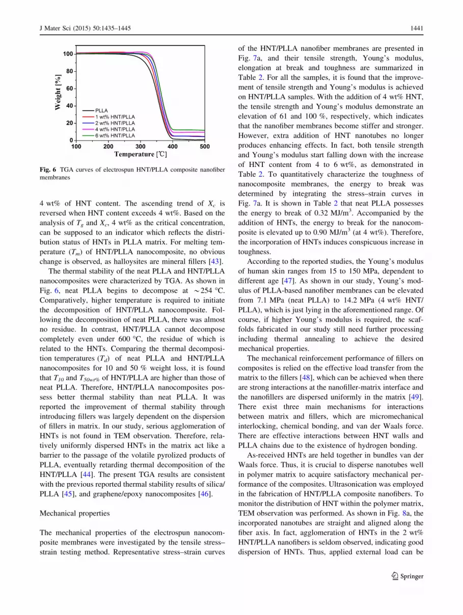
The thermal stability of the neat PLLA and HNT/PLLA
nanocomposites were characterized by TGA. As shown in
Fig. 6, neat PLLA begins to decompose at *254 �C.
Comparatively, higher temperature is required to initiate
the decomposition of HNT/PLLA nanocomposite. Fol-
lowing the decomposition of neat PLLA, there was almost
no residue. In contrast, HNT/PLLA cannot decompose
completely even under 600 �C, the residue of which is
related to the HNTs. Comparing the thermal decomposi-
tion temperatures (Td) of neat PLLA and HNT/PLLA
nanocomposites for 10 and 50 % weight loss, it is found
that T10 and T50wt% of HNT/PLLA are higher than those of
neat PLLA. Therefore, HNT/PLLA nanocomposites pos-
sess better thermal stability than neat PLLA. It was
reported the improvement of thermal stability through
introducing fillers was largely dependent on the dispersion
of fillers in matrix. In our study, serious agglomeration of
HNTs is not found in TEM observation. Therefore, rela-
tively uniformly dispersed HNTs in the matrix act like a
barrier to the passage of the volatile pyrolized products of
PLLA, eventually retarding thermal decomposition of the
HNT/PLLA [44]. The present TGA results are consistent
with the previous reported thermal stability results of silica/
PLLA [45], and graphene/epoxy nanocomposites [46].
Mechanical properties
The mechanical properties of the electrospun nanocom-
posite membranes were investigated by the tensile stress–
strain testing method. Representative stress–strain curves
of the HNT/PLLA nanofiber membranes are presented in
Fig. 7a, and their tensile strength, Young’s modulus,
elongation at break and toughness are summarized in
Table 2. For all the samples, it is found that the improve-
ment of tensile strength and Young’s modulus is achieved
on HNT/PLLA samples. With the addition of 4 wt% HNT,
the tensile strength and Young’s modulus demonstrate an
elevation of 61 and 100 %, respectively, which indicates
that the nanofiber membranes become stiffer and stronger.
However, extra addition of HNT nanotubes no longer
produces enhancing effects. In fact, both tensile strength
and Young’s modulus start falling down with the increase
of HNT content from 4 to 6 wt%, as demonstrated in
Table 2. To quantitatively characterize the toughness of
nanocomposite membranes, the energy to break was
determined by integrating the stress–strain curves in
Fig. 7a. It is shown in Table 2 that neat PLLA possesses
the energy to break of 0.32 MJ/m3. Accompanied by the
addition of HNTs, the energy to break for the nanocom-
posite is elevated up to 0.90 MJ/m3 (at 4 wt%). Therefore,
the incorporation of HNTs induces conspicuous increase in
toughness.
According to the reported studies, the Young’s modulus
of human skin ranges from 15 to 150 MPa, dependent to
different age [47]. As shown in our study, Young’s mod-
ulus of PLLA-based nanofiber membranes can be elevated
from 7.1 MPa (neat PLLA) to 14.2 MPa (4 wt% HNT/
PLLA), which is just lying in the aforementioned range. Of
course, if higher Young’s modulus is required, the scaf-
folds fabricated in our study still need further processing
including thermal annealing to achieve the desired
mechanical properties.
The mechanical reinforcement performance of fillers on
composites is relied on the effective load transfer from the
matrix to the fillers [48], which can be achieved when there
are strong interactions at the nanofiller-matrix interface and
the nanofillers are dispersed uniformly in the matrix [49].
There exist three main mechanisms for interactions
between matrix and fillers, which are micromechanical
interlocking, chemical bonding, and van der Waals force.
There are effective interactions between HNT walls and
PLLA chains due to the existence of hydrogen bonding.
As-received HNTs are held together in bundles van der
Waals force. Thus, it is crucial to disperse nanotubes well
in polymer matrix to acquire satisfactory mechanical per-
formance of the composites. Ultrasonication was employed
in the fabrication of HNT/PLLA composite nanofibers. To
monitor the distribution of HNT within the polymer matrix,
TEM observation was performed. As shown in Fig. 8a, the
incorporated nanotubes are straight and aligned along the
fiber axis. In fact, agglomeration of HNTs in the 2 wt%
HNT/PLLA nanofibers is seldom observed, indicating good
dispersion of HNTs. Thus, applied external load can be
Fig. 6 TGA curves of electrospun HNT/PLLA composite nanofiber
membranes
J Mater Sci (2015) 50:1435–1445 1441
123

effectively transferred to HNTs, inducing the improvement
of mechanical properties for PLLA-based composite
nanofibers. However, if HNT content is too high (e.g.,
6 wt%), agglomeration becomes evident. As shown in
Fig. 8b, the two HNTs in the fibers are assembled
‘‘shoulder by shoulder’’. Good particle–matrix interfacial
adhesion cannot form in aggregative nanotubes, which
impairs the effective load transfer from the polymer matrix
to the fillers. Thus, these aggregates act as defects, result-
ing in degraded mechanical performance [35]. In the results
of DSC, 4 wt% is deduced to be the critical concentration
to judge whether the dispersion of HNTs is aggravated.
HNT/PLLA nanofiber membranes exhibit their best
mechanical performance at 4 wt% of HNT content, which
is consistent of DSC results.
It should be emphasized that nanotubes are preferen-
tially oriented along the longitude of fiber, which is
induced by the shear force during electrospinning pro-
cessing. Longitudinal alignment rather than random ori-
entation of nanofillers in nanofibers is beneficial for the
improvement of the mechanical properties of the HNT/
PLLA nanocomposite [25].
To gain better estimation of the enhancing effect of
HNT particles, Reuss and Voigt models equation [46, 50]
was used to estimate the reinforcement effect of the HNT
particles on the Young’s modulus of the composite. The
Fig. 7 Stress-strain and Young’s modulus of electrospun HNT/PLLA nanofiber membranes
Table 2 Mechanical properties of electrospun HNT/PLLA nanofiber
membranes
HNT
content
(wt%)
Tensile
strength
(MPa)
Young’s
modulus
(MPa)
Elongation
at break (%)
Toughness
(MJ/m3)
0 0.75 ± 0.02 7.1 ± 0.6 59.6 ± 6.1 0.32 ± 0.03
1 0.92 ± 0.04 12.0 ± 1.3 74.9 ± 7.9 0.52 ± 0.04
2 1.05 ± 0.02 12.9 ± 1.2 79.3 ± 8.2 0.63 ± 0.05
4 1.21 ± 0.02 14.2 ± 1.3 88.7 ± 9.0 0.90 ± 0.07
6 1.13 ± 0.03 13.7 ± 1.3 71.6 ± 7.2 0.62 ± 0.05
Fig. 8 TEM images of
electrospun 2 wt% (a) and
6 wt% (b) HNT/PLLA
nanofibers
1442 J Mater Sci (2015) 50:1435–1445
123

lower and upper bounds of Young’s modulus deduced by
Reuss and Voigt models are given by:
Elowerc ¼ Ef Em
�Ef 1� Vf
� �þ EmVf
� �ð1Þ
Eupperc ¼ Ef Vf þ Em 1� Vf
� �; ð2Þ
where Eclowerand Ec
upperare lower- and upper-bound of
composite’s modulus, Ef and Em are modulus of filler and
matrix, and Vf is volume fraction of filler. Ef of HNT was
assumed to be 300 GPa [51]. Here, 1200 and 60 nm are
used as lf and df, respectively, from the SEM image (data
not shown). The volume fraction of the HNT can be cal-
culated according to
Vf ¼Wf
Wf þqf
qm
� �� qf
qm
� �Wf
; ð3Þ
where Wf is the weight fraction of the HNT, and qf and qm
are the densities of the HNT and the polymer matrix,
respectively. HNT density and PLLA density are taken as
2.5 and 1.25 g/cm3, respectively. The experimental data,
theoretical lower- and upper-bound of Young’s modulus
are showed in Fig. 7b. It is found that the experimental data
lie between these two bounds, confirming the reasonability
of our results.
Protein adsorption onto HNT-doped PLLA fibrous
scaffolds
An ideal scaffolding material should allow good protein
adsorption onto the material surface, to provide sufficient
nutrition to promote cell growth and migration. As dem-
onstrated in Fig. 9, neat PLLA and HNT-incorporated
PLLA nanofiber scaffolds have greater absorption of FBS
than cover slips which are lack of porous fibrous structure.
In addition, the HNT/PLLA nanofiber membranes can
absorb more protein than PLLA samples without HNTs.
The protein adsorption onto PLLA scaffolds with 1, 2 and
4 wt% HNT loading is 1.1–1.8 times higher than that of
neat PLLA scaffolds. Therefore, the incorporation of HNT
favors the protein adsorption, which could be related to the
difference in surface composition of nanofibers due to the
incorporation of HNTs [52]. In fact, rough surface of
nanofiber with high HNT content may also make partial
contribution to the higher protein absorption [53].
Conclusions
HNTs were employed for enhancing the mechanical proper-
ties of PLLA-based nanofibers scaffolds. Substantial
improvement of mechanical properties of HNT/PLLA com-
posite nanofibers is achieved with the addition of HNTs. At
4 wt% of HNT content, HNT/PLLA nanofiber membranes
possess the optimum mechanical performance, which repre-
sents 61 % increase in tensile strength, 100 % improvement
of Young’s modulus, 49 % augment of elongation to break, as
well as 181 % elevation in energy to break. The results of
SEM and TEM demonstrate the effective dispersion of HNTs
in PLLA matrix. Strong interactions between nanofillers and
PLLA are confirmed by FTIR, XRD, and DSC. Therefore,
efficient transfer of applied load from the matrix to HNTs is
enabled, which explains the reinforcement effect of incorpo-
rated HNTs on PLLA nanofibers. The introduction of HNTs
also improves the degree of crystallization and thermal sta-
bility of PLLA-based nanofibers. Furthermore, HNT-rein-
forced PLLA nanofiber membranes possessed higher protein
adsorption from FBS than neat PLLA specimen, which pos-
sesses potential application in tissue engineering.
Acknowledgements This research was supported by the National
Natural Science Foundation of China (Grant No. 21071114), the
Excellent Program of Activity of Science and Technology for Over-
seas-Returned Scientists founded by the Ministry of Human Resources
and Social Security of the People’s Republic of China, the Program for
Innovative Research Teams of Hubei Provincial Department of Edu-
cation, the Scientific Research Foundation for Returned Overseas
Chinese Scholars of State Education Ministry, Key Natural Science
Foundation of Hubei Province (Grant No. 2012FFA100), the Inno-
vative Team Incubation Program in High-Tech Industry of Wuhan
City (Grant No. 2014070504020244) and Graduate Innovative Fund of
Wuhan Institute of Technology (Grant No. CX2013010).
References
1. Ma PX (2004) Scaffolds for tissue fabrication. Mate Today
7:30–40
2. Hutmacher DW (2000) Scaffolds in tissue engineering bone and
cartilage. Biomaterials 21:2529–2543
3. Vasita R, Katti DS (2006) Nanofibers and their applications in
tissue engineering. Int J Nanomed 1:15–30
Fig. 9 Protein adsorption onto cover slips and electrospun HNT/
PLLA nanofiber membranes
J Mater Sci (2015) 50:1435–1445 1443
123

4. Rezwan K, Chen QZ, Blaker JJ, Boccaccini AR (2006) Biode-
gradable and bioactive porous polymer/inorganic composite
scaffolds for bone tissue engineering. Biomaterials 27:3413–3431
5. Xu J, Cai N, Xu WX, Xue YA, Wang ZL, Dai Q, Yu FQ (2013)
Mechanical enhancement of nanofibrous scaffolds through poly-
electrolyte complexation. Nanotechnology 24:025701
6. Zhang YZ, Lim CT, Ramakrishna S, Huang ZM (2005) Recent
development of polymer nanofibers for biomedical and biotech-
nological applications. J Mater Sci Mater Med 16:933–946.
doi:10.1007/s10856-005-4428-x
7. McCullen SD, Ramaswamy S, Clarke LI, Gorga RE (2009)
Nanofibrous composites for tissue engineering applications.
Wires Nanomed Nanobi 1:369–390
8. Ray SS (2012) Polylactide-based bionanocomposites: a promis-
ing class of hybrid materials. Acc Chem Res 45:1710–1720
9. Wang Z, Cai N, Dai Q, Li C, Hou D, Luo X, Xue Y, Yu F (2014)
Effect of thermal annealing on mechanical properties of poly-
electrolyte complex nanofiber membranes. Fiber Polym
15:1406–1413
10. Ionita M, Pandele MA, Iovu H (2013) Sodium alginate/graphene
oxide composite films with enhanced thermal and mechanical
properties. Carbohydr Polym 94:339–344
11. Ge JJ, Hou HQ, Li Q, Graham MJ, Greiner A, Reneker DH,
Harris FW, Cheng SZD (2004) Assembly of well-aligned mul-
tiwalled carbon nanotubes in confined polyacrylonitrile environ-
ments: electrospun composite nanofiber sheets. J Am Chem Soc
126:15754–15761
12. Liu MX, Zhang Y, Wu CC, Xiong S, Zhou CR (2012) Chitosan/
halloysite nanotubes bionanocomposites: structure, mechanical
properties and biocompatibility. Int J Biol Macromol 51:566–575
13. Lvov YM, Shchukin DG, Mohwald H, Price RR (2008) Halloy-
site clay nanotubes for controlled release of protective agents.
ACS Nano 2:814–820
14. Hassan-Nejad M, Ganster J, Bohn A, Pinnow M, Volkert B
(2009) Bio-based nanocomposites of cellulose acetate and nano-
clay with superior mechanical properties. Macromol Symp
280:123–129
15. Wang B, Huang H-X (2013) Effects of halloysite nanotube ori-
entation on crystallization and thermal stability of polypropylene
nanocomposites. Polym Degrad Stab 98:1601–1608
16. Logakis E, Pollatos E, Pandis C, Peoglos V, Zuburtikudis I,
Delides CG, Vatalis A, Gjoka M, Syskakis E, Viras K et al (2010)
Structure–property relationships in isotactic polypropylene/multi-
walled carbon nanotubes nanocomposites. Compos Sci Technol
70:328–335
17. Peng F, Shaw MT, Olson JR, Wei M (2011) Hydroxyapatite needle-
shaped particles/Poly(L-lactic acid) electrospun scaffolds with
perfect particle-along-nanofiber orientation and significantly
enhanced mechanical properties. J Phys Chem C 115:15743–15751
18. Gorrasi G, Pantani R, Murariu M, Dubois P (2014) PLA/hal-
loysite nanocomposite films: water vapor barrier properties and
specific key characteristics. Macromol Mater Eng 299:104–115
19. Liu L, Ren Y, Li Y, Liang Y (2013) Effects of hard and soft
components on the structure formation, crystallization behavior
and mechanical properties of electrospun poly(L-lactic acid)
nanofibers. Polymer 54:5250–5256
20. Thompson CJ, Chase GG, Yarin AL, Reneker DH (2007) Effects
of parameters on nanofiber diameter determined from electros-
pinning model. Polymer 48:6913–6922
21. Zhou C, Shi Q, Guo W, Terrell L, Qureshi AT, Hayes DJ, Wu Q
(2013) Electrospun bio-nanocomposite scaffolds for bone tissue
engineering by cellulose nanocrystals reinforcing maleic anhy-
dride grafted PLA. ACS Appl Mater Interfaces 5:3847–3854
22. Joussein E, Petit S, Churchman J, Theng B, Righi D, Delvaux B
(2005) Halloysite clay minerals—a review. Clay Miner
40:383–426
23. Sun XM, Zhang Y, Shen HB, Jia NQ (2010) Direct electro-
chemistry and electrocatalysis of horseradish peroxidase based on
halloysite nanotubes/chitosan nanocomposite film. Electrochim
Acta 56:700–705
24. Tang ZH, Wei QY, Lin TF, Guo BC, Jia DM (2013) The use of a
hybrid consisting of tubular clay and graphene as a reinforcement
for elastomers. RSC Adv 3:17057–17064
25. Liu MX, Zhang Y, Zhou CR (2013) Nanocomposites of halloy-
site and polylactide. Appl Clay Sci 75–76:52–59
26. Matusik J, Stodolak E, Bahranowski K (2011) Synthesis of
polylactide/clay composites using structurally different kaolinites
and kaolinite nanotubes. Appl Clay Sci 51:102–109
27. Zhou SB, Zheng XT, Yu XJ, Wang JX, Weng J, Li XH, Feng B,
Yin M (2007) Hydrogen bonding interaction of poly(D, L-lactide)/
hydroxyapatite nanocomposites. Chem Mater 19:247–253
28. Shao D, Wei Q, Zhang L, Cai Y, Jiang S (2008) Surface func-
tionalization of carbon nanofibers by sol–gel coating of zinc
oxide. Appl Surf Sci 254:6543–6546
29. Liu M, Wu C, Jiao Y, Xiong S, Zhou C (2013) Chitosan-hal-
loysite nanotubes nanocomposite scaffolds for tissue engineering.
J Mater Chem B 1:2078–2089
30. Ismail H, Pasbakhsh P, Fauzi MNA, Abu Bakar A (2008) Mor-
phological, thermal and tensile properties of halloysite nanotubes
filled ethylene propylene diene monomer (EPDM) nanocompos-
ites. Polym Test 27:841–850
31. Qu X-H, Wu Q, Zhang K-Y, Chen GQ (2006) In vivo studies of
poly(3-hydroxybutyrate-co-3-hydroxyhexanoate) based polymers:
biodegradation and tissue reactions. Biomaterials 27:3540–3548
32. Morimune S, Kotera M, Nishino T, Goto K, Hata K (2011)
Poly(vinyl alcohol) Nanocomposites with Nanodiamond. Mac-
romolecules 44:4415–4421
33. Zhuang W, Liu J, Zhang JH, Hu BX, Shen J (2009) Preparation,
characterization, and properties of TiO2/PLA nanocomposites by
in situ polymerization. Polym Compos 30:1074–1080
34. Yang X, Li L, Shang S, Tao X-m (2010) Synthesis and charac-
terization of layer-aligned poly(vinyl alcohol)/graphene nano-
composites. Polymer 51:3431–3435
35. Wang Z, Cai N, Zhao D, Xu J, Dai Q, Xue Y, Luo X, Yang Y, Yu
F (2013) Mechanical reinforcement of electrospun water-soluble
polymer nanofibers using nanodiamonds. Polym Compos
34:1735–1744
36. Kim JY, Park HS, Kim SH (2006) Unique nucleation of multi-
walled carbon nanotube and poly(ethylene 2,6-naphthalate)
nanocomposites during non-isothermal crystallization. Polymer
47:1379–1389
37. Pasbakhsh P, Ismail H, Fauzi MNA, Bakar AA (2010) EPDM/
modified halloysite nanocomposites. Appl Clay Sci 48:405–413
38. Liu M, Guo B, Du M, Jia D (2007) Drying induced aggregation
of halloysite nanotubes in polyvinyl alcohol/halloysite nanotubes
solution and its effect on properties of composite film. Appl Phys
A-Mater 88:391–395
39. Ramaswamy S, Clarke LI, Gorga RE (2011) Morphological,
mechanical, and electrical properties as a function of thermal
bonding in electrospun nanocomposites. Polymer 52:3183–3189
40. Wei H-F, Hsiue G-H, Liu C-Y (2007) Surface modification of
multi-walled carbon nanotubes by a sol–gel reaction to increase
their compatibility with PMMA resin. Compos Sci Technol
67:1018–1026
41. Dong Y, Bickford T, Haroosh H, Lau K-T, Takagi H (2013) Multi-
response analysis in the material characterisation of electrospun
poly (lactic acid)/halloysite nanotube composite fibres based on
Taguchi design of experiments: fibre diameter, non-intercalation
and nucleation effects. Appl Phys A-Mater 112:747–757
42. Lizundia E, Oleaga A, Salazar A, Sarasua JR (2012) Nano- and
microstructural effects on thermal properties of poly (L-lactide)/
multi-wall carbon nanotube composites. Polymer 53:2412–2421
1444 J Mater Sci (2015) 50:1435–1445
123

43. Prashantha K, Lacrampe MF, Krawczak P (2011) Processing and
characterization of halloysite nanotubes filled polypropylene
nanocomposites based on a masterbatch route: effect of halloy-
sites treatment on structural and mechanical properties. Express
Polym Lett 5:295–307
44. Kim I-H, Jeong YG (2010) Polylactide/exfoliated graphite
nanocomposites with enhanced thermal stability, mechanical
modulus, and electrical conductivity. J Polym Sci Pol Phys
48:850–858
45. Kontou E, Niaounakis M, Georgiopoulos P (2011) Comparative
study of PLA nanocomposites reinforced with clay and silica
nanofillers and their mixtures. J Appl Polym Sci 122:1519–1529
46. Reynaud E, Jouen T, Gauthier C, Vigier G, Varlet J (2001)
Nanofillers in polymeric matrix: a study on silica reinforced PA6.
Polymer 42:8759–8768
47. Edwards C, Marks R (1995) Evaluation of biomechanical prop-
erties of human skin. Clin Dermatol 13:375–380
48. Schadler LS, Giannaris SC, Ajayan PM (1998) Load transfer in
carbon nanotube epoxy composites. Appl Phys Lett 73:3842–
3844
49. Tang Y, Ye L, Zhang Z, Friedrich K (2013) Interlaminar fracture
toughness and CAI strength of fibre-reinforced composites with
nanoparticles—A review. Compos Sci Technol 86:26–37
50. Fu S-Y, Feng X-Q, Lauke B, Mai Y-W (2008) Effects of particle
size, particle/matrix interface adhesion and particle loading on
mechanical properties of particulate–polymer composites. Com-
pos Part B-Eng 39:933–961
51. Prashantha K, Lecouvet B, Sclavons M, Lacrampe MF, Krawc-
zak P (2013) Poly(lactic acid)/halloysite nanotubes nanocom-
posites: structure, thermal, and mechanical properties as a
function of halloysite treatment. J Appl Polym Sci 128:1895–
1903
52. Qi R, Cao X, Shen M, Guo R, Yu J, Shi X (2012) Biocompati-
bility of electrospun halloysite nanotube-doped Poly(Lactic-co-
Glycolic Acid) composite nanofibers. J Biomater Sci Polym Ed
23:299–313
53. Nitya G, Nair G, Mony U, Chennazhi K, Nair S (2012) In vitro
evaluation of electrospun PCL/nanoclay composite scaffold for
bone tissue engineering. J Mater Sci Mater Med 23:1749–1761.
doi:10.1007/s10856-012-4647-x
J Mater Sci (2015) 50:1435–1445 1445
123