toughening by multiple mechanisms in ceramic-matrix composites with discontinuous elongated...
TRANSCRIPT

Toughening by Multiple Mechanisms in Ceramic-MatrixComposites with Discontinuous Elongated Reinforcements
Hongxiang Zhai
Department of Mechanical Engineering, Northern Jiaotong University, Beijing, 100044, People’s Republic of China
Yong Huang, Changan Wang, and Xin Wu†
Department of Materials Science and Engineering, Tsinghua University, Beijing, 100084, People’s Republic of China
The dependence of toughening mechanisms on reinforcementorientation and the toughening effect governed by multipletoughening mechanisms were characterized for ceramic-matrix composites (CMCs) with discontinuous elongated rein-forcements. Two kinds of Si3N4-based composites, with direc-tionally oriented and randomly oriented SiC whiskers,respectively, were tested by the three-point bending ofchevron-notched bars. Based on microscopic observations andmicromechanical analyses, three mechanisms were confirmedto dominate the crack-bridging behavior: (1) bridging andbreaking of long reinforcements, (2) frictional pullout andbreaking of short reinforcements, and (3) local matrix spalling.Both the occurrence of the multiple mechanisms and theirtoughening effects were proved dependent on the reinforce-ment orientation. The combined effect of the multiple mecha-nisms correlated with random orientation thus was character-ized by a statistical approach to solve for the crack-bridgingstress function. The theoretical model was in good agreementwith the experimental results.
I. Introduction
IT IS well known that the toughness of brittle ceramics can beenhanced byin situ production of long grains or by addition of
elongated reinforcement phases such as whiskers, or short fibers.Many whisker-reinforced ceramic-matrix composite (CMC) sys-tems have been developed, e.g., SiC-whisker-reinforced alumina,silicon nitride, mullite, and tetragonal zirconia polycrystal.1–9 Insitu composites also have made some encouraging progress inSi3N4 systems based on the technology of microstructurallytailoring thea/b-sialon two-phase system.10–12Those tougheningmeasures have been confirmed not only to increase fracturetoughness but also to increase significantly fracture strength aswell as strength reliability.10–15
The present concern with the toughening effect was directedtoward increasing toughness magnitude, as well as exploring someanticipated fracture-resistance characteristics, with the goal ofimproving the strength reliability and flaw tolerance of brittleceramics.13–21 Although crack geometry somewhat influencesR-curve behavior,22,23 this issue has been focused essentially onthe micromechanics of the interaction between bridging ligamentsand the matrix.23–26 The detailed mechanisms, which govern a
special toughening effect, however, must be confirmed for a givenmaterial system.
Previous work has suggested that the toughening mechanismsof whisker-reinforced CMCs include mostly whisker–matrix inter-face debonding, whisker bridging (elastic and frictional), as well ascrack deflection.15–18 The occurrence of such multiple mecha-nisms can be governed by varied reinforcement–matrix interactionconditions, which, however, are correlated closely with the rein-forcement orientation. Further development therefore is required toreveal the relationship between toughening mechanisms and rein-forcement orientation. The significant effects of reinforcementorientation on toughening mechanisms have been reviewed forfiber-reinforced cement-based composites.27–30 Consideration ofthe influence of whisker orientation on toughening was mentionedearlier for whisker-reinforced CMCs,16,17and some detailed stud-ies were done recently for whisker-reinforced Si3N4-based mate-rials.31–38
Toughening generated from crack bridging could be a complexenergy-absorption process that has to be characterized by astatistical approach for most long-grain or whisker-reinforcedCMCs, in which reinforcements are randomly oriented within thesurrounding matrix. The amount of energy absorption associatedwith each mechanism for a single reinforcement may not besignificant. The large amount of reinforcements, bridging over anextended length behind the crack tip, however, can contribute aconsiderable toughening effect to the composite. Thus, to charac-terize the crack-bridging stress in a manner reflecting the wholeeffect of bridging reinforcements, the combined action of allindividual mechanisms associated with random reinforcementorientation must be statistically represented. The toughening pro-cess has not yet been addressed in the literature in such a statisticalsense.
The present work represents an attempt to develop a tougheningmodel for CMCs with discontinuous elongated reinforcements.The work is focused on the concept that toughening mechanismsare dependent on reinforcement orientation and on the combinedeffect of the multiple toughening mechanisms associated withrandom orientation of reinforcements. SiC-whisker-reinforcedSi3N4-based composites were chosen as model materials becauseSi3N4-based composites themselves are recognized as importantengineering materials. Directionally oriented reinforcement tech-niques were used to observe and analyze the effects of reinforce-ment orientation and the relevant mechanisms. The necessarysteady crack propagation was generated by using three-pointbending bars with chevron notches as well as oblique notches. Animproved compliance approach taking into account notch-machining damage was used to determine theR-curve data.
II. Experiments
(1) ProcedureThe present study involved the processing of 20-vol%-SiC-
whisker-reinforced Si3N4-matrix composites with two kinds of
R. H. Dauskardt—contributing editor
Manuscript No. 190685. Received September 23, 1997; approved August 20, 1999.Supported by the State Natural Science Fund of China (No. 59672029) and the
State 863 Program of China.*Member, American Ceramic Society.†Present address: Department of Mechanical Engineering and Applied Mechanics,
The University of Michigan, Ann Arbor, Michigan 48109.
J. Am. Ceram. Soc.,83 [8] 2006–16 (2000)
2006
journal

whisker orientation characteristics: directional and random. Thematerials are denoted A and B, respectively. Y2O3–MgO–Al2O3
was used as an additive to adjust the whisker–matrix interfaceproperties, as well as to cause the development of elongatedb-Si3N4 grains. The whiskers were mixed with the Si3N4 powdersand the additives, then ball-milled in ethanol solvent. Whiskersizes were measured with an optical microscope after ball milling.The average diameter observed was;1.5 mm and the averagelength ;45 mm. Dried milled powders for material A were firstmixed with a polymer binder, and then extruded through 30-mm-diameter tubing to form a wire measuring 1 mm in diameter.Sample wires were laid out in parallel to form plates measuring 60mm 3 40 mm3 10 mm (length3 width 3 thickness). After theplates had dried, a single plate was put into a graphite die set andheated to;200°C to turn out the binder, then hot-pressed at 30MPa and 1820°C for 90 min in nitrogen. The dried milled powdersfor material B were directly cold-packed to form disk platesmeasuring 75 mm and then hot-pressed under conditions identicalto those used for material A. X-ray analysis and SEM observationwere conducted to examine the crystalline and microstructuralcharacteristics of the materials. Those results showed that a matrixphase transformation froma-Si3N4 (powder) tob-Si3N4 occurredduring sintering and that the matrix completely consisted of small,rodlike b-Si3N4 grains with random orientation.
For the three-point-bending test, hot-pressed plates of bothmaterial A and material B were ground to a thickness of 3 mm andcut into bars measuring 6 mm3 3 mm (width 3 thickness) incross-sectional area. Chevron notches were cut using a diamondsaw 0.18 mm thick. The bars for material A were cut along adifferent direction with respect to the extruding layout direction, sothat the angles between the bar length direction and the wiredirection were 0°, 15°, 30°, 45°, 60°, and 75°. The correspondingbars are denoted S00, S15, S30, S45, S60, and S75. No distinctdirection was used in cutting the chevron notch of material B, butseveral bars were cut into oblique notches for observing thecrack-bridging behaviors behind the crack tip. Figure 1 schemat-ically illustrates the test mode, the directionally orientated angleu,the notch geometry, and the relevant parameters (C represents thecrack length).
All bending tests were performed in a standard materials testerunder a displacement-controlling mode, with a constant crosshead-displacement rate of 0.02 mm/min. Load–deflection data wererecorded by a computer data-acquisition system. After a crack hadfully propagated, the oblique-notched bars were unloaded imme-diately, to maintain connection of the notched section, and thencarefully removed from the fixture for SEM examination. Thefractured surfaces of all broken bars also were observed.
(2) Determination of the R-CurveThe variation in fracture resistanceKR is measurable in terms of
the change in compliance reflected by the load–deflection curve
with increasing crack areaA. The relationship betweenKR and thecompliancel is given by39,40
KR 5 PÎ~E9/ 2!~dl/dA! (1)
wherel 5 f/P, E9 5 E/(1 2 n2), f is the deflection,P is the appliedload, andE and n are Young’s modulus and Poisson’s ratio,respectively, of the material.
The compliance of a bending bar can be estimated by treatingthe bar as a series of spanwise slices in terms of the slice-synthesismodel suggested by Bluhm.41 The valuel thus is expressed by areciprocal summation:42
1/l 5 Oi51
m
ki/l i (2)
wherem is the number of slices,li is the compliance of theithslice, andki is the shear correction factor taking into account theinterslice shear effect. Because each slice could be regarded as asingle-edge-notched bar (SENB) with thicknessDz (Fig. 2), for thethree-point bending configuration, the valueli thus can bedetermined as follows:
l i 5 ~2/EDz!F l0 1 E0
j
Y2~j! djG (3)
Here,j is the normalized notch/crack length of the slice,Y(j) is thegeometric factor of the SENB,43 l0 is the compliance of anunnotched and uncracked slice,l0 5 (S/2W)3 1 (1 2 n)(S/4W),andSandWare the span and the width of the slice, respectively.41
Inserting Eq. (3) into Eq. (2), the valuel, in principle, can beestimated.
For an actual notched bar, however, the effect of the notch-machining damage must be taken into account. That damageusually causes one or more small branch cracks to form at thenotch tip, during formation of the main crack. Hence, an additionalcompliance could be generated, which would not occur were onlya single main crack of the same size formed. Figure 2 illustrates theinfluential damage zone, whered represents the depth of the zone.The additional compliance for theith slice can be represented by
l9i 5 ~2/EDz!Ej
j1r0
Y2~j! dj (4)
where r0 is the additional crack extension correlated with thebranch cracks,r0 5 (d/sin w)/W, andw is the inclined angle of thenotch. The actual compliance of the bar thus is corrected as
1/l* 5 Oi51
m
ki/~l i 1 l9i! (5)
Fig. 1. Test mode, notch geometry, and the directionally oriented angleu.Fig. 2. Schematic diagram indicating the spanwise slice and the notch-machining damage zone.
August 2000 Toughening by Multiple Mechanisms in Ceramic-Matrix Composites 2007

Using an integral instead of a summation and consideringki [ 1along the crack front, Eq. (5) can be rewritten into an integralform:
1/l* 5 @BE/ 2~a1 2 a0!#F~a 2 a0!F21~a!
1 Ea
a1
k~j! F21~j! djG (6)
where
F~a! 5 l0 1 E0
a1r0
Y2~j! dj
and a0 5 C0/W, a1 5 C1/W, a 5 C/W (see Fig. 1 for theparametersC0, C1, C, W, and B). It has been indicated that theshear correction factork(j) is notch-geometry-dependent44 andreduced with increasingj after a characteristic crack length.42 Aconstantk(j) 5 1.45, which was suggested by Bluhm,41 however,was experimentally confirmed to be applicable to the presentapproach. Figure 3 shows a typical result from the presentapproach. The tests were conducted by using oblique-notched barswith a load–unload mode so that crack extension could bemeasured. The load–deflection curves and the compliance calcu-lated by using Eq. (6) are shown in Figs. 3(a) and (b), respectively.As seen from Fig. 3(b), the calculated compliance corrected withthe damage depthd 5 60 mm was satisfactory in comparison withthe measured data.
On the other hand, with the occurrence of branch cracks, theactual crack area increment, with crack extension dC, could becorrected as dA* 5 (b 1 b9) dC. Here,b is the length of the crackfront of the main crack,b9 is an additional length caused by branchcracks, andb9 5 2d/cosw. Equation (1) therefore is corrected as
KR 5 ~P/BÎW!Y* ~a! (7)
where
Y* ~a! 5 @~BE9/ 2!~dl*/da!~a1 2 a0!/~a 2 a0 1 r 0!#1/ 2
The valuesY*(a) andKR determined by Eq. (7) also are shown inFig. 3(b), which indicate that the notch damage correction wasnecessary and reasonable. Clearly, Eq. (7) is applicable to not onlythe oblique-notched but also the chevron-notched bars, because achevron-notched bar can be regarded as the synthesis of twosymmetric oblique-notched bars.
(3) Observations and AnalysesFigure 4 shows a set of typical load–deflection curves for
specimens S00 to S75, taken from one plate of material A. Figure5 shows the correspondingR-curves determined by using Eq. (7).The early rising stage of theR-curves corresponds to the load-increasing stage of the load–deflection curves. When the loadapproached its peak value, theR-curve essentially approached firstsaturation, and only limited crack extension (;0.2 to ;0.3 mm)was necessary to trigger the first saturation. Beyond the peak load,cracking progressed steadily, and the shape of theR-curvesbecame obviously orientation-dependent.
Specimens with small or large orientation angles (u 5 0°, 15°,and 75°) displayed only one saturation value in theR-curves, atwhich KR remained steady, and no further toughening behaviorappeared. For intermediate orientation angles (u 5 30°, 45°, and60°), however, theR-curves displayed two saturation stages, withKR rising again after the first saturation and gradually approachinga secondary saturation value with greater crack extension. Not onlythe increasing tendency ofKR but also the magnitudes of the firstsaturation values varied depending on the orientation angle. Foru 5 0, the first saturation value was;8.5 MPazm1/2. That value
reduced to;7.5 MPazm1/2 for u 5 15° and then decreased further,to ;7.0 MPazm1/2, whenq . 15. Clearly, the first saturation valuereduced with increases in the orientation angle.
The fractured surfaces of the specimens were observed by SEMto identify the effects of orientation and the relevant mechanisms.The most commonly observed images were whisker holes distrib-uted throughout the fracture surface and broken whiskers exposedout of the crack plane. That evidence means that the whiskers hadnot broken immediately but rather had gone through a whisker–matrix interaction process as the crack front reached and passedthrough them. During that process, the whisker–matrix interfacesmust have debonded, to a certain extent, otherwise the whiskerswould have broken along the crack plane, and no holes andexposed parts would have been observed. Figure 6 shows typicalmicrographs for specimens S00 to S75. The extent of debondingcan be estimated roughly from the length of exposed whiskers andthe shape of whisker holes. For a small orientation angle, theexposed whiskers were quite short, and the whisker holes approx-imated a circular shape. As the orientation angle increased, theexposed whiskers lengthened, and the whisker holes changed to an
Fig. 3. Results examining the present compliance method: (a) load–deflection curve of the load–unload test, (b) comparisons between thecalculated compliance and the experimental data, as well as the correctedand uncorrectedY*(a) andKR.
2008 Journal of the American Ceramic Society—Zhai et al. Vol. 83, No. 8

oblique, half-cylindrical shape. Obviously, whisker orientation hada strong influence on the debonding and the following interactionbetween whisker and matrix.
Interestingly, the extent of debonding changed with an increasein the orientation angle. The increased debonding length may havegradually formed accompanying the process of interaction be-tween whisker and matrix, or it may have formed suddenly at acharacteristic stage of whisker deformation. Because increases indebonding length would allow the bridging whiskers to deformfurther, thus absorbing more energy, further toughening mustcorrespond to change in debonding length. That correspondencewould explain why the S30 to S60 specimens displayed secondarytoughening whereas the S00 to S15 specimens did not. In the caseof the S75 specimen, the local matrix spalling became thedominant mechanism, causing the whisker-bridging process to becut off, so that no secondary toughening behavior was observed.Similar secondary toughening behavior could reasonably be ex-pected in the specimens of material B, because a large number ofwhiskers would be randomly oriented within the angle range from30° to 60°. A typical experimental example of that situation isdescribed in the next section. The acting mode of the tougheningmechanisms, however, could have differed from that for thespecimens of material A, since various mechanisms correspondingto the random angles existed at the same time. Not a simple
mechanism, then, but rather a combination of multiform toughen-ing mechanisms could be expected to govern the tougheningprocess in CMCs reinforced by randomly oriented whiskers.
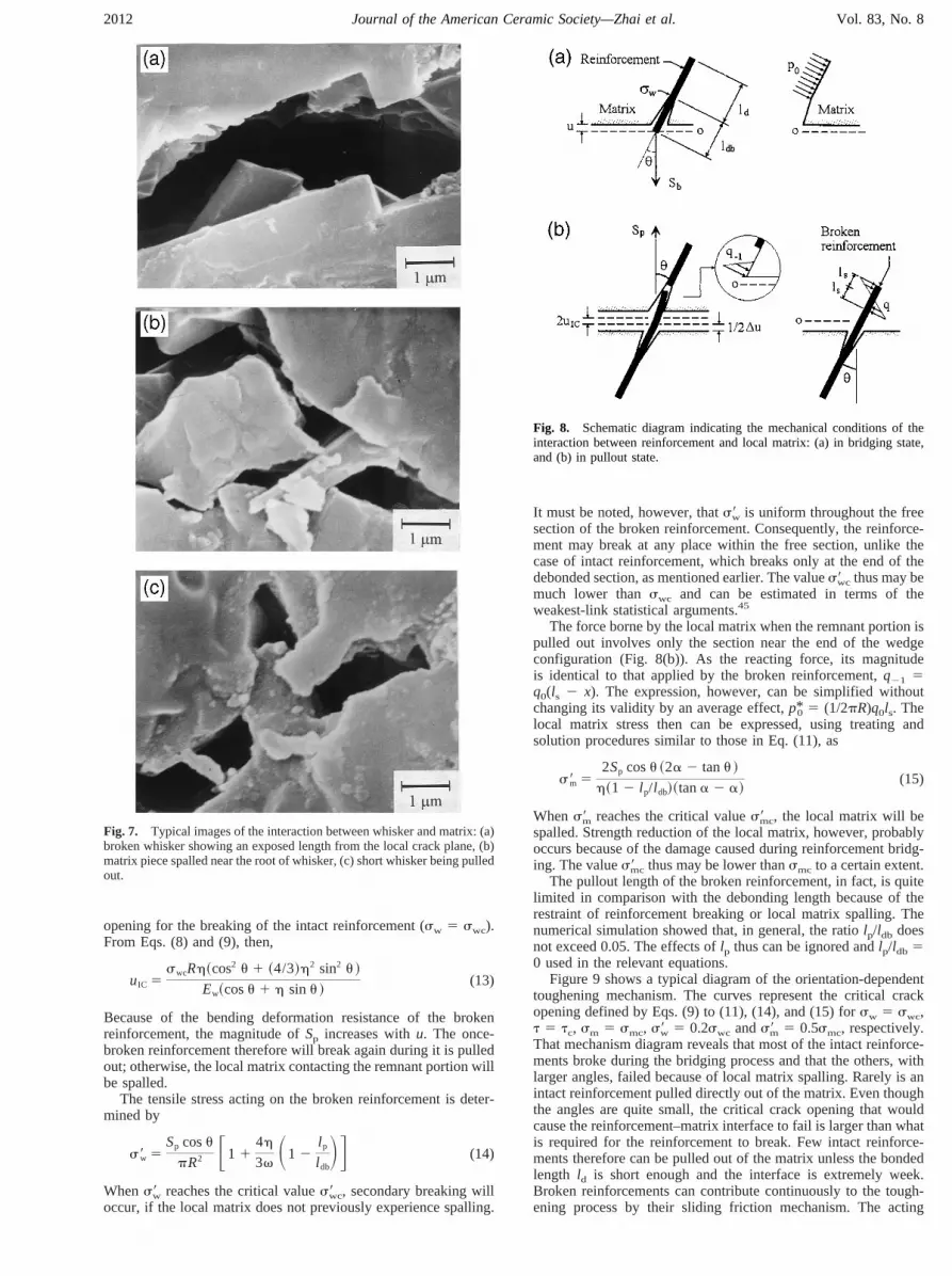
The essential reason for the orientation effect could lie in themicromechanical behavior of interaction between whiskers and thematrix. Apparently, the orientation angle caused the bridgingwhiskers to bear a tensile force and an additional moment at thesame time. Consequently, the whiskers always broke near the endof the debonded section of them because a maximum stress wouldbe concentrated there. On the reverse side, the local matrixsurrounding the whisker must have borne a pressing force corre-sponding to the moment applied to the whisker. That force mayhave spalled the local matrix before whisker breaking and so cutoff the whisker bridging process. The observed examples ofwhisker breaking and local matrix spalling, respectively, areshown in Figs. 7(a) and (b). Although pullout of whisker wasconsidered as a possible circumstance, the orientation angle madeit difficult for the brittle whiskers and matrix. The broken whis-kers, however, probably were pulled out of the matrix becausetheir remnant parts were short and had been completely debondedfrom the matrix. Figure 7(c) shows a short whisker being pulledout of the matrix. Some frictional interference between the brokenwhisker and the local matrix would have occurred during crackopening.
Fig. 4. Load–deflection curves, respectively, from the specimens S00 to S75.
August 2000 Toughening by Multiple Mechanisms in Ceramic-Matrix Composites 2009

III. Theoretical Model
(1) Orientation-Dependent Toughening MechanismsBased on the experimental observations, if the bridging rein-
forcements are independent each other within the crack-bridgingzone, the mechanical behavior of a single reinforcement with crackopening can be characterized by a local treatment. Figure 8(a)shows an intact reinforcement in the bridging state. That reinforce-ment, with orientation angleu with respect to the normal directionof the crack plane, will bear a traction forceSb corresponding tothe crack openingu. The valuesldb and ld represent the debondedlength and the bonded length, respectively, whereldb 1 ld 5 l/2,and l is the length of the reinforcement. The location of theintermediate point, o, between the crack planes is steady forsymmetry of the crack opening.
For completely elastic reinforcement and matrix, the value ofuis governed essentially by the elongationut and the deflectionun ofthe reinforcement, with the formu 5 ut cosu 1 un sin u. Solvingut andun separately from the parallel and the vertical componentof Sb then gives
Sb 5pREwu
h~cos2 u 1 ~4/3!h2 sin2 u !(8)
where h 5 ldb/R, and R and Ew are the radius and Young’smodulus of the reinforcement, respectively. Withu, and thusSb,increasing, only three consequences can occur: the reinforcementis broken, the local matrix is spalled, or the reinforcement is pulledout of the matrix. Which of the consequences occurs completelydepends on the micromechanical condition of the interactionbetween reinforcement and matrix.
Stress acting on the reinforcement is composed of the tensilestress caused by the parallel component ofSb and the bendingstress from the vertical component. The tensile stress is uniform,whereas the bending component is distributed along the axisdirection of reinforcement. As a result, the maximum tensile stresssw is concentrated on the surface of the reinforcement at the endof the debonded section (Fig. 8), and the magnitude of it is given by
sw 5Sb~cosu 1 h sinu !
pR2 (9)
The breaking of the reinforcement then is governed bysw. Whensw reaches the critical valueswc, the reinforcement will break ifthe reinforcement–matrix interface of the bonded portion does notfail and also if the local matrix surrounding the reinforcement doesnot undergo prior spalling.
Fig. 5. R-curves determined by Eq. (7), corresponding to the load–deflection curves shown in Fig. 4, respectively.
2010 Journal of the American Ceramic Society—Zhai et al. Vol. 83, No. 8

Occurrence of pullout for an intact reinforcement depends onthe shear stress applied to the reinforcement–matrix interface. Thatstress can be expressed simply by
t 5Sb cosu
2pRld(10)
Whent reaches the critical valuetc, the interface will fail, and thereinforcement then may be gradually pulled out of the matrix.
The actual stress field around the local matrix can be quitecomplex, but further details are not necessary for the present case.As a first approximation, the local matrix can be simplified to awedge configuration, which bears a uniform pressing force,p0 5(Sb sin u)/pRld, on the side contacting the reinforcement (Fig. 8).In terms of that situation, the maximum main stresssm acting onthe pressing surface of the wedge configuration can be expressed as
sm 5Sb~2a 2 tana! sinu
pRld~tana 2 a!(11)
wherea 5 p/2 2 u. Whensm reaches the critical valuesmc, thelocal matrix will be spalled.
As a restrictive mechanism, once the local matrix is spalled, thebridging process of the reinforcement will immediately end. If thebridging reinforcement is broken, however, the interaction be-tween reinforcement and matrix will not end. Owing to thereinforcement breaks at the end of the debonded section, theremnant portion with lengthldb will yet remain in the matrix.Deformation interference between the broken reinforcement andthe local matrix, thus, must occur while the remnant portion ispulled out. A frictional resistanceSp then would be generated. Theforce applied to the remnant portion can be represented by adistributing form,q 5 q0(ls 2 x). Here,q0 is a constant that can bedetermined through the mechanical equilibrium,x is the referencecoordinate defined in the range from 0 to 2ls, ls 5 (ldb 2 lp)/2,and lp is the pullout length of the remnant portion. In theseterms, then,
Sp 53pREwv tanu
2h3~1 2 l p/l db!~1 1 l p/l db!2 Du (12)
wherev is the friction coefficient between the remnant portion andthe local matrix,Du 5 2 (u 2 uIC), anduIC is the critical crack
Fig. 6. Scanning electron micrographs of the fractured surfaces, respectively, from specimens S00 to S75.
August 2000 Toughening by Multiple Mechanisms in Ceramic-Matrix Composites 2011
opening for the breaking of the intact reinforcement (sw 5 swc).From Eqs. (8) and (9), then,
uIC 5swcRh~cos2 u 1 ~4/3!h2 sin2 u !
Ew~cosu 1 h sinu !(13)
Because of the bending deformation resistance of the brokenreinforcement, the magnitude ofSp increases withu. The once-broken reinforcement therefore will break again during it is pulledout; otherwise, the local matrix contacting the remnant portion willbe spalled.
The tensile stress acting on the broken reinforcement is deter-mined by
s9w 5Sp cosu
pR2 F1 14h
3v S1 2l p
l dbDG (14)
Whens9w reaches the critical values9wc, secondary breaking willoccur, if the local matrix does not previously experience spalling.
It must be noted, however, thats9w is uniform throughout the freesection of the broken reinforcement. Consequently, the reinforce-ment may break at any place within the free section, unlike thecase of intact reinforcement, which breaks only at the end of thedebonded section, as mentioned earlier. The values9wc thus may bemuch lower thanswc and can be estimated in terms of theweakest-link statistical arguments.45
The force borne by the local matrix when the remnant portion ispulled out involves only the section near the end of the wedgeconfiguration (Fig. 8(b)). As the reacting force, its magnitudeis identical to that applied by the broken reinforcement,q21 5q0(ls 2 x). The expression, however, can be simplified withoutchanging its validity by an average effect,p*0 5 (1/2pR)q0ls. Thelocal matrix stress then can be expressed, using treating andsolution procedures similar to those in Eq. (11), as
s9m 52Sp cosu ~2a 2 tanu !
h~1 2 l p/l db!~tana 2 a!(15)
Whens9m reaches the critical values9mc, the local matrix will bespalled. Strength reduction of the local matrix, however, probablyoccurs because of the damage caused during reinforcement bridg-ing. The values9mc thus may be lower thansmc to a certain extent.
The pullout length of the broken reinforcement, in fact, is quitelimited in comparison with the debonding length because of therestraint of reinforcement breaking or local matrix spalling. Thenumerical simulation showed that, in general, the ratiolp/ldb doesnot exceed 0.05. The effects oflp thus can be ignored andlp/ldb 50 used in the relevant equations.
Figure 9 shows a typical diagram of the orientation-dependenttoughening mechanism. The curves represent the critical crackopening defined by Eqs. (9) to (11), (14), and (15) forsw 5 swc,t 5 tc, sm 5 smc, s9w 5 0.2swc ands9m 5 0.5smc, respectively.That mechanism diagram reveals that most of the intact reinforce-ments broke during the bridging process and that the others, withlarger angles, failed because of local matrix spalling. Rarely is anintact reinforcement pulled directly out of the matrix. Even thoughthe angles are quite small, the critical crack opening that wouldcause the reinforcement–matrix interface to fail is larger than whatis required for the reinforcement to break. Few intact reinforce-ments therefore can be pulled out of the matrix unless the bondedlength ld is short enough and the interface is extremely week.Broken reinforcements can contribute continuously to the tough-ening process by their sliding friction mechanism. The acting
Fig. 7. Typical images of the interaction between whisker and matrix: (a)broken whisker showing an exposed length from the local crack plane, (b)matrix piece spalled near the root of whisker, (c) short whisker being pulledout.
Fig. 8. Schematic diagram indicating the mechanical conditions of theinteraction between reinforcement and local matrix: (a) in bridging state,and (b) in pullout state.
2012 Journal of the American Ceramic Society—Zhai et al. Vol. 83, No. 8

process, however, is restricted by the secondary breaking and thelocal matrix spalling.
(2) Bridging Stress Governed by Multiple MechanismsBecause of the dependence of toughening mechanism on
reinforcement orientation, when reinforcements are distributedrandomly throughout the matrix, the multiple toughening mecha-nisms corresponding to random orientations must occur at thesame time with crack opening, and then generate a combinedeffect. Figure 10 illustrates schematically a typical combinedsituation for the given crack opening. Suppose, for a unit crackplane,nb reinforcements oriented in the angle rangeub2–ud0 areintact and bridging the crack interfaces; at the same time,np
reinforcements in the angle rangesub1–up1 andup2–ub2 have beenbroken and are pulling out of the matrix. Dividingub2–ud0 into nintervals withDu, andub1–up1 and up2–ub2 into n9 intervals, thecrack bridging forcep(u) acting normally on the unit crack plane,i.e., the crack bridging stress, can be represented by
p~u! 5 nb,1Sb~u,ub,1! 1 nb,2Sb~u,ub,2! 1 . . . 1 nb,iSb~u,ub,i!
1 . . . 1 nb,nSb~u,ub,n!
1 np,1Sp~u,up,1! 1 np,2Sp~u,up,2! 1 . . .
1 np,jSp~u,up,j! 1 . . . 1 np,n9Sp~u,up,n9! (16)
where nb,i and np,j, respectively, represent the numbers of thereinforcements that lie in the angle intervalsub,i 1 Du andup,j 1Du; nb,1 1 nb,2 1 nb,i 1 . . . 1 nb,n 5 nb andnp,1 1 np,2 1 np,j 1. . . 1 np,n9 5 np. Suppose the total number of the reinforcementspassing through the unit crack plane isNw. Equation (16) can be
rewritten as
p~u! 5 NwF Oi51
n
~nb,i/Nw!Sb~u,ub,i! 1 Oj51
n9
~np,j/Nw!Sp~u,up,j!G(17)
or rewritten again as
p~u! 5 NwF Oi51
n
Sb~u,ub,i! g~ub,i!Du 1 Oj51
n9
Sp~u,up,j! g~ub,i!DuG(18)
where g(u) represents the probability density of the orientationdistribution. Using an integral instead of the summation, Eq. (18)can be generally expressed as
p~u! 5 NwFE0
ud0
Sb~u,u ! g~u ! du 2 Eub1
ub2
Sb~u,u ! g~u ! duG1 NwFE
ub1
ub2
Sp~u,u ! g~u ! du 2 Eup1
up2
Sp~u,u ! g~u ! du
2 Eud1
ud2
Sp~u,u ! g~u ! duG (19)
Although the orientation distribution may change with differentmaterials processing methods, an essential estimation assumes thatthe orientation is uniformly distributed throughout the three-dimensional space. The probability that a reinforcement is justoriented within a space direction then is 2/V, whereV 5 4p, beingthe whole surface area of the unit sphere. If an annular areaincrement with respected to angleu is dV 5 2p sin u du (Fig. 11),then the probability that the reinforcements are just oriented at thisangle becomesg(u) du 5 (2/V) dV 5 sin u du. Hence, theprobability density of the orientation distribution is known to be
g~u ! 5 sinu ~0 # u # p/ 2! (20)
Inserting Eqs. (8), (12), and (20) into Eq. (19) and integratingthen gives the bridging stress function:
p~u! 5 @ Jb~0,ud0! 2 Jb~ub1,ub2! 1 Jp~ub1,ub2! 2 Jp~up1,up2!
2 Jp~ud1,ud2!#~u/R!
2 @ J0~ub1,ub2! 2 J0~up1,up2! 2 J0~ud1,ud2!# (21)
Fig. 9. Orientation-dependent toughening mechanism diagram.
Fig. 10. Typical combined state of the multiple toughening mechanismsfor a given crack opening.
Fig. 11. Schematic diagram indicating the orientation distribution ofreinforcement.
August 2000 Toughening by Multiple Mechanisms in Ceramic-Matrix Composites 2013

Here, the functionsJb(u1,u2), Jp(u1,u2), andJ0(u1,u2) are given by
Jb~u1 ,u2! 53VwEw
8x1h3 ln F ~1 1 x1 cosu1!~1 2 x1 cosu2!
~1 2 x1 cosu1!~1 1 x1 cosu2!G(21a)
Jp~u1 ,u2! 5
3VwEwv0
h3 H ln F ~1 2 sinu2! cosu1
~1 2 sinu1! cosu2G 1 sinu2 2 sinu1J
(21b)
J0~u1 ,u2! 5Vwswcv0
2h2x22 H26h ln Fcosu2 1 4h sinu2
cosu1 1 4h sinu1G
2 2hx22 ln S cosu2
cosu1D
2 4h2x2x12@4h~sin2 u2 2 sin2 u1! 1
1
2~sin 2u1
2 sin 2u2!#
2 ~64h4 1 60h2 2 6!~u2 2 u1!J (21c)
where
x1 5 ~1 2 3/4h2!1/ 2
x2 5 ~1 1 16h2!
Vw 5 NwpR2
andu1 andu2, respectively, represent the lower and upper integrallimits, which are determined by the critical crack-opening curves,depending on the corresponding toughening mechanism. Thedefinitions of ub1, ub2, up1, andup2, as well as the characteristicanglesubd andupd, are shown in Fig. 10. The valuesud1 andud2
represent the angle range within which the local matrix is spalledduring pullout of the broken reinforcement, andud0 is the angle atwhich the local matrix is spalled during the reinforcement bridg-ing. Note that the conditionsub2 # ubd, up2 # upd, ud1 $ upd, andud2 # ubd must be satisfied in integral calculation. In addition, asa first approximation,Vw can be regarded as the volume fraction ofthe reinforcements in the composites.
For directly oriented reinforcement, all reinforcements areoriented at a given orientation angle. In that case, Eq. (19) can beexpressed as
p~u! 5 ~Vw/pR2!@Sb~u,u ! 1 H~u,uIC! Sp~u,u !# ~u # ubd!(22a)
p~u! 5 ~Vw/pR2!Sb~u,u !@1 2 H~u,u9IC!# ~u . ubd!(22b)
whereH(u,uIC) andH(u,u9IC) represent the Heaviside step function.Here, H(u,uIC) 5 0 for u # uIC, H(u,uIC) 5 1 for u . uIC,H(u,u9IC) 5 0 for u # u9IC, H(u,u9IC) 5 1 for u . u9IC, and u9ICrepresents the critical crack-opening correlated with local matrixspalling suffered during reinforcement bridging.
In the case of all parameters involved in the present model, theextent of debonding has the strongest influence on the shape of thebridging stress. Figure 12 shows an example of Eq. (21), whichreveals the dependence of the crack bridging stress on the extent ofdebonding. For shorter debonding length, the bridging stress mayreach a high level, but the critical crack opening is very limited.When the debonding length is great, the bridging stress decreases,and the crack opening is able to become large. Because the energycontributing to the toughening process amounts to twice the areaunder the bridging stress curve, a large debonding length clearly isadvantageous for toughening.
(3) Toughening Characteristics and Dominant FactorsThe increased strain energy release rate generated from the
bridging stressDG can be expressed by40
DG 5 2E0
ue
p~u! du (23)
whereue is the crack opening at the end of the crack bridging zone.For a slitlike crack, the valueue can be correlated with the crackextensionDC (5 C 2 C0) through the relationship46
ue 5 ~8/p!1/ 2~K0/E9!~DC!1/ 2 (24)
whereK0 is the toughness at the crack tip. The energy consumedby the interface debonding itself would be quite small in compar-ison with that consumed by the bridging as well as pullout ofreinforcements. The affirmative estimation has been made forfiber-reinforced cement-based composites.27 In that case, thefracture resistanceKR can be evaluated by
KR 5 ~K02 1 E9DG!1/ 2 (25)
Here,DG increases withue, and tends toward saturation whenue reaches the critical crack opening, for a given debonding lengthldb and other parameters. The value ofldb, however, may increaseduring the interaction between reinforcements and matrix, asmentioned earlier. In that case,DG may show a quasi-saturationstage, corresponding to the initial debonding length, and thencontinuously increases, tending toward secondary saturation cor-responding to the changed debonding length. The relations be-tween the saturation valueDGs and the orientation angleu areshown in Fig. 13 for directionally oriented reinforcement, in whichthe theoretical curves were determined by Eq. (23) correlated withEq. (22) for various debonding lengths. The symbolsF and 11stand for the data from the first saturation and the secondarysaturation, respectively, which are taken from the experimentalresults shown in Fig. 5. Those results reveal that the first saturation(or the quasi-saturation) corresponds to the relative debondinglength ldb/R 5 4–6 and the secondary saturation toldb/R 5 8–10for the present materials.
Based on the present examination,ldb/R 5 4 and ldb/R 5 10,respectively, were used to fit theR-curve data of material B for thetwo-step toughening process, with the same parameters for mate-rial A. Figure 14 shows a typical result of the data fitting, in whichthe theoretical curves were determined by Eq. (25) correlated withEq. (21). Clearly, the present theoretical model is in betteragreement with the experimental data throughout the entire datarange. Note, however, that the broken whiskers with debondinglength ldb 5 10R ' 7.5 mm were not always easy to observedirectly from the fractured surfaces, possibly because the once-broken whiskers were broken again during pullout.
Fig. 12. Bridging stresses determined by Eq. (21) for several debondinglengths.
2014 Journal of the American Ceramic Society—Zhai et al. Vol. 83, No. 8

IV. Summary
A toughening model characterized by combining the multiplemechanisms has been established based on experimental observa-tions and microstructural analyses. The present work reveals thatthe variation in interaction conditions between reinforcement andthe matrix with change in reinforcement orientation will cause thereinforcement as well as the matrix to contribute different mech-anisms to the toughening effect. The reinforcement bridging, thefriction-pullout of the broken reinforcement, and the local matrixspalling were confirmed to be the three main mechanisms govern-ing the toughening effect. For a given debonding length andmaterial parameters, which of the mechanisms occur and howmuch effect can be generated with crack opening were provedorientation-dependent. Consequently, for randomly oriented rein-forcements, the toughening effect must be governed by thecombined action of the multiple mechanisms, because the differentmechanisms corresponding to random orientation angles generallyexist at the same time for each increment of crack opening.Clearly, only after the reinforcement–matrix interface had partiallydebonded can those mechanisms occur. Furthermore, the extent ofdebonding has a strong influence on the characteristics of crackbridging stress. A large debonding length led to a decrease inbridging stress level but allowed the critical crack opening toincrease, thus absorbing more energy. The amount of energyconsumed by the debonding itself, however, may not be significantin comparison with that consumed by the bridging as well as thefriction-pullout of reinforcements. That inference was confirmedby the results of the theoretical fit to theR-curve data, in whichenergy consumption from the interface debonding was ignored.
References
1P. F. Becher and G. C. Wei, “Toughening Behavior in SiC-Whisker-ReinforcedAlumina,” J. Am. Ceram. Soc., 67 [12] C-267–C-269 (1984).
2G. C. Wei and P. F. Becher, “Development of SiC-Whisker-Reinforced Ceram-ics,” Am. Ceram. Soc. Bull., 64 [2] 298–304 (1985).
3J. Rodel, E. R. Fuller Jr., and B. R. Lawn, “In Situ Observations of TougheningProcesses in Alumina Reinforced with Silicon Carbide Whiskers,”J. Am. Ceram.Soc., 74 [12] 3154–57 (1991).
4J. Li, Y. Huang, L. Zheng, and J. Wu, “Effects of Additives on MechanicalProperties of SiC(w)/Si3N4 Ceramic Composite”; pp. 333–38 in Proceedings of theFirst International Symposium on the Science of Engineering Ceramics (Koda,Aichi-Prefecture, Japan, October 1991). Edited by S. Kimura and K. Niihara. CeramicSociety of Japan, Tokyo, Japan, 1991.
5S. R. Choi and J. A. Salem, “Strength, Toughness andR-Curve Behavior ofSiC-Whisker-Reinforced Composite Si3N4 with Reference to Monolithic Si3N4,” J.Mater. Sci., 27, 1491–98 (1992).
6P. D. Shalek, J. J. Petrovic, G. F. Hurley, and F. D. Gac, “Hot-Pressed SiCWhisker/Si3N4 Matrix Composites,”Am. Ceram. Soc. Bull., 65 [2] 351–56 (1986).
7Y. Goto and A. Tsuge, “Mechanical Properties of Unidirectionally OrientedSiC-Whisker-Reinforced Si3N4 Fabricated by Extrusion and Hot-Pressing,”J. Am.Ceram. Soc., 76 [6] 1420–24 (1993).
8R. Ruh, K. S. Mazdiyasni, and A. Zangvil, “Mullite–SiC-Whisker-ReinforcedCeramic Composites: Characterization and Properties”; pp. 328–41 inFiber-Reinforced Ceramic Composites. Edited by K. S. Mazdiyasni. Noyes Publications,Park Ridge, NJ, 1990.
9Y. Huang, L. Zheng, J. Li, and X. Hu, “SiC Whisker and Mullite ParticleReinforced Y-TZP Composites”; pp. 315–20 in Proceedings of the First InternationalSymposium on the Science of Engineering Ceramics (Koda, Aichi-Prefecture, Japan,October 1991). Edited by S. Kimura and K. Niihara. Ceramic Society of Japan,Tokyo, Japan, 1991.
10C.-W. Li, D.-J. Lee,and S.-C. Lui, “R-Curve Behavior and Strength forIn SituReinforced Silicon Nitrides with Different Microstructures,”J. Am. Ceram. Soc., 75[7] 1777–85 (1992).
11S. R. Choi and J. A. Salem., “Crack-Growth Resistance ofIn Situ-ToughenedSilicon Nitride,” J. Am. Ceram. Soc., 77 [4] 1042–46 (1994).
12C.-W. Li, S.-C. Lui, and J. Goldacker, “Relation between Strength, Microstruc-ture, and Grain-Bridging Characteristics inIn SituReinforced Silicon Nitride,”J. Am.Ceram. Soc., 78 [2] 449–59 (1995).
13H. Zhai, Y. Huang, C. Guo, and J. Cheng, “Strength Distribution in ToughenedCeramics ExhibitingR-Curve Behavior”; pp. 522–27 inCeramic Materials andComponents for Engines, Proceedings of 5th International Symposium (Shanghai,China, May 29–June 1, 1994). Edited by D. S. Yan, X. R. Fu, and S. X. Shi. WorldScientific, Singapore, 1995.
14A. G. Evans, “Perspective on the Development of High-Toughness Ceramics,”J. Am. Ceram. Soc., 73 [2] 187–206 (1990).
15P. F. Becher, H. T. Lin, and K. B. Alexander, “Development of TougheningCeramics for Elevated Temperatures”; pp. 307–24 in Proceedings of the FirstInternational Symposium on the Science of Engineering Ceramics (Koda, Aichi-Prefecture, Japan, October 1991). Edited by S. Kimura and K. Niihara. CeramicSociety of Japan, Tokyo, Japan, 1991.
16P. F. Becher, “Microstructural Design of Toughened Ceramics,”J. Am. Ceram.Soc., 74 [2] 255–69 (1991).
17P. F. Becher, C. H. Hsueh, P. Angelini, and T. N. Tiegs, “Toughening Behaviorin Whisker-Reinforced Ceramic Matrix Composites,”J. Am. Ceram. Soc., 71 [12]1050–61 (1988).
18P. F. Becher, T. N. Tiegs, and P. Angelini, “Whisker Toughened CeramicComposites”; pp. 311–327 inFiber Reinforced Ceramic Composites. Edited by K. S.Mazdiyasni. Noyes Publications, Park Ridge, NJ, 1990.
19J. Bennison and B. R. Lawn, “Flaw Tolerance in Ceramics with Rising CrackResistance Characteristics,”J. Mater. Soc., 24, 3169–75 (1989).
20S.-K. Lee, D.-K. Kim, and C.-H. Kim, “Flaw-Tolerance andR-Curve Behavior ofLiquid-Phase-Sintered Silicon Carbides with Different Microstructures,”J. Am. Cera.Soc., 78 [1] 65–70 (1995).
21K. Duan, Y. -W. Mai, and B. Cotterell, “R-Curve Effect on Strength andReliability of Toughened Ceramic Materials,”J. Mater. Sci., 30, 1405–8 (1995).
22R. W. Steinbrech, A. Reichi, and W. Schaarwa¨chter, “R-Curve Behavior of LongCrack in Alumina,”J. Am. Ceram. Soc., 73 [7] 2009–15 (1990).
23R. W. Steinbrech, “R-Curve Behavior of Ceramics”; pp. 187–208 inFractureMechanics of Ceramics, Vol. 9. Edited by R. C. Bradtet al. Plenum Press, New York,1992.
24Y.-W. Mai and B. R. Lawn, “Crack-Interface Grain Bridging as a FractureResistance Mechanism in Ceramics: II, Theoretical Fracture Model,”J. Am. Ceram.Soc., 70 [4] 289–94 (1987).
25M. D. Thouless and A. G. Evans, “Effects of Pull-Out on the MechanicalProperties of Ceramic-Matrix Composites,”Acta Metall., 36 [3] 517–22 (1988).
26A. G. Evans and D. B. Marshall, “Mechanical Behavior of Ceramic MatrixComposites”; pp. 1–39 inFiber Reinforced Ceramic Composites. Edited by K. S.Mazdiyasni. Noyes Publications, Park Ridge, NJ, 1990.
27V. C. Li and M. Maalej, “Toughening in Cement Based Composites, Part II: FiberReinforced Cementitious Composites,”Cem. Concr. Compos., 18, 239–249 (1996).
28A. M. Brandt, “Influence of the Fiber Orientation on the Energy Absorption atFracture of SFRC Specimens”; pp. 403–20 inBrittle Matrix Composites I. Edited byA. M. Brandt and I. H. Marshall. Elsevier Applied Science Publishers, London, U.K.,1986.
Fig. 13. Fit of the modeling toughening effects to the saturated fractureresistance data of specimens S00 to S75, with different extents ofdebonding; the curves were calculated by Eq. (23) correlated with Eq. (22).
Fig. 14. Fit of the modeling toughening behavior to theR-curve datafrom material B; the fitting curves were calculated by Eq. (25) correlatedwith Eq. (21).
August 2000 Toughening by Multiple Mechanisms in Ceramic-Matrix Composites 2015

29J. Morton, “The Work of Fracture of Random Fiber Reinforced Cement,”Mater.Construct., 12 [71] 393–96 (1979).
30C. K. Leung and V. C. Li, “Effects of Fiber Inclination on Crack BridgingStresses in Fiber Reinforced Brittle Matrix Composites,”J. Mech. Phy. Solids, 40,1333–62 (1992).
31H. Zhai, “Toughening Behavior and Reliability of Multiphase Ceramics”; pp.5–44 in Report of Postdoctoral Research, Tsinghua University, Beijing, China,Octber 1994.
32H. Zhai, C. Wang, and Y. Huang, “Toughening Effects of CMCs ReinforcedDirectionally with Discontinuous Elongated Reinforcements,”High Technol. Lett.7[4] 11–15 (1997).
33H. Zhai, C. Wang, and Y. Huang, “Reinforcing Mechanisms and Their Orienta-tion Effect of Discontinuous Elongated Reinforcements in Ceramic Matrix,”HighTechnol. Lett., 7 [5] 26–30 (1997).
34H. Zhai, Q. Yuan, Y. Huang, and C. Wang, “Fracture Process of SiC-Whisker-Reinforced andIn Situ Reinforced Si3N4 Composites,”J. Chin. Ceram. Sci., 26 [5]572–77 (1998).
35H. Zhai, “Determination of Crack Bridging Stress by Chevron Notched Specimenfor Toughened Ceramics”; pp. 641–44 in Proceedings of the First China InternationalConference on High-Performance Ceramics (Beijing, China, October 1998). Editedby D. S. Yan and Z. D. Guan. Tsinghua University Press, Beijing, China, 1999.
36H. Zhai, C. Wang, and Y. Huang, “Coupling Action Process of the Crack-Bridging Mechanisms in Whisker-Reinforced CMCs”; pp. 669–72 in Proceedings ofthe First China International Conference on High-Performance Ceramics (Beijing,China, October 1998). Edited by D. S. Yan and Z. D. Guan. Tsinghua UniversityPress, Beijing, China, 1999.
37H. Zhai, Y. Huang, and C. Wang, “Toughening Mechanisms and WhiskerOrientation Dependence in Whisker-Reinforced CMCs,”Chin. J. Mater. Res.,13, [4]390–94 (1999).
38H. Zhai, Y. Huang, and C. Wang, “Coupling Effects of Multiple TougheningMechanisms in Whisker-Reinforced CMCs,”Chin. J. Mater. Res., Suppl.,14,99–103(2000).
39D. Munz, R. T. Bubsey, and J. E. Srawley, “Compliance and Stress IntensityCoefficients for Sort Bar Specimens with Chevron Notches,”Int. J. Fract., 16 [4]359–74 (1980).
40J. R. Rice, “Mathematical Analysis in the Mechanics of Fracture”; pp. 191–311in Fracture. Edited by H. Liebowitz. Academic Press, New York, 1968.
41J. I. Bluhm, “Slice Synthesis of a Three Dimensional ‘Work of Fracture’Specimen,”Eng. Fract. Mech., 7, 593–604 (1975).
42M. Sakai and K. Yamasaki, “Numerical Fracture Analysis of Chevron-NotchedSpecimens: I, Shear Correction Fractor,k,” J. Am. Ceram. Soc., 66 [5] 371–75 (1983).
43J. E. Srawley and B. Gross; pp. 559 in ASTM Special Technical Publication, Vol.601,Crack and Fracture. American Society for Testing and Materials, Philadelphia,PA, 1976.
44D. Munz, R. T. Bubsey, and J. E. Srawley, “Compliance and Stress IntensityCoefficients for Short Bar Specimens with Chevron Notches,”Int. J. Fract., 16 [4]359–74 (1980).
45A. M. Fraudenthal, “Statistical Approach to Brittle Fracture”; pp. 591–619 inFracture, Vol. II. Edited by H. Liebowitz. Academic Press, New York, 1968.
46H. Tada, P. C. Paris, and G. R. Irwin,Stress Analysis of Cracks Handbook, PartIII; p. 8. Paris Production, St. Louis, MO, 1985. M
2016 Journal of the American Ceramic Society—Zhai et al. Vol. 83, No. 8