tool design (mce 528)
TRANSCRIPT
TOOL DESIGN (MCE 528)
INTRODUCTION
Machining by cutting produces accurate parts by removing the machining allowance in the form of chips by using cutting tools that are harder than the workpiece and will penetrate it. Depending on the accuracy requirements , hand tools, power-driven cutting tools, or common machine tools are used. Generally, the machining system consists of cutting tool, the workpiece, and the machine tool. The machine tool is responsible for
- Application of cutting power - Guiding or limiting the tool/ workpiece movements - Controlling the cutting variables, such as the cutting speed, depth of cut, feed rate,
and lubrication. - Providing the manufacturing facilities, the clamping of the tool, and the work piece. The choice of the proper cutting tool and machining variables depends upon the
workpiece material properties, heat treatment, temperature, and the amount of work harderning prior to machining. Cutting tool material and geometry play a significant role in the characteristics of the machining process, wear resistance, cost, product accuracy, and surface quality of the machine part. Performance indices of machining processes are determined by measurements of shear angle, cutting forces, power consumption, tool temperature and wear and machine tool deflection and vibration.
Machining by cutting employs tools of a given geometry that are classified according to the number of cutting edges accommodated in the cutting tool to single – point or multipoint tool. In this regard, turning, shaping, boring and planning utilized tools that have a single cutting edge to form or generate the required geometry. Drilling employs twist drills that accommodate two cutting edges to form cut holes. On the other hand, reaming, milling, sawing, broaching and filing use tools that have a definite number of cutting edges to cut the required part geometry.
Machine tools that are normally used in machining by cutting, abrasion, and erosion represent 70% of the total operating production machines, and metal-forming machines are about 30%. Metal-cutting machines tools comprise about 65% of the total machine tools. Most metal-cutting machines are lathes and shapers. Single-point cutting tools are, therefore, the most popular cutting tools. These tools have popular wedge forms that allow the metal to be removed from the workpiece material.
Tool Geometry
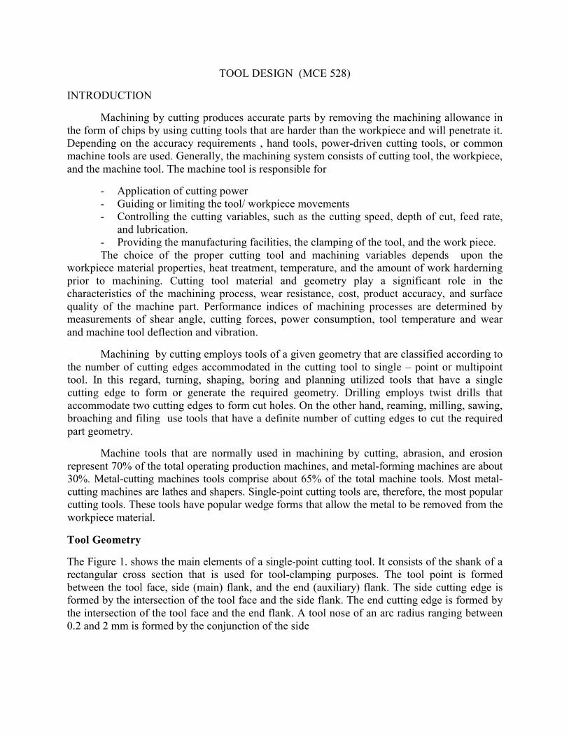
The Figure 1. shows the main elements of a single-point cutting tool. It consists of the shank of a rectangular cross section that is used for tool-clamping purposes. The tool point is formed between the tool face, side (main) flank, and the end (auxiliary) flank. The side cutting edge is formed by the intersection of the tool face and the side flank. The end cutting edge is formed by the intersection of the tool face and the end flank. A tool nose of an arc radius ranging between 0.2 and 2 mm is formed by the conjunction of the side
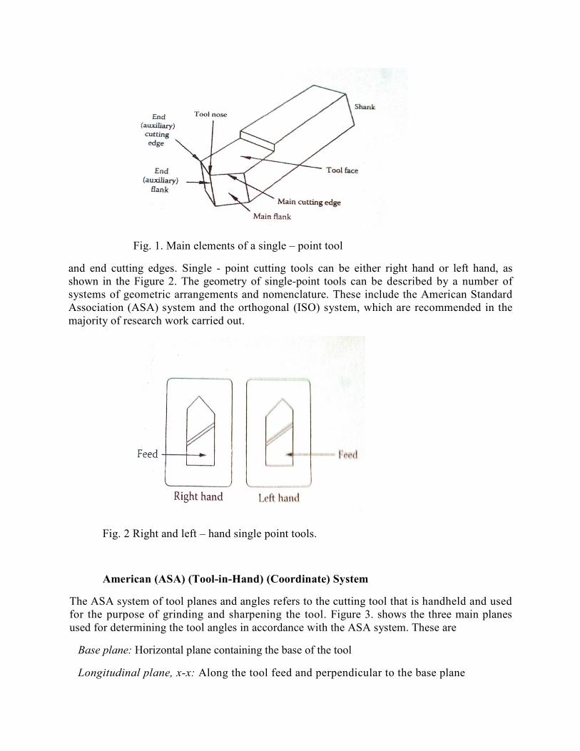
Fig. 1. Main elements of a single – point tool
and end cutting edges. Single - point cutting tools can be either right hand or left hand, as shown in the Figure 2. The geometry of single-point tools can be described by a number of systems of geometric arrangements and nomenclature. These include the American Standard Association (ASA) system and the orthogonal (ISO) system, which are recommended in the majority of research work carried out.
Fig. 2 Right and left – hand single point tools.
American (ASA) (Tool-in-Hand) (Coordinate) System
The ASA system of tool planes and angles refers to the cutting tool that is handheld and used for the purpose of grinding and sharpening the tool. Figure 3. shows the three main planes used for determining the tool angles in accordance with the ASA system. These are
Base plane: Horizontal plane containing the base of the tool
Longitudinal plane, x-x: Along the tool feed and perpendicular to the base plane
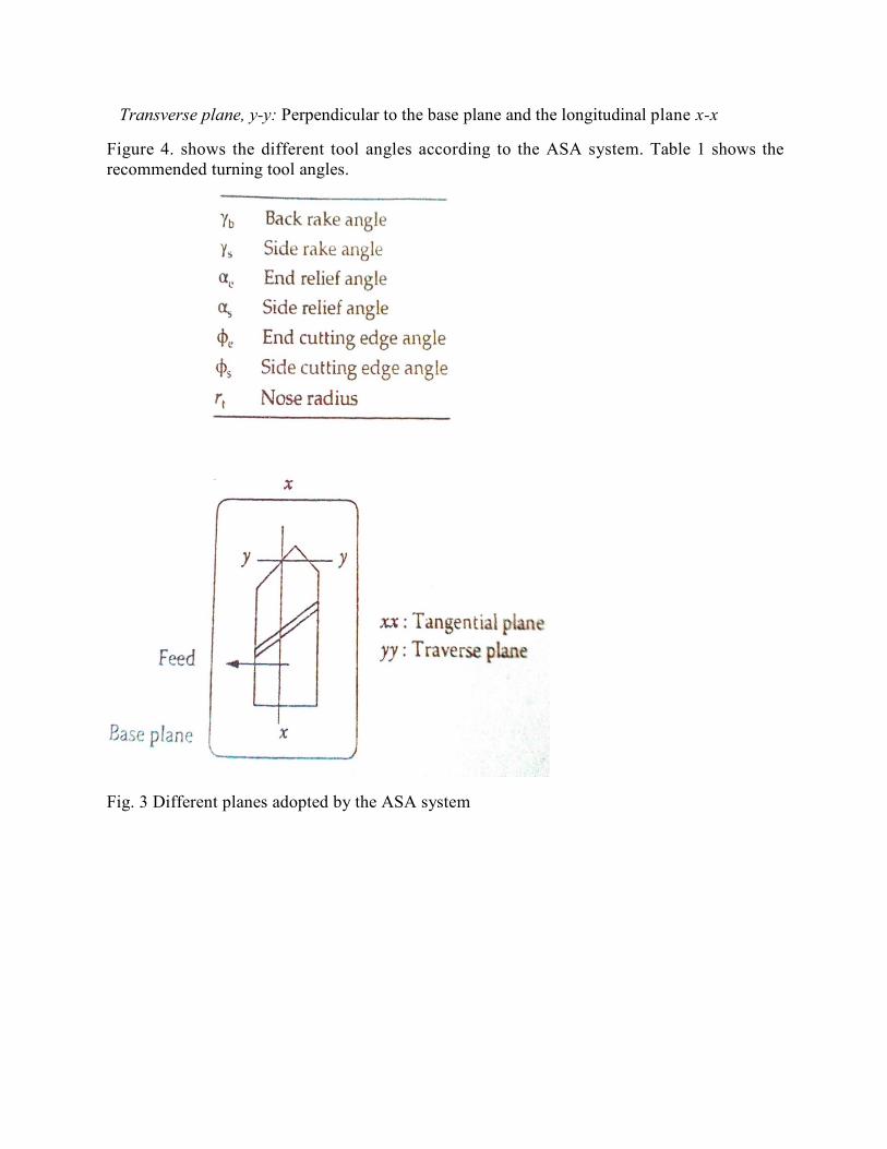
Transverse plane, y-y: Perpendicular to the base plane and the longitudinal plane x-x
Figure 4. shows the different tool angles according to the ASA system. Table 1 shows the recommended turning tool angles.
Fig. 3 Different planes adopted by the ASA system
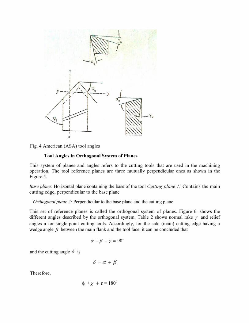
Fig. 4 American (ASA) tool angles
Tool Angles in Orthogonal System of Planes
This system of planes and angles refers to the cutting tools that are used in the machining operation. The tool reference planes are three mutually perpendicular ones as shown in the Figure 5.
Base plane: Horizontal plane containing the base of the tool Cutting plane 1: Contains the main cutting edge, perpendicular to the base plane
Orthogonal plane 2: Perpendicular to the base plane and the cutting plane
This set of reference planes is called the orthogonal system of planes. Figure 6. shows the different angles described by the orthogonal system. Table 2 shows normal rake and relief
angles a for single-point cutting tools. Accordingly, for the side (main) cutting edge having a wedge angle between the main flank and the tool face, it can be concluded that
and the cutting angle is
Therefore,
ϕc + + � = 1800
90
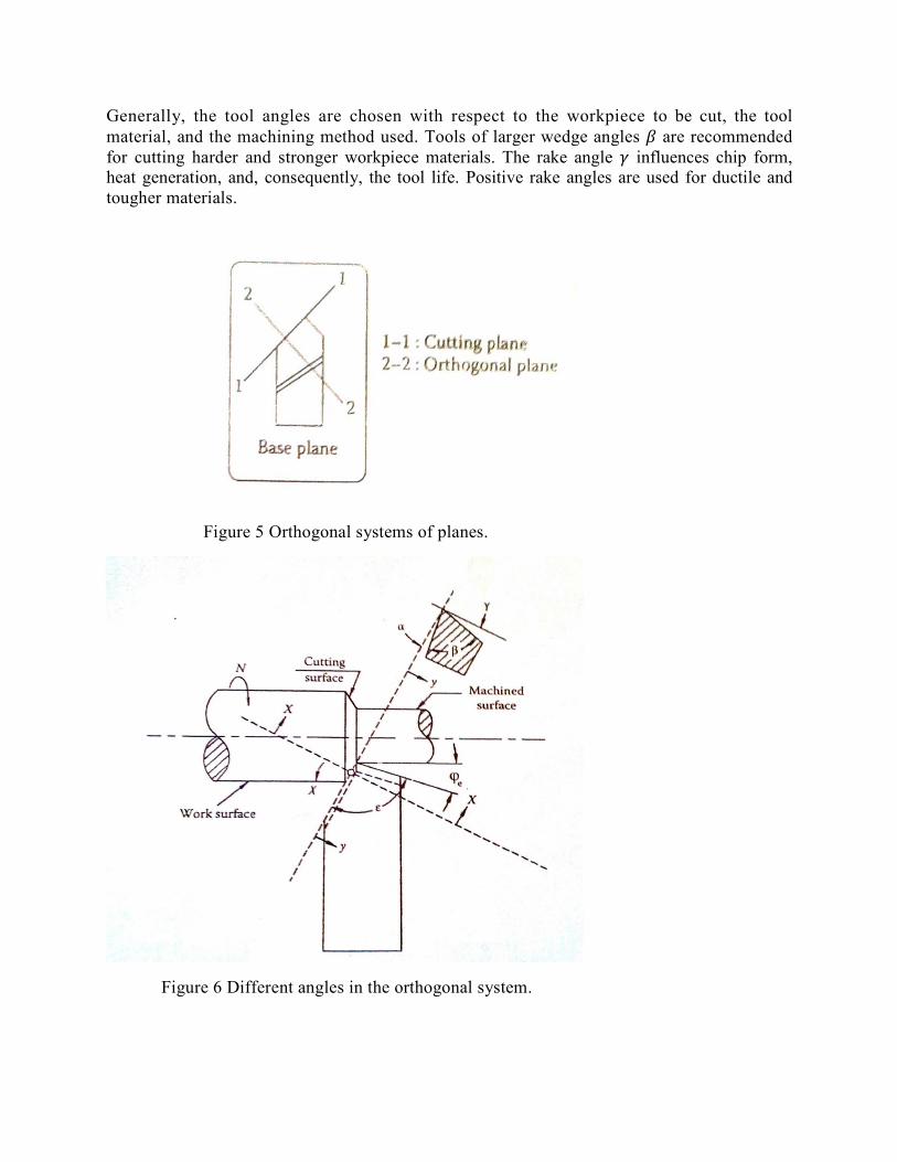
Generally, the tool angles are chosen with respect to the workpiece to be cut, the tool material, and the machining method used. Tools of larger wedge angles � are recommended for cutting harder and stronger workpiece materials. The rake angle � influences chip form, heat generation, and, consequently, the tool life. Positive rake angles are used for ductile and tougher materials.
Figure 5 Orthogonal systems of planes.
Figure 6 Different angles in the orthogonal system.
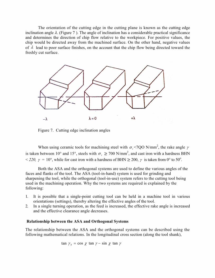
The orientation of the cutting edge in the cutting plane is known as the cutting edge inclination angle �. (Figure 7 ). The angle of inclination has a considerable practical significance and determines the direction of chip flow relative to the workpiece. For positive values, the chip would be directed away from the machined surface. On the other hand, negative values of lead to poor surface finishes, on the account that the chip flow being directed toward the freshly cut surface.
Figure 7. Cutting edge inclination angles
When using ceramic tools for machining steel with t <7QO N/mm2, the rake angle
is taken between 10° and 15°, steels with ≥ 700 N/mm2, and cast iron with a hardness BHN
< 220, = 10°, while for cast iron with a hardness of BHN ≥ 200, is taken from 0° to 50o.
Both the ASA and the orthogonal systems are used to define the various angles of the faces and flanks of the tool. The ASA (tool-in-hand) system is used for grinding and sharpening the tool, while the orthogonal (tool-in-use) system refers to the cutting tool being used in the machining operation. Why the two systems are required is explained by the following:
1. It is possible that a single-point cutting tool can be held in a machine tool in various orientations (settings), thereby altering the effective angles of the tool.
2. In a single turning operation, as the feed is increased, the effective rake angle is increased and the effective clearance angle decreases.
Relationship between the ASA and Orthogonal Systems
The relationship between the ASA and the orthogonal systems can be described using the following mathematical relations. In the longitudinal cross section (along the tool shank),
tan
t
tansintancos b
In the traverse (feed) direction,
The relationship between rake and clearance angles in the longitudinal and transverse cross section is explained by
For calculating the rake and clearance angles in the orthogonal system as a function of rake and clearance angles in longitudinal/traverse (ASA) system and the setting angle the
following equations apply:
Effect of Tool Setting
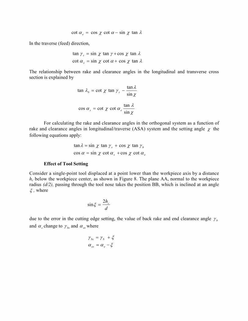
Consider a single-point tool displaced at a point lower than the workpiece axis by a distance hc below the workpiece center, as shown in Figure 8. The plane AA, normal to the workpiece radius (d/2), passing through the tool nose takes the position BB, which is inclined at an angle
, where
due to the error in the cutting edge setting, the value of back rake and end clearance angle
and change to and where
tansincotcoscot e
tancoscotsincot
tancostansintan
s
s
sin
tantancottan sb
sin
tancotcotcos es
es
bs
cotcoscotsincos
tancostansintan
d
hc2sin
b
c bs es
ees
bbs
Fig. 8 Effect of setting on ASA tool angles.
In boring operations, the angles and change in the opposite direction where the rake
angle increases and the relief angle decreases.
Effect of Tool Feed Motion
As shown in Figure 9, the position of the traverse cross-sectional plane is determined by the
cutting speed vector �⃗ resulting from the addition of the primary speed vector ��⃗ to the
auxiliary motion speed vector �⃗ the angle of rotation becomes
As a result of tool motion, the angles and in the longitudinal cross section of
the motion system will change to
At larger values of feed vector f in relation to the cutting speed V, the motion system clearance angle may become equal to zero if
b e
V
f1tan
b e
eem
bbm
V
fe
1tan
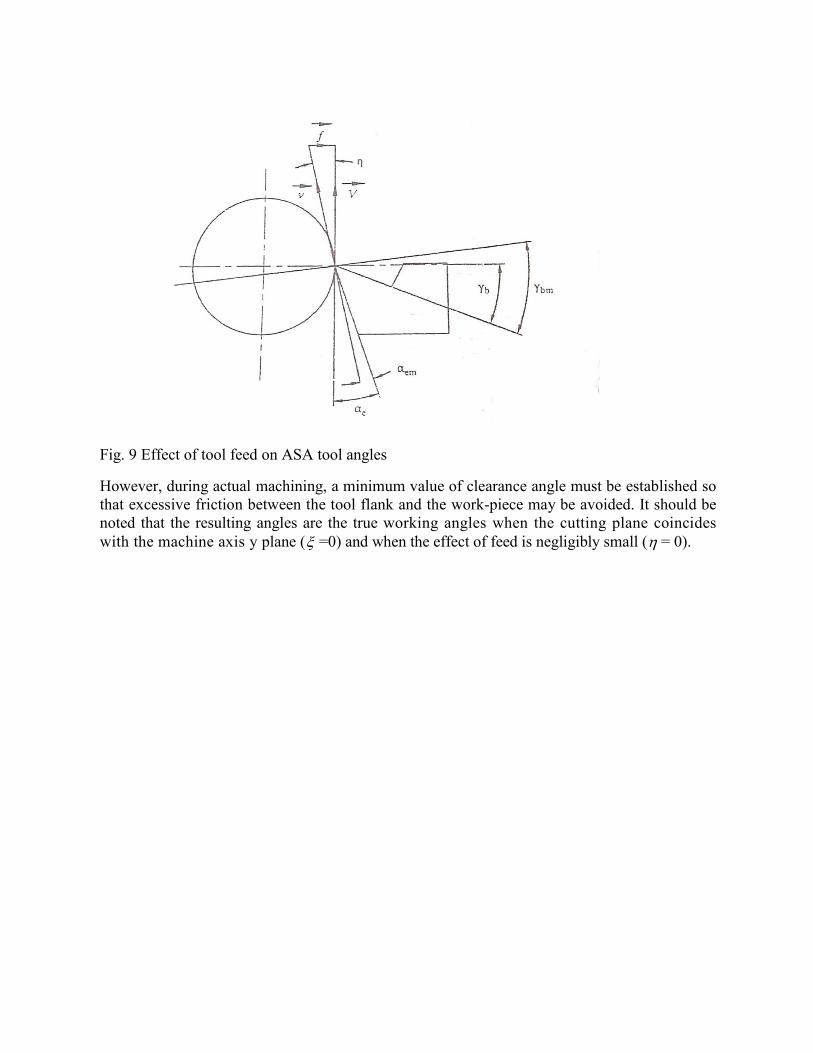
Fig. 9 Effect of tool feed on ASA tool angles
However, during actual machining, a minimum value of clearance angle must be established so that excessive friction between the tool flank and the work-piece may be avoided. It should be noted that the resulting angles are the true working angles when the cutting plane coincides with the machine axis y plane ( =0) and when the effect of feed is negligibly small ( = 0).

Example
A turning tool has a side rake angle of 16° and a back rake angle of 10°. Calculate the plan setting (approach) angle, which will make the cutting orthogonal. If the setting angle is 50°, what change must be made in order to achieve orthogonal cutting conditions?
Solution
Because tan for orthogonal cutting 0, then
tan 10 = cot
changes from 16° to 11° 52' 2.5"
or tan = cot 50 tan 16
=13°31'43"
increases from 10° to 13° 31' 43"
,sin/tantancot sb
sin/0tan16tan
,21.0tan
tan50cot10tan
50
"25'2458
6149.0cot
s
s
o
o
For
s
b
b
b