to brushed motor controllers/drivers
TRANSCRIPT
TO BRUSHED MOTORCONTROLLERS/DRIVERS
ESSENTIAL GUIDE
Copyright © 2020 TOSHIBA ELECTRONIC DEVICES & STORAGE CORPORATION, All Rights Reserved
Essential Guide to Brushed Motor Controllers/Drivers 2
IntroductionBrushed motors are one of several types of DC motors used in a wide range of
electrical and electronic products. While the motor specifications are important,
it is the electronic control circuitry that is the secret to achieving the desired
performance. This white paper addresses the brushed motor control function
and introduces an integrated circuit (IC) that can provide the desired control for
many common applications.
Introduction to Brushed MotorsMotors are everywhere. Stop a minute and think about all the motors in your
home, office, and car. Dig deep and list as many as you can. Probably more than
you thought. And if you are reading this white paper, chances are that you are
working on a motor project.
When choosing a small motor for use in an industrial, business, or consumer
product, the first design decision is the type of motor. Of course, the two main
categories are AC and DC motors.
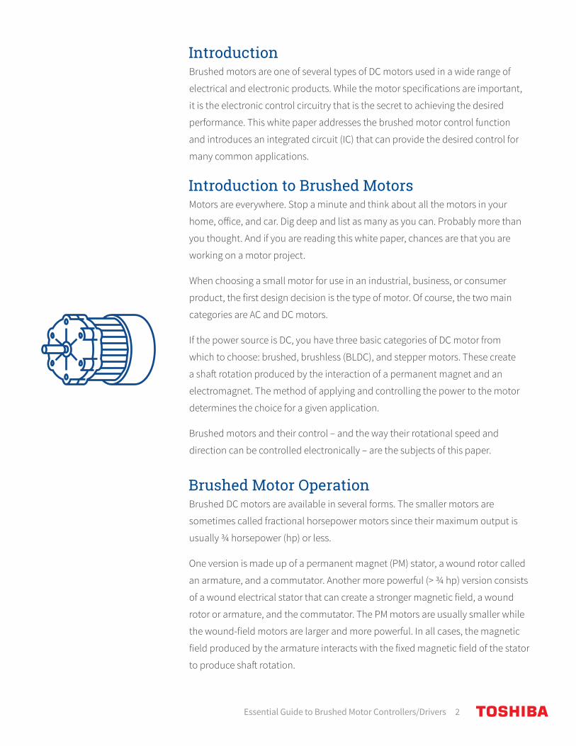
If the power source is DC, you have three basic categories of DC motor from
which to choose: brushed, brushless (BLDC), and stepper motors. These create
a shaft rotation produced by the interaction of a permanent magnet and an
electromagnet. The method of applying and controlling the power to the motor
determines the choice for a given application.
Brushed motors and their control – and the way their rotational speed and
direction can be controlled electronically – are the subjects of this paper.
Brushed Motor OperationBrushed DC motors are available in several forms. The smaller motors are
sometimes called fractional horsepower motors since their maximum output is
usually ¾ horsepower (hp) or less.
One version is made up of a permanent magnet (PM) stator, a wound rotor called
an armature, and a commutator. Another more powerful (> ¾ hp) version consists
of a wound electrical stator that can create a stronger magnetic field, a wound
rotor or armature, and the commutator. The PM motors are usually smaller while
the wound-field motors are larger and more powerful. In all cases, the magnetic
field produced by the armature interacts with the fixed magnetic field of the stator
to produce shaft rotation.
Essential Guide to Brushed Motor Controllers/Drivers 3
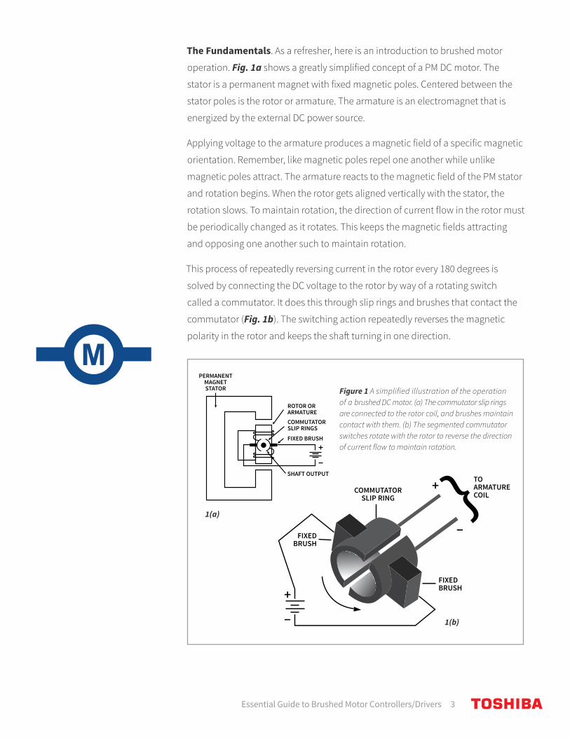
The Fundamentals. As a refresher, here is an introduction to brushed motor
operation. Fig. 1a shows a greatly simplified concept of a PM DC motor. The
stator is a permanent magnet with fixed magnetic poles. Centered between the
stator poles is the rotor or armature. The armature is an electromagnet that is
energized by the external DC power source.
Applying voltage to the armature produces a magnetic field of a specific magnetic
orientation. Remember, like magnetic poles repel one another while unlike
magnetic poles attract. The armature reacts to the magnetic field of the PM stator
and rotation begins. When the rotor gets aligned vertically with the stator, the
rotation slows. To maintain rotation, the direction of current flow in the rotor must
be periodically changed as it rotates. This keeps the magnetic fields attracting
and opposing one another such to maintain rotation.
This process of repeatedly reversing current in the rotor every 180 degrees is
solved by connecting the DC voltage to the rotor by way of a rotating switch
called a commutator. It does this through slip rings and brushes that contact the
commutator (Fig. 1b). The switching action repeatedly reverses the magnetic
polarity in the rotor and keeps the shaft turning in one direction.
Figure 1 A simplified illustration of the operation of a brushed DC motor. (a) The commutator slip rings are connected to the rotor coil, and brushes maintain contact with them. (b) The segmented commutator switches rotate with the rotor to reverse the direction of current flow to maintain rotation.
PERMANENTMAGNETSTATOR
ROTOR ORARMATURECOMMUTATORSLIP RINGS
SHAFT OUTPUT
TO ARMATURE COILCOMMUTATOR
SLIP RING+
+
FIXEDBRUSH
FIXEDBRUSH
FIXED BRUSH
PERMANENTMAGNETSTATOR
ROTOR ORARMATURECOMMUTATORSLIP RINGS
SHAFT OUTPUT
TO ARMATURE COILCOMMUTATOR
SLIP RING+
+
FIXEDBRUSH
FIXEDBRUSH
FIXED BRUSH
1(a)
1(b)
Essential Guide to Brushed Motor Controllers/Drivers 4
One key difference between smaller fractional horsepower and the larger more powerful motors is the stator.

Essential Guide to Brushed Motor Controllers/Drivers 5
All brushed motor operation is based on this concept. One key difference between
smaller fractional horsepower and the larger more powerful motors is the stator. Large
motors have an electromagnetic stator. The stator field is produced by a coil winding
on a magnetic core that forms the poles. It is powered by the same DC voltage applied
to the armature. Two common connections are shown in Fig. 2.
Figure 2 Larger brushed motors use an electromagnetic field powered by the DC input. Two common arrangements are the series-wound motor (left) and the shunt-wound motor (right).
M
M
STATOR FIELD WINDING
STATOR FIELD WINDING
ARMATUREWINDING
ARMATUREWINDING
M
M
STATOR FIELD WINDING
STATOR FIELD WINDING
ARMATUREWINDING
ARMATUREWINDING
Motor Characteristics. There are two characteristics of the DC motor that are
paramount. First, the direction of rotation depends upon the polarity of the
applied DC voltage. Reversing the direction of current flow through the rotor
reverses the direction of the shaft rotation.
Second, the speed of the motor is proportional to the amount of DC applied to
the rotor. The higher the current in the rotor, the stronger the magnetic field and
more rapid the rotation. Brushed DC motors are high-speed devices with rotation
speeds from several thousand revolutions per minute (rpm) to over 25,000 rpm.
And if low speed is a desired trait, a gear motor can be used. Gear motors are
brushed DC motors with a set of gears attached to the shaft to reduce the speed
to a value required by the application.
The two main control functions to be applied to a DC motor are speed and
direction. Electronic circuits readily address these functions.
Directional Control with an H-BridgeNot all applications require a reversal of shaft rotation. But those that do could
use a manual switch to change directions. However, in most cases an electronic
solution is preferred.

Essential Guide to Brushed Motor Controllers/Drivers 6
Changing the direction of rotation of the motor shaft is generally achieved by
simply reversing the current direction in the motor coils. One superior method of
reversing the current in a motor is to use an H-bridge. This is a bridge circuit made
with semiconductor (MOSFET) switches arranged in an H configuration (Fig. 3).
The bridge is made up of MOSFET switches. DC voltage VDD is applied to the bridge
as shown. The motor (M) is connected across the bridge. Control logic is used to
turn the MOSFETs off or on. If Q1 and Q4 are turned on, electron current flow will
be through Q4, then the motor from right to left and through Q1. Q2 and Q3 are off
at this time.
To reverse the current flow through the motor, Q1 and Q4 are turned off and Q2
and Q3 are turned on by the controller. Electron flow is then through Q2, the motor
from left to right and Q3.
While the H-bridge is mainly used to control motor direction of rotation, it can be
used for other functions. Pulse width modulation (PWM) pulses may be applied to
the MOSFETs via the controller for speed control.
Speed Variation with PWMThe rotational speed of a brushed motor is proportional to the amount of DC
voltage applied. As it turns out, that DC does not have to be continuous. It can just
be an average voltage. With that being the case, PWM has become the standard
method of controlling the speed of a DC motor.
+VDD
Q1
Q2
Q3M
Q4
CONTROLLER
Figure 3 The H-bridge is an effective solution to controlling the direction of current flow in the load like a brushed motor.
Essential Guide to Brushed Motor Controllers/Drivers 7
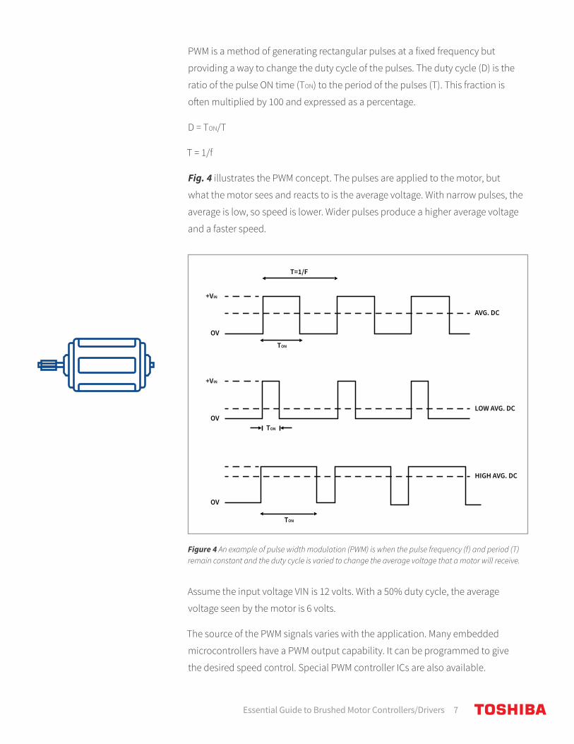
PWM is a method of generating rectangular pulses at a fixed frequency but
providing a way to change the duty cycle of the pulses. The duty cycle (D) is the
ratio of the pulse ON time (TON) to the period of the pulses (T). This fraction is
often multiplied by 100 and expressed as a percentage.
D = TON/T
T = 1/f
Fig. 4 illustrates the PWM concept. The pulses are applied to the motor, but
what the motor sees and reacts to is the average voltage. With narrow pulses, the
average is low, so speed is lower. Wider pulses produce a higher average voltage
and a faster speed.
Assume the input voltage VIN is 12 volts. With a 50% duty cycle, the average
voltage seen by the motor is 6 volts.
The source of the PWM signals varies with the application. Many embedded
microcontrollers have a PWM output capability. It can be programmed to give
the desired speed control. Special PWM controller ICs are also available.
TON
T=1/F
TON
OV
OV
OV
+VIN
+VIN
AVG. DC
LOW AVG. DC
HIGH AVG. DC
TON
Figure 4 An example of pulse width modulation (PWM) is when the pulse frequency (f) and period (T) remain constant and the duty cycle is varied to change the average voltage that a motor will receive.

Essential Guide to Brushed Motor Controllers/Drivers 8
The rotational speed of a brushed motor is proportional to the amount of DC voltage applied. As it turns out, that DC does not have to be continuous.

Essential Guide to Brushed Motor Controllers/Drivers 9
If both motor speed and directional control are required, the PWM signal can be
applied to the H-bridge. With the direction selected, the active transistors can be
switched off and on accordingly to control the speed.
An H-Bridge DriverAn available driver IC for brushed motor use is the Toshiba TC78H653FTG,
dual H-bridge driver (Fig. 5). This MOSFET driver targets low-voltage
applications such as battery-operated and mobile devices. Some examples
are cameras, printers, electronic locks, smart meters, and toys. The part can
also be supported by USB power.
Figure 5 A general block diagram of Toshiba TC78H653FTG, dual H-bridge IC for motor control.
Previously adopted drivers used bipolar transistors. This latest chip uses MOSFETs
to deliver low voltage (1.8V) and high current (4A). The very low “on” resistance of
the MOSFETs improves motor torque since more voltage gets to the motor and
greatly minimizes losses and heat dissipation. This chip contains two MOSFET
Essential Guide to Brushed Motor Controllers/Drivers 10
H-Bridge drivers and is capable of driving two brushed motors or a single
two-phase stepper motor. Some highlights of this IC include:
• DC operating voltage range: 1.8 to 7.5V
• Output current: 2A per channel
• Output ON resistance: 0.11 ohms (typ.)
• Available protection modes: thermal shutdown (TSD), over-current detection (ISD), and under-voltage lockout (UVLO)
• Selectable modes: Forward, Reverse, Stop, and Brake
• Can be used with brushed DC or stepper motors
• Package: P-VQFN16 (3 mm x 3 mm)
For more details, download the data sheet and application note.
Toshiba features about 180 DC motor driver products in its portfolio – of which over
40 are for brushed motors. For more information on its products, visit the website.