tesys u starter-controllers - aecom.vn
TRANSCRIPT
TeSys UStarter-controllers
Catalogue
October 2008

2
1
3
4
5
6
7
8
9
10
2
1
3
4
5
6
7
8
9
10
�
General contents TeSys motor starters - open versionTeSys U starter-controllers
TeSys U starter-controllers
Presentation . . . . . . . . . . . . . . . . . . . . . . . . . . . . . . . . . . . . . . . . . . . . . . . . . page 2
Application examples . . . . . . . . . . . . . . . . . . . . . . . . . . . . . . . . . . . . . . . . . . page 8
Non-reversing and reversing power bases . . . . . . . . . . . . . . . . . . . . . . . . page 12
Add-on contact blocks and auxiliary contact modules . . . . . . . . . . . . . . page 14
Control units and function modules . . . . . . . . . . . . . . . . . . . . . . . . . . . . . page 18
PowerSuite software workshop . . . . . . . . . . . . . . . . . . . . . . . . . . . . . . . . . page 22
Parallel wiring module and pre-wired coil connection components . . . . page 26
Communication modules . . . . . . . . . . . . . . . . . . . . . . . . . . . . . . . . . . . . . page 28
Communication gateways LUF P . . . . . . . . . . . . . . . . . . . . . . . . . . . . . . . . page 44
Characteristics . . . . . . . . . . . . . . . . . . . . . . . . . . . . . . . . . . . . . . . . . . . . . . page 46
Tripping curves . . . . . . . . . . . . . . . . . . . . . . . . . . . . . . . . . . . . . . . . . . . . . . page 54
Selection curves according to categories . . . . . . . . . . . . . . . . . . . . . . . . page 58
Dimensions, mounting . . . . . . . . . . . . . . . . . . . . . . . . . . . . . . . . . . . . . . . . page 60
Schemes . . . . . . . . . . . . . . . . . . . . . . . . . . . . . . . . . . . . . . . . . . . . . . . . . . . page 62
Data profile under AS-Interface . . . . . . . . . . . . . . . . . . . . . . . . . . . . . . . . . page 69
Main registers accessible with the communication modules . . . . . . . . . page 69
TeSys U starter-controllers, variable speed controllers and soft start/soft stop units
Altistart U01 and TeSys U . . . . . . . . . . . . . . . . . . . . . . . . . . . . . . . . . . . . . . page 74
Magnetic control unit for the protection of variable speed controllers and soft start/soft stop units . . . . . . . . . . . . . . . . . . . . . . . . . . . . . . . . . . . page 84
TeSys U controllersPresentation . . . . . . . . . . . . . . . . . . . . . . . . . . . . . . . . . . . . . . . . . . . . . . . . page 90
Application example . . . . . . . . . . . . . . . . . . . . . . . . . . . . . . . . . . . . . . . . . . page 90
Characteristics . . . . . . . . . . . . . . . . . . . . . . . . . . . . . . . . . . . . . . . . . . . . . . page 92
References . . . . . . . . . . . . . . . . . . . . . . . . . . . . . . . . . . . . . . . . . . . . . . . . . page 94
Combinations providing type 2 coordination . . . . . . . . . . . . . . . . . . . . . . page 95
Dimensions, mounting . . . . . . . . . . . . . . . . . . . . . . . . . . . . . . . . . . . . . . . . page 96
Schemes . . . . . . . . . . . . . . . . . . . . . . . . . . . . . . . . . . . . . . . . . . . . . . . . . . . page 97
Product reference index . . . . . . . . . . . . . . . . . . . . . . . . . . . . . . . . . . . . . . . page 98
�
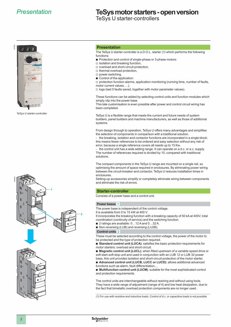
PresentationThe TeSys U starter-controller is a D.O.L. starter (1) which performs the following functions:
Protection and control of single-phase or 3-phase motors:isolation and breaking function,overload and short-circuit protection,thermal overload protection,power switching.Control of the application: protection function alarms, application monitoring (running time, number of faults,
motor current values, ...),logs (last 5 faults saved, together with motor parameter values).
These functions can be added by selecting control units and function modules which simply clip into the power base. This late customisation is even possible after power and control circuit wiring has been completed.
TeSys U is a flexible range that meets the current and future needs of system builders, panel builders and machine manufacturers, as well as those of additional systems.
From design through to operation, TeSys U offers many advantages and simplifies the selection of components in comparison with a traditional solution.
the breaking, isolation and contactor functions are incorporated in a single block; this means fewer references to be ordered and easy selection without any risk of error, because a single reference covers all needs up to �5 Kw.
the control unit has a wide setting range. It can operate on a d.c. or a.c. supply. The number of references required is divided by �0, compared with traditional solutions.
The compact components in the TeSys U range are mounted on a single rail, so optimising the amount of space required in enclosures. By eliminating power wiring between the circuit-breaker and contactor, TeSys U reduces installation times in enclosures. Setting-up accessories simplify or completely eliminate wiring between components and eliminate the risk of errors.
bvvvvbv
v
-
-
Starter-controllerConsists of a power base and a control unit.
Power bases The power base is independent of the control voltage. It is available from 0 to �5 kW at 400 V. It incorporates the breaking function with a breaking capacity of 50 kA at 400V, total coordination (continuity of service) and the switching function.
� ratings are available: 0…�� A and 0…3� A.Non-reversing (LUB) and reversing (LU�B).
bb
Control units These must be selected according to the control voltage, the power of the motor to be protected and the type of protection required.
Standard control unit (LUCA): satisfies the basic protection requirements for motor starters: overload and short-circuit.
Magnetic control unit (LUCL): when fitted upstream of a variable speed drive or soft start-soft stop unit and used in conjunction with an LUB �� or LUB 3� power base, this unit provides isolation and short-circuit protection of the motor starter.
Advanced control unit (LUCB, LUCC or LUCD): allows additional advanced functions such as alarm, fault differentiation,...
Multifunction control unit (LUCM): suitable for the most sophisticated control and protection requirements.
The control units are interchangeable without rewiring and without using tools. They have a wide range of adjustment (range of 4) and low heat dissipation, due to the fact that bimetallic overload protection components are no longer used.
b
b
b
b
(1) For use with resistive and inductive loads. Control of d.c. or capacitive loads is not possible.
11
22
Presentation TeSys motor starters - open version TeSys U starter-controllers
5388
49
1
2
�079
83
TeSys U starter-controller
3
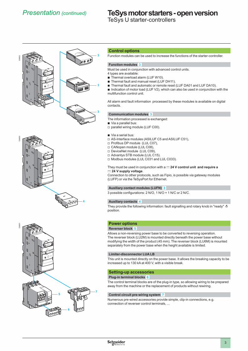
Control optionsFunction modules can be used to increase the functions of the starter-controller.
Function modules Must be used in conjunction with advanced control units. 4 types are available:
Thermal overload alarm (LUF W�0).Thermal fault and manual reset (LUF DH��).Thermal fault and automatic or remote reset (LUF DA0� and LUF DA�0).Indication of motor load (LUF V�), which can also be used in conjunction with the
multifunction control unit.
All alarm and fault information processed by these modules is available on digital contacts.
bbbb
Communication modules The information processed is exchanged:
Via a parallel bus:parallel wiring module (LUF C00).
Via a serial bus:AS-Interface modules (ASILUF C5 and ASILUF C5�),Profibus DP module (LUL C07),CANopen module (LUL C08),DeviceNet module (LUL C09),Advantys STB module (LUL C�5).Modbus modules (LUL C03� and LUL C033).
They must be used in conjunction with a c 24 V control unit and require a c 24 V supply voltage. Connection to other protocols, such as Fipio, is possible via gateway modules (LUFP) or via the TeSysPort for Ethernet.
bv
bvvvvvv
Auxiliary contact modules (LUFN) 3 possible configurations: 2 N/O, 1 N/O + 1 N/C or 2 N/C.
Auxiliary contacts They provide the following information: fault signalling and rotary knob in "ready" position.
Power optionsReverser block
Allows a non-reversing power base to be converted to reversing operation.The reverser block (LU�M) is mounted directly beneath the power base without modifying the width of the product (45 mm). The reverser block (LU6M) is mounted separately from the power base when the height available is limited.
Limiter-disconnector LUA LBThis unit is mounted directly on the power base. It allows the breaking capacity to be increased up to �30 kA at 400 V, with a visible break.
Setting-up accessoriesPlug-in terminal blocks
The control terminal blocks are of the plug-in type, so allowing wiring to be prepared away from the machine or the replacement of products without rewiring.
Control circuit pre-wiring system Numerous pre-wired accessories provide simple, clip-in connections, e.g. connection of reverser control terminals, ...
33
33
33
44
55
66
77
Presentation (continued) TeSys motor starters - open versionTeSys U starter-controllers
5388
5�
5
6
7
3
3
3
5388
5�53
8850
4
4
Presentation (continued) TeSys motor starters - open versionTeSys U starter-controllers
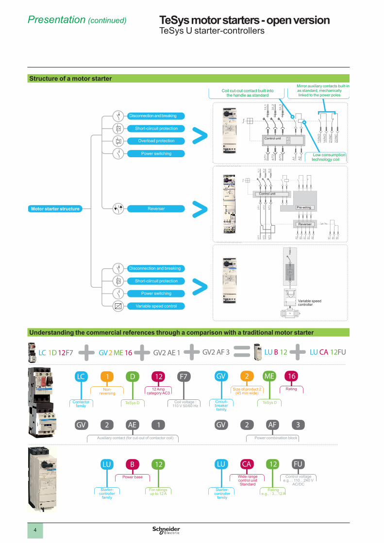
Structure of a motor starter
13/N
O
14/N
O
21/N
C
22/N
C
2/T1
4/T2
6/T3
A1
A2
1/L1
3/L2
5/L3
84 8281
2/T1
4/T2
6/T3
2/T1
4/T2
6/T3
A3
B3
A1
B1
A2
1/L1
3/L2
5/L3
In
Coil cut-out contact built into the handle as standard
Disconnection and breaking
Short-ciircuit protection
Overload protection
Power switching
Disconnection and breaking
Short-ciircuit protection
Power switching
Variable speed control
ReverserMotor starter structure
Mirror auxiliary contacts built-in as standard, mechanically linked to the power poles
Low consumption technology coil
Control unit
Control unit
Pre-wiring
Reverser
Variable speed controller
Understanding the commercial references through a comparison with a traditional motor starter
Contactor family
Non-reversing
TeSys D
�� Amp category AC3
Coil voltage : 110 V 50/60 Hz
Circuit-breaker family
Size of product 2 (45 mm wide)
TeSys D
Rating
Auxiliary contact (for cut-out of contactor coil) Power combination block
Starter-controller
family
Power base
For ratings up to �� A
Starter-controller
family
Wide range control unit Standard
Ratinge.g.. : 3…�� A
Control voltagee.g.. : ��0…�40 V
AC/DC
5
Presentation (continued) TeSys motor starters - open versionTeSys U starter-controllers
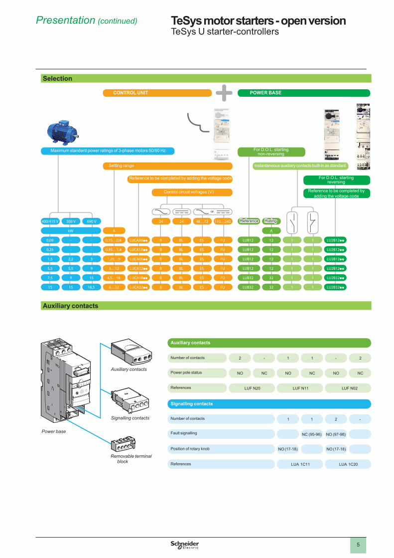
Selection
Setting range
Maximum standard power ratings of 3-phase motors 50/60 Hz
Reference
or
CONTROL UNIT POWER BASE
Reference to be completed by adding the voltage code
Control circuit voltages (V)
Rating
Instantaneous auxiliary contacts built-in as standard.
For D.O.L. starting non-reversing
For D.O.L. starting reversing
Reference to be completed by adding the voltage code
Auxiliary contacts
Auxiliary contacts
Signalling contacts
Number of contacts
Power pole status
Position of rotary knob
Number of contacts
Fault signalling
References
References
Signalling contacts
Auxiliary contacts
Removable terminal block
Power base
6
1
1
2
3
2
3
1
2
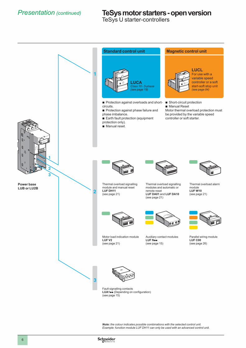
Standard control unit Magnetic control unit Advanced control unit Multifunction control unit
LUCAClass 10 - 3-phase(see page 19)
LUCLFor use with a variable speed controller or a soft start-soft stop unit (see page 84)
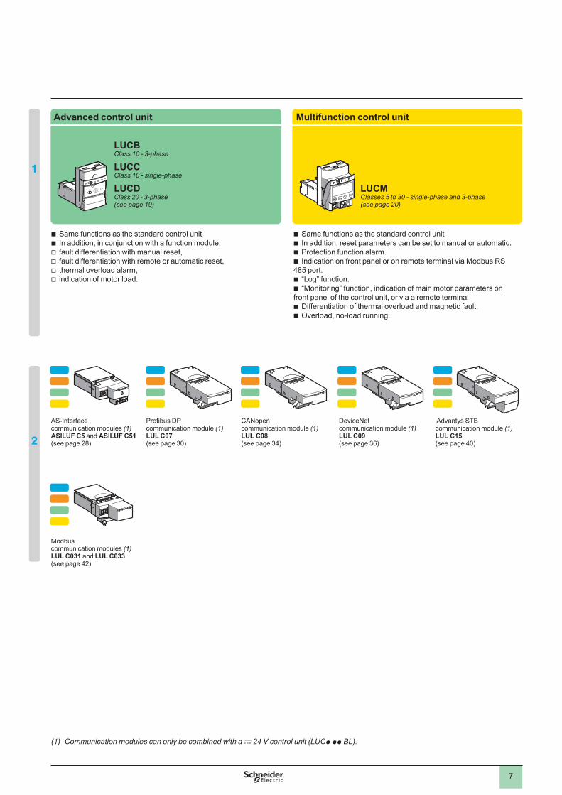
LUCBClass 10 - 3-phase
LUCCClass 10 - single-phase
LUCDClass 20 - 3-phase(see page 19)
LUCMClasses 5 to 30 - single-phase and 3-phase(see page 20)
Protection against overloads and short-circuits.
Protection against phase failure and phase imbalance.
Earth fault protection (equipment protection only).
Manual reset.
b
b
b
b
Short-circuit protectionManual Reset
Motor thermal overload protection must be provided by the variable speed controller or soft starter.
bb
Same functions as the standard control unitIn addition, in conjunction with a function module:fault differentiation with manual reset,fault differentiation with remote or automatic reset, thermal overload alarm, indication of motor load.
bbvvvv
Same functions as the standard control unitIn addition, reset parameters can be set to manual or automatic.Protection function alarm. Indication on front panel or on remote terminal via Modbus RS
485 port.“Log” function.“Monitoring” function, indication of main motor parameters on
front panel of the control unit, or via a remote terminal Differentiation of thermal overload and magnetic fault.Overload, no-load running.
bbbb
bb
bb
Power base LUB or LU2B
Thermal overload signalling module and manual resetLUF DH11(see page ��)
Thermal overload signalling modules and automatic or remote resetLUF DA01 and LUF DA10(see page ��)
Thermal overload alarm moduleLUF W10(see page ��)
AS-Interface communication modules (1)ASILUF C5 and ASILUF C51(see page �8)
Profibus DP communication module (1)LUL C07(see page 30)
CANopen communication module (1) LUL C08(see page 34)
DeviceNet communication module (1)LUL C09(see page 36)
Advantys STB communication module (1)LUL C15(see page 40)
Motor load indication module LUF V2(see page ��)
Auxiliary contact modulesLUF Npp(see page �5)
Parallel wiring moduleLUF C00(see page �6)
Modbus communication modules (1)LUL C031 and LUL C033(see page 4�)
Fault signalling contactsLUA1pp (Depending on configuration)(see page �5)
Note: the colour indicates possible combinations with the selected control unit. Example: function module LUF DH11 can only be used with an advanced control unit.
(1) Communication modules can only be combined with a c 24 V control unit (LUCp pp BL).
Presentation (continued) TeSys motor starters - open versionTeSys U starter-controllers
7
1
1
2
3
2
3
1
2
Standard control unit Magnetic control unit Advanced control unit Multifunction control unit
LUCAClass 10 - 3-phase(see page 19)
LUCLFor use with a variable speed controller or a soft start-soft stop unit (see page 84)
LUCBClass 10 - 3-phase
LUCCClass 10 - single-phase
LUCDClass 20 - 3-phase(see page 19)
LUCMClasses 5 to 30 - single-phase and 3-phase(see page 20)
Protection against overloads and short-circuits.
Protection against phase failure and phase imbalance.
Earth fault protection (equipment protection only).
Manual reset.
b
b
b
b
Short-circuit protectionManual Reset
Motor thermal overload protection must be provided by the variable speed controller or soft starter.
bb
Same functions as the standard control unitIn addition, in conjunction with a function module:fault differentiation with manual reset,fault differentiation with remote or automatic reset, thermal overload alarm, indication of motor load.
bbvvvv
Same functions as the standard control unitIn addition, reset parameters can be set to manual or automatic.Protection function alarm. Indication on front panel or on remote terminal via Modbus RS
485 port.“Log” function.“Monitoring” function, indication of main motor parameters on
front panel of the control unit, or via a remote terminal Differentiation of thermal overload and magnetic fault.Overload, no-load running.
bbbb
bb
bb
Power base LUB or LU2B
Thermal overload signalling module and manual resetLUF DH11(see page ��)
Thermal overload signalling modules and automatic or remote resetLUF DA01 and LUF DA10(see page ��)
Thermal overload alarm moduleLUF W10(see page ��)
AS-Interface communication modules (1)ASILUF C5 and ASILUF C51(see page �8)
Profibus DP communication module (1)LUL C07(see page 30)
CANopen communication module (1) LUL C08(see page 34)
DeviceNet communication module (1)LUL C09(see page 36)
Advantys STB communication module (1)LUL C15(see page 40)
Motor load indication module LUF V2(see page ��)
Auxiliary contact modulesLUF Npp(see page �5)
Parallel wiring moduleLUF C00(see page �6)
Modbus communication modules (1)LUL C031 and LUL C033(see page 4�)
Fault signalling contactsLUA1pp (Depending on configuration)(see page �5)
Note: the colour indicates possible combinations with the selected control unit. Example: function module LUF DH11 can only be used with an advanced control unit.
(1) Communication modules can only be combined with a c 24 V control unit (LUCp pp BL).
8
Application examples 1
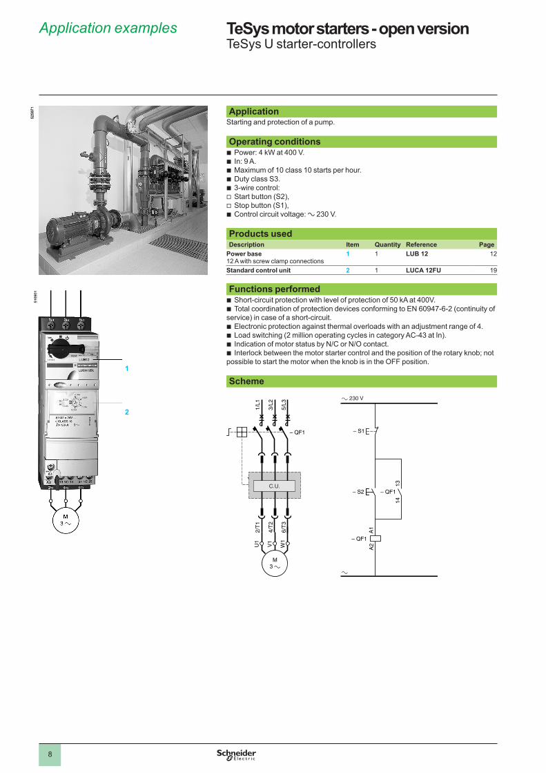
ApplicationStarting and protection of a pump. Operating conditions
Power: 4 kW at 400 V.In: 9 A.Maximum of 10 class 10 starts per hour.Duty class S3.3-wire control:Start button (S�),Stop button (S�),Control circuit voltage: a �30 V.
Products used Description Item Quantity Reference Page
Power base �� A with screw clamp connections
1 � LUB 12 ��
Standard control unit 2 � LUCA 12FU �9 Functions performed
Short-circuit protection with level of protection of 50 kA at 400V.Total coordination of protection devices conforming to EN 60947-6-� (continuity of
service) in case of a short-circuit.Electronic protection against thermal overloads with an adjustment range of 4.Load switching (� million operating cycles in category AC-43 at In).Indication of motor status by N/C or N/O contact.Interlock between the motor starter control and the position of the rotary knob; not
possible to start the motor when the knob is in the OFF position. Scheme
bbbbbvvb
bb
bbbb
5�59
7�5�
597�
5�09
0�5�
090�
1/L1
3/L2
5/L3
2/T
1
4/T
2
6/T
3
A2
A1
1314
–
M3
230 V
U1
V1
W1
C.U.
1/L1
3/L2
5/L3
2/T
1
4/T
2
6/T
3
A2
A1
1314
–
M3
230 V
U1
V1
W1
C.U.
TeSys motor starters - open version 1 TeSys U starter-controllers
1
2
1
2
3
4
5
6
7
8
9
10
9
Application examples 1
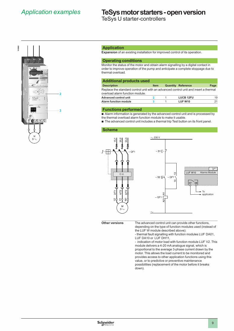
ApplicationExpansion of an existing installation for improved control of its operation. Operating conditions
Monitor the status of the motor and obtain alarm signalling by a digital contact in order to improve operation of the pump and anticipate a complete stoppage due to thermal overload. Additional products used Description Item Quantity Reference Page
Replace the standard control unit with an advanced control unit and insert a thermal overload alarm function module.Advanced control unit 2 � LUCB 12FU �9Alarm function module 3 � LUF W10 �� Functions performed
Alarm information is generated by the advanced control unit and is processed by the thermal overload alarm function module to make it usable.
The advanced control unit includes a thermal trip Test button on its front panel. Scheme
Other versions The advanced control unit can provide other functions,
depending on the type of function modules used (instead of the LUF W module described above):- thermal fault signalling with function modules LUF DA0�, LUF DA�0 or LUF DH��,- indication of motor load with function module LUF V�. This module delivers a 4-�0 mA analogue signal, which is proportional to the average 3-phase current drawn by the motor. This allows the load current to be monitored and provides access to other application functions using this value, or to predictive or preventive maintenance possibilities (replacement of the motor before it breaks down).
b
b
5�09
0�5�
090�
LUF W10
1/L1
3/L2
5/L3
2/T
1
4/T
2
6/T
3
A2
A1
1314
–
M3 a
a 230 V
a
U1
V1
W1
07 08
C.U.
To application
Alarms ModuleLUF W10
1/L1
3/L2
5/L3
2/T
1
4/T
2
6/T
3
A2
A1
1314
–
M3 a
a 230 V
a
U1
V1
W1
07 08
C.U.
To application
Alarms Module
TeSys motor starters - open version 1 TeSys U starter-controllers
2
3
1
2
3
4
5
6
7
8
9
10
�0
Application examples 1 TeSys motor starters - open version 1 TeSys U starter-controllers
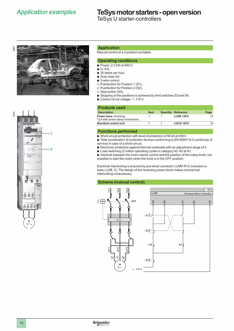
ApplicationManual control of a �-position turntable. Operating conditions
Power: �.� kW at 400 V.In: 6 A.30 starts per hourDuty class S4.3-wire control:Pushbutton for Position � (S�),Pushbutton for Position � (S�),Stop button (S5),Stopping at the positions is achieved by limit switches S3 and S4.Control circuit voltage: a ��5 V.
Products used Description Item Quantity Reference Page
Power base, reversing, �� A with screw clamp connections
1 � LU2B 12FU �3
Standard control unit 2 � LUCA 12FU �9 Functions performed
Short-circuit protection with level of protection of 50 kA at 400V.Total coordination of protection devices conforming to EN 60947-6-� (continuity of
service) in case of a short-circuit.Electronic protection against thermal overloads with an adjustment range of 4.Load switching (� million operating cycles in category AC-43 at In).Interlock between the motor starter control and the position of the rotary knob; not
possible to start the motor when the knob is in the OFF position.
Electrical interlocking is ensured by pre-wired connector LU9M R�C included on base LU�B ��. The design of the reversing power block makes mechanical interlocking unnecessary. Scheme (manual control)
bbbbbvvvbb
bb
bbb
5�09
7�5�
097�
5�37
6�
1
2
5�37
6�
1
2
1/L1
3/L2
5/L3
2/T
1
4/T
2V
1
U1
W1
6/T
3
M3
A3
B3
A1
B1
A2
LU2B
115 V
C.U.
Reverser Motor Controller
1/L1
3/L2
5/L3
2/T
1
4/T
2V
1
U1
W1
6/T
3
M3
A3
B3
A1
B1
A2
LU2B
115 V
C.U.
Reverser Motor Controller
1
2
3
4
5
6
7
8
9
10
��
Application examples 1 TeSys motor starters - open version 1 TeSys U starter-controllers
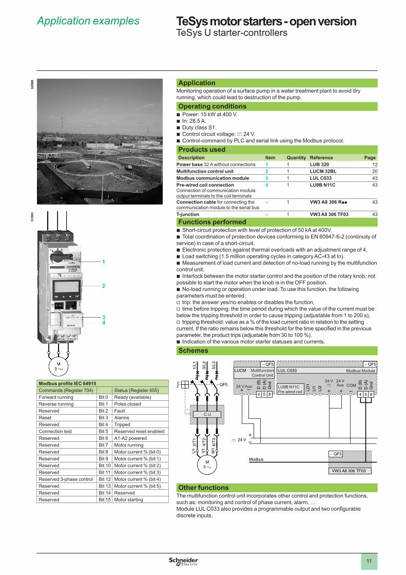
ApplicationMonitoring operation of a surface pump in a water treatment plant to avoid dry running, which could lead to destruction of the pump.
Operating conditionsPower: �5 kW at 400 V.In: �8.5 A.Duty class S�.Control circuit voltage: c �4 V.Control-command by PLC and serial link using the Modbus protocol.
Products used Description Item Quantity Reference Page
Power base 3� A without connections 1 � LUB 320 ��Multifunction control unit 2 � LUCM 32BL �0Modbus communication module 3 � LUL C033 43Pre-wired coil connectionConnection of communication module output terminals to the coil terminals
4 � LU9B N11C 43
Connection cable for connecting the communication module to the serial bus
– � VW3 A8 306 Rpp 43
T-junction – � VW3 A8 306 TF03 43
Functions performed Short-circuit protection with level of protection of 50 kA at 400V.Total coordination of protection devices conforming to EN 60947-6-� (continuity of
service) in case of a short-circuit.Electronic protection against thermal overloads with an adjustment range of 4.Load switching (�.5 million operating cycles in category AC-43 at In).Measurement of load current and detection of no-load running by the multifunction
control unit.Interlock between the motor starter control and the position of the rotary knob; not
possible to start the motor when the knob is in the OFF position.No-load running or operation under load. To use this function, the following
parameters must be entered:trip: the answer yes/no enables or disables the function,time before tripping: the time period during which the value of the current must be
below the tripping threshold in order to cause tripping (adjustable from � to �00 s),tripping threshold: value as a % of the load current ratio in relation to the setting
current. If the ratio remains below this threshold for the time specified in the previous parameter, the product trips (adjustable from 30 to �00 %).
Indication of the various motor starter statuses and currents.
Schemes
Other functions
The multifunction control unit incorporates other control and protection functions, such as: monitoring and control of phase current, alarm, …Module LUL C033 also provides a programmable output and two configurable discrete inputs.
bbbbb
bb
bbb
b
b
vv
v
b
5�09
695�
0969
5�09
035�
0903
4 5 8
Modbus
4 5 8
VW3 A8 306 TF03
1/L1
3/L2
5/L3
2/T
1
4/T
2
6/T
3
M3 a
U1
V1
W1
D (
B)
D (
A)
Gnd
+c 24 V
LO1
LI1
LI2 D (
B)
D (
A)
Gnd
LUCM LUL C033
C.U.
LU9B N��CPre wired coil
Modbus ModuleMultifunction Control Unit
24 V Aux�4 Vc
�4 VAux COM
4 5 8
Modbus
4 5 8
VW3 A8 306 TF03
1/L1
3/L2
5/L3
2/T
1
4/T
2
6/T
3
M3 a
U1
V1
W1
D (
B)
D (
A)
Gnd
+c 24 V
LO1
LI1
LI2 D (
B)
D (
A)
Gnd
LUCM LUL C033
C.U.
LU9B N��CPre wired coil
Modbus ModuleMultifunction Control Unit
24 V Aux�4 Vc
�4 VAux COMModbus profile IEC 64915
Commands (Register 704) Status (Register 455)Forward running Bit 0 Ready (available)Reverse running Bit � Poles closedReserved Bit � FaultReset Bit 3 AlarmsReserved Bit 4 TrippedConnection test Bit 5 Reserved reset enabledReserved Bit 6 A�-A� poweredReserved Bit 7 Motor runningReserved Bit 8 Motor current % (bit 0)Reserved Bit 9 Motor current % (bit �)Reserved Bit �0 Motor current % (bit �)Reserved Bit �� Motor current % (bit 3)Reserved 3-phase control Bit �� Motor current % (bit 4)Reserved Bit �3 Motor current % (bit 5)Reserved Bit �4 ReservedReserved Bit �5 Motor starting
1
2
34
1
2
3
4
5
6
7
8
9
10
��
TeSys motor starters - open version 1 TeSys U starter-controllersNon-reversing power bases
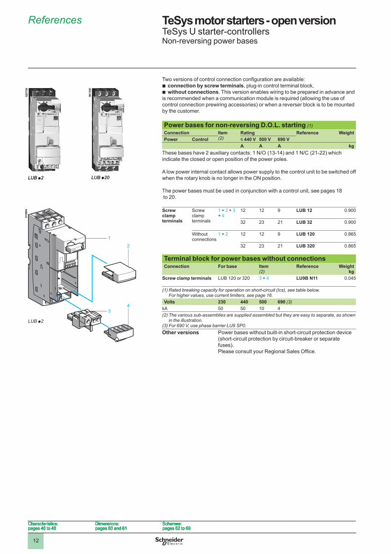
Two versions of control connection configuration are available:connection by screw terminals, plug-in control terminal block,without connections. This version enables wiring to be prepared in advance and
is recommended when a communication module is required (allowing the use of control connection prewiring accessories) or when a reverser block is to be mounted by the customer.
bb
Power bases for non-reversing D .O .L . starting (1)Connection Item
(2)Rating Reference Weight
Power Control y 440 V 500 V 690 VA A A kg
These bases have 2 auxiliary contacts: 1 N/O (13-14) and 1 N/C (21-22) which indicate the closed or open position of the power poles.
A low power internal contact allows power supply to the control unit to be switched off when the rotary knob is no longer in the ON position.
The power bases must be used in conjunction with a control unit, see pages �8 to �0.
Screw clamp terminals
Screw clamp terminals
� + � + 3 + 4
�� �� 9 LUB 12 0.900
3� �3 �� LUB 32 0.900
Without connections
� + � �� �� 9 LUB 120 0.865
3� �3 �� LUB 320 0.865
Terminal block for power bases without connectionsConnection For base Item
(2)Reference Weight
kgScrew clamp terminals LUB ��0 or 3�0 3 + 4 LU9B N11 0.045
(1) Rated breaking capacity for operation on short-circuit (Ics), see table below. For higher values, use current limiters, see page 16.
Volts 230 440 500 690 (3)kA 50 50 �0 4(2) The various sub-assemblies are supplied assembled but they are easy to separate, as shown
in the illustration.(3) For 690 V, use phase barrier LU9 SP0.Other versions Power bases without built-in short-circuit protection device
(short-circuit protection by circuit-breaker or separate fuses).Please consult your Regional Sales Office.
LUB p2
5�07
39
LUB p2
5�07
39
LUB p20
56�3
30
LUB p20
56�3
30
�
�
43
5�09
04
�
�
43
5�09
04
Characteristics: pages 46 to 48
Dimensions: pages 60 and 6�
Schemes:pages 6� to 69
Characteristics: pages 46 to 48
Dimensions: pages 60 and 6�
Schemes:pages 6� to 69
Characteristics: pages 46 to 48
Dimensions: pages 60 and 6�
Schemes:pages 6� to 69
Characteristics: pages 46 to 48
Dimensions: pages 60 and 6�
Schemes:pages 6� to 69
LUB p2
References 1
1
2
3
4
5
6
7
8
9
10
�3
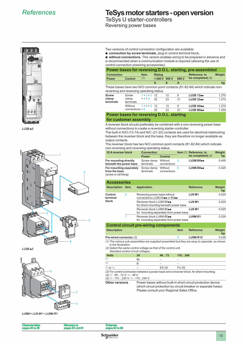
TeSys motor starters - open version 1 TeSys U starter-controllersReversing power bases
Two versions of control connection configuration are available:connection by screw terminals, plug-in control terminal block,without connections. This version enables wiring to be prepared in advance and
is recommended when a communication module is required (allowing the use of control connection prewiring accessories).
bb
Power bases for reversing D .O .L . starting, pre-assembledConnection Item
(1)Rating Reference, to
be completed) (2)Weight
Power Control y 440 V 500 V 690 VA A A kg
These bases have two N/O common point contacts (81-82-84) which indicate non-reversing and reversing operating status.Screw clamp terminals
Screw clamp terminals
� + � + 3 + 4 + 5
�� �� 9 LU2B 12pp �.�703� �3 �� LU2B 32pp �.�70
Without connections
� + � + 3 + 5
�� �� 9 LU2B A0pp �.�703� �3 �� LU2B B0pp �.�50
Power bases for reversing D .O .L . startingfor customer assembly
A reverser block should preferably be combined with a non-reversing power base without connections to create a reversing starter-controller.The built-in N/O (13-14) and N/C (21-22) contacts are used for electrical interlocking between the reverser block and the base; they are therefore no longer available as output contacts.The reverser block has two N/O common point contacts (81-82-84) which indicate non-reversing and reversing operating status.32 A reverser block Connection Item (1) Reference, to
be completed) (2)Weight
kgPower ControlFor mounting directly beneath the power base
Screw clamp terminals
Without connections
3 LU2M B0pp 0.400
For mounting separately from the base(screw or rail fixing)
Screw clamp terminals
Without connections
6 LU6M B0pp 0.4�5
AccessoriesDescription Item Application Reference Weight
kgControl terminal block
4 Reversing power base without connections LU�B A0pp or B0pp
LU9 M1 0.0�5
Reverser block LU�M B0pp for direct mounting beneath power base
LU9 M1 0.0�5
Reverser block LU6M B0pp for mounting separately from power base
LU9 M1 0.0�5
7 Reverser block LU6M B0pp for mounting separately from power base
LU9M R1 0.030
Control circuit pre-wiring componentsDescription Item Reference Weight
kgPre-wired connector (3) 5 LU9M R1C 0.035(1) The various sub-assemblies are supplied assembled but they are easy to separate, as shown
in the illustration.(2) Select the same control voltage as that of the control unit.
Standard control circuit voltages:Volts 24 48…72 110…240
c BL – –a B – –c or a – ES (4) FU (5)(3) For control connection between a power base and a reverser block, for direct mounting.(4) c : 48…72 V, a : 48 V.(5) c : 110…220 V, a : 110...240 V.Other versions Power bases without built-in short-circuit protection device
(short-circuit protection by circuit-breaker or separate fuses). Please consult your Regional Sales Office.
LU2B p2
56��
70
LU2B p2
56��
70
4
3
5
�
�
LU2B p2
6
7
4
LU6M + LU9 M1 + LU9M R1
5�09
055�
0906
4
3
5
�
�
LU2B p2
6
7
4
LU6M + LU9 M1 + LU9M R1
5�09
055�
0906
Characteristics: pages 46 to 48
Dimensions: pages 60 and 6�
Schemes :pages 6� to 69
Characteristics: pages 46 to 48
Dimensions: pages 60 and 6�
Schemes :pages 6� to 69
Characteristics: pages 46 to 48
Dimensions: pages 60 and 6�
Schemes :pages 6� to 69
Characteristics: pages 46 to 48
Dimensions: pages 60 and 6�
Schemes :pages 6� to 69
References 1
1
2
3
4
5
6
7
8
9
10
�4
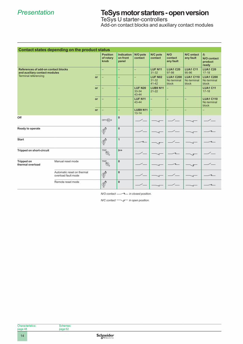
Presentation TeSys motor starters - open versionTeSys U starter-controllersAdd-on contact blocks and auxiliary contact modules
Contact states depending on the product statusPosition of rotary knob
Indication on front panel
N/O pole contact
N/C pole contact
N/O contact any fault
N/C ontact any fault N/O contact
product ready
References of add-on contact blocks and auxiliary contact modules Terminal referencing
– – – LUF N11 3�-3�
LUA1 C20 97-98
LUA1 C11 95-96
LUA1 C20 �7-�8
or – – – LUF N02 3�-3�4�-4�
LUA1 C200 No terminal block
LUA1 C110 No terminal block
LUA1 C200 No terminal block
or – – LUF N20 33-3443-44
LUB9 N11 ��-��
– – LUA1 C11 �7-�8
or – – LUF N11 43-44
– – – LUA1 C110 No terminal block
or – – LUB9 N11 �3-�4
– – – –
OffOFF
0
Ready to operate 0
Start 1
Tripped on short-circuit TRIP I>>
Tripped on thermal overload
Manual reset mode TRIP 0
Automatic reset on thermal overload fault mode
0
Remote reset mode 0
N/O contact in closed position. N/C contact in open position.
Characteristics:page 48
Schemes:page 6�
�5
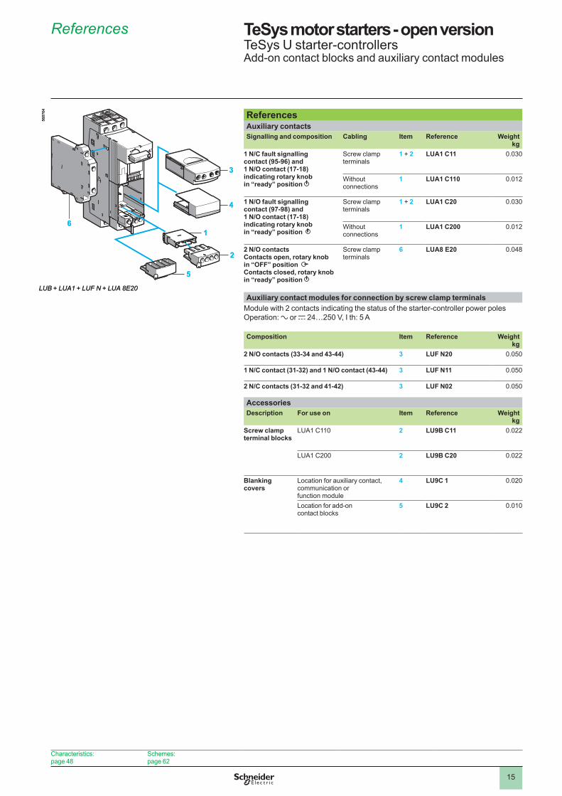
References TeSys motor starters - open versionTeSys U starter-controllersAdd-on contact blocks and auxiliary contact modules
ReferencesAuxiliary contacts Signalling and composition Cabling Item Reference Weight
kg1 N/C fault signalling contact (95-96) and 1 N/O contact (17-18) indicating rotary knob in “ready” position
Screw clamp terminals
1 + 2 LUA1 C11 0.030
Without connections
1 LUA1 C110 0.0��
1 N/O fault signalling contact (97-98) and 1 N/O contact (17-18) indicating rotary knob in “ready” position
Screw clamp terminals
1 + 2 LUA1 C20 0.030
Without connections
1 LUA1 C200 0.0��
2 N/O contactsContacts open, rotary knob in “OFF” position Contacts closed, rotary knob in “ready” position
Screw clamp terminals
6 LUA8 E20 0.048
Auxiliary contact modules for connection by screw clamp terminalsModule with � contacts indicating the status of the starter-controller power polesOperation: a or c �4…�50 V, I th: 5 A
Composition Item Reference Weightkg
2 N/O contacts (33-34 and 43-44) 3 LUF N20 0.050
1 N/C contact (31-32) and 1 N/O contact (43-44) 3 LUF N11 0.050
2 N/C contacts (31-32 and 41-42) 3 LUF N02 0.050
AccessoriesDescription For use on Item Reference Weight
kgScrew clamp terminal blocks
LUA� C��0 2 LU9B C11 0.0��
LUA� C�00 2 LU9B C20 0.0��
Blanking covers
Location for auxiliary contact, communication or function module
4 LU9C 1 0.0�0
Location for add-on contact blocks
5 LU9C 2 0.0�0
3
4
6
2
1
5
5687
64
LUB + LUA1 + LUF N + LUA 8E20
3
4
6
2
1
5
5687
64
LUB + LUA1 + LUF N + LUA 8E20
Characteristics:page 48
Schemes:page 6�
�6
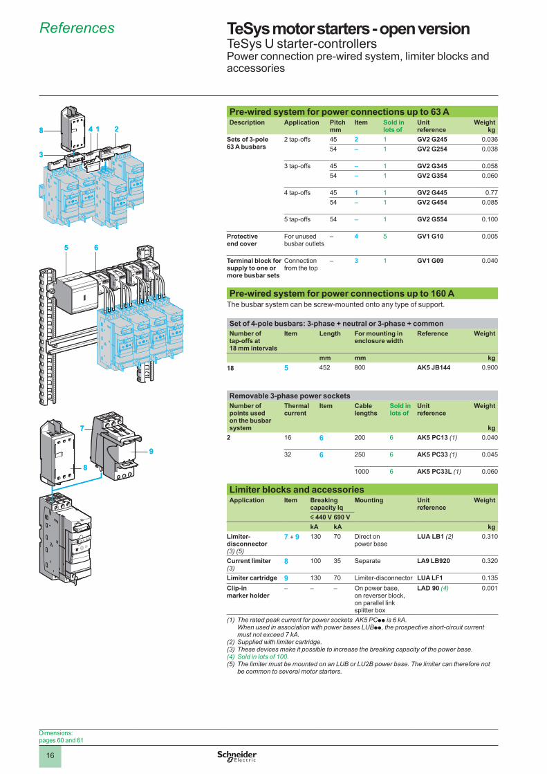
Pre-wired system for power connections up to 63 A Description Application Pitch
mmItem Sold in
lots ofUnit reference
Weightkg
Sets of 3-pole 63 A busbars
� tap-offs 45 2 � GV2 G245 0.03654 – � GV2 G254 0.038
3 tap-offs 45 – � GV2 G345 0.05854 – � GV2 G354 0.060
4 tap-offs 45 1 � GV2 G445 0.7754 – � GV2 G454 0.085
5 tap-offs 54 – � GV2 G554 0.�00
Protective end cover
For unused busbar outlets
– 4 5 GV1 G10 0.005
Terminal block for supply to one or more busbar sets
Connection from the top
– 3 � GV1 G09 0.040
Pre-wired system for power connections up to 160 AThe busbar system can be screw-mounted onto any type of support.
Set of 4-pole busbars: 3-phase + neutral or 3-phase + commonNumber of tap-offs at 18 mm intervals
Item Length For mounting in enclosure width
Reference Weight
mm mm kg18 5 45� 800 AK5 JB144 0.900
Removable 3-phase power socketsNumber of points used on the busbar system
Thermal current
Item Cable lengths
Sold in lots of
Unit reference
Weight
kg2 �6 6 �00 6 AK5 PC13 (1) 0.040
3� 6 �50 6 AK5 PC33 (1) 0.045
�000 6 AK5 PC33L (1) 0.060
Limiter blocks and accessoriesApplication Item Breaking
capacity IqMounting Unit
referenceWeight
y 440 V 690 VkA kA kg
Limiter-disconnector (3) (5)
7 + 9 �30 70 Direct on power base
LUA LB1 (2) 0.3�0
Current limiter (3)
8 �00 35 Separate LA9 LB920 0.3�0
Limiter cartridge 9 �30 70 Limiter-disconnector LUA LF1 0.�35Clip-in marker holder
– – – On power base, on reverser block, on parallel link splitter box
LAD 90 (4) 0.00�
(1) The rated peak current for power sockets AK5 PCpp is 6 kA. When used in association with power bases LUBpp, the prospective short-circuit current must not exceed 7 kA.
(2) Supplied with limiter cartridge.(3) These devices make it possible to increase the breaking capacity of the power base.(4) Sold in lots of 100.(5) The limiter must be mounted on an LUB or LU2B power base. The limiter can therefore not
be common to several motor starters.
3
8 14 2
3
8 14 2
5 65 6
7
8
9
7
8
9
Dimensions:pages 60 and 6�
References TeSys motor starters - open versionTeSys U starter-controllersPower connection pre-wired system, limiter blocks and accessories
�7
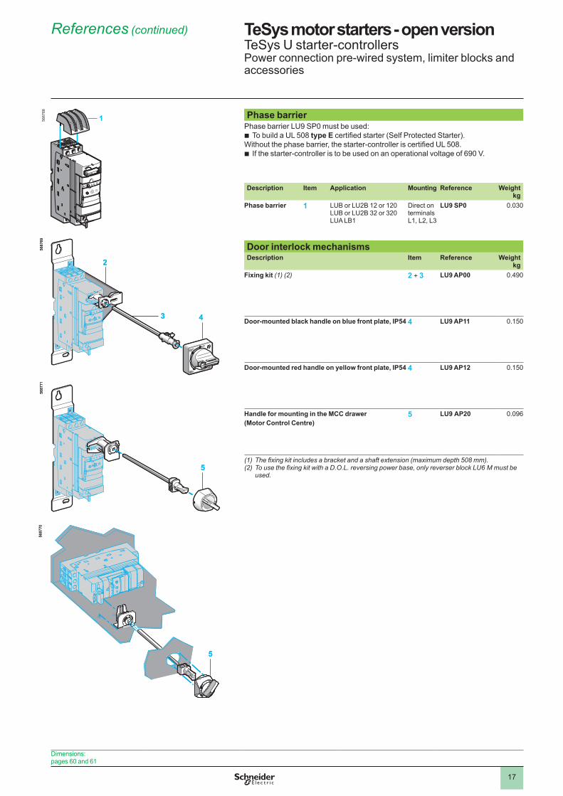
Phase barrier Phase barrier LU9 SP0 must be used:
To build a UL 508 type E certified starter (Self Protected Starter).Without the phase barrier, the starter-controller is certified UL 508.
If the starter-controller is to be used on an operational voltage of 690 V.
b
b
Description Item Application Mounting Reference Weightkg
Phase barrier 1 LUB or LU�B �� or ��0LUB or LU�B 3� or 3�0LUA LB�
Direct on terminals L�, L�, L3
LU9 SP0 0.030
Door interlock mechanisms Description Item Reference Weight
kgFixing kit (1) (2) 2 + 3 LU9 AP00 0.490
Door-mounted black handle on blue front plate, IP54 4 LU9 AP11 0.�50
Door-mounted red handle on yellow front plate, IP54 4 LU9 AP12 0.�50
Handle for mounting in the MCC drawer (Motor Control Centre)
5 LU9 AP20 0.096
(1)Thefixingkitincludesabracketandashaftextension(maximumdepth508mm).(2)TousethefixingkitwithaD.O.L.reversingpowerbase,onlyreverserblockLU6Mmustbe
used.
5687
69
3
2
4
5687
69
3
2
4
5
5687
7�
5
5687
7�56
8770
RE
SE
TTE
ST
0
5
5687
70
RE
SE
TTE
ST
0
5
Dimensions:pages 60 and 6�
References (continued) TeSys motor starters - open versionTeSys U starter-controllersPower connection pre-wired system, limiter blocks and accessories
5687
68
1
�8
TeSys motor starters - open version TeSys U starter-controllersControl units
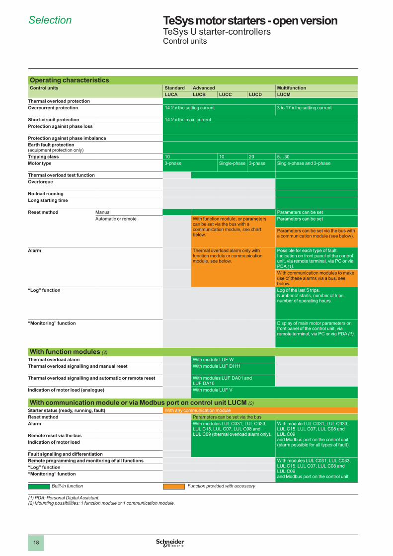
Operating characteristicsControl units Standard Advanced Multifunction
LUCA LUCB LUCC LUCD LUCMThermal overload protectionOvercurrent protection 14.2 x the setting current 3 to 17 x the setting current
Short-circuit protection 14.2 x the max. currentProtection against phase loss
Protection against phase imbalanceEarth fault protection (equipment protection only)Tripping class �0 �0 �0 5…30Motor type 3-phase Single-phase 3-phase Single-phase and 3-phase
Thermal overload test functionOvertorque
No-load runningLong starting time
Reset method
Manual Parameters can be setAutomatic or remote With function module, or parameters
can be set via the bus with a communication module, see chart below.
Parameters can be set
Parameters can be set via the bus with a communication module (see below).
Alarm
Thermal overload alarm only with function module or communication module, see below.
Possible for each type of fault. Indication on front panel of the control unit, via remote terminal, via PC or via PDA (1).With communication modules to make use of these alarms via a bus, see below.
“Log” function
Log of the last 5 trips. Number of starts, number of trips, number of operating hours.
“Monitoring” function
Display of main motor parameters on front panel of the control unit, via remote terminal, via PC or via PDA (1).
With function modules (2)Thermal overload alarm With module LUF WThermal overload signalling and manual reset With module LUF DH��
Thermal overload signalling and automatic or remote reset With modules LUF DA0� and LUF DA�0
Indication of motor load (analogue) With module LUF V
With communication module or via Modbus port on control unit LUCM (2)Starter status (ready, running, fault) With any communication moduleReset method Parameters can be set via the busAlarm With modules LUL C03�, LUL C033,
LUL C�5, LUL C07, LUL C08 and LUL C09 (thermal overload alarm only).
With module LUL C03�, LUL C033, LUL C�5, LUL C07, LUL C08 and LUL C09 and Modbus port on the control unit (alarm possible for all types of fault).
Remote reset via the busIndication of motor load
Fault signalling and differentiationRemote programming and monitoring of all functions With modules LUL C03�, LUL C033,
LUL C�5, LUL C07, LUL C08 and LUL C09 and Modbus port on the control unit.
“Log” function“Monitoring” function
Built-in function Function provided with accessory
(1) PDA: Personal Digital Assistant.(2) Mounting possibilities: 1 function module or 1 communication module.
Selection
1
2
3
4
5
6
7
8
9
10
�9
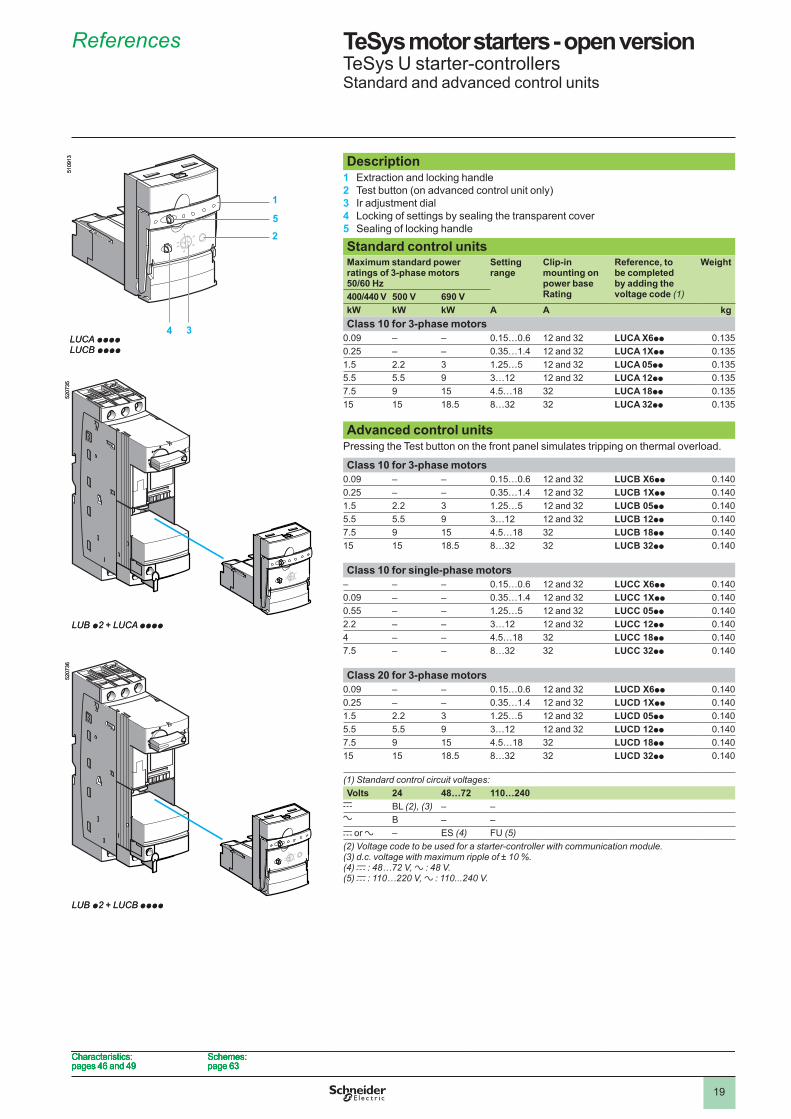
TeSys motor starters - open version TeSys U starter-controllersStandard and advanced control units
Description1 Extraction and locking handle2 Test button (on advanced control unit only)3 Ir adjustment dial4 Locking of settings by sealing the transparent cover5 Sealing of locking handle
Standard control unitsMaximum standard power ratings of 3-phase motors 50/60 Hz
Setting range
Clip-in mounting on power base Rating
Reference, to be completed by adding the voltage code (1)
Weight
400/440 V 500 V 690 VkW kW kW A A kgClass 10 for 3-phase motors
0.09 – – 0.�5…0.6 �� and 3� LUCA X6pp 0.�350.�5 – – 0.35…�.4 �� and 3� LUCA 1Xpp 0.�35�.5 �.� 3 �.�5…5 �� and 3� LUCA 05pp 0.�355.5 5.5 9 3…�� �� and 3� LUCA 12pp 0.�357.5 9 �5 4.5…�8 3� LUCA 18pp 0.�35�5 �5 �8.5 8…3� 3� LUCA 32pp 0.�35
Advanced control unitsPressing the Test button on the front panel simulates tripping on thermal overload.
Class 10 for 3-phase motors0.09 – – 0.�5…0.6 �� and 3� LUCB X6pp 0.�400.�5 – – 0.35…�.4 �� and 3� LUCB 1Xpp 0.�40�.5 �.� 3 �.�5…5 �� and 3� LUCB 05pp 0.�405.5 5.5 9 3…�� �� and 3� LUCB 12pp 0.�407.5 9 �5 4.5…�8 3� LUCB 18pp 0.�40�5 �5 �8.5 8…3� 3� LUCB 32pp 0.�40
Class 10 for single-phase motors– – – 0.�5…0.6 �� and 3� LUCC X6pp 0.�400.09 – – 0.35…�.4 �� and 3� LUCC 1Xpp 0.�400.55 – – �.�5…5 �� and 3� LUCC 05pp 0.�40�.� – – 3…�� �� and 3� LUCC 12pp 0.�404 – – 4.5…�8 3� LUCC 18pp 0.�407.5 – – 8…3� 3� LUCC 32pp 0.�40
Class 20 for 3-phase motors0.09 – – 0.�5…0.6 �� and 3� LUCD X6pp 0.�400.�5 – – 0.35…�.4 �� and 3� LUCD 1Xpp 0.�40�.5 �.� 3 �.�5…5 �� and 3� LUCD 05pp 0.�405.5 5.5 9 3…�� �� and 3� LUCD 12pp 0.�407.5 9 �5 4.5…�8 3� LUCD 18pp 0.�40�5 �5 �8.5 8…3� 3� LUCD 32pp 0.�40
(1) Standard control circuit voltages:Volts 24 48…72 110…240
c BL (2), (3) – –a B – –c or a – ES (4) FU (5)(2) Voltage code to be used for a starter-controller with communication module.(3) d.c. voltage with maximum ripple of ± 10 %.(4) c : 48…72 V, a : 48 V.(5) c : 110…220 V, a : 110...240 V.
5
1
2
34
5�09
�3
LUCA ppppLUCB pppp
5
1
2
34
5�09
�3
LUCA ppppLUCB pppp
LUB p2 + LUCA pppp
5�07
35
LUB p2 + LUCA pppp
5�07
35
LUB p2 + LUCB pppp
5�07
36
LUB p2 + LUCB pppp
5�07
36
Characteristics: pages 46 and 49
Schemes:page 63
Characteristics: pages 46 and 49
Schemes:page 63
Characteristics: pages 46 and 49
Schemes:page 63
Characteristics: pages 46 and 49
Schemes:page 63
References
1
2
3
4
5
6
7
8
9
10
�0
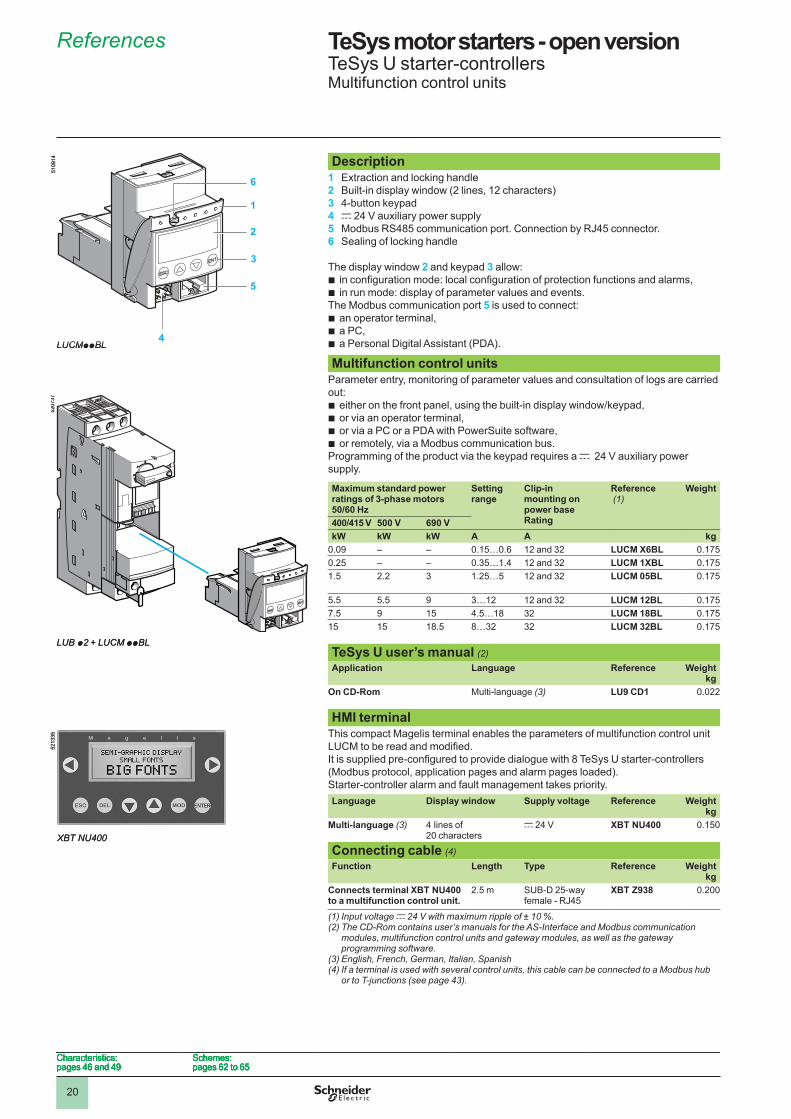
TeSys motor starters - open version TeSys U starter-controllersMultifunction control units
Description1 Extraction and locking handle2 Built-in display window (� lines, �� characters)3 4-button keypad4 c 24 V auxiliary power supply5 Modbus RS485 communication port. Connection by RJ45 connector.6 Sealing of locking handle
The display window 2 and keypad 3 allow:in configuration mode: local configuration of protection functions and alarms,in run mode: display of parameter values and events.
The Modbus communication port 5 is used to connect:an operator terminal,a PC,a Personal Digital Assistant (PDA).
bb
bbb
Multifunction control unitsParameter entry, monitoring of parameter values and consultation of logs are carried out:
either on the front panel, using the built-in display window/keypad,or via an operator terminal,or via a PC or a PDA with PowerSuite software,or remotely, via a Modbus communication bus.
Programming of the product via the keypad requires a c 24 V auxiliary power supply.
bbbb
Maximum standard power ratings of 3-phase motors 50/60 Hz
Setting range
Clip-in mounting on power base Rating
Reference (1)
Weight
400/415 V 500 V 690 VkW kW kW A A kg
0.09 – – 0.�5…0.6 �� and 3� LUCM X6BL 0.�750.�5 – – 0.35…�.4 �� and 3� LUCM 1XBL 0.�75�.5 �.� 3 �.�5…5 �� and 3� LUCM 05BL 0.�75
5.5 5.5 9 3…�� �� and 3� LUCM 12BL 0.�757.5 9 �5 4.5…�8 3� LUCM 18BL 0.�75�5 �5 �8.5 8…3� 3� LUCM 32BL 0.�75
TeSys U user’s manual (2)Application Language Reference Weight
kgOn CD-Rom Multi-language (3) LU9 CD1 0.0��
HMI terminalThis compact Magelis terminal enables the parameters of multifunction control unit LUCM to be read and modified. It is supplied pre-configured to provide dialogue with 8 TeSys U starter-controllers (Modbus protocol, application pages and alarm pages loaded). Starter-controller alarm and fault management takes priority.Language Display window Supply voltage Reference Weight
kgMulti-language (3) 4 lines of
�0 charactersc �4 V XBT NU400 0.�50
Connecting cable (4)Function Length Type Reference Weight
kgConnects terminal XBT NU400 to a multifunction control unit .
�.5 m SUB-D �5-way female - RJ45
XBT Z938 0.�00
(1) Input voltage c 24 V with maximum ripple of ± 10 %.(2) The CD-Rom contains user’s manuals for the AS-Interface and Modbus communication
modules, multifunction control units and gateway modules, as well as the gateway programming software.
(3) English, French, German, Italian, Spanish(4) If a terminal is used with several control units, this cable can be connected to a Modbus hub
or to T-junctions (see page 43).
6
1
2
3
5
4
5�09
�4
LUCMppBL
6
1
2
3
5
4
5�09
�4
LUCMppBL
LUB p2 + LUCM ppBL
5�07
37
LUB p2 + LUCM ppBL
5�07
37
XBT NU400
5��3
35
XBT NU400
5��3
35
Characteristics: pages 46 and 49
Schemes:pages 6� to 65
Characteristics: pages 46 and 49
Schemes:pages 6� to 65
Characteristics: pages 46 and 49
Schemes:pages 6� to 65
Characteristics: pages 46 and 49
Schemes:pages 6� to 65
References
1
2
3
4
5
6
7
8
9
10
��
TeSys motor starters - open version TeSys U starter-controllersFunction modules
Characteristics: pages 46 and 5�
Schemes:page 64
Characteristics: pages 46 and 5�
Schemes:page 64
Characteristics: pages 46 and 5�
Schemes:page 64
Characteristics: pages 46 and 5�
Schemes:page 64
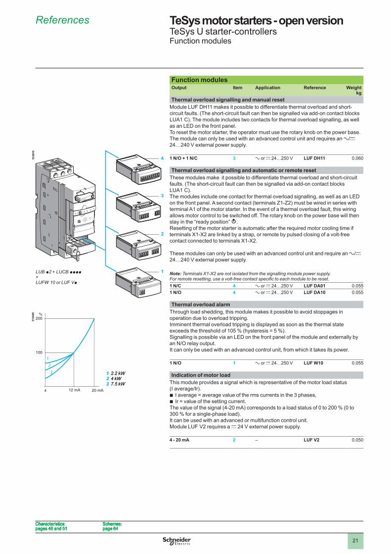
Function modulesOutput Item Application Reference Weight
kgThermal overload signalling and manual reset
Module LUF DH�� makes it possible to differentiate thermal overload and short-circuit faults. (The short-circuit fault can then be signalled via add-on contact blocks LUA� C). The module includes two contacts for thermal overload signalling, as well as an LED on the front panel. To reset the motor starter, the operator must use the rotary knob on the power base. The module can only be used with an advanced control unit and requires an a/c 24…240 V external power supply.
1 N/O + 1 N/C 3 a or c �4…�50 V LUF DH11 0.060
Thermal overload signalling and automatic or remote resetThese modules make it possible to differentiate thermal overload and short-circuit faults. (The short-circuit fault can then be signalled via add-on contact blocks LUA� C). The modules include one contact for thermal overload signalling, as well as an LED on the front panel. A second contact (terminals Z�-Z�) must be wired in series with terminal A� of the motor starter. In the event of a thermal overload fault, this wiring allows motor control to be switched off. The rotary knob on the power base will then stay in the “ready position” .Resetting of the motor starter is automatic after the required motor cooling time if terminals X�-X� are linked by a strap, or remote by pulsed closing of a volt-free contact connected to terminals X�-X�.
These modules can only be used with an advanced control unit and require an a/c 24…240 V external power supply.
Note: Terminals X1-X2 are not isolated from the signalling module power supply. Forremoteresetting,useavolt-freecontactspecifictoeachmoduletobereset.1 N/C 4 a or c �4…�50 V LUF DA01 0.0551 N/O 4 a or c �4…�50 V LUF DA10 0.055
Thermal overload alarmThrough load shedding, this module makes it possible to avoid stoppages in operation due to overload tripping.Imminent thermal overload tripping is displayed as soon as the thermal state exceeds the threshold of 105 % (hysteresis = 5 %).Signalling is possible via an LED on the front panel of the module and externally by an N/O relay output.It can only be used with an advanced control unit, from which it takes its power.
1 N/O 1 a or c �4…�50 V LUF W10 0.055
Indication of motor loadThis module provides a signal which is representative of the motor load status (I average/Ir).
I average = average value of the rms currents in the 3 phases,Ir = value of the setting current.
The value of the signal (4-�0 mA) corresponds to a load status of 0 to �00 % (0 to 300 % for a single-phase load).It can be used with an advanced or multifunction control unit.Module LUF V� requires a c 24 V external power supply.
bb
4 - 20 mA 2 – LUF V2 0.050
2
3
4
1
123
100
200%
20 mA4 12 mA
LUB p2 + LUCB pppp + LUFW 10 or LUF Vp
5�09
�55�
0445
1 2.2 kW2 4 kW3 7.5 kW
2
3
4
1
123
100
200%
20 mA4 12 mA
LUB p2 + LUCB pppp + LUFW 10 or LUF Vp
5�09
�55�
0445
1 2.2 kW2 4 kW3 7.5 kW
References
1
2
3
4
5
6
7
8
9
10
��
Presentation, functions
PowerSuite software workshop
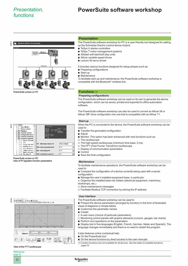
PresentationThe PowerSuite software workshop for PC is a user-friendly tool designed for setting up the Schneider Electric control device motors:
TeSys U starter-controllersTeSys T motor management systemsAltistart soft start/soft stop unitsAltivar variable speed drivesLexium 05 servo drives
It includes various functions designed for setup phases such as:Preparing configurationsStart-upMaintenance
To facilitate start-up and maintenance, the PowerSuite software workshop is compatible with the Bluetooth® wireless link.
bbbbb
bbb
Functions (1)Preparing configurations
The PowerSuite software workshop can be used on its own to generate the device configuration, which can be saved, printed and exported to office automation software.
The PowerSuite software workshop can also be used to convert an Altivar 58 or Altivar 58F drive configuration into one that is compatible with an Altivar 71.
Start-upWhen the PC is connected to the device, the PowerSuite software workshop can be used to:
Transfer the generated configurationAdjustMonitor. This option has been enhanced with new functions such as:The oscilloscopeThe high-speed oscilloscope (minimum time base: � ms)The FFT (Fast Fourier Transform) oscilloscopeDisplay of communication parametersControlSave the final configuration
bbbvvvvbb
MaintenanceTo facilitate maintenance operations, the PowerSuite software workshop can be used to:
Compare the configuration of a device currently being used with a saved configuration
Manage the user’s installed equipment base, in particular:Organize the installed base into folders (electrical equipment, machinery,
workshops, etc.)Store maintenance messagesFacilitate Modbus TCP connection by storing the IP address
b
bv
vv
User interfaceThe PowerSuite software workshop can be used to:
Present the device parameters (arranged by function) in the form of illustrated views of diagrams or simple tables
Customize the parameter namesCreate:A user menu (choice of particular parameters)Monitoring control panels with graphic elements (cursors, gauges, bar charts)Perform sort operations on the parametersDisplay text in five languages (English, French, German, Italian and Spanish). The
language changes immediately and there is no need to restart the program.
It also features online contextual help:On the PowerSuite toolOn the device functions by direct access to the user manuals
b
bbvvbb
bb(1) Certain functions are not available for all devices. See the table of available functions,
page 23.
5345
�3
PowerSuite screen on PC
5345
�3
PowerSuite screen on PC
PowerSuite screen on PCView of PI regulator function parameters
533�
8�
PowerSuite screen on PCView of PI regulator function parameters
533�
8�
View of the FTT oscilloscope
57�7
06
View of the FTT oscilloscope
57�7
06
References:page �4
�3
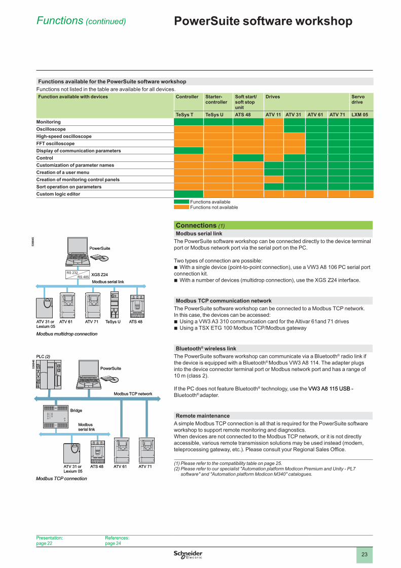
Functions available for the PowerSuite software workshopFunctions not listed in the table are available for all devices.Function available with devices Controller Starter-
controllerSoft start/soft stop unit
Drives Servo drive
TeSys T TeSys U ATS 48 ATV 11 ATV 31 ATV 61 ATV 71 LXM 05MonitoringOscilloscopeHigh-speed oscilloscopeFFT oscilloscopeDisplay of communication parametersControlCustomization of parameter namesCreation of a user menuCreation of monitoring control panelsSort operation on parametersCustom logic editor
Functions available Functions not available
Connections (1)Modbus serial link
The PowerSuite software workshop can be connected directly to the device terminal port or Modbus network port via the serial port on the PC.
Two types of connection are possible:With a single device (point-to-point connection), use a VW3 A8 �06 PC serial port
connection kit.With a number of devices (multidrop connection), use the XGS Z24 interface.
b
b
Modbus TCP communication network The PowerSuite software workshop can be connected to a Modbus TCP network. In this case, the devices can be accessed:
Using a VW3 A3 3�0 communication card for the Altivar 6�and 7� drivesUsing a TSX ETG 100 Modbus TCP/Modbus gateway
bb
Bluetooth® wireless linkThe PowerSuite software workshop can communicate via a Bluetooth® radio link if the device is equipped with a Bluetooth® Modbus VW3 A8 ��4. The adapter plugs into the device connector terminal port or Modbus network port and has a range of �0 m (class �).
If the PC does not feature Bluetooth® technology, use the VW3 A8 ��5 USB -VW3 A8 ��5 USB - Bluetooth® adapter.
Remote maintenanceA simple Modbus TCP connection is all that is required for the PowerSuite software workshop to support remote monitoring and diagnostics.When devices are not connected to the Modbus TCP network, or it is not directly accessible, various remote transmission solutions may be used instead (modem, teleprocessing gateway, etc.). Please consult your Regional Sales Office.
(1) Please refer to the compatibility table on page 25.(2) Please refer to our specialist "Automation platform Modicon Premium and Unity - PL7
software" and "Automation platform Modicon M340" catalogues.
RS �3�RS 485
ATV 3� or Lexium 05
ATV 6� ATV 7� TeSys U ATS 48
Modbus multidrop connection
Modbus serial link
PowerSuite
XGS Z24
5368
45
RS �3�RS 485
ATV 3� or Lexium 05
ATV 6� ATV 7� TeSys U ATS 48
Modbus multidrop connection
Modbus serial link
PowerSuite
XGS Z24
5368
45
Modbus TCP connection
Bridge
Modbus TCP network
ATV 3� or Lexium 05
ATS 48 ATV 6� ATV 7�
Modbus serial link
PLC (2)
5368
46
PowerSuite
Modbus TCP connection
Bridge
Modbus TCP network
ATV 3� or Lexium 05
ATS 48 ATV 6� ATV 7�
Modbus serial link
PLC (2)
5368
46
PowerSuite
Functions (continued) PowerSuite software workshop
Presentation:page ��
References: page �4
�4
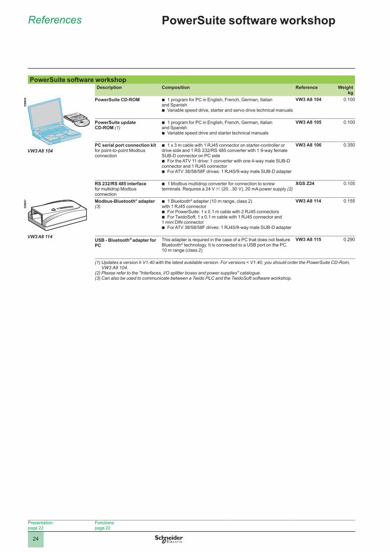
PowerSuite software workshopDescription Composition Reference Weight
kgPowerSuite CD-ROM 1 program for PC in English, French, German, Italian
and Spanish Variable speed drive, starter and servo drive technical manuals
b
b
VW3 A8 104 0.�00
PowerSuite update CD-ROM (1)
1 program for PC in English, French, German, Italian and Spanish
Variable speed drive and starter technical manuals
b
b
VW3 A8 105 0.�00
PC serial port connection kitfor point-to-point Modbus connection
1 x 3 m cable with 1 RJ45 connector on starter-controller or drive side and 1 RS 232/RS 485 converter with 1 9-way female SUB-D connector on PC side
For the ATV �� drive: � converter with one 4-way male SUB-D connector and � RJ45 connector
For ATV 38/58/58F drives: 1 RJ45/9-way male SUB-D adapter
b
b
b
VW3 A8 106 0.350
RS 232/RS 485 interfacefor multidrop Modbus connection
� Modbus multidrop converter for connection to screw terminals. Requires a �4 V c (�0...30 V), �0 mA power supply (2)b XGS Z24 0.�05
Modbus-Bluetooth® adapter (3)
� Bluetooth® adapter (�0 m range, class �) with � RJ45 connector
For PowerSuite: 1 x 0.1 m cable with 2 RJ45 connectorsFor TwidoSoft: 1 x 0.1 m cable with 1 RJ45 connector and
� mini DIN connectorFor ATV 38/58/58F drives: 1 RJ45/9-way male SUB-D adapter
b
bb
b
VW3 A8 114 0.�55
USB - Bluetooth® adapter for PC
This adapter is required in the case of a PC that does not feature Bluetooth® technology. It is connected to a USB port on the PC.�0 m range (class �)
VW3 A8 115 0.�90
(1) Updates a version u V1.40 with the latest available version. For versions < V1.40, you should order the PowerSuite CD-Rom, VW3 A8 104.
(2) Please refer to the "Interfaces, I/O splitter boxes and power supplies" catalogue.(3) Can also be used to communicate between a Twido PLC and the TwidoSoft software workshop.
VW3 A8 104
5368
48
VW3 A8 104
5368
4853
6847
VW3 A8 114
5368
47
VW3 A8 114
References PowerSuite software workshop
Presentation:page ��
Fonctions:page ��
�5
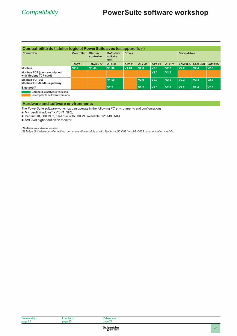
Compatibilité de l’atelier logiciel PowerSuite avec les appareils (1)Connexion Controller Starter-
controllerSoft start/soft stop unit
Drives Servo drives
TeSys T TeSys U (2) ATS 48 ATV 11 ATV 31 ATV 61 ATV 71 LXM 05A LXM 05B LXM 05CModbus V2 .5 V1 .40 V1 .30 V1 .40 V2 .0 V2 .3 V2 .2 V2 .2 V2 .4 V2 .5Modbus TCP (device equipped with Modbus TCP card)
V2 .3 V2 .2
Modbus TCP via Modbus TCP/Modbus gateway
V1 .50 V2 .0 V2 .3 V2 .2 V2 .2 V2 .4 V2 .5
Bluetooth® V2 .2 V2 .2 V2 .3 V2 .2 V2 .2 V2 .4 V2 .5 Compatible software versions Incompatible software versions
Hardware and software environmentsThe PowerSuite software workshop can operate in the following PC environments and configurations:
Microsoft Windows® XP SP�, SP�,Pentium III, 800 MHz, hard disk with 300 MB available, 128 MB RAMSVGA or higher definition monitor
bbb
(1) Minimum software version.(2) TeSys U starter-controller without communication module or with Modbus LUL C031 or LUL C033 communication module.
Compatibility PowerSuite software workshop
Presentation:page ��
Functions:page ��
References:page �4
�6
TeSys motor starters - open version 1 TeSys U starter-controllersParallel wiring module and pre-wired coil connection components
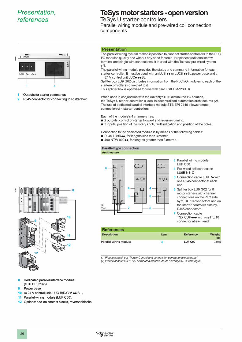
Presentation The parallel wiring system makes it possible to connect starter-controllers to the PLC I/O modules quickly and without any need for tools. It replaces traditional screw terminal and single wire connections. It is used with the Telefast pre-wired system (1).The parallel wiring module provides the status and command information for each starter-controller. It must be used with an LUB pp or LU�B ppBL power base and a c �4 V control unit LUCp ppBL.Splitter box LU9 G02 distributes information from the PLC I/O modules to each of the starter-controllers connected to it.This splitter box is optimised for use with card TSX DMZ28DTK.
When used in conjunction with the Advantys STB distributed I/O solution, the TeSys U starter-controller is ideal in decentralised automation architectures (2). The use of dedicated parallel interface module STB EPI ��45 allows remote connection of 4 starter-controllers.
Each of the module’s 4 channels has:� outputs: control of starter forward and reverse running,3 inputs: position of the rotary knob, fault indication and position of the poles.
Connection to the dedicated module is by means of the following cables: RJ45 LU9Rpp, for lengths less than 3 metres,490 NTW 000pp, for lengths greater than 3 metres.
Parallel type connectionArchitecture
3 Parallel wiring module
LUF C004 Pre-wired coil connection
LU9B N��C5 Connection cable LU9 Rp with
one RJ45 connector at each end
6 Splitter box LU9 G02 for 8 motor starters with channel connections on the PLC side by � HE �0 connectors and on the starter-controller side by 8 RJ45 connectors.
7 Connection cable TSX CDPppp with one HE �0 connector at each end.
ReferencesDescription Item Reference Weight
kgParallel wiring module 3 LUF C00 0.045
(1) Please consult our “Power Control and connection components catalogue”.(2) Please consult our “IP 20 distributed inputs/outputs Advantys STB” catalogue.
bb
bb
1 Outputs for starter commands2 RJ45 connector for connecting to splitter box
1 2
5669
6�
1 Outputs for starter commands2 RJ45 connector for connecting to splitter box
1 2
5669
6�
3
57
4
3
4
6
ToPLC
3
57
4
3
4
6
ToPLC
12
910
11
12
8
5�09
�7
8 Dedicated parallel interface module (STB EPI ��45)
9 Power base10 c 24 V control unit (LUC B/D/C/M pp BL)11 Parallel wiring module (LUF C00),12 Options: add-on contact blocks, reverser blocks
12
910
11
12
8
5�09
�7
8 Dedicated parallel interface module (STB EPI ��45)
9 Power base10 c 24 V control unit (LUC B/D/C/M pp BL)11 Parallel wiring module (LUF C00),12 Options: add-on contact blocks, reverser blocks
Presentation, references 1
1
2
3
4
5
6
7
8
9
10
�7
TeSys motor starters - open version 1 TeSys U starter-controllersParallel wiring module and pre-wired coil connection components
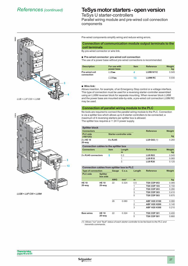
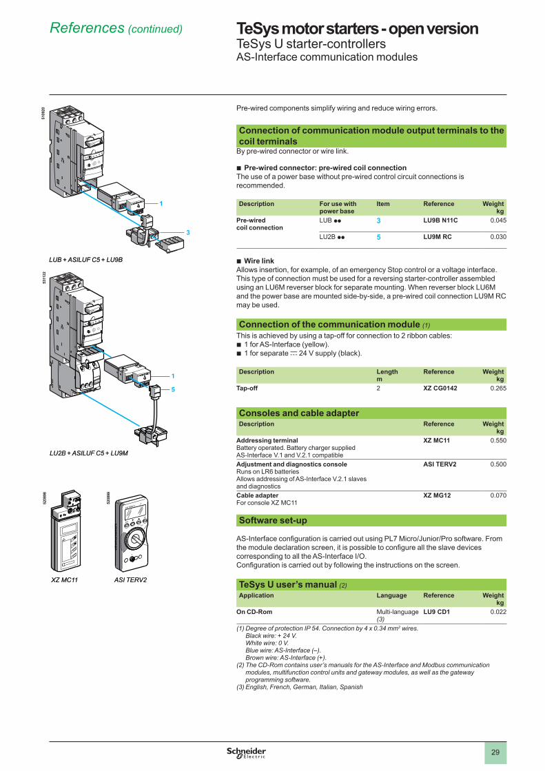
Pre-wired components simplify wiring and reduce wiring errors. Connection of communication module output terminals to the coil terminals
By pre-wired connector or wire link.
Pre-wired connector: pre-wired coil connectionThe use of a power base without pre-wired connections is recommended. Description For use with
power baseItem Reference Weight
kgPre-wired coil connection
LUBpp 4 LU9B N11C 0.045
LU�Bpp 13 LU9M RC 0.030
Wire link:Allows insertion, for example, of an Emergency Stop control or a voltage interface.This type of connection must be used for a reversing starter-controller assembled using an LU6M reverser block for separate mounting. When reverser block LU6M and the power base are mounted side-by-side, a pre-wired coil connection LU9M RC may be used.
Connection of parallel wiring module to the PLCNo tools are required to connect the parallel wiring module to the PLC. Connection is via a splitter box which allows up to 8 starter-controllers to be connected; a maximum of 4 reversing starters per splitter box is allowed.The splitter box requires a c �4 V power supply.
Splitter blockConnectors Reference Weight
kgPLC side (16I/12O)
Starter-controller side
2 x HE 1020-way
8 x RJ45 LU9 G02 (1) 0.�60
Connection cables to the splitter boxConnectors Item Length
mReference Weight
kg2 x RJ45 connectors 5 0.3 LU9 R03 0.045
� LU9 R10 0.0653 LU9 R30 0.��5
Connection cables from splitter box to PLCType of connection Gauge C .s .a . Length Reference WeightPLC side Splitter
box sideAWG mm2 m kg
HE 10 20-way
HE 10 20-way
�� 0.3�4 0.5 TSX CDP 053 0.085� TSX CDP 103 0.�50� TSX CDP 203 0.�803 TSX CDP 303 0.4�05 TSX CDP 503 0.670
�8 0.080 � ABF H20 H100 0.080� ABF H20 H200 0.�403 ABF H20 H300 0.��0
Bare wires HE 10 20-way
�� 0.3�4 3 TSX CDP 301 0.4005 TSX CDP 501 0.660
(1) Allows “run” and “fault” status of each starter-controller to be fed back to the PLC and transmits commands.
b
b3
4
5669
64
LUB + LUF C00 + LU9B
3
13
5�09
�8
LU2B + LUF C00 + LU9M
3
4
5669
64
LUB + LUF C00 + LU9B
3
13
5�09
�8
LU2B + LUF C00 + LU9M
Characteristics: pages 46 and 5�Characteristics: pages 46 and 5�Characteristics: pages 46 and 5�Characteristics: pages 46 and 5�
References (continued) 1
1
2
3
4
5
6
7
8
9
10
�8
TeSys motor starters - open version 1 TeSys U starter-controllersAS-Interface communication modules
Presentation
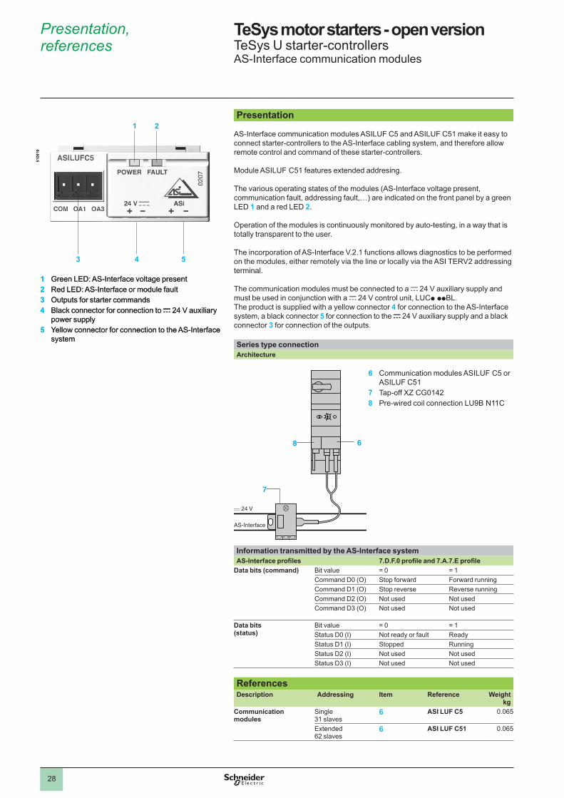
AS-Interface communication modules ASILUF C5 and ASILUF C5� make it easy to connect starter-controllers to the AS-Interface cabling system, and therefore allow remote control and command of these starter-controllers. Module ASILUF C51 features extended addresing.
The various operating states of the modules (AS-Interface voltage present, communication fault, addressing fault,…) are indicated on the front panel by a green LED 1 and a red LED 2.
Operation of the modules is continuously monitored by auto-testing, in a way that is totally transparent to the user.
The incorporation of AS-Interface V.�.� functions allows diagnostics to be performed on the modules, either remotely via the line or locally via the ASI TERV� addressing terminal.
The communication modules must be connected to a c 24 V auxiliary supply and must be used in conjunction with a c �4 V control unit, LUCp ppBL.The product is supplied with a yellow connector 4 for connection to the AS-Interface system, a black connector 5 for connection to the c 24 V auxiliary supply and a black connector 3 for connection of the outputs. Series type connectionArchitecture
6 Communication modules ASILUF C5 or
ASILUF C5�7 Tap-off XZ CG01428 Pre-wired coil connection LU9B N��C
Information transmitted by the AS-Interface systemAS-Interface profiles 7.D.F.0 profile and 7.A.7.E profile
Data bits (command) Bit value = 0 = 1Command D0 (O) Stop forward Forward runningCommand D� (O) Stop reverse Reverse runningCommand D� (O) Not used Not usedCommand D3 (O) Not used Not used
Data bits (status)
Bit value = 0 = 1Status D0 (I) Not ready or fault ReadyStatus D� (I) Stopped RunningStatus D� (I) Not used Not usedStatus D3 (I) Not used Not used
ReferencesDescription Addressing Item Reference Weight
kgCommunication modules
Single 3� slaves
6 ASI LUF C5 0.065
Extended 6� slaves
6 ASI LUF C51 0.065
c 24 V
AS-Interface
68
7
c 24 V
AS-Interface
68
7
1 2
3 4 5
1 Green LED: AS-Interface voltage present2 Red LED: AS-Interface or module fault3 Outputs for starter commands4 Black connector for connection to c 24 V auxiliary
power supply5 Yellow connector for connection to the AS-Interface
system
5�09
�9
1 2
3 4 5
1 Green LED: AS-Interface voltage present2 Red LED: AS-Interface or module fault3 Outputs for starter commands4 Black connector for connection to c 24 V auxiliary
power supply5 Yellow connector for connection to the AS-Interface
system
5�09
�9Presentation, references 1
1
2
3
4
5
6
7
8
9
10
�9
TeSys motor starters - open version 1 TeSys U starter-controllersAS-Interface communication modules
Pre-wired components simplify wiring and reduce wiring errors. Connection of communication module output terminals to the coil terminals
By pre-wired connector or wire link.
Pre-wired connector: pre-wired coil connectionThe use of a power base without pre-wired control circuit connections is recommended. Description For use with
power baseItem Reference Weight
kgPre-wired coil connection
LUB pp 3 LU9B N11C 0.045
LU�B pp 5 LU9M RC 0.030
Wire linkAllows insertion, for example, of an emergency Stop control or a voltage interface.This type of connection must be used for a reversing starter-controller assembled using an LU6M reverser block for separate mounting. When reverser block LU6M and the power base are mounted side-by-side, a pre-wired coil connection LU9M RC may be used. Connection of the communication module (1)
This is achieved by using a tap-off for connection to � ribbon cables: � for AS-Interface (yellow).� for separate c �4 V supply (black).
bb
Description Lengthm
Reference Weight kg
Tap-off � XZ CG0142 0.�65
Consoles and cable adapterDescription Reference Weight
kgAddressing terminalBattery operated. Battery charger suppliedAS-Interface V.� and V.�.� compatible
XZ MC11 0.550
Adjustment and diagnostics consoleRuns on LR6 batteriesAllows addressing of AS-Interface V.�.� slaves and diagnostics
ASI TERV2 0.500
Cable adapterFor console XZ MC��
XZ MG12 0.070
Software set-up
AS-Interface configuration is carried out using PL7 Micro/Junior/Pro software. From the module declaration screen, it is possible to configure all the slave devices corresponding to all the AS-Interface I/O.Configuration is carried out by following the instructions on the screen. TeSys U user’s manual (2)Application Language Reference Weight
kgOn CD-Rom Multi-language
(3)LU9 CD1 0.0��
(1) Degree of protection IP 54. Connection by 4 x 0.34 mm2 wires. Black wire: + 24 V. White wire: 0 V. Blue wire: AS-Interface (–). Brown wire: AS-Interface (+).
(2) The CD-Rom contains user’s manuals for the AS-Interface and Modbus communication modules, multifunction control units and gateway modules, as well as the gateway programming software.
(3) English, French, German, Italian, Spanish
b
b
1
3
1
5
5�09
�0
LUB + ASILUF C5 + LU9B
53��
��
LU2B + ASILUF C5 + LU9M
1
3
1
5
5�09
�0
LUB + ASILUF C5 + LU9B
53��
��
LU2B + ASILUF C5 + LU9M
XZ MC11
5�08
98
ASI TERV2
5�08
99
XZ MC11
5�08
98
ASI TERV2
5�08
99
References (continued) 1
1
2
3
4
5
6
7
8
9
10
30
TeSys motor starters - open version 1 TeSys U starter-controllersProfibus DP communication module and pre-wired coil connection components
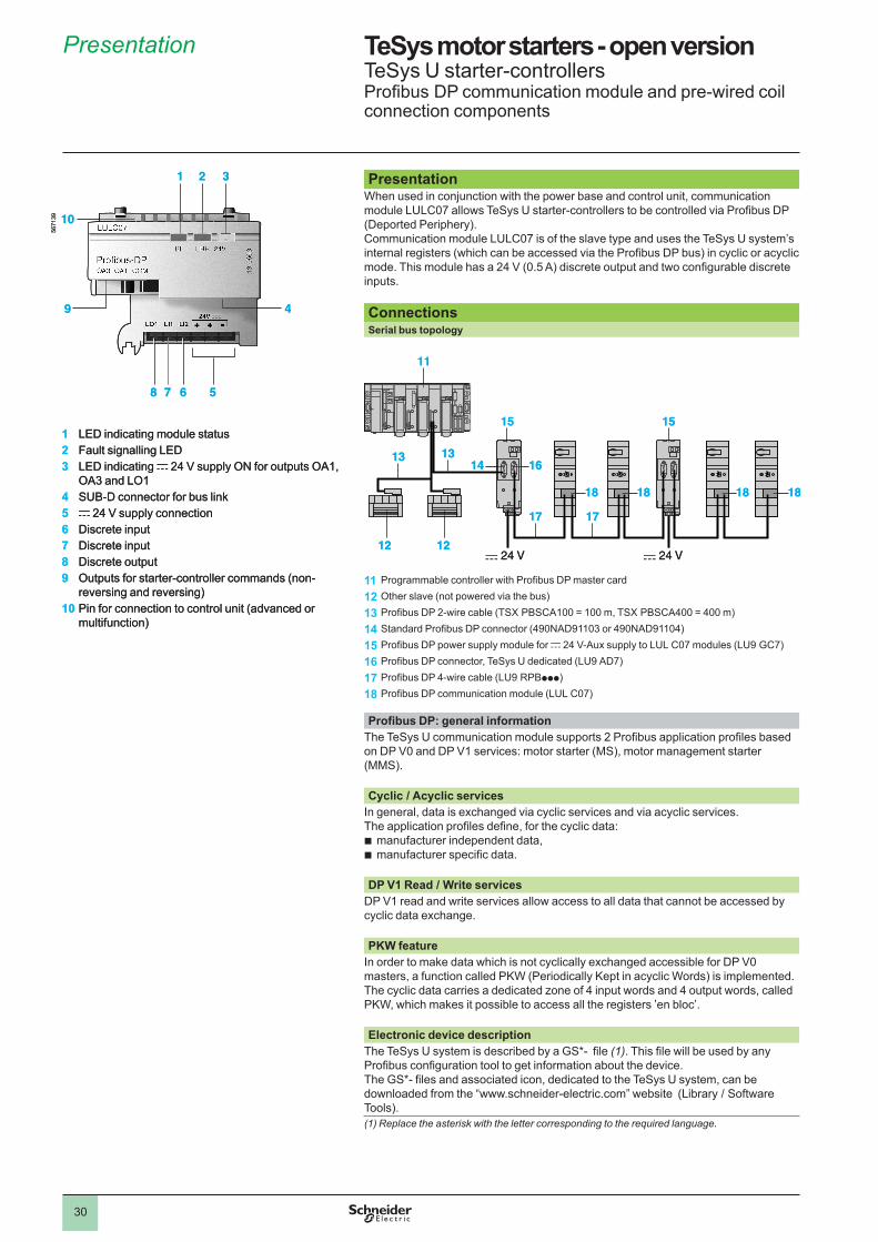
Presentation When used in conjunction with the power base and control unit, communication module LULC07 allows TeSys U starter-controllers to be controlled via Profibus DP (Deported Periphery). Communication module LULC07 is of the slave type and uses the TeSys U system’s internal registers (which can be accessed via the Profibus DP bus) in cyclic or acyclic mode. This module has a 24 V (0.5 A) discrete output and two configurable discrete inputs. ConnectionsSerial bus topology
11 Programmable controller with Profibus DP master card
12 Other slave (not powered via the bus)
13 Profibus DP 2-wire cable (TSX PBSCA100 = 100 m, TSX PBSCA400 = 400 m)
14 Standard Profibus DP connector (490NAD91103 or 490NAD91104)
15 Profibus DP power supply module for c 24 V-Aux supply to LUL C07 modules (LU9 GC7)
16 Profibus DP connector, TeSys U dedicated (LU9 AD7)
17 Profibus DP 4-wire cable (LU9 RPBppp)
18 Profibus DP communication module (LUL C07)
Profibus DP: general informationThe TeSys U communication module supports 2 Profibus application profiles based on DP V0 and DP V� services: motor starter (MS), motor management starter (MMS).
Cyclic / Acyclic servicesIn general, data is exchanged via cyclic services and via acyclic services.The application profiles define, for the cyclic data:
manufacturer independent data,manufacturer specific data.
bb
DP V1 Read / Write services DP V� read and write services allow access to all data that cannot be accessed by cyclic data exchange.
PKW featureIn order to make data which is not cyclically exchanged accessible for DP V0 masters, a function called PKW (Periodically Kept in acyclic Words) is implemented. The cyclic data carries a dedicated zone of 4 input words and 4 output words, called PKW, which makes it possible to access all the registers ’en bloc’.
Electronic device descriptionThe TeSys U system is described by a GS*- file (1). This file will be used by any Profibus configuration tool to get information about the device.The GS*- files and associated icon, dedicated to the TeSys U system, can be downloaded from the “www.schneider-electric.com” website (Library / Software Tools). (1) Replace the asterisk with the letter corresponding to the required language.
1 2 3
9 4
10
5678
1 LED indicating module status2 Fault signalling LED3 LED indicating c �4 V supply ON for outputs OA�,
OA3 and LO�4 SUB-D connector for bus link5 c �4 V supply connection6 Discrete input7 Discrete input8 Discrete output9 Outputs for starter-controller commands (non-
reversing and reversing)10 Pin for connection to control unit (advanced or
multifunction)
567�
39
11
12
13 13
1515
12
1614
17 17
18 18 18 18
c 24 V c 24 V
11
12
13 13
1515
12
1614
17 17
18 18 18 18
c 24 V c 24 V
Presentation 1
1
2
3
4
5
6
7
8
9
10
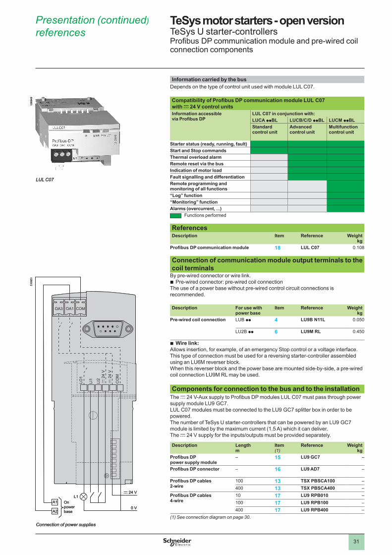
3�
TeSys motor starters - open version 1 TeSys U starter-controllersProfibus DP communication module and pre-wired coil connection components
Information carried by the busDepends on the type of control unit used with module LUL C07.
Compatibility of Profibus DP communication module LUL C07 with c 24 V control unitsInformation accessible via Profibus DP
LUL C07 in conjunction with:LUCA ppBL LUCB/C/D ppBL LUCM ppBLStandard control unit
Advanced control unit
Multifunction control unit
Starter status (ready, running, fault)Start and Stop commandsThermal overload alarmRemote reset via the busIndication of motor loadFault signalling and differentiationRemote programming and monitoring of all functions“Log” function“Monitoring” functionAlarms (overcurrent, . . .)
Functions performed
ReferencesDescription Item Reference Weight
kgProfibus DP communication module 18 LUL C07 0.�08
Connection of communication module output terminals to the coil terminals
By pre-wired connector or wire link.Pre-wired connector: pre-wired coil connection
The use of a power base without pre-wired control circuit connections is recommended. Description For use with
power baseItem Reference Weight
kgPre-wired coil connection LUB pp 4 LU9B N11L 0.050
LU�B pp 6 LU9M RL 0.450
Wire link:Allows insertion, for example, of an emergency Stop control or a voltage interface.This type of connection must be used for a reversing starter-controller assembled using an LU6M reverser block. When this reverser block and the power base are mounted side-by-side, a pre-wired coil connection LU9M RL may be used. Components for connection to the bus and to the installation
The c 24 V-Aux supply to Profibus DP modules LUL C07 must pass through power supply module LU9 GC7. LUL C07 modules must be connected to the LU9 GC7 splitter box in order to be powered.The number of TeSys U starter-controllers that can be powered by an LU9 GC7 module is limited by the maximum current (1.5 A) which it can deliver. The c 24 V supply for the inputs/outputs must be provided separately.
Description Length m
Item(1)
Reference Weight kg
Profibus DP power supply module
– 15 LU9 GC7 –
Profibus DP connector – 16 LU9 AD7 –
Profibus DP cables 2-wire
�00 13 TSX PBSCA100 –400 13 TSX PBSCA400 –
Profibus DP cables 4-wire
�0 17 LU9 RPB010 –�00 17 LU9 RPB100 –400 17 LU9 RPB400 –
(1) See connection diagram on page 30.
b
b
�069
49
LUL C07
�069
49
LUL C07
OA3
A1
A2
L1c 24 V
0 V
LO1
LI1
LI2
c 2
4 V
c 2
4 V
CO
M
OA1 COM
5�09
5�
Onpower base
Connection of power supplies
OA3
A1
A2
L1c 24 V
0 V
LO1
LI1
LI2
c 2
4 V
c 2
4 V
CO
M
OA1 COM
5�09
5�
Onpower base
Connection of power supplies
Presentation (continued) references 1
1
2
3
4
5
6
7
8
9
10
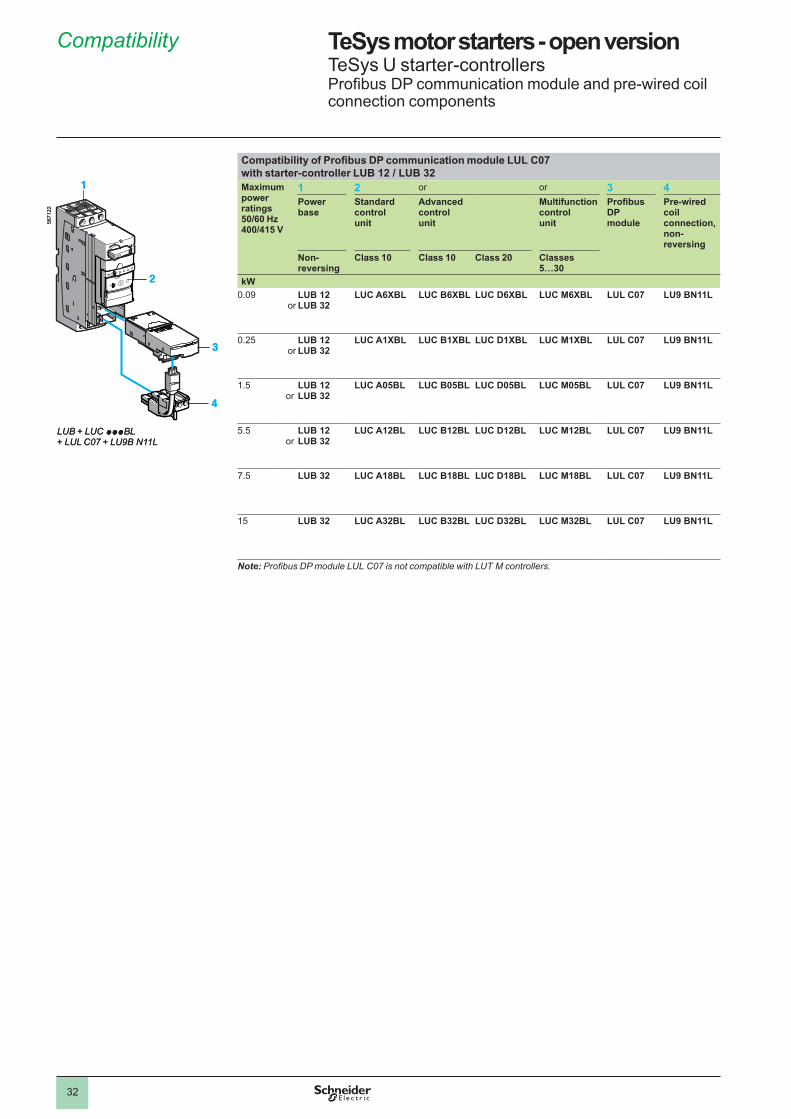
3�
TeSys motor starters - open version 1 TeSys U starter-controllersProfibus DP communication module and pre-wired coil connection components
Compatibility of Profibus DP communication module LUL C07 with starter-controller LUB 12 / LUB 32 Maximum power ratings50/60 Hz400/415 V
1 2 or or 3 4Power base
Standard control unit
Advanced control unit
Multifunction control unit
Profibus DP module
Pre-wiredcoil connection, non-reversing
Non-reversing
Class 10 Class 10 Class 20 Classes 5…30
kW0.09
orLUB 12LUB 32
LUC A6XBL LUC B6XBL LUC D6XBL LUC M6XBL LUL C07 LU9 BN11L
0.�5or
LUB 12LUB 32
LUC A1XBL LUC B1XBL LUC D1XBL LUC M1XBL LUL C07 LU9 BN11L
�.5or
LUB 12LUB 32
LUC A05BL LUC B05BL LUC D05BL LUC M05BL LUL C07 LU9 BN11L
5.5or
LUB 12LUB 32
LUC A12BL LUC B12BL LUC D12BL LUC M12BL LUL C07 LU9 BN11L
7.5 LUB 32 LUC A18BL LUC B18BL LUC D18BL LUC M18BL LUL C07 LU9 BN11L
�5
LUB 32 LUC A32BL LUC B32BL LUC D32BL LUC M32BL LUL C07 LU9 BN11L
Note: ProfibusDPmoduleLULC07isnotcompatiblewithLUTMcontrollers.
4
3
1
2
567�
��
LUB + LUC pppBL+ LUL C07 + LU9B N11L
4
3
1
2
567�
��
LUB + LUC pppBL+ LUL C07 + LU9B N11L
Compatibility 1
1
2
3
4
5
6
7
8
9
10
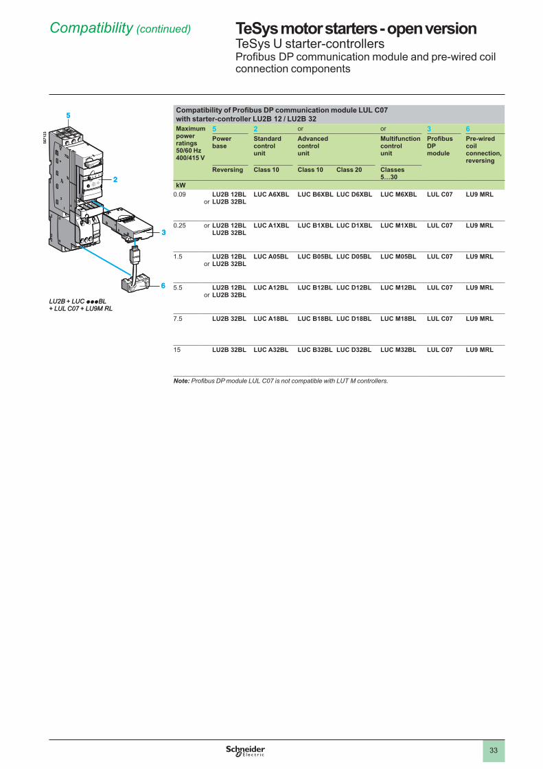
33
TeSys motor starters - open version 1 TeSys U starter-controllersProfibus DP communication module and pre-wired coil connection components
Compatibility of Profibus DP communication module LUL C07 with starter-controller LU2B 12 / LU2B 32Maximum power ratings50/60 Hz400/415 V
5 2 or or 3 6Power base
Standard control unit
Advanced control unit
Multifunction control unit
Profibus DP module
Pre-wiredcoil connection, reversing
Reversing Class 10 Class 10 Class 20 Classes 5…30
kW0.09
orLU2B 12BLLU2B 32BL
LUC A6XBL LUC B6XBL LUC D6XBL LUC M6XBL LUL C07 LU9 MRL
0.�5 or LU2B 12BLLU2B 32BL
LUC A1XBL LUC B1XBL LUC D1XBL LUC M1XBL LUL C07 LU9 MRL
�.5or
LU2B 12BLLU2B 32BL
LUC A05BL LUC B05BL LUC D05BL LUC M05BL LUL C07 LU9 MRL
5.5or
LU2B 12BLLU2B 32BL
LUC A12BL LUC B12BL LUC D12BL LUC M12BL LUL C07 LU9 MRL
7.5 LU2B 32BL LUC A18BL LUC B18BL LUC D18BL LUC M18BL LUL C07 LU9 MRL
�5 LU2B 32BL LUC A32BL LUC B32BL LUC D32BL LUC M32BL LUL C07 LU9 MRL
Note: ProfibusDPmoduleLULC07isnotcompatiblewithLUTMcontrollers.
567�
��
6
3
5
2
567�
�3
LU2B + LUC pppBL+ LUL C07 + LU9M RL
567�
��
6
3
5
2
567�
�3
LU2B + LUC pppBL+ LUL C07 + LU9M RL
Compatibility (continued) 1
1
2
3
4
5
6
7
8
9
10
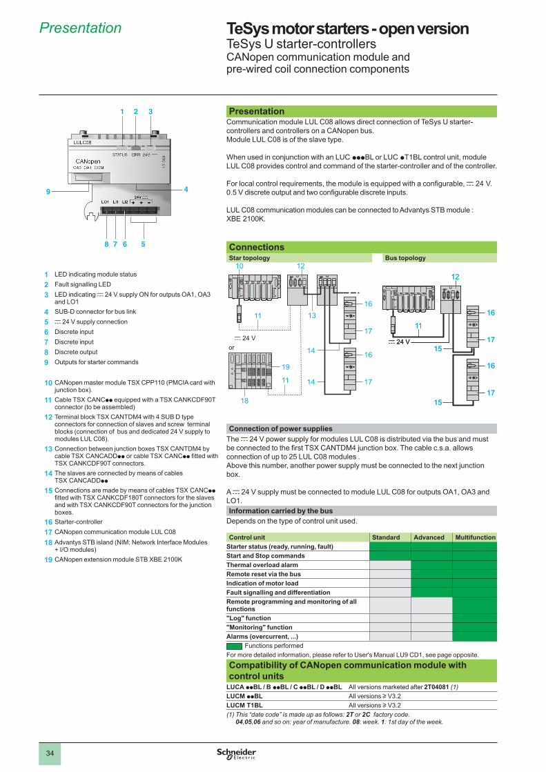
34
TeSys motor starters - open version 1 TeSys U starter-controllersCANopen communication module and pre-wired coil connection components
Presentation Communication module LUL C08 allows direct connection of TeSys U starter-controllers and controllers on a CANopen bus. Module LUL C08 is of the slave type.
When used in conjunction with an LUC pppBL or LUC pT�BL control unit, module LUL C08 provides control and command of the starter-controller and of the controller.
For local control requirements, the module is equipped with a configurable, c �4 V. 0.5 V discrete output and two configurable discrete inputs.
LUL C08 communication modules can be connected to Advantys STB module : XBE ��00K.
ConnectionsStar topology Bus topology
Connection of power suppliesThe c �4 V power supply for modules LUL C08 is distributed via the bus and must be connected to the first TSX CANTDM4 junction box. The cable c.s.a. allows connection of up to �5 LUL C08 modules . Above this number, another power supply must be connected to the next junction box.
A c �4 V supply must be connected to module LUL C08 for outputs OA�, OA3 and LO�.Information carried by the bus
Depends on the type of control unit used.
Control unit Standard Advanced MultifunctionStarter status (ready, running, fault)Start and Stop commandsThermal overload alarmRemote reset via the busIndication of motor loadFault signalling and differentiationRemote programming and monitoring of all functions"Log" function"Monitoring" functionAlarms (overcurrent, . . .)
Functions performedFor more detailed information, please refer to User's Manual LU9 CD�, see page opposite.
Compatibility of CANopen communication module with control units
LUCA ppBL / B ppBL / C ppBL / D ppBL All versions marketed after 2T04081 (1)LUCM ppBL All versions u V3.�LUCM T1BL All versions u V3.�(1) This “date code” is made up as follows: 2T or 2C factory code.
04,05,06 and so on: year of manufacture. 08: week. 1: 1st day of the week.
15
12
c 24 V
11
1517
16
17
16
15
12
c 24 V
11
1517
16
17
16
Presentation 1
1 LED indicating module status
2 Fault signalling LED
3 LED indicating c �4 V supply ON for outputs OA�, OA3 and LO�
4 SUB-D connector for bus link
5 c �4 V supply connection
6 Discrete input
7 Discrete input
8 Discrete output
9 Outputs for starter commands
10 CANopen master module TSX CPP��0 (PMCIA card with junction box).
11 Cable TSX CANCpp equipped with a TSX CANKCDF90T connector (to be assembled)
12 Terminal block TSX CANTDM4 with 4 SUB D type connectors for connection of slaves and screw terminal blocks (connection of bus and dedicated �4 V supply to modules LUL C08).
13 Connection between junction boxes TSX CANTDM4 by cable TSX CANCADDpp or cable TSX CANCpp fitted with TSX CANKCDF90T connectors.
14 The slaves are connected by means of cables TSX CANCADDpp
15 Connections are made by means of cables TSX CANCpp fitted with TSX CANKCDF180T connectors for the slaves and with TSX CANKCDF90T connectors for the junction boxes.
16 Starter-controller
17 CANopen communication module LUL C08
18 Advantys STB island (NIM: Network Interface Modules+ I/O modules)
19 CANopen extension module STB XBE 2100K
1 2
5
3
678
9 4
10
14 17
14
13
12
11
c 24 V
16
17
16
18
19
11
or
1
2
3
4
5
6
7
8
9
10
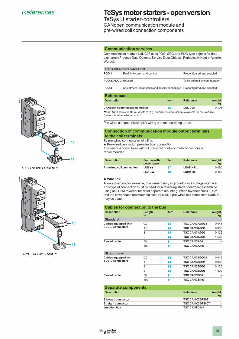
35
TeSys motor starters - open version 1 TeSys U starter-controllersCANopen communication module and pre-wired coil connection components
Communication servicesCommunication module LUL C08 uses PDO, SDO and PKW type objects for data exchange (Process Data Objects, Service Data Objects, Periodically Kept in Acyclic Words).
Transmit and Receive PDOPDO 1 Real time command-control Preconfigured and enabled
PDO 2, PDO 3 Unused To be defined by configuration
PDO 4 Adjustment, diagnostics and acyclic exchanges Preconfigured and enabled
ReferencesDescription Item Reference Weight
kgCANopen communication module 16 LUL C08 0.�08Note: The Electronic Data Sheets (EDS), and user’s manuals are available on the website “www.schneider-electric.com”.
Pre-wired components simplify wiring and reduce wiring errors. Connection of communication module output terminals to the coil terminals
By pre-wired connector or wire link.Pre-wired connector: pre-wired coil connection
The use of a power base without pre-wired control circuit connections is recommended. Description For use with
power baseItem Reference Weight
kgPre-wired coil connection LUB pp 17 LU9B N11L 0.050
LU�B pp 18 LU9M RL 0.450
Wire link:Allows insertion, for example, of an emergency stop control or a voltage interface.This type of connection must be used for a reversing starter-controller assembled using an LU6M reverser block for separate mounting. When reverser block LU6M and the power base are mounted side-by-side, a pre-wired coil connection LU9M RL may be used. Cables for connection to the busDescription Length
mItem Reference Weight
kgStandard
Cables equipped with SUB-D connectors
0.3 14 TSX CANCADD03 0.045�.0 14 TSX CANCADD1 0.0653 14 TSX CANCADD3 0.��55 14 TSX CANCADD5 �.500
Reel of cable 50 11 TSX CANCA50 –�00 11 TSX CANCA100 –
UL approvedCables equipped with SUB-D connectors
0.3 14 TSX CANCBDD03 0.045� 14 TSX CANCBDD1 0.0653 14 TSX CANCBDD3 0.��55 14 TSX CANCBDD5 �.500
Reel of cable 50 11 TSX CANCB50 –�00 11 TSX CANCB100 –
Separate componentsDescription Reference Weight
kgElbowed connector TSX CANKCDF90T –Straight connector TSX CANKCDF180T –Junction box TSX CANTD M4 –
b
b
17
16
5�09
��
LUB + LUL C08 + LU9B N11L
16
18
5669
88
LU2B + LUL C08 + LU9M RL
17
16
5�09
��
LUB + LUL C08 + LU9B N11L
16
18
5669
88
LU2B + LUL C08 + LU9M RL
References 1
1
2
3
4
5
6
7
8
9
10
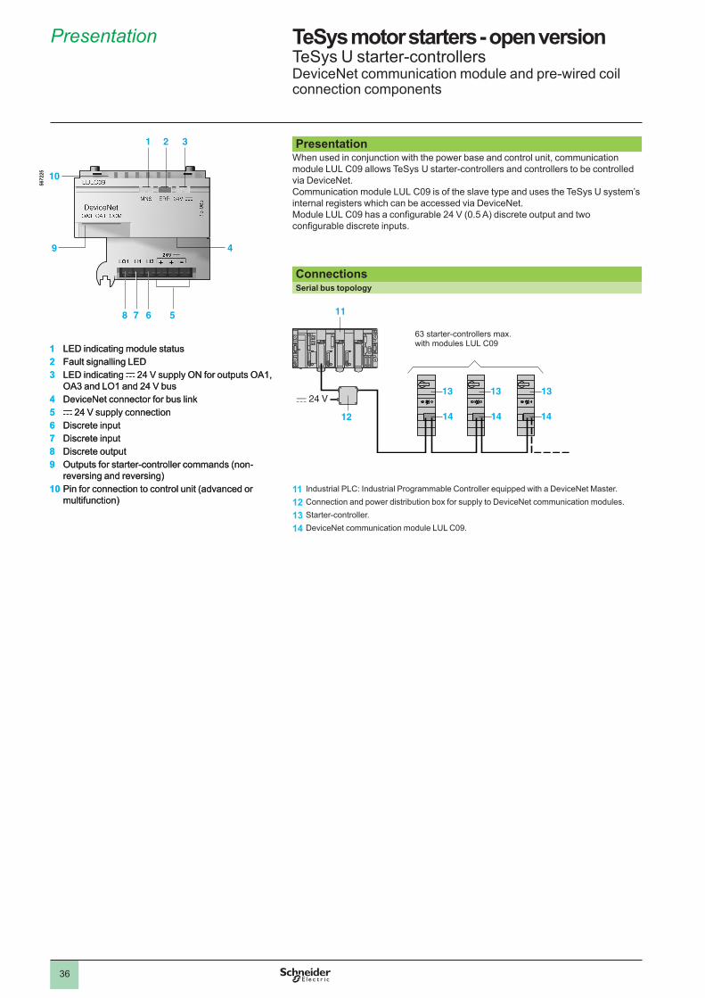
36
TeSys motor starters - open version 1 TeSys U starter-controllersDeviceNet communication module and pre-wired coil connection components
Presentation When used in conjunction with the power base and control unit, communication module LUL C09 allows TeSys U starter-controllers and controllers to be controlled via DeviceNet.Communication module LUL C09 is of the slave type and uses the TeSys U system’s internal registers which can be accessed via DeviceNet.Module LUL C09 has a configurable 24 V (0.5 A) discrete output and two configurable discrete inputs.
ConnectionsSerial bus topology
11 Industrial PLC: Industrial Programmable Controller equipped with a DeviceNet Master.
12 Connection and power distribution box for supply to DeviceNet communication modules.
13 Starter-controller.
14 DeviceNet communication module LUL C09.
1 2 3
49
10
5678
1 LED indicating module status2 Fault signalling LED3 LED indicating c �4 V supply ON for outputs OA�,
OA3 and LO� and �4 V bus4 DeviceNet connector for bus link5 c �4 V supply connection6 Discrete input7 Discrete input8 Discrete output9 Outputs for starter-controller commands (non-
reversing and reversing)10 Pin for connection to control unit (advanced or
multifunction)
567�
�5
c 24 V
11
14 14 1412
13 13 13
63 starter-controllers max. with modules LUL C09
c 24 V
11
14 14 1412
13 13 13
63 starter-controllers max. with modules LUL C09
Presentation 1
1
2
3
4
5
6
7
8
9
10
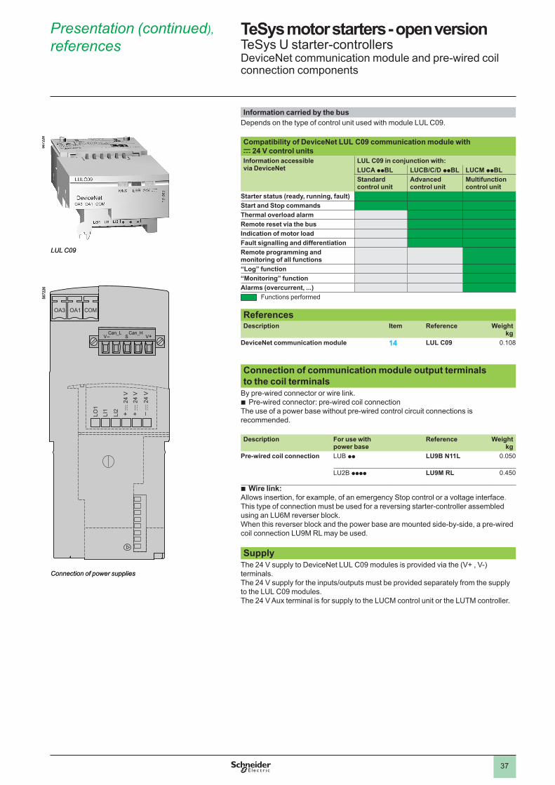
37
TeSys motor starters - open version 1 TeSys U starter-controllersDeviceNet communication module and pre-wired coil connection components
Information carried by the busDepends on the type of control unit used with module LUL C09.
Compatibility of DeviceNet LUL C09 communication module with c 24 V control unitsInformation accessible via DeviceNet
LUL C09 in conjunction with:LUCA ppBL LUCB/C/D ppBL LUCM ppBLStandard control unit
Advanced control unit
Multifunction control unit
Starter status (ready, running, fault)Start and Stop commandsThermal overload alarmRemote reset via the busIndication of motor loadFault signalling and differentiationRemote programming and monitoring of all functions“Log” function“Monitoring” functionAlarms (overcurrent, . . .)
Functions performed
ReferencesDescription Item Reference Weight
kgDeviceNet communication module 14 LUL C09 0.�08
Connection of communication module output terminals to the coil terminals
By pre-wired connector or wire link.Pre-wired connector: pre-wired coil connection
The use of a power base without pre-wired control circuit connections is recommended.
b
Description For use with power base
Reference Weight kg
Pre-wired coil connection LUB pp LU9B N11L 0.050
LU�B pppp LU9M RL 0.450
Wire link:Allows insertion, for example, of an emergency Stop control or a voltage interface.This type of connection must be used for a reversing starter-controller assembled using an LU6M reverser block. When this reverser block and the power base are mounted side-by-side, a pre-wired coil connection LU9M RL may be used.
SupplyThe 24 V supply to DeviceNet LUL C09 modules is provided via the (V+ , V-) terminals.The 24 V supply for the inputs/outputs must be provided separately from the supply to the LUL C09 modules.The 24 V Aux terminal is for supply to the LUCM control unit or the LUTM controller.
b
567�
�8
LUL C09
567�
�8
LUL C09
OA3
LO�
LI�
LI�
+ c
�4
V
+ c
�4
V
c
�4
V
OA� COM
V V+SCan_L Can_H
567�
�6
Connection of power supplies
OA3
LO�
LI�
LI�
+ c
�4
V
+ c
�4
V
c
�4
V
OA� COM
V V+SCan_L Can_H
567�
�6
Connection of power supplies
Presentation (continued), references 1
1
2
3
4
5
6
7
8
9
10
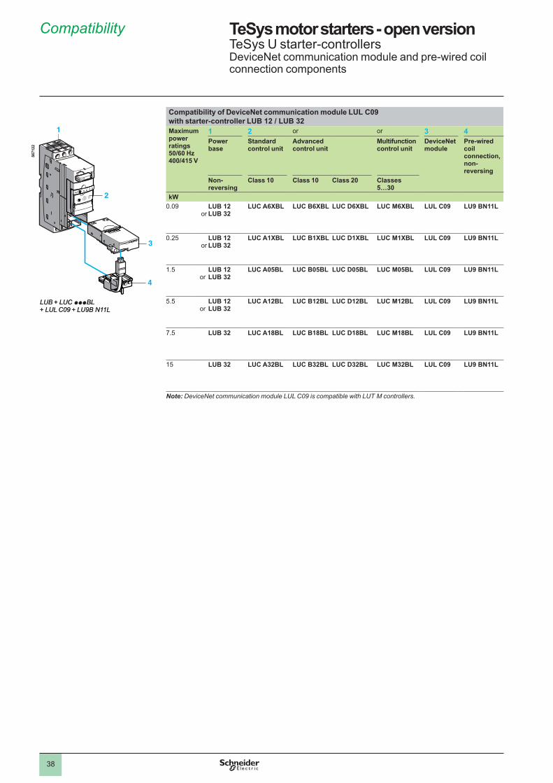
38
TeSys motor starters - open version 1 TeSys U starter-controllersDeviceNet communication module and pre-wired coil connection components
Compatibility of DeviceNet communication module LUL C09 with starter-controller LUB 12 / LUB 32 Maximum power ratings50/60 Hz 400/415 V
1 2 or or 3 4Power base
Standard control unit
Advanced control unit
Multifunction control unit
DeviceNet module
Pre-wiredcoil connection, non-reversing
Non-reversing
Class 10 Class 10 Class 20 Classes 5…30
kW0.09
orLUB 12LUB 32
LUC A6XBL LUC B6XBL LUC D6XBL LUC M6XBL LUL C09 LU9 BN11L
0.�5or
LUB 12LUB 32
LUC A1XBL LUC B1XBL LUC D1XBL LUC M1XBL LUL C09 LU9 BN11L
�.5or
LUB 12LUB 32
LUC A05BL LUC B05BL LUC D05BL LUC M05BL LUL C09 LU9 BN11L
5.5or
LUB 12LUB 32
LUC A12BL LUC B12BL LUC D12BL LUC M12BL LUL C09 LU9 BN11L
7.5 LUB 32 LUC A18BL LUC B18BL LUC D18BL LUC M18BL LUL C09 LU9 BN11L
�5
LUB 32 LUC A32BL LUC B32BL LUC D32BL LUC M32BL LUL C09 LU9 BN11L
Note: DeviceNet communication module LUL C09 is compatible with LUT M controllers.
4
3
1
2
567�
��
LUB + LUC pppBL+ LUL C09 + LU9B N11L
4
3
1
2
567�
��
LUB + LUC pppBL+ LUL C09 + LU9B N11L
Compatibility 1
1
2
3
4
5
6
7
8
9
10
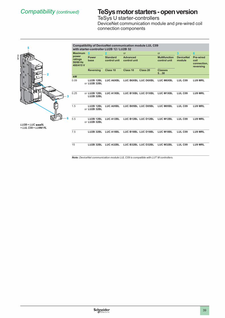
39
TeSys motor starters - open version 1 TeSys U starter-controllersDeviceNet communication module and pre-wired coil connection components
Compatibility of DeviceNet communication module LUL C09 with starter-controller LU2B 12 / LU2B 32 Maximum power ratings50/60 Hz 400/415 V
5 2 or or 3 6Power base
Standard control unit
Advanced control unit
Multifunction control unit
DeviceNet module
Pre-wiredcoil connection, reversing
Reversing Class 10 Class 10 Class 20 Classes 5…30
kW0.09
orLU2B 12BLLU2B 32BL
LUC A6XBL LUC B6XBL LUC D6XBL LUC M6XBL LUL C09 LU9 MRL
0.�5 or LU2B 12BLLU2B 32BL
LUC A1XBL LUC B1XBL LUC D1XBL LUC M1XBL LUL C09 LU9 MRL
�.5or
LU2B 12BLLU2B 32BL
LUC A05BL LUC B05BL LUC D05BL LUC M05BL LUL C09 LU9 MRL
5.5or
LU2B 12BLLU2B 32BL
LUC A12BL LUC B12BL LUC D12BL LUC M12BL LUL C09 LU9 MRL
7.5 LU2B 32BL LUC A18BL LUC B18BL LUC D18BL LUC M18BL LUL C09 LU9 MRL
�5 LU2B 32BL LUC A32BL LUC B32BL LUC D32BL LUC M32BL LUL C09 LU9 MRL
Note: DeviceNet communication module LUL C09 is compatible with LUT M controllers.
567�
��
6
3
5
2
567�
�3
LU2B + LUC pppBL+ LUL C09 + LU9M RL
567�
��
6
3
5
2
567�
�3
LU2B + LUC pppBL+ LUL C09 + LU9M RL
Compatibility (continued) 1
1
2
3
4
5
6
7
8
9
10
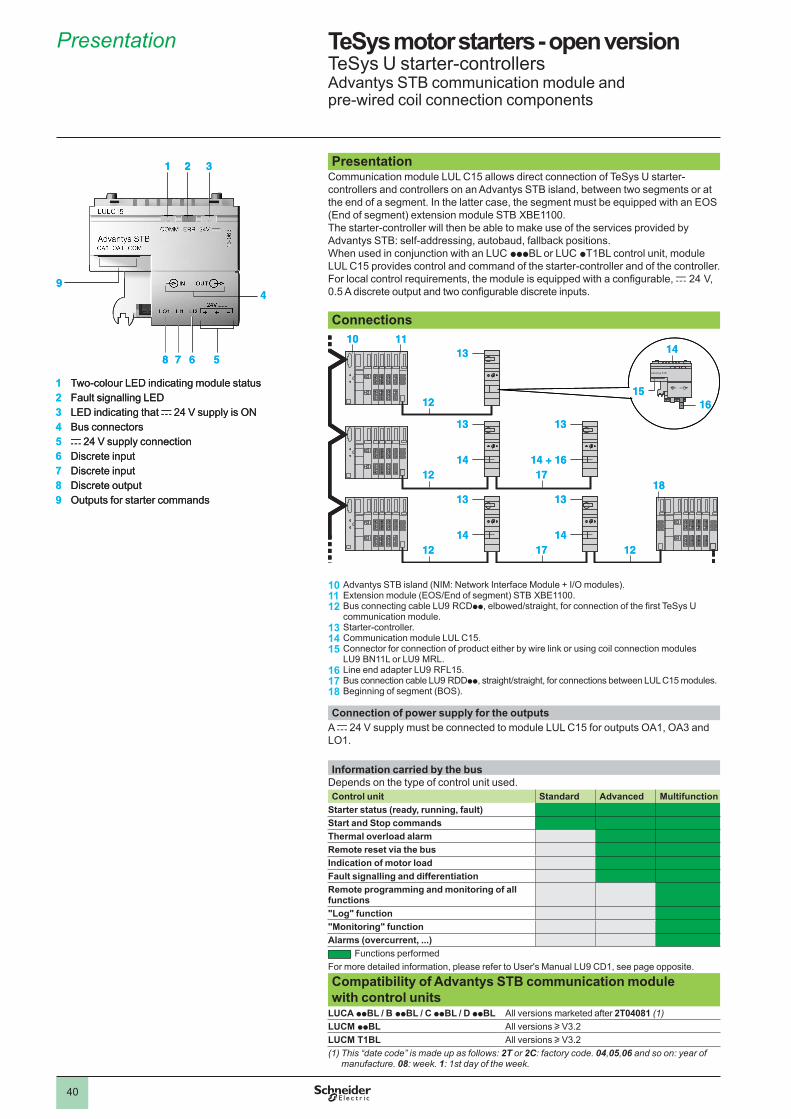
40
TeSys motor starters - open version 1 TeSys U starter-controllersAdvantys STB communication module and pre-wired coil connection components
PresentationCommunication module LUL C�5 allows direct connection of TeSys U starter-controllers and controllers on an Advantys STB island, between two segments or at the end of a segment. In the latter case, the segment must be equipped with an EOS (End of segment) extension module STB XBE1100.The starter-controller will then be able to make use of the services provided by Advantys STB: self-addressing, autobaud, fallback positions.When used in conjunction with an LUC pppBL or LUC pT�BL control unit, module LUL C�5 provides control and command of the starter-controller and of the controller.For local control requirements, the module is equipped with a configurable, c �4 V, 0.5 A discrete output and two configurable discrete inputs. Connections
101112
131415
161718
Advantys STB island (NIM: Network Interface Module + I/O modules).Extension module (EOS/End of segment) STB XBE1100.Bus connecting cable LU9 RCDpp, elbowed/straight, for connection of the first TeSys U communication module.Starter-controller.Communication module LUL C�5.Connector for connection of product either by wire link or using coil connection modules LU9 BN��L or LU9 MRL.Line end adapter LU9 RFL�5.Bus connection cable LU9 RDDpp, straight/straight, for connections between LUL C15 modules.Beginning of segment (BOS).
Connection of power supply for the outputsA c �4 V supply must be connected to module LUL C�5 for outputs OA�, OA3 and LO�.
Information carried by the bus Depends on the type of control unit used.Control unit Standard Advanced Multifunction
Starter status (ready, running, fault)Start and Stop commandsThermal overload alarmRemote reset via the busIndication of motor loadFault signalling and differentiationRemote programming and monitoring of all functions"Log" function"Monitoring" functionAlarms (overcurrent, . . .)
Functions performedFor more detailed information, please refer to User's Manual LU9 CD�, see page opposite.
Compatibility of Advantys STB communication module with control units
LUCA ppBL / B ppBL / C ppBL / D ppBL All versions marketed after 2T04081 (1)LUCM ppBL All versions u V3.�LUCM T1BL All versions u V3.�(1) This “date code” is made up as follows: 2T or 2C: factory code. 04,05,06 and so on: year of
manufacture. 08: week. 1: 1st day of the week.
12 16
12 17
17 1212
141310 11
15
18
13
14
13
14 + 16
13
14
13
14
12 16
12 17
17 1212
141310 11
15
18
13
14
13
14 + 16
13
14
13
14
4
1 2 3
9
5678
1 Two-colour LED indicating module status2 Fault signalling LED3 LED indicating that c �4 V supply is ON4 Bus connectors5 c �4 V supply connection6 Discrete input7 Discrete input8 Discrete output9 Outputs for starter commands
4
1 2 3
9
5678
1 Two-colour LED indicating module status2 Fault signalling LED3 LED indicating that c �4 V supply is ON4 Bus connectors5 c �4 V supply connection6 Discrete input7 Discrete input8 Discrete output9 Outputs for starter commands
Presentation 1
1
2
3
4
5
6
7
8
9
10
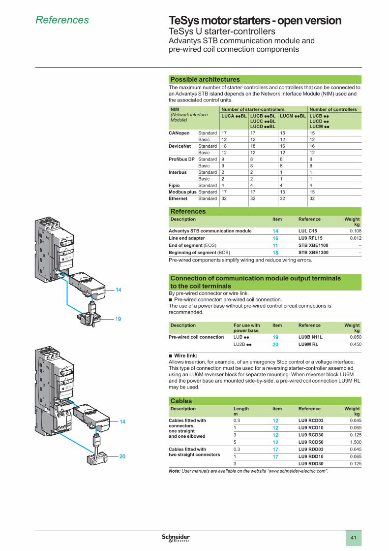
4�
TeSys motor starters - open version 1 TeSys U starter-controllersAdvantys STB communication module and pre-wired coil connection components
Possible architecturesThe maximum number of starter-controllers and controllers that can be connected to an Advantys STB island depends on the Network Interface Module (NIM) used and the associated control units.
NIM(Network Interface Module)
Number of starter-controllers Number of controllersLUCA ppBL LUCB ppBL
LUCC ppBLLUCD ppBL
LUCM ppBL LUCB ppLUCD ppLUCM pp
CANopen Standard �7 �7 �5 �5Basic �� �� �� ��
DeviceNet Standard �8 �8 �6 �6Basic �� �� �� ��
Profibus DP Standard 9 8 8 8Basic 9 8 8 8
Interbus Standard � � � �Basic � � � �
Fipio Standard 4 4 4 4Modbus plus Standard �7 �7 �5 �5Ethernet Standard 3� 3� 3� 3�
ReferencesDescription Item Reference Weight
kgAdvantys STB communication module 14 LUL C15 0.�08Line end adapter 16 LU9 RFL15 0.0��End of segment (EOS) 11 STB XBE1100 –Beginning of segment (BOS) 18 STB XBE1300 –
Pre-wired components simplify wiring and reduce wiring errors.
Connection of communication module output terminals to the coil terminals
By pre-wired connector or wire link.Pre-wired connector: pre-wired coil connection..
The use of a power base without pre-wired control circuit connections is recommended. Description For use with
power baseItem Reference Weight
kgPre-wired coil connection LUB pp 19 LU9B N11L 0.050
LU�B pp 20 LU9M RL 0.450
Wire link:Allows insertion, for example, of an emergency Stop control or a voltage interface.This type of connection must be used for a reversing starter-controller assembled using an LU6M reverser block for separate mounting. When reverser block LU6M and the power base are mounted side-by-side, a pre-wired coil connection LU9M RL may be used. CablesDescription Length
mItem Reference Weight
kgCables fitted with connectors, one straight and one elbowed
0.3 12 LU9 RCD03 0.045� 12 LU9 RCD10 0.0653 12 LU9 RCD30 0.��55 12 LU9 RCD50 �.500
Cables fitted with two straight connectors
0.3 17 LU9 RDD03 0.045� 17 LU9 RDD10 0.0653 LU9 RDD30 0.��5
Note: User manuals are available on the website “www.schneider-electric.com”.
b
b
�9
�4
20
14
�9
�4
20
14
References 1
1
2
3
4
5
6
7
8
9
10
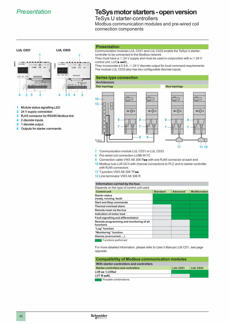
4�
Presentation Communication modules LUL C03� and LUL C033 enable the TeSys U starter-controller to be connected to the Modbus network.They must have a c �4 V supply and must be used in conjunction with a c �4 V control unit, LUCp ppBL.They incorporate a 0.5 A, c �4 V discrete output for local command requirements.The module LUL C033 also has two configurable discrete inputs. Series type connectionArchitectureStar topology Bus topology
7 Communication module LUL C03� or LUL C0338 Pre-wired coil connection LU9B N��C9 Connection cable VW3 A8 306 Rpp with one RJ45 connector at each end10 Modbus hub LU9 GC3 with channel connections to PLC and to starter-controller
with RJ45 connectors11 T-junction VW3 A8 306 TFpp12 Line terminator VW3 A8 306 R Information carried by the bus
Depends on the type of control unit used.Control unit Standard Advanced Multifunction
Starter status (ready, running, fault)Start and Stop commandsThermal overload alarmRemote reset via the busIndication of motor loadFault signalling and differentiationRemote programming and monitoring of all functions“Log” function“Monitoring” functionAlarms (overcurrent, . . .)
Functions performed
For more detailed information, please refer to User’s Manual LU9 CD�, see page opposite. Compatibility of Modbus communication modulesWith starter-controllers and controllersStarter-controllers and controllers LUL C031 LUL C033
LUB pp / LU2Bp2LUT M ppBL
Possible combinations.
1 Module status signalling LED2 �4 V supply connection3 RJ45 connector for RS485 Modbus link4 � discrete inputs5 � discrete output6 Outputs for starter commands
5�06
�4
LUL C033
5669
70
LUL C0311 1
2536 2536 4
1 Module status signalling LED2 �4 V supply connection3 RJ45 connector for RS485 Modbus link4 � discrete inputs5 � discrete output6 Outputs for starter commands
5�06
�4
LUL C033
5669
70
LUL C0311 1
2536 2536 4
7
9
8
7
9
8
10
12
To PLC
7
9
8
7
9
8
10
12
To PLC
11 12
8
11
8
77
11 12
8
11
8
77
TeSys motor starters - open version 1 TeSys U starter-controllersModbus communication modules and pre-wired coil connection components
Presentation 1
1
2
3
4
5
6
7
8
9
10
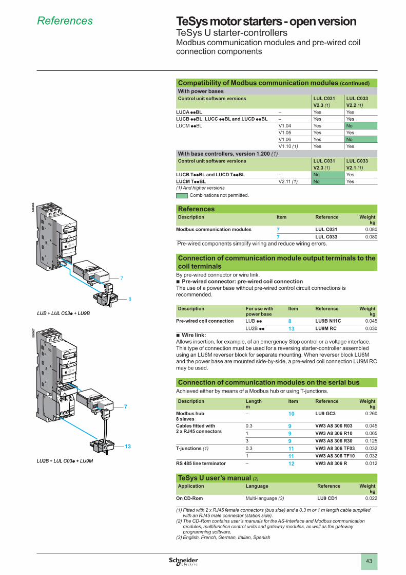
43
TeSys motor starters - open version 1 TeSys U starter-controllersModbus communication modules and pre-wired coil connection components
Compatibility of Modbus communication modules (continued)With power basesControl unit software versions LUL C031 LUL C033
V2 .3 (1) V2 .2 (1)LUCA ppBL – Yes YesLUCB ppBL, LUCC ppBL and LUCD ppBL – Yes YesLUCM ppBL V�.04 Yes No
V�.05 Yes YesV�.06 Yes NoV�.�0 (1) Yes Yes
With base controllers, version 1 .200 (1)Control unit software versions LUL C031 LUL C033
V2 .3 (1) V2 .1 (1)LUCB TppBL and LUCD TppBL – No YesLUCM TppBL V�.�� (1) No Yes(1) And higher versions
Combinations not permitted. ReferencesDescription Item Reference Weight
kgModbus communication modules 7 LUL C031 0.080
7 LUL C033 0.080 Pre-wired components simplify wiring and reduce wiring errors. Connection of communication module output terminals to the coil terminals
By pre-wired connector or wire link.Pre-wired connector: pre-wired coil connection
The use of a power base without pre-wired control circuit connections is recommended.
b
Description For use with power base
Item Reference Weight kg
Pre-wired coil connection LUB pp 8 LU9B N11C 0.045LU�B pp 13 LU9M RC 0.030
Wire link:Allows insertion, for example, of an emergency Stop control or a voltage interface.This type of connection must be used for a reversing starter-controller assembled using an LU6M reverser block for separate mounting. When reverser block LU6M and the power base are mounted side-by-side, a pre-wired coil connection LU9M RC may be used. Connection of communication modules on the serial bus
Achieved either by means of a Modbus hub or using T-junctions.
Description Length m
Item Reference Weight kg
Modbus hub 8 slaves
– 10 LU9 GC3 0.�60
Cables fitted with 2 x RJ45 connectors
0.3 9 VW3 A8 306 R03 0.045� 9 VW3 A8 306 R10 0.0653 9 VW3 A8 306 R30 0.��5
T-junctions (1) 0.3 11 VW3 A8 306 TF03 0.03�� 11 VW3 A8 306 TF10 0.03�
RS 485 line terminator – 12 VW3 A8 306 R 0.0��
TeSys U user’s manual (2)Application Language Reference Weight
kgOn CD-Rom Multi-language (3) LU9 CD1 0.0��
(1) Fitted with 2 x RJ45 female connectors (bus side) and a 0.3 m or 1 m length cable supplied with an RJ45 male connector (station side).
(2) The CD-Rom contains user’s manuals for the AS-Interface and Modbus communication modules, multifunction control units and gateway modules, as well as the gateway programming software.
(3) English, French, German, Italian, Spanish
b
7
8
5669
66
LUB + LUL C03p + LU9B
7
13
5669
67
LU2B + LUL C03p + LU9M
7
8
5669
66
LUB + LUL C03p + LU9B
7
13
5669
67
LU2B + LUL C03p + LU9M
References 1
1
2
3
4
5
6
7
8
9
10
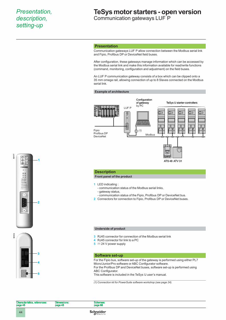
44
TeSys motor starters - open version 0 Communication gateways LUF P
PresentationCommunication gateways LUF P allow connection between the Modbus serial link and Fipio, Profibus DP or DeviceNet field buses.
After configuration, these gateways manage information which can be accessed by the Modbus serial link and make this information available for read/write functions (command, monitoring, configuration and adjustment) on the field buses.
An LUF P communication gateway consists of a box which can be clipped onto a 35 mm omega rail, allowing connection of up to 8 Slaves connected on the Modbus serial link.
Example of architecture
DescriptionFront panel of the product
1 LED indicating : - communication status of the Modbus serial links, - gateway status, - communication status of the Fipio, Profibus DP or DeviceNet bus.
2 Connectors for connection to Fipio, Profibus DP or DeviceNet buses.
Underside of product
3 RJ45 connector for connection of the Modbus serial link4 RJ45 connector for link to a PC5 c �4 V power supply
Software set-up
For the Fipio bus, software set-up of the gateway is performed using either PL7 Micro/Junior/Pro software or ABC Configurator software.For the Profibus DP and DeviceNet buses, software set-up is performed using ABC Configurator.This software is included in the TeSys U user’s manual.
(1) Connection kit for PowerSuite software workshop (see page 24).
Configurationof gatewayby PC
TeSys U starter-controllers
Fipio Profibus DP DeviceNet
LUF P
ATS 48 ATV 3�
(1)Modbus
Configurationof gatewayby PC
TeSys U starter-controllers
Fipio Profibus DP DeviceNet
LUF P
ATS 48 ATV 3�
(1)Modbus
5�4�
7756
�5��
1
2
3
5
4
5�4�
7756
�5��
1
2
3
5
4
Characteristics, references:page 45
Dimensions:page 45
Schemes:page 68
Characteristics, references:page 45
Dimensions:page 45
Schemes:page 68
Characteristics, references:page 45
Dimensions:page 45
Schemes:page 68
Characteristics, references:page 45
Dimensions:page 45
Schemes:page 68
Presentation, description, setting-up 0
1
2
3
4
5
6
7
8
9
10
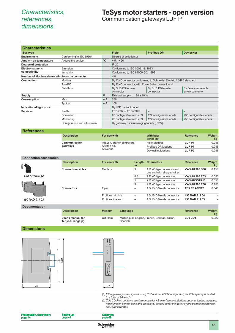
45
TeSys motor starters - open version 0 Communication gateways LUF P
CharacteristicsBus type Fipio Profibus DP DeviceNet
Environment Conforming to IEC 60664 Degree of pollution: �Ambient air temperature Around the device °C + 5…+ 50Degree of protection IP �0Electromagnetic compatibility
Emission Conforming to IEC 5008�-�: �993Immunity Conforming to IEC 6�000-6-�: �999
Number of Modbus slaves which can be connected y 8Connection Modbus By RJ45 connector conforming to Schneider Electric RS485 standard
To a PC By RJ45 connector, with PowerSuite connection kitField bus By SUB D9 female
connectorBy SUB D9 female connector
By 5-way removable screw connector
Supply V External supply, c �4 ± �0 %Consumption Max. mA �80
Typical mA �00Indication/diagnostics By LED on front panelServices Profile FED C3� or FED C3�P – –
Command 26 configurable words (1) 122 configurable words 256 configurable wordsMonitoring 26 configurable words (1) 122 configurable words 256 configurable wordsConfiguration and adjustment By gateway mini messaging facility (PKW)
ReferencesDescription For use with With bus/
serial linkReference Weight
kgCommunication gateways
TeSys U starter-controllers, Altistart 48, Altivar 3�
Fipio/Modbus LUF P1 0.�45Profibus DP/Modbus LUF P7 0.�45DeviceNet/Modbus LUF P9 0.�45
Connection accessoriesDescription For use with Length
mConnectors Reference Weight
kgConnection cables Modbus 3 � RJ45 type connector and
one end with stripped wiresVW3 A8 306 D30 0.�50
0.3 � RJ45 type connectors VW3 A8 306 R03 0.050� � RJ45 type connectors VW3 A8 306 R10 0.0503 � RJ45 type connectors VW3 A8 306 R30 0.�50
Connectors Fipio – � SUB-D 9 male connector TSX FP ACC12 0.040
Profibus mid line – � SUB-D 9 male connector 490 NAD 911 04 –Profibus line end – � SUB-D 9 male connector 490 NAD 911 03 –
DocumentationDescription Medium Language Reference Weight
kgUser’s manual for TeSys U range (2)
CD-Rom
Multilingual: English, French, German, Italian, Spanish
LU9 CD1 0.0��
Dimensions
(1)IfthegatewayisconfiguredusingPL7andnotABCConfigurator,theI/Ocapacityislimited to a total of 26 words.
(2) This CD-Rom contains user’s manuals for AS-Interface and Modbus communication modules, multifunction control units and gateways, as well as for the gateway programming software, ABCConfigurator.
8��6
3�
TSX FP ACC 12
8��6
3�
TSX FP ACC 12
490 NAD 911 03
8��7
�3
490 NAD 911 03
8��7
�3
75 27
120
==
75 27
120
==
Presentation, description:page 44
Setting-up:page 44
Schemes:page 68
Presentation, description:page 44
Setting-up:page 44
Schemes:page 68
Presentation, description:page 44
Setting-up:page 44
Schemes:page 68
Presentation, description:page 44
Setting-up:page 44
Schemes:page 68
Presentation, description:page 44
Setting-up:page 44
Schemes:page 68
Presentation, description:page 44
Setting-up:page 44
Schemes:page 68
Presentation, description:page 44
Setting-up:page 44
Schemes:page 68
Presentation, description:page 44
Setting-up:page 44
Schemes:page 68
Characteristics, references, dimensions 0
1
2
3
4
5
6
7
8
9
10
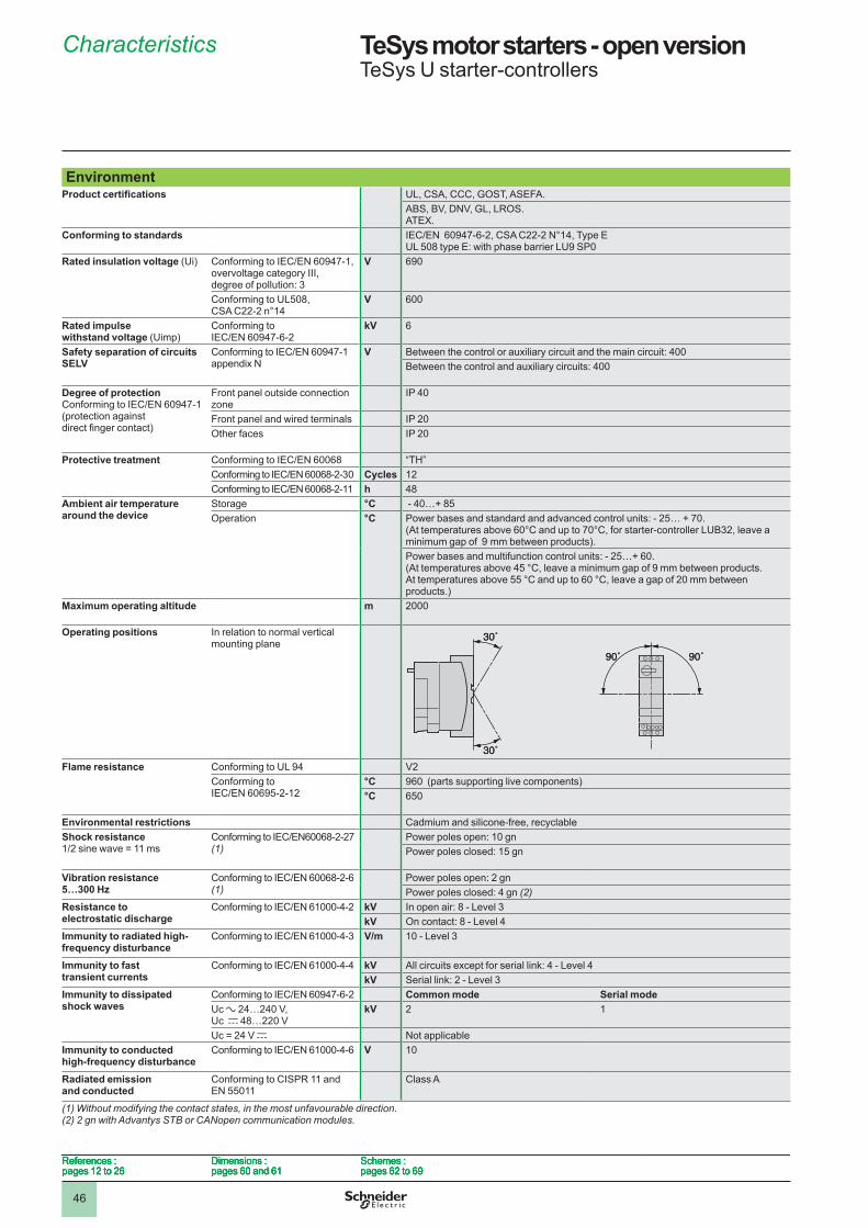
46
TeSys motor starters - open version 1 TeSys U starter-controllers
EnvironmentProduct certifications UL, CSA, CCC, GOST, ASEFA.
ABS, BV, DNV, GL, LROS.ATEX.
Conforming to standards IEC/EN 60947-6-2, CSA C22-2 N°14, Type E UL 508 type E: with phase barrier LU9 SP0
Rated insulation voltage (Ui) Conforming to IEC/EN 60947-1, overvoltage category III, degree of pollution: 3
V 690
Conforming to UL508, CSA C22-2 n°14
V 600
Rated impulse withstand voltage (Uimp)
Conforming to IEC/EN 60947-6-2
kV 6
Safety separation of circuits SELV
Conforming to IEC/EN 60947-1 appendix N
V Between the control or auxiliary circuit and the main circuit: 400 Between the control and auxiliary circuits: 400
Degree of protectionConforming to IEC/EN 60947-1(protection against direct finger contact)
Front panel outside connection zone
IP 40
Front panel and wired terminals IP �0Other faces IP �0
Protective treatment Conforming to IEC/EN 60068 “TH”Conforming to IEC/EN 60068-2-30 Cycles ��Conforming to IEC/EN 60068-2-11 h 48
Ambient air temperature around the device
Storage °C - 40…+ 85Operation °C Power bases and standard and advanced control units: - 25… + 70.
(At temperatures above 60°C and up to 70°C, for starter-controller LUB32, leave a minimum gap of 9 mm between products).Power bases and multifunction control units: - 25…+ 60. (At temperatures above 45 °C, leave a minimum gap of 9 mm between products. At temperatures above 55 °C and up to 60 °C, leave a gap of 20 mm between products.)
Maximum operating altitude m �000
Operating positions In relation to normal vertical mounting plane
Flame resistance Conforming to UL 94 V�Conforming to IEC/EN 60695-2-12
°C 960 (parts supporting live components)°C 650
Environmental restrictions Cadmium and silicone-free, recyclableShock resistance1/2 sine wave = 11 ms
Conforming to IEC/EN60068-2-27 (1)
Power poles open: �0 gnPower poles closed: �5 gn
Vibration resistance 5…300 Hz
Conforming to IEC/EN 60068-2-6(1)
Power poles open: � gnPower poles closed: 4 gn (2)
Resistance to electrostatic discharge
Conforming to IEC/EN 61000-4-2 kV In open air: 8 - Level 3kV On contact: 8 - Level 4
Immunity to radiated high-frequency disturbance
Conforming to IEC/EN 61000-4-3 V/m �0 - Level 3
Immunity to fast transient currents
Conforming to IEC/EN 61000-4-4 kV All circuits except for serial link: 4 - Level 4kV Serial link: � - Level 3
Immunity to dissipated shock waves
Conforming to IEC/EN 60947-6-2 Common mode Serial modeUc a �4…�40 V,Uc c 48…��0 V
kV � �
Uc = 24 V c Not applicableImmunity to conducted high-frequency disturbance
Conforming to IEC/EN 61000-4-6 V �0
Radiated emission and conducted
Conforming to CISPR �� and EN 550��
Class A
(1) Without modifying the contact states, in the most unfavourable direction.(2) 2 gn with Advantys STB or CANopen communication modules.
30˚
30˚
30˚
30˚
90˚ 90˚90˚ 90˚
References :pages �� to �6
Dimensions : pages 60 and 6�
Schemes : pages 6� to 69
References :pages �� to �6
Dimensions : pages 60 and 6�
Schemes : pages 6� to 69
References :pages �� to �6
Dimensions : pages 60 and 6�
Schemes : pages 6� to 69
References :pages �� to �6
Dimensions : pages 60 and 6�
Schemes : pages 6� to 69
Characteristics 1
1
2
3
4
5
6
7
8
9
10
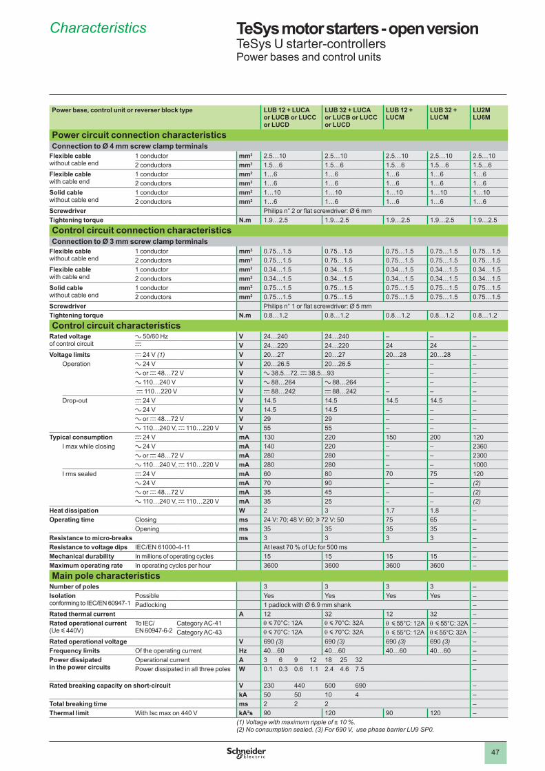
47
TeSys motor starters - open version 1 TeSys U starter-controllersPower bases and control units
Power base, control unit or reverser block type LUB 12 + LUCAor LUCB or LUCCor LUCD
LUB 32 + LUCAor LUCB or LUCCor LUCD
LUB 12 + LUCM
LUB 32 + LUCM
LU2MLU6M
Power circuit connection characteristicsConnection to Ø 4 mm screw clamp terminals
Flexible cablewithout cable end
� conductor mm2 �.5…�0 �.5…�0 �.5…�0 �.5…�0 �.5…�0� conductors mm2 �.5…6 �.5…6 �.5…6 �.5…6 �.5…6
Flexible cablewith cable end
� conductor mm2 �…6 �…6 �…6 �…6 �…6� conductors mm2 �…6 �…6 �…6 �…6 �…6
Solid cablewithout cable end
� conductor mm2 �…�0 �…�0 �…�0 �…�0 �…�0� conductors mm2 �…6 �…6 �…6 �…6 �…6
Screwdriver Philips n° 2 or flat screwdriver: Ø 6 mmTightening torque N .m �.9…�.5 �.9…�.5 �.9…�.5 �.9…�.5 �.9…�.5
Control circuit connection characteristicsConnection to Ø 3 mm screw clamp terminals
Flexible cable without cable end
� conductor mm2 0.75…�.5 0.75…�.5 0.75…�.5 0.75…�.5 0.75…�.5� conductors mm2 0.75…�.5 0.75…�.5 0.75…�.5 0.75…�.5 0.75…�.5
Flexible cable with cable end
� conductor mm2 0.34…�.5 0.34…�.5 0.34…�.5 0.34…�.5 0.34…�.5� conductors mm2 0.34…�.5 0.34…�.5 0.34…�.5 0.34…�.5 0.34…�.5
Solid cable without cable end
� conductor mm2 0.75…�.5 0.75…�.5 0.75…�.5 0.75…�.5 0.75…�.5� conductors mm2 0.75…�.5 0.75…�.5 0.75…�.5 0.75…�.5 0.75…�.5
Screwdriver Philips n° 1 or flat screwdriver: Ø 5 mmTightening torque N .m 0.8…�.� 0.8…�.� 0.8…�.� 0.8…�.� 0.8…�.�
Control circuit characteristicsRated voltageof control circuit
a 50/60 Hz V �4…�40 �4…�40 – – –c V �4…��0 �4…��0 �4 �4 –
Voltage limits c �4 V (1) V �0…�7 �0…�7 �0…�8 �0…�8 –Operation a �4 V V �0…�6.5 �0…�6.5 – – –
a or c 48…7� V V a 38.5…7�. c 38.5…93 – – –a ��0…�40 V V a 88…�64 a 88…�64 – – – c ��0…��0 V V c 88…�4� c 88…�4� – – –
Drop-out c �4 V V �4.5 �4.5 �4.5 �4.5 –a �4 V V �4.5 �4.5 – – –a or c 48…7� V V �9 �9 – – –a ��0…�40 V, c ��0…��0 V V 55 55 – – –
Typical consumption c �4 V mA �30 ��0 �50 �00 ��0I max while closing a �4 V mA �40 ��0 – – �360
a or c 48…7� V mA �80 �80 – – �300a ��0…�40 V, c ��0…��0 V mA �80 �80 – – �000
I rms sealed c �4 V mA 60 80 70 75 ��0a �4 V mA 70 90 – – (2)a or c 48…7� V mA 35 45 – – (2)a ��0…�40 V, c ��0…��0 V mA 35 �5 – – (2)
Heat dissipation W � 3 �.7 �.8 –Operating time Closing ms �4 V: 70; 48 V: 60; u 7� V: 50 75 65 –
Opening ms 35 35 35 35 –Resistance to micro-breaks ms 3 3 3 3 –Resistance to voltage dips IEC/EN 61000-4-11 At least 70 % of Uc for 500 ms –Mechanical durability In millions of operating cycles �5 �5 �5 �5 –Maximum operating rate In operating cycles per hour 3600 3600 3600 3600 –
Main pole characteristicsNumber of poles 3 3 3 3 –Isolationconforming to IEC/EN 60947-1
Possible Yes Yes Yes Yes –Padlocking 1 padlock with Ø 6.9 mm shank –
Rated thermal current A �� 3� �� 3� –Rated operational current (Ue y 440V)
To IEC/ EN 60947-6-�
Category AC-4� q y 70°C: 12A q y 70°C: 32A q y 55°C: 12A q y 55°C: 32A –Category AC-43 q y 70°C: 12A q y 70°C: 32A q y 55°C: 12A q y 55°C: 32A –
Rated operational voltage V 690 (3) 690 (3) 690 (3) 690 (3) –Frequency limits Of the operating current Hz 40…60 40…60 40…60 40…60 –Power dissipated in the power circuits
Operational current A 3 6 9 �� �8 �5 3� –Power dissipated in all three poles W 0.� 0.3 0.6 �.� �.4 4.6 7.5 –
Rated breaking capacity on short-circuit V �30 440 500 690 –kA 50 50 �0 4 –
Total breaking time ms � � � –Thermal limit With Isc max on 440 V kA²s 90 ��0 90 ��0 –
(1) Voltage with maximum ripple of ± 10 %.(2) No consumption sealed. (3) For 690 V, use phase barrier LU9 SP0.
Characteristics 1
1
2
3
4
5
6
7
8
9
10
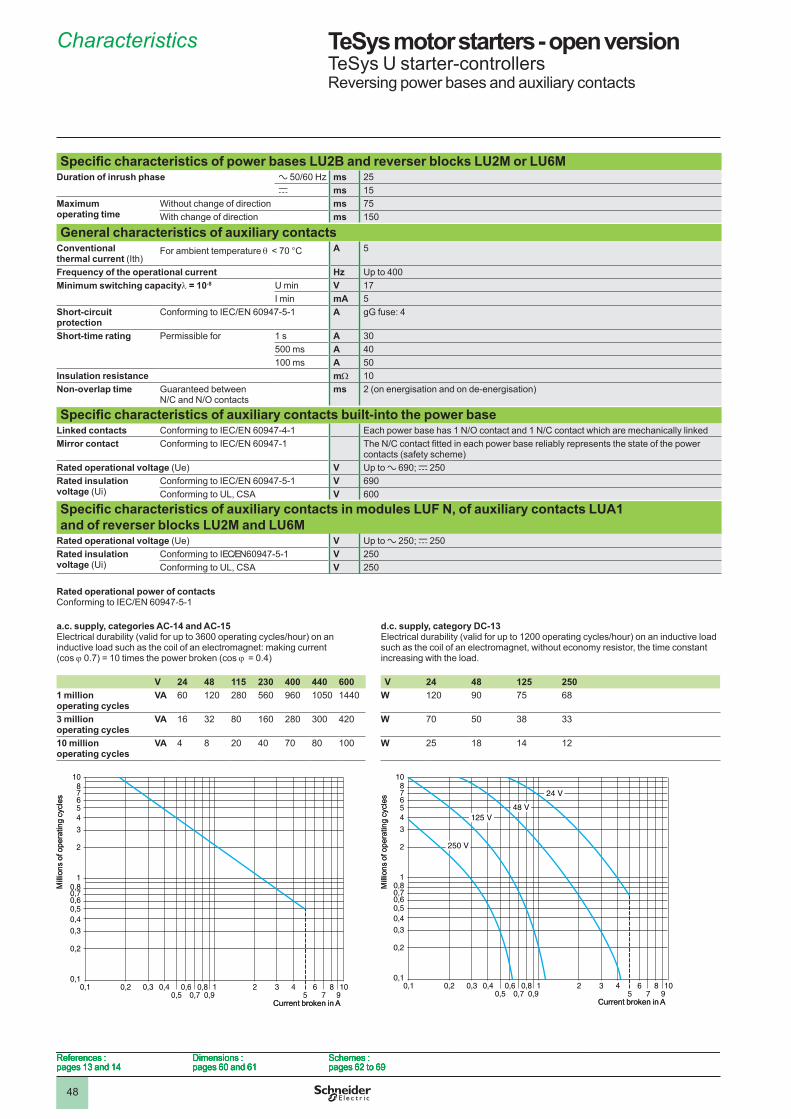
48
TeSys motor starters - open version 1 TeSys U starter-controllersReversing power bases and auxiliary contacts
Specific characteristics of power bases LU2B and reverser blocks LU2M or LU6M Duration of inrush phase a 50/60 Hz ms �5
c ms �5Maximum operating time
Without change of direction ms 75With change of direction ms �50
General characteristics of auxiliary contacts Conventional thermal current (Ith)
For ambient temperature q < 70 °C A 5
Frequency of the operational current Hz Up to 400Minimum switching capacityl = 10-8 U min V �7
I min mA 5Short-circuit protection
Conforming to IEC/EN 60947-5-1 A gG fuse: 4
Short-time rating Permissible for � s A 30500 ms A 40�00 ms A 50
Insulation resistance mW �0Non-overlap time Guaranteed between
N/C and N/O contactsms � (on energisation and on de-energisation)
Specific characteristics of auxiliary contacts built-into the power baseLinked contacts Conforming to IEC/EN 60947-4-1 Each power base has 1 N/O contact and 1 N/C contact which are mechanically linkedMirror contact Conforming to IEC/EN 60947-1 The N/C contact fitted in each power base reliably represents the state of the power
contacts (safety scheme)Rated operational voltage (Ue) V Up to a 690; c �50Rated insulation voltage (Ui)
Conforming to IEC/EN 60947-5-1 V 690Conforming to UL, CSA V 600
Specific characteristics of auxiliary contacts in modules LUF N, of auxiliary contacts LUA1and of reverser blocks LU2M and LU6M
Rated operational voltage (Ue) V Up to a �50; c �50Rated insulation voltage (Ui)
Conforming to IEC/EN 60947-5-1 V �50Conforming to UL, CSA V �50
Rated operational power of contacts Conforming to IEC/EN 60947-5-1
a .c . supply, categories AC-14 and AC-15Electrical durability (valid for up to 3600 operating cycles/hour) on an inductive load such as the coil of an electromagnet: making current (cos j 0.7) = 10 times the power broken (cos j = 0.4)
d .c . supply, category DC-13Electrical durability (valid for up to 1200 operating cycles/hour) on an inductive load such as the coil of an electromagnet, without economy resistor, the time constant increasing with the load.
V 24 48 115 230 400 440 600 V 24 48 125 2501 million operating cycles
VA 60 ��0 �80 560 960 �050 �440 W ��0 90 75 68
3 million operating cycles
VA �6 3� 80 �60 �80 300 4�0 W 70 50 38 33
10 million operating cycles
VA 4 8 �0 40 70 80 �00 W �5 �8 �4 ��
0,1 0,2 0,3 0,40,5
0,60,7
0,80,9
1 2 3 45
67
8910
0,1
0,2
0,30,4
0,60,5
0,80,7
7
1
2
3
54
6
810
Mill
ions
of o
pera
ting
cycl
es
Current broken in A
0,1 0,2 0,3 0,40,5
0,60,7
0,80,9
1 2 3 45
67
8910
0,1
0,2
0,30,4
0,60,5
0,80,7
7
1
2
3
54
6
810
Mill
ions
of o
pera
ting
cycl
es
Current broken in A
0,1 0,2 0,3 0,40,5
0,60,7
0,80,9
1 2 3 45
67
8910
0,1
0,2
0,30,4
0,60,5
0,80,7
7
1
2
3
54
6
810
48 V
250 V
125 V
24 V
Mill
ions
of o
pera
ting
cycl
es
Current broken in A
0,1 0,2 0,3 0,40,5
0,60,7
0,80,9
1 2 3 45
67
8910
0,1
0,2
0,30,4
0,60,5
0,80,7
7
1
2
3
54
6
810
48 V
250 V
125 V
24 V
Mill
ions
of o
pera
ting
cycl
es
Current broken in A
References :pages �3 and �4
Dimensions : pages 60 and 6�
Schemes : pages 6� to 69
References :pages �3 and �4
Dimensions : pages 60 and 6�
Schemes : pages 6� to 69
References :pages �3 and �4
Dimensions : pages 60 and 6�
Schemes : pages 6� to 69
References :pages �3 and �4
Dimensions : pages 60 and 6�
Schemes : pages 6� to 69
Characteristics 1
1
2
3
4
5
6
7
8
9
10

49
TeSys motor starters - open version 1 TeSys U starter-controllersControl units
Characteristics of standard control units LUCAProtection Motor type 3-phase
Conforming to standard IEC/EN 60947-6-2, UL 508, CSA C22-2 n°14Overload protection
Tripping class conforming to UL 508, IEC/EN 60947-6-2
�0
Frequency limits of the operational current Hz 40…60Temperature compensation °C - 25…+ 70Protection against phase imbalance Yes
Short-circuit protection
Tripping threshold 14.2 x Ir (setting current)Tripping tolerance ± �0 %
Characteristics of advanced control units LUCB, LUCC and LUCDControl unit type LUCB LUCC LUCD
Protection Motor type 3-phase Single-phase 3-phaseConforming to standard IEC/EN 60947-6-2, UL 508,
CSA C22-2 n°14IEC/EN 60947-6-2, UL 508, CSA C22-2 n°14
IEC/EN 60947-6-2, UL 508, CSA C22-2 n°14
Overload protection
Tripping class conforming to UL 508, IEC/EN 60947-6-2
�0 �0 �0
Frequency limits of the operational current Hz 40…60 40…60 40…60Temperature compensation °C - 25…+ 70 - 25…+ 55 - 25…+ 70Protection against phase imbalance Yes – Yes
Short-circuit protection
Tripping threshold 14.2 x Ir max. 14.2 x Ir max. 14.2 x Ir max.Tripping tolerance ± �0 % ± �0 % ± �0 %
Characteristics of multifunction control units LUCMProtection Motor type Parameters can be set: single-phase or 3-phase
Conforming to standard IEC/EN 60947-6-2, UL 508Overload protection
Tripping class conforming to UL 508, IEC/EN 60947-6-2
5, �0, �5, �0, �5, 30 (selectable)
Frequency limits of the operational current Hz 50…60Temperature compensation °C - 25…+ 55
Communication interface for terminal on enclosure door
Physical interface RS 485 multi-dropConnections RJ45 on front panelProtocol Modbus RTUMaximum transmission speed bit/s 19 200 (self-configuration up to this value)Maximum return time ms �00
Display Type LCD, � lines of �� charactersLanguage version Multilanguage (English, French, German, Italian, Spanish)Precision ± 5 %Resolution � % of Ir
Auxiliary supply External type V c 24, with maximum ripple of ± 10 %.Heat dissipation W 0.8
Configuration table for protection devices and alarms on multifunction control units LUCMTripping Alarm Adjustment of tripping
thresholdAdjustment of time before tripping
Adjustment of alarm threshold
Factory setting Factory setting Range Default value Range Default value Range Default value
Overcurrent Activated (1) – 3…�7 Ir �4.� – – – –Overload Activated (1) Activated 0.5…3� A (2) Ir min Class: 5…30 5 �0…�00 % of
the thermal state85 %
Earth fault Activated Activated 0.�…5 Ir min 0.3 Ir min 0.�…�.� s 0.� s 0.�…5 Ir min 0.3 Ir minPhase imbalance Activated Activated �0…30 % �0 % 0.�…�0 s 5 s �0…30 % �0 %Torque limitation Deactivated Deactivated �…8 Ir � Ir �…30 s 5 s �…8 Ir � IrNo-load running Deactivated Deactivated 0.3…� Ir 0.5 Ir �…�00 s �0 s 0.3…� Ir 0.5 IrLong starting time Deactivated Deactivated �…8 Ir Ir �…�00 s �0 s �…8 Ir Ir
Configuration of additional functions on multifunction control units LUCMFactory setting Setting range
Reset Manual Manual, automatic or remoteTime before reset ��0 s �…�000 sType of load 3-phase motor 3-phase motor, single-phase motor
Self-cooled Self-cooled, force cooledLanguage English English, French, German, Italian, SpanishDisplay Average current Average current, thermal state of motor, current in phase 1 / 2 / 3, earth leakage current, phase imbalance, cause of
last 5 faults(1) This function cannot be deactivated.(2) The setting range depends on the rating of the control unit used.
References :pages �9 and �0
Dimensions : pages 60 and 6�
Schemes : pages 6� to 69
References :pages �9 and �0
Dimensions : pages 60 and 6�
Schemes : pages 6� to 69
References :pages �9 and �0
Dimensions : pages 60 and 6�
Schemes : pages 6� to 69
References :pages �9 and �0
Dimensions : pages 60 and 6�
Schemes : pages 6� to 69
Characteristics 1
1
2
3
4
5
6
7
8
9
10
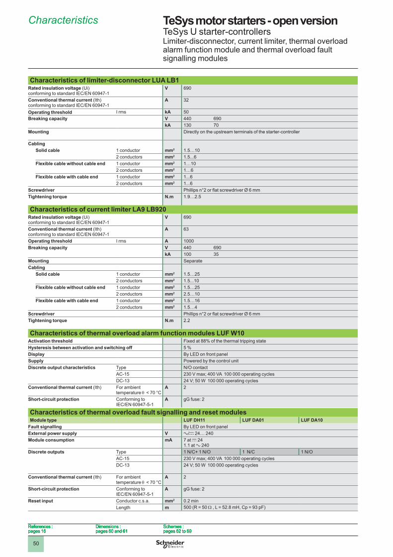
50
TeSys motor starters - open version 1 TeSys U starter-controllersLimiter-disconnector, current limiter, thermal overload alarm function module and thermal overload fault signalling modules
Characteristics of limiter-disconnector LUA LB1Rated insulation voltage (Ui)conforming to standard IEC/EN 60947-1
V 690
Conventional thermal current (Ith)conforming to standard IEC/EN 60947-1
A 3�
Operating threshold I rms kA 50Breaking capacity V 440 690
kA �30 70Mounting Directly on the upstream terminals of the starter-controller
CablingSolid cable � conductor mm2 �.5…�0
� conductors mm2 �.5...6Flexible cable without cable end � conductor mm2 �…�0
� conductors mm2 �…6Flexible cable with cable end � conductor mm2 �...6
� conductors mm2 �...6Screwdriver Phillips n°2 or flat screwdriver Ø 6 mmTightening torque N .m �.9…�.5
Characteristics of current limiter LA9 LB920Rated insulation voltage (Ui)conforming to standard IEC/EN 60947-1
V 690
Conventional thermal current (Ith)conforming to standard IEC/EN 60947-1
A 63
Operating threshold I rms A �000Breaking capacity V 440 690
kA �00 35Mounting SeparateCabling
Solid cable � conductor mm2 �.5…�5� conductors mm2 �.5...�0
Flexible cable without cable end � conductor mm2 �.5…�5� conductors mm2 �.5…�0
Flexible cable with cable end � conductor mm2 �.5…�6� conductors mm2 �.5…4
Screwdriver Phillips n°2 or flat screwdriver Ø 6 mmTightening torque N .m �.�
Characteristics of thermal overload alarm function modules LUF W10Activation threshold Fixed at 88% of the thermal tripping stateHysteresis between activation and switching off 5 %Display By LED on front panelSupply Powered by the control unitDiscrete output characteristics Type N/O contact
AC-�5 230 V max; 400 VA 100 000 operating cyclesDC-�3 �4 V; 50 W �00 000 operating cycles
Conventional thermal current (Ith) For ambient temperature q < 70 °C
A �
Short-circuit protection Conforming to IEC/EN 60947-5-1
A gG fuse: 2
Characteristics of thermal overload fault signalling and reset modulesModule type LUF DH11 LUF DA01 LUF DA10
Fault signalling By LED on front panelExternal power supply V a/c �4… �40Module consumption mA 7 at c �4
�.� at a �40 Discrete outputs Type 1 N/C+ 1 N/O 1 N/C 1 N/O
AC-�5 230 V max; 400 VA 100 000 operating cyclesDC-�3 �4 V; 50 W �00 000 operating cycles
Conventional thermal current (Ith) For ambient temperature q < 70 °C
A �
Short-circuit protection Conforming to IEC/EN 60947-5-1
A gG fuse: 2
Reset input Conductor c.s.a. mm2 0.� minLength m 500 (R = 50 W , L = 52.8 mH, Cp = 93 pF)
References :pages �6
Dimensions : pages 60 and 6�
Schemes : pages 6� to 69
References :pages �6
Dimensions : pages 60 and 6�
Schemes : pages 6� to 69
References :pages �6
Dimensions : pages 60 and 6�
Schemes : pages 6� to 69
References :pages �6
Dimensions : pages 60 and 6�
Schemes : pages 6� to 69
Characteristics 1
1
2
3
4
5
6
7
8
9
10
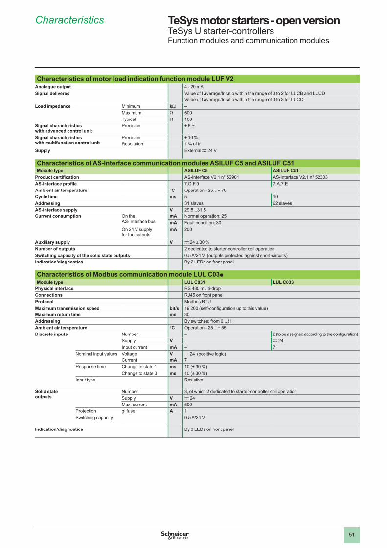
5�
TeSys motor starters - open version 1 TeSys U starter-controllersFunction modules and communication modules
Characteristics of motor load indication function module LUF V2Analogue output 4 - �0 mASignal delivered Value of I average/Ir ratio within the range of 0 to 2 for LUCB and LUCD
Value of I average/Ir ratio within the range of 0 to 3 for LUCCLoad impedance Minimum kW –
Maximum W 500Typical W �00
Signal characteristics with advanced control unit
Precision ± 6 %
Signal characteristics with multifunction control unit
Precision ± �0 %Resolution � % of Ir
Supply External c �4 V
Characteristics of AS-Interface communication modules ASILUF C5 and ASILUF C51Module type ASILUF C5 ASILUF C51
Product certification AS-Interface V2.1 n° 52901 AS-Interface V2.1 n° 52303AS-Interface profile 7.D.F.0 7.A.7.EAmbient air temperature °C Operation - 25…+ 70Cycle time ms 5 �0Addressing 3� slaves 6� slavesAS-Interface supply V �9.5...3�.5Current consumption On the
AS-Interface busmA Normal operation: �5mA Fault condition: 30
On �4 V supply for the outputs
mA �00
Auxiliary supply V c �4 ± 30 %Number of outputs � dedicated to starter-controller coil operationSwitching capacity of the solid state outputs 0.5 A/24 V (outputs protected against short-circuits)Indication/diagnostics By � LEDs on front panel
Characteristics of Modbus communication module LUL C03pModule type LUL C031 LUL C033
Physical interface RS 485 multi-dropConnections RJ45 on front panelProtocol Modbus RTUMaximum transmission speed bit/s 19 200 (self-configuration up to this value)Maximum return time ms 30Addressing By switches: from 0...3�Ambient air temperature °C Operation - 25…+ 55Discrete inputs Number – 2 (to be assigned according to the configuration)
Supply V – c �4Input current mA – 7
Nominal input values Voltage V c �4 (positive logic)Current mA 7
Response time Change to state � ms �0 (± 30 %)Change to state 0 ms �0 (± 30 %)
Input type Resistive
Solid state outputs
Number 3, of which � dedicated to starter-controller coil operationSupply V c �4Max. current mA 500
Protection gI fuse A �Switching capacity 0.5 A/24 V
Indication/diagnostics By 3 LEDs on front panel
Characteristics 1
1
2
3
4
5
6
7
8
9
10
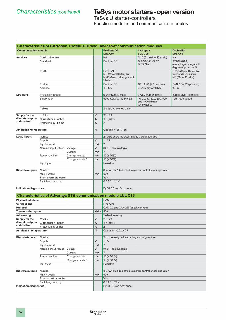
5�
TeSys motor starters - open version 1 TeSys U starter-controllersFunction modules and communication modules
Characteristics of CANopen, Profibus DPand DeviceNet communication modulesCommunication module Profibus DP
LUL C07CANopen LUL C08
DeviceNet LUL C09
Services Conformity class NA S �0 (Schneider Electric) NAStandard Profibus DP CIADS-30� V4.0�
DR 303-�IEC 6�0�6-�, overvoltage category III, degree of pollution: 3
Profile LVSG V1.0 MS (Motor Starter) and MMS (Motor Management Starter)
– ODVA (Open DeviceNet Vendor Association) MS (Motor Starter)
Protocol Profibus DP CAN �.0A (�B passive) CAN �.0A (�B passive)Address �…��5 0…��7 (by switches) 0…63
Structure Physical interface 9-way SUB-D male 9-way SUB-D female “Open Style” connectorBinary rate 9600 Kbits/s…12 Mbits/s �0, �0, 50, ��5, �50, 500
and 1000 Kbits/s (by switches)
��5…500 kbaud
Cables � shielded twisted pairs
Supply for the discrete outputs and control
c �4 V V �0…�8Current consumption A 1.5 (max)Protection by gl fuse A �
Ambient air temperature °C Operation -25…+55
Logic inputs Number 2 (to be assigned according to the configuration)Supply V c �4Input current mA 7Nominal input values Voltage V c �4 (positive logic)
Current mA 7Response time Change to state � ms �0 (± 30%)
Change to state 0 ms �0 (± 30%)Input type Resistive
Discrete outputs Number 3, of which � dedicated to starter-controller coil operationMax. current mA 500Short-circuit protection YesSwitching capacity 0.5 A / c �4 V
Indication/diagnostics By 3 LEDs on front panel
Characteristics of Advantys STB communication module LUL C15Physical interface CANConnections Fire WireProtocol CAN �.0 and CAN �.B (passive mode)Transmission speed kbit/s 800Addressing Self-addressingSupply for the discrete outputs and control
c �4 V V �0…�8Current consumption A 1.5 (max)Protection by gl fuse A �
Ambient air temperature °C Operation - 25…+ 55
Discrete inputs Number 2 ( to be assigned according to configuration)Supply V c �4Input current mA 7Nominal input values Voltage V c �4 (positive logic)
Current mA 7Response time Change to state � ms �0 (± 30 %)
Change to state 0 ms �0 (± 30 %)Input type Resistive
Discrete outputs Number 3, of which � dedicated to starter-controller coil operationMax. current mA 500Short-circuit protection YesSwitching capacity 0.5 A / c �4 V
Indication/diagnostics By 3 LEDs on front panel
Characteristics (continued) 0
1
2
3
4
5
6
7
8
9
10
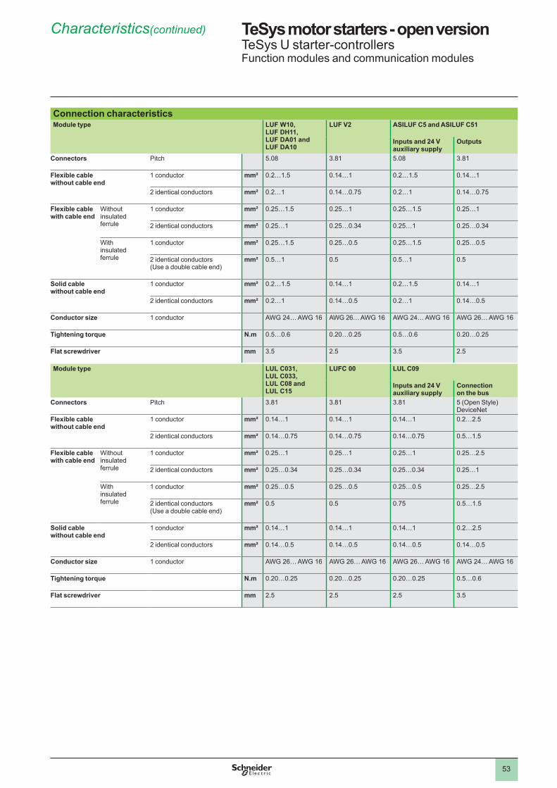
53
TeSys motor starters - open version 1 TeSys U starter-controllersFunction modules and communication modules
Connection characteristicsModule type LUF W10,
LUF DH11, LUF DA01 and LUF DA10
LUF V2 ASILUF C5 and ASILUF C51
Inputs and 24 V auxiliary supply
Outputs
Connectors Pitch 5.08 3.8� 5.08 3.8�
Flexible cable without cable end
� conductor mm² 0.�…�.5 0.�4…� 0.�…�.5 0.�4…�
� identical conductors mm² 0.�…� 0.�4…0.75 0.�…� 0.�4…0.75
Flexible cable with cable end
Without insulated ferrule
� conductor mm² 0.�5…�.5 0.�5…� 0.�5…�.5 0.�5…�
� identical conductors mm² 0.�5…� 0.�5…0.34 0.�5…� 0.�5…0.34
With insulated ferrule
� conductor mm² 0.�5…�.5 0.�5…0.5 0.�5…�.5 0.�5…0.5
� identical conductors(Use a double cable end)
mm² 0.5…� 0.5 0.5…� 0.5
Solid cable without cable end
� conductor mm² 0.�…�.5 0.�4…� 0.�…�.5 0.�4…�
� identical conductors mm² 0.�…� 0.�4…0.5 0.�…� 0.�4…0.5
Conductor size � conductor AWG 24… AWG 16 AWG 26… AWG 16 AWG 24… AWG 16 AWG 26… AWG 16
Tightening torque N .m 0.5…0.6 0.�0…0.�5 0.5…0.6 0.�0…0.�5
Flat screwdriver mm 3.5 �.5 3.5 �.5
Module type LUL C031, LUL C033, LUL C08 and LUL C15
LUFC 00 LUL C09
Inputs and 24 V auxiliary supply
Connection on the bus
Connectors Pitch 3.8� 3.8� 3.8� 5 (Open Style) DeviceNet
Flexible cable without cable end
� conductor mm² 0.�4…� 0.�4…� 0.�4…� 0.�…�.5
� identical conductors mm² 0.�4…0.75 0.�4…0.75 0.�4…0.75 0.5…�.5
Flexible cable with cable end
Without insulated ferrule
� conductor mm² 0.�5…� 0.�5…� 0.�5…� 0.�5…�.5
� identical conductors mm² 0.�5…0.34 0.�5…0.34 0.�5…0.34 0.�5…�
With insulated ferrule
� conductor mm² 0.�5…0.5 0.�5…0.5 0.�5…0.5 0.�5…�.5
� identical conductors(Use a double cable end)
mm² 0.5 0.5 0.75 0.5…�.5
Solid cable without cable end
� conductor mm² 0.�4…� 0.�4…� 0.�4…� 0.�…�.5
� identical conductors mm² 0.�4…0.5 0.�4…0.5 0.�4…0.5 0.�4…0.5
Conductor size � conductor AWG 26… AWG 16 AWG 26… AWG 16 AWG 26… AWG 16 AWG 24… AWG 16
Tightening torque N .m 0.�0…0.�5 0.�0…0.�5 0.�0…0.�5 0.5…0.6
Flat screwdriver mm �.5 �.5 �.5 3.5
Characteristics(continued) 0
1
2
3
4
5
6
7
8
9
10

60
Dimensions TeSys motor starters - open versionTeSys U starter-controllers
DimensionsStarter-controllers LUB: non-reversing LU2B: reversing
Rail mounting Screw fixing Rail mounting Screw fixing
126
a (1)
154
X1
X1 45
X2
X2
��6
�35 (1)73
30 Ø4 (2)
�63…
�67
��4
45
120/
125
�33…
�37
�9 Ø4 (2)
aWith Modbus module �35With Advantys STB, CANopen, Profibus DP or DeviceNet modules
�47
Minimum electrical clearance: X1 = 50 mm for Ue = 440 V and 70 mm for Ue = 500 and 690 V, X2 = 0Reverser block for mounting separately from power base
Rail mounting Screw fixing
45��3
��5
��3 36
104
Ø4
Sets of busbars and plug-in power socketsGV2 G445 and GV2 G454 GV2 Gppp with terminal block GV1 G09 GV2 G245 and G254
95
la
�8
pGV1 G09
30
l
IGV2 G245 (2 x 45) 89GV2 G254 (2 x 54) 98
I P GV2 G554 GV2 G345 et G354GV2 G445 (2 x 45) �79 45 �60 lGV2 G454 (2 x 54) �06 54
aNumber of tap-offs 5 6 7 8 IGV2 G445 (2 x 45) ��4 �69 3�4 359 GV2 G345 (2 x 45) 134GV2 G454 (2 x 54) �60 3�4 368 4�� GV2 G354 (2 x 54) 152
AK5 JB144 AK5 PC13, PC33, PC33L
79
8�
30
458�
438
45�
45,5
35,538
(1) Depth with communication module.(2) Retractablefixinglugs.
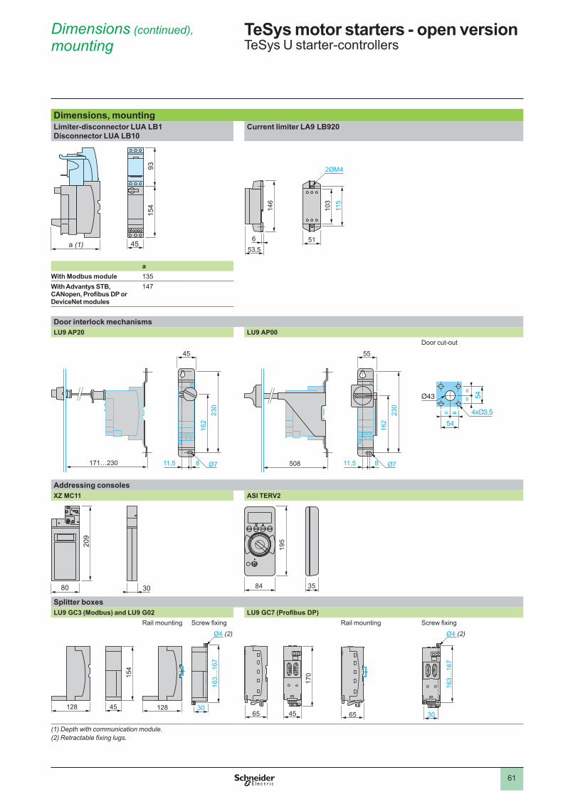
6�
Dimensions (continued), mounting
TeSys motor starters - open versionTeSys U starter-controllers
Dimensions, mountingLimiter-disconnector LUA LB1 Disconnector LUA LB10
Current limiter LA9 LB920
a (1) 45
93�5
4
653,5
�46
2ØM4
�03
��5
5�
aWith Modbus module �35With Advantys STB, CANopen, Profibus DP or DeviceNet modules
�47
Door interlock mechanismsLU9 AP20 LU9 AP00
Door cut-out
�7�…�30 ��,5 8
45
�30
�6�
Ø7 508 ��,5 8
55
�30
�6�
Ø7
= =
==
54
54
Addressing consolesXZ MC11 ASI TERV2
3080
�09
�95
84 35
Splitter boxesLU9 GC3 (Modbus) and LU9 G02 LU9 GC7 (Profibus DP)
Rail mounting Screw fixing Rail mounting Screw fixing
128 45
154
��8 30
Ø4 (2)
163…
167
4565
170
65
163…
167
30
Ø4 (2)
(1) Depth with communication module.(2) Retractablefixinglugs.
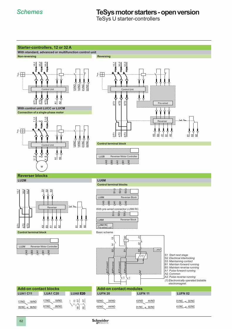
6�
TeSys motor starters - open version 1 TeSys U starter-controllers
Starter-controllers, 12 or 32 AWith standard, advanced or multifunction control unitNon-reversing Reversing
With control unit LUCC or LUCMConnection of a single-phase motor
Control terminal block
Reverser blocksLU2M LU6M
Control terminal blocks
With pre-wired connector LU9M RC
Control terminal block Basic scheme
S� Start next stageS� Electrical interlockingS3 Maintaining contactB� Maintain forward runningB3 Maintain reverse runningA� Pulse forward runningA� CommonA3 Pulse reverse running(1) Electronically operated bistable
electromagnet.
Add-on contact blocks Add-on contact modulesLUA1 C11 LUA1 C20 LUA8 E20 E20E20 LUFN 20 LUFN 11 LUFN 02
13/N
O
14/N
O
21/N
C
22/N
C
2/T
1
4/T
2
6/T
3
A1
A2
1/L1
3/L2
5/L3
Control Unit 13/N
O
14/N
O
21/N
C
22/N
C
2/T
1
4/T
2
6/T
3
A1
A2
1/L1
3/L2
5/L3
Control Unit
84 8281
2/T
1
4/T
2
6/T
3
2/T
1
4/T
2
6/T
3
A3
B3
A1
B1
A2
1/L1
3/L2
5/L3
Control Unit
Pre-wired
Reverser
84 8281
2/T
1
4/T
2
6/T
3
2/T
1
4/T
2
6/T
3
A3
B3
A1
B1
A2
1/L1
3/L2
5/L3
Control Unit
Pre-wired
Reverser
13/N
O
14/N
O
21/N
C
22/N
C
2 4 6
A1
A2
1 3 5
L1 L2
M
U V
Control Unit
13/N
O
14/N
O
21/N
C
22/N
C
2 4 6
A1
A2
1 3 5
L1 L2
M
U V
Control Unit
Reverser Motor Controller
Reversed
Reverser Motor Controller
Reversed
1/L1
3/L2
5/L3
A3
2/T
1
4/T
2
6/T
3
B3
A1
S1
S2
S3
B1
A2 84 8281
Reverser
1/L1
3/L2
5/L3
A3
2/T
1
4/T
2
6/T
3
B3
A1
S1
S2
S3
B1
A2 84 8281
Reverser
Reverser BlockReverser Block
S1
S2
S3
LU6M
LU9M RC
S1
S2
S3
LU6M
LU9M RC
Reverser Block
Pre-wired coil
S1
S2
S3
LU6M
LU9M RC
S1
S2
S3
LU6M
LU9M RC
Reverser Block
Pre-wired coil
Reverser Motor ControllerReverser Motor ControllerLU6M
A1
A3
A2
S1
22
A2
A1
21
1413
S3
B1
B3
S2
(1)
Rev
erse
Forw
ard
Rev
erse
Forw
ard
LU6M
A1
A3
A2
S1
22
A2
A1
21
1413
S3
B1
B3
S2
(1)
Rev
erse
Forw
ard
Rev
erse
Forw
ard
Schemes 1
OI 5758
6768
1
2
3
4
5
6
7
8
9
10
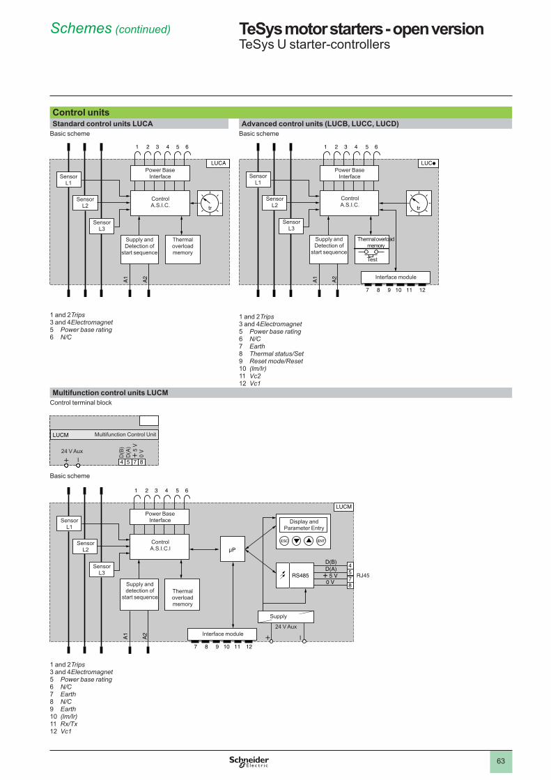
63
TeSys motor starters - open version 1 TeSys U starter-controllers
Control unitsStandard control units LUCA Advanced control units (LUCB, LUCC, LUCD)
Basic scheme
� and � Trips3 and 4 Electromagnet5 Power base rating6 N/C
Basic scheme
� and � Trips3 and 4 Electromagnet5 Power base rating6 N/C7 Earth8 Thermal status/Set9 Reset mode/Reset�0 (lm/Ir)�� Vc2 �� Vc1
Multifunction control units LUCMControl terminal block
Basic scheme
� and � Trips3 and 4 Electromagnet5 Power base rating6 N/C7 Earth8 N/C9 Earth�0 (lm/Ir)�� Rx/Tx �� Vc1
SensorL�
SensorL�
SensorL3
Power Base Interface
Control A.S.I.C.
Supply and Detection of
start sequence
Thermal overload memory
SensorL�
SensorL�
SensorL3
Power Base Interface
Control A.S.I.C.
Supply and Detection of
start sequence
Thermal overload memory
p
SensorL�
SensorL�
SensorL3
Power Base Interface
Control A.S.I.C.
Supply and Detection of
start sequence
Thermal overload memory
Interface module
Test
p
SensorL�
SensorL�
SensorL3
Power Base Interface
Control A.S.I.C.
Supply and Detection of
start sequence
Thermal overload memory
Interface module
Test
654
D(B
)D
(A)
+ 5
V
754
LUCM
0 V
8
24 V Aux
Multifunction Control Unit
654
D(B
)D
(A)
+ 5
V
754
LUCM
0 V
8
24 V Aux
Multifunction Control Unit
A1
7 8 9 10 11 12
1 2 3 4 5 6
A2
LUCM
D(B)D(A)
+ 5 V0 V
ESC ENT
RS485
4578
RJ45
SensorL�
SensorL�
SensorL3
Power Base Interface
Control A.S.I.C.l
Supply and detection of
start sequenceThermal overload memory
Interface module
Display and Parameter Entry
Supply
24 V Aux
A1
7 8 9 10 11 12
1 2 3 4 5 6
A2
LUCM
D(B)D(A)
+ 5 V0 V
ESC ENT
RS485
4578
RJ45
SensorL�
SensorL�
SensorL3
Power Base Interface
Control A.S.I.C.l
Supply and detection of
start sequenceThermal overload memory
Interface module
Display and Parameter Entry
Supply
24 V Aux
Schemes (continued) 1
1
2
3
4
5
6
7
8
9
10
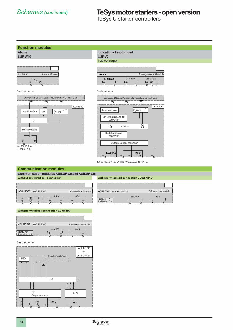
64
TeSys motor starters - open version 1 TeSys U starter-controllers
Function modulesAlarm Indication of motor loadLUF W10 LUF V2
4-20 mA output
Basic scheme Basic scheme
�00 W < load < 500 W c 30 V max and 40 mA min
Communication modulesCommunication modules ASILUF C5 and ASILUF C51Without pre-wired coil connection With pre-wired coil connection LU9B N11C
With pre-wired coil connection LU9M RC
Basic scheme
Alarms ModuleAlarms Module
24 V Aux
Analogue output Module
24 V Aux 24 V Aux
Analogue output Module
24 V Aux
Advanced Control Unit or Multifunction Control Unit
Input interface Supply
Bistable Relay
LED
Advanced Control Unit or Multifunction Control Unit
Input interface Supply
Bistable Relay
LED
c
Input interface Supply
Advanced Control Unit or Multifunction Control Unit
µP - Analogue/Digital converter
Isolation
Digital/Analogue converter
Voltage/Current converter
c
Input interface Supply
Advanced Control Unit or Multifunction Control Unit
µP - Analogue/Digital converter
Isolation
Digital/Analogue converter
Voltage/Current converter
Com
OA
1
OA
3 AS-i
ASILUF C5 AS-Interface Moduleor ASILUF C5�
Com
OA
1
OA
3 AS-i
ASILUF C5 AS-Interface Moduleor ASILUF C5�
AS-i
ASILUF C5
LU9B N11CPre-wired coil
AS-Interface Moduleor ASILUF C5�
AS-i
ASILUF C5
LU9B N11CPre-wired coil
AS-Interface Moduleor ASILUF C5�
AS-i
ASILUF C5
LU9M RCPre-wired coil
AS-Interface Moduleor ASILUF C5�
AS-i
ASILUF C5
LU9M RCPre-wired coil
AS-Interface Moduleor ASILUF C5�
c 24 V
ASILUF C5
Com
OA
1
OA
3 AS-i
A2SI
ASILUF C51
Output Interface
Ready-Fault-PoleLED
or
c 24 V
ASILUF C5
Com
OA
1
OA
3 AS-i
A2SI
ASILUF C51
Output Interface
Ready-Fault-PoleLED
or
Schemes (continued) 1
1
2
3
4
5
6
7
8
9
10
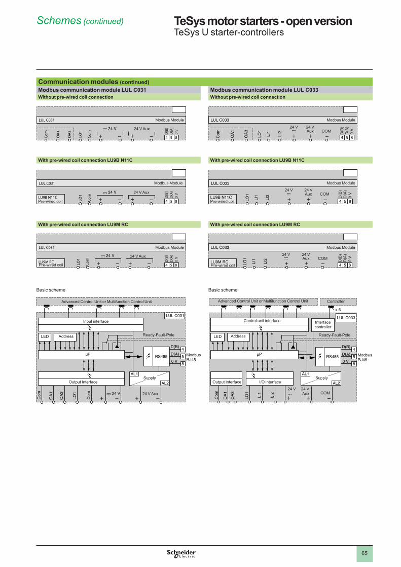
65
TeSys motor starters - open version 1 TeSys U starter-controllers
Communication modules (continued)Modbus communication module LUL C031 Modbus communication module LUL C033Without pre-wired coil connection Without pre-wired coil connection
With pre-wired coil connection LU9B N11C With pre-wired coil connection LU9B N11C
With pre-wired coil connection LU9M RC With pre-wired coil connection LU9M RC
Basic scheme Basic scheme
Com
OA
1
Com
LO1
OA
3
654
D(B
)D
(A)
0 V
854
LUL C031
24 V Aux
Modbus Module
Com
OA
1
Com
LO1
OA
3
654
D(B
)D
(A)
0 V
854
LUL C031
24 V Aux
Modbus Module
Com
OA
1
LI1
LI2
LO1
OA
3
654
D(B
)D
(A)
0 V
854
LUL C033
�4 Vc
Modbus Module
�4 VAux COM
Com
OA
1
LI1
LI2
LO1
OA
3
654
D(B
)D
(A)
0 V
854
LUL C033
�4 Vc
Modbus Module
�4 VAux COM
Com
LO1
654
D(B
)D
(A)
0 V
854
LUL C031
LU9B N11C24 V Aux
Modbus Module
Pre-wired coil Com
LO1
654
D(B
)D
(A)
0 V
854
LUL C031
LU9B N11C24 V Aux
Modbus Module
Pre-wired coil LI1
LI2
LO1
654
D(B
)D
(A)
0 V
854
LUL C033
LU9B N11C
Modbus Module
Pre-wired coil
�4 Vc
�4 VAux COM
LI1
LI2
LO1
654
D(B
)D
(A)
0 V
854
LUL C033
LU9B N11C
Modbus Module
Pre-wired coil
�4 Vc
�4 VAux COM
Com
LO1
54
D(B
)D
(A)
0 V
854
LUL C031
LU9M RC24 V Aux
Modbus Module
Pre-wired coil Com
LO1
54
D(B
)D
(A)
0 V
854
LUL C031
LU9M RC24 V Aux
Modbus Module
Pre-wired coil LI1
LI2
LO1
54
D(B
)D
(A)
0 V
854
LUL C033
LU9M RC
Modbus Module
Pre-wired coil
�4 Vc
�4 VAux COMLI
1
LI2
LO1
54
D(B
)D
(A)
0 V
854
LUL C033
LU9M RC
Modbus Module
Pre-wired coil
�4 Vc
�4 VAux COM
LUL C031
Com
Com
OA
1
OA
3
LO1
D(B)
D(A)
0 VRS485
AL1
AL2
4
5
8
ModbusRJ45
24 V
Supply
24 V Aux
Address
Input interface
Advanced Control Unit or Multifunction Control Unit
Ready-Fault-PoleLED
Output Interface
LUL C031
Com
Com
OA
1
OA
3
LO1
D(B)
D(A)
0 VRS485
AL1
AL2
4
5
8
ModbusRJ45
24 V
Supply
24 V Aux
Address
Input interface
Advanced Control Unit or Multifunction Control Unit
Ready-Fault-PoleLED
Output Interface
Com LI1
LI2
OA
1
OA
3
LO1
D(B)
D(A)
0 VRS485
AL1
AL2
4
5
8
ModbusRJ45
x 6
LUL C033
I/O interfaceSupply
Address
Control unit interface
Advanced Control Unit or Multifunction Control Unit
Ready-Fault-PoleLED
Interfacecontroller
Output Interface
Controller
�4 Vc
�4 VAux COM
Com LI1
LI2
OA
1
OA
3
LO1
D(B)
D(A)
0 VRS485
AL1
AL2
4
5
8
ModbusRJ45
x 6
LUL C033
I/O interfaceSupply
Address
Control unit interface
Advanced Control Unit or Multifunction Control Unit
Ready-Fault-PoleLED
Interfacecontroller
Output Interface
Controller
�4 Vc
�4 VAux COM
Schemes (continued) 1
1
2
3
4
5
6
7
8
9
10
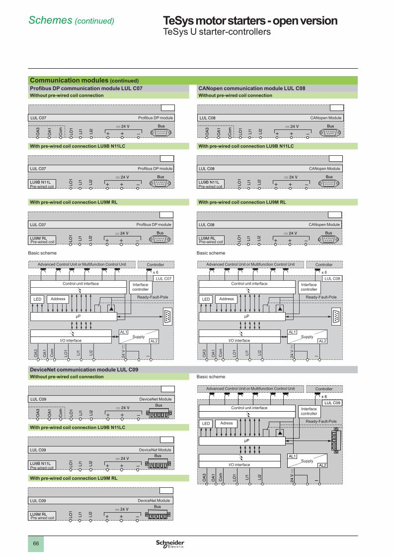
66
TeSys motor starters - open version 1 TeSys U starter-controllers
Communication modules (continued)Profibus DP communication module LUL C07 CANopen communication module LUL C08Without pre-wired coil connection Without pre-wired coil connection
With pre-wired coil connection LU9B N11LC With pre-wired coil connection LU9B N11LC
With pre-wired coil connection LU9M RL With pre-wired coil connection LU9M RL
Basic scheme Basic scheme
DeviceNet communication module LUL C09Without pre-wired coil connection Basic scheme
With pre-wired coil connection LU9B N11LC
With pre-wired coil connection LU9M RL
Com
OA
1
LO1
LI1
LI2
OA
3
LUL C07
Bus
Profibus DP module
Com
OA
1
LO1
LI1
LI2
OA
3
LUL C07
Bus
Profibus DP module
Com
OA
1
LO1
LI1
LI2
OA
3
654
D(B
)D
(A)
0 V
854
LUL C08
Bus
CANopen Module
Com
OA
1
LO1
LI1
LI2
OA
3
654
D(B
)D
(A)
0 V
854
LUL C08
Bus
CANopen Module
LU9B N11L
LO1
LI1
LI2
LUL C07
Bus
Pre-wired coil
Profibus DP module
LU9B N11L
LO1
LI1
LI2
LUL C07
Bus
Pre-wired coil
Profibus DP module
LU9B N11L
LO1
LI1
LI2
LUL C08
Bus
Pre-wired coil
CANopen Module
LU9B N11L
LO1
LI1
LI2
LUL C08
Bus
Pre-wired coil
CANopen Module
LU9M RL
LO1
LI1
LI2
LUL C07
Bus
Pre-wired coil
Profibus DP module
LU9M RL
LO1
LI1
LI2
LUL C07
Bus
Pre-wired coil
Profibus DP module
LU9M RLLO
1
LI1
LI2
LUL C08
Bus
Pre-wired coil
CANopen Module
LU9M RLLO
1
LI1
LI2
LUL C08
Bus
Pre-wired coil
CANopen Module
LUL C07
Com LI2
LI1
OA1
OA3
LO1
AL1
AL2
x 6
I/O interfaceSupply
Address
Control unit interface
Ready-Fault-PoleLED
Interfacecontroller
Advanced Control Unit or Multifunction Control Unit Controller
LUL C07
Com LI2
LI1
OA1
OA3
LO1
AL1
AL2
x 6
I/O interfaceSupply
Address
Control unit interface
Ready-Fault-PoleLED
Interfacecontroller
Advanced Control Unit or Multifunction Control Unit Controller
LUL C08
Com LI2
LI1
OA1
OA3
LO1
AL1
AL2
x 6
I/O interfaceSupply
Address
Control unit interface
Ready-Fault-PoleLED
Interfacecontroller
Advanced Control Unit or Multifunction Control Unit Controller
LUL C08
Com LI2
LI1
OA1
OA3
LO1
AL1
AL2
x 6
I/O interfaceSupply
Address
Control unit interface
Ready-Fault-PoleLED
Interfacecontroller
Advanced Control Unit or Multifunction Control Unit Controller
LUL C09
Com LI2
LI1
OA
1
OA
3
LO1
AL1
AL2
x 6
24 V
c
I/O interfaceSupply
Adress
Control unit interface
Ready-Fault-PoleLED
Interfacecontroller
Advanced Control Unit or Multifunction Control Unit Controller
LUL C09
Com LI2
LI1
OA
1
OA
3
LO1
AL1
AL2
x 6
24 V
c
I/O interfaceSupply
Adress
Control unit interface
Ready-Fault-PoleLED
Interfacecontroller
Advanced Control Unit or Multifunction Control Unit Controller
Com
OA
1
LO1
LI1
LI2
OA
3
LUL C09
Bus
DeviceNet Module
Com
OA
1
LO1
LI1
LI2
OA
3
LUL C09
Bus
DeviceNet Module
LU9B N11L
LO1
LI1
LI2
LUL C09Bus
Pre wired coil
DeviceNet Module
LU9B N11L
LO1
LI1
LI2
LUL C09Bus
Pre wired coil
DeviceNet Module
LU9M RL
LO1
LI1
LI2
LUL C09
Bus
Pre wired coil
DeviceNet Module
LU9M RL
LO1
LI1
LI2
LUL C09
Bus
Pre wired coil
DeviceNet Module
Schemes (continued) 1
1
2
3
4
5
6
7
8
9
10
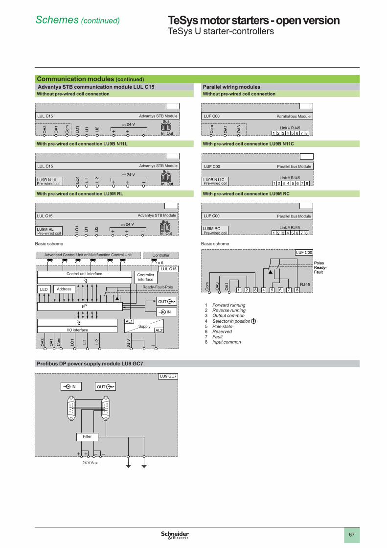
67
TeSys motor starters - open version 1 TeSys U starter-controllers
Communication modules (continued) Advantys STB communication module LUL C15 Parallel wiring modulesWithout pre-wired coil connection Without pre-wired coil connection
With pre-wired coil connection LU9B N11L With pre-wired coil connection LU9B N11C
With pre-wired coil connection LU9M RL With pre-wired coil connection LU9M RC
Basic scheme Basic scheme
Profibus DP power supply module LU9 GC7
Com
OA
1
LO1
LI1
LI2
OA
3
LUL C15Bus
In Out
Advantys STB Module
Com
OA
1
LO1
LI1
LI2
OA
3
LUL C15Bus
In Out
Advantys STB Module
87654321Com
OA
1
OA
3
LUF C00
Link // RJ45
Parallel bus Module
87654321Com
OA
1
OA
3
LUF C00
Link // RJ45
Parallel bus Module
LO1
LI1
LI2
LUL C15Bus
In OutLU9B N11LPre-wired coil
Advantys STB Module
LO1
LI1
LI2
LUL C15Bus
In OutLU9B N11LPre-wired coil
Advantys STB Module
87654321
LUF C00
LU9B N11C Link // RJ45
Parallel bus Module
Pre-wired coil 87654321
LUF C00
LU9B N11C Link // RJ45
Parallel bus Module
Pre-wired coil
LU9M RL
LO1
LI1
LI2
LUL C15Bus
In OutPre-wired coil
Advantys STB Module
LU9M RL
LO1
LI1
LI2
LUL C15Bus
In OutPre-wired coil
Advantys STB Module
87654321
LUF C00
LU9M RC Link // RJ45
Parallel bus Module
Pre-wired coil 87654321
LUF C00
LU9M RC Link // RJ45
Parallel bus Module
Pre-wired coil
LUL C15
Com LI2
LI1
OA
1
OA
3
LO1
AL1
AL2
x 6
24 V
c
OUT
IN
I/O interfaceSupply
Address
Control unit interface
Advanced Control Unit or Multifunction Control Unit
Ready-Fault-PoleLED
Controller interface
Controller
LUL C15
Com LI2
LI1
OA
1
OA
3
LO1
AL1
AL2
x 6
24 V
c
OUT
IN
I/O interfaceSupply
Address
Control unit interface
Advanced Control Unit or Multifunction Control Unit
Ready-Fault-PoleLED
Controller interface
Controller
Com
OA
3
OA
1
87654321
LUF C00
RJ45
Poles Ready-Fault
Com
OA
3
OA
1
87654321
LUF C00
RJ45
Poles Ready-Fault
OUTIN
LU9 GC7
Filter
24 V Aux.
OUTIN
LU9 GC7
Filter
24 V Aux.
Schemes (continued) 1
� Forward running� Reverse running3 Output common4 Selector in position5 Pole state6 Reserved7 Fault8 Input common
1
2
3
4
5
6
7
8
9
10
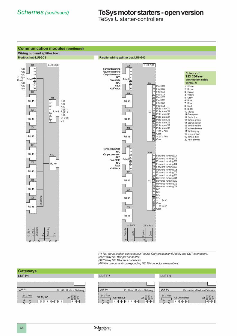
68
TeSys motor starters - open version 1 TeSys U starter-controllers
Communication modules (continued)Wiring hub and splitter boxModbus hub LU9GC3 Parallel wiring splitter box LU9 G02
(1) Not connected on connectors X1 to X8. Only present on RJ45 IN and OUT connectors.(2) 20-way HE 10 input connector.(3) 20-way HE 10 output connector.(4) Wire colours and corresponding HE 10 connector pin numbers.
GatewaysLUF P1 LUF P7 LUF P9
LU9 GC3
0 V
0 V
D (
A) +
D (
B) –
12
34
56
78
RJ 45
X1
12
34
56
78
RJ 45
X9
X2
X3
X4
X5
X6
X7
X8
X10
RJ 45
RJ 45
RJ 45
RJ 45
RJ 45
RJ 45
RJ 45
RJ 45
Shi
eldi
ng
Shi
eldi
ng
Shi
eldi
ng
LU9 GC3
0 V
0 V
D (
A) +
D (
B) –
12
34
56
78
RJ 45
X1
12
34
56
78
RJ 45
X9
X2
X3
X4
X5
X6
X7
X8
X10
RJ 45
RJ 45
RJ 45
RJ 45
RJ 45
RJ 45
RJ 45
RJ 45
Shi
eldi
ng
Shi
eldi
ng
Shi
eldi
ng
LU9 G02
c 24 V
Com
Com
12
34
56
78
910
1112
1314
1516
1718
1920
12
34
56
78
910
1112
1314
1516
1718
1920
(2)
12
34
56
78
(3)
RJ 45
X1
X2
X3
X4
X5
X6
X7
X8
X10
X9
RJ 45
RJ 45
RJ 45
RJ 45
RJ 45
RJ 45
12
34
56
78
RJ 45
Forward runningReverse runningOutput common
N/CPole state
N/CFault
+24 V Aux
Forward runningN/C
Output commonN/C
Pole stateN/C
Fault+24 V Aux
Out
puts
Inpu
ts
24 V Aux
87654321
LUF P1
X2 Fip I/O
54
D(B
)D
(A)
0 V
8549
X1
Fip I/O - Modbus Gateway
24 V Aux
87654321
LUF P1
X2 Fip I/O
54
D(B
)D
(A)
0 V
8549
X1
Fip I/O - Modbus Gateway
24 V Aux
87654321
LUF P7
X2 Profibus
54
D(B
)D
(A)
0 v
8549
X1
Profibus - Modbus Gateway
24 V Aux
87654321
LUF P7
X2 Profibus
54
D(B
)D
(A)
0 v
8549
X1
Profibus - Modbus Gateway
24 V Aux
54321
LUF P9
X2 DeviceNet
54
D(B
)D
(A)
0 V
854
X1
DeviceNet - Modbus Gateway
24 V Aux
54321
LUF P9
X2 DeviceNet
54
D(B
)D
(A)
0 V
854
X1
DeviceNet - Modbus Gateway
24 V Aux
Colours of TSX CDPppp connection cable wires (4)
1 White2 Brown3 Green4 Yellow5 Grey6 Pink7 Blue8 Red9 Black10 Violet11 Grey-pink12 Red-blue13 White-green14 Brown-green15 White-yellow16 Yellow-brown17 White-grey18 Grey-brown19 White-pink20 Pink-brown
N/CN/CN/CD (B) –D (A) +N/C�4 V (�)0 V
N/C N/C N/C
D (B) –D (A) +
N/CN/C 0 V
Fault X�Fault X�Fault X3Fault X4Fault X5Fault X6Fault X7Fault X8Pole state X�Pole state X�Pole state X3Pole state X4Pole state X5Pole state X6Pole state X7Pole state X8+ 24 V AuxCom+ 24 V AuxCom
Forward running X�Forward running X�Forward running X3Forward running X4Forward running X5Forward running X6Forward running X7Forward running X8Reverse running X�Reverse running X�Reverse running X3Reverse running X4N/CN/CN/CN/C+ c �4 VCom+ c �4 VCom
Schemes (continued) 1
1
2
3
4
5
6
7
8
9
10
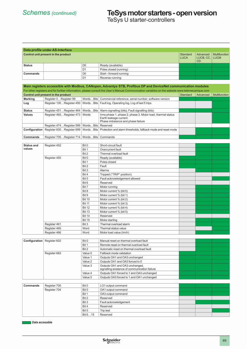
69
TeSys motor starters - open version 1 TeSys U starter-controllers
Data profile under AS-InterfaceControl unit present in the product Standard
LUCAAdvancedLUCB, CC, CD
MultifunctionLUCM
Status D0 Ready (available)D� Poles closed (running)
Commands D0 Start - forward runningD� Reverse running
Main registers accessible with Modbus, CANopen, Advantys STB, Profibus DP and DeviceNet communication modulesFor other registers and for further information, please consult the User’s Manual Communication variables on the website www.telemecanique.comControl unit present in the product Standard Advanced MultifunctionMarking Register 0…Register 99 Words…Bits Commercial reference, serial number, software versionLog Register �00…Register 450 Words…Bits Fault log, Operating log, Log of last 5 trips
Status Register 45�…Register 464 Words…Bits Alarm signalling (bits), Fault signalling (bits)Values Register 465…Register 473 Words Irms phase �, phase �, phase 3. Motor load, thermal status
Earth leakage current. Phase imbalance and phase failure
Register 474…Register 599 Words…Bits ReservedConfiguration Register 600…Register 699 Words…Bits Protection and alarm thresholds, fallback mode and reset mode
Commands Register 700…Register 7�4 Words…Bits Commands
Status and values
Register 45� Bit 0 Short-circuit faultBit � Overcurrent faultBit � Thermal overload fault
Register 455 Bit 0 Ready (available)Bit � Poles closedBit � FaultBit 3 AlarmsBit 4 Tripped (“TRIP” position)Bit 5 Fault acknowledgement allowedBit 6 ReservedBit 7 Motor runningBit 8 Motor current % (bit 0)Bit 9 Motor current % (bit �)Bit �0 Motor current % (bit �)Bit �� Motor current % (bit 3)Bit �� Motor current % (bit 4)Bit �3 Motor current % (bit 5)Bit �4 ReservedBit �5 Motor starting
Register 46� Bit 3 Thermal overload alarmRegister 465 Word Thermal status valueRegister 466 Word Motor load value (Im/Ir)
Configuration Register 60� Bit 0 Manual reset on thermal overload faultBit � Remote reset on thermal overload faultBit � Automatic reset on thermal overload fault
Register 68� Value 0 Fallback mode validationValue � Outputs OA� and OA3 unchangedValue � Outputs OA� and OA3 forced to 0Value 3 Outputs OA� and OA3 unchanged,
signalling existence of communication failureValue 4 Outputs OA� forced to � and OA3 unchangedValue 5 Outputs OA3 forced to � and OA� unchanged
Commands Register 700 Bit 0 LO� output commandRegister 704 Bit 0 OA� output command
Bit � OA3 output commandBit � ReservedBit 3 Fault acknowledgementBit 4 ReservedBit 5 Trip testBit 6…�5 Reserved
Data accessibleData accessible
Schemes (continued) 1
1
2
3
4
5
6
7
8
9
10
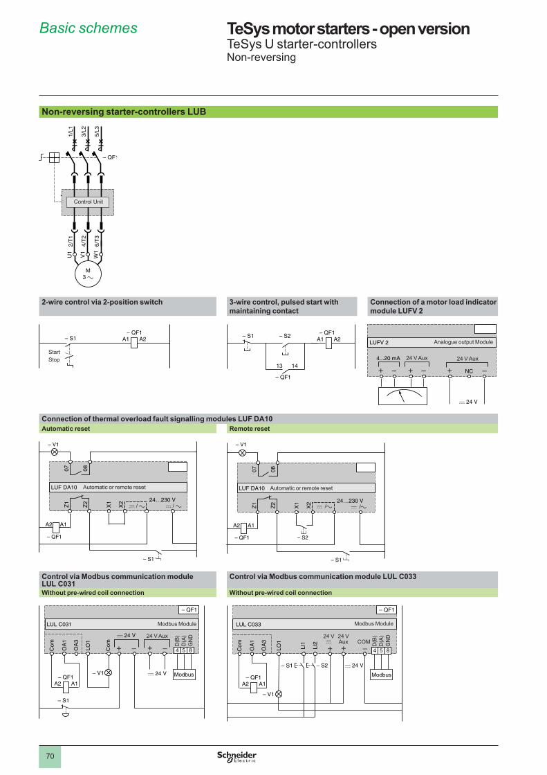
70
TeSys motor starters - open version 1 TeSys U starter-controllersNon-reversing
Non-reversing starter-controllers LUB
2-wire control via 2-position switch 3-wire control, pulsed start with maintaining contact
Connection of a motor load indicator module LUFV 2
Connection of thermal overload fault signalling modules LUF DA10Automatic reset Remote reset
Control via Modbus communication module LUL C031
Control via Modbus communication module LUL C033
Without pre-wired coil connection Without pre-wired coil connection
1/L1
3/L2
5/L3
2/T
1
4/T
2
6/T
3
M3 a
U1
V1
W1
Control Unit
1/L1
3/L2
5/L3
2/T
1
4/T
2
6/T
3
M3 a
U1
V1
W1
Control Unit
A2A1
StartStop
A2A1
StartStop
A2A1
13 14
Reversed
A2A1
13 14
Reversed
4...20 mA
NC
LUFV 2 Analogue output Module
24 V Aux24 V Aux4...20 mA
NC
LUFV 2 Analogue output Module
24 V Aux24 V Aux
Z1
Z2
07 08
LUF DA10
A1
24…230 V
A2
X1
X2
– QF1
– V1
– S1
Automatic or remote reset
Z1
Z2
07 08
LUF DA10
A1
24…230 V
A2
X1
X2
– QF1
– V1
– S1
Automatic or remote reset
Z1
Z2
07 08
LUF DA10
A1
24…230 V
A2
X1
X2
– QF1 – S2
– V1
– S1
Automatic or remote reset
Z1
Z2
07 08
LUF DA10
A1
24…230 V
A2
X1
X2
– QF1 – S2
– V1
– S1
Automatic or remote reset
A1A2
Com
OA
1
Com
LO1
OA
3
654
D(B
)D
(A)
GN
D
854
Modbus
LUL C031 Modbus Module
24 V Aux
A1A2
Com
OA
1
Com
LO1
OA
3
654
D(B
)D
(A)
GN
D
854
Modbus
LUL C031 Modbus Module
24 V Aux
A1A2
Com
OA
1
LI1
LI2
LO1
OA
3
654
D(B
)D
(A)
GN
D
854
Modbus
LUL C033
– S2– S1
Modbus Module
�4 Vc
�4 VAux COM
A1A2
Com
OA
1
LI1
LI2
LO1
OA
3
654
D(B
)D
(A)
GN
D
854
Modbus
LUL C033
– S2– S1
Modbus Module
�4 Vc
�4 VAux COM
Basic schemes 1
1
2
3
4
5
6
7
8
9
10
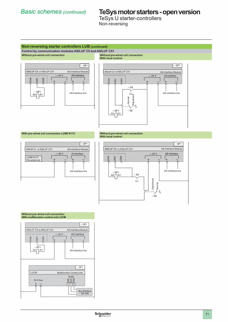
7�
TeSys motor starters - open version 1 TeSys U starter-controllersNon-reversing
Non-reversing starter controllers LUB (continued)Control by communication modules ASILUF C5 and ASILUF C51Without pre-wired coil connection Without pre-wired coil connection
With local control
With pre-wired coil connection LU9B N11C Without pre-wired coil connectionWith local control
Without pre-wired coil connectionWith multifunction control unit LUCM
A1A2
Com
OA
1
OA
3
AS-Interface
ASILUF C5 AS-Interface Module
AS-Interface line
or ASILUF C5�
A1A2
Com
OA
1
OA
3
AS-Interface
ASILUF C5 AS-Interface Module
AS-Interface line
or ASILUF C5�
A1A2
Com
OA
1
OA
3
AS-Interface
ASILUF C5
Adj
ustm
ent
Nor
mal
AS-Interface Module
AS-Interface line
or ASILUF C5�
A1A2
Com
OA
1
OA
3
AS-Interface
ASILUF C5
Adj
ustm
ent
Nor
mal
AS-Interface Module
AS-Interface line
or ASILUF C5�
AS-Interface
ASILUF C5 AS-Interface Module
LU9B N��C Pre wired coil
AS-Interface line
or ASILUF C5�
AS-Interface
ASILUF C5 AS-Interface Module
LU9B N��C Pre wired coil
AS-Interface line
or ASILUF C5�
A1A2
Com
OA
1
OA
3
AS-Interface
ASILUF C5
AS-i Module
Adj
ustm
ent
Nor
mal
AS-Interface Module
AS-Interface line
or ASILUF C5�
A1A2
Com
OA
1
OA
3
AS-Interface
ASILUF C5
AS-i Module
Adj
ustm
ent
Nor
mal
AS-Interface Module
AS-Interface line
or ASILUF C5�
A�A�
Com
OA
�
OA
3
AS-Interface
654
D(B
)D
(A)
GN
D
854
RJ45
Bus ModbusRS 485
ASILUF C5
LUCM Multifunction Control Unit
24 V Aux
AS-Interface Module
AS-Interface line
or ASILUF C5�
A�A�
Com
OA
�
OA
3
AS-Interface
654
D(B
)D
(A)
GN
D
854
RJ45
Bus ModbusRS 485
ASILUF C5
LUCM Multifunction Control Unit
24 V Aux
AS-Interface Module
AS-Interface line
or ASILUF C5�
Basic schemes (continued) 1
1
2
3
4
5
6
7
8
9
10
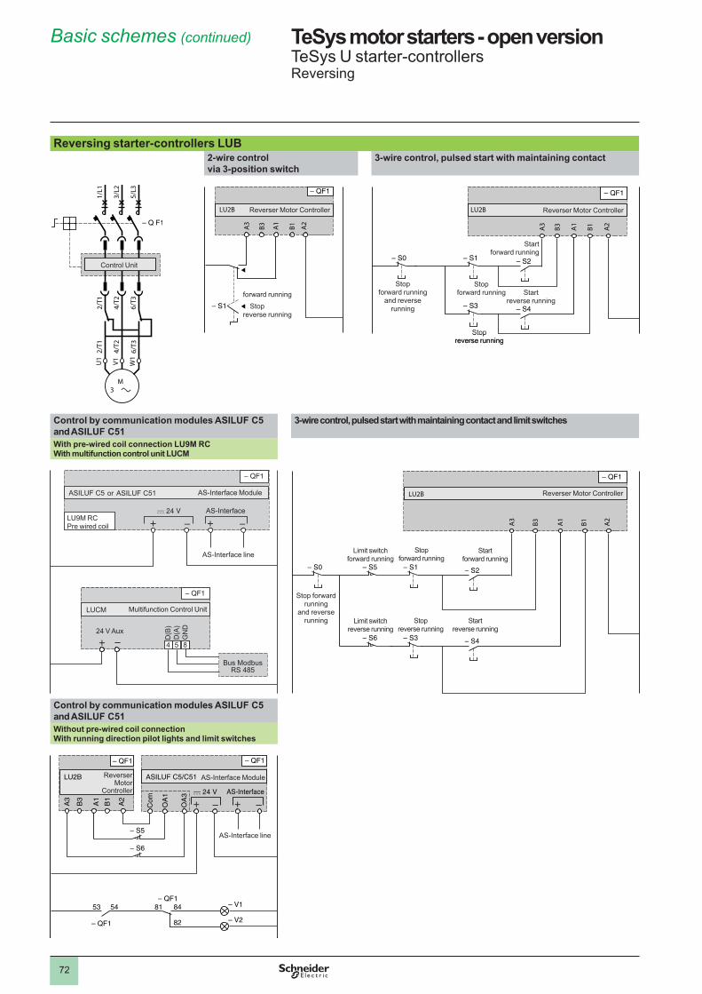
7�
TeSys motor starters - open version 1 TeSys U starter-controllersReversing
Reversing starter-controllers LUB2-wire control via 3-position switch
3-wire control, pulsed start with maintaining contact
Control by communication modules ASILUF C5 and ASILUF C51
3-wire control, pulsed start with maintaining contact and limit switches
With pre-wired coil connection LU9M RCWith multifunction control unit LUCM
Control by communication modules ASILUF C5 and ASILUF C51Without pre-wired coil connectionWith running direction pilot lights and limit switches
2/T1
4/T2
6/T3
2/T1
4/T2
6/T3
U1
W1
V1
M 3
1/L1
3/L2
5/L3
Control Unit
2/T1
4/T2
6/T3
2/T1
4/T2
6/T3
U1
W1
V1
M 3
1/L1
3/L2
5/L3
Control Unit
A3
B3 A1
B1 A2
LU2B Reverser Motor Controller
Stopforward running
reverse running
A3
B3 A1
B1 A2
LU2B Reverser Motor Controller
Stopforward running
reverse running
A3
B3 A1
B1 A2
LU2B
Stop forward running
and reverse running
Reverser Motor Controller
Stop forward running
Stop reverse running
Start forward running
Start reverse running
A3
B3 A1
B1 A2
LU2B
Stop forward running
and reverse running
Reverser Motor Controller
Stop forward running
Stop reverse running
Start forward running
Start reverse running
AS-Interface
654
D(B
)D
(A)
GN
D
854
Bus ModbusRS 485
LUCM
ASILUF C5
24 V Aux
AS-Interface Module
Multifunction Control Unit
LU9M RC Pre wired coil
AS-Interface line
or ASILUF C5�
AS-Interface
654
D(B
)D
(A)
GN
D
854
Bus ModbusRS 485
LUCM
ASILUF C5
24 V Aux
AS-Interface Module
Multifunction Control Unit
LU9M RC Pre wired coil
AS-Interface line
or ASILUF C5�
A3
B3 A1
B1 A2
LU2B
Stop forward running
and reverse running
Reverser Motor Controller
Stop forward running
Stop reverse running
Start forward running
Start reverse running
Limit switch forward running
Limit switch reverse running
A3
B3 A1
B1 A2
LU2B
Stop forward running
and reverse running
Reverser Motor Controller
Stop forward running
Stop reverse running
Start forward running
Start reverse running
Limit switch forward running
Limit switch reverse running
53 54 81 84
82
A3
B3
A1
B1
A2
Com
OA
1
OA
3 AS-Interface
LU2B ASILUF C5/C51 AS-Interface ModuleReverser Motor
Controller
AS-Interface line
53 54 81 84
82
A3
B3
A1
B1
A2
Com
OA
1
OA
3 AS-Interface
LU2B ASILUF C5/C51 AS-Interface ModuleReverser Motor
Controller
AS-Interface line
Basic schemes (continued) 1
1
2
3
4
5
6
7
8
9
10

73
TeSys motor starters - open version 1 TeSys U starter-controllersReversing
Reversing starter controllers LU2B (continued)Control via Modbus communication module LUL C031 Control via Modbus communication module LUL C033
Without pre-wired coil connection . With local control Without pre-wired coil connection . With local control
Reversing starter-controllers LUB + LU6M
3-wire control, pulsed start with maintaining contact 2-wire control via 3-position switch
A3
B3
A1
B1
A2
Com
OA
1
Com
LO1
OA
3
654
D(B
)D
(A)
GN
D
854
Modbus
LU2B LUL C031 Modbus Module
24 V Aux
Adj
ustm
ent
Nor
mal
Start reverse running
Start forward running
Reverser Motor
Controller
A3
B3
A1
B1
A2
Com
OA
1
Com
LO1
OA
3
654
D(B
)D
(A)
GN
D
854
Modbus
LU2B LUL C031 Modbus Module
24 V Aux
Adj
ustm
ent
Nor
mal
Start reverse running
Start forward running
Reverser Motor
Controller
A3
B3
A1
B1
A2
Com
OA
1
LI1
LI2
LO1
OA
3
654
D(B
)D
(A)
GN
D
854
Modbus
LU2B LULC 033 Modbus Module
Adj
ustm
ent
Nor
mal
Start reverse running
Start forward running
Reverser Motor
Controller �4 Vc
�4 VAux COM
A3
B3
A1
B1
A2
Com
OA
1
LI1
LI2
LO1
OA
3
654
D(B
)D
(A)
GN
D
854
Modbus
LU2B LULC 033 Modbus Module
Adj
ustm
ent
Nor
mal
Start reverse running
Start forward running
Reverser Motor
Controller �4 Vc
�4 VAux COM
2/T1
4/T2
6/T3
2/T1
4/T2
6/T3
U1
W1
V1
M 3
1/L1
3/L2
5/L3
1/L1
3/L2
5/L3
Control Unit
2/T1
4/T2
6/T3
2/T1
4/T2
6/T3
U1
W1
V1
M 3
1/L1
3/L2
5/L3
1/L1
3/L2
5/L3
Control Unit
A3
B3 A1
B1 A2
21 22
S1 S2 S3
13 14
A2A1
LU6M
S5 S6 S8
S7 S9
Reverser Block
Stop forward running
and reverse running
Stop forward running
Stop reverse running
Start forward running
Start reverse running
A3
B3 A1
B1 A2
21 22
S1 S2 S3
13 14
A2A1
LU6M
S5 S6 S8
S7 S9
Reverser Block
Stop forward running
and reverse running
Stop forward running
Stop reverse running
Start forward running
Start reverse running
A3
B3
A1
B1
A2
21 22
S1
S2
S3
A2A1
LU6M Reverser Block
Stopforward running
reverse running
A3
B3
A1
B1
A2
21 22
S1
S2
S3
A2A1
LU6M Reverser Block
Stopforward running
reverse running
Basic schemes (continued) 1
1
2
3
4
5
6
7
8
9
10
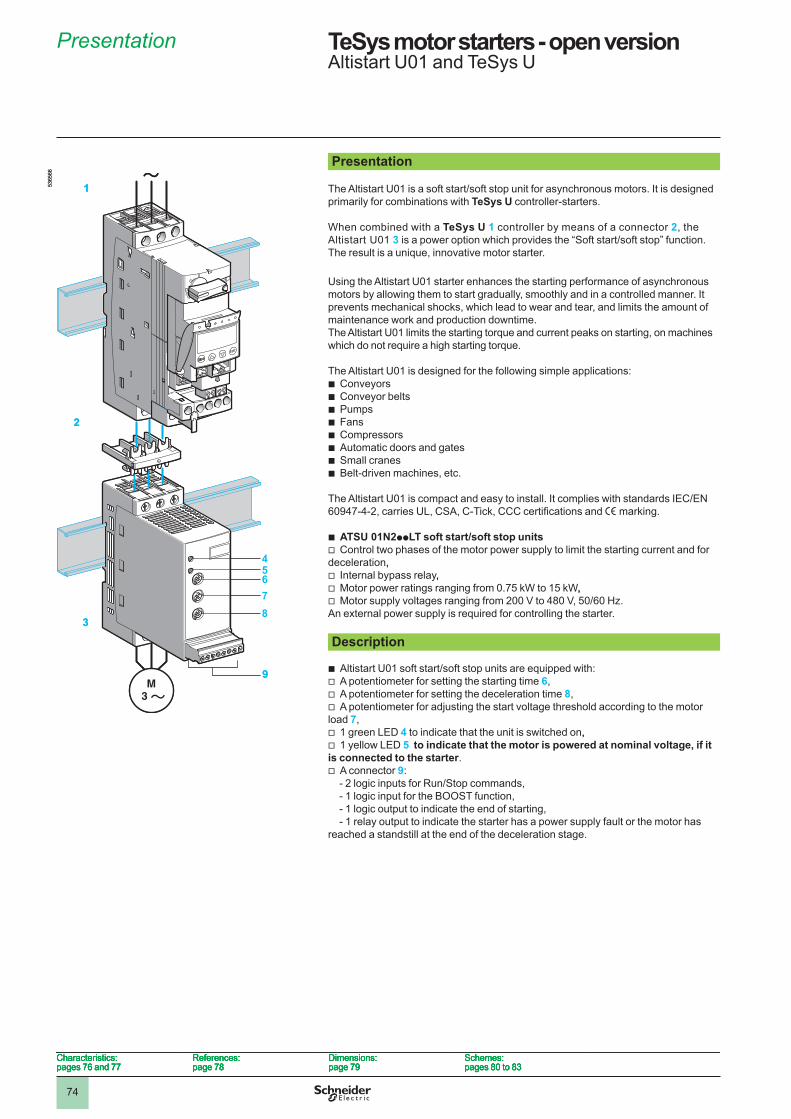
74
45678
Presentation
The Altistart U01 is a soft start/soft stop unit for asynchronous motors. It is designed primarily for combinations with TeSys U controller-starters.
When combined with a TeSys U 1 controller by means of a connector 2, the Altistart U0� 3 is a power option which provides the “Soft start/soft stop” function. The result is a unique, innovative motor starter.
Using the Altistart U0� starter enhances the starting performance of asynchronous motors by allowing them to start gradually, smoothly and in a controlled manner. It prevents mechanical shocks, which lead to wear and tear, and limits the amount of maintenance work and production downtime.The Altistart U0� limits the starting torque and current peaks on starting, on machines which do not require a high starting torque.
The Altistart U0� is designed for the following simple applications:b Conveyorsb Conveyor beltsb Pumpsb Fansb Compressorsb Automatic doors and gatesb Small cranesb Belt-driven machines, etc.
The Altistart U01 is compact and easy to install. It complies with standards IEC/EN 60947-4-2, carries UL, CSA, C-Tick, CCC certifications and e marking.
b ATSU 01N2ppLT soft start/soft stop unitsv Control two phases of the motor power supply to limit the starting current and for deceleration,,v Internal bypass relay,,v Motor power ratings ranging from 0.75 kW to �5 kW,,v Motor supply voltages ranging from 200 V to 480 V, 50/60 Hz.An external power supply is required for controlling the starter. Description
b Altistart U01 soft start/soft stop units are equipped with:v A potentiometer for setting the starting time 6,v A potentiometer for setting the deceleration time 8,v A potentiometer for adjusting the start voltage threshold according to the motor load 7,v � green LED 4 to indicate that the unit is switched on,,v � yellow LED 5 to indicate that the motor is powered at nominal voltage, if it is connected to the starter.v A connector 9:
- 2 logic inputs for Run/Stop commands,- � logic input for the BOOST function,- � logic output to indicate the end of starting,- � relay output to indicate the starter has a power supply fault or the motor has
reached a standstill at the end of the deceleration stage.
5365
66
1
2
3
9
5365
66
1
2
3
9
Characteristics:pages 76 and 77
References:page 78
Dimensions:page 79
Schemes:pages 80 to 83
Characteristics:pages 76 and 77
References:page 78
Dimensions:page 79
Schemes:pages 80 to 83
Characteristics:pages 76 and 77
References:page 78
Dimensions:page 79
Schemes:pages 80 to 83
Characteristics:pages 76 and 77
References:page 78
Dimensions:page 79
Schemes:pages 80 to 83
Presentation1 TeSys motor starters - open versionAltistart U0� and TeSys U
1
2
3
4
5
6
7
8
9
10
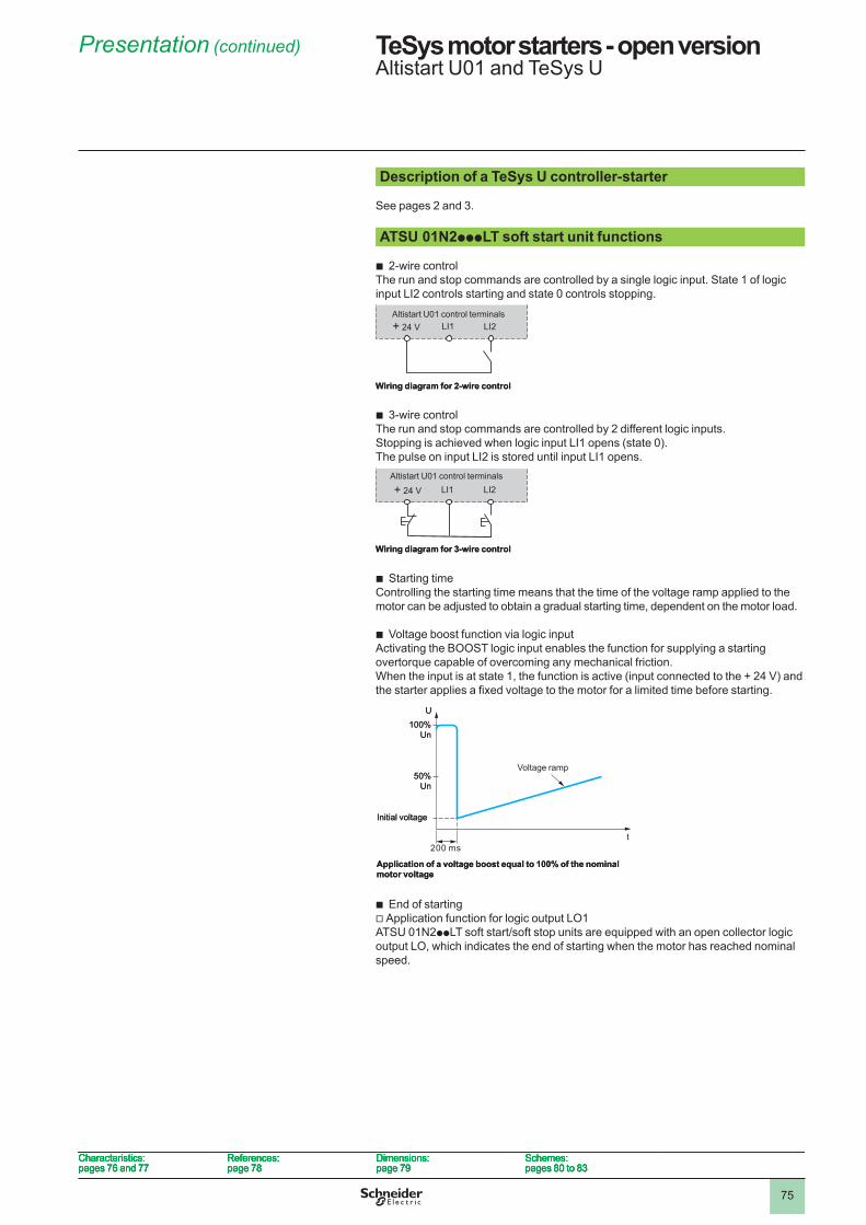
75
Description of a TeSys U controller-starter
See pages � and 3. ATSU 01N2pppLT soft start unit functions
b �-wire controlThe run and stop commands are controlled by a single logic input. State � of logic input LI� controls starting and state 0 controls stopping.
b 3-wire controlThe run and stop commands are controlled by � different logic inputs. Stopping is achieved when logic input LI� opens (state 0). The pulse on input LI� is stored until input LI� opens.
b Starting timeControlling the starting time means that the time of the voltage ramp applied to the motor can be adjusted to obtain a gradual starting time, dependent on the motor load.
b Voltage boost function via logic inputActivating the BOOST logic input enables the function for supplying a starting overtorque capable of overcoming any mechanical friction.When the input is at state 1, the function is active (input connected to the + 24 V) and the starter applies a fixed voltage to the motor for a limited time before starting.
b End of startingv Application function for logic output LO�ATSU 0�N�ppLT soft start/soft stop units are equipped with an open collector logic output LO, which indicates the end of starting when the motor has reached nominal speed.
+ 24 V LI1 LI2
Wiring diagram for 2-wire control
Altistart U0� control terminals+ 24 V LI1 LI2
Wiring diagram for 2-wire control
Altistart U0� control terminals
LI1 LI2+ 24 V
Wiring diagram for 3-wire control
Altistart U0� control terminalsLI1 LI2+ 24 V
Wiring diagram for 3-wire control
Altistart U0� control terminals
�00 mst
Application of a voltage boost equal to 100% of the nominal motor voltage
Voltage ramp
U�00%
Un
50% Un
Initial voltage
�00 mst
Application of a voltage boost equal to 100% of the nominal motor voltage
Voltage ramp
U�00%
Un
50% Un
Initial voltage
Characteristics:pages 76 and 77
References:page 78
Dimensions:page 79
Schemes:pages 80 to 83
Characteristics:pages 76 and 77
References:page 78
Dimensions:page 79
Schemes:pages 80 to 83
Characteristics:pages 76 and 77
References:page 78
Dimensions:page 79
Schemes:pages 80 to 83
Characteristics:pages 76 and 77
References:page 78
Dimensions:page 79
Schemes:pages 80 to 83
Presentation (continued) TeSys motor starters - open versionAltistart U0� and TeSys U
1
2
3
4
5
6
7
8
9
10
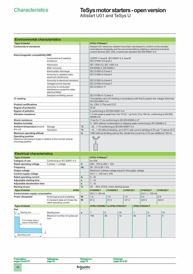
76
Environmental characteristicsType of starter ATSU 01N2ppLT
Conformity to standards Altistart U0� electronic starters have been developed to conform to the strictest international standards and the recommendations relating to electrical industrial control devices (IEC, EN), in particular standard IEC/EN 60947-4-2.
Electromagnetic compatibility EMCConducted and radiated emissions
CISPR �� level B, IEC 60947-4-�, level BIEC 6�000-4-6 level 3
Harmonics IEC �000-3-�, IEC �000-3-4EMC immunity EN 5008�-�, EN 5008�-�Electrostatic discharge IEC 6�000-4-� level 3Immunity to radiated radio-electrical interference
IEC 6�000-4-3 level 3
Immunity to electrical transients IEC 6�000-4-4 level 4Voltage/current impulse IEC 6�000-4-5 level 3Immunity to conducted interference caused by radio-electrical fields
IEC 6�000-4-��
Damped oscillating waves IEC 6�000-4-�� level 3e marking The starters carry e marking in accordance with the European low voltage directives
IEC/EN 60947-4-2.Product certifications UL, CSA, C-Tick and CCCDegree of protection IP �0Degree of pollution 2 conforming to IEC/EN 60947-4-2Vibration resistance 1.5 mm peak to peak from 3 to 13 Hz, 1 gn from 13 to 150 Hz, conforming to IEC/EN
60068-�-6Shock resistance 15 gn for 11 ms conforming to IEC/EN 60068-2-27Relative humidity 5…95% without condensation or dripping water conforming to IEC 60068-�-3Ambient temperature around the unit
Storage °C - 25…+ 70 conforming to IEC/EN 60947-4-2Operation °C - 10…+ 40 without derating, up to 50°C with current derating of 2% per °C above 40°C
Maximum operating altitude m �000 without derating (above this, derate the current by �.�% per additional �00 m)Operating positionMaximum permanent angle in relation to the normal vertical mounting position
Electrical characteristicsType of starter ATSU 01N2ppLT
Category of use Conforming to IEC 60947-4-� Ac-53bRated operating voltage 3-phase a voltage V 200 - 10% to 480 + 10% Frequency Hz 50 - 5% to 60 + 5%Output voltage Maximum 3-phase voltage equal to line supply voltageControl supply voltage �4 V c, �00 mA ± �0%Rated operating current A 6...3�Adjustable starting time s �...�0Adjustable deceleration time s �...�0Starting torque % 30.... 80% of DOL motor starting torqueType of starter ATSU 01N206LT 01N209LT 01N212LT 01N222LT 01N232LT
Control power supply consumption �4 V c, 65 mA �4 V c, �00 mAPower dissipated At full load at end of starting W �.5 �.5 �.5 �.5 �.5
In transient state at 5 times the rated operating current
W 6�.5 9�.5 ���.5 ���.5 3��.5
Type of starter ATSU 01N206LT to ATSU 01N222LT ATSU 01N232LTUse
Starting time s � 5 �0 � 5 �0Maximum number of cycles per hour
�00 �0 �0 50 �0 5
10° 10°10° 10°
Starting time
Full voltage state or starter at standstill
Operating cycle
t
I Starting time
Full voltage state or starter at standstill
Operating cycle
t
I
Presentation:pages 74 and 75
References:page 78
Dimensions:page 79
Schemes:pages 80 to 83
Presentation:pages 74 and 75
References:page 78
Dimensions:page 79
Schemes:pages 80 to 83
Presentation:pages 74 and 75
References:page 78
Dimensions:page 79
Schemes:pages 80 to 83
Presentation:pages 74 and 75
References:page 78
Dimensions:page 79
Schemes:pages 80 to 83
TeSys motor starters - open versionAltistart U0� and TeSys U
Characteristics
1
2
3
4
5
6
7
8
9
10
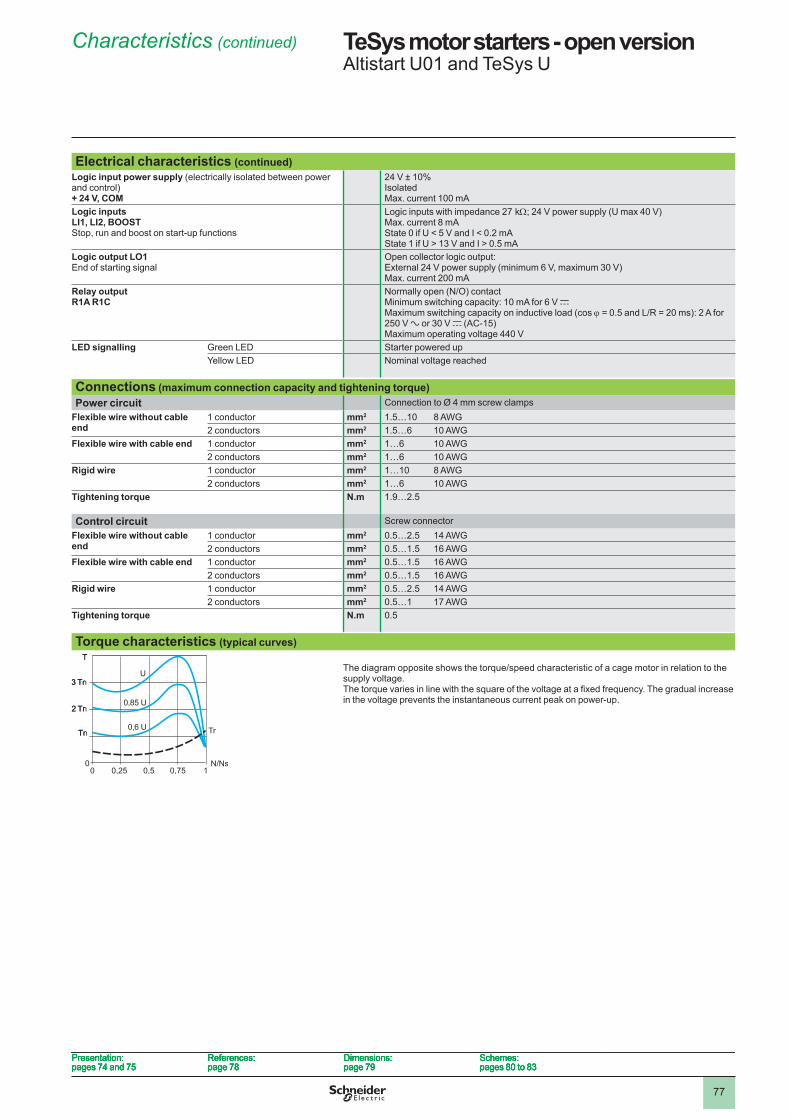
77
Electrical characteristics (continued)Logic input power supply (electrically isolated between power and control) + 24 V, COM
�4 V ± �0%IsolatedMax. current 100 mA
Logic inputsLI1, LI2, BOOST Stop, run and boost on start-up functions
Logic inputs with impedance �7 kW; 24 V power supply (U max 40 V)Max. current 8 mAState 0 if U < 5 V and I < 0.� mAState � if U > �3 V and I > 0.5 mA
Logic output LO1End of starting signal
Open collector logic output:External 24 V power supply (minimum 6 V, maximum 30 V)Max. current 200 mA
Relay outputR1A R1C
Normally open (N/O) contactMinimum switching capacity: �0 mA for 6 V cMaximum switching capacity on inductive load (cos j = 0.5 and L/R = 20 ms): 2 A for �50 V a or 30 V c (AC-�5)Maximum operating voltage 440 V
LED signalling Green LED Starter powered upYellow LED Nominal voltage reached
Connections (maximum connection capacity and tightening torque)Power circuit Connection to Ø 4 mm screw clamps
Flexible wire without cable end
� conductor mm2 �.5…�0 8 AWG� conductors mm2 �.5…6 10 AWG
Flexible wire with cable end � conductor mm2 �…6 10 AWG� conductors mm2 �…6 10 AWG
Rigid wire � conductor mm2 �…�0 8 AWG� conductors mm2 �…6 10 AWG
Tightening torque N .m �.9…�.5
Control circuit Screw connectorFlexible wire without cable end
� conductor mm2 0.5…�.5 14 AWG� conductors mm2 0.5…�.5 16 AWG
Flexible wire with cable end � conductor mm2 0.5…�.5 16 AWG� conductors mm2 0.5…�.5 16 AWG
Rigid wire � conductor mm2 0.5…�.5 14 AWG� conductors mm2 0.5…� 17 AWG
Tightening torque N .m 0.5
Torque characteristics (typical curves)
The diagram opposite shows the torque/speed characteristic of a cage motor in relation to the supply voltage. The torque varies in line with the square of the voltage at a fixed frequency. The gradual increase in the voltage prevents the instantaneous current peak on power-up.
00 0,25 0,5 0,75 1
N/Ns
U
0,85 U
0,6 U
T
Tr
3 Tn
� Tn
Tn
00 0,25 0,5 0,75 1
N/Ns
U
0,85 U
0,6 U
T
Tr
3 Tn
� Tn
Tn
Presentation:pages 74 and 75
References:page 78
Dimensions:page 79
Schemes:pages 80 to 83
Presentation:pages 74 and 75
References:page 78
Dimensions:page 79
Schemes:pages 80 to 83
Presentation:pages 74 and 75
References:page 78
Dimensions:page 79
Schemes:pages 80 to 83
Presentation:pages 74 and 75
References:page 78
Dimensions:page 79
Schemes:pages 80 to 83
Characteristics (continued) TeSys motor starters - open versionAltistart U0� and TeSys U
1
2
3
4
5
6
7
8
9
10
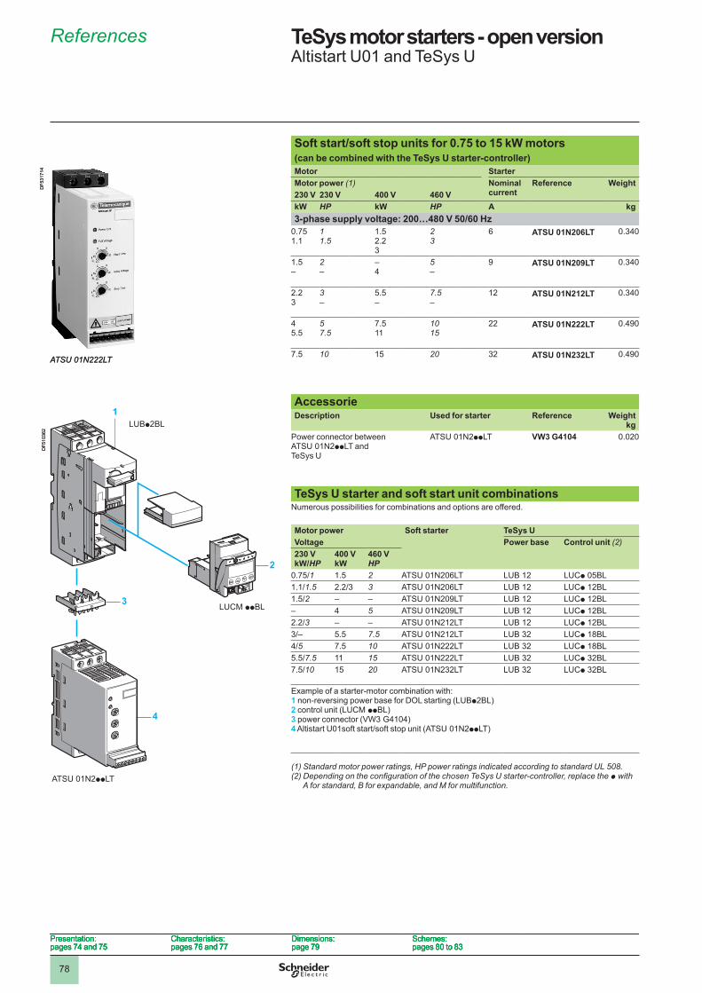
78
TeSys motor starters - open versionAltistart U0� and TeSys U
Soft start/soft stop units for 0 .75 to 15 kW motors (can be combined with the TeSys U starter-controller)Motor StarterMotor power (1) Nominal
currentReference Weight
230 V 230 V 400 V 460 VkW HP kW HP A kg3-phase supply voltage: 200…480 V 50/60 Hz
0.75�.�
11.5
�.5�.�3
23
6 ATSU 01N206LT 0.340
�.5–
2–
–4
5–
9 ATSU 01N209LT 0.340
�.�3
3–
5.5–
7.5–
�� ATSU 01N212LT 0.340
45.5
57.5
7.5��
1015
�� ATSU 01N222LT 0.490
7.5 10 �5 20 3� ATSU 01N232LT 0.490
AccessorieDescription Used for starter Reference Weight
kgPower connector between ATSU 0�N�ppLT and TeSys U
ATSU 0�N�ppLT VW3 G4104 0.0�0
TeSys U starter and soft start unit combinations Numerous possibilities for combinations and options are offered.
Motor power Soft starter TeSys UVoltage Power base Control unit (2)230 VkW/HP
400 VkW
460 VHP
0.75/1 �.5 2 ATSU 0�N�06LT LUB �� LUCp 05BL1.1/1.5 2.2/3 3 ATSU 0�N�06LT LUB �� LUCp ��BL1.5/2 – – ATSU 0�N�09LT LUB �� LUCp ��BL– 4 5 ATSU 0�N�09LT LUB �� LUCp ��BL2.2/3 – – ATSU 0�N���LT LUB �� LUCp ��BL3/– 5.5 7.5 ATSU 0�N���LT LUB 3� LUCp �8BL4/5 7.5 10 ATSU 0�N���LT LUB 3� LUCp �8BL5.5/7.5 �� 15 ATSU 0�N���LT LUB 3� LUCp 3�BL7.5/10 �5 20 ATSU 0�N�3�LT LUB 3� LUCp 3�BL
Example of a starter-motor combination with:1 non-reversing power base for DOL starting (LUBp�BL)2 control unit (LUCM ppBL)3 power connector (VW3 G4104)4 Altistart U01soft start/soft stop unit (ATSU 01N2ppLT)
ATSU 01N222LT
DF5
3�7�
4
ATSU 01N222LT
DF5
3�7�
4
1
2
4
LUBp2BL
LUCM ppBL
ATSU 01N2ppLT
3
DF5
�036
�
1
2
4
LUBp2BL
LUCM ppBL
ATSU 01N2ppLT
3
DF5
�036
�
Presentation:pages 74 and 75
Characteristics:pages 76 and 77
Dimensions:page 79
Schemes:pages 80 to 83
Presentation:pages 74 and 75
Characteristics:pages 76 and 77
Dimensions:page 79
Schemes:pages 80 to 83
Presentation:pages 74 and 75
Characteristics:pages 76 and 77
Dimensions:page 79
Schemes:pages 80 to 83
Presentation:pages 74 and 75
Characteristics:pages 76 and 77
Dimensions:page 79
Schemes:pages 80 to 83
(1) Standard motor power ratings, HP power ratings indicated according to standard UL 508.(2)DependingontheconfigurationofthechosenTeSysUstarter-controller,replacethep with
A for standard, B for expandable, and M for multifunction.
References
1
2
3
4
5
6
7
8
9
10
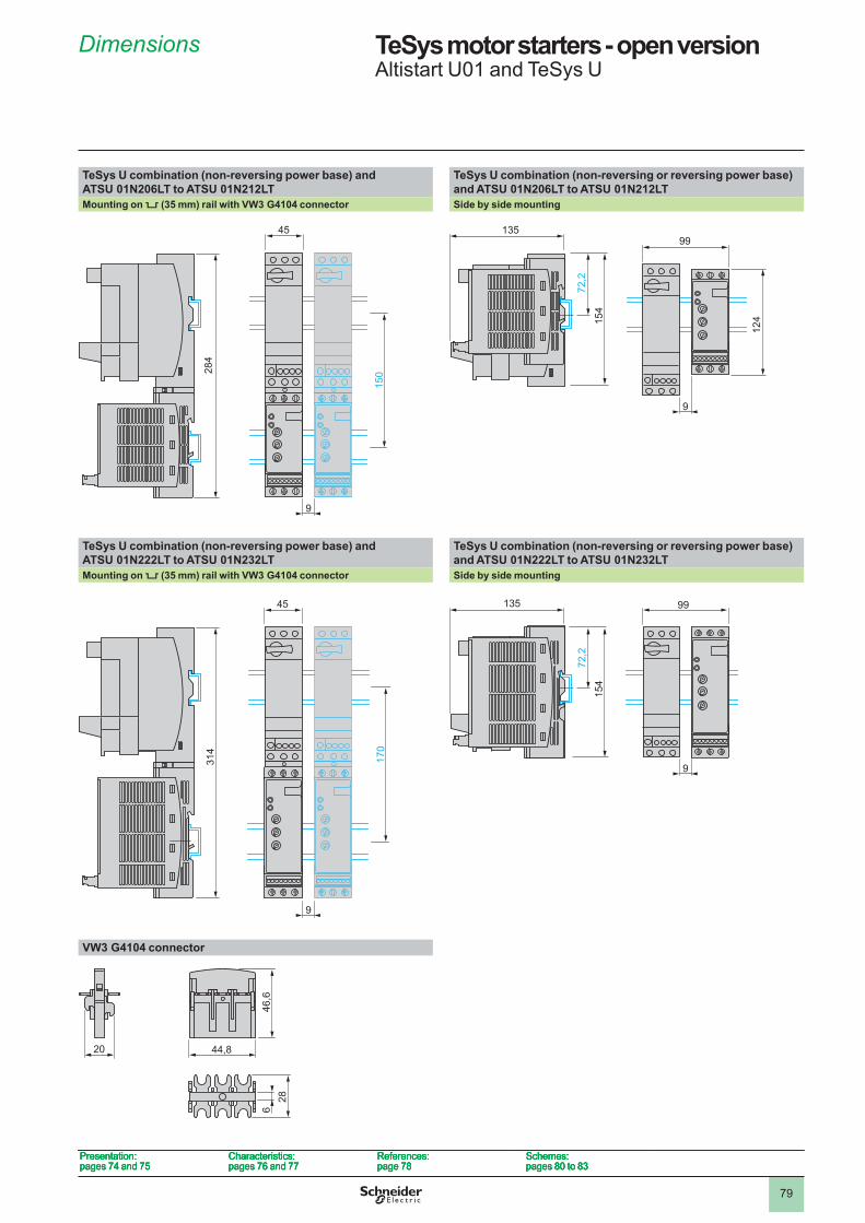
79
TeSys motor starters - open versionAltistart U0� and TeSys U
TeSys U combination (non-reversing power base) and ATSU 01N206LT to ATSU 01N212LT
TeSys U combination (non-reversing or reversing power base) and ATSU 01N206LT to ATSU 01N212LT
Mounting on 5 (35 mm) rail with VW3 G4104 connector Side by side mounting
TeSys U combination (non-reversing power base) and ATSU 01N222LT to ATSU 01N232LT
TeSys U combination (non-reversing or reversing power base) and ATSU 01N222LT to ATSU 01N232LT
Mounting on 5 (35 mm) rail with VW3 G4104 connector Side by side mounting
VW3 G4104 connector
15028
4
45
9
15028
4
45
9
99�35
�54
7�,�
9
��4
99�35
�54
7�,�
9
��4
314
45
170
9
314
45
170
9
99�35
7�,�
�54
9
99�35
7�,�
�54
9
44,820
646
,628
44,820
646
,628
Presentation:pages 74 and 75
Characteristics:pages 76 and 77
References:page 78
Schemes:pages 80 to 83
Presentation:pages 74 and 75
Characteristics:pages 76 and 77
References:page 78
Schemes:pages 80 to 83
Presentation:pages 74 and 75
Characteristics:pages 76 and 77
References:page 78
Schemes:pages 80 to 83
Presentation:pages 74 and 75
Characteristics:pages 76 and 77
References:page 78
Schemes:pages 80 to 83
Dimensions
1
2
3
4
5
6
7
8
9
10
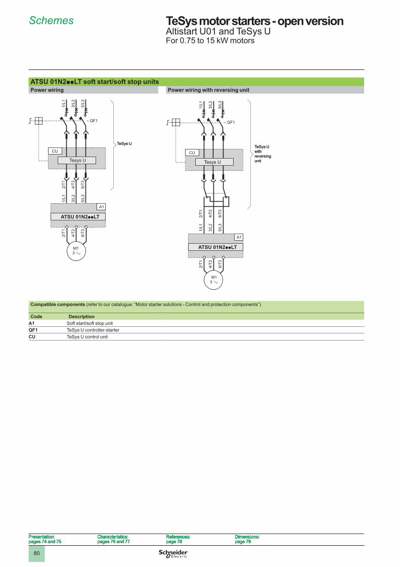
80
TeSys motor starters - open version Altistart U0� and TeSys UFor 0.75 to �5 kW motors
ATSU 01N2ppLT soft start/soft stop unitsPower wiring Power wiring with reversing unit
Compatible components (refer to our catalogue: “Motor starter solutions - Control and protection components”)
Code DescriptionA1 Soft start/soft stop unitQF1 TeSys U controller-starterCU TeSys U control unit
2/T1
4/T2
6/T3
2/T1
4/T2
6/T3
1/L1
3/L2
5/L3
1/L1
3/L2
5/L3
M1 3
A1
CU
– QF1
ATSU 01N2ppLT
Tesys U
TeSys U
2/T1
4/T2
6/T3
2/T1
4/T2
6/T3
1/L1
3/L2
5/L3
1/L1
3/L2
5/L3
M1 3
A1
CU
– QF1
ATSU 01N2ppLT
Tesys U
TeSys U
2/T1
4/T2
6/T3
2/T1
4/T2
6/T3
1/L1
3/L2
5/L3
1/L1
3/L2
5/L3
M1 3
CU
– QF1
A1
ATSU 01N2ppLT
TeSys U with reversing unit
2/T1
4/T2
6/T3
2/T1
4/T2
6/T3
1/L1
3/L2
5/L3
1/L1
3/L2
5/L3
M1 3
CU
– QF1
A1
ATSU 01N2ppLT
TeSys U with reversing unit
Presentation:pages 74 and 75
Characteristics:pages 76 and 77
References:page 78
Dimensions:page 79
Presentation:pages 74 and 75
Characteristics:pages 76 and 77
References:page 78
Dimensions:page 79
Presentation:pages 74 and 75
Characteristics:pages 76 and 77
References:page 78
Dimensions:page 79
Presentation:pages 74 and 75
Characteristics:pages 76 and 77
References:page 78
Dimensions:page 79
Schemes
Tesys U
1
2
3
4
5
6
7
8
9
10
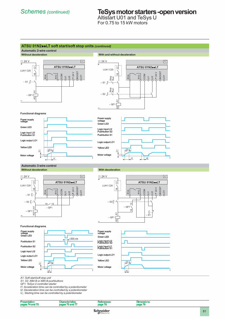
8�
TeSys motor starters -open versionAltistart U0� and TeSys UFor 0.75 to �5 kW motors
ATSU 01N2ppLT soft start/soft stop units (continued) Automatic 2-wire control Without deceleration With and without deceleration
Functional diagrams
Automatic 3-wire control Without deceleration With deceleration
Functional diagrams
A1: Soft start/soft stop unitS1, S2: XB4 B or XB5 B pushbuttonsQF1: TeSys U controller-startert1: Acceleration time can be controlled by a potentiometert2: Deceleration time can be controlled by a potentiometerU1: Starting time can be controlled by a potentiometer
– QF1
– S1
LUA1 C20
R1A
A1
A2
1718
R1C
LI1
LI2 + 24
V
BO
OS
TLO
1
CO
MA1
+
–
c 24 V
ATSU 01N2ppLT
– QF1
– S1
LUA1 C20
R1A
A1
A2
1718
R1C
LI1
LI2 + 24
V
BO
OS
TLO
1
CO
MA1
+
–
c 24 V
ATSU 01N2ppLT
– QF1
– S2
A1
A2
A1+
–
c 24 V
– S1
ATSU 01N2ppLT
R1A
R1C
LI1
LI2 + 24
V
BO
OS
TLO
1
CO
M
LUA1 C20 1718
Sto
pR
unS
top
Run
– QF1
– S2
A1
A2
A1+
–
c 24 V
– S1
ATSU 01N2ppLT
R1A
R1C
LI1
LI2 + 24
V
BO
OS
TLO
1
CO
M
LUA1 C20 1718
Sto
pR
unS
top
Run
�0 s
tt�
U�
Power supply voltage
Green LED
Logic input LI�Pushbutton S�
Logic output LO�
Yellow LED
Motor voltage
�0 s
tt�
U�
Power supply voltage
Green LED
Logic input LI�Pushbutton S�
Logic output LO�
Yellow LED
Motor voltaget� tt�
�0 s
U�
Power supply voltageGreen LED
Logic input LI�Pushbutton S�
Logic output LO�
Yellow LED
Motor voltage
Pushbutton S�
t� tt�
�0 s
U�
Power supply voltageGreen LED
Logic input LI�Pushbutton S�
Logic output LO�
Yellow LED
Motor voltage
Pushbutton S�
– QF1
– S2
– QF114 13
A1
A2
A1+
–
c 24 V
– S1 R1A
R1C
ATSU 01N2ppLT
LI1
LI2 + 24
V
BO
OS
TLO
1
CO
M
LUA1 C20
1718
– QF1
– S2
– QF114 13
A1
A2
A1+
–
c 24 V
– S1 R1A
R1C
ATSU 01N2ppLT
LI1
LI2 + 24
V
BO
OS
TLO
1
CO
M
LUA1 C20
1718
– QF1
– QF1
– S2
A1
1413
A2
A1+
–
c 24 V
– S1
ATSU 01N2ppLT
R1A
R1C
LI1
LI2 + 24
V
BO
OS
TLO
1
CO
M
LUA1 C20
1718
– QF1
– QF1
– S2
A1
1413
A2
A1+
–
c 24 V
– S1
ATSU 01N2ppLT
R1A
R1C
LI1
LI2 + 24
V
BO
OS
TLO
1
CO
M
LUA1 C20
1718
500 ms
tt�
�0 s
U�
Power supply voltageGreen LED
Pushbutton S�
Logic output LO�
Yellow LED
Motor voltage
Logic input LI�
Pushbutton S�
500 ms
tt�
�0 s
U�
Power supply voltageGreen LED
Pushbutton S�
Logic output LO�
Yellow LED
Motor voltage
Logic input LI�
Pushbutton S�
t
�0 s
t�
Power supply voltageGreen LED
Logic output LO�
Yellow LED
Motor voltage
Logic input LI�Pushbutton S�Logic input LI�Pushbutton S�
t
�0 s
t�
Power supply voltageGreen LED
Logic output LO�
Yellow LED
Motor voltage
Logic input LI�Pushbutton S�Logic input LI�Pushbutton S�
Presentation:pages 74 and 75
Characteristics:pages 76 and 77
References:page 78
Dimensions:page 79
Presentation:pages 74 and 75
Characteristics:pages 76 and 77
References:page 78
Dimensions:page 79
Presentation:pages 74 and 75
Characteristics:pages 76 and 77
References:page 78
Dimensions:page 79
Presentation:pages 74 and 75
Characteristics:pages 76 and 77
References:page 78
Dimensions:page 79
Schemes (continued)
1
2
3
4
5
6
7
8
9
10
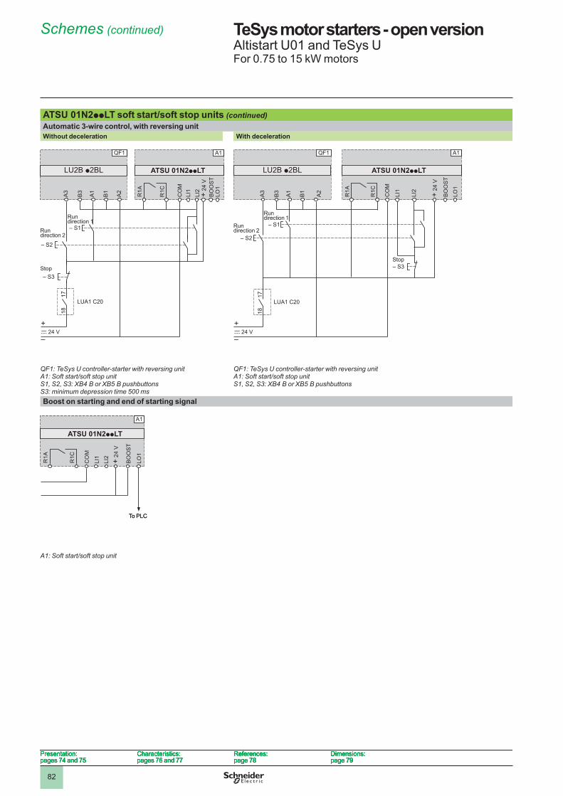
8�
TeSys motor starters - open versionAltistart U0� and TeSys UFor 0.75 to �5 kW motors
ATSU 01N2ppLT soft start/soft stop units (continued) Automatic 3-wire control, with reversing unit Without deceleration With deceleration
QF1: TeSys U controller-starter with reversing unitA1: Soft start/soft stop unitS1, S2, S3: XB4 B or XB5 B pushbuttonsS3: minimum depression time 500 ms
QF1: TeSys U controller-starter with reversing unitA1: Soft start/soft stop unitS1, S2, S3: XB4 B or XB5 B pushbuttons
Boost on starting and end of starting signal
A1: Soft start/soft stop unit
A3
B3
A1
A2
B1
A1
ATSU 01N2ppLT
R1A
R1C
CO
M
BO
OS
TLO
1
LI2
LI1 + 24
V
– S2
– S1
– S3
c 24 V+
–
LUA1 C20
1718
QF1
LU2B p2BL
Run direction �
Run direction �
Stop
A3
B3
A1
A2
B1
A1
ATSU 01N2ppLT
R1A
R1C
CO
M
BO
OS
TLO
1
LI2
LI1 + 24
V
– S2
– S1
– S3
c 24 V+
–
LUA1 C20
1718
QF1
LU2B p2BL
Run direction �
Run direction �
StopA
3
B3
A1
A2
B1
LU2B p2BL
A1QF1
ATSU 01N2ppLT
R1A
R1C
CO
M
BO
OS
T
LO1
LI2
LI1 + 24
V
– S2
– S1
c 24 V
– S3
+
–
LUA1 C20
1718
Run direction �
Run direction �
StopA
3
B3
A1
A2
B1
LU2B p2BL
A1QF1
ATSU 01N2ppLT
R1A
R1C
CO
M
BO
OS
T
LO1
LI2
LI1 + 24
V
– S2
– S1
c 24 V
– S3
+
–
LUA1 C20
1718
Run direction �
Run direction �
Stop
A1
ATSU 01N2ppLT
R1A
R1C
LI1
LI2 + 24
V
BO
OS
T
LO1
CO
M
To PLC
A1
ATSU 01N2ppLT
R1A
R1C
LI1
LI2 + 24
V
BO
OS
T
LO1
CO
M
To PLC
Presentation:pages 74 and 75
Characteristics:pages 76 and 77
References:page 78
Dimensions:page 79
Presentation:pages 74 and 75
Characteristics:pages 76 and 77
References:page 78
Dimensions:page 79
Presentation:pages 74 and 75
Characteristics:pages 76 and 77
References:page 78
Dimensions:page 79
Presentation:pages 74 and 75
Characteristics:pages 76 and 77
References:page 78
Dimensions:page 79
Schemes (continued)
1
2
3
4
5
6
7
8
9
10
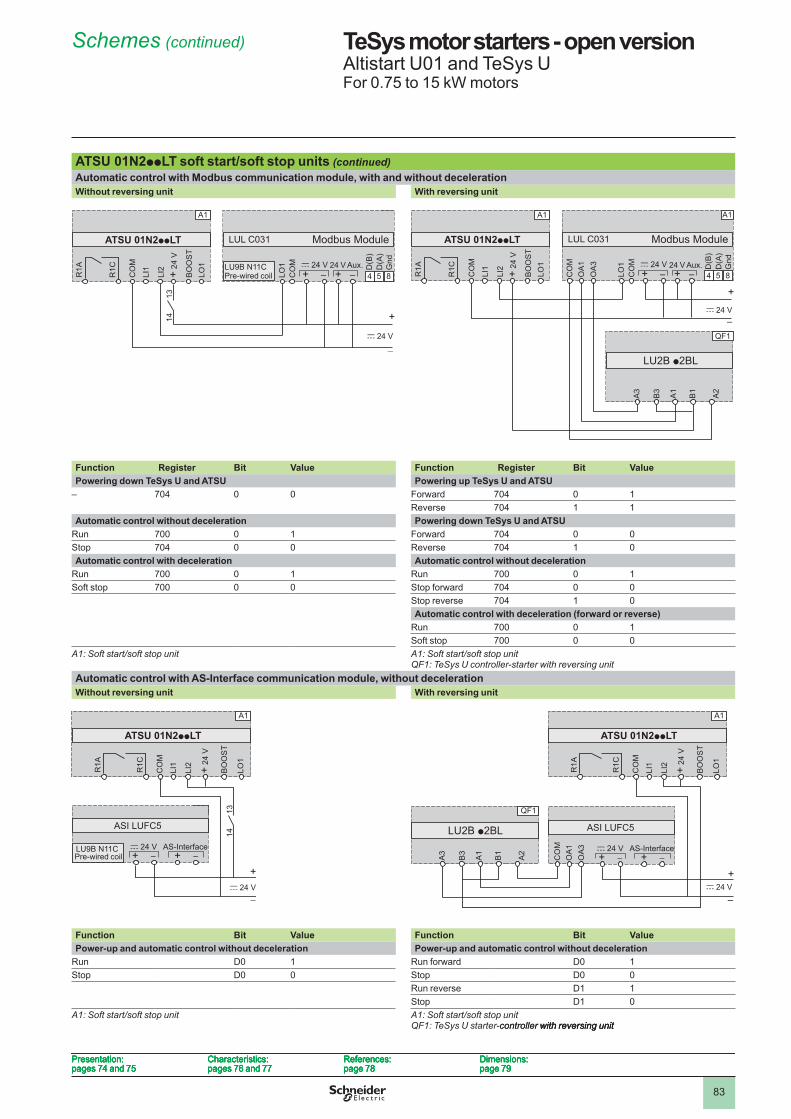
83
TeSys motor starters - open versionAltistart U0� and TeSys UFor 0.75 to �5 kW motors
ATSU 01N2ppLT soft start/soft stop units (continued) Automatic control with Modbus communication module, with and without decelerationWithout reversing unit With reversing unit
Function Register Bit Value Function Register Bit ValuePowering down TeSys U and ATSU Powering up TeSys U and ATSU
– 704 0 0 Forward 704 0 �Reverse 704 � �
Automatic control without deceleration Powering down TeSys U and ATSURun 700 0 � Forward 704 0 0Stop 704 0 0 Reverse 704 � 0Automatic control with deceleration Automatic control without deceleration
Run 700 0 � Run 700 0 �Soft stop 700 0 0 Stop forward 704 0 0
Stop reverse 704 � 0Automatic control with deceleration (forward or reverse)
Run 700 0 �Soft stop 700 0 0
A1: Soft start/soft stop unit A1: Soft start/soft stop unitQF1: TeSys U controller-starter with reversing unit
Automatic control with AS-Interface communication module, without decelerationWithout reversing unit With reversing unit
Function Bit Value Function Bit ValuePower-up and automatic control without deceleration Power-up and automatic control without deceleration
Run D0 � Run forward D0 �Stop D0 0 Stop D0 0
Run reverse D� �Stop D� 0
A1: Soft start/soft stop unit A1: Soft start/soft stop unitQF1: TeSys U starter-controller with reversing unitcontroller with reversing unit with reversing unit
A1
LO1
CO
M D(B
)D
(A)
Gnd
A1
–+–+c 24 VLU9B N11C
LUL C031
4 5 8
ATSU 01N2ppLT
R1A
R1C
Modbus Module
CO
M
BO
OS
TLO
1
LI2
LI1 + 24
V
c 24 V
+
1314
Pre-wired coil24 V Aux.
A1
LO1
CO
M D(B
)D
(A)
Gnd
A1
–+–+c 24 VLU9B N11C
LUL C031
4 5 8
ATSU 01N2ppLT
R1A
R1C
Modbus Module
CO
M
BO
OS
TLO
1
LI2
LI1 + 24
V
c 24 V
+
1314
Pre-wired coil24 V Aux.
A1
LO1
CO
M D(B
)D
(A)
Gnd
A1
–+–+c 24 V
LUL C031
4 5 8OA
1O
A3
CO
M
ATSU 01N2ppLT
R1A
R1C
Modbus Module
CO
M
BO
OS
TLO
1
LI2
LI1 + 24
V
c 24 V
+
A3
B3
A1
A2
B1
LU2B p2BL
QF1
24 V Aux.
A1
LO1
CO
M D(B
)D
(A)
Gnd
A1
–+–+c 24 V
LUL C031
4 5 8OA
1O
A3
CO
M
ATSU 01N2ppLT
R1A
R1C
Modbus Module
CO
M
BO
OS
TLO
1
LI2
LI1 + 24
V
c 24 V
+
A3
B3
A1
A2
B1
LU2B p2BL
QF1
24 V Aux.
CO
M
BO
OS
T
LO1
LI2
LI1 + 24
V
A1
++AS-Interfacec 24 VLU9B N11C
ASI LUFC5
ATSU 01N2ppLT
R1A
R1C
1314
c 24 V
+Pre-wired coil
CO
M
BO
OS
T
LO1
LI2
LI1 + 24
V
A1
++AS-Interfacec 24 VLU9B N11C
ASI LUFC5
ATSU 01N2ppLT
R1A
R1C
1314
c 24 V
+Pre-wired coil
CO
M
BO
OS
T
LO1
LI2
LI1 + 24
V
A1
++AS-Interfacec 24 V
ASI LUFC5
ATSU 01N2ppLT
R1A
R1C
A3
B3
A1
A2
B1
LU2B p2BL
QF1
OA
1O
A3
CO
M
c 24 V+
CO
M
BO
OS
T
LO1
LI2
LI1 + 24
V
A1
++AS-Interfacec 24 V
ASI LUFC5
ATSU 01N2ppLT
R1A
R1C
A3
B3
A1
A2
B1
LU2B p2BL
QF1
OA
1O
A3
CO
M
c 24 V+
Presentation:pages 74 and 75
Characteristics:pages 76 and 77
References:page 78
Dimensions:page 79
Presentation:pages 74 and 75
Characteristics:pages 76 and 77
References:page 78
Dimensions:page 79
Presentation:pages 74 and 75
Characteristics:pages 76 and 77
References:page 78
Dimensions:page 79
Presentation:pages 74 and 75
Characteristics:pages 76 and 77
References:page 78
Dimensions:page 79
Schemes (continued)
1
2
3
4
5
6
7
8
9
10
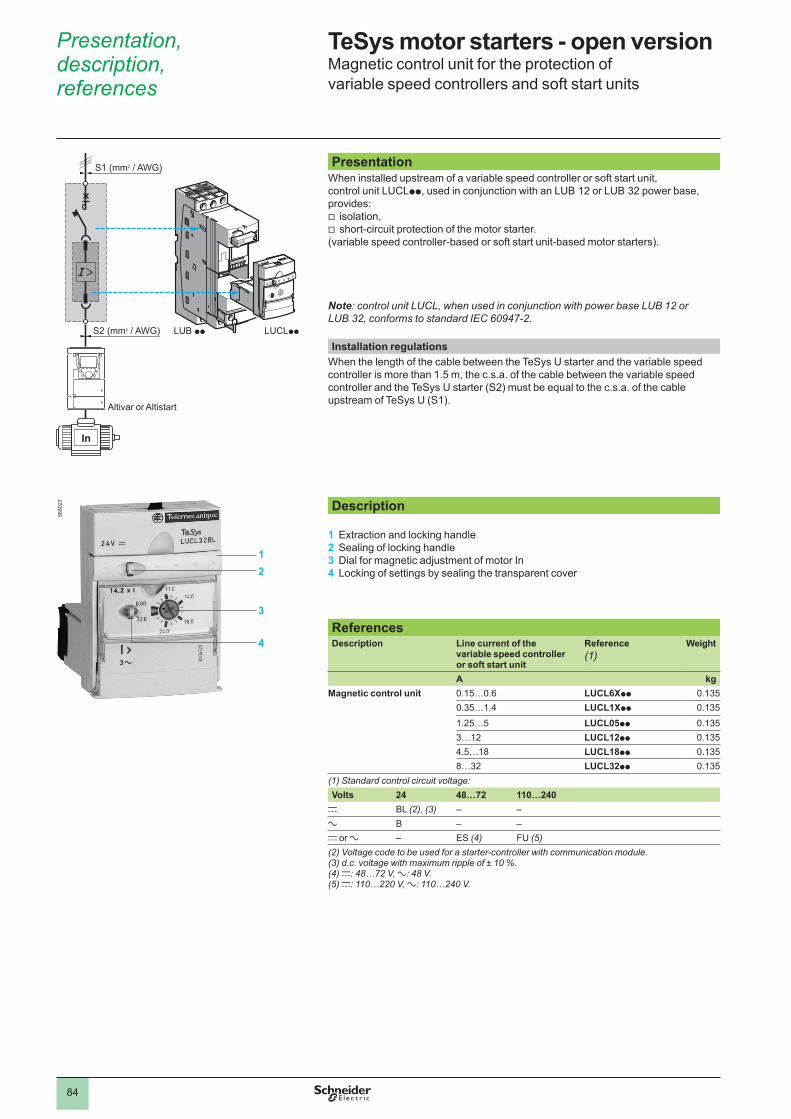
84
Presentation, description, references
TeSys motor starters - open versionMagnetic control unit for the protection of variable speed controllers and soft start units
PresentationWhen installed upstream of a variable speed controller or soft start unit, control unit LUCLpp, used in conjunction with an LUB �� or LUB 3� power base, provides:
isolation,short-circuit protection of the motor starter.
(variable speed controller-based or soft start unit-based motor starters).
Note: control unit LUCL, when used in conjunction with power base LUB 12 or LUB 32, conforms to standard IEC 60947-2.
vv
Installation regulationsWhen the length of the cable between the TeSys U starter and the variable speed controller is more than �.5 m, the c.s.a. of the cable between the variable speed controller and the TeSys U starter (S�) must be equal to the c.s.a. of the cable upstream of TeSys U (S�).
Description
1 Extraction and locking handle2 Sealing of locking handle3 Dial for magnetic adjustment of motor In 4 Locking of settings by sealing the transparent cover
ReferencesDescription Line current of the
variable speed controller or soft start unit
Reference(1)
Weight
A kgMagnetic control unit 0.�5…0.6 LUCL6Xpp 0.�35
0.35…�.4 LUCL1Xpp 0.�35
�.�5…5 LUCL05pp 0.�353…�� LUCL12pp 0.�354.5…�8 LUCL18pp 0.�358…3� LUCL32pp 0.�35
(1) Standard control circuit voltage:Volts 24 48…72 110…240
c BL (2), (3) – –a B – –c or a – ES (4) FU (5)(2) Voltage code to be used for a starter-controller with communication module.(3) d.c. voltage with maximum ripple of ± 10 %.(4) c: 48…72 V, a: 48 V.(5) c: 110…220 V, a: 110…240 V.
5680
�7
12
3
4
LUB pp LUCLpp
S1 (mm2 / AWG)
S2 (mm2 / AWG)
Altivar or Altistart
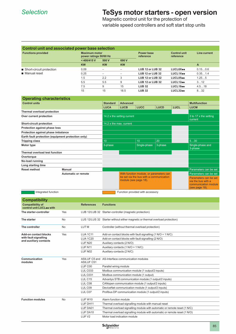
85
Selection TeSys motor starters - open versionMagnetic control unit for the protection of variable speed controllers and soft start stop units
Control unit and associated power base selectionFunctions provided Maximum motor
power ratings 50/60 HzPower base reference
Control unit reference
Line current
< 400/415 V 500 V 690 VKW KW KW A
Short-circuit protectionManual reset
bb
0.09 – – LUB 12 or LUB 32 LUCL6Xpp 0.�5…0.60.�5 – – LUB 12 or LUB 32 LUCL1Xpp 0.35…�.4�.5 �.� 3 LUB 12 or LUB 32 LUCL05pp �.�5…55.5 5.5 9 LUB 12 or LUB 32 LUCL12pp 3…��7.5 9 �5 LUB 32 LUCL18pp 4.5…�8�5 �5 �8.5 LUB 32 LUCL32pp 8…3�
Operating characteristicsControl units Standard Advanced Multifunction
LUCA LUCB LUCC LUCD LUCL LUCMThermal overload protectionOver current protection 14.2 x the setting current 3 to 17 x the setting
currentShort-circuit protection 14.2 x the max. currentProtection against phase lossProtection against phase imbalanceEarth fault protection (equipment protection only)Tripping class �0 �0 �0 5…30Motor type 3-phase Single-phase 3-phase Single-phase and
3-phaseThermal overload test functionOvertorqueNo-load runningLong starting timeReset method Manual Parameters can be set
Automatic or remote With function module, or parameters can be set via the bus with a communication module (see page �8).
Parameters can be setParameters can be set via the bus with a communication module (see page �8).
Integrated function Function provided with accessory
CompatibilityCompatibility of control unit LUCLpp with
References Functions
The starter-controller Yes LUB 12/LUB 32 Starter-controller (magnetic protection)
The starter No LUS 12/LUS 32 Starter without either magnetic or thermal overload protection)
The controller No LUT M Controller (without thermal overload protection)
Add-on contact blocks with fault signalling and auxiliary contacts
Yes LUA �C�� Add-on contact blocks with fault signalling (1 N/O + 1 N/C)LUA �C�0 Add-on contact blocks with fault signalling (2 N/O)LUF N�0 Auxiliary contacts (2 N/O)LUF N�� Auxiliary contacts (1 N/O + 1 N/C)LUF N0� Auxiliary contacts (2 N/C)
Communication modules
Yes ASILUF C5 and ASILUF C5�
AS-Interface communication modules
LUF C00 Parallel wiring moduleLUL C033 Modbus communication module (1 output/2 inputs)LUL C03� Modbus communication module (� output)LUL C�5 Advantys STB communication module (1 output/2 inputs)LUL C08 CANopen communication module (1 output/2 inputs)LUL C09 DeviceNet communication module (1 output/2 inputs)LUL C07 Profibus DP communication module (1 output/2 inputs)
Function modules No LUF W�0 Alarm function moduleLUF DH�� Thermal overload signalling module with manual resetLUF DA0� Thermal overload signalling module with automatic or remote reset (1 N/C)LUF DA�0 Thermal overload signalling module with automatic or remote reset (1 N/O)LUF V� Motor load indication module
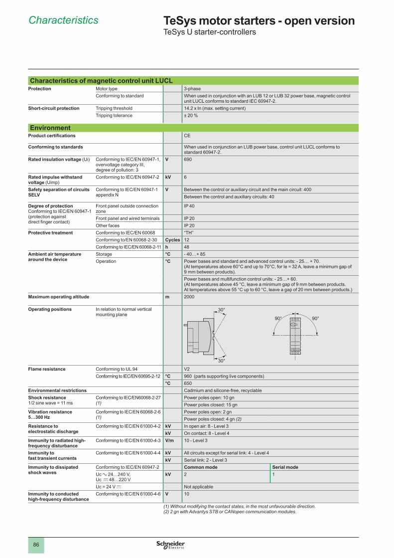
86
Characteristics TeSys motor starters - open versionTeSys U starter-controllers
Characteristics of magnetic control unit LUCLProtection Motor type 3-phase
Conforming to standard When used in conjunction with an LUB �� or LUB 3� power base, magnetic control unit LUCL conforms to standard IEC 60947-�.
Short-circuit protection Tripping threshold 14.2 x In (max. setting current)Tripping tolerance ± �0 %
EnvironmentProduct certifications CE
Conforming to standards When used in conjunction an LUB power base, control unit LUCL conforms to standard 60947-�.
Rated insulation voltage (Ui) Conforming to IEC/EN 60947-1, overvoltage category III, degree of pollution: 3
V 690
Rated impulse withstand voltage (Uimp)
Conforming to IEC/EN 60947-2 kV 6
Safety separation of circuits SELV
Conforming to IEC/EN 60947-1 appendix N
V Between the control or auxiliary circuit and the main circuit: 400Between the control and auxiliary circuits: 40
Degree of protectionConforming to IEC/EN 60947-1(protection against direct finger contact)
Front panel outside connection zone
IP 40
Front panel and wired terminals IP �0Other faces IP �0
Protective treatment Conforming to IEC/EN 60068 “TH”Conforming to/EN 60068-2-30 Cycles ��Conforming to IEC/EN 60068-2-11 h 48
Ambient air temperature around the device
Storage °C - 40…+ 85Operation °C Power bases and standard and advanced control units: - 25… + 70.
(At temperatures above 60°C and up to 70°C, for Ie = 32 A, leave a minimum gap of 9 mm between products).Power bases and multifunction control units: - 25…+ 60. (At temperatures above 45 °C, leave a minimum gap of 9 mm between products. At temperatures above 55 °C up to 60 °C, leave a gap of 20 mm between products.)
Maximum operating altitude m �000
Operating positions In relation to normal vertical mounting plane
Flame resistance Conforming to UL 94 V�Conforming to IEC/EN 60695-2-12 °C 960 (parts supporting live components)
°C 650Environmental restrictions Cadmium and silicone-free, recyclableShock resistance1/2 sine wave = 11 ms
Conforming to IEC/EN60068-2-27 (1)
Power poles open: �0 gnPower poles closed: �5 gn
Vibration resistance 5…300 Hz
Conforming to IEC/EN 60068-2-6(1)
Power poles open: � gnPower poles closed: 4 gn (2)
Resistance to electrostatic discharge
Conforming to IEC/EN 61000-4-2 kV In open air: 8 - Level 3kV On contact: 8 - Level 4
Immunity to radiated high-frequency disturbance
Conforming to IEC/EN 61000-4-3 V/m �0 - Level 3
Immunity to fast transient currents
Conforming to IEC/EN 61000-4-4 kV All circuits except for serial link: 4 - Level 4kV Serial link: � - Level 3
Immunity to dissipated shock waves
Conforming to IEC/EN 60947-2 Common mode Serial modeUc a �4…�40 V,Uc c 48…��0 V
kV � �
Uc = 24 V c Not applicableImmunity to conducted high-frequency disturbance
Conforming to IEC/EN 61000-4-6 V �0
(1) Without modifying the contact states, in the most unfavourable direction.(2) 2 gn with Advantys STB or CANopen communication modules.
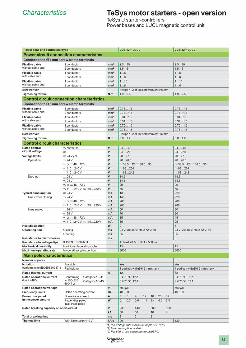
87
Characteristics TeSys motor starters - open versionTeSys U starter-controllersPower bases and LUCL magnetic control unit
Power base and control unit type LUB 12 + LUCL LUB 32 + LUCL
Power circuit connection characteristicsConnection to Ø 4 mm screw clamp terminals
Flexible cable without cable end
� conductor mm2 �.5…�0 �.5…�0� conductors mm2 �.5…6 �.5…6
Flexible cable with cable end
� conductor mm2 �…6 �…6� conductors mm2 �…6 �…6
Flexible cable without cable end
� conductor mm2 �…�0 �…�0� conductors mm2 �…6 �…6
Screwdriver Philips n° 2 or flat screwdriver: Ø 6 mmTightening torque N .m �.9…�.5 �.9…�.5
Control circuit connection characteristicsConnection to Ø 3 mm screw clamp terminals
Flexible cable without cable end
� conductor mm2 0.75…�.5 0.75…�.5� conductors mm2 0.75…�.5 0.75…�.5
Flexible cable with cable end
� conductor mm2 0.34…�.5 0.34…�.5� conductors mm2 0.34…�.5 0.34…�.5
Flexible cable without cable end
� conductor mm2 0.75…�.5 0.75…�.5� conductors mm2 0.75…�.5 0.75…�.5
Screwdriver Philips n° 2 or flat screwdriver: Ø 5 mmTightening torque N .m 0.8…�.� 0.8…�.�
Control circuit characteristicsRated control circuit voltage
a 50/60 Hz V �4…�40 �4…�40c V �4…��0 �4…��0
Voltage limits c �4 V (1) V �0…�7 �0…�7Operation a �4 V V �0…�6.5 �0…�6.5
a or c 48…7� V V a 38.5…7�. c 38.5…93 a 38.5…7�. c 38.5…93a ��0…�40 V V a 88…�64 a 88…�64c ��0…�40 V V c 88…�4� c 88…�4�
Drop-out c �4 V V �4.5 �4.5a �4 V V �4.5 �4.5a or c 48…7� V V �9 �9a ��0…�40 V, c ��0…��0 V V 55 55
Typical consumption c �4 V mA �30 ��0I max while closing a �4 V mA �40 ��0
a or c 48…7� V mA �80 �80a ��0…�40 V, c ��0…��0 V mA �80 �80
I rms sealed c �4 V mA 60 80a �4 V mA 70 90a or c 48…7� V mA 35 45a ��0…�40 V, c ��0…��0 V mA 35 �5
Heat dissipation W � 3Operating time Closing ms �4 V: 70; 48 V: 60; u 7� V: 50 �4 V: 70; 48 V: 60; u 7� V: 50
Opening ms 35 35Resistance to micro-breaks ms 3 3Resistance to voltage dips IEC/EN 61000-4-11 At least 70 % of Uc for 500 msMechanical durability In millions of operating cycles �5 �5Maximum operating rate In operating cycles per hour 3600 3600
Main pole characteristicsNumber of poles 3 3Isolationconforming to IEC/EN 60947-1
Possible Yes YesPadlocking 1 padlock with Ø 6.9 mm shank 1 padlock with Ø 6.9 mm shank
Rated thermal current A �� 3�Rated operational current (Ue y 440 V)
Conforming to IEC/ EN 60947-�
Category AC-4� θ y 70 °C: 12 A θ y 70 °C: 32 ACategory AC-43 θ y 70 °C: 12 A θ y 70 °C: 32 A
Rated operational voltage V 690 (3) 690 (3)Frequency limits Of the operating current Hz 40…60 40…60Power dissipated in the power circuits
Operational current A 3 6 9 �� �8 �5 3�Power dissipated in all three poles
W 0.� 0.3 0.6 �.� �.4 4.6 7.5
Rated breaking capacity on short-circuit V �30 440 500 600kA 50 50 �0 4
Total breaking time ms � � �Thermal limit With Isc max on 440 V kA2s 90 ��0
(1) d.c. voltage with maximum ripple of ± 10 %.(2) No consumption sealed. (3) For 690 V, use phase barrier LU9SP0.
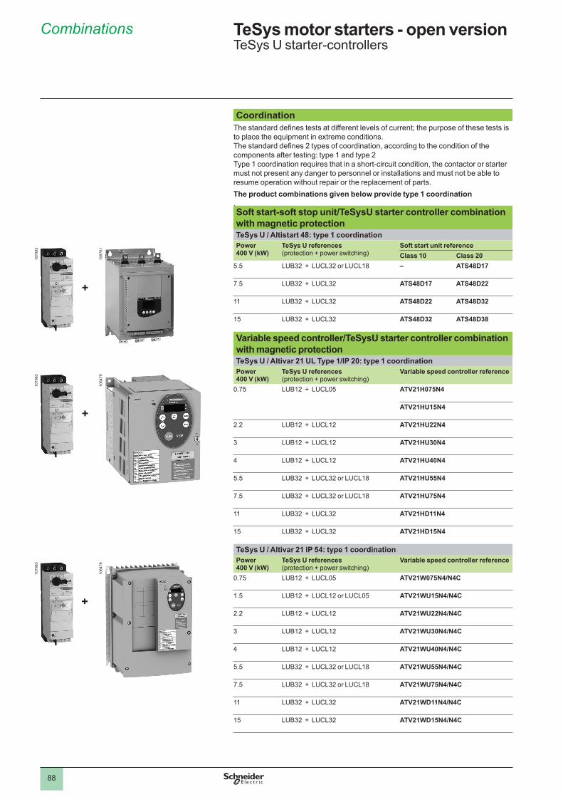
88
CoordinationThe standard defines tests at different levels of current; the purpose of these tests is to place the equipment in extreme conditions. The standard defines 2 types of coordination, according to the condition of the components after testing: type � and type �Type � coordination requires that in a short-circuit condition, the contactor or starter must not present any danger to personnel or installations and must not be able to resume operation without repair or the replacement of parts.The product combinations given below provide type 1 coordination .Soft start-soft stop unit/TeSysU starter controller combination with magnetic protection TeSys U / Altistart 48: type 1 coordinationPower400 V (kW)
TeSys U references (protection + power switching)
Soft start unit reference Class 10 Class 20
5.5 LUB32 + LUCL32 or LUCL18 – ATS48D17
7.5 LUB32 + LUCL32 ATS48D17 ATS48D22
�� LUB32 + LUCL32 ATS48D22 ATS48D32
�5 LUB32 + LUCL32 ATS48D32 ATS48D38
Variable speed controller/TeSysU starter controller combination with magnetic protection TeSys U / Altivar 21 UL Type 1/IP 20: type 1 coordinationPower400 V (kW)
TeSys U references (protection + power switching)
Variable speed controller reference
0.75 LUB12 + LUCL05 ATV21H075N4
ATV21HU15N4
�.� LUB12 + LUCL12 ATV21HU22N4
3 LUB12 + LUCL12 ATV21HU30N4
4 LUB12 + LUCL12 ATV21HU40N4
5.5 LUB32 + LUCL32 or LUCL18 ATV21HU55N4
7.5 LUB32 + LUCL32 or LUCL18 ATV21HU75N4
�� LUB32 + LUCL32 ATV21HD11N4
�5 LUB32 + LUCL32 ATV21HD15N4
TeSys U / Altivar 21 IP 54: type 1 coordinationPower400 V (kW)
TeSys U references (protection + power switching)
Variable speed controller reference
0.75 LUB12 + LUCL05 ATV21W075N4/N4C
�.5 LUB12 + LUCL12 or LUCL05 ATV21WU15N4/N4C
�.� LUB12 + LUCL12 ATV21WU22N4/N4C
3 LUB12 + LUCL12 ATV21WU30N4/N4C
4 LUB12 + LUCL12 ATV21WU40N4/N4C
5.5 LUB32 + LUCL32 or LUCL18 ATV21WU55N4/N4C
7.5 LUB32 + LUCL32 or LUCL18 ATV21WU75N4/N4C
�� LUB32 + LUCL32 ATV21WD11N4/N4C
�5 LUB32 + LUCL32 ATV21WD15N4/N4C
Combinations TeSys motor starters - open versionTeSys U starter-controllers
�079
83
�067
6�
+
�079
83
�064
76
+
�079
83
�064
79
+
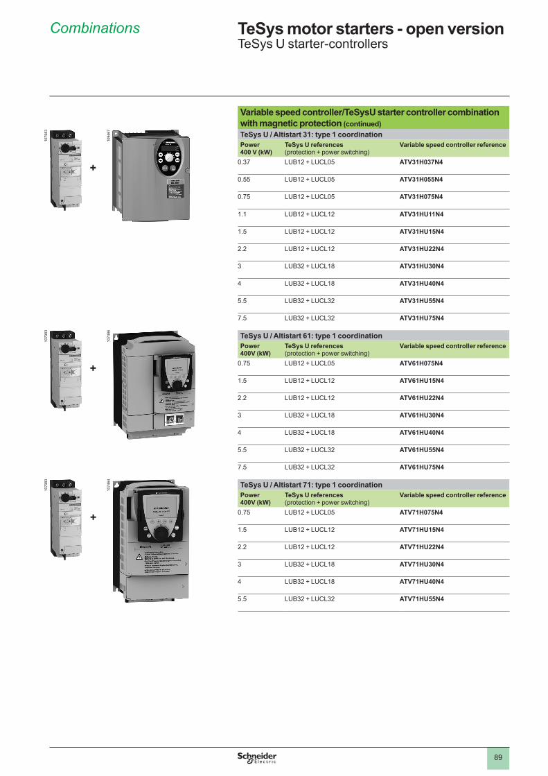
89
Variable speed controller/TeSysU starter controller combination with magnetic protection (continued)TeSys U / Altistart 31: type 1 coordinationPower400 V (kW)
TeSys U references (protection + power switching)
Variable speed controller reference
0.37 LUB12 + LUCL05 ATV31H037N4
0.55 LUB12 + LUCL05 ATV31H055N4
0.75 LUB12 + LUCL05 ATV31H075N4
�.� LUB12 + LUCL12 ATV31HU11N4
�.5 LUB12 + LUCL12 ATV31HU15N4
�.� LUB12 + LUCL12 ATV31HU22N4
3 LUB32 + LUCL18 ATV31HU30N4
4 LUB32 + LUCL18 ATV31HU40N4
5.5 LUB32 + LUCL32 ATV31HU55N4
7.5 LUB32 + LUCL32 ATV31HU75N4
TeSys U / Altistart 61: type 1 coordinationPower400V (kW)
TeSys U references (protection + power switching)
Variable speed controller reference
0.75 LUB12 + LUCL05 ATV61H075N4
�.5 LUB12 + LUCL12 ATV61HU15N4
�.� LUB12 + LUCL12 ATV61HU22N4
3 LUB32 + LUCL18 ATV61HU30N4
4 LUB32 + LUCL18 ATV61HU40N4
5.5 LUB32 + LUCL32 ATV61HU55N4
7.5 LUB32 + LUCL32 ATV61HU75N4
TeSys U / Altistart 71: type 1 coordinationPower400V (kW)
TeSys U references (protection + power switching)
Variable speed controller reference
0.75 LUB12 + LUCL05 ATV71H075N4
�.5 LUB12 + LUCL12 ATV71HU15N4
�.� LUB12 + LUCL12 ATV71HU22N4
3 LUB32 + LUCL18 ATV71HU30N4
4 LUB32 + LUCL18 ATV71HU40N4
5.5 LUB32 + LUCL32 ATV71HU55N4
Combinations TeSys motor starters - open versionTeSys U starter-controllers
�079
83
�094
67
+
�079
83
�074
86
+
�079
83
�074
64
+
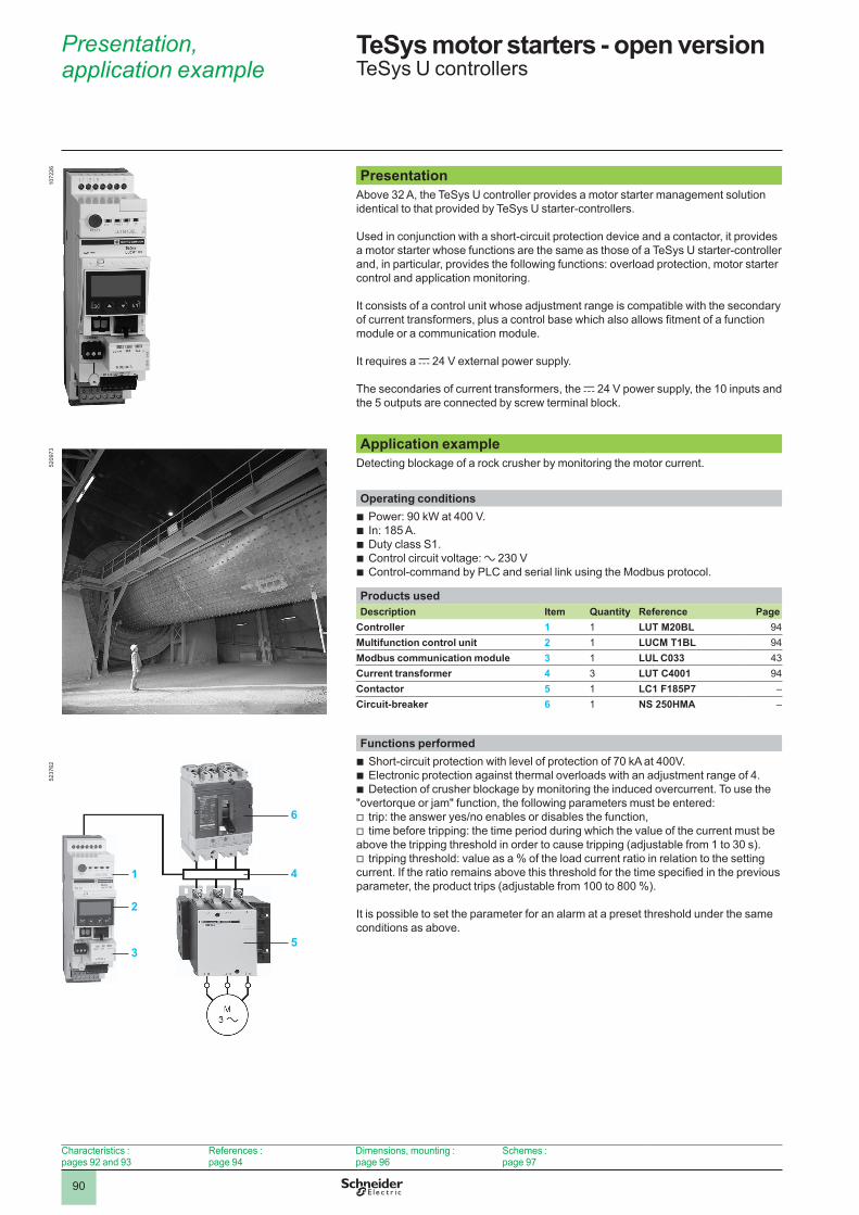
90
PresentationAbove 3� A, the TeSys U controller provides a motor starter management solution identical to that provided by TeSys U starter-controllers.
Used in conjunction with a short-circuit protection device and a contactor, it provides a motor starter whose functions are the same as those of a TeSys U starter-controller and, in particular, provides the following functions: overload protection, motor starter control and application monitoring.
It consists of a control unit whose adjustment range is compatible with the secondary of current transformers, plus a control base which also allows fitment of a function module or a communication module.
It requires a c 24 V external power supply.
The secondaries of current transformers, the c �4 V power supply, the �0 inputs and the 5 outputs are connected by screw terminal block.
Application exampleDetecting blockage of a rock crusher by monitoring the motor current.
Operating conditionsPower: 90 kW at 400 V.In: �85 A.Duty class S�.Control circuit voltage: a �30 VControl-command by PLC and serial link using the Modbus protocol.
Products used Description Item Quantity Reference Page
Controller 1 � LUT M20BL 94Multifunction control unit 2 � LUCM T1BL 94Modbus communication module 3 � LUL C033 43Current transformer 4 3 LUT C4001 94Contactor 5 � LC1 F185P7 –Circuit-breaker 6 � NS 250HMA –
Functions performed Short-circuit protection with level of protection of 70 kA at 400V.Electronic protection against thermal overloads with an adjustment range of 4.Detection of crusher blockage by monitoring the induced overcurrent. To use the
"overtorque or jam" function, the following parameters must be entered:trip: the answer yes/no enables or disables the function,time before tripping: the time period during which the value of the current must be
above the tripping threshold in order to cause tripping (adjustable from � to 30 s).tripping threshold: value as a % of the load current ratio in relation to the setting
current. If the ratio remains above this threshold for the time specified in the previous parameter, the product trips (adjustable from �00 to 800 %).
It is possible to set the parameter for an alarm at a preset threshold under the same conditions as above.
bbbbb
bbb
vv
v
Presentation, application example
TeSys motor starters - open version 1 TeSys U controllers
5�37
6�
6
4
5
1
2
3
5�09
73�0
7��6
Characteristics : pages 9� and 93
References : page 94
Dimensions, mounting : page 96
Schemes : page 97
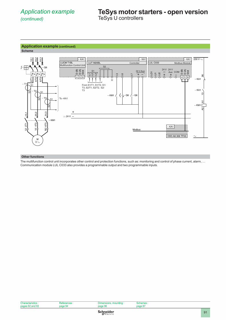
9�
Application example (continued)Scheme
230 V a
a
4 5 8
Modbus
4 5 8
VW3 A8 306 TF03
D (
B)
D (
A)
Gnd
+c 24 V
LO1
LI1
LI2 D (
B)
D (
A)
Gnd
I.3 I.6 I.7 9613
A1
A2
LUCM T1BL LUT M20BL
L1 L2 L3
LUL C033
2/T
1
4/T
2
6/T
3
1/L1
3/L2
5/L3
1/L1
2T1
3/L2
4T2
5/L3
6T3
U1
W1
V1
M3 a
– T1
– Q6
– Q6 – Q6
– KA1
– KM1
– KA1 – KA1
– KM1
– KA1
– KA1
– KA1
S1
S2 S1
S2 S1
S2
– T2
– T3
– KM1
S1
S2Multifunction Control Unit
From S1/T1, S1/T2, S1/T3, S2/T1, S2/T2, S2/T3
To –KA�
24 V Aux
Controller
�4 Vc
�4 VAux COM
Modbus Module
Other functionsThe multifunction control unit incorporates other control and protection functions, such as: monitoring and control of phase current, alarm, …Communication module LUL C033 also provides a programmable output and two programmable inputs.
Application example (continued)
TeSys motor starters - open version 1 TeSys U controllers
Characteristics : pages 9� and 93
References : page 94
Dimensions, mounting : page 96
Schemes : page 97
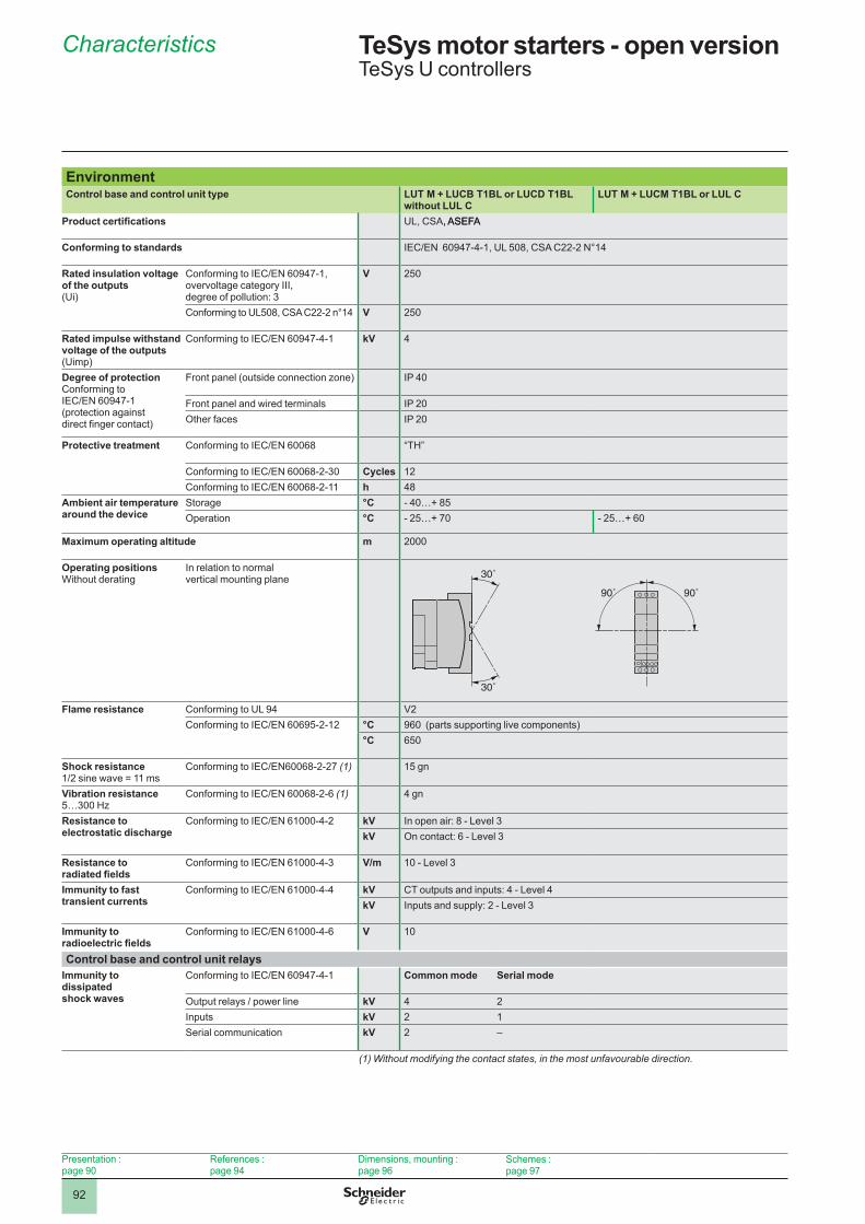
9�
EnvironmentControl base and control unit type LUT M + LUCB T1BL or LUCD T1BL
without LUL CLUT M + LUCM T1BL or LUL C
Product certifications UL, CSA, ASEFA, ASEFA
Conforming to standards IEC/EN 60947-4-1, UL 508, CSA C22-2 N°14
Rated insulation voltage of the outputs(Ui)
Conforming to IEC/EN 60947-1, overvoltage category III, degree of pollution: 3
V �50
Conforming to UL508, CSA C22-2 n°14 V �50
Rated impulse withstand voltage of the outputs (Uimp)
Conforming to IEC/EN 60947-4-1 kV 4
Degree of protectionConforming to IEC/EN 60947-1(protection against direct finger contact)
Front panel (outside connection zone) IP 40
Front panel and wired terminals IP �0Other faces IP �0
Protective treatment Conforming to IEC/EN 60068 “TH”
Conforming to IEC/EN 60068-2-30 Cycles ��Conforming to IEC/EN 60068-2-11 h 48
Ambient air temperature around the device
Storage °C - 40…+ 85Operation °C - 25…+ 70 - 25…+ 60
Maximum operating altitude m �000
Operating positionsWithout derating
In relation to normal vertical mounting plane 30˚
30˚
90˚ 90˚
Flame resistance Conforming to UL 94 V�Conforming to IEC/EN 60695-2-12 °C 960 (parts supporting live components)
°C 650
Shock resistance1/2 sine wave = 11 ms
Conforming to IEC/EN60068-2-27 (1) �5 gn
Vibration resistance 5…300 Hz
Conforming to IEC/EN 60068-2-6 (1) 4 gn
Resistance to electrostatic discharge
Conforming to IEC/EN 61000-4-2 kV In open air: 8 - Level 3kV On contact: 6 - Level 3
Resistance to radiated fields
Conforming to IEC/EN 61000-4-3 V/m �0 - Level 3
Immunity to fast transient currents
Conforming to IEC/EN 61000-4-4 kV CT outputs and inputs: 4 - Level 4kV Inputs and supply: � - Level 3
Immunity to radioelectric fields
Conforming to IEC/EN 61000-4-6 V �0
Control base and control unit relaysImmunity to dissipated shock waves
Conforming to IEC/EN 60947-4-1 Common mode Serial mode
Output relays / power line kV 4 �Inputs kV � �Serial communication kV � –
(1) Without modifying the contact states, in the most unfavourable direction.
Characteristics TeSys motor starters - open version 1 TeSys U controllers
Presentation : page 90
References : page 94
Dimensions, mounting : page 96
Schemes : page 97
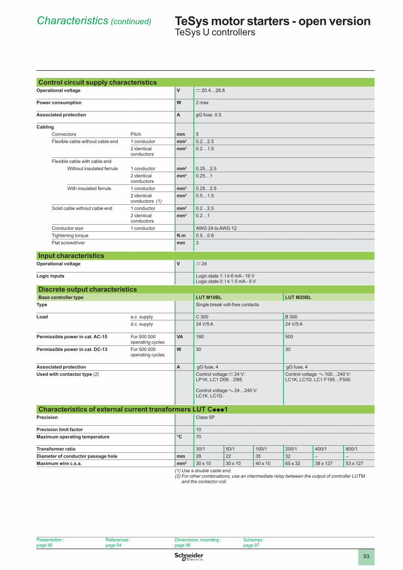
93
Control circuit supply characteristicsOperational voltage V c �0.4…�8.8
Power consumption W 2 max
Associated protection A gG fuse. 0.5
CablingConnectors Pitch mm 5Flexible cable without cable end � conductor mm2 0.�…�.5
� identical conductors
mm2 0.�…�.5
Flexible cable with cable endWithout insulated ferrule � conductor mm2 0.�5…�.5
� identical conductors
mm2 0.�5…�
With insulated ferrule � conductor mm2 0.�5…�.5� identical conductors (1)
mm2 0.5…�.5
Solid cable without cable end � conductor mm2 0.�…�.5� identical conductors
mm2 0.�…�
Conductor size � conductor AWG 24 to AWG 12Tightening torque N .m 0.5…0.6Flat screwdriver mm 3
Input characteristicsOperational voltage V c �4
Logic inputs Logic state �: I u 6 mA - �6 VLogic state 0: I y �.5 mA - 5 V
Discrete output characteristicsBase controller type LUT M10BL LUT M20BL
Type Single break volt-free contacts
Load a.c. supply C 300 B 300d.c. supply 24 V/5 A 24 V/5 A
Permissible power in cat . AC-15 For 500 000 operating cycles
VA �80 500
Permissible power in cat . DC-13 For 500 000 operating cycles
W 30 30
Associated protection A gG fuse, 4 gG fuse, 4Used with contactor type (2)
Control voltage c �4 V:LP�K, LC� D09…D95.
Control voltage a �4…�40 V:LC�K, LC�D.
Control voltage a �00…�40 V: LC�K, LC�D, LC� F�85…F500
Characteristics of external current transformers LUT Cppp1Precision Class 5P
Precision limit factor �0Maximum operating temperature °C 70
Transformer ratio 30/1 50/1 100/1 200/1 400/1 800/1Diameter of conductor passage hole mm �8 �� 35 3� – –Maximum wire c .s .a . mm2 30 x 10 30 x 10 40 x 10 65 x 32 38 x 127 53 x 127
(1) Use a double cable end.(2) For other combinations, use an intermediate relay between the output of controller LUTM
and the contactor coil.
Characteristics (continued) TeSys motor starters - open version 1 TeSys U controllers
Presentation : page 90
References : page 94
Dimensions, mounting : page 96
Schemes : page 97
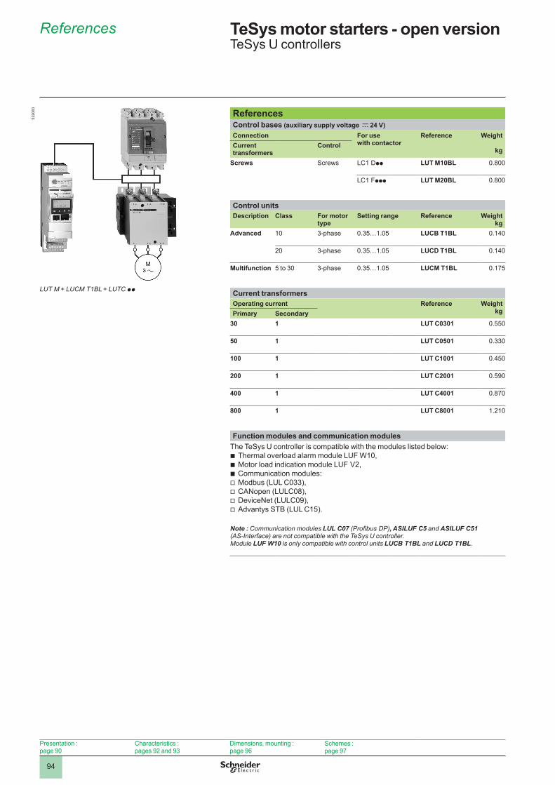
94
References TeSys motor starters - open version 1 TeSys U controllers
LUT M + LUCM T1BL + LUTC pp
53�0
83
Presentation : page 90
Characteristics : pages 9� and 93
Dimensions, mounting : page 96
Schemes : page 97
ReferencesControl bases (auxiliary supply voltage c 24 V)Connection For use
with contactorReference Weight
kg Current transformers
Control
Screws Screws LC� Dpp LUT M10BL 0.800
LC� Fppp LUT M20BL 0.800
Control unitsDescription Class For motor
typeSetting range Reference Weight
kgAdvanced �0 3-phase 0.35…�.05 LUCB T1BL 0.�40
�0 3-phase 0.35…�.05 LUCD T1BL 0.�40
Multifunction 5 to 30 3-phase 0.35…�.05 LUCM T1BL 0.�75
Current transformersOperating current Reference Weight
kgPrimary Secondary30 1 LUT C0301 0.550
50 1 LUT C0501 0.330
100 1 LUT C1001 0.450
200 1 LUT C2001 0.590
400 1 LUT C4001 0.870
800 1 LUT C8001 �.��0
Function modules and communication modulesThe TeSys U controller is compatible with the modules listed below:
Thermal overload alarm module LUF W�0,Motor load indication module LUF V�,Communication modules:Modbus (LUL C033),CANopen (LULC08),DeviceNet (LULC09),Advantys STB (LUL C�5).
bbbvvvv
Note : Communication modules LUL C07 (ProfibusDP), ASILUF C5 and ASILUF C51 (AS-Interface) are not compatible with the TeSys U controller. Module LUF W10 is only compatible with control units LUCB T1BL and LUCD T1BL.
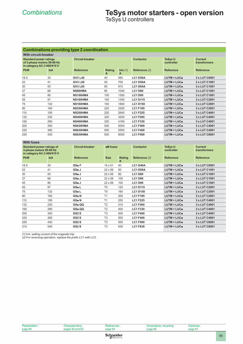
95
Combinations providing type 2 coordinationWith circuit-breakerStandard power ratings of 3-phase motors 50-60 Hz in category AC-3 400/415 V
Circuit-breaker Contactor TeSys U controller
Current transformers
PkW IeA Reference Rating A
Irm (1) A
Reference (2) Reference Reference
�8.5 35 GV3 L40 40 560 LC1 D50A LUTM + LUCp 3 x LUT C0501�� 4� GV3 L50 50 700 LC1 D50A LUTM + LUCp 3 x LUT C100130 55 GV3 L65 65 9�0 LC1 D65A LUTM + LUCp 3 x LUT C100137 66 NS80HMA 80 �040 LC1 D80 LUTM + LUCp 3 x LUT C100145 80 NS100HMA �00 �300 LC1 D95 LUTM + LUCp 3 x LUT C100155 97 NS160HMA �50 �350 LC1 D115 LUTM + LUCp 3 x LUT C200175 �3� NS160HMA �50 �800 LC1 D150 LUTM + LUCp 3 x LUT C200190 �60 NS250HMA ��0 ��00 LC1 F185 LUTM + LUCp 3 x LUT C2001��0 �95 NS250HMA ��0 �640 LC1 F225 LUTM + LUCp 3 x LUT C4001�3� �30 NS400HMA 3�0 3�00 LC1 F265 LUTM + LUCp 3 x LUT C4001�60 �80 NS400HMA 3�0 4�60 LC1 F330 LUTM + LUCp 3 x LUT C4001�00 350 NS630HMA 500 5000 LC1 F400 LUTM + LUCp 3 x LUT C4001��0 385 NS630HMA 500 5500 LC1 F400 LUTM + LUCp 3 x LUT C4001�50 430 NS630HMA 500 6000 LC1 F500 LUTM + LUCp 3 x LUT C8001
With fusesStandard power ratings of 3-phase motors 50-60 Hz in category AC-3 400/415 V
Circuit-breaker aM fuses Contactor TeSys U controller
Current transformers
PkW IeA Reference Size Rating A
Reference (2) Reference Reference
�8.5 35 GSp F 14 x 51 40 LC1 D40A LUTM + LUCp 3 x LUT C0501�� 4� GSp J 22 x 58 50 LC1 D50A LUTM + LUCp 3 x LUT C100130 55 GSp J 22 x 58 80 LC1 D80 LUTM + LUCp 3 x LUT C100137 66 GSp J 22 x 58 �00 LC1 D80 LUTM + LUCp 3 x LUT C100145 80 GSp J 22 x 58 �00 LC1 D95 LUTM + LUCp 3 x LUT C100155 97 GSp L T0 ��5 LC1 D115 LUTM + LUCp 3 x LUT C200175 �3� GSp L T0 �60 LC1 D150 LUTM + LUCp 3 x LUT C200190 �60 GSp N T� �00 LC1 F185 LUTM + LUCp 3 x LUT C2001��0 �95 GSp N T� �50 LC1 F225 LUTM + LUCp 3 x LUT C4001�3� �30 GSp QQ T� 3�5 LC1 F265 LUTM + LUCp 3 x LUT C4001�60 �80 GSp QQ T� 400 LC1 F330 LUTM + LUCp 3 x LUT C4001�00 350 GS2 S T3 500 LC1 F400 LUTM + LUCp 3 x LUT C4001��0 385 GS2 S T3 500 LC1 F400 LUTM + LUCp 3 x LUT C4001�50 430 GS2 S T3 500 LC1 F500 LUTM + LUCp 3 x LUT C80013�5 540 GS2 S T3 630 LC1 F630 LUTM + LUCp 3 x LUT C8001
(1) Irm: setting current of the magnetic trip.(2)Forreversingoperation,replacetheprefixLC1withLC2.
Combinations TeSys motor starters - open version 1 TeSys U controllers
Presentation : page 90
Characteristics : pages 9� and 93
References : page 94
Dimensions, mounting : page 96
Schemes : page 97
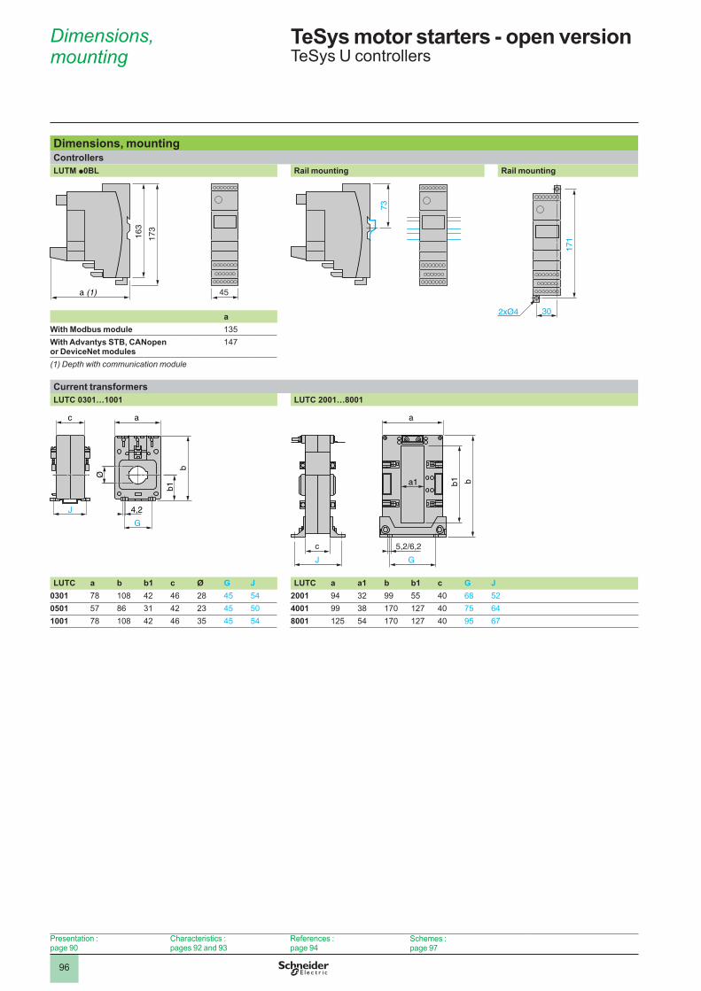
96
Dimensions, mounting
TeSys motor starters - open version 1 TeSys U controllers
Dimensions, mountingControllersLUTM p0BL Rail mounting Rail mounting
45
163
173
a (1)
73
302xØ4
171
aWith Modbus module �35With Advantys STB, CANopen or DeviceNet modules
�47
(1) Depth with communication module
Current transformersLUTC 0301…1001 LUTC 2001…8001
4,2
G
J
ac
b1
Ø
b
c 5,2/6,2
J G
a
a1 b1 b
LUTC a b b1 c Ø G J LUTC a a1 b b1 c G J0301 78 �08 4� 46 �8 45 54 2001 94 3� 99 55 40 68 5�0501 57 86 3� 4� �3 45 50 4001 99 38 �70 ��7 40 75 641001 78 �08 4� 46 35 45 54 8001 ��5 54 �70 ��7 40 95 67
Presentation : page 90
Characteristics : pages 9� and 93
References : page 94
Schemes : page 97

97
Schemes TeSys motor starters - open version 1 TeSys U controllers
SchemesReversing controller LUT M
L1 L2 L3
LUTM
13/N
O
23/N
O
95 96/N
O
97/N
C
LUTM
98 05 06/N
C
I.1 I.2 I.3 I.4
+
LUTM
I.5 I.6 I.7 I.8 I.9 I.10
LUTM
S1
S2
(1)
24 V Aux.
3-wire control, pulsed start with maintaining contact
I.9 I.10
I.1 I.2 I.3 I.4 I.5 R
ST
I.6 S
F
I.7 S
R
I.8 + + –
13
– KM1 – KM2
23 95
96
97
98
05
06
24 V c24…250 V a
– KM1AV – KM2 – Q1AR 24 V c
24 V cChannel � Channel �
Any fault
Control unit fault
External fault
Trip
Stop
Reset
Control for Modbus communication module LUL C033
I.9 I.10
I.1 I.2 I.3 I.4 I.5 R
ST
I.6 S
F
I.7 S
R
I.8 + + –
13
– KM1 – KM2
23 95 96 97 98 05 06
24 V c24…250 V a
– KM1 – KM2
– Q1– Q1 24 V c
24 V c
– KM1 – KM2 AU
CO
M
OA
1
OA
3
LO1
LI1
LI2
AU
Channel � Channel �
Any fault
Controll unit fault
“Local”/“remote”
Trip
Stop
Reset
Manu � Manu �
Any fault
Free Free On
Modbus network port
Communication module
“Local”/“remote”
(1) The contacts are represented with controller powered up and not in a fault condition.
Presentation : page 90
Characteristics : pages 9� and 93
References : page 94
Dimensions, mounting : page 96
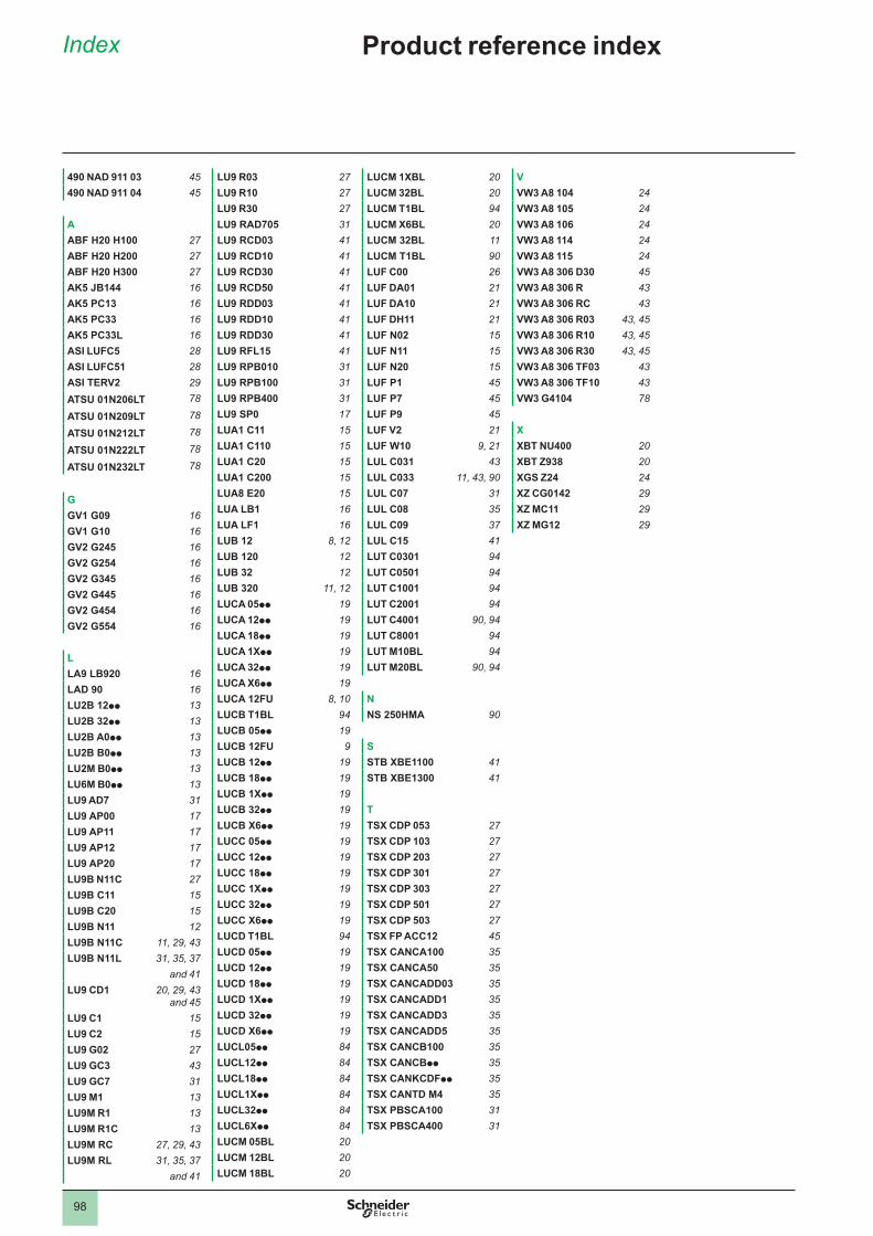
2
1
3
4
5
6
7
8
9
10
2
1
3
4
5
6
7
8
9
10
98
Index Product reference index
490 NAD 911 03 45490 NAD 911 04 45
AABF H20 H100 27ABF H20 H200 27ABF H20 H300 27AK5 JB144 16AK5 PC13 16AK5 PC33 16AK5 PC33L 16ASI LUFC5 28ASI LUFC51 28ASI TERV2 29ATSU 01N206LT 78
ATSU 01N209LT 78
ATSU 01N212LT 78
ATSU 01N222LT 78
ATSU 01N232LT 78
GGV1 G09 16GV1 G10 16GV2 G245 16GV2 G254 16GV2 G345 16GV2 G445 16GV2 G454 16GV2 G554 16
LLA9 LB920 16LAD 90 16LU2B 12pp 13LU2B 32pp 13LU2B A0pp 13LU2B B0pp 13LU2M B0pp 13LU6M B0pp 13LU9 AD7 31LU9 AP00 17LU9 AP11 17LU9 AP12 17LU9 AP20 17LU9B N11C 27LU9B C11 15LU9B C20 15LU9B N11 12LU9B N11C 11, 29, 43LU9B N11L 31, 35, 37 and 41LU9 CD1 20, 29, 43
and 45LU9 C1 15LU9 C2 15LU9 G02 27LU9 GC3 43LU9 GC7 31LU9 M1 13LU9M R1 13LU9M R1C 13LU9M RC 27, 29, 43LU9M RL 31, 35, 37
and 41
LU9 R03 27LU9 R10 27LU9 R30 27LU9 RAD705 31LU9 RCD03 41LU9 RCD10 41LU9 RCD30 41LU9 RCD50 41LU9 RDD03 41LU9 RDD10 41LU9 RDD30 41LU9 RFL15 41LU9 RPB010 31LU9 RPB100 31LU9 RPB400 31LU9 SP0 17LUA1 C11 15LUA1 C110 15LUA1 C20 15LUA1 C200 15LUA8 E20 15LUA LB1 16LUA LF1 16LUB 12 8, 12LUB 120 12LUB 32 12LUB 320 11, 12LUCA 05pp 19LUCA 12pp 19LUCA 18pp 19LUCA 1Xpp 19LUCA 32pp 19LUCA X6pp 19LUCA 12FU 8, 10LUCB T1BL 94LUCB 05pp 19LUCB 12FU 9LUCB 12pp 19LUCB 18pp 19LUCB 1Xpp 19LUCB 32pp 19LUCB X6pp 19LUCC 05pp 19LUCC 12pp 19LUCC 18pp 19LUCC 1Xpp 19LUCC 32pp 19LUCC X6pp 19LUCD T1BL 94LUCD 05pp 19LUCD 12pp 19LUCD 18pp 19LUCD 1Xpp 19LUCD 32pp 19LUCD X6pp 19LUCL05pp 84LUCL12pp 84LUCL18pp 84LUCL1Xpp 84LUCL32pp 84LUCL6Xpp 84LUCM 05BL 20LUCM 12BL 20LUCM 18BL 20
LUCM 1XBL 20LUCM 32BL 20LUCM T1BL 94LUCM X6BL 20LUCM 32BL 11LUCM T1BL 90LUF C00 26LUF DA01 21LUF DA10 21LUF DH11 21LUF N02 15LUF N11 15LUF N20 15LUF P1 45LUF P7 45LUF P9 45LUF V2 21LUF W10 9, 21LUL C031 43LUL C033 11, 43, 90LUL C07 31LUL C08 35LUL C09 37LUL C15 41LUT C0301 94LUT C0501 94LUT C1001 94LUT C2001 94LUT C4001 90, 94LUT C8001 94LUT M10BL 94LUT M20BL 90, 94
NNS 250HMA 90
SSTB XBE1100 41STB XBE1300 41
TTSX CDP 053 27TSX CDP 103 27TSX CDP 203 27TSX CDP 301 27TSX CDP 303 27TSX CDP 501 27TSX CDP 503 27TSX FP ACC12 45TSX CANCA100 35TSX CANCA50 35TSX CANCADD03 35TSX CANCADD1 35TSX CANCADD3 35TSX CANCADD5 35TSX CANCB100 35TSX CANCBpp 35TSX CANKCDFpp 35TSX CANTD M4 35TSX PBSCA100 31TSX PBSCA400 31
VVW3 A8 104 24VW3 A8 105 24VW3 A8 106 24VW3 A8 114 24VW3 A8 115 24VW3 A8 306 D30 45VW3 A8 306 R 43VW3 A8 306 RC 43VW3 A8 306 R03 43, 45VW3 A8 306 R10 43, 45VW3 A8 306 R30 43, 45VW3 A8 306 TF03 43VW3 A8 306 TF10 43VW3 G4104 78
XXBT NU400 20XBT Z938 20XGS Z24 24XZ CG0142 29XZ MC11 29XZ MG12 29