to 11a-1-20, airmunitions general (1966) - bulletpicker
TRANSCRIPT
'~'"f•
-----------*-----------1.0.11A-1- 20
TECHNICAL MANUAL
AIRMUNITIONS GENERAL
AF 42(600)39004F42600-67-D-3681
~rN.~. LATEST CHANGED PAGES SUPERSEDE
~~~~ THE SAME PAGES 0' PREVIOUS DATE
In...t eh...." ...... In.. Ita.le~ '-"OtlCI ~."••,,~. D.__.....~••••
BASIC AND ALL CHANGES HAVE BEEN MERGEDTO MAKE TIDS A COMPLETE PUBLICATION.
PUBLISHED UNDI!R AUTHORITY 0' THI! SIClnARY 0' THIAIR PORa
------------*-----------AJ1IS/Ogden UtahIJul 68/1000-unmr 1 FEBRUARY 1966CHANGE -2 . 1FEBRUARY 1968

•
••
T. O. llA-I-20 Table of Contents
TABLE OF CONTENTS
INTRODUCTION v Section Page
Section Page VIII CHEMICAL AGENTS. 8-18-1 Introduc tion. 8-1
GENERAL SAFETY REQUIREMENTS 1-1 8-3 Classification. 8-18-9 Blister Gases (Casualty) . 8-1
II DEFINITION OF TERMS 2-1 8-14 Choking Gases. 8-32-1 Introduction 2-1 8-16 Blood and Nerve Poisons. 8-32-3 Definitions 2-1 8-21 Training and Riot Control
Gases 8-6III CLASSIFICATION OF ITEMS 3 -1 8-29 Incapacitating Chemical
3-1 Introduction 3 -1 Agents. 8-63-3 Type 3-1 8-33 Screening Smokes. 8-73-14 Standardization, Use, and 8-39 Incendiaries 8-7
Form 3-1 8-50 Marking and Identification 8-83 -16 Storage 3 -13-18 Storage Compatibility 3 -1 IX SMALL ARMS AMMUNITION 9-13-20 Shipping Regulations. 3 -1 9-1 Introduction. 9-13-25 Burning or Explosive 9-3 Definitions 9-1
Characteristics . 3-2 9-23 Classification. 9-93-29 Security 3-3 9-40 Accessories 9-143-31 Identification 3-3 9-42 Care and Precautions in3-51 Painting and Marking 3-4 Handling 9-163-59 Packing and Marking. 3-5 9-46 Packing and Marking. 9-173 -61 Precautions in Use 3-5
IV DESCRIPTION OF FORMS AND X AIRCRAFT CANNON AMMUNITION 10-1
REPORTS 4-1 10-1 Introduction. , 10-1
4-1 Introduction 4-1 10-3 Definitions 10-1
4-2 Forms, Records, and Reports 4-1 10-12 Cartridges for 20-MM Gun,M3 10-34-4 Field Report of Accidents 4-1
10-24 Cartridges for 20-MM Gun,4-6 Malfunctions Involving Air-M24Al . 10-6
munitions or Explosives 4-110-31 Cartridges for 20-MM Gun,4-10 Damaged or Improper Shipment. 4-1
M39Al . 10-84-12 Disposition of Unserviceable10-33 Cartridges for 20-MM Gun,Munitions and Components 4-1
M61 (TI71E3). 10-84-14 Security 4-110-39 Packing Data 10-9
V PROPELLANTS 5-1 10-44 Precautions 10-10
5-1 Introduction. 5-15-3 Solid Propellants 5-1 XI CARTRIDGE/PROPELLANT5-10 Single-Base Propellants 5-1 ACTUATED DEVICES (CAD/PAD) 11-15-14 Double-Base Propellants. 5-2 11-1 Introduction. 11-15-17 Composite Propellants. 5-3 11-3 Description. 11-15-20 Small Arms Propellants 5-3 11-23 Functioning of Components 11-25-22 Liquid Propellants. 5-4 11-29 Care and Precautions in
Handling 11-2VI LOW EXPLOSIVES. 6-1
6-1 Introduction. 6-16-7 Black Powder. 6-2 XII GRENADES 12-16-11 Pyrotechnic Compositions 6-2 12-1 Introduction. 12-1
12-3 Classification. 12-1VII HIGH EXPLOSIVES. 7-1 12-8 Hand Grenades 12-1
7-1 Introduction. 7-1 12-22 Training and Practice Hand7-3 Terms and Definitions. 7-1 Grenades. 12-37-15 Classification. 7-2 12-27 Rifle Grenades 12-47-20 Demolition and Fragmentation 12-36 Grenade Fuzes 12-6
Explosives 7-3 12-41 Grenade Projection Adapters 12-67-58 Initiating and Priming 12-45 Grenade Packaging and
Explosives 7-6 Marking 12-11
Table of ContentsList of illustrations
T.O. llA-I-20
TABLE OF CONTENTS (Continued)
Section Page Section Page
XIII AIRCRAFT BOMBS, DISPENSERS, 15-38 5. O-Inch HVAR . 15-8AND FUZES. 13 -1 15-40 Warheads, 5. O-Inch HVAR . 15-813 -1 Introduction. 13 -1 15-43 Fuzes, 5. O-Inch HVAR .. 15-813-8 High Explosive Bombs . 13 -1 15-47 Launcher, 5. O-Inch HVAR . 15-1C ,13-21 Chemical (Gas) Bombs 13 -7 15-49 Target Rocket, 5.0-Inch, HVAR,13-23 Smoke Bombs. 13-11 Non-Maneuvering, TDU-11/B. 15-1013-25 Incendiary Bombs . 13-1113-32 Miscellaneous Bombs 13 -16 XVI JATOS 16-113-38 Practice and Dummy Bombs 13-16 16-1 Introduction. 16-113-46 Fuzes 13-22 16-3 Description. 16-113 -51 Functional Types of Fuzes 13-24 16-5 Major Components. 16-113-63 Packing and Marking. 13-36 16-10 Propelling Charge. 16-1
16-14 Function. 16-3XIV PYROTECHNICS. 14-1
14-1 Introduction. 14-1 XVII GUIDED. MISSrr.-ES . 17 -114-3 Description. 14-1 17-1 Introduction. 17-114-13 Classification. 14-2 17-4 Definitions 17 -114-16 Types 14-2 17-6 Classification. 17 -114-29 Training Pyrotechnics. 14-8 17-10 Identification 17-114-32 Care and Precautions in 17-12 Warheads 17-2
Handling. 14-10 17-14 Fuzes 17-314-37 Precaution in Firing. 14-11 17-19 Electrical Power System. 17-514-39 Packing and Marking. 14-11 17-21 Propulsion System 17-5
17-26 Control and Guidance Systems 17-7XV AIRCRAFT ROCKETS 15-1 17-30 Launchers 17-7
15-1 Introduction. 15-1 17-36 Packing and Marking. 17-815-5 2.75-Inch FFAR. 15-215-7 Warheads, 2. 75-Inch FFAR 15-2 XVIII DEMOLITION MATERIALS. 18-115-15 Fuzes, 2. 75-Inch FFAR . 15-3 18-1 Introduction 18-115-20 Launchers, 2.75-Inch FFAR 15-5 18-3 Demolition Materials 18-115-27 5.0-Inch FFAR (Zuni) . 15-615-29 Warheads, 5.0-Inch FFAR . 15-6 APPENDIX A-I15-32 Fuzes, 5.0-Inch FFAR 15-715-35 Launcher, 5.0-Inch FFAR . 15-7 INDEX 1-1
LIST OF ILLUSTRATIONSNumber Title Page Number Title Page
3-1. Fire Symbol 1 3-2 7-1. Detonating Wave Amplified by Use of3-2. Fire Symbol 2 . 3-2 Booster 7-23-3. Fire Symbol 3 . 3-2 7-2. Schematic Arrangement of Components3-4. Fire Symbol 4 . 3-2 of Explosive Trains . 7-33-5. Persistent Poison Gas 3-2 8-1. Fillings and Markings of Chemical3-6. Non-Persistent Poison Gas 3-2 Munitions 8-23-7. BW Agents 3-2 8-2. Characteristics of Military Gases . 8-43-8. WP Munitions 3-2 9-1. Small Arms Cartridge Components and3-9. Incendiaries. 3-2 Terminology 9-23-10. Nerve Gas (G Agents). 3-2 9-2. Rifle Grenade Cartridges, Carbine3-11. Color and Markings for Various Types of Cartridges, and Caliber. 45
Ammunition, Except Bombs, Cartridges . 9-3Pyrotechnic s, and Small Arms 9-3. Caliber . 30 Cartridges. 9-3Cartridges 3-5 9-4. Cartridges l 7.62-Millimeter . 9-4
5-1. Examples of Propellant Grain Shapes 9-5. Caliber. 50 Cartridges. 9-4and Forms 5-2 9-6. Types of Cartridges - Sectioned. 9-4
5-2. Comparative Burning Rates of Propel- 9-7. Types of Cartridge Cases. 9-5lant Grain Shapes 5-2 9-8. Typical Shotgun Shells - Sectioned. 9-5
5-3. Progressive Burning of Propellant Grains 9-9. Components of Primers - Separated . 9-5(Multi -perforated) . 5-3 9-10. Primers - Sectioned . 9-6
5-4. Forms of Rocket Propellant Grains 9-11. Caliber. 30 Bullets - Sectioned 9-7(United States and Foreign) . 5-3 9-12. Caliber .50 Bullets - Sectioned 9-8
6-1. Typical Low-Explosive Trains. 6-2 9-13. Caliber .45 Bullets - Sectioned 9-9
ii

ToO. 11A-I-20 List of illustrations
LIST OF ILLUSTRATIONS (Continued)
Number Title Page Number Title Page
9-9
9-10
9-14
9-14
.12-9· 12-10· 12-10
· 13-6
· 13-4
· 13-7
.13-18
Grenade, Chemical, Bursting Type,M19Al . . . . . . 12-7
Grenade, Rifle, Colored Smoke, M22Series . . . . . . . . . . . . 12-8
Grenade, Rifle, Colored Smoke, M23(Streamer) . . . . .
Grenade Projection Adapter, MIA2 .Grenade Projection Adapter, M2Al .Table of Leading Particulars, Hand
Grenades 12-11Table of Leading Particulars, Rifle
Grenades . . . . . . . . . . . 12-12Components of Bomb Complete Round
With Box Fin. . . . . . . . . . 13-2Typical Bomb Explosive Train .... 13-2Old Series General Purpose Bomb with
Box Fin Assembly . . . . . . . 13-3Old Series General Purpose Bomb with
Conical Fin Assembly; E'!PlodedView " .13-3
New Series General Purpose Bomb,Typical. . . . . . . . . . . . 13-4
Low Drag General Purpose, Typical. . 13-4Low Drag General Purpose Snakeye I
Series, Bomb. . . . . . .Old Series General Purpose Bomb,
Cutaway View . . . . . . .New Series General Purpose Bomb,
Cutaway View . 0 • • • • •
Low Drag General Purpose Bomb,Cutaway View . . . . . .. . 13-8
Low Drag, General Purpose, Snakeye I,Bomb with Fin AssemblyOpened . . . . . . . . . . . . 13-9
Armor-Piercing Bomb, Cutaway View. 13-9Semi-Armor-Piercing Bomb, Cutaway
View. . . . . . . . . .. . 13-10Fragmentation Bombs, M41Al and
M82, Cutaway Views. . .. . 13-11Fragmentation Bomb, Typical AN -M88
and AN-M81 Series, CutawayView 13-12
Fragmentation Bomb, M83, ButterflyWing Stabilized, Cutaway View.. 13-13
Gas Bomb, Nonpersistent, GB, M125Al,Cutaway View . .. .... 13-13
Gas Bomb, Nonpersistent, GB, MC-I,Cutaway View. .. . ... 13-14
Gas Bomb, Nonpersistent, GB, MK94Mod 0, Cutaway View 13-14
Smoke Bomb, PWP or WP, AN-M47A4,Cutaway View 13-15
Fire Bombs, M116A2 and BLU Series,Cutaway Views 13-15
Depth Bomb, AN-MK54 Mod 1, CutawayView . . . . . . . . . .. 0 13-17
Leaflet Bomb, M129El, CompleteRound and with Lid Removed
Photoflash Bomb, Typical, CutawayView 0 •••••••••••• 13-19
Cluster, Fragmentation Bomb, withSpoiler Ring and Drag Plate,Cutaway View . . 0 • • • 0 • • 13 -20
12-10.12-11.12-12.
12-8.
13-1.
12-9.
13-4.
13-5.
12-13.
13-8.
13-2.13-3.
12-7.
13-6.13-7.
13-9.
13-10.
13-11.
13-15.
13-16.
13"':12.13-13.
13-14.
13-20.
13-18.
13-19.
13-17.
13-21.
13-23.
13 -22.
13-24.
13-25.
9-109-109-10
9-11
9-12
9-13
9-16
9-16
9-18
9-199-199-19
· 12-2
o12-3· 12-4· 12-5
Caliber.22 Cartridges . . . . .Caliber. 30 and 7. 62 -Millimeter
Grenade Cartridges . . 0
Caliber. 30 Blank CartridgeM1909 .
Caliber. 38 Special Cartridges.Caliber.45, Line Throwing BlankCartridge Links and Metallic Belt
End .Link Cartridges, with Caliber. 30,
7.62-Millimeter, and Caliber. 50 Ammunition. . . .
Bandoleer, Magazine, Filler, andClips .
Component Parts of Caliber. 22Ammunition..... 0 •••
Component Parts of 5. 56-MillimeterAmmunition .
Component Parts of Caliber. 30Carbine Ammunition (CenterfirePrimers are used in all Car-tridges) .. 0 •••••••• 9-15
Component Parts of Caliber. 30 Ammunition (Corrosive and NoncorrosivePrimers Have Been Used in allCartridges Listed).... 0 • 0 9-15
Component Parts of 7. 62-MillimeterAmmunition (Primer No. 26 orEquivalent Used In CartridgesListed). . . . 0 • • • •
Component Parts of Caliber. 38Special Ammunition . . .
Component Parts of Caliber. 45Ammunition (Corrosive and Noncorrosive Primers are used inCartridges Listed) 9-17
Component Parts of Caliber. 50Ammunition (Corrosive and Noncorrosive Type Primers Used inall Cartridges Listed) . 0 •
Intended Use of Different ShotgunCartridges
Shotgun Gages . . . . . . . . .Bullet Diameters 0 0 • • • • • •
Cartridge Components, 20-MillimeterElectric Primer-Typical. . 0 • 10-2
Cartridges, 20-MM. . 10-2Fuze, Point Detonating, M505 Series 0 10-420-MM Cartridges, Components, and
Markings. . . . . . . . . . 0 10-5Disintegrating Links for 20-Millimeter
Cartridges . . . . . . . . . . 10-7
General Types of Hand Grenades,Service, Practice, Training,:ind Simulator. . . . .
Later Developments in HandGrenades 0 0 • • • 0 •
Chemical Hand Grenades . .Grenade, Rifle, HEAT, M31.Grenade, Rifle, AT, Practice, M29
(T42). . . 0 0 • 0 • • •• • 12-7Grenade, Rifle, illuminating, M27 .. 12-7
9-24.
9-23.
9-21.
9-26.
9-14.9-15.
9-20.
9-16.
9-17.9-18.9-19.
9-27.
9-22.
9-25.
9-29.
9-28.
9-30.
10-5.
9-31.9-32.
10-1.
12-2.
12-3.12-4.12-5.
12-1.
10-2.10-3.10-4.
12-6.
iii

Li.st of illustrations T. O. 11A-1-20
LIST OF ILLUSTRATIONS (Continued)
Number Title Page Number Title Page
· 14-2
· 14-9
· 14-3
· 14-7
Of
,
•
· 15-3
· 15-4· 15-4
· 15-7
· 15-8
· 15-7
· 15-9· 15-9
· 16-2
· 17-2· 17-2· 17-3· 17-3
· 18-8· 18-9· 18-9· 18-10· 18-11· 18-12· 18-13
· 15-10· 15-11
Non-· 15-11· 16-2
2.75-Inch Folding Fin AircraftRocket (FFAR)
2. 75-Inch Rocket Warhead MK1Mod 4 (HE) .
2. 75-Inch Rocket Warhead M151 .3. 5-Inch Smoke WP Warhead, Fuze,
and Adapter, for 2. 75-InchAircraft Rocket. . 15-5
Nose Fuze MK176 Mod 1 (AccelerationArming, Point-Detonating) . 15-5
Nose Fuze MK181 Mod 0 . . 15-65.0-Inch Folding Fin Aircraft Rocket
(FFAR) (ZUNI).Rocket Head, 5.0-Inch, MK24 Mod 0,
Installed in 5. O-Inch FFAR(ZUNI)
Fuzes for 5. O-Inch FFAR (ZUNI) Typical.
LAU-10/A Rocket Launcher, Loadedwith 5.0-Inch (FFAR) (ZUNI)Rockets.
Fuze, Rocket, Nose, MK149 Mod 0Base Fuze MK164 Mod 0, Cross
Section, Unarmed PositionFuze, Rocket VT, M403 .Target Rocket, 5.0-Inch, HVAR,
Maneuvering, TDU -11/BTypical JATO Identification SystemMajor Parts of Typical JATO Rocket
MotorsStatus Prefix Symbols (Classification
Letters) .Launch Environment Symbols.Mission SymbolsVehicle Type SymbolsDepartment of Defense Missile
Designation . 17-4Typical Demolition Material . 18-2Torpedo, Bangalore, M1A2. . 18-4Kit, Demolition, M37 . 18-5Destructor, High-Explosive, Universal,
M10 . 18-5Cord, Detonating, Waterproof, Plastic-
Reinforced . 18-7Fuze, Blasting, Time, Fabric-covered
and Plastic-covered . 18-7Lighter, Fuze, Weatherproof, M2. .18-7Blasting Caps, Non-electric and
Electric.Detonator, 8-Second Delay, M2.Demolition EquipmentFiring DevicesDetonator, Concussion Type, M1Demolition Equipment Set Number 1 .Demolition Equipment Set Number 5 .'
15-8.
15-12.
15 -13.
15-5.
15-11.
15-4.
15-9.15-10.
15-6.15-7.
15-14.15-15.
15-16.15-17.
17-1.
16-1.16-2.
18-1.18-2.18-3.18-4.
17-2.17-3.17-4.17-5.
18-5.
18-6.
18-7.18-8.
18-9.18-10.18-11.18-12.18-13.18-14.
· 13 -30· 13 -31
· 13 -35· 13 -36
· 13 -32· 13 -33· 13 -34
· 14-8
· 14-4· 14-5· 14-6· 14-6
· 14-9
· 14-10
· 14-10
Cluster, Fragmentation Bomb, Quick-Opening Type . . 13 -21
Aimable Clusters, Typical, M25, M35,and M34A1 . 13 -21
Bomb Dispenser SUU-7A/A . .13-23Bomb Dispenser SUU-24/A and Integral
Components. .13-23Fire Bomb BLU-29/B, Igniter AN-
M23A1, and Fuze FMU-60/B .. 13-24Tail Fuze AN-M100A2, Cross Section .13-25Tail Fuze M115, Cross Section . 13 -26Tail Fuze M190 .13-27Nose Fuze AN-M103A1, Cross Section. 13-28Arming-Pin Type Fuze. . . . .13-29Mechanical Time Nose Fuze AN-
M146A1 (Unarmed) CutawayView.
Hydrostatic Tail Fuze AN -MK230Proximity Nose Fuze M166, Cross
SectionTail Fuze M123A1, Cross SectionTail Fuze M132, Cross SectionTail Fuzes AN-M100A2 and AN-
M102A2Bomb Color Coding.Representative Ignition Train for
PyrotechnicsAircraft Parachute Flare, MK24
Mod 3Fusee, Warning, Railroad: Red,
20 Minute, M72 .Flare, Trip, M49Tracking Flare, MK21 Mod 0Aircraft SignalsSignal, Smoke and illumination,
Marine: AN-MK13 Mod 0Light, Float, Aircraft, AN-MK6
Mod 2Signal, illumination, Ground, White
Star, Parachute, M127 (T73)(Hand-held) - Section
Signal, illumination, Ground: RedStar, Parachute M131 (T66E1)(Hand-held) .
Cartridge, Photoflash, M112A1,4-Second Delay
Simulator, Booby Trap, Flash, M117,illuminating, M118 andWhistling, Ml19.
The Rocket Principle (Pressure inClosed Tube) . 15-2
The Rocket Principle (Movement of theTube-Opening in One End) . 15-2
The Rocket Principle (Movement of theTube-Nozzle in One End) . . 15-2
13 -27.
13-26.
13-30.
13-28.13-29.
13 -31.13-32.13 -33.13-34.13-35.13 -36.
14-3.
14-2.
13-39.13-40.13 -41.
13-42.14-1.
13-37.13-38.
14-8.
14-4.14-5.14-6.14-7.
14-9.
14-10.
14-12.
15-1.
14-11.
15-2.
15-3.
T.O. llA-1-20
INTRODUCTION
Introduction
..This manual provides information on general airmunit ions items used by, or in support of, United StatesAir Force activities. Information is furnished for theclassification, identification, and use of these items.The air munitions described include those procuredand issued by the Departments of the Air Force, Army,and Navy. Specific data pertaining to dimension orcomposition of Chemical Corps or Navy designeditems may be found in pertinent Department of theArmy and Department of the Navy publications (Referto Appendix). Information pertaining to nuclear orbiological munitions has not been included (refer tospecific Technical Manuals). General informationpertaining to care, handling, packing, and marking ofairmunitions is contained. For more specific data onmaintenance, storage, handling, inspection, or destruction, refer to applicable technical manuals.
The appendix contains a list of current references,including supply and technical manuals, forms, andother available authorized publications applicable tothis manual.Whenever the words SHALL or Wll..L appear in thistechnical manual, it shall be construed to mean thatthe requirements are binding. The word SHOULD indicates a nonmandatory desire or a preferred methodof accomplishment. The word MAY is used to indicate an acceptable or suggested means of accomplishment.
Users of this manual are encouraged to submit comments or recommendations for changes for improvement. Deficiencies noted in this manual should bereported to Headquarters, OOAMA (OOYST), Hill AirForce Base, Utah, 84401, in accordance with SectionVIII, T. O. 00-5-1.
v/vi

T.O. llA-1-20
SECTION IGENERAL SAFETY REQUIREMENTS
Section IParagraphs 1-1 to 1-3
1-1. INTRODUCTION.
1-2. GENERAL. These safety requirements andprecautions will be complied with by munitions personnel during storage, handling and inspection of conventional munitions. All personnel engaged directlyas well as indirectly in operations in which ammunition, explosives and/or other hazardous material isinvolved should be thoroughly trained in explosivesafety and capable of recognizing hazardous explosiveexposures. Thinking safety and working safely mustbecome a firmly established habit when working withor in the vicinity of items capable of exhibiting a
hazard due to the nature of their explosive, flalJ'mabIe or toxic fillers.
1-3. REQUIREMENTS. The safety requirements setforth in AFM 127-100 will be complied with. Theabsence of a safety requirement in this T. O. or inthe above reference does not necessarily indicatethat no safeguards are needed. If immediately dangerous ammunition is encountered, all operations inthe immediate vicinity will be shut down, personnelevacuated to a safe location and EOD or other authorized personnel called to render assistance in elimination of the hazard. Operations will not be resumeduntil the hazard has been eliminated.
1-1/1-2


T.O. llA-1-20
SECTION IIDEFINITION OF TERMS
Section IIParagraphs 2-1 to 2-18
2-1. INTRODUCTION.
2-2. The terms used in conjunction with variousitems, classification, and use are standard throughout all airmunitions activities and are covered in theapplicable sections of the manual. A complete definition of terms used within this manual is not furnished.The following definitions are simple descriptions ofterms and phrases commonly used in conjunction withexplosives. These are listed to provide a degree ofuniformity of description in the use of technical information throughout the manual.
2-3. DE FINITIONS.
2-4. AIRMUNITIONS. Airmunitions are those itemsof military ammunition used by Air Force aircraft,weapons, or personnel. They are used in direct orindirect support of tactical or strategic objectives.
2-5. AUTOIGNITION TEMPERATURE. This temperature is the minimum temperature that combustible materials in contact with air will ignite, withoutan ignition source, and will continue to support combustion.
2-6. BIOLOGICAL WARFARE (BW). The militaryuse of biological agents to produce death or diseasein man, animals, and growing plants, is called biological warfare.
2-7. BRISANCE. The ability of an explosive to shatter its surrounding medium by very rapid expansionof gases and energy is called brisance.
2-8. CHEMICAL MUNITION. Chemical munitionsare those items of ammunition such as bombs, rockets, and grenades, containing a chemical agent(s).Such agents include war gases, smokes, and incendiaries.
2-9. COMPLETE ROUND. A complete round of ammunition consists of all the necessary components tofire the system once.
2-10. DEFLAGRATE. Deflagration is a rapid burning action that consumes an explosive mass at a rateless than that normally considered to be a detonation.Propellants would normally fall within this category.
2-11. DEMILITARIZE, The term demilitarize meansto mutilate, disarm or accomplish any other actionrequired to render explosives unusable for militaryuse.
2-12. DETONATE. Detonation is a very rapid decomposition of the mass, normally at speeds upward
of 1500 feet per second. High explosives fall withinthis category.
2-13. ELECTROEXPLOSIVE DEVICE. Any explosivedevice such as a blasting cap, squib, explosi ve switch,explosive valve, igniter, etc., which is designed tobe initiated by an electric current, is an electroexplosive device.
2-14. EXPLOSION PROOF. The term explosionproof, as used in connection with electrical equipment, means that such equipment is enclosed in acase, which is capable of withstanding an internalburning or explosion of elements co'ntained inside thecase and prevent ignition by spark, flash or explosionof any outside gas or vapor surrounding the enclosure.
2-15. EXPLOSIVES. The term explosives includesall ammunition, biological and chemical fillers, demolition material, solid rocket motors, liquid propellants, cartridges, pyrotechnics, mines, bombs,grenades, warheads of all types, explosive elementsof ejection and aircrew egress systems, explosivecomponents of missile systems and space systems,and assembled kits and devices containing explosivesmaterial. The terms explosives, explosives weight,net weight, and other like terms, refer to the fillersof an explosive item. Fillers may be propellants,TNT, Composition B, pyrotechnics, chemical agents,biological agents, etc.
2-16. EXPLOSIVES AREA OR LOCATION, An explosives area or location is any area or location specifically designated and set aside from other areas,and used for manufacturing, maintenance, storage,demilitarization, shipping and receiVing, and othersimilar type explosives operations. Such areas mayalso be referred to as explosives parking or loadingareas when armed or explosives-loaded aircraft areinvolved.
2-17. EXPLOSIVE HAZARD. An explosive hazard isany condition which may result in the occurrence, orcontribute to the severity, of an explosives accidentor incident.
2-18. EXPLOSIVES SAFETY DISTANCE (QUANTITYDISTANCE). The prescribed minimum distance between various classes and quantities (net weight) ofexplosives and between such explosives and specifiedexposures (inhabited buildings, public highways, public railways, petroleum, aircraft, etc.) affording anacceptable degree of protection and safety is caLledthe explosives safety ctist::l.llce.
2-1
Section IIParagraphs 2-19 to 2-30
T. O. llA-1-20
2-19. EXPOSED EXPLOSIVES. Exposed explosivesare as follows:
a. Explosives that are actually visable (such as unpackaged bulk explosives, disassembled or open components, etc.) and are susceptible to initiation directly by static or mechanical spark.
b. Explosives that create (or accidentally create)explosive dust or give off vapors, fumes ur gases inexplosive concentrations.
2-20. EXUDATE. Impurities in an explosive compound will sometimes leech out, or exude, from themass due to heat, sweating, or chemical reaction. Inbombs this material will usually ooze out around thefuze seat liner and drop onto the floor. Some exudateis extremely sensitive because it contains minuteparticles of explosive.
2-21. HIGH ORDER DETONATION. A detonationwherein all of the explosive is detonated at its maximum rate of detonation is called a high order detonation.
2-22. HYGROSCOPIC. The ability or capacity of amedium to absorb water is called hygroscopicity. Ifthe explosive is hygroscopic the rate of detonationwill be lower.
2-23. INERT. (As applicable to explosives). Inertitems are those containing no explosives, activechemicals or pyrotechnics but not necessarily noncombustible.
2-24. LOW ORDER DETONATION. When only a portion of the explosive mass detonates, usually lowerthan its maximum rate of detonation, it is called alow order detonation.
2-25. MAGAZINE. A magazine is any building orstructure, except an operating building, used for thestorage of explosives. Magazines are of two generaltypes: igloo (earth covered) and above ground (nonearth covered).
2-26. MASS-DETONATING EXPLOSIVES. Massdetonating explosives are explosives that can be expected to explode and consume most of the entire mass
2-2
virtually instantaneously when a small portion is subject to fire, severe concussion or impact, impulse ofan initiating agent, or to the effect of a considerabledischarge of energy from without. Explosives of thiscategory, when detonated, cause severe structuraldamage to adjacent objects and may induce simultaneous detonation of other explosives stored sufficiently close to the initial explosion. When the explosivesare located on or near the surface of the ground, amass detonation is normally characterized by a crater. High explosives (TNT, etc.), black powder,certain combinations used in propellants, certainpyrotechnics, other similar explosives alone or incombination, and some complete items containing different classes of explosives in various componentsmay be found in this category.
2-27. MILITARY AMMUNITION. Militaryammunition is that type of munition that consists of explosiveor chemical agents, with their characteristicmechanical devices, designed for use against military ob-jectives. '
2-28. POWER. The ability of an' explosive to displace its surrounding medium. The ability to dowork. The power of an explosive is governed by therate of deflagration, temperature of the explosive,and the volume of gas liberated.
2-29. PROPAGATING EXPLOSION. A propagatingexplos{on is the communication of an explosion (detonation or deflagration) from one explosive source toanother by fire, fragment or blast (shock wave),where the time interval between explosions is sufficient to limit the total over-pressure at any giventime to that which each explosion produces independently. (This condition, where detonation occurs,would be evidenced by a distinct shock wave fromeach detonation with a discernible pressure drop between each explosion. )
2-30. WEIGHT OF EXPLOSIVE. Explosive weightsused in this manual will be construed to mean fillerof the item in grams, grains, or pounds as indicated.The term explosive will include high explosive, lowexplosive or chemical depending upon the item referred to. Conversion of grain, gram, and pound is:7000 grains equal 1 pound, 454 grams equal 1 pound,15.4 grains equal 1 gram, and 28.35 grams equal 1ounce.
..

,..
T.O. llA-1-20
SECTION IIICLASSIFICATION OF ITEMS
Section IIIParagraphs 3-1 to 3-23
"
3-1. INTRODUCTION.
3-2. Airmunitions are classified according to theircharacteristics, i. e., type, standardization, use, etc.
3-3. TYPE.
3-4. SMALL ARMS AMMUNITION. Small arms ammunition consists of cartridges used in rifles, carbines, revolvers, pistols, submachineguns, machineguns, and shotgun shells.
3-5. AIRCRAFT CANNON AMMUNITION. Aircraftcannon ammunition consists of cartridges used in automatic aircraft cannon against ground, seaborne oraircraft targets. The cartridges are fixed, completerounds, and the projectiles may be ball, high-explosive,incendiary, armor-piercing, or a combination.
3-6. CARTRIDGE ACTUATED DEVICES (CAD) ANDPROPELLANT ACTUATED DEVICES (PAD). Cartridge actuated and propellant actuated devices aredevices designed to facilitate an emergency escapefrom high speed aircraft, or perform other mechanical function in weapon systems.
3-7. GRENADES. Grenades are explosive- orchemical-filled projectiles of a size and shape convenient for thrOWing by hand or projecting from arifle.
3-B. AIRCRAFT BOMBS, DISPENSERS, AND FUZES.Aircraft bombs are containers filled with an explosive, chemical, or other agent. They are fuzed, stabilized, and designed for release from aircraftagainst ground targets. Dispensers are either mechanical devices attached to the aircraft, or free fallingmechanical devices designed to dispense a quantity ofsmaller items over a large target area. Fuzes aremechanical devices designed for the specific purposeof causing the bomb to function as intended, or foropening clusters at prescribed times. Two fuzes areusually used in bombs to obtain different effects, flexibility in use, or reliability in functioning.
3-9. PYROTECHNICS. Pyrotechnics consist of containers filled with low-explosive composition, designed for release from aircraft or for projectionfrom the ground for illumination or signals.
3-10. AffiCRAFT ROCKETS (UNGUIDED MISSILES).Aircraft rockets are propellant-type motors, filledwith solid or liqUid propellant, fitted with rocketheads containing high-explosive or chemical agents.Guidance is prOVided by the launch aircraft to the extent of pointing the rocket in a predicted collisioncourse with the target. A guidance system is not incorporated in the complete round.
3-11. JET-ASSIST-TAKE-OFF (JATO). JATO's consist of propellant-type motors used to furnish auxiliary thrust in the launching of aircraft, rockets,guided missiles, target drones, and mine clearingdetonating cables.
3 -12. GUIDED MISSILES. Guided missiles consist ofpropellant-type motors fitted with warheads containing high-explosive or other active agent and equippedwith electronic guidance devices. Guided missilesmay be air-launched or launched from fixed or mobileground sites.
3-13. DEMOLITION MATERIALS.· Demolition materials consist of explosives and explosive charges designed for use in demolition and in connection withblasting for military construction.
3-14. STANDARDIZATION, USE, AND FORM.
3-15. Airmunitions are classified according to standardization as Standard, Substitute Standard, or Limited Standard; according to form of issue as Fixed,Semifixed or Separated; and according to filler asExplosive, Chemical, Leaflet, Inert, or Empty.
3-16. STORAGE.
3-17. Airmunitions are classified for storage pur- (poses into quantity-distance classes 1 through 8.
3-1B. STORAGE COMPATIBILITY.
3 -19. Airmunitions are presently grouped for compatibility in storage into 17 groups, lettered A throughQ. (Refer to AFM 127-100.)
3-20. SHIPPING REGULATIONS.
3-21. Agent T. C. George's ICC Freight Tariff No.15, as amended, classifies ammunition items intoclass A explosives (which are subdivided into types 1through B), class B explosives, and class C explosives. ICC shipping regulations are established accordingly. Regulations pertaining to transportationof these classes of explosives are published by theBureau of Explosives, 30 Vesey Street, New York,N.Y.
3-22. Movement of explosives by commercial aircraft is governed by regulations of the Federal Aviation Agency (FAA).
3 -23. The Military Traffic Management TerminalService (MTMTS), formerly the Defense TrafficManagement Service (DTMS), is a Department ofDefense (DOD) agency, which regulates and monitors
Change 1 - 2B July 1967 3-1

Section IIIParagraphs 3-24 to 3-28
T.O. llA-1-20
Figure 3-10. Nerve Gas(G Agents)
Figure 3 -8. WP Munitions
Figure 3-6. Non-PersistentPoison Gas
Figure 3 -5. PersistentPoison Gas
3 -27. Liquid propellants independently present a widevariety of hazards that are not directly associatedwith symbols 1 through 4. Extensive fire fightingguidance for these liquids, based upon the individualcharacteristics of each commodity, will be found inpertinent publications, as AFM's 160-39, 127-201,and AFP 92-1-2. Therefore, these fire symbols haveno application to liquid propellants except for the useof symbol 4 to indicate situations presenting the additional hazard of detonation. EXCEPTION: Fire symbols need not be posted on operational missile sites(e. g., Titan, Thor, etc.) where only single types ofweapons systems are involved and written fire fighting plans or instructions exist and personnel concerned have been specifically advised of the hazardsinvolved.
3 -28. Chemical and biological warfare (BW) hazardmarkers will be used to identify chemicals, nervegas (G agents), and BW munitions in operating buildings and storage facilities for fire fighting purposes.The type or types of markers used will depend notonly upon the type of agent but also upon the absenceor presence of explosive components. If munitionscontain an explosive component, hazard markers willbe used in conjunction with fire symbols. Chemical,nerve gas, and BW munitions, which contain no explosives, will be identified by the appropriate hazardmarker(s), as described in figures 3-5 through 3-10.
Figure 3-7. BW Agents
Figure 3 -9. Incendiaries
3-25. BURNING OR EXPLOSIVE CHARACTERISTICS.
3-24. The United States Coast Guard, Treasury Department, is vested with explosives safety responsibilities for the loading and discharge of military explosives from all domestic and foreign vessels.
all military shipments including ammunition and explosives.
a. Fire Symbol 1. This symbol will be used forquantity-distance classes 1 and 8 explosives. Thesematerials are principally fire hazards. (See figure3-1. )
3 -26. Explosives, other than liquid propellants, aredivided into four groups in accordance with the general burning or explosive characteristics of the materials and the danger of fighting fires in which theyare present. The four groups are identified by symbols 1 through 4 (AFM 127-100) as follows:
b. Fire Symbol 2. This symbol will be used forquantity-distance class 3. Limited explosions may beexpected from fire in these materials. (See figure3-2. )
c. Fire Symbol 3. This symbol will be used forquantity-distance Class 2 explosives. These materials burn with intense heat. (See figure 3-3. )
d. Fire Symbol 4. This symbol will be used forquantity-distance Classes 4, 5, 6, and 7 explosivesand for certain liquid propellants. This symbol isalso applicable to all liquid propellant situations thatpresent detonation possibilities. (See figure 3-4.)
Figure 3-1. Fire Symbol 1 Figure 3-2. Fire Symbol 2
Figure 3-3. Fire Symbol 3 Figure 3-4. Fire Symbol 4
3-2 Change 1 - 28 July 1967
T.O. llA-I-20 Section IIIParagraphs 3-29 to 3-42
,.
3-29. SECURITY.
3 -30. Airmunitions are classified in accordance withsecurity regulations as unclassified, confidential, secret, or top secret. (Refer to AFR 205 series. )
3-31. IDENTIFICATION.
3 -32. Airmunitions are identified by painting andmarking on items, containers, and packing boxes.This identification does not include grade except inthe case of small arms cartridges. For purposes ofrecord, the standard nomenclature of the item, lotnumber, and the Federal Stock Number (or Department of Defense Code Number), completely identifiesthe airmunition. Once removed from packing, airmunitions may be identified by the painting and marking on the items. Other essential information mayalso be obtained from the marking on airmunltionitems, packing containers, and ammunition datacards. Included in both the marking and the standardnomenclature are the follOWing:
a. Name or type or abbreviation thereof.
b. Caliber, weight, or size.
c. Model designation.
d. Federal stock number (FSN).
3 -33. Where required, additional information is included such as the model and type of fuze and themodel of the weapon in which the item is fired.
3-34. The lot number is marked on the ammunitionor shipping container but is not a part of the nomenclature. However, when referring to specific ammunition in shipping documents and field reports, it isnecessary to mention the lot number, FSN, and standard nomenclature. (Refer to AFR 67-79 and AFM67-1. )
3-35. TYPE DESIGNATION. This is an identifyingsymbol used with nomenclature to distinguish different models and types of items or equipment withincategories and to indicate modifications and changesthereto.
NOTE
Only one type identification will be assignedto items of military supply that are physicallyand functionally interchangeable.
3-36. MARK OR MODEL. Ammunition items areassigned identifying numbers as they are developed.When a particular design has been accepted for limited procurement and service test, the model designation of the development item is indicated by theletter T or letters XM and an Arabic number, andmodifications are indicated by the addition of E andan Arabic number. To identify a particular design,a model designation becomes an essential part of thenomenclature and is included in the markings of theitem.
3-3 7. The present system of Army model designationconsists of the letter M followed by an Arabic number, for example, MI. Modifications are indicatedby adding the letter A and the appropriate Arabicnumber. Thus MIAI indicates the first modificationof an item for which the original model designationwas MI. Wherever a B suffix appears in a modeldesignation it indicates an item of alternate (substitute) design, material, or manufacture. Certainitems standardized for use by both Army and Navy aredesignated by the letter combination AN preceding themodel number.
3-38. Model designation of items of Navy design consists of the letters MK signifying the word Mark, followed by an Arabic number with a modification (Mod)number, for example, MK 6 Mod 2.
.3-39. Model designation for items of Air Force desian consists of a component or unit indicator (consi~ting of two letters of the alphabet) accompanied bya purpose indicator (consisting of one letter). This isfollowed by a dash, a model number, a slash and anequipment designator. Thus, BLU-10/B is an exampIe of a complete round model number for the 250pound fire bomb.
3-40. AMMUNITION LOT NUMBER. At the time ofmanufacture, every item of ammunition is assigned alot number. Where the size of the item permits, thelot number is marked on the item itself to ensurepermanency of this means of identification. In addition to this lot number, there is assigned to eachcomplete round of fixed and semifixed ammunition anammunition lot number, which serves to identify theconditions under which the round was assembled andthe components used in the assembly. This ammunition lot number is marked on every complete round ofammunition (except where the item is too small) andon allyac.king containers. It is required for all pur- .poses of record, including reports on condition, func ""tioning, and accidents in which the ammunition is involved. An ammunition lot consists of a number ofitems manufactured from similar materials undersimilar conditions, which may be expected to functionalike. The lot number conSists, in general, of theloader's initials or symbol and the number of the lot.(Refer to llAI3-1-3.)
3-41. CALIBRATION OF LOTS. Calibration data forcertain lots of ammunition are prOVided in order toeffect improvement in the relative accuracy. Thedata accounts for variations among ammunition lotsdue to differences in muzzle velocity level (interiorballistics) and differences in ballistic coefficient(exterior ballistics). The application of correctionsdetermined from the data is intended to reduce variations in performance due to the employment of individual ammunition-weapon combinations.
3-42. AMMUNITION DATA CARD. An ammunitiondata card will be prepared at the time the explosivetype items enter the Air Force inventory. (Refer toAFM 310 -1. It shall be the res ponsibility of the contractor to prepare the data cards in the requirednumbers. An ammunition data card, 5 by 8 inches in
3-3

Section IIIParagraphs 3-43 to 3-53
T.O. llA-I-20
size, will be made for each lot of ammunition. Theform of the data card for inert items shall be basicallythe same as that for loaded items. Ammunition datacards are used for the following purposes:
a. Provide minimum controls for identification ofunits and groups of units containing explosiv.e mixtures procured by the Air Force.
b. Provide a permanent file of data required to main. tain administrative control of such items entering theAir Force Inventory.
c. Provide a means of identifying all items containing an explosive lot (or batch) which proves defective.
3-43. FEDERAL STOCK NUMBER AND DEPARTMENT OF DEFENSE AMMUNITION CODE. The Federal stock number (FSN), e. g., FSN 1325-028-5298,has replaced the ammunition identification code (AlC)and the Ordnance stock number. There is a differentFederal stock number for each item of supply. Thefirst four digits in a Federal stock number are alwaysthe Federal supply classification (FSC) class to whichthe item belongs. The next seven digits constitute theFederal item identification number (FIlN). The dashbetween the third and fourth digits in the FUN servesto reduce errors in transmitting. There is a differentFIlN for each item. A Department of Defense identification code (DomC) is added as a suffix to the Federal stock number, e. g., 1325-028-5298 (E450). TheDODIC must not be confused with the DOD ammunitioncode (DODAC), which is an eight-character representation consisting of the four-character FSC code number and a second part consisting of a letter and threedigits. Thus for example, 1325-E450, a typicalDODAC, consists of FSC class 1325 and DOmC E450.The DODIC, when suffixed to more than one FSN, indicates the items are interchangeable for issue anduse. (Refer to 1300 series Federal Stock Catalogs.)
3-44. NOMENCLATURE. Standard nomenclature isestablished so that every item of ammunition suppliedmay be specifically identified by name. It consists ofthe type, size, and model of each item. Its use forall purposes of record is mandatory, except wherethe use of the FSN or DOmC is authorized. The useof exact nomenclature in the requisitioning, shipment,storage, issue, recording, and use of ammunitionitems will keep errors to a minimum.
3-45. GRADING. Airmunitions are manufactured torigorous specifications and are thoroughly inspectedbefore acceptance. Airmunitions in storage are periodically inspected and tested in accordance with specific instructions of the Airmunitions Wing OOAMA.Each lot of small arms ammunition is graded primarily on the qualities that make that lot especially suitable for use in a particular class of weapons such asaircraft and antiaircraft machineguns, rifles andground machineguns . (Refer to llA13 -1-3. )
3-46. SERVICEABILITY CRITERIA. Airmunitions,other than small arms ammunition, are serviceablefor all design applications, and are restric ted or suspended' as a result of surveillance tests. T.O. lIA1-1 provides Air Force personnel with information
3-4
pertinent to suspensions and restrictions on all typesof airmunitions used by the Air Force. Safety supplements are periodically sent to the field to maintaincurrent status of T. O. llA-1-1.
3-47. PRIORITY OF ISSUE. Subject to special instructions from the Airmunitions Wing, OOAMA, airmunitions of appropriate type and model will be usedin the follOWing order: limited standard, substitutestandard, and standard. These categories are listedin the status column of Federal Stock List 1300 series .Within this rule airmunitions that have had the longestor least favorable storage will be used first. Amonglots of equal age and serviceability, priority of issuewill be given to the smallest lot.
3-48. To prevent the building up of excess stocks inthe field, transfers from one station to another shouldbe arranged within the command if no stock of appropriate grade for immediate use is on hand. If thisaction is not feasible, information should be requestedfrom the Airmunitions Wing, OOAMA.
3-49. Priority of issue for small arms ammunitionlots is established by the Airmunitions Wing, OOAMA,or in special instructions.
3-50. Certain items because of their scarcity, cost,or technical nature are known as regulated items.Close supervision is exercised over these items inorder to ensure distribution to appropriate units andcommands in accordance with Department of the AirForce priorities. Factors governing the issue ofregulated items are as follows:
a. Shelf life: Shelf life is the life expectancy underprescribed packing and storage conditions and beginsfrom the date of manufacture.
b. Service life: Service life is the life expectancy ofan item when removed from prescribed packaging orit is installed in ope-rating configuration. Further details will be found in the applicable item technicalorders.
3-51. PAINTING AND MARKING.
3 -52. PAINTING. Ammunition is painted primarilyto prevent rust. Secondary purposes are to prOVide,by color, a ready means of identification as to typeand to camouflage the ammunition by use of lusterless paint. In 1960, the Military Standard Ammunition Color Coding (MIL-STD-709) was implementedfor Air Force, Army and Navy ammunition items.The new standard directed that all new items wouldbe color coded and marked in accordance with the newsystem. It also provided for the items presently instock to be exempt from a massive remarking andrepainting program for economical reasons. As aresult many groups of items will be encountered inthe field which are marked under both systems.
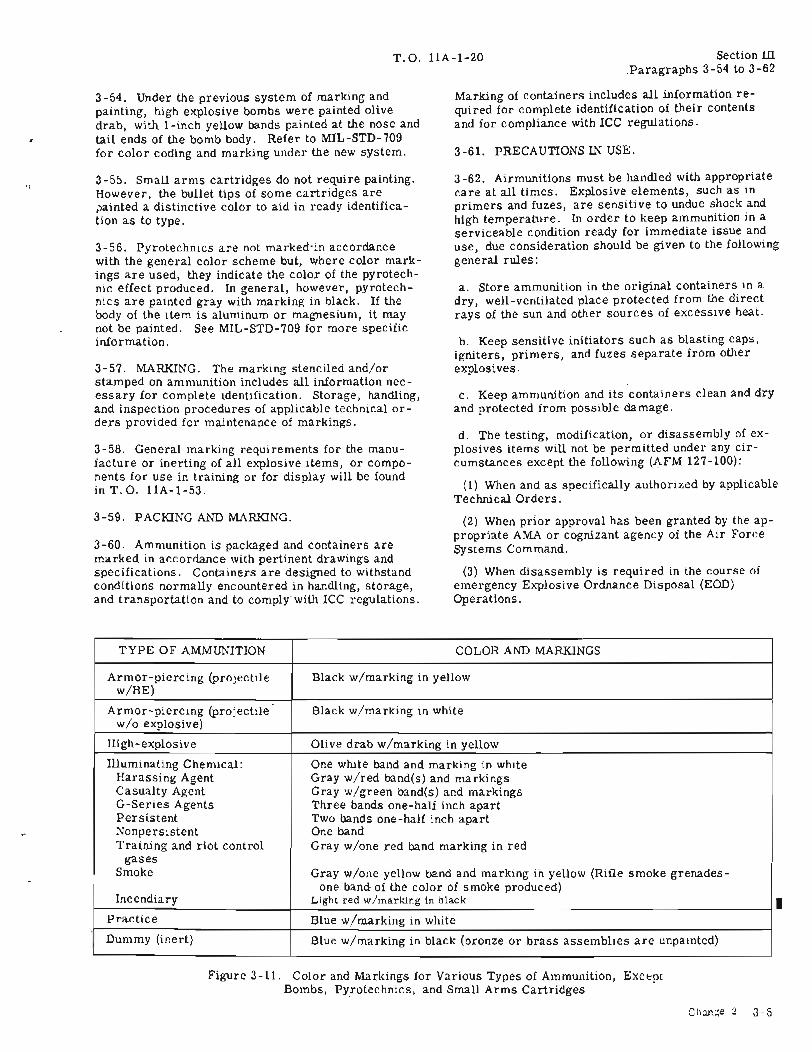
3-53. For grenades, rockets, JATO's guided missiles, demolition material, and miscellaneous explosive devices, color and markings are shown in figure3 -11.
n
T.O. llA-1-20 Section III.Paragraphs 3-54 to 3-62
..
3-54. Under the previous system of marking andpainting, high explosive bombs were painted olivedrab, with i-inch yellow bands painted at the nose andtail ends of the bomb body. Refer to MIL-STD-709for color coding and marking under the new system.
3-55. Small arms cartridges do not require painting .However, the bullet tips of some cartridges arepainted a distinctive color to aid in ready identification as to type.
3-56. Pyrotechnics are not marked-in accordancewith the general color scheme but, where color markings are used, they indicate the color of the pyrotechnic effect produced. In general, however, pyrotechnics are painted gray with marking in black. If thebody of the item is aluminum or magnesium, it maynot be painted. See MIL-STD-709 for more specificinformation.
3-57. MARKING. The marking stenciled and/orstamped on ammunition includes all information necessary for complete identification. Storage, handling,and inspection procedures of applicable technical orders provided for maintenance of markings.
3-58. General marking requirements for the manufacture or inerting of all explosive items, or components for use in training or for display will be foundin T.O. llA-1-53.
3-59. PACKING AND MARKING.
3-60. Ammunition is packaged and containers aremarked in accordance with pertinent drawings andspecifications. Containers are designed to withstandconditions normally encountered in handling, storage,and transportation and to comply- with ICC regulations.
Marking of containers includes all information required for complete identification of their contentsand for compliance with ICC regulations.
3-61. PRECAUTIONS IN USE.
3-62. Airmunitions must be handled with appropriatecare at all times. Explosive elements, such as inprimers and fuzes, are sensitive to undue shock andhigh temperature. In order to keep ammunition in aserviceable condition ready for immediate issue anduse, due consideration should be given to the followinggeneral rules:
a. Store ammunition in the original containers in adry, well-ventilated place protected from the directrays of the sun and other sources of excessive heat.
b. Keep sensitive initiators such as blasting caps,igniters, primers, and fuzes separate from otherexplosives.
c. Keep ammunition and its containers clean and dryand protected from possible damage.
d. The testing, modification, or disassembly of explosives items will not be permitted under any circumstances except the following (AFM 127-100):
(1) When and as specifically authorized by applicableTechnical Orders.
(2) When prior approval has been granted by the appropriate AMA or cognizant agency of the Air ForceSystems Command.
(3) When disassembly is required in the course ofemergency Explosive Ordnance Disposal (EOD)Operations.
TYPE OF AMMUNITION COLOR AND MARKINGS
Armor-piercing (projectile Black w/marking in yelloww/HE)
Armor-piercing (projectile Black w/marking in whitew/o explosive)
High-explosive Olive drab w/marking in yellow
Illuminating Chemical: One white band and marking in whiteHarassing Agent Gray wired band(s) and markingsCasualty Agent Gray w/green band(s) and markingsG-Series Agents Three bands one-half inch apartPersistent Two bands one-half inch apartNonpersistent One bandTraining and riot control Gray w/one red band marking in red
gasesSmoke Gray w/one yellow band and marking in yellow (Rifle smoke grenades-
Incendiaryone band of the color of smoke produced)
Light red w/marking in black
Practice Blue w/marking in white
Dummy (inert) Blue w/marking in black (bronze or brass assemblies are unpainted)
•Figure 3-11. Color and Markings for Various Types of Ammunition, Excc-pt
Bombs, Pyrotechnics, and Small Arms Cartridges
Chan;:e 2 3-5

Section III T.O. llA-1-20
e. Do not open sealed containers or remove protective or safety devices until just before use, except asrequired for inspection.
f. Return airmunitions prepared for use but not usedto its original packing and mark it appropriately. Use
3-6
such airmunitions first in subsequent issues in orderto keep stocks of opened packings to a minimum.
g. The use of live airmunitions as a substitute forauthorized inert, empty, or dummy airmunitions isprohibited. Such substitution must be considered ashazardous and will not be permitted under any circumstances.
T.O. llA-1-20
SECTION IVDESCRIPTION OF FORMS AND REPORTS
Section NParagraphs 4-1 to 4-15
--.r-l. INTRODUCTION.
4-2. FORMS, RECORDS, AND REPORTS
4-3. All classified forms, records, and reports mustbe handled in accordance with AFR-205-1. Lot andserial numbers of the affected items will be includedin all reports. For a listing of all forms, refer tothe current AFR 0-9. Refer to AFM 67-1, AFR 6744, and AFR 67-70 regarding forms for issue, receipt,and storage of airmunitions.
4-4. FIELD REPORT OF ACCIDENTS.
4-5. Any accident involving injury to personnel ordamage to materiel will be reported in accordancewith AFR 127-4.
4-6. MALFUNCTIONS INVOLVING AIRMUNITIONSOR EXPLOSIVES.
4-7. A malfunction is defined as the failure of a munition item to function in accordance with the design,intent, and expected performance when fired,launched, tactically employed, or subj ected to nonfunctional tests. Malfunctions do not include accidents, and incidents resulting from negligence, malpractice, or implications in other situations such asvehicle accidents or fires. Malfunctions, however,do include abnormal or premature functioning of amunition item incident to normal handling, mainte-
nance, storage, transportation, and tactical deployment.
4-8. When a malfunction involVing an item of airmunitions occurs, the using unit commanding officer willimmediately report all available facts concerning themalfunction.
4-9. Airmunition malfunction reports will be submitted in accordance with AFR 127-2 and -4.
4-10. DAMAGED OR IMPROPER SffiPMENT.
4-11. Damaged or improper shipments· of airmunitionswill be reported in accordance with AFR 71-4.
4-12. DISPOSITION OF UNSERVICEABLE MUNITJONSAND COMPONENTS.
4-13. Unserviceable ammunition and components willbe reported thru appropriate channels to OOAMA,Hill Air Force Base, Utah 84401, on an AmmunitionDisposition Report (AF Form 191) in accordance withAFM 67-1 for disposition instructions. Unsatisfactory reports will be submitted in accordance withT. O. 00-35D-54. Refer to T. O. llA-1-10 for use Iof AFTO Form 15.
4-14. SECURITY.
4-15. Airmunitions should be afforded adequatephysical security at all times.
Change 1 - 28 July 1967 4-1/4-2

.. _ ....... ~,. I

T.O. llA-1-20
SECTION VPROPELLANTS
Section VParagraphs 5-1 to 5-12
5-1. INTRODUCTION.
5-2. Propellants are liquid or solid compositionsused to propel a projectile, rocket, missile, etc. Allpropellants used by the military are explosive in nature.
5-3. SOLID PROPELLANTS.
5-4. Most explosives currently used as solid propellants have a nitrocellulose base. Various organic andinorganic substances are added to the nitrocellulosebase during manufacture to give improved qualitiesfor special purposes. These propellants are distinguished by M- or T- numbers and by such terms assingle-base, double-base, and composite, anc bycommercial trade names or symbols. Black powder,formerly classed as a propellant, is no longer usedas such but is used as a delay element, as an ignitingcharge for propellants, in flash reducers, or forother special purposes.
5-5. CLASSIFICATION. Solid propellants are classified in accordance with their compositions as follows:
a. Single-base Propellant. Compositions that areprincipally gelatinized nitrocellulose and contain nohigh-explosive ingredient, such as nitroglycerin, aresingle-base compounds(e. g. , guncotton).
b. Double-base Propellant. Compositions that arepredominately nitrocellulose and nitroglycerin aredouble-base compounds.
c. Composite Propellant. Compositions that do notcontain significant amounts of nitrocellulose or nitroglycerin and are mechanical mixtures of a fuel with aninorganic oxidant are composite compounds. A partor all of the fuel may also serve as a binding agent.
5-6. PHYSICAL CHARACTERISTICS. Solid propellants are manufactured in the form of flakes, balls,sheets, cords, or perforated cylindrical grains. (Seefigure 5-1.) They are made of different shapes to obtain certain types of burning. The cylindrical grainsare made in various diameters and lengths. Forsmall size grains, either no perforation or a singleperforation is required. However, for larger grains,equally spaced perforations are present in order tohave an increasing burning surface area. The critical dimension is the web size, that is, the averagethickness of the grain between burning surfaces. Websize or web thickness influences the initial rate ofburning of the propellant grain.
5-7. BURNING ACTION. Unconfined nitrocellulosepropellant burns relatively slow and even but, when
confined, the rate of burning increases with temperature and pressure. In order not to exceed the permissible chamber pressure of the weapon in which itis to be used, the rate of burning of the propellanthas to be controlled. At any given pressure, the rateof burning is proportional to the propellant surfacefree to burn. (See figure 5-2.) Therefore, propellants are made into accurate sizes and definite shapesreferred to as grains. The basic rates of burningare as follows:
a. Degressive Burning. As the surface areas of thecord and strip form of propellant change with burning, the surface of the grain decreases. The burningaction of these grain is classified as degressive.
b. Neutral Burning. As a single-perforated grainburns (figure 5-2), the outer surface decreases andthe inner surface increases. The result of the twoactions is that the total surface remains approximately the same in area. The burning of this type of grainis known as neutral.
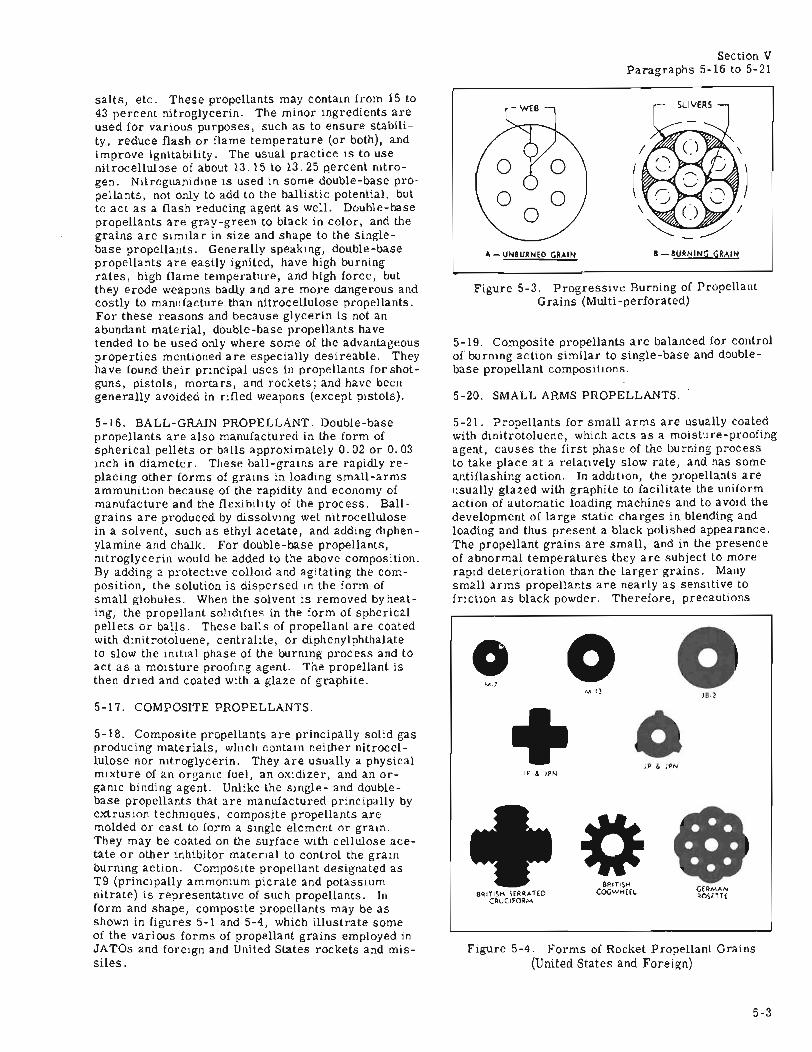
c. Progressive Burning. When the multiperforatedgrain burns (figure 5-2), the total surface area increases, since the perforated grain burns from theinside and outside at the same time. This type ofburning is called progressive.
5-8. SLIVERS. When a multiperforated grain is notcompletely consumed, portions of the grain remainin the form of slivers (figure 5-3) and may be ejectedas such from the weapon or combustion chamber.
5-9. USE. Nitrocellulose propellants are used forsmall arms and larger-caliber ammunition. Theperforated form of grain is the one most commonlyused in the United States military propellants. Singleperforated grains are used for small arms cartridges,grenade cartridges, and some rockets. Multiperforated grains are used for larger caliber weapons.
5-10. SINGLE-BASE PROPELLANTS.
5-11. Single-base propellants contain nitrocelluloseas their chief ingredient. One of the first standardized nitrocellulose propellants was termed pyrocellulose. Single-base compositions are now used inartillery, small arms, and grenade cartridges.
5-12. SMOKELESS AND FLASHLESS CHARACTERISTICS. Pyrocellulose propellant is unduly hygroscopic and gives bright flashes when fired. It wasreplaced before World War IT by propellants designated, Flashless Nonhygroscopic (FNH) and Nonhygroscopic (NH), single-base propellants. These propellants are not truly nonhygroscopic, but they areless hygroscopic than pyrocellulose. This method ofdesignation has since been replaced and propellant
5-1

Section VParagraphs 5-13 to 5-15
T.O. llA-1-20
..
MULTIPERFORATED
CORDSHEET
STARPERFORATED
/' MULTI, PERFORATED
(SPECIAL)
RAPD 212774
Figure 5-1. Examples of Propellant Grain Shapes and Forms
compositions are now identified by standard M- or Tnumbers. Whether ammunition upon being fired isflashless, smokeless, or both, depends on the weaponin which it is used, the type of ignition used, weaponwear, the temperature of the weapon, ambient temperature conditions, and the quantity and compositionof the propellant. Some double-base propellants alsohave flashless and smokeless characteristics.
resembles coarse sand. It is more sensitive to friction, shock, and heat than completely colloided nitrocellulose propellants. When exposed, it absorbsmoisture readily and therefore must be protectedfrom the atmosphere. It burns rapidly in the openand explodes if confined. It is usually exploded byflame from a primer or fuze.
5-14. DOUBLE-BASE PROPELLANTS.5-13. EC BLANK POWDER. EC blank powder, oneof the earliest partially colloided nitrocellulosesingle-base compositions developed, is used in caliber .30 blank ammunition'. It is usually orange orsalmon pink in color. Though it is soft and light, it
5-15. Double-base propellants are those having nitrocellulose and nitroglycerin as their major ingredients,accompanied by one or more minor ingredients suchas centralite, vaseline phthalate esters, inorganic
ROSETTEMULTI
PERFORATED
25 50 75 100
TRIPERFORATED
PROGRESSIVE
o75 100I
SINGLEPERFORATED
25 50I I
NEARLY NEUTRAL,a
PERCENT OF GRAIN CONSUMED
5-2
Figure 5-2. Comparative Burning Rates of Propellant Grain Shapes..
T. O. llA-I-20 Section VParagraphs 5-16 to 5-21
5-20. SMALL ARMS PROPELLANTS.
Figure 5-3. Progressive Burning of PropellantGrains (Multi-perforated)
B- BURNING GRAIN
(
A - UNBURNED GRAIN
5-19. Composite propellants are balanced for controlof burning action similar to single-base and doublebase propellant compositions.
salts, etc. These propellants may contain from 15 to43 percent nitroglycerin. The minor ingredients areused for various purposes, such as to ensure stability, reduce flash or flame temperature (or both), andimprove ignitability. The usual practice is to usenitrocellulose of about 13.15 to 13.25 percent nitrogen. Nitroguanidine is used in some double-base propellants, not only to add to the ballistic potential, butto act as a flash reducing agent as well. Double-basepropellants are gray-green to black in color, and thegrains are similar in size and shape to the singlebase propellants. Generally speaking, double-basepropellants are easily ignited, have high burningrates, high flame temperature, and high force, butthey erode weapons badly and are more dangerous andcostly to manufacture than nitrocellulose propellants.For these reasons and because glycerin is not anabundant material, double-base propellants havetended to be used only where some of the advantageousproperties mentioned are especially desireable. Theyhave found their principal uses in propellants for shotguns, pistols, mortars, and rockets; and have beengenerally avoided in rifled weapons (except pistols).
Figure 5-4. Forms of Rocket Propellant Grains(United States and Foreign)
5-21. Propellants for small arms are usually coatedwith dinitrotoluene, which acts as a moisture-proofingagent, causes the first phase of the burning processto take place at a relatively slow rate, and has someantiflashing action. In addition, the propellants areusually glazed with graphite to facilitate the uniformaction of automatic loading machines and to avoid thedevelopment of large static charges in blending andloading and thus present a black polished appearance.The propellant grains are small, and in the presenceof abnormal temperatures they are subject to morerapid deterioration than the larger grains. Manysmall arms propellants are nearly as sensitive tofriction as black powder. Therefore, precautions
JB·'
oJP & JPN
oM·I]
JP &. JPN
o+
M.)
BRITISH SERRATEDCRUCIFDRM
5-16. BALL-GRAIN PROPELLANT. Double-basepropellants are also manufactured in the form ofspherical pellets or balls approximately 0.02 or 0.03inch in diameter. These ball-grains are rapidly replacing other forms of grains in loading small-armsammunition because of the rapidity and economy ofmanufac ture and the flexibility of the proc ess. Ballgrains are produced by dissolving wet nitrocellulosein a solvent, such as ethyl acetate, and adding diphenylamine and chalk. For double-base propellants,nitroglycerin would be added to the above composition.By adding a protective colloid and agitating the composition, the solution is dispersed in the form ofsmall globules. When the solvent is removed byheating, the propellant solidifies in the form of sphericalpellets or balls. These balls of propellant are coatedwith dinitrotoluene, centralite, or diphenylphthalateto slow the initial phase of the burning process and toact as a moisture proofing agent. The propellant isthen dried and coated with a glaze of graphite.
5-17. COMPOSITE PROPELLANTS.
5-18. Composite propellants are principally solid gasproducing materials, which contain neither nitrocellulose nor nitroglycerin. They are usually a physicalmixture of an organic fuel, an oxidizer, and an organic binding agent. Unlike the single- and doublebase propellants that are manufactured principally byextrusion techniques, composite propellants aremolded or cast to form a single element or grain.They may be coated on the surface with cellulose acetate or other inhibitor material to control the grainburning action. Composite propellant designated asT9 (principally ammonium picrate and potassiumnitrate) is representative of such propellants. Inform and shape, composite propellants may be asshown in figures 5-1 and 5-4, which illustrate someof the various forms of propellant grains employed inJATOs and foreign and United States rockets and missiles.
5-3

Section VParagraphs 5-22 to 5-27
T. O. llA-1-20
used in handling black powder should be observed forsmall arms propellants.
5-22. LIQUID PROPELLANTS.
5-23. Liquid propellants have been explored in an attempt to find propellants for large size rockets andmissiles that can be controlled in combustion betterthan solid propellants. They may include any viscousor nonviscous fluid or liquified gas that is principallyan organic fuel and a strong oxidizer. With or without catalysts, stabilizers, and auxiliary additives(when fed through an arrangement of connecting feedlines, valves, controls, and metering devices), liquidpropellants can be reacted or combusted instantaneously, to produce gaseous products for propellingrockets at velocities greater than the speed of sound(supersonic speeds, approximately 650 mph and over).
5-24. CLASSIFICATION. Liquid propellants can beclassified in accordance with the type of reaction system that is involved, either as a monopropellant or abipropellant, as follows:
a. Monopropellant (e. g. Hydrazine) systems includea composite mixture or compound of fuel and an oxidizer' delivered by means of a pump or from a pressurized tank, for eventual reaction in the chamber ofthe JATO or rocket. To initiate a reaction in suchsystem, a separate source of ignition is required.
b. Bipropellant systems include a fuel and oxidizereach contained separately in containers for dual feed,carburetion, and combustion within the reactionchamber. Their reaction may be initiated by either
5-4
the intimate contact of the fuel with the oxidizer, asmay be the case of hydrazine and nitric acid, or byexternal influence (electrical spark ignition or catalysts)' as is the case of a hydrocarbon (alcohol) andliquid oxygen.
5-25. CHARACTERISTICS. Liquid propellants differfrom solid propellants, primarily in that they aremore adaptable to control of long-term combustionreactions, the former being very adaptable for dynamic regulation and control while the latter is statically controlled by the propellant composition andgrain design. Like some chemical agents and explosives, liquid propellants are hazardous, toxic, flammable, sensitive, and must be recognized for theirinherent dangerous properties.
5-26. USES. The common combustible and flammablematerials that have been used as fuels and oxidizersin liquid propellant systems are as follows:
a. Fuels are: alcohols (ethyl, methyl, furfural);kerosene, aviation gasoline; octane~eptane, pentane,hydrocarbons; aniline, monoethylani'l.1ne, hydrazine,diborane, pentaborane, aluminum barohydride, liquidhydrogen, and anhydrous ammonia.
b. Oxidizers are: white fuming and red fumingnitric acids (WFNA and RFNA); nitrogentetroxide;liquid oxygen, hydrogen peroxide.
5-27. Liquid propellant materials have been employedin rockets and guided missiles. Development of liqui(propellants for use in small arms and artillery weapons is now underway.

T.O. llA-1-20
SECTION VILOW EXPLOSIVES
Section VIParagraphs 6-1 to 6-6
6-1. INTRODUCTION.
6-2. To understand the composition and functioning ofa complete round of ammunition, a basic knowledge ofthe characteristics and uses of military explosives isnecessary. In order that ammunition may function atthe time and place desired, it is necessary to employdifferent kinds of explosives, each of which has a specific role, either as a propellant or as a burstingcharge. Explosives suitable for one purpose may beentirely unsatisfactory for another. Thus, the explosive used to burst a forged steel projectile would notonly be unsuited but also highly dangerous if used forejecting and propelling projectiles out of the weaponor propelling missiles and bodies. Similarly, the explosives used in initiators, such as in primers andfuzes, are so sensitive to shock that only small quantities can be used safely. Other characteristics ofvarious types of explosives (propellants and high explosives) are outlined in Sections V and VII of thismanual.
6-3. DEFINITION. By definition, an e~:plosive includes any chemical compound or mechanical mixturethat, under the influence of a flame or a spark, undergoes a sudden chemical change (decomposition)with the liberation of energy in the form of heat andlight and accompanied by a large volume of gases.
NOTE
The definition of Low Explosive containedherein is for military explosive classificationonly. It does not necessarily coincide withthe interpretation of the Interstate CommerceCommission Shipping Classification Regulations.
6-4. LOW EXPLOSIVES. Military explosives aredivided into a class of low explosives or high explosives, according to their rates of decomposition. Lowexplosives are mostly solid combustible materialsthat decompose rapidly but do not normally explode.This action is known as deflagration. Upon ignitionand decomposition, they develop a large volume ofgases that produce enough pressure to propel a missile in a definite direction. The rate of burning is animportant characteristic, which depends upon suchfactors as combustion gas pressure, grain size andform, composition, etc. Low explosives do not usually propagate a detonation. Under certain conditions,however, they react in the same manner as high explosives; that is, they may detonate. The singlebase, double-base, and composite propellants, aswell as black powder mixtures are typical examplesof low explosives.
6-5. REQUIREMENT FOR A LOW EXPLOSIVE. Before an explosive (propellant) can be adopted for military use, it must possess the following principalcharacteristics:
a. Possess controlled burning rate.
b. Be capable of instant ignition and combustion.
c. Be stable over extended periods of storage undernormal conditions.
d. Be balanced for complete combustion and producea minimum amount of residue.
e. Possess a safe minimum toxic and explosive hazard.
f. Be able to withstand mechanical shock indicent toloading, transportation, and handling by commercialand military carriers.
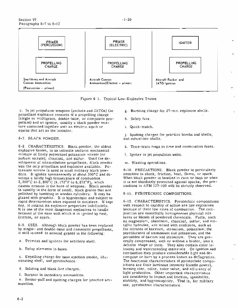
6-6. LOW -EXPLOSIVE TRAIN. The arrangement ofa series of combustible materials, beginning with asmall quantity of sensitive explosive and ending witha relatively large quantity of comparatively insensitive explosive, is termed an explosive train. In general there are two explosive trains. (See figure 6-1.)These are the propelling-charge explosive train andthe bursting-charge train. In all explosive ammunition one or both of these explosive trains will befound. Typical examples of the trains are as follows:
a. The low-explosive or propelling-charge explosivetrain is employed for the ejection or propulsion of abody or missile from the weapon. This train mayconsist of a prime1', an igniter or igniting charge,and a propelling charge. Thus, a spit of fire from asmall quantity of sensitive explosive (primer) istransmitted in a manner so that a large amount ofrelatively insensitive explosive (the propelling charge)burns in the proper manner to propel the body forward. A primer is absent in rockets and the igniteris absent in small arms ammunition.
b. In small arms ammunition (cartridges), wherethe propelling charge is relatively small, the igniteris not required. The components in this train are apercussion primer and a propelling charge. Thefiring pin explodes the primer and the flame passesthrough the vent leading to the powder chamber andignites the propelling charge; the expansion of the resultant gases forces the bullet out through the bore ofthe weapon.
6-1
Section VIParagraphs 6-7 to 6-12
PRIMER(PERCUSSION)
PROPELLINGCHARGE
SmallArms and AircraftCannon Ammunition
(Percussion - primer)
T.O.llA-1-20
PRIMER(ELECTRIC)
PROPELLINGCHARGE
Ai rcraft CannonAmmunition(Electric - primer)
PROPELLINGCHARGE
Ai rcraft Racket andJATO Ignition
,.
Figure 6-1. Typical Low-Explosive Trains
c. In jet propulsion weapons (rockets and JATOs) thepropellant explosive consists of a propelling charge(single or multigrain, double-base, or composite propellant) and an igniter, usually a black powder mixture contained together with an electric squib orsquibs that act as the initiator.
6-7. BLACK POWDER.
6-8. CHARACTERISTICS. Black powder, the oldestexplosive known, is an intimate uniform mechanicalmixture of finely pulverized potassium nitrate (orsodium nitrate), charcoal, and sulfur. Until the development of nitrocellulose propellants, black powderwas the only propellant and explosive available. Potassium nitrate is used in most military black powders. It ignites spontaneously at about 300°C and develops a fairly high temperature of combustion2, 300°C to 3, 800°C (4,172° F to 6,872° F), whichcauses erosion in the bore of weapons. Black powderis usually in the form of small, black grains that arepolished by tumbling in wooden cylinders. It may beglazed with graphite. It is hygroscopic and subject torapid deterioration when exposed to moisture. If keptdry, it retains its explosive properties indefinitely.It is one of the most dangerous explosives to handlebecause of the ease with which it is ignited by heat,friction, or spark.
6-9. USES. Although black powder has been replacedby single- and double-base and composite propellants,it still is used in several grades in the following:
a. Primers and igniters for artillery shell.
b. Delay elements in fuzes.
c. Expelling charge for base ejection smoke, illuminating shell, and pyrotechnics.
d. Saluting and blank fire charges.
f. Burster in incendiary ammunition.e. Smoke-puff and spotting charges for practice am
munition.
6-2
g. Bursting charge for 37-mm explosive shells.
h. Safety fuze.
i. QuiCk-match.
j. Spotting charges for practice bombs and shells,and subcaliber shells.
k. Time-train rings in time and combination fuzes.
1. Igniter in jet propulsion units.
m. Blasting operations.
6-10. PRECAUTIONS. Black powder is particularlysensitive to shock, friction, heat, flame, or spark.When black powder is handled in cans or bags or whenit is not absolutely protected against sparks, the precautions in AFM 127-100 will be strictly observed.
6-11. PYROTECHNIC COMPOSITIONS.
6-12. CHARACTERISTICS. Pyrotechnic compositionswith respect to rapidity of action are low explosivesbecause of their low rates of combustion. The composition are essentially homogeneous physical mixtures or blends of powdered chemicals. Fuels, suchas magnesium, aluminum, charcoal, sulfur, and metallic hydrides, are mixed with oxidizers, such asthe nitrates of barrium, strontium, potassium; theperchlorates of ammonium and potassium; and theperoxides of barium and strontium. They are generally compressed, with or without a binder, into adefinite shape or form. They also contain color intensity and waterproofing materials. On ignition andcombustion they produce considerable light and decompose or burn by a process known as deflagration.The functional characteristics of pyrotechnic compositions are their luminous intensity (candle power),burning rate, color, color value, and efficiency oflight production. Other important characteristicsare sensitivity to impact, and friction, ignitibility,stability, and hygroscopicity. That is, for militaryuse, pyrotechnic characteristics.

T. O. llA-1-20 Section VIParagraphs 6-13 to 6-14
6-13. USES. Pyrotechnic illuminating and ignitingcompositions are used in a wide variety of ammunition items. The most important uses are---
a. Flares (trip, airport, ground, aircraft, parachute, reconnaissance and landing observation, bombardment, and tow target).
b. Aircraft and ground signals.
c. Photoflash cartridges and bombs.
d. Igniter in incendiaries.
e. Gunflash simulators.
f. Igniter for jet propulsion units (rockets, JATOs,and guided missiles).
g. Signal smokes.
6-14. PRECAUTIONS. Pyrotechnic compositions arehazardous materials. The precautions in AFM 127100 apply to these compositions.
6-3/6-4

,.
T.O. llA-1-20
SECTION VIIHIGH EXPLOSIVES
Section VIIParagraphs 7-1 to 7-12
7-1. INTRODUCTION.
7-2. High explosives are usually nitration products oforganic substances, such as toluene, phenol, pentaerythritol, amines, glycerin, and starch and may benitrogen-containing inorganic substances of mixturesof both. A high explosive may be a pure compound oran intimate mixture of several compounds with additives such as powdered metals (aluminum), plasticizing oils, waxes, etc., which impart desired stabilityand performance characteristics. A high explosive ischaracterized by the extreme rapidity with which itsdecomposition occurs; this action is known as detonation. When initiated by a blow or shock, it will decompose almost instantaneously, either in a mannersimilar to an extremely rapid combustion or withrupture and rearrangement of the molecules themselves. In either case, gaseous and solid products ofreaction are produced. The disruptive effect of thereaction makes some explosives valuable as a bursting charge but precludes their use as a propellant forthe reason that the gases formed would develop excessive pressures that might burst the barrel of theweapon.
7-3. TERMS AND DEFINITIONS.
7-4. PRIMER. A primer is a relatively small andsensitive initial explosive train component which, onbeing actuated, initiates functioning of the explosivetrain and will not reliably initiate high-explosivecharges. In general, primers are classified in accordance with the method of initiation, such as percussion, stab, electric, friction, chemical, etc.
7-5. DETONATOR. A detonator is an explosive traincomponent that can be activated by either a nonexplosive impulse or by the action of a primer and is capable of reliably initiating high-order detonation in asubsequent high-explosive component of the train.When activated by a nonexplosive impulse, a detonatorincludes the func tion of a primer. In general, detonators are classified in accordance with the method ofinitiation; such as percussion, stab, electric, friction, flash, chemical, etc.
7-6. IGNITER. An igniter is usually one of the following devices used to directly, or indirectly, initiatea sequence of ignition:
a. A device containing a readily burning composition, usually in the form of black powder, used toamplify the initiation of a primer in the functioning ofa fuze.
b. A device containing a spontaneously combustiblematerial, such as white phosphorus, used to ignite
the fillings of incendiary bombs and flame throwerfuels at the time of dispersion or rupture of the bombcasing.
c. A device used to initiate burning of the fuel mixture in a rocket combustion chamber.
7-7. DELAY. A delay is an explosive train component that introduces a controlled time delay in the
. functioning of the train.
7-8. RELAY. A relay is an element of a fuze explosive train that augments an outside and otherwise inadequate output of a prior explosive component, so asto reliably initiate a succeeding train component. Relays, in general, contain a small single explosivecharge, such as lead azide, and are not usually employed to initiate high-explosive charges.,.
7-9. LEAD. A lead is an explosive train componentthat consists of a column of high explosive, usuallysmall in diameter, used to transmit detonation fromone detonating component to a succeeding highexplosive component. It is generally used to transmit the detonation from a detonator to a boostercharge.
7-10. BOOSTER CHARGE. A booster charge is thefinal high-explosive component of an explosive trainthat amplifies the detonation from the lead or detonator, so as to reliably detonate the main high-explosivecharge of the munition. .
7-11. FUZE EXPLOSIVE TRAIN. A fuze explosivetrain is an arrangement of a series of combustibleand explosive elements consisting of a primer, a detonator, a delay, a relay, a lead, and booster charge,one or more of which may be either omitted or combined. The function of the explosive train is to accomplish the controlled augmentation of a relativelysmall impulse into one of sufficient energy to causethe main charge of the munition to function.
7-12. PRIMER COMPOSITIONS. A primer composition is an explosive that is sensitive to a blow such asthat imparted by a firing pin. It is used to transmitshock or a flame to another explosive, a time element, or a detonator. Most military priming compositions consist of mixtures of one or more initial detonating agents, oxidants, fuels, sensitizers, andbinding agents. Many compositions contain potassiumchlorate, lead thiocyanate, antimony sulfide, leadazide, lead styhpnate, mercury fulminate, and abinding agent. The potassium chlorate acts as anOXidiZing agent, the lead thiocyanate as the fuel andas a detonating agent. Other materials such asground glass and carborundum may also be added to
7-1

Section VIIParagraphs 7-13 to 7-18
T. O. llA-I-20
increase sensitivity to friction. Priming compositions for electric primers and squibs may containbarium nitrate as the oXidizing agent instead of potassium chlorate and lead styphnate or DDNP (diazodinitrophenol) as the initiating explosive. Primer mixtures are used in the percussion elements of artilleryprimers, in fuzes, and in small arms primers and asthe upper layer of a detonator assembly.
7-13. BURSTING CHARGE. This is an encased explosive that, when initiated, is designed to break themetal casing into small fragments.
7-14. HIGH-EXPLOSIVE TRAIN. Explosive trainmay be defined as a series of steps by which a small,initial amount of energy is built up to the large amountof energy necessary to ensure a high-order detonationfor a bursting charge. Fundamentally, an explosivetrain consists of a detonator, booster, and burstingcharge. This sequence is often interrupted by a delayor relay. To illustrate the principle of the explosivetrain, a 2, ODD-pound bomb filled with TNT has a fuzeof the firing pin type. The TNT by itself will not detonate from the release of the firing pin, because theinitial source of energy being a friction or percussioneffect of the firing pin is insufficient and must bestepped up to a point where it will detonate the TNT.This is always accomplished by means of an explosivetrain. Components and performance characteristicsin explosive trains are as follows:
a. The detonator sets up a high-explosive wave wheninitiated by the stab action of a firing pin or by aflame. This detonation is so small and weak that itwill not initiate a high-order detonation in the bursting charge, unless a booster is placed between thetwo. The booster picks up the small explosive wavefrom the detonator and amplifies it to an extent thatthe bursting charge is initiated and a high-order detonation results. (See figure 7-1.)
b. To gain the action necessary to control the timeand place at which an explosive will function, it is
necessary to incorporate other components in a highexplosive train. The action desired may be a burstin the air, a burst instantly upon impact with the target, or a burst shortly after the projectile penetratedthe target. The components that may be used to givethese various actions are a primer, a black powderdelay pellet or train, an upper detonator, or anycombination of these components. Regardless of thearrangement of the components, the basic chain willremain the same, other components being-plaeeQ-infront of the basic chain. (See figure 7-2.)
c. The action that causes a bomb to burst in the airmay be obtained by placing a primer, which is firedwhen the bomb is dropped, and a black powder timetrain in front of the basic chain. The primer ignitesthe time-train, which burns for the length of time desired, and, in turn, initiates the action of the detonator, booster, and bursting charge. (See scheme B,figure 7-2.)
d. To burst the munition promptly upon impact withthe target, a superquick or instantaneous action isnecessary. This action is usually obtained by placingan upper detonator in the extreme front of the fuzeand a lower detonator in the body near the boostercharge. In this manner, the detonating wave is transmitted instantly to the bursting charge. (See schemeC, figure 7-2.)
e. To permit penetration of the target by the munition, a delay action is necessary as included inarmor-piercing bombs. This is obtained by placinga primer and delay element ahead of the detonator. Insome cases, this combination of primer and delay isinserted between an upper and lower detonator. (Seescheme D, figure 7-2.)
f. A variation of the high-explosive train is found inchemical items. In this train there is no large bursting charge such as is found in high-explosives projectiles, as it is only necessary to rupture the shell caseand allow the chemical contents to escape. The actualbursting of the case is accomplished by an enlargedbooster, known as a burster charge, contained in atube running down the center of the bomb.
D ."".'0
. ......'==-'./
7-15. CLASSIFICATION.
7-16. High explosives may be subdivided into threetypes, according to their sensitivity, as initiating,booster, and bursting explosives.
7-17. INITIATING HIGH EXPLOSIVES. Initiatinghigh explosives are extremely sensitive to shock,friction, and heat. Under normal conditions, theywill not burn, but will detonate if ignited. Theirstrength and brisance are inferior, but are sufficientto detonate high explosives. Because of their sensitivity, they are used in munitions for initiating andintensifying high-order explosions. Mercury fulminate, lead azide, lead styphante, and diazodinitrophenol are examples of such explosives.
Figure 7-1. Detonating Wave Amplified byUse of Booster
7-2
7-18. BOOSTER EXPLOSIVES. Explosives of thistype include tetryl, PETN, and RDX. They intermediate sensitivity between initiating explosives and

T.O. llA-1-20 Section VIIParagraphs 7-19 to 7-25
explosives used as bursting charges such as TNT.They may be ignited by heat, friction, or impact andmay detonate when burned in large quantities.
readily detonated, and yet, in small-caliber shellwithstands the force of setback in the weapon. It isalso a constituent of tetrytol.
7-19. BURSTING EXPLOSIVES. Bursting explosivesinclude explosive D, amatol, TNT, tetryl, pentolite,picratol, tritonal, RDX compositions, torpex, DBX,HBX, and others.
7-20. DEMOLITION AND FRAGMENTATION EXPLOSIVES.
7-21. TETRYL. Tetryl (trinitrophenylmethylnitramine) is a fine yellow crystalline material. Whenheated it first melts and then decomposes and explodes. It burns readily and is more easily detonatedthan TNT or ammonium picrate (explosive D) and ismuch more sensitive than picric acid. It is detonatedby friction, shock, or spark. It is insoluble in water,practically nonhygroscopic. Tetryl is stable at alltemperatures that may be encountered in storage. Itis toxic when taken internally; on contact, it discolorsskin tissue (tobacco stain) and causes dermatitis.
7-22. Brisance tests show tetryl to have a very highshattering power. It is greater in brisance than TNTand is exceeded in standard military explosives onlyby PETN and some of the newer military explosives,such as RDX.
7-23. The major uses of tetryl are as follows:
a. Tetryl is the standard booster explosive and issufficiently insensitive when compressed to be usedsafely as a booster explosive. The violence of itsdetonation ensures a high-order detonation of thebursting charge. It is used in the form of pressedpellets. Tetryl is a common bursting charge for 20mm projectiles. It produces appreciably better fragmentation of these shells than TNT. It is also more
b. Tetryl is used in detonators, the tetryl beingpressed into the bottom of the detonator shell and thencovered with a small priming charge of mercury fulminate, lead azide, or other initiator.
7-24. PETN (Pentaerythrite Tetranitrate). PETN isone of the strongest known high explosives. It ismore sensitive to shock or friction than TNT or tetryl. In its pure form, PETN is a white crystallinepowder; however, it may be a light gray due to impurities. It will detonate under a long, slow pressurePETN in bulk must be stored wet. Its primary use isin booster and bursting charges in small caliber ammunition; upper detonator or in some land mines andshells; explosive core of primacord (detonating cord).When suspended in molten TNT it forms a pentoliteexplosive of high brisance.
7-25. RDX. RDX, one of the most powerful explosives, is commonly known as cyclonite (cyclotrimethylenetrinitramine), CTMTN, C6; hexogen (H)(German); T4 (Italian) and Tanoyaku (Japanese). It iswhite crystalline solid having a melting point of 202
0
C.(397 0 F .) and is very stable. It has slightly morepower and brisance than PETN. It is more easilyinitiated by mercury fulminate than is tetryl. RDXhas been used mainly in mixtures with other explosives, but can be used by itself as a sub-booster,booster, and bursting charge. It is being combinedwith nitrohydrocarbons, which also permit castloading, or with waxes or oils for press-loading. Ithas a high degree of stability in storage.
~~
IDETONATOR IrJ-SFLASHU ITU.'
BOOSTER
PRIMER
UPPERDETON·ATOR
BOOffiR
IorrON'TOR I
BOOSTER
PRIMER
DETONATOR
MECHANICALTIME
TRAIN
BURSTINGCHARGE.
BURSTINGCHARGE
BURSTINGCHARGE
BURSTINGCHARGE
A- ....SIC HIGH·EXPLOSIVE B -TIMI ACTION HE TIAINIHII TIAIN
C -SUPERQUICK ACTIONHE TUIN D -QEUY A.CTIOH
HE TRAIN
Figure 7-2. Schematic Arrangement of Components of Explosive Trains
7-3
Section VIIParagraphs 7-26 to 7-37
T.O. llA-I-20
7-26. TNT (Trinitrotoluene). Trinitrotoluene, commonly known as TNT, is a constituent of many explosives, such as amatol, pentolite, tetrytol, torpex,tritonal, picratol, ednatol, and composition B and hasbeen used by itself under such names as triton, trotyl,trilite, trinol, and tritolo.
7-27. TNT in a refined form is one of the most stableof high explosives and can be stored over long periodsof time. It is relatively insensitive to blows or friction. Confined TNT, when detonated, explodes withviolence. When ignited by a flame, unconfined TNTburns slowly without explosion, evolving a heavy oilyblack smoke; however, burning or rapid heating oflarge quantities, especially in closed vessels, maycause a violent detonation. It is nonhygroscopic anddoes not form sensitive compounds with metals, butis readily acted upon by alkalies to form unstablecompounds that are very sensitive to heat and impact.It usually resembles a light brown sugar but whenpure is crystalline and nearly white. When meltedand poured into a shell or bomb it forms a solid crystalline explosive charge. TNT is a very satisfactorymilitary explosive. The melting point of standardgrade 1 TNT is 80. 2°C. (176°F.). Ammunitionloaded with TNT can be stored, handled, and shippedwith comparative safety.
I WARNING
Exudate can be extremely hazardous andshould be removed in accordance with existing directives.
7-28. When stored in warm climates or during warmsummer months, some ammunition loaded with TNTmay exude an oily brown liquid. This exudate oozesout around the threads at the nose of the bomb andmay form a pool on the floor. The exudate is flammable and contains TNT. Pools of exudate should becarefully removed.
7-29. TNT in crystalline form can be detonated readily by a No. 6 blasting cap or when highly compressedby a No. 8 blasting cap. When cast, it is necessaryto use a booster charge of pressed tetryl or an explosive of similar brisance to ensure complete detonation.
7-30. The major uses of TNT are as follows:
a. TNT is used as a bursting charge for highexplosive shell and bombs, either alone or mixed withammonium nitrate to form 50/50 or 80/20 amatol.Flake TNT is used in fragmentation hand grenades.Other military uses of TNT are in mines and forparts of certain shell and bomb bursters.
b. TNT is used to demolish bridges, railroads, fortifications, and other structures. For such purposesTNT is used in the form of a large shaped charge ora small highly compressed block enclosed in a waterproof fiber container that protects it from crumblingin handling. The triton blocks used by the Corps ofEngineers are blocks of pressed TNT inclosed incardboard containers.
7-4
c. TNT is suitable for all types of blasting and produces approximately the same effect as the sameweight of dynamite of 50 to 60 percent grade. It isalso used as a booster surround in some amatolloaded ammunition.
7-31. AMATOL. Amatol, a mechanical mixture ofammonium nitrate and TNT in various percentages,has approximately the same general characteristicsas TNT. It is crystalline, yellow or brownish, andinsensitive to friction, but it may be detonated bysevere impact. It is less sensitive to detonation thanTNT and is readily detonated by mercury fulminateand other detonators. It is hygroscopic and in thepresence of moisture attacks copper, brass, andbronze, forming dangerously sensitive compounds.Amatol, 50/50, has approximately the same rate ofdetonation and brisance as TNT, while amatol, 80/20,is slightly lower in velocity and brisance than TNT.Amatol, 80/20, produces a white smoke on detonation,and amatol, 50/50; produces a smoke less black thanstraight TNT.
7-32. Amatol, 50/50, consists of 50 percent ammonium nitrate and TNT by weight. When hot, it is sufficiently fluid to be poured or cast like TNT. Amatol,80/20, consists of 80 percent ammonium nitrate and20 percent TNT. It resembles wet brown sugar.When hot, it becomes semiplastic (consistency ofputty) and in that state it can be pressed into shellsand bombs.
7-33. Amatol is a substitute for TNT. Amatol, 50/50, was used for 75-mm and larger shell, and 80/20amatol was used for shell of 155-mm and larger.Amatol was also used in large bombs. Its primaryuse, however, is for bangalore torpedoes.
7-34. PICRIC ACID (Trinitrophenol). Picric acid, anitrated product of phenol under the name of melinite,was adopted as a military high explosive by the Frenchin 1886 and has been used more extensively as a military explosive by foreign nations than by this country.The British designate it as lyddite.
7-35. Picric acid is a lemon-yellow crystalline solid.It is stable but reacts with metals when moist, insome cases forming extremely sensitive compounds.Picric acid is more readily detonated by means of adetonator than TNT but has about the same sensitivityto shock. It is not as toxic as TNT and is also nonhygroscopic although slightly soluble in water. Picricacid has a high melting point--approximately 122°C.(251.6°F.).
7-36. Picric acid is chiefly used for conversion toammonium picrate (explosive D) and to form burstingcharge mixtures with other nitro compounds.
7-37. AMMONIUM PICRATE (Explosive D). Ammonium picrate is the least sensitive to shock and friction of all military explosives. This makes it wellsuited for use as a bursting charge in armor-piercingprojectiles. It is slightly inferior in explosivestrength to TNT. When heated, it does not melt butdecomposes and explodes. It reacts slowly withmetals, and when wet it may form sensitive and
T.O. llA-1-20
dangerous compoWlds with iron, copper, and lead. Itis difficult to detonate. When ignited in the open itwill burn readily like tar or resin.
7-38. Explosive D is used as a bursting charge forarmor-piercing bombs and in other types of projectiles that must withstand severe shock and stressesbefore detonating.
7-3 9. Special Precautions. The following precautionsshould be observed:
a. Ammonium picrate, which has been pressed at aloading plant and removed from a munition, is verymuch more sensitive to shock or blow than fresh ammonium picrate. It should be protected against coming in contact with lead, iron, or copper because itforms sensitive compounds.
b. Although less sensitive than TNT, it can be exploded by severe shOCk or friction, is highly flammable, and may detonate when heated to a high temperature.
7-40. PICRATOL. Picratol is a mixture of 52 percent explosive D and 48 percent TNT. It can bepoured like straight TNT and has approximately thesame resistance to shock as that of straight explosiveD. The brisance of picratol is between that of explosive D and TNT. Picratol is nonhygroscopic. Picratolis a standard filler employed for all semi-armorpierc ing bombs.
7-41. PENTOLITE. Pentolite is a 50/50 mixture ofPETN and TNT and is commonly known as pentol(German) and pentritol. Pentolite has largely beendisplaced by composition B. Pentolite should not bedrilled to form booster cavities; forming tools shouldbe used. It is superior to TNT in explosive strengthand is less sensitive than PETN. It may be meltloaded and is satisfactory for the follOWing uses:
a. As a bursting charge in small caliber shells, e.g.,20-mm.
b. In shaped-charge ammWlition of many types, e.g.,antitank rifle grenades, and bazookas.
c. In rockets and shaped demolition charges.
d. In some ammWlition, as a booster or boostersurroWld.
7-42. TETRYTOL. Tetrytol is a Wliform mixture of75 percent tetryl and 25 percent TNT. It has higherbrisance than TNT and is more effective in cuttingthrough steel and in demolition work. It is less sensitive to shock and friction than tetryl and only slightlymore sensitive than TNT. Tetrytol is stable in storage but exudes at 65 C. (149°F.). Tetrytol is nonhygroscopic and is suitable for Wlderwater demolition,since submergence for 24 hours does not appreciablyaffect its characteristics. Tetrytol is used in chainand individual demolit)on blocks and in certain destructors.
Section VIIParagraphs 7-38 to 7-47
I WARNING
The block must not be broken into fragments,as this may cause detonation.
7-43. NITROSTARCH EXPLOSIVES. Nitrostarch,gray in color, is nitrated cornstarch used to sensitizecombustibles and oxidizing agents in much the samemanner that nitroglycerin is used in dynamite. It ishighly flammable, and can be ignited by the slightestspark, as may result from friction and burns, withexplosive violence. Nitrostarch is less sensitivethan dry guncotton or nitroglycerin. Nitrostarch explosives are readily detonated by a No. 6 blastingcap.
7-44. A nitrostarch demolition explosive is used as asubstitute for TNT and is available as: four 1/4pOWld units, each 1/4-pound unit containing three1/12-poWld small size pellets (briquets) wrapped inparaffined paper with markings to indicate the location of holes for the blasting caps; 1/2 -pound blocks;and 1-pound blocks. TNT formulas fot computingsmall charges are directly applicable to the nitrostarch demolition explosive.
7-45. DYNAMITE. Commercial blasting explosiveswith the exception of black powder are referred to asdynamite. There are several types, each type beingsubdivided into a series of grades, each type andgrade differing in one or more characteristics. Dynamite consists essentially of nitroglycerin absorbedin a porous material. Each composition generally isdesignated as either a straight, ammonia, gelatin, orammonia-gelatin dynamite and generally available asparaffin coated 1/2 -pound sticks or cartridges, ratedaccording to the percent by weight of nitroglycerincontent.
7-45. Dynamite of from 50- to 50-percent nitroglycerin content is equivalent on an equal weight basis toTNT in explosive strength. Dynamite of 40-percentis equivalent to TNT in the ratio of 1-1/4 pounds ofdynamite to 1 pound TNT. Straight dynamite is moresensitive to shock and friction than TNT and is capable of being detonated by the action of a rifle bullet.Generally, the higher percentages of dynamite havevery good water resistance. Explosion of the common types of dynamite produces poisonous fumes,which are dangerous in confined places. Dynamite,as well as other nitroglycerin explosives, are adversely affected by extreme cold, dynamite freezesat -20°F., consequently, it is Wlsatisfactory for service under low-temperature arctic conditions.
7-47. Dynamite is used as a substitute for nitrostarchor TNT for training purposes. It is also employed bythe Corps of Engineers for trench, harbor, dam,flood control, and mining demolitions. The followinglimitations are applicable to its use:
a. Not to be issued or used for destruction of duds.
b. Not to be supplied for training in use of demolition equipment.
7-5
Section VIIParagraphs 7-48 to 7-59
T. O. llA-1-20
c. Not to be carried in combat vehicles subject toextreme of temperature.
7-48. EDNATOL. Ednatol is a mixture of haleite orexplosive H (ethylenedinitramine) and TNT and is oneof the most powerful explosives. It is less sensitivethan tetryl, PETN, or RDX. Ednatol is equivalent totetryl in brisance. It can be cast in the same manneras amatol. It has no tendency to combine with metalsin the absence of moisture and has no toxic effect. Inthe presence of moisture, haleite hydrolyzes slightlygiving an acid reaction; hydrolysis of ednatol is notappreciable. Ednatol is very stable and can be storedfor long periods; it is nonhygroscopic. Ednatol maybe used for the same purpose as pentolite, namely,in rockets, grenades, and high-explosive antitankmunitions. As an explosive for producing blast effect,it is superior to amatol, pentolite, and compositionC -3 and nearly equal to composition B.
7-49. TRITONAL. Tritonal is a generic term for explosives containing TNT and powdered aluminum, generally in the ratio of 80/20. It produces a greaterblast effect than TNT or composition B. Because ofthe aluminum powder constituent, the inclusion ofmoisture in the mixture must be avoided. It is usedin light-case and general-purpose bombs.
7-50. HBX. HBX is an aluminized (powdered aluminum) explosive having the same order of sensitivityas composition B. HBX may produce pressure withina casing due to gassing. t is used as a burstingcharge in mines, depth bumbs, depth charges, andtorpedoes.
7-51. COMPOSITION A. Composition A (comp A) isa mixture containing 91 percent RDX and 9 percentbeeswax; a composition that is semiplastic in nature.When the beeswax was replaced by a wax derivedfrom petroleum and with subsequent changes in themethod of adding the desensitizer, the designationwas changed to composition A-2. Recently the composition has been redesignated as composition A-3,because of changes in the granulation of RDX and themethod of manufacture. Composition A-3 is granularin form, resembling tetryl. It is usually buff in colorand is press-loaded in minor-caliber (20-, 37-, and40-mm) shell. It is 30 percent stronger than TNT;strength is usually dependent on the amount of waxbinder.
7-52. COMPOSITION B. Composition B (comp B) isa (59/40/1) mixture of RDX, TNT, and beeswax. Itf.!color may vary from dirty white, light yellow, tobrownish yellow. It is less sensitive than tetryl butmore sensitive than TNT. It is intermediate betweenTNT and RDX, with respect to sensitivity and initiation. It is only inferior to tritonal and torpex withrespect to blast effect. Composition B is an authorized filling for Army-Navy (Al'l') standard aircraftbombs, mines, torpedoes, antitank artillery shells(76- and 105-mm), demolition charges, and in rockets. Composition B containing 60 percent RDX and40 percent TNT, exclusive of wax, is known as composition B-2, a nonstandard explosive. Because ofits greater sensitivity to impact, composition B-2 isnot as suitable as composition B for use in bombs.
7-6
7-53. COMPOSITION C (Series). Composition C,sometimes referred to as PE, is a plastic explosive.The original composition C was 88-percent RDX and12-percent inert plasticizer. C-2 was developed with80-percent RDX and 20-percent explosive plasticizer.Disadvantages of the earlier compositions led to thedevelopment of C-3, a composition of 77-percent RDXand 23-percent explosive plasticizer, with a partialsubstitution for a part of the RDX with tetryl. In coldweather Composition C -3 became hard to handle andwas not pliable, resulting in the more recent development of Composition C-4. Composition C-4 is nowthe standardized composition for plastic explosive.The first three compositions were brown in color,normally the consistency of putty, and had the tendency to leach out (sweat out) the plasticizing oils.The leach out of the oils reduced the amount of plasticizer protection for the RDX crystals and made theexplosive too sensitive to use in the field.
7-54. Composition C-2 is putty-like in compositionand about 35 percent stronger than TNT. It was employed as a demolition charge.
7-55. Composition C-3 is slightly inferior to composition B as an explosive for producing blast effect. Itis considerably less sensitive than TNT and may notalways be detonated by a No.8 blasting cap, but willalways be detonated by the special Corps of Engineersblasting caps. It was used principally as a commandoand demolition explosive, either with or without acontainer. It is also used as a filler in some types ofmunitions. If its plasticity is lost by long storage atlow temperatures, it may be restored to satisfactoryplasticity by molding with the hands after warming byimmersion in warm water. It must not be exposed toopen flame, as it catches fire easily and burns withan intense flame. If burned in large quantities, theheat generated may cause it to explode. Its explosionproduces poisonous gases in such quantities that itsuse in closed spaces is dangerous. Existing inventories of this material are being exhausted and replaced with a standardized composition C -4.
7-56. Composition C-4 is a (91/9) RDX and plasticexplosive composition. It is a semiplastic putty -likematerial, dirty white to light brown in color, lesssensitive, more stable, less volatile, and more brisant than composition C-3. It is a nonhygroscopicmaterial that has found application in demolitionblocks and specialized uses.
7-57. DBX. DBX is a (21/21/40/18) RDX, ammonium nitrate, TNT, and aluminum powder composition. It is gray in color, with a melting point between80° and 90°C. (176° and 194°F.). It will react withmetals in the same manner as amatol. Because DBXcontains ammonium nitrate, it is slightly hygroscopic.It resembles torpex in sensitivity, strength, andbrisance.
7-58. INITIATING AND PRIlViiNG EXPLOSIVES.
7-59. MERCURY FULlVIINATE. Mercury fulminateis a heavy crystalline solid. It is white when pure,but ordinarily has a faint brownish-yellow or grayishtint. It is extremely sensitive to heat, friction,
'.

T. O. llA-1-20 Section VIIParagraphs 7-60 to 7-62
spark, flame, or shock, detonating completely innearly every instance. Its sensitivity varies withtemperature. It has been found that its sensitivity isdependent in part on crystal size. It is nonhygroscopic and may be safely stored for long periods oftime at moderate temperatures when wet. However,it will not stand long-term storage at elevated temperatures. For all practical purposes, mercury:ulminate has been replaced by lead azide and leadstyphnate. It was used on limited scale in a fewprimers, in fuze detonators, and in blasting caps. Itmay be used alone or mixed with potassium chlorate.At present this material is no longer included instandard ammunition.
7-60. LEAD AZIDE. Lead azide, one of the moststable initiators, is used to detonate high explosives.It is a fine-grained, cream-colored compound. It issensitive to flame and impact but is not certain to detonate by the action of a firing pin (stab-action). It isnot easily decomposed on long continued storage atmoderately elevated temperatures. It flashes at amuch higher temperature than mercury fulminate. Asmaller weight of lead azide than of mercury fulminateis required to detonate an equal amount of TNT, tetryl, etc. Lead azide has replaced mercury fulminatebecause of its properties; it stands up better in storage, and is less hazardous to manufacture. It is usedin primer mixtures, in detonator assemblies, andfuzes. When in contact with copper metal, it forms asupersensitive explosive.
7-61. LEAD STYPHNATE. This explosive has beenwidely employed commercially and as an initiator for
foreign military explosives. Recently, it has beenadopted by the United States military. It may be palestraw, deep yellow, orange-yellow, or reddish-brownin color. Lead styphnate is slightly less sensitivethan mercury fulminate and has about the samestrength as lead azide. It should be stored underwater in conductive rubber containers. It is used indetonators to lower the ignition temperature of leadazide. As a primer it produces a very good flame.It is more easily ignited by an electrical spark thanis mercury fulminate, lead aZide, or DDNP. As asubstitute for mercury fulminate in primer compositions, lead styphnate offers sensitivity, stability, andample flame. It is useless as a detonator, except asa sensitizing agent when employed in lead azidefriction -type primers or lead azide detonators.
7-62. DIAZODINITROPHENOL (DDNP). Extensivelyemployed in commercial blasting caps, this explosivehas found a place in military priming compositionsand detonators. It is nonhygroscopic and greenishyellow to brown in color. Its. sensitivity to impact isequal to mercury fulminate; however, it is much lesssensitive to friction (about that of lead azide). Ifpressed into a blasting cap shell with a reinforcingcap and a piece of black powder safety fuze is crimpedin the shell, a charge of DDNP undergoes detonationwhen ignited. For the less sensitive high explosives(explosive D and cast TNT), it is a better initiator ofdetonation than mercury fulminate. For the moresensitive high explosives, DDNP is not superior tolead azide. It is not as stable as lead azide but markedly superior to mercury fulminate. It is used tosome extent in leading fuze detonators and the manufacture of priming compositions.
7-7/7-8


T. O. llA-1-20
SECTION VIIICHEMICA AGENTS
Section VllIParagraphs 8-1to 8-13
8-1. INTRODUCTION.
8-2. A military chemical agent is a substance thatproduces a toxic (casualty) or an irritating (harassing)effect, a screening smoke, an incendiary action, or acombination of these.
8-3. CLASSIFICATION.
8-4. Chemical agents are compounds and mixturesother than pyrotechnics and are used as fillers (figure8-1) in artillery shell, mortar shell, grenades, rockets, and bombs. They are classified according totactical use, physiological effect, and purpose.
8-5. MILITARY GASES. A military gas is any agentor combination of agents that can produce either atoxic or irritating physiological effect. Such agent(s)may be in solid, liquid, or gaseous state (figure 8-2),either before or after dispersion. The gases may bepersistent (those remaining effective at point of release for more than 10 minutes) or nonpersistent(those becoming ineffective within 10 minutes). Persistent gases are further divided into moderately persistent (those remaining effective in the open 10 minutes to 12 hours) and highly persistent (those remaining effective in the open longer than 12 hours). Themilitary gases are classified in accordance with theirtoxic and irritating effects as follows:
a. Casualty gases: Blister and choking gases. Bloodand nerve poisons.
b. Training and riot control gases: Vomiting andtear gases.
8-6. SCREENING SMOKES. A screening smoke is acloud that consists of small particles of solids, liqUids, or both, dispersed and suspended in air.
8-7. INCENDIARIES. An incendiary may be a solid,liqUid, or a gelled semiplastic material that, by itsintense heat and flame, can start fires and scorchcombustible and noncombustible materials, as well asinjure and inactivate personnel.
8-8. SIMULATED MILITARY GASES. Simulatedagents are essentially mild nontoxic harassants (substitute for the real agent) designed specifically for"raining purposes.
8-9. BLISTER GASES (CASUALTY).
8-10. Blister gases are agents that affect the nose,throat, eyes, lungs, or exposed skin tissue. Theyharass and produce casualties resultant from the injuries (inflammations, blisters, destruction of body
tissue). The principal gases in this group are mustard, mustard mixtures, lewisite, and simulatedmustard gases.
8-11. MUSTARD GAS (H). This gas is a dark-brownliquid that slowly evaporates to a colorless gas havingthe odor of garlic. Distilled mustard gaS (HD) maybe practically odorless. Its principal physiologicaleffect is to produce skin blisters, although the blistering does not ordinarily appear for several hoursafter contact. If inhaled, mustard gas vapors have achoking (lung irritant) effect. For complete protection against mustard (H, HD), mustardT (HT), orthe nitrogen mustards (HN-l, HN-2, HN-3), bothprotective mask and protective clothing are necessary. HN-l vapor and liquid are dangerous. HN-lattacks the respiratory tract as does H gas, but to alesser degree, and has especially dangerous effectson the eyes that may result in permanent injury orblindness. The tactical use of mustard gas and itsmixtures is to neutralize areas, contaminate materiel, restrict aggressor movements, and inflict casualties. These agents can be dispersed by artilleryand mortar shell and from aircraft bombs. Foodcontaminated by mustard gases or its mixtures isunfit for use.
8-12. LEWISITE GAS (L). Lewisite gas is a darkbrown liquid that evaporates to a colorless gas andhas an odor of geraniums. In addition to being ablister and choking gas, lewisite acts as an arsenical poison. The protective mask and protectiveclothing are necessary against L. Lewisite is bestdestroyed with bleach, DANC solution, or an alcoholic solution of caustic soda. If lewisite is destroyedby burning, there is a danger of contaminating the atmosphere with poisonous arsenic oxide. The tacticaluse of L and the methods of projection are the sameas those for H. It renders food and water p'ermanentiy unfit for use.
8-13. SIMULATED H AGENTS. These agents possess physical properties that are similar to mustardgas and generally include a dye, an odoriferous constituent, or both. Unusually nontoxic, such materialis employed as a substitute filler for the agent inmunitions in Simulated military training exercises.A simulated agent may be harmless or partiallyharmful. The following principal materials are used:
a. Molasses residuum (MR) is a nontoxic (25 percent solution) thick, sirupy, viscous liquid with amolasses odor. When dispersed from aircraft,chemical spray tanks, artillery shell, mortar shell, .or bombs, the spray patterns resemble those of mus- I
tard gas (H).
8-1

Section VITI T.O.llA-1-20
GROUP A, NERVE GASES-Chemical Agents Requiring Complete Protective Clothing Plus Gas Masks
MARKINGS
SYMBOL NAME PRESENT PREVIOUS
GV
G Agents Gray background, with three 1/2 inchgreen bands spaced 1/2 inch apart.
GROUP A, BLISTER GASES-Chemical Agents Requiring Complete Protective Clothing Plus Gas Masks
H
HD
HT
L
HN-1
Mustard
Mustard (distilled)
Mustard (T mixture)
Lewisite
Nitrogen Mustard
Gray background, H Gas and two 1/2inch bands spaced 1/2 inch apart all ingreen
Gray background, HD Gas and two 1/2inch bands spaced 1/2 inch apart, allgreen
Gray background, HT Gas and two 1/2inch bands spaced 1/2 inch apart, all ingreen
Gray background, L Gas and two 1/2inch bands spaced 1/2 inch apart, allin green
Gray background, HN-1 Gas and two 1/2inch bands spaced 1/2 inch apart, all ingreen
H Gas and 2 bands (All ingreen)
HD Gas and 2 bands (All ingreen)
HT Gas and 2 bands (All ingreen)
L Gas and 2 bands (All in green)
HN-1 Gas and 2 bands (All ingreen)
GROUP B, TOXIC & SMOKE-Chemical Agents Requiring Gas Masks
BZ BZ Agent Gray background, BZ Gas and two 1/2inch bands spaced 1/2 inch apart, all inred
Chlorine
Adamsite
Phosgene
Chloropicrin
CG Gas and 1 band (All ingreen)
CL Gas and 1 band (All ingreen)
CNS Gas and 1 band (All in red)
AC Gas and 1 band (All ingreen)
CK Gas and 1 band (All ingreen)
CN Gas and 1 band (All in red)
CNB G· sand 1 band (All in red)
PS Gas and 2 bands (All ingreen)
FS Smoke and 1 band (All inyellow)
DA Gas and 1 band (All in red)
DM Gas and 1 band (All in red)
Hydrocyanic Acid
Cyanogen Chloride
O-chlorobenzalmalononitrile
Chloraceto-Phenone
Tear Gas Solution
Tear Gas Solution
Dlphenylchorcarsine
Gray background, CG Gas and one 1/2inch band, all in green
Gray background, CL Gas and one 1/2inch band, all in green
Gray background, CS Gas and one 1/2inch band, all in red
Gray background, AC Gas and one 1/2inch band, all in green
Gray background, CK Gas and one 1/2inch band, all in green
Gray background, CN Gas and one 1/2inch band, all in red
Gray background, CNS Gas and one 1/2inch band, all in red
Gray background, CNB Gas and one 1/2inch band, all in red
Gray background, PS Gas and two 1/2inch green bands spaced 1/2 inchapart, all in green
Gray background, DM Gas and one 1/2inch red band
Gray background, DA Gas and one 1/2inch red band
Sulfur trioxide-Chloro- Light green background, FS Smoke insulfonic acid mixture white letters or FS smoke adjacent to
one 1/2 inch band all in light green
CL
CG
CK
CN
CS
CNS
AC
PS
CNB
FS
DM
DA
Figure 8-1. Fillings and Markings of Chemical Munitions (Sheet 1 of 2)
8-2

T. O. llA-1-20 Section VIIIParagraphs 8-14 t? 8-17
GROUP B, TOXIC & SMOKE-Chemical Agents Requiring Gas Masks (Continued)
MARKINGS
SYMBOL NAME PRESENT PREVIOUS
FM Titanium Light green background, FM smoke FM Smoke and 1 band (All intetrachloride in white letters or FM Smoke adjacent yellow)
to one 1/2 inch band, all in light green
GROUP C-Spontaneously Flammable Chemical Agents
WP White Phosphorus Light green background with the WP Smoke and 1 band (All inlettering for WP light red yellow)
PWP White Phosphorus Light green background with the PWP Smoke and 1 band (All in(plasticized) lettering for PWP light red yellow)
GROUP D-Incendiary and Readily Flammable Chemical Agents
1M Incendiary oil Light red background & 1M Incendiary 1M Incendiary and 1 band (Allin black or in light red letters adjacent in purple)to a 1/2 inch light red band
NP Incendiary oil Light red background & NP incendiary NP Incendiary and 1 band (Allin black or in light red letters adjacent in purple)to a 1/2 inch light red band
PTI Incendiary Mixture Light red background & PTI Incendiary PTI Incendiary and 1 band (Allin black or in light red letters adjacent in purple)to a 1/2 inch light red band
TH Thermite Light red background & TH Incendiary TH Incendiary and 1 band (Allin black or in light red lette~s adjacent in purple)to a 1/2 inch light red band
HC Hexachloroethane Light green background, HC Smoke in HC Smoke and 1 band (All inburning mixture white letters or in light green letters yellow)
adjacent to a light green band
CN CN Burning Gray background with one 1/2 inch red CN Gas and 1 band (All inMixtures band yellow)
CN'-DM CN -DM Burning Gray background with one 1/2 inch red CN-DM Gas and 1 band (All inMixtures band red)
Colored Burning Light green background with a series of Smoke (name of color and 1Mixtures the letter "C" in a color approximating band) (All in yellow)
that of the smoke encircling the item
Figure 8-1. Fillings and Markings of Chemical Munitions ( Sheet 2 of 2)
b. Asbestine suspension (AS) is a nontoxic suspension of finely ground asbestos in water. It mayormay not include butyric acid (odor of rancid butter),a material that imparts a disagreeable lingering scentto the mixture. With butyric aCid, it is known as anasbestine-butric acid suspension; without butyric, itis known as an asbestine suspension. AS is dispersedas a spray from aircraft. When dispersed, it willadhere like MR to surfaces and personnel and showup in contrast to the surrounding medium.
8-14. CHOKING GASES.
8-15. Choking gases affect the nose, throat, andlungs of unprotected personnel. They cause casualties resulting from a lack of oxygen. The principalgas in this group is phosgene. Phosgene (CG) appears
on projection as a whitish cloud, changing to a colorless gas. In high concentrations, one or two breathsmay be fatal in a few hours. CG produces but a slightirritation of the sensory nerves in the upper air passages; therefore, any personnel exposed to this gasare likely to inhale it more than they would equivalentconcentrations of other olfactory sensitizing gases.Phosgene is insidious in its action; consequently, personnel exposed to it often have little or no warningsymptoms Wltil it is too late to avoid serious poisoning. CG as a chemical agent can be employed effectively at very low temperatures, since it freezes below -155 F.
8-16. BLOOD AND NERVE POISONS.
8-17. Blood and nerve poisons, when absorbed by theblood stream, affect the nervous system, respiratorysystem, or muscular functions ot the body, to cause
8-3

Section vrn T. O. llA-1-20
Chemical Agent; State Eye and Skin ProtectionAgents Formula; Symbol Use at 20 C. Toxicity Rate of Action Physiological Action Requir~d Odor
0", Phosgene Delayed-or Colorless None Immediate to 3 Damages and floods Protective New-mown hay;Zf-o COCl2 immediate- gas hours lungs mask green corngz CG action casualtyOW:r: O agentU..:
Diphosgene Delayed-or Colorless Slightly Immediate to 3 Damages and floods Protective New-mown hay;CICOOCCl3 immediate- liquid lacrimatory hours lungs mask green cornDP action casualty
agent
Saoun Quick-action Colorless Very high Very rapid Cessation of breath Protective Faintly fruity;
'" (CH3)2N(C2HSO)CNPO casualty agent to brown and death may follow mask and none when puref-o GA liquid clothingZW Sarin Quick-action Colorless Very high Very rapid Cessation of breath Protective Almost none0..: CH3(C3H70)FPO casualty agent liquid and death may follow mask and when pureW GB clothing>a: Soman Quick-action Colorless Very high Very rapid Cessation of breath Protective Fruity;"lZ CH3(C6HI30 )FPO casualty agent liquid and death may follow mask and camphor odor
GO clothing when impure
VX Quick-action Colorless Very high Rapid Produces casualties Protective Odorlesscasualty agent liquid when inhaled or mask and
absorbed clothing
Hydrogen cyanide Quick-action Colorless Moderate Very rapid Interferes with use Protective Peach kernels
'" HCN casualty agent gas or of oxygen by body mask andf-oZ AC liquid ti~c;ues; accelerates clothingW0 rate of breathing«
Cyanogen chloride Quick -action0 Colorless Low- Chokes, irritates, Protective Somewhat like
8 CNCI casualty agent gas lacrimatory causes slow mask AC; can go...:I CK and irritating breathing rate Unnoticedm Arsine Delayed-action Colorless None Delayed action Protective Mild garlicDamages blood,
AnH3 casualty agent gas -2 hours to as liver, and kidneys maskSA much as 11 days
Distilled mustard Delayed-action Colorless Eyes very Delayed-hours Blisters; destroys· Protective Garlic
'"(CICH 2CH2)2S casualty agent to pale susceptible; to days tissues ~ injures mask and
f-o HD yellow skin less so blood vessels clothingZ liquid"l0
Nitrogen mustard Delayed-action Protective Fishy or musty« Dark Eyes susceptible Delayed action Blisters; aUectsa: (C ICH2CH2)2NC2HS casualty agent liquid to low concen- -12 hours or respiratory tract, mask andW HN-I tration; less longer destroys tissues; clothingf-o
'" toxic to skin injures blood::3 vesselsm
Nitrogen mustard Delayed-action Dark Toxic to eyes; Skin effects Similar to HD. Protective Soapy in low(CICH2CH2)2NCH3 casualty agent liquid blisters skin delayed 12 hours Bronchopneumonia mask and concentrations ~
HN-2 or longer may occur after clothing fruity in high24 hours concpntrations·
Nitrogen mustard Delayed-action Dark Eyes very Serious effects Similar to HN-2 Protective None if pureN(CH2CH2C 1)3 casualty agent liquid susceptible; same as for HI>; mask andHN-3 skin less so minor effects clothing
sooner
Phosgene oxime Colorless Powerful Immediate Violently irritates Protective Sharp-dichloroformoxime solid or irritant to effects ,on mucous membrane mask and penetratingCI 2CNOH liqUId eyes and nose contact of eyes and nose; clothingCX forms wheal rapidly
Lewisite Moderately Dark 1,500 mg-min/ Rapid Similar to HD plus Protective Variable; mayCICH:CHAsCI 2 delayed oily m3 exposure may cause systemic mask and resembleL casualty liquid severely dam- poisoning clothing geraniums
agent ages cornea;skin lesssusceptible
Figure 8-2. Characteristics of Military Gases (Sheet 1 of 2)
8-4
.'
,
T. O. llA-1-20
Chemical Agent; State -Eye and Skin Protection
Agents Formula; Symbol Use at ZO C. Toxicity Rate of Action Physiological Action Required Odor
- Mustard-lewisite Delayed-action Dark Very high Prompt stinging; Similar to HD plus Protective Garliclike
" ffilxlure casualty agent oily delayed (about 13 may cause s,ystemlC mask and0
HL liquid hours) blistering poisoning clothingg,'Jl Phenyldichloro- Delayed-action Colorless 633 mg-min/ Immediate eye Irrilates, causes Protective None...Z arSine casualty agent liquid m3 produces effect; skin nausea and mask and
~ C6HSAsCIZ eye casualty, effects I/Z to vomiting, clothing(j« PD less toxic to 1 hour blisters
~ skin~... Ethyldichloro- Delayed-action Colorless Vapor harmful Immediate Damages respira- Protective Fruity but'Jl
:J arsine casualty agent liquid only on long ex- irritation; tory tract, affects mask and bitmg:
III CZHSAsCI2 posure; liquid delayed eyes, blisters J clothing irritating
ED blisters less blistering can cause death
than L
Methyldichloro- Delayed-action Colorless Corneal damage Rapid Irritates respiratory Protective None
arsine casualty agent liquid possible, tract, injures lungs mask and
CH3AsC 12 blisters less and eyes J causes clothing
MD than HD systemic pOIsOning
Diphenylchloro- Training and White to IrntatIng; not Very rapid Like cold symptoms Protective None
'Jl arsine riot control brown toxic plus headache, mask...Z (C6HS)2AsC I agent solid vomiting, nausea~ DA(j« Adamslte Training and Yellow Irritating; Very rapid Like cold symptoms Protective None(jz: NH(C 6Hq)ZAsC I riot control to green relatively plus headache, mask
~ DM agent solid nontoxic vomiting, nausea
:E Diphenylcyano- Training and White to Irritating; not More rapid Like cold symptoms Protective Bitter almond-0> arsine riot control pink toxic than OM or plus headache, mask garlic mixture
(C6 HS)ZAsCn agent solid OA vomiting, nausea
DC
Chloroac etophenone Training and Solid Temporary Instantaneous Lacrimatory, Protective Appl.e
C6HSCOCH2CI riot control severe eye ir- irritates respira- mask blossoms
CN agent fitation; mild tory tractskin irritation
Chloroacetophenone Tralning anJ LiqUid Temporary Instantaneous Lac rimatory, Protective Chloroform
in chloroform riot control severe eye ir- irritates mask
CNC agent ritation; mild respIratoryskin irritation tract
Chloroacetophenone Training and Liquid Irritating; not Instantaneous Acts as vomiting Protective Flypaper
and chloroplc rin riot control toxic and choklng agent mask
in chloroform agent as well as tear
CNS agent
Chloroac etophenone Training and Liquld Temporary Instantaneous Powerfully Protective Benzene'Jl in benzene and car ~ riot control severe eye ir- lac nmatory mask...z: bon tetrachlonde agent ritation; mild~ CNB skin irritation<.:>« Bromobenzylcyanide Training and Liquid Irritating; not Instantaneous Irritates eyes and Protectivea::
Soured fruit
« C6HSCHBrCH riot control toxic respiratory mask"l BBC agent passages...
O-chlorobenzyl- Tra ining and Colorless Highly irri- Instantaneous Highly irritating; Protective Pepper
mulononitrile riot control solid tating; not but not toxic clothing
C ICOHqCHC(CN)Z agent toxicCS
BZ Delayed-action(jZ temporarily
~ incapac itating« ... agent... Z
tit3~«u3
Figure 8-2. Characteristics of Military Gases (Sheet 2 of 2)
8-5

T. O. llA-1-20 Section vmParagraphs 8 -31 to 8 -40
a. Those which produce temporary physical disability such as paralysis, blindness, or deafness.
b. Those which produce temporary mental aberrations. Unlike the lethal agents, these incapacitantscan produce purely temporary effects without permanent damage. In this respect they resemble the riotcontrol agents.
8 -31. The incapacitating agents suggest employmentwhere military necessity requires control of a situation but where there is good reason for not harmingthe surrounding population or even the troops. Theyalso suggest covert uses either to confuse defense orretaliatory forces, or to affect the rationality of animportant leadership group at some particularly crucial point.
8-32. INCAPACITATING AGENT BZ. The ChemicalIncapacitating Weapons System includes those agentsand related munitions and disseminating devices designed to produce an incapacitating effect upon man tomeet military requirements. Agent BZ and two munitions have been type -classified standard B to provide a limited capability to meet these reqUirements.The physiological effects include interference withordinary activity; dry, flushed skin, urinary retention; constipation; slOWing or mental and physical activity; headache, giddiness, and disorientation; hallucinations; drowsiness; sometimes maniacal behavior;and increase in body temperature.
8-33. SCREENING SMOKES.
8-34. A screening smoke is produced by the dispersion of particles in the atmosphere through the burning of solids or the spraying of liquids. It is used toobscure military movements, blanket the enemy fromobservation, spot artillery fire and bombing, as wellas to disguise cloud gas. Smoke screen producingmaterials are rated in units for their top obscuringpower (TOP). The principal smoke producing agentsare white phosphorus, sulfur trioxide-chlorsulfonicacid mixture and hexachlorethanezinc mixture, withobscurring powers in the order listed.
NOTE
TOP is a relative value that indicates theamount of obscurity (due to reflection andrefraction of light rays) that 1 pound ofsmoke producing material will developunder standard and controlled conditionsagainst a 25 -candlepower light source.
8-35. WHITE PHOSPHORUS (WP). WP, which has a3,500 unit TOP, is a white to light yellow, waxlike,luminous substance (phosphorescent in the dark). Onignition it produces a yellow-white flame and densewhite smoke. WP is poisonous when taken internally.Its smoke or fumes are not. When dispersed by ammunition, as small particles, it ignites spontaneouslyon exposure to air and continues to burn on contactwith solid materials, even when embedded in humanflesh. WP smoke is unpleasant to breathe but harmless; the particles, however, will poison food and
. water. It is used in bursting-type projectiles, artillery, and mortar shell, grenades, rockets, andbombs. It is used as an igniter in incendiary ammunition that contains flammable fuels (1M, NP, PT1).WP, when used in projectiles and burst on terraincovered with soft deep snow, is smothered and produces approximately 75 percent less smoke.
8-36. PLASTICIZED WffiTE PHOSPHORUS (PWP).PWP is a finely divided form of WP suspended in athickened and gelled xylene rubber mixture. LikeWP, it is an effective double purpose screening andincendiary agent that can be dispersed under arctic,tropic, and temperate climatic conditions.
8-37. SULFUR TRIOXIDE-CHLORSULFONIC ACIDMIXTURE (FS). FS with a 2,240 unit TOP, secondonly to WP and PWP, is a liquid with an acrid andacid odor that produces dense white smoke when dispersed in a humid atmosphere. FS smoke is nonpoisonous. Its liquid irritates and inflames contactedskin tissue. A protective mask is required for protection against exposures to heavy ·concentrations.The mask and protective clothing should be used forprotection against combination FS gas and liquidsprays. Liquid FS renders food and water unfit foruse; the smoke merely imparts an unpleasant taste.In view of the fact that liquid FS possesses corrosiveproperties of strong mineral acids, such as sulfuricor hydrochloric, stringent precautions should be observed at all times for protecting nonagressor personnel and noncombat forces and materiel during useand handling. FS is dispersed from mortar shells,grenades, and by aircraft spray from cylinders.Since FS smoke mixtures freeze at low temperatures(approximately _220 F.), smoke shells containing thisagent are partially or completely ineffective for useat freezing temperatures. Under tropical and highhumidity conditions, FS performs very effectively.
8-38. HEXACHLORETHANE-ZINC MIXTURE (HC).HC, with a 2,000 unit TOP, is a combination of zincpowder, hexachlorethane, ammonium perchlorate,and ammonium chloride. When ignited, it produceszinc chloride that passes into the air as a densegrayish-white smoke. HC is toxic to unprotected per·sonnel exposed to heavy concentrations for short periods or to light concentrations for extended periods oftime. A protective mask offers adequate protectionagainst light concentrations. For heavy concentrations and prolonged exposure, a self-contained oxygen mask is required. Food and water are notspoiled by HC, but acquire a disagreeable odor. HCis dispersed effectively from fixed and floating smokepots, base ejection artillery shell, mortar shell, andgrenades under favorable (humid atmospheres andhard terrain) arctic, tropic, or temperate regionconditions.
8 -39. INCENDIARIES.
8-40. Incendiaries start and intensify fires and harass and cause casualties. The principal incendiarysolid mixtures as used in ammunition are thermiteand thermate (TH). For functioning in arctic regionson ice or deep snow, TH incendiaries (bomb and grenade) are ineffective, since they bury themselves andsmother in melted ice or snow. Because thermite
8-7

Section vmParagraphs 8-18 to 8-30
T. O. llA-1-20
temporary or permanent paralysis or instant death.They can immobilize aggressor forces by renderingthem helpless. Hydrocyanic acid and cyanogen chloride are representative of such agents.
8-18. Nerve gases are usually colorless to lightbrown at the point of release. Their odor is faint,sweetish, fruity, or nonexistent. On exposure, personnel will experience nausea, vomiting, and diarrhea; these effects are followed by muscular twitchingand convulsions. Due to the extreme toxicity of thenerve gases, these effects are caused by extremelylow concentrations of the gases and are quite rapid.Protection requires impermeable clothing and theprotective mask.
8-19. HYDROCYANIC ACID (AC). AC is a colorlessgas upon release. Its odor is faint and similar to thatof bitter almonds or peach kernels. It is not readilydetected in the field. On exposure, personnel firstexperience a rapid stimulation of the respiratory system, later followed by deeper inhalation. Death byparalysis of the respiratory system may occur in afew minutes.
8-20. CYANOGEN CHLORIDE (CK). CK is a colorless liquid. On release in the field, it changes into acolorless gas that is about twice as heavy as air. CKsometimes may be faint in odor, otherwise its odor issharp and pungent. On contact or exposure, CK willirritate flesh and stimulate a strong flow of tears. Itsaction is rapid after inhalation, producing paralysisof the respiratory system. Unlike AC, it first produces an involuntary spasm (a warning of its presence)of short duration of the upper respiratory tract. Forprotection against CK and AC, a protective mask isreqUired.
8-21. TRAINING AND RIOT CONTROL GASES.
8-22. A group of vomiting and tear gases that, whenvaporized or dispersed, exist as suspended particlesin the atmosphere. They cause partial or completetemporary disability of personnel. The principal onesin this category are chloracetophenone and liquid mixtures of chloracetophenone in hydrocarbon solvents.
8-23. CHLORACETOPHENONE (CN). Commonlyknown as tear gas and haVing a frUity apple blossomodor, CN is typical of such agents. It is solid material (white or black in color) that, when convertedinto a gas, gas-aerosol, or finely divided particles,will cause a profuse flow of tears, necessitating theuse of a protective mask for protection. CN in normal concentrations has no permanent injurious effecton the eyes. In high concentrations it irritates theskin, producing a burning and itching sensation. Foodand water contaminated by CN possess a disagreeabletaste. It is the principal constituent in the filler usedin CNS, CNB mortar shell, and CN -DM grenade. Itcan be used in bursting-type munitions in arcticregions.
8-24. TEAR GAS SOLUTION (CNB). CNB is a 10perc ent liquid mixture of CN in equal parts of benzene and carbon tetrachloride. It is a less severe
8-6
lac'i-imator and skin irritator than CNS. For this- characteristic, it fS usedas a filler-ln hand grenades,artillery shell, mortar shell, small bombs, and aircraft spray for all training purposes. It has a characteristic fruity-benzene odor.
8-25. TEAR GAS SOLUTION (CNS). CNS is a 23.2percent liquid mixture of CN in equal parts of chloropicrin (PS) and chloroform. CNS has an odor similarto fly paper. The protective mask is an effectiveprotector against both CNS and CNB. CNS as well asCNB can be used in grenades, mortar shell, smallbombs, and aircraft spray.
8-26. ADAMSITE (DM). DM typifies the vomitinggases. It is a yellow or green solid when pure. It isdispersed by burning-type munitions such as candlesand grenades and appears as a yellow smoke with anodor resembling coal smoke. Physiologically, itcauses lacrimation, violent sneezing, intense headache, nausea, and temporary physical weakness. Forprotection, the protective mask is required.· DM hasonly a slight corrosive effect on metals. It rendersfood and water permanently unfit for use. Very lowtemperature (arctic) conditions impose no speciallimitations on DM or its mixture with CN (CN-DMburning mixture) when dispersed by hand grenade.
8-27. CHLORACETOPHENONE AND DIPHENYLAMillE CHLORARSlNE (CN-DM MIXTURE). The CNDM burning mixture is a solid mixture of CN and DMincluding nitrocellulose, a burning ingredient. Whenignited, it burns to form an irritating yellowish whitesmoke. CN-DM vapors cause headache, nausea,sneezing, depressed sick feeling, intense eye irritation, and temporary disability. In hot humid tropicalweather, it will irritate exposed skin. A protectivemask gives adequate protection against CN-DMsmokes and vapors.
8-28. O-CHLOROBENZALMALONONITRILE (CS).CS is white crystalline powder. It has a minimumpurity of 96 percent, is insoluble in water and ethanol,but soluble in methylene chloride. The onset of incapacitation is 20 to 60 seconds and the duration of effects is 5 to 10 minutes after the affected individualis removed to fresh air. During this time affectedindividuals are incapable of effective concerted action. The physiological effects include extreme burning"of the eyes accompanied by copious flow of tears;coughing, difficulty in breathing, and chest tightness;involuntary closing of the eyes; stinging sensation ofmoist skin; running nose; and dizziness or swimmingof the head. Heavy concentrations will cause nauseaand vomiting in addition to the above effects. Protection is provided by the protective mask and ordinaryfield clothing secured at the neck, wrist, and ankles.
8-29. INCAPACITATING CHEMICAL AGENTS.
8-30. Incapacitating chemical agents are capable ofproducing physiological or mental effects that preventexposed personnel from performing their primarymilitary duties for a significant period of time; thereis complete recovery from these effects. The incapacitating agents fall into two general groups.

Section VIIIParagraphs 8-41 to 8-52
T. O. llA-1-20
and thermate generate great heat, they are useful indestroying equipment and vital parts of materiel thatmight be in danger of capture by the enemy. In burst:ing ammunition (grenade or bomb), they are employedfor casualty as well as incendiary effects.
8-41. THERWTE (TH). Thermite is an intimateuniform mixture of poWdered aluminum and iron oxide. On ignition, it produces intense heat (approximately 4, 3000 F. in a few seconds) with the formationof a white hot mass of molten iron and slag. TH isused in cartridges, bombs, grenades, mortar shell,and artillery shell. TH as a filler is included in thinwalled nonmagnesium metal containers.
8-42. THERMATE (TH3) is essentially a thermite,barium nitrate, sulfur, and lubricating oil composition contained in a heavy -wall body, usually magnesium or a magnesium alloy. When ignited by electricalor mechanical means, the contents and body burnwith an intense heat of about 3, 7000 F. and are difficult to extinguish.
8-43. Magnesium, in fire pOWder, thin ribbon, orsolid form, is a material that ignites and burns withintense heat and white light. It is a material extensively used in pyrotechnic mixtures and incendiarymunitions. As a container body With thermate, it isan effective incendiary.
8-44. Aluminum, in powder, flake, or grain form(12 to 120 mesh), is silvery gray in color. When ignited in mixture with strong oxidizing agents, such asnitrates, chlorates, or perchlorates, it will burn withgreat heat and intensely bright light. In a fine powdered form, it is used as a constituent of explosivemixtures and primer compositions, in flares, andvarious pyrotechnic devices. The coarse granularform of material is used in incendiary bomb mixtures.In flake form, aluminum powder is used as an ingredient in detonating mixtures.. Alloyed with magnesiummetal, it is used to make an aluminum-magnesiumalloy powder. Such alloy powder is employed in thesame manner as aluminum powder. Special precautions are to be taken when loading or blending aluminum and aluminum-alloy powders to avoid undue exposure to humid atmospheres, dampness, and mois-ture. .
8-45. INCENDIARY OIL (1M). 1M is an 88 percentgasoline mixture thickened with fatty soaps, fattyacids, and special chemical additives (isobutyl methacrylate polymer, napthenic acid). It mayor maynot contain metallic sodium or WP particles for ignition. When dispersed and ignited, 1M adheres tocombustible and noncombustible surfaces. It burnslike ordinary gasoline with a hot orange flame andgives off a black smoke. 1M is used as a filler inbombs, grenades, and portable and mechanizedflame throwers. Winterized 1M incendiary fuels canbe dispersed from bombs or grenades and effectivelyemployed under arctic climatic conditions.
8-8
8-46. INCENDIARY-OIl~, NAPALM (NP). NP is a .flammable fuel, principally low octane fuel thickenedwith a napalm thickner (a special gelling mixture offatty acids and fatty soap~and chem!c<!! additives).As a filler with or without metallic sodium or WPparticles, NP can be used in munitions in the samemanner as 1M.
8-47. INCENDIARY OIL, NAPALM B. Napalm B isa transparent, extremely viscous liquid, closely resembling a clear thick syrup. Napalm B is about 25percent gasoline. Napalm B is used in munitions requiring incendiary gel (e. g. BLU-27/B, and BLU32/B). Napalm B adheres to the target better thanNP and burns with a hotter flame.
8-48. WESTCO MIX (INCENLJEL). Westco mix consists of two solutions, A and B, mixed in the field toform an· incendiary gel. Solution A is a crystalized,distilled cottonseed unsaturated fatty acid with an additive. The additive contributes about one-half percent nitrogen as amine and about 5 percent isopro!:lanol. The additive lowers the freeZing point of solution A during gelling operation. Solution B is a mixture of concentrated caustic soda and caustic potash.Westco mix (about 7 percent by volumn) is mixedwith JP-4 or gasoline to obtain incendiary gel. Theexcessive caustic hazards of improperly mixed Westco mix have resulted in limited use.
8-49. INCENDIARY MIXTURE (PT1). PT1 is a complex mixture comprised of magnesium dust, magnesium oxide, and carbon with a sufficient amount of petroleum distillate and asphalt to form a paste. Themixture is used as an incendiary bomb filling.
8-50. MARKING AND IDENTIFICATION.
8 -51. All ammunition containing chemical agents isidentified and marked with distinctive symbols or letters and colors. (Refer to figure 8-1.)
8-52. For the purpose of storage, chemical agentsand munitions are segregated into four groups, according to the nature of the filling and their inherenthazards as follows (AFM 127-100):
a. Group A (blister and nerve gases) includes chemical agents requiring complete protective clothingplus protective masks.
b. Group B (toxic and smoke) includes chemicalagents requiring protective masks.
c. Group C includes spontaneously flammable chemical agents, such as WP.
d. Group D includes incendiary and readily flammable chemical agents.

T.O. llA-I-20
SECTION IXSMALL ARMS AMMUNITION
Section IXParagraphs 9-1 to 9-13
9-1. INTRODUCTION.
9-2. Small arms ammunition consists of cartridgesof various types and sizes used in rifles, survivalweapons, carbines, pistols, revolvers, machineguns,submachineguns, and shotguns. Small arms ammunition is commonly referred to as that ammunition forweapons with a bore diameter of O. 5-inch or less,plus shotgun ammunition.
9-3. DEFINITIONS.
';-4. CARTRIDGE. A cartridge is a complete assembly consisting of all the components necessary to firea weapon once. In most types of small-arms ammunition, a cartridge consists of a cartridge case, primer,propellant, and bullet. A shotgun cartridge differs inthat it contains shot, pellets, or a single slug. Construction of a typical cartridge and its components isillustrated in figure 9-1. Types of cartridges and accessories are illustrated in figures 9-2 through 9-21.Cartridge components are tabulated in figures 9-22through 9-32.
9-5. CARTRIDGE CASE. A cartridge case is a container designed to hold an ammunition primer andpropellant to which a bullet may be affixed. Its profile and size conforms to that of the chamber of theweapon in which the cartridge is fired.
9-6. Small-arms cartridge cases (figure 9-7) areeither of the centerfire or rimfire type. Centerfirecases are rimmed, semirimmed, or rimless andhave either solid or folded heads. Semirimmed andrimless cases always have solid heads, whereasrimmed cases used for low pressure loading may haveeither solid or folded heads. From the standpoint ofshape, cases are known as straight, straight taper,or bottleneck.
9-7. The cartridge case has three functions. It is themeans whereby the other components (primer, propellant, and bullet) are assembled into a unit. It provides a waterproof container for the propellant andprimer. Another of its functions is to expand andseal the chamber against the escape of gases to therear when the cartridge is fired. This process ofsealing by expansion is termed obturation. An extractor groove or rim, turned in the head of the cartridge case, prOVides a means of removing the casefrom the chamber of the weapon. Shotgun cartridgesand other cartridges are manufactured with a rim atthe cartridge case head to facilitate extraction of thefired case from the weapon.
9-8. The shotgun cartridge case consists of a brassor steel head and a paper or plastic case, or the casemay be made entirely of brass or aluminum. The headis reinforced by a base of compressed paper in whichthe primer pocket is formed. (See figure 9-8. ) Somepaper or plastic body cartridges have a steel reinforcement called the lining, under the metal head.The paper and plastic body cartridges are waterproofed. The head is attached to the cartridge bodyby crimping.
9-9. The primer is pressed into the primer pocket ofthe cartridge case and staked or crimped, and thejoint is sealed by a thin film of lacquer or varnish.The cartridge case is then loaded with a charge ofpropellant powder and the inside of the neck coatedwith lacquer or other waterproofing compound. Thebullet is then inserted, and the mouth of the casecrimped into the cannelure of the bullet. For caliber.30 carbine and caliber. 45 cartridges, the mouth ofthe case is not crimped to the bullet but is held inplace by the tight fit in the case. In some revolvercartridges, a cannelure in the case prevents the bullet from being seated too deeply.
9-10. PROPELLANT SPACE. Propellant space isthe total inside volume of the case with the bulletseated. PropeJ.lant space is important in the designof the cartridge because it determines the maximumquantity of propellant that may be used. The pressureof the expanding gases resulting from the burning of .the propellant is dependent upon this volume. Themanner in which the propellant burns is influenced byany empty space left in the case after the charge isloaded. Shotgun cartridges differ as to propellantspace, depending upon specific kind or formula ofpropellants used. The wad and construction of thebase of these cartridges are regulated in manufactureso that there may be space left in the case.
9-11. HEADSPACE. The term headspace is definedas the linear distance from the face of the fully closedbolt of a weapon to one of several different referencepoints, depending upon the gun chamber design.
9-12. For rimless, bottleneck cartridges, such as5.56 millimeter, caliber. 30, caliber. 50, and 7.62millimeter, headspace is the distance from the shoulder of the chamber against which the shoulder of thecartridge case rests to the face of the closed bolt.
9-13. For other rimless cartridges, such as caliber.30 carbine and caliber. 45, headspace is the distancefrom the shoulder of the chamber against which the
9-1
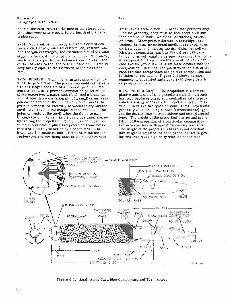
T.O. llA-I-20Section IXParagraphs 9-14 to 9-16
neck of the case rests to the face of the closed bolt.It is thus very nearly equal to the length of the cartridge case.
9-14. For rimfire, rimmed, and semirimmed centerfire cartridges, such as caliber. 22, caliber. 38,and shorgun cartridges, the extractor rim of the casestops the forward motion of the cartridge. Therefore,headspace is equal to the distance from the rear faceof the chamber to the face of the closed bolt. This isvery nearly equal to the thickness of the extractorrim.
9-15. PRIMER. A primer is an assembly which ignites the propellant. The primer assembly of centerfire cartridges consists of a brass or gilding-metalcup that contains a primer composition pellet of sensitive explosive, a paper disk (foil), and a brass anvil. A blow from the firing pin of a small-arms weapon on the center of the primer cup compresses theprimer composition violently between the cup and theanvil, thus causing the composition to explode. Theholes or vents in the anvil allow the flame to passthrough the primer vent in the cartridge case, thereby igniting the propellant. The primer compositionin the cup is held in place and protected from moisture and electrolytic action by a paper disk. Thebrass anvil is inserted last. Primers of the noncorrosive type are now being used in the manufacture of
small-arms ammunition. In order that primers mayfunction properly, they must be free from such surface defects as folds, wrinkles, scratches, scales,or dents. Other primer defects in cartridges arecocked, broken, or inverted anvils; scratched, torn,or dirty cups; and missing anvils, disks, or pellets.Rimfire ammunition, such as the caliber. 22 cartridge, does not contain a primer assembly; the primer composition is spun into the rim of the cartridgecase and the propellant is in intimate contact with thecomposition. In firing, the pin strikes the rim of thecase and thus compresses the primer composition andinitiates its explosion. Figure 9-9 shows primercomponents separated and figure 9-10 shows detailsof several primers.
9-16. PROPELLANT. The propellant is a low explosive substance of fine granulation which, throughburning, produces gases at a controlled rate to provide the energy necessary to propel a bullet or missile. There are two types of small-arms propellantsgenerally used, the single-base (nitrocellulose) typeand the double-base (nitrocellulose and nitroglycerin)type. The weight of the propellant charge and granulation of the propellant of a particular compositionare in accordance with specification requirements.The weight of the propellant charge is not constant;this weight is adjusted for each propellant lot to givethe required muzzle velocity with the associated
ORC Chi
-----CLOSURE DISK SLUG
1----- S'ULlET (TRACERI-----1
lG, ITE" OMPOSITION
~_RA ER COMPOSITIO
-;-J-- i_I.
SSEMBLY
"BOAT.TAILED"
BASE
"SQl.ARE" SASE
PRIMEI, VE, I-~'"+-~CAR .,IOGE HEf\D
, I BULLET .'
EASE INeE DIARY IFILLLK CA~",,;-.JELURE CO, ~g~1TI0, J I
-. CRI/vlP POINT FILLER)
.-:- ---~.-- - I t". -......\-
.~-~·'-r~~;;;:;:;;~-::;--l- MEPU\T
I I CORE JAC'<ETr ~'------80DY-------o-+--7-'-!---"7-"";
I HC·\D
Ir------ ----
Figure 9-1. Small Arms Cartridge Components and Terminology
9-2
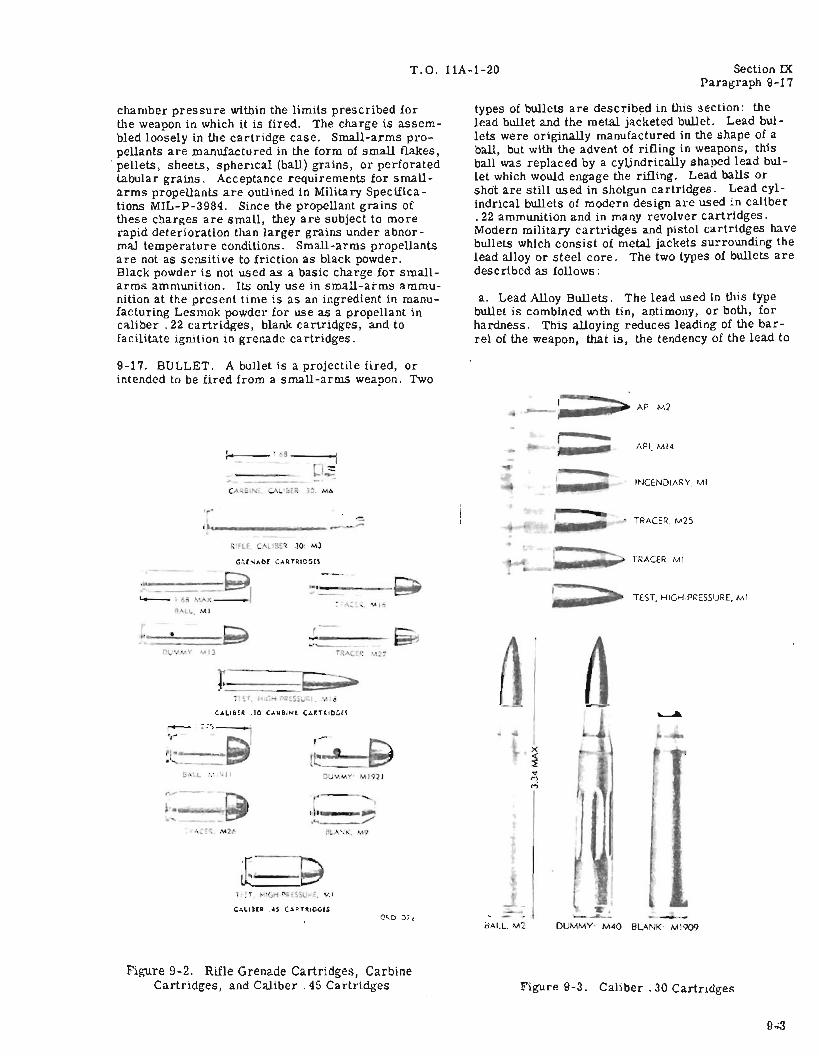
T.O. llA-1-20 Section IXParagraph 9-17
chamber pressure within the limits prescribed forthe weapon in which it is fired. The charge is assembled loosely in the cartridge case. Small-arms propellants are manufactured in the form of small flakes,
. pellets, sheets, spherical (ball) grains, or perforatedtabular grains. Acceptance requirements for smallarms propellants are outlined in Military Specifications MIL-P-3984. Since the propellant grains ofthese charges are small, they are subject to morerapid deterioration than larger grains under abnormal temperature conditions. Small-arms propellantsare not as s ensitive to friction as black powder.Black powder is not used as a basic charge for smallarms ammunition. Its only use in small-arms ammunition at the present time is as an ingredient in manufacturing Lesmok powder for use as a propellant incaliber.22 cartridges, blank cartridges, and tofacilitate ignition in grenade cartridges.
types of bullets are described in this section: thelead bullet and the metal jacketed bullet. Lead bullets were originally manufactured in the shape of aball, but with the advent of rifling in weapons, thisball was replaced by a cyUndrically shaped lead bullet which would engage the rifling. Lead balls orshOt are still used in shotgun cartridges. Lead cylindrical bullets of modern design are used in caliber.22 ammunition and in many revolver cartridges.Modern military cartridges and pistol cartridges havebullets which consist of metal jackets surrounding thelead alloy or steel core. The two types of bullets aredescribed as follows:
a. Lead Alloy Bullets. The lead used in this typebullet is combined with tin, antimony, or both, forhardness. This alloying reduces leading of the barrel of the weapon, that is, the tendency of the lead to
9-17. BULLET. A bullet is a projectile fired, orintended to be fired from a small-arms weapon. Two
AP. M2
I- •• s ,l~-::
CA ... til CA '&tR 3•. ,,",0
API. MI4
INCENDIARY. MI
-='..-_------- _._- TRACER. M25
,..~j6:i' ...AX
Ro\U•. :Vol
GRENADE CARTRIDGfS
~._-----.-.A ....... "I-!~
TRACER, MI
TEST. HIGH.PRESSURE, MI
.----DUMMY: M40 BLANK' M1909cALL. 2
Ix<{
~
"MM
0'<0 u71
J.., _.'--.
,r. I
..._-_/Po .'.K. M9
CAlHHR .4S CAR rA.rDGH
'II
CALIBER .30 C"",RBI,...E CARTRIOGH
6r\~t
•
;;- ,::~---;::J~t--......"
Figure 9-2. Rifle Grenade Cartridges, CarbineCartridges, and Caliber. 45 Cartridges Figure 9-3. Caliber. 30 Cartridges
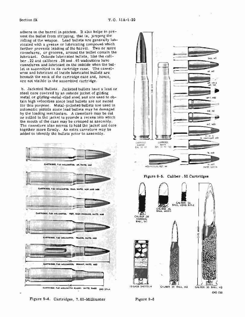
Section IX T.O. llA-1-20
adhere to the barrel in patches. It also helps to prevent the bullet from stripping, that is, jumping therifling of the weapon. Lead bullets are generaily lubricated with a grease or lubricating compound whichfurther prevents leading of the barrel. Two or morecannelures, or grooves, around the bullet contain thelubricant. Outside lubricated bullets, like the caliber .22 and calibers. 38 and. 45 wadcutters havecannelures and lubricant on the outside when the bullet is assembled in its cartridge case. The cannelures and lubricant of inside lubricated bullets arebeneath the neck of the cartridge case and, hence,are not visible in the assembled cartridge.
b. Jacketed Bullets. Jacketed bullets have a lead orsteel core covered by an outside jacket of gildingmetal or gilding-metal-clad steel and are used to obtain high velocities since lead bullets are not suitedfor this purpose. Metal-jacketed bullets are used inautomatic pistols since lead bullets may be damagedby the loading mechanism. A cannelure may be cutor rolled in the jacket to provide a recess into whichthe mouth of the case may be crimped at assembly.The cannelure also serves to hold the jacket and coretogether more firmly. An extra cannelure may beadded to identify the bullets prior to assembly.
CARTRIOGl. 7.62 MILUMnu; U. NATO. M"
,. RTR.lOCEOU.........ViY
CAl 50 '.1
HIGH..,'lk[5SUR~ n:ST. Ml
CALIBER .22:BALL, LONG RIFLE
CALIBER .45:BALL. MI91 I
Figure 9-5. Caliber. 50 Cartridges
~
CALIBER .30CARBINE,BALL, MI
IJ.-.""';;"--D12·GAGE SHOTGUN
c:.u:nIOGI. 7.62 MILLlMlnl, TtST, HIGH PaDSlJU, NATO, _
CAITIIOGI, 7.62 MILLIMfTU: IALL. NATO. M.s. AND MIO
CAaTt'OGI. 7.62 MILLlMml, TlACII, NATO, 10462
------------'UlO<>---- _CAIYIIOGI. 7.62 M'WMml, DUMMY, NATO, M6.J
----------2..60-------_CARTI.IDGI, 7.62 MllUMml .LANK: NATO, XMI2 CAO 07...A
ORD DBD
Figure 9-4. Cartridges, 7. 62-Millimeter Figure 9-6. Types of Cartridges - Sectioned
9-4

T.O. llA-1-20 Section IXParagraphs 9-18 to 9-22
CA..:OOij~l) ,"' .... c\ ,....~"'·-o,::; rJ-l."-~
Figure 9-8. Typical Shotgun Shells - Sectioned
9-21. Shot is classed as soft or drop shot if it is madeof lead and as chilled shot if it is made of the harderlead -antimony alloy.J
)
i I CENTER FIRE CASES
RIMLESS SEMI RIMMED RIMMED
vl SPUN I IIPRIMER
,~II/' ,~JI_RIMFIRE_
CASESOLID HEAD FOLDED HEAD
9-19. SHOT. Shot is a mass or load of numerous,relatively small, lead pellets used in a shotgun cartridge, referred to as birdshot or buckshot. Shotgun
9-22. CALIBER. The caliber of a weapon is the diameter of the bore' of the weapon measured from thesurface of one land to the surface of the land directlyopposite. Caliber is usually expressed in inches orin millimeters. When expressed as a decimal withoutan indication of the unit, the unit inches is understood.For example, a. caliber .30 cartridge has a bulletwhich is about 0.3085-inch in diameter. The lands ofthe rifling of a weapon are the raised spiral portionsof the rifling formed by cutting spiral grooves, generally 0.003- or O. 004-inch deep, into the surface ofthe bore. The diameter of a lead alloy bullet is gen-
. e.rally O. 003-inch greater than the bore diameter be.tween grooves. The diameter of a jacketed bulletgenerally should not be more than O. 001-inch greaterthan the diameter between grooves. Bullet diametersfor cartridges described in this section ar!3 listed infigure 9-32.
9-18. The body of the bullet is cylindrical. The nosemay be round, as in the carbine, pistol, and revolverbullets, or ogival (curved taper) as in service rifleand machinegun bullets. The length of ogvie. or taperfor caliber. 30 and caliber. 50 bullets is approximately 2-1/2 times the bullet diameter. The basemay be square (cylindrical) or boattailed (having aconical taper). A special type of bullet is the wadcutter, or midrange, which has a cylindrical bodyand a blunt nose with a sharp edge in order that itmay cut the target cleanly. The wadcutter bulletsare currently used in the caliber. 38 special and caliber .45 for competition only.
Figure 9-7. Types of Cartridge Cases
Figure 9-9. Components of Primers - Separated
ANVIL
RA PD 97673A
PAPER DISK(FOIU
PRIMUMIXTUU
CUP
cartridges contain a charge of small pellets or shotinstead of a single bullet with the exception of the 10gage blank cartridge.
9-20. Shotgun cartridges are identified as to size bygage. The gage of a shotgun refers to the number oflead balls or shot of the diameter of the bore requiredto weigh 1 pound. The. 410-gage shotgun is an exception in that the diameter of the bore is 0.410-inch.The bore of a 12-gage shotgun measures O. 729-inchin diameter, thus 12 balls or pellets of O. 729-inchwould weigh one pound. Refer to figure 9-31 for gageused in shotgun cartridges.
9-5
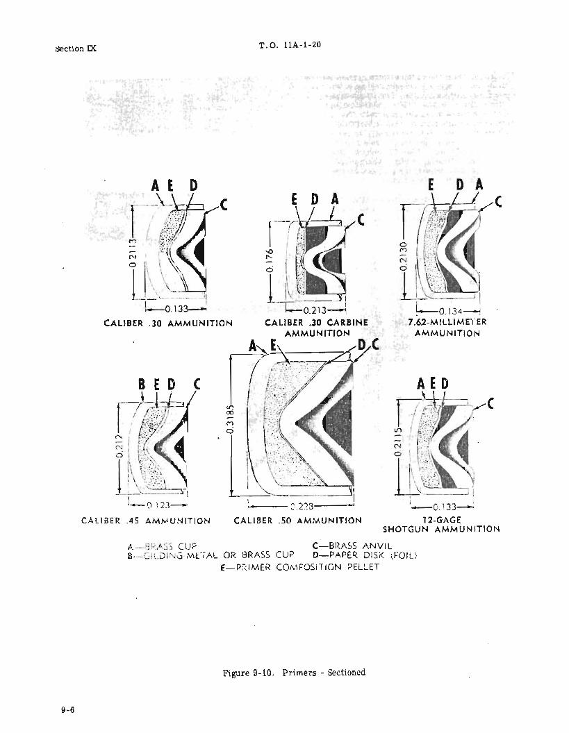
Section IX T. O. llA-1-20
'k
......-Oi23- I,. 0223------~
C L BER .50 AMMUNITION
(
CALIBER .30 AMMUNITIO
CALIBER .45 AMMUNITION
A---'J~./·.'··) CUP C-BRASS ANVILB---CiLOI C)-METAL OR BRASS C P D-P.A.PE~ DISK (FOIl)
E-P,'IMER COMFOSITION PELLET
Figure 9-10. Primers - Sectioned
9~6
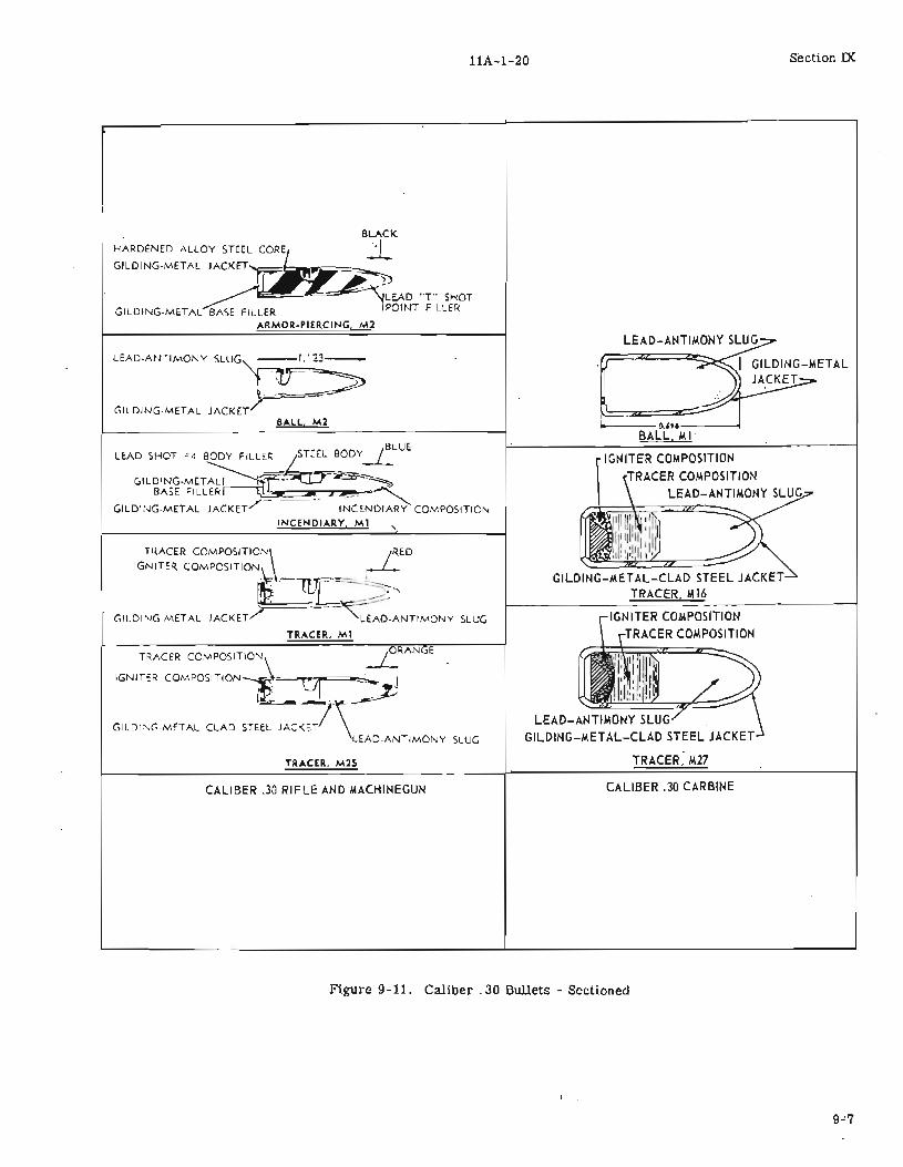
T.O. llA-1-20 Section IX
GILDING-METAL BASE FILLERARMOR-PIERCING, M2
IGNITER COjlPOSITION:rRACER COMPOSITION
IGNITER COMPOSITION
TRACER COMPOSITIONLEAD-ANTIMONY SLU
I
I. O.',o---...ojBALL, MI"
GILDING-METAL-CLAD STEEL JACKETTRACER. M16
LEAD-ANTIMONY SLUGGILDING-METAL-CLAD STEEL JACKET
TRACER, M27
mACER COMPOSITION\ IRED
IGNITER COMPOSITION :-l .--L-I': =ttL l~_,l:Ji ~-
GILDING-METAL JACKET./' ----~EAD-ANTIMONYSLL'G
TRACER. Ml
BLUELEAD SHOT =4 BODY FILLER ~STEELBODY-L
GILDING-MET~~~"~BASE FtLL~~r----1lC - -~
GILDI~G-METAL JACKET/" INCENDIARY CO,V.POSITIO",
INCENDIARY, Ml '.
LEAD-ANTIMONY SLUG"i" "v=~'~
~GILDING-METAL JACKET/
BAll, M2
TRACER, M2S
TRACER COMPOSIT10~ 1 RANE
'GN"" COM"OS"'ON~~..I- -\~
GILDI~G"METAL CLAD STEEL JACKET7- \LEAD-ANTIMONY SLUG
CALIBER .30 RIFLE AND MACHINEGUN CALIBER .30 CARBINE
Figure 9-11. Caliber. 30 Bullets - Sectioned

Section IX , T.O. llA-1-20
AP. M2
IULLET. CALlln .50: TRACER. Ml0
A
G
ALUMINUM COLOR
~ALUMINUM COLOR
. ~RED
r-r-~=::;::-::~=._::-_-~:J·SS·f'
All~~~ZAPI. M8
API.T. M20 IULLET. CALliER .50: TRACER. MIT
:~:.~o E all F
IULLET. CALlln .50: TRACt:ll. HEADLIGHT, M21
A--GILDING-METAL JACKETI-STEEL COREC-LEAD-ANTIMONY POINT FILLERO-HARDENED ALLOY STEEL COREE-LEAD-ANTIMONY BASE FILLERF-INCENDIARY MIXTURE
G-IGNITER COMPOSITIONH-TRACERJ-LEAD-ANTIMONY SLUGK-STEEL BODYL-GILDING-METAL-CLAD
STEEL CONTAINER
A-IGNITER COMPOSITIONI-SUB-IGNITER COMPOSITIONC-TRACER COMPOSITIONI>---LEAD-ANTIMONY SLUGE-GILDING-METAL JACKETF-GILDING-METAL-CLAD STEEL JACKETG-GILDING·METAL CLOSURE
Figure 9-12. Caliber. 50 Bullets - Sectioned
9-8
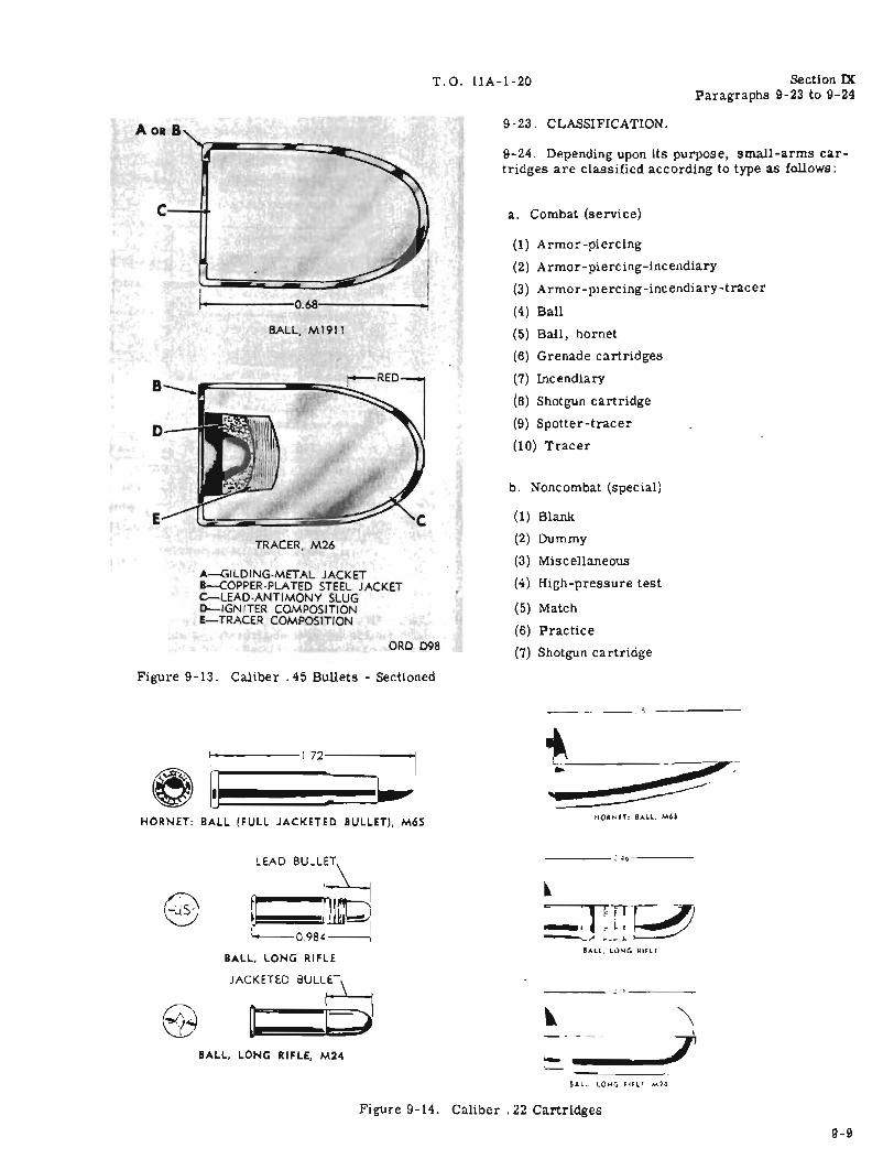
-T.O. llA-1-20 Section IX
Paragraphs 9-23 to 9-24
c-~
BALL, M1911
(1) Blank
(2) Dummy
(3) Miscellaneous
(4) High-pressure test
(5) Match
(6) Practice
(7) Shotgun cartridge
(1) Armor-piercing
(2) Armor-piercing-incendiary
(3) Armor-piercing-incendiary-tracer
(4) Ball
(5) Ball, hornet
(6) Grenade cartridges
(7) Incendiary
(8) Shotgun cartridge
(9) Spotter-tracer
(10) Tracer
b. Noncombat (special)
a. Combat (service)
9-23. CLASSIFICATION.
9-24. Depending upon its purpose, small-arms cartridges are classified according to type as follows:
TRACER, M26
ORD D98
A~ILDING·METAL JACKETB-COPPER·PLATED STEEL JACKETC-LEAD·ANTIMONY SLUGD--IGNITER COMPOSITIONE-TRACER COMPOSITION
1-.-----0681-------l
Figure 9-13. Caliber. 45 Bullets - Sectioned
;,-----
....1~-----I.72:-----'1
" ..~!!!!!~~:~~HORNET: BALL (FULL JACKETED BULLET), M65
HORNET: eALL, M6S
LEAD BULL~
~ rlli.~~O.984==1
BALL, LONG RIFLE
____ : '6----
BALL, LONG RIFLE, M24 -BALL. LONG RIFLE. M24
Figure 9-14. Caliber. 22 Cartridges
9-9

Section IXParagraphs 9-25 to 9-26
T. O. 11A-1-20
IAU.. LIAD IULUT. 1»-GUIH IULLIT
I=:0J.4:::j
IALL. ISl-GRAJH IULLIT, snn JAeKn' 'COPPER PLAnD)
I-oI,r·;;;;;;;~.1.6.a::::;_-::~1
CARBINE, CALIBER .30: M6
1-01.-----2.0--------1I
RIFLE, NATO, 7.62 MILLIMETER: M64 IALL. MID-lANGE, 146-GIlAIH IUUIT (WAD-CUTTU)
t.ol-------2.49-------i!
@ I~-~·~RIFLE. CALIBER .30, M3 ORD D96 1PoCaAIN IUWT. STIlL JACKET. (TRACER)
ORD D110
-----2.0MNC
nsT. HIGH.PRISSUU. 1Sl-GRAlH IUUET
NAME OR INITIALS OFMANUFACTURER AND YEAR
Figure 9-17. Caliber. 38 Special Cartridges
9-25. ARMOR-PIERCING. This type of cartridge isintended for use against aircraft and armored vehicles, concrete shelters, and similar bullet-resistingtargets. Armor-piercing bullets are jacketed andhave a core of hardened steel (figure 9-11 and 9-12),which may be made of tungsten-chromium ormanganese-molybdenum steel. The 7. 62-MM AP bullet has both a point and base filler of lead-antimony.The caliber. 30 armor-piercing bullet has a point filler of lead and a gilding-metal base filler between thecore and the jacket, whereas the caliber. 50 armorpiercing bullet has only a lead-antimony point filler.These bullets have smooth cannelures cut into thejacket for crimping of the cartridge case.
9-26. ARMOR-PIERCING-INCENDIARY. This typeof cartridge is used in caliber. 30 and caliber . 50weapons as a single combination cartridge in lieu ofthe separate armor-piercing and incendiary cartridges. The bullets (figure 9-11 and 9-12) have ahardened steel core and a point filler of incendiarymixture instead of lead;
PAPER CUP'-"'~.~.
Figure 9-15. Caliber. 30 and 7. 52-MillimeterGrenade Cartridges
!~--------2.5MAX-------
Figure 9-16. Caliber. 30 Blank CartridgeM1909 Figure 9-18. Caliber. 45, Line Throwing BlanK
9-10
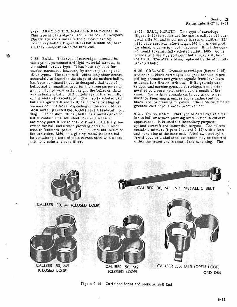
T.O. 11A-1-20 Section IXParagraphs 9-27 to 9-31
9-27. ARMOR-PIERCING-INCENDIARY-TRACER.This type of cartridge is used in caliber. 50 weapons.The bullets are similar to the armor-piercingincendiary bullets (figure 9-12) but in addition, havea tracer composition in the base end.
9-28. BALL. This type of cartridge, intended foruse against personnel and light material targets, isthe oldest service type. It has been replaced forcombat purposes, however, by armor-piercing andother types. The term ball, which long since ceasedaccurately to describe the shape of the modern bullet,has been continued in use to designate that type ofbullet and ammunition used for the same purposes asammunition of very early design, the bullet of whichwas actually a ball. Ball bullets are of the lead alloyor the metal-jacketed type. The metal-jacketed ballbullets (figure 9-6 and 9-13) have cores or slugs ofvarious compositions, depending on the intended use.Most metal-jacketed ball bullets have a lead-antimonyslug. The caliber. 50 ball bullet is a metal-jacketedbullet containing a soft steel core with a leadantimony point filler to ensure similar ballistic properties for ball and armor-piercing cartrid~ '"s whenused in functional packs. The 7. 62-MM ball bullet ofthe cartridge, M59, is a gilding-metal jacketed bullet containing a core of plain carbon steel with a leadantimony point and base filler.
9-29. BALL, HORNET. This type of cartridge(figure 9-14) is authorized for use in caliber. 22 survival rifle M4 and in the upper barrel of caliber .22/.410 gage survival rifle-shotgun M6 and is designedfor shooting game for food purposes. It has the conventional 45-grain full-jacketed bullet, M65. Somerounds with the M39 soft point bullet may still be inthe field. The M39 is being replaced by the M65 fulljacketed bullet.
9-30. GRENADE. Grenade cartridges (figure 9-15)are special blank cartridges designed for use in propelling grenades and ground signals from launchersattached to rifles or carbines. Rifle grenade cartridges and carbine grenade cartridges are distingUished by a rose-petal crimp at the mouth of thecase. The carbine grenade cartridge is no longerused for launching grenades but is authorized forblank fire for training purposes. The 5. 56-millimetergrenade cartridge is under procurement.
9-31. INCENDIARY. This type of cartridge is similar to ball or armor-piercing ammunition in outwardappearance. It is used for incendiary purposesagainst airc raft and flammable targets. The bulletscontain a mixture (figure 9-11 and 9-12) with a leadantimony slug at the base end. A hollow steel cylindrical body or a clad steel container may be insertedwithin the jacket and in front of the base slug. The
CALIBER .50, M2(CLOSED LOOP)
CALIBER .50, MIS (OPEN LOOP)
ORO 084
CALIBER .30,' M I END, METALLIC BELT
CALIBER .50, M9(CLOSED LOOP)
CALI BER .30, M 1 (CLOSED LOOP)
II
Figure 9-19. Cartridge Links and Metallic Belt End
9-11
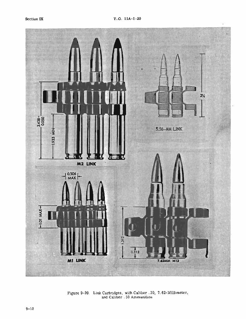
Section IX T.O. llA-1-20
2~
15 56-MM LINK
M2 LI K
qT
Figure 9-20. Link Cartridges, with Caliber. 30, 7. 62-Millimeter,and Caliber . 50 Ammunition
9-12

T. O. 11A-1-20
9-32. SHOTGUN AMMUNITION. Shotgun cartridges(figure 9-8) consist of a brass or steel head, a primer, a paper, plastic, or metal body, a propellingcharge, cardboard or felt wads, a load of lead shot,and a closing wad. The paper cases or bodies arewaterproofed.
9-33. SPOTTER TRACER. The M48 spotter-tracerbullets contain a tracer element and an incendiarycharge which give off a puff of smoke and a flash onimpact with the target.
9-34. TRACER. This type of cartridge (figures 9-11,9-12, and 9-13) is intended for use with other typesto show the gunner, by its trace, the path of the bullets, thus assisting in correcting aim. It may also beused for incendiary purposes. The bullets contain alead-antimony slug in the forward position and atracer composition in the rear. They have either
Section IXParagraphs 9-32 to 9-36
square or boattailed bas es. The bullet jackets aremade of gilding-metal or gilding-metal-clad steel.An igniter composition is also present, which is ignited by the burning propellant gases which, in turn,ignites the tracer composihon. Some fracer bulletsare visible the instant of firing while others have adim trace for a short distance from the muzzle of thegun and then a bright trace thereafter.
9-35. BLANK. This type of cartridge (figure 9-16)is distinguished by the absence of a bullet. It is usedfor simulated fire, in maneuvers, and in firing salutes. It is also used in machine guns equipped withblank firing attachments in order to operate theseweapons for instructional purposes. EC blank firepropellant is used to produce the noise.
9-36. DUMMY. This type of cartridge is used forpractice in Joading weapons, to detect flinching of
BANDOLEER, Ml (FOR 5· AND 8-RD CARTRIDGE CLIPS)
!lil1r!l
J
',\-.'",
ir-' ~I...-.l.~
l'=2.37 IN.
CALIBER .30 (5 RD)CARTRIDGE CLIP
Figure 9-21. Bandoleer, Magazine, Filler, Clips
9·13

Section IXParagraphs 9.-37 to 9-41
T.O. llA-1-20
personnel in firing weapons, and to simulate firing.The cartridge case of older lots of dummy ammunition is tin-coated but the current method of identification is by means of holes through the side of thecase and by the empty primer pocket. The ammunition is completely inert but simulates service ammunition in sufficient detail to meet drill requirements.presence of two knurled cannelures is a characteristic of caliber . 50 incendiary bullets.
9-3 7. lUGH PRESSURE TEST. This type of ammunition is manufactured to produce pressures substantially in excess of the specification pressure of the
BulletCartridge
Cartridge Case Propellant Jacket Slug
Long rifle Brass2.. Smokeless ...... Lead or(lead or leadbullet). 1 Lesmok alloy.
A.
Long rifle, Brass2 .. Smokeless Gilding Lead-M24. 1 or metal. anti-
Western mony.Ball
Long rifle, Brass ... Smokeless Gilding Lead or(com- metal leadmercial).1 or alloy.
lead.
Hornet, Brass ... Western Gilding Lead-ball, Ball metal. anti-M65. 3 mony.
1 Rimfire type primer.2 Cartridges may have steel cases.3 Commercial centerfire primer.
Figure 9-22. Component Parts of Caliber. 22 Ammunition
corresponding service items. It is used for prooffiring of weapons at place of manufacture, test, andrepair. Due to the excessive pressures developed bythis type of ammunition and the consequent danger involved in firing, the weapons under test are firedonly by authorized personnel from fixed rests underhoods by means of mechanical firing devices.
9-38. MATCH. This cartridge is procured fromvarious manufacturers for use in all rifles, revolvers, pistols, for competition in marksmanship. Thebullet is more exacting in standards than regularrounds.
9-39. MISCELLANEOUS SMALL ARMS CARTRIDGES.These cartridges (figures 9-17 and 9-18) consist ofvarious types and calibers used for special or auxiliary purposes. They include caliber .38 special cartridges for use by aircrew and Air Police personnel,caliber. 38 tracer rounds, and caliber. 45 blank linethrowing cartridges for use with a special projectileattached to a standard line in the Navy line-throwinggun.
9-40. ACCESSORIES.
9-41. Metallicbelt links (figures 9-19 and 9-20) areused with 5.56- and 7. 62-millimeter and calibers. 30and . 50 cartridges in machineguns. The links aremade of steel, processed for rust prevention, andare required to meet specific test requirements toassure satisfactory ammunition feed and functioningunder all service conditions. A metallic belt end isattached to metallic link belts of caliber. 30 cartridges packed in metal boxes for ground machineguns use. The belt end facilitates starting the belt ofcartridges through the gun. Clips (figure 9-21) areprOVided for rifle and carbine cartridges; the 5-roundclip for rifles M1903 and M1917, the 9-round clip(nonexpendable in peacetime) for the rifle M1, the 10round clip for the caliber. 30 carbine, the 8-roundclip for the 5. 56- and the 5-round clip for the 7.62millimeter rifles. Filler and magazine assemblies
BULLET
Cartridge Cart Case Propellant Jacket Core or Slug Point Filler Base Filler
Ball M193 Brass Western Gilding lead alloy None Noneball metal
Tracer Brass GildingXM196 metal
Grenade Brass None None None None
Blank Brass None None None NoneXM200
Dummy Brass inert Gilding lead alloy None NoneXM199 metal
Information to complete table will be furnished when available.
Figure 9-23. Component Parts of 5. 56-Millimeter Ammunition
9-14

T.O. llA-1-20 Section IX
BULLETCartridge
Base FillerCartridge Case Propellant Jacket (Slug)
Ball, Ml Brass or Ballor Gilding-metal or Lead-steel. Hercules Gilding-metal antimony.
Flake. clad steel.
Dummy, M13. Brass orsteel. . ........... Gilding - metal Lead-
or Gilding- antimony.metal-cladsteel.
High -pressure Brass Ballor Gilding- metal- Lead-test, M18. Hercules clad steel. antimony.
Flake.
Tracer, M16. Brass Ball or Gilding-metal- Lead- Tracer and igniter com-Hercules clad steel. antimony. position.Flake.
Tracer, M27. Brass Ballor Gilding - metal- Lead- Tracer and igniter com-Hercules clad steel. antimony. position.Flake.
Figure 9-24. Component Parts of Caliber. 30 Carbine Ammunition(Centerfire Primers are used in all Cartridges)
BULLETCartrid '
Cartridge Case Propellant Jacket Core or Slug Point Filler Base Filler
AP, M2 Brass Smokeless Gilding- Steel Lead T-shot Gilding-metalmetal
API, M14 Brass Smokeless Gilding- Steel Incendiary Lead-antimony.metal composi non.
Ball, M2 Brass or Smokeless Gilding-metal Lead-steel. or gilding- antimony.
metal-cladsteel.
Match, M72 Brass Smokeless Gilding- Lead-metal antimony.
Blank MI909 Brass or EC blank.steel.
Dummy, M40 Brass or None Gilding-metalsteel. clad -steel.
HPT, Ml Brass Smokeless Gilding - metal Lead-or steel. antimony.
Incendiary, Brass Smokeless Gilding- Lead-shot Incendiary Gilding-metal.Ml. metal No.4 body composition.
filler.
Tracer, Ml Brass Smokeless Gilding-metal Lead- Tracer andor steel. antimony. igniter-compo
Tracer, M25 Brass Smokeless Gilding- metal- Lead- Tracer andclad steel. antimony. igniter-compo
Figure 9-25. Component Parts of Caliber. 30 Ammunition (Corrosive and NoncorrosivePrimers Have Been Used in all Cartridges Listed)
9-15

Section IXParagraphs 9-42 to 9-44
T. O. llA-1-20
are available for the 5. 56 - and 7. 62 - millimeterrifles.
9-42. CARE AND PRECAUTIONS IN HANDLING.
9-43. Small arms ammunition is comparatively safeto handle. However, care must be taken to preventammunition boxes from becoming broken or damaged.Broken boxes must be repaired immediately and careful attention given to the transfer of all markings tothe new parts of the box. Metal liners and metalcans should be sealed and air-tested if equipment forthis work is available.
9-44. AMMUNITION PROTECTION. Cartridgesshould be carefully protected from mud, sand, dirt,and water. If they get wet or dirty, they should beWiped off at once. If light corrosion or verdigrisforms on cartridges, it should be wiped off. However,cartridges should not be polished merely to makethem look brighter or better. The primer of acartridge should be protected from blows by sharp instruments, as such a blow might explode the cartridge. Ammunition should not be expos ed to excessive heat or the direct rays of the sun for any considerable length of time. Such exposure is likely toaffect the firing qualities of cartridges.
BULLETCartridge
Cartridge Case Propellant Jacket Core or Slug Point Filler Base Filler
Ball, M59 Brass Double-base, Gilding-metal Steel Lead-antimony Lead -antimonyWestern ball.
Ball, M80 Brass Double-base, Gilding-metal LeadWestern ball. or gilding-
metal-cladsteel.
HPT, M60 Brass Double-base, Gilding-metal Lead-Western ball. antimony.
AP, M61 Brass Double -base, Gilding-metal Steel Lead-antimony Lead -antimonyWestern ball.
Tracer, M62 Brass Double-base, Gilding-metal- Lead- Tracer, sub-Western ball. clad steel. antimony igniter and
igniter camp 8
Blank, XM82 Brass SR 4759
Dummy, M63 Brass None Gilding-metal-clad steel.
Grenade, M64 Brass Double-base,Western ball.
Figure 9-26. Component Parts of 7. 62-Millimeter Ammunition (Primer No. 36 or EquivalentUsed in Cartridges Listed)
BULLETCartridge
Cartridge Case Propellant Jacket Core or Slug Point Filler Base Filler
Ball, Lead Brass (1) Lead-antimony
Ball, M41 Brass (1 ) Gilding Lead-metal antimony
Ball, Copper Brass (1) Copper plated Lead-plated steel antimony
Ball, Wad Brass (1 ) Lead- Blunt nosecutter antimony
Tracer Brass (1) Gilding Lead- Tracer andmetal antimony igniter com-
position
(1) Propellant may be: Bullseye, Pistol powder No.5, Pistol powder No. 6, or DuPont No. 80.
Figure 9-27. Component Parts of Caliber. 38 Special Ammunition
9-16
'.
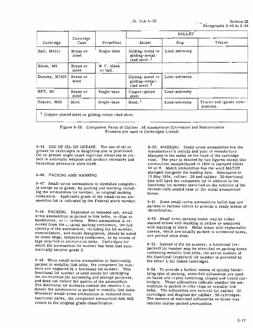
T.O. llA-I-20 Section IX- Paragraphs 9-45 to 9-54
BULLETCartridge
Slug TracerCartridge Case Propellant Jacket
Ball, M1911 Brass or Single-base Gilding-metal or Lead-antimonysteel gilding- metal-
clad steel. 1
Blank, M9 Brass or W.C. blanksteel or ball.
Dummy, M1921 Brass or Gilding-metal or Lead-antimonysteel gilding-metal-
clad steel. 1
HPT, Ml Brass or Single-base Copper-plated Lead-antimonysteel steel
Tracer, M26 Steel Single-base Steel. 1 Lead-antimony Tracer and igniter com-position.
1 Copper-plated steel or gilding-metal-clad steel.
Figure 9-28. Component Parts of Caliber. 45 Ammunition (Corrosive and NoncorrosivePrimers are used in Cartridges Listed)
9-45. USE OF OIL OR GREASE. The use of oil orgrease on cartridges is dangerous ana is prohibited.Oil or grease might cause injurious abrasives to collect in automatic weapons and produce excessive andhazardous pressures when fired.
9-46. PACKING AMD MARKING.
9-47. Small-arms ammunition is identified completely except as to grade, by packing and marking including the ammunition lot number, on original packingcontainers. Applicable grade of the small-arms ammunition lot is indicated by the Federal stock number.
9-48. PACKING. Dependent on intended use, smallarms ammunition is packed in link belts, in clips orbandoleers, or in artons. When ammunition is removed from the u Iginal packing containers, the fullidentity of the ammunition, including the lot number,nomenclature, and model designation, should be notedon issue slips, temporary containers, or by means oftags attached to ammunition belts. Cartridges forwhich the ammunition lot number has been lost automatically become grade 3.
9-49. When small-arms ammunition is functionallypacked in metallic link belts, the component lot numbers are replaced by a functional lot number. Thisfunctional lot number is used solely for identifyingthe ammunition for accounting and storage purposes,and does not reflect the quality of the ammunition.The functional lot numbers contain the interfix L todenote the ammunition is packed in metallic link belts.Whenever small-arms ammunition is removed fromfunctional packs, the component ammunition lots willrevert to the original grade classification.
9-50. MARKING. Small-arms ammunition has themanufacturer's initials and year of manufacturestamped in the metal on the head of the cartridgecase. The year is denoted by two figures except thatammunition manufactured in 1944 is stamped either44 or 4. Match ammunition has the word MATcHstamped alongside the loading date. Subsequent to15 May 1954, caliber. 30 and caliber. 50 functionallots will have the component lot in addition to thefunctional lot number stenciled on the exterior of thehermetically sealed cans or the metal ammunitionboxes.
9-51. Some small-arms ammunition bullet tips arepainted in various colors to provide a ready means ofidentification.
9-52. Small arms packing boxes may be eitherstained brown with marking in yellow or unstainedwith marking in black. Metal boxes with replaceablecovers, which are usually packed in wirebound boxes,are painted olive drab.
9-53. Instead of the lot number, a functional (repacked) lot number may be stenciled on packing boxescontaining metallic link belts; the serial number ofthe functional (repacked) lot number is preceded bythe letter L for linked cartridges.
9-54. To provide a further means of quickly identifying type of packing, stenciled silhouettes are usedon boxes and crates containing clipped and linked cartridges. These silhouettes indicate whether the ammunition is packed in rifle clips or metallic linkbelts. The Silhouettes are vertical for caliber. 30cartridges and diagonal for caliber. 50 cartridges.The absence of stenciled silhouettes on boxes mayindicate carton-packed ammunition.
9-17
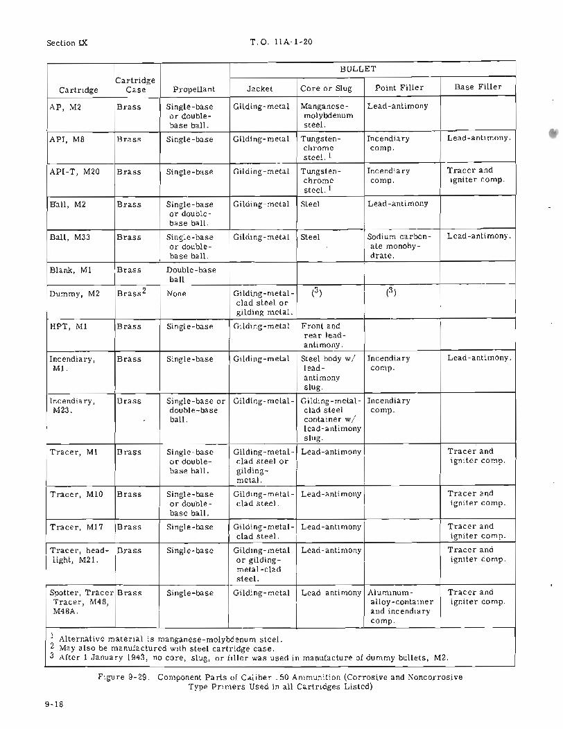
Section IX T.O.llA-I-20
BULLETCartridge
Point Filler Base FillerCartridge Case Propellant Jacket Core or Slug
AP, M2 Brass Single-base Gilding- metal Manganese- Lead -antimonyor double- molybdenumbase ball. steel.
API, M8 Brass Single - base Gilding-metal Tungsten- Incendiary Lead-antimony.chrome composteel. I
API-T, M20 Brass Single-base Gilding-metal Tungsten- Incendiary Tracer andchrome compo igniter composteel. I
Ball, M2 Brass Single -base Gilding- metal Steel Lead-antimonyor double-base ball.
Ball, M33 Brass Single-base Gilding- metal Steel Sodium carbon- Lead-antimony.or double- ate monohy-base ball. drate.
Blank, MI Brass Double-baseball
Dummy, M2 Brass2 None Gilding-metal- (3 ) (3)clad steel orgilding metal.
HPT, MI Brass Single-base Gilding-metal Front andrear lead-antimony.
Incendiary, Brass Single-base Gilding-metal Steel body wi Incendiary Lead-antimony.Ml. lead- compo
antimonyslug.
Incendiary, Brass Single-base or Gilding-metal- Gilding- metal- IncendiaryM23. double- base clad steel compo
ball. container wilead-antimonyslug.
Tracer, MI Brass Single-base Gilding-metal- Lead -antimony Tracer andor double- clad steel or igniter compobase ball. gilding-
metal.
Tracer, MIO Brass Single-base Gilding- metal- Lead-antimony Tracer andor double- clad steel. igniter compobase ball.
Tracer, Ml7 Brass Single -base Gilding - metal- Lead-antimony Tracer andclad steel. igniter compo
Tracer, head- Brass Single-base Gilding- metal Lead -antimony Tracer andlight, M21. or gilding- igniter compo
metal-cladsteel.
Spotter, Tracer Brass Single - bas e Gilding- metal Lead-antimony Aluminum- Tracer andTracer, M48, alloy-container igniter compoM48A. and incendiary
compo
I Alternative material is manganese-molybdenum steel.2 May also be manufactured with steel cartridge case.3 After I January 1943, no core, slug, or filler was used in manufacture of dummy bullets, M2.
Figure 9-29. Component Parts of Caliber. 50 Ammunition (Corrosive and NoncorrosiveType Primers Used in all Ca.rtridges Listed)
9-18
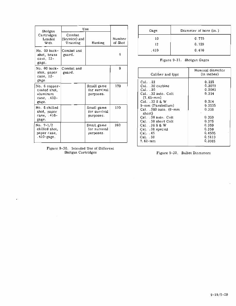
T.O. llA-1-20 Section IX
ShotgunUse
Cartridges CombatLoaded (Service) and Number
With Training Hunting of Shot
No. 00 buck- Combat andshot, brass guard. 9case, 12-gage.
No. 00 buck- Combat and 9shot, paper guard.case, 12-gage.
No. 6 copper- Small game 170coated shot, for survivalaluminum purposes.case, .410-gage.
No. 6 chilled Small game 170shot, paper for survivalcase, .410- purposes.gage.
No. 7-1/2 Small game 260chilled shot, for survivalpaper case, purposes .. 410-gage.
Figure 9-30. Intended Use of DifferentShotgun Cartridges
Gage Diameter of bore (in. )
10 0.775
12 0.729
.410 0.410
Figure 9-31. Shotgun Gages
Nominal diameterCaliber and type (in inches)
Cal. .22 0.225Cal. .30 carbine 0.3075Cal . . 30 0.3085Cal. .32 auto. Colt 0.314
(7. 65-mm)Cal. .32 S & W 0.3149-mm (Parabellum) 0.3555Cal. .380 auto. (9-mm 0.356
short)Cal. .38 auto. Colt 0.359Cal . . 38 short Colt 0.375Cal. .38 S & W 0.359Cal. .38 special 0.359Cal. .45 0.4505Cal. .50 0.51107.62-mm 0.3085
Figure 9-32. Bullet Diameter1:>
9-19/9-Z0

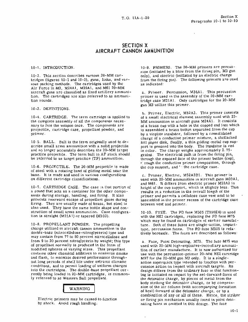
T. O. llA-1-20
SECTION XAIRCRAFT CANNON AMMUNITION
Section XParagraphs 10-1 to 10-10
10-1. INTRODUCTION.
10-2. This section describes various 20-MM cartridges (figures 10-1 and 10-2), guns, links, and various packing methods. The cartridges used by theAir Force in M3, M24Al, M39Al, and M61 20-MMaircraft guns are classified as fixed artillery ammunition. The cartridges are also referred to as ammunition rounds.
10-3. DEFINITIONS.
10-4. CARTRIDGE. The term cartridge is applied tothe complete assembly of all the components necessary to fire the weapon once. The components areprojectile, cartridge case, propellant powder, andprimer.
10-5. BALL. Ball is the term originally used to describe small arms ammunition with a solid. projectileand no longer accurately describes the 20-MM targetpractice projectile. The term ball in AF stock shouldbe referred to as target practice (TP) ammunition.
10-6. PROJECTILE. The 20-MM projectile is madeof steel with a rotating band of gilding metal near thebase. It is made and used in various configurationson different cartridge classifications.
10-7. CARTRIDGE CASE. The case is that portion ofa round that acts as a container for the other components during storage, handling, and firing. It alsoprevents rearward escape of propellant gases duringfiring. They are usually made of brass, but steel isalso used. They have the same bottle shape and construction of small arms ammunition. Case configuration is straight (M21A1) or tapered (M103).
10-8. PROPELLANT POWDER. The propellingcharge utilized in aircraft cannon ammunition is thedouble-base (nitrocellulose-nitroglycerin) type andmay contain from 77 to 80 percent nitrocellulose andfrom 9 to 20 percent nitroglycerin by weight; this typeof propellant normally is produced in the form ofmodified spheres of varying sizes. This propellantcontains other chemical additives to minimize smokeand flash, to maintain desired performance throughout long periods of shelf life under extreme climaticconditions, and to permit loading of uniform chargesinto the cartridges. The double-base propellant currently being loaded in 20-MM cartridges, is commonly referred to as Western Ball propellant.
r WARNING IElectric primers may be caused to functionby shock. Avoid rough handling.
10-9. PRIMERS. The 20-MM primers are percussion (initiated by a blow from the firing pin, M3 gunonly), and electric (initiated by an electric chargefrom the firing pin). The following primers are usedas indicated:
a. Primer. Percussion, M36A1. This percussionprimer is used in the assembly of the 20-MM cartridge case M21A1. Only cartridges for the 20-MMgun M3 utilize this primer.
b. Primer, Electric, M52A3. This primer consistsof a small electrical element assembly used with 20MM ammunition in aircraft guns M24Al. It consistsof a brass cup with a hole in the cupped end into whichis assembled a brass button separated from the cupby a vinylite insulator, followed by a consolidatedcharge of a conductive primer mixture, a shellackedfoil paper disk, finally, a thin gilding-metal cup support is pressed into the body. The insulator is redin color. The charge weighs approximately 2.75grains. The electrical path is from the firing pin,through the exposed face of the primer button (cup),tough the conductive primer composition, throughthe cup support, and t I the cartridge case.
c. Primer, Electric, M52A3B1. This primer isused with 20-MM ammunition in aircraft guns M39A1,and M61. It differs from electric primer M52A3 inheight of the cup support, which is slightly less. Thisresults in a reduction in the overall length of theprimer and permits a cellulose case vent seal to beassembled in the primer recess of the cartridge casebetween vent and primer.
10-10. FUZE. The PD fuze M505 (T196E4) is usedwith the HEI cartridges, replacing the PD fuze M75which may be found on cartridges of earlier manufacture. Both of these fuzes are single-action, impacttype, percussion fuzes. The PD fuze M505 is relatively boresafe. The fuzes are described as follows:
a. Fuze, Point Detonating, M75. The fuze M75 wasused with 20-MM high-explosive-incendiary ammunition of earlier manufacture. It is now authorized foruse with the percussion-primer 20-MM HEI cartridgeM97 for the 20-MM gun M3 only. It is a singleaction superquick type intended to function with percussion action on impact with aircraft targets. Itsdesign differs from the ordinary fuze in that functioning is initiated on impaGt by the set-forward force ofthe detonator charge, by pieces of metal from thebody striking the detonator charge, or by compression of the air column (with accompanying formationof heat) forward of the detonator charge, or by acombination of any or all of these. Hence, the strikeror firing pin mechanism usually found in point detonating fuzes is omitted in this design. The fuze
10-1
Section X T. O. llA-I-20
•I
lA PO 212989...
iO.,~..'"~ i ===o<·x:·Y·:
W~
\
PROPElLANT
CASE VENT SEAL~ .,
ELECTRIC PRIMER M52A381~2129'8aA
CUP~DISKCHA;~ SUPPORT
\ . I
.!", . ' ..
'-::: • j
BUTTON INSULATOR
ELECTRIC PRIMERM52AJB1- ENLARGED
6615
t " ,MAY.__ , J'i:, -I_\""',
· '''''• '... \ It.!--.... I'I· ... "I
r' ,/_,'." .... ,........ ,-,
· \ . 1 \.,1":"'·,"1J' ,; ....
-', '.. ;.\ \ .... '.\
TRACER CAVITY PLUG---fl;:;::2I111111......
RA PO l)tOl04B
DIS~CU.PSUPPORTCUP CHARGE
I,I . ~
~8UrTO~ INSULATOR
lL1CTRIC ,RIMIl M'lA3---(IH.U,lGIO)
e~
"z~;:;~z
1R
7.23 MAX. I
Figure 10-1. Cartridge Components, 20-Millimeter Electric Primer-Typical
$ n D20 .... MI03S1 ou....yxxx-x- )(x- xx lIIelAIE2
$~ [I~ D20.... 11I103~
Ix X)( - x-x x-)()(
$ I
20 .... 11I103
I CARTR I DGE CA E LOT NUMBER "00" $[ xxx-x-xx-xx
$~NUMBER
]~20 .... "21'1 • 0
V$[·.)OClC-X-XX-)()(, .• x- "
,
V'~/20 .... 111103
$~'OC:l( 4 )(-XX-XX
]20.... "21'1xxx-x-xx-xx
$[,I: g ~
$20 .... 11I10311
xxx-X-XX-x)( ~ K I:!: ~ I':
20 .... W21AII!llxxx-x-xx-,oc .
Figure 10-2. Cartridges, 20-MM
10-2
T.O. llA-I-20 Section XParagraphs 10-11 to 10-13
consists of two major parts; a body with an air spacein the fore -part of the fuze and a magazine containingthe explosive train which is screwed into the base ofthe body to seat against an aluminum impact disk.The explosive train consists of a mercury fulminatedetonator charge, an intermediary charge of leadazide, and a tetryl base charge (booster). Since thereare no interrupter or other safety devices, the fuzeis not considered a boresafe type. Upon firing, noaction takes place until impact. Upon impact withsufficiently resistant targets, the head is crushedand the detonator charge functions. Action of the detonator charge in turn initiates functioning of the leadazide intermediary charge, which causes the basecharge (booster) to detonate. The booster actioncauses the projectile to explode.
b. Fuze, Point Detonating, M505 (TI96E4). TheM505 is used with 20-MM high-explosive incendiaryammunition. It is a single-action superquick fuze intended to function on impact with aircraft targets. Thefuze will not function unless the detonator is in linewith the firing pin. The fuze (figure 10-3) consists ofa body assembly, a rotor assembly, and a boosterholder assembly. The body assembly consists of analuminum-alloy firing pin and a rotor safety spring ofcorrosion-resisting steel wire contained in a steelbody and covered by a sheet steel cover. The coveris crimped behind the shoulder of the body so that itfor .1S a cap, which covers that portion of the fuzeprotruding from the projectile. The rotor assemblyconsists of a brass rotor containing detonator M47(T32). This assembly is so placed in the cavity ofthe body that it is held by the free leg of the rotorsafety spring against a flat surface of the otherwisespherical rotor so that the detonator is out-of-line toprovide mechanical boresafety. The booster-holderassembly, which consists of a steel booster-holdercontaining booster M123 (T42), is screwed into thebase of the fuze body. The fuze has a delayed armingdistance of 20 to 35 feet from the muzzle of the gun.Prior to firing the HEI projectile, the rotor containing the detonator, which is out-of-line with the firingpin, and the firing pin are locked in position by therotor safety spring. Centrifugal force, resultingfrom the rotation of the projectile causes the free legof the spring to move, thus allowing the rotor to movein-line with the firing pin. The movement of the rotorsafety spring releases the firing pin. The firing pinis now suspended over the detonator. The close fitbetween the firing pin and the adjacent walls holds thefiring pin in position. The fuze functions when thenose of the fuze is crushed against the target, thusforcing the firing pin against the detonator. The det0nator in turn initiates the booster. The booster action causes the projectile to explode.
c. The M505A3 fuze (figure 10-3) differs from fuzeM505 in the design of the firing pin, in the addition ofthe U-shape safety spring, and in slight modificationof other parts, which, in connection with the use ofdifferent sealing compounds during assembly, improve metal parts security and sealing of the fuze.The nose end of the firing pin is slightly crowned instead of spherical and the flat on the end of the firingpin does not have a radius on its edge. The firing pinalso has a flange. When the firing pin is assembled
in the fuze body, the flange is forward of the nose endof the body. The design of the body is modified to accommodate the rotor safety spring. The arming ofthis fuze takes place in a similar manner to that offuze M505. Mter fuze M505A3 is armed, the flangeon the firing pin prevents it from moving back againstthe detonator until the flange is sheared off when thenose of the fuze is crushed against the target. Thisfuze is intended to function when the projectile hasmoved an optimum distance after impact. Modification, especially the design of the firing pin, are forthe purpose of obtaining less variation in the time between impact and functioning of the fuze than havebeen obtained with fuze M505.
10-11. CLASSIFICATION. The 20-MM cartridgesused by the Air Force are classified as follows:
a. Practice (TP) (Ball). For use as a traininground in preparation for pilot combat efficiencytraining.
b. Armor-Piercing Incendiary (API). For combinedarmor-piercing and incendiary effect against aircraft,armored vehicles, and concrete shelters.
c. High-Explosil/e Incendiary (HEI). For combinedexplosive incendlary effect against aircraft and lightmaterial targets. The projectile has high explosivein the nose and incendiary mixture in the base, or acomposite mixture of both elements.
d. Incendiary. This cartridge is used for incendiaryeffect against aircraft and light material targets.
e. Dummy. These rounds are completely inert andused for testing the mechanism of 20-MM guns. Dummy rounds are also used for ballast on certain aircraft.
10-12. CARTRIDGES FOR 20-MM GUN, M3.
10-13. The 20-MM gun, M3, is a link disintegrating,belt-fed automatic aircraft cannon for use againstaircraft and ground or sea-borne targets. At present,the M3 is the only 20-MM gun that fires percussionprimed ammunition. Percussion-primed·ammunitionmanufactured in the United states, that is to be usedjointly by the British, must be proof-fired in Britishguns to determine whether the lot develops sufficientlylow chamber pressure for acceptance for firing theBritish weapons. If the ammunition is accepted byboth United states and British services, the wordsCOMMON AMM are marked or printed on the packingboxes. All ammunition for this gun is issued in theform of fixed complete rounds (cartridges). Theshape, length, and weight of the cartridges are approximately the same. This weapon has a muzzlevelocity of 2, 730 feet per second. Characteristicsof 20-MM gun M3 cartridges are as follows:
I WARNING IElectric-primed ammunitic~ ':_:.j:~~~0T befired in the gun M3.
10-3

Section XParagraphs 10-14 to 10-16
T.O. llA-1-20
M505E3NOS E CAP ------I'iI/,7"":
FIRING PIN
CENTRIFUGAL SPRING--m:--;~J\
CENTRIFUGAL SPRING
r--;.::-------- BODY--------1""
".;""o--,."-iC-----BOOSTERASS EM B LY ------......,.'-7'i~
N----COVER
DETOalATOR'r't-'ii'+7"-Tr'i-----ROTOR AS SEMBLY--------f-,Hrim\
/:C::..,..,}:.'''''''''. '~PIz!l;;rrfTrr-----DETONATOR ------+-r~;,tF.;,;.,.
M505A2
Figure 10-3. Fuze, Point Detonating, M505 Series
a. Identification. The color scheme for the paintingand marking of these cartridges for purposes of identification is indicated in figure 10-4. It should benoted that painting and marking of the high-explosiveincendiary and incendiary cartridges differ from thebasic color scheme prescribed in MIL-STD-709, butall essential information is provided.
b. Projectile. Dependent upon type of projectile,ammunition for this gun is classified as highexplosive-incendiary (HEI), armor-piercing withtracer (AP-T), incendiary, target-practice (TP), ordummy.
c. Fuze. The PD fuze M505 (T196E4) is used withthe HEI cartridges, replacing the PD fuze M75 whichmay be found on cartridges of earlier manufacture.Both of these fuzes are single-action, impact-type,percuss ion fuzes. The PD fuze M505 is relativelyboresafe.
d. Cartridge Case. The cartridge cases M21A1(brass) and M21A1B1 (steel) are used with these cartridges. The weight of the cartridge case M21A1 is0.214 pound, the cartridge case M21A1B1 is approximately 0.025 pound lighter and has a deeper extracting groove machined in the head. A single vent isprovided in both cartridge cases.
e. Propelling Charge. The cartridge containsSingle-base (nitrocellulose) propellant.
£. Primer. The percussion primer M36A1, containing a 2.1-grain charge of primer mixture, is usedwith these cartridges.
g. Disintegrating Belt Cartridge Links. These linksand filler (figure 10-5) are considered as ammunition
components. They are listed in United States AirForce Stock List 1300. Metallic belt link M7, M8,or M10 (M8E1) can be used to make up belts foreither right-or left-hand 20-MM feed mechanism M3or AN-M2; however, only one type of link may be usedin the same belt. The link M8 is an improvement indesign over the link M7. The link M10 (M8E1) differsfrom the link M8 in finish, heat treatment, and contour design. It can be distinguished from the M8 bythe comparatively greater flexibility of the belt andprevents holdups in the ammunition chute. A cartridge link filler is used with the link M10 (M8E1)when it is desired to load belts for double-loop lefthand feed.
10-14; CARTRIDGE, 20 MILLIMETER, AP-T, M95.This cartridge (figure 10-1) is for use against armored targets. The projectile is a solid shot madefrom bar or forged steel. A 'drawn steel windshieldis crimped into annular grooves in the projectile body,the portion of the windshield over the crimping actingas the bourrelet of the projectile. The base of theprojectile contains a red tracer composition, sealedin by means of a metal closing cup. The tracer burnsfor about 2.25 seconds, equivalent to a range of about1,400 yards. Minimum burning time of tracer is 2.0seconds, equivalent to a range of 1,270 yards.
10-15. CARTRIDGE, 20 MILLIMETER, AP-T, M95,STEEL CASE. This cartridge is the same as theitem in paragraph 10-14, except that the steel cartridge case M21A1B1 is substituted for the M21Al.
10-16. CARTRIDGE, 20 MILLIMETER, HEI, M58(T241), W/FUZE, PD, M505. This cartridge-(figure10-1), which replaces the M97A1, differs from theM97A1 principally in the interior design and loadingof the projectile. It provides an adequate ballistic
10-4
T. O. llA-1-20 Section X
PROJECTILE LINKER-DELINKER
ExploslveWeightGrs and Nomenclature
Nomenclature Gun Link Aircraft Primer Case Filler Fuze Old Color Code New Color Code and Stock No. Link
Cartridge, 20MM High- M3 MIO AIH Percussion Brass Approx PO 00 Projectile Red 00 Projectile, 1/2- Linker-Delinker, MIOEX.11osive Incendiary Senes (M8EI) AlE M36AI M21AI 147 Grains M7~ Annulus Silver Fuze lnch Red Band M16 Power 4925-(HE!) M97 or M210 Counter- Wax M~05E3 Black Lettenng Above Rotating 723-12~1 (MaySenes InsuTl!!.ency M3uAIEI Coaled Band, Yellow Be Hand
Lettering Operated)
Cartndge, 20MM Hlgh- M24 MIO B-47 £leetrte Brass Approx PO 00 Projectile Red 00 ProJectile,1/2- Linker-DeHnker MIOExplosive [ncendliHy Series (MBEl) M52A3 M2lAI 147 Grains M505 Annulus Silver Fuze inch Red Band M13, Hand,(HEI) M97AI Wax Black Leltering Above Rotating 4925-722-6304
Coated Band, YellowLettenng
Cartndge, 20MM M3 MI0 AIH Percussion Brass BB. ~ PO Blue-Gray Projec- same As Above Repositioner Ml7 MIO[ncendlary (LNC) M96 Series (MBEI) AlE M36AI M2lAt Grains M~05 tHe, Light Blue Tip. Hand, 4925-730-
Counter- Wax BLack Lettenng 7594Insurgency Coated
Cartndge, 20~t!VI M24 MIO B-47 Electric Brass BB.5 PO Blue-Gray Pro)ec- Same As AboveIncendiary (LNC) M96 Senes (MBEl) M2A3 M21Al Grains M505 hie. Light Blue Tip,
Wax Black LetteringCoated
Cartndge, 20MM M3 MIO AIH PercusslOn Brass Inert None Black Projectile, Blue PrOJectile,Target Practice (TP) Senes (MBEI) AlE M36AI M21AI White Lettenng White LettenngM99 Counter- Wax
Insurgency Coated
Cartridge, 20MM ~124 MIO B-47 Electric Brass Inert None Black Projectile, Blue Projectile.T. et Practice (TP) Senes (MBEI) M2A3 M21Al White Lettering White LettenngM. , I M2A3BI Wax
Coated
Cartradge, 20MM M24 MIO B-47 SteeL S-.Jlid inert None Cadmium Plated, Same As AboveDummy, M18A3 and (MBEI) Couoler- Plug Steel BLack Lettering
M3 fnsurgency Cartrtdgj•Series
Cartradgp, 20MM M39 MI2 F-86 Electnc Brass B~ None Black Projectile, Bl.ack Projectl1e,Armor-PierCIng: Series (T6IE3) F-IOO M2A3BI MI03 Grains Blue TIp, White Blue Tip, WhileIncendiary (API) ~53 F·IOI Not Lettenng Lettering
A5 WaxedCartridge, 20MM M61 M17 (T99) B-~2 Electric Brass B5 None Black Projecttle, Black Projectile, Linker-Dehnker MI7Armor-Pl(?rcin~ Series B-5B M2A3BI MI03 Grains Blue Tip, White Blue Ti p, White Power XM28IncendIary (API) "'t53 Ml4 F-I04 Dual Not Lettering Lett~nng 4925 -073 -9099
(T76EI) Feed System WaxedF-I05B Dual
Feed SystemF-105D and F
LinklessSUU/16
Gun POD
Cartridge, 20MM HIgh- M39 MI2 Same As Electric BI"ass IBO PO 00 PrOjectile Red 00 PrOJectile, 1/2-ExplOSIve lncendiary Series (T6IE3) Above M52A3BI MI03 Grains M505AI Annulus Stiver Fuze inch Red Band(HEI) M~6AI Not Black Lettering Above ROUting
Waxed Band, Yellow
Cartndce, 20MM High- i 't61 M17 (T99) B-52 Electric Brass IBO PO 00 Projectile Red on Pro)ecllle, 1/2- Linker-DeHnker M17Explosive Incendia.ry Series B-58 M52A3BI Mi03 Grains M505AI Annulus Sliver Fuze Inch Red Band (T52) Hand,(HEI) ~158Al MI4 F-I04 Dual Not Black Lettenng Above Rotating 492~-715-9071
(T76El) Feed System Waxed Band, YellowF-I05B Du,l Lettering Linker·Delinker Ml7
Feed System T50, PowerF-I05D and F
Linkless
Cartndge, 20MM M3S I .\1l2 F-B6 Electric Brass Inert None Black PrOJectile, Blue Projectile, Coupler- Ml7Target Practice (TPj Senes I (T61E3) F-IOO M52A3BI MI03 White Lettering White Lettering- Dlsconnector,M55At, M55A2 F-IOI Not Nose Mayor May Hand, 4925-
i A5 Waxed Not Be Painted 727-2533
Cartndge, 20M~{,~IBI Ml7 (T99) B·~2 ElectriC Brass Inert None Black Projectile, Blue Projectile, Linker-DeHnker 1ot17
Ta rget P rachce (TP) Series B-58 M52A3BI MI03 White Lettenng White Lettering - M23 (T~l) PowerM~~AI, M55A2 Ml4 F-I04 Dual Nol Nose Mayor May 492~-71~-9073
(T76EI) Feed System Waxed Not Be PaintedF-I05B Dual Linker-Dehnker
Feed. System M25 Hand, 4925-F-I05D and F 7B7 -9B03
Llnkless
Ca.rtl"'ldge, 20MM M39 Ml7 (T99) Bulk Packed Brass MI03BI Inert None Cadmium-Plated Lance ShapedDummy M51Al Series Ml4 Checkout Gur. Plug Inert and Zinc Chromate Black Projectile(M51EB) M61 (T7BEI) System and Loaded/. Coated, Black WhHp Lettering
Series for Instruc- Laminac Letteringtlons
Cartnd~e. 20M.\1 M39 Ml7 (T99) Bulk Packed Brass MI03BI Inert None C:J.dmium-Plated Lance ShapedDummy M51AIEl Series I M14 Checkout Gun Plug Inert and Zinc Chromate Black Projectlle
M61 (T76El) System and Loaded/. Coa ted, Black Whlte LetteringSeries lor Instruc- LamInae Lettenng
Hons
Carll"'ldge, 20MM High- M24 MIO Electric Brass 130 PO 00 Projectile Red. 00 Projectile, 1/2-Exploslve Incendlary Senes (MBEI) M52A3BI M2lAI Grains M~0~E3 Annulus, Silver Fuze lnch Red Band(HE!) M97E2 and Wax Black Lettenng Above RotatingM97E3 Coated Band, Yellow
Lettering
Cartndg~, 20MM HIgh- M39 Ml2 Electric Brass 175 PO OD ProjectUe Red 00 PrOlect~le, 1/2-Explosive Incendiary Series (T61E3) M52A3BI MI03 Grail1.5 M505E3 Annulus, Silver Fuu InCh Red Ban(l Abov(HEll M56A2 No Wax M505A2 Black LeHenng Rotating Band,
Yellow Lettering
Figure 10-4. 20-MM Cartridges, Components, and Markings (Sheet 1 of 2)
10-5
Section XParagraphs 10-17 to 10-25
T.O. llA-1-20
PROJECTILE LINKER-DELlNKER
ExplosiveWeight
NomenclatureGrs andNomenclature GWl Link Aircraft Primer Case Filler Fuze Old Color Code New Color Code- and Stock No. Link
Cartridge, 20MM High- M61 Ml7 (T99) B-52 Electric Brass i75 I'D 00 Projectile Red 00 Projectile, 1/2-ExplosIVe lncendlary Series B-58 M52A3EI MlO3 Grains M505E3 Annulus, stIver Fuze inch Red Band Abov(HE!) M56A2 Ml4 F-I04 Dual Black Letterlng Rotating Band,
(T76El) Feed System Yellow LettenngF-I05B Dual
Feed SystemF-I05D and F
LlnklesB
Cartndge, 20MM M61 M17 (T99) Bulk Brass MI03Bl Inert NOne Cadmium - Plated and Lance ShapedDummy Dumbbell, Gum Series Ml4 Packed Plug Inert Chromate Coated, ProjectileDrwe Deactlvation, (T76El) Loaded/w Black LetteringM51AIE2 Laminae
Figure 10-4. 20-MM Cartridges, Components, and Markings (Sheet 2 of 2)
match with the M97Al. The M58 is an improvementover the M97A1 in blast, fragmentation, and incendiary effect. The weight of the incendiary charge(MOX-2B) is 0.026 pound. The weight of explosive is0.03 pound, composed of 0.026 pound of MOX-2B and0.004 pound of RDX. Upon impact, the charge isfunctioned with a combined detonative and incendiaryeffect. A base cover is welded to the base of the projectile for additional safety. The PD fuze M505 is aninstantaneous percussion fuze of the impact-type.
10-17. CARTRIDGE, 20 MILLIMETER, HEI, M97,W/FUZE, PD, M75. This cartridge, which is replaced by the M97A1 differs from the M97A1 principally in the fuze. The fuze M75 has no interrupter orother special devices for boresafety. In this respect,it differs from the fuze M505.
10-18. CARTRIDGE, 20 MILLIMETER, HEI, M97A1,W/FUZE, PD, M505. This cartridge is for useagainst airc raft and light materiel targets, functioning with both explosive and incendiary effect. Thehigh-explosive is tetryl and is located in the nose portion of the projectile, while the incendiary mixture islocated in the base. The combined weight of the highexplosive-incendiary filler is 0.017 pound composedof 0.005 pOWld of incendiary mixture and 0.012 poundof tetryl. Upon impact, its filler is detonated, theshell shattered, and the incendiary composition ignited. Its fuze is an instantaneous percussion fuze ofthe impact-type. The thickness of the base is approximately 0.2 inch, and a base cover is welded thereonfor additional protection.
10-19. CARTRIDGE, 20 MILLIMETER, HEI, M97A1,STEEL CASE, W/FUZE, PD, M505. This cartridgeis the same as the item in paragraph 10-18, exceptthat the steel cartridge case M21A1B1 is substitutedfor the M21A1.
10-20. CARTRIDGE, 20 MILLIMETER, INCENDIARY, M96. This cartridge is for use against aircraft, functioning with incendiary effect. The body ofthe projectile is made of cold-drawn steel. The nose,threaded to screw into the body, is made of a die-castzinc alloy; it is painted light blue for identification.Both the body and nose are filled with incendiary composition. This projectile does not require a fuze, asfunctioning is initiated by impact of nose upon target.
10-21. CARTRIDGE, 20 MILLIMETER, INCENDIARY, M96, STEEL CASE. This cartridge is the same
10-6
as the item in paragraph 10-20, except that the steelcartridge case M21A1B1 is substituted for the M21Al.
10-22. CARTRIDGE, 20 MILLIMETER, DUMMY,M18A3. This cartridge is a completely inert assembly, which is intended to provide a cartridge for drillpurposes and for testing the feed mechanism of theweapon. The service projectile and cartridge caseare simulated by a one-piece zinc- or cadmiumcoated casing made of steel, cold-drawn to size,shape, or weight of the service round. A steel baseplug, formed to provide an extractor groove like thaton service ammunition, is soldered into the recessedbase. Some rounds of earlier manufacture have athreaded base and base plug. Alternative manufacturing designs for this drill cartridge have a steelbody plug secured in the nose of the cartridge. Weightis 0.57 pound; length is 7.22 inches.
10-23. CARTRIDGE, 20 MILLIMETER, TP, M99.This cartridge (figure 10-2) is for practice firing.The projectile is similar in shape and ballistic properties to the incendiary shell M96 but is hollow andcontains no explosive. The nose consists of a zincdie-casting as in the M96 incendiary. Its weight isadjusted to give the projectile a weight of 2,00 grains(0.29 lb.). The projectile body is made of colddrawn steel.
I WARNING
If Cartridge, 20-MM, Test, High-Pressure,M54E2, is discovered in the field, it will notbe used. Such rounds will be reported thruappropriate channels to OOAMA (OOYI), HillAir Force Base, Utah. These rounds are forproof test of the M39A1 and M61 guns only.
10-24. CARTRIDGES FOR 20-MM GUN, M24Al.
10-25. The 20-MM gun, M24A1, is an automatic aircraft cannon for use against aircraft and ground orseaborne targets. It is a combination blowback andgas-operated, air-cooled, belt-fed gWl. It can beadapted for belt feeding from either the right- or lefthand side. The gWl is designed to fire electricprimed ammWlition only. All ammunition for this gWl
is issued in the form of fixed complete rounds. Thecartridges are linked into disintegrating belts by useof cartridge link M10 (figure 10-5). The cartridgesfor this gun are the same as those fired in 20-MM
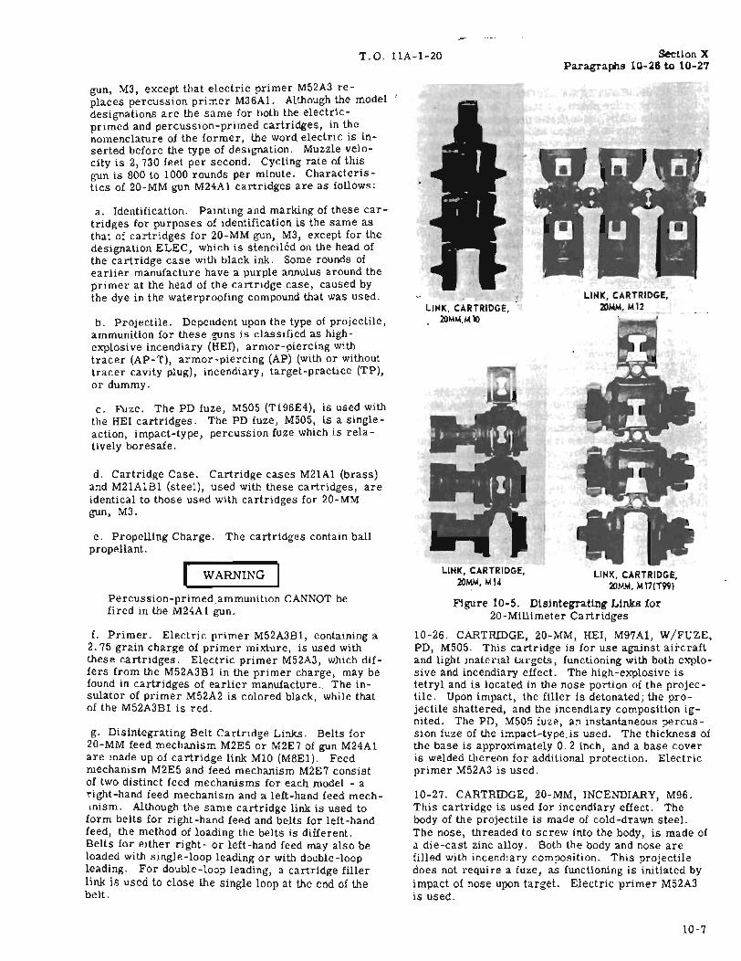
T.O. llA-1-20 section XParagralils 10-28 to 10-27
10-27. CARTRIDGE, 20-MM, INCENDIARY, M96.This cartridge is used for incendiary effect. Thebody of the projectile is made of cold-drawn steel.The nose, threaded to screw into the body, is made ofa die-cast zinc alloy. Both the body and nose arefilled with incendiary composition. This projectiledoes not require a fuze, as functioning is initiated byimpact of nose upon target. Electric primer M52A3is used.
LINK, CARTRIDGE,2OMM,M12
LINK, CARTRIDGE,2OMM, M14
LINK, CARTRIDGE,2OMM,MI0
LINK, CARTRIDGE,2OMM, 1.1 17(T99)
Figure 10-5. Disintegrating Links for20-Millimeter Cartridges
10-26. CARTRIDGE, 20-MM, HEI, M97Al, W/FUZE,PD, M505. This cartridge is for use against aircraftand light material targets, functioning with both explosive and incendiary effect. The high-explosive istetryl and is located in the nose portion of the projectile. Upon impact, the filler is detonated; the projectile shattered, and the incendiary composition ignited. The PD, M505 fuze, an instantaneous percussion fuze of the impact-type. is used. The thickness ofthe base is approximately 0.2 inch, and a base coveris welded thereon for additional protection. Electricprimer M52A3 is used.
a. Identification. Painting and marking of these cartridges for purposes of identification is the same asthat of cartridges for 20-MM gun, M3, except for thedesignation ELEC, which is stenciled on the head ofthe cartridge case with black ink. Some rounds ofearlier manufacture have a purple annulus around theprimer at the head of the cartridge case, caused bythe dye in the waterproofing compound that was used.
b. Projectile. Dependent upon the type of projectile,ammunition for these guns is classified as highexplosive incendiary (HEI), armor-piercing withtracer (AP-T), armor-piercing (AP) (With or withouttracer cavity plug), incendiary, target-practice (TP),or dummy.
c. Fuze. The PD fuze, M505 (T196E4), is used withthe HEI cartridges. The PD fuze, M505, is a singleaction, impact-type, percussion fuze which is relatively boresafe.
gun M3 except that electric primer M52A3 re-, , d 1 r
places percussipn primer M36A1. Although the mo edesignations are the same for both the electric-primed and percussion-primed cartridges, in thenomenclature of the former, the word electric is inserted before the type of designation. Muzzle velo-city is 2,730 feet per second. Cycling rate of thisgun is 800 to 1000 rounds per minute. Characteristics of 20-MM gun M24A1 cartridges are as follows:
e. Propelling Charge. The cartridges contain ballpropellant.
d. Cartridge Case. Cartridge cases M21A1 (brass)and M21A1B1 (steel), used with these cartridges, areidentical to those used with cartridges for 20-MMgun, M3.
f. Primer. Electric primer M52A3B1, containing a2.75 grain charge of primer mixture, is used withthese cartridges. Electric primer M52A3, which differs from the M52A3B1 in the primer charge, may befound in cartridges of earlier manufacture. The insulator of primer M52A2 is colored black, while thatof the M52A3B1 is red.
g. Disintegrating Belt Cartridge Links. Belts for20-MM feed mechanism M2E5 or M2E7 of gun M24A1are made up of cartridge link M10 (M8E1). Feedmechanism M2E5 and feed mechanism M2E7 consistof two distinct feed mechanisms for each model - al:'ight-hand feed mechanism and a left-hand feed mechmism. Although the same cartridge link is used to
form belts for right-hand feed and belts for left-handfeed, the method of loading the belts is different.Belts for either right- or left-hand feed may also beloaded with single-loop leading or with double-loopleading. For double-loop leading, a cartridge fillerlink is used to close the single loop at the end of thebelt.
r WARNING
Percussion-primed ammunition CANNOT befired in the M24A1 gun.
10-7
Section XParagraphs 10-28 to 10-34
T. O. llA-1-20
10-28. CARTRIDGE, 20-MM, TP, M99Al. This cartridge is for practice firing. The projectile is similar in shape and ballistic properties to incendiaryprojectile M96, but is hollow and contains no explosive. The nose consists of a zinc die-casting as inthe M96 incendiary but its weight is adjusted to givethe projectile a weight of 2,000 grains (0.29 lb.).
'TI'he projectile body is made of cold-drawn steel.Electric primer M52A3B1 is used.
10-29. CARTRIDGE, 20-MM, AP-T, M95. This cartridge is for use against armored targets. The projectile is a solid shot made from forged steel. Adrawn steel windshield is crimped into annulargrooves in the projectile body, the portion of thewindshield over the crimped area acts as the bourrelet of the projectile. The base of the projectilecontains a red tracer composition, sealed in by meansof a metal closing cup. The tracer burns for about2.25 seconds, equivalent to a range of about 1,400yards. Minimum burning time of tracer is 2. 0 sec0nds' equivalent to a range of 1,270 yards. The electric primer M52A3B1 is used.
10-30. CARTRIDGE, 20-MM, DUMMY, M18A3. Thiscartridge is a completely inert assembly, which is intended to provide a cartridge for drill purposes andfor testing the feed mechanism of the weapon. Theservice projectile and cartridge case are simulatedby a one-piece zinc- or cadmium-coated casing madeof steel, cold-drawn to size, shape, and weight of theservice round. A steel base plug, formed to providean extractor groove like that on service ammunition,is soldered into the recessed base. Some rounds ofearlier manufacture have a threaded base and baseplug. Alternative manufacturing designs for this drillcartridge have a steel body plug secured in the noseof the cartridge. Weight is 0.57 pound; length is 7.22inches.
10-31. CARTRIDGES FOR 20-MM GUN, M39Al.
10-32. The 20-MM gun, M39A1, is an automatic aircraft cannon for use against aircraft and ground orseaborne targets. This gun is a gas -operated, beltfed, electrically fired weapon having a rate of fire of1800 rounds per minute. The M8 (T13) and M8A1chargers used on these guns, utilize the caliber. 30carbine grenade cartridge M6 to develop the necessary gas pressure to start the functioning of the weapon. All ammunition for this gun·is issued in theform of fixed complete rounds known as cartridges.The cartridges are electric -primed. Before firing,the cartridges are loaded in ammunition belts of thedisintegrating belt type, made up from cartridge linkM12 (figure 10-5). The cartridges are approximatelyO. 6 inch shorter in overall length and approximately0.19 inch wider at the base of the cartridge case thanthe cartridges used in the 20-MM guns M3 and M24Al.The cartridges used in the gun M39A1, are also usedin 20-MM gun M6l. Muzzle velocity of the API, ball,and HEI rounds fired from the gun M39A1 is 3,300feet per second.
10-8
10-33. CARTRIDGES FOR 20-MM GUN, M61(Tl71E3).
10-34. The 20-MM gun, M61 (Tl71E3), is an automatic aircraft cannon for use against aircraft andground or seaborne targets. The gun is an electrically, hydraulically, Or" air-turbine powered, beltor linkless-fed, electrically fired weapon haVing arate of fire of 4,000 to 6,000 rounds per minute.When electrically powered, the electric drive M7 isused. It is a rotating, six-barrel gun. A round ofammunition is fired through each barrel, as the barrels rotate once around the longitudinal axis. Thecartridges are electric-primed and are identical withthe cartridges used for 20-MM gun M39Al. Beforefiring, the cartridges are loaded in ammunition beltsof the disintegrating type, made up from cartridgelink M14 or M17. The muzzle velocity of the API,ball, or HEI round is approximately 3,430 feet persecond in the 20-MM gun M6l. Characteristics of thecartridges used in the 20-MM guns M39A1 and M61are as follows: .
a. Identification. The color scheme for the paintingand marking of these cartridges for purposes of identification is indicated in figure 10-4.
b. Projectile. Dependent upon type of projectile,ammunition for these guns is classified as armorpiercing incendiary (API), ball, high-explosive incendiary (HEI), dummy, and high-pressure-test (HPT).The dummy cartridge consists of cartridge case M103(dummy) assembled to the ball projectile. Prior tostandardization, ball cartridge M55 was designated astarget practice (TP) cartridge T199. The nomenclature has been changed to ball to have the designationconform to the small-arms system.
c. Fuze. The PD fuze, M505 (T196E4), is the fuzethat has been used with the HEI cartridge. This fuzeis classified as a single-action, impact-type, percussion fuze and it incorporates features that make itrelatively boresafe. In 1957, all production of thefuze M505 was converted to the fuze M505A3. Thelatter is a modification which was designed for thepurpose of replacing the fuze M505 for use with HEIcartridges for 20-MM guns M39A1 and M61.
d. Cartridge Case. Cartridge cases M103 (brass),M103B1 (steel), and M103 (dummy) (brass) are usedas components of these cartridges. The weight of thecartridge case M103 is approximately 0.26 pound.The weight of the cartridge case M103B1 is approximately 0.25 pound. The cartridge case M103 (dummy),which is used only with the dummy cartridge, weighsapproximately 0.26 pound. In more recent production using primer M52A3B1, a cellulose case ventseal is used to seal the vent before the primer is inserted. Cartridge case M103 (dummy) does not havea primer recess or vent.
e. Propelling Charge. The cartridge cases containapproximately 0.08 pound of double-base WesternBall propellant.
T.O. llA-1-20 Section XParagraphs 10-35 to 10-42
f. Primer. Electric primer M52A3B1 is used withthe service cartridges.
g. Disintegrating Belt Cartridge Links. Cartridgelinks for the 20-MM aircraft guns are considered asammunition components and are listed in Air ForceStock List 1300.
10-35. CARTRIDGE, 20-MM, ELECTRIC, HEI,M56A3 (T198E1), W/FUZE, PD, M505A3. This cartridge (figure 10-1) is for use against aircraft andlight materiel targets, functioning with both detonative and incendiary effect. The projectile body is asteel, relatively thin-walled casing. The total weightof filler is 0.03 pound, composed of incendiary MOX2B and RDX. The RDX explosive is loaded betweenthe base of the fuze and the incendiary composition,which occupies the rest of the interior of the projectile body. The thickness of the base of the projectileis approximately 0.21 inch and a base cover is weldedthereon for additional safety. Upon impact, thecharge is functioned with a combined detonative andincendiary effect. Functioning is initiated by the PDfuze M505A3, an instantaneous fuze of the impacttype, which is described in paragraph 10-lOc. Cartridge case M103, loaded with approximately 0.083pound of double base (Western Ball) propellant, andthe electric primer M52A3B1 are used in this cartridge. A cellulose case vent seal is assembled inthe primer recess, between vent and primer.
10-36. CARTRIDGE, 20-MM, ELECTRIC, TP(BALL), M55A1. This cartridge is for use in practice firing; prior to standardization of the basic model,this type of cartridge was referred to as a targetpractice (TP) cartridge. The nomenclature has beenchanged to ball in order to have the designation conform to the small-arms system. The projectile ofthis cartridge consists of body, nose, and rotatingband. The body is made of steel; it is hollow andcontains no filler. The nose, which may be assembled to the body with screw threads and a thermosetting resin or keyed to the body by swaging, is madeof aluminum alloy and is solid. Cartridge M55A1 ofcurrent production, which replaces cartridges M55and M55A1 of earlier design, incorporates severalimprovements in the design of the projectile. Theseinclude better steel for the body, a modified (doubleundercut) rotating band seat, and metal parts moresecurely fastened together. Cartridge case M103loaded with approximately 0.084 pound of double-base(Western Ball) propellant and electric primerM52A3B1 are used in the cartridge M55Al. A cellulose case vent seal is assembled in the primer recess, between vent and primer. Early production ofcartridge M55A1 may contain electric primer M52A3and no case vent seal and the propellant may besingle-base (nitrocellulose).
10-37. CARTRIDGE, 20-MM, ELECTRIC, ARMORPIERCING INCENDIARY, M53 (T221E3). This cartridge is for use against armored targets, functioningwith a combined incendiary and penetration effect.
The body of the projectile is solid shot made from baralloy steel. The nose, which is made of aluminumalloy, is charged with 3 separately pressed increments of incendiary composition weighing a total of85 grains. The nose is sealed with a closure disk.A steel adapter is crimped into the annular groovesin the projectile body; the adapter receives the baseportion of the nose and is crimped so as to allow theconical base of the closure disk to seat on the tip ofthe projectile body. This cartridge does not requirea fuze, as functioning is initiated by impact of noseupon target. Cartridge case M103 and electric primerM52A3B1 are used in this cartridge. A cellulosecase vent seal is assembled in the primer recess between the vent and the primer.
!.u-;jtl. CARTRIDGE, 20-MM, DUMMY, M51. Thiscartridge (figure 10-1) is a completely inert assemblythat is used for drill purposes, for testing the feederassembly of the weapon, and for ballast. The servicecartridge is simulated by assembling the projectile ofball cartridge M55 or M55A1 with steel cartridge caseM103 (dummy). The cartridge case contains approximately 0.086 pound of inert material to produce anaverage overall weight equal to that of the servicecartridges.
10-39. PACKING DATA.
10-40. The cartridges for 20-MM guns M39A1, andM61 are packed in both bulk and functional type packing in steel ammunition box T-46. The T-46 ammunition box is a self-sealing steel ammunition box that isreplacing the M23 wooden outer packing box in newproduction and may contain the following:
a. Bulk (linkless) pack - 150 cartridges. (Someissued in 200 cartridge pack.)
b. M39A1 - M61 Guns - 100 cartridges per belt, 1belt per box. (Previously packed 50 cartridges perbelt, now obsolete.)
10-41. Cartridges for 20-MM guns M3 and M24A1 arecontained in both bulk and functional-type packing.Primary bulk packs vary from 10 rounds in a cardboard carton to 55 rounds per steel can; these containers are overpacked (in varying quantities) intometal cans or wooden boxes for shipment and storage.Functional packings are made up of one type, morethan one type, or several types, or ratio pack of cartridges in a 40-round link belt which is packed intometal can M21, and overpacked (in varying quantities)into either metal cans or wooden boxes. The beltsare either linked for right-hand feed or linked forleft-hand feed. For additional information on packingof 20-MM ammunition, refer to United States AirForce Stock List 1300.
10-42. PAINTING AND STENCILING. The selfsealing metal boxes are painted OD and stenciled in
10-9

T. O. llA-1-20Section XParagraphs 10-43 to 10-45
yellow (MIL-STD-709). Repainting of cartridges willnot be accomplished solely to comply with MlL-STD709.
10-43. MARKINGS. Outer packing boxes, crates,metal boxes, and inner containers are fully markedto identify the ammunition contained therein. Thesemarkings include the descriptive nomenclature in·eluding the word linked and the letters R or L (M10link, M3 gun), to signify metallic link belts right- orleft-hand feed, the ammunition lot number, and the
. number of rounds. In addition, the outer container ismarked with the Federal Stock Number, Departmentof Defense Code, ICC shipping name, average weight,and cube, and loaded date. Type of pack can be determined by referencing Federal Stock Number inUSAF SL 1300 and T.O. llA-1-46.
10-44. PRECAUTIONS.
~~W-A-R-N-I-N-G~
Ammunition for gun M39A1, or M61 CANNOTbe fired in either 20-MM gun M3 or M24Al.Ammunition for either gun M3 or M24A1CANNOT be fired in gun M39A1 or M61.Ammunition linked for guns M39A1 CANNOTbe fired in gun M61. Ammunition linked forgun M61 CANNOT be fired in gun M39Al.
10-45. Complete rounds, particularly rounds withfuzes, will be handled with care at all times. Explosive elements in fuzes and primers are particularlysensitive to shock and high temperature. Particularprecautions must be taken with 20-MM cartridgescontaining electric primers as outlined in AFM 127100.
10-10
T.O. 11A-1-20 Section XIParagraphs 11-1 to 11-22
SECTION XICARTRIDGE/PROPELLANT ActuATE-O DEVICES (CAD/PAD)
11-1. INTRODUCTION.
11-2. Many explosive devices are utilized in weaponsystems. These devices, commonly called CartridgePropellant Actuated Devices (CAD/PAD) are designedto perform such operations as removing canopies orescape hatches, positioning seat prior to ejection,stowing equipment, ejecting seat and crewmember,separating crewmember from seat, deploying droguechutes, etc. CAD/PAD also perform numerous otheroperations such as jettisoning external stores, actuating fire extinguisher systems, releasing arrestinghooks, cutting or separating electrical and hoist cables, missile stage separation, etc.
11-3 . DESCRIPTION.
11-4. ACTUATORS, CANOPY. Canopy actuators arepneumatically or electrically actuated units designedto open and close canopies during normal operationsand ballistically remove canopies during emergencyexit.
11-5. ACTUATORS, ROTARY. Rotary actuators aregas actuated units designed to separate crewmemberfrom the seat after ejection.
11-6. BOLT, EXPLOSIVE. Explosive bolts are gasor electrically actuated, frangible units designed torelease attaching components.
11-7. CARTRIDGE, FIRE EXTINGUISHER. Fire extinguisher cartridges are electrically actuated unitsdesigned to actuate fire extinguisher systems.
11-8. CARTRIDGE, GUILLOTINE. A guillotine cartridge is a percussion fired cartridge used in theMartin-Baker guillotine to sever the drogue parachuteattaching line.
11-9. CARTRIDGE, M30Al. The M30A1 cartridge isa percussion fired cartridge used in the M6A1 ejectionseat trainer catapult.
11-10. CARTRIDGE, M57. The M57 cartridge is apercussion fired cartridge used in the M2A1 ejectionseat trainer catapult.
11-11. CARTRIDGE SET. The set is used in theMartin-Baker Catapult and Drogue Gun System. Itconsists of a percussion initiated primary catapultcartridge, two gas initiated auxiliary cartridges, anda percussion initiated Drogue Gun Cartridge.
11-12. CATAPULT. A catapult is a gas actuated unitcontaining a cartridge designed to forcefully eject theseat and crewmember from the aircraft.
11-13. CATAPULT, ROCKET. A rocket catapult isa gas actuated unit containing a cartridge or otherinitiating explosive charge and a rocket motor designed to forcefully eject the seat and crewmemberfrom an aircraft.
11-14. CUTTER. A cutter is a mechanical, electrical, or gas pressure actuated unit designed to cutelectrical wiring, cables, harness, etc., during thefunctioning of an aircraft emergency exit system.Cutters are also used to cut shroud lines on drogueclmtes, hoist cables on h~!licopters and parachutereefing lines.
11-15. DESTRUCTORS. Destructors are electricallyactuated, frangible units designed to release attachingcomponents.
11-16. GENERATOR, GAS. Gas generators aremechanical or electrically actuated units designed toproduce the gas pressure necessary to operate otherdevices.
11-17. GUN, PARACHUTE DEPLOYMENT. Theparachute deployment gun is a mechanically actuatedunit designed to fire a projectile attached to the parachute risers to assure immediate parachute deployment.
11-18. INITIATOR. Initiators are mechanical or gaspressure actuated devices designed to produce thegas pressure necessary to actuate other cartridge orpropellant actuated devices.
11-19. MECHANISM, FIRING. The firing mechanismis a gas pressure actuated unit designed to providethe gas pressure necessary to actuate F/TF 102 canopy counter balance cylinders during an emergency.
11-20. RELEASE, FIRING PIN (EXACTOR). Thefiring pin release is a nonexplosive, gas pressureoperated unit designed to release the firing pin in theM1 series remover or arm the seat catapult initiatorin the F/TF 102 and F106 aircraft.
11-21. REMOVER, CANOPY. A remover is a mechanical or gas pressure actuated unit designed to remove the canopy from the aircraft during an emergency. The M8 and M9 removers also incorporateprovisions to electrically open and close the canopyduring normal operations.
11-22. THRUSTER. A thruster is an electrical orgas pressure actuated unit designed to mechanicallyoperate other components by extension or retractionof piston rods.
11-1
Section XIParagraphs 11-23 to 11-32
T.O. 11A-1-20
11-23. FUNCTIONING OF COMPONENTS.
11-24. A detailed description of the aircraft systemis contained in the applicable aircraft maintenancerepair manual. Detailed descriptions for cartridge/propellant actuated devices are contained in the appropriate 11 series technical orders.
11-25. Structurally, an aircraft catapult is composedof three tubes: outer tUbe, telescoping tube, and innertube. The telescoping tube of the catapult is attachedto the crewmember's seat. A trunnion is used to attach the outer tube to the aircraft structure. The catapult is actuated by gas pressure from the burningpropellant of a special blank cartridge incorporated inthe catapult. This blank cartridge is fired by a firingpin in the catapult that, in turn, is actuated by gaspressure from a remotely located (in the aircraft)initiator. Pressure, generated within the initiator byan integral special blank cartridge, is transmitted tothe catapult through a system of connecting hose ortube. The gas pressure exerts a force on the catapultfiring pin, forcing firing pin downward, shearing theshear pin, unlocking the catapult, and the remainderof the movement of the firing pin fires the cartridgein the catapult.
11-26. The remover is actuated just prior to actuation of the catapult. The remover is a telescopingtube ejector similar to a catapult but smaller andsomewhat less powerful. One end of the remover isattached to the canopy, the other to the aircraft structure. Upon firing the remover cartridge, the remover is extended axially and the head and inner tubeare ejected with the canopy. The Ml series firing pinrelease, which is not integral with the remover butattached to it, is connected to an initiator, and functions independently of the catapult. The initiator gaspressure operates the exactor plunger, thus releasingthe canopy firing pin that fires the remover cartridge.Other canopy removers are gas pressure actuated anddo not use a firing pin release.
11-27. Thrusters consist essentially of a cylinder,piston, cartridge, and a firing pin, which is actuatedby gas pressure furnished from an initiator. Whenthe thruster cartridge is ignited, the piston is forceddown the cylinder, exerting a thrust on the relatedaircraft component. The various models of thrustersdiffer in design details such as thrust exerted, lengthof stroke, etc.
11-28. Initiators provide a source of gas pressure,which actuates another component of the system, such
11-2
as a catapult or thruster. Initiators may differ in themethod of firing; that is, they may be fired mechanically by the operation of some form of lanyard or bygas pressure furnished by the preceding item in thesystem. Delay initiators incorporate a delay elementin the initiator cartridge.
11-29. CARE AND PRECAUTIONS IN HANDLING.
11-30. Due consideration should be given to the observance of appropriate safety precautions in handling cartridge/propellant actuated devices. The following precautions will be observed:
a. All types of cartridge/propellant actuated devicesmust be handled with care.
b. Air or mechanical pressure should not be appliedto the inlet ports of those devices that are initiated bygas pressure. When not installed in an aircraft, theseports should be kept closed with a shipping plug.
c. The cotter pin must not be taken out of Ml seriesremovers until removers are installed in an aircraftand then only if safety pin or firing pin is in place.Do not remove removers from the aircraft unlesscotter pin or safety pin is installed.
d. The safety pin will always be inserted in the initiator until just prior to flight. Do not remove theinitiator from the aircraft or perform any maintenanceon the initiator or in the immediate area unless thesafety pin is installed.
NOTE
Disassembly, testing or modification of anyCAD/PAD is prohibited without prior approval or direction from OOAMA (OOYI), Hill AirForce Base, Utah.
11-31. PACKING AND MARKING. All cartridge/propellant actuated devices are assembled andshipped as sealed units with cartridges installedtherein. Since they are shipped in various quantities,nonstandard packaging is often utilized.
11-32. In addition to nomenclature and ammunitionlot number, packages prepared for shipment aremarked, in accordance with Interstate CommerceCommission shipping regulations, the same as smallarms ammunition. The Federal Stock Number (FSN)is included in the marking.
T. O. llA-I-20
SECTION XIIGRENADES
Section XliParagraphs 12-1 to 12-17
12-1. INTRODUCTION.
12-2. A grenade is a small, short-range missilefilled with high-explosive or chemical. It can beplaced, thrown, or projected against enemy personnel or material at relatively short ranges. A grenade can also be used for screening or signaling operations. When used as a hand grenade it is thrown ina prescribed manner for each type of grenade used.The rifle grenade is a fin stabilized projectile projected from the M16 rifle, using a special grenadecartridge, to cover the distance from maximum handgrenade to minimum mortar range. The rifle grenade may be used for antiarmor, antipersonnel ,smoke, illumination, signaling, or incendiary effect.
12-3. CLASSIFICATION.
12-4. Grenades are classified according to type, fil-ler, a ntended use.
12-5. TYPE. Two types of grenades are used by theAir Force, hand and rifle. A hand grenade may bemodified into a rifle grenade by the use of a specialgrenade projection adapter. Rifle grenades are manufactured to a specific design including the projectionrequirements.
12-6. FILLER. Grenade fillers are classified as explosive, chemical, or inert.
12-7. USE. Grenades are classified according to intended tactical use. They may be used for fragmentation, irritant, screening smoke, signaling smoke,and incendiary effect. Grenades may also be usedfor riot control and training.
12-8. HAND GRENADES.
12-9. The three general types of hand grenades areservice, practice, and training and simulator. (Seefigure 12-1.) Service hand grenades are classifiedaccording to use. Practice hand grenades and simulated or simulator hand grenades are designed tosimulate the fragmentation type service hand grenades. All hand grenades are issued fuzed.
12-10. FRAGMENTATION HAND GRENADES. Thethree types of fragmentation grenades used by theUSAF are service, practice, and training. The service grenade is a high-explosive filled combat item.The practice grenade is designed to simulate the service grenade for training personnel in throwing. Thetraining grenade is designed for training personnel inhandling prior to thrOWing the practice or servicegrenades. Fragmentation grenades are shaped likea large lemon.
12-11. FRAGMENTATION HAND GRENADE, MK2.The MK2 grenade has a cast iron serrated body andis assembled with a detonating fuze. A safety lever,curved to fit the shape of the grenade, is attached tothe fuze and held in place by a safety pin. (See figure12-1. )
12-12. FRAGMENTATION HAND GRENADES, M26,M26Al, AND M26A2. (See figure 12-2.) The M26series grenades are slightly larger than the MK2 andconsist of a thin metal body lined with a wire woundcoil in place of the cast iron body used in earlier typesof grenades. The M26 series grenades are assembledwith the same detonating fuzes used in the MK2.
12-13. CHEMICAL HAND GRENADES. There arethree general categories of chemical grenades; riotcontrol, smoke, and incendiary. They employ avariety of fillers. Chemical grenades may be thrown,projected, or placed, depending upon their design,fuZing, and filler. Extreme cold may form ice in thestarter mixtures of chemical grenades and causemalfunctions.
12-14. IRRITANT HAND GRENADE, CN-DM, M6.The body of the M6 grenade is a thin sheet metal container with six emission holes in th_ top and 18 emission holes in the side. The fillin s a mixture of tearand vomiting gases. The grenade 1S assembled withan igniting fuze secured by a safety lever and a safetypin. General configuration of the M6 is shown in fig..,ure 12-3.
12-15. TEAR GAS HAND GRENADE, CN, M7Al. TheM7Al grenade body is a thin sheet metal containerwith four emission holes in the top and One on the bottom. The filling is a semi-solid compound that produces tear gas when ignited. The fuze safety lever,and safety pin of the M7A1 are similar to the CN -DM,M6 grenade. General configuration of the M7A1 issimilar to the gas grenade shown in figure 12-3.
12-16. RIOT CONTROL HAND GRENADE, CN,M25A1. (See figure 12-2.) The M25A1 is a ballshaped bursting hand grenade approximately threeinches in diameter. The body is made of two plastichemispheres cemented together with a fuze well extending through the body of the grenade. The well isclosed at the bottom end with a screw plug. A fillingis located in one side of the body. The filling is asemi-solid compound that produces tear gas when ignited. A bursting fuze is assembled in the well as anintegral part of the grenade. The fuze is kept unarmed by a safety pin.
12-17. SMOKE HAND GRENADE, WP, M15. (Seefigure 12-3.) The M15 is a bursting smoke grenade
12-1

Section XIIParagraphs 12-18 to 12-21
T. O. llA-I-20
PRIMERMIXTURE
FRiCTIONIGNITER
SAFETYFUSE
SAFETY
JPYROTEOlNICMIXTURE(CHARGE)"
ONE PIECfCAST IRON
Training HandGr<nad. MK lA 1
IGNITER
Practice Hand Grea.de M21
PHI~EH
:7HIK[lt :'))HI~
:..TIlIKEH
Ft&gmCDtatioa HaadGrenade MK-2
DOO'----+
Figure 12-1. General Types of Hand Grenades, Service, Practice, Training, and Simulator
made of a sheet metal cylinder with a steel cap brazedon top and a rounded bottom for night identification.The body is made of heavier steel, as shown in figure12-3, and does not have emission holes. The M15uses a detonating fuze which ruptures the grenadebody and disburses the WP filler. The fuze is keptsafe by a safety pin.
12-18. GRENADE, HAND AND RlFLE, CHEMICALBURSTING TYPE M34. (See figure 12-2.) The M34WP (White Phosphorus) smoke hand grenade is abursting-type multi-purpose munition used for antipersonnel, screening, and incendiary effect. TheM34 WP hand and rifle grenade is a grooved, cylindrical steel container, 2-3/8 inches in diameter,5-1/2 inches long. The grenade base is tapered sothat the grenade can be mounted on an MIA2 grenadeprojection adapter. The body is grooved to ensureuniform break up of the case. The body contains 15ounces of WP filler and the M206A2 detonating fuze.Delay time is 4.0 to 5.0 seconds. It scatters WPparticles over a 40 yard radius and launch range isapproximately 130 yards. The white phosphorus willburn for approximately 60 seconds and ignite anycombustible substance it contacts.
12-19. WHITE SMOKE HAND GRENADE, HC, ANM8. The AN-M8 grenade is a thin sheet steel cylinder with four emission holes in the top. It has an igniting type fuze with a safety lever held by a safetypin. General configuration of the AN-M8 is similarto the incendiary grenade shown in figure 12-3. "
12-20. COLORED SMOKE HAND GRENADE, M18.The M18 grenade is a thin sheet metal cylinder withfour emission holes in the top and one in the bottomwith general configuration of the gas grenade shownin figure 12-3. The M18 grenade is filled with eitherred, green, violet, or yellow smoke mixture and thetop of the grenade is painted the same color as thesmoke it produces. It has an igniting fuze with asafety lever held by a safety pin.
12-21. INCENDIARY HAND GRENADE, TH-3, ANM14. (See figure 12-3.) The AN-MI4 grenade provides a source of intense heat for destroying equipment. The body is a thin sheet metal cylinder withfour emission holes in the top. The igniting fuze ofthe grenade is saftied with a lever held by a safetypin. Thermate (TH-3) may explode rather than burnwhen frozen. Spontaneous ignition of white phosphorus grenades may result from the freeZing, and
..
12-2
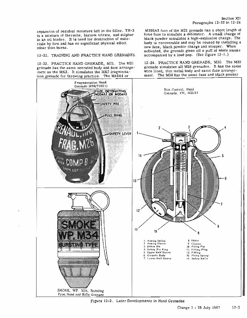
T.O. llA-1-20
expansion of residual moisture left in the filler. TH-3is a mixture of thermite, barium nitrate, and sulphurin an oil binder. It is used for destruction of materials by fire and has no significant physical effectother than burns.
12-22. TRAINING AND PRACTICE HAND GRENADES.
section XIIParagraphs 12-22 to 12-24
M205A2 fuze of the M21 grenade has a short length oftime fuze to simulate a detonator. A small charge ofblack powder simulates a high-explosive charge. Thebody is recoverable and may be reused by installing anew fuze, black powder charge and stopper. Whenactivated, the grenade gives off a puff of white smokeaccompanied by a loud pop. (See figure 12-1.)
12-24. PRACTICE HAND GRENADE, M30. The M30grenade simulates all M26 grenades. It has the samewire lined, thin metal body and same fuze arrangement. The M30 has the same fuze and black powder
Riot control, HandGrenade, CN, M25Al
12-23. PRACTICE HAND GRENADE, M21. The M21grenade has the same serrated body and fuze arrangement as the MK2. It simulates the MK2 fragmentation grenade for throwing practice. The MIOA4 or
SMOKE, WP, M34, Burstingrype, Hand and Rifle Grenade
1. Arming Spring2. Arming Sleeve3. Safety Oin4. Safery Pin Riog5. Upper Half Sleeve6. Grenade Body7 _ Lower Half Sleeve
8. Slider9. Closure
19. F lrin.g Pin11. Filli"g Plug12. Filling13· Firing Spring14. Safety Ball.
4
6
Figure 12-2. Later Developments in Hand Grenades
Change 1 - 28 July 1967 12-3
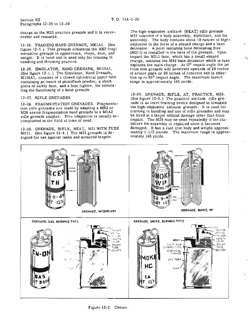
Section xnParagraphs 12-25 to 12-30
T.O. llA-1-20
charge as the M21 practice grenade and it is recoverable and reusable.
12-25. TRAINING HAND GRENADE, MK1A1. (Seefigure 12-1.) This grenade simulates the MK2 fragmentation grenade in appearance, shape, size, andweight. It is inert and is used only for training inhandling and throwing practice.
12-26. SIMULATOR, HAND GRENADE, M116A1.(See figure 12-1.) The Simulator, Hand Grenade,M116A1, cOllBists of a closed cylindrical paper tubecontaining an ounce of photoflash powder, a shortpiece of safety fuze, and a fuze lighter, for simulating the functioning of a hand grenade.
12-27. RIFLE GRENADES.
12-28. FRAGMENTATION GRENADES. Fragmentation rifle grenades are made by adapting a MK2 orM26 series fragmentation hand grenade to a M1A2rille grenade adapter. This adaptation is usually accomplished in the field at time of need.
12-29. GRENADE, RIFLE, HEAT, M31 WITH FUZEM211. (See figure 12-4.) The M31 grenade is designed for use against tanks and armored targets.
The high-explosive antitank (HEAT) rifle grenadeM31 consists of a body assembly, stabilizer, and finassembly. The body contains about 10 ounces of highexplosive in the form of a shaped charge and a basedetonator. A point initiating base detonating fuze(M211) is installed in the base of the grenade. Uponimpact the M211 fuze, which has a small shapedcharge, initiates the M48 base detonator which in turnexplodes the main charge. At 0 0 impact angle the jetfrom this grenade will penetrate upwards of 10 inchesof armor plate or 20 inches of concrete and is effective up to 650 impact angle. The maximum launchrange is approximately 165 yards.
12-30. GRENADE, RIFLE, AT, PRACTICE, M29.(See figure 12-5.) The practice antitank rifle grenade is an inert training device designed to simulatethe high-explosive antitank grenade. It is used fortraining in handling and use of rifle grenades and maybe fired at a target without damage other than fromimpact. The M29 may be used repeatedly if the stabilizer fin assembly is replaced when it becomesdamaged. It has a cast iron body and weighs approximately 1-1/2 pounds. The maximum range is approximately 165 yards.
GRENADE, INCENDIARY GRENADE, SMOKE, WP
GRENADE, GAS, BURNING TYPE GRENADE, SMOKE, BURNING TYPE
GA~ PORT I
TAPE / !I
c
r~~'I EAT Il··~
.:..
.iI, .. ~::; .......
....
Figure 12-3. Chemical Hand Grenades
12-4

..
FIN
T. O. llA-1-20
NOSE PROTECTOR CAP
SHAPE CHARGE LINER - .......__
STABllIZER TUBE ASSEM8lY
Figure 12-4. Grenade, Rifle, HEAT, M31
Section XU
RYSTAl
ORO 0764
12-5
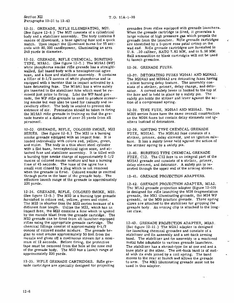
Section XlIParagraphs 12-31 to 12-43
T.O. llA-1-20
12-3.1. GRENADE, RIFLE ILLUMINATING, M27.(See figure 12-6.) The M27 consists of a cylindricalbody and a stabilizer assembly. The body contains 8ounces of illuminant, a base igniting fuze and a quickmatch. Upon impact the illuminant burns for 55 seconds with 80,000 candlepower, illuminating an area240 yards in diameter.
12-32. GRENADE, RIFLE CHEMICAL, BURSTINGTYPE, M19A1. (See figure 12-7.) The M19A1 (WP)white phosphorus smoke rifle grenade has a straightwalled, flat based body with a hemispherical ogivenose, and a fuze and stabilizer assembly. It containsa filler of 8-1/2 ounces of white phosphorus and iseqUipped with a burster that is impact activated by abase detonating fuze. The M19A1 has a wire safetypin inserted in the stabilizer tube which must be removed just prior to firing. Like the WP hand grenade, the WP rifle grenade is used to produce screening smoke but may also be used for casualty and incendiary effect. The body is sealed to prevent theentrance of air. Precaution should be taken in firingthe M19A1 rifle grenade in training so that the grenade bursts at a distance of over 35 yards from allpersonnel.
12-33. GRENADE, RIFLE, COLORED SMOKE, M22SERIES. (See figure 12-8.) The M22 is a burningsmoke grenade eqUipped with an impact fuze. It isloaded individually With colors red, yellow, green,and violet. The body is a thin sheet steel cylinderwith a flat base, hemispherical ogive nose, and attached fuze and stabilizer assembly. It is filled witha burning type smoke charge of approximately 6-1/2ounces of colored smoke mixture and has a burningtime of 45 seconds. The nose of the ogive has asmall vent closed by a plug which is not removedwhen the grenade is fired. Colored smoke is emittedthrough ports in the base of the grenade body. Theeffective launch range of the grenade is approximately220 yards.
12-34. GRENADE, RIFLE, COLORED SMOKE, M23.(See figure 12-9.) The M23 is a burning type grenadefurnished in colors red, yellow, green and violet.The M23 is shorter than the M22 series because of adifferent fuze length. Unlike the M22, which has animpact fuze, the M23 contains a fuze which is ignitedby the muzzle blast from the grenade cartridge. TheM23 grenade can be fired from all launcher-equippedrifles using the appropriate grenade cartridge. Thechemical fillings consist of approximately 6-1/2ounces of colored smoke mixture. The grenade begins to emit smoke approximately 50 feet from themuzzle and gives off a continuous stream for a minimum of 12 seconds. Before firing, the protectivetape must be removed from the hole at the nose endof the grenade body. The M23 has a launch range ofapproximately 220 yards.
12-35. RIFLE GRENADE CARTRIDGES. Rifle grenade cartridges are specially designed for projecting
12-6
grenades from rifles equipped with grenade launchers.When the grenade cartridge is fired, it generates alarge volume of high pressure gas which propels thegrenade from the launcher. Rifle grenade cartridgesare identified by a 5-point rose petal crimp on thewad end. Rifle grenade cartridges are furnished inU.S.. 30 caliber, NATO 7.62 MM, and in 5.56 MM.Ball ammunition or blank cartridges will not be usedto launch grenades.
12-36. GRENADE FUZES.
12-37. DETONATING FUZES M204A1 AND M204A2.The M204A1 and M204A2 are detonating fuzes havinga silent burning delay feature. The assembly consists of a striker, primer, delay charge, and detonator. A curved safety lever is hooked to the top ofthe fuze and is held in place by a safety pin. Thesafety pin holds the striker and lever against the action of a compressed spring.
12-38. TIME FUZE, M205A1 AND M205A2. TheM205 series fuzes have the same overall constructionas the M204 fuzes but contain delay elements and igniters instead of detonators.
12-39. IGNITING TYPE CHEMICAL GRENADEFUZE, M201Al. The M201A1 fuze consists of astriker, primer, delay element, and an ignition mixture. It has a safety lever held against the action ofthe striker spring by a safety pin.
12-40. BURSTING TYPE CHEMICAL GRENADEFUZE, C12. The C12 fuze is an integral part of theM25A1 grenade and consists of a striker, primer,delay element, and detonator. A safety pin is inserted through the upper end of the arming sleeve.
12-41. GRENADE PROJECTION ADAPTERS.
12-42. GRENADE PROJECTION ADAPTER, M1A2.The M1A2 grenade projection adapter (figure 12-10)is designed for rifle launching the M26 fragmentationgrenade, the MK1 illuminating grenade, the M34 WPgrenade, or the M30 practice grenade. Threespringclaws are attached to the stabilizer for gripping thegrenade body. An arming clip is attached to the longest claw.
12-43. GRENADE PROJECTION ADAPTER, M2A1.(See figure 12-11.) The M2A1 adapter is designedfor launching chemical grenades and consists of astabilizer and fin assembly and a set-back armingband. The stabilizer and fin assembly is a machinedmetal tube adaptable to various grenade launchers.The stabilizer has a shroud-type fin at one end and abase plate at the other. The set-back band is of metal with its ends joined by a coil spring. The bandmoves to the rear at launch and allows the grenadeto arm. The MK1 illuminating grenade must not beused in this adapter.
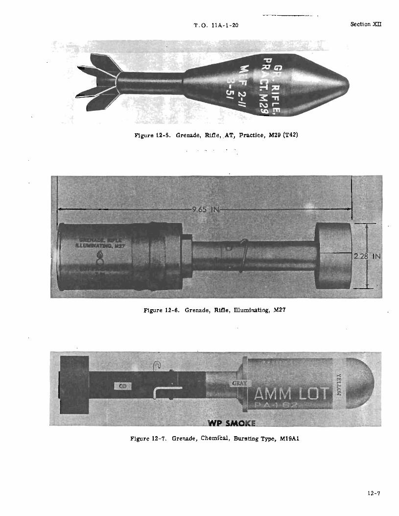
T.O. llA-1-20
Figure 12-5. Grenade, RUle, .AT, Practice, M29 (T42)
Section x:n
Figure 12-6. Grenade, Rifle, muminating, M27
Figure 12-7. Grenade, Chemical, Bursting Type, M19A1
12-7

Section XII
12-8
T.O. llA-1-20
STARTER MIXTURE CHARGE
NAE M22 SMOKE CHARGE
./FUZE ASSEMBLY
FIRING PIN SPRING _ ...........
FIN ASSEMBLY
Figure 12-8. Grenade, Rifle, Colored Smoke, M22 Series
r

T.O. llA-1-20 section xn
SMOKE CHARGE
STARTERMIXTURECHARGE
STABILIZER TUBE
FIN ASSEMBLY
ORD D767
Figure 12-9. Grenade, Rifle, Colored Smoke, M23 (Streamer)
12-9

Section XII T.O. llA-1-20
SAFETY PIN
SAFETY LEVER
STABILIZER
CLAWS
12-10
Figure 12-10. Grenade Projection Adapter, M1A2
SAFETYPIN
SAFETYLEVER
Figure 12-11. Grenade Projection Adapter, M2A1
STABILIZE
ASSEMBLY

T. O. llA-1-20 Section XIIPara~raphs 12-44 to 12-52
12-44. COMPLETE ROUND DATA. A completerOWld consists of all the components necessary forthe item to fWlction as intended. Rifle grenades, asissued in present packs, may contain grenade cartridges for both rifle and carbine and auxiliary grenade cartridges. New packs of rifle grenades willcontain grenade cartridges for rifles only. CompleterOWlds of rifle grenades are as follows:
a. ANTITANK (M31) .... Filled body, fuze, andstabilizer are issued in one assembly. LaWlchingcartridge may be attached to the stabilizer assembly.
b. ILLUMINATING (M27) .... Filled bodY,fuze andstabilizer are issued in one assembly.
c. PRACTICE (M29) .... Empty body and simulatedfuze and stabilizer issued in one assembly. Replacement fin assemblies are provided for reuse of thegrenades.
d. SMOKE (M22, M23) .... Filled body, fuze, andstabilizer are issued in one assembly.
12-45. GRENADE PACKAGING AND MARKING.
12-46. Hand and rifle grenades are usually packedand shipped as fuzed complete round assemblies.Each grenade is packed in an individual fiber or hermetically sealed container in an outer wooden packingbox. Box dimensions, cubes, and weight are listedby item in the 1330 class stock list.
12-47. FIBER CONTAINERS. Fiber containers areusually black and they are sealed to make them relatively moisture-proof. The grenade nomenclatureand the explosive or chemical color identification arestenciled aroWld the container.
12-48. METAL CONTAINERS. Metal containers arehermetically-sealed cans. They are painted eithergrey or black. The grenade nomenclature and theexplosive or chemical color identification are stenciled aroWld the containers.
12-49. FRAGMENTATION AND PRACTICE HANDGRENADES. Fragmentation and practice grenadesare individually packaged in fiber containers with 25or 40 grenade containers packed in a wooden box.The grenade box has a hinged top equipped with asealed hasp.
12-50. TRAINING HAND GRENADES. Training gre'nades are packed 25 each in a divided (egg crated)box. The top of the box is nailed and banded by steelstrapping.
12-51. RIFLE GRENADES M31, M29, M27, M19A1,M22, M23A1, M23A2. These grenades are individually packaged in metal or fiber containers. severalindividual containers are packaged in a wooden overpack box. The box has cleated ends, a hinged top,rope handles, and is secured by a sealed hasp.
12-52. Tables of leading particulars for hand andrifle grenades are shown in figures 12-12 and 12-13.
CHEMICALOR
EXPLOSIVE FUZELENGTH DIAMETER WEIGHT WEIGHT
NOMENCLATURE (INCHES) (INCHES) (POUNDS) (0 NCES) TYPE MODEL ADAPTER
Fragmentation Hand Grenade, 4.50 N/A 1. 40 1. 75 TNT Deton M204A1 M1A2MK2 M204A2
I M6A4C
Fragmentation Hand Grenade, 4.00 N/A 0.85 5.5 Deton M204A1 M1A2M26 Comp B M204A2 M1A2
M26A1 4.00 0.85 5.5 Deton M204A2 M1A2Comp B
M26A2 4.00 0.96 6.3 Deton M204A2 M1A2Comp B
Practice Hand Grenade, M21 4.50 N/A 1. 27 0.10 Ignite M205A1 M1A2Black M10A4Powder
Practice Hand Grenade, M30 4.00 N/A 0.92 0.10 Ignite M205Al M1A2Black M205A2Powder
Training Hand Grenade, 4.50 N/A Inert Inert Inert N/AMKIAI SimUlated
Irritant Hand Grenade, 4.50 2.50 1. 40 10.25 Ignite M201Al M2AlCN-DM. M6 CN-DM
Figure 12-12. Table-of Leading Particulars, ~and, Grenades (Sheet 1 of 2)
12-11
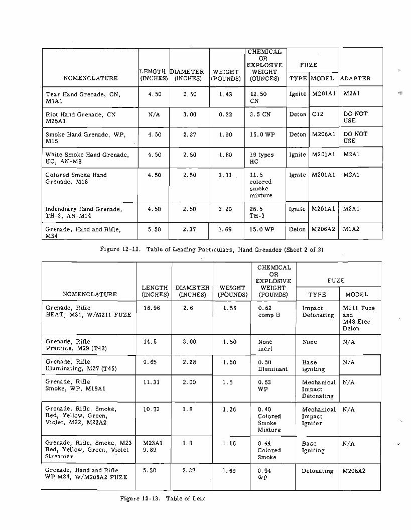
Section XU T.O. llA-1-20
CHEMICALOR
EXPLOSIVE FUZELENGTH PIAMETER WEIGHT WEIGHT
NOMENCLATURE (INCHES) (INCHES) (POUNDS) (OUNCES) TYPE MODEL ADAPTER
Tear Hand Grenade, CN, 4.50 2.50 1. 43 12.50 Ignite M201A1 M2A1M7A1 CN
Riot Hand Grenade, CN N/A 3.00 0.22 3.5 CN Deton C12 DO NOTM25A1 USE
Smoke Hand Grenade, WP, 4.50 2.37 1. 90 15.0 WP Deton M206A1 DO NOTM15 USE
White Smoke Hand Grenade, 4.50 2.50 1. 80 19 types Ignite M201A1 M2A1HC, AN-M8 HC
Colored Smoke Hand 4.50 2.50 1. 31 11. 5 Ignite M201A1 M2A1Grenade, M18 colored
smokemixture
Indendiary Hand Grenade, 4.50 2.50 2.20 26.5 Ignite M201A1 . M2A1TH-3, AN-M14 TH-3
Grenade, Hand and Rifle, 5.50 2.37 1. 69 15.0 WP Deton M206A2 M1A2M34
Figure 12-12. Table of Leading Particulars, Hand Grenades (Sheet 2 of 2)
CHEMICALOR
EXPLOSIVE FUZELENGTH DIAMETER WEIGHT WEIGHT
NOMENCLATURE (INCHES) (INCHES) (pbUNDS) (POUNDS) TYPE MODEL
Grenade, Rifle 16.96 2.6 1. 56 0.62 Impact M211 FuzeHEAT, M31, W/M211 FUZE comp B Detonating and
M48 ElecDeton
Grenade, Rifle 14.5 3.00 1. 50 None None N/APractice, M29 (T42) inert
Grenade, Rifle 9.65 2.28 1. 50 0.50 Base N/AIlluminating, M27 (T45) llluminant igniting
Grenade, Rifle 11. 31 2.00 1.5 0.53 Mechanical N/ASmoke, WP, M19A1 WP Impact
Detonating
Grenade, Rifle, Smoke, 10.72 1.8 1. 26 0.40 Mechanical N/ARed, Yellow, Green, Colored ImpactViolet, M22, M22A2 Smoke Igniter
Mixture
Grenade, Rifle, Smoke, M23 M23A1 1.8 1.16 0.44 Base N/ARed, Yellow, Green, Violet 9.89 Colored IgnitingStreamer Smoke
Grenade, Hand and Rifle 5.50 2.37 1. 69 0.94 Detonating M206A2WP M34, W/M206A2 FUZE WP
Figure 12-13. Table of Leading Particulars, Rifle Grenades
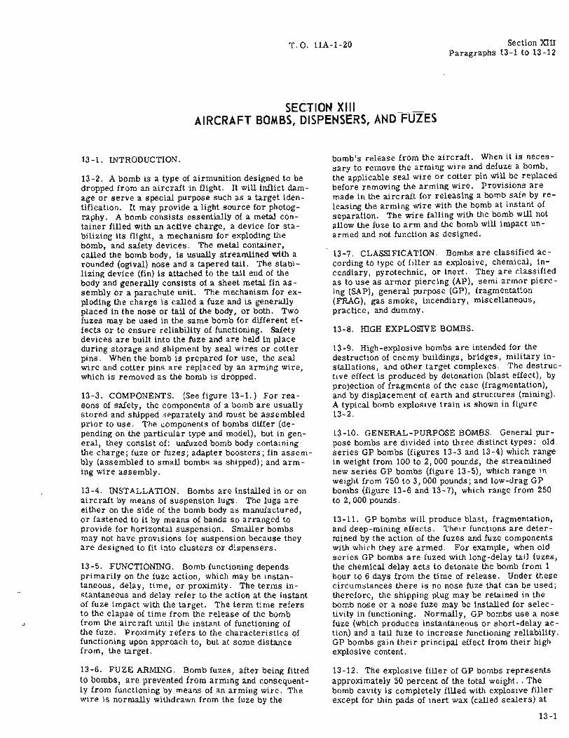
T.O. llA-1-20
SECTION X II __ _ _AIRCRAFT BOMBS, DISPENSERS, AND FUZES
Section XIIIParagraphs 13-1 to 13-12
13-1. INTRODUCTION.
13 -2. A bomb is a type of airmunition designed to bedropped from an aircraft in flight. It will inflict damage or serve a special purpose such as a target identification. It may provide a light source for photography. A bomb consists essentially of a metal container filled with an active charge, a device for stabilizing its flight, a mechanism for exploding thebomb, and safety devices. The metal container,called the bomb body, is usually streamlined with arounded (ogival) nose and a tapered tail. The stabilizing device (fin) is attached to the tail end of thebody and generally consists of a sheet metal fin assembly or a parachute unit. The mechanism for exploding the charge is called a fuze and is generallyplaced in the nose or tail of the body, or both. Twofuzes may be used in the same bomb for different effects or to ensure reliability of functioning. Safetydevices are built into the fuze and are held in placeduring storage and shipment by seal wires or cotterpins. When the bomb is prepared for use, the sealwire and cotter pins are replaced by an arming wire,which is removed as the bomb is dropped.
13-3. COMPONENTS. (See figure 13-1.) For reasons of safety, the components of a bomb are usuallystored and shipped "eparately and must be assembledprior to use. The components of bombs differ (depending on the particular type and model), but in general, they consist of: unfuzed bomb body containingthe charge; fuze or fuzes; adapter boosters; fin assembly (assembled to small bombs as shipped); and arming wire assembly.
13-4. INSTALLATION. Bombs are installed in or onaircraft by means of suspension lugs. The lugs areeither on the side of the bomb body as manufactured,or fastened to it by means of bands so arranged toprovide for horizontal suspension. Smaller bombsmay not have provisions for suspension because theyare designed to fit into clusters or dispensers.
13-5. FUNCTIONING. Bomb functioning dependsprimarily on the fuze action, which may be instantaneous, delay, time, or proximity. The terms instantaneous and delay refer to the action at the instantof fuze impact with the target. The term time refersto the elapse of time from the release of the bombfrom the airc raft until the instant of functioning ofthe fuze. Proximity refers to the characteristics offunctioning upon approach to, but at some distancefrom, the target.
13-6. FUZE ARMING. Bomb fuzes, after being fittedto bombs, are prevented from arming and consequently from functioning by means of an arming wire. Thewire is normally withdrawn from the fuze by the
bomb's release from the aircraft. When it is necessary to remove the arming wire and defuze a bomb,the applicable seal wire or cotter pin will be replacedbefore removing the arming wire. Provisions aremade in the aircraft for releasing a bomb safe by releasing the arming wire with the bomb at instant ofseparation. The wire falling with the bomb will notallow the fuze to arm and the bomb will impact unarmed and not function as designed.
13-7. CLASSIFICATION. Bombs are classified according to type of filler as explosive, chemical, incendiary, pyrotechnic, or inert. They are classifiedas to use as armor piercing (AP), semi armor piercing (SAP), general purpose (GP), fragmentation(FRAG) , gas smoke, incendiary, miscellaneous,practice, and dummy.
13-8. mGH EXPLOSIVE BOMBS.
13-9. High-explosive bombs are intended for thedestruction of enemy buildings, bridges, military installations, and other target complexes. The destructive effect is produced by detonation (blast effect), byprojection of fragments of the case (fragmentation),and by displacement of earth and structures (mining).A typical bomb explosive train is shown in figure13-2.
13-10. GENERAL-PURPOSE BOMBS. General purpose bombs are divided into three distinct types: old.series GP bombs (figures 13-3 and 13-4) which rangein weight from 100 to 2,000 pounds, the streamlinednew series GP bombs (figure 13-5), which range inweight from 750 to 3,000 pounds; and low-drag GPbombs (figure 13-6 and 13-7), which range from 250to 2, 000 pounds.
13-11. GP bombs will produce blast, fragmentation,and deep-mining effects. Their functions are determined by the action of the fuzes and fuze componentswith which they are armed. For example, when oldseries GP bombs are fuzed with long-delay tail fuzes,the chemical delay acts to detonate the bomb from 1hour to 6 days from the time of release. Under tt.esecircumstances there is no nose fuze that can be used;therefore, the shipping plug may be retained in thebomb nose or a nose fuze may be installed for selectivity in functioning. Normally, GP bombs use a nosefuze (which produces instantaneous or short-delay action) and a tail fuze to increase functioning reliability.GP bombs gain their principal effect from their highexplosive content.
13-12. The explosive filler of GP bombs representsapproximately 50 percent of the total weight. , Thebomb cavity is completely filled with explosive fillerexcept for thin pads of inert wax (called sealers) at
13-1
Section XIII T. o. 11A-1-20
NOSE FUZE
Figure 13-1. Components of Bomb Complete Round with Box Fin
NOSE EXPLOSIVE TRAIN TAl L EXPLOSIVE TRAIN
DETONATOR ADAPTER-BOOSTER
BOOSTER LEAD
------PRIMERDETONATORASSEMBLY
FIRING PIN
Figure 13-2. Typical Bomb Explosive Train
13 -2
T. O. llA-1-20 section XIII
Figure 13-3. Old Series General Purpose Bomb with Box Fin Assembly
the nose and tail portions. The type of explosive filler used, as with fuzes, depends upon the use or func-
tion of the bomb. GP bombs can be loaded with tritonal,amatol, TNT, Comp B, H6and, in some cases, HBX.
ARMING RE ASSEMBlV
NOSE FUZE
FAHNEST
CENTER SUPPORT lUBE •
OCK NUT
Figure 13-4. Old Series General Purpose Bomb With Conical Fin Assembly, Exploded View
13 -3
Section XIIIParagraph 13-13
T.O. llA-I-20
Figure 13-5. New Series General Purpose Bomb, Typical
Figure 13-6. Low Drag General Purpose, Typical
0110 01121
ORO 011 ~
Figure 13-7. Low Drag General Purpose Snakeye I Series, Bomb
13 -13. The development of high-altitude bombing andhign-speed aircraft made changes necessary in bothexternal and internal design of GP bombs, plus theuse of conical streamlined fin assemblies. The newseries and low-drag type bombs and the fin assem-
13 -4
blies used, (figure 13-5 and figure 13-6) were designed to reduce air resistance and give better ballistic accuracy and aerodynamic performance in thetransonic and supersonic ranges. A later model ofthe low-drag series (Snakeye I and Snakeye II)

T.O. lIA-I-20 Section XIIIParagraphs 13 -14 to 13 -19
..
(figure 13 -7) incorporates a retarding fin assemblywhich provides a high-speed low-altitude bombing capability. Some new-series GP bombs are designedfor electric fuzing. However, other nose and tail fuzecombinations are also authorized. Old-series GPbombs are shipped with adapter-boosters installed.New-series and low-drag bombs are shipped withoutadapter-boosters.
13-14. The old-series GP bomb is a relatively thincased bomb (figure 13-8) with an ogival nose, parallelside walls, and a tapered aft section. Both nose andtail fuzes are used for a majority of operations. Approximately 50 percent of the complete weight of theround is its explosive filler of amatol 50--50, TNT,tritonal or Composition B. Two suspension lugs, 14inches or 30 inches apart, are welded to one side ofthe bomb body, and a single lug is welded to the opposite side at the center-of -gravity. The old-seriesGP bomb uses both the box-type fin assembly and theconical-type fin assembly. The box-type fin assembly is secured to the aft end of the bomb body with afin locknut, while the conical-type fin assembly issecured by means of a support tube, a locking web anda locknut. The base plug of the bomb is locked securely to the bomb body by two studs which extendfrom the base plug into the solidified explosive filler.The adapter-booster is locked to the base plug by alocking pin which is passed through a hole in theadapter-booster into a groove in the base plug. Theabove modifications were initiated to prevent removalof the base plug and adapter-booster when fuze antiwithdrawal devices are used. Bombs filled with amatol 50-50 include nose and tail surrounds of TNT, abody gasket, and an auxiliary booster. These features are not included with other explosive fillers.
13-15. The new-series general purpose bombs (previously called demolition bombs) (figure 13-9) aredesigned for a higher blast effect than smaller general purpose bombs. They are designed for improvedaerodynamic performance and accuracy in flight whenreleased from most altitudes and airspeeds. Thesebombs have a Cigar-shaped body. A conical fin assembly is bolted to the rear. They are designed foreither mechanical or electric fuzing. For electricfuzing they are equipped with two conduits (plumbing)for the fuze cable harness. These conduits connectthe nose and tail fuze cavities with a charging receptacle located between the suspension lugs. Thesebombs are equipped for double suspension. Unlikethe smaller (old-series) general purpose bombs, thenew-series bombs have adapter-boosters capable ofreceiving tail fuzes with a 2-inch thread instead of theusual 1-1/2-inch thread. A fuze adapter is used onthe inside of the adapter-booster to convert the fuzeseal to accommodate fuzes with the smaller 1-1/2inch threads. Bomb M1l7 has a 14-inch span betweenlugs, while bomb M118 has a 30-inch span. In thelatter bomb, a single hoisting lug may be attached atthe center of gravity.
13-16. Low-drag GP bombs have a slender body(figure 13-10) with a long, pointed nose. A streamlined fin is attached to the aft end of the bomb body bysix or eight setscrews. These bombs use proximity
(VT), mechanical or electrical fuzes. Mechanicaland proximity fuzes require the installation ofadapter-boosters to provide fuze seats of smallerdiameters. Two conduits for the electric fuze cableharness connect the nose and tail fuze cavities withthe charging receptacle cavity between the lugs of theouter surface of the bomb case.' When electric fuzesare not used, a plug is threaded into the charging receptacle cavity. As shipped, the bomb body has anose fuze plug, a support cup in the nose fuze cavityand a base fuze plug. When the bomb is mechanicallyfuzed, these three parts are removed and the adapterboosters and fuzes are inserted. Adapter-boostersand arming wires are not used with electric fuzes. Ifthe bomb is tail fuzed only, the support cup must bereinserted in the nose cavity to prevent collapse ofthe fuze cavity on heavy impact. The bomb body hasa base plug containing locking pins which are imbeddecin the solidified explosive filler. Two suspensionlugs, spaced either 14 inches or 30 inches apart, anda hoisting lug at the center of gravity are threadedinto lug inserts on the bomb body at time of use.
13 -17. The Snakeye 1- and Snakeye II-Series (Mk81Mod 1 and Mk82 Mod 1 Low-Drag) bombs are characterized by a flight-retarding tail fin assembly(figure 13-11) attached by a quiCk-attachment mechanism. The retarding fin provides the aircraft witha high-speed, low-altitude bombing capability. Itreplaces the standard fin assembly and presents alow-drag configuration when closed. When theretarding-fin release-band assembly is activated, theassembly expands into four blades which open like anumbrella and decelerate the bomb so that it impactsalmost perpendicular to the ground. The releasemechanism is mechanical and is activated by the removal of the tail-release wire. The snakeye seriesbombs normally employ a nose fuze only. An optionof releasing this bomb as a low drag configuration isavailable by not deploying the retarding fin assembly.
13-18. ARMOR-PIERCING. (See figure 13-12.)Armor-piercing bombs are used to pierce highly resistant targets, such as concrete bomb-proof construction and the heavy decking of armor plate on seagoing vessels. The various sizes range from 1,000to 1, 600 pounds. The case of the AP bomb is verythick, especially at the nose. The percentage of explosive is approximately 15 percent of the totalweight. This type of bomb is loaded with explosive D,which is sufficiently insensitive to withstand the forceof impact Without exploding. The bomb is adapted fora tail fuze only, which is of the delay type to permitdeep penetration of the target before detonation.
13-19. SEMI-ARMOR-PIERCING. (See figure 13-13.)Semi-armor-pierci~gbombs are used against reinforced concrete construction and lightly armoredshipping. The various models range in size from 500to 2,000 pounds. The percentage of explosive is apprOXimately 30 percent of the total weight. This typeof bomb is loaded with picrato!. A delay tail fuze isused with this bomb. Although some of these bombsare adapted for a nose fuze, it is rarely used. Thenose fuze well is ordinarily closed with an armorpiercing plug.
13-5
Section XIII T.O. llA-1-20
FIN ASSEMBLY
LOCKING PI
FUZE SEAT liNER
ORO 01118
13-6
Figure 13-8. Old Series General Purpose Bomb, Cutaway View

T.O. llA-1-20 Section XIIIParagraphs 13-20 to 13-22
13-20. FRAGMENTATION. (See figures 13-14 and13 -15.) Fragmentation bombs are designed for highvelocity projection of fragments. With the exceptionof the four-pound M83 fragmentation bomb, the bodyof a fragmentation bomb consists of a thin tabularsleeve closed at each end by a cast-steel cup. A bodyof heavy steel bar stock, spirally wound, is assembled to the outside of the steel sleeve and provides theprincipal source of fragments when the bomb is detonated. The nose piece is threaded to receive an impact fuze and the tail cap is threaded to provide attachment of the fin assembly. Fragmentation bombswhich weigh 220 pounds or more and are effectiveagainst personnel or materiel are threaded to receiveboth nose and tail fuzes. The bombs are usuallyloaded with COMP B or TNT and the explosive chargeaverages 14 percent of the total weight. Fragmentation bombs range in size from 4 to 260 pounds. Allsmall and medium sizes may be assembled in clustersby use of cluster adapters. The cluster is droppedfrom the aircraft as a unit. Withdrawal of the armingwire when the cluster is dropped acts to release thebombs from the cluster. This action is accomplishedeither by mechanical means directly or by arming amechanical time fuze that opens the cluster after aninterval. Fragmentation bombs are usually stabilizedby one of the following methods:
a. Fin-stabilized. This type of fragmentation bombis stabihzed by fins. They are fitted with arming-v· e type fuzes that function instantaneously on impact. PrOXimity nose fuzes may also be used to produce air burst. Bombs of the 220-pound size orlarger are adapted for both nose and tail fuzes. Thesmaller bombs use a nose fuze only. Conical or boxfins may be used on the 220 and 260 pound bombs.
b. Parachute-stabilized. This type of fragmentationbomb is fitted with a parachute unit to stabilize thebomb and retard its fall. It is used for low-altitudebombing, and the time interval between release of the
bomb and its functioning on impact permits the aircraft to clear the danger area. The paraChute fragmentation bomb uses an instantaneous impact typefuze. The fuze has a delay in arming after the arming wire is withdrawn by the opening of the parachutebut functions instantaneously on impact.
c. Butterfly wing-stabilized. (See figure 13-16.)This type is the 4-pound Fragmentation Bomb M83(Butterfly), which is a cylindrical bomb used only inclusters. Metal butterfly wings, which encase thebody, are opened by spring action when the bomb isreleased from the cluster. The wings are forced tothe top of a cable extension and caused to rotate bythe airstream. The wings retard the fall of the bomband, by turning the cable, withdraw the fuze armingstem, thus arming the fuze. The fuze is locatedtransversely in the side of the cylindrical body. Theaction of the fuze may be air-burst, instantaneous onimpact, delay after impact, or antidisturbance.
13 -21. CHEMICAL (GAS) BOMBS.
13-22. Chemical bombs are generally made of aseamless tubing type construction with exacting methods to ensure no leakage of the filler. They may resemble the general purpose bomb construction or bequite different in size and shape. Some models aremade of rather light metal construction to allow for .easier case opening without destruction of the fillercontents by the heat of a large amount of burster explosive. The bomb generally incorporates a bursterwell (tube) from the nose to the tail. Upon functioningof the burster explosive, the bomb case ruptures anddisperses the chemical agent. The agent may be apersistent or non-persistent type. The bombs may bein the form of smaller bomblets for use in dispensersand clusters. Dispenser type bomblets mayor maynot have fin-stabilization. Examples of gas bombsare as follows:
a. Bomb, Gas, Nonpersistent, GB, 10-lb, M125ALThis bomb is a sheet-steel cylinder with a burster
CH
OSE FUZE Ell
NOSE 'Uj
PTe 800STER ~CCESS COVE~SSEM8lY
AN ~ AOtMENT SCREWTAil S lER ONER )
TAIL ADAPTER eOOSTEooomo
Fibrure 13-9. New Series General Purpose Bomb, Cutaway View
13 -7
Section XIII
ARMI G WIRE ASSEMBLY
T.O. llA-1-20
FIN ASSEMBLY
REAR CHARGING TUBE
FORWARD CHARGING TUBE
ORO 01122•
13-8
Figure 13-10. Low Drag General Purpose Bomb, Cutaway View
T.O. llA-1-20 section XIII
;
r
\
Figure 13-11. Low Drag, General Purpose, Snakeye I, Bomb with Fin Assembly Opened
Figure 13-12. Armor-piercing Bomb, Cutaway View
13-9

Section xm T.O. llA-1-20
ADAPTER
ARMING-WIRE ASSEMBLY
~~~==:::!'.,.~:.- __- NOSE PLUG
Figure 13 -13 _ Semi - armor -piercing Bomb, Cutaway View
13-10
•
ORO 01108
:,,,

T.O. 11A-1-20
well and fuze at the front and a parachute at the rearends. The bomb is used in ejection functioning clusters. This bomb is shown in figure 13-17.
b. Bomb, Gas, Nonpersistent, GB, 750-lb, MC-I.This bomb (figure 13-18) is designed for internal orexternal carriage on bomber and tactical-fighter aircraft utilizing single or double lug suspension for release at altitudes up to 60,000 feet, and air speeds upto 600 knots. MC-1 is essentially a new-series,general-purpose bomb M117 modified to accommodatea liquid chemical filler and a burster.
c. Bomb, Gas, MK94 Mod O. Gas bomb MK94 Modo (figure 13-19) is essentially a MK82 Mod 1 generalpurpose, low-drag bomb which has been modified forGB filling. The modification consists largely in theelimination of the electric cable conduits from thelow-drag bomb, and the addition of a burster and filler hole.
13-23. SMOKE BOMBS.
13-24. Smoke bombs such as the AN-M47A4, are generally used for screening purposes and for concealingtroop movements. They may also be used for marking target areas. The bomb usually has a thin metalcase containing a full length burster well (figure
Section XIIIParagraphs 13-23 to 13-28
13-20). The standard filling for these bombs isplasticized white phosphorus (PWP), which is asmoke-producing agent. Plasticized white phosphorus has a mild incendiary effect and will set fire tomaterials having a low kindling point, such as clothing, dry brush, paper, canvas, etc. Functioning ofa fuze and a burster shatters the bomb on impact,dispersing the agent in burning particles over a widearea. The particles are ignited spontaneously byatmospheric oxygen and produce a dense white smoke.
13-25. INCENDIARY BOMBS.
13-26. Incendiary bombs are filled with burningagents such as thickened fuels and metallic fillings.A third type of incendiary material, not classified asa filling, is the magnesium from which the bodies ofsome incendiary bombs are made.
13-27. The incendiary bomb is designed for useagainst combustible land targets where large andnumerous fires will cause serious damage and foruse in igniting oil slicks on water.
13-28. THICKENED FUELS. Thickened fuels arecomposed of flammable liquids, such as gasoline,thickened to a jellylike consistency. PT1 and NP areexamples of thickened fuels which are used to fill
..
NOSE FUZE BOMB BODY EXPLOSIVE CHARGE
BOMB BODY
. ORO 01112
Figure 13-14. Fragmentation Bombs, M41A1 and M82, Cutaway View
13-11
Section XIII T.O. llA-1-20
Figure 13-15. FLlgmentation Bomb, Typical AN-MBB and AN-MB1 Series, Cutaway View
13-12
T.O. llA-I-20 Section XlIIParagraph 13-29
Figure 13-16. Fragmentation Bomb, M83 Butterfly Wing Stabilized, Cutaway View
incendiary bombs. PTI is essentially a mixture ofmagnesium, petroleum products, and isobutyl methacrylate.
13-29. METALLIC FILLINGS. The basic ingredient _of metallic incendiary filling is thermite. THERMITE
1PRIMER
is a mixture of powdered aluminum and powdered ironoxide, which, when ignited by an igniter (such as blackpowder), burns at a temperature of about 4, 000 D F.White-hot molten iron is released when thermiteburns, and acts as a heat reservoir to prolong andspread the incendiary effect. When used as a filling
Figure 13-17. Gas Bomb, Nonpersistent, GB, M125Al, Cutaway View
13-13
Section XIII T.O. 11A-1-20
4
16 14 13 12 11
5
ORO 01150
13 -14
Figure 13-18. Gas Bomb, Nonpersistent, GB, MC-1, Cutaway View
NOSE fUZE ORO 01176
Figure 13-19. Gas Bomb, Nonpersistent GB, MK94 Mod 0, Cutaway View

T.O. llA-1-20 Section XIllParagraphs 13 -30 to 13 -31
,.'.
Figure 13-20. Smoke Bomb, PWP or WP, AN-M47A4, Cutaway View
for munitions, thermite is called TH1. THERMATE(TH3) is a mixture of TH1, barium nitrate, and sulfurin an oil binder. Thermate is the standard metallicfilling used in incendiary bombs,
material in its path. Bomb bodies made of magnesium comprise the bomb's main incendiary charge.The body of a magnesium bomb usually is made withan internal cavity containing a Thermate igniting filler. The 4-pound incendiary bomb AN-M50A3 is anexample of a bomb with a magnesium body.
13-30. MAGNESIUM. Magnesium is a soft metalwhich, when heated sufficiently in the presence ofoxygen, ignites and burns vigorously. Magnesiummelts and flows as it burns, igniting all combustible
13-31. FIRE BOMBS. (See figure 13-21.) Firebombs are usually thin-skinned containers of thickened fuel for use against such targets as dug-introops, supply installations, wooden structures, and
,------ 137.0 IN.::~=~;~lli!l111
, I,AN ,\1123,1,1
WP IGl'IrTER
,,;'-r!
'~Ii II", r JilS:-E.;'IBL(
----_.
~USP[f>lCION
Ll,.Sq IN.'
/""-
//
- :_,\""'y
..
Figure 13-21. Fire Bombs, M116A2 and BLU Series, Cutaway View
13-15

Section XIIIParagraphs 13-32 to 13-41
T.O. llA-1-20
land convoys. Most fire bombs rupture upon impactspreading burning, thickened fuel on surrounding objects. Impact fuze and AN -M23A1 igniter combinations are used to ignite the combustible filling.
13-32. MISCELLANEOUS BOMBS.
13 -33. Missile cluster adapters, aircraft depthbombs, leaflet bombs, and photoflash bombs are classified as miscellaneous because of their physical andfunctional characteristics. The characteristics aresuch, that these items do not lend themselves togrouping in other catagories.
13-34. ADAPTER, CLUSTER, MISSILE. A missilecluster adapter is an antipersonnel or antimaterielmunition, which physically resembles a 500-poundgeneral purpose bomb. The body is a hollow shellwith the entire upper half acting as a lid, which ishinged at the base of the conical tail fin assembly.The filler consists of a large quantity of small, solid,streamlined missiles having winged tail assembliesor hollow tubing construction tetrahedrons. The missiles are contained in paper sacks. A conical tail finis welded to the lower half of the cluster. The suspension lugs are spaced 14-inches apart. This bombis shipped and stored empty and is loaded with missiles as required. The functioning of the missilecluster adapter is effected by the use of a mechanicaltime fuze in the nose. After the cluster has been released and time delay has occurred, the fuze functions, causing the top half of the adapter to open, allowing the missiles to disperse immediately and dropto earth.
13-35. AIRCRAFT DEPTH BOMBS (ADB). (See figure13-22.) The aircraft depth bomb, similar to a lightcase bomb, is designed for use against underwatertargets, submarines in particular. The bomb casecontains a bursting charge of HBX, HBX-1, or TNTwhich represents approximately 70 percent of thetotal weight. The cylindrical case has a flat nosewhich reduces ricochet upon impact. The bomb functions at a predetermined depth dependent upon the setting of the hydrostatic fuze assembled to the bomb.Generally, depth bombs are fuzed with hydrostatictail fuzes only, but provisions are also made for nosefuzing in the event that surface detonation may be desired for certain tactical conditions.
13-36. LEAFLET BOMBS. Leaflet bombs are usedto distribute literature from an aircraft. The bombsare issued empty and unfuzed. Prior to loading in theairc raft, the bomb is packed with leaflets, fuzed witha mechanical time fuze and adapter booster, whichwill function a primacord charge and cause the bombto open before impact and disperse the leaflets. Anexample is Bomb Leaflet, 750-pound, M129E1. Thisbomb (figure 13 -23) is an aimable-cluster type andhas an external configuration which is similar in appearance to the 750-pound new series, general purpose bomb. It is designed for either internal or external carriage on aircraft. The bomb body is madeof fiberglass-reinforced plastic. It is split longitudinally into two sections, which are held togetherby four latches on each side. When joined, these
13-16
halves form a cylindrical bomb body with an o¢.valshaped nose. The fuze well is located in the nose ofthe bomb. No provision is made for a tail fuze.
13-37. PHOTOFLASH BOMBS. (See figure 13-24.)Photoflash bombs are essentially pyrotechnic itemsbut are classified with explosive bombs because oftheir explosive nature and because they resemble explosive bombs in appearance and use. Photoflashbombs are thin-walled bombs designed to burst in airto produce a light of high intensity for night photography. Photoflash bombs have round cylindricalbodies and all use mechanical time nose fuzes. Theyrange in weight from 100 to 150 pounds. The bombcases are loaded with either a charge of photographicflash powder or metal alloy dust representing approximately 45 or 75 percent of the total bomb weight.The metal-dust type of bomb produces a greater candlepower and is more resistant to detonation by bulletor flak penetration. Photoflash bombs are finstabilized and may be equipped with a drag plate andspoiler ring (figure 13 -25) or trail angles to providea favorable trajectory. -
13-38. PRACTICE AND DUMMY BOMBS.
13-39. PRACTICE BOMBS. Practice bombs are usedfor target practice and are available in sizes from 25to 750 pounds. Practice bombs simulate the releasecharacteristics of the larger bombs and are effectivefor training in bombing techniques and proficiency.Most practice bombs have a spotting charge and fuze,others are completely inert. Some models of practice bombs have a spotting charge and fuze, othersare completely inert. Some models of practice bombsare sand or water loaded in the field to specific weightstandards before use. Several configurations of service bombs are used for practice. The filling is sandor a reduced explosive charge.
13-40. DUMMY BOMBS. Completely inert bombsand components are used for training of ground crewsin assembling, fUZing, unfuzing and other handling ofbombs. Dummy bombs are made up from the metalparts of service bombs, inert-loaded when necessary.
13-41. ARMING WIRE ASSEMBLIES. Arming wireassemblies are used to prevent arming of fuzes whilefuzed bombs or clusters are being loaded or carriedin aircraft or to permit the rounds to be dropped safe.An arming wire assembly consists of a length ofbrass or stainless steel wire, to which a swivel loopis attached at one end and Fahnestock clips on theother end. A single (I-branch) assembly, used forone fuze only, has a swivel loop at one end. A double (2-branch) assembly, used for two fuzes on thesame bomb, has the swivel loop between the ends.Multibranch assemblies are used for qUick-openingadapters, which are equipped with release mechanisms or time fuzes. The wire is threaded throughholes in the fuze arming pin or vane tab and usuallyheld in place by a safety clip (Fahnestock). Theswivel loop is attached to the pawl on the shackle orin the arming solenoid. When the round is droppedsafe, the arming wire assembly is released at thesame time and prevents the fuze from arming. Themodels of arming assemblies authorized for differentrounds differ in number of branches and in the
.J
T.O. llA-1-20
Figure 13-22. Depth Bomb, AN-MK54 Mod 1, Cutaway View
13-17
Section XIIIParagraphs 13-42 to 13-44
T.O. llA-1-20
diameter and length of the branches. Bulk armingwire is available for fabrication of arming wire assemblies.
13-42. FINS. A fin assembly is usually used to stabillze a bomb or aimable cluster in flight. Fin assemblies are made of sheet metal. The box-type assembly consists of a fin sleeve that fits over the tailof the bomb and is secured by a fin locknut and finblades fabricated to the sleeve forming a square boxlike assembly. Although more recent designs requirethe use of heavier gage steel to strengthen the assembly, box-type fins are not strong enough for use onbombs dropped from high altitudes or carried externally on high-speed aircraft. For this use, conicalfin assemblies have been developed. The conical finassembly consists of an elongated fin cone (fin sleeve)and four streamlined blades assembled perpendicularly to the cone. In some cases, a coupling tube assemblyand fin locknut is used to secure the assembly tothe bomb. In other cases, the fin assemblies are attached to the bomb by means of radial screws or by bolts.For some 1DO-pound and all larger bombs, the fin assembly is packed and shipped separately from the bomb body.
13-43. OTHER MEANS OF STABILIZATION. Somebombs are eqUipped with parachute units, in place offin assemblies, to retard the fall of the b.:>mb. Theunit consists of a closed metal case containing theparachute and its attachment. The cover is removedby withdrawal of the arming wire or by means of a
hangwire when the bomb is released. Tail fuzes aregenerally not used in parachute bombs. The means ofstabilization used with the 4-pound butterfly fragmentation bomb is the metal b',.1tterfly wing assembly.
13-44. CLUSTERS AND ADAPTERS. A cluster consists of several bombs that are suspended and released from a carrying station in the aircraft intendedfor one bomb. The mechanical devices required toaccomplish this suspension are called adapters.Adapters are of the following three types:
a. QuiCk-opening (Frame) Adapters. This type consists of a frame to which several bombs are attachedby means of straps, forming an assembly (figure 1326) that may be suspended and released as a unit. Thestraps are fastened with clamps that may be releasedwhen the arming wire is withdrawn, or by the actionof a time fuze, to provide for delay opening. Theframe is also equipped with a fuze lock that preventsarming of the bomb fuzes until after the bombs arereleased from the cluster.
b. Aimable Adapters. (See figure 13-27.) This typeconsists essentially of a streamlined metal body containing the clustered bombs, a fin assembly or othermeans of stabilization, and a time fuze. The fuzeactuates the opening of the adapter body to releasethe individual bombs from the adapter at the time desired. Some models of aimable adapters can beeqUipped with a spoiler ring at the nose and a drag
LEAflETS
Figure 13-23. Leaflet Bomb, M129E1, Complete Round and With Lid Removed
13-18
,.
T. O. llA-1-20 Section XIII
\
Figure 13-24. Photoflash Bomb, Typical, Cutaway View
13-19

Section XIII T.O. llA-1-20
Figure 13-25. Cluster, Fragmentation Bomb, with Spoiler Ring and Drag Plate,Cutaway View
13-20
,..
T.O. llA-1-20
NOSE V1EW TAlL VIEW
Figure 13-26. Cluster, Fragmentation Bomb, Quick-Opening Type
Section XIII
ORO 01178
SUSPENSION LUG '"
~~,
CASE
ORO 01\8\
ORO 01188
Figure 13-27. Aimable Clusters, Typical, M25, M35, and M34A1
lS-21
Section XIIIParagraphs 13-45 to 13-49
T.O.llA-1-20
plate on the rear end of the fin assembly (figure13-25) to alter the trajectory.
13-45. BOMB DISPENSERS. (See figure 13-28 and13 -29.) The bomb dispenser is a mechanical devicedesigned to dispense small bombs from aircraft inflight. It usually consists of a thin metal constructiontype container streamlined for external suspension orrectangular for internal carriage. The dispenser iselectrically actuated by circuitry within the aircraft.The airmunitions dispensed are usually fragmentation,smoke, or incendiary type items, and are dispensedeither from tubes or compartments. The bombs areequipped with safety devices that preclude the possibility of arming until after they have been ejectedfrom the dispenser. Dispensers are usually issuedcompletely loaded with the bombs. Dispensers aregenerally for external suspension on high performanceaircraft, except where noted. The designations, ADU(Adapting Items, Special), BLU (Bombs, AircraftLive, Special), CBU (Clusters, Bombs, Special), andSUU (Suspension and Release, Special), are established in accordance with Air Force - Navy Aeronautical Bulletin 440a. Examples of typical dispensersare as follows:
a. Dispenser and Bomb, CBU-1A/A and CBU-2/A.The CBU-1A/A and CBU-2/A use bomb dispenserSUU -7A/A (figure 13 -28). The dispenser is cylindrical in shape with a round nose and a conical tail. Twosuspension lugs are assembled to the dispenser forattaching the dispenser to the aircraft and for use inremoving the dispenser from the shipping container.The dispenser is suitable for bomb rack ejection. Ithas a thin aluminum skin and contains 19 thin-walledanodized aluminum tubes. The nose cone acts as aplenum (air) chamber at the front of the dispenser.The payload is usually the bomb, BLU -4A/B, or BLU3B, small fragmentation bombs. The bomblets areheld in the tubes by explosive detents. Air pressureforces the bomblets out of the tube when the detentsare fired. Some applications of the dispenser mayrequire the addition of tube extensions and other modifications.
b. Dispenser and Bomb, CBU -3/A. The CBU-3/Auses the bomb dispenser SUU-10/A, which is constructed almost identical to the SUU -7A/A dispenser.This unit is loaded with the BLU -7B (antiarmor ),parachute armed and stabilized bomb. The bomb hasa shaped-charge explosive and functicms upon impact.
c. Dispenser and Bomb, CBU-12/A. The CBU-12/Auses the bomb dispenser SUU -7B/A, which is almostidentical to the SUU-7A/A in general construction.This dispenser is loaded with the smoke bomb BLU17/B. This is a small bomb that discharges WP overa 35 yard radius for incendiary effect.
d. Dispenser and Bomb, CBU-14/A. The CBU-14/Auses the bomb dispenser SUU -14/A. The dispenseris triangular shaped with a blunt nose fairing assembly. Two suspension lugs are assembled to the dispenser for atV<iching it to the aircraft and for use inremoving the dispenser from the shipping container.The dispenser is made up of six thin-walled alodinedaluminum ejection tubes that are bound together by a
13-22
strongback. The nose fairing assembly also servesas the breech end of the dispenser. The fragmentation bomb, BLU-3/B is the payload of the CBU-14/A.This dispenser was designed for low speed aircraft.
e. Adapter, Cluster Bomb, ADU-253/B. The ADU253/B uses the SUU-24/A dispenser (figure 13-29).This dispenser is rectangular in shape and subdividedinto 24 cells, each cell accommodates three ADU253/B cluster bomb adapters. The cluster bombadapter is an anodized greenish-gold aluminum container loaded with airmunitions. The adapter is cubeshaped and held together by a steel safety band. Thetimer can be set to release the restraining band at apredetermined time after release from the aircraft.The fragmentation bomb, BLU-3/B is the payload ofthe ADU-253/B. This adapter was designed for internal suspension in bomber aircraft.
f. The SUU-24/A dispenser can also be loaded withthe BLU-29/B fire bomb. The BLU-29/B fire bombis a napalm filled, rectangular shaped case, completewith AN-M23A1 (WP) igniter, and a FMU-60/B fuzeassembly as shown in figure 13-30.
13-46. FUZES.
13 -47. Bomb fuzes are devices used to initiate functioning of bombs under the circumstances desired.The fuzes are classified according to position as nose,tail, and body and according to function as time, impact, hydrostatic, and proximity (VT). Fuzes arealso classified according to method of arming asarming-pin type and arming-vane type.
13-48. NOSE FUZES. The essential parts of a nosefuze are striker head, firing pin, safety block, arming mechanism, primer, detonator, and, usually, adelay element and booster, all assembled in the fuzebody. In the arming-pin type, a spring-loaded armingpin is held in position by an arming wire. The wirealso restrains a plate which holds a safety block inposition. In the arming-vane type, the striker is retained by a safety block or a ring of safety discswhich are released by the action of the arming vane.The arming vane is kept from rotating prematurelyby the arming wire. In both cases, the striker isheld in place, after arming, by a shear wire. In thenewer-type nose fuzes, an arming vane is also used,but safety blocks or discs are not present. The vanedrives a mechanical governor, which rotates anarming-gear train at a constant speed. The armingtime is preset and is independent of air speed.
13-49. TAIL FUZES. The essential parts of a tailfuze are the primer, detonator, inertial-type firingpin, and arming mechanism, all assembled in thefuze body. In the tail fuze, an arming stem isscrewed into the firing pin to keep it from strikingthe primer until the action of the vane unscrews thearming stem. The firing pin is held in place, whilethe bomb is in flight, by an anti-creep spring. Dependent upon the degree of sensitivity to impact 'required, the firing pin may be of the simple inertialtype (figure 13-31) or the cocked type (figure 13-32).In the newer tail fuzes, a drive and cable assemblyfor side mounting (figure 13 -33) is used instead of a
T.O. llA-1-20 Section XIII
a
CBU -11 A, 2/A, 2A1A and CBU-2B/A without Extension Tubes
~eD DC"""f----~~
CBU-l/A, 2/A, 2A1A and CBU-2B/A with Extension Tubes
Figure 13-28. Bomb C>ispenser SUU-7A/A
I
l=~'- ----
ADAPTER CLUSTER BOMB, ADU-253/B
TIMER
PUL L PI N -+------,,;p..,.-----'
'i)
DISPENSER, SUU-24/ A
_______ 0
FRAGMENTATION BOMB, BLU-3/B
Figure 13 -29. Bomb Dispenser SUU -24/A and Integral Components
13-23

Section XlIIParagraphs 13 -50 to 13 -52
T.O.llA-I-20
direct-drive arming vane and stem. These fuzes alsocontain a mechanical governor which rotates anarming-gear train at a constant speed. The armingtime is preset and is independent of air speed.
13-50. ARMING. Fuzes are so constructed that theycannot function while they are unarmed. A fuze isconsidered armed when the next normally expectedevent will initiate functioning of the fuze; that eventmay be impact (impact fuzes), time train running tocompletion (mechanical-time fuzes), or approach tothe target (VT fuzes). As shipped, the fuzes are in asafe (unarmed) condition. In an unarmed fuze, thefiring pin is mechanically restrained from initiatingthe explosive train of the fuze. In a detonator-safefuze, the explosive train is interrupted, since the detonator is held out of line with the firing pin and booster lead until the fuze arms. Methods of arming areas follows:
a. Arming-vane Type Fuzes. (See figure 13 -34. )When the arming wire is withdrawn on release of thebomb, the vane rotates in the airstream. The rotation is transmitted, generally through a reductiongear train, to a shaft or threaded stem in the fuze. InVT fuzes, a shaft runs a rotor, bringing the detonatorinto line and also connecting it in the electrical firingcircuit. Mechanical arming delay devices can also beattached to certain fuzes to increase the arming delay.The device has its own vane and reduction gears. Thedevice prevents rotation of the fuze vane until a presetamount of air travel has been accomplished. In othernose fuzes, the rotation of the vane unscrews an arming screw and releases an arming stem, causing thedetonator to move into line in the detonator-safe type.Safety blocks are also ejected from between thestriker and the fuze body, thus freeing the firing pinfrom restraint. In tail fuzes, the rotation unscrews
an arming stem from an inertia-type firing pin orcocked (spring-loaded) firing pin, thus releasing thefiring pin to function at a preset time (mechanicaltime fuzes) or on impact. A definite number of turnsof the vane is required to arm each model of fuze.The speed of rotation of the vane under like conditionsdepends on the angle of twist of the vane blades, hencedifferent vane models may be used with the same fuzemodel to produce the desired arming time. Anemometer wind vanes (w/cup-shaped blades) are used toproduce rotation of the vane in the airstream. Suchvanes are required for sidearming tail fuzes that areused on some bombs.
b. Arming-Pin-Type Fuzes. (See figure 13-35.)When the arming wire is withdrawn on release of thebomb, the arming pin is ejected. The ejection of thearming pin may arm the fuze directly. Usually thisejection initiates a powder train or clockwork mechanism that arms the fuze after a predetermined time.
13-51. FUNCTIONAL TYPES OF FUZES.
13-52. MECHANICAL TIME. (See figure 13-36.)Nose and tail mechanical-time fuzes function to explode the bomb a certain number of seconds after release. Armed fuzes will also function on impact. Thefuze contains an arming pin as well as an armingvane. Ejection of the arming pin on withdrawal ofthe arming wire (which actually takes place about 0.2second after release) initiates the action of the·mechanical-time (clockwork) mechanism. In additionto mechanical arming actuated by the arming vane, atime arming feature is incorporated in the timemechanism of most models. Time arming means thatthe fuze is unarmed (usually because the detonator iskept out of line) until the time mechanism has run fora fixed time interval. The running time of the
IGNITER
..
Figure 13-30. Fire Bomb BLU-29/B, Igniter AN-M23A1, and Fuze FMU-60/B
13-24
T.O. llA-1-20 Section XIII
ORD D1226
STATIONARYGEAR 29 TEETH
Y PIN (SHOWN DOTTEDl
VANE
!
OfLAY HOlDER
PINION(1Dl£R GEAR)
---RELAY
•: ErnET 190" UT Of POSITION)
Y: '(""O'"l[ ~tN Afl('A8M,"G w.-t. 1.1 ... FlAO
1.I!~IP'l~~ "UI allOR{ AIIAC IN"'1*",tNG "'.."'! UPlAaPIN 8£101. tr..OvING.-liM'NG WIH " 'OMSIS "'O~ ORO'f'fD
I..;;.~-"""'..,..---DETONATOR
!-+--;O""----OfLAY ELEMENT
.-=----DETONATOR HOLDERL.J~"'w::c:..1l~~
PlUNGER-----'.......1
RJZE BODY----~·
VANE NUT-----.j
ANTI·CREEP SPRING
'.'
Figure 13 -31. Tail Fuze AN -M100A2, Cross Section
13-25
Section XIII T.O. llA-1-20
Figure 13-32. Tail Fuze M115, Cross Section
13-26
T.O. llA-1-20 Section XlIIParagraphs 13-53 to 13-56
010 01240
FUZE 80DYl-_-'.A,SSEMBlY
A,IIMING ASSEMelY_-'<...._~
FUlE .,SSfM8l Y..... 189 MI90
M191, or MI92
o.,.
1Yll. OIM A-INCHES
M189MI90 13.0M191 17"M191 181
Figure 13 -33. Tail Fuze M190
mechanism is usually adjustable and can be set whenthe complete round is assembled or as long as thefuze is accessible. A typical time range is 5 to 92seconds.
fuze is armed by air resistance in tumbling flight.Impact forces from any direction will cause instantaneous detonation. These fuzes are principally usedin unstabilized munitions such as fire bombs.
13-53. IMPACT. Nose and tail impact fuzes begintheir function when the bomb strikes a resistant material. Fuzes classed instantaneous (nose) or nondelay (tail) act to explode the bomb when the strikerof the fuze hits the target or when the inertia plungerstrikes the fuze primer, respectively. The inherentdelay in functioning is about 0.0005 second for theinstantaneous and for nondelay type. Impact fuzesclassed as delay contain an element that delays theexplosion of the bomb until a fixed time has elapsedafter impact. The delay may be provided by a slowburning delay charge a clockwork mechanism, or achemical reaction. The slow-burning element is usedin nose or tail fuzes to provide short delay times(less than 1 sec. ) and in tail fuzes to provide mediumdelay times (4 to 14 sec.). A chemical reaction isused in tail fuzes to provide long delay times (10minutes up to 144 hours) and usually incorporates anantiwithdrawal feature. Antidisturbance fuzes detonate the bomb if the fuze is disturbed after impact.
13-54. The always active impact and inertia-firingfuzes are fully armed by anemometer vanes aftercompleting the required amount of air travel. The
13-55. HYDROSTATIC. (See figure 13-37.) Hydrostatic fuzes act under the influence of water pressureto explode a bomb at a predetermined depth below thesurface. They are used in depth bomb for antisubmarine warfare. Hydrostatic fuzes are tail fuzes ofthe arming-vane type. They can be set for depth of25, 50, 75, 100, or 125 feet.·
13-56. PROXIMITY. (See figure 13-38.) StandardVT bomb fuzes are self-contained electronicallyoperated fuzes that function as automatic time fuzes,without setting or adjustment, to detonate the bombas it approaches the target. They produce air burstsat heights between 20 and 125 feet over average land.A VT fuze is a nose fuze with a vane that arms thefuze mechanically and electrically and also drives anelectric generator. The generator furnishes pov.'-:!rto charge a firing capacitor and to operate a radiotransmitting and receiving unit. In flight, the fuzebroadcasts a continuous radio signal. When this signal is reflected from the object to the armed fuze,the reflected signal interacts with the transmittedsignal to produce beats. Whe:: ::.~ ueat reaches apredetermined intensity, it trips an electronic switch
13-27
Section xm T.O. llA-1-20
SmlNG PIN
ORO 01200
BOOSTER CUP
ARMING·STEM COLLAIl
VANE HUll
,.'
. :.. ..-. ,', ....
."
. ... .-'1.,- "•
VA
....,..- DETONATOIl SLIDEll
STRIKER ASSEM8lY
VANE CUP
VANE STRAP
REDUCTION GEARMECHANISM
Figure 13-34. Nose Fuze AN-MI03A1, Cross Section
13-28
T. O. llA-1-20 Section XIllParagraphs 13-57 to 13-60
that permits the firing capacitor to discharge throughan electric detonator, thus exploding the bomb. Thereare two types of VT fuzes, the bar and the ring, whichdiffer in behavior as well as appearance. Bar-typefuzes generally produce somewhat higher bursts thanring-type fuzes and are less apt to show a variation inburst height as the bomb type i.s varied. The bar-type"uzes give higher burst heights for steep angles of approach to the target where the ring-type fuzes producehigher burst heights for shallow angles of approach.
of electric fuzes has helped eliminate some of theproblems created by increased speed and changedbombing tactics. When the bomb is released fromthe aircraft, the aircraft charging gear simultaneously energizes the arming and firing circuits. A seriesof delay elements prevents the fuze from arming orfrom detonating until the desired target or targetarea is reached. Some models of electric fuzes arecompletely self-contained units and do not rely on theaircraft electric system for energizing.
I WARNING
Chemical long delay fuzes are very sensitiveto impact and extremes in heat which may rupture the ampule. Once installed in a bombthese fuzes WILL NOT be removed.
13-57. LONG-DELAY TAIL FUZES. These fuzes require less than 100 feet of air travel to initiate the delayed action. They incorporate a booby-trap featurein that any attempt to remove these fuzes after installation will trigger an antiwithdrawal mechanism,causing instantaneous detonation of the bomb. Longdelay fuzes function in delay times ranging from minutes to days after impact, depending on which delay isused. The delay time is accomplished by chemicalaction. Completion of the chemical action cause therelease of the firing mechanism. In addition, longdelay and chemical-action fuzes contain a delay wadand a glass or thin metal ampule filled with solvent(figures 13-39 and 13-40). Delay time is shortenedby heat and lengthened by cold.
13-59. DIFFERENCES BETWEEN NOSE AND TAILFUZES. In addition to the general methods by whichnose and tail fuzes are held unarmed and the forcesacting on the firing pin on impact, there are otherdifferences between nose and tail fuzes, which aredue to their relative positions on the bomb. The position of the vanes is reversed for the two types; toadapt a nose fuze for use as a tail fuze, as has beendone for some mechanical-time fuzes, the pitch ofthe vane blades is reversed. Tail fuzes are moreprotected than nose fuzes in that they are not subjeded to the striking force of the complete round onin act. The vane is separated from the fuze body bya long arming stem so that the airstream will act up onon it. Series (figure 13-41) of tail fuzes that differonly in the length of the arming stem are provided foruse with bombs of different sizes. Tail fuzes witharming stems of special lengths are provided for use'with conical fin assemblies that are longer than thecorresponding box-type fin assemblies. In the caseof fin-stabilized bombs, using side-arming tail fuzes,the arming vane is located near the forward end ofthe fin assembly.
13-58. ELECTRIC FUZES. The electric fuzes havean electric charging assembly that replaces the arming vanes used in other bomb fuzes. The development
13-60. INTERCHANGEABILITY OF FUZES. When itis desirable to use another model in place of thestandard fuze because either the authorized fuze is
4 -TIME MECHANISMROTATES ARBOR,FRE.EING SLIDER PIN.
5 - SPRING aVES SLIDERTO ARMED POSITION,AliNING DETONATORWITH FIRING PIN.
ORO 0669
)2 - PULLING OUT ARMING
WIRE LETS ARMING PINFLY OUT.
3-ARBOR IS THEN FREETO TURN, STARTINGTIME MECHANISM.
TOTAL TIME DELAY1.9 SECONDS
l-ARMING PINRETAINS ARBOR.ARBOR RETAINSSLIDER.
Figure 13-35. Arming-pin Type Fuze
13-29
Section XllI
13 -30
T.O. llA-1-20
P-FIRI G PI SRRINGQ;-STATfO RY GEARR-MOVABI1E GEAS-FIXED PINIONT-TIME SET SCREWU-HALF-ROUND PINV-TIMING DISK
W_IDETONATING SLIDERARMING STEM '
)(~T MING MECHANISMY-DETONATOR%-DETONATOR-SLIDE ASSYAA-BOOSTER
Figure 13-36. Mechanical Time Nose Fuze AN-M146A1 (unarmed) Cutaway View
T. o. llA-1-20 section xm
Figure 13-37. Hydrostatic Tail Fuze AN-MK230
13-31

Section XIII T. O. llA-1-20
1r------------------8AIt------~~-~-------"";1
Figure 13-38. Proximity Nose Fuze M166, Cross Section
13-32
T.O. UA-1-20 Section XlIIParagraph 13-61
not available GJ: the special action of another fuze isdesired, the following conditions must be fulfilled:
a. The Fuze Must Fit Mechanically. The fuze mustphysically fit into the fuze seat of the bomb or anadapter must be furnished to achieve the proper fit.
b. The Fuze Must Fit Functionally. The fuze mustbe able to arm and operate properly under normalconditions of use. For example, short tail fuzes willnot arm if used on large bombs. Also the armingtime of the selected fuze must meet requirements.
c. The Explosive Train Must Be Completed By Combination of Bomb and Fuze. All elements, detonator,booster and main charge, must be present. Somefuzes contain a detonator only, and if these are usedon a fuze-seat liner without a booster, low-orderdetonation or a dud may result. Other fuzes have ablack-powder igniter in place of the booster element,and, if these are used in high-explosive bombs, theigniter will not reliably initiate the booster or charge.
d. The Components of the Explosive Train Must BeIn Proximity. The detonator. booster and main _charge must be sufficiently close so that the detonation wave is not weakened by passing from one element to the next. Some fuzes have short boosters,and if these are used in deep fuze seats, the spacemust be filled with an auxiliary booster or similarexplosive charge, otherwise a low-order detonationor dud may result.
13-61. TACTICAL USE OF FUZES. There are various terms used to indicate the tactical use of fuzes.This terminology is as follows:
a. Air Travel. The amount of air travel requiredto arm the fuze is measured in feet along the trajectory. This measurement is referred to as value.The value for any particular fuze varies with thedelivery attitude of the aircraft and with variationsdue to manufacturing tolerances.
b. Minimum-Safe Air Travel (MinSAT). Minimumsafe air travel is the distance of air travel withinwhich no fuze arms. This is the minimum-safe valueof air travel for any normal fuze of a particular type.
c. Arming Zone. The arming zone represents thetolerance in air travel to arm the fuze. It is the zonein which some fuzes are armed and other fuzes arenot yet armed. The length of the arming zone addedto minimum-safe air travel gives maximum air travel,after which all fuzes are armed.
d. Safe Vertical Drop. Safe vertical drop is thevertical distance below the release altitude at whichno fuze is armed. It is the vertical component ofminimum-safe air travel. It should be noted that theWG.....1 safe refers to the condition of the unarmed fuzesand not to the security of the releasing aircraft. Safevertical drop varies not only with the speed of theaircraft, but with altitude of release, size, shape andweight of the bomb, and other factors which affectshape and direction of the trajectory.
lJllE
RETAINERoal G NUT
AMPOULERETAINER
AMPOULECAP
usION Il,O.lL
D
0110 01235
Figure 13-39. Tail Fuze_lVI123Al, Cross Section
e. Maximum Drop to Arm. Maximum drop to armis the vertical distance below release altitude atwhich all fuzes are armed. It has the same value asthe minimum arming altitude, which is the lowest altitude at which bombs may be released with the possibility that the fuzes will become armed.
f. Safe Altitudes and Distances. Safe altitudes anddistances are those at which the releasing aircraft incurs a specified minimum risk of damage from thebomb dropped.
13-33

Section XIII T.O. llA-1-20
13-34
VA
dEARl
MOVABLE E R CAR
P,NIO, --:--
fAIl
AR>I1ll1iC-
v'
_____-FU-f
~
Loe
________ 81:. 'oJ '.-
~l U'4G -: F
FEL ASl-lEk
DElAY HG ER W''"1t:F.
I~LOS1Nl" L L
-, I:'iG 1 ,------------""-I...
DET()r I lQR--__. r'~-..I.::
Figure 13-40. Tail Fuze M132, Cross Section
T.O. llA-I-20
- -- ---_....
13-62. FUZE SAFETY FEATURES. Most fuzes incorporate one or more of the folloWing types of safetyfeatures:
a. Detonator safe. Fuzes that are detonator-safehave the elements of their firing train firmly fixedout of alignment in the fuze body while the fuze is unarmed. This increases safety during shipment, storage, and handling. The arming action of the fuzealigns the firing train.
Section XIIIParagraph 13 -62
b. Shear safe. A shear-safe fuze will not becomearmed if its arming mechanism is damaged or completely severed from the fuze body. Shear-safe fuzesafford additional safety for externally-mounted bombs.c. Delay Arming. This feature, whether it is me
chanical or electrical, slows the armmg of a fuze andkeeps it in the safe condition until the bomb has fallena sufficient distance away from the aircraft to minimize the effects of premature explosion. Delay arming helps to make low altitude bombing operationssafer.
Figure 13-41. Tail Fuzes AN-MI00A2 and AN-MI02A2
13-35
T.O. llA-1-20Section XIII .Paragraphs 13 -63 to 13 -66
13-63. PACKING AND MARKING.
13-64. PACKING. In general, bombs are shippedunfuzed with the fuze holes closed by metal shippingplugs. Large bombs are shipped uncrated with shipping bands that protect the suspension lugs. Somebombs, to which protruding suspension lugs are notassembled during shipment, are shipped withoutshipping bands. The very large bombs are shippedon skids or pallets. The fin assemblies of all largebombs are shipped separately in metal or woodencrates, cartons, or wooden boxes. Some smallerbombs are shipped finned in metal crates. Smallfragmentation bombs may be packed in wooden boxes,sometimes with fuzes in the same box. Cluster typebombs are shipped fuzed in metal drums, woodenboxes (usually metal-lined), or sealed containers.
FUzes are shipped in individual sealed containerspacked in quantity in wooden boxes. Miscellaneouscomponents such as arming delays, primer-detonators,adapter-boosters, and vane assemblies are generallypacked in wooden boxes.
13-65. MARKING. All information for identificationand directions for shipping are marked on containersfor bombs and components and on the bomb bodieswhen no container is used. Figure 13-42 providesinformation on the systems of color and markings ofbombs. Military Standard 709 will guide futuremarkings.
13-66. CARE AND PRECAUTIONS IN HANDLING.The general precautions in AFM 127-100 will be observed in handling bombs and components.
•
Band Color Marking Color
Old New.Bomb Type Body Color Old New Stenciling Stenciling
SAP Olive drab Yellow Yellow Black Yellow
GP Olive drab Yellow Yellow Black Yellow
GP (LD) Olive drab Yellow Yellow Yellow Yellow
Depth Olive drab Yellow Yellow Black Yellow
Frag1 Olive drab Yellow Yellow Black Yellow
Chemical:Red or Green2Gas Gray Green Red or Green 2,3 Green
Smoke Gray Yellow Blue Yellow BlueIncendiary Olive drab Purple Light red Purple PurpleFire Olive drab 4,8 Purple (No Band) Black 4 Yellow
Practice Black5 (Old Issue) .(No Band)6 (No Band)7Orange (New Issue)
l. Small fragmentation bombs (except M83) have yellow nose and tail.2. Red for harassing; green for casualty.3. One band for nonpersistent; two bands for persistent; three bands for G-series.4. FB MK77 Mod 0 and 1- have unpainted body and red marking.5. MPB MK5.6. PB MKI06, MK76 Mod 1, 2, and 4, and MK89 have white bands.7. PB MKI06 has white bands.8. All models used by AF have unpainted bodies. After filling, red markings are added if the bomb is
to be stored. No markings are added if the bomb is to be used immediately.
Figure 13-42. Bomb Color Coding
13-36 Change 2

T.O. llA-1-20
SECTION XIVPYROTECHNICS
Section XIVParagraphs 14-1 to 14-7
14-1. INTRODUCTION.
14-2. The term pyrotechnics as used herein refersonly to pyrotechnic items used for military purposesto produce bright lights for illumination, coloredlights or smokes for signaling, light or infrared formissile tracking, or simulated battle noises and effects for training. The art of pyrotechny is literallythe art of fire. Pyrotechnic items are thereforethose which produce their effect by burning, henceare consumed in the process. Mechanical or chemical smoke generators, electric signal lights, and likeitems are not classed as pyrotechnics. illuminatingprojectiles, smoke projectiles, tracer items, andsmoke grenades, are not classed as pyrotechnics.Photoflash bombs though pyrotechnic in nature, areclassed as bombs because of their relatively greaterhazard. Location markers and various other miscellaneous items, though not in strict conformance withthe concept of pyrotechnics, are classed as pyrotechnic ammunition.
14-3. DESCRIPTION.
14-4. COMPLETE ROUND. Pyrotechnics are usuallyrelatively small items and are issued in the form ofcomplete rounds, that is, each item as issued is assembled with all the elements necessary for properfunctioning. Large items, such as certain aircraftflares, are an exception to this general rule in thatthe fuzes are issued separately for assembly in thefield.
14-5. IGNITION TRAIN. Pyrotechnics generally function by means of an ignition train (figure 14-1), whichis somewhat similar to the propellant train of artillery ammunition. The train begins with an initiator,usually a primer which may be of the percussion,friction, or electric-type.. The flame produced oninitiation is transmitted successively to a propellingcharge, delay element, expelling charge, and finallyto the main charge of pyrotechmc composition (sometimes referred to as a candle). One or more of theintermediate elements between initiator and maincharge may be absent, depending upon the requirements of the pyrotechnic. Typical elements and theirbasic functions are as follows:
a. Initiator. This element is USUally a percussion,friction, or electric primer. The main purpose of theinitiator is to produce a flame to start the sequence ofignition events.
b. Propelling Charge. This element mayor may notbe in e train depending upon the type of pyrotechnic.For empIe, when high burst ranging signals arefired from a rifle, a propelling charge is used tofurther project the signal to a predetermined distance.
Normally the propellant will transmit flame to thedelay or ignition element of the signal for subsequentignition when the item is in flight.
c. Delay Element. When used in a particular pyrotechnic design, the delay element is used to delay ignition of the pyrotechnic composition until a specifictime has elapsed, or to delay the expelling of an itemfrom a container.
d. Expelling Charge. The expelling charge functionssimilar to the propelling charge, primarily to expelan item of pyrotechnic composition from a container,i. e., expel signals from the cartridge.
e. Pyrotechnic Composition. This composition isthe main element of the munition, and the element towhich the ignition train is subordinate.
14-6. EXPLOSIVES. Explosives used in the parts ofthe ignition train leading up to e main charge areespecially selected primer co ositions (mixtures)for the initiator, loose black powder for boosters,propelling charges and expelling charges, and compressed black powder for delay elements.
14-7. CHARG. YROTECHNIC COMPOSI-TIONS. The earliest pyrotechnic compositions consisted of varying mixtures of the constituents of blackpowder, namely, charcoal, sulfur, and saltpeter(potassium or sodium nitrate). Other materials wereadded to produce special effects, such as, iron filings,coarse charcoal, and realgar (arsenic sulfide). Manyother materials were added or substituted as the artof pyrotechnics progressed. Present day pyrotechniccompositions, in general, consist of physical mixtures of various combinations. In some cases, asingle material may perform more than one of thefollowing functions:
a. Oxidizers such as chlorates, perchlorates, peroxides, chromates, and nitrates provide some oxygenfor burning, additional oxygen being obtained fromthe air. In pyrotechnic items such as bariumchromate-boron mixtures, which have obturated components, the gaseous fuze powders do not requireoxygen from the air.
b. Fuels, such as aluminum and magnesium powder,their alloys, sulfur, lactose, and other easily oxidizable materials provide brilliance.
c. Combustible binding and water-proofing agents,such as shellac, linseed oil, resins, resinates, andparafin ensure even burning.
d. Color intensifiers, such as polyvinyl chloride,hexachlorbenzene, or other organic chlorides mixed
14-1
Section XIVParagraphs 14-8 to 14-17
T. O. llA-1-20
,~ 0 'O-~ -0INITlAfQll: PROPElLING DElAY !:XPEllING ~tOTtCHNIC
CHAIIGE ElEMENT CHAllGf: COMPOSITION
Figure 14-1. Representative Ignition Trainfor Pyrotechnics
with barium and copper salts are used to producegreen or with strontium salts to produce red.
e. Dyes, such as methylamino-anthraquinone areused to produce red and auramine to produce yellow.
f. Magnesium carbonate and sodium bicarbonate areused as coolants.
14-8. Pyrotechnic smoke compositions are of the following two general types:
a. Those that burn with practically no flame but withthe formation of a dense, colored smoke as a productof combustion.
b. Those that burn at a temperature so low that anorganic dye will volatilize rather than burn and hencewill color the smoke.
14-9. FRICTION IGNITER. A friction igniter consists of a primer cup containing a mixture of potassium chlorate, charcoal, and dextrin binder. A loopof wire coated with red phosphorus in shellac extendsthrough this cup.
14-10. QUICK MATCH. The term quick match is applied to strands of cotton soaked in a mixture of blackpowder and gum Arabic and coated over with mealedpowder. It is used as an initiator to transmit flameto igniting, priming, or pyrotechnic charges.
14-11. PRIMING CHARGE. The priming charge is adried paste of black powder in intimate contact withthe first-fire composition. Current newer pyrotechnic items use a priming paste composed of a specialnonhygroscopic composition containing barium nitrate,zirconium hydride, silicon, tetranitrocarbazole, anda plastic binder.
14-12. FIRST FIRE. The first-fire composition isgenerally a mechanical mixture of illuminant chargeand black powder. However, for certain items, itmay be a special, nonhygroscopic easily ignitablecomposition, with high-burning temperature.
14-13. CLASSIFICATION.
14-14. Pyrotechnics are classified according to purpose as illuminants (photoflash cartridges and flares),signals, combination signaling and illuminating items,and simulators. Other types of ammunition modifiedto produce a pyrotechnic effect are classed with theparent types. The pyrotechnic effect produced generally falls into one of the following classes:
14-2
a. Photoflash Cartridges. These cartridges producea single flash or light for photographic purposes.
b. Flares. A flare produces a single source of illumination which is generally of high candle-powerand substantial duration. Flares may be parachutesupported, stationary, or attached to tow targets,rockets, drones or missiles. Their primary functionis illumination, however, they may be used for identification, location of position, targets, or warning.
c. Signals. There are two types of effects obtainedwith signals; illumination and smoke. A particularmodel may produce any variety or combination ofthese effects. Light producing signals are muchsmaller and faster burning than flares and may consist of a single parachute-supported star or one tofive freely falling stars, with or without coloredtracers. Smoke signals are of the slow burning type,which produce a colored smoke.
d. Simulators. Simulators imitate actual battlesounds and flashes of light produced by service itemsof ammunition. They are designed for use in training.
e. Miscellaneous-Type. Pyrotechnics which havenomenclatures other than those listed have a varietyof uses and are classed as miscellaneous.
14-15. VISIBILITY. The principal factors controlling the visibility of pyrotechnics are design, position,atmospheric conditions, and are clarified as follows:
a. Factors of design include candlepower and color.
b. Factors of position include height at which theflare or signal functions and relative position of flare,objective, and observer.
c. Atmospheric conditions are: degree of naturalillumination, color and brightness of the sky, andclarity of the atmosphere as affected by the presenceof haze, fog, dust, smoke, rain, or snow.
14-16. TYPES.
14-17. Types of pyrotechnics consist of flares, signals, photoflash cartridges, and items designed forvarious kinds of training in the use of pyrotechnics.Flares are designed to provide a strong light for anappreciable period to illuminate terrain for variousair and ground tactical operations. Types of flaresconsist of aircraft flares (released from aircraft),ground flares (operated on, or projected from theground), and guide or tracking flares. Signals aredesigned for both aircraft and ground use for varioustypes of signaling in tactical and survival operations.Photoflash cartridges are designed for use in connection with aerial photography during reconnaissancemissions. Pyrotechnic training items are designedto prOVide targets for air-to-air interception practice,and to prOVide devices that simulate ammunitionitems to accustom troops to combat conditions, andto track missiles in flight. Grenades using
T.O. llA-I-20 section XIVParagraphs 14-18 to 14-19
pyrotechnic compositions are designed for illumination or signaling; for detailed information pertainingto these grenades, see Section XII.
14-18. AIRCRAFT FLARES. Flares for aircraft usefurnish illumination for reconnaissance, observation,bombardment, and landing. These flares produce awhite or yellow-white light of 60,000 to 2,000,000candlepower for periods ranging from 1 to 3 minutesdepending on the design of the particular model. Theyare generally parachute-supported to retard theirspeed of fall and thus provide a longer interval of illumination. The flares have some form of delayed
1. REMOVE THUMB SCREW.
2. DEPRESS EJECTION DIAL AND TURNCLOCKWISE TO THE DESIRED TIMESETTING, RELEASE PRESSURE ASSETTING IS APPROACHED. DIAL MUSTRETURN TO UPMOST POSITION AFTER$ETTING
3. DEPRESS IGNITION DIAL AND TURNCLOCKWISE TO THE DESIRED TIMESETTING RELEASE PRESSURE ASSETTING IS APPROCHED. DIAL MUSTRETURN TO UPMOST POSITION AFTERSETTING.
4. POSITIVE STOP SAFETY PIN MUSTBE PULLED AS A FINAL OPERATIONPRIOR TO FIRING
5. IF FLARE IS NOT FIRED, REPLACESAFETY PIN.
6. TO RE-SET ON SAFE, DEPRESSAND TURN IN'COUNTER-CLOCKWISEDIRECTION TO SAFE.
ignition to ensure their clearing the aircraft as theydescend to a specified altitude before starting to burn.A representative aircraft flare is the parachute flareMK24 Mod 3 (figure 14-2), which is used for reconnaissance and night operations. It is launched fromtube dispensers mounted on 14-inch suspension bombracks and also can be launched from cargo type aircraft.
14-19. GROUND FLARES. Flares for ground use aredesigned for illumination for aircraft landings atemergency fields, for lighting airports in case ofpower failure or to warn of attempted infiltration by
Figure 14-2. Aircraft Parachute Flare, MK24 Mod 3
14-3
Section XIVParagraphs 14-20 to 14-24
T.O. llA-I-20
enemy troops. Certain ground flares such as fuseesmay be used as recognition signals. Representativeground flares are as follows:
a. The airport flare M76, is a 20-pound cylindricalcharge of illuminant (candle) encased in a zincsheathed box-board tube fitted with meanS of ignition,which burns with a yellow flame visible for 5 to 7minutes at a distance of 20 to 30 miles depending uponatmospheric conditions.
b. The red fusee M72, is a 20-minute red-fire candle for multipurpose use. (See figure 14-3.)
c. The trip flare M49A2 (figure 14-4) resembles anoffensive hand grenade and is used for warning of attempted infiltration.
14-20. TRACKING FLARES. Tracking flares are aspecial type of flare for use in the tracking of guidedmissiles. Typical tracking flares in use are as follows:
a. Flare, Tracking, W1l2B, used on Target Rocket,TDU-ll/B and missile AIM-9/B.
b. Flare, Tracking, MK21 Mod 0 (figure 14-5), usedon Target Rocket, TDU-ll/B.
c. Flare, Tracking, MK27 Mod 0, used on AGM12B/C.
d. Flare, Tracking, TAU-50/B, used on Tow Target,TDU-4/B.
e. Flare, Tracking, TAy-56/B, used on Q2C Drone.
14-21. SIGNALS. Pyrotechnic signals are designedto produce: light of various intensities, duration, and
color; smoke of various colors and densities; or anycombination of these. Signals may consist of a singleparachute-supported star or a number of free-fallingstars or clusters of various colors. Smoke signalsare usually of the slow-burning type.
14-22. AIRCRAFT SIGNALS. Aircraft signals (figure14-6) used directly in connection with combat operations were originally intended for signaling air-to-airor air-to-ground, but since the introduction of pyrotechnic pistol AN -M8 aircraft signals have also beenused by ground troops for ground-to-ground andground-to-air signaling. Single-star signals, doublestar signals, and double-star tracer signals containgreen, red, or yellow candles of pyrotechnic composition. Stars may be distinguished at distances up toabout 5 miles at night and 2 to 3 miles in daylight.Total burning time is 7 to 13 seconds for both singleand double-star signals. For the double-star-tracersignals, the tracer burns for 2-1/2 to 4 seconds andeach star burns for 3 to 4-1/2 seconds.
14-23. DISTRESS SIGNALS. Distress signals for daytime use produce smoke, those for night use producea light or stars, and those for either day or night produce both smoke and light. Signals, flares, other pyrotechnics, or smoke grenades may also be used for distress signaling. Signals intended primarily for distress signaling are hand-held self-contained units.The distress signal AN -MK13 Mod 0 represents theday and night type. This signal contains smoke inone end 'and a red flare in the opposite end. (See figure 14-7.)
14-24. DRIFT SIGNALS, MARKERS, AND LIGHTS,These pyrotechnic devices are used by aircraft overwater as an aid to navigation by providing a stationary reference point for determination of drift of an
TEAR STRiP .........
A""'1==-:cc:-:-::~."..-::---.."-~---,,----,,.----~ I I IJrf"-J._FU_S_EE_'W_A_R_N_IN_~_~T_RA_:',;..::::..:~::.;:::....:,_R_,:_~_20_-_M_IN_U_TE_' _M_
72
.J!L_
1
---------__W,II,:------------------- 15.881N. .
14-4
RED.FLARE COMPOSITION
Figure 14-3. Fusee, Warning, Railroad: Red, 20 Minute, M72
PMER FILLER
RA PO 113321A
T. O. llA-1-20 Section XIV
UPPER CAP
RA PD. 89353C
ANCHOR CLIP
......--PERCUSSION PRIMER
TRIGGER MECHANISM-FRONT VIEW BEFORE COCKING
TRIGGER PIVOT
TRIGGER SPRING
SAFETY LEVER(COCKED)r-_· •
SAFETY LEVER~IIMOVING FROM COCKEDTO RELEASE POSITIONI
, IIII1/ ~1~,t);.'.1
Figure 14-4. Flare, Trip, M49
14-5

Section XIVParagraph 14-25
T. O. llA-1-20
PORT SEAL (ALUMINUM FOIL TAPE) ~
HANGER & TUBE JSUBASSEllllLY
LAMINAe FLARE COMPOSITIO~ FIRST FIRE COltPOSITION JIGNITION COMPOSITION
AFT END
Figure 14-5. Tracking Flare, MK21 Mod 0
aircraft. They are also used to mark the location ofa submarine or other object for the attention of surface vessels, for determining the wind direction before landing an aircraft, or to mark the location of thesurface for emergency landing at night. The signalscontain a pyrotechnic candle that ignites on impactwith the surface of the water and floats, nose down,emitting flame and smoke from the tail. One type ofmarker produces a slick on the water surface. Theother types, which produce smoke and flame, arecalled night drift signals or aircraft float lights. Drift
SIGNAL, Alle...".. SINGU.ST,-, lUl-M43AI
Figure 14-6. Aircraft Signals
14-6
signals and markers are thrown overboard from anaircraft. The slick marker AN -M59, which is fordaytime use, contains a 2-1/4 pound cylinder of uramine, a soluble dye salt, in a brittle plastic case.The marker, although not a pyrotechnic has a somewhat similar effect. It produces a colored film orslick on the surface when the case is shattered by impact with water. The yellowish green flourescentslick produced by the uramine is approximately 20feet in diameter. The slick persists for at least 2hours and can be seen at a range of 10 miles from analtitude of 3,000 feet. The smoke and illuminationsignal AN-MK5 Mod 4 contains a three-unit candlethat burns for 720 to 900 seconds, producing 650 candlepower. The aircraft float light AN -MK6 Mod 3(figure 14-8) prOVides a long-burning surface markerfor night or day use. A pull-type igniter is located inthe tail of the body. The light may be launched fromsurface vessels as well as aircraft. The candles burnsuccessively, producing flame and dense grayishwhite smoke for 1 hour.
14-25. GROUND SIGNALS. Signals fired from theground are of several types as follows:
a. SIGNAL, ILLUMINATION, GROUND: WHITESTAR, PARACHUTE, M127(T73) (HAND HELD). Thissignal (figure 14 -9) is rocket-propelled and finstabilized. The expendable-type launcher is integralwith the signal and, hence, for firing does not requirea grenade launcher attached to a rifle firing a specialcartridge. When fired, the signal reaches an altitudeof 650 to 700 feet and produces a parachute-supportedwhite star.
b. SIGNAL, ILLUMINATION, GROUND: RED STAR,PARACHUTE, M131 (T66E1) (HAN!? HELD) (FORMERLY SIGNAL, DISTRESS, RED STAR, PARACHUTE, T66E1). This signal (figure 14-10) is arocket-propelled spin stabilized signal which is firedfrom a hand-held expendable launcher. When fired,it reaches an altitude of 1,500 feet and produces aparaChute-supported single red star which burns for30 seconds and is identifiable up to 30 to 35 miles. Itis intended to produce a distinctive red light aboveground fog, haze, or overcast such as is commonlyencountered in arctic regions, thereby enabling ground

T.O. llA-1-20 Section XIVParagraphs 14-26 to 14-27
Figure 14-7. Signal, Smoke and illumination, Marine: AN-MK13 Mod 0
personnel who are obscured by such conditions to signal to personnel in aircraft. As issued, the signal isassembled within two tubes. The outer tube is essentiallya sealed waterproof container. The inner tube,after removal of the metal cap and outer tube, servesas an expendable launcher for firing.
14-26. PHOTOFLASH CARTRIDGES. These cartridges are used in connection with aerial photographyduring reconnaissance missions and are electricallyinitiated.
14-27. A service photoflash cartridge consists of aphotoflash charge and delay fuze assembled in a casethat, in turn, is assembled in an electrically primed
cartridge case together with a small propellingcharge. Examples are as follows:
a. Cartridge, photoflash, M112A1 (figure 14-11)contains 7 ounces of photoflash powdel' and has a peaklight emission of 120 million candlepower. Cartrid:',cswith delays of 1, 2, or 4 seconds are provided.
b. Cartridge, photoflash, M123(T89) contains 1. 75pounds of phUloflash powder and has a peak lightemission of 260 million candlepower. A pyrotechmcdelay fuze in the igmtlOn train delays ignition of thephotoflash powder. Cartridges with delays of 2, 4,and 6 seconds are provided.
14 -7

Section XIVParagraphs 14-28 to 14-30
t!)Zwf-~~:sowJ:~w>f- >o 0Uu.i:fJ~w...JCX:w0. 0 <"<J:::l wf-f- ~al~~cx:f-<f-::l 0::l::lOZO'0~I.Il
II'..J0:r VI
II' "-"- \!) ~<
~~... «:
\!) ..J..J
Z :::>~ "-... \!)
~ zu ~... ..."- ~~ u...
"-~
T.O. llA-1-20
---- -- ----:-=--
IJ()'A'J\f ()J~ f=()/?'AI;.\/~/), .'
...«:
\!) ~ wU'l
Z Z :::>
'" 0 0: u..
..J ~ ~'..J u Z:::> ~ ~"- ...
=-:::::::-----'"~ -------
I-----------------'NI 5Z·0Z--------------,-----
Figure 14-8. Light, Float, Aircraft, AN-MK6 Mod 2
14-28. A practice photoflash cartridge consists of aninert solid unit that is assembled in an electricallyprimed cartridge case together with a small propelling charge. The following are examples:
a. Cartridge, photoflash, practice, M121 simulatesthe M112A1 and is used as a practice round in thesame projector.
14-8
b. Cartridge, photoflash, practice, M124 simulatesthe M123 and is used as a practice round for use inprojectors for the cartridge M123.
14-29. TRAINING PYROTECHNICS.
14-30. Photoflash cartridges used for training purposes are Cartridge, photoflash, practice, M121 andM124.
T.O. llA-1-20 section XIV
Figure 14-9. Signal, lliumination, Ground, White Star, Parachute,M127(T73) (Hand-held) - Section
----------------Io.oa IN --------.--------
00 z x V
'163
".
I...L_
[( CC II y w U
A-PU~ ... RINGI-PULL CORDC-SAFETY LATCHO-S-·RrKEp. ARME-~n~.IKER POINT iFIRING PIN~
F-PRIMERG-METAL CAPH-PROPELc, NG CHARGEJ-SETBACK WADK-PINl-EXf-IAUST Housr "'GM-MOTOR QUICKMATCH....-J:"IR(·CLAy CHOKEP-LAL'NCf-IER TUBEQ-ROCKET CHARGER-TRANS; T ION Cf-IARG[
>.-9X_-ER -::'"<ARGET-DE '.' CHA~GE.
U-0.: :,.;,vAr::Hv _EJE':"'iN0 ';:H.t:..RGE~. ':::~ ... t"y ":r-.AR(~t
X-EX:'lt_~IN.j ':HARSEY-Ql ,-KMATCHZ_IS"JITIC)"J Cr~ARGE
A.A- C ::')T.i=l. l (H.'\kGE81- _:..l.MI ANT COMPOSITION C:ANDLEICC-t' i\c. Ci....AY HEADEROo-;uO:K ABSORBERn.;,... CHEC-< WADFF -S.~S:lfNSION CHAINGG-F'AR"-CHUTEHH~PAi'A..Cl-4L;TE CASE
~1MF
Figure 14-10. Signal, illumination, Ground: Red Star, ParachuteM127(T73) (Hand-held) - Section
14-9

Section XIVParagraphs 14-31 to 14-3 5
T.O. llA-1-20
~--~~~~-----ALUMINUM(MARKING IN Bl.ACiKlj::====:::====:s~;;r--,
Figure 14-11. Cartridge, Photoflash, Mll2A1 , 4-second Delay
14-31. Simulators are pyrotechnic devices designedto imitate the actual battle sounds, flashes, and lightsof service items of ammunition. They are used in thetraining of troops for conditioning without being subjected to the hazards of live ammunition. The detailsof purpose, description, functioning, instructions,and precautions are given in applicable llA10- seriestechnical orders. Training pyrotechnics are to behandled with the same precautions as prescribed fortheir service counterparts. Representative types ofsimulators are as follows:
a. Firecracker, M80, simulates the sound of an exploding booby trap or land mine and the firing of arifle or machinegun.
b. Simulator, booby trap, flash, M1l7 (figure 14-12)simulates a trip wire-actuated land mine or boodytrap with accompanying flash and report.
Figure 14-12. Simulator, Booby Trap, Flash, M1l7,Illuminating, Ml18 and Whistling, M1l9
14-10
c. Simulator, booby trap, illuminating, M1l8 (figure14-12) simulates a trip wire land mine or booby trapwith30-second flame and report.
d. Simulator, booby trap, whistling, M1l9 (figure14-12) simulates a trip wire land mine or booby trapwith whistle, flash, and report.
14-32. CARE AND PRECAUTIONS IN HANDLING.
14-33. Due consideration should be given to the observance of appropriate safety precautions in handlingpyrotechnics ammunition. Pyrotechnic compositionsare particularly susceptible to deterioration by moisture and are of an especially hazardous nature, beingmore readily ignited than most types of highexplosives. Information concerning the care to beexercised in handling pyrotechnics will be found inapplicable llA10- se.ries technical orders.
14-34. PRECAUTIONS. Pyrotechnics, in general,contain material of hazardous nature. Even thougheach of the ingredients in a pyrotechnic composition(mixture) may be relatively stable in itself, it may intime react with one or more of the other materials inthe mixture to cause deterioration and, consequently,even greater than normal hazard. Pyrotechnics aremore dangerous than many other types of ammunitionbecause they are more easily initiated.. They shouldnot be handled roughly or exposed to moisture. Itemsevidencing such moisture should be discarded. Pyrotechnics should never be disassembled. They shouldnot be left in aircraft indefinitely.
14-35. The follOWing specific precautions apply to theseveral types of pyrotechnics.
a. Flares. Care should be exercised to avoid damage to fiber cases and rip cords located outside thecasing of certain types of flares. Before 'the leadwires of electrically ignited flares are connected itmust be assured that there is no electrical ener~ inthe electrical circuit.
b. Signals. Signals with dented, deformed, orcracked barrels or with loose closing caps will not beused. Signals will be guarded against a blow on theprimer, because such a blow may ignite the signal.

T.O. llA-1-20
SECTION XVAI RCRAFT ROCKETS
Section XVParagraphs 15-1 to 15-4
15-1. INTRODUCTION.
15-2. Several types of Navy rockets have been usedby the Air Force for forward firing from aircraftfitted with post (zero length) or rail launchers. Themodifications and adaptations of World War II modelswith the newer aircraft have progressed to newermodels in the rockets. At present the Air Force usesthree basic types of rockets. The rockets are the2. 75-Inch Folding Fin Aircraft Rocket (FFAR), the5. O-Inch Folding Fin Aircraft Rocket (FFAR) (ZUNI),and the 5. O-Inch High Velocity Aircraft Rocket(HVAR). The FFAR's are designed for use in tubularlaunchers. The HVAR is fired from retractablelaunchers, using suspension bands and lugs. Theversatility use of these rockets is determined by theinterchangeability of warheads and fuze combinations.
15-3. ROCKET TERMINOLOGY. A rocket is a missile which is propelled by the reaction caused by adischarging jet of gas from the burning of a charge ofa propellant within the rocket motor. A militaryrocket consists essentially of a head, a motor, andmeans of stabilization during flight. The head comprises the element necessary to produce the desiredeffect at the target, usually an explosive filler andfuze. The motor comprises the elements necessaryto propel the rocket, including the propellant charge,nozzle or nozzles, and means of igniting the propellant. Stabilization is accomplished either by fins attached to the motor (fin type) or, in the case of multiple nozzle rockets, by so locating the nozzles that therocket is rotated in flight (spin type). In order that arocket may be launched on a definite trajectory, adevice called a launcher is required. Aside fromproviding means for initiating ignition of the rocketpropellant, the launcher is required only to aim therocket. Consequently, rocket launchers may be solight and portable that rockets can be fired from airplanes at ground target areas inaccessible to conventional artillery. The employment of rocketry is moreeconomical than that of artillery against light and, insome instances, heavy targets at relatively shortranges. A further advantage of the use of rocketslies in the fact that the forces of setback are relatively small but spread over a comparatively longperiod of acceleration, thus permitting the use oflight-case projectiles of higher capacity and less expensive construction than artillery shell of similarcaliber, and the use of fuzes of less rugged construction. A rocket is relatively inexpensive, easilylaunched, and economical of personnel. The disadvantages of rockets, as compared with conventionalartillery rounds, lies in the fact that operating personnel and inflammable material must be protectedfrom the rearward blast of hot gas, that dispersion ofrockets is considerably greater than that of compar-
able artillery shell, and that operation is limited torelatively short distances from the target.
15-4. THE ROCKET PRINCIPLE. The basic principle of rocket propulsion may be described and illustrated as follows:
a. When a gas is compressed in a closed vessel ofany shape, pressure (as stated in Pascal's law) isequal and opposite in all directions; hence, the force
. in one direction counterbalanced by an equal force inthe opposite direction with no resulting motion of theclosed vessel. This is illustrated diagrammaticallyby arrows and shading in figure 15-1 representing aclosed tube. Note that although the equal and oppositeforces on the side walls of the tube are representedin figure 15-1, they are omitted in figures 15-2 and15-3 because they cancel each other and thereforeare not necessary in the further discussion of therocket principle.
b. When an opening to the atmosphere is made inone end of the tube (figure 15-2), the pressure at theopening drops to near atmospheric while the pressureon the closed end remains momentarily greater thanatmospheric; as a consequence, the tube tends tomove in the direction of the closed end as a stream orjet of gas is ejected from the open end. If pressureis continually built up within the tube, as by the burning of a propellant, high pressure is maintained at theclosed end until the propellant burns out, while nearatmospheric pressure prevails at the opening. Thus,.the high pressure at the closed end, acting on an areaequal to the area of the opening, results in a force orthrust in the direction of the closed end. Note thatfor a comparatively small opening, the pressure atthe open end may be considered substantially the sameas that at the closed end, except at the actual openingwhich is atmospheric. Thus it is that the forces atthe closed and open ends are equal and opposite, except on an area equal to that of the opening; at theopening, this force is zero, whereas at the closed endthe force which tends to produce motion is equal to thepressure times the area of the opening. The forcescausing motion in the direction of the closed end whilethe propellant is burning are represented diagrammatically by the shading. The burning of a propellantin a tube, closed at one end and with an opening in theother end, results in pressure and heat energy which,by reaction, as the gas escapes through the opening'or nozzle, tends to move the tube.
c. As the gas passes by the square corners near andat the opening (figure 15-2), there are substantialfrictional losses due to turbulence which are represented by the curlicues in the shading near the opening. These losses are largely overcome by using the
15·1
T.O. llA-1-20 Section XIVParagraphs 14-36 to 14-41
c. Photoflash cartridge. The shunt cap must not beremoved from the cartridge until just prior to loadingthe cartridge into the projector.
d. Simulators. Protective or safety devices shouldnot be removed from simulators until just before use.The gunflash simulator contains an explosive fillersimilar to that of a photoflash bomb and requires thesame care in handling. The electric squib used tofire the simulator requires the same care as an electric blasting cap.
,14-36. HANDLING. Besides the hazardous pyrotechnic compositions, pyrotechnics are composed of sensitive elements, such as fuzes, friction compositions,and primers. Disassembly of pyrotechnics or components is prohibited. Pyrotechnics should be handledwith care and protected against shock. Boxes containing pyrotechnics should not be dropped or thrown.Boxes containing signal cartridges, which are discharged by percussion primers, should be placed flatwith top up. Protective or safety devices should notbe removed until just before use. Care should beexercised to avoid damage to fiber cases and ripcords located outside the casing of Navy type flares.Pyrotechnics, especially the type which are projected,should be handled so as to avoid denting or deformingthe barrel or case. Pyrotechnics which are seriouslydented, deformed, cracked, broken, or haVing looseclosing or shipping covers will be suspended from useand reported for disposition.
14-37. PRECAUTIONS IN FIRING.
14-38. Detailed information concerning safety precautions to be observed in firing pyrotechnics will befound in appli 'able llA10- series technical orders.Generiilsarety'precautions for firing pyrotecfuUcsare as follows:
a. When firing pyrotechnics, extreme care shouldbe taken to fire them in such a manner that burningmaterial or burned signals will not fall on friendly'personnel or into boxes of pyrotechnics or other ammunition or other flammable material. Care shouldalso be exercised when firing through trees or otherobstructions .
b. Projected pyrotechnics (especially rocketpropelled ground signals) may cause heavy recoilwhen fired.
c. The shell burst simulator projects burning paperfragments to a distance of 10 yards. It can ignite dryleaves and grass. The flash booby trap simulator isdangerous for personnel within 6 feet at time of functioning. The illuminating booby trap simulator produces a flame that will ignite wood or other combustible material or produce serious burns to personnel.
14-39. PACKING AND MARKING.
14-40. PACKING. The functioning of pyrotechnics isaffected by moisture. Pyrotechnics are packed inmoistureproof or hermetically sealed containers.The seals of such packings should not be broken untiljust before the item is to be used. If pyrotechnicsare exposed to moisture, they should be separatedfrom all other material until an examination has beenmade to make sure that they are serviceable and notdangerous. Although some pyrotechnic compositions(mixtures) may become more sensitive due to exposure to moisture, most pyrotechnic items becomemore difficult to i . e, hence less dependable.
14-41. MARKING. In addition to descriptive nomenclature, quantity, ammunition lot number, and monthand year loaded, packages offered for shipment aremarked with the Interstate Commerce Commission(ICC) shipping name or classification of the articlevolume and gross weights, and the Federal StockNumber (FSN).
14-11/14-12.

Section XVParagraphs 15-5 to 15-11
T. O. 11A-1-20
Figure 15-1. The Rocket Principle(Pressure in Closed Tube)
Figure 15-2. The Rocket Principle (Movementof the Tube-opening in one end)
Figure 15-3. The Rocket Principle (Movementof the Tube-nozzle in one end)
shape shown in figure 15-3, forming a nozzle. Thistype of opening comprises a smooth contour whichprovides for a nonturbulent, hence relatively frictionless, flow of gas represented by the smoothness ofthe shading. The constricted opening, called thethroat, limits the flow of gas and thereby maintainspressure within the tube while the propellant is burning. The gas, while flowing through the nozzle, isstill under a pressure which decreases from thethroat to the open end of the nozzle. Such pressuresrepresented by (d) and (d') normal to the wall of thenozzle result in force components (f) and (f t
) in thedirection of flight. Hence, energy which otherwisewould be lost, if the gas were discharged through anopening such as that in figure 13 -3, is converted toadditional thrust by use of the nozzle. Forces, suchas (c) and (c '), resulting from pressure on the approach side of the nozzle are of substantially the samemagnitude as (may be slightly less due to somewhatlower pressure at the nozzle end) but in the opposite
15-2
direction to those on an equivalent area at the closedend; hence, they balance each other. Since forcecomponents represented by (b) and (e) are equal andopposite to (b ' ) and (e ') they have no effect on motion.Thus, the principal forces producing motion of thetube consist of those resulting from the internal pressure acting at the closed end on an area equivalent tothat of the throat plus the axial forces (f) and (f') resulting from the pressure within the nozzle.
15-5. 2.75-INCH FFAR.
15-6. The 2. 75-inch fin stabilized aircraft rocket(figure 15-4) is for combat and rocket practice firing.It is a versatile weapon because it has several different types of warheads used for various types of targets. The body section comprises most of the lengthof the rocket and houses the rocket motor and integraligniter. The rocket is threaded internally at the forward end to receive the warhead and is composed ofaluminum alloy. The aft motor section contains thenozzle and folded fins, which when retracted are thesame diameter as the body section. A fin retainerholds the fins in position until the rocket is launched.A contact button connected to the igniter circuit islocated on the aft end. There are several differentmodels of rocket motors of the MK series. The motoruses an internal burning solid propellant grain, whichupon firing, actuates the blast-operated folding fins tostabilize the rocket in flight.
15-7. WARHEADS, 2. 75-INCH FFAR.
15-8. ROCKET HEAD lllGH EXPLOSIVE (HE), 2.75INCH FFAR, MKl. This head (figure 15-5) is intended for air-to-air and soft ground targets. Thedelay element in the fuze permits the rocket to enterthe aircraft structure before detonating. The filleris HBX-1, which consists of a mixture of TNT, RDX.aluminum and a desensitizer.
15-9. ROCKET HEAD, lllGH EXPLOSIVE, ANTITANK (HEAT), 2. 75-INCH FFAR, MK5. This headhas the same external configuration as the HE, MK1except that it has a shaped explosive charge for armorpenetration. The filler is Composition B.
15-10. ROCKET HEAD, 2.75-lNCH, M151. Thisspecial head (figure 15-6) has been recently standardized. This warhead has a pearlite, malleable iron(PMI) case, threaded at the forward end for fuze attachment, and threaded externally at the aft end forattachment to the head closure of the motor assembly. This warhead is shipped with or without fuze.Composition B4 is the explosive filler in this head.This round has antiricochet capabilities. It has agraze sensitive and superquick action fuze. Thelength is 13 inches, without fuze.
15-11. ROCKET HEAD, SMOKE (WP), 3. 5-INCH.This head (figure 15-7) has been adapted from the3. 5-inch Army ground launched rocket and fitted to a2. 75 -inch rocket motor. This warhead is internallythreaded at th,e' aft end to receive a modified M404A1Base Detonating Fuze. The warhead contains a 2.33pound charge of white phosphorus. The M8 burstercasing is press fitted into the union, and the steel
T. O. llA-1-20 Section XVParagraphs 15-12 to 15-18
body is fitted over it. The steel ogive and the internalsteel dome, which closes the forward end of the fillercavity, are attached to the body. It is used by propeller type observation aircraft to spot targets for jetaircraft. A special adapter made of aluminum alloyis required to mate this head to the 2.75 -inch motor.
15-12. ADAPTER. The adapter is designed to adaptthe 2. 75-Inch Rocket Motor to the 3. 5-Inch WP RocketHead. It is made of aluminum alloy and has two external threads, one on each end of the adapter. Oneend of the adapter will fit the internal thread of thefuze and the other end will fit the internal thread ofthe rocket motor.
15-13. ROCKET HEAD, SMOKE (WP), 2.75-INCH,E13. This smoke head is used as a spotting head forthe 2. 75-inch FFAR. It contains approximately 2.4pounds of WP, weighs approximately 9 pounds, andlooks identical to the M15!. Because of this featurethe markings must be carefully observed and maintained. This warhead will replace the Rocket Head,Smoke (WP), 3.5-Inch.
15-14. ROCKET HEAD, PRACTICE, 2.75-INCHFFAR. This training item consists of an inert loaded
MK1 or MK5 head with inert fuze and assembled to alive service motor.
15-15. FUZES, 2. 75-INCH FFAR.
15-16. FUZE, MK176 (PD). The MK1, HE loadedhead is received with the MK176 fuze installed. Thisfuze (figure 15-8) is a cone-shaped steel body containing the explosi ve train, which includes the firingmechanism, arming mechanism, primer, delay element, detonator, and booster. Arming is by sustainedacceleration.
15-17. FUZE, MK181 (POINT INITIATING). Thisfuze is used with the MK5 Anti-tank (HEAT) warhead.The fuze (figure 15-9) contains a booster pellet at thebase of the shaped charge warhead filler. The Shapedcharge Booster M122, has a concave shape at its afterend to direct the explosion of the booster into a jet ofhigh temperature gases. This jet travels to the baseof the rocket head, through the cone and flash tube, toignite the booster pellet and, in turn, the main charge.Arming of the fuze is by sustained acceleration.
15-18. FUZE, M427. This fuze is used with the M151and E13 warheads. The fuze has a cylindrical body
CONTACT DISC.
MAXIMUM FIN OPENING
DETENTS GROOVE
LOCK WIRES
':
FIN RETAINER
ROCKET LEAVESLAUNCHER
POSITION BEFORE FIRING..-'
FINAL FLIGHT POSITION
Figure 15-4. 2. 75-Inch Folding Fin Aircraft Rocket (FFAR)
15-3

Section XVParagraph 15-19
T.O. llA-I-20
BRAZING GROOVE HBX-1
Figure 15-5. 2. 75-Inch Rocket Warhead MKI Mod 4 (HE)
FUZE MK 176
with a conical nose section which arms by sustainedacceleration and is graze sensitive with a superquickaction.
15-19. FUZE, M404Al, BASE DETONATING. TheM404Al Base Detonating Fuze is used (figure 15-7),
with the 3. 5-Inch WP, Warhead. The fuze consistsof a body which contains the functioning parts, asafety band, a detonator and a booster pellet. Thefuze is externally threaded at the forward end and internally threaded at the aft end and serves as a coupling between the rocket head and the rocket motor.
r- N
~ ~
D~.3: C"'>_>_02-'UI~;a~-"O... al~
° ~F9'IUI0 -l
FUZE M427
Figure 15-6. 2. 75-Inch Rocket Warhead M151
15-4
...
ADAPTER
T. O. llA-1-20
ARMING PIN
/WARHEAD
Section XVParagraphs 15-20 to 15-21
Figure 15-7. 3. 5-Inch Smoke WP Warhead, Fuze, and Adapter, for 2. 75-Inch Aircraft Rocket
The fuze has been adapted to work in the aircraft MA2Airborne Rocket Launcher by doing away with thesafety band; replacing the arming pin with a longerarming pin which extends through the fuze body: andcutting a 1/16 inch wide slot through the fuze wall toallow the longer arming pin to be inserted completelythrough the fuze. The arming pin is then secured and
made safe by inserting a cotter pin through the safetypin hole in the arming pin.
15-20. LAUNCHERS, 2. 75-INCH FFAR.
15-21. The 2. 75-inchFFAR's are launched from aircraft from tubular type launchers.
DETONATOR
ROTa
~+-------PRIMER
DIAPHRAGM
DELAY ELEMENT
Figure 15-8. Nose Fuze MK176 Mod 1 (Acceleration Arming, Point-Detonating)
15-5
Section XVParagraphs 15-22 to 15-30
T.O. 11A-1-20
'.'.'
...: ..... "
".:,
PRIMER- I_
DETONATOR-------,~
BOOSTER
WINDSHIELD-- -.l
NF MK 18\ MOl) Q
External View. Unarmed Po,ilion, Sectional View.
Figure 15-9. Nose Fuze MK181 Mod 0
15-22. MA-2 AIRBORNE ROCKET LAUNCHER,TRAINING. This launcher permits the carrying andservice launching of two 2. 75-inch FFAR rockets.Tubes are reusable, but can be jettisoned. They areused for pilot training and qualification. Liaison typeaircraft also use these launchers for use of the targetspotting (WP) rocket.
15-23. MA-3 AIRBORNE ROCKET LAUNCHER. TypeMA-3 airborne rocket launcher is an expendable underwing store intended for service launching of seven2. 75-inch rockets from combat aircraft.
rocketry training for pilot indoctrination and proficiency, It is designed for carriage at 750 KCAS ormach 1. 5 (whichever is lower) from sea level to35,000 ft. It will hold four 2. 75-inch FFARs and sixpractice bombs, and is designed to the structural andinterchangeability requirements of MIL-A-8591. Both14-inch and 30-inch standard lug spacing and standardlug fittings are provided. The pod is 122 inches long,elliptical in cross section, and has a breadth of 19.3inches. It weighs 240 lb. without stores.
15-27. 5. O-INCH FFAR (ZUNI).
15-24. LAU-3/A AIRBORNE ROCKET LAUNCHER.Type LAU-3/A is an expendable launcher intended forservice launching nineteen 2. 75-inch rockets. Thelauncher is adaptable for either 14- or 30-inch lugsuspension pylons.
15-25. LAU-32/A AND LAU-32B/A AIRBORNEROCKET LAUNCHERS. These two launchers areidentical except for different types of intervalometers.These launchers have seven tubes and are used on jetaircraft. Normally, only 14-inch suspension lugs areused, although provisions for use of 30-inch lugs areprovided for different aircraft pylons. LAU-3/A isan expendable launcher and the LAU -32B/A is reusable with metal tubes.
15-26. SUU-20/A DISPENSER. The SUU-20/A dispenser is an aerodynamically clean external storedeveloped to satisfy the requirements of bombing and
15-28. The Zuni rocket system consists of supersonic unguided 5. O-inch rockets (figure 15-10) designed for both air-to-ground and air-to-air attackin a four round launcher container. The 5. O-inchRocket Motor MK16 and Mods, in the high performance motor used in all configurations. The motoruses an internal burning solid propellant grain, whichupon firing, actuates the blast-operated folding fins tostabilize the rocket in flight.
15-29. WARHEADS, 5.0-INCH FFAR.
15-30. 5. O-INCH ROCKET HEAD, MK24 MOD 0 (GP).(See figure 15 -11.) This head comes equipped withthe MK191 Mod 0 base detonating fuze. Delayed action is accomplished by the steel ogive nose whilecontact detonation is accomplished by removal of thesteel point and the installation of the MK188 Mod 0point detonating fuze.
15-6
T.O. llA-1-20 Section XVParagraphs 15-31 to 15-36
I I..:. . ~ .
... ."
. " ." .'
Figure 15-10. 5.0-lnch Folding Fin Aircraft Rocket (FFAR) (ZUNI)-- --------
15-31. 5. O-JNCH ROCKET HEAD, MK32 MOD 0(ATAP) . The MK32 Mod 0 anti tank, antipers onnel(ATAP) head with a point detonating fuze effectsshaped charge action. It is highly effective againstheavy targets such as tanks or bunkers.
15-32. FUZES, 5.0-JNCH FFAR.
15-33. FUZE,. 188 MOD 0 (PD). The MK.188 Modo point detonating fuze (figure 15-12) is used with theMK24 Mod 0 and MK32 Mod 0 warheads.
I WARNING
Do not tamper with or remove the MK191 Modo Base Fuze installed in the MK24 Mod 0 Warhead. Treat all warheads that have beendropped more than 10 feet as ARMED.
15-34. FUZE, MK191 MOD 0 (BD). Base Fuze MK191Mod 0 (figure 15-12) is an electromechanical, acceleration arming, impact fuze designed for use with theRocket Warhead MK24 for the 5. O-inch Folding FinAircraft Rocket (ZUNI). This fuze is distinguishedby its electrical operation which does not require prelaunching charging but, instead, impact-energizesthe primer initiating circuit.
15-35. LAUNCHER, 5. O-INCH FFAR.
15-36. LAU-10/A L CHER. (See figure 15-13.)The launcher is a dU:L purpose Wlit for shipping andlaunching the rocket :notors. The launcher is usedin combat and as a reusable training device. Thelauncher when attached to the aircraft weighs approximately 105 pounds empty and 533 pounds loadedready to fire four Zuni rockets.
Figure 15-11. Rocket Head, 5.0-Inch, MK24 Mod 0, Installed in 5.0-Inch FFAR (ZUNI)
15-7

Section XVParagraphs 15-37 to 15-46
NOSE FUZE MK 188
T.O. llA-1-20
BASE FUZE MK 191 MOD 0
Figure 15-12. Fuzes for 5. O-Inch FFAR (ZUNI) - Typical
15-37. FRANGIBLE FAIRINGS. The treated paperfrangible fairings will shatter from rocket impact orblast. A metal band at the fairing base, eqUipped withlugs and a leaf spring, attaches the fairing to thelauncher center section. The fairing fits flush withthe outside surface of the launcher center section toform an aerodynamically smooth joint. A mountedlauncher with completely assembled rockets and fairings is shown in figure 15-13.
15-38. 5. O-INCH HVAR.
15-39. The 5. O-inch fin stabilized aircraft rocket isa Navy type rocket used by the Air Force for forwardfiring from aircraft. It may be used for air-toground firing as a service round, or modified as atarget rocket in AIM-9 training.
15-40. WARHEADS, 5. O-INCH HVAR.
15-41. 5. O-INCH ROCKET HEAD, MK6 AND MODS.This head comes eqUipped with the MK159 Mods 0 or1, MK163 Mods 0 or 1, MK164 Mod 0 or MK165 Modo Base Fuze installed. It is a general purpose highexplosive filled rocket head used for general blastand moderate fragmentation damage. The MK6 Mod4 head has a deep fuze cavity provision for use of aVT fuze.
15-42. 5. O-INCH ROCKET HEAD, (HEAT) MK25MOD 1. The MK25 Mod 1 high-explosive antitankwarhead incorporates a shaped charge principle for
15-8
the maximum penetration against armored targets.This head uses a built-in detonatiI1g cord to transmitthe point-detonating fuze action to the base detonatingelement for maximum effect of the shaped charge.
15-43. FUZES, 5. O-INCH HVAR.
15-44. FUZE, ROCKET, NOSE, MK149 MOD O. (Seefigure 15-14.) This is an airarming, impact operatedfuze, designed for use in all standard MK series5. O-inch HVAR heads. It is detonator safe until acceleration of firing arms the fuze. Impact with thetarget provides a superquick action.
15-45. FUZE, ROCKET BASE, MK157, MK163,MK164, MK165, AND MODS. These fuzes (figure15-15) are essentially the same in principle exceptfor various internal construction features. The fuzesare detonator safe until the build up of gas pressureresulting from the burning propellant arms the fuze.Primarily the base fuze is a back-up for the nosefuze, however, the base fuze could be used alone togain slight penetration of the target. These fuzesare normally installed during manufacture and arenot to be removed in the field except upon explicitdirection.
15-46. FUZE, ROCKET, VT, M403. (See figure15-16.) The VT fuze M403 is a ring type proximityfuze used for air-to-ground firing. It is designed togive an air-burst to the warhead at an optimum heightfor effect against exposed targets. The height of
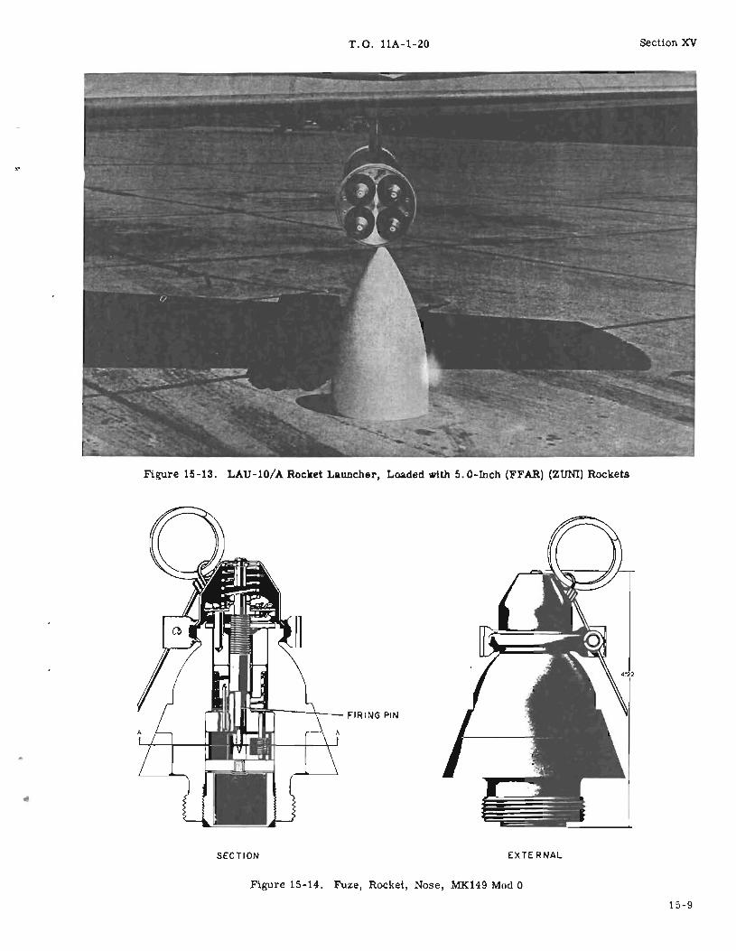
T.O. llA-1-20 Section XV
Figure 15-13. LAU-10/A Rocket Launcher, Loaded with 5. O-Inch (FFAR) (ZUNI) Rockets
~w"'---+-__ FI RING PIN
SECTION EXTERNAL
Figure 15-14. Fuze, Rocket, Nose, MK149 Mod 0
15-9

Section XVParagraphs 15-47 to 15-52
T. O. 11A-I-20
SETBACKBLOCK
SECTION B-B(DURING ACCELERATION)
Figure 15-15. Base Fuze MK164 Mod 0, Cross Section, Unarmed Position
burst will vary dependent upon the attitude of therocket launch, the speed of the rocket (aircraft speedplus rocket speed), and density of the target medium.This fuze requires a deep cavity fuze seat such asprovided by the 5. O-inch Rocket Head, MK6, Mod 4.
15-47. LAUNCHER, 5. O-INCH HVAR.
15-48. The 5. O-inch HVAR is fired from the AirForce retractable jettisoning type launcher, or fromthe modified post-type launcher. Current use of therocket is limited to launchers requiring the M34Rocket Kit conversion of the rocket.
15-49. TARGET ROCKET, 5.0-INCH, HVAR, NONMANEUVERING, TDU-11/B.
15-50. The rocket (figure 15-17) is designed to provide a target for AIM-9 training. A standard 5. O-inchHVAR is modified to allow it to be carried on a AIM-9launcher and to give it the proper flight characteristics. Visual and infrared augmentation is given byfour parasitic flares attached to the fins of the rocket.The complete target rocket is longer than the standard5. O-inch HVAR and also heavier. It is 6-1/2 feet longand weighs approximately 215 pounds.
15-10
15-51. TARGET GROUP, TDU-14/B. This group ofaccessories and a 5. O-inch motor is necessary to assemble a TDU-l1/B. The accessory group consistsof the follOWing components:
a. Rocket head, 5.0-inch, MK6 Mod 1, modified including head extension and forward-hanger assembly.The head and head extension assemblies are leadfilled.
b. Fin assembly, 5. O-inch HVAR, modified including aft hanger.
c. Center hanger assembly.
15-52. FLARE, GUIDED MISSILE, AERIAL, INFRARED, W112B. These flares are used, in units of four,depending upon the type of tracking desired. TheTDU -14/B accessory kit includes the necessary components for attaching these flares to the fin assembly.The flares are not in the modification kit and must beordered separately.

•
T.O. llA-1-20
SEALWIRE
WRENCHLUG
,
Section XV
TRACKI"", CC;ES
~, I' r-
I
rr==!
Figure 15-16. Fuze, Rocket VT, M403
~D ASSEMBLY
ill_----=e[~L~y~ EXTENSION
Figure 15-17. Target Rocket, 5.0-Inch, HVAR, Non-Maneuvering, TDU-ll/B
Hi-ll/15-12


T.O. 11A-I-20
SECTION XVIJATOS
section XVIParagraphs 16-1 to 16-11
16-1. INTRODUCTION.
16-2. The term JATO is derived from the initial letters of the Jet Assisted Takeoff, indicating the firstof several uses for which JATOs have been developed.A JATO, like a rocket, is a device that producesthrust. The basic manner in which thrust is obtainedis also consistent with the rocket principle. JATO'sare not designed to incorporate a warhead. JATO isalso referred to as RATO and ATO.
16-3. DESCRIPTION.
16-4. The JATO motor is usually a solid propellantthrust unit containing no moving parts. It is usedprimarily for applying thrust in assisting the takeoffof aircraft. JATO units may be used for other applications requiring the same characteristics. Themotor is completely identified by its nomenclatureand ammunition lot number. Firing is restricted tothe temperature ranges stenciled on each motor. TheJATO unit is primarily a rocket motor operating asthe nomenclature indicates. Figure 16-1 illustratesa typical JATO unit and the means of interpreting thenomenclature.
16-5. MAJOR COMPONENTS.
16-6. The JATO unit, as issued, is comprised ofseveral major parts. The parts are normally completely assembled with the exception of the igniter,which is placed in the unit just prior to use. Themajor parts are as follows (figure 16-2):
a. Body assembly
b. Closure assembly
c. Igniter assembly
d. Propelling charge
e. Nozzle assembly
f. Blowout assembly
16-7. BODY ASSEMBLY. The body assembly isusually a deep-drawn steel case and may have athicker ring welded to the rear of the case to provide'1 chamber for the propelling charge, or be so con3tructed that the aft cap assembly is of heavier metal(i. e., 15-KS-l,000). Mounting lug assemblies areusually welded to the main body assembly to facilitateinstallation on the aircraft. The mounting assemblies, of whatever configuration, serve to provide aground to the electrical ignition system. The forwardend of the body assembly has either a modified coneor dome contour to improve the propellant chamber
characteristics. An igniter well is welded in the extreme forward end. If the unit uses a resonance rod,it is attached to the inner face of the i~ter boss.Resonance rods aid in controlling the burning of somegrains by dampening pressure waves resultant fromrapid burning propellaht. The shipping plug, in theigniter well during shipment and storage, has holesdrilled through it and a plastic moisture cap affixed.The holes are for emergency exit of gases to neutralize thrust should accidental ignition occur. The rear(or aft) end incorporated a rounded or tapered end tominimize friction losses of the burning propellantgases.
16-8. CLOSURE ASSEMBLY. The closure assemblyis steel forging that has been machined to fit thechamber and either has the nozzle machined into theassembly, or has a threaded provision for tlle insertion of the nozzle and pressure relief diaphram. Theclosure is held in place by a closure ring that iseither threaded or secured by bolts. A synthetic rubber sealing ring is fitted in a groove to eliminate gasleak.
16-9. IGNITER ASSEMB Y. Various types of igniterassemblies are used for different models of JATOunits and generally consist of a plastic case, whichcontains the igniter composition and two electricsquibs, a flanged externally-threaded steel plug, anda cOlUlector wire. The igniter charge is ignited bythe electric squibs COlUlected in parallel. The ignitercase is fastened to the steel plug by a screw and a nuton the terminal post. The screw and the terminalpost serve as terminals for the connector wire andthe two squibs. The screw makes contact with thesteel plug, thereby prOViding a ground for the ignitersystem. The igniter assembly is usually shipped ina hermetically sealed container located in the shippingbox of the JATO unit, and not assembled to the motoruntil preparation for use.
16-10. PROPELLING CHARGE.
16-11. The propelling charge may consist of severalcompositions. (See figure 16-1.) Most current JATOunits use a solid physical state propellant and are ofthe KS, NS, or DS composition. The propellantcharge may be held firm within the body chamber bymeans of plastic inhibitor strips, sponge rubberstrips, or a close tolerance fit. To control burningrates of the various propellants used, inhibitors maybe spaced in slots extending longitudinally in thegrain, in specific locations within the grain, on certain burning surfaces, etc. Some propellant grainsutilize a liner for shock protection and as an inhibitorcombined.
16-1

Section XVI T.O. llA-1-20
For the 16-NS-I000, the burning time is 16 secondsduration, the propellant is ammonium nitrate and ina solid state. and the thrnst produced is 1,000 pounds
_----t=~l--------16 - Duration of thrust in seconds
N - Ammonium nitrate base
'S - Solid propellant
.4...-------1000 - Nominal thrust in pounds
•
lAtInA .B .C .D .E ..F .
H .K .N .0 ..
Ldt..L· .P .S, .
T,p< ./ proptllolll
Acid with fud or asphalt with ptrchlora~.
Ball or chopptd double base.Composi~ (picra~-nitrate).
Double base, cast (may conrain composite strands or particles).
Extruded double base.Furfuryl alcohol with oxidizer (includes all alcohols higher than
ethyl).Hydride Cud•.Perchlorates, cut with binder fuel other than asphalt.Nitrate. and nitrb-Compounds other than thoo<: designated above.Liquid oxygen with alcohol or hydrocarbon•.
. . Pl,Pcol .e• •f proptllo'"
Liquida.Plastic composition. (which can be deformed under modera~ stress).Solids (which are not readily deformed at ordinary temperature.).
Figure 16-1. Typical JATO Identification System
BLOWOUT ASSEMBLY
SPONGE SUPPORTS
BODY ASSEMBLY
IGNITER ASSEMBLY
CLOSURE ASSEMBLY
PLUGSHIPPING
BODYASSEMBLY
BLOWOUT ASSEMBLY
RODRESONANCE \RACKET MOUNTING Aft.
BRACKET MOUNTING Fwd.CLOSUREASSEMBLY
SPRING0\
. NOZZLE ASSEMBLY
Figure 16-2. Major Parts of Typical JATO Rocket Motors
16-2
T.O. llA-I-20 Section XVIParagraphs 16-12 to 16-15
o
16-12. NOZZLE ASSEMBLY. The nozzle assemblyis either a fitted unit that fits in a recess machinedfor it and retained by a lock ring, or screws into athreaded hole. The nozzle is fabricated of steel andis usually lined·with a graphite material to reduce excessive corrosion from the hot gases. Corrosion results in enlarging the nozzle throat and the thrust ob-'tained reduces accordingly. A molded plastic cupcovers the nozzle and is blown out upon firing of theJATO. The plastic cup is cemented to the expansioncone to prevent the entrance of moisture into themotor.
16-13. BLOWOUT ASSEMBLY. All JATO units willincorporate some safety device of the blowout type toprovide for sudden, excessive pressures from the
burning propellant. Accidental cracking of the grain,for example, would result in an appreciable increasein the burning surface and result in substantiallyhigher pressures. If a relief from the excess pressure were not provided, a mechanical rupture of thechamber could result, inflicting heavy damage to theaircraft.
16-14. FUNCTION.
16-15. JATO units are ignited by closing the electrical circuit firing switch located in the pilot's compartment. Current passes through the electricsquibS, igniting the composition contained in the igniter cup. Flame produced ignites the propellantgrain. Gas passed through the nozzle blows out theplastic nozzle closure and produces thrust.
16-3/16-4

17 -1. INTRODUCTION.
T.O. 11A-1-20
SECTION XVIIGUIDED MISSILES
17-6. CLASSIFICATION.
Section XVIIParagraphs 17 -1 to 17-11
17 -2. The term guided missile refers to an unmannedvehicle moving above the earth's surface or underwater, the trajectory or flight path of which is capable of being altered by a mechanism within the vehicle.The missile usually carries a lethal or useful military load.
17 -3. For reasons of safety and ease in handling andshipping, the components of a guided missile are usually stored and shipped separately and must be assembled prior to use. Assembly is performed at predesignated assembly areas. Refer to Air ForceTechnical Order 11 or 21-series for specific information about a particular missiles system, e.g. T.O.21-AIM-4-1 pertains to the Falcon missile (AIM-4).
17-4. DEFINITIONS.
17- 5. The components of the various guided missilesdiffer, depending upon the particular type and model.In general, a guided missile is composed of sevenbasic and distinct major components, defined as follows:
a. Aerodynamic structure. This refers to the designand fabrication of the missile body. The structuremay be altered or partially fabricated by other majorcomponents.
b. Control system. The control system is that component that acts as a pilot to keep the missile in astable flight attitude and make changes in course inresponse to signals from the guidance system. Thecontrol system operates the control surfaces and/orthe propulsion unit.
c. Guidance system. The guidance system is thatcomponent that provides continued target intelligence(course data) that will take the missile to its target.
d. Propulsion system. The propulsion system isthat component of a guided missile that supplies thepower for the missile flight.
e. Warhead. The payload of a guided missile is itswarhead. The warhead contains a useful militaryload. The mission of a guided missile is to deliverthe warhead to a point where maximum effect will beinflicted on a specific target.
f. Fuze. The fuze is that component of a guidedmissile that causes the warhead to function at the timeand under the circumstances desired.
g. Electrical power system. The electrical powersystem provides electricity for the operation of guidance, control, and fuzing systems of the missile.
17-7. Guided missiles are classified according to theorigin of the missile and its destination. They aredesignated by model number and modification letter,prefix letter, popular name, and other appropriatedesignations, in accordance with AFR66-20.
17-8. ELEMENTS OF THE DESIGNATION. Eachdesignation consists of a combination of significantletters and numbers in the following sequence:
a. status Prefix Symbol. A letter indicating that thevehicle is being used for experimentation or test.(Refer to figure 17-1.)
b. Launch Environment Symbol. A letter denotingthe environment from which the vehicle is launched.(Refer to figure 17 -2. )
c. Mission Symbol. A letter designating the primarymission of the vehicle. (Refer to figure 17 -3. )
d. Type Symbol. A letter designating the kind ofvehicle. (Refer to figure 17-4.)
e. Design Number. A number designating each vehicle type with the same basic design. Design numberswill be assigned consecutively, beginning with numeral 1 for each vehicle type.
f. Series Symbol. A letter used to denote majormodifications to the vehicle that result in significantdifferences affecting the relationship of the vehicleto the nonexpendable portions of the related systemcomponents, or that result in significant changes tothe logistic support. Series symbol letters will beassigned consecutively, beginning with A. To avoidconfusion, the letters I and 0 will not be used asseries letters.
17 -9. The basic designation consists of the elementsdescribed; the manufacturer's code and serial number are normally used only for logistical and accounting purposes. When a status prefix symbol is applicable, use of a launch environment symbol is optional.The type symbol and design number will be separatedby a dash. Basic designations of some Air Forceguided missiles are listed in figure 17-5. The AirForce uses some Navy developed missile systems.Typical Air Intercept guided missiles in use by theAir Force are illustrated in figure 17-6.
17-10. IDENTIFICATION.
17 -11. Guided missiles and their components may beidentified by the painting and marking thereon. Themarkings include such data as name of the component,
17-1

Section XVIIParagraphs 17-1'2 to 17-13
T.O. llA-I-20
LETTER TITLE DESCRIPTION
J Special Test, Temporary Vehicles on special test programs by authorized organiza-tions and vehicles on bailment contract having a specialconfiguration to accommodate the test. At completion ofthe test the vehicles will be either returned to theiroriginal configuration or returned to standard operationalconfiguration.
N Special Test, Permanent Vehicles on special test programs by authorized activitiesand vehicles on bailment contract, whose configurationsare so drastically changed that return of the vehicles totheir original configurations or conversion to standardoperational configurations is beyond practicable oreconomical limits.
X Experimental Vehicles in a developmental or experimental stage, but notestablished as standard vehicles for service use.
y Prototype Preproduction vehicles procured for evaluation and testof a specific design.
Z Planning Vehicles in the planning or predevelopment stage.
Figare 17 -1. Status Prefix Symbols (Classification letters)
its model designation, lot number and manufacturer,date of manufacture, type of warhead, and other appropriate identifying markings.
17-12. WARHEADS.
17 -13. The useful military load of guided missiles iscontained in the warhead. Dependent upon the targetand the effect desired, the type of warheads that maybe used are as follows:
a. High Explosive. The high-explosive warhead depends upon blast effect for destruction or demolitionof the target.
b. High-Explosive Fragmentation. The effect of thiswarhead is produced primarily by the fragments of thewarhead being projected at high velocity. The blastat the point of functioning will cause additional damage to the target or nearby objects.
LETTER TITLE DESCRIPTION
A Air Air Launched
B Multiple Capable of being launched from more than one environ-ment.
C Coffin Horizontally stored in a protective enclosure and launchedfrom the ground.
H Silo Stored Vertically stored below ground level and launched fromthe ground.
L Silo Launched Vertically stored and launched from below ground level.
M Mobile Launched from a ground vehicle or movable platform.
P Soft Pad Partially or nonprotected in storage and launched fromthe ground.
R Ship Launched from a surface vessel such as ship, barge, etc.
U Underwater Launched from a submarine or other underwater device.
Figure 17 -2. Launch Environment Symbols
17-2

T.O. llA-I-20 Section XVIIParagraphs 17-14 to 17-15
LETTER TITLE DESCRIPTION
D Decoy Vehicles designed or modified to confuse, deceive, ordivert enemy defenses by simulating an attack vehicle.
E Special Electronic Vehicles designed or modified with electronic equipmentfor communications, countermeasures, electronic radia-tion sounding, or other electronic recording or relaymissions.
G Surface Attack Vehicles designed to destroy enemy land or sea targets.
I Intercept-Aerial Vehicles designed to intercept aerial targets in defensiveor offensive roles.
Q Drone Vehicles designed for target, reconnaissance, or surveil-lance purposes.
T Training Vehicles designed or permanently modified for trainingpurposes.
U Underwater Attack Vehicles designed to destroy enemy submannes or otherunderwater targets or to detonate underwater.
W Weather Vehicles designed to observe, record, or relay datapertaining to meteorological phenomena.
Figure 17-3. Mission Symbols
c. Chemical. This type warhead may contain toxicchemical agents.
d. Nuclear. This type warhead may be designed toproduce casualties (by thermal radiation, blast, andnuclear radiation), to cause destruction and damageto structures and equipment, and/or to deny the useof an area due to residual radioactive effects.
e. Practice. Practice warheads simulate servicewarheads and are provided for such purposes astraining in handling, fuzing, and loading.
17-14. FUZES.
17-15. One or more fuzes may be usen Ll! conjunctionwith any of the warheads described in paragraph 17 -13.
LETTER TITLE DESCRIPTION
M Guided Missile Unmanned, self-propelled vehicles designed to move in atrajectory or flight path all or partially above the earth'ssurface and whose trajectory or course, while the vehicleis in motion, is capable of being controlled remotely or byhoming systems, or by inertial and/or programmedguidance from within. This term does not include spacevehicles, space boosters, or naval torpedoes, but doesinclude target and reconnaissance drones.
N Probe Non-orbital instrumented vehicles not involved in spacemissions that are used to penetrate the aerospace environ-ment and transmit or report back information.
R Rocket Self-propelled vehicles without installed or remote controlguidance mechanisms, whose trajectory or flight pathcannot be altered after launch. Rocket systems designedfor line-of -sight ground fire against ground targets arenot included.
Figure 17 -4. Vehicle Type Symbols
17-3
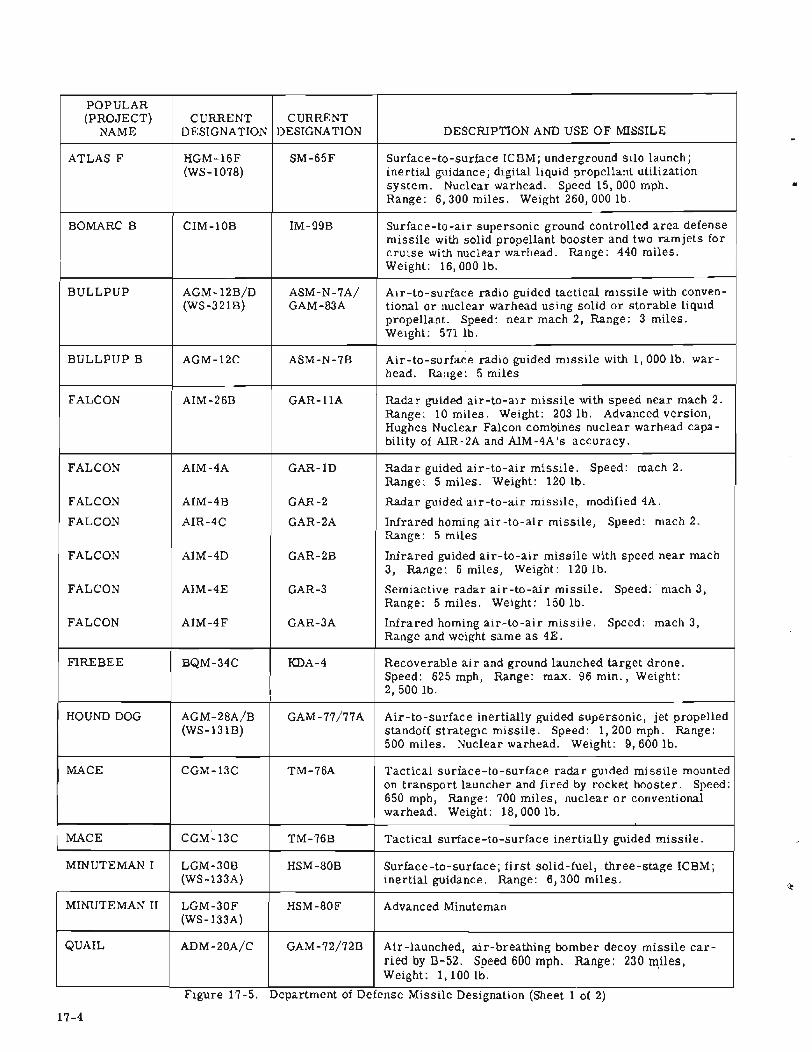
Section XVII T.O. llA-1-20
POPULAR(PROJECT) CURRENT CURRENT
NAME DESIGNATION DESIGNATION DESCRIPTION AND USE OF MISSILE
ATLAS F HGM-16F SM-65F Surface-to-surface ICBM; underground silo launch;(WS-1078) inertial guidance; digital liquid propellant utilization
system. Nuclear warhead. Speed 15,000 mph.Range: 6,300 miles. Weight 260, 000 lb.
BOMARC B CIM-10B IM-99B Surface-to-air supersonic ground controlled area defensemissile with solid propellant booster and two ramjets forcruise with nuclear warhead. Range: 440 miles.Weight: 16,000 lb.
BULLPUP AGM-12B/D ASM-N-7AI Air-to-surface radio guided tactical missile with conven-(WS-321B) GAM-83A tional or nuclear warhead using solid or storable liquid
propellant. Speed: near mach 2, Range: 3 miles.Weight: 571 lb.
BULLPUP B AGM-12C ASM-N-7B Air-to-surface radio guided missile with 1,000 lb. war-head. Range: 5 miles
FALCON AIM-26B GAR-llA Radar guided air-to-air missile with speed near mach 2.Range: 10 miles. Weight: 203 lb. Advanced version,Hughes Nuclear Falcon combines nuclear warhead capa-bility of AIR-2A and AIM-4A 's accuracy.
FALCON AIM-4A GAR-lD Radar guided air-to-air missile. Speed: mach 2.Range: 5 miles. Weight: 120 lb.
FALCON AIM-4B GAR-2 Radar guided air-to-air missile, modified 4A.
FALCON AIR-4C GAR-2A Infrared homing air-to-air missile, Speed: mach 2.Range: 5 miles
FALCON AIM-4D GAR-2B Infrared guided air-to-air missile with speed near mach3, Range: 6 miles, Weight: 120 lb.
FALCON AIM-4E GAR-3 Semiactive radar air-to-air missile. Speed: mach 3,Range: 5 miles. Weight: 150 lb.
FALCON AIM-4F GAR-3A Infrared homing air-to-air missile. Speed: mach 3,Range and weight same as 4E.
FIREBEE BQM-34C KDA-4 Recoverable air and ground launched target drone.Speed: 625 mph, Range: max. 96 min., Weight:2,500 lb.
HOUND DOG AGM-28A/B GAM-77/77A Air-to-surface inertially guided supersonic, jet propelled(WS-131B) standoff strategic missile. Speed: 1,200 mph. Range:
500 miles. Nuclear warhead. Weight: 9,600 lb.
MACE CGM-13C TM-76A Tactical surface-to-surface radar guided missile mountedon transport launcher and fired by rocket booster. Speed:650 mph, Range: 700 miles, nuclear or conventionalwarhead. Weight: 18,000 lb.
MACE CGM-13C TM-76B Tactical surface-to-surface inertially guided missile.
MINUTEMAN I LGM-30B HSM-80B Surface-to-surface; first solid-fuel, three-stage ICBM;(WS-133A) inertial guidance. Range: 6,300 miles.
MINUTEMAN II LGM-30F HSM-80F Advanced Minuteman(WS-133A)
QUAIL ADM-20A/C GAM-nlnB Air-launched, air-breathing bomber decoy missile car-ried by B-52. Speed 600 mph. Range: 230 miles,Weight: 1,100 lb.
Flgure 17-5. Department of Defense M1SSlle DeslgnatlOn (Sheet 1 of 2)
17-4
•
T.O. 11A-1-20 Section XVIIParagraphs 17-16 to 17-23
POPULAR(PROJECT) CURRENT CURRENT
NAME DESIGNATION DESIGNATION DESCRIPTION AND USE OF MISSILE
SHRIKE AGM-45 ASM-N-10 Antiradiation, solid fueled missile with homing capabilityagainst radar installations.
SIDEWINDER IB AIM-9B AAM-N-7 Air-to-air supersonic guided missile with conventionalHE warhead using passive infrared guidance system andsolid propellant. Speed: mach 2.5. Range: 3,500-11,000 ft. Weight: 155 lb.
SPARROW IIIB AIM-7E AAM-N-6B Air-to-air; supersonic launch capability; semiactivehoming radar.
SPARROW III AIM-7D AIM-101 Air-to-air electronically controlled homing missile usingsolid propellant with conventional warhead. Speed: 1,500mph. Weight: 400 lb.
SUPER FALCON AIM-4F, G GAR-3A/4A Air-to-air, infrared; range: 5 miles.
TITAN II LGM-25C XSM-68B Strategic inertially guided liquid fuel ICBM with nuclearwarhead. Speed: 15,000 mph.· Range: 10, 000 miles.Weight: 330,000 lb.
TITAN III 624A Modified Titan II, plus two solid-propellant strap-onstages.
Figure 17-5. Department of Defense Missile Designation (Sheet 2 of 2)
Depending on the type of target and effect desired atthe target, fuzes used with guided missiles may be ofthe impact, VT (proximity), or ground-controlledtypes.
17-16. IMPACT FUZE. An impact fuze is one that isactuated by striking the target. Functioning time afterimpact depends upon the design of the fuze and thenature of the target.
17-17. VT FUZE. VT fuzes function on approach toa target. Each type of VT fuze is actuated by somecharacteristic of, and at a predetermined distancefrom, the target. Five basic types of guided missileVT fuzes are as follows:
a. Radio-proximity.
b. Pressure-proximity.
c. Electrostatic -proximity.
d. Plf6tgelectric -proximity.
e. Acoustic -proximity.
17-18. GROUND-CONTROLLED FUZING. In groundcontrolled fUZing, the mechanism for determiningtarget proximity is not housed in the fuze, but is onthe ground. When the proper proximity relationshipis reached between the missile and the target, a signal to detonate is sent to the missile.
17-19. ELECTRICAL POWER SYSTEM.
17-20. This system supplies electrical power foroperation of the guidance and control mechanisms andfor the fuzing of the warhead. The types of systemsare as follows:
a. Battery supply, with or without electronic rectifier and transformer circuit. This type is suitablefor small, short-range missiles.
b. An alternating-current generator using a turbinedriven by Wind, battery, engine, or compressed air.This type is suitable for longer range missiles.
17-21. PROPULSION SYSTEM.
17-22. The propulsion system used in guided missilesemploys a jet-type engine, which is the only knowntype capable of propelling such missiles at the required speeds. A jet engine is one that operates onthe reaction principle. It consists essentially of acombustion chamber and a nozzle. When a fuel isburned in the combustion chamber, a thrust is produced as a result of the products of combustion expanding and passing through the nozzle.
17-23. TYPES. Jet engines are of two general types,the air-breathing type, and the nonair-breathing type.The air-breathing type, of which the pulse jet, ramjet, and turbo jet engines are examples, uses liquidfuel and atmospheric oxygen as the oxidizer. The
17-5

Section XVII T.O. llA-1-20
:>
AIR-2.A & 2a
17-6
I I I I I I J
'--.......:...F..:.:T._'-__~2=---- 3~ 4-'---__~5~__~6~__~7 ~8::-__....:9::-__..!.IO
Figure 17-6. Air-to-Air Missiles, Typical

T.O. llA-1-20 Section XVIIParagraphs 17 -24 to 17-31
nonair-breathing type, of which rocket engines are exexamples, uses solid propellant (fuel and oxidizercombined) or liquid fuel with an oxidizer.
17-24. FUELS AND PROPELLANTS. Fuels and propellants for jet engines are discussed in Section V.
17-25. PHASES OF OPERATION. The complete missile propulsion system generally operates in twophases: the launching phase, during which the missile is accelerated to the cruising speed by somemeans such as a catapult or a high-thrust jet enginesometimes called a booster unit or JATO; and thecruising phase, during which the missile is maintained at cruising speed by a relatively lower-thrustjet engine sometimes called a sustainer unit. In othercases, the missile propulsion system does not requirea booster unit or catapult and operates in only onephase. The propulsion system may use a combinationof liquid, jet engine or solid fuel units, e. g., theBomarc missile is launched with a solid rocket booster unit, and cruises by means of a liquid fuel ram-jetsustainer engine.
17-26. CONTROL AND GUIDANCE SYSTEMS. Thecontrol and guidance are parts of an integrated system for automatically directing the flight of the missile.
17-27. CONTROL SYSTEM. The control system includes all the components neCl sary for completeautomatic control of a missile .n flight. The systemreceives intelligence from a radio signal or otherelectrical device and makes corrections for changesin yaw, pitch, and ,'011. The systems usually includegyroscopes, Signal amplifiers, servomotors, andcontrol-surfaces. The system may also receive internal or external guidance signals in order to adjustthe path of a missile. Each control system componenthas a distinct function as follows:
a. Gyroscopes. The gyroscope is used in a missileto fix a reference direction.
b. Electric amplifiers. The amplifier increases thesignal strength to a sufficient level to control the servomotors.
c. Servomotors. The servomotor supplies power tocontrol surfaces to change the flight path of a missile.
d. Control surfaces. The control surface changesthe missile path by application of some force in response to a directing signal. This change in path(steering) is accomplished by one or more of the following devices: air vanes, jet vanes, movable jetmotor, or side jets.
17-28. GUIDANCE SYSTEM. The main functions performed by the guidance system are tracking, computing, and directing. Tracking is the process of determining the location of a missile and its target withrespect to the launcher, and missile and target withrespect to each other and some other reference.Computing is the process of calculating the directingsignals for the missile by use of tracking information.
Directing is the process ofsen~~g the ~omp.uted signal to the missile. Directing may also be accomplished from within a missile. The directing signalsare sent to the control system, thus giving control ofmissile flight. Some basic guidance systems are asfollows:
a. Preset guidance system. A preset system is aguidance system wherein a predetermined path is setinto the missile before launching and cannot be adjusted after launching.
b. Terrestrial reference guidance system. A terrestrial reference system is a guidance system for apredetermined path, wherein the path of the missilecan be adjusted after launching, by devices within themissile that react to some phenomena of the earth.
c. Radio navigation guidance system. A radio navigation system is a guidance system for a predetermined path wherein the path of the missile can be adjusted by devices within the missile that are controllecby external radio signals.
d. Celestial navigation guidance system. A celestialnavigation system is a guidance system for a predetermined path wherein the path of the missile can beadjusted by the use of continuous celestial observation.
e. Inertial guidance system. An inertial system is aguidance system for a predetermined path wherein thepath of the missile can be adjusted after launching bydevices wholly within the missile.
f. Command guidance system. A command systemis a guidance system wherein the path of the missilecan be changed after launching by directing signalsfrom some agency outside the missile.
g. Beam climber guidance system. A beam climbersystem is a guidance system wherein the direction ofthe missile can be changed after launching by a devicein the missile that keeps the missile in a beam ofenergy.
h. Homing guidance system. A homing system is aguidance system wherein the direction of the missilecan be changed after launching by a device in the missile that reacts to some distinguishing characteristicof the target.
17-29. Guidance is not always maintained from launchto target. Some missiles are projected into a ballistic trajectory and guided until point of separation ofthe payload. Examples are intercontinental ballisticmissile (ICBM) systems, where the ballistic path ofthe reentry vehicle is predicted from the trajectory,and guidance stops at time of separation of the reentry vehicle from the missile.
17-30. LAUNCHERS.
17-31. Launchers are mechanical structures thatprovide whatever control and acceleration are neededduring the initial stages of flight to enable the missilecontrol, guidance, and propulsion systems, to directand carry it to the target.
17-7
T.O. llA-1-20Section XVIIParagraphs 17 -3 2 to 17-38
17-32. TYPES OF LAUNCHERS. Some basic typesof launching devices are trainable platform, verticaltower, vertical ramp, ramp or rail (other than vertical), zero length (a launcher on which there is negligible travel by the missile), gun type, catapult, andaircraft.
17-33. FIRING. Firing of guided missiles from alaWlcher is usually accomplished electrically by remote control.
17-34. BLAST PROTECTION. Due to the dangerousblast of flame emitted by guided missiles, the launching site must be cleared of all personnel and unnecessary equipment. All unprotected combustible material must also be removed from the laWlching area.
17-35. CARE, HANDLING, AND PRESERVATION.In general, the same regulations apply to guided missiles as to other types of ammunition. However, certain components of the missile require special handling. The control equipment, which includes suchitems as gyroscopes, homing devices, electronicequipment, and other precision instruments, must beprotected from rough or careless handling. Specialprecautions must be taken with certain of the fuelsand oxidizers due to fire, explosion, contact, andinhalation hazards. Protective clothing and masksmust be used when handling certain of the fuels and
oxidizers. Careful training in safety measures, procedures for handling, and precautions in use of guidedmissile explosive or flammable components is essential.
17-36. PACKING AND MARKING.
17-37. PACKING. The components of guided missiles are packed in appropriate types of containers.Fuzes and warheads are packed in wooden or metalcontainers. Propellants, which include fuel, oxidizer,reducer, and solid and liquid propellants, are packedin specially designed tanks, metal drums, glass bottles, or fiber containers in wooden boxes. Controland guidance equipment are packed in specially constructed packings since they are precision instruments. Propulsion systems are packed in metalcrates or wooden boxes. Special equipment such ascompressors, cable sets, storage batteries, firingpanels, .and similar items are also packed in suitableboxes, crates, and containers.
17 -3 8. MARKING. The packing boxes, crates,drums, and containers in which guided missile components are packed are marked for easy identification.They mayor may not be coded for a specific gUidedmissile complete rOWld. Packings of propellants andcomponents of propellants, fuzes, and warheads arealso marked to indicate the Interstate CommerceCommission shipping name and any important instructions in handling or storage.
•
17-8
T. O. 11A-1-20
SECTION XVIIIDEMOLITION MATERIALS
Section XVIIIParagraphs 18-1 to 18-13
18-1. INTRODUCTION.
18-2. The term demolition materials refers to a variety of explosive charges of different sizes andshapes, explosive initiating devices designed for usewith such charges, explosive and nonexplosive mechanical devices, and apparatus such as instruments,tools, and equipment used with the charges for performing various military demolition functions. Thesefunctions include such operations as destruction ofearth works, fortifications, railroads, dams, bridges,and buildings, and excavation for construction projects and clearing obstacles and minefields. Certaindemolition materials are grouped into lots and sets,for the convenience of especially designated militaryunits in performing prescribed kinds of demolitionwork or miss ions and training therefor. Proceduresfor the use of demolition materials are prOVided inT.O. 11A-1-58.
18-3. DEMOLITiON MATERIALS.
18-4. TNT (TRINITROTOLUENE) BLOCKS. TNT ispackaged in 1/4-pound, 1/2-pound, and 1 pound blocksas follows (figure 18-1):
NOTE
Priming adapters and the standard base offiring devices fit all TNT blocks.
a. The 1/4-pound blocks are in an olive drab cardboard container with metal ends'. One end has athreaded cap well.
b. The 1/2-pound blocks are in a yellow or olivedrab cardboard container with metal ends. The yellow container has an unthreaded cap well and the olivedrab container, a threaded cap well.
c. The I-pound blocks are merely two 1/2-poundblocks in an olive drab cardboard container with metalends. One end has a threaded cap well.
18-5. TNT is affected by intense cold, being lesssensitive to shock.
18-6. TETRYTOL (Ml CHAIN DEMOLITION BLOCK)Demolition block Ml has all the desirable characteristics of TNT and is slightly more powerful, having adetonation rate of 23, 000 feet per second. It is moreeffective as a cutting or breaching charge. It isslightly soluble in water, is brittle, and breaks easilywhen dropped.
18-7. Each block is 11 inches long by 2 inches squareand weighs 2-1/2 pounds. A tetryl pellet is cast intothe block near each end. Eight blocks spaced 8
inches apart, are cast lengthwise onto a single lineof detonating cord, 2 feet of which is left free at eachend of the chain. Each block is enclosed in an olivedrab asphalt-impregnated paper wrapper. One chain(8 blocks) is packed in an olive drab cloth haversackwith a carrying strap attached. The complete bagmeasures 4 by 8 by 11 inches and weighs about 22pounds. It contains 20 pounds of explosive.
18-8. The Ml chain demolition block may be used inforward combat areas as an alternate for TNT. Thecomplete chain, or any part of the chain, may be laidout in a line, wrapped arOlilld a target, or used in thehaversack as it is packed. Entire chai"n will detonateeven though the blocks may not be in contact with eachother. If less than eight blocks are needed, the required number is cut from the chain. If blocks areseparated by cutting, the detonating cord should becoated with waterproof grease to prevent penetrationby moisture, which may cause misfire.
18-9. The sensitivity of this explosive is decreasedby cold like that of TNT. A slight decrease instrength may result in extremely cold weather.
18-10. TETRYTOL (M2 DEMOLITION BLOCK). TheM2 demolition block is similar to the Ml chain block,except that it nas a threaded cap well in each end andhas no core of detonating cord. The M2 demolitionblock measures 11 by 2 by 2 inches. A booste r tetryl pellet, cast into block, surrounds each cap well.Eight blocks, 2-1/2 pounds each, are packed in ahaversack. The M2 demolition block is used in samemanner at the Ml block for cutting and breaching.Chains may be made by connecting blocks with detonating cord.
18-11. The M2 demolition block has slightly greaterloss of strength at low temperature than the M1 andrequires a minimum of six turns of the detonatingcord instead of the usual four to obtain detonation.The M2 retains its sensitivity to shock, however, asit ignites or explodes under. 50-caliber incendiarymachinegun fire at subzero temperatures.
18-12. COMPOSITiON C3 (M3 OR M5 DEMOLITIONBLOCK). Composition C3 is packaged as the M3 orM5 demolition block. (See figure 18-1.) The M3block is perforated around the middle to make it easyto break open. Each block measures 11 by 2 by 2inches and weighs 2-1/4 pounds. The M5 demolitionblock has a plastic container with a threaded cap well.
18-13. Because of its plasticity and high detonationvelocity, Composition C3 is ideally suited to ~utting
steel structural members. It is easily molded inclose contact to irregularly shaped objects and is anexcellent underwater charge if enclosed in a containerto prevent erosion.
18-1
Section XVIII T.O. llA-1-20
,-
c
BLOCK MSAI
40-LB CRATERINGCHARGE
BLOCK M3
IS-LB SHAPEDCHARGE
1/4-LB. TNTBLOCK
DEMOLITION CHARGES AND DYNAMITE
1/2-LB TNTBLOCK
l-LB. TNT BLOCK
®: ~..,;,=p.-;~~J' ::2)DYNAMITE
STICK40-LB. SHAPED
CHARGE
129·112-IN.
t! i:'
BLASTING CAP(RECTRIC)
BLASTING CAP(NONELECTRIC)
BLASTING
MACH'NE~
TIME BLASTINGFUSE
FUSE IGNITER(FRICTION TYPE)
QFib~FUSE IGNITER
(WEATHERPROOF)
DETONATING CORD
RELEASE
PRESSURERELEASE
•
~~PULL
DELAY
PULL· RELEASE
4J 'a
'--------FIRING DEVICES-------J
PRESSURE
INITIATING AND PRIMING MATERIALS
BANGALORE TORPEDO
"'L..:'':';':':'
I....----------------400-FT-----------------i
PRO) ECTED CHARGE M3A I
OBSTACLE AND MINE FIELD CLEARING DEVICES
Figure 18-1. Typical Demolition Material
--1.8-2
T.O.11A-1-20 Section XVIIIParagraphs 18-14 to 18-29
18-14. When chilled, Composition C3 changes colorfrom bright yellow to red, with no visible breakdownof material. Below -20 0 F., it becomes stiff and brittle; plasticity is restored only by reheating. Althoughat -200 F. the velocity is reduced, detonation is stillof high order.
18-15. COMPOSITION C4 (M5A1 DEMOLITION3LOCK). Composition C4 is packaged as a block explosive measuring 11 by 2 by 2 inches and weighing2-1/4 pounds. (See figure 18-1.) Each block iswrapped in a plastic covering with a threaded cap wellat either end for use as a block explosive.
18 -16. Because of its high detonation velocity (slightlyhigher than C3) and its plasticity, Composition C4 iswell suited for cutting steel and timber and breachingconcrete. It may be used as an underwater charge, ifenclosed in the original or an improvised container toprevent erosion.
18-17. C4 remains pliable like putty at temperaturesbetween -70" F. and +170" F. Below -70" it becomeshard and brittle.
18-18. MILITARY DYNAMITE. Military dynamite(M1) is a standard stick 1-1/4 by 8 inches and weighsapproximately a half-pound. Because it detonates ata velocity of approximately 20,000 feet per second, itis very satisfactory for military construction, quarrying, and other demolition work.
18-19. COMMERCIAL DYNAMITES. These are usedin certain military demolitions and construction wherespecial explosives may be required. They includestraight, ammonia, and gelatin dynamites. Commercial straight dynamites are named according to thepercentage by weight of nitroglycerine they contain;for example, 40 percent straight dynamite contains 40percent nitroglycerine. Ammonia dynamite is different, however, as 40 percent ammonia dynamite indicates that the dynamite is as strong as 40 percentstraight dynamite but not that it contains 40 percentnitroglycerine by weight. Sixty percent straight dynamite, approximately equal in strength to TNT, hasa variety of uses; gelatin dynamite is applicable tounderwater demolitions and for land clearing, cratering, and quarrying. A gelatin dynamite of low heavingforce and a high rate of detonation is used for blastinghard rock. Available dynamites and their characteristics are described in T.O. 11A-1-34.
18-20. Straight dynamite contains nitroglycerine anda nonexplosive filler. Its high velocity of detonationproduces a shattering action. Although straight dynamite is water resistant only to a small degree, it maybe used underwater if fired within 24 hours alter submersion.
18-21. Ammonia dynamite contains ammonia nitrateand nitroglycerine, which is the explosive base. Because of its medium detonating velocity, it producesa heaving action. It is not satisfactory for use underwater.
18-22. Gelatin dynamite is a jelly made by disolvingnitrocellulose in nitroglycerine. Because of its high
resistance to water, it is satisfactory for underwaterdemolitions.
18-23. Commercial dynamite is not a standard military explosive because of its undesirable characteristics, but is acceptable in emergencies. It must behandled carefully as a flame, sparks, friction, andsharp blows may detonate it. Commercial dynamitedeteriorates rapidly and requires special care instorage.
18-24. The sensitivity of dynamite decreases at diminishing temperatures until the dynamite freezes,alter which it becomes extremely sensitive. Gelatindynamite does not freeze as easily as straight dynamite. When straight dynamite is stored, the nitroglycerine tends to settle out of the sticks; accordingly, straight dynamite cases should be frequently andregularly turned to prevent settling.
18-25. AMMONIUM NITRATE CRATERING CHARGE.Ammonium nitrate cratering explosive is issued as a40-pound charge in a cylindrical metal container8-1/4 inches in diameter and 17 inches high. (Seefigure 18-1.) The container has a cap well and detonating cord tunnel for priming. An integral TNTbooster is provided to ensure detonation. On top ofthe container is a ring for lowering the charge into ahole. The cleat placed above and to the side of thecap well is for attaching either electric or nonelectricpriming assemblies.
18-26. Ammonium nitrate is used chiefly as a cratering charge because of its pushing or heaVing characteristics. It is also effective in ditching and quarrying.
18-27. Except for the loss in strength at low temperatures, ammonium nitrate is satisfactory for use inthe Arctic.
18-28. NITRAMON CRATERING CHARGE. Generallythe nit ramon cratering charge is issued in a cylindrical metal container 7 inches in diameter and 24 incheslong. The charge and container weigh 43 pounds. Thecharge has two priming tunnels. The container has aring on top for general handling and lowering intoboreholes. The nitramon cratering charge, generallyused in cratering, is also effective in ditching andquarrying. This is a blasting agent comparable withammonium nitrate. It is not removed from its metalwaterproof container for crate ring operations becauseof its hygroscopic characteristics.
18-29. SHAPED CHARGES. A shaped charge is anexplosi ve charge with its detonating action directed toincrease its effectiveness in penetrating steel, armor,and concrete and other masonry. Charges as issued,are usually cylindrical in shape but may be linearlike the charge included in the M157 demolition kIt.Cylindrical shaped charges have a conical top, a conical recess in the base, and a conical liner that maybe metal, glass, or some other inert material.Shaped charges, generally, are made from such explosives as Composition B, pen"'''''. ~rid ::dnatol.
18-3

T.O. 11A-1-20Section XVlIIParagraphs 18-30 to 18-35
NOTE
The threaded cap well in the top is for primingwith military electric or nonelectric blastingcaps or any standard firing device with blasting cap attached.
18-30. The M2A3 shaped charge weighs 15 pounds andcontains 11-1/2 pounds of pentolite (PETN and TNT)or Composition B (RDX and TNT). For protection,the explosive is issued in a water-resistant fiber container. (See figure 18-1.) A cardboard cylinder,fitted to the charge before use, prOVides the necessarystandoff distance. Three M2A3 shaped charges arepacked in a wooden box.
18-31. The M3 shaped charge consists of approximately 30 pounds of 50/50 pentolite, or CompositionB, and a 50/50 pentolite booster in a metal container.(See figure 18-1.) The shaped charge has a metalcavity liner. A metal tripod prOVides the correctstandoff distance. The M3 shaped charge is packedone each in a wooden box.
18-32. Shaped charges M2A3 and M3 are very usefulfor small arctic projects, especially for drilling holes,having the strength necessary to loosen perma-frostand ice. Shaped charges, however, should not be usedas a cure-all demolition explosive as is the tendencyto do so, for the logistical difficulties of supplyingthem in large quantities generally limits their use.
18-33. BANGALORE TORPEDO. The M1j\2 bangalore torpedo consists of loading assemblies, cOlUlecting sleeves, and a nose sleeve. (See figure 18-2.)
Each loading assembly, which may be used singly, isa 5-foot length of steel tubing 2-1/8 inches in diameter filled with 8-1/2 pounds of Composition B explosive and weighs 13 pounds. Four inches of length atboth ends is filled with a Composition A-3 booster.All sections have a threaded cap well at each end sothat they may be assembled in any order. The connecting sleeves make rigid joints. A nose sleeve isplaced on the front of the torpedo to assist in pushingit through entanglements and over the ground. It isalso desirable to attach an improvised leading sectionwithout explosive on the end to forestall prematuredetonation by mine when the torpedo is shoved intoplace. In the assembly of two or more tubes, thenose sleeve is pressed onto one end of one tube, andthe other end is cOlUlected to a second tube by a connecting sleeve. A bangalore torpedo or torpedo section may be improvised by the use of 2-inch diameterpipe with a 24-gage wall thickness with approximately2 pounds of explosive per foot of length. Successivepipe lengths, however, must be closely connected.
18-34. The bangalore torpedo clears a path 10 to 15feet wide through barbed wire entanglements. Inminefield breaching, it will explode all antipersolUlelmines and most of the antitank mines in a narrow footpath. It should be used for this purpose only in anemergency, as many of the mines at the sides may beshocked into a sensitive state, which makes extremecare necessary in any further mine clearing. Bangalore torpedoes are also useful as expedient individualcharges.
18-35. ROCKET-PROPELLED TRAIN BANGALORETORPEDO. The train consists of 20 sections of
NOSE SLEEVE
i I~::I!¥":~i'AissiEMiBiLiyiiiiiiiiiiiiiiiiiiiiiiiiiiiiiiill
•THREADEDCAP WELL
ORO 0355
Figure 18-2. Torpedo, Bangalore, M1A2
18-4

T.O. llA-1-20 Section XVIIIParagraphs 18-36 to 18-42
bangalore torpedo fitted together by special connectingsleeves to form a 100-foot train. A kit contains therocket motor, tail assemblies, and couplings for 20sections. The motor is fitted to the front of the trainto provide propulsion. Detonation occurs at the tailassembly by means of a pull fuze, a nonelectric blasting cap, and a reel of cable.
18-36. The rocket-propelled bangalore torpedo isused against barbed wire entanglements, antipersonnelmines, and similar small obstacles. The rocket propulsion enables deeper penetration of small obstacleswith less chance of exposure of personnel to enemyobservation and fire.
18-37. M37 DEMOLITION CHARGE ASSEMBLY. TheM37 charge assembly (figure 18-3) consists of eightM5Al demolition blocks (Composition C4), eight demolition block hook assemblies, and two M15 primingassemblies. The demolition blocks are packed in twobags, four blocks per bag and placed in an M85 carrying case. The M15 priming assembly is a 5-footlength of detonating cord with two plastic adapters andtwo RDX boosters attached. The adapters arethreaded to fit the standard cap well in the demolitionblock. The priming assembly has two detonating cordclips for fiXing the M37 charge assembly to the mainline.
18-38. This assembly is applicable for use by assaultdemolition teams in the reduction of small obstacles.It is a versatile demolition kit and may be used foremergency destruction plans.
18-39. IMPROVlSED CHARGES. Demolition teamsoperating in the field frequently find targets to whichstandard methods and charges may not apply and improvisions are required. Frequently the s'Jccess ofthe mission depends upon the ingenuity of the team.The package and pole charges are such improvisations. By skillful modifications, they may be appliedsucc essfully in many situations.
ORO 0353
Figure 18-3. Kit, Demolition, M37
Figure 18-4. Destructor, High-Explosive,Universal, M10
RA PO 205653ACOMPONENTS
'!l'0.
I,NJiESl
18-40. The MI0 Universal High-Explosive Destructor(figure 18-4) is a high-explosive charge in an assembled metal device initiated by means of blasting capsor land mine activators with standard firing devices.The destructor has booster cups containing tetryl pellets. The chief function of the destructor is in theconversion of loaded projectiles and bombs to improvised demolition charges and in the destruction ofabandoned ammunition.
18-41. FOREIGN EXPLOSIVES. Explosives used byforeign countries include TNT, picric acid, and guncotton. Picric acid has characteristics like TNT except that it corrodes metals and thus forms extremely,ensitive compounds. A picric acid explosive in a:usted or corroded container will not be used; in fact,it should not be handled in any way, except to move itvery carefully to a safe area for disposal.
18-42. Explosives of allied nations and those captured from the enemy may be used to supplementstandard supplies. Such explosives, however, shouldbe used only by experienced personnel. Capturedbombs, propellants, and other devices may be used
18-5

T. O. llA-1-20Section XVIIIParagraphs 18-43 to 18-51
with U. S. military explosives for larger demolitionprojects, such as pier, bridge, tunnel, and airfielddestruction. Most foreign explosive blocks have capwells large enough to receive U. S. military blastingcaps.
18-43. DETONATING CORD. Detonating cord consists of a flexible tube filled with PETN encased in awhite, yellow, or yellow-and-black waterproof cov;ering. Watersoaked detonating cord will detonate ifinitiated from a dry end. Like other high-explosives,it is subject to sympathetic detonation. Detonatingcord is issued in spools in 50-, 100-, 500-, and1, OOO-foot lengths. Detonating cord detonates at approximately four miles per second. The followingthree types of detonating cord - I, II, and IV - areused in military demolitions on land and under water.
a. Types I and II Detonating Cord. These detonatingcords consist of an explosive core of PETN enclosedin a braided seamless cotton tube. On the outside ofthis tube is a layer of asphalt covered by a layer ofrayon with a wax gum composition finish. Type II hasa slightly larger diameter than type I, as it has an extra layer of cotton covering that increases its tensilestrength to apprOXimately 150 pounds. Types I and IIdetonating cord are used in the detonation of chargesfrom single point initiaters.
b. Type IV, Plastic-Reinforced Detonating Cord.(See figure 18-5.) This cord is similar to that described in paragraph 18-43a, except for the specialplastic covering designed for vigorous use and severeweather. This covering increases the cord's tensilestrength from 150 pounds to 250 pounds; it also makesthe cord more stable in high temperatures and decreases the possibility that the wrapper may lose itswaterproof qualities when handled. Type IV detonating cord is used in the detonation of underwater orunderground charges, where initiation is desired onthe surface.
18-44. Detonating cord does not lose its explosiveproperties by exposure to long periods of cold. Evenduring severe drops in temperature, it fires all standard military explosives. The only variation in methodis the use of six instead of the normal four turns whendetonating the M2 (tetrytol) demolition block. Theouter covering of chilled detonating cord becomesstiff and cracks when bent. Repeated flexings deepenthe cracks and break the explosive train. Care mustbe taken to ensure a minimum of cracking in tyingdetonating cord; and connections must be checked fortightness, as the cord tends to loosen after being tied.
18-45. DETONATING CORD CLIP, M1. The M1 detonating cord clip is used to hold together two strandsof detonating cord, either parallel or at right anglesto each other, or to fasten a blasting cap to detonatingcord. Connections are made more quickly with theseclips than with knots. Also, knots may loosen andfail to function properly if left in place any length oftime. Joints made with clips are not affected by longexposure.
18-6
I WARNING
Each roll of blasting time fuze must be testedshortly before use. The rate of burning willvary for the same or ,different roll under different atmospheric and/or climatic conditions,from a burning time of 30 seconds or less perfoot to 45 seconds or more per foot. Particular precautions must be taken when used underwater as the rate of burning is increased significantly.
18-46. BLASTING TIME FUZE (FABRIC COVERED).This consists of black powder tightly wrapped withseveral layers of fabric and waterproofing materials.It may be any color, orange being the most common.This fuze burns slowly at a uniform rate, allowingpersonnel firing the charge to reach safety before theexplosion. Each roll must be tested immediatelyprior to using under actual conditions in the areawhere the charge is to be placed.
18-47. BLASTING TIME FUZE (PLASTIC COVERED). (See figure 18-6.) This fuze is in the formof a O. 20-inch diameter cord consisting of a blackpowder core tightly wrapped with waterproofing materials and a plastic cover. The dark green cover issmooth with single painted bands at either I-foot or18-inch intervals and double painted bands at either5-foot or 90-inch intervals, depending on old or newmanufacture. These markings are used to estimatethe approximate lengths of fuze required for tacticalsituations.
18-48. Blasting time fuze is issued in 50-foot rolls;two rolls, one nested inside the other, are packedtogether. One can contains 500 feet of fuze.
18-49. When ignited by a match or a fuze igniter, thefuze transmits a flame to a nonelectric blasting cap.This fuze is for use in demolitions both on land orunderwater. The burning rate of the fuze is approximately 40 seconds per foot.
18-50. Although the powder train of the time fuzedoes not break down or deteriorate during long periodsof cold, the outside covering becomes brittle andcracks easily. It is necessary to handle time fuzecarefully during priming to prevent cracking andbreaking of the powder train. The burning rate isdetermined in the same manner as when it is used ina moderate climate--a measured length is cut off andburned in the area and at the temperature in which itwill be used. A good procedure is to cut time fuze ina warm shelter and keep it ext to the body until timefor priming. Nonelectric firing, however, is undesirable in arctic/subarctic temperatures.
18-51. FUZE LIGHTERS. The M2 waterproof fuzelighter was designed as a positive method of lightingtime fuze (figure 18-7) and safety fuze. It operateseffectively under all weather conditions, even underwater if it is properly waterproofed. A pull on the
T.O. llA-1-20 Section XVllIParagraphs 18-52 to 18-55
striker retaining-pin causes the striker to hit the percussion cap, igniting the fuze. A sealing compound isgenerally used to waterproof the joint between the fuzeand the lighter. Although the plastic sealing compoundis applied and the nonelectric firing assembly is properly prepared, any slight disturbance of the lighteron the time fuze allows water to enter at the unionwhen installed underwater.
18 - 52. The M2 weathe rproof fuze lighte r is unsatisfactory for arctic use, as the percentage of failuresis too high. The warming of the lighter and fuze, justbefore using them, reduces failures to a marked degree. Because of the tendency of the fuze end to fray,repeated cuts may have to be made before it can beinserted deeply enough into the M2 lighter to be ignited.
POLYETHYLENECOATING
RAYON LAYER
ENLARGED VIEW OFSECTIONED END OF CORD
Figure 18-5. Cord, Detonating, Waterproof,Plastic - reinforced
18-53. The M60 weatherproof fuze lighter is designedto ignite time fuzes under all weather conditions andunderwater. The fuze is inserted into a fuze retainerand sealed and waterproofed by means of two rubberseals. A pull on the pull ring releases the strikerassembly, allowing the firing pin to drive againstthe primer, which ignites and initiates the fuze.
FIBERWRAPPING
BLACKpowDER CORE
Figure 18-6. Fuze, Blasting, Time,Fabric-covered and Plastic-covered
18-54. The M60 fuze lighter has been tested underextreme cold conditions and found satisfactory. Itfunctions without failure at temperatures as low as_25°F.
18-55. CAP CRIMPER. The M2 cap crimper is usedto squeeze the shell of a nonelectric blasting caparound a time fuze, firing device, or detonating cordsecurely enough to keep it from being pulled off. Thecrimper forms a water resistant groove completely
Figure 18-7. Lighter, Fuze, Weatherproof, M2
18-7

Section XVIIIParagraphs 18-56 to 18-60
T.O. llA-1-20
......
Figure 18-8. Blasting Caps, Non-electricand Electric
b. Delay. Military electric delay blasting caps areshown in figure 18-9. They consist of 1st, 2d, 3d,and 4th delay types with approximate time delays of 1second, 1.18 seconds, 1. 35 seconds, and 1. 53 seconds, respectively. Commercial delay caps up to10th delay (approximately 2.5 seconds) are availablebut not issued by the military. The commercial millisecond electric delay cap is available also, but notissued.
18-59. FIRING WIRE AND REEL. Wire for firingelectric charges is issued in 500-foot lengths. It isthe two conductor, No. 18 AWG, plastic-covered orrubber-covered type. It is carried on reel unitRL39A. Single-conductor, No. 20 AW annunciatorwire is issued for making connections between blasting caps and firing wire. The RL39A reel unit consists of a spool, a handle assembly, a crank, an axle,and two carrying straps. The fixed end of the wire isextended from the spool through a hole in the side ofthe drum and fastened to brass thumbnut terminals.The handles are made of two U-shaped steel rods. Aloop at each end encircles a bearing assembly, whichis a brass housing with a steel center to accommodatethe axle. The crank is riveted to one end of the axleand a cotter pin is placed in the hole at the other endto hold the axle in place.
18-58. Both electric and nonelectric blasting caps areunaffected by cold; and thus perform with equal reliability in arctic as in temperate climates. Despitetheir reliability, nonelectric caps are difficult to useand undesirable, as numerous manual operations arerequired, and time fuzes fray when cut in coldweather. Moreover, extreme care is required tokeep snow out of the caps during priming. Electriccaps are easier than nonelectric caps to prepare. Itis difficult, however, when wearing arctic mittens tosplice wires by the Western Union or pig tail twists.A more satisfactory method is the crank tie, whereinthe two ends of wire are placed side by side, the endsbent to form a short crank, and the wires wound together by turning the crank. This makes a quick,taut connection, which becomes tighter by pulling. Allthe enamel should be removed from the bare wiresbefore making the crank tie .
18-60. BLASTING MACHINE. (See figure 18-10.)Blasting machines are classified by the number ofcaps which can be fired in a series circuit. Theymay be used to fire parallel and series -parallel
18-57. The two types of electric blasting caps usedare:
a. Instantaneous. The military instantaneous electric blasting caps are type II (J 2 PETN) and M-6(RDX). These have 12-foot electric leads for attaching to a firing wire and then to a blasting machine orother source of power for detonation. Commercialelectric blasting caps No. 6 and No. 8 have threelengths of leads: short (4-10 feet), medium (12-40feet), and long (50-100 feet). The lead wires oithecommercial blasting cap enter through a seal madeeither of sulphur, rubber, or plastic. A shortcircuit tab or shunt fastens the loose ends of the wirestogether, preventing accidental firing.
SHORT·CIRCUITINGTAB MUST BE
REMOVED BEFORECONNECTING CAPSIN A FIRili,G CIRCUIT. \~
GREEN TUBE-RED CAP
WHITE TUBE-BLUE CAP
YEllOW TUBE-COPPER CAP
._;.~_............ .. .·.--i tJt~~.
18-56. BLASTING CAPS. (See figure 18-8.) Blastingcaps, used for initiating explosives, are of the nonelectric and electric types. The military types consist of a thin, tabular, metallic shell of noncorrosivemetal about 2-1/2 inches long and 1/4-inch in diameter filled with a sensitive high-explosive. In priming,the caps are inserted into the cap wells of demolitionexplosives. The electric type has wires for attachment to a blasting machine and the nonelectric typemay be crimped to any standard firing device. Thenonelectric caps may also be crimped to blasting timefuze fitted with a fuze lighter or crimped to detonatingcord fitted with a delay detonator. Special Army caps,both electric and nonelectric, loaded with pentaerythrite tetranitrate (PETN) are used to detonate lesssensitive military explosives, such as TNT and ammonium nitrate. Commercial caps, principally No.6and No.8, may be used to detonate the more s~nsitive
explosives, such as dynamite, a gelatin dynamite, ornitrostarch. The No.8 cap is more powerful andmore expensive than the No. 6 cap. For descriptionof wiring and electric wiring circuits, refer to T. O.llA-1-58.
around the blasting cap. The rear portion of the jawsis shaped and sharpened for cutting fuze and detonatingcord. One leg of the handle is pointed for use inpunching holes in explosive materials for the easy insertion of blasting caps. The other leg has a screwdriver end. Cap crimpers are made of a soft nonsparking metal and must not be used as pliers for anypurpose, as this damages the crimping surface. Alsothe cutting jaws must be kept clean and will be usedonly for cutting fuze and detonating cord.
18-8

T.O. llA-1-20 _____ Section XVIIIParagraphs 18-61 to 18-65
circuits if only a few blasting caps are in the circuit.The standard blasting machines used are as follows:
a. The 10-cap blasting machine is a small electric,impulse-type generator that produces adequate current to fire 10 electric caps connected in series.
b. The 30-cap blasting machine fires 30 electric capsconnected in series. It weighs about 20 pounds.
eN' PROTECTOR
- -'WElY PIN AND RING
HOUSING
lise HD
T-l'\JU. RING 'D£NTIFIESI-SfCOND DRAY
c. The 50-cap and 100-cap blasting machines aresimilar to the 30-cap machines except for size andweight and are operated in the same manner. Theyare adequate for firing their rated capacity of electric blasting caps connected in series.
Figure 18-9. Detonator, 8-second Delay, M2
according to the design of the particular model. Typical devices are as follows:
•I ..4-MACHINE, BlASTING, IO-CAP CAPACITY, CLASS A, W/EXTRA HANDLEa-cAP, BLASTING, SPECiAl, ELECTRIC, J2 ,PETNl
~DAPTER. PRIMING, M1A4 OR ADAPTER, PRIMING,
MIA3 OR ADAPTER, PRIMING M1A2LVANOMETER. BLASTING, W/LEATHER CASE AND CARRYING STRAP
_lWIRE, FIRING, ",,-CONDUCTOR, VINYL-POLYMER COVERED,500-FT ROLl., NO 20 AWG
.- AG, CANVAS, CARRYING, DEMOLITION EQUIPMENT
RA PO lil022B
Figure 18-10. Demolition Equipment
ORO 0326CUTAWAY VIEW
a. The delay type firing device (M1) is a chemicaldevice used for firing a delay-action mine or demolition block. Delay action is initiated by crushing aglass capsule, filled with corrosive liquid, containedin a thin-walled portion of the case. An identificationand safety strip, colored to indicate the delay time ofthe device, is visible through an inspection hole in thecoupling base. The nominal delay time (at 75° F.) andcorresponding colors are: 9 minutes, black; 15 minutes, red; 1 hour, white; 2-1/2 hours, green; 5-1/2hours, yellow; and 11-1/2 hours, blue. The nominaldelay time is SUbject to te perature correction inaccordance with a table furnished with the firing device.
18-61. Both the 10-cap and 30-cap blasting machinesfire satisfactorily their rated number of electric capsafter prolonged exposure to arctic conditions. Although low temperatures retard the mechanical operation of the armature, normal rotation may be obtainedby vigorous operation of the handle at least 10 timesbefore firing. The handle of the 10-cap blasting machine is inclined to break at the connecting slot, especially after prolonged chilling. Thus the deviceshould be carefully loosened before operation. Thelead wires are difficult to attach by operators wearing heavy mittens.
18-64. FIRING DEVICES. Firing devices (figure 1811) are of two general types: the tubular type and thebox type. The coupling base, fitted to all types, hasthe standard thread and nipple and always contains apercussion cap primer. The coupling base, may beused interchangeably as 'appropriate for the particular task to be accomplished. Firing devices may beused with explosive charges and primed blasting caps.When used directly with demolition blocks, a firingdevice requires a crimped-on blasting cap.
18-65. The tubular type firing devices, consistinggenerally of head, case, coupling base, and percussion cap primer, are arranged for actuation by pressure, pull or release of pull, or chemical action,
18-62. GALVANOMETER. The galvanometer (figure18-10) is an instrument used in testing the electricfiring system to check the continuity of the variousparts, such as blasting cap, firing wire, wire connections, splices, and circuits in order to reduce thepossibility of misfires. The components include anelectromagnet, a small special silver-chloride drycell, a scale, and an indicator needle. When the twoexternal terminals are connected in a closed circuit,the flow of current from the dry cell moves the needleacross the scale. The extent of the needle deflectiondepends on the amount of resistance in the closed cir,-,uit and on the strength of the cell. The galvanometer must be handled carefully and kept dry.
18-63. The standard silver chloride dry cell installedin all galvanometers is unsatisfactory in demolitionsin the arctic. The cell freezes and ruptures, completely ceasing operation, at temperatures below Ou F.If, however, the galvanometer is warmed by heatingand then placed next to the body until use, it gives apartial scale reading that is usable.
18-9
Section XVIIIParagraphs 18-~6 to 18-68
T. O. 11A-1-20
RELEASE
PULL
PULL-RELEASE
.~.'~~[~1)DDELAY
PRESSURE
PULL-FRICTION
PRESSURE-RELEASEFigure 18-11. Firing Devices
b. The pressure type firing device (M1A1) is actuatedby pressure and is used in setting up booby traps.When a saiety pin between the firing pin and primerhas been removed, a pressure of 20 pounds on thepressure cap acts to release the spring-loaded firingpin that fires the primer.
c. The pull-friction type firing device (M2), whichcontains a friction initiated primer, is actuated by apull wire and is used in setting up booby traps. Thebody is plastic and the base is nonremovable. Acoated wire, to which a spring and pull ring are attached, passes through the body, through the frictioncompound, and into a nipple on the base. A directpull of 3 to 11 pounds on the trip wire (pull wire)stretches the spring and draws the coated wire throughthe friction compound thereby igniting it. Once fired,the device cannot be reused.
d. The pull-release type firing device (M3) is amechanical device actuated by either an increase (pull)or a decrease (release) of tension in a taut trip wireand is used with antipersonnel mines M3 or in settingup booby traps. A direct pull of 6 to 10 pounds on thetrip wire, or release of tension, such as cutting ordetaching the trip wire, act in different ways to release the spring-loaded firing pin that fires theprimer.
18-66. The box type firing devices, consisting of arectangular steel body and primed coupling base, areactuated by release of pressure. Examples of thistype are as follows:
a. The pressure-release type firing device (M5) isa mechanical device used to activate antitank minesequipped with supplementary fuze wells (cap well) andfor general booby-trap installations with chargeshaving a threaded well. A release plate will releasethe spring-loaded firing pin, which fires the primer,when a restraining load of at least 5 pounds is displaced more than five-eighths of an inch. This firingdevice may be reused.
b. The release type firing device (M1) is actuatedwhen a restraining weight is removed from it and isused in setting up booby traps. A restraining weightof at least 2 pounds is applied on the top face of thelatch at the time of installation. After the saiety pinhas been removed, displacement of the restrainingweight releases the latch, allowing a spring lever toactuate the firing pin that strikes the primer.
18-67. Inert firing devices used for training purposesare to be employed in exactly the same manner andwith the same care and precautions as are the explosive items comprising the firing devices simulated.
e. The pull type firing device (M1) is a mechanicaldevice actuated by a pull on a trip wire and is usedwith antipersonnel mines M3, for activation of antitank mines and in setting up booby traps. A directpull of 3 to 5 pounds on the trip wire releases thespring-loaded pin that fires the primer.
18-68. M1 CONCUSSION DETONATOR. The M1 concussion detonator is a mechanical firing device activated by the concussion wave of a nearby blast. (Seefigure 18-12.) It fires several charges simultaneously. A single charge fired in any way in water orair will detonate all charges primed with concussion
18-10

T.O. llA-1-20 Section XVIIIParagraphs 18-69 to 18-73
detonators within range of the main charge or of eachother. These detonators should not be used in surf atdepths greater than 15 feet, as they function by hydrostatic pressure at a depth of 25 feet. Methods of useare outlined in T.O. llA9-1-101.
18-69. MINE AND BOOBY TRAP FIRING DEVICES.standard mine and booby trap fuzes and firing devicesinclude the following general types:
a. Pull. The M1 pull firing device is initiated by apull on a tripwire.
18-71. ELECTRIC AND NONELECTRIC DEMOLITION SET. The electric and nonelectric demolitionequipment set consists of ~NT and M5A1 (CompositionC4) demolition blocks and accessories for electric andnonelectric priming and firing. The set is carried inthe engineer platoon demolition chest.
18-72. NONELECTRIC DEMOLITION SET. The nonelectric demolition equipment set consists of M5A1(Composition C4) demolition blocks and accessoriesfor nonelectric priming. The set is carried in a canvas haversack.
b. Pressure. The M1A1 pressure firing device functions by pressure.
c. Pressure-release. The M5 pressure-releasefunctions when pressure is released from it.
d. Combination. The M3 pull-release firing devicefunctions when a taut tripwire is either pulled or cut.Also, two or more devices may be installed in a single charge so that firing may result in any combination of the above actions.
18-70. DEMOLITION SETS. Demolition sets are anassembly of demolition explosive items, accessories,and tools for various demolition jobs.
18-73. All equipment in demolition sets 1 and 5 (figures 18-13 and -14) performs satisfactorily underarctic winter conditions except the following items:
a. Cap sealing compound. Because of its high viscosity and the difficulty of thawing and keeping warm,cap-sealing compound is unsatisfactory for use in theArctic.
b. Engineer pocket knife. The engineer pocket knifeis not sturdy enough for arctic use. The blades do nothold their sharp edges at subzero temperatures.
c. Firing wire and reel. This equipment must bekept free of ice and snow. All snow must be removedduring rewinding.
END VIEW WITH DIAPHRAGM COVERAND DIAPHRAGM REMOVED TO SHOWCATCH SPRING ASSEMBLY
PROTECTIVEGRILL
";...,,, ..u/ SNAP DIAPHRAGM
CARDBOfIJAROPROTECTIVECOVER
I
SHIPPlNGPLUG
~~~BATTERY CUP PR1MER
BASE GASKETBASE AND BLASTING
CAP ASSEMBLY
EXTERIORASSEMBLED FOR INSTALLATION
Figure 18-12. Detonator, Concussion Type, M1
18-11
Section xvrn
D
..
T.O. llA-1-20
z RA PO 131019
18-12
Figure 18-13. Demolition Equipment Set Number 1
T.O. llA-1-20 Section XVIII
G
K
L
B
A. • LIGHTER, FUSE, WEATHERPROOF, M2..1 . FIRING DEVICE, PRESSURE
TYPE, MIA!.C • BLOCK, DEMOLITION, M3.D • CLIP, CORD, DETONATING, M!.E • FIRING DEVICE. PULL
FRICTION TYPE, M2.F • ADAPTER, PRIMING. M1A4 OR
ADAPTER, PRIMING, EXPLOSIVE,MIA3 OR ADAPTER, PRIMING,EXPLOSIVE, M IA2.
G • CRIMPER, CAP, W/FUSE CUTTER, M2.H • CORD, DETONATING (IOO-FT SPOOL)
J • BAG, CANVAS, CARRYING,DEMOLITIO EQUIPMENT.
K • FUSE, BLASTING. TIME (25-FT COIL)L - CAP, BLASTING, SPECIAL,
NONELECTRIC, J 1 (pETN)M - DETONATOR, IS-SEC. DELAY, MI.N • TAI'E, FRICTION, GENERAL USE,
BLACK, WIDTH 3/4.IN., B OZ. ROLl.P - ADHESIVE, PASTE, fOR DEMOLITION
CHARGES, 1/2·LB. CAN, MI.Q • BOX, CAP, 10-CAP CAPACITY,
INFANTRY.
RAPD 131021'"
Figure 18-14. Demolition Equipment Set Number 5
18-13/18-14

T. O. llA-I-20
APPEN:DIX IREFERENCES
A-l. DEPARTMENT OF THE Am FORCE.
Numerical Index of Standard Air Force Publications
Numerical Index of Departmental Forms
Numerical Index of Training Publications
Regulations for Firing Ammunition, Bombing and Small Arms Training
Report of Damaged or Improper Shipment
Preservation, Packaging, Packing, and Marking Policy
Responsibilities for USAF Aerospace Accident Prevention Programs
Investigating and Reporting USAF Accidents/Incidental
Ammunition and Explosive Materiel Quality Assurance
Safeguarding Classified Information
AF Glossary of Standardized Terms and Definitions
Air Force Manual of Abbreviations
Maintenance Management
USAF Supply Manual
Packaging and Handling of Dangerous Materials for Transportation onMilitary Aircraft
Explosives Safety Manual
Numerical Index and Requirements Table - Armament, Fire ControlGuidance, Hazard Detecting, Personnel Ejection Systems, andAssociated Equipment
Materiel Deficiency Reporting on Air Force Equipment and Materiel
Military Explosives
General Instructions for Disposal of Ammunition
Ammunition and Explosive Materiel Serviceability and Location Record
Routine Unsatisfactory Report
Ammunition Disposition Report
Report of Damaged or Improper Shipment
Inspection Reports, Motor Vehicles Transporting Class A and BAmmunition and Explosives over Public Highways
USAF Stock List - Ammunition and Explosives
USAF Stock List of End Items -- FSC Group 81 Containers, Packaging,and Packing Supplies, Class 8140 Ammunition Boxes, Packages, andSpecial Containers
A-2. DEPARTMENT OF THE ARMY.
Index of Administrative Publications
Index of Blank Forms
Index of Technical Manuals, Technical Bulletins, Supply Manuals(types 7, 8, and 9), Supply Bulletins, Lubrication Orders andModification Work Orders.
Appendix I
AFR 0-2
AFR 0-9
AFR 50-series
AFR 50-13
AFR 71-4
AFR 71-6
AFR 127-1
AFR 127-4
AFR 136-6
AFR 205-1
AFM 11-1
AFM 11-2
AFM 66-1
AFM 67-1 Vol. 1
AFM 71-4
AFM 127-100
T. O. 0-1-11
T. O. 00-35D-54
T. O. 11A-1-34
T. O. 11A-I-42
AFTO Form 15
AFTO Form 29
AF Form 91
DD Form 6
DD Form 626
FSC 1300
FSC 8140
DA Pam 310-1
DA Pam 310-2
DA Pam 310-4
A-I
Appendix I T. O. 11A-1-20
A-2. DEPARTMENT OF THE ARMY. (Continued)
Index of Supply Catalogs and Supply Manuals
Explosives: Responsibilities and Procedures for Explosive OrdnanceDisposal
Military Security: Safeguarding Defense Information
Fire Report
Safety: Accident Reporting and Records
Safety: Identification of Inert Ammunition and Ammunition Components
Logistics (General): Report of Damaged or Improper Shipment
Logistics (General): Malfunctions Involving Ammunition and Explosives
Requisitioning, Receipt, and Issue System
Military Chemistry and Chemical Agents
Chemical, Biological, and Radiological (CBR) - Decontamination
storage and Shipment and Handling of Chemical Agents and HazardousChemicals
Treatment of Chemical Warfare Casualties
Ground Chemical Munitions
Chemical Bombs and Clusters
Flame Thrower and Fire Bomb Fuels
Care, Handling, Preservation, and Destruction of Ammunition
Demolition Materials
Targets, Target Material, and Training Course Layouts
The Army Equipment Record System and Procedure: Protection andstorage of Army Equipment Log Book Assembly
Chemical, Biological, and Radiological (CBR) Operations
Chemical Corps Reference Handbook
Camouflage, Basic Principles and Field Camouflage
Explosives and Demolitions
Ordnance General and Depot Support Service
Ordnance Ammunition Service
Battlefield Illumination
Small Unit Procedures in Chemical, Biological and Radiological (CBR)Operations
Report of Malfunctions and Accidents Involving Ammunition and Explosives
Chemical Weapons and Equipment
Ammunition and Explosives: Bombs
Department of Defense Ammunition Code
Serviceability standards for Chemical Corps Materiel
Cluster, Generator Incapacitating BZ, 175-lb: M14
Cluster, Bomb, Incapacitating BZ, 750-lb, M43
Nonpersistent Gas Bombs: Handling, Shipping and Storage
Conversion Set External Cluster storage M16
Bomb, Fire: 750-lb, M116A2
Bomb, Gas, Nonpersistent, 750-1b, MC-1
Ammunition: Restricted or Suspended
A-2
DA Pam 310-6
AR 75-15
AR 380-5
AR 385-12
AR 385-40
AR 385-65
AR 700-58
AR 700-1300-8
AR 725-50
TM 3-215
TM 3-220
TM 3-250
TM 8-285
TM 3-300
TM 3-400
TM 3-366
TM 9-1300-206
TM 9-1375-200
TM 9-6920-210-14(TM 9-855)
TM 38-750
FM 3-5
FM 3-8
FM 5-20
FM 5-25
FM 9-4
FM 9-5
FM 20-60
FM21-40
8R 700-45-6
8M 3-1-1300
8M 9-5-1325
8M 708-100
8B 3-30
TB CML 117
TB CML H6
TB CW 22
TB 3-400-1
TB 3-400-9
TB 400-2
TB 9-AMM-2

T.O. llA-1-20
A-2. DEPARTMENT OF THE ARMY. (Continued)
List of Current Issue Items, Ammunition
List of all Items, stock List, Ammunition Components
Operational Procedure for Use in storage, Handling, Movement,Decontamination, and Disposal of GB-Filled Shell
Aircraft Bombs, Bomb Fuzes, Miscellaneous Explosive and InertComponents, and Instruction Material
Ordnance Safety Manual
Report of Damaged or Improper Shipment
Ammunition Condition Report
A-3. DEPARTMENT OF THE NAVY.
Index of Ordnanc e Publications
Aircraft Rockets
Index of Ordnance Publications (Navy)
Appendix I
CML 3-2
CML 5-1-7
CML C MATCOMINSTRUCTIONSNO.9.2-14(B)
ORD 9-5-1325
ORD M 7-224
DD Form 6
DA Form 2415
OPO
OP 2210
OPO
A-3/A-4

T.O. 11A-I-20
INDEX
Page
IndexAccidents - DBX
Page
AAccidents, reports ., .Adamsite (DM) . . ., .Aircraft cannon ammunition (20-MM)
Care and precautions in handlingCartridge case.Classification . . .Complete round . .Dummy ammunition
Fuzes ..Marking.Packing.Practice roundsPrimers:
Electric. .General ..Percussion
Projectiles:Armor piercing incendiary.Ball (T P) . . . . . . .HiglI -explosive inc endia ryIncendiary. . .Dummy ....
Propellant powde l'
Aluminum ....Amatol. . . . .. . ...Ammonium picrate (Explosive D)Ammunition, basic types:
Aircraft cannon ammunition (20-MM).
Bombs .Cartridge-actuated devicesDemolition materials.Grenades ...Guided missiles.JATOS ...PyrutechnicsRockets. . . . . . . .Small arms ammunition.
Armor-piercing cartridge
BBangalore torpedoes.. .Basic types of ammunitiun. (See Ammunition
basic types) ,Bipropellant system (liquid propellants)Black powder. . . . . . .Blank cartridge, small armsBlasting machines. . .Blister gases. . . . .Blood and nerve poisonsBombs:
Arming wire assemblies . . . .Care and precautions in handling.
4-18-6
10-110-310-1010-110-310-110-310-610-810-9
.10-110-1010-910-3
10-110-110-1
10-310-310-310-310-310-18-87-47-4
10-110-313 -111 -118-112 -117-116-114-115-19-19-10
10-4
18-4
5-46-29 -13
18-88-18-3
13 -1613 -36
Classification . . . .Clusters and adaptersFins ..Fuzes .General. . . . . . .Packing and marking .Types .
Booster charge adapter
BourreletBurster charge
(
Caliber (Small arms) . . . .. . .Cap crimpers. . . . . . . . . . .Care and precautions. (See specific items.)Cartridge-actuated devices for aircraft use:
Actuators. . . . . . . . . . .Care and precautions in handling.CartridgesCatapults . . . . .Initiators . . . . .Packing and markingRemovers .Thrusters .
Cartridges (see also Small arms ammunition):Grenade (rifle).Photoflash . . . . . . . . . .
Catapults .Chemical agents (see also Gases):
Blister gases . . . . .Blood and nerve poisonsChoking gasesClassification . . . . .General. . . . . . . . . .Identification of airmunitions containingchemical agents . . . . . . . . . . .Incendiaries. . . . . . . . . . . . .Marking of ammunition containing chemicalagents . . . . . . . . . . .Screening smokes . . . . . .Training and riot control gases
Choking gases (phosgene).Classification:
Ammunition. . . . . .Chemical agents. . . . . . .
CN -DM (tear gas and Adamsite).Color and markings . . . . . .Composite propellants. (See Propellants.)Composition A . . . .Composition B . . . .Composition C (Series).Cyanogen chloride (CK)
D
Data cardDBX ...
13 -113-1813 -1813-2213 -113-3613-1
7-17-2
10-47-3
9-518-7
11-111-211-111-111-111-211-111-1
9-1114-711-1
8-18-38-38-18-1
8-88-7
8-88-78-68-3
3 -18-18-63-4
7-67-67-68-6
3 -37-6
1-1
IndexDDNP - Incendiaries
T.O. 11A-I-20
INDEX (Continued)
Page
DDNP .Definitions, general (see also specific items).Demolition explosivesDemolition materials:
Classification . . .Demolition materials.Firing devices. . .Foreign explosives. .General .Mine-clearing devices
Double-base propellants. (See Propellants.)Dynamite. . . . . .. . .
E
Ednatol .Explosive and chemical agents:
Chemical agents .High explosivesLow explosives. .Propellants . . .
Explosive charges. (See Demolition materials.)Explosive trains:
Fuze explosive.High explosive.Low explosive .
F
Firecracker . . . . .Fires, reports . . . .Flares. (See Pyrotechnics.)Forms .Fragmentation bombs . .Fragmentation explosivesFragmentation grenadesFS .Fuzes:
Aircraft caIUlon ammunition.Bombs ....Guided missilesGrenades ...'Proximity (VT)Rockets ....
G
Ganvanometer, blastingGases (See also Chemical agents):
Blister . . . . . . . .Blood and nerve poisonsCasualtyChoking .....Military. . . . .Simulated militaryTraining and riot control
Grading ammunition .Grenades:
General ... ' ...Grenade cartridges.
1-2
7-72-1
18-1
18-118-118-918-518-118-4
7-518-3
7-6
8-17-16-15-1
7-17-26-1
14-104-1
4-113-7
7-312-18-7
10-113-2217-312-613 -2715-3,15-715-8
18-9
8-18-38-18-38-18-18-63-4
12-112-6
Hand .Packing and marking .Rifle:
Adapters and clipsAntitank .....Chemical-burstingFragmentation . .General .....Grenade cartridges .Illuminating . . . .Practice and trainingSmoke ....
Guided missiles:Care, handling, and preservationClassification . . . . . . .Control and guidance systemsElectrical power systemFuzesGeneral .Identification . . . .Packing and marking .Launchers.....Propulsion system.Warheads
Guncotton .....
H
Hand grenades. (See Grenades. )Hazardous conditions, reportsHBX .HC .High explosives:
Classification .Definitions and terms.Demolition and fragmentationGeneral .High explosive train . . . .Initiating and priming:
Diazodinitrophenol (DDNP).Lead azide ....Lead styphnate. . .Mercury fulminate .Primer compositions
Hydrocyanic acid (AC) .
Identification of ammunition:Ammunition containing chemical agents.Data card .Federal Stock NumberGeneral .Lot number .Mark or model numberType designation.
Incendiaries:Aluminum ...Firebomb fuelsGeneral ....Incendiary mixture (PTI)Incendiary oils (NP and NP-B).Magnesium .
Page
12-1 ,.12-11
12-6 Q
12-412-612-412-112-612-612-412-6
17-817-117-717-517-317-117-117-817-717-517-2
5-1
4-17-68-7
7-27-17-37-17-2
7-77-77-77-67-18-6
8-13-33-43-33-33-33-3
8-88-88-78-88-88-8

T. O. 11A-I-20 IndexJATOS - Screening
INDEX (Continued)
Page Page
s
Principle .Terminology .
Rotating band (projectile).
Screening smokes:General. . . . . . . . . . . . . .Hexachlorethane-zinc (He) . . . . .Sulfur trioxide-chlorsulfuric acid (FS)
Primer compositions (high explosives).Primers:
Aircraft cannon ammunition.Demolition explosives. .Explosive train . . . .Small arms ammunition.
Priority of issue . . . .Projectiles. (See specific items.)Propellants:
ClassificationComposite ..Double-base.For small armsGeneral ....Liquid:
Characteristics.ClassificationUses .....
Nitrocellulose (guncotton) .Physical characteristicsSingle-base'. . . . . .Solid . . . . . . . . .
Pyrotechnic compositionsPyrotechnics:
Candlepower. . . . . .Care and precautions in handling.Classification .Complete roundDefinition. . .Flares:
Care and precautions in handling.Types:
AircraftGround.Tracking
Ignition trainPacking and markingPhotoflash cartridges:
Practice. . . . . .Service . . . . . .
Pyrotechnic compositions, general.Signals .Visibility . . . . . .
5-15-35-25-35-1
8-78-78-7
1-3
7-34-1
7-1
10-118-87-19-23-4
5-45-45-45-15-15-15-1
14-1
14-10
14-214-1014-214-114-1
14-314-314-414-114-11
14-814-714-114-414-2
15-115-515-715-115-110-1
R
(See Grenades. )
RDX .....ReportsRifle grenades.Rockets:
General. .Launchers.
8-35-17-53-4
9-5
8-84-1
8-88-8
6-26-16-16-16-16-26-1
7-77-78-13-3
3-48-83-57-65-48-18-1
16-116-116-116-116-1
3-53-47-37-58-3
14-77-57-4
12-6
o
Nerve poisons. . . . .Nitrocellulose propellantsNitrostarch explosives.Nomenclature. . . . .
M
Magnesium. . . . .. . ...Malfunctions involving airmunitions .Marking (see also specific items)
Airmunitions . . . . . . . . . .Ammunition containing chemical agents.Containers . . . . . . . . . . . . .
Me rcury fulminate. . . . . . . . . . .Monopropellant system (liquid propellants) .Mustard gas (H). . . .Mustard gas, simulated
N
p
JATOS:ClassificationComplete roundIdentificationIgniters. . .Terminology .
J
l
ThermateThermite
Lead azide ..Lead styphnateLewisite (L). .Lot number ..Low explosives:
Black powderClassificationDefinition. .General ...Low-explosive trainPyrotechnic compositions.Requirements for . .
Packing. (See specific items.)Packing ammunition.PaintingPETN ....Pentolite. . .Phosgene (CG)Photoflash cartridgesPicratal . . . . . .Picric acid. . . . .Positioning clips (grenade launchers)
Ogive (projectile) . . .

,ndexSecurity - Windshield
T.O. 11A-1-20
INDEX (Continued)
Page Page
White phosphorus (WP and PWP). . .Security classification. . . . . . . .Shipping regulations, classification ofammunition. . . . . . . . . . . . .Shotgun ammunition . . . . . . . . .Signals, pyrotechnic. (See Pyrotechnics.)Simulators:
Pyrotechnic:Care and precautions in firingUsed in training . . . . . .
Simulated military gases . . .Simulated mustard gas . . . .
Single-base propellants. (See Propellants.)Small arms ammunition;
Care and precautions in handling.Cartridges:
Armor-piercing .Armor -pierc ing-incendiary . .Armor -pierc ing - incendiary -trac e rBall .....Ball, Hornet.Blank.Dummy .Grenade .High-pressure testIncendiary. .Match ....MiscellaneousTracer ...
Components of cartridges.General ....Grades and lots . . . . .
1-4
8-73 -3
3-19-13
14-1114-108-18-1
9-16
9-109-109-119-119-119-139-139-11'9-149-119-149-149-139-19-19-17
Links, belts, and clips.Malfunctions and reportsPacking and marking .Shotgun shell . . . . .Types of cartridges
Smoke, screening. (See Screening smokes.)
T
Tear gas (CN, CNB, and CNS)Tetryl . . . . .Tetrytol . . . .Thermate (TH3) .Thermite (TH)TNT .Tracer:
Aircraft cannon projectilesSmall arms
Training:FlaresGases
GrenadesInert firing devices.Pyrotechnics
Tritonal . . . . . .
wWhite phosphorus (WP and PWP)Windshield (projectile). . . . .
9-144-19-179-139-9
8-67-37-58-88-87-4
10-49-13
14-108-18-6
12 -318-1014-87-6
8-710-4