tm 9-2320-360-24p - combat index
TRANSCRIPT
TM 9-2320-360-24PThis manual supersedes TM 9-2320-360-34P, dated 31 March 1994 and
TM 9-2320-360-20P, dated 31 March 1994, including all changes.
TECHNICAL MANUAL
UNIT, DIRECT SUPPORT AND GENERAL SUPPORT MAINTENANCEREPAIR PARTS AND SPECIAL TOOLS LIST
TRUCK, TRACTOR, M1070,8 X 8,HEAVY EQUIPMENT TRANSPORTER (HET)
NSN 2320-01-318-9902EIC: B5C
Approved for public release; distribution is unlimited.
HEADQUARTERS, DEPARTMENT OF THE ARMY
FEBRUARY 1998
TECHNICAL MANUALNo. 9-2320-360-24P
HEADQUARTERSDEPARTMENT OF THE ARMY
WASHINGTON, D.C. 15 February 1998
UNIT, DIRECT SUPPORT AND GENERAL SUPPORT MAINTENANCE
TM 9-2320-360-24P
REPAIR PARTS AND SPECIAL TOOLS LIST
FOR
TRUCK, TRACTOR, M1070,8 X 8,
HEAVY EQUIPMENT TRANSPORTER (HET)NSN 2320-01-318-9902
EIC: B5CCurrent as of: 1 December 1997
REPORTING ERRORS AND RECOMMENDING IMPROVEMENTSYou can help improve this manual. If you find any mistakes or if you know of away to improve the procedures, please let us know. Mail your letter, DA Form2028 (Recommended Changes to Publications and Blank Forms), or DA Form2028-2 located in back of this manual direct to: Commander, U.S. Army Tank-automotive and Armaments Command, AlTN: AMSTA-IM-HHE, Warren, Ml48397-5000. A reply will be furnished to you.
TABLE OF CONTENTS
Page
1-1
2-1
2-2 12-4 22-6 32-7 32-8 3
2-12 42-14 52-16 62-18 72-20 82-22 92-26 10
Section I. INTRODUCTION . . . . . . . . . . . . . . . . . . . . . . . . . . . . . . . . . . . . . . . . .
Section II. REPAIR PARTS LIST . . . . . . . . . . . . . . . . . . . . . . . . . . . . . . . . . . . . . . . . . . . . . . . . . . . .
Group 01 Engine
0100 Engine Mounting . . . . . . . . . . . . . . . . . . . . . . . . . . . . . . . . . . . . . . . . . . .0100 Engine Assembly . . . . . . . . . . . . . . . . . . . . . . . . . . . . . . . . . . . . . . . . .0101 Cylinder Block (Sheet 1 of 3) . . . . . . . . . . . . . . . . . . . . . . . . . . . . . . . . . . .0101 Cylinder Block (Sheet 2 of 3) . . . . . . . . . . . . . . . . . . . . . . . . . . . . . . . . .0101 Cylinder Block (Sheet 3 of 3) . . . . . . . . . . . . . . . . . . . . . . . . . . . . . . . . . . . .0101 Engine End Plates . . . . . . . . . . . . . . . . . . . . . . . . . . . . . . . . . . . . . . . . . . . . . . . . . . .0101 Air Box Covers and Drains . . . . . . . . . . . . . . . . . . . . . . . . . . . . . . . . .0101 Cylinder Head . . . . . . . . . . . . . . . . . . . . . . . . . . . . . . . . . . . . . . . . . . .0102 Crankshaft . . . . . . . . . . . . . . . . . . . . . . . . . . . . . . . . . . . . . . . . . . . . . .0102 Crankshaft Cover, Trunnion and Oil Seal . . . . . . . . . . . . . . . . . . . . . . . .0103 Flywheel Housing and Flexplate Assembly . . . . . . . . . . . . . . . . . . . .0104 Piston and Connecting Rod Assembly . . . . . . . . . . . . . . . . . . . . . . . . . . .
Approved for public release; distribution is unlimited.
IllusFigure
*This manual supersedes TM 9-2320-360-34P, dated 31 March 1994 and TM 9-2320-360-20P, dated 31March 1994, including all changes.
i
TM 9-2320-360-24P
TABLE OF CONTENTS (CONT)
Group 01
Group 03
Group 04
Engine (Cont)
0105 Rocker Cover and Gasket.. .................................................................
0105 Rocker Arms, Valves, and Cam Followers .........................................
0105 Camshafts.. .........................................................................................
0105 Idler Gear.. ..........................................................................................
0105 Vibration Damper and Front Cover.. ...................................................
0106 Oil Breather Tubes.. ...........................................................................
0106 Oil Filter Assembly and Sampling Valve .............................................
0106 Oil Cooler ........................................ ...................................................
0106 Oil Pan and Dipstick.. ........................................................................
0106 Oil Pump Mounting.. ...........................................................................
0106 Oil Pump Assembly. ............................................................................
0108 Exhaust Manifold and Gasket.. ..........................................................
0109 Water Pump Drive Gear.. ....................................................................
0109 Blower Drive ........... .................. .........................................................
0109 Accessory Drive ..................................................................................
0112 Engine Brake Retarder.. ......................................................................
Fuel System
0301 Fuel Injector ........................................................................................
0302 Fuel Supply Pump ..................... ........................................................
0302 Hand Priming Pump Assembly ...........................................................
0304 Air Cleaner Assembly.. ...................................................................
0304 Air Intake Ducting.. ...........................................................................
0305 Blower Assembly (Sheet 1 of 2) ........................................................
0305 Blower Assembly (Sheet 2 of 2). ........................................................
0305 Turbocharger Mounting.. ....................................................................
0305 Turbocharger Assembly.. ...................................................................
0306 Left Side Fuel Tank Assembly ............................................................
0306 Right Side Fuel Tank Assembly.. ........................................................
0306 Fuel Lines and Fittings (Sheet 1 of 2) ................................................
0306 Fuel Lines and Fittings (Sheet 2 of 2) .................................................
0309 Fuel/Water Separator Assembly ........................................................
0309 Secondary Fuel Filter.. ........................................................................
0311 Ether Starting Aid.. .............................................................................
Exhaust System
0401 Muffler/Tailpipe Assembly (Sheet 1 of 2) ............................................
Page IllusFigure
2-30 11
2-32 12
2-34 13
2-36 14
2-38 15
2-40 16
2-42 17
2-44 18
2-48 19
2-50 20
2-52 21
2-54 22
2-56 23
2-58 24
2-60 25
2-62 26
2-64 27
2-66 28
2-68 29
2-70 30
2-72 31
2-74 32
2-75 32
2-80 33
2-82 34
2-84 35
2-86 36
2-88 37
2-89 37
2-94 38
2-96 39
2-98 40
2-100 41
410401 Muffler/Tailpipe Assembly (Sheet 2 of 2) . . . . . . . . . . . . . . . . . . . . . . . . . . . . . . . . . . . . . . . . . . . . 2-101
ii
TM 9-2320-360-24P
TABLE OF CONTENTS (CONT)
Group 05 Cooling System
0501 Radiator Assembly .............................................................................
0502 Radiator Mounting.. ............................................................................
0503 Cooling Hoses, Lines, and Fittings. .....................................................
0503 Cooling System Hoses and Fittings.. ..................................................
0503 Engine Aftercooler ...............................................................................
0504 Water Pump Assembly.. ......................................................................
0505 Fan Assembly and Belts .....................................................................
0505 Fan Clutch Assembly .........................................................................
0508 Coolant Filter.. .....................................................................................
Group 06 Electrical System
0601
0601
0601
0601
0603
0603
0606
0607
0607
0607
0607
0607
0607
0607
0608
0608
0608
0609
0609
0609
0609
0609
0609
0609
0609
0609
0609
12V Alternator Mounting ...................................................................
12V Alternator Assembly.. ..................................................................
24V Alternator Mounting ....................................................................
24V Alternator Assembly.. ................ ... ............................................
Starter Mounting .................................................................................
Starter Assembly ...............................................................................
Engine Circuit Breakers .....................................................................
Instrument Panel (Sheet 1 of 3) ........................................................
Instrument Panel (Sheet 2 of 3). .......................................................
Instrument Panel (Sheet 3 of 3) ........................................................
Instrument Panel Wiring Harnesses .................. ...............................
Electrical Control Box Assembly (Sheet 1 of 2) ................................
Electrical Control Box Assembly (Sheet 2 of 2) .............................
Steering Column Harness and Switch ...............................................
Engine Electronic Throttle Assembly .................................................
Engine Electronic Control Module (Sheet 1 of 2) ...............................
Engine Electronic Control Module (Sheet 2 of 2) ...............................
Headlight Assembly ........................................................................
Front Composite Light.. ........ ............................ ..............................
Rear Composite Light ........................................................................
Blackout Drive Light.. .........................................................................
Cab Clearance Light Assembly.. ........................................................
Clearance Marker Lights.. ..................................................................
Rear I.D. Light Assembly ..................................................................
Backup Light and Alarm.. ..............................................................
Map Light Assembly. ........................................................................
Mounted Worklamp.. .........................................................................
Page
2-104 42
2-106 43
2-110 44
2-112 45
2-116 46
2-118 47
2-120 48
2-122 49
2-126 50
2-128 51
2-130 52
2-134 53
2-136 54
2-140 55
2-142 56
2-146 57
2-148 58
2-149 58
2-150 58
2-154 59
2-158 60
2-159 60
2-162 61
2-164 62
2-166 63
2-167 63
2-170 64
2-172 65
2-174 66
2-176 67
2-178 68
2-180 69
2-182 70
2-184 71
2-186 72
2-188 73
IllusFigure
iii
TM 9-2320-360-24P
Group 06
TABLE OF CONTENTS (CONT)
Electrical System (Cont)
Page
0609
0609
0610
0610
0610
0612
0612
0612
0613
0613
0613
0613
0613
0613
0613
0613
0613
0613
0613
0613
0613
0613
0613
0613
0613
0613
0613
0613
0613
0613
0613
0613
0613
0613
0613
0613
0616
Beacon Light Assembly (Sheet 1 of 2). ...............................................
Beacon Light Assembly (Sheet 2 of 2) ...............................................
Fuel Level Sending Unit.. ....................................................................
Sending Units and Warning Switches.. ...............................................
Buzzer Warning System.. ....................................................................
Battery Box Assembly ................ ..... ...................................... ...
Battery Cables and Terminals .......... .................................................
Slave Receptacle .................... ............. .........................................
Engine Wiring Installation.. ............... .................................................
Engine Wiring Harness (Sheet 1 of 2) ..............................................
Engine Wiring Harness (Sheet 2 of 2). ...............................................
Cab Wiring Installation (Sheet 1 of 3) ..............................................
Cab Wiring Installation (Sheet 2 of 3) .................................................
Cab Wiring Installation (Sheet 3 of 3) ...............................................
Electrical Control Box Wiring Harnesses (Sheet 1 of 5) ...................
Electrical Control Box Wiring Harnesses (Sheet 2 of 5) ....................
Electrical Control Box Wiring Harnesses (Sheet 3 of 5) ....................
Electrical Control Box Wiring Harnesses (Sheet 4 of 5) ....................
Electrical Control Box Wiring Harnesses (Sheet 5 of 5) ....................
Cab Rear Wiring Harness.. .......... .....................................................
Cab Wiring Harness (Sheet 1 of 3) ....................................................
Cab Wiring Harness (Sheet 2 of 3) .....................................................
Cab Wiring Harness (Sheet 3 of 3) ....................................................
Winch Assembly Wire Harness and Switches ..................................
Chassis Wiring Harness (Sheet 1 of 4). ..............................................
Chassis Wiring Harness (Sheet 2 of 4). ...........................................
Chassis Wiring Harness (Sheet 3 of 4). ...........................................
Chassis Wiring Harness (Sheet 4 of 4) ............................................
Chassis Wiring Installation (Sheet 1 of 4) ..........................................
Chassis Wiring Installation (Sheet 2 of 4) ........................................
Chassis Wiring Installation (Sheet 3 of 4) .....................................
Chassis Wiring Installation (Sheet 4 of 4) ..........................................
STE/ICE Components (Sheet 1 of 2). ................................................
STE/lCE Components (Sheet 2 of 2). ..............................................
STE/ICE Engine Wiring Harness ....... .............................................
STE/ICE Chassis Wring Harness ......................................................
Ventilator (Sheet 1 of 3) .....................................................................
2-190 74
2-191 74
2-194 75
2-196 76
2-198 77
2-200 78
2-204 79
2-206 80
2-208 81
2-212 82
2-213 82
2-216 83
2-217 83
2-218 83
2-220 84
2-221 84
2-222 84
2-223 84
2-224 84
2-230 85
2-232 86
2-233 86
2-234 86
2-238 87
2-240 88
2-241 88
2-242 88
2-243 88
2-246 89
2-247 89
2-248 89
2-249 89
2-252 90
2-253 90
2-256 91
2-258 92
2-260 93
IllusFigure
iv
TM 9-2320-360-24P
TABLE OF CONTENTS (CONT)
Page
Group 06
Group 07
Electrical System (Cont)
0616 Ventilator (Sheet 2 of 3) . . . . . . . . . . . . . . . . . . . . . . . . . . . . . . . . . . . . . . . . . . . . . . . . .. 2-261
0616 Ventilator (Sheet 3 of 3) . . . . . . . . . . . . . . . . . . . . . . . . . . . . . . . . . . . . . . . . . . . . . . . . . . . . . . 2-262Transmission
0705
0705
0708
0708
0710
0710
0710
0710
0710
0710
0713
0713
0713
0713
0713
0713
0714
0714
0714
0721
0721
0721
0721
0721
0721
2-266 94
2-267 94
2-270 95
2-271 95
Transmission Shift Controls (Sheet 1 of 2) .........................................
Transmission Shift Controls (Sheet 2 of 2) .........................................Flywheel Assembly, Lockup Clutch, and Torque
Converter (Sheet 1 of 2). .............................................................Flywheel Assembly, Lockup Clutch, and Torque
Converter (Sheet 2 of 2). .............................................................
Transmission Assembly.. ....................................................................
Transmission Mounting.. .....................................................................
Front Support and Main Regulator Valve.. ..........................................
Input Shaft and Forward Clutch ..........................................................
Rear Cover Assembly .........................................................................
Transmission Housing, Oil Filter, and Oil Pan ....................................
Fifth Clutch Assembly .........................................................................
Fourth Clutch, Center Support, and Third Clutch.. ..............................
Planetaries and Main Shaft (Sheet 1 of 2) ..........................................
Planetaries and Main Shaft (Sheet 2 of 2) ..........................................
Second and Reverse Clutch ...............................................................
First Clutch and Adapter Housing .......................................................
Governor Assembly ............................................................................
Control Valve Assembly ......................................................................Lockup Cutoff Valve Assembly ...........................................................
Input Charging Oil Pump. ....................................................................
External Filter Element, Housing, and Bracket ...................................
Transmission Hoses, Fittings, and Solenoid (Sheet 1 of 4) ................
Transmission Hoses, Fittings, and Solenoid (Sheet 2 of 4). ...............
Transmission Hoses, Fittings, and Solenoid (Sheet 3 of 4) ................
Transmission Hoses, Fittings, and Solenoid (Sheet 4 of 4). ...............
2-274
2-276
2-278
2-280
2-282
2-286
2-288
2-290
2-292
2-293
2-296
2-298
2-300
2-302
2-306
2-308
2-310
2-312
2-313
2-314
2-315Group 08 Transfer Case
0801 Transfer Case Mounting ..................................................................... 2-320
0801 Transfer Case Assembly (Sheet 1 of 3). ............................................. 2-322
0801 Transfer Case Assembly (Sheet 2 of 3). ............................................. 2-323
0801 Transfer Case Assembly (Sheet 3 of 3). ............................................. 2-324
0803 Lockout Air Shift Chamber.. ................................................................ 2-3300803 Transfer Case Shift Controls.. ............................................................. 2-332
IllusFigure
93
93
96
97
98
99
100
101
102
103
104
104
105
106
107
108
109
110
111
112
112
112
112
113
114
114
114
115
116
v
TM 9-2320-360-24P
TABLE OF CONTENTS (CONT)
Group 08
Group 09
Group 10
Group 11
Group 12
2-334 117
2-336 118
2-338 119
2-340 120
2-342 121
2-344 122
2-346 123
2-348 124
2-350 125
2-352 126
2-356 127
2-358 128
Transfer Case (Cont)
0804 Transfer Case Lubrication Lines and Fittings .....................................
0804 Transfer Case Lube Pump Assembly .................................................
Propeller Shafts
0900 Propeller Shaft, Transmission to Transfer Case.. ...............................
0900 Propeller Shaft, No. 3 Axle to No. 4 Axle ............................................
0900 Propeller Shaft, Transfer Case to No. 2 Axle.. ....................................
0900 Propeller Shaft, No. 2 Axle to No. 3 Axle ............................................
0900 Propeller Shaft Transfer Case to No. 1 Axle.. ....................................
Front Axle
1000 No. 1 Axle Assembly. ..........................................................................
1000 No. 1 Axle Housing .............................................................................
1002 No. 1 Differential Carrier Assembly.. ...................................................
1003 Planetary Carrier Assembly ................................................................
1004 No. 1 Axle Pivot and Spindle Assembly.. ............................................
Rear Axles
1100 No. 2 Axle Assembly.. .........................................................................
1100 No. 3 Axle Assembly ...........................................................................
1100 No. 4 Axle Assembly ...........................................................................
1100 No. 2 Axle Housing .............................................................................
1100 No. 3 Axle Housing .............................................................................
1100 No. 4 Axle Housing ............................................................................
1100 No. 2 and No. 3 Axle Spindle and Shaft.. ............................................
1102 No. 2 Differential Carrier Assembly (Sheet 1 of 2). .............................
1102 No. 2 Differential Carrier Assembly (Sheet 2 of 2). .............................
1102 No. 3 Differential Carrier Assembly.. ...................................................
1102 No. 4 Differential Carrier Assembly.. ...................................................
1104 No. 4 Axle Pivot and Spindle Assembly.. ............................................
Brake System
1202 Brake Assemblies, No. 1 and No. 4 Axles ..........................................
1202 Brake Assemblies, No. 2 and No. 3 Axles ..........................................
1208 Brake Chamber Assemblies (Sheet 1 of 2). ........................................
1208 Brake Chamber Assemblies (Sheet 2 of 2). ........................................
1208 Treadle Valve Assembly .....................................................................
1208 Cab Air Hoses and Tubing (Sheet 1 of 5). ..........................................
1208 Cab Air Hoses and Tubing (Sheet 2 of 5). ..........................................
1208 Cab Air Hoses and Tubing (Sheet 3 of 5). ..........................................
1208 Cab Air Hoses and Tubing (Sheet 4 of 5). ..........................................
2-362 129
2-364 130
2-366 131
2-368 132
2-370 133
2-372 134
2-374 135
2-376 136
2-377 136
2-382 137
2-386 138
2-390 139
2-394
2-398
2-402
2-403
2-406
2-410
2-411
2-412
2-413
Page IllusFigure
140
141
142
142
143
144
144
144
144
vi
TM 9-2320-360-24P
Group 12
TABLE OF CONTENTS (CONT)
Page
Brake System (Cont)
1208
1208
1208
1208
1208
1208
1208
1208
1208
1208
1208
1208
1208
1208
1208
1208
1208
1208
1209
1209
1209
1209
1209
1209
1209
1209
1209
1209
1211
1211
Cab Air Hoses and Tubing (Sheet 5 of 5). ..........................................
Air Couplings, Brackets, and Fittings.. ................................................
Air Tanks, Brackets, and Fittings (Sheet 1 of 2) .................................
Air Tanks, Brackets, and Fittings (Sheet 2 of 2) .................................
Service Brake Relay Valves and Fittings.. ..........................................
Spring Brake Relay Valves and Fittings.. ............................................
Air Valves, Lines, and Fittings (Sheet 1 of 2). .....................................
Air Valves, Lines, and Fittings (Sheet 2 of 2). .....................................
Chassis Air Lines and Clamps (Sheet 1 of 3) .....................................
Chassis Air Lines and Clamps (Sheet 2 of 3) .....................................
Chassis Air Lines and Clamps (Sheet 3 of 3) .....................................
Axle Air Lines, Manifolds, and Fittings (Sheet 1 of 4) .........................
Axle Air Lines, Manifolds, and Fittings (Sheet 2 of 4) .........................
Axle Air Lines, Manifolds, and Fittings (Sheet 3 of 4) .........................
Axle Air Lines, Manifolds, and Fittings (Sheet 4 of 4) .........................
Front Air Harness.. ..............................................................................
Rear Air Harness ................................................................................
Dash Manifold Valve ...........................................................................Air Compressor Installation (Sheet 1 of 2). .........................................
Air Compressor Installation (Sheet 2 of 2). .........................................
Air Compressor Assembly (Sheet 1 of 3). ...........................................
Air Compressor Assembly (Sheet 2 of 3). ...........................................
Air Compressor Assembly (Sheet 3 of 3). ...........................................
Air Dryers (Sheet 1 of 2) .....................................................................
Air Dryers (Sheet 2 of 2). ....................................................................
Coalescing Filter, Aftercooler, and Manifold Installation .....................
Coalescing Filter .................................................................................
Aftercooler ....................................... ....................................................
Hand Control Valve.. ...........................................................................
Pogo Stick Assembly ..........................................................................
2-414 144
2-422 145
2-424 146
2-425 146
2-430 147
2-432 148
2-434 149
2-435 149
2-438 150
2-439 150
2-440 150
2-444 151
2-445 151
2-446 151
2-447 151
2-452 152
2-456 153
2-460 154
2-462 155
2-463 155
2-466 156
2-467 156
2-468 156
2-472 157
2-473 157
2-476 158
2-478 159
2-480 160
2-484 161
2-486 162
Group 13 Wheels and Tire
1311 Wheel Assembly ................................................................................. 2-490
1311 Hub and Drum Assembly.. .................................................................. 2-494
1311 Central Tire Inflation System (CTIS) (Sheet 1 of 7) ............................ 2-496
1311 Central Tire Inflation System (CTIS) (Sheet 2 of 7) ............................ 2-497
1311 Central Tire Inflation System (CTIS) (Sheet 3 of 7) ............................ 2-498
1311 Central Tire Inflation System (CTIS) (Sheet 4 of 7) ............................ 2-499
IllusFigure
163
164
165
165
165
165
vii
TM 9-2320-360-24P
TABLE OF CONTENTS (CONT)
Group 13 Wheels and Tire (Cont)
1311 Central Tire Inflation System (CTIS) (Sheet 5 of 7) ............................
1311 Central Tire Inflation System (CTIS) (Sheet 6 of 7) ............................
1311 Central Tire Inflation System (CTIS) (Sheet 7 of 7) ............................
1311 CTIS Controller ...................................................................................
1311 CTIS Manifold .....................................................................................
1313 Tire ......................................................................................................
Group 14 Steering System
1401 Steering Wheel and Column Assembly.. .............................................
1401 Steering Linkage .................................................................................
1401 Steering Tee Box Assembly ................................................................
1401 Steering Reduction Gear Assembly/Installation.. ................................
1401 Front Steering Shaft Assembly ...........................................................
1401 Rear No. 3 Steering Shaft Assembly ..................................................
1401 Rear No. 1, 4, and 5 Steering Shaft Assemblies.. ...............................
1401 Rear No. 2 Steering Shaft Assembly ..................................................
1401 Drag Link No. 1 and Pitman Arm ........................................................
1401 Drag Link No. 4 and Pitman Arm ........................................................
1407 Steering Gear Assembly ....................................................................
1410 Power Steering Pump Installation .......................................................
1410 Power Steering Pump Assembly (Sheet 1 of 2). .................................
1410 Power Steering Pump Assembly (Sheet 2 of 2). .................................
1410 Auxiliary Power Steering Pump Manifold (Sheet 1 of 2) .....................
1410 Auxiliary Power Steering Pump Manifold (Sheet 2 of 2) .....................
1410 Auxiliary Power Steering Pump Assembly ..........................................
1411 Power Steering System Hoses and Fittings (Sheet 1 of 3). ................
1411 Power Steering System Hoses and Fittings (Sheet 2 of 3). ................
1411 Power Steering System Hoses and Fittings (Sheet 3 of 3) .................
1411 Auxiliary Power Steering System Hoses and Fittings (Sheet 1 of 2).
1411 Auxiliary Power Steering System Hoses and Fittings (Sheet 2 of 2).
1413 Power Steering Reservoir Assembly ..................................................
Group 15 Frame
1501 Frame Assembly (Sheet 1 of 6) ..........................................................
1501 Frame Assembly (Sheet 2 of 6) ..........................................................
1501 Frame Assembly (Sheet 3 of 6) ..........................................................
1501 Frame Assembly (Sheet 4 of 6) ..........................................................
1501 Frame Assembly (Sheet 5 of 6) ..........................................................
1501 Frame Assembly (Sheet 6 of 6) ..........................................................
Page
2-500 165
2-501 165
2-502 165
2-506 166
2-508 167
2-512 168
2-514 169
2-516 170
2-520 171
2-522 172
2-524 173
2-526 174
2-528 175
2-530 176
2-532 177
2-534 178
2-536 179
2-540 180
2-542 181
2-543 181
2-548 182
2-549 182
2-552 183
2-556 184
2-557 184
2-558 184
2-562 185
2-563 185
2-566 186
2-568 187
2-569 187
2-570 187
2-571 187
2-572 187
2-573 187
IIlusFigure
viii
TM 9-2320-360-24P
TABLE OF CONTENTS (CONT)
2-578 188
2-580 189
2-582 190
2-584 191
2-588 192
2-590 193
2-592 194
2-594 195
2-596 196
2-598 197
2-600 198
2-601 198
2-602 198
Group 15 Frame (Cont)
1501 Steps.. ................................................. ...............................................
1503 Pintle Hook.. .................................. ......................................................
1504 Tire Carrier and Davit Assembly .........................................................
1506 Fifth Wheel Assembly .........................................................................
1506 Fifth Wheel Ramps.. ............................................................................
Group 16 Suspension
1601 Spring Assembly .................................................................................
1601 Air Spring Assembly.. ..........................................................................
1601 Suspension Air Lines and Fittings .......................................................
1601 Height Control Valves .........................................................................
1601 Shock Absorbers.. ................................... ............................................
1605 Torque Rods and Rear Suspension (Sheet 1 of 3). ............................
1605 Torque Rods and Rear Suspension (Sheet 2 of 3). ............................
1605 Torque Rods and Rear Suspension (Sheet 3 of 3). ............................
Group 18 Cab and Body
1801 Cab Assembly (Sheet 1 of 2). .............................................................
1801 Cab Assembly (Sheet 2 of 2) ..............................................................
1801 Cab Insulation (Sheet 1 of 4) ..............................................................
1801 Cab Insulation (Sheet 2 of 4) ..............................................................
1801 Cab Insulation (Sheet 3 of 4) ..............................................................
1801 Cab Insulation (Sheet 4 of 4) ..............................................................
1801 Door Assembly (Sheet 1 of 2). ............................................................
1801 Door Assembly (Sheet 2 of 2). ............................................................
1801 Hood Installation (Sheet 1 of 2). ..........................................................
1801 Hood Installation (Sheet 2 of 2). ..........................................................
1801 Rear Splash Guards and Cab Ladders.. .............................................1801 Cab Trim ......................................... ....................................................
1801 Cab Access Panels (Sheet 1 of 2). .....................................................
1801 Cab Access Panels (Sheet 2 of 2) ......................................................
1802 Cab Glass ....................................... ....................................................
1802 Right Front Fender.. ............................................................................
1802 Left Front Fender ................................................................................
1802 Right Hand and Left Hand Rear Fenders ...........................................
1806 Driver Seat Assembly (Sheet 1 of 2). ..................................................
1806 Driver Seat Assembly (Sheet 2 of 2). ..................................................
1806 Passenger Seat Assembly (Sheet 1 of 2). ..........................................
1806 Passenger Seat Assembly (Sheet 2 of 2) ...........................................
2-604
2-605
2-608
2-609
2-610
2-611
2-616
2-617
2-622
2-623
2-628
2-630
2-632
2-633
2-636
2-638
2-640
2-642
2-644
2-645
2-648
2-649
Page IllusFigure
199
199
200
200
200
200
201
201
202
202
203
204
205
205
206
207
208
209
210
210
211
211
ix
TM 9-2320-360-24P
TABLE OF CONTENTS (CONT)
Group 18
Group 20
Group 22
Cab and Body (Cont)
1806 Rear Passenger Seat Assembly (Sheet 1 of 2) ..................................
1806 Rear Passenger Seat Assembly (Sheet 2 of 2) ..................................
1808 Stowage Box Assembly ......................................................................
1808 Tool Stowage Box Assembly ..............................................................
1808 Wheel Chock Stowage Box Assembly. ...............................................
Winches
2001 Dressed Winch Assembly (Sheet 1 of 2) ............................................
2001 Dressed Winch Assembly (Sheet 2 of 2) ............................................
2001 Main Winch Assembly (Sheet 1 of 2) ..................................................
2001 Main Winch Assembly (Sheet 2 of 2). ................................................
2001 Main Winch Counterbalance Valve .....................................................
2001 Main Winch Drive Motor ......................................................................
2001 Auxiliary Winch Assembly (Sheet 1 of 2) ............................................
2001 Auxiliary Winch Assembly (Sheet 2 of 2) ............................................
2001 Auxiliary Inch Counterbalance Valve ...............................................
2001 4-Way Control Valve ...........................................................................
2001 Winch Platform ....................................................................................
2001 Winch Ladder ......................................................................................
2004 PTO Assembly (Sheet 1 of 2) .............................................................
2004 PTO Assembly (Sheet 2 of 2) .............................................................
2004 PTO Shafts ..........................................................................................
Body Accessory Items
2202 Windshield Wiper Assembly (Sheet 1 of 2) .........................................
2202 Windshield Wiper Assembly (Sheet 2 of 2). .......................................
2202 Heater Hoses and Fittings (Sheet 1 of 2) ............................................
2202 Heater Hoses and Fittings (Sheet 2 of 2) ............................................
2202 Heater Control Panel Assembly ..........................................................
2202 Air Horns .............................................................................................
2202 Reflectors ............................................................................................
2202 Exhaust Fan (Sheet 1 of 2). ................................................................
2202 Exhaust Fan (Sheet 2 of 2) .................................................................
2202 Primary Heater, 24V Front .................................................................
2202 Mirror Assembly ..................................................................................
2210 Data Plates (Sheet 1 of 12) .................................................................
2210 Data Plates (Sheet 2 of 12) .................................................................
2210 Data Plates (Sheet 3 of 12). ................................................................
Page
2-652 212
2-653 212
2-656 213
2-658 214
2-660 215
2-662 216
2-663 216
2-666 217
2-667 217
2-672 218
2-674 219
2-678 220
2-679 220
2-682 221
2-684 222
2-686 223
2-688 224
2-690 225
2-691 225
2-694 226
2-696
2-697
2-700
2-701
2-704
2-706
2-708
2-710
2-711
2-714
2-718
2-720
2-721
2-722
2210 Data Plates (Sheet 4 of 12) . . . . . . . . . . . . . . . . . . . . . . . . . . . . . . . . . . . . . . . . . . . 2-723
IllusFigure
227
227
228
228
229
230
231
232
232
233
234
235
235
235
235
x
TM 9-2320-360-24P
TABLE OF CONTENTS (CONT)
Page IllusFigure
Group 22 Body Accessory Items (Cont)
2210 Data Plates (Sheet 5 of 12) ................................................................. 2-724
2210 Data Plates (Sheet 6 of 12). ................................................................ 2-7252210 Data Plates (Sheet 7 of 12). ................................................................ 2-7262210 Data Plates (Sheet 8 of 12) ................................................................. 2-7272210 Data Plates (Sheet 9 of 12) ................................................................. 2-728
2210 Data Plates (Sheet 10 of 12). .............................................................. 2-7292210 Data Plates (Sheet 11 of 12). .............................................................. 2-7302210 Data Plates (Sheet 12 of 12) ............................................................... 2-731
Group 24 Hydraulic System
2401 Hydraulic Pump Assembly .................................................................. 2-7342406 Hydraulic Filter.. .................................................................................. 2-7362406 Hydraulic Lines and Fittings (Sheet 1 of 3) ......................................... 2-7382406 Hydraulic Lines and Fittings (Sheet 2 of 3) ......................................... 2-739
2406 Hydraulic Lines and Fittings (Sheet 3 of 3). ........................................ 2-7402406 Pneumatic Lines and Fittings.. ............................................................ 2-7442408 Hydraulic Reservoir Assembly.. .......................................................... 2-748
Group 33 Special Purpose Kits
3301 Engine Shipping Container ................................................................. 2-7503301 Transmission Shipping Container.. ..................................................... 2-7523301 Transfer Case Shipping Container ...................................................... 2-7543303 Engine Arctic Kit (Sheet 1 of 5). .......................................................... 2-756
3303 Engine Arctic Kit (Sheet 2 of 5). .......................................................... 2-7573303 Engine Arctic Kit (Sheet 3 of 5). .......................................................... 2-7583303 Engine Arctic Kit (Sheet 4 of 5). .......................................................... 2-7593303 Engine Arctic Kit (Sheet 5 of 5). .......................................................... 2-7603303 Arctic Kit Battery Box Assembly.. ........................................................ 2-7643303 Arctic Kit Wiring Harness .................................................................... 2-766
3401 Rifle Mounting ..................................................................................... 2-768
Group 47 Non-Electric Gages
4701 Speedometer and Tachometer Cables.. ............................................. 2-7704702 Air Pressure Gages.. ........................................................................... 2-772
Group 91 Chemical, Biological, And Radiological (CBR) Equipment
9111 Gas Particulate Filter Unit (GPFU) Assembly (Sheet 1 of 3) .............. 2-7749111 Gas Particulate Filter Unit (GPFU) Assembly (Sheet 2 of 3). ............. 2-7759111 Gas Particulate Filter Unit (GPFU) Assembly (Sheet 3 of 3) .............. 2-776
9120 Decontamination Kit.. .......................................................................... 2-780
9131 Chemical Alarm Kit.. ............................................................................ 2-782
235
235
235
235
235
235
235
235
236
237
238
238
238
239
240
241
242
243
244
244
244
244
244
245
246
247
248
249
250
250
250
251
252
xi
TM 9-2320-360-24P
Group 94
Group 95
Section III.
Group 26
Repair Kits
9401 RepairKits . . . . . . . . . . . . . . . . . . . . . . . . . . . . . . . . . . . . . . . . . . . . . . . 2-784
General Use Standardized Parts
9501 Bulk Material . . . . . . . . . . . . . . . . . . . . . . . . . . . . . . . . . . . . . . . . . . . . 2-806
SPECIAL TOOLS LIST . . . . . . . . . . . . . . . . . . . . . . . . . . . . . . . . . . . .. . . . . .. . . . .. . . . . . . . . . . . . . 3-1
Tools and Test Equipment
2604 Special Tools (Sheet 1 of 29) . . . . . . . . . . . . . . . . . . . . . . . . . . . . . . . 3-2
2604 Special Tools (Sheet 2 of 29) . . . . . . . . . . . . . . . . . . . . . . . . . . . . . . . 3-3
2604 Special Tools (Sheet 3 of 29) . . . . . . . . . . . . . . . . . . . . . . . . . . . . . . . 3-4
2604 Special Tools (Sheet 4 of 29) . . . . . . . . . . . . . . . . . . . . . . . . . . . . . . . 3-5
2604 Special Tools (Sheet 5 of 29) . . . . . . . . . . . . . . . . . . . . . . . . . . . . . . . 3-6
2604 Special Tools (Sheet 6 of 29) . . . . . . . . . . . . . . . . . . . . . . . . . . . . . . . 3-7
2604 Special Tools (Sheet 7 of 29) . . . . . . . . . . . . . . . . . . . . . . . . . . . . . . . 3-8
2604 Special Tools (Sheet 8 of 29) . . . . . . . . . . . . . . . . . . . . . . . . . . . . . . . 3-9
2604 Special Tools (Sheet 9 of 29) . . . . . . . . . . . . . . . . . . . . . . . . . . . . . . 3-10
2604 Special Tools (Sheet 10 of 29) . . . . . . . . . . . . . . . . . . . . . . . . . . . . 3-11
2604 Special Tools (Sheet 11 of 29) . . . . . . . . . . . . . . . . . . . . . . . . . . . . . 3-12
2604 Special Tools (Sheet 12 of 29) . . . . . . . . . . . . . . . . . . . . . . . . . . . . 3-13
2604 Special Tools (Sheet 13 of 29) . . . . . . . . . . . . . . . . . . . . . . . . . . . . 3-14
2604 Special Tools (Sheet 14 of 29) . . . . . . . . . . . . . . . . . . . . . . . . . . . . 3-15
2604 Special Tools (Sheet 15 of 29) . . . . . . . . . . . . . . . . . . . . . . . . . . . . 3-16
2604 Special Tools (Sheet 16 of 29) . . . . . . . . . . . . . . . . . . . . . . . . . . . . 3-17
2604 Special Tools (Sheet 17 of 29) . . . . . . . . . . . . . . . . . . . . . . . . . . . . 3-18
2604 Special Tools (Sheet 18 of 29) . . . . . . . . . . . . . . . . . . . . . . . . . . . . 3-19
2604 Special Tools (Sheet 19 of 29) . . . . . . . . . . . . . . . . . . . . . . . . . . . . 3-20
2604 Special Tools (Sheet 20 of 29) . . . . . . . . . . . . . . . . . . . . . . . . . . . . 3-21
2604 Special Tools (Sheet 21 of 29) . . . . . . . . . . . . . . . . . . . . . . . . . . . . 3-22
2604 Special Tools (Sheet 22 of 29) . . . . . . . . . . . . . . . . . . . . . . . . . . . . 3-23
2604 Special Tools (Sheet 23 of 29) . . . . . . . . . . . . . . . . . . . . . . . . . . . . 3-24
2604 Special Tools (Sheet 24 of 29) . . . . . . . . . . . . . . . . . . . . . . . . . . . . 3-25
2604 Special Tools (Sheet 25 of 29) . . . . . . . . . . . . . . . . . . . . . . . . . . . . 3-26
2604 Special Tools (Sheet 26 of 29) . . . . . . . . . . . . . . . . . . . . . . . . . . . . 3-27
2604 Special Tools (Sheet 27 of 29) . . . . . . . . . . . . . . . . . . . . . . . . . . . . 3-28
2604 Special Tools (Sheet 28 of 29) . . . . . . . . . . . . . . . . . . . . . . . . . . . . 3-29
2604 Special Tools (Sheet 29 of 29) . . . . . . . . . . . . . . . . . . . . . . . . . . . . 3-30
TABLE OF CONTENTS (CONT)
Page IllusFigure
KITS
BULK
253
253
253
253
253
253
253
253
253
253
253
253
253
253
253
253
253
253
253
253
253
253
253
253
253
253
253
253
253
Section IV. NATIONAL STOCK NUMBER AND PART NUMBER INDEX . . . . . . . . . . . I-1
xii
TM 9-2320-360-24P
UNIT, DIRECT SUPPORT AND GENERAL SUPPORT MAINTENANCEREPAIR PARTS AND SPECIAL TOOLS LIST
Section I. INTRODUCTION
This manual lists and authorizes spares and repair parts; special tools; special test, measurement, and diagnosticequipment (TMDE); and other special support equipment required for performance of direct support and generalsupport maintenance of the HET Tractor. It authorizes the requisitioning, issue, and disposition of spares, repairparts and special tools as indicated by the Source, Maintenance, and Recoverability (SMR) codes.
This Repair Parts and Special Tools List (RPSTL) is divided into the following sections:a. Section II. Repair Parts List. A list of spares and repair parts authorized by this RPSTL for use in the
performance of maintenance. The list also includes parts which must be removed for replacement of theauthorized parts. Parts lists are composed of functional groups in ascending alphanumeric sequence, with theparts in each group listed in ascending figure and item number sequence. Bulk materials are listed in NSNsequence.
b. Section III. Special Tools List. A list of special tools, special TMDE, and other special supportequipment authorized by this RPSTL for the performance of maintenance.
c. Section IV. National Stock Number and Part Number Index. A list, in National item identificationnumber (NIIN) sequence, of all National stock numbers (NSNs) appearing in the listings, followed by a list inalphanumeric sequence of all pat-t numbers appearing in the listings. NSNs and part numbers arecross-referenced to each illustration figure and item number appearance.
a. Illustration (Column (1)). This column is divided as follows:
(1) ((a) FIG NO.) Figure Number. Indicates the figure number illustrating an exploded view of a functionalgroup.
(2) ((b) ITEM NO.). Indicates the number used to identify items called out in the illustration.
b. SMR CODE (Column (2)). The Source, Maintenance, and Recoverability (SMR) code is a five-positioncode containing supply/requisitioning information, maintenance category authorization criteria, and dispositioninstructions, as shown in the following breakout:
How you get an item Who can install Who can do disposition action onreplace or use complete repair* an unserviceablethe item on the item item
*Complete Repair: Maintenance capacity, capability, and authority to perform all the corrective maintenance tasksof the “Repair” function in a use/user environment in order to restore serviceability to a failed item.
1-1
TM 9-2320-360-24P
Section II. REPAIR PARTS LIST
2-1
TM 9-2320-360-24P
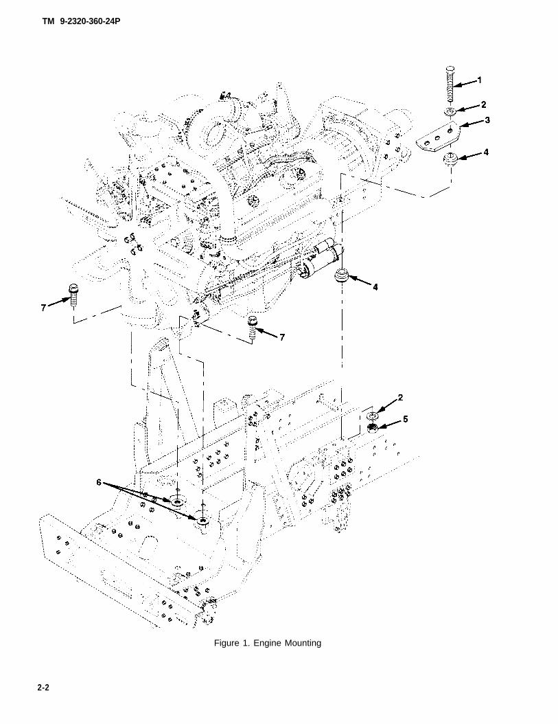
Figure 1. Engine Mounting
2-2
TM 9-2320-360-24P
Section II. REPAIR PARTS LIST
(1) (2) (3) (4) (5) (6) ( 7 ) (8)
ILLUSTRATION DESCRIPTION QTY
(a) (b) NATIONAL INC
FIG. ITEM SMR STOCK PART IN
NO. NO. CODE NUMBER CAGE NUMBER USABLE ON CODE UM UNIT
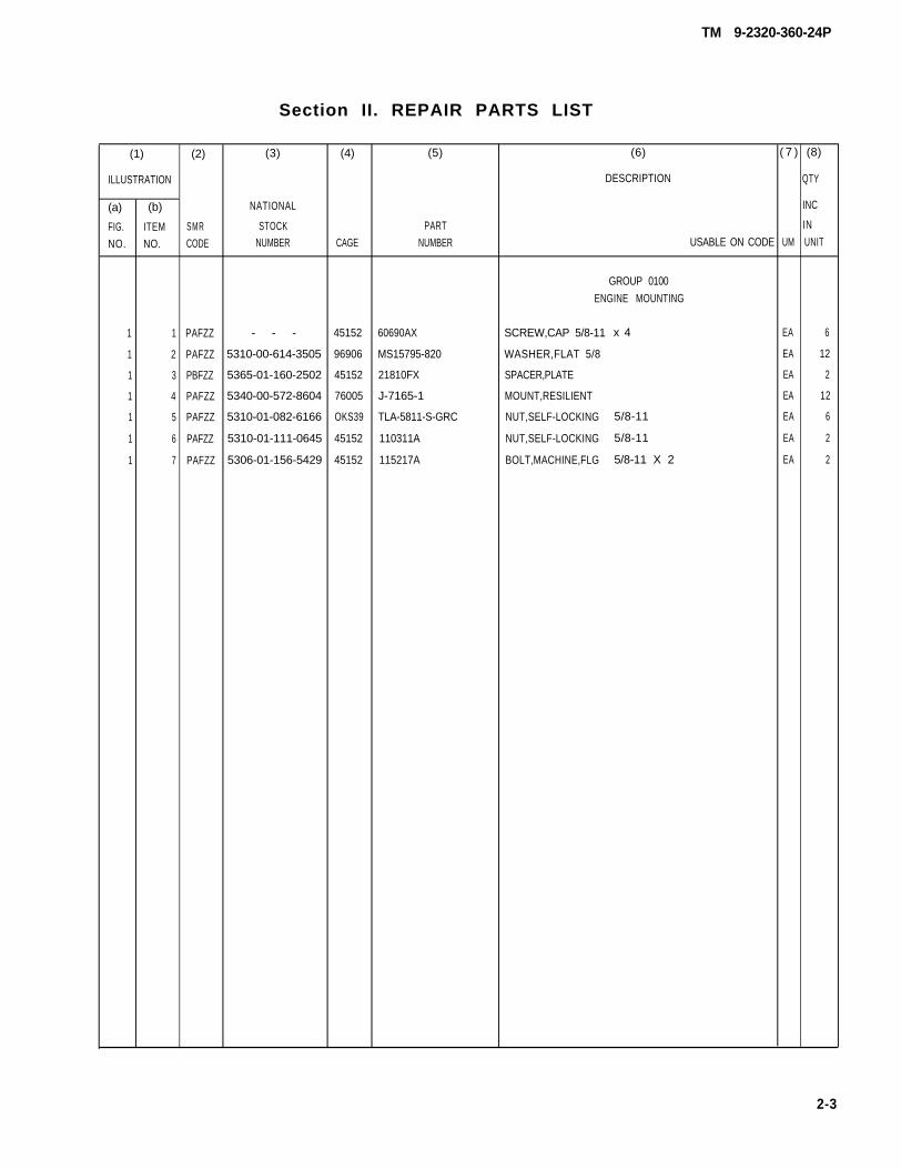
GROUP 0100
ENGINE MOUNTING
1 1 PAFZZ - - - 45152 60690AX SCREW,CAP 5/8-11 x 4 EA 6
1 2 PAFZZ 5310-00-614-3505 96906 MS15795-820 WASHER,FLAT 5/8 EA 12
1 3 PBFZZ 5365-01-160-2502 45152 21810FX SPACER,PLATE EA 2
1 4 PAFZZ 5340-00-572-8604 76005 J-7165-1 MOUNT,RESILIENT EA 12
1 5 PAFZZ 5310-01-082-6166 OKS39 TLA-5811-S-GRC NUT,SELF-LOCKING 5/8-11 EA 6
1 6 PAFZZ 5310-01-111-0645 45152 110311A NUT,SELF-LOCKING 5/8-11 EA 2
1 7 PAFZZ 5306-01-156-5429 45152 115217A BOLT,MACHINE,FLG 5/8-11 X 2 EA 2
2-3
TM 9-2320-360-24P
1
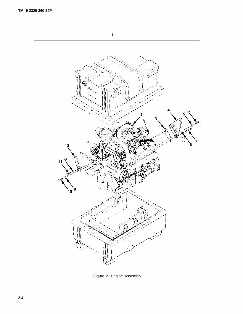
Figure 2. Engine Assembly
2-4
TM 9-2320-360-24P
Section II. REPAIR PARTS LIST
(1) (2) (3) (4) (5) (6) (7) (8 )
ILLUSTRATION DESCRIPTION QTY
(a) (b) NATIONAL INC
FIG ITEM SMR STOCK PART IN
NO NO CODE NUMBER CAGE NUMBER USABLE ON CODE UM UNIT
GRDUP 0100
ENGINE ASSEMBLY
2 1 PAFHH 2815-01-335-7448 19207 57K3047 ENGINE/CONTAINER DDEC II EA 1
2 1 PAFHH 19207 57K4184 ENGINE/CONTAINER DDEC III EA 1
2 2 PAFHH 2815-01-354-2911 19207 12436583 . ENGINE ASSY, DRESSED DDEC II EA 1
2 2 PAFHH 19207 12472145 . ENGINE ASSY, DRESSED DDEC III ONLY EA 1
2 3 PAFZZ 5330-00-725-2301 72582 5117332 ..GASKET EA 2
2 4 PFFZZ 5340-01-157-1763 72582 5133354 ..BRACKET EA 2
2 5 PAFZZ 5310-00-261-7340 96906 MS35338-8 ..WASHER.LOCK 3/8 EA 1
2 6 PAFZZ 5305-01-054-2280 72582 5101377 ..SCREW,CAP,HEX 3/8-16 X 1 EA 1
2 7 PAOZZ 5306-01-166-2607 72582 8921935 ..BOLT,SELF-LOCKING 7/16-14 X 1 1/8 EA 2
2 8 PAOZZ 5310-00-209-0965 96906 MS35338-47 ..WASHER,LOCK 7/16 EA 2
2 9 PAFZZ 5310-00-584-5272 96906 MS35338-48 ..WASHER,LOCK 1/2 EA 1
2 10 PAFZZ 5305-00-225-3661 96906 MS35307-424 ..SCREW,CAP,HEX 1/2-13 X 4 1/4 EA I
2 11 PAFZZ 5305-00-224-1176 72582 223435 ..SCREW,CAP,HEXAGON 5/8-11 X 1 3/4 EA 1
2 12 PAFZZ 5310-00-820-6653 96906 MS35338-50 ..WASHER,LOCK 5/8 EA 1
2 13 PFFZZ 5340-01-336-5418 72582 8928612 ..BRACKET,LIFT EA 1
2-5
TM 9-2320-360-24P
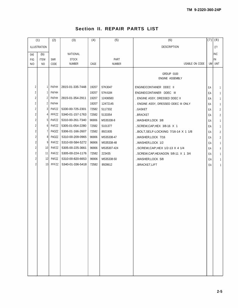
Figure 3. Cylinder Block (Sheet 1 of 3)
2-6
TM 9-2320-360-24P
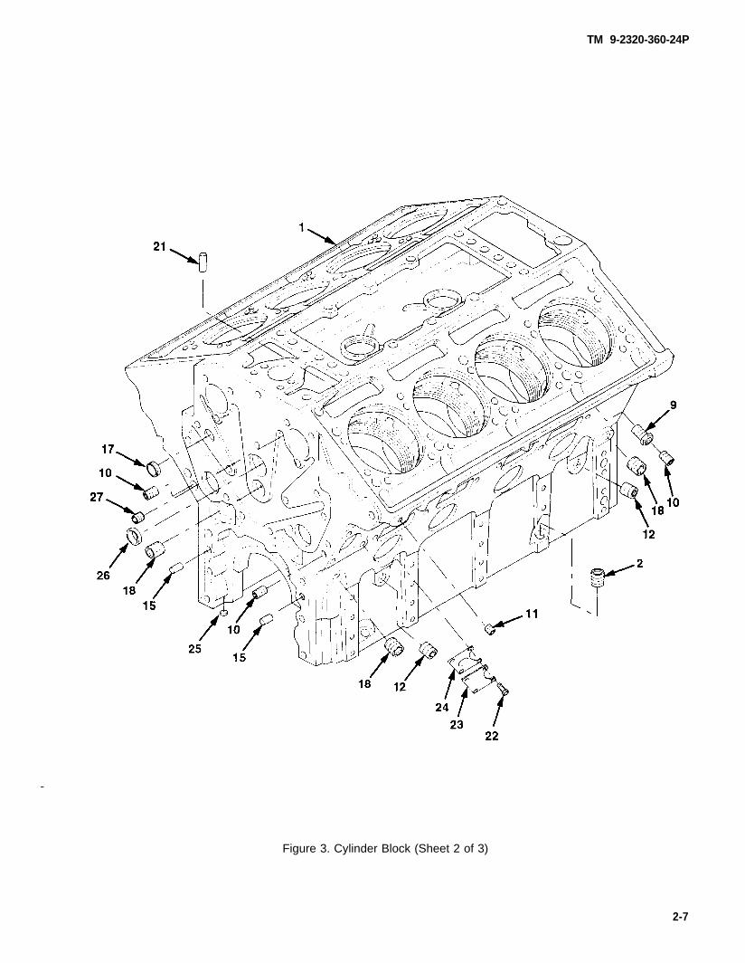
Figure 3. Cylinder Block (Sheet 2 of 3)
2-7
TM 9-2320-360-24P
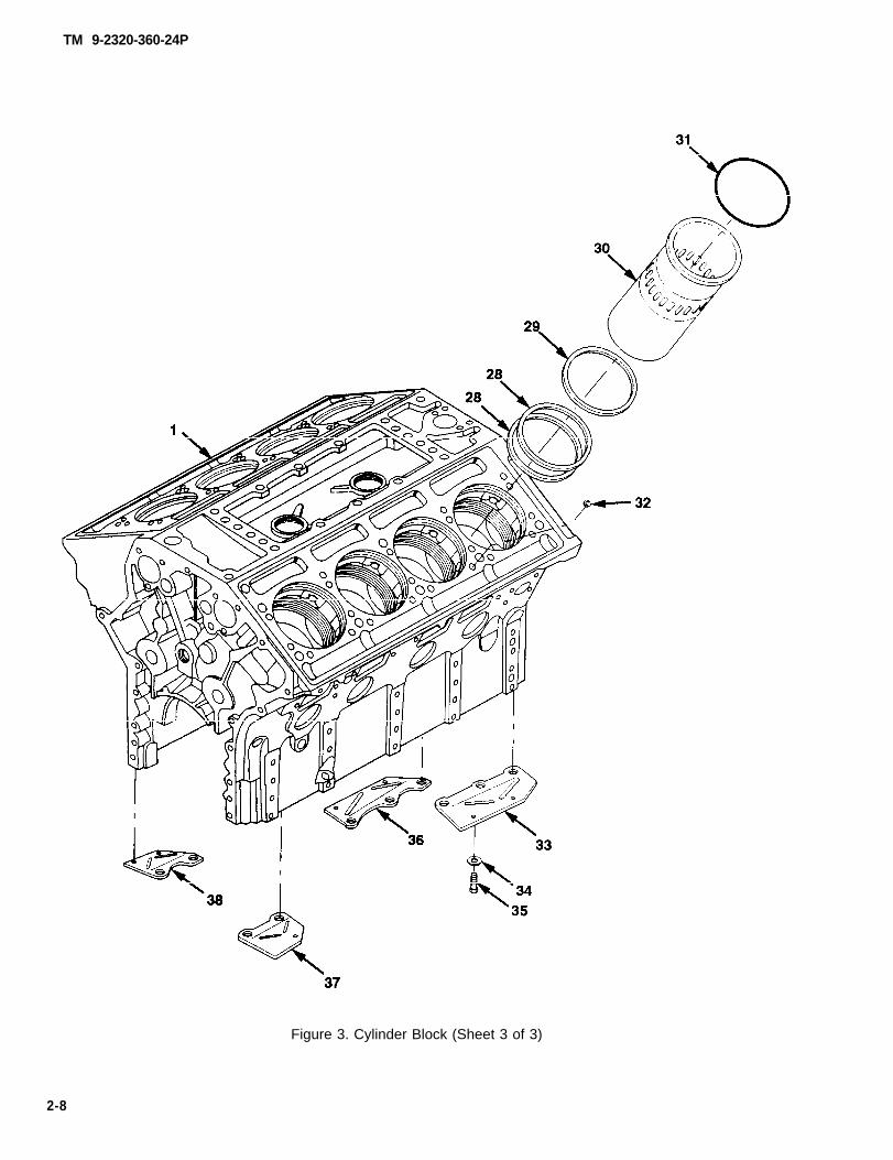
Figure 3. Cylinder Block (Sheet 3 of 3)
2-8
TM 9-2320-360-24P
Section II. REPAIR PARTS LIST
(1) (2) (3) (4) (5) (6) (7) (8 )
ILLUSTRATION DESCRIPTION QTY
(a) (b) NATIONAL INC
FIG ITEM SMR STOCK PART IN
N O . NO. CODE NUMBER CAGE NUMBER USABLE ON CODE UM UNIT
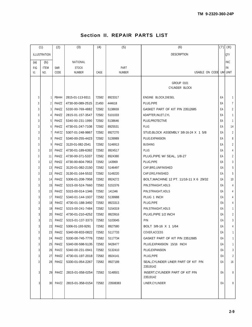
GROUP 0101
CYLINDER BLOCK
3 1 PBHHH 2815-01-113-9311 72582 8923317 ENGINE BLOCK,DIESEL EA 1
3 2 PAHZZ 4730-00-089-2515 21450 444618 PLUG,PIPE EA 7
3 3 PAHZZ 5330-00-769-4882 72582 5138659 GASKET PART OF KIT P/N 23512685 EA 2
3 4 PAHZZ 2815-01-157-3547 72582 5101033 ADAPTER,INLET,CYL EA 1
3 5 PAHZZ 5340-00-231-1990 72582 5138646 PLUG,PROTECTIVE EA 1
3 6 PAHZZ 4730-01-247-7108 72582 8925531 PLUG EA 14
3 7 PAFZZ 5307-01-248-9867 72582 8927270 STUD,BLOCK ASSEMBLY 3/8-16-24 X 1 5/8 EA 2
3 8 PAHZZ 5340-00-255-4423 72582 5139989 PLUG.EXPANSION EA 8
3 9 PAHZZ 3120-01-082-2541 72582 5146913 BUSHING EA 2
3 10 PAHZZ 4730-01-189-6392 72582 8924517 PLUG EA 4
3 11 PAHZZ 4730-00-371-5337 72582 8924380 PLUG,PIPE W/ SEAL, 1/8-27 EA 2
3 12 PAHZZ 4730-00-604-7953 72582 143969 PLUG,PIPE EA 3
3 13 PAHZZ 3120-01-082-2150 72582 5146497 CAP,BRG,UNFINISHED EA 5
3 13 PAHZZ 3130-01-164-5532 72582 5149220 CAP,ERG,FINISHED EA 5
3 14 PAHZZ 5306-01-208-7958 72582 8924272 BOLT,MACHINE 12 PT. 11/16-11 X 6 29/32 EA 10
3 15 PAHZZ 5315-00-524-7660 72582 5151576 PIN,STRAIGHT,HDLS EA 4
3 15 PAHZZ 5315-00-014-1346 72582 141346 PIN,STRAIGHT,HDLS EA 4
3 17 PAHZZ 5340-01-144-1937 72582 5139988 PLUG 1 INCH EA 4
3 18 PAHZZ 4730-01-188-3492 72582 8923313 PLUG,PIPE EA 4
3 19 PAHZZ 5315-00-241-7484 72582 5154319 PIN,STRAIGHT,HDLS EA 1
3 20 PAHZZ 4730-01-210-4252 72582 8923916 PLUG,PIPE 1/2 INCH EA 2
3 21 PAHZZ 5315-01-137-3373 72582 5103045 PIN EA 3
3 22 PAHZZ 5306-01-193-9291 72582 8927580 BOLT 3/8-16 X 1 1/64 EA 4
3 23 PAHZZ 5340-00-833-0822 72582 5117733 COVER,ACCESS EA 1
3 24 PAHZZ 5330-00-745-7776 72582 5117734 GASKET PART OF KIT P/N 23512685 EA 1
3 25 PAHZZ 5340-00-598-5135 72582 9428477 PLUG,EXPANSION 15/16 INCH EA 1
3 26 PAHZZ 5340-00-231-0941 72582 5132410 PLUG,EXPANSION EA 3
3 27 PAHZZ 4730-01-197-2018 72582 8924141 PLUG,PIPE EA 2
3 28 PAHZZ 5330-01-054-2267 72582 8927189 SEAL,CYLINDER LINER PART OF KIT P/N EA 16
23519142
3 29 PAHZZ 2815-01-058-0254 72582 5148501 INSERT,CYLINDER PART OF KIT P/N EA 823519142
3 30 PAHZZ 2815-01-358-0154 72582 23508383 LINER,CYLINDER EA 8
2-9
TM 9-2320-360-24P
Section II. REPAIR PARTS LIST
(1) (2) (3) (4) (5) (6) (7) (8)
ILLUSTRATION DESCRIPTION QTY
(a) (b) NATIONAL INC
FIG ITEM SMR STOCK PART INNO NO CODE NUMBER CAGE NUMBER USABLE ON CODE UM UNIT
GROUP 0101
CYLINDER BLOCK
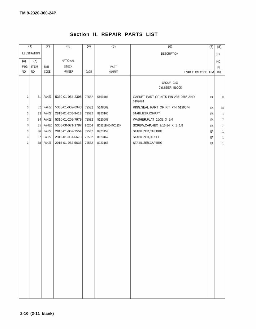
3 31 PAHZZ 5330-01-054-2398 72582 5100404 GASKET PART OF KITS P/N 23512685 AND EA 85199674
3 32 PAFZZ 5365-01-062-0943 72582 5148502 RING,SEAL PART OF KIT P/N 5199574 EA 34
3 33 PAHZZ 2815-01-205-9413 72582 8923160 STABILIZER,CSHAFT EA 1
3 34 PAHZZ 5310-01-209-7979 72582 5125608 WASHER,FLAT 15/32 X 3/4 EA 7
3 35 PAHZZ 5305-00-071-1787 80204 B1821BH044C113N SCREW,CAP,HEX 7/16-14 X 1 1/8 EA 7
3 36 PAHZZ 2815-01-052-3554 72582 8923159 STABILIZER,CAP,BRG EA 1
3 37 PAHZZ 2815-01-051-6673 72582 8923162 STABILIZER,DIESEL EA 1
3 38 PAHZZ 2915-01-052-5633 72582 8923163 STABILIZER,CAP,BRG EA 1
2-10 (2-11 blank)