titanium dioxide-coated nanofibers for advanced filters
TRANSCRIPT

This article was published in the above mentioned Springer issue.The material, including all portions thereof, is protected by copyright;all rights are held exclusively by Springer Science + Business Media.
The material is for personal use only;commercial use is not permitted.
Unauthorized reproduction, transfer and/or usemay be a violation of criminal as well as civil law.
ISSN 1388-0764, Volume 12, Number 7

RESEARCH PAPER
Titanium dioxide-coated nanofibers for advanced filters
Byung-Yong Lee • Kris Behler • Murat Erdem Kurtoglu • Meghan Ann Wynosky-Dolfi •
Richard F. Rest • Yury Gogotsi
Received: 29 January 2009 / Accepted: 23 November 2009 / Published online: 10 December 2009
� Springer Science+Business Media B.V. 2009
Abstract This article reports on titanium dioxide
(TiO2)-coated nanofibers deposited on a filter surface
by the electrospinning process. After depositing a
micrometer-thick film of polyamide 11 nanofibers on
polypropylene fabric, TiO2 nanoparticles can be
directly electrosprayed onto the nanofibers. X-ray
diffraction and Raman spectroscopy showed minimal
change in the phase composition (anatase and rutile)
and no change in the particle size of nanocrystalline
TiO2 after coating. Scanning electron microscopy
demonstrated that nanofibers were uniformly coated
by titanium dioxide nanoparticles without agglomer-
ation. TiO2-coated filters showed excellent photo-
catalytic-bactericidal activity and photo-induced
hydrophilicity.
Keywords Electrospinning � Titanium dioxide �Photocatalyst � Filter � Fibers � Electrospraying �Nanomanufacturing
Introduction
The electrospinning technique has been widely used
for manufacturing nanofibers with different function-
alities required in drug delivery systems, nanosen-
sors, micro/nano electronic devices, scaffolds for
tissue engineering and filtration media (Li and Xia
2004; Burger et al. 2006). In particular, electrospun
nanofibers have high specific surface areas with a
distinctive nanoscale surface texture, for which they
have been extensively studied in applications ranging
from high-performance filters to chemical and bio-
logical sensors, and protective clothing because their
small mesh allows trapping of very small (submi-
crometer) particles (Ko 2006). As a result of this
increased interest, the electrospinning method has
been applied not only to polymeric materials but also
to ceramics, particularly to metal oxides (Li et al.
2003). Among the metal oxides, titanium dioxide has
attracted a great deal of interest for electrospinning
applications because of its unique photoinduced
catalytic activity and superhydrophilicity coupled
with low cost, chemical stability and biological
inertness (Im et al. 2008; Li and Xia 2003). In
general, electrospun hybrid organic–inorganic fibers
have been prepared either by co-electrospinning (Ko
et al. 2003; Ko et al. 2006; Ye et al. 2004) or by
impregnating inorganic precursors into a polymeric
solution followed by the nucleation and growth of
functional inorganic particles on the electrospun
polymer fibers. However, co-electrospinning is not
B.-Y. Lee � K. Behler � M. E. Kurtoglu � Y. Gogotsi (&)
Department of Materials Science and Engineering,
A.J. Drexel Nanotechnology Institute, Drexel University,
Philadelphia, PA 19104, USA
e-mail: [email protected]
M. A. Wynosky-Dolfi � R. F. Rest
Department of Microbiology and Immunology,
Drexel University College of Medicine,
Philadelphia, PA 19129, USA
123
J Nanopart Res (2010) 12:2511–2519
DOI 10.1007/s11051-009-9820-x
Author's personal copy

the method of choice when nanoparticles require
access to the surface, because they will be wrapped
by polymer. Nucleation and growth of inorganic
materials, particularly metal oxides, usually require
post-treatment at elevated temperatures, which pre-
vents their applicability to temperature-sensitive
substances like polymers. Therefore, pre-crystalline
precursors that do not need a high temperature post-
treatment would be more suitable for this purpose.
To place TiO2 on fabric surfaces, dip coating has
been used (Horikoshi et al. 2002). However, TiO2
particles within the fabric are not exposed to
sufficient UV light to produce a significant photo-
catalytic effect, and they can be carried by air flow,
due to the loosely bound particle-like structure of
the coating, potentially affecting people who breathe
the filtered air.
In this work, titanium dioxide-coated filters were
prepared by electrospraying polyamide 11 (PA 11)
nanofibers onto the surface of a conventional filter
followed by electrospraying a suspension of nano-
crystalline titanium dioxide onto the electrospun
nanofibers. This potentially allows producing a filter
capable of both trapping small particles such as
viruses and destroying them on the filter surface.
Experimental
Materials
Non-woven polypropylene fabric obtained from
Amerinova LLC, USA, was used as the filter
substrate for consecutive nanofiber and TiO2 deposi-
tions. Polyamide 11 (Rilsan�, Arkema, Inc), which is
a green polymer produced from renewable resources,
was used for nanofiber electrospinning. Formic acid
(99%, Acros) and dichloromethane (99.5?%, Alfa
Aesar) were used without further purification. Col-
loidal silica binder was prepared using TEOS (tetra-
ethyl orthosilicate, 98%, Acros), anhydrous ethanol,
nitric acid (70%, Sigma-Aldrich) and distilled water.
Degussa P25 TiO2 (composed of 70% anatase and
30% rutile) was used to prepare the aqueous TiO2
dispersion. Methylene blue (Sigma-Aldrich) was
selected as a model pollutant for the photocatalytic
activity tests.
Preparation of TiO2-coated electrospun nanofiber
Non-woven fabric was thoroughly cleaned by dipping
into a deionized water–ethanol mixture and subse-
quently dried at room temperature. Before electros-
pinning of the PA 11 nanofibers, the polypropylene
fabric substrate was dip-coated with a sol–gel silica
solution to improve the adhesion of the electrospun
nanofibers onto the hydrophobic fabric by forming
silanol groups. Silica-impregnated polypropylene
substrate was sonicated for 5 min to remove loosely
attached residual particles and dried in an oven at
60 �C. Silica solution was prepared by sol–gel
technique as follows; 104 g of TEOS was mixed
with 500 g of anhydrous ethanol and stirred for 1 h.
Then a 184 g of distilled water, ethanol, and HNO3
mixture was drop-wise added to this solution fol-
lowed by 6 h of vigorous stirring. Before coating, the
solution was aged at room temperature for 12 h.
For polymeric solution, 2 g of PA 11 powder was
dissolved in 60 ml formic acid–dichloromethane (1:1
v/v) mixture followed by heating to 70 �C on a hot
plate with vigorous stirring. This solution was then
drawn into a syringe with a 30 G needle. Non-woven
fabrics were attached to the surface of aluminum foil
which was placed on an electrically grounded,
rotating collection drum. Prepared polymeric solu-
tions were electrospun (Nanofiber Electrospinning
Unit, Kato Tech Co., Japan) onto silica-coated fabric
to produce PA 11 nanofibers with the following
parameters: two different voltages of 10 and 20 kV,
syringe pump speed from 1.2 to 3 cm/h, tip-to
collector distance (TCD) 15 cm, coating time
1–3 min (Behler et al. 2007).
TiO2 particle suspensions were prepared by son-
icating 5 g TiO2 powder in a 95 g water: ethanol (1:1
w/w) mixture. 3-Aminopropylmethoxysilane was
added to the mixture to functionalize the TiO2
surfaces. One gram of NaCl was added to increase
the electrical conductivity of the suspension. After
stirring the final suspension on a magnetic stirrer for
4 h, it was electrosprayed onto the electrospun PA 11
nanofibers using the following parameters: 15 kV,
7.5 cm TCD, 18 G syringe needle. After electrospin-
ning for 3 h, the prepared TiO2-electrosprayed
nanofibers on the filters were kept in air for 1 h,
and dried at 70 �C for 30 min. In addition to
polypropylene fabric filters, a set of electrospun
2512 J Nanopart Res (2010) 12:2511–2519
123
Author's personal copy
TiO2–PA 11-coated aluminum foils was also pre-
pared, using the same parameters.
Characterization
The SEM images of the electrospun nanofibers coated
with TiO2 were collected by a Zeiss Supra 50VP from
5 to 10 spots. To confirm TiO2 presence on the filter,
EDX analysis was conducted using an Oxford Energy
Dispersive X-ray Microanalyser. The crystal structure
of the electrosprayed TiO2 was analyzed by X-ray
diffraction (XRD) using Siemens D500 with nickel
filtered Cu Ka radiation (40 kV, 30 mA) between
2h = 20� and 80�. The diffraction peaks of the
anatase (101) and rutile (110) planes were selected to
analyze the crystallinity and the anatase-to-rutile ratio
of the electrosprayed TiO2. Raman spectra were
measured at room temperature using a 514.5 nm Ar-
ion laser as the excitation source (Renishaw
RM1000). Optical spectra of the samples were
collected by Thermo Scientific, Evolution 600 UV–
Vis Spectrophotometer equipped with a reflectance
sphere.
Photocatalytic activity testing
Methylene blue degradation tests were carried out on
the TiO2 electrosprayed PA 11 nanofibers on both
filters and aluminum foils in order to evaluate the
photocatalytic activity. The samples were covered by
800 ll, 1.4 9 10-6 M methylene blue solution and
irradiated with two 15 W UV-A lamps (1 mW/cm2,
Philips F15T8) for 4 h. Methylene blue concentration
on the samples was monitored by visually observing
the change in color and by measuring absorbance at
664 nm with a spectral colorimeter (Spectra UV-
4000). Contact angle measurements were performed
by the sessile drop method at room temperature using
a home-made apparatus, equipped with a CCD solid
state color video camera (HITACHI VK-C360,
camera: Nikon) (Mattia et al. 2006).
Antibacterial test
Escherichia coli (E. coli) was grown in Luria Bertani
(LB) broth, a standard and widely used growth media
for E. coli, overnight at 37 �C with shaking at
250 rpm. Bacteria were pelleted and resuspended to
desired concentrations. One centimeter squares of
TiO2-electrosprayed filters or aluminum foil were
placed in wells of a 24 well tissue culture plate and
50 ll drops of bacteria were carefully placed in the
center of the filter or foil squares. Remaining wells of
24 wells of plate were filled with water and a 2 mm
thick, 10 cm 9 15 cm Pyrex glass plate was placed
on top of the tissue culture plate to maintain a humid
environment and to avoid evaporation. This set-up
was repeated in duplicate—one placed under UV
light and the other not. Samples were irradiated with
2 UV-A bulbs suspended 8 cm above the 24 well
plate at room temperature. At 0, 30, 60, and 120 min,
bacteria were recovered from the filter or foil squares,
diluted, and plated on LB agar plates. LB agar plates
were incubated at 37 �C overnight, at which time
colonies were counted. Data are represented as three
independent experiments.
Results and discussion
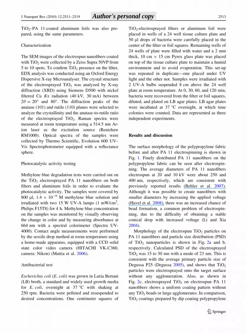
The surface morphology of the polypropylene fabric
before and after PA 11 electrospinning is shown in
Fig. 1. Finely distributed PA 11 nanofibers on the
polypropylene fabric can be seen after electrospin-
ning. The average diameters of PA 11 nanofibers
electrospun at 20 and 10 kV were about 250 and
400 nm, respectively, which are consistent with
previously reported results (Behler et al. 2007).
Although it was possible to create nanofibers with
smaller diameters by increasing the applied voltage
(Havel et al. 2008), there was an increased chance of
bead formation, a common problem of electrospin-
ning, due to the difficulty of obtaining a stable
conical drop with increased voltage (Li and Xia
2004).
Morphology of the electrospun TiO2 particles on
PA 11 nanofibers and particle size distribution (PSD)
of TiO2 nanoparticles is shown in Fig. 2a and b,
respectively. Calculated PSD of the electrosprayed
TiO2 was 15 to 30 nm with a mode of 23 nm. This is
consistent with the average primary particle size of
Degussa P25 (Degussa 2005), and shows that TiO2
particles were electrosprayed onto the target surface
without any agglomeration. Also, as shown in
Fig. 2c, electrosprayed TiO2 on electrospun PA 11
nanofibers shows a uniform coating pattern without
any TiO2 beads or large agglomerates. In comparison,
TiO2 coatings prepared by dip coating polypropylene
J Nanopart Res (2010) 12:2511–2519 2513
123
Author's personal copy
were not homogeneous (Fig. 2d). Large agglomerates
of TiO2 particles were easily detectable even under
low magnification. The presence of TiO2 particles
and colloidal silica for all of the samples were
confirmed by EDX analysis (data not shown).
The X-ray diffraction diagram of the TiO2-coated
fabric via electrospinning is shown in Fig. 3. The
main peak positions and their relative intensities of
the anatase and rutile phases on nanofibers are
consistent with the diffraction patterns of the as-
received TiO2 powder, albeit with much more noise
in the nanofibers’ spectra due to the limited thickness
of titania. No broadening of the peaks was observed
on the XRD pattern of the electrospun TiO2 samples
compared to the original TiO2 powder. On the other
hand, the rutile to anatase volume ratio, calculated by
the Spurr equation (Spurr and Myers 1957), was
slightly increased from 0.16 in the original powder to
0.19 on the electrospun substrate. This behavior was
attributed to the slightly higher charge accumulated
on the rutile particles inside the solution due to the
lower point of zero charge (PZC) of rutile compared
to that of anatase (Kosmulski 2002), which possibly
resulted in better functionalization of the rutile
surfaces. Since the change in composition is very
small, a significant change of the photocatalytic
activity was not expected.
Raman spectra of the TiO2-electrosprayed nanof-
ibers and Degussa P25 are shown in Fig. 4. On
Degussa P25 TiO2 powder spectra, we identified the
main Raman peaks of anatase at 147 cm-1 (Eg),
198 cm-1 (Eg), 398 cm-1 (B1g), 519 cm-1 (A1g and
B1g), and 640 cm-1 (Eg), 801 cm-1 (B1g), and of
rutile at 448 cm-1 (Eg). Positions and the intensities
of the Raman active peaks were in agreement with
previously reported results (Ocana et al. 1992; Zhao
et al. 2008; Nuansing et al. 2006). The reported
144 cm-1 (B1g) peak of rutile was likely an overtone
with the anatase assigned peak (147 cm-1) and was
not observed (Arabatzis et al. 2002; Miao et al. 2004).
The intensities of the peaks at 235, 448, and
612 cm-1, which were attributed to the rutile phases
with TiO2-electrosprayed nanofiber, somewhat
increased compared to the original TiO2 powder.
This was consistent with our XRD results, which also
showed that there was more rutile in the coatings than
in the powders, though anatase was still the dominant
phase in the titania coating. Although the reason for
this is unclear, it may be due to a better response of
the rutile phase to the applied potential during
electrospraying, causing more rutile particles to be
deposited on the fibers. This assumption is reasonable
if the reported point of zero charge (PZC) values of
anatase (pH 6.2) and rutile (pH 5.3) are considered
(Malati 1999). As the prepared dispersion was around
pH 4.6, the anatase phase particles were expected to
be more positively charged than the rutile ones,
which in turn, increase the chances of attraction of
rutile particles to the negatively charged substrate.
Raman peaks of PA 11 were also observed. As
shown in Fig. 4, TiO2-electrosprayed nanofibers
exhibit peaks at 1108 and 1122 cm-1 corresponding
to the trans-C–C symmetric stretching in the PA 11
chain (Behler et al. 2007). Raman peaks of PA 11
Fig. 1 a SEM images of as-received base non-woven poly-
propylene fabric. b PA 11-electrosprayed nanofiber with 10 kV
electronic voltage
2514 J Nanopart Res (2010) 12:2511–2519
123
Author's personal copy

(c) (d)
(a)
15 20 25 30 350
5
10
15
20
25
30
Diameter of particles (nm)
Dis
trib
uti
on
(re
lati
ve n
um
ber
%) (b)
Fig. 2 a SEM image and b calculated particle size distribution (PSD) of electrosprayed TiO2 particles. c SEM images of TiO2-
electrosprayed PA 11 nanofiber. d TiO2 dip-coated polypropylene substrate
Fig. 3 X-ray diffraction patterns of the TiO2-electrosprayed
nanofiber and the as-received TiO2 powder
200 400 600 800 1000 1200
Inte
nsi
ty (
a.u
.)
Raman Shift (cm-1)
801
Electrosprayed TiO2 on PA 11
Electrospun PA 11
TiO2 powder (P25)
147
198 235
398448 519
612
640
801
1122
11081062
11081062 1122
147
198
398
448
519
640
Fig. 4 Raman spectra of TiO2-deposited electrospun nanofi-
ber, electrospun PA 11, and TiO2 (P25) powder
J Nanopart Res (2010) 12:2511–2519 2515
123
Author's personal copy

were not observed below 800 cm-1, as previously
observed (Hernandez et al. 1995; Cui and Yan 2005).
There were no peaks attributable to colloidal silica in
the Raman spectra, which usually shows a broad peak
at 440 cm-1 and weaker peaks at 492, 605, 800, and
1,060 cm-1 (Bosc et al. 2006). We assume that the
film was too thin and silica peaks were suppressed by
closely positioned TiO2 peaks.
Since the optical spectra of the TiO2-coated fabric
samples could be difficult to be interpreted accurately
caused by the unusual scattering of the substrate, an
aluminum foil which was prepared by the same
procedure was used instead. As shown in Fig. 5, the
spectra of as-received aluminum foil do not have any
band edges within the 200–800 nm wavelength
range, whereas electrosprayed TiO2 had a clear band
edge near 350 nm, which corresponds to the anatase.
Methylene blue decomposition by TiO2-electro-
sprayed fabric and aluminum foil was performed
under UVA light to investigate their photocatalytic
properties. Non-treated fabric and aluminum foil
were used as controls. Figure 6 shows the dye
concentration versus time measured in 20 min inter-
vals. No detectable dye degradation was seen on the
control samples after 3 h of illumination. For TiO2-
coated aluminum foil, total decomposition of the dye
occurred after 75 min (Fig. 7). This shows excellent
photocatalytic performance for electrosprayed TiO2.
For TiO2-electrosprayed nanofibers on polypropylene
fabric, partial decomposition of the dye was observed
after about 40 min, but no further decomposition of
the dye was observed after that. On the other hand,
90% decomposition was observed on the TiO2-
deposited aluminum foil after 40 min. The discrep-
ancy between the fabric and foil may have been
300 400 500 600 700 8000
10
20
30
40
50
60
70
80
90
100
TiO2 electrosprayed nanofiber
on aluminum foil
As-received aluminum foil
Ref
lect
ance
(%
)
Wavelength (nm)
Fig. 5 Diffuse-Reflectance (DR) UV-visible spectra of as-
received aluminum foil and TiO2-electrosprayed aluminum foil
0 20 40 60 80 100 120 140 160 1800.0
0.2
0.4
0.6
0.8
1.0
non-treated aluminum foil
non-treated polypropylene fiber
electrosprayed aluminum foil
electrosprayed PA 11 nanofiber
Co
nce
ntr
atio
n c
han
ge,
C /
C0
(a.u
.)
UV illumination time (min)
Fig. 6 Photo-decomposition of methylene blue under UVA
illumination by TiO2-electrosprayed substrates and non-treated
controls for 3 h (light intensity: 1 mW/cm2)
Before UVA illumination, t = 0
(1) (2) (3)
t = 75 minutes
Fig. 7 Methylene blue dye degradation on TiO2-electro-
sprayed samples for 75 min; (1) TiO2-electrosprayed fabric,
(2) TiO2-electrosprayed aluminum foil, (3) control (non-treated
fabric and aluminum foil)
2516 J Nanopart Res (2010) 12:2511–2519
123
Author's personal copy
caused by the absorption of the dye inside the fabric
where TiO2 particles were not available or did not
receive the required UVA irradiation that was
blocked by the surface layer of fibers. The nanofi-
ber-supported TiO2 would destroy particles and
aerosols coming into contact with the filter surface,
but liquid that penetrated through the film would not
have direct contact with TiO2, which could explain
incomplete decomposition of methylene blue on the
filter. Although some of the dye would desorb to the
surface in the presence of a liquid (i.e., water), quick
drying of the dye should have prevented the complete
desorption in a reasonable time scale.
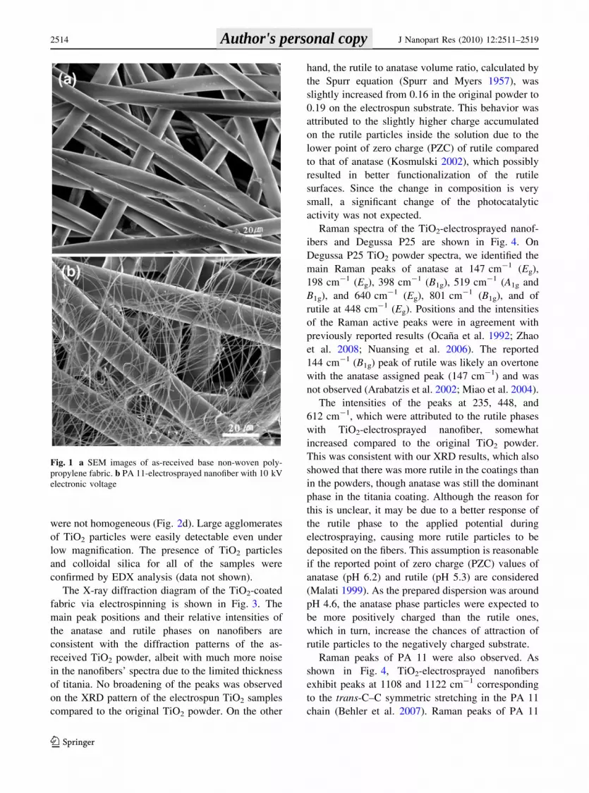
This has been confirmed by E. coli killing on
untreated and TiO2-coated fabric and foil (Fig. 8).
Similar to dye degradation tests, a significant bacte-
ricidal effect of TiO2 was observed after 30 min;
however, while complete killing was achieved when
TiO2 was deposited on foil, only partial killing of
bacteria occurred on fibers, regardless of coating.
Apparently, uncoated foils were able to kill more
bacteria than that of uncoated fabrics, which is due to
the higher amount of UV exposure resulting from the
higher reflectivity of the aluminum foils. These
results support the proposed concept, but suggest
that further optimization of TiO2 coverage will be
required to increase the bactericidal properties of the
filter (Kau et al. 2009).
Figure 9 shows the contact angle measurement
results. As-spun PA 11 nanofibers were hydrophobic
with a contact angle of 65�. After modifying the
surface with TiO2 particles, surfaces became more
hydrophilic with a contact angle of 30�. TiO2-coated
fabric showed photo-induced super-hydrophilicity, as
expected. After an hour of illumination with UVA
light, the contact angle decreased below 5� showing
increased hydrophilicity and excellent wetting.
Results of this study show that it is possible to
combine both nanofiber protection and photocatalytic
properties of TiO2 leading to bactericidal properties
in filter manufacturing. The proposed technique is
simple and can be applied to any filter surface.
Moreover, by using the electrospraying technique,
TiO2 was placed exactly where it is needed—on the
very surface of the filter. This serves two functions—
to decrease the consumption of TiO2, thus decreasing
filter cost, and to eliminate TiO2 from the inner layers
of the filter.
Conclusions
Electrosprayed-TiO2 nanoparticles maintained their
primary particle size after spraying onto electrospun
PA 11 nanofibers with a uniform distribution. Meth-
ylene blue degradation showed a high photocatalytic
activity of TiO2-coated nanofibers. Contact angle
measurements demonstrated super-hydrophilic
behavior of electrosprayed TiO2 under UVA radia-
tion. We showed that it is possible to electrospray
TiO2 particles directly onto nanofibers to add photo-
catalytic properties to masks and filters. The use of a
2
4
6
8
10
12 Uncoated fabric TiO
2-coated electrospun fabric
1209060300
UVA illumination time (min)
Nu
mb
er o
f E
. co
li(x1
05 ce
ll /m
l)
Nu
mb
er o
f E
. co
li(x1
05 ce
ll /m
l)
0
2
4
6
8
10
12
1209060300
UVA illumination time (min)
Uncoated foil TiO
2-coated electrospun foil
(a)
(b)
Fig. 8 Photocatalytic E. coli inactivation on TiO2-electro-
sprayed samples in comparison with controls under UVA light
illumination. a Number of E. coli colonies on fabric and b on
foil with and without TiO2 coating
J Nanopart Res (2010) 12:2511–2519 2517
123
Author's personal copy

thin nanofiber coating on the surface of polypropyl-
ene fabric decreases the mesh, enabling the filter to
catch smaller particles and increase the active surface
area improving the contact between TiO2 and
biological or organic contaminants. Electrospraying
decreases the amount of TiO2 used and places TiO2
particles on the outer surface of the filter, where they
are most required.
Acknowledgments This work was supported in part by
Amerinova LLC, USA, and Drexel University College of
Medicine. The authors are grateful to Lou Schiliro
(Amerinova) for helpful discussions and to Arkema, Inc. for
providing PA 11. M.E.K. was supported by ArtCraft Glass,
Inc., Kutahya, Turkey. K. B. was supported by the NSF
Graduate Student Research Fellowship.
References
Arabatzis I, Antonaraki S, Stergiopoulos T, Hiskia A, Papa-
constantinou E, Bernard M, Falaras P (2002) Preparation,
characterization and photocatalytic activity of nanocrys-
talline thin film TiO2 catalysts towards 3,5-dichlorophe-
nol degradation. J Photochem Photobiol A 149:237–245
Behler K, Havel M, Gogotsi Y (2007) New solvent for
polyamides and its application to the electrospinning of
polyamides 11 and 12. Polymer 48:6617–6621
Bosc F, Ayral A, Guizard C (2006) Mixed TiO2-SiO2 meso-
structured thin films. Thin Solid Films 495:252–256
Burger C, Hsiao B, Chu B (2006) Nanofibrous materials and
their applications. Annu Rev Mater Res 36:333–368
Cui X, Yan D (2005) Preparation, characterization and crys-
talline transitions of odd-even polyamides 11, 12 and 11,
10. Eur Polym J 41:863–870
Degussa (2005) Technical information Aeroxide and Aeroperl
titanium dioxide as photocatalyst. TI No 1243
Havel M, Behler K, Korneva G, Gogotsi Y (2008) Transparent
thin films of multiwalled carbon nanotubes self-assembled
on polyamide 11 nanofibers. Adv Funct Mater 18:2322–
2327
Hernandez M, Servant L, Grondin J, Lassegues J (1995)
Spectroscopic characterization of metal chloride/polyam-
ide complexes. Ionics 5–6:454–468
Horikoshi S, Watanabe N, Onishi H, Hidaka H, Serpone N
(2002) Photodecomposition of a nonylphenol polyeth-
oxylate surfactant in a cylindrical photoreactor with TiO2
immobilized fiberglass cloth. Appl Catal B 37:117–129
Im J, Kim M, Lee Y (2008) Preparation of PAN-based elec-
trospun nanofiber webs containing TiO2 for photocatalytic
degradation. Mater Lett 62:3652–3655
Kau J, Sun D, Huang H, Wong M, Lin H, Chang H (2009) Role
of visible light-activated photocatalyst on the reduction of
anthrax spore-induced morality in mice. PLoS ONE
4:e4167
Ko F (2006) Nanofiber technology. In: Gogotsi Y (ed)
Nanomaterials handbook. CRC Press, Boca Raton, pp
553–564
Ko F, Gogotsi Y, Ali A, Naguib N, Ye H, Yang G, Li C, Willis
P (2003) Electrospinning of continuous carbon nanotube-
filled nanofiber yarns. Adv Mater 15:1161–1165
Ko F, Lam H, Titchenal N, Ye H, Gogotsi Y (2006) Coelec-
trospinning of carbon nanotube reinforced nanocomposite
fibrils. Polym Nanofibers 918:231–245
0 20 40 60 80 100 120
0
5
10
15
20
25
30
Co
nta
ct a
ng
le o
f w
ater
dro
p (
°)
UV illumination time (min)
As-spun PA 11
Fig. 9 The water contact
angle dependence on the
UVA illumination time for
the TiO2-electrosprayed
nanofiber (light intensity:
1 mW/cm2)
2518 J Nanopart Res (2010) 12:2511–2519
123
Author's personal copy

Kosmulski M (2002) The significance of the difference in the
point of zero charge between rutile and anatase. Adv
Colloid Interface Sci 99(3):255–264
Li D, Xia Y (2003) Fabrication of titania nanofibers by elec-
trospinning. Nano Lett 3:555–560
Li D, Xia Y (2004) Electrospinning of nanofibers: reinventing
the wheel? Adv Mater 16:1151–1170
Li D, Wang Y, Xia Y (2003) Electrospinning of polymeric and
ceramic nanofibers as uniaxially aligned arrays. Nano Lett
3:1167–1171
Malati M (1999) Experimental inorganic/physical chemistry:
an investigate, integrated approach to practical project
work. Horwood Publishing, West Sussex
Mattia D, Bau H, Gogotsi Y (2006) Wetting of CVD carbon
films by polar and nonpolar liquids and implications for
carbon nanopipes. Langmuir 22:1789–1794
Miao L, Tanemura S, Toh S, Kaneko K, Tanemura M (2004)
Fabrication, characterization and Raman study of anatase-
TiO2 nanorods by a heating-sol-gel template process. J
Cryst Growth 264:246–252
Nuansing W, Ninmuang S, Jarernboon W, Maensiri S, Sera-
phin S (2006) Structural characterization and morphology
of electrospun TiO2 nanofibers. Mater Sci Eng B
131:147–155
Ocana M, Garcia-Ramos J, Serna C (1992) Low-temperature
nucleation of rutile observed by Raman spectroscopy dur-
ing crystallization of TiO2. J Am Ceram Soc 75:2010–2012
Spurr R, Myers H (1957) Quantitative analysis of anatase-rutile
mixtures with an X-ray diffractometer. Anal Chem
29:760–762
Ye H, Lam H, Titchenal N, Gogotsi Y, Ko F (2004) Rein-
forcement and rupture behavior of carbon nanotubes-
polymer nanofibers. Appl Phys Lett 85:1775–1777
Zhao J, Jia C, Duan H, Li H, Xie E (2008) Structural properties
and photoluminescence of TiO2 nanofibers were fabri-
cated by electrospinning. J Alloys Compd 461:447–450
J Nanopart Res (2010) 12:2511–2519 2519
123
Author's personal copy