time-aware multi agent systems
TRANSCRIPT

MULTIAGENT SYSTEMS AND SOFTWARE ARCHITECTURE
Proceedings of the Special Track at Net.ObjectDaysErfurt, Germany, September 19, 2006
Danny Weyns and Tom Holvoet (Eds.)

c©Katholieke Universiteit Leuven – Faculteit IngenieurswetenschappenArenbergkasteel, B-3001 Heverlee (Belgium)
Alle rechten voorbehouden. Niets uit deze uitgave mag worden vermenigvuldigden/of openbaar gemaakt worden door middel van druk, fotocopie, microfilm,elektronisch of op welke andere wijze ook zonder voorafgaande schriftelijke toe-stemming van de uitgever.
All rights reserved. No part of the publication may be reproduced in any formby print, photoprint, microfilm or any other means without written permissionfrom the publisher.
D/2006/7515/71ISBN 90–5682–737–5

Preface
Multiagent systems are generally considered as an approach for engineering ap-plications in complex domains. A multiagent system application is designed as aset of autonomous software entities (agents) that are embedded in shared struc-ture (the environment). Agents can flexibly achieve their design objectives byacting in the environment and interacting with one another. Multiagent systemsare typically ascribed quality properties such as adaptability, robustness, andscalability.
Mainstream software engineering generally recognizes software architectureas the primary vehicle to manage complexity and to achieve the system’s requiredqualities. Software architecture consists of the structures of the system, whichcomprise software elements, the externally visible properties of those elements,and the relationships among them. Software elements provide the functionalityof the system, while the required system qualities are primarily achieved throughthe structures of the software architecture.
So there is a clear connection between multiagent systems and software ar-chitecture. Yet this connection is rarely explored. Agent-oriented methodologiestypically give an individual interpretation to the various phases of the soft-ware engineering process. This isolates agent-oriented software engineering frommainstream software engineering practice, hampering the industrial acceptanceof agent technology.
Multiagent Systems and Software Engineering (MASSA) places the connec-tion between multiagent systems and software architecture in the forefront. Theoverall goal of the special track is to explore how current practice in softwarearchitecture can be valuable for software engineering with multiagent systems.
This volume contains the papers that were accepted for MASSA. The sub-mitted papers were reviewed by three reviewers. From the eleven submissionswe received for the special track, six submissions were accepted. In addition,the volume contains tree invited papers. We hope that the research presentedin this volume will stimulate the further exploration of the connection betweenmultiagent systems and software architecture.
August 23, 2006 Danny WeynsLeuven, Belgium
3

4

Organization
MASSA 2006 is organized in conjunction with the Net.ObjectDays Conference,Erfurt, Germany, September 19, 2006.
Program Chair
Danny Weyns Katholieke Universiteit Leuven, Belgium
Program Committee
Hausi Muller University of Victoria, British Columbia, USADavid Garlan Carnegie Mellon University, USADennis Smith Software Engineering Institute, SEI, USAMarin Litoiu BM Canada Ltd., CanadaRenee Elio University of Alberta, CanadaWouter Joosen Katholieke Universiteit Leuven, BelgiumPaolo Giorgini University of Trento, ItalyJorg Muller Technical University Clausthal, GermanyTom Holvoet Katholieke Universiteit Leuven, BelgiumJames Odell Intelligent Automation, Inc., USAH. Van Dyke Parunak NewVectors LLC, Ann Arbor, USALiz Sonenberg University of Melbourne, AustraliaOnn Shehory IBM Reseach Labs, IsraelAlessandro Garcia Lancaster University, UKFranco Zambonelli University of Modena and Reggio Emilia, Italy
Website
http://www.cs.kuleuven.ac.be/∼distrinet/events/massa/2006/
Acknowledgements
We are grateful to the Net.ObjectDays organization, in particular Rainer Unlandand Kirsten Paradies, for supporting the organization of the MASSA specialtrack. We thank the members of the program committee for their reviews andthank all authors for submitting their work to MASSA 2006.
5

Table of Contents
Multiagent Systems and Software Architecture . . . . . . . . . . . . . . . . . . . . . . . . 7Danny Weyns, Tom Holvoet
On Applying the PROSA Reference Architecture in MultiagentManufacturing Control Applications . . . . . . . . . . . . . . . . . . . . . . . . . . . . . . . . . 31Paul Verstraete, Bart Saint Germain, Karuna Hadeli, PaulValckenaers, Hendrik Van Brussel
The Proper Role of Agent Technologies in Design and Implementationof Dependable Network Enabled Systems . . . . . . . . . . . . . . . . . . . . . . . . . . . . 49Rune Gustavsson, Martin Fredriksson, Per Mellstrand
A Scalable Agent-Based Workflow Management System for BusinessProcess Management Environments . . . . . . . . . . . . . . . . . . . . . . . . . . . . . . . . . 59Hesam Chiniforooshan Esfahani, Seyed Hassan Mirian Hosseinabadi
Time-Aware Multi Agent Systems . . . . . . . . . . . . . . . . . . . . . . . . . . . . . . . . . . . 71Daniela Micucci, Marco Oldani, Francesco Tisato
Metamodeling of Semantic Web Enabled Multiagent Systems . . . . . . . . . . . 79Geylani Kardas, Arda Goknil, Oguz Dikenelli, N. Yasemin Topaloglu
Experiences with Theme/UML for Architectural Design in MultiagentSystems . . . . . . . . . . . . . . . . . . . . . . . . . . . . . . . . . . . . . . . . . . . . . . . . . . . . . . . . . 87Nelis Boucke, Danny Weyns, Tom Holvoet
On the Quantitative Assessment of Modular Multi-Agent Architectures . . 111Claudio SantAnna, Cidiane Lobato, Uira Kulesza, Christina Chavez,Alessandro Garcia, Carlos Lucena
MaDL: A Description Language for Component and Aspect-OrientedAgent Architectures . . . . . . . . . . . . . . . . . . . . . . . . . . . . . . . . . . . . . . . . . . . . . . . 136Mercedes Amor, Lidia Fuentesa
Author Index . . . . . . . . . . . . . . . . . . . . . . . . . . . . . . . . . . . . . . . . . . . . . . . . . . . 145
6

Multiagent Systems and Software Architecture
Danny Weyns and Tom Holvoet
AgentWise, DistriNetDepartment of Computer Science, K.U.LeuvenCelestijnenlaan 200A, B-3001 Leuven, Belgium{Danny.Weyns|Tom.Holvoet}@cs.kuleuven.ac.be
Abstract. Five years of application-driven research taught us that thereis a close connection between multiagent systems and software architec-ture. In this paper, we give an overview of a reference architecture forsituated multiagent systems we have developed during our research. Thereference architecture generalizes common functions and structures fromvarious applications we have studied and built. It provides a blueprint todevelop new multiagent system applications with similar characteristicsand requirements as the systems from which the reference architecturewas derived. The reference architecture enables to integrate multiagentsystems in mainstream software engineering. We believe that this inte-gration is a key to industrial adoption of multiagent systems.
1 Introduction
Five years of application-driven research taught us that there is a close connec-tion between multiagent systems and software architecture. Our perspective onthe essential purpose of multiagent systems is as follows:
A multiagent system provides the software to solve a problem by structur-ing the system as a number of interacting autonomous entities embeddedin an environment in order to achieve the functional and quality require-ments of the system.
This perspective states that a multiagent system provides the software to solvea problem. In particular, a multiagent system structures the system as a num-ber of interacting elements, in order to achieve the requirements of the system.This is exactly what software architecture is about. [1] defines software archi-tecture as: “the structure or structures of the system, which comprise softwareelements, the externally visible properties of those elements, and the relation-ships among them.” Software elements (or in general architectural elements)provide the functionality of the system, while the required quality attributes areprimarily achieved through the structures of the software architecture.
Target Application Domain. In our research, we target a family of soft-ware systems with the following main characteristics: (1) stakeholders involvedin the systems have various, often conflicting quality requirements (maintain-ability, availability, performance, etc.); (2) the systems are subject to highly
7
dynamic operating conditions (dynamically changing workloads, unpredictablepeaks in demand, continuous changes in availability of resources and services,etc.); (3) activity in the systems is inherently localized, i.e. global control is hardto achieve or even impossible. Example domains are automated transportationsystems, mobile and ad-hoc networks, and wireless sensor networks.
Architecture-Centric Software Development with Situated MultiagentSystems. To develop such application, we apply an architecture-centric ap-proach that integrates multiagent systems as software architecture in a main-stream software engineering process. Our particular focus is on situated multia-gent systems, i.e. one particular family of multiagent systems that put the focuson the interactions of the agents in the environment, rather than on their indi-vidual capabilities. Key aspects of the approach are architecture-centric softwaredevelopment, self-management, and decentralized control. Architecture-centricsoftware development compels the stakeholders involved in a system to dealexplicitly with quality goals and tradeoffs between the various system require-ments. Self-management enables a software system to deal autonomously withthe dynamic and changing circumstances in which it has to operate. Key qual-ities for endowing systems with abilities to manage dynamism and change areflexibility and openness. Decentralized control is essential to cope with the in-herent locality of activity. In a system where global control is not an option, thefunctionality of the system has to be achieved by collaborating subsystems.
Reference Architecture for Situated Multiagent Systems. Central tothe architecture-centric approach for software development is a reference archi-tecture we have developed for situated multiagent systems [2–5]. The referencearchitecture extracts and generalizes common functions and structures from var-ious applications we have studied and built, including a number of experimentalrobotic applications, a peer-to-peer file sharing system, and an industrial logis-tic transportation system for warehouses [6, 7]. The reference architecture doc-uments the knowledge and experiences we have acquired in our research. It canserve as a blueprint for developing software architectures for applications thatshare the common base of the reference architecture.
Overview. The remainder of this paper is structured as follows. In Sect. 2, wegive an overview of the reference architecture for situated multiagent systems.Section 3 briefly explains how the reference architecture can guide the architectwhen building a concrete software architecture. In Sect. 4, we discuss relatedwork that explicitly connects software architecture with multiagent systems. Fi-nally, in Sect. 5, we draw conclusions.
2 Reference Architecture for Situated MultiagentSystems
A reference architecture embodies a set of architectural best practices gatheredfrom the design and development of a family of applications with similar charac-
8

teristics and system requirements [8, 1]. It provides an asset base architects candraw from when developing software architectures for new systems that sharethe common base of the reference architecture.
In this section, we give an overview of the reference architecture for situatedmultiagent systems we have developed in our research. The reference architec-ture is documented with various architectural views that describe the architec-ture from different perspectives [9]. Views include a module decomposition view,a shared data view, a collaborating components view, and a communicating pro-cesses view. Each view is organized as a set of view packets. A view packet is asmall, relatively self-contained bundle of information of the reference architec-ture, or a part of the architecture. The overview of the reference architecturein this paper is limited to the main view packets. For the complete documenta-tion of the reference architecture, including a formal specification of the variousarchitectural elements, we refer to [10].
2.1 Module Decomposition View
The module decomposition view shows how the system is decomposed into mod-ules, i.e. manageable software implementation units that provide coherent unitsof functionality. The relationship between the modules is is–part–of that definesa part/whole relationship between a submodule and the aggregate module.
The basic criteria for module decomposition is the achievement of qualityattributes. For example, changeable parts of a system are encapsulated in sep-arate modules, supporting modifiability. Another example is the separation offunctionality of a system that has higher performance requirements from otherfunctionality. This decomposition allows to apply different tactics to achieve therequired performance throughout the various parts of the system.
Modules in the module decomposition view include a description of the inter-faces of the module that documents how the module is used in combination withother modules. The interface description distinguishes between provided inter-faces and required interfaces. A provided interface specifies what functionalitythe module offers to other modules. A required interface specifies what function-ality the module needs from other modules, it defines constrains of a module interms of the services a module requires to provide its functionality.
In this paper, we discuss three view packets of the module decompositionview. Subsequently, we describe the top-level decomposition of the situated mul-tiagent system, the basic decomposition of an agent, and finally, the basic de-composition of the application environment.
View Packet: Situated Multiagent System. Fig. 1 gives an overview ofthe top level decomposition of the situated multiagent system. The situatedmultiagent system is decomposed in two subsystems: Agent and ApplicationEnvironment. The Deployment Context refers to the given hardware and soft-ware and external resources with which the multiagent system interacts (sensorsand actuators, a printer, a network, a database, a web service, etc.).
9

������� ���������� ������ ������ ���� ��� ����� �
������� � ����� � ���������� � �����������
���������
� ������
�� �! ����� ���"$#&%
� ����' ( ������ ��)���� ����� ��� * ��+ � �������
* ��+ � �������
( ������ ��� ����'
� �������
)���� ���� ��
)�� ���� '���' * ��� ��� + ����
( ��, � � ��' * ��� ��� + ������-��������'�������
./� ��������� � ����� � ����0$! ����� ��
01! ���� ��� ����� � ����
�����
�����./� ��������� �
Fig. 1. Top level decomposition of a situated multiagent system
Agent is an autonomous problem solving entity in the system. An agent encap-sulates its state and controls its behavior. The responsibility of an agent is toachieve its design objectives, i.e. to realize the application specific goals it isassigned. Agents are situated in an environment which they can perceive andin which they can act and interact with one another. Agents are able to adapttheir behavior according to the changing circumstances in the environment. Asituated agent is a cooperative entity. The overall application goals result frominteraction among agents, rather than from sophisticated capabilities of individ-ual agents.
Application Environment is the medium that enables agents to share informa-tion and to coordinate their behavior. The core responsibilities of the applicationenvironment are:
• To provide access to external entities and resources.• To enable agents to perceive and manipulate elements in their neighborhood,
and to interact with one another.• To mediate the activities of agents. As a mediator, the environment not only
enables perception, action and interaction, it also constrains them.
The application environment is the part of the environment that has to be de-signed for a concrete multiagent system application. External entities and re-
10

sources with which the multiagent system interacts are part of the deploymentcontext. The internal structure of the deployment context and its functioningare not considered in the reference architecture.
Interface Descriptions. The Sense interface enables an agent to perceivethe environment, Send enables an agent to send messages to other agents, andInfluence enables an agent to invoke influences in the environment. We use amodel for action that is based on Ferber’s influence–reaction model, describedin [11, 12]. In essence, this model separates what an agent wants to perform fromwhat actually happens. Agents produce influences in the environment and sub-sequently the environment reacts to the influences resulting in a new state ofthe environment.
The application environment requires the interface Perceive to pass on rep-resentations (resulting from sensing the environment) to the agent, and the in-terface Receive to deliver messages. Furthermore, the application environmentrequires the interface Observe from the deployment context to observe particularresources (based on perception requests of agents), Transmit to send messages,and Act to modify the state of external resources (based on influences invokedby agents).
Finally, the deployment context requires the interface Deliver from the ap-plication environment to deliver the incoming messages to the agents.
Design Rationale. The main principles that underly the decomposition of asituated multiagent system are:
• Decentralized control. In a situated multiagent system, control is dividedamong the agents situated in the application environment. Decentralizedcontrol is essential to cope with the inherent locality of activity, which is acharacteristic of the target applications of the reference architecture, see theintroduction section.
• Self-management. In a situated multiagent system self-management is essen-tially based on the ability of agents to adapt their behavior. Self-managementenables a system to manage the dynamic and changing operating conditionsautonomously, which is an important requirement of the target applicationsof the reference architecture, see the introduction section.
However, the decentralized architecture of a situated multiagent system impliesa number of tradeoffs and limitations.
• Decentralized control typically requires more communication. The perfor-mance of the system may be affected by the communication links betweenagents.
• There is a trade-off between the performance of the system and its flexibilityto handle disturbances. A system that is designed to cope with many distur-bances generally needs redundancy, usually to the detriment of performance,and vice versa.
• Agents’ decision making is based on local information only, which may leadto suboptimal system behavior.
11

These tradeoffs and limitations should be kept in mind throughout the designand development of a situated multiagent system. Special attention should bepayed to communication which could impose a major bottleneck.
Deployment of the Multiagent System. The reference architecture abstracts fromthe concrete deployment of the multiagent system application, which is highlyapplication dependent. For a distributed application, the deployment contextconsists of multiple processors deployed on different nodes that are connectedthrough a network. Depending on the specific application requirements, distri-bution can take different forms. For some applications, the same instance of theapplication environment subsystem is deployed on each node. For other applica-tions, specific instances are instantiated on different nodes, e.g., when differenttypes of agents are deployed on different nodes. Some functionalities providedby the application environment may be limited to the local context (e.g., ob-servation of the deployment context may be limited to resources of the localdeployment context); other functionalities may be integrated (e.g., neighbor-ing nodes may share state). Integration of functionality among nodes typicallyrequires additional support. Such support may be provided (partially or com-plete) by appropriate middleware. Examples are support for message transfer ina distributed setting (e.g. [13]), support for a distributed pheromone infrastruc-ture (e.g. [14]), and support for mobility (e.g. [15]). [6] discusses an automatedtransportation system and show how distribution can be integrated with thefunctionality provided by the reference architecture.
Crosscutting Concerns. Concerns such as security, monitoring, and logging usu-ally crosscut several architecture modules. Crosscutting concerns in multiagentsystems are hardly explored and are open research problems. An example of earlyresearch in this direction is [16]. That work applies an aspect-oriented softwareengineering approach, aiming to integrate crosscutting concerns in an applicationin a non-invasive manner. As most current research on aspect-oriented softwaredevelopment, the approach of [16] is mainly directed at the identification andspecification of aspects at the programming level. Recently, the relationship be-tween aspects and software architecture became subject of active research, seee.g. [17–19].
Human-Software Interaction. The reference architecture does not explicitly han-dle human-software interaction. Depending on the application domain, the roleof humans in multiagent systems can be very diverse. In some applications hu-mans can play the role of agents and interact directly—or via an intermediatewrapper—with the application environment. In other applications, humans canbe part of the deployment context with which the multiagent system applicationinteracts.
View Packet: Agent. Fig. 2 gives an overview of the decomposition of a situ-ated agent. The Agent subsystem is decomposed in three modules: Perception,Decision Making and Communication.
12

������������� ��� � ���
�� �� ��� ���� ���� ���
���������
����� ��� � � ���
���� � � �!�" � ��� �
"���#��!$��!� � �� � � �
%'&�(
" � ��) ��� � � * �
���� � � �!�
���� � � �!�
����� � � * �
+ ��, - � � �� �+ ��, - � � �� �
��� � � * �" � ��)
" � ��� �
����� � � * �
� ��)���- �
��� ��*�� ) � ) + ��� ��� , � �
�.�/ ��� � � ) + ��� ��� , � �
������ ��) � ���$
�� - � ���� � �
Fig. 2. Primary decomposition of a situated agent
Perception is responsible for collecting runtime information from the environ-ment (application environment and deployment context). The perception modulesupports selective perception [3]. Selective perception enables an agent to directits perception according to its current tasks. To direct its perception an agentselects a set of foci and filters. Foci allow the agent to sense the environment onlyfor specific types of information. Sensing results in a representation of the sensedenvironment. A representation is a data structure that represents elements orresources in the environment. The perception module maps this representationto a percept, i.e. a description of the sensed environment in a form of data ele-ments that can be used to update the agent’s current knowledge. The selectedset of filters further reduces the percept according to the criteria specified by thefilters.
Decision Making is responsible for action selection. The responsibility of thedecision making module is to select influences to realize the agent’s tasks, and toinvoke the influences in the environment [2]. To select actions, a situated agentemploys a behavior–based action selection mechanism. [20] gives an overview ofaction selection mechanisms for situated agents systems and discusses a numberof well-known behavior–based mechanisms for action selection. The main advan-tages of behavior–based action selection mechanisms are efficiency and flexibilityto deal with dynamism in the environment.
13

To enable situated agents to set up explicit collaborations, we have extendedbehavior-based action selection mechanisms with the notions of role and situatedcommitment [21, 22]. A role represents a coherent part of an agent’s functionalityin the context of an organization. A situated commitment is an engagement ofan agent to give preference to the actions of a particular role in the commitment.Agents typically commit relative to one another in a collaboration, but an agentcan also commit to itself, e.g. when a vital task must be completed. Roles andcommitments have a well-known name that is shared among the agents in thesystem. Sharing these names enable agents to set up collaborations via messageexchange. We explain the coordination between decision making and the com-munication module (see below) in the design rationale of this view packet.
Communication is responsible for communicative interactions with other agents.Message exchange enables agents to exchange information and to set up collabo-rations. The communication module processes incoming messages, and producesoutgoing messages according to well-defined communication protocols [4]. A com-munication protocol specifies a set of possible sequences of messages. We use thenotion of a conversation to refer to an ongoing communicative interaction. Aconversation is initiated by the initial message of a communication protocol. Ateach stage in the conversation there is a limited set of possible messages thatcan be exchanged. Terminal states determine when the conversation comes toan end.
The information exchanged via a message is encoded according to a sharedcommunication language. The communication language defines the format of themessages, i.e. the subsequent fields the message is composed of. Communicativeinteractions among agents are based on an ontology that defines a shared vocab-ulary of words that agents use in messages. The ontology enables agents to referunambiguously to concepts and relationships between concepts in the domainwhen exchanging messages.
Interface Descriptions. The provided Request interface of the perceptionmodule enables decision making and communication to request a perception ofthe environment. To sense the environment according to their current needs,decision making and communication pass on a focus and filter selector to theperception module. Such a selector specifies a set of foci and filters that theperception module uses to sense the environment selectively.
The provided interfaces of agent, Perceive and Receive, delegate for pro-cessing to the provided Perceive interface of the perception module and theprovided Receive interface of the communication module respectively. The portsdecouple the internals of the agent subsystem from external elements.
The perception module’s required Sense interface is delegated to the agent’srequired Sense interface. Similarly, the Send interface of the communicationmodule and the Influence interface of the decision making module are dele-gated to the required interfaces of agent with the same name.
Design Rationale. Each module in the decomposition encapsulates a particu-
14

lar functionality of the agent. By minimizing the overlap of functionality amongmodules, the architect can focus on one particular aspect of the agent’s function-ality. Allocating different functionalities of an agent to separate modules resultsin a clear design. It helps to accommodate change and to update one modulewithout affecting the others, and it supports reusability.
Perception on Command. Selective perception enables an agent to focus its at-tention to the relevant aspects in the environment according to its current tasks.When selecting actions and communicating messages with other agents, decisionmaking and communication typically request perception to update the agent’sknowledge about the environment. By selecting an appropriate set of foci andfilters, the agent directs its attention to the current aspects of its interest, andadapts it attention when the operating conditions change.
Coordination between Decision Making and Communication. The overall behav-ior of the agent is the result of the behavior of two modules: decision making andcommunication. Decision making is responsible for selecting suitable influencesto act in the environment. Communication is responsible for the communicativeinteractions with other agents. Decision making and communication coordinateto complete the agent’s tasks more efficiently. For example, agents can sendeach other messages with requests for information that enable them to act morepurposefully. Decision making and communication also coordinate during theprogress of a collaboration. Collaborations are typically established via messageexchange. Once a collaboration is achieved, the communication module activatesa situated commitment. This commitment will affect the agent’s decision makingtowards actions in the agent’s role in the collaboration. This continues until thecommitment is deactivated and the collaboration ends.
Ensuring that both decision making and communication behave in a coordi-nated way requires a careful design. On the other hand, the separation of func-tionality for coordination (via communication) from the functionality to performactions to complete tasks has several advantages, as listed above (clear design,improved modifiability and reusability). Two particular advantages of separat-ing communication from performing actions are: (1) it allows both functions toact in parallel, and (2) it allows both functions to act at a different pace. Inmany applications, sending messages and executing actions happen at differenttempo. A typical example is robotics, but it applies to any application in whichthe time required for performing actions in the environment differs significantlyfrom the time to communicate messages. For such applications, separation ofcommunication and performing actions improves efficiency and adaptability.
View Packet: Application Environment. Fig. 3 gives an overview of theprimary decomposition of the application environment. The Application Envi-ronment subsystem is decomposed in seven modules. We discuss the responsi-bilities of each of the modules in turn.
Representation Generator provides the functionality to agents for perceivingthe environment. When an agent senses the environment, the representation
15

����� � �����
������ ��� � �� � � �����
������ ��� � �� � � �����
�������� �� ����� � � � ��� ��� ��� � �� ��� ����� � �
������� � ���� � !�"$#%"�&'� ( !�"�)$*+"�
,-��� ����.�� � � ��/��� ��� � �
�0��1�2�3�2 � � �, � � �
45#�67 ��8�� � �
,0� � ��� 8 � 8 � �� ��� 9 �����
:���; � � � � 8 � �� ��� 9 �����
����.��� 8 ���� 3
����� ��<��/� � 2
=>1�2 ��� ����� � � �?����� ��,0� � ��� 2�2 � �<
� �� 2 � ,-��� ����� ���
@-���
=%1�2 ��� ���
AB� �� 2 � ��� � � �03 ���C�� � �� D���� � � �?����� ��,-� � ��� 2�2 � �<
� �� 8:������/� ���
:�������� ��� � �� 8
� /9 � � ������
� �9 � � ������
=%1�2 ��� ���
=>1/2 ��� ���
AB� �� 2 � ��� �
����� � �����
AB� �/ 2 � ��� �
AB� �� 2 � ��� �
A+� �� 2�� � �
A+� �� 2�� � �
@-���
,0��� ����� ���� �� 2 �
����� � ����� 7 2 <
����� � ����� 7 2 <
� 3 �� � � � 2
Fig. 3. Primary decomposition of the application environment
generator uses the current state of the application environment and possiblystate collected from the deployment context to produce a representation for theagent. Agents’ perception is subject to perception laws that provide a means toconstrain perception. A perception law defines restrictions on what an agent cansense from the environment with a set of foci.
Observation & Data Processing provides the functionality to observe the de-ployment context. The observation & data processing module translates obser-vation requests into observation primitives that can be used to collect the re-quested data from the deployment context. Data collected from resources in thedeployment context is returned to the requester, i.e. the representation generator.Rather than delivering raw data retrieved from the resources in the deploymentcontext, the observation & data processing module can provide additional func-tions to pre-process data, examples are sorting or integration of sensor data.
Interaction is responsible to deal with agents’ influences in the environment.Agents’ influences can be divided in two classes: influences that attempt to mod-
16

ify state of the application environment and influences that attempt to modifythe state of resources of the deployment context. Agents influences are subjectto action laws that represent domain specific constraints on agents’ influences.For influences that relate to the application environment, the interaction modulecalculates the reaction of the influences resulting in an update of the state ofthe application environment. Influences related to the deployment context arepassed to the translation module that converts the influences invoked by theagents into low-level action primitives in the deployment context.
The Communication Service is responsible for collecting messages; it providesthe necessary infrastructure to buffer messages, and to deliver messages to theappropriate agents. The communication service regulates the exchange of mes-sages between agents according a set of applicable communication laws. Com-munication laws impose constraints on the message stream or enforce domain–specific rules to the exchange of messages. To actually transmit the messages,the communication service makes use of a message transfer system provided bythe deployment context. The communication service uses the translation mod-ule to convert the high-level message descriptions into low-level communicationprimitives of the deployment context.
Translation bridges the gap between influence and message descriptions usedby agents and the corresponding action and communication primitives of thedeployment context. Influences and messages used by agents are typically de-scribed at a higher-level of abstraction. For example, a FIPA ACL message [23]consists of a header with the message performative, followed by the subject ofthis performative, i.e. the content of the message that is described in a contentlanguage that is based on a shared ontology. Such message descriptions enablea designer to express the communicative interactions between agents indepen-dently of the applied communication technology. However, to actually transmitsuch messages, they have to be translated into low-level primitives of a commu-nication infrastructure provided by the deployment context.
Translation provides a dual functionality: (1) it translates influences intolow-level action primitives with the deployment context; and (2) it translatesACL messages into low-level formatted messages (that can be transmitted viathe deployment context) and vice versa.
Synchronization & Data Processing monitors domain-specific parts of thedeployment context and keeps the corresponding representation in the state ofthe application environment up to date. An example is the topology of a dynamicnetwork which changes are reflected in a network abstraction maintained in thestate of the application environment. The synchronization & data processingmodule converts the resource data observed from the deployment context intoa format that can be used to update the state of the application environment.Such conversion typically includes a processing or integration of collected re-source data.
Dynamics is responsible for maintaining processes in the application environ-ment that happen independent of agents and the deployment context. A typical
17

example is the maintenance of a digital pheromone, see e.g. [14]. The dynamicsmodule directly accesses the state of the application environment and maintainsthis state according to its application specific definition.
Interface Descriptions. The Sense interface of the application environmentdelegates perception requests to the Sense interface of the perception genera-tor. To observe resources in the deployment context, the perception generator’srequired interface Collect depends on the Collect interface that is providedby the observation & data processing module. The required interface Observeof observation & data processing is delegated to Observe interface of the ap-plication environment. The data that results from the observation of resourcesin the deployment context is processed by the observation & data processingmodule. The Generate interface of observation & data processing uses the per-ception generator’s provided interface Generate to generate a representation forthe requesting agent based on the processed data. The Perceive interface of theperception generator delegates the delivering of the perception result (i.e. a rep-resentation of the sensed elements) to the Perceive interface of the applicationenvironment that makes the representation available to the agent.
The only interface required by the synchronization & data processing modulefor its functioning (i.e. synchronize the state of the application environment withparticular resources in the deployment context) is Observe. The processing ofthis interface is delegated to the Observe interface of the application environ-ment.
The Send interface of the application environment enables agents to sendmessages to other agents. The application environment delegates this interfaceto the Send interface of the communication service. To convert messages into alow-level format for transmission via the deployment context, the communica-tion service’s required interface Translate depends on the interface Translateprovided by the translation module. The Transmit interface of the translationmodule delegates the transmission of messages to the Transmit interface of theapplication environment. The application environment provides the Deliver in-terface to deliver incoming messages. The Deliver interface of the applicationenvironment delegates incoming messages to the Deliver interface of the trans-lation module. Translation converts the messages into an appropriate format foragents and uses the DeliverMsg interface of the communication service to deliverthe messages. The Receive interface of the communication service delegates thedelivering of messages to the Receive interface of the application environmentthat passes on the messages to the addressees.
The provided interface Influence of the application environment enablesagents to invoke influences in the environment. For influences that attempt tomodify the state of resources in the deployment context, the interaction module’srequired interface Translate depends on the interface Translate provided bythe translation module. This latter interface provides the functionality to convertinfluences into low-level action primitives of the deployment context. The Actinterface of the translation module delegates the actions to external resources to
18

the Act interface of the application environment that invokes the actions in thedeployment context.
Notice that the dynamics module does not provide or require any function-ality of the other modules of the application environment. The interfacing ofdynamics with the state repository of the application environment is discussedbelow in the shared data view.
Design Rationale. The decomposition of the application environment can beconsidered in two dimensions: horizontally, i.e. a decomposition based on thedistinct ways agents can access the environment; and vertically, i.e. a decom-position based on the distinction between the high-level interactions betweenagents and the application environment, and the low-level interaction betweenthe application environment and the deployment context. The decomposition isschematically shown in Fig. 4.
����� ������� �� � ��������� ����� �� ����� ��
������������������ ����� ��������� � ����������
� ��� ��� ����� ��
������� ����� ��������� � ������������� ����� ������������ ���� �����
� ��� ��� ����� ��
����� ������� �� ������� ��� ��
!#"�$ ��� ����� ���%� ��� ����� ���� $�$ ���
� ��������� ����� ��& ��� �� ���
'(� ��� $ � ��� �� ')� ��� $ � ��� ��& ������*�� ��� +���� ���%� ��� ����� ���� $�$ ���
� ��� ��� ����� ��
� �������� � $
Fig. 4. Decomposition application environment
The horizontal decomposition of the application environment consists of threecolumns that basically correspond to the various ways agents can access theenvironment: perception, communication, and action. An agent can sense theenvironment to obtain a representation of its vicinity, it can exchange messageswith other agents, and an agent can invoke an influence in the environmentattempting to modify the state of affairs in the environment. Besides influencesinvoked by agents, we also consider activities that happen independent of agentsand that modify the state of the application environment as part of the actioncolumn.
The vertical decomposition of the application environment consists of tworows. The top row deals with the access of agents to the application environ-ment and includes representation generator, communication service, and inter-action and dynamics. The specification of activities and concepts in the top row
19

is the same as those used by the agents. The top row defines the various lawsthat constrain the activity of agents in the environment. The bottom row dealswith the interaction of the application environment with the deployment con-text and consists of observation and synchronization with data processing, andtranslation. The functionality related to the low-level interaction of the applica-tion environment includes: (1) support for the conversion of high-level activityrelated to agents into low-level interactions related to the deployment contextand vice versa, and (2) support for pre-processing of resource data to transfer itto a higher-level representation useful to agents.
The two-dimensional decomposition of the application environment yields aflexible modularization that can be tailored to a broad family of applicationdomains. For instance, for applications that do not interact with an external de-ployment context, the bottom layer of the vertical decomposition can be omitted.For applications in which agents interact via marks in the environment but donot communicate via message exchange, the column with communication andcommunication service can be omitted.
Each module of the application environment is located in a particular col-umn and row and is assigned a particular functionality (the translation modulespans two cells, proving the functionality for the translation of influences andmessages.). Minimizing the overlap of functionality among modules, helps thearchitect to focus on one particular aspect of the functionality of the applicationenvironment. It supports reuse, and it further helps to accommodate change andto update one module without affecting the others.
2.2 Shared Data View
The shared data view shows how the situated multiagent system is structuredas a set of data accessors that read and write data in various shared data repos-itories. The elements of the shared data view are data accessors, repositories,and the connectors between the two. Data accessors are runtime componentsthat perform calculations that require data from one or more data reposito-ries. Data repositories mediate the interactions among data accessors. A shareddata repository can provide a trigger mechanism to signal data consumers ofthe arrival of interesting data. Besides reading and writing data, a repositorymay provide additional support, such as support for concurrency or persistency.The relationship of the shared data view is attachment that determines whichdata accessors are connected to which data repositories [9]. Data accessors areattached to connectors that are attached to a data store.
We give two view packets of the shared data view. First, we discuss the shareddata view packet of a situated agent. Then, we zoom in on the view packet ofthe application environment.
View Packet: Agent. Fig. 5 shows the shared data view of an agent.The data accessors of the Agent view packet are Perception, Decision Making
and Communication. These data accessors are runtime instances of the corre-sponding modules described in the module decomposition view (see previous
20

�����
� ���� ��� ���� � ���
� ���� ����� � ��
� ������ ��� ��������� ��
����������
���� ���������� � �� ��� �!�� "��" # �� �� $ ��%�
���&�� � �"�# �� �� $ ����
' (�)+*-,+.
� ���� � ���/ ��0�1 �"���
2�3545687 9 : ; < 3
=�>5654 < 3
Fig. 5. Shared data view agent
section). The data accessors share the Current Knowledge repository.
The Current Knowledge repository contains data that is shared among the dataaccessors. Data stored in the current knowledge repository refers to state per-ceived in the environment, to state related to the agent’s roles and situatedcommitments, and possibly other internal state that is shared among the dataaccessors. The communication and decision making components can read andwrite data from the repository. The perception component maintains the agent’sknowledge of the surrounding environment. To update the agent’s knowledge ofthe environment, both the communication and decision making components cantrigger the perception component to sense the environment, see the module viewof an agent discussed in the previous section.
Interface Descriptions. Fig. 5 shows the interconnections between the currentknowledge repository and the internal components of the agent. These intercon-nections are called assembly connectors [24]. An assembly connector ties onecomponent’s provided interface with one or more components’ required inter-faces, and is drawn as a lollipop and socket symbols next to each other. Unlessstated otherwise, we assume that the provided and required interfaces per as-sembly connector share the same name.
The current knowledge repository exposes two interfaces. The provided in-terface Update enables the perception component to update the agents knowl-edge according to the information derived from sensing the environment. TheRead-Write interface enables the communication and decision making compo-nent to access and modify the agent’s current knowledge.
21

Design Rationale. The shared data style decouples the various components ofan agent. Low coupling improves modifiability (changes in one element do notaffect other elements, or the changes have only a local effect) and reuse (ele-ments are not dependent on too many other elements). Low coupled elementsusually have clear and separate responsibilities, which makes the elements betterto understand in isolation. Decoupled elements do not require detailed knowl-edge about the internal structures or operations of the other elements. Due tothe concurrent access of the repository, the shared data style requires specialefforts to synchronize data access.
Both communication and decision making delegate perception of the envi-ronment to the perception component. The perception component updates theagent knowledge with the information derived from perceiving the environment.The current knowledge repository makes the up-to-date information available forthe communication and decision making component. By sharing the knowledge,both components can use the most actual data for their functioning.
The current knowledge repository enables the communication and decisionmaking components to share data and to communicate indirectly. This approachallows both components to act in parallel and at a different pace, improvingefficiency and adaptability (see also the design rationale of the module decom-position view of agent in the previous section).
View Packet: Application Environment. Fig. 6 shows the shared data viewof the application environment. The various data accessors are attached to tworepositories: State and Laws. The data accessors are runtime instances of thecorresponding modules introduced in the module decomposition view.
The State repository contains data that is shared between the components ofthe application environment. Data stored in the state repository typically in-cludes an abstraction of the deployment context together with additional staterelated to the application environment. Examples of state related to the deploy-ment context are a representation of the local topology of a network, and dataderived from a set of sensors. Examples of additional state are the representationof digital pheromones that are deployed on top of a network, and virtual markssituated on the map of the physical environment. The state repository may alsoinclude agent-specific data, such as the agents’ identities, the positions of theagents, and tags used for coordination purposes.
To perform their functionalities, interaction, dynamics, synchronization &data processing, and observation & data processing can read and write state ofthe application environment. The representation generator, the communicationservice, and the translation components only need to read state of the staterepository to perform their functionalities.
The Laws repository contains the various laws that are defined for the applica-tion at hand. The laws repository is divided in three sub-repositories, one withthe perception laws, one with the action laws, and one with communication laws.Each of these sub-repositories is attached to the component responsible for thecorresponding functionality.
22

� � ��� ��� ���� ��� � � ���������� ����� ���� ��� �� ���
� � ����� ��������� ��� ���� ������� ��� ���
� ��� ������ ���� ���� ������ ��� �! �� �������� ��" � #$� ������% ��� ���
� � � ������ ���
& ')(*(*+ , -�.*/ , 0*12 134, 5 0*1*6�7*18/
� � � ��� �
� 9���: �
� ;=<���� ���� ����� ������ ��� �� >� �������� ��"
? @BA CED�F$G ? HBA CEDEF8G ? I$A CEDEF8G
JLK M
N 0*6�(80*1*7*1*/
O .8/ .�P!7*(*0*Q�, / 0*5 R S 5 034, T*7*T�U 1*/ 785 VW.*-B7
P!7*X*Y*, 5 7*T�U 1*/ 785 VW.*-B7
� ����Z
� ����Z�[ \>9
� ����Z�[ ]^� � �
� ����Z�[ � 9
� ����Z�[ �9
2 X*Y8, 34.8+ 7*18/*-B0*1VW, _*Y*5 .*/ , 081*Q
Fig. 6. Shared data view of the application environment
Interface Descriptions. The state repository exposes two interfaces. The pro-vided interface Read enables attached components to read state of the repository.The Read-Write interface enables the attached components to access and modifythe application environment’s state.
The laws repository exposes three interfaces to read the various types of laws:Read-AL, Read-PL, and Read-CL. These provided interfaces enable the attachedcomponents to consult the respective types of laws.
Design Rationale. The motivations for applying the shared data style in thedesign of the application environment are similar as for the design of an agent.The shared data style results in low coupling between the various elements,improving modifiability and reuse.
23

The state repository enables the various components of the application envi-ronment to share state and to communicate indirectly. This avoids duplicationof data and allows different components to act in parallel.
The laws repository encapsulates the various laws as first–class elements inthe agent system. This approach avoids that laws are scattered over differentcomponents of the system. On the other hand, explicitly modelling laws mayinduce a important computational overhead. If performance is a high-rankedquality, laws may be hard coded in the various applicable modules.
3 Architectural Design with the Reference Architecture
Architectural design requires a systematic approach to develop a software archi-tecture that meets the required functionality and satisfies the quality require-ments. In our research, we use techniques from the Attribute Driven Design(ADD [25, 1]) method to design the architecture for a software system with areference architecture. ADD is a decomposition method that is based on under-standing how to achieve quality goals through proven architectural approaches.Usually, the architect starts from the system as a whole and then iterativelyrefines the architectural elements, until the elements are sufficiently fine-grainedto start detailed design and implementation. At that point, the software archi-tecture becomes a prescriptive plan for construction of the system that enableseffective satisfaction of the systems functional and quality requirements [9].
At each stage of the decomposition the architect selects an architectural el-ement for refinement and determines the architectural drivers, i.e. the combina-tion of functional goals and quality attributes that have to be realized. Then thearchitect selects an appropriate architectural approach that satisfies the driversto decompose the architectural element and allocate functionality to the sub-elements.
The reference architecture can serve as a blueprint to guide the architectthrough the decomposition process. The reference architecture provides an inte-grated set of architectural patterns the architect can draw from to select suitablearchitectural solutions. However, it is important to notice that the reference ar-chitecture neither provides a ready-made cookbook for architectural design, norshould it stifle the creativity of the architect. Using a reference architecturedoes not relieve the architect from difficult architectural issues, including theselection of supplementary architectural approaches to deal with specific systemrequirements. A reference architecture offers a reusable set of architectural as-sets for building software architectures for concrete applications. Yet, this setis not complete and needs to be complemented with additional architecturalapproaches.
4 Related Work
Related work discusses a number of representative efforts that explicitly connectmultiagent systems with software architecture.
24

Architectural Properties of Multiagent Systems. In [26], Shehory presentsan initial study on the role of multiagent systems in software engineering, andin particular their merit as a software architecture style. The author observesthat the largest part of research in the design of multiagent systems addressesthe question: given a computational problem, can one build a multiagent systemto solve it? However, a more fundamental question is left unanswered: givena computational problem, is a multiagent system an appropriate solution? Ananswer to this question should precede the previous one, lest multiagent systemsmay be developed where much simpler, more efficient solutions apply.
The author presents an initial set of architectural properties that can supportdesigners to assess the suitability of a multiagent system as a solution to a givenproblem. The properties provide a means to characterize multiagent systemsas a software architecture style. Properties include the agent internal architec-ture, the multiagent system organization, the communication infrastructure andother infrastructure services such as a location service, security, and support formobility. Starting from this perspective, the author evaluates a number of mul-tiagent system frameworks and applications and compares them with respect toperformance, flexibility, openness, and robustness.
Although the discussed properties are not unique to multiagent systems, theauthor states that the combination of the properties results in systems that aresuitable for solving a particular family of problem domains. Characteristics ofthese domains are: distribution of information, location, and control; the envi-ronment is open and dynamically changing; and uncertainty is present. At thesame time, the author points out that if only a few of these domain characteris-tics are present, it may be advisable to consider other architectures as solutionsinstead of a multiagent system.
Almost a decade later, the majority of researchers in agent-oriented softwareengineering still pass over the analysis whether a multiagent system is an appro-priate solution for a given problem. Our research shares the position of Shehory.In particular: (1) a designer should consider a multiagent system as one of thepossible architectural solutions to a problem at hand; and (2) the choice shouldbe driven by the characteristics of the problem domain and in particular thequality goals of the system.
Organizational Perspective on Multiagent Architectures. As part of theTropos methodology [27], a set of architectural styles were proposed which adoptconcepts from organization management theory [28, 29]. The styles are modelledusing the i? framework [30] which offers modelling concepts such as actor, goal,and actor dependency. Styles are evaluated with respect to various softwarequality attributes.
Proposed styles are joint venture, hierarchical contracting, bidding, and someothers. As an example, the joint venture style models an agreement betweena number of primary partner actors who benefit from sharing experience andknowledge. Each partner actor is autonomous and interacts directly with otherpartner actors to exchange services, data, and knowledge. However, the strate-gic operations of the joint venture are delegated to a joint management actor
25

that coordinates tasks and manages the sharing of knowledge and resources.Secondary partner actors supply services or support tasks for the organizationcore.
Different kinds of dependencies exist between actors, such as goal depen-dencies, task dependencies, and resource dependencies. An example of a taskdependency in a joint venture is a coordination task between the joint man-agement actor and a principal partner. A particular kind of dependency is theso-called softgoal that is used to specify quality attributes. Softgoal dependen-cies are similar to goal dependencies, but their fulfillment cannot be definedprecisely [29]. [28] states that softgoals do not have a formal definition, and areamenable to a more qualitative kind of analysis. Examples of softgoals in thejoint venture style are “knowledge sharing” among principle partner actors, and“added value” between the joint management actor and a principle partner actor.According to [29], a joint venture is particularly useful when adaptability, avail-ability, and aggregability are important quality requirements. A joint ventureis partially useful for systems that require predictability, security, cooperativily,and modularity. The style is less useful when competively is an important qualitygoal.
A softgoal dependency in Tropos has no clear definition, it lacks a criterion toverify whether the goal is satisfied or not. Contrary, in our work we use qualityattribute scenarios [31] to precisely specify quality goals. A scenario includes acriterion to measure whether the scenario is satisfied. In [32], Klein et al. de-scribe “general scenarios” that allow a precise articulation of quality attributesindependent of a particular domain. This allows to specify scenarios for architec-tural styles. Another difference with our work is the handling of tradeoffs amongquality requirements. Whereas we use a utility tree [33] to prioritize quality at-tribute scenarios and to determine the drivers for architectural design, Troposdoes not consider systematically prioritizing quality goals such as a utility tree.In Tropos, a designer visualizes the design process and simultaneously attemptsto satisfy the collection of softgoals for a system.
The assessment of architectural styles in Tropos is based on a set of qualityattributes. Some of these attributes, such as availability and reliability, have beenstudied for years and have generally accepted definitions. Other attributes, suchas cooperativity, competitivity, and aggregability, do not. Simply naming suchattributes by themselves is not a sufficient basis on which to judge an architec-tural style for suitability. Stating that the joint venture style shows aggregabilityis subject to interpretation and may lead to misunderstanding. In our work, wehave rigorously specified the various architectural patterns of the reference archi-tecture in different views, and explained the rationale for the design of each view.
PROSA: Reference Architecture for Manufacturing Systems. PROSA—i.e. an acronym for Product–Resource–Order–Staff Architecture—defines a ref-erence architecture for a family of coordination and control application, withmanufacturing systems as the main domain [34]. These systems are character-ized by frequent changes and disturbances. PROSA aims to provide the requiredflexibility to cope with these dynamics.
26

The PROSA reference architecture [35, 36] is built around three types ofbasic agents: resource agent, product agent, and order agent. A resource agentcontains a production resource of the manufacturing system, and an informationprocessing part that controls the resource. A product agent holds the know-howto make a product with sufficient quality, it contains up-to-date information onthe product life cycle. Finally, an order agent represents a task in the manufac-turing system, it is responsible for performing the assigned work correctly andon time. The agents exchange knowledge about the system, including processknowledge (i.e. how to perform a certain process on a certain resource), produc-tion knowledge (i.e. how to produce a certain product using certain resources),and process execution knowledge (i.e. information and methods regarding theprogress of executing processes on resources). Staff agents are supplementaryagents that can assist the basic agents in performing their work. Staff agentsallow to incorporate centralized services (e.g, a planner or scheduler). However,staff agents only give advice to basic agents, they do not introduce rigidity inthe system.
The PROSA reference architecture uses object-oriented concepts to modelthe agents and their relationships. Aggregation is used to represent a clusterof agents that in turn can represent an agent at a higher level of abstraction.Specialization is used to differentiate between the different kinds of resourceagents, order agents, and product agents specific for the manufacturing systemat hand. Although intuitive, in essence it is unclear what the precise semanticsis of notions such as “aggregation” or “specialization” for agents. What are theconstraints imposed by such a hierarchy with respect to the behavior of agents asautonomous and adaptive entities? Without a rigorous definition, such conceptsinevitable leads to confusion and misunderstanding.
[37] presents an interesting extension of PROSA in which the environment isexploited to obtain BDI [38] functionality for the various PROSA agents. Asimilar idea was proposed by Bruecker in [14], and has recently further beenelaborated by Parunak and Brueckner, see [39].
Aspect-Oriented Agent Architecture. In [16], Garcia et al. observe thatseveral agent concerns such as autonomy, learning, and mobility crosscut eachother and the basic functionality of the agent. The authors state that existingapproaches that apply well-known patterns to structure agent architectures—anexample is the layered architecture of Kendall [40]—fail to cleanly separate thevarious concerns. This results in architectures that are difficult to understand,reuse, and maintain. To cope with the problem of crosscutting concerns, theauthors propose an aspect-oriented approach to structure agent architectures.
The authors make a distinction between basic concerns of agent architec-tures, and additional concerns that are optional. Basic concerns are featuresthat are incorporated by all agent architectures and include knowledge, interac-tion, adaptation, and autonomy. Examples of additional concerns are mobility,learning, and collaboration. An aspect-oriented agent architecture consists of a“kernel” that encapsulates the core functionality of the agent (essentially theagent’s internal state), and a set of aspects [41]. Each aspect modularizes a par-
27
ticular concerns of the agent (basic and additional concerns). The architecturalelements of the aspect-oriented agent architecture provide two types of inter-faces: regular and crosscutting interfaces. A crosscutting interface specifies whenand how an architectural aspect affects other architectural elements. The au-thors claim that the proposed approach provides a clean separation between theagent’s basic functionality and the crosscutting agent properties. The resultingarchitecture is easier to understand and maintain, and improves reuse.
State-of-the-art research in aspect-oriented software development is mainlydirected at the specification of aspects at the programming level, and this is thesame for the work of Garcia and his colleagues. The approach has been developedbottom up, resulting in specifications of aspects at the architectural level thatmirror aspect-oriented implementation techniques. The notion of crosscuttinginterface is a typical example. Unfortunately, a precise semantics of “when andhow an architectural aspect affects other architectural elements” is lacking.
The aspect-oriented agent architecture applies a different kind of modular-ization as we did in the reference architecture for situated multiagent systems.Whereas a situated agent in the reference architecture is decomposed in func-tional building blocks, Garcia and his colleagues take another perspective onthe decomposition of agents. The main motivation for the aspect-oriented agentarchitecture is to separate different concerns of agents aiming to improve under-standability and maintenance. Yet, it is unclear whether the interaction of thedifferent concerns in the kernel (feature interaction [42]) will not lead to similarproblems the approach initially aimed to resolve. Anyway, crosscutting concernsin multiagent systems are hardly explored and provide an interesting venue forfuture research.
5 Conclusion
The reference architecture for situated multiagent systems presented in this pa-per shows how knowledge and experiences with multiagent systems can system-atically be documented and maturated in a form that has proven its value inmainstream software engineering. We believe that the integration of multiagentsystems as software architecture in mainstream software engineering is a key toindustrial adoption of multiagent systems.
References
1. Bass, L., Clements, P., Kazman, R.: Software Architecture in Practice. AddisonWesley Publishing Comp. (2003)
2. Weyns, D., Holvoet, T.: Formal Model for Situated Multi-Agent Systems. Funda-menta Informaticae 63 (2004) 125–158
3. Weyns, D., Steegmans, E., Holvoet, T.: Towards Active Perception in SituatedMulti-Agent Systems. Applied Artificial Intelligence 18 (2004) 867–883
4. Weyns, D., Steegmans, E., Holvoet, T.: Protocol based communication for situatedmulti-agent systems. In: 3th Joint Conference on Autonomous Agents and Multi-Agent Systems, AAMAS, New York, USA (2004)
28

5. Weyns, D., Holvoet, T.: A Reference Architecture for Situated Multiagent Sys-tems. In: Third International Workshop on Environments for Multiagent Systems,E4MAS, Hakodate, Japan, 2006 (2006)
6. Weyns, D., Schelfthout, K., Holvoet, T., Lefever, T.: Decentralized control of E’GVtransportation systems. In: 4th Joint Conference on Autonomous Agents andMultiagent Systems, AAMAS, Industry Track, Utrecht, The Netherlands (2005)
7. Boucke, N., Weyns, D., Schelfthout, K., Holvoet, T.: Applying the ATAM to anArchitecture for Decentralized Contol of a AGV Transportation System. In: 2ndInternational Conference on Quality of Software Architecture, QoSA, Vasteras,Sweden, Springer (2006)
8. Reed, P.: Reference Architecture: The Best of Best Practices. The Rational Edge(2002) www-128.ibm.com/developerworks/rational/library/2774.html.
9. Clements, P., Bachmann, F., Bass, L., Garlan, D., Ivers, J., Little, R., Nord, R.,Stafford, J.: Documenting Software Architectures: Views and Beyond. AddisonWesley Publishing Comp. (2002)
10. Weyns, D.: An Architecture-Centric Approach for Software Engineering with Situ-ated Multiagent Systems. PhD, Katholieke Universiteit Leuven, Belgium (October,2006)
11. Ferber, J., Muller, J.: Influences and Reaction: a Model of Situated MultiagentSystems. 2nd International Conference on Multi-agent Systems, Japan (1996)
12. Ferber, J.: An Introduction to Distributed Artificial Intelligence. Addison-Wesley(1999)
13. Bellifemine, F., Poggi, A., Rimassa, G.: Jade, A FIPA-compliant Agent Framework.In: 4th International Conference on Practical Application of Intelligent Agents andMulti-Agent Technology, London, UK (1999)
14. Brueckner, S.: Return from the Ant, Synthetic Ecosystems for ManufacturingControl. Ph.D Dissertation, Humboldt University, Berlin, Germany (2000)
15. Kotz, D., Gray, R.: Mobile Agents and the Future of the Internet. ACM OperatingSystems Review 33 (1999) 3–17
16. Garcia, A., Kulesza, U., Lucena, C.: Aspectizing Multi-Agent Systems: From Ar-chitecture to Implementation. In: Software Engineering for Multi-Agent SystemsIII, SELMAS 2004. Lecture Notes in Computer Science, Vol. 3390, Springer (2005)
17. Atkinson, C., Kuhne, T.: Aspect-Oriented Development with Stratified Frame-works. IEEE Software 20 (2003) 81–89
18. Tekinerdogan, B.: ASAAM: Aspectual Software Architecture Analysis Method. In:4th Working Conference on Software Architecture (WICSA 2004), Oslo, Norway,IEEE Computer Society (2004)
19. Cuesta, C., del Pilar Romay, M., de la Fuente, P., Barrio-Solorzano, M.: Archi-tectural Aspects of Architectural Aspects. In: 2nd European Workshop on Soft-ware Architecture, EWSA. Lecture Notes in Computer Science, Vol. 3527, Springer(2005)
20. Weyns, D., Holvoet, T.: From Reactive Robotics to Situated Multiagent Systems:A Historical Perspective on the Role of Environment in Multiagent Systems. In:Engineering Societies in the Agents World VI, 6th International Workshop, ESAW,Kusadasi, Turkey. Lecture Notes in Computer Science, Vol. 3963, Springer (2006)
21. Weyns, D., Steegmans, E., Holvoet, T.: Integrating free-flow architectures with rolemodels based on statecharts. In: Software Engineering for Multi-Agent SystemsIII, SELMAS. Lecture Notes in Computer Science, Vol. 3390, Springer (2004)
22. Steegmans, E., Weyns, D., Holvoet, T., Berbers, Y.: A design process for adaptivebehavior of situated agents. In: Agent-Oriented Software Engineering V, 5th In-
29

ternational Workshop, AOSE 2004, New York, NY, USA, July 19, 2004. LectureNotes in Computer Science, Vol. 3382, Springer (2004)
23. FIPA: Foundation for Intelligent Physical Agents, FIPA Abstract ArchitectureSpecification. http://www.fipa.org/repository/bysubject.html ((8/2006))
24. UML: The Unified Modeling Language (8/2006) http://www.uml.org/.25. Buchmann, F., Bass, L.: Introduction to the Attribute Driven Design Method. In:
23rd International Conference on Software Engineering, Toronto, Ontario, Canada,IEEE Computer Society (2001)
26. Shehory, O.: Architectural Properties of MultiAgent Systems. Technical ReportCMU-RI-TR-98-28, Robotics Institute, CMU, Pittsburgh, PA (1998)
27. Giunchiglia, F., Mylopoulos, J., Perini, A.: The TROPOS Software DevelopmentMethodology: Processes, Models and Diagrams. 1st International Joint Conferenceon Autonomous Agents and Multi-Agent Systems, AAMAS, Bologna, Italy (2002)
28. Kolp, M., Giorgini, P., Mylopoulos, J.: A Goal-Based Organizational Perspec-tive on Multi-agent Architectures. In: 8th International Workshop on IntelligentAgents, London, UK, Springer (2002)
29. Castro, J., Kolp, M., Mylopoulos, J.: Towards Requirements-Driven InformationSystems Engineering: The Tropos Project. Informatica Systems 27 (2002) 365–389
30. Yu, E.: Modelling Strategic Relationships for Process Reengineering. PhD Disser-tation: University of Toronto, Canada (1995)
31. Barbacci, M., Klein, M., Longstaff, T., Weinstock, C.: Quality Attributes. Tech-nical Report CMU/SEI-95-TR-21 (1995)
32. Klein, M., Kazman, R., Bass, L., Carriere, J., Barbacci, M., Lipson, H.: Attribute-Based Architecture Styles. In: 1st Working Conference on Software Architecture,WICSA, San Antonio, TX, USA (1999)
33. Clements, P., Kazman, R., Klein, M.: Evaluating Software Architectures: Methodsand Case Studies. Addison Wesley Publishing Comp. (2002)
34. Wyns, J., Brussel, H.V., Valckenaers, P., Bongaerts, L.: Workstation Architec-ture in Holonic Manufacturing Systems. In: 28th CIRP International Seminar onManufacturing Systems, Johannesburg, South Africa (1996)
35. Brussel, H.V., Wyns, J., Valckenaers, P., Bongaerts, L., Peeters, P.: Reference Ar-chitecture for Holonic Manufacturing Systems: PROSA. Jounal of ManufactoringSystems 37 (1998) 255–274
36. Valckenaers, P., Van Brussel, H.: Holonic Manufacturing Execution Systems. CIRPAnnals-Manufacturing Technology 54 (2005) 427–432
37. Holvoet, T., Valckenaers, P.: Exploiting the Environment for Coordinating AgentIntentions. In: 3th International Workshop on Environments for Multiagent Sys-tems, E4MAS, Hakodate, Japan (2006)
38. Rao, A., Georgeff, M.: BDI Agents: From Theory to Practice. In: 1st InternationalConference on Multiagent Systems, 1995, Agents, San Francisco, USA. (1995)
39. Parunak, H.V.D., Brueckner, S.: Concurrent Modeling of Alternative Worlds withPolyagents. In: 7th International Workshop on Multi-Agent-Based Simulation,Hakodate, Japan (2006)
40. Kendall, E., Jiang, C.: Multiagent System Design Based on Object Oriented Pat-terns. Journal of Object Oriented Programming (1997)
41. Kiczales, G., Lamping, J., Menhdhekar, A., Maeda, C., Lopes, C., Loingtier, J.,Irwin, J.: Aspect-Oriented Programming. In: European Conference on Object-Oriented Programming. Lecture Notes in Computer Science, Vol. 1241, Berlin,Heidelberg, New York, Springer (1997)
42. Calder, M., Kolberg, M., Magill, E., Reiff-Marganiec, S.: Feature Interaction: ACritical Review and Considered Forecast. Computer Networks 41 (2003) 115–141
30

On applying the PROSA reference architecturein multi-agent manufacturing control
applications
Paul Verstraete, Bart Saint Germain, Karuna Hadeli, Paul Valckenaers, andHendrik Van Brussel
K.U.Leuven, Leuven, Belgium
Abstract. PROSA is a holonic reference architecture for manufacturingcontrol. This paper is inspired by the practical experience of our group inapplying this reference architecture in concrete applications. The papermakes two key observations. As a first observation, all entities in the’world of interest’ should not only be represented as an agent in themulti-agent system but also as an entity in the environment. A secondobservation is that there exist multiple viewpoints on the basic elementsin the reference architecture. Two examples of such viewpoints are given.It is explained how PROSA merges both views.
1 Introduction
PROSA, as a reference architecture, provides a template for the architectural de-sign of manufacturing control systems. The architect can select from a standardset of components and uses them in a way appropriate for the desired systemarchitecture. The two following sections give more details about PROSA andreference architectures.
The basic components in PROSA represent three relatively independent as-pects of the manufacturing reality. The clear correspondence between the struc-ture of the reality, in this case the manufacturing system, and the architectureof the manufacturing control system makes it easier to adapt the manufacturingcontrol system architecture. Section 5 explains this.
The reference architecture ensures that the important aspects are not leftout of the architecture. PROSA does not require the architect to be a specialistin all aspects of manufacturing. Depending on the viewpoint of the architect,some basic components will have mature implementations, while others havetemporary ones. Providing all basic components of PROSA in the architecture,allows to extend the architecture to more mature versions later on. Section 6details this further.
2 A holonic reference architectures for multi-agentmanufacturing control systems
This section explains what a holonic architecture for multi-agent manufacturingcontrol systems is. First, it defines architecture in general. Next, it discusses
31

holonic architectures, a specific type of architecture, used in the context of man-ufacturing control. Finally, the relation between multi-agent systems and holonicmanufacturing control systems is clarified.
2.1 What is an architecture?
In literature there are many definitions for the term architecture (e.g. [17, 19, 4].In this paper, we use the definition from Wyns [19]. He defines architecture as:
– the art or practice of designing and building structures and especially hab-itable ones,
– formation or construction as (or as if as) the result of a conscious act,– architectural product or work,– a method or style of building.
Architecture may refer to a product, e.g. the architecture of a building, or it mayrefer to a method or style, e.g. building architecture, the knowledge and stylesused to design buildings.
Reference architectures and system architectures are two different types ofarchitecture.
A system architecture is defined as [19]: the architecture of a specific con-struction or system (e.g. a piece of software, a building or a mechanical device).System architecture corresponds to ’architecture as a product’. A system archi-tecture is the result of a design process, and specifies a solution for a specificproblem. It specifies the structure of the solution, the components, and theirresponsibilities, dependencies, interfaces, data, interactions, and constraints.
A reference architecture [19] corresponds to architecture as a style or methodas mentioned in the dictionary. It refers to a coherent design principle used ina specific domain. An example of such an architectures is the Gothic style forbuilding. The architecture may specify one or more of the following aspects: ageneric system structure, the kinds of system components, their responsibilities,dependencies, interfaces, data, interactions, constraints, design rules, etc.
The reference architecture is used as the basis for designing the system ar-chitecture for a particular system. When designing a system according to anarchitectural style, the architect can select from a set of standard componentsand use them in ways appropriate to the desired system architecture [9].
2.2 Holonic architecture
Holonic architectures are composed out of holons. They were introduced in themanufacturing control domain, to create systems that could better deal withcurrent and future challenges then the existing systems.
To discuss holonic architectures further, we define the terms manufacturingcontrol and holon.
32

Manufacturing control Manufacturing control is the operational level of pro-duction planning and control. It is the decision making activity concerned withthe short-term and detailed assignment of operations to production resources.
Holon Koestler proposed the word Holon 25 years ago. The word itself is acombination from the Greek holos = whole, with the suffix on which, as inproton or neutron, suggests a particle or part.
Holons are autonomous self-reliant units, in the sense that they have a degreeof independence and can handle contingencies without asking higher authoritiesfor instructions. They are stable intermediate forms, that can be used to createa bigger whole. They are self-contained wholes to their subordinated parts, andat the same time dependent parts when seen from the inverse direction.
By using holons, designers aim to create complex systems that can be reusedand redesigned much more rapidly.
Holonic architectures Holonic architectures were introduced to provide ananswer to some shortcomings in existing architectures of manufacturing controlsystems. Two types of architecture are frequently used,hierarchical architecturesand heterarchical architectures.
Hierachical architectures [4] introduce levels of control and have a pyramidicalstructure. There are strict master-slave relationships between the components.Control decisions are operated top-down and status is reported bottom-up. Hi-erarchical control claims to have a high and predicatable performance. Localcontrollers are helpless however when cut-off from their directing supervisors.This makes robustness very difficult and increases the coupling between the dif-ferent modules. Also, in hierarchical control, decision making is often based onobsolete information, because of the complexity of the algorithms at the higherlevels in the hierachy.
Heterarchical architectures [4] allow for full autonomy between the compo-nents in the architecture. The cooperation between entities is arranged via anexplicit negotiation procedure. (e.g. contract-net protocol) or via indirect co-ordination. Full local autonomy is maintained during the cooperative process.This architecture claims to increase robustness. Because components functionautonomously, they should not fail when other components malfunction. Thedisadvantages of this architecture are reduced predictability of the control sys-tem and possible incompatibility issues.
Holonic architectures try to combine the high and predictable performancepromised by hierarchical systems with the robustness against disturbances andthe agility of heterarchical systems by having characteristics of both architec-tures. A holon can function on it’s own (as a whole), which increases robustness(as in heterarchical architectures). At the same time, it can also function as partof a bigger whole, forming a hierarchy with other holons for a certain period oftime. This is a feature similar to hierarchical architectures.
33

2.3 Multi-Agent manufacturing control system
To discuss the relation between holonic architectures and multi-agent systems inthe context of manufacturing control, we clarify the terms agent and multi-agentsystem.
Agent comes from latin, and literally means ’a person who is acting’. In thecontext of software engineering, it is a computer system, that is situated in someenvironment, that is capable of flexible autonomous action in order to meetits design objectives [18]. A multi-agent system is a loosely coupled network ofproblem-solver entities that work together to find answer to problems that arebeyond the individual capabilities of knowledge of each entity [7].
A multi-agent system can have different types of architecture, e.g. a heter-archical or a holonic architecture. Agents can serve as components of both ar-chitectures, since these architectures contain autonomous components. However,not all architectures are possible. A multi-agent system cannot have a hierarchi-cal architecture for example. A hierarchical architecture has components whichare totally dependent towards their supervisors [4], which is not compatible withthe notion of an agent.
This paper discusses the application of a holonic reference architecture, PROSA,to a particular type of systems, multi-agent systems, in a particular domain,manufacturing control.
3 The PROSA reference architecture
PROSA is a holonic reference architecture for manufacturing control. PROSAstands for Product, Resource, Order and Staff holon. The product, resource andorder holons are mandatory components of the architecture. The staff holon isan optional component.
The reference architecture is designed to [19]:
– separate the necessary components, which are generic, from the optionalcomponents, which can be manufacturing system specific
– separate the structural aspects of the architecture from the algorithmic as-pects for resource allocation and process planning
– separate the resource allocation aspects from process specific aspects– foresee migration and evolution possibilities to enable the incorporation of
legacy systems, or the introduction of new technology.
More information on the reference architecture and its components is given inthe following sections.
4 Two key observations in applying the PROSA referencearchitecture
Our group at PMA has been applying the PROSA reference architecture inconcrete applications for many years. This paper discusses two key observations,based on this experience:
34

– representing entities in the ’world of interest’: The components of the sys-tem archictecture represent something that exists in reality (i.e. that part ofreality that is relevant for the application). This allows the control architec-ture to be adapted to changes in that reality more easily (new workstations,additional orders, fluctuating transportation delays,... )[12],
– multiple viewpoints on the basic elements in the reference architecture: peo-ple in a factory have to deal with many problems at once. The personalexperience and background determine which of these problems is consid-ered the most important. Therefore, a manufacturing control architecture(and a manufacturing control reference architecture), is required to supportheterogenous requirements.
Both observations help to reveal why the product, resource and order holonare the basic components of the PROSA reference architecture. They representthree relatively independent aspects of the manufacturing reality. These aspectsare important in every application of the reference architecture in manufacturing,even if they are perceived differently depending on the viewpoint.
5 Representing entities in the ’world of interest’
This section presents a holonic architecture for multi-agent manufacturing con-trol systems. First, the architecture itself is discussed. Next, it is shown howthe three basic holon in the PROSA reference architecture (order, product andresource) fit into this architecture. The final section discusses which parts of thearchitecture are vulnerable to changes, why they are vulnerable and how thisaffects the total architecture
5.1 A concrete holonic architecture for manufacturing systems
In this section, we give an overview of the different components of the man-ufacturing system architecture, their responsibilities and interrelationships (asshown in Figure 1). A holonic manufacturing system(HMS) comprises both themanufacturing control system and the manufacturing system itself [13]. At thehighest level, the archictecture therefore consists out of two layers:
– the control system,– the world of interest.
Holons are components that crosscut the control system and the world ofinterest. Holons have an optional (emulated) physical part (e.g. raw material,machine) which belongs to the world of interest. They have an information pro-cessing part and decision taking part which belongs to control system.
In the following paragraphs, we discuss the architecture and responsibilitiesof each of these components.
35

Fig. 1. A holonic architecture
Control System The control system is a multi-agent system, which treats boththe environment and the agents as first order abstractions. In this section, wedefine the environment. Next, we discuss the responsibilities of the environmentand the agents.
Environment The environment is a software system which represents the worldof interest in the manufacturig control system. It provides:
– an emulation model of the manufacturing system: The environment containsemulation models of the entities (e.g. machine, tool, ) in the world of interest,i.e. models that mimic the behaviour and structural aspects of those entities,
– specific knowledge of the resources (e.g. machine, tool, ...): The environmentis not limited to providing sensory information to the control system. Itcan also interpolate this information (e.g. interpolating the position of atransporter between two sensor positions) or provide support for what-ifscenarios [11].
In this architecture, the environment has the following responsibilities:
– it provides a structuring to the MAS and enforces physical rules in theenvironment,
– a consistent interface to the manufacturing system (see Figure 1). The envi-ronment provides one consistent shared data model, representing the manu-facturing system,
36

– it serves as a communication infrastructure for the agents. The environ-ment provides a blackboard infrastructure that enables indirect interactionthrough stigmergy [10, 11].
Agents An agent has the responsibility to fullfill a goal (which can be a goingconcern [8] or a goal that just needs to be accomplished once). The agent isprovided the decision rules to select the best option for fullfilling its goal.
In this architecture, each type of agent has a different responsibility. An agentcan be an order agent, a product agent or a resource agent.
– order agents normally seek to accomplish their task. These agents search forsolutions and select amongst candidate solutions the most attractive one tobecome their intention, which eventually gets executed,
– product agents provide order agents with knowledge about available routingsand processing sequences that are able to create the proper product,
– resource agents drive their resource (actuation) and keep their internal statemodel synchronized with the resource through appropriate input (sensorreadings).
The World of Interest The world of interest (WOI) is that part of realitywhich falls within a certain scope relevant for the application.
According to Webster scope is defined as: An area in which something actsor operates or has power or control: ’the range of a supersonic jet’; ’the ambitof municipal legislation’; ’within the compass of this article’; within the scope ofan investigation’; ’outside the reach of the law’; ’in the political orbit of a worldpower’.
Scope in this context has two dimensions:
– range: That part of the world in which the manufacturing operates,– level of detail: The smallest part which is relevant for the application.
Holon First, we discuss the architecture of the holon. Next, the responsibilitiesof the various holon types (resource, order and product) are discussed.
Architecture of a holon The architecture of a holon in general contains thefollowing components [1]:
– physical processing component: the actual hardware performing manufactur-ing operations or an emulation model of that hardware,
– physical control component: a controller making sure the hardware stays ina safe state and is capable of performing basic commands,
– decision making component: this model contains the decision rules the holonuses,
– inter-holon interface: an interface for interaction with other holons,– human interface.
37

In this architecture:
– the physical processing component of the holon is part of the world of inter-est,
– the physical control component, as far as the control stays decision free,together with an emulation model of the actual hardware are part of theenvironment,
– the decision making component is part of the agent.
That part of the holon that is also part of the environment is called the envi-ronment entity. The environment entity provides the following functionalities:
– information about the physical part: In this model all properties of the phys-ical part are included that are important or have been important in the pastin the operation of the resource, even if they were important only once. Theyare properties of the resource as a whole, not properties of it’s internal parts.
– information about the present state: The entity in the environment synchro-nizes it’s state with the real world. It keeps track of the events that arerelevant to the resource as a whole. Which information can be delivered tothe entity depends on the information that can be delivered by the real world.The environment entity can also interpolate information between events.
– information about the near future: Agents can deposit state information intothe environment entity about the expected states in the near future. Envi-ronment entities are not capable of generating this information themselves,since they should not be aware of the objectives of the agents. They canhowever store this information.
– what-if functionality to the agents: Environment entities can give informa-tion about the properties of their state in the future, if this information isdelivered by agents. This allows for other agents to estimate the state of theenvironment in the near future. A more detailed explanation be found in [11,6] .
To summarize: a holon = agent + environment entity + physical (or emulated)hardware.
Responsibilities of the various holon types A holon has both the responsibilitiesof its environment entity component and of its agent component.
In PROSA, the three type of holons have the following responsibilities:
– resource holon: A resource holon offers production capacity and functionalityto the surrounding holons. It contains a physical part, namely a productionresource of the manufacturing system, and an information processing partthat controls the resource.
– order holon: An order holon represents a task in the manufacturing system.It is responsible for performing the assigned work correctly and on time. Itmanages the physical product being produced, the product state model, andall logistical information processing related to the job.
38

– product holon: A product holon holds the process and product knowledgeto assure the correct making of the product with sufficient quality. A prod-uct holon contains consistent and up-to-date information on the productlife cycle, user requirements, design, process plans, bill of materials, qual-ity assurance procedures, etc. As such it contains the product model of theproduct type, not the product state model of one physical product instancebeing produced.
5.2 Discussion
A holon in the context of manufacturing systems mimics the ’structure of theproblem domain’ (the production facility) into the architecture of the manufac-turing control system. This is done by enriching every physical entity (in theWOI) with an environment entity component and a decision taking component.
If the structure of the manufacturing system evolves, the clear correspondencebetween the structure of the manufacturing system and the architecture of themanufacturing control system makes it easier to adapt the manufacturing controlsystem architecture.
A holon increases separation of concerns between the domain entities. Bygathering all components related to one domain entity into one component, thiscomponent can be reused everywhere where the domain entity is needed (e.g.a machine manufacturer delivers resource holons with each machines which canbe integrated into the manufacturing control system of the client. In the case ofPROSA:
– Resource holons only need knowledge about their own resource. Logisti-cal concerns and product related concerns (e.g. sequence of operations) areshielded from the resource holon.
– Rrder holons only need knowledge about the raw material they govern andthe task they have to fulfill. They are shielded from technological concerns(product) or detailed knowlege of the resources.
– Product holons only need to be aware off process and product knowledge.They are shielded from logistical concerns(order) or the concrete resourceallocation policy (resource) used in the plant.
6 Multiple viewpoints on the basic components in thereference architecture
As stated before, PROSA has three basic elements: the order holon, the productholon and the resource holon. Experience shows that, depending on the back-ground of the ’designer’, these three basic elements are perceived differently.To illustrate this, we take an industrial example (based on reality but simpli-fied), which is described in a first section. For this example, we describe twoviewpoints, namely the viewpoint of a product engineer and of a productionmanager. After describing their viewpoints, we give an example high-level de-sign of the manufacturing control system. Finally, we discuss how this design
39

can fullfill the requirements of both the product engineer and the productionmanager.
Fig. 2. An example industrial case
6.1 An example industrial case
The industry discussed in this example produces optical film for medical ap-plications or for use in safety checks of sewage systems. It has the followingcharacteristics:
– large product volumes together with an increased product variety: The clientsare mainly other businesses, requesting large product volumes. However,demand for the main product has dropped over the years. Niche productshave been released to the markets, thus increasing the product variety. Moreand more small quantities of specialized products are requested togetherwith larger orders.
– expensive raw materials: Silver is a very important ingredient of the film.It directly influences the film quality and is very expensive. Therefore it iscrucial that the appropriate amount of silver is present in the film. Too muchsilver is too expensive, not enough delivers bad quality film.From time to time, the film is damaged at some spots (traces on the film).These parts should be recycled as much as possible. This depends on the
40

type of film and the quality required. Also new parts, in low quantities, needto be combined with other orders, to replace the scrap.
– unconventional process plans: Standard production planning software (e.g.MRP) expects the product to be assembled out of smaller parts. In this case,the product is disassembled out of raw materials. A big roll of fime, calledthe ’master roll’ is slit into smaller pieces by a so called ’slitting machine’.After slitting, the films need to be cut into leaves in ’cutting machines’ or arerolled on ’rolling machines’. After that, the film ’leaves’ or the film ’rolls’ arepackaged and put in pallets, after which they are transported to the clients.
– delicate production processes: The film has week spots, imperfections causedby production. These imperfections should be evaluated. The decision whetheror not a certain type of film can still be produced with such a spot dependson the specifications of the particular type of the film.Some machines are more accurate than others. Older machines can theoret-ically perform the same operation as the newer ones, but for high qualityfilm, the newer machine is preferable. In cases where the newer machine isnot available or not functioning well, the older machine can still be used,but special care should be taken. High quality products produced by oldermachines should undergo additional quality checks.
This example discusses one production facility, which is used by both com-pany divisions. The topology of the production facility is depicted in Figure 6.Ithas one slitting machine which serves two production lines. The one productionline mainly consists out of the older machines, while the other production linehas the newer ones. For some types of film, only part of the new line can be used.The last operation steps are performed on old machines. If a machine in one ofthe two lines fails, the corresponding machine in the other line can be used.
6.2 Two viewpoints on the industrial case: a product engineer anda production manager
The production manager is responsible for optimizing the day to day productionof a production facility.
The production manager is bound by the master production schedule whichstates which quantities of which type of products have to be produced on amonthly basis. If the client changes his mind within this period, he is responsiblefor resolving this conflict.
He can resolve a conflict by adjusting the production plan, by introducingnew orders or by cancelling orders.
If production passes duedate, this is his responsibility. Sometimes he has tointroduce rush orders (which have priority over all other work) to satisfy animportant inpatient client.
41

The product engineer is responsible for producing high quality optical filmin the same production facility. He has a large technical knowledge about theproduct and the machines available in the plant. He has no direct contact withclients. Quality complaints or complaints on the design of the product are hisconcern.
6.3 An example high-level design
The design starts with gathering the requirements from all parties involved,in this case the production manager and the product engineer. In a next step,these requirements are used to determine the scope of the application. This scopedetermines the relevant components for the environment that is modeled in thefollowing step. Finally, some suggestions for possible decision algorithms (usedby the agents) are given. The selection of the appropriate decision algorithm isalso driven by the requirements.
Requirements The production manager needs to satisfy clients by deliveringtheir orders in time. Therefore he needs the following information:
– up-to-date status reports of orders: Clients request up-to-date informationon the progress of their orders. To be capable of delivering this informationto the clients, the production manager needs to be capable to trace theproduction in the plant.
– short-term forecasts of order progress: Clients want dependable delivery times.A client needs to organize its own activities (production or private use). Un-expected delays make this more difficult. Therefore it is important that thereare as few delays as possible. If a delay cannot be avoided, it should be com-municated to the client as soon as possible, and the estimated delay shouldbe reliable. By doing this, the client gets maximal chances to adapt to theunforeseen change [5]. To be capable of delivering this information to clients,producing short-term forecasts on the delivery are part of the core businessof the production manager.
– flexibility to deal with unavoidable disturbances (e.g. late deliveries, sickness,breakdown of a machine): The production manager needs to be capable toperform adaptations quickly. The consequence of this adaptations should becommunicated to all parties involved as fast as possible.
The product engineer needs to satisfy future or current clients by producinghigh quality optical film. Therefore he needs the following information:
– up-to-date technological knowledge: A product engineer has very specificknowledge on the capabilities of the different workstations and the processesin the plant. This knowledge is constantly evolving: process plans are re-fined, workstations are improved, new products or processes are introducedand new machines are bought.
42

– quality control: A product engineer wants information on the currently ob-tained quality, and the evolution on the quality in the near future. Thequality requirements are subject to evolution (new possibilities because ofnew processes, higher competition, ...).
– maintenance: While not being directly involved in maintenance, this activ-ity has direct impact on the product quality. Therefore, current maintenanceactivities and in the short term future should be visible for the product en-gineer. He should also be capable of influencing those activities. Not directlyresponsible for maintenance, still might have an impact
Scope As mentioned before, scope in this context has two dimensions:
– range: Part of the world in which the manufacturing operates.– level of detail: The smallest component which is relevant for the application.
The range in this case contains the production facility, the clients and the rawmaterials. The level of detail is determined by influences the designer want to ex-cert on the manufacturing process and the information he wants to obtain. Everyconcept needed to express these should be explicitly included in the architecture.
– The production manager wants to influence: the release of orders and thelogistics of the order.
– The product engineer wants to influence: the product design, on which ma-chine an operation is performed, the operation settings used for performingan operation and finally the quality inspection of the product.
– The production manager needs information on: load forecast, client status,breakdowns, alternatives for assigning operations to machines.
– The product engineer needs information on: outcome of operations, opera-tions to be performed, current state of the machine and it’s capability.
Note that this is only an illustrative analysis for determining the scope. Inreality a more detailed analysis is made.
The environment The environment is composed out of environment entities.Which entities are relevant is determined by the scope of the application (seeprevious section). The detailed modeling of an environment entity is out of thescope of this paper [16]. Instead this section discusses the information providedby each of the three different entity types: resources, orders and products.
– resource type entities provide information on:• the model of the real part: There are three types of resources: slitting
resources, cutting resources and turning resources. Each type of resourcedelivers information about it’s capabilities. E.g. for a slitting machine, itdelivers the range of accuracy in which it can slit (perfectly maintainedor completely unmaintained), the speed range it supports for slitting, ...
43

• the present state: This information comprises the properties of the states,their current values and the range of values between which these prop-erties can vary using information about the current state. These rangesare subset of the ranges present in the model of the real part. E.g. theo-retically a new slitting machine can deliver a speed between 100m/s andzero,but because of calibration problems the speed range has diminishedto 84m/s and zero. The current speed is 82m/s.
• the near future state: This information comprises the properties of thestates and range of values between which these properties may vary inthe near future. An entity can store this information optionally, afterreceiving it from the agents. E.g. Because no maintenance is expected tobe performed in the near future, in two days, the slitting machine willhave a speed range between 83.7m/s and zero.
– product type entities provide information on:• the model of the real part: In this model all relevant properties of the
product type are included. An example of product type is a film in the 80× 104 mm format, leaves. This model contains the technically possibleranges for the properties of this product type. For example, a film inthe 80x104 mm can contain from 50 to 70 mg silver. Less or more silvermakes the film useless. That 70 mg silver is far too expensive, and doesnot provide a quality gain, is a choice related to the objective of theagent (good quality at an economic price) and therefore not relevant inthis model.
• the present state: There is a difference between technically possible andtechnically realistic values. For the 80x 104 mm film, there is no rawmaterial to be found that contains more than 60 mg silver. Therefore,independent of what the policy is of the production facility is at this mo-ment, 80 × 104 mm with more than 60 mg of silver is technically possible,but not realizable because of the unavailability of the raw material.
• the near future state: What is technically realisable and even what istechnically possible changes over time. If information about evolution inthis information is available for the near future, agents can store thisinformation in the entity. For example, raw material with silver up to63 mg silver is expected to be delivered in the near future, because ofmarket demand. Therefore, up till 63 mg silver film of the 80 × 104 mmfilm type will be technically realizable in the near future.
– order type entities provide information on:• the model of the real part: In this model all relevant properties of a
ordered product are included. An example of an order type is a filmin the 80 × 104 mm format, leaves, due in two weeks, ordered by animportant client. This model contains the desired property ranges ofthe client (which should be within the technically possible ranges) Forexample, the ordered film should have a silver level between 54-56 mgsilver. 55 is the actually desired value, but a small deviation is toleratedby the client.
44
• the present state: This information contains the current state of theproduct ordered by the client. It could still be raw material, part ofa bigger roll, at this point in time, lying somewhere in the storage.
• the near future: Agents can store information about the near future inthis entity. For example, the order is expected to be slitted in about 5hours.
The agents A detailed design of the agents (specifying the roles of the agentsand their design) is out of the scope of this paper. Instead, example decisionrules will be given for each agent type.
– resource agent: The resource agent can decide which orders to produce atwhat time. He is given a schedule that he tries to execute [14, 15]. If thisschedule turns out to be unfeasible, he uses dispatching rules to decide whichoperation to execute first. Example dispatching rules are First Come FirstServe(FCFS), Earliest Due Date (EDD), shortest production time (SPD) [2].
– order agent: An order agent is responsible for getting an order produced. Heis responsible for searching alternative solutions and can consult the productagent for advice on the technical feasibility and the desirability of the alter-native. He decides which alternative to use for producing an order. The orderagent is initialised with a solution to get his order produced. If this solutionis feasible, he executes this. In the meanwhile he keeps searching for possi-ble alternatives. If the solution becomes unfeasible (because of breakdown,late delivery) he uses a perfomance indicator to compare the alternativeshe found, and to choose a new solution to execute. Example performanceindicators are leadtime or work in progress.
– product agent: A product agent holds the knowledge to produce a prod-uct type. More specifically, he needs to decide which operations are techni-cally suited for which machines and which sequences of operations can beperformed. To determine the possible sequence of operations a non-linearprocess plan is used [3]. The product agent is also provided with rules todetermine which capabilities are suited for which operations (e.g. slittingspeed should be higher than 50m/s).
6.4 Discussion
In the previous section, we presented an example high-level design for an in-dustrial example. This section examines each requirement and discusses how itinfluences the presented design.
The production manager requires:
– up-to-date status information on the progress of the orders: Status infor-mation is encapsulated in the environment entity. The complexity of thisinformation does not affect the complexity of the calculations the agentsmake in using their decision rules. The agents extract from the environmentonly the information they need for their calculations. It does not affect the
45

reusability of the agents either. The environment is responsible for synchro-nization with the reality. This relieves the agents from this responsibilityand avoids that they need the knowledge to update these models. Becauseadding status information only affects the environment entity and not therest of the system, it is easier to keep this status information up-to-date:all relevant aspects can be reported easily and no simplifications need to beintroduced for complexity reasons.
– short-term forecasts of order progress: Order agents have information on thesolution they are intending to execute (this solution can be provided to themor they can search for it themselves). They can store this information in theenvironment entity. This creates short-term forecasts of the order progress.[11]
– flexibility to deal with unavoidable disturbances: If a breakdown occurs, allorder agents will search for an alternative themselves. This causes the systemto self-organize and adapt to the change [11]. Note that this adaptationcan take unavailability of workers into account because they are modeledin the environment, so that up-to-date status information of the workers isavailable. The production manager can (but is not required to) influence thechange process by providing solutions to order agents. He can also modifythe decision rules used by the order agents.
The product engineer requires:
– up-to-date technological knowledge: Technological knowledge is encapsulatedin the product holon. Evolution in technological knowlegde only requires thisholon to be adapted. This reduces the effort to upgrade the manufacturingsystem and increases the chance that up-to-date knowledge will be used bythe manufacturing control system in its operation.
– control on quality: Because up-to-date status information of the orders isavailable and this information can be very detailed, quality can be easilyinspected by the production manager.
– influence on maintenance: maintenance schedules can be easily stored in theenvironment entities. In this manner, this information is visible to all ordersso that they can take it into account. The product engineer can modify oradd to this information.
7 Conclusion
The PROSA reference architecture provides a generic solution for designing man-ufacturing control system architectures. It contains knowledge on the manufac-turing domain. This knowledge ensures that no important aspects of the manu-facturing domain are omitted in the architectural design
By presenting a high-level system architecture, the paper reveals why thethree basic components of the architecture are chosen to represent three impor-tant aspects of manufacturing reality. The high-level system architecture consists
46

out of holons. A holon contains an element in the world of interest, an environ-ment entity and an agent. Every element in the world of interest, in the scopeof the application, corresponds to a holon. The holonic architecture thus mimicsthe structure of the physical manufacturing system in the structure of the man-ufacturing control system. If the structure of the manufacturing system evolves,this clear correspondence makes it easier to adapt the manufacturing controlsystem architecture.
The paper also illustrates how the three basic components of the architecturecan be perceived differently, depending on the background of the designers. Theyare all three relevant in every design. The production manager, since he is mainlydealing with logistics and resource allocation, considers the order and resourceholons as the most important components, and can provide detailed input fortheir implementation. The product engineer has more knowledge on the productholon. To also fulfill his requirements, it is important that more advanced ver-sion of product and process planning integrate easily into the architecture (e.g.introducing non-linear process planning).
References
1. Bussmann, S. An agent-oriented architecture for holonic manufacturing control.In Proceedings of First International Workshop on IMS (1998).
2. Daniel Sipper, R. B. Production: Planning, Control and Integration. McGraw-Hill, 1997.
3. Detand, J. A Computer Aided Process Planning System Generating Non-LinearProcess Plans. PhD thesis, Katholieke Universiteit Leuven, 1998.
4. Dilts, D. M., Boyd, N. P., and Whorms, H. H. The evolution of controlarchitectures for automated manufacturing systems. Journal of ManufacturingSystems 10 (1991), 79–93.
5. Germain, B. S., Valckenaers, P., Verstraete, P., and Van Brussel, H.Resource coordination in supply networks. In SMC (2) (2004), pp. 1972–1978.
6. Holvoet, T., and Valckenaers, P. Exploiting the environment for coordinatingagent intentions. In AAMAS conference 2006, 8-12 May, Hakodate, Japan (2006).
7. O’Hare, G., and Jennings, N. Foundation of Distributed Artificial Intelligence.Wiley Inter-Science, 1994.
8. Parunak, H. From chaos to commerce: Practical issues and research opportunitiesin the nonlinear dynamics of decentralized manufacturing systems. In Proceedingsof Second International Workshop on Intelligent Manufacturing Systems (1999),pp. k15–k25.
9. Perry, D. E., and Wolf, A. L. Foundations for the study of software architec-ture. ACM SIGSOFT Software Engineering Notes 17 (1992), 40–52.
10. Theraulaz, G., and Bonabeau, E. A brief history of stigmergy. Artificial Life5, 2 (1999), 97–116.
11. Valckenaers, P., and Van Brussel, H. Holonic manufacturing execution sys-tems. Cirp Annals-Manufacturing Technology 54, 1 (2005), 427–432.
12. Valckenaers, P., Van Brussel, H., Bochmann, O., Saint Germain, B., andZamfirescu, C. On the design of emergent systems: an investigation of integrationand interoperability issues. Engineering Applications Of Artificial Intelligence 16,4 (2003), 377–393.
47

13. Van Brussel, H., Wyns, J., Valckenaers, P., Bongaerts, L., and Peeters,P. Reference architecture for holonic manufacturing systems: Prosa. ComputersIn Industry 37, 3 (1998), 255–274.
14. Verstraete, P., and Valckenaers, P. Towards cooperating planning and man-ufacturing execution systems. In 12th IFAC Symposium on Information ControlProblems in Manufacturing,17-19 May, Saint Etienne, France (2006).
15. Verstraete, P., Valckenaers, P., Van Brussel, H., and Hadeli, K. Inte-gration of planning systems and an agent-oriented mes. International Journal forInformation Technology and Management 8, 1-3 (2006), 159–174.
16. Verstraete, P., Valckenaers, P., Van Brussel, H., Saint Germain, B.,and Hadeli. Engineering environments for flexible and easy to maintain multi-agent manufacturing control systems. In The Modern Information Technology inthe Innovation Processes of Industrial Enterprises (2006). to be published.
17. Weyns, D., Schelfthout, K., and Holvoet, T. Architectural design of adistributed application with autonomic quality requirements. In ICSE Workshopon Design and Evolution of Autonomic Application Software, DEAS, St. Louis,USA, May 21 (2005).
18. Wooldridge, M., and Jennings, N. R. Intelligent agents: Theory and practice.Knowledge Engineering Review 10, 2 (1995), 115–152.
19. Wyns, J. Reference Architecture For Holonic Manufacturing Systems: the Keyto Support Evolution and Reconfiguration. PhD thesis, Katholieke UniversiteitLeuven, 1999.
48

The proper role of agent technologies in design and implementation of dependable network enabled systems
Rune Gustavsson, Martin Fredriksson, and Per Mellstrand
{rgu, mfe, pme}@bth.se Blekinge Institute of Technology
Sweden
Abstract: Envisions of future network enabled socio-technical systems are in focus of several international ongoing efforts by industry and academia. Different interest groups, e.g., the agent and the Grid computing communities, have to that end put forward several roadmaps. However, those roadmaps by and large presuppose a key role to be played by their favorite technologies. We propose another complementary approach with a focus on the requirements on the goal system (Network Enabled Capabilities) and a generic configurable framework to support design, implementation, monitoring, and maintenance of future dependable and secure socio-technical systems. We propose the use of agent technologies foremost in requirement engineering and high-level design whence the implementation platform is in our cases preferably based on Service Oriented Architectures as in Grid computing.
1 Background
During more than a decade our research group Societies of Computation SOC1 has been addressing designing, implementing and maintaining trustworthy service-mediated network-based information systems. By a structured explorative R&D approach we have got insights in methodological issues as well as needed support by tools and environments to that end. The application areas include: distributed home-based health care (ALFEBIITE2), military-civilian task forces (SOTDS3), and protection of critical infrastructures (CRISP4 and INTEGRAL5). The main tools and development environments derived in those efforts have been commercialised in two spin-off companies and are now used in projects with major European defence or civilian contractors.
1 www.soc.bth.se 2 EU funded project Alfebiite (1999 – 2003). IST–1999–10298A logical framework for ethical behaviour
between infohabitants in the information trading economy of the universal information ecosystem. 3 VINNOVA (Swedish Agency for Innovation Systems) funded project SOTDS (2000 – 2003). 21315-1
Service Oriented Trustworthy Distributed Systems. 4 EU funded project CRISP (2002 – 2006). ENK5-CT-2002-00673 Distributed Intelligence in Critical
Infrastructures for Sustainable Power. 5 EU funded project INTEGRAL (2006 – 2009) Integrated ICT-platform based Distributed Control (IIDC)
in electricity grids with a large share of DES and RES.
49

In effect, in all those application areas we are investigating the challenges of embedding supporting ICT (Information and Communication Technologies, in the EU terminology) in society critical infrastructures. These embeddings are due to new types of system requirements (by regulators or new business opportunities) leading to increasing demands on the overall performance of the related infrastructures. These sets of new requirements pose challenges related to maintenance and upgrading of the infrastructures and related revisions of business processes. However, the changes are simultaneously constrained in order to sustain critical system invariants such as keeping or increasing qualities of service of the applications at hand as well as maintaining trustworthiness of system behaviours. All applications that we mention in this article are instances of Network Enabled Capabilities (NEC) or Ambient Intelligent systems (AmI) in contemporary military or EU wordings. Industrial technologies to that end include: GRID computing, web services, and semantic web [3, 8, 19]. We argue that agent technologies cannot alone compete with existing and emerging industrial approaches of system development but should aim at filling in crucial gaps in those bottom-up approaches with a top-down principled approach [7, 9, 10, 12, 13, 16, 17, 24]. The remaining part of the paper is organized as follows. In the next Section 2 Lessons learned from use of agents in system development we assess our findings of the usefulness of agent-based approaches towards developing NEC based systems. Those findings are summarized as a list of shortcomings of present day agent methodologies to that end. In Section 3 The methodological pyramid, we propose a framework enabling assessments of different approaches of system development. In Section 4 we are addressing the Role of architectures in system design and implementation introducing some basic concepts. The paper ends with Conclusions and References. The list of references can be seen as a validation of our approach.
2 Lessons learned from use of agents in system development
One of the outstanding strengths of a multi-agent approach is the high-level description of the active system components, i.e., agents, and the high-level view of coordination, e.g., facilitated by means of agent communication languages. Having the capabilities of agents, we can model distributed information system on a very high-level, where agents can be either humans or software components. In short, a multi-agent approach allows us to model loosely coupled knowledge-intensive distributed systems. An excellent state-of-the-art overview in the form of the dMARS architecture is given in a recent article in the journal Autonomous Agents and Multi-Agent Systems [6].
So far so good, but what kinds of guidelines, methodologies or tools exists (or can we in effect derive) supporting transitions from the agent based high-level models into implementation of the requirements into industrial strength systems of systems? It is fair to say that the agent community so far has focused on either formal models of multi-agent systems or implementations of closed agent-based simulations or applications [5, 11, 18, 20, 21, 22]. There have been considerable efforts on addressing Software Engineering (SE) aspects of agent system development. Those
50

efforts might seem at odds with the basic ideas of multi-agents systems as being distributed systems. In our view, multi-agent approaches are most appealing in addressing challenges of real distributed systems. In effect, software intensive systems as exemplified by the NESSI effort, below [13].
We have ourselves learned the limitations agent technologies of late 90’s in the application area of smart homes [1, 2, 14, 15, 31]. The multi-agent systems considered were on energy management and comfort management modeled as computational markets with different utility criteria. However, it turned out to be difficult to combine the two different agent systems and to handle conflicting goals between the different systems. In effect this was due to the fact that each agent system was closed both with respect to agent capabilities and market mechanisms. In short, we suffered from a lack of a suitable middleware supporting several (in)dependant agent system in distributed environments. As a result of our lessons learned we early opted for service oriented systems to increase flexibility and to introduce high-level coordination mechanisms expressed as process algebras to manage self healing of coordination and configuration (missions) [16]. Later even more shortcomings of state-of-the-art agent technologies have emerged as we have continued development of our prototype systems in the NEC areas mentioned above. A lesson learned is that present day Multi-Agent System (MAS) approaches are insufficient to alone enable design, implementation, and maintenance of those kinds of systems mentioned above, especially in hostile environments. The MAS approach is powerful indeed in creating and communicating scenarios related to advanced applications as NEC systems. However, there are also some clear inherent shortcomings of present day MAS methodologies and techniques, mainly due to the heritage from Distributed AI (DAI), mostly in addressing critical requirements and implementations of net-enabled system [7, 9, 10, 12, 13, 16, 17, 23, 25, 26, 28, 27, 30]:
• A MAS is typically designed as a monolithic system performing a specific (high-level) task. They typically do not scale well.
• There is weak support for requirement engineering taking into account non-functional system aspects such as dependability and other aspects on quality of service (QoS).
• There is weak or no support of implementing and maintaining MAS on industry platforms. Most agent system implementation platforms are research prototypes and/or standalone systems.
• There is weak support for implementing autonomic criteria such as self*- requirements (self-healing, self-configuration et cetera)
The Agentlink III homepage6 lists the present R&D focus areas of the agent
community in the form of the following Technical Forum Groups (TFG): Agent-Oriented Software Engineering (AOSE), Towards a Standard Agent-to-Agent Argumentation Interchange Format (AIF), Coordinating Agent Standardisation Activities (CASA), and Environments for Multiagent Systems (ENV). Those activities are in line with Agentlink’s Roadmap7. In short, the focus of those efforts are quite interesting but agent-centric presupposing (implicitly) that the agent 6 www.agentlink.org/ 7 www.agentlink.org/roadmap/index.html
51
approach is potentially suitable for supporting the whole life-cycle of, e.g., NEC type of systems. We claim in this paper that agent technologies play an important but limited role in developing NEC systems. In fact, the shortcomings listed above are barely addressed by current efforts of the agent community [20].
The assessment of multi-agent support technologies in development of grid based systems or in developing ambient intelligent systems has just recently begun. Some of those assessments, also addressing the shortcomings listed above, are in MAS Roadmaps such as Research Directions for Service-Oriented Multiagent System [19] and more generally in discussions on further directions on R&D on GRID computing8. Our investigations can be seen as a complementary approach as a combination of top-down agent-based approaches with bottom-up industrial approaches and with a semantic bridge support to ensure correct behavior [16, 17].
3 The methodological pyramid
The following methodological pyramid is from the CommonKADS configurable methodology supporting design and maintenance of knowledge intensive systems [29]. The pyramid of Figure 1 illustrates that after deciding the use of the methodology, that is the type of application, we can configure the methodology accordingly. As a starting point we decide about the relevant world view, that is, the relevant epistemology and ontology for the system at hand. Epistemological issues have two dimensions. Internal epistemology related to what the system should be able to know about itself and/or its environment. External epistemology related to what a user and/or maintainer should know about the system. In short, the internal instrumentation determines the abilities of self* services, whence the external instrumentation determines the user views of the systems as well as the possibilities of the system administrator to control and support proper system behavior [7, 12]. The systems we are addressing in the paper are of NEC-type. In that case proper system instrumentation supporting measurements and control is of crucial importance [24].
Given the methodological pyramid we can interpret and compare the different roadmaps mentioned above. The roadmap from Agentlink III is targeted on use cases (systems) that are in effect future agent based systems. As a consequence there is a focus on agent-centric issues such as theories, methods, and tools to that end. The EU GRID Expert Group, on the other hand, is focusing on present and future Grid-centric systems. That approach has a (implicitly) broader application driven world view that the Agentlink has (in a sense a more articulated world view).
As a preparation for the upcoming EC funded R&D Seventh Frame Programme (FP7) major industrial EU and US partners have initiated the European Technology Platform NESSI9 (Networked European Software Services Initiative) to support industrial take up of R&D results from FP7. 8 Next Generation GRIDs Expert Group Report 3 (2006). Future for European Grids: GRIDS and Service Oriented Knowledge Utilities. Vision and Research Directions 2010 and Beyond. EC NGG Group, January 2006. 9 www.nessi-europe.com
52

Fig. 1. The CommonKADS methodology pyramid. The main product components and processes of the methodology are indicated.
The NESSI vision envisages the wide adoption of services offered through network-enabled systems that in turn provide support for virtualisation and globalization of business processes. The NESSI initiative aims at mastering design and use of complex software systems and their provision as service oriented utilities. In fact, NESSI identifies software as the glue and drive behind the evolution of the information and services eco-systems. Furthermore the NESSI initiative focuses rather on envisioned systems than possibilities of a specific technology. We share that view of challenges of the future. This standpoint implies that we, for instance, advocate to configure the use of agent technologies depending on the target system rather than a pre-established “integration of technologies”. A roadmap will be developed by NESSI to foster development of efficient software engineering methods to increase the product development processes. Specific areas of concern are:
• Infrastructure supporting virtualisation of resources across the network • Service integration based on Service Oriented Architectures (SOA). • Semantics as a key element for the transformation of information to knowledge • Trust and security. Concern over security is possible the most significant barrier to
acceptance of IT services and digital absolutely crucial in a more dynamic environment.
We have addressed specific trust and security concerns related to services eco-
system enabled by service-oriented architectures (SOA) [12, 17, 24, 28]. Our work is in fact much in line with the NESSI initiative. We have developed an approach towards securing critical network enabled missions [12, 13] in service based eco-systems. In general terms, a mission in our context is characterized by: actors with different capabilities and roles, distributed resources, a mission statement (Effect
53

Based Operations), and rules of engagement. Setting up a mission is itself a nontrivial task. The task includes finding resources (humans and artifacts), setting up a network with mission-oriented security and dependability concerns taken into account, resolve command and control issues (liabilities, authorities, authorizations), and, finally, implementation and maintenance of mission-oriented services.
The following Figure 2 captures the model-based approach of requirement engineering supported by the CommonKADS methodology [29].
Fig. 2. The CommonKADS model set supporting requirement engineering of knowledge intensive systems
The model set of Figure 2 captures the different aspects and separation of concerns in capturing the necessary requirements of knowledge intensive systems. The corresponding processes are based on a risk-driven spiral model illustrating the openness of the requirement task. The result of the requirement process is a design model. The CommonKADS methodology leaves open the implementation process as such but advocates implementations of rule bases since the original methodology aimed at stand alone or well separated knowledge systems. CommonKADS is the methodology of choice (configurable and comprehensive) in development of knowledge intensive systems [29]. CommonKADS was developed in several EU-funded projects during mid-80’s to mid-90’s as a methodology for knowledge-intensive monolithic (stand-alone) systems. Not surprisingly, the CommonKADS methodology (in parts or as a full methodology with some changes) has during the last decade been proposed as a good candidate for Agent-Based Software Engineering (AOSE). Examples include the MAS-CommonKADS10 approach and its extension CoMoMas. MAS-CommonKADS has been used foremost in modelling of MAS. The book [11] Conceptual Modelling of Multi-agent Systems: the Comomas Engineering Environment describes multi-agent systems at a conceptual and implementation-independent level. The book
10 http://ksi.cpsc.ucalgary.ca/KAW/KAW96/iglesias/Iglesias.html
54

presents a short overview of important issues in the domain of multi-agent systems with a focus on European research projects. The author compares the following architectures: ARCHON, ATLANTIS, ATOME, CIRCA, IMAGINE, InteRRap, PALADIN and REAKT. Our own adaptations of the CommonKADS methodology for our purposes are based on experiences from the original work on CommonKADS and some lessons learned later of system developments, e.g., Multi Agent Systems as Open Societies [15], Structured Engineering Process for Agent Communication Modelling [1], and Agents with Power [14]. The work reported in [1] was actually incorporated as the Communication Model in Figure 2.
We have extended the model set of Figure 2 to advanced support systems based on agent-based information management of critical information decision systems. In essence, we have in this context replaced the Knowledge Model with a Coordination Model supporting coordination of workflows (bundles of services) as Service Level Agreements (SLAs) [12]. In this context we have also included methodologies based on ethnography and science of information to support relevant requirement engineering supporting knowledge sharing and common awareness in distributed teams [4] such as those involved in different missions. In short, we have enhanced the theory, methods, and tool aspects of Figure 1.
4 The role of architectures in system design and implementation
A system provides a set of services that are used to carry out a (general) business purpose11. System components typically consist of hardware, software, data, and workers (Figure 3). Systems are specified by the services they provide along with other non-behavioural requirements such as reliability or cost of ownership. A system design consists of specifying components, their attributes, and their relationships. The IEEE standard 1471-200012 addresses the activities of the creation, analysis, and sustainability of architectures of software-intensive systems, and the recording of such architectures in terms of architectural descriptions. The conceptual model includes; Mission, Environment, System, Architecture, Stakeholders, Architectural description, Rationale, Concerns, Viewpoint, View, Library viewpoint, and Model with relations. The standard enforce a principled way of designing suitable architectures. In our case most of the goal architectures have been service-oriented architectures (SOA) supporting agent mediated service oriented computations (SOC). The CommmonKADS methodology supports the activities in the design of an architecture according to the IEEE standard (Figure 1). The following Figure 3 illustrates system architecture views of the Rational Unified Process for Systems Engineering13. 11 Blanchart and Fabrycky, System Engineering and Analysis (Third Edition), Prentice Hall, 1998. 12 IEEE Recommended Practice for Architectural Description of Software-Intensive Systems, IEEE Std
1471-2000. 13 Rational Unified Process for Systems Engineering, RUP SE1.1. Rational White Paper TP 165A, 5/02
55

Fig. 3. Static system architecture views according to the RUP SE methodology
The table of Figure 3 captures the architecture of RUP from various viewpoints and levels. The focus of present AOSE architecture is mainly on Context – Analysis – Design models from a Computational Viewpoint. The CommonKADS model suit covers all viewpoints of Figure 3 on the same levels.
5 Conclusions
We have presented a configurable methodology supporting the whole life cycle of dependable network enabled systems (NEC systems). The methodology is supported by a set of models and tools as well as environments supporting simulations and experiments [24]. The architecture of the methodology can be expressed using IEEE standards and the industrial RUP standard. Furthermore our methodology allows imports of technologies such as agent technologies at appropriate places of the system architecture.
The reported work is in fact on ongoing efforts. Challenges include addressing semantics of system behavior in a proper way [16]. To that end we combine a scientific approach of modeling coordination of services (missions) with means of engineering instrumentation and monitoring on-line behavior of systems to ensure desired quality of service.
The progress reported in this paper is due to collaboration within our research group SOC as well as work with colleagues in our (inter)national projects. We acknowledge their contributions and support.
56

6 References
1. Akkermans, J.M., Gustavsson, R., and Ygge, F.(2000). Structured Engineering Process for Agent Communication Modelling. In Knowledge Engineering and Agent Technology, IOS Press.
2. Akkermans, J.M., Ygge, F., and Gustavsson, R. (1996). HOMEBOTS: Intelligent Decentralized Services for Energy Management. In J.F. Schreinemakers (Ed.) Knowledge Management: Organization, Competence and Methodology, Ergon Verlag, Wuerzburg, D, 1996.
3. Antoniou, G., and van Harmelen, F. (2004). A Semantic Web Primer. The MIT Press, Cooperative Information Systems series.
4. Barwise, J. and Perry J. (1999) Situations and attitudes. CSLI Publications. 5. d’ Inverno, M., and Luck, M. (2004). Understanding Agent Systems. Springer Verlag,
2nd ed, 2004. 6. d’Inverno, M., Luck, M., Georgeff, M., Kinny, D., and, Wooldridge, M. (2004). The
dMARS Architecture: A Specification of the Distributed Multi-Agent Reasoning System. Autonomous Agents and Multi-Agent Systems, Volume 9, Numbers ½, July/September 2004, pp. 5 – 53.
7. Fredriksson, M. (2004). Online Engineering. On the nature of open computational systems. Dissertation Series No. 2004: 05, School of Engineering, Blekinge Institute of Technology, 2004.
8. Foster, I., and Kesselman, C. (2004). (eds.). The GRID 2. Blueprint for a new computing infrastructure. Morgan Kaufmann Publishers, 2004.
9. Fredriksson, M. and Gustavsson, R. and Ricci, A. (2004). Online Engineering and Open Computational Systems – A unified approach towards theory and practice of agent systems. In Bergenti, R., Gleizes, M-P., and Zambonelli, F (eds.) Methodologies and Software Engineering for Agent Systems, Kluwer,
10. Fredriksson, M., Gustavsson, R., and Ricci A. (2003). Sustainable coordination. In Klusch, M, Bergamaschi, S., Edwards, P., and Peatta, P. (eds.) Intelligent information agents: The AgentLink perspective, Lecture notes in artificial intelligence (LNAI), vol. 2586, pp. 203-233, Springer Verlag.
11. Glaser, N. (2002). Conceptual modelling of Multi-Agent Systems: the Comomas Engineering Environment. Kluwer Academic Publishers Dordrecht, ISBN 1402070616.
12. Gustavsson, R. (2006). Ensuring dependability in service oriented computing. In Proceedings of The 2006 International Conference on Security & Management (SAM’06) at The 2006 World Congress in Computer Science, Computer Engineering, and Applied Computing, Las Vegas, 2006.
13. Gustavsson, R. (2006) Proper use of Agent Technologies in Design and Implementation of Software Intensive Systems. In Proceedings of Integration of Software Engineering and Agent Technology (ISEAT 2006) at Sixth International Conference on Quality Software (QSIC 2006).
14. Gustavsson, R. (1999): Agents with Power. Invited paper, in Communications of the ACM, March 1999, Vol. 42 No.3, pp. 41-47.
15. Gustavsson, R. (1998) Multi agent Systems as Open Societies – A design Framework. 4th International Workshop on Agent Theories, Architectures, and Languages, ATAL '97. LNAI vol. 1365, Springer Verlag, 1998, pp. 329 – 337.
57

16. Gustavsson, R. and Fredriksson M (2005). Process algebras as support for sustainable systems of services. Invited paper to a special issue on Applicable Algebra in Engineering, Communication and Computing named Algebraic Approaches for Multi-Agent Systems.
17. Gustavsson, R and Mellstrand, P. (2006). Ensuring Quality of Service in Service Oriented Critical Infrastructures. In Proceedings of International Workshop on Complex Network and Infrastructure Protection, CNIP 2006, March 28 – 29, 2006. Extended version to appear in a Special issue of The International Journal of Critical Infrastructures (IJCI).
18. Hinchey, M. G., Rash, J. L., Truszkowski, W. T. , Rouff, C., and Gordon-Spears, D. (2003) (eds.). Formal Approaches to Agent-Based Systems, Springer Verlag LNAI 2699, 2003.
19. Huhns, M.,N., et. al. (2005) Research Directions for Service-Oriented Multiagent Systems. IEEE Internet Computing, November-December, 2005.
20. Kirn, S., Herzog, O., Lockemann, and Spaniol, O. (Editors) (2006) Multiagent Engineering. Theory and Applications in Enterprises. Springer Verlag, ISBN- 10 3-540-31406-7.
21. Kowalczyk, R., Muller, J., Tianfield, H., and Unland, R. (eds.).(2003). Agent Technologies, Infrastructures, Tools, and Applications for E-Services, Springer Verlag LNAI 2592.
22. Luck, M., Ashari, R., and d’Inverno, M.(2004). Agent-Based Software Development. Artech House Publishers.
23. Mellstrand, P. (2005) Protecting Software Execution by Dynamic Environment Hardening. BTH licentiate dissertation series no. 2005:12.
24. Mellstrand, P. and Gustavsson, R. (2006) Experiment Based Validation of CIIP. In Proceedings of 1st International Workshop on Critical Information Infrastructures Security (CRITIS 06) at 9th Information Security Conference (ISC 2006).
25. Mellstrand, P and Gustavsson, R. (2006) An experimental driven approach towards dependable and sustainable future energy systems. In Proceedings of CRIS Third International Conference on Critical Infrastructures, Alexandria VA.
26. Mellstrand, P. and Gustavsson R. (2006) Preventing Buffer Overflow by Dynamic Environment Hardening. In Proceedings of CRIS Third International Conference on Critical Infrastructures, Alexandria, VA.
27. Mellstrand, P. and Gustavsson, R. (2003) Safe execution of unreliable software. In Focardi, R. and Zavattaro, G. (eds.) Electronic notes in theoretical computer science, vol. 85(3). Elsevier.
28. Rindebäck, C. and Gustavsson, R., (2005). Why Trust is Hard - Challenges in e-mediated Services. In Proceedings of Workshop on Trust in Agent Societies at the Conference Autonomous Agents and Multi Agent Systems 2004 (AAMAS-04). Special issue of LNAI on Trusting Agents for trusting Electronic Societies, 2005, Springer Verlag.
29. Schreiber, A., et al. (2000) Knowledge Engineering and Management: The CommonKADS Methodology. MIT Press.
30. Törnqvist, B. and Gustavsson, R. (2004) On adaptive aspect-oriented coordination for critical infrastructures. In Proceedings of the First International Workshop on Coordination and Adaptation Techniques for Software Entities, Oslo, 2004.
31. Ygge, F. (1998). Market-Oriented Programming and its Application to Power Load Management. Ph.D. Thesis. ISBN 91-628-3055-4, CODEN LUNFD6/(NFCS-1012)/1-224/(1998). Lund University, 1998
58

A Scalable Agent-Based Workflow ManagementSystem for Business Process Management
Environments
Hesam Chiniforooshan Esfahani and Seyed Hassan Mirian Hosseinabadi
Software Quality Research Lab Department of Computer Engineering SharifUniversity of Technology
{chineeforoushan,mirian}@ce.sharif.edu
Abstract. To accommodate the rapidly evolving business environments,there is a need for workflow management systems that can activate intraorganizational business processes, in an efficient way. In this paper anAgent-Based Workflow Management System (AB-WfMS) is presentedwith the aim of supporting this issue through the adoption of agenttechnology. The proposed enterprise architecture has set apart some ofthe classical management responsibilities of central workflow engine, forautonomous process agents. In this way, the paper proposes a scalableworkflow management system, which is applicable for a wide range ofdistributed heterogeneous business management environments.
Keywords: Software Agent, Workflow Management System, Businessprocess Engineering, Belief-Desire-Intention Model of Agency
1 Introduction
Workflow Management Systems play a key role in organizations motivated toimprove global business enterprises. Generally speaking a workflow system iscomposed of a set of applications and tools that allow definition, creation, andmanagement of various activities associated with workflows [6]. BPMS (BusinessProcess Management System) are one of the primary categories of workflowmanagement systems that provide externalized business process and workflowto a set of pre-existing applications [7].
Most of the commercially available workflow management systems do notprovide sufficient flexibility to be used by distributed organizations across mul-tiple platforms [13]. Thus, there is a need for a scalable architecture of workflowmanagement systems which has adequate degree of flexibility to be deployed indistributed cross organizational business enterprises.
Regarding theoretical and practical foundation of software agents and theirinherent attitude to be applied in distributed environments, a number of aca-demic workflow products have used them in their architectures [2, 4, 5, 13]. Insome researches agents were used as pre-existing problem solving blocks of work-flow system. The proposed architecture by Jennings et al in [2] is a well knownsample of such systems. In some other works, organizational roles are assigned
59

to agents and make them responsible of handling role duties. The architectureproposed by Lie Yu et al in [5] can be categorized in this class. In other workssuch as [4] special kind of workflow systems for dealing with web service orches-tration are proposed in which proactive agents are deployed for negotiating withpassive Web services. The main problem of these works stands in their limitationin activating only those process instances that deal with Web services.
This work presents an agent-based architecture, called AB-WfMS, for BPMworkflow systems. The primary difference of AB-WfMS with other agent basedworkflow management systems is that in those works each agent has a set of pre-defined functionalities and restricted number of capabilities while in AB-WfMS,dynamic configuration of agents enabled them to offer miscellaneous capabilitiesrequired for enacting a workflow process on globally distributed environments,and in this way it presents a scalable architecture for workflow managementsystems.
The rest of this paper is organized as follows. In Section 2 a brief introductionto AB-WfMS enterprise architecture is presented. Following this, in Sections 3and 4 the architecture of AB-WfMS execution environment and architecture ofAB-WfMS process agents will be investigated. Section 5 presents an example ofapplying AB-WfMS in a real world enterprise business domain, and Section 6 hasa discussion on AB-WfMS scalability. Finally in Sections 7 and 8 we will haveconclusion on this paper and provide some insight for future works, respectively.
2 AB-WfMS Enterprise Architecture
We define business enterprise as a collection of corporative business organiza-tions that each organization can be modeled as set of performers (organizationemployees), customers, business processes, organization units, and a networkof workstations. In fact, business processes cohesively connect other constituentparts of an organization. Thus, for presenting AB-WfMS enterprise architecture,we will explain its major subsystems which are directly involved in business pro-cess activation.
One of the AB-WfMS architectural focal points is the concept of ”processagent”. A process agent is an instance of a generic agent class that providesprimary functionalities for activating a business process on behalf of a customer.Generation of a process agent will be performed in response to request of anorganization customer for activating a business process. Thus, each process agentis responsible for following activity steps, defined for that business process till itreaches one of terminating states of the business process and returns the resultsback to the customer. Internal structure of process agents is presented in section4.
Application of these process agents requires an infrastructure that supportsprocess agents’ generation, activation, migration and negotiation with organi-zation performers. This infrastructure is explained in section 3 as executionenvironment architecture of AB-WfMS.
60

3 AB-WfMS Execution Environment Architecture
Fig. 1 depicts Deployment view of AB-WfMS execution environment architec-ture. Form his point of architectural view, the distributed execution environmentof AB-WfMS is consist of number of agent platforms that each platform has fourprimary types of nodes, named MainNode, InterfaceNode, ContainerNode andDBNode. We have taken advantage of AML (Agent Modeling Language) [10]for presenting AB-WfMS architecture and its constituent parts in this paper.
Fig. 1. Deployment view of AB-WfMS execution environment architecture
3.1 Platform
In this architecture each platform represents an organization with its own con-stituent parts. Each platform consists of a number of InterfaceNodes for inter-acting with outside world, a number of ContainerNodes for contributing processagents with organization performers, a MainNode and a DBNode for providingnumber of supporting services which are required for process agents’ activities.
As mentioned before, AB-WfMS has a scalable distributed architecture. Theclaim of scalability is realized by distribution of platforms across any numberbusiness enterprise organizations. Based on this architecture, inter and intra or-ganizational workflows of business processes can be performed through migrationof process agents among local nodes of platform and remote nodes of differentplatforms, respectively.
3.2 InterfaceNode
At each platform, InterfaceNodes provide external interfaces of workflow systemwith two parties: business process designers and organization customers. Busi-ness process designers utilize Process Description Service to define and modify
61

business processes that can be activated within the organization enterprise. Cus-tomers of each organization will send their process activation requests to theorganization through Process Agent Generation Service.
AB-WfMS relies on dynamic generation of process agents. Each process agentis an instance of generic process agent class and AgentFactory is responsible forinstantiating and initializing process agents. ProcessRepository which is filledby ProcessDescriptionInterface holds required data for AgentFactory. Generatedprocess agent will be sent to one of the platform ContainerNodes to start itsactivity (through Process Agent Dissemination Service). Fig. 2 depicts primarycomponents and services of InterfaceNode.
Fig. 2. InterfaceNode
3.3 ContainerNode
In AB-WfMS, a ContainerNode is a terminal workstation that provides an execu-tion environment for process agents. This execution environment is externalizedby ProcessAgentContainer. Besides, a ContainerNode is where process agentsinteract with workflow participants (organization performers or automated sys-tems). Fig. 3 depicts basic components and services of ContainerNode.
In order to facilitate the execution of process agents, ProcessAgentContainerprovides a number of preliminary services which are realized by a number of ser-vice agents. Migration Manager Agent, State Controller Agent, Agent ActivatorAgent, and Container Resource Descriptor Agent are primary service agents,activated on each ProcessAgentContainer. Process agents will take advantage ofservices offered by each of these service agents, through its service port.
62
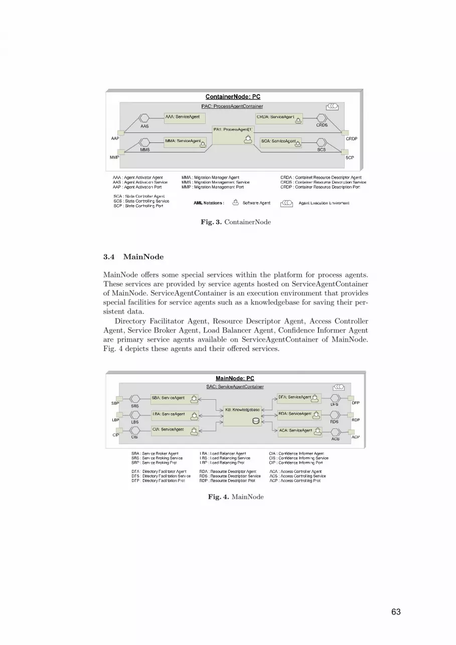
Fig. 3. ContainerNode
3.4 MainNode
MainNode offers some special services within the platform for process agents.These services are provided by service agents hosted on ServiceAgentContainerof MainNode. ServiceAgentContainer is an execution environment that providesspecial facilities for service agents such as a knowledgebase for saving their per-sistent data.
Directory Facilitator Agent, Resource Descriptor Agent, Access ControllerAgent, Service Broker Agent, Load Balancer Agent, Confidence Informer Agentare primary service agents available on ServiceAgentContainer of MainNode.Fig. 4 depicts these agents and their offered services.
Fig. 4. MainNode
63

3.5 DBNode
DBNode is the central database server of platform that is used to store ap-plication data and workflow relevant information. Application data is stored inApplicationDataRepository which must be designed by workflow application de-velopers. Workflow relevant information is classified in three categories: ActivityDefinitions, Service Descriptions, and Role-Performer pairs. Each category ofthis information will be stored in a separate repository on DBNode.
4 Process Agent Architecture
Process agents are designed in two layer architecture, namely Reasoning Layerand Enactment Layer. The Reasoning Layer takes advantage of BDI model ofagency [9, 12] and supports rational behavior of process agent while the Enact-ment Layer has an architecture which is customized for AB-WfMS and providesfunctional behavior of process agent. Fig. 5 depicts the architecture of a processagent.
Fig. 5. Two layer architecture of process agent
4.1 Reasoning Layer
Each process Agent must have a comprehensive view of steps it has to followfor activating a business process and based on this view, decides what to do
64

at each step. Reasoning Layer components which are initialized during agentgeneration in AgentFactory hold this information for process agent and generatethe commands that should be applied by Enactment Layer components. Belief-Base, Goal Descriptor, Plan Library, and Interpreter are primary componentsof this layer for representing beliefs, desires, intentions of process agent, anddeliberating over them.
BeliefBase holds agent knowledge of the world [9]. Process agent knowl-edge of the world can be separated into its Environmental Beliefs, and ProcessInstance Beliefs. Environmental beliefs of a process agent reveal the agent knowl-edge about its activation context such as access point information of platformrepositories and MainNode. Process Instance Beliefs represent process agent’sknowledge of business process which undertakes. These beliefs can be separatedinto three parts, called Activity Beliefs, Transition Beliefs and Workflow Rele-vant Data Beliefs.
Activity Beliefs represent description of each activity that is referenced inthe business process instance. Transition Beliefs represent the sequential andparallel order of those activities and the conditions that should be satisfied byeach transition and Workflow Relevant Data Beliefs maintain the latest value ofeach workflow relevant data.
Plan Library holds process agent’s plans. Each plan represents a genericcommand type that can be undertaken by Enactment Layer components. Exam-ples of these generic command types are: loading an activity class, establishingconnection with a server, generating sub-agents, migrating to another Contain-erNode, etc.
Goal Descriptor describes agent’s motivational stance which are the driv-ing forces for its actions. Different classifications form miscellaneous goals thatan agent may have, are presented in [1, 3], but in AB-WfMS, we have identifiedtwo primary categories of goals, named Activity Goal and Transition Goal. Ac-tivity Goals represent desired states which are expected to arrive after executionof an activity in a workflow process. Activity goals can be divided to activitysub-goals that represent desired intermediate states during execution of activity.Transition Goals specify the motivations for firing transitions during workflowactivation. Join point transition criteria [9] are the primary focus of transitiongoals.
Interpreter is responsible for selecting plans from Plan Library based onprocess agent’s current goal, customizing them according to BeliefBase knowl-edge, and generating appropriate commands to be applied in Enactment layercomponents. This is of interpreter responsibilities to update agent’s environmen-tal and process instance beliefs, and to deliberate over process agent’s currentgoal (or sub-goal). Internal and external events which are issued by EnactmentLayer components and execution context of process agent respectively, fire thetriggering conditions of interpreter internals. These events will be handled byEvent Handling Services.
65

4.2 Agent Enactment Layer
Agent Enactment Layer provides functional component for activating the com-mand issued by Reasoning Layer Interpreter. The constituent components ofthis layer will be explained in brief by the rest of this subsection.
Activity Loader loads activity classes from Activity Repository (on DBN-ode) and after their instantiation, makes them executed by participation of per-former who represents the role associated with that activity, on current Con-tainerNode.
Service Provider is the process agent interface, for negotiating with remoteservice providers. SBA (Service Broker Agent which is placed on MainNode) di-rects Service Provider toward appropriate server, then it establishes the requiredconnections, requests for services, receives the results and delivers them to pro-cess agent
Sub-Agent Creator / Unifier , Parallelism is an inherent characteristicof business processes. During activation of a process instance, those sequencesof activities which can be executed in parallel and form sub-processes will bedelegated to sub-agents in order to be executed simultaneously. A sub-agent hasa restricted view of business process and its generation is the responsibility ofSub-Agent Creator / Unifier at parent process agent.
State Assessment Module identifies current execution state of processagent. The execution state of a process agent is defined as current executionstatus of activity classes which are loaded within the process agent, and currentvalue of workflow relevant data on latest transitions.
Migration Manager is responsible for negotiating with host ContainerN-ode Migration Manager Service (MMS) in order to provide necessary informationfor process agent transmission.
Monitoring Module provides facilities for evaluating some performancemetrics of organization performers. These metrics include Responsiveness mea-sures like response time or processing time, Dependability measures such asMTBF (Mean Time Between Failure) or MTTR (Mean Time To Repair) andMissionability measures like interval availability. These metrics will be evaluatedwhen a role is assigned to a performer in order to handle an activity. Resultsof these evaluations will be sent to Confidence Informer Agent (CIA) for futurerole assignments.
5 Example
Suppose that an Insurance Corporation is going to automate its processes by theuse of a workflow management system. This company is composed of different or-ganizations that each one is responsible for specific type of insurance service suchas Trading Insurance, Home Insurance, Industrial Insurance, etc. Each organi-zation has its own business processes defined within the organization frameworkand a number of processes that may deal with other organizations workflows.
66

In context of AB-WfMS each organization will be realized as a platform.For instance, consider Trading Platform in respect to Trading Insurance Or-ganization. At first, business process designers must define different workflowprocesses which may be applied in that organization such as registration pro-cess, value assessment process, damage estimation process, payment process, etc.These definitions will be stored in ProcessRepository of InterfaceNode.
Along with process definition, the designers have to declare organizationalperformers, their physical placement, and their assigned roles at each workflowprocess. For instance, it must be declared that Alice has the role of damageestimator in damage estimation process, and she can be accessed by networkaddress of Alice.Trade.InsuPlat.com. This information will be kept in Role-PerformerRepository of DBNode. Besides, workflow designers have to provideactivity classes and service descriptions that are referenced in different work-flows and save them in ActivityRepository and ServiceRepository of DBNode.
For example, consider different activities that form damage estimation pro-cess. All of these activities should be implemented by workflow programmers andbe added to ActivityRepository by workflow designers. The point here is that,the implemented activity classes can be reused by other workflow processes. Forinstance, Confirmation is an activity which may be referenced in damage estima-tion process, payment process or many other workflow processes. For this reason,we proposed AB-WfMS as a solution for business process management environ-ments. Because in such environments, there are number of preexisting tools andapplication classes which can be utilized in different workflow processes.
After finalizing these initial steps and setting up ProcessAgentContainersat each workstation, customers can order for activating workflow processes. In-terfaceNodes are responsible for receiving these orders, generating the processagents and disseminating them over the network of ContainerNodes. Generatedprocess agent will accomplish the workflow process on behalf of customer andreturn the result back to him.
6 AB-WfMS Architectural Quality Attributes
Scalability is the primary architectural quality attribute which has been focusedin this work. One of the primary difficulties in designing scalable systems is howto solve the limitation of centralized services, data, and applications [11]. Takingadvantages of BDI concepts, a degree of rationality has been provided for processagents that makes them capable of local decision making, and in this way thenecessity of an over loaded workflow central engine has been faded. Besides,communication overheads which was due to continues interactions of systemcomponents with central engine, has been reduced. Synchronized communicationis another obstacle in scaling distributed systems [11]. In AB-WfMS, Mobility ofprocess agents and their ability of migrating to proper ContainerNodes alleviatedthe problem of synchronized communication.
Availability is the second architectural quality attribute that we will explainin this part. Availability is defined as readiness of system [14], and its associated
67

tactics are in three categories: fault detection, fault recovery, and fault preven-tion. At each platform, SCA is responsible for monitoring the execution state ofprocess agents, so this service agent can detect process agents’ failures duringtheir runtime. Besides, each process agent has a Checkpointing schedule whichsupports fault recovery. AB-WfMS has faced fault prevention tactic by imposingconfidential constraints on role assignments through CIA.
Modifiability is the next architectural quality attribute which is supportedby AB-WfMS. The purpose of this attribute is controlling the time and costto implement, test, and deploy changes. AB-WfMS supports this attribute bychoosing deferred binding time tactic [14]. Most of bindings in AB-WfMS aredeferred for runtime. For example, activity class loading, service providing, androle assigning are all bindings which have been deferred for runtime.
Portability is another quality attribute which has been foreseen in this archi-tecture. There are number of implemented FIPA complaint platforms for agentbased systems that most of them are Java based and have inherent attitude ofportability. JADE [15] and JADEX [16] are two well known platforms of thiskind.
7 Conclusion
This paper presented an agent based architecture for workflow management sys-tems, with special consideration of business process management environments.Collaboration of autonomous process agents and distributed service agents, incontext of distributed platforms, provides scalable architecture that can assist usto develop intra-organizational workflows. Taking advantages of BDI concepts inprocess agents architecture, improved their deliberative attitudes and provideda sound basis for autonomous activation of business processes.
The focal point of this architecture is that it tries to minimize the centralengine of workflow management system, and in this way supports world widedistributed workflows. For this aim, each process agent has a comprehensive viewof business process it has to under take and a number of managerial capabilitiesfor making deliberative decisions.
8 Future Work
In terms of practical application of our architecture, one of the key problemsthat needs to be addressed is how well the legacy software tools and applicationscan be deployed by process agents. One of the applicable solutions is use ofwrapping classes for these tools, and keeping them in activity repository. In thisway, a unique interface will be provided for interacting with such applications.The drawback of this solution is that workflow developers have to implement awrapping class for any of these legacy softwares that one may have a differentinterface.
68

The second aspect that requires further consideration is the distribution ofservice agents within the main container. For Platforms with too many contain-ers, process agents servicing may face to congestion at main container. Although,replication of main container in a platform is a solution to this problem but onecan place different service agents (those of main container) on different maincontainers, and in this way remove a potential bottlenecks of system.
Detailed design of process agents and service agents also communication lan-guage that will be deployed by them, is the major open area which must beconsidered for a real implementation of AB-WFMS. But, the building blocks ofthis architecture are selected in a way to be in accordance with JADE imple-mentation framework. Hence, for a JADE [15] developer, activating the agentexecution platform seems straightforward. Besides, as process agents are usingBDI model of agency, their implementation can be less complicated by usingJADEX [16] platform.
Acknowledgments. Special thanks to Miss Sara Javanmardi for her guidelineson paper structuring, and kindest appreciations to Mr. Amir Reza Abdolrashidifor his contributions as proof reader of this paper. Besides, profound helps ofDr. Majid Nikraz must be esteemed for reviewing the paper.
References
1. L. Braubach, A. Pokahr, D. Moldt, W. Lamersdorf: Goal Representation for BDIAgent Systems. Proceedings of the Second Workshop on Programming MultiagentSystems: Languages, frameworks, techniques, and tools (ProMAS04). Springer.Berlin, New York (2004) 9–20.
2. N. R. Jennings, T. J. Norman, P. Faratin: Autonomous Agents for Business ProcessManagement. Int. Journal of. Applied Articial Intelligence (2000)
3. van Lamsweerde: Goal-Oriented Requirements Engineering: A Guided Tour.Proceedings, 5th IEEE International Symposium on Requirements Engineering(RE’01), Toronto (2001)
4. Paul Allen Buhler: A Software Architecture for Distributed Workflow Enactmentwith Agents and WEB Services. PHD Thesis, University of South Carolina (2004)
5. LEI YU: Agent Oriented and Role Based Business Process Management for Com-putational Media. PHD DISSERTATION, University of Zurich (2000)
6. Jorge Cardoso, Robert P. Bostrom, Amit Sheth: Workflow Management Systemsvs. ERP Systems: Differences, Commonalities, and Applications. Information Tech-nology and Management, Springer (2004)
7. Paul Andrew, James Conard, Scott Woodgate, Jon Flanders, George Hatoun, Is-rael Hilerio, Pravin Indurkar, Dennis Pilarinos, Jurgen Willis: Presenting WindowsWorkflow Foundation, Beta Edition. Sams publication (2005)
8. Workflow Management Coalition: Workflow Reference Model,WfMC (2005)
9. Milind, Wooldridge, and Michael: The Belief-Desire-Intention Model of Agency,Proceedings of the 5th. International Workshop on Intelligent Agents (1999)
10. Agent Modeling Language, Language Specification version 9, Witestein Technology(2004)
69

11. Andrew S.Tanenbaum, Maartin Van Steen: Distributed systems principles andparadigms, Prentice Hall (2002)
12. A. Rao, M. Georgeff : BDI Agents: From Theory to. Practice, In: Proc. First Int.Conf on Multi-Agent. Systems (ICMAS-95) (1995)
13. Lars Ehrler, Martin Fleurke, Maryam Purvis, Bastin Tony Roy Savarimuthu:JBees: a distributed and adaptive WfMS with monitoring and controlling capa-bilities, Journal of Information Systems and E-Business Management (2003)
14. Len Bass, Paul Clements, Rick Kazman: Software Architecture in Practice, SecondEdition, Addison Wesley (2003)
15. Giovanni Caire: Jade User Guide, www.jadeworld.com/downloads/jade/manuals/UserGuide(2003)16. A. Pokahr and L. Braubach: Jadex User Guide, http://vsis-www.informatik.uni-
hamburg.de/projects/jadex/download.php, (2004)
70

Time-Aware Multi Agent Systems
Daniela Micucci1, Marco Oldani1 and Francesco Tisato1
Universita’ degli Studi di Milano - BicoccaVia Bicocca degli Arcimboldi 8 20126 Milan, Italy
micucci,oldani,[email protected]
Abstract. Time emerges as a key concept in Multi Agent Systems(MASs) and influences the overall system architecture. Since architec-tural abstractions aim at capturing issues that are relevant in specificdomains, MAS architectures should provide abstractions allowing thetemporal behaviour to be modelled, observed, and controlled. In otherterms, time should be a full-fledged first-class concept in MAS architec-tures. This paper proposes Time-Awareness Model (TAM), a referencemodel for building Time-Aware MASs. The model defines a collection ofarchitectural abstractions allowing temporal issues to be modelled in aplatform-independent way. Moreover, the paper applies TAM in a refer-ence architecture for Time-Aware MASs. The reference architecture hasbeen exploited in the Packet-World test-bed.
1 Introduction
Time emerges as a key concept in Multi Agent Systems (MASs) and influencesthe overall system architecture ([2]). Consequently, a MAS architecture shouldprovide abstractions allowing the temporal behaviour to be modelled, observed,and controlled. In other terms, time should be a full-fledged first-class concept.
In the MAS area several domain concepts rose to the rank of first-class ab-stractions: for instance, space and the related issues (contiguity, movement, dis-tance, and so on) in a situated MAS. The same does not hold for the generalconcept of time, though several works address time-related issues (e.g., [1] pro-poses semantic duration model, [5] a time management service for simulationMAS, and [6] a real-time agent facilitator allowing agents to communicate usingRTKQML).
Treating time as a platform-dependent detail has several drawbacks. It is dif-ficult for an agent to reason about time due to the lack of platform-independentabstractions modelling timing issues. The temporal behaviour of the agents canbe hardly specified at the conceptual level. Software re-use is difficult. Finally,intermixing conceptual and platform issues introduces subtle errors, becauseplatform-dependent strategies (e.g., thread scheduling) influence the overall be-haviour of the system.
This paper proposes a reference model for building Time-Aware MASs. Themodel, termed Time-Awareness Model (TAM in the sequel), defines a collec-tion of architectural abstractions allowing temporal issues to be modelled in a
71
platform-independent way. Furthermore, the paper presents a reference archi-tecture for Time-Aware MASs. It augments the architecture proposed by Weyns([4] and [3]) with first-class time management mechanism based on TAM. Finallyit sketches a case study based on the Packed-World test-bed.
2 A Model for Time Awareness
Time-Awareness Model (TAM in the following) captures the following basicconcepts for building time aware systems:
– Time-reasoning deals with the static aspects of time;– Time-sensitivity deals with the dynamic aspects of time;– Time-awareness bridges time-reasoning and time-sensitivity.
The proposed model aims at separating static and dynamic concerns so that,on one side, individual components deal only with the aspect of interest; on theother side, they can be easily integrated since they rely on a uniform model.
2.1 Time-reasoning
Time-reasoning concepts model the static aspects of time. The main abstractionis the timeline that is an ordered collection of time grains. A time grain is anelementary time unit modelling the fact that, in a real computing system, thetime is bound to be described by discrete chunks. A time interval is a collectionof adjacent time grains in a timeline. It is defined by a pair < begin, end > oftime grains, where the end grain does not precede the begin grain.
Timelines are arranged in a dependency hierarchy (figure 1). The logicaltimeline is the root of the hierarchy. Temporal placement and duration of alogical time grain are defined in terms of a “real” time interval that, in turn, isa multiple of an arbitrary measurement unit of “real” time. The logical timelineis the bridge between the physics of the computing system and the metaphysicsof the “real” time.
A virtual timeline is associated with a reference timeline. A virtual time grainof a virtual timeline is mapped onto an interval of the reference timeline. Themapping places the grain in a temporal context and defines its duration. Virtualtimelines support timed facts. A timed fact is a predicate about one or moresubjects, which is valid inside a time interval. A time reasoner exploits the timeas a domain concept by performing computations and reasoning about timedfacts.
Timelines provide abstractions allowing facts to be placed in a temporalframework without any direct relationship with the “real” flowing of the time.Therefore timelines can be exploited by any time reasoning application dealingwith the concept of time. For example, “car C was at location L1 during intervalI1” and “car C was at location L2 during interval I2” are timed facts allowing todraw offline inferences about the speed of car C, no matter when the inferencesare performed.
72

Fig. 1. Timelines hierarchy
2.2 Time-sensitivity
Time-sensitivity models the dynamic aspects of time. The main abstraction is thetimer (figure 2) generating periodic timed events that are assumed to representthe flow of the time. A timer ticks time sensitive entities, acting as observers ofthe timer.
Like timelines, timers are arranged in a dependency hierarchy (figure 2). Avirtual timer is a time sensitive entity, which, in turn, behaves like a timer. Itcounts events generated by its reference timer and ticks its observers when thecount equals its period.
Fig. 2. Timer hierarchy
The logical timer is the root of the hierarchy. It is ticked by system-dependentevents. The period of the logical timer is defined as a multiple of an arbitrarytime measurement unit. This is the hook between the physics of the computingsystem - which generates physical events - and the metaphysics, which providesan arbitrary interpretation of the physical events in terms of “real” time flow.
Like timelines hierarchy, timers hierarchy allows the time flow to be perceivedwith different time magnitudes.
Timers provide abstractions allowing events to be interpreted as symptomsof the time flow. Timers enter the stage as soon as the system activities must be
73

driven by events that model the flow of the “real” time. Timers generate events,which trigger actions of time sensitive components. Since the logical timer is theunique hook with the metaphysical concept of time flow, it encapsulates bothsystem-dependent mechanisms and the interpretation of what the “real” timeis. This implies that a time sensitive applications relying on the concepts aboveis not aware of such issues. Therefore the application can be easily executedand tested in a simulation environment without affecting, from a logical pointof view, its temporal behaviour.
2.3 Putting it Together: Time-awareness
Many systems exploit both time-reasoning and time- sensitivity. Therefore thestatic issues modelled by timelines must be bound with the dynamic issues mod-elled by timers.
Fig. 3. Timer hierarchy
A clock (figure 3) is a time sensitive entity that bridges static and dynamicissues by associating a timeline with a timer. A clock defines the concept ofpresent time (more precisely, of present grain) over a timeline: when ticked bythe associated timer, the clock advances the present grain of the associatedtimeline.
Bridging static and dynamic time-related issues has several implications.There must be an agreement on the unique measurement unit of the time thatis exploited by the logical timeline and by the logical clock. Therefore, if a timerand a timeline are associated by a virtual clock, the duration of the present grainof the timeline must be consistent with the actual period of the timer. Moreover,the hierarchies of clocks and of timelines must be consistent.
74

3 A Reference Architecture for Time-Aware MAS
To quickly put in practice TAM concepts we augmented an existing referencearchitecture with first-class time management mechanism. The architecture isthe one proposed by Weyns ([4] and [3]) since it has been designed so that theintegration of our concepts become a quite easy task.
Fig. 4. Timer hierarchy
The architecture proposed by Weyns includes three primary abstractions:agent, ongoing activity, and environment, each of them including specific mod-ules. Our architecture provides the same set of primary abstractions and includesa subset of the Weyns’ modules (halftone screening boxes in figure 4) describedin the following.
An agent perceives the environment via its Perception module. It in chargeof mapping the state of the environment into agent perceptions, which are trans-lated and integrated into agent knowledge via a Knowledge Integration module.The Decision module, exploiting the knowledge, produces actions both to in-teract with the environment and to communicate with other agents: the Execmodule executes actions, and the Communication one manages messages ex-change between agents.
Ongoing activity models other processes, that are not agents, but that mayproduce activities in the system, e.g., a moving object, evaporating pheromonesor environmental variables such as temperature. An ongoing activity has just anOperation module that influences the environment.
Environment includes a Reactor module that, according to agents’ actionsand ongoing activities, updates the environment state. The environment is alsoin charge of synchronising the overall behaviour of the system.
75

In the following we present the TAM-based extensions (white boxes in figure4) to the above reference architecture.
A time-aware agent is an agent enriched with the TAM abstractions. A TimeSensing module is a time sensitive component which reifies a virtual timers hier-archy. The Knowledge Integration module turns timing events and perceptionsinto Timed-Knowledge by managing clocks - which control timelines hosted in-side the knowledge base - and by defining timed facts. This allows the Decisionmodule to manage and to reason about timed facts. In particular, the Decisionmodule may assert timed facts stating when an action must be performed. TheEngine module is in charge of activating the other passive modules according tosome domain-dependant activation policies. In particular, a time-aware Enginebehaves like an interpreter of the timed facts. It triggers the actions accordingto the timed facts and to the perception of the current virtual time. Note thatan agent exploiting a time-aware Engine is capable of dynamically planning itsown behaviour, i.e., the agent performs reflection [7].
A time-aware ongoing activity is an ongoing activity enriched with a TimeSensing module that reifies a virtual timers hierarchy. Time Sensing moduletriggers the execution of operations according to the perception of timer events.
The time-aware environment enriches the environment. It is in charge ofmanaging global information, i.e., the state of the environment and the logicaltime. Therefore, it includes a Time Flowing module containing the logical timerwhich is the root of the hierarchy of all the virtual timers exploited by agentsand ongoing activities. Moreover, its State is enriched with the logical timelinewhich in turn is the root of the hierarchy of all the virtual timelines exploitedby agents. Time Flowing also includes a clock that bridges the logical timelineand the logical timer. Finally, it includes a logical timeline supporting the globaltimed facts that define the state of the environment.
4 A Case Study: the Packet-World
The time model and the related reference architecture we propose in this paperwill be exploited in the reference case study denoted Packet-World and presentedin [2]. Shortly, we have a rectangular grid that may contain: agents (cognitive andreactive), coloured packets, one packet destination for each colour, and colouredpheromone trails leaved by agents. Agents’ aim is to look for packets, pick upthem, and look for the corresponding destination to drop them.
An agent interact with the other agents by dropping pheromone at the fieldit is located on. This way, it constructs pheromone trails from clusters of pack-ets to destination. Pheromone evaporates over time. When an agent perceivesa pheromone it may decide to reach either the destination moving towards theincreasing pheromone strength, or the cluster of packets moving towards thedecreasing pheromone strength. The agent executes three main activities: per-ception deals with the local observation of the environment, deliberation dealswith the selection of the next action to perform (i.e., move, pick/put a packetor drop a pheromone), action deals with the execution of the selected action.
76

Perception and action activities have the same duration for all the agents. Delib-eration activities have different durations for cognitive and reactive agents: if twoagents start deliberating at the same time, the reactive one must complete theactivity before the cognitive one. The need for a time management mechanismis due to the following constraints:
1. all the agents’ activities must be executed with respect to their domaintemporal relationships independently from the underlying platform;
2. the effectiveness of pheromone-based communication depends on the evapo-ration rate that is a time-related phenomenon.
4.1 Time-Aware MAS Solution
The pheromone evaporation phenomenon is reified by one time-aware ongoingactivity that has one virtual timer with period equals to 1. When the Operationmodule is activated by the Time Sensing one, it decreases by 1 the currentstrength of all the pheromones in the environment, satisfying constraint 2.
Each agent is reified by a time-aware agent. All the time-aware agents haveonly one virtual timer and one virtual timeline. The period of each virtual timeris 1. Agents do not need to reason about timed events: a line of reasoning doesnot involve inferences based on timed events. Notwithstanding this, agents makeuse of time to trigger the execution of their activities: they only exploit timeto reason about their behaviour over time. In other words, agents exploit thevirtual timeline hosted in their knowledge base to plan their behaviour overtime, i.e., they exploit reflection. This is achieved by planning on the agent’svirtual timeline timed facts that predicate about the activities the agent mustperform (see figure 5).
Fig. 5. Timer hierarchy
In the example, timed facts predicate that an activity must be executedbetween the start and the end of the interval. Every time a timed fact is valid, i.e.,the present time falls inside its interval, the agent’s time-aware Engine moduletriggers the activity according to what the fact predicates.
From the problem statements, perception and action activities have the sameduration for all the agents: it is a priori fixed to 1 virtual time grain. The dura-tion of a deliberation activity is a priori fixed too and it is different according to
77

agent type: 1 virtual time grain for reactive agents (e.g., agent 1 in figure 5) and3 virtual time grains for cognitive ones (e.g., agent 3 in figure 5). All the agentscyclically execute the activities in the following order: perception, deliberation,and action. Our Time-Aware MAS architecture and the above described config-uration allow satisfying constraint 1. Indeed, all the agents are synchronised onthe logical present time that is unique inside the system, all the agents perceivethe same time flow since they have virtual timers with the same period, andagents’ temporal constraints rely on a uniform time model.
5 Conclusions
This paper proposes Time-Awareness Model (TAM), a reference model for build-ing Time-Aware MAS. TAM defines a collection of architectural abstractionsallowing the temporal behaviour to be modelled, observed, and controlled ina platform-independent way. In other terms, the abstractions raise time as afull-fledged first-class concept. Treating time as a full-fledged first-class bringsseveral advantages. An agent may reason about time related issues and its be-haviour over time may be specified at the problem-domain level. An agent maymodify its planned facts adapting dynamically its behaviour to the run-timesituations. Such an agent exhibits a full-fledged autonomous and adaptive be-haviour. Conceptual and platform temporal issues are well separated so that itis possible defining time related strategies that are platform independent. Lastbut not least, this separation facilitates the components re-use.
Finally, the paper presents a reference architecture, based on TAM, for Time-Aware MAS that has been exploited in the Packet-World test-bed.
References
1. Helleboogh A., Holvoet T., Weyns D., and Berbers Y. Extending time managementsupport for multi-agent systems. In MABS, pages 37–48, 2004.
2. Helleboogh A., Holvoet T., Weyns D., and Berbers Y. Towards time managementadaptability in multi-agent systems. In Adaptive Agents and Multi-Agent Systems,pages 88–105, 2005.
3. Weyns D. and Holvoet T. The packet-world as a case to study sociality in multiagentsystems. In AAMAS ’02: Proceedings of the first international joint conference onAutonomous agents and multiagent systems. ACM Press, 2002.
4. Weyns D. and Holvoet T. A formal model for situated multi-agent system. Funda-menta Informaticae, 63:125–158, 2004.
5. Braubach L., Pokahr A., Lamersdorf W., Krempels K.H., and Woelk P.O. A generictime management service for distributed multi-agent system. Applied ArtificialIntelligence, 20:229–249, 2006.
6. DiPippo L., Hodys E., and Thuraisingham B. Towards a real-time agent architec-ture. In WORDS ’99: Proceedings of the Fifth International Workshop on Object-Oriented Real-Time Dependable Systems, page 59. IEEE Computer Society, 1999.
7. P. Maes. Concepts and Experiments in Computational Reflection. In ProceedingsoF Object-oriented programming systems, languages and applications, pages 147–155. ACM Press, 1987.
78

Metamodeling of Semantic Web Enabled
Multiagent Systems
Geylani Kardas1, Arda Goknil2, Oguz Dikenelli2, and N. Yasemin Topaloglu2
1Ege University, International Computer Institute, 35100 Bornova, Izmir, [email protected]
2Ege University, Department of Computer Engineering, 35100 Bornova, Izmir, Turkey{arda.goknil, oguz.dikenelli, yasemin.topaloglu}@ege.edu.tr
Abstract. Several agent researchers are currently studying agent mod-eling and they propose di�erent architectural metamodels for develop-ing Multiagent Systems (MAS) according to speci�c agent developmentmethodologies. When support for Semantic Web technology and its re-lated constructs are considered, agent metamodels should include meta-entities to model MASs which work in semantic web environment. In thispaper, we introduce an agent metamodel to de�ne the required constructsof a Semantic Web enabled MAS in order to provide semantic capabilitymodeling and interaction of agents both with other agents and semanticweb services. We �rst give a conceptual MAS architecture to identify newconstructs in addition to constructs of a traditional MAS and then wepropose a metamodel including the �rst-class entities required by such aconceptual architecture.
1 Introduction
A software methodology is typically characterized by a modeling language anda software process as mentioned in [1]. Same is valid for the Multiagent System(MAS) methodologies from the perspective of agent oriented software engineer-ing (AOSE) paradigm. Again given in [1], we use agent modeling languages forthe description of models, de�ning the elements of the model together with aspeci�c syntax (notation) and associated semantics. On the other hand, soft-ware process de�nes development activities and their interrelationships. Eachmethodology naturally de�nes a speci�c metamodel based on artifacts of theprocess and its architectural constructs. However, a metamodel can be indepen-dent from a speci�c methodology and de�ne architectural constructs and theirrelations for a speci�c application area or domain.
In MAS community, there are various studies which de�ne metamodels ofspeci�c methodologies like Gaia, Adelfe, PASSI [3] and SODA [9]. Also, Founda-tion for Intelligent Physical Agents (FIPA) has an on-going e�ort for developinga notation to express relationships between agents, agent roles and agent groupsin a MAS. Collaborating with Object Management Group's (OMG) Agent SIG,FIPA Modeling Technical Committee proposes a metamodel called Agent ClassSuperstructure Metamodel (ACSM) [7] which is based on - and extends - UML
79

2.0 superstructure. It presents a superstructure speci�cation that de�nes theuser-level constructs required to model agents, their roles and their groups [10].However, we believe that a signi�cant de�ciency exists in those noteworthy agentmodeling studies when we consider their support on Semantic Web [2] technologyand its constructs.
Semantic Web evolution has doubtlessly brought a new vision into agentresearch. This Second Generation Web aims to improve WWW (World WideWeb) such that web page contents are interpreted by using ontologies. It isapparent that the interpretation in question will be realized by autonomouscomputational entities - so agents - to handle semantic content on behalf oftheir human users. Surely, Semantic Web environment has speci�c architecturalentities and a di�erent semantic which must be considered to model a MASin this environment. Therefore, modeling techniques and development processshould support this new environment by de�ning new meta-entities and meta-structures.
In this study, we introduce an agent metamodel aiming to de�ne requiredconstructs of a Semantic Web enabled MAS in order to provide semantic capa-bility modeling and interaction of agents. The interaction in question involvesboth communications of an agent: agent-to-agent and agent-to-semantic entity(e.g. a semantic web service [14]). Hence, we �rst give a conceptual MAS ar-chitecture to identify new constructs in addition to constructs of a traditionalMAS. Then we propose a metamodel including the �rst-class entities requiredby such a conceptual metamodel.
The paper is organized as follows: Section 2 discusses about the constructsof a conceptual architecture for a MAS which is capable to work on the Se-mantic Web environment. Section 3 introduces our proposed metamodel. Thismetamodel is the �rst step to incorporate a model driven approach to the de-velopment of MASs. Finally, conclusion and future work are given in Section4.
2 A Conceptual Architecture for Semantic Web Enabled
MASs
We need to de�ne a conceptual architecture for semantic web enabled MASs inwhich autonomous agents can also evaluate semantic data and collaborate withsemantically de�ned entities such as semantic web services by using content lan-guages. Our proposed conceptual architecture for such MASs is given in Figure1.
The architecture de�nes three layers: Architectural Service Layer, AgencyLayer and Communication Infrastructure Layer. A group of system agents pro-vides services de�ned in the Architectural Service Layer. Every agent in thesystem has an inner agent architecture described in the Agency Layer and theycommunicate with each other according to the protocols de�ned in the Commu-nication Infrastructure.
80

Semantic web agents are agents which are initiated by using the platformarchitecture and able to use semantic services within the service layer. In Archi-tectural Service Layer, services (and/or roles) of semantic web agents inside theplatform are described. All services in the Architectural Service Layer use thecapability of the Agency Layer. Besides domain speci�c agent services, yellowpage and mediator services should also be provided.
Fig. 1. The conceptual architecture for Semantic Web enabled MASs.
Agent Registry is a system facilitator in which capabilities of agents are se-mantically de�ned and advertised for other platform members. During their taskexecutions, platform agents may need other agents' services. Hence, they queryon this facilitator to determine relevant agents for interaction.
No matter it is FIPA-compliant [6] or not, a traditional MAS owns one ormore registries which provides yellow page services for system's agents to lookfor proper agent services. Of course registries mentioned above are not simplestructures and mostly implemented as directory services and served by someplatform speci�c agents. For example there is a mandatory agent called direc-tory facilitator (DF) in FIPA abstract architecture speci�cation on which agentservices are registered [6]. When an agent looks for a speci�c agent service, itgathers supplier data (agent's name, address, etc.) of the service from the DFand then it begins to communicate with this service provider agent to completeits task. However, capability matching becomes complex and has to be rede-�ned when we take into consideration of MASs on semantic web environment.In case of agent service discovery in such systems, we should de�ne semanticmatching criteria of service capabilities and design registration mechanisms (di-rectory services) of agent service speci�cations according to those criteria. That
81

makes matching of requested and advertised services more e�cient by not onlytaking into consideration of identical service matching: New capability matchingwill determine type and degree of relation between two services (requested andadvertised) semantically. Hence, the conceptual architecture includes an agentregistry to provide capability matching on agent services.
On the other hand, agents of the platform may also need to interact withSemantic Web Services which are web services with semantic interface to be dis-covered and executed. To support interoperability and automatic composition ofWeb services, capability of services are de�ned in service ontologies such as OWL-S [12] and WSMO [15]. In our approach, those service capabilities should alsobe advertised on proper registries to provide dynamic discovery and executionof the services by agents. Hence, we de�ne a conceptual entity called SemanticService Registry in the proposed architecture. This registry can also be modeledas a service matchmaker in which semantic interfaces of the platform's semanticweb services are advertised to be discovered by the agents. Considering OWL-Sservices, agents may query on this facilitator by sending its requested semanticservice OWL-S pro�le to the facilitator. The facilitator (or matchmaker) per-forms a semantic capability matching between the given request and advertisedpro�les and informs the agent about suitable services. Then the agent may in-teract with those services to complete its task. Engagement and invocation ofthe semantic web service is also performed according to its semantic protocolde�nitions.
A semantic web enabled agent interacts with agents within the di�erent or-ganization(s) and semantic web services may use knowledge sources handled bythe di�erent knowledgebase(s) and/or peer system(s). In such environment, it isobvious that, there exist more than one ontology and di�erent entities may usedi�erent ontologies. So, there should be another architectural service in whichtranslation and mapping of di�erent ontologies are performed. We call this ser-vice as Ontology Mediator and it may be provided by one or more agents withinthe MAS. Agents which provide this conceptual service, may handle the trans-lation request(s) using the pre-de�ned mapping knowledge introduced througha speci�c user interface. Through the usage of the ontology translation support,any agent of the platform may communicate with MAS and/or services outsidethe platform even if they use di�erent ontologies.
The middle layer of the architecture is the Agency which includes inner struc-tural components of Semantic Web enabled agents. Every agent in the systemhas a Semantic Knowledgebase which stores the agent's local ontologies. Thoseontologies are used by the agent during his interaction with other platform agentsand semantic web services. Evaluation of the ontologies and primitive inferenceare realized by the Reasoner.
Semantic Knowledge Wrapper within the Agency provides utilization of abovementioned ontologies by upper-level Agency components. For example, duringhis task execution, the agent may need object (or any other programmatic) rep-resentation of a speci�c ontology individual. Or the content interpreter requestsa query on one of the ontologies to reason about something. To meet up such
82

requirements, the Semantic Knowledge Wrapper of the agent may form graphrepresentations of the related ontologies within the runtime environment of theagency. One such good example for the wrapper is the proper application of theJENA [8] framework in agent internal architecture and is discussed in [5].
The Planner of the Agency Layer includes necessary reusable plans with theirrelated behavior libraries. The reusable agent plans are composed of tasks whichare executed according to the agent's intentions. The planner is based on reactiveplanning paradigm e.g. HTN (Hierarchical Task Network) planning frameworkpresented in [13]. In reactive planning a library of general pre-de�ned (may bede�ned at compile time) plans is provided to agent and the agent performs oneor more of these plans in response to its perceptions of the environment [4].
Semantic Content Interpreter module uses the logical foundation of seman-tic web, ontology and knowledge interpretation. During its communications, theagent receives messages from other agents or semantic services. It needs to eval-uate received message content to control its semantic validity and interpret thecontent according to its beliefs and intentions. Necessary content validity andinterpretation takes place in this module.
The bottom layer of the architecture is responsible of abstracting the archi-tecture's communication infrastructure implementation. For example, it may bean implementation of FIPA's Agent Communication and Agent Message Trans-port speci�cations [6] to handle agent messaging. Hence, the layer transfers anycontent (including semantic knowledge) by using FIPA ACL and transport in-frastructure. Physical communication may take place via well-known HTTP-IIOP (Internet Inter-ORB Protocol). However, the content language within themessage infrastructure is crucial.
3 Proposed Metamodel for Semantic Web Enabled MASs
In this section, we introduce an agent metamodel superstructure to de�ne ele-ments and their relationships of a Semantic Web Enabled MAS depending onthe previously discussed conceptual architecture. Figure 2 depicts this core meta-model for Semantic Web enabled agent platforms.
Semantic Organization is a composition of Semantic Web Agents which isconstituted according to organizational roles of those agents.
A Semantic Web Agent is an autonomous entity which is capable of interac-tion with both other agents and semantic web services within the environment.Interaction processes are executed according to prede�ned semantic communi-cation protocols. Conceptually, a Semantic Web Agent can be considered asa specialization of the commonly-known software agent entity within internalagent structure and communication content perspectives.
It should be noted that a Semantic Organization should be implementedas only a composition of Semantic Web Agents. The organization does not in-volve other semantic entities such as semantic web services. However, it includesorganizational roles and those roles are played by its agents. Taking into consid-eration of those organizational roles, a Semantic Web Agent may be a member
83

of di�erent Semantic Organizations. That means, one agent may play more thanone Role and one Role may be played by many Semantic Web Agents within theSemantic Organization context.
Fig. 2. The core metamodel for Semantic Web enabled MASs.
Roles provide both the building blocks for agent social systems and the re-quirements by which agents interact as it has been remarked in [10]. We believethat the same is true for roles played in Semantic Web enabled agent environ-ments. However, this general model entity should be specialized in the meta-model according to task de�nitions of architectural and domain based roles: AnArchitectural Role de�nes a mandatory Semantic Web enabled MAS role thatshould be played at least one agent inside the platform regardless of the organi-zation context whereas a Domain Role completely depends on the requirementsand task de�nitions of a speci�c Semantic Organization created for a speci�cbusiness domain.
Some of the organization agents must play architectural roles to provideservices de�ned in Architectural Service Layer of the conceptual architecture forother agents. Hence two specialization of the Architectural Role are also de�nedin the metamodel: Registry Role and Ontology Mediator Role. Registry Roles areplayed by one or more Semantic Web Agents to provide yellow page services forother agents of the organization. Within the scope of the role, they may storecapability advertisements of Semantic Web Agents or Semantic Web Services. So,
84

other agents may discover any needed service according to semantic capabilitiesof services by interacting with those facilitator agents which play registry roles.
Ontology Mediator Role in the metamodel de�nes basic ontology manage-ment functionality that should be supported by ontology mediator agents as itis discussed in the previous section. A Semantic Web Agent that plays an On-tology Mediator Role should be aware of whole ontology knowledgebase of theSemantic Organization.
One Role is composed of one or more Behaviors. Task de�nitions and relatedtask execution processes of Semantic Web agents are modeled inside Behaviorentities. Proper arrangement of those behaviors constitutes agent roles.
According to played roles, agents inevitably communicate with other agentsto perform desired tasks. Each Communication entity de�nes a speci�c inter-action between two agents of the platform which takes place in proper to pre-de�ned agent interaction protocol. One Communication is composed of one ormoreMessages whose content can be expressed in a RDF based semantic contentlanguage.
One of the important �rst-class entities of the metamodel is Semantic WebService. A Semantic Web Service represents any service (except agent services)whose capabilities and interactions are semantically described within a SemanticWeb enabled MAS. A Semantic Web Service composes one or more Serviceentities. Each service may be a web service or another service with prede�nedinvocation protocol in real-life implementation. But they should have a semanticweb interface to be used by autonomous agents of the platform. It should benoted that association between semantic web agents and services is providedover agent Role entities in the metamodel. Because agents interact with semanticweb services, depending on their roles de�ned inside the organization.
Like any other Semantic Web environment, a Semantic Web enabled MASis inconceivable without ontologies. Hence, the proposed metamodel includes anOntology entity and its required specializations. An Ontology represents anyinformation gathering and reasoning resource for MAS members. Collection ofthe ontologies creates knowledgebase of the MAS that provides domain context.Specializations of the Ontology called Organization Ontology, Service Ontologyand Role Ontology are utilized by related metamodel entities. For example se-mantic interface and capability description of services are formed according toService Ontology and this ontology is used by Semantic Web Agents in order todiscover and invoke Semantic Web Services.
4 Conclusion and Future Work
A metamodel for Semantic Web enabled MASs is introduced in this paper. Theproposed metamodel provides �rst class entities to model MASs which workin semantic web environment. We believe that the metamodel in here helpsto bridge the gap of modeling agent and semantic web constructs in a singleenvironment by de�ning entities of a semantic web enabled MAS at �rst time.
85

The metamodel discussed in this study can be used as a basis to developmethodologies for Semantic Web enabled MAS development within the contextof Model Driven Architecture (MDA) [11]. However, the current metamodelcould not be considered as a complete Platform Independent Model (PIM) forsemantic web enabled MAS. We aim to de�ne MDA compatible models whichelaborate the entities of our metamodel to generate source code of semantic webenabled MASs. Currently, we are studying on de�ning platform independent se-mantic web service constructs and mapping them into platform speci�c semanticweb service languages e.g. OWL-S and WSMO.
References
1. Bauer, B. and Odell, J.: UML 2.0 and Agents: How to Build Agent-based Systemswith the New UML Standard. Journal of Engineering Applications of Arti�cialIntelligence, Volume 18, issue 2, March 2005, Pages 141-157.
2. Berners-Lee, T., Hendler, J. and Lassila, O.: The Semantic Web, Scienti�c Amer-ican, 284(5), (2001), pp:34-43.
3. Bernon, C., Cossentino, M., Gleizes, M., Turci, P. and Zambonelli, F.: A Studyof some Multi-Agent Meta-Models. Agent-Oriented Software Engineering (AOSE)2004, Lecture Notes in Computer Science, Springer, Berlin.
4. Dickinson, I. and Wooldridge, M.: Agents are not (just) web services: consideringBDI agents and web services. The Workshop on Service-Oriented Computing andAgent-Based Engineering (SOCABE'2005), July 2005, Utrecht, the Netherlands
5. Dikenelli, O., Erdur, R. C., Kardas, G., Gümüs, O., Seylan, I., Gurcan, O., Tiryaki,A. M. and Ekinci, E. E.: Developing Multi Agent Systems on Semantic Web En-vironment using SEAGENT Platform. Engineering Societies in the Agents WorldVI, Lecture Notes in Arti�cial Intelligence, Springer-Verlag, Vol. 3963, pp. 1 -13.
6. FIPA (Foundation for Intelligent Physical Agents): FIPA Speci�cations, availableat: http://www.�pa.org
7. FIPA Modeling TC: Agent Class Superstructure Metamodel, available at:http://www.omg.org/docs/agent/04-12-02.pdf, 2004
8. JENA - A Semantic Web Framework for Java, available at:http://jena.sourceforge.net
9. Molesini, A., Denti, E. and Omicini, A.: MAS Meta-models on Test: UML vs.OPM in the SODA Case Study. 4th International Central and Eastern EuropeanConference on Multi-Agent Systems (CEEMAS'05), Budapest, Hungary.
10. Odell, J., Nodine, M. and Levy, R.: A Metamodel for Agents, Roles and Groups.Agent-Oriented Software Engineering (AOSE) V, LNCS, Springer, Berlin, 2005.
11. Object Management Group (OMG): MDA Guide Version 1.0.1. Document Num-ber: omg/2003-06-01 (2003)
12. The OWL Services Coalition: Semantic Markup for Web Services (OWL-S), 2004,http://www.daml.org/services/owl-s/1.1/
13. Sycara, K., Williamson, M., and Decker, K.: Uni�ed information and control work-�ow in hierarchical task networks. In: Working Notes of the AAAI-96 workshop�Theories of Action, Planning, and Control�. (1996)
14. Sycara, K., Paolucci, M., Ankolekar, A., and Srinivasan, N.: Automated discovery,interaction and composition of Semantic Web Services. Journal of Web Semantics,Elsevier 1, (2003) pp. 27-46
15. Web Service Modeling Ontology, http://www.wsmo.org/
86

Experiences with Theme/UML for Architectural Designof a Multiagent System
Nelis Boucke, Danny Weyns, and Tom Holvoet
DistriNet, Department of Computer Science, KULeuvenCelestijnenlaan 200A, 3001 Leuven, Belgium
{nelis.boucke,danny.weyns,tom.holvoet}@cs.kuleuven.be
Abstract. In a recent R&D project, our research group developed an industrialAGV transportation system using a multiagent system (MAS). The software ar-chitecture of this system is modeled using several architectural views. In thispaper, we study an alternative way of structuring of the architectural descriptionusing Theme/UML. Theme/UML is an aspect-oriented design approach that pro-vides support for advanced separation of concerns.Our goal is twofold. (1) We structure the architectural description based on impor-tantarchitectural concerns(such as coordination and distribution), instead of thecurrent structure based on different viewtypes (module, component, deployment).The goal is to investigate the advantages and trade-offs of separating concerns inarchitectural design of MASs. (2) Currently, Theme/UML provides only supportfor detailed design. We aim to evaluate whether Theme/UML can be applied toarchitectural design.The results of our experience are promising. The advantage of separating archi-tectural concerns is that the resulting architectural description (1) is better alignedwith the architectural concerns, and (2) facilitates the investigation of alterna-tives for those concerns. We illustrate this by changing the distribution schema ofthe AGV transportation system. A trade-off is that describing the concerns sep-arately makes it more difficult to get an overall view on the system. Finally, theexperiment shows that Theme/UML is not ready for architectural design. To im-prove support for architectural design of MASs, we propose several extensions toTheme/UML .
1 Introduction
In a recent R&D project called EMC2 [1,2,3], our research group and Egemin1 devel-oped an innovative version of an AGV transportation system. The goal of this projectwas to investigate the feasibility of using a multiagent system (MAS) to improve theflexibility of the transportation system. The software architecture of this system is mod-eled with different architectural views, including module views, component and con-nector views, and deployment views [5].
To cope with the complexity of a large-scale MAS such as the AGV transportationsystem, a good separation of concerns is essential. Experience taught us that severalconcerns, specific to MAS (e.g. decomposition agents/environment, and coordination)and more general concerns (e.g. distribution, persistency, etc.), tend to crosscut each
1 Egemin is a Belgian manufacturer of automated logistic systems for warehouses [4].
87

other in multiple views and components. We use the termarchitectural concernsto de-note such concerns. An architectural concern is an area of interest or a focus of the soft-ware architect. Examples of architectural concerns for the AGV transportation systemare the decomposition into agents and an environment, coordination, and distribution.In the project, a specific distribution scheme was chosen from the start. Distribution wasnot considered as a separate concern for which alternatives may be considered. As a re-sult, distribution is scattered over various design models2 of the software architecture.This makes it difficult to use an alternative distribution schema for the system.
In this paper, we experiment with Theme/UML [6] to investigate an alternative wayof structuring the design models of the AGV transportation system. Theme/UML is anaspect-oriented design approach that provides support for advanced separation of con-cerns. The goal of our experiment is twofold. First, we aim to investigate the advantagesand the trade-offs of separating architectural concerns in architectural design of MAS.Second, since a MAS structures a software system at the level of software architec-ture in the first place, we aim to evaluate whether Theme/UML—that currently onlyprovides support for detailed design—can be extended for architectural design.
Overview. The remainder of this paper is structured as follows. Section 2 introduces thenecessary background. Section 3 describes the motivations for using Theme/UML. InSec. 4 we introduce Theme/UML and our architectural extensions. Section 5 illustratesthe architectural description of the AGV transportation system structured accordingto the architectural concerns. In Sec. 6 we reflect on the design and the architecturalextensions to Theme/UML. Section 7 discusses related work. Finally, we conclude insection 8.
2 Background
This section briefly introduces our position on MAS and software engineering, it ex-plains the basic terminology of aspect-oriented software development (AOSD), and in-troduces the AGV transportation system.
MAS and software engineering. Today’s distributed applications have to deal withhighly dynamic operating conditions, such as dynamically changing workloads, contin-uous changes in availability of resources and services, etc. MASs are ascribed qualityattributes such as flexibility, openness, and robustness that enables the systems to handlethe dynamic operating conditions autonomously. Basically, a MAS structures a systemin a number of autonomous entities, embedded in an environment, which cooperate inorder to achieve the system goals [7].
With respect to software engineering and MAS, our position is that using MAS forlarge scale system development does not render typical software engineering techniquesobsolete. On the contrary, we belief that MAS should be integrated with mainstreamsoftware engineering practice. Two common software engineering techniques form arecurring theme through this paper, namely software architecture and aspect-orienteddesign techniques.
2 A view is an example of a design model. Other examples are module diagrams, interactiondiagrams, statecharts, etc.
88

Software architecturecovers the first design decisions that meet the essential qualityrequirements of the system. A common definition for software architecture is [8]: “thesoftware architecture of a program or computing system is the structure or structuresof the system, which comprise architectural elements, the externally visible propertiesof those components, and the relationships among them”. It is generally accepted thatarchitectures are too complex to be described in a simple one-dimensional fashion andmust be described using several views [9]. Each architectural view shows particulartypes of elements and the corresponding relationships between them. Decomposing asystem in agents and an environment and using specific mechanisms for coordinationbetween the individual agents, determines the structure of the system and the fulfillmentof the quality attributes. As such, a MAS in the first place structures a software systemat the level of software architecture.
Aspect oriented software developmentaims to improve separation of concerns tocope with the complexity of large-scale software systems. Obviously, good separationof concerns is also important for MASs. During development there are always importantconcerns that are intermingled, thus hampering the development and maintenance of theapplication. Examples of concerns that a software architect has to conquer when devel-oping MASs are coordination, agent mobility, learning, and autonomy (for a detaileddiscussion, see [10, pag. 175-246]). In Sect. 3, we give several examples of crosscuttingconcerns and point to the associated problems. Several approaches have been developedin the AOSD community to deal with crosscutting concerns. Most approaches however,are directed at the programming level or the level of detailed design. A good overviewof existing AOSD approaches can be found in [11]. Recently, the role of software ar-chitecture in AOSD became subject of active research [12,13].
AOSD terminology. The terminology of this section is based on [11,14]. Since aspectorientation origins from programming level, some of the basic terminology closely re-sembles this level. Yet, we will provide some of the terms to show in the paper how thisrelates to architecture.
A concernis an area of interest or focus in a system, important for a stakeholderof the system. Concerns are the primary criteria for decomposing software into smaller,more manageable and comprehensible parts that have meaning to a software engineer.Some examples of concerns for a banking applications are the withdrawal of money,logging, and authentication.
Crosscuttingof concerns means that concerns are both scattered and tangled witheach other in a particular representation.Scatteringmeans a single concerns is spreadover multiple modules.Tanglingmeans a single module contains parts of several con-cerns. For example: if a system is decomposed in modules and if the two concerns underconsideration are logging and authentication, they are crosscutting if both concerns arescattered over multiple modules and tangled in several of these modules.
A join point is a well defined element of a language on which additional behaviorcan be attached. Examples of join points in the Java language are calling and executing amethod. Notice that the notion of join point on the architectural level must use architec-tural language elements. Examples of join points for a components-oriented languageare using a component service and changes in the observable behavior of a component.A pointcutdefines a set of join points. Typically, a pointcut is specified using a list ofjoin points or a regular expression over join points. Anadvicedescribes additional be-havior to be executed on particular join points, thus defining a part of the crosscutting
89
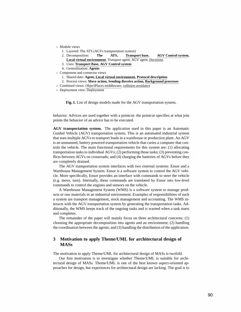
– Module views1. Layered: The ATS (AGVs transportation system)2. Decomposition: The ATS, Transport base, AGV Control system,
Local virtual environment , Transport agent, AGV agent, Decisions3. Uses:Transport Base, AGV Control system4. Generalization:Agents
– Component and connector views1. Shared date:Agent, Local virtual environment, Protocol description2. Process views:Move action, Sending-Receive action, Background processes
– Combined views: ObjectPlaces middleware, collision avoidance– Deployment view: Deployment
Fig. 1.List of design models made for the AGV transportation system.
behavior. Advices are used together with a pointcut: the pointcut specifies at what joinpoints the behavior of an advice has to be executed.
AGV transportation system. The application used in this paper is an AutomaticGuided Vehicle (AGV) transportation system. This is an automated industrial systemthat uses multiple AGVs to transport loads in a warehouse or production plant. An AGVis an unmanned, battery powered transportation vehicle that caries a computer that con-trols the vehicle. The main functional requirements for this system are: (1) allocatingtransportation tasks to individual AGVs; (2) performing those tasks; (3) preventing con-flicts between AGVs on crossroads; and (4) charging the batteries of AGVs before theyare completely drained.
The AGV transportation system interfaces with two external systems: Ensor and aWarehouse Management System. Ensor is a software system to control the AGV vehi-cle. More specifically, Ensor provides an interface with commands to steer the vehicle(e.g. move, turn). Internally, these commands are translated by Ensor into low-levelcommands to control the engines and sensors on the vehicle.
A Warehouse Management System (WMS) is a software system to manage prod-ucts or raw materials in an industrial environment. Examples of responsibilities of sucha system are transport management, stock management and accounting. The WMS in-teracts with the AGV transportation system by generating the transportation tasks. Ad-ditionally, the WMS keeps track of the ongoing tasks and is warned when a task startsand completes.
The remainder of the paper will mainly focus on three architectural concerns: (1)choosing the appropriate decomposition into agents and an environment; (2) handlingthe coordination between the agents; and (3) handling the distribution of the application.
3 Motivation to apply Theme/UML for architectural design ofMASs
The motivation to apply Theme/UML for architectural design of MASs is twofold.Our first motivation is to investigate whether Theme/UML is suitable for archi-
tectural design of MASs. Theme/UML is one of the best known aspect-oriented ap-proaches for design, but experiences for architectural design are lacking. The goal is to
90

<<subsystem>>TransportBase
<<component>>TransportBaseLVE
TransportAgentSA
WMSInterface<<component>>
TransportManagerAgent
ObjectSharingInterface
<<component>>TransportAgent
<<component>>ObjectPlaces
TMAgentSA
remote : RemoteCommunication
wms
<<use>><<use>>
<<subsystem>>AGVControlSystem
<<component>>AGVControlLVE
AGVAgentSA
ObjectSharingInterface
<<component>>AGVAgent
<<component>>ObjectPlaces
vehicle remote : RemoteCommunication
<<use>>
<<use>><<use>>
tbl SubsystemResponsitbilities
AGV Control system: Responsible for anything related to controlling an AGV vehicle.Transport Base: Responsible for transports, i.e. communication with external warehouse managment
system and searching suited AGV to do the job.
cc AGVControlSystem cc TransportBase
Fig. 2. Primary views of AGV transportation system design. Top: clarification tabledescribing the responsibility of each subsystem. Left: C&C model showing the AGV-ControlSystem. Right: C&C model showing the TransportBase.
investigate whether Theme/UML can be extended for architectural design and to iden-tify possible trade-offs and shortcomings of the approach with respect to architecturaldesign.
Secondly, architects using MASs for large-scale systems must cope with multiplearchitectural concerns that tend to crosscut each other in the design models. Archi-tectural concerns that are spread over multiple models are difficult to understand, andconsidering alternative solutions to a particular concerns is complex. The Theme/UMLapproach provides support for advanced separation of concerns in design and is specif-ically aimed to cope with crosscutting concerns. Our goal is to use Theme/UML togroup the design models per concern, aiming for more coherent documentation andbetter support to investigate alternatives for the separated concerns.
3.1 Illustration of crosscutting concerns
In this section, we give two examples of crosscutting concerns in the existing architec-tural models of the AGV transportation system, and we explain the associated problems.
Coordination vs. decomposition agents/environment.The first example illustratescrosscutting between coordination amongst the agents and the decomposition into agentsand the environment. Figure 1 lists the design models (in this case architectural views)of the architectural documentation of the AGV transportation system. We have anno-tated the list to illustrate how the two concerns are tackled in various design models.
91

: AGVVehicle transportBase : Server : WMS, WMS
AGVVehicleInterface
<<subsystem>>AGVControlSystem
vehicle
remote
<<subsystem>>TransportBase
remote
w ms
<<component>>Ensor
<<component>>WMS
Fig. 3.Deployment view.
Design model names marked in bold include fragments of the agent/environmentdecomposition, underlined names include fragments of the coordination between theagents. Thus design models that are bold and underlined intermingle the definition ofcoordination with the decomposition into agents and the environment, illustrating thatthe two concerns crosscut each other in the design models.
Firstly, notice that the representation on which we identified crosscutting concernsare thedesign models, not the software components. As explained before, it is gener-ally acknowledged that an architecture is described using several design models andchoosing a good set of design models is very important for architectural design [9]. Asadvocated in [12], the design models themselves, rather than the software elements andrelationships they show, form the dominant decomposition for an architecture.
Secondly, notice that the current organization of the architectural documentation isessentially based on thetypes of architectural elementslike modules, components, andprocesses. The choice what to describe in a specific design model is left to the softwarearchitect. Since architectural concerns are often not made explicit, this choice is notmade with the architectural concerns in mind [15].
When architectural concerns crosscut each other in several architectural models, anarchitect who wants to change one concern (e.g. coordination) must search within alldesign models, with few guidelines where to search. Even worse, because the relationsbetween concerns are implicit, changing one concern in one design model may haveunforseen effects on other concerns in other design models. As such, all design modelsmust be reexamined and possible adapted to change something to a single architecturalconcern.
Distribution vs. decomposition agents/environment.As a second example of cross-cutting concerns in the AGV transportation system, we consider the intermingling ofthe decomposition into agents/environment and the distribution of the system.
Figure 2 shows the design models of the AGV transportation system that correspondwith the first three decomposition views of Fig. 1.
The system is decomposed in three types of agents (AGVAgent, TransportManager-Agent, and TransportAgent) and an environment.
The design of the environment assumes a specific distributed scheme. The assump-tions are: (1) the deployment infrastructure that consists of mobile AGVs equipped withcomputers and a number of stationary computer systems; (2) each AGVAgent is part ofa AGVControlSystem that is deployed on an AGV; and (3) the TransportAgents anda TransportManagerAgent are part of a TransportBase that is deployed on a stationary
92

computer system. Accordingly, the environment component is split up to provide en-vironment services to the agents on each host. Therefore a local representation of theenvironment (Local Virtual Environment, LVE) and middleware to exchange informa-tion between hosts (ObjectPlaces component) are present on each computer system.Figure 3 illustrates the deployment of the subsystems on the hosts.
The three design models of Fig. 2 represent the basic decomposition on which thearchitecture is built. Yet, the design models clearly intermingle at least two differentconcerns (decomposition agent/environment and distribution). What belongs to whichconcern is not made explicit, only the agent and environment components for the as-sumed distribution schema are visible. Since distribution and the decomposition intoagents and an environment are not considered as separate concerns, it becomes difficultto compare alternative solutions, or to change one of the concerns later on.
Currently Egemin considers to introduce the MAS solution step-by-step, startingwith a centralized server that contains all the agents. In such a setup, remote communi-cation would only be needed to communicate with Ensor (the vehicle control software).However, the original MAS design assumes as particular distribution schema, consid-ering alternatives for distribution was not an upfront requirement. A consequence isthat the assumptions about distribution are implicitly embedded in the design models,and that it is unclear what exactly needs to be changed. For example, in a centralizedsetting, it makes no sense to split up the environment. But, since all other views arebased on the primary decomposition with LVE components, changing the architectureis quite difficult. All views assuming the use of the LVE need to be changed, implyingthat nearly all design diagrams need to be adapted.
The basic reason why this change is so difficult is that the design models are notstructured according to the architectural concerns. Structuring the software according toimportant architectural concerns has the advantage that it becomes easier to change thearchitecture and to consider alternative solutions. In Sec. 5, we show that reorganizingthe current architecture based on architectural concerns allows to investigate differentdistribution schemas for the AGV transportation system.
Reflection. In both examples, the problems with crosscutting concerns stem from theorganization of the design models. As noted before, the architectural models are orga-nized according totypes of architectural elements, grouping modules together, group-ing components together, etc. Theme/UML promotes a way of structuring accordingto architectural concerns, grouping all architectural elements belonging to a particularconcern together. After all, each architectural concern determines a part of the structure,as such it seems logical to describe each concern as a separate block.
Notice that we are not questioning the value of the current design. The architectsdesigned the system for flexibility and performance, using the guidelines for organizingarchitectural documentation of Clements et al. [9]. We only argue that a reorganizationof the design models, with minimal changes to the architecture, could largely improvethe coherence of the architecture documentation and easily allow to investigate alter-native solutions for various concerns. In Sec. 5 we illustrate the design of the AGVtransportation system restructured according to the architectural concerns and show thatcomparing different distribution schemas or changing the distribution schema, is easier.But first we introduce Theme/UML and a number of architectural extensions needed todescribe the architecture of the AGV transportation system.
93

<<theme>> Test1
cl Classes
+opp1()
KlasseA
+opp3()
KlasseB
+opp3()
KlasseC
instance
sd opp1
a : KlasseA c : KlasseB
opp1()
opp3()
<<theme>> Test-Param
cl Classes
sd x
a : KlasseX
x()
do_x()
+x()
KlasseX
+check()
KlasseY
y : KlasseY
check()
KlasseX.x(..)
<<theme>> Test2
cl Classes
+opp1()
KlasseA
+opp3()+opp4()
KlasseB
+opp3()+opp4()
KlasseC
instance
sd opp1
a : KlasseA c : KlasseB
opp1()
opp4()
Fig. 4.Three example themes: Test1, Test2 and Test-Param.
4 Theme/UML and architectural extensions
Theme/UML is an aspect oriented design approach, introduced by Clarke et al. [16,6].Historically, the approach originates from the work on subject oriented programmingand design [17,18] and multi-dimensional separation of concerns [19]. Currently, it isone of the best known and documented aspect-oriented design approaches. TheTheme/UML languages is an extension to UML3.
The essential idea behind the Theme/UML approach is to structure the design (andthe corresponding design models) according to the important concerns. In this sectionwe briefly explain the Theme/UML essentials, together with extensions we have intro-duced for architectural design.
A theme. A themedescribes a part of the design using several design models (e.g.class diagrams or sequence diagrams), where only the portions relevant to a particularconcern are shown. Essentially, a theme groups several design models together thatdescribe a single concern.
Themes are graphically represented by a UML package with a<<theme>> stereo-type. Yet, there is a significant difference between themes and packages. Themes mustbe declaratively complete (meaning all elements used in the theme must be definedwithin the theme) and are always described independently from other themes (thereis no “include” or “import” statement like for packages). Relations and dependenciesbetween themes are specified during the composition.
3 Originally defined as extension to UML 1.3 in [20], later used in UML 1.4 and UML 2.0.
94

<<theme>> Test
<<theme>> Test2
<<theme>> Test1
themename("Test")match(name)merge
cl Classes
+opp1()
KlasseA
+opp3()+opp4()
KlasseB
+opp3()+opp4()
KlasseC
instance
sd opp1
a : KlasseA c : KlasseB
opp1()
opp4()
opp3()
Fig. 5.Composing Test1 and Test2 together in the composed theme Test.
Themes can be composed together to form new themes. Themes defined by a com-position of other themes are called composed themes, the other ones are called ba-sic themes. For example, Fig. 4 contains three basic themes (Test1 , Test2 andTest-Param ), Fig. 5 contains the composed themeTest and Fig. 6 contains thecomposed themeSystem .
In the original Theme/UML approach, design models are either class or sequencediagrams. We consider design models in a broader sense, a design model can be: graph-ical (e.g. UML class diagram) or textual (e.g. a table with responsibilities for eachcomponent or a formal description of the behavior); a general design model (e.g. anarchitectural view or an UML diagram) or a domain specific model (e.g. Agent UML(AUML [21])). For clarity every design model is named and embed in a frame. Em-bedding all design models in frames is not standard in UML or Theme/UML, bothapproaches only embed sequence diagrams in a frame. But we have used the framesto allow a better visual separation between models within a theme, especially in caseof multiple design models. The types of design models are sequence diagrams (sd) andclass diagrams (cl); and we have added state diagrams (st), clarification tables (tbl),C&C diagrams (cc) and deployment diagrams (dpl). The type of the design diagram isvisible in the upper-left corner of the frame. For example in Fig. 4, all themes containone class and one sequence diagram.
Parameterized themes.A theme can optionally containparameters, this defines pat-terns that can be instantiated later on [22]. The parameters are specified in a dashedbox at the upper right corner of the theme. Themes with parameters can be instantiatedmultiple times and a parameter can be bound to multiple values. A parameterized themedescribes crosscutting behavior.
For example in Fig. 4, theTest-Param theme contains one parameter, being theKlasseX.x(..) method (the dots mean that the parameters are unspecified). Thesequence diagrambehavior specifies that when the operationx is called (which isa parameter), the sequence of the parameterized method must be changed by first call-ing thecheck operation and then the behavior of the original method. As such, theTest-Param theme adds the check behavior to the methods whereKlasseX.x()
95

<<theme>> Test
<<theme>> Test-Param
themename("System")bind(KlasseB.opp3())
<<theme>> System
cl Classes
+opp1()
KlasseA
+opp3()+opp4()
KlasseB
+opp3()+opp4()
KlasseC
instance
sd opp1
a : KlasseA c : KlasseB
opp1
opp4
opp3()+check()
KlasseY
y : KlasseY
check()
do_opp3()
Fig. 6.Composing Test and Test-Param together in the composed theme System.
is bound to. The composition is described in details in Fig. 6 and the result is explainedin details when introducing the bind tag.
Composition of themes. Once the concerns are designed in separate themes, thethemes must be integrated to understand the system as a whole.
Theme composition is done in a theme composition diagram. Relations are repre-sented by lines connecting the themes. Every relation is annotated with a UML notecontaining composition tags (additional information about how the concerns should berelated / composed). Composition tags must be interpreted from top to bottom. Typ-ically, a composition relationship contains tags identifying corresponding design ele-ments in the related models and tags specifying how the corresponding elements mustbe integrated. For parameterized themes, the composition relationship contains bindingtags to bind the parameters to concrete values. Possible tags are:
themename(”x”): Specifies the name of a composite theme. In Fig. 5 the composedthemeTest describes the composition between themeTest1 and Test2 . InFig. 6 theTest theme is further composed with theTest-Param theme, thisnew composed theme is calledSystem .
match(name): Matches the elements of different themes based on their name. Thematch relations only applies for elements of the same type. The match relations isused in Fig. 5 to match elements from themeTest1 with elements form themeTest2 . In the example, all classes match with each other. The operationopp1 isdefined in both themes, but but the behavior specified in the themes is different andmust be integrated (see further).
map(expression,componentType):Maps the component types in expression on thetype componentType. The expression can either be a single type (e.g.map(typeA,typeB)), a list of types (e.g. map({typeA1,typeA2},typeB) or a regu-lar expression on types (e.g. typeA+ stands for typeA and all subtypes, typeA*
96

stands for all types of which their name starts with typeA). The map tag is not partof standard Theme/UML.
merge: Merge matching elements. For each type of model and type of element, onehave to specify what happens in case of a merge. An example can be found inFig. 5. The figure contains both the composition specification (left) and the reifi-cation of this specification (at the right). As can be seen from the figure, both theclass definitions and behavior have been merged.
override(themeA,themeB): Overrides matching elements from themeA with elementsfrom themeB. This tag is part of standard Theme/UML, but we have not used it.
bind(params): Binds concrete values to parameters. “params” stands for a list of con-crete values to fill in. For example, Fig. 6 binds themeTest-Param to the themeTest . More concretely, the composition tag bind(KlasseB.opp3()) specifies to bindKlasseB to KlasseX andopp3() to x() . The result of the binding is that thebehavior specified in the parameterized theme (Test-Param ) is inserted in thebehavior of the theme it is composed with (Test ). The right part of Fig. 6 is areification of the binding.
Finally, we introduceinteraction refinements. An interaction refinement is a relation be-tween two design models (not themes!). It is not part of standard UML or Theme/UML.Figure 11 contains an example of the interaction refinement. Interaction refinement isindicated by a forked arrow between design models. Above the arrow is the descriptionof the original interaction, below the arrow is a description on how the interaction mustbe refined. Using AOSD terminology: the part above the arrow (a situation description)together the bind tags roughly corresponds to a pointcut and the part below the arrowroughly corresponds to an advice.
Overview of our architectural extensions to Theme/UML Firstly, we integrated sev-eral new types of design models, namely state diagram, clarification table, deploymentdiagram, AUML sequence diagram.
Secondly, we introduced support for refinement, both for components and interac-tion. Refinement on the level of components is supported by the map tag that can beadded to the composition specification, mapping several component of a theme on asingle component of another theme. Refinement on the level of interaction is added bythe interaction refinement relations between design models.
Finally, we used a slightly different notation to specify the composition relation be-tween themes. All composition tags are specified in a single composition specification–a UML note attached to the composition– and must be interpreted from top to bottom.
5 Design of the AGV transportation system
In this section we illustrate the design of the AGV transportation system restructuredaccording to the concerns, and we show that changing the distribution schema and com-paring different distribution schemas is easier with the new design4.
4 From now on we refer to the design of the motivation section (and associated previous work)as the original design, the design of this section is called the new design.
97

<<theme>> Agents-Environment-Decomposition
AGVAgent: Agent controlling an AGV-vehicle. Decides on transportation tasks, routing, maintenance, …
TransportAgent: Agent responsible for a transportation task. Searches for most suited AGV and keep track of the state of the task.
TransportManagerAgent: responsible for communication with external WMS, instanciating TransportAgents and processing query’s and updates of WMS.
Environment: Provides abstraction layer: (1) offering communication and coordination between agents (2) between the agent and the real world, i.e. representation of real world state of AGV in an understandable format and translating high level operation to format understandeable for Ensor.
WMS: Warehouse Managment System (WMS). External to system. Generates tasks and possible changes task or queries progress.
Ensor: Low level vehicle control software. External to system. Provides operation to drive around and to query the vehicle status.
<<component>>Environment
TransportAgentSA
WMSInterface
AGVAgentSA
<<component>>TransportManagerAgent
AGVVehicleInterface
TMAgentSA
<<component>>TransportAgent
<<component>>Ensor
<<component>>AGVAgent
<<component>>WMS
System boundary
cc C&C tbl ComponentReponsibilities
Fig. 7.Theme describing the decomposition into agents and environment.
<<theme>> TransportManagerAgent-Behavior
sd NewTransportArrival
wms : WMS tm : TransportManager env : Environment
createTransportAgent
ta : TransportAgent
new(t)
start()
newTransport
sd TransportFinished
sd QueryTransportStatus
sd AdaptTranportState
cl Interfaces
+newTransport(in t : Transport)
«interface»WMSInterface
+createTransportAgent(in t : Transport)
«interface»TMAgentSA
+new(in t : Transport)+start()
«interface»TransportAgentSA
Fig. 8.Theme grouping the behavior of the TransportManagerAgent.
<<theme>> Agents-Environment-
Decomposition
<<theme>>TransportManagerAgent
-Behavior
themename("AEDAgentBehavior")match(name)merge
Fig. 9. Composition of Agent-Environment-Decomposition theme (Fig. 7) andTransportManagerAgent-Behavior theme (Fig. 8).
98

In Sec. 5.1 we start from two important architectural concerns to define basic themes,the decomposition into agent and an environment and the behavior of the individualagents. In Sec. 5.2, the coordination protocol between the agents is introduced. InSec. 5.3 we add distribution into the design, describing two deployment alternatives:centralized and decentralized deployment of agents. Finally, we reflect on the designand the architectural extensions of Theme/UML in Sec. 6.
5.1 Decomposition of agents and individual behavior
This section starts from two important architectural concerns: the decomposition intoagent and an environment (Agents-Environment-Decomposition theme) andthe behavior of individual agents (we only elaborate on the behavior of the Trans-portManagerAgent in theTransportManagerAgent-Behavior theme). We de-scribe both themes in more detail and describe how they can be composed.
The Agent-Environment-Decomposition theme defines the decomposi-tion into agents and environment, and the responsibilities of the component types.Figure 7 shows the theme and its two design models. The first model, calledC&C,contains a component/connector view showing the component types, the connectorsand the respective interfaces. Two components are external to the system, Ensor andWMS. We decided to include them into this decomposition view to illustrate how andwhere they interact with the system. The second model, a clarification table calledComponentResponsibilities , lists the main responsibilities of the individualcomponents. Notice that the relations between elements in different design modelswithin a single theme are implicit, based on the names and types of the elements. For ex-ample, the TransportAgent appears in both models (C&C andComponentResponsibilities ) and represents the same component.
TheTransportManagerAgent-Behavior theme in Fig. 8 describes the be-havior of the TransportManagerAgent and the respective interaction with the environ-ment. Only the arrival of a new task together with the creation of a TransportAgent isdetailed, other possible interactions are represented by the empty model frames. Wedecided to provide a separate theme to describe the behavior of each agent, separatingthe behavior description from the decomposition.
The two themes of this section are composed in theAEDAgentBehavior themein Fig. 9. The composition tags specify that matching is based on names and that mergeintegration is used to compose the themes together. In this particular example, there isno real merging because all models are of a different type. The composition groups themodels together and because of the implicit relations between the design models withinthe new theme, theTransportManagerAgent-Behavior theme adds interfacespecifications and behavior to theAgent-Environment-Decomposition theme.
5.2 Adding coordination
In this paper we focus on a single subproblem for coordination: the allocation of tasks toAGVs. Since there is no central controlling entity, the agents have to agree amongst eachother which AGV performs what transport. To solve this problem, we have used the wellknown Contract Net (CNET) protocol. The CNET protocol is originally proposed bySmith et al. [23]. We used the FIPA-CNET protocol described in the FIPA standard [24],slightly extending the original protocol.
99

<<theme>> FIPA-ContractNet-Protocol
sd <<auml>> Protocol interaction
Initiator Participant
cfp
refuse
propose
reject-Proposal
accept-Proposal
failure
inform-done
m
m - k
k
k-1
st Initiator
Proposing/ cfp
refuse
propose
Notifyingna: / selectWinner
/ reject-Proposal
TaskInProcess
/ accept-Proposal
inform-done
failure
st Participant
cfp
[suited] / propose
PossibleTask
[unsuited] / refuse
PerformTask
accept-proposal / startTask
reject-Proposal
[suceed] / inform-done
[failure] / failure
Proposing/ isSuited
isSuited(...)
selectWinner(...)
start(...)
<Initiator{start(..)},Participant>
startTask(...)
cl Classes
+selectWinner(in ...)+start(in ...)«signal»-refuse()«signal»-propose()«signal»-failure()«signal»-inform-done()
Initiator
+isSuited() : bool+startTask()«signal»-cfp()«signal»-reject-Proposal()«signal»-accept-Proposal()
-succesful : bool-done : bool
Participant
Agent
Fig. 10.Theme describing the FIPA Contract Net protocol.
<<theme>> Message-Send
sd MessageComSubSys
A B
<A,B.x,ComSubSys>
mf : MessageFactory
x = assemble("x")
sd MessageSend
A B
x
ComSubSys
send(x,B)
mi : MessageInterpreter
mi=getMessagIn()
put(x)
x
cl Classes
A
«signal»-x()
B
+send()
ComSubSys
MessageInterpreter+getMessageIn()
Agentmf
mi
MessageFactory
Fig. 11.Theme describing the handling of a message between agent A and agent B.
100

<<theme>> Fipa-CNET-Protocol
<<theme>> NetworkMessages
<<theme>>AED+AgentBehavior
themename("System-With-Coord")NetworkMessages.bind(Fipa-CNET-Protocol.Initiator,Fipa-CNET-Protocol.Participant.*)NetworkMessages.bind(Fipa-CNET-Protocol.Participant,Fipa-CNET-Protocol.Initiator.*)
Fipa-CNET-Protocol.bind(TransportAgent.start(...),AGVAgent)
Fig. 12.Composition of CNET coordination and agents/environment.
Figure 10 describes the CNET protocol as a parameterized theme, calledFipa-ContractNet-Protocol , independent of a particular application. The pa-rameters are specified when binding the theme with a particular application, e.g. inFig. 12 the CNET protocol is bound to the agents of the AGV transportation system.
The CNET protocol description contains four models. The ProtocolSequence modeldescribes the interaction between the agents, using the AUML language [21]. Notice thedifference between operations calls (black arrow head) and sending messages. This di-agram does not specify how these messages are sent. The Initiator and the Participantdesign models describe the internal states and the transitions between these states for therespective agents. The annotations of the transitions are’event [condition] / action ’. The ’na:’ in the transition between Propos-ing and Notifying stands for an event triggered by a timer. Finally, the Classes modeldescribes the interfaces of the participating classes.
Before being able to bind the CNET protocol to the decomposition into agents andan environment in the AGV transportation system, we must solve a mismatch betweenthem. At the one hand, the CNET protocol is described as an interaction between agents,abstracting away how exactly this interaction takes place. At the other hand, in the de-composition into agents/environment all interactions are mediated by the environment.To solve the mismatch we defined a new themeMessage-Send to describe messagesending between two agents, in Fig. 11. TheMessage-Send theme contains an inter-action refinement indicated by an forked arrow. TheMessage-Send theme describesthat each signal x between types A and B (i.e. the interaction matching model Mes-sageSend) is replaced by assembling the appropriate message, sending it through thecommunication subsystem and interpretation and signalling by the MessageInterpreter.We still abstract from how messages are handled within the environment.
Finally, we come to the binding of the CNET protocol, sending of messages andthe agents/environment decomposition, illustrated in Fig. 12. For clarity, we add aprefix with the theme name to the elements used in the binding. As last illustration,we partially instantiated the composition of coordination and the decomposition intoagents/environment in Fig. 13.
5.3 Adding distribution
To add distribution, we first considered the distributed infrastructure on which the AGVtransportation system has to be deployed (Fig. 14). The architectural decisions on how
101

ta : TransportAgent B : AGVAgentmf : MessageFactory
cfp = assemble("cfp")
env
send(cfp,B)
mi : MessageInterpreter
mi=getMessagIn()
put(cfp)
cfp
mf2 : MessageFactory
propose = assemble("propose")
send(propose,A)
isSuited(...)
Fig. 13.Partial instantiation of composing between coordination and the decompositioninto agents/environment.
<<theme>> Infrastructure
<<device>>WirelessHub
<<device>>WiredRouter
AGV Vehicle Server
When instanciating this infrastructure there will be multiple AGVVehicles and possibly multiple wirelessAccessPoints and Servers
dpl DeploymentInfrastructure
Fig. 14.Partial instantiation of composing between coordination and the decompositioninto agents/environment.
102

<<theme>> Centralized-deployment
tbl SubsystemResponsibilities
WMS: external to system, contains the Warehouse Management System (WMS)
CentralServer: centralized server responsible to run all agent and environment logic
AGVVehicle: contains only components to support remote acces to ensor.
CentralServerWMS
Server
dpl Infrastructure
: CentralServer
<<component>>Environment
: AGVVehicle
TransportAgentSA
WMSInterface
AGVAgentSA
<<component>>TransportManagerAgent
AGVVehicleInterfaceAGVVehicleInterface
RemoteCommunication
: WMS
<<component>>RemoteProxyEnsor
<<component>>LocalProxyEnsor
TMAgentSA
<<component>>TransportAgent
<<component>>WMS <<component>>
AGVAgent
<<component>>Ensor
dpl Central
Fig. 15.Centralized deployment.
to deploy the system on this infrastructure are important because of significant influenceon the qualities and the structure of the system. We describe two deployment alterna-tives: centralized deployment —with all agents on a single server—, and decentralizeddeployment —with the AGV agents located on the AGV vehicles—.
Centralized deployment The idea behind the centralized deployment schema is tokeep all computation on a centralized server. This deployment schema is describedin Fig. 15. The system has two subsystems: an AGVVehicle subsystem and the Cen-tralServer subsystem. In this case, all agents are deployed on a central server subsys-tem and the AGV vehicle subsystem only contains the vehicle control software anda remote interface to handle communication with the environment component on thecentral server subsystem.
Notice that central deployment is easy, only the communication with the remotevehicle software needs to be added. The LocalProxyEnsor could also contain somecaching mechanism to speed up the communication between the Environment and En-sor. Figure 16 describes the relations between theInfrastructure , theCentralized-Deployment and theSystem-With-Coord theme.
Decentralized deploymentThe idea behind the second deployment schema is to dis-tribute the computation over the AGV vehicles, described in Fig. 17.
The decentralized deployment schema has also two subsystems: the AGV Controlsubsystem and the Transport Base subsystem. The AGV Agents are deployed on thefirst subsystem, a transport manager and all transport agents are deployed on the secondsubsystem. Because the agents are spread over multiple computer systems, the environ-ment needs to be split up into several components and additional support is needed forcommunication and state maintenance between the different parts of the environment(provided by an in-house developed middleware called ObjectPlaces [25,26]).
103

<<theme>> Infrastructure
<<theme>> Centralized-Deployment
<<theme>> System-With-Coord
themename(“Centralized-System”)match(name)merge
Fig. 16.Composition of infrastructure, centralized deployment and the remainder of thesystem.
cc LVE
<<component>>LVE
<<component>>AGVControlLVE
ObjectSharingInterface
<<component>>TransportBaseLVE
<<component>>ObjectPlaces
TransportBase: Server subsystem containing at least one TransportManagerAgent and several TranportAgents. In practice there can be multiple instanced of the TransportBase in a single system.AGVControl: Subsystem to control an AGV vehicle. Contains exactly one AGVAgent. There will be one AGVControl subsystem for every AGV in the system.
LVE: Local Virtual Environment, local representation of the environment. An additional responsibility is to keep the LVE consistent with the other LVEs.
AGVControlLVE: LVE accessible by the AGVAgent and handling the communication with Ensor.
TransportBaseLVE: LVE accesible by the TranportAgent and TransportAgentManager.ObjectPlaces: Middleware for coordination in ad-hoc networks.
tbl SubSystemResponsibilities
<<subsystem>>AGVControlSystem
<<component>>AGVControlLVE
AGVAgentSA
ObjectSharingInterface
<<component>>AGVAgent
<<component>>ObjectPlaces
vehicle remote : RemoteCommunication
<<use>>
<<use>><<use>>
cc AGVControlSubsystem
<<subsystem>>TransportBase
<<component>>TransportBaseLVE
TransportAgentSA
WMSInterface<<component>>
TransportManagerAgent
ObjectSharingInterface
<<component>>TransportAgent
<<component>>ObjectPlaces
TMAgentSA
remote : RemoteCommunication
wms
<<use>><<use>>
cc TransportBaseSubsystem
<<theme>> Decentralized-deployment
: AGVVehicle
: WMS, WMS
transportBase : Server
AGVVehicleInterface
<<subsystem>>AGVControlSystem
vehicle
remote
<<subsystem>>TransportBase
remote
wms
<<component>>WMS
<<component>>Ensor
dpl Decentralized
tbl ComponentResponsibilities
Fig. 17.Decentralized deployment and associated refinements of design.
<<theme>> Infrastructure
<<theme>> Decentralized-Deployment
<<theme>> System-With-Coord
themename(“Decentralized-System”)map({LVE+,ObjectPlaces},Environment)match(name)merge
Fig. 18.Composition of infrastructure, decentralized deployment and the remainder ofthe system.
104

The Decentralized-Deployment theme contains five design models. Twoclarification tables explain the responsibilities of newly introduced subsystems andcomponents. The AGVControlSubsystem and the TransportBaseSubsystem C&C di-agram explain the internal structure of the respective subsystems. The LVE C&C dia-gram shows the generalization relation between the LVE and the specialized AGVCon-trolLVE and TransportBaseLVE. The final design model, the Decentralized deploymentdiagram, describes the deployment of the system.Notice that the design diagrams of Fig. 17 (new design) are similar to the diagrams ofFig. 7 (original design). As we have explained before, the first design models in theoriginal design are the result of relating the decomposition into agents and an envi-ronment and the deployment infrastructure, the same is true for the models in Fig. 17.Additionally, we did not alter the design, we only restructured it. The new descripstionalso contains separate models for the decomposition into agents and an environmentand a separate model describing the infrastructure. These models are lost in the originaldocumentation.
Finally, we describe the relation between theInfrastructure ,Decentralized-Deployment and theSystemWithCoordination theme inFig. 18. The composition maps the LVE+ (LVE and all subtypes) and Objectplaceson the environment. For the remainder we use straightforward matching by name andmerge integration.
6 Discussion
6.1 Design of the AGV transportation system
Using Theme/UML for the architectural design of the AGV transportation system provedto be a valuable experience. Restructuring the design according to the important archi-tectural concerns makes comparing alternative solutions or changing the architectureeasier. Section 5 shows that the new design (1) makes it easier to compare two differ-ent deployment schemas for the same decomposition into agents/environment, and (2)allows to change the deployment of the software without any change to the design forcoordination.
It is important to notice that reifying the composition of the new design will yield thesame system as in the original design. The difference is that the architectural descriptionis structured to align with the architectural concerns. Since each concern determines aspecific part of the architectural structure, describing this structure as a single blockmakes it easier to change the concern. For example, since all decisions for distributionare described in a single theme, it is easier to change the distribution.
Critical notes. Obviously, the advantages of separating concerns only applies to theconcerns that are explicitly considered during architectural design. As such, choosingthe appropriate architectural concerns is very important.
The composition of different parts of the design is not always easy. Assuming thatall composition relations can be defined using a few composition tags would be naive.For example, we encountered a mismatch between the structures of theFIPA-ContractNet-Protocol and theAgent-Environment-Decompositionthemes which need to be composed (see Fig. 10 and Fig. 7 respectively). To solve this
105

problem, we first build the additionalSystem-With-Coord theme that defines howthe different structures should be matched with each other. Afterwards, we composedthe mismatching themes with the additional theme, forming a solution to the composi-tion.
A drawback of the new design is that it is more difficult to have an overall view onthe system. While the structures of individual architectural concerns is much clearer,reification of some compositions will be needed to to get an overall view of the system.Adding reified design models in the architectural documentation helps to improve theunderstanding of the system as a whole.
In our experiment, only a small part of the design of the AGV transportation systemhas been considered. How scalable the approach is in case of a large increase in concernsand themes needs furter study.
Each theme describes a separated concern, however, a theme provides no encap-sulation. All parts of the structure and behavior of a theme can always be overridenor changed by another theme. For example, in Fig. 4 there is no direct compositionrelations betweenTest2 andTest-Param , but still Test-Param changes the be-havior specified inTest2 . The change happens because Test-Param is composed withTest , being a composition ofTest1 andTest2 . Clearly, this can lead to unexpectedinterferences between concerns. As a consequence, to determine if the behavior haschanged or is overridden one must study the relations of the theme and all compositethemes containing this theme.
6.2 Theme/UML
We point out a number of limitations of Theme/UML for architectural design of MAS,and we explain the extensions we have introduced to deal with these limitations.
There is no support to integrate new types of design models. As explained in sec-tion 4, the UML specification contains several types of diagrams related to detaileddesign. MAS architects however, use design models specific for architecture (such asthe set of diagrams used by Clements et al. in [9]), and MAS-specific design models(such as AUML). The integration of new types of design models in this paper shows thatnew models can be integrated relatively easily. Still, disciplined guidelines to integratenew types of models are essential to extend Theme/UML for architectural design.
Theme/UML has no support for gradual refinement of design models, however thisis essential for architectural design. To allow refinement of components, we added themap tag to the Theme/UML composition. A map tag expresses the refinement of a com-ponent in one theme in several subcomponents belonging to other themes. To supportrefinement of interactions, we introduced an interaction refinement relation that is in-spired by the work of Atkinson et al. [27,28]. Interaction refinement relations, togetherwith the parametrization of Theme/UML, provides a powerful way of refining interac-tions between components.
Theme/UML only supports execution joinpoints. Figure 19 illustrates the differencebetween call joinpoints and execution joinpoints. Joinpoints are represented by a blackdisc. This is a severe limitation, both for detailed and for architectural design.
There is a lack of tool support for Theme/UML. A designer using Theme/UMLmust use a standard UML drawing tool and must do every reification of a compositionby hand, a cumbersome process. A tool that includes support for automatic reificationof compositions would be most helpful.
106

caller : A callee : B
operation()
before call
after call
before execution
after execution
Fig. 19.Composition of infrastructure, decentralized deployment and the remainder ofthe system.
7 Related work
Software architecture in MAS. Several researchers use the notion of software archi-tecture and architectural design (based on [8,9,29]) to develop MASs. Shehory [30]considers MAS from the perspective of architectural styles, to reasons about the qual-ities that are typically attributed to the MAS styles. PROSA [31] offers a referencearchitecture for coordination in manufacturing control. Our research group defined areference architecture for situated MAS [32] and developed an industrial AGV trans-portation system using MAS. The software architecture of this system is modeled withdifferent architectural views and structured according to different viewtypes (module,component, deployment). The approach promoted in this paper differs from previousapproaches, since it advocates a way of structuring the architectural models based onimportantarchitectural concerns.
Aspect orientation and MAS. Aspect orientation is rarely used to develop MAS.Kendall describes the use of aspect orientation in the context of MAS in [33,34] (morerecently continued in [35]). The approach uses aspect-oriented programming to designand implement role models.In [36], Garcia et al. observe that several agent concerns such as autonomy, learning,and mobility crosscut each other and the basic functionality of an agent. The authorspropose an aspect-oriented approach to develop agent architectures, using two types ofinterfaces: regular and crosscutting interfaces. A crosscutting interface specifies whenand how an aspectual component crosscuts other components. The authors claim thatthe proposed approach provides a clean separation between the agent’s basic function-ality and the crosscutting agent properties. Unfortunately, a precise semantics of thecrosscutting interface is lacking. The differences with the work in this paper are: (1)we focus on MASs as a whole, identifying concerns that span several agents; (2) weuse the well known aspect-oriented design language Theme/UML; and (3) we identifycrosscutting and separation of concerns on the level of design models, not components.More recent, Garcia et al. [37] identifies crosscutting concerns for agent systems de-scribed in the ANote modeling language. ANote defines several domain specific views,e.g. an agent view, a goal view and a scenario view. Both in the goal and scenario viewcrosscutting concerns have been identified and a new notation is provided to cope withthis crosscutting. The main differences with the work in this paper are: (1) the authors
107

used a domain specific language ANote, while we use several types of design modelsbased on UML; and (2) the authors provide a specific extension to the domain specificlanguage, while we use the model separation capabilities of Theme/UML.
Architectural design and aspect orientation. Next to Theme/UML there are severalaspect-oriented design languages. A good survey on design approaches (both architec-tural and detailed design) can be found in [38,39]. We briefly introduce two approachesclosely related to the work in this paper.
Atkinson and Kuhne [28] propose architectural stratification to combine the strengthsof component-based frameworks and model-driven architectures to support AOSD. Theapproach is about gradual refinement of architectural structures base on architecturalconcerns, introducing interaction refinement as a relations between different designmodels (in this case architectural views). Our notion of interaction refinement is basedon this work.
Katara and Katz [40] observe that incremental design of aspects has been neglectedand that cooperation or interference between aspects should be made clear at the designlevel. The work is strongly related to Theme/UML, since it provides a similar extensionto UML. The concern diagram of that paper is similar to our notion of concern compo-sition diagram. The main difference is that Katara et al. focusses on how aspects can becombined to treat different concerns of a system and possible interactions between con-cerns, while the work in this paper and Theme/UML only use the diagram to describethe composition of design models.
8 Conclusion
In this paper, we studied an alternative way of structuring the design models of a MASfor an AGV transportation system using Theme/UML.
The results of our experience are promising. Separating the architectural concernsresults in more coherent architectural description and allows to better investigate alter-natives for particular concerns. We illustrated this by changing the distribution schemaof the AGV transportation system. On the other hand, documenting different concernsseparately makes it more difficult to have an overall view of the system.
Finally, the experiment shows that Theme/UML is not ready yet for architecturaldesign. We propose several extensions to Theme/UML to support architectural design.Extensions include the integration of new types of design models and support for refine-ment. The proposed extensions are based on particular needs we experienced during therestructuring of the design models of the AGV transportation system. As future work,we plan to use Theme/UML for a number of additional architectural (re) designs. Fromthese experiences we aim to extend Theme/UML for architectural design in a disci-plined manner.
9 Acknowledgement
EMC2 and Nelis Boucke are supported by the Institute for the Promotion of Innovation throughScience and Technology in Flanders (IWT-Vlaanderen). Thanks to Steven Op de beeck and Dim-itri Van Landuyt for the discussions about this paper.
108

References
1. Weyns, D., Schelfthout, K., Holvoet, T., Lefever, T.: Decentralized control of E’GV trans-portation systems. In: International Conference on Autonomous Agents and Multi-AgentSystems, Industry Track. (2005) 25–29
2. Boucke, N., Weyns, D., Schelfthout, K., Holvoet, T.: Applying the atam to an architecture fordecentralized control of a transportation system: Experience report. In: Quality of SoftwareArchitectures conference (QoSA). (2006)
3. Egemin, DistriNet: Emc2: Egemin modular controls concept. (IWT-funded project withDistrinet and Egemin. http://emc2.egemin.com)
4. Egemin: Egemin website. (www.egemin.com )5. Boucke, N., Holvoet, T., Lefever, T., Sempels, R., Schelfthout, K., Weyns, D., Wielemans, J.:
Applying the Architecture Tradeoff Analysis Method (ATAM) to an industrial multi-agentsystem application. Technical Report CW431, Departement of Computer Sience, KULeuven(2005)
6. Clarke, S., Baniassad, E.: Aspect-Oriented Analysis and Design. Addison-Wesley (2005)7. Weyns, D., Helleboogh, A., Steegmans, E., De Wolf, T., Mertens, K., Boucke, N., Holvoet,
T.: Agents are not part of the problem, agents can solve the problem. In: Proceedings of theOOPSLA 2004 Workshop on Agent-oriented Methodologies. (2004)
8. Bass, L., Clements, P., Kazman, R.: Software Architectures in Practice (Second Edition).Addison-Wesley (2003)
9. Clements, P., Bachman, F., Bass, L., Garlan, D., Ivers, J., Little, R., Nord, R., Stafford, J.:Documenting Software Architectures, Views and Beyond. Addison Wesley (2003)
10. Loughran, N., Rashid, A., Chitchyan, R., Leidenfrost, N., Fabry, J., Cacho, N., Garcia, A.,Sanen, F., Truyen, E., Win, B.D., Joosen, W., Boucke, N., Holvoet, T., Jackson, A., Nedos,A., Hatton, N., Munnelly, J., Fritsch, S., Clarke, S., Amor, M., Fuentes, L., Pinto, M., Canal,C.: A domain analysis of key concerns known and new candidates. AOSD-Europe Deliver-able D43, AOSD-Europe-KUL-6 (2006)
11. Filman, R.E., Elrad, T., Clarke, S., Aks.it, M., eds.: Aspect-Oriented Software Development.Addison-Wesley (2005)
12. Baniassad, E., Clements, P.C., Araujo, J., Moreira, A., Rashid, A., Tekinerdogan, B.: Dis-covering early aspects. IEEE SoftwareJanuary/February (2006)
13. Early Aspects: Aspect-oriented requirements engineering and architecture design. (www.early-aspects.net/ )
14. AOSD Wiki: Glossary. (www.aosd.net/wiki/index.php?title=Glossary )15. Boucke, N., Holvoet, T.: Relating architectural views with architectural concerns. In: Ac-
cepted on Early Aspects at ICSE. (2006)16. Baniassad, E., Clarke, S.: Theme: An approach for aspect-oriented analysis and design. In:
Proceedings of the International Conference on Software Engineering. (2004)17. Harrison, W., Ossher, H.: Subject-oriented programming: a critique of pure objects. SIG-
PLAN Not. 28 (1993) 411–42818. Clarke, S., Harrison, W., Ossher, H., Tarr, P.: Subject-oriented design: towards improved
alignment of requirements, design, and code. SIGPLAN Not.34 (1999) 325–33919. Tarr, P.L., Ossher, H., Harrison, W.H., Jr., S.M.S.: N degrees of separation: Multi-
dimensional separation of concerns. In: International Conference on Software Engineering.(1999) 107–119
20. Clarke, S.: Extending standard uml with model composition semantics. Science of ComputerProgramming44 (2002) 71–100
21. Odell, J., Parunak, H.V.D., Bauer, B.: Extending uml for agents. In abd Yves Lesperance,G.W., Yu, E., eds.: Proc. of the Agent-Oriented Information Systems Workshop at the 17thNational conference on Artificial Intelligence. (2000) 3–17
109

22. Clarke, S., Walker, R.J.: Composition patterns: an approach to designing reusable aspects.In: Proceedings of the International Conference on Software Engineering. (2001) 5–14
23. Smith, R.G.: The contract net protocol: high-level communication and control in a distributedproblem solver. Distributed Artificial Intelligence (1988) 357–366
24. FIPA TC Communication: Fipa contract net interaction protocol specification (documentsc00029).http://www.fipa.org/specs/fipa00029/SC00029H.html (2002)FIPA-Standard.
25. Schelfthout, K., Weyns, D., Holvoet, T.: Middleware for protocol-based coordination indynamic networks. In: MPAC ’05: Proceedings of the 3rd international workshop on Mid-dleware for pervasive and ad-hoc computing, New York, NY, USA, ACM Press (2005) 1–8
26. Schelfthout, K., Holvoet, T., Berbers, Y.: Views: Customizable abstractions for context-aware applications in manets. In: Proceedings of SELMAS’05, workshop at ICSE’05. (2005)
27. Atkinson, C., Kuhne, T.: Stratified frameworks. International Journal of Computing Scienceand Informatics, Informatica25 (2001) 393401
28. Atkinson, C., Kuhne, T.: Aspect-oriented development with stratified frameworks. IEEESoftware20 (2003) 81–89
29. Garlan, D., Shaw, M.: An introduction to software architecture. In Ambriola, V., Tortora,G., eds.: Advances in Software Engineering and Knowledge Engineering, Singapore, WorldScientific Publishing Company (1993) 1–39
30. Shehory, O.: Architectural properties of multiagent systems. Technical Report CMU-RI-TR-98-28, Robotics Institute, Carnegie Mellon University, Pittsburgh, PA (1998)
31. Brussel, H.V., Wyns, J., Valckenaers, P., Bongaerts, L., Peeters, P.: Reference architecturefor holonic manufacturing systems: Prosa. Computers in Industry37 (1998)
32. Weyns, D., Holvoet, T.: Multiagent systems and software architecture. In: Special Track onMuliagent Systems and Software Architecture, Net.ObjectDays. (2006)
33. Kendall, E.A.: Role model designs and implementations with aspect-oriented program-ming. In: OOPSLA ’99: Proceedings of the 14th ACM SIGPLAN conference on Object-oriented programming, systems, languages, and applications, New York, NY, USA, ACMPress (1999) 353–369
34. Kendall, E.A.: Role modelling for agent systems analysis, design and implementation. IEEEConcurrency8 (2000) 34–41
35. Cabri, G., Leonardi, L., Zambonelli, F.: Modeling role-based interactions for agents. In: TheWorkshop on Agent-oriented methodologies at OOPSLA. (2002)
36. Garcia, A., Kulesza, U., Lucena, C.: Aspectizing multi-agent systems: From architectureto implementation. Software Engineering for Multi-Agent Systems IIILNCS 3390(2004)121–143
37. Garcia, A., Chavez, C., Choren, R.: Enhancing agent-oriented models with aspects. In:Proceedings of the ACM Fifth International Joint Conference on Autonomous Agents &Multi Agent Systems. (2006)
38. Op de beeck, S., Truyen, E., Boucke, N., Sanen, F., Bynens, M., Joosen,W.: A study of aspect-oriented design approaches. Report CW 435, De-partment of Computer Science, K.U.Leuven, Leuven, Belgium (2006) URL =http://www.cs.kuleuven.ac.be/publicaties/rapporten/cw/CW435.abs.html.
39. Chitchyan, R., Rashid, A., Sawyer, P., Bakker, J., Alarcon, M.P., Garcia, A., Tekinerdogan,B., Clarke, S., Jackson, A.: Survey of aspect-oriented analysis and design (2005) AOSD-Europe Deliverable No: AOSD-Europe-ULANC-9.
40. Katara, M., Katz, S.: Architectural views of aspects. In: Proceedings International conferenceon Aspect-oriented software development. (2003) 1–10
110

On the Quantitative Assessment of ModularMulti-Agent System Architectures
Claudio Sant’Anna1,2, Cidiane Lobato2, Uira Kulesza2
Alessandro Garcia1, Christina Chavez3, Carlos Lucena2
1 Computing Department, Lancaster University - UK{c.santanna,a.garcia}@lancaster.ac.uk
2 Computer Science Department, PUC-Rio - Brazil{claudios,cidiane,uira,lucena}@inf.puc-rio.br
3 Computer Science Department, Federal University of Bahia - [email protected]
Abstract. A number of concerns in multi-agent systems (MAS) have abroadly-scoped impact on the system architectural decomposition, whichin turn hinder the design of modular MAS architectures. These con-cerns inherently crosscut the boundaries of several architecture elements,such as components, connectors, and their interfaces. Typical examplesof crosscutting concerns in MAS architecture include learning, mobility,coordination, context-awareness, and error handling. Nowadays there aresome architectural proposals that envisage an emerging aspect-orientedarchitectural pattern as a potential solution to address modularity short-comings of conventional architectural patterns for MAS designs. How-ever, little effort has been dedicated to effectively assess when and whichof these existing architectural solutions promote in fact superior mod-ularity in the presence of typical crosscutting MAS concerns. This pa-per presents a quantitative comparison of aspect-oriented and traditionalMAS architectures with respect to their support for promoting enhancedmodularity in the presence of architectural crosscutting concerns in MASdesign. Our evaluation used two medium-sized MAS applications andwas centered on fundamental modularity attributes, such as separationof architectural concerns, architectural coupling, component cohesion,and interface simplicity.
1 Introduction
Software architecture is a fundamental element of multi-agent systems (MAS).Architects strive to develop reusable and adaptable MAS architectures that areresilient in face of changes especially for systems in volatile business domainssuch as eCommerce, banking, and telecommunications. However, in order to beeffectively reusable and adaptable, MAS software architectures must be modu-lar. It requires from architects to make proper early design decisions, such as theadequate selection and composition of architectural patterns in order to achievesatisfactory separation of concerns. Modular MAS architectures also demand
111

the careful employment of well-designed component interfaces, reduction of ar-chitectural coupling, maximization of components’ cohesion, and the like. Theseall concern places where we explicitly consider elementar requirements in ourMAS designs, such as reusability, adaptability, flexibility, maintainability, andso forth.
In fact, conceiving modular software architectures for complex MAS is not atrivial task mainly due to a number of recurring widely-scoped MAS concernsand application-specific concerns. A number of these concerns have a crosscut-ting impact on the MAS architectural decomposition, and systematically affectthe boundaries of several architectural elements, such as components and theirinterfaces [11, 24, 25, 19]. Typical examples of crosscutting concerns in MAS ar-chitecture include learning [23], mobility [22, 47], autonomy [17, 48], coordination[32, 3], context-awareness [40], and error handling [13]. The problem is that tobuild flexible MAS applications and frameworks, many of those typical cross-cutting features should be modularized in order to be separated and optionallyexposed as architectural variabilities in the MAS architecture decomposition.This scenario becomes even more challenging when there is a need for reusingand composing MAS frameworks (and platforms), in which their architecturespartially addresses each of those broadly-scoped MAS concerns and, at the sametime, embody a number of crosscutting architectural decisions [34].
In this context, there a number of architectural patterns proposed to buildmodular MAS [31, 10, 45]. For example, Kendall and colleagues [31] propose aspecialization of the layered architecture in order to provide a clear separationof MAS concerns as layers, with narrow interfaces between adjacent layers. Inprevious work [24, 17], we have defined an aspect-oriented architectural patternfor a similar purpose. There are also some existing MAS frameworks and ap-plications that follow a similar aspect-oriented architecture design [3, 40, 43, 41].However, little effort has been dedicated to systematically assess to what ex-tent this new architectural solution promotes in fact superior modularity in thepresence of typical crosscutting concerns in MAS architecture designs. Withouta clear evidence of each solution strengths and drawbacks, modular MAS archi-tects are not guided on when to use each of the available architecture patternsand how to compose them.
This paper presents two complementary case studies where we have quan-titatively evaluated the degree to which the aspect-oriented pattern scales upto promote improved architecture modularity when compared to other con-ventional patterns, such as mediator-based and publisher-subscriber styles. Wehave architected and implemented two medium-sized MAS with similar driv-ing modularity-related requirements, from different domains, based on distinctMAS platforms and frameworks, and with distinct exploitation of typical MASproperties. Our evaluation is based on architectural metrics, which are rooted atfundamental modularity principles, such as separation of concerns, narrow in-terfaces, low architectural coupling, high component cohesion, and compositionsimplicity. This empirical assessment is one step ahead with respect to a first
112

similar empirical study that we have previously carried out to compare aspect-oriented and object-oriented implementations for the same MAS application [25].
The paper is organized as follows. Section 2 presents conventional patternsfor architecting MAS and the application of an aspect-oriented architecture pat-tern for MAS design. Section 3 describes the two case studies, and our usedassessment procedures and metrics. Section 4 presents and discusses the archi-tecture measurement results. Section 5 introduces a more general analysis andrelated work. Section 6 presents concluding remarks.
2 Architectural Patterns and Modular MAS
Every application, in general, requires a recurring architectural pattern whichis the most appropriate to satisfy its highest-priority requirements, while alsopromoting architecture modularity. Although of course there is no single archi-tectural pattern that is the most suitable for all MAS applications, modularity isa stringent software engineering property that underlie almost all architecturaldecisions in MAS designs. Architectural patterns provide guidelines to buildmodular software architectures in the sense that they prescribe a set of architec-tural roles, their interactions, and associated constraints. All these architecturalrules are typically targeted at preserving basic design principles, such as simpleinterfaces, low coupling, and so forth.
A number of architectural patterns [7] have been proposed for the modulardesign of MAS architectures. Section 2.1 revisits some of those architecturalsolutions and briefly discusses architectural crosscutting in MAS decompositions.This discussion serves as a twofold purpose: it describes the consequences ofnot having explicit architectural support for the modularization of crosscuttingconcerns in MAS designs, and works as a motivation for outlining an aspect-oriented architectural pattern [24] for MAS in Section 2.2.
2.1 Conventional Architectural Patterns for MAS
There are some architectural approaches [2, 10, 31] that promote enhanced mod-ularity of architectural MAS concerns. They rest on traditional architecturalpatterns, such as the Layers pattern [31], Mediator pattern [10], the Reflectionpattern [2], or the Publisher-Subscriber pattern [29]. For instance, Kendall etal [31] propose the Layered Agent architectural pattern with multiple layers forthe separate representation of agent concerns (Figure 1 (a)). The layered ar-chitecture establishes a composition style in which all the interactions featurea two-way information flow and only subjacent layers communicate with eachother.
The use of mediators [10] is also a common architectural approach to addressthe composition of agent concerns that interact in multiple ways. Compositionpatterns, such as the Mediator pattern [16] and the Composite pattern [16], aremediator-oriented solutions. They provide means of allowing integration of agentproperties using a central component, the mediator (Figure 1 (b)). The Mediator
113

pattern, for instance, defines a mediator component that encapsulates how a setof components, the colleagues, interact with each other. This solution promotesloose coupling by keeping components from referring to each other explicitly, andit lets the agent developers vary their interaction independently. The SkeletonAgent framework [10] realizes a mediator-based architecture by implementingthe Composite pattern.
Our previous empirical investigation [25] has identified that implementationfollowing conventional architectural patterns may hinder the development ofmodular agent architectures. The main reason is that such implementations failto address the modularization of crosscutting MAS concerns. The crosscuttingmanifestation leads to two major problems – scattering and tangling [46] – whichare fundamental anti-modularity factors in MAS architectures. Scattering inMAS architectures is the occurrence of architectural elements, such as interfaces,that belong to one agent concern in architectural components encapsulatingother agent concerns [24]. For example, the interaction-related interfaces arescattered over the agent architectures in Figure 1. Architectural tangling is themix of multiple agent concerns together in the same module [24]. For instance,tangling is evident in the agent kernel of Figures 1 (a) and 1 (b) as both areimplementing interfaces associated with different agent concerns.
2.2 An Aspect-Oriented Pattern for MAS Architectures
In order to address such modularity breakdowns in MAS architectures, an aspect-oriented architectural pattern [24], and a number of aspectual MAS implemen-tation frameworks [19, 3, 43] that realize this pattern have been defined. Table 1summarizes the main roles defined by the aspect-oriented architectural pattern,their respective responsibilities, and interaction constraints. Section 3 will de-scribe two different instantiations of the aspect-oriented pattern in the contextof our case studies. This pattern documents the fundamental attributes of anaspect-oriented architectural design. Architectural aspects (or aspectual compo-nents) and aspectual interaction rules are exploited at the architectural level tocapture the crosscutting architectural concerns that are hard to modularize withexisting architectural abstractions defined by other patterns. An architectural as-pect is used to represent each crosscutting concern as an individual componentat an early stage of design [24].
In MAS design, architectural aspects should be used to modularize typicalcrosscutting MAS properties and to separate them from other architectural com-ponents. The architectural components expose through their interfaces certainjoin points that are used by the aspects. The goal of aspectizing MAS architec-tures is to allow the association of crosscutting agenthood properties with thenon-crosscutting basic functionality at certain join points. The key abstractionto enable adjustable compositions is the notion of crosscutting interfaces (Ta-ble 1), which are modularity abstractions attached to the architectural aspects.A crosscutting interface is different from a conventional module interface in thesense that the latter essentially provides services to other components. Cross-cutting interfaces provide services to the system, but also specify when and how
114

Fig. 1. Manifestation of Crosscutting Concerns in Conventional Agent Architectures.
an aspect affects other architectural components. The relationship between anarchitectural aspects and other components by means of crosscutting interfacesis called crosscutting relationship. Architectural join points are the elements inan architecture specification that can be affected by a certain aspect.
Opposed to interfaces in traditional architecture styles, crosscutting inter-faces flexibly determine which architectural join points the architectural aspectof a software agent will be connected to. With this dependency inversion, cross-cutting interfaces overcome the problems associated with the rigidness implicitin traditional architectural styles (Figure 1). Each agent’s architectural aspectcan be more flexibly composed with the agent kernel and with any other agentaspects depending on the requirements of a specific agent architecture. Each ofthe architectural aspects is related to more than one component, representingthe crosscutting nature of agent properties in complex architectures.
3 Experimental Settings
This section describes the configuration of our empirical assessment. We haveperformed a pair-wise comparison about the modularity of an aspect-oriented(AO) architecture and a second (non-AO) architectural solution in the context oftwo MAS case studies, which are described in Section 3.1 and Section 3.2. Thefirst case study involved the comparative evaluation of a mediator-based andaspect-oriented architecture for a MAS framework [19], called AspectT, whichsupports the development of applications with heterogeneous agent architec-tures. The second study encompassed a publisher-subscriber [4] and an aspect-
115

Table 1. The Aspect-Oriented Architectural Pattern: Architectural Elements, theirResponsibilities and Interactions.
ArchitecturalRole
Responsibilities andConstraints
Interaction Constraints
Base Components(and Interfaces)
- modularize services that realizea non-crosscutting concern- provide the architectural joinpoints to aspects
- can be affected by one or morecrosscutting interfaces- access services available inother conventional interfaces
Architectural As-pects (or AspectualComponents)
- encapsulate an architecturalcrosscutting concern- contain at least one crosscuttinginterface- may implement conventional in-terfaces
- affect base components andother aspects through its cross-cutting interfaces- can be directly associated withother aspects
CrosscuttingInterfaces
- provide crosscutting servicesand specify when and how eachof them affects other interfaces
- are allowed to affect both con-ventional and other crosscuttinginterfaces- affect base interfaces usingaspectual composition opera-tors, such as before, after, andaround
oriented version [39] of the MobiGrid architecture [4], used to develop mobileagents in Grid environments. Other architectural patterns were also instanti-ated and composed in all the system versions, such the client-server. However,the aforementioned ones are the heart of the architecture design and, therefore,we concentrate our attention on them.
Both systems were ideal for our experimental investigation due to severalreasons. First, the chosen systems have stringent modularity requirements dueto the demand for producing reusable, adaptable and evolvable MAS architec-tures. Hence, all the system versions were developed with modularity principlesas main driving design criteria, making sense the exploitation of AO software ar-chitectures. Second, the original architecture of each case study was developed indifferent contexts – the first system was developed in our own laboratory, whilethe second one has been developed out of our research environment [4]. Third, apreliminary qualitative assessment focused at the implementation level has beenrecently conducted and reported [17, 21, 39]. It has allowed us to supplement thequalitative focus on separation of concerns of our preliminary studies with bothbroader quantitative analysis and a systematic investigation about the scalabilityof aspect-oriented architectures in distinct MAS application scenarios.
Finally, they are realistic systems that involve emphasis on different MASconcerns, such as mobility, learning, autonomy, and their distinct compositions;they also encompasses the application of common MAS platforms and frame-works, such as JADE [6], Aglets [37], and TSpaces [38]. Sections 3.1 and 3.2focus on describing the main AO and non-AO architectural choices for both
116

AspectT and MobiGrid case studies; each design choice for all the investigatedsolutions have been deeply discussed and documented elsewhere [17, 19, 21, 4, 39].Section 3.3 presents our evaluation steps and the architectural metrics applied.
3.1 The AspectT Architecture
We developed an aspect-oriented agent framework [19], called AspectT, whichdefines an architecture for implementing different kinds of agents, such as, in-formation and user agents. This framework has been implemented using theAspectJ and Java programming languages. We have used this framework inthe implementation of two case studies: (i) Portalware – a web-based systemfor the development of e-commerce portals [19]; and (ii) ExpertCommittee – aconference management MAS [21]. AspectT was structured following the aspect-oriented pattern for MAS architectures detailed in Section 2.2. Figure 2 showsthe framework architecture. It defines a set of components playing the roles ofarchitectural aspects that address different crosscutting agent properties, suchas interaction, autonomy, mobility, and learning. Following we describe the maincomponents of the AO architecture and their respective relationships.
Fig. 2. The AspecT Architecture.
The aspect-oriented architecture has the Kernel component as a central ele-ment. This component defines two interfaces: (i) KnowledgeUpdating – used toupdate the agent knowledge (belief, goal and plan); and (ii) Services – whichallows to expose the agent services. A set of aspectual components are used toaddress different crosscutting agent features. Each of them either introduces newbehavior in other components or refines the components’ behavior by observing
117

specific service execution. The interaction aspect is used to modularize the cross-cutting impact on the use of communication architectures, such as JADE [37].The Interaction aspectual component specifies crosscutting interfaces for mes-sage receiving (MessageReception) and for message sending (MessageSending).
The Adaptation component intercepts the MessageReception interface ofthe Interaction component by means of the KnowledgeAdaptation crosscut-ting interface to update the agent beliefs when new external messages are re-ceived. It also defines the BehaviorAdaptation interface to instantiate specificplans when the agent needs to achieve any goal. The Autonomy aspectual com-ponent defines three crosscutting interfaces: (i) GoalCreation – cuts across theInteraction component to create new reactive goals when new external messagesare received; (ii) DecisionMaking – introduces in the Kernel component thebehavior of creation of proactive goals; and finally (iii) ExecutionAutonomy –associates the agent with its own thread of control and also makes it possiblethe concurrent execution of agent plans. The Collaboration, Mobility andLearning components encompass crosscutting agent properties that are neces-sary only on specific agent architectures. The Collaboration component con-tains two interfaces: (i) Knowledge – introduces new knowledge associated withroles to be played by the agent; and (ii) Binding – affects specific services fromthe Kernel component in order to instantiate new roles and attach them to theagent according to certain conditions. The Mobility aspect is used to overcomethe crosscutting nature of mobility concerns by directly using existing mobil-ity platforms. The Mobility component uses the Travel interface to introducemobility capacities in the agent and to determine the execution points in whichthe agent can be moved. Finally, the Learning component is responsible for col-lecting information to execute its learning algorithms (InformationGatheringinterface). It also introduces new learning-specific knowledge associated withthese algorithms (LearningKnowledge interface).
The AspectT framework has been developed as an alternative to an equiva-lent object-oriented mediator-based architecture, presented in Section 2.2. Thecombination of these two architectural styles defines a central component whichmediates all the communication between the other ones. The Kernel componentplays this central role.
3.2 The MobiGrid Architecture
Our second case study was the MobiGrid framework [4], which is a mobile agentsystem within a grid environment project called InteGrade [27]. In this system,mobile agents are used to encapsulate and execute long processing tasks usingthe idle cycles of a network of personal workstations. The agents can migratewhenever the local machine is requested by its user since they are providedwith automatic migration capabilities. The original MobiGrid architecture wasdefined based on the OO framework provided by the Aglets platform [37], andfollows a publisher-subscriber architecture pattern.
Due to the high coupling between the Aglets underlying model and the Mo-biGrid mobile agents, we have decided to reengineer the MobiGrid architecture
118

taking into account the following requirements: (i) to modularize the MobiGridmobility concerns, that is, to promote an explicit separation between the cross-cutting mobility concern and other non-crosscutting MobiGrid concerns; and(ii) to enhance the MobiGrid variability in terms of a flexible choice of distinctmobility platforms to be used (e. g. Aglets [37], JADE [6], etc.).
In the reengineering process, we have generated two versions of the MobiGridarchitecture. In a first moment, we decided not to use the concept of crosscut-ting interfaces (Section 2.2); our goal was then to assess the applicability ofconventional architectural components and interfaces in order to explicitly sep-arate the mobility concern. After that, we provided an alternative version ofthis reengineering using aspectual components and crosscutting interfaces [39].In both solutions, the separation of the mobility concerns and the integrationbetween MobiGrid and distinct mobility platforms respectively resulted in theconception of two architectural components: the MobilityProtocol and theMobilityManagement.
Figures 3 and 4 illustrate the two versions resulted from the MobiGrid ar-chitecture reengineering: the non-aspectual architecture and the aspect-orientedone. The former follows the publisher-subscriber architectural pattern; the latteris based on the aspect-oriented architectural pattern (Section 2.2). The archi-tectural designs presented in both figures respectively follow a simplified UMLnotation (Figure 3), and the AOGA notation (Figure 4). Note that the main dif-ference between the proposed architectures is the use of crosscutting interfacesand aspects for designing the two new components defined in the reengineeredMobiGrid Architecture (Figure 4).
Despite this difference, in both cases, the MobiGrid architecture is composedof four kinds of components: (i) the MobiGrid component, which modularizes thebasic concerns of an agent-based application; (ii) the MobilityProtocol compo-nent, which modularizes the mobility protocol execution – i.e. the instantiation,migration, remote initialization, and destruction of MobiGrid agents; (iii) theMobilityManagement component, which provides a flexible integration betweenMobiGrid and distinct mobility platforms; and (iv) the MobilityPlatform,which represents a specific mobility platform being used, such as Aglets [37].In both architectures, the main purpose of the MobilityProtocol componentis the explicit separation of the mobility concerns from the MobiGrid compo-nent. In addition, the MobilityManagement component connects the MobiGridwith the MobilityPlatform component, which modularizes and externalizes theplatform services.
The IMobileAgentProtocol and IReferenceMobileAgent interfaces playa central role in the design of both non-AO and AO architec-tures. The IMobileAgentProtocol is the interface that delegates to theIReferenceMobileAgent the mobility services invoked by the MobiGrid; thisdelegation is independent from platform-specific issues. The IMobileAgent isthe interface which is responsible for delegating to a specific platform the in-voked services; to do that, it uses the IPlatformServices interface provided by
119

Fig. 3. The non-AO MobiGrid Architecture.
the MobilityPlatform component. The mobility services include the access tothe agent ids, context ids, mobile agent lifecycle, messaging, and so on.
The AO architecture in Figure 4 uses the crosscutting interface abstraction(Section 2.2) to make it possible a clean modularization of the mobility concernin the MobiGrid. The MobilityProtocol component now implements a genericmobility protocol in in order to prevent the explicit invocations of the mobilityservices by the MobiGrid component. Such explicit invocations happen in thenon-AO architecture due to the interaction constraints imposed by the publisher-subscriber pattern. In other words, we invert the way in which access to themobility services is typically designed in mobile agent systems. To do that, theIMobileElement crosscutting interface is used to determine when and how amobile agent is instantiated on a platform to represent a specific agent on theMobiGrid. This interface also triggers the agent migration to other environments,since the mobile agent may have to migrate whenever elements of the MobiGridare called or executed. That is, the IMobileElement interface is used to affectwell-defined mobility join points in order to determine when MobiGrid agentsshould move. Thus, the IMobileElement interface allows an explicit separationof mobility issues from the other MobiGrid non-crosscutting concerns.
Other interfaces are used in both architectures in order to maintaina flexible integration between MobiGrid and distinct mobility platforms;they make information relative to the mobile agent lifecycle available tothe MobiGrid component. However, they externalize the mobility concernthrough the MobilityProtocol component in different ways. In Figure 4, theIReferenceObserver interface crosscuts join points as calls of mobility platformservices in order to maintain a consistence between the platform runtime and theMobiGrid. This is possible because the IReferenceObserver interface is also af-fected by the InstantiationEvent, MigrationEvent, IInitializationEvent,and IDestructionEvent interfaces, which respectively allow the agent instan-
120

Fig. 4. The AO MobiGrid Architecture.
tiation, departure, arrival, and destruction handling in the MobilityProtocolcomponent.
A different architectural scheme is used to propagate the platformevents in Figure 3. The IReferenceObserver interface still observes theseevents, but now following the publisher-subscriber architectural pattern.Additional required interfaces are necessary in order to delegate plat-form events to the MobilityProtocol component: MigrationPropagator,InstantiationPropagator, IInitializationPropagator andIDestructionPropagator. These interfaces are respectively connected tothe InstantiationEvent, MigrationEvent, IInitializationEvent, andIDestructionEvent interfaces in order to allow event handling in theMobilityProtocol component. Finally, note that in both AO and non-AOarchitectures the MobilityManagement component realizes a conventionalinterface called the IReferenceTable. This interface is used to abstract thecontext and messaging services provided by different platforms.
3.3 Evaluation Procedures and Assessment Metrics
Our evaluation has strictly focused on the evaluation of architecture artifacts,since we are concerned with both: (i) understanding the suitability of existingMAS architecture-level solutions in order to address the modularity problemsassociated with widely-scoped crosscutting properties, and (ii) investigating towhat extent the crosscutting nature of certain MAS properties entail designanomalies visible earlier at the architecture stage. The used architecture descrip-tions were based on conventional and aspect-oriented component-and-connectormodels [35, 5, 18].
We have used a suite of architectural metrics (Table 2) to support modularityevaluation of the investigated software architectures (Sections 3.1 and 3.2). We
121

have not used conventional architectural assessment methods because they tra-ditionally focus either on the architecture coverage of scenarios described in therequirements specification [12], or on the satisfaction of high-level non-functionalrequirements (e.g. [1]) without a clear focus on modularity assessment. Our goalhere was to assess internal structural attributes in the architecture descriptionwith a direct impact on architecture modularity. As a consequence, our inves-tigation has provided us with a more fine-grained understanding of the overallarchitecture quality since modularity impacts a huge number of non-functionalrequirements in MAS, such as reusability, adaptability, flexibility, changeabilityand the like. The outcomes of our analyses can be used in conjunction withother architectural assessment methods, such as ATAM, for performing a trade-off evaluation with respect to other architectural qualities, such as performanceand availability.
A discussion about each of those architectural metrics is out of the scope ofthis work. Table 2 presents a definition for each of the used metrics and theirassociation with distinct modularity attributes. This suite includes metrics forarchitectural separation of concerns, architectural coupling, component cohesionand interface complexity. We have already used similar categories of metrics [17,42] for evaluating aspect- and object-oriented designs in a number of systematiccase studies [26, 9, 15, 36, 8] not related to multi-agent systems. They have beenproved to be effective modularity indicators for detailed design and implemen-tation artifacts. The metrics can also be classified in two categories according tothe architectural viewpoint under assessment: concern viewpoint or componentviewpoint. On one hand, the results of the SoC metrics are obtained for eachconcern of interest in the system. On the other hand, the results of the othermetrics are all gathered for each component in the system architecture. Table 2also relates the metrics to the viewpoint from which their values are obtained.For all the employed metrics, a lower value implies a better result.
The metrics of separation of concerns (SoC) measure the degree to which asingle concern in the system maps to the architectural elements (components,interfaces, operations and parameters). The interface complexity is measuredin terms of the total number of interfaces, operations and parameters of eachcomponent. The coupling metrics measure the number of components connectedto each component. The cohesion metric computes each component’s semanticcohesion based on the number of concerns addressed by it. The higher the numberof different concerns in the component the lower the cohesion is.
In order to proceed with the measurement of separation of concerns, there isan architecture shadowing process in which the architect must assign every com-ponent element (interface, operation and parameter) to one or more concerns.The chosen architectural concerns to be assessed are related to the driven archi-tectural issues that should be modularized in each system. For example, in theAspectT case, we have shadowed the architecture artifacts with respect to thekernel, adaptation, interaction, autonomy, collaboration, mobility, and learningconcerns because these are the properties that should be adaptable, reusable,and easily (un)plugged from the system. As in the MobiGrid system the design
122

Table 2. Architectural Metrics Suite.
Attribute Metric Definition Viewpoint
Arc
hit
ectu
ral
Separa
tion
ofC
oncern
s Concern Diffusion overArchitectural Components(CDAC)
Counts the number of ar-chitectural components whichencompass a concern.
ConcernConcern Diffusion over
Architectural Interfaces(CDAI)
Counts the number of inter-faces related to a concern.
Concern Diffusion overArchitectural Operations(CDAO)
Counts the number of opera-tions (defined in architecturalinterfaces) that are related toa concern.
Arc
hit
ectu
ral
Coupling
Architectural Fan-inCounts the number of com-ponents which require ser-vice from a component (callercomponents).
Com
ponent
Architectural Fan-outCounts the number of com-ponents from which the com-ponent requires service (calleecomponents).
Com
ponent
Cohesi
on
Lack of Concern-based Co-hesion (LCC)
Counts the number of con-cerns addressed by a compo-nent.
Inte
rface
Com
ple
xity
Number of Interfaces Counts the number of inter-faces of each component.
Number of OperationsCounts the number of opera-tions in the interfaces of eachcomponent.
was much more focused on modularizing specific mobility issues (Section 3.2), wetreated each of the core mobility features (mobility platform, mobility protocol,and mobility management) and the MobiGrid application as driving concernsin order to investigate their associated crosscutting structures in both archi-tectural solutions. After the shadowing of the architecture models, the data ofthe separation of concerns metrics (CDAC, CDAI, and CDAO) was manuallycollected.
4 Empirical Results
This section presents the results of the measurement process. The data havebeen collected based on the set of defined measures (Section 3.3) in the twocase studies. The presentation is broken in three parts. Section 4.1 presentsthe evaluation results for the separation of architectural concerns. Section 4.2
123

presents the results for the coupling and cohesion metrics. Section 4.3 presentsthe results for the interface complexity metrics. We present the results by meansof tables that put side-by side the values of the metrics for the aspect-orientedand non-aspect oriented architectures of each system.
4.1 Separation of Architectural Concerns
In the quantitative evaluation of the AspectT framework, the data collected forboth AO and mediator-based architectures shows favourable results for the AOversion for most of the metrics used. Table 3 presents the complete data col-lected for both AspectT architecture versions considering the SoC metrics. Theapplication of the SoC metrics allowed us to evaluate how effective was the sep-aration of the agency concerns in the both AspectT architectures. These metricscount the total number of components, interfaces and operations dedicated toimplement a concern (Section 3.3).
We can observe significant differences between the AO and non-AO versionsfor all the SoC metrics. Table 3 shows that the mediator-based architecturerequires two components to address each of the system concerns (CDAC met-ric), except for the Kernel concern. It happens because the Kernel componentneeds to inevitably embody functionalities from the different concerns besidesto implement the kernel-specific functionalities. It happens because the Kernelcomponent plays the mediator role and, as a consequence, propagates infor-mation relative to every concern to the other “colleague” components. On theother hand, each component in the AO version is responsible for implementingthe functionalities associated with exactly one concern because such informationis directly collected from the context where it is generated through crosscuttinginterfaces; as a result, the design of the Kernel component and its interfaces arenot affected by other concerns.
We can also observe in Table 3 that the AO version requires fewer interfaces(CDAI metric) and operations for most of the system concerns with exceptionof the Kernel concern. The Kernel concern in the AO version is represented bythe Kernel component. This component needs to expose new interfaces in theAO version to enable the implementation of the different aspectual components.However, all these additional interfaces are part of the Kernel functionalities andseparation of architectural concerns is not hindered. As we can see in Table 3,there is also a significant increase in the number of operations (CDAO metric)for almost all the agency concerns in the non-AO version, the only exception isthe Kernel concern. The Interaction concern, for example, is addressed in the AOversion by 3 interfaces and 10 operations. While the same Interaction concern inthe mediator version requires 9 interfaces and 22 operations. This growth in thenon-AO architecture is mainly caused by the use of the mediator-based patternwhich requires the additional interfaces in the Kernel component (see Figure 1)with their associated operations.
Table 4 shows the results for the three SoC metrics for the MobiGrid architec-tures. As discussed in Sections 3.1 and 3.2, the MobiGrid application and agent
124

Table 3. AspectT Architectures: Separation of Concerns Measures.
Concern#components(CDAC)
#interfaces(CDAI)
#operations(CDAO)
AO Non-AO AO Non-AO AO Non-AO
Kernel 1 1 4 2 68 14
Interaction 1 2 3 9 10 22
Adaptation 1 2 2 6 5 34
Autonomy 1 2 3 7 31 80
Collaboration 1 2 4 6 37 87
Mobility 1 2 3 3 20 35
Learning 1 2 2 4 6 16
mobility issues are the two architectural concerns of interest in the MobiGrid sys-tem. The AO architecture performed better than the publisher-subscriber one interms of SoC. As shown in Table 4, the mobility concerns are scattered over fewerarchitectural components in the AO architecture (CDAC metric). These concernsare present in 4 components in the non-AO architecture, whereas they crosscutonly 3 components in the AO architecture. This occurs because, in the non-AOarchitecture, the MobiGrid component encompasses two mobility-related inter-faces – IMobilityLifeCycleObserver and IMobilityLifeCycleSubscriber –for explicitly handling of mobility life-cycle events. These events are captured bythe IMobileElement crosscutting interface in the AO architecture which makesthe mobility-related interfaces unnecessary in the MobiGrid component.
The SoC metrics also showed better results for the AO architecture interms of number of interfaces (CDAI metric) – 13 vs. 32 – and number ofoperations (CDAO metric) – 326 vs. 407. This is mainly caused because theMobilityProtocol and MobilityManagement aspectual components need fewerinterfaces and operations for handling events. This will be further discussedin subsection 4.3. The aforementioned absence of mobility interfaces in theMobiGrid component also contributes for that difference.
Table 4. MobiGrid Architectures: Separation of Concerns Measures.
Concern#components(CDAC)
#interfaces(CDAI)
#operations(CDAO)
AO Non-AO AO Non-AO AO Non-AO
Mobility 3 4 13 23 326 407
Application(MobiGrid)
1 1 1 1 18 18
125

4.2 Architectural Coupling and Component Cohesion
Tables 5 and 6 present the results for architectural coupling and componentcohesion metrics considering, respectively, the AspectT and MobiGrid architec-tures. As in subsection 4.1, the tables in this subsection and in subsection 4.3 putside-by-side the metrics values for the AO and non-AO architectures. However,since the values here are for each component (component viewpoint), the bottomof the tables also provide the total values (sum of all the component measures)that represent the results for the overall architecture viewpoint. Therefore, rowslabelled “Total” indicate the tally for the system architecture, while rows labeled“Diff” indicate the percentual difference between the AO and non-AO architec-tures in the system viewpoint relative to each metric. A positive value meansthat the non-AO architecture fared better, whereas a negative value indicatesthat the AO architecture exhibited better results.
As we can observe in Table 5, there is an expressive coupling increase in thenon-AO AspectT architecture considering the number of requiring components(Architectural Fan-in metric). The fan-in is 12 in the mediator-based architec-ture, while it is 9 in the AO architecture, representing a difference of 25% infavour of the latter. This occurs because in the AO version the services of sev-eral aspects (e.g. Adaptation, Autonomy, Learning) are not requested by othercomponents granted to the dependency inversion promoted by AO architectures.With respect to the architectural fan-out, the measures did not show a expressivedifference from system viewpoint; the difference was lower than 10% (Table 5).
As stated in Section 3.3, we assess the lack of cohesion of a component count-ing the number of distinct concerns addressed by it, which is captured by theLack of Concern-based Cohesion (LCC) metric. LCC measurement resulted inbetter results for the AO version (13 vs. 7 = 46.2%). This superiority is justi-fied by the fact that in the mediator-based architecture, the Kernel componentneeds to implement required interfaces associated with the six system concerns(CBLC metric). Hence, there is an explicit architectural tangling in the Kernelcomponent.
Table 5. AspectT Architectures: Coupling and Cohesion Measures.
ComponentArchitecturalFan-Out
ArchitecturalFan-In
#Concerns(Lack of Cohesion)
AO Non-AO AO Non-AO AO Non-AO
Kernel 0 6 5 5 1 7
Interaction 3 2 2 2 1 1
Adaptation 2 1 0 1 1 1
Autonomy 2 1 0 1 1 1
Collaboration 1 1 1 1 1 1
Mobility 2 1 1 1 1 1
Learning 1 0 0 1 1 1
Total: 11 12 9 12 7 13
Diff: -8.3% -25.0% -46.2%
126

The AO architecture of the MobiGrid system presented better outcomes interms of the two coupling metrics and in terms of the cohesion metric as well(Table 6). The non-AO architecture exhibited architectural fan-out 50% higherthan the AO architecture. This difference is a consequence of the reduction offan-out in both MobiGrid and MobilityManagement components in the AO ver-sion, since they do not have to explicitly call the MobilityProtocol componentfor notifying events. Being an aspectual component, MobilityProtocol cap-tures the events by means of crosscutting interfaces. MobilityPlatform alsocontributes for decreasing the fan-out, because it does not need to be connectedto the MobilityManagement component in order to notify events. In this case,the aspectual MobilityManagement component observes the events by means ofits IReferenceObserver crosscutting interface. For the same reasons, the ar-chitectural fan-in metric also showed worse results for the publisher-subscriberversion of the architecture (50% higher). In this case the fan-in reduction isobserved in the MobilityProtocol and MobilityManagement components.
Similarly to the AspectT case, the cohesion measures in the MobiGrid ar-chitectures pointed out a difference in favour of the AO solution only in one ofthe components, namely the MobiGrid component. This component encompassestwo concerns in the non-AO solution: the MobiGrid concern, which is the primarypurpose of the original definition of this component, and the mobility concern.The IMobilityLifeCycleObserver and IMobilityLifeCycleSubscriber in-terfaces contain operations related to the mobility concern, which reduce thecohesion of the component; in fact, these operations have a purpose differentfrom the main purpose of the component. On the other hand, these interfacesare not necessary in the AO solution and, as a consequence, the MobiGrid com-ponent is not affected by the mobility concern and entirely dedicated to its mainconcern.
Table 6. MobiGrid Architectures: Coupling and Cohesion Measures.
ComponentArchitecturalFan-Out
ArchitecturalFan-In
#Concerns(Lack of Cohesion)
AO Non-AO AO Non-AO AO Non-AO
MobilityPlatform 0 1 1 1 1 1
MobilityManag. 1 2 1 2 1 1
MobilityProtocol 2 2 0 2 1 1
MobiGrid 0 1 1 1 1 2
Total: 3 6 3 6 4 5
Diff: -50.0% -50.0% -20.0%
4.3 Interface Complexity
Tables 7 and 8 show the results for the interface complexity metrics for the As-pectT and MobiGrid architectures, respectively. Regarding the AspectT system
127

(Table 7), the metrics demonstrate the modularity benefits obtained in the AOversion compared to the non-AO one. There was a bigger difference in the num-ber of interfaces specified for each version (35 vs. 21 = 43.2%) which favoursthe AO version. This difference is mainly due to the additional interfaces of theKernel component, but it is also thanks to the values collected for other compo-nents. The increase in the number of interfaces metric for the mediator versionis also reflected in the number of operations. Table 7 shows that the number ofoperations is 38.5% higher in the non-AO version. Again, it happens becausethe Kernel component plays the mediator role and, as a consequence, it hasadditional interfaces and operations to propagate information relative to everyconcern to the other “colleague” components (Section 4.1).
Table 7. AspectT Architectures: Interface Complexity Metrics.
Component#Interfaces #OperationsAO Non-AO AO Non-AO
Kernel 4 16 68 115
Interaction 3 5 10 13
Adaptation 2 4 5 29
Autonomy 3 4 31 49
Collaboration 4 4 37 47
Mobility 3 2 20 19
Learning 2 2 6 16
Total: 21 35 177 288
Diff: -43.2% -38.5%
The use of aspects had a strong positive influence in the interface complex-ity of the MobiGrid architectural components, as shown in Table 8. For thenon-AO architecture, the number of interfaces was more than 40% higher thanin the AO solution. Also, the number of operations was higher in the non-AOsolution (19.1%). The main reason for this result is the decrease on the num-ber of required interfaces of the MobilityManagement aspect. In the non-AOsolution, the conventional component has four required interfaces to propagatefour mobility events relative to the initialization, migration, destruction and in-stantiation of agents. These events are observed by the IReferenceObserverinterface and propagated to the MobilityProtocol component. On the otherhand, in the AO solution, the aspectual component MobilityProtocol cross-cuts the IReferenceObserver interface and directly observes the events whenMobilityPlatform notify them. Hence, the required interfaces to propagatethem are not necessary. Moreover, the inferiority of the non-AO version in thenumber of interfaces is granted to the fact it needs additional pairs of subscriptioninterfaces involving the collaboration of the components MobilityManagementand MobilityPlatform, and the components MobilityProtocol and MobiGridcomponents.
128

Table 8. MobiGrid Architectures: Interface Complexity Metrics.
Component#Interfaces #OperationsAO Non-AO AO Non-AO
MobilityPlatform 3 4 176 185
MobilityManagement 4 9 124 155
MobilityProtocol 6 8 26 61
MobiGrid 1 3 18 24
Total: 14 24 344 425
Diff: -41.7% -19.1%
5 General Analysis and Related Work
This section provides a more general analysis with respect to modularity break-downs observed in the results previously presented in Section 4. This sectionalso brings discussions on how such results and conclusions are connected toobservations made by related work.
5.1 Detecting Early Modularity Anomalies in MAS Architectures
The use of the architectural modularity metrics (Section 3.3) allowed us to ob-serve some early design anomalies in the investigated MAS architectures. Ourobservations are classified into three main categories: (i) bidirectional architec-tural coupling, (ii) architectural interface bloat, and (iii) hindering of architec-tural variability and adaptability.
Bidirectional Architectural Coupling. First, after a careful joint analysis of theMobiGrid and AspectT architectures, we observed that both non-AO options –i.e. the mediator-based and the publisher-subscriber designs – imposed some un-desirable bidirectional couplings. In the mediator architecture, all the “colleague”components need to inevitably have references to the “mediator” component andvice-versa. Similarly, in mediator-based architectures, all the “subscriber” com-ponents need to know the “publisher” components and vice-versa. Even thoughthese architectural solutions overcome the problem of direct couplings betweencolleagues and between subscribers, the AO architectural solutions for both Mo-biGrid and AspectT systems have reduced even more the overall architecturecouplings by making almost all the inter-component relationships unidirectional(aspects affect the components). This phenomenon is observed mostly from thefan-in and fan-out measures (Section 4.2). For example, the Kernel componenthas the fan-out zero in the AO version of the AspectT architecture, while it is6 in the mediator version (Table 5). Also, Adaptation, Autonomy and Learningcomponents have a fan-in zero.
Architectural Interface Bloat. The inter-component interaction constraintsdefined by the mediator-based and publisher-subscriber architectures did notscale respectively in the AspectT and MobiGrid systems, causing a complexityincrease in the component interfaces. Such constraints have influenced the defini-tion of extra operations and additional interfaces for the sake of realizing certain
129

crosscutting MAS concerns, such as mobility and learning issues. For example,the evidence of interface bloat can be observed in several parts of both non-AOarchitectures. As discussed in Section 4.3, the Kernel component in the AspectTdesign (Table 7) and the MobiGrid component (Table 8) had clearly much “widerboundaries” respectively due to their needs of mediating inter-component con-versations and handling event subscriptions and notifications. In the particularcase of MobiGrid, the event propagation is a issue that crosscuts the modularityof all the four architectural components.
Hindering of Architectural Variability and Adaptability. Variability andadaptability were main driving requirements in the architecture design of bothmulti-agent systems. For example, the design of the AspectT framework hadthe stringent requirement of making it optional the usage of the componentsLearning, Mobility, and Collaboration in order to allow for the flexible defi-nition of heterogeneous agent architectures. In addition, the architecture designalso required support for: (i) the adaptability of the Kernel elements, such asthe provided services and agent plans, and (ii) the adaptability of agent rolesand protocols, which should be dynamically plugged and unplugged. In the Mo-biGrid architectures, mobility issues should be modularized in order to promoteeasier variation and adaptation of the mobility platforms and protocols. However,the non-modularization of architectural crosscutting concerns in the mediator-based and publisher-subscriber architectures hindered the satisfaction of thesevariability and adaptability goals. This problem can be observed in the SoCmeasures (Section 4.1) where the results in Tables 3 and 4 show the tanglingand scattering of several concerns, such as mobility, learning, and collaboration.As a result, the plugability and adaptation of elements realizing such concernsbecome cumbersome. Moreover, we have observed a certain rigidness in the com-position rules defined by conventional patterns to support alternative composi-tions between agent components in order to smoothly produce heterogeneousagent architectures. This inflexibility is visible in both mediator and publisher-subscriber architectural patterns through the join analysis of all the metrics. Thearchitectural composition rules of such patterns required the definition of highercoupling, more complex interfaces (as discussed above), and inferior separationof concerns.
The AO pattern also facilitated the variability of the mobility platform in theMobiGrid system. Although the non-AO architecture in Figure 3 allows a flexibleintegration between the MobiGrid and distinct mobility platforms, it does notprovide a clean separation of mobility issues. This purpose is not reached becauseit involves the direct use of the platform underlying models, even though thereare no references to a specific platform in the MobiGrid component. In fact, theMobiGrid component can indistinctly use mobility platforms such as Aglets andJADE, but it is still connected to the MobilityProtocol component throughthe IProtocolServices interface. This means that MobiGrid component makesexplicit calls to MobilityProtocol services. In addition, the MobilityProtocolcomponent externalizes the mobile agent lifecycle in a scheme based on thepublisher-subscriber architectural pattern (see Figure 3). Then the high coupling
130

between MobiGrid and platform models still remains, and the mobility concernis not totally separated from the MobiGrid application concern.
5.2 Related Work
The body of knowledge on the interplay of MAS and Software Architecture hasbeen mostly concentrated on suggesting and implementing new MAS architec-tures [24, 28, 2, 49, 10]. In particular, aspect-oriented software architectures [24,25, 3, 43] are emerging as a promising way to develop modular MAS. However,less attempts has been done in studying how these architectures may be char-acterized and evaluated [14, 44]. To the best of our knowledge, no work hasclearly indicated a framework on how to assess MAS architecture modularityand performed systematic case studies on the basis of such modularity evalua-tion framework.
Davidsson and colleagues [14] have used an Analytic Hierarchy Process tocompare six MAS architectural styles for handling the task of dynamic and dis-tributed resource allocation. Woods and Barbacci [50] have used the ArchitectureTradeoff Analysis Method (ATAM) [12] for evaluating quality attributes of theagent-based system architectures. Similarly, Ivezic and colleagues [30] use anATAM-based methodology to assess different architecture alternatives for a sup-ply chain management MAS. However, none of this previous work has focusedon supporting the assessment of modularity attributes in MAS architectures.
In a previous work, we have defined how to use an aspect-oriented designpattern to flexibly build heterogeneous agent architectures [24] (Section 2.2).We have also described guidelines to transit from the aspect-oriented definitionof agent architectures to AspectJ-like [33] implementations. In [17, 19], we havedefined the aspect-oriented agent framework, which we have qualitatively as-sessed in three different case studies. In [25] we have quantitatively comparedOO and AO implementations of the Portalware MAS [19]. However, our evalu-ation was focused at the implementation stage and has used to simple systems.We have now exploited two multiple case studies in order to perceive how ourproposed aspect-oriented architectural rules (Table 1) are reusable and scalableto different contexts, and on which circumstances they succeed or fail in orderto promote improved MAS architecture stability.
In this work, we have not focused on assessing existing reference architec-tures [12] for MAS such as the one proposed in [49], which may be seen as acomplementary abstraction to be exploited at architectural stage. Reference ar-chitectures can embody one or more architectural patterns. As a result, we havecentered on the assessment and comparison of architectural patterns, which maybe seen as one of the most basic building blocks in MAS architectural decom-positions. Further work could explore the evaluation of existing MAS referencearchitectures.
131

6 Concluding Remarks and Future Work
Modularity occupies a pivotal position in the design of good MAS architectures.It is during architectural design that crucial modularity-related requirementsin MAS such as adaptability, flexibility, reusability, maintainability, testabil-ity, etc., must be addressed. Yet the task of considering the multi-dimensionalfacets of modularity remains a deep challenge to MAS architects. As adaptabil-ity, reusability, and maintainability are typically driving requirements in MASdesigns, the architectural pattern that provides the most appropriate balancebetween the modularity attributes should be selected. However, building mod-ular MAS architects is a challenging task mainly because they need to reasonand make decisions with respect to a number of crosscutting architectural con-cerns. MAS architects need to deal with issues such as making an agent interactappropriately, handling the agents’ adaptive behavior, structuring the agents’autonomous behavior, designing the agent roles and protocols for inter-agentcollaboration purposes, and incorporating learning mechanisms into the agent’sstructure in a modular manner.
This paper is a first attempt to systematically evaluate the added value ofaspect-oriented software architectures for designing MAS. Without a clear evi-dence of its strengths and drawbacks, MAS architects are not guided on whento use them. As previously discussed (Section 5.2), there is no systematic assess-ment on what extent such an emerging aspect-oriented MAS architectures scalein different circumstances and applications. We should emphasize here that theconclusions drawn from this first study are limited to the particular two casestudies and selected optional architectures. However, it provides a first under-standing towards how to determine for the use of aspects early at the designof adaptable and reusable MAS architectures in the presence of crosscuttingconcerns. A number of additional studies in the future should be performed toimprove our body of knowledge regarding the interplay of aspects and MAS ar-chitectures. A next step in our assessments is to evaluate aspect-oriented MASarchitectures in the light of different architectural attributes other than modu-larity issues, such as performance and availability. It would allow us to have amore broad understanding of when and when not using such an architecturalstyle for MAS.
Acknowledgements. Claudio is supported by CAPES-Brazil under Grant No.3651/05-3. This work has been also partially supported by FAPERJ under grantNo. E-26/151.493/2005 for Uira. Alessandro is supported by European Commis-sion as part of the Grant IST-2-004349: AOSD-Europe, 2004-2008. Christina hasbeen partially supported by CNPq-Brazil, under Grant No. 479395/2004-7 andby Fapesb (The State of Bahia Research Foundation).
References
1. T. Al-Naeem, I. Gorton, M. A. Babar, F. Rabhi, and B. Benatallah. A Quality-driven Systematic Approach for Architecting Distributed Software Applications. In
132

ICSE ’05: Proceedings of the 27th international conference on Software engineering,pages 244–253, New York, NY, USA, 2005. ACM Press.
2. A. Amandi and A. Price. Building Object-Agents from a Software Meta-Architecture. In SBIA ’98: Proceedings of the 14th Brazilian Symposium on Arti-ficial Intelligence, pages 21–30, London, UK, 1998. Springer-Verlag.
3. M. Amor, L. Fuentes, and J. Troya. Training Compositional Agents in NegotiationProtocols Using Ontologies. Journal of Integrated Computer-Aided Engineering,2(11):179–194, 2004.
4. R. M. Barbosa and A. Goldman. MobiGrid. In A. Karmouch, L. Korba, andE. R. M. Madeira, editors, MATA, volume 3284 of Lecture Notes in ComputerScience, pages 147–157. Springer, 2004.
5. T. Batista, C. Chavez, A. Garcia, C. Sant’Anna, U. Kulesza, A. Rashid, andF. Filho. Reflections on Architectural Connection: Seven Issues on Aspects andADLs. In International Workshop Aspect-Oriented Requirements Engineering andArchitecture Design (Early Aspects 2006) at ICSE 2006, Shangai, China, 2006.
6. F. Bellifemine, G. Rimassa, and A. Poggi. JADE A FIPA-compliant Agent Frame-work. In 4th International Conference on the Practical Applications of Agents andMulti-Agent Systems (PAAM-99), pages 97–108, London, UK, 1999.
7. F. Buschmann, R. Meunier, H. Rohnert, P. Sommerlad, and M. Stal. Pattern-Oriented Software Architecture: A System of Patterns. John Wiley & Sons, 1996.
8. N. Cacho, T. Batista, A. Garcia, C. Sant’Anna, and G. Blair. Improving Adapt-ability of Reflective Middleware with Aspect-Oriented Programming. In Fifth In-ternational Conference on Generative Programming and Component Engineering(GPCE’06) - (submitted), October 2006.
9. N. Cacho, C. Sant’Anna, E. Figueiredo, A. Garcia, T. Batista, and C. Lucena.Composing Design Patterns: a Scalability Study of Aspect-oriented Programming.In AOSD ’06: Proceedings of the 5th international conference on Aspect-orientedsoftware development, pages 109–121, New York, NY, USA, 2006. ACM Press.
10. D. Camacho. Coordination of Planning Agents to Solve Problems in the Web. AICommun., 16(4):309–311, 2003.
11. R. Chitchyan, A. Rashid, P. Sawyer, A. Garcia, M. P. Alarcon, J. Bakker, B. Tekin-erdogan, and A. J. Siobhan Clarke and. Survey of Aspect-Oriented Analysis andDesign Approaches. Technical Report AOSD-Europe-ULANC-9, AOSD-Europe,May 2005.
12. P. Clements, R. Kazman, and M. Klein. Evaluating Software Architectures: Meth-ods and Case Studies. Addison-Wesley, Boston, MA, USA, 2002.
13. K. Damasceno, N. Cacho, A. Garcia, A. Romanovsky, and C. Lucena. Context-Aware Exception Handling in Mobile Agent Systems: The MoCA Case. In 5thInternational Workshop on Software Engineering for Large-Scale Multi-Agent Sys-tems (SELMAS 2006) at ICSE 2006, Shangai, China, 2006.
14. P. Davidsson, S. Johansson, and M. Svahnberg. Characterization and Evaluationof Multi-agent System Architectural Styles. In A. Garcia, R. Choren, C. J. P.de Lucena, P. Giorgini, T. Holvoet, and A. B. Romanovsky, editors, SELMAS,volume 3914 of Lecture Notes in Computer Science, pages 179–188. Springer, 2005.
15. F. Filho, N. Cacho, R. Ferreira, E. Figueiredo, A. Garcia, and C. Rubira. Ex-ceptions and Aspects: The Devil is in the Details. In Proc. of FSE-14, 14th Int’lConference on Foundations on Software Engineering, Portland, November 2006.
16. E. Gamma, R. Helm, R. Johnson, and J. Vlissides. Design Patterns - Elements ofReusable Object-Oriented Software. Addison-Wesley, 1996.
17. A. Garcia. From Objects to Agents: An Aspect-Oriented Approach. PhD thesis,Pontificial Catholic Universisty of Rio de Janeiro, Brazil, April 2004.
133
18. A. Garcia, C. Chavez, T. Batista, C. Santanna, U. Kulesza, A. Rashid, and C. Lu-cena. On the Modular Representation of Architectural Aspects. In European Work-shop on Software Architecture (EWSA 2006), Nantes, France, September 2006.
19. A. Garcia, C. J. P. de Lucena, and D. D. Cowan. Agents in Object-orientedSoftware Engineering. Softw., Pract. Exper., 34(5):489–521, 2004.
20. A. Garcia, C. J. P. de Lucena, F. Zambonelli, A. Omicini, and J. Castro, editors.Software Engineering for Large-Scale Multi-Agent Systems, Research Issues andPractical Applications [the book is a result of SELMAS 2002], volume 2603 ofLecture Notes in Computer Science. Springer, 2003.
21. A. Garcia, U. Kulesza, and C. J. P. de Lucena. Aspectizing Multi-agent Systems:From Architecture to Implementation. In R. Choren, A. Garcia, C. J. P. de Lu-cena, and A. B. Romanovsky, editors, SELMAS, volume 3390 of Lecture Notes inComputer Science, pages 121–143. Springer, 2004.
22. A. Garcia, U. Kulesza, C. Sant’Anna, and C. Lucena. The Mobility Aspect Pat-tern. In Proc. of the 4th Latin-American Conference on Pattern Languages ofProgramming, SugarLoafPLoP’04, Fortaleza, Brazil, August 2004.
23. A. Garcia, U. Kulesza, J. Sardinha, R. Milidiu, and C. Lucena. The LearningAspect Pattern. In Proc. of the 11th Conference on Pattern Languages of Programs(PLoP2004), Monticello, USA, September 2004.
24. A. Garcia and C. Lucena. Taming Heterogeneous Agent Architectures with As-pects. Communications of the ACM, June 2005. (to appear), 2006.
25. A. Garcia, C. Sant’Anna, C. Chavez, V. T. da Silva, C. J. P. de Lucena, andA. von Staa. Separation of Concerns in Multi-agent Systems: An Empirical Study.In C. J. P. de Lucena, A. Garcia, A. B. Romanovsky, J. Castro, and P. S. C.Alencar, editors, SELMAS, volume 2940 of LNCS, pages 49–72. Springer, 2003.
26. A. Garcia, C. Sant’Anna, E. Figueiredo, U. Kulesza, C. Lucena, and A. von Staa.Modularizing Design Patterns with Aspects: A Quantitative Study. In P. Tarr,editor, Proc. 4rd Int’ Conf. on Aspect-Oriented Software Development (AOSD-2005), pages 3–14. ACM Press, Mar. 2005.
27. A. Goldchleger, F. Kon, A. Goldman, M. Finger, and G. C. Bezerra. InteGradeobject-oriented Grid middleware leveraging the idle computing power of desktopmachines. Concurr. Comput. : Pract. Exper., 16(5):449–459, 2004.
28. Z. Guessoum and J.-P. Briot. From Active Objects to Autonomous Agents. IEEEConcurrency, 7(3):68–76, 1999.
29. A. Helsinger, M. Thome, and T. Wright. Cougaar: a Scalable, Distributed Multi-agent Architecture. In SMC (2), pages 1910–1917. IEEE, 2004.
30. N. Ivezic, M. Barbacci, J. Robert, D. Libes, and T. E. Potok. An Analysis ofa Supply Chain Management Agent Architecture. In ICMAS’00, pages 401–402,2000.
31. E. Kendall, P. Krishna, C. Pathak, and C. Suresh. Implementing ApplicationFrameworks – OO Frameworks at Work, chapter A Framework for Agent Systems.John Wiley & Sons, 1999.
32. E. A. Kendall. Role Model Designs and Implementations with Aspect-orientedProgramming. In OOPSLA ’99: Proceedings of the 14th ACM SIGPLAN confer-ence on Object-oriented programming, systems, languages, and applications, pages353–369, New York, NY, USA, 1999. ACM Press.
33. G. Kiczales, E. Hilsdale, J. Hugunin, M. Kersten, J. Palm, and W. Griswold.Getting Started with AspectJ. Com. of the ACM, 44(10):59–65, October 2001.
34. U. Kulesza, V. Alves, A. Garcia, C. J. P. de Lucena, and P. Borba. ImprovingExtensibility of Object-Oriented Frameworks with Aspect-Oriented Programming.In 9th International Conference on Software Reuse, Turin, Italy, 2006.
134

35. U. Kulesza and A. G. C. Lucena. Towards a Method for the Development ofAspect-Oriented Generative Approaches. In A. Moreira, A. Rashid, E. Banias-sad, B. Tekinerdogan, P. Clements, and J. Araujo, editors, Early Aspects 2004:Aspect-Oriented Requirements Engineering and Architecture Design Workshop atOOPSLA 2004, Oct. 2004.
36. U. Kulesza, C. Sant’Anna, A. Garcia, R. Coelho, A. von Staa, and C. Lu-cena. Quantifying the Effects of Aspect-Oriented Programming: A MaintenanceStudy. In Proceedings of the 9th International Conference on Software Maintenance(ICSM’06), Philadelphia, USA, September 2006.
37. D. B. Lange and O. Mitsuru. Programming and Deploying Java Mobile AgentsAglets. Addison-Wesley Longman Publishing Co., Inc., Boston, MA, USA, 1998.
38. T. J. Lehman, S. W. McLaughry, and P. Wyckoff. T Spaces: The Next Wave. InHawaii International Conference on System Sciences (HICSS-32), 1999.
39. C. Lobato, A. Garcia, C. Lucena, and A. Romanovsky. A Modular ImplementationFramework for Code Mobility. In Proc. of IEE Mobility Conference, October 2006.
40. N. Loughran, A. Rashid, R. Chitchyan, N. Leidenfrost, J. Fabry, N. Cacho, A. Gar-cia, F. Sanen, E. Truyen, B. Win, W. Joosen, N. Bouck, T. Holvoet, A. Jackson,A. Nedos, N. Hatton, J. Munnelly, S. Fritsch, S. Clarke, M. Amor, L. Fuentes,M. Pinto, and C. Canal. A Domain Analysis of Key Concerns - Known andNew Candidates. Technical Report AOSD-Europe Deliverable D43, AOSD-Europe,2006.
41. A. D. Pace, F. Trilnik, and M. Campo. Assisting the Development of Aspect-BasedMulti-agent Systems Using the Smartweaver Approach. In Garcia et al. [20], pages165–181.
42. C. Sant’Anna, A. Garcia, C. Chavez, A. von Staa, and C. Lucena. On the Reuseand Maintenance of Aspect-Oriented Software: An Evaluation Framework. In Proc.of the XVII Brazilian Simposium on Software Eng., pages 19–34, October 2003.
43. L. M. Seiter, D. W. Palmer, and M. Kirschenbaum. An aspect-oriented approachfor modeling self-organizing emergent structures. In SELMAS ’06 Workshop, pages59–66, New York, NY, USA, 2006. ACM Press.
44. O. Shehory. Software Architecture Attributes of Multi-agent Systems. In P. Cian-carini and M. Wooldridge, editors, AOSE, volume 1957 of Lecture Notes in Com-puter Science, pages 77–90. Springer, 2000.
45. O. Silva, A. Garcia, and C. J. P. de Lucena. The Reflective Blackboard Pattern:Architecting Large Multi-agent Systems. In Garcia et al. [20], pages 73–93.
46. P. Tarr, H. Ossher, W. Harrison, and S. S. Jr. N Degrees of Separation: Multi-Dimensional Separation of Concerns. In 21st Int’l Conf. on Software Engineering(ICSE’99), pages 107–119, May 1999.
47. N. Ubayashi and T. Tamai. Separation of Concerns in Mobile Agent Applica-tions. In REFLECTION ’01: Proceedings of the Third International Conferenceon Metalevel Architectures and Separation of Crosscutting Concerns, pages 89–109,London, UK, 2001. Springer-Verlag.
48. G. Weiss, M. Rovatsos, and M. Nickles. Capturing Agent Autonomy in Roles andXML. In AAMAS ’03: Proc. of the second int’l joint conference on Autonomousagents and multiagent systems, pages 105–112, New York, NY, USA, 2003.
49. D. Weyns, K. Schelfthout, T. Holvoet, and T. Lefever. Decentralized control ofE’GV transportation systems. In AAMAS ’05, pages 67–74, New York, NY, USA,2005. ACM Press.
50. S. Woods and M. Barbacci. Architectural Evaluation of Collaborative Agent-BasedSystems. Technical Report CMU/SEI-99-TR-025, Software Engineering Institute,Carnegie Mellon University, PA, USA, 1999.
135

MaDL: A Description Language for Componentand Aspect-Oriented Agent Architectures ?
Mercedes Amor and Lidia Fuentes
Departamento de Lenguajes y Ciencias de la Computacion.Universidad de Malaga.Malaga, 29071. Spain.
{pinilla,lff}@lcc.uma.es
Abstract. Normally current agent methodologies and OO agent frame-works put little effort on defining the agent internal structure, as it isnot possible either to study or verify specific structural properties of theagent. Architecture Description Languages (ADLs) are widely used torepresent the software architecture of a system. The explicit specifica-tion of agent software architecture promotes the study and verificationof its structural properties. In this context, this paper presents MaDL,an ADL based on XML for the configuration of agent software archi-tectures. MaDL identifies architectural concepts present both in agentmethodologies and in existing FIPA-compliant and task-oriented agents.Since agents’ dialogues are governed by interaction protocols, normallythey crosscut and are intermingled with various agent inner components.MaDL models those interaction properties that do not align well withagent domain-specific components as aspects as is proposed in the As-pect Oriented technologies. This separation succeeds in providing a moreadaptable agent architecture appropriate for software reuse. Adaptingthe agent architecture to new extra-functional requirements mainly en-tails locating and modifying the aspects involved.
1 Introduction
Advances in agent technology depend heavily on improving the process of devel-oping software agents of Multi-Agent Systems (MAS) [1, 2]. As a result, severalagent-oriented methodologies [3] for developing MAS are available today. Mostagent-oriented methodologies encourage modelling specific abstract concepts ofagent-orientation such as goals, intentions and organizations [1, 3]. But little ef-fort has been put on defining the agent structure as a collection of softwareelements, the externally visible properties of those elements, and the relation-ships among them [4]. Normally the agent architecture is described in terms ofdeliberative or reactive architectural components, depending on the agent type,as it is not possible to study and verify the completeness or other domain-specific
? This work has been funded in part by the Spanish CICYT project TIN2005-09405-C02-01 and in part by the AOSDEurope NoE IST-2-004349.
136

2 M. Amor and L. Fuentes
structural properties of the agent. As a general rule, agent-oriented methodolo-gies do not provide architectural languages to represent and study the high levelstructure of the agents, i.e. neither to encompass agent components (re)use, normanage agent evolution at the architectural level.
In practice however, what agent developers use are the application frame-works (also known as agent toolkits [3]) provided together with agent platforms[5–7]. The agent architecture of these frameworks normally consists of a col-lection of highly-coupled objects that typically incorporate agent models whichfocus on one type of agent, and do not provide direct support for handling andreusing other agent properties. As a matter of fact, every time an agent needs tobe upgraded, the developer is forced to inspect the implementation code, then tochange and re-compile it. In general, agent development frameworks place littleemphasis on agent reuse and evolution at the architectural level.
Architecture Description Languages (ADLs) were proposed to represent thesoftware architecture of a system, providing precise descriptions of the con-stituent computational components and their interactions (connections) [8]. Wepropose MaDL (Malaca Description Language), an ADL for agents based onXML (strictly speaking this could be considered a Domain Specific Language).MaDL identifies architectural concepts present both in the design phase of agent-oriented methodologies and at the implementation in an existing FIPA-compliantdevelopment framework such as Jade. Since agent behaviour is normally drivenby the execution of interaction protocols [9], several internal agent componentshave to manipulate input and output messages. This means that the interactionprotocols crosscut and are intermingled with various agent components. TheAspect Oriented technologies [10] propose to model these crosscutting concernsas first order entities, named aspects, separately from the agent domain-specificcomponents providing agent functionality, thereby improving agent modularisa-tion, component (re)use and architectural evolution. MaDL provides constructsfor the explicit description of an agent’s architecture in terms of componentsthat define the specific agent behaviour; aspects that intercept agent interac-tions; and a set of weaving rules that add aspects to components oblivious toaspects existence.
The rest of the paper is organized as follows. Section 2 introduces the mainconcepts of MaDL, and uses it to describe and configure a Seller agent, usedas case study and illustrated at the beginning of the section. In section 3 somerelated work is discussed. Finally Section 4 concludes the paper and outlinesfuture work.
2 The MaDL Description Language
The domain specific language MaDL (from the Malaca Description Language)supports the description of software agent architectures. This language permitsus to define the agent functionality and agent communication separately. Agentinteraction is characterized by different crosscutting concerns identified both atthe design and the implementation phases. In the agent architecture these cross-
137

MaDL: A DL for Component and Aspect-Oriented Agent Architectures 3
cutting concerns are represented separately by independent units named aspects.This separation facilitates reuse and changes with respect to the agent coordi-nation. A distinctive feature of MaDL is that it provides support for the explicitand separate description of agent interaction protocols. Inter-agent coordination,which is a fundamental concern of the agents in order to carry out their tasks, isdescribed in terms of interaction protocols and is detailed at the design phase bymeans of (UML) sequence diagrams in most methodologies [3]. Agent interactionis specified at the implementation phase where communication properties relatedto the agent platform in which the agents will run are detailed. According tothis, MaDL supports the explicit specification of platform-dependant interactionagent features related to deploying and executing the agent on a specific agentplatform. These features make MaDL well-suited for specifying the architecturaldesign of FIPA-compliant and task-oriented agents at the design and the im-plementation phases. The MaDL language is XML-based and provides specificXML constructs for defining the set of components and aspects that comprisethe internal architecture of an agent.
The Seller agent used as case study has been taken from a very simple MASfor trading books online provided within the Jade distribution [5]. This agent willbe used throughout the paper to illustrate MaDL concepts. The Seller agent ispart of a MAS consisting of book seller agents and buyer agents. In simple terms,the Seller agent handles a catalogue of books. When a Buyer agent wants to buy abook, they interact with a Seller agent following an agreed coordination protocol.During the conversation, the Seller consults the catalogue for book availability. Ifthe sale succeeds, the Seller agent updates the catalogue to register that the bookhas being sold. All through the conversation agents interchange ACL messages.Agents will run on a Jade agent platform, and both agents will use the Jadeagent platform to distribute such messages, agreeing on their representation ina FIPA-compliant String format. The Java implementation for the Jade agentplatform of both the Buyer and the Seller agents is freely available within theJade distribution incorporated as the book-trading example.
2.1 The MaDL Language
The definition of agent architecture in MaDL is mainly structured in accor-dance to the proposed separation. Any architectural definition consists of com-ponent definition (enclosed within the element Functionality), and aspect defi-nition (inside the element Interaction). Aspect definition includes both platform-independent and platform-dependant interaction concerns as well as aspect weav-ing rules.
Functionality Definition. Functionality description is composed of a setof component definitions. Components represent loci of agent functionality de-fined in terms of agent actions. An agent action is a basic executable commandof agent behaviour, which will execute agent tasks. For this reason, agent ac-tions are mapped to the components provided interface. The initial mappingcan be done in terms of the resources required by the actions or the semantic ofthe action. For instance, the function of the Seller agent is to carry out actions
138

4 M. Amor and L. Fuentes
on the book catalogue (consult, update). Only single component is required torepresent the book catalogue, and map agent actions to a component providedinterface, which includes services for consulting the catalogue (by book title)and for its management (update the catalogue when a book is sold). Similar toADLs, we specify components by their public interface. All ADLs support spec-ification of components interfaces, although they differ in the terminology andkinds of information specified [8]. The main motivation for not using existingADLs component definition is that they only provide the syntactic specificationof the interface and do not provide semantic support. Supporting semantic isneeded to ensure consistent mappings of architectures from one level of abstrac-tion to another. Consider the public interface of two similar catalogues differingonly in the goods they catalogue, books and films. Without providing a seman-tic connotation to the terms used in both catalogue interfaces, it is not possibleto make a distinction between them. In this context, ontologies are intendedto represent a common understanding of terms, that is, a semantic agreement,which provides the means to make interfaces available with semantic informa-tion. Suppose that one ontology was defined for books and a different one forfilms. Then we could use the appropriate one when specifying the interface ofeach catalogue, establishing a ontology-based semantic difference between bothcatalogues. In any case, since the language used to specify the interface is explic-itly specified (attribute notation of the InterfaceDescription element) and theinterface is described separately, any other specification language could easily beincorporated.
The definition of the component, named BookCatalogue, in the MaDL lan-guage is given in Fig. 1. An (ontology-based) name uniquely identifies the com-ponent inside the architecture (i.e. the component we are describing is identifiedBookCatalogue inside the architecture). Notice that the component definitiononly points to the corresponding interface specification. In this way, the de-signer is able to reuse component interface specifications (and obviously also thecomponent) across MaDL architectural descriptions. The component interfacespecification is based on OWL-S, a XML-based language recommended by W3Cfor specifying ontologies of the descriptions of services. It provides XML-basedconstructs for deriving three different views of services [11]. Two of these viewsprovide platform-independent descriptions. Just the third description dependson the specific implementation platform. For instance, the interface specifica-tions of the catalogue implemented as a Java class and as a Web service (thinkof using Amazon.com as book catalogue) would only differ in the named ground-ing description: The first one specifies how to bind the platform-independentservice descriptions to the methods and parameters offered by the Java class.For the Web service, the grounding description ties the platform-independentservice description to the WSDL description of the Web service.
Apart from the specification of public interfaces, the description of compo-nents includes other relevant information concerning its deployment (deploy-mentInfo element) and implementation (implementation element). Its comple-tion can be postponed until the developer finds or build the most suitable com-
139

MaDL: A DL for Component and Aspect-Oriented Agent Architectures 5
ponent. For the Java implementation this information would refer to the Javaclass (as in Fig. 1). In the case where the developer would prefer to use theWeb-based catalogue, the implementation element would indicate the URI toaccess the service.
Interaction Definition. Any agent property concerning its interaction andhow it is involved in processing input/output messages pertaining agent inter-action, is separated and represented by the definition of an aspect. In generalterms any aspect (defined within an AspectDescription element) is characterizedinside the agent architecture by two attributes: firstly the agent communicationproperty it represents -or the role it fulfils- which is also an architectural name;and secondly its scope, which characterizes the inter-agent messages the aspectcan process.The scope influences the aspect instantiation and how each instanceis identified in the agent architecture. The software architect can specify if theremust be a unique instance for that aspect (AGENT SCOPE), or there is an in-stance for each interaction protocol the agent supports (PROTOCOL SCOPE),or for each conversation the agent holds (CONVERSATION SCOPE). The im-plementation information given as part of the aspect definition is closely relatedto the use of MaDL to configure aspects in Malaca, a framework supportingcomponent and aspect-oriented agent architectures [12, 13].
The language compels the developer to provide the definition of three fun-damental aspects of the agent communication: Coordination, Distribution, andACLRepresentation. Typically agents communicate by means of message inter-change according predefined interaction protocols, which are designed in a plat-form independent manner. The Coordination aspect represents any interactionprotocol supported by the agent. The Distribution and the ACLRepresentationaspects are derived from the practical realization of the FIPA communicationmodel in current agent platforms. Three fundamental aspects that resolve mes-sage communication between agents in a FIPA agent platform are the messagestructure, message representation and message transport[14]. FIPA resolves thelast two issues defining standardized representations of the ACL, and delegatingmessage transport to the agent platform, which provides a Message TransportService (MTS) for the transfer of ACL messages between agents.
Fig. 1 shows the MaDL definition of these basic aspects for the Seller agent.The interaction protocol between the Seller and the Buyer agent is characterizedin a coordination aspect definition. According to this definition each conversationis represented by a different aspect instance. The coordination aspect descrip-tion includes relevant information concerning the interaction protocol (within theProtocolDescription element). The features that characterize interaction proto-cols are: the explicit description of the interaction protocol (a pointer to it isgiven by href attribute); the language used to specify the protocol (notation at-tribute); and the role the agent will play in the interaction (AgentRole attribute).The ProtDL language, which is part of MaDL, supports the explicit descriptionof agent interaction protocols in XML. An interaction protocol description con-sists of: the description of interchanged messages and the detailed description ofeach participating role. Each role is described by a finite state machine (FSM),
140

6 M. Amor and L. Fuentes
<Functionality> <ComponentDescription> <OntologyID>BookCatalogue</OntologyID> <InterfaceDescription href="BookCatalogueServices.xml" notation="OWL-S"/> <DeploymentInfo notation="JavaClass"/> <Implementation>trade.book.BookCatalogueComponent.class</Implementation> </ComponentDescription></Functionality><Interaction><Coordination> <Role name="Coordination"/><AspectScope scope="CONVERSATION_SCOPE"/> <Implementation uri="..."/><ProtocolDescription href="http://web/TradingBooksProtocol.xml" notation="ProtDL" protocol="TradingBooksProtocol" AgentRole="Seller"/></Coordination><Distribution> <Role name="Distribution"/> <AspectScope scope="AGENT_SCOPE"/> <RoleInstance name="JADE"/><Implementation uri="..."/></Distribution><ACLRepresentation> <Role name="RepresentationACL"/><AspectScope scope="AGENT_SCOPE"/> <RoleInstance name="fipa.acl.rep.string.std"/><Implementation uri="..."/></ACLRepresentation><AspectWeaving> <AspectCompositionRule> <InterceptionPoint>RECV_MSG</InterceptionPoint> <ApplyAspect><Aspect role="RepresentationACL" role_instance="fipa.acl.rep.string.std"/></ApplyAspect> <ApplyAspect><Aspect role="Coordination" role_instance="CONVERSATION_BASED"/></ApplyAspect> </AspectCompositionRule> <AspectCompositionRule><InterceptionPoint>SEND_MSG</InterceptionPoint> <ApplyAspect><Aspect role="RepresentationACL" role_instance="fipa.acl.rep.string.std"/></ApplyAspect> <ApplyAspect><Aspect role="Distribution" role_instance="JADE"/></ApplyAspect> </AspectCompositionRule></AspectWeaving></Interaction>
Fig. 1. Definition and configuration of the component and aspects of the Seller agentin MaDL.
which allows the behaviour of the agent to be described during the interaction.Interactions among architectural components and rules that govern those in-teractions are described as part of the definition of interactions protocol. Thisinformation is similar to traditional ADL connectors [8]. For a more detaileddescription of ProtDL see [15]. Currently most of the implemented agents, suchas the Seller agent studied, adopt a rule-based behaviour that can be properlymodelled by a FSM. According to this, changing the interaction protocol onlyrequires modifying the protocol specification or changing the location the aspectdefinition points to. The distribution aspect identifies which agent platform(s)the agent will use for message distribution, dealing with sending and receivingmessages using existing MTSs. The role name given to this aspect is distributionand the role instance name would depend on the specific agent platform it pro-vides access to. As shown in Fig. 1 the agent being defined will use the Jade agentplatform (this information is understood from the attribute name of the Role-Instance element). The scope property of the aspect is set to AGENT SCOPE,settling on its use for the whole agent communication. Finally, the fundamentalSeller agent communication definition is completed by a specification of whichformat will be used to represent ACL messages given in the definition of theACLRepresentation aspect. As was the case for the Seller agent all the messageswould be represented in the FIPA String format. The implementation elementwould point to a parser able to deal with this particular ACL format.
The agent interaction description finishes with the definition of the aspectweaving under the AspectWeaving element. Aspect weaving consists of describ-
141

MaDL: A DL for Component and Aspect-Oriented Agent Architectures 7
ing how the aspects previously defined are applied to process input and out-put messages. From an architectural view, aspect weaving describes aspect re-lations. This information is given by two rules (each one defined within an As-pectCompositionRule element) describing which aspects (identified by their roleand role instance names) will process input (first rule) and output (second rule)messages. Weaving rules for the Seller agent are given in Fig. 1. The first ruleindicates which RepresentationACL aspect decodifies input messages and afterthat, the coordination aspect controlling a conversation will handle the decodedACL message. Finally, The MaDL language allows specifying the initial state ofthe agent and its initial resources (initial content of the Knowledge Base, e.g.beliefs, goals, and conditions, the acquaintance database) and activities.
3 Related Work
Research in agent-oriented software engineering has concentrated on providingmethodologies and modelling languages, finding in that context the first effortsin the definition of ADL for agents. These languages are proposed in the con-text of specific agent-oriented methodologies with the aim of supporting thedescription of specific views such as the type of agents in the MAS and theirinterfaces to other agent [16] or agent deployment in mobile agent platforms[17]. However they do not cope with agent internal architectures. Currently, fewresearch efforts aim at truly defining a ADLs for MAS architectures.We can citeonly the language SKwyRL-ADL [18]. This ADL is based on the BDI agentmodel and existing classical ADLs and is specially defined for the design of BDIMAS. Regarding the agent architecture, this language provides for typical BDIconcepts, but no architectural design concepts are supported. Applying aspect-orientation and dealing with agent concerns at the architectural design is onlyconsidered by Agent-DSL [19]. This is a domain-specific language to model bothnon-crosscutting and crosscutting agent features such as knowledge, interaction,adaptation, autonomy and roles. This language presents important similaritiesand also differences. Agent-DSL supports the definition of several agent con-cerns, such as learning and mobility, while MaDL, so far, aspectualizes onlycommunication concerns. Regarding the aspect model, in AgentDSL the weav-ing information is part of the aspects, while in MaDL, this information is definedseparately from aspects facilitating aspect reuse and architectural evolution.
4 Conclusions and Future Work
The MaDL language supports the description of agent architectures promotinga better separation of agent communication concerns both at the design and theimplementation stages by means of component and aspects. This separation atthe agent architectural level limits the impact of agent evolution, improves thepotential for component and aspect reuse and then simplifies the agent archi-tectural evolution. Designing and developing agent communication is resolved inindependent aspects, which can be modified and reused separately from agent
142

8 M. Amor and L. Fuentes
functionality. Our experience has shown that the combined use of the languageMaDL, MDA and Malaca produces important benefits to MAS development,bridging the gap between design and implementation phases in agent-orientedmethodologies [20].
Further extensions to MaDL include extending the language in order to sup-port more agent concerns. This extension will also assist in uncovering someother issues related to our proposal, helping us make it more robust and general.Using XML as the basis of ADLs provides a modular extension mechanism andmakes tool support especially important. Currently we are developing some toolsfor automating the definition of MaDL descriptions.
References
1. Zambonelli, F., and Omicini, A., Challenges and Research Directions in Agent-Oriented Software Engineering, J. Autonomous Agents and MAS, 9 (2004)
2. Luck, M., McBurney, P., Preist, C., A Manifesto for Agent Technology. TowardsNext Generation Computing, J. Autonomous Agents and MAS, 9 (2004)
3. Luck, M., Ashri, D’Inverno, M. Agent-Based Software Development, Artech House(2004)
4. Bass L., Clements P., Kazman R., Software Architecture in Practice, Addison-Wesley(2004)
5. TILAB, JADE: Java Agent Development Framework. http://jade.cselt.it6. Emorphia, FIPA-OS. http://fipa-os.sourceforge.net7. Nwana et al, ZEUS: A Toolkit for Building Distributed Multi-Agent Systems, 3rd
Int. Conf. on Autonomous Agents (1999)8. N. Medvidovic, and R. N. Taylor, A Classification and Comparison Framework
for Software Architecture Description Languages, IEEE Transaction on SoftwareEngineering (2000)
9. Nwana, H.S. Software Agents: An Overview, The Knowledge Engineering Review,11(3)(1996)
10. Aspect-Oriented Software Development. http://www.aosd.net11. W3C, OWL-S: Semantic Mark-up for Web Services. http://www.w3.org12. Amor, M., Fuentes, L., Troya, J.M., A Component-Based Approach for Interoper-
ability Across FIPA-Compliant Platforms, CIA VII, LNAI 2782(2003)13. Amor, M., Fuentes, L., Mandow, L., Troya, J.M., Building Software Agents from
Software Components, Current Topics in Artificial Intelligence, LNAI 3040(2004)14. The Foundation of Intelligent Physical Agents. http://www.fipa.org15. Amor M., Fuentes L., Troya J.M., Training Compositional Agents in Negotiation
Protocols, Integrated Computer-Aided Engineering Int. J. (11)(2004)16. S. DeLoach, Multiagent Systems Engineering: A Methodology And Language for
Designing Agent Systems, AOIS’99(1999)17. Gervais, M-P., Muscutariu, F., Towards an ADL for Designing Agent-Based Sys-
tems, AOSE 2001, LNCS 2222 (2001)18. Faulkner S., Giorgini P., Mouratidis H. and Kolp M., A Secure Architectural De-
scription Language for Agent Systems, AAMAS’05 (2005)19. Kulesza U, Garcia A., Lucena C., An aspect-oriented generative approach, OOP-
SLA’04 (2004)20. Amor M., Fuentes L., Vallecillo A., Bridging the Gap Between Agent-Oriented
Design and Implementation Using MDA, AOSE V, LNCS 3382(2005)
143

144

Author Index
Amor, Mercedes 136Arda, Goknil 79
Boucke, Nelis 87
Chavez, Christina 111Chiniforooshan Esfahani, Hesam 59
Dikenelli, Oguz 79
Fredriksson, Martin 49Fuentesa, Lidia 136
Garcia, Alessandro 111Gustavsson, Rune 49
Hadeli, Karuna 31Holvoet, Tom 7, 87
Kardas, Geylani 79Kulesza, Uira 111
Lobato, Cidiane 111Lucena, Carlos 111
Mellstrand, Per 49Micucci, Daniela 71Mirian Hosseinabadi, Seyed Hassan 59
Oldani, Marco 71
Saint Germain, Bart 31SantAnna, Claudio 111
Tisato, Francesco 71Topaloglu, N. Yasemin 79
Valckenaers, Paul 31Van Brussel, Hendrik 31Verstraete, Paul 31
Weyns, Danny 7, 87
145