thresholds for high-cycle fatigue in a turbine engine ti–6al–4v alloy
TRANSCRIPT

International Journal of Fatigue 21 (1999) 653–662www.elsevier.com/locate/ijfatigue
Thresholds for high-cycle fatigue in a turbine engine Ti–6Al–4Valloy
R.O. Ritchiea,*, B.L. Boycea, J.P. Campbella, O. Rodera, A.W. Thompsona,W.W. Milligan b
a Department of Materials Science and Mineral Engineering, University of California, Berkeley, CA 94720-1760, USAb Department of Metallurgical and Materials Engineering, Michigan Technological University, Houghton, MI 49931-0001, USA
Received 1 June 1998; received in revised form 1 December 1998
Abstract
The characterization of critical levels of microstructural damage that can lead to fatigue-crack propagation under high-cyclefatigue loading conditions is a major concern for the aircraft industry with respect to the structural integrity of turbine enginecomponents. The extremely high cyclic frequencies characteristic of in-flight loading spectra necessitate that a damage-tolerantdesign approach be based on a crack-propagation threshold,DKTH. The present study identifies a practical lower-bound large-crackthreshold under high-cycle fatigue conditions in a Ti–6Al–4V blade alloy (with|60% primaryα in a matrix of lamellarα+β).Lower-bound thresholds are measured by modifying standard large-crack propagation tests to simulate small-crack behavior. Thesetechniques include high load-ratio testing under both constant-R and constant-Kmax conditions, performed at cyclic loading fre-quencies up to 1 kHz andR-ratios up to 0.92. The results of these tests are compared to the near-threshold behavior of naturally-initiated small cracks, and to the crack initiation and early growth behavior of small cracks emanating from sites of simulatedforeign object damage. 1999 Elsevier Science Ltd. All rights reserved.
Keywords:Fatigue; Threshold; Titanium; High-cycle fatigue small cracks; Foreign object damage
1. Introduction
A 1992 study conducted by the Scientific AdvisoryBoard of the US Air Force targeted high-cycle fatigue(HCF) as the single biggest cause of turbine engine fail-ures in military aircraft [1]. HCF results in rapid, essen-tially unpredictable failures due to fatigue-crack propa-gation under ultrahigh frequency loading. Furthermore,cracking often initiates from small defects which areassociated with damage caused by a variety of drivers,including fretting and impacts by foreign objects [2]. Toprevent HCF failures, design methodologies are requiredthat identify the critical levels of precursory microstruc-tural damage which can lead to such failure. The currentstudy, which is part of the US Air Force’s Multidiscipli-nary University Research Initiative on ‘High Cycle Fati-gue,’ is targeted at identifying these critical levels of
* Corresponding author. Tel: (510)486-5798; fax: (510)486-4995.E-mail address:[email protected] (R.O. Ritchie)
0142-1123/99/$ - see front matter. 1999 Elsevier Science Ltd. All rights reserved.PII: S0142-1123 (99)00024-9
damage and characterizing fatigue behavior under rep-resentative operating conditions in a Ti–6Al–4V alloy.The Ti–6Al–4V alloy, typically used in the front, low-temperature, stages of the engine, was chosen as a proto-typical material for study by the joint military–industry–academia HCF program.
While the exact forcing functions which cause HCFfailure remain unknown, it has been established thatengine components experience high frequency (.1 kHz)vibrational loading due to transient airflow dynamics [2,3]. This vibratory loading is often superimposed on ahigh mean stress. Because of the very high frequency ofloading, even cracks growing at slow per-cycle velocities(i.e. 10210 to 1029 m/cycle) propagate to failure in ashort period of time. For example, a crack growing at aconstant velocity of 10210 m/cycle would cause failurein a 20 mm thick turbine component in approximately30 h of operation (at 1 kHz). In contrast, this same crackvelocity in a 20 mm automobile piston rod would give2000 h of continuous operation due to the low frequencyof loading (|50 Hz). For this reason, it is necessary to
654 R.O. Ritchie et al. / International Journal of Fatigue 21 (1999) 653–662
operate HCF-critical turbine components below thefatigue-crack propagation threshold (DKTH) such thatcrack propagation cannot occur (within|109 cycles).
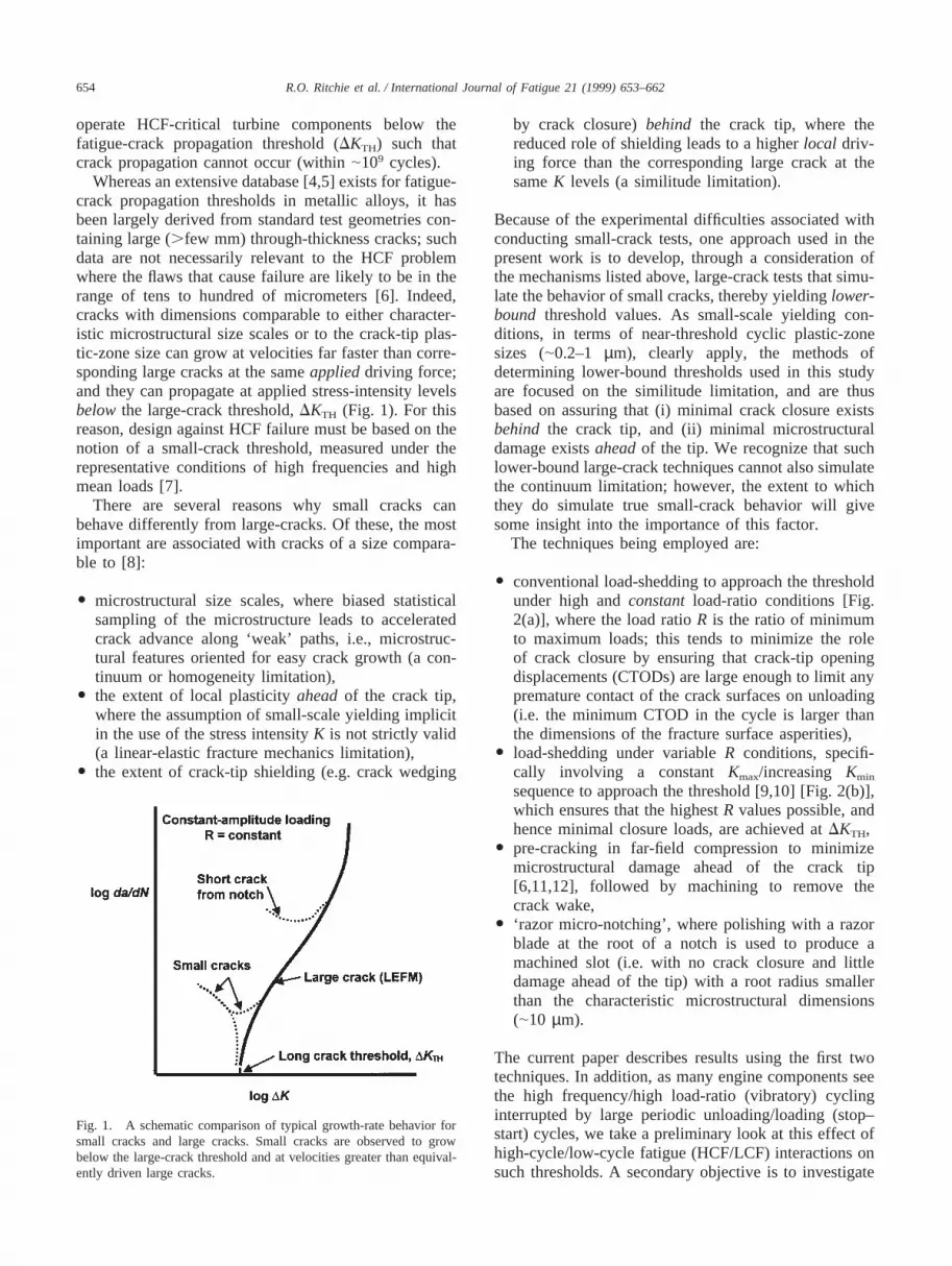
Whereas an extensive database [4,5] exists for fatigue-crack propagation thresholds in metallic alloys, it hasbeen largely derived from standard test geometries con-taining large (.few mm) through-thickness cracks; suchdata are not necessarily relevant to the HCF problemwhere the flaws that cause failure are likely to be in therange of tens to hundred of micrometers [6]. Indeed,cracks with dimensions comparable to either character-istic microstructural size scales or to the crack-tip plas-tic-zone size can grow at velocities far faster than corre-sponding large cracks at the sameapplieddriving force;and they can propagate at applied stress-intensity levelsbelow the large-crack threshold,DKTH (Fig. 1). For thisreason, design against HCF failure must be based on thenotion of a small-crack threshold, measured under therepresentative conditions of high frequencies and highmean loads [7].
There are several reasons why small cracks canbehave differently from large-cracks. Of these, the mostimportant are associated with cracks of a size compara-ble to [8]:
O microstructural size scales, where biased statisticalsampling of the microstructure leads to acceleratedcrack advance along ‘weak’ paths, i.e., microstruc-tural features oriented for easy crack growth (a con-tinuum or homogeneity limitation),
O the extent of local plasticityaheadof the crack tip,where the assumption of small-scale yielding implicitin the use of the stress intensityK is not strictly valid(a linear-elastic fracture mechanics limitation),
O the extent of crack-tip shielding (e.g. crack wedging
Fig. 1. A schematic comparison of typical growth-rate behavior forsmall cracks and large cracks. Small cracks are observed to growbelow the large-crack threshold and at velocities greater than equival-ently driven large cracks.
by crack closure)behind the crack tip, where thereduced role of shielding leads to a higherlocal driv-ing force than the corresponding large crack at thesameK levels (a similitude limitation).
Because of the experimental difficulties associated withconducting small-crack tests, one approach used in thepresent work is to develop, through a consideration ofthe mechanisms listed above, large-crack tests that simu-late the behavior of small cracks, thereby yieldinglower-bound threshold values. As small-scale yielding con-ditions, in terms of near-threshold cyclic plastic-zonesizes (|0.2–1 µm), clearly apply, the methods ofdetermining lower-bound thresholds used in this studyare focused on the similitude limitation, and are thusbased on assuring that (i) minimal crack closure existsbehind the crack tip, and (ii) minimal microstructuraldamage existsaheadof the tip. We recognize that suchlower-bound large-crack techniques cannot also simulatethe continuum limitation; however, the extent to whichthey do simulate true small-crack behavior will givesome insight into the importance of this factor.
The techniques being employed are:
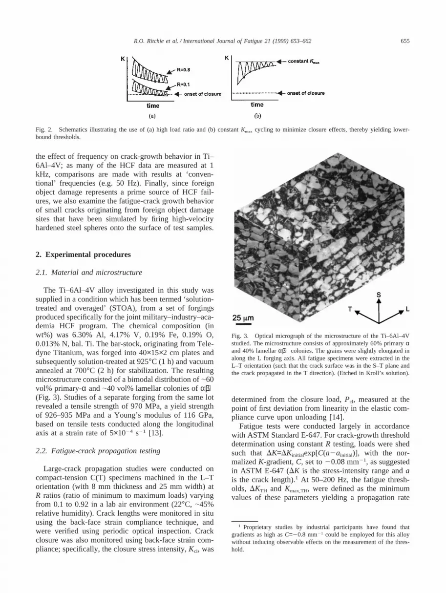
O conventional load-shedding to approach the thresholdunder high andconstant load-ratio conditions [Fig.2(a)], where the load ratioR is the ratio of minimumto maximum loads; this tends to minimize the roleof crack closure by ensuring that crack-tip openingdisplacements (CTODs) are large enough to limit anypremature contact of the crack surfaces on unloading(i.e. the minimum CTOD in the cycle is larger thanthe dimensions of the fracture surface asperities),
O load-shedding under variableR conditions, specifi-cally involving a constant Kmax/increasing Kmin
sequence to approach the threshold [9,10] [Fig. 2(b)],which ensures that the highestR values possible, andhence minimal closure loads, are achieved atDKTH,
O pre-cracking in far-field compression to minimizemicrostructural damage ahead of the crack tip[6,11,12], followed by machining to remove thecrack wake,
O ‘razor micro-notching’, where polishing with a razorblade at the root of a notch is used to produce amachined slot (i.e. with no crack closure and littledamage ahead of the tip) with a root radius smallerthan the characteristic microstructural dimensions(|10 µm).
The current paper describes results using the first twotechniques. In addition, as many engine components seethe high frequency/high load-ratio (vibratory) cyclinginterrupted by large periodic unloading/loading (stop–start) cycles, we take a preliminary look at this effect ofhigh-cycle/low-cycle fatigue (HCF/LCF) interactions onsuch thresholds. A secondary objective is to investigate
655R.O. Ritchie et al. / International Journal of Fatigue 21 (1999) 653–662
Fig. 2. Schematics illustrating the use of (a) high load ratio and (b) constantKmax cycling to minimize closure effects, thereby yielding lower-bound thresholds.
the effect of frequency on crack-growth behavior in Ti–6Al–4V; as many of the HCF data are measured at 1kHz, comparisons are made with results at ‘conven-tional’ frequencies (e.g. 50 Hz). Finally, since foreignobject damage represents a prime source of HCF fail-ures, we also examine the fatigue-crack growth behaviorof small cracks originating from foreign object damagesites that have been simulated by firing high-velocityhardened steel spheres onto the surface of test samples.
2. Experimental procedures
2.1. Material and microstructure
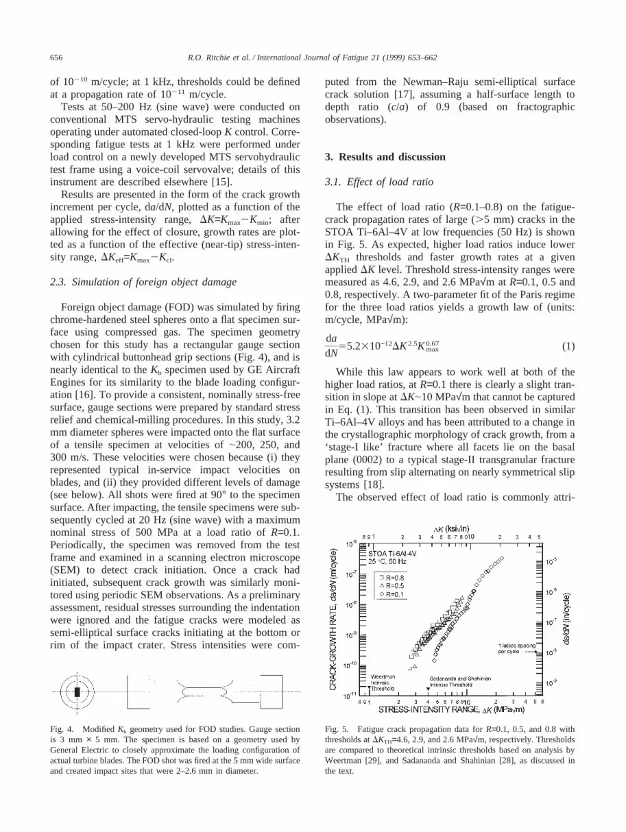
The Ti–6Al–4V alloy investigated in this study wassupplied in a condition which has been termed ‘solution-treated and overaged’ (STOA), from a set of forgingsproduced specifically for the joint military–industry–aca-demia HCF program. The chemical composition (inwt%) was 6.30% Al, 4.17% V, 0.19% Fe, 0.19% O,0.013% N, bal. Ti. The bar-stock, originating from Tele-dyne Titanium, was forged into 40×15×2 cm plates andsubsequently solution-treated at 925°C (1 h) and vacuumannealed at 700°C (2 h) for stabilization. The resultingmicrostructure consisted of a bimodal distribution of|60vol% primary-α and|40 vol% lamellar colonies ofα+β(Fig. 3). Studies of a separate forging from the same lotrevealed a tensile strength of 970 MPa, a yield strengthof 926–935 MPa and a Young’s modulus of 116 GPa,based on tensile tests conducted along the longitudinalaxis at a strain rate of 5×1024 s21 [13].
2.2. Fatigue-crack propagation testing
Large-crack propagation studies were conducted oncompact-tension C(T) specimens machined in the L–Torientation (with 8 mm thickness and 25 mm width) atR ratios (ratio of minimum to maximum loads) varyingfrom 0.1 to 0.92 in a lab air environment (22°C, |45%relative humidity). Crack lengths were monitored in situusing the back-face strain compliance technique, andwere verified using periodic optical inspection. Crackclosure was also monitored using back-face strain com-pliance; specifically, the closure stress intensity,Kcl, was
Fig. 3. Optical micrograph of the microstructure of the Ti–6Al–4Vstudied. The microstructure consists of approximately 60% primaryαand 40% lamellarα+β colonies. The grains were slightly elongated inalong the L forging axis. All fatigue specimens were extracted in theL–T orientation (such that the crack surface was in the S–T plane andthe crack propagated in the T direction). (Etched in Kroll’s solution).
determined from the closure load,Pcl, measured at thepoint of first deviation from linearity in the elastic com-pliance curve upon unloading [14].
Fatigue tests were conducted largely in accordancewith ASTM Standard E-647. For crack-growth thresholddetermination using constantR testing, loads were shedsuch that DK=DKinitialexp[C(a2ainitial)], with the nor-malizedK-gradient,C, set to20.08 mm21, as suggestedin ASTM E-647 (DK is the stress-intensity range andais the crack length).1 At 50–200 Hz, the fatigue thresh-olds, DKTH and Kmax,TH, were defined as the minimumvalues of these parameters yielding a propagation rate
1 Proprietary studies by industrial participants have found thatgradients as high asC=20.8 mm21 could be employed for this alloywithout inducing observable effects on the measurement of the thres-hold.
656 R.O. Ritchie et al. / International Journal of Fatigue 21 (1999) 653–662
of 10210 m/cycle; at 1 kHz, thresholds could be definedat a propagation rate of 10211 m/cycle.
Tests at 50–200 Hz (sine wave) were conducted onconventional MTS servo-hydraulic testing machinesoperating under automated closed-loopK control. Corre-sponding fatigue tests at 1 kHz were performed underload control on a newly developed MTS servohydraulictest frame using a voice-coil servovalve; details of thisinstrument are described elsewhere [15].
Results are presented in the form of the crack growthincrement per cycle, da/dN, plotted as a function of theapplied stress-intensity range,DK=Kmax2Kmin; afterallowing for the effect of closure, growth rates are plot-ted as a function of the effective (near-tip) stress-inten-sity range,DKeff=Kmax2Kcl.
2.3. Simulation of foreign object damage
Foreign object damage (FOD) was simulated by firingchrome-hardened steel spheres onto a flat specimen sur-face using compressed gas. The specimen geometrychosen for this study has a rectangular gauge sectionwith cylindrical buttonhead grip sections (Fig. 4), and isnearly identical to theKb specimen used by GE AircraftEngines for its similarity to the blade loading configur-ation [16]. To provide a consistent, nominally stress-freesurface, gauge sections were prepared by standard stressrelief and chemical-milling procedures. In this study, 3.2mm diameter spheres were impacted onto the flat surfaceof a tensile specimen at velocities of|200, 250, and300 m/s. These velocities were chosen because (i) theyrepresented typical in-service impact velocities onblades, and (ii) they provided different levels of damage(see below). All shots were fired at 90° to the specimensurface. After impacting, the tensile specimens were sub-sequently cycled at 20 Hz (sine wave) with a maximumnominal stress of 500 MPa at a load ratio ofR=0.1.Periodically, the specimen was removed from the testframe and examined in a scanning electron microscope(SEM) to detect crack initiation. Once a crack hadinitiated, subsequent crack growth was similarly moni-tored using periodic SEM observations. As a preliminaryassessment, residual stresses surrounding the indentationwere ignored and the fatigue cracks were modeled assemi-elliptical surface cracks initiating at the bottom orrim of the impact crater. Stress intensities were com-
Fig. 4. ModifiedKb geometry used for FOD studies. Gauge sectionis 3 mm × 5 mm. The specimen is based on a geometry used byGeneral Electric to closely approximate the loading configuration ofactual turbine blades. The FOD shot was fired at the 5 mm wide surfaceand created impact sites that were 2–2.6 mm in diameter.
puted from the Newman–Raju semi-elliptical surfacecrack solution [17], assuming a half-surface length todepth ratio (c/a) of 0.9 (based on fractographicobservations).
3. Results and discussion
3.1. Effect of load ratio
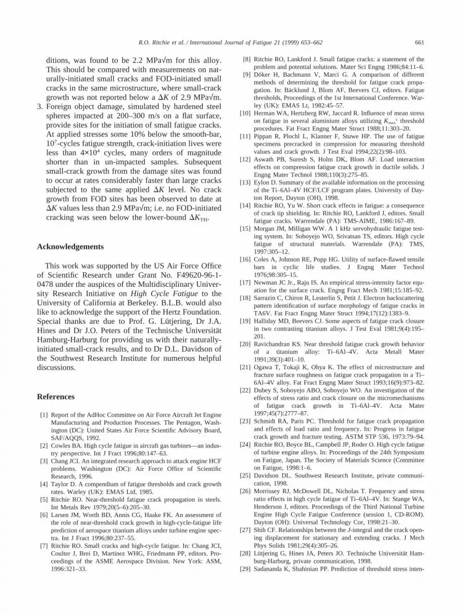
The effect of load ratio (R=0.1–0.8) on the fatigue-crack propagation rates of large (.5 mm) cracks in theSTOA Ti–6Al–4V at low frequencies (50 Hz) is shownin Fig. 5. As expected, higher load ratios induce lowerDKTH thresholds and faster growth rates at a givenappliedDK level. Threshold stress-intensity ranges weremeasured as 4.6, 2.9, and 2.6 MPa√m at R=0.1, 0.5 and0.8, respectively. A two-parameter fit of the Paris regimefor the three load ratios yields a growth law of (units:m/cycle, MPa√m):
dadN
55.2310−12DK2.5K0.67max (1)
While this law appears to work well at both of thehigher load ratios, atR=0.1 there is clearly a slight tran-sition in slope atDK|10 MPa√m that cannot be capturedin Eq. (1). This transition has been observed in similarTi–6Al–4V alloys and has been attributed to a change inthe crystallographic morphology of crack growth, from a‘stage-I like’ fracture where all facets lie on the basalplane (0002) to a typical stage-II transgranular fractureresulting from slip alternating on nearly symmetrical slipsystems [18].
The observed effect of load ratio is commonly attri-
Fig. 5. Fatigue crack propagation data forR=0.1, 0.5, and 0.8 withthresholds atDKTH=4.6, 2.9, and 2.6 MPa√m, respectively. Thresholdsare compared to theoretical intrinsic thresholds based on analysis byWeertman [29], and Sadananda and Shahinian [28], as discussed inthe text.

657R.O. Ritchie et al. / International Journal of Fatigue 21 (1999) 653–662
buted to the role of crack closure, which in Ti alloys isgenerally observed to be roughness induced (i.e. arisingfrom the wedging of crack-surface asperities) [19–21].To examine this, closure stress intensity values,Kcl, weremeasured at each load ratio. No detectable closure wasobserved atR=0.5 and 0.8. However, atR=0.1,Kcl valueswere observed to be roughly constant at|2.0 MPa√m[Fig. 6(a)]. In Fig. 6(b), the results of Fig. 5 are replottedin terms of the effective stress-intensity range, afteraccounting for crack closure. It is apparent that, similarto previous studies in Ti–6Al–4V [22], characterizinggrowth rates in terms ofDKeff reduces the disparity incrack-growth behavior between the threeR ratios; thisresult is consistent with crack closure as a mechanismfor the load ratio (orKmax) effect.
Fig. 6. (a) Crack closure, measured by unloading compliance, staysapproximately constant atKcl|2 MPa√m. (b) When crack closure isconsidered inDKeff (=Kmax2Kcl), the load ratio effect betweenR=0.1andR=0.5 is negligible. At low growth rates, the apparent discrepancyis most likely due to imprecision in measuring the closure level.
The measured variation with load ratio of the thres-hold DKTH andKmax,TH values, plotted in Fig. 7, can becompared with the simple closure model of Schmidt andParis [24]. This model is based on the notion thatKcl
and the effectiveDK threshold,DKeff,TH, are constant andindependent ofR; it predicts that measuredDKTH andKmax,TH thresholds will be load-ratio independent,respectively above and below a transitionR at whichpoint Kmin=Kcl. Although clearly there are insufficientdata to verify this simplified analysis, the present results
Fig. 7. Variation ofKmax,TH andDKTH with load ratio appears to fol-low the Schmidt and Paris closure model [23]. Although more dataare required to clearly establish a transition, the data presented hereshow a change in slope atR<0.5, consistent withKcl=2–3 MPa√mas observed.

658 R.O. Ritchie et al. / International Journal of Fatigue 21 (1999) 653–662
are consistent with this model, and the transitionR,above which closure is ineffective (Kmin . Kcl), isobserved atKmin=Kcl <2–3 MPa√m. Such an estimateof Kcl is consistent with the experimentally measuredvalues [Fig. 6(a)], determined from back-face straincompliance.
3.2. Effect of frequency
The role of cyclic frequency is shown in Fig. 8 wherethe growth rates at 50 Hz are compared with data col-lected at 1 kHz. It is clear that results at 1 kHz are notstatistically distinguishable from the conventional fre-quency data. Cursory experiments performed at 200 Hzexhibited a similar result. This lack of a frequency effecton ambient-temperaturegrowth-ratebehavior in STOATi–6Al–4V is consistent with preliminary results at 2kHz on the same material system [25]. In contrast,stress/life(S/N) fatigue tests conducted in another Ti–6Al–4V microstructure (consisting almost entirely ofprimary α) [26] showed an increase in fatigue strength(defined as the stress for failure within 107 cycles) asthe frequency increased from 70 to 400 to 1800 Hz.These results suggest that the role of high frequencieson the fatigue of Ti–6Al–4V at ambient temperaturesmay be largely associated with crack initiation, ratherthan the propagation life per se.
Testing at 1 kHz permits thresholds to be readilyobtained at much lower growth rates. Using the ASTMstandardK-gradient of 0.08 mm21, measurements downto 10211 m/cycle require several weeks at 50 Hz,whereas these same measurements can be obtained in asingle day at 1 kHz. In the present study, thresholds mea-sured at 10211 m/cycle (at 1 kHz) were found to be|0.1
Fig. 8. Comparison of fatigue-crack propagation at 50 Hz and 1 kHzshowing no statistically significant deviation in behavior. High fre-quency testing also enables collection of very low growth rate data(down to 10211 m/cycle) in a relatively short amount of time (|1 day).
MPa√m lower than the 10210 m/cycle thresholds(measured at either frequency).
3.3. Constant Kmax/variable R testing
Results at 1 kHz from the variableR, constant-Kmax/increasing-Kmin tests, which minimize the effect ofcrack closure, are shown in Fig. 9. Here, for a constantKmax of 26.5 MPa√m, a final load ratio ofR=0.92 wasachieved, yielding a threshold of 2.2 MPa√m, comparedto a DKTH value of 2.4 MPa√m for constantR=0.8 test-ing. These high load ratios result in an extremely largeminimum crack-tip opening displacements2
(CTODmin<0.7 µm and 4.3µm for R=0.8 and 0.92,respectively) superimposed on a relatively small cycliccrack-tip opening displacement (DCTOD <20 nm forbothR=0.8 and 0.92). With such large crack-tip openingdisplacements, crack closure from fracture-surfaceasperity wedging would be expected to be essentiallynon-existent, as the asperity sizes would need to exceedthe CTODmin of several micrometers.
The DKTH threshold value of 2.2 MPa√m measuredunder constant-Kmax/increasingKmin cycling atR=0.92 isconsidered to represent a practical lower-bound thres-hold for large cracks measured to date in STOA Ti–6Al–4V. It should be compared with measurements on nat-urally-initiated small cracks in the same microstructure,where small-crack growth (a|45–1000 µm) was notobserved below aDK of 2.9 MPa√m (R=0.1) [28].
Fig. 9. A constantKmax test at 1000 Hz was used to achieveR=0.92resulting in a lower-bound threshold of 2.2 MPa√m. Results are com-pared with constantR data at both 50 and 1000 Hz.
2 Crack-tip opening displacements,δ, were calculated in terms ofthe yield stress,σy, and appropriate Young’s modulus,E9, fromδ<β(K2/σyE9). The constantβ is a function of the yield strain,σy/E9,the strain-hardening coefficient and whether plane-stress or plane-strain conditions are assumed; a value of 0.8 was used for Ti–6Al–4V, based on the numerical calculations of Shih [27].

659R.O. Ritchie et al. / International Journal of Fatigue 21 (1999) 653–662
3.4. Intrinsic thresholds
Since threshold values are experimentally measured atsuch high load ratios in the apparent total absence of aninfluence of crack closure, their magnitude shouldapproach that of the so-calledintrinsic threshold. Severalestimates of this parameter have been theoretically cal-culated to represent the absolute lower-bound stressintensity for fatigue-crack growth.
The simplest approach to estimate the intrinsic thres-hold is to extrapolate the Paris law regime down to thepoint where the crack increment per cycle is on the orderof a lattice spacing per cycle. In Ti–6Al–4V, this giveslower-bound DKTH thresholds of |4.6 3.0, and 2.8MPa√m at R values of 0.1, 0.5, and 0.8, respectively.Clearly, this approach is overly simplistic because near-threshold crack advance does not occur uniformly acrossthe entire crack front; the measured da/dN values do notdescribe growth locally, but rather an average growthoccurring over the entire crack front.
A more sound approach is to model the intrinsic thres-hold in terms of the applied driving force below whichdislocations can no longer be emitted from the crack tip[29, 30]. In this regard, the approach of Sadananda andShahinian [29] considers the total energy required todrive a dislocation from a crack tip as the sum of fourcomponents: the ‘self’ energy of the dislocation,Us, thesurface energy created by the slip step at the crack tip,Uγ, the lattice frictional energy required to move a dislo-cation, Uf, and the energy from an image force,UI,imparted by the presence of the nearby free surface(crack wake). This total energyUT is then converted intoa required shear stress and stress intensity:
UT5Us1Uγ1Uf1UI5τxyb2 (2)
5Kb2
Î2prScosq2sinq2cos
3q2 D
whereb is the Burgers vector,r is the distance betweenthe dislocation and the crack tip (taken here to equalb), q is the angle between the actual crack propagationdirection and the pure Mode-I direction,τxy is the shearstress required to drive the dislocation, andK is the cor-responding stress intensity. The analysis predicts thethreshold to occur whenKmax is no longer sufficient toemit a dislocation, i.e. when:
Kmax,TH~τxy(b)12 (3)
For Ti–6Al–4V, the predicted intrinsic thresholdKmax,TH is 4.3 MPa√m for all R values. This compareswell to the experimentally measured values atR=0.1whereKmax,TH=5.1 MPa√m; however, atR=0.92 whereKmax,TH is held at 26.5 MPa√m, the prediction is clearlyquestionable, possibly because the analysis is essentiallybased on static (monotonic) loading and makes no allow-
ance for reversed plasticity and enhanced crack-tipblunting at highR values.
The corresponding approach of Weertman [30] is alsobased on the limiting conditions for dislocation emissionfrom an atomically sharp crack, in this case using theperfectly brittle Griffith solution modified by a para-meter,g, which describes the degree of ductility:
DKTH52gF 2Eg1−n2G1
2(4)
HereE is the Young’s modulus,n is Poisson’s ratio,and g is the true surface energy of the solid. The mod-ifying parameter,g, is a function of the theoretical tensilestrength normalized by the theoretical shear strength(typical values are taken between 0.6 and 1, with unityrepresenting the perfectly brittle case). Using thisapproach, the intrinsic threshold for Ti–6Al–4V is pre-dicted to be on the order of 1 MPa√m. Whereas thisrepresents a better estimate of a theoretical lower boundfor the fatigue threshold, it is a factor of 2 smaller thanexperimentally measured lower-bound values, possiblybecause the approach also does not taken into accountcyclic plasticity, both in the form of crack-tip bluntingand dislocation shielding arising from the presence ofthe plastic zone at the crack tip.
3.5. Effect of foreign object damage
As foreign object damage can be a prime source ofcracks initiated in HCF, the role of simulated FOD onthresholds and early crack growth was examined usingspecimens previously impacted by steel shot at velocitiesbetween 200 and 300 m/s. An SEM micrograph of atypical impact site at 300 m/s is presented in Fig. 10with a schematic illustration of the relevant features inthe crater profile. While at 300 and 250 m/s, shear bandswere seen emanating from the surface of the crater, suchshear bands were not observed for 200 m/s impacts. Inaddition, the 300 m/s impact caused a piling-up ofmaterial along the crater rim; this feature was not seenfor the lower velocity impacts.
The effect of these impact damage sites was to reducethe fatigue life markedly compared to that obtained withan un-impacted smooth-bar sample. At a maximumapplied stress of 500 MPa (R=0.1), single fatigue cracksin the 200 m/s impacted samples were initiated near thebottom of the crater within|4.3×10⁴ cycles, whereas inthe 300 m/s FOD site, the crack initiated at the craterrim within |2.9×10⁴ cycles. In terms of total life, the200 m/s impacted sample also resulted in a longer over-all fatigue life of 7.5×10⁴ cycles, compared to 4.6×10⁴
cycles from the 300 m/s impacted sample. These livesare to be compared with corresponding behavior in asmooth bar, where initiation and total lives at this stressexceed 107 cycles (i.e. 500 MPa is below the 107-cyclefatigue limit for this material).

660 R.O. Ritchie et al. / International Journal of Fatigue 21 (1999) 653–662
Fig. 10. (a) SEM micrograph of simulated foreign object damageresulting from an impact by a hardened steel sphere with an incidentvelocity of 300 m/s and (b) corresponding schematic illustrating fea-tures present at 300 and 250 m/s. At 200 m/s neither the shear bandsnor the ‘pile up’ were observed.
Consistent with previous low-cycle fatigue results[31], the presence of the shear bands did not appear toplay a significant role in the overall fatigue life, e.g. theinitiation of the fatigue cracks at damage sites did notappear to be directly associated with them. It is possible,though, that shear banding will have an effect on fatiguebehavior at lower applied stresses when lives exceed|106 cycles.
The growth rates of the small cracks originating fromsuch impact sites are compared in Fig. 11 with growth-rate data for large (.5 mm) and naturally-initiated small(|45–1000µm) cracks in this microstructure. Both thenaturally-initiated and FOD-initiated small-crack velo-cities were within the same scatter band, initially up toan order of magnitude faster than corresponding large-crack results (although small-crack data tended to mergewith large-crack results aboveDK = |10 MPa√m as thecrack size increased). However, in the limited data col-lected to date, no FOD-initiated cracks have beenobserved in the STOA Ti–6Al–4V material below aDKof |2.9 MPa√m; i.e. no FOD-initiated cracking wasobserved below the lower-bound (large-crack) thres-hold, DKTH.
Fig. 11. Fatigue crack propagation rates of naturally-initiated small(45–1000µm) cracks (dashed line) and small cracks emanating froma variety of FOD impact sites (closed symbols). These small crackresults obtained atR=0.1 are compared to large cracks atR=0.1 andR=0.8–0.92 (open symbols).
4. Summary
The problem of turbine engine high-cycle fatiguerequires that design must be based on the notion of athreshold stress intensity for no crack growth under theappropriate conditions of high mean loads, ultrahigh fre-quency (vibratory) loading, and small crack sizes. Sincethe measurement of small-crack thresholds is experimen-tally tedious and complex, the approach used in the cur-rent work has been to simulate such thresholds withlower-boundlarge-crack measurements. Our preliminaryresults in Ti–6Al–4V show that using constantKmax/increasingKmin cycling, aDKTH threshold for large(.5 mm) cracks can be measured at very high loadratios (R|0.92) and frequencies (1 kHz) which is a lowerbound compared to that of naturally-initiated small (45–1000µm) cracks and small cracks emanating from sitesof foreign object damage.
5. Conclusions
Based on a preliminary investigation into the high-cycle fatigue of a solution treated and overaged Ti–6Al–4V turbine engine alloy, the following conclusions canbe made:
1. Ambient-temperature fatigue-crack propagation (overthe range|10211 to 1026 m/cycle) and thresholdDKTH values were found to be independent of testfrequency (50–1000 Hz) for large (.5 mm) through-thickness cracks.
2. A lower-boundthreshold, measured for large cracksat R=0.92 under constant-Kmax/increasing-Kmin con-
661R.O. Ritchie et al. / International Journal of Fatigue 21 (1999) 653–662
ditions, was found to be 2.2 MPa√m for this alloy.This should be compared with measurements on nat-urally-initiated small cracks and FOD-initiated smallcracks in the same microstructure, where small-crackgrowth was not reported below aDK of 2.9 MPa√m.
3. Foreign object damage, simulated by hardened steelspheres impacted at 200–300 m/s on a flat surface,provide sites for the initiation of small fatigue cracks.At applied stresses some 10% below the smooth-bar,107-cycles fatigue strength, crack-initiation lives wereless than 4×10⁴ cycles, many orders of magnitudeshorter than in un-impacted samples. Subsequentsmall-crack growth from the damage sites was foundto occur at rates considerably faster than large crackssubjected to the same appliedDK level. No crackgrowth from FOD sites has been observed to date atDK values less than 2.9 MPa√m; i.e. no FOD-initiatedcracking was seen below the lower-boundDKTH.
Acknowledgements
This work was supported by the US Air Force Officeof Scientific Research under Grant No. F49620-96-1-0478 under the auspices of the Multidisciplinary Univer-sity Research Initiative onHigh Cycle Fatigueto theUniversity of California at Berkeley. B.L.B. would alsolike to acknowledge the support of the Hertz Foundation.Special thanks are due to Prof. G. Lu¨tjering, Dr J.A.Hines and Dr J.O. Peters of the Technische Universita¨tHamburg-Harburg for providing us with their naturally-initiated small-crack results, and to Dr D.L. Davidson ofthe Southwest Research Institute for numerous helpfuldiscussions.
References
[1] Report of the AdHoc Committee on Air Force Aircraft Jet EngineManufacturing and Production Processes. The Pentagon, Wash-ington (DC): United States Air Force Scientific Advisory Board,SAF/AQQS, 1992.
[2] Cowles BA. High cycle fatigue in aircraft gas turbines—an indus-try perspective. Int J Fract 1996;80:147–63.
[3] Chang JCI. An integrated research approach to attack engine HCFproblems. Washington (DC): Air Force Office of ScientificResearch, 1996.
[4] Taylor D. A compendium of fatigue thresholds and crack growthrates. Warley (UK): EMAS Ltd, 1985.
[5] Ritchie RO. Near-threshold fatigue crack propagation in steels.Int Metals Rev 1979;20(5–6):205–30.
[6] Larsen JM, Worth BD, Annis CG, Haake FK. An assessment ofthe role of near-threshold crack growth in high-cycle-fatigue lifeprediction of aerospace titanium alloys under turbine engine spec-tra. Int J Fract 1996;80:237–55.
[7] Ritchie RO. Small cracks and high-cycle fatigue. In: Chang JCI,Coulter J, Brei D, Martinez WHG, Friedmann PP, editors. Pro-ceedings of the ASME Aerospace Division. New York: ASM,1996:321–33.
[8] Ritchie RO, Lankford J. Small fatigue cracks: a statement of theproblem and potential solutions. Mater Sci Engng 1986;84:11–6.
[9] Doker H, Bachmann V, Marci G. A comparison of differentmethods of determining the threshold for fatigue crack propa-gation. In: Backlund J, Blom AF, Beevers CJ, editors. Fatiguethresholds, Proceedings of the 1st International Conference. War-ley (UK): EMAS Lt, 1982:45–57.
[10] Herman WA, Hertzberg RW, Jaccard R. Influence of mean stresson fatigue in several aluminium alloys utilizingKmax
c thresholdprocedures. Fat Fract Engng Mater Struct 1988;11:303–20.
[11] Pippan R, Plochl L, Klanner F, Stuwe HP. The use of fatiguespecimens precracked in compression for measuring thresholdvalues and crack growth. J Test Eval 1994;22(2):98–103.
[12] Aswath PB, Suresh S, Holm DK, Blom AF. Load interactioneffects on compression fatigue crack growth in ductile solids. JEngng Mater Technol 1988;110(3):275–85.
[13] Eylon D. Summary of the available information on the processingof the Ti–6Al–4V HCF/LCF program plates. University of Day-ton Report, Dayton (OH), 1998.
[14] Ritchie RO, Yu W. Short crack effects in fatigue: a consequenceof crack tip shielding. In: Ritchie RO, Lankford J, editors. Smallfatigue cracks. Warrendale (PA): TMS-AIME, 1986:167–89.
[15] Morgan JM, Milligan WW. A 1 kHz servohydraulic fatigue test-ing system. In: Soboyejo WO, Srivatsan TS, editors. High cyclefatigue of structural materials. Warrendale (PA): TMS,1997:305–12.
[16] Coles A, Johnson RE, Popp HG. Utility of surface-flawed tensilebars in cyclic life studies. J Engng Mater Technol1976;98:305–15.
[17] Newman JC Jr., Raju IS. An empirical stress-intensity factor equ-ation for the surface crack. Engng Fract Mech 1981;15:185–92.
[18] Sarrazin C, Chiron R, Lesterlin S, Petit J. Electron backscatteringpattern identification of surface morphology of fatigue cracks inTA6V. Fat Fract Engng Mater Struct 1994;17(12):1383–9.
[19] Halliday MD, Beevers CJ. Some aspects of fatigue crack closurein two contrasting titanium alloys. J Test Eval 1981;9(4):195–201.
[20] Ravichandran KS. Near threshold fatigue crack growth behaviorof a titanium alloy: Ti–6Al–4V. Acta Metall Mater1991;39(3):401–10.
[21] Ogawa T, Tokaji K, Ohya K. The effect of microstructure andfracture surface roughness on fatigue crack propagation in a Ti–6Al–4V alloy. Fat Fract Engng Mater Struct 1993;16(9):973–82.
[22] Dubey S, Soboyejo ABO, Soboyejo WO. An investigation of theeffects of stress ratio and crack closure on the micromechanismsof fatigue crack growth in Ti–6Al–4V. Acta Mater1997;45(7):2777–87.
[23] Schmidt RA, Paris PC. Threshold for fatigue crack propagationand effects of load ratio and frequency. In: Progress in fatiguecrack growth and fracture testing. ASTM STP 536, 1973:79–94.
[24] Ritchie RO, Boyce BL, Campbell JP, Roder O. High cycle fatigueof turbine engine alloys. In: Proceedings of the 24th Symposiumon Fatigue, Japan. The Society of Materials Science (Committeeon Fatigue, 1998:1–6.
[25] Davidson DL. Southwest Research Institute, private communi-cation, 1998.
[26] Morrissey RJ, McDowell DL, Nicholas T. Frequency and stressratio effects in high cycle fatigue of Ti–6Al–4V. In: Stange WA,Henderson J, editors. Proceedings of the Third National TurbineEngine High Cycle Fatigue Conference (session 1, CD-ROM).Dayton (OH): Universal Technology Cor, 1998:21–30.
[27] Shih CF. Relationships between theJ-integral and the crack open-ing displacement for stationary and extending cracks. J MechPhys Solids 1981;29(4):305–26.
[28] Lutjering G, Hines JA, Peters JO. Technische Universita¨t Ham-burg-Harburg, private communication, 1998.
[29] Sadananda K, Shahinian PP. Prediction of threshold stress inten-

662 R.O. Ritchie et al. / International Journal of Fatigue 21 (1999) 653–662
sity for fatigue crack growth using a dislocation model. Int J Fract1977;13(5):585–94.
[30] Weertman J. Fatigue crack growth in ductile metals. In: Mura T,editor. Mechanics of fatigue. New York: ASME, 1982:11–9.
[31] Timothy SP, Hutchings IM. Influence of adiabatic shear bandson the fatigue strength of a titanium alloy. Fat Engng Mater Struct1984;7(3):223–7.