threads & bolt heads - caldwell county schools
TRANSCRIPT
AutoCAD® Solid Modeling Threads & Bolts
Marcus Dula, Drafting Instructor
Caldwell Community College & Technical Institute
South Caldwell High School
Adapted from technique developed by Robert Southworth, United Kingdom, and
contributor to Cad Digest.
© 2006 Marcus P. Dula
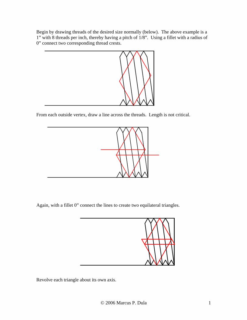
Begin by drawing threads of the desired size normally (below). The above example is a 1” with 8 threads per inch, thereby having a pitch of 1/8”. Using a fillet with a radius of 0” connect two corresponding thread crests.
From each outside vertex, draw a line across the threads. Length is not critical.
Again, with a fillet 0” connect the lines to create two equilateral triangles.
Revolve each triangle about its own axis.
© 2006 Marcus P. Dula 1
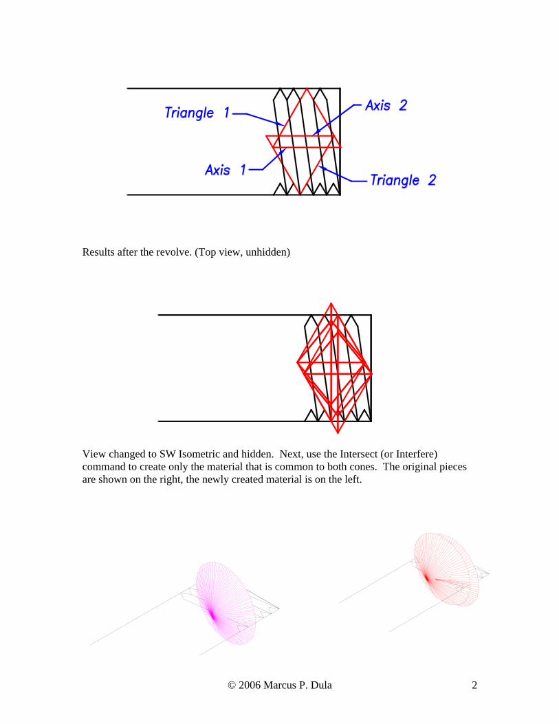
Results after the revolve. (Top view, unhidden)
© 2006 Marcus P. Dula 2
View changed to SW Isometric and hidden. Next, use the Intersect (or Interfere) command to create only the material that is common to both cones. The original pieces are shown on the right, the newly created material is on the left.
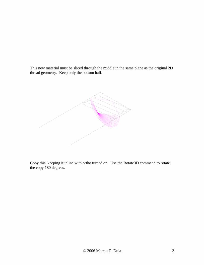
thread geometry. Keep only the bottom half.
This new material must be sliced through the middle in the same plane as the original 2D
Copy this, keeping it inline with ortho turned on. Use the Rotate3D command to rotate the copy 180 degrees.
© 2006 Marcus P. Dula 3
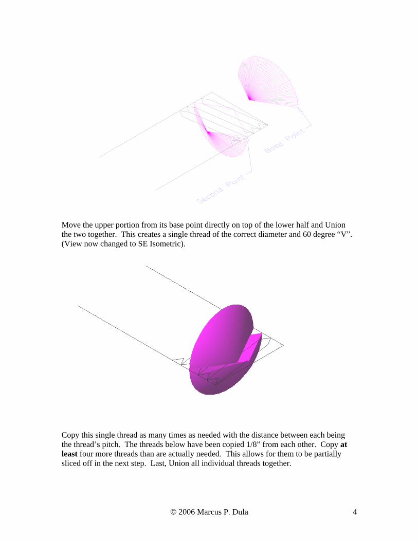
Move the upper portion from its base point directly on top of the lower half and Union
e two together. This creates a single thread of the correct diameter and 60 degree “V”. th(View now changed to SE Isometric).
opy this single thread as many times as needed with the distance between each being e thread’s pitch. The threads below have been copied 1/8” from each other. Copy at
Cthleast four more threads than are actually needed. This allows for them to be partially sliced off in the next step. Last, Union all individual threads together.
© 2006 Marcus P. Dula 4
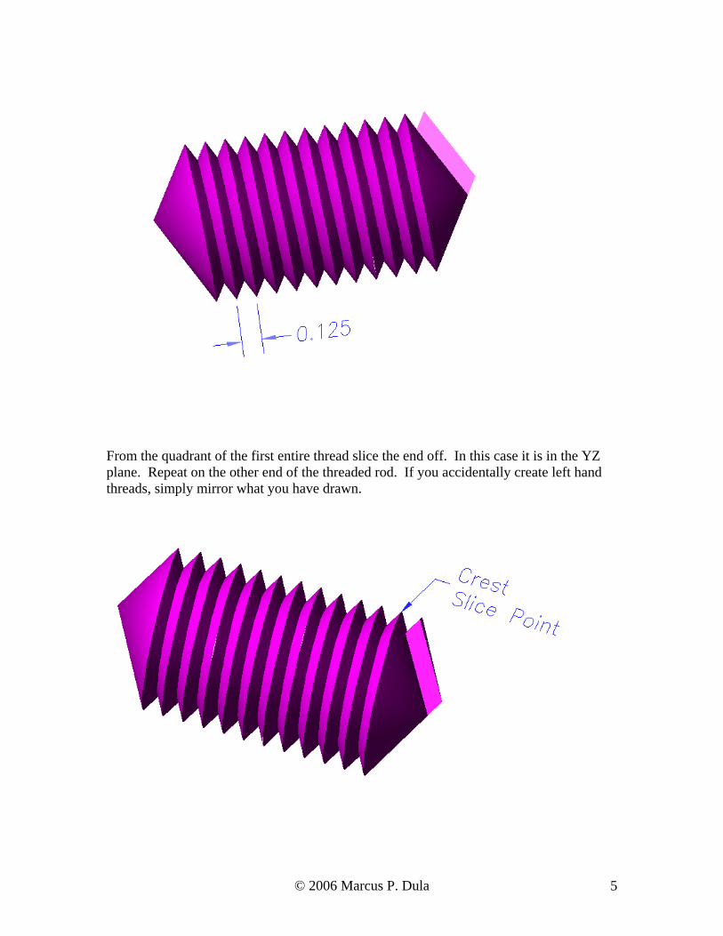
From the quadrant of the first entire thread slice the end off. In this case it is in the YZ plane. Repeat on the other end of the threaded rod. If you accidentally create left hand threads, simply mirror what you have drawn.
© 2006 Marcus P. Dula 5
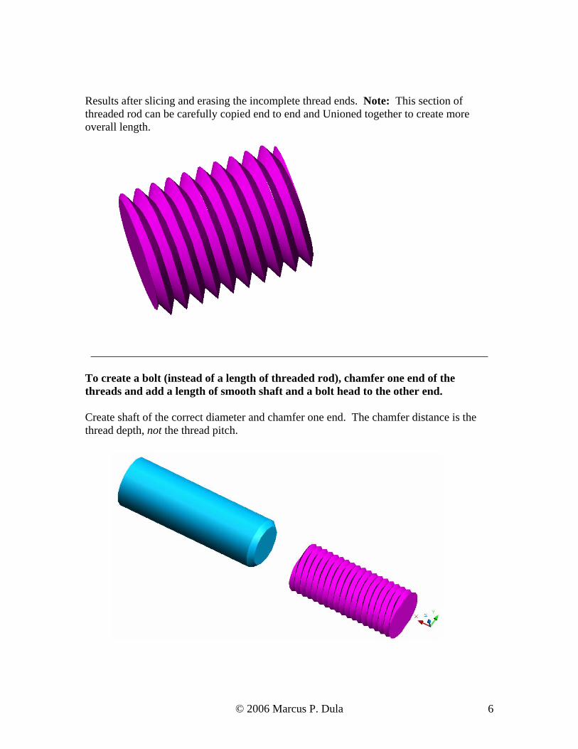
Results after slicing and erasing the incomplete thread ends. Note: This section of threaded rod can be carefully copied end to end and Unioned together to create more overall length.
______________________________________________________________________ To create a bolt (instead of a length of threaded rod), chamfer one end of the threads and add a length of smooth shaft and a bolt head to the other end. Create shaft of the correct diameter and chamfer one end. The chamfer distance is the thread depth, not the thread pitch.
© 2006 Marcus P. Dula 6
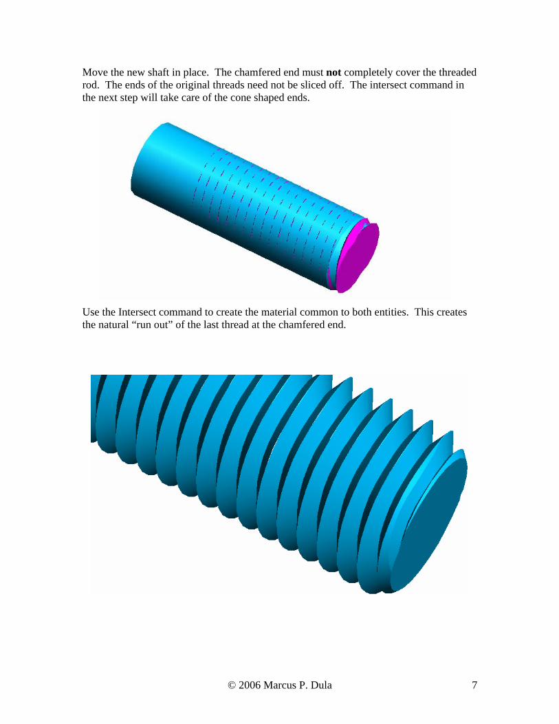
Move the new shaft in place. The chamfered end must not completely cover the threaded rod. The ends of the original threads need not be sliced off. The intersect command in the next step will take care of the cone shaped ends.
Use the Intersect command to create the material common to both entities. This creates the natural “run out” of the last thread at the chamfered end.
© 2006 Marcus P. Dula 7
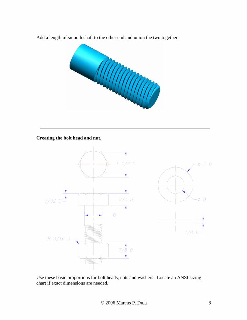
Add a length of smooth shaft to the other end and union the two together. ______________________________________________________________________ Creating the bolt head and nut.
Use these basic proportions for bolt heads, nuts and washers. Locate an ANSI sizing chart if exact dimensions are needed.
© 2006 Marcus P. Dula 8
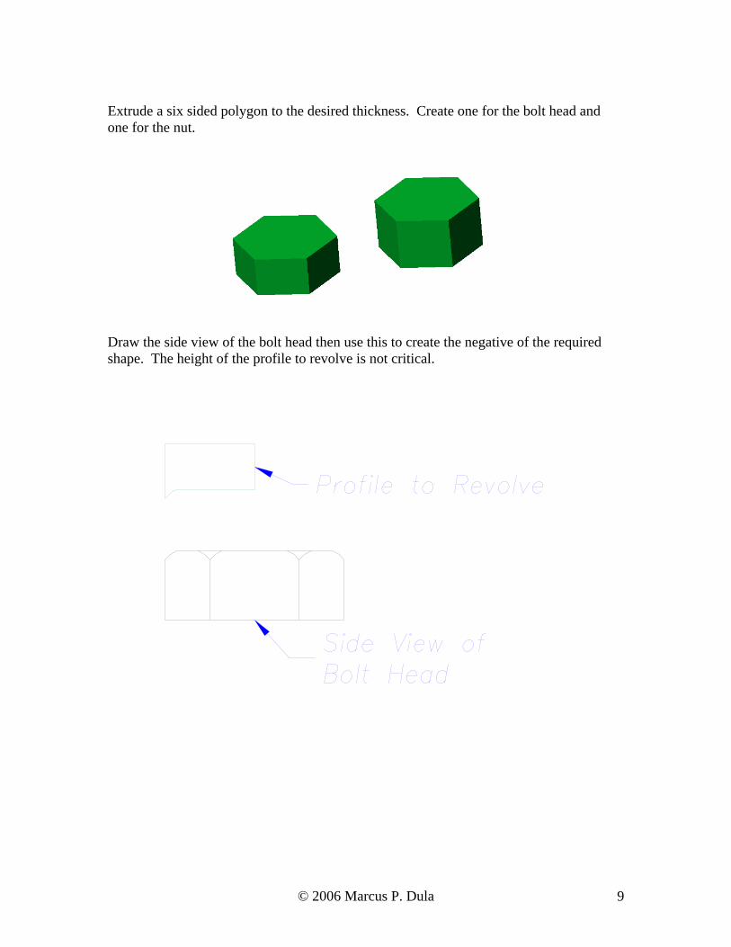
Extrude a six sided polygon to the desired thickness. Create one for the bolt head and one for the nut. Draw the side view of the bolt head then use this to create the negative of the required shape. The height of the profile to revolve is not critical.
© 2006 Marcus P. Dula 9
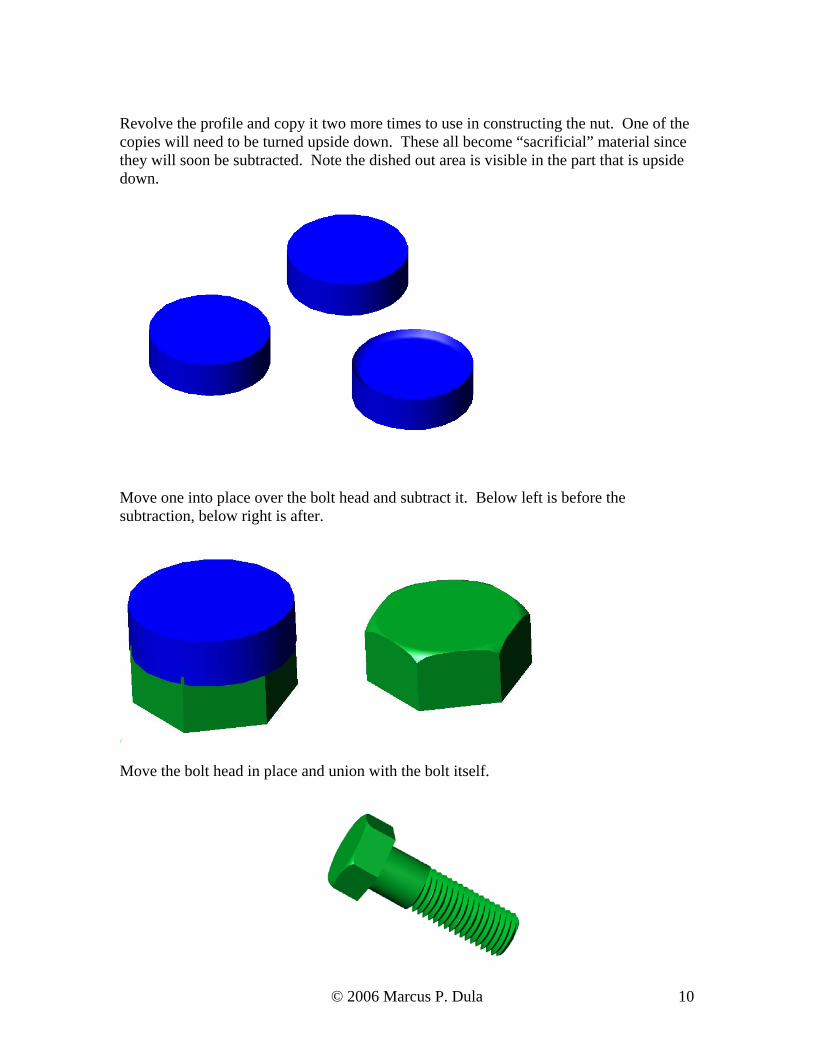
Revolve the profile and copy it two more times to use in constructing the nut. One of the copies will need to be turned upside down. These all become “sacrificial” material since they will soon be subtracted. Note the dished out area is visible in the part that is upside down.
Move one into place over the bolt head and subtract it. Below left is before the subtraction, below right is after.
Move the bolt head in place and union with the bolt itself.
© 2006 Marcus P. Dula 10
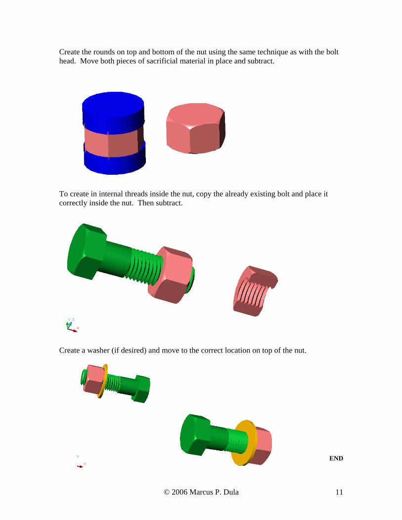
Create the rounds on top and bottom of the nut using the same technique as with the bolt head. Move both pieces of sacrificial material in place and subtract.
To create in internal threads inside the nut, copy the already existing bolt and place it correctly inside the nut. Then subtract.
Create a washer (if desired) and move to the correct location on top of the nut.
END
© 2006 Marcus P. Dula 11