channel and bolt fixings - ancon (au)
TRANSCRIPT
Channel and Bolt Fixingsfor the Construction IndustrySeptember 2008 (Version 4)

Leviat is the new name of CRH’s construction accessories companies worldwide.
We are one team. We are Leviat.
Under the Leviat brand, we are uniting theexpertise, skills and resources of Ancon and itssister companies to create a world leader in fixing,connecting and anchoring technology.
The products you know and trust will remain anintegral part of Leviat’s comprehensive brand andproduct portfolio. As Leviat, we can offer you anextended range of specialist products and services,greater technical expertise, a larger and more agilesupply chain and better, faster innovation.
By bringing together CRH’s constructionaccessories family as one global organisation,we are better equipped to meet the needs of ourcustomers, and the demands of constructionprojects, of any scale, anywhere in the world.
This is an exciting change. Join us on our journey. Read more about Leviat at Leviat.com

people worldwidecountries
sales in
locations300030+60
Imagine. Model. Make. Leviat.com
Our product brands include:

2 Tel: 1300 304 320 www.ancon.com.au
Innovative engineered products and
construction solutions that allow
the industry to build safer,
stronger and faster.
5
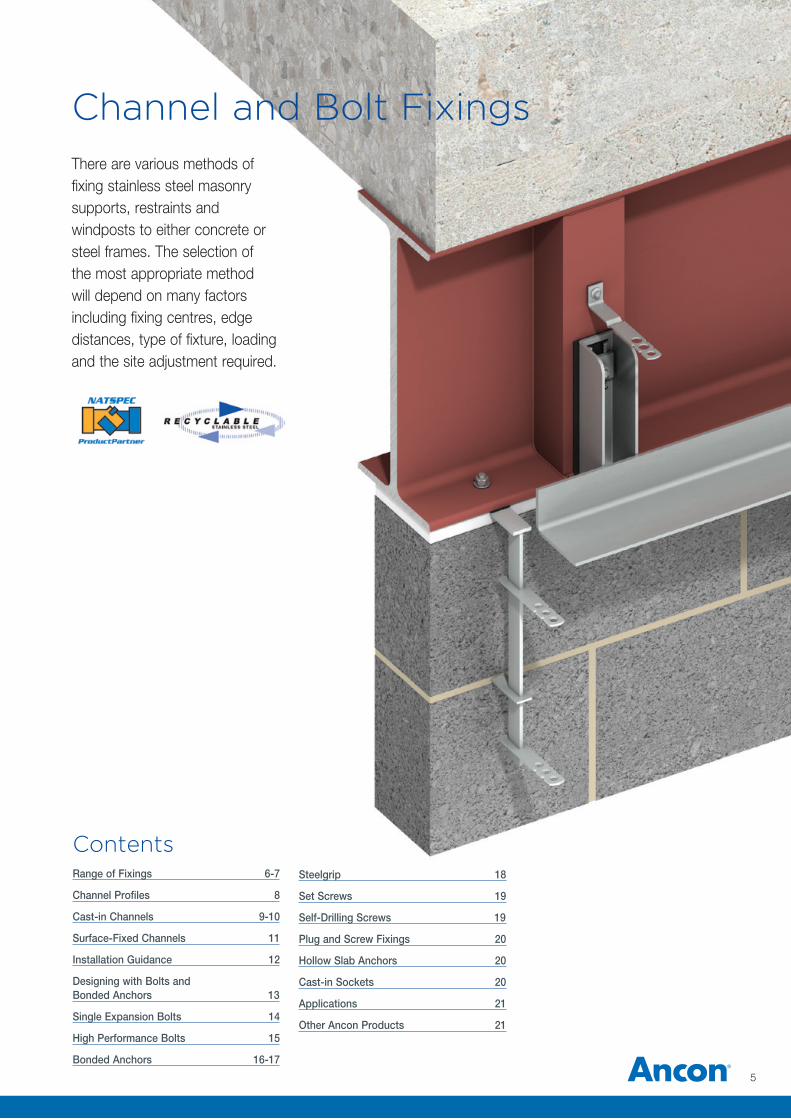
Channel and Bolt FixingsThere are various methods of fixing stainless steel masonry supports, restraints and windposts to either concrete or steel frames. The selection of the most appropriate method will depend on many factors including fixing centres, edge distances, type of fixture, loading and the site adjustment required.
Range of Fixings 6-7
Channel Profiles 8
Cast-in Channels 9-10
Surface-Fixed Channels 11
Installation Guidance 12
Designing with Bolts and Bonded Anchors 13
Single Expansion Bolts 14
High Performance Bolts 15
Bonded Anchors 16-17
Contents Steelgrip 18
Set Screws 19
Self-Drilling Screws 19
Plug and Screw Fixings 20
Hollow Slab Anchors 20
Cast-in Sockets 20
Applications 21
Other Ancon Products 21
Channel and Bolt Fixings
Cast-in ChannelsCast-in Channels range from simple self-anchoring slots for accepting restraint fixings to large capacity channels with integral anchors (pages 8-10). They provide the necessary adjustment required when fixing to concrete and can eliminate site drilling. Nail holes aid the fixing of channels to timber formwork and an infill prevents the ingress of concrete during casting.
Cast-in fixings do not generate expansive forces in the concrete and can be used at close centres and closer to the edges than expansion fixings.
OmegaPatent No: 2249110The Omega 21/18 Channel is a self-anchoring channel for use with Ancon wall ties referenced _ _21. The shallow depth of 18mm allows the channel to be used where there is reduced cover to the reinforcement. Nail holes aid the fixing of the channel to timber formwork. If steel formwork is to be used, or the formwork is to be surface-vibrated, please seek advice from our Technical Services Team.
30/20Patent No: EP0882164BAncon 30/20 is a high performance channel. Its unique shape allows the applied load to be fed directly from the channel lips to the anchors and the more compact section size improves its fit between reinforcement. Specially designed T-head bolts ride up the sloping sides of the channel and securely lock behind the front lips. This channel also accepts standard 20mm wide wall ties. 30/20 is filled with continuously extruded closed-cell PE-LD foam. This material is removed easily in long sections and is 100% recyclable.
Ancon 30/20 should be used in preference to 38/17 channel. 30/20 is a high performance channel and its lower material content offers considerable cost benefits.
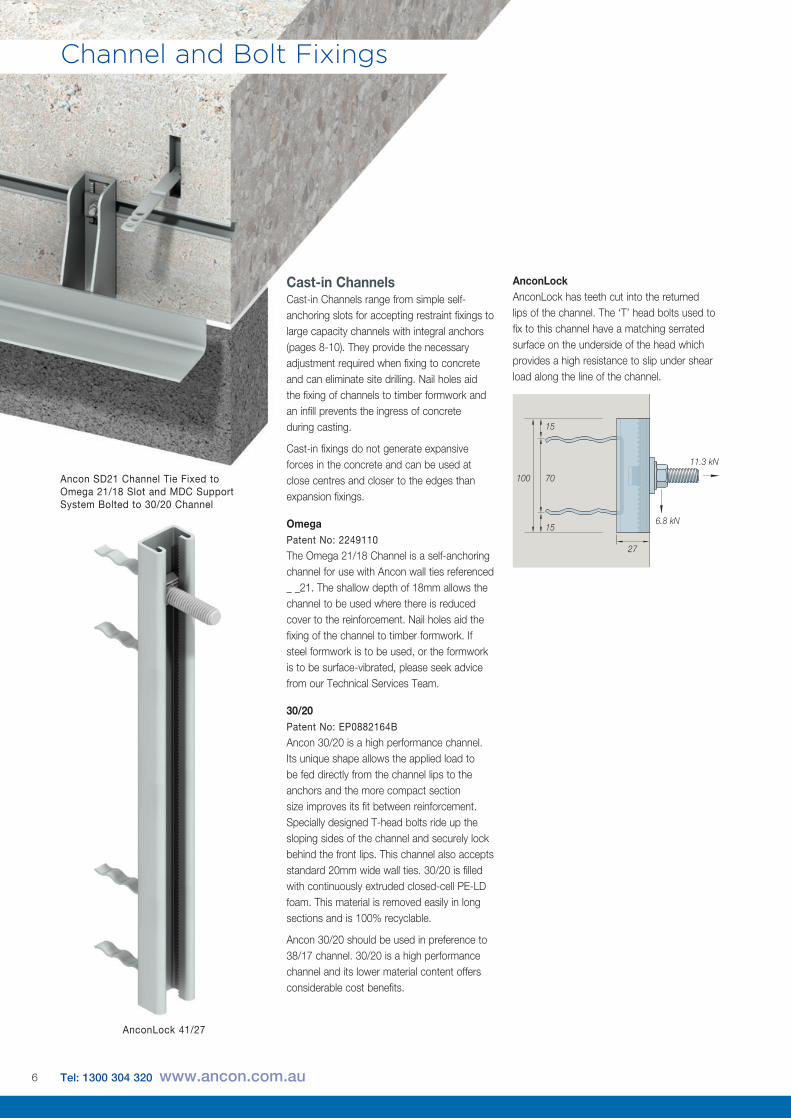
AnconLockAnconLock has teeth cut into the returned lips of the channel. The ‘T’ head bolts used to fix to this channel have a matching serrated surface on the underside of the head which provides a high resistance to slip under shear load along the line of the channel.
11.3 kN
15
70
27
100
156.8 kN
AnconLock 41/27
Ancon SD21 Channel Tie Fixed to Omega 21/18 Slot and MDC Support System Bolted to 30/20 Channel
6 Tel: 1300 304 320 www.ancon.com.au
Surface-Fixed Channels Plain-backed channels can be surface-fixed to steel, concrete and in some instances, masonry (page 11).
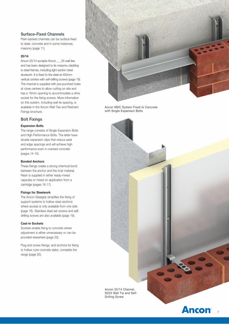
25/14Ancon 25/14 accepts Ancon _ _ 25 wall ties and has been designed to tie masonry cladding to steel frames, including light section steel studwork. It is fixed to the steel at 450mm vertical centres with self-drilling screws (page 19). The channel is supplied with pre-punched holes at close centres to allow cutting on site and has a 16mm opening to accommodate a drive socket for the fixing screws. More information on this system, including wall tie spacing, is available in the Ancon Wall Ties and Restraint Fixings brochure.
Bolt FixingsExpansion BoltsThe range consists of Single Expansion Bolts and High Performance Bolts. The latter have double expansion clips that reduce axial and edge spacings and will achieve high performance even in cracked concrete (pages 14-15).
Bonded AnchorsThese fixings create a strong chemical bond between the anchor and the host material. Resin is supplied in either ready-mixed capsules or mixed on application from a cartridge (pages 16-17).
Fixings for SteelworkThe Ancon Steelgrip simplifies the fixing of support systems to hollow steel sections where access is only available from one side (page 18). Stainless steel set screws and self-drilling screws are also available (page 19).
Cast-in SocketsSockets enable fixing to concrete where adjustment is either unnecessary or can be provided elsewhere (page 20).
Plug and screw fixings, and anchors for fixing to hollow core concrete slabs, complete the range (page 20).
Ancon 25/14 Channel, SD25 Wall Tie and Self-Drilling Screw
Ancon MDC System Fixed to Concrete with Single Expansion Bolts
7
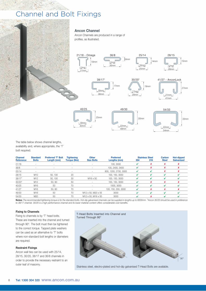
Ancon ChannelAncon Channels are produced in a range of profiles, as illustrated.
25/14
14mm
Channel Standard Preferred ‘T’ Bolt Tightening Other Preferred Stainless Steel Carbon Hot-dipped Reference Bolts Length (mm) Torque (Nm) Size Bolts Lengths (mm) 304 316 Steel Galvanised
21/18 - - - - 100, 3000
36/8 - - - - 100, 2400, 3400
25/14 - - - - 800, 1200, 2700, 3000
28/15 M10 50, 100 20 - 100, 150, 3000
38/17* M12 50, 100 30 M16 x 50 100, 150, 3000
30/20* M12 50, 90 50 - 100, 150, 3000
40/25 M16 50 70 - 1000, 3000
41/27 M16 50, 80 70 - 100, 150, 200, 3000
49/30 M16 50 70 M12 x 50, M20 x 55 3000
54/33 M20 50 70 M12 x 50, M16 x 50 3000
Notes: The recommended tightening torque is for the standard bolts. Hot-dip galvanised channels can be supplied in lengths up to 6000mm. *Ancon 30/20 should be used in preference to 38/17 channel. 30/20 is a high performance channel and its lower material content offers considerable cost benefits.
✔ ✘ ✘ ✘
✔ ✘ ✘ ✘
✔ ✔ ✘ ✘
✔ ✔ ✔ ✔
✔ ✔ ✔ ✔
✔ ✘ ✘ ✘
✔ ✔ ✔ ✔
✔ ✘ ✘ ✘
✔ ✔ ✔ ✔
✔ ✘ ✔ ✔
41/27 - AnconLock49/30
72/49 54/33
40/25 30/20
38/17 25/14 28/15
36/8 21/18 - Omega
41/27 - AnconLock49/30
72/49 54/33
40/25 30/20
38/17 25/14 28/15
36/8 21/18 - Omega
41/27 - AnconLock49/30
72/49 54/33
40/25 30/20
38/17 25/14 28/15
36/8 21/18 - Omega
41/27 - AnconLock49/30
72/49 54/33
40/25 30/20
38/17 25/14 28/15
36/8 21/18 - Omega
41/27 - AnconLock49/30
72/49 54/33
40/25 30/20
38/17 25/14 28/15
36/8 21/18 - Omega
41/27 - AnconLock49/30
72/49 54/33
40/25 30/20
38/17 25/14 28/15
36/8 21/18 - Omega
41/27 - AnconLock49/30
72/49 54/33
40/25 30/20
38/17 25/14 28/15
36/8 21/18 - Omega
41/27 - AnconLock49/30
72/49 54/33
40/25 30/20
38/17 25/14 28/15
36/8 21/18 - Omega
41/27 - AnconLock49/30
72/49 54/33
40/25 30/20
38/17 25/14 28/15
36/8 21/18 - Omega
21/18 - Omega 36/8 28/15
30/20* 41/27 - AnconLock
40/25 49/30 54/33
38/17*
13mm
18mm
21mm
17mm
19mm
29mm 21mm
27mm
41mm
22mm
30mm
49mm22mm
33mm
54mm
18mm
25mm
40mm
12mm
15mm
28mm
18mm
17mm
38mm
12mm8mm
36mm
Channel and Bolt Fixings
41/27 - AnconLock49/30
72/49 54/33
40/25 30/20
38/17 25/14 28/15
36/8 21/18 - Omega
25mm16mm
The table below shows channel lengths, availability and, where appropriate, the ‘T’ bolt required.
Fixing to ChannelsFixing to channels is by ‘T’ head bolts. These are inserted into the channel and turned through 90°. The bolt must then be tightened to the correct torque. Tapped plate washers can be used as an alternative to ‘T’ bolts where non-standard bolt lengths or diameters are required.
Restraint FixingsAncon wall ties can be used with 25/14, 28/15, 30/20, 38/17 and 36/8 channels in order to provide the necessary restraint to an outer leaf of masonry.
90°
T-Head Bolts Inserted into Channel and Turned Through 90°
Stainless steel, electro-plated and hot-dip galvanised T-Head Bolts are available.
8 Tel: 1300 304 320 www.ancon.com.au
Channel Spacing
End Distance
Concrete Depth
Channel Reference Edge Distance (mm) Tension (kN) Shear (kN)
21/18 - Omega 50 - -
28/15 50 7 7
38/17* 75 9 9
30/20* 75 10 12
40/25 100 12 12
41/27 - AnconLock 100 16 13.6**
49/30 150 15 15
54/33 160 25 25
**Longitudinal Load
Channel Reference End Distance (mm) Spacing (mm) Concrete Depth (mm)
21/18 - Omega 50 100 75
28/15 50 100 95
38/17* 50 150 95
30/20* 50 150 95
40/25 80 200 100
41/27 - AnconLock 50 200 100
49/30 130 300 105
54/33 175 320 165
Notes: The allowable loads shown in the tables above are for channels using the standard bolts. *Ancon 30/20 should be used in preference to 38/17 channel. 30/20 is a high performance channel and its lower material content offers considerable cost benefits.
50100
50StandardEdge
Distance
200
200
200
50ReducedEdge
Distance
200
200
200
Edge Distance
200
100
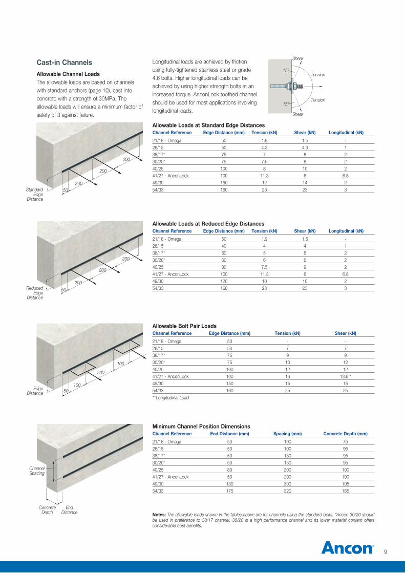
Cast-in ChannelsAllowable Channel LoadsThe allowable loads are based on channels with standard anchors (page 10), cast into concrete with a strength of 30MPa. The allowable loads will ensure a minimum factor of safety of 3 against failure.
Longitudinal loads are achieved by friction using fully-tightened stainless steel or grade 4.6 bolts. Higher longitudinal loads can be achieved by using higher strength bolts at an increased torque. AnconLock toothed channel should be used for most applications involving longitudinal loads.
Shear
Shear
15°
15°
Tension
Tension
Channel Reference Edge Distance (mm) Tension (kN) Shear (kN) Longitudinal (kN)
21/18 - Omega 50 1.9 1.5 -
28/15 50 4.3 4.3 1
38/17* 75 7 8 2
30/20* 75 7.5 8 2
40/25 100 8 10 2
41/27 - AnconLock 100 11.3 6 6.8
49/30 150 12 14 2
54/33 160 23 23 3
Channel Reference Edge Distance (mm) Tension (kN) Shear (kN) Longitudinal (kN)
21/18 - Omega 50 1.9 1.5 -
28/15 40 4 4 1
38/17* 60 5 6 2
30/20* 60 6 6 2
40/25 80 7.5 9 2
41/27 - AnconLock 100 11.3 6 6.8
49/30 120 10 10 2
54/33 160 23 23 3
Allowable Loads at Standard Edge Distances
Allowable Loads at Reduced Edge Distances
Allowable Bolt Pair Loads
Minimum Channel Position Dimensions
9
Double Crimped Lugs
Thickness
Length Spacing
Spacing
Width
Centres
Single ‘L’ Lugs
Double Crimped Lugs
Bull Horn Lugs
Channel and Bolt Fixings
Single ‘L’ Lugs
Thickness
Length
Spacing
Return
SpacingWidth
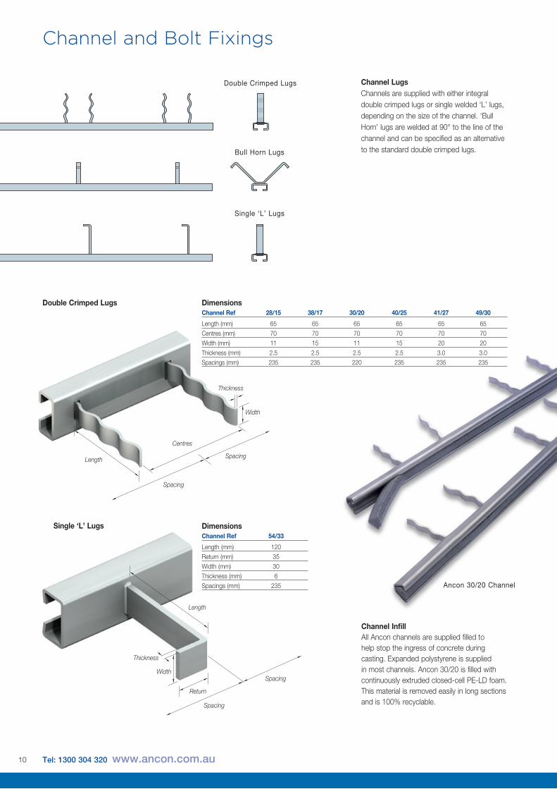
DimensionsChannel Ref 28/15 38/17 30/20 40/25 41/27 49/30
Length (mm) 65 65 65 65 65 65
Centres (mm) 70 70 70 70 70 70
Width (mm) 11 15 11 15 20 20
Thickness (mm) 2.5 2.5 2.5 2.5 3.0 3.0
Spacings (mm) 235 235 220 235 235 235
Channel Ref 54/33
Length (mm) 120
Return (mm) 35
Width (mm) 30
Thickness (mm) 6
Spacings (mm) 235
Dimensions
Channel LugsChannels are supplied with either integral double crimped lugs or single welded ‘L’ lugs, depending on the size of the channel. ‘Bull Horn’ lugs are welded at 90° to the line of the channel and can be specified as an alternative to the standard double crimped lugs.
Ancon 30/20 Channel
Channel InfillAll Ancon channels are supplied filled to help stop the ingress of concrete during casting. Expanded polystyrene is supplied in most channels. Ancon 30/20 is filled with continuously extruded closed-cell PE-LD foam. This material is removed easily in long sections and is 100% recyclable.
10 Tel: 1300 304 320 www.ancon.com.au
v
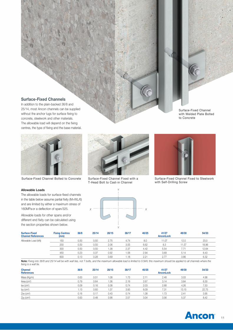
Surface-Fixed ChannelsIn addition to the plain-backed 36/8 and 25/14, most Ancon channels can be supplied without the anchor lugs for surface fixing to concrete, steelwork and other materials. The allowable load will depend on the fixing centres, the type of fixing and the base material.
Allowable LoadsThe allowable loads for surface-fixed channels in the table below assume partial fixity (M=WL/6) and are limited by either a maximum stress of 160MPa or a deflection of span/325.
Allowable loads for other spans and/or different end fixity can be calculated using the section properties shown below.
Surface-Fixed Fixing Centres 36/8 25/14 28/15 38/17 40/25 41/27 49/30 54/33Channel References (mm) AnconLock
Allowable Load (kN) 150 0.50 0.50 2.75 4.74 8.0 11.07 12.0 23.0
200 0.50 0.50 2.06 3.55 6.62 8.3 11.57 18.96
300 0.50 0.50 1.38 2.37 4.42 5.54 7.71 12.64
450 0.23 0.37 0.92 1.58 2.94 3.69 5.14 8.43
600 0.13 0.28 0.69 1.18 2.21 2.77 3.86 6.32
Note: Fixing into 36/8 and 25/14 will be with wall ties, not T bolts, and the maximum allowable load is limited to 0.5kN; this maximum should be applied to all channels where the fixing is a wall tie.
Channel 36/8 25/14 28/15 38/17 40/25 41/27 49/30 54/33References AnconLock
Mass (Kg/m) 0.63 0.51 1.08 1.73 2.11 2.48 3.03 4.98
Area (cm2) 0.79 0.64 1.36 2.19 2.67 3.14 3.84 6.30
Ixx (cm4) 0.09 0.16 0.38 0.74 2.03 2.68 4.26 7.53
Iyy (cm4) 1.13 0.60 1.37 3.93 6.09 7.31 13.15 22.75
Zxx (cm3) 0.16 0.17 0.43 0.74 1.38 1.73 2.41 3.95
Zyy (cm3) 0.63 0.48 0.98 2.07 3.04 3.56 5.37 8.42
Y
XX
Y
Surface-Fixed Channel Fixed to Steelwork with Self-Drilling Screw
Surface-Fixed Channel Bolted to Concrete Surface-Fixed Channel Fixed with a T-Head Bolt to Cast-in Channel
Surface-Fixed Channel with Welded Plate Bolted to Concrete
11
v
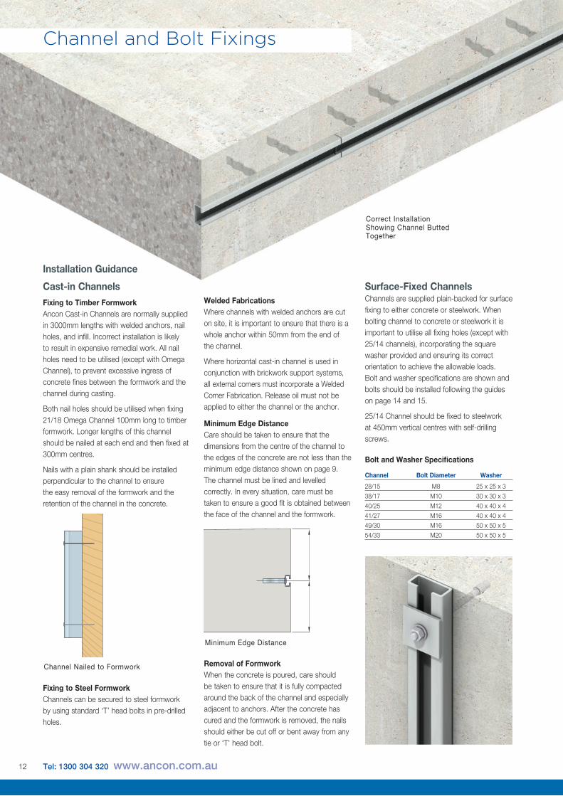
Correct Installation Showing Channel Butted Together
Bolt and Washer Specifications
Channel Bolt Diameter Washer
28/15 M8 25 x 25 x 3
38/17 M10 30 x 30 x 3
40/25 M12 40 x 40 x 4
41/27 M16 40 x 40 x 4
49/30 M16 50 x 50 x 5
54/33 M20 50 x 50 x 5
Surface-Fixed Channels Channels are supplied plain-backed for surface fixing to either concrete or steelwork. When bolting channel to concrete or steelwork it is important to utilise all fixing holes (except with 25/14 channels), incorporating the square washer provided and ensuring its correct orientation to achieve the allowable loads. Bolt and washer specifications are shown and bolts should be installed following the guides on page 14 and 15.
25/14 Channel should be fixed to steelwork at 450mm vertical centres with self-drilling screws.
Welded FabricationsWhere channels with welded anchors are cut on site, it is important to ensure that there is a whole anchor within 50mm from the end of the channel.
Where horizontal cast-in channel is used in conjunction with brickwork support systems, all external corners must incorporate a Welded Corner Fabrication. Release oil must not be applied to either the channel or the anchor.
Minimum Edge DistanceCare should be taken to ensure that the dimensions from the centre of the channel to the edges of the concrete are not less than the minimum edge distance shown on page 9. The channel must be lined and levelled correctly. In every situation, care must be taken to ensure a good fit is obtained between the face of the channel and the formwork.
Removal of FormworkWhen the concrete is poured, care should be taken to ensure that it is fully compacted around the back of the channel and especially adjacent to anchors. After the concrete has cured and the formwork is removed, the nails should either be cut off or bent away from any tie or ‘T’ head bolt.
Channel and Bolt Fixings
Installation Guidance
Cast-in ChannelsFixing to Timber FormworkAncon Cast-in Channels are normally supplied in 3000mm lengths with welded anchors, nail holes, and infill. Incorrect installation is likely to result in expensive remedial work. All nail holes need to be utilised (except with Omega Channel), to prevent excessive ingress of concrete fines between the formwork and the channel during casting.
Both nail holes should be utilised when fixing 21/18 Omega Channel 100mm long to timber formwork. Longer lengths of this channel should be nailed at each end and then fixed at 300mm centres.
Nails with a plain shank should be installed perpendicular to the channel to ensure the easy removal of the formwork and the retention of the channel in the concrete.
Fixing to Steel FormworkChannels can be secured to steel formwork by using standard ‘T’ head bolts in pre-drilled holes.
Minimum Edge Distance
Channel Nailed to Formwork
12 Tel: 1300 304 320 www.ancon.com.au
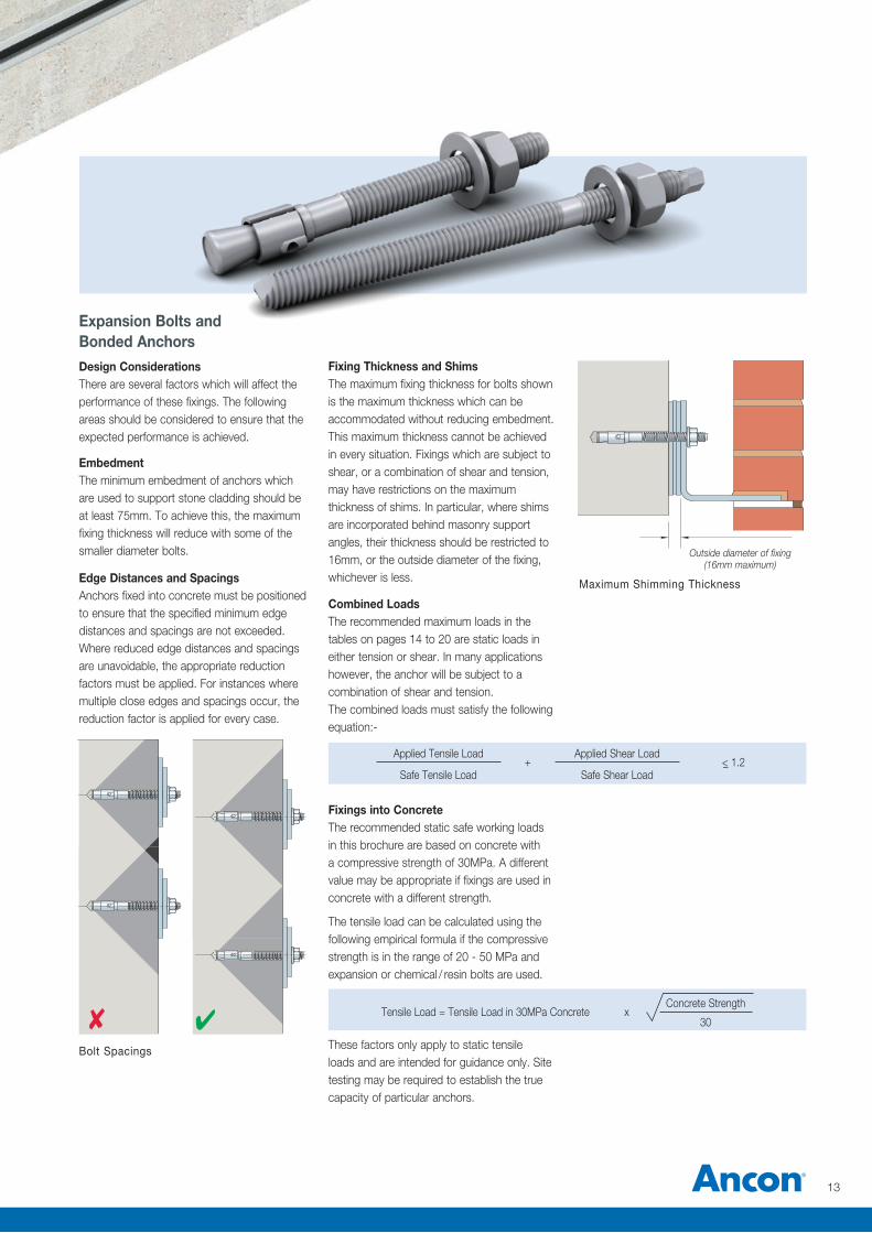
Fixing Thickness and ShimsThe maximum fixing thickness for bolts shown is the maximum thickness which can be accommodated without reducing embedment. This maximum thickness cannot be achieved in every situation. Fixings which are subject to shear, or a combination of shear and tension, may have restrictions on the maximum thickness of shims. In particular, where shims are incorporated behind masonry support angles, their thickness should be restricted to 16mm, or the outside diameter of the fixing, whichever is less.
Outside diameter of fixing (16mm maximum)
Maximum Shimming Thickness
✔✘Bolt Spacings
Tensile Load = Tensile Load in 30MPa Concrete x
Concrete Strength 30
Applied Tensile Load +
Applied Shear Load <_ 1.2
Safe Tensile Load Safe Shear Load
Combined LoadsThe recommended maximum loads in the tables on pages 14 to 20 are static loads in either tension or shear. In many applications however, the anchor will be subject to a combination of shear and tension. The combined loads must satisfy the following equation:-
Fixings into ConcreteThe recommended static safe working loads in this brochure are based on concrete with a compressive strength of 30MPa. A different value may be appropriate if fixings are used in concrete with a different strength.
The tensile load can be calculated using the following empirical formula if the compressive strength is in the range of 20 - 50 MPa and expansion or chemical / resin bolts are used.
These factors only apply to static tensile loads and are intended for guidance only. Site testing may be required to establish the true capacity of particular anchors.
Edge Distances and SpacingsAnchors fixed into concrete must be positioned to ensure that the specified minimum edge distances and spacings are not exceeded. Where reduced edge distances and spacings are unavoidable, the appropriate reduction factors must be applied. For instances where multiple close edges and spacings occur, the reduction factor is applied for every case.
Expansion Bolts and Bonded AnchorsDesign ConsiderationsThere are several factors which will affect the performance of these fixings. The following areas should be considered to ensure that the expected performance is achieved.
EmbedmentThe minimum embedment of anchors which are used to support stone cladding should be at least 75mm. To achieve this, the maximum fixing thickness will reduce with some of the smaller diameter bolts.
13
Channel and Bolt Fixings
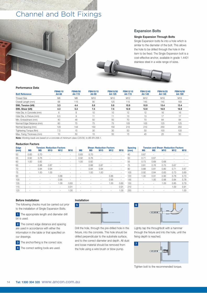
Installation
Drill the hole, through the pre-drilled hole in the fixture, into the concrete. This hole should be drilled perpendicular to the substrate surface, and to the correct diameter and depth. All dust and loose material should be removed from the hole using a wire brush or blow pump.
5
Lightly tap the throughbolt with a hammer through the fixture and into the hole, until the fixing depth is reached.
6
Tighten bolt to the recommended torque.
7
Before InstallationThe following checks must be carried out prior to the installation of Single Expansion Bolts.
The appropriate length and diameter drill bit is used.
The correct edge distance and spacing are used in accordance with either the information in the table or that specified on our drawings.
The anchor/fixing is the correct size.
The correct setting tools are used.
1
2
3
4
Expansion BoltsSingle Expansion Through BoltsSingle Expansion bolts fix into a hole which is similar to the diameter of the bolt. This allows the hole to be drilled through the hole in the item to be fixed. The Single Expansion bolt is a cost-effective anchor, available in grade 1.4401 stainless steel in a wide range of sizes.
FBN6/10 FBN8/50 FBN10/15 FBN10/50 FBN12/15 FBN12/45 FBN16/25 FBN16/50Bolt Reference A4-68 A4-115 A4-90 A4-125 A4-115 A4-145 A4-145 A4-169
Thread Size M6 M8 M10 M10 M12 M12 M16 M16
Overall Length (mm) 68 115 90 125 115 145 145 169
SWL Tension (kN) 3.3 4.4 5.8 5.8 10.9 10.9 13.4 13.4SWL Shear (kN) 4.3 5.3 7.5 7.5 12.9 12.9 16.9 16.9Hole Dia. in Concrete (mm) 6 8 10 10 12 12 16 16
Hole Dia. in Fixture (mm) 6.5 9 11 11 13 13 17 17
Min. Embedment (mm) 40 48 50 50 70 70 84 84
Normal Edge Distance (mm) 60 75 75 75 105 105 125 125
Normal Spacing (mm) 120 144 150 150 210 210 250 250
Tightening Torque (Nm) 7.5 15 30 30 50 50 100 100
Max. Fixing Thickness (mm) 10 50 15 50 15 45 25 50
Note: Working loads are based on a concrete of minimum class C25/30, to BS EN 206-1.
Performance Data
Edge Tension: Reduction Factors Shear: Reduction Factors Spacing Tension and Shear: Reduction Factors(mm) M6 M8 M10 M12 M16 M6 M8 M10 M12 M16 (mm) M6 M8 M10 M12 M16
50 0.83 0.70 - - - 0.83 0.70 - - - 40 0.67 - - - -
55 0.92 0.76 - - - 0.92 0.76 - - - 50 0.71 0.67 - - -
60 1.00 0.82 - - - 1.00 0.82 - - - 55 0.73 0.69 0.68 - -
65 - 0.88 0.87 - - - 0.88 0.87 - - 75 0.81 0.76 0.75 0.67 -
70 - 0.94 0.94 - - - 0.94 0.94 - - 90 0.88 0.81 0.80 0.71 0.67
75 - 1.00 1.00 - - - 1.00 1.00 - - 100 0.92 0.84 0.83 0.73 0.69
90 - - - 0.86 - - - - 0.86 - 120 1.00 0.91 0.90 0.78 0.73
100 - - - 0.95 - - - - 0.95 - 145 - 1.00 0.98 0.84 0.78
105 - - - 1.00 0.83 - - - 1.00 0.83 150 - - 1.00 0.85 0.79
115 - - - - 0.91 - - - - 0.91 210 - - - 1.00 0.91
125 - - - - 1.00 - - - - 1.00 250 - - - - 1.00
Reduction Factors
14 Tel: 1300 304 320 www.ancon.com.au
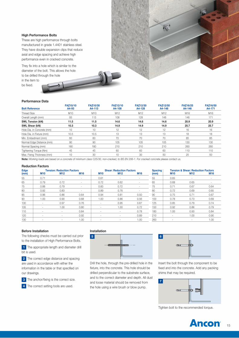
Installation
Drill the hole, through the pre-drilled hole in the fixture, into the concrete. This hole should be drilled perpendicular to the substrate surface, and to the correct diameter and depth. All dust and loose material should be removed from the hole using a wire brush or blow pump.
5
Insert the bolt through the component to be fixed and into the concrete. Add any packing shims that may be required.
6
Tighten bolt to the recommended torque.
7
2
3
4
Before InstallationThe following checks must be carried out prior to the installation of High Performance Bolts.
The appropriate length and diameter drill bit is used.
The correct edge distance and spacing are used in accordance with either the information in the table or that specified on our drawings.
The anchor/fixing is the correct size.
The correct setting tools are used.
1
Edge Tension: Reduction Factors Shear: Reduction Factors Spacing Tension & Shear: Reduction Factors(mm) M10 M12 M16 M10 M12 M16 (mm) M10 M12 M16
55 0.71 - - 0.61 - - 55 0.65 - -
65 0.79 0.72 - 0.72 0.62 - 65 0.68 0.65 -
75 0.88 0.79 - 0.83 0.72 - 75 0.71 0.67 0.64
80 0.92 0.83 - 0.89 0.76 - 80 0.72 0.69 0.65
85 0.96 0.86 0.64 0.94 0.81 0.50 90 0.75 0.71 0.67
90 1.00 0.90 0.68 1.00 0.86 0.56 100 0.78 0.73 0.69
100 - 0.97 0.76 - 0.95 0.67 125 0.85 0.79 0.74
105 - 1.00 0.80 - 1.00 0.72 150 0.92 0.86 0.79
110 - - 0.84 - - 0.78 180 1.00 0.93 0.84
120 - - 0.92 - - 0.89 210 - 1.00 0.90
130 - - 1.00 - - 1.00 260 - - 1.00
Reduction Factors
High Performance BoltsThese are high performance through bolts manufactured in grade 1.4401 stainless steel. They have double expansion clips that reduce axial and edge spacing and achieve high performance even in cracked concrete.
They fix into a hole which is similar to the diameter of the bolt. This allows the hole to be drilled through the hole in the item to be fixed.
FAZ10/10 FAZ10/30 FAZ12/10 FAZ12/30 FAZ12/50 FAZ16/25 FAZ16/50Bolt Reference A4-93 A4-113 A4-108 A4-128 A4-148 A4-146 A4-171
Thread Size M10 M10 M12 M12 M12 M16 M16
Overall Length (mm) 93 113 108 128 148 146 171
SWL Tension (kN) 11.5 11.5 14.6 14.6 14.6 20.9 20.9SWL Shear (kN) 10.3 10.3 14.9 14.9 14.9 25.7 25.7Hole Dia. in Concrete (mm) 10 10 12 12 12 16 16
Hole Dia. in Fixture (mm) 10.5 10.5 13 13 13 18 18
Min. Embedment (mm) 60 60 70 70 70 85 85
Normal Edge Distance (mm) 90 90 105 105 105 130 130
Normal Spacing (mm) 180 180 210 210 210 260 260
Tightening Torque (Nm) 45 45 60 60 60 110 110
Max. Fixing Thickness (mm) 10 30 10 30 50 25 50
Note: Working loads are based on a concrete of minimum class C25/30, non-cracked, to BS EN 206-1. For cracked concrete please contact us.
Performance Data
15
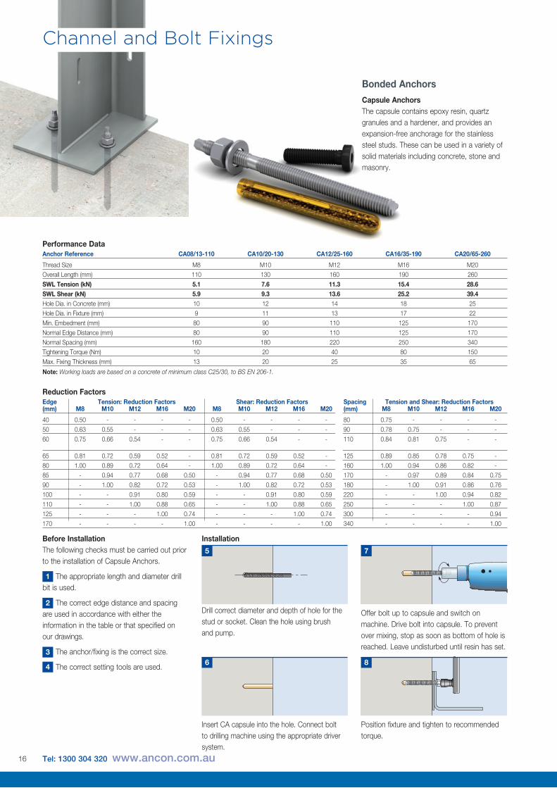
Bonded AnchorsCapsule AnchorsThe capsule contains epoxy resin, quartz granules and a hardener, and provides an expansion-free anchorage for the stainless steel studs. These can be used in a variety of solid materials including concrete, stone and masonry.
Anchor Reference CA08/13-110 CA10/20-130 CA12/25-160 CA16/35-190 CA20/65-260
Thread Size M8 M10 M12 M16 M20
Overall Length (mm) 110 130 160 190 260
SWL Tension (kN) 5.1 7.6 11.3 15.4 28.6SWL Shear (kN) 5.9 9.3 13.6 25.2 39.4Hole Dia. in Concrete (mm) 10 12 14 18 25
Hole Dia. in Fixture (mm) 9 11 13 17 22
Min. Embedment (mm) 80 90 110 125 170
Normal Edge Distance (mm) 80 90 110 125 170
Normal Spacing (mm) 160 180 220 250 340
Tightening Torque (Nm) 10 20 40 80 150
Max. Fixing Thickness (mm) 13 20 25 35 65
Note: Working loads are based on a concrete of minimum class C25/30, to BS EN 206-1.
Performance Data
Installation
Insert CA capsule into the hole. Connect bolt to drilling machine using the appropriate driver system.
6
Position fixture and tighten to recommended torque.
8
Offer bolt up to capsule and switch on machine. Drive bolt into capsule. To prevent over mixing, stop as soon as bottom of hole is reached. Leave undisturbed until resin has set.
7
Before InstallationThe following checks must be carried out prior to the installation of Capsule Anchors.
The appropriate length and diameter drill bit is used.
The correct edge distance and spacing are used in accordance with either the information in the table or that specified on our drawings.
The anchor/fixing is the correct size.
The correct setting tools are used.
1
2
3
4
Drill correct diameter and depth of hole for the stud or socket. Clean the hole using brush and pump.
5
Edge Tension: Reduction Factors Shear: Reduction Factors Spacing Tension and Shear: Reduction Factors(mm) M8 M10 M12 M16 M20 M8 M10 M12 M16 M20 (mm) M8 M10 M12 M16 M20
40 0.50 - - - - 0.50 - - - - 80 0.75 - - - -
50 0.63 0.55 - - - 0.63 0.55 - - - 90 0.78 0.75 - - -
60 0.75 0.66 0.54 - - 0.75 0.66 0.54 - - 110 0.84 0.81 0.75 - -
65 0.81 0.72 0.59 0.52 - 0.81 0.72 0.59 0.52 - 125 0.89 0.85 0.78 0.75 -
80 1.00 0.89 0.72 0.64 - 1.00 0.89 0.72 0.64 - 160 1.00 0.94 0.86 0.82 -
85 - 0.94 0.77 0.68 0.50 - 0.94 0.77 0.68 0.50 170 - 0.97 0.89 0.84 0.75
90 - 1.00 0.82 0.72 0.53 - 1.00 0.82 0.72 0.53 180 - 1.00 0.91 0.86 0.76
100 - - 0.91 0.80 0.59 - - 0.91 0.80 0.59 220 - - 1.00 0.94 0.82
110 - - 1.00 0.88 0.65 - - 1.00 0.88 0.65 250 - - - 1.00 0.87
125 - - - 1.00 0.74 - - - 1.00 0.74 300 - - - - 0.94
170 - - - - 1.00 - - - - 1.00 340 - - - - 1.00
Reduction Factors
Channel and Bolt Fixings
16 Tel: 1300 304 320 www.ancon.com.au
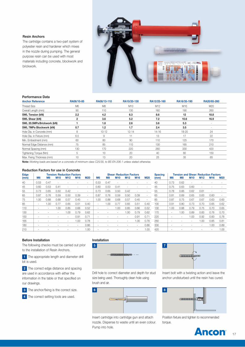
Anchor Reference RA06/10-85 RA08/13-110 RA10/20-130 RA12/25-160 RA16/35-190 RA20/65-260
Thread Size M6 M8 M10 M12 M16 M20
Overall Length (mm) 90 110 130 160 190 260
SWL Tension (kN) 2.2 4.2 6.3 8.6 12 18.8SWL Shear (kN) 2 3.6 5.2 7.2 10.6 16.9SWL 20.5MPa Brickwork (kN) 1 1.8 2.6 3.6 5.3 - SWL 7MPa Blockwork (kN) 0.7 1.2 1.7 2.4 3.5 -
Hole Dia. in Concrete (mm) 8 10-12 12-14 14-16 18-20 24
Hole Dia. in Fixture (mm) 6.5 9 11 13 17 22
Min. Embedment (mm) 60 80 90 110 125 170
Normal Edge Distance (mm) 75 85 110 130 165 210
Normal Spacing (mm) 130 170 220 260 330 420
Tightening Torque (Nm) 5 10 20 40 80 150
Max. Fixing Thickness (mm) 10 13 20 25 35 65
Note: Working loads are based on a concrete of minimum class C25/30, to BS EN 206-1 unless stated otherwise.
Performance Data
Resin AnchorsThe cartridge contains a two-part system of polyester resin and hardener which mixes in the nozzle during pumping. The general purpose resin can be used with most materials including concrete, blockwork and brickwork.
Installation
Insert cartridge into cartridge gun and attach nozzle. Dispense to waste until an even colour. Pump into hole.
Drill hole to correct diameter and depth for stud size being used. Thoroughly clean hole using brush and air.
5
6
Insert bolt with a twisting action and leave the anchor undisturbed until the resin has cured.
Position fixture and tighten to recommended torque.
7
Before InstallationThe following checks must be carried out prior to the installation of Resin Anchors.
The appropriate length and diameter drill bit is used.
The correct edge distance and spacing are used in accordance with either the information in the table or that specified on our drawings.
The anchor/fixing is the correct size.
The correct setting tools are used.
1
2
3
4
8
Edge Tension: Reduction Factors Shear: Reduction Factors Spacing Tension and Shear: Reduction Factors(mm) M6 M8 M10 M12 M16 M20 M6 M8 M10 M12 M16 M20 (mm) M6 M8 M10 M12 M16 M20
40 0.53 0.47 - - - - 0.53 0.47 - - - - 40 0.73 0.62 - - - -
45 0.60 0.53 0.41 - - - 0.60 0.53 0.41 - - - 45 0.75 0.63 0.60 - - -
55 0.73 0.65 0.50 0.42 - - 0.73 0.65 0.50 0.42 - - 55 0.78 0.66 0.62 0.61 - -
65 0.87 0.76 0.59 0.50 0.39 - 0.87 0.76 0.59 0.50 0.39 - 65 0.81 0.69 0.65 0.63 0.60 -
75 1.00 0.88 0.68 0.57 0.45 - 1.00 0.88 0.68 0.57 0.45 - 85 0.87 0.75 0.67 0.67 0.63 0.60
85 - 1.00 0.77 0.65 0.51 0.40 - 1.00 0.77 0.65 0.51 0.40 100 0.91 0.80 0.73 0.70 0.65 0.62
110 - - 1.00 0.85 0.66 0.52 - - 1.00 0.85 0.66 0.52 130 1.00 0.88 0.79 0.75 0.70 0.65
130 - - - 1.00 0.79 0.62 - - - 1.00 0.79 0.62 170 - 1.00 0.89 0.83 0.76 0.70
150 - - - - 0.91 0.71 - - - - 0.91 0.71 220 - - 1.00 0.92 0.83 0.76
165 - - - - 1.00 0.78 - - - - 1.00 0.78 260 - - - 1.00 0.85 0.81
180 - - - - - 0.86 - - - - - 0.86 330 - - - - 1.00 0.89
210 - - - - - 1.00 - - - - - 1.00 420 - - - - - 1.00
Reduction Factors for use in Concrete
17
Channel and Bolt Fixings
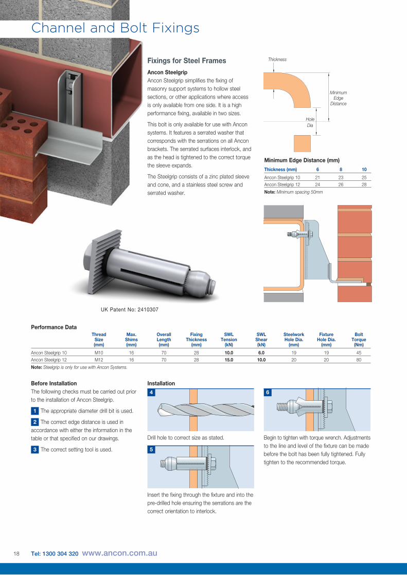
Minimum Edge
Distance
Hole Dia
Thickness
Installation
Drill hole to correct size as stated.
4
Begin to tighten with torque wrench. Adjustments to the line and level of the fixture can be made before the bolt has been fully tightened. Fully tighten to the recommended torque.
6
Insert the fixing through the fixture and into the pre-drilled hole ensuring the serrations are the correct orientation to interlock.
5
Before InstallationThe following checks must be carried out prior to the installation of Ancon Steelgrip.
The appropriate diameter drill bit is used.
The correct edge distance is used in accordance with either the information in the table or that specified on our drawings.
The correct setting tool is used.
1
2
3
Thread Max. Overall Fixing SWL SWL Steelwork Fixture Bolt Size Shims Length Thickness Tension Shear Hole Dia. Hole Dia. Torque (mm) (mm) (mm) (mm) (kN) (kN) (mm) (mm) (Nm)
Ancon Steelgrip 10 M10 16 70 28 10.0 6.0 19 19 45
Ancon Steelgrip 12 M12 16 70 28 15.0 10.0 20 20 80
Note: Steelgrip is only for use with Ancon Systems.
Performance Data
Fixings for Steel FramesAncon SteelgripAncon Steelgrip simplifies the fixing of masonry support systems to hollow steel sections, or other applications where access is only available from one side. It is a high performance fixing, available in two sizes.
This bolt is only available for use with Ancon systems. It features a serrated washer that corresponds with the serrations on all Ancon brackets. The serrated surfaces interlock, and as the head is tightened to the correct torque the sleeve expands.
The Steelgrip consists of a zinc plated sleeve and cone, and a stainless steel screw and serrated washer.
Thickness (mm) 6 8 10
Ancon Steelgrip 10 21 23 25
Ancon Steelgrip 12 24 26 28
Note: Minimum spacing 50mm
Minimum Edge Distance (mm)
UK Patent No: 2410307
18 Tel: 1300 304 320 www.ancon.com.au
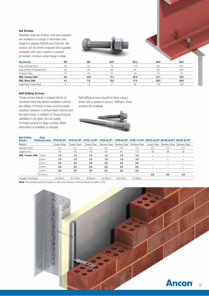
Self-Drilling Steel Screws Thickness (mm) HTCS-65-2PT HTCS-85-2PT HTCS-110-2PT HTSS-65-2PT HTSS-85-2PT HTSS-110-2PT SDTCS-38-5PT SDTSS-38-5PT SDTSS-35-5PT
Material Coated Steel Coated Steel Coated Steel Stainless Steel Stainless Steel Stainless Steel Coated Steel Stainless Steel Stainless Steel
Diameter (mm) 5.5 5.5 5.5 5.5 5.5 5.5 5.5 5.5 5.5
Length (mm) 65 85 110 65 85 110 38 38 35
SWL Tension (kN) 1.6mm 1.0 1.0 1.0 1.0 1.0 1.0 - - -
2.0mm 1.5 1.5 1.5 1.5 1.5 1.5 - - -
2.5mm 2.0 2.0 2.0 2.0 2.0 2.0 - - -
3.0mm 2.5 2.5 2.5 2.5 2.5 2.5 - - -
3.5mm 2.5 2.5 2.5 2.5 2.5 2.5 - - -
4.0-12mm - - - - - - 2.5 2.5 2.5
Insulation Thickness 35-50mm 50-70mm 70-95mm 35-50mm 50-70mm 70-95mm - - -
Note: The working loads are based on tests and include a minimum factor of safety of 3.0.
Set ScrewsStainless steel set screws, nuts and washers are available in a range of diameters and lengths in grades A2(304) and A4(316). Set screws can be shrink-wrapped and supplied complete with nylon washer to prevent bi-metallic corrosion when fixing to steel.
Self-Drilling ScrewsThese screws feature a shaped drill tip of hardened steel that allows installation without pre-drilling. Hi-thread screws accommodate insulation between a surface-fixed channel and the steel frame. In addition to those products identified in the table, we can supply hi-thread screws for larger cavities. More information is available on request.
Self-drilling screws should be fixed using a driver with a speed of around 1800rpm. Drive sockets are available.
Set Screws M6 M8 M10 M12 M16 M20
Area of Shank (mm2) 28 50 78 113 201 314
Area of Root of Thread (mm2) 20 36 58 84 157 245
Property Class 70 70 70 70 70 70
SWL Tension (kN) 6.0 10.9 17.4 25.2 47.1 73.5SWL Shear (kN) 4.1 7.5 12.0 17.4 32.5 50.8Tightening Torque (Nm) 6 14 27 48 120 230
19
Channel and Bolt Fixings
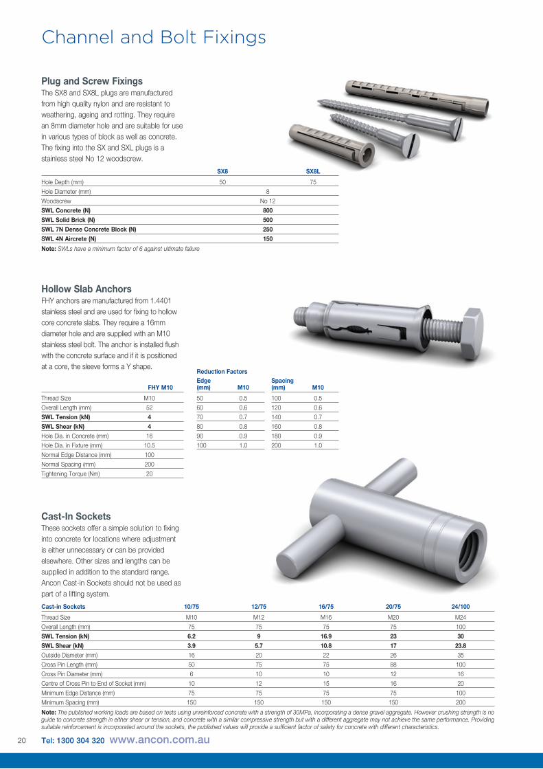
Cast-In SocketsThese sockets offer a simple solution to fixing into concrete for locations where adjustment is either unnecessary or can be provided elsewhere. Other sizes and lengths can be supplied in addition to the standard range. Ancon Cast-in Sockets should not be used as part of a lifting system.
Cast-in Sockets 10/75 12/75 16/75 20/75 24/100
Thread Size M10 M12 M16 M20 M24
Overall Length (mm) 75 75 75 75 100
SWL Tension (kN) 6.2 9 16.9 23 30SWL Shear (kN) 3.9 5.7 10.8 17 23.8Outside Diameter (mm) 16 20 22 26 35
Cross Pin Length (mm) 50 75 75 88 100
Cross Pin Diameter (mm) 6 10 10 12 16
Centre of Cross Pin to End of Socket (mm) 10 12 15 16 20
Minimum Edge Distance (mm) 75 75 75 75 100
Minimum Spacing (mm) 150 150 150 150 200
Note: The published working loads are based on tests using unreinforced concrete with a strength of 30MPa, incorporating a dense gravel aggregate. However crushing strength is no guide to concrete strength in either shear or tension, and concrete with a similar compressive strength but with a different aggregate may not achieve the same performance. Providing suitable reinforcement is incorporated around the sockets, the published values will provide a sufficient factor of safety for concrete with different characteristics.
SX8 SX8L
Hole Depth (mm) 50 75
Hole Diameter (mm) 8
Woodscrew No 12
SWL Concrete (N) 800SWL Solid Brick (N) 500SWL 7N Dense Concrete Block (N) 250SWL 4N Aircrete (N) 150
Note: SWLs have a minimum factor of 6 against ultimate failure
FHY M10
Thread Size M10
Overall Length (mm) 52
SWL Tension (kN) 4SWL Shear (kN) 4Hole Dia. in Concrete (mm) 16
Hole Dia. in Fixture (mm) 10.5
Normal Edge Distance (mm) 100
Normal Spacing (mm) 200
Tightening Torque (Nm) 20
Hollow Slab AnchorsFHY anchors are manufactured from 1.4401 stainless steel and are used for fixing to hollow core concrete slabs. They require a 16mm diameter hole and are supplied with an M10 stainless steel bolt. The anchor is installed flush with the concrete surface and if it is positioned at a core, the sleeve forms a Y shape.
Plug and Screw FixingsThe SX8 and SX8L plugs are manufactured from high quality nylon and are resistant to weathering, ageing and rotting. They require an 8mm diameter hole and are suitable for use in various types of block as well as concrete. The fixing into the SX and SXL plugs is a stainless steel No 12 woodscrew.
Edge (mm) M10
50 0.5
60 0.6
70 0.7
80 0.8
90 0.9
100 1.0
Spacing (mm) M10
100 0.5
120 0.6
140 0.7
160 0.8
180 0.9
200 1.0
Reduction Factors
20 Tel: 1300 304 320 www.ancon.com.au
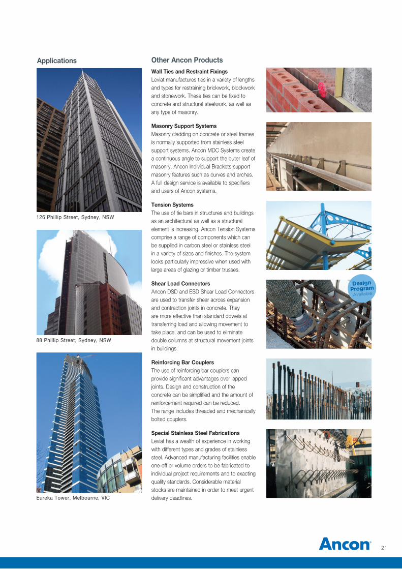
Other Ancon ProductsWall Ties and Restraint FixingsLeviat manufactures ties in a variety of lengths and types for restraining brickwork, blockwork and stonework. These ties can be fixed to concrete and structural steelwork, as well as any type of masonry.
Masonry Support SystemsMasonry cladding on concrete or steel frames is normally supported from stainless steel support systems. Ancon MDC Systems create a continuous angle to support the outer leaf of masonry. Ancon Individual Brackets support masonry features such as curves and arches. A full design service is available to specifiers and users of Ancon systems.
Tension SystemsThe use of tie bars in structures and buildings as an architectural as well as a structural element is increasing. Ancon Tension Systems comprise a range of components which can be supplied in carbon steel or stainless steel in a variety of sizes and finishes. The system looks particularly impressive when used with large areas of glazing or timber trusses.
Shear Load ConnectorsAncon DSD and ESD Shear Load Connectors are used to transfer shear across expansion and contraction joints in concrete. They are more effective than standard dowels at transferring load and allowing movement to take place, and can be used to eliminate double columns at structural movement joints in buildings.
Reinforcing Bar CouplersThe use of reinforcing bar couplers can provide significant advantages over lapped joints. Design and construction of the concrete can be simplified and the amount of reinforcement required can be reduced. The range includes threaded and mechanically bolted couplers.
Special Stainless Steel FabricationsLeviat has a wealth of experience in working with different types and grades of stainless steel. Advanced manufacturing facilities enable one-off or volume orders to be fabricated to individual project requirements and to exacting quality standards. Considerable material stocks are maintained in order to meet urgent delivery deadlines.
Applications
126 Phillip Street, Sydney, NSW
88 Phillip Street, Sydney, NSW
Eureka Tower, Melbourne, VIC
21
Worldwide contacts for Leviat:
Notes regarding this catalogue© Protected by copyright. The construction applications and details provided in this publication are indicative only. In every case, project working details should be entrusted to appropriately qualified and experienced persons. Whilst every care has been exercised in the preparation of this publication to ensure that any advice, recommendations or information is accurate, no liability or responsibility of any kind is accepted by Leviat for inaccuracies or printing errors. Technical and design changes are reserved. With a policy of continuous product development, Leviat reserves the right to modify product design and specification at any time.
AustraliaLeviat98 Kurrajong Avenue, Mount Druitt Sydney, NSW 2770 Tel: +61 - 2 8808 3100 Email: [email protected]
AustriaLeviatLeonard-Bernstein-Str. 10 Saturn Tower, 1220 Wien Tel: +43 - 1 - 259 6770 Email: [email protected]
BelgiumLeviatIndustrielaan 2 1740 Ternat Tel: +32 - 2 - 582 29 45 Email: [email protected]
China LeviatRoom 601 Tower D, Vantone Centre No. A6 Chao Yang Men Wai Street Chaoyang District Beijing · P.R. China 100020 Tel: +86 - 10 5907 3200 Email: [email protected]
Czech Republic LeviatBusiness Center Šafránkova Šafránkova 1238/1 155 00 Praha 5 Tel: +420 - 311 - 690 060 Email: [email protected]
FinlandLeviatVädursgatan 5 412 50 Göteborg / Sweden Tel: +358 (0)10 6338781 Email: [email protected]
France Leviat6, Rue de Cabanis FR 31240 L’Union Toulouse Tel: +33 - 5 - 34 25 54 82 Email: [email protected]
Germany Leviat Liebigstrasse 14 40764 Langenfeld Tel: +49 - 2173 - 970 - 0 Email: [email protected]
IndiaLeviat309, 3rd Floor, Orion Business Park Ghodbunder Road, Kapurbawdi, Thane West, Thane, Maharashtra 400607 Tel: +91 - 22 2589 2032 Email: [email protected]
Italy LeviatVia F.lli Bronzetti 28 24124 Bergamo Tel: +39 - 035 - 0760711 Email: [email protected]
MalaysiaLeviat28 Jalan Anggerik Mokara 31/59 Kota Kemuning, 40460 Shah Alam Selangor Tel: +603 - 5122 4182 Email: [email protected]
Netherlands LeviatOostermaat 3 7623 CS Borne Tel: +31 - 74 - 267 14 49 Email: [email protected]
New ZealandLeviat2/19 Nuttall Drive, Hillsborough, Christchurch 8022 Tel: +64 - 3 376 5205 Email: [email protected]
Norway LeviatVestre Svanholmen 5 4313 Sandnes Tel: +47 - 51 82 34 00 Email: [email protected]
Philippines Leviat2933 Regus, Joy Nostalg, ADB Avenue Ortigas Center Pasig City Tel: +63 - 2 7957 6381 Email: [email protected]
Poland LeviatUl. Obornicka 287 60-691 Poznan Tel: +48 - 61 - 622 14 14 Email: [email protected]
SingaporeLeviat14 Benoi Crescent Singapore 629977 Tel: +65 - 6266 6802 Email: [email protected]
Spain LeviatPolígono Industrial Santa Ana c/ Ignacio Zuloaga, 20 28522 Rivas-Vaciamadrid Tel: +34 - 91 632 18 40 Email: [email protected]
Sweden LeviatVädursgatan 5 412 50 Göteborg Tel: +46 - 31 - 98 58 00 Email: [email protected]
Switzerland LeviatGrenzstrasse 24 3250 Lyss Tel: +41 - 31 750 3030 Email: [email protected]
United Kingdom LeviatPresident Way, President Park, Sheffield, S4 7UR Tel: +44 - 114 275 5224 Email: [email protected]
United States of America Leviat6467 S Falkenburg Rd. Riverview, FL 33578 Tel: (800) 423-9140 Email: [email protected]
For countries not listedEmail: [email protected]
Leviat.com
Leviat.com
New South Wales, Sydney
98 Kurrajong AvenueMount Druitt | SydneyNSW 2770
Queensland
4/15 Terrace PlaceMurarrie | BrisbaneQLD 4172
Sales Offices and Production
New South Wales, Casino
10 Irving DriveCasinoNSW 2470
Western Australia
18 Tennant Street Welshpool | PerthWA 6106
Victoria
9/63-69 Pipe RoadLaverton North | MelbourneVIC 3026
Masonry, Structural and Precast Concrete products:
1300 304 [email protected]
For more information on the following products, please contact:
Concrete Floor Jointing products:
1800 335 [email protected]@leviat.comIsedio.com.au
Remedial Masonry products:
1300 667 [email protected]
General Enquiries
1300 304 320
Leviat.com

Imagine. Model. Make. Leviat.com