thesis hard cover
TRANSCRIPT

ii
DEDICATION
An honours thesis is never simply the work of one person. Rather, it is the result
of the combined efforts of many people, working with and supporting the author. It is
because of this fact that I would like to thank the following people:
First of all, ALLAH, thank you for making me who I am today, and for giving me
the abilities that I have. I will always be grateful for your grace and thrilled for the good
accommodation facilities I utilized to cleave my way to success.
My Parents, as always, you have supported me throughout all that I have done.
Gratitude for your unconditional support, both financially and emotionally. Thank you
for your endless prayers and much needed support throughout my four years at
University Selangor.
iii
DECLARATION AND COPYRIGHT PAGE
I hereby declare that this research is the result of my own investigations, except
where otherwise stated. Sources are acknowledged by citations / quotations and a
reference is appended.
Signature : …………………………………..…………………
Name : ……………………………………………………..
Matric No. : ……………………………………………………..
Date : ……………………………………………………..
© Copyright (Universiti Selangor)
iv
APPROVAL PAGE
WIRELESS CONTROL UNMANNED GROUND VEHICLE FOR
CONTAMINATED AREAS
BY
AMRO KHIDIR ABASHAR HAG ELKHALIFA
Approved by:
‘‘I hereby declare that I have read this thesis and in my
opinion this Thesis is sufficient in terms of scope and quality for the
award of the degree of Bachelor of Engineering (Hons.) Mechatronics’’
Supervisor:
……………………………… Date: ………………………
(Mdm. Nor Laili Binti Mahmud)

v
ACKNOWLEDGEMENTS
Foremost, I would like to express my sincere gratitude to my advisor Head of
Bachelor of Mechatronics Engineering Division, Mdm. Nor Laili Binti Mahmud for
accepting to be my supervisor in this project and her interest which helped me to address
my research questions, for the continuous support in my bachelor study and research, for
her patience, motivation, enthusiasm and immense knowledge. Her guidance effectively
helped me in all the time of research and writing of this thesis. I could not have imagined
having a better supervisor and mentor for my thesis, which have on occasion made me
optimistic.
This dissertation would not have been possible without the encouragement and
the help of several individuals in the Mechatronic Engineering and Electrical Engineering
Departments who in one way or another contributed and extended their valuable
assistance in the preparation and completion of this study
vi
ABSTRACT
The main goal of this project is to presents wireless control to transmit data for
controlling unmanned ground vehicle (UGV). This type of robot is generally capable of
operating outdoors and over a wide variety of terrain, functioning where human are
preferred not to be. Data will be transmitted between UGV & Base station (BS) using
Bluetooth. UGV contains different types of sensors such as: Temperature & Humidity,
infra-red to gain more information about the environment then sends it back to BS. GPS
device has been attached to the UGV to get its position where UGV was designed to send
the position to the Base station to know where the UGV is located exactly. This project
facing difficulties in the design due to the limitation of the great size of the data to be sent
by the Bluetooth module. Besides sensors required for such a project are almost not
available or they are available over the budget ranged. UGV is actively being developed
for both civilian Deep sea exploration, Exploration of volcanoes, to look for survivors in
a disaster struck area and military use to perform dull, dirty, and dangerous activities.
UGV is increasingly becoming the platform of choice in missions that might be
dangerous for humans, like inspections in the battlefield and nuclear biologically
contaminated regions, or inaccessible areas like wildfires.
vii
ABSTRAK
Matlamat utama projek ini adalah untuk membentangkan kawalan Penghantaran
data tanpa wayar bagi mengawal kenderaan darat tanpa pemandu (UGV). Robot jenis ini
umumnya mampu beroperasi dipelbagai bentuk muka bumi dan di kawasan yang tidak
boleh atau sukar dihampiri oleh manusia. Data akan dihantar antara UGV & stesen
pangkalan (BS) menggunakan teknologi Bluetooth. UGV mengandungi pelbagai jenis
sensor seperti: Suhu & Kelembapan, infra-merah untuk mendapatkan maklumat lebih
lanjut mengenai alam sekitar dan kemudiannya menghantar tersebut kembali ke BS.
Peranti GPS telah dipasang kepada UGV ini bagi membolehkan BS mengetahui
kedudukan sebenar UGV tersebut. Projek ini menghadapi masalah dalam reka bentuk
disebabkan oleh penghantaran data yang terhad dengan penggunaan modul Bluetooth.
Selain daripada itu, sensor yang diperlukan amat sukar didapati dipasaran dan sekiranya
ia ada, harganya melangkaui bajet. Pada masa kini, UGV giat dibangunkan oleh syarikat-
syarikat konglomerat untuk digunakan oleh pihak awam penerokaan laut dalam,
ekplorasi gunung berapi, mencari mangsa yang terselamat didalam bencana dan
kegunaan ketenteraan seperti melaksanakan misi sulit, kotor dan berbahaya. UGV
semakin menjadi platform pilihan dalam misi yang mungkin berbahaya bagi manusia
seperti pemeriksaan di medan perang dan nuklear, kawasan biologi tercemar atau
kawasan-kawasan tidak boleh diakses seperti kebakaran.
viii
LIST OF FIGURES
NO. TITLE PAGE
Figure 2.1
Figure 2.2
Figure 2.3
Figure 2.4
Figure 2.5
Figure 2.6
Figure 2.7
Figure 2.8
Figure 2.9
Figure 2.10
Figure 2.11
Figure 2.12
Figure 2.13
Figure 2.14
Figure 2.15
Figure 3.1
Figure 3.2
Figure 3.3
Figure 3.4
Figure 3.5
Figure 3.6
Figure 3.7
Figure 3.8
Figure 3.9
Figure 3.10
Figure 3.11
Figure 3.12
Figure 3.13
Figure 3.14
Figure 3.15
Figure 3.16
Figure 3.17
Figure 3.18
Figure 3.19
Figure 3.20
Figure 3.21
Figure 3.22
Figure 3.23
Figure 3.24
Figure 3.25
Figure 3.26
Unmanned Ground Vehicle
Micro UGV
SUGV
MUGV
LUGV
Tethered
Autonomous
Semi-autonomous
Tele-operated
UGVs For Logistics Or Convoy UGVs For Bomb Disposal
UGVs for Rescue
UGVs for Firefighting/Decontamination
UGVs for Reconnaissance Missions
UGV for All Purposes
Research methodology flowchart
Driving wheels
The main body
Block diagram of UGV
UGV programming flow chart
Power supply circuit
Diode 1N4004
Capacitor 22uf
LM1117 voltage regulator pin diagram
7805 Voltage regulator pin diagram
Main control circuit configuration
PIC16F877A microcontroller
The LM35 temperature sensor
Humidity sensor by cytron technologies
Smoke detector circuit configuration
IR sensor circuit configuration
Magnetic buzzer
Connecting H-Bridge with motor
H-Bridge motor clockwise rotation
H-Bridge motor anti-clockwise rotation
Motors driving circuit
Forward movement process
Reverse movement process
Right movement process
left movement process
GPS transmission circuit schematic
4
5
5
6
6
7
8
8
9
10
11
11
12
12
13
16
16
17
19
20
21
22
22
23
23
25
26
31
32
34
35
36
37
38
38
39
40
40
41
42
42
ix
Figure 3.27
Figure 3.28
Figure 3.29
Figure 3.30
Figure 3.31
Figure 3.32
Figure 3.33
Figure 3.34
Figure 3.35
Figure 3.36
Figure 3.37
Figure 3.38
Figure 3.39
Figure 3.40
Figure 3.41
Figure 3.42
Figure 3.43
Figure 3.44
Figure 3.45
Figure 3.46
Figure 3.47
Figure 3.48
Figure 3.49
Figure 4.1
Figure 4.2
Figure 4.3
Figure 4.4
Figure 4.5
Figure 4.6
Figure 4.7
Figure 4.8
Figure 4.9
Figure 4.10
Figure 4.11
Figure 4.12
Figure 4.13
Figure 4.14
SKGPS-53 overview
MAX232
GPS segments
Trilateration
Trilateration
Trilateration
Trilateration
Trilateration
Voltage divider rule
Bluetooth transmission circuit schematic
BLUBEE Bluetooth module
How Bluetooth Operates
Piconet
Scatternet
Scatternet
Bluetooth protocol stack
Overall UGV schematic
Creating a New Standard EXE Project
The main window design
Directions instruction dialog
Programming of directions
Received data dialog
Received data programming
Located position within 10 minutes
Error measured within 10 minutes
Error plot over time
Located position within 10 minutes
Error measured within 10 minutes
Error plot over time
Located position within 10 minutes
Error measured within 10 minutes
Error plot over time
Located position within 10 minutes
Error measured within 10 minutes
Error plot over time
Error plots over time
data shown in visual basic controller
43
45
46
47
48
48
49
49
51
51
53
58
59
60
60
61
68
70
70
71
72
73
73
76
77
78
79
80
81
81
82
82
83
83
84
85
88
x
LIST OF TABLES
NO. TITLE PAGE
Table 4.1
Table 4.2
Table 4.3
Table 4.4
Table 4.5
Table 4.6
Error measured in chancellery
Error measured in FK
Error measured in hostel
Error measured in main field
Temperature data collected
Humidity data collected
76
79
82
85
89
90
xi
CONTENTS
Dedication II
Declaration and Copyright Page III
Approval Page IV
Acknowledgements V
Abstract VI
Abstrak VII
List of Figures VIII
List of Tables x
1 INTRODUCTION 1
1.1 Background of the Study 1
1.2 Problem Statement 2
1.3 Objectives of Study 2
1.4 Significance of Study 3
1.5 Scope of Study 3
2 LITERATURE REVIEW 4
2.1 Unmanned Ground Vehicles (UGVs) 4
2.2 UGV Categories: 5
2.2.1 Size 5
2.2.2 Mode of Operation 7
2.3 Applications of UGV 11
2.3.1 Military Applications: 11
2.3.2 Civilian Applications 15
2.4 The Basic Parts of UGV 15
3 RESEARCH METHODOLOGY 17
3.1 Introduction 17
3.2 Mechanical Part of UGV 19
3.2.1 Body 19
3.2.2 Wheels 19
3.2.3 Covers 20
3.2.4 Motion 20
3.2.5 Component 20
3.2.6 Organization 21
3.3 Control System 21
3.3.1 Flow Chart of the UGV 22
3.3.2 Power Supply Circuit 23
3.3.2.1 Diode 1N4004: 24
xii
3.3.2.2 Capacitor 24
3.3.2.3 Lm1117 Voltage Regulator 25
3.3.2.4 7805 Voltage Regulator 25
3.3.3 Main Control Circuit 26
3.3.3.1 PIC16F877A 28
3.3.3.2 Sensors 30
3.3.3.2.1 Temperature Sensor 31
3.3.3.2.2 Humidity Sensor 33
3.3.3.2.3 Smoke Detector 34
3.3.3.2.4 IR Sensor 35
3.3.3.2.5 Magnetic Buzzer (Sounder) 36
3.3.4 Motor Driving Circuit: 37
3.3.4.1 Forward Movement 40
3.3.4.2 Reverse Movement 41
3.3.4.3 The Right Direction Movement 42
3.3.4.4 The Left Direction Movement 42
3.3.5 GPS Transmission Circuit 43
3.3.5.1 SKGPS-53 44
3.3.5.2 MAX232 46
3.3.5.3 Global Positioning System (GPS) 46
3.3.5.3.1 GPS System Consist Three Segments 47
3.3.5.3.2 User Segment 47
3.3.5.3.3 Trilateration 48
3.3.6 Bluetooth Transmission Circuit 52
3.3.6.1 BLUEBEE Bluetooth Module 54
3.3.6.2 Bluetooth 56
3.3.6.2.1 Piconets 60
3.3.6.2.2 Scatternets 61
3.3.6.2.3 Bluetooth Protocol Stack 63
3.3.6.2.3.1 Radio Layer 64
3.3.6.2.3.2 Transmitter 64
3.3.6.2.3.3 Receiver 64
3.3.6.2.3.4 Baseband Layer 64
3.3.6.2.3.5 Link Manager Protocol (LMP) 65
3.3.6.2.3.6 Host Controller Interface (HCI) 65
3.3.6.2.3.7 Logical Link Control and Adaptation
……………………………..……Protocol (L2CAP) 64
3.3.6.2.3.8 RF Communication 66
3.3.6.2.3.9 Service Discovery Protocol (SDP) 66
3.3.6.2.3.10 Adopted Protocols 67
3.3.6.2.3.10.1 Point-to-Point Protoco 67
3.3.6.2.3.10.2 TCP/IP/UDP 67
3.3.6.2.3.10.3 Object Exchange
…………………………………………………….Protocol 67
xiii
3.3.6.2.3.10.4 Wireless Application
…………………………………………..………...Environment/Wireless
……………………………………… ……..……Application Protocol 67
3.3.6.3 Advantages of Bluetooth 68
3.3.6.4 Disadvantages of Bluetooth 69
3.3.7 Overall UGV System Operation Principle 69
3.3.8 Visual Basic 6.0 71
4 RESULTS AND DISCUSSION 76
4.1 Introduction 76
4.1.1 Ionospheres Errors 76
4.1.2 Multipath 76
4.1.3 Selective Availability or SA 77
4.2 GPS receiver analysis over time: 77
4.2.1 Chancellery: Measured Positions Using SKGPS-53 78
4.2.1.1 Error Measured In Meters 79
4.2.1.2 Error Plot over Time: 80
4.2.2 Engineering: Measured Positions Using SKGPS-53 81
4.2.2.1 Error Measured In Meters 82
4.2.2.2 Error Plot over Time: 83
4.2.3 Hostel: Measured Positions Using SKGPS-53 84
4.2.3.1 Error Measured In Meters 85
4.2.3.2 Error Plot over Time: 86
4.2.4 Main Field: Measured Positions Using SKGPS-53 87
4.2.4.1 Error Measured In Meters 88
4.2.4.2 Error Plot over Time: 89
4.2.5 Discussion of Errors Measured Over Time 89
4.3 Temperature and Humidity Sensors Accuracy Analysis 91
4.3.1 Temperature accuracy 92
4.3.2 Humidity accuracy 93
5 CONCLUSION AND RECOMMENDATION 94
5.1 Conclusion 94
5.2 Recommendation 95
REFERENCES 97
APPENDIX 99
1
CHAPTER 1
INTRODUCTION
1.1 Background of the Study
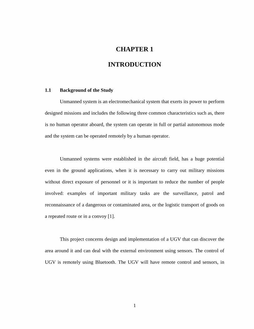
Unmanned system is an electromechanical system that exerts its power to perform
designed missions and includes the following three common characteristics such as, there
is no human operator aboard, the system can operate in full or partial autonomous mode
and the system can be operated remotely by a human operator.
Unmanned systems were established in the aircraft field, has a huge potential
even in the ground applications, when it is necessary to carry out military missions
without direct exposure of personnel or it is important to reduce the number of people
involved: examples of important military tasks are the surveillance, patrol and
reconnaissance of a dangerous or contaminated area, or the logistic transport of goods on
a repeated route or in a convoy [1].
This project concerns design and implementation of a UGV that can discover the
area around it and can deal with the external environment using sensors. The control of
UGV is remotely using Bluetooth. The UGV will have remote control and sensors, in
2
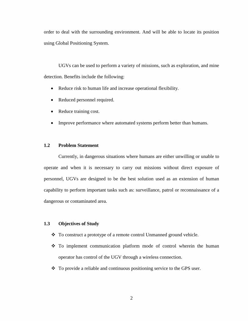
order to deal with the surrounding environment. And will be able to locate its position
using Global Positioning System.
UGVs can be used to perform a variety of missions, such as exploration, and mine
detection. Benefits include the following:
Reduce risk to human life and increase operational flexibility.
Reduced personnel required.
Reduce training cost.
Improve performance where automated systems perform better than humans.
1.2 Problem Statement
Currently, in dangerous situations where humans are either unwilling or unable to
operate and when it is necessary to carry out missions without direct exposure of
personnel, UGVs are designed to be the best solution used as an extension of human
capability to perform important tasks such as: surveillance, patrol or reconnaissance of a
dangerous or contaminated area.
1.3 Objectives of Study
To construct a prototype of a remote control Unmanned ground vehicle.
To implement communication platform mode of control wherein the human
operator has control of the UGV through a wireless connection.
To provide a reliable and continuous positioning service to the GPS user.
3
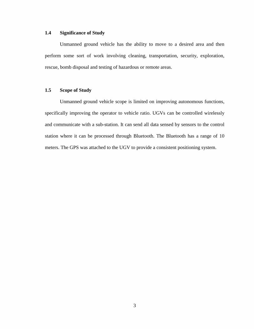
1.4 Significance of Study
Unmanned ground vehicle has the ability to move to a desired area and then
perform some sort of work involving cleaning, transportation, security, exploration,
rescue, bomb disposal and testing of hazardous or remote areas.
1.5 Scope of Study
Unmanned ground vehicle scope is limited on improving autonomous functions,
specifically improving the operator to vehicle ratio. UGVs can be controlled wirelessly
and communicate with a sub-station. It can send all data sensed by sensors to the control
station where it can be processed through Bluetooth. The Bluetooth has a range of 10
meters. The GPS was attached to the UGV to provide a consistent positioning system.
4
CHAPTER 2
LITERATURE REVIEW
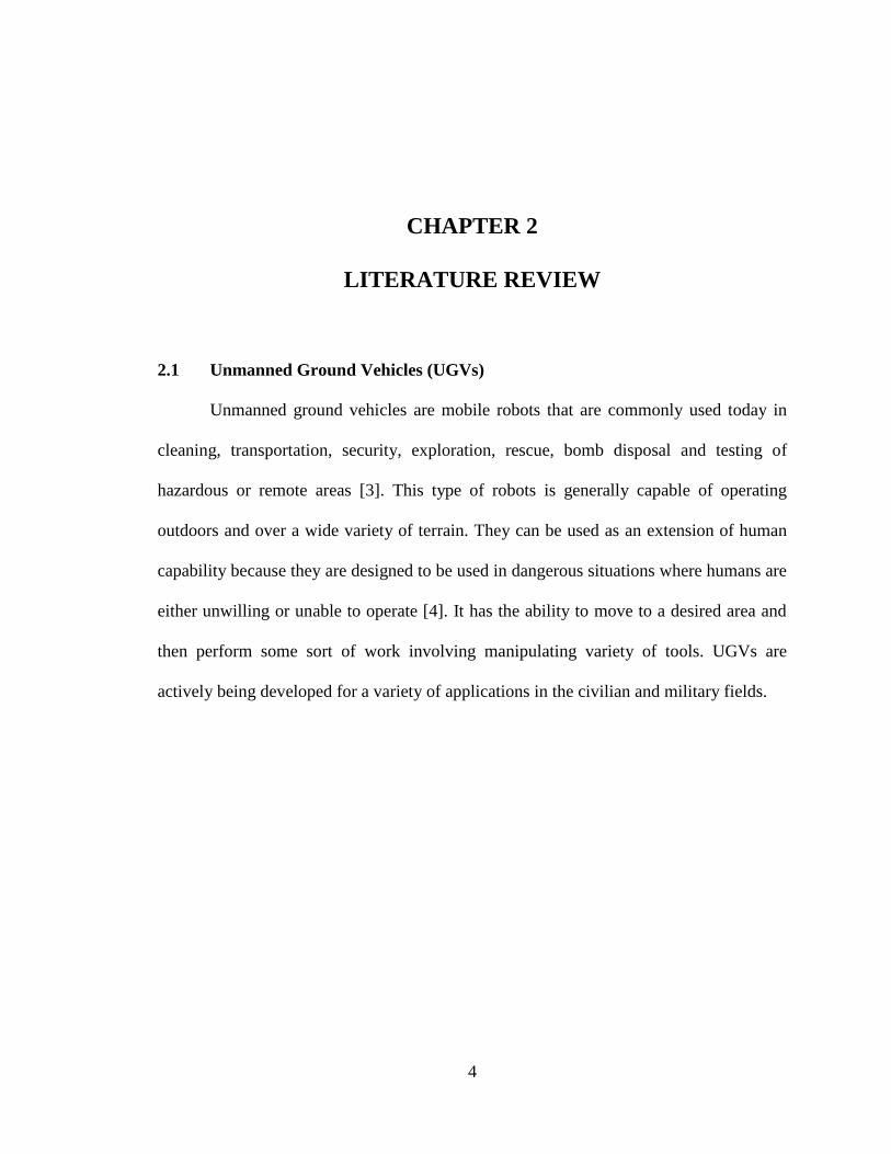
2.1 Unmanned Ground Vehicles (UGVs)
Unmanned ground vehicles are mobile robots that are commonly used today in
cleaning, transportation, security, exploration, rescue, bomb disposal and testing of
hazardous or remote areas [3]. This type of robots is generally capable of operating
outdoors and over a wide variety of terrain. They can be used as an extension of human
capability because they are designed to be used in dangerous situations where humans are
either unwilling or unable to operate [4]. It has the ability to move to a desired area and
then perform some sort of work involving manipulating variety of tools. UGVs are
actively being developed for a variety of applications in the civilian and military fields.
5
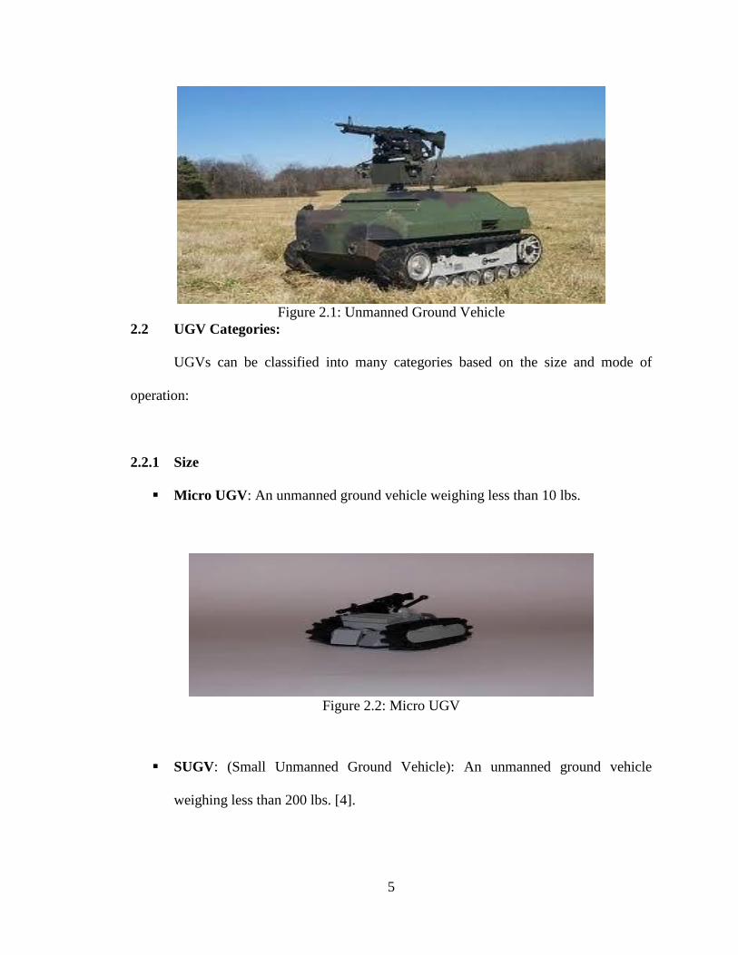
Figure 2.1: Unmanned Ground Vehicle
2.2 UGV Categories:
UGVs can be classified into many categories based on the size and mode of
operation:
2.2.1 Size
Micro UGV: An unmanned ground vehicle weighing less than 10 lbs.
Figure 2.2: Micro UGV
SUGV: (Small Unmanned Ground Vehicle): An unmanned ground vehicle
weighing less than 200 lbs. [4].
6
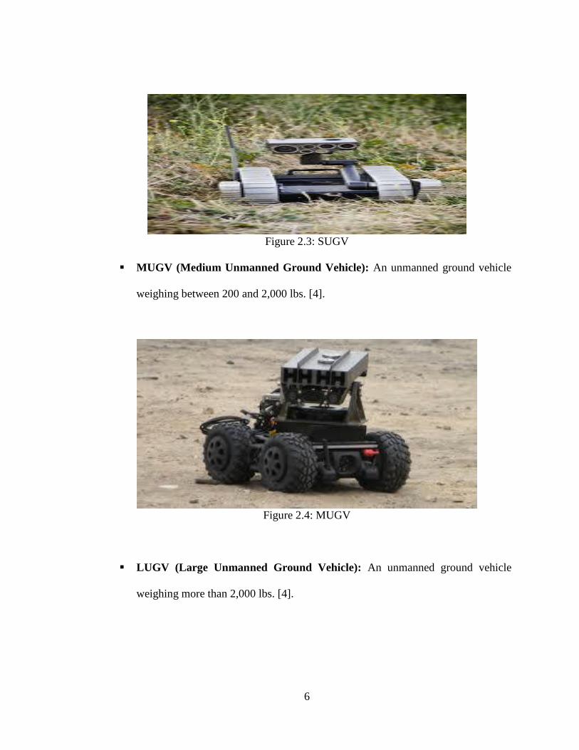
Figure 2.3: SUGV
MUGV (Medium Unmanned Ground Vehicle): An unmanned ground vehicle
weighing between 200 and 2,000 lbs. [4].
Figure 2.4: MUGV
LUGV (Large Unmanned Ground Vehicle): An unmanned ground vehicle
weighing more than 2,000 lbs. [4].
7
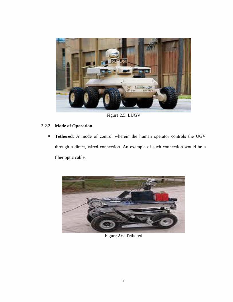
Figure 2.5: LUGV
2.2.2 Mode of Operation
Tethered: A mode of control wherein the human operator controls the UGV
through a direct, wired connection. An example of such connection would be a
fiber optic cable.
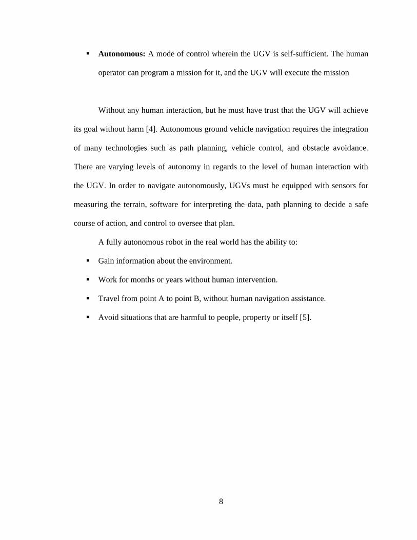
Figure 2.6: Tethered
8
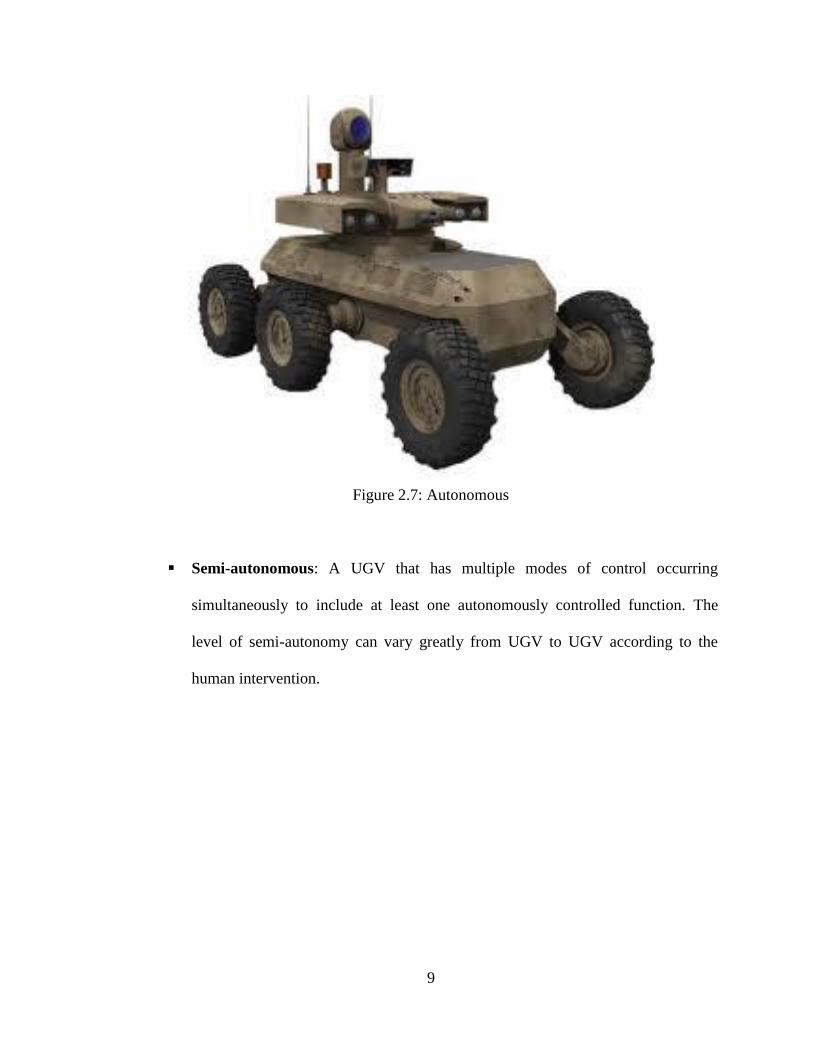
Autonomous: A mode of control wherein the UGV is self-sufficient. The human
operator can program a mission for it, and the UGV will execute the mission
Without any human interaction, but he must have trust that the UGV will achieve
its goal without harm [4]. Autonomous ground vehicle navigation requires the integration
of many technologies such as path planning, vehicle control, and obstacle avoidance.
There are varying levels of autonomy in regards to the level of human interaction with
the UGV. In order to navigate autonomously, UGVs must be equipped with sensors for
measuring the terrain, software for interpreting the data, path planning to decide a safe
course of action, and control to oversee that plan.
A fully autonomous robot in the real world has the ability to:
Gain information about the environment.
Work for months or years without human intervention.
Travel from point A to point B, without human navigation assistance.
Avoid situations that are harmful to people, property or itself [5].
9
Figure 2.7: Autonomous
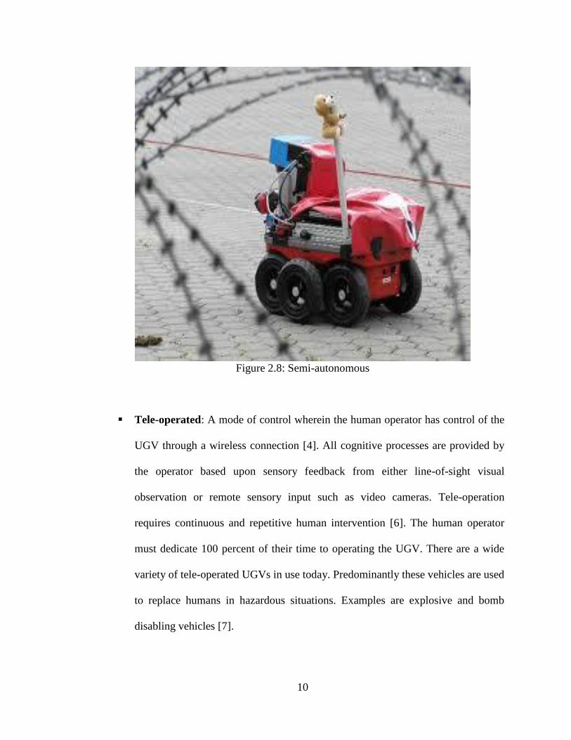
Semi-autonomous: A UGV that has multiple modes of control occurring
simultaneously to include at least one autonomously controlled function. The
level of semi-autonomy can vary greatly from UGV to UGV according to the
human intervention.
10
Figure 2.8: Semi-autonomous
Tele-operated: A mode of control wherein the human operator has control of the
UGV through a wireless connection [4]. All cognitive processes are provided by
the operator based upon sensory feedback from either line-of-sight visual
observation or remote sensory input such as video cameras. Tele-operation
requires continuous and repetitive human intervention [6]. The human operator
must dedicate 100 percent of their time to operating the UGV. There are a wide
variety of tele-operated UGVs in use today. Predominantly these vehicles are used
to replace humans in hazardous situations. Examples are explosive and bomb
disabling vehicles [7].
11
Figure 2.9: Tele-operated
2.3 Applications of UGV
Many applications require unmanned ground vehicles (UGVs) to do the man’s job
like:
2.3.1 Military Applications:
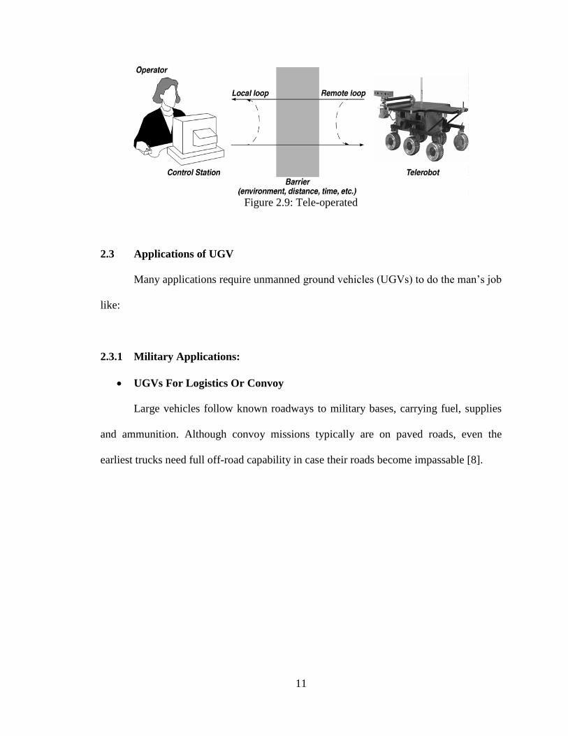
UGVs For Logistics Or Convoy
Large vehicles follow known roadways to military bases, carrying fuel, supplies
and ammunition. Although convoy missions typically are on paved roads, even the
earliest trucks need full off-road capability in case their roads become impassable [8].
12
Figure 2.10: UGVs for Logistics or Convoy
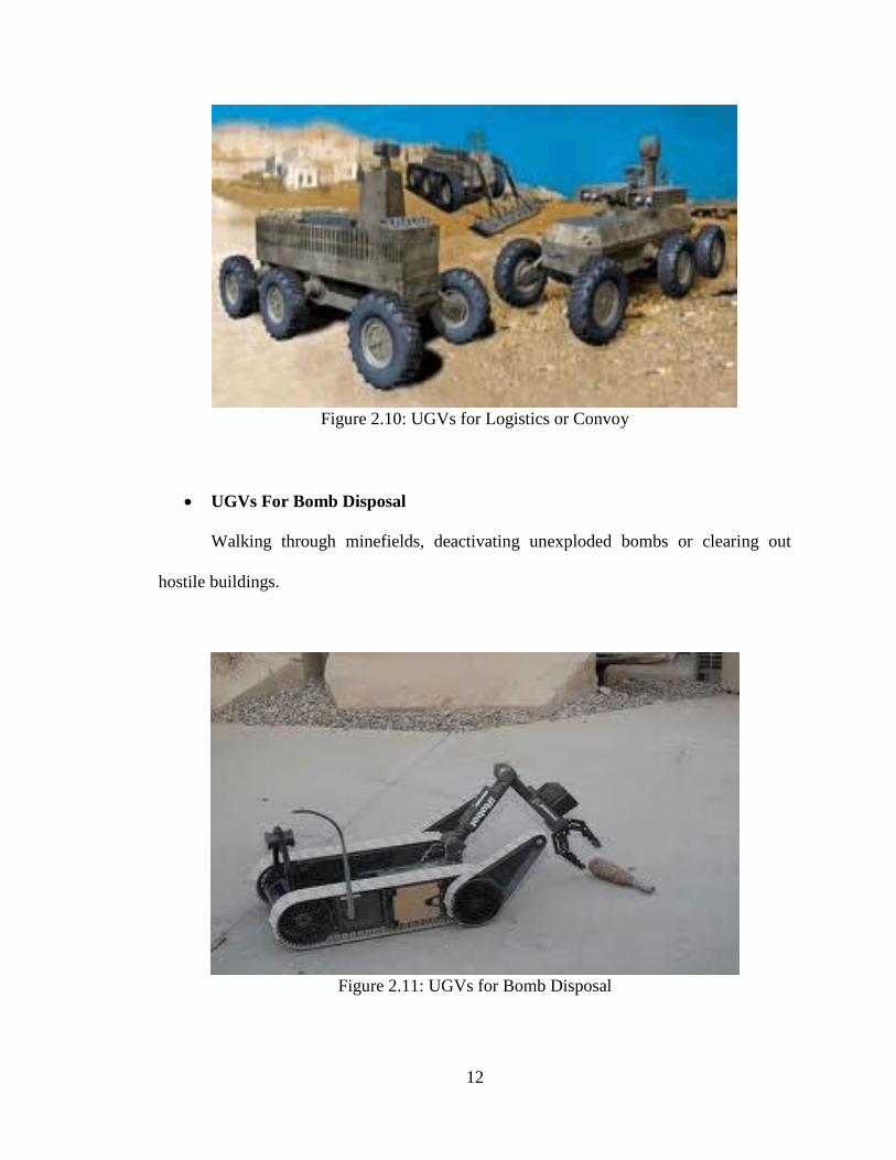
UGVs For Bomb Disposal
Walking through minefields, deactivating unexploded bombs or clearing out
hostile buildings.
Figure 2.11: UGVs for Bomb Disposal
13
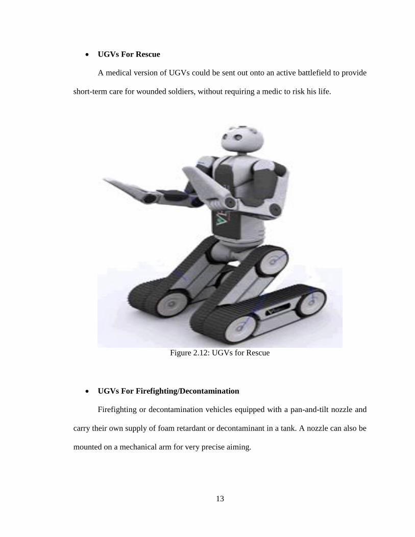
UGVs For Rescue
A medical version of UGVs could be sent out onto an active battlefield to provide
short-term care for wounded soldiers, without requiring a medic to risk his life.
Figure 2.12: UGVs for Rescue
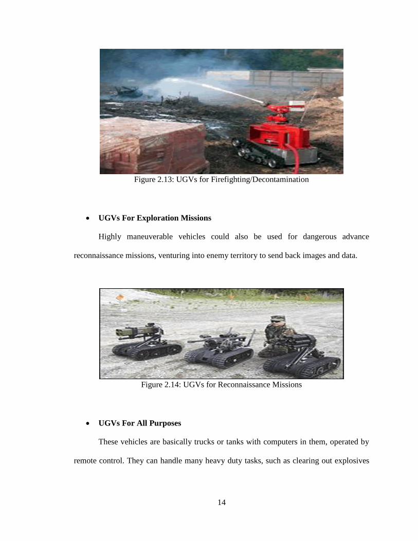
UGVs For Firefighting/Decontamination
Firefighting or decontamination vehicles equipped with a pan-and-tilt nozzle and
carry their own supply of foam retardant or decontaminant in a tank. A nozzle can also be
mounted on a mechanical arm for very precise aiming.
14
Figure 2.13: UGVs for Firefighting/Decontamination
UGVs For Exploration Missions
Highly maneuverable vehicles could also be used for dangerous advance
reconnaissance missions, venturing into enemy territory to send back images and data.
Figure 2.14: UGVs for Reconnaissance Missions
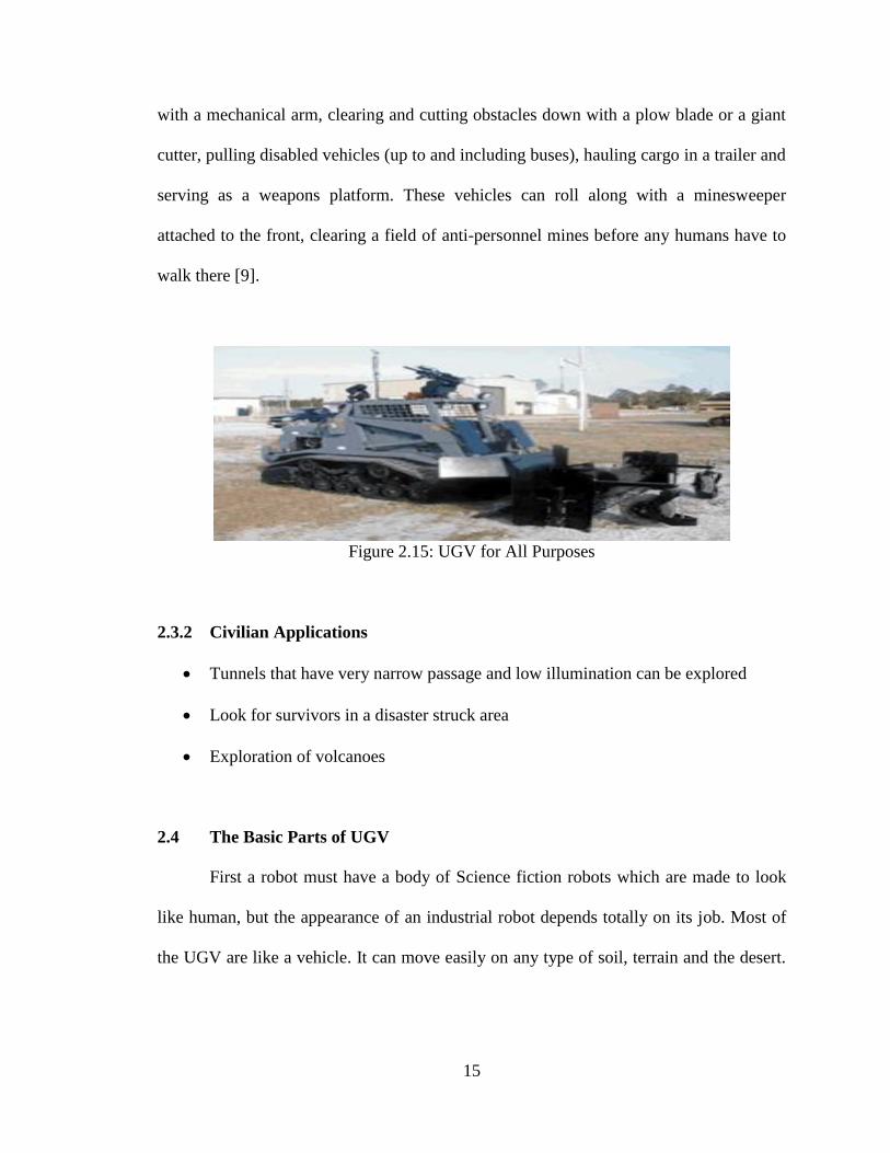
UGVs For All Purposes
These vehicles are basically trucks or tanks with computers in them, operated by
remote control. They can handle many heavy duty tasks, such as clearing out explosives
15
with a mechanical arm, clearing and cutting obstacles down with a plow blade or a giant
cutter, pulling disabled vehicles (up to and including buses), hauling cargo in a trailer and
serving as a weapons platform. These vehicles can roll along with a minesweeper
attached to the front, clearing a field of anti-personnel mines before any humans have to
walk there [9].
Figure 2.15: UGV for All Purposes
2.3.2 Civilian Applications
Tunnels that have very narrow passage and low illumination can be explored
Look for survivors in a disaster struck area
Exploration of volcanoes
2.4 The Basic Parts of UGV
First a robot must have a body of Science fiction robots which are made to look
like human, but the appearance of an industrial robot depends totally on its job. Most of
the UGV are like a vehicle. It can move easily on any type of soil, terrain and the desert.
16
Like the human, a UGV also needs a brain. This really what sets UGVs apart from all
other vehicles used by people. A UGV’s brain is a computer and it controls everything
the UGV does. As known if there is computers been used, they are good as computing;
that is, doing rote tasks like adding a column of numbers or processing words. However,
they can’t really think as a human does. For a UGV to be really useful, it must have some
sort of intelligence. This intelligence is contained in the program, the set of instructions
that it follows. Most UGVs today are not very intelligent, but researchers are constantly
working to make computers, and therefore UGVs, smarter. Just as a human have sense
organs such as eyes and ears, UGVs need sensors. A UGV might have electronic eyes to
find its way around and see what it is doing; electronic ears to hear commands and
noises, safety touch sensors to stop it if it accidentally bumps into anything. These are
some of the many types of sensors used by UGVs. Many UGVs need some type of hand,
usually called a manipulator or gripper, to do their jobs. Sometimes different tools, such
as a screwdriver or a drill, are attached directly to the UGVs. Other types of grippers use
magnets and vacuums to pick up and hold different objects [7].
17
CHAPTER 3
RESEARCH METHODOLOGY
3.1 Introduction
The previous chapter covered the different types of UGVs, different functions,
and different components. This chapter describes the research and design methodology
which is used to achieve the objective of this project. The required information is
collected through several methods such as observation and interviews before the main
content is extracted and turned into data. The data obtained here is carefully studied
before coming to a strong conclusion.
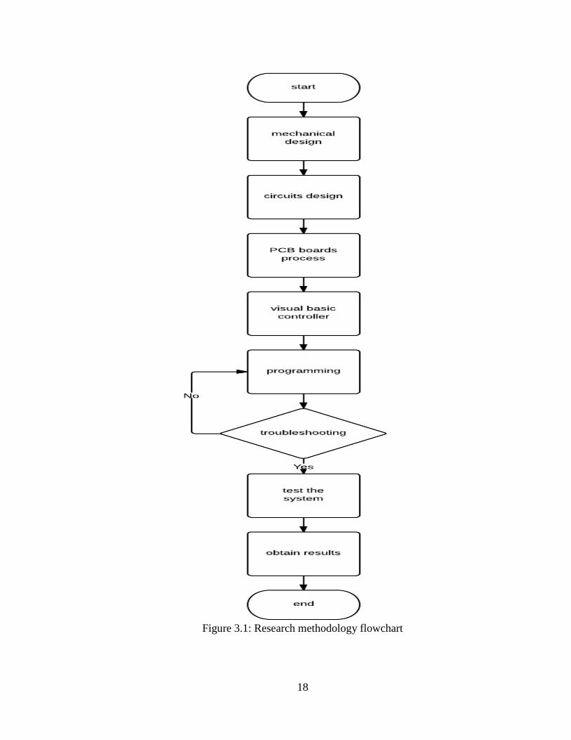
Starting with the mechanical design of the UGV, after finishing up with the
vehicle, the circuit was designed using eagle software, then PCB boards process took a
place before fixing the components in it, after that visual basic controller was designed to
meet the required functions, then programming of microcontroller took place, then the
system undergo through long troubleshooting process of programming, after all the
system was tested and the final results were obtained. The whole process is described in
figure 3.1 in a flowchart. The described process was followed to finish up this project
with a decent budget and using available components in the market.
18
Figure 3.1: Research methodology flowchart
19
3.2 Mechanical Part of UGV
This part will demonstrate the mechanical part of the project and the component
to be used in building the chassis of the vehicle.
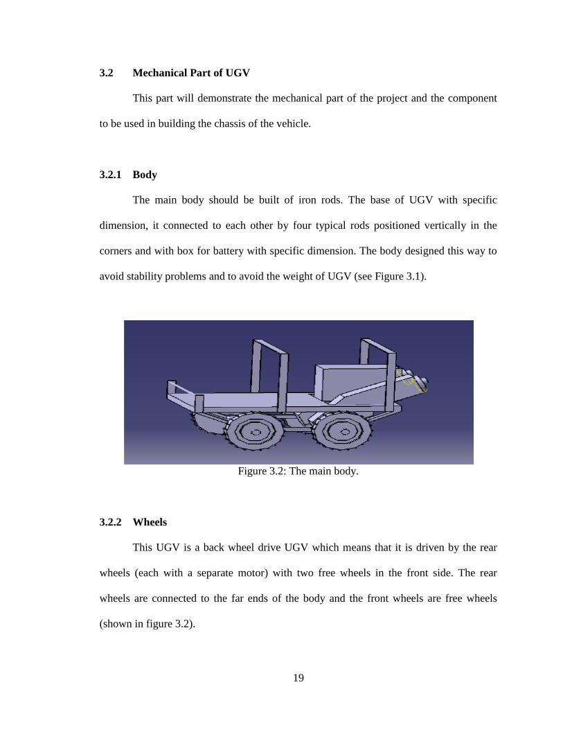
3.2.1 Body
The main body should be built of iron rods. The base of UGV with specific
dimension, it connected to each other by four typical rods positioned vertically in the
corners and with box for battery with specific dimension. The body designed this way to
avoid stability problems and to avoid the weight of UGV (see Figure 3.1).
Figure 3.2: The main body.
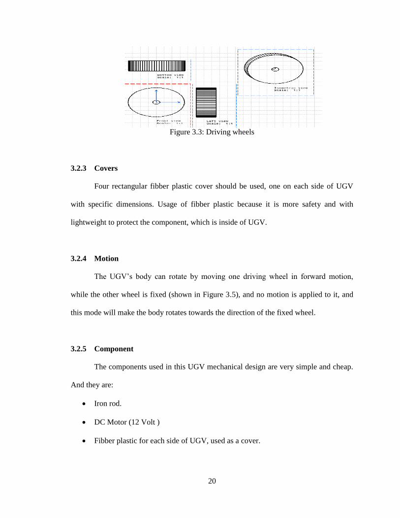
3.2.2 Wheels
This UGV is a back wheel drive UGV which means that it is driven by the rear
wheels (each with a separate motor) with two free wheels in the front side. The rear
wheels are connected to the far ends of the body and the front wheels are free wheels
(shown in figure 3.2).
20
Figure 3.3: Driving wheels
3.2.3 Covers
Four rectangular fibber plastic cover should be used, one on each side of UGV
with specific dimensions. Usage of fibber plastic because it is more safety and with
lightweight to protect the component, which is inside of UGV.
3.2.4 Motion
The UGV’s body can rotate by moving one driving wheel in forward motion,
while the other wheel is fixed (shown in Figure 3.5), and no motion is applied to it, and
this mode will make the body rotates towards the direction of the fixed wheel.
3.2.5 Component
The components used in this UGV mechanical design are very simple and cheap.
And they are:
Iron rod.
DC Motor (12 Volt )
Fibber plastic for each side of UGV, used as a cover.
21
Battery (12V, 19 A )
The rear driving wheels.
The front free wheel.
3.2.6 Organization
The electric and electronic circuits and the battery are supposed to be attached to
lower floor. The kit board are supposed to be attached to the higher floor.
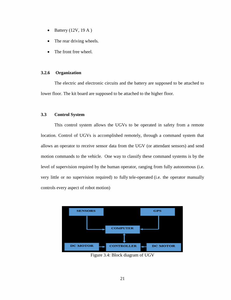
3.3 Control System
This control system allows the UGVs to be operated in safety from a remote
location. Control of UGVs is accomplished remotely, through a command system that
allows an operator to receive sensor data from the UGV (or attendant sensors) and send
motion commands to the vehicle. One way to classify these command systems is by the
level of supervision required by the human operator, ranging from fully autonomous (i.e.
very little or no supervision required) to fully tele-operated (i.e. the operator manually
controls every aspect of robot motion)
Figure 3.4: Block diagram of UGV
22
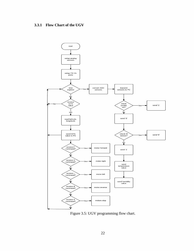
3.3.1 Flow Chart of the UGV
Figure 3.5: UGV programming flow chart.
23
Figure 3.5 demonstrates the flow chart of the UGV, starting with defining the
analog sensors which are temperature and humidity sensors, the setting up the
microcontroller I/O ports, then read the GPS value in time of movement, if the GPS
values of latitude and longitude, then it will be send to the PC.
Movement commands are: F for motor forward, R for motor right, L for motor
left, B for motor reverse and S for motor stop. If any of these values were commanded
the process of reading the GPS values begins again as well as the sensors readings on the
other hand run right after GPS values are transmitted, it starts with converting sensors
using ADC and then transmit the readings of the sensors to the PC.
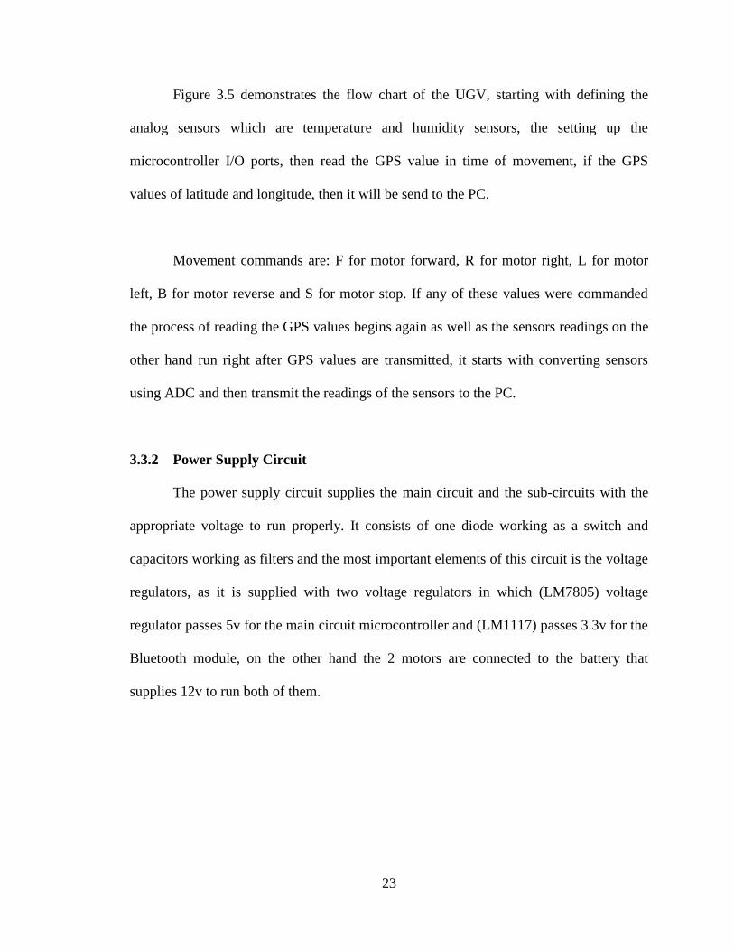
3.3.2 Power Supply Circuit
The power supply circuit supplies the main circuit and the sub-circuits with the
appropriate voltage to run properly. It consists of one diode working as a switch and
capacitors working as filters and the most important elements of this circuit is the voltage
regulators, as it is supplied with two voltage regulators in which (LM7805) voltage
regulator passes 5v for the main circuit microcontroller and (LM1117) passes 3.3v for the
Bluetooth module, on the other hand the 2 motors are connected to the battery that
supplies 12v to run both of them.
24
Figure 3.6: Power supply circuit
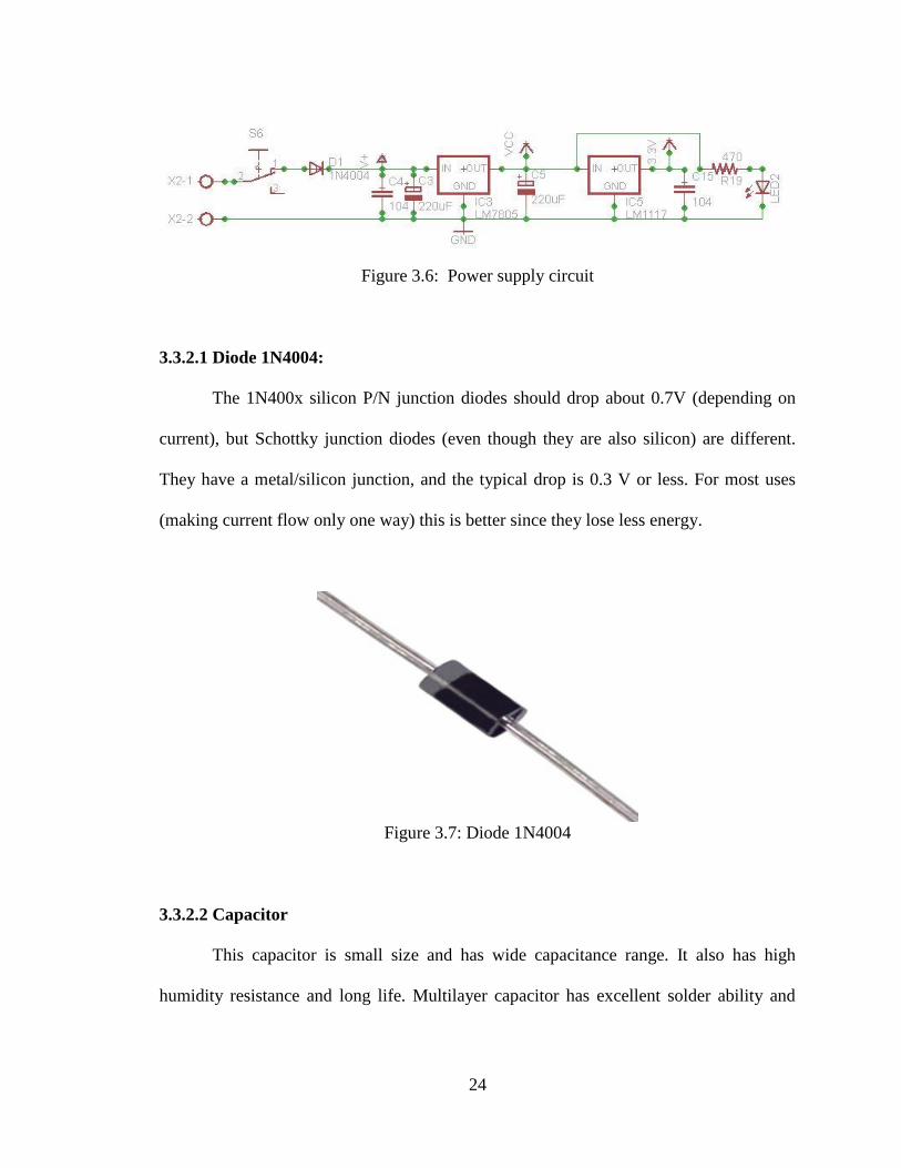
3.3.2.1 Diode 1N4004:
The 1N400x silicon P/N junction diodes should drop about 0.7V (depending on
current), but Schottky junction diodes (even though they are also silicon) are different.
They have a metal/silicon junction, and the typical drop is 0.3 V or less. For most uses
(making current flow only one way) this is better since they lose less energy.
Figure 3.7: Diode 1N4004
3.3.2.2 Capacitor
This capacitor is small size and has wide capacitance range. It also has high
humidity resistance and long life. Multilayer capacitor has excellent solder ability and
25
resistance to soldering heat. The inductance (ESL) is also low and has excellent
frequency characteristics.
Figure 3.8: Capacitor 22uf.
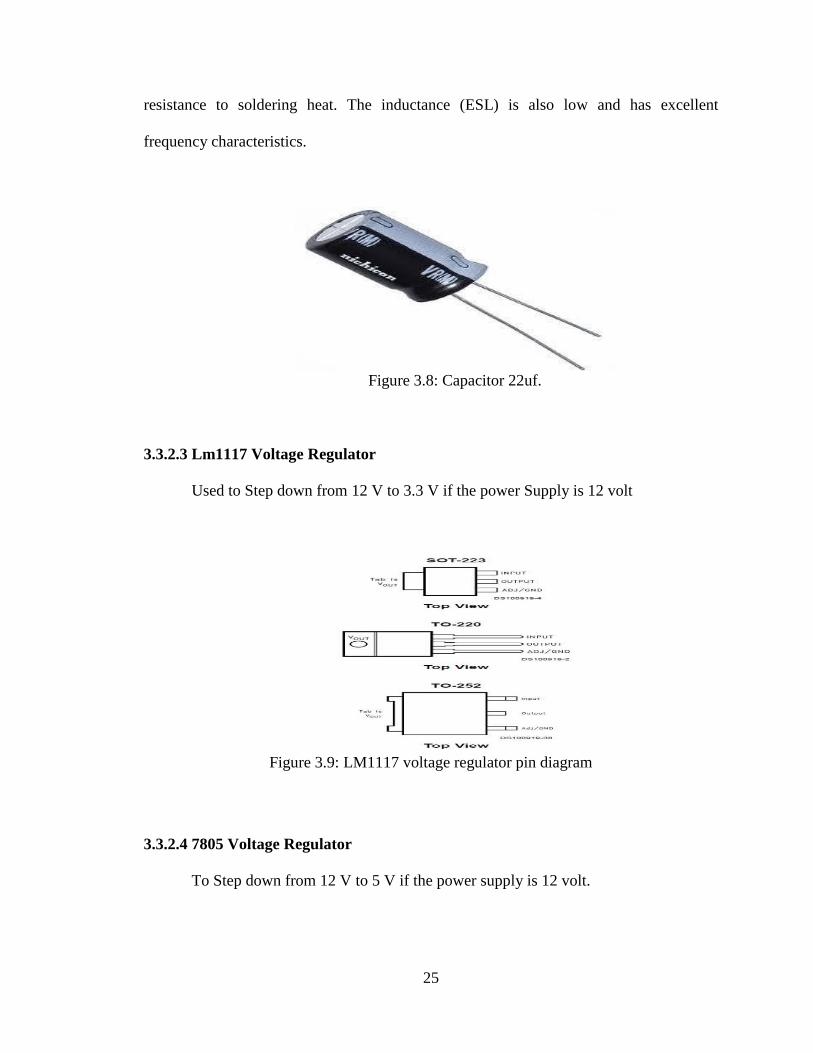
3.3.2.3 Lm1117 Voltage Regulator
Used to Step down from 12 V to 3.3 V if the power Supply is 12 volt
Figure 3.9: LM1117 voltage regulator pin diagram
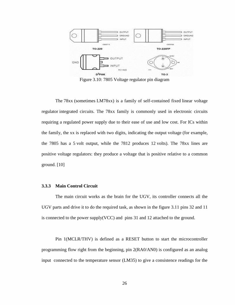
3.3.2.4 7805 Voltage Regulator
To Step down from 12 V to 5 V if the power supply is 12 volt.
26
Figure 3.10: 7805 Voltage regulator pin diagram
The 78xx (sometimes LM78xx) is a family of self-contained fixed linear voltage
regulator integrated circuits. The 78xx family is commonly used in electronic circuits
requiring a regulated power supply due to their ease of use and low cost. For ICs within
the family, the xx is replaced with two digits, indicating the output voltage (for example,
the 7805 has a 5 volt output, while the 7812 produces 12 volts). The 78xx lines are
positive voltage regulators: they produce a voltage that is positive relative to a common
ground. [10]
3.3.3 Main Control Circuit
The main circuit works as the brain for the UGV, its controller connects all the
UGV parts and drive it to do the required task, as shown in the figure 3.11 pins 32 and 11
is connected to the power supply(VCC) and pins 31 and 12 attached to the ground.
Pin 1(MCLR/THV) is defined as a RESET button to start the microcontroller
programming flow right from the beginning, pin 2(RA0/AN0) is configured as an analog
input connected to the temperature sensor (LM35) to give a consistence readings for the
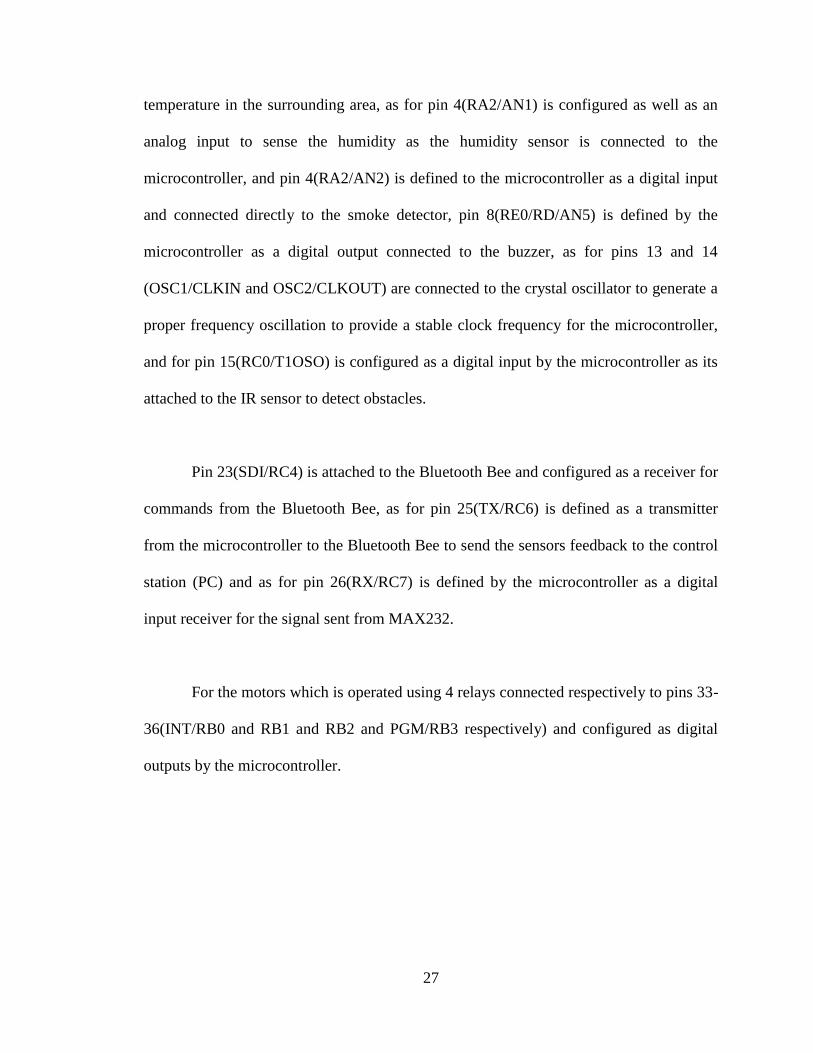
27
temperature in the surrounding area, as for pin 4(RA2/AN1) is configured as well as an
analog input to sense the humidity as the humidity sensor is connected to the
microcontroller, and pin 4(RA2/AN2) is defined to the microcontroller as a digital input
and connected directly to the smoke detector, pin 8(RE0/RD/AN5) is defined by the
microcontroller as a digital output connected to the buzzer, as for pins 13 and 14
(OSC1/CLKIN and OSC2/CLKOUT) are connected to the crystal oscillator to generate a
proper frequency oscillation to provide a stable clock frequency for the microcontroller,
and for pin 15(RC0/T1OSO) is configured as a digital input by the microcontroller as its
attached to the IR sensor to detect obstacles.
Pin 23(SDI/RC4) is attached to the Bluetooth Bee and configured as a receiver for
commands from the Bluetooth Bee, as for pin 25(TX/RC6) is defined as a transmitter
from the microcontroller to the Bluetooth Bee to send the sensors feedback to the control
station (PC) and as for pin 26(RX/RC7) is defined by the microcontroller as a digital
input receiver for the signal sent from MAX232.
For the motors which is operated using 4 relays connected respectively to pins 33-
36(INT/RB0 and RB1 and RB2 and PGM/RB3 respectively) and configured as digital
outputs by the microcontroller.
28
Figure 3.11: Main control circuit configuration
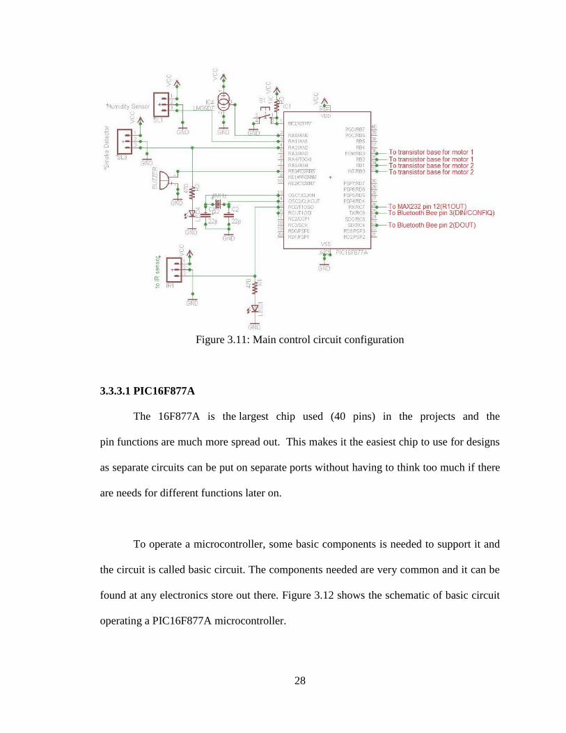
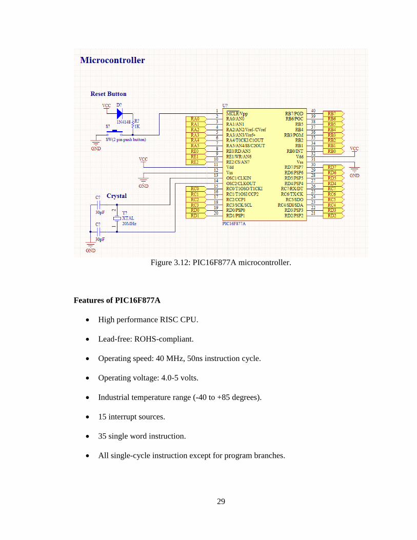
3.3.3.1 PIC16F877A
The 16F877A is the largest chip used (40 pins) in the projects and the
pin functions are much more spread out. This makes it the easiest chip to use for designs
as separate circuits can be put on separate ports without having to think too much if there
are needs for different functions later on.
To operate a microcontroller, some basic components is needed to support it and
the circuit is called basic circuit. The components needed are very common and it can be
found at any electronics store out there. Figure 3.12 shows the schematic of basic circuit
operating a PIC16F877A microcontroller.
29
Figure 3.12: PIC16F877A microcontroller.
Features of PIC16F877A
High performance RISC CPU.
Lead-free: ROHS-compliant.
Operating speed: 40 MHz, 50ns instruction cycle.
Operating voltage: 4.0-5 volts.
Industrial temperature range (-40 to +85 degrees).
15 interrupt sources.
35 single word instruction.
All single-cycle instruction except for program branches.
30
Analog Features
10-bit, 8-channel A/D converter.
Brown-out reset.
Analog comparable module.
The differences between PIC16F877A and PIC16F877:
Firstly, the masking is different in both the microcontrollers. Secondly, while
burning the code in PIC microcontroller there is an acknowledgment received for each
code word written in the PIC’s memory. In case of PIC16F877, the code word is written
one by one and hence there is no acknowledgment required for each code word written
and hence the speed of writing is reduced. Whereas in case of PIC16F877A the code
word is written in blocks and hence acknowledgment is required only for the block of the
code word and hence the speed of writing is more when compared to that of
PIC16F877A.
3.3.3.2 Sensors
A sensor is a device that measures a physical quantity and converts it into a signal
which can be read by an observer or by an instrument. Also the sensor responds to a
signal or stimulus. Here, the term stimulus means a property or a quantity that needs to be
converted into electrical form. Hence, sensor can be defined as a device which receives a
signal and converts it into electrical form which can be further used for electronic
devices. A sensor differs from a transducer in the way that a transducer converts one form
31
of energy into other form whereas a sensor converts the received signal into electrical
form only.
3.3.3.2.1 Temperature Sensor
In any electronic system from the all observation to the entire system the
important observation is the temperature. If the temperature exceed from the desired
value of the temperature it causes many problems one of them is the noise (thermal
noise). The noise is unwanted signal which is caused as mentioned from high temperature
especially if the type of the communication between the systems is wireless
communication all of this is without the other noise resources in the channel like the
electromagnetic waves that propagates in the air, because of that the crucial need to
receive the transmitted signal clear without any noise, but in practical life it doesn’t
exists. So this UGV system there must control on the system temperature to avoid the
noise also if the integrated circuits exceed from the allowed operating temperature it will
cause damage to the integrated circuit [13].
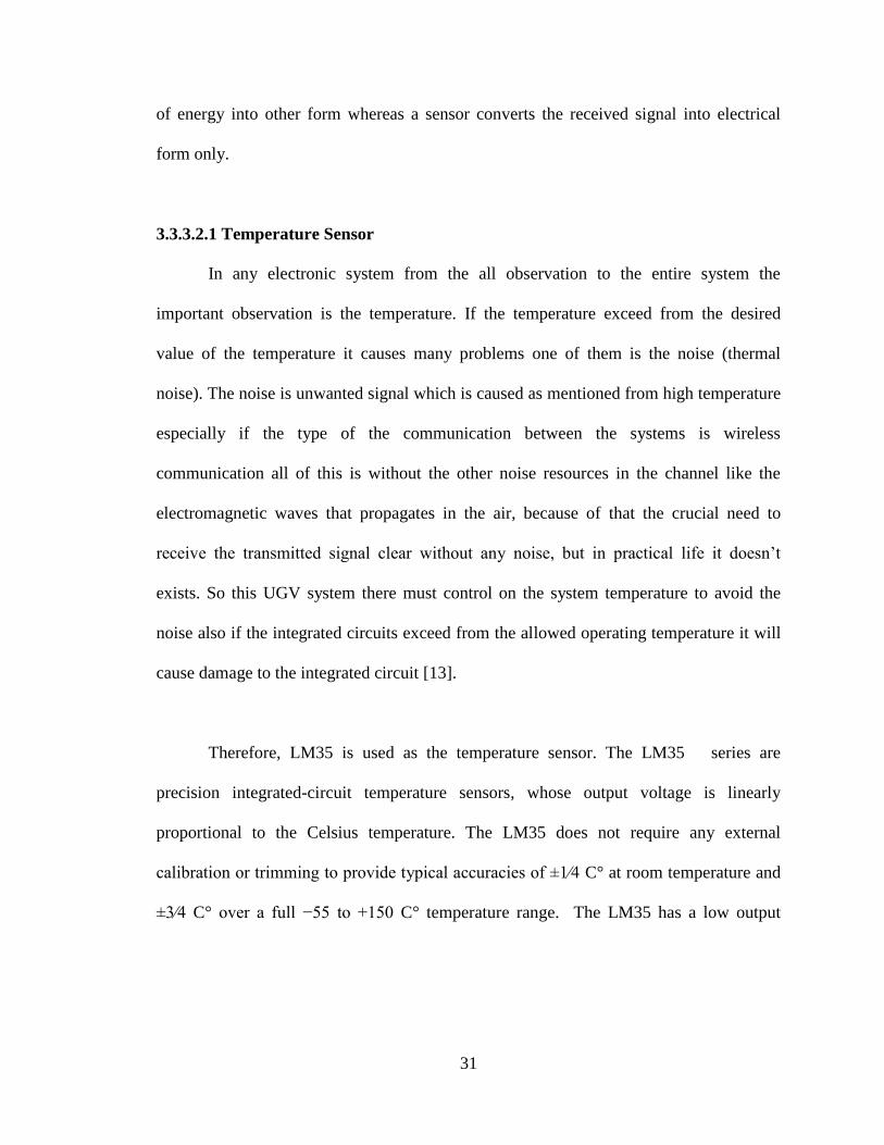
Therefore, LM35 is used as the temperature sensor. The LM35 series are
precision integrated-circuit temperature sensors, whose output voltage is linearly
proportional to the Celsius temperature. The LM35 does not require any external
calibration or trimming to provide typical accuracies of ±1⁄4 C° at room temperature and
±3⁄4 C° over a full −55 to +150 C° temperature range. The LM35 has a low output
32
impedance, linear output, and precise inherent calibration make interfacing to readout or
control circuitry especially easy. It can be used with single power supplies [13].
Figure 3.13:The LM35 temperature sensor.
Features of the LM35
Calibrated directly in ° Celsius (Centigrade)
Linear with the voltage
Rated for full −55° to +150°C range
Suitable for remote applications
Low cost
Operates from 4 to 30 volts
Less than 60 μA current
Low self-heating, 0.08°C in still air
Low impedance output, 0.1 W for 1 mA load
33
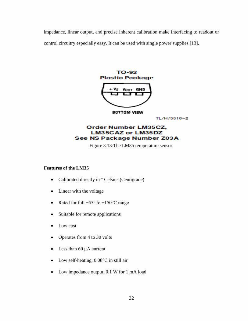
3.3.3.2.2 Humidity Sensor
Humidity sensor is a device consisting of a special plastic material whose
electrical characteristics change according to the amount of humidity in the air. Basically
it is a sensor that senses the amount of water vapor in air. The module of HSM-20G is
essential for those applications where the relative humidity can be converted to standard
voltage output.
The Applications Include:
Humidifiers & dehumidifiers.
Air-conditioner.
Humidity data loggers.
Automotive climate control.
Figure 3.14: Humidity sensor by cytron technologies.
34
The Humidity Sensor Features Include:
Voltage analog output for both humidity and temperature.
Small size makes it easy to conceal.
Compatible with all types of microcontrollers.
High sensitivity to humidity in the air.
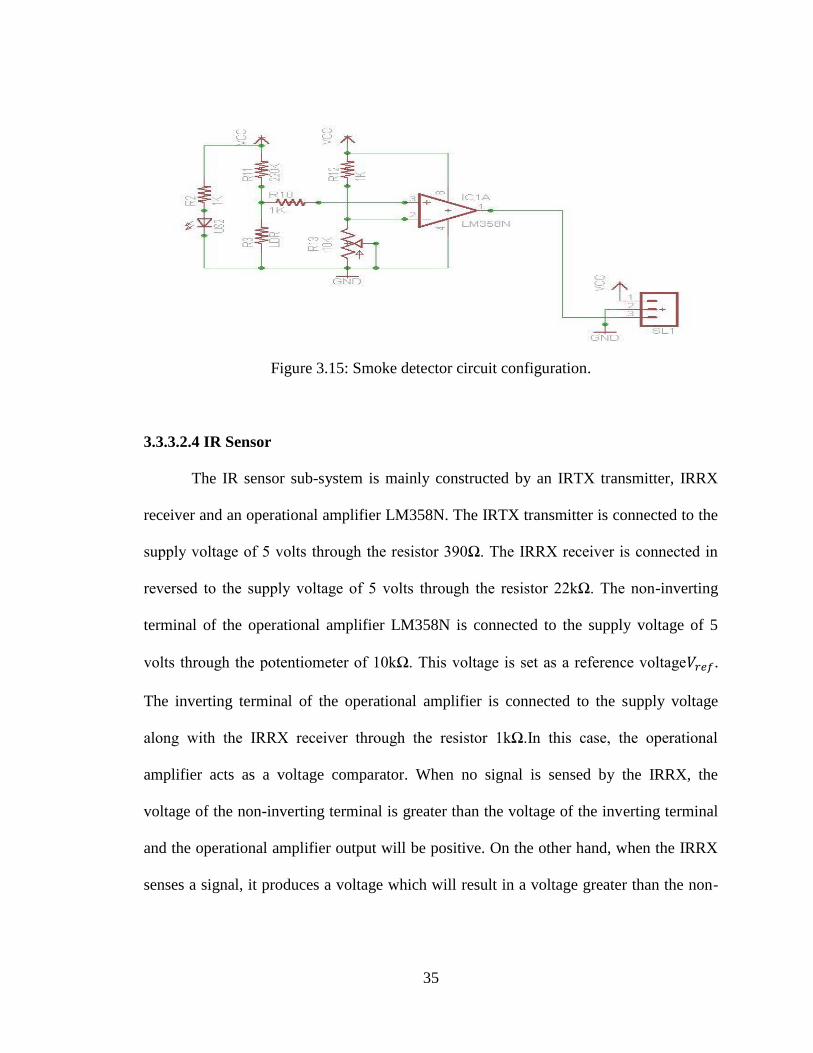
3.3.3.2.3 Smoke Detector
It provides information concerning the proper application of smoke detectors used
in conjunction with fire alarm systems. The guide outlines basic principles that should be
considered in the application of early warning fire and smoke detection devices. It
presents operating characteristics of detectors and environmental factors, which may aid,
delay, or prevent their operation [14].
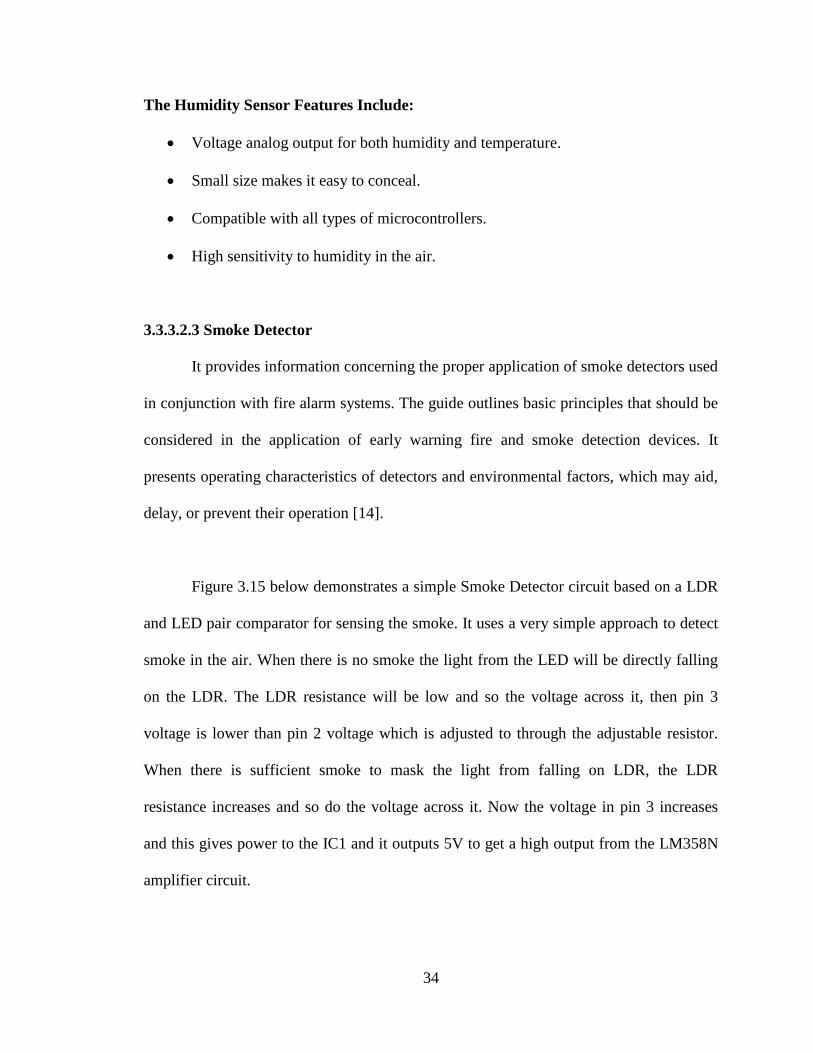
Figure 3.15 below demonstrates a simple Smoke Detector circuit based on a LDR
and LED pair comparator for sensing the smoke. It uses a very simple approach to detect
smoke in the air. When there is no smoke the light from the LED will be directly falling
on the LDR. The LDR resistance will be low and so the voltage across it, then pin 3
voltage is lower than pin 2 voltage which is adjusted to through the adjustable resistor.
When there is sufficient smoke to mask the light from falling on LDR, the LDR
resistance increases and so do the voltage across it. Now the voltage in pin 3 increases
and this gives power to the IC1 and it outputs 5V to get a high output from the LM358N
amplifier circuit.
35
Figure 3.15: Smoke detector circuit configuration.
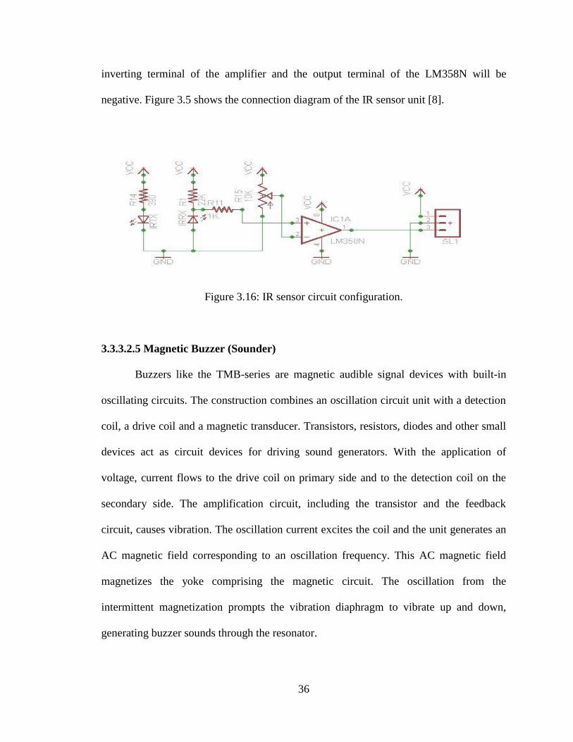
3.3.3.2.4 IR Sensor
The IR sensor sub-system is mainly constructed by an IRTX transmitter, IRRX
receiver and an operational amplifier LM358N. The IRTX transmitter is connected to the
supply voltage of 5 volts through the resistor 390Ω. The IRRX receiver is connected in
reversed to the supply voltage of 5 volts through the resistor 22kΩ. The non-inverting
terminal of the operational amplifier LM358N is connected to the supply voltage of 5
volts through the potentiometer of 10kΩ. This voltage is set as a reference voltage .
The inverting terminal of the operational amplifier is connected to the supply voltage
along with the IRRX receiver through the resistor 1kΩ.In this case, the operational
amplifier acts as a voltage comparator. When no signal is sensed by the IRRX, the
voltage of the non-inverting terminal is greater than the voltage of the inverting terminal
and the operational amplifier output will be positive. On the other hand, when the IRRX
senses a signal, it produces a voltage which will result in a voltage greater than the non-
36
inverting terminal of the amplifier and the output terminal of the LM358N will be
negative. Figure 3.5 shows the connection diagram of the IR sensor unit [8].
Figure 3.16: IR sensor circuit configuration.
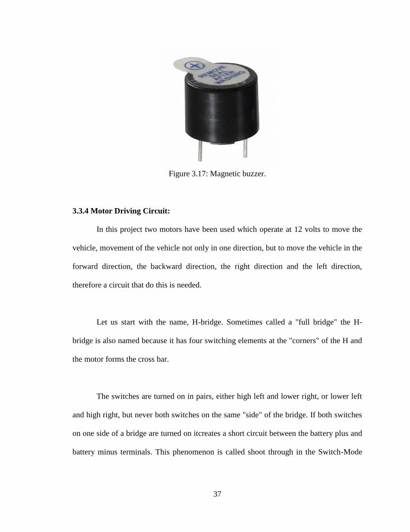
3.3.3.2.5 Magnetic Buzzer (Sounder)
Buzzers like the TMB-series are magnetic audible signal devices with built-in
oscillating circuits. The construction combines an oscillation circuit unit with a detection
coil, a drive coil and a magnetic transducer. Transistors, resistors, diodes and other small
devices act as circuit devices for driving sound generators. With the application of
voltage, current flows to the drive coil on primary side and to the detection coil on the
secondary side. The amplification circuit, including the transistor and the feedback
circuit, causes vibration. The oscillation current excites the coil and the unit generates an
AC magnetic field corresponding to an oscillation frequency. This AC magnetic field
magnetizes the yoke comprising the magnetic circuit. The oscillation from the
intermittent magnetization prompts the vibration diaphragm to vibrate up and down,
generating buzzer sounds through the resonator.
37
Figure 3.17: Magnetic buzzer.
3.3.4 Motor Driving Circuit:
In this project two motors have been used which operate at 12 volts to move the
vehicle, movement of the vehicle not only in one direction, but to move the vehicle in the
forward direction, the backward direction, the right direction and the left direction,
therefore a circuit that do this is needed.
Let us start with the name, H-bridge. Sometimes called a "full bridge" the H-
bridge is also named because it has four switching elements at the "corners" of the H and
the motor forms the cross bar.
The switches are turned on in pairs, either high left and lower right, or lower left
and high right, but never both switches on the same "side" of the bridge. If both switches
on one side of a bridge are turned on itcreates a short circuit between the battery plus and
battery minus terminals. This phenomenon is called shoot through in the Switch-Mode
38
Power Supply (SMPS) literature. If the bridge is sufficiently powerful it will absorb that
load and the batteries will simply drain quickly. Usually however the switches in question
melt [9].
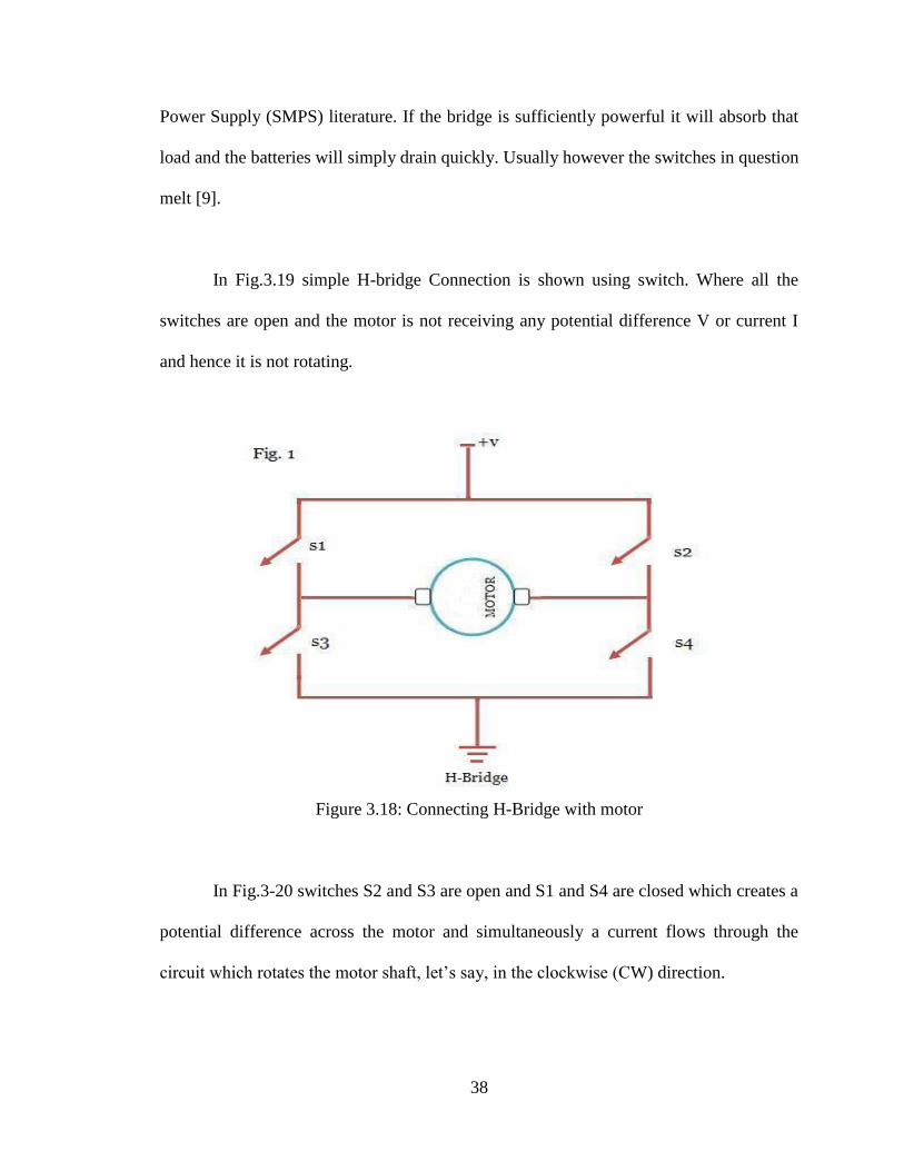
In Fig.3.19 simple H-bridge Connection is shown using switch. Where all the
switches are open and the motor is not receiving any potential difference V or current I
and hence it is not rotating.
Figure 3.18: Connecting H-Bridge with motor
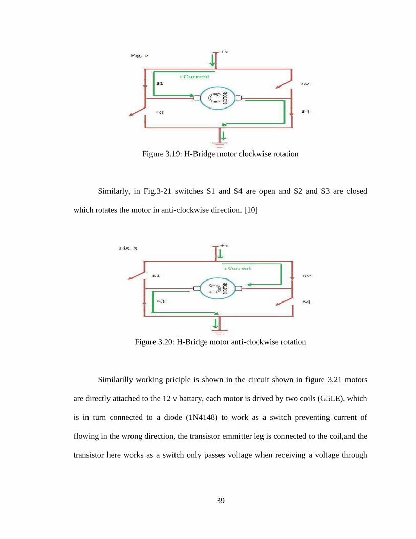
In Fig.3-20 switches S2 and S3 are open and S1 and S4 are closed which creates a
potential difference across the motor and simultaneously a current flows through the
circuit which rotates the motor shaft, let’s say, in the clockwise (CW) direction.
39
Figure 3.19: H-Bridge motor clockwise rotation
Similarly, in Fig.3-21 switches S1 and S4 are open and S2 and S3 are closed
which rotates the motor in anti-clockwise direction. [10]
Figure 3.20: H-Bridge motor anti-clockwise rotation
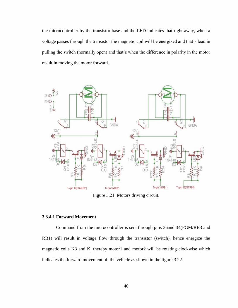
Similarilly working priciple is shown in the circuit shown in figure 3.21 motors
are directly attached to the 12 v battary, each motor is drived by two coils (G5LE), which
is in turn connected to a diode (1N4148) to work as a switch preventing current of
flowing in the wrong direction, the transistor emmitter leg is connected to the coil,and the
transistor here works as a switch only passes voltage when receiving a voltage through
40
the microcontroller by the transistor base and the LED indicates that right away, when a
voltage passes through the transistor the magnetic coil will be energized and that’s lead in
pulling the switch (normally open) and that’s when the difference in polarity in the motor
result in moving the motor forward.
Figure 3.21: Motors driving circuit.
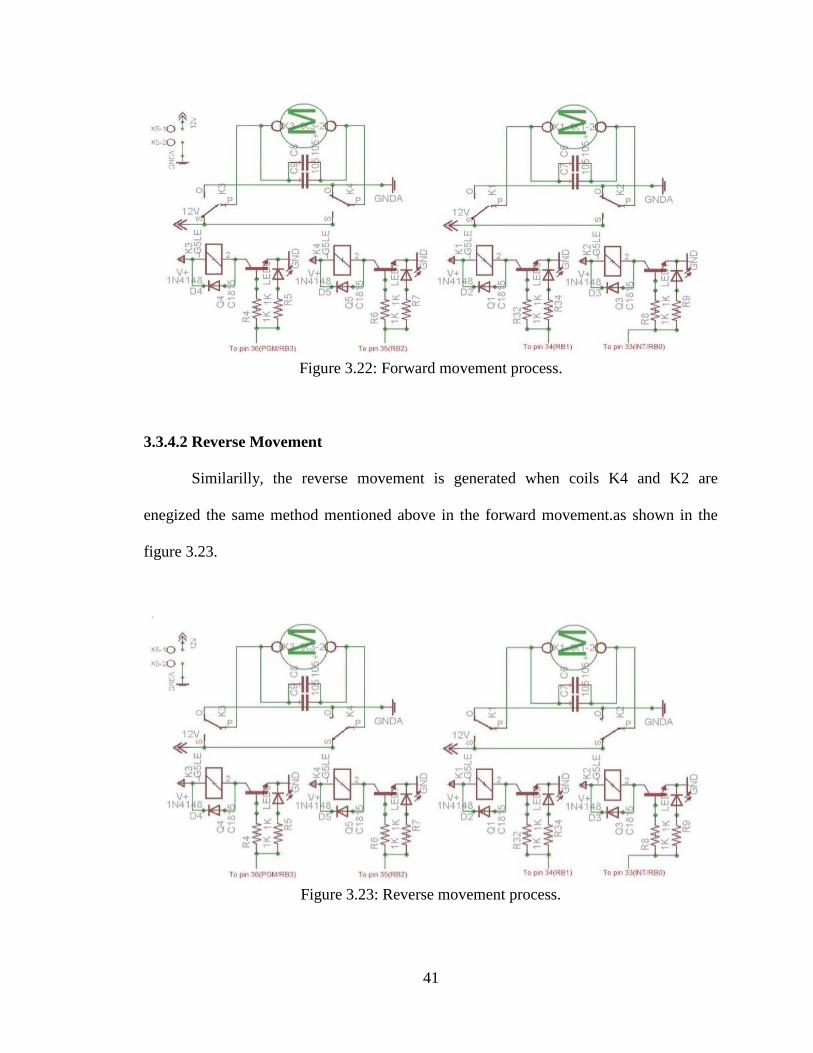
3.3.4.1 Forward Movement
Command from the microcontroller is sent through pins 36and 34(PGM/RB3 and
RB1) will result in voltage flow through the transistor (switch), hence energize the
magnetic coils K3 and K, thereby motor1 and motor2 will be rotating clockwise which
indicates the forward movement of the vehicle.as shown in the figure 3.22.
41
Figure 3.22: Forward movement process.
3.3.4.2 Reverse Movement
Similarilly, the reverse movement is generated when coils K4 and K2 are
enegized the same method mentioned above in the forward movement.as shown in the
figure 3.23.
Figure 3.23: Reverse movement process.
42
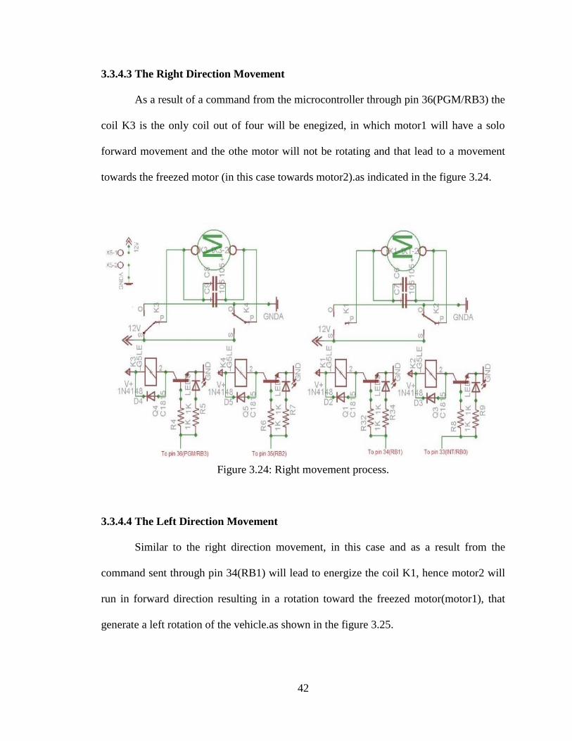
3.3.4.3 The Right Direction Movement
As a result of a command from the microcontroller through pin 36(PGM/RB3) the
coil K3 is the only coil out of four will be enegized, in which motor1 will have a solo
forward movement and the othe motor will not be rotating and that lead to a movement
towards the freezed motor (in this case towards motor2).as indicated in the figure 3.24.
Figure 3.24: Right movement process.
3.3.4.4 The Left Direction Movement
Similar to the right direction movement, in this case and as a result from the
command sent through pin 34(RB1) will lead to energize the coil K1, hence motor2 will
run in forward direction resulting in a rotation toward the freezed motor(motor1), that
generate a left rotation of the vehicle.as shown in the figure 3.25.
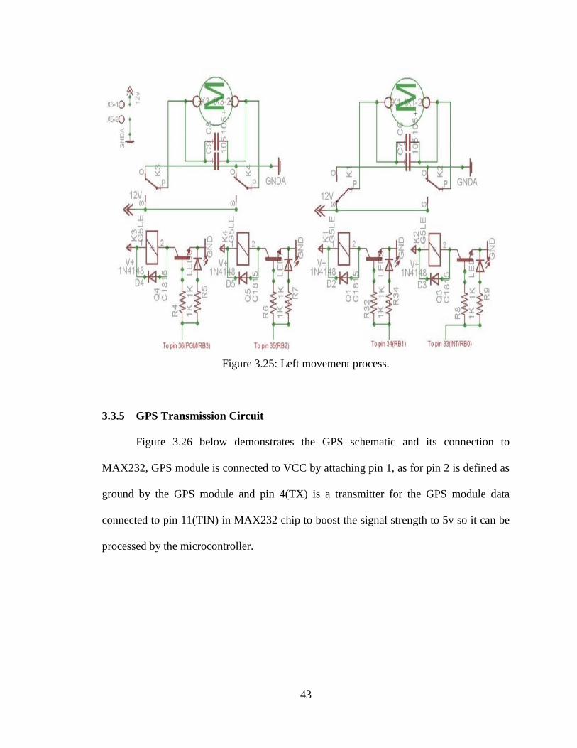
43
Figure 3.25: Left movement process.
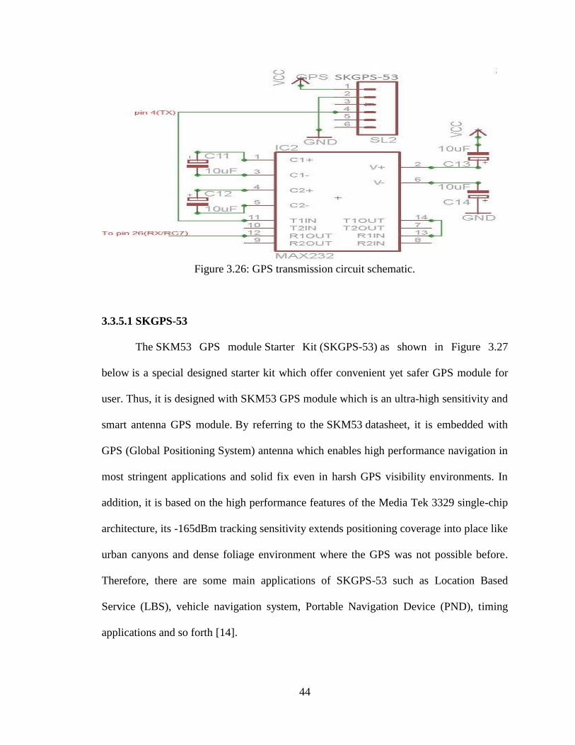
3.3.5 GPS Transmission Circuit
Figure 3.26 below demonstrates the GPS schematic and its connection to
MAX232, GPS module is connected to VCC by attaching pin 1, as for pin 2 is defined as
ground by the GPS module and pin 4(TX) is a transmitter for the GPS module data
connected to pin 11(TIN) in MAX232 chip to boost the signal strength to 5v so it can be
processed by the microcontroller.
44
Figure 3.26: GPS transmission circuit schematic.
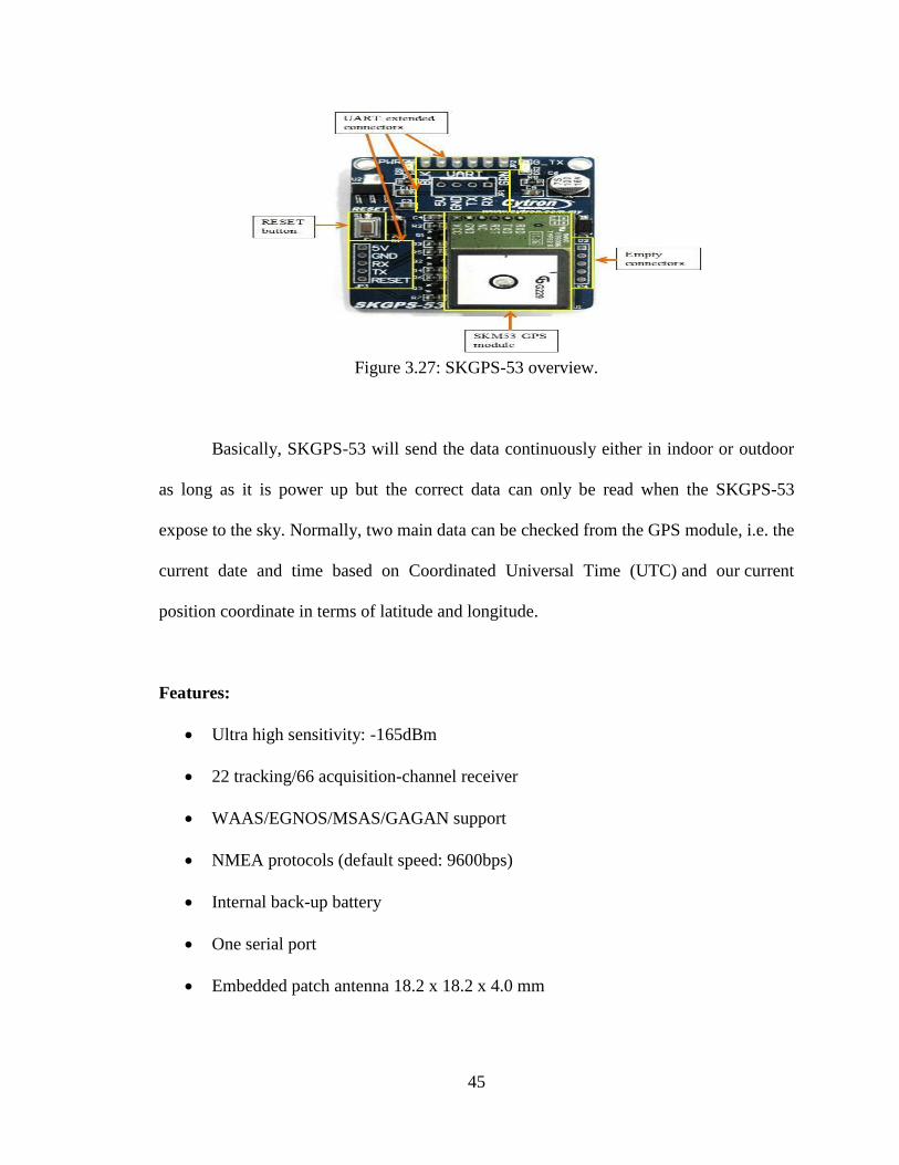
3.3.5.1 SKGPS-53
The SKM53 GPS module Starter Kit (SKGPS-53) as shown in Figure 3.27
below is a special designed starter kit which offer convenient yet safer GPS module for
user. Thus, it is designed with SKM53 GPS module which is an ultra-high sensitivity and
smart antenna GPS module. By referring to the SKM53 datasheet, it is embedded with
GPS (Global Positioning System) antenna which enables high performance navigation in
most stringent applications and solid fix even in harsh GPS visibility environments. In
addition, it is based on the high performance features of the Media Tek 3329 single-chip
architecture, its -165dBm tracking sensitivity extends positioning coverage into place like
urban canyons and dense foliage environment where the GPS was not possible before.
Therefore, there are some main applications of SKGPS-53 such as Location Based
Service (LBS), vehicle navigation system, Portable Navigation Device (PND), timing
applications and so forth [14].
45
Figure 3.27: SKGPS-53 overview.
Basically, SKGPS-53 will send the data continuously either in indoor or outdoor
as long as it is power up but the correct data can only be read when the SKGPS-53
expose to the sky. Normally, two main data can be checked from the GPS module, i.e. the
current date and time based on Coordinated Universal Time (UTC) and our current
position coordinate in terms of latitude and longitude.
Features:
Ultra high sensitivity: -165dBm
22 tracking/66 acquisition-channel receiver
WAAS/EGNOS/MSAS/GAGAN support
NMEA protocols (default speed: 9600bps)
Internal back-up battery
One serial port
Embedded patch antenna 18.2 x 18.2 x 4.0 mm
46
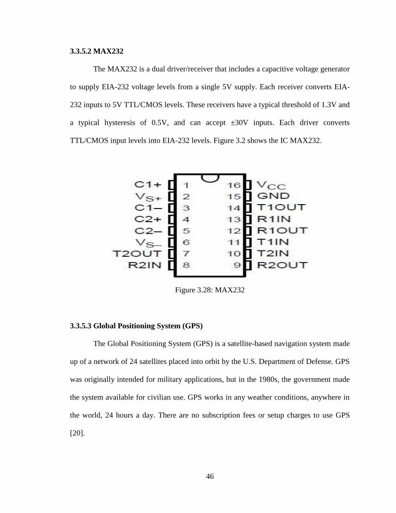
3.3.5.2 MAX232
The MAX232 is a dual driver/receiver that includes a capacitive voltage generator
to supply EIA-232 voltage levels from a single 5V supply. Each receiver converts EIA-
232 inputs to 5V TTL/CMOS levels. These receivers have a typical threshold of 1.3V and
a typical hysteresis of 0.5V, and can accept ±30V inputs. Each driver converts
TTL/CMOS input levels into EIA-232 levels. Figure 3.2 shows the IC MAX232.
Figure 3.28: MAX232
3.3.5.3 Global Positioning System (GPS)
The Global Positioning System (GPS) is a satellite-based navigation system made
up of a network of 24 satellites placed into orbit by the U.S. Department of Defense. GPS
was originally intended for military applications, but in the 1980s, the government made
the system available for civilian use. GPS works in any weather conditions, anywhere in
the world, 24 hours a day. There are no subscription fees or setup charges to use GPS
[20].
47
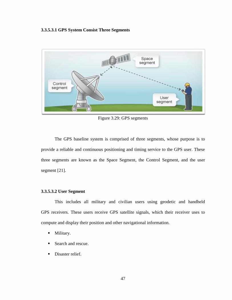
3.3.5.3.1 GPS System Consist Three Segments
Figure 3.29: GPS segments
The GPS baseline system is comprised of three segments, whose purpose is to
provide a reliable and continuous positioning and timing service to the GPS user. These
three segments are known as the Space Segment, the Control Segment, and the user
segment [21].
3.3.5.3.2 User Segment
This includes all military and civilian users using geodetic and handheld
GPS receivers. These users receive GPS satellite signals, which their receiver uses to
compute and display their position and other navigational information.
Military.
Search and rescue.
Disaster relief.
48
Surveying.
Marine
Remote controlled vehicle and robot guidance.
Satellite positioning and tracking.
Shipping.
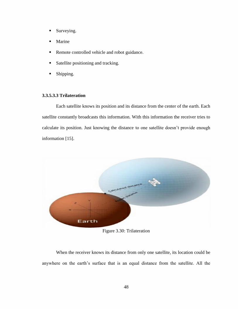
3.3.5.3.3 Trilateration
Each satellite knows its position and its distance from the center of the earth. Each
satellite constantly broadcasts this information. With this information the receiver tries to
calculate its position. Just knowing the distance to one satellite doesn’t provide enough
information [15].
Figure 3.30: Trilateration
When the receiver knows its distance from only one satellite, its location could be
anywhere on the earth’s surface that is an equal distance from the satellite. All the
49
receiver can determine is that it is somewhere on the perimeter of a circle that is an equal
distance from the satellite .The receiver must have additional information.
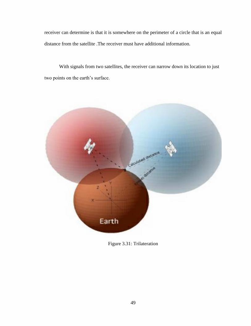
With signals from two satellites, the receiver can narrow down its location to just
two points on the earth’s surface.
Figure 3.31: Trilateration
50
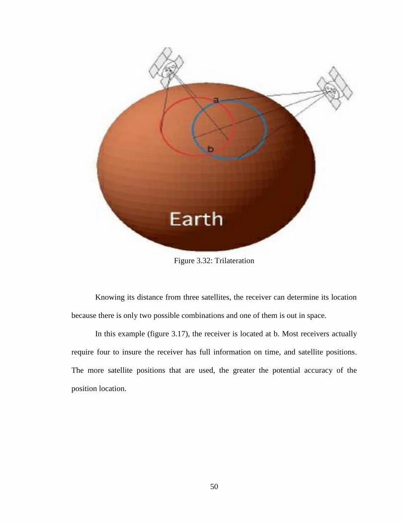
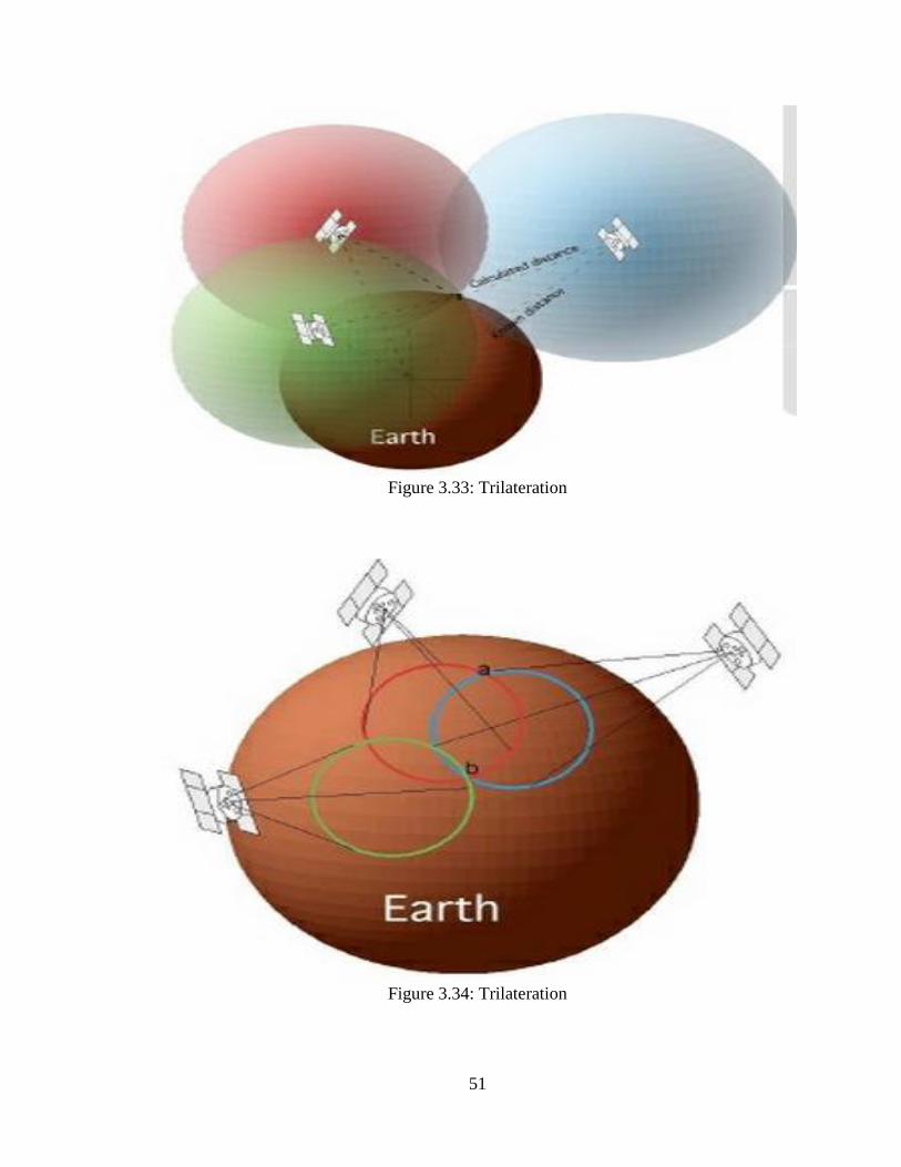
Figure 3.32: Trilateration
Knowing its distance from three satellites, the receiver can determine its location
because there is only two possible combinations and one of them is out in space.
In this example (figure 3.17), the receiver is located at b. Most receivers actually
require four to insure the receiver has full information on time, and satellite positions.
The more satellite positions that are used, the greater the potential accuracy of the
position location.
51
Figure 3.33: Trilateration
Figure 3.34: Trilateration
52
The GPS system operates on the principles of trilateration, determining positions
from distance measurements. This can be explained using the velocity equation.
Velocity =Distance /Time
Rearranging the equation for distance:
Distance=Velocity x Time
If the system knows the velocity of a signal and the time it takes for the signal to
travel from the sender to the receiver, the distance between the sender and the receiver
can be determined [14].
3.3.6 Bluetooth Transmission Circuit
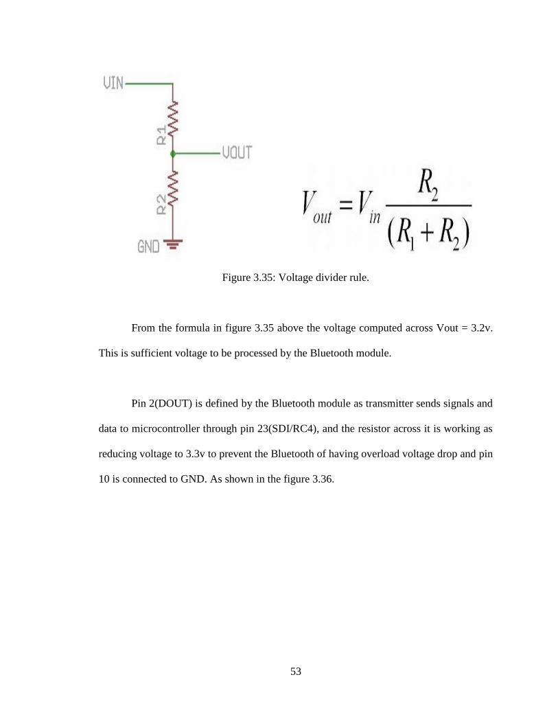
This Bluetooth module operating with 3.3v supplied by the voltage regulator
(LM1117), pin one is connected to the power source 3.3v, as for pin 3(DIN/CONFIG) is
the receiver that receives signals from the microcontroller sent through pin 25(TX/RC6)
and the two resistors reduces the voltage drop to 3.3v by using voltage divider rule across
R17 as follow:
53
Figure 3.35: Voltage divider rule.
From the formula in figure 3.35 above the voltage computed across Vout = 3.2v.
This is sufficient voltage to be processed by the Bluetooth module.
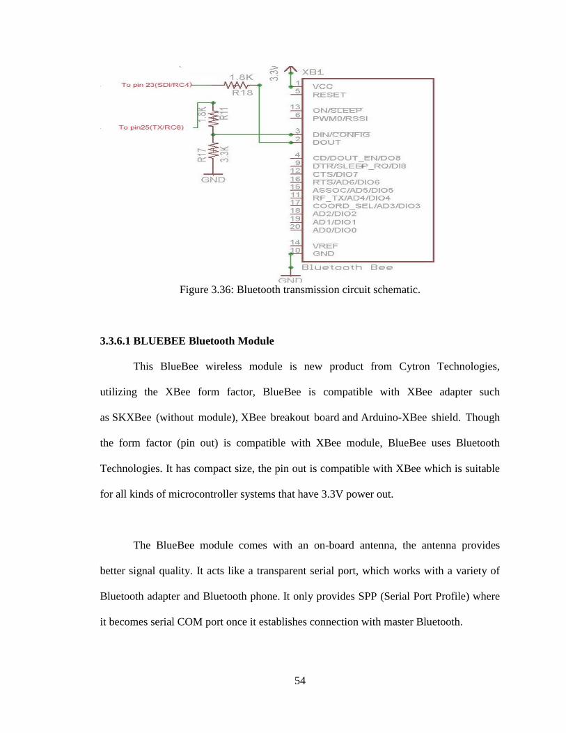
Pin 2(DOUT) is defined by the Bluetooth module as transmitter sends signals and
data to microcontroller through pin 23(SDI/RC4), and the resistor across it is working as
reducing voltage to 3.3v to prevent the Bluetooth of having overload voltage drop and pin
10 is connected to GND. As shown in the figure 3.36.
54
Figure 3.36: Bluetooth transmission circuit schematic.
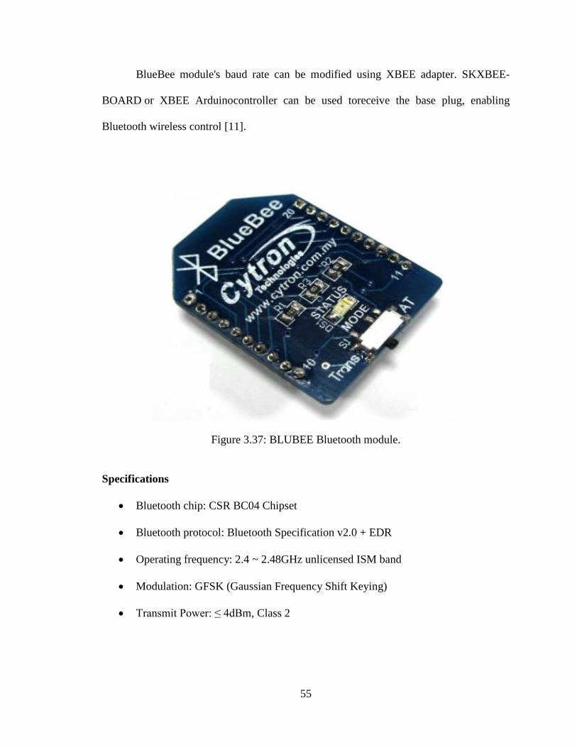
3.3.6.1 BLUEBEE Bluetooth Module
This BlueBee wireless module is new product from Cytron Technologies,
utilizing the XBee form factor, BlueBee is compatible with XBee adapter such
as SKXBee (without module), XBee breakout board and Arduino-XBee shield. Though
the form factor (pin out) is compatible with XBee module, BlueBee uses Bluetooth
Technologies. It has compact size, the pin out is compatible with XBee which is suitable
for all kinds of microcontroller systems that have 3.3V power out.
The BlueBee module comes with an on-board antenna, the antenna provides
better signal quality. It acts like a transparent serial port, which works with a variety of
Bluetooth adapter and Bluetooth phone. It only provides SPP (Serial Port Profile) where
it becomes serial COM port once it establishes connection with master Bluetooth.
55
BlueBee module's baud rate can be modified using XBEE adapter. SKXBEE-
BOARD or XBEE Arduinocontroller can be used toreceive the base plug, enabling
Bluetooth wireless control [11].
Figure 3.37: BLUBEE Bluetooth module.
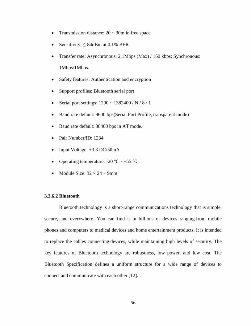
Specifications
Bluetooth chip: CSR BC04 Chipset
Bluetooth protocol: Bluetooth Specification v2.0 + EDR
Operating frequency: 2.4 ~ 2.48GHz unlicensed ISM band
Modulation: GFSK (Gaussian Frequency Shift Keying)
Transmit Power: ≤ 4dBm, Class 2
56
Transmission distance: 20 ~ 30m in free space
Sensitivity: ≤-84dBm at 0.1% BER
Transfer rate: Asynchronous: 2.1Mbps (Max) / 160 kbps; Synchronous:
1Mbps/1Mbps.
Safety features: Authentication and encryption
Support profiles: Bluetooth serial port
Serial port settings: 1200 ~ 1382400 / N / 8 / 1
Baud rate default: 9600 bps(Serial Port Profile, transparent mode)
Baud rate default: 38400 bps in AT mode.
Pair Number/ID: 1234
Input Voltage: +3.3 DC/50mA
Operating temperature: -20 ~ +55
Module Size: 32 × 24 × 9mm
3.3.6.2 Bluetooth
Bluetooth technology is a short-range communications technology that is simple,
secure, and everywhere. You can find it in billions of devices ranging from mobile
phones and computers to medical devices and home entertainment products. It is intended
to replace the cables connecting devices, while maintaining high levels of security. The
key features of Bluetooth technology are robustness, low power, and low cost. The
Bluetooth Specification defines a uniform structure for a wide range of devices to
connect and communicate with each other [12].
57
When two Bluetooth enabled devices connect to each other, this is called pairing.
The structure and the global acceptance of Bluetooth technology means any Bluetooth
enabled device, almost everywhere in the world, can connect to other Bluetooth enabled
devices located in proximity to one another.
A fundamental strength of Bluetooth wireless technology is the ability to
simultaneously handle data and voice transmissions. which provides users with a variety
of innovative solutions such as hands-free headsets for voice calls, printing and fax
capabilities, and synchronization for PCs and mobile phones, just to name a few.
The range of Bluetooth technology is application specific. The Core Specification
mandates a minimum range of 10 meters, but there is no set limit and manufacturers can
tune their implementations to provide the range needed to support the use cases for their
solutions [13].
Principle Operation of Bluetooth
Bluetooth networking transmits data via low-power radio waves. It communicates
on a frequency of 2.45GHz (actually between 2.402 GHz and 2.480 GHz, to be exact).
This frequency band has been set aside by international agreement for the use of
industrial, scientific and medical devices (ISM).
58
A number of devices that you may already use take advantage of this same radio-
frequency band. Baby monitors, garage-door openers and the newest generation of
cordless phones all make use of frequencies in the ISM band. Making sure that Bluetooth
and these other devices don't interfere with one another has been a crucial part of the
design process [16].
One of the ways Bluetooth devices avoid interfering with other systems is by
sending out very weak signals of about 1 mill watt. By comparison, the most powerful
cell phones can transmit a signal of 3 watts. The low power limits the range of a
Bluetooth device to about 10 meters (32 feet), cutting the chances of interference between
your computer system and your portable telephone or television. Even with the low
power, Bluetooth doesn't require line of sight between communicating devices. The walls
in the house won't stop a Bluetooth signal, making the standard useful for controlling
several devices in different rooms.
Bluetooth can connect up to eight devices simultaneously. With all of those
devices in the same 10-meter (32-foot) radius, you might think they'd interfere with one
another, but it's unlikely. Bluetooth uses a technique called spread-spectrum frequency
hopping that makes it rare for more than one device to be transmitting on the same
frequency at the same time. In this technique, a device will use 79 individual, randomly
chosen frequencies within a designated range, changing from one to another on a regular
basis. In the case of Bluetooth, the transmitters change frequencies 1,600 times every
59
second, meaning that more devices can make full use of a limited slice of the radio
spectrum. Since every Bluetooth transmitter uses spread-spectrum transmitting
automatically, it’s unlikely that two transmitters will be on the same frequency at the
same time. This same technique minimizes the risk that portable phones or baby monitors
will disrupt Bluetooth devices, since any interference on a particular frequency will last
only a tiny fraction of a second. [13]
Knowing that an ad hoc network consists of multiple wireless devices that
communicate with each other, without a central controlling device. This is basically the
method used by Bluetooth, but usually a controlling Access Point is used to coordinate
communications between members of the wireless network. To put it quite simply, an ad
hoc network consists of multiple wireless devices that communicate with each other. In
the case of Bluetooth, there is no dedicated Access Point to control data transmissions.
Instead, the first Bluetooth device that initiates a transmission becomes a temporary
master of the small network, and other devices are slaves that receive permission to
transmit or receive from this master. The master is not a dedicated device like an Access
Point [15].
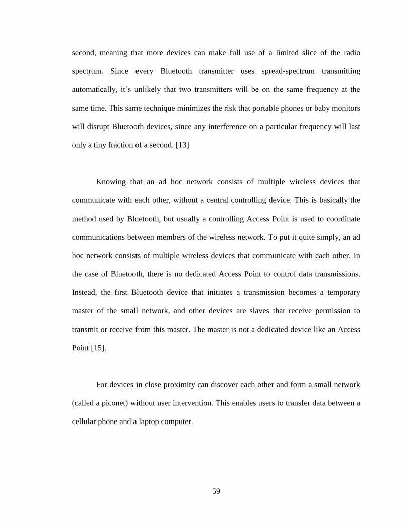
For devices in close proximity can discover each other and form a small network
(called a piconet) without user intervention. This enables users to transfer data between a
cellular phone and a laptop computer.
60
3.3.6.2.1 Piconets
When Bluetooth-capable devices come within range of one another, an electronic
conversation takes place to determine whether they have data to share or whether one
needs to control the other. The user doesn't have to press a button or give a command, the
electronic conversation happens automatically. Once the conversation has occurred, the
devices, whether they're part of a computer system or a stereo form a network. Bluetooth
systems create a personal area network (PAN), or piconet, a piconetis formed when two
or more devices discover each other and begin to communicate. A piconet can have up to
eight devices, with one device acting as a master and the rest acting as slaves. The first
device to initiate transmission becomes the master, although the specification provides
for a master and slave unit to exchange roles. A specific frequency hopping sequence is
used by all devices within each piconet.
Figure 3.38: How Bluetooth Operates
As stated earlier, a single piconet can have up to eight devices. The reason for this
limit is simple: The address is only 3 bits long. This means that in binary, only the values
of 07 can be stored in the address field. The master has no address, but 0 is reserved for
61
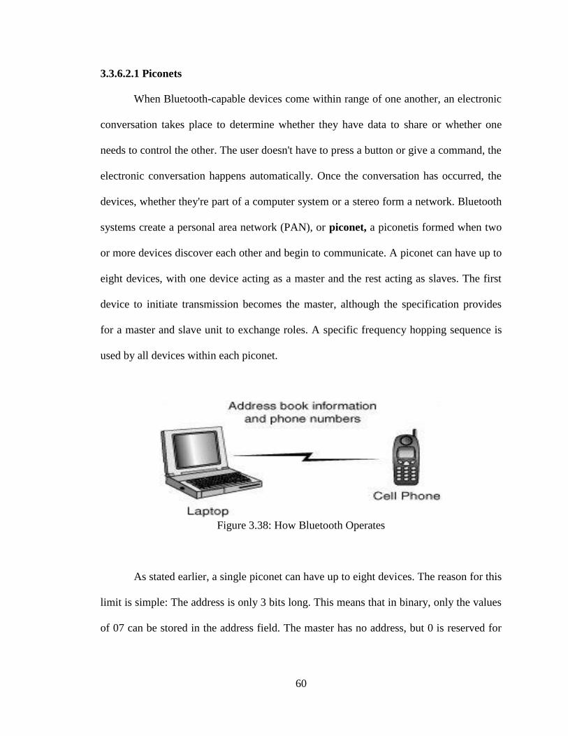
broadcast messages, so the only addresses remaining for use by slaves are 7. However, a
device can participate in two different piconets (called a scatternet).
.
Figure 3.39: Piconet
Obviously it's possible to link various devices in a piconet. digital images can be
downloaded from a digital camera to the laptop, use more than one Bluetooth enabled
cell phone to place voice calls, and even connect a personal digital assistant (PDA) to the
laptop to exchange information.
3.3.6.2.2 Scatternets
A device can be a master of only one piconet. The device can, at the same time,
also be a slave in another piconet that is within range. A slave can also participate in two
different piconets that are within its range. However, because the master device
determines the hopping pattern used for a piconet, a device cannot be a master of more
62
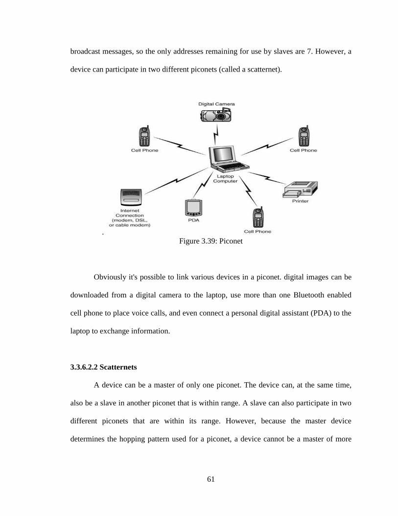
than one piconet. Figure 3.40. A scatternet is formed when a device is a member of more
than one piconet.
Figure 3.40: Scatternet
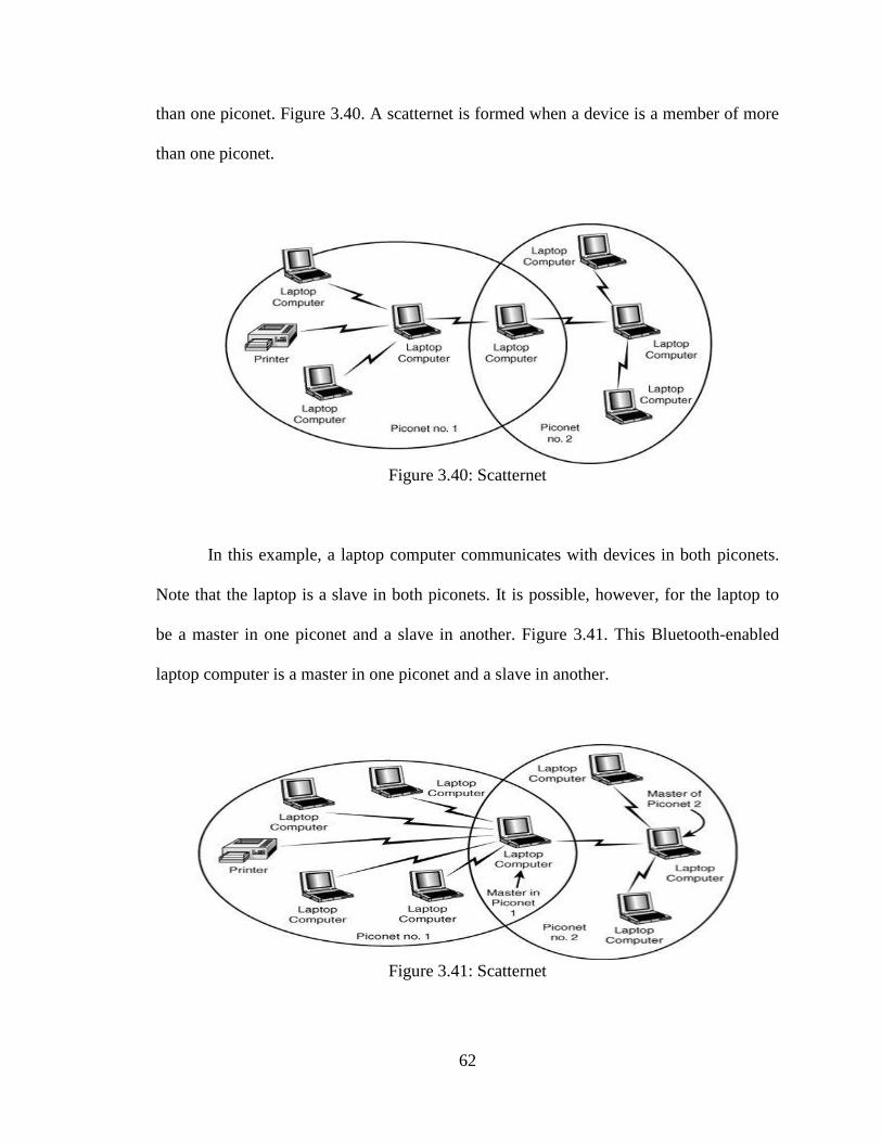
In this example, a laptop computer communicates with devices in both piconets.
Note that the laptop is a slave in both piconets. It is possible, however, for the laptop to
be a master in one piconet and a slave in another. Figure 3.41. This Bluetooth-enabled
laptop computer is a master in one piconet and a slave in another.
Figure 3.41: Scatternet
63
When a device is a member of two piconets, it keeps track of both frequency
hopping patterns and occasionally listens in on the correct frequency on each of the two
piconets so that it can stay in touch with both piconets. A master device transmits a
packet to its slaves occasionally to maintain the link, based on negotiations between the
master and its slave devices. Thus, a device that is a member of two piconets must listen
for these transmissions (or make them if it's the master in one piconet) within the
timeframe negotiated for each of the piconets of which it is a member [13].
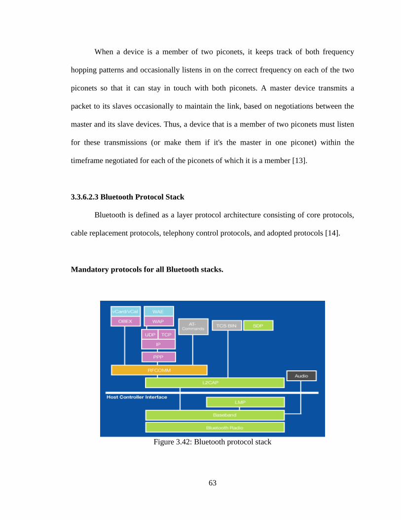
3.3.6.2.3 Bluetooth Protocol Stack
Bluetooth is defined as a layer protocol architecture consisting of core protocols,
cable replacement protocols, telephony control protocols, and adopted protocols [14].
Mandatory protocols for all Bluetooth stacks.
Figure 3.42: Bluetooth protocol stack
64
3.3.6.2.3.1 Radio Layer
When looking at the different layers of the Bluetooth protocol stack, The radio
layer will always be first. Everything in Bluetooth runs over the Radio Layer, which
defines the requirements for a Bluetooth radio transceiver.
3.3.6.2.3.2 Transmitter
Operates in the 2.4 GHz unlicensed ISM band.
Nominal output power = 0 dBm (1 mW).
GFSK modulation: BT=0.5, 0.28 < m < 0.35.
3.3.6.2.3.3 Receiver
The radio layer defines the sensitivity levels of the transceiver, establishes the
requirements for using Spread-spectrum Frequency Hopping and classifies Bluetooth
devices into three different power classes:
Power Class 1 – long rang devices (100m).
Power Class 2 – normal or standard range devices (10m).
Power Class 3 – short (10cm)-range operation.
3.3.6.2.3.4 Baseband Layer
The next floor in the Bluetooth protocol stack is the Baseband Layer, which is the
physical layer of the Bluetooth. It is used as a link controller, which works with the link
manager to carry out routines like creating link connections with other devices. It controls
65
device addressing, channel control (how devices find each other) Symbol rate = 1 Ms/s.
Slotted channel with slot time = 625 ms. Time-division duplex (TDD) for full duplex.
There are two types of links between master and slaves:
Synchronous connection oriented (SCO).
SCO is a point to point link.
Asynchronous connection less (ACL).
ACL is a packet switched link between master and all slaves in the piconet.
3.3.6.2.3.5 Link Manager Protocol (LMP)
A Bluetooth device’s Link Manager Protocol (LM) carries out link setup,
authentication, link configuration and other protocols. It discovers other LMs within the
area and communicates with them via the Link Manager Protocol (LMP).
3.3.6.2.3.6 Host Controller Interface (HCI)
Next in the protocol stack, above the LMP is the Host Controller Interface (HCI),
which is there to allow command line access to the Baseband Layer and LMP for control
and to receive status information. It’s made up of three parts:
The HCI firmware, which is part of the actual Bluetooth hardware,
The HCI driver, which is found in the software of the Bluetooth device
The Host Controller Transport Layer, which connects the firmware to the driver.
66
3.3.6.2.3.7 Logical Link Control and Adaptation Protocol (L2CAP)
Above the HCI level is the Logical Link Control and Adaptation Protocol
(L2CAP), which provides data services to the upper level host protocols. The L2CAP
plugs into the Baseband Layer and is located in the data link layer, rather than riding
directly over LMP. It provides connection-oriented and connectionless data services to
upper layer protocols.
Protocol types are first identified in the L2CAP. Data services are provided here
using protocol multiplexing, segmentation and reassembly operation, and group
abstractions occur. L2CAP allows higher-level protocols and applications to send and
receive data packets up to 64 kilobytes. The L2CAP spends a lot of its time handling
segmentation and reassembly tasks.
3.3.6.2.3.8 RF Communication
Above L2CAP, the RFCOMM protocol is what actually makes upper layer
protocols think they’re communicating over a RS232 wired serial interface, so there’s no
need for applications to know anything about Bluetooth.
3.3.6.2.3.9 Service Discovery Protocol (SDP)
Also relying on L2CAP is the Service Discovery Protocol (SDP). The SDP
provides a way for applications to detect which services are available and to determine
the characteristics of those services.
67
3.3.6.2.3.10 Adopted Protocols
Adopted protocols are defined by other standards-making organizations and
incorporated into Bluetooth’s protocol stack, allowing Bluetooth to create protocols only
when necessary. The adopted protocols include:
3.3.6.2.3.10.1 Point-to-Point Protocol (PPP)
Internet standard protocol for transporting IP datagram over a point-to-point link.
3.3.6.2.3.10.2 TCP/IP/UDP
Foundation Protocols for TCP/IP protocol suite
3.3.6.2.3.10.3 Object Exchange Protocol (OBEX)
Session-layer protocol for the exchange of objects, providing a model for object
and operation representation
3.3.6.2.3.10.4 Wireless Application Environment/Wireless Application Protocol
(WAE/WAP)
WAE specifies an application framework for wireless devices and WAP is an
open standard to provide mobile users access to telephony and information services. [28]
68
3.3.6.3 Advantages of Bluetooth
Bluetooth does not require a clear line of sight between the synced devices. This
means that the devices need not be facing each other, and it is also possible to carry out
transfers when both the devices are in separate rooms.
The fact that this technology requires no cables and wires is something that has
made it so popular. With so many devices engulfing our lives today, the need for clutter-
free technology is becoming more intense.
The maximum range that it offers is 100 meters, but this range is not the same for
all similar connections. It depends on the nature of the devices and the version that they
operate upon.
The processing power and battery power that it requires in order to operate is very
low. This makes it an ideal tool for so many electronic devices, as the technology can be
implemented pretty much anywhere.
One major advantage is its simplicity of use. Anyone can figure out how to set up
a connection and sync two devices with ease. Moreover, the technology is completely
free to use and requires no charges to be paid to any service provider.
69
The chances of other wireless networks interfering with yours are very low. This
is because of the low powered wireless signals that the technology adopts, and also
because of something known as frequency hopping.[15]
3.3.6.4 Disadvantages of Bluetooth
Though the transfer speeds are impressive at around 1 Mbps, certain other
technologies like Infrared can offer speeds up to 4 Mbps. This is an area that can be
improved on in the near future.
Even though the security is good, it is even better on Infrared. This is because of
the comparatively larger range of Bluetooth and also the lack of a line of sight. Someone
who knows how to hack such networks can do so eventually.
The battery usage during a single transfer is negligible, but there are some people
who leave the device switched on in their devices. This inevitably eats into the battery of
these devices, and lowers the battery life considerably [15].
3.3.7 Overall UGV System Operation Principle
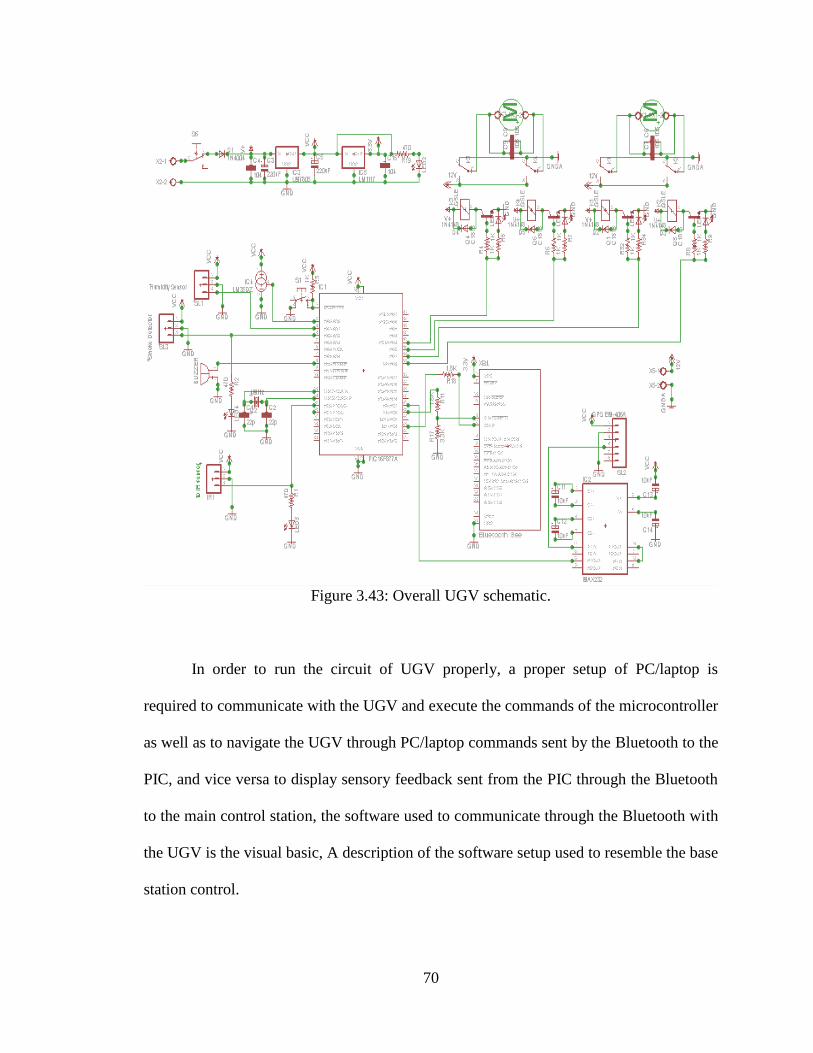
Figure 3.43 is the whole schematic of the UGV system combining all the previous
explained sub-circuits together in one schematic to perform a fully operating UGV
system.
70
Figure 3.43: Overall UGV schematic.
In order to run the circuit of UGV properly, a proper setup of PC/laptop is
required to communicate with the UGV and execute the commands of the microcontroller
as well as to navigate the UGV through PC/laptop commands sent by the Bluetooth to the
PIC, and vice versa to display sensory feedback sent from the PIC through the Bluetooth
to the main control station, the software used to communicate through the Bluetooth with
the UGV is the visual basic, A description of the software setup used to resemble the base
station control.
71
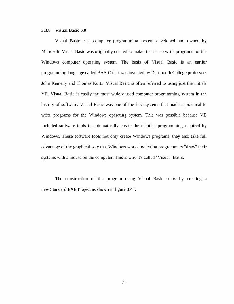
3.3.8 Visual Basic 6.0
Visual Basic is a computer programming system developed and owned by
Microsoft. Visual Basic was originally created to make it easier to write programs for the
Windows computer operating system. The basis of Visual Basic is an earlier
programming language called BASIC that was invented by Dartmouth College professors
John Kemeny and Thomas Kurtz. Visual Basic is often referred to using just the initials
VB. Visual Basic is easily the most widely used computer programming system in the
history of software. Visual Basic was one of the first systems that made it practical to
write programs for the Windows operating system. This was possible because VB
included software tools to automatically create the detailed programming required by
Windows. These software tools not only create Windows programs, they also take full
advantage of the graphical way that Windows works by letting programmers "draw" their
systems with a mouse on the computer. This is why it's called "Visual" Basic.
The construction of the program using Visual Basic starts by creating a
new Standard EXE Project as shown in figure 3.44.
72
Figure 3.44: Creating a New Standard EXE Project
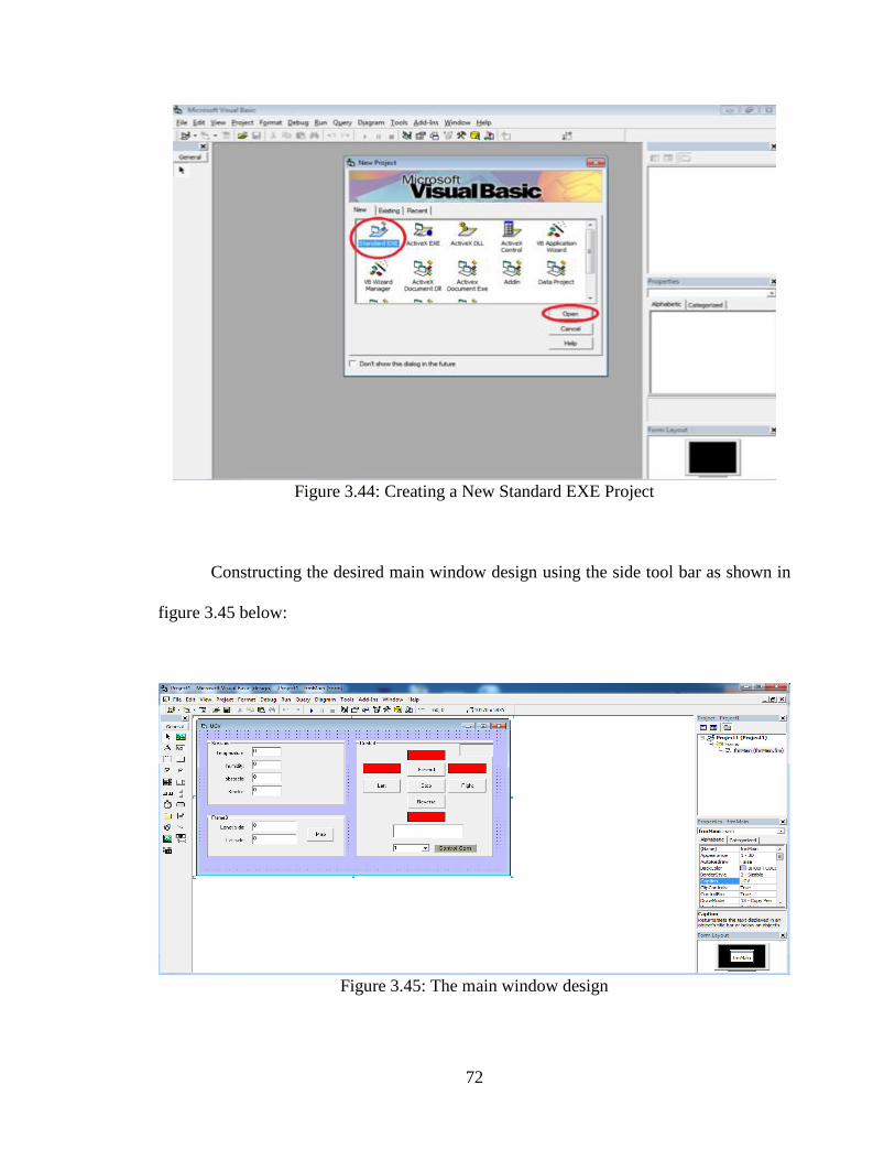
Constructing the desired main window design using the side tool bar as shown in
figure 3.45 below:
Figure 3.45: The main window design
73
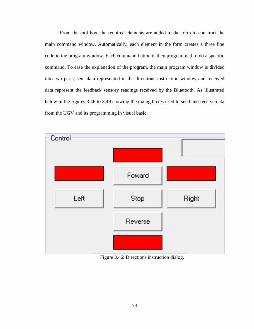
From the tool box, the required elements are added to the form to construct the
main command window. Automatically, each element in the form creates a three line
code in the program window. Each command button is then programmed to do a specific
command. To ease the explanation of the program, the main program window is divided
into two parts, sent data represented in the directions instruction window and received
data represent the feedback sensory readings received by the Bluetooth. As illustrated
below in the figures 3.46 to 3.49 showing the dialog boxes used to send and receive data
from the UGV and its programming in visual basic.
Figure 3.46: Directions instruction dialog.
74
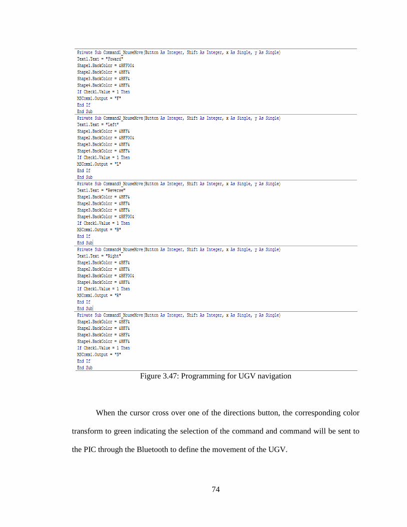
Figure 3.47: Programming for UGV navigation
When the cursor cross over one of the directions button, the corresponding color
transform to green indicating the selection of the command and command will be sent to
the PIC through the Bluetooth to define the movement of the UGV.
75
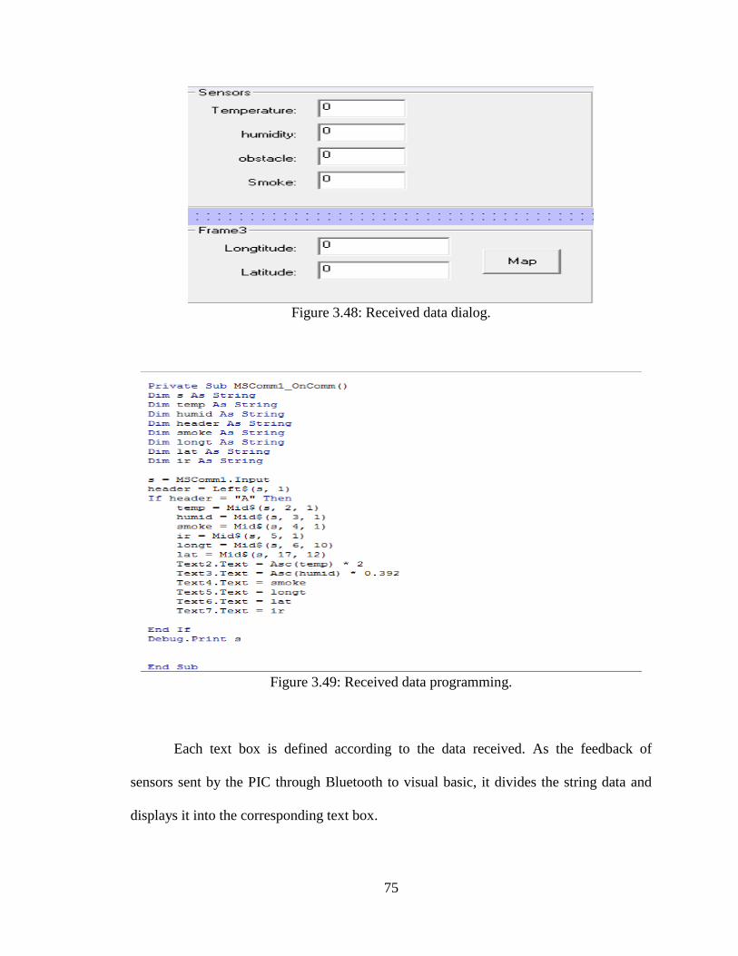
Figure 3.48: Received data dialog.
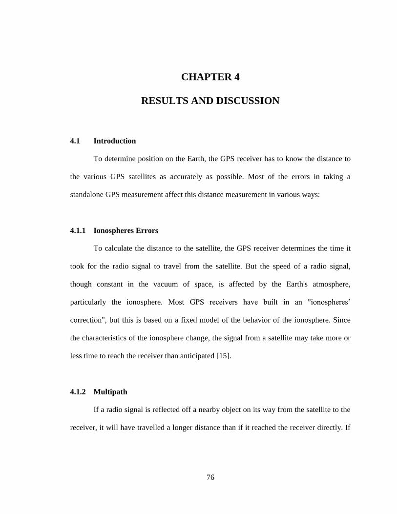
Figure 3.49: Received data programming.
Each text box is defined according to the data received. As the feedback of
sensors sent by the PIC through Bluetooth to visual basic, it divides the string data and
displays it into the corresponding text box.
76
CHAPTER 4
RESULTS AND DISCUSSION
4.1 Introduction
To determine position on the Earth, the GPS receiver has to know the distance to
the various GPS satellites as accurately as possible. Most of the errors in taking a
standalone GPS measurement affect this distance measurement in various ways:
4.1.1 Ionospheres Errors
To calculate the distance to the satellite, the GPS receiver determines the time it
took for the radio signal to travel from the satellite. But the speed of a radio signal,
though constant in the vacuum of space, is affected by the Earth's atmosphere,
particularly the ionosphere. Most GPS receivers have built in an "ionospheres’
correction", but this is based on a fixed model of the behavior of the ionosphere. Since
the characteristics of the ionosphere change, the signal from a satellite may take more or
less time to reach the receiver than anticipated [15].
4.1.2 Multipath
If a radio signal is reflected off a nearby object on its way from the satellite to the
receiver, it will have travelled a longer distance than if it reached the receiver directly. If
77
the receiver locks onto this instead of the original signal, it will calculate an erroneous
position of the satellite. Unfortunately, there are not many ways to help eliminate or
reduce this effect other than by using more expensive receivers that are less prone to
multipath.
4.1.3 Selective Availability or SA
This is the largest contributor of errors to consumer GPS receivers. When the U.S.
military set up the GPS constellation of satellites, they didn't want consumers to have
access to the same accuracy as the military. So, they intentionally introduce an error into
the public, unscrambled signal. This error arises from the satellites providing slightly
inaccurate orbital data to the receivers, as well as offsetting the time transmitted from
their atomic clocks slightly. Both effects cause the receiver to calculate an erroneous
position of the satellite.
4.2 GPS receiver analysis over time:
Though GPS receivers have opened up a whole new level of accuracy in
navigation and locating positions, there are a multitude of errors inherent in
measurement. Left uncorrected, these errors can result in inaccuracies of the order of tens
of meters or so. This analysis done in UNiSEL campus describes in a quantitative fashion
how averaging positional measurements over a period of time results in improved
accuracy. True position measured using phone GPS and measured position are measured
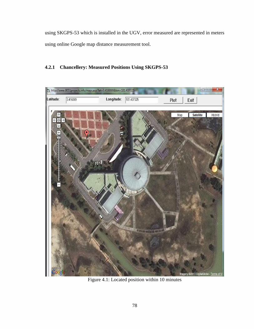
78
using SKGPS-53 which is installed in the UGV, error measured are represented in meters
using online Google map distance measurement tool.
4.2.1 Chancellery: Measured Positions Using SKGPS-53
Figure 4.1: Located position within 10 minutes
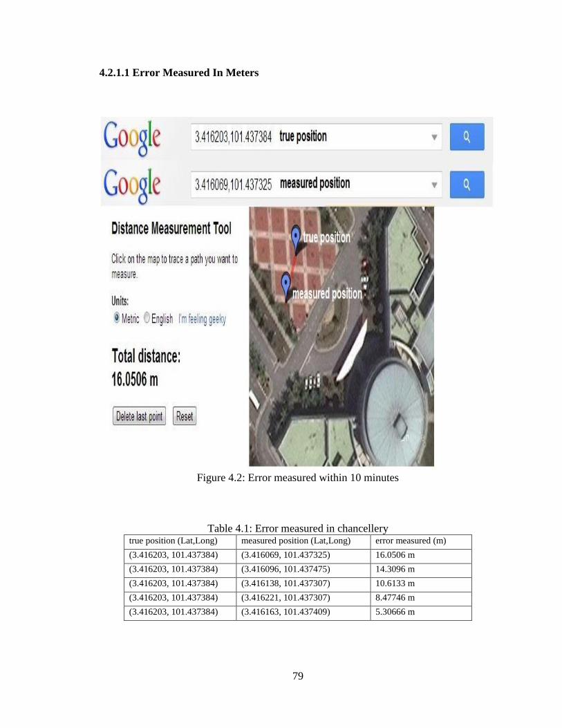
79
4.2.1.1 Error Measured In Meters
Figure 4.2: Error measured within 10 minutes
Table 4.1: Error measured in chancellery true position (Lat,Long) measured position (Lat,Long) error measured (m)
(3.416203, 101.437384) (3.416069, 101.437325) 16.0506 m
(3.416203, 101.437384) (3.416096, 101.437475) 14.3096 m
(3.416203, 101.437384) (3.416138, 101.437307) 10.6133 m
(3.416203, 101.437384) (3.416221, 101.437307) 8.47746 m
(3.416203, 101.437384) (3.416163, 101.437409) 5.30666 m
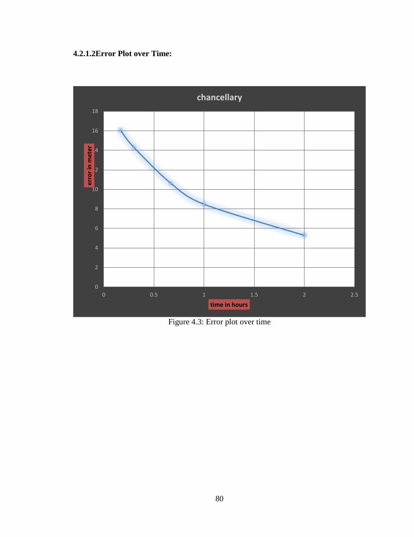
80
4.2.1.2Error Plot over Time:
Figure 4.3: Error plot over time
0
2
4
6
8
10
12
14
16
18
0 0.5 1 1.5 2 2.5
err
or
in m
ete
r
time in hours
chancellary
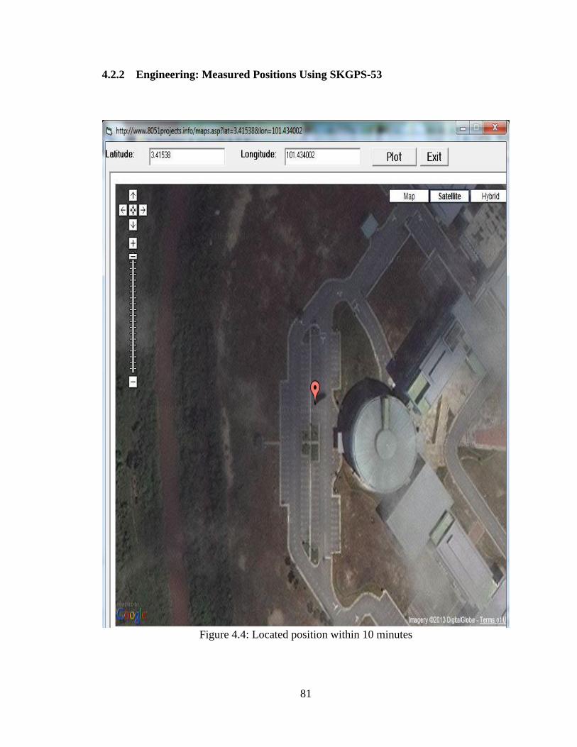
81
4.2.2 Engineering: Measured Positions Using SKGPS-53
Figure 4.4: Located position within 10 minutes
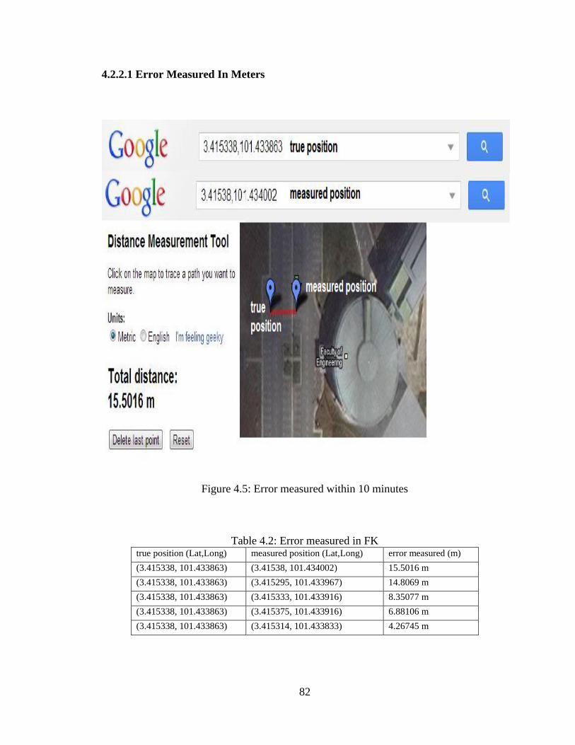
82
4.2.2.1 Error Measured In Meters
Figure 4.5: Error measured within 10 minutes
Table 4.2: Error measured in FK true position (Lat,Long) measured position (Lat,Long) error measured (m)
(3.415338, 101.433863) (3.41538, 101.434002) 15.5016 m
(3.415338, 101.433863) (3.415295, 101.433967) 14.8069 m
(3.415338, 101.433863) (3.415333, 101.433916) 8.35077 m
(3.415338, 101.433863) (3.415375, 101.433916) 6.88106 m
(3.415338, 101.433863) (3.415314, 101.433833) 4.26745 m
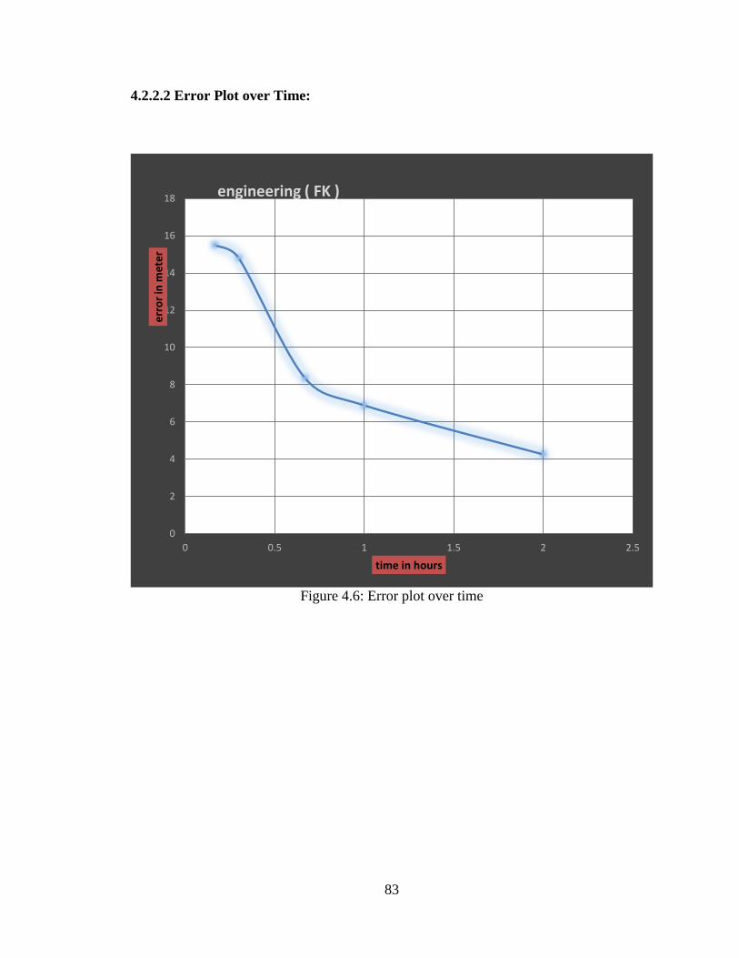
83
4.2.2.2 Error Plot over Time:
Figure 4.6: Error plot over time
0
2
4
6
8
10
12
14
16
18
0 0.5 1 1.5 2 2.5
err
or
in m
ete
r
time in hours
engineering ( FK )
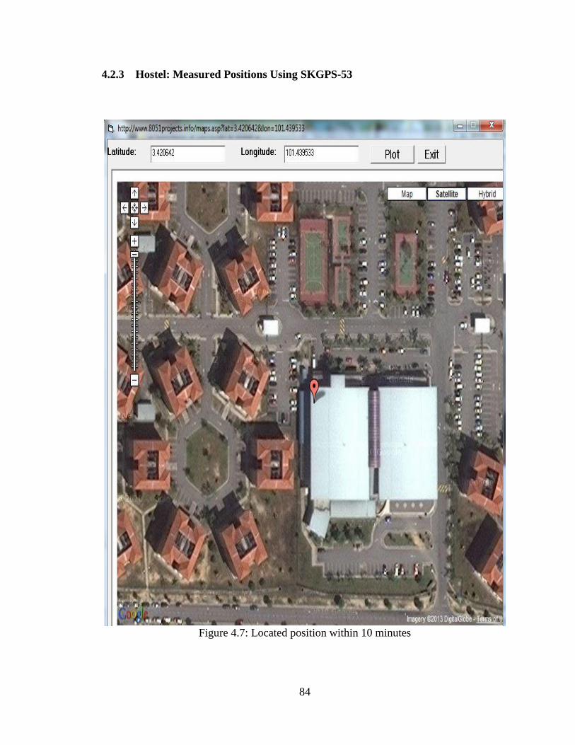
84
4.2.3 Hostel: Measured Positions Using SKGPS-53
Figure 4.7: Located position within 10 minutes
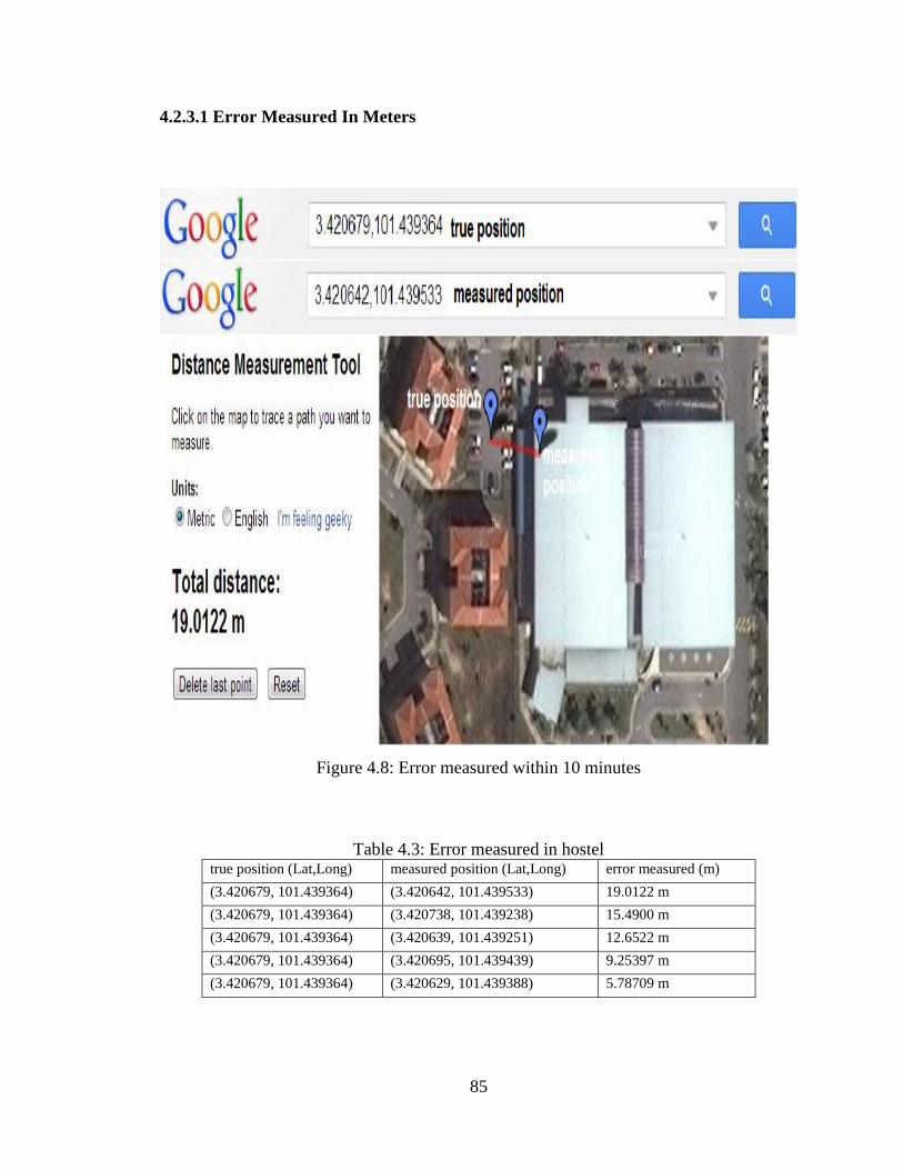
85
4.2.3.1 Error Measured In Meters
Figure 4.8: Error measured within 10 minutes
Table 4.3: Error measured in hostel true position (Lat,Long) measured position (Lat,Long) error measured (m)
(3.420679, 101.439364) (3.420642, 101.439533) 19.0122 m
(3.420679, 101.439364) (3.420738, 101.439238) 15.4900 m
(3.420679, 101.439364) (3.420639, 101.439251) 12.6522 m
(3.420679, 101.439364) (3.420695, 101.439439) 9.25397 m
(3.420679, 101.439364) (3.420629, 101.439388) 5.78709 m
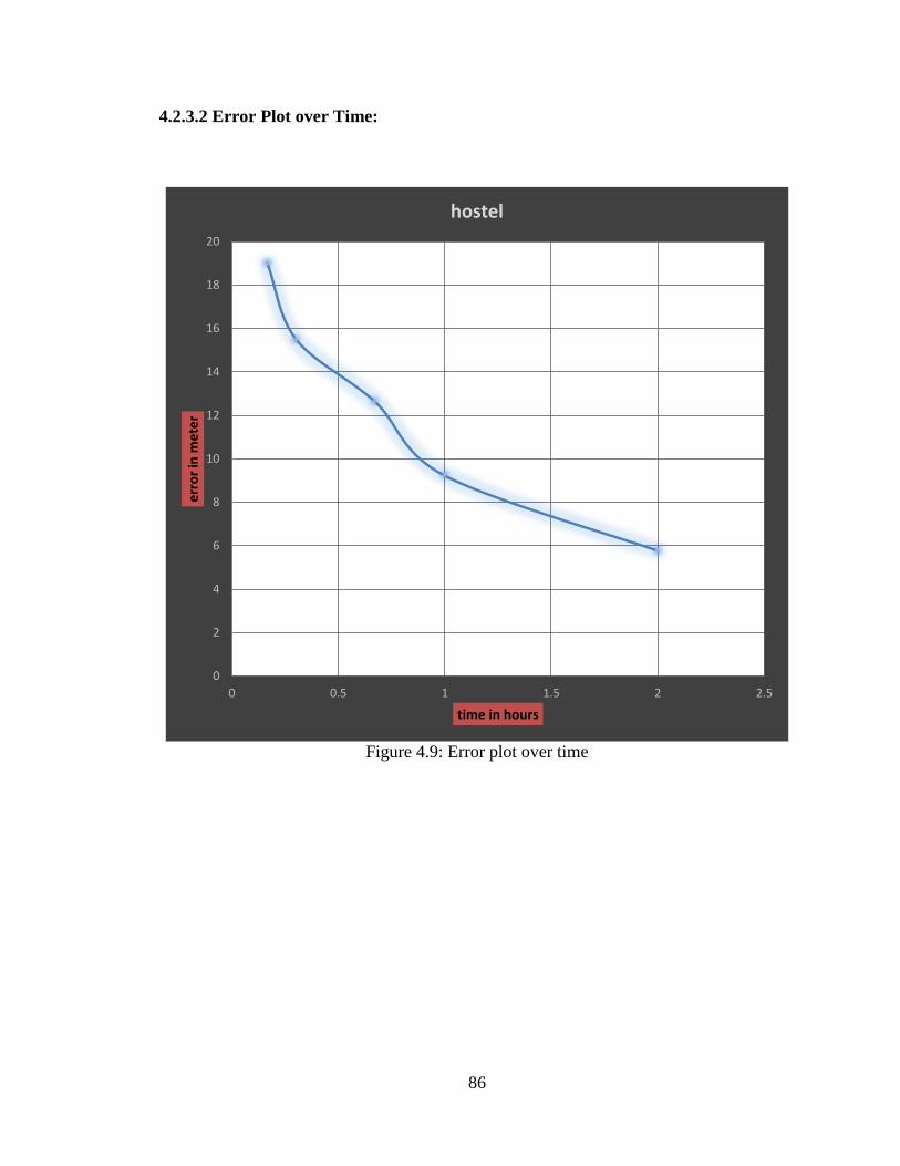
86
4.2.3.2 Error Plot over Time:
Figure 4.9: Error plot over time
0
2
4
6
8
10
12
14
16
18
20
0 0.5 1 1.5 2 2.5
err
or
in m
ete
r
time in hours
hostel
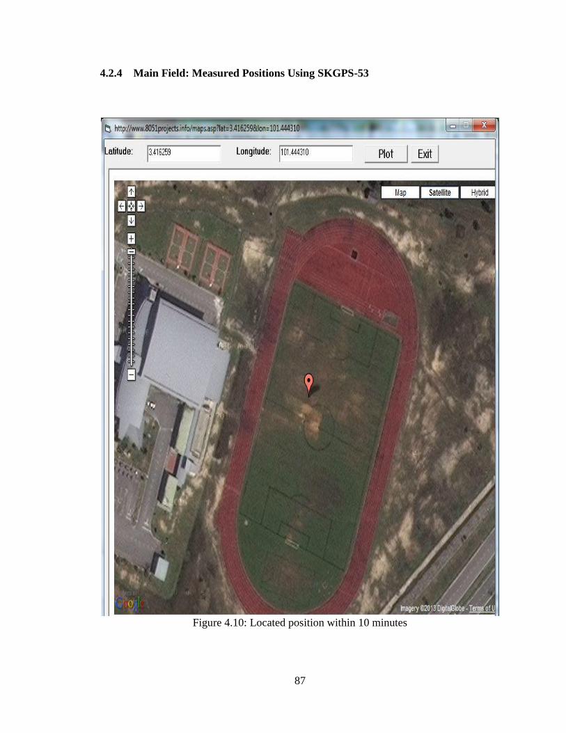
87
4.2.4 Main Field: Measured Positions Using SKGPS-53
Figure 4.10: Located position within 10 minutes
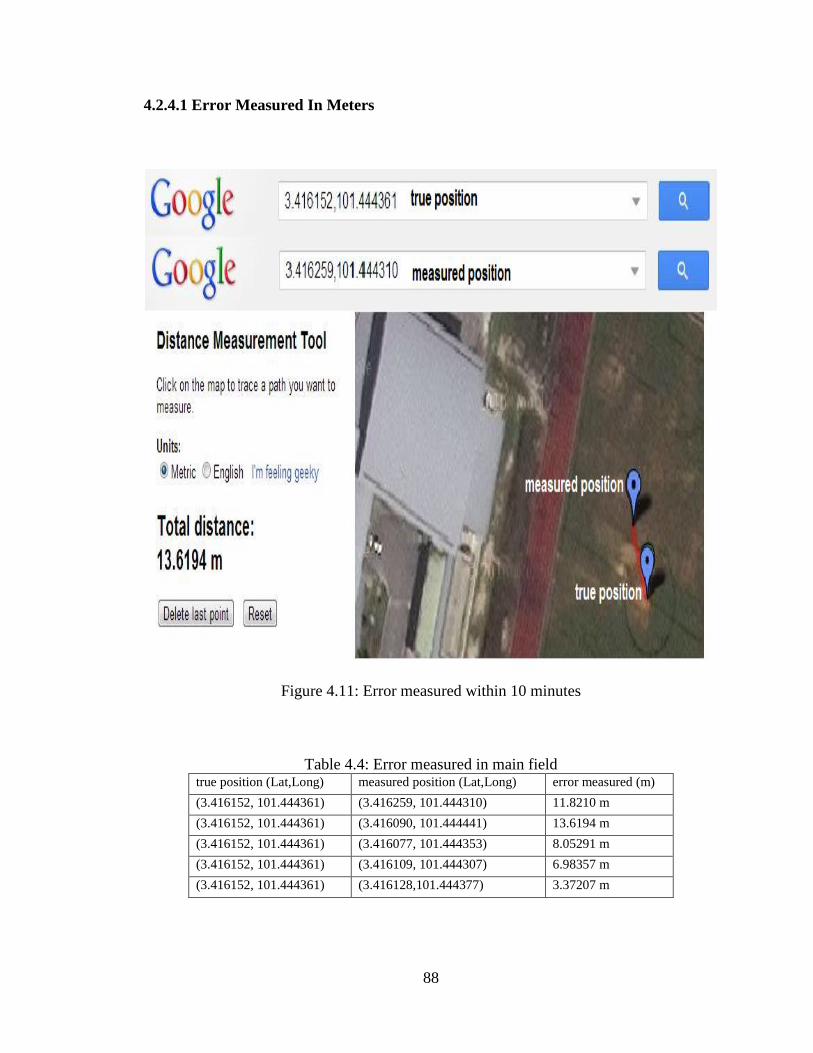
88
4.2.4.1 Error Measured In Meters
Figure 4.11: Error measured within 10 minutes
Table 4.4: Error measured in main field true position (Lat,Long) measured position (Lat,Long) error measured (m)
(3.416152, 101.444361) (3.416259, 101.444310) 11.8210 m
(3.416152, 101.444361) (3.416090, 101.444441) 13.6194 m
(3.416152, 101.444361) (3.416077, 101.444353) 8.05291 m
(3.416152, 101.444361) (3.416109, 101.444307) 6.98357 m
(3.416152, 101.444361) (3.416128,101.444377) 3.37207 m
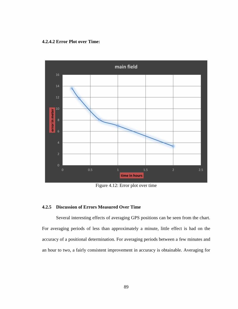
89
4.2.4.2 Error Plot over Time:
Figure 4.12: Error plot over time
4.2.5 Discussion of Errors Measured Over Time
Several interesting effects of averaging GPS positions can be seen from the chart.
For averaging periods of less than approximately a minute, little effect is had on the
accuracy of a positional determination. For averaging periods between a few minutes and
an hour to two, a fairly consistent improvement in accuracy is obtainable. Averaging for
0
2
4
6
8
10
12
14
16
0 0.5 1 1.5 2 2.5
err
or
in m
ete
r
time in hours
main field
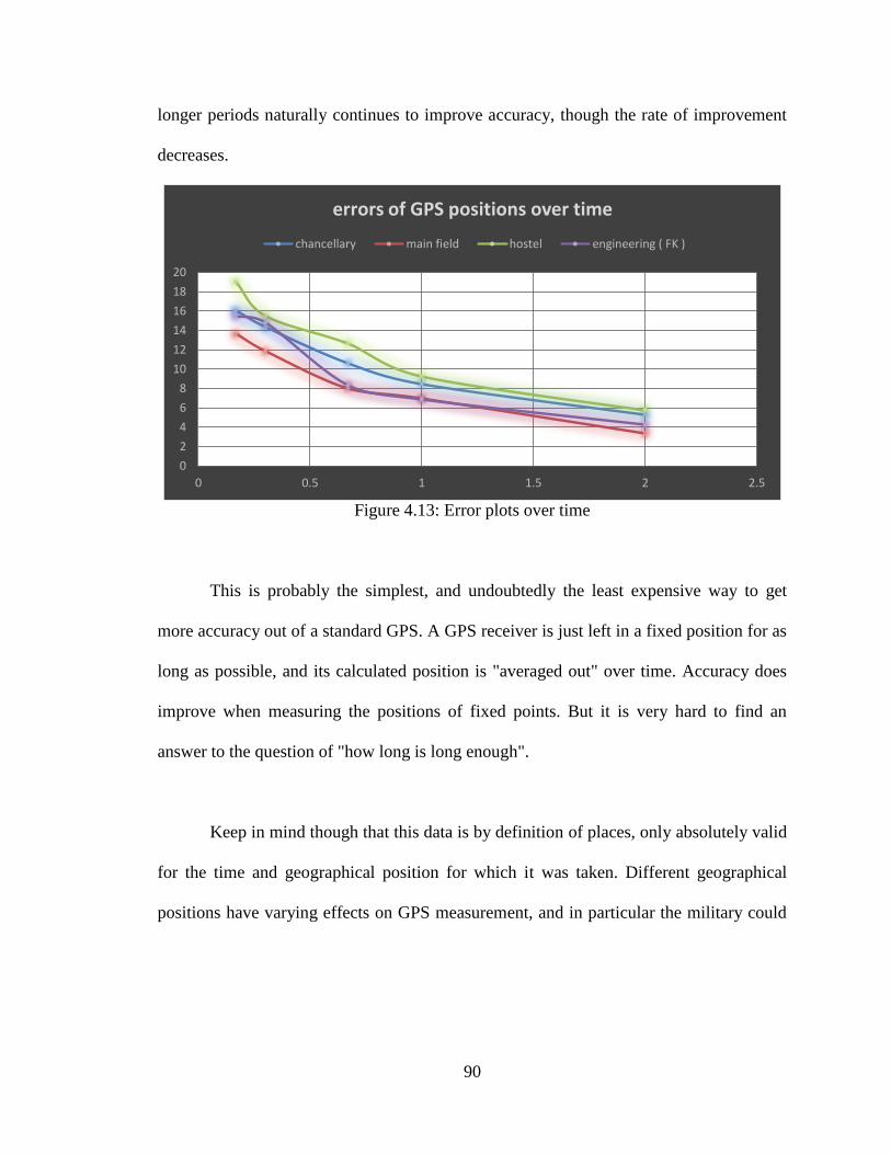
90
longer periods naturally continues to improve accuracy, though the rate of improvement
decreases.
Figure 4.13: Error plots over time
This is probably the simplest, and undoubtedly the least expensive way to get
more accuracy out of a standard GPS. A GPS receiver is just left in a fixed position for as
long as possible, and its calculated position is "averaged out" over time. Accuracy does
improve when measuring the positions of fixed points. But it is very hard to find an
answer to the question of "how long is long enough".
Keep in mind though that this data is by definition of places, only absolutely valid
for the time and geographical position for which it was taken. Different geographical
positions have varying effects on GPS measurement, and in particular the military could
0
2
4
6
8
10
12
14
16
18
20
0 0.5 1 1.5 2 2.5
errors of GPS positions over time
chancellary main field hostel engineering ( FK )
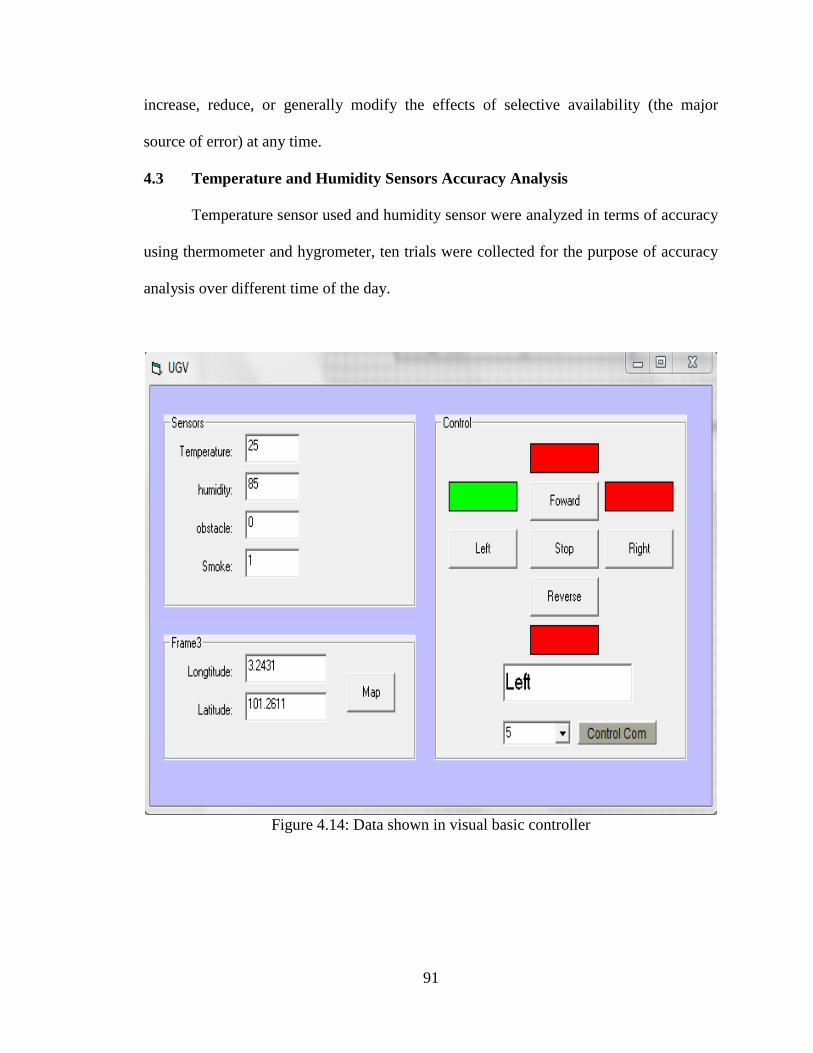
91
increase, reduce, or generally modify the effects of selective availability (the major
source of error) at any time.
4.3 Temperature and Humidity Sensors Accuracy Analysis
Temperature sensor used and humidity sensor were analyzed in terms of accuracy
using thermometer and hygrometer, ten trials were collected for the purpose of accuracy
analysis over different time of the day.
Figure 4.14: Data shown in visual basic controller
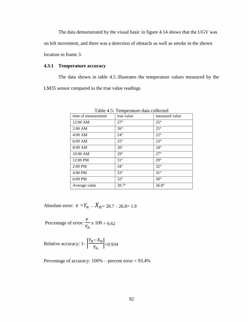
92
The data demonstrated by the visual basic in figure 4.14 shows that the UGV was
on left movement, and there was a detection of obstacle as well as smoke in the shown
location in frame 3.
4.3.1 Temperature accuracy
The data shown in table 4.5 illustrates the temperature values measured by the
LM35 sensor compared to the true value readings
Table 4.5: Temperature data collected time of measurement true value measured value
12:00 AM 27° 25°
2:00 AM 26° 25°
4:00 AM 24° 22°
6:00 AM 25° 23°
8:00 AM 26° 24°
10:00 AM 29° 27°
12:00 PM 31° 29°
2:00 PM 34° 32°
4:00 PM 33° 31°
6:00 PM 32° 30°
Average value 28.7° 26.8°
Absolute error: e = - = 28.7 – 26.8= 1.9
Percentage of error:
x 100 = 6.62
Relative accuracy: 1- |
|=0.934
Percentage of accuracy: 100% – percent error = 93.4%
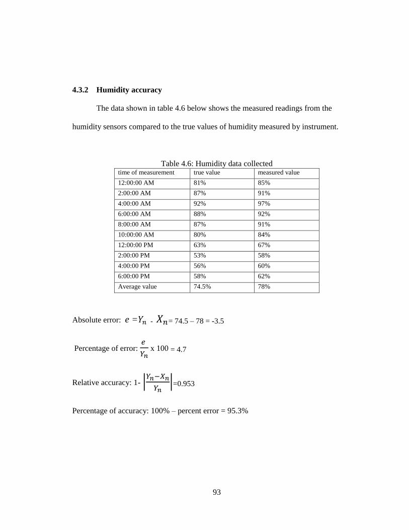
93
4.3.2 Humidity accuracy
The data shown in table 4.6 below shows the measured readings from the
humidity sensors compared to the true values of humidity measured by instrument.
Table 4.6: Humidity data collected time of measurement true value measured value
12:00:00 AM 81% 85%
2:00:00 AM 87% 91%
4:00:00 AM 92% 97%
6:00:00 AM 88% 92%
8:00:00 AM 87% 91%
10:00:00 AM 80% 84%
12:00:00 PM 63% 67%
2:00:00 PM 53% 58%
4:00:00 PM 56% 60%
6:00:00 PM 58% 62%
Average value 74.5% 78%
Absolute error: e = - = 74.5 – 78 = -3.5
Percentage of error:
x 100 = 4.7
Relative accuracy: 1- |
|=0.953
Percentage of accuracy: 100% – percent error = 95.3%
94
CHAPTER 5
CONCLUSION AND RECOMMENDATION
5.1 Conclusion
This project illustrated the design of a simple UGV, which is capable of being
controlled remotely to be used in exploration, security and rescue applications. The UGV
designed in this project includes several types of sensors, such as IR sensor for obstacles
detection, temperature sensor and humidity sensor to give feedback of the surrounding
environment, smoke detector, GPS to give consistent location updates for the UGV.
The UGV Bluetooth communication with the Base, which is used in controlling
the UGV manually from a remote place, and shows the sensory reading to the operator.
In addition, a GPS device has been attached to the UGV to get its position. This UGV
was designed to send the position to the Base station to know where is the UGV exactly.
This UGV was designed according to minimum cost, and the available technologies.
The UGV is a simplified implementation of a multi-function UGV, which can
move freely, interact with obstacles, observe and transmit data to the Base station.
95
5.2 Recommendation
As for future work this UGV may be equipped with a camera to be used in many
applications. In addition, it can be equipped with a gripper to pick up anything. It may be
programmed to get a voice orders.
The transmission of video data from the camera on the UGV to Base station needs
for high compression rate. So the compression technique is taking a large place. This
technique is not for videos only; it can be for any group of data that does not have the
required band width, low bit rates and a suitable size for transmitting.
The mechanical body should be replaced with a more high-level chassis, and
rotating cameras, which may include more environments, operations, and applications for
the UGV.
Also for the electrical and control systems the UGV should have another type of
sensors such as pressure sensor, light sensor and ultrasonic sensor. In addition to a power
supply that generates different levels of voltages whether if it DC or AC.

96
As mentioned before that the UGV is being controlled remotely from far distance,
so supplying the UGV with laptop containing suitable software to report the base station
about what is happening in real time in addition storing this files in archives in the UGV.
Cooling system must be added to the UGV to avoid any system breaks down and
power supply should be through solar panel to get more accurate readings from the GPS
for long periods positioning.
97
REFERENCES
[1] Clifton A. Ericson II,concise encyclopaediaos system safety, los angles, USA,
1992.
[2] Dr Stephen Prior,Increasing the Traffic ability of Unmanned Ground Vehicles
through Intelligent Morphing,military school of Colorado, 2001.
[3] Sid D. Harth Odedra,Product Design and Engineering, Middlesex University
Trent Park Campus, Bramley Road, London N14 4YZ, U.K.
[4] Test Operations Procedure (TOP) 2-2-540 Testing of Unmanned Ground Vehicle
(UGV) Systems, Standard Form 298 (Rev. 8-98) Prescribed by ANSI Std. Z39-
18,US Army Aberdeen Test Center (TEDT-AT-AD-F) 400 Colleran Rd, Bldg 321
TOP 2-2-540 APG, MD 21005-5059.
[5] Petercroke& Salah sukkariah,Field and Service Robotics,cairopuplishing
Centre, Egypt, 19998.
[6] Technology Development for Army Unmanned Ground Vehicles byNational
Research Council (U.S.). Committee on Army Unmanned Ground Vehicle
Technology.
[7] David G. Alciatore, Military Robots, , Colorado state University.2006.
[8] Buie, James L. "Coupling transistor logic and other circuits," U. S.
Patent3,283,170 (Filed: September 1961. Issued: November 1, 1966).
98
[9] Chuk’s robotic notebook, Chuck McManis, president of the home brew robotics
club of Silicon Valley. 2006.
[10] Dr. Roy Winkelman,Florida Center for Instructional Technology /College of
EducationUniversity of South Florida by, 2002.
[11] Ogletree T.W.,Soper M.E,Curt Franklin and Julia Layton, Upgrading and
Repairing Networks on” How Bluetooth Works”.2007.
[12] Lakshmi Anand K,Bluetooth Protocol Stack, Director of MSPVL Polytechnic
College, Pavoorchatram, 2008.
[13] Authors Kenneth C. Laudon and Jane P. Laudon of Management Information
Systems: Managing the Digital Firm 10th edition.2001.
[14] Ahmed El-Rabbany,Introduction to GPS (The Global Positioning System),1999.
[15] Bradford W. Parkinson, James J. Spilker Jr., global positioning system:
Theory and application, 1996.
[16] Steven L. Eddins,MedData Interactive,The MathWorks, Inc.Gates mark
Publishing,2009.
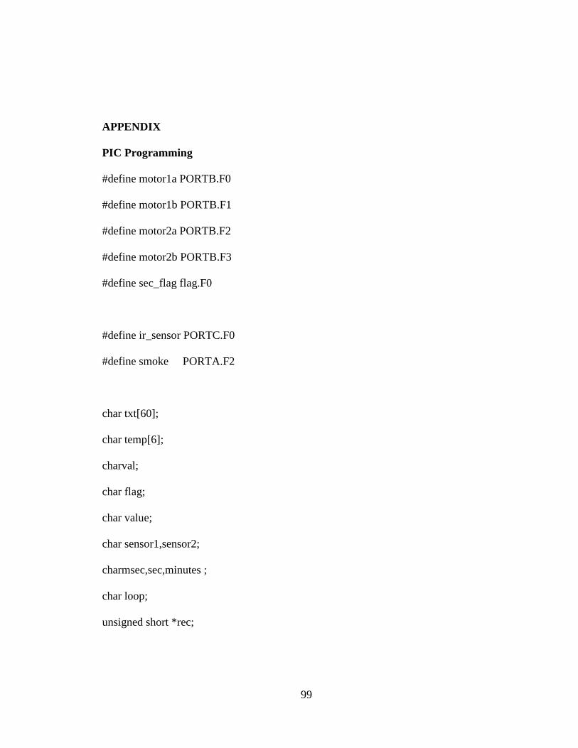
99
APPENDIX
PIC Programming
#define motor1a PORTB.F0
#define motor1b PORTB.F1
#define motor2a PORTB.F2
#define motor2b PORTB.F3
#define sec_flag flag.F0
#define ir_sensor PORTC.F0
#define smoke PORTA.F2
char txt[60];
char temp[6];
charval;
char flag;
char value;
char sensor1,sensor2;
charmsec,sec,minutes ;
char loop;
unsigned short *rec;
100
char val1;
voidread_data(void);
void forward(void)
motor1a =1;
motor1b =0;
motor2a =1;
motor2b =0;
delay_ms(50);
void reverse(void)
motor1a =0;
motor1b =1;
motor2a =0;
motor2b =1;
delay_ms(50);
void left(void)
101
motor1a =1;
motor1b =0;
motor2a =0;
motor2b =0;
delay_ms(50);
void right(void)
motor1a =0;
motor1b =0;
motor2a =1;
motor2b =0;
delay_ms(50);
void stop(void)
motor1a =0;
motor1b =0;
motor2a =0;
motor2b =0;
delay_ms(50);
102
void main(void)
ADCON1=0x84;
TRISA =0xFF;
TRISB =0x00;
TRISC =0b10010001;
OPTION_REG = 0b10000010;
INTCON = 0xA0;
Usart_init(9600);
Soft_Uart_Init(PORTC, 4, 5, 9600, 0);
Soft_Uart_Write('A');
PORTA=PORTB=PORTC=0x00;
PORTB=0x00;
do
if(sec_flag)
sec_flag=0;
Usart_write('A');
sensor1 = adc_read(0x00)/4;
Usart_write(sensor1);
103
sensor2 = adc_read(0x01)/4;
if(smoke)Usart_write('1');
elseUsart_write('0');
if(ir_sensor)Usart_write('1');
elseUsart_write('0');
while(1)
while(!usart_data_ready());
val = usart_read();
if(val=='$')
for(loop=1;loop<=5;loop++)
while(!usart_data_ready());
temp[loop]=Usart_read();
if(temp[1]=='G' && temp[2]=='P' && temp[3]=='R' && temp[4]=='M' &&
temp[5]=='C')
read_data();
break;
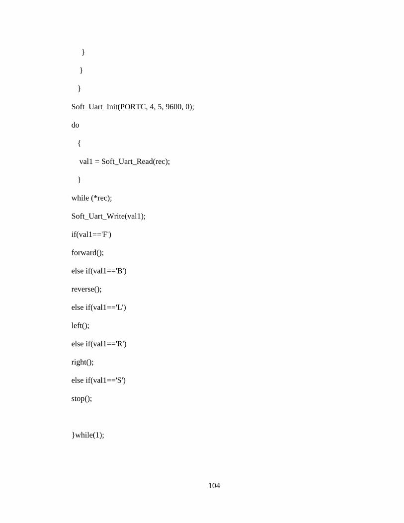
104
Soft_Uart_Init(PORTC, 4, 5, 9600, 0);
do
val1 = Soft_Uart_Read(rec);
while (*rec);
Soft_Uart_Write(val1);
if(val1=='F')
forward();
else if(val1=='B')
reverse();
else if(val1=='L')
left();
else if(val1=='R')
right();
else if(val1=='S')
stop();
while(1);
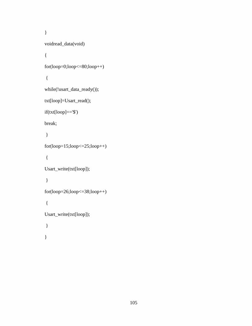
105
voidread_data(void)
for(loop=0;loop<=80;loop++)
while(!usart_data_ready());
txt[loop]=Usart_read();
if(txt[loop]=='$')
break;
for(loop=15;loop<=25;loop++)
Usart_write(txt[loop]);
for(loop=26;loop<=38;loop++)
Usart_write(txt[loop]);
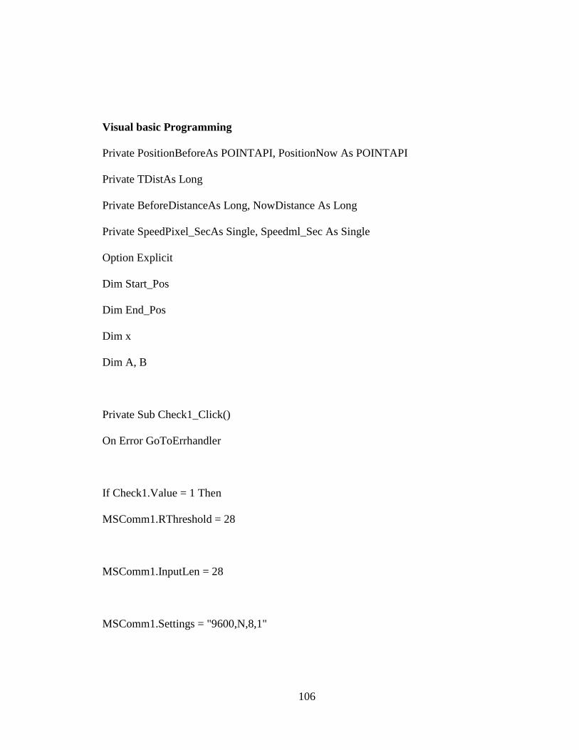
106
Visual basic Programming
Private PositionBeforeAs POINTAPI, PositionNow As POINTAPI
Private TDistAs Long
Private BeforeDistanceAs Long, NowDistance As Long
Private SpeedPixel_SecAs Single, Speedml_Sec As Single
Option Explicit
Dim Start_Pos
Dim End_Pos
Dim x
Dim A, B
Private Sub Check1_Click()
On Error GoToErrhandler
If Check1.Value = 1 Then
MSComm1.RThreshold = 28
MSComm1.InputLen = 28
MSComm1.Settings = "9600,N,8,1"
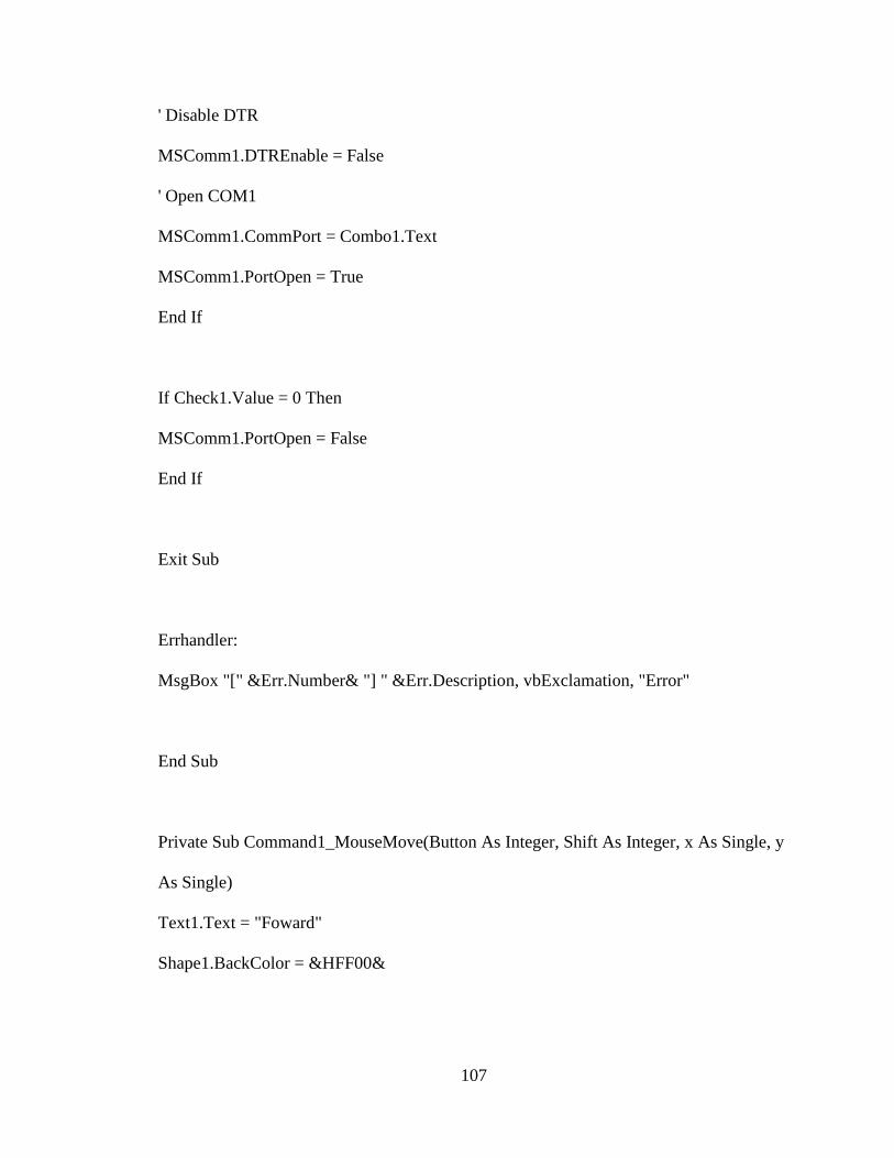
107
' Disable DTR
MSComm1.DTREnable = False
' Open COM1
MSComm1.CommPort = Combo1.Text
MSComm1.PortOpen = True
End If
If Check1.Value = 0 Then
MSComm1.PortOpen = False
End If
Exit Sub
Errhandler:
MsgBox "[" &Err.Number& "] " &Err.Description, vbExclamation, "Error"
End Sub
Private Sub Command1_MouseMove(Button As Integer, Shift As Integer, x As Single, y
As Single)
Text1.Text = "Foward"
Shape1.BackColor = &HFF00&
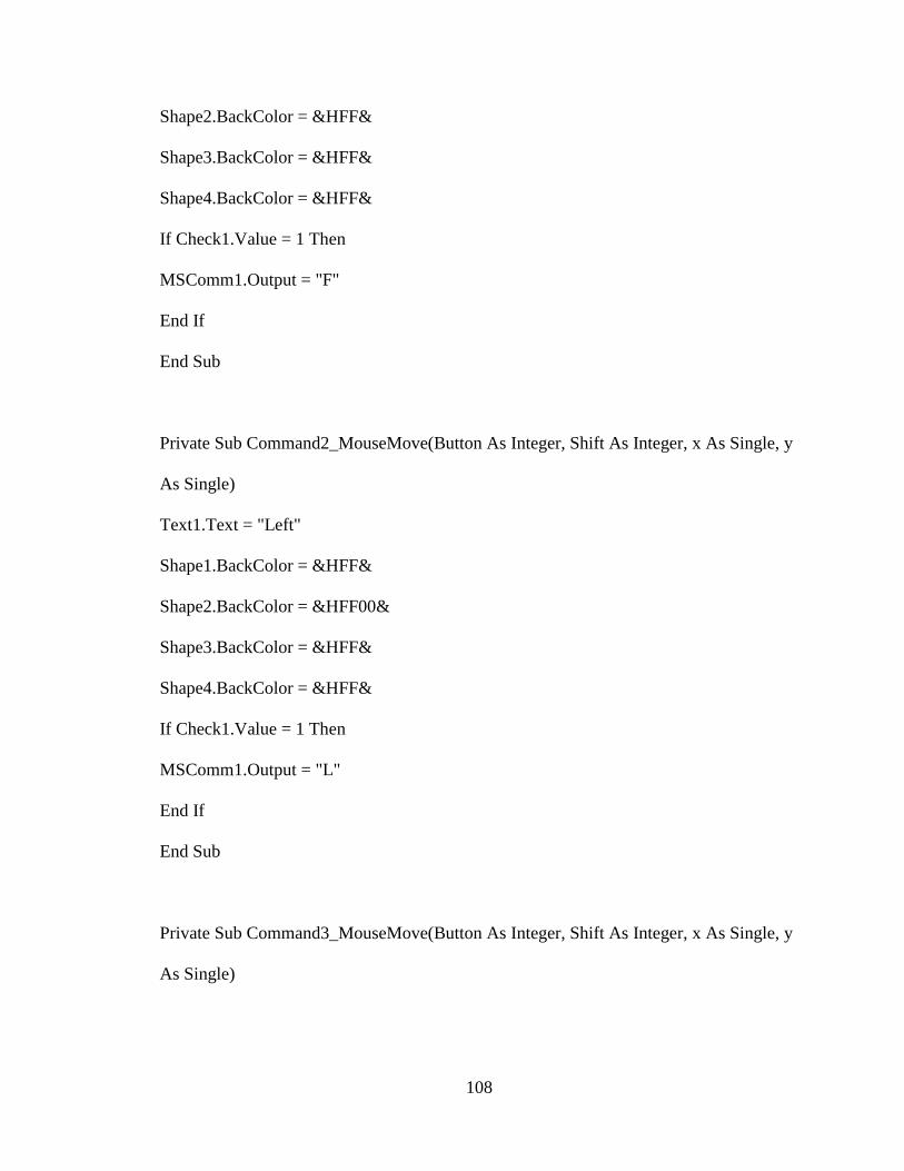
108
Shape2.BackColor = &HFF&
Shape3.BackColor = &HFF&
Shape4.BackColor = &HFF&
If Check1.Value = 1 Then
MSComm1.Output = "F"
End If
End Sub
Private Sub Command2_MouseMove(Button As Integer, Shift As Integer, x As Single, y
As Single)
Text1.Text = "Left"
Shape1.BackColor = &HFF&
Shape2.BackColor = &HFF00&
Shape3.BackColor = &HFF&
Shape4.BackColor = &HFF&
If Check1.Value = 1 Then
MSComm1.Output = "L"
End If
End Sub
Private Sub Command3_MouseMove(Button As Integer, Shift As Integer, x As Single, y
As Single)
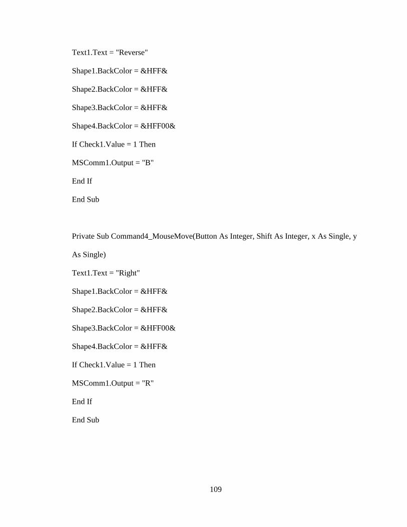
109
Text1.Text = "Reverse"
Shape1.BackColor = &HFF&
Shape2.BackColor = &HFF&
Shape3.BackColor = &HFF&
Shape4.BackColor = &HFF00&
If Check1.Value = 1 Then
MSComm1.Output = "B"
End If
End Sub
Private Sub Command4_MouseMove(Button As Integer, Shift As Integer, x As Single, y
As Single)
Text1.Text = "Right"
Shape1.BackColor = &HFF&
Shape2.BackColor = &HFF&
Shape3.BackColor = &HFF00&
Shape4.BackColor = &HFF&
If Check1.Value = 1 Then
MSComm1.Output = "R"
End If
End Sub
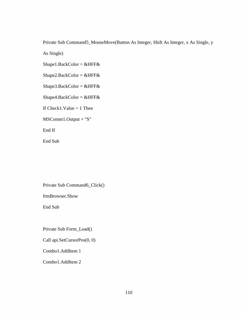
110
Private Sub Command5_MouseMove(Button As Integer, Shift As Integer, x As Single, y
As Single)
Shape1.BackColor = &HFF&
Shape2.BackColor = &HFF&
Shape3.BackColor = &HFF&
Shape4.BackColor = &HFF&
If Check1.Value = 1 Then
MSComm1.Output = "S"
End If
End Sub
Private Sub Command6_Click()
frmBrowser.Show
End Sub
Private Sub Form_Load()
Call api.SetCursorPos(0, 0)
Combo1.AddItem 1
Combo1.AddItem 2

111
Combo1.AddItem 3
Combo1.AddItem 4
Combo1.AddItem 5
End Sub
Private Sub MSComm1_OnComm()
Dim s As String
Dim temp As String
Dim humid As String
Dim header As String
Dim smoke As String
Dim longt As String
Dim lat As String
s = MSComm1.Input
header = Left$(s, 1)
If header = "A" Then
temp = Mid$(s, 2, 1)
humid = Mid$(s, 3, 1)
smoke = Mid$(s, 4, 1)
longt = Mid$(s, 5, 10)
lat = Mid$(s, 16, 12)
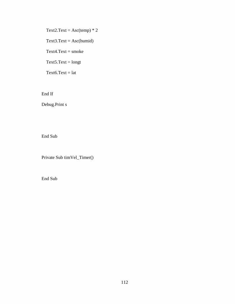
112
Text2.Text = Asc(temp) * 2
Text3.Text = Asc(humid)
Text4.Text = smoke
Text5.Text = longt
Text6.Text = lat
End If
Debug.Print s
End Sub
Private Sub timVel_Timer()
End Sub
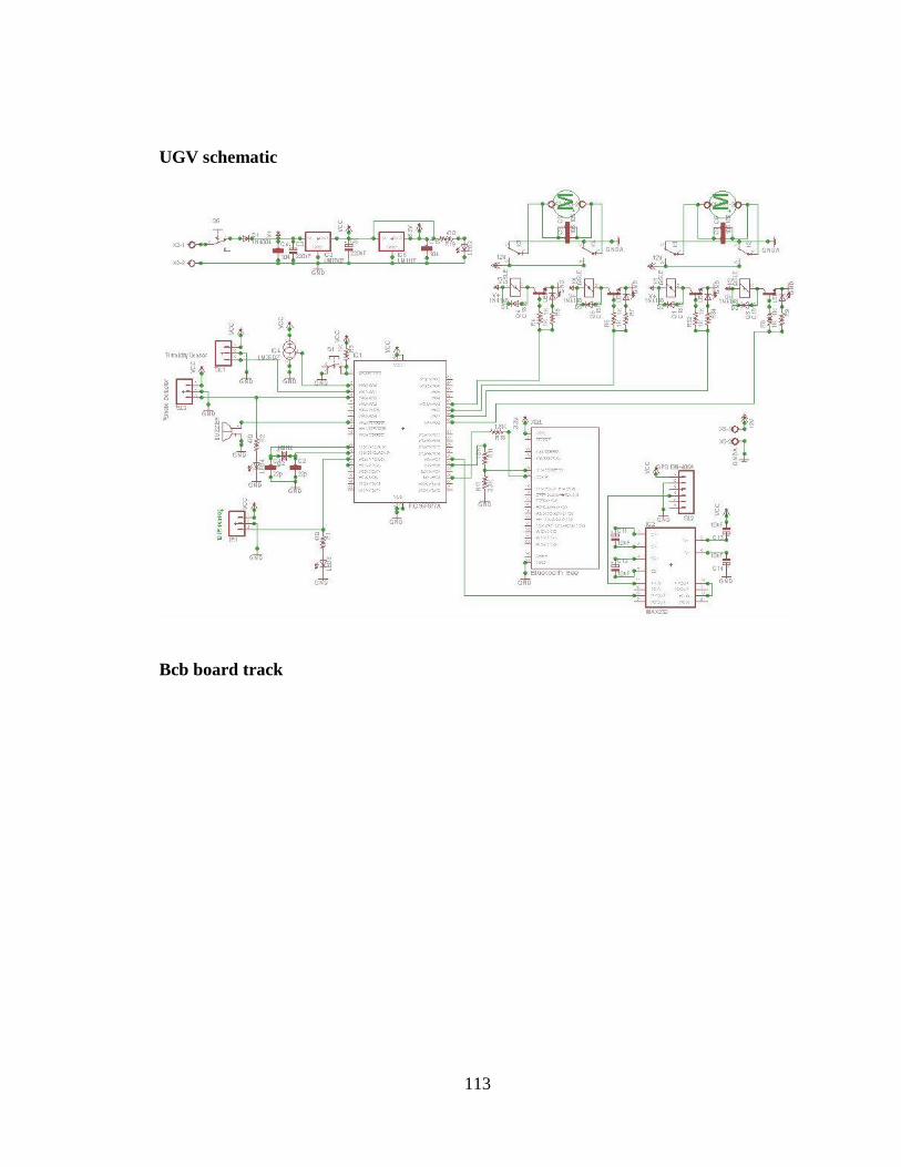
113
UGV schematic
Bcb board track
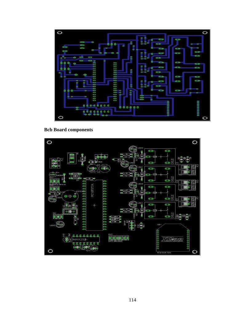
114
Bcb Board components

115