thermal residual strains and stresses in silicon carbide-fiber-reinforced silicon nitride composites
TRANSCRIPT
Composites Engineering, Vol. 3. No. I I, pp. 1075-1086. 1993. Printed in Great Britain.
0961-9526193 $6.00+ .oO Pergamon Press Lfd
THERMAL RESIDUAL STRAINS AND STRESSES IN SILICON CARBIDE-FIBER-REINFORCED SILICON
NITRIDE COMPOSITES
A. SAIGAL Department of Mechanical Engineering, Tufts University, Medford, MA 02155, U.S.A.
D. S. KUPPERMAN, J. P. SINGH and D. SINGH Materials and Components Technology Division, Argonne National Laboratory,
Argonne, IL 60439, U.S.A.
J . RICHARDSON Intense Pulsed Neutron Source Division, Argonne National Laboratory,
Argonne, IL 60439, U.S.A.
and
R. T. BHATT U.S. Army Propulsion Directorate, NASA Lewis Research Center, Cleveland, OH 44135, U.S.A.
(Received 3 I August 1992; final version accepted 12 March 1993)
Abstract-Neutron diffraction was used to measure thermal residual strains in SiC-fiber- reinforced reaction-bonded silicon nitride composites as a function of volume fraction of fibers. The measured values are in agreement with those estimated by finite-element modeling. Due to the anisotropy of the thermal expansion coefficient of Sic, residual axial strain (stress) is tensile and residual transverse strain (stress) is compressive in the fibers. The variation in the measured residual axial strain in the matrix can be related to the density of the composite. In addition, neutron diffraction was used to study the effects of fiber coatings and processing on the thermal residual strains.
I. INTRODUCTION
Dense silicon nitrides and silicon carbides are currently being evaluated for advanced heat engines and gas turbine applications because of their high-temperature capabilities (Raze11 and Lewis, 1991). However, the inherent flaw sensitivity, poor reliability and catastrophic failure mode of these ceramic materials in the monolithic form has led to the development of fiber-reinforced ceramic matrix composites (CMCs).
For high-temperature (> 1000°C) applications involving CMCs, dense silicon nitride (Si,N,) and Sic are desirable as matrices because of their strength retention and oxidation resistance. Reinforcements can be in the form of particulates, whiskers, or continuous fibers. Silicon carbide is one of the most widely used reinforcement materials. Addition of Sic or TiN particulates or Sic whiskers to the Si3N, matrix can result in a twofold increase in fracture toughness (Buljian and Sarin, 1987; Mah, 1981). Compared to particulates or whiskers, continuous fiber reinforcements offer certain advantages. First, fiber reinforcements in a brittle matrix can bridge matrix flaws and delay the onset of matrix fracture to much higher stress and strain levels than the unreinforced matrix. Second, tailoring the fiber/matrix bond permits the matrix cracks to go around the fibers and not through them. This allows the fibers to bear the load beyond the matrix fracture and prevent catastrophic failure of the material at the instant of matrix fracture.
The choice of fiber materials is limited because of creep deformation (oxides) and resistance to degradation (nonoxides). In addition, thermal expansion compatibility with the matrix, formability, availability and cost must also be considered. Specifically, SCS-6 monofilaments produced by chemical vapor deposition are currently the only fibers with the potential for high-temperature operation. As such, Sic-fiber-reinforced silicon nitride composites are the focus of a number of studies.
1075
1076 A. SAIGAL et al.
The mechanical performance of composites is influenced by process-induced residual strains and stresses that are locked in the constituents during postfabrication cooling. Silicon carbide/silicon nitride composites are fabricated at temperatures above 1000°C and, because of mismatch between the coefficients of thermal expansion of the fiber and the matrix, the thermally induced residual strains and stresses can be significant. Because frictional forces and the subsequent behavior of the composites depend on the residual stresses that develop during postfabrication cooldown, it is important to know the magni- tudes of the residual strains and stresses that exist in the composites (Phillips, 1974).
For all composites with crystalline constituents, neutron diffraction is a powerful tool for measuring bulk elastic residual strains, from which residual stresses can be calcu- lated in much the same way as with X-ray diffraction (X-ray diffraction, however, is limited to determination of surface strains/stresses while neutron diffraction detects average strains/stresses through the thickness of the specimen (Hutchings and Windsor, 1986; Noyan and Cohen, 1987). Such stresses are called microstresses, because they vary on the scale of the microstructure. Macrostresses, on the other hand, are long-range relative to the scale of the microstructure (such as those generated by welding and surface finishing). X-rays measure the sum of the micro- and macrostress fields, which can be separated in some cases, in the near-surface region.
Microstresses are difficult to measure experimentally. Unlike macrostresses, which are amenable in principle to both destructive and nondestructive evaluation, microstresses must be measured by diffraction. When a sample containing both micro- and macro- stresses is placed in the path of a neutron beam, the macrostresses are averaged out if the diffraction peak contains contributions from the entire thickness of the specimen. This makes the microstress portion directly available. Further, unlike X-rays, neutrons can penetrate deep into the interior of most engineering materials, typically by a factor of 1000 deeper than can X-rays. This provides an excellent volume sample, a true bulk measurement of residual strains, and independence from surface-related effects.
Neutron diffraction has been used to measure residual strains and stresses in a number of metal, intermetallic and ceramic matrix composites. Allen et al. (1987) measured residual stresses and load-induced bulk stresses in an Sic whisker-reinforced Al matrix composite. Saigal and Kupperman (1991) and Saigal et al. (1992) used neutron diffraction to measure residual strains in nickel and titanium aiuminide matrix com- posites. Kupperman and Majumdar (1989) used the technique to study the variation of average residual thermal strains with temperature and volume fraction of whiskers in an Sic-whisker-reinforced AlzO, matrix composite. Krawitz et al. (1989) measured residual stress as a function of temperature in a high volume-fraction WC-Ni cemented carbide composite. The results agreed reasonably well with calculated values (Majumdar and Krawitz, 1990). In addition, Majumdar et al. (1991) used the Intense Pulsed Neutron Source (IPNS) and the associated General Purpose Powder Diffractometer (GPPD) at Argonne National Laboratory to measure residual strains in a number of engineering composite materials.
In the present study, neutron diffraction was used to measure average residual thermal strains in an Sic fiber-reinforced reaction-bonded silicon nitride (SiC/RBSN) composite as a function of the volume fraction of the fibers. The effects of fiber coating and density on average residual strains were also studied.
2. COMPOSITE SYSTEM
SiC/RBSN composites containing different volume fraction of fibers were produced at NASA Lewis. Starting materials for the composite fabrication were Sic monofilaments and attrition-milled high purity silicon powder. The Sic monofilaments used for com- posites were produced by Textron Speciality Materials, Inc., by chemical vapor deposition from methytrichlorosilane onto a heated carbon substrate. The SCS fibers consist of a sheath with an outer diameter of 142pm surrounding a pyrolitic graphite-coated carbon core with a diameter of 37pm. Except for the surface coating, the uncoated (SCS-0) and coated (SC%6) fibers had identical microstructures. The SCS-0 fibers contained no
Fiber-reinforced silicon nitride composites 1077
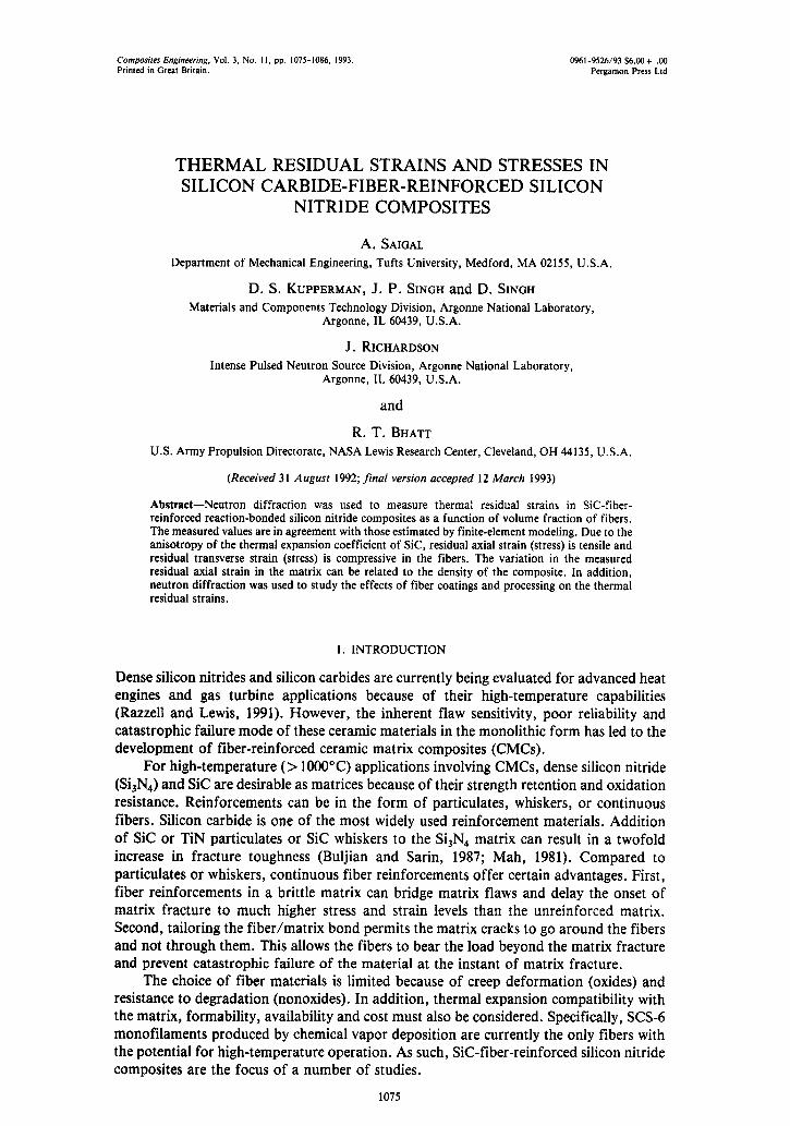
1. Typical cross-section of a unidirectionally fiber-reinforced SiC/RBSN composite.
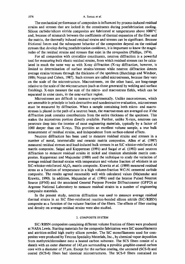
Fig. 10. Defects observed around fibers in as-cut SCS-6/RBSN composite.
Fiber-reinforced silicon nitride composites 1079
surface coating, whereas SCS-6 fibers contained an approximately 3 pm thick carbon-rich coating on top of the Sic substrate. For the silicon nitride matrix, high-purity silicon powder was obtained from Union Carbide. This powder was attrition milled to reduce its average particle size from 7 pm to 0.3 pm.
Composite fabrication involved four steps: fabrication of Sic fiber mats, fabrication of silicon tapes, consolidation of preform by warm pressing alternate layers of fiber mats and silicon tapes in a vacuum hot press, and nitridation of SiC/Si preforms at appropriate conditions to convert silicon to silicon nitride matrix. Silicon carbide fiber mats are produced by winding SIC fibers on a cylindrical drum, coating with fugitive polymer binder to maintain the fiber spacing and drying. Silicon tape is produced by mixing attrition-milled silicon powder with fugitive polymer binder and an organic solvent into a dough that is then rolled to the desired thickness. Details of the fabrication method are reported elsewhere (Bhatt, 1988).
Using this fabrication method, both SCS-O/RBSN and SCSd/RBSN composites were prepared. These composites generally contained 30-40% porosity. Some of the SCSd/RBSN composites were fully densified by hot-isostatic pressing (HIPing) following nitridation. HIP processing involved processing temperature in excess of 1600°C and use of sintering oxide additive such as MgO. Figure 1 shows a typical cross-section of a unidirectionally fiber-reinforced SiC/RBSN composite.
In this study, SiC/RBSN composites containing approximately 8, 12, 16, 20 and 23 vol.% of coated SCS-6 fibers in the as-fabricated condition were analyzed. In addition, composites containing 24 vol.% of uncoated SCS-0 fibers in the as-fabricated condition and 29vol.% of coated SCS-6 fibers in the hot isostatic pressed condition were also analyzed to study the effects of fiber coating and hot isostatic pressing on average residual strains. The composite samples were 2 mm thick.
3. NEUTRON DIFFRACTION MEASUREMENTS
Thermal neutrons with wavelengths on the order of the lattice spacing are used for the experiments. Bragg’s law of diffraction can be applied to neutrons as follows:
2 d,,kt sin 8 = &, , (1)
where dhkr is the spacing of diffracting planes, 28 is the angle between the incident and the scattered neutron beams when a Bragg peak is detected, 1 is the de Broglie wavelength of the neutron, and hkl are the Miller indices of the diffracting planes (Allen et al., 1985). The data were collected using the IPNS and GPPD at Argonne. The IPNS is a spallation-type neutron source emitting 30 pulses-‘; the GPPD is a time-of-flight instrument. The spectrum is measured at a fixed Bragg angle 28 of f 90”. The main advantage of a pulsed neutron source over a steady neutron source is that it uses a white spectrum of neutron energies. Therefore, during a single measurement using IPNS, many diffraction peaks of each phase are recorded simultaneously in various spatial directions.
For residual strain measurements, the lattice spacings in various crystallographic directions of stress-free matrix powder and fibers (which are used to fabricate the compo- site) are determined first and compared with those of the constituents in the composite. If the constituents are subjected to residual strains, a shift in the d spacing is observed. For any (hkl) diffraction peak, the lattice strain is given by:
Ehkl = @hk, - do)/do, (2)
where dhkl and do represent the average interplanar spacings in the stressed and unstressed lattice, respectively. With a pulsed source, changes in lattice spacing are related to time of flight shifts in the Bragg peaks. The relationship of time of flight to neutron wavelength is described by:
L = ht/mL, (3)
where h is the Planck’s constant, t is the time of flight for a neutron to reach a detector after leaving its source, L is the flight path of the neutron from its source to the detector,
1080 A. &GAL et d.
Lattice Spacing Measured Peroendicular to Fiber Direction --r- ~~ from 90°-L Detector
Lattice Spacing Measured Parallel to Fiber Direction - from 90”~R Detector
Beam 900-L
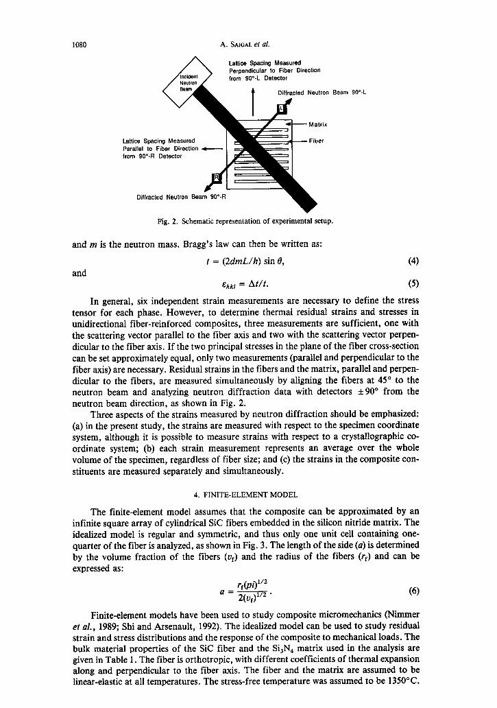
Fig. 2. Schematic representation of experimental setup.
and m is the neutron mass. Bragg’s law can then be written as:
and t = (2dmL/h) sin 6, (4)
E,,~, = At/t. (5)
In general, six independent strain measurements are necessary to define the stress tensor for each phase. However, to determine thermal residual strains and stresses in unidirectional fiber-reinforced composites, three measurements are sufficient, one with the scattering vector parallel to the fiber axis and two with the scattering vector perpen- dicular to the fiber axis. If the two principal stresses in the plane of the fiber cross-section can be set approximately equal, only two measurements (parallel and perpendicular to the fiber axis) are necessary. Residual strains in the fibers and the matrix, parallel and perpen- dicular to the fibers, are measured simultaneously by aligning the fibers at 45” to the neutron beam and analyzing neutron diffraction data with detectors &90” from the neutron beam direction, as shown in Fig. 2.
Three aspects of the strains measured by neutron diffraction should be emphasized: (a) in the present study, the strains are measured with respect to the specimen coordinate system, although it is possible to measure strains with respect to a crystallographic co- ordinate system; (b) each strain measurement represents an average over the whole volume of the specimen, regardless of fiber size; and (c) the strains in the composite con- stituents are measured separately and simultaneously.
4. FINITE-ELEMENT MODEL
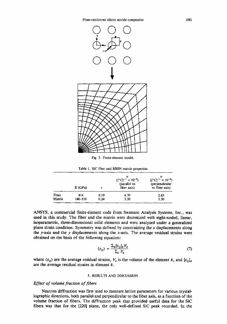
The finite-element model assumes that the composite can be approximated by an infinite square array of cylindrical Sic fibers embedded in the silicon nitride matrix. The idealized model is regular and symmetric, and thus only one unit cell containing one- quarter of the fiber is analyzed, as shown in Fig. 3. The length of the side (a) is determined by the volume fraction of the fibers (v& and the radius of the fibers (rf) and can be expressed as:
(6)
Finite-element models have been used to study composite micromechanics (Nimmer et al., 1989; Shi and Arsenault, 1992). The idealized model can be used to study residual strain and stress distributions and the response of the composite to mechanical loads. The bulk material properties of the Sic fiber and the S&N4 matrix used in the analysis are given in Table 1. The fiber is orthotropic, with different coefficients of thermal expansion along and perpendicular to the fiber axis. The fiber and the matrix are assumed to be linear-elastic at all temperatures. The stress-free temperature was assumed to be 1350°C.
Fiber-reinforced silicon nitride composites 1081
000 Y
a
h@
x 0 rf
Fig. 3. Finite-element model.
Table 1. SIC fiber and RBSN matrix properties
E @Pa)
([“q-G 10-y (I”c]-G 10-y (parallel to (perpendicular
V fiber axis) to fiber axis)
Fiber 414 0.19 4.70 2.63 Matrix 160-310 0.24 3.30 3.30
ANSYS, a commercial finite-element code from Swanson Analysis Systems, Inc., was used in this study. The fiber and the matrix were discretized with eight-noded, linear, isoparametric, three-dimensional solid elements and were analyzed under a generalized plane strain condition. Symmetry was defined by constraining the x displacements along the y-axis and the y displacements along the x-axis. The average residual strains were obtained on the basis of the following equation:
(Eij) = z:RIEijlk V,
xk v, (7)
where (Eij) are the average residual strains, vk is the volume of the element k, and [&ij]k
are the average residual strains in element k.
5. RESULTS AND DISCUSSION
Effect of volume fraction of fibers
Neutron diffraction was first used to measure lattice parameters for various crystal- lographic directions, both parallel and perpendicular to the fiber axis, as a function of the volume fraction of fibers. The diffraction peak that provided useful data for the Sic fibers was that for the [220] plane, the only well-defined Sic peak recorded. In the
1082 A. SAIGAL et al.
0.0020
5 E
0.0000 I 1 T
2 T a 1 _------ -0.0005 - __---- Transverse -
-0.0010-““““““““*“‘~“~‘~~~““~’ 0 5 10 15 20 25 30 35
Volume Fraction 01 Fibers
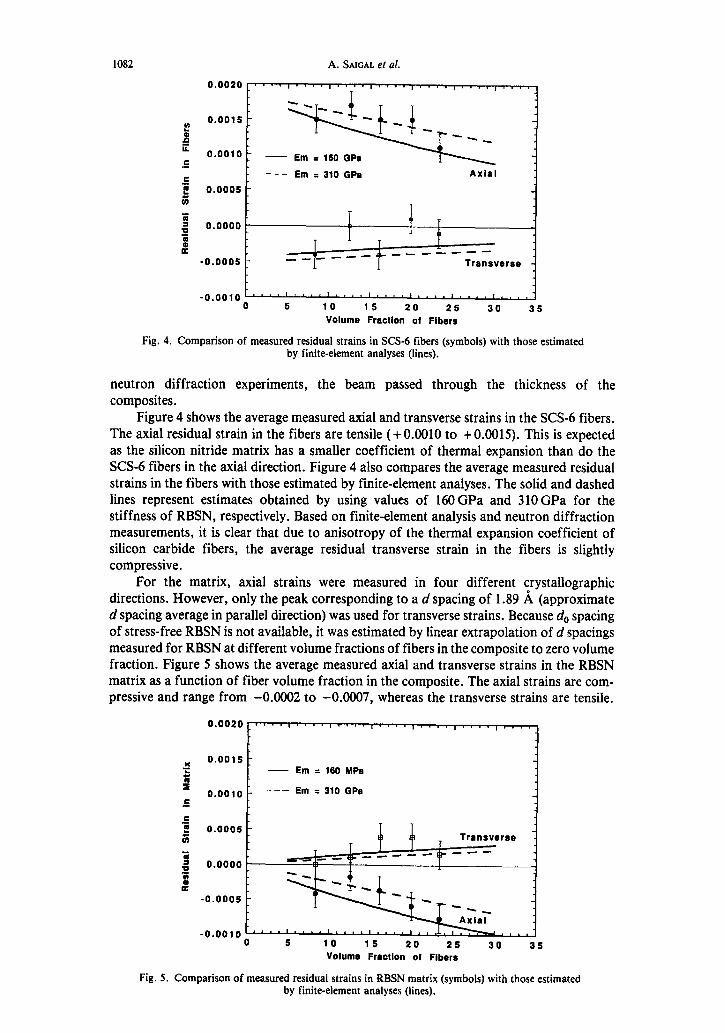
Fig. 4. Comparison of measured residual strains in SCS-6 fibers (symbols) with those estimated by finite-element analyses (lines).
neutron diffraction experiments, the beam passed through the thickness of the composites.
Figure 4 shows the average measured axial and transverse strains in the SCS-6 fibers. The axial residual strain in the fibers are tensile (+ 0.0010 to + 0.0015). This is expected as the silicon nitride matrix has a smaller coefficient of thermal expansion than do the SCS-6 fibers in the axial direction. Figure 4 also compares the average measured residual strains in the fibers with those estimated by finite-element analyses. The solid and dashed lines represent estimates obtained by using values of 160 GPa and 310 GPa for the stiffness of RBSN, respectively. Based on finite-element analysis and neutron diffraction measurements, it is clear that due to anisotropy of the thermal expansion coefficient of silicon carbide fibers, the average residual transverse strain in the fibers is slightly compressive.
For the matrix, axial strains were measured in four different crystallographic directions. However, only the peak corresponding to a d spacing of 1.89 I! (approximate d spacing average in parallel direction) was used for transverse strains. Because d,, spacing of stress-free RBSN is not available, it was estimated by linear extrapolation of d spacings measured for RBSN at different volume fractions of fibers in the composite to zero volume fraction. Figure 5 shows the average measured axial and transverse strains in the RBSN matrix as a function of fiber volume fraction in the composite. The axial strains are com- pressive and range from -0.0002 to -0.0007, whereas the transverse strains are tensile.
_ Transverse
10 15 20 25 30 35 Volume Fraction of Fibers
Fig. 5. Comparison of measured residual strains in RBSN matrix (symbols) with those estimated by finite-element analyses (lines).
Fiber-reinforced silicon nitride composites
79-....,....,....,....,....,....
l
Fig. 6. Measured composite density as a function of volume fraction of fibers.
1083
The measured residual strains in the fibers and in the matrix are in general agreement with those estimated by finite-element analyses. However, it appears that the measured axial compressive strain in the matrix first decreases and then steadily increases as the volume fraction of the fibers in the composite increases. Similarly, it appears that the measured axial tensile strain in the fibers first increases and then steadily decreases as the volume fraction of the fibers in the composite increases. On the other hand, finite-element analyses show that the compressive strain in the matrix and the tensile strain in the fiber, along the fiber axis and as a function of volume fraction of fibers, should steadily increase and decrease, respectively.
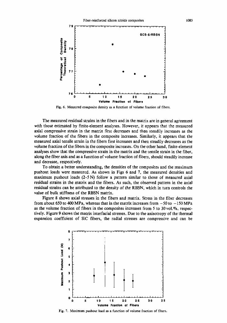
To obtain a better understanding, the densities of the composites and the maximum pushout loads were measured. As shown in Figs 6 and 7, the measured densities and maximum pushout loads (2-5 N) follow a pattern similar to those of measured axial residual strains in the matrix and the fibers. As such, the observed pattern in the axial residual strains can be attributed to the density of the RBSN, which in turn controls the value of bulk stiffness of the RBSN matrix.
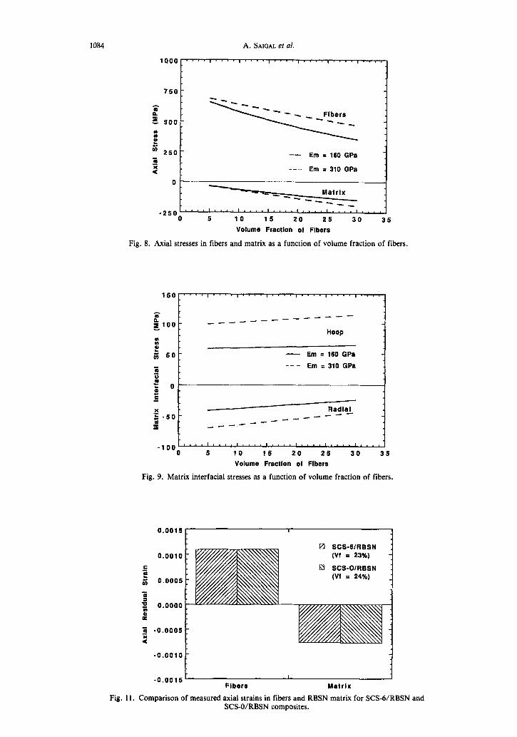
Figure 8 shows axial stresses in the fibers and matrix. Stress in the fiber decreases from about 650 to 400 MPa, whereas that in the matrix increases from - 50 to - 150 MPa as the volume fraction of fibers in the composites increases from 5 to 30 vol.%, respec- tively. Figure 9 shows the matrix interfacial stresses. Due to the anisotropy of the thermal expansion coefficient of Sic fibers, the radial stresses are compressive and can be
I....I....11...I....l.,..II.,I
5 10 16 20 26 30 35
Volume Fraction of Fibers
Fig. 7. Maximum pushout load as a function of volume fraction of fibers.
1084 A. SAIGAL et al.
750
4 5oo: ; j
b a - 250 - 5
Em = 160 GPa
9 --- Em = 310 GPa
0
-250 “““‘,.““““““‘,““““.” 0 5 10 15 20 26 30 35
VOkJtIIe Fraction of Flbers
Fig. 8. Axial stresses in fibers and matrix as a function of volume fraction of fibers.
Fig. 11.
150 ,“‘I.“‘I..“I.,‘.I”,‘I..“I’.”
z 5100 - __----- __-----
Hoop
:: e 3 50- - Em = 160 GPa
--- 5 Em q 310 GPa
P = 0 0 ,E
M Radial g -50 -
_--- _--- _--- --
2t
-100 “‘~““.‘~~~~‘~.~~‘~~.~‘~.~~‘.~~, 0 5 10 15 20 25 30 35
Volume Fraction of Flbers
Fig. 9. Matrix interfacial stresses as a function of volume fraction of fibers.
0.0015 [ I 4
0.0010 I S e tj 0.0005
Z
ii
0.0000 0 K
3 -0.0005 9 I
-0.0010
1
q SCS-GIRBSN (Vf = 23%)
M SCS-OIRBSN w I 24%)
-0.0015~ I i
Fibers Matrix
Comparison of measured axial strains in fibers and RBSN matrix for SCSd/RBSN SCS-O/RBSN composites.
and
Fiber-reinforced silicon nitride composites 1085
hoop ----
--------
radial 1
t- SCS-GIABSN 1
loo- --- SCS-OIRBSN axial
--a______--w---
150 I I I I I
0.5 0.6 0.7 0.6 0.9 1 1.1
xla
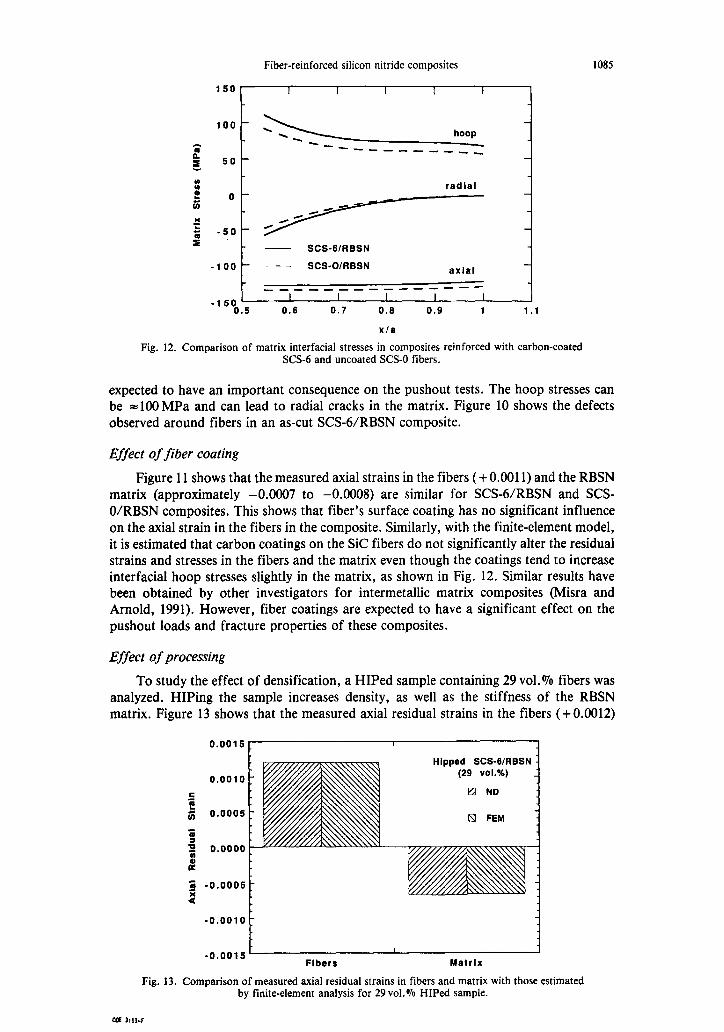
Fig. 12. Comparison of matrix interfacial stresses in composites reinforced with carbon-coated SCS-6 and uncoated 5X3-0 fibers.
expected to have an important consequence on the pushout tests. The hoop stresses can be =lOOMPa and can lead to radial cracks in the matrix. Figure 10 shows the defects observed around fibers in an as-cut SCS6/RBSN composite.
Effect of fiber coating
Figure 11 shows that the measured axial strains in the fibers (+ 0.0011) and the RBSN matrix (approximately -0.0007 to -0.0008) are similar for SCSd/RBSN and SCS- O/RBSN composites. This shows that fiber’s surface coating has no significant influence on the axial strain in the fibers in the composite. Similarly, with the finite-element model, it is estimated that carbon coatings on the Sic fibers do not significantly alter the residual strains and stresses in the fibers and the matrix even though the coatings tend to increase interfacial hoop stresses slightly in the matrix, as shown in Fig. 12. Similar results have been obtained by other investigators for intermetallic matrix composites (Misra and Arnold, 1991). However, fiber coatings are expected to have a significant effect on the pushout loads and fracture properties of these composites.
Effect of processing
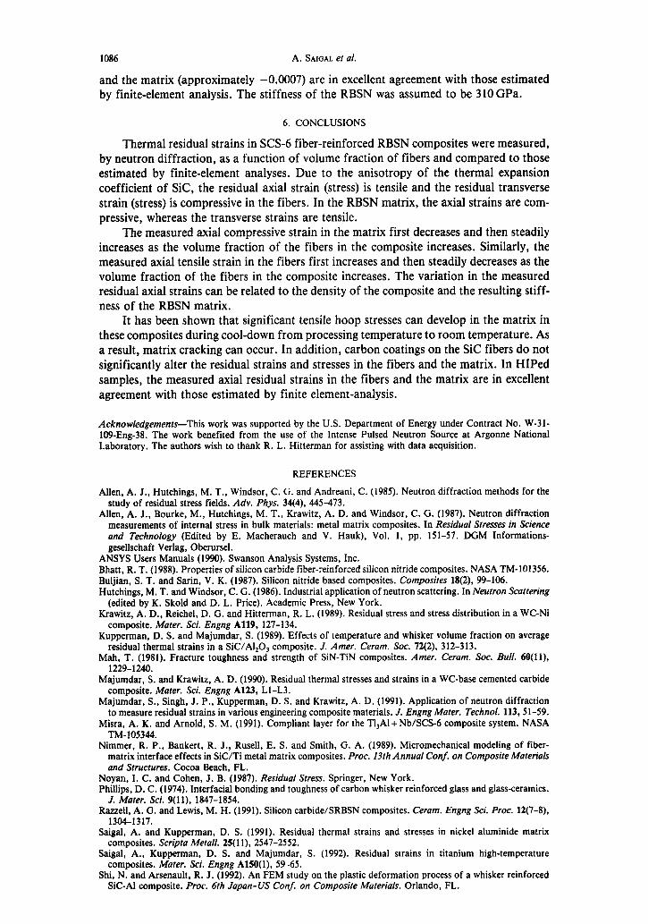
To study the effect of densification, a HIPed sample containing 29 vol.% fibers was analyzed. HIPing the sample increases density, as well as the stiffness of the RBSN matrix. Figure 13 shows that the measured axial residual strains in the fibers (+ 0.0012)
0.0016 1 I 4
Hipped SCS-G/RBSN (29 vol.%)
tZi ND
Q FEM
0.0010
lz H G 0.0005
5 : 0 0.0000
t
g -0.0005
4
1::::::: Fibers hlatrtx
Fig. 13. Comparison of measured axial residual strains in fibers and matrix with those estimated by finite-element analysis for 29 vol.% HIPed sample.
1086 A. SAIGAL et al.
and the matrix (approximately -0.0007) are in excellent agreement with those estimated by finite-element analysis. The stiffness of the RBSN was assumed to be 310 GPa.
6. CONCLUSIONS
Thermal residual strains in SCS-6 fiber-reinforced RBSN composites were measured, by neutron diffraction, as a function of volume fraction of fibers and compared to those estimated by finite-element analyses. Due to the anisotropy of the thermal expansion coefficient of Sic, the residual axial strain (stress) is tensile and the residual transverse strain (stress) is compressive in the fibers. In the RBSN matrix, the axial strains are com- pressive, whereas the transverse strains are tensile.
The measured axial compressive strain in the matrix first decreases and then steadily increases as the volume fraction of the fibers in the composite increases. Similarly, the measured axial tensile strain in the fibers first increases and then steadily decreases as the volume fraction of the fibers in the composite increases. The variation in the measured residual axial strains can be related to the density of the composite and the resulting stiff- ness of the RBSN matrix.
It has been shown that significant tensile hoop stresses can develop in the matrix in these composites during cool-down from processing temperature to room temperature. As a result, matrix cracking can occur. In addition, carbon coatings on the Sic fibers do not significantly alter the residual strains and stresses in the fibers and the matrix. In HIPed samples, the measured axial residual strains in the fibers and the matrix are in excellent agreement with those estimated by finite element-analysis.
Acknowledgements-This work was supported by the U.S. Department of Energy under Contract No. W-31- 109-Eng-38. The work benefited from the use of the Intense Pulsed Neutron Source at Argonne National Laboratory. The authors wish to thank R. L. Hitterman for assisting with data acquisition.
REFERENCES
Allen, A. J., Hutchings, M. T., Windsor, C. G. and Andreani, C. (1985). Neutron diffraction methods for the study of residual stress fields. Adv. Phys. 34(4), 445-473.
Allen, A. J., Bourke, M., Hutchings, M. T., Krawitz, A. D. and Windsor, C. G. (1987). Neutron diffraction measurements of internal stress in bulk materials: metal matrix composites. In Residual Stresses in Science and Technology (Edited by E. Macherauch and V. Hauk), Vol. 1, pp. 151-57. DGM Informations- gesellschaft Verlag, Oberursel.
ANSYS Users Manuals (1990). Swanson Analysis Systems, Inc. Bhatt, R. T. (1988). Properties of silicon carbide fiber-reinforced silicon nitride composites. NASA TM-101356. Buljian, S. T. and Sarin, V. K. (1987). Silicon nitride based composites. Composites 18(2), 99-106. Hutchings, M. T. and Windsor, C. G. (1986). Industrial application of neutron scattering. In Neutron Scattering
(edited by K. Skold and D. L. Price). Academic Press, New York. Krawitz, A. D., Reichel, D. G. and Hitterman, R. L. (1989). Residual stress and stress distribution in a WC-N1
composite. Moter. Sci. Engng A119, 127-134. Kupperman, D. S. and Majumdar, S. (1989). Effects of temperature and whisker volume fraction on average
residual thermal strains in a SiC/Al,O, composite. J. Amer. Cerom. Sot. 72(2), 312-313. Mah, T. (1981). Fracture toughness and strength of SiN-TiN composites. Amer. Cerom. Sot. Bull. 60(11),
1229-1240. Majumdar, S. and Krawitz, A. D. (1990). Residual thermal stresses and strains in a WC-base cemented carbide
composite. Mater. Sci. Engng A123, Ll-L3. Majumdar, S., Singh, J. P., Kupperman, D. S. and Krawitz, A. D. (1991). Application of neutron diffraction
to measure residual strains in various engineering composite materials. J. Engng Mater. Technol. 113,51-59. Misra, A. K. and Arnold, S. M. (1991). Compliant layer for the T&Al + Nb/SCS-6 composite system. NASA
TM-105344. Nimmer, R. P., Bankert, R. J., Rusell, E. S. and Smith, G. A. (1989). Micromechanical modeling of fiber-
matrix interface effects in SiC/Ti metal matrix composites. Proc. 13th Annual Conf. on Composite Moteriols ond Structures. Cocoa Beach, FL.
Noyan, I. C. and Cohen, J. B. (1987). Residual Stress. Springer, New York. Phillips, D. C. (1974). Interfacial bonding and toughness of carbon whisker reinforced glass and glass-ceramics.
J. Mater. Sci. 9(11), 1847-1854. Razzell, A. G. and Lewis, M. H. (1991). Silicon carbide/SRBSN composites. Cerom. Engng Sci. Proc. 12(7-8),
1304-1317. Saigal, A. and Kupperman, D. S. (1991). Residual thermal strains and stresses in nickel aluminide matrix
composites. Scripta Metall. 25(11), 2547-2552. Saigal, A., Kupperman, D. S. and Majumdar, S. (1992). Residual strains in titanium high-temperature
composites. Mater. Sci. Engng A150(1), 59-65. Shi, N. and Arsenault, R. J. (1992). An FEM study on the plastic deformation process of a whisker reinforced
SIC-Al composite. Proc. 6th Japan-US Conf. on Composite Materials. Orlando, FL.