the spe foundation through member donations and a contribution from offshore europe
TRANSCRIPT

1
Primary funding is provided by
The SPE Foundation through member donations
and a contribution from Offshore Europe
The Society is grateful to those companies that allow their
professionals to serve as lecturers
Additional support provided by AIME
Society of Petroleum Engineers
Distinguished Lecturer Program www.spe.org/dl 1

2
Perforating with Lasers: Are You
Ready for the Power of Light?
Brian C. Gahan, PE Laser Rock Technologies, LLC
Society of Petroleum Engineers
Distinguished Lecturer Program www.spe.org/dl

3
Presentation Outline
• Laser Applications Background
• Downhole Laser Selection
• Perforation Tests
• High Power Fiber Laser (HPFL)
Field Applications Examples
• Summary

4
Lasers…In the beginning
Light Amplification by Stimulated Emission of
Radiation
Albert Einstein theorized the
concepts of the “photoelectric
effect” in a paper published in
1905 – for which he later won
the Nobel Prize in Physics in
1922.


7
Research Lasers Applied
CO2 – Carbon Dioxide
Nd:YAG - neodymium-doped yttrium
aluminum garnet
LP:YAG – Lamp-Pumped Nd:YAG
DP:YAG – Diode-Pumped Nd:YAG
HPFL – High Power Fiber Laser
COIL – Chemical Oxygen Iodine Laser

8
Laser Spectrum
A B C D
A) Diode B) YAG, Fiber C) MIRACL D) CO2

9
Specific Energy Defined
33 cm
kJ
/seccm
kW
dV/dt
P
RemovedVolume
InputEnergySE
Reference: SPE 77627
Lower SE Value = Higher Efficiency
10
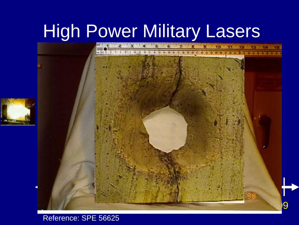
High Power Military Lasers
Q: Can Lasers Penetrate All Rock?
A: Yes, But Inefficient and Expensive
Type Power (kW) Λ (μm) Location
COIL 6.8 1.34 USAF
CO2 50,150 10.6 USAF
MIRACL 1600 3.4 US Army
Reference: SPE 56625
97 00 98 99 01 02 03 04 05 06 07 08 09

11
High Power Industrial Lasers
Q: How Much Energy Does it Take?
A: Much Less Than Literature Predicted
Type Power (kW) Λ (μm) Location
Nd:YAG 1.6 1.06 ANL
CO2 6 10.6 ANL
Diode 4 0.8 NA Tech
Reference: SPE 71466, 84353
97 00 98 99 01 02 03 04 05 06 07 08 09
12
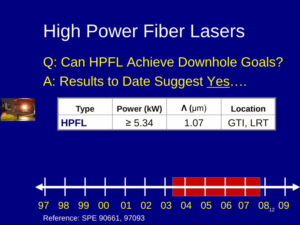
High Power Fiber Lasers
Q: Can HPFL Achieve Downhole Goals?
A: Results to Date Suggest Yes….
Type Power (kW) Λ (μm) Location
HPFL ≥ 5.34 1.07 GTI, LRT
Reference: SPE 90661, 97093
97 00 98 99 01 02 03 04 05 06 07 08 09
13
• Several Methods Observed
• Function of Thermal Properties
– Carbonates – Dissociation
CaCO3 →CaO + CO2
– Sandstones – Spallation
– Shales – Spallation
– Steel - Melt
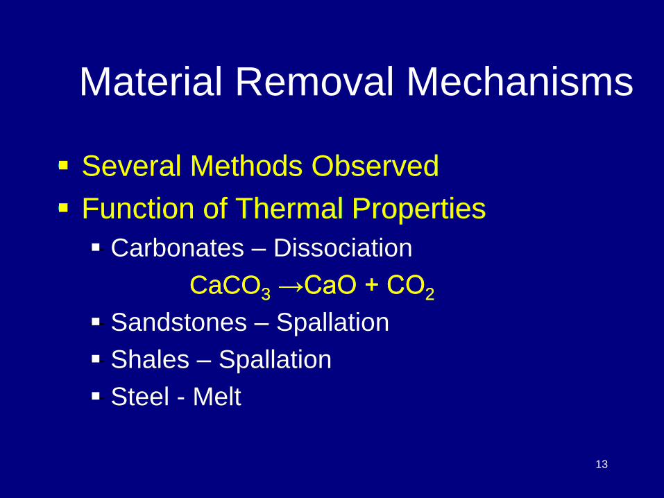
Material Removal Mechanisms
Several Methods Observed
Function of Thermal Properties
Carbonates – Dissociation
CaCO3 →CaO + CO2
Sandstones – Spallation
Shales – Spallation
Steel - Melt

14
Possible Downhole Applications
Drilling
Perforating
Seismic Shot Holes
Casing Cutting/ Abandonment
Offshore Platform Abandonment
Casing “Windows” for Multi-Laterals
Downhole Slotted Liners/Screens
15
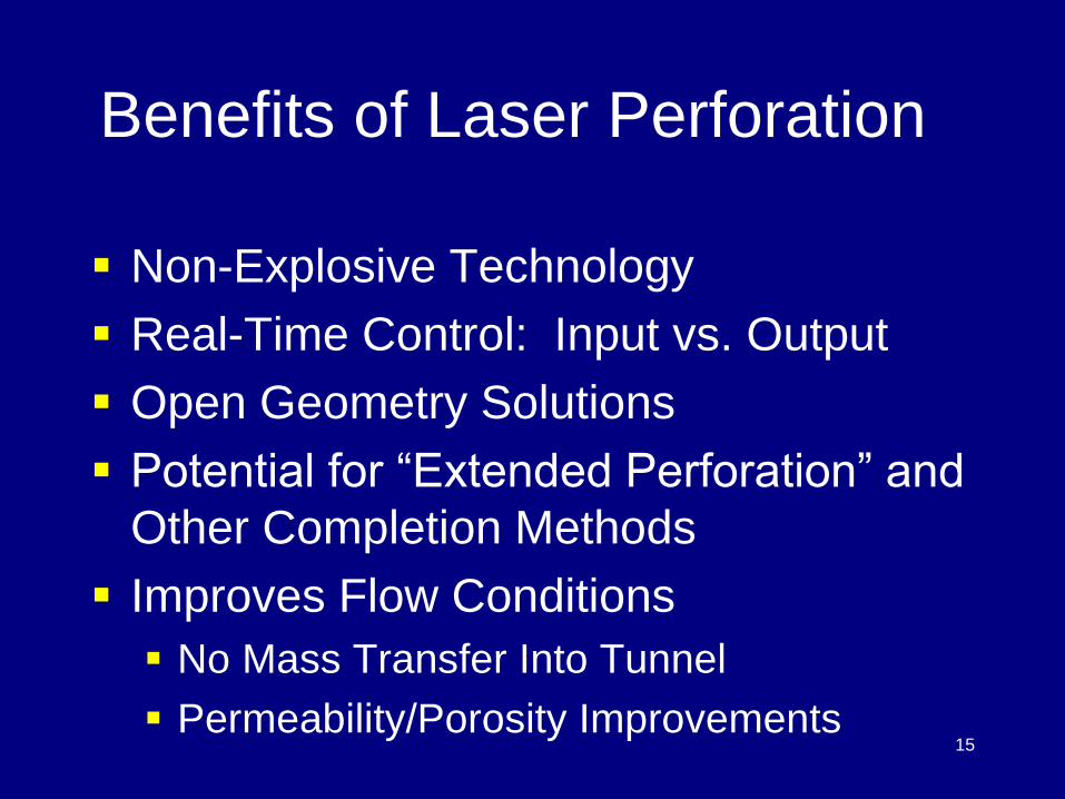
Benefits of Laser Perforation
Non-Explosive Technology
Real-Time Control: Input vs. Output
Open Geometry Solutions
Potential for “Extended Perforation” and
Other Completion Methods
Improves Flow Conditions
No Mass Transfer Into Tunnel
Permeability/Porosity Improvements
16
Presentation Outline
• Laser Applications Background
• Downhole Laser Selection
• Perforation Tests
• High Power Fiber Laser (HPFL)
Field Applications Examples
• Summary

17
Downhole Laser Selection
Technical
Provide Required Output Power
Deliver Beam to Downhole Target
Operate at Downhole Conditions
Cut / Drill Multiple Materials
Mobile, Rugged On-site Deployment

18
Downhole Laser Selection
Economic
Existing, Commercially Available
Minimal Maintenance and Repair
High Energy Conversion Efficiencies
Minimal Energy Losses
Attenuation
Absorbtion
19
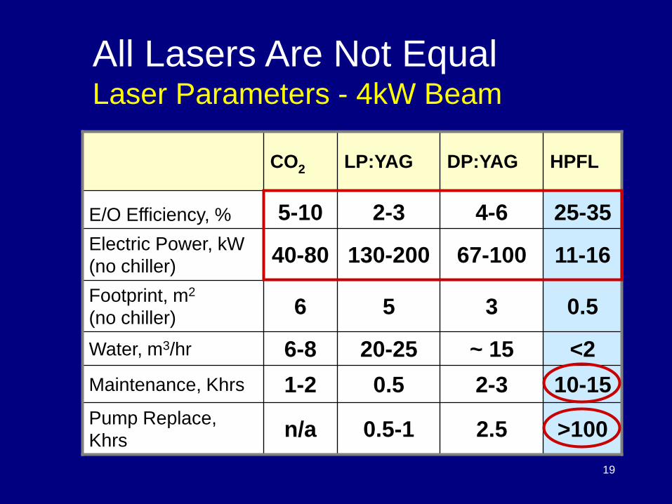
All Lasers Are Not Equal Laser Parameters - 4kW Beam
CO2 LP:YAG DP:YAG HPFL
E/O Efficiency, % 5-10 2-3 4-6 25-35
Electric Power, kW
(no chiller) 40-80 130-200 67-100 11-16
Footprint, m2
(no chiller) 6 5 3 0.5
Water, m3/hr 6-8 20-25 ~ 15 <2
Maintenance, Khrs 1-2 0.5 2-3 10-15
Pump Replace,
Khrs n/a 0.5-1 2.5 >100

20
All Lasers Are Not Equal Power Required for 4kW Beam
0
50
100
150
200
250
2 5 8 11 14 17 20 23
E/O Efficiency (%)
Po
wer
Req
uir
ed
, K
w Power Required to Generate
4 kW Output Beam LP:YAG
HPFL
DP:YAG
CO2

21
All Lasers Are Not Equal Comparison of Lowest SE
Laser Comparasion
0
2
4
6
8
10
12
14
16
COIL CO2 Nd:YAG Fiber
Laser Type
Sp
ecif
ic e
nerg
y (
kJ/c
c)
BG Ls
BG = Berea Gray Sandstone
LS = Limestone

22
High Power Fiber Laser (HPFL)
Power: Up to 50 kW + /unit
Wavelength: Yb: 1070 nm
E/O Efficiency: 25-30+%
Dimensions (10 kW):
60 x 80 x 160 cm
(2.0 x 2.5 x 5.25 ft)
Footprint: 0.5 m2 (5.38 ft2)
Weight: 400 kg (882 lb)

23
Presentation Outline
• Laser Applications Background
• Downhole Laser Selection
• Perforation Tests
• High Power Fiber Laser (HPFL)
Field Applications Examples
• Summary

24
HPFL Perforation: Limestone
HPFL Perforation in Reservoir Limestone
Length: 6 inches Power: 5.34 kW
Beam Application: Continuous
Lased
Tunnel 6”
Natural
Fractures

25
HPFL Perforation: Limestone
HPFL Perforation in Quarry Limestone
Length: 12.2 inches Power: 5.34 kW
Beam Application: Continuous
Lased Tunnel
12.2”
26
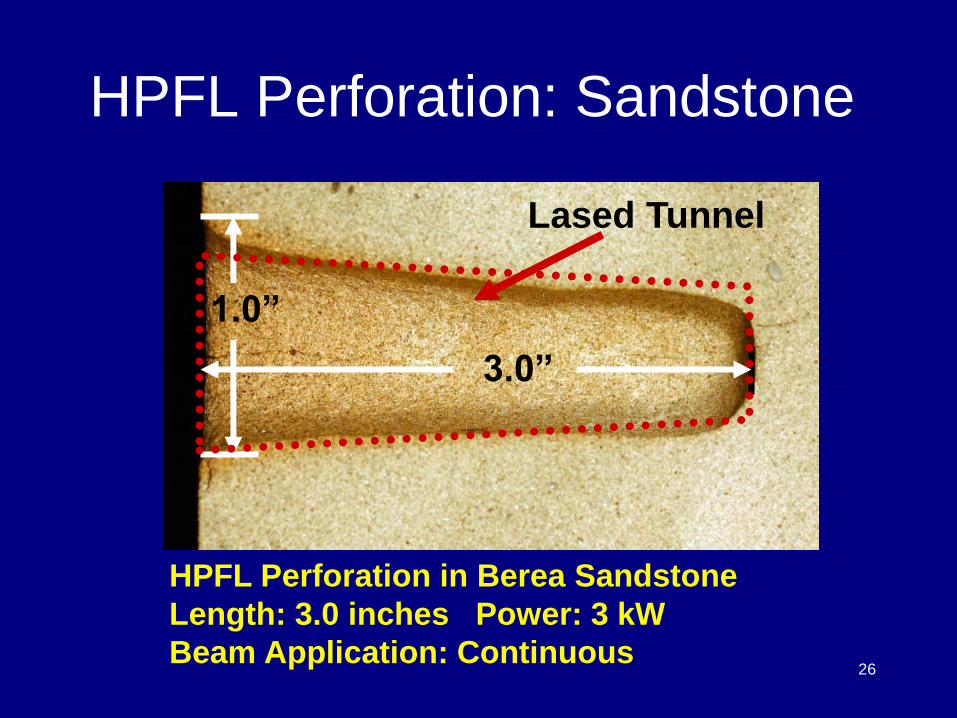
HPFL Perforation: Sandstone
HPFL Perforation in Berea Sandstone
Length: 3.0 inches Power: 3 kW
Beam Application: Continuous
Lased Tunnel
3.0”
1.0”

27
HPFL Perforation Through Steel, Cement, and SS
Power: 4.4 kW Beam Application: Continuous
HPFL Perforation: Composite
Berea Berea

28
Small Block Perf Test
Creating 1 x 3 Inch Tunnel in Small Berea Block

29
Large Block Perf Test
1-inch Grid for Data
Acquisition Before and
After Lasing
12.0 in
12.0 in
12.0 in
30
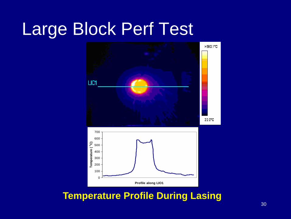
Large Block Perf Test
0
100
200
300
400
500
600
700
Profile along LIO1
Te
mp
era
ture
(oC
)
Temperature Profile During Lasing

31
Tunnel Cutaway Tunnel Cutaway with 2-D Permeability Map
Large Block Perf Test Post-Lase Analysis
Micrograph of Tunnel Wall
32
Large Block Perf Test Post-Lase Analysis
Thin Section Comparison of Tunnel Surface
Note: Void Space is Blue

33
High Pressure Cell for Laser Applications Simulates Downhole Pressure Conditions
Initial Tests Successful (Triaxial)
Testing Under Various Configurations
High Pressure Perf Tests

34
First In-Situ Laser Perf Study Cuttings Expelled (Underbalanced)
Pressure/Stress Improves Cutting Efficiency
High Pressure Perf Tests

35
HP Perf Tests– Clad Test CT Simulated Wellbore
Berea Sandstone
Bedford Limestone
0.5” Steel Disc
Cement
Rock Core
36
HP Perf Tests– Clad Test CT
Long view of X-ray CT scan image of laser perforated
limestone core sample
0.5 inch steel disc
1.5 inch cement plug (super yield 250)
4.5 inch depth

37
HP Perf Tests - Sandstone
sandstone sample in the high pressure perforation cell at ambient conditions,
confining pressure, axial and pore pressure.
High Pressure Laser Perforation Trials
Berea Sandstone5.34 kW, 8.0 Seconds, 0.35 Inch Beam Diameter
0
5
10
15
20
25
30
B1 B2 B3 B4 B5 Brine Oil
Trial Number with Pressure Conditions, psi
Sp
ecif
ic E
nerg
y,
kJ/c
c
Pc = 0
Pa = 0
Pp = 0
Pc = 1120
Pa = 1180
Pp = 0
Pc = 1101
Pa = 1106
Pp = 864
Pc = 2031
Pa = 2000
Pp = 0
Pc = 2100
Pa = 2215
Pp = 1565
Pc = 1893
Pa = 1991
Pp = 0
Pc = 1844
Pa = 1956
Pp = 0
Pc = Confining Pressure
Pa = Axial Pressure
Pp = Pore Pressure

38
HP Perf Tests - Limestone
High Pressure Laser Perforation Trials
Indiana Limestone5.34 kW, 8.0 Seconds, 0.35 Inch Beam Diameter
0
20
40
60
80
100
120
L1 L2 L3 L4 L5 Brine Oil
Trial Number with Pressure Conditions, psi
Sp
ecif
ic E
nerg
y,
kJ/c
c
Pc = 0
Pa = 0
Pp = 0
Pc = 1029
Pa = 1139
Pp = 0
Pc = 982
Pa = 1056
Pp = 864
Pc = 2069
Pa = 2169
Pp = 0
Pc = 2100
Pa = 2225
Pp = 1615
Pc = 1922
Pa = 1981
Pp = 0
Pc = 1800
Pa = 1930
Pp = 0
Pc = Confining Pressure
Pa = Axial Pressure
Pp = Pore Pressure
39
Presentation Outline
• Laser Applications Background
• Downhole Laser Selection
• Perforation Tests
• High Power Fiber Laser (HPFL)
Field Applications Examples
• Summary

40
HPFL Field Applications Well Completions Concept
Fiber Optics Downhole via CT

41
HPFL Field Application Examples US Army ZEUS Humvee

42
HPFL Field Application Examples US Navy LaWS

43
HPFL Field Application Examples Earthquake Retrofit of CA Hospital
Source: EWI
Controller, Chiller and
Power Conditioning HPFL
Laser Pilot Bit: 265 mm holes for up to 19.0 mm diameter rebar
Processing
Head

44
Presentation Outline
• Laser Applications Background
• Downhole Laser Selection
• Perforation Tests
• High Power Fiber Laser (HPFL)
Field Applications Examples
• Summary

45
Summary
Lasers Can Break/Cut All Rock
Previous Literature Outdated
Potential Non-Explosive Perf Option
HPFL: Breakthrough Technology
Most Efficient, Reliable Laser Type
Meets Field Deployment Needs
Commercially Available
Over Time: Power ↑, $/kW ↓

46
Summary Successful Lab Demos
Longest Tunnel to Date in SS, LS
Minimal Removal Energy Observed
Optimal Fluid Flow Conditions Result
First In-Situ Laser Perf Study
Cuttings Expelled (Underbalanced)
Pressure/Stress Improves Cutting Efficiency

47
Multi-Dimensional Applications
Tool Location Wellbore
Kick off into Reservoir
Perf, Slot, Surface Ablation
Proven Remote Deployment
US Army Humvee
Construction - CA Hospital
Summary
48
Thank You For Your Attention


50
Society of Petroleum Engineers
Distinguished Lecturer Program www.spe.org/dl 50
Your Feedback is Important
Enter your section in the DL Evaluation Contest by
completing the evaluation form for this presentation :
Click on: Section Evaluation