spe 155320 offshore drilling & well testing of a hpht gas
TRANSCRIPT
SPE 155320
Offshore Drilling & Well Testing Of A HPHT Gas Well: A Case Study Prerak H Shah, SPE, Harsh T Pandya, SPE, Harsh Sharma , SPE, Arpit Saxena, SPE, Gujarat State Petroleum Corporation Limited (GSPC)
Copyright 2012, Society of Petroleum Engineers This paper was prepared for presentation at the SPE Oil and Gas India Conference and Exhibition held in Mumbai, India, 28–30 March 2012. This paper was selected for presentation by an SPE program committee following review of information contained in an abstract submitted by the author(s). Contents of the paper have not been reviewed by the Society of Petroleum Engineers and are subject to correction by the author(s). The material does not necessarily reflect any position of the Society of Petroleum Engineers, its officers, or members. Electronic reproduction, distribution, or storage of any part of this paper without the written consent of the Society of Petroleum Engineers is prohibited. Permission to reproduce in print is restricted to an abstract of not more than 300 words; illustrations may not be copied. The abstract must contain conspicuous acknowledgment of SPE copyright.
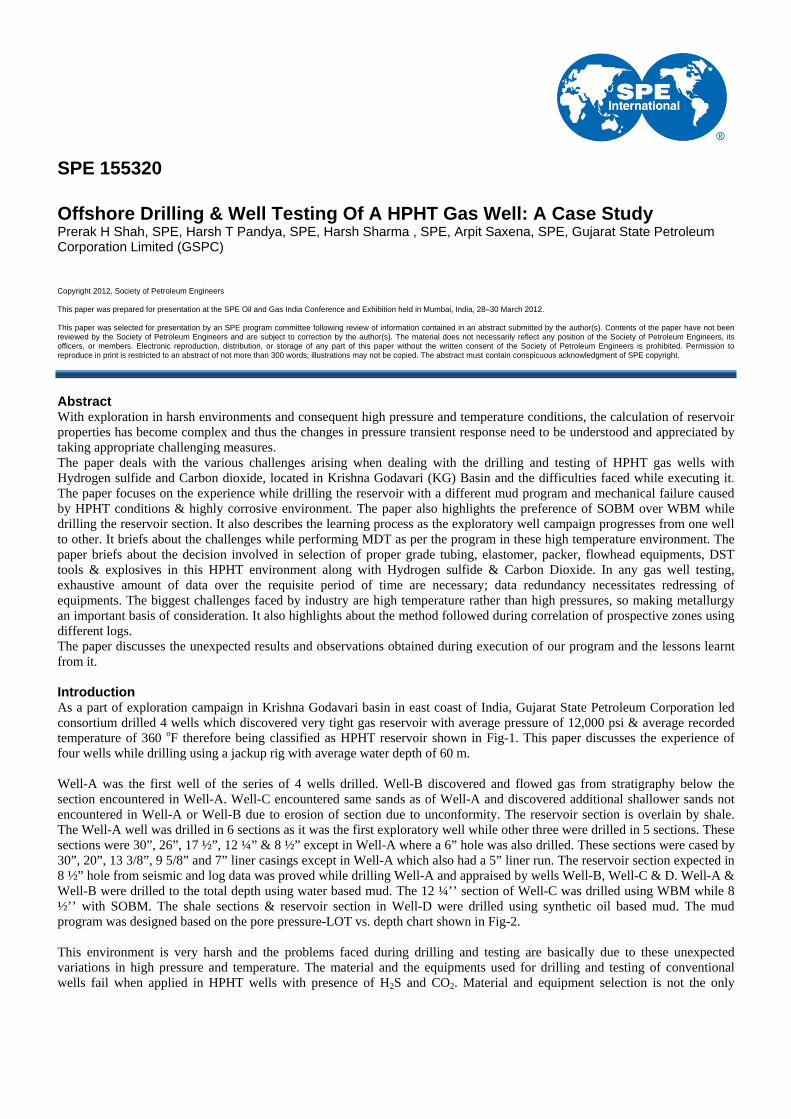
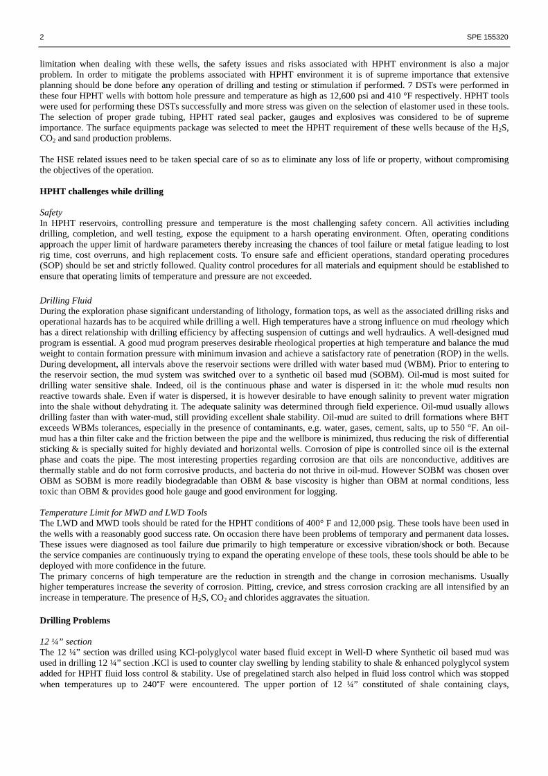
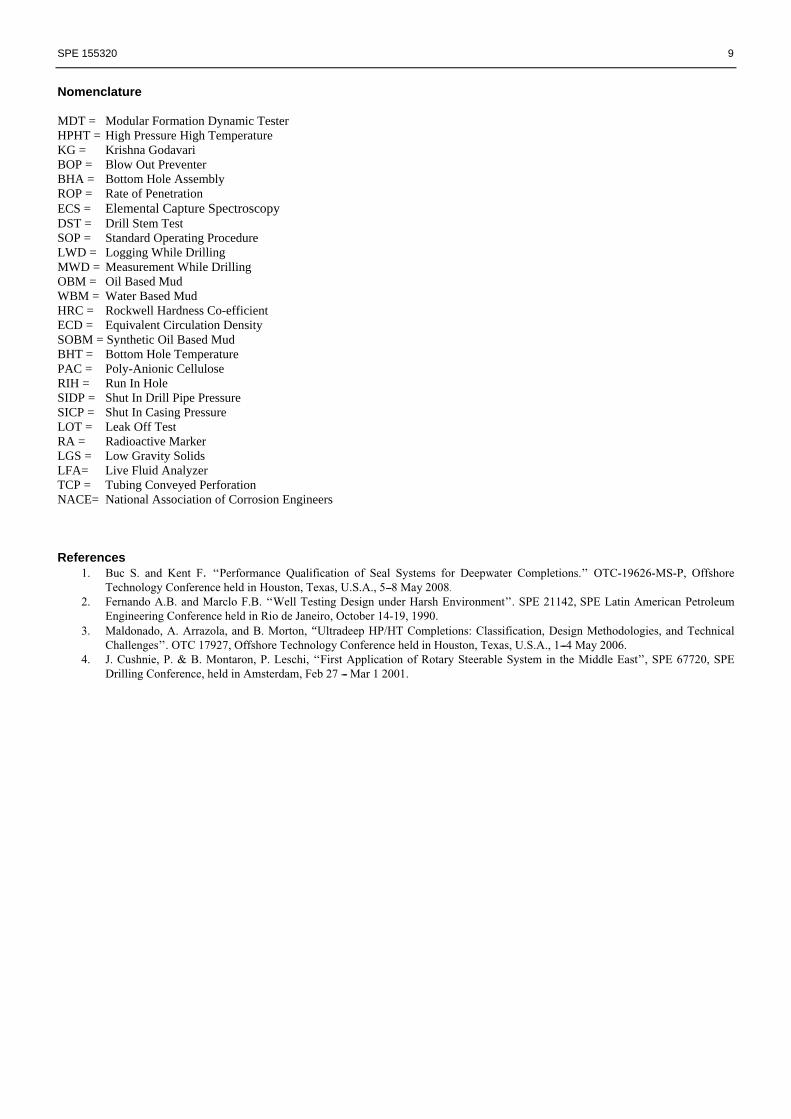
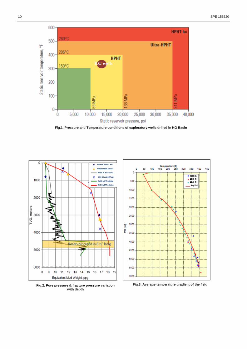
Abstract With exploration in harsh environments and consequent high pressure and temperature conditions, the calculation of reservoir properties has become complex and thus the changes in pressure transient response need to be understood and appreciated by taking appropriate challenging measures. The paper deals with the various challenges arising when dealing with the drilling and testing of HPHT gas wells with Hydrogen sulfide and Carbon dioxide, located in Krishna Godavari (KG) Basin and the difficulties faced while executing it. The paper focuses on the experience while drilling the reservoir with a different mud program and mechanical failure caused by HPHT conditions & highly corrosive environment. The paper also highlights the preference of SOBM over WBM while drilling the reservoir section. It also describes the learning process as the exploratory well campaign progresses from one well to other. It briefs about the challenges while performing MDT as per the program in these high temperature environment. The paper briefs about the decision involved in selection of proper grade tubing, elastomer, packer, flowhead equipments, DST tools & explosives in this HPHT environment along with Hydrogen sulfide & Carbon Dioxide. In any gas well testing, exhaustive amount of data over the requisite period of time are necessary; data redundancy necessitates redressing of equipments. The biggest challenges faced by industry are high temperature rather than high pressures, so making metallurgy an important basis of consideration. It also highlights about the method followed during correlation of prospective zones using different logs. The paper discusses the unexpected results and observations obtained during execution of our program and the lessons learnt from it. Introduction As a part of exploration campaign in Krishna Godavari basin in east coast of India, Gujarat State Petroleum Corporation led consortium drilled 4 wells which discovered very tight gas reservoir with average pressure of 12,000 psi & average recorded temperature of 360 oF therefore being classified as HPHT reservoir shown in Fig-1. This paper discusses the experience of four wells while drilling using a jackup rig with average water depth of 60 m. Well-A was the first well of the series of 4 wells drilled. Well-B discovered and flowed gas from stratigraphy below the section encountered in Well-A. Well-C encountered same sands as of Well-A and discovered additional shallower sands not encountered in Well-A or Well-B due to erosion of section due to unconformity. The reservoir section is overlain by shale. The Well-A well was drilled in 6 sections as it was the first exploratory well while other three were drilled in 5 sections. These sections were 30”, 26”, 17 ½”, 12 ¼” & 8 ½” except in Well-A where a 6” hole was also drilled. These sections were cased by 30”, 20”, 13 3/8”, 9 5/8” and 7” liner casings except in Well-A which also had a 5” liner run. The reservoir section expected in 8 ½” hole from seismic and log data was proved while drilling Well-A and appraised by wells Well-B, Well-C & D. Well-A & Well-B were drilled to the total depth using water based mud. The 12 ¼’’ section of Well-C was drilled using WBM while 8 ½’’ with SOBM. The shale sections & reservoir section in Well-D were drilled using synthetic oil based mud. The mud program was designed based on the pore pressure-LOT vs. depth chart shown in Fig-2. This environment is very harsh and the problems faced during drilling and testing are basically due to these unexpected variations in high pressure and temperature. The material and the equipments used for drilling and testing of conventional wells fail when applied in HPHT wells with presence of H2S and CO2. Material and equipment selection is not the only
2 SPE 155320
limitation when dealing with these wells, the safety issues and risks associated with HPHT environment is also a major problem. In order to mitigate the problems associated with HPHT environment it is of supreme importance that extensive planning should be done before any operation of drilling and testing or stimulation if performed. 7 DSTs were performed in these four HPHT wells with bottom hole pressure and temperature as high as 12,600 psi and 410 °F respectively. HPHT tools were used for performing these DSTs successfully and more stress was given on the selection of elastomer used in these tools. The selection of proper grade tubing, HPHT rated seal packer, gauges and explosives was considered to be of supreme importance. The surface equipments package was selected to meet the HPHT requirement of these wells because of the H2S, CO2 and sand production problems. The HSE related issues need to be taken special care of so as to eliminate any loss of life or property, without compromising the objectives of the operation. HPHT challenges while drilling Safety In HPHT reservoirs, controlling pressure and temperature is the most challenging safety concern. All activities including drilling, completion, and well testing, expose the equipment to a harsh operating environment. Often, operating conditions approach the upper limit of hardware parameters thereby increasing the chances of tool failure or metal fatigue leading to lost rig time, cost overruns, and high replacement costs. To ensure safe and efficient operations, standard operating procedures (SOP) should be set and strictly followed. Quality control procedures for all materials and equipment should be established to ensure that operating limits of temperature and pressure are not exceeded. Drilling Fluid During the exploration phase significant understanding of lithology, formation tops, as well as the associated drilling risks and operational hazards has to be acquired while drilling a well. High temperatures have a strong influence on mud rheology which has a direct relationship with drilling efficiency by affecting suspension of cuttings and well hydraulics. A well-designed mud program is essential. A good mud program preserves desirable rheological properties at high temperature and balance the mud weight to contain formation pressure with minimum invasion and achieve a satisfactory rate of penetration (ROP) in the wells. During development, all intervals above the reservoir sections were drilled with water based mud (WBM). Prior to entering to the reservoir section, the mud system was switched over to a synthetic oil based mud (SOBM). Oil-mud is most suited for drilling water sensitive shale. Indeed, oil is the continuous phase and water is dispersed in it: the whole mud results non reactive towards shale. Even if water is dispersed, it is however desirable to have enough salinity to prevent water migration into the shale without dehydrating it. The adequate salinity was determined through field experience. Oil-mud usually allows drilling faster than with water-mud, still providing excellent shale stability. Oil-mud are suited to drill formations where BHT exceeds WBMs tolerances, especially in the presence of contaminants, e.g. water, gases, cement, salts, up to 550 °F. An oil-mud has a thin filter cake and the friction between the pipe and the wellbore is minimized, thus reducing the risk of differential sticking & is specially suited for highly deviated and horizontal wells. Corrosion of pipe is controlled since oil is the external phase and coats the pipe. The most interesting properties regarding corrosion are that oils are nonconductive, additives are thermally stable and do not form corrosive products, and bacteria do not thrive in oil-mud. However SOBM was chosen over OBM as SOBM is more readily biodegradable than OBM & base viscosity is higher than OBM at normal conditions, less toxic than OBM & provides good hole gauge and good environment for logging. Temperature Limit for MWD and LWD Tools The LWD and MWD tools should be rated for the HPHT conditions of 400° F and 12,000 psig. These tools have been used in the wells with a reasonably good success rate. On occasion there have been problems of temporary and permanent data losses. These issues were diagnosed as tool failure due primarily to high temperature or excessive vibration/shock or both. Because the service companies are continuously trying to expand the operating envelope of these tools, these tools should be able to be deployed with more confidence in the future. The primary concerns of high temperature are the reduction in strength and the change in corrosion mechanisms. Usually higher temperatures increase the severity of corrosion. Pitting, crevice, and stress corrosion cracking are all intensified by an increase in temperature. The presence of H2S, CO2 and chlorides aggravates the situation. Drilling Problems 12 ¼” section The 12 ¼” section was drilled using KCl-polyglycol water based fluid except in Well-D where Synthetic oil based mud was used in drilling 12 ¼” section .KCl is used to counter clay swelling by lending stability to shale & enhanced polyglycol system added for HPHT fluid loss control & stability. Use of pregelatined starch also helped in fluid loss control which was stopped when temperatures up to 240°F were encountered. The upper portion of 12 ¼” constituted of shale containing clays,
SPE 155320 3
argillaceous micrites, claystones & lower portion with pyrite ferrous carbonaceous with silt streaks & claystones. This section, mainly shaly sand was expected above the reservoir section in 8 ½” section was drilled directionally in all the wells. While drilling this section in Well-A many tight spots were observed with background gas & trip gas 17% due to swabbing and ROP decreasing from 30m/hr to 6m/hr with incremental cuttings observed at shale shaker on return of viscous sweeps indicating improper hole cleaning. Several wiper trips were made and viscous sweeps pumped for hole cleaning. Circulation pressure increased tremendously rising to 4000 psi and observed ECD of 10.1ppg with a mud weight of 9.1ppg & pipe got stuck. Many failed attempts were made to release free pipe but in vain & hence the stuck part of assembly was left in hole as fish and conditioned hole with cavings appearing on surface. Hence mud weight had to be raised to 9.9 ppg for hole stability. Logging the section also failed due to held ups in this section and kick off assembly ran to sidetrack the well getting held up and its bit balled with native clays giving unacceptable ROPs. Also hole fill of 5m was observed while cleanout trip prior to running casing for which finally mud weight was raised to 11.1ppg. Since drilling of section required drill/slide technique to drill directionally mud rheology was kept on a higher side and mud allowed to shear through the bit at high gpm as higher rheology requirement had led to loss of drilling fluid in form of residual fluid over cutting at shale shaker & inflow line. Drilling this section posed challenges of low gravity solids (drilled solids) requiring constant dilution & dumping leading to failure of meeting HPHT fluid loss requirement. Enhanced polyglycol cloud out at high temperatures preventing hydration of shale and hence was a choice for this section lying over the HPHT reservoir section. A partially water soluble, water dispersible blend, containing sulfonated organic resins was also used as an additive which aids in stabilizing shale sections, controlling solids dispersion and improving wall cake characteristics. Being partially soluble, it plugs micro-fractured shale and sealing shale so that the hydrostatic overbalance from the fluid column is not transmitted to the pore pressure network of shale formations adjacent to the wellbore and aids in fluid loss even at HPHT conditions.MBT values were measured continuously for clay dispersion. Polyanionic cellulose also helped in same. Learning from Well-A experience initial mud weight for this section in Well-B was kept to 11.1 ppg and increased gradually to 12.1 for hole stabilization. Similar experiences to that of Well-A were found in Well-B with bit balling and bit undergauge requiring BHA changes. High torque values were experienced in this section. Around 23% of gas cut was recorded and mud weight was raised from 12.1 to 14.5ppg.Rubber element in mud motors were observed at shakers for which the mud motor was replaced. Logging open hole in Well-B had similar experience to that of Well-A where the logging tool got struck while running in hole & well was self flowing with return density of mud decreased from 14.5 to 14.2 ppg while circulating hole clean & conditioning. SICP rose to 200 psi on closing well with BOP stack & choke manifold and on circulating out influx returns weighed as low as 13.9 ppg. On opening well, gas peak was seen to be 60% with drop in pH, increased fluid loss & overall changes in mud rheology and decrease in chloride by a margin of 7000 mg/L indicating water influx. Hence mud weight was raised to 14.7 ppg and mud treated to restore fluids and well was stabilized. Mud properties for drilling of 12 ½” sections for all wells were based on experience from Well-A & same formulation was used with rheology maintained by addition of polyanionic cellulose additive. Controlling LGS was a similar problem to that encountered in Well-A. Above problems were also encountered in Well-C which showed trip gas due to swabbing with 11.2 ppg mud which was weighed learning from experiences of Well-A & Well-B. The 9 5/8’’ casing was RIH to bottom without problem and circulated out clean with background gas at 40%. The mud weight was increased to 12.4 ppg prior performing the cement job. The temperature effects were much in evidence and to compensate the evaporation losses the addition of water made at 2 to 10 bbl/hr was done. Later, mud cooler was installed and evaporation losses were notably reduced. PAC and caustic soda in the mud maintained system properties like cuttings carrying capacity, fluid loss and alkalinity respectively. Well-D was last well drilled of four wells & SOBM was used as drilling fluid for 12 ¼” section of this well. It experienced the same problem as previously drilled wells with tight spots requiring washing & reaming down and many replacements of valve seat and rubber which could not handle the high temperatures, all of which hampering drilling operations. RSS tool got failed to activate and was tripped out for running in a mud motor. Background gas also appeared in Well-D & problems of rubber appearance at shale shaker were observed. Water influx similar to that in Well-B was observed by retort analysis and confirmed from bottoms up. 8 ½” section The 8 ½” section was lithologically made up of two sections with upper portion same as lower portion of 12 ¼” section & Lower portion made up of mainly sandstones with silty claystones & carbonaceous shale. The section was drilled in Well-A & Well-B using a low-colloid, contaminant-resistant water-based drilling fluid designed for high-temperature drilling providing good inhibition, minimizing clay migration and swelling and stable at temperatures more than 250oF. In HPHT applications it delivers high ROP and improves solids removal capability while minimizing formation damage to help reduce drilling costs. Same sections in Well-C & Well-D were drilled with SOBM. The water based KCl-enhanced polyglycol mud used for drilling 12 ¼” section was displaced by a water based low colloid, contaminant resistant mud at 9 5/8” shoe and drilled till the section total depth in Well-A & Well-B. While drilling this section in Well-A, low ROP up to 5 m/hr was encountered requiring periodic wiper trips & viscous sweeps along with pumping of enhanced polyglycol pills for inhibition and cleaning. Gas cut in mud up to 21% and BHT of 240 °F at less than half of total meterage to be drilled was encountered and mud weight was raised from 11.5 ppg to 11.8 ppg. Similar experience to that encountered while logging 12 ¼” section was encountered in this section with logging tool getting held up in hole. The gas flow rate was found to be increasing from 2% to 61% while drilling with well flowing with SIDP & SICP recorded as 2000 psi & 3800 psi respectively when well was closed at BOP at 4750m TVD with 11.8 ppg giving an inference of close to 12,000 psi reservoir pressure. The well was killed with 12 bbls of 14 ppg mud &
4 SPE 155320
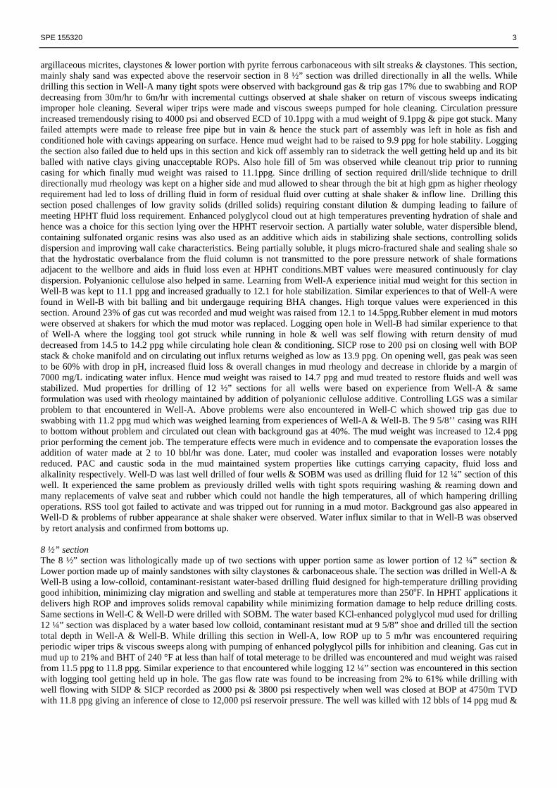
circulated to increase mud weight to 14.1 ppg. On confirming no well flow, while pulling out well started flowing due to swabbing & hence mud weight raised to 14.5 ppg while closing BOP & circulating & conditioning. While pulling out string for running logging tools indication of hole taking less volume to fill was observed due to swabbing. While running logs BHT of 350°F was recorded in 8 ½” section of Well-A .Well flowing was observed while taking cores & mud weight had to be raised to 14.8ppg & on circulation weighed up to 14.2ppg .25% gas cut was still observed & hence mudweight was raised to 14.6ppg & later raised to 14.8 ppg to reduce gas cut to negligible at 4728m. After logging run, owing to gas influx and well destabilization problem the section up to 4728m was cased & cemented with 7” liner so as to safely drill and minimize formation damage in reservoir section for good testing result by keeping mud weight to 14.2ppg & test bottom of the reservoir. Well-A was first exploratory well in series of four wells drilled to evaluate certain portion of the block. Hence further a 6” hole was drilled in Well-A and after testing the & 7” casing liner, drilled shoe track & 7m new formation when well started flowing with SIDP & SICP of 200 psi & 250 psi respectively & mud weight of 14.2 ppg indicating reservoir pressure close to 12,000 psi. Mud weight was increased to 14.8 ppg, conducted LOT & further drilling encountered mud motor failure and 54% trip gas while pulling out for motor change. Mud weight was raised to 14.9 ppg. On reaching the section total depth the hole was logged which experienced held ups & second run could not record data and ran a clean out BHA which on tripping out was covered with thick filter cake. The 5” liner was run & cemented in Well-A. Similar experience was made while drilling well Well-B when drilling out new formation for conducting LOT, encountered gas influx and well flowing with SIDP & SICP close to 250 psi & 39 psi was recorded with 14.7 ppg mud weight giving an inference of close to 12000 psi reservoir pressure. Drilling this section encountered problems like high drilling torques of magnitude reaching to 27K ft-lbs, frequent held ups with drilling BHA & logging tools. The hole got packed off many times requiring reaming and pumping viscous sweeps. Mud motor failure was also encountered similar to Well-A. ROP in lower portion of this section reached to as low as 1-3 m/hr and sometimes rotary drilling was not possible at all with sliding being the only option. Very high torques and tight pull required several wiper trips & viscous sweeps. To alleviate problems of very high torques reaching to maximum allowable torques addition of lubricating fluid in batches were made to ease rotary drilling. High torque values also damaged top drive system. Similar to experiences in Well-A rubber was seen on shaker indicative of problem associated with mud motor. A maximum of 90% background gas & maximum of 40 ppm H2S were recorded which required mud to be treated with ZnCO3 for H2S as Zinc Carbonate is added to drilling fluid as H2S scavenger. Also the maximum BHT recorded while logging this interval was 380 °F and hence continuous circulation of mud was required to cool the LWD & MWD tool which encountered problems at high temperatures. Drilling break due to one or other reason also posed danger to functionality of MWD & LWD tool. Fluid loss was controlled by combined effects of naturally occurring oxidized lignite, resinated lignite, synthetic polymers, and prehydrated gel. The high temperature gelation was treated with modified tannin compounds, water, oxidized lignite & resinated lignite, which were used as additives along with viscous sweeps. The glycol at 4-6% v/v & KCl at 8% v/wt inhibited reactive formation and cuttings appeared dry on surface which is indicative that the formulation was acting as a good inhibitor for clay hydration. MBT also increased on account of clay particles intruding through shaker screens apertures.API & HPHT filtration losses were kept below 6.0 cc/30min & 15 cc/30 min for HPHT filtration during interval. The pH had to be increased from 9.5 to 11.5 to compensate down hole temperature effect which had led to decrease in pH from 11.5 to 9.0 so that both effects kept the pH as per program. The major problem while drilling this section was controlling LGS & rheology requiring advanced shaker screens. Bottom hole temperatures up to 410 °F had been recorded with average temperature gradient (shown in Fig-3), contributing to drastic reduction in pH which is a major factor for activation of many additives in the mud & hence it had to be kept as per program requirement. The mud rheology was optimum in cleaning well-bore while drilling, but destabilized by substantial addition of water for diluting LGS when not treated uniformly with appropriate products prior cased hole logging runs resulting in Barite settling. Also, modified xanthum gum polymer burnt out at temperature beyond 300°F adding another factor for Barite settling as viscosity had dropped & barite weight could not be sustained. In Well-B, additions of Calcium Carbonate fine and medium at 4 sacks per hour of each were made along with 2 sacks per hour of Nut plug which may have aided in torque reduction figures. Drilling continued, often with difficulty due to the high torque levels. On adding Lubricating fluid, higher than normal YP’s were being seen and its use was discontinued. This had initially been a big concern, but with continued circulation and shear allied to dilution with drill water, the properties quickly fell back into line with the program specification .The pH was maintained from 11.5 to 11.8 range and Zinc Carbonate was used to treat the H2S in the mud.
Prior to drilling 8 ½” section in Well-C hole was displaced with SOBM of 12.5 to 15.1 ppg and drilling carried out using mud motor. Maximum background gas of 33% was recorded while tripping out after coring & requiring mud weight to be raised from 12.5 to 12.7 ppg. SIDP & SICP of 180 & 220 psi were recorded .While drilling further to bottom of section with mud weight raised to 14.1 ppg; SICP & SIDP were recorded 630 psi & 460 psi respectively. Same experience to those observed while drilling previous wells were observed here with hole taking less volume to fill while tripping out indicating influx of gas & continuous circulation required to cool the MWD/LWD tool. 58 ppm of H2S was recorded while drilling to the target depth. The SOBM performed as expected although some concerns were there pertaining the high plastic viscosity value which was due to running for long periods of time with either no centrifuges operational, or one or both of them operating at less than 100% efficiency. As the downhole temperatures increased, the mud system was replaced with high temperature additives for emulsion stability and flow properties. The concentration of lime was kept high just to treat out the effects of acid gases. The H2S was treated with zinc carbonate to precipitate and remove any sulfides in the system.
SPE 155320 5
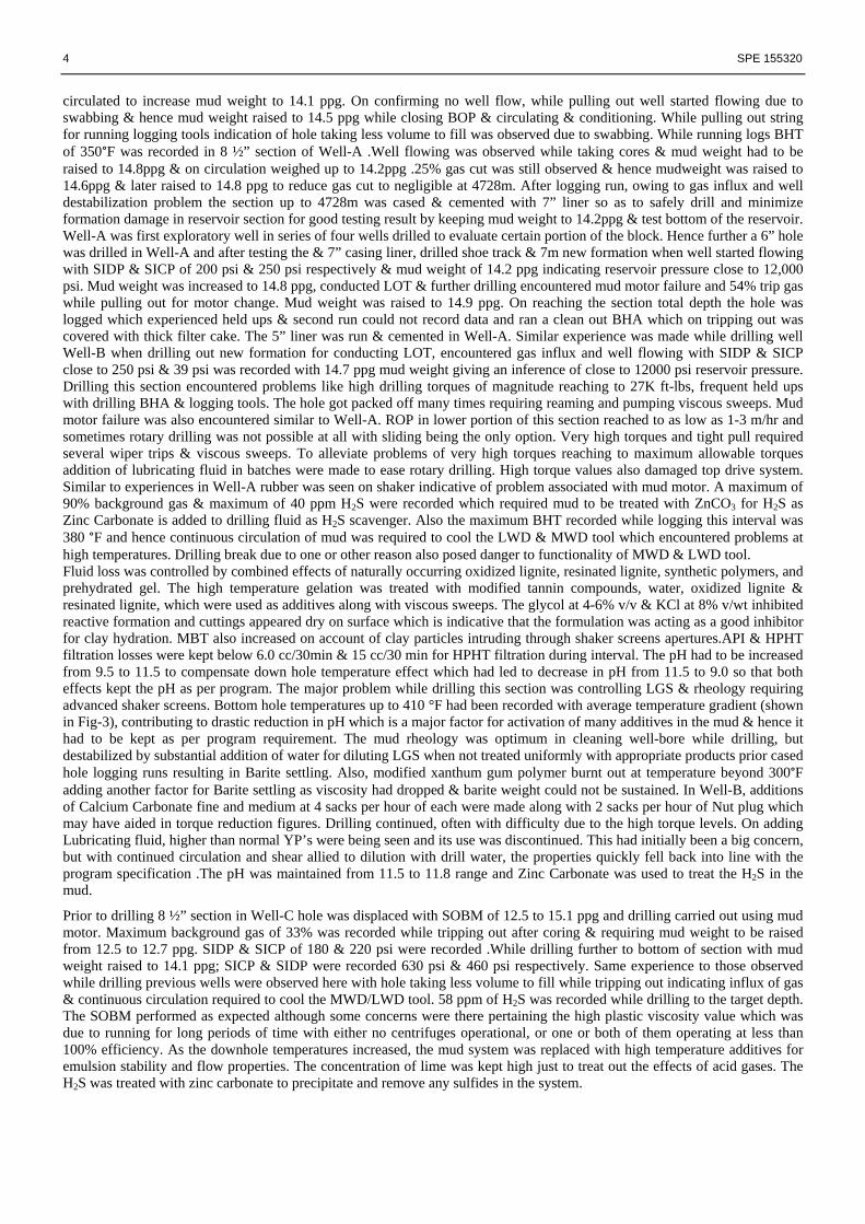
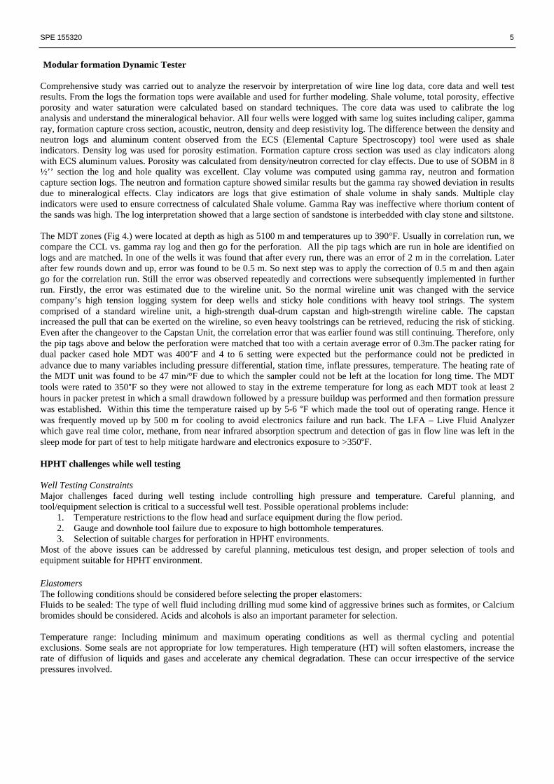
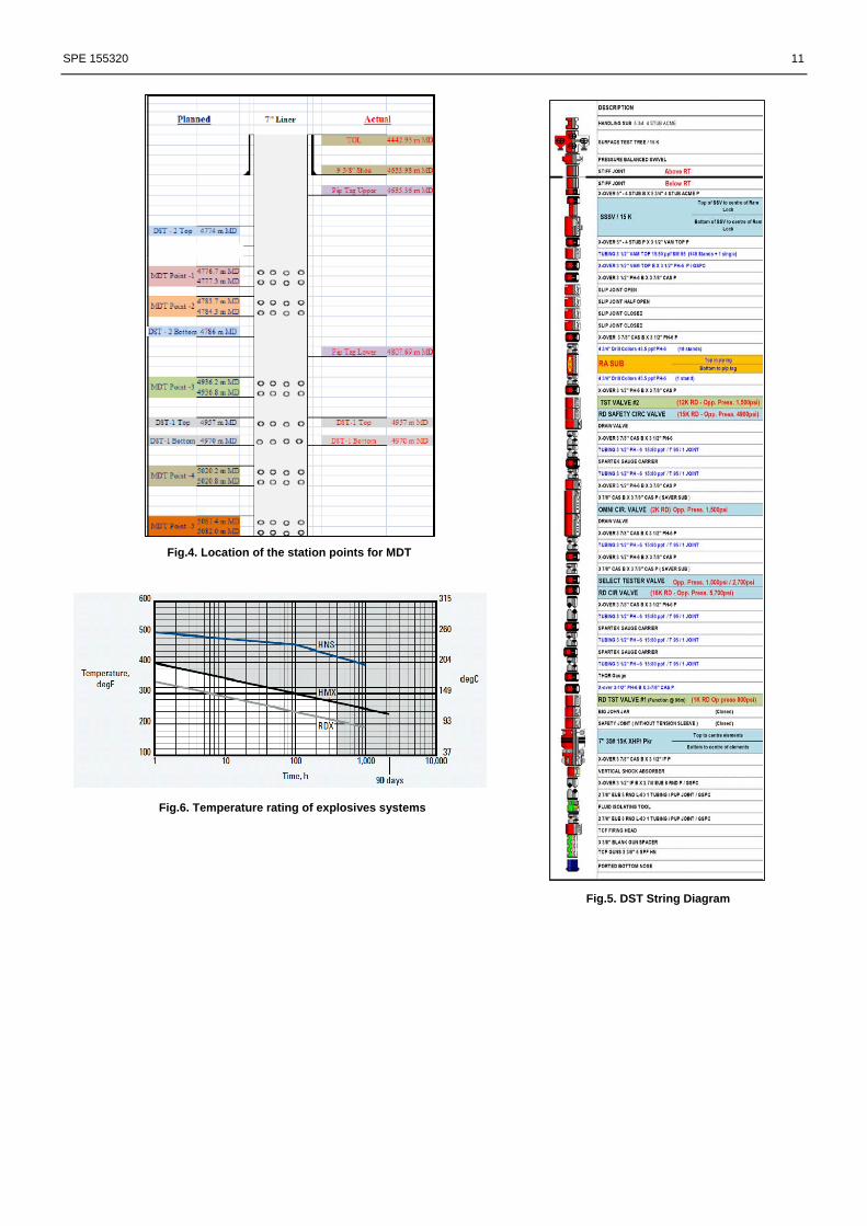
Modular formation Dynamic Tester Comprehensive study was carried out to analyze the reservoir by interpretation of wire line log data, core data and well test results. From the logs the formation tops were available and used for further modeling. Shale volume, total porosity, effective porosity and water saturation were calculated based on standard techniques. The core data was used to calibrate the log analysis and understand the mineralogical behavior. All four wells were logged with same log suites including caliper, gamma ray, formation capture cross section, acoustic, neutron, density and deep resistivity log. The difference between the density and neutron logs and aluminum content observed from the ECS (Elemental Capture Spectroscopy) tool were used as shale indicators. Density log was used for porosity estimation. Formation capture cross section was used as clay indicators along with ECS aluminum values. Porosity was calculated from density/neutron corrected for clay effects. Due to use of SOBM in 8 ½’’ section the log and hole quality was excellent. Clay volume was computed using gamma ray, neutron and formation capture section logs. The neutron and formation capture showed similar results but the gamma ray showed deviation in results due to mineralogical effects. Clay indicators are logs that give estimation of shale volume in shaly sands. Multiple clay indicators were used to ensure correctness of calculated Shale volume. Gamma Ray was ineffective where thorium content of the sands was high. The log interpretation showed that a large section of sandstone is interbedded with clay stone and siltstone. The MDT zones (Fig 4.) were located at depth as high as 5100 m and temperatures up to 390°F. Usually in correlation run, we compare the CCL vs. gamma ray log and then go for the perforation. All the pip tags which are run in hole are identified on logs and are matched. In one of the wells it was found that after every run, there was an error of 2 m in the correlation. Later after few rounds down and up, error was found to be 0.5 m. So next step was to apply the correction of 0.5 m and then again go for the correlation run. Still the error was observed repeatedly and corrections were subsequently implemented in further run. Firstly, the error was estimated due to the wireline unit. So the normal wireline unit was changed with the service company’s high tension logging system for deep wells and sticky hole conditions with heavy tool strings. The system comprised of a standard wireline unit, a high-strength dual-drum capstan and high-strength wireline cable. The capstan increased the pull that can be exerted on the wireline, so even heavy toolstrings can be retrieved, reducing the risk of sticking. Even after the changeover to the Capstan Unit, the correlation error that was earlier found was still continuing. Therefore, only the pip tags above and below the perforation were matched that too with a certain average error of 0.3m.The packer rating for dual packer cased hole MDT was 400°F and 4 to 6 setting were expected but the performance could not be predicted in advance due to many variables including pressure differential, station time, inflate pressures, temperature. The heating rate of the MDT unit was found to be 47 min/°F due to which the sampler could not be left at the location for long time. The MDT tools were rated to 350°F so they were not allowed to stay in the extreme temperature for long as each MDT took at least 2 hours in packer pretest in which a small drawdown followed by a pressure buildup was performed and then formation pressure was established. Within this time the temperature raised up by 5-6 °F which made the tool out of operating range. Hence it was frequently moved up by 500 m for cooling to avoid electronics failure and run back. The LFA – Live Fluid Analyzer which gave real time color, methane, from near infrared absorption spectrum and detection of gas in flow line was left in the sleep mode for part of test to help mitigate hardware and electronics exposure to >350°F. HPHT challenges while well testing Well Testing Constraints Major challenges faced during well testing include controlling high pressure and temperature. Careful planning, and tool/equipment selection is critical to a successful well test. Possible operational problems include:
1. Temperature restrictions to the flow head and surface equipment during the flow period. 2. Gauge and downhole tool failure due to exposure to high bottomhole temperatures. 3. Selection of suitable charges for perforation in HPHT environments.
Most of the above issues can be addressed by careful planning, meticulous test design, and proper selection of tools and equipment suitable for HPHT environment. Elastomers The following conditions should be considered before selecting the proper elastomers: Fluids to be sealed: The type of well fluid including drilling mud some kind of aggressive brines such as formites, or Calcium bromides should be considered. Acids and alcohols is also an important parameter for selection. Temperature range: Including minimum and maximum operating conditions as well as thermal cycling and potential exclusions. Some seals are not appropriate for low temperatures. High temperature (HT) will soften elastomers, increase the rate of diffusion of liquids and gases and accelerate any chemical degradation. These can occur irrespective of the service pressures involved.
6 SPE 155320
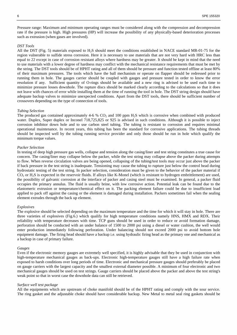
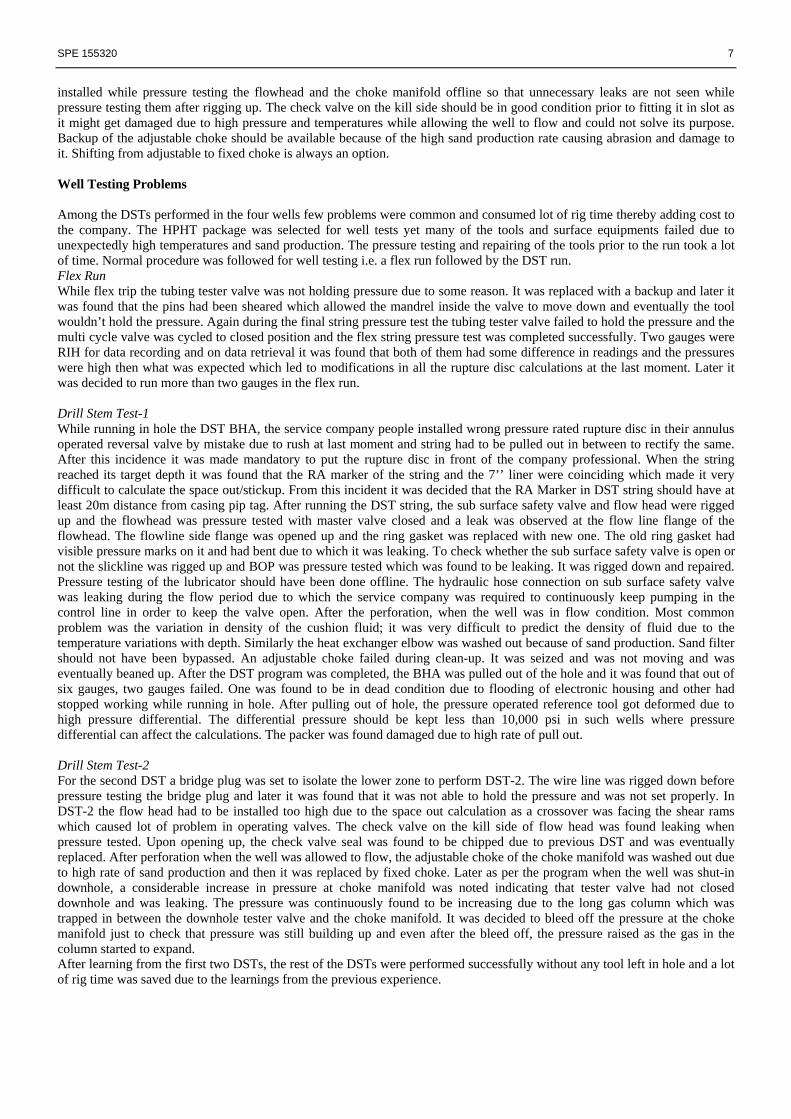
Pressure range: Maximum and minimum operating ranges must be considered along with the compression and decompression rate if the pressure is high. High pressures (HP) will increase the possibility of any physically-based deterioration processes such as extrusion (when gases are involved). DST Tools All the DST (Fig. 5) materials exposed to H2S should meet the conditions established in NACE standard MR-01-75 for the region vulnerable to sulfide stress corrosion. Here it is necessary to use materials that are not very hard with HRC less than equal to 22 except in case of corrosion resistant alloys where hardness may be greater. It should be kept in mind that the need to use materials with a lower degree of hardness may conflict with the mechanical resistance requirements that must be met by the string. The DST tools should be of HPHT rating and all of them should be pressure and function tested offline at least 80% of their maximum pressures. The tools which have the ball mechanism or operate on flapper should be redressed prior to running them in hole. The gauges carrier should be coupled with gauges and pressure tested in order to know the error resolution if any. Sufficient quantity of O-rings should be available and a new ring is advised to be used each time to minimize pressure losses downhole. The rupture discs should be marked clearly according to the calculations so that it does not leave with chances of error while installing them at the time of running the tool in hole. The DST string design should have adequate backup valves to minimize unexpected conditions. Apart from the DST tools, there should be sufficient number of crossovers depending on the type of connection of tools. Tubing Selection The produced gas contained approximately 4-6 % CO2 and 100 ppm H2S which is corrosive when combined with produced water. Duplex, Super duplex or Inconel 718,725,825 or 925 is advised in such conditions. Although it is possible to inject corrosion inhibitor down hole and to use carbon steel tubing. The tubing is resistant to corrosion and requires minimal operational maintenance. In recent years, this tubing has been the standard for corrosive applications. The tubing threads should be inspected well by the tubing running service provider and only those should be run in hole which qualify the minimum torque values. Packer Selection In testing of deep high pressure gas wells, collapse and tension along the casing/liner and test string constitutes a true cause for concern. The casing/liner may collapse below the packer, while the test string may collapse above the packer during attempts to flow. When reverse circulation valves are being opened, collapsing of the tubing/test tools may occur just above the packer if back pressure in the test string is inadequate. Tensioning may cause the tubing to rupture just below the control head during hydrostatic testing of the test string. In packer selection, consideration must be given to the behavior of the packer material if CO2 or H2S is expected in the reservoir fluids. If alloys like K-Monel (which is resistant to hydrogen embrittlement) are used, the possibility of galvanic corrosion at the interface of packer and casing steel must be examined. In general, a packer fluid occupies the primary annulus. The fluid is usually brine, with low corrosive action. Potential leak can be found due to the elastomeric extrusion or temperature/chemical effect on it. The packing element failure could be due to insufficient load applied to pack off against the casing or the element is damaged during installation. Packers sometimes fail when the sealing element extrudes through the back up element. Explosives The explosive should be selected depending on the maximum temperature and the time for which it will stay in hole. There are three varieties of explosives (Fig.6.) which qualify for high temperature conditions namely HNS, HMX and RDX. Their reliability with temperature decreases with time. TCP guns should be used in order to reduce or avoid formation damage, perforation should be conducted with an under balance of 1500 to 2000 psi using a diesel or water cushion, the well would enter production immediately following perforation. Under balancing should not exceed 2000 psi to avoid bottom hole equipment damage. The firing head should have a backup i.e. using hydraulic firing head as the primary one and mechanical as a backup in case of primary failure. Gauges Even if the electronic memory gauges are extremely well specified, it is highly advisable that they be used in conjunction with high-temperature mechanical gauges as back-ups. Electronic high-temperature gauges still have a high failure rate when exposed to harsh conditions over long periods of time. Electronic and mechanical pressure gauges should preferably be placed on gauge carriers with the largest capacity and the smallest external diameter possible. A minimum of four electronic and two mechanical gauges should be used on test strings. Gauge carriers should be placed above the packer and above the test string's weak point so that in worst case the downhole data can still be retrieved. Surface well test package All the equipments which are upstream of choke manifold should be of the HPHT rating and comply with the sour service. The ring gasket and the adjustable choke should have considerable backup. New Metal to metal seal ring gaskets should be
SPE 155320 7
installed while pressure testing the flowhead and the choke manifold offline so that unnecessary leaks are not seen while pressure testing them after rigging up. The check valve on the kill side should be in good condition prior to fitting it in slot as it might get damaged due to high pressure and temperatures while allowing the well to flow and could not solve its purpose. Backup of the adjustable choke should be available because of the high sand production rate causing abrasion and damage to it. Shifting from adjustable to fixed choke is always an option. Well Testing Problems Among the DSTs performed in the four wells few problems were common and consumed lot of rig time thereby adding cost to the company. The HPHT package was selected for well tests yet many of the tools and surface equipments failed due to unexpectedly high temperatures and sand production. The pressure testing and repairing of the tools prior to the run took a lot of time. Normal procedure was followed for well testing i.e. a flex run followed by the DST run. Flex Run While flex trip the tubing tester valve was not holding pressure due to some reason. It was replaced with a backup and later it was found that the pins had been sheared which allowed the mandrel inside the valve to move down and eventually the tool wouldn’t hold the pressure. Again during the final string pressure test the tubing tester valve failed to hold the pressure and the multi cycle valve was cycled to closed position and the flex string pressure test was completed successfully. Two gauges were RIH for data recording and on data retrieval it was found that both of them had some difference in readings and the pressures were high then what was expected which led to modifications in all the rupture disc calculations at the last moment. Later it was decided to run more than two gauges in the flex run. Drill Stem Test-1 While running in hole the DST BHA, the service company people installed wrong pressure rated rupture disc in their annulus operated reversal valve by mistake due to rush at last moment and string had to be pulled out in between to rectify the same. After this incidence it was made mandatory to put the rupture disc in front of the company professional. When the string reached its target depth it was found that the RA marker of the string and the 7’’ liner were coinciding which made it very difficult to calculate the space out/stickup. From this incident it was decided that the RA Marker in DST string should have at least 20m distance from casing pip tag. After running the DST string, the sub surface safety valve and flow head were rigged up and the flowhead was pressure tested with master valve closed and a leak was observed at the flow line flange of the flowhead. The flowline side flange was opened up and the ring gasket was replaced with new one. The old ring gasket had visible pressure marks on it and had bent due to which it was leaking. To check whether the sub surface safety valve is open or not the slickline was rigged up and BOP was pressure tested which was found to be leaking. It was rigged down and repaired. Pressure testing of the lubricator should have been done offline. The hydraulic hose connection on sub surface safety valve was leaking during the flow period due to which the service company was required to continuously keep pumping in the control line in order to keep the valve open. After the perforation, when the well was in flow condition. Most common problem was the variation in density of the cushion fluid; it was very difficult to predict the density of fluid due to the temperature variations with depth. Similarly the heat exchanger elbow was washed out because of sand production. Sand filter should not have been bypassed. An adjustable choke failed during clean-up. It was seized and was not moving and was eventually beaned up. After the DST program was completed, the BHA was pulled out of the hole and it was found that out of six gauges, two gauges failed. One was found to be in dead condition due to flooding of electronic housing and other had stopped working while running in hole. After pulling out of hole, the pressure operated reference tool got deformed due to high pressure differential. The differential pressure should be kept less than 10,000 psi in such wells where pressure differential can affect the calculations. The packer was found damaged due to high rate of pull out. Drill Stem Test-2 For the second DST a bridge plug was set to isolate the lower zone to perform DST-2. The wire line was rigged down before pressure testing the bridge plug and later it was found that it was not able to hold the pressure and was not set properly. In DST-2 the flow head had to be installed too high due to the space out calculation as a crossover was facing the shear rams which caused lot of problem in operating valves. The check valve on the kill side of flow head was found leaking when pressure tested. Upon opening up, the check valve seal was found to be chipped due to previous DST and was eventually replaced. After perforation when the well was allowed to flow, the adjustable choke of the choke manifold was washed out due to high rate of sand production and then it was replaced by fixed choke. Later as per the program when the well was shut-in downhole, a considerable increase in pressure at choke manifold was noted indicating that tester valve had not closed downhole and was leaking. The pressure was continuously found to be increasing due to the long gas column which was trapped in between the downhole tester valve and the choke manifold. It was decided to bleed off the pressure at the choke manifold just to check that pressure was still building up and even after the bleed off, the pressure raised as the gas in the column started to expand. After learning from the first two DSTs, the rest of the DSTs were performed successfully without any tool left in hole and a lot of rig time was saved due to the learnings from the previous experience.
8 SPE 155320
Discussion and Conclusions Drilling 12 ¼” section was mainly shale overlying the sandstone formations and was drilled using water based mud with KCl & enhanced polyglycol system except in Well-D as it was the last well drilled in the series of four wells and planned from the learnings obtained from Well-A, Well-B & Well-C. In spite of many additives added in water based mud for clay hydration and inhibition drilling this section encountered problems like low ROP, hole cleaning problems due to cavings falling in the wellbore, wellbore fill, stuck pipe, bit balling, high torque values damaging top drive systems, all of which were contributed by swelling of clay due to hydration. Same was also observed drilling the 8 ½” section using water based mud. However to derive learning, 8 1/2” section in Well-C was drilled with SOBM where the problems due to clay hydration in shale were alleviated & hence SOBM was used in drilling 12 ¼” & 8 ½” sections in Well-D. Drilling with SOBM did not experience problems relating to clay hydration as SOBM did not destabilize clay. However effects due to high temperature & pressures were dominant with BHT recorded up to 410°F requiring continuous circulation of mud to cool LWD & MWD tools & enable proper functioning. Rubber elements from mud motor were seen at shakers due to high temperature, high wear & high bottomhole pressure. The pH had to be kept higher than program to compensate reduction in pH due to very high temperatures. Gelation had also been an issue with water based mud used in very high temperature environment. The mud weight had to be kept very high close to 14.9 ppg in 8 ½” section to overcome reservoir pressures & overcome swabbing effects along with density reduction with temperature. The LGS while drilling was a major problem in these sections as they blinded the shakers because of increased viscosity due to clays and drilling fluid had to be diluted & sheared to reduce fluid loss at shakers & flow line. Because of very high temperatures mud cooler was required to cool mud. Well Testing There were several DSTs performed on these four wells and many lessons were learnt. The O-rings of high pressure and temperature rating should be selected to avoid unnecessary pressure drops due to their failures. As seen during sand production, it is necessary to pass the flow through sand filter prior to choke manifold to avoid abrasions or washout of equipments and connections. Metal to metal seals should be changed prior to final equipment rig up as it takes a lot of time in dissembling the equipment and pressure testing it again. All the DST tools with moving parts like ball or flapper should be redressed and pressure tested at 80% of their maximum rating properly before running in hole to ensure their functionality downhole. The rupture disc of required rating should be marked separately as to avoid confusion at last moment while installing them before running the tool in hole. At least four gauges should be run in hole for any operation to get more reliable data and in order to assure that at least two of them actually function, thus yielding a reliable quantitative interpretation of the test in terms of depletion, productivity, damage, permeability, etc. While running in hole, care must be taken to prevent breaking down of weak formations. With a small clearance between packer element and wall of hole a pressure is built up under the packer and can cause loss circulation. The DST assembly should be pulled out slowly to avoid packer damage. If the pressure keeps on increasing at the choke manifold even after downhole shut-in, don’t be in rush to operate the tool again because it may be due to the expansion of trapped gas column between the downhole tester valve and the choke manifold. Apart from the practical experiences, the test program should include all the sequence of events, a comprehensive contingency plan, all aspects of safety, and calculation of test-string tension. Further, they should be based on the strictest safety standards and operational procedures. With all data thus united in one single volume, all necessary information may be consulted rapidly and directly; quality control of the material and equipment used should be efficacious and rigorous especially in terms of exposure to high concentrations of H2S. About the authors The authors Prerak H. Shah and Harsh T. Pandya are petroleum engineers working in drilling and completions department of Gujarat State Petroleum Corporation Limited. Both of the authors are young professionals with one year of experience and are Bachelors in Petroleum Engineering from Pandit Deendayal Petroleum University, India. They have keen interest in engineering research in field of drilling and completions. Acknowledgement The authors would like to thank Gujarat State Petroleum Corporation Limited (GSPC) for permission to publish the material contained in this paper. We would also like to acknowledge testing and completions engineer Mr. Amit Ranjan and Mr. Jainendra Kumar for providing their valuable inputs.
SPE 155320 9
Nomenclature MDT = Modular Formation Dynamic Tester HPHT = High Pressure High Temperature KG = Krishna Godavari BOP = Blow Out Preventer BHA = Bottom Hole Assembly ROP = Rate of Penetration ECS = Elemental Capture Spectroscopy DST = Drill Stem Test SOP = Standard Operating Procedure LWD = Logging While Drilling MWD = Measurement While Drilling OBM = Oil Based Mud WBM = Water Based Mud HRC = Rockwell Hardness Co-efficient ECD = Equivalent Circulation Density SOBM = Synthetic Oil Based Mud BHT = Bottom Hole Temperature PAC = Poly-Anionic Cellulose RIH = Run In Hole SIDP = Shut In Drill Pipe Pressure SICP = Shut In Casing Pressure LOT = Leak Off Test RA = Radioactive Marker LGS = Low Gravity Solids LFA= Live Fluid Analyzer TCP = Tubing Conveyed Perforation NACE= National Association of Corrosion Engineers References
1. Buc S. and Kent F. ‘‘Performance Qualification of Seal Systems for Deepwater Completions.’’ OTC-19626-MS-P, Offshore Technology Conference held in Houston, Texas, U.S.A., 5---8 May 2008.
2. Fernando A.B. and Marclo F.B. ‘‘Well Testing Design under Harsh Environment’’. SPE 21142, SPE Latin American Petroleum Engineering Conference held in Rio de Janeiro, October 14-19, 1990.
3. Maldonado, A. Arrazola, and B. Morton, “Ultradeep HP/HT Completions: Classification, Design Methodologies, and Technical Challenges’’. OTC 17927, Offshore Technology Conference held in Houston, Texas, U.S.A., 1---4 May 2006.
4. J. Cushnie, P. & B. Montaron, P. Leschi, ‘‘First Application of Rotary Steerable System in the Middle East’’, SPE 67720, SPE Drilling Conference, held in Amsterdam, Feb 27 --- Mar 1 2001.
10 SPE 155320
Fig.1. Pressure and Temperature conditions of exploratory wells drilled in KG Basin
Fig.3. Average temperature gradient of the field Fig.2. Pore pressure & fracture pressure variation with depth
SPE 155320 11
Fig.4. Location of the station points for MDT
Fig.5. DST String Diagram
Fig.6. Temperature rating of explosives systems