the socially distanced dispenser - libraetd
TRANSCRIPT
The Socially Distanced Dispenser
A Capstone Report
presented to the faculty of the
School of Engineering and Applied Science
University of Virginia
by
Quincy Mendelson
with
Jonathan Burkher
Jake Moses
Justin Nguyen-Galante
December 10, 2020
On my honor as a University student, I have neither given nor received unauthorized aid
on this assignment as defined by the Honor Guidelines for Thesis-Related Assignments.
Quincy Mendelson
Capstone advisor: Harry Powell, Department of Electrical and Computer Engineering
2
Statement of work:
Jake Moses
My individual contributions to this project revolved around the development of the
embedded code, as well as the setting up of the JTAG and Bluetooth configurations on the PCB.
The code was developed in C in Code Composer Studio [1] and utilized both the generic
MSP430 libraries as well as the driverlib library made available online. The JTAG and Bluetooth
configurations, on the other hand, involved the frequently used NI Ultiboard — for footprint
development of the headers— and NI Multisim — for connections to other parts of the board—
applications.
The final version of the embedded code that I wrote for this project— which runs on an
MSP430FR2311 chip— is shown in the Appendix, and performs the following tasks: it first
performs all of the GPIO setup, as well as the UART setup in preparation for the main loop, then
it waits for a user to connect to the Bluetooth. Once a user is connected to the Bluetooth it waits
for a character to be sent (either ‘1’, ‘2’, ‘3’, or ‘4’) so that it knows how much product to
dispense. Once it has received that value, the code begins to run the motor, stopping the motor
once the Hall-effect Sensor has triggered the specified number of interrupts, indicating that the
motor has turned the specified number of times. If the motor is not functioning correctly, the
code also has a built-in interrupt to stop the motor if a specific character is received from the
Bluetooth— as the mobile application has an internal timer that sends the character ‘N’ if the
dispenser takes too long to dispense. Upon completion of the motor turning (whether successful
or unsuccessful) the code sends back a completion statement (indicating success or error) to the
user through Bluetooth. In addition to the code shown below, I was also responsible for writing
the test programs for the PCB— to ensure that the motor, Hall-effect sensor, and Bluetooth were
all functioning correctly.
On top of the MSP430 code that I developed throughout this project I was responsible for
ensuring that our PCB had on-board debugging capabilities by utilizing JTAG. This was
essential to the project because we would not have been able to debug on the actual PCB nor
upload new code to the PCB without the debugger or JTAG interface. Also, I was responsible for
researching which Bluetooth module to use (ended up being the HM-19) and how to incorporate
it into the project in an efficient and effective manner.
Quincy Mendelson
My focus was on designing and selecting parts for several of the hardware systems for
the project, including the microcontroller, motor and motor driver, power supply and voltage
regulator, and the Hall-effect sensor. I was also responsible for creating the PCB footprints for
these parts and completing the PCB layout for two board iterations in Ultiboard [2]. I also
maintained all Multisim files for our project [3]. After the boards were designed and parts
received, I soldered the majority of the components and coordinated with 3W Electronics to
solder the surface mount parts and resolve connection issues on our first board. With Jake’s help,
I tested all hardware components and the PCB.
3
My secondary responsibility was the mechanical design and assembly of the dispenser. I
selected the dispenser we used, along with the plastic electronics enclosure, motor hub and
bracket, and all fasteners. With help from fellow students, I designed and 3D printed a connector
to attach the motor to the dispenser. The plastic enclosure was modified using a water jet help
from Sebring Smith at Lacy Hall. SolidWorks CAD software was used to complete the designs
for the connector and the enclosure [4].
Justin Nguyen-Galante
My individual contributions were mainly concentrated around the mobile application
portion of this project. At the onset of the project, I researched and compiled the technology
stack we would need. Then, I helped design all of the UI in Figma, and the actual
implementation of said UI followed (all code can be found in the appendix). To achieve this, I
used Expo in tandem with React Native, a common tool and framework for developing mobile
applications. However, this toolset would only provide value during the development of the UI,
since Expo is not compatible with any existing Bluetooth libraries. Thus, the application had to
be ejected from Expo and ported to a native iOS application, meaning that development would
proceed using Xcode. At this point, my responsibilities were to integrate Bluetooth capabilities
in the application and to ensure that the application was communicating with the microcontroller
as we would expect. After the code for Bluetooth capabilities (also seen in the appendix) was
written and the entire app was confirmed to work with the microcontroller as designed, I worked
on quality of life improvements to the application such as including more responsive error
messages and implementing a timeout condition which would trigger if the physical dispenser
got stuck. Finally, after I was completely finished working on the mobile application, I helped
with physical construction of the dispenser, final testing, and recording the demo.
Jonathan Burkher
My individual contribution to this project revolved around mobile application
development in the project with some delving into the Bluetooth and embedded code work. In
the beginning of this project, I created one of the footprints that would be used on the printed
circuit board for Quincy to use. Then I looked into what we would need to create the application.
What language I would code in, what environment, how I would design the application, etc. I
then helped to create the design for the mobile application in a program called Figma. Next, I
helped to create the actual implementation of the application’s code. This involved multiple
bouts of testing to ensure functionality worked as expected before adding new features. The next
step was adding Bluetooth functionality. This was the more difficult step, as I had created the
app in Expo to expedite the creation process, but Expo did not have a Bluetooth library. So I had
to eject Expo which slowed the process down. Once the Bluetooth functionality was
implemented, I tested it with the Bluetooth module on an MSP430 launchpad to confirm we
could find and connect to it. I also spoke with Jake to confirm the Bluetooth module was
receiving what we expected it to. Once I knew the app worked as intended, I helped with end to
end testing and debugging for the overall project. This included debugging and fixing the
embedded code, overall construction of the physical dispenser, and recording videos for the
demo.
4
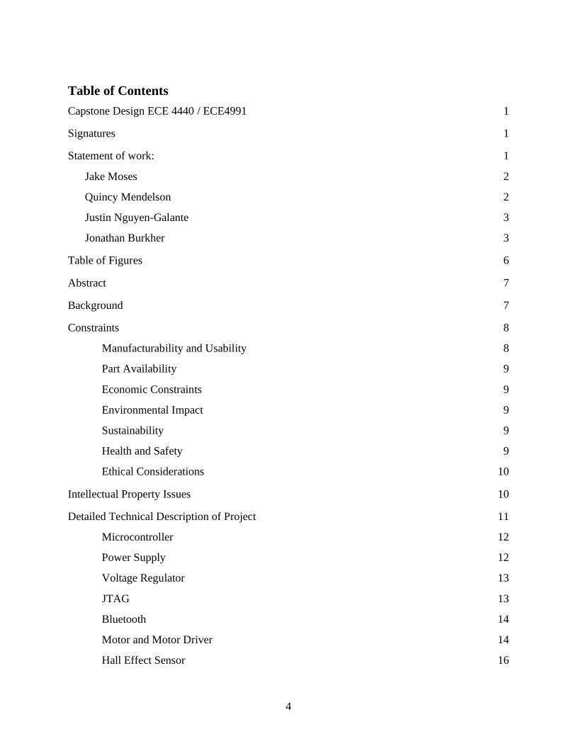
Table of Contents
Capstone Design ECE 4440 / ECE4991 1
Signatures 1
Statement of work: 1
Jake Moses 2
Quincy Mendelson 2
Justin Nguyen-Galante 3
Jonathan Burkher 3
Table of Figures 6
Abstract 7
Background 7
Constraints 8
Manufacturability and Usability 8
Part Availability 9
Economic Constraints 9
Environmental Impact 9
Sustainability 9
Health and Safety 9
Ethical Considerations 10
Intellectual Property Issues 10
Detailed Technical Description of Project 11
Microcontroller 12
Power Supply 12
Voltage Regulator 13
JTAG 13
Bluetooth 14
Motor and Motor Driver 14
Hall Effect Sensor 16
5
Project Timeline 23
Who did What 26
Test Plan 27
Bluetooth Test Plan 27
Mobile App Test Plan 29
Motor Test Plan 31
Hall Effect Sensor Test Plan 32
PCB Testing 32
Final Results 33
Costs 36
Future Work 36
References 38
Appendix 41
Embedded (MSP430) Code 51
main.c 51
bluetooth_motor_sensor_setup.c 54
bluetooth.h 55
motor.h 56
sensor.h 58
Mobile Application Code 58
App.js 58
styles.js 60
Header.js 65
DeviceListItem.js 67
LandingPage.js 68
DevicesPage.js 70
DispensePage.js 76
6
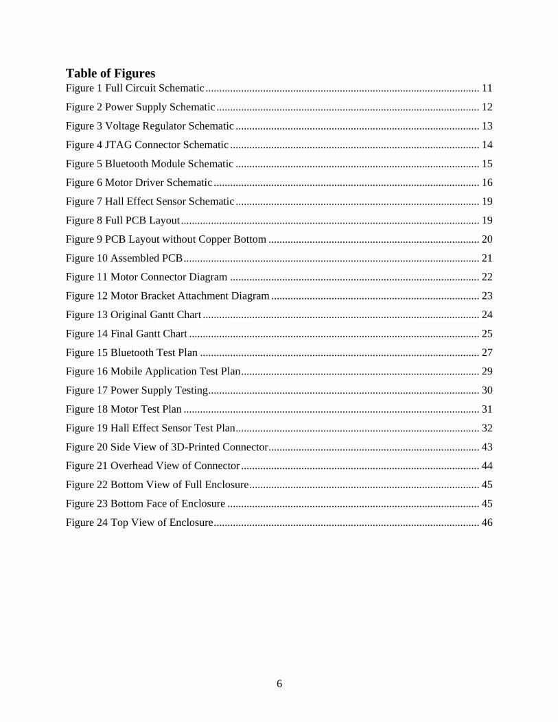
Table of Figures Figure 1 Full Circuit Schematic .................................................................................................... 11
Figure 2 Power Supply Schematic ................................................................................................ 12
Figure 3 Voltage Regulator Schematic ......................................................................................... 13
Figure 4 JTAG Connector Schematic ........................................................................................... 14
Figure 5 Bluetooth Module Schematic ......................................................................................... 15
Figure 6 Motor Driver Schematic ................................................................................................. 16
Figure 7 Hall Effect Sensor Schematic ......................................................................................... 19
Figure 8 Full PCB Layout ............................................................................................................. 19
Figure 9 PCB Layout without Copper Bottom ............................................................................. 20
Figure 10 Assembled PCB ............................................................................................................ 21
Figure 11 Motor Connector Diagram ........................................................................................... 22
Figure 12 Motor Bracket Attachment Diagram ............................................................................ 23
Figure 13 Original Gantt Chart ..................................................................................................... 24
Figure 14 Final Gantt Chart .......................................................................................................... 25
Figure 15 Bluetooth Test Plan ...................................................................................................... 27
Figure 16 Mobile Application Test Plan ....................................................................................... 29
Figure 17 Power Supply Testing................................................................................................... 30
Figure 18 Motor Test Plan ............................................................................................................ 31
Figure 19 Hall Effect Sensor Test Plan......................................................................................... 32
Figure 20 Side View of 3D-Printed Connector............................................................................. 43
Figure 21 Overhead View of Connector ....................................................................................... 44
Figure 22 Bottom View of Full Enclosure .................................................................................... 45
Figure 23 Bottom Face of Enclosure ............................................................................................ 45
Figure 24 Top View of Enclosure ................................................................................................. 46
7
Abstract In the age of Covid-19, limiting the number of surfaces that are touched by multiple
people is a key factor in slowing the spread. To help achieve this, the Socially Distanced
Dispenser serves as a contactless food dispenser, best deployed in a setting with many potential
users such as a grocery store or a dining hall [5]. The dispenser takes user input from a
smartphone application over a secure Bluetooth connection and automatically dispenses the
desired amount of food, limiting the required contact for any user to receive their food to their
personal smartphone. Each module of the Socially Distanced Dispenser is self-sufficient aside
from the occasional food item refill.
Background
The inspiration behind this project was to create a product that in some way addressed the
current situation of the world. Grocery stores or dining halls are high-risk zones for contraction
of the virus, which poses the inconvenience of having to frequently sanitize common surfaces
between customers. To ensure these common surfaces are cleaned, effort on either the
customer’s end or an employee’s end has to be spent, and given the countless number of
common surfaces, it is increasingly hard to guarantee that all surfaces are cleaned between each
customer’s use. The Socially Distanced Dispenser addresses this issue by eliminating any need
for contact in the first place, which allows for more focus and effort to be directed to other
surfaces that require frequent cleaning.
The concept of contactless dispensers is not novel. Most hand sanitizer dispensers rely on
infrared or photo sensors to dispense product without contact [6]. This approach, however, would
not make sense in the context of our problem. Dispensers akin to the automatic hand sanitizer
can only dispense a set, static amount. If the user wants more sanitizer than the set amount, they
will have to trigger the dispensing mechanism repeatedly. If the user wants less than the set
amount, that’s simply not an option and some product would have to go to waste. For the context
of the hand sanitization problem, this is fine, as most users will be content with one dispense of
the set amount. Food, however, is a different issue. Many users will desire many different
amounts of food and having to repeatedly trigger the dispensing mechanism to receive the
desired amount is inconvenient. And if the user wants less than the set amount, food will have to
be wasted, which is not good practice.
Another system that could be considered similar to the Socially Distanced Dispenser is
Coca Cola’s ‘Freestyle Beverage Dispenser’. Coke’s dispenser allows users to choose from a
wide variety of drinks by having users scan a QR code on their smartphone, which then directs
them to a web application where users can select their beverage [7]. This approach saves the user
from having to download an app and from having to form a Bluetooth connection with the
machine, but the overhead is far greater than what the Socially Distanced Dispenser would need.
A web application is far out of scope as each module only dispenses one type of food item and
the customization options are limited simply to quantity. The Freestyle Beverage Dispenser
allows users to choose from hundreds of different items and customization options which
necessitates serving large amounts of user-facing views and having a database. In addition to the
large overhead of a web application, the price of a single module of the Freestyle Beverage
Dispenser can range from $2,000 to $11,500 [8]. So, while having to download an app is
inconvenient for the customer, it’s a one-time action. The inconvenience would be diminished
with each use of the Socially Distanced Dispenser.
8
The Socially Distanced Dispenser is a unique solution to the problem it addresses
because it serves as a simple, cost efficient, easy to use, and appropriately scaled contactless
dispenser. In addition, all of the aforementioned contactless dispensers were for liquid products
whereas the Socially Distanced Dispenser serves solid products. This difference necessitates a
completely different automated dispensing mechanism, which the Socially Distanced Dispenser
provides. The prototype we develop will also be portable and is essentially ready to use out of
the box. Each module is self-contained, and no external connections are needed. So as soon as
our dispenser is powered and the desired food item is loaded, it will be ready to go, which allows
for simple installation and minimal maintenance.
This project draws directly from much of our past coursework. In order to dispense the
food, a stepper motor was attached to the knob of the dispenser. This motor was controlled using
a MSP430 microcontroller, incorporating knowledge gained from ECE3430: Introduction to
Embedded Computing. The MSP430 was connected to the Bluetooth module and the motor
driver using a PCB. We used the circuit prototyping, testing and PCB design skills we learned in
the Fundamentals of Electrical Engineering series (ECE2630, ECE2660, and ECE3750)
throughout this project. The user interface also utilizes our previous classes, including Advanced
Software Development and Mobile App Development (CS3240 and CS4720). These classes
helped us learn to create clean and easy to use user experiences that do not discourage customers
from using the product. The application will also need to establish a secure Bluetooth connection
that does not jeopardize user privacy, which will require knowledge from Defense Against the
Dark Arts (CS4630) and Introduction to Cybersecurity (CS3501). Finally, as 3D printing will be
an aspect of our project, the experience of designing objects in CAD software from the
Introduction to Engineering (ENGR 1620 and 1621) course will be useful as well.
Constraints Manufacturability and Usability
Our dispenser will most likely use two custom-made pieces: the enclosure for the moving
parts of the machine, and the piece to attach the motor to the knob of the dispenser. A
prefabricated enclosure may be purchased if one of an appropriate size and shape can be found.
Otherwise, the enclosure will be made using plastic or wood, and will require some simple
machining, such as use of a water jet or laser cutter. The motor attachment will be 3D printed,
and will likely be a small and simple design, making it fast to print and cheap to produce.
The rest of our parts, including the dispenser itself, will be purchased off-the-shelf from
various vendors, but primarily Digikey. The chips and other components that will be included in
the PCB and large enough to solder easily, making the electronic components simple to
manufacture.
Another aspect we must consider is how easy it is for a consumer to interact with our
product. If it is difficult or time consuming for a user to connect to the dispenser, then the user
will most likely choose not to do so and collect food elsewhere. We must keep this in mind as we
design the mobile application to ensure the user can connect swiftly and without problems. On
this topic, the application must be simple and intuitive enough to take roughly as much time as
the user manually turning the knob. We must also take into consideration any complications the
dispenser could have and how they should be dealt with. Problems such as mechanical or
electrical failure, dispenser jams, and parts becoming dirty must all be carefully considered.
9
Part Availability
There were no issues procuring the parts needed for this project. The majority of parts
were purchased through Digi-key, but parts were also purchased from Home Depot, Amazon,
McMaster-Carr, Newark, Pololu, and Michael’s craft store. Other board components, such as
resistors and capacitors, were taken from our lab kits from the Fundamentals of Electrical
Engineering series. All parts used were available in plentiful quantities, so we would not
anticipate any supply issues if this project were to be continued or replicated.
Economic Constraints
Our budget for this project was $500, but we only ended up spending $356.92. The
budget is further discussed in the Costs section and Appendix of this report.
Since our project’s end users are grocery store and dining hall customers, we wanted to
ensure our product is easily affordable for our target market to achieve wider availability. The
cost for one Socially Distanced Dispenser module is of around $140 and our target businesses
generally have sizable budgets, so there shouldn’t be any major economic constraints.
Environmental Impact
The day-to-day use of the Socially Distanced Dispenser will not have much of an
environmental impact, besides perhaps saving resources spent on sanitization materials. The
main environmental concern is during the manufacturing and the end-of-life phases. The Socially
Distanced Dispenser consists of a fair amount of plastic, which poses concerns for when it’s time
to dispose of the dispenser [9]. In regard to the electronic components such as the Printed Circuit
Board, there are standards for responsibly recycling and reusing electronic waste that certified
electronic recyclers must follow [10]. To minimize the environmental footprint of the dispenser,
we will encourage owners to utilize a certified electronic recycler at the end of the dispenser’s
life.
Sustainability
The only maintenance required to ensure smooth, sustained operation is battery
replacement and occasional cleaning of the dispenser to adhere to FDA cleanliness requirements.
The lifespan of the Socially Distanced Dispenser is limited to the battery and cleaning material
supply of the owner, but this should be of little concern to established grocery stores or dining
halls. A possible improvement to the project would be to perhaps connect multiple dispensers
and motors to one controller and allow users to select from the options as opposed to having an
individual PCB for each dispenser. In the event of degradation of the dispenser, all parts should
be easily replaceable and reproducible as mentioned in the Manufacturability and Usability
section.
Health and Safety
The Socially Distanced Dispenser qualifies as a vending machine as defined by the Food
and Drug Administration in its 2017 FDA Food Code. According to these guidelines, we
provided tight-fitting covers to protect the food in the container from customer tampering. Our
dispenser is designed to hold shelf-stable, dry food such as rice or cereal, and is therefore exempt
from many of the guidelines defined by the FDA for temperature-controlled vending machines.
Per FDA regulations for bulk food available for customer self-dispensing, we also provided a
10
place on our dispenser to display a label containing the name, ingredient list, and nutrition
information of the food item contained in the dispenser [11].
Our project also involves moving parts, namely the stepper motor used to actuate the
dispensing mechanism, which poses the concern of a user potentially injuring themselves. The
Occupational Safety and Health Administration requires that all machinery containing moving
parts, such as a rotating motor, contain safeguards to prevent employee injury. Steps must be
taken to prevent physical contact with moving parts, and the protection system must be secure to
prevent tampering [12].
Ethical Considerations
As far as normal operation of the dispenser goes, the only ethical concern would perhaps
be that the dispenser is only accessible to users with smartphones. In this day and age, however,
essentially all smartphones have Bluetooth capability, and in 2019, 81 percent of adult
Americans owned a smartphone and 96 percent owned cell phones in general [13]. So, the
ethical constraint on the usage of our project is relatively insignificant as an overwhelming
majority of all potential users have the ability to operate the dispenser. A potentially more
tangible opportunity for ethical concerns to arise would be when the user establishes a Bluetooth
connection. To ensure that no malicious third party can invade users’ privacy, extra care will be
taken when forming the connection and when transmitting data to and from the dispenser. All
Bluetooth standards will be followed to achieve this.
Intellectual Property Issues The first patent that encompasses similar material to our project is patent US6964355B2
[14]. This patent claims a “Dry food dispensing system”, which is obviously closely related to
the Socially Distanced Dispenser. Even in light of the claims of this patent, the Socially
Distanced Dispenser is still patentable since it is both novel and a non-obvious improvement
over the existing patent. The main claim of the patent is “A system for measuring and dispensing
a predetermined quantity of a granular product, comprising…”. This claim is also present in our
project, however, we have the addition of a mobile app, a stepper motor, and various sensors and
modules to remove the need for physical contact.
Another patent that concerns a similar device to the Socially Distanced Dispenser is
patent US8757222B2. This patent is for Coca-Cola’s freestyle beverage dispenser [15]. This
patent most likely makes the Socially Distanced Dispenser unpatentable, since the concepts and
ideas are very similar, and the main selling point of our dispenser, contactless operation, is a
feature that was recently added to the freestyle dispenser (also in- response to Covid-19). The
two dispensers mainly differ in the product they dispense (the Freestyle dispenser dispenses
liquid products whereas the Socially Distanced Dispenser aims for solid food products) [15], but
this fact alone is most likely not enough to claim as non-obvious or novel. Thus, in the light of
the claims made by this patent, the Socially Distanced Dispenser is not patentable, even though
we use differing mechanisms and methods to dispense food.
A third patent that details a similar idea is patent US20190108709A1 [16]. This patent
idea surrounds a food/drink dispensing device that manages a connection with a mobile terminal.
This product dispenses snack sized food packages and bottled beverages through a classic style
11
vending machine, which a user can connect to with their mobile device. The three main claims of
the patent are: a food/drink dispensing device that manages a connection with a mobile
application, a mobile terminal that connects to a food/drink dispensing device for dispensing
food/drink, and a program for executing a predetermined function in a mobile terminal which
connects to a food/drink dispensing device [16]. Because of its similarity, and the fact that our
project differs only in the dispense mechanism, the Socially Distanced Dispenser would not be
patentable.
Detailed Technical Description of Project
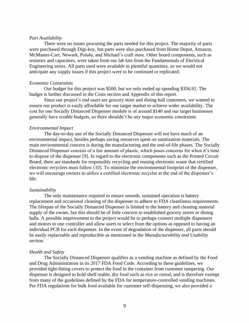
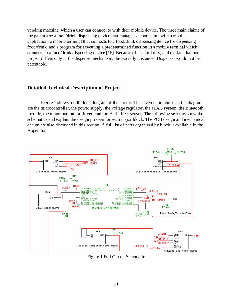
Figure 1 shows a full block diagram of the circuit. The seven main blocks in the diagram
are the microcontroller, the power supply, the voltage regulator, the JTAG system, the Bluetooth
module, the motor and motor driver, and the Hall-effect sensor. The following sections show the
schematics and explain the design process for each major block. The PCB design and mechanical
design are also discussed in this section. A full list of parts organized by block is available in the
Appendix.
Figure 1 Full Circuit Schematic
12
Microcontroller
A 20-pin MSP430FR2311IPW20 microcontroller was used, shown by U1 in Figure 1
[17]. This MCU was chosen based on recommendations given in documentation from Texas
Instruments explaining how to drive a stepper motor with an MSP430 [18]. The MSP430FR2111
was used in the first PCB iteration, but the model only had 16 pins [19]. The additional I/O pins
provided by MSP430FR2311IPW20 were tied to test points to aid in debugging the circuit, as
shown by U14, U15, and U16 in Figure 1. Additionally, a Texas Instruments LaunchPad was
available for the MSP430FR2311 but not for the MSP430FR2111. By acquiring a development
board and using exactly the same MCU contained in the board, we were able to work on
embedded software development and hardware development in parallel.
Power Supply
An external wall plug was used to power the board. Originally, batteries were going to be
used instead, but the current demands of the motor meant that the batteries would have been
depleted very quickly. Batteries would also likely be more expensive and less convenient to
users than a wall plug.
A 5V, 10W AC-to-DC wall plug was ultimately selected [20]. While the JTAG and
Bluetooth components both required 3.3V, the Hall-effect sensor required a minimum of 3.6V.
The selected motor was rated at 3V, but research revealed that supplying a stepper motor with
more than the rated voltage could improve performance. To satisfy the needs of the Hall-effect
sensor and get the best performance from the motor, we chose to use 5V. We also expected the
whole board to require fewer than 2A of current, and thus decided that the 10W plug was
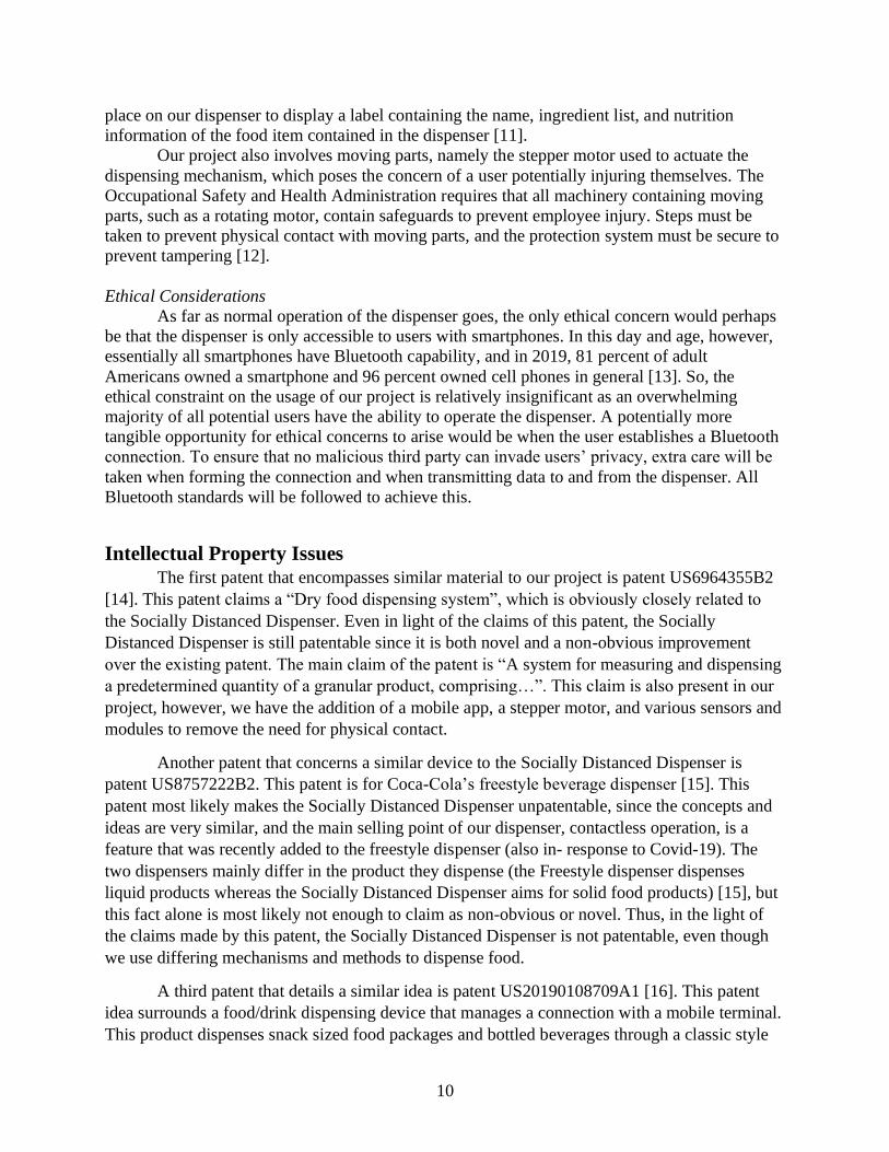
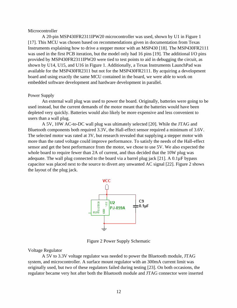
adequate. The wall plug connected to the board via a barrel plug jack [21]. A 0.1µF bypass
capacitor was placed next to the source to divert any unwanted AC signal [22]. Figure 2 shows
the layout of the plug jack.
Figure 2 Power Supply Schematic
Voltage Regulator
A 5V to 3.3V voltage regulator was needed to power the Bluetooth module, JTAG
system, and microcontroller. A surface mount regulator with an 300mA current limit was
originally used, but two of these regulators failed during testing [23]. On both occasions, the
regulator became very hot after both the Bluetooth module and JTAG connector were inserted
13
and began to output 5V. One possible source of this problem was an incorrect board layout. The
regulator should have had copper planes placed underneath the pads on the PCB to help dissipate
heat, but these planes were forgotten. Another potential cause of the failure was that the worst-
case current consumption may have exceeded 300mA.
Following the failures, the regulator was exchanged for a through-hole regulator with a
1.5A current limit [24]. The through-hole model was much more successful in dissipating heat
than the surface mount model. Out of an abundance of caution, the Bluetooth module and JTAG
connector were never plugged in simultaneously after the second regulator failure. No further
failures occurred after the regulator model was changed.
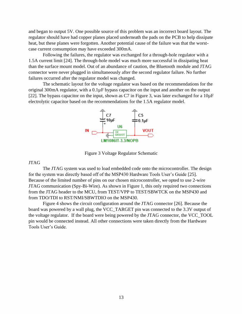
The schematic layout for the voltage regulator was based on the recommendations for the
original 300mA regulator, with a 0.1µF bypass capacitor on the input and another on the output
[22]. The bypass capacitor on the input, shown as C7 in Figure 3, was later exchanged for a 10µF
electrolytic capacitor based on the recommendations for the 1.5A regulator model.
Figure 3 Voltage Regulator Schematic
JTAG
The JTAG system was used to load embedded code onto the microcontroller. The design
for the system was directly based off of the MSP430 Hardware Tools User’s Guide [25].
Because of the limited number of pins on our chosen microcontroller, we opted to use 2-wire
JTAG communication (Spy-Bi-Wire). As shown in Figure 1, this only required two connections
from the JTAG header to the MCU, from TEST/VPP to TEST/SBWTCK on the MSP430 and
from TDO/TDI to RST/NMI/SBWTDIO on the MSP430.
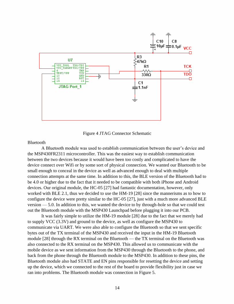
Figure 4 shows the circuit configuration around the JTAG connector [26]. Because the
board was powered by a wall plug, the VCC_TARGET pin was connected to the 3.3V output of
the voltage regulator. If the board were being powered by the JTAG connector, the VCC_TOOL
pin would be connected instead. All other connections were taken directly from the Hardware
Tools User’s Guide.
14
Figure 4 JTAG Connector Schematic
Bluetooth
A Bluetooth module was used to establish communication between the user’s device and
the MSP430FR2311 microcontroller. This was the easiest way to establish communication
between the two devices because it would have been too costly and complicated to have the
device connect over Wifi or by some sort of physical connection. We wanted our Bluetooth to be
small enough to conceal in the device as well as advanced enough to deal with multiple
connection attempts at the same time. In addition to this, the BLE version of the Bluetooth had to
be 4.0 or higher due to the fact that it needed to be compatible with both iPhone and Android
devices. Our original module, the HC-05 [27] had fantastic documentation, however, only
worked with BLE 2.1, thus we decided to use the HM-19 [28] since the mannerisms as to how to
configure the device were pretty similar to the HC-05 [27], just with a much more advanced BLE
version — 5.0. In addition to this, we wanted the device to by through-hole so that we could test
out the Bluetooth module with the MSP430 Launchpad before plugging it into our PCB.
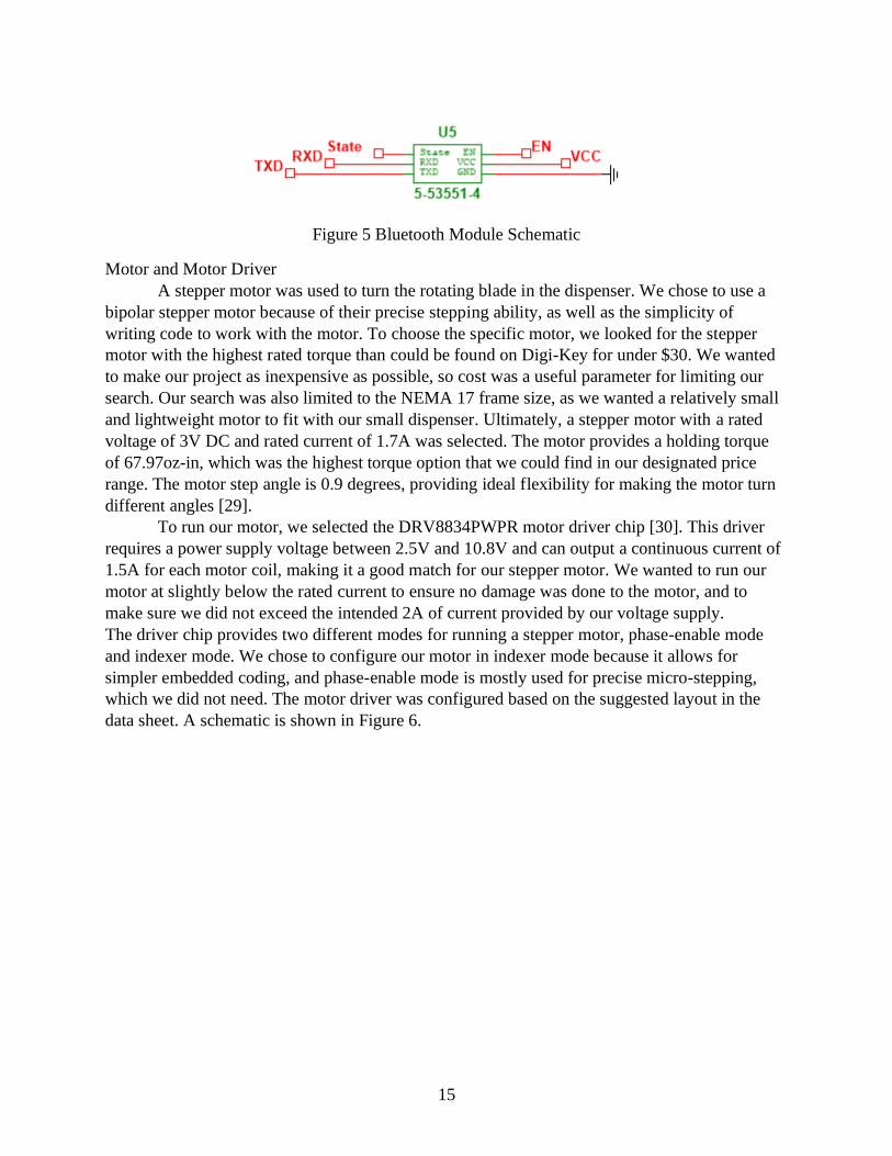
It was fairly simple to utilize the HM-19 module [28] due to the fact that we merely had
to supply VCC (3.3V) and ground to the device, as well as configure the MSP430 to
communicate via UART. We were also able to configure the Bluetooth so that we sent specific
bytes out of the TX terminal of the MSP430 and received the input in the HM-19 Bluetooth
module [28] through the RX terminal on the Bluetooth — the TX terminal on the Bluetooth was
also connected to the RX terminal on the MSP430. This allowed us to communicate with the
mobile device as we sent information from the MSP430 through the Bluetooth to the phone, and
back from the phone through the Bluetooth module to the MSP430. In addition to these pins, the
Bluetooth module also had STATE and EN pins responsible for resetting the device and setting
up the device, which we connected to the rest of the board to provide flexibility just in case we
ran into problems. The Bluetooth module was connection in Figure 5.
15
Figure 5 Bluetooth Module Schematic
Motor and Motor Driver
A stepper motor was used to turn the rotating blade in the dispenser. We chose to use a
bipolar stepper motor because of their precise stepping ability, as well as the simplicity of
writing code to work with the motor. To choose the specific motor, we looked for the stepper
motor with the highest rated torque than could be found on Digi-Key for under $30. We wanted
to make our project as inexpensive as possible, so cost was a useful parameter for limiting our
search. Our search was also limited to the NEMA 17 frame size, as we wanted a relatively small
and lightweight motor to fit with our small dispenser. Ultimately, a stepper motor with a rated
voltage of 3V DC and rated current of 1.7A was selected. The motor provides a holding torque
of 67.97oz-in, which was the highest torque option that we could find in our designated price
range. The motor step angle is 0.9 degrees, providing ideal flexibility for making the motor turn
different angles [29].
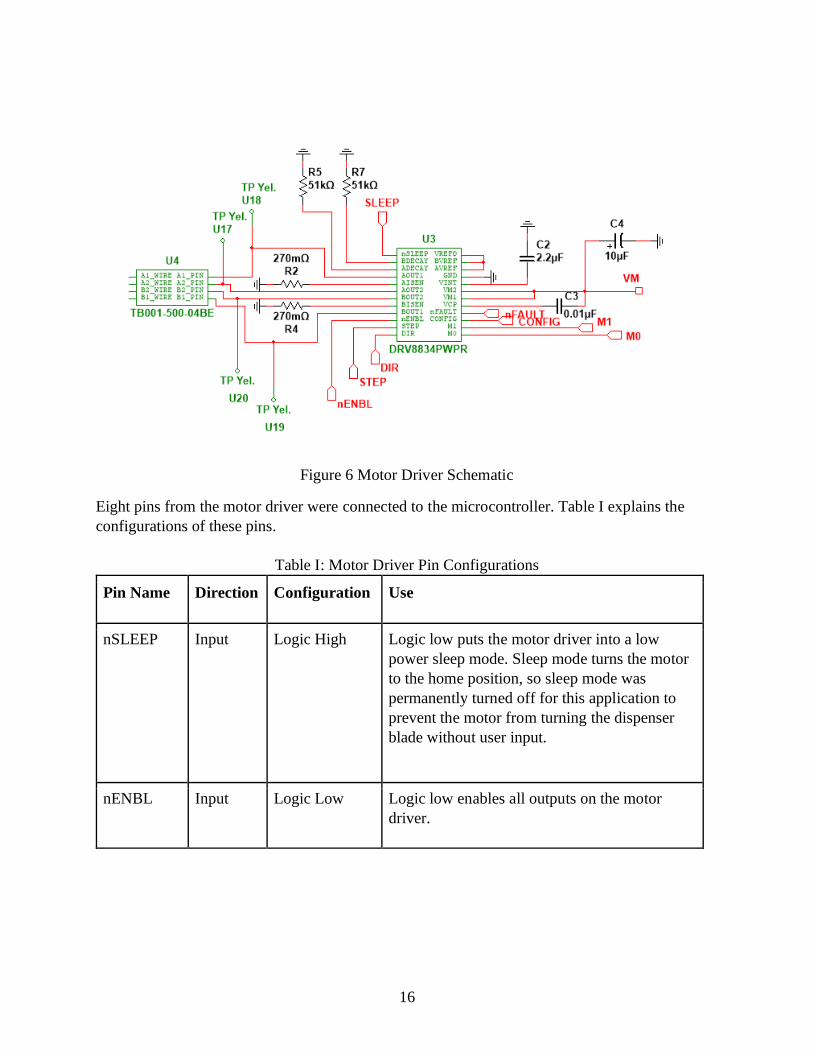
To run our motor, we selected the DRV8834PWPR motor driver chip [30]. This driver
requires a power supply voltage between 2.5V and 10.8V and can output a continuous current of
1.5A for each motor coil, making it a good match for our stepper motor. We wanted to run our
motor at slightly below the rated current to ensure no damage was done to the motor, and to
make sure we did not exceed the intended 2A of current provided by our voltage supply.
The driver chip provides two different modes for running a stepper motor, phase-enable mode
and indexer mode. We chose to configure our motor in indexer mode because it allows for
simpler embedded coding, and phase-enable mode is mostly used for precise micro-stepping,
which we did not need. The motor driver was configured based on the suggested layout in the
data sheet. A schematic is shown in Figure 6.
16
Figure 6 Motor Driver Schematic
Eight pins from the motor driver were connected to the microcontroller. Table I explains the
configurations of these pins.
Table I: Motor Driver Pin Configurations
Pin Name Direction Configuration Use
nSLEEP Input Logic High Logic low puts the motor driver into a low
power sleep mode. Sleep mode turns the motor
to the home position, so sleep mode was
permanently turned off for this application to
prevent the motor from turning the dispenser
blade without user input.
nENBL Input Logic Low Logic low enables all outputs on the motor
driver.
17
STEP Input Toggles The rising edge of the input signal moves the
motor to the next step. This pin alternated
between low and high logic when dispensing to
continuously turn the motor.
DIR Input Logic High or
Logic Low
This pin determines the direction in which the
motor turns. The blade in our dispenser can turn
in either direction, so the value of this pin could
be set to either high or low.
M0/M1 Input Logic Low The values of M1 and M0 determine the size of
the motor steps. Both M1 and M0 were set to
low to use full steps.
CONFIG Input Logic High Logic high sets the driver to indexer mode.
nFAULT Output N/A Sends information about driver status back to
the microcontroller. Logic low means there is
some kind of problem, such as overheating or
insufficient supply voltage.
The remainder of the motor driver pins are configured based on the recommended design
for using indexer mode provided in the driver datasheet. ADECAY and BDECAY set the decay
mode of the bridge currents. In this case, a 51kΩ resistor on each pin is used to set the driver to a
mixed decay mode [31]. The current decays quickly for the first half of the off portion of the
duty cycle, then slowly for the second half. AISEN and BISEN are used for current limiting for
the motor driver. The current limit was set to 1.5A for this project. The resistor values of R2 and
R4 are based on the following equation:
𝐼𝐿𝑖𝑚𝑖𝑡 =𝑉𝑅𝑒𝑓
5𝑅𝑆𝑒𝑛𝑠𝑒→ 𝑅𝑆𝑒𝑛𝑠𝑒 =
2𝑉
5•1.5𝐴= 0.267𝛺 ≈ 270𝑚𝛺 Resistors [32]
VM1 and VM2 are the voltage supply pins for the motor driver. These pins are connected
to the board’s 5V supply and bypassed to ground with a 10µF electrolytic capacitor. VCP is the
gate drive voltage needed to enable internal transistors in the driver to function properly. This pin
is connected to the supply voltage with a 0.01µF capacitor.
VINT can be used as internal supply, and is thus bypassed to ground with a 2.2µF
capacitor [33]. VREFO outputs a 2V reference voltage. It is tied to BVREF and AVREF here to
provide a reference voltage to the internal digital-to-analog converter used in indexer mode.
18
A1OUT, A2OUT, B1OUT, and B2OUT connect to the four wires on the stepper motor
according to the diagram provided in the motor’s datasheet [30, 29]. Test points were placed on
each of these pins for use during motor testing. The four wires were connected to the PCB using
a four-pin terminal block, designated by U4 in Figure 6.
Hall-effect Sensor
The Hall-effect sensor is used to track the position of the blades and count the number of
turns completed by the motor [34]. We chose this option because we wanted to avoid using
mechanically triggered parts, such as limit switches, out of concern that they may break and
require replacement. The selected sensor, conversely, is intended to operate up to 20 billion
switching cycles before failure.
Magnets embedded in the motor-dispenser connector trigger the sensor [35]. The output
signal from the Hall-effect sensor is fed back to the microcontroller. The sensor is active low, so
a falling edge from the output signal is set to trigger an interrupt in the microcontroller,
incrementing a counter until the correct amount of product has been dispensed. The sensor has a
sinking output, so a pull-up resistor connected to the output of the voltage regulator is used to set
the output to 3.3V when no magnet is detected. When a magnet is detected, a current from the
output wire pulls the voltage down to a low value.
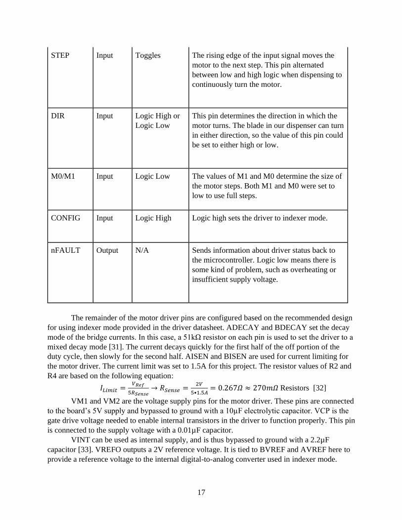
Figure 7 shows the schematic for the Hall-effect sensor block. A value of 33kΩ is used
for the pull-up resistor, R6, to produce a current of 10mA, which is an acceptable input current
for an I/O pin on the MSP430FR2311. A 0.1µF bypass capacitor, C6, is placed between the 5V
supply voltage and ground. A three-pin terminal block is used to connect the sensor to the PCB
[36].
The Hall-effect sensor is sensitive only to south poles of magnets. Six magnets also needed to sit
in a small connector, so 0.25-inch diameter disk magnets were selected for use and embedded in
a plastic connector with the south pole facing the sensor.
19
Figure 7 Hall Effect Sensor Schematic
Printed Circuit Board
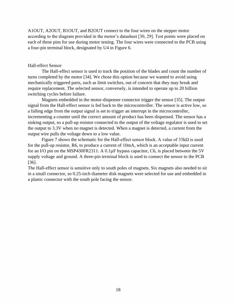
Figure 8 shows the full PCB design. Figure 9 shows the PCB design without the copper
bottom layer for easier visibility. The PCB layout was completed in NI Ultiboard and checked
with FreeDFM from Advanced Circuits.
Figure 8 Full PCB Layout
20
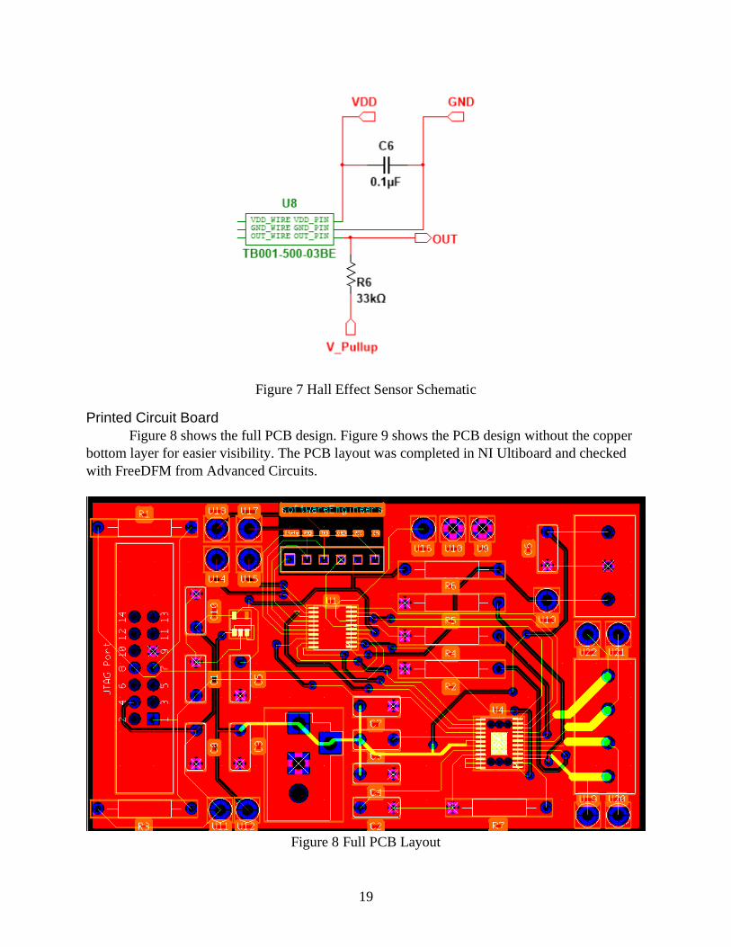
Figure 9 PCB Layout without Copper Bottom
The first step taken to complete the PCB design was to group components by their
required power supply voltage. The motor driver, shown as U4, and the Hall-effect sensor, which
connected to the terminal block in the upper right corner, required 5V. The Bluetooth, JTAG,
and microcontroller required 3.3V. The items requiring 3.3V were grouped on the left side of the
board, and those requiring 5V were placed on the right. The microcontroller, U1, was placed
centrally, as it connects to systems on both sides of the board.
We also chose to place anything connecting to an external component along an edge of
the board for ease of use. The terminal blocks connecting to the hall effect sensor and the motor
were placed on the right edge of the board, while the JTAG connector was placed on the left
edge. The power jack was placed along the bottom edge of the board. Test points were also
placed around the edges for accessibility.
Heat dissipation is vital for the proper functioning of the motor driver, so a ground plane
was placed on the board with a number of thermal vias. This layout was successful in dissipating
heat from the motor driver, but the use of many surface mount components necessitated some
routing on the copper bottom side. This cut up the ground plane, making it very difficult for
current to find a path in some areas. This is very visible to the right side of U1 in FIGURE. If
another iteration of the board were to be made, the ground plane would be modified to sit only
under the motor driver.
Another change that would need to be made is the footprint of the voltage regulator, seen
to the right of C10 in Figure 9. The original model came in a surface mount package, but a
through-hole version was later used instead. The through hole model was attached to the board
by soldering the ground and VCC pins to the bypass capacitor C10, with the output pin soldered
to a via along the output path of the original voltage regulator footprint.
21
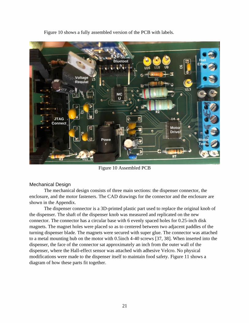
Figure 10 shows a fully assembled version of the PCB with labels.
Figure 10 Assembled PCB
Mechanical Design
The mechanical design consists of three main sections: the dispenser connector, the
enclosure, and the motor fasteners. The CAD drawings for the connector and the enclosure are
shown in the Appendix.
The dispenser connector is a 3D-printed plastic part used to replace the original knob of
the dispenser. The shaft of the dispenser knob was measured and replicated on the new
connector. The connector has a circular base with 6 evenly spaced holes for 0.25-inch disk
magnets. The magnet holes were placed so as to centered between two adjacent paddles of the
turning dispenser blade. The magnets were secured with super glue. The connector was attached
to a metal mounting hub on the motor with 0.5inch 4-40 screws [37, 38]. When inserted into the
dispenser, the face of the connector sat approximately an inch from the outer wall of the
dispenser, where the Hall-effect sensor was attached with adhesive Velcro. No physical
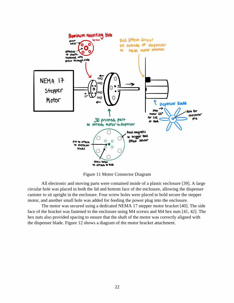
modifications were made to the dispenser itself to maintain food safety. Figure 11 shows a
diagram of how these parts fit together.
Motor Driver
Power
Jack
Voltage Regulat
or
MCU
Bluetooth
Module
JTAG Connect
or
Hall Effect Senso
Motor Termi
nal
22
Figure 11 Motor Connector Diagram
All electronic and moving parts were contained inside of a plastic enclosure [39]. A large
circular hole was placed in both the lid and bottom face of the enclosure, allowing the dispenser
canister to sit upright in the enclosure. Four screw holes were placed to hold secure the stepper
motor, and another small hole was added for feeding the power plug into the enclosure.
The motor was secured using a dedicated NEMA 17 stepper motor bracket [40]. The side
face of the bracket was fastened to the enclosure using M4 screws and M4 hex nuts [41, 42]. The
hex nuts also provided spacing to ensure that the shaft of the motor was correctly aligned with
the dispenser blade. Figure 12 shows a diagram of the motor bracket attachment.

23
Figure 12 Motor Bracket Attachment Diagram
Project Timeline
Throughout our project there were many tasks that were able to be completed in parallel,
and then towards the culmination of the project all of these tasks were polished and sequentially
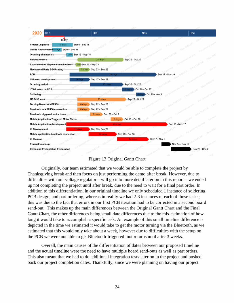
tested and built into the final dispenser. Our original Gantt Chart— depicting our predicted
timeline— is shown in Figure 13, followed by the final Gantt Chart which shows our actual
timeline:
24
Figure 13 Original Gantt Chart
Originally, our team estimated that we would be able to complete the project by
Thanksgiving break and then focus on just performing the demo after break. However, due to
difficulties with our voltage regulator—will go into more detail later on in this report—we ended
up not completing the project until after break, due to the need to wait for a final part order. In
addition to this differentiation, in our original timeline we only scheduled 1 instance of soldering,
PCB design, and part ordering, whereas in reality we had 2-3 instances of each of those tasks;
this was due to the fact that errors in our first PCB iteration had to be corrected in a second board
send-out. This makes up the main differences between the Original Gantt Chart and the Final
Gantt Chart, the other differences being small date differences due to the mis-estimation of how
long it would take to accomplish a specific task. An example of this small timeline difference is
depicted in the time we estimated it would take to get the motor turning via the Bluetooth, as we
estimated that this would only take about a week, however due to difficulties with the setup on
the PCB we were not able to get Bluetooth-triggered motor turns until after 3 weeks.
Overall, the main causes of the differentiation of dates between our proposed timeline
and the actual timeline were the need to have multiple board send-outs as well as part orders.
This also meant that we had to do additional integration tests later on in the project and pushed
back our project completion dates. Thankfully, since we were planning on having our project
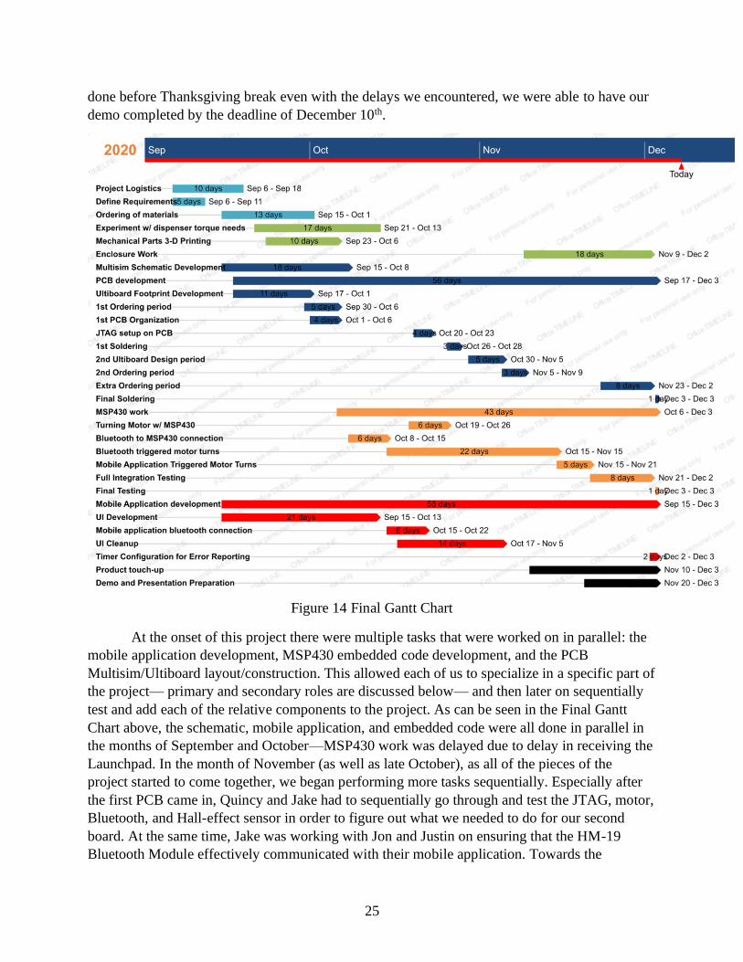
25
done before Thanksgiving break even with the delays we encountered, we were able to have our
demo completed by the deadline of December 10th.
Figure 14 Final Gantt Chart
At the onset of this project there were multiple tasks that were worked on in parallel: the
mobile application development, MSP430 embedded code development, and the PCB
Multisim/Ultiboard layout/construction. This allowed each of us to specialize in a specific part of
the project— primary and secondary roles are discussed below— and then later on sequentially
test and add each of the relative components to the project. As can be seen in the Final Gantt
Chart above, the schematic, mobile application, and embedded code were all done in parallel in
the months of September and October—MSP430 work was delayed due to delay in receiving the
Launchpad. In the month of November (as well as late October), as all of the pieces of the
project started to come together, we began performing more tasks sequentially. Especially after
the first PCB came in, Quincy and Jake had to sequentially go through and test the JTAG, motor,
Bluetooth, and Hall-effect sensor in order to figure out what we needed to do for our second
board. At the same time, Jake was working with Jon and Justin on ensuring that the HM-19
Bluetooth Module effectively communicated with their mobile application. Towards the
26
culmination of the project, the entire team came together to serially go through all of the tests on
the final board (with the new voltage regulator) and then add smaller features to the product to
ensure that it was ready for the demo.
Who did What
Jake Moses
- Primary: JTAG on-board debugging, configuration of the HM-19 Bluetooth module
[46], as well as was responsible for writing all of the embedded code— Motor, Hall-
effect Sensor, & Bluetooth — that was put in the MSP430FR2311 chip.
- Secondary: Development of the Ultiboard footprints for different PCB components—
independently worked on JTAG header and Bluetooth header footprints— as well as
other hardware debugging & construction.
Quincy Mendelson
- Primary: Hardware design and component selection, Multisim schematics, PCB
footprints and PCB layout, hardware and PCB testing
- Secondary: Mechanical design, part selection, and assembly; budgeting, parts ordering,
and other logistic
Jon Burkher
- Primary: Mobile application design, mobile application test plan, mobile application
development, test connection with Bluetooth interface.
- Secondary: development of Ultiboard footprints for Bluetooth PCB component,
debugging and modifying embedded code.
Justin Nguyen-Galante
- Primary: Mobile application planning and design, mobile application UI development,
mobile application Bluetooth development, mobile application testing
- Secondary: Physical construction of dispenser, end-to-end testing
27
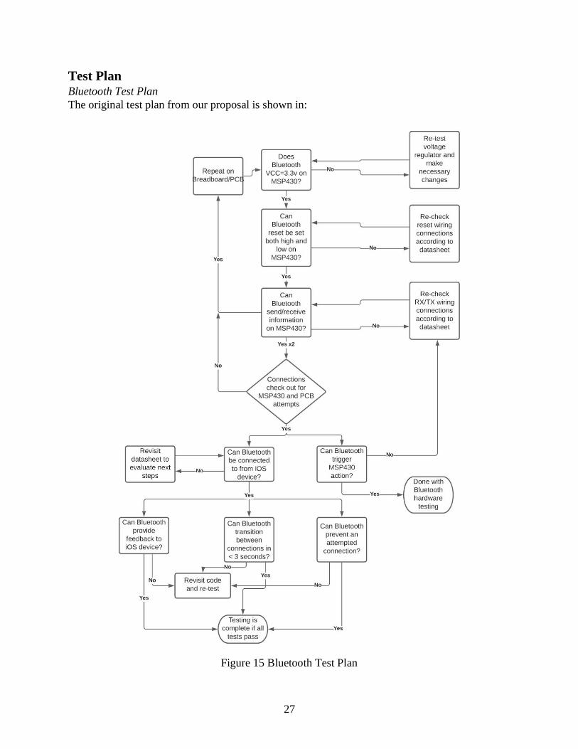
Test Plan Bluetooth Test Plan
The original test plan from our proposal is shown in:
Figure 15 Bluetooth Test Plan
28
The test plan shown above was mostly followed while moving through the project, the
only major difference was that we did not end up using the reset on the Bluetooth, since we did
not need it to prevent multiple connections/force disconnections from the device. Other than that
differentiation it was fairly easy to move from one piece of testing to the next, one example of
this is the parallelism in testing the Bluetooth feedback, Bluetooth connections, and the
Bluetooth’s ability to trigger an action on the MSP430. The piece of testing that took the longest
was definitely the initial establishment of communication between the HM-19 Bluetooth and the
MSP430, as configuring the UART was more difficult than expected, essentially since the
MSP430 Launchpad’s on-board debugger caused some problems. However, once we got past
those initial communication issues, the rest of the testing went smoothly, as testing the feedback
mechanisms, as well as the timing between sending/receiving messages provided good feedback
for how we could expect the mobile application to function. It is also worth mentioning that this
testing plan was initially conducted on the MSP430 Launchpad to ensure that the actual code on
the MSP430FR2311 chip was functioning correctly, and once it was established that the code
functioned correctly we moved onto testing the bluetooth when it was plugged into the PCB— so
we could test its integration with other components in addition to its individual functionality. The
integration testing is discussed in more detail further below in this report.
29
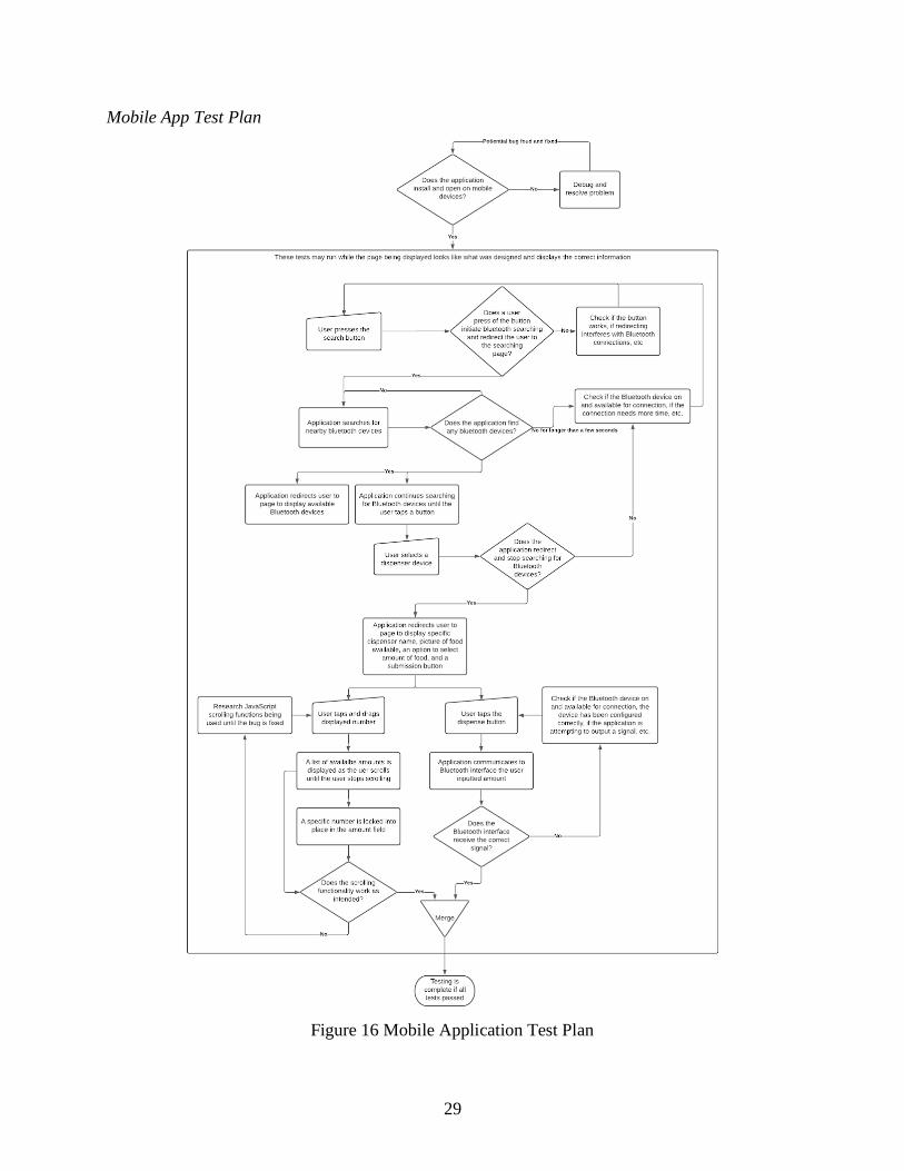
Mobile App Test Plan
Figure 16 Mobile Application Test Plan
30
The mobile application test plan was followed with only a slight addition. The test plan
was created based around each user action and the possible outcomes of the app: success of
failure. The first step a user would have to do would be to open the application. If that worked
properly, then we could test each step of the app to ensure it flowed smoothly. First, we tested
the initial button of the app to check that it was searching for available Bluetooth connections
and to see if the app moved to the next page. The Bluetooth check was done by using print
statements and reading the terminal. Then we checked to see if the app could find Bluetooth
devices. This should give the user the option to select that device from the app, which initiates a
user connection. We checked this connection by printing out specific information only available
to that device. Once the user was connected, the application could redirect them to the final page,
where they can select an amount of food to be dispensed. We checked the application side
features first to ensure they worked properly, then checked that we were outputting the correct
information using the terminal. This is where the addition occurred. We wanted to confirm that
the Bluetooth module was receiving what we wanted to send, rather than just confirm it was sent.
Since the Bluetooth module was communicating with the MSP430, we checked in the terminal
of Code Composer [8] to see if the Bluetooth module was receiving what we expected. Another
addition to the testing plan was checking in our own terminal for receiving feedback from the
Bluetooth module, which was designated by the embedded code.
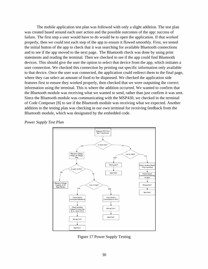
Power Supply Test Plan
Figure 17 Power Supply Testing
31
Figure 17 shows the original test plan for the power supply and the voltage regulator.
This plan was mostly followed during development, but we were able to fit our power jack into a
breadboard and thus were able to test the plug and the jack prior to soldering them into the PCB.
This way, we were able to confirm that the parts were working properly in case any issues arose
when they were added to the PCB.
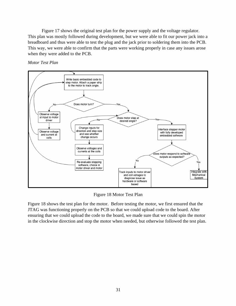
Motor Test Plan
Figure 18 Motor Test Plan
Figure 18 shows the test plan for the motor. Before testing the motor, we first ensured that the
JTAG was functioning properly on the PCB so that we could upload code to the board. After
ensuring that we could upload the code to the board, we made sure that we could spin the motor
in the clockwise direction and stop the motor when needed, but otherwise followed the test plan.
32
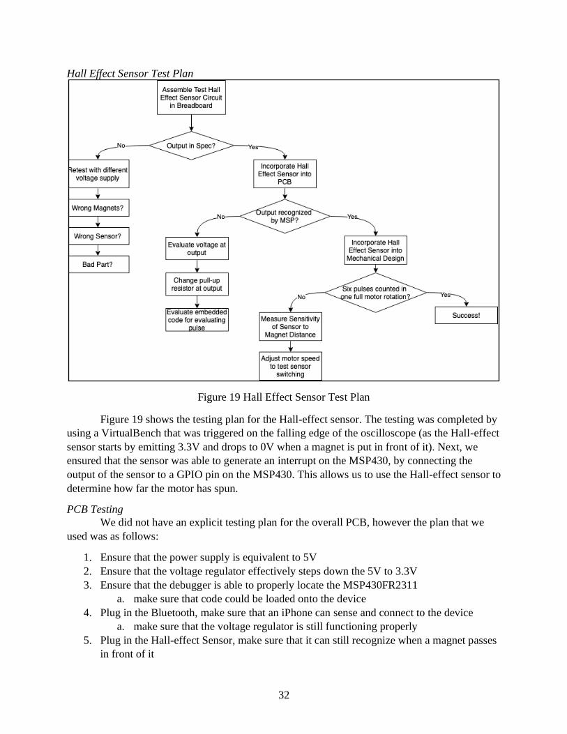
Hall Effect Sensor Test Plan
Figure 19 Hall Effect Sensor Test Plan
Figure 19 shows the testing plan for the Hall-effect sensor. The testing was completed by
using a VirtualBench that was triggered on the falling edge of the oscilloscope (as the Hall-effect
sensor starts by emitting 3.3V and drops to 0V when a magnet is put in front of it). Next, we
ensured that the sensor was able to generate an interrupt on the MSP430, by connecting the
output of the sensor to a GPIO pin on the MSP430. This allows us to use the Hall-effect sensor to
determine how far the motor has spun.
PCB Testing
We did not have an explicit testing plan for the overall PCB, however the plan that we
used was as follows:
1. Ensure that the power supply is equivalent to 5V
2. Ensure that the voltage regulator effectively steps down the 5V to 3.3V
3. Ensure that the debugger is able to properly locate the MSP430FR2311
a. make sure that code could be loaded onto the device
4. Plug in the Bluetooth, make sure that an iPhone can sense and connect to the device
a. make sure that the voltage regulator is still functioning properly
5. Plug in the Hall-effect Sensor, make sure that it can still recognize when a magnet passes
in front of it
33
a. make sure that the voltage regulator is still functioning properly
6. Plug in the motor, ensure that all lines going through the motor driver have the correct
voltage
a. make sure that the voltage regulator is still functioning properly
7. Attempt to connect to the device from the mobile application and execute the entire
dispenser program
a. Able to send specific character to the MSP
b. MSP causes motor to turn
c. motor stops after specified number of terms due to Hall-effect Sensor
d. Mobile application receives feedback after completion of motor turning
We followed the above plan repeatedly as we went through debugging the board, as it
allowed our team to ensure that individual components were working properly on the PCB,
before moving onto the holistic functionality of the device. We found that when we connected all
of the devices to the board at the same time too much current was being drawn out of the voltage
regulator. This led us to change which voltage regulator we were using so as to not blow the
voltage regulator every time all components of the board were plugged in at the same time.
In addition to the specific testing order that is listed above, we had many test points on
the board to test the following: UART RX/TX lines from the Bluetooth to the MSP430 and the
voltage connections going from all GPIO pins to the various components on the board. This
proved to be very helpful as it allowed us to use the VirtualBench to confirm the functionality
and behavior of all components on the board.
Final Results Our final device was capable of completing most tasks that we had set out to accomplish.
Once powered on, the Bluetooth module in our PCB was recognizable by the mobile application.
The user of the application could select a dispenser to connect with, then select the amount of
product to dispense. After selecting the desired amount and pressing the “Dispense” button, the
motor would turn the appropriate number of times, as tracked by the Hall-effect sensor. After the
vending finished, the customer would see a message on the app screen stating that the order had
been completed. In the event of a jammed dispenser, the action was aborted after a set time
period and the user received an error message on the application screen as planned.
Our success criteria listed in our original proposal is shown below:
Table II: Success Criteria
Points Mobile
Application
Bluetooth
Connectivity
Bluetooth-Motor
Control
Dispensing
3 User is able to
select from
multiple quantities
of food and
Bluetooth is able to
handle multiple
people attempting
to access the device,
Motor is
completely
controlled by
Bluetooth, can
System is able to
dispense food with
a success rate of
>95% with no
34
receive feedback
after the
transaction has
completed
and not allow them
to connect, as well
as allow people to
connect with low
latency
select multiple
quantities with
low latency
dependence on the
amount of food in
the container
2 User is able to
select from
multiple quantities
of food with
delayed feedback
users can connect
with low latency
but Bluetooth
cannot handle
multiple people
attempting to
connect at once
Motor is
completely
controlled by
Bluetooth, can
select multiple
quantities with
high latency
System is able to
dispense food, but
not for all varieties
of food amounts in
the container
1 User is able to
select from
multiple quantities
of food with no
feedback
User can connect to
Bluetooth with high
latency, and
Bluetooth cannot
handle multiple
connections
motor is
controlled by
Bluetooth, but
only one quantity
can be seleact
System can be
automatically
turned but needs to
be monitored
depending on
amount in container
0 User is able to
select from only a
single quantity of
food
User is not able to
connect to the
device via
Bluetooth and needs
to use a designated
tablet
motor is
controlled only by
the MSP430 and
the code on it
System needs to be
manually turned
Points Grade
10 - 12 A
7 - 9 B
4 - 6 C
0 - 3 D
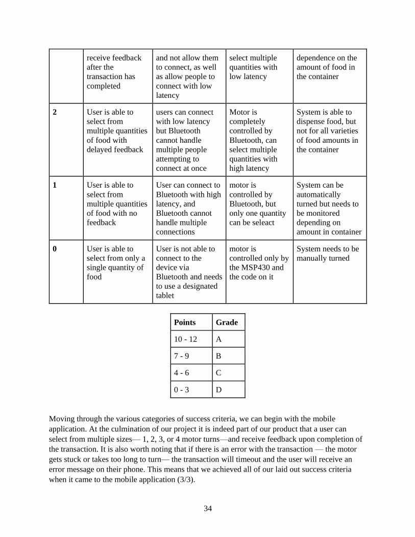
Moving through the various categories of success criteria, we can begin with the mobile
application. At the culmination of our project it is indeed part of our product that a user can
select from multiple sizes— 1, 2, 3, or 4 motor turns—and receive feedback upon completion of
the transaction. It is also worth noting that if there is an error with the transaction — the motor
gets stuck or takes too long to turn— the transaction will timeout and the user will receive an
error message on their phone. This means that we achieved all of our laid out success criteria
when it came to the mobile application (3/3).
35
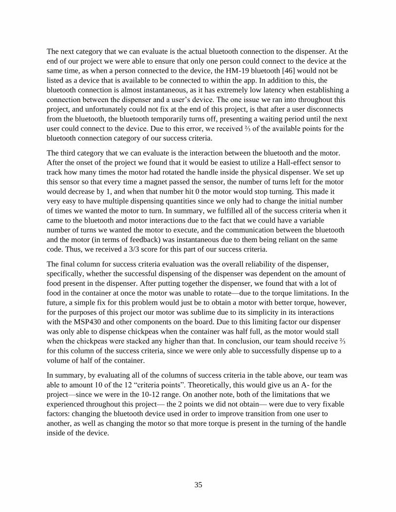
The next category that we can evaluate is the actual bluetooth connection to the dispenser. At the
end of our project we were able to ensure that only one person could connect to the device at the
same time, as when a person connected to the device, the HM-19 bluetooth [46] would not be
listed as a device that is available to be connected to within the app. In addition to this, the
bluetooth connection is almost instantaneous, as it has extremely low latency when establishing a
connection between the dispenser and a user’s device. The one issue we ran into throughout this
project, and unfortunately could not fix at the end of this project, is that after a user disconnects
from the bluetooth, the bluetooth temporarily turns off, presenting a waiting period until the next
user could connect to the device. Due to this error, we received ⅔ of the available points for the
bluetooth connection category of our success criteria.
The third category that we can evaluate is the interaction between the bluetooth and the motor.
After the onset of the project we found that it would be easiest to utilize a Hall-effect sensor to
track how many times the motor had rotated the handle inside the physical dispenser. We set up
this sensor so that every time a magnet passed the sensor, the number of turns left for the motor
would decrease by 1, and when that number hit 0 the motor would stop turning. This made it
very easy to have multiple dispensing quantities since we only had to change the initial number
of times we wanted the motor to turn. In summary, we fulfilled all of the success criteria when it
came to the bluetooth and motor interactions due to the fact that we could have a variable
number of turns we wanted the motor to execute, and the communication between the bluetooth
and the motor (in terms of feedback) was instantaneous due to them being reliant on the same
code. Thus, we received a 3/3 score for this part of our success criteria.
The final column for success criteria evaluation was the overall reliability of the dispenser,
specifically, whether the successful dispensing of the dispenser was dependent on the amount of
food present in the dispenser. After putting together the dispenser, we found that with a lot of
food in the container at once the motor was unable to rotate—due to the torque limitations. In the
future, a simple fix for this problem would just be to obtain a motor with better torque, however,
for the purposes of this project our motor was sublime due to its simplicity in its interactions
with the MSP430 and other components on the board. Due to this limiting factor our dispenser
was only able to dispense chickpeas when the container was half full, as the motor would stall
when the chickpeas were stacked any higher than that. In conclusion, our team should receive ⅔
for this column of the success criteria, since we were only able to successfully dispense up to a
volume of half of the container.
In summary, by evaluating all of the columns of success criteria in the table above, our team was
able to amount 10 of the 12 “criteria points”. Theoretically, this would give us an A- for the
project—since we were in the 10-12 range. On another note, both of the limitations that we
experienced throughout this project— the 2 points we did not obtain— were due to very fixable
factors: changing the bluetooth device used in order to improve transition from one user to
another, as well as changing the motor so that more torque is present in the turning of the handle
inside of the device.
36
Costs The final cost of a single unit of our device came to $172.34. This does not include the
costs of having parts soldered onto the board, nor the costs associated with resistors and
capacitors taken from our lab kits. The cost per unit is reduced significantly when considering
manufacturing 10,000 units. When calculating the extended cost, the components taken from the
lab kit were factored in by finding equivalent surface mount items on Digi-Key. The final
extended cost came to $123.78 per unit, excluding the costs associated with labor and
production.
If this product were to go to market, a number of things would need to be changed. For
one, a much larger dispenser would be needed to meet the demands of shoppers. This would
necessitate a more powerful motor to dispense with increased weight of product. We would also
need to pay for a license to provide our app in app stores, as well as invest in creating a
compatible version for other phone operating systems. There would, of course, be additional
costs from labor, packaging, and assembly, although ideally most assembly would be done with
automated machinery.
There are some ways in which costs would be reduced when developing a market-ready
product. If this product were to be produced at a large scale, most of the resistors and capacitors
would likely be replaced with surface mount versions to reduce costs and minimize the potential
for breaking the board. All test points would be removed, and the microcontrollers would ideally
be pre-programmed before being placed on the PCB, removing the need for a JTAG header. Not
only would these changes reduce the costs associated with parts, but they would also reduce the
size of the PCB, reducing the cost of the board itself.
Detailed spreadsheets breaking down the cost of a single dispenser, the cost of
manufacturing 10,000 dispensers, and the overall status of our budget are provided in the
appendix.
Reflection and Future Work
One suggestion as to how our project could have been improved would be to implement
the timeout condition, which would trigger if the dispenser did not successfully dispense the
requested amount of food in a certain timeframe, in the embedded side of things. This was the
original plan, but due to a lack of time and difficulty with the priority of interrupts for the UART
and timers in the embedded code, dispenser timeout was handled in the mobile application’s
code. This is not ideal, as the mobile application code does not receive information directly from
the hall effect sensors as the embedded code does, which means it can’t be as responsive and is
more hard-coded in nature. If Covid-19 did not shorten our working period and hamper our
ability to work together, I’m confident that the timeout condition could have been implemented
in our embedded code.
An additional area in which we struggled involved dealing with the HM-19 Bluetooth
[28] that had very unorganized documentation and that was difficult to configure to our needs. If
we were going to expand on this product in the future we would probably want to invest in a
37
bluetooth that had more easily-customizable capabilities; as one of the big problems discussed in
the Final Results section of this paper was how the bluetooth could not transition between
connections very well. Thus, by utilizing a Bluetooth module with better documentation, we
could transition between connections more easily, and possibly allow multiple connections at the
same time and implement a queueing mechanism on the device.
Another suggestion for improvement would be to more carefully measure the dimensions
of the dispenser and resize our enclosure accordingly. When putting the dispenser together, one
of the issues that we ran into was that some of the parts were too loose-fitting, which led to parts
moving around when the motor spun.
A third suggestion would be to use a higher torque motor and/or a smoother rotating
valve. We found that the motor we used would get stuck if we put too much food in the
dispenser. We believe that a higher torque motor or a valve that rotates smoother would help to
prevent the dispenser from getting stuck.
There are several opportunities for expansion beyond improving deficiencies in our
design. For example, sensing could be added to dispense products by weight rather than volume.
This could also be used to ensure that a customer has placed a container below the dispenser
before vending. Another idea would be to make a single module containing multiple dispensers
all powered and controlled by the same PCB, which is more realistic for use in a commercial
setting. The possibilities for iterating on this project are numerous and exciting.
38
References [1] "Code Composer Studio (CCS) Integrated Development Environment (IDE)", Texas Instruments,
2020. [Online]. Available: https://www.ti.com/tool/CCSTUDIO. [Accessed: 14- Sep- 2020].
[2] “Ultiboard,” National Instruments, 2020. https://www.ni.com/en-
us/shop/software/products/ultiboard.html (accessed Dec. 10, 2020).
[3] "What is Multisim™?", Ni.com, 2020. [Online]. Available: https://www.ni.com/en-us/shop/electronic-
test-instrumentation/application-software-for-electronic-test-and-instrumentation-category/what-is-
multisim.html. [Accessed: 14- Sep- 2020]
[4] “SOLIDWORKS,” Dassault Systèmes SolidWorks Corporation, 2020. https://www.solidworks.com/
(accessed Dec. 10, 2020).
[5] Pullen, J., 2020. 5 Technologies Changing the Restaurant Industry. [online] msnbc.com. Available at:
<http://www.nbcnews.com/id/48959179/ns/business-small_business/t/technologies-changing-restaurant-
industry/#.X1WNXHlKiUk> [Accessed 7 September 2020].
[6] urdesignmag. 2020. An Insight on How the Best Automatic Soap Dispensers Work. [online] Available
at: <https://www.urdesignmag.com/technology/2018/05/14/an-insight-on-how-the-best-automatic-soap-
dispensers-work/> [Accessed 6 September 2020].
[7] Magloff, L., 2020. 'Freestyle' Beverage Dispenser Offers Restaurants Contactless Pouring. [online]
Springwise. Available at: <https://www.springwise.com/innovation/food-drink/coca-cola-vending-
machine-qr-codes-covid> [Accessed 6 September 2020].
[8] Cost Aide. 2020. How Much Does Coca-Cola Freestyle Cost In 2020?. [online] Available at:
<https://costaide.com/coca-cola-freestyle-cost/> [Accessed 7 September 2020].
[9] Sedaghat, L., 2020. 7 Things You Didn’t Know About Plastic (And Recycling). [online] National
Geographic Society Newsroom. Available at: <https://blog.nationalgeographic.org/2018/04/04/7-things-
you-didnt-know-about-plastic-and-recycling/> [Accessed 14 September 2020].
[10] US EPA. 2020. Certified Electronics Recyclers | US EPA. [online] Available at:
<https://www.epa.gov/smm-electronics/certified-electronics-
recyclers#:~:text=Currently%20two%20accredited%20certification%20standards,e%2DStewards%C2%
AE%22).> [Accessed 14 September 2020].
[11] Food and Drug Administration, "FDA Food Code 2017", U.S. Department of Health and Human
Services, College Park, MD, 2017.
[12] Chapter 1 - Basics of Machine Safeguarding. [Online]. Available:
<https://www.osha.gov/Publications/Mach_SafeGuard/chapt1.html. [Accessed: 07-Sep-2020].>
[13] Pew Research Center: Internet, Science & Tech. 2020. Demographics of Mobile Device Ownership
and Adoption in The United States. [online] Available at: <https://www.pewresearch.org/internet/fact-sheet/mobile/> [Accessed 14 September 2020].
39
[14] Landau, O., 2002. Dry Food Dispensing System. US6964355B2.
[15] Rudick, A., Mattos, L., Antonio, N., Mattos, M., Zhang, Q. and Kolls, B., 2010. Vessel Activated
Beverage Dispenser. US8757222B2.
[16] Yamazaki, Y. Sugawara, T. “System and method to purchase from a vending machine by using a
mobile phone” United States Patent 20190108709A1.
[17] “MSP430FR231x Mixed-Signal Microcontrollers.” Texas Instruments, Dec. 2019, [Online].
Available: https://www.ti.com/lit/ds/symlink/msp430fr2311.pdf?HQS=TI-null-null-digikeymode-df-pf-
null-wwe&ts=1607451878388.
[18] “Stepper Motor Control Using MSP430™ MCUs.” Texas Instruments, Dallas, Texas, Sep-2017.
[19] “MSP430FR21xx, MSP430FR2000 Mixed-Signal Microcontrollers.” Texas Instruments, Dec. 2019,
[Online]. Available: https://www.ti.com/lit/ds/symlink/msp430fr2111.pdf?HQS=TI-null-null-
digikeymode-df-pf-null-wwe&ts=1607640218681.
[20] “SWI10-N Series Datasheet.” CUI Inc., Sep. 21, 2020, [Online]. Available:
https://www.cui.com/product/resource/swi10-n.pdf.
[21] “PJ-059A Datasheet.” CUI Devices, Apr. 14, 2016, [Online]. Available:
https://www.cuidevices.com/product/resource/pj-059a.pdf.
[22] “K104K15X7RF5TL2 Vishay Beyschlag/Draloric/BC Components | Capacitors | DigiKey,”
DigiKey. https://www.digikey.com/en/products/detail/vishay-beyschlag-draloric-bc-
components/K104K15X7RF5TL2/286706 (accessed Dec. 10, 2020).
[23] “TLV733P Capacitor-Free, 300-mA, Low-Dropout Regulator in 1-mm × 1-mm X2SON Package.”
Texas Instruments, Jul. 2019, [Online]. Available:
https://www.ti.com/lit/ds/symlink/tlv733p.pdf?HQS=TI-null-null-digikeymode-df-pf-null-
wwe1&ts=1607459604239.
[24] “LM1086 1.5-A Low Dropout Positive Voltage Regulators.” Texas Instruments, Apr. 2015,
[Online]. Available: https://www.ti.com/lit/ds/symlink/lm1086.pdf?HQS=TI-null-null-digikeymode-df-
pf-null-wwe&ts=1607459637405.
[25] “MSP430TM Hardware Tools User’s Guide.” Texas Instruments, Feb. 2020, [Online]. Available:
https://www.ti.com/lit/ug/slau278af/slau278af.pdf?ts=1607523855998.
[26] “TE Connectivity 5499910-2 Datasheet.” TE Connectivity, [Online]. Available:
https://www.te.com/commerce/DocumentDelivery/DDEController?Action=srchrtrv&DocNm=5499910&
DocType=Customer+Drawing&DocLang=English&PartCntxt=5499910-2&DocFormat=pdf.
[27] Components101. 2020. HC-05 - Bluetooth Module. [online] Available at:
<https://components101.com/wireless/hc-05-bluetooth-module> [Accessed 7 September 2020].
40
[28] “HM-18/HM-19 CC2640R2 Bluetooth Module Datasheet.” DSD Tech, [Online]. Available:
https://drive.google.com/file/d/1tKEwk9f0gSQ1rSV3ei9nNnNElQzgrnN0/view.
[29] “42BYGHM809.” SparkFun Electronics, Jan. 14, 2011.
[30] “DRV8834 Dual-Bridge Stepper or DC Motor Driver.” Texas Instruments, Mar. 2015, [Online].
Available: https://www.ti.com/lit/ds/symlink/drv8834.pdf?HQS=TI-null-null-digikeymode-df-pf-null-
wwe&ts=1607461359992.
[31] “CF14JT51K0 Stackpole Electronics Inc | Resistors | DigiKey,” DigiKey.
https://www.digikey.com/en/products/detail/stackpole-electronics-inc/CF14JT51K0/1830392 (accessed
Dec. 10, 2020).
[32] “KNP100JR-73-0R27 Yageo | Resistors | DigiKey.”
https://www.digikey.com/en/products/detail/yageo/KNP100JR-73-0R27/2059073?gclid=CjwKCAiAq8f-
BRBtEiwAGr3DgWGTq2RxcxE6x7vAZExOT6rVA38ETUzUdIEjjYrq9-
YA6h6cFRxHMxoCfLAQAvD_BwE (accessed Dec. 10, 2020).
[33] T. Umemura, “FG28X5R1E225KRT06 Characterization Sheet,” p. 1, Dec. 2015.
[34] “55140 Miniature Flange Mounting Sensor.” Littelfuse, Feb. 08, 2019, [Online]. Available:
https://www.littelfuse.com/~/media/electronics/datasheets/hall_effect_sensors/littelfuse_hall_effect_senso
rs_55140_datasheet.pdf.pdf.
[35] “Disk Neodymium Magnets N35-8193.” Radial Magnets Inc., [Online]. Available:
https://radialmagnet.com/wp-content/uploads/2017/01/Disk%20Neodymium%20Magnets%20N35-
8193.pdf.
[36] “TB001-500 Series Datasheet.” CUI Devices, Apr. 20, 2020, [Online]. Available:
https://www.cuidevices.com/product/resource/tb001-500.pdf.
[37] “Pololu Universal Aluminum Mounting Hub for 5mm Shaft, #4-40 Holes (2-Pack),” Pololu.
https://www.pololu.com/product/1203 (accessed Dec. 10, 2020).
[38] “R4-40X5/8 2701 APM Hexseal | Hardware, Fasteners, Accessories | DigiKey,” DigiKey.
https://www.digikey.com/en/products/detail/apm-hexseal/R4-
40X5%2F8%25202701/1159350?gclid=CjwKCAiAq8f-
BRBtEiwAGr3DgXEfAaSuU48ERuiZ7hJdCJISrQBHEti6UIq08DlwhmM3-wO-
NFoxChoCGjIQAvD_BwE (accessed Dec. 10, 2020).
[39] “Multipurpose Boxes With Lids.” Multicomp, Jan. 12, 2014, [Online]. Available:
http://www.farnell.com/datasheets/1520779.pdf.
41
[40] “Pololu Stamped Aluminum L-Bracket for NEMA 17 Stepper Motors,” Pololu.
https://www.pololu.com/product/2266 (accessed Dec. 10, 2020).
[41] “Button Head Hex Drive Screw Passivated 18-8 Stainless Steel, M4 x 0.70 mm Thread, 45mm
Long,” McMaster-Carr. https://www.mcmaster.com/92095A205/ (accessed Dec. 10, 2020).
[42] “Aluminum Hex Nut M4 x 0.7 mm Thread,” McMaster-Carr.
https://www.mcmaster.com/91854A101/ (accessed Dec. 10, 2020).
[43] “Thru Hole Mount Test Points.” Keystone Electronics, [Online]. Available:
https://www.keyelco.com/userAssets/file/M65p56.pdf.
[44] “C320C112JDG5TA KEMET | Capacitors | DigiKey,” DigiKey.
https://www.digikey.com/en/products/detail/kemet/C320C112JDG5TA/6159240 (accessed Dec. 10,
2020).
[45] “535541_1 Drawing.” TE Connectivity, [Online]. Available:
https://www.te.com/commerce/DocumentDelivery/DDEController?Action=showdoc&DocId=Customer+
Drawing%7F535541%7FN6%7Fpdf%7FEnglish%7FENG_CD_535541_N6.pdf%7F5-535541-4.
[46] “Button Head Hex Drive Screw 18-8 Stainless Steel, M4 x 0.70mm Thread, 55mm Long,”
McMaster-Carr. https://www.mcmaster.com/92095A330/ (accessed Dec. 10, 2020).
Appendix
In this section you should include helpful information that does not fit into the above categories
but will be helpful in understanding and assessing your work. Complete code listings should be
in this section, and detailed cad drawings.
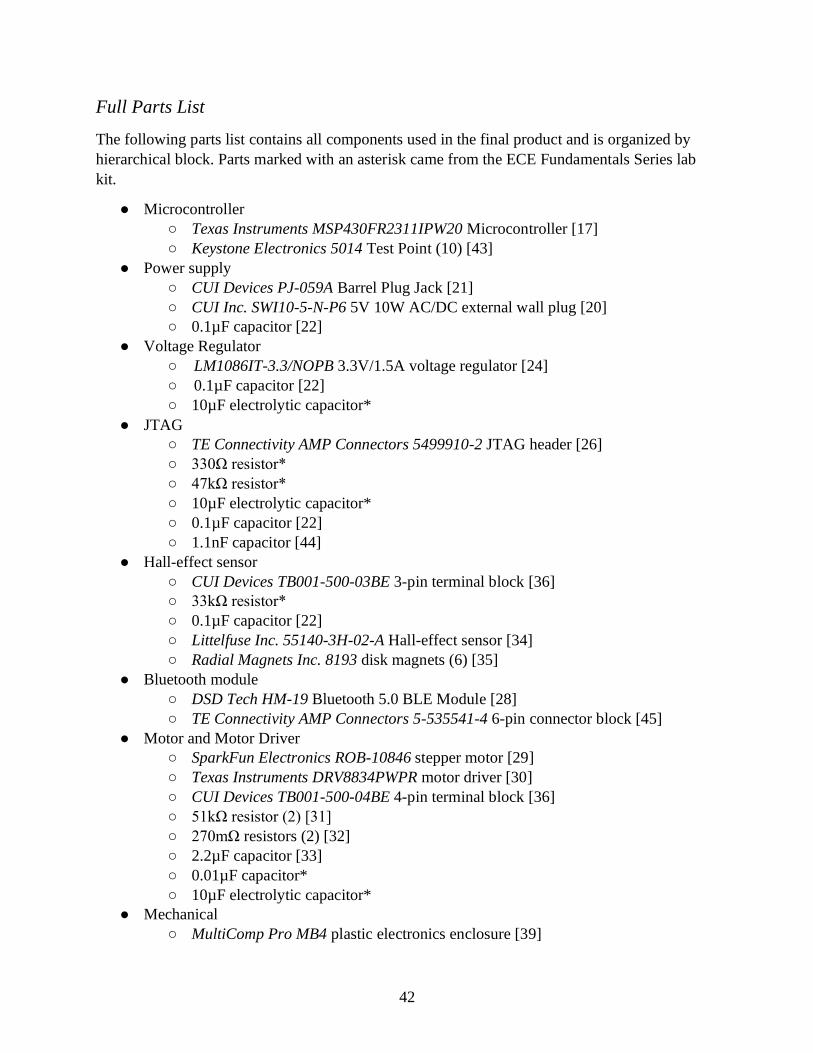
42
Full Parts List
The following parts list contains all components used in the final product and is organized by
hierarchical block. Parts marked with an asterisk came from the ECE Fundamentals Series lab
kit.
● Microcontroller
○ Texas Instruments MSP430FR2311IPW20 Microcontroller [17]
○ Keystone Electronics 5014 Test Point (10) [43]
● Power supply
○ CUI Devices PJ-059A Barrel Plug Jack [21]
○ CUI Inc. SWI10-5-N-P6 5V 10W AC/DC external wall plug [20]
○ 0.1µF capacitor [22]
● Voltage Regulator
○ LM1086IT-3.3/NOPB 3.3V/1.5A voltage regulator [24]
○ 0.1µF capacitor [22]
○ 10µF electrolytic capacitor*
● JTAG
○ TE Connectivity AMP Connectors 5499910-2 JTAG header [26]
○ 330Ω resistor*
○ 47kΩ resistor*
○ 10µF electrolytic capacitor*
○ 0.1µF capacitor [22]
○ 1.1nF capacitor [44]
● Hall-effect sensor
○ CUI Devices TB001-500-03BE 3-pin terminal block [36]
○ 33kΩ resistor*
○ 0.1µF capacitor [22]
○ Littelfuse Inc. 55140-3H-02-A Hall-effect sensor [34]
○ Radial Magnets Inc. 8193 disk magnets (6) [35]
● Bluetooth module
○ DSD Tech HM-19 Bluetooth 5.0 BLE Module [28]
○ TE Connectivity AMP Connectors 5-535541-4 6-pin connector block [45]
● Motor and Motor Driver
○ SparkFun Electronics ROB-10846 stepper motor [29]
○ Texas Instruments DRV8834PWPR motor driver [30]
○ CUI Devices TB001-500-04BE 4-pin terminal block [36]
○ 51kΩ resistor (2) [31]
○ 270mΩ resistors (2) [32]
○ 2.2µF capacitor [33]
○ 0.01µF capacitor*
○ 10µF electrolytic capacitor*
● Mechanical
○ MultiComp Pro MB4 plastic electronics enclosure [39]
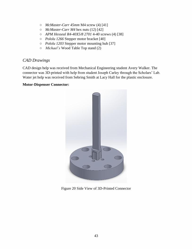
43
○ McMaster-Carr 45mm M4 screw (4) [41]
○ McMaster-Carr M4 hex nuts (12) [42]
○ APM Hexseal R4-40X5/8 2701 4-40 screws (4) [38]
○ Pololu 1266 Stepper motor bracket [40]
○ Pololu 1203 Stepper motor mounting hub [37]
○ Michael’s Wood Table Top stand (2)
CAD Drawings
CAD design help was received from Mechanical Engineering student Avery Walker. The
connector was 3D-printed with help from student Joseph Carley through the Scholars’ Lab.
Water jet help was received from Sebring Smith at Lacy Hall for the plastic enclosure.
Motor-Dispenser Connector:
Figure 20 Side View of 3D-Printed Connector
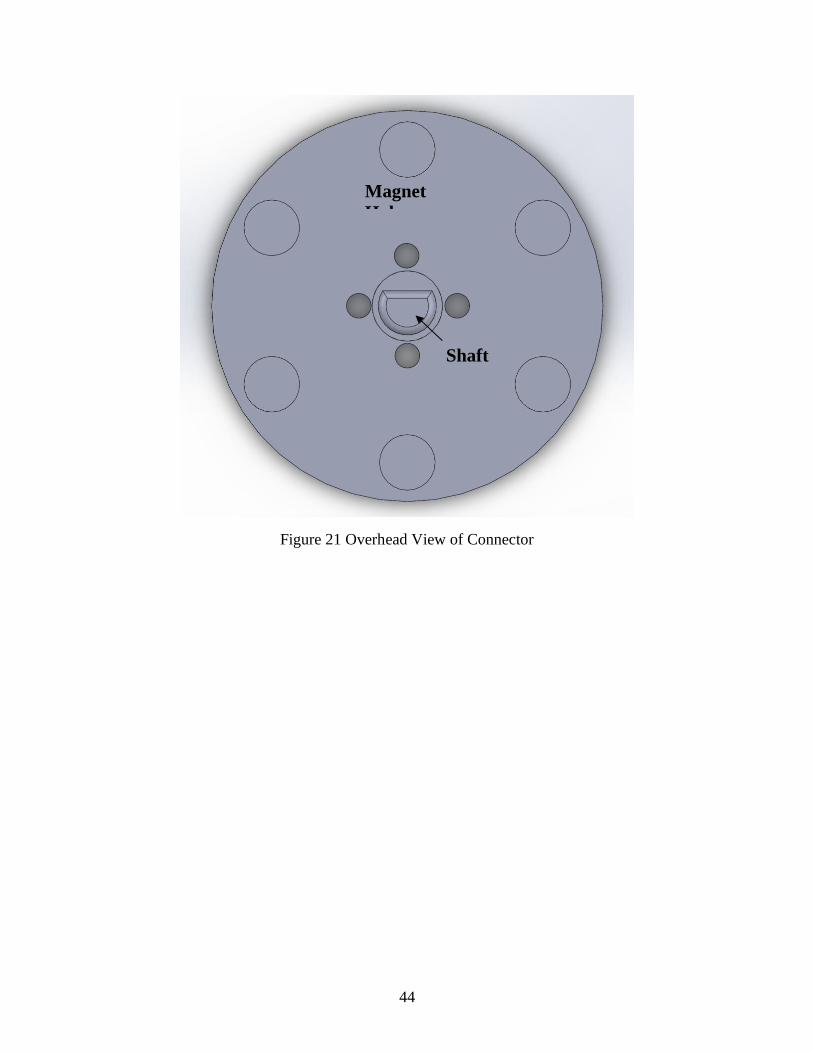
44
Figure 21 Overhead View of Connector
Magnet
Hole
4-40
Shaft
inserted
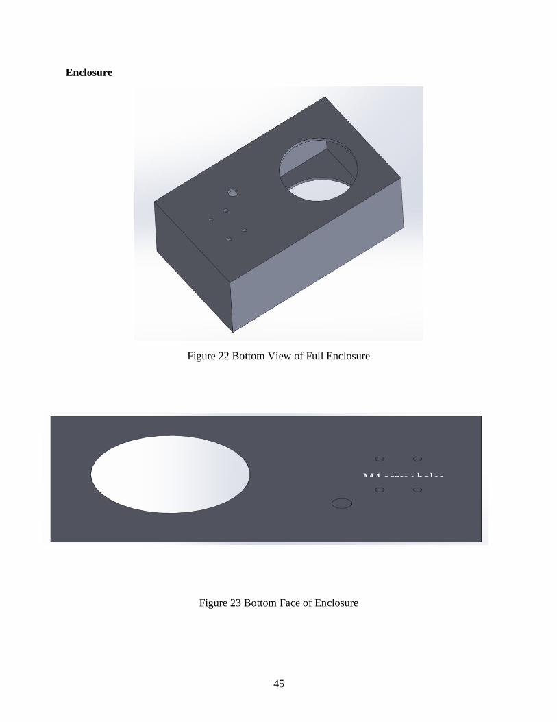
45
Enclosure
Figure 22 Bottom View of Full Enclosure
Figure 23 Bottom Face of Enclosure
M4 screw holes
Hole for
46
Figure 24 Top View of Enclosure
Costs
● Cost for a single unit: $172.34 per dispenser
● Cost for 10,000 units: $1,137,854.41 total, $123.79 per dispenser
● Total amount spent: $366.51
○ Orange boxes denote purchases we made ourselves that we will have reimbursed.
Records of these purchases will not be present in any UVA ordering system.
Table III: Costs of Parts for Single Unit
Manufacturer Part Number Description Price
C320C112JDG5TA 1.1nF Capacitor $1.82
PJ-059A Barrel Plug Jack $0.77
SWI10-5-N-P6 Wall plug AC to 5V DC converter $8.50
TB001-500-04BE 4-wire Terminal Block $0.76
TB001-500-03BE 3-wire Terminal Block $0.69
55140-3H-02-A Hall-effect Sensor $10.45
ROB-10846 Stepper Motor $17.95
DRV8834PWPR Motor Driver Chip $2.71
1203 Motor Mounting Hub $7.49
5499910-2 JTAG Header $3.34
Top hole for dispenser
Smaller hole in bottom
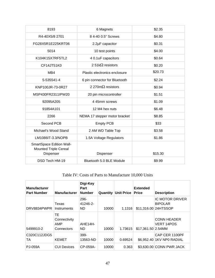
47
8193 6 Magnets $2.35
R4-40X5/8 2701 8 4-40 0.5" Screws $4.80
FG28X5R1E225KRT06 2.2µF capacitor $0.31
5014 10 test points $4.00
K104K15X7RF5TL2 4 0.1uF capacitors $0.64
CF14JT51K0 2 51kΩ resistors $0.20
MB4 Plastic electronics enclosure $20.73
5-535541-4 6 pin connector for Bluetooth $2.24
KNP100JR-73-0R27 2 270mΩ resistors $0.94
MSP430FR2311IPW20 20 pin microcontroller $1.51
92095A205 4 45mm screws $1.09
91854A101 12 M4 hex nuts $6.48
2266 NEMA 17 stepper motor bracket $8.85
Second PCB Empty PCB $33
Michael's Wood Stand 2 AM WD Table Top $3.58
LM1086IT-3.3/NOPB 1.5A Voltage Regulators $1.86
SmartSpace Edition Wall-
Mounted Triple Cereal
Dispenser Dispenser $15.30
DSD Tech HM-19 Bluetooth 5.0 BLE Module $9.99
Table IV: Costs of Parts to Manufacture 10,000 Units
Manufacturer
Part Number Manufacturer
Digi-Key
Part
Number Quantity Unit Price
Extended
Price Description
DRV8834PWPR
Texas
Instruments
296-
41246-2-
ND 10000 1.1316 $11,316.00
IC MOTOR DRIVER
BIPOLAR
24HTSSOP
5499910-2
TE
Connectivity
AMP
Connectors
AHE14H-
ND 10000 1.73615 $17,361.50
CONN HEADER
VERT 14POS
2.54MM
C320C112JDG5
TA KEMET
399-
13563-ND 10000 0.69524 $6,952.40
CAP CER 1100PF
1KV NP0 RADIAL
PJ-059A CUI Devices CP-059A- 10000 0.363 $3,630.00 CONN PWR JACK
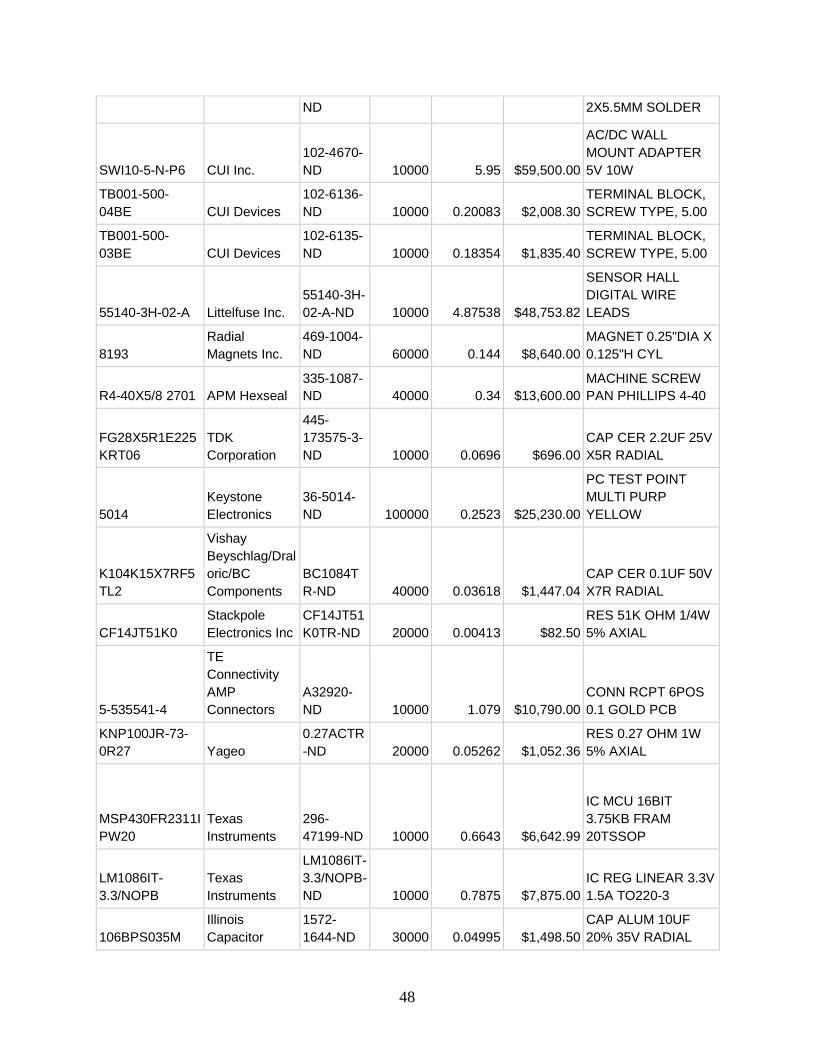
48
ND 2X5.5MM SOLDER
SWI10-5-N-P6 CUI Inc.
102-4670-
ND 10000 5.95 $59,500.00
AC/DC WALL
MOUNT ADAPTER
5V 10W
TB001-500-
04BE CUI Devices
102-6136-
ND 10000 0.20083 $2,008.30
TERMINAL BLOCK,
SCREW TYPE, 5.00
TB001-500-
03BE CUI Devices
102-6135-
ND 10000 0.18354 $1,835.40
TERMINAL BLOCK,
SCREW TYPE, 5.00
55140-3H-02-A Littelfuse Inc.
55140-3H-
02-A-ND 10000 4.87538 $48,753.82
SENSOR HALL
DIGITAL WIRE
LEADS
8193
Radial
Magnets Inc.
469-1004-
ND 60000 0.144 $8,640.00
MAGNET 0.25"DIA X
0.125"H CYL
R4-40X5/8 2701 APM Hexseal
335-1087-
ND 40000 0.34 $13,600.00
MACHINE SCREW
PAN PHILLIPS 4-40
FG28X5R1E225
KRT06
TDK
Corporation
445-
173575-3-
ND 10000 0.0696 $696.00
CAP CER 2.2UF 25V
X5R RADIAL
5014
Keystone
Electronics
36-5014-
ND 100000 0.2523 $25,230.00
PC TEST POINT
MULTI PURP
YELLOW
K104K15X7RF5
TL2
Vishay
Beyschlag/Dral
oric/BC
Components
BC1084T
R-ND 40000 0.03618 $1,447.04
CAP CER 0.1UF 50V
X7R RADIAL
CF14JT51K0
Stackpole
Electronics Inc
CF14JT51
K0TR-ND 20000 0.00413 $82.50
RES 51K OHM 1/4W
5% AXIAL
5-535541-4
TE
Connectivity
AMP
Connectors
A32920-
ND 10000 1.079 $10,790.00
CONN RCPT 6POS
0.1 GOLD PCB
KNP100JR-73-
0R27 Yageo
0.27ACTR
-ND 20000 0.05262 $1,052.36
RES 0.27 OHM 1W
5% AXIAL
MSP430FR2311I
PW20
Texas
Instruments
296-
47199-ND 10000 0.6643 $6,642.99
IC MCU 16BIT
3.75KB FRAM
20TSSOP
LM1086IT-
3.3/NOPB
Texas
Instruments
LM1086IT-
3.3/NOPB-
ND 10000 0.7875 $7,875.00
IC REG LINEAR 3.3V
1.5A TO220-3
106BPS035M
Illinois
Capacitor
1572-
1644-ND 30000 0.04995 $1,498.50
CAP ALUM 10UF
20% 35V RADIAL
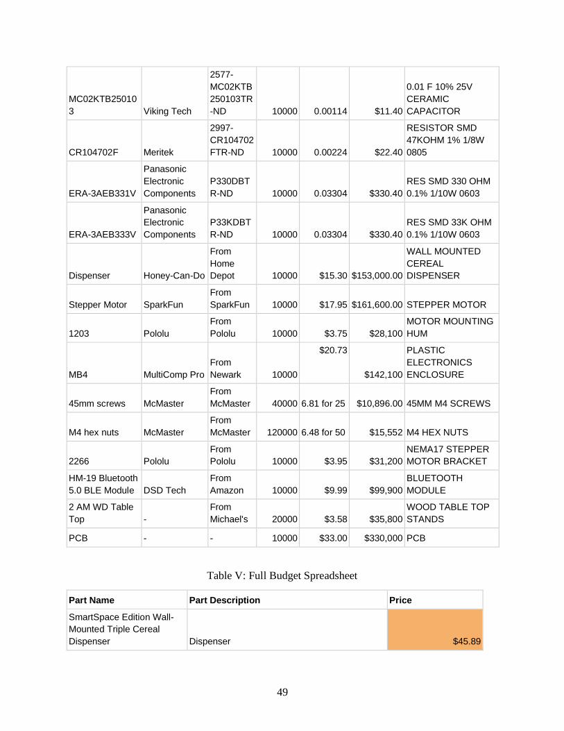
49
MC02KTB25010
3 Viking Tech
2577-
MC02KTB
250103TR
-ND 10000 0.00114 $11.40
0.01 F 10% 25V
CERAMIC
CAPACITOR
CR104702F Meritek
2997-
CR104702
FTR-ND 10000 0.00224 $22.40
RESISTOR SMD
47KOHM 1% 1/8W
0805
ERA-3AEB331V
Panasonic
Electronic
Components
P330DBT
R-ND 10000 0.03304 $330.40
RES SMD 330 OHM
0.1% 1/10W 0603
ERA-3AEB333V
Panasonic
Electronic
Components
P33KDBT
R-ND 10000 0.03304 $330.40
RES SMD 33K OHM
0.1% 1/10W 0603
Dispenser Honey-Can-Do
From
Home
Depot 10000 $15.30 $153,000.00
WALL MOUNTED
CEREAL
DISPENSER
Stepper Motor SparkFun
From
SparkFun 10000 $17.95 $161,600.00 STEPPER MOTOR
1203 Pololu
From
Pololu 10000 $3.75 $28,100
MOTOR MOUNTING
HUM
MB4 MultiComp Pro
From
Newark 10000
$20.73
$142,100
PLASTIC
ELECTRONICS
ENCLOSURE
45mm screws McMaster
From
McMaster 40000 6.81 for 25 $10,896.00 45MM M4 SCREWS
M4 hex nuts McMaster
From
McMaster 120000 6.48 for 50 $15,552 M4 HEX NUTS
2266 Pololu
From
Pololu 10000 $3.95 $31,200
NEMA17 STEPPER
MOTOR BRACKET
HM-19 Bluetooth
5.0 BLE Module DSD Tech
From
Amazon 10000 $9.99 $99,900
BLUETOOTH
MODULE
2 AM WD Table
Top -
From
Michael's 20000 $3.58 $35,800
WOOD TABLE TOP
STANDS
PCB - - 10000 $33.00 $330,000 PCB
Table V: Full Budget Spreadsheet
Part Name Part Description Price
SmartSpace Edition Wall-
Mounted Triple Cereal
Dispenser Dispenser $45.89
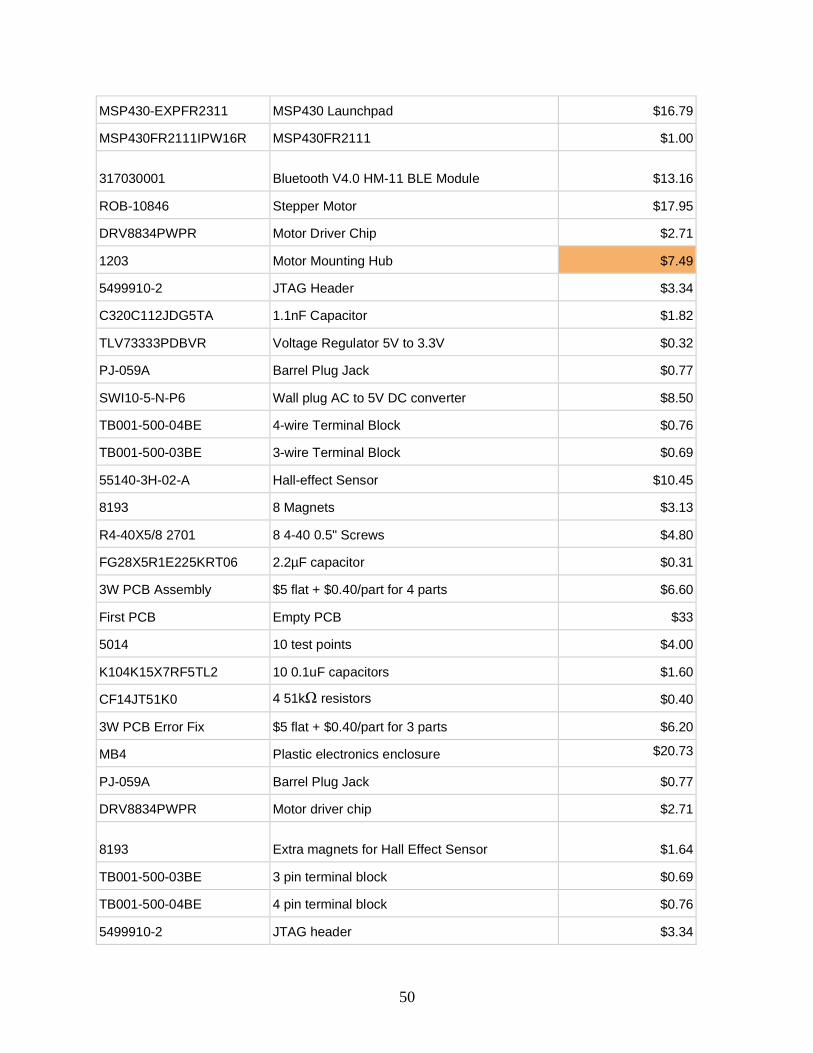
50
MSP430-EXPFR2311 MSP430 Launchpad $16.79
MSP430FR2111IPW16R MSP430FR2111 $1.00
317030001 Bluetooth V4.0 HM-11 BLE Module $13.16
ROB-10846 Stepper Motor $17.95
DRV8834PWPR Motor Driver Chip $2.71
1203 Motor Mounting Hub $7.49
5499910-2 JTAG Header $3.34
C320C112JDG5TA 1.1nF Capacitor $1.82
TLV73333PDBVR Voltage Regulator 5V to 3.3V $0.32
PJ-059A Barrel Plug Jack $0.77
SWI10-5-N-P6 Wall plug AC to 5V DC converter $8.50
TB001-500-04BE 4-wire Terminal Block $0.76
TB001-500-03BE 3-wire Terminal Block $0.69
55140-3H-02-A Hall-effect Sensor $10.45
8193 8 Magnets $3.13
R4-40X5/8 2701 8 4-40 0.5" Screws $4.80
FG28X5R1E225KRT06 2.2µF capacitor $0.31
3W PCB Assembly $5 flat + $0.40/part for 4 parts $6.60
First PCB Empty PCB $33
5014 10 test points $4.00
K104K15X7RF5TL2 10 0.1uF capacitors $1.60
CF14JT51K0 4 51kΩ resistors $0.40
3W PCB Error Fix $5 flat + $0.40/part for 3 parts $6.20
MB4 Plastic electronics enclosure $20.73
PJ-059A Barrel Plug Jack $0.77
DRV8834PWPR Motor driver chip $2.71
8193 Extra magnets for Hall Effect Sensor $1.64
TB001-500-03BE 3 pin terminal block $0.69
TB001-500-04BE 4 pin terminal block $0.76
5499910-2 JTAG header $3.34
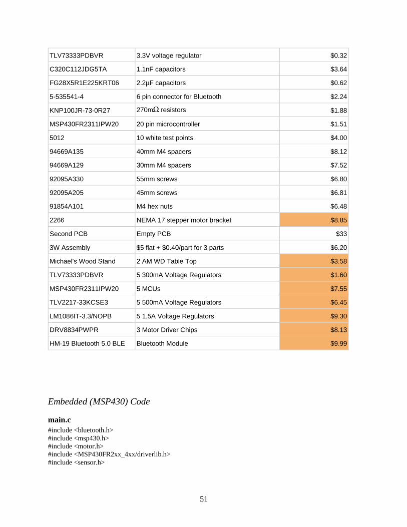
51
TLV73333PDBVR 3.3V voltage regulator $0.32
C320C112JDG5TA 1.1nF capacitors $3.64
FG28X5R1E225KRT06 2.2µF capacitors $0.62
5-535541-4 6 pin connector for Bluetooth $2.24
KNP100JR-73-0R27 270mΩ resistors $1.88
MSP430FR2311IPW20 20 pin microcontroller $1.51
5012 10 white test points $4.00
94669A135 40mm M4 spacers $8.12
94669A129 30mm M4 spacers $7.52
92095A330 55mm screws $6.80
92095A205 45mm screws $6.81
91854A101 M4 hex nuts $6.48
2266 NEMA 17 stepper motor bracket $8.85
Second PCB Empty PCB $33
3W Assembly $5 flat + $0.40/part for 3 parts $6.20
Michael's Wood Stand 2 AM WD Table Top $3.58
TLV73333PDBVR 5 300mA Voltage Regulators $1.60
MSP430FR2311IPW20 5 MCUs $7.55
TLV2217-33KCSE3 5 500mA Voltage Regulators $6.45
LM1086IT-3.3/NOPB 5 1.5A Voltage Regulators $9.30
DRV8834PWPR 3 Motor Driver Chips $8.13
HM-19 Bluetooth 5.0 BLE Bluetooth Module $9.99
Embedded (MSP430) Code
main.c
#include <bluetooth.h>
#include <msp430.h>
#include <motor.h>
#include <MSP430FR2xx_4xx/driverlib.h>
#include <sensor.h>
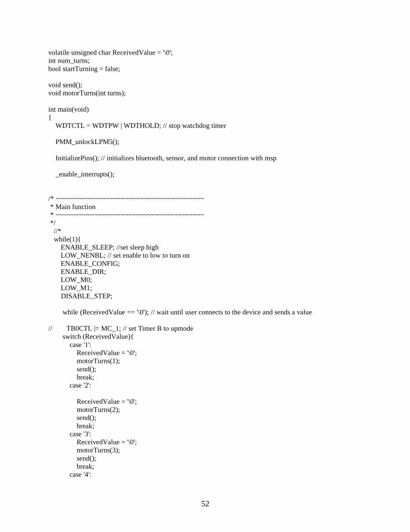
52
volatile unsigned char ReceivedValue = '\0';
int num_turns;
bool startTurning = false;
void send();
void motorTurns(int turns);
int main(void)
{
WDTCTL = WDTPW | WDTHOLD; // stop watchdog timer
PMM_unlockLPM5();
InitializePins(); // initializes bluetooth, sensor, and motor connection with msp
_enable_interrupts();
/* ~~~~~~~~~~~~~~~~~~~~~~~~~~~~~~~~~~~~~~~
* Main function
* ~~~~~~~~~~~~~~~~~~~~~~~~~~~~~~~~~~~~~~~
*/
//*
while(1){
ENABLE_SLEEP; //set sleep high
LOW_NENBL; // set enable to low to turn on
ENABLE_CONFIG;
ENABLE_DIR;
LOW_M0;
LOW_M1;
DISABLE_STEP;
while (ReceivedValue == '\0'); // wait until user connects to the device and sends a value
// TB0CTL |= MC_1; // set Timer B to upmode
switch (ReceivedValue){
case '1':
ReceivedValue = '\0';
motorTurns(1);
send();
break;
case '2':
ReceivedValue = '\0';
motorTurns(2);
send();
break;
case '3':
ReceivedValue = '\0';
motorTurns(3);
send();
break;
case '4':
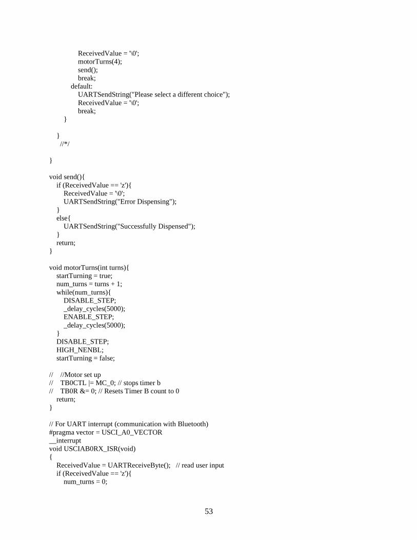
53
ReceivedValue = '\0';
motorTurns(4);
send();
break;
default:
UARTSendString("Please select a different choice");
ReceivedValue = '\0';
break;
}
}
//*/
}
void send(){
if (ReceivedValue == 'z'){
ReceivedValue = '\0';
UARTSendString("Error Dispensing");
}
else{
UARTSendString("Successfully Dispensed");
}
return;
}
void motorTurns(int turns){
startTurning = true;
num_turns = turns + 1;
while(num_turns){
DISABLE_STEP;
_delay_cycles(5000);
ENABLE_STEP;
_delay_cycles(5000);
}
DISABLE_STEP;
HIGH_NENBL;
startTurning = false;
// //Motor set up
// TB0CTL |= MC_0; // stops timer b
// TB0R &= 0; // Resets Timer B count to 0
return;
}
// For UART interrupt (communication with Bluetooth)
#pragma vector = USCI_A0_VECTOR
__interrupt
void USCIAB0RX_ISR(void)
{
ReceivedValue = UARTReceiveByte(); // read user input
if (ReceivedValue == 'z'){
num_turns = 0;
54
}
UCA0IFG &= ~UCRXIFG;
}
// For Hall Effect Sensor Interrupt
#pragma vector=PORT1_VECTOR
__interrupt void Port_1(void)
{
P1IFG &= ~SENSOR_BIT; // Clear P1.1 IFG
if (startTurning){
if (num_turns){
num_turns--;
} else {
HIGH_NENBL;
}
}
}
bluetooth_motor_sensor_setup.c #include <bluetooth.h>
#include <motor.h>
#include <sensor.h>
void InitializePins()
{
// Software reset enabled. USCI logic held in reset state.
UCA0CTL1 |= UCSWRST;
// Select USCI UART functionality.
UCA0CTLW0 |= UCSSEL__SMCLK + UCRXEIE;
// Baud Rate calculation
UCA0BRW = 6; // 1000000/115200 = 8.68
UCA0MCTLW |= UCOS16 | UCBRF_8 | 0x20; //0xD600 is UCBRSx = 0xD6
// UCBRSx value = 0xD6 (See UG)
UCA0BR1 = 0;
P1SEL1 &= ~(BIT6 | BIT7); // USCI_A0 UART operation
P1SEL0 |= BIT6 | BIT7;
SET_RECEIVE_AS_AN_INPUT;
SET_TRANSMIT_AS_AN_OUTPUT;
// SET_STATE_AS_AN_OUTPUT; // Bluetooth state pin (not needed)
// SET_EN_AS_AN_OUTPUT; // Bluetooth enable pin (not needed)
// Motor Configurations
SET_SLEEP_AS_AN_OUTPUT;
SET_NENBL_AS_AN_OUTPUT;
SET_STEP_AS_AN_OUTPUT;
SET_DIR_AS_AN_OUTPUT;
SET_M0_AS_AN_OUTPUT;
55
SET_M1_AS_AN_OUTPUT;
SET_CONFIG_AS_AN_OUTPUT;
SET_NFAULT_AS_AN_INPUT;
// Hall Effect Sensor Configuration
SET_SENSOR_AS_AN_INPUT;
UCA0TXBUF = 0; // initialize transmit buffer to 0 (for UART communication with Bluetooth)
UCA0CTL1 &= ~UCSWRST; // Initialize eUSCI (gets out of Reset state)
UCA0IE |= UCRXIE; // Enable USCI_A0 RX interrupt
P1IE |= SENSOR_BIT; // Enable HallEffectSensor Interrupt
P1IES |= SENSOR_BIT; // make interrupt falling edge
P1IFG &= ~SENSOR_BIT; // Clear interrupt flag
}
void UARTSendByte(unsigned char SendValue)
{
while (!(UCA0IFG & UCTXIFG)); //wait to be ready
UCA0TXBUF = SendValue;
while ((UCA0STATW & UCBUSY));
}
unsigned char UARTReceiveByte()
{
while (!(UCA0IFG & UCRXIFG)); //wait until ready to read
unsigned char ReceiveValue = UCA0RXBUF;
while ((UCA0STATW & UCBUSY));
return ReceiveValue;
}
void UARTSendString(unsigned char *str)
{
if (str != NULL) {
while (*str != '\0') {
UARTSendByte(*str);
str++;
}
}
}
bluetooth.h
#ifndef BLUETOOTH_H
#define BLUETOOTH_H
#include <msp430.h>
#include <stddef.h>
56
/* ~~~~~~~~~~~~~~~~~~~~~~~~~~~~~~~~~~~~~~~
* UC0RX USCI_A0 receive data input in UART mode
* ~~~~~~~~~~~~~~~~~~~~~~~~~~~~~~~~~~~~~~~
* GPIO : P1.6
* ~~~~~~~~~~~~~~~~~~~~~~~~~~~~~~~~~~~~~~~
*/
#define USCIA0_RECEIVE_BIT BIT6
#define USCIA0_RECEIVE_PORT P1IN
#define USCIA0_RECEIVE_DDR P1DIR
#define SET_RECEIVE_AS_AN_INPUT USCIA0_RECEIVE_DDR &= ~USCIA0_RECEIVE_BIT
/* ~~~~~~~~~~~~~~~~~~~~~~~~~~~~~~~~~~~~~~~
* UC0TX USCI_A0 transmit data output in UART mode
* ~~~~~~~~~~~~~~~~~~~~~~~~~~~~~~~~~~~~~~~
* GPIO : P1.7
* ~~~~~~~~~~~~~~~~~~~~~~~~~~~~~~~~~~~~~~~
*/
#define USCIA0_TRANSMIT_BIT BIT7
#define USCIA0_TRANSMIT_PORT P1OUT
#define USCIA0_TRANSMIT_DDR P1DIR
#define SET_TRANSMIT_AS_AN_OUTPUT USCIA0_TRANSMIT_DDR |=
USCIA0_TRANSMIT_BIT
#define BLUETOOTH_EN_BIT BIT5
#define BLUETOOTH_EN_PORT P1OUT
#define BLUETOOTH_EN_DDR P1DIR
#define SET_EN_AS_AN_OUTPUT BLUETOOTH_EN_DDR |= BLUETOOTH_EN_BIT
#define BLUETOOTH_STATE_BIT BIT0
#define BLUETOOTH_STATE_PORT P2OUT
#define BLUETOOTH_STATE_DDR P2DIR
#define SET_STATE_AS_AN_OUTPUT BLUETOOTH_STATE_DDR |=
BLUETOOTH_STATE_BIT
void InitializePins();
void UARTSendByte(unsigned char SendValue);
unsigned char UARTReceiveByte();
void UARTSendString(unsigned char *str);
#endif
motor.h #ifndef MOTOR_H
#define MOTOR_H
#include <msp430.h>
#include <stddef.h>
57
#define SLEEP_BIT BIT0
#define SLEEP_PORT P1OUT
#define SLEEP_DDR P1DIR
#define SET_SLEEP_AS_AN_OUTPUT SLEEP_DDR |= SLEEP_BIT
#define ENABLE_SLEEP SLEEP_PORT |= SLEEP_BIT
#define NENBL_BIT BIT4
#define NENBL_PORT P2OUT
#define NENBL_DDR P2DIR
#define SET_NENBL_AS_AN_OUTPUT NENBL_DDR |= NENBL_BIT
#define LOW_NENBL NENBL_PORT &= ~NENBL_BIT
#define HIGH_NENBL NENBL_PORT |= NENBL_BIT
#define STEP_BIT BIT6
#define STEP_PORT P2OUT
#define STEP_DDR P2DIR
#define SET_STEP_AS_AN_OUTPUT STEP_DDR |= STEP_BIT
#define ENABLE_STEP STEP_PORT |= STEP_BIT
#define DISABLE_STEP STEP_PORT &= ~STEP_BIT
#define DIR_BIT BIT5
#define DIR_PORT P2OUT
#define DIR_DDR P2DIR
#define SET_DIR_AS_AN_OUTPUT DIR_DDR |= DIR_BIT
#define ENABLE_DIR DIR_PORT |= DIR_BIT
#define DISABLE_DIR DIR_PORT &= ~DIR_BIT
#define M0_BIT BIT3
#define M0_PORT P1OUT
#define M0_DDR P1DIR
#define SET_M0_AS_AN_OUTPUT M0_DDR |= M0_BIT
#define LOW_M0 M0_PORT &= ~M0_BIT
#define HIGH_M0 M0_PORT |= M0_BIT
#define M1_BIT BIT2
#define M1_PORT P1OUT
#define M1_DDR P1DIR
#define SET_M1_AS_AN_OUTPUT M1_DDR |= M1_BIT
#define LOW_M1 M1_PORT &= ~M1_BIT
#define HIGH_M1 M1_PORT |= M1_BIT
#define CONFIG_BIT BIT1
#define CONFIG_PORT P2OUT
#define CONFIG_DDR P2DIR
#define SET_CONFIG_AS_AN_OUTPUT CONFIG_DDR |= CONFIG_BIT
#define ENABLE_CONFIG CONFIG_PORT |= CONFIG_BIT
#define NFAULT_BIT BIT4
#define NFAULT_PORT P1IN
#define NFAULT_DDR P1DIR
#define SET_NFAULT_AS_AN_INPUT NFAULT_DDR &= ~NFAULT_BIT
#endif
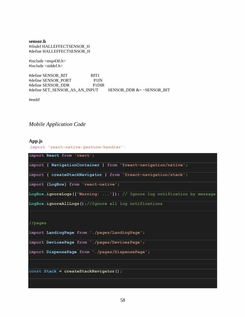
58
sensor.h #ifndef HALLEFFECTSENSOR_H
#define HALLEFFECTSENSOR_H
#include <msp430.h>
#include <stddef.h>
#define SENSOR_BIT BIT1
#define SENSOR_PORT P1IN
#define SENSOR_DDR P1DIR
#define SET_SENSOR_AS_AN_INPUT SENSOR_DDR &= ~SENSOR_BIT
#endif
Mobile Application Code
App.js
import 'react-native-gesture-handler';
import React from 'react';
import { NavigationContainer } from '@react-navigation/native';
import { createStackNavigator } from '@react-navigation/stack';
import {LogBox} from 'react-native';
LogBox.ignoreLogs(['Warning: ...']); // Ignore log notification by message
LogBox.ignoreAllLogs();//Ignore all log notifications
//pages
import LandingPage from './pages/LandingPage';
import DevicesPage from './pages/DevicesPage';
import DispensePage from './pages/DispensePage';
const Stack = createStackNavigator();
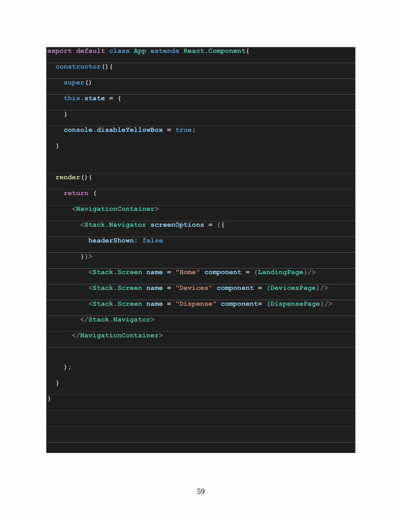
59
export default class App extends React.Component{
constructor(){
super()
this.state = {
}
console.disableYellowBox = true;
}
render(){
return (
<NavigationContainer>
<Stack.Navigator screenOptions = {{
headerShown: false
}}>
<Stack.Screen name = "Home" component = {LandingPage}/>
<Stack.Screen name = "Devices" component = {DevicesPage}/>
<Stack.Screen name = "Dispense" component= {DispensePage}/>
</Stack.Navigator>
</NavigationContainer>
);
}
}
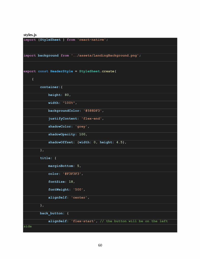
60
styles.js
import {StyleSheet } from 'react-native';
import background from '../assets/LandingBackground.png';
export const HeaderStyle = StyleSheet.create(
{
container:{
height: 80,
width: "100%",
backgroundColor: '#588DF3',
justifyContent: 'flex-end',
shadowColor: 'grey',
shadowOpacity: 100,
shadowOffset: {width: 0, height: 4.5},
},
title: {
marginBottom: 5,
color: '#F3F3F3',
fontSize: 18,
fontWeight: '500',
alignSelf: 'center',
},
back_button: {
alignSelf: 'flex-start', // the button will be on the left
side
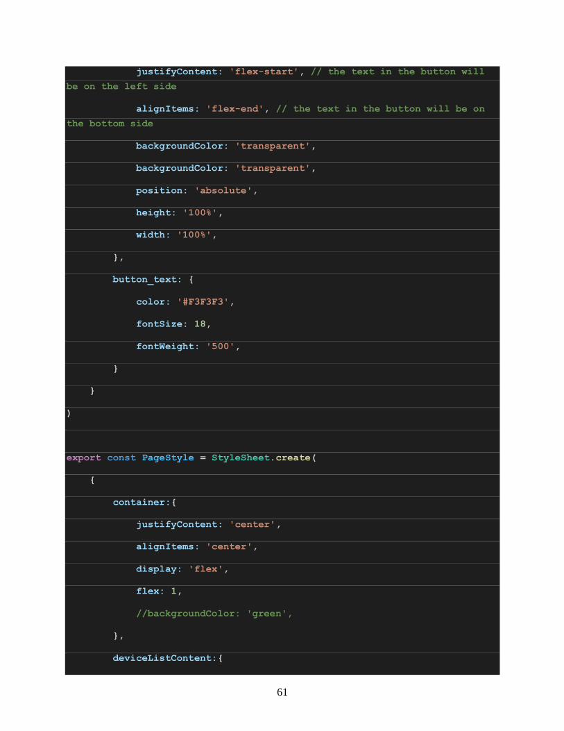
61
justifyContent: 'flex-start', // the text in the button will
be on the left side
alignItems: 'flex-end', // the text in the button will be on
the bottom side
backgroundColor: 'transparent',
backgroundColor: 'transparent',
position: 'absolute',
height: '100%',
width: '100%',
},
button_text: {
color: '#F3F3F3',
fontSize: 18,
fontWeight: '500',
}
}
)
export const PageStyle = StyleSheet.create(
{
container:{
justifyContent: 'center',
alignItems: 'center',
display: 'flex',
flex: 1,
//backgroundColor: 'green',
},
deviceListContent:{
62
display: 'flex',
flex: 1,
justifyContent: 'flex-start',
alignItems: 'center',
},
button: {
alignSelf: 'center',
shadowColor: 'grey',
shadowOpacity: 50,
shadowOffset: {width: 0, height: 4.5},
backgroundColor: '#588DF3',
position: 'absolute',
height: 45,
},
dispenseButton: {
alignSelf: 'center',
shadowColor: 'grey',
shadowOpacity: 50,
shadowOffset: {width: 0, height: 4.5},
backgroundColor: '#588DF3',
height: 45,
},
backgroundImageCenter: {
backgroundColor: 'transparent',
flex: 1,
opacity: 0.75,
top: 11,
63
width: '100%',
alignItems: 'center',
justifyContent: 'center',
},
backgroundImageTop: {
backgroundColor: 'transparent',
flex: 1,
opacity: 0.75,
top: 11,
width: '100%',
alignItems: 'center',
justifyContent: 'flex-start',
},
animationContainer: {
//backgroundColor: 'blue',
alignItems: 'center',
justifyContent: 'center',
flex: 1,
display: 'flex',
width: '100%',
},
contentContainer: {
display: 'flex',
flex: 1,
//backgroundColor: 'purple',
width: '100%',
},
64
card: {
width: '90%',
shadowColor: 'grey',
shadowOpacity: 50,
shadowOffset: {width: 0, height: 4.5},
},
buttonText: {
color: '#588DF3',
fontSize: 18,
fontWeight: '500',
},
image: {
backgroundColor: 'transparent',
flex: 1,
width: '100%',
position: 'relative',
},
imageContainer: {
backgroundColor: 'transparent',
justifyContent: 'flex-start',
alignItems: 'center',
flex: 1,
display: 'flex',
},
errorText: {
color: 'red',
fontSize: 18,
65
fontWeight: '500',
},
modalContent: {
backgroundColor: 'white',
padding: 22,
justifyContent: 'center',
alignItems: 'center',
borderRadius: 4,
borderColor: 'rgba(0, 0, 0, 0.1)',
},
modalContentTitle: {
fontSize: 20,
marginBottom: 12,
color: '#588DF3',
},
}
)
Header.js
import React from 'react';
import {StyleSheet, View } from 'react-native';
import {Text, Button, Icon, Left} from 'native-base'
import {HeaderStyle} from '../styles/styles';
const styles = StyleSheet.flatten(HeaderStyle);
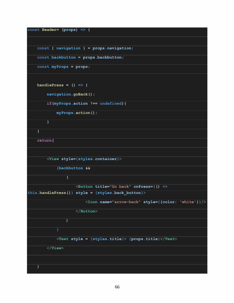
66
const Header= (props) => {
const { navigation } = props.navigation;
const backbutton = props.backbutton;
const myProps = props;
handlePress = () => {
navigation.goBack();
if(myProps.action !== undefined){
myProps.action();
}
}
return(
<View style={styles.container}>
{backbutton &&
(
<Button title="Go back" onPress={() =>
this.handlePress()} style = {styles.back_button}>
<Icon name="arrow-back" style={{color: 'white'}}/>
</Button>
)
}
<Text style = {styles.title}> {props.title}</Text>
</View>
)
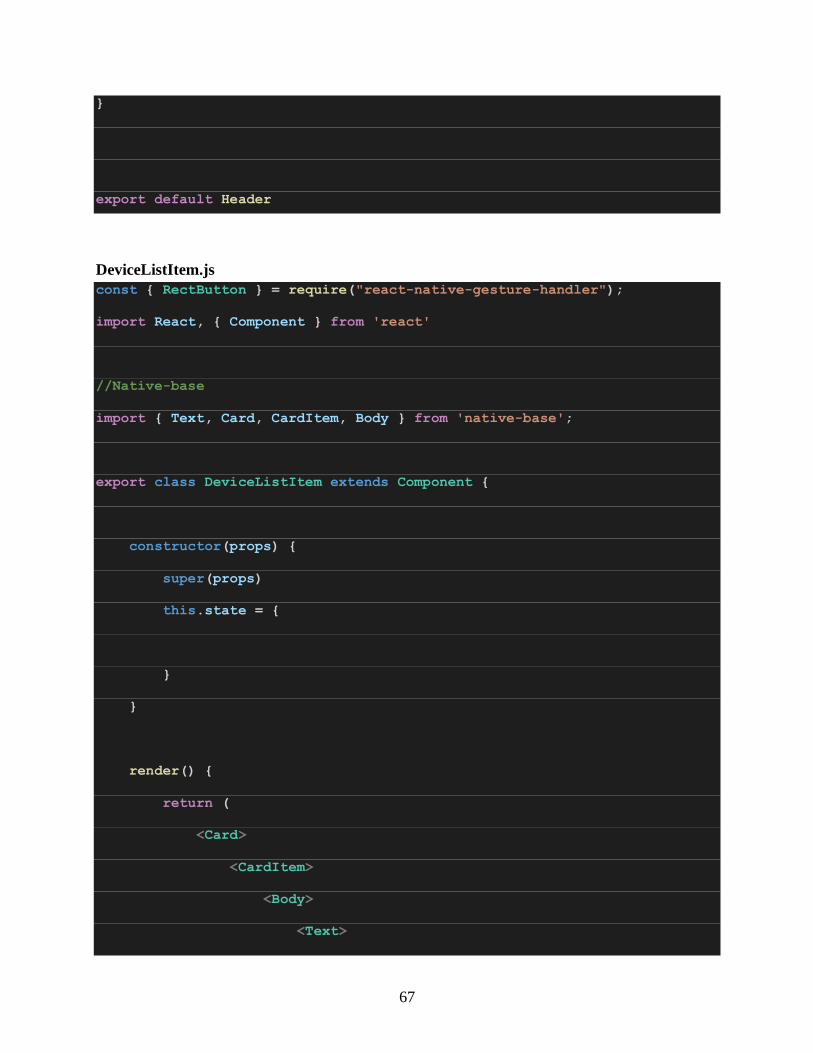
67
}
export default Header
DeviceListItem.js
const { RectButton } = require("react-native-gesture-handler");
import React, { Component } from 'react'
//Native-base
import { Text, Card, CardItem, Body } from 'native-base';
export class DeviceListItem extends Component {
constructor(props) {
super(props)
this.state = {
}
}
render() {
return (
<Card>
<CardItem>
<Body>
<Text>
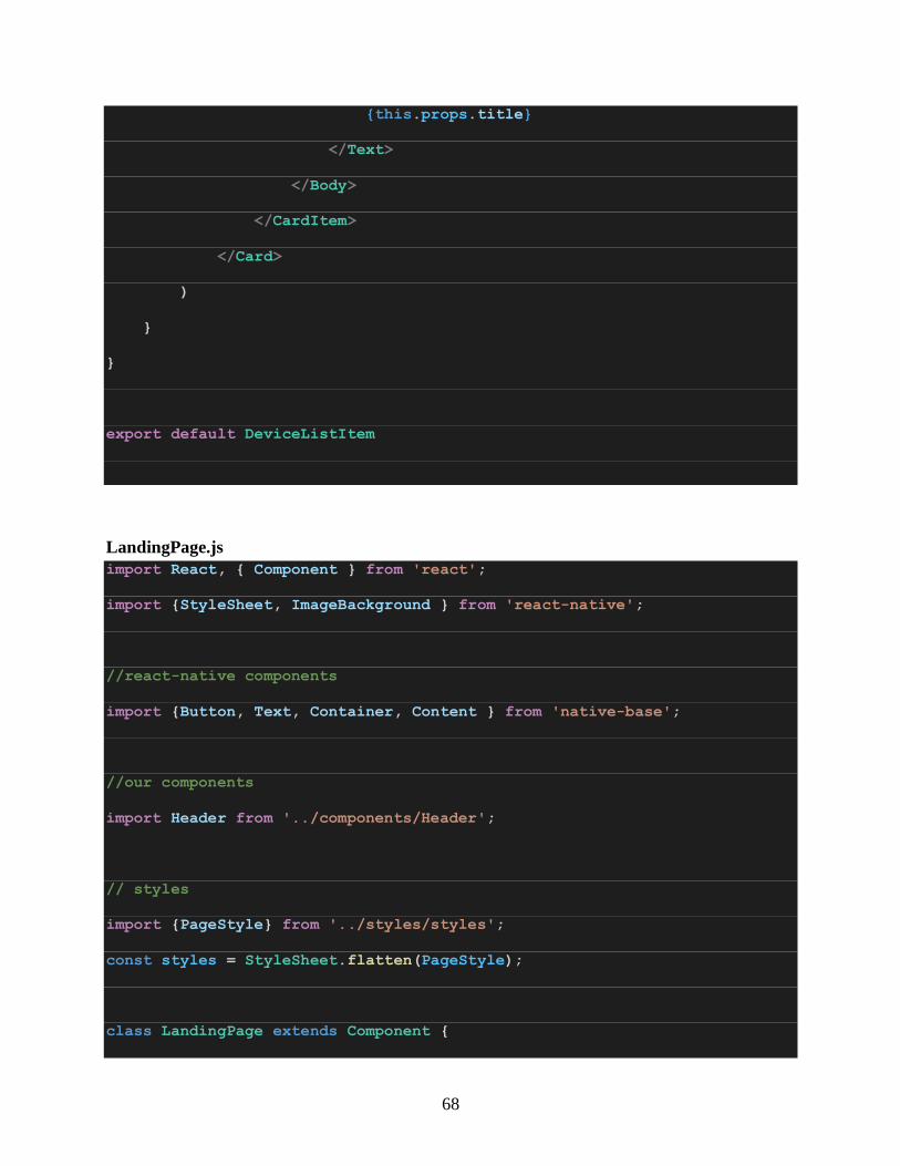
68
{this.props.title}
</Text>
</Body>
</CardItem>
</Card>
)
}
}
export default DeviceListItem
LandingPage.js
import React, { Component } from 'react';
import {StyleSheet, ImageBackground } from 'react-native';
//react-native components
import {Button, Text, Container, Content } from 'native-base';
//our components
import Header from '../components/Header';
// styles
import {PageStyle} from '../styles/styles';
const styles = StyleSheet.flatten(PageStyle);
class LandingPage extends Component {
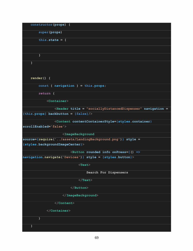
69
constructor(props) {
super(props)
this.state = {
}
}
render() {
const { navigation } = this.props;
return (
<Container>
<Header title = "sociallyDistancedDispenser" navigation =
{this.props} backbutton = {false}/>
<Content contentContainerStyle={styles.container}
scrollEnabled='false'>
<ImageBackground
source={require('../assets/LandingBackground.png')} style =
{styles.backgroundImageCenter}>
<Button rounded info onPress={() =>
navigation.navigate('Devices')} style = {styles.button}>
<Text>
Search For Dispensers
</Text>
</Button>
</ImageBackground>
</Content>
</Container>
)
}
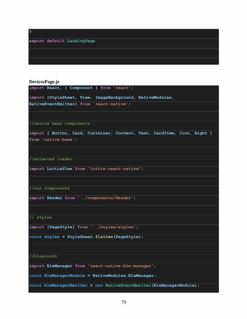
70
}
export default LandingPage
DevicesPage.js
import React, { Component } from 'react';
import {StyleSheet, View, ImageBackground, NativeModules,
NativeEventEmitter} from 'react-native';
//native baes components
import { Button, Card, Container, Content, Text, CardItem, Icon, Right }
from 'native-base';
//animated loader
import LottieView from "lottie-react-native";
//our components
import Header from '../components/Header';
// styles
import {PageStyle} from '../styles/styles';
const styles = StyleSheet.flatten(PageStyle);
//bluetooth
import BleManager from 'react-native-ble-manager';
const BleManagerModule = NativeModules.BleManager;
const bleManagerEmitter = new NativeEventEmitter(BleManagerModule);
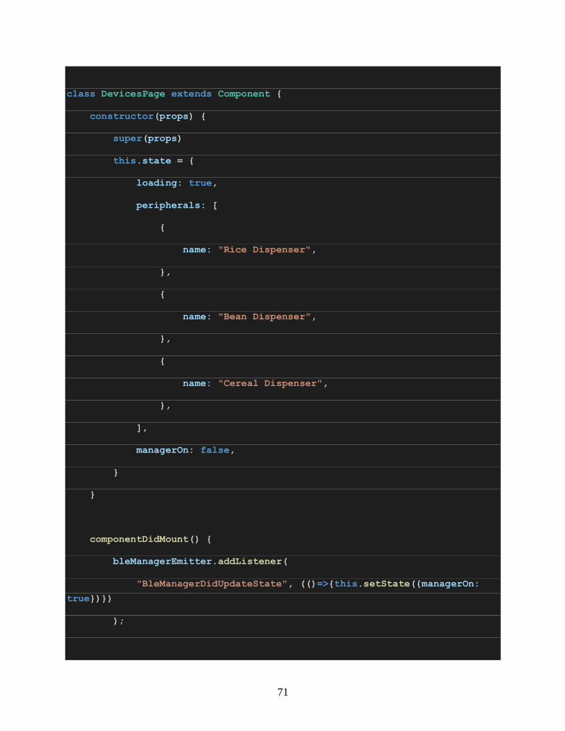
71
class DevicesPage extends Component {
constructor(props) {
super(props)
this.state = {
loading: true,
peripherals: [
{
name: "Rice Dispenser",
},
{
name: "Bean Dispenser",
},
{
name: "Cereal Dispenser",
},
],
managerOn: false,
}
}
componentDidMount() {
bleManagerEmitter.addListener(
"BleManagerDidUpdateState", (()=>{this.setState({managerOn:
true})})
);
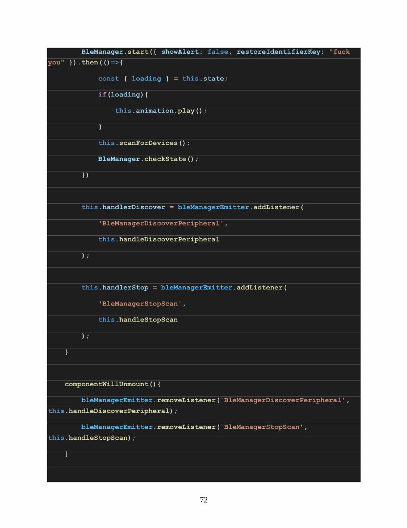
72
BleManager.start({ showAlert: false, restoreIdentifierKey: "fuck
you" }).then(()=>{
const { loading } = this.state;
if(loading){
this.animation.play();
}
this.scanForDevices();
BleManager.checkState();
})
this.handlerDiscover = bleManagerEmitter.addListener(
'BleManagerDiscoverPeripheral',
this.handleDiscoverPeripheral
);
this.handlerStop = bleManagerEmitter.addListener(
'BleManagerStopScan',
this.handleStopScan
);
}
componentWillUnmount(){
bleManagerEmitter.removeListener('BleManagerDiscoverPeripheral',
this.handleDiscoverPeripheral);
bleManagerEmitter.removeListener('BleManagerStopScan',
this.handleStopScan);
}
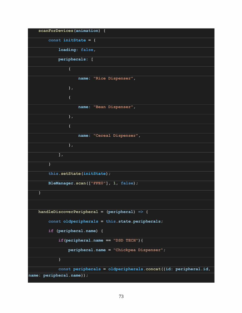
73
scanForDevices(animation) {
const initState = {
loading: false,
peripherals: [
{
name: "Rice Dispenser",
},
{
name: "Bean Dispenser",
},
{
name: "Cereal Dispenser",
},
],
}
this.setState(initState);
BleManager.scan(["FFE0"], 1, false);
}
handleDiscoverPeripheral = (peripheral) => {
const oldperipherals = this.state.peripherals;
if (peripheral.name) {
if(peripheral.name == "DSD TECH"){
peripheral.name = "Chickpea Dispenser";
}
const peripherals = oldperipherals.concat({id: peripheral.id,
name: peripheral.name});
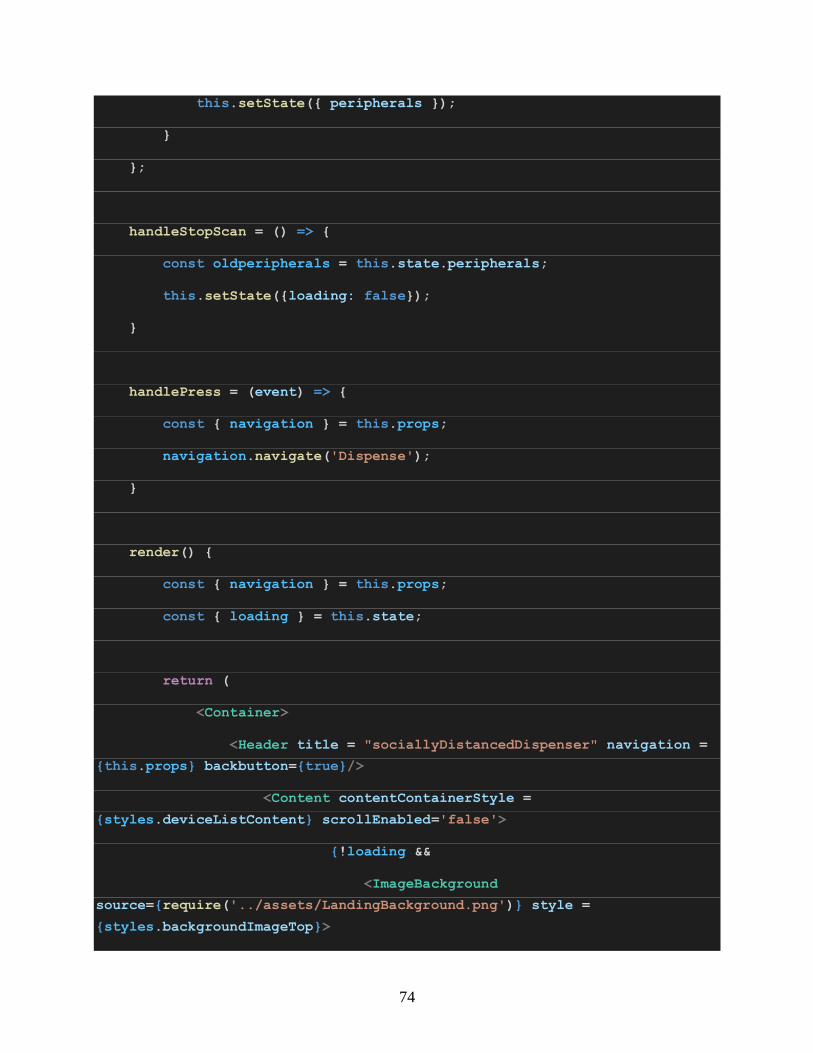
74
this.setState({ peripherals });
}
};
handleStopScan = () => {
const oldperipherals = this.state.peripherals;
this.setState({loading: false});
}
handlePress = (event) => {
const { navigation } = this.props;
navigation.navigate('Dispense');
}
render() {
const { navigation } = this.props;
const { loading } = this.state;
return (
<Container>
<Header title = "sociallyDistancedDispenser" navigation =
{this.props} backbutton={true}/>
<Content contentContainerStyle =
{styles.deviceListContent} scrollEnabled='false'>
{!loading &&
<ImageBackground
source={require('../assets/LandingBackground.png')} style =
{styles.backgroundImageTop}>
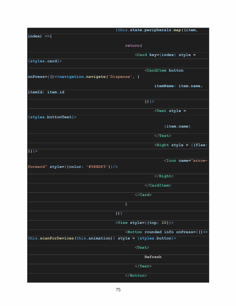
75
{this.state.peripherals.map((item,
index) =>{
return(
<Card key={index} style =
{styles.card}>
<CardItem button
onPress={()=>navigation.navigate('Dispense', {
itemName: item.name,
itemId: item.id
})}>
<Text style =
{styles.buttonText}>
{item.name}
</Text>
<Right style = {{flex:
1}}>
<Icon name="arrow-
forward" style={{color: '#588DF3'}}/>
</Right>
</CardItem>
</Card>
)
})}
<View style={{top: 10}}>
<Button rounded info onPress={()=>
this.scanForDevices(this.animation)} style = {styles.button}>
<Text>
Refresh
</Text>
</Button>
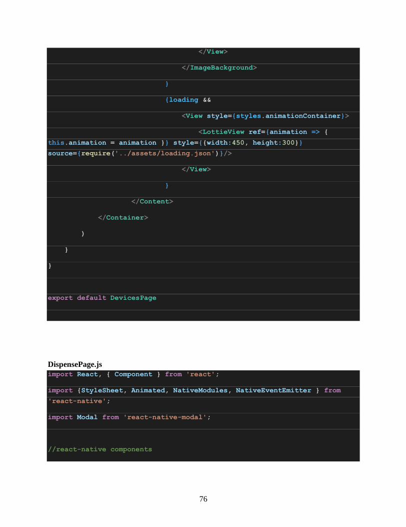
76
</View>
</ImageBackground>
}
{loading &&
<View style={styles.animationContainer}>
<LottieView ref={animation => {
this.animation = animation }} style={{width:450, height:300}}
source={require('../assets/loading.json')}/>
</View>
}
</Content>
</Container>
)
}
}
export default DevicesPage
DispensePage.js
import React, { Component } from 'react';
import {StyleSheet, Animated, NativeModules, NativeEventEmitter } from
'react-native';
import Modal from 'react-native-modal';
//react-native components
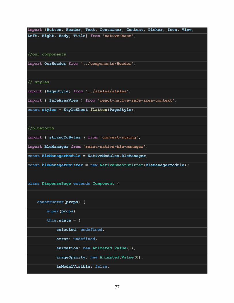
77
import {Button, Header, Text, Container, Content, Picker, Icon, View,
Left, Right, Body, Title} from 'native-base';
//our components
import OurHeader from '../components/Header';
// styles
import {PageStyle} from '../styles/styles';
import { SafeAreaView } from 'react-native-safe-area-context';
const styles = StyleSheet.flatten(PageStyle);
//bluetooth
import { stringToBytes } from 'convert-string';
import BleManager from 'react-native-ble-manager';
const BleManagerModule = NativeModules.BleManager;
const bleManagerEmitter = new NativeEventEmitter(BleManagerModule);
class DispensePage extends Component {
constructor(props) {
super(props)
this.state = {
selected: undefined,
error: undefined,
animation: new Animated.Value(1),
imageOpacity: new Animated.Value(0),
isModalVisible: false,
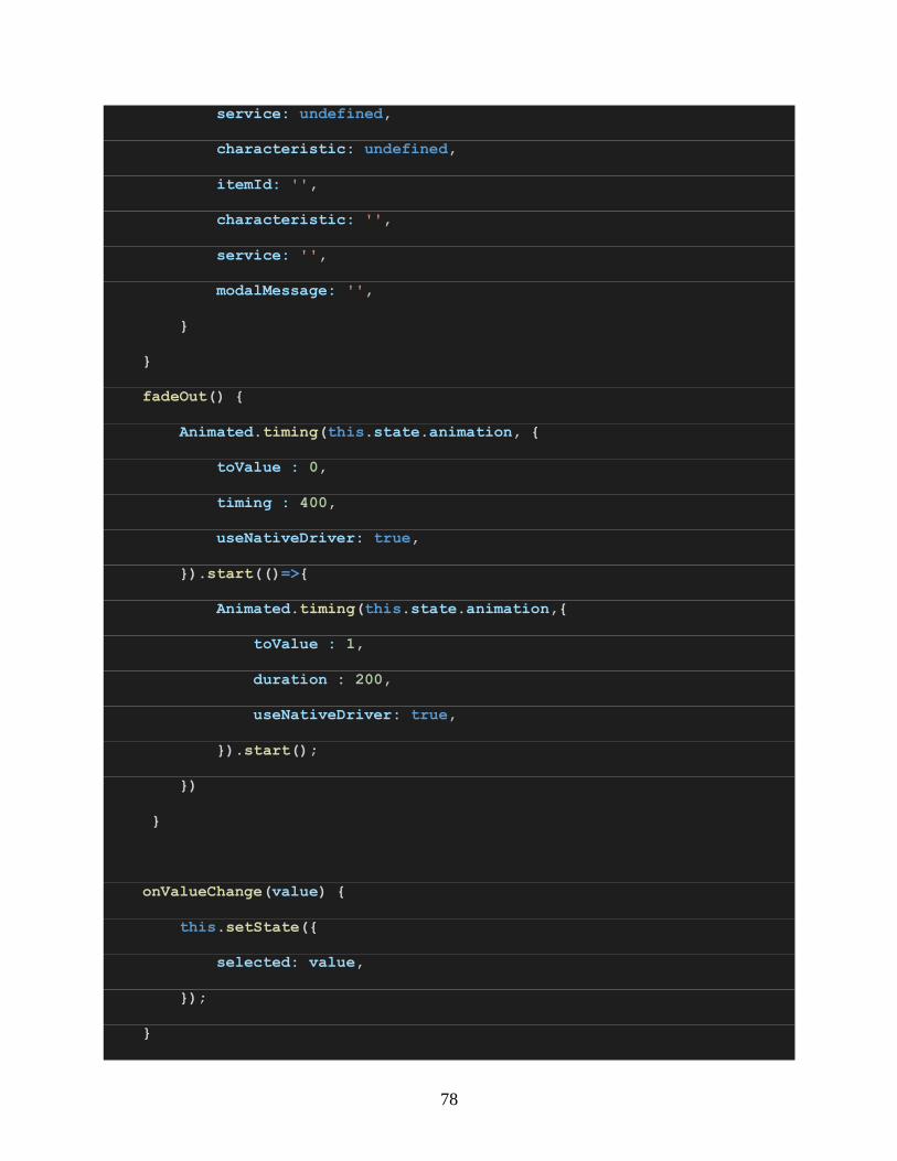
78
service: undefined,
characteristic: undefined,
itemId: '',
characteristic: '',
service: '',
modalMessage: '',
}
}
fadeOut() {
Animated.timing(this.state.animation, {
toValue : 0,
timing : 400,
useNativeDriver: true,
}).start(()=>{
Animated.timing(this.state.animation,{
toValue : 1,
duration : 200,
useNativeDriver: true,
}).start();
})
}
onValueChange(value) {
this.setState({
selected: value,
});
}
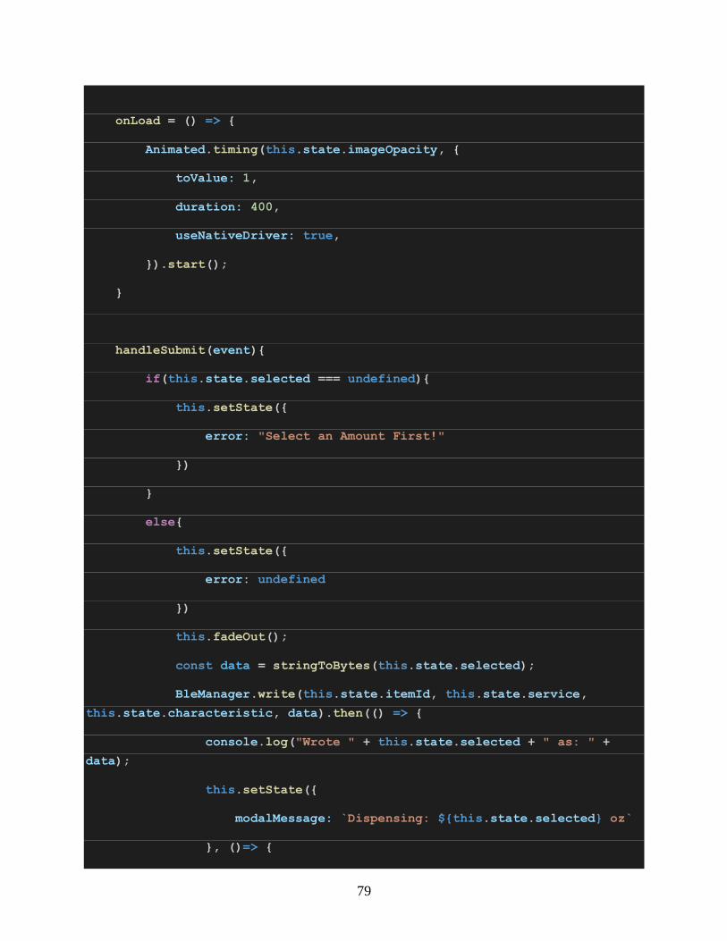
79
onLoad = () => {
Animated.timing(this.state.imageOpacity, {
toValue: 1,
duration: 400,
useNativeDriver: true,
}).start();
}
handleSubmit(event){
if(this.state.selected === undefined){
this.setState({
error: "Select an Amount First!"
})
}
else{
this.setState({
error: undefined
})
this.fadeOut();
const data = stringToBytes(this.state.selected);
BleManager.write(this.state.itemId, this.state.service,
this.state.characteristic, data).then(() => {
console.log("Wrote " + this.state.selected + " as: " +
data);
this.setState({
modalMessage: `Dispensing: ${this.state.selected} oz`
}, ()=> {
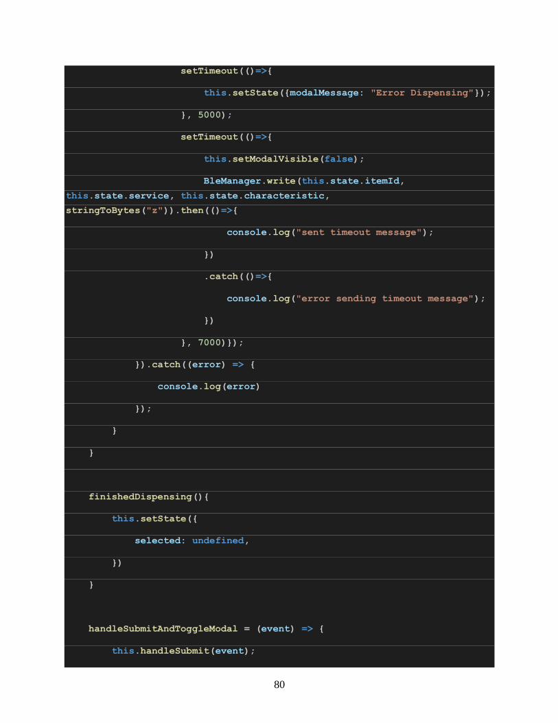
80
setTimeout(()=>{
this.setState({modalMessage: "Error Dispensing"});
}, 5000);
setTimeout(()=>{
this.setModalVisible(false);
BleManager.write(this.state.itemId,
this.state.service, this.state.characteristic,
stringToBytes("z")).then(()=>{
console.log("sent timeout message");
})
.catch(()=>{
console.log("error sending timeout message");
})
}, 7000)});
}).catch((error) => {
console.log(error)
});
}
}
finishedDispensing(){
this.setState({
selected: undefined,
})
}
handleSubmitAndToggleModal = (event) => {
this.handleSubmit(event);
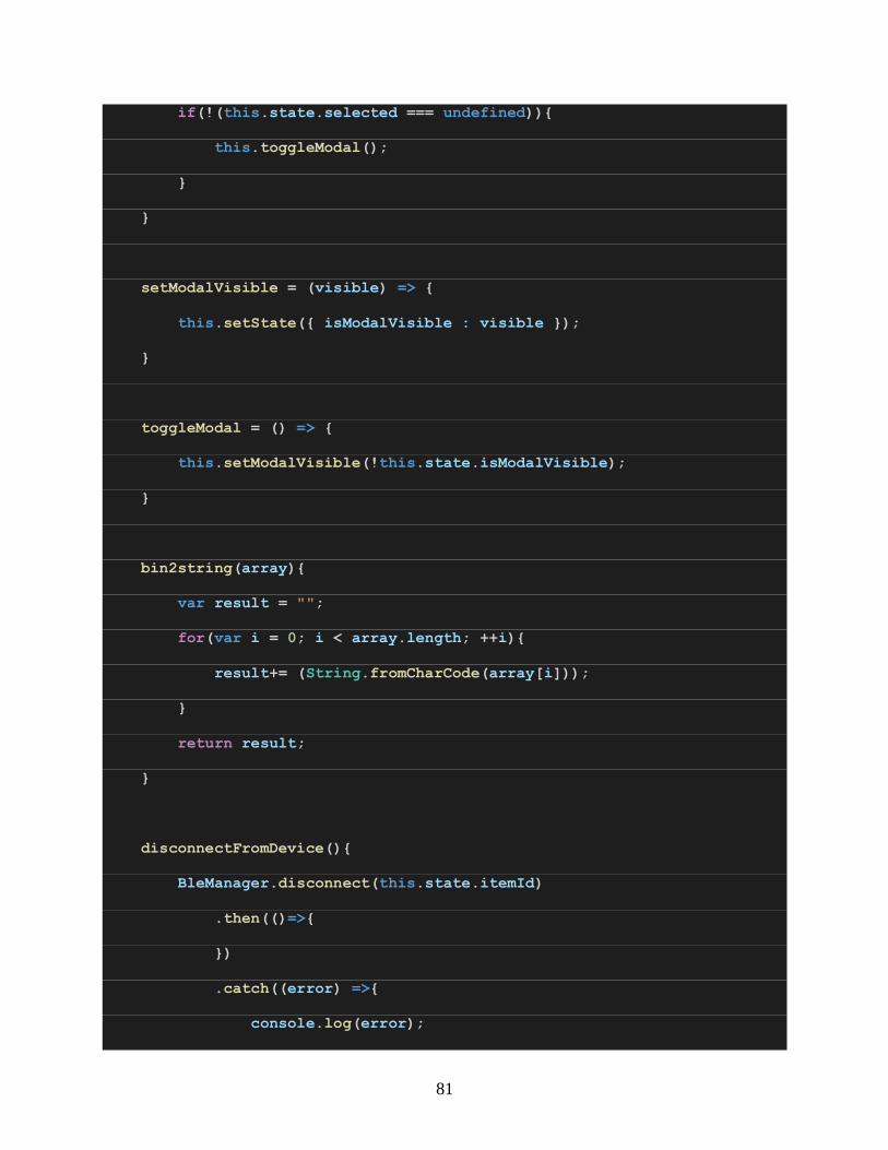
81
if(!(this.state.selected === undefined)){
this.toggleModal();
}
}
setModalVisible = (visible) => {
this.setState({ isModalVisible : visible });
}
toggleModal = () => {
this.setModalVisible(!this.state.isModalVisible);
}
bin2string(array){
var result = "";
for(var i = 0; i < array.length; ++i){
result+= (String.fromCharCode(array[i]));
}
return result;
}
disconnectFromDevice(){
BleManager.disconnect(this.state.itemId)
.then(()=>{
})
.catch((error) =>{
console.log(error);
82
});
}
async componentDidMount(){
BleManager.start({ showAlert: false, restoreIdentifierKey: "fuck
you" });
const { route, navigation } = this.props;
const itemName = route.params.itemName;
const itemId = route.params.itemId;
this.setState({itemId: itemId});
BleManager.connect(itemId).then(()=>{
BleManager.retrieveServices(itemId).then((info)=>{
this.setState({
characteristic:
info.characteristics[0].characteristic,
service: info.characteristics[0].service,
}, () => {
BleManager.startNotification(itemId,
this.state.service, this.state.characteristic).then(()=>{
bleManagerEmitter.addListener(
"BleManagerDidUpdateValueForCharacteristic",
readResponse = ({ value, itemId,
characteristic, service }) => {
const data = this.bin2string(value);
this.finishedDispensing();
this.setState({modalMessage: data});
setTimeout(()=>this.setModalVisible(false), 2000);
83
console.log(`Received ${data} for
characteristic ${characteristic}`);
}
);
})
.catch((error)=>{
console.log(error);
})
});
})
.catch((error)=>{
console.log(error);
})
})
.catch((error) => {
console.log(error);
})
}
componentWillUnmount(){
bleManagerEmitter.removeListener("BleManagerDidUpdateValueForCharacteristi
c", readResponse);
}
render() {
const { route, navigation } = this.props;
const itemName = route.params.itemName;
84
var images = [
require('../assets/rice2.jpeg'),
require('../assets/cereal2.jpg'),
require('../assets/beans2.jpg'),
require('../assets/chickpeas.jpg'),
]
if(itemName === "Rice Dispenser"){
var index = 0;
}
else if(itemName === "Cereal Dispenser"){
var index = 1;
}
else if(itemName === "Chickpea Dispenser"){
var index = 3;
}
else{
var index = 2;
}
return (
<Container>
<OurHeader title = {itemName} navigation = {this.props}
backbutton = {true} action={this.disconnectFromDevice.bind(this)}/>
<Content contentContainerStyle={styles.imageContainer}
scrollEnabled='false'>
<View style = {{flex: 2, width: '100%'}}>
85
<Animated.Image source={images[index]} onLoad =
{this.onLoad} style = {{
backgroundColor: 'transparent',
flex: 1,
width: '100%',
position: 'relative', opacity:
this.state.imageOpacity}}/>
</View>
<SafeAreaView style = {{flex: .5, width: '100%',
backgroundColor: 'transparent', alignItems: 'center', justifyContent:
'center'}}>
<Picker
headerStyle = {{backgroundColor: '#588df3'}}
headerTitleStyle = {{ color: '#fff',
fontWeight: '500'}}
headerBackButtonTextStyle = {{ color: '#fff'}}
renderHeader={backAction =>
<Header style={{ backgroundColor:
"#588df3" }}>
<Left>
<Button transparent
onPress={backAction}>
<Icon name="arrow-back" style={{
marginLeft: 5, color: "#fff" }} />
</Button>
</Left>
<Body style={{ flex: 3 }}>
<Title style={{ color: "#fff"
}}>Select Amount</Title>
</Body>
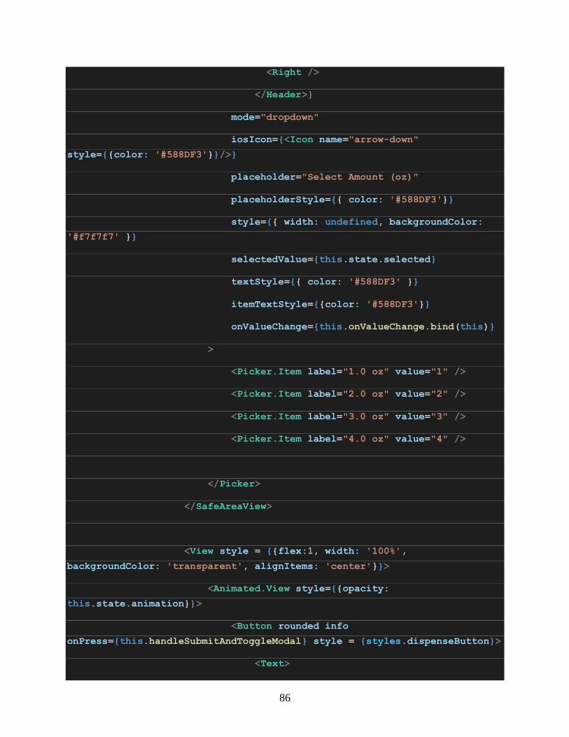
86
<Right />
</Header>}
mode="dropdown"
iosIcon={<Icon name="arrow-down"
style={{color: '#588DF3'}}/>}
placeholder="Select Amount (oz)"
placeholderStyle={{ color: '#588DF3'}}
style={{ width: undefined, backgroundColor:
'#f7f7f7' }}
selectedValue={this.state.selected}
textStyle={{ color: '#588DF3' }}
itemTextStyle={{color: '#588DF3'}}
onValueChange={this.onValueChange.bind(this)}
>
<Picker.Item label="1.0 oz" value="1" />
<Picker.Item label="2.0 oz" value="2" />
<Picker.Item label="3.0 oz" value="3" />
<Picker.Item label="4.0 oz" value="4" />
</Picker>
</SafeAreaView>
<View style = {{flex:1, width: '100%',
backgroundColor: 'transparent', alignItems: 'center'}}>
<Animated.View style={{opacity:
this.state.animation}}>
<Button rounded info
onPress={this.handleSubmitAndToggleModal} style = {styles.dispenseButton}>
<Text>
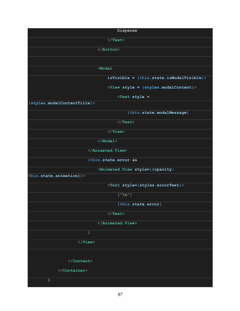
87
Dispense
</Text>
</Button>
<Modal
isVisible = {this.state.isModalVisible}>
<View style = {styles.modalContent}>
<Text style =
{styles.modalContentTitle}>
{this.state.modalMessage}
</Text>
</View>
</Modal>
</Animated.View>
{this.state.error &&
<Animated.View style={{opacity:
this.state.animation}}>
<Text style={styles.errorText}>
{"\n"}
{this.state.error}
</Text>
</Animated.View>
}
</View>
</Content>
</Container>
)
88
}
}
export default DispensePage