the reconfiguration of tool parameters in clay extruder
TRANSCRIPT
The reconfiguration of tool parameters in clay extruder
Hülya Oral1, Meryem Birgül Çolakoğlu21Architectural Design Computing, Istanbul Technical University 2Architecture, Is-tanbul Technical University1,2{oralh|colakoglumer}@itu.edu.tr
Reconfigurable manufacturing systems (RMS), which have emerged with masscustomization in the industry, allow the tool or system parameters to be adjustedin a controlled manner to produce customized products. Although thereconfigurable manufacturing systems have been applied in building andconstruction for waste, time, and cost reduction in producing specific mold formsat a prototype level, their utilization in additive manufacturing (extrusion) has notbeen explored. This paper presents, initial steps of ongoing research on thedevelopment of reconfigurable tools and workflow by transforming the tool'srigid parts with controlled parametric movable parts. The clay extruder tool usedin crafts is transformed into a reconfigurable extruder tool that allows makingcustomized forms. In the experimental setup, die combinations and tool headrotations are examined with the proposed Extrusion-based Making Grammar(EbMG). Produced forms illustrate the variations of the design space in relationto the rule sets. Here, a rule-based approach is found to be efficient forcontrolling the making parameters. This study explored the potentials oftransforming a rigid craft tool into a customizable tool that allow the generationof product variation. It presents the preliminary stage of transforming craft toolsinto further digital craft tools.
Keywords: Hands-on making, craft, reconfigurable tools, extrusion, tool making
1 INTRODUCTIONCustomization strategies have already been inte-grated into the architecture, engineering, and con-struction (AEC) industry in terms of housing (Mat-sumuraet al. 2019), urban spaces (Verebes2015), andbuilding components (Tu and Wei 2013). It has re-cently expanded to the area of the design and devel-opment of on-demand or bespoke tools which pro-duce a specific family of products by implementingthe strategies of flexible and reconfigurable manu-
facturing systems (FMS and RMS). These systems areemployed to respond to theuserdemands in termsofproduct variation in the industry. The reconfigurablemanufacturing systems have been applied in build-ing and construction for waste, time, and cost reduc-tion in producing specific mold forms (Khabazi andBudig 2016; Raun and Kirkegaard 2015) at a proto-type level. However, their utilization in additiveman-ufacturing i.e., extrusion has not been explored. Yet,the integration of customization strategies into craft
Digital fabrication and robotics - Volume 2 - eCAADe 39 | 161
practices in terms of tool development is overlooked.The customization of craft tools is a promising areaof research that enables in-situ fabrication by trans-formingmanual rigid tools into reconfigurablemech-anisms.
This study aims to parameterize the craft tooluse to control the making process and produce cus-tomized designs. As a case study, a manual clayextruder is analyzed to determine the part-functionrelations and control the variation in outputs usingExtrusion-based Making Grammar (EbMG). We uti-lized experimentation and a rule-based method todiscover and define the parameters of the die-toolhead component as the first phase of this study. Theoutputs produced with combinations of tool partsand functions extend the defined solution space ofthe rigid tool.
2 BACKGROUNDThe idea of mass customization is to provide an in-creased variability with the flexible and reconfig-urable manufacturing systems (FMS and RMS) at anaffordable cost unlike crafts (Piller 2013). The RMScan respond promptly to the changes in the market,but in a defined design space (Bortolini, Galizia, andMora 2018). The FMS can adapt to any changes inthe production workflow in the long run, becauseof the use of digital fabrication tools such as CNC,robotic arm, and 3D printers. Digital fabrication toolsoffer a certain degree of flexibility in terms of varia-tion. However, the FMS has a higher investment costcompared to the RMS, which uses the combinatoriallogic of assembly (Koren 2006). Moreover, digital fab-rication tools have limitations such as file-to-factoryproduction, single tool operation, limited bed size,limited manipulation of tool parameters and parts(Koren 2006; Oxman 2007; Peek and Moyer 2017).Having been low-cost and easy-to-operate, reconfig-urable tooling strategies can be employed to trans-form craft tools. It enables the manufacturing of afamily of products rather than one-off and uniqueproducts with available tools and techniques (Oraland Colakoglu 2020). By using changing or moving
parts with manual, machine or robot control, recon-figurable tools allow experimentation with the ma-terial, resulting in novel production workflows (Asut,Eigenraam, and Christidi 2018; Raun and Kirkegaard2015; Tessmann and Mehdizadeh 2019).
In the literature, the customization of toolsmainly relies on themoveablemechanismswhichen-able the variation of building components. Thesemechanisms are designed by parameterization andreconfiguration of existing tool parts and functions(Oral and Colakoglu 2020). Pin-based tooling, parts-based molds, polymer, and fabric-formed molds aredeveloped to reduce lead-time, cost, and waste inproducing differentiated units out of one mecha-nism. In pin-based molds, double-curved surfacegeometry is controlled via pins moving on Z-axis(Kelkar, Nagi, and Koc 2005; Schipper et al. 2014).Parts-based molds consist of moveable planar partsto change the size or form of the components(Khabazi and Budig 2016; Shaffer 2017). The varia-tion can also be produced by flexible materials likeelastic fabrics and polymers controlled by move-able mechanical parts (Khan 2008; Tessmann andMehdizadeh 2019). Changes in the orientation oftool parts directly affect the overall size and form ina defined solution space.
In crafts, every product needs individualizedpro-duction as a result of lacking control defined as “therisk in making” (Pye 1968). Craft practices mainlyrely on tacit knowledge gained through hands-onmaking with material and the tool. The functionof the tool is derived from the affordances of itsparts and the expertise of the craftsman. Consider-ing the hidden knowledge in crafts, it is important toparametrize the making process. The rule-based ap-proach is a widely used method to decipher existingdesigns (Duarte 2005; Colakoğlu 2005) and recentlythe fabrication processes (MacLachlan and Jowers2016). Formalizing the manual-making processescan enhance creativity through shape computations(Knight 2018), resulting in the emergence of outputs.Tool reconfigurations leading to emergent use of thetool can be explored with a grammar based on com-
162 | eCAADe 39 - Digital fabrication and robotics - Volume 2
binations of tool subparts and functions rather thanshape computation. A making grammar can be gen-erated by focusing on not the outputs, but on theprocess of forming thematerial with the tool. Aman-ual tool can be parametrized to be controlled and re-configured to generate variation as in the paramet-ric model. Especially for non-expert designers andmulti-operators, visually described rules can create amedium to formalize the making process and facili-tate the execution of the grammar.
3METHODOLOGYThe methodology of this paper consists of the ex-perimental method to decipher the use of the crafttool and the rule-based method to explicitly definethe tool use. In the first stage, a set of experi-ments are conducted with the die-tool head com-ponent to explore the reconfiguration scenarios hid-den in tool use. Die combinations, tool head rotation,and die change operations, which are embedded intool affordances. are discovered in this phase. TheExtrusion-based Making Grammar (EbMG) is gener-ated by adding the discovered functions to the rigidtool ruleset. In this study, die combinations andtool head rotations are examined and variable formsare physically producedwith the tool and playdoughmaterial. The outputs of this study are the novel useof the craft tool with the reconfiguration of tool pa-rameters unveiled through hands-on experimenta-tion and variable extruded units with differentiatedsurface patterns. The physical outputs are discussedregarding the effect of die shapes and rule combina-tions on the surface and the boundary of extrudedforms.
The following questions will be examined in thisstudy.
RQ1: Which parameters of extrusion as a hands-onmaking process can be identified in the context ofreconfigurable tools?
RQ2: How the parameters can accommodateproduct variation fromthe reconfigurationof the toolhead and die parts?
RQ1will be explored by conducting experiments
to discover moveable, changeable, and combinableparts of the manual extruder. RQ2 will be discussedthrough the physical outputs produced with theExtrusion-based Making Grammar.
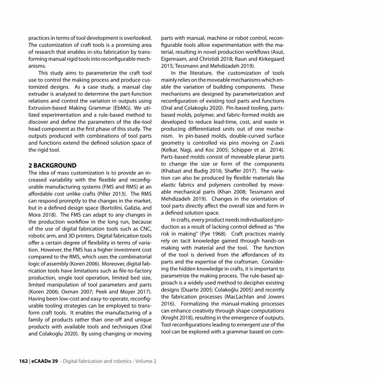
4 RECONFIGURING THE PARAMETERS OFTHE EXTRUSION4.1 Parameterizing theMaking ProcessThe manual clay extruder is chosen as a craft tool tobe examined. It is used inworkshops to produce coilsout of soft materials such as clay, polymer clay, andplaydough. It is selected for its adaptability to 1:1scale being able to produce extruded building unitsand components. The sub-parts of the extruder arethe tool head holding the polygonal metal dies, thepressing disk controlled by the rotation of the screw,handle, and the tube for the material (Figure 1).
Figure 1The sub-parts of thecraft tool.
In the conventional use of the tool, first, the soft ma-terial is put in the tube and the die is placed intothe tool head. When the handle is rotated, the diskpushes the clay down through the die to make thematerial dislodged. The output is a straight extru-sion that is built layer by layer. It is cut to the definedlength by a wire.
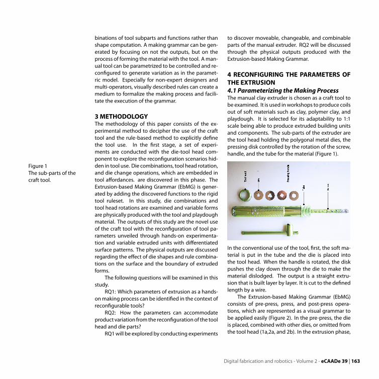
The Extrusion-based Making Grammar (EbMG)consists of pre-press, press, and post-press opera-tions, which are represented as a visual grammar tobe applied easily (Figure 2). In the pre-press, the dieis placed, combined with other dies, or omitted fromthe tool head (1a,2a, and 2b). In the extrusion phase,
Digital fabrication and robotics - Volume 2 - eCAADe 39 | 163
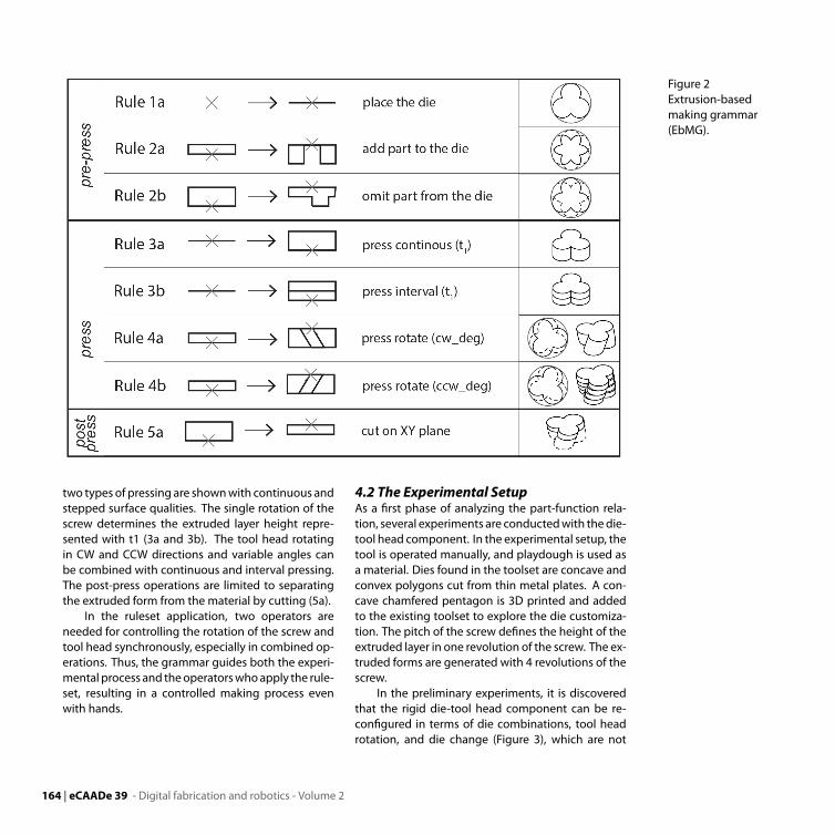
Figure 2Extrusion-basedmaking grammar(EbMG).
two types of pressing are shownwith continuous andstepped surface qualities. The single rotation of thescrew determines the extruded layer height repre-sented with t1 (3a and 3b). The tool head rotatingin CW and CCW directions and variable angles canbe combined with continuous and interval pressing.The post-press operations are limited to separatingthe extruded form from the material by cutting (5a).
In the ruleset application, two operators areneeded for controlling the rotation of the screw andtool head synchronously, especially in combined op-erations. Thus, the grammar guides both the experi-mental process and theoperatorswhoapply the rule-set, resulting in a controlled making process evenwith hands.
4.2 The Experimental SetupAs a first phase of analyzing the part-function rela-tion, several experiments are conductedwith thedie-tool head component. In the experimental setup, thetool is operated manually, and playdough is used asa material. Dies found in the toolset are concave andconvex polygons cut from thin metal plates. A con-cave chamfered pentagon is 3D printed and addedto the existing toolset to explore the die customiza-tion. The pitch of the screw defines the height of theextruded layer in one revolution of the screw. The ex-truded forms are generated with 4 revolutions of thescrew.
In the preliminary experiments, it is discoveredthat the rigid die-tool head component can be re-configured in terms of die combinations, tool headrotation, and die change (Figure 3), which are not
164 | eCAADe 39 - Digital fabrication and robotics - Volume 2
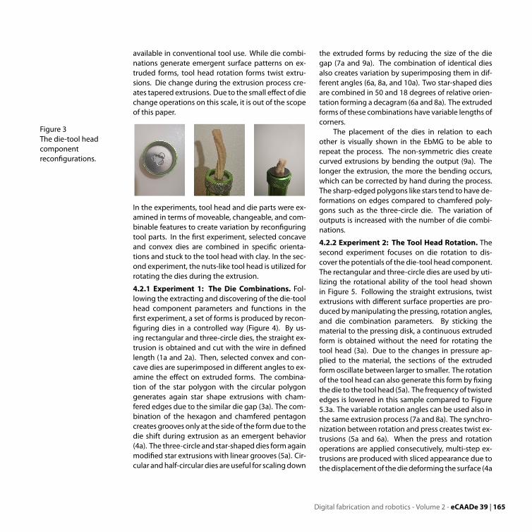
available in conventional tool use. While die combi-nations generate emergent surface patterns on ex-truded forms, tool head rotation forms twist extru-sions. Die change during the extrusion process cre-ates tapered extrusions. Due to the small effect of diechange operations on this scale, it is out of the scopeof this paper.
Figure 3The die-tool headcomponentreconfigurations.
In the experiments, tool head and die parts were ex-amined in terms of moveable, changeable, and com-binable features to create variation by reconfiguringtool parts. In the first experiment, selected concaveand convex dies are combined in specific orienta-tions and stuck to the tool head with clay. In the sec-ond experiment, the nuts-like tool head is utilized forrotating the dies during the extrusion.
4.2.1 Experiment 1: The Die Combinations. Fol-lowing the extracting and discovering of the die-toolhead component parameters and functions in thefirst experiment, a set of forms is produced by recon-figuring dies in a controlled way (Figure 4). By us-ing rectangular and three-circle dies, the straight ex-trusion is obtained and cut with the wire in definedlength (1a and 2a). Then, selected convex and con-cave dies are superimposed in different angles to ex-amine the effect on extruded forms. The combina-tion of the star polygon with the circular polygongenerates again star shape extrusions with cham-fered edges due to the similar die gap (3a). The com-bination of the hexagon and chamfered pentagoncreates grooves only at the sideof the formdue to thedie shift during extrusion as an emergent behavior(4a). The three-circle and star-shapeddies formagainmodified star extrusions with linear grooves (5a). Cir-cular andhalf-circular dies areuseful for scalingdown
the extruded forms by reducing the size of the diegap (7a and 9a). The combination of identical diesalso creates variation by superimposing them in dif-ferent angles (6a, 8a, and 10a). Two star-shaped diesare combined in 50 and 18 degrees of relative orien-tation forming a decagram (6a and 8a). The extrudedforms of these combinations have variable lengths ofcorners.
The placement of the dies in relation to eachother is visually shown in the EbMG to be able torepeat the process. The non-symmetric dies createcurved extrusions by bending the output (9a). Thelonger the extrusion, the more the bending occurs,which can be corrected by hand during the process.The sharp-edged polygons like stars tend to have de-formations on edges compared to chamfered poly-gons such as the three-circle die. The variation ofoutputs is increased with the number of die combi-nations.
4.2.2 Experiment 2: The Tool Head Rotation. Thesecond experiment focuses on die rotation to dis-cover the potentials of the die-tool head component.The rectangular and three-circle dies are used by uti-lizing the rotational ability of the tool head shownin Figure 5. Following the straight extrusions, twistextrusions with different surface properties are pro-duced bymanipulating the pressing, rotation angles,and die combination parameters. By sticking thematerial to the pressing disk, a continuous extrudedform is obtained without the need for rotating thetool head (3a). Due to the changes in pressure ap-plied to the material, the sections of the extrudedformoscillate between larger to smaller. The rotationof the tool head can also generate this form by fixingthedie to the tool head (5a). The frequencyof twistededges is lowered in this sample compared to Figure5.3a. The variable rotation angles can be used also inthe same extrusion process (7a and 8a). The synchro-nization between rotation and press creates twist ex-trusions (5a and 6a). When the press and rotationoperations are applied consecutively, multi-step ex-trusions are produced with sliced appearance due tothedisplacementof thediedeforming the surface (4a
Digital fabrication and robotics - Volume 2 - eCAADe 39 | 165
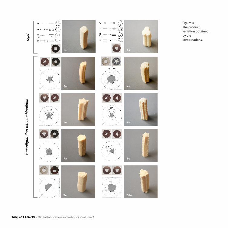
Figure 4The productvariation obtainedby diecombinations.
166 | eCAADe 39 - Digital fabrication and robotics - Volume 2
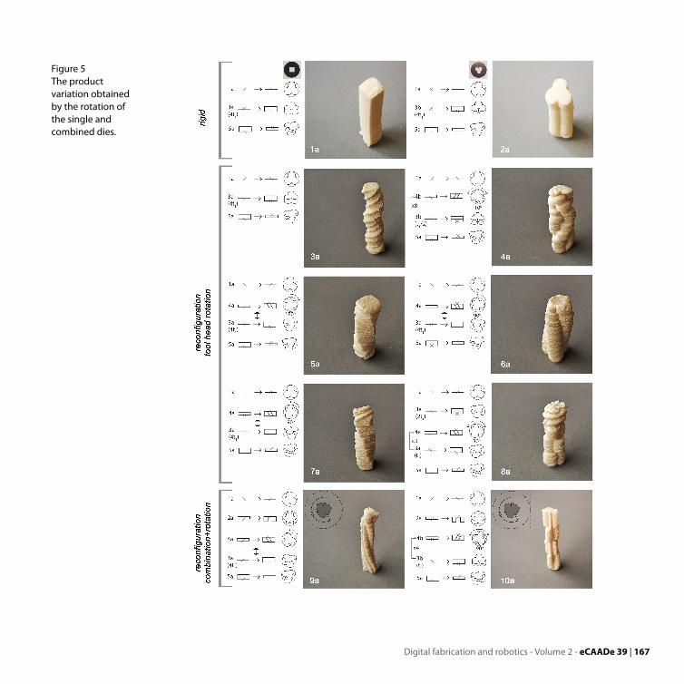
Figure 5The productvariation obtainedby the rotation ofthe single andcombined dies.
Digital fabrication and robotics - Volume 2 - eCAADe 39 | 167
and 8a). The combination and rotation of dies alsogenerate variation both in the section and the sur-face. As shown in Figure 5.9a, continuous press with360 degrees of tool head rotation introduces variablegrooveson the surface. Themulti-stepextrusionwithequal press duration creates equally distributed par-titioning on the form (10a).
The tool use is visually represented to coordinatesynchronous operations during the making. Inter-val extrusion operation with rotation is representedby extruded form with horizontal lines, while contin-uous extrusion operation with rotation by extrudedform with no lines. Degrees shows the approximateangles of rotation due tomanualmaking. The specialcondition as emergent behavior in which material isstuck to the pressing disk is shown in Figure 5.3a.The rules and their combinations can be increased byusing different polygonal dies and rotation-press se-quences.
5 RESULTS ANDDISCUSSIONThe produced forms are straight, twist, and multi-step extrusions with variable surface patterns. Theseforms can bemodeled by lofting the series of orthog-onal sections with bending deformations. Consider-ing the dimensions of the hand-held tool, the pro-duced forms can be used in the early design and pro-totyping phase to experiment and define the toler-ances of extrusion in terms ofmaterial properties, dieshape and dimensions, haptic feedback, and press-ing force.
The findings of the experiments are related tothe effect of die shapes and combinations on sur-faces and the boundary of extruded forms. The layerheight is calculated as 3 mm in square die and 2,22mm in there-circle die related to the die gap area. Alarger die gap area results in smaller extruded mate-rial. To achieve the same height in different dies, thenumber of screw revolutions should be increased.Surfacedeformations arehigh in extrusionswith con-cave polygons compared to convex ones due to thesharp edges. Circular and half-circular dies are usefulin reducing the width of the components. However,
the extruded form is bent in the non-symmetricalpolygons such as half-circle bend due to the unequalpressing applied to thematerial. Thebending also in-creaseswhen thenumberof operations andheightofthe extruded forms rise. The rotation of the tool headanddifferent angular superimpositionof the concavepolygons creates variable grooves on surfaces. Thesegrooves are effective in enlarging the surface areaand creating visually appealing patterns.
Considering the intricate surface details of theoutputs, problems are encountered in the produc-tion of these surfaces with rigid or reconfigurablemolds. Two or more mold parts with smaller surfaceprotrusions are required to produce such detailedsurface elements in CNC molding with high cost andwaste. When liquid material is poured into the mold,the material can be stuck in small protrusions. In re-configurable molding, part-based or flexible mate-rial molds must be used to produce 3-dimensionalforms rather than pin-based tooling. In the literature,part-basedmolds produce different sizes of the sameunit, whereas, in polymer and fabric-formed molds,intricate surfaceswith certainprecisionaredifficult toproduce since the fabric behavior is inconsistent.
The extruder has the same advantages of addi-tive manufacturing technique as low waste and pro-ducing complex surface details. In addition, the ex-truder has a 2-dimensional die cost, which is verylow compared to the multi-part and complex moldsused in rigid and reconfigurable molding. In addi-tion, diversity can be increased with modifiable diedesigns and combinations. Although the forms aredirectly producedwith the reconfigurable extruder inthis study, the extruder with a circular die can be uti-lized to extrude coils of discrete tool paths as in the3D clay printer. The robotic arm, which is one of thedigital fabrication tools, canperformcustomizedpro-duction workflows through different end effectors.The reconfigurable extruder can be integrated intorobotic production as in clay printing, but this timethe nozzle is changeable and combinable owing tothe dies. New 3D printed pentagonal die can gener-ate interlocking units with protruding parts fitting to
168 | eCAADe 39 - Digital fabrication and robotics - Volume 2
each unit by eliminating additional joints.
6 CONCLUSIONThis study aimed to decode the parameters of acraft tool use to control and reconfigure the toolparts for producing customized units as initial stepsof the ongoing research. A manual clay extruderwas examined to define part-function relations thatcan be changeable, moveable, or combinable by fol-lowing the reconfiguration methods in the indus-try. The methodology based on experimentationand a rule-based approach is found to be effectiveto parametrize the intuitive making process to fur-ther control the workflow. The novel part-functionrelations are discovered which is not included in theconventional use of the rigid tool such as die com-binations, tool head rotation, and die change. Vari-able dies and part-function combinations are exam-ined by benefitting the combinatorial logic in termsof reconfigurable tooling.
The series of experiments shows the productvariation generated by the minimum number of thedies. The use of a 3D printed die as an extensionof the toolset shows the CAD/CAM tools can also beconvenient to enhance available tools to generatenew forms. The diversity is achieved in terms of sur-face variations compared to the rigid tool as a re-sult of the numerical explorations with the material.The resulting die shapes and operations are repre-sented visually for the use of non-expert designersand multi-operator applying the ruleset. The limita-tion of this study is related to the experimental setup.Playdough is used as amaterial in the experiments inwhich clay, polymer, and air-drying clay can be exam-ined further.
Future studies will be focused on:
• Controlling the tool with motors to improvethe accuracy and precision in produced compo-nents.
• Developing an interface to control and simulatethe tool use.
• Using different materials in experiments to eval-uate the effect on the forms.
Unveiling tool parameters and define them explicitlyenables the design and development of novel toolsand procedures derived from available tools, materi-als, and techniques. Furthermore, for each rigid af-fordance of tool parts, variable affordances emergefrom experimenting with them. Parameterizing andcontrolling themanual tools enable producing diver-sity in components. Using manual tools as an inputfor developing customized tools provides a gradualimprovement in craft practices as a result of integrat-ing computational thinking into making processes.
ACKNOWLEDGEMENTWewould like to thank Istanbul Bilgi University for fi-nancially supporting this presentation.
REFERENCESAsut, S, Eigenraam, P and Christidi, N 2018 ’Re-flex Re-
sponsive FlexibleMold for Computer Aided IntuitiveDesign and Materialization’, Proceedings of the 36theCAADe Conference, Lodz, Poland, pp. 717-726
Bortolini, M, Galizia, FG and Mora, C 2018, ’Reconfig-urable manufacturing systems: Literature reviewand research trend’, Journal of Manufacturing Sys-tems, 49, pp. 93-106
Colakoglu,MB2005, ’DesignbyGrammar: An Interpreta-tion and Generation of Vernacular Hayat Houses inContemporary Context’, Environment and PlanningB: Planning and Design, 32(1), p. 141–149
Duarte, JP 2005, ’Towards the mass customizationof housing: the grammar of Siza’s houses atMalagueira’, Environment and planning B: Planningand Design, 32(3), pp. 347-380
Kelkar, A, Nagi, R and Koc, B 2005, ’Geometric algorithmsfor rapidly reconfigurable mold manufacturing offree-form objects’, Computer-AidedDesign, 37(1), pp.1-16
Khabazi, Z and Budig, M 2016 ’Cellular Concrete Cast-ing Using Digital Moulds’, Proceedings of the 34theCAADe Conference, pp. 83-92
Khan, O 2008 ’ReconfigurableMolds as ArchitectureMa-chines’, Proceedings of the 28th Annual Conference oftheAssociation forComputerAidedDesign inArchitec-ture (ACADIA), pp. 286-291
Knight, T 2018, ’Craft, Performance, and Grammars’, inLee, JH (eds) 2018, Computational Studies onCulturalVariation and Heredity, Springer Singapore, Singa-
Digital fabrication and robotics - Volume 2 - eCAADe 39 | 169
pore, pp. 205-224Koren, Y 2006, ’General RMS Characteristics. Com-
parison with Dedicated and Flexible Systems’, inDashchenko, AI (eds) 2006, ReconfigurableManufac-turing Systems and Transformable Factories, SpringerBerlin Heidelberg, Berlin, Heidelberg, pp. 27-45
MacLachlan, L and Jowers, I 2016, ’Exploration of multi-material surfaces as weighted shapes’, GraphicalModels, 83, pp. 28-36
Matsumura, S, Gondo, T, Sato, K, Morita, Y and Eguchi,T 2019, ’Technological developments of Japaneseprefabricated housing in an early stage’, JAPAN AR-CHITECTURAL REVIEW, 2(1), pp. 52-61
Oral, H and Colakoglu, MB 2020, ’Flexible Tools in Mouldand Formwork Making: A Review’, J. of Design Re-search, 18 (3/4), pp. 173-195
Oxman, N 2007 ’Digital Craft Fabrication BasedDesign intheAge of Digital Production’,WorkshopProceedingsfor Ubicomp 2007: International Conference on Ubiq-uitous Computing, pp. 534-538
Peek, N and Moyer, I 2017 ’Popfab: A Case for PortableDigital Fabrication’, Proceedings of the Tenth Interna-tional Conference on Tangible, Embedded, and Em-bodied Interaction - TEI ’17, Yokohama, Japan, pp.325-329
Piller, F 2013, ’Three capabilities that make mass cus-tomisation work’, in Piroozfar, P.A.E. and Piller, F.T.(eds) 2013, Mass customisation and personalisationin architecture and construction, Routledge, NewYork, pp. 17-30
Pye, D 1968, The nature and art of workmanship, Univer-sity Press Cambridge
Raun, C and Kirkegaard, PH 2015 ’Adaptive Mould–A Cost–Effective Mould System Linking DesignandManufacturing of Double–Curved GFRC Panels’,17th international congress of GRCA-GRC, Dubai
Schipper, R, Grünewald, S, Eigenraam, P, Raghunath,P and Kok, M 2014 ’Optimization of The FlexibleMouldProcess for TheProductionofDouble-CurvedConcrete Elements’, CIC 2014: The 1st Concrete Inno-vation Conference, Oslo, Norway
Shaffer, M 2017, ’Developing robotic formwork: en-hancing formwork mobility and variability throughmechanization’, Construction Robotics, 1(1-4), pp.77-83
Tessmann, O and Mehdizadeh, S 2019 ’Rotoform: re-alization of hollow construction elements throughroto-forming with hyper-elastic membrane form-work’, Proceedings of the Symposium on Simulationfor Architecture and Urban Design, pp. 1-7
Tu, KJ and Wei, HY 2013, ’Emerging trends and conceptsof mass customisation in Taiwan’s housing industry’,in Piroozfar, P.A.E. and Piller, F.T. (eds) 2013, Masscustomizationandpersonalization inarchitectureandconstruction, Routledge, New York
Verebes, T 2015, ’Cities andTheir Specificities: Standards,Customs and the Making of 21th Century Urbanity’,Architectural Design, 85(6), pp. 8-17
170 | eCAADe 39 - Digital fabrication and robotics - Volume 2