the model reconstruction of la salle's ship la belle
TRANSCRIPT
The Model Reconstructionof
La Salle's Ship La BelleGlenn Grieco
•
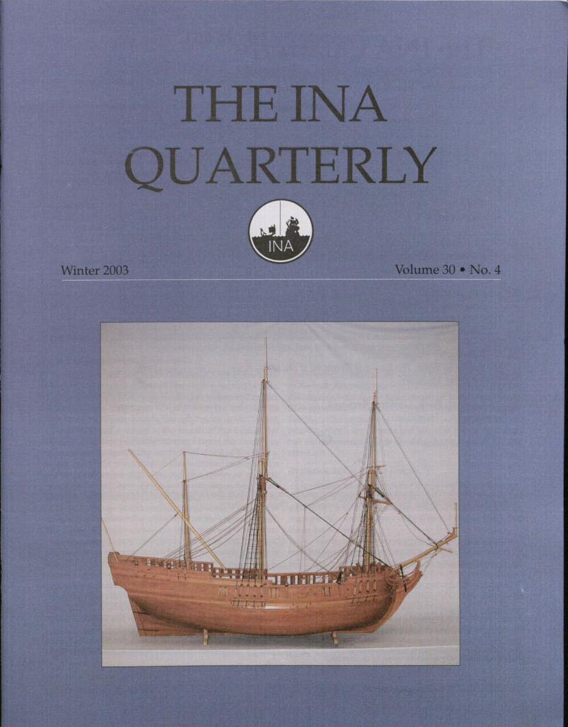
Fig. 1. Early representation of a barque longue from the album of Jean Jouve dated 1679.
InApril 1997, the Texas Historical Commission com-pleted the excavation of a small French ship named La Belle.Built in 1684 and possibly given as a gift to Robert Cavalierde la Salle from King Louis XIV of France, the little ship LaBelle was one of four vessels that left France in an ill-fatedattempt to found a colony at the mouth of the MississippiRiver. In1686, two years after leaving France, the vessel ranaground in Matagorda Bay on the Gulf Coast of Texas. Thewreck of La Belle not only provides a unique example of apoorly-documented ship type, but also serves as an earlyexample of many new design and construction teclmiquesin use in the French shipyards. Although only about a thirdof the hull has survived, sufficient information can be ex-tracted to reconstruct the appearance of the original vessel.The archaeological evidence, in conjunction with naval doc-uments, contemporary models and drawings, and firsthandaccounts of its appearance, can be used to answer questionsabout its assembly and the shipbuilding practices of the sev-enteenth century. What type of ship was this? How was itdesigned and built, rigged and outfitted? For an oceangoingvessel, La Belle was very small, but the techniques used tobuild it were analogous to those used for larger ships, pro-viding a concise and manageable example for the period.
This article documents the construction of two mod-els of La Belle. The first model, constructed during the ear-ly phases of the reassembly of the archaeological remains,
was used to determine the correct lines and arrangementof the hull. As conservation of the remains progressed, newdiscoveries were made that contribute to our knowledgeof its appearance. The second model incorporates these newfindings. The purpose of the models is not only to repre-sent the overall appearance and layout of the original ship,but also to recreate the methods and sequence of its con-struction.
Evolution of the Barque LongueBefore an accurate set of lines could be reconstruct-
ed, it was necessary to determine the type of vessel repre-sented by La Belle. It is widely believed that La Belle is anexample of a vessel type called a barque longue, but whatwas a barque longue?
The term barque longue applies to a range of small ves-sels first recognized as a distinct type by the French navy in1675.The classification of barque longue was officially replacedby corvette in 1676. However, vessels in both these classesvary in size and complexity. Between the 1670s and the mid-eighteenth century, the barque longue grew and evolved intowhat was later considered a sloop of war or light frigate.
Perhaps the earliest representation of a barque longueis from the album of Jean [ouve dated 1679. This small,undecked vessel carried only a simple two-masted rig and,at most, a few swivel guns as armament (fig. 1). This was
3 INAQuarterly 30.4
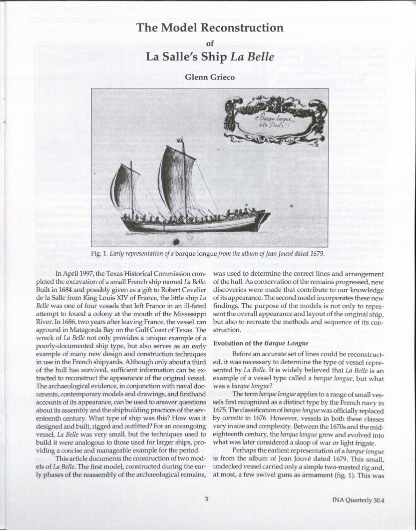
Fig, 2, Drawing of a light frigate from the album of Cueroult du Pas,
certainly not a vessel intended for a trans-atlantic crossing, Eventually, with theaddition of a deck, these ships began tocarry light four-pounder carriage guns.
The only official record of U1Bellerefers to it as a barqueof forty to fifty tons,[outel's journal provides the most com-plete description of U1Belle. Referred toas a bark throughout the journal, Joutelintroduces U1Belle as "a little frigate, car-rying six guns." Falconer's Marine Die-timwry defines a bark as "a general namegiven to small ships: it is however pecu-liarly appropriated by seamen to thosewhich carry three masts without a miz-zen top-sail." It is difficult to determinewhether the definitions and translationsprovided by Falconer's dictionary can beapplied to a vessel built a century earli-er, However, there is less ambiguity in[outel's use of the word frigate, One ofthe defining features of frigates is the useof a three-masted ship rig. Joutellater mentions a collision be-tween l'Amiable and U1Belle in which "the vessel U1Belle wouldhave been in danger of perishing, butescap'd with the lossofitsmizzen, which came by the board,"
Another eyewitness account from the Spanish sailor JuanEnriquez Barroto provides further evidence that the vessel hadthree masts. Coming upon the remains of U1 Belle in 1687, oneyear after itranaground, Barrotostates: "On the beach was foundthe other gun carriage and the main yard, which was measuredand found to be sixteen cubits. We brought this yard and that ofthe fore topsail for making oars, and from that of the foresailboom was made four oars, Captain Pedro de Yriarte tookthat of the mizzen also," The mizzen yard would have car-ried a lateen sail and would be easily distinguishable fromthe yards for the fore and main masts.
If these eyewitness accounts are accurate, it is diffi-cult to refute the assertion that U1 Belle carried three masts.As a commander on board Le loly, Henri Joutel had suffi-cient knowledge of French ships to give a reliable descrip-tion of the rigging of U1Belle. This is significant, for it providesthe only evidence that the barque longue had evolved into aform that could be considered a light frigate.
What evidence do the archaeological remains hold toindicate how U1Bellewas rigged? Remains of mast steps for boththe foremast and the main mast have survived. However, theabsence of a mizzen mast step among the recovered materialdoes not rule out the possibility of a mizzen mast.
Taking into consideration the steep rake of its stem-post, the proposed reconstructed length of La Belle placesthe main mast slightly forward of the longitudinal centerpoint. No reliable contemporary representations of two-masted vessels place the main mast so far forward, sug-
INA Quarterly 30.4
gesting that a third mast was needed to balance the rig. Thiswould be particularly true if the main mast was squarerigged, as indicated by Baroto's reference to the main yard.Thus the preponderance of evidence, both historical and ar-chitectural, points to La Belle being a three-masted vessel.
From [outel' s journal, it is known that La Belle was armedwith six guns. Itappears that six four-pound carmon composedthe typical armament for a barque longue of this size.
When the remains of U1 Belle were first encountered bytwo pilots from Baroto's ship, they reported finding" a lost shipthat has three fleurs-cle-lis on its poop; six pieces of artillery,mounted, woolded, and have down; two iron swivel guns with-out chambers, which they brought in our canoe." From this de-scription, it appears that there were six carriage guns on decksecured with lashings. Baroto himself observed five swivel gunsthe next day "that fire a ball up to four pounds ... still upon theircarriages, lashed to the side of the ship." The discrepancy in thenumber of observed carriage guns may indicate a misuse of theterm carriage in the second passage. One swivel gun recoveredfrom the wreck had a bore diameter close to that of a four-poundball. It is possible that the swivel guns would have been lashedto the sides of the vessel when not in use, While discussing theordnance,hestatesthatthehullhas "eight portholes and asmanyother flues." 1£ the word flue indicates the pipe or post attachedto the side of the vessel to support a swivel gun, then seven ofeight guns were accounted for at the time. The single SWivelgun recovered by the Texas Historical Commission could bethe eighth gun that fell from the side of the hull before the shipwas found by Baroto. .
What of the eight portholes mentioned by Baroto? Itwascommon for vesseJs to have more gunports than the actual num-ber of guns on board. Carmon could be moved from one side of
4
-, ~•
....... g
--------_ ...........---_.-----::.=.- ........• -• __ VI ""
I t 10 "
" ,~U
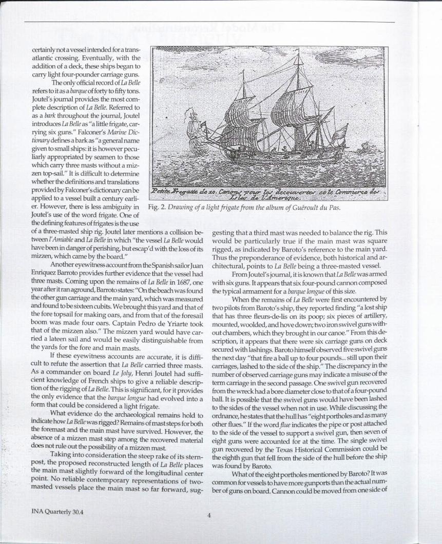
Fig. 3. Reconstructed lines of La Belle from data gathered during the excavation and disassembly. Courtesy Texas Historical Commission.
the vessel to the other to increase the firepower of a broadside orto transfer weight to adjust the vessel's trim while sailing.
All evidence indicates that La Belle was a frigate, just as[outel described. Its appearance may have been similar to a lightfrigate illustrated by Cueroult du Pas in 1710 (fig. 2).
Reconstructing a set of lines
A large amount of data is available for a reconstructionof the lines of La Belle. The dockyard manuscript prepared inDecember 1686, two years after it was built, gives many of theoverall dimensions needed for its reconstruction. A set of recon-structed lines based on the archaeological remains, drawn byGreg Cook for the Texas Historical Commission (fig. 3), pro-vides a good first impression of the shape of its hull
The first step in producing a set of lines for La Bellewas todetermine the shape of the midship section. Fortunately, a largeportion of the starboard side of the hull at midships has sur-vived. Adjusted so the centerline of the frame is vertical, the re-mains of the midship frame form the basis of the reconstruction.In [outel's description, the draft of La Belle is given as seven feet(2.268 m). If this is accurate, the archaeological remains repre-sent almost the entire midship section up to the waterline. Fig-ure 24 shows a representative section near midships thatcombines the archaeological and archival data.
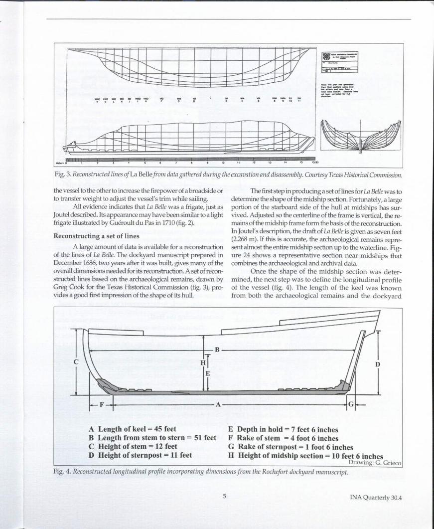
Once the shape of the midship section was deter-mined, the next step was to define the longitudinal profileof the vessel (fig. 4). The length of the keel was knownfrom both the archaeological remains and the dockyard
Jr J
PIr
B
HT J D
I ~
I-F I A Gl-I
A Length of keel = 45 feet E Depth in hold = 7 feet 6 inchesB Length from stem to stern = 51 feet F Rake of stem = 4 foot 6 inchesC Height of stem = 12 feet G Rake of sternpost = 1 foot 6 inchesD Height of stern post = 11 feet H Height of midship section = 10 feet 6 inches
Drawing: G. GriecoFig. 4, Reconstructed longitudinal profile incorporating dimensions from the Rochefort dockyard manuscript,
5 INA Quarterly 30,4
f,
I
~ ~ Reconstructed lines of the French
bbiWLight Frigate
~
La BelleBuilt in the French s.hipyud at Rochefort
1684
-:-
tf);---- -- - - -- :\,/-I b I 0 0
1//- - -- ------ - -r-. ------ -------- - ---_. ------- --------i _1/ J: "- / r-, -1/i" <, - '" -
10:: ,<, 1---- »> /1//: I, / V /\
~~--j! "S: <, Kif !t---- t--- ----- -------
/
..__ .... _---- ..... ------_.---_.- ----t _______
10 IS 20 as " " eo 45· so0 ,FrmchPeet Drawing: G. Grieco
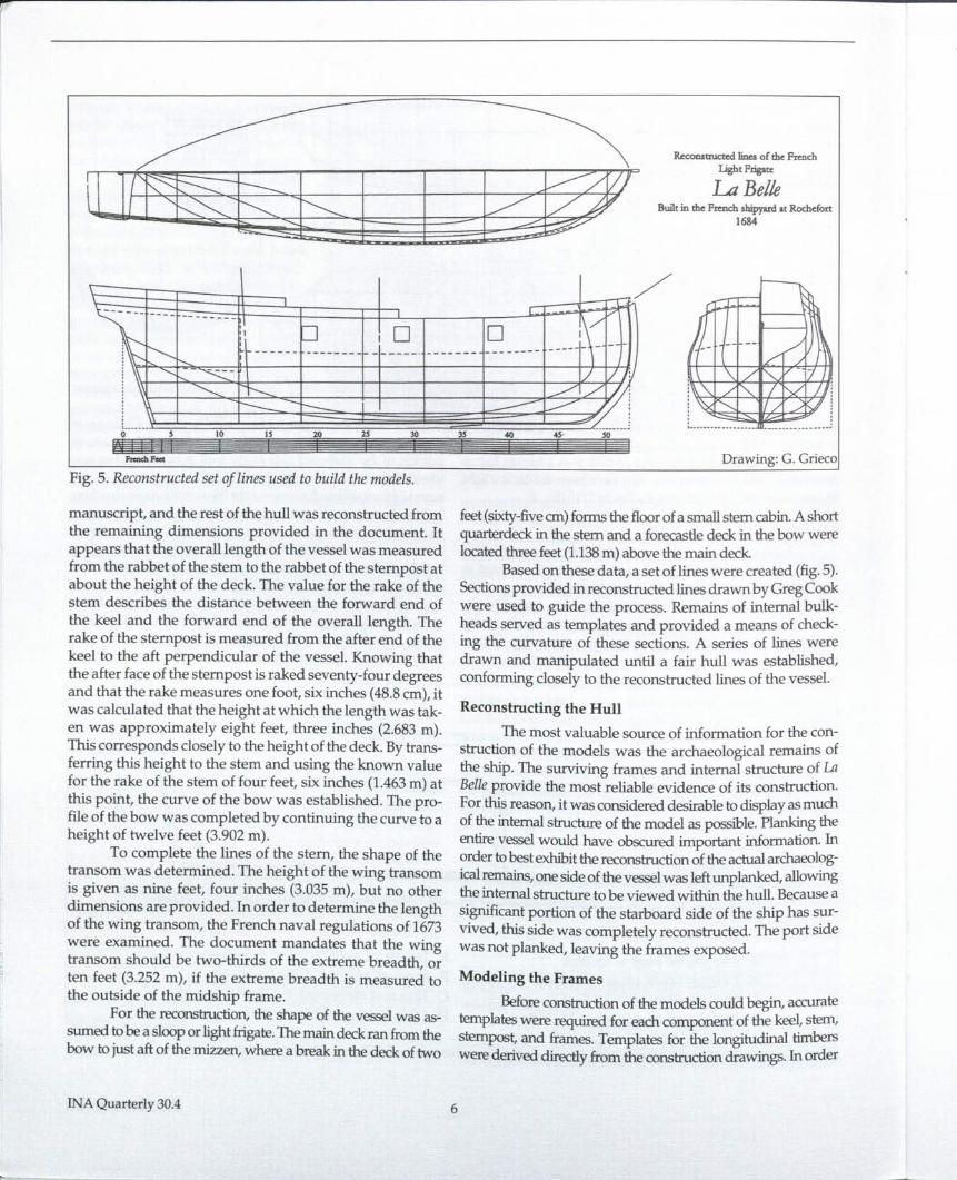
Fig. 5. Reconstructed set of lines used to build the models.
manuscript, and the rest of the hull was reconstructed fromthe remaining dimensions provided in the document. Itappears that the overall length of the vessel was measuredfrom the rabbet of the stem to the rabbet of the stempost atabout the height of the deck. The value for the rake of thestem describes the distance between the forward end ofthe keel and the forward end of the overall length. Therake of the stempost is measured from the after end of thekeel to the aft perpendicular of the vessel. Knowing thatthe after face of the stempost is raked seventy-four degreesand that the rake measures one foot, six inches (48.8 em), itwas calculated that the height at which the length was tak-en was approximately eight feet, three inches (2.683 m).This corresponds closely to the height of the deck. By trans-ferring this height to the stem and using the known valuefor the rake of the stem of four feet, six inches (1.463 m) atthis point, the curve of the bow was established. The pro-file of the bow was completed by continuing the curve to aheight of twelve feet (3.902 m).
To complete the lines of the stern, the shape of thetransom was determined. The height of the wing transomis given as nine feet, four inches (3.035 m), but no otherdimensions are provided. Inorder to determine the lengthof the wing transom, the French naval regulations of 1673were examined. The document mandates that the wingtransom should be two-thirds of the extreme breadth, orten feet (3.252 m), if the extreme breadth is measured tothe outside of the midship frame.
For the reconstruction, the shape of the vessel was as-sumed tobe a sloop or light frigate.The main deck ran from thebow to just aft of the mizzen, where a break in the deck of two
INAQuarterly 30.4
feet (sixty-fiveem) forms the floor of a small stern cabin. A shortquarterdeck in the stem and a forecastle deck in the bow werelocated three feet (1.138m) above the main deck.
Based on these data, a set of lines were created (fig.5).Sections provided in reconstructed lines drawn by Greg Cookwere used to guide the process. Remains of internal bulk-heads served as templates and provided a means of check-ing the curvature of these sections. A series of lines weredrawn and manipulated until a fair hull was established,conforming closely to the reconstructed lines of the vessel.
Reconstructing the HullThe most valuable source of information for the con-
struction of the models was the archaeological remains ofthe ship. The surviving frames and internal structure of LaBelle provide the most reliable evidence of its construction.For this reason, it was considered desirable to display as muchof the internal structure of the model as possible. Planking theentire vessel would have obscured important information. Inorder tobest exhibit the reconstruction of the actual archaeolog-ical remains, one side of the vessel was left unplanked, allowingthe internal Structure to be viewed within the hull. Because asignificant portion of the starboard side of the ship has sur-vived, this side was completely reconstructed. The port sidewas not planked, leaving the frames exposed.
Modeling the Frames
Beforeconstruction of the models could begin, accuratetemplates were required for each component of the keel, stem,stempost, and frames. Templates for the longitudinal timberswere derived directly from the construction drawings. Inorder
6
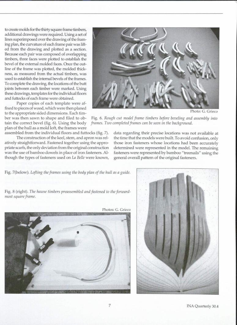
Photo: G. Grieco
to createmolds for the thirty square frame timbers,additional drawings were required. Using a set oflines superimposed over the drawing of the fram-ing plan, the curvature of each frame pair was lift-ed from the drawing and plotted as a section.Because each pair was composed of overlappingtimbers, three faces were plotted to establish thebevel of the external molded faces. Once the out-line of the frame was plotted, the molded thick-ness, as measured from the actual timbers, wasused to establish the internal bevels of the frames.To complete the drawing, the locations of the buttjoints between each timber were marked. Usingthese drawings, templates for the individual floorsand futtocks of each frame were obtained.
Paper copies of each template were af-fixed to pieces of wood, which were then planedto the appropriate sided dimensions. Each tim-ber was then sawn to shape and filed to ob- Fig. 6. Rough cut model frame timbers before beveling and assembly intotain the correct bevel (fig. 6). Using the body frames. Two completed frames can be seen in the background.plan of the hull as a mold loft, the frames wereassembled from the individual floors and futtocks (fig. 7).
The construction of the keel, stem, and apron was rel-atively straightforward. Fastened together using the appro-priate scarfs, the only deviation from the original constructionwas the use of bamboo dowels in place of iron fasteners. Al-though the types of fasteners used on La Belle were known,
data regarding their precise locations was not available atthe time that the models were built. To avoid confusion, onlythose iron fasteners whose locations had been accuratelydetermined were represented in the model. The remainingfasteners were represented by bamboo "treenails" using thegeneral overall pattern of the original fasteners.
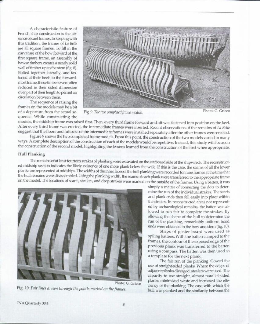
Fig. 7(below). Lofting the frames using the body plan of the hull as a guide.
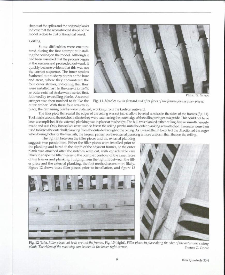
Fig. 8 (right). The hawse timbers preassembled and fastened to the forward-most square frame.
Photos: G. Grieco
••
7 INAQuarterly 30.4
r
A characteristic feature ofFrench ship construction is the ab-senceofcantframes.lnkeepingwiththis tradition, the frames of U1 Belleare all square frames. To fill in thecurvature of the bow forward of thefirst square frame, an assembly ofhawse timbers creates a nearly solidwall of timber up to the stem (fig.8).Bolted together laterally, and fas-tened at their heels to the forward-most frame, these timberswere oftenreduced in their sided dimensionover part of their length to permit aircirculation between them.
The sequence of raising theframes on the models may be a bitof a departure from the actual se- Fig.9. The two completedframe models.quence. While constructing themodels, the midship frame was raised first. Then, every third frame forward and aft was fastened into position on the keel.After every third frame was erected, the intermediate frames were inserted. Recent observations of the remains of U1 Bellesuggest that the floors and futtocks of the intermediate frames were installed separately after the other frames were erected.
Figure 9 shows the two completed frame models. From this point, the construction of the two models varied in manyways. A complete description of the construction of each of the models would be repetitive. Instead, this study will focus onthe construction of the second model, highlighting the lessons learned from the construction of the first when appropriate.
Hull Planking
The remains of at least fourteen strakes ofplanking were excavated on the starboard side of the shipwreck. The reconstruct-ed midship section indicates the likely existence of one more plank below the wale. H this is the case, the seams of all the lowerplanks are represented at midships. The widths of the inner facesof the hull planking were recorded for nine frames at the time thatthe hull remains were disassembled. Using the planking width, the seams of each plank were transferred to the appropriate frameon the model. The locations of scarfs, stealers, and drop strakes were marked on the outside of the frames. Using a batten, it was
simply a matter of connecting the dots to deter-mine the run of the individual strakes. The scarfsand plank ends then fell easily into place withinthe strakes. In reconstructed areas not represent-ed by archaeological remains, the batten was al-lowed to run fair to complete the strakes. Byallowing the shape of the hull to determine therun of the planking, remarkably uniform hoodends were obtained in the bow and stem (fig.10).
Strips of poster board were used asspiling battens. With the batten clamped to theframes, the contour of the exposed edge of theprevious plank was transferred to the battenusing a compass. The batten was then used asa template for the next plank.
The fair run of the planking allowed theuse of straight-sided planks. Where the edges ofadjacent planks diverged, stealers were used. Thecapacity to use straight, almost parallel-sidedplanks minimized waste and increased the effi-ciency of the planking. The ease with which thehull was planked and the similarity between the
Photo:G. GriecoFig. 10. Fair lines drawn through the points marked on the frames.
INA Quarterly 30.4 8
shapes of the spiles and the original planksindicate that the reconstructed shape of themodel is close to that of the actual vessel.
Fig. 11. Notches cut in forward and after faces of the frames for the filler pieces.
Ceiling
Some difficulties were encoun-tered during the first attempt at install-ing the ceiling on the model. Although ithad been assumed that the process beganat the keelson and proceeded outward, itquickly became evident that this was notthe correct sequence. The inner strakesfeathered out to sharp points at the bowand stern, where they encountered thefour outer strakes, indicating that theywere installed last. In the case of U1Belle,an outer notched strake was inserted first,followed by two ceiling planks. A secondstringer was then notched to fit like theouter timber. With these four strakes inplace, the remaining planks were installed, working from the keelson outward.
The filler piece that sealed the edges of the ceiling was set into shallow beveled notches in the sides of the frames (fig. 11).Tool marks around the notches indicate they were sawn using the outer edge of the ceiling stringer as a guide. This could not havebeen accomplished if the external planking was in place at this height. The hull was planked either ceiling-first or simultaneouslyinside and out. Only iron spikes were used to fasten the ceiling planks until the outer planking was attached. Treenails were thenused to fasten the outer hull planking from the outside through to the ceiling. As it was difficult to control the direction of the augerwhen boring holes for the treenails, the treenail pattem on the external planking ismore uniform than that on the ceiling.
The tight fit between the filler pieces and the external plankingsuggests two possibilities. Either the filler pieces were installed prior tothe planking and faired to the depth of the adjacent frames, or the outerplank was attached after the notches were cut, with considerable caretaken to shape the filler pieces to the complex contour of the inner facesof the frames and planking. Judging from the tight fit between the fill-er piece and the external planking, the first method seems more likely.Figure 12 shows these filler pieces prior to installation, and figure 13
..
f
Fig. 12 (left). Filler pieces cut to fit around the frames. Fig. 13 (right). Filler pieces in place along the edge of the outermost ceilingplank. The riders of the mast step can be seen in the lower right corner. Photos: G. Grieco
9 INA Quarterly 30.4
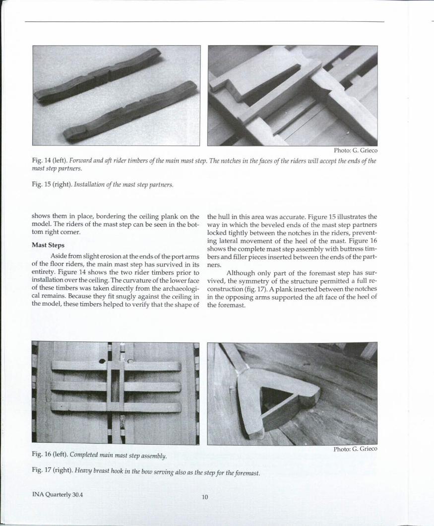
Photo: G. Grieco
Fig. 14 (left). Forward and aft rider timbers of the main mast step. The notches in the faces of the riders will accept the ends of themast step partners.
Fig. 15 (right). Installation of the mast step partners.
shows them in place, bordering the ceiling plank on themodel. The riders of the mast step can be seen in the bot-tom right comer.
Mast Steps
Aside from slight erosion at the ends of the port armsof the floor riders, the main mast step has survived in itsentirety. Figure 14 shows the two rider timbers prior toinstallation over the ceiling. The curvature of the lower faceof these timbers was taken directly from the archaeologi-cal remains. Because they fit snugly against the ceiling inthe model, these timbers helped to verify that the shape of
Fig. 16 (left). Completed main mast step assembly.
the hull in this area was accurate. Figure 15 illustrates theway in which the beveled ends of the mast step partnerslocked tightly between the notches in the riders, prevent-ing lateral movement of the heel of the mast. Figure 16shows the complete mast step assembly with buttress tim-bers and filler pieces inserted between the ends of the part-ners.
Although only part of the foremast step has sur-vived, the symmetry of the structure permitted a full re-construction (fig. 17). A plank inserted between the notchesin the opposing arms supported the aft face of the heel ofthe foremast.
J
Photo: G. Grieco
Fig. 17 (right). Heavy breast hook in the bow serving also as the step for the foremast.
INA Quarterly 30.4 10
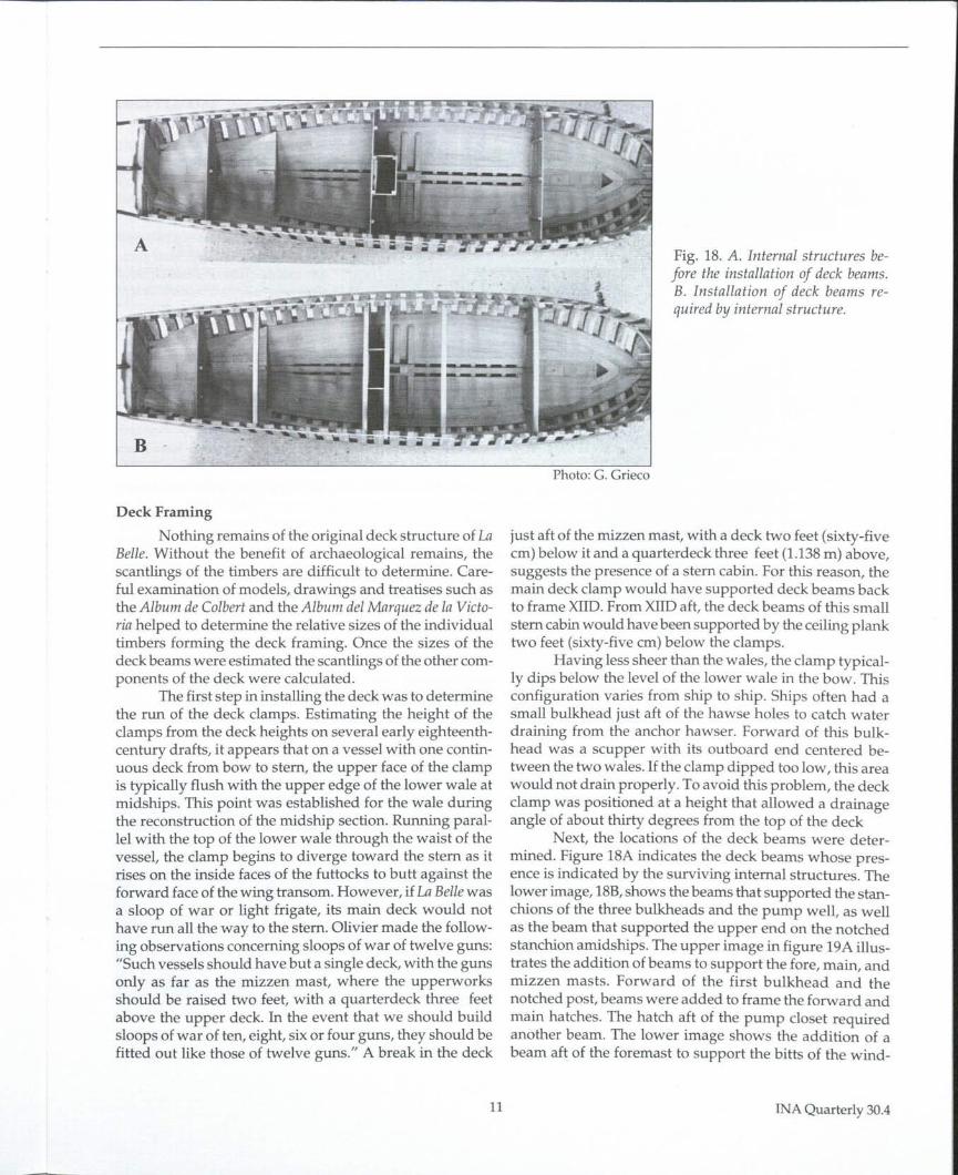
Fig. 18. A. Internal structures be-fore the installation of deck beams.B. Installation of deck beams re-quired by internal structure.
Deck FramingNothing remains of the original deck structure of La
Belle. Without the benefit of archaeological remains, thescantlings of the timbers are difficult to determine. Care-ful examination of models, drawings and treatises such asthe Album de Colbert and the Album del Marquez de la Victo-ria helped to determine the relative sizes of the individualtimbers forming the deck framing. Once the sizes of thedeck beams were estimated the scantlings of the other com-ponents of the deck were calculated.
The first step in installing the deck was to determinethe run of the deck clamps. Estimating the height of theclamps from the deck heights on several early eighteenth-century drafts, it appears that on a vessel with one contin-uous deck from bow to stern, the upper face of the clampis typically flush with the upper edge of the lower wale atmidships. This point was established for the wale duringthe reconstruction of the midship section. Running paral-lel with the top of the lower wale through the waist of thevessel, the clamp begins to diverge toward the stern as itrises on the inside faces of the futtocks to butt against theforward face of the wing transom. However, if La Belle wasa sloop of war or light frigate, its main deck would nothave run all the way to the stern. Olivier made the follow-ing observations concerning sloops of war of twelve guns:"Such vessels should have but a single deck, with the gunsonly as far as the mizzen mast, where the upperworksshould be raised two feet, with a quarterdeck three feetabove the upper deck. In the event that we should buildsloops of war of ten, eight, six or four guns, they should befitted out like those of twelve guns." A break in the deck
Photo: G. Grieco
just aft of the mizzen mast, with a deck two feet (sixty-fiveem) below it and a quarterdeck three feet (1.138m) above,suggests the presence of a stern cabin. For this reason, themain deck clamp would have supported deck beams backto frame XIID.From XIIDaft, the deck beams of this smallstern cabin would have been supported by the ceiling planktwo feet (sixty-five em) below the clamps.
Having less sheer than the wales, the clamp typical-ly dips below the level of the lower wale in the bow. Thisconfiguration varies from ship to ship. Ships often had asmall bulkhead just aft of the hawse holes to catch waterdraining from the anchor hawser. Forward of this bulk-head was a scupper with its outboard end centered be-tween the two wales. If the clamp dipped too low, this areawould not drain properly. To avoid this problem, the deckclamp was positioned at a height that allowed a drainageangle of about thirty degrees from the top of the deck
Next, the locations of the deck beams were deter-mined. Figure 18A indicates the deck beams whose pres-ence is indicated by the surviving internal structures. Thelower image, 18B,shows the beams that supported the stan-chions of the three bulkheads and the pump well, as wellas the beam that supported the upper end on the notchedstanchion amidships. The upper image in figure 19A illus-trates the addition of beams to support the fore, main, andmizzen masts. Forward of the first bulkhead and thenotched post, beams were added to frame the forward andmain hatches. The hatch aft of the pump closet requiredanother beam. The lower image shows the addition of abeam aft of the foremast to support the bitts of the wind-
11 INAQuarterly 30.4
lass. Three additional beams were positioned to break upspans of more than three feet (97.6 cm). In order to tie theclamps together at the bow and to add lateral strength, abreasthook was notched down into the clamps and boltedthrough the futtocks, With molded dimensions equivalentto those of the deck beams, the breasthook also served as afastening surface for the forward ends of the waterwaysand planking.
Construction of the deck framing began by dove-tailing the deck beams two inches (5.4 cm) into the clamps(fig. 20). The dovetail joints increased the lateral strengthof the hull and tied the sides of the vessel together. Withall the beams placed in their proper positions, the loca-tions of the hatch carlings and mast partners were marked.
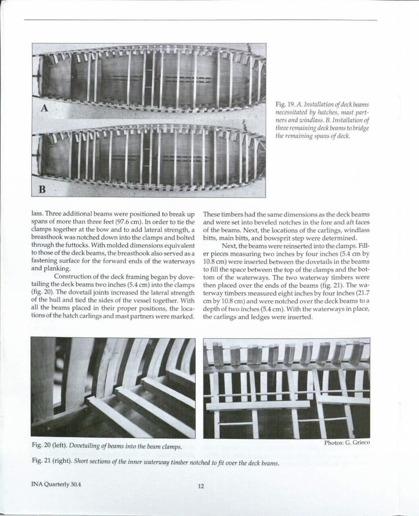
Fig. 19.A. Installation of deck beamsnecessitated by hatches, mast part-ners and windlass. B. Installation ofthree remaining deck beams to bridgethe remaining spans of deck.
These timbers had the same dimensions as the deck beamsand were set into beveled notches in the fore and aft facesof the beams. Next, the locations of the carlings, windlassbitts, main bitts, and bowsprit step were determined.
Next, the beams were reinserted into the clamps. Fill-er pieces measuring two inches by four inches (5.4 cm by10.8 em) were inserted between the dovetails in the beamsto fill the space between the top of the clamps and the bot-tom of the waterways. The two waterway timbers werethen placed over the ends of the beams (fig. 21). The wa-terway timbers measured eight inches by four inches (21.7cm by 10.8 ern) and were notched over the deck beams to adepth of two inches (5.4 ern). With the waterways in place,the carlings and ledges were inserted.
Fig. 20 (left). Dovetailing of beams into the beam clamps.
Fig. 21 (right). Short sections of the inner waterway timber notched to fit over the deck beams.
INA Quarterly 30.4 12
Deck Planking
On both models, only the starboard side of the deck was planked.This not only permits the inspection of the internal construction fea-tures, but also allows the details of the deck framing to be seen. Due tothe absence of archaeological evidence, the deck planking pattern onLa Belle will never be determined for certain. The deck planking of themodel approximates the appearance and planking patterns of modelsfrom the seventeenth and early eighteenth centuries.
Thin strips were cut from black plastic binder cover sheets toinsert between the planks to represent the tarred seams. Each plankwas fastened to each deck beam using two one inch (2.7 cm)diametertreenails. Figure 22 shows the completed deck planking.
GunportsBefore the gunports were cut and framed, their locations were
determined. Many factors were considered in determining the placementof cannon on a narrow-decked vessel like La Belle.Structures such as hatchcoamings, masts, pumps, and bitts, can prevent them from being with-drawn from their ports. Outside of the hull, the location of the fore andmain mast channels can dictate the placement of gunports. The breadthof the vessel is also a limiting factor. The barrel of a four-pounder cannonis six feet (1.951 m) long. With a deck less than fourteen feet (4.553 m)wide and a foot of tumblehome in the waist, two cannon barely fit abreastwith the port lids closed. Forward and aft of midships, the narrowing ofthe deck would prevent this arrangement entirely unless the guns weredrawn in at an angle. Consideration must also given to the gun crewswho fired the guns. Seventeenth-century French naval regulations re-quired a minimum spacing of six feet, six inches (2.114 m) between theguns on larger warships to provide room for the crews to service them.
The reconstructed breadth of the gunports was calculated tobe eighteen inches (48.8 em) square. This calculation was later con-firmed by a single gunport lid found during the excavation of La Belle.The frames were erected on eighteen-inch (48.8 em) centers, conve-niently allowing the top timbers of two adjacent frames to be used toframe the sides of the ports.
Photo: G. Grieco
Fig. 22. Deck planking on the starboard side ofthe model.
0 , to is 20 35 .. 50
~ I I I I I ~French Feet Drawing: G. Grieco
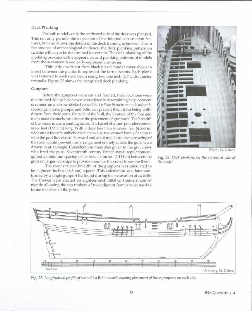
Fig. 23. Longitudinal profile of second La Belle model showing placement of three gunports on each side.
13 INA Quarterly 30.4
Two possible configurations were for-mulated. The first configuration relied on En-riquez Barreto's description of the hull andassumed the use of eight gunports. Employedon the first model, this arrangement allowed theforward two pairs of guns to be secured inboardwith the gunports closed, but the space avail-able on deck between the afterrnost pairs ofports was not sufficient for two guns to be posi-tioned abreast. This suggests an eight port con-figuration using only six guns. With four gunsin the forward four ports, the two aftermostguns could be used one per pair of ports andmoved from side to side as necessary. The sec-ond configuration assumed that only six portswere present (fig.23).In this arrangement, spacewould have been tight between the afterrnostpair of guns. However, with a slight angling ofthe carriages, both guns could have been run inwhen the ports were closed.
Once the locations of the ports wereestimated, the top timbers at the port openings were cut toa height of eleven inches (29.8 cm) above the deck. A threeinch (8.1cm) thick lintel raised the sill to the required heightof one foot, two inch (37.9 cm). A second timber of the samedimensions formed the upper edge of the gunport.
1\
Photo: G. Grieco
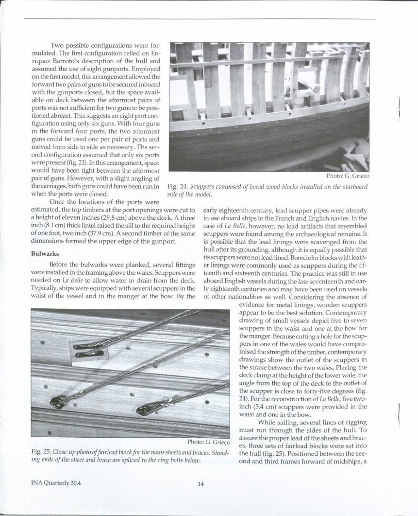
Fig. 24. Scuppers composed of bored wood blocks installed on the starboardside of the model.
early eighteenth century, lead scupper pipes were alreadyin use aboard ships in the French and English navies. In thecase of La Belle, however, no lead artifacts that resembledscuppers were found among the archaeological remains. Itis possible that the lead linings were scavenged from thehull after its grounding, although it is equally possible thatits scuppers were not lead lined. Bored elm blocks with leath-er linings were commonly used as scuppers during the fif-teenth and sixteenth centuries. The practice was still in useaboard English vessels during the late seventeenth and ear-ly eighteenth centuries and may have been used on vesselsof other nationalities as well. Considering the absence of
evidence for metal linings, wooden scuppersappear to be the best solution. Contemporarydrawing of small vessels depict five to sevenscuppers in the waist and one at the bow forthe manger. Because cutting a hole for the scup-pers in one of the wales would have compro-mised the strength of the timber, contemporarydrawings show the outlet of the scuppers inthe strake between the two wales. Placing thedeck clamp at the height of the lower wale, theangle from the top of the deck to the outlet ofthe scupper is close to forty-five degrees (fig.24). For the reconstruction of La Belle, five two-inch (5.4 cm) scuppers were provided in thewaist and one in the bow.
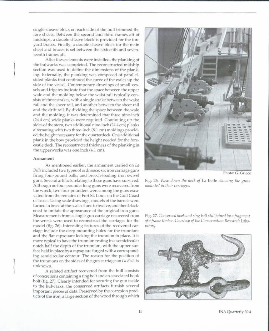
While sailing, several lines of riggingmust run through the sides of the hull. Toassure the proper lead of the sheets and brae-
Photo: G. Grieco es. three sets of fair lead blocks were set intothe hull (fig. 25). Positioned between the sec-ond and third frames forward of midships, a
Bulwarks
Before the bulwarks were planked, several fittingswere installed in the framing above the wales. Scuppers wereneeded on La Belle to allow water to drain from the deck.Typically, ships were equipped with several scuppers in thewaist of the vessel and in the manger at the bow. By the
-•
•Fig. 25. Close-up photo offair/ead block for the main sheets and braces. Stand-ing ends of the sheet and brace are spliced to the ring bolts below.
INA Quarterly 30.4
"
14
1\
single sheave block on each side of the hull trimmed thefore sheets. Between the second and third frames aft ofmidships, a double sheave block is provided for the foreyard braces. Finally, a double sheave block for the mainsheet and braces is set between the sixteenth and seven-teenth frames aft.
After these elements were installed, the planking ofthe bulwarks was completed. The reconstructed midshipsection was used to define the dimensions of the plank-ing. Externally, the planking was composed of parallel-sided planks that continued the curve of the wales up theside of the vessel. Contemporary drawings of small ves-sels and frigates indicate that the space between the upperwale and the molding below the waist rail typically con-sists of three strakes, with a single strake between the waistrail and the sheer rail, and another between the sheer railand the drift rail. By dividing the space between the waleand the molding, it was determined that three nine-inch(24.4 em) wide planks were required. Continuing up thesides of the stem, two additional nine-inch (24.4em) planksalternating with two three-inch (8.1 em) moldings provid-ed the height necessary for the quarterdeck. One additionalplank in the bow provided the height needed for the fore-castle deck. The reconstructed thickness of the planking inthe upperworks was one inch (4.1 em).
1
ArmamentAs mentioned earlier, the armament carried on La
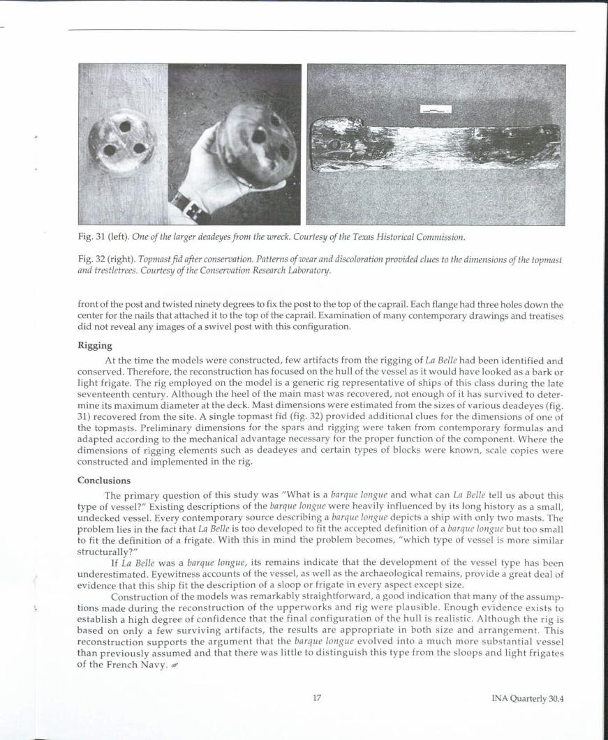
Belle included two types of ordnance: six iron carriage gunsfiring four-pound balls, and breech-loading iron swivelguns. Several artifacts relating to these guns have survived.Although no four-pounder long guns were recovered fromthe wreck, two four-pounders were among the guns exca-vated from the remains of Fort St. Louis on the Gulf Coastof Texas. Using scale drawings, models of the barrels wereturned in brass at the scale of one to twelve, and then black-ened to imitate the appearance of the original iron guns.Measurements from a single gun carriage recovered fromthe wreck were used to reconstruct the carriages for themodel (fig. 26). Interesting features of the recovered car-riage include the deep mounting holes for the trunnionsand the flat capsquare locking the trunnion in place. It ismore typical to have the trunnion resting in a semicircularnotch half the depth of the trunnion, with the upper sur-face held in place by a capsquare forged with a correspond-ing semicircular contour. The reason for the position ofthe trurmions on the sides of the gun carriage on La Belle isunknown.
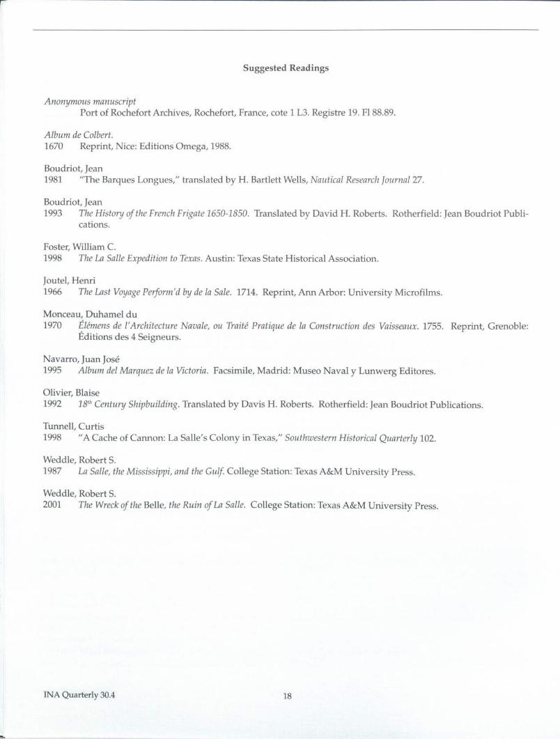
A related artifact recovered from the hull consistsof concretions containing a ring bolt and an associated hookbolt (fig. 27). Clearly intended for securing the gun tackleto the bulwarks, the conserved artifacts furnish severalimportant pieces of data. Preserved by the corrosion prod-ucts of the iron, a large section of the wood through which
Photo: G. Grieco
Fig. 26. View down the deck of La Belle showing the gunsmounted in their carriages.
Fig. 27. Conserved hook and ring bolt still joined by afragmentof a frame timber. Courtesy of tire Conservation Research Labo-ratory.
15 INA Quarterly 30.4

the bolts were fastened has survived. Although the origi-nal thickness of the wood has diminished, a rove for theforelock of the hook-bolt has corroded into the positionwhere it rested against the outer surface of the hull plank-ing. Neither the rove nor forelock has survived on the ringbolt; however, the remains of the shank indicate that thebolt ran through timber approximately two inches (5.4em)thicker than the hook. This suggests that the hook piercedthe outer hull planking while the ring bolt penetrated awale. Superimposing a scale image of these artifacts overthe bulwarks of the reconstructed midship section, the an-gle of the bolts and their lengths provides supporting evi-dence for the reconstruction (fig. 28).
Also found on the wreck was a loaded swivel gunattached to its post and mounting hardware (fig. 29). Theconserved gun was 54.55 inches (1.478 m) long from themuzzle to the tip of the tiller (fig. 30). The muzzle had abore of 3.42 inches (9.3 em), close to the bore diameter ofthe four-pounder carriage guns. Although Baroto mentionsthat the swivel guns appeared to be capable of firing a four-pound ball, the breach of the barrel contained a two-inchball and the chamber held a powder charge with a wood-en plug. Primarily used as an anti-persormel weapon, thegun could also have fired a handful of small shot.
Iron swivel guns were used aboard vessels from thesixteenth through the eighteenth centuries. Examples ofwrought iron, stave and hoop constructed weapons almostidentical in design and dimensions to the one found on La
oSide View
c
Top View
Bot-ton View
o 10 20 30 40 50
inchesDrawing: D. L. Hamilton
INA Quarterly30.4
.
•
Drawing: G. Grieco
Fig. 28. Drawing of the bulwarks of La Belle showing how thehook and ring bolt may hate been oriented.
Belle have been found on shipwrecks from as early as thesixteenth century. The post and mounting hardware stillattached to the gun were more unusual finds. The swivelwas set into a hole in the top of the five-inch (14.9 em) di-ameter post. A two-inch (6.1 em) wide iron band encirclesthe top of the post, and four inches (10.8 em) down fromthe band a two-flanged iron strap that went around the
Fig. 29 (left). The swivel gun recovered from the wreck of LaBelle.
Fig. 30 (below). Photograph of the swivel gun after conserva-tion. The breech chamber and wedge are not shown in this photo.Courtesy of the Conservation Research Laboratory.
16
•
Fig. 31 (left).One of the larger deadeyes from the wreck. Courtesy of the Texas Historical Commission.
Fig. 32 (right). Topmast fid after conservation. Patterns of wear and discoloration provided clues to the dimensions of the topmastand trestletrees. Courtesy of the Conservation Research Laboratory.
front of the post and twisted ninety degrees to fix the post to the top of the capraiJ.Each flange had three holes down thecenter for the nails that attached it to the top of the caprail. Examination of many contemporary drawings and treatisesdid not reveal any images of a swivel post with this configuration.
RiggingAt the time the models were constructed, few artifacts from the rigging of La Belle had been identified and
conserved. Therefore, the reconstruction has focused on the hull of the vessel as it would have looked as a bark orlight frigate. The rig employed on the model is a generic rig representative of ships of this class during the lateseventeenth century. Although the heel of the main mast was recovered, not enough of it has survived to deter-mine its maximum diameter at the deck. Mast dimensions were estimated from the sizes of various deadeyes (fig.31) recovered from the site. A single topmast fid (fig. 32) provided additional clues for the dimensions of one ofthe topmasts. Preliminary dimensions for the spars and rigging were taken from contemporary formulas andadapted according to the mechanical advantage necessary for the proper function of the component. Where thedimensions of rigging elements such as deadeyes and certain types of blocks were known, scale copies wereconstructed and implemented in the rig.
ConclusionsThe primary question of this study was "What is a barque longue and what can La Belle tell us about this
type of vessel?" Existing descriptions of the barque longue were heavily influenced by its long history as a small,undecked vessel. Every contemporary source describing a barque longue depicts a ship with only two masts. Theproblem lies in the fact that La Belle is too developed to fit the accepted definition of a barque longue but too smallto fit the definition of a frigate. With this in mind the problem becomes, "which type of vessel is more similarstructurally?"
If La Belle was a barque longue, its remains indicate that the development of the vessel type has beenunderestimated. Eyewitness accounts of the vessel, as well as the archaeological remains, provide a great deal ofevidence that this ship fit the description of a sloop or frigate in every aspect except size.
Construction of the models was remarkably straightforward, a good indication that many of the assump-tions made during the reconstruction of the upperworks and rig were plausible. Enough evidence exists toestablish a high degree of confidence that the final configuration of the hull is realistic. Although the rig isbased on only a few surviving artifacts, the results are appropriate in both size and arrangement. Thisreconstruction supports the argument that the barque longue evolved into a much more substantial vesselthan previously assumed and that there was little to distinguish this type from the sloops and light frigatesof the French Navy. ""
17 INAQuarterly30.4
Suggested Readings
AnonynlOus manuscriptPort of Rochefort Archives, Rochefort, France, cote 1 L3. Registre 19. FI88.89.
Album de Colbert.1670 Reprint, Nice: Editions Omega, 1988.
Boudriot, Jean1981 "The Barques Longues," translated by H. Bartlett Wells, Nautical Research Journal 27.
Boudriot, Jean1993 The History of the French Frigate 1650-1850. Translated by David H. Roberts. Rotherfield: Jean Boudriot Publi-
cations.
Foster, William C.1998 The La Salle Expedition to Texas. Austin: Texas State Historical Association.
[outel, Henri1966 The Last Voyage Perform'd by de la Sale. 1714. Reprint, Ann Arbor: University Microfilms.
Monceau, Duhamel du1970 Elemens de l'Archiiecture Naoale, au Traite Pratique de la Construction des Vaisseaux. 1755. Reprint, Grenoble:
Editions des 4 Seigneurs.
Navarro, Juan Jose1995 Album del Marquez de la Victoria. Facsimile, Madrid: Museo Naval y Lunwerg Editores.
Olivier, Blaise1992 18th Century Shipbuilding. Translated by Davis H. Roberts. Rotherfield: Jean Boudriot Publications.
Tunnell, Curtis1998 "A Cache of Cannon: La Salle's Colony in Texas," Southwestern Historical Quarterly 102.
Weddle, Robert S.1987 La Salle, the Mississippi, and the Gulf College Station: Texas A&M University Press.
Weddle, Robert S.2001 The Wreck of the Belle, the Ruin of La Salle. College Station: Texas A&M University Press.
INA Quarterly 30.4 18