the lsts toolchain for networked vehicle systems
TRANSCRIPT

The LSTS Toolchain for Networked Vehicle Systems*
Jose Pinto1, Paulo S. Dias1, Ricardo Martins1, Joao Fortuna1, Eduardo Marques2 and Joao Sousa1
Abstract— This paper describes the open-source softwaretoolchain developed by the Underwater Systems and TechnologyLaboratory (LSTS) for supporting networked heterogeneousair and ocean vehicle systems. The toolchain supports thedeployment of air and ocean vehicles interacting over limitedacoustic and wireless networks combined with disruption-tolerant networking protocols. We present the different com-ponents of the toolchain and how they can be deployed andextended for different scenarios. We conclude with descriptionsof recent applications to onboard deliberative planning andintegration of low-cost micro UAVs into the toolchain.
I. INTRODUCTION
There is an ongoing trend towards the creation of Net-worked Vehicle Systems. These systems are composed byautonomous vehicles, sensors and human operators that forma network with a dynamic topology. This happens becauseeach node in the network has a set of communication meanswhich bandwidth, latency and reliability depends on theirpose and the poses of its peers. Each node in the networkmay have a dynamical physical position. As nodes move, thenetwork topology changes: communication will be affectedin terms of connectivity, bandwidth and reliability. We arethus interested in complex behaviors that require orchestra-tion of communications, movement and computations insidethe network.
Consider the scenario in Fig. 1. Two operators are con-nected to the network (others could join in at any moment)and control the network through communication links thatare created and destroyed dynamically. If the objective ofthe operator on the right was to obtain an underwatersidescan survey at a remote location, this should be statedto the system and the network should automatically adaptto encompass the resulting objectives. The objectives wouldinclude:
• find one or more vehicles which are capable of gatheringthe required data;
• survey location using one or more vehicles; and• relay (important pieces of) data back to base station.In the presented scenario one UAV could, for instance,
download the objectives from the control station, fly towardsa device that provides both wireless and acoustic underwatercommunications and relay the objectives to that device.
1 Underwater Systems and Technology Laboratory (LSTS), Faculdade deEngenharia da Universidade do Porto [email protected]
2 Large-Scale Informatics Systems Laboratory, Faculdade de Ciencias daUniversidade de Lisboa
*The research leading to these results has received funding from the Eu-ropean Commission FP7-ICT Cognitive Systems, Interaction, and Roboticsunder the contract #270180 (NOPTILUS).
*The authors gratefully acknowledge Kanna Rajan and Frederic Py fromMBARI for discussions on autonomy and support in integration of TREX.
This device is then responsible for contacting one or moreAUVs that are capable of doing the survey and relaying theobjectives to them. After the survey is completed, the dataneeds to somehow travel back to the base station using directcommunications (if the AUV comes near the base station) orusing one or more communication relays like before.
Orchestrating mobile heterogeneous nodes like this is verycomplex for human operators since they must be aware of allconnected and disconnected devices, their current capabilitiesand state and also any faults or changes that may occur inthe system. This is why it is very important that the systemaids the operators in decision making and allow disconnecteddevices to sense the environment and adapt behavior to fulfillthe desired objectives.
At LSTS, we have developed different algorithms andtechnologies for the operation of these networked vehiclesystems, with applications to adaptive ocean sampling [1],mine hunting [2], data muling [3], among others [4]. Forthis we have developed several AUVs, UAVs, ROVs andASVs (see figure 2). Most of these vehicles have been devel-oped from scratch by the group including their electronics,onboard software and operating consoles. Others have beendeveloped under ongoing collaborations with the PortugueseAir Force Academy (bottom-left UAV in figure 2) and thePortuguese Navy (bottom-right AUV in figure 2).
This paper presents the open-source LSTS softwaretoolchain [5] and design decisions that were taken to enforcethe modularity and adaptability of these tools. In section IIwe describe our system architecture and illustrate it with asample deployment scenario. We then present the onboardsoftware in III and the integrated Command and ControlSoftware in more detail in section IV. In sections V and VIwe describe how this toolchain was extended for supporting
ASV
Surface buoy
Drifting sensor
AUV
Moored sensor
operator
UAV
operator
Fig. 1. Conceptual deployment of a Networked Vehicle System
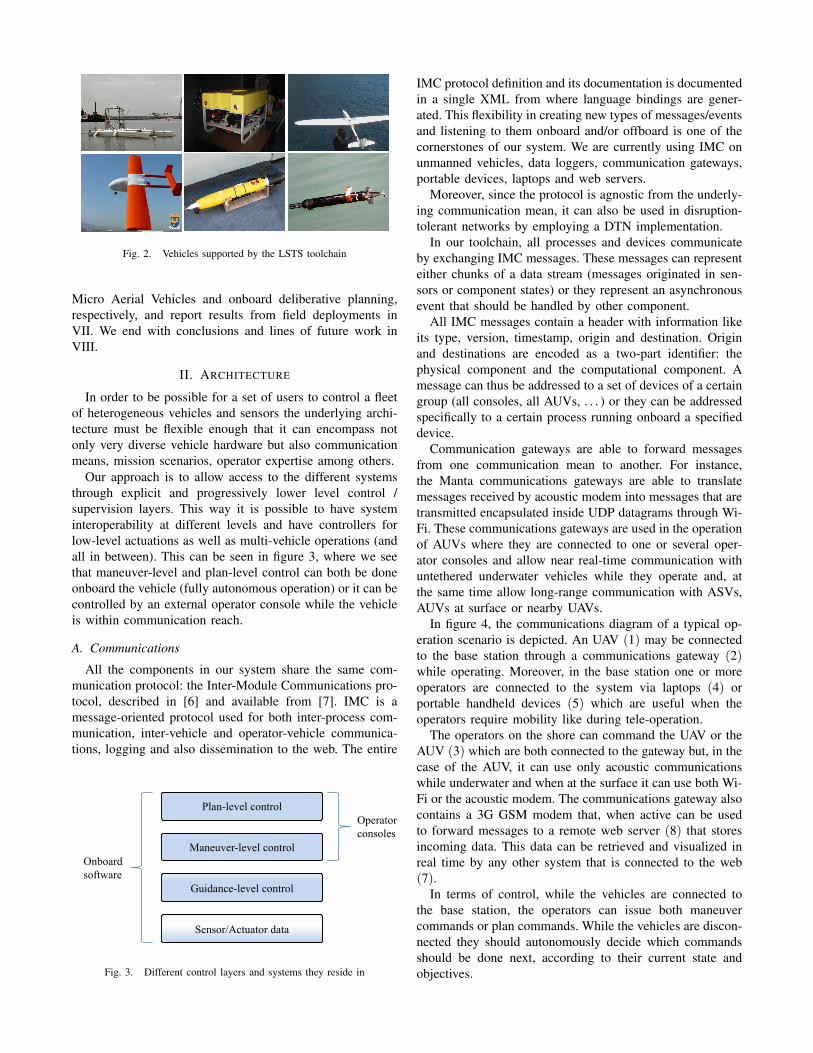
Fig. 2. Vehicles supported by the LSTS toolchain
Micro Aerial Vehicles and onboard deliberative planning,respectively, and report results from field deployments inVII. We end with conclusions and lines of future work inVIII.
II. ARCHITECTURE
In order to be possible for a set of users to control a fleetof heterogeneous vehicles and sensors the underlying archi-tecture must be flexible enough that it can encompass notonly very diverse vehicle hardware but also communicationmeans, mission scenarios, operator expertise among others.
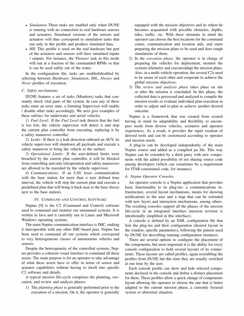
Our approach is to allow access to the different systemsthrough explicit and progressively lower level control /supervision layers. This way it is possible to have systeminteroperability at different levels and have controllers forlow-level actuations as well as multi-vehicle operations (andall in between). This can be seen in figure 3, where we seethat maneuver-level and plan-level control can both be doneonboard the vehicle (fully autonomous operation) or it can becontrolled by an external operator console while the vehicleis within communication reach.
A. Communications
All the components in our system share the same com-munication protocol: the Inter-Module Communications pro-tocol, described in [6] and available from [7]. IMC is amessage-oriented protocol used for both inter-process com-munication, inter-vehicle and operator-vehicle communica-tions, logging and also dissemination to the web. The entire
Plan-level control Plan-level control
Maneuver-level control Maneuver-level control
Guidance-level control Guidance-level control
Sensor/Actuator data Sensor/Actuator data
Operator
consoles
Onboard
software
Fig. 3. Different control layers and systems they reside in
IMC protocol definition and its documentation is documentedin a single XML from where language bindings are gener-ated. This flexibility in creating new types of messages/eventsand listening to them onboard and/or offboard is one of thecornerstones of our system. We are currently using IMC onunmanned vehicles, data loggers, communication gateways,portable devices, laptops and web servers.
Moreover, since the protocol is agnostic from the underly-ing communication mean, it can also be used in disruption-tolerant networks by employing a DTN implementation.
In our toolchain, all processes and devices communicateby exchanging IMC messages. These messages can representeither chunks of a data stream (messages originated in sen-sors or component states) or they represent an asynchronousevent that should be handled by other component.
All IMC messages contain a header with information likeits type, version, timestamp, origin and destination. Originand destinations are encoded as a two-part identifier: thephysical component and the computational component. Amessage can thus be addressed to a set of devices of a certaingroup (all consoles, all AUVs, . . . ) or they can be addressedspecifically to a certain process running onboard a specifieddevice.
Communication gateways are able to forward messagesfrom one communication mean to another. For instance,the Manta communications gateways are able to translatemessages received by acoustic modem into messages that aretransmitted encapsulated inside UDP datagrams through Wi-Fi. These communications gateways are used in the operationof AUVs where they are connected to one or several oper-ator consoles and allow near real-time communication withuntethered underwater vehicles while they operate and, atthe same time allow long-range communication with ASVs,AUVs at surface or nearby UAVs.
In figure 4, the communications diagram of a typical op-eration scenario is depicted. An UAV (1) may be connectedto the base station through a communications gateway (2)while operating. Moreover, in the base station one or moreoperators are connected to the system via laptops (4) orportable handheld devices (5) which are useful when theoperators require mobility like during tele-operation.
The operators on the shore can command the UAV or theAUV (3) which are both connected to the gateway but, in thecase of the AUV, it can use only acoustic communicationswhile underwater and when at the surface it can use both Wi-Fi or the acoustic modem. The communications gateway alsocontains a 3G GSM modem that, when active can be usedto forward messages to a remote web server (8) that storesincoming data. This data can be retrieved and visualized inreal time by any other system that is connected to the web(7).
In terms of control, while the vehicles are connected tothe base station, the operators can issue both maneuvercommands or plan commands. While the vehicles are discon-nected they should autonomously decide which commandsshould be done next, according to their current state andobjectives.

(1)
(7)
(5)
(4)
(3)
(2)
(8)
wi-fi
acoustic comms
web/xml
wi-fi (unavailable)
Fig. 4. Components deployed in a typical operation
III. ONBOARD SOFTWARE
The onboard software used in all our embedded systemsis DUNE (DUNE Uniform Navigation Environment) [8].DUNE is writen in C++ and runs on Linux 2.6+, QNX v6.x,Solaris, Mac OS X, eCos, RTEMS, OpenBSD, FreeBSD,NetBSD and Microsoft Windows.
A. DUNE Tasks
In DUNE, related logical operations are isolated fromeach other in tasks which usually run in separate threadsof execution. Tasks communicate with one another only byusing a message bus which is responsible for forwardingIMC messages from the producer to all their registeredreceivers. Each task follows a common life-cycle and alsohas method handlers for all messages that it consumes. Thelife-cycle of a DUNE task comprises the following methods:
• onEntityReservation() / onEntityResolution()• onReportEntityState()• onResourceAcquisition() / onResourceRelease() / onRe-
sourceInitialization()• onUpdateParameters()• onRequestActivation() / onRequestDeactivation()• onActivation() / onDeactivation()• onMain()• consume(< M > message)Any implemented task can choose to override the inherited
(empty) implementation of the previous methods with theirspecific code. As an example, a sensor payload implementsthe methods onActivation and onDeactivation so that it turnson and off the payload as requested by other tasks andthus save on energy consumption. Resource aquisition andinitialization also follow timed phases in the initialization ofthe system.
Each task can also register one or more computationalentities that can later be used to address it univocally insidea networked vehicle system. Tasks can also implement onUp-dateParameters that is triggered whenever their configurationgets changed.
The onMain method is called periodically by the schedulerso it is overriden by any tasks that want to execute something
at timed delays. Finally, all tasks can consume messagesgenerated by any other threads by implementing consumemethods that take as their sole parameter the generatedmessage (handled messages will have a corresponding type).
In DUNE, tasks are divided into sensors, actuators, esti-mators, monitors, supervisors, controllers and transports asfollows:
• Sensors are device driver tasks, associated with somehardware that measures the environment.
• Actuators are device drivers for hardware that allows thevehicle to interact with the environment and / or move.
• Estimators are tasks that aggregate information fromsensors into state estimations. One good example of anestimator is the Navigation task.
• Controllers are tasks that handle high-level commandsand transform them into lower-level commands or actu-ations according to current estimated state. For instance,all supported maneuvers have a corresponding maneuvercontroller.
• Monitors are tasks that receive information from othertasks and may change the vehicle state accordingly. Forinstance, the Operational Limits monitor will changethe vehicle mode to “blocked” whenever the operationallimits are breached.
• Supervisors are tasks that enable and disable other tasksaccording to the current vehicle state. For instance, if thevehicle enters “blocked” mode, the vehicle supervisorwill stop the current maneuver controller from sendingcommands.
• Transports are tasks in charge of transporting messagesin and out of the message bus. Logging is a specialtransport task that listens to a set of messages andrecords their serialized state to persistent storage. Othertransport tasks are UDP, TCP, HTTP, etc.
B. Run configurations
All running instances of DUNE share the same code basebut run under different configurations. We call configurationto a description of the tasks that are enabled and theirparameters. The configuration of a running DUNE instancecan change according to user intervention or in response toa Supervisor task command.
A DUNE configuration file describes which tasks areenabled initially and also what are their initial parameters.Using a referencing mechanism, a configuration file mayinclude parts of other configuration files. This allows thecreation of small and less error-prone vehicle-specific con-figuration files, since most of the tasks (and their parameters)are common between similar vehicles.
To choose if a task will be enabled in a configuration file,the user must select in which profiles the task will be enabledby default. DUNE uses profiles to allow multiple (typical)configurations to be defined on a single file. Some examplesprofiles are:
• Hardware This task will be enabled only when DUNEis connected to the real hardware devices (real vehicle).
• Simulation These tasks are enabled only when DUNEis running with no connection to real hardware sensorsand actuators. Simulated versions of the sensors andactuators will thus correspond to simulation tasks thatrun only in this profile and produce simulated data.
• HIL This profile is used on the real hardware but partof the actuators and sensors will have simulated inputs/ outputs. For instance, the Thruster task in this modewill run at a fraction of the commanded RPMs so thatit can be used safely out of the water.
In the configuration file, tasks are enabled/disabled byselecting between Hardware, Simulation, HIL, Always andNever profiles of execution.
C. Safety mechanisms
DUNE features a set of tasks (Monitors) tasks that con-stantly check vital parts of the system. In case any of thesetasks enter an error state, a listening Supervisor will enable/ disable other tasks accordingly. We next give examples ofthese safeties for underwater and aerial vehicles.
1) Fuel Level: If the Fuel Level task detects that the fuelis too low, the vehicle supervisor will detect it and stopthe current plan controller from executing, replacing it bya safety maneuver controller.
2) Leaks: If there is a leak detection onboard an AUV, itsvehicle supervisor will shutdown all payloads and execute asafety maneuver to bring the vehicle to the surface.
3) Operational Limits: If the user-defined limits werebreached by the current plan controller, it will be blockedfrom controlling and only teleoperation and safety maneuversare allowed to be executed by the vehicle supervisor.
4) Communications: If an UAV loses communicationwith the base station for more than a user defined timeinterval, the vehicle will stop the current plan and execute apredefined plan that will bring it back near to the base (hovernext to the base station).
IV. COMMAND AND CONTROL SOFTWARE
Neptus [9] is the C2 (Command and Control) softwareused to command and monitor our unmanned systems. It iswritten in Java and it currently run in Linux and MicrosoftWindows operating systems.
The main Neptus communication interface is IMC, makingit interoperable with any other IMC-based peer. Neptus hasbeen used to command all our systems which correspondto very heterogeneous classes of autonomous vehicles andsensors.
Despite the heterogeneity of the controlled systems, Nep-tus provides a coherent visual interface to command all theseassets. The main purpose is for an operator to take advantageof what these assets have to offer in terms of sensor andactuator capabilities without having to dwell into specificC2 software and details.
A typical mission life-cycle comprises the planning, exe-cution, and review and analysis phases:
1) The planning phase is generally performed prior to theexecution of a mission. On it, the operator is generally
equipped with the mission objectives and its where hebecomes acquainted with possible obstacles, depths,tides, traffic, etc. With these elements in mind theoperator can choose the best locations for the commandcenter, communication and location aids, and startspreparing the mission plans to be used and does roughsimulations of them.
2) In the execution phase, the operator is in charge ofpreparing the vehicles for deployment, monitor thesystems telemetry and execute/adapt the mission plans.Also, in a multi-vehicle operation, the several C2s needto be aware of each other and cooperate to achieve theglobal mission objectives.
3) The review and analysis phase takes place on siteor after the mission is concluded. In this phase, thecollected data is processed and analyzed to compile themission results or evaluate individual plan execution inorder to adjust and re-plan to achieve another desiredoutcome.
Neptus is a framework that was created from scratchhaving in mind its adaptability and flexibility to encom-pass needs from diverse vehicles, scenarios and operatorexperiences. As a result, it provides the rapid creation ofderived tools and can be customized according to operatorand mission needs.
A plug-in can be developed independently of the mainNeptus source and added as a compiled jar file. This wayNeptus can be extended by a third party with new compo-nents with the added possibility of not sharing source codeamong developers (which can sometimes be a requirementfor ITAR-constrained code, for instance).
A. Neptus Operator Consoles
An operator console is a Neptus application that providesbasic functionality to its plug-ins: a communications in-frastructure, several layout mechanisms, means for showingnotifications to the user and a map that can be extendedwith new layers and interaction mechanisms, among others.The resulting consoles support all the phases of the missionlife-cycle in an integrated interface (mission revision isintentionally simplified in this interface).
A console is defined by an XML configuration file thatlists the plug-ins and their configuration (desired layout inthe window, specific parameters), following the pattern usedby DUNE for describing running configuration instances.
There are several options to configure the placement ofthe components, but most important it is the ability for everyconsole configuration to hold several layouts of its compo-nents. These layouts are called profiles, again resembling theprofiles from DUNE but this time they are usually switchedat run time by the user.
Each console profile can show and hide selected compo-nents declared in the console and define a distinct placementfor them. These profiles allow a quick change of componentslayout allowing the operator to choose the one that is betteradapted to the current mission phase, a currently focusedsystem or abnormal situation.
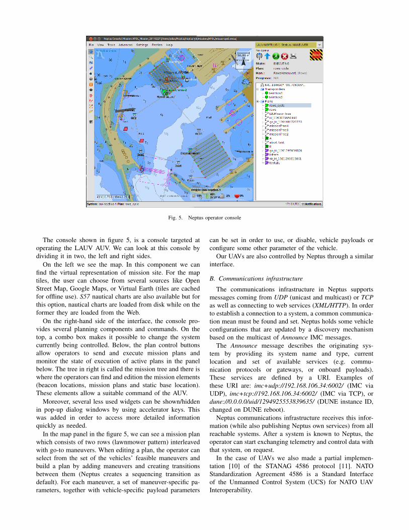
Fig. 5. Neptus operator console
The console shown in figure 5, is a console targeted atoperating the LAUV AUV. We can look at this console bydividing it in two, the left and right sides.
On the left we see the map. In this component we canfind the virtual representation of mission site. For the maptiles, the user can choose from several sources like OpenStreet Map, Google Maps, or Virtual Earth (tiles are cachedfor offline use). S57 nautical charts are also available but forthis option, nautical charts are loaded from disk while on theformer they are loaded from the Web.
On the right-hand side of the interface, the console pro-vides several planning components and commands. On thetop, a combo box makes it possible to change the systemcurrently being controlled. Below, the plan control buttonsallow operators to send and execute mission plans andmonitor the state of execution of active plans in the panelbelow. The tree in right is called the mission tree and there iswhere the operators can find and edition the mission elements(beacon locations, mission plans and static base location).These elements allow a suitable command of the AUV.
Moreover, several less used widgets can be shown/hiddenin pop-up dialog windows by using accelerator keys. Thiswas added in order to access more detailed informationquickly as needed.
In the map panel in the figure 5, we can see a mission planwhich consists of two rows (lawnmower pattern) interleavedwith go-to maneuvers. When editing a plan, the operator canselect from the set of the vehicles’ feasible maneuvers andbuild a plan by adding maneuvers and creating transitionsbetween them (Neptus creates a sequencing transition asdefault). For each maneuver, a set of maneuver-specific pa-rameters, together with vehicle-specific payload parameters
can be set in order to use, or disable, vehicle payloads orconfigure some other parameter of the vehicle.
Our UAVs are also controlled by Neptus through a similarinterface.
B. Communications infrastructure
The communications infrastructure in Neptus supportsmessages coming from UDP (unicast and multicast) or TCPas well as connecting to web services (XML/HTTP). In orderto establish a connection to a system, a common communica-tion mean must be found and set. Neptus holds some vehicleconfigurations that are updated by a discovery mechanismbased on the multicast of Announce IMC messages.
The Announce message describes the originating sys-tem by providing its system name and type, currentlocation and set of available services (e.g. commu-nication protocols or gateways, or onboard payloads).These services are defined by a URI. Examples ofthese URI are: imc+udp://192.168.106.34:6002/ (IMC viaUDP), imc+tcp://192.168.106.34:6002/ (IMC via TCP), ordune://0.0.0.0/uid/1294925553839635/ (DUNE instance ID,changed on DUNE reboot).
Neptus communications infrastructure receives this infor-mation (while also publishing Neptus own services) from allreachable systems. After a system is known to Neptus, theoperator can start exchanging telemetry and control data withthat system, on request.
In the case of UAVs we also made a partial implemen-tation [10] of the STANAG 4586 protocol [11]. NATOStandardization Agreement 4586 is a Standard Interfaceof the Unmanned Control System (UCS) for NATO UAVInteroperability.
To add support for 4586, Neptus was extended with newspecific console widgets and the communications infrastruc-ture was adapted to be able to exchange 4586 messages. Thiswas done by extending the base communications infrastruc-ture.
C. Mission Review and Analysis
The Neptus interface for analyzing the collected data is theMRA (Mission Review and Analysis) shown in figures 6 and7. This interface is targeted at viewing IMC logs and othercollected sensor data (for sensors that have own specific fileformats).
Logs are produced onboard devices by serializing gen-erated messages and concatenating them into one or morebinary files. In order to present the data, these files areinitially indexed and merged with files logged onboard othersystems, ordering them by the origin timestamp. As a result,both operator commands and multi-vehicle surveys can beconcentrated in a single log file and visualized (see sectionVII-A for multi-vehicle visualization examples).
MRA interface is divided in two parts. On the left side,the messages and available visualizations are listed, whileon the right the active visualization is displayed. Any IMCmessage can be inspected rapidly in a tabular form or asa multi-variable/multi-message time-series plot. Some plotsare predefined and others can be created inside MRA by
Fig. 6. Sidescan visualization in Neptus MRA
Fig. 7. Camera visualization in Neptus MRA
selecting fields to plot. Moreover, plots can also be createdin Javascript derived language and saved as a plot script.
Other specialized visualizations are also available, andsimilarly to the console widgets, can be added as Neptusplug-ins. Examples of these specialized visualizations are thesidescan analyzer seen in figures 6, 12, or 14, plots like thefigure 10, 13, or 15, mission replays with map overlays likeseen in figure 11, a photo visualization plugin like in figure7, 3D bathymetry and trajectory visualizations, etc.
V. EXTENSIONS FOR MICRO AERIAL VEHICLES
The prices of UAVs recently have come down abruptlymostly due to the creation of a very low-cost auto-pilothardware and software based on the Arduino platform, theArduPilot [12].
In order to add support for vehicles based on Arduino,some extensions were added to DUNE in order to be ableto parse normal plans and transform them into ArduPilotcommands. For navigation and low-level control of MicroAerial Vehicles we use ArduPilot-Mega, while for plan andmaneuver execution we rely on DUNE.
If we compare this hybrid ArduPilot-DUNE system tojust ArduPilot, in the former we get rich features such asadvanced behavior and missions. Comparing it to a singlesystem with low and higher level control this also presentsadvantages like fault-tolerance to an error on the maincomputer.
A. Hardware integration
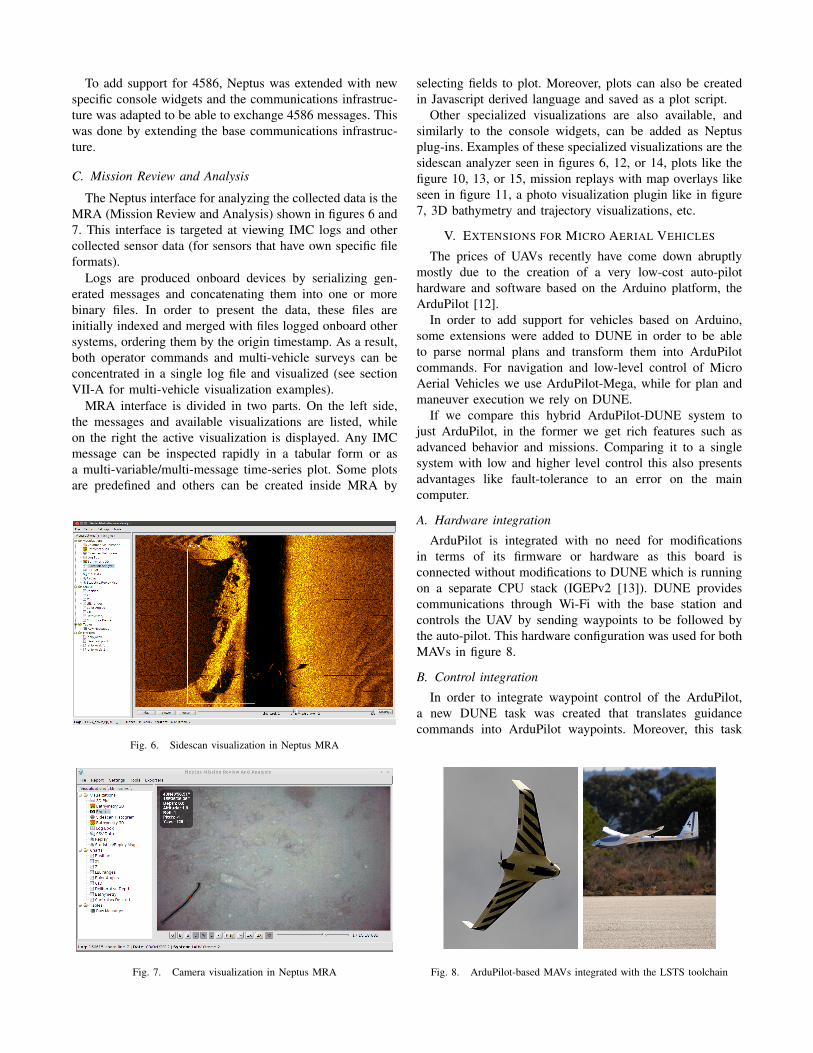
ArduPilot is integrated with no need for modificationsin terms of its firmware or hardware as this board isconnected without modifications to DUNE which is runningon a separate CPU stack (IGEPv2 [13]). DUNE providescommunications through Wi-Fi with the base station andcontrols the UAV by sending waypoints to be followed bythe auto-pilot. This hardware configuration was used for bothMAVs in figure 8.
B. Control integration
In order to integrate waypoint control of the ArduPilot,a new DUNE task was created that translates guidancecommands into ArduPilot waypoints. Moreover, this task
Fig. 8. ArduPilot-based MAVs integrated with the LSTS toolchain
also translates between ArduPilot telemetry data and cor-responding IMC messages.
Since the integration was done at the guidance level, allplans / maneuvers that use guidance commands to controlthe underlying hardware can still be used.
VI. EXTENSIONS FOR ONBOARD DELIBERATIVEPLANNING
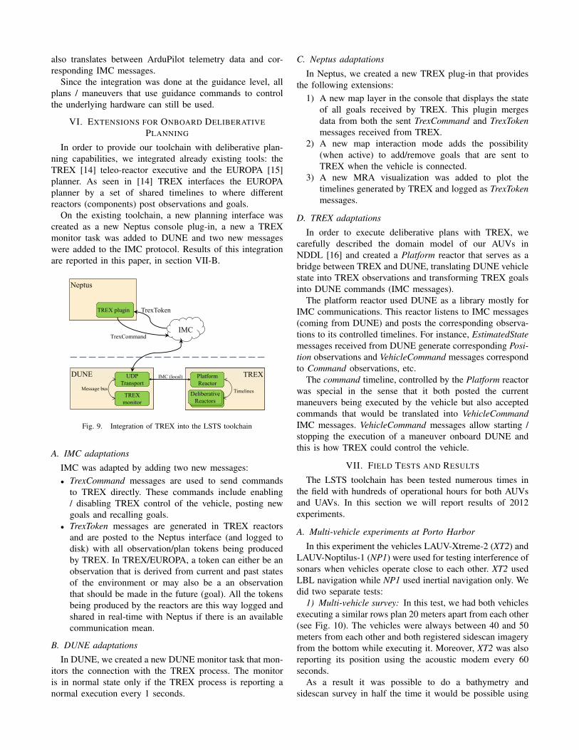
In order to provide our toolchain with deliberative plan-ning capabilities, we integrated already existing tools: theTREX [14] teleo-reactor executive and the EUROPA [15]planner. As seen in [14] TREX interfaces the EUROPAplanner by a set of shared timelines to where differentreactors (components) post observations and goals.
On the existing toolchain, a new planning interface wascreated as a new Neptus console plug-in, a new a TREXmonitor task was added to DUNE and two new messageswere added to the IMC protocol. Results of this integrationare reported in this paper, in section VII-B.
Neptus Neptus
TREX plugin TREX plugin
IMC
TrexToken
DUNE DUNE
TREX
monitor
TREX
monitor
TREX TREX Platform
Reactor
Platform
Reactor
UDP
Transport
UDP
Transport
Deliberative
Reactor
Deliberative
Reactor
Message bus Timelines
Deliberative
Reactors
IMC (local)
TrexCommand
Deliberative
Reactors
Fig. 9. Integration of TREX into the LSTS toolchain
A. IMC adaptations
IMC was adapted by adding two new messages:• TrexCommand messages are used to send commands
to TREX directly. These commands include enabling/ disabling TREX control of the vehicle, posting newgoals and recalling goals.
• TrexToken messages are generated in TREX reactorsand are posted to the Neptus interface (and logged todisk) with all observation/plan tokens being producedby TREX. In TREX/EUROPA, a token can either be anobservation that is derived from current and past statesof the environment or may also be a an observationthat should be made in the future (goal). All the tokensbeing produced by the reactors are this way logged andshared in real-time with Neptus if there is an availablecommunication mean.
B. DUNE adaptations
In DUNE, we created a new DUNE monitor task that mon-itors the connection with the TREX process. The monitoris in normal state only if the TREX process is reporting anormal execution every 1 seconds.
C. Neptus adaptations
In Neptus, we created a new TREX plug-in that providesthe following extensions:
1) A new map layer in the console that displays the stateof all goals received by TREX. This plugin mergesdata from both the sent TrexCommand and TrexTokenmessages received from TREX.
2) A new map interaction mode adds the possibility(when active) to add/remove goals that are sent toTREX when the vehicle is connected.
3) A new MRA visualization was added to plot thetimelines generated by TREX and logged as TrexTokenmessages.
D. TREX adaptations
In order to execute deliberative plans with TREX, wecarefully described the domain model of our AUVs inNDDL [16] and created a Platform reactor that serves as abridge between TREX and DUNE, translating DUNE vehiclestate into TREX observations and transforming TREX goalsinto DUNE commands (IMC messages).
The platform reactor used DUNE as a library mostly forIMC communications. This reactor listens to IMC messages(coming from DUNE) and posts the corresponding observa-tions to its controlled timelines. For instance, EstimatedStatemessages received from DUNE generate corresponding Posi-tion observations and VehicleCommand messages correspondto Command observations, etc.
The command timeline, controlled by the Platform reactorwas special in the sense that it both posted the currentmaneuvers being executed by the vehicle but also acceptedcommands that would be translated into VehicleCommandIMC messages. VehicleCommand messages allow starting /stopping the execution of a maneuver onboard DUNE andthis is how TREX could control the vehicle.
VII. FIELD TESTS AND RESULTS
The LSTS toolchain has been tested numerous times inthe field with hundreds of operational hours for both AUVsand UAVs. In this section we will report results of 2012experiments.
A. Multi-vehicle experiments at Porto Harbor
In this experiment the vehicles LAUV-Xtreme-2 (XT2) andLAUV-Noptilus-1 (NP1) were used for testing interference ofsonars when vehicles operate close to each other. XT2 usedLBL navigation while NP1 used inertial navigation only. Wedid two separate tests:
1) Multi-vehicle survey: In this test, we had both vehiclesexecuting a similar rows plan 20 meters apart from each other(see Fig. 10). The vehicles were always between 40 and 50meters from each other and both registered sidescan imageryfrom the bottom while executing it. Moreover, XT2 was alsoreporting its position using the acoustic modem every 60seconds.
As a result it was possible to do a bathymetry andsidescan survey in half the time it would be possible using
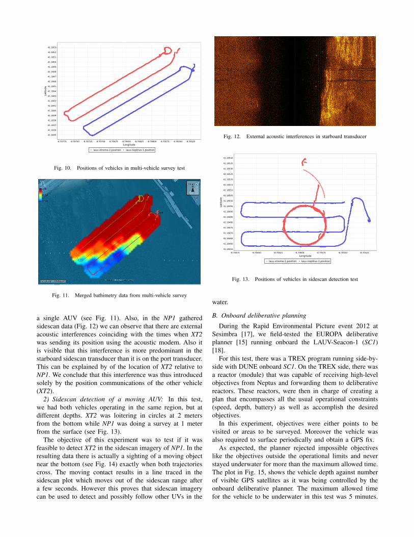
Fig. 10. Positions of vehicles in multi-vehicle survey test
Fig. 11. Merged bathimetry data from multi-vehicle survey
a single AUV (see Fig. 11). Also, in the NP1 gatheredsidescan data (Fig. 12) we can observe that there are externalacoustic interferences coinciding with the times when XT2was sending its position using the acoustic modem. Also itis visible that this interference is more predominant in thestarboard sidescan transducer than it is on the port transducer.This can be explained by of the location of XT2 relative toNP1. We conclude that this interference was thus introducedsolely by the position communications of the other vehicle(XT2).
2) Sidescan detection of a moving AUV: In this test,we had both vehicles operating in the same region, but atdifferent depths. XT2 was loitering in circles at 2 metersfrom the bottom while NP1 was doing a survey at 1 meterfrom the surface (see Fig. 13).
The objective of this experiment was to test if it wasfeasible to detect XT2 in the sidescan imagery of NP1. In theresulting data there is actually a sighting of a moving objectnear the bottom (see Fig. 14) exactly when both trajectoriescross. The moving contact results in a line traced in thesidescan plot which moves out of the sidescan range aftera few seconds. However this proves that sidescan imagerycan be used to detect and possibly follow other UVs in the
Fig. 12. External acoustic interferences in starboard transducer
Fig. 13. Positions of vehicles in sidescan detection test
water.
B. Onboard deliberative planning
During the Rapid Environmental Picture event 2012 atSesimbra [17], we field-tested the EUROPA deliberativeplanner [15] running onboard the LAUV-Seacon-1 (SC1)[18].
For this test, there was a TREX program running side-by-side with DUNE onboard SC1. On the TREX side, there wasa reactor (module) that was capable of receiving high-levelobjectives from Neptus and forwarding them to deliberativereactors. These reactors, were then in charge of creating aplan that encompasses all the usual operational constraints(speed, depth, battery) as well as accomplish the desiredobjectives.
In this experiment, objectives were either points to bevisited or areas to be surveyed. Moreover the vehicle wasalso required to surface periodically and obtain a GPS fix.
As expected, the planner rejected impossible objectiveslike the objectives outside the operational limits and neverstayed underwater for more than the maximum allowed time.The plot in Fig. 15, shows the vehicle depth against numberof visible GPS satellites as it was being controlled by theonboard deliberative planner. The maximum allowed timefor the vehicle to be underwater in this test was 5 minutes.
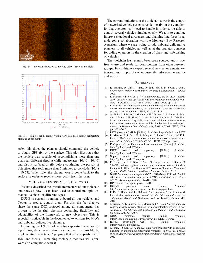
Fig. 14. Sidescan detection of moving AUV (trace on the right)
Fig. 15. Vehicle depth against visible GPS satellites during deliberatibeplanning experiments
After this time, the planner should command the vehicleto obtain GPS fix, at the surface. This plot illustrates thatthe vehicle was capable of accomplishing more than onegoals (at different depths) while underwater (10:40 - 10:46)and also it surfaced briefly before continuing the pursuit ofobjectives that took more than 5 minutes to conclude (10:48- 10:58). When idle, the planner would come back to thesurface in order to receive more goals from the user.
VIII. CONCLUSIONS AND FUTURE WORK
We have described the overall architecture of our toolchainand showed how it can been used to control multiple un-manned vehicles of different types.
DUNE is currently running onboard all our vehicles andNeptus is used to control them. For this, the fact that weshare the same IMC protocol among all components hasproven to be the right decision concerning flexibility andadaptability of the framework to new objectives. This isespecially noticeable in the documented extensions for MAVsand onboard deliberative planning.
Extending the LSTS toolchain for supporting new controlalgorithms, data visualizations or hardware is possible byimplementing new tasks / plug-ins that are compatible withIMC and then all remaining toolchain modules will after-wards be compatible with it.
The current limitations of the toolchain towards the controlof networked vehicle systems reside mostly on the complex-ity that operators still need to handle in order to be able tocontrol several vehicles simultaneously. We aim to continueimprove situational awareness and planning interfaces in anundergoing collaboration with the Monterey Bay ResearchAquarium where we are trying to add onboard deliberativeplanners to all vehicles as well as at the operator consolesfor aiding operators in the creation of plans and safe taskingof vehicles.
The toolchain has recently been open sourced and is nowfree to use and ready for contributions from other researchgroups. From this, we expect several new requirements, ex-tensions and support for other currently unforeseen scenariosand results.
REFERENCES
[1] R. Martins, P. Dias, J. Pinto, P. Sujit, and J. B. Sousa, MultipleUnderwater Vehicle Coordination for Ocean Exploration. IJCAI,2009.
[2] R. Martins, J. B. de Sousa, C. Carvalho Afonso, and M. Incze, “REP10AUV: shallow water operations with heterogeneous autonomous vehi-cles,” in OCEANS, 2011 IEEE-Spain. IEEE, 2011, pp. 1–6.
[3] R. Martins, “Disruption/delay tolerant networking with low-bandwidthunderwater acoustic modems,” in Autonomous Underwater Vehicles(AUV), 2010 IEEE/OES. IEEE, 2010, pp. 1–5.
[4] A. Tinka, S. Diemer, L. Madureira, E. Marques, J. B. Sousa, R. Mar-tins, J. Pinto, J. E. Silva, A. Sousa, P. Saint-Pierre et al., “Viability-based computation of spatially constrained minimum time trajectoriesfor an autonomous underwater vehicle: implementation and experi-ments,” in American Control Conference, 2009. ACC’09. IEEE, 2009,pp. 3603–3610.
[5] LSTS group on GitHub. [Online]. Available: https://github.com/LSTS[6] R. Martins, P. S. Dias, E. R. Marques, J. Pinto, J. Sousa, and F. L.
Pereira, “IMC: A communication protocol for networked vehicles andsensors,” in OCEANS 2009-EUROPE. IEEE, 2009, pp. 1–6.
[7] IMC protocol specification and documentation. [Online]. Available:https://github.com/LSTS/imc
[8] DUNE source code repository. [Online]. Available:https://github.com/LSTS/dune
[9] Neptus source code repository. [Online]. Available:https://github.com/LSTS/neptus
[10] R. Goncalves, P. S. Dias, J. Pinto, G. Goncalves, and J. Sousa, “ASTANAG 4586 compliant command and control operational interfacefor multiple UAVs,” in Humous 2010 Humans Operating UnmannedSystems, ISAE - Toulouse, ONERA - Toulouse, France, 2010.
[11] NATO Standardization Agency (NSA), “STANAG 4586 ed. 2.5 feb2007 draft,” in Standard Interfaces of UAV Control System (UCS) forNATO UAV Interoperability. NATO, 2007.
[12] DIY Drones, “Ardupilot project,” 2011.[13] IGEPv2 processor board. [Online]. Available:
http://www.isee.biz/products/processor-boards/igepv2-board[14] F. Py, K. Rajan, and C. McGann, “A Systematic Agent Framework
for Situated AutonomousSystems,” in 9th International Conf. onAutonomous Agents and Multiagent Systems, Toronto, Canada, May2010.
[15] J. Bresina, A. K. Jonsson, P. H. Morris, and K. Rajan, “Mixed-initiativeconstraint-based activity planning for mars exploration rovers,” in Pro-ceedings of 4th International Workshop on Planning and Schedulingfor Space (IWPSS), 2004.
[16] NDDL reference manual. [Online]. Available:https://code.google.com/p/europa-pso/wiki/NDDLReference
[17] REP12 experiment web site. [Online]. Available:https://whale.fe.up.pt/rep12/
[18] J. Pinto, J. Sousa, F. Py, and K. Rajan, “Experiments with deliberativeplanning on autonomous underwater vehicles,” in IROS 2012 Work-shop on Robotics for Environmental Monitoring, Vilamoura, Portugal,2012.