the ion funnel: theory, implementations, and applications
TRANSCRIPT

The Ion Funnel: Theory, Implementations, and Applications
Ryan T. Kelly, Aleksey V. Tolmachev, Jason S. Page, Keqi Tang, and Richard D. Smith*
Biological Sciences Division, Pacific Northwest National Laboratory, P.O. Box 999, Richland, WA99352
AbstractThe electrodynamic ion funnel has enabled the manipulation and focusing of ions in a pressureregime (0.1 to 30 Torr) that has challenged traditional approaches, providing the basis for muchgreater mass spectrometer ion transmission efficiencies. The initial ion funnel implementationsaimed to efficiently capture ions in the expanding gas jet of an electrospray ionization source andradially focus them for efficient transfer through a conductance limiting orifice. We review theimprovements in fundamental understanding of ion motion in ion funnels, the evolution in itsimplementations that have brought the ion funnel to its current state of refinement, as well asapplications of the ion funnel for purposes such as ion trapping, ion cooling, low pressureelectrospray, and ion mobility spectrometry.
Keywordsion optics; rf focusing; ion guide; multipole ion guide; stacked ring ion guide; ESI
I. INTRODUCTIONThe prominent and rapidly expanding role of mass spectrometry (MS) in the physical andbiological sciences can be attributed in part to the versatility afforded by the growing catalogof available ionization methods. Many ionization techniques of increasing importanceoperate at elevated or atmospheric pressure, including electrospray ionization (ESI) (Fenn etal., 1990), atmospheric pressure matrix-assisted laser desorption/ionization (AP MALDI)(Creaser & Ratcliffe, 2006), and desorption electrospray ionization (DESI) (Takats et al.,2004). To achieve the maximum possible sensitivity, ions created at higher pressures mustbe transmitted with high efficiency through narrow, conductance limiting apertures thatseparate differentially pumped vacuum chambers prior to reaching the high vacuum regionof the mass analyzer. The extent to which the motion of ions can be controlled in thesedifferent vacuum stages largely determines the overall ion transmission efficiency of themass spectrometer.
In the absence of background gas molecules (e.g., high vacuum), ions can be manipulatedwith extreme precision and in a well understood fashion using magnetic and electric fields.At elevated pressures, collisions with gas molecules increasingly dominate the behavior ofion motion. Such collisions have been successfully exploited at lower pressures (∼10 mTorr)since at least the early 1990s, where collisional ion focusing within rf-only multipolesensures efficient transmission to high vacuum (Thomson, 1998). At higher pressures (∼1Torr and above), it becomes much more challenging to control ion motion over larger areasor volumes, particularly in the presence of strong gas dynamic effects that typically occur inthe first vacuum stage of a mass spectrometer, as conventional ion optics become ineffective
*Corresponding Author. email: [email protected] .
NIH Public AccessAuthor ManuscriptMass Spectrom Rev. Author manuscript; available in PMC 2011 March 1.
Published in final edited form as:Mass Spectrom Rev. 2010 ; 29(2): 294–312. doi:10.1002/mas.20232.
NIH
-PA Author Manuscript
NIH
-PA Author Manuscript
NIH
-PA Author Manuscript

at these higher pressures. For example, the high rate of collisions inhibits effective focusingwith static lens stacks, and rf-only multipoles exhibit either an acceptance area that is toosmall to efficiently capture ions from an expanding gas jet (for small inscribed radius) or aneffective potential that is too weak to focus ions to a narrow conductance-limiting aperture(for large inscribed radius). As a result, nearly all commercial mass spectrometers haveconventionally employed a skimmer as a conductance-limiting orifice to separate the firstand the second vacuum chambers, which samples only a small fraction of the ion cloud andcreates a major sensitivity bottleneck for MS.
The ion funnel was originally implemented in our laboratory (Shaffer et al., 1997) as areplacement for the ion transmission-limited skimmer, seeking to efficiently capture ionsentering the first (rough pumped) vacuum stage from an ESI source to ensure their nearlossless transmission through a conductance-limiting orifice. Since its creation, the ionfunnel has been adapted for a variety of uses and has proven to be a broadly applicable toolfor ion focusing and manipulation at elevated pressures that challenge conventionalapproaches. Although it has undergone several iterations since it was conceived, thedefining features of the ion funnel are a series of closely spaced ring electrodes whose innerdiameters gradually decrease, serving to radially confine ions as they pass through. Out-of-phase rf potentials are applied to adjacent electrodes, and a dc gradient is typically appliedalong the axis of the ion funnel to drive ions through the device.
In this review, we describe the concept of the ion funnel and detail the improvements inhardware design that have led to dramatically improved performance, as well as thecomputer modeling that has provided a clearer understanding of ion funnel operation. Theapplications of the ion funnel are then discussed, which not only encompass the original aimof improving ion transmission through ESI-MS interfaces, but also include ion mobilityspectrometry (IMS), ion cooling for nuclear physics applications, low-pressure electrospray,ion trapping and more. We also briefly discuss other related ion optic designs andapproaches that seek to achieve similar results as the ion funnel.
II. PRINCIPLE OF OPERATIONThe ion funnel is related to the stacked ring rf ion guide (Gerlich, 1992), which consists of aseries of cylindrical ring electrodes of fixed i.d. (Figure 1). Radio frequency potentials ofopposite polarity are applied on adjacent electrodes. The arrangement creates an effectivepotential (also called pseudo-potential) that radially confines ions inside the ion guide. Theeffective potential, V*, expressed in Volts, is proportional to the squared amplitude of thelocal rf electric field Erf (Dehmelt, 1967; Gerlich, 1992):
(1)
Here zi and e are ion charge state and elementary charge, respectively, m is the ion mass inSI units, and ω is the rf frequency f expressed in angular units, ω = 2π f. The radial and axialpositions are represented by r and z, respectively (Figure 1). The stacked ring geometrygenerates the electric field configuration that corresponds to the following effective potentialspatial distribution (Gerlich, 1992;Tolmachev et al., 2000):
(2)
Kelly et al. Page 2
Mass Spectrom Rev. Author manuscript; available in PMC 2011 March 1.
NIH
-PA Author Manuscript
NIH
-PA Author Manuscript
NIH
-PA Author Manuscript

(3)
Vtrap is the axial effective potential well depth; Vmax is the maximum value of the effectivepotential at r = ρ, z = d(i+1/2), i=0,1,…; d is the spacing between the ring electrodes; I0, I1are zero and 1st order modified Bessel functions, respectively; δ = d/π; Vrf is one half of thepeak-to-peak rf amplitude. The stacked ring rf ion guide creates an effective potentialdistribution that corresponds to a steep potential gradient near the electrodes and a near fieldfree region over most of the internal volume.
The ion funnel was based on the stacked ring rf ion guide, but utilized ring electrodes withprogressively smaller i.d.’s, enabling the spatially dispersed ion cloud entering the ionfunnel to be efficiently focused to a much smaller radial size for efficient transfer throughthe conductance limiting orifice at the exit (Shaffer et al., 1997). The device was originallyintended for operation in the high pressure region of the ESI-MS interface, typically 1 to 10Torr, compared to pressures below 0.1 Torr used previously with stacked ring ion guidesand in general with rf ion guides of any geometry. Another important new feature of the ionfunnel was the dc potential gradient applied to the ring electrodes to drive ions along theaxis, which provided added control relative to relying solely on gas dynamic effects (Shafferet al., 1999). This feature took advantage of the fact that the stacked ring ion guide geometryis naturally “segmented” in the axial direction, in contrast to the axial continuity of standardmultipoles. Multiple studies of the ion funnel have explored the properties of the ion funnelin various applications, as reviewed in the sections below.
III. EVOLUTION OF THE ION FUNNELWhile the ion funnel concept continues to be adapted to a growing number of applications(see Section IV), its original and most prevalent use has been to decrease the ion losses thatoccur in the interface of high pressure ion sources of mass spectrometers. In this section, thesuccessive refinements that have been applied to the ion funnel over the past decade toincrease ESI-MS sensitivity are detailed. Other devices that aim to employ rf focusing forthe same purpose are reviewed as well.
A. Hardware ImprovementsThe first published ion funnel design (Shaffer et al., 1997), shown in Figure 2, consisted of28 electrodes (rings, lenses) that decreased in i.d. from 22 mm to 1.0 mm. Each of the ionfunnel rings was 1.59 mm thick, and the ceramic spacers inserted between them had thesame thickness. Carbon resistors were soldered between neighboring electrodes to enable alinear dc potential gradient, and capacitors were utilized to decouple the rf and dc powersources. Initial coupling of this ion funnel with a mass spectrometer demonstrated >10-foldsignal gains relative to the unmodified instrument, but a significant m/z bias in the massspectra was evident. For example, while dramatic gains in sensitivity were observed forpeaks between m/z 800 and 1000, peaks below m/z 750 and above m/z 1250 were almostcompletely rejected. This relatively narrow transmission window could be shifted to higheror lower values by varying the applied rf potentials, but simultaneous ion transmission overa broad m/z range was not possible with this design.
Computational modeling (see Section IIIB) indicated that the m/z-dependent iontransmission behavior of the initial ion funnel was due to pronounced axial rf potential wellsthat form at the exit of the ion funnel when the orifice is small relative to the interelectrode
Kelly et al. Page 3
Mass Spectrom Rev. Author manuscript; available in PMC 2011 March 1.
NIH
-PA Author Manuscript
NIH
-PA Author Manuscript
NIH
-PA Author Manuscript

spacing (Shaffer et al., 1999). Therefore, in the subsequent prototype the i.d. of the final ionfunnel ring was increased from 1.0 mm to 2.0 mm (Shaffer et al., 1999). This small designmodification significantly reduced ion transmission biases, but maximum signalenhancement was still achieved when the rf amplitude was optimized for each analyte. Sincethe optimum rf amplitude was found to increase approximately linearly with increasing m/z,the authors sought to further broaden the transmission window using a linked scan of rfvoltage with the quadrupole mass analyzer. Using this approach the charge state distributionfor a model protein was found to be very similar to that obtained with the skimmer interface,but with more than an order of magnitude intensity increase. Despite its effectiveness, linkedscanning of the rf potential with the mass analyzer has some notable limitations. Theapproach is only applicable to certain mass analyzers such as those employing quadrupolemass filters, and cannot be applied to other mass analyzers for which ion introduction andanalysis are decoupled. Further, because ion activation also increases with increasing rfvoltage, ion fragmentation can occur at high rf, leading to artifacts in the mass spectra.
To overcome these difficulties, Kim et al. (2000a) developed a new design that, aside from afew noteworthy modifications that have since been incorporated, closely resembles ionfunnels that are currently in use. The electrodes were made from 0.5-mm-thick brass plates,and the dielectric spacers inserted in between electrodes were 0.5-mm-thick patternedTeflon sheets. Each of the brass plates had tabs that were used for electrical connection viazero-insertion-force (ZIF) sockets. A custom-made circuit board with a resistor chain wasmounted onto a ZIF socket to provide the dc gradient. On the other side of the funnel, asecond ZIF socket was connected to a circuit board with two capacitor networks forproviding rf to each electrode, with neighboring plates 180° out of phase from one another.The total number of electrodes increased from 28 to 100 for the new design, with the first 55electrodes having a constant i.d. of 25.4 mm, and the final 45 electrodes tapering in uniformsteps to a 1.5-mm-i.d. conductance-limiting electrode. The fixed-diameter section increasedresidence time to enhance droplet and cluster desolvation, and also helped to disperse thedirected gas flow from the inlet capillary prior to reaching the ion funnel exit. Whilepartially effective, enhanced pumping was still needed; a high speed roots pump wasconnected to the ion funnel chamber, and an additional turbo pump was used in the octopoleregion of the mass spectrometer. Because of the closer spacing between neighboringelectrodes relative to the i.d. of the exit plate, the axial pseudopotential well depth that hadhindered transmission of low m/z species was further reduced, such that it was no longernecessary to scan the rf voltage with the quadrupole to achieve broad, unbiased m/ztransmission. This was fortunate, not only for simplifying the supporting electronics, butbecause the ion funnel could be more broadly applied beyond mass filter-based instruments.For example, this design was used in the first implementation of the ion funnel with anFTICR instrument (Belov et al., 2000a; Belov et al., 2000b), and helped to achieve thelowest detection limits reported to date for ESI-MS (∼30 zmol or ∼18,000 molecules).
Early work with the ion funnel recognized that due to gas dynamic effects the pressure in theion funnel vacuum chamber was not uniform; the effective pressure at the ion funnel exitwas estimated to be 2–3 times higher than the value recorded at the pressure gauge (Shafferet al., 1998), leading to increased pumping requirements in downstream vacuum chambers.This was because although the expanding supersonic gas jet entering the chamber terminatesat the Mach disk just a few mm from the capillary exit, a significant amount of directed flowpersists a much greater distance (Douglas & French, 1988; Tejeda et al., 1996), even to theexit of the ion funnel. Efforts to reduce these effects such as increasing the length of the ionfunnel by adding a fixed width drift region (Kim et al., 2000a) were only partiallysuccessful; additional high speed pumps were required in all previous designs. This directedgas flow became especially problematic as efforts to increase ion transmission into the ionfunnel chamber led to the use of larger i.d. (Kim et al., 2000a) or multiple (Kim et al.,
Kelly et al. Page 4
Mass Spectrom Rev. Author manuscript; available in PMC 2011 March 1.
NIH
-PA Author Manuscript
NIH
-PA Author Manuscript
NIH
-PA Author Manuscript

2000b) inlets, creating correspondingly greater gas loads. Kim, et al. (2001) developed aneffective approach to mitigate these gas dynamic effects by disrupting the gas flow in the ionfunnel. A 9-mm-diameter brass disk, termed the “jet disrupter” electrode, was suspendedperpendicular to the gas flow in the center of the ion funnel, 22 mm downstream of the firstion funnel electrode to effectively block the “line of sight” between the inlet and theconductance limit. The jet disrupter was suspended by two thin wires connected to a ringelectrode, which allowed a dc voltage to be applied with no rf. By biasing the jet disrupter∼5 V above adjacent ring electrodes, ions were deflected around the electrode while the gasmolecules were effectively dispersed and evacuated by the pump on the ion funnel chamber.Current measurements made using a 7-capillary heated inlet and an ion funnel with andwithout the jet disrupter indicated that ion transmission efficiency was preserved when thejet disrupter was used. Importantly, for a given inlet/pump configuration in the ion funnelchamber, the pressure in the subsequent vacuum chamber was 2–3 times lower when the jetdisrupter was employed. This allowed for greater conductance into the ion funnel with ahigh speed pumping configuration, or alternatively made it possible to operate the ion funnelwith a lower pumping speed system. In this work the sensitivity gains for both a 7-capillaryinlet and a custom-built orifice inlet having a counter-flow of nitrogen gas were alsomeasured. The interfaces had a similar conductance and produced similar increases inintensity relative to the standard instrument setup. In addition, S/N was compared betweenthe ion funnel-modified designs and the standard interface. The ion funnel did not increaseS/N for MS-only measurements for which “chemical noise” dominated, as the signal frominterfering species increased in proportion to the analyte signal, but a clear improvementwas shown for MS/MS analyses where such species were removed.
More recently, Page et al. (2007) interfaced an ion funnel with both Thermo LTQ linear iontrap and LTQ-FT hybrid instruments, enabling a direct comparison of performance with theunmodified instruments for proteomics analyses. This version was similar to that initiallydeveloped by Kim et al. (2000a), but incorporated refinements in design and fabrication thathad been made over time, including a jet disrupter electrode, as shown in Figure 2. Theelectrode rings were created by electrical discharge machining rather than boring a taperedhole through a stack of electrodes, which improved reproducibility and eliminated the needfor manually removing burrs from each plate. The jet disrupter enabled the standard roughpump supplied with the LTQ to maintain the ion funnel chamber at a useful pressure (∼1.3Torr). With the latest design incorporated onto LTQ ion trap instruments, the authors foundthat the accumulation time required to “fill” the trap was reduced by 90%. For MS-onlyexperiments, the effect on instrument performance was minimal, as the fill time accountedfor a relatively small portion of the overall duty cycle; however, MS/MS experimentsrequired longer ion accumulation times for the selected ions, and the ion funnel provided asignificant benefit. For example, for the smallest samples (0.3 μg) of S. Oneidensis trypticdigest analyzed by LC-MS/MS, the ion funnel-modified LTQ produced twice the number ofpeptide identifications relative to the standard instrument. Figure 3 compares base peakchromatograms of the S. Oneidensis digest obtained using the LTQ with (A) a standardskimmer interface and (B) an ion funnel interface. Not only is the dramatic (∼7-fold)sensitivity increase apparent when the ion funnel is employed, but the similar profiles in thechromatograms and mass spectra (Figures 3C and 3D) highlight the absence of m/z bias inion transmission. The ion funnel was also evaluated in a LTQ-FT hybrid ion trap-FTICRinstrument. Because of the greater ion populations utilized by the hybrid instrument(requiring longer ion accumulation times), the ion funnel provided a larger improvement induty cycle (∼25– 55%) than for the standalone ion traps.
Kelly et al. Page 5
Mass Spectrom Rev. Author manuscript; available in PMC 2011 March 1.
NIH
-PA Author Manuscript
NIH
-PA Author Manuscript
NIH
-PA Author Manuscript

B. Insights from Theoretical ModelingAt pressures exceeding 1 Torr, with ion mean free paths on the order of 1 μm, the largenumber of ion-neutral collisions results in ion motion that can no longer be described by thegoverning equations in vacuum that are regularly applied for dc and rf ion optics design.Also, the ion funnel generally utilizes an axial dc electric field to facilitate ion motionthrough the dense gas medium, an approach essentially new for rf ion guides when firstimplemented (Shaffer et al., 1997). Ion funnel development was thus accompanied bycomputer modeling that enhanced the understanding of ion optical properties and guidedrefinements in design. The first report on the initial ion funnel prototype included results ofsimulations performed with a users program written for SIMION (Scientific InstrumentServices, Ringoes, NJ) to model the effects of rf fields and viscous damping of gases(Shaffer et al., 1997). The approach, though qualitative, provided a picture of ion motiongoverned by a combination of effective rf focusing, the axial dc field and the viscousdamping forces from the bath gas. The observed narrow m/z window of the originalprototype (Shaffer et al., 1997; Shaffer et al., 1998) was initially difficult to interpret,however, as the simplified computer model available at the time suggested 100% iontransmission efficiency for m/z as low as 18 for a wide range of rf, dc and pressureconditions modeled (Shaffer et al., 1997).
To improve the ion funnel performance, it was necessary to develop an adequate theoreticalunderstanding of its ion transmission properties. The effort began with the creation of acomputer model that was capable of a realistic representation of all major aspects of the ionfunnel operation (Tolmachev et al., 2000). The model was created based on previouslydeveloped modeling and theoretical approaches for collisional cooling and focusing rf ionguides (Douglas & French, 1992; Dodonov et al., 1997; Tolmachev et al., 1997). Four majorcomponents were considered. First, the damping action of the ion-neutral collisions wasincluded at the quantitative level, based upon experimental and theoretical studies ofcollisional cooling. Second, a realistic model of the random component of the ion-neutralcollisions was incorporated; the process was previously found to be essential for obtaining acorrect scale of the ion focusing in collisional focusing ion guides (Tolmachev et al., 1997).Third, rf focusing was simulated at the rf ion motion time scale, rather than using aneffective potential approximation. This detailed level of ion motion simulations requiredsub-microsecond time steps, which greatly increased computation time. However, modelingthe fast rf motion of ions was necessary to correctly predict low m/z ion transmissionbehavior and also to quantitatively describe ion losses in the narrow ion funnel exit. Evenmore important, a realistic behavior with respect to gas pressure could only be obtainedwhen the ion motion was simulated completely, down to the scale of rf oscillations. Finally,the new model included a simulation of the coulombic ion-ion interactions, which definedthe spatial distribution of ions inside the ion funnel and was found to be critical for obtainingcorrect ion transmission characteristics. The space charge forces were simulated using themacro-ion multi-particle approach (Tolmachev et al., 2000), which further increased thecomputational intensity of the model.
The model demonstrated behavior consistent with the experimental results (Shaffer et al.,1999), such that the reduced ion transmission efficiency and m/z-dependent optimum rfvoltage were reproduced. The model showed that ions can be trapped in effective potentialwells created along the ion funnel axis at z-positions corresponding to each exit ringelectrode. The axial wells trap ions in an m/z-dependent fashion, creating the undesired m/z-dependent transmission behavior. In other words, the traps are filled with ions until fullycompensated by space charge potential, which creates radial fields, resulting in the ionejection and loss in the radial direction. This led to the increase in exit ring diameters from 1mm to 2 mm (Shaffer et al., 1999). While this increase in diameter indeed reduced theunwanted axial potential traps, the trapping effect was still quite severe, as seen from the
Kelly et al. Page 6
Mass Spectrom Rev. Author manuscript; available in PMC 2011 March 1.
NIH
-PA Author Manuscript
NIH
-PA Author Manuscript
NIH
-PA Author Manuscript

calculated effective potential distribution for the modified configuration (Figure 4). Theeffective potential was calculated based on the rf electric field intensity Erf(r, z), computednumerically for the dimensions of the updated ion funnel using eq. (1). The largest axialwell, indicated by an arrow in Figure 4, is quite pronounced and reaches several volts inboth the radial and the axial dimensions. The calculation does not include the dc gradient,typically 10 to 30 V/cm, which should be added to the effective potential distribution toobtain the complete picture of the electric fields acting on an ion. Even with the dc fieldapplied, the traps at the exit cannot be fully compensated. The trap effective potential isinversely proportional to m/z, thus low m/z ions are subject to stronger axial trapping.However, the effective potential, eq. (1), is only applicable for sufficiently high m/z for theadiabatic approximation to be valid (Gerlich, 1992). The outcome of this limitation can beeasily observed with the model, which shows that low m/z ions acquire an increasedamplitude of rf oscillations, larger than the size of the axial traps. Such low m/z ions cannotbe trapped in the axial wells, nor can they be confined by the radial effective focusing sincethe amplitude of the rf motion becomes too high to fit into the reduced diameters of the exitring electrodes; the behavior can be termed “low m/z instability”. The combination of thesetwo effects defines the m/z-dependent ion transmission behavior observed experimentally(section IIIA).
In a separate simulation study, published after the report of the increased exit electrode i.d.(Shaffer et al., 1999), the detrimental action of the axial potential wells was independentlyconfirmed (Lynn et al., 2000). Applying the Douglas ion-neutral collisional drag coefficientmodel (Chen et al., 1997) into the SIMION ion trajectory simulation package providedinsights suggesting opening the exit rings to 2 mm i.d. to minimize axial trapping (Shaffer etal., 1999).
As discussed in section IIIA, a new ion funnel design was developed based upon anincreased level of understanding from the improved theoretical modeling. The initialexperimental results were published together with the theoretical reasoning (Kim et al.,2000a; Tolmachev et al., 2000), which is briefly summarized below. The computer modelgenerated a time-lapse sequence of ion motion for various conditions. The model clearlydemonstrated both the expected ion focusing action and the detrimental effects, such as thelow m/z instability and trapping in the exit potential wells, providing a way for an intuitiveunderstanding of operation. Eventually, a convenient quantitative description was found inthe form of relationships describing ion funnel characteristics. A set of practically usefulrelationships was obtained for conditions when the inner radius of the ring electrodes, ρ, islarge compared to the spacing between electrodes d. The effective potential, V*, dependenceon radius r can be approximated for d < r < ρ, as follows:
(4)
Here, δ = d / π. The maximum effective potential, corresponding to r = ρ, is given by
(5)
Vrf is 0 to peak amplitude of the rf voltage. The axial well depth Vtrap is given by thefollowing relationships:
Kelly et al. Page 7
Mass Spectrom Rev. Author manuscript; available in PMC 2011 March 1.
NIH
-PA Author Manuscript
NIH
-PA Author Manuscript
NIH
-PA Author Manuscript

(6)
In this equation, I0 is the modified Bessel function of the order 0, which can beapproximated by the exponent, the approximate right-hand side of (6). The relationship in(6) is very important for the ion funnel design, and more generally for any stacked ring ionguide since it provides a way to choose a correct ratio of the inner radius ρ to the spacing d,ensuring that the axial traps are sufficiently small compared to the maximum effectivepotential V *ρ. The condition can be expressed in a form of the following inequality:
(7)
The first ion funnel prototype used exit ring i.d.’s close to the spacing between electrodes,2ρ ≈ d, or even smaller. Substituting ρ/δ ≈ π/2 into equation (4), we obtain
, meaning that the axial effective potential wells are very pronounced andare nearly as intense as the maximum effective potential. Considering that the maximumpotential (5) is reached at the maximum radial position, r = ρ, which corresponds to the ionloss, it is clear that the exit section worked to stop and trap ions rather than radially focusthem.
The exponent in (6) leads to very fast decreasing of Vtrap with increasing the ratio ρ/δ.Assuming ρ = d we obtain , a favorably low axial trapping potentialconsistent with inequality (7). This simple calculation explains why the second design(Shaffer et al., 1999), which used increased i.d.’s of the exit rings, demonstrated markedlyimproved performance.
The low m/z transmission range, related to the m/z instability, can be estimated using theadiabaticity parameter relationships. The adiabaticity condition implies that there is anegligible energy exchange between the macro and micro motion of ions, making it possibleto apply the concept of effective potential (Gerlich, 1992). The condition is fulfilled whenthe amplitude of rf oscillations is small compared to the characteristic scale of rf fieldhomogeneity. Approximately, low m/z ions acquire increased amplitudes of rf oscillations,approaching inter-electrode distance. The effective potential approach is inaccurate for suchlow m/z ions; computer simulations show that such ions cannot be efficiently confined bythe rf field. As a result of this limit, the velocity of ions confined by the rf focusing is limitedby umax = d·f, which determines the low m/z cutoff for low pressure conditions. A low m/zcutoff also arises from instability in the axial traps, which is likely to occur at the ion funnelexit where apertures become small compared to d (Tolmachev et al., 2000).
Another useful relationship provides evaluation of the ion current imax, corresponding to thespace charge limit on efficient ion transmission:
(8)
Here, ε0 is the dielectric constant, τ is the ion velocity relaxation time (Tolmachev et al.,1997) related to the ion mobility K as follows: τ = m/z mu K / e, where e is elementary
Kelly et al. Page 8
Mass Spectrom Rev. Author manuscript; available in PMC 2011 March 1.
NIH
-PA Author Manuscript
NIH
-PA Author Manuscript
NIH
-PA Author Manuscript

charge and mu is the atomic unit mass. Importantly, the ion current limit (8) is inverselyproportional to the cubic power of the inter-electrode spacing d = πδ. This is due to theeffective focusing field, estimated as the derivative of the effective potential (4) by radius,being inversely proportional to d3. It follows that the spacing minimization provides a wayto greatly improve the ion funnel focusing efficiency.
The ion funnel rf frequency should be above a certain limit defined by adiabaticityrequirements, which are more stringent for the smaller spacing d. The adiabaticity parameteris inversely proportional to the rf frequency squared (Gerlich 1992), thus higher frequenciescan be used to offset the effect of reduced spacing; in practical terms, frequencies on theorder of ∼1 MHz are acceptable with the reduced spacing (Tolmachev et al., 2000). Thespacing d should not be too small due to a limitation related to the z-velocity of ions, vz: atlow pressures, <∼1 mTorr, where the mean free path is increased, ion velocities may exceedthe limit vz < d·f; thus the lower pressure operation may require larger ring spacing andhigher rf frequency (Tolmachev et al., 2000).
The reduction in electrode spacing of the current version of the ion funnel to d = 1 mm (Kimet al., 2000a) resulted in an increase in focusing power by ∼30 times over previous designs,assuming the same rf voltage and frequency, considering the cubic power proportionality ofthe maximum effective rf focusing field on d (Tolmachev, 2000). This implied a capabilityof operation at increased pressures where the effective potential is suppressed (Tolmachev etal., 1997), and for 1 Torr pressure conditions it was estimated that the effective focusing issufficient to overcome the drag force from gas flows up to sonic speeds (Tolmachev et al,2000). The ring electrode proportions, and the distribution of ions inside the ion funnel canbe seen in the simulation screen shot in Figure 5. The dependence of the ion transmissionefficiency on the amplitude of the rf voltage Vrf showed threshold-like behavior for thisdesign. As shown in Figure 6, the ion transmission was found to increase sharply atrelatively low rf voltages (∼20 Vp-p) and remain constant for a wide range of Vrf. Thesaturation level corresponded to an estimated transmission efficiency of ∼100% for analyteions. The behavior was consistent with the results of the computer model, also shown inFigure 6, which showed ion transmission reaching 100% efficiency for Vrf above a certainthreshold voltage that was dependent on parameters including m/z, rf frequency, andpressure. For Figure 6, the ion current was measured after the ion funnel exit for pressure 1Torr, input current 5 nA, frequency 0.7 MHz, axial dc field 16 V/cm. Simulations werecarried out for the same conditions; the ion current was supposed to consist of equalamounts of 1+ and 2+ gramicidin ions.
An alternative ion funnel design supported by a simulation study has been reported byJarrold and coworkers (Julian et al., 2005). An ion funnel electrode spacing of 5.6 mm wasused, together with the smallest (exit) ring electrode i.d. of 7.9 mm. The funnel was typicallyoperated at a pressure of ∼220 mTorr, but it was also used successfully at pressures rangingfrom several Torr to ∼50 mTorr. Ions with varying m/z between 75 and 3000 were passedthrough the funnel with no apparent discrimination. The study did not specify the iontransmission efficiency achieved, and no transmission profiles versus Vrf and m/z werereported. A simple method for simulating ion motion based on ion mobility (i.e., driftapproximation) and diffusion was proposed, and a guideline for the boundary between thestrong rf field and the field-free region was formulated, which is qualitatively consistentwith the effective potential approximation. The increased spacing provided a number ofpractical advantages; as mentioned in Section II, the stacked ring ion guides operating at lowpressures can use larger spacing to fulfill the condition vz < d·f for increased axial ionvelocities vz.
Kelly et al. Page 9
Mass Spectrom Rev. Author manuscript; available in PMC 2011 March 1.
NIH
-PA Author Manuscript
NIH
-PA Author Manuscript
NIH
-PA Author Manuscript

Another direction of ion funnel development that has also benefited from modeling relates toextending the range of efficient operation to higher pressures (i.e., >30 Torr), which enablesincreased ion transmission efficiency at the MS inlet. In this case, the major challengerelates to the physics of ion motion at higher pressures, where the rf oscillations of ions arein phase with the rf field. The in-phase motion is due to the drift-like behavior, generallyobserved at a macroscopic scale in ion mobility experiments, where the ion velocity isproportional to the electric field strength. This is opposed to the vacuum case, where a phaseshift is established between the rf field and the rf ion motion, which is required for theeffective potential to be non-zero (Dehmelt, 1967; Gerlich, 1992; Ibrahim et al., 2006). Aphase shift can still be developed at increased pressures if a sufficiently high rf frequency isused, ωτ >> 1 (Tolmachev et al., 1997). The theoretical and modeling results for the highpressure ion funnel were confirmed by experiments that demonstrated efficient operation atpressures up to 30 Torr using increased rf frequencies (Ibrahim et al., 2006).
C. Related RF Focusing DevicesSince the introduction of the ion funnel, a number of alternative devices have beendeveloped to perform a related function, i.e., to improve ion transmission in the highpressure interface region of the mass spectrometer. For example, Shimadzu patented axiallysegmented multipoles having an inscribed radius that converged towards the exit (Inatsugu& Waki, 2002). A conical octopole ion guide described recently (Roach et al., 2008) alsouses the converging geometry, but without axial segmentation, thus precluding theapplication of an axial dc field. Also, Thermo Fisher recently developed a stacked ring ionguide (Wouters et al., 2008) whose rf ring electrodes at the exit have a constant i.d. but areprogressively spaced to effect ion focusing. In this section we describe these devices andcontrast them with the ion funnel.
The segmented multipoles (Inatsugu & Waki, 2002) are somewhat similar to the ion funnelin their ability to produce rf ion focusing and a dc electric field to facilitate ion motion alongthe axis towards the exit of the ion guide. The converging geometry combines an increasedion acceptance area with the ability to create a tight ion beam at the exit, which is againsimilar to the ion funnel. A potential disadvantage of the multipolar, rather than the stackedring geometry, however, is that the rf focusing at the first entrance segment is significantlyreduced, due to an increased distance d between rods having opposite rf phases. Forexample, consider a segmented multipole whose inscribed radius decreases along the axis bya factor of 10, similar to commonly used ion funnel configurations that have a 25 mmentrance i.d. and a 2.5 mm exit electrode i.d. (Page et al., 2007). The effective potential isproportional to the rf electric field intensity squared, eq. (1), thus a 10-fold increased spacingd converts into a 100-fold reduced effective potential. This can greatly limit the ability tocompensate for the drag forces from intense gas flows typically occurring at the entrance ofthe ion guide in higher-pressure regions. The coulombic expansion of the ion beam willcontribute to the radial ion losses at the entrance, due to the reduced effective potential.According to the theoretical evaluation of the ion funnel (Tolmachev et al., 2000), the radialeffective field, defined as the derivative of the effective potential by radius, is responsiblefor counterbalancing the gas flow drag force and the coulombic ion expansion.Approximately, the effective field is inversely proportional to the cubic power of distance d:
(9)
The cubic dependence results from the effective potential being proportional to the rf fieldintensity squared (Gerlich, 1992); the additional factor ∼d arises when the derivative of theeffective potential is taken to obtain the effective focusing field. A factor of 10 convergencethus results in 1000 times weaker entrance rf focusing defined by the effective field if the
Kelly et al. Page 10
Mass Spectrom Rev. Author manuscript; available in PMC 2011 March 1.
NIH
-PA Author Manuscript
NIH
-PA Author Manuscript
NIH
-PA Author Manuscript

multipolar geometry is used. The issue cannot be solved by simply increasing rf voltage,since this will increase low-m/z instability at the exit. Even with an axially adjusted rfvoltage profile, the requirements for rf amplitude at the entrance would be much greater thanfor an ion funnel that uses a small, non-variable spacing d = 1 mm (Tolmachev et al., 2000).Thus, the design suffers from a finite size of the ion entrance area. Additionally, the m/ztransmission range in each segment will vary, thus limiting the overall m/z transmission.
Tapered multipoles (Roach et al., 2008) that resemble standard rf multipole ion guides butare arranged with a conical taper decreasing toward the exit have also been explored. Theseare similar in concept to the segmented multipoles described above, but lack the ability toapply a dc gradient or to apply stronger rf at the entrance to compensate for the weakerfocusing field, and as such are expected to have limited transmission efficiency. In addition,as for the above design, the m/z transmission characteristics will vary with axial location,limiting the m/z transmission range.
A variation on the ion funnel that was recently described by researchers at Thermo Fisher isthe progressively spaced stacked ring ion guide, which has demonstrated improved iontransmission relative to the standard skimmer interface of a triple quadrupole massspectrometer (Wouters et al., 2008). The prototype comprised a small number of ringelectrodes (18), similar to the original ion funnel (Shaffer et al., 1997), and incorporated twoadjacent stacked ring ion guide sections, with the first section having a larger ring diameterthan the second. In addition to decreasing the diameter of the ring electrodes part waythrough the device, the increased electrode spacing toward the exit produces an increasing rfelectric field that further focuses ions, even with constant ring electrode i.d. The design usesno dc potential gradient to drive ion transmission, relying solely on the flow of gasexpanding from the heated inlet capillary.
Unlike modern ion funnels, which capture and transmit ions with ∼100% efficiency over abroad m/z range using fixed rf voltage and frequency (Tolmachev et al., 2000), all of theabove exhibit a strong dependence of the m/z range transmitted on rf. In the Thermo design,this made it necessary to modulate the rf amplitude (by a factor of 30) in concert with thescanning of the quadrupole mass analyzer to transmit ions over a broad m/z range. Thislinked scanning approach, similar to that described for an early ion funnel prototype (Shafferet al., 1999), is most appropriate only with scanning/mass filter-based analyzers, and wouldbe ineffective with ion traps, FTICR, TOF, etc. It appears that, as with early ion funnelprototypes (Shaffer et al., 1997), the device suffers from severe axial wells in the rf effectivepotential, which form in part because of the large ratio of the electrode spacing d to the ringinscribed radius ρ (i.e., d/ρ ∼2). However, unlike the ion funnel, where such wells can beminimized by decreasing d/ρ, a strong axial field is an unavoidable consequence of theprogressive spacing. Consider conventional stacked ring ion guides and ion funnels, inwhich the constant, non-variable inter-electrode spacing creates a “local symmetry” in theaxial direction. Ring electrodes with alternating phases of rf compensate each other,enabling a strong radial effective potential with a minimal axial component. An essentiallyfield-free region begins when the distance from an electrode is ∼60% of the distancebetween the electrodes (Julian et al., 2005). With variable spacing this symmetry isdisrupted, contributing to increased axial rf electric fields. When the ratio d/ρ becomes large,> 1, the off-axis field becomes comparable to the on-axis field in between neighboringelectrodes, producing a weak radial focusing combined with an increased axial barrier. Theaxial wells can trap ions of a certain m/z range, creating the defocusing radial coulombicelectric field. Low m/z ions acquire increased amplitudes of rf oscillation and can be eitherfragmented or ejected. If not ejected, experimental artifacts can become evident in the massspectra (e.g., as multiply charged ions dissociate to yield higher m/z products).
Kelly et al. Page 11
Mass Spectrom Rev. Author manuscript; available in PMC 2011 March 1.
NIH
-PA Author Manuscript
NIH
-PA Author Manuscript
NIH
-PA Author Manuscript

All rf ion guide types used currently in mass spectrometry avoid the creation of intense rffields around the axis. Ideally, the rf focusing relies on zero rf fields at the axis, combinedwith intense rf fields at off-axis radial positions. An example of such a configuration is the rfmultipole ion guide, where rf field intensity approaches zero at the axis, due to symmetry.Reducing rf field intensity along the axis is critical for operation at pressures >1 mTorr toavoid collisional activation of ions. With the progressively spaced stacked ring ion guide, anincreased rf voltage would be required to offset relatively large interelectrode spacing,resulting in further increased intensities of rf fields around the axis, which can result incollisional activation of ions.
The authors observed a five-fold sensitivity improvement over the standard skimmerinterface (Wouters et al., 2008), which is somewhat smaller than the order-of-magnitudegains provided by the ion funnel when used for similar comparisons (Page et al., 2007).Also, it is not clear how much of the improvement was due to the stepwise decrease in ringelectrode i.d. along the axis, and what portion was derived from the progressive spacing.Our simulations of such devices using increased d/ρ ratios showed the transmission optimumdepends on conditions that are difficult to control, including gas flow velocity and ioncurrent variations. Sample simulation results in Figure 7 show the ion transmission profilessimulated for a test configuration of the progressively spaced stacked ring ion guide. For allconditions evaluated, the ion transmission was below 30% and the transmission optimumwas dependent on m/z, ion current, and gas flow velocity. In addition, the model showedmore stable operation with respect to the gas flow velocity and the ion current when an axialdc gradient was applied.
IV APPLICATIONSA. Increased transmission efficiency from elevated pressure ion sources
Having established the ability of the ion funnel to effectively transmit ions between the firstand second differentially pumped vacuum stages, researchers sought to further leverage theion funnel to reduce ion losses through the atmospheric pressure interface. Such a design,capable of high transmission efficiency from the atmospheric pressure ion source to highvacuum would enable unprecedented sensitivity and also improved quantitation, as m/z-dependent transmission biases (Lin & Sunner, 1994) would be eliminated. Severalapproaches for using the ion funnel to improve the transmission of ions from the ESI sourceinto the mass spectrometer are shown in Figure 8.
Initial efforts to increase transmission through the atmospheric pressure interface by simplyincreasing the diameter of the heated capillary inlet and adding pumping speed to the firstdifferentially pumped stage (Kim et al., 2000a) were unsuccessful due to less efficientdesolvation of the electrosprayed droplets. Also, with increasing inlet diameters the gas flowtransitions from laminar to turbulent, leading to large ion losses. To preserve the desolvationafforded by a standard inlet while increasing conductance, an interface having multiple,narrow-bore (400–500 μm i.d.) heated inlet capillaries was evaluated (Kim et al., 2000b).The use of multi-capillary inlets was made possible by the large entrance aperture of the ionfunnel. A skimmer interface, for example, would be unable to efficiently sample ionsentering the first vacuum stage significantly off-axis. The multi-capillary inlet led todramatic sensitivity gains; however, the increased conductance required the use of two high-speed pumps (Figure 8B) to maintain the appropriate downstream vacuum pressures.
To eliminate the need for high speed pumps and make possible the routine use of multi-capillary inlets, the working pressure of the ion funnel was increased to ∼30 Torr (Ibrahim etal., 2006). The previous pressure limitation on the ion funnel was due to the need for greaterrf frequency and amplitude at elevated pressures to compensate for the increased collisional
Kelly et al. Page 12
Mass Spectrom Rev. Author manuscript; available in PMC 2011 March 1.
NIH
-PA Author Manuscript
NIH
-PA Author Manuscript
NIH
-PA Author Manuscript

frequency of ions with background gas at elevated pressures and the lower effectiveconfining field (see Section IIIB). The large electrical capacitance of the ion funnelprecluded the application of greater rf; excess metal was therefore removed from theelectrodes, lowering the capacitance approximately four-fold. With the reduced capacitance,the ion funnel operated with a 1.74 MHz rf and up to 170 VP-P, and demonstrated iontransmission efficiencies at pressures as high as 30 Torr that were similar to a standard ionfunnel designed for 2 Torr. The reduced pumping requirements enabled by the higherpressure ion funnel were made possible by an additional pumping stage, as depicted inFigure 8C. Here, the additional stage was a second ion funnel immediately behind the higherpressure ion funnel. This ion funnel chamber was operated at 1.3 Torr and used a standard rffrequency and amplitude (560 kHz and 70 Vp-p). This arrangement demonstrated howmultiple ion funnels can be coupled in series with minimal ion losses to customize the inletconductance requirements, while maintaining the pressures in the downstream ion optics ofthe instrument using standard rough pumps. A five-fold sensitivity enhancement wasobserved for a single emitter used in conjunction with an 18 heated capillary inlet designcompared to when a single inlet was used.
B. Improving ionization efficiency with multi-emitter ESI sourcesThe multi-capillary inlet/ion funnel interfaces described above have also enabled newtechniques for improving ionization efficiency, which is greatly enhanced when theelectrospray is operated at low nL/min flow rates (Gale & Smith, 1993; Wilm & Mann,1994). The higher flow rates from typical capillary LC separations preclude the use of nano-ESI without wasteful post-column flow splitting (Fuh & Hsieh, 1999; Andrews et al., 2004),and operation of LC at nano-ESI-compatible flow rates (<100 nL/min) severely decreasesthe sample loading capacity and can lead to reduced system robustness (Smith et al., 2004).As an alternative, the multiple inlets developed to increase conductance into the firstvacuum stage also make possible the efficient sampling from multiple electrospray emitters,effectively reducing the flow at each emitter and producing multiple, highly efficientelectrosprays. Although multiplexed electrosprays had been demonstrated previously(Rulison & Flagan, 1993; Almekinders & Jones, 1999), the first multi-emitter designedspecifically for increased MS sensitivity used an ion funnel interface with a multi-capillaryinlet (Tang et al., 2001). The microchip-based array of 9 emitters was able to producemultiple, stable electrosprays at flows as low as 300 nL/min at each emitter. Recentadvances have increased the number of individual emitters and reduced the flow ratesaccessible to each emitter in the array (Kelly et al., 2007; Kelly et al., 2008b). A linearlyarranged 19 electrospray emitter array coupled to a 19 capillary inlet and an ion funneloperated at 18 Torr provided a ∼9-fold MS sensitivity enhancement compared to a singleelectrospray emitter/single inlet ion funnel interface (Kelly et al., 2007). The emitter arraywas comprised of fused silica capillaries that were tapered using a chemical etchingtechnique (Kelly et al., 2006) to provide high aspect ratio, externally tapered emitters, eachcapable of operating at flows as low as 20 nL/min. A 19 capillary (each 400 μm i.d.) heatedinlet was used to match each emitter in the array with an individual inlet to the ion funnel.The emitter array and ion funnel interface were tested by infusing and analyzing a bovineserum albumin (BSA) tryptic digest solution with a single emitter and the multi-emitterarray. A broad range of sensitivity improvements for the tryptic peptides was observed, from2.4- to 12.4-fold, and the differences were attributed to variable reductions in ionizationsuppression when the multi-emitter array was used; individual electrosprays were operatedat ∼50 nL/min. Reduced ion suppression was further verified by infusing a test mixturecontaining a peptide and an oligosaccharide over a range of flows with an individual emitterand the emitter array. At each common flow rate, the oligosaccharide, which is typicallyhighly suppressed due to its low surface activity (Schmidt et al., 2001), exhibited a stronger
Kelly et al. Page 13
Mass Spectrom Rev. Author manuscript; available in PMC 2011 March 1.
NIH
-PA Author Manuscript
NIH
-PA Author Manuscript
NIH
-PA Author Manuscript

relative intensity when the array was used in place of the individual emitter, as the smallerdroplets ensured more complete desolvation.
More recently, the 19 emitter array and ion funnel interface were coupled to an HPLCseparation operating at 2 μL/min to analyze human plasma tryptic digest samples (Kelly etal., 2008b). Standard proteins not found in human blood plasma were spiked into thesamples prior to digestion and analyzed by HPLC coupled to a TOF MS. Compared with asingle emitter/single inlet configuration, the multi-emitter array provided an 11-fold averageincrease in MS sensitivity for the spiked peptides, and the LC peak S/N increased ∼7-fold. Inaddition, the low dead volume of the emitter array preserved chromatographic peak shapes,such that the separation efficiency was retained. In this work, direct infusion experimentscompared the multi-emitter/multi inlet interface to the standard skimmer interface of theunmodified instrument using a mixture of standard peptides. The cumulative sensitivitygains relative to a standard skimmer interface for a peptide mixture resulting from thecombination of the multi-emitters, a multi-capillary inlet and a tandem ion funnel interface(Ibrahim et al., 2006) are shown in Figure 9. The capillary-based emitter arrays have sincebeen reconfigured to a circular arrangement to improve the inter-emitter electric fielduniformity, which can otherwise be disrupted as a result of inhomogeneous electricalshielding caused by the closely spaced emitters (Kelly et al., 2008a).
C. Subambient pressure electrosprayESI emitter arrays and multi-capillary inlets increase MS sensitivity when coupled with anion funnel interface; however, significant losses can still occur during transmission into themass spectrometer (Kelly et al., 2008a). Recently, ion funnel technology has enabled theelectrospray to be operated inside the first vacuum region of the mass spectrometer (Page etal., 2008a), completely eliminating the transmission losses that normally occur at the inlet.The new subambient pressure ionization with nanoelectrospray (SPIN) source, depicted inFigure 8D, used small (5 to 10 μm i.d.) chemically etched emitters positioned at the inlet ofan ion funnel, where both the electrospray and ion transmission occurred at 30 Torr. Thepressure was low enough to ensure effective ion funnel operation, but sufficiently high toprovide adequate droplet desolvation while avoiding electrical discharge. Initialcharacterization of the SPIN source showed stable electrosprays with a variety of LC-compatible solvents (i.e., water, methanol, and acetonitrile) at pressures ranging from 760 to25 Torr. Electrospray current profiles were obtained using an array of charge collectors andshowed that the electrospray current remained unchanged through the range of pressures,while the plume became narrower at lower pressures due to increased droplet/ion mobilities(Gamero-Castaño et al., 1998). Using two different solutions, a ∼6-fold increase insensitivity was demonstrated when the SPIN source replaced a heated capillary inletinterface, indicating that sample losses that normally occur through an inlet were eliminated,while the ionization efficiency was largely preserved. In subsequent experiments, the SPINsource was used with LC-MS to analyze a protein digest sample (Page et al., 2008b).Compared to a standard inlet, the SPIN source produced a 5–12-fold increase in sensitivityfor detected peptides, again demonstrating increased detector response through reduced ionlosses and also showing stable operation at 30 Torr for a range of solvent compositionsprovided by gradient elution LC. The SPIN source promises to be an enabling technologyfor additional novel ESI source designs.
D. Ion Mobility Spectrometry and Ion TrappingIon funnel technology has benefitted IMS instrumentation in ways that extend far beyondimproved ion transmission through the ESI interface. As we describe in this section, the ionfunnel has also been incorporated at locations along the IMS drift tube as well as at the distalend to counteract diffusion and make possible high sensitivity, high resolution IMS-MS.
Kelly et al. Page 14
Mass Spectrom Rev. Author manuscript; available in PMC 2011 March 1.
NIH
-PA Author Manuscript
NIH
-PA Author Manuscript
NIH
-PA Author Manuscript
Also, the ion funnel has been adapted to trap, store and release ions from continuous beamESI sources for maximizing the duty cycle with inherently pulsed IMS operation. Ion funneltraps (IFTs) are of broader applicability than for IMS alone, but because much of the IFTdevelopment has been applied to improving IMS duty cycle, we present the applicationsrelated to both ion trapping and IMS together in this section.
The first implementation of the ion funnel with an IMS instrument, reported by Bowers andcoworkers (Wyttenbach et al., 2001), was used to trap ions in between injections into the ionmobility drift cell, as well as to effectively transmit ions through the ESI interface. The driftcell operated at much lower pressures (0.02 Torr) and with a far shorter drift cell (4.5 cm)than subsequent designs that incorporated ion funnels, and as such, was capable of sub-millisecond separations having injection pulse rates of 1–10 kHz. With such rapid injectionsinvolving relatively small ion populations, the potential applied to the penultimate ion funnelelectrode could be modulated to accumulate ions in between pulses with a trappingefficiency of nearly 100%. The ion funnel itself was based on the original design of Shaffer,et al. (1998), but following the tapered section, two straight sections were incorporated tohelp mitigate the transmission biases of the Shaffer design. The initial characterization of theESI-IMS instrumentation used a quadrupole mass analyzer to study the thermodynamics ofpeptide hydration, perform structural analyses of biomolecules, and to measure reaction ratecoefficients. The instrument has enjoyed continued use for numerous studies; for examples,see (Gidden et al., 2004; Gidden et al., 2005; Baker et al., 2006; Liu et al., 2006; Baker &Bowers, 2007).
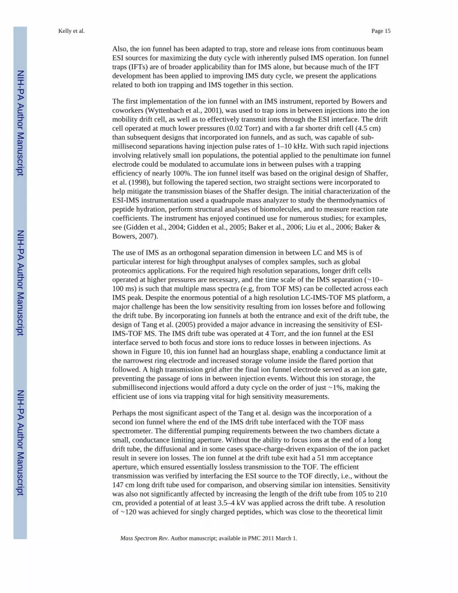
The use of IMS as an orthogonal separation dimension in between LC and MS is ofparticular interest for high throughput analyses of complex samples, such as globalproteomics applications. For the required high resolution separations, longer drift cellsoperated at higher pressures are necessary, and the time scale of the IMS separation (∼10–100 ms) is such that multiple mass spectra (e.g, from TOF MS) can be collected across eachIMS peak. Despite the enormous potential of a high resolution LC-IMS-TOF MS platform, amajor challenge has been the low sensitivity resulting from ion losses before and followingthe drift tube. By incorporating ion funnels at both the entrance and exit of the drift tube, thedesign of Tang et al. (2005) provided a major advance in increasing the sensitivity of ESI-IMS-TOF MS. The IMS drift tube was operated at 4 Torr, and the ion funnel at the ESIinterface served to both focus and store ions to reduce losses in between injections. Asshown in Figure 10, this ion funnel had an hourglass shape, enabling a conductance limit atthe narrowest ring electrode and increased storage volume inside the flared portion thatfollowed. A high transmission grid after the final ion funnel electrode served as an ion gate,preventing the passage of ions in between injection events. Without this ion storage, thesubmillisecond injections would afford a duty cycle on the order of just ∼1%, making theefficient use of ions via trapping vital for high sensitivity measurements.
Perhaps the most significant aspect of the Tang et al. design was the incorporation of asecond ion funnel where the end of the IMS drift tube interfaced with the TOF massspectrometer. The differential pumping requirements between the two chambers dictate asmall, conductance limiting aperture. Without the ability to focus ions at the end of a longdrift tube, the diffusional and in some cases space-charge-driven expansion of the ion packetresult in severe ion losses. The ion funnel at the drift tube exit had a 51 mm acceptanceaperture, which ensured essentially lossless transmission to the TOF. The efficienttransmission was verified by interfacing the ESI source to the TOF directly, i.e., without the147 cm long drift tube used for comparison, and observing similar ion intensities. Sensitivitywas also not significantly affected by increasing the length of the drift tube from 105 to 210cm, provided a potential of at least 3.5–4 kV was applied across the drift tube. A resolutionof ∼120 was achieved for singly charged peptides, which was close to the theoretical limit
Kelly et al. Page 15
Mass Spectrom Rev. Author manuscript; available in PMC 2011 March 1.
NIH
-PA Author Manuscript
NIH
-PA Author Manuscript
NIH
-PA Author Manuscript

once the ion injection pulse and the TOF spectrum acquisition frequency were accountedfor, indicating that the ion funnel at the exit of the drift tube did not measurably degradeIMS resolution. A 0.6 s analysis (10 averaged scans) showed a high quality arrival timedistribution for a 10 μM peptide solution, which verified the improved sensitivity overprevious designs.
In a subsequent study, Baker et al. (2007) replaced the ion funnels at the entrance and exit ofan 88 cm drift cell with low-capacitance ion funnels (Ibrahim et al., 2006) that were capableof efficient operation at pressures as high as 12 Torr, rather than a maximum of 4 Torr forthe previous design (Tang et al., 2005). Ignoring sources of broadening outside of the driftcell, peak resolution is proportional to the voltage drop through the cell (Asbury & Hill,2000). However, above a certain E/N, where E is the electric field and N is the numberdensity of the bath gas, ion mobilities become dependent on E/N, and measured arrival timedistributions are distorted. By increasing the operating pressure of the drift cell, higherelectric fields become accessible without the negative effects associated with exceeding thelow-field limit. The reduced capacitance allowed for increased rf frequencies, and a non-tapered section was added to the terminus of the “hourglass” ion funnel to further increasetrapping capacity. Operation at 12 Torr enabled the resolving power of the IMS separation toincrease to ∼80, compared with ∼50 at 4 Torr, without a significant loss of sensitivity.
The utility of the ion funnel for ion mobility studies was extended by Clemmer andcoworkers (Koeniger et al., 2006), who developed a highly flexible instrument capable ofseveral operational modes. Key to the design was a drift tube divided into two regions. Anhourglass-shaped ion funnel, essentially the same as that of Tang et al. (2005), was placed atthe beginning of the drift tube and was used for storing and pulsing ions into the drift tube asbefore. Two additional ion funnels were placed at the center and end of the drift tube,respectively. The final ion funnel was used for efficient transmission into the TOF and couldalso be used to induce fragmentation if desired. The center ion funnel, combined with an ionactivation region and a grid used for gating, could be used to select ions of a certain mobilityrange from the first stage of the drift tube, collisionally activate or fragment those ions, andseparate the resulting conformers or fragments according to mobility in the latter portion ofthe drift tube prior to MS. This was notably the first IMS—IMS analogue to MS—MS.
An additional benefit to incorporating ion funnels along the drift tube is that the separationlength could be made arbitrarily long without incurring large ion losses, as the broadeningion packet could be refocused multiple times without diminishing resolution. An example ofsuch a design was also described by Clemmer and coworkers (Merenbloom et al., 2006).The 290-cm-long drift tube assembly had ion funnels at the beginning and end of the drifttube, in addition to two ion funnels along the length. These additional ion funnels dividedthe drift tube into three distinct regions and made possible high resolution IMS—IMS—IMS/MS separations of proteins and peptides, and were capable of resolving many featuresthat could not be identified by MS alone.
While IMS clearly benefits from the ability of the ion funnel to trap and store ions for rapidinjection, other instruments can also take advantage of ion trapping. TOF MS is aninherently pulsed technique, with a limited duty cycle when used in conjunction with acontinuous ESI source, and Ibrahim et al. (2007) have explored an IFT for improving TOFperformance. The ion funnel trap had a unique geometry, as shown in Figure 11, thatresembled the hourglass ion funnel described by Baker et al. (2007), but included a finalsection that refocused the ions released from the trap to a conductance limiting orifice. High-transmission grids defined the entrance and exit of the fixed-width trapping section, andwere respectively used as gates to control the ion population in the trap and to release ionsinto the TOF. The dc gradient in the trapping region was adjusted independently from the
Kelly et al. Page 16
Mass Spectrom Rev. Author manuscript; available in PMC 2011 March 1.
NIH
-PA Author Manuscript
NIH
-PA Author Manuscript
NIH
-PA Author Manuscript

rest of the IFT, and was found to provide optimum performance with a shallow gradient (4V/cm), alleviating space-charge-related ion losses that occurred with steeper gradients as aresult of a more compressed ion cloud. The linear dynamic range for the trap extended to∼107 charges, and the intensity of the released ion packets increased linearly withaccumulation times up to 20 ms for a model analyte, regardless of concentration.Importantly, for solutions containing 10 nM peptides, the maximum sensitivity gains for theion trapping TOF relative to continuous mode ranged from 13–20-fold. Improvements in S/N were even more pronounced, up to 35-fold, and were largely attributed to improvementsin desolvation and declustering that occurred due to a gentle rf heating for longer periodsduring trapping. The improved S/N enabled the detection of neurotensin at a concentrationof just 100 pM, while the peak was buried in the chemical noise for continuous mode.Because extraction from the trap at 1 Torr was mobility-based, sufficiently fast extractiontimes could preferentially select multiply charged species while almost completely rejectingsingly charged ions. This could be used to further improve S/N for chemical noise limitedanalyses of multiply charged species including proteins and peptides, as such noise-relatedspecies are generally singly charged (Kast et al., 2003).
The IFT has since been used to implement automated gain control (AGC) with LC-ESI-TOFMS analyses (Ibrahim et al., 2008). While it is vitally important to transmit ions from theESI source with high efficiency, particularly for the detection of trace species, excessive ioncurrents can also degrade TOF resolving power due to detector saturation and an increaseddistribution of radial velocities in the extraction region. When coupled with HPLC analyses,the IFT was used to attenuate the currents entering the TOF when intense peaks were elutedfrom the LC such that high resolving power was maintained throughout the analysis, andalso to maximize the transmission of trace species. For the smallest samples analyzed (500ng), the approach provided a dramatic five-fold increase in the number of unique peptidesidentified from a S. Oneidensis global tryptic digest compared to when trapping and AGCwere not used (i.e., continuous mode).
Clowers et al. (2008) recently refined the IFT described above (Ibrahim et al., 2007) andevaluated its performance for IMS ion introduction. The principal hardware modificationwas the addition of a second grid at the exit of the trapping region. This created a moreuniform radial potential distribution during accumulation, allowing ions to accumulatecloser to the exit grids. As a result, the ion storage capacity of the trap increased by ∼50%,and fast ejection times were maintained at pressures as high as 4 Torr. When used for IMSwith a charge collector for detection, the intensity of the detected peptide peak increased ∼7-fold for a 400 μs injection relative to the currents measured when ions were introducedcontinuously. The overall accumulation efficiency was evaluated as a function ofaccumulation time for different pressures (2 and 4 Torr) and peptide concentrations. Theefficiency varied from ∼10% to nearly 100% depending on the conditions, and was mostadversely affected by longer storage times. Still, an ion utilization efficiency of 10% for an80 ms accumulation represents a marked improvement over conventional gating approaches.The ion funnel trap was also used for IMS-TOF MS experiments, and the gains observedusing the charge collector were verified. Evaluation of the percent coverage of a BSA trypticdigest as a function of accumulation time showed a maximum at 10 ms; longeraccumulations reduced coverage by as much as ∼20%. This observation was attributed toion discrimination in the trap that occurred once the charge capacity was exceeded.
E. Calibrant Introduction for High Mass Measurement Accuracy AnalysesAs the demand for ultra-high mass measurement accuracy (MMA) has grown, particularlywith the spread of high-resolution instrumentation and the application to complex biologicalsamples (Liu et al., 2007), the need for internal calibration methods has increased.Introduction of a calibrant with the analyte through the same electrospray source can
Kelly et al. Page 17
Mass Spectrom Rev. Author manuscript; available in PMC 2011 March 1.
NIH
-PA Author Manuscript
NIH
-PA Author Manuscript
NIH
-PA Author Manuscript

negatively impact an analysis due to ion suppression and added space charge in the massanalyzer, making independently controlled, separate electrospray sources more attractive. Toavoid the potential reduction in duty cycle and the moving parts associated withmechanically switching between analyte and calibrant emitters (Hannis & Muddiman, 2000;Flora et al., 2001), a dual-channel ion funnel was developed (Tang et al., 2002). The frontsection of the ion funnel contained a series of electrodes, each having two rings, such thattwo distinct channels were formed. The channels were aligned with individual heatedcapillary inlets; one was used for the standard transmission of analyte ions, while the secondchannel was used for calibrant. The voltage applied to the jet disrupter electrode in thecalibrant channel could be modulated rapidly to either pass ions or block their passage, andsuch modulations were shown not to affect the transmission of ions through the analytechannel. The separate channels merged prior to the exit of the ion funnel such that twoseparate ion streams were focused together and transmitted to high vacuum.
F. Tuning Ion TransmissionThe ability to tune the transmission characteristics in the ESI source can improve instrumentperformance in ion trapping instruments where unwanted lower m/z species can occupy“charge space” in the trap, degrading dynamic range and sensitivity (Shwartz et al., 1996).The fundamental mechanisms of ion transmission and the multiple dc and rf elements of theion funnel enabled ion beam manipulations that were not possible with standard skimmerinterface designs. As in Section III, early ion funnel interfaces exhibited m/z discriminationand narrow transmission windows that were problematic and not well understood (Shaffer etal., 1997; Shaffer et al., 1998). However, as the technology progressed, the ion funnelprovided a much broader transmission window with minimal discrimination and the abilityto tune the transmission in a controlled fashion.
Manipulation of the rf frequency and the axial dc field was shown to easily control the lowerm/z limit of the ion funnel (Page et al., 2006). This was demonstrated by varying the rffrequency from 700 to 100 kHz, which resulted in a low m/z cut-off in the ion funnel thatincreased progressively from ∼100–1000 m/z. The dc gradient was also changed from 9 to29 V/cm, and steeper dc gradients were found to increase the lower m/z cutoff. Theexperimental results were used with a theoretical model to develop mathematicalrelationships for both the low and high m/z cutoffs of an ion funnel. Filtering of lower m/zions was also accomplished by creating a dc potential barrier at the exit of the ion funnel andusing the mobility of the ions to selectively pass them to the mass analyzer (Page et al.,2005b). Here, the potential on the final ion funnel electrode, which served as theconductance limit, was varied over a range of 10 V and provided effective, linear filtering ofbackground species from 0 to 500 m/z. The filter was tested with an LC analysis of a BSAtryptic digest solution. The ion current exiting the ion funnel was recorded with and withoutthe low m/z filter, and showed that 40–70% of the total ion current was from unwanted“background” species. The jet disrupter electrode was also used as an “ion valve” to regulatethe intensity of the ion beam to prohibit the overfilling of an ICR cellin anotherimplementation of AGC (Page et al., 2005a). The voltage applied to the jet disrupter wasautomatically adjusted within a 30 V range to vary the transmission efficiency of the ionfunnel. More intense ion beams, from the LC elution of more concentrated species, initiateda calculated reduction in transmission efficiency to maintain a desired ion population in theICR cell, improving MMA and data quality.
G. Other Novel ApplicationsThe Tureček group developed an ion funnel interface for neutralization—reionizationstudies of electrosprayed ions for mechanistic studies (Seymour et al., 2003). To compensatefor the low yields of the various reactions, in addition to other losses in the instrument, it
Kelly et al. Page 18
Mass Spectrom Rev. Author manuscript; available in PMC 2011 March 1.
NIH
-PA Author Manuscript
NIH
-PA Author Manuscript
NIH
-PA Author Manuscript

was important that the source provide efficient ion transmission. The ion funnel that wasemployed was modeled after the initial prototype developed by Shaffer, et al. (1997; 1998).This design has been shown to have a limited m/z transmission window, but for the intendedapplication, the ion funnel could be tuned for maximum transmission of the individualspecies being studied. The interface proved capable of transmitting 1–2 nA of current andhas been used successfully for a number of investigations (Chen et al., 2005; Yao et al.,2005; Chen & Tureček, 2006; Jones et al., 2007; Yao et al., 2007). The same group has alsoused an electrospray—ion funnel interface for immobilizing biomolecules on plasma-modified surfaces (Kitching et al., 2003), and have since adapted the platform for softlanding of biomolecules, including multiply charged protein ions (Volny et al., 2005;Volny& Tureček, 2006; Volny et al., 2007) and preparative MS separations with subsequent soft-landing recovery of parent molecules from electrosprayed mixtures (Mayer et al., 2005). Inall cases, throughput was critical, and the ion funnel served to efficiently transfer ions intohigh-vacuum.
The Armentrout group has recently incorporated an ion funnel into the electrospray interfaceof a guided ion beam mass spectrometer (Moision & Armentrout, 2007). The intendedapplication of performing thermochemical investigations using threshold collision-induceddissociation placed stringent requirements on the ion source. Besides providing a stable,intense ion beam, the source needed to produce ions having well defined kinetic energydistributions and internal energies described by a room-temperature Maxwell-Boltzmanndistribution. The 88-plate jet disrupter-equipped ion funnel was based largely on previouslypublished designs (Kim et al., 2001; Tang et al., 2002), but with a single wire soldered toeach of the plates and connected to a custom-built circuit board through which both rf anddc potentials were applied. The ion funnel operated at ∼0.01 Torr, considerably lower thanthe pressures employed in most designs. In initial experiments, the authors found that rfheating in the ion funnel produced ions that had internal energies exceeding their thermaltemperatures, and that to avoid such heating it was necessary to operate at significantlylower rf potentials. Unfortunately, the reduced potentials were insufficient for ion focusingand the signal diminished. As a solution, the ion funnel was operated to produce maximumsignal, but an rf-only hexapole that spanned two differentially pumped chambers wasinserted after the ion funnel to thermalize the focused ions. The authors also tested a designin which the ion funnel was removed and the hexapole alone was used, but found thatdroplets and solvent clusters from the electrospray rapidly fouled the hexapole rods anddegraded performance. Thus, in this design, the jet disrupter and ion funnel primarily servedto remove unwanted contaminants while preserving sensitivity, which enabled stable, robustoperation of the instrument for extended periods. The same group has since used the ESI-ionfunnel interface with slight modifications to investigate the bond energies of Ca2+(H2O)xcomplexes (Carl et al., 2007).
Researchers have also used ion funnels for atomic physics applications. Specifically, ionfunnel designs have been used to cool intense, low-energy radioactive ion beams (Varentsov& Habs, 2002; Heinz et al., 2004; Block et al., 2006; Neumayr et al., 2006a; Neumayr et al.,2006b; Block et al., 2007; Eliseev et al., 2007). In one proof-of-concept experiment (Heinzet al., 2004), a He buffer gas was used to cool and transfer 20 nA beams of 129Xe with 65%efficiency using a 450-mm-long ion funnel that had a maximum i.d. of 60 mm. The ionfunnel has been successfully implemented into a Penning-trap mass spectrometer thatmeasures rare isotopes from fusion-evaporation reactions (Neumayr et al., 2006a; Block etal., 2007). Such diverse applications further demonstrate the broad potential of the ionfunnel concept.
Kelly et al. Page 19
Mass Spectrom Rev. Author manuscript; available in PMC 2011 March 1.
NIH
-PA Author Manuscript
NIH
-PA Author Manuscript
NIH
-PA Author Manuscript

V CONCLUSIONSOver the past decade the ion funnel has proven to be effective for improving the sensitivityof ESI-MS and highly versatile, as evidenced by the diverse applications outside of the fieldof ESI-MS. While much of the ion funnel development to date has stemmed from ourlaboratory, research by independent groups is increasing. Admittedly, the resource intensivenature of the state-of-the-art designs, requiring significant costs for machining andsupporting electronics, as well as some technical expertise may in some cases deterotherwise interested researchers. The broader spread of the ion funnel will therefore likelyhappen as manufacturers of MS instrumentation continue to adopt the technology,increasing accessibility and allowing economies of scale to sharply reduce the associatedcosts. Even as commercialization spreads, we expect that innovative, independentresearchers will continue to make refinements and find novel applications for theforeseeable future.
AcknowledgmentsPortions of this research were supported by the U.S. Department of Energy (DOE) Office of Biological andEnvironmental Research, the NIH National Center for Research Resources (RR018522), the NIH National CancerInstitute, and the National Institute of Allergy and Infectious Diseases NIH/DHHS through interagency agreementY1-AI-4894-01NIH. This research was performed in the Environmental Molecular Sciences Laboratory, a U.S.DOE national scientific user facility located at the Pacific Northwest National Laboratory (PNNL) in Richland,Washington. PNNL is a multiprogram national laboratory operated by Battelle for the DOE under Contract No. DE-AC05-76RLO 1830.
REFERENCESAlmekinders JC, Jones C. Multiple jet electrohydrodynamic spraying and applications. J. Aerosol Sci.
1999; 30:969–971.Andrews CL, Yu C-P, Yang E, Vouros P. Improved liquid chromatography—mass spectrometry
performance in quantitative analysis using a nanosplitter interface. J. Chromatogr. A. 2004;1053:151–159. [PubMed: 15543981]
Asbury GR, Hill HH. Evaluation of ultrahigh resolution ion mobility spectrometry as an analyticalseparation device in chromatographic terms. J. Microcolumn Sep. 2000; 12:172–178.
Baker ES, Hong JW, Gaylord BS, Bazan GC, Bowers MT. PNA/dsDNA complexes: Site specificbinding and dsDNA biosensor applications. J. Am. Chem. Soc. 2006; 128:8484–8492. [PubMed:16802814]
Baker ES, Bowers MT. B-DNA helix stability in a solvent-free environment. J. Am. Soc. MassSpectrom. 2007; 18:1188–1195. [PubMed: 17434745]
Baker ES, Clowers BH, Li F, Tang K, Tolmachev AV, Prior DC, Belov ME, Smith RD. Ion mobilityspectrometry—mass spectrometry performance using electrodynamic ion funnels and elevated driftgas pressures. J. Am. Soc. Mass Spectrom. 2007; 18:1176–1187. [PubMed: 17512752]
Belov ME, Gorshkov MV, Udseth HR, Anderson GA, Smith RD. Zeptomole-sensitivity electrosprayionization—fourier transform ion cyclotron resonance mass spectrometry of proteins. Anal. Chem.2000a; 72:2271–2279. [PubMed: 10845374]
Belov ME, Gorshkov MV, Udseth HR, Anderson GA, Tolmachev AV, Prior DC, Harkewicz R, SmithRD. Initial implementation of an electrodynamic ion funnel with FTICR mass spectrometry. J. Am.Soc. Mass Spectrom. 2000b; 11:19–23. [PubMed: 10631660]
Block M, Ackermann D, Blaum K, Chaudhuri A, Di Z, Eliseev S, Ferrer R, Habs D, Herfurth F,Heßberger FP, Hofmann S, Kluge H-J, Maero G, Martín A, Marx G, Mazzocco M, Mukherjee M,Neumayr JB, Plaß WR, Quint W, Rahaman S, Rauth C, Rodríguez D, Scheidenberger C,Schweikhard L, Thirolf PG, Vorobjev G, Weber C. Mass measurements in the endpoint region ofthe rp-process at SHIPTRAP. Hyperfine Interact. 2006; 173:133–142.
Block M, Ackermann D, Blaum K, Chaudhuri A, Di Z, Eliseev S, Ferrer R, Habs D, Herfurth F,Heßberger FP, Hofmann S, Kluge H-J, Maero G, Martín A, Marx G, Mazzocco M, Mukherjee M,
Kelly et al. Page 20
Mass Spectrom Rev. Author manuscript; available in PMC 2011 March 1.
NIH
-PA Author Manuscript
NIH
-PA Author Manuscript
NIH
-PA Author Manuscript

Neumayr JB, Plaß WR, Quint W, Rahaman S, Rauth C, Rodríguez D, Scheidenberger C,Schweikhard L, Thirolf PG, Vorobjev G, Weber C. Towards direct mass measurements ofnobelium at SHIPTRAP. Eur. Phys. J. D. 2007; 45:39–45.
Carl DR, Moision RM, Armentrout PB. Binding energies for the inner hydration shells of Ca2+: Anexperimental and theoretical investigation of Ca2+(H2O)x complexes (x=5–9). Int. J. MassSpectrom. 2007; 265:308–325.
Chen X, Syrstad EA, Nguyen MT, Gerbaux P, Tureček F. Adenine radicals in the gas phase: anexperimental and computational study of hydrogen atom adducts to adenine. J. Phys. Chem. A.2005; 109:8121–8132. [PubMed: 16834198]
Chen X, Tureček F. The arginine anomaly: arginine radicals are poor hydrogen atom donors inelectron transfer induced dissociations. J. Am. Chem. Soc. 2006; 128:12520–12530. [PubMed:16984203]
Chen Y-L, Collings BA, Douglas DJ. Collision cross sections of myoglobin and cytochrome c ionswith Ne, Ar, and Kr. J. Am. Soc. Mass Spectrom. 1997; 8:681–687.
Clowers BH, Ibrahim YM, Prior DC, Danielson WF, Belov ME, Smith RD. Enhanced ion utilizationefficiency using an electrodynamic ion funnel trap as an injection mechanism for ion mobilityspectrometry. Anal. Chem. 2008; 80:612–623. [PubMed: 18166021]
Creaser CS, Ratcliffe L. Atmospheric pressure matrix-assisted laser desorption/ionisation massspectrometry: A review. Curr. Anal. Chem. 2006; 2:9–15.
Dehmelt HG. Radiofrequency spectroscopy of stored ions. Adv. Atom. Mol. Phys. 1967; 3:53–72.Dodonov A, Kozlovsky V, Loboda A, Raznikov V, Sulimenkov I, Tolmachev A, Kraft A, Wollnik H.
A new technique for decomposition of selected ions in molecule ion reactor coupled with ortho-time-of-flight mass spectrometry. Rapid Commun. Mass Spectrom. 1997; 11:1649–1656.[PubMed: 9364793]
Douglas DJ, French JB. Gas dynamics of the inductively coupled plasma mass spectrometry interface.J. Anal. At. Spectrom. 1988; 3:743–747.
Douglas DJ, French JB. Collisional focusing effects in radio-frequency quadrupoles. J. Am. Soc. MassSpectrom. 1992; 3:398–408.
Eliseev SA, Block M, Chaudhuri A, Di Z, Habs D, Herfurth F, Kluge H-J, Neumayr JB, Plaß WR,Rauth C, Thirolf PG, Vorobjev G, Wang Z. Extraction efficiency and extraction time of theSHIPTRAP gas-filled stopping cell. Nuclear Instruments & Methods in Physics Research B. 2007;258:479–484.
Fenn JB, Mann M, Meng CK, Wong SF, Whitehouse CM. Electrospray ionization-principles andpractice. Mass Spectrom. Rev. 1990; 9:37–70.
Flora JW, Hannis JC, Muddiman DC. High-mass accuracy of product ions produced by SORI-CIDusing a dual electrospray ionization source coupled with FTICR mass spectrometry. Anal. Chem.2001; 73:1247–1251. [PubMed: 11305659]
Fuh M-R, Hsieh C-J. Determination of flunarizine in rat brain by liquid chromatography-electrospraymass spectrometry. J. Chromatogr. B. 1999; 736:167–173.
Gale DC, Smith RD. Small volume and low flow-rate electrospray ionization mass spectrometry ofaqueous samples. Rapid Commun. Mass Spectrom. 1993; 7:1017–1021.
Gamero-Castaño M, Aguirre-de-Carcer I, de Juan L, de la Mora J Fernández. On the current emittedby Taylor cone-jets of electrolytes in vacuo: Implications for liquid metal ion sources. J. Appl.Phys. 1998; 83:2428–2434.
Gerlich, D. Inhomogeneous rf fields: A versatile tool for the study of processes with slow ions. In: Ng,C-Y.; Baer, M., editors. State-Selected and State-to-State Ion-Molecule Reaction Dynamics. Part1. Experiment. Wiley; New York: 1992. p. 1-176.Advances in Chemical Physics Series 82
Gidden J, Baker ES, Ferzoco A, Bowers MT. Structural motifs of DNA complexes in the gas phase.Int. J. Mass Spectrom. 2005; 240:183–193.
Gidden J, Ferzoco A, Baker ES, Bowers MT. Duplex formation and the onset of helicity in polyd(CG)n oligonucleotides in a solvent-free environment. J. Am. Chem. Soc. 2004; 126:15132–15140. [PubMed: 15548010]
Hannis JC, Muddiman DC. A dual electrospray ionization source combined with hexapoleaccumulation to achieve high mass accuracy of biopolymers in fourier transform ion cyclotron
Kelly et al. Page 21
Mass Spectrom Rev. Author manuscript; available in PMC 2011 March 1.
NIH
-PA Author Manuscript
NIH
-PA Author Manuscript
NIH
-PA Author Manuscript

resonance mass spectrometry. J. Am. Soc. Mass Spectrom. 2000; 11:876–883. [PubMed:11014449]
Heinz S, Äystö J, Habs D, Hegewisch S, Huikari J, Nieminen A, Rinta-Antila S, Schumann M,Szerypo J. A radio frequency ring electrode cooler for low-energy ion beams. Nuclear Instruments& Methods in Physics Research A. 2004; 533:239–247.
Ibrahim Y, Tang K, Tolmachev AV, Shvartsburg AA, Smith RD. Improving mass spectrometersensitivity using a high-pressure electrodynamic ion funnel interface. J. Am. Soc. Mass Spectr.2006; 17:1299–1305.
Ibrahim Y, Belov ME, Tolmachev AV, Prior DC, Smith RD. Ion funnel trap interface for orthogonaltime-of-flight mass spectrometry. Anal. Chem. 2007; 79:7845–7852. [PubMed: 17850113]
Ibrahim YM, Belov ME, Liyu AV, Smith RD. Automated gain control ion funnel trap by orthogonaltime-of-flight mass spectrometry. Anal. Chem. 2008; 80:5367–5376. [PubMed: 18512944]
Inatsugu, N.; Waki, H. Mass Spectrometer. US Patent. 6,462,338 B1. 2002.Jones JW, Sasaki T, Goodlett DR, Tureček F. Electron capture in spin-trap capped peptides. An
experimental example of ergodic dissociation in peptide cation-radicals. J. Am. Soc. MassSpectrom. 2007; 18:432–444. [PubMed: 17112737]
Julian RR, Mabbett SR, Jarrold MF. Ion funnels for the masses: Experiments and simulations with asimplified ion funnel. J. Am. Soc. Mass Spectrom. 2005; 16:1708–1712. [PubMed: 16095911]
Kast J, Gentzel M, Wilm M, Richardson K. Noise filtering techniques for electrospray quadrupole timeof flight mass spectra. J. Am. Soc. Mass Spectrom. 2003; 14:766–776. [PubMed: 12837599]
Kelly RT, Page JS, Luo Q, Moore RJ, Orton DJ, Tang K, Smith RD. Chemically etched open tubularand monolithic emitters for nanoelectrospray ionization mass spectrometry. Anal. Chem. 2006;78:7796–7801. [PubMed: 17105173]
Kelly RT, Page JS, Tang K, Smith RD. Array of chemically etched fused-silica emitters for improvingthe sensitivity and quantitation of electrospray ionization mass spectrometry. Anal. Chem. 2007;79:4192–4198. [PubMed: 17472340]
Kelly RT, Page JS, Marginean I, Tang K, Smith RD. Nanoelectrospray emitter arrays providing inter-emitter electric field uniformity. Anal. Chem. 2008a; 80:5660–5665. [PubMed: 18553942]
Kelly RT, Page JS, Zhao R, Qian W-J, Mottaz HM, Tang K, Smith RD. Capillary-based multinanoelectrospray emitters: Improvements in ion transmission efficiency and implementation withcapillary reversed-phase LC-ESI-MS. Anal. Chem. 2008b; 80:143–149. [PubMed: 18044958]
Kim T, Tolmachev AV, Harkewicz R, Prior DC, Anderson GA, Udseth HR, Smith RD, Bailey TH,Rakov S, Futrell JH. Design and implementation of a new electrodynamic ion funnel. Anal. Chem.2000a; 72:2247–2255. [PubMed: 10845370]
Kim T, Udseth HR, Smith RD. Improved ion transmission from atmospheric pressure to high vacuumusing a multi-capillary inlet and electrodynamic ion funnel interface. Anal. Chem. 2000b;72:5014–5019. [PubMed: 11055723]
Kim T, Tang K, Udseth HR, Smith RD. A multicapillary inlet jet disruption electrodynamic ion funnelinterface for improved sensitivity using atmospheric pressure ion sources. Anal. Chem. 2001;73:4162–4170. [PubMed: 11569805]
Kitching KJ, Lee H-N, Elam WT, Johnston EE, MacGregor H, Miller RJ, Tureček F, Ratner BD.Development of an electrospray approach to deposit complex molecules on plasma modifiedsurfaces. Rev. Sci. Inst. 2003; 74:4832–4839.
Koeniger SL, Merenbloom SI, Valentine SJ, Jarrold MF, Udseth HR, Smith RD, Clemmer DE. AnIMS—IMS analogue of MS—MS. Anal. Chem. 2006; 78:4161–4174. [PubMed: 16771547]
Lin B, Sunner J. Ion transport by viscous gas flow through capillaries. J. Am. Soc. Mass Spectrom.1994; 5:873–885.
Liu D, Wyttenbach T, Bowers MT. Hydration of mononucleotides. J. Am. Chem. Soc. 2006;128:15155–15163. [PubMed: 17117867]
Liu T, Belov ME, Jaitly N, Qian W-J, Smith RD. Accurate mass measurements in proteomics. Chem.Rev. 2007; 107:3621–3653. [PubMed: 17649984]
Lynn EC, Chung M-C, Han C-C. Characterizing the transmission properties of an ion funnel. RapidCommun. Mass Spectrom. 2000; 14:2129–2134. [PubMed: 11114020]
Kelly et al. Page 22
Mass Spectrom Rev. Author manuscript; available in PMC 2011 March 1.
NIH
-PA Author Manuscript
NIH
-PA Author Manuscript
NIH
-PA Author Manuscript
Mayer PS, Tureček F, Lee H-N, Scheidemann AA, Olney TN, Schumacker F, Štrop P, Smrčina M,Pátek M, Schirlin D. Preparative separation of mixtures by mass spectrometry. Anal. Chem. 2005;77:4378–4384. [PubMed: 16013849]
Merenbloom SI, Koeniger SL, Valentine SJ, Plasencia MD, Clemmer DE. IMS-IMS and IMS-IMS-IMS/MS for separating peptide and protein fragment ions. Anal. Chem. 2006; 78:2802–2809.[PubMed: 16615796]
Moision RM, Armentrout PB. An electrospray ionization source for thermochemical investigation withthe guided ion beam mass spectrometer. J. Am. Soc. Mass Spectrom. 2007; 18:1124–1134.[PubMed: 17462909]
Neumayr JB, Beck L, Habs D, Heinz S, Szerypo J, Thirolf PG, Varentsov V, Voit F, Ackermann D,Beck D, Block M, Di Z, Eliseev SA, Geissel H, Herfurth F, Heßberger FP, Hofmann S, Kluge H-J,Mukherjee M, Münzenberg G, Petrick M, Quint W, Rahaman S, Rauth C, Rodríguez D,Scheidenberger C, Sikler G, Wang Z, Weber C, Plaß WR, Breitenfeldt M, Chaudhuri A, Marx G,Schweikhard L, Dodonov AF, Novikov Y, Suhonen M. The ion-catcher device for SHIPTRAP.Nuclear Instruments and Methods in Physics Research B. 2006a; 244:489–500.
Neumayr JB, Thirolf PG, Habs D, Heinz S, Kolhinen VS, Sewtz M, Szerypo J. Performance of theMLL-IonCatcher. Rev. Sci. Instrum. 2006b; 77:065109.
Page JS, Bogdanov B, Vilkov AN, Prior DC, Buschbach MA, Tang K, Smith RD. Automatic gaincontrol in mass spectrometry using a jet disrupter electrode in an electrodynamic ion funnel. J.Am. Soc. Mass Spectrom. 2005a; 16:244–253. [PubMed: 15694774]
Page JS, Tolmachev AV, Tang K, Smith RD. Variable low-mass filtering using an electrodynamic ionfunnel. J. Mass Spectrom. 2005b; 40:1215–1222. [PubMed: 16127660]
Page JS, Tolmachev AV, Tang K, Smith RD. Theoretical and experimental evaluation of the low m/ztransmission of an electrodynamic ion funnel. J. Am. Soc. Mass Spectrom. 2006; 17:586–592.[PubMed: 16503158]
Page JS, Tang K, Smith RD. An electrodynamic ion funnel interface for greater sensitivity and higherthroughput with linear ion trap mass spectrometers. Int. J. Mass Spectrom. 2007; 265:244–250.
Page JS, Tang K, Kelly RT, Smith RD. Subambient pressure ionization with nanoelectrospray sourceand interface for improved sensitivity in mass spectrometry. Anal. Chem. 2008a; 80:1800–1805.[PubMed: 18237189]
Page, JS.; Tang, K.; Kelly, RT.; Smith, RD. A new ionization source for mass spectrometry:Subambient pressure ionization with nanoelectrospray (SPIN). 56th ASMS Conference on MassSpectrometry and Allied Topics; Denver, CO. 2008b.
Roach, P.; Kuchta, K.; Woodward, W.; Castleman, AW. Efficiently transporting ions from viscousflow to ultra-high vacuum with minimal loss. 56th ASMS Conference on Mass Spectrometry andAllied Topics; Denver, CO. 2008.
Rulison AJ, Flagan RC. Scale-up of electrospray atomization using linear arrays of Taylor cones. Rev.Sci. Instrum. 1993; 64:683–686.
Seymour JL, Syrstad EA, Langley CC, Tureček F. Neutralization-reionization of ions produced byelectrospray. Instrument design and initial data. Int. J. Mass Spectrom. 2003; 228:687–702.
Shaffer SA, Tang K, Anderson GA, Prior DC, Udseth HR, Smith RD. A novel ion funnel for focusingions at elevated pressure using electrospray ionization mass spectrometry. Rapid Commun. MassSpectrom. 1997; 11:1813–1817.
Shaffer SA, Prior DC, Anderson GA, Udseth HR, Smith RD. An ion funnel interface for improved ionfocusing and sensitivity using electrospray ionization mass spectrometry. Anal. Chem. 1998;70:4111–4119. [PubMed: 9784749]
Shaffer SA, Tolmachev A, Prior DC, Anderson GA, Udseth HR, Smith RD. Characterization of a newelectrodynamic ion funnel interface for electrospray ionization mass spectrometry. Anal. Chem.1999; 71:2957–2964. [PubMed: 10450147]
Shwartz, JC.; Zhou, X-G.; Bier, ME. Method and apparatus of increasing dynamic range andsensitivity of a mass spectrometer. US Patent. 5,572,022. 1996.
Smith RD, Shen Y, Tang K. Ultrasensitive and quantitative analyses from combined separations—mass spectrometry for the characterization of proteomes. Acc. Chem. Res. 2004; 37:269–278.[PubMed: 15096064]
Kelly et al. Page 23
Mass Spectrom Rev. Author manuscript; available in PMC 2011 March 1.
NIH
-PA Author Manuscript
NIH
-PA Author Manuscript
NIH
-PA Author Manuscript

Takats Z, Wiseman JM, Gologan B, Cooks RG. Mass spectrometry sampling under ambient conditionswith desorption electrospray ionization. Science. 2004; 306:471–473. [PubMed: 15486296]
Tang K, Lin Y, Matson DW, Kim T, Smith RD. Generation of multiple electrosprays usingmicrofabricated emitter arrays for improved mass spectrometric sensitivity. Anal. Chem. 2001;73:1658–1663. [PubMed: 11338576]
Tang K, Tolmachev AV, Nikolaev E, Zhang R, Belov ME, Udseth HR, Smith RD. Independentcontrol of ion transmission in a jet disrupter dual-channel ion funnel electrospray ionization MSinterface. Anal. Chem. 2002; 74:5431–5437. [PubMed: 12403604]
Tang K, Shvartsburg AA, Lee H-N, Prior DC, Buschbach MA, Li F, Tolmachev A, Anderson GA,Smith RD. High-sensitivity ion mobility spectrometry/mass spectrometry using electrodynamicion funnel interfaces. Anal. Chem. 2005; 77:3330–3339. [PubMed: 15889926]
Tejeda G, Maté B, Fernández-Sánchez JM, Montero S. Temperature and density mapping ofsupersonic jet expansions using linear raman spectroscopy. Phys. Rev. Lett. 1996; 76:34–37.[PubMed: 10060427]
Thomson BA. 1997 McBryde Medal Award Lecture - Radio frequency quadrupole ion guides inmodern mass spectrometry. Can. J. Chem. 1998; 76:499–505.
Tolmachev AV, Chernushevich IV, Dodonov AF, Standing KG. A collisional focusing ion guide forcoupling an atmospheric pressure ion source to a mass spectrometer. Nuclear Instruments andMethods in Physics Research B. 1997; 124:112–119.
Tolmachev AV, Kim T, Udseth HR, Smith RD, Bailey TH, Futrell JH. Simulation-based optimizationof the electrodynamic ion funnel for high sensitivity electrospray ionization mass spectrometry.Int. J. Mass Spectrom. 2000; 203:31–47.
Varentsov VL, Habs D. A cooler for intense low-energy ion beams. Nuclear Instruments and Methodsin Physics Research. 2002; 490:16–29.
Volný M, Elam WT, Branca A, Ratner BD, Tureček F. Preparative soft and reactive landing ofmultiply charged protein ions on a plasma-treated metal surface. Anal. Chem. 2005; 77:4890–4896. [PubMed: 16053302]
Volný M, Tureček F. High efficiency in soft landing of biomolecular ions on a plasma-treated metalsurface: Are double-digit yields possible? J. Mass Spectrom. 2006; 41:124–126. [PubMed:16317712]
Volný M, Sengupta A, Wilson CB, Swanson BD, Davis EJ, Tureček F. Surface-enhanced ramanspectroscopy of soft-landed polyatomic ions and molecules. Anal. Chem. 2007; 79:4543–4551.[PubMed: 17503769]
Wilm MS, Mann M. Electrospray and Taylor-Cone Theory, Dole’s beam of macromolecules at last?Int. J. Mass Spectrom. Ion Processes. 1994; 136:167–180.
Wouters, ER.; Splendore, M.; Senko, MW.; Syka, JEP.; Dunyach, J-J. Design of a progressivelyspaced stacked ring ion guide for improved ion transmission at high pressure. 56th ASMSConference on Mass Spectrometry and Allied Topics; Denver, CO. 2008.
Wyttenbach T, Kemper PR, Bowers MT. Design of a new electrospray ion mobility massspectrometer. Int. J. Mass Spectrom. Ion Processes. 2001; 212:13–23.
Yao C, Cuadrado-Peinado ML, Polášek M, Tureček F. Specific generation of 1-methylcytosineradicals in the gas phase. Angew. Chem. Int. Ed. 2005; 44:6708–6711.
Yao C, Syrstad EA, Tureček F. Electron transfer to protonated β-alanine N-methylamide in the gasphase: An experimental and computational study of dissociation energetics and mechanisms. J.Phys. Chem. A. 2007; 111:4167–4180. [PubMed: 17455922]
Kelly et al. Page 24
Mass Spectrom Rev. Author manuscript; available in PMC 2011 March 1.
NIH
-PA Author Manuscript
NIH
-PA Author Manuscript
NIH
-PA Author Manuscript

Figure 1.Diagram of a stacked ring rf ion guide.
Kelly et al. Page 25
Mass Spectrom Rev. Author manuscript; available in PMC 2011 March 1.
NIH
-PA Author Manuscript
NIH
-PA Author Manuscript
NIH
-PA Author Manuscript
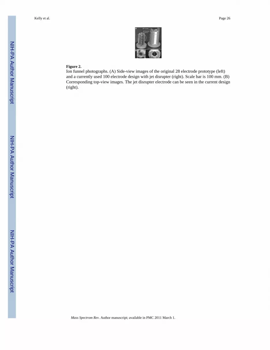
Figure 2.Ion funnel photographs. (A) Side-view images of the original 28 electrode prototype (left)and a currently used 100 electrode design with jet disrupter (right). Scale bar is 100 mm. (B)Corresponding top-view images. The jet disrupter electrode can be seen in the current design(right).
Kelly et al. Page 26
Mass Spectrom Rev. Author manuscript; available in PMC 2011 March 1.
NIH
-PA Author Manuscript
NIH
-PA Author Manuscript
NIH
-PA Author Manuscript

Figure 3.Base peak chromatograms from the LC—MS analysis of a global tryptic digest of S.oneidensis using the standard instrument interface (A) and the ion funnel interface (B).Representative mass spectra from (A) and (B) are shown in (C) and (D), respectively.Adapted with permission from (Page et al., 2007).
Kelly et al. Page 27
Mass Spectrom Rev. Author manuscript; available in PMC 2011 March 1.
NIH
-PA Author Manuscript
NIH
-PA Author Manuscript
NIH
-PA Author Manuscript

Figure 4.Effective rf potential along the ion funnel central (z) axis for the ion funnel prototypedeveloped by Shaffer, et al. (1999). The effective potential is calculated according toequation (1), using numerically computed electric field intensity. The parameters are: m/z =1000, Vrf =100 V, rf frequency = 700 kHz. The axial interval shown corresponds to the final11 ring electrodes of the ion funnel and the 1-mm-i.d. conductance limit located at z =96mm. The axial position of the largest axial well is indicated by the arrow. Adapted withpermission from (Shaffer et al., 1999).
Kelly et al. Page 28
Mass Spectrom Rev. Author manuscript; available in PMC 2011 March 1.
NIH
-PA Author Manuscript
NIH
-PA Author Manuscript
NIH
-PA Author Manuscript

Figure 5.Screen capture of the ion funnel computer model simulation for the design of Kim, et al.(Kim, et al., 2000a). Vpp = 200V; frequency = 0.7 MHz; dc gradient = 30 V/cm; inputcurrent = 8 nA; m/z = 1000. Exit configuration: final rf ring = 2 mm i.d.; dc-onlyconductance limit (1.5 mm) positioned 0.5 mm from the final rf ring.
Kelly et al. Page 29
Mass Spectrom Rev. Author manuscript; available in PMC 2011 March 1.
NIH
-PA Author Manuscript
NIH
-PA Author Manuscript
NIH
-PA Author Manuscript

Figure 6.Experimental (circles) and simulated (triangles) dependence of ion transmission on rfpotential for gramicidin ions using the 100 electrode ion funnel design (Kim, et al., 2000a).The ion current was measured after the ion funnel exit for P = 1 Torr; input current = 5 nA;frequency = 0.7 MHz; axial dc field = 16 V/cm. Simulations used the same conditions.Adapted with permission from (Tolmachev et al., 2000).
Kelly et al. Page 30
Mass Spectrom Rev. Author manuscript; available in PMC 2011 March 1.
NIH
-PA Author Manuscript
NIH
-PA Author Manuscript
NIH
-PA Author Manuscript

Figure 7.Ion transmission efficiency vs. rf voltage simulated using the computer model of theprogressively spaced stacked ring ion guide. The ion m/z, current, and initial velocitycorresponding to each curve are shown in the figure. The modeled configuration consistedof 11 ring rf electrodes, 5 mm i.d., with the spacing progressively increasing from 2 to 5mm. The exit DC-only ring electrode, 2 mm i.d., is positioned 1.5 mm from the final rf ringelectrode. The rf frequency was 700 kHz, gas pressure was 1 Torr (N2), and a uniform gasflow along z-axis was assumed. The initial ion cloud was 2.5 mm in diameter.
Kelly et al. Page 31
Mass Spectrom Rev. Author manuscript; available in PMC 2011 March 1.
NIH
-PA Author Manuscript
NIH
-PA Author Manuscript
NIH
-PA Author Manuscript

Figure 8.Drawings of various ESI/ion funnel interfaces. (A) The initial ion funnel design (Shaffer etal., 1998), using single capillary inlets and high-speed pumps. (B) Implementation ofmultiple heated inlet capillaries (Kim et al., 2000b), which increased ion transmission butalso increased the pumping requirements, even when a jet disrupter electrode was used. (C)Higher pressure ion funnel operated in tandem with a standard ion funnel (Ibrahim et al.,2006). The additional pumping stage enables the use of low-speed pumps. (D) A lowpressure ESI interface, in which the electrospray source sprays directly into an ion funnel,eliminating the transmission losses that normally occur at the inlet (Page et al., 2008b).
Kelly et al. Page 32
Mass Spectrom Rev. Author manuscript; available in PMC 2011 March 1.
NIH
-PA Author Manuscript
NIH
-PA Author Manuscript
NIH
-PA Author Manuscript

Figure 9.Sensitivity enhancements afforded by the use of a linear array of 19 emitters, a multi-capillary heated inlet, and high-pressure ion funnel interface compared with the commercialinstrument configuration (Kelly et al., 2008a). The peptides in the mixture each had aconcentration of 500 nM and the solution flow rate was 2 μL/min.
Kelly et al. Page 33
Mass Spectrom Rev. Author manuscript; available in PMC 2011 March 1.
NIH
-PA Author Manuscript
NIH
-PA Author Manuscript
NIH
-PA Author Manuscript

Figure 10.Schematic of the ESI-IMS-QTOF instrument with ion funnels at the entrance and exit of theion mobility drift tube. Adapted with permission from (Tang et al., 2005).
Kelly et al. Page 34
Mass Spectrom Rev. Author manuscript; available in PMC 2011 March 1.
NIH
-PA Author Manuscript
NIH
-PA Author Manuscript
NIH
-PA Author Manuscript

Figure 11.Diagram of an ion funnel trap. Adapted with permission from (Ibrahim et al., 2007).
Kelly et al. Page 35
Mass Spectrom Rev. Author manuscript; available in PMC 2011 March 1.
NIH
-PA Author Manuscript
NIH
-PA Author Manuscript
NIH
-PA Author Manuscript