the international laser ranging service
TRANSCRIPT

THE INTERNATIONAL LASER RANGING SERVICE
MICHAEL PEARLMAN
Harvard-Smithsonian Center for Astrophysics, 60 Garden St. Cambridge, MA 02138, USA
CAREY NOLL
NASA Goddard Space Flight Center, Code 690 Greenbelt, MD 20771, USA
JAN MCGARRY
NASA Goddard Space Flight Center, Code 694 Greenbelt, MD 20771, USA
WERNER GURTNER
Astronomical Institute of Bern, Sidlerstrasse 5 CH-3012 Berne, Switzerland
ERRICOS PAVLIS Joint Center for Earth Systems Technology, University of Maryland, Baltimore County,
1000 Hilltop Circle Baltimore, MD 21250, USA
The International Laser Ranging Service (ILRS) was established in September 1998 as a service within the IAG to support programs in geodetic, geophysical, and lunar research activities and to provide data products to the International Earth Rotation and Reference Frame Service (IERS) in support of its prime objectives. The ILRS develops the standards and specifications necessary for product consistency and the priorities and tracking strategies required to maximize network efficiency. This network consists of more than thirty SLR stations, routinely tracking nearly thirty retroreflector-equipped satellites and the Moon in support of user needs. The Service collects, merges, analyzes, archives and distributes satellite and lunar laser ranging data to satisfy a variety of scientific, engineering, and operational needs and encourages the application of new technologies to enhance the quality, quantity, and cost effectiveness of its data products. The ILRS works with the global network to improve station performance, new satellite missions in the design and building of retroreflector targets to maximize data quality and quantity, and science programs to optimize scientific data yield. The ILRS Central Bureau maintains a comprehensive web site (http://ilrs.gsfc.nasa.gov) as the primary vehicle for the distribution of information within the ILRS community.

2
2
During the last few years, the ILRS has addressed very important challenges. Several new SLR stations have enhanced the global coverage of the network, particularly in the Southern Hemisphere. Two Combination Centers have been established to provide Official ILRS Data Products to the IERS for the process of maintaining the International Terrestrial Reference Frame and seven ILRS Analysis Centers have been established to provide the solutions for the combination process. Procedures have been introduced to track vulnerable satellites, such as ICESat and ALOS. Work continues at several institutions on ground system development toward the next generation laser ranging system with the introduction of kilohertz pulse repetition rates, greater automation, and greater eye safety. Work also continues on the development of new lighter weight retroreflector arrays.
1. ILRS Organization
The ILRS coordinates the activities of the international laser ranging community from data acquisition through the delivery of products to the users. The ILRS is organized into Tracking Stations and Subnetworks, Operations Centers, Data Centers, Analysis and Associate Analysis Centers, a Central Bureau, Working Groups, and a Governing Board (see Figure 1 and [1] and [2]).
Figure 1 ILRS Organization
Stations in the ILRS Tracking Network range to the approved constellation
of artificial satellites and the Moon with state-of-the-art laser ranging systems and transmit their data in near-real time to the ILRS Data Centers. The full

3
3
network currently consists of more than thirty SLR stations as shown in Figure 2. For the most part, stations are designed by the local participating agencies using fairly standard components. Some examples of stations are shown in Figure 3.
Figure 2. ILRS Tracking Network (as of July 2007)
The majority of ILRS stations have a co-located GNSS receiver that adheres
to standards established by the International GNSS Service (IGS). Some are also co-located with VLBI, DORIS, and absolute gravity instrumentation. The ILRS has given strong encouragement to the development of Fundamental Reference Stations, where a combination of several space geodetic techniques including SLR, VLBI, GNSS, DORIS, and absolute gravimetry are co-located to strengthen reference system constraints and system synergy.
ILRS Operations Centers collect and merge the data from the tracking sites, provide initial quality checks on these incoming data, reformat and compress the data if necessary, and relay the data to an ILRS Data Center.
Two Global Data Centers archive all the ranging data and auxiliary data (e.g., station log files and satellite orbit predictions), make the data available to the ILRS Analysis Centers and external users of the data, and act as distribution centers for the primary ILRS products.
The Analysis and Associate Analysis Centers routinely generate the official ILRS products (station coordinates at one-week intervals, Earth Orientation Parameters at one-day intervals) as well as special products, such as satellite predictions, time-bias information, precise orbits for special-purpose satellites, or scientific data products of a mission-specific nature. Lunar Analysis Centers

4
4
process ranging data to the targets on the Moon and produce lunar-specific data products. There are currently about thirty ILRS Analysis and Associate Centers.
Figure 3. Selected ILRS network stations (clockwise from top left, Zimmerwald Switzerland, Greenbelt USA, Maui USA, Matera Italy)
The Central Bureau (CB) is responsible for the daily coordination and management of the ILRS. The CB maintains the ILRS Web site (http://ilrs.gsfc.nasa.gov), a source for all SLR- and LLR-related information, details about the organization and operation of ILRS, and also an entry point to the data and products stored at the Data Centers. The CB maintains the ILRS documentation, organizes meetings and workshops, and issues service reports.
The ILRS has four standing Working Groups that provide the expertise necessary to make technical decisions, to plan programmatic courses of action and are responsible for reviewing and approving the content of technical and scientific databases maintained by the Central Bureau.
The ILRS Governing Board (GB) is responsible for the general direction of the service and defines official ILRS policy and products, determines satellite-tracking priorities, and develops standards and procedures. The sixteen-member

5
5
body interacts with other services and organizations and is selected from ILRS associates representing all components of the service.
2. Scientific Applications of Laser Ranging
Laser ranging measurements provide a long-term stable time history of station positions and precision orbit determination. Data products support maintenance of the Terrestrial Reference Frame, (Earth center of mass and scale), plate tectonics and crustal deformation, static and time-varying gravity field, Earth Orientation (polar motion and length of day), precision orbit determination and calibration of altimetry missions, mass distribution studies, relativity, and lunar and space science.
2.1. The Global Terrestrial Reference Frame
The terrestrial reference system is the basis through which we connect and compare measurements over space, time, and evolving technologies. It is the means by which we know that measured change over time is real and not corrupted with instabilities in our measurement system.
One of the best-known scientific realizations of a global terrestrial reference system is the International Terrestrial Reference Frame (ITRF), updated every few years by the International Earth Rotation and Reference Systems Service (IERS). It is based on contributions from the four different space geodetic techniques (SLR, VLBI, GNSS, and DORIS) consisting of solutions for the positions and velocities of all participating tracking stations in an Earth-fixed geocentric coordinate system. The most important contributions of the laser ranging technique to the reference frame are the fixing of its origin (defined with respect to the center-of-mass of the Earth, including oceans and atmosphere) and its scale (defined by the speed of light, realized mainly through the measurement of the time of propagation, i.e., the ranges to satellites). Origin and scale are crucial elements, not only for “classical” referencing purposes (i.e., crustal deformation studies), but also as providers of an absolute reference for investigations on sea level change, ice budget, etc. ILRS contributions come either as multiyear solutions based on ranges to the geodynamic satellites LAGEOS-1 and -2 or, within the current IERS Combination Pilot Project, as time-series of weekly solutions.
2.2. The Earth in Space
The connection between the terrestrial and the celestial reference systems is given by the current position of the Earth’s body with respect to its current axis

6
6
of rotation (polar motion), its angular rotation about its axis (UT1) or the temporal change of this angle (angular velocity, length-of-day), and the orientation of the axis of rotation in space (precession and nutation). One of the official ILRS products is the time-series of polar motion and length-of-day, submitted weekly to the IERS for combination with the time-series generated by the other space geodetic techniques.
2.3. The Earth's Gravity Field
Global gravity field models are based on a combination of space-borne and ground-based measurements. Dedicated gravity satellite missions including satellite-to-satellite tracking in-orbit observation of derivatives of the gravity field, and ocean-surface altimetry have provided high spatial and temporal resolution of the gravity field. The lower-degree terms of this field and their secular changes (e.g., of the dynamic flattening of the Earth) are most accurately observed by laser ranging. In this way, SLR provides extremely valuable information on (changes in) the overall mass distribution of Earth.
2.4. Precise Orbit Determination and Verification
SLR provides routine precise orbit determination for some missions and verification and calibration of precise orbits determined with other tracking techniques such as GNSS or DORIS for others. The high accuracy and unambiguous nature of SLR data makes it an independent source of quality control and calibration for other tracking techniques. In particular, SLR has been used in all of the recent ocean and ice topography missions to support altimeter measurements and for a number of special engineering missions (e.g., altimeter calibration).
SLR, with its totally passive spaceborne reflectors, also acts as a backup for active tracking techniques. It has saved satellite missions (ERS-1, GFO-1, TOPEX/Poseidon, and Meteor-3M) after the failure of the primary tracking system.
The ILRS continues to encourage new missions with high precision orbit requirements to include retroreflectors as a fail-safe backup tracking system, to improve or strengthen overall orbit precision, and to provide important intercomparison and calibration data with onboard microwave navigation systems.

7
7
2.5. Lunar Ranging
The two ILRS stations currently capable of routinely tracking the four lunar targets have a long history of providing LLR data: the McDonald Observatory in Texas has been in operation since the Apollo 12 mission (since 1985 with the current system), whereas the Grasse Observatory in France started lunar laser ranging in 1987. Several stations have demonstrated lunar capability while others have tracked the Moon for some periods of time (e.g., Maui, Hawaii, 1984-1990). A number of stations (e.g., Matera, Italy, and Mount Stromlo, Australia) are planning to include lunar tracking in their future activities. Applications in gravitational physics include: testing of the Equivalence Principle; (limits for) time-variation of the gravity constant G; and the assessment of the geodetic precession. Applications in lunar science include the determination or the improvement of lunar ephemerides and rotation; dissipation-caused (negative) acceleration; and an assessment of the interior and the Lunar Love numbers.
2.6. Role within other Activities
In early 2004, under its new reorganization, the International Association of Geodesy (IAG) established the Global Geodetic Observatory System (GGOS) project to coordinate geodetic research in support of scientific and applications disciplines. GGOS is intended to integrate different geodetic techniques, models and approaches to provide better consistency, long-term reliability, and understanding of geodetic, geodynamic, and global change processes. Through the IAG’s measurement services (IGS, IVS, ILRS, IDS, and IGFS), GGOS will work to ensure the robustness of the three aspects of geodesy: geometry and kinematics, Earth orientation and rotation, and static and time varying gravity field. GGOS will identify geodetic products and establish requirements on accuracy, time resolution, and consistency. The project will work to coordinate an integrated global geodetic network and implement compatible standards, models, and parameters.
A fundamental aspect of GGOS is the establishment of a global network of stations with co-located techniques, working together to deliver the most accurate and robust reference frame. The ILRS is one of the service participants in GGOS, bringing its unique strengths to the geodetic complex.
3. Satellites Tracked
Since its inception, SLR has tracked more than fifty satellites with retroreflectors. Currently, the ILRS tracks 25 satellites for geodynamics, remote

8
8
sensing (altimeter, SAR, etc.), gravity field determination, general relativity, validation of global navigation systems satellite orbits, and engineering tests (see Figure 4). Altitudes range from a few hundreds of kilometers to geosynchronous altitudes (36,000 km). Two stations, Grasse, France and McDonald, USA, routinely range to four targets on the Moon. Satellites are added and deleted from the ILRS tracking roster as the GB approves new observation campaigns and older ones are completed.
The ILRS assigns satellite tracking priorities in an attempt to maximize data yield on the full satellite complex while at the same time placing greatest emphasis on the most immediate data needs. Nominally, tracking priorities decrease with increasing orbital altitude and increasing orbital inclination (at a given altitude). Priorities of some satellites are then increased to intensify support for active missions (such as altimetry), special campaigns, and post-launch intensive tracking campaigns.
New missions added during the past year are ALOS, ANDE-RR, TerraSAR-X, GLONASS-102, ETS-8, and GIOVE-A. Missions scheduled for ILRS tracking support over the next year include GIOVE-B, PROBA-2, Jason-2, and LRO-LR. It is anticipated that the entire thirty-satellite Galileo complex, to be launched by 2013 will require, at least intermittent, SLR tracking.
The ILRS supports space engineering studies on some rather unique missions. The Russian Reflector satellite included retroreflectors over its nearly 1 1/2 meter length (Figure 5). Differences in the laser return time-of-arrival were used to interpret the orientation and dynamics of the satellite (Figure 6). Another mission, the Naval Research Laboratory's Tether Physics and Survivability satellite, (TiPS) with retroreflector arrays on two satellites separated by a four-kilometer tether was tracked by SLR to study tether dynamics in space.
Figure 4. Examples of satellites tracked by the ILRS network: LAGEOS-1, Jason-1, and GIOVE-A (photo courtesy of ESA).

9
9
Figure 5. Schematic of Reflector satellite.
Figure 6. Range residual pattern on the Reflector satellite observed at Yarragadee (courtesy of N. Parkhomenko, RSA).
4. Network Performance
Satellite Laser Ranging uses short pulse lasers and fast timing electronics to measure the two-way range from a ground station to retroreflector arrays on satellites and the Moon (see Figure 7). The measurement is the roundtrip travel time corrected for optical refraction and spacecraft center-of-mass. The prime data product from the ILRS stations are normal points, which are full-rate ranging data averaged over time intervals from fifteen seconds to five minutes

10
10
depending upon the satellite altitude. Absolute accuracy is typically sub-centimeter. Data are archived and available to the user on a pass-by-pass basis.
Figure 7. Laser Ranging Configuration.
The space segment is totally passive and the refraction model in the optical
wavelength region is relatively simple. Laser ranging stations operate in both day and night time and the data are available to the user in near real-time through the data centers. Laser ranging provides centimeter orbital accuracy and brings a unique ability to detect small changes through the analysis of long-term stable time series of data.
Most of the current laser tracking stations range ten times per second during part or all of the satellite pass, with many stations interleaving passes from different satellites (see Figure 8). An example of a productive day at Yarragadee is shown in Figure 9.

11
11
Figure 8. Interleaved passes from Zimmerwald Switzerland station.
Figure 9. An example of a productive day of tracking at Yarragadee Australia.
12
12
5. Analysis and Data Products
The most important aspects of the SLR/LLR observations are absolute accuracy and long, stable time histories. Accuracy approaches the level of a few mm for modern stations; time histories can be 25-30 years for a few core sites, or even longer for the high altitude satellites (e.g., LAGEOS).
Since its inception, the ILRS put the generation of official analysis products high on its agenda. The Analysis Working Group has initiated several pilot projects, to address questions on the official products, to define standards, to reach consensus on product definition and, ultimately, to arrive at reliable and high-quality operational products.
5.1. “Positioning and EOP” Product
The first-ever Pilot Project focused on the computation of the best-possible ILRS product for station coordinates and Earth Orientation Parameters (EOPs). Various scenarios were defined and tested for establishing the proper satellite mix, means of representing the results, computational strategies, etc.
This resulted in the currently operational processing scheme. At this moment, seven different Analysis Centers (ACs), (ASI/Italy, BKG/Germany, DGFI/Germany, GA/Australia, GFZ/Germany, JCET/USA and NSGF/UK) deliver weekly solutions on LAGEOS-1 and -2 and Etalon-1 and -2 for global station coordinates and EOPs on Tuesday of each week. These solutions are merged into a combined solution by the two official Combination Centers (CCs) at ASI and DGFI. Based on the contributions that the analysis groups made to the Pilot Project and an evaluation of the quality of their results, the ILRS adopted ASI as its official CC, with prime responsibility for the generation of combination solutions for external customers such as the IERS. DGFI is the official Backup ILRS CC with the same product generation schedule. Several other institutions such as GRGS/OCA, France and NCL/UK are also well on their way in the development of their contributions to the official ILRS product. Once they pass a standardized set of benchmarks in the near future, these groups become additional ACs.
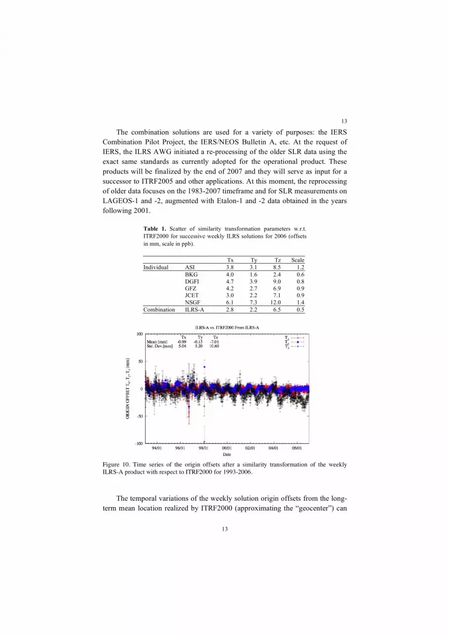
As an illustration of the quality of the individual solutions as well as that of the official combination product (the quality of the primary and the backup solutions is effectively identical), Table 1 gives a summary of the scatter of weekly solutions for the Cartesian component offsets and global scale from a similarity transformation with respect to ITRF2000. The combination solution gives naturally the best result, however all of these products indicate the high quality that ILRS ACs and CCs provide.
13
13
The combination solutions are used for a variety of purposes: the IERS Combination Pilot Project, the IERS/NEOS Bulletin A, etc. At the request of IERS, the ILRS AWG initiated a re-processing of the older SLR data using the exact same standards as currently adopted for the operational product. These products will be finalized by the end of 2007 and they will serve as input for a successor to ITRF2005 and other applications. At this moment, the reprocessing of older data focuses on the 1983-2007 timeframe and for SLR measurements on LAGEOS-1 and -2, augmented with Etalon-1 and -2 data obtained in the years following 2001.
Table 1. Scatter of similarity transformation parameters w.r.t. ITRF2000 for successive weekly ILRS solutions for 2006 (offsets in mm, scale in ppb).
Tx Ty Tz Scale Individual ASI 3.8 3.1 8.5 1.2 BKG 4.0 1.6 2.4 0.6 DGFI 4.7 3.9 9.0 0.8 GFZ 4.2 2.7 6.9 0.9 JCET 3.0 2.2 7.1 0.9 NSGF 6.1 7.3 12.0 1.4 Combination ILRS-A 2.8 2.2 6.5 0.5
Figure 10. Time series of the origin offsets after a similarity transformation of the weekly ILRS-A product with respect to ITRF2000 for 1993-2006.
The temporal variations of the weekly solution origin offsets from the long-term mean location realized by ITRF2000 (approximating the “geocenter”) can

14
14
be seen in Figure 10. Note the dominant annual signal in the z component, clearly a manifestation of mass redistribution in the Earth system, related to climate. Similarly, Figure 11 shows the temporal variation of the scale of the weekly solutions with respect to that of ITRF2000.
Figure 11. Time series of the scale differences after a similarity transformation of the weekly ILRSB product with respect to ITRF2000 for 1993-2006.
5.2. “Benchmarking” Process
A Benchmarking Pilot Project had been established early on, to provide internal quality checks and quality control over the analysis process. Initially, this was used to scrutinize individual elements of the SLR observations, measurement corrections and parameter solutions. Having reached a fully operational status, the Benchmarking Process is now an integral part of the AWG procedures used to assess the quality of new candidate contributors to the ILRS combination products and to identify possible errors.
5.3. New Products
In addition to the Station Coordinate and EOP Product, the AWG is currently working on the delivery of additional official products including satellite orbits

15
15
and a time series of temporal variations in the origin of the ITRF with respect to the origin of the weekly solution [3], the latter being the closest approximation to the “geocenter”. These products are expected to become routinely available by the end of 2007.
6. Modeling
The precision of the travel-time measurement is now of the order of several tens of picoseconds, corresponding to a few millimeters in distance. Ranging accuracy is limited mainly by errors in modeling for refraction propagation and the extrapolation from the reflectors to the satellite center-of-mass.
6.1. Refraction
Since the launch of LAGEOS-1 in 1976, laser ranging stations have used the Marini and Murray model [4] for atmospheric propagation correction. The model works well at higher elevations, but degrades substantially below 20°, and ILRS recently (2002) “lowered” the minimum elevation cut-off to 10° above the horizon to improve the decorrelation of measurement biases and station height. A new model available since 2004 [5] provides improved refraction correction at lower elevations, and it has been adopted by ILRS and the IERS as the new standard, along with the companion mapping functions that work for all wavelengths used in SLR today [6]. Additional improvements are expected when ILRS implements modeling of horizontal refraction gradients due to circulation in the lower atmosphere. Experiments with two years of SLR data have shown a ~20-30% reduction in the residual variance when accounting for these errors [7].
6.2. Retroreflector Array
Early retroreflector designs, even those of the LAGEOS era, relied on multi-cornercube returns to maximize return signal strength. Determining the effective reflection plane with respect to the satellite center-of-mass is a fundamental correction in SLR metrology. This correction is highly dependent upon return signal strength and the ranging station detector configuration, neither of which were sufficiently well considered in the early correction models. Errors could be as high as a centimeter, when the entire error budget of a normal point aside from this correction is at or below the millimeter for most sites. With SLR being the principal technique to establish unambiguously the scale of the ITRF, an error of that size amounts to almost 2 ppb, when we are striving for 0.1-0.2 ppb for the future ITRF realizations. This correction has proven one of the more
16
16
significant contributors in measurement biases today and there are coordinated efforts such as theoretical studies [8] and calibration measurements [9], addressing this error source under the aegis of ILRS. Models are now being implemented that use ground systems characteristics to improve the modeled correction to the level of better than a single millimeter.
7. Advances Underway
A number of advances are currently being implemented that will substantially improve data productivity and quality, while at the same time reduce operational costs. Many of these advances that are now working in one or two stations are envisioned as general characteristics of the future SLR network.
7.1. Automation
Stations are implementing increased automation to reduce personnel costs and facilitate data throughput. The new Mount Stromlo Australia station was designed from the beginning with around-the-clock fully automated, unmanned operations. The Zimmerwald laser station operates autonomously for periods of several hours each day. The fully automated NASA Next Generation SLR (NGSLR) system is currently under development.
7.2. KHz Ranging
With higher-repetition-rate lasers, faster event timers, and better control software, SLR systems are now able to significantly improve the ranging signal-to-noise conditions, while maintaining modest laser characteristics. The new Graz SLR station was the first to successfully operate a 2 kHz laser system, increasing the data volume by up to two orders of magnitude. The NGSLR prototype is also being developed with this capability, as are upgrades at several other stations.
7.3. New, More Powerful Stations
A number of new systems with large meter-class telescopes and state-of-the-art optical and mechanical performance are now operational. This helps to give the tracking network a mix of capabilities to better match the range of targets that now appear on the ILRS roster. The Matera station in southern Italy and the remotely controlled Tanegashima station in Japan both use powerful lasers and large optics to achieve single-shot range precision of a few millimeters.

17
17
7.4. Two-Color Ranging
Several groups are using two-wavelength ranging which provides a promising technique for developing better models for the refraction delay imposed by the atmosphere. Two-color ranging at 423 nm and 846 nm has been underway experimentally at Concepción Chile for some time. The Zimmerwald station began routine operations at these same wavelengths in 2002. Other stations (including GSFC and Matera) have also demonstrated dual-wavelength capability, some of them with superior accuracy using streak cameras. Key to the success of this approach for refraction modeling is the extreme accuracy in measuring the differential time-of-flight of the two pulses at the different wavelengths. Present technology does not permit us to utilize this approach now, however, there are major advances in developing the required technology, so we are looking forward to a promising future for the improvement of the refraction models, and hence also the ILRS science products.
7.5. Improved Satellite Retroreflector Array Design
Multi-cornercube arrays will spread the return pulse. Even with LAGEOS, the return signal is smeared over several centimeters, making measurements highly dependent upon signal strength and ground system properties. Most of the recently launched satellites are using standardized arrays with restricted cornercube view. The spherical satellite GFZ-1, Westpac, and LARETS experimented with special reflector geometries to limit access to a very few (or single) cubes. Using another approach, the Russian Space Agency has provided the ILRS with a space borne test Luneberg Sphere that gives the same array correction for a wide variety of aspect angles [10]. An improved version is now being readied for launch in a sun-synchronous low Earth orbit in 2008. Efforts are also underway to improve the efficiency of the arrays for high orbiting spacecraft to increase the effective cross-section while reducing the payload weight and surface area, both of which are at a premium on the spacecraft. The recently launched ETS-8 synchronous satellite is using a newer design array with uncoated cubes (totally internally reflecting) with considerable success. Work is also underway on hollow cube options being proposed for possible arrays for the GPS III series of satellites (see Figure 12). Commercial cubes will undergo performance testing in late 2007 at NASA’s Goddard Space Flight Center and at the Laboratori Nazionali di Frascati (LNF) in Italy in a newly built environmental test chamber [9].

18
18
Figure 12. Single hollow cube and hollow cube array configuration (drawing courtesy of Armando Morell, NASA Goddard Space Flight Center).
7.6. Transponders
Optical transponders for extraterrestrial ranging are currently under early development by several research teams. An optical transponder is a combination of a laser-ranging receiver and a separate laser pulse transmitter. As opposed to two-way ranging with retroreflector targets, one-way ranging with a transponder would offer the exciting opportunity of ranging to Mars, planetary moons or orbiters, and deep space missions [11]. These transponders will also help to connect the terrestrial reference frame with reference systems used for planetary missions.
7.7. New Missions
The Ocean Surface Topography Mission (OSTM) will continue the oceanography program begun by the TOPEX/Poseidon and Jason-1 missions. An updated version of the Jason-1 satellite (Jason-2) scheduled for launch in mid-2008, will use an altimeter and a microwave radiometer to monitoring global ocean circulation, study the tie between the oceans and atmosphere, improve global climate predictions, and monitor events such as El Nino conditions and ocean eddies. Jason-2 will also carry the Time Transfer by Laser Link (T2L2) time-transfer experiment. SLR will be used for orbit determination and instrument validation.
The Galileo radio navigation system will ultimately have thirty satellites in orbit by 2013. The current mission plan is to have retroreflector arrays on all of the satellites for precision orbit determination and validation of the radio system. The first system test satellite GIOVE-A is currently in orbit; the second, GIOVE-B, is scheduled for launch in early 2008. The role of these test satellites

19
19
is to secure the Galileo frequency allocations by providing a signal in space, characterize the on-board clock, and test some of the on-board systems.
PROBA-2, the second in a series of technology demonstration missions by the European Space Agency is scheduled for launch in December 2007. The series is intended to provide in-orbit demonstration and evaluation of new hardware and software spacecraft technologies, onboard system operational autonomy, and in particular Earth observation and space environment instruments. PROBA-B will carry solar observation and plasma measuring instruments in addition to new spacecraft components for testing. GPS and SLR will provide orbit determination.
The Lunar Reconnaissance Orbiter (LRO), scheduled for launch in October 2008, will orbit the Moon to measure the ground topography with laser altimetry and to study other lunar characteristics such as gravity field, radiation conditions, lighting characteristics, and surface properties in preparation for future human landing. Laser ranging will be used to improve upon the radio tracking accuracy available with C-band. Laser ranging from the Earth will make one-way range measurements to a receiver on the satellite; recorded time on the satellite clock will be transmitted to Earth by telemetry for decoding into range.
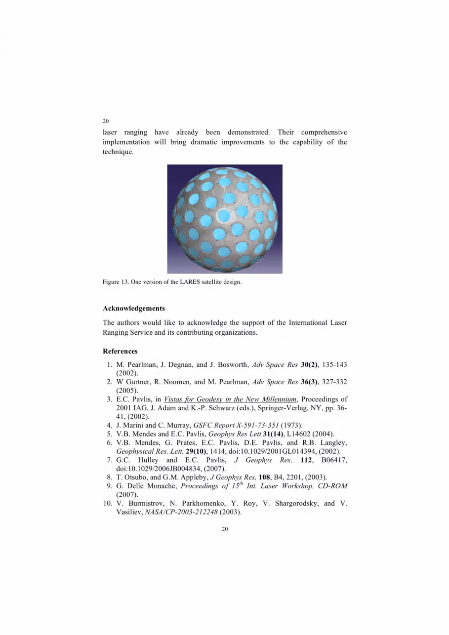
The need for new, well-designed geodetic SLR targets has always been advocated by ILRS. In response to that need, a small group of Italian, U.S., and German scientists proposed the design and launch of a “mini-LAGEOS” satellite named LARES (after LAser RElativity Satellite) [12]. The primary goal for this mission is to improve the accuracy of the space-geodetic general relativity test for frame-dragging [13]. Although at a lower orbit than LAGEOS, the new design (Figure 13) aims to improve orbital accuracy with a significantly smaller area-to-mass ratio, better optical, mechanical and thermal properties, and careful calibration and testing prior to the launch (~2009).
8. Conclusions
Laser ranging has proven to be a fundamental component of the space-geodetic complex, offering a straightforward, conceptually simple, highly accurate and unambiguous observable. It provides essential contributions to geosciences, space sciences and fundamental physics. It will play an important role in the GGOS project.
Current and future challenges lie in the improvement of the accuracy, reliability and availability of the data and in the long-term support of the network. Many of the technological building blocks for the next generation of
20
20
laser ranging have already been demonstrated. Their comprehensive implementation will bring dramatic improvements to the capability of the technique.
Figure 13. One version of the LARES satellite design.
Acknowledgements
The authors would like to acknowledge the support of the International Laser Ranging Service and its contributing organizations.
References
1. M. Pearlman, J. Degnan, and J. Bosworth, Adv Space Res 30(2), 135-143 (2002).
2. W Gurtner, R. Noomen, and M. Pearlman, Adv Space Res 36(3), 327-332 (2005).
3. E.C. Pavlis, in Vistas for Geodesy in the New Millennium, Proceedings of 2001 IAG, J. Adam and K.-P. Schwarz (eds.), Springer-Verlag, NY, pp. 36-41, (2002).
4. J. Marini and C. Murray, GSFC Report X-591-73-351 (1973). 5. V.B. Mendes and E.C. Pavlis, Geophys Res Lett 31(14), L14602 (2004). 6. V.B. Mendes, G. Prates, E.C. Pavlis, D.E. Pavlis, and R.B. Langley,
Geophysical Res. Lett, 29(10), 1414, doi:10.1029/2001GL014394, (2002). 7. G.C. Hulley and E.C. Pavlis, J Geophys Res, 112, B06417,
doi:10.1029/2006JB004834, (2007). 8. T. Otsubo, and G.M. Appleby, J Geophys Res, 108, B4, 2201, (2003). 9. G. Delle Monache, Proceedings of 15th Int. Laser Workshop, CD-ROM
(2007). 10. V. Burmistrov, N. Parkhomenko, Y. Roy, V. Shargorodsky, and V.
Vasiliev, NASA/CP-2003-212248 (2003).

21
21
11. J. Degnan, Geodynamics, Special Issue on Laser Altimetry 34, 551-594 (2002).
12. A. Bosco et al. Int. J. of Modern Physics D (2007). 13. I. Ciufolini and E.C. Pavlis. Nature, 431, 958-960 (2004).