the infn tier-1
TRANSCRIPT

This content has been downloaded from IOPscience. Please scroll down to see the full text.
Download details:
IP Address: 2.234.254.97
This content was downloaded on 09/12/2013 at 21:19
Please note that terms and conditions apply.
The INFN Tier-1
View the table of contents for this issue, or go to the journal homepage for more
2012 J. Phys.: Conf. Ser. 396 042016
(http://iopscience.iop.org/1742-6596/396/4/042016)
Home Search Collections Journals About Contact us My IOPscience
The INFN Tier-1
G. Bortolotti, A. Cavalli, L. Chiarelli, A. Chierici, S. Dal Pra,L. dell’Agnello, D. De Girolamo, M. Donatelli, A. Ferraro,D. Gregori, A. Italiano, B. Martelli, A. Mazza, M. Onofri,A. Prosperini, P. P. Ricci, E. Ronchieri, F. Rosso, V. Sapunenko,R. Veraldi, C. Vistoli. S. ZaniINFN-CNAF V.le Berti Pichat 6/2 40127 Bologna, Italy
E-mail: [email protected]
Abstract. INFN-CNAF is the central computing facility of INFN: it is the Italian Tier-1 forthe experiments at LHC, but also one of the main Italian computing facilities for several otherexperiments such as BABAR, CDF, SuperB, Virgo, Argo, AMS, Pamela, MAGIC, Auger etc..Currently there is an installed CPU capacity of 100,000 HS06, a net disk capacity of 9 PB andan equivalent amount of tape storage (these figures are going to be increased in the first halfof 2012 respectively to 125,000 HS06, 12 PB and 18 PB). More than 80,000 computing jobsare executed daily on the farm, managed by LSF, accessing the storage, managed by GPFS,with an aggregate bandwidth up to several GB/s. The access to the storage system from thefarm is direct through the file protocol. The interconnection of the computing resources andthe data storage is based on 10 Gbps technology. The disk-servers and the storage systemsare connected through a Storage Area Network allowing a complete flexibility and easiness ofmanagement; dedicated disk-servers are connected, also via the SAN, to the tape library. TheINFN Tier-1 is connected to the other centers via 3x10 Gbps links (to be upgraded at the endof 2012), including the LHCOPN and to the LHCONE. In this paper we show the main resultsof our center after 2 full years of run of LHC.
1. IntroductionThe Large Hadron Collider (LHC) has been running for more than 2 years. In the WLCG(Worldwide LHC Computing Grid) [1] structure, the Computing centres are organized accordingto the MONARC model [2], i.e. in a hierarchy separating the centres in Tier levels: INFN-CNAF (CNAF in the following) is a Tier-1 for all four LHC experiments (ALICE, ATLAS,CMS, LHCb). It hosts also a Tier-2 for the LHCb experiment. The Tier-1 at CNAF is themain INFN computing facility in Italy: besides the WLCG experiments, it provides computingand storage resources to several other experiments both running with accelerators data (i.e.Kloe, CDF, BABAR, SuperB) and without accelerators i.e. astro-particle physics experiments(e.g. AMS, Argo, Auger, Borexino, Fermi, Icarus, Magic, Pamela and Virgo). Even with such alarge number of different experiments, with different requirements and computing models, ourstrategy, since the beginning of the Tier-1 activity, has been to offer the same set of services to allof them. Therefore we have only one farm shared among all the experiments, and the same MassStorage System, GEMSS is used by all experiments at CNAF. The EMI (European MiddlewareInitiative) Grid middleware is used to operate both computing and storage resources. Moreover,all the services are redundant both at hardware and software levels in order to guarantee a true
International Conference on Computing in High Energy and Nuclear Physics 2012 (CHEP2012) IOP PublishingJournal of Physics: Conference Series 396 (2012) 042016 doi:10.1088/1742-6596/396/4/042016
Published under licence by IOP Publishing Ltd 1
24x7 support (e.g. storage services can support the failure of up to 50% of the disk-serverswithout service interruption): this is also possible due to a proactive monitoring system (seesection 6). Both the uniformity of offered services and their internal redundancy allow to manageall the resources, namely more than 1000 servers, 12 PB of disk space and 1 tape library with atechnical staff of 20 FTEs. During these years of LHC data taking, with the consolidation of theservices offered to the experiments, a non negligible effort has been devoted to strengthen theinternal structure of the CNAF Tier-1: the four internal sub-groups (Infrastructure, Farming,Network and Storage) will be briefly described in the following sections. The last section willdescribe our monitoring system.
2. InfrastructureThe CNAF Tier-1 has ∼ 120 equipped racks distributed in an area of ∼ 1000 square meters(only part of which are currently in production).
In order to guarantee the best continuous uptime, requirement for a Tier-1, the infrastructurehas been built to meet key requirements in terms of reliability, redundancy and maintainability.
The key features of the electrical system are two 2500 kVA transformers (with an extra 2500kVA transformer to guarantee a N+1 redundancy) and two 1700 kVA rotary diesel UPS systems(i.e. each of them is composed by a high-mass spinning flywheel and a diesel engine) providingredundant emergency power for computational, storage and network units up to 3400 kVA. Anadditional diesel engine provides emergency power for chilling units up to 1200 kVA. The energy,through two completely independent electric lines (one from each rotary UPS) is distributed tothe racks through busbars, providing 2N redundancy at rack level: therefore servers with twopower supplies can avoid the vast majority of site infrastructure electrical failures occurringbetween the uninterruptible power supply and the computer equipment, thus guaranteeing adramatic uptime improvement [3]. In order to lower the Power Usage Effectiveness (PUE) ofour system from the current value (1.6) to 1.5, we are studying the optimization of the tworotary UPS systems which are apparently very efficient under an high load while for the timebeing our IT absorbed power is of the order of 600 KW.
The cooling system is based on 6 chillers (able to provide free-cooling) which guarantee 2MW cooling power with an outside air temperature of 40 oC. The circulation of the chilled wateris guaranteed by 2+2 pumps (2N redundancy). The racks and the air conditioning units (50 kWof heat dissipation each) are structured inside high density islands, in which hot and cold aisleare physically separated in order to avoid hot and cold air mixing, thus increasing the coolingefficiency.
The Tier-1 computing centre is also equipped with a gaseous fire suppression system.All the system critical points are monitored by an ad-hoc supervisory and control system
enabling us to spot problems and failures.
3. FarmingThe Tier-1 common cluster (also including the co-located Tier-2 resources) delivers 125 kHS06distributed on 10,000 CPU cores in use by about 20 experiments: more than 80,000 computingjobs are executed every day on the computing farm. Part of the jobs are executed on VirtualMachines which are transparently and dynamically provisioned as Virtual computing nodesusing the INFN Worker Nodes on Demand Service (WNoDeS) [4]. For each experiment, usuallyonly one queue is defined on the farm. The job scheduling is performed by LSF [5] schedulerand the computing resource allocation is based on the ’Hierarchical Fairshare’ scheduling. Noresources are dedicated to any experiment and the slot allocation to a job is done according tothe following principles: it is directly proportional to the assigned share (namely the resourcequota on the farm) of the experiment (or subgroup) the submitter of the job belongs to, and
International Conference on Computing in High Energy and Nuclear Physics 2012 (CHEP2012) IOP PublishingJournal of Physics: Conference Series 396 (2012) 042016 doi:10.1088/1742-6596/396/4/042016
2

Figure 1. Tier-1 farm usage (May 2011 - May 2012)
inversely proportional to the historical resource usage. This strategy allows to maximize resourceutilization: the Tier-1 farm is nearly always 100% full of jobs (see fig. 1).
We are currently testing some extension to allow the ”job packing”, i.e. the clustering ofa set of jobs on a subset of computing nodes, to allow some special use cases such as parallelprocessing and the ”whole node” i.e. the allocation of a whole computing node to a process).
Each computing node delivers one job slot per physical core: we are considering to enablethe hyper-trading mechanism (and hence the number of job slots per motherboard) taking intoaccount the upper limit given by the network (for each job a bandwidth of 5 MB/s is providedwhile, currently, each computing node has 1 Gbps link).
The computing resources can be accessed both via grid and directly: the direct access isprovided for ”legacy” experiments or for those not fully exploiting the potential of the grid.
Currently we install and manage the farm, such as most of the other Tier-1, with Quattor[6] but we are considering also Puppet.
4. NetworkThe Tier-1 internal network is based on four core switches linked together by 6x10Gbitinterconnections. We have a total of 248 10 Gbps ports, number which is currently increasing.All the racks containing computing nodes are equipped each with two gigabit switches with upto 20 Gbps uplinks to the core in order to guarantee the above mentioned 5 MB/s for each job tothe storage resources. On the other hand, the storage servers are connected with Fiber ChannelInterfaces to the Storage Area Network and via a 10 Gbit interface to the network ∼ 15% ofstorage resources still use 2xGbps connections).
CNAF is also one of the main nodes of GARR, the Italian academic and research network [7].The Tier-1 is connected to CERN and the other Tier-1s with two dedicated 10Gbit connections(LHCOPN) with a 10 Gbps backup line through KIT, the German Tier-1. CNAF is alsointerconnected to the LHCONE. A further 10Gbit link is used for Tier-1 ⇔ Tier-2 and generalpurpose traffic (see fig. 2).
It is foreseen an upgrade for the LHCOPN connection to 100 Gbps at the beginning of 2013.
International Conference on Computing in High Energy and Nuclear Physics 2012 (CHEP2012) IOP PublishingJournal of Physics: Conference Series 396 (2012) 042016 doi:10.1088/1742-6596/396/4/042016
3

Figure 2. CNAF network infrastructure
5. StorageCNAF is currently using a model where all our hardware storage systems (disk and tape drives)are accessed through Storage Area Network (SAN) switches and servers running Scientific Linuxas operating system and equipped with redundant HBA (Fibre Channel Host Bus Adapter). Thishas demonstrated so far to be a robust, stable and very flexible approach. The disk storage fora total of ∼ 9 PetaByte (PB) of net disk space (to be increased to ∼ 12 PB by the end ofQ2 2012) is composed by several storage systems (7 Data Direct DDN systems S2A 9950 for atotal of 7 PB, 7 EMC2 CX3-80 + 1 EMC2 CX4-960 for a total of 1.9 PB and 3 Fujitsu EternusDX400 S2 for a total of 2.8 PB currently under installation) and is served to the farm through40 disk servers with 10 Gb/s Ethernet connection and 90 disk servers with 2x1 Gb/s Ethernetconnection (the gigabit server being for the oldest systems, namely the EMC CX).
The tape storage (14 PB of uncompressed space) is provided by an Oracle SUN SL8500 tapelibrary with 20 Oracle T10KB drives (100 MB/s of bandwidth and 9000 1TB tape cartridges)and 10 Oracle T10KC drives (200 MB/s of bandwidth and 1000 5TB tape cartridges). Theconnections to the tape drives use a subset of the Fibre Channel SAN that is referred to as TapeArea Network (TAN).
Both the disk space and the tape space, structured as a Hierarchical Mass Storage system,is managed by GEMSS [8], the Grid Enable Mass Storage System, an home made integrationof IBM General Parallel File System (GPFS)[9] with the IBM Tivoli Storage Manager (TSM)[10].
GPFS is a clustered file-system which provides a scalable POSIX file access: the farmcomputing nodes do not need a direct connection to the storage backend thought the SAN,but they access the data using the GPFS disk-servers (which have redundant Fibre Channelconnections to the SAN).
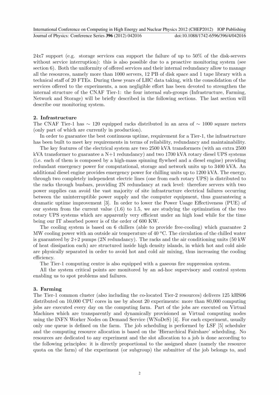
The disk space is subdivided into different GPFS clusters: a total of seven clusters is used, onecluster for each of LHC experiment, one dedicated to SuperB/BaBar and two shared betweenno-LHC users. A further GPFS cluster comprising only the farm computing nodes is provided.In general, for each experiment, a disk only file-system and file-system with HSM features areprovided (see fig. 3). The farm computing nodes and the User Interfaces statically mount thesefile-systems (which are POSIX compliant) and the access to the data is performed using the fileprotocol as they were local to the nodes. Therefore roughly 12000 CPU cores corresponding to
International Conference on Computing in High Energy and Nuclear Physics 2012 (CHEP2012) IOP PublishingJournal of Physics: Conference Series 396 (2012) 042016 doi:10.1088/1742-6596/396/4/042016
4
Figure 3. GEMSS layout for a typical experiment served at CNAF
a computing power of about 125 kHS06 are currently directly accessing via POSIX the GEMSSfilesystems.
The storage resources are also accessible from the WAN by means of GridFTP servers throughthe storage resource manager (SRM) protocol.
StoRM [11] is a storage resource manager developed by INFN, which allows Grid applicationsto interact with storage resources through standard POSIX calls. Its modular design allows forhigh availability and scalability. StoRM is able to take advantage of high performance filesystems like GPFS to improve performance.
Finally, an Oracle clustered database infrastructure is deployed for relational datastoring/retrieving. Oracle technologies like Automatic Storage Manager, Real ApplicationClusters and Streams are exploited. Presently the Oracle database service is composed by32 dual-core servers organized in 7 clusters serving a total amount of 5TB of data.
6. MonitoringThe Tier-1 monitoring and control system is composed by two independent levels.
The first layer is composed by a set of Nagios servers (at least one for logical service, such asfarming, storage and network) that collect information from all the relevant services and hosts.When an error occurs on one of the monitored services or hosts, the controlling Nagios serveris able to perform predefined actions such as trying to restart the interested service, remount afile-system or, in case of a cluster service based on a DNS alias, to delete the faulty host fromthe DNS alias (and to reregister when the hosts is back into operation). In any case, the Nagiosserver signals the issue via email or, in case of a blocking problem, via SMS to the on-dutyexperts.
The second layer is the dashboard: it collects all relevant information from the Nagios serversabout servers, services, worker nodes and switch availability status, presenting it on a privateweb page accessible to authorized users. This page allows the on duty people to have a syntheticvision of the status of the center (see fig. 4).
Other monitor informations, for statistical and historical purposes, are gathered throughLemon (for the servers CPU and RAM usage, GPFS throughput etc.. are collected) and MRTG(it collects all the network bandwidth statistics).
International Conference on Computing in High Energy and Nuclear Physics 2012 (CHEP2012) IOP PublishingJournal of Physics: Conference Series 396 (2012) 042016 doi:10.1088/1742-6596/396/4/042016
5

Figure 4. The CNAF Tier-1 dashboard
References[1] The Worldwide LHC Computing Grid web site: http://lcg.web.cern.ch/LCG
[2] The Models of Networked Analysis at Regional Centres for LHC Experiments web site:http://monarc.web.cern.ch/MONARC/
[3] Pitt Turner IV W, Seader J.H. and Brill K.G., Tier Classifications Define Site Infrastructure Performance,10 white paper of The Uptime Institute
[4] The Worker Nodes on Demands Service web site: http://web.infn.it/wnodes/index.php/wnodes
[5] The IBM Platform LSF web site: http://www-03.ibm.com/systems/technicalcomputing/
platformcomputing/products/lsf/index.html
[6] The Quattor installation system web site: http://www.quattor.org/
[7] The GARR Research Network. web site: http://www.garr.it/
[8] D. Andreotti, et al, INFN-CNAF Tier-1 Storage and Data Management Systems for the LHC Experiments
International Conference on Computing in High Energy and Nuclear Physics (CHEP 2010) IOP PublishingJournal of Physics: Conference Series 331 (2011) 052005 doi:10.1088/1742-6596/331/5/052005
[9] The IBM General Parallel File System web site: http://publib.boulder.ibm.com/infocenter/clresctr/
vxrx/topic/com.ibm.cluster.gpfs.doc/gpfsbooks.html/
[10] The IBM Tivoli Storage Manager website: http://www-01.ibm.com/software/tivoli/products/storage-mgr/[11] Forti A., Magnoni L., Vagnoni V., Zappi R. et al. Storm: a SRM Solution on Disk Based Storage System
in Proceedings of the Cracow Grid Workshop 2006 (CGW2006), Cracow, Poland;
International Conference on Computing in High Energy and Nuclear Physics 2012 (CHEP2012) IOP PublishingJournal of Physics: Conference Series 396 (2012) 042016 doi:10.1088/1742-6596/396/4/042016
6